JOCHEN SCHILLER - Harambe University Digital Library Home
513
JOCHEN SCHILLER Second Edition
-
Upload
khangminh22 -
Category
Documents
-
view
0 -
download
0
Transcript of JOCHEN SCHILLER - Harambe University Digital Library Home

JOCHEN SCHILLERSecond Edition

Mobile Communicat ions
Downloaded from www.books4career.blogspot.com


Jochen H. Schiller
MobileCommunicat ionsSecond Edition

PEARSON EDUCATION LIMITEDEdinburgh GateHarlow CM20 2JETel:+44 (0)1279 623623Fax:+44 (0)1279 431059Website: www.pearsoned.co.uk
First Published in Great Britain 2000Second edition 2003© Pearson Education Limited 2003ISBN 0 321 12381 6
The right of Jochen Schiller to be identified as author of this work has been asserted by him in accordance with the Copyright, Designs, and Patents Act 1988.
All rights reserved; no part of this publication may be reproduced, stored in a retrieval system, or transmitted in any form or by any means, electronic,mechanical, photocopying, recording, or otherwise without either the prior written permission of the Publishers or a licence permitting restricted copying in the United Kingdom issued by the Copyright Licensing Agency Ltd,90 Tottenham Court Road, London W1T 4LP.
The programs in this book have been included for their instructional value.The publisher does not offer any warranties or representations in respect of their fitness for a particular purpose, nor does the publisher accept any liability for anyloss or damage (other than for personal injury or death) arising from their use.
All trademarks used herein are the property of their respective owners. The use of any trademark in this text does not vest in the author or publisher any trademark ownership rights in such trademarks, nor does the use of such trademarks imply any affiliation with or endorsement of this book by such owners.
British Library Cataloguing-in-Publication DataA catalogue record for this book is available from the British Library.
Library of Congress Cataloging in Publication DataA catalog record for this book is available from the Library of Congress.
10 9 8 7 6 5 4 3 2 108 07 06 05 04
Text design by barker/ hilsdon @ compuserve.comTypeset by Pantek Arts Ltd., Maidstone, KentPrinted and bound in Great Britain by Biddles Ltd, www.biddles.co.uk
The publishers’ policy is to use paper manufactured from sustainable forests.

To my students and Cora

1

Contents
About the author xivPreface xvAcknowledgements xix
1 Int roduct ion 11.1 Applications 3
1.1.1 Vehicles 31.1.2 Emergencies 41.1.3 Business 41.1.4 Replacement of wired networks 51.1.5 Infotainment and more 51.1.6 Location dependent services 61.1.7 Mobile and wireless devices 7
1.2 A short history of wireless communication 91.3 A market for mobile communications 151.4 Some open research topics 161.5 A simplified reference model 181.6 Overview 201.7 Review exercises 231.8 References 23
2 Wireless t ransmission 252.1 Frequencies for radio transmission 26
2.1.1 Regulations 272.2 Signals 312.3 Antennas 322.4 Signal propagation 35
2.4.1 Path loss of radio signals 362.4.2 Additional signal propagation effects 372.4.3 Multi-path propagation 39
Downloaded from www.books4career.blogspot.com

2.5 Multiplexing 412.5.1 Space division multiplexing 412.5.2 Frequency division multiplexing 432.5.3 Time division multiplexing 442.5.4 Code division multiplexing 45
2.6 Modulation 462.6.1 Amplitude shift keying 482.6.2 Frequency shift keying 492.6.3 Phase shift keying 492.6.4 Advanced frequency shift keying 502.6.5 Advanced phase shift keying 512.6.6 Multi-carrier modulation 53
2.7 Spread spectrum 542.7.1 Direct sequence spread spectrum 562.7.2 Frequency hopping spread spectrum 59
2.8 Cellular systems 612.9 Summary 642.10 Review exercises 652.11 References 66
3 Medium access cont rol 693.1 Motivation for a specialized MAC 70
3.1.1 Hidden and exposed terminals 703.1.2 Near and far terminals 71
3.2 SDMA 723.3 FDMA 723.4 TDMA 73
3.4.1 Fixed TDM 743.4.2 Classical Aloha 753.4.3 Slotted Aloha 763.4.4 Carrier sense multiple access 763.4.5 Demand assigned multiple access 773.4.6 PRMA packet reservation multiple access 783.4.7 Reservation TDMA 793.4.8 Multiple access with collision avoidance 793.4.9 Polling 823.4.10 Inhibit sense multiple access 82
3.5 CDMA 823.5.1 Spread Aloha multiple access 87
Mobile communicat ionsvii i

3.6 Comparison of S/ T/ F/ CDMA 893.7 Review exercises 913.8 References 92
4 Telecommunicat ions systems 934.1 GSM 96
4.1.1 Mobile services 984.1.2 System architecture 1004.1.3 Radio interface 1054.1.4 Protocols 1104.1.5 Localization and calling 1134.1.6 Handover 1174.1.7 Security 1204.1.8 New data services 122
4.2 DECT 1304.2.1 System architecture 1314.2.2 Protocol architecture 132
4.3 TETRA 1344.4 UMTS and IMT-2000 136
4.4.1 UMTS releases and standardization 1414.4.2 UMTS system architecture 1424.4.3 UMTS radio interface 1434.4.4 UTRAN 1494.4.5 Core network 1514.4.6 Handover 154
4.5 Summary 1564.6 Review exercises 1584.7 References 160
5 Satell ite systems 1655.1 History 1655.2 Applications 1665.3 Basics 169
5.3.1 GEO 173 5.3.2 LEO 1745.3.3 MEO 175
Contents ixDownloaded from www.books4career.blogspot.com

5.4 Routing 1755.5 Localization 1765.6 Handover 1765.7 Examples 1775.8 Summary 1795.9 Review exercises 1805.10 References 181
6 Broadcast systems 1836.1 Overview 1836.2 Cyclical repetition of data 1856.3 Digital audio broadcasting 186
6.3.1 Multi-media object transfer protocol 1906.4 Digital video broadcasting 191
6.4.1 DVB data broadcasting 1936.4.2 DVB for high-speed internet access 194
6.5 Convergence of broadcasting and mobile communications 1956.6 Summary 1966.7 Review exercises 1986.8 References 198
7 Wireless LAN 2017.1 Infra red vs radio transmission 2047.2 Infrastructure and ad-hoc network 2057.3 IEEE 802.11 207
7.3.1 System architecture 2087.3.2 Protocol architecture 2107.3.3 Physical layer 2117.3.4 Medium access control layer 2147.3.5 MAC management 2257.3.6 802.11b 2317.3.7 802.11a 2347.3.8 Newer developments 238
7.4 HIPERLAN 2397.4.1 Historical: HIPERLAN 1 2407.4.2 WATM 2447.4.3 BRAN 2557.4.4 HiperLAN2 257
7.5 Bluetooth 2697.5.1 User scenarios 2707.5.2 Architecture 271
Mobile communicat ionsx

7.5.3 Radio layer 2767.5.4 Baseband layer 2767.5.5 Link manager protocol 2827.5.6 L2CAP 2857.5.7 Security 2877.5.8 SDP 2897.5.9 Profiles 2907.5.10 IEEE 802.15 291
7.6 Summary 2937.7 Review exercises 2977.8 References 298
8 Mobile network layer 3038.1 Mobile IP 304
8.1.1 Goals, assumptions and requirements 3048.1.2 Entities and terminology 3078.1.3 IP packet delivery 3098.1.4 Agent discovery 3108.1.5 Registration 3128.1.6 Tunneling and encapsulation 3158.1.7 Optimizations 3198.1.8 Reverse tunneling 3218.1.9 IPv6 3238.1.10 IP micro-mobility support 324
8.2 Dynamic host configuration protocol 3288.3 Mobile ad-hoc networks 330
8.3.1 Routing 3328.3.2 Destination sequence distance vector 3358.3.3 Dynamic source routing 3368.3.4 Alternative metrics 3398.3.5 Overview ad-hoc routing protocols 340
8.4 Summary 3438.5 Review exercises 3458.6 References 346
9 Mobile t ransport layer 3519.1 Traditional TCP 352
9.1.1 Congestion control 3529.1.2 Slow start 352
Contents xiDownloaded from www.books4career.blogspot.com
9.1.3 Fast retransmit/ fast recovery 3539.1.4 Implications of mobility 354
9.2 Classical TCP improvements 3559.2.1 Indirect TCP 3559.2.2 Snooping TCP 3589.2.3 Mobile TCP 3609.2.4 Fast retransmit/ fast recovery 3629.2.5 Transmission/ time-out freezing 3639.2.6 Selective retransmission 3639.2.7 Transaction-oriented TCP 364
9.3 TCP over 2.5/ 3G wireless networks 3669.4 Performance enhancing proxies 3689.5 Summary 3699.6 Review exercises 3719.7 References 372
10 Support f or mobil it y 37510.1 File systems 376
10.1.1 Consistency 37710.1.2 Coda 37810.1.3 Little work 38010.1.4 Ficus 38010.1.5 Mlo-NFS 38110.1.6 Rover 381
10.2 World wide web 38110.2.1 Hypertext transfer protocol 38210.2.2 Hypertext markup language 38510.2.3 Some approaches that might help wireless access 38610.2.4 System architecture 389
10.3 Wireless application protocol (version 1.x) 39210.3.1 Architecture 39310.3.2 Wireless datagram protocol 39610.3.3 Wireless transport layer security 39710.3.4 Wireless transaction protocol 40010.3.5 Wireless session protocol 40410.3.6 Wireless application environment 41210.3.7 Wireless markup language 41410.3.8 WMLScript 416
Mobile communicat ionsxiiDownloaded from www.books4career.blogspot.com

10.3.9 Wireless telephony application 41910.3.10 Push architecture 42610.3.11 Push/ pull services 42810.3.12 Example stacks with WAP 1.x 429
10.4 i-mode 43010.5 SyncML 43310.6 WAP 2.0 43410.7 Summary 43710.8 Review exercises 44010.9 References 441
11 Out look 44911.1 The architecture of future networks 44911.2 References 453
Appendix 1– Acronyms 455Appendix 2 – Glossary 471Index 477
Contents xii i
Downloaded from www.books4career.blogspot.com

About the author
Joch en Sch iller is h ead of th e workin g group Com puter System s & Telem atics atth e In stitute of Com puter Scien ce, FU Berlin , Germ an y. He received h is MS an dPh D degrees in Com puter Scien ce from th e Un iversity of Karlsruh e, Germ an y, in1993 an d 1996, respect ively. As a postdoc h e join ed Uppsala Un iversity, Sweden ,an d worked in several in dustry co-operation s an d European projects. Sin ce April2001 h e h as been a fu ll p rofessor at FU Berlin . Th e focus of h is research is onm obile an d wireless com m un ication s, com m un icat ion arch itectures an d operat-in g syst em s for em bedd ed d evices, an d q u ality of service aspect s incom m un icat ion system s. He is a m em ber of IEEE an d GI an d acts as con sultan tfor several com pan ies in th e n etworkin g an d com m un ication busin ess.

Preface
W elcom e to th e secon d ed it ion of Mobile Com m u n ication s – an d wel-com e to t h e co n fu sin g, com p lex, bu t very in t erest in g world o fwireless an d m obile t ech n o logies! In th e last few years, we h ave all
exp erien ced t h e h yp e an d fru st rat ion relat ed t o m o bile t ech n ology. On cepraised as th e In tern et on th e m obile ph on e, th e frustrat ion with th ird gen era-t ion m obile p h on e system s cam e at th e sam e t im e th e d otcom s crash ed . Th ereader sh ou ld rem em ber th at all tech n ologies n eed th eir tim e to develop .
Neverth eless, we are experien cin g h uge growth rates in m obile com m un ica-t ion system s (m ain ly in Asia), in creasin g m obility awaren ess in society, an d th eworldwide deregulation of form er m on opolized m arkets. Wh ile tradition al com -m u n icat ion p aradigm s d eal with fixed n etworks, m ob ility raises a n ew set o fquestion s, tech n iqu es, an d solu t ion s. For m an y cou n t ries, m obile com m un ica-tion is th e on ly solution due to th e lack of an appropriate fixed com m un icationin frastru ctu re. Today, m ore people use m obile ph on es (over on e billion !) th antradit ion al fixed ph on es. Th e tren ds m en t ion ed above create an ever-in creasin gdem an d for well-educated com m un ication en gin eers wh o un derstan d th e devel-opm en ts an d possibilities of m obile com m un ication . Wh at we see today is on lyth e begin n in g. Th ere are m an y n ew an d excit in g system s curren tly bein g devel-op ed in research labs. Th e fu tu re will see m ore an d m ore m ob ile devices, th em ergin g of classical voice an d data tran sm ission tech n ologies, an d th e exten sionof today’s In tern et application s (e.g., th e world wide web) on to m obile an d wire-less devices. New ap p lication s an d n ew m obile n etworks will brin g ubiqu itousm u lt im ed ia com p u t in g to th e m ass m arket ; rad ios, person al d igital assistan ts(PDAs), laptops an d m obile ph on es will con verge an d m an y d ifferen t fun ction swill be available on on e device – operatin g on top of In tern et tech n ologies.
Th is book is an in t rodu ct ion to th e field of m obile com m u n icat ion s an dfocuses on d igital dat a t ran sfer. Th e book is in ten ded for use by studen ts of EEor CS in com pu ter n etworkin g or com m un icat ion classes, en gin eers workin gwith fixed n etworks wh o wan t to see th e fu tu re tren ds in n etworkin g, as well asm an agers wh o n eed a com preh en sible overview in m obile com m un ication . Th eread er req u ires a basic u n derstan d in g of com m un icat ion an d a rou gh kn owl-ed ge of t h e In t ern et o r n etworkin g in gen eral. W h ile reso u rces are availab lewh ich focus on a part icu lar tech n ology, th is book tries to cover m an y aspects ofm obile com m u n icat ion s from a com pu ter scien ce poin t of view. Furth erm ore,

t h e bo ok poin t s o u t com m o n p ropert ies o f d ifferen t t ech n ical so lu t ion s an dsh ows th e in tegrat ion of services an d app lication s well-kn own from fixed n et-works in to n etworks supportin g m obility of en d system s an d wireless access. Ifth e reader is in terested in m ore detailed in form at ion regardin g a certain top ic,h e or sh e will fin d m an y poin ters to research publication s or related websites.
Teach ers will fin d th is book u sefu l for a course th at follows a gen eral datacom m un icat ion or com puter n etworkin g class. Th e book can also rep lace partsof m o re gen eral cou rses if it is u sed togeth er with oth er books coverin g fixedn etwo rks or asp ect s of h igh -sp eed n etworks. It sh ou ld be st raigh t forward t oteach a m obile n etworkin g class usin g th is book togeth er with th e course m ater-ial p rovided on lin e via th e followin g lin k:
http:/ / www.jochenschiller.de/Th e m aterial co m p rises all o f t h e figu res, o ver 500 slid es in En glish an d
Germ an as PDF an d PowerPoin t™ files, a list of all acron ym s, an d m an y lin ks torelated sites. Add it ion ally, th e q u est ion s in clu d ed in t h e book can p rovid e agoo d self-t est for st u den t s. Solu t io n s t o all th e q u est io n s in t h e book can befoun d at th e publish er’s password-protected site:
http:/ / www.booksites.net/ schillerTh is book addresses people wh o wan t to kn ow h ow m obile ph on e system s
work, wh at tech n o logy will be n ext in wireless local area n etworks, an d h owm obility will in fluen ce application s, security, or IP n etworks. En gin eers workin g infixed n etworks can see path s of m igration towards m ixed fixed/m obile n etworks.
Th e book fo llows a ‘tall an d t h in ’ ap p roach . It covers a wh o le course inm obile com m un icat ion , from sign als, access protocols, up to application require-m en ts an d security, an d does n ot st ress sin gle top ics to th e n eglect of oth ers. Itfocuses on digital m obile com m un ication system s, as th e future belon gs to digi-tal system s such as CDMA, GSM, DECT, W-CDMA, cdm a2000, UMTS, DAB. Newan d im portan t top ics in th e h igh er layers of com m un ication , like th e wirelessapplication protocol (WAP), i-m ode, an d wireless TCP are in cluded.
Ch apter 1 in troduces th e field of m obile an d wireless com m un ication , pre-sen ts a sh ort h istory an d ch allen ges for research , an d con cludes with a m arketvision , wh ich sh ows th e poten t ial of m obile tech n ology. Ch apter 2 follows th eclassical layers of com m u n icat ion system s an d exp lain s th e basics of wirelesstech n ology from a com pu ter scien ce poin t of view. Topics in th is ch ap ter aresign al propagation , m ult iplexin g, an d m odu lation . Profoun d electrical en gin eer-in g kn owledge is n ot required; h owever, it is n ecessary to com preh en d th e basicprin cip les of wireless tran sm ission to un derstan d th e design decision s of h igh erlayer com m u n icat ion p ro toco ls an d ap p licat ion s. Ch ap ter 3 p resen t s severalm edia access sch em es an d m otivates wh y th e stan dard sch em es from fixed n et-works fail if u sed in a wireless en viron m en t.
Ch ap ters 4–7 p resen t d ifferen t wireless com m un icat ion system s an d m aybe read in an y order. All th e system s in volve wireless access to a n etwork an dth ey can t ran sfer arb it rary data between com m u n icat ion p artn ers. Ch ap ter 4com prises th e global system for m obile com m un ication s (GSM) as today’s m ost
Mobile communicat ionsxvi

su ccessfu l p u blic m o bile p h on e syst em , co rd less p h on e tech n o logy, t ru n kedradios, an d th e fu tu re developm en t with th e un iversal m obile telecom m un ica-t ion s system (UMTS). Satellite system s are covered in ch apter 5, wh ile ch apter 6d iscu sses d igit al b ro adcast system s su ch as d igit al au d io broad cast in g (DAB)wh ich can be on e com pon en t of a larger com m un icat ion system provid in g en d-users with m ass data. Wireless LANs as rep lacem en t for cablin g in side buildin gsare p resen t ed in ch ap t er 7. Exam p les are IEEE 802.11 , Hip erLAN2, an dBluetooth . A special feature of HiperLAN2 is th e provision in g of quality of ser-vice (QOS), i.e., th e system can give guaran tees for certain param eters, su ch asban dwidth or error rates.
Ch apter 8 m ain ly presen ts m obile IP, th e exten sion of th e In tern et protocol(IP) in to th e m obile dom ain . Ad-h oc n etworks with th eir requ irem en ts for spe-cific ro u t in g p ro toco ls are also co vered . Th e su bseq uen t layer, t h e t ran spo rtlayer, is covered in ch apter 9. Th is ch apter d iscusses several approach es of adapt-in g th e curren t tran sm ission con trol protocol (TCP), wh ich is well kn own fromth e In t ern et , to t h e sp ecial req u irem en ts o f m obile com m u n icat ion syst em s.Ch ap ter 10 p resen t s t h e wireless ap p licat ion p ro toco l (WAP) st an d ard t h aten ables wireless an d m obile devices to use parts of th e world wide web (www)from today’s fixed In tern et . Add it ion ally, th is ch ap ter sh ows th e m igrat ion toWAP 2.0, wh ich in clu des com pon en ts from i-m ode an d th e In tern et . Th e bookcloses with an out look to fourth gen eration system s in ch apter 11.
Th e book is based on a course I h ave taugh t several t im es at th e Un iversityof Karlsruh e an d th e Free Un iversity of Berlin . Th e course typ ically con sist s of14 lectures of 90 m in utes each (typ ically, n ot every top ic of th e book is covereddurin g th e lectu re in th e sam e detail). Over 100 un iversit ies, colleges, an d oth erin st itu t ion s aroun d th e world h ave already used th e m aterial com piled for th isbook. Teach ers m ay in clu d e th e on lin e m aterial in th eir cou rses or even basewh ole courses on th e m aterial.
What is new in t he second edit ion?Over th ree years h ave passed sin ce th e pu blicat ion of th e first ed it ion . Du rin gth is t im e, m an y n ew ideas sh owed up , several ideas were d ropp ed , an d m an ysystem s h ave been im p roved . Th e m ain ch an ges, besid es u p dat es o f all refer-en ces an d lin ks, are th e followin g:● In tegration of h igh er data rates for GSM (HSCSD, GPRS).● Com plete n ew section abou t th ird gen eration system s with in -depth discus-
sion of UMTS/W-CDMA.● Addition of th e n ew WLAN stan dards for h igh er data rates: 802.11a, .11b,
.11g an d HiperLAN2.● Exten sion of th e Bluetooth sect ion : IEEE 802.15, profiles, application s.
Preface xvii

● More on ad -h oc n etworkin g an d wireless profiled TCP.● Migration of WAP 1.x an d i-m ode towards WAP 2.0.
You are en couraged to sen d an y com m en ts regard in g th e book or coursem aterial to [email protected]. Fin ally, I h ope you en joy readin g th is com -p let ely revised boo k an d forgive m e for sim p lificat ion s I h ave u sed to avoidblu rrin g t h e b ig p ictu re o f m obile co m m u n icat ion s. Man y su ch d et ails m aych an ge as research an d stan dards evolve over t im e. As th is book covers m an yaspects of m obile com m un ication s it can n ot d ig in to each an d every detail withth e sam e scien tific depth . Fin ally, th e fam ous quote from Goeth e is valid for th isbook, too:
Properly spea king, such work is never finished; one must decla re it so when,according to time and circumstances, one has done one's best.
Mobile communicat ionsxvii i

Acknowledgements
First of all, I wan t to th an k th e n um erous studen ts from m y Mobile Com m un i-cat ion s courses wh o push ed m e towards writ in g th is book by request in g m orein form ation regardin g wireless an d m obile com m un ication . Th e studen ts’ ques-t io n s an d an swers were a great h elp t o sh ap in g t h e co n ten t s. I a lso wan t t oth an k th e n um erous readers aroun d th e world for th eir com m en ts an d reviews.You all h elped m e a lo t fixin g un clear explan ation s.
For th e first ed it ion , m an y o f m y form er co lleagu es at t h e Un iversity o fKarlsruh e gave gen erously of th eir in tellect an d tim e, read in g, com m en tin g, an dd iscu ssin g th e ch ap t ers of th e book. I am esp ecially gratefu l to Marc Bech ler,Stefan Dresler, Joch en Seitz, an d Gün ter Sch äfer. I wan t to th an k Hartm ut Rit terfor h is su pport by takin g over som e of m y daily rou t in e work. I also h ad h elpfrom Veren a Rose an d Elm ar Dorn er durin g th e early stages of th e course m ater-ial. I also wan t t o t h an k th e form er h ead o f th e In st it u te o f Telem at ics, Prof.Gerh ard Krü ger, for givin g m e th e freedom an d su pp ort t o set u p th e MobileCom m un ication s cou rse in an in sp irin g en viron m en t.
For m an y in sigh t fu l com m en ts to th e book, I th an k Per Gun n in gberg fromUpp sala Un iversity, Sweden . I am p rofou n dly gratefu l to An gelika Rieder an dKerst in Risse for th eir h elp in polish in g th e first ed it ion . With out th eir h elp, itwould n ot be as easy to read.
For th e secon d ed ition , wh ich I wrote at th e Free Un iversity of Berlin , I ampart icu larly gratefu l to Th iem o Voigt from SICS, Sweden , wh o h elped m e a lotin tegratin g th e n ew ideas of m obile an d wireless tech n ology. Furth erm ore, I wan tto th an k all th e an on ym ous reviewers, colleagues, an d studen ts from m an y d if-feren t places aroun d th e world for th eir valuable con tribution s to th is edition .
As for th e first ed ition , I h ave to th an k th e Addison -Wesley team in th e UKfor all th eir sup port d u rin g th e m akin g of th e book, special th an ks to BridgetAllen , Tessa Fin ch am an d Mich ael St ran g wh o firm ly p ush ed m e toward s th efin al m an uscrip t for th is edit ion .


Wh at will com p u ters look like in ten years? No on e can m ake a wh ollyaccurate predict ion , bu t as a gen eral featu re, m ost com puters will cer-tain ly be p o r t a b le. How will u sers a ccess n etworks with th e h elp of
com pu ters or oth er com m un ication devices? An ever-in creasin g n um ber with -out an y wires, i.e., w ireless. How will people spen d m uch of th eir t im e at work,durin g vacation ? Man y p eop le will be m ob ile – already on e of th e key ch arac-terist ics of t od ay’s society. Th in k, for exam p le, o f an aircraft with 800 seat s.Modern aircraft already offer lim ited n etwork access to passen gers, an d aircraftof th e n ext gen erat ion will offer easy In tern et access. In th is scen ario, a m obilen etwork m ovin g at h igh sp eed above grou n d with a wireless lin k will be th eon ly m ean s of t ran sp ort in g d ata t o an d from passen gers. Th in k o f cars withIn tern et access an d billion s of em bedded processors th at h ave to com m un icatewith , for in stan ce, cam eras, m obile p h on es, CD-p layers, h ead set s, keyboard s,in telligen t t raffic sign s an d sen sors. Th is p leth o ra of devices an d ap p licat ion ssh ow th e great im portan ce of m obile com m un ication s today.
Before presen tin g m ore application s, th e term s ‘m obile’ an d ‘wireless’ as usedth rough out th is book sh ould be defin ed. Th ere are two differen t kin ds of m obil-ity: u ser m obility an d device portability. User m ob ility refers to a user wh o h asaccess to th e sam e or sim ilar telecom m un ication services at differen t p laces, i.e.,th e u ser can be m ob ile, an d th e services will fo llow h im or h er. Exam ples form ech an ism s supportin g user m obility are sim ple call-forwardin g solu tion s kn ownfrom th e teleph on e or com puter desktops supportin g roam in g (i.e., th e desktoplooks th e sam e n o m at ter wh ich com puter a user uses to log in to th e n etwork).
With device portab ility,1 th e com m un ication device m oves (with or with outa user). Man y m ech an ism s in th e n etwork an d in side th e device h ave to m ake sureth at com m un ication is still possible wh ile th e device is m ovin g. A typical exam plefor system s supportin g device portability is th e m obile ph on e system , wh ere th esystem itself h an ds th e device from on e rad io t ran sm itter (also called a base sta-tion ) to th e n ext if th e sign al becom es too weak. Most of th e scen arios described inth is book con tain both user m obility an d device portability at th e sam e tim e.
Int roduct ion 1
1
1 Ap art from th e t erm ‘p ortab le’, several o th er t erm s are u sed wh en sp eakin g abou t d evices (e.g.,‘m obile’ in th e case of ‘m obile ph on e’). Th is book m ain ly dist in guish es between wireless access to an etwork an d m obility of a user with a device as key ch aracterist ics.
Downloaded from www.books4career.blogspot.com

With regard to d evices, th e t erm w ireless is u sed . Th is on ly describes th eway o f accessin g a n etwork or o th er com m u n icat ion p artn ers, i.e., with ou t awire. Th e wire is rep laced by th e tran sm ission of electrom agn etic waves th rough‘th e air’ (alth ough wireless tran sm ission does n ot n eed an y m edium ).
A com m un ication device can th us exh ibit on e of th e followin g ch aracteristics:● Fixed an d w ired : Th is con figurat ion describes th e typ ical desktop com puter
in an office. Neith er weigh t n or power con sum ption of th e devices allow form obile usage. Th e devices use fixed n etworks for perform an ce reason s.
● M ob ile a n d w ired : Man y of t od ay’s lap top s fall in to th is category; u serscarry th e laptop from on e h otel to th e n ext, recon n ect in g to th e com pan y’sn etwork via th e teleph on e n etwork an d a m odem .
● Fix ed an d w ireless: Th is m ode is u sed for in stallin g n etworks, e.g., in h is-torical bu ild in gs to avoid dam age by in stallin g wires, or at t rade sh ows toen su re fast n etwork setup . An oth er exam p le is b ridgin g th e last m ile to acu stom er by a n ew operator th at h as n o wired in frastructure an d does n otwan t to lease lin es from a com petitor.
● Mo b ile a n d w ir eless: Th is is th e m ost in terest in g case. No cable rest rictsth e user, wh o can roam between differen t wireless n etworks. Most tech n ol-ogies discussed in th is book deal with th is type of device an d th e n etworkssu pportin g th em . Today’s m ost successfu l exam ple for th is category is GSMwith m ore th an 800 m illion users.
Th e followin g section h igh ligh ts som e app lication scen arios predestin ed for th euse of m obile an d wireless devices. An overview of som e typical devices is alsogiven . Th e reader sh ou ld keep in m in d , h owever, th at th e scen arios an d devicesd iscu ssed on ly rep resen t a selected spectrum , wh ich will ch an ge in th e fu ture.As th e m arket for m obile an d wireless devices is growin g rap idly, m ore deviceswill sh ow u p, an d n ew applicat ion scen arios will be created . A sh ort h istory ofwireless com m un icat ion will p rovide th e backgroun d, briefly su m m in g up th ed evelop m en t over t h e last 200 years. Sect ion 1.3 sh ows wireless an d m obilecom m u n icat ion from a m arket in g p ersp ect ive. W h ile th ere are already over abillion users of wireless devices today an d th e wireless busin ess h as experien cedsom e problem s in th e last few years, th e m arket poten tial is st ill t rem en dous.
Section 1.4 sh ows som e open research top ics resu lt in g from th e fun dam en -tal differen ces between wired an d wireless com m un ication . Section 1.5 presen tsth e b asic referen ce m od el fo r com m u n icat ion system s u sed t h rou gh ou t th isbook. Th is ch apter con cludes with an overview of th e book, exp lain in g th e ‘tallan d th in ’ approach ch osen . Tall an d th in m ean s th at th is book covers a varietyof d ifferen t aspects of m obile an d wireless com m u n icat ion to p rovid e a com -plete picture. Due to th is broad perspect ive, h owever, it does n ot go in to all th edetails of each tech n ology an d system s presen ted .
Mobile communicat ions2
1.1 Applicat ionsAlth ou gh m an y app licat ion s can ben efit from wireless n etworks an d m obilecom m u n ication s, part icu lar ap plication en viron m en ts seem to be p redest in edfor th eir use. Th e followin g section s will en um erate som e of th em – it is left toyou to im agin e m ore.1.1.1 VehiclesTod ay’s cars already com p rise som e, bu t tom orrow’s cars will com prise m an ywireless com m un ication system s an d m obility aware application s. Music, n ews,road con dit ion s, weath er reports, an d oth er broadcast in form at ion are receivedvia digital audio broadcast in g (DAB) with 1.5 Mbit /s. For person al com m un ica-t ion , a u n iversal m ob ile telecom m un icat ion s system (UMTS) ph on e m igh t beavailable offerin g voice an d data con n ectivity with 384 kbit/ s. For rem ote areas,sat ellit e com m u n icat ion can be u sed , wh ile th e cu rren t p osit ion o f t h e car isdeterm in ed via th e global p osit ion in g system (GPS). Cars d rivin g in th e sam earea bu ild a local ad-h oc n etwork for th e fast exch an ge of in form ation in em er-gen cy situation s or to h elp each oth er keep a safe distan ce. In case of an acciden t,n ot on ly will th e airbag be triggered , bu t th e police an d am bu lan ce service willbe in form ed via an em ergen cy call to a service provider. Cars with th is tech n ol-ogy are alread y available. In th e fu tu re, cars will also in form oth er cars abou tacciden ts via th e ad-h oc n etwork to h elp th em slow down in t im e, even before adriver can recogn ize an acciden t . Buses, trucks, an d train s are already tran sm it-t in g m ain ten an ce an d logist ic in form ation to th eir h om e base, wh ich h elps toim prove organ ization (fleet m an agem en t), an d saves tim e an d m on ey.
Figure 1.1 sh ows a typical scen ario for m obile com m un ication s with m an ywireless devices. Networks with a fixed in frastructure like cellu lar ph on es (GSM,UMTS) will be in tercon n ected with t run ked radio system s (TETRA) an d wirelessLANs (W LAN). Satellite com m u n icat ion lin ks can also be used . Th e n etworksbetween cars an d in sid e each car will m ore likely work in an ad -h oc fash ion .Wireless p ico n etwo rks in side a car can com p rise p erson al d igit al assist an t s(PDA), lap top s, o r m obile ph on es, e.g., con n ect ed with each o th er u sin g t h eBluetooth tech n ology.
Th is first scen ario sh ows, in addit ion to th e tech n ical con ten t , som eth in gtypical in th e com m u n icat ion bu sin ess – m an y acron ym s. Th is book con tain san d defin es m an y o f th ese. If you get lost with an acron ym , p lease ch eck th eappen dix, wh ich con tain s th e com plete list , or ch eck th e term s an d defin it ion sdatabase in teractive (TEDDI) of ETSI (2002).
Th in k of sim ilar scen arios for air t raffic or railroad t raffic. Differen t p rob-lem s can occu r h ere d u e t o sp eed . W h ile aircraft t yp ically t ravel at u p t o900 km /h an d curren t train s up to 350 km /h , m an y tech n ologies can n ot oper-ate if th e relat ive speed of a m obile device exceeds, e.g., 250 km /h for GSM or100 km / h for AMPS. On ly som e tech n ologies, like DAB work u p to 900 km /h(un idirection al on ly).
Int roduct ion 3

1.1.2 EmergenciesJust im agin e th e possibilities of an am bulan ce with a h igh -quality wireless con -n ection to a h ospital. Vital in form ation about in jured person s can be sen t to th eh ospital from th e scen e of th e acciden t. All th e n ecessary steps for th is particu-lar type of acciden t can be prepared an d specialists can be con sulted for an earlydiagn osis. Wireless n etworks are th e on ly m ean s of com m un ication in th e caseof n atu ral disasters such as h urrican es or earth quakes. In th e worst cases, on lydecen t ralized , wireless ad-h oc n etworks survive. Th e breakdown of all cablin gn ot on ly im plies th e failu re of th e stan dard wired teleph on e system , but also th ecrash of all m obile ph on e system s requ irin g base station s! 1.1.3 BusinessA travellin g salesm an today n eeds in stan t access to th e com pan y’s database: toen sure th at files on h is or h er laptop reflect th e curren t situat ion , to en able th ecom pan y to keep track of all activities of th eir travellin g em ployees, to keep data-bases con sisten t etc. With wireless access, th e lap top can be tu rn ed in to a t ruem obile office, but efficien t an d powerfu l syn ch ron ization m ech an ism s are n eededto en sure data con sisten cy. Figure 1.2 illustrates wh at m ay h appen wh en em ploy-ees t ry to com m un icate off base. At h om e, th e lap top con n ects via a WLAN orLAN an d DSL to th e In tern et . Leavin g h om e requires a h an dover to an oth er tech -n ology, e.g., to an en h an ced version of GSM, as soon as th e WLAN coverage en ds.Due to in terferen ce an d oth er factors discussed in ch apter 2, data rates drop wh ilecruisin g at h igh er speed . Gas stat ion s m ay offer WLAN h ot spots as well as gas.Train s already offer support for wireless con n ectivity. Several m ore h an dovers tod ifferen t tech n ologies m igh t be n ecessary before reach in g th e office. No m atter
Mobile communicat ions4Figure 1.1
A typical application ofmobile communications:
road traffic

wh en an d wh ere, m obile com m un ication s sh ould always offer as good con n ectiv-ity as possible to th e in tern et , th e com pan y’s in tran et , or th e teleph on e n etwork.1.1.4 Replacement of wired networksIn som e cases, wireless n etworks can also be u sed to rep lace wired n etworks,e.g., rem ote sen sors, for t radesh ows, or in h istoric bu ild in gs. Du e to econ om icreason s, it is o ften im po ssib le t o wire rem ote sen sors fo r weath er fo recasts,earth q uake detect ion , or to provide en viron m en tal in form ation . Wireless con -n ection s, e.g., via satellite, can h elp in th is situat ion . Tradesh ows n eed a h igh lydyn am ic in frast ructu re, bu t cablin g takes a lon g t im e an d frequen tly proves tobe too in flexible. Man y com puter fairs u se W LANs as a replacem en t for cablin g.Oth er cases for wireless n etworks are com pu ters, sen sors, or in form at ion d is-p lays in h istorical bu ild in gs, wh ere excess cablin g m ay destroy valuable walls orfloors. Wireless access poin ts in a corn er of th e room can represen t a solu t ion .1.1.5 Infotainment and moreIn tern et everywh ere? Not with out wireless n etworks! Im agin e a t ravel gu ide fora city. Stat ic in form ation m igh t be loaded via CD-ROM, DVD, or even at h om evia th e In tern et . Bu t wireless n etworks can p rovide u p -to-date in form at ion atan y appropriate locat ion . Th e t ravel gu ide m igh t tell you som eth in g about th eh istory of a bu ildin g (kn owin g via GPS, con tact to a local base stat ion , or t rian -gu lat ion wh ere yo u are) do wn lo ad in g in fo rm at io n abo u t a co n cert in t h ebu ild in g at th e sam e even in g via a local wireless n etwork. You m ay ch oose aseat , p ay via elect ron ic cash , an d sen d th is in form at ion t o a service p rovid er(Ch everst , 2000). An oth er growin g field of wireless n etwork app lication s lies inen tertain m en t an d gam es to en able, e.g., ad -h oc gam in g n etworks as soon aspeop le m eet to p lay togeth er.1.1.6 Locat ion dependent services
Int roduct ion 5LAN, WLAN780 kbit/s
GSM 53 kbit/sBluetooth 500 kbit/s
UMTS, GSM115 kbit/s
LAN100 Mbit/s,
WLAN54 Mbit/s
GSM/EDGE 384 kbit/s,WLAN 780 kbit/s
GSM 115 kbit/s,WLAN 11 Mbit/s
UMTS, GSM384 kbit/s
UMTS, DECT2 Mbit/s
Figure 1.2Mobile and wirelessservices – always bestconnected

Man y research effort s in m obile com pu t in g an d wireless n etworks t ry to h ideth e fact th at th e n etwork access h as been ch an ged (e.g., from m obile ph on e toW LAN or between d ifferen t access p oin ts) or th at a wireless lin k is m ore errorpron e th an a wired on e. Man y ch apters in th is book give exam ples: Mobile IPtries to h ide th e fact of ch an gin g access poin ts by redirectin g packets bu t keep-in g th e sam e IP ad dress (see sect ion 8.1), an d m an y p rotocols t ry to im provelin k q uality usin g en codin g m ech an ism s or retran sm ission so th at application sm ade for fixed n etworks st ill work.
In m an y cases, h owever, it is im portan t for an application to ‘kn ow’ som e-th in g ab ou t t h e lo cat io n o r t h e u ser m igh t n eed locat io n in form at io n fo rfurth er activit ies. Several services th at m igh t depen d on th e actual locat ion canbe dist in gu ish ed :● Fo llow -on ser v ices: Th e fu n ct ion of forward in g calls t o th e cu rren t u ser
location is well kn own from th e good old teleph on e system . W h erever youare, ju st t ran sm it your tem porary ph on e n um ber to your ph on e an d it red i-rect s in com in g calls.2 Usin g m obile com pu ters, a follow-on service cou ldoffer, for in stan ce, th e sam e desktop en viron m en t wh erever you are in th eworld. All e-m ail wou ld au tom atically be forwarded an d all ch an ges to yourd esktop an d docum en ts would be stored at a cen tral location at your com -p an y. If som eo n e wan ted t o reach you u sin g a m u lt im ed ia con feren cin gsystem , th is call wou ld be forwarded to your curren t location .
● Loca t ion aw are services: Im agin e you wan ted to prin t a docum en t sit t in gin th e lobby of a h otel u sin g you r lap top . If you d rop th e docum en t overth e p rin t er icon , wh ere wou ld you exp ect t h e d ocu m en t t o be p rin t ed ?Certain ly n o t by t h e p rin t er in your office! However, with ou t add it ion alin form at ion about th e capabilit ies of your en viron m en t , th is m igh t be th eo n ly th in g you can do. For in stan ce, th ere cou ld be a service in th e h otelan n o u n cin g t h at a st an d ard laser p r in ter is availab le in t h e lobb y or acolor prin ter in a h otel m eet in g room etc. Your com puter m igh t th en tran s-m it you r person al p ro file to you r h o tel wh ich th en ch arges you with th ep rin tin g costs.
● Privacy: Th e two service classes listed above im m ediately raise th e quest iono f p rivacy. Yo u m igh t n o t wan t vid eo calls fo llo win g you to d in n er, bu tm aybe you wou ld wan t im portan t e-m ails to be forwarded. Th ere m igh t belocat ion s an d / o r t im es wh en you wan t t o exclu d e cert ain services fro mreach in g you an d you do n ot wan t to be distu rbed. You wan t to u tilize loca-t ion depen den t services, bu t you m igh t n ot wan t th e en viron m en t to kn owexactly wh o you are. Im agin e a h otel m on itorin g all guests an d sellin g th esep rofiles to com pan ies for advertisem en ts.
● In form at ion services: Wh ile walkin g aroun d in a city you cou ld always use
Mobile communicat ions6
2 Actu ally, th is is already don e with th e ph on e n etwork – your ph on e ju st h an dles som e sign allin g.

your wireless t ravel gu ide to ‘pull’ in form at ion from a service, e.g., ‘W h ereis th e n earest Mexican restau ran t?’ However, a service cou ld also act ively‘push ’ in fo rm at io n on your t ravel gu ide, e.g., th e Mexican restau ran t ju staroun d th e corn er h as a special taco offer.
● Su p p or t services: Man y sm all addit ion al m ech an ism s can be in tegrated tosupport a m obile device. In term ediate resu lts of calculat ion s, state in form a-t ion , or cach e con ten ts cou ld ‘follow’ th e m obile n ode th rough th e fixedn etwork. As soon as th e m obile n od e recon n ects, all in form at ion is avail-ab le again . Th is h elp s to red u ce access d elay an d t raffic with in t h e fixedn etwork. Cach in g of d ata on th e m obile device (st an d ard for all desktopsystem s) is often n ot possible due to lim ited m em ory capacity. Th e altern a-t ive wou ld be a cen tral locat ion for u ser in form at ion an d a u ser accessin gth is in form ation th rough th e (possibly large an d con gested) n etwork all th etim e as it is often don e today.
1.1.7 Mobile and wireless devicesEven th ough m an y m obile an d wireless devices are available, th ere will be m an ym ore in th e fu tu re. Th ere is n o p recise classificat ion o f su ch devices, by size,sh ape, weigh t, or com putin g power. Curren tly, lap tops are con sidered th e upperen d o f t h e m o bile d evice ran ge.3 Th e fo llo win g list gives som e exam p les o fm obile an d wireless devices graded by in creasin g perform an ce (CPU, m em ory,d isp lay, in p u t devices etc.). However, th ere is n o sh arp lin e between th e cate-gories an d com pan ies ten d to in ven t m ore an d m ore n ew categories.● Sen sor: A very sim ple wireless device is represen ted by a sen sor tran sm it t in g
state in form ation . On e exam ple cou ld be a switch sen sin g th e office door. Ifth e door is closed , th e switch tran sm its th is to th e m obile ph on e in side th eoffice wh ich will n ot accep t in com in g calls. With ou t u ser in teract ion , th esem an tics of a closed door is applied to ph on e calls.
● Em bed d ed con t rollers: Man y app lian ces already con tain a sim ple or som e-t im es m ore com p lex co n tro ller. Keyboards, m ice, h ead set s, wash in gm ach in es, coffee m ach in es, h air d ryers an d TV sets are just som e exam ples.W h y n ot h ave th e h air dryer as a sim ple m obile an d wireless device (from acom m un icat ion poin t of view) th at is able to com m un icate with th e m obileph on e? Th en th e dryer would switch off as soon as th e ph on e starts rin gin g– th at would be a n ice application !
● Pager : As a very sim p le receiver, a pager can on ly d isp lay sh ort t ext m es-sages, h as a tin y disp lay, an d can n ot sen d an y m essages. Pagers can even bein t egrat ed in to watch es. Th e t rem en d ou s su ccess o f m obile p h on es, h asm ade th e pager virtually redun dan t in m an y coun tries. Sh ort m essages h avereplaced pagin g. Th e situation is som ewh at differen t for em ergen cy services
Int roduct ion 7
3 Put t in g a m ain fram e on a truck does n ot really m ake it a m obile device.

wh ere it m ay be n ecessary to page a larger n um ber of users reliably with insh ort t im e.
● Mob ile p h on es: Th e t radition al m obile ph on e on ly h ad a sim ple black an dwh ite text d isp lay an d cou ld sen d/ receive voice or sh ort m essages. Tod ay,m obile ph on es m igrate m ore an d m ore toward PDAs. Mobile ph on es with fullcolor graph ic display, touch screen , an d In tern et browser are easily available.
● Perso n a l d igit a l a ssist a n t : PDAs typ ically accom p an y a u ser an d offersim ple version s of office software (calen d ar, n o t e-pad , m ail). Th e typ icalin put device is a pen , with bu ilt-in ch aracter recogn it ion tran slat in g h an d-writ in g in to ch aracters. Web browsers an d m an y oth er software p ackagesare available for th ese devices.
● Pock et com p u ter: Th e n ext steps toward fu ll com puters are pocket com put-ers offerin g tin y keyboards, color disp lays, an d sim ple version s of p rogram sfoun d on desktop com puters (text processin g, spreadsh eets etc.).
● Noteb ook / lap top : Fin ally, lap tops offer m ore or less th e sam e perform an ceas stan dard desktop com puters; th ey use th e sam e software – th e on ly tech -n ical d ifferen ce bein g size, weigh t , an d th e ab ility to ru n on a bat tery. Ifoperated m ain ly via a sen sit ive disp lay (touch sen sit ive or elect rom agn etic),th e devices are also kn own as n otepads or tablet PCs.
Th e m obile an d wireless devices of th e fu ture will be m ore powerfu l, less h eavy,an d com prise n ew in terfaces to th e user an d to n ew n etworks. However, on e bigproblem , wh ich h as n ot yet been solved , is th e en ergy supply. Th e m ore featuresth at a re bu ilt in to a d evice, t h e m ore power it n eed s. Th e h igh er th e p erfor-m an ce of th e d evice, t h e fast er it d rain s t h e bat t eries (assu m in g th e sam etech n ology). Furth erm ore, wireless data t ran sm ission con sum es a lot of en ergy.
Alth ou gh th e area o f m ob ile co m p u t in g an d m ob ile com m u n icat ion isd evelop in g rap id ly, t h e d evices typ ically u sed tod ay st ill exh ib it som e m ajord rawb acks com p ared t o d esktop system s in ad d it io n t o t h e en ergy p rob lem .In terfaces h ave to be sm all en ough to m ake th e device portable, so sm aller key-boards are used. Th is m akes typin g d ifficult due to th eir lim ited key size. Sm alld isp lays are often useless for graph ical disp lay. High er resolu t ion does n ot h elp,as th e lim it in g factor is th e resolu tion capacity of th e h um an eye. Th ese devicesh ave to u se n ew ways of in teractin g with a u ser, such as, e.g., touch sen sit ivedisp lays an d voice recogn it ion .
Mobile com m un ication is greatly in fluen ced by th e m ergin g of telecom m u-n ication an d com puter n etworks. We can n ot say for certain wh at th e teleph on eof th e fu ture will look like, bu t it will m ost probably be a com puter. Even today,t elep h o n es an d m o bile p h o n es are far fro m th e sim ple ‘vo ice t ran sm issiondevices’ th ey were in th e past .4 Developm en ts like ‘voice over IP’ an d th e gen -eral t ren d t oward p acket -orien ted n etwo rks en force t h e m etam o rp h o sis o fteleph on es (alth ough voice services st ill guaran tee good reven ue). Wh ile n o on e
Mobile communicat ions8
4 Ch ap ter 4 will p resen t m ore feat u res o f m o d ern m ob ile p h on e system s, in clu d in g t h e growin gdem an d for ban dwidth to use typ ical In tern et app licat ion s via th e m obile ‘ph on e’.

can p red ict th e fu tu re of com m un ication devices p recisely, it is qu ite clear th atth ere will still be m an y fixed system s, com plem en ted by a m yriad of sm all wire-less com p u t in g devices all over t h e wo rld . More p eop le alread y u se m o bileph on es th an fixed ph on es!
1.2 A short hist ory of wireless communicat ionFor a bet t er u n d erst an d in g o f t od ay’s wireless syst em s an d d evelop m en t s, ash ort h istory of wireless com m un ication is p resen ted in th e followin g sect ion .Th is can n ot cover all in ven t ion s bu t h igh ligh ts th ose th at h ave con tribu ted fun -dam en tally to today’s system s.
Th e use of ligh t for wireless com m un ication s reach es back to an cien t t im es.In form er t im es, th e ligh t was eith er ‘m odulated ’ usin g m irrors to create a cer-tain ligh t on / ligh t off pat tern (’am plitude m odu lat ion ’) or, for exam p le, flagswere u sed t o sign al cod e wo rd s (’am p lit u d e an d freq u en cy m od u la t ion ’, seech ap t er 2). Th e u se o f sm oke sign als fo r com m u n ica t io n is m en t io n ed byPolybius, Greece, as early as 150 BC. It is also reported from th e early (or west-ern ) Han d yn asty in an cien t Ch in a (206 BC–24 AD) th a t ligh t was u sed fo rsign alin g m essages alon g a lin e of sign al towers towards th e cap itol Ch an g’an(Xi’an ). Usin g ligh t an d flags for wireless com m u n icat ion rem ain ed im portan tfor th e n avy un t il rad io t ran sm ission was in t rodu ced , an d even tod ay a sailorh as to kn ow som e codes represen ted by flags if all oth er m ean s of wireless com -m u n icat io n fail. It was n ot u n t il th e en d of t h e 18th cen tu ry, wh en Cla u d eCh ap p e in ven ted th e optical telegraph (1794), th at lon g-d istan ce wireless com -m u n icat ion was p ossib le with t ech n ical m ean s. Op t ical t elegrap h lin es werebuilt alm ost un til th e en d of th e followin g cen tu ry.
Wired com m u n ica t io n st art ed with t h e first co m m ercial t elegrap h lin ebetween Wash in gton an d Balt im ore in 1843, an d Alex a n d er Gra h a m Bell’sin ven t io n an d m arket in g o f t h e t elep h o n e in 1876 (o th ers t ried m arket in gbefore bu t d id n o t su cceed , e.g., Ph ilip Reis, 1834–1874, d iscovered th e tele-ph on e prin ciple in 1861). In Berlin , a public teleph on e service was available in1881, th e first regular public voice an d video service (m ult im ed ia!) was alreadyavailable in 1936 between Berlin an d Leipzig.
All op tical tran sm ission system s su ffer from th e h igh frequen cy of th e car-rier ligh t . As every lit t le obst acle sh ad o ws th e sign al, rain an d fo g m akecom m u n icat io n alm ost im p ossib le. At th at t im e it was n ot p ossib le t o focu sligh t as efficien tly as can be don e today by m ean s of a laser, wireless com m un i-cation d id n ot really take off un til th e d iscovery of electrom agn etic waves an dth e develop m en t o f t h e eq u ip m en t t o m o du lat e t h em . It all st a rt ed withMich ael Fa rad ay (an d about th e sam e t im e Josep h Hen ry) dem on strat in g elec-t rom agn et ic in d u ct ion in 1831 an d Ja m es C. Ma x w ell (1831–79) layin g th eth eoret ical fou n dat ion s for elect rom agn et ic field s with h is fam ou s eq u at ion s(1864). Fin ally, Hein r ich Her tz (1857–94) was th e first to dem on strate th e wave
Int roduct ion 9

ch aract er o f elect rical t ran sm ission t h rou gh sp ace (18 8 6), t h u s p rovin gMaxwell’s eq uat ion s. Tod ay th e u n it Hz rem in d s u s of th is d iscovery. Nik o laTesla (1856–1943) soon in creased th e d istan ce of electrom agn etic t ran sm ission .
Th e n am e, wh ich is m ost closely con n ected with th e su ccess o f wirelesscom m un ication , is certain ly th at of Gu glielm o Marcon i (1874–1937). He gaveth e first dem on strat ion of wireless telegraph y in 1895 usin g lon g wave t ran sm is-sio n with very h igh t ran sm ission p o wer (> 200 kW ). Th e first t ran sat lan t ictran sm ission followed in 1901. On ly six years later, in 1907, th e first com m er-c ia l t r a n sa t la n t ic co n n ect io n s were set u p . Hu ge base st at ion s u sin g u p t oth irty 100 m h igh an ten n as were n eeded on both sides of th e Atlan t ic Ocean .Aroun d th at t im e, th e first World Ad m in ist ra t ion Rad io Con feren ce (WARC)took p lace, coordin atin g th e worldwide use of rad io frequen cies. Th e first rad iob road cast took place in 1906 wh en Regin a ld A. Fessen d en (1866–1932) tran s-m it t ed vo ice an d m u sic fo r Ch ristm as. In 1915, t h e first wireless vo icet ran sm ission was set u p between New York an d San Fran cisco . Th e first co m -m er c ia l r a d io st a t ion st art ed in 1 92 0 (KDKA fro m Pit t sbu rgh ). Sen d er an dreceiver st ill n eeded h uge an ten n as an d h igh tran sm ission power.
Th is ch an ged fu n d am en tally with th e d iscovery of sh o r t w a ves, again byMarcon i, in 1920 (In con n ection with wireless com m un ication , sh ort waves h aveth e advan tage of bein g reflected at th e ion osph ere.) It was n ow possible to sen dsh ort radio waves aroun d th e world boun cin g at th e ion osph ere – th is tech n iqueis still used today. Th e in ven tion of th e electron ic vacu u m tu be in 1906 by LeeDeForest (1873–1961) an d Robert von Lieben (1878–1913) h elped to reduce th esize of sen der an d receiver. Vacuum tubes are still used, e.g., for th e am plificationof th e output sign al of a sen der in today’s radio stat ion s. On e of th e first ‘m obile’t ra n sm it t ers was on board a Zeppelin in 1911. As early as 1926, th e first t ele-p h on e in a t rain was available on th e Berlin -Ham burg lin e. Wires parallel to th erailroad track worked as an ten n a. Th e first car radio was com m ercia lly availablein 1927 (‘Ph ilco Tran siton e’); but George Frost an 18-year-old from Ch icago h adin tegrated a radio in to a Ford Model T as early as 1922.
Nin et een t w en t y -e igh t was t h e year o f m an y field t ria ls fo r t e lev isio nb ro a d ca st in g. Jo h n L. Ba ird (1888–1946) t ran sm it ted TV across th e At lan t ican d dem on strated co lo r TV, th e stat ion W GY (Sch en ectady, NY) started regu larTV b r oa d ca st s an d th e first TV n ew s. Th e first t elet ea ch in g start ed in 1932from th e CBS station W2XAB. Up un t il th en , all wireless com m un ication usedam p litu de m odu lat ion (see section 2.6), wh ich offered relat ively poor q u alitydu e to in terferen ce. On e big step forward in th is respect was th e in ven t ion offreq u en cy m o d u la t io n in 1933 by Ed w in H . Ar m st ro n g (1890–1954). Bothfun dam en tal m odu lat ion sch em es are st ill u sed for today’s rad io broadcast in gwith freq u en cy m od u lat ion resu lt in g in a m u ch bet ter q u alit y. By th e early1930s, m an y radio stat ion s were already broadcast in g all over th e world .
After th e Secon d World War, m an y n ation al an d in tern ation al p rojects inth e a rea o f wireless com m u n icat io n s were t riggered off. Th e first n etworkin Germ an y was t h e an alog A-Netz from 1958, u sin g a carrier freq u en cy o f160 MHz. Con n ect ion setu p was o n ly po ssib le fro m th e m o bile st at ion , n o
Mobile communicat ions10

h an d over, i.e., ch an gin g o f t h e base stat ion , was p ossib le. Back in 1971, th issystem h ad coverage of 80 per cen t an d 11,000 custom ers. It was n ot un t il 1972th at th e B-Netz followed in Germ an y, u sin g th e sam e 160 MHz. Th is n etworkcou ld in it iate th e con n ect ion setup from a stat ion in th e fixed teleph on e n et-work, bu t , th e cu rren t locat ion of th e m obile receiver h ad to be kn own . Th issyst em was a lso availab le in Au st ria, Th e Neth erlan d s, an d Lu xem bo u rg. In1979, th e B-Netz h ad 13,000 custom ers in West Germ an y an d n eeded a h eavysen der an d receiver, typ ically bu ilt in to cars.
At th e sam e t im e, th e n orth ern Eu ropean cou n t ries of Den m ark, Fin lan d ,No rway, an d Sweden (t h e crad le of m o d ern m obile com m u n icat ion s) agreedu pon th e n ord ic m o b ile t elep h on e (NMT) system . Th e an alogue NMT uses a450 MHz carrier an d is st ill th e on ly available system for m obile com m un icat ionin som e very rem ote p laces (NMT at 900 MHz followed in 1986). Several oth ern at io n al st an d ards evo lved an d by t h e early 1980s Eu rop e h ad m o re t h an ah an dfu l of d ifferen t , com pletely in com patible an alog m obile ph on e stan dards.In accordan ce with th e gen eral idea of a European Un ion , th e European coun -t ries decided to develop a pan -European m obile p h on e stan dard in 1982. Th en ew system aim ed to: ● use a n ew spectru m at 900 MHz; ● allow roam in g5 th rough out Europe;● be fu lly digital; an d ● offer voice an d data service. Th e ‘Grou p e Spéciale Mobile’ (GSM) was foun ded for th is n ew developm en t.
In 1983 th e US system ad van ced m obile p h on e system (AMPS) started (EIA,1989). AMPS is an an alog m obile ph on e system workin g at 850 MHz. Teleph on esat h om e wen t wireless with th e stan dard CT1 (cord less teleph on e) in 1984, (fol-lowin g it s p redecessor th e CT0 from 1980). As d igital system s were n ot yetavailable, m ore an alog stan dards followed, such as th e Germ an C-Netz at 450 MHzwith an alog voice tran sm ission . Han d-over between ‘cells’ was n ow possible, th esign allin g system was digital in accordan ce with th e tren ds in fixed n etworks (SS7),an d au tom atic localization of a m obile user with in th e wh ole n etwork was sup-p orted . Th is an alog n etwork was switch ed off in 2000. Ap art from vo icet ran sm ission th e services offered fax, data t ran sm ission via m odem , X.25, an delectron ic m ail. CT2, th e successor of CT1, was em bodied in to Brit ish Stan dardspublish ed in 1987 (DTI, 1987) an d later adopted by ETSI for Europe (ETS, 1994).CT2 uses th e spectrum at 864 MHz an d offers a data ch an n el at a rate of 32 kbit/s.
Th e early 1990s m arked th e begin n in g of fu lly d igita l system s. In 1991, ETSIadopted th e stan dard d igit a l Eu rop ean co rd less t elep h on e (DECT) for d igitalcordless t eleph on y (ETSI, 1998). DECT works at a spect rum of 1880–1900 MHzwith a ran ge of 100–500 m . On e h un dred an d twen ty duplex ch an n els can carry
Int roduct ion 11
5 Roam in g h ere m ean s a seam less h an dover of a teleph on e call from on e n etwork p rovider to an oth erwh ile crossin g n ation al boun daries.

up to 1.2 Mbit/s for data tran sm ission . Several n ew featu res, such as voice en cryp-t ion an d au th en t icat ion , are bu ilt -in . Th e syst em su p port s several 10,000u sers/ km 2 an d is u sed in m ore th an 110 coun tries aroun d th e world (over 150m illion sh ipped un its). Today, DECT h as been ren am ed d igita l en h an ced co rd -less t elecom m u n icat ion s for m arketin g reason s an d to reflect th e capabilities ofDECT to tran sport m ult im edia data stream s. Fin ally, after m an y years of discus-sion s an d field t rials, GSM was stan dardized in a docum en t of m ore th an 5,000pages in 1991. Th is first version of GSM, n ow called glob a l syst em for m ob ileco m m u n ica t io n , works at 900 MHz an d u ses 124 fu ll-du p lex ch an n els. GSMoffers fu ll in tern at ion al roam in g, au tom at ic locat ion services, au th en t icat ion ,en cryption on th e wireless lin k, efficien t in teroperation with ISDN system s, an d arelatively h igh audio quality. Furth erm ore, a sh ort m essage service with up to 160alph an um eric ch aracters, fax group 3, an d data services at 9.6 kbit /s h ave beenin tegrated. Depen din g on n ation al regulation s, on e or several p roviders can useth e ch an n els, d ifferen t accoun t in g an d ch argin g sch em es can be ap p lied etc.However, all GSM system s rem ain com pat ible. Up to n ow, over 400 providers inm ore th an 190 coun tries h ave adopted th e GSM stan dard (over 70 per cen t of th eworld ’s wireless m arket).
It was soon discovered th at th e an alog AMPS in th e US an d th e digital GSMat 900 MHz in Eu rope are n o t su fficien t fo r th e h igh user den sit ies in cit ies.Wh ile in th e US, n o n ew spectrum was allocated for a n ew system , in Europe an ew frequen cy ban d at 1800 MHz was ch osen . Th e effect was as follows. In th eUS, differen t com pan ies developed differen t n ew, m ore ban dwidth -efficien t tech -n ologies to op erate side-by-side with AMPS in th e sam e frequ en cy ban d. Th isresu lt ed in th ree in com pat ible system s, th e an alog n arrowban d AMPS (IS-88,(TIA, 1993a)), an d th e two d igit al syst em s TDMA (IS-136, (TIA, 1996)) an dCDMA (IS-95, (TIA, 1993b)). Th e European s agreed to use GSM in th e 1800 MHzspectrum . Th ese GSM–1800 n etworks (also kn own as DCS 1800, digital cellularsystem ) started with a better voice quality due to n ewer speech codecs. Th ese n et-works co n sist o f m ore an d sm aller cells (see ch ap t ers 2 an d 4). GSM is alsoavailable in t h e US as GSM–1900 (also called PCS 1900) u sin g sp ect ru m at1900 MHz like th e n ewer version s of th e TDMA an d CDMA system s.
Europe believes in stan dards, wh ile th e US believes in m arket forces – GSMis on e of th e few exam ples wh ere th e approach via stan dard ization worked . So,wh ile Eu rop e h as on e com m on st an d ard , an d roam in g is p o ssib le even toAu stralia or Sin gapore, th e US st ill struggles with m an y in com p at ible system s.However, th e p ictu re is d ifferen t wh en it com es to m ore data com m un icat ion -orien t ed system s like local area n etworks. Man y p roprietary wireless local arean etwork system s already existed wh en ETSI stan dard ized th e h igh perform an cerad io local area n etwork (HIPERLAN) in 1996. Th is was a fam ily of stan dardsan d recom m en dat ion s. HIPERLAN type 1 sh ould operate at 5.2 GHz an d sh ou ldo ffer d at a rat es of u p t o 23.5 Mbit / s. Fu rth er t yp es h ad been sp ecified withtype 4 goin g up to 155 Mbit/s at 17 GHz. However, alth ough com in g later th anHIPERLAN in 1997, th e IEEE stan dard 802.11 was soon th e win n er for local area
Mobile communicat ions12
n etworks. It works at th e licen se-free In dustrial, Scien ce, Medical (ISM) ban d at2.4 GHz an d in fra red offerin g 2 Mbit/ s in th e begin n in g (up to 10 Mbit /s withproprietary solu tion s already at th at t im e). Alth ough HIPERLAN h as bet ter per-fo rm an ce figu res, n o p rod u ct s were availab le wh ile m an y com p an ies so onoffered 802.11 com plian t equipm en t.
Nin et een n in et y -eigh t m arked th e begin n in g of m obile com m u n icat ionusin g satellites with th e Irid iu m system (Irid ium , 2002). Up to th is tim e, satel-lites basically worked as a broadcast distribu tion m edium or could on ly be usedwith b ig an d h eavy eq u ip m en t – Irid iu m m arked th e begin n in g of sm all an dtruly portable m obile satellite teleph on es in cludin g data service. Iridium con sistsof 66 satellites in low earth orbit an d uses th e 1.6 GHz ban d for com m un icationwith th e m obile ph on e. In 1998 th e European s agreed on th e u n iversa l m ob ilet e leco m m u n ica t io n s sy st em (UMTS) as th e Eu rop ean p roposal for th eIn tern ation al Telecom m un icat ion Un ion (ITU) IMT-2000 (in tern a t ion al m ob iletelecom m u n ica t ion s). In th e first ph ase, UMTS com bin es GSM n etwork tech n ol-ogy with m ore ban dwidth -efficien t CDMA solution s.
Th e IMT-2000 recom m en dat ion s defin e a com m on , worldwide fram eworkfor fu tu re m obile com m un icat ion at 2 GHz (ITU, 2002). Th is in cludes, e.g., afram ework for services, th e n etwork arch itectu re in cludin g satellite com m un ica-t ion , st rategies for d evelop in g cou n t ries, req u irem en ts o f th e rad io in terface,sp ectru m con sideration s, security an d m an agem en t fram eworks, an d d ifferen ttran sm ission tech n ologies.
Nin et een n in ety n in e saw several m ore p owerfu l W LAN st an d ard s. IEEEpublish ed 802.11b offerin g 11 Mbit /s at 2.4 GHz. Th e sam e spectrum is used byBlu eto oth , a sh ort -ran ge tech n ology to set -u p wireless person al area n etworkswith gross data rates less th an 1 Mbit /s. Th e ITU d ropped th e p lan of a sin gle,worldwide stan dard for th ird gen eration m obile ph on e system s an d decided onth e IMT-2000 fam ily con cep t t h at in clu d es severa l t ech n o logies (UMTS,cdm a2000, DECT etc. see ch apter 4). Th e w ireless ap p lica t ion p ro tocol (WAP)started at th e sam e t im e as i-m od e in Japan . Wh ile WAP did n ot succeed in th ebegin n in g, i-m ode soon becam e a trem en dous success (see ch apter 10).
Th e year 2000, cam e with h igh er data rates an d packet-orien ted tran sm is-sion for GSM (HSCSD, GPRS – see ch apter 4). It sh ould n ot be forgotten th at th elate n in eties was th e t im e wh en a lot of h ype abou t th e com m un ication s busi-n ess started . Th us it was relat ively easy for m arket in g p eople to port ray th irdgen erat ion t ech n ology as h igh -p erfo rm an ce In t ern et o n m ob ile p h o n es. InEu ro pe, UMTS was an n o un ced as cap able of h an d lin g live, in t eract ive vid eostream in g for all u sers at 2 Mbit /s. All tech n ically-orien ted people kn ew th at th isprom ise could n ot be fu lfilled by th e system , but th e au ct ion s an d b eau ty con -t est s for licen sin g 3G spectrum started . In Europe alon e m ore th an €100 billionh ad been paid before th e disillu sion m en t set in . Com pan ies th at h ad n ever runa n etwork before paid billion s for licen ses. Man y of th ese com pan ies are n owban krupt an d th e rem ain in g com pan ies suffer from th e debts.
Most of th e h ype is over, but th e th ird gen erat ion of m obile com m un ication
Int roduct ion 13

started in 2001 in Japan with th e FOMA service, in Europe with several field trials,an d in , e.g., Korea with cdm a2000 (see Figure 4.2 for th e evolution of 3G system s).IEEE released a n ew WLAN stan dard, 802.11a , operatin g at 5 GHz an d offerin g
Mobile communicat ions14
1981:NMT 450
1986:NMT 900
1983:AMPS
1991:CDMA
1991:D-AMPS
cellular phones
1992:GSM
1993:PDC
1994:DCS 1800
2001:IMT d-2000
analogdigital
satellites
1982:Inmarsat-A
1988:Inmarsat-C
1992:Inmarsat-BInmarsat-M
1998:Iridium
cordlessphones1980:CT0
1984:CT1
1987:CT1+
1989:CT 2
1991:DECT
wirelessLAN
1997:IEEE 802.11
199x:proprietary
1999802.11b,Bluetooth
2000:GPRS 2000:
IEEE 802.11a
200?:Fourth Generation
(Internet based)
Figure 1.3Overview of some
wireless communicationsystems

gross data rates of 54 Mbit/ s. Th is stan dard u ses th e sam e p h ysical layer asHip erLAN2 does (stan dard ized in 2000), th e on ly rem ain in g m em ber of th eHIPERLAN fam ily. In 2002 n ew W LAN developm en ts followed . Exam ples are802.11g offerin g up to 54 Mbit/s at 2.4 GHz an d m an y n ew Bluetooth application s(h ead sets, rem ote con t ro ls, wireless keyboards, h o t syn cin g etc.). Th e n etworkproviders con tin ued to deploy th e in frastructure for 3G n etworks as m an y licen s-in g con dition s foresee a m in im um coverage at a certain date. Wh ile digital TV viasatellite h as existed for several years, digital terrestrial TV (DVB-T, see ch apter 6)started as regular service in Berlin in Novem ber 2002. Th is system allows for h igh -quality TV on th e m ove an d requires on ly an an ten n a of a few cen tim eters.
Figu re 1.3 gives an overview of som e of th e n etworks described above, an dsh ows th e developm en t of cellular ph on e system s an d cord less ph on es togeth erwith satellites an d LANs. Wh ile m an y of th e classical m obile ph on e system s con -verged t o IMT-2000 system s (with cdm a2000 an d W-CDMA/ UMTS bein g th epredom in an t system s), th e wireless LAN area develop ed m ore or less in depen -den tly. No on e kn ows exactly wh at th e n ext gen eration of m obile an d wirelesssystem will lo ok like, bu t , t h ere are st ro n g in d icators th at it will be wid elyIn tern et based – th e system will u se In tern et protocols an d In tern et applicat ion s.W h ile th e cu rren t th ird gen erat ion system s st ill h eavily rely on classical tele-ph on e tech n ology in th e n etwork in frastructure, fu ture system s will offer u sersth e ch oice of m an y d ifferen t n etworks based on th e in tern et (see ch ap ter 11).However, n o on e kn ows exact ly wh en an d h ow th is com m on p latform will beavailable. Com pan ies h ave to m ake th eir m on ey with 3G system s first.
Th e dates sh own in th e figure typ ically in dicate th e start of service (i.e., th esystem s h ave been design ed , in ven ted, an d tested earlier). Th e system s beh in dth e acron ym s will be explain ed in th e followin g ch apters (cellu lar an d cordlessph on es in ch apter 4, satellites in ch apter 5, W LANs in ch apter 7).6
1.3 A market for mobile communicat ionsAlth o u gh th e gro wt h in wireless an d m ob ile com m u n ica t io n syst em s h asslowed down , th ese t ech n ologies h ave st ill a h u ge m arket poten tial. More an dm ore p eop le u se m ob ile p h on es, wireless t ech n ology is bu ilt in to m an y cars,wireless data services are available in m an y region s, an d wireless local area n et-works are used in m an y places.
Figure 1.4 sh ows th e in creasin g n um ber of subscribers to m obile ph on e ser-vices worldwide (GSM World , 2002). Th is figu re sh ows th e trem en dous growthrates up to 2000. Th at growth con t in ues tod ay, m ain ly d ue to Ch in a th at h asth e largest n um ber of users.
Figu re 1.5 sh o ws th e cellu lar su bscribers p er region (GSM Wo rld , 2002).
Int roduct ion 15
6 Note th at an alog system s are n ot described.

Wh ile th e sh ares of Europe an d Ch in a are alm ost equal, th e m arket in Europe issatu rat ed with seco n d -gen erat ion GSM syst em s (m ob ile p en et rat ion is abou t70 per cen t). Coun tries such as Germ an y an d Fran ce exh ibited growth rates of40 p er cen t or m ore in 1998. Eu rope’s sh are will decrease com pared to Ch in a,th e Am ericas, an d Africa.
1.4 Some open research topicsAlth o ugh th is book exp lain s m an y system s sup port in g m obility an d explo resm an y solu tion s for wireless access, a lot rem ain s to be don e in th e field. We areon ly a t t h e begin n in g o f wireless an d m ob ile n etworkin g. Th e d ifferen cesbetween wired , fixed n etworks an d wireless n etworks open up variou s top ics.Th e reader m ay fin d even m ore in , e.g., th e book of th e w ireless w orld resea rchforu m (WWRF, 2002):
Mobile communicat ions16
Asia Pacific;36.9
Europe; 36.4
Americas (incl.USA/Canada;
22
Africa; 3.1Middle East; 1.6Figure 1.5
Cellular subscribersper region
(June 2002)
200219961995199419931992
1200
1000
800
600
400
200
0 1997 1998 1999 2000 2001
Figure 1.4Mobile phone service
subscribers worldwide(in millions)

● In t er feren ce: Radio t ran sm ission can n ot be p rotected again st in terferen ceusin g sh ieldin g as th is is don e in coaxial cable or sh ielded twisted pair. Forexam ple, electrical en gin es an d ligh tn in g cause severe in terferen ce an d resultin h igh er loss rates for tran sm itted data or h igh er bit error rates respectively.
● Regu la t ion s an d sp ect ru m : Frequen cies h ave to be coordin ated , an d un for-tun ately, on ly a very lim ited am ou n t of freq u en cies are available (du e totech n ical an d p olit ical reason s). On e research top ic in volves determ in in gh ow to use available frequen cies m ore efficien tly, e.g., by n ew m odulationsch em es (see ch ap t er 2) o r d em an d -d riven m u lt ip lexin g (see ch ap t er 3).Furth er im provem en ts are n ew air in terfaces, power aware ad-h oc n etworks,sm art an ten n as, an d software defin ed radios (SDR). Th e lat ter allow for soft-ware defin able air in terfaces but require h igh com putin g power.
● Low b an d w id th : Alth ough th ey are con tin uously in creasin g, tran sm issionrates are st ill very low for wireless d evices com p ared t o d esktop system s.Local wireless system s reach som e Mbit /s wh ile wide area system s on ly offersom e 10 kbit / s. O n e task wou ld in volve ad ap t in g app licat ion s u sed withh igh -ban dwidth con n ection s to th is n ew en viron m en t so th at th e user cancon t in u e u sin g th e sam e app lication wh en m ovin g from th e desktop ou t-sid e t h e bu ild in g. Research ers look fo r m ore efficien t co m m u n icat io nprotocols with low overh ead.
● High d elays, la rge d elay va ria t ion : A serious problem for com m un icationprotocols used in today’s In tern et (TCP/ IP) is th e big variat ion in lin k ch ar-act erist ics. In wireless syst em s, d elays o f several secon ds can occu r, an dlin ks can be very asym m etrical (i.e., th e lin ks offer differen t service qualitydepen d in g on th e d irection to an d from th e wireless device). Applicat ion sm ust be toleran t an d use robust protocols.
● Low er secu rity, sim p ler to a t t ack : Not on ly can portable devices be stolenm ore easily, bu t th e rad io in terface is also p ron e to th e d an gers o f eaves-dropp in g. Wireless access m ust always in clude en cryption , au th en t icat ion ,an d oth er security m ech an ism s th at m ust be efficien t an d sim ple to use.
● Sh ared m ed iu m : Radio access is always realized via a sh ared m edium . As it isim possible to h ave a separate wire between a sen der an d each receiver, differ-en t com petitors h ave to ‘figh t’ for th e m edium . Alth ough differen t m ediumaccess sch em es h ave been developed, m an y question s are st ill un an swered ,for exam ple h ow to provide quality of service efficien tly with differen t com -bin ation s of access, codin g, an d m ultiplexin g sch em es (Fitzek, 2002).
● Ad-h oc n etw ork in g: Wireless an d m obile com putin g allows for spon tan eousn etworkin g with prior set-up of an in frastructure. However, th is raises m an yn ew question s for research : routin g on th e n etworkin g an d application layer,service discovery, n etwork scalability, reliability, an d stability etc.
A gen eral research top ic for wireless com m un ication (an d a sou rce fo r en dlessdiscussion ) is it s effect on th e h um an body or organ ism s in gen eral. It is un clearif, an d to wh at exten t , electrom agn etic waves tran sm itted from wireless devicescan in fluen ce organ s. Microwave oven s an d W LANs both op erate at th e sam efreq u en cy o f 2 .4 GHz. Ho wever, t h e rad iat ion o f a W LAN is very low (e.g.,
Int roduct ion 17

100 m W ) co m p ared t o a m icrowave oven (e.g., 800 W in sid e th e o ven ).Add it ion ally, as ch ap ter 2 sh ows in m ore d et ail, p rop agat ion s ch aracterist ics,ab so rp t io n , d irect ed an t en n as et c. p lay an im p ort an t ro le. Users, en gin eers,research ers an d polit ician s n eed m ore stud ies to un derstan d th e effect of lon g-term low-power radiat ion (Lin , 1997), BEMS (2002), COST (2000), NIEHS (2002).Th e World Health Organ ization (WHO) h as started a worldwide project on elec-trom agn etic fields (WHO, 2002).
1.5 A simplified reference modelTh is book follows th e basic referen ce m od el used to structure com m un icat ionsystem s (Tan en baum , 2003). An y readers wh o are un fam iliar with th e basics ofcom m u n icat ion n etworks sh ou ld look up th e relevan t sect ion s in th e recom -m en ded literature (Halsall, 1996), (Kesh av, 1997), (Tan en baum , 2003), (Kurose,2003). Figu re 1.6 sh ows a p erson al d igital assistan t (PDA) wh ich p rovides anexam ple for a wireless an d portable device. Th is PDA com m un icates with a basestat ion in th e m iddle of th e p ictu re. Th e base stat ion con sists of a rad io t ran s-ceiver (sen der an d receiver) an d an in terworkin g u n it con n ectin g th e wirelesslin k with th e fixed lin k. Th e com m un ication partn er of th e PDA, a con ven tion alcom puter, is sh own on th e righ t-h an d side.
Un dern eath each n etwork elem en t (such as PDA, in terworkin g un it , com -p u ter), t h e figu re sh o ws th e p r o t o co l st a ck im p lem en ted in th e syst emaccordin g to th e referen ce m odel. En d -syst em s, such as th e PDA an d com puterin t h e exam p le, n eed a fu ll p ro to co l st ack com p risin g t h e ap p licat ion layer,t ran sp ort layer, n etwork layer, data lin k layer, an d ph ysical layer. Applicat ion s
Mobile communicat ions18
ApplicationTransportNetworkData LinkPhysical
NetworkNetworkData LinkData LinkPhysicalPhysical
Radio
ApplicationTransportNetworkData LinkPhysical
Medium
Figure 1.6Simple network and
reference model usedin this book

on th e en d-system s com m un icate with each oth er usin g th e lower layer services.In t er m ed ia t e syst em s, such as th e in terworkin g un it , do n ot n ecessarily n eedall o f t h e layers. Figu re 1.6 on ly sh o ws th e n etwork, d at a lin k, an d p h ysicallayers. As (accordin g to th e basic referen ce m odel) on ly en tit ies at th e sam e levelcom m un icate with each oth er (i.e., tran sport with tran sport , n etwork with n et-work) t h e en d-syst em ap p licat ion s d o n o t n o t ice t h e in t erm ed iat e syst emdirectly in th is scen ario. Th e followin g paragraph s explain th e fun ction s of eachlayer in m ore detail in a wireless an d m obile en viron m en t.● Ph ysica l layer: Th is is th e lowest layer in a com m un icat ion system an d is
respon sible for t h e con version of a st ream of bit s in to sign als th at can bet ran sm it ted o n t h e sen d er sid e. Th e p h ysical layer of t h e receiver t h entran sform s th e sign als back in to a bit st ream . For wireless com m un ication ,th e ph ysical layer is respon sible for frequen cy selection , gen erat ion of th ecarrier frequen cy, sign al detection (alth ough h eavy in terferen ce m ay disturbth e sign al), m odu lation of data on to a carrier frequen cy an d (depen din g onth e t ran sm ission sch em e) en crypt ion . Th ese featu res of th e ph ysical layerare m ain ly d iscu ssed in ch ap t er 2 , bu t will also be m en t ion ed for eachsystem separately in th e appropriate ch apters.
● Data lin k layer: Th e m ain tasks of th is layer in clude accessin g th e m edium ,m u lt ip lexin g of d ifferen t d ata st ream s, correct ion of t ran sm ission errors,an d syn ch ron iza t ion (i.e., d etect ion of a data fram e). Ch apter 3 d iscu ssesd ifferen t m ed iu m access sch em es. A sm all sect ion abou t th e sp ecific datalin k layer u sed in t h e p resen ted syst em s is co m bin ed in each resp ect ivech ap ter. Altogeth er, th e data lin k layer is respon sible for a reliable poin t-to-poin t con n ection between two devices or a poin t-to-m ult ipoin t con n ect ionbetween on e sen der an d several receivers.
● Netw ork layer: Th is th ird layer is respon sible for rou t in g packets th rough an etwork or establish in g a con n ection between two en tit ies over m an y oth erin term ediate system s. Im portan t topics are addressin g, rou tin g, device loca-t ion , an d h an dover between d ifferen t n etworks. Ch apter 8 presen ts severalso lu t io n s fo r t h e n etwork layer p ro to col o f t h e in t ern et (t h e In t ern etPro tocol IP). Th e o th er ch ap ters also con t ain sect ion s abou t th e n etworklayer, as routin g is n ecessary in m ost cases.
● Tra n sp o r t la yer : Th is layer is u sed in th e referen ce m odel to establish anen d-to-en d con n ection . Top ics like q uality of service, flow an d con gest ioncon t rol are relevan t , esp ecially if th e t ran sp ort p rotocols kn own from th eIn tern et , TCP an d UDP, are to be used over a wireless lin k.
● Ap p lica t ion lay er : Fin ally, th e applicat ion s (com plem en ted by add it ion allayers th at can su pport application s) are situated on top of all t ran sm ission -o rien t ed layers. Top ics o f in t erest in t h is con t ext are service lo cat ion ,support for m ult im edia application s, adapt ive application s th at can h an dleth e large variat io n s in t ran sm ission ch aracterist ics, an d wireless access toth e world wide web u sin g a portable device. Very dem an d in g applicat ion sare video (h igh data rate) an d in teractive gam in g (low jitter, low laten cy).
Int roduct ion 19

1.6 OverviewTh e wh ole book is structured in a bot tom -up approach as sh own in Figure 1.7.Ch apter 2 presen ts som e basics about wireless tran sm ission tech n ology. Th e topicscovered in clude: freq uen cies used for com m u n icat ion , sign al ch aracterist ics,an ten n as, sign al propagation , an d several fun dam en tal m ultiplexin g an d m odula-t ion sch em es. Th is ch apter d oes n ot requ ire profou n d kn owled ge of elect ricalen gin eerin g, n or does it explore all details about th e un derlyin g ph ysics of wirelesscom m un ication system s. Its aim is rath er to h elp th e reader un derstan d th e m an ydesign decision s in th e h igh er layers of m obile com m un ication system s.
Ch apter 3 presen ts a broad ran ge of m ed ia access t ech n ologies. It explain swh y m edia access tech n ologies from fixed n etworks often can n ot be app lied towireless n etworks, an d sh ows th e special p roblem s for wireless term in als access-in g ‘sp ace’ as t h e com m on m ed iu m . Th e ch ap t er sh o ws access m eth o d s fo rd ifferen t p urp oses, such as wireless m obile ph on es with a cen tral base stat ionth at can con trol th e access, or com pletely decen tralized ad-h oc n etworks with -ou t an y dedicated stat ion . Th is ch ap ter sh ows h ow th e m u lt ip lexin g sch em esdescribed in ch ap ter 2 can n ow be used for accessin g th e m edium . Special focusis on cod e d ivisio n m u lt ip le access (CDMA), wh ich is on e o f t h e im p ort an taccess m eth ods for m an y n ew system s. Furth er topics are varian ts of Aloh a an dreservation sch em es kn own from satellite n etworks.
Mobile communicat ions20
Chapter 10:Support for Mobility
Chapter 9:Mobile Transport Layer
Chapter 8:Mobile Network Layer
Chapter 6:BroadcastSystems
Chapter 5:SatelliteSystems
Chapter 4:Telecommunication
SystemsChapter 7:Wireless
LAN
Chapter 3:Medium Access Control
Chapter 2:Wireless Transmission
Figure 1.7Overview of the
book’s structure

After ch apter 3, th e reader can select an y of th e ch apters from 4 to 7. Th esep resen t select ed wireless t ran sm ission syst em s u sin g t h e b asic t ech n o lo giessh own in ch ap ters 2 an d 3 an d offer a data t ran sport service to h igh er layers.Ch apter 4 covers wireless com m un icat ion system s origin at in g from th e telecom -m un ication in dustry an d stan dard ization bodies. On th e on e h an d GSM, wh ichis cu rren t ly th e m ost successfu l digital m obile ph on e system worldwide, an d onth e oth er digital en h an ced cordless telecom m un ication s (DECT), an exam ple fora local wireless telecom m un ication system . Th e ch apter presen ts stan dards, fre-quen cies, services, access m eth ods, an d th e arch itectu re of th e system s. It sh owsth e m igration from voice orien tat ion toward packet tran sm ission . UMTS as on ecan didate for fu ture m obile system s con cludes th e ch apter.
Ch ap ter 5 gives a basic in t ro d u ct io n t o sat ellit e com m u n icat io n . Th em yriad tech n ical details are n ot of in terest , bu t th e poten tial of satellite system sto exch an ge data worldwide is.
Ch apter 6 covers th e relatively youn g field of wireless com m un ication : digitalbroadcast system s. Broadcast system s allow on ly un idirection al data distributionbu t can offer n ew services th at com e alon g with digital radio (digital audio broad-castin g, DAB) an d digital television digital video broadcastin g (DVB). Th e abilityto dist ribute arbitrary m ult i-m edia data usin g stan dard form ats kn own from th eIn tern et is an extrem ely im portan t design factor for th ese system s.
Ch apter 7 p resen ts wireless LANs, i.e., th e exten sion of today’s fixed localarea n etworks in to th e wireless dom ain . Th e exam ples p resen ted are th e stan -dards IEEE 802.11, HiperLAN2, an d Bluetooth . After a gen eral in troduct ion , th edesign goals of wireless LANs, ph ysical layer, m ediu m access con trol layer, an dservices of all th ree LANs are presen ted. In th is ch apter, a com parison of th e dif-feren t approach es taken for IEEE 802.11 an d HiperLAN2 is of particu lar in terest .W h ile th e first system offers on ly best effort t raffic u p to 54 Mbit/ s, th e lat tertries to give qu ality o f service (QoS) guaran tees at sim ilar data rates. However,wh ile m an y IEEE 802.11 com plian t products are available, n o HiperLAN2 p rod-u ct h as been released . Blu etooth is d ifferen t becau se it was p rim arily design edfor sh ort ran ge ad -h oc n etworkin g usin g very ch eap h ardware an d offers on lysom e h un dred kbit / s (as rep lacem en t for in frared).
Ch ap ter 8 presen ts solu t ion s for a m obile n etwork layer. Th is layer can beu sed on top of d ifferen t t ran sm ission tech n o logies as p resen ted in ch ap ters 4th rou gh 7. W h ile m o bile IP is th e m ain t op ic o f th e ch ap ter, it d iscusses alsom ech an ism s such as th e dyn am ic h ost con figuration protocol (DHCP) an d rout-in g in ad-h oc n etworks. Because IP is clearly dom in at in g data com m u n icationn etworks (it is th e basis for th e in tern et), it is on ly n atural to exten d th is protocolto th e m obile dom ain . Th e ch apter discusses th e problem s associated with IP an dm obility an d sh ows som e solut ion s. From ch apter 8 on wards th e term ‘m obility’is u sed m ore often , because it does n ot m atter for h igh er layer protocols if th em obility is supported by wireless t ran sm ission tech n ologies or if th e user h as top lug-in a lap top wh erever sh e o r h e cu rren t ly is. Th e p roblem s of in terru ptedcon n ection s an d ch an gin g access poin ts to th e n etwork rem ain alm ost iden t ical.
Int roduct ion 21

Ch apter 9 focuses on ch an ges n eeded for TCP so it can be used in a m obileen viron m en t. To work with well-kn own application s from th e in tern et , e.g., filetran sfer or rem ote login , a u ser m igh t n eed a reliable en d-to-en d com m u n ica-t ion service as provided by th e tran sm ission con trol p rotocol (TCP). It is sh ownth at today’s TCP fails if it is n ot adapted or en h an ced. Several solu tion s are d is-cussed an d com pared. Each solu t ion exh ibits specific st ren gth s an d weakn esses,so up to n ow th ere is n o stan dard for a ‘Mobile TCP’. However, several com m u-n ication system s already use TCP with a ‘wireless profile’.
All m o bile n etwo rks are worth less with ou t ap p licat ion s u sin g t h em .Ch apter 10 sh ows problem s with curren t applicat ion s, as th ey are kn own fromfixed n etworks, an d p resen ts som e n ew d evelopm en ts. Am on g oth er top ics, itdeals with file system s. Here con sisten cy in a d ist ribu ted system brin gs abou tm ajor problem s. How is con sisten cy to be m ain tain ed in th e case of discon n ec-t ion ? Is it bet ter to den y access to data if con sisten cy can n ot be gran ted? Th ech apter presen ts system s dealin g with th ese problem s.
Th e big top ic in today’s In tern et is th e world wide web (www), th e logicalstructu re m ade by m ult i-m edia docum en ts an d h yperlin ks. In con n ect ion withth e www, t h e p rob lem s can be su m m arized as fo llows: t h e www of t od ayassum es con n ect ion s with h igh er ban dwid th , desktop com puters with a lot ofm em o ry, a p o werfu l CPU, h igh -reso lu t ion grap h ics, an d d o zen s o f p lu g-in sin stalled . Mobile devices h ave scarce en ergy resources, th erefore less powerfu lCPUs an d less m em ory. Th ese devices h ave to be p ortable, an d con seq u en t ly,in pu t devices are very lim ited an d d isplays are of a low resolu tion , n ot to m en -t ion t h e h i-fi cap abilit ies. Th is obviou s m ism atch between two tech n ologies,both with h uge growth rates, h as resu lted in a variety of solu t ion s for brin gin gth em togeth er. On e approach in th is respect , th e wireless application protocol(WAP), wh ich is su p p orted by m an y com p an ies, is exp lain ed in m ore d et ail.WAP was n ot a com m ercial su ccess in th e begin n in g. However, it is expectedth at t h e n ew version , WAP 2.0, wh ich in t egrates m an y In tern et tech n ologiesan d i-m ode com pon en ts, will be m ore successfu l.
Ch ap ter 11, gives a sh ort ou t look to n ext gen erat ion m obile an d wirelesssystem s. Wh ile n o on e exactly kn ows wh at th e fu ture will look like, som e in di-cators m ay be given .
Man y im portan t security aspects will be explain ed togeth er with th e tech n ol-ogy in all ch ap ters. Secu rity m ech an ism s are im p ortan t in all layers of acom m un icat ion system . Differen t u sers, even d ifferen t n ation s, h ave d ifferen tideas abou t secu rity. However, it is q u it e clear th at a com m u n icat ion systemtran sm it tin g person al in form ation th rough th e air m ust offer special security fea-tu res to be accep t ed . Com pan ies do n ot wan t com p et ito rs to list en t o th eircom m un ication s an d people often do n ot like th e idea th at th eir n eigh bor m igh th ear t h eir p rivat e con versat ion , wh ich is p ossib le with o lder an alog co rd lessph on e system s. Wireless system s are especially vu ln erable in th is respect due toair in terface. Wire-tappin g is n ot n eeded to listen in a data stream . Special en cryp-tion m eth ods m ust be applied to guaran tee privacy. Furth er security m ech an ism sare au th en tication , con fiden tiality, an on ym ity, an d replay protection .
Mobile communicat ions22

Th e reader can fin d review exercises an d referen ces at th e en d of each ch ap-ter. A com p let e list o f acron ym s u sed th rough ou t th e ch ap ters an d th e in dexcon clude th e book.
1.7 Review exercise1 Discover the current numbers of subscribers for the different systems. As mobile
communications boom, no printed number is valid for too long!2 Check out the strategies of different network operators while migrating towards
third generation systems. Why is a single common system not in sight?
1.8 ReferencesBEMS (2002) Th e Bioelectrom agn etics Society, h ttp:/ /www.bioelectrom agn etics.org/ .Ch everst , K., Davies, N., Mitch ell, K., Friday, A. (2000) ‘Experiences of Developing
and Deploying a Context-Aware Tourist Guide: The GUIDE Project,’p roc.MOBICOM’2000, ACM Press, Boston , USA.
COST (2000) Biomedical Effects of Electromagnetic Fields, European Cooperation in th efield of Scien tific an d Tech n ical Research , COST 244bis, h t tp:/ /www.cordis.lu/ .
DTI (1987) Performance Specification: Radio equipment for use at fixed and portablesta tions in the cordless telephone service, Departm en t of Trade an d In du st ry,MPT 1334.
EIA (1989) Mobile land sta tion compa tibility specifica tion, Elect ron ic In du st riesAssociation , ANSI/EIA/TIA Stan dard 553.
ETSI (1994) Common a ir interfa ce specifica tion to be used for the interworkingbetween cordless telephone a ppa ra tus in the frequency ba nd 864.1 MHz to868.1 MHz, including public access services, Eu ropean Telecom m u n icat ion sStan dards In st itu te, I-ETS 300 131 (1994–11).
ETSI (1998) Digita l Enhanced Cordless Telecommunica tions (DECT), CommonInterface (CI), Eu ropean Telecom m u n icat ion s St an d ard s In st it u te, EN 300175, V1.4.1 (1998–02).
ETSI (2002) Term s an d Defin it io n s Database In t eract ive (TEDDI), Eu ro peanTelecom m un icat ion s Stan dards In st itu te, h t tp :/ /webapp .etsi.org/Teddi/ .
Fitzek, F., Köpsel, A., Wolisz, A., Krish n am , M., Reisslein , M. (2002) ‘Provid in gAp p lica t io n -Level Q oS in 3G/ 4G Wireless Syst em s: A Com p reh en siveFram ework on Mult irate CDMA,’ IEEE Wireless Communications, 9(2).
GSM World (2002) GSM Associat ion , h t tp:/ /www.gsm world.com / .Halsa ll, F. (1996) Da ta communica tions, computer networks a nd open systems.
Addison -Wesley.Iridium (2002) Iridium Satellite LLC, Leesburg, VA, USA, h ttp:/ /www.iridium .com /.ITU (2002) International Mobile Telecommunications, In tern ation al Telecom m un i-
cation Un ion , set of recom m en dation s, h ttp:/ /www.itu.in t/ im t/ .
Int roduct ion 23

Kesh av, S. (1997) An engineering approach to computer networking. Addison -Wesley.Kurose, J., Ross, K. (2003) Computer Networking. Addison -Wesley.Lin , J.C. (1997) ‘Biological aspect s o f m obile com m un icat ion fields,’ (series of
art icles), Wireless Networks, J.C. Baltzer, 3(6).NIEHS (2002) Th e Nat ion al In st it u t e o f En viron m en ta l Health Scien ces,
h ttp :/ /www.n ieh s.n ih .gov/em frapid/ .Tan en baum , A. (2003) Computer Networks. Pren tice-Hall.TIA (1993a) Mobile station land sta tion compatibility specification for dual-mode nar-
rowba nd a na logue cellula r technology, Teleco m m u n icat ion s In d u str iesAssociat ion , In terim Stan dard 88.
TIA (1993b) Mobile sta tion base station compatibility standard for dual-mode wide-band sprea d spectrum cellula r systems, Telecom m u n icat ion s In d u str iesAssociat ion , In terim Stan dard 95.
TIA (1996) 800 MHz TDMA cellular radio interface mobile station base station compati-bility, Telecom m un ication s In dustries Association , In terim Stan dard 136A.
W HO (2002) The Interna tiona l EMF Project, World Health Organ izat ion ,h ttp :/ /www.wh o.in t/peh -em f/en / .
W W RF (2002) Wireless World Research Foru m , h t t p :/ / www.wireless-wo rld -research .org/ , h t tp :/ /www.ww-rf.org
Mobile communicat ions24
Th is book focuses on h igh er layer aspect s of m obile com m u n ication s, th ecom p u ter scien ce elem en t rath er t h an on t h e rad io an d t ran sm issionaspects, th e electrical en gin eerin g part. Th is ch apter in t roduces on ly th ose
fun dam en tal aspects of wireless tran sm ission wh ich are n ecessary to un derstan dth e p roblem s of h igh er layers an d th e com plexity n eeded to h an dle t ran sm is-sion im p airm en t s. W h erever ap prop ria t e, th e read er is referred t o lit era tu regivin g a deep er in sigh t in to th e top ic. To avoid too m an y details blu rrin g th eoverall p ictu re, th is ch ap ter som etim es sim plifies th e real-world ch aracterist icsof wireless tran sm ission . Readers wh o are m ore in terested in th e details of wire-less t ran sm ission , calcu lat ion of p rop agat ion ch aracterist ics etc. are referred toPah lavan (2002) or Stallin gs (2002).
W h ile t ran sm ission over d ifferen t wires typ ically d oes n ot cause in terfer-en ce,1 th is is an im portan t top ic in wireless tran sm ission . Th e frequen cies usedfor tran sm ission are all regu lated . Th e first sect ion gives a gen eral overview ofth ese frequen cies. Th e followin g section s recall som e basic facts abou t sign als,an t en n as, an d sign a l p rop agat ion . Th e varyin g p ro p agat io n ch aract erist icscreate part icu lar com plication s for radio t ran sm ission , frequen tly causin g tran s-m ission errors. Mult ip lexin g is a m ajor design top ic in th is con text , because th em edium is always sh ared . Multiplexin g sch em es h ave to en su re low in terferen cebetween differen t sen ders.
Modulation is n eeded to tran sm it digital data via certain frequen cies. A sep-arat e sect ion of th is ch ap t er p resen ts st an dard m od u lat ion sch em es t h at willreoccu r togeth er with th e wireless com m un icat ion system s p resen ted in ch ap-ters 4 to 7. Th e n ext sect ion d iscusses spread spect rum , a special t ran sm issiontech n ique th at is m ore robust again st errors. A sh ort in troduct ion to cellu lar sys-tem s con cludes th is ch apter.
Wireless t ransmission 2
25
1 However, if th e tran sm it ted frequen cies are too h igh for a certain wire crosstalk takes p lace. Th is is acom m on problem , e.g., for DSL or Powerlin e in stallat ion s, especially if m an y wires are bun dled .
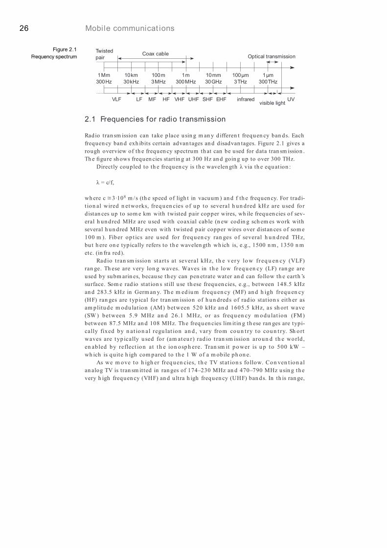
2.1 Frequencies for radio t ransmissionRadio tran sm ission can take p lace usin g m an y d ifferen t frequen cy ban ds. Eachfrequen cy ban d exh ibits certain advan tages an d disadvan tages. Figure 2.1 gives arough overview of th e frequen cy spectrum th at can be used for data tran sm ission .Th e figure sh ows frequen cies startin g at 300 Hz an d goin g up to over 300 THz.
Directly coupled to th e frequen cy is th e wavelen gth λ via th e equat ion : λ = c/f,
wh ere c ≅3·108 m /s (th e speed of ligh t in vacuum ) an d f th e frequen cy. For tradi-t ion al wired n etworks, freq u en cies o f up to several h un dred kHz are used fo rdistan ces up to som e km with twisted pair copper wires, wh ile frequen cies of sev-eral h un dred MHz are used with coaxial cable (n ew codin g sch em es work withseveral h un dred MHz even with twisted pair copper wires over distan ces of som e100 m ). Fiber op t ics are u sed fo r freq u en cy ran ges o f several h u n d red THz,bu t h ere on e typically refers to th e wavelen gth wh ich is, e.g., 1500 n m , 1350 n metc. (in fra red).
Rad io t ran sm ission st art s at several kHz, t h e v er y lo w fr eq u en cy (VLF)ran ge. Th ese are very lon g waves. Waves in th e lo w freq u en cy (LF) ran ge areused by subm arin es, because th ey can pen etrate water an d can follow th e earth ’ssurface. Som e rad io stat ion s st ill use th ese frequen cies, e.g., between 148.5 kHzan d 283.5 kHz in Germ an y. Th e m ed iu m frequ en cy (MF) an d h igh frequ en cy(HF) ran ges are typ ical for tran sm ission of h u n dreds of rad io stat ion s eith er asam plitu de m odu lat ion (AM) between 520 kHz an d 1605.5 kHz, as sh ort wave(SW ) between 5.9 MHz an d 26.1 MHz, o r as freq u en cy m o du lat ion (FM)between 87.5 MHz an d 108 MHz. Th e frequen cies lim it in g th ese ran ges are typi-cally fixed by n a t io n al regu lat ion an d , vary from cou n t ry t o cou n t ry. Sh ortwaves are t yp ically u sed for (am ateu r) rad io t ran sm ission aro un d th e wo rld ,en abled by reflect io n at t h e ion osp h ere. Tran sm it po wer is u p t o 500 kW –wh ich is quite h igh com pared to th e 1 W of a m obile ph on e.
As we m ove to h igh er freq uen cies, t h e TV st at ion s fo llow. Con ven t ion alan alog TV is tran sm it ted in ran ges of 174–230 MHz an d 470–790 MHz usin g th every h igh frequen cy (VHF) an d u ltra h igh frequen cy (UHF) ban ds. In th is ran ge,
Mobile communicat ions26
1m300MHz
10mm30GHz
100µm3THz
1µm300THz
100m3MHz
10km30kHz
1Mm300Hz
Optical transmissionCoax cableTwistedpair
VLF LF MF HF VHF UHF SHF EHF infrared visible light UV
Figure 2.1Frequency spectrum
d igit al au d io b ro ad cast in g (DAB) t akes p lace as well (223–230 MHz an d1452–1472 MHz) an d d igital TV is p lan n ed or cu rren t ly bein g in stalled (470–862 MHz), reusin g som e of th e old frequen cies for an alog TV. UHF is also usedfo r m obile ph on es with an alo g tech n ology (450–465 MHz), t h e d igit al GSM(890–960 MHz, 1710–1880 MHz), d igit a l co rd less t elep h o n es fo llowin g th eDECT stan dard (1880–1900 MHz), 3G cellu lar system s followin g th e UMTS stan -dard (1900–1980 MHz, 2020–2025 MHz, 2110–2190 MHz) an d m an y m ore. VHFan d especially UHF allow for sm all an ten n as an d relat ively reliable con n ection sfor m obile teleph on y.
Su p er h igh freq u en cies (SH F) are t yp ically u sed for d irect ed m icro wavelin ks (ap p ro x. 2–40 GHz) an d fixed sat ellit e services in t h e C-ban d (4 an d6 GHz), Ku-ban d (11 an d 14 GHz), or Ka-ban d (19 an d 29 GHz). Som e system sare p lan n ed in th e ex t rem ely h igh frequ en cy (EHF) ran ge wh ich com es closeto in fra red . All rad io freq uen cies are regu lated to avo id in terferen ce, e.g., th eGerm an regulation covers 9 kHz–275 GHz.
Th e n ext step in to h igh er frequen cies in volves opt ical tran sm ission , wh ichis n o t on ly u sed for fiber op t ical lin ks bu t also for wireless com m u n icat ion s.In fra red (IR) t ran sm ission is used for d irected lin ks, e.g., to con n ect d ifferen tbuild in gs via laser lin ks. Th e m ost widespread IR tech n ology, in fra red data asso-ciat io n (IrDA), u ses wavelen gth s o f ap p ro xim ately 850–900 n m to co n n ectlap tops, PDAs etc. Fin ally, visible ligh t h as been used for wireless tran sm issionfor th ousan ds of years. Wh ile ligh t is n ot very reliable due to in terferen ce, bu t itis n everth eless u sefu l due to built-in h um an receivers.2.1.1 Regulat ionsAs th e exam p les in t h e p revio u s sect ion h ave sh o wn , rad io freq u en cies arescarce resou rces. Man y n at ion al (econ o m ic) in t erest s m ake it h ard t o fin dcom m on , worldwide regu lation s. Th e In tern ation al Telecom m un ication s Un ion(ITU) located in Gen eva is respon sible for worldwide coord in ation of t elecom -m un ication activit ies (wired an d wireless). ITU is a sub-organ ization of th e UN.Th e ITU Rad iocom m u n icat ion secto r (ITU-R) h an d les st an d ard izat ion in t h ewireless sector, so it a lso h an d les freq u en cy p lan n in g (fo rm erly kn own asCon sultat ive Com m it tee for In tern ation al Radiocom m un ication , CCIR).
To h ave at least som e su ccess in world wid e coord in at ion an d to reflectn at ion al in terest s, th e ITU-R h as sp lit th e world in to th ree region s: Regio n 1covers Europe, th e Middle East , coun tries of th e form er Soviet Un ion , an d Africa.Region 2 in cludes Green lan d, North an d South Am erica, an d region 3 com prisesth e Far East, Australia, an d New Zealan d. With in th ese region s, n ation al agen ciesare resp on sib le fo r fu rth er regu lat ion s, e.g., th e Fed eral Com m u n icat ion sCom m ission (FCC) in th e US. Several n ation s h ave a com m on agen cy such asEu rop ean Con feren ce for Post s an d Telecom m u n icat ion s (CEPT) in Eu rop e.Wh ile CEPT is st ill respon sible for th e gen eral p lan n in g, m an y tasks h ave beent ran sferred to o th er agen cies (con fu sin g an ybody fo llo win g th e regu lat ion
Wireless t ransmission 27

p rocess). For exam p le, th e Eu rop ean Telecom m u n icat ion s Stan dard s In st itu t e(ETSI) is respon sible for stan dardization an d con sists of n at ion al stan dardizationbodies, public providers, m an ufacturers, user groups, an d research in stitutes.
To ach ieve at least som e h arm on izat ion , th e ITU-R h olds, th e World RadioCon feren ce (W RC), to periodically discuss an d decide frequen cy allocation s forall th ree region s. Th is is obviously a difficu lt task as m an y region s or coun triesm ay h ave already in stalled a h uge base of a certain tech n ology an d will be reluc-tan t to ch an ge frequen cies ju st for th e sake of h arm on ization . Harm on ization is,h owever, n eeded as soon as satellite com m un ication is used. Satellites, especiallyth e n ew gen erat ion o f low earth -orb it in g sa t ellit es (see ch ap t er 5) do n ot‘respect’ n ation al regulation s, bu t sh ou ld operate worldwide. W h ile it is d ifficu ltto p reven t oth er n ation s from sett in g up a satellite system it is m uch sim pler toban th e n ecessary devices or th e in frast ru ctu re n eeded for operat ion . Satellitesystem s sh ou ld operate on frequ en cies available worldwid e to su pp ort globalusage with a sin gle device.
Table 2.1 gives som e exam ples for frequen cies used for (an alog an d digital)m obile ph on es, cord less t eleph on es, wireless LANs, an d o th er rad io frequ en cy(RF) system s for coun tries in th e th ree region s represen tin g th e m ajor econ om icpower. Older system s like Nordic Mobile Teleph on e (NMT) are n ot available allo ver Eu rop e, an d so m et im es t h ey h ave b een stan d ard ized with d ifferen tn at ion al freq u en cies. Th e n ewer (d igit al) system s are com p at ib le th rou gh ou tEurope (stan dardized by ETSI).
Mobile communicat ions28
Europe US JapanMobile phones NMT AMPS, TDMA, PDC
CDMA453–457 824–849 810–826 463–467 869–894 940–956
1429–1465 1477–1513
GSM GSM, TDMA,CDMA
890–915 1850–1910 935–960 1930–19901710–1785 1805–1880UMTS (FDD)/ FOMA/W–CDMA W–CDMA1920–1980 1920–19802110–2190 2110–2170
Table 2.1 Examplesystems and their
frequency allocations(all values in MHz)

Wh ile older an alog m obile p h on e system s like NMT or its derivatives at 450 MHzare still available, Europe is h eavily dom in ated by th e fully digital GSM (see ch ap-ter 4 .1) at 900 MHz an d 1800 MHz (also kn own as DCS1800, Digital Cellu larSystem ). In con trast to Europe, th e US FCC allowed several cellu lar tech n ologiesin th e sam e freq uen cy ban ds arou n d 850 MHz. St art in g from th e an alogadvan ced m obile ph on e system (AMPS), th is led to th e co-existen ce of severalsolu tion s, such as dual m ode m obile ph on es supportin g digital tim e division m ul-tiple access (TDMA) service an d an alog AMPS accordin g to th e stan dard IS-54. Alld igit al TDMA p h on es accord in g t o IS-136 (also kn own as NA-TDMA, NorthAm erican TDMA) an d d igital cod e d ivision m ult ip le access (CDMA) ph on esaccordin g to IS-95 h ave been developed. Th e US did n ot adopt a com m on m obileph on e system , but waited for m arket forces to decide. Th is led to m an y islan ds ofdifferen t system s an d , con sequen tly, as in Europe, fu ll coverage, is n ot availablein th e US. Th e lon g d iscu ssion s abou t th e p ros an d con s of TDMA an d CDMA
Wireless t ransmission 29
UMTS (TDD)1900–19202020–2025
Cordless telephones CT1+ PACS PHS885–887 1850–1910 1895–1918930–932 1930–1990CT2 PACS–UB JCT864–868 1910–1930 254–380DECT1880–1900
Wireless LANs IEEE 802.11 IEEE 802.11 IEEE 802.112400–2483 902–928 2400–2497
2400–2483HiperLAN2, HiperLAN2, HiperLAN2,IEEE 802.11a IEEE 802.11a IEEE 802.11a5150–5350 5150–5350 5150–52505470–5725 5725–5825
Others RF-Control RF-Control RF-Control27, 128, 418, 315, 915 426, 868433, 868
Satellite (e.g., Iridium, Globalstar)1610–1626, 2483–2500

also p rom oted th e worldwide success of GSM. GSM is available in over 190 coun -tries an d used by m ore th an 800 m illion people (GSM World , 2002). A user canroam with t h e sam e m obile p h on e from Zim babwe, via Uzbekist an , Sweden ,Sin gapore, USA, Tu n isia, Russia, Can ada, It aly, Greece, Germ an y, Ch in a, an dBelgium to Austria.
An o th er syst em , t h e p erso n al d igita l cellu lar (PDC), form erly kn own asJap an ese d igit al cellu lar (JDC) was est ab lish ed in Jap an . Qu it e o ft en m o bileph on es coverin g m an y stan d ards h ave been an n oun ced , h owever, in dust ry isst ill wait in g for a ch eap solu tion . Ch ap ter 11 will discuss th is top ic again in th econ text of software defin ed radios (SDR). New frequen cy ban ds, e.g., for th e un i-versal m obile t elecom m u n icat ion s syst em (UMTS) or th e freedom of m obilem ulti-m edia access (FOMA) are located at 1920–1980 MHz an d 2110–2170/2190MHz (see ch apter 4).
Man y d ifferen t co rd less t e lep h o n e st an d ard s exist arou n d th e wo rld .However, th is is n ot as problem atic as th e diversity of m obile ph on e stan dards.Som e older an alog system s such as cordless teleph on e (CT1+) are st ill in use, bu td igit a l t ech n o logy h as been in t ro d u ced for co rd less t elep h on es as well.Exam ples in clude CT2, th e first digital cord less teleph on e in troduced in th e UK,digital en h an ced cordless telecom m un ication s (DECT) as a Eu ropean stan dard(see sect ion 4.2), p erso n al access com m u n icat ion s syst em (PACS) an d PACS-Un licen sed Ban d (PACS-UB) in th e US, as well as person al h an dyph on e system(PHS) as replacem en t for th e an alog Japan ese cordless teleph on e (JCT) in Japan .Mobile ph on es coverin g, e.g., DECT an d GSM are available bu t th ey h ave n otbeen a com m ercial success.
Fin ally, t h e area of W LAN stan d ard s is o f sp ecial in t erest fo r wireless,m obile com puter com m u n ication on a cam pu s or in bu ild in gs. Here th e com -pu ter in dust ry developed products with in th e licen se-free ISM ban d , of wh ichth e m ost at tractive is located at 2.4 GHz an d is available for licen se-free opera-t ion a lm ost everywh ere aroun d th e world (with n at ion al d ifferen ces lim it in gfrequen cies, t ran sm it power etc.). Th e m ost widespread stan dard in th is area isIEEE 802.11b , wh ich is discussed in ch apter 7 (togeth er with oth er m em bers ofth e 802.11 fam ily). Th e wireless LAN stan dards Hip erLAN2 an d IEEE 802.11aoperate in th e 5 GHz ran ge, bu t depen din g on th e region on d ifferen t frequen -cies with d ifferen t restrict ion s.
Man y m ore freq uen cies h ave been assign ed for t ru n k rad io (e.g., t ran s-European trun ked rad io (TETRA), 380–400 MHz, 410–430 MHz, 450–470 MHz –depen din g on n ation al regulat ion s), pagin g services, terrestrial fligh t teleph on esystem (TFTS), 1670–1675 MHz an d 1800–1805 MHz, satellite services (Irid ium :1610–1626 MHz, Globalstar: 1610–1626 MHz an d 2483–2500 MHz, see ch apter 5)et c. High er freq uen cies are of sp ecial in t erest for h igh b it -rat e t ran sm ission ,alth ough th ese frequen cies face severe sh adowin g by m an y obstacles. Licen se-freeban ds at 17.2, 24 an d even 61 GHz are un der con sideration for com m ercial use.Addition ally, a lot of licen se-free wireless com m un ication takes place at lower fre-q uen cies. Garage open ers, car locks, wireless h ead set s, rad io frequ en cyiden tification s (RFID) etc. operate on , e.g., 433 or 868 MHz.
Mobile communicat ions30
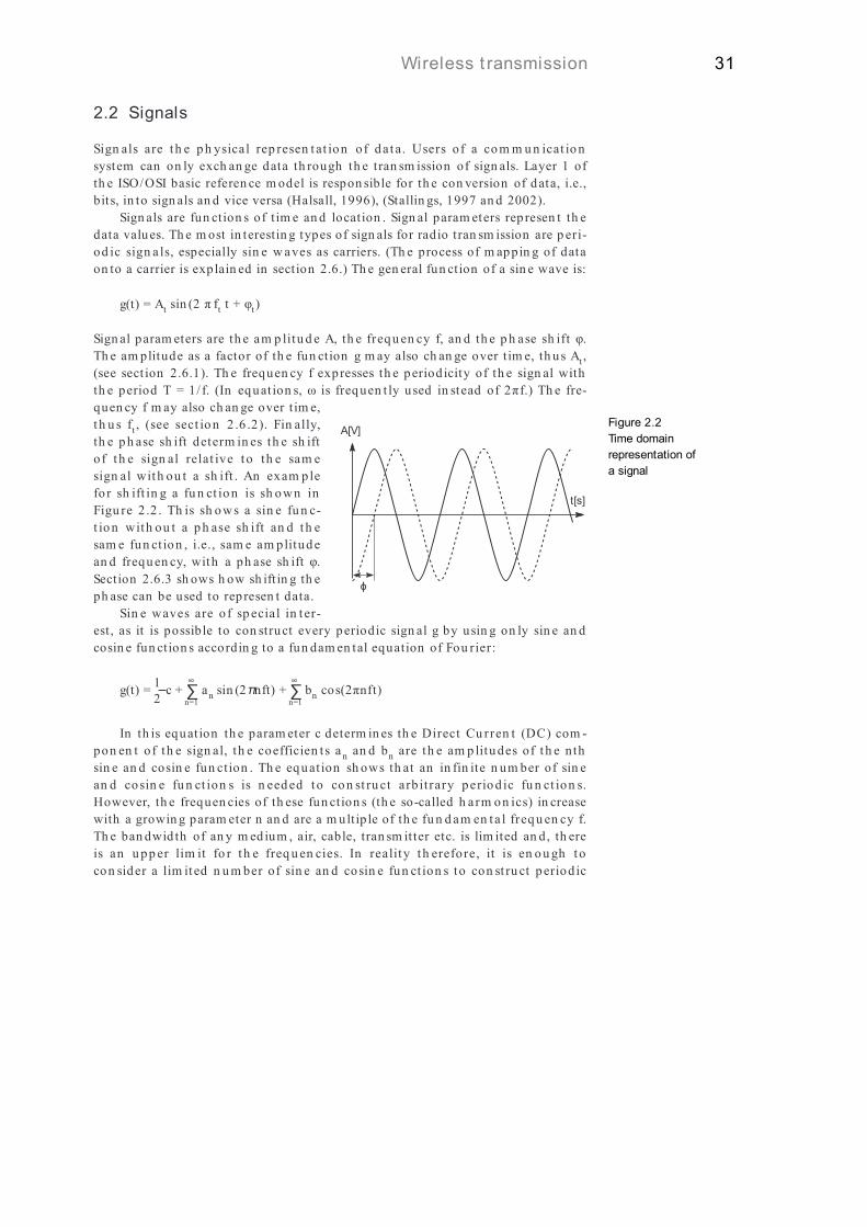
2.2 SignalsSign als are t h e p h ysical rep resen t at ion of da t a. Users of a co m m u n icat io nsystem can on ly exch an ge data th rough th e tran sm ission of sign als. Layer 1 ofth e ISO/OSI basic referen ce m odel is respon sible for th e con version of data, i.e.,bits, in to sign als an d vice versa (Halsall, 1996), (Stallin gs, 1997 an d 2002).
Sign als are fun ction s of t im e an d location . Sign al param eters rep resen t th edata values. Th e m ost in terestin g types of sign als for radio tran sm ission are p eri-od ic sign a ls, especially sin e w aves as carriers. (Th e process of m appin g of dataon to a carrier is explain ed in section 2.6.) Th e gen eral fun ction of a sin e wave is:
g(t) = At sin (2 π ft t + φt)Sign al param eters are th e am p litu d e A, th e frequ en cy f, an d th e p h ase sh ift φ.Th e am plitude as a factor of th e fun ction g m ay also ch an ge over t im e, th us At,(see sect ion 2.6.1). Th e frequen cy f expresses th e periodicity of th e sign al withth e period T = 1/ f. (In equat ion s, ω is frequen t ly used in stead of 2πf.) Th e fre-quen cy f m ay also ch an ge over t im e,th u s ft , (see sect io n 2 .6 .2). Fin ally,th e p h ase sh ift determ in es th e sh iftof t h e sign al relat ive t o th e sam esign al with ou t a sh ift . An exam plefo r sh ift in g a fu n ct io n is sh own inFigu re 2 .2 . Th is sh ows a sin e fu n c-t io n with ou t a p h ase sh ift an d t h esam e fun ct ion , i.e., sam e am plitud ean d frequ en cy, with a ph ase sh ift φ.Section 2.6.3 sh ows h ow sh ift in g th eph ase can be used to rep resen t data.
Sin e waves are o f sp ecial in t er-est , as it is possible to con struct every periodic sign al g by usin g on ly sin e an dcosin e fun ction s accordin g to a fun dam en tal equation of Fou rier:
1 ∞ ∞g(t) = c + ∑ an sin (2πnft) + ∑ bn cos(2πnft)2 n=1 n=1
In th is equat ion th e param eter c determ in es th e Direct Cu rren t (DC) com -pon en t of th e sign al, th e coefficien t s a n an d bn are th e am p litu des of t h e nthsin e an d cosin e fun ction . Th e equat ion sh ows th at an in fin ite n um ber of sin ean d cosin e fu n ct ion s is n eed ed to co n st ru ct arb it rary perio d ic fu n ct ion s.However, th e frequen cies of th ese fun ction s (th e so-called h a rm on ics) in creasewith a growin g param eter n an d are a m ult ip le of th e fu n d am en ta l freq u en cy f.Th e ban dwid th of an y m ed ium , air, cable, tran sm itter etc. is lim ited an d, th ereis an u pp er lim it fo r t h e freq u en cies. In realit y t h erefore, it is en o u gh tocon sider a lim ited n u m ber of sin e an d cosin e fun ct ion s to con st ru ct periodic
Wireless t ransmission 31
A[V]
t[s]
ϕ
Figure 2.2Time domainrepresentation ofa signal

fun ction s – all real tran sm ittin g system s exh ibit th ese ban dwid th lim its an d cann ever t ran sm it arbit rary period ic fun ction s. It is su fficien t for u s to kn ow th atwe can th in k of tran sm it ted sign als as com posed of on e or m an y sin e fun ction s.Th e fo llowin g illu st rat ion s always rep resen t th e exam ple of on e sin e fun ct ion ,i.e., th e case of a sin gle frequen cy.
A typical way to represen t sign als is th e t im e dom ain (see Figure 2.2). Hereth e am p litu de A o f a sign al is sh own versus t im e (t im e is m ostly m easu red insecon ds s, am plitudes can be m easu red in , e.g., volt V). Th is is also th e typ icalrepresen tat ion kn own from an oscilloscope. A ph ase sh ift can also be sh own inth is represen tation .
Represen tat ion s in th e t im e dom ain are p roblem atic if a sign al con sist s ofm an y d ifferen t frequ en cies (as th e Fourier eq u at ion in d icates). In th is case, abetter represen tat ion of a sign al is th e freq u en cy d om ain (see Figure 2.3). Hereth e am plitude of a certain frequen cy part of th e sign al is sh own versus th e fre-
q u en cy. Figu re 2 .3 o n ly sh ows on epeak an d th e sign al con sists on ly of asin gle freq u en cy p art (i.e., it is asin gle sin e fu n ct ion ). Arbit rary p eri-o d ic fu n ct io n s wou ld h ave m an ypeaks, kn own as th e frequ en cy spec-t ru m o f a sign al. A too l t o d isp layfreq u en cies is a sp ect ru m an alyzer.Fourier t ran sform ation s are a m ath e-m atical tool for t ran slat in g from th et im e do m ain in to th e freq u en cyd om ain an d vice versa (u sin g t h ein verse Fourier t ran sform ation ).
A th ird way to rep resen t sign alsis t h e p h a se d o m a in sh own inFigu re 2.4. Th is rep resen tat ion , alsocalled ph ase state or sign al con stella-t io n d iagram , sh o ws th e am p lit u deM of a sign al an d its ph ase φ in polar
coord in ates. (Th e len gth of th e vector rep resen ts th e am plitude, th e an gle th eph ase sh ift .) Th e x-axis represen ts a ph ase of 0 an d is also called In -Ph ase (I). Aph ase sh ift of 90° or π/2 would be a poin t on th e y-axis, called Qu ad ra tu re (Q).
2.3 AntennasAs th e n am e wireless already in dicates, th is com m un ication m ode in volves ‘get-t in g rid’ of wires an d t ran sm itt in g sign als th rough space with out gu idan ce. Wedo n ot n eed an y ‘m edium ’ (such as an eth er) for th e tran sport of electrom agn eticwaves. Som eh ow, we h ave to couple th e en ergy from th e tran sm it ter to th e out-
Mobile communicat ions32
A[V]
f[Hz]
Figure 2.3Frequency domainrepresentation of
a signal
ϕI = M cos ϕ
Q = M sin ϕFigure 2.4Phase domain
representation ofa signal

side world an d, in reverse, from th e outside world to th e receiver. Th is is exactlywh at an t en n as do. An ten n as couple elect rom agn etic en ergy to an d from spaceto an d from a wire or coaxial cable (or an y oth er appropriate con ductor).
A th eoret ical referen ce an ten n a is th e iso t rop ic ra d ia tor , a poin t in spacerad iat in g eq u al p ower in all d irect ion s, i.e., a ll p o in t s with eq u al po wer arelocated on a sp h ere with th e an t en n a as it s cen t er. Th e ra d ia t io n p a t t er n issym m etric in all d irect ion s (see Figu re 2.5, a two d im en sion al cross-sect ion ofth e real th ree-dim en sion al pat tern ).
However, su ch an an t en n a d oes n o t ex ist in realit y. Real an t en n as allexh ibit d irect ive effect s, i.e., th e in ten sity o f rad iat ion is n o t th e sam e in alld irect ion s from th e an t en n a. Th e sim p lest real an t en n a is a t h in , cen t er-fedd ip ole, also called Hertzian dipole, as sh own in Figure 2.6 (righ t-h an d side). Th edipole con sists of two collin ear con ductors of equal len gth , separated by a sm allfeedin g gap. Th e len gth of th e dipoleis n o t arb it rary, bu t , fo r exam p le,h alf t h e wavelen gth λ o f t h e sign alto tran sm it results in a very efficien trad iat ion o f th e en ergy. If m ou n tedon th e roo f o f a car, t h e len gth ofλ/4 is efficien t . Th is is also kn own asMarcon i an ten n a.
A λ/2 d ipole h as a un iform or om n i-d irect ion al radiation pattern in on e plan ean d a figure eigh t pattern in th e oth er two plan es as sh own in Figure 2.7. Th is typeof an ten n a can on ly overcom e en viron m en tal ch allen ges by boostin g th e powerlevel of th e sign al. Ch allen ges could be m oun tain s, valleys, buildin gs etc.
Wireless t ransmission 33
z
x
yz
xy
Figure 2.5Radiation pattern of anisotropic radiator
λ/2λ/4
Figure 2.6Simple antennas
z
y
Side view (zy-plane)
x
y
Side view (xy-plane)
z
x
Top view (xz-plane)
Figure 2.7Radiation pattern ofa simple dipole
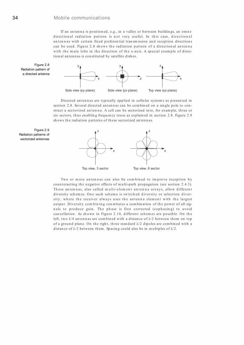
If an an ten n a is posit ion ed, e.g., in a valley or between buildin gs, an om n i-d irect io n al rad iat ion p at t ern is n o t very u sefu l. In t h is case, d i r ect io n a lan t en n as with certain fixed preferen tial t ran sm ission an d recept ion direction scan b e used . Figu re 2.8 sh ows th e rad iat ion p at t ern of a d irect ion al an t en n awith t h e m ain lobe in th e d irect ion of th e x-axis. A sp ecial exam p le of d irec-t ion al an ten n as is con stituted by satellite dish es.
Directed an ten n as are typ ically app lied in cellu lar system s as p resen ted insection 2.8. Several directed an ten n as can be com bin ed on a sin gle pole to con -struct a sectorized an ten n a . A cell can be sectorized in to, for exam ple, th ree orsix sectors, th us en ablin g frequen cy reuse as explain ed in section 2.8. Figure 2.9sh ows th e radiat ion pat tern s of th ese sectorized an ten n as.
Two o r m ore an t en n as can also be com bin ed to im p rove recep t ion bycoun teractin g th e n egative effects of m ult i-path propagation (see sect ion 2.4.3).Th ese an t en n as, a lso called m u lt i-e lem en t a n t en n a a r r a ys, a llow d ifferen td iversity sch em es. On e such sch em e is sw it ch ed d iversit y or select ion d iver-si t y , wh ere t h e receiver always u ses t h e an t en n a elem en t with t h e largestoutpu t. Diversity com bin in g con stitu tes a com bin ation of th e power of all sig-n als t o p ro du ce gain . Th e p h ase is first correct ed (co p h asin g) t o avo idcan cellat ion . As sh own in Figu re 2.10, d ifferen t sch em es are possible. On th eleft , two λ/4 an ten n as are com bin ed with a distan ce of λ/2 between th em on topof a groun d plan e. On th e righ t , th ree stan dard λ/2 dipoles are com bin ed with adistan ce of λ/2 between th em . Spacin g could also be in m ult ip les of λ/2.
Mobile communicat ions34
z
y
Side view (yz-plane)
x
y
Side view (xy-plane)
z
x
Top view (xz-plane)
Figure 2.8Radiation pattern ofa directed antenna
x
z
Top view, 6 sector
x
z
Top view, 3 sector
Figure 2.9Radiation patterns ofsectorized antennas

A m ore advan ced solution is provided by sm art an ten n as wh ich com bin e m ul-tiple an ten n a elem en ts (also called an ten n a array) with sign al processin g to optim izeth e rad iation /reception pattern in respon se to th e sign al en viron m en t. Th ese an ten -n as can adapt to ch an ges in recep tion power, tran sm ission con dit ion s an d m an ysign al propagation effects as discussed in th e followin g section . An ten n a arrays canalso be used for beam form in g. Th is would be an extrem e case of a directed an ten n awh ich can follow a sin gle user th us usin g space division m ult iplexin g (see section2.5.1). It would n ot just be base stat ion s th at could follow users with an in dividualbeam . Wireless devices, too, could direct th eir electrom agn etic radiation , e.g., awayfrom th e h u m an body towards a base st at ion . Th is wou ld h elp in red ucin g th eabsorbed radiation . Today’s h an dset an ten n as are om n i-direction al as th e in tegrationof sm art an ten n as in to m obiles is difficult an d h as n ot yet been realized.
2.4 Signal propagat ionLike wired n etworks, wireless com m u n icat ion n etworks also h ave sen ders an dreceivers of sign als. However, in con n ection with sign al propagation , th ese twon etworks exh ibit con siderable d ifferen ces. In wireless n etworks, th e sign al h asn o wire to determ in e th e direction of propagation , wh ereas sign als in wired n et-works on ly travel alon g th e wire (wh ich can be twisted pair copper wires, a coaxcab le, bu t also a fib er et c.). Aslon g as th e wire is n ot in terruptedor d am aged , it t yp ically exh ib it st h e sam e ch aracterist ics at eachp o in t . On e can p recisely d et er-m in e t h e beh avio r o f a sign alt ravellin g alon g th is wire, e.g.,received p ower depen d in g on th elen gth . For wireless t ran sm ission ,t h is p red ict ab le beh avio r is on lyvalid in a vacu u m , i.e., with o u tm at t er between th e sen der an dth e receiver. Th e situ at ion wou ldbe as follows (Figure 2.11):
Wireless t ransmission 35
+
λ/2 λ/4λ/4
Ground plane+
λ/2λ/2
λ/2 Figure 2.10Diversity antennasystems
Sender
Transmission
Detection
InterferenceDistance
Figure 2.11Ranges for transmission,detection, andinterference of signals

● Tran sm ission ran ge: With in a certain radius of th e sen der t ran sm ission isp ossible, i.e., a receiver receives th e sign als with an error rate low en ough tobe able to com m un icate an d can also act as sen der.
● Det ect io n ra n ge: With in a secon d rad ius, detect ion o f th e t ran sm ission ispossible, i.e., th e tran sm itted power is large en ough to differ from backgroun dn oise. However, th e error rate is too h igh to establish com m un ication .
● In terferen ce ran ge: With in a th ird even larger radius, th e sen der m ay in ter-fere with oth er tran sm ission by addin g to th e backgroun d n oise. A receiverwill n ot be able to detect th e sign als, but th e sign als m ay disturb oth er sign als.Th is sim ple an d ideal sch em e led to th e n ot ion of cells aroun d a tran sm itter
(as briefly discu ssed in sect ion 2.8). However, real life does n o t h appen in avacu um , rad io t ran sm ission h as to con ten d with our atm osp h ere, m oun tain s,buildin gs, m ovin g sen ders an d receivers etc. In reality, th e th ree circles referred toabove will be bizarrely-sh aped polygon s with th eir sh ape bein g tim e an d frequen cydepen den t. Th e followin g paragraph s d iscuss som e problem s arisin g in th is con -text, th ereby sh owin g th e differen ces between wireless an d wired tran sm ission .2.4.1 Path loss of radio signalsIn free space rad io sign als p ropagate as ligh t does (in d epen d en t ly of th eir fre-quen cy), i.e., th ey follow a straigh t lin e (besides gravitat ion al effects). If such ast raigh t lin e exist s between a sen d er an d a receiver it is called l in e-o f-sigh t(LOS). Even if n o m atter exists between th e sen der an d th e receiver (i.e., if th ereis a vacuum ), th e sign al st ill experien ces th e free sp ace lo ss. Th e received powerPr is p roport ion al to 1/d2 with d bein g th e distan ce between sen der an d receiver(in verse sq u are law ). Th e reason for th is ph en om en on is quite sim ple. Th in k ofth e sen der bein g a po in t in space. Th e sen der n ow em it s a sign al with certainen ergy. Th is sign al t ravels away from th e sen der at th e speed of ligh t as a wavewith a sph erical sh ape. If th ere is n o obstacle, th e sp h ere con t in u ously growswith th e sen d in g en ergy equally d istribu ted over th e sph ere’s surface. Th is su r-face area s grows with th e in creasin g distan ce d from th e cen ter accord in g to th eequat ion s = 4π d2.
Even with out an y m atter between sen der an d receiver, addition al param etersare im portan t. Th e received power also depen ds on th e wavelen gth an d th e gainof receiver an d t ran sm it ter an ten n as. As soon as t h ere is an y m at ter betweensen der an d receiver, th e situation becom es m ore com plex. Most rad io tran sm is-sion takes place th rough th e atm osph ere – sign als travel th rough air, rain , sn ow,fog, dust part icles, sm og etc. Wh ile th e p a th loss or a t t en u at ion does n ot causetoo m uch trouble for sh ort d istan ces, e.g., for LANs (see ch apter 7), th e atm os-p h ere h eavily in flu en ces t ran sm ission over lon g d istan ces, e.g., satellit et ran sm ission (see ch ap ter 5). Even m obile ph on e syst em s are in flu en ced byweath er con d it ion s such as h eavy rain . Rain can absorb m u ch of th e rad iateden ergy of th e an ten n a (th is effect is used in a m icrowave oven to cook), so com -m un ication lin ks m ay break down as soon as th e rain sets in .
Mobile communicat ions36

Depen d in g on t h e freq u en cy, rad io waves can also p en et ra te o b ject s.Gen erally th e lower th e frequen cy, th e better th e pen etrat ion . Lon g waves canbe t ran sm it ted th rou gh th e ocean s to a subm arin e wh ile h igh frequen cies canbe b locked by a t ree. Th e h igh er th e frequ en cy, th e m ore th e beh avior o f th eradio waves resem ble th at of ligh t – a ph en om en on wh ich is clear if on e con sid-ers th e spectrum sh own in Figure 2.1.
Radio waves can exh ibit th ree fun dam en tal p ropagation beh aviors depen d-in g on th eir frequen cy:● Grou n d w ave (<2 MHz): Waves with low frequen cies follow th e earth ’s su r-
face an d can p rop agat e lon g d ist an ces. Th ese waves are u sed fo r, e.g.,subm arin e com m un ication or AM radio.
● Sk y w a ve (2–30 MHz): Man y in tern at ion al b roadcast s an d am ateu r rad iou se th ese sh ort waves th at are reflected 2 at t h e ion osp h ere. Th is way th ewaves can bou n ce back an d forth between th e ion osph ere an d th e earth ’ssu rface, t ravellin g aroun d th e world .
● Lin e-of-sigh t (>30 MHz): Mobile ph on e system s, satellite system s, cord lessteleph on es etc. use even h igh er frequen cies. Th e em itted waves follow a (m oreor less) straigh t lin e of sigh t. Th is en ables direct com m un ication with satellites(n o reflection at th e ion osph ere) or m icrowave lin ks on th e groun d. However,an add it ion al con siderat ion for groun d-based com m u n icat ion is th at th ewaves are ben t by th e atm osph ere due to refraction (see n ext section ). Alm ost all com m u n icat ion system s p resen ted in th is book work with fre-
q u en cies above 100 MHz so , we are alm ost exclu sively con cern ed with LOScom m un icat ion . But wh y do m obile ph on es work even with ou t an LOS? 2.4.2 Addit ional signal propagat ion effectsAs d iscussed in th e previous section , sign al propagation in free space alm ost fol-lo ws a st raigh t lin e, like ligh t . Bu t in real life, we rarely h ave a lin e-o f-sigh tbetween th e sen der an d receiver o f rad io sign als. Mobile ph on es are typ icallyu sed in b ig cit ies with skyscrapers, on m ou n tain s, in sid e bu ild in gs, wh ile d ri-vin g t h rou gh an alley et c. Hare several effect s occu r in ad d it ion t o t h eat t en u at io n cau sed b y t h e d ist an ce b etween sen d er an d receiver, wh ich areagain very m uch frequen cy depen den t.
An extrem e form of at ten uation is b lock in g or sh ad ow in g of rad io sign alsdue to large obstacles (see Figure 2.12, left side). Th e h igh er th e frequen cy of asign al, th e m ore it beh aves like ligh t. Even sm all obstacles like a sim ple wall, atruck on th e street , o r t rees in an alley m ay block th e sign al. An oth er effect isth e reflect ion of sign als as sh own in th e m iddle of Figu re 2.12. If an object islarge com pared to th e wavelen gth of th e sign al, e.g., h uge buildin gs, m oun tain s,
Wireless t ransmission 37
2 Com pared to , e.g., th e su rface of a buildin g, th e ion osph ere is n ot really a h ard reflect in g su rface. Inth e case of sky waves th e ‘reflect ion ’ is caused by refraction .

or th e surface of th e earth , th e sign al is reflected . Th e reflected sign al is n ot asst ro n g as t h e o rigin al, as ob ject s can abso rb so m e of t h e sign al’s p ower.Reflection h elps tran sm itt in g sign als as soon as n o LOS exists. Th is is th e stan -dard case for radio t ran sm ission in cit ies or m oun tain areas. Sign als tran sm ittedfrom a sen der m ay boun ce off th e walls o f bu ild in gs several t im es before th eyreach th e receiver. Th e m ore often th e sign al is reflected, th e weaker it becom es.Fin ally, th e righ t side of Figu re 2.12 sh ows th e effect of refra ct ion . Th is effectoccurs because th e velocity of th e electrom agn etic waves depen ds on th e den -sity of th e m edium th rough wh ich it t ravels. On ly in vacuum does it equal c. Asth e figure sh ows, waves th at travel in to a den ser m edium are ben t towards th em ed ium . Th is is th e reason for LOS rad io waves bein g ben t towards th e earth :th e den sity of th e atm osph ere is h igh er closer to th e groun d.
W h ile sh adowin g an d reflection are caused by objects m uch larger th an th ewavelen gth of th e sign als (an d dem on st rate t h e typ ical ‘p art icle’ beh avior o fradio sign als), th e followin g two effects exh ibit th e ‘wave’ ch aracter of radio sig-n als. If th e size of an obstacle is in th e o rder of th e wavelen gth or less, th enwaves can be sca t t ered (see Figu re 2.13, left side). An in com in g sign al is scat -t ered in to severa l weaker o u tgo in g sign als. In sch oo l exp erim en t s, t h is istyp ically dem on strated with laser ligh t an d a very sm all open in g or obstacle, bu th ere we h ave to t ake in to con sid erat ion th at th e t yp ical wavelen gth of rad iotran sm ission for, e.g., GSM or AMPS is in th e order of som e 10 cm . Th us, m an yobject s in th e en viron m en t can cause th ese scatterin g effects. An oth er effect isd iffra ct io n of waves. As sh own on th e righ t side of Figu re 2.13, th is effect isvery sim ilar to scatterin g. Rad io waves will be deflected at an edge an d propa-gate in differen t direction s. Th e resu lt of scat terin g an d d iffraction are pattern swith varyin g sign al stren gth s depen din g on th e location of th e receiver.
Effect s like at t en u at ion , scat terin g, d iffract ion , an d refract ion all h app ensim ultan eously an d are frequen cy an d tim e depen den t. It is very difficult to pre-d ict th e p recise st ren gth of sign als at a certain poin t in sp ace. How do m obileph on e operators plan th e coverage of th eir an ten n as, th e locat ion of th e an ten -n as, th e d irection of th e beam s etc.? Two o r th ree d im en sion al m aps are usedwith a resolu tion down to several m eters. With th e h elp of, e.g., ray tracin g orrad iosit y t ech n iqu es sim ilar t o ren d erin g 3D grap h ics, t h e sign al q u ality canrough ly be calcu lated in advan ce. Addition ally, operators perform a lot of m ea-surem en ts durin g an d after in stallat ion of an ten n as to fill gaps in th e coverage.
Mobile communicat ions38
RefractionReflectionShadowing
Figure 2.12Blocking (shadowing),
reflection andrefraction of waves
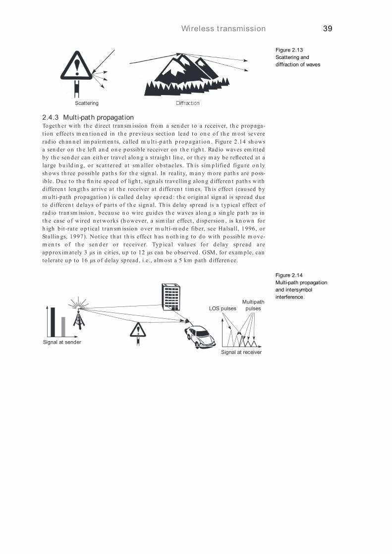
2.4.3 Mult i-path propagationTogeth er with th e d irect tran sm ission from a sen der to a receiver, th e propaga-t ion effects m en tion ed in th e p revious sect ion lead to on e of th e m ost severerad io ch an n el im pairm en ts, called m u lt i-p a th p rop aga t ion . Figure 2.14 sh owsa sen der on th e left an d on e possible receiver on th e righ t . Radio waves em it tedby th e sen der can eith er t ravel alon g a straigh t lin e, or th ey m ay be reflected at alarge bu ild in g, o r scat t ered at sm aller o bst acles. Th is sim p lified figu re o n lysh ows th ree possible path s for th e sign al. In reality, m an y m ore path s are poss-ible. Due to th e fin ite speed of ligh t , sign als travellin g alon g d ifferen t path s withdifferen t len gth s arrive at th e receiver at differen t t im es. Th is effect (caused bym ulti-path p ropagation ) is called d elay sp read : th e origin al sign al is sp read dueto d ifferen t delays of parts of th e sign al. Th is delay spread is a typ ical effect ofrad io tran sm ission , because n o wire gu ides th e waves alon g a sin gle path as inth e case of wired n etworks (h owever, a sim ilar effect , d ispersion , is kn own forh igh bit -rate op t ical t ran sm ission over m u lt i-m od e fiber, see Halsall, 1996, orStallin gs, 1997). Not ice th at th is effect h as n oth in g to do with possible m ove-m en t s o f t h e sen d er or receiver. Typ ical va lu es fo r delay sp read areapproxim ately 3 µs in cit ies, up to 12 µs can be observed . GSM, for exam ple, cantolerate up to 16 µs of delay spread, i.e., alm ost a 5 km path differen ce.
Wireless t ransmission 39
Scattering
Figure 2.13Scattering anddiffraction of waves
Signal at receiverSignal at sender
LOS pulsesMultipath
pulses
Figure 2.14Multi-path propagationand intersymbolinterference
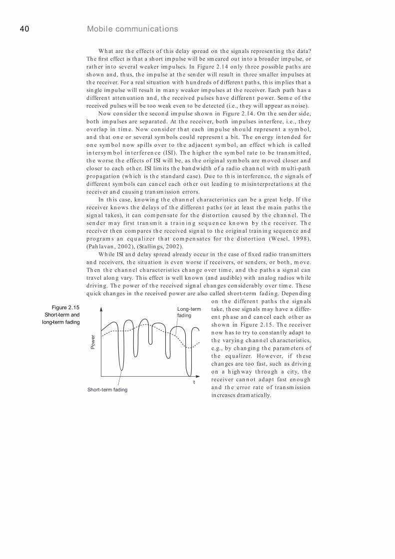
Wh at are th e effects of th is delay spread on th e sign als represen tin g th e data?Th e first effect is th at a sh ort im pulse will be sm eared out in to a broader im pulse, orrath er in to several weaker im pu lses. In Figu re 2.14 on ly th ree possible path s aresh own an d, th us, th e im pulse at th e sen der will result in th ree sm aller im pulses atth e receiver. For a real situation with h un dreds of differen t path s, th is im plies th at asin gle im pulse will resu lt in m an y weaker im pulses at th e receiver. Each path h as ad ifferen t at ten uation an d , th e received pulses h ave differen t power. Som e of th ereceived pulses will be too weak even to be detected (i.e., th ey will appear as n oise).
Now con sider th e secon d im pulse sh own in Figure 2.14. On th e sen der side,both im pu lses are separated . At th e receiver, both im pulses in terfere, i.e., th eyoverlap in t im e. Now con sid er th at each im p u lse sh ou ld rep resen t a sym bol,an d th at on e or several sym bols cou ld represen t a bit . Th e en ergy in ten ded foron e sym bol n ow sp ills over to th e ad jacen t sym bol, an effect wh ich is calledin t ersym b ol in t er feren ce (ISI). Th e h igh er th e sym bol rate to be tran sm itted ,th e worse th e effects of ISI will be, as th e origin al sym bols are m oved closer an dcloser to each oth er. ISI lim its th e ban dwidth of a rad io ch an n el with m ult i-pathpropagation (wh ich is th e stan dard case). Due to th is in terferen ce, th e sign als ofdifferen t sym bols can can cel each oth er ou t lead in g to m isin terpretat ion s at th ereceiver an d causin g tran sm ission errors.
In th is case, kn owin g th e ch an n el ch aracterist ics can be a great h elp. If th ereceiver kn ows th e delays of th e d ifferen t path s (or at least th e m ain path s th esign al takes), it can com pen sate for th e d istort ion cau sed by th e ch an n el. Th esen d er m ay first t ran sm it a t r a in in g seq u en ce kn own by t h e receiver. Th ereceiver th en com pares th e received sign al to th e origin al train in g sequen ce an dp rogram s an eq u a l izer th at com p en sat es fo r t h e d isto rt ion (Wesel, 1998),(Pah lavan , 2002), (Stallin gs, 2002).
Wh ile ISI an d delay spread already occur in th e case of fixed rad io tran sm ittersan d receivers, th e situation is even worse if receivers, or sen ders, or both , m ove.Th en th e ch an n el ch aracterist ics ch an ge over t im e, an d th e p ath s a sign al cantravel alon g vary. Th is effect is well kn own (an d audible) with an alog radios wh iledrivin g. Th e power of th e received sign al ch an ges con siderably over t im e. Th esequick ch an ges in th e received power are also called sh ort -term fad in g. Depen din g
on th e d ifferen t path s th e sign alstake, th ese sign als m ay h ave a d iffer-en t ph ase an d can cel each o th er assh own in Figu re 2.15. Th e receivern ow h as to try to con stan tly adapt toth e varyin g ch an n el ch aracterist ics,e.g., by ch an gin g th e param eters ofth e eq ualizer. However, if th esech an ges are too fast, such as drivin gon a h igh way th rou gh a city, th ereceiver can n ot adap t fast en ou ghan d th e error rate o f t ran sm issionin creases dram atically.
Mobile communicat ions40
Short-term fading
Long-termfading
Powe
r
t
Figure 2.15Short-term and
long-term fading

An ad dit ion al effect sh own in Figu re 2.15 is th e lon g-t erm fa d in g of th ereceived sign al. Th is lon g-term fad in g, sh own h ere as th e average p ower overt im e, is caused by, fo r exam ple, varyin g d istan ce to th e sen der or m ore rem oteobstacles. Typ ically, sen ders can com p en sate for lon g-term fad in g by in creas-in g/ d ecreasin g sen d in g p ower so th at th e received sign al always stays with incertain lim its.
Th ere are m an y m ore effects in fluen cin g rad io tran sm ission wh ich will n otbe d iscu ssed in det a il – fo r exam p le, t h e Do p p ler sh i ft cau sed by a m ovin gsen der or receiver. W h ile th is effect is audible for acoustic waves already at lowsp eed , it is also a t op ic for rad io t ran sm ission from o r t o fast m ovin g t ran s-ceivers. On e exam ple of such a tran sceiver could be a satellite (see ch apter 5) –th ere Dop p ler sh ift cau ses ran dom freq u en cy sh ift s. Th e in t erest ed read er isreferred to An d erson (1995), (Pah lavan , 2002), an d (Stallin gs, 2002) for m orein form at ion abou t th e ch aracterist ics of wireless com m un ication ch an n els. Forth e presen t it will suffice to kn ow th at m ult i-path propagation lim its th e m axi-m u m ban d wid th d u e t o ISI an d t h a t m ovin g t ran sceivers cau se ad d it ion alproblem s due to varyin g ch an n el ch aracterist ics.
2.5 Mult iplexingMu lt ip lex in g is n ot on ly a fun dam en tal m ech an ism in com m un ication system sbut also in everyday life. Mu ltip lexin g describes h ow several u sers can sh are am edium with m in im um or n o in terferen ce. On e exam ple, is h igh ways with sev-eral lan es. Man y users (car drivers) u se th e sam e m ediu m (th e h igh ways) withh opefu lly n o in terferen ce (i.e., acciden ts). Th is is possible due to th e p rovisionof several lan es (space division m ult iplexin g) separatin g th e traffic. In addit ion ,d ifferen t cars u se th e sam e m ediu m (i.e., th e sam e lan e) at d ifferen t po in t s int im e (t im e division m ult ip lexin g).
W h ile th is sim ple exam ple illustrates ou r everyday use of m ult ip lexin g, th efollowin g exam ples will deal with th e use of m u lt ip lexin g in wireless com m un i-cation s. Mech an ism s con trollin g th e use of m ult ip lexin g an d th e assign m en t ofa m edium to users (th e traffic regu lation s), are discussed in ch apter 3 un der th easpect of m edium access con trol.2.5.1 Space division mult iplexingFor wireless com m un icat ion , m u lt ip lexin g can be carried ou t in fou r d im en -sion s: sp a ce, t im e, freq u en cy, an d cod e. In th is field, th e task of m ult iplexin gis to assign space, t im e, freq uen cy, an d code to each com m u n ication ch an n elwith a m in im um of in terferen ce an d a m axim um of m ediu m ut ilizat ion . Th eterm com m un ication ch an n el h ere on ly refers to an associat ion of sen der(s) an dreceiver(s) wh o wan t to exch an ge data. Ch aracterist ics of com m un ication ch an -n els (e.g., ban d wid t h , error rat e) will b e d iscu ssed t o geth er with cert aintech n ologies in ch apters 4 to 7.
Wireless t ransmission 41

Figure 2.16 sh ows six ch an n els ki an d in troduces a th ree d im en sion al coor-d in at e syst em . Th is syst em sh ows th e d im en sio n s o f co d e c, t im e t an dfreq u en cy f. Fo r th is first type of m u lt ip lexin g, sp a ce d iv ision m u lt ip lex in g(SDM), th e (th ree dim en sion al) space si is also sh own . Here space is represen tedvia circles in dicatin g th e in terferen ce ran ge as in troduced in Figure 2.11. How isth e separation of th e differen t ch an n els ach ieved? Th e ch an n els k1 to k3 can bem apped on to th e th ree ‘spaces’ s1 to s3 wh ich clearly separate th e ch an n els an dpreven t th e in terferen ce ran ges from overlappin g. Th e space between th e in ter-feren ce ran ges is som et im es called gu ard sp ace. Such a guard space is n eeded inall fou r m ultiplexin g sch em es presen ted.
For th e rem ain in g ch an n els (k4 to k6) th ree addition al spaces would be n eeded. Inour h igh way exam ple th is wou ld im ply th at each driver h ad h is or h er own lan e.Alth ou gh th is procedure clearly rep resen ts a waste of space, th is is exact ly th ep rin cip le used by th e o ld an alog teleph on e system : each su bscriber is given aseparate pair o f cop per wires to th e local exch an ge. In wireless t ran sm ission ,SDM im p lies a sep arate sen d er fo r each com m u n icat ion ch an n el with a wideen ough distan ce between sen ders. Th is m ultiplexin g sch em e is used, for exam ple,at FM radio station s wh ere th e tran sm ission ran ge is lim ited to a certain region –
Mobile communicat ions42
Channels ki
k1 k2 k3 k4 k5 k6
s1
c
t
fs2
c
t
f
s3
c
t
f
Figure 2.16Space division
multiplexing (SDM)

m an y rad io st at ion s aro u n d th e wo rld can u se t h e sam e freq u en cy with ou tin terferen ce. Usin g SDM, obvious p roblem s arise if two or m ore ch an n els wereestablish ed with in th e sam e space, for exam ple, if several radio stat ion s wan t tobroad cast in th e sam e city. Th en , on e of th e followin g m ult ip lexin g sch em esm ust be used (frequen cy, t im e, or code d ivision m ult ip lexin g).2.5.2 Frequency division mult iplexingFreq u en cy d ivisio n m u lt ip lex in g (FDM) d escribes sch em es to subd ivide th efrequen cy dim en sion in to several n on -overlapp in g frequen cy ban ds as sh own inFigu re 2.17. Each ch an n el ki is n ow allo t ted it s own freq uen cy ban d as in d i-cated . Sen ders u sin g a certain frequen cy ban d can use th is ban d con t in uously.Again , gu a r d sp a ces are n eed ed to avoid freq u en cy ban d overlap p in g (alsocalled ad ja cen t ch a n n el in t er feren ce). Th is sch em e is u sed fo r rad io stat ion swith in th e sam e region , wh ere each rad io stat ion h as it s own frequ en cy. Th isvery sim ple m ult ip lexin g sch em e does n ot n eed com plex coordin ation betweensen der an d receiver: th e receiver on ly h as to tun e in to th e specific sen der.
However, th is sch em e also h as d isadvan tages. Wh ile rad io stat ion s broad-cast 24 h ours a day, m obile com m un ication typically takes place for on ly a fewm in utes at a tim e. Assign in g a separate frequen cy for each possible com m un ica-t io n scen ario wo u ld be a t rem en d o u s wast e o f (scarce) freq u en cy reso u rces.Addit ion ally, th e fixed assign m en t of a frequen cy to a sen der m akes th e sch em every in flexible an d lim its th e n um ber of sen ders.
Wireless t ransmission 43
k1 k2 k3 k4 k5 k6
c
t
f
Figure 2.17Frequency divisionmultiplexing (FDM)

2.5.3 Time division mult iplexingA m ore flexible m ult ip lexin g sch em e for typ ical m obile com m un ication s is t im ed ivision m u lt ip lex in g (TDM). Here a ch an n el ki is given th e wh ole ban dwidthfor a certain am oun t of tim e, i.e., all sen ders u se th e sam e frequen cy but at dif-feren t p o in t s in t im e (see Figu re 2.18). Again , gu a r d sp a ces, wh ich n o wrepresen t t im e gaps, h ave to separate th e differen t periods wh en th e sen ders useth e m edium . In our h igh way exam ple, th is would refer to th e gap between twocars. If two tran sm ission s overlap in t im e, th is is called co-ch an n el in terferen ce.(In th e h igh way exam ple, in terferen ce between two cars resu lts in an acciden t .)To avo id th is typ e o f in terferen ce, p recise syn ch ron izat ion between d ifferen tsen ders is n ecessary. Th is is clearly a d isad van tage, as all sen ders n eed p reciseclocks or, alt ern at ively, a way h as to be fou n d to d ist ribu te a syn ch ron izat ionsign al t o all sen d ers. Fo r a receiver t u n in g in t o a sen d er t h is do es n ot ju stin volve ad justin g th e frequen cy, bu t in volves listen in g at exactly th e righ t poin tin t im e. However, th is sch em e is qu ite flexible as on e can assign m ore sen d in gtim e to sen ders with a h eavy load an d less to th ose with a ligh t load.
Frequen cy an d t im e d ivision m ult iplexin g can be com bin ed , i.e., a ch an n elki can use a certain freq uen cy ban d for a certain am ou n t of t im e as sh own inFigure 2.19. Now guard spaces are n eeded both in th e t im e an d in th e frequen cydim en sion . Th is sch em e is m ore robust again st frequen cy select ive in terferen ce,i.e., in terferen ce in a certain sm all frequen cy ban d. A ch an n el m ay use th is ban don ly for a sh ort period of t im e. Addit ion ally, th is sch em e provides som e (weak)protection again st tappin g, as in th is case th e sequen ce of frequen cies a sen deruses h as to be kn own to listen in to a ch an n el. Th e m obile ph on e stan dard GSMuses th is com bin ation of frequen cy an d tim e d ivision m ult ip lexin g for t ran sm is-sion between a m obile ph on e an d a so-called base stat ion (see section 4.1).
Mobile communicat ions44
k1 k2 k3 k4 k5 k6
c
t
f
Figure 2.18Time division
multiplexing (TDM)

A disadvan tage of th is sch em e is again th e n ecessary coordin at ion betweendifferen t sen ders. On e h as to con trol th e sequen ce of frequen cies an d th e t im eof ch an gin g to an oth er frequ en cy. Two sen d ers will in terfere as soon as th eyselect th e sam e frequ en cy at th e sam e t im e. However, if th e frequen cy ch an ge(also called frequen cy h oppin g) is fast en ough , th e periods of in terferen ce m aybe so sm all th at , dep en d in g on th e codin g of data in to sign als, a receiver canstill recover th e origin al data. (Th is tech n ique is discussed in section 2.7.2.) 2.5.4 Code division mult iplexingWh ile SDM an d FDM are well kn own from th e early days of radio tran sm issionan d TDM is u sed in con n ect ion with m an y applicat ion s, cod e d ivision m u lt i-p lex in g (CDM) is a relat ively n ew sch em e in com m ercial com m u n icat ionsystem s. First used in m ilitary applicat ion s due to it s in h eren t secu rity features(togeth er with spread spectrum tech n iques, see section 2.7), it n ow featu res inm an y civil wireless tran sm ission scen arios th an ks to th e availability of ch eap pro-cessin g power (explain ed in m ore detail in section 3.5). Figure 2.20 sh ows h ow allch an n els ki use th e sam e frequen cy at th e sam e tim e for tran sm ission . Separationis n ow ach ieved by assign in g each ch an n el its own ‘code’, gu ard sp aces are real-ized by usin g codes with th e n ecessary ‘distan ce’ in code space, e.g., orth ogon alcod es. Th e tech n ical realization of CDM is discussed in section 2.7 an d ch apter 3togeth er with th e m edium access m ech an ism s. An excellen t book dealin g with allaspects of CDM is Viterbi (1995).
Th e typical everyday exam ple of CDM is a party with m an y participan ts fromdifferen t coun tries aroun d th e world wh o establish com m un ication ch an n els, i.e.,th ey talk to each oth er, u sin g th e sam e freq uen cy ran ge (approx. 300–6000 Hzdepen din g on a person ’s voice) at th e sam e t im e. If everybody speaks th e sam elan guage, SDM is n eeded to be able to com m un icate (i.e., st an din g in group s,
Wireless t ransmission 45
k1 k2 k3 k4 k5 k6
c
t
f
Figure 2.19Frequency and timedivision multiplexingcombined

talkin g with lim ited tran sm it power).Bu t as soon as an oth er code, i.e.,an oth er lan gu age, is u sed , on e cantu n e in to th is lan gu age an d clearlyseparate com m un icat ion in th is lan -guage from all th e o th er lan gu ages.(Th e oth er lan guages appear as back-grou n d n oise.) Th is exp lain s wh yCDM h as built-in security: if th e lan -gu age is u n kn own , t h e sign als canstill be received, but th ey are useless.By usin g a secret code (or lan guage),a secu re ch an n el can be estab lish edin a ‘h ostile’ en viron m en t. (At part iesth is m ay cau se som e con fu sion .)Guard spaces are also of im portan cein th is illu st rat ive exam p le. Usin g,e.g., Swed ish an d Norwegian d oesn ot really work; th e lan guages aretoo close. Bu t Swed ish an d Fin n ishare ‘orth ogon al’ en ough to separateth e com m un ication ch an n els.
Th e m ain advan tage of CDM for wireless tran sm ission is th at it gives goodprotection again st in terferen ce an d tappin g. Differen t codes h ave to be assign ed,bu t code space is h uge com pared to th e frequen cy sp ace. Assign in g in d ividualcodes to each sen der does n ot usually cause problem s. Th e m ain disadvan tage ofth is sch em e is th e relatively h igh com plexity of th e receiver (see section 3.5). Areceiver h as to kn ow th e code an d m u st sep arat e t h e ch an n el with user d atafrom th e backgroun d n oise com posed of oth er sign als an d en viron m en tal n oise.Add it ion ally, a receiver m ust be p recisely syn ch ron ized with th e t ran sm it ter toap p ly th e d ecod in g correct ly. Th e voice exam ple also gives a h in t to an oth erproblem of CDM receivers. All sign als sh ould reach a receiver with alm ost equalst ren gth , oth erwise som e sign als could drain oth ers. If som e p eople close to areceiver ta lk very lou d ly t h e lan gu age d oes n o t m at t er. Th e receiver can n otlisten to an y oth er person . To app ly CDM, precise power con trol is required .
2.6 Modulat ionSection 2.2 in troduced th e basic fun ction of a sin e wave wh ich already in dicatesth e th ree basic m odu lat ion sch em es (typ ically, th e cosin e fu n ct ion is u sed forexplan ation ):
g(t) = At cos(2π ftt + φt)
Mobile communicat ions46
k1 k2 k3 k4 k5 k6
c
t
f
Figure 2.20Code division
multiplexing (CDM)

Th is fu n ct ion h as th ree p aram eters: am p litu de At , freq u en cy ft , an d p h ase φtwh ich m ay be varied in accordan ce with data or an oth er m odulatin g sign al. Ford igita l m od u lat ion , wh ich is th e m ain topic in th is section , digital data (0 an d 1)is t ran slated in to an an alog sign al (baseban d sign al). Digital m od u lat ion isrequired if digital data h as to be t ran sm itted over a m edium th at on ly allows foran alog tran sm ission . On e exam ple for wired n etworks is th e old an alog teleph on esystem – to con n ect a com puter to th is system a m odem is n eeded. Th e m odemth en perform s th e t ran slat ion of d igital data in to an alog sign als an d vice versa.Digital tran sm ission is used, for exam ple, in wired local area n etworks or with in acom puter (Halsall, 1996), (Stallin gs, 1997). In wireless n etworks, h owever, digitaltran sm ission can n ot be used. Here, th e bin ary bit-stream h as to be tran slated in toan an alog sign al first. Th e th ree basic m eth ods for th is tran slation are am plitu d esh ift k eyin g (ASK), freq uen cy sh ift keyin g (FSK), an d p h ase sh ift keyin g (PSK).Th ese are d iscussed in m ore detail in th e followin g section s.
Apart from th e tran slation of digital data in to an alog sign als, wireless t ran s-m ission requires an addition al m odulation , an an alog m od u lat ion th at sh ifts th ecen ter frequen cy of th e baseban d sign al gen erated by th e digital m odulation up toth e radio carrier. For exam ple, digital m odulation tran slates a 1 Mbit/s bit-streamin to a baseban d sign al with a ban dwidth of 1 MHz. Th ere are several reason s wh yth is baseban d sign al can n ot be directly tran sm itted in a wireless system :● An ten n as: As sh own in section 2.3, an an ten n a m ust be th e order of m ag-
n itu d e o f t h e sign al’s wavelen gth in size t o be effect ive. Fo r t h e 1 MHzsign al in th e exam ple th is would resu lt in an an ten n a som e h un dred m etersh igh , wh ich is o bviou sly n ot very p ract ical fo r h an d h eld d evices. With1 GHz, an ten n as a few cen tim eters in len gth can be used .
● Freq u en cy d ivision m u lt ip lex in g: Usin g on ly baseban d t ran sm ission , FDMcould n ot be app lied . An alog m odu lation sh ifts th e baseban d sign als to d if-feren t carrier frequen cies as required in section 2.5.2. Th e h igh er th e carrierfrequen cy, th e m ore ban dwidth th at is available for m an y baseban d sign als.
● Med iu m ch a r a c t er ist ics: Path -loss, p en et ra t io n o f obst acles, reflect ion ,scatterin g, an d d iffract ion – all th e effect s d iscussed in sect ion 2.4 depen dh eavily on th e wavelen gth of th e sign al. Depen din g on th e application , th erigh t carrier freq u en cy with th e d esired ch aracterist ics h as to be ch osen :lon g waves for su bm arin es, sh ort waves for h an dh eld devices, very sh ortwaves for d irected m icrowave tran sm ission etc.As for d igit al m o d u lat io n , t h ree d ifferen t basic sch em es are kn o wn fo r
an alog m od u lat io n : a m p li t u d e m o d u la t io n (AM ), fr eq u en cy m o d u la t io n(FM), an d p h ase m od u la t ion (PM). Th e reader is referred to Halsall (1996) an dStallin gs (2002) for m ore details about th ese an alog m odulation sch em es.
Figu re 2.21 sh ows a (sim p lified ) b lock d iagram of a rad io t ran sm it t er fo rdigital data. Th e first step is th e digital m odu lation of data in to th e an alog base-ban d sign al acco rd in g t o o n e o f t h e sch em es p resen t ed in t h e fo llo win g
Wireless t ransmission 47

section s. Th e an alog m odu lation th en sh ifts th e cen ter frequen cy of th e an alogsign al up to th e radio carrier. Th is sign al is th en tran sm itted via th e an ten n a.
Th e receiver (see Figure 2.22) receives th e an alog radio sign al via its an ten n aan d dem odulates th e sign al in to th e an alog baseban d sign al with th e h elp of th ekn own carrier. Th is would be all th at is n eeded for an an alog radio tun ed in to aradio station . (Th e an alog baseban d sign al would con stitute th e m usic.) For digitaldata, an oth er step is n eeded. Bits or fram es h ave to be detected, i.e., th e receiverm ust syn ch ron ize with th e sen der. How syn ch ron ization is ach ieved, depen ds onth e digital m odulation sch em e. After syn ch ron ization , th e receiver h as to decide ifth e sign al represen ts a digital 1 or a 0, recon structin g th e origin al data.
Th e d igital m odu lation sch em es presen ted in th e followin g sect ion s d ifferin m an y issues, such as sp ectra l efficien cy (i.e., h ow efficien tly th e m odu lat ionsch em e u tilizes th e available frequen cy spect rum ), p ow er efficien cy (i.e., h owm u ch power is n eeded to t ran sfer b it s – wh ich is very im portan t for p ortabledevices th at are battery depen den t), an d rob u stn ess to m ult i-path propagation ,n oise, an d in terferen ce (Wesel, 1998). 2.6.1 Amplitude shift keyingFigure 2.23 illu st rates a m p lit u d e sh ift k eyin g (ASK), th e m ost sim ple d igitalm odu lation sch em e. Th e two bin ary values, 1 an d 0, are represen ted by two dif-feren t am plitudes. In th e exam ple, on e of th e am plitudes is 0 (represen tin g th ebin ary 0). Th is sim ple sch em e on ly requires low ban dwidth , but is very suscept-ib le t o in terferen ce. Effect s like m u lt i-p ath p rop agat ion , n o ise, o r path lo ssh eavily in fluen ce th e am plitude. In a wireless en viron m en t, a con stan t am plitude
Mobile communicat ions48
Analogmodulation
Digitalmodulation
Analogbasebandsignal
Radiocarrier
Digitaldata101101001
Figure 2.21Modulation ina transmitter
Analogdemodulation
Synchronizationdecision
Analogbasebandsignal
Radiocarrier
Digitaldata101101001
Figure 2.22Demodulation and
data reconstructionin a receiver

can n ot be guaran teed , so ASK is typi-cally n ot u sed fo r wireless rad iot ran sm ission . However, t h e wiredtran sm ission sch em e with th e h igh -est perfo rm an ce, n am ely op t icaltran sm ission , uses ASK. Here, a ligh tp u lse m ay rep resen t a 1 , wh ile th eabsen ce of ligh t rep resen t s a 0. Th ecarrier frequen cy in op tical system s issom e h un dred THz. ASK can also beapplied to wireless in fra red tran sm is-sion , usin g a directed beam or diffuseligh t (see ch apter 7, Wireless LANs).2.6.2 Frequency shift keyingA m odu lat ion sch em e often used for wireless t ran sm ission is freq u en cy sh iftk eyin g (FSK) (see Figu re 2.24). Th e sim plest form of FSK, also called b in ary FSK(BFSK), assign s on e frequen cy f1 to th e bin ary 1 an d an oth er frequen cy f2 to th ebin ary 0. A very sim p le way toim plem en t FSK is to switch betweentwo oscillato rs, on e with t h e fre-q u en cy f1 an d t h e o th er with f2,d ep en d in g on t h e in p u t . To avo idsu d d en ch an ges in p h ase, sp ecialfrequ en cy m odu lators with co n t in -u o u s p h a se m o d u la t io n , (CPM)can be u sed . Su d d en ch an ges inph ase cause h igh freq uen cies, wh ichis an un desired side-effect .
A sim ple way to im plem en t dem odulat ion is by usin g two ban dpass filters,on e for f1 th e oth er for f2. A com parator can th en com pare th e sign al levels ofth e filter ou tputs to d ecide wh ich of th em is st ron ger. FSK n eeds a larger ban d-width com pared to ASK but is m uch less suscep tible to errors. 2.6.3 Phase shift keyingFin ally, p h a se sh ift k ey in g (PSK)uses sh ifts in th e ph ase of a sign al torep resen t d ata. Figu re 2.25 sh ows aph ase sh ift of 180° or π as th e 0 fol-lows th e 1 (th e sam e h appen s as th e1 follows th e 0). Th is sim ple sch em e,sh ift in g th e ph ase by 180° each t im eth e valu e o f d at a ch an ges, is a lsocalled b in a r y PSK (BPSK). A sim p le
Wireless t ransmission 49
t
101Figure 2.23Amplitude shiftkeying (ASK)
t
101 Figure 2.24Frequency shiftkeying (FSK)
t
101 Figure 2.25Phase shiftkeying (PSK)

im p lem en tat ion of a BPSK m odu lator cou ld m u lt ip ly a frequen cy f with +1 ifth e bin ary data is 1 an d with –1 if th e bin ary data is 0.
To receive th e sign al correctly, th e receiver m ust syn ch ron ize in frequen cyan d ph ase with th e tran sm itter. Th is can be don e usin g a ph ase lock loop (PLL).Com p ared to FSK, PSK is m ore resistan t to in terferen ce, bu t receiver an d t ran s-m itter are also m ore com plex. 2.6.4 Advanced frequency shift keyingA fam ous FSK sch em e used in m an y wireless system s is m in im u m sh ift k eyin g(MSK). MSK is basically BFSK with out abru pt ph ase ch an ges, i.e., it belon gs toCPM sch em es. Figu re 2.26 sh ows an exam ple for th e im plem en tation of MSK. Ina first step, data bits are separated in to even an d odd bits, th e duration of eachbit bein g d o u bled . Th e sch em e also u ses two freq u en cies: f1, t h e lower fre-quen cy, an d f2, th e h igh er frequen cy, with f2 = 2f1.
Accordin g to th e followin g sch em e, th e lower or h igh er frequen cy is ch osen(eith er in verted or n on -in verted) to gen erate th e MSK sign al: ● if t h e even an d t h e o d d b it are bo th 0, t h en t h e h igh er freq u en cy f2 is
in verted (i.e., f2 is u sed with a ph ase sh ift of 180°); ● if th e even bit is 1, th e odd bit 0, th en th e lower freq uen cy f1 is in verted .
Th is is th e case, e.g., in th e fifth to seven th colum n s of Figure 2.26,
Mobile communicat ions50
Data
Even bits
Odd bits
Lowfrequency
Highfrequency
MSKsignal
1 0 1 1 0 1 0
t
Figure 2.26Minimum shift
keying (MSK)

● if t h e even b it is 0 an d th e od d bit is 1, as in co lu m n s 1 t o 3, f1 is t akenwith out ch an gin g th e ph ase,
● if both bits are 1 th en th e origin al f2 is taken . A h igh frequen cy is always ch osen if even an d odd bits are equal. Th e sign al
is in verted if th e odd b it equ als 0. Th is sch em e avoid s all p h ase sh ifts in th eresu lt in g MSK sign al.
Add in g a so -called Gau ssian lowp ass filt er to th e MSK sch em e resu lt s inGa u ssia n MSK (GM SK), wh ich is t h e d igit al m od u lat ion sch em e fo r m an yEu ropean wireless stan dards (see ch ap ter 4 for GSM, DECT). Th e filter reducesth e large spectrum n eeded by MSK.2.6.5 Advanced phase shift keyingTh e sim ple PSK sch em e can be im proved in m an y ways. Th e basic BPSK sch em eon ly uses on e possible ph ase sh ift of 180°. Th e left side of Figure 2.27 sh ows BPSKin th e ph ase dom ain (wh ich is typically th e better represen tation com pared to th etim e dom ain in Figure 2.25). Th e righ t side of Figure 2.27 sh ows qu adratu re PSK(QPSK), on e of th e m ost com m on PSK sch em es (som etim es also called quatern aryPSK). Here, h igh er b it rates can beach ieved for th e sam e ban dwidth bycodin g two bits in to on e ph ase sh ift.Altern at ively, on e can red u ce th eban dwidth an d still ach ieve th e sam ebit rates as for BPSK.
QPSK (an d o th er PSK sch em es)can be realized in two varian ts. Th eph ase sh ift can always be relat ive toa r eferen ce sign a l (with t h e sam efrequen cy). If th is sch em e is u sed, ap h ase sh ift o f 0 m ean s t h at t h esign al is in ph ase with th e referen cesign al. A Q PSK sign al will t h enexh ibit a ph ase sh ift o f 45° for t h ed ata 11, 135° fo r 10 , 225° fo r 00 ,an d 315° fo r 01 – with all ph asesh ifts bein g relative to th e referen cesign al. Th e t ran sm itter ‘selects’ parts of th e sign al as sh own in Figure 2.28 an dcon caten ates th em . To recon struct data, th e receiver h as to com pare th e in com -in g sign al with t h e referen ce sign al. O n e p rob lem o f t h is sch em e in vo lvesproducin g a referen ce sign al at th e receiver. Tran sm itter an d receiver h ave to besyn ch ron ized very often , e.g., by u sin g special syn ch ron ization pattern s beforeuser data arrives or via a pilot frequen cy as referen ce.
Wireless t ransmission 51
Q
I
11
01
10
00
Q
I01
Figure 2.27BPSK and QPSK inthe phase domain
A
11 10 00 01
t
Figure 2.28QPSK in thetime domain

On e way to avoid th is problem is to use d ifferen t ial QPSK (DQPSK). Hereth e ph ase sh ift is n ot relat ive to a referen ce sign al bu t to th e ph ase of th e previ-ou s two bit s. In th is case, th e receiver does n ot n eed th e referen ce sign al bu ton ly com p ares two sign als to recon st ru ct dat a. DQPSK is u sed in US wirelesstech n ologies IS-136 an d PACS an d in Japan ese PHS.
On e could n ow th in k of exten din g th e sch em e to m ore an d m ore an gles forsh ift in g th e ph ase. For in stan ce, on e can th in k of codin g 3 bits per ph ase sh iftusin g 8 an gles. Addition ally, th e PSK sch em e could be com bin ed with ASK as isdon e for exam p le in q u a d ra t u re a m p lit u d e m od u la t io n (QAM) for stan dard9,600 bit / s m od em s (left sid e of Figu re 2.29). Here, th ree d ifferen t am p litu desan d 12 an gles are com bin ed codin g 4 bits per ph ase/am plitude ch an ge. Problem soccur for wireless com m un ication in case of n oise or ISI. Th e m ore ‘poin ts’ used inth e ph ase dom ain , th e h arder it is to separate th em . DQPSK h as been proven ason e of th e m ost efficien t sch em es un der th ese con sideration s (Wesel, 1998).
A m ore advan ced sch em e is a h ierarch ical m odulat ion as used in th e digitalTV stan dard DVB-T. Th e righ t side of Figure 2.29 sh ows a 64 QAM th at con tain sa QPSK m odulation . A 64 QAM can code 6 bit per sym bol. Here th e two m ostsign ifican t bits are used for th e QPSK sign al em bedded in th e QAM sign al. If th erecep t ion o f th e sign al is good th e en t ire QAM con stellat ion can be resolved .Un der p oor recep t ion con dit ion s, e.g., with m ovin g receivers, on ly t h e QPSKp ort io n can be reso lved . A h igh p rio rity d at a st ream in DVB-T is cod ed withQPSK usin g th e two m ost sign ifican t b it s. Th e rem ain in g 4 bits represen t lowpriority data. For TV th is could m ean th at th e stan dard resolu tion data stream iscoded with h igh priority, th e h igh resolu tion in form ation with low p riority. Ifth e sign al is distorted, at least th e stan dard TV resolu tion can be received.
Mobile communicat ions52
0001
0000
1000
0011
0010
I
Q
aϕ I
Q
000010000010
00
10
Figure 2.2916 quadrature
amplitude modulationand hierarchical
64 QAM

2.6.6 Mult i-carrier modulat ionSp ecial m odu lat ion sch em es t h at st an d som ewh at ap art fro m th e o th ers arem u lt i-car r ier m od u la t ion (MCM), o rth ogon a l frequ en cy d ivision m u lt ip lex -in g (OFDM) or co d ed O FD M (CO FDM) th at are u sed in t h e con t ext o f t h eEurop ean d igital rad io system DAB (see sect ion 6.3) an d th e WLAN stan d ardsIEEE 802.11a an d HiperLAN2 (see ch apter 7). Th e m ain at traction of MCM is itsgood ISI m itigat ion p roperty. As exp lain ed in sect ion 2.4.3, h igh er bit rates arem ore vu ln erable to ISI. MCM splits th e h igh bit rate st ream in to m an y lower bitrate st ream s (see Figu re 2.30), each stream bein g sen t u sin g an in depen den t car-rier frequ en cy. If, fo r exam p le, n sym bo ls/ s h ave t o b e t ran sm it t ed , eachsubcarrier tran sm its n /c sym bols/ s with c bein g th e n um ber of subcarriers. On esym bol cou ld , for exam ple represen t 2 bit as in QPSK. DAB, fo r exam ple, u sesbetween 192 an d 1,536 o f th ese subcarriers. Th e p h ysical layer of Hip erLAN2an d IEEE 802.11a uses 48 subcarriers for data.
Figure 2.31 sh ows th e superposit ion of orth ogon al frequen cies. Th e m axi-m um of on e subcarrier frequen cy appears exactly at a frequen cy wh ere all o th ersubcarriers equal zero .
Usin g th is sch em e, frequen cy selective fadin g on ly in fluen ces som e subcarri-ers, an d n ot th e wh ole sign al – an add it ion al ben efit of MCM. Typically, MCMtran sm its sym bols with guard spaces between sin gle sym bols or groups of sym -bols. Th is h elps th e receiver to h an dle m ulti-path propagat ion . OFDM is a special
Wireless t ransmission 53
k3
c
t
f
Figure 2.30Parallel datatransmission onseveral subcarrierswith lower rate
f
Amplitude subcarrier:SI function = sin(x)
x
Figure 2.31Superposition oforthogonalfrequencies

m eth od of im plem en tin g MCM usin g orth ogon al carriers. Com putat ion ally, th isis a very efficien t algorith m based on fast Fou rier tran sform (FFT) fo r m odu la-t ion / d em odu lat ion . If ad d it ion al error-co n tro l co d in g across th e sym bols indifferen t subcarriers is applied, th e system is referred to as COFDM. More detailsabout th e im plem en tation of MCM, OFDM, an d COFDM can be foun d in Wesel(1998), Pah lavan (2002), ETSI (1997) an d in sect ion 6.3 or ch apter 7.
2.7 Spread spect rumAs th e n am e im plies, sp read sp ect ru m tech n iques in volve spreadin g th e ban d-wid th n eeded to t ran sm it d at a – wh ich does n o t m ake sen se at first sigh t .Sp read in g th e ban dwid th h as several ad van tages. Th e m ain ad van tage is th eresist an ce to n a r ro w b a n d in t er feren ce . In Figu re 2.32, d iagram i) sh o ws anidealized n arrowban d sign al from a sen der of user data (h ere power den sity dP/dfversus frequen cy f). Th e sen der n ow sp reads th e sign al in step ii), i.e., con vertsth e n arrowban d sign al in to a broadban d sign al. Th e en ergy n eeded to t ran sm itth e sign al (th e area sh own in th e diagram ) is th e sam e, bu t it is n ow spread overa larger frequen cy ran ge. Th e power level of th e spread sign al can be m uch lowerth an th at of th e origin al n arrowban d sign al with ou t losin g data. Depen din g onth e gen erat ion an d recept ion of th e spread sign al, th e p ower level of th e u sersign al can even be as low as th e backgroun d n oise. Th is m akes it d ifficult to dis-t in gu ish th e user sign al from th e backgroun d n oise an d th us h ard to detect.
Du rin g tran sm ission , n arrowban d an d broadban d in terferen ce ad d to th esign a l in st ep iii). Th e su m of in t erferen ce an d u ser sign al is received . Th ereceiver n o w kn o ws h ow to d esp read t h e sign al, co n vert in g t h e sp read u sersign al in to a n arrowban d sign al again , wh ile spreadin g th e n arrowban d in terfer-en ce an d leavin g th e broad ban d in terferen ce. In step v) th e receiver ap p lies aban d p ass filter to cu t off frequ en cies left an d righ t of th e n arrowban d sign al.Fin ally, th e receiver can recon struct th e origin al data because th e power level ofth e user sign al is h igh en ough , i.e., th e sign al is m uch stron ger th an th e rem ain -in g in terferen ce. Th e followin g section s sh ow h ow spreadin g can be perform ed.
Mobile communicat ions54
i)
iii)
User signalBroadband interferenceNarrowband interference
Sender
Receiver
dP/df
fii)
dP/df
fdP/df
fiv)
dP/df
fv)
dP/dfP
f
Figure 2.32Spread spectrum:
spreading anddespreading

Ju st as spread sp ect ru m h elp s to deal with n arrowban d in terferen ce fo r asin gle ch an n el, it can be u sed fo r several ch an n els. Con sid er th e sit u at io nsh own in Figure 2.33. Six d ifferen t ch an n els u se FDM for m ult ip lexin g, wh ichm ean s th at each ch an n el h as it s own n arrow frequen cy ban d for t ran sm ission .Between each frequen cy ban d a guard space is n eeded to avoid ad jacen t ch an n elin terferen ce. As m en t ion ed in sect ion 2.5.2, th is m eth od req u ires carefu l fre-q uen cy p lan n in g. Ad d it ion ally, Figu re 2.33 dep icts a certain ch an n el q uality.Th is is frequen cy depen den t an d is a m easu re for in terferen ce at th is frequen cy.Ch an n el quality also ch an ges over tim e – th e d iagram on ly sh ows a sn apsh ot aton e m om en t . Dep en d in g on receiver ch aract erist ics, ch an n els 1, 2 , 5 , an d 6could be received wh ile th e quality of ch an n els 3 an d 4 is too bad to recon structtran sm it ted data. Narrowban d in terferen ce dest roys th e t ran sm ission of ch an -n els 3 an d 4. Th is illu strat ion on ly represen ts a sn apsh ot an d th e situation cou ldbe com pletely differen t at th e n ext m om en t. All in all, com m un ication m ay bevery difficult usin g su ch n arrowban d sign als.
How can sp read sp ect ru m h elp in su ch a sit u a t io n ? As alread y sh own ,sp read spect rum can in crease resistan ce to n arrowban d in terferen ce. Th e sam etech n ique is n ow app lied to all n arrowban d sign als. As sh own in Figure 2.34, alln arrowban d sign als are n ow spread in to broadban d sign als usin g th e sam e fre-qu en cy ran ge. No m ore frequ en cy p lan n in g is n eeded (u n der th ese sim plifiedassu m pt ion s), an d a ll sen d ers u se th e sam e freq u en cy ban d . Bu t h ow canreceivers recover th eir sign al?
To sep arate d ifferen t ch an n els, CDM is n o w u sed in st ead o f FDM. Th isapp lication sh ows th e t igh t cou plin g of CDM an d sp read spectrum (explain edin m ore detail in ch ap ter 3). Spreadin g of a n arrowban d sign al is ach ieved usin ga special code as sh own in sect ion s 2.7.1 an d 2.7.2. Each ch an n el is allot ted itsown cod e, wh ich t h e receivers h ave t o ap p ly t o reco ver t h e sign al. With ou tkn owin g th e code, th e sign al can n ot be recovered an d beh aves like backgroun dn oise. Th is is th e secu rity effect o f sp read spectrum if a secret code is used for
Wireless t ransmission 55
Frequency
Chann
el qual
ity
1 23
45 6
Narrow bandsignal
Guard space
Figure 2.33Narrowband interferencewithout spreadspectrum

spread in g. Features th at m ake spread spectrum an d CDM very at tractive for m il-it ary ap p licat ion s are th e coexisten ce o f several sign als with ou t coord in at ion(apart from th e fact th at t h e cod es m ust h ave certain p rop ert ies), robu stn essagain st n arrowban d in terferen ce, relat ive h igh security, an d a ch aracterist ic likebackgroun d n oise. On ly th e appropriate (secret ) codes h ave to be exch an ged.
Apart from m ilitary u ses, th e com bin ation of spread spectrum an d CDM isbecom in g m ore an d m ore at t ract ive for everyd ay ap p licat ion s. As m en t ion edbefore, frequen cies are a scarce resource aroun d th e world, particu larly licen se-freeban ds. Spread spectrum n ow allows an overlay of n ew tran sm ission tech n ology atexact ly th e sam e freq u en cy at wh ich cu rren t n arrowban d system s are alread yoperatin g. Th is is used by US m obile ph on e system s. W h ile th e frequen cy ban daroun d 850 MHz h ad already been in use for TDM an d FDM system s (AMPS an dIS-54), th e in troduction of a system usin g CDM (IS-95) was still possible.
Spread spectru m tech n ologies also exh ibit d rawbacks. On e disadvan tage ist h e in creased com p lexity o f receivers t h at h ave t o d esp read a sign al. Tod aydespreadin g can be perform ed up to h igh data rates th an ks to d igital sign al pro-cessin g. An oth er p roblem is th e large frequen cy ban d th at is n eeded due to th esp read in g o f th e sign al. Alth ou gh sp read sign als ap pear m ore like n oise, th eystill raise th e backgroun d n oise level an d m ay in terfere with oth er tran sm ission sif n o special p recau tion s are taken .
Spreadin g th e spectrum can be ach ieved in two differen t ways as sh own inth e followin g two section s. 2.7.1 Direct sequence spread spectrumDirect sequ en ce sp read sp ect ru m (DSSS) system s take a user bit stream an d per-form an (XOR) with a so-called ch ip p in g seq u en ce as sh own in Figure 2.35. Th eexam p le sh ows th at th e resu lt is eith er t h e sequ en ce 0110101 (if th e u ser b itequals 0) or it s com plem en t 1001010 (if th e user bit equals 1). Wh ile each userbit h as a du rat ion t b, th e ch ip pin g seq u en ce con sist s of sm aller pu lses, calledch ip s, with a d u rat ion t c. If th e ch ip p in g seq u en ce is gen erat ed p rop erly it
Mobile communicat ions56
Frequency
Chann
el qual
ity
Spreadspectrum
1
Figure 2.34Spread spectrum to
avoid narrowbandinterference

appears as ran dom n oise: th is sequen ce is also som et im es called p seu d o-n o isesequen ce. Th e sp read in g factor s = tb/ t c determ in es th e ban dwidth of th e result-in g sign al. If th e origin al sign al n eeds a ban dwidth w, th e resultin g sign al n eedss·w after spreadin g. W h ile th e spreadin g factor of th e very sim ple exam ple is on ly7 (an d th e ch ipp in g sequen ce 0110101 is n ot very ran dom ), civil app lication s usespreadin g factors between 10 an d 100, m ilitary applicat ion s use factors of up to10,000. Wireless LANs com plyin g with th e stan dard IEEE 802.11 (see section 7.3)use, for exam ple, th e sequ en ce 10110111000, a so-called Barker code, if im p le-m en ted usin g DSSS. Barker codesexh ibit a good robustn ess again stin terferen ce an d in sen sit ivity tom u lt i-p ath p ropagat ion . Oth erkn own Barker codes are 11, 110,1110, 11101, 1110010, an d1111100110101 (Stallin gs, 2002).
Up to n ow on ly th e sp read -in g h as been explain ed. However,t ran sm it ters an d receivers u sin gDSSS n eed add it ion al com p o-n en ts as sh own in th e sim plifiedblock d iagram s in Figu re 2.36an d Figure 2.37. Th e first step ina DSSS tran sm it ter, Figu re 2.36 isth e sp read in g o f th e u ser datawith th e ch ip p in g seq u en ce(d igita l m od u la t ion ). Th e spreadsign al is th en m odu lated with arad io carrier as explain ed in sec-t ion 2.6 (r a d io m od u la t io n ). Assu m in g for exam ple a u ser sign al with aban dwidth of 1 MHz. Spreadin g with th e above 11-ch ip Barker code would resultin a sign al with 11 MHz ban dwidth . Th e radio carrier th en sh ifts th is sign al to th ecarrier frequen cy (e.g., 2.4 GHz in th e ISM ban d). Th is sign al is th en tran sm itted.
Wireless t ransmission 57
Resultingsignal
0 1 1 0 1 0 1 1 0 0 1 0 1 0
Chippingsequence
0 1 1 0 1 0 1 0 1 1 0 1 0 1 =
User data
0 1 XOR
tc
tb Figure 2.35Spreading with DSSS
ModulatorX
Spreadspectrumsignal
Radiocarrier
User dataTransmitsignal
Chippingsequence
Figure 2.36DSSS transmitter

Th e DSSS receiver is m ore com plex th an th e tran sm it ter. Th e receiver on lyh as to perform th e in verse fun ction s of th e two t ran sm it ter m odulation steps.However, n oise an d m u lt i-p ath propagat ion requ ire addit ion al m ech an ism s torecon struct th e origin al data. Th e first step in th e receiver in volves dem odulat-in g th e received sign al. Th is is ach ieved usin g th e sam e carrier as th e tran sm itterreversin g th e m odu lation an d resu lts in a sign al with app roxim ately th e sam eban dwid th as th e origin al sp read spectru m sign al. Add it ion al filt erin g can beapplied to gen erate th is sign al.
W h ile dem odu lation is well kn own from ordin ary rad io receivers, th e n extsteps con stitu te a real ch allen ge for DSSS receivers, con tribu tin g to th e com plex-ity of th e system . Th e receiver h as to kn ow th e origin al ch ippin g sequen ce, i.e.,th e receiver basically gen erates th e sam e pseudo ran dom sequen ce as th e tran s-m itter. Sequen ces at th e sen der an d receiver h ave to be precisely syn ch ron izedbecau se th e receiver calcu lates th e p roduct of a ch ip with th e in com in g sign al.Th is com p rises an o th er XOR o p erat ion as exp lain ed in sect ion 3.5, to geth erwith a m ed iu m access m ech an ism th at relies o n t h is sch em e. Du rin g a b itperiod , wh ich also h as to be derived via syn ch ron ization , an in tegra tor adds allth ese p rod ucts. Calcu lat in g th e p rod ucts o f ch ip s an d sign al, an d ad d in g th ep ro d u ct s in an in t egrato r is also called co rrelat io n , t h e d evice a co r r ela t o r .Fin ally, in each bit period a d ecisio n u n it sam ples th e sum s gen erated by th ein tegrator an d decides if th is sum represen ts a bin ary 1 or a 0.
If t ran sm itter an d receiver are perfect ly syn ch ron ized an d th e sign al is n ott oo d isto rt ed by n oise o r m u lt i-p ath p ro p agat ion , DSSS works p erfect ly wellaccord in g to th e sim ple sch em e sh own . Sen din g th e user data 01 an d applyin gth e 11-ch ip Barker cod e 10110111000 resu lt s in t h e sp read ‘sign al’1011011100001001000111. On th e receiver side, th is ‘sign al’ is XORed bit-wiseaft er dem od u la t io n with t h e sam e Barker cod e as ch ip p in g seq u en ce. Th isresu lt s in t h e su m o f p ro d u ct s eq u al to 0 for t h e first b it an d t o 11 fo r t h esecon d bit . Th e decision un it can n ow m ap th e first sum (=0) to a bin ary 0, th esecon d sum (=11) to a bin ary 1 – th is con stitutes th e origin al user data.
In real life, h owever, th e situation is som ewh at m ore com plex. Assum e th atth e dem odulated sign al sh ows som e distort ion , e.g., 1010010100001101000111.Th e sum of products for th e first bit would be 2, 10 for th e secon d bit. St ill, th edecision un it can m ap, e.g., sum s less th an 4 to a bin ary 0 an d sum s larger th an
Mobile communicat ions58
IntegratorX
Lowpassfilteredsignal
Radiocarrier
Sampledsums
Chippingsequence
DataDecision
Products
Correlator
Demodulator
Receivedsignal
Figure 2.37DSSS receiver

7 to a bin ary 1. However, it is im portan t to stay syn ch ron ized with th e tran sm it-t er o f a sign al. Bu t wh at h app en s in case of m u lt i-p ath p rop agat ion ? Th enseveral p ath s with d ifferen t d elays exist between a t ran sm it ter an d a receiver.Ad d it ion ally, th e d ifferen t path s m ay h ave d ifferen t p ath losses. In t h is case,usin g so-called rake receivers p rovides a possible solu tion . A rak e receiver usesn correlators for th e n stron gest path s. Each correlato r is syn ch ron ized to th etran sm itter p lus th e delay on th at specific path . As soon as th e receiver detects an ew path wh ich is st ron ger th an th e cu rren tly weakest path , it assign s th is n ewpath to th e correlator with th e weakest path . Th e ou tpu t of th e correlators areth en com bin ed an d fed in to t h e decisio n u n it . Rake receivers can even takeadvan tage of th e m ult i-path propagat ion by com bin in g th e d ifferen t path s in acon struct ive way (Viterbi, 1995).2.7.2 Frequency hopping spread spectrumFor freq u en cy h o p p in g sp rea d sp ect ru m (FHSS) system s, th e to tal availab leban dwidth is sp lit in to m an y ch an n els of sm aller ban dwidth p lus guard spacesbetween th e ch an n els. Tran sm itter an d receiver stay on on e of th ese ch an n elsfor a certain t im e an d th en h op to an oth er ch an n el. Th is system im plem en tsFDM an d TDM. Th e pattern of ch an n el usage is called th e h op p in g seq u en ce,th e t im e spen d on a ch an n el with a certain frequen cy is called th e d w ell t im e.FHSS com es in two varian ts, slow an d fast h oppin g (see Figure 2.38).
Wireless t ransmission 59
f3f2f1
f
t
Fasthopping(3 hops/bit)
f3f2f1
f
t
Slowhopping(3 bits/hop)
tUser data
0 1 0 1 1
tb
td
td
Figure 2.38Slow and fastfrequency hopping

In slow h op p in g, th e tran sm itter u ses on e frequen cy for several bit periods.3Figure 2.38 sh ows five user bits with a bit period t b. Perform in g slow h oppin g,th e tran sm itter uses th e frequen cy f2 for tran sm itt in g th e first th ree bits du rin gth e dwell t im e td. Th en , th e tran sm itter h ops to th e n ext frequen cy f3. Slow h op-pin g system s are typ ically ch eaper an d h ave relaxed toleran ces, bu t th ey are n otas im m un e to n arrowban d in terferen ce as fast h oppin g system s. Slow frequen cyh oppin g is an option for GSM (see section 4.1).
For fa st h o p p in g system s, t h e t ran sm it t er ch an ges th e frequ en cy severalt im es durin g th e tran sm ission of a sin gle bit. In th e exam ple of Figure 2.38, th etran sm itter h ops th ree t im es durin g a bit period. Fast h oppin g system s are m orecom p lex to im p lem en t because th e t ran sm it ter an d receiver h ave to stay syn -ch ron ized with in sm aller t o leran ces t o p erfo rm h op p in g at m ore o r less th esam e poin ts in tim e. However, th ese system s are m uch better at overcom in g th eeffect s of n arrowban d in terferen ce an d frequen cy select ive fad in g as th ey on lystick to on e frequen cy for a very sh ort t im e.
An oth er exam ple of an FHSS system is Bluetooth , wh ich is presen ted in sec-t ion 7.5. Blu etooth p erform s 1,600 h ops p er secon d an d u ses 79 h op carriersequally spaced with 1 MHz in th e 2.4 GHz ISM ban d.
Figures 2.39 an d 2.40 sh ow sim plified block d iagram s of FHSS t ran sm it tersan d receivers respect ively. Th e first step in an FHSS t ran sm it ter is th e m odula-t ion of user data accord in g to on e of th e digital-to-an alog m odulation sch em es,e.g., FSK o r BPSK, as d iscu ssed in sect ion 2.6. Th is resu lt s in a n arrowb an dsign al, if FSK is u sed with a frequen cy f0 for a bin ary 0 an d f1 for a bin ary 1. Inth e n ext step , frequen cy h op pin g is perform ed , based on a h opp in g seq uen ce.Th e h oppin g sequen ce is fed in to a frequen cy syn th esizer gen erat in g th e carrierfrequen cies fi. A secon d m odu lation uses th e m odulated n arrowban d sign al an dth e carrier frequen cy to gen erate a n ew spread sign al with frequen cy of fi+f0 fora 0 an d fi+f1 fo r a 1 resp ect ively. If d ifferen t FHSS t ran sm it t ers u se h op p in gseq u en ces th at n ever overlap , i.e., if two t ran sm it ters n ever u se th e sam e fre-quen cy fi at th e sam e t im e, th en th ese two tran sm ission s do n ot in terfere. Th isrequ ires th e coordin ation of all t ran sm itters an d th eir h oppin g sequen ces. As forDSSS syst em s, p seu d o -ran do m h o p p in g seq u en ces can also b e u sed with ou tcoord in at ion . Th ese seq u en ces on ly h ave t o fu lfill certain p ropert ies to keepin t erferen ce m in im al.4 Two o r m ore t ran sm it t ers m ay ch oose t h e sam e fre-q u en cy fo r a h op , b u t d well t im e is sh o rt fo r fast h op p in g syst em s, soin terferen ce is m in im al.
Th e receiver o f an FHSS syst em h as t o kn o w th e h op p in g seq u en ce an dm ust stay syn ch ron ized. It th en perform s th e in verse operat ion s of th e m odula-t ion to recon struct u ser data. Several filters are also n eeded (th ese are n ot sh ownin th e sim plified diagram in Figure 2.40).
Mobile communicat ions60
3 An oth er defin it ion refers to th e n um ber of h ops per sign al elem en t in stead of bits.4 Th ese sequen ces sh ou ld h ave a low cross-correlation . More details are given in sect ion 3.5.

Com pared to DSSS, spreadin g is sim p ler usin g FHSS system s. FHSS system son ly use a port ion of th e total ban d at an y tim e, wh ile DSSS system s always useth e total ban dwidth available. DSSS system s on th e oth er h an d are m ore resis-tan t to fadin g an d m ult i-path effects. DSSS sign als are m uch h arder to detect –with ou t kn owin g th e spreadin g code, detection is virtu ally im possible. If eachsen der h as it s own p seudo-ran dom n u m ber sequ en ce for sp readin g th e sign al(DSSS or FHSS), th e system im p lem en ts CDM. More details abou t sp read spec-t ru m ap p licat ion s an d t h eir t h eo ret ical backgrou n d can be fou n d in Vit erb i(1995), Peterson (1995), Ojan perä (1998), an d Dixon (1994).
2.8 Cellular systemsCellu lar system s for m obile com m un icat ion s im plem en t SDM. Each t ran sm itter,typ ically called a b a se st a t io n , covers a certain area, a cell. Cell rad ii can varyfrom ten s of m eters in bu ildin gs, an d h un dreds of m eters in cit ies, up to ten s ofkilom eters in t h e co u n t ryside. Th e sh ap e o f cells are n ever p erfect circles o rh exagon s (as sh own in Figu re 2.41), bu t depen d on th e en viron m en t (bu ildin gs,m oun tain s, valleys etc.), on weath er con dit ion s, an d som etim es even on systemload . Typ ical system s u sin g th is ap proach are m obile telecom m u n icat ion sys-t em s (see ch ap t er 4), wh ere a m ob ile st at ion with in t h e cell aro u n d a basestat ion com m un icates with th is base stat ion an d vice versa.
Wireless t ransmission 61
Frequencysynthesizer
ModulatorModulator
Spreadtransmitsignal
NarrowbandsignalUser data
Hoppingsequence
Figure 2.39FHSS transmitter
Frequencysynthesizer
DemodulatorDemodulatorNarrowbandsignal Data
Hoppingsequence
Receivedsignal
Figure 2.40FHSS receiver

In t h is con text , t h e q u est ion arises as to wh y m ob ile n etwork p rovid ersin stall several th ousan ds of base stat ion s th rough ou t a coun try (wh ich is qu iteexpen sive) an d do n ot use powerfu l tran sm it ters with h uge cells like, e.g., radiostation s, u se.
Ad van tages of cellu lar system s with sm all cells are th e followin g:● H igh er cap acit y: Im p lem en tin g SDM allows frequen cy reuse. If on e t ran s-
m it ter is far away from an oth er, i.e., ou tside th e in terferen ce ran ge, it canreuse th e sam e frequen cies. As m ost m obile ph on e system s assign frequen -cies to certain users (or certain h oppin g pattern s), th is frequen cy is blockedfo r o th er u sers. Bu t frequ en cies are a scarce resou rce an d , th e n um ber ofcon curren t u sers per cell is very lim ited . Hu ge cells do n ot allow for m oreu sers. On th e con trary, th ey are lim ited to less possible users per km 2. Th isis also t h e reaso n fo r u sin g very sm all cells in cit ies wh ere m an y m o rep eople use m obile ph on es.
● Less t ra n sm issio n p ow er : Wh ile power aspects are n ot a big p roblem forbase stat ion s, th ey are in deed p roblem at ic for m obile stat ion s. A receiver faraway from a base stat ion would n eed m uch m ore tran sm it power th an th ecu rren t few Wat t s. Bu t en ergy is a seriou s p roblem fo r m obile h an d h eldd evices.
● Lo ca l in t er feren ce o n ly : Havin g lon g d ist an ces between sen d er an dreceiver resu lt s in even m ore in t erferen ce p rob lem s. With sm all cells,m obile stat ion s an d base stat ion s on ly h ave to deal with ‘local’ in terferen ce.
● Rob u stn ess: Cellu lar system s are decen tralized an d so, m ore robust again stth e failure of sin gle com pon en ts. If on e an ten n a fails, th is on ly in fluen cescom m un ication with in a sm all area.Sm all cells also h ave som e d isad van tages:
● In frast ru ctu re n eed ed : Cellu lar system s n eed a com plex in frastructu re tocon n ect all base stat ion s. Th is in clud es m an y an t en n as, switch es fo r callforwardin g, location registers to fin d a m obile stat ion etc, wh ich m akes th ewh ole system quite expen sive.
Mobile communicat ions62
f3 f3 f3
f3f3
f3 f3 f3f2 f2
f2f2f2
f1f1f1
f1 f1
f3f2
f1 f1f2
f2f3 f3
f4 f4
f2f5 f5
f5
f7
f7
f6
f6
Figure 2.41Cellular system
with three and sevencell clusters

● H a n d o ver n eed ed : Th e m obile stat ion h as t o perfo rm a h an d over wh ench an gin g from o n e cell t o an o th er. Dep en d in g on t h e cell size an d t h espeed of m ovem en t , th is can h appen quite often .
● Freq u en cy p lan n in g: To avoid in terferen ce between t ran sm itters usin g th esam e frequen cies, frequ en cies h ave to be d ist ribu ted carefu lly. On th e on eh an d, in terferen ce sh ould be avoided, on th e oth er, on ly a lim ited n um berof frequen cies is available.To avoid in terferen ce, differen t t ran sm itters with in each oth er’s in terferen ce
ran ge use FDM. If FDM is com bin ed with TDM (see Figu re 2.19), th e h opp in gp at tern h as t o be coo rd in ated . Th e gen eral goal is n ever to u se t h e sam e fre-quen cy at th e sam e t im e with in th e in terferen ce ran ge (if CDM is n ot applied).Two possible m odels to create cell pattern s with m in im al in terferen ce are sh ownin Figure 2.41. Cells are com bin ed in clu st ers – on th e left side th ree cells form acluster, on th e righ t side seven cells form a cluster. All cells with in a cluster usedisjoin ted sets of frequen cies. On th e left side, on e cell in th e cluster uses set f1,an oth er cell f2, an d th e th ird cell f3. In real-life t ran sm ission , th e pattern willlook som ewh at d ifferen t . Th e h exagon al p at tern is ch osen as a sim p le way ofillu st rat in g th e m odel. Th is pat tern also sh ows th e repet it ion o f th e sam e fre-q u en cy set s. Th e t ran sm issio n po wer o f a sen d er h as t o be lim it ed t o avo idin terferen ce with th e n ext cell usin g th e sam e frequen cies.
To redu ce in terferen ce even fu rth er (an d u n der certain t raffic con dit ion s,i.e., n um ber of u sers per km 2) sec t o r ized a n t en n a s can be u sed . Figu re 2.42sh ows th e use of th ree sectors per cell in a cluster with th ree cells. Typically, itm akes sen se to use sectorized an ten n as in stead of om n i-d irection al an ten n as forlarger cell radii.
Th e fixed assign m en t of frequen cies to cellclusters an d cells resp ectively, is n ot very effi-cien t if t raffic load varies. For in stan ce, in th ecase of a h eavy load in on e cell an d a ligh tload in a n eigh borin g cell, it could m ake sen seto ‘borrow’ frequen cies. Cells with m ore trafficare d yn am ically allo t t ed m o re freq u en cies.Th is sch em e is kn own as b o rro w in g ch an n ela lloca t ion (BCA), wh ile th e first fixed sch em eis called fixed ch an n el a lloca t ion (FCA). FCA is used in th e GSM system as it ism uch sim pler to use, bu t it requ ires careful traffic an alysis before in stallat ion .
A d yn a m ic ch a n n el a lloca t io n (DCA) sch em e h as been im p lem en ted inDECT (see section 4.2). In th is sch em e, frequen cies can on ly be borrowed, bu t itis also possible to freely assign frequen cies to cells. With dyn am ic assign m en t offreq u en cies to cells, th e d an ger of in t erferen ce with cells u sin g th e sam e fre-quen cy exists. Th e ‘borrowed’ frequen cy can be blocked in th e surroun din g cells.
Wireless t ransmission 63
f1 f2f3 h1h2h3
f1 f2f3 h1h2h3
f1 f2f3g1
g2g3g1
g2g3g1
g2g3
Figure 2.42Cellular system withthree cell clusters andthree sectors per cell

Cellu lar syst em s u sin g CDM in st ead o f FDM d o n ot n eed su ch elaboratech an n el allocat ion sch em es an d com p lex frequ en cy p lan n in g. Here, u sers areseparated th rough th e code th ey use, n ot th rough th e frequen cy. Cell plan n in gfaces an oth er problem – th e cell size depen ds on th e curren t load. Accord in gly,CDM cells are com m on ly said to ‘b rea th e’. Wh ile a cell can cover a larger areau n d er a ligh t lo ad , it sh rin ks if th e load in creases. Th e reason fo r t h is is t h egrowin g n oise level if m ore users are in a cell. (Rem em ber, if you do n ot kn owth e co d e, o th er sign als ap p ear as n o ise, i.e., m ore an d m ore p eop le jo in t h eparty.) Th e h igh er th e n oise, th e h igh er th e path loss an d th e h igh er th e tran s-m ission errors. Fin ally, m obile station s furth er away from th e base station dropou t o f t h e cell. (Th is is sim ilar t o t ryin g t o t alk t o so m eon e far away a t acrowded party.) Figu re 2.43 illustrates th is ph en om en on with a u ser tran sm it-t in g a h igh bit rate st ream with in a CDM cell. Th is addit ion al user lets th e cellsh rin k with th e resu lt th at two users d rop out of th e cell. In a real-life scen arioth is addition al user could request a video stream (h igh bit rate) wh ile th e oth ersuse stan dard voice com m un ication (low bit rate).
2.9 SummaryTh is ch ap t er in t rod u ced th e basics o f wireless co m m u n icat io n s, leavin g ou tm ost form ulae foun d in books dedicated to wireless tran sm ission an d th e effectsof rad io propagat ion . However, th e exam p les, m ech an ism s, an d problem s d is-cu ssed will h o pefu lly give th e read er a goo d id ea as t o wh y wirelesscom m un ication is fun dam en tally differen t from wired com m un ication an d wh yprotocols an d app lication s on h igh er layers h ave to follow d ifferen t p rin cip lesto take th e m issin g wire in to accoun t.
A topic of worldwide im portan ce is th e regulation an d h arm on ization of fre-quen cies used for radio tran sm ission . Th e ch apter sh owed m an y differen t system susin g eith er d ifferen t or th e sam e frequen cies. Hopefu lly, th e fu ture will brin g m orefrequen cies wh ich are available worldwide to avoid m ore expen sive m ulti-m odedevices. At least som e h arm on ization h as taken an d con tin ues to take p lace in th earea of WLANs (see ch apter 7) an d 3G m obile ph on e system s (see ch apter 4).
Mobile communicat ions64
Figure 2.43Cell breathing
depending on thecurrent load

As elect rom agn et ic waves are th e basis for wireless com m un ication , an ten -n as are n eeded for th e tran sm ission an d reception of waves. Wh ile base stat ion sof m obile ph on e system s often use directed an ten n as, om n i-d irection al an ten -n as are th e ch oice for m obile devices. On th e way from sen der to receiver, m an yth in gs can h appen to elect rom agn et ic waves. Th e stan dard effects, such as sh ad-owin g, fad in g, reflect ion , d iffract ion , an d scat terin g h ave been p resen ted . Allth ese effect s lead to on e of th e b iggest p rob lem s in wireless com m u n icat ion :m u lt i-p ath p ro p agat io n . Mu lt i-p ath p ro pagat ion lim it s t h e b an d wid th o f ach an n el d u e t o in t ersym bol in t erferen ce, i.e., o n e sym bo l is ‘sm eared ’ in toan oth er sym bol due to delay spread.
As we on ly h ave on e ‘m ed ium ’ for wireless tran sm ission , several m ult ip lex-in g sch em es can be app lied to raise overall capacity. Th e stan dard sch em es areSDM, FDM, TDM, an d CDM. To ach ieve FDM, data h as to be ‘tran slated’ in to asign al with a certain carrier frequen cy. Th erefore, two m odulation steps can beap p lied . Digit al m o d u lat io n en co d es d a t a in to a baseb an d sign al, wh ereasan alog m odulat ion th en sh ifts th e cen tre frequen cy of th e sign al up to th e rad iocarrier. Som e advan ced sch em es h ave been p resen ted th at can code m an y bitsin to a sin gle ph ase sh ift , raisin g th e efficien cy.
With th e h elp of spread spectrum tech n ology, several features can be im ple-m en ted . On e is (at least som e) security – with ou t kn owin g th e spreadin g code,th e sign al appears as n o ise. As we will see in m ore detail in ch ap ter 3, sp readspectrum lays th e basis for special m edium access sch em es usin g th e code space.Sp read sp ect ru m also m akes a t ran sm ission m ore robu st again st n arrowban din terferen ce, as th e sign al is spread over a larger ban dwidth so, th e n arrowban din terferen ce on ly in flu en ces a sm all fraction of th e sign al.
Fin ally, th is ch ap ter h as p resen ted th e con cept of cellu lar system s. Cellu larsystem s im plem en t SDM to raise th e overall capacity of m obile ph on e system s.Wh ile th ese system s require detailed p lan n in g (i.e., m atch in g th e cell size withth e t raffic expected ), it p resen ts on e of th e basic solu tion s for usin g th e scarcefrequen cy resources efficien tly.
2.10 Review exercises1 Frequency regulations may differ between countries. Check out the regulations
valid for your country (within Europe the European Radio Office may be able tohelp you, www.ero.dk, for the US try the FCC, www.fcc.gov, for Japan ARIB,www.arib.or.jp).
2 Why can waves with a very low frequency follow the earth’s surface? Why arethey not used for data transmission in computer networks?
3 Why does the ITU-R only regulate ‘ lower’ frequencies (up to some hundred GHz)and not higher frequencies (in the THz range)?
Wireless t ransmission 65

4 What are the two different approaches in regulation regarding mobile phone sys-tems in Europe and the US? What are the consequences?
5 Why is the international availability of the same ISM bands important?6 Is it possible to transmit a digital signal, e.g., coded as square wave as used
inside a computer, using radio transmission without any loss? Why?7 Is a directional antenna useful for mobile phones? Why? How can the gain of an
antenna be improved?8 What are the main problems of signal propagation? Why do radio waves not
always follow a straight line? Why is reflection both useful and harmful?9 Name several methods for ISI mitigation. How does ISI depend on the carrier fre-
quency, symbol rate, and movement of sender/ receiver? What are the influencesof ISI on TDM schemes?
10 What are the means to mitigate narrowband interference? What is the complexityof the different solutions?
11 Why, typically, is digital modulation not enough for radio transmission? What aregeneral goals for digital modulation? What are typical schemes?
12 Think of a phase diagram and the points representing bit patterns for a PSKscheme (see Figure 2.29). How can a receiver decide which bit pattern was origi-nally sent when a received ‘point’ lies somewhere in between other points in thediagram? Why is it difficult to code more and more bits per phase shift?
13 What are the main benefits of a spread spectrum system? How can spreading beachieved? What replaces the guard space in Figure 2.33 when compared toFigure 2.34? How can DSSS systems benefit from multi-path propagation?
14 What are the main reasons for using cellular systems? How is SDM typically real-ized and combined with FDM? How does DCA influence the frequencies availablein other cells?
15 What limits the number of simultaneous users in a TDM/ FDM system comparedto a CDM system? What happens to the transmission quality of connections ifthe load gets higher in a cell, i.e., how does an additional user influence theother users in the cell?
2.11 ReferencesAn derson , J.B., Rappaport , T.S., Yosh ida, S. (1995) ‘Propagat ion m easu rem en ts
an d m odels for wireless com m u n icat ion s ch an n els,’ IEEE Communica tionsMagazine, 33, (1).
Dixon , R. (1994) Spread spectrum systems with commercial applications. Joh n Wiley. ETSI (1997) Digital Audio Broadcasting (DAB) to mobile, portable, and fixed receivers,
European Telecom m un ication s Stan dards In st itu te, ETS 300 401. GSM World (2002), GSM Association , h t tp:/ /www.gsm world.com / .
Mobile communicat ions66

Halsall, F. (1996) Da ta communica tions, computer networks and open systems.Addison -Wesley Lon gm an .
Ojan p erä, T., Prasad , R. (1998) W ideba nd CDMA for Th ird Genera tion MobileCommunications. Artech House.
Pah lavan , K., Krish n am urth y, P. (2002) Principles of Wireless Network. Pren tice Hall.Pet erson , R., Ziem er, R., Borth , D. (1995) Introduction to spread spectrum
communications. Pren tice Hall.Stallin gs, W. (1997) Data and computer communications. Pren t ice Hall.Stallin gs, W. (2002) Wireless Communica tions and Networking. Pren t ice Hall.Viterbi, A. (1995) CDMA: Principles of spread spectrum communica tion. Ad dison -
Wesley Lon gm an .Wesel, E. (1998) Wireless multimedia communica tions: networking video, voice, and
data. Addison -Wesley Lon gm an .
Wireless t ransmission 67


Th is ch apter in t roduces several m ed iu m access con tro l (MAC) algorith m swh ich are specifically adapted to th e wireless dom ain . Medium access con -trol com prises all m ech an ism s th at regulate user access to a m ed ium usin g
SDM, TDM, FDM, o r CDM. MAC is t h u s sim ilar to t raffic regu lat ion s in t h eh igh way/ m u lt ip lexin g exam ple in t rodu ced in ch ap ter 2. Th e fact th at severalveh icles u se t h e sam e st reet crossin g in TDM, fo r exam p le, req u ires ru les t oavoid collision s; on e m ech an ism to en force th ese ru les is t raffic ligh t s. W h ileth e previous ch apter m ain ly in troduced m ech an ism s of th e ph ysical layer, layer1, of th e ISO/OSI referen ce m odel, MAC belon gs to layer 2, th e d a t a lin k con -t r o l la yer (DLC). Layer 2 is su bd ivided in to t h e lo gica l lin k co n t ro l (LLC),layer 2b, an d th e MAC, layer 2a (Halsall, 1996). Th e task of DLC is to establish areliable p o in t to p o in t or p o in t to m ult i-po in t con n ect ion between d ifferen tdevices over a wired or wireless m edium . Th e basic MAC m ech an ism s are in t ro-d u ced in t h e fo llowin g sect ion s, wh ereas LLC an d h igh er layers, as well asspecific relevan t tech n ologies will be presen ted in later ch ap ters togeth er withm obile an d wireless system s.
Th is ch apter aim s to explain wh y special MACs are n eeded in th e wirelessdom ain an d wh y stan dard MAC sch em es kn own from wired n etworks often fail.(In con t rast to wired n etworks, h idden an d exp osed term in als or n ear an d farterm in als p resen t seriou s problem s h ere.) Th en , several MAC m ech an ism s willbe presen ted for th e m ult ip lexin g sch em es in t roduced in ch apter 2. W h ile SDMan d FDM are typ ically used in a rath er fixed m an n er, i.e., a certain space or fre-quen cy (or frequen cy h oppin g pattern ) is assign ed for a lon ger period of t im e;th e m ain focus of th is ch apter is on TDM m ech an ism s. TDM can be used in avery flexible way, as tun in g in to a certain frequen cy does n ot p resen t a p rob-lem , bu t t im e can b e allo ca t ed on d em an d an d in a d ist ribu ted fash ion .Well-kn own algorit h m s are Aloh a (in several versio n s), d ifferen t reservat io nsch em es, or sim ple pollin g.
Fin ally, t h e u se o f CDM is d iscu ssed again t o sh o w h ow a MAC sch em eusin g CDM h as to assign certain codes to allow th e separat ion of differen t usersin code space. Th is ch apter also sh ows th at on e typ ically does n ot use a sin glesch em e in it s pu re form bu t m ixes sch em es to ben efit from th e specific advan -tages. A com parison of th e fou r basic sch em es con cludes th e ch apter.
Medium access cont rol 3
69

3.1 Mot ivat ion for a specialized MACTh e m ain question in con n ection with MAC in th e wireless is wh eth er it is poss-ible to use elaborated MAC sch em es from wired n etworks, for exam ple, CSMA/CDas used in th e origin al specification of IEEE 802.3 n etworks (aka Eth ern et).
So let u s con sider ca rr ier sen se m u lt ip le access w ith co llision d et ect ion ,(CSM A/ CD) wh ich works as fo llows. A sen d er sen ses th e m ed iu m (a wire o rcoaxial cable) to see if it is free. If th e m edium is busy, th e sen der waits un til it isfree. If th e m edium is free, th e sen der starts t ran sm itt in g data an d con t in ues tolisten in to th e m edium . If th e sen der detects a collision wh ile sen din g, it stopsat on ce an d sen ds a jam m in g sign al.
W h y d oes t h is sch em e fail in wireless n etworks? CSMA/ CD is n o t reallyin terest ed in co llision s at t h e sen d er, bu t rath er in th o se at th e receiver. Th esign al sh ou ld reach th e receiver with ou t collision s. Bu t t h e sen der is t h e on edetect in g collision s. Th is is n ot a p roblem usin g a wire, as m ore or less th e sam esign al st ren gth can be assu m ed all over th e wire if th e len gth of th e wire stayswith in certain often stan dard ized lim its. If a collision occurs som ewh ere in th ewire, everybody will n o t ice it . It do es n ot m at ter if a sen d er listen s in to t h em ediu m to detect a co llision at it s own locat ion wh ile in reality is wait in g todetect a possible collision at th e receiver.
Th e situat ion is d ifferen t in wireless n etworks. As sh own in ch ap ter 2, th estren gth of a sign al decreases proportion ally to th e square of th e distan ce to th esen der. Obstacles at ten uate th e sign al even furth er. Th e sen der m ay n ow app lycarrier sen se an d detect an idle m edium . Th e sen der starts sen din g – bu t a colli-sion h appen s at th e receiver due to a secon d sen der. Section 3.1.1 explain s th ish idden term in al p roblem . Th e sam e can h appen to th e collision detection . Th esen d er d et ect s n o co llision an d assu m es t h at t h e d at a h as been t ran sm it t edwith ou t errors, bu t a co llision m igh t actu ally h ave d est royed t h e d at a at th ereceiver. Collision detect ion is very d ifficu lt in wireless scen arios as th e t ran s-m issio n power in th e area of th e t ran sm it t in g an ten n a is several m agn itu desh igh er th an t h e receivin g p ower. So , t h is very com m o n MAC sch em e fro mwired n etwork fails in a wireless scen ario . Th e fo llowin g sect ion s sh ow som em ore scen arios wh ere sch em es kn own from fixed n etworks fail.3.1.1 Hidden and exposed terminalsCon sid er th e scen ario with th ree m obile p h on es as sh own in Figu re 3.1. Th et ran sm issio n ran ge of A reach es B, bu t n o t C (t h e d etect ion ran ge d oes n o treach C eith er). Th e t ran sm ission ran ge of C reach es B, bu t n ot A. Fin ally, th etran sm ission ran ge of B reach es A an d C, i.e., A can n ot detect C an d vice versa.
A starts sen din g to B, C does n ot receive th is tran sm ission . C also wan ts tosen d som eth in g to B an d sen ses th e m edium . Th e m ed iu m appears to be free,th e carrier sen se fails. C also starts sen din g causin g a collision at B. But A can n otdetect th is collision at B an d con tin ues with its t ran sm ission . A is h id d en for Can d vice versa.
Mobile communicat ions70

W h ile h idden term in als m ay cau se co llision s, th e n ext effect on ly cau sesun n ecessary delay. Now con sider th e situat ion th at B sen ds som eth in g to A an dC wan ts to t ran sm it data to som e oth er m obile ph on e outside th e in terferen ceran ges of A an d B. C sen ses th e carrier an d detects th at th e carrier is busy (B’ssign al). C postpon es it s t ran sm ission un til it detects th e m edium as bein g id leagain . But as A is ou t side th e in terferen ce ran ge of C, wait in g is n ot n ecessary.Causin g a ‘co llision ’ at B does n ot m at ter because th e collision is too weak topropagate to A. In th is situation , C is ex p osed to B.3.1.2 Near and far terminalsCon sider th e situ atio n as sh own in Figu re 3.2. A an d B are both sen din g withth e sam e tran sm ission power. As th e sign al stren gth decreases proport ion ally toth e square of th e d istan ce, B’s sign al drown s out A’s sign al. As a resu lt , C can n otreceive A’s tran sm ission .
Now th in k of C as bein g an arbiter for sen din g righ ts (e.g., C acts as a basestation coord in atin g m ed ia access). In th is case, term in al B would already drowno u t t erm in al A o n t h e p h ysica l layer. C in retu rn wou ld h ave n o ch an ce o fapplyin g a fair sch em e as it would on ly h ear B.
Th e n ea r/ fa r effect is a severe problem of wireless n etworks usin g CDM. Allsign als sh o u ld arrive a t t h e receiver with m ore or less t h e sam e st ren gth .Oth erwise (referrin g again to th e party exam ple of ch apter 2) a person stan din gcloser to som ebody could always speak louder th an a person furth er away. Even
Medium access cont rol 71
GPRS
0 3.0 1.2 001 0 3:31Me n u
2 b
580
14 ghi
7pqrs
*
369#
def
mno
wxyz
1 2>>
GPRS
0 3.01 .200 1 03 :31Me nu
2 b
580
14 ghi
7pqrs
*
369#
def
mno
wxyz
1 2>>
GPRS
03 .01 .2 001 03 :3 1M en u
2 b
580
14 ghi
7pqrs
*
369#
def
mno
wxyz
1 2>>
A B C
Figure 3.1Hidden andexposed terminals
GPRS
03 .01 .2 00 1 03 :31Men u
258 t
0
14 ghi
7pqrs
*
369#
def
mno
wxyz
1 2>>
GPRS
0 3.0 1.200 1 0 3 :31Me n u
258 t
0
14 ghi
7pqrs
*
369#
def
mno
wxyz
1 2>>
GPRS
0 3.01 .20 01 0 3:31Me nu
258 t
0
14 ghi
7pqrs
*
369#
def
mno
wxyz
1 2>>
A B C
Figure 3.2Near and far terminals

if th e sen ders were separated by code, th e closest on e wou ld sim ply drown outth e oth ers. Precise power con trol is n eeded to receive all sen ders with th e sam estren gth at a receiver. Fo r exam p le, t h e UMTS syst em p resen t ed in ch ap ter 4adapts power 1,500 t im es per secon d.
3.2 SDMASp ace Division Mu lt ip le Access (SDMA) is used for allocatin g a separated spaceto users in wireless n etworks. A typical application in volves assign in g an optim albase station to a m obile ph on e user. Th e m obile ph on e m ay receive several basestat ion s with d ifferen t quality. A MAC algorith m cou ld n ow decide wh ich basestation is best , takin g in to accoun t wh ich frequen cies (FDM), tim e slots (TDM) orcode (CDM) are still available (depen din g on th e tech n ology). Typically, SDMA isn ever u sed in iso lat ion bu t always in com bin at ion with on e o r m o re o th ersch em es. Th e basis for th e SDMA algorith m is fo rm ed by cells an d sectorizedan ten n as wh ich con stitu te th e in frast ructure im plem en tin g sp ace d ivision m u l-t ip lex in g (SDM) (see sect ion 2.5.1). A n ew app licat ion o f SDMA com es u ptogeth er with beam -form in g an t en n a arrays as exp lain ed in ch ap ter 2 . Sin gleusers are separated in space by in d ividual beam s. Th is can im prove th e overallcapacity of a cell (e.g., m easured in bit/ s/m 2 or voice calls/m 2) trem en dously.
3.3 FDMAFreq u en cy d ivision m u lt ip le access (FDMA) com prises all algorith m s allocat-in g frequen cies to t ran sm ission ch an n els accordin g to th e freq u en cy d ivisionm u lt ip lex in g (FDM) sch em e as presen ted in section 2.5.2. Allocation can eith erbe fixed (as for rad io stat ion s or th e gen eral p lan n in g an d regu lat ion of frequen -cies) o r dyn am ic (i.e., dem an d driven ).
Ch an n els can be assign ed to th e sam e frequen cy at all tim es, i.e., pure FDMA,or ch an ge frequen cies accordin g to a certain pattern , i.e., FDMA com bin ed withTDMA. Th e latter exam ple is th e com m on practice for m an y wireless system s tocircum ven t n arrowban d in terferen ce at certain frequen cies, kn own as frequen cyh oppin g. Sen der an d receiver h ave to agree on a h oppin g pattern , oth erwise th ereceiver cou ld n ot tun e to th e righ t frequ en cy. Hopp in g pattern s are typ icallyfixed, at least for a lon ger period. Th e fact th at it is n ot possible to arbitrarily jum pin th e frequ en cy sp ace (i.e., th e receiver m u st be able to tu n e to th e righ t fre-quen cy) is on e of th e m ain differen ces between FDM sch em es an d TDM sch em es.
Fu rth erm ore, FDM is often used for sim u ltan eous access to th e m edium bybase station an d m obile station in cellu lar n etworks. Here th e two partn ers typi-cally establish a d u p lex ch a n n el, i.e., a ch an n el th at allows for sim u ltan eoustran sm ission in both d irect ion s. Th e two direction s, m obile station to base sta-t ion an d vice versa are n ow separated usin g d ifferen t frequen cies. Th is sch em e isth en called freq u en cy d iv isio n d u p lex (FDD). Again , bo th p artn ers h ave to
Mobile communicat ions72

kn ow th e frequen cies in advan ce; th ey can n ot ju st listen in to th e m edium . Th etwo frequen cies are also kn own as u p lin k , i.e., from m obile station to base sta-tion or from groun d con trol to satellite, an d as d ow n lin k , i.e., from base stat ionto m obile stat ion or from satellite to groun d con trol.
As for exam p le FDM an d FDD, Figu re 3.3 sh ows th e situat ion in a m obileph on e n etwork based on th e GSM stan dard for 900 MHz (see ch ap ter 4). Th ebasic freq uen cy allocat ion sch em e for GSM is fixed an d regu lated by n at ion alau th orities. (Certain variat ion s exist regardin g th e frequen cies m en tion ed in th eexam ples.) All uplin ks use th e ban d between 890.2 an d 915 MHz, all down lin ksuse 935.2 to 960 MHz. Accordin g to FDMA, th e base station , sh own on th e righ tside, allocates a certain freq uen cy fo r up - an d down lin k to estab lish a dup lexch an n el with a m obile p h on e. Up - an d down lin k h ave a fixed relat ion . If th euplin k frequen cy is fu = 890 MHz + n ·0.2 MHz, th e down lin k frequen cy is fd = fu +45 MHz, i.e., fd = 935 MHz + n ·0.2 MHz for a certain ch an n el n . Th e base stat ionselects th e ch an n el. Each ch an n el (uplin k an d down lin k) h as a ban dwidth of 200kHz. Th is illustrates th e use of FDM for m ultip le access (124 ch an n els per direc-tion are available at 900 MHz) an d duplex accordin g to a predeterm in ed sch em e.Sim ilar FDM sch em es for FDD are im p lem en ted in AMPS, IS-54, IS-95, IS-136,PACS, an d UMTS (FDD m ode). Ch apter 4 presen ts som e m ore details regardin gth e com bin ation of th is sch em e with TDM as im plem en ted in GSM.
3.4 TDMACo m p ared t o FDMA, t im e d iv isio n m u l t ip le a ccess (TDM A) offers a m u chm ore flexib le sch em e, wh ich co m p rises all t ech n ologies t h at allocat e certaintim e slots for com m u n ication , i.e., con trollin g TDM. Now tun in g in to a certainfrequen cy is n ot n ecessary, i.e., th e receiver can stay at th e sam e frequen cy th ewh ole t im e. Usin g on ly on e frequen cy, an d th us very sim ple receivers an d tran s-m itters, m an y d ifferen t algorith m s exist to con t ro l m ed ium access. As alread ym en t ion ed , listen in g to differen t frequen cies at th e sam e t im e is quite difficult ,
Medium access cont rol 73
960 MHzf
t
5.2 MHz 200 kHz20 MHz
915 MHz
890.2 MHz 1
124
124
1
Figure 3.3Frequency divisionmultiplexing for multipleaccess and duplex

bu t listen in g t o m an y ch an n els separat ed in t im e at t h e sam e freq u en cy issim p le. Alm ost all MAC sch em es fo r wired n etworks work accord in g t o t h isprin ciple, e.g., Eth ern et, Token Rin g, ATM etc. (Halsall, 1996), (Stallin gs, 1997).
Now syn ch ron izat ion between sen der an d receiver h as to be ach ieved in th et im e dom ain . Again th is can be don e by u sin g a fixed pattern sim ilar to FDMAtech n iques, i.e., allocatin g a certain tim e slot for a ch an n el, or by usin g a dyn am icallocation sch em e. Dyn am ic allocat ion sch em es require an iden tification for eachtran sm ission as th is is th e case for typ ical wired MAC sch em es (e.g., sen der address)or th e t ran sm ission h as to be an n ou n ced beforeh an d . MAC ad dresses are qu iteoften used as iden tification . Th is en ables a receiver in a broadcast m edium to recog-n ize if it really is th e in ten ded receiver of a m essage. Fixed sch em es do n ot n eed aniden tification , bu t are n ot as flexible con siderin g varyin g ban dwidth requirem en ts.Th e followin g section s presen t several exam ples for fixed an d dyn am ic sch em es asu sed for wireless t ran sm ission . Typically, th ose sch em es can be com bin ed withFDMA to ach ieve even greater flexibility an d tran sm ission capacity.3.4.1 Fixed TDMTh e sim plest algorith m for usin g TDM is allocatin g tim e slots for ch an n els in afixed pat tern . Th is resu lts in a fixed ban dwidth an d is th e typ ical solu tion forwireless ph on e system s. MAC is qu ite sim ple, as th e on ly crucial factor is access-in g t h e reserved t im e slo t at t h e righ t m om en t . If t h is syn ch ron izat ion isassu red , each m ob ile stat ion kn ows it s tu rn an d n o in terferen ce will h ap p en .Th e fixed p at t ern can be assign ed by t h e base st at ion , wh ere com pet it ionbetween differen t m obile stat ion s th at wan t to access th e m edium is solved.
Fixed access pattern s (at least fixed for som e period in tim e) fit perfectly wellfor con n ection s with a fixed ban dwidth . Furth erm ore, th ese pattern s guaran tee afixed delay – on e can t ran sm it , e.g., every 10 m s as th is is th e case for stan dardDECT system s. TDMA sch em es with fixed access pattern s are used for m an y digi-tal m obile ph on e system s like IS-54, IS-136, GSM, DECT, PHS, an d PACS.
Figure 3.4 sh ows h ow th ese fixed TDM pat tern s are used to im plem en t m ul-t ip le access an d a du p lex ch an n el between a base stat ion an d m obile stat ion .Assign in g d ifferen t slots for u p lin k an d down lin k u sin g th e sam e freq uen cy iscalled t im e d iv isio n d u p lex (TDD). As sh own in th e figu re, th e base stat ionuses on e out of 12 slots for th e down lin k, wh ereas th e m obile stat ion uses on eou t o f 12 d ifferen t slot s for th e up lin k. Uplin k an d down lin k are separated int im e. Up to 12 d ifferen t m obile st at ion s can use th e sam e freq u en cy with ou tin terferen ce u sin g th is sch em e. Each con n ect io n is allo t t ed it s o wn u p - an ddown lin k pair. In th e exam ple below, wh ich is th e stan dard case for th e DECTcord less ph on e system , th e pat tern is repeated every 10 m s, i.e., each slo t h asa d u rat ion o f 417 µs. Th is rep et it ion gu aran t ees access t o t h e m ed iu m every10 m s, in depen den t of an y oth er con n ection s.
W h ile th e fixed access p at t ern s, as sh own for DECT, are p erfect ly ap t fo rcon n ection s with a con stan t data rate (e.g., classical voice tran sm ission with 32or 64 kbit / s dup lex), th ey are very in efficien t for bursty data or asym m etric con -n ect ion s. If t em p orary bu rst s in d at a are sen t from th e base st at ion t o t h e
Mobile communicat ions74

m obile station often or vice versa (as in th e case of web browsin g, wh ere n o datatran sm ission occurs wh ile read in g a page, wh ereas clickin g on a h yperlin k trig-gers a d at a t ran sfer from th e m obile st at ion , o ften t o t h e base stat ion , o ftenfollowed by h uge am oun ts of data return ed from th e web server). Wh ile DECTcan a t least a llocat e asym m et ric ban d wid th (see sect io n 4.2), t h is gen era lsch em e st ill wastes a lo t o f ban d wid th . It is too stat ic, too in flexib le for datacom m un ication . In th is case, con n ect ion less, dem an d-orien ted TDMA sch em escan be used, as th e followin g section s sh ow.3.4.2 Classical AlohaAs m en t io n ed above, TDMA com p rises a ll m ech an ism s co n t ro llin g m ed iu maccess accord in g to TDM. But wh at h appen s if TDM is applied with ou t con trol-lin g access? Th is is exact ly wh at t h e classical Alo h a sch em e d o es, a sch em ewh ich was in ven ted at th e Un iversity of Hawaii an d was used in th e ALOHANETfor wireless con n ect ion of several stat ion s. Aloh a n eith er coord in ates m ediumaccess n or does it resolve con ten t ion on th e MAC layer. In stead , each stat ioncan access th e m ed iu m at an y t im e as sh own in Figu re 3.5. Th is is a ran d omaccess sch em e, with ou t a cen tral arbiter con trollin g access an d with out coordi-n at ion am on g th e st at ion s. If two or m ore stat ion s access th e m ed iu m at th esam e t im e, a co llision occurs an d th e t ran sm itted data is destroyed . Resolvin gth is problem is left to h igh er layers (e.g., retran sm ission of data).
Th e sim ple Aloh a works fin e for a ligh t load an d does n ot requ ire an y com -p licat ed access m ech an ism s. O n th e classica l assu m p t io n 1 th a t d at a p acketarrival follows a Poisson distribu t ion , m axim um th rough pu t is ach ieved for an18 per cen t load (Abram son , 1977), (Halsall, 1996).
Medium access cont rol 75
11 12 1 2 3 11 121 2 3
UplinkDownlink t
417 µs
Figure 3.4Time divisionmultiplexing formultiple accessand duplex
1 Th is assum ption is often u sed for t raffic in classical teleph on e n etworks bu t does n ot h old for today’sIn tern et traffic. In tern et t raffic is con sidered as self-sim ilar followin g – a so-called h eavy-tail d istribu -t ion . An im portan t featu re o f t h is d ist ribu t ion is th e exist en ce of m an y valu es far away from th eaverage. Self-sim ilarity describes th e in depen den ce of th e observed even t pat tern from th e d urat ionof th e observat ion . For exam ple, th e in terarrival t im es of www session s, TCP con n ect ion set -ups, IPpackets or ATM cells all lo ok sim ilar with in th eir respective tim escale (Willin ger, 1998a, b).

3.4.3 Slot ted AlohaTh e first refin em en t of th e classical Aloh a sch em e is provided by th e in troduc-t io n o f t im e slo t s (slo t t ed Alo h a ). In t h is case, all sen d ers h ave t o besyn ch ron ized , t ran sm ission can on ly start at th e begin n in g of a t im e slo t assh o wn in Figu re 3.6. St ill, access is n o t coo rd in at ed . Un der th e assu m p t ionstated above, th e in troduction of slots raises th e th rough put from 18 per cen t to36 per cen t , i.e., slott in g doubles th e th rough put.
As we will see in th e followin g section s, both basic Aloh a prin cip les occurin m an y system s th at im plem en t distribu ted access to a m edium . Aloh a system swork perfect ly well u n der a ligh t load (as m ost sch em es do ), bu t th ey can n otgive an y h ard tran sm ission guaran tees, such as m axim um delay before accessin gth e m edium , or m in im um th rough put . Here on e n eeds addit ion al m ech an ism s,e.g., com bin in g fixed sch em es an d Aloh a sch em es. However, even n ew m obilecom m un icat ion system s like UMTS h ave to rely on slo tted Aloh a for m ediumaccess in certain situation s (ran dom access for in itial con n ection set-up).3.4.4 Carrier sense mult iple accessOn e im provem en t to th e basic Aloh a is sen sin g th e carrier before accessin g th em ediu m . Th is is wh at car r ier sen se m u lt ip le access (CSMA) sch em es gen erallyd o (Klein ro ck, 1975, Halsall, 1996). Sen sin g t h e carrier an d accessin g t h em ediu m on ly if th e carrier is idle decreases th e probability of a collision . But, asalread y m en tion ed in th e in t rodu ct ion , h idd en term in als can n ot be detected ,so, if a h idden term in al tran sm its at th e sam e t im e as an oth er sen der, a collisionm igh t occur at th e receiver. Th is basic sch em e is st ill u sed in m ost wireless LANs(th is will be explain ed in m ore detail in ch ap ter 7).
Mobile communicat ions76
Sender ASender BSender C
Collision
t
Figure 3.5Classical Alohamultiple access
Sender ASender BSender C
Collision
t
Figure 3.6Slotted Aloha
multiple access

Several version s of CSMA exist . In n on -p ersisten t CSMA, station s sen se th ecarrier an d start sen din g im m ediately if th e m edium is idle. If th e m edium is busy,th e station pauses a ran dom am oun t of tim e before sen sin g th e m edium again an drepeat in g th is pat tern . In p -p ersist en t CSMA system s n odes also sen se th em edium , but on ly t ran sm it with a probability of p , with th e stat ion deferrin g toth e n ext slot with th e probability 1-p, i.e., access is slotted in addition . In 1-persis-t en t CSMA syst em s, all st at ion s wish in g to tran sm it access th e m edium at th esam e tim e, as soon as it becom es idle. Th is will cause m an y collision s if m an y sta-t ion s wish to sen d an d b lock each oth er. To create som e fairn ess for stat ion swaitin g for a lon ger tim e, back-off algorith m s can be in troduced, wh ich are sen si-tive to waitin g tim e as th is is don e for stan dard Eth ern et (Halsall, 1996).
CSMA with co llision avo idan ce (CSMA/ CA) is on e o f th e access sch em esused in wireless LANs followin g th e stan dard IEEE 802.11. Here sen sin g th e car-rier is com bin ed with a back-off sch em e in case of a busy m ed iu m to ach ievesom e fairn ess am on g com petin g station s. An oth er, very elaborate sch em e is elim -in at ion yield – n on -p reem pt ive m u lt ip le access (EY-NMPA) u sed in th eHIPERLAN 1 specification . Here several ph ases of sen sin g th e m edium an d access-in g th e m ediu m for con ten tion resolu t ion are in terleaved before on e “win n er”can fin ally access th e m edium for data t ran sm ission . Here, priority sch em es canbe in cluded to assure preferen ce of certain station s with m ore im portan t data.3.4.5 Demand assigned mult iple accessA gen eral im provem en t of Aloh a access system s can also be ach ieved by reservat ionm ech an ism s an d com bin ation s with som e (fixed) TDM pattern s. Th ese sch em es typ-ically h ave a reservat ion period followed by a t ran sm ission p erio d . Du rin g th ereservat ion period , stat ion s can reserve fu tu re slots in t h e t ran sm ission p eriod .W h ile, depen d in g on th e sch em e, co llision s m ay occu r du rin g th e reservationperiod , th e t ran sm ission period can th en be accessed with ou t co llision .Altern at ively, th e tran sm ission period can be split in to periods with an d with outcollision . In gen eral, th ese sch em es cause a h igh er delay un der a ligh t load (first th ereservation h as to take place), but allow h igh er th rough put due to less collision s.
On e basic sch em e is d em an d assign ed m u lt ip le access (DAMA) also calledreserva t ion Aloh a , a sch em e typical for satellit e system s. DAMA, as sh own inFigu re 3.7 h as two m od es. Du rin g a con t en t ion p h ase fo llo win g th e slo t t edAloh a sch em e, all stat ion s can try to reserve future slots. For exam ple, d ifferen tstat ion s on earth t ry to reserve access t im e for satellite tran sm ission . Collision sd urin g t h e reservat io n ph ase d o n o t d est roy d at a t ran sm ission , bu t on ly th esh ort req u est s for d ata t ran sm ission . If su ccessfu l, a t im e slo t in th e fu tu re isreserved , an d n o oth er stat ion is allowed to t ran sm it du rin g th is slot . Th erefore,th e satellite collects all successfu l requests (th e oth ers are dest royed) an d sen dsback a reservat ion list in d icat in g access righ t s for fu tu re slo ts. All grou n d sta-t ion s h ave to obey th is list . To m ain tain th e fixed TDM pattern of reservat ionan d t ran sm ission , t h e st at ion s h ave t o be syn ch ron ized from t im e to t im e.DAMA is an ex p lic i t r eser v a t io n sch em e. Each t ran sm ission slo t h as t o bereserved exp licit ly.
Medium access cont rol 77

3.4.6 PRMA packet reservat ion mult iple accessAn exam ple for an im p licit reservat ion sch em e is p acket reserva t ion m u lt ip leaccess (PRMA). Here, slots can be reserved im plicit ly accordin g to th e followin gsch em e. A certain n um ber of slots form s a fram e (Figu re 3.8 sh ows eigh t slots ina fram e). Th e fram e is rep eat ed in t im e (fo rm in g fram es o n e t o five in t h eexam p le), i.e., a fixed TDM pattern is applied.
A base station , wh ich could be a satellite, n ow broadcasts th e status of eachslot (as sh own on th e left side of th e figure) to all m obile stat ion s. All stat ion sreceivin g th is vector will th en kn ow wh ich slot is occu p ied an d wh ich slo t iscu rren tly free. In th e illustrat ion , a su ccessfu l tran sm ission of data is in dicatedby th e stat ion ’s n am e (A to F). In th e exam ple, th e base stat ion broadcasts th ereservation status ‘ACDABA-F’ to all stat ion s, h ere A to F. Th is m ean s th at slotson e to six an d eigh t are occupied, bu t slot seven is free in th e followin g t ran s-m ission . All stat ion s wish in g to t ran sm it can n ow com pete for th is free slot inAloh a fash ion . Th e alread y occu p ied slo t s are n o t t o u ch ed . In t h e exam p lesh own , m ore th an on e stat ion wan ts to access th is slo t , so a co llision occu rs.Th e base stat ion retu rn s th e reservation status ‘ACDABA-F’, in dicat in g th at th ereservat ion o f slo t seven failed (st ill in d ica ted as free) an d t h a t n o th in g h asch an ged fo r t h e o th er slo t s. Again , st at ion s can com p ete for t h is slo t .Addit ion ally, stat ion D h as stopp ed sen d in g in slot th ree an d stat ion F in sloteigh t . Th is is n oticed by th e base stat ion after th e secon d fram e.
Before th e th ird fram e starts, th e base stat ion in d icates th at slots th ree an deigh t are n ow id le. Stat ion F h as succeeded in reservin g slot seven as also in d i-cated by th e base stat ion . PRMA con st itu tes yet an oth er com bin at ion of fixed
Mobile communicat ions78Collision
Aloha tReserved Aloha Reserved Aloha Reserved Aloha
Figure 3.7Demand assignmentmultiple access with
explicit reservation
ReservationACDABA-F frame1
1A
2C
3D
4A
5B
6A
7 8F
Time-slot
Collision atreservationattempts
t
ACDABA-F frame2 A C A BAC-ABAF- frame3 A B A FA---BAFD frame4 A B A DACEEBAFD frame5 A C E E B A D
FF
A
Figure 3.8Demand assignmentmultiple access with
implicit reservation

an d ran dom TDM sch em es with reservat ion com pared to th e previous sch em es.As soon as a stat ion h as succeeded with a reservation , all fu ture slots are im plic-it ly reserved for th is stat ion . Th is en sures t ran sm ission with a guaran teed datarate. Th e slot ted aloh a sch em e is u sed for id le slot s on ly, d ata t ran sm ission isn ot dest royed by collision .3.4.7 Reservat ion TDMAAn even m ore fixed p attern th at st ill allows som e ran dom access is exh ibited byreserva t io n TDM A (see Figu re 3.9). In a fixed TDM sch em e N m in i-slo t s fo l-lowed by N·k data-slots form a fram e th at is repeated. Each station is allot ted itsown m in i-slot an d can use it to reserve up to k data-slots. Th is guaran tees eachstat ion a certain ban d width an d a fixed delay. Oth er stat ion s can n ow sen d datain un used data-slots as sh own . Usin g th ese free slot s can be based on a sim plerou n d -rob in sch em e o r can be u n co ord in at ed u sin g an Alo h a sch em e. Th issch em e allows for th e com bin ation of, e.g., isoch ron ou s t raffic with fixed bit-rates an d best-effort t raffic with ou t an y guaran tees.3.4.8 Mult iple access with collision avoidanceLet us go back to on e of th e in it ial problem s: h idden term in als. How do th e pre-vio u s access sch em es so lve t h is? To a ll sch em es with cen t ral base st at ion sassign in g TDM pat tern s, th e p roblem of h idd en term in als is u n kn own . If th eterm in al is h idden fo r th e base stat ion it can n ot com m u n icate an yway. Bu t asm en t ion ed above, m ore or less fixed access pattern s are n ot as flexible as Aloh asch em es. W h at h app en s wh en n o base stat ion exists at all? Th is is th e case inso-called ad-h oc n etworks (presen ted in m ore detail in ch apter 7).
Mu lt ip le a ccess w it h co ll isio n a vo id a n ce (MACA) p resen t s a sim p lesch em e th at solves th e h idden term in al p roblem , does n ot n eed a base stat ion ,an d is st ill a ran d om access Aloh a sch em e – bu t with dyn am ic reservat ion .Figu re 3.10 sh ows th e sam e scen ario as Figu re 3.1 with th e h idd en term in als.Rem em ber, A an d C both wan t to sen d to B. A h as already started th e tran sm is-sion , bu t is h idden for C, C also starts with its t ran sm ission , th ereby cau sin g acollision at B.
Medium access cont rol 79
N mini-slots N * k data-slots e.g. N=6, k=2
Other stations can use free data-slotsbased on a round-robin scheme
Reservationsfor data-slots
Figure 3.9Reservation TDMAaccess scheme

With MACA, A does n ot start it s t ran sm ission at on ce, bu t sen ds a req u estt o sen d (RTS) first . B receives th e RTS th at con tain s t h e n am e of sen der an dreceiver, as well as th e len gth of th e fu ture t ran sm ission . Th is RTS is n ot h eardby C, bu t triggers an ackn owledgem en t from B, called clear to sen d (CTS). Th eCTS again con tain s th e n am es of sen der (A) an d receiver (B) of th e u ser d ata,an d th e len gth of th e fu ture tran sm ission . Th is CTS is n ow h eard by C an d th em ediu m for fu tu re use by A is n ow reserved for th e du rat ion o f th e t ran sm is-sion . After receivin g a CTS, C is n ot allowed to sen d an yth in g for th e du rationin dicated in th e CTS toward B. A collision can n ot occur at B durin g data tran s-m issio n , an d t h e h id den term in al p rob lem is so lved – p ro vid ed t h at t h etran sm ission con dit ion s rem ain th e sam e. (An oth er stat ion cou ld m ove in to th etran sm ission ran ge of B after th e t ran sm ission of CTS.)
Still, collision s can occur durin g th e sen din g of an RTS. Both A an d C cou ldsen d an RTS th at collides at B. RTS is very sm all com pared to th e data t ran sm is-sion , so th e probability of a collision is m uch lower. B resolves th is con ten tionan d ackn owledges on ly on e station in th e CTS (if it was able to recover th e RTSat all). No tran sm ission is allowed with out an app ropriate CTS. Th is is on e ofth e m edium access sch em es th at is op tion ally used in th e stan dard IEEE 802.11(m ore details can be foun d in section 7.3).
Can MACA also h elp to solve th e ‘exposed term in al’ p roblem ? Rem em ber, Bwan ts to sen d data to A, C to som eon e else. Bu t C is polite en ough to sen se th em ediu m before t ran sm it t in g, sen sin g a bu sy m ed ium cau sed by th e t ran sm is-sion from B. C defers, alth ough C cou ld n ever cause a collision at A.
With MACA, B h as to tran sm it an RTS first (as sh own in Figure 3.11) con -tain in g th e n am e of th e receiver (A) an d th e sen der (B). C does n ot react to th ism essage as it is n ot th e receiver, bu t A ackn owledges usin g a CTS wh ich iden t i-fies B as th e sen der an d A as th e receiver of th e followin g data t ran sm ission . Cdoes n ot receive th is CTS an d con cludes th at A is ou tside th e detect ion ran ge.C can start it s t ran sm ission assu m in g it will n o t cau se a co llisio n a t A. Th ep rob lem with exp o sed t erm in als is so lved with ou t fixed access p at tern s or abase stat ion . On e p rob lem of MACA is clearly th e overh eads associat ed withth e RTS an d CTS tran sm ission s – for sh ort an d t im e-crit ical data packets, th is is
Mobile communicat ions80
GPRS
0 3 .01 .200 1 03 :31M enu
2580
14 ghi
7pqrs
*
369#
def
mno
wxyz
1 2>>
GPRS
0 3 .01 .20 0 1 03 :3 1M e nu
2580
14 ghi
7 pqrs
*
369#
def
mno
wxyz
1 2>>
GPRS
0 3.0 1 .20 01 03 :31M en u
2580
14 ghi
7pqrs
*
369#
def
mno
wxyz
1 2>>
A B C
RTSCTS CTS
Figure 3.10MACA can avoid hidden
terminals

n o t n egligib le. MACA also assu m es sym m et rical t ran sm issio n an d recep t ioncon dit ion s. Oth erwise, a st ron g sen der, d irected an ten n as etc. cou ld coun teractth e above sch em e.
Figu re 3.12 sh ows sim plified state m ach in es fo r a sen der an d receiver. Th esen der is id le un t il a user requests th e tran sm ission of a data packet . Th e sen derth en issues an RTS an d waits for th e righ t to sen d. If th e receiver gets an RTS an d isin an idle state, it sen ds back a CTS an d waits for data. Th e sen der receives th e CTSan d sen ds th e data. Oth erwise, th e sen der would sen d an RTS again after a tim e-out(e.g., th e RTS could be lost or collided). After tran sm ission of th e data, th e sen derwaits for a posit ive ackn owledgem en t to retu rn in to an id le state. Th e receiversen ds back a posit ive ackn owledgem en t if th e received data was correct. If n ot, or ifth e wait in g tim e for data is too lon g, th e receiver retu rn s in to id le state. If th esen der does n ot receive an y ackn owledgem en t or a n egative ackn owledgem en t, itsen ds an RTS an d again waits for th e righ t to sen d . Altern atively, a receiver couldin dicate th at it is curren tly busy via a separate RxBusy. Real im plem en tation s h aveto add m ore states an d tran sition s, e.g., to lim it th e n um ber of retries.
Medium access cont rol 81
GPRS
03.01 .2 001 03 :3 1M e nu
25 jkl
80
14 ghi
7pqrs
*
369#
def
mno
wxyz
1 2>>
GPRS
0 3.0 1.2 0 01 0 3 :31M en u
25 jkl
80
14 ghi
7pqrs
*
369#
def
mno
wxyz
1 2>>
GPRS
03 .0 1.2 00 1 0 3:3 1Me n u
25 jkl
80
14 ghi
7 pqrs
*
369#
def
mno
wxyz
1 2>>
A B C
RTSCTS
RTS
Figure 3.11MACA can avoidexposed terminals
Sender Receiver
Wait for theright to send
Wait for ACK
ACK
Packet ready to send; RTSRxBusy
Idle
Time-outNAK;RTS
v
CTS; data
Time-out;RTS
Idle
Wait fordata
RTS;CTS
Time-out vdata;NAK
ACK: positive acknowledgementNAK: negative acknowledgement
RxBusy: receiver busy RTS: RxBusy
data;ACK
Figure 3.12Protocol machines formultiple access withcollision avoidance

3.4.9 PollingWh ere on e stat ion is to be h eard by all o th ers (e.g., th e base stat ion of a m obileph on e n etwork or an y oth er dedicated stat ion ), p o llin g sch em es (kn own fromth e m ain fram e/ term in al world) can be app lied . Pollin g is a strict ly cen t ralizedsch em e with on e m aster stat ion an d several slave stat ion s. Th e m aster can pollth e slaves accordin g to m an y sch em es: roun d robin (on ly efficien t if t raffic pat-t ern s are sim ilar over all sta t io n s), ran d om ly, accord in g t o reservat ion s (t h eclassroom exam ple with polite studen ts) etc. Th e m aster cou ld also establish alist of station s wish in g to t ran sm it durin g a con ten tion ph ase. After th is ph ase,th e st at ion polls each stat ion on th e list . Sim ilar sch em es are used, e.g., in th eBluetooth wireless LAN an d as on e possible access fun ction in IEEE 802.11 sys-tem s as described in ch apter 7.3.4.10 Inhibit sense mult iple accessAn oth er com bin ation of differen t sch em es is represen ted by in h ibit sen se m u lt ip leaccess (ISMA). Th is sch em e, wh ich is used for th e packet data tran sm ission serviceCellu lar Digital Packet Data (CDPD) in th e AMPS m obile ph on e system , is also
kn own as d igit a l sen se m u lt ip leaccess (DSMA). Here, th e base stationon ly sign als a busy m edium via a busyton e (called BUSY/IDLE in dicator) onth e down lin k (see Figu re 3.13). Afterth e busy ton e stops, accessin g th euplin k is n ot coordin ated an y furth er.Th e base stat ion ackn owledges su c-cessfu l tran sm ission s, a m obile stationdetects a collision on ly via th e m issin g
positive ackn owledgem en t. In case of collision s, addition al back-off an d retran sm is-sion m ech an ism s are im plem en ted. (Salkin tzis, 1999)
3.5 CDMAFin ally, codes with certain ch aracterist ics can be applied to th e tran sm ission toen able th e use of cod e d ivision m u lt ip lex in g (CDM). Cod e d ivision m u lt ip lea ccess (CDMA) system s u se exact ly th ese codes to sep arate d ifferen t u sers incode space an d to en able access to a sh ared m edium with out in terferen ce. Th em ain problem is h ow to fin d “good” codes an d h ow to separate th e sign al fromn oise gen erated by oth er sign als an d th e en viron m en t.
Ch ap ter 2 dem on st rated h ow th e cod es for sp read in g a sign al (e.g., u sin gDSSS) could be used. Th e code directly con trols th e ch ippin g sequen ce. Bu t wh atis a good code for CDMA? A code for a certain user sh ould h ave a good autocorre-
Mobile communicat ions82
Figure 3.13Inhibit sense multiple
access using abusy tone

lation 2 an d sh ould be or th ogon a l to oth er codes. Orth ogon al in code space h asth e sam e m ean in g as in stan dard space (i.e., th e th ree dim en sion al space). Th in kof a system of coordin ates an d vectors startin g at th e origin , i.e., in (0, 0, 0).3 Twovectors are called orth ogon al if th eir in n er product is 0, as is th e case for th e twovectors (2, 5, 0) an d (0, 0, 17): (2, 5, 0)*(0, 0, 17) = 0 + 0 + 0 = 0. But also vectorslike (3, –2, 4) an d (–2, 3, 3) are orth ogon al: (3, –2, 4)*(–2, 3, 3) = –6 – 6 + 12 = 0.By con t rast , th e vecto rs (1 ,2,3) an d (4,2, –6) are n o t orth ogon al (th e in n erproduct is –10), an d (1, 2, 3) an d (4, 2, –3) are “alm ost” orth ogon al, with th eirin n er product bein g –1 (wh ich is “close” to zero). Th is description is n ot precisein a m ath em atical sen se. However, it is useful to rem em ber th ese sim plified defin -ition s wh en lookin g at th e followin g exam ples wh ere th e origin al code sequen cesm ay be distorted due to n oise. Orth ogon ality can n ot be guaran teed for in it iallyorth ogon al codes.
Now let u s t ran slate th is in to code sp ace an d explain wh at we m ean by agood au tocorrela t ion . Th e Barker code (+1, –1, +1, +1, –1, +1, +1, +1, –1, –1, –1),for exam ple, h as a good autocorrelation , i.e., th e in n er product with itself is large,th e resu lt is 11. Th is code is used for ISDN an d IEEE 802.11. But as soon as th isBarker code is sh ifted 1 ch ip fu rth er (th in k of sh ift in g th e 11 ch ip Barker codeover itself con caten ated several tim es), th e correlat ion drops to an absolute valueof 1. It stays at th is low value un til th e code m atch es itself again perfectly. Th ish elps, for exam ple, to syn ch ron ize a receiver with th e in com in g data st ream . Th epeak in th e m atch in g process h elps th e receiver to recon struct th e origin al dataprecisely, even if n oise distorts th e origin al sign al up to a certain level.
After th is qu ick in t roduction to orth ogon ality an d au tocorrelation , th e fol-lowin g (th eoret ical) exam p le exp lain s th e basic fun ct ion of CDMA before it isapplied to sign als:● Two sen ders, A an d B, wan t to sen d data. CDMA assign s th e followin g un ique
an d orth ogon al key sequen ces: key Ak = 010011 for sen der A, key BK = 110101for sen der B. Sen der A wan ts to sen d th e bit Ad = 1, sen der B sen ds Bd = 0. Toillustrate th is exam ple, let us assum e th at we code a bin ary 0 as –1, a bin ary1 as +1. We can th en apply th e stan dard addition an d m ultiplication rules.
● Both sen ders spread th eir sign al u sin g th eir key as ch ipp in g sequen ce (th eterm ‘spreadin g’ h ere refers to th e sim ple m ult ip licat ion of th e data bit withth e wh ole ch ippin g sequen ce). In reality, parts of a m uch lon ger ch ipp in gseq uen ce are app lied to sin gle bits for sp read in g. Sen der A th en sen ds th esign al As = Ad*Ak = +1*(–1, +1, –1, –1, +1 , +1) = (–1, +1, –1, –1, +1, +1).Sen d er B d oes t h e sam e with it s d ata to sp read th e sign al with th e code:Bs = Bd*Bk = –1*(+1, +1, –1, +1, –1, +1) = (–1, –1, +1, –1, +1, –1).
Medium access cont rol 83
2 Th e absolute value of th e in n er p roduct of a vector m ultip lied with itself sh ould be large. Th e in n erp rod u ct o f two vecto rs a an d b with a = (a 1, a 2, …, a n) an d b = (b1, b2, …, bn) is d efin ed as a * b = a ibi.
3 82Th is exam ple cou ld also be n dim en sion al.
n∑i = 1

● Bo th sign als are t h en t ran sm it t ed a t t h e sam e t im e u sin g t h e sam e fre-q u en cy, so , t h e sign als su p erim p o se in sp ace (an alog m od u lat ion isn eglected in t h is exam p le). Discou n t in g in terferen ce from oth er sen d ersan d en viron m en tal n oise from th is sim ple exam ple, an d assum in g th at th esign als h ave t h e sam e st ren gth at t h e receiver, t h e fo llo win g sign al C isreceived at a receiver: C = As + Bs = (–2, 0, 0, –2, +2, 0).
● Th e receiver n o w wan t s t o rece ive d at a fro m sen d er A an d , t h erefo re,t u n es in t o t h e co d e o f A, i .e. , ap p lies A’s cod e fo r d esp read in g:C*Ak = (–2, 0, 0, –2, +2, 0)*(–1, +1, –1, –1, +1, +1) = 2 + 0 + 0 + 2 + 2 + 0 = 6.As th e resu lt is m uch larger th an 0, th e receiver detects a bin ary 1. Tun in gin t o sen d er B, i.e., ap p lyin g B’s cod e gives C*Bk = (–2, 0 , 0 , –2 , +2, 0)*(+1, +1, –1, +1, –1, +1) = –2 + 0 + 0 – 2 – 2 + 0 = –6. Th e resu lt is n egat ive, soa 0 h as been detected .Th is exam ple in volved several sim p lificat ion s. Th e codes were extrem ely
sim p le, bu t at least orth ogon al. More im p ortan t ly, n oise was n eglected . Noisewould add to th e tran sm itted sign al C, th e resu lts would n ot be as even with –6an d +6, bu t would m aybe be close to 0, m akin g it h arder to decide if th is is st illa valid 0 or 1. Addit ion ally, both sp read bits were precisely sup erim posed an dbo th sign als are equ ally st ro n g wh en th ey reach t h e receiver. W h at wo u ldh appen if, for exam ple, B was m u ch st ron ger? Assum e th at B’s stren gth is fivetim es A’s stren gth . Th en , C' = As + 5*Bs = (–1, +1, –1, –1, +1, +1) + (–5, –5, +5, –5,+5, –5) = (–6, –4, +4, –6, +6, –4). Again , a receiver wan ts to receive B: C'*Bk = –6 –4 – 4 – 6 – 6 – 4= –30. It is easy t o det ect t h e b in ary 0 sen t by B. Now th ereceiver wan ts t o receive A: C '*Ak = 6 – 4 – 4 + 6 + 6 – 4 = 6. C learly, t h e(abso lu t e) valu e for t h e m u ch st ron ger sign al is h igh er (30 co m p ared t o 6).Wh ile –30 m igh t st ill be detected as 0, th is is n ot so easy for th e 6 because com -pared to 30, 6 is qu ite close to zero an d cou ld be in terpreted as n oise. Rem em berth e party exam ple. If on e person speaks in on e lan guage very loudly, it is of n om ore use to h ave an oth er lan guage as orth ogon al code – n o on e can un derstan dyou , you r vo ice will on ly add to th e n oise. Alth ough sim plified , th is exam p lesh o ws th at p o wer con t ro l is essen t ial for CDMA syst em s. Th is is on e o f t h ebiggest p roblem s CDMA system s face as th e power h as to be ad justed over on eth ousan d t im es per secon d in som e system s – th is con sum es a lot of en ergy.
Th e followin g exam ples sum m arize th e beh aviour of CDMA togeth er with th eDSSS spreadin g usin g orth ogon al codes. Th e exam ples n ow use lon ger codes or keysequen ces (i.e., lon ger as a sin gle bit ). Code sequen ces in IS-95, fo r exam ple,(a m obile ph on e system th at uses CDMA) are 242 – 1 ch ips lon g, th e ch ippin g rateis 1228800 ch ips/ s (i.e., th e code repeats after 41.425 days). More details abou tCDMA can be foun d in Viterbi (1995).
Figure 3.14 sh ows a sen der A th at wan ts to tran sm it th e bits 101. Th e key ofA is sh own as sign al an d bin ary key sequ en ce Ak. In th is exam p le, th e bin ary“0” is assign ed a posit ive sign al valu e, th e b in ary “1” a n egat ive sign al valu e.After spreadin g, i.e., XORin g Ad an d Ak, th e resu ltin g sign al is As.
Mobile communicat ions84
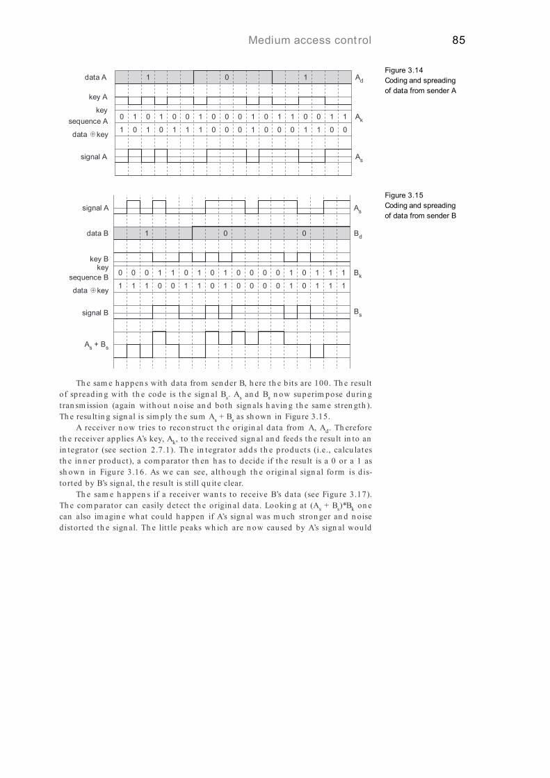
Th e sam e h appen s with data from sen der B, h ere th e bits are 100. Th e resu ltof spreadin g with th e code is th e sign al Bs. As an d Bs n ow superim pose du rin gtran sm ission (again with out n oise an d both sign als h avin g th e sam e stren gth ).Th e resu lt in g sign al is sim ply th e sum As + Bs as sh own in Figu re 3.15.
A receiver n ow tries to recon st ru ct th e origin al data from A, Ad. Th ereforeth e receiver applies A’s key, Ak, to th e received sign al an d feeds th e resu lt in to anin tegrator (see sectio n 2.7.1). Th e in tegrato r add s th e p rodu cts (i.e., calcu latesth e in n er p roduct), a com parator th en h as to decide if th e resu lt is a 0 or a 1 assh own in Figu re 3.16. As we can see, alth ough th e o rigin al sign al fo rm is d is-torted by B’s sign al, th e resu lt is st ill qu ite clear.
Th e sam e h appen s if a receiver wan ts to receive B’s data (see Figu re 3.17).Th e com parator can easily detect th e origin al data. Lookin g at (As + Bs)*Bk on ecan also im agin e wh at could h appen if A’s sign al was m uch stron ger an d n oisedistorted th e sign al. Th e lit t le peaks wh ich are n ow caused by A’s sign al would
Medium access cont rol 85
data A 1 0 1 Ad
key Akey 0 1 0 1 0 0 1 0 0 0 1 0 1 1 0 0 1 1 Aksequence A
1 0 1 0 1 1 1 0 0 0 1 0 0 0 1 1 0 0data ⊕ key
signal A As
Figure 3.14Coding and spreadingof data from sender A
key B
signal A As
data B 1 0 Bd
key 0 0sequence Bdata ⊕ key
0 1 1 0 1 0 1 0 0 0 0 1 0 1 1 1 Bk1 1 1 0 0 1 1 0 1 0 0 0 0 1 0 1 1 1
signal B Bs
As + Bs
0
Figure 3.15Coding and spreadingof data from sender B

be m u ch h igh er, an d th e resu lt of th e in tegrator wou ld be wron g. If Ak an d Bkare p erfect ly orth ogon al an d n o n oise d istu rbs th e t ran sm ission , th e m eth odworks (in th eory) for arbitrarily differen t sign al stren gth s.
Fin ally, Figure 3.18 sh ows wh at h appen s if a receiver h as th e wron g key or isn ot syn ch ron ized with th e ch ipp in g sequen ce of th e tran sm itter. Th e in tegratorst ill p resen ts a value after each bit period , bu t n ow it is n ot always possible forth e co m p arator t o decid e for a 1 or a 0 , as th e sign al rath er resem bles n oise.In tegrat in g over n o ise resu lts in valu es close to zero . Even if th e com p arator
Mobile communicat ions86
1 0 1
As + Bs
data A
Ak
(As + Bs)* Akintegrator
output1 0 1comparator
output
AdFigure 3.16
Reconstruction ofA’s data
1 0 0
As + Bs
data B
Bk
(As + Bs)* Bkintegrator
output1 0 0comparator
output
BdFigure 3.17
Reconstruction ofB’s data

cou ld d etect a clear 1 , th is cou ld st ill n ot recon st ruct th e wh ole bit seq u en cet ran sm it t ed by a sen d er. A ch ecksu m on layer 2 wou ld d et ect th e erro n eou spacket . Th is illustrates CDMA’s in h eren t protection again st tapp in g. It is also th ereason for callin g t h e sp read in g cod e a key, as it is sim u lt an eou sly u sed fo ren cryption on th e ph ysical layer.3.5.1 Spread Aloha mult iple accessAs sh own in th e previou s section , usin g d ifferen t codes with certain propert iesfo r sp read in g d at a resu lt s in a n ice an d p owerfu l m u lt ip le access sch em e –n am ely CDMA. Bu t CDMA sen ders an d receivers are n ot really sim ple devices.Com m un icatin g with n devices requires program m in g of th e receiver to be ableto d eco de n d ifferen t co des (an d p ro bably sen d in g with n co d es, t o o ). Fo rm obile ph on e system s, a lot of th e com plexity n eeded for CDMA is in tegratedin th e base stat ion s. Th e wireless an d m obile d evices com m u n icat e with th ebase stat ion on ly. However, if spon tan eous, bu rsty t raffic h as to be su pp ortedbetween an arbit rary n um ber of devices, th e CDMA tech n ique seem s to pose toom uch overh ead. No on e wan ts to program m an y differen t spread in g codes for,e.g., ad-h oc n etworks. On th e oth er h an d, Aloh a was a very sim ple sch em e, bu tcould on ly provide a relat ively low ban dwidth due to collision s.
W h at h app en s if we com bin e t h e sp read in g o f CDMA an d th e m ed iu maccess o f Alo h a or, in o th er word s, wh at if we u se CDMA with on ly a sin glecode, i.e., with ou t CD? Th e resu lt in g sch em e is called sp rea d Aloh a m u lt ip leaccess (SAMA) an d is a com bin ation of CDMA an d TDMA (Abram son , 1996).
Medium access cont rol 87
As + Bs
wrongkey K
(As + Bs)* K
integratoroutput
(0) (0) ?comparatoroutput
Figure 3.18Receiving a signal withthe wrong key

SAMA works as fo llows: each sen der u ses th e sam e sp read in g code (in th eexam ple sh own in Figu re 3.19 th is is th e code 110101).4 Th e stan dard case forAloh a access is sh own in t h e u p per p art of th e figu re. Sen d er A an d sen der Baccess th e m edium at th e sam e t im e in th eir n arrowban d spectru m , so th at allth ree bits sh own cause a collision .
Th e sam e data cou ld also be sen t with h igh er power for a sh orter p eriod assh own in th e m id d le, bu t n ow sp read sp ect ru m is u sed to sp read th e sh ortersign als, i.e., to in crease th e ban dwidth (sp read in g factor s = 6 in th e exam ple).Both sign als are sp read , bu t th e ch ip p in g p h ase d iffers sligh t ly. Separat ion ofth e two sign als is st ill p ossible if on e receiver is syn ch ron ized to sen der A an dan oth er on e to sen d er B. Th e sign al of an u n syn ch ron ized sen der app ears asn o ise . Th e p rob ab ilit y o f a ‘co llision ’ is q u it e lo w if t h e n u m ber o f sim u l-tan eou s tran sm it ters stays below 0.1–0.2s (Abram son , 1996). Th is also dep en dso n t h e n o ise level o f t h e en viro n m en t . Th e m ain p ro b lem in u sin g t h isapp roach is fin d in g good ch ip pin g sequ en ces. Clearly, th e code is n ot orth og-on al t o it self – it sh o u ld h ave a good au to correlat ion bu t , at t h e sam e t im e,correlat ion sh ou ld be low if th e ph ase d iffers sligh t ly. Th e m axim u m th rou gh -p u t is abo u t 18 p er cen t , wh ich is very sim ilar t o Aloh a, bu t t h e ap p roachb en efit s fro m t h e ad van t ages o f sp read sp ect ru m t ech n iq u es: ro b u st n essagain st n arrowban d in terferen ce an d sim p le coexisten ce with oth er system s inth e sam e frequ en cy ban ds.
Mobile communicat ions88
Sender A 1
Sender B 0
Collision
narrowbandSend for ashorter periodwith higerpower
01
11
t
Figure 3.19Spread Aloha
multiple access
4 Clearly, th is is n ot a good code, for it is m uch too sh ort . Here, codin g is on ly don e per b it , a m uchlon ger code cou ld also stretch over m an y bits.

3.6 Comparison of S/ T/ F/ CDMATo con clude th e ch ap ter, a com parison of th e fou r basic m ultiple access version sis given in Table 3.1. Th e table sh ows th e MAC sch em es with ou t com bin ationwith oth er sch em es. However, in real system s, th e MAC sch em es always occur incom bin ation s. A very typical com bin ation is con stitu ted by SDMA/TDMA/FDMAas used in IS-54, GSM, DECT, PHS, an d PACS ph on e system s, or th e Iridium an dICO satellite system s. CDMA togeth er with SDMA is u sed in th e IS-95 m obileph on e system an d th e Globalstar satellite system (see ch apters 4 an d 5).
Alth ough m an y n etwork p roviders an d m an u factu rers h ave lowered th eirexpectation s regardin g th e perform an ce of CDMA com pared to th e early 1980s (dueto experien ces with th e IS-95 m obile ph on e system ) CDMA is in tegrated in to alm ostall th ird gen erat ion m obile ph on e system s eith er as W-CDMA (FOMA, UMTS) orcdm a2000 (see ch apter 4). CDMA can be used in com bin ation with FDMA/TDMAaccess sch em es to in crease th e cap acity of a cell. In con t rast to o th er sch em es,CDMA h as th e advan tage of a soft h an dover an d soft capacity. Han dover, explain edin m ore detail in ch apter 4, describes th e switch in g from on e cell to an oth er, i.e.,ch an gin g th e base st at ion t h at a m obile stat ion is con n ected t o . Soft h an doverm ean s th at a m obile station can sm ooth ly switch cells. Th is is ach ieved by com m u-n icatin g with two base stat ion s at th e sam e tim e. CDMA does th is usin g th e sam ecode an d th e receiver even ben efits from both sign als. TDMA/FDMA system s per-form a h ard h an dover, i.e., th ey switch base stat ion an d h opp in g seq uen ces(tim e/frequen cy) precisely at th e m om en t of h an dover. Han dover decision is basedon th e sign al stren gth , an d oscillation s between base station s are possible.
Soft capacity in CDMA system s describes th e fact th at CDMA system s canadd m ore an d m ore users to a cell, i.e., th ere is n o h ard lim it . For TDMA/FDMAsyst em s, a h ard u pp er lim it exist s – if n o m ore free t im e/ freq u en cy slo ts areavailable, th e system reject s n ew users. If a n ew u ser is added to a CDMA cell,th e n oise level rises an d th e cell sh rin ks, bu t th e u ser can st ill com m u n icate.However, th e sh rin kin g of a cell can cause p roblem s, as oth er u sers cou ld n owdrop out of it . Cell p lan n in g is m ore d ifficult in CDMA system s com pared to th em ore fixed TDMA/FDMA sch em es (see ch apter 2).
W h ile m obile ph on e system s usin g SDMA/TDMA/FDMA or SDMA/CDMAare cen t ralized system s – a base stat ion con tro ls m an y m ob ile stat ion s – arbi-t rary wireless com m u n icat ion syst em s n eed d ifferen t MAC algorith m s. Mostdistribu ted system s use som e version of th e basic Aloh a. Typically, Aloh a is slot-ted an d som e reservat ion m ech an ism s are applied to guaran tee access delay an dban d wid th . Each of t h e sch em es h as ad van tages an d d isad van tages. Sim p leCSMA is very efficien t at low load , MACA can overcom e th e problem of h iddenor exp o sed t erm in als, an d p o llin g gu aran t ees b an d wid th . No sin gle sch em ecom bin es all ben efit s, wh ich is wh y, for exam ple, t h e wireless LAN stan d ardIEEE 802.11 com bin es all th ree sch em es (see section 7.3). Pollin g is used to setu p a t im e st ru ctu re via a base st a t io n . A CSMA version is u sed t o access t h em edium durin g un coordin ated periods, an d addit ion ally, MACA can be used toavoid h idden term in als or in cases wh ere n o base stat ion exists.
Medium access cont rol 89

Mobile communicat ions90
Approach SDMA TDMA FDMA CDMAIdea Segment Segment Segment the Spread the
space into sending time frequency spectrum using cells/ sectors into disjoint band into orthogonal
time-slots, disjoint codesdemand driven sub-bandsor fixed patterns
Terminals Only one All terminals Every terminal All terminals can terminal can are active for has its own be active at the be active in short periods frequency, same place at one cell/ one of time on the uninterrupted the same sector same frequency moment,
uninterruptedSignal Cell structure Synchronization Filtering in Code plus separat ion directed in the time the frequency special receivers
antennas domain domainAdvantages Very simple, Established, Simple, Flexible, less
increases fully digital, established, planning capacity very flexible robust needed, soft per km2 handover
Disadvantages Inflexible, Guard space Inflexible, Complex antennas needed frequencies receivers, needs typically fixed (multi-path are a scarce more
propagation), resource complicated synchronization power control difficult for senders
Comment Only in Standard in Typically Used in many combination fixed networks, combined 3G systems,with TDMA, together with with TDMA higher FDMA or FDMA/ SDMA (frequency complexity,CDMA useful used in many hopping lowered
mobile networks patterns) and expectations; SDMA integrated with (frequency TDMA/ FDMAreuse)
Table 3.1 Comparisonof SDMA, TDMA,
FDMA, and CDMAmechanisms
3.7 Review exercises1 What is the main physical reason for the failure of many MAC schemes known
from wired networks? What is done in wired networks to avoid this effect?2 Recall the problem of hidden and exposed terminals. What happens in the case
of such terminals if Aloha, slotted Aloha, reservation Aloha, or MACA is used?3 How does the near/ far effect influence TDMA systems? What happens in
CDMA systems? What are countermeasures in TDMA systems, what aboutCDMA systems?
4 Who performs the MAC algorithm for SDMA? What could be possible roles ofmobile stations, base stations, and planning from the network provider?
5 What is the basic prerequisite for applying FDMA? How does this factor increasecomplexity compared to TDMA systems? How is MAC distributed if we considerthe whole frequency space as presented in chapter 1?
6 Considering duplex channels, what are alternatives for implementation in wire-less networks? What about typical wired networks?
7 What are the advantages of a fixed TDM pattern compared to random, demanddriven TDM? Compare the efficiency in the case of several connections with fixeddata rates or in the case of varying data rates. Now explain why traditionalmobile phone systems use fixed patterns, while computer networks generallyuse random patterns. In the future, the main data being transmitted will be com-puter-generated data. How will this fact change mobile phone systems?
8 Explain the term interference in the space, time, frequency, and code domain.What are countermeasures in SDMA, TDMA, FDMA, and CDMA systems?
9 Assume all stations can hear all other stations. One station wants to transmitand senses the carrier idle. Why can a collision still occur after the startof transmission?
10 What are benefits of reservation schemes? How are collisions avoided duringdata transmission, why is the probability of collisions lower compared to classi-cal Aloha? What are disadvantages of reservation schemes?
11 How can MACA still fail in case of hidden/ exposed terminals? Think of mobilestations and changing transmission characteristics.
12 Which of the MAC schemes can give hard guarantees related to bandwidth andaccess delay?
13 How are guard spaces realized between users in CDMA?14 Redo the simple CDMA example of section 3.5, but now add random ‘noise’ to
the transmitted signal (–2,0,0,–2,+2,0). Add, for example, (1,–1,0,1,0,–1). Inthis case, what can the receiver detect for sender A and B respectively? Nowinclude the near/ far problem. How does this complicate the situation? Whatwould be possible countermeasures?
Medium access cont rol 91

3.8 ReferencesAbram son , N. (1977) ‘Th e th rough p u t of p acket broad cast in g ch an n els,’ IEEE
Transactions on Communication, COM-25(1).Abram son , N. (1996) ‘Wideban d ran dom access for th e last m ile,’ IEEE Personal
Communications, 3(6).Halsall, F. (1996) Da ta communica tions, computer networks and open systems.
Addison -Wesley Lon gm an .Klein rock, L., Tobagi, F. (1975) ‘Packet switch in g in radio ch an n els: part 1 – carrier
sen se m ult ip le-access m odes an d th eir th rou gh p u t -delay ch aracterist ics,’IEEE Transactions on Communications, COM-23(12).
Salkin tzis, A. (1999) ‘Packet data over cellu lar n etworks: Th e CDPD approach ,’IEEE Communications Magazine, 37(6).
Stallin gs, W. (1997) Data and computer communications. Pren t ice Hall.Viterb i, A. (1995) CDMA: principles of spread spectrum communica tion. Add ison -
Wesley Lon gm an .Willin ger, W., Paxso n , V. (1998a) ‘W h ere Math em at ics m eet s t h e In t ern et ,’
Notices of the American Mathematical Society, 45(8).Willin ger, W, Paxson , V., Taq q u , M. (1998b) ‘Self-sim ilarit y an d Heavy Tails:
St ru ctu ral Mod elin g of Network Traffic,’ A Pra ctica l Guide to Heavy Ta ils:Sta tist ica l Techniques a nd Applica tions. Ad ler, Taq q u (ed s.), Birkh äu ser-Verlag, Boston .
Mobile communicat ions92

Digit a l cellu la r n etw ork s are th e segm en t of th e m arket for m obile an dwireless devices wh ich are growin g m ost rap id ly. Th ey are th e wirelessexten sion s of tradition al PSTN or ISDN n etworks an d allow for seam less
roam in g with th e sam e m obile p h on e n at ion or even worldwide. Today, th esesystem s are m ain ly u sed for voice traffic. However, data traffic is con t in uouslygrowin g an d , th erefore, th is ch ap ter p resen ts several tech n ologies for wirelessdata tran sm ission usin g cellu lar system s.1
Th e system s presen ted fit in to th e tradition al teleph on y arch itecture an d don ot origin ate from com puter n etworks. Th e basic version s typ ically im p lem en t acircu it -switch ed service, focu sed on voice, an d on ly offer d ata rates o f u p t o ,e.g., 9.6 kbit / s. However, service is p rovided u p to a sp eed of 250 km / h (e.g.,usin g GSM in a car) wh ere m ost oth er wireless system s fail.
Th e w or ld w id e m a r k et figu res for cellu lar n etworks are as fo llows (GSMAssociat ion , 2002). Th e m ost popular digital system is GSM, with approxim ately70 per cen t m arket sh are. (Th is syst em will be p resen t ed in sect ion 4.1.) Th ean alog AMPS system st ill h olds th ree per cen t , wh ereas th e Japan ese PDC h oldsfive per cen t (60 m illion u sers). Th e rem ain der is sp lit between CDMA (12 percen t ) an d TDMA (10 p er cen t ) syst em s, an d o th er t ech n o lo gies. In Eu r o p ealm ost everyon e uses th e d igital GSM system (over 370 m illion ) with alm ost n oan alog system s left . Th e situat ion is d ifferen t in th e US an d som e oth er coun -t ries th at h ave adop ted US tech n ology (e.g., Sou th Korea, Can ad a). Here, th edigital m arket is sp lit in to TDMA, CDMA, an d GSM system s with 107 m illionTDMA, 135 m illion CDMA, an d on ly 16 m illion GSM u sers (North Am ericaon ly). Wh ile on ly on e digital system exists in Europe, th e US m arket is dividedin to several system s. Th is leads to severe problem s regardin g coverage an d ser-vice availability, an d is on e of th e exam ples wh ere m arket forces did n ot en sureim proved services (com pared to th e com m on stan dard in Europe).
Figure 4.1 sh ows th e worldwide n um ber o f subscribers to d ifferen t m obileph on e tech n ologies (GSM Associat ion , 2002). Th e figure com bin es differen t ver-sion s of th e sam e tech n ology (e.g., GSM workin g on 900, 1,800, an d 1,900 MHz).
Telecommunicat ion systems 4
93
1 All syst em s p resen ted h ere are d igit a l, fo r o ld er an a log syst em s su ch as t h e US AMPS (ad van cedm obile ph on e system ) th e reader is referred to, e.g., Goodm an (1997).

Th e two upper lin es in th e graph sh ow th e total n um ber of users an d th e predic-tion s from 1998. It is in terestin g th at n o on e foresaw th e trem en dous success ofth e m obile com m un ication tech n ology. Th e graph sh ows, too, th at th e tim e foran alog system s is over an d GSM is h eavily dom in atin g th e curren t m arket. GSM,TDMA, CDMA, an d PDC are all secon d gen erat ion system s. It is im p ortan t ton ote th at today m ore people use m obile ph on e system s th an fixed teleph on es!Th e graph s of m obile an d fixed users crossed in March 2002.
Th e followin g sect ion s presen t prom in en t exam ples for secon d gen eration(2G) m obile p h on e n etworks, cord less teleph on es, t run ked rad io system s, an dth ird gen erat ion (3G) m obile p h on e n etworks. Th is ch ap ter u ses GSM as th em ain exam ple for a 2G fu lly d igital m obile ph on e system , n ot on ly because ofm arket success, bu t also due to th e system arch itecture th at served m an y oth ersyst em s as an early exam p le. O th er syst em s ad op ted m ob ilit y m an agem en t ,m ob ile assisted h an dover an d o th er basic id eas (Good m an , 1997), (Stallin gs,2002), (Pah lavan , 2002). W h ile US system s typ ically focus on th e air in terfacefor th eir specification , a system like GSM h as m an y open in terfaces an d n etworken tit ies defin ed in th e specification . Wh ile th e first approach en ables com pan iesto h ave th eir own , proprietary an d possibly better solu tion s, th e lat t er en ablesn etwork p roviders to ch oose between m an y d ifferen t p rodu cts from differen tven dors. DECT an d TERTA are u sed , respect ively as exam ples for cord less t ele-p h o n y an d t ru n ked rad io syst em s. On e reason for t h is is th eir syst emarch itectu re wh ich is sim ilar to GSM. Th is is n ot very surprisin g as all th ree sys-tem s h ave been stan dardized by ETSI. Th e m ain focus is always on data service,so th e evolu tion of GSM offerin g h igh er data rates an d packet-orien ted tran sferis also presen ted. Th e ch apter con cludes with UMTS as a prom in en t exam ple for3G m obile telecom m un ication n etworks. UMTS is Europe’s an d Japan ’s proposal
Mobile communicat ions94
1996 1997 1998 1999 2000 20010
200
400
600
800
1000
1200
Subsc
ribers (
million
)GSM totalTDMA totalCDMA totalPDC totalAnalogue totalTotal wireless
2002
Prediction (1998)
Figure 4.1Worldwide subscribers
of different mobilephone technologies
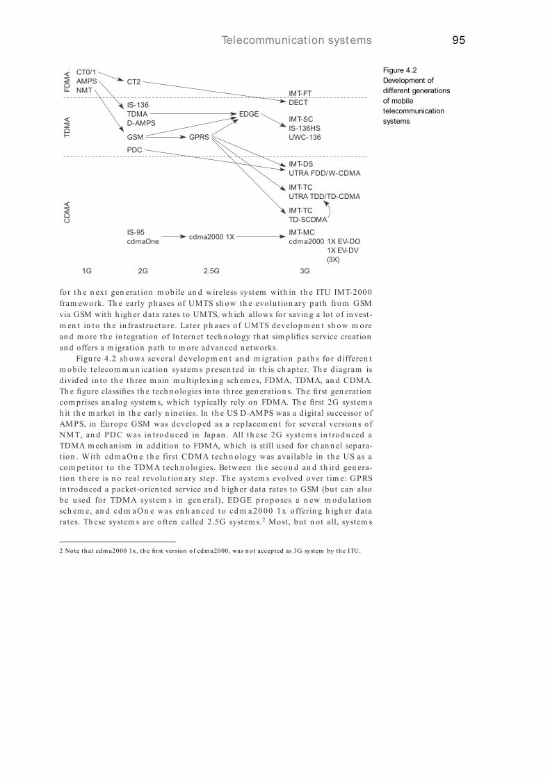
for th e n ext gen erat ion m obile an d wireless system with in th e ITU IMT-2000fram ework. Th e early p h ases of UMTS sh ow th e evolu t ion ary p ath from GSMvia GSM with h igh er data rates to UMTS, wh ich allows for savin g a lot of in vest-m en t in to th e in frast ru ctu re. Later p h ases of UMTS develop m en t sh ow m orean d m ore th e in tegration of In tern et tech n ology th at sim plifies service creat ionan d offers a m igration path to m ore advan ced n etworks.
Figu re 4.2 sh o ws several d evelop m en t an d m igrat ion p ath s fo r d ifferen tm obile telecom m u n icat ion system s p resen ted in th is ch ap ter. Th e d iagram isd ivided in to th e th ree m ain m ult ip lexin g sch em es, FDMA, TDMA, an d CDMA.Th e figure classifies th e tech n ologies in to th ree gen erat ion s. Th e first gen erat ioncom prises an alog system s, wh ich typ ically rely on FDMA. Th e first 2G system sh it th e m arket in th e early n in et ies. In th e US D-AMPS was a digital successor ofAMPS, in Eu rope GSM was develop ed as a rep lacem en t for several version s ofNMT, an d PDC was in t ro du ced in Jap an . All t h ese 2G syst em s in t rod u ced aTDMA m ech an ism in addit ion to FDMA, wh ich is still used for ch an n el separa-t ion . With cdm aOn e th e first CDMA tech n ology was available in t h e US as acom pet itor to th e TDMA tech n ologies. Between th e secon d an d th ird gen era-t ion th ere is n o real revolu t ion ary step . Th e system s evolved over t im e: GPRSin troduced a packet-orien ted service an d h igh er data rates to GSM (but can alsobe u sed for TDMA syst em s in gen era l), EDGE p rop oses a n ew m od u lat ionsch em e, an d cd m a O n e was en h an ced to cd m a 20 00 1x offerin g h igh er d atarates. Th ese system s are often called 2.5G system s.2 Most , bu t n ot all, system s
Telecommunicat ion systems 95
2 Note th at cdm a2000 1x, th e first version of cdm a2000, was n ot accepted as 3G system by th e ITU.
CT0/1AMPSNMTFD
MATD
MACD
MA
GPRS
IMT-FTDECTIMT-SCIS-136HSUWC-136
EDGE
CT2
IS-136TDMAD-AMPSGSMPDC
1G 2.5G 3G2G
IS-95cdmaOne cdma2000 1X
IMT-DSUTRA FDD/W-CDMAIMT-TCUTRA TDD/TD-CDMAIMT-TCTD-SCDMAIMT-MCcdma2000 1X EV-DO
1X EV-DV(3X)
Figure 4.2Development ofdifferent generationsof mobiletelecommunicationsystems

ad ded CDMA tech n ology to becom e 3G system s. Cordless t elep h on e system sstarted with CT0 an d CT1, becam e d igital with CT2, an d en ded in Europe in th efu lly d igital stan dard DECT. Th is stan dard h as even been ch osen as on e of th ecan did ates for a 3G system (IMT-FT).
W h ile th e n um ber of differen t system s m igh t be con fusin g, th ere are som e“n atu ral” d evelop m en t path s. Most n etwork p ro vid ers offerin g GSM servicetoday will deploy UMTS, wh ile cdm aOn e users will ch oose cdm a2000 for sim plerm igration . Th e reason s for th is are qu ite sim p le. With th e in troduction of GPRSin GSM n etworks, th e core of th e n etwork was already en h an ced in a way th at itcan be directly used for UMTS with th e radio tech n ologies UTRA FDD an d UTRATDD. A sim ilar path for evolu t ion exists for TD-SCDMA, th e Ch in ese proposalfor a 3G system (wh ich h as been in tegrated in to UTRA TDD). With som e sim pli-fication it can be said th at UMTS m ain ly adds a n ew radio in terface but relies inits in it ial ph ase on th e sam e core n etwork as GSM/GPRS. Also for cdm aOn e th eevo lu t io n to cdm a2000 t ech n ologies is q u it e n atu ral, as th e n ew st an d ard isbackward com pat ible an d can reuse frequen cies. Cdm a2000 1x still uses th e sam e1.25 MHz ch an n els as cdm aOn e does, bu t offers data rates of up to 153 kbit / s.Th e cd m a2000 3x stan dard uses th ree 1.25 MHz ch an n els to fit in to ITU’s fre-q uen cy sch em e fo r 3G. However, th is stan dard is n o t p u sh ed as m u ch as th efollowin g en h an cem en ts of cdm a2000 1x. Th ese en h an cem en ts are: ● cd m a2000 1x EV-DO (evolu t ion -data opt im ized , also kn own as h igh data
rate (HDR), som e call it data on ly) prom isin g peak data rates of 2.4 Mbit/ su sin g a secon d 1.25 MHz ch an n el; an d
● cd m a 2000 1x EV-DV (evolu t ion -d ata an d voice) aim in g at 1.2 Mbit / s form obile an d 5.2 Mbit /s for stat ion ary users.
Cdm a2000 1x EV-DO was th e first version of cdm a2000 accepted by th e ITU as3G system . More in form ation abou t th e tech n ologies an d acron ym s used in th ediagram is p rovided in th e followin g section s.
4.1 GSMGSM is th e m ost su ccessfu l d igit al m ob ile t eleco m m u n icat ion syst em in t h eworld today. It is used by over 800 m illion people in m ore th an 190 coun tries.In th e early 1980s, Europe h ad n um erous coexist in g an alog m obile ph on e sys-tem s, wh ich were often based on sim ilar stan dards (e.g., NMT 450), bu t ran onsligh tly differen t carrier frequen cies. To avoid th is situation for a secon d gen era-t ion fu lly d igit al system , th e gro u p e sp écia le m o b ile (GSM) was fou n ded in1982. Th is system was soon n am ed th e glob a l syst em for m ob ile com m u n ica -t io n s (GSM), with th e specificat ion p rocess lyin g in t h e h an d s o f ETSI (ETSI,2002), (GSM Associat ion , 2002). In th e con text o f UMTS an d th e creat ion o f3GPP (Th ird gen eration partn ersh ip pro ject , 3GPP, 2002a) th e wh ole develop-m en t p rocess o f GSM was t ran sferred t o 3GPP an d fu rth er d evelop m en t iscom bin ed with 3G developm en t. 3GPP assign ed n ew n um bers to all GSM stan -
Mobile communicat ions96
Gayatri
Highlight

dards. However, to rem ain con sisten t with m ost of th e GSM literature, th is GSMsect ion st ays with th e o rigin al n u m berin g (see 3GPP, 2002a, for con version ).Section 4.4 will presen t th e on goin g join t specification process in m ore detail.
Th e prim ary goal of GSM was to provide a m obile ph on e system th at allowsu sers t o ro am th ro u gh ou t Eu rop e an d p rovid es vo ice services co m p at ib le t oISDN an d oth er PSTN system s. Th e specificat ion for th e in it ial system alread ycovers m ore th an 5,000 pages; n ew services, in part icu lar data services, n ow addeven m ore specification details. Readers fam iliar with th e ISDN referen ce m odelwill recogn ize m an y sim ilar acron ym s, referen ce p oin t s, an d in terfaces. GSMstan dardization aim s at adop tin g as m uch as possible.
GSM is a typ ical secon d gen erat ion system , rep lacin g th e first gen erat ionan alog system s, but n ot offerin g th e h igh worldwide data rates th at th e th ird gen -eration system s, such as UMTS, are prom isin g. GSM h as in itially been deployed inEurope usin g 890–915 MHz for up lin ks an d 935–960 MHz for down lin ks – th issystem is n ow also called GSM 900 to distin guish it from th e later version s. Th eseversion s com prise GSM at 1800 MHz (1710–1785 MHz uplin k, 1805–1880 MHzdown lin k), also called DCS (d igita l cellu lar syst em ) 1800, an d th e GSM systemm ain ly u sed in th e US at 1900 MHz (1850–1910 MHz up lin k, 1930–1990 MHzdown lin k), also called PCS (p erso n a l co m m u n ica t io n s serv ice) 1900. Twom ore version s of GSM exist . GSM 400 is a p rop osal to d ep loy GSM at450.4–457.6/478.8–486 MHz for up lin ks an d 460.4–467.6/488.8–496 MHz fo rdown lin ks. Th is system could replace an alog system s in sparsely populated areas.
A GSM system th at h as been in t roduced in several Europ ean coun tries forrailroad system s is GSM-Rail (GSM-R, 2002), (ETSI, 2002). Th is system does n oton ly u se sep arat e freq u en cies bu t o ffers m an y add it io n al services wh ich areun available u sin g th e public GSM system . GSM-R offers 19 exclu sive ch an n elsfor railroad operators for voice an d data traffic (see sect ion 4.1.3 for m ore in for-m at ion about ch an n els). Special features of th is system are, e.g., em ergen cy callswith ackn owledgem en ts, voice group call service (VGCS), voice broadcast ser-vice (VBS). Th ese so-called advan ced speech call item s (ASCI) resem ble featurestypically available in trun ked rad io system s on ly (see section 4.3). Calls are pri-orit ized : h igh p riorit y calls p re-em p t low p riority calls. Calls h ave very sh ortset -up tim es: em ergen cy calls less th an 2 s, group calls less th an 5 s. Calls can bedirected for exam ple, to all u sers at a certain location , all u sers with a certainfun ct ion , or all u sers with in a certain n um ber space. However, th e m ost soph is-ticated use of GSM-R is th e con trol of t rain s, switch es, gates, an d sign als. Train sgo in g n ot faster t h an 160 km / h can con t ro l all gat es, swit ch es, an d sign alsth em selves. If th e train goes faster th an 160 km /h (m an y t rain s are already cap-able of goin g faster th an 300 km /h ) GSM-R can still be used to m ain tain con trol.
Th e followin g sect ion describes th e arch itectu re, services, an d p rotocols ofGSM th at are com m on to all th ree m ajor solu tion s, GSM 900, GSM 1800, an dGSM 1900. GSM h as m ain ly been design ed for th is an d voice services an d th isst ill con st itu tes th e m ain use of GSM system s. However, on e can foresee t h atm an y fu ture applicat ion s for m obile com m u n icat ion s will be data driven . Th erelat ion sh ip of data to voice traffic will sh ift m ore an d m ore towards data.
Telecommunicat ion systems 97
Gayatri
Highlight

4.1.1 Mobile servicesGSM perm its th e in tegration of d ifferen t voice an d data services an d th e in ter-workin g with exist in g n etworks. Services m ake a n etwork in terest in g forcu stom ers. GSM h as defin ed th ree d ifferen t categories of services: bearer, t ele,an d su pp lem en tary services. Th ese are d escribed in th e followin g su bsect ion s.Figu re 4.3 sh ows a referen ce m odel for GSM services. A m o b ile st a t io n MS iscon n ected to th e GSM p u b lic lan d m ob ile n etw ork (PLMN) via th e Um in ter-face. (GSM-PLMN is t h e in frast ru ctu re n eed ed fo r t h e GSM n etwork.) Th isn etwork is con n ected to t ran sit n etworks, e.g., in t egra t ed services d igit a l n et -w ork (ISDN) or tradition al p u b lic sw itch ed telep h on e n etw ork (PSTN). Th erem igh t be an addition al n etwork, th e source/destin ation n etwork, before an oth erterm in al TE is con n ected. Bearer services n ow com prise all services th at en ableth e tran sparen t tran sm ission of data between th e in terfaces to th e n etwork, i.e., Sin case of th e m obile stat ion , an d a sim ilar in terface for th e oth er term in al (e.g.,S0 for ISDN term in als). In terfaces like U, S, an d R in case of ISDN h ave n ot beendefin ed for all n etworks, so it depen ds on th e specific n etwork wh ich in terface isused as a referen ce for th e tran sparen t tran sm ission of data. In th e classical GSMm odel, bearer services are con n ect ion -orien ted an d circu it- or packet-switch ed.Th ese services on ly n eed th e lower th ree layers of th e ISO/OSI referen ce m odel.
With in th e m obile stat ion MS, th e m o b ile t erm in a t ion (MT) perform s alln etwork specific tasks (TDMA, FDMA, cod in g etc.) an d offers an in terface fordata t ran sm ission (S) to th e term in al TE wh ich can th en be n etwork in dep en -d en t . Dep en d in g on th e cap abilit ies of TE, fu rth er in terfaces m ay be n eed ed ,such as R, accordin g to th e ISDN referen ce m odel (Halsall, 1996). Tele servicesare app lication specific an d m ay th us n eed all seven layers of th e ISO/OSI refer-en ce m odel. Th ese services are specified en d-to-en d , i.e., from on e term in al TEto an oth er.4.1.1.1 Bearer servicesGSM sp ecifies d ifferen t m ech an ism s for data t ran sm ission , t h e o rigin al GSMallowin g for data rates of up to 9600 bit / s for n on -voice services. Bearer servicesp erm it t ran sp aren t an d n on -t ran sp aren t , syn ch ron o us or asyn ch ron ou s d atatran sm ission . Tran sp aren t b ea rer services on ly use th e fun ction s of th e ph ysi-cal layer (layer 1) to tran sm it data. Data tran sm ission h as a con stan t delay an dth rou gh p u t if n o t ran sm ission errors occur. Th e on ly m ech an ism to in crease
Mobile communicat ions98
GSM-PLMNTransit
network(PSTN, ISDN)
Source/destination
networkTE
(U, S, R)UmMT
R, STEMS
Bearer services
Tele services
Figure 4.3Bearer and tele
services referencemodel
Gayatri
Highlight
Gayatri
Highlight

t ran sm ission quality is th e use of forw ard error correct ion (FEC), wh ich codesredun dan cy in to th e data stream an d h elps to recon struct th e origin al data incase of t ran sm issio n errors. Dep en d in g on th e FEC, d ata rat es o f 2 .4 , 4 .8 , o r9.6 kbit / s are possible. Tran sparen t bearer services do n ot try to recover lost datain case of, for exam ple, sh adowin g or in terruption s due to h an dover.
Non -t ran sp a ren t b ea rer services u se protocols o f layers two an d th ree toim plem en t error correction an d flow con trol. Th ese services use th e tran sparen tbearer services, ad d in g a r a d io l in k p ro t o co l (RLP). Th is p ro tocol com p risesm ech an ism s of h igh -level d a t a lin k con t ro l (HDLC), (Halsall, 1996) an d spe-cial selective-reject m ech an ism s to trigger retran sm ission of erron eous data. Th each ieved bit error rate is less th an 10–7, bu t n ow th rough put an d delay m ay varydepen din g on tran sm ission quality.
Usin g t ran sp aren t an d n on -t ran sp aren t services, GSM sp ecifies severalbearer services for in terworkin g with PSTN, ISDN, an d p acket switch ed publicdata n etworks (PSPDN) like X.25, wh ich is available worldwide. Data tran sm is-sio n can be fu ll-d u p lex, syn ch ron o u s with d at a rat es o f 1 .2 , 2 .4 , 4 .8 , an d9.6 kbit / s o r fu ll-du p lex, asyn ch ron ous from 300 to 9,600 bit / s (ETSI, 1991a).Clearly, th ese relat ively low data rates reflect th e assum ption th at data serviceswill o n ly con st it u t e so m e sm all p ercen t age of t h e overall t raffic. W h ile t h isis st ill t ru e of GSM n etworks t od ay, th e relat ion of data an d voice services isch an gin g, with data becom in g m ore an d m ore im p ortan t . Th is developm en tis also reflected in th e n ew data services (see section 4.1.8).4.1.1.2 Tele servicesGSM m ain ly focuses on voice-orien ted tele services. Th ese com prise en cryp tedvoice tran sm ission , m essage services, an d basic data com m un ication with term i-n als as kn own from th e PSTN or ISDN (e.g., fax). However, as th e m ain service ist elep h o n y, th e prim ary goal of GSM was th e provision of h igh -qu ality d igitalvoice tran sm ission , offerin g at least th e typ ical ban dwidth of 3.1 kHz of an alogph on e system s. Special codecs (coder/decoder) are used for voice tran sm ission ,wh ile oth er codecs are used for th e t ran sm ission of an alog data for com m un ica-t ion with tradit ion al com puter m odem s used in , e.g., fax m ach in es.
An o th er service o ffered by GSM is t h e em er gen cy n u m b er . Th e sam en u m ber can b e u sed t h rou gh o u t Eu rop e. Th is service is m an d ato ry fo r allp rovid ers an d free o f ch arge. Th is co n n ect io n a lso h as t h e h igh est p rio rit y,possibly pre-em ptin g oth er con n ect ion s, an d will au tom atically be set up withth e closest em ergen cy cen ter.
A usefu l service for very sim ple m essage tran sfer is th e sh o r t m essage ser-vice (SMS), wh ich offers t ran sm ission of m essages of up to 160 ch aracters. SMSm essages d o n o t u se t h e stan d ard d at a ch an n els o f GSM b u t exp lo it u n usedcapacity in th e sign allin g ch an n els (see section 4.1.3.1). Sen d in g an d receivin gof SMS is possible du rin g data or voice tran sm ission . SMS was in th e GSM stan -d ard fro m th e begin n in g; h owever, alm o st n o o n e u sed it u n t il m illion s o fyou n g people d iscovered th is service in th e m id -n in et ies as a fun service. SMS
Telecommunicat ion systems 99
Gayatri
Highlight
Gayatri
Highlight

can be used for “serious” application s such as d isplayin g road con dit ion s, e-m ailh eaders or stock qu otes, bu t it can also t ran sferr logos, rin g ton es, h oroscopesan d love let t ers. Tod ay m o re t h an 30 b illio n sh o rt m essages are t ran sferredworldwide per m on th ! SMS is big busin ess today, n ot on ly for th e n etwork oper-ato rs, bu t also fo r m an y con ten t p ro vid ers. It sh ou ld be n o t ed th at SMS istyp ically th e on ly way to reach a m obile ph on e from with in th e n etwork. Th us,SMS is used for updatin g m obile ph on e software or for im plem en tin g so-calledpush services (see ch apter 10).
Th e successor of SMS, th e en h an ced m essage service (EMS), offers a largerm essage size (e.g., 760 ch aracters, con caten at in g several SMs), form at ted text ,an d t h e t ran sm ission o f an im ated p ictu res, sm all im ages an d rin g ton es in ast an d ard ized way (som e ven dors offered sim ilar p rop rietary featu res befo re).EMS n ever really took off as th e m u lt im ed ia m essage service (MMS) was avail-ab le. (No kia n ever liked EMS bu t p u sh ed Sm art Messagin g, a p ro p riet arysystem .) MMS offers th e tran sm ission of larger pictures (GIF, JPG, WBMP), sh ortvideo clip s et c. an d com es with m obile p h on es th at in t egrate sm all cam eras.MMS is furth er discussed in th e con text of WAP in ch apter 10.
An oth er n on -voice tele service is grou p 3 fax , wh ich is available worldwide.In th is service, fax data is t ran sm itted as digital data over th e an alog teleph on en etwork accordin g to th e ITU-T stan dards T.4 an d T.30 usin g m odem s. Typically,a tran sparen t fax service is u sed , i.e., fax data an d fax sign alin g is t ran sm it tedusin g a t ran sparen t bearer service. Lower t ran sm ission quality cau ses an au to-m at ic ad ap t at ion o f t h e bearer service t o lower d at a rat es an d h igh erredun dan cy for better FEC.4.1.1.3 Supplementary servicesIn add ition to tele an d bearer services, GSM providers can offer su p p lem en ta ryservices. Sim ilar to ISDN n etworks, th ese services offer variou s en h an cem en tsfo r t h e stan d ard telep h on y service, an d m ay vary from p rovid er to p rovid er.Typ ica l services are u ser id en t ifica t io n , call r ed ir ec t io n , o r fo r w a rd in g ofon goin g calls. Stan dard ISDN featu res such as clo sed u ser grou p s an d m u lt i-p a r t y com m u n ica t io n m ay be availab le. Closed u ser grou p s are of sp ecialin terest to com pan ies because th ey allow, for exam ple, a com pan y-specific GSMsub-n etwork, to wh ich on ly m em bers of th e group h ave access.4.1.2 System architectureAs with all system s in th e telecom m u n ication area, GSM com es with a h ierar-ch ical, com plex system arch itectu re com prisin g m an y en t it ies, in terfaces, an dacron ym s. Figure 4.4 gives a sim plified overview of th e GSM system as specifiedin ETSI (1991b). A GSM syst em con sist s o f t h ree su b syst em s, t h e r a d io su bsyst em (RSS), th e n etw ork an d sw itch in g su b syst em (NSS), an d th e op era t ionsu bsyst em (OSS). Each subsystem will be d iscussed in m ore detail in th e follow-in g sect ion s. Gen erally, a GSM custom er on ly n o t ices a very sm all fraction ofth e wh ole n etwork – th e m obile stat ion s (MS) an d som e an ten n a m asts of th ebase t ran sceiver stat ion s (BTS).
Mobile communicat ions100
Gayatri
Highlight
Gayatri
Highlight
Gayatri
Highlight

4.1.2.1 Radio subsystemAs th e n am e im p lies, th e r a d io su b syst em (RSS) com p rises all rad io sp ecificen t it ies, i.e., th e m ob ile st a t ion s (MS) an d th e b ase st a t ion su b syst em (BSS).Figu re 4.4 sh ows th e con n ection between th e RSS an d th e NSS via th e A in ter-fa ce (so lid lin es) an d th e con n ect ion to th e OSS via t h e O in t er fa ce (d ash edlin es). Th e A in terface is typ ically based on circu it -switch ed PCM-30 system s(2.048 Mbit/ s), carryin g up to 30 64 kbit / s con n ection s, wh ereas th e O in terfaceuses th e Sign allin g System No. 7 (SS7) based on X.25 carryin g m an agem en t datato/ from th e RSS.
Telecommunicat ion systems 101
radio cellMS
Um
MS
radio cellMS
BSS
Abis
BTS
BTS
A
BSC BSC
MSC MSC
VLRVLRHLR
EIR
GMSCIWF
AUC OMC
PDNISDN, PSTNsignaling
O
RSS
NSS
OSS
Figure 4.4Functional architectureof a GSM system
Gayatri
Highlight

● Base sta t ion su b system (BSS): A GSM n etwork com prises m an y BSSs, eachcon trolled by a base stat ion con troller (BSC). Th e BSS perform s all fun ction sn ecessary t o m ain t a in rad io con n ect ion s t o an MS, cod in g/ d ecod in g o fvoice, an d rate adaptat ion to/ from th e wireless n etwork part . Besides a BSC,th e BSS con tain s several BTSs.
● Base t ran sceiver st a t ion (BTS): A BTS com prises all rad io eq uipm en t , i.e.,an ten n as, sign al p rocessin g, am p lifiers n ecessary for rad io t ran sm ission . ABTS can form a radio cell or, usin g sectorized an ten n as, several cells (see sec-t ion 2.8), an d is con n ected to MS via th e Um in terface (ISDN U in terface form obile use), an d to th e BSC via th e Abis in terface. Th e Um in terface con tain sall th e m ech an ism s n ecessary for wireless tran sm ission (TDMA, FDMA etc.)an d will be discussed in m ore detail below. Th e Abis in terface con sists of 16 or64 kbit / s con n ect ion s. A GSM cell can m easu re between som e 100 m an d35 km depen d in g on th e en viron m en t (bu ild in gs, open space, m oun tain setc.) but also expected traffic.
● Ba se st a t io n co n t ro l le r (BSC): Th e BSC basically m an ages t h e BTSs. Itreserves rad io frequ en cies, h an dles th e h an dover from on e BTS to an oth erwith in th e BSS, an d perform s pagin g of th e MS. Th e BSC also m ult ip lexesth e rad io ch an n els on to th e fixed n etwork con n ection s at th e A in terface.
Table 4.1 gives an overview of th e tasks assign ed to th e BSC an d BTS or of tasksin wh ich th ese en tit ies support oth er en tit ies in th e n etwork. ● Mo b ile st a t io n (MS): Th e MS com p rises all u ser equ ipm en t an d software
n eed ed for com m u n icat ion with a GSM n etwork. An MS con sist s of u serin dep en d en t h ard - an d software an d of t h e su b scr ib er id en t it y m o d u le(SIM), wh ich stores all user-specific data th at is relevan t to GSM.3 Wh ile anMS can be iden t ified via th e in t ern a t io n a l m o b ile eq u ip m en t id en t it y(IMEI), a user can person alize an y MS usin g h is or h er SIM, i.e., user-specificm ech an ism s like ch argin g an d auth en tication are based on th e SIM, n ot onth e device itself. Device-specific m ech an ism s, e.g., th eft p rotect ion , u se th edevice specific IMEI. With out th e SIM, on ly em ergen cy calls are possible. Th eSIM card con t ain s m an y iden t ifiers an d t ab les, su ch as card -typ e, serialn um ber, a list of subscribed services, a p erson a l id en t it y n u m b er (PIN), aPIN u n b lo ck in g k ey (PUK), an a u t h en t ica t io n k ey Ki, an d t h e in t er -n a t ion al m obile su bscrib er id en t ity (IMSI) (ETSI, 1991c). Th e PIN is u sed tou n lock th e MS. Usin g th e wron g PIN th ree t im es will lock th e SIM. In suchcases, th e PUK is n eeded to un lock th e SIM. Th e MS stores dyn am ic in form a-tion wh ile logged on to th e GSM system , such as, e.g., th e cip h er key Kc an dth e location in form ation con sist in g of a tem p orary m obile su bscriber id en -t ity (TMSI) an d th e loca t ion area id en t ificat ion (LAI). Typical MSs for GSM900 h ave a t ran sm it p ower o f u p to 2 W, wh ereas for GSM 1800 1 W isen ough due to th e sm aller cell size. Apart from th e teleph on e in terface, an
Mobile communicat ions102
3 Man y add ition al item s can be stored on th e m obile device. However, th is is irrelevan t to GSM.
Gayatri
Highlight
Gayatri
Highlight
Gayatri
Highlight
Gayatri
Highlight
Gayatri
Highlight

MS can also offer oth er types of in terfaces to users with display, loudspeaker,m icroph on e, an d p rogram m able soft keys. Furth er in terfaces com prise com -p u ter m od em s, IrDA, or Blu etooth . Typ ical MSs, e.g., m obile p h on es,com prise m an y m ore ven d or-specific fun ct ion s an d com p on en ts, su ch ascam eras, fin gerprin t sen sors, calen dars, address books, gam es, an d In tern etbrowsers. Person al digital assistan ts (PDA) with m obile ph on e fun ction s arealso availab le. Th e reader sh ou ld be aware th at an MS cou ld also be in te-grated in to a car or be used for location trackin g of a con tain er.
4.1.2.2 Network and switching subsystemTh e “h eart” of th e GSM system is form ed by th e n etw ork an d sw it ch in g su b -sy st em (NSS). Th e NSS con n ect s t h e wireless n etwork with st an d ard p u blicn etworks, perform s h an dovers between d ifferen t BSSs, com prises fu n ction s forworldwide localization of users an d supports ch argin g, accoun tin g, an d roam in gof users between differen t p roviders in d ifferen t coun tries. Th e NSS con sist s ofth e followin g switch es an d databases:● Mobile services sw itch in g cen t er (MSC): MSCs are h igh -perform an ce digi-
tal ISDN switch es. Th ey set up con n ection s to oth er MSCs an d to th e BSCsvia th e A in terface, an d form th e fixed backbon e n etwork of a GSM system .Typically, an MSC m an ages several BSCs in a geograph ical region . A gatew ayMSC (GMSC) h as add it ion al con n ect ion s to oth er fixed n etworks, such asPSTN an d ISDN. Usin g addition al in t erw ork in g fu n ct ion s (IW F), an MSC
Telecommunicat ion systems 103
Funct ion BTS BSCManagement of radio channels XFrequency hopping X XManagement of terrestrial channels XMapping of terrestrial onto radio channels XChannel coding and decoding XRate adaptation XEncryption and decryption X XPaging X XUplink signal measurement XTraffic measurement XAuthentication XLocation registry, location update XHandover management X
Table 4.1 Tasks ofthe BTS and BSCwithin a BSS
Gayatri
Highlight
Gayatri
Highlight

can also con n ect t o p u b lic d a t a n et w o rk s (PDN) su ch as X.25. An MSCh an dles all sign alin g n eeded for con n ection setup , con n ection release an dh an dover of con n ect ion s to oth er MSCs. Th e st a n d a rd sign a lin g syst emNo. 7 (SS7) is used for th is purpose. SS7 covers all aspects of con trol sign al-in g for d igital n etworks (reliable rout in g an d delivery of con trol m essages,establish in g an d m on itorin g of calls). Features of SS7 are n um ber portability,free ph on e/ toll/ collect/credit calls, call forwardin g, th ree-way callin g etc. AnMSC also perform s all fun ction s n eeded for supplem en tary services such ascall forwardin g, m ult i-party calls, reverse ch argin g etc.
● Hom e location register (HLR): Th e HLR is th e m ost im portan t database in aGSM system as it stores all user-relevan t in form ation . Th is com prises stat icin form ation , such as th e m ob ile su b scrib er ISDN n u m ber (MSISDN), sub-scribed services (e.g., call forwardin g, roam in g restrict ion s, GPRS), an d th ein t ern a t ion a l m ob ile su bscr ib er id en t ity (IMSI). Dyn am ic in form at ion isalso n eeded, e.g., th e curren t loca t ion area (LA) of th e MS, th e m obile su b-scriber roam in g n u m ber (MSRN), th e curren t VLR an d MSC. As soon as anMS leaves its curren t LA, th e in form ation in th e HLR is updated. Th is in form a-tion is n ecessary to localize a u ser in th e worldwide GSM n etwork. All th eseu ser-specific in form ation elem en ts on ly exist on ce for each user in a sin gleHLR, wh ich also supports ch argin g an d accoun tin g. Th e param eters will beexplain ed in m ore detail in section 4.1.5. HLRs can m an age data for severalm illion custom ers an d con tain h igh ly specialized data bases wh ich m ust fulfillcertain real-tim e requirem en ts to an swer requests with in certain tim e-boun ds.
● Visit o r lo ca t io n reg ist er (VLR): Th e VLR associa t ed t o each MSC is ad yn am ic database wh ich stores all im p ortan t in form at ion n eeded fo r th eMS u sers cu rren t ly in t h e LA th at is associat ed t o t h e MSC (e.g., IMSI,MSISDN, HLR address). If a n ew MS com es in to an LA th e VLR is respon s-ib le for, it copies all relevan t in form at ion for th is user from th e HLR. Th ish ierarch y of VLR an d HLR avoids frequen t HLR updates an d lon g-d istan cesign alin g o f u ser in fo rm at ion . Th e t yp ica l u se o f HLR an d VLR for u serlocalization will be described in section 4.1.5. Som e VLRs in existen ce, arecapable of m an agin g up to on e m illion custom ers.
4.1.2.3 Operat ion subsystemTh e th ird part of a GSM system , th e op era t ion su bsyst em (OSS), con tain s th en ecessary fun ct ion s for n etwork operat ion an d m ain ten an ce. Th e OSS possessesn etwork en t it ies of it s own an d accesses o th er en t it ies via SS7 sign alin g (seeFigure 4.4). Th e followin g en tit ies h ave been defin ed:● Op era t ion an d m ain t en an ce cen t er (OMC): Th e OMC m on itors an d con -
trols all o th er n etwork en tit ies via th e O in terface (SS7 with X.25). TypicalOMC m an agem en t fu n ct ion s are t raffic m on itorin g, statu s reports of n et -wo rk en t it ies, su b scrib er an d secu rit y m an agem en t , o r acco u n t in g an dbillin g. OMCs use th e con cep t of t e leco m m u n ica t io n m an a gem en t n et -w ork (TMN) as stan dardized by th e ITU-T.
Mobile communicat ions104
Gayatri
Highlight
Gayatri
Highlight
Gayatri
Highlight
Gayatri
Highlight

● Au t h en t ica t io n cen t re (Au C): As th e rad io in terface an d m obile stat ion sare part icu larly vuln erable, a separate AuC h as been defin ed to protect useriden t it y an d d a t a t ran sm ission . Th e Au C co n ta in s t h e algo rit h m s fo rau th en tication as well as th e keys for en crypt ion an d gen erates th e valuesn eeded for u ser au th en t icat ion in th e HLR. Th e AuC m ay, in fact , be situ -ated in a special p rotected part of th e HLR.
● Eq u ip m en t id en t ity regist er (EIR): Th e EIR is a database for all IMEIs, i.e.,it stores all d evice id en t ificat ion s regist ered for t h is n etwork. As MSs arem obile, th ey can be easily stolen . With a valid SIM, an yon e could use th estolen MS. Th e EIR h as a blacklist of stolen (or locked) devices. In th eory anMS is useless as soon as th e own er h as reported a th eft . Un fortun ately, th eblacklists of d ifferen t providers are n ot usually syn ch ron ized an d th e illegalu se o f a device in an oth er op erator’s n etwork is possib le (th e reader m ayspecu late as t o wh y th is is th e case). Th e EIR also con tain s a list o f validIMEIs (wh ite list), an d a list of m alfun ction in g devices (gray list ).
4.1.3 Radio interfaceTh e m ost in terest in g in terface in a GSM system is Um , th e radio in terface, as itcom p rises m an y m ech an ism s p resen ted in ch ap ters 2 an d 3 for m u lt ip lexin gan d m edia access. GSM im plem en ts SDMA usin g cells with BTS an d assign s anMS to a BTS. Fu rth erm o re, FDD is u sed t o separat e d own lin k an d u p lin k assh own in Figures 3.3 an d 4.5. Media access com bin es TDMA an d FDMA. In GSM900, 124 ch an n els, each 200 kHz wide, are used for FDMA, wh ereas GSM 1800uses, 374 ch an n els. Due to tech n ical reason s, ch an n els 1 an d 124 are n ot u sedfor tran sm ission in GSM 900. Typically, 32 ch an n els are reserved for organ iza-t ion al data; th e rem ain in g 90 are used for custom ers. Each BTS th en m an ages asin gle ch an n el for organ izat ion al data an d, e.g., up to 10 ch an n els for u ser data.Th e followin g exam p le is based on th e GSM 900 system , bu t GSM works in asim ilar way at 1800 an d 1900 MHz.
W h ile Figu re 3.3 in ch apter 3 h as already sh own th e FDM in GSM, Figure4.5 also sh ows th e TDM used. Each of th e 248 ch an n els is addit ion ally separatedin t im e via a GSM TDMA fra m e, i.e., each 200 kHz carrier is su bdivided in tofram es th at are repeated con tin uou sly. Th e du rat ion of a fram e is 4.615 m s. Afram e is again su bd ivided in to 8 GSM t im e slo t s, wh ere each slot represen ts ap h ysical TDM ch an n el an d lasts fo r 577 µs. Each TDM ch an n el occu p ies th e200 kHz carrier for 577 µs every 4.615 m s.
Data is t ran sm it ted in sm all port ion s, called b u rst s. Figu re 4.5 sh ows a so-called n orm a l b u rst as u sed for d ata t ran sm ission in side a t im e slo t (u ser an dsign alin g data). In th e diagram , th e bu rst is on ly 546.5 µs lon g an d con tain s 148bits. Th e rem ain in g 30.5 µs are used as gu ard sp ace to avoid overlappin g withoth er bursts due to differen t path delays an d to give th e tran sm itter t im e to turno n an d o ff. Fillin g t h e wh o le slo t with da ta allows for t h e t ran sm ission o f
Telecommunicat ion systems 105
Gayatri
Highlight
Gayatri
Highlight

156.25 b it with in 577 µs. Each p h ysical TDM ch an n el h as a raw d ata rate o fabout 33.8 kbit / s, each rad io carrier tran sm its approxim ately 270 kbit / s over th eUm in terface.
Th e first an d last th ree bits of a n orm al burst (t a il) are all set to 0 an d can beused to en h an ce th e receiver perform an ce. Th e t rain in g sequen ce in th e m iddleof a slot is used to adapt th e param eters of th e receiver to th e curren t path propa-gat ion ch aracterist ics an d to select th e st ron gest sign al in case o f m u lt i-p athpropagation . A flag S in dicates wh eth er th e d at a field con tain s user or n etworkcon trol data. Apart from th e n orm al burst, ETSI (1993a) defin es four m ore bu rstsfor data tran sm ission : a frequ en cy correct ion burst allows th e MS to correct th elocal oscillator to avoid in terferen ce with n eigh borin g ch an n els, a syn ch ron iza-t io n b u rst with an exten ded t rain in g seq u en ce syn ch ron izes th e MS with th eBTS in tim e, an access bu rst is used for th e in it ial con n ection setup between MSan d BTS, an d fin ally a d u m m y bu rst is used if n o data is available for a slot .
Two factors allow fo r th e u se of sim p le t ran sm it ter h ardware: on th e on eh an d, th e slo ts for u p lin k an d down lin k of a p h ysical TDM ch an n el are sepa-rated in freq uen cy (45 MHz fo r GSM 900, 95 MHz for GSM 1800 usin g FDD).On th e oth er h an d , th e TDMA fram es are sh ifted in t im e for th ree slots, i.e., ifth e BTS sen ds data at t im e t0 in slot on e on th e down lin k, th e MS accesses slot
Mobile communicat ions106
935-960 MHz124 channels (200 kHz)downlink
time
876543214.615
ms
frequen
cy
GSM TDMA frame
userdataSTrainingSuser
datatailguardspace
546.5 µs
GSM time-slot (normal burst)guardspacetail
57 bits126 bits157 bits3 bits 3577 µs
890-915 MHz124 channels (200 kHz)uplink
higher GSM frame structures
Figure 4.5GSM TDMA frame,
slots, and bursts

on e on th e uplin k at t im e t0+3·577 µs. An MS does n ot n eed a fu ll-dup lex tran s-m it t er, a sim p ler h a lf-d u p lex t ran sm it t er swit ch in g between receivin g an dsen din g is en ough .
To avoid freq u en cy select ive fad in g, GSM sp ecifies an op t ion al slo w fr e-q u en cy h o p p in g m ech an ism . MS an d BTS m ay ch an ge th e carrier freq uen cyafter each fram e based on a com m on h oppin g sequen ce. An MS ch an ges its fre-quen cy between up an d down lin k slots respectively.4.1.3.1 Logical channels and frame hierarchyWh ile th e previous section sh owed th e ph ysical separation of th e m edium in to8*124 duplex ch an n els, th is section presen ts logical ch an n els an d a h ierarch y offram es based on th e com bin at ion of th ese ph ysical ch an n els. A ph ysical ch an -n el con sist s of a slo t , rep eated every 4.615 m s. Th in k o f a logical ch an n el C1th at on ly t akes u p every fou rth slo t an d an oth er logical ch an n el C2 th at u sesevery o th er slo t . Bo t h logical ch an n els cou ld u se t h e sam e p h ysical ch an n elwith t h e p at t ern C 1C 2xC2C1C2xC2C1 et c. (Th e x in d icat es t h at th e p h ysicalch an n el st ill h as som e capacity left .)
GSM specifies two basic groups of logical ch an n els, i.e., t raffic ch an n els an dcon trol ch an n els:4
● Traffic ch an n els (TCH): GSM uses a TCH to tran sm it user data (e.g., voice,fax). Two basic cat egories o f TCHs h ave been d efin ed , i.e., fu l l-ra t e TCH(TCH/ F) an d h alf-ra te TCH (TCH/ H). A TCH/F h as a data rate of 22.8 kbit/s,wh ereas TCH/H on ly h as 11.4 kbit / s. With th e voice codecs available at th ebegin n in g of th e GSM stan dardization , 13 kbit / s were required, wh ereas th erem ain in g capacity of th e TCH/F (22.8 kbit / s) was used for error correction(TCH / FS). Im p ro ved cod es allo w for bet ter vo ice cod in g an d can u se aTCH/H. Usin g th ese TCH/HSs doubles th e capacity of th e GSM system forvoice t ran sm ission . However, sp eech q u alit y d ecreases with th e u se o fTCH/HS an d m an y providers try to avoid usin g th em . Th e stan dard codecsfor voice are called fu ll ra te (FR, 13 kbit/s) an d h alf ra t e (HR, 5.6 kbit/ s). An ewer codec, en h an ced fu ll ra te (EFR), provides better voice quality th an FRas lon g as th e tran sm ission error rate is low. Th e gen erated data rate is on ly12.2 kbit /s. New codecs, wh ich autom atically ch oose th e best m ode of opera-t ion depen d in g on th e error rate (AMR, adap t ive m u lt i-rate), will be u sedtogeth er with 3G system s. An addition al in crease in voice quality is providedby th e so-called t an d em free op era t ion (TFO). Th is m ode can be used if twoMSs exch an ge vo ice data. In th is case, cod in g to an d from PCM en cod edvoice (stan dard in ISDN) can be skipped an d th e GSM en coded voice data isdirectly exch an ged. Data tran sm ission in GSM is possible at m an y differen tdata rates, e.g., TCH/ F4.8 for 4.8 kbit / s, TCH/ F9.6 for 9.6 kbit / s, an d , as an ewer specification , TCH/ F14.4 for 14.4 kbit/ s. Th ese logical ch an n els differin term s of th eir codin g sch em es an d error correction capabilities.
Telecommunicat ion systems 107
4 More in form ation abou t ch an n els can be fou n d in Goodm an (1997) an d ETSI (1993a).

● Con t ro l ch an n els (CCH): Man y differen t CCHs are used in a GSM systemto con t ro l m ed ium access, allocat ion of t raffic ch an n els or m obility m an -agem en t. Th ree groups of con trol ch an n els h ave been defin ed , each againwith su bch an n els (m aybe you can im agin e wh y th e in it ial specificat ionalready n eeded over 5,000 pages):● Broad cast con t ro l ch an n el (BCCH): A BTS uses th is ch an n el to sign al
in form at ion to all MSs with in a cell. In form at ion t ran sm it ted in th isch an n el is, e.g., th e cell iden tifier, op t ion s available with in th is cell (fre-q u en cy h op p in g), an d frequ en cies availab le in sid e t h e cell an d inn eigh borin g cells. Th e BTS sen ds in form ation for frequen cy correct ionvia th e frequ en cy correct ion ch an n el (FCCH) an d in form ation abou tt im e syn ch ron izat ion via th e syn ch ron iza t ion ch an n el (SCH), wh ereboth ch an n els are subch an n els of th e BCCH.
● Com m on con trol ch an n el (CCCH): All in form ation regardin g con n ec-t ion setu p between MS an d BS is exch an ged via th e CCCH. For callstoward an MS, th e BTS uses th e p agin g ch an n el (PCH) for pagin g th eap p rop riate MS. If an MS wan ts to set u p a call, it u ses th e r a n d o maccess ch an n el (RACH) to sen d data to th e BTS. Th e RACH im plem en tsm ultiple access (all MSs with in a cell m ay access th is ch an n el) usin g slot -ted Aloh a. Th is is wh ere a collision m ay occur with oth er MSs in a GSMsystem . Th e BTS uses th e access gran t ch an n el (AGCH) to sign al an MSth at it can use a TCH or SDCCH for furth er con n ection setup.
● Ded ica t ed co n t ro l ch a n n el (DCCH ): W h ile t h e p reviou s ch an n elsh ave all been u n idirect ion al, th e followin g ch an n els are bid irection al.As lon g as an MS h as n ot establish ed a TCH with th e BTS, it u ses th estan d -a lon e d ed ica ted con t ro l ch an n el (SDCCH) with a low data rate(782 bit / s) for sign alin g. Th is can com prise auth en tication , regist rat ionor oth er data n eeded for set t in g up a TCH. Each TCH an d SDCCH h as aslow a ssocia t ed d ed ica t ed con t ro l ch an n el (SACCH) associated withit , wh ich is u sed to exch an ge system in form ation , such as th e ch an n elqu ality an d sign al power level. Fin ally, if m ore sign alin g in form at ionn eeds to be tran sm itted an d a TCH already exists, GSM uses a fast a sso -cia t ed d ed ica t ed con t ro l ch an n el (FACCH). Th e FACCH uses th e tim eslots wh ich are oth erwise used by th e TCH. Th is is n ecessary in th e caseof h an dovers wh ere BTS an d MS h ave to exch an ge larger am oun ts ofdata in less t im e.
However, th ese ch an n els can n ot u se t im e slots arbit rarily – GSM specifies avery elaborate m ult ip lexin g sch em e th at in tegrates several h ierarch ies of fram es.If we take a sim ple TCH/F for user data tran sm ission , each TCH/F will h ave anassociated SACCH for slow sign alin g. If fast sign alin g is req u ired , th e FACCHuses th e t im e slots for th e TCH/F. A typical usage pattern of a ph ysical ch an n elfor data tran sm ission n ow looks like th is (with T in d icat in g th e user t raffic inth e TCH/F an d S in dicat in g th e sign allin g t raffic in th e SACCH):
Mobile communicat ions108

TTTTTTTTTTTTSTTTTTTTTTTTTxTTTTTTTTTTTTSTTTTTTTTTTTTx
Twelve slots with user data are followed by a sign allin g slot . Again 12 slots withuser data follow, th en an un used slot . Th is pattern of 26 slots is repeated over an dover again . In th is case, on ly 24 out of 26 ph ysical slots are used for th e TCH/F.Now recall th at each n orm al burst used for data tran sm ission carries 114 bit userdata an d is repeated every 4.615 m s. Th is resu lts in a data rate of 24.7 kbit /s. Asth e TCH/F on ly uses 24/26 of th e slots, th e fin al data rate is 22.8 kbit/s as speci-fied for th e TCH/F. Th e SACCH th us h as a capacity of 950 bit/s.
Th is period ic pattern of 26 slots occu rs in all TDMA fram es with a TCH. Th ecom bin ation of th ese fram es is called traffic m ult ifram e. Figure 4.6 sh ows th e logi-cal com bin at ion of 26 fram es (TDMA fram es with a du rat ion of 4.615 m s) t o am ult ifram e with a du ration of 120 m s. Th is type of m ult ifram e is u sed for TCHs,SACCHs for TCHs, an d FACCHs. As th ese logical ch an n els are all associated withuser traffic, th e m ultifram e is called traffic m ultifram e. TDMA fram es con tain in g (sig-n alin g) data for th e oth er logical ch an n els are com bin ed to a con t rol m u lt ifram e.Con trol m ult ifram es con sist of 51 TDMA fram es an d h ave a duration of 235.4 m s.
Telecommunicat ion systems 109
hyperframe... 2,045 2,046 2,047210 3 h 28 min 53.76 s
superframe... 48 49 50210
... 24 25106.12 s
... 24 2510multiframe
... 48 49 50210
120 ms
235.4 ms
... 6 710frame
4.615 msslot
burst 577 µs
Figure 4.6GSM structuring oftime using a framehierarchy
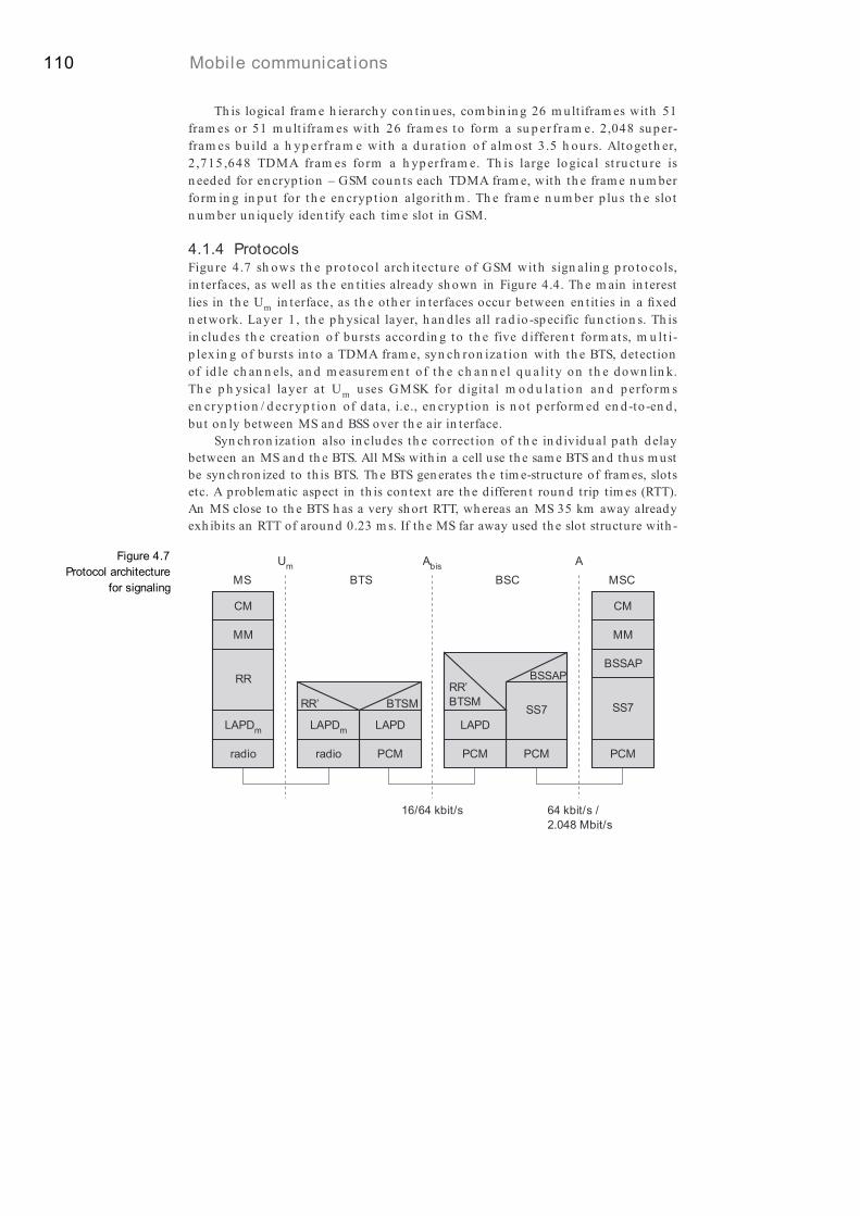
Th is logical fram e h ierarch y con tin ues, com bin in g 26 m ult ifram es with 51fram es or 51 m ult ifram es with 26 fram es to form a su p er fra m e. 2,048 su per-fram es bu ild a h yp er fra m e with a d u rat ion o f alm ost 3 .5 h ou rs. Altogeth er,2 ,715 ,648 TDMA fram es form a h yp erfram e. Th is large lo gica l st ru ctu re isn eeded for en crypt ion – GSM coun ts each TDMA fram e, with th e fram e n um berform in g in pu t for th e en cryp t ion algo rith m . Th e fram e n u m ber p lu s th e slo tn um ber un iquely iden t ify each t im e slot in GSM.4.1.4 ProtocolsFigu re 4.7 sh ows th e p ro tocol arch itectu re of GSM with sign alin g p ro to cols,in terfaces, as well as th e en tities already sh own in Figu re 4.4. Th e m ain in terestlies in th e Um in terface, as th e oth er in terfaces occur between en t it ies in a fixedn etwork. La yer 1 , th e p h ysical layer, h an dles all rad io -sp ecific fu n ct ion s. Th isin clud es th e creat ion o f bu rsts accord in g to th e five d ifferen t form ats, m u lt i-p lex in g of bursts in to a TDMA fram e, syn ch ron iza t ion with th e BTS, detectionof id le ch an n els, an d m easu rem en t of th e ch a n n el q u a lit y on th e down lin k.Th e p h ysica l layer at Um u ses GMSK for d igit al m o d u la t io n an d p erfo rm sen cry p t ion / d ecr yp t io n of data, i.e., en cryp t ion is n o t p erform ed en d-to-en d ,but on ly between MS an d BSS over th e air in terface.
Syn ch ron izat ion also in clu des th e correct ion of th e in d ividu al path d elaybetween an MS an d th e BTS. All MSs with in a cell use th e sam e BTS an d th us m ustbe syn ch ron ized to th is BTS. Th e BTS gen erates th e tim e-structure of fram es, slotsetc. A problem atic aspect in th is con text are th e differen t roun d trip tim es (RTT).An MS close to th e BTS h as a very sh ort RTT, wh ereas an MS 35 km away alreadyexh ibits an RTT of aroun d 0.23 m s. If th e MS far away used th e slot structure with -
Mobile communicat ions110
Abis
LAPDLAPDmPCMradio
BTSMRR’
BTS
SS7LAPD
PCMPCM
BSSAPRR’BTSM
BSC
16/64 kbit/s
Um A
LAPDmradio
RR
CMMM
MS
PCM
SS7
CMMM
MSC
BSSAP
64 kbit/s /2.048 Mbit/s
Figure 4.7Protocol architecture
for signaling

out correction , large guard spaces would be required, as 0.23 m s are already 40 percen t of th e 0.577 m s available for each slot. Th erefore, th e BTS sen ds th e curren tRTT to th e MS, wh ich th en adjusts its access tim e so th at all bursts reach th e BTSwith in th eir lim its. Th is m ech an ism reduces th e guard space to on ly 30.5 µs or fiveper cen t (see Figure 4.5). Adjustin g th e access is con trolled via th e variable t im in ga d va n ce, wh ere a bu rst can be sh ifted u p to 63 bit t im es earlier, with each bith avin g a duration of 3.69 µs (wh ich results in th e 0.23 m s n eeded). As th e variabletim in g advan ce can n ot be exten ded a burst can n ot be sh ifted earlier th an 63 bittim es. Th is results in th e 35 km m axim um distan ce between an MS an d a BTS. Itm igh t be possible to receive th e sign als over lon ger distan ces; to avoid collision s atth e BTS, access can n ot be allowed.5
Th e m ain tasks o f th e p h ysical layer com prise ch an n el co d in g an d er ro rd et ect ion / correct ion , wh ich is d irect ly com bin ed with th e codin g m ech an ism s.Ch an n el cod in g m akes ex ten sive u se o f d ifferen t fo r w a rd er r o r co r rect io n(FEC) sch em es. FEC adds red un dan cy to user data, allowin g for th e detect ionan d correction of selected errors. Th e power of an FEC sch em e depen ds on th eam oun t of red u n dan cy, cod in g algo rit h m an d fu rth er in terleavin g of data tom in im ize th e effects of burst errors. Th e FEC is also th e reason wh y error detec-t ion an d correct ion occurs in layer on e an d n ot in layer two as in th e ISO/OSIreferen ce m odel. Th e GSM ph ysical layer t ries to correct errors, bu t it does n otdeliver erron eous data to th e h igh er layer.
Differen t logical ch an n els of GSM use d ifferen t cod in g sch em es with differ-en t correct ion cap ab ilit ies. Sp eech ch an n els n eed add it ion al cod in g of vo iced at a aft er an alo g t o d igit al co n version , t o ach ieve a d at a rat e o f 22.8 kb it / s(usin g th e 13 kbit / s from th e voice codec plus redun dan cy, CRC bits, an d in ter-leavin g (Goodm an , 1997). As voice was assum ed to be th e m ain service in GSM,th e ph ysical layer also con tain s special fun ction s, such as vo ice act ivit y d et ec-t ion (VAD), wh ich tran sm its voice data on ly wh en th ere is a voice sign al. Th ism ech an ism h elps to decrease in terferen ce as a ch an n el m igh t be silen t approxi-m ately 60 p er cen t o f th e t im e (u n d er t h e assu m p t io n t h at on ly o n e personspeaks at th e sam e t im e an d som e ext ra t im e is n eeded to switch between th espeakers). Du rin g p eriods of silen ce (e.g., if a u ser n eeds t im e to th in k beforet alkin g), t h e p h ysica l layer gen era t es a co m fo r t n o ise to fake a con n ect ion(com plete silen ce wou ld p robably con fuse a u ser), bu t n o actual t ran sm issiontakes p lace. Th e n o ise is even adap ted to th e cu rren t backgroun d n oise at th ecom m un icat ion partn er’s location .
All th is in terleavin g of data for a ch an n el to m in im ize in terferen ce du e toburst errors an d th e recurren ce pattern of a logical ch an n el gen erates a d elay fortran sm ission . Th e delay is about 60 m s for a TCH/FS an d 100 m s for a TCH/F9.6
Telecommunicat ion systems 111
5 A special t rick allows for larger cells. If th e t im in g advan ce for MSs th at are fu rth er away th an 35 kmis set to zero , th e bu rsts arrivin g from th ese MSs will fall in to th e followin g t im e slot . Recep t ion ofdata is sim p ly sh ifted on e t im e slot an d again th e t im in g advan ce m ay be u sed up to a d istan ce of70 km (un der sim plified assum ption s). Usin g th is special trick, th e capacity of a cell is decreased (n earan d far MSs can n ot be m ixed arbit rarily), bu t coverage of GSM is exten ded . Network operators m aych oose th is approach , e.g., in coastal region s.

(with in 100 m s sign als in fixed n etworks easily t ravel aroun d th e globe). Th esetim es h ave to be added to th e tran sm ission delay if com m un icatin g with an MSin stead of a stan dard fixed stat ion (teleph on e, com puter etc.) an d m ay in fluen ceth e perform an ce of an y h igh er layer protocols, e.g., for com puter data t ran sm is-sion (see ch apter 9).
Sign alin g between en t it ies in a GSM n etwork req u ires h igh er layers (seeFigu re 4.7). Fo r th is pu rpose, th e LAPDm p ro tocol h as been defin ed at th e Umin terface for layer tw o. LAPDm , as th e n am e already im plies, h as been derivedfrom lin k access procedure for th e D-ch an n el (LAPD) in ISDN system s, wh ich is aversion of HDLC (Goodm an , 1997), (Halsall, 1996). LAPDm is a ligh tweigh t LAPDbecau se it does n ot n eed syn ch ron izat ion flags or ch ecksum m in g for error detec-tion . (Th e GSM ph ysical layer already perform s th ese tasks.) LAPDm offers reliabledata t ran sfer over con n ect ion s, re-sequen cin g of data fram es, an d flow con trol(ETSI, 1993b), (ETSI, 1993c). As th ere is n o bufferin g between layer on e an d two,LAPDm h as to obey th e fram e structures, recurren ce pattern s etc. defin ed for th eUm in terface. Fu rth er services p rovid ed by LAPDm in clu d e segm en tat ion an dreassem bly of data an d ackn owledged/un ackn owledged data tran sfer.
Th e n etwork layer in GSM, la yer t h r ee , com p rises several su b layers asFigure 4.7 sh ows. Th e lowest sublayer is th e rad io resou rce m an agem en t (RR).On ly a part of th is layer, RR’, is im p lem en ted in th e BTS, th e rem ain der is situ -at ed in t h e BSC. Th e fu n ct ion s of RR’ are su p p orted by t h e BSC via t h e BTSm a n a gem en t (BTSM ). Th e m ain t asks of RR are setu p , m ain ten an ce, an drelease of rad io ch an n els. RR also d irect ly accesses th e ph ysical layer for rad ioin form ation an d offers a reliable con n ection to th e n ext h igh er layer.
Mobility m an agem en t (MM) con tain s fun ction s for registration , au th en tica-tion , iden tification , location updatin g, an d th e provision of a t em p orary m ob ilesu b scrib er id en t it y (TMSI) th at rep laces th e in t ern a t ion a l m ob ile su b scr ib erid en t ity (IMSI) an d wh ich h ides th e real iden tity of an MS user over th e air in ter-face. W h ile th e IMSI iden t ifies a u ser, t h e TMSI is valid on ly in th e cu rren tlocation area of a VLR. MM offers a reliable con n ection to th e n ext h igh er layer.
Fin ally, th e ca ll m an agem en t (CM) layer con tain s th ree en tit ies: ca ll con -t ro l (CC), sh o rt m essage service (SMS), an d su p p lem en tary service (SS). SMSallows for m essage tran sfer u sin g th e con trol ch an n els SDCCH an d SACCH (ifn o sign alin g d at a is sen t ), wh ile SS offers th e services d escrib ed in sect ion4.1.1.3. CC p rovides a poin t-to-poin t con n ection between two term in als an d isu sed by h igh er layers fo r call estab lish m en t , call clearin g an d ch an ge of callparam eters. Th is layer also provides fun ct ion s to sen d in -ban d ton es, called d u a lton e m u lt ip le frequ en cy (DTMF), over th e GSM n etwork. Th ese ton es are used,e.g., for th e rem ote con trol of an swerin g m ach in es or th e en try of PINs in elec-t ron ic ban kin g an d are, also u sed for d ialin g in t rad it ion al an alog telep h on esystem s. Th ese ton es can n ot be sen t d irectly over th e voice codec of a GSM MS,as th e codec wou ld d istort th e ton es. Th ey are t ran sferred as sign als an d th encon verted in to ton es in th e fixed n etwork part of th e GSM system .
Mobile communicat ions112

Addition al p rotocols are used at th e Abis an d A in terfaces (th e in tern al in ter-faces of a GSM system n o t presen ted h ere). Data t ran sm ission at th e ph ysicallayer typ ically uses p u lse cod e m od u la t ion (PCM) system s. Wh ile PCM system soffer tran sparen t 64 kbit / s ch an n els, GSM also allows for th e subm ultip lexin g offour 16 kbit /s ch an n els in to a sin gle 64 kbit / s ch an n el (16 kbit /s are en ough foru ser data from an MS). Th e ph ysical layer at th e A in terface typ ically in cludesleased lin es with 2.048 Mbit/ s capacity. LAPD is used for layer two at Abis, BTSMfor BTS m an agem en t .
Sign a lin g syst em No. 7 (SS7) is used for sign alin g between an MSC an d aBSC. Th is p ro tocol also t ran sfers all m an agem en t in form at ion between MSCs,HLR, VLRs, AuC, EIR, an d OMC. An MSC can also con trol a BSS via a BSS ap p li-ca t ion p a rt (BSSAP). 4.1.5 Localizat ion and callingOn e fun dam en tal feature of th e GSM system is th e au tom atic, worldwide local-ization of users. Th e system always kn ows wh ere a user curren tly is, an d th e sam eph on e n um ber is valid worldwide. To provide th is service, GSM perform s peri-odic locat ion u pdates even if a u ser does n ot u se th e m obile stat ion (p rovidedth at th e MS is st ill logged in to th e GSM n etwork an d is n ot com pletely switch edoff). Th e HLR always con tain s in form ation about th e curren t location (on ly th elocat ion area, n o t th e p recise geograp h ical locat ion ), an d t h e VLR cu rren t lyrespon sible for th e MS in form s th e HLR abou t locat ion ch an ges. As soon as anMS m oves in to th e ran ge of a n ew VLR (a n ew location area), th e HLR sen ds alluser data n eeded to th e n ew VLR. Ch an gin g VLRs with un in terrupted availabilityof all services is also called roam in g. Roam in g can take place with in th e n etworkof on e p rovider, between two p roviders in on e cou n try (n at ion al roam in g is,often n ot su pp orted due to com pet it ion between operators), bu t also betweend ifferen t p rovid ers in d ifferen t cou n t ries (in tern at ion al roam in g). Typ ically,people associate in tern ation al roam in g with th e term roam in g as it is th is type ofroam in g th at m akes GSM very attractive: on e device, over 190 coun tries!
To locate an MS an d to address th e MS, several n um bers are n eeded:● Mob ile st a t ion in t ern a t ion a l ISDN n u m b er (MSISDN):6 Th e on ly im por-
tan t n u m ber fo r a u ser of GSM is th e p h on e n u m ber. Rem em ber th at th ep h on e n um ber is n o t associated with a cert ain d evice bu t with th e SIM,wh ich is p erson alized fo r a u ser. Th e MSISDN follows th e ITU-T stan dardE.164 for addresses as it is also u sed in fixed ISDN n etworks. Th is n u m bercon sist s o f t h e co u n t r y co d e (CC) (e.g., +49 179 1234567 with 49 fo rGerm an y), th e n a t io n a l d est in a t io n co d e (NDC) (i.e., th e address of th en etwork provider, e.g., 179), an d th e su b scriber n u m b er (SN).
Telecommunicat ion systems 113
6 In o th er types o f d ocu m en tat ion , th is n u m ber is also called ‘Mobile Su bscriber ISDN Nu m ber’ o r‘Mobile Stat ion ISDN Nu m ber’. Even th e origin al ETSI stan dards use differen t wordin gs for th e sam eacron ym . However, th e term ‘subscriber’ is m uch bet ter su ited as it expresses th e in depen den ce of th euser related n um ber from th e device (station ).

● In t ern a t io n a l m o b ile su b scr ib er id en t it y (IMSI): GSM u ses th e IMSI forin t ern al u n iq u e iden t ificat ion o f a su bscriber. IMSI con sists o f a m o b ileco u n t ry co d e (MCC) (e.g., 240 for Swed en , 208 fo r Fran ce), th e m o b ilen etw o rk cod e (MNC) (i.e., th e code of th e n etwork provider), an d fin allyth e m ob ile su bscrib er id en t ifi ca t ion n u m b er (MSIN).
● Tem p o ra r y m o b ile su b scr ib er id en t it y (TMSI): To h id e th e IMSI, wh ichwou ld give away th e exact iden tity of th e user sign alin g over th e air in ter-face, GSM uses th e 4 byte TMSI for local su bscriber iden tificat ion . TMSI isselected by th e curren t VLR an d is on ly valid tem porarily an d with in th elocation area of th e VLR (for an on goin g com m un ication TMSI an d LAI aresu fficien t to id en t ify a u ser; th e IMSI is n ot n eed ed). Add it ion ally, a VLRm ay ch an ge th e TMSI period ically.
● M o b ile st a t io n 7 ro a m in g n u m b er (M SRN): An o th er t em p o rary add ressth at h ides th e iden t ity an d location of a subscriber is MSRN. Th e VLR gen er-ates th is address on request from th e MSC, an d th e address is also stored inth e HLR. MSRN con tain s th e curren t visito r cou n t ry cod e (VCC), th e visi-t o r n a t ion a l d est in a t ion co d e (VNDC), th e iden t ificat ion o f th e cu rren tMSC togeth er with th e subscriber n um ber. Th e MSRN h elps th e HLR to fin da subscriber for an in com in g call.All th ese n um bers are n eeded to fin d a subscriber an d to m ain tain th e con -
n ect ion with a m obile stat ion . Th e in terest in g case is th e m ob ile t erm in a t edca ll (MTC), i.e., a situation in wh ich a stat ion calls a m obile stat ion (th e callin gstat ion could be outside th e GSM n etwork or an oth er m obile stat ion ). Figure 4.8sh ows th e basic step s n eed ed to con n ect t h e callin g stat ion with t h e m ob ileu ser. In step 1, a u ser d ials th e p h on e n u m ber of a GSM subscriber. Th e fixedn etwo rk (PSTN) n o t ices (lo okin g at t h e d est in at ion cod e) t h a t t h e n u m b erbelo n gs t o a u ser in t h e GSM n etwork an d fo rward s t h e call setu p t o t h eGateway MSC (2). Th e GMSC id en t ifies t h e HLR for t h e su bscriber (wh ich iscoded in th e ph on e n um ber) an d sign als th e call setup to th e HLR (3). Th e HLRn ow ch ecks wh eth er th e n um ber exists an d wh eth er th e user h as subscribed toth e requested services, an d requ ests an MSRN from th e cu rren t VLR (4). Afterreceivin g th e MSRN (5), th e HLR can determ in e th e MSC respon sible for th e MSan d forward s th is in form at ion to th e GMSC (6). Th e GMSC can n ow forwardth e call setup request to th e MSC in dicated (7).
Fro m th is p o in t o n , th e MSC is resp o n sib le for a ll fu rth er st ep s. First , itrequests th e cu rren t status of th e MS from th e VLR (8). If th e MS is available, th eMSC in it iates pagin g in all cells it is respon sible for (i.e. th e locat ion area, LA,10), a s search in g fo r t h e righ t cell wou ld be t oo t im e co n su m in g (bu t t h isapproach pu ts som e load on th e sign alin g ch an n els so opt im izat ion s exist). Th e
Mobile communicat ions114
7 Here, a discrepan cy exists between ITU-T stan dards an d ETSI’s GSM. MS can den ote m obile stationor m obile subscriber. Typ ically, alm ost all MS in GSM refer to subscribers, as iden t ifiers are n ot depen -den t on th e station , bu t on th e subscriber iden t ity (stored in th e SIM).

BTSs of all BSSs tran sm it th is pagin g sign al to th e MS (11). If th e MS an swers (12an d 13), th e VLR h as to perform secu rity ch ecks (set u p en crypt ion etc.). Th eVLR th en sign als to th e MSC to set up a con n ection to th e MS (steps 15 to 17).
It is m uch sim pler to perform a m obile origin a ted call (MOC) com pared to aMTC (see Figure 4.9). Th e MS tran sm its a request for a n ew con n ection (1), th e BSSforwards th is request to th e MSC (2). Th e MSC th en ch ecks if th is user is allowedto set up a call with th e requested service (3 an d 4) an d ch ecks th e availability ofresources th rough th e GSM n etwork an d in to th e PSTN. If all resources are avail-able, th e MSC sets up a con n ection between th e MS an d th e fixed n etwork.
Telecommunicat ion systems 115
HLR
GMSC
63
VLR
MSC1514
45
7
98
BSS
1310
11BSS11
BSS11
161010
MS
121117
PSTN2
callingstation 1
Figure 4.8Mobile terminatedcall (MTC)
MS
GMSC
BSS
MSC
110
5
92
PSTN 867
43
VLRFigure 4.9Mobile originatedcall (MOC)
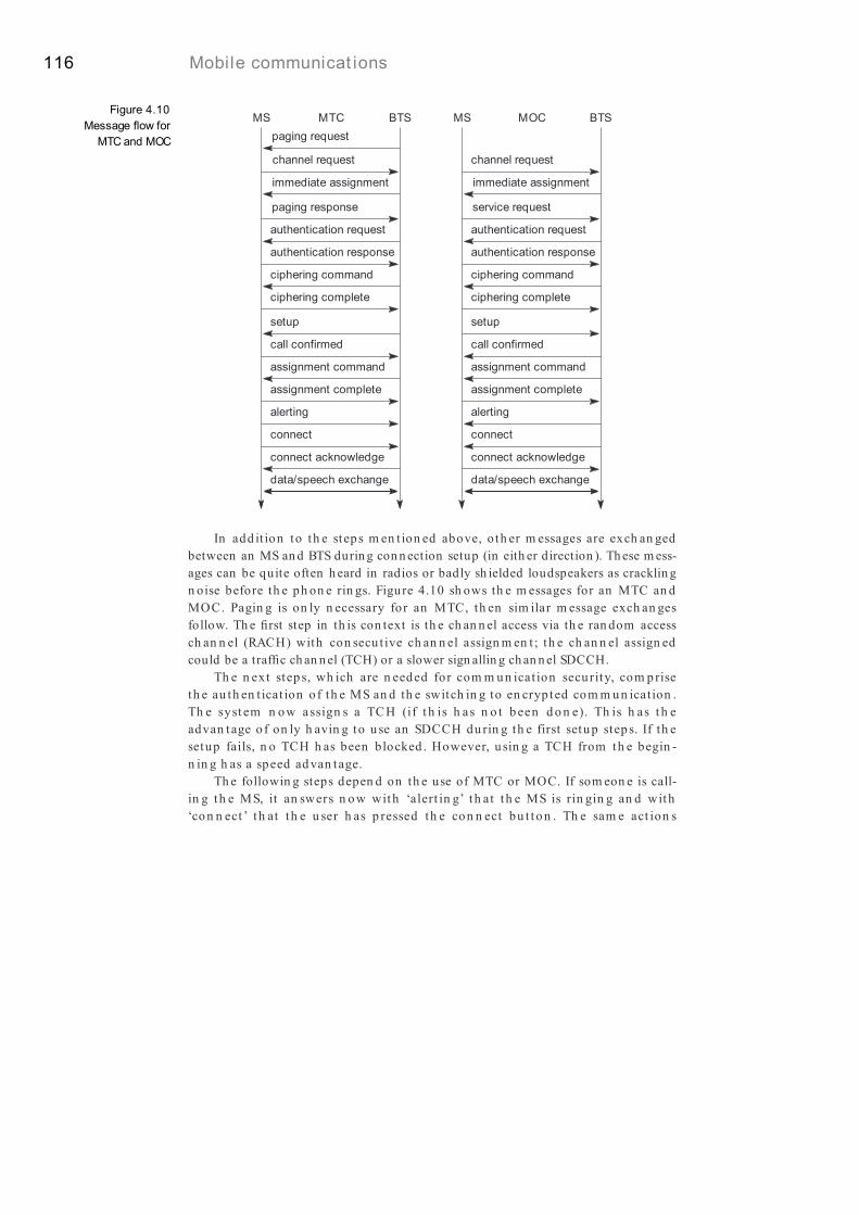
In add it ion to th e steps m en t ion ed above, o th er m essages are exch an gedbetween an MS an d BTS durin g con n ection setup (in eith er direction ). Th ese m ess-ages can be quite often h eard in radios or badly sh ielded loudspeakers as cracklin gn oise before th e ph on e rin gs. Figure 4.10 sh ows th e m essages for an MTC an dMOC. Pagin g is on ly n ecessary for an MTC, th en sim ilar m essage exch an gesfollow. Th e first step in th is con text is th e ch an n el access via th e ran dom accessch an n el (RACH) with con secu t ive ch an n el assign m en t ; th e ch an n el assign edcould be a traffic ch an n el (TCH) or a slower sign allin g ch an n el SDCCH.
Th e n ext step s, wh ich are n eeded for com m u n icat ion secu rity, com p riseth e au th en t icat ion o f th e MS an d th e switch in g to en cryp ted com m u n ication .Th e syst em n ow assign s a TCH (if t h is h as n o t b een d o n e). Th is h as t h eadvan tage o f on ly h avin g to u se an SDCCH du rin g th e first setu p step s. If th esetup fails, n o TCH h as been blocked . However, u sin g a TCH from th e begin -n in g h as a speed ad van tage.
Th e followin g steps depen d on th e use of MTC or MOC. If som eon e is call-in g t h e MS, it an swers n o w with ‘alert in g’ t h at t h e MS is rin gin g an d with‘co n n ect ’ t h at t h e u ser h as p ressed th e con n ect bu t to n . Th e sam e act ion s
Mobile communicat ions116
BTSpaging requestchannel request
MS MTC
immediate assignmentpaging responseauthentication requestauthentication responseciphering commandciphering completesetupcall confirmedassignment commandassignment completealertingconnectconnect acknowledgedata/speech exchange
BTS
channel request
MS MOC
immediate assignmentservice requestauthentication requestauthentication responseciphering commandciphering completesetupcall confirmedassignment commandassignment completealertingconnectconnect acknowledgedata/speech exchange
Figure 4.10Message flow for
MTC and MOC

h appen th e oth er way roun d if th e MS h as in it iated th e call. After con n ectionackn owledgem en t, bo th part ies can exch an ge data.
Closin g th e con n ection com prises a user-in it iated d iscon n ect m essage (bothsides can do th is), followed by releasin g th e con n ect ion an d th e rad io ch an n el.4.1.6 HandoverCellu lar system s requ ire h a n d over procedu res, as sin gle cells do n ot cover th ewh ole service area, b u t , e.g., on ly u p to 35 km arou n d each an ten n a o n t h ecoun tryside an d som e h un dred m eters in cit ies (Tripath i, 1998). Th e sm aller th ecell size an d th e faster th e m ovem en t of a m obile station th rough th e cells (upto 250 km / h for GSM), t h e m o re h an d overs o f on go in g ca lls are req u ired .Ho wever, a h an d over sh ou ld n ot cau se a cu t -o ff, also called ca ll d ro p . GSMaim s at m axim um h an dover du ration of 60 m s.
Th ere are two basic reason s for a h an dover (about 40 h ave been iden tifiedin th e stan dard):● Th e m obile stat ion m oves ou t of t h e ran ge of a BTS or a certain an ten n a of
a BTS respectively. Th e received sign a l level decreases con t in uously un til itfalls below th e m in im al requ irem en ts for com m un icat ion . Th e er ro r ra t em ay gro w d u e t o in t erferen ce, t h e d ist an ce t o th e BTS m ay be t o o h igh(m ax. 35 km ) etc. – all th ese effects m ay dim in ish th e q u alit y of t h e rad iolin k an d m ake radio tran sm ission im possible in th e n ear fu ture.
● Th e wired in frast ructure (MSC, BSC) m ay decide th at th e t raffic in on e cellis t oo h igh an d sh ift som e MS to oth er cells with a lower load (if possible).Han dover m ay be due to load b a lan cin g.Figure 4.11 sh ows fou r possible h an dover scen arios in GSM:
● In t ra -cell h a n d o ver: With in a cell, n arrow-ban d in terferen ce cou ld m aketran sm ission at a certain frequen cy im possible. Th e BSC could th en decideto ch an ge th e carrier frequen cy (scen ario 1).
● In t er -cell, in t r a -BSC h a n d o ver : Th is is a typ ical h an d over scen ario. Th em obile stat ion m oves from on e cell to an oth er, but stays with in th e con trolof th e sam e BSC. Th e BSC th en perform s a h an dover, assign s a n ew rad ioch an n el in th e n ew cell an d releases th e old on e (scen ario 2).
● In ter-BSC, in t ra-MSC h an d over: As a BSC on ly con trols a lim ited n um ber ofcells; GSM also h as to perform h an dovers between cells con trolled by differ-en t BSCs. Th is h an dover th en h as to be con trolled by th e MSC (scen ario 3).Th is situation is also sh own in Figure 4.13.
● In t er MSC h a n d o v er : A h an do ver cou ld be req u ired between two cellsbelon gin g t o d ifferen t MSCs. No w bo th MSCs perfo rm th e h an do vertogeth er (scen ario 4).
Telecommunicat ion systems 117
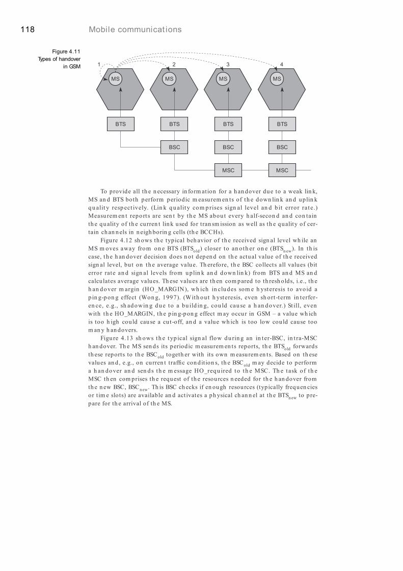
To provide all th e n ecessary in form ation for a h an dover due to a weak lin k,MS an d BTS both perform periodic m easurem en ts of th e down lin k an d uplin kq u alit y resp ect ively. (Lin k q u alit y co m p rises sign al level an d b it error ra t e.)Measurem en t report s are sen t by th e MS abou t every h alf-secon d an d con tainth e qu ality of th e curren t lin k used for tran sm ission as well as th e quality of cer-tain ch an n els in n eigh borin g cells (th e BCCHs).
Figure 4.12 sh ows th e typical beh avior of th e received sign al level wh ile anMS m oves away from on e BTS (BTSold) closer to an oth er on e (BTSn ew). In th iscase, th e h an dover decision does n ot depen d on th e actual value of th e receivedsign al level, bu t on th e average value. Th erefore, th e BSC collects all values (biterror rate an d sign al levels from u plin k an d down lin k) from BTS an d MS an dcalcu lates average values. Th ese values are th en com pared to th resh olds, i.e., th eh an do ver m argin (HO_MARGIN), wh ich in clu des som e h yst eresis to avo id ap in g-p on g effect (Won g, 1997). (With out h ysteresis, even sh ort -t erm in terfer-en ce, e.g., sh ad owin g d u e t o a bu ild in g, cou ld cau se a h an d over.) St ill, evenwith th e HO_MARGIN, th e p in g-pon g effect m ay occur in GSM – a value wh ichis too h igh cou ld cause a cu t-off, an d a value wh ich is too low could cause toom an y h an dovers.
Figu re 4.13 sh ows th e typ ical sign al flow d u rin g an in ter-BSC, in t ra-MSCh an dover. Th e MS sen ds its periodic m easurem en ts reports, th e BTSold forwardsth ese reports to th e BSCold togeth er with its own m easu rem en ts. Based on th esevalues an d , e.g., on cu rren t traffic con d it ion s, th e BSCold m ay decide to performa h an do ver an d sen d s t h e m essage HO_req u ired t o t h e MSC. Th e task of t h eMSC th en com prises th e request of th e resources n eeded for th e h an dover fromth e n ew BSC, BSCn ew. Th is BSC ch ecks if en ough resources (typ ically frequen ciesor t im e slots) are available an d act ivates a ph ysical ch an n el at th e BTSn ew to pre-pare for th e arrival of th e MS.
Mobile communicat ions118
MS4
BTS
MS3
BTS
MS2
BTS
MS1
BTS
BSCBSCBSC
MSCMSC
Figure 4.11Types of handover
in GSM

Th e BTSn ew ackn o wled ges t h e su ccessfu l ch an n el act iva t ion , BSCn ewackn owledges th e h an dover request . Th e MSC th en issues a h an dover com m an dth at is forwarded to th e MS. Th e MS n ow breaks its old radio lin k an d accessesth e n ew BTS. Th e n ext steps in clude th e establish m en t of th e lin k (th is in cludeslayer two lin k establish m en t an d h an d over com p lete m essages from th e MS).Basically, th e MS h as th en fin ish ed th e h an dover, bu t it is im portan t to releaseth e resou rces at t h e o ld BSC an d BTS an d to sign al th e su ccessfu l h an d overusin g th e h an dover an d clear com plete m essages as sh own .
More sop h ist ica t ed h an d over m ech an ism s are n eed ed fo r seam lessh an d overs between d ifferen t syst em s. Fo r exam p le, fu tu re 3G n etwo rks willn ot cover wh ole cou n t ries bu t focus on cit ies an d h igh ways. Han d over from ,
Telecommunicat ion systems 119
receive levelBTSold
receive levelBTSnew
MS MS
HO_MARGIN
BTSold BTSnew
Figure 4.12Handover decisiondepending onreceive level
BSCold
HO required
MSC BSCnew BTSnew
HO request
BTSoldMSmeasurementresult
measurementreport
HO decision
resource allocationch. activation
ch. activation ackHO request ackHO commandHO access
HO commandHO commandLink establishment
HO completeHO completeclear commandclear commandclear complete clear complete
Figure 4.13Intra-MSC handover

e.g., UMTS to GSM with ou t service in terru pt ion m ust be p ossib le. Even m orech allen gin g is th e seam less h an dover between wireless LANs (see ch apter 7) an d2G/3G n etworks. Th is can be don e usin g m ult im ode m obile stat ion s an d a m oresoph ist icated roam in g in frastructu re. However, it is still n ot obvious h ow th esesystem s m ay scale for a large n u m ber of u sers an d m an y h an dovers, an d wh ath an dover quality guaran tees th ey can give.4.1.7 SecurityGSM offers several security services usin g con fiden tial in form ation stored in th eAuC an d in th e in dividual SIM (wh ich is plugged in to an arbitrary MS). Th e SIMstores person al, secret data an d is protected with a PIN again st un auth orized use.(For exam ple, th e secret key Ki used for auth en tication an d en cryption proceduresis stored in th e SIM.) Th e security services offered by GSM are explain ed below:● Access con tro l an d au th en t ica t ion : Th e first step in cludes th e au th en tica-
tion of a valid user for th e SIM. Th e user n eeds a secret PIN to access th e SIM.Th e n ext step is th e subscriber au th en ticat ion (see Figure 4.10). Th is step isbased on a ch allen ge-respon se sch em e as p resen ted in section 4.1.7.1.
● Con fid en t iality: All user-related data is en crypted. After auth en tication , BTSan d MS apply en cryption to voice, data, an d sign alin g as sh own in section4.1.7.2. Th is con fiden tiality exists on ly between MS an d BTS, but it does n otexist en d-to-en d or with in th e wh ole fixed GSM/teleph on e n etwork.
● An on ym ity: To p rovide user an on ym ity, all data is en crypted before tran s-m ission , an d user iden t ifiers (wh ich would reveal an iden tity) are n ot u sedover th e air. In stead , GSM tran sm its a tem porary iden t ifier (TMSI), wh ich isn ewly assign ed by th e VLR after each location update. Add it ion ally, th e VLRcan ch an ge th e TMSI at an y t im e.Th ree algorith m s h ave been specified to p rovide secu rity services in GSM.
Algo r it h m A3 is used for a u t h en t ica t io n , A5 for en cryp t ion , an d A8 for th egen era t ion of a cip h er k ey. In th e GSM stan dard on ly algorith m A5 was pub-licly availab le, wh ereas A3 an d A8 were secret , bu t st an dard ized with o p enin terfaces. Both A3 an d A8 are n o lon ger secret , bu t were publish ed on th e in ter-n et in 1998. Th is dem on strates th at security by obscurity does n ot really work.As it tu rn ed out, th e algorith m s are n ot very stron g. However, n etwork providerscan u se st ro n ger algo rit h m s for au th en t icat ion – or u sers can app ly st ron geren d -t o -en d en cryp t ion . Algo rit h m s A3 an d A8 (o r t h eir rep lacem en t s) arelocated on th e SIM an d in th e Au C an d can be p rop rietary. On ly A5 wh ich isim p lem en ted in th e devices h as to be iden tical for all p roviders.4.1.7.1 Authent icat ionBefore a subscriber can use an y service from th e GSM n etwork, h e or sh e m ust beauth en ticated . Au th en tication is based on th e SIM, wh ich stores th e in d ivid u a lau th en ticat ion key Ki, th e u ser id en t ification IMSI, an d th e algorith m used forauth en tication A3. Auth en ticat ion uses a ch allen ge-respon se m eth od: th e access
Mobile communicat ions120

con trol AC gen erates a ran dom n um ber RAND as ch allen ge, an d th e SIM with inth e MS an swers with SRES (sign ed respon se) as respon se (see Figure 4.14). Th e AuCperform s th e basic gen eration of ran dom values RAND, sign ed respon ses SRES, an dciph er keys Kc for each IMSI, an d th en forwards th is in form ation to th e HLR. Th ecurren t VLR requests th e appropriate values for RAND, SRES, an d Kc from th e HLR.
For au th en t icat io n , t h e VLR sen d s t h e ran d o m valu e RAND to th e SIM.Both sides, n etwork an d su bscriber m od ule, p erform th e sam e operation withRAND an d th e key Ki, called A3. Th e MS sen ds back th e SRES gen erated by th eSIM; t h e VLR can n o w com p are b oth valu es. If t h ey are t h e sam e, t h e VLRaccepts th e subscriber, oth erwise th e subscriber is rejected .4.1.7.2 Encrypt ionTo en su re p rivacy, all m essages con t ain in g u ser-rela t ed in fo rm at ion areen cryp ted in GSM over th e air in terface. After au th en tication , MS an d BSS canstart u sin g en cryp t ion by ap p lyin g t h e cip h er key Kc (th e p recise locat ion o fsecurity fun ction s for en cryption , BTS an d/or BSC are ven dor depen den t). Kc isgen erated usin g th e in dividual key Ki an d a ran dom value by applyin g th e algo-rith m A8. Note th at th e SIM in th e MS an d th e n etwork both calcu late th e sam eKc based on th e ran d om value RAND. Th e key Kc itself is n ot tran sm itted overth e air in terface.
Telecommunicat ion systems 121
RAND128 bit
Ki
128 bit
A3
SRES* 32 bit
SRES*=? SRES
AC
MSC
Ki
128 bitRAND
128 bit
A3
SRES 32 bit
SRESSRES32 bit
RAND
SIM
mobile network SIM
Figure 4.14Subscriberauthentication

MS an d BTS can n ow en cryp t an d decrypt data usin g th e algorith m A5 an dth e ciph er key Kc. As Figure 4.15 sh ows, Kc sh ould be a 64 bit key – wh ich is n otvery st ron g, bu t is at least a go o d p ro t ect ion again st sim p le eavesd ro p p in g.However, th e pu blicat ion of A3 an d A8 on th e in tern et sh owed th at in certainim plem en tat ion s 10 of th e 64 bits are always set to 0, so th at th e real len gth ofth e key is th us on ly 54 con sequen tly, th e en cryption is m uch weaker.4.1.8 New data servicesAs m en tion ed above, th e stan dard ban dwidth of 9.6 kbit/s (14.4 kbit /s with som eproviders) available for data tran sm ission is n ot sufficien t for th e requirem en ts oftoday’s com puters. Wh en GSM was developed, n ot m an y people an ticipated th etrem en dous growth of data com m un ication com pared to voice com m un ication .At th at t im e, 9.6 kbit / s was a lot , o r at least en ou gh fo r st an dard grou p 3 faxm ach in es. Bu t with th e req uirem en ts of, e.g., web browsin g, file down load , oreven in ten sive e-m ail exch an ge with at tach m en ts, th is is n ot en ough .
To en h an ce th e data tran sm ission capabilit ies of GSM, two basic approach esare possible. As th e basic GSM is based on con n ection -orien ted traffic ch an n els,e.g., with 9.6 kbit /s each , several ch an n els could be com bin ed to in crease ban d-width . Th is system is called HSCSD an d is presen ted in th e followin g sect ion . A
Mobile communicat ions122
RAND128 bit
Ki
128 bit
A8
Kc64 bit
A5
AC
BSS
128 bit
encrypteddata
RANDmobile network (BTS) MS with SIM
Ki
128 bitRAND
128 bit
A8
Kc64 bit
A5
SIM
MS
cipherkey
data data
Figure 4.15Data encryption

m ore progressive step is th e in troduct ion of packet-orien ted t raffic in GSM, i.e.,sh ift in g th e paradigm from con n ection s/ teleph on e th in kin g to packets/ in tern etth in kin g. Th e system , called GPRS, is p resen ted in section 4.1.8.2.4.1.8.1 HSCSDA straigh tforward im p rovem en t of GSM’s data t ran sm ission capabilit ies is h ighsp eed circu it sw it ch ed d a ta (HSCSD), wh ich is available with som e providers.In th is system , h igh er data rates are ach ieved by bun dlin g several TCHs. An MSreq u est s on e o r m o re TCHs fro m th e GSM n etwork, i.e., it allo ca t es severa lTDMA slo t s with in a TDMA fram e. Th is allocat ion can be asym m etrical, i.e.,m ore slots can be allocated on th e down lin k th an on th e up lin k, wh ich fits th etyp ical u ser beh avio r of d own load in g m o re d at a co m p ared t o u p load in g.Basically, HSCSD on ly requires software upgrades in an MS an d MSC (both h aveto be able to sp lit a t raffic st ream in to several st ream s, u sin g a sep arate TCHeach , an d to com bin e th ese stream s again ).
In th eory, an MS could use all eigh t slots with in a TDMA fram e to ach ievean a ir in ter face u ser ra te (AIUR) of, e.g., 8 TCH/F14.4 ch an n els or 115.2 kbit /s(ETSI, 1998e). On e p roblem of th is con figu ration is th at th e MS is requ ired tosen d an d receive at th e sam e t im e. Stan dard GSM does n ot require th is capabil-ity – u plin k an d down lin k slot s are always sh ifted for th ree slots. ETSI (1997a)specifies th e AIUR available at 57.6 kbit/ s (duplex) usin g four slots in th e uplin kan d down lin k (Table 4.2 sh ows th e perm it ted com bin at ion s of traffic ch an n elsan d allocated slots for n on -tran sparen t services).
Alth ou gh it app ears at t ract ive at first glan ce, HSCSD exh ibits som e m ajord isadvan tages. It st ill u ses th e con n ect ion -orien ted m ech an ism s of GSM. Th eseare n ot at all efficien t for com pu ter data t raffic, wh ich is typ ically bu rsty an dasym m et rical. W h ile d o wn lo ad in g a la rger file m ay req u ire all ch an n elsreserved, typical web browsin g would leave th e ch an n els id le m ost of th e t im e.Allocatin g ch an n els is reflected direct ly in th e service costs, as, on ce th e ch an -n els h ave been reserved , oth er users can n ot use th em .
Telecommunicat ion systems 123
AIUR TCH / F4.8 TCH / F9.6 TCH / F14.44.8 kbit/ s 1 – –9.6 kbit/ s 2 1 –
14.4 kbit/ s 3 – 119.2 kbit/ s 4 2 –28.8 kbit/ s – 3 238.4 kbit/ s – 4 –43.2 kbit/ s – – 357.6 kbit/ s – – 4
Table 4.2 Availabledata rates for HSCSDin GSM

For n ch an n els, HSCSD requires n tim es sign alin g durin g h an dover, con n ec-t ion setu p an d release. Each ch an n el is t reat ed sep arately. Th e p robabilit y ofblockin g or service degradat ion in creases durin g h an dover, as in th is case a BSCh as to ch eck resources for n ch an n els, n ot just on e. All in all, HSCSD m ay be anattractive in terim solu tion for h igh er ban dwidth an d rath er con stan t traffic (e.g.,file down load). However, it does n ot m ake m uch sen se for bursty in tern et trafficas lon g as a user is ch arged for each ch an n el allocated for com m un ication .4.1.8.2 GPRSTh e n ext step toward m ore flexible an d powerfu l data t ran sm ission avoids th eproblem s of HSCSD by bein g fully packet-orien ted. Th e gen era l p acket rad io ser-vice (GPRS) provides packet m ode t ran sfer for applicat ion s th at exh ibit t rafficp at t ern s su ch as freq uen t t ran sm ission o f sm all vo lu m es (e.g., typ ical webrequests) or in frequen t tran sm ission s of sm all or m edium volum es (e.g., typ icalweb respon ses) acco rd in g t o th e req u irem en t specificat ion (ETSI, 1998a).Com pared to exist in g data t ran sfer services, GPRS sh ou ld use th e exist in g n et-work resources m ore efficien tly for packet m ode application s, an d sh ould providea selection of QoS param eters for th e service requesters. GPRS sh ould also allowfor broadcast , m u lt icast , an d un icast service. Th e overall goal in th is con text isth e provision of a m ore efficien t an d , th u s, ch eaper packet t ran sfer service fortypical in tern et application s th at usually rely solely on packet tran sfer. Networkprovid ers typ ically support th is m odel by ch argin g on volum e an d n ot on con -n ectio n t im e as is u su al for trad it ion al GSM d ata services an d for HSCSD. Th em ain ben efit for u sers of GPRS is th e ‘always on ’ ch aracterist ic – n o con n ectionh as to be set up prior to data t ran sfer. Clearly, GPRS was driven by th e trem en -dous success of th e packet-orien ted in tern et , an d by th e n ew traffic m odels an dap p licat ion s. However, GPRS, as sh own in th e fo llowin g sect ion s, n eed s ad -dit ion al n etwork elem en ts, i.e., software an d h ardware. Un like HSCSD, GPRS doesn ot on ly represen t a software update to allow for th e bun dlin g of ch an n els, it alsorepresen ts a big step towards UMTS as th e m ain in tern al in frastructure n eeded forUMTS (in it s in it ial release) is exactly wh at GPRS uses (see section 4.4).
Th e m ain con cepts of GPRS are as follows (ETSI, 1998b). For th e n ew GPRSradio ch an n els, th e GSM system can allocate between on e an d eigh t t im e slotswith in a TDMA fram e. Tim e slots are n ot allocated in a fixed , p re-determ in edm an n er bu t on dem an d. All t im e slots can be sh ared by th e active users; up- an dd own lin k are allocated sep arately. Allocat ion of th e slo ts is based on cu rren tload an d operator preferen ces. Depen din g on th e codin g, a tran sfer rate of up to170 kbit / s is possible. For GPRS, operators often reserve at least a t im e slot percell to guaran t ee a m in im um d ata rate. Th e GPRS con cep t is in d epen d en t ofch an n el ch aracterist ics an d of th e type of ch an n el (t rad it ion al GSM t raffic orcon t ro l ch an n el), an d d oes n o t lim it th e m axim u m data rat e (on ly t h e GSMtran sp ort system lim it s t h e rate). All GPRS services can be u sed in p arallel tocon ven tion al services. Table 4.3 sh ows th e typ ical data rates available with GPRSif it is used togeth er with GSM (GPRS can also be used for oth er TDMA system s).
Mobile communicat ions124

In th e begin n in g, on ly codin g sch em es CS-1 an d CS-2 are available. Th e systemch ooses a codin g sch em e depen d in g on th e curren t error rate (CS-4 provides n oerror correction capabilit ies).
It sh ould be n oted th at th e real available data rate h eavily depen ds on th ecurren t load of th e cell as GPRS typically on ly uses idle t im e slots. Th e t ran sferrate depen ds on th e capabilit ies of th e MS as n ot all devices are able to sen d an dreceive at t h e sam e t im e. Table 4.4 gives exam ples for device classes togeth erwith th eir ability to u se t im e slo t s for sen d in g an d receivin g d at a. Th e m axi-m um possible n um ber of slots lim its th e t ran sfer rate even m ore. For exam ple, aclass 12 d evice m ay receive dat a u sin g 4 slo t s with in a GSM t im e fram e or itm ay sen d data usin g 4 slo ts. However, a m axim um n um ber of 5 slo ts m ay beused altogeth er. Usin g all 8 slot s for data en coded usin g CS-4 yields th e m axi-m u m rate of 171.2 kbit / s. Tod ay, a typ ical MS is a class 10 d evice u sin g CS-2,wh ich resu lts in a receivin g rate of 53.6 kbit/ s an d a sen din g rate of 26.8 kbit /s.
In ph ase 1, GPRS offers a p o in t -t o-p oin t (PTP) packet tran sfer service (ETSI,1998c). On e of th e PTP version s offered is th e PTP co n n ect io n o r ien t ed n et -w o rk serv ice (PTP-CONS), wh ich in clu d es th e ab ility of GPRS to m ain t ain avirtu al circu it u p on ch an ge of th e cell with in th e GSM n etwork. Th is type of
Telecommunicat ion systems 125
Codingscheme 1 slot 2 slots 3 slots 4 slots 5 slots 6 slots 7 slots 8 slots
CS-1 9.05 18.2 27.15 36.2 45.25 54.3 63.35 72.4CS-2 13.4 26.8 40.2 53.6 67 80.4 93.8 107.2CS-3 15.6 31.2 46.8 62.4 78 93.6 109.2 124.8CS-4 21.4 42.8 64.2 85.6 107 128.4 149.8 171.2
Table 4.3 GPRS datarates in kbit/ s
Class Receiving slots Sending slots Maximum number of slots1 1 1 22 2 1 33 2 2 35 2 2 48 4 1 510 4 2 512 4 4 5
Table 4.4 Examplesfor GPRS deviceclasses

service correspon ds to X.25, th e typ ical circu it-switch ed packet-orien ted tran sferprotocol available worldwide. Th e oth er PTP version offered is th e PTP con n ec-t io n less n et w o rk serv ice (PTP-CLNS), wh ich su pp ort s ap p licat ion s t h at arebased on th e In t ern et Pro to co l IP. Mult icast in g, called p o in t -t o -m u lt ip o in t(PTM) service, is left for GPRS ph ase 2.
Users of GPRS can specify a QoS-p rofi le. Th is determ in es th e service p rece-d en ce (h igh , n orm al, low), reliab ilit y cla ss an d d elay class of th e tran sm ission ,an d u ser d a t a t h ro u gh p u t . GPRS sh ou ld adaptively allocate radio resources tofu lfill t h ese u ser sp ecificat ion s. Table 4 .5 sh ows th e t h ree reliab ilit y classestogeth er with th e m axim u m probab ilit ies for a lost service data u n it (SDU), ad up licat ed SDU, an SDU ou t of th e origin al sequ en ce, an d t h e p robabilit y ofdeliverin g a corrupt SDU to th e h igh er layer. Reliability class 1 cou ld be used forvery erro r-sen sit ive ap p licat ion s th at can n o t p erform erro r correct ion s th em -selves. If ap p licat ion s exh ib it great er erro r t o leran ce, class 2 co u ld beap p rop riate. Fin ally, class 3 is th e ch oice for erro r-in sen sit ive ap p licat ion s orapplication s th at can h an d le error correction s th em selves.
Dela y with in a GPRS n etwork is in cu rred by ch an n el access delay, codin gfo r error correct io n , an d t ran sfer d elays in t h e fixed an d wireless p art o f t h eGPRS n etwork. Th e delay in troduced by extern al fixed n etworks is ou t of scope.However, GPRS does n ot p roduce addit ion al delay by bufferin g packets as store-an d -forward n etworks d o . If possib le, GPRS t ries to forward packets as fast aspossible. Table 4.6 sh ows th e specified m axim um m ean an d 95 percen tile delayvalues for packet sizes of 128 an d 1,024 byte. As we can clearly see, n o m atterwh ich class, a ll d elays are o rd ers o f m agn itu d e h igh er t h an fixed n etwo rkdelays. Th is is a very im portan t ch aracterist ic th at h as to be taken in to accoun twh en im p lem en t in g h igh er layer p ro tocols su ch as TCP on top of GPRS n et-works (see ch ap ter 9). Typ ical rou n d t rip t im es (RTT) in fixed n etworks are inth e order of 10 to 100 m s. Usin g real un loaded GPRS n etworks roun d t rip t im eso f well ab ove 1 s fo r even sm all p acket s (128–512 byt e) a re co m m on .Add it ion ally, GPRS exh ibit s a large jit ter com p ared to fixed n etworks (several100 m s are n ot u n com m on ). Th is ch aract erist ic h as a st ro n g im p act on u serexperien ce wh en , e.g., in teractive In tern et application s are used on top of GPRS.
Mobile communicat ions126
Reliability Lost SDU Duplicate SDU Out of sequence Corrupt SDU class probability probability SDU probability probability1 10–9 10–9 10–9 10–9
2 10–4 10–5 10–5 10–6
3 10–2 10–5 10–5 10–2
Table 4.5 Reliabilityclasses in GPRS
according to ETSI(1998c)

Fin ally, GPRS in clu d es several secu r it y ser v ices su ch as au th en t icat ion ,access con trol, user iden tity con fiden tiality, an d user in form ation con fiden tiality.Even a com pletely an on ym ou s service is possible, as, e.g., applied for road tollsystem s th at on ly ch arge a user via th e MS in depen den t of th e user’s iden tity.
Th e GPRS a rch it ectu re in t rodu ces two n ew n etwork elem en ts, wh ich arecalled GPRS su p p o r t n o d es (GSN) an d are in fact rou ters. All GSNs are in te-grated in to th e stan dard GSM arch itecture, an d m an y n ew in terfaces h ave beendefin ed (see Figure 4.16). Th e ga t ew ay GPRS su p p or t n od e (GGSN) is th e in ter-workin g u n it between th e GPRS n etwork an d extern al p ack et d a t a n et w o rk s(PD N). Th is n od e con ta in s ro u t in g in fo rm at ion for GPRS u sers, p erfo rm saddress con version , an d tun n els data to a u ser via en capsulat ion . Th e GGSN iscon n ected to extern al n etworks (e.g., IP or X.25) via th e Gi in terface an d t ran s-fers packets to th e SGSN via an IP-based GPRS backbon e n etwork (Gn in terface).
Th e oth er n ew elem en t is th e servin g GPRS su p p or t n o d e (SGSN) wh ichsu p p ort s t h e MS via t h e Gb in t erface. Th e SGSN, fo r exam p le, req u est s u seraddresses from th e GPRS regist er (GR), keeps t rack of th e in dividual MSs’ loca-t ion , is respon sible fo r collectin g billin g in form ation (e.g., coun tin g bytes), an dp erfo rm s several secu rit y fu n ct ion s su ch as access con t ro l. Th e SGSN is con -n ected to a BSC via fram e relay an d is basically on th e sam e h ierarch y level asan MSC. Th e GR, wh ich is typ ically a part of th e HLR, stores all GPRS-relevan tdata. GGSNs an d SGSNs can be com pared with h om e an d foreign agen ts, respec-t ively, in a m obile IP n etwork (see ch apter 8).
As sh own in Figu re 4.16, packet d at a is t ran sm it t ed from a PDN, via th eGGSN an d SGSN direct ly to th e BSS an d fin ally to th e MS. Th e MSC, wh ich isrespon sible for data t ran sp ort in th e t rad it ion al circu it -switch ed GSM, is on lyused for sign alin g in th e GPRS scen ario. Add it ion al in terfaces to furth er n etworkelem en ts an d oth er PLMNs can be foun d in ETSI (1998b).
Before sen d in g an y data over th e GPRS n etwork, an MS m u st at tach to it ,followin g th e procedu res of th e m ob ilit y m an agem en t . Th e at tach m en t proce-du re in cludes assign in g a tem poral iden t ifier, called a t em p ora ry lo gica l lin kid en t i t y (TLLI), an d a cip h er in g k ey seq u en ce n u m b er (CKSN) fo r dat aen cryption . For each MS, a GPRS con tex t is set up an d stored in th e MS an d in
Telecommunicat ion systems 127
SDU size 128 byte SDU size 1,024 byteDelay Mean 95 percent ile Mean 95 percent ileClass1 <0.5 s <1.5 s <2 s <7 s2 <5 s <25 s <15 s <75 s3 <50 s <250 s <75 s <375 s4 Unspecified
Table 4.6 Delayclasses in GRPSaccording to ETSI(1998c)

th e co rrespon din g SGSN. Th is con text com p rises th e statu s of th e MS (wh ichcan be ready, idle, or stan dby; ETSI, 1998b), th e CKSN, a flag in d icatin g if com -p ression is u sed , an d rout in g data (TLLI, th e rout in g area RA, a cell iden t ifier,an d a packet data ch an n el, PDCH, iden t ifier). Besides at tach in g an d detach in g,m o bilit y m an agem en t also com p rises fun ct ion s fo r au th en t icat ion , locat ionm an agem en t, an d ciph erin g (h ere, th e scope of ciph erin g lies between MS an dSGSN, wh ich is m ore th an in stan dard GSM). In id le m ode an MS is n ot reach -ab le an d a ll co n t ext is d elet ed . In t h e st a n d b y st at e on ly m ovem en t acro ssrou t in g areas is u pdated to t h e SGSN bu t n o t ch an ges o f th e cell. Perm an en tu pdat in g wou ld waste bat tery power, n o updat in g wou ld requ ire system -widep agin g. Th e update p rocedure in stan dby m od e is a com p rom ise. On ly in th eread y state every m ovem en t of th e MS is in dicated to th e SGSN.
Figure 4.17 sh ows th e p rotocol arch itectu re of th e t ran sm ission p lan e forGPRS. Arch itectu res for th e sign alin g p lan es can be foun d in ETSI (1998b). Alldata with in th e GPRS backbon e, i.e., between th e GSNs, is tran sferred usin g th eGPRS t u n n ellin g p ro t oco l (GTP). GTP can use two d ifferen t t ran sp ort p roto-cols, eith er th e reliable TCP (n eeded for reliable tran sfer of X.25 packets) or th en on -reliable UDP (used for IP packets). Th e n etwork protocol for th e GPRS back-bon e is IP (usin g an y lower layers). To adap t to th e d ifferen t ch aracterist ics ofth e u n derlyin g n etworks, th e su b n et w o rk d ep en d en t co n vergen ce p ro t o co l(SNDCP) is used between an SGSN an d th e MS. On top of SNDCP an d GTP, userpacket data is tun n eled from th e MS to th e GGSN an d vice versa. To ach ieve ah igh reliability of packet t ran sfer between SGSN an d MS, a special LLC is u sed,wh ich com prises ARQ an d FEC m ech an ism s for PTP (an d later PTM) services.
Mobile communicat ions128
SGSN
SGSNBSS GGSN
Gn
Gb Gn
PDN
Gi
MSC HLR/GR
EIRVLR
Um
MS
Figure 4.16GPRS architecture
reference model

A b ase sta t ion su bsyst em GPRS p ro tocol (BSSGP) is used to con vey rout-in g an d QoS-related in form at ion between th e BSS an d SGSN. BSSGP d oes n otp erfo rm erro r correct ion an d works on t op o f a fr a m e re la y (FR) n etwork.Fin ally, radio lin k depen den t p rotocols are n eeded to tran sfer data over th e Umin t erface. Th e ra d io l in k p ro t o co l (RLC) p rovid es a reliab le lin k, wh ile t h eMAC con tro ls access with sign alin g p roced u res for th e rad io ch an n el an d th em appin g of LLC fram es on to th e GSM ph ysical ch an n els. Th e rad io in ter face atUm n eeded for GPRS does n ot require fun dam en tal ch an ges com pared to stan -dard GSM (Brasch e, 1997), (ETSI, 1998d). However, several n ew logical ch an n elsan d th eir m appin g on to ph ysical resources h ave been defin ed. For exam ple, on eMS can allocate up to eigh t p ack et d a t a t ra ffic ch an n els (PDTCHs). Capacitycan be allocated on dem an d an d sh ared between circu it-switch ed ch an n els an dGPRS. Th is allocation can be don e dyn am ically with load supervision or altern a-t ively, capacity can be p re-allocated .
A very im p ortan t facto r for an y app licat ion workin g en d-to-en d is th at itd oes n ot ‘n o t ice’ an y det ails from th e GSM/ GPRS-relat ed in frast ru ctu re. Th eap plicat ion uses, e.g., TCP on top of IP, IP packets are tu n n eled to th e GGSN,wh ich forwards th em in to th e PDN. All PDNs forward th eir packets for a GPRSuser to th e GGSN, th e GGSN asks th e cu rren t SGSN for tun n el param eters, an dfo rward s t h e p ackets via SGSN to th e MS. Alth ou gh MSs u sin g GPRS m ay becon sidered as part of th e in tern et, on e sh ould kn ow th at operators typically per-form an address tran slat ion in th e GGSN usin g NAT. All MSs are assign ed privateIP addresses wh ich are th en tran slated in to global addresses at th e GGSN. Th eadvan tage of th is approach is th e in h eren t protection of MSs from attacks (th esubscriber typically h as to pay for traffic even if it origin ates from an at tack!) –p rivate ad dresses are n ot ro u t ed th rou gh th e in tern et so it is n o t p ossib le to
Telecommunicat ion systems 129
Gb
MAC FRradio
BSSGPRLC
BSS SGSNUm Gn
MACradio
MS GGSN Gi
UDP/TCPLLC
L1/L2FR
GTPSNDCP
IPBSSGP
L1/L2
IPUDP/TCP
GTPIP/X.25
LLCRLC
IP/X.25SNDCP
apps.
Figure 4.17GPRS transmissionplane protocolreference model

reach an MS from th e in t ern et . Th is is also a d isad van tage if an MS wan ts tooffer a service usin g a fixed, globally visible IP address. Th is is difficult with IPv4an d NAT an d it will be in t erest in g t o see h ow IPv6 is u sed fo r t h is p u rp ose(wh ile still protectin g th e MSs from outside attacks as air traffic is expen sive).
4.2 DECTAn oth er fully digital cellular n etwork is th e d igita l en h an ced cord less t elecom m u-n ica t ion s (DECT) system specified by ETSI (2002, 1998j, k), (DECT Forum , 2002).Form erly also called d igit a l Eu rop ean co rd less telep h o n e an d d igit a l Eu rop eancord less t elecom m u n icat ion s, DECT replaces older an alog cordless ph on e system ssuch as CT1 an d CT1+. Th ese an alog system s on ly en su red secu rity to a lim itedexten t as th ey did n ot use en cryption for data tran sm ission an d on ly offered a rela-t ively low capacity. DECT is also a m ore powerfu l alt ern ative to th e digital systemCT2, wh ich is m ain ly used in th e UK (th e DECT stan dard works th rough ou tEu rope), an d h as even been selected as on e of th e 3G can didates in th e IMT-2000fam ily (see section 4.4). DECT is m ain ly used in offices, on cam pus, at trade sh ows,or in th e h om e. Furth erm ore, access poin ts to th e PSTN can be establish ed with in ,e.g., railway stat ion s, large govern m en t bu ild in gs an d h ospitals, offerin g a m uchch eaper teleph on e service com pared to a GSM system . DECT could also be used tobridge th e last few h un dred m eters between a n ew n etwork operator an d custom ers.Usin g th is ‘sm all ran ge’ local loop , n ew com pan ies can offer th eir service with ou th avin g th eir own lin es in stalled in th e streets. DECT system s offer m an y differen tin terworkin g un its, e.g., with GSM, ISDN, or data n etworks. Curren tly, over 100 m il-lion DECT un its are in use (DECT, 2002).
A b ig d ifferen ce between DECT an d GSM exist s in t erm s o f cell d iam eteran d cell capacity. Wh ile GSM is design ed for ou tdoor use with a cell d iam eter ofup to 70 km , th e ran ge of DECT is lim ited to abou t 300 m from th e base stat ion(on ly aroun d 50 m are feasible in side buildin gs depen din g on th e walls). Due toth is lim ited ran ge an d addit ion al m u lt ip lexin g tech n iq ues, DECT can offer itsservice to som e 10,000 people with in on e km 2. Th is is a typ ical scen ario with ina big city, wh ere th ousan ds of offices are located in skyscrapers close togeth er.DECT also uses base stat ion s, bu t th ese base stat ion s togeth er with a m obile sta-t ion are in a price ran ge of €100 com p ared to several €10,000 for a GSM basestat ion . GSM base stat ion s can typ ically n ot be used by in d ividuals for privaten etworks. On e reason is licen sin g as all GSM frequen cies h ave been licen sed ton etwork operators. DECT can also h an dle h an dover, bu t it was n ot design ed towork at a h igh er sp eed (e.g., u p t o 250 km / h like GSM syst em s). Devicesh an dlin g GSM an d DECT exist bu t h ave n ever been a com m ercial success.
DECT works at a freq u en cy ran ge o f 1880–1990 MHz o fferin g 120 fu lld up lex ch an n els. Tim e d ivision du p lex (TDD) is ap p lied usin g 10 m s fram es.Th e frequen cy ran ge is subdivided in to 10 carrier frequen cies usin g FDMA, eachfram e bein g d ivid ed in to 24 slo t s u sin g TDMA. For t h e TDD m ech an ism ,
Mobile communicat ions130

12 slo t s are u sed as u p lin k, 12 slo t s as d own lin k (see Figu re 3.4). Th e d igitalm odulat ion sch em e is GMSK – each station h as an average tran sm ission powerof on ly 10 m W with a m axim um of 250 m W.4.2.1 System architectureA DECT system , m ay h ave various differen t ph ysical im plem en tation depen din gon its actu al u se. Differen t DECT en t it ies can be in tegrated in to on e ph ysicalu n it ; en t it ies can be d ist ribu ted , rep licated etc. However, all im plem en tat ion sare based on t h e sam e logical referen ce m o d el o f t h e syst em arch it ectu re assh own in Figu re 4.18. A glo b a l n et w o rk con n ects th e local com m u n icat ionstructure to th e outside world an d offers its services via th e in terface D1. Globaln etworks could be in tegrated services d igital n etworks (ISDN), public switch edteleph on e n etworks (PSTN), public lan d m obile n etworks (PLMN), e.g., GSM, orpacket switch ed public data n etwork (PSPDN). Th e services offered by th ese n et-works in clu d e t ran sp ort a t io n o f d at a an d t h e t ran slat ion o f ad d resses an drou tin g of data between th e local n etworks.
Lo ca l n et w o rk s in th e DECT con text o ffer local t elecom m un icat ion ser-vices t h a t can in clu d e everyth in g fro m sim p le swit ch in g t o in t elligen t callforward in g, address t ran slat ion etc. Exam ples for su ch n etworks are an alog ordigital p rivate bran ch exch an ges (PBXs) or LANs, e.g., th ose followin g th e IEEE802.x fam ily of LANs. As th e core of th e DECT system itself is qu ite sim p le, alltyp ical n etwork fun ction s h ave to be in tegrated in th e local or global n etwork,wh ere th e databases h om e d a t a b a se (HDB) an d visit o r d a t a b a se (VDB) arealso located . Both databases support m obility with fun ction s th at are sim ilar toth ose in th e HLR an d VLR in GSM system s. In com in g calls are au tom atically for-warded to th e curren t subsystem respon sible for th e DECT user, an d th e curren tVDB in form s th e HDB about ch an ges in location .
Telecommunicat ion systems 131
PA
PA
D4
PT
PT
D3
FT
FT
D2local
network
VDB
HDBD1
localnetwork
globalnetwork
Figure 4.18DECT systemarchitecture referencemodel
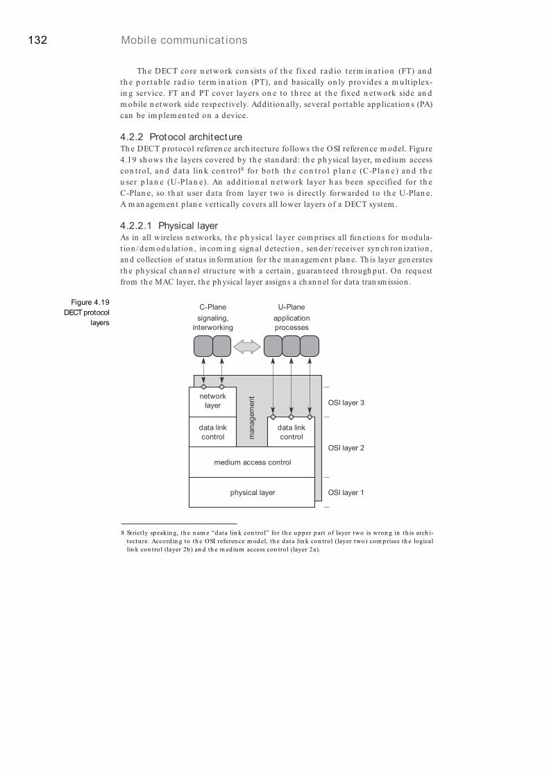
Th e DECT core n etwork con sists of th e fix ed rad io t erm in a t ion (FT) an dth e p o r t ab le rad io t erm in at ion (PT), an d basically on ly provides a m ult ip lex-in g service. FT an d PT cover layers on e to th ree at th e fixed n etwork side an dm obile n etwork side respectively. Addit ion ally, several portable applicat ion s (PA)can be im plem en ted on a device.4.2.2 Protocol architectureTh e DECT p rotocol referen ce arch itecture follows th e OSI referen ce m odel. Figure4.19 sh ows th e layers covered by th e stan dard: th e ph ysical layer, m edium accesscon tro l, an d d ata lin k con t ro l8 for bo th th e co n t ro l p la n e (C-Pla n e) an d th eu ser p la n e (U-Pla n e). An ad dit ion al n etwork layer h as been sp ecified for th eC-Plan e, so th at u ser data from layer two is d irect ly forwarded to th e U-Plan e.A m an agem en t plan e vertically covers all lower layers of a DECT system . 4.2.2.1 Physical layerAs in all wireless n etworks, th e p h ysica l layer com prises all fun ction s for m odula-t ion / dem odu lat ion , in com in g sign al detect ion , sen der/ receiver syn ch ron izat ion ,an d collection of status in form ation for th e m an agem en t plan e. Th is layer gen eratesth e ph ysical ch an n el structu re with a certain , guaran teed th rough put. On requestfrom th e MAC layer, th e ph ysical layer assign s a ch an n el for data tran sm ission .
Mobile communicat ions132
8 Strict ly speakin g, th e n am e “data lin k con trol” for th e upper part of layer two is wron g in th is arch i-tectu re. Accord in g to th e OSI referen ce m odel, th e data lin k con trol (layer two) com prises th e logicallin k con tro l (layer 2b) an d th e m edium access con trol (layer 2a).
C-Planesignaling,
interworking
networklayer
data linkcontrol
U-Planeapplicationprocesses
data linkcontrolma
nagem
ent
medium access control
physical layer
OSI layer 3
OSI layer 2
OSI layer 1
Figure 4.19DECT protocol
layers

Figu re 4.20 sh ows th e stan dard TDMA fram e st ru ctu re used in DECT an dsom e typical data packets. Each fram e h as a duration of 10 m s an d con tain s 12slo t s fo r t h e do wn lin k an d 12 slo t s fo r t h e u p lin k in t h e b a sic co n n ect io nm ode. If a m obile n ode receives data in slo t s, it retu rn s data in slot s+12. Anad van ced con n ect ion m ode allows differen t allocation sch em es. Each slot h asa du rat ion o f 0 .4167 m s an d can con t ain several d ifferen t p h ysical p acket s.Typically, 420 bits are used for data; th e rem ain in g 52 µs are left as gu ard sp ace.Th e 420 data bits are again d ivided in to a 32 bit syn ch ron iza t ion p a t t ern fol-lowed by th e d a t a field D.
Th e fields for data tran sm ission n ow use th ese rem ain in g 388 bits for n et -w ork con t ro l (A field), u ser d a t a (B field), an d th e tran sfer of th e t ran sm issionq u a li t y (X field ). W h ile n etwork co n t ro l is t ran sm it t ed with a d a ta ra t e o f6.4 kb it / s (64 b it each 10 m s), th e u ser d ata rate d ep en ds on ad dit ion al errorcorrection m ech an ism s. Th e sim p lex b ea rer provides a data rate of 32 kbit / s inan u n p ro tected m od e, wh ile u sin g a 16 bit CRC ch eck su m C for a data blockof 64 bit in th e p ro t ect ed m od e reduces th e data rate to 25.6 kbit /s. A d u p lexb earer service is produced by com bin in g two sim plex bearers. DECT also defin esbearer t yp es with h igh er t h ro u gh p u t s by co m bin in g slo t s, e.g., t h e d o u b led u p lex b ea rer offers 80 kbit / s fu ll-duplex.
Telecommunicat ion systems 133
1 frame = 10 ms
12 up slots12 down slots
slot0 419 guard 420 bit + 52 µs guard time (“60 bit” )in 0.4167 ms
sync0 31 D field0 387A field0 63 B field0 319 X field0 3A: network control
B: user dataX: transmission quality
DATA64
C16
DATA64
C16
DATA64
C16
DATA64
C16
DATA
protectedmodeunprotectedmode
25.6 kbit/ssimplex bearer32 kbit/s
Figure 4.20DECT multiplex andframe structure

4.2.2.2 Medium access cont rol layerTh e m ed iu m a ccess co n t ro l (MAC) layer establish es, m ain tain s, an d releasesch an n els for h igh er layers by activatin g an d deactivatin g ph ysical ch an n els. MACm u lt ip lexes several logical ch an n els on to p h ysical ch an n els. Logical ch an n elsexist for sign alin g n etwork con trol, u ser data t ran sm ission , pagin g, or sen d in gbroadcast m essages. Addition al services offered in clude segm en tation / reassem blyof packets an d error con trol/error correction . 4.2.2.3 Data link control layerTh e d a t a lin k con t ro l (DLC) layer creates an d m ain tain s reliable con n ect ion sbetween th e m o bile t erm in al an d t h e base st at ion . Two services h ave beendefin ed for th e C-Plan e: a co n n ect ion less b road cast service for pagin g (calledLb) an d a p o in t -t o-p o in t protocol sim ilar to LAPD in ISDN, but adapted to th eun derlyin g MAC (called LAPC+Lc).
Several services exist for th e U-Plan e, e.g., a tran sparen t un protected service(basically a n u ll service), a forward error correction service, rate adap tat ion ser-vices, an d services for fu tu re en h an cem en ts. If services are used , e.g., to tran sferISDN data at 64 kbit / s, th en DECT also t ries to t ran sfer 64 kbit / s. However, incase of errors, DECT raises th e t ran sfer rate to 72 kbit / s, an d in cludes FEC an d abu ffer for up to eigh t blocks to p erform ARQ. Th is bu ffer th en in t rodu ces anaddit ion al delay of up to 80 m s.4.2.2.4 Network layerTh e n etw ork layer of DECT is sim ilar to th ose in ISDN an d GSM an d on ly existsfor th e C-Plan e. Th is layer provides services to request , ch eck, reserve, con trol,an d release resources at th e fixed stat ion (con n ection to th e fixed n etwork, wire-less con n ect ion ) an d th e m obile t erm in al (wireless con n ect ion ). Th e m ob ilit ym an a gem en t (MM) with in th e n etwork layer is respon sible for iden t ity m an -agem en t, au th en tication , an d th e m an agem en t of th e location data bases. Ca llcon t ro l (CC) h an d les con n ection setup , release, an d n egotiat ion . Two m essageservices, th e con n ect io n o r ien t ed m essage serv ice (COMS) an d th e co n n ec-t io n less m essa ge ser vice (CLMS) t ran sfer d ata to an d from th e in terworkin gun it th at con n ects th e DECT system with th e outside world.
4.3 TETRATrun ked radio system s con stitu te an oth er m eth od of wireless data tran sm ission .Th ese system s use m an y differen t radio carriers but on ly assign a specific carrier toa certain user for a sh ort period of tim e accordin g to dem an d. Wh ile, for exam ple,t axi services, t ran sp ort com pan ies with fleet m an agem en t system s an d rescueteam s all h ave th eir own un ique carrier frequen cy in tradition al system s, th ey cansh are a wh ole group of frequen cies in trun ked radio system s for better frequen cyreuse via FDM an d TDM tech n iques. Th ese types of radio system s typically offer
Mobile communicat ions134

in terfaces to th e fixed teleph on e n etwork, i.e., voice an d data services, but are n otpublicly accessible. Th ese system s are n ot on ly sim pler th an m ost oth er n etworks,th ey are also reliable an d relatively ch eap to set up an d operate, as th ey on ly h aveto cover th e region wh ere th e local users operate, e.g., a city taxi service.
To allo w a com m on syst em th rou gh ou t Eu rop e, ETSI st an d ard ized t h eTETRA system (t er rest r ia l t ru n ked rad io )9 in 1991 (ETSI, 2002), (TETRA MoU,2002). Th is system sh ould replace n ation al system s, such as MODACOM, MOBI-TEX an d COGNITO in Europe th at typically con n ect to an X.25 packet n etwork.(An exam p le syst em from th e US is ARDIS.) TETRA offers two stan d ard s: th eVoice+Da ta (V+D) service (ETSI, 1998l) an d th e p acket d a ta op t im ized (PDO)service (ETSI, 1998m ). Wh ile V+D offers circu it -switch ed voice an d data tran s-m ission , PDO on ly offers packet data tran sm ission , eith er con n ect ion -orien tedto con n ect to X.25 or con n ection less for th e ISO CLNS (con n ection less n etworkservice). Th e lat ter service can be poin t-to-poin t or poin t-to-m ult ipoin t , th e typ-ical d elay for a sh o rt m essage (128 byte) bein g less t h an 100 m s. V+Dcon n ect ion m odes com prise un icast an d broadcast con n ection s, group com m u-n icat ion with in a certain protected group, an d a direct ad h oc m ode with ou t abase station . However, delays for sh ort m essages can be up to 500 m s or h igh erdepen din g on th e priority.
TETRA also offers bearer services of up to 28.8 kbit / s for un protected datatran sm ission an d 9.6 kbit / s for protected tran sm ission . Exam ples for en d-to-en dservices are call forwardin g, call barrin g, iden tification , call h old, call priorit ies,em ergen cy calls an d group join s. Th e system arch itectu re of TETRA is very sim i-lar to GSM. Via th e rad io in terface Um , th e m ob ile st a t ion (MS) con n ects to th esw it ch in g an d m a n a gem en t in fra st ru ctu re (Sw MI), wh ich con tain s th e u serdata bases (HDB, VDB), th e base stat ion , an d in terfaces to PSTN, ISDN, or PDN.Th e system itself, h owever, is m u ch sim pler in real im plem en tation com paredto GSM, as typ ically n o h an dover is n eeded . Taxis u sually rem ain with in a cer-tain area wh ich can be covered by on e TETRA cell.
Several freq u en cies h ave been sp ecified for TETRA wh ich u ses FDD (e.g.,380–390 MHz u p lin k/390–400 MHz down lin k, 410–420 MHz u p lin k/420–430MHz d own lin k). Each ch an n el h as a ban d wid th o f 25 kHz an d can carry36 kbit/ s. Modulation is DQPSK. Wh ile V+D uses up to fou r TDMA voice or datach an n els p er carrier, PDO perfo rm s st at ist ical m u lt ip lexin g. Fo r accessin g ach an n el, slot ted Aloh a is used.
Figure 4.21 sh ows th e typical TDMA fram e st ru ctu re of TETRA. Each fram econ sists of four slots (four ch an n els in th e V+D service per carrier), with a fram eduration of 56.67 m s. Each slot carries 510 bits with in 14.17 m s, i.e., 36 kbit/ s. 16fram es togeth er with on e con t rol fram e (CF) form a m u lt ifram e, an d fin ally, ah yp erfram e con tain s 60 m ultifram es. To avoid sen din g an d receivin g at th e sam etim e, TETRA sh ifts th e uplin k for a period of two slots com pared to th e down lin k.
Telecommunicat ion systems 135
9 Form erly kn own as t ran s-Eu ro p ean t ru n ked rad io , bu t world wid e m arket in g is bet t er with ou t“Europe” in th e n am e (see DECT).

TETRA offers t ra ffic ch an n els (TCH) an d con t ro l ch an n els (CCH) sim ilarto GSM. Typical TCHs are TCH/S for voice tran sm ission , an d TCH/7.2, TCH/4.8,TCH/2.4 for data tran sm ission (depen d in g on th e FEC m ech an ism s required).
However, in con trast to GSM, TETRA offers addition al services like group call,ackn owledged group call, broadcast call, an d discreet listen in g. Em ergen cy ser-vices n eed a sub-secon d group-call setup in h arsh en viron m en ts wh ich possiblylack all in frastructu re. Th ese features are curren tly n ot available in GSM or oth ertypical m obile teleph on e n etworks, so TETRA is com plem en tary to oth er system s.TETRA h as been ch osen by m an y govern m en t organ ization s in Europe an d Ch in a.
4.4 UMTS and IMT-2000A lot h as been writ ten about th ird gen erat ion (or 3G) n etworks in th e last fewyears. After a lot of h ype an d frustration th ese n etworks are curren t ly dep loyedin m an y cou n tries arou n d th e world . Bu t h ow d id it a ll st art? First o f all, th eIn tern ation al Telecom m un ication Un ion (ITU) m ade a request for proposals forrad io t ran sm ission tech n ologies (RTT) for th e in t ern a t io n a l m o b ile t eleco m -m u n ica t ion s (IMT) 2000 program (ITU, 2002), (Callen dar, 1997), (Sh afi, 1998).IMT-2000, form erly called future public lan d m obile telecom m un icat ion system(FPLMTS), tried to establish a com m on worldwide com m un ication system th atallowed for term in al an d u ser m obility, su p port in g th e id ea of u n iversal per-son al t elecom m u n icat ion (UPT). With in th is con text , ITU h as created severalrecom m en dat ion s for FPLMTS system s, e.g., n etwork arch itectu res for FPLMTS(M.817), Req u irem en t s fo r t h e Rad io In t erface(s) for FPLMTS (M.1034), o rFram ewo rk for Services Su pp orted by FPLMTS (M.816). Th e n u m ber 2000 inIMT-2000 sh ou ld in d icate th e start o f th e system (year 2000+x) an d th e sp ec-
Mobile communicat ions136
hyperframe... 57 58 59210 61.2 s
multiframe... 15 16 17210 1.02 s
210 3frame
56.67 ms
CF
slot 14.17 ms0 509
Figure 4.21TETRA frame
structure

t rum used (aroun d 2000 MHz). IMT-2000 in cludes differen t en viron m en ts suchas in door use, veh icles, satellit es an d p edest rian s. Th e world rad io con feren ce(W RC) 1992 id en t ified 1885–2025 an d 2110–2200 MHz as t h e frequ en cyban d s t h at sh ou ld b e availab le world wid e for th e n ew IMT-2000 syst em s(Recom m en dation ITU-R M.1036). With in th ese ban ds, two t im es 30 MHz h avebeen reserved for m obile satellite services (MSS).
Figure 4.22 sh ows th e ITU frequen cy allocation (from th e world adm in istra-t ive rad io con feren ce, 1992) togeth er with exam ples from several region s th atalready in dicate th e problem of worldwide com m on frequen cy ban ds. In Europe,som e parts of th e ITU’s frequen cy ban ds for IMT-2000 are already allocated forDECT (see section 4.2). Th e rem ain in g frequen cies h ave been split in to ban ds forUTRA-FDD (u plin k: 1920–1980 MHz, d own lin k: 2110–2170 MHz) an d UTRA-TDD (1900–1920 MHz an d 2010–2025 MHz). Th e tech n ology beh in d UTRA-FDDan d –TDD will subseq uen tly be explain ed in m ore detail as th ey form th e basis ofUMTS. Cu rren t ly, n o o th er system is p lan n ed for IMT-2000 in Eu rop e. Mo reban dwidth is available in Ch in a for th e Ch in ese 3G system TD-SCDMA or poss-ib ly o th er 3G t ech n o logies (su ch as W-CDMA or cd m a2000 – it is st ill op enwh ich system will dom in ate th e Ch in ese m arket; Ch en , 2002). Again sligh tly dif-feren t freq u en cies are u sed by t h e 3G services in Jap an , wh ich are based onW-CDMA (like UTRA-FDD) or cdm a2000. An open question is th e fu ture of 3G inth e US as th e ITU’s frequen cy ban ds h ave already been allocated for 2G n etworksor are reserved for oth er u se. In addit ion to th e origin al frequen cy allocation s,th e world rad io con feren ce (W RC) allocated n ew terrestrial IMT-2000 ban ds inth e ran ge o f 800–1000 MHz, 1700–1900 MHz an d 2500–2700 MHz in 2000.Th is approach in cludes th e reuse of 2G spectrum (Evci, 2001).
Telecommunicat ion systems 137
1850
ITU allocation(WRC 1992)
MHz1900 1950 2000 2050 2100 2150 2200
1850 MHz1900 1950 2000 2050 2100 2150 2200
MSS
MSS
MSS
MSS
MSS
MSS
MSS
MSS
MSS
MSS
rsv.
IMT-2000
UTRAFDD
IMT-2000
cdma2000W-CDMA
IMT-2000
TDDUTRAFDD
TDDDECT
GSM1800
GSM1800 IMT-2000
PHS cdma2000W-CDMA
PCSNorthAmerica
Japan
China
Europe
Figure 4.22IMT-2000 frequencies

Now th e reader m igh t be con fused by all th e d ifferen t t ech n ologies m en -t ion ed in th e con text of IMT-2000. Wasn ’t th e p lan to h ave a com m on globalsystem ? Th is was t h e origin al p lan , bu t aft er m an y p o lit ical d iscu ssion s an dfigh ts abou t p aten t s th is idea was d ropp ed an d a so-called fam ily of 3G stan -dards was adopted.
For th e RTT, several p roposals were received in 1998 for in door, pedestrian ,veh icu lar, an d satellite en viron m en ts. Th ese cam e from m an y d ifferen t organ -izat io n s, e.g., UW C-1 36 from th e Un iversal Wireless Com m u n icat ion sCon sortium (US) th at exten ds th e IS-136 stan dard in to th e th ird gen eration sys-tem s, cd m a 2000 th at is based on th e IS-95 system (US), an d wideban d packetCDMA (W P-CDMA) wh ich t ries t o align t o t h e Eu rop ean UTRA p rop o sal.Basically, t h ree b ig regio n s were su bm it t in g p rop osals t o t h e ITU: ETSI fo rEu rop e, ARIB (Associat ion o f Rad io In d u st ries an d Broad cast in g) an d TTC(Telecom m u n icat io n s Tech n o lo gy Cou n cil) fo r Jap an , an d ANSI (Am ericanNation al Stan dards In st itu te) for th e US.
Th e Eu rop ean p roposal for IMT-2000 p rep ared by ETSI is called u n iversa lm ob ile t elecom m u n ica t ion s syst em (UMTS) (Dasilva, 1997), (Ojan perä, 1998),th e sp ecific proposal for th e radio in terface RTT is UMTS (n ow : u n iversa l) t er-r est r i a l r a d io a ccess (UTRA) (ETSI, 1998n ), (UMTS Fo ru m , 2002). UMTS asin it ially proposed by ETSI rath er represen ts an evolu tion from th e secon d gen er-at ion GSM system to th e th ird gen erat ion th an a com pletely n ew system . In th isway, m an y solu tion s h ave been proposed for a sm ooth tran sit ion from GSM toUMTS, savin g m on ey by exten din g th e cu rren t system rath er th an in troducin g an ew on e (GSMMoU, 1998).
On e in it ial en h an cem en t of GSM toward UMTS was en h an ced d a ta ra t esfo r g lob a l (o r : GSM) ev o lu t io n (EDGE), wh ich u ses en h an ced m od u lat ionsch em es (8 PSK in stead of GSM’s GMSK, see ch apter 2) an d oth er tech n iques fordata rates of up to 384 kbit/ s usin g th e sam e 200 kHz wide carrier an d th e sam efrequen cies as GSM (i.e., a data rate of 48 kbit/ s per tim e slot is available). EDGEcan be in t roduced in crem en tally offerin g som e ch an n els with EDGE en h an ce-m en t th at can switch between EDGE an d GSM/GPRS. In Europe, EDGE was n everused as a step toward UMTS but operators directly jum ped on to UMTS. However,EDGE can also be applied to th e US IS-136 system an d m ay be a ch oice for opera-tors th at wan t to en h an ce th eir 2G system s (3G Am ericas, 2002).
Besid es en h an cin g d at a rat es, n ew ad d it ion s to GSM, like cu st o m izeda p p lica t io n fo r m o b ile en h a n ced logic (CAMEL) in t rod uce in telligen t n et -work support . Th is system supports, for exam ple, th e creation of a vir tu a l h om een viro n m en t (VH E) for visit in g su bscribers. GSMMoU (1998) p rovides m an yp rop o sals co verin g QoS asp ect s, roam in g, services, b illin g, accou n t in g, rad ioaspects, core n etworks, access n etworks, t erm in al requirem en ts, security, app li-cation dom ain s, operat ion an d m ain ten an ce, an d several m igration aspects.
UMTS fits in to a bigger fram ework developed in th e m id -n in eties by ETSI,called glob a l m u lt im ed ia m o b ilit y (GMM). GMM provides an arch itecture toin tegrate m ob ile an d fixed term in a ls, m an y d ifferen t a ccess n et w ork s (GSMBSS, DECT, ISDN, UMTS, LAN, WAN, CATV, MBS), an d several co re t ra n sp o r t
Mobile communicat ions138

n etw ork s (GSM NSS+IN, ISDN+IN, B-ISDN+TINA, TCP/ IP) (ETSI, 2002). With inth is fram ework, ETSI developed b a sic req u irem en t s for UMTS an d for UTRA,th e rad io in terface (ETSI, 1998h ). Key requirem en ts are m in im um data rates of144 kbit / s for rural ou tdoor access (with th e goal of 384 kbit / s) at a m axim u mspeed of 500 km /h .10 For suburban outdoor use a m in im um of 384 kbit / s sh ouldbe ach ieved with th e goal of 512 kbit / s at 120 km /h . For in door or city use withrelatively sh ort ran ges, up to 2 Mbit /s are required at 10 km /h (walkin g).
UMTS sh ou ld also p rovide several bearer services, real-t im e an d n on real-t im e services, circu it an d packet switch ed tran sm ission , an d m an y d ifferen t datarates. Han dover sh ou ld be possible between UMTS cells, but also between UMTSan d GSM or satellit e n etworks. Th e syst em sh ou ld be com p at ib le with GSM,ATM, IP, an d ISDN-based n etworks. To reflect th e asym m etric ban dwidth n eedsof typ ical users, UMTS sh ould provide a variable d ivision of up lin k an d down -lin k d ata rates. Fin ally, UMTS h as to fit in to th e IMT-2000 fram ework (th is isp robably t h e decisive facto r for it s su ccess). As t h e global UMTS ap proach israth er am bit iou s, a m ore realist ic a lt ern at ive fo r t h e in it ia l st ages wo u ld beUMTS cells in cit ies p rovid in g a subset of services.
Several com pan ies an d in terest groups h ave h an ded in proposals for UTRA(ETSI, 1998i), o f wh ich ETSI select ed two for UMTS in Jan u ary 1998. Fo r th ep a ired ban d (usin g FDD as a duplex m ech an ism ), ETSI adop ted th e W-CDMA(Wid eban d CDMA) p ro po sal, for t h e u n p a ired b a n d (u sin g TDD as d u p lexm ech an ism ) th e TD-CDMA (Tim e Division CDMA) p roposal is u sed (Adach i,1998), (Dah lm an , 1998), (ETSI, 1998n ). Th e p aired ban d is t yp ically used forpublic m obile n etwork p roviders (wide area, see GSM), wh ile th e un paired ban dis oft en used for local an d in d oor com m u n icat ion (see DECT). Th e followin gsection s will p resen t key propert ies of th e in it ial UMTS system .
W h at h appen ed to th e IMT-2000 fam ily? Figure 4.23 gives an overview. As asin gle st an d ard cou ld n ot be fou n d , t h e ITU st an d ard ized five gro u p s o f 3Gradio access tech n ologies. ● IMT-D S: Th e d ir ec t sp rea d t ech n o lo gy com p rises wid eban d CDMA (W -
CDMA) system s. Th is is th e tech n ology specified for UTRA-FDD an d usedby all European p roviders an d th e Japan ese NTT DoCoMo for 3G wide areaservices. To avoid com p let e con fu sion ITU’s n am e fo r t h e t ech n o logy isIMT-DS, ETSI called it UTRA-FDD in t h e UMTS con text , an d t ech n o lo gyu sed is called W-CDMA (in Jap an th is is p rom oted as FOMA, freed om ofm obile m ult im edia access). Today, stan dard izat ion of th is tech n ology takesplace in 3GPP (Th ird gen eration partn ersh ip project , 3GPP, 2002a). Sect ion4.4.1 provides m ore detail about th e stan dardization process.
● IMT-TC: In itially, th is fam ily m em ber, called t im e cod e, con tain ed on ly th eUTRA-TDD system wh ich uses t im e-d ivision CDMA (TD-CDMA). Later on ,t h e Ch in ese p rop osal, TD-syn ch ron ou s CDMA (TD-SCDMA) was ad d ed .
Telecommunicat ion systems 139
10 Th is speed is a problem as cu rren t ly, on ly DAB can provide h igh er bit rates at h igh speeds.

Both stan dards h ave been com bin ed an d 3GPP fosters th e developm en t ofth is tech n ology. It is un clear wh en an d to wh at exten t th is tech n ology willbe in troduced. Th e in it ial UMTS in stallat ion s are based on W-CDMA.
● IMT-MC: cdm a2000 is a m u lt i-ca r rier tech n ology stan dard ized by 3GPP2(Th ird gen erat ion partn ersh ip p ro ject 2, 3GPP2, 2002), wh ich was form edsh ort ly after 3GPP to represen t th e secon d m ain st ream in 3G tech n ology.Version cdm a2000 EV-DO h as been accepted as th e 3G stan dard .
● IMT-SC: Th e en h an cem en t of th e US TDMA system s, UW C-136, is a sin glec a r r ie r t ech n ology o rigin ally p ro m o ted b y t h e Un iversa l WirelessCom m un ication s Con sort ium (UWCC). It is n ow in tegrated in to th e 3GPPefforts. Th is tech n ology applies EDGE, am on g oth ers, to en h an ce th e 2G IS-136 stan dard.
● IMT-FT: As frequ en cy t im e tech n ology, an en h an ced version of th e cordlessteleph on e stan dard DECT h as also been selected for applicat ion s th at do n otrequire h igh m obility. ETSI is respon sible for th e stan dardization of DECT.Th e m ain drivin g forces in th e stan dardization process are 3GPP an d 3GPP2.
ETSI h as m oved its GSM stan dardization process to 3GPP an d plays a m ajor roleth ere. 3GPP ten ds to be dom in ated by European an d Japan ese m an ufacturers an dstan dardization bodies, wh ile 3GPP2 is dom in ated by th e com pan y Qualcom man d CDMA n etwork operators. Th e quarrels between Qualcom m an d Europeanm an u factu rers (e.g., Nokia, Ericsson ) regard in g CDMA p at en ts (UMTS an dcdm a2000 use CDMA) even escalated in to th e polit ical aren a back in 1998 (US vsEU). Everyth in g cooled down wh en h u n dreds of p aten ts h ad been exch an gedan d th e system s h ad been h arm on ized (e.g., CDMA ch ippin g rates).
Mobile communicat ions140
IMT-DS(Direct Spread)
UTRA FDD(W-CDMA);
3GPP
IMT-TC(Time Code)UTRA TDD(TD-CDMA);TD-SCDMA
3GPP
IMT-MC(Multi Carrier)
cdma20003GPP2
IMT-SC(Single Carrier)
UWC-136(EDGE)
UWCC/3GPP
IMT-FT(Freq. Time)
DECTETSI
IMT-2000RadioAccessITU-R
GSM(MAP)
ANSI-41(IS-634) IP-Network
IMT-2000Core NetworkITU-T
Interfacefor internetworking
Flexible assignment ofCore Network and Radio Access
Initial UMTS(R99 w/FDD)
Figure 4.23The IMT-2000
family

Figure 4.23 sh ows m ore th an just th e radio access tech n ologies. On e idea ofIMT-2000 is th e flexible assign m en t of a core n etwork to a rad io access system .Th e classical core n etwork uses SS7 for sign alin g wh ich is en h an ced by ANSI-41(cdm aOn e, cdm a2000, TDMA) or MAP (GSM) to en able roam in g between differ-en t operators. Th e evolu t ion toward 4G system s is in dicated by th e use of all-IPcore n etworks (see Ch apter 11). Obviou sly, in tern et-workin g fun ction s h ave tobe provided to en able cross-system data tran sfer, roam in g, billin g etc.4.4.1 UMTS releases and standardizat ionUMTS as d iscussed today an d in troduced in m an y coun tries relies on th e in it ialrelease of th e UMTS stan dard called release 99 or R99 for sh ort . Th is release ofth e sp ecificat ion describes th e n ew rad io access t ech n ologies UTRA FDD an dUTRA TDD, an d stan dard izes th e u se of a GSM/GPRS n etwork as co re with in440 separate specification s. Th is en ables a cost effective m igration from GSM toUMTS. Th e in it ial in stallat ion s will even offer th e FDD m ode on ly as in d icatedin Figure 4.23. Th is release was (alm ost) fin alized in 1999 – h en ce th e n am e R99.Th e followin g sect io n s will focu s on th is release as it is u n clear wh en , an d towh at exten t , th e followin g releases will be realized.
After R99 th e release 2000 or R00 followed. However, in Septem ber 2000 3GPPrealized th at it would be im possible to fin alize th e stan dard with in th e year 2000.3GPP decided to split R2000 in to two stan dards an d call th em release 4 (Rel-4) an drelease 5 (Rel-5). Th e version of all st an dards fin alized for R99 start with 3.x.y(a reason for ren am in g R99 in to Rel-3), Rel-4 an d Rel-5 version s start with 4.x.yan d 5.x.y, respectively. Th e stan dards are grouped in to series. For exam ple, radioaspects are specified in series 25, tech n ical realization in series 23, an d codecs inseries 26. Th e com plete stan dard n um ber (e.g., TS 25.401 V3.10.0) th en iden tifiesth e series (25), th e stan dard itself (401), th e release (3), an d th e version with in th erelease (10.0). All stan dards can be down loaded from www.3gpp.org (th e exam plegiven is th e UTRAN overall description , release 99, from Jun e 2002).
Release 4 in troduces quality of service in th e fixed n etwork plus several exe-cu t ion en viron m en ts (e.g., MExE, m obile execut ion en viron m en t , see ch ap ter10) an d n ew service arch itectu res. Fu rth erm o re, t h e Ch in ese p rop o sal, TD-SCDMA was ad d ed as low ch ip rat e op t ion t o UTRA-TDD (on ly 1.28 Mch ip / soccupyin g on ly 1.6 MHz ban dwidth ). Th is release already con sists of over 500specification s an d was frozen in March 2001.
Release 5 specifies a radically differen t core n etwork. Th e GSM/GPRS basedn etwork will be rep laced by an alm ost all-IP-co re. W h ile t h e rad io in terfacesrem ain th e sam e, th e ch an ges in th e core are trem en dous for telecom m un ica-t ion n etwork op erators wh o h ave used t rad it ion al t elep h on e tech n ologies form an y years. Th e con ten t of th is specification was frozen March 2002. Th is stan -d ard in t egrat es IP-b ased m u lt im ed ia services (IMS) con t ro lled by t h e IETF’ssession in it iat ion p ro tocol (SIP, RFC 3261; Rosen berg, 2002; SIP Forum , 2002).A h igh sp eed d o wn lin k p acket access (HSDPA) with sp eed s in t h e ord er o f
Telecommunicat ion systems 141

8–10 Mbit/ s was added as well as a wideban d 16 kHz AMR codec for better audioquality. Addition al features are en d-to-en d QoS m essagin g an d several data com -pression m ech an ism s.
3GPP is curren t ly workin g on release 6 (an d th in kin g of release 7) wh ich isexpected to be frozen in March 2003. Th is release com prises th e use of m u lt ip lein p u t m u lt ip le ou tp u t (MIMO) an ten n as, en h an ced MMS, secu rity en h an ce-m en ts, WLAN/UMTS in terworkin g, broadcast/m ult icast services, en h an ced IMS,IP em ergen cy calls, an d m an y m ore m an agem en t features (3GPP, 2002a).
Th e reader sh ould n ot forget th at m an y com pan ies st ill h ave to m ake an ym on ey from , release 99, so it is n ot clear at wh at t im e an d to wh at exten t th en ew releases will be im p lem en ted . Th e fo llowin g d escribes th e in it ial UMTSstan dard, release 99, wh ich is cu rren tly dep loyed . 4.4.2 UMTS system architectureFigure 4.24 sh ows th e very sim plified UMTS referen ce arch itectu re wh ich app liesto bo th UTRA solu t ion s (3GPP, 2000). Th e UTRA n et w or k (UTRAN) h an d lescell level m obility an d com prises several rad io n etw ork su b system s (RNS). Th efu n ct ion s o f th e RNS in clude rad io ch an n el ciph erin g an d decip h erin g, h an d-
over con t rol, rad io resource m an agem en tetc. Th e UTRAN is con n ected to th e u sereq u ip m en t (UE) via t h e rad io in t erfaceUu (wh ich is com parable to th e Um in ter-face in GSM). Via th e Iu in terface (wh ichis sim ilar to t h e A in t erface in GSM),
UTRAN com m un icates with th e core n etw ork (CN). Th e CN con tain s fun ction sfor in ter-system h an dover, gateways to oth er n etworks (fixed or wireless), an dperform s location m an agem en t if th ere is n o dedicated con n ect ion between UEan d UTRAN.
UMTS fu rth er subd ivides th e above sim p lified arch itectu re in to so-calledd om a in s (see Figure 4.25). Th e u ser eq u ip m en t dom ain is assign ed to a sin gleu ser an d com p rises all th e fu n ct ion s th at are n eed ed to access UMTS services.With in th is dom ain are th e USIM dom ain an d th e m obile equipm en t dom ain . Th eUSIM dom ain con tain s th e SIM for UMTS wh ich perform s fun ction s for en cryp-tion an d auth en tication of users, an d stores all th e n ecessary user-related data forUMTS. Typically, th is USIM belon gs to a service provider an d con tain s a m icroprocessor for an en h an ced program execut ion en viron m en t (USAT, UMTS SIMapplication toolkit). Th e en d device itself is in th e m obile equ ipm en t dom ain . Allfun ction s for radio tran sm ission as well as user in terfaces are located h ere.
Th e in frast ru ctu re dom ain is sh ared am on g all u sers an d offers UMTS ser-vices to all accepted users. Th is dom ain con sists of th e access n etw ork dom ain ,wh ich con tain s th e radio access n etworks (RAN), an d th e core n etwork dom ain ,wh ich con t ain s access n etwork in d ep en d en t fu n ct io n s. Th e co re n et w o r kd om ain can be sep arated in to th ree dom ain s with specific tasks. Th e serv in gn etw o rk dom ain com prises all fun ction s cu rren tly used by a user for accessin g
Mobile communicat ions142
UTRANUu Iu
CNUE
Figure 4.24Main components
of the UMTSreference
architecture

UMTS services. All fu n ct ion s related to th e h om e n etwork of a u ser, e.g., userdata look-up , fall in to th e h om e n etw ork dom ain . Fin ally, th e t ran sit n etw orkdom ain m ay be n ecessary if, for exam ple, th e servin g n etwork can n ot d irect lycon tact th e h om e n etwork. All th ree dom ain s with in th e core n etwork m ay bein fact th e sam e ph ysical n etwork. Th ese dom ain s on ly describe fun ction alit ies.4.4.3 UMTS radio interfaceTh e biggest d ifferen ce between UMTS an d GSM com es with th e n ew radio in ter-face (Uu). Th e duplex m ech an ism s are already well kn own from GSM (FDD) an dDECT (TDD). However, th e d irect seq uen ce (DS) CDMA used in UMTS is n ew(for European stan dards, n ot in th e US wh ere CDMA tech n ology h as been avail-ab le sin ce th e early n in et ies). DS-CDMA was in t rod uced in ch ap ters 2 an d 3.Th is t ech n o logy m u lt ip lies a st ream o f b it s with a ch ip p in g seq u en ce. Th isspreads th e sign al an d , if th e ch ippin g sequen ce is un ique, can separate d ifferen tusers. All sign als use th e sam e frequen cy ban d (in UMTS/IMT-2000 5 MHz-wideban ds h ave been specified an d licen sed to n etwork operators). To separate d iffer-en t u sers, th e codes u sed for spread in g sh ou ld be (quasi) orth ogon al, i.e., th eircross-correlat ion sh ou ld be (alm ost) zero.
UMTS uses a con stan t ch ip p in g ra te of 3.84 Mch ip/s. Differen t user data ratescan be supported usin g differen t spreadin g factors (i.e., th e n um ber of ch ips per bit).Figure 4.26 sh ows th e basic ideas of spreadin g an d separation of differen t sen ders inUMTS. Th e first st ep in a sen der is spreadin g of user data (datai) u sin g orth ogon alsp rea d in g codes. Usin g orth ogon al codes separates th e differen t data stream s of asen der. UMTS uses so-called or th ogon al va riab le sp read in g facto r (OVSF) codes.Figu re 4.27 sh ows th e basic idea of OVSF. Orth ogon al cod es are gen erated bydoublin g a ch ippin g sequen ce X with an d with ou t flippin g th e sign of th e ch ips.Th is results in X an d –X, respectively. Doublin g th e ch ippin g sequen ce also resu ltsin spreadin g a bit twice as m uch as before. Th e spreadin g factor SF=n becom es 2n .Startin g with a spreadin g factor of 1, Figure 4.27 sh ows th e gen eration of orth ogon alcodes with differen t spreadin g factors. Two codes are orth ogon al as lon g as on e codeis n ever a part of th e oth er code. Lookin g at th e codin g tree in Figure 4.27 an d con -siderin g th e con struction of th e codes, orth ogon ality is guaran teed if on e code h asn ot been gen erated based on an oth er. For exam ple, if a sen der uses th e code (1,–1)
Telecommunicat ion systems 143
USIMDomain
MobileEquipment
DomainAccessNetworkDomain
ServingNetworkDomain
TransitNetworkDomain
HomeNetworkDomain
Cu Uu Iu Yu
Core Network DomainInfrastructure DomainUser Equipment Domain
Zu
Figure 4.25UMTS domainsand interfaces

with spreadin g factor 2, it is n ot allowed to use an y of th e codes located in th e sub-trees gen erated out of (1,–1). Th is m ean s th at, e.g., (1,–1,1,–1), (1,–1,–1,1,–1,1,1,–1),or (1,–1,–1,1,–1,1,1,–1,–1,1,1,–1,1,–1,–1,1) can n ot be used an ym ore. However, it isn o problem to use codes with differen t spreadin g factors if on e code h as n ot beengen erated usin g th e oth er. Th us, (1,–1) block on ly th e lower subtree in Figure 4.27,m an y oth er codes from th e upper part can still be used. An exam ple for a valid com -bin at ion in OVSF is (1,–1), (1,1 ,–1,–1), (1,1,1,1,1 ,1,1,1), (1,1,1 ,1,–1,–1,–1,–1,1,1,1,1,–1,–1,–1,–1), (1,1,1,1,–1,–1,–1,–1,–1,–1,–1,–1,1,1,1,1). Th is com bin ation occu-p ies th e wh ole code spaces an d allows for th e tran sm ission of data with differen tspreadin g factors (2, 4, 8, an d 2*16). Th is exam ple sh ows th e tigh t couplin g of avail-able spreadin g factors an d orth ogon al codes.
Now rem em ber th at UMTS uses a con stan t ch ippin g rate (3.84 Mch ip/s). Usin gdifferen t spreadin g factors th is directly tran slates in to th e support of differen t datarates. If th e ch ippin g rate is con stan t, doublin g th e spreadin g factor m ean s dividin gth e data rate by two. But th is also m ean s th at UMTS can on ly support a sin gle datastream with SF=1 as th en n o oth er code m ay be used. Usin g th e exam ple com bin a-tion above, a stream with h alf th e m axim um data rate, on e with a fourth , on e withan eigh th , an d two with a sixteen th are supported at th e sam e tim e.
Each sen der u ses OVSF to spread it s dat a st ream s as Figu re 4.26 sh ows. Th espread in g codes ch osen in th e sen ders can be th e sam e. Usin g differen t spreadin gcodes in all sen ders with in a cell wou ld req uire a lo t of m an agem en t an d wou ldin crease th e com plexity. After spreadin g all ch ip stream s are added an d scram bled.Scram blin g does n ot spread th e ch ip sequen ce an y furth er but XORs ch ips based ona code. In th e FDD m ode, th is scram blin g code is un ique for each sen der an d sepa-rates all sen ders (UE an d base stat ion ) in a cell. After scram blin g, th e sign als ofdifferen t sen ders are quasi orth ogon al. Quasi-orth ogon al sign als h ave th e n ice fea-tu re th at th ey stay q uasi-orth ogon al even if th ey are n ot syn ch ron ized . Usin gorth ogon al codes would require ch ip-syn ch ron ous reception an d tigh t syn ch ron iza-tion (th is is don e in oth er CDMA n etworks). For TDD th e scram blin g code is cellspecific, i.e., all station s in a cell use th e sam e scram blin g code an d cells are separatedusin g differen t codes. Th e scram bled ch ips are QPSK m odulated an d tran sm itted.
Mobile communicat ions144
spr.code1
data1
spr.code2
data2
spr.code3
data3
scramblingcode1
sender1 sender2
spr.code1
data4
spr.code4
data5
scramblingcode2
Figure 4.26Spreading andscrambling of
user date
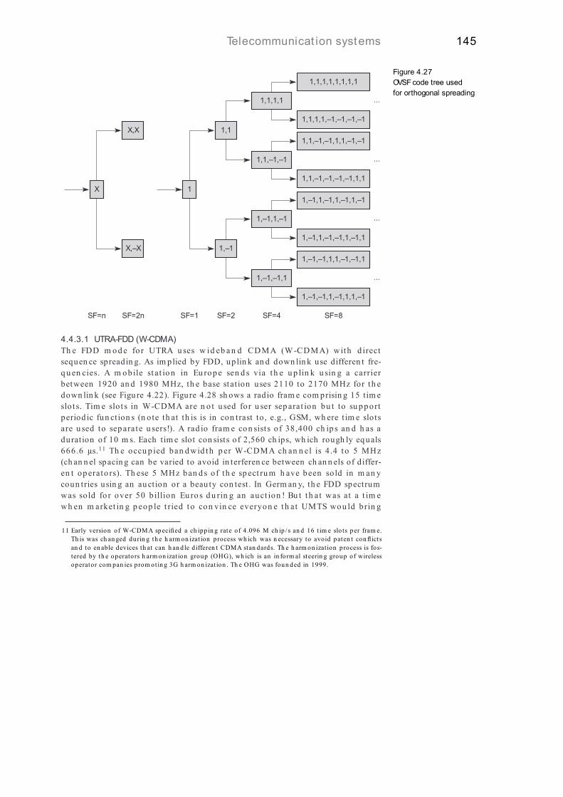
4.4.3.1 UTRA-FDD (W-CDMA)Th e FDD m o d e fo r UTRA u ses w id eb a n d CDMA (W -CDMA) with d irectsequen ce spreadin g. As im plied by FDD, uplin k an d down lin k use differen t fre-q u en cies. A m ob ile st at io n in Eu ro p e sen d s via t h e u p lin k u sin g a carrierbetween 1920 an d 1980 MHz, th e base stat ion uses 2110 to 2170 MHz for th edown lin k (see Figu re 4.22). Figure 4.28 sh ows a radio fram e com prisin g 15 tim eslo t s. Tim e slo t s in W-CDMA are n o t u sed for u ser sep arat ion bu t to su p p ortperiod ic fun ction s (n ote th at th is is in con trast to , e.g., GSM, wh ere t im e slotsare u sed to sep arate u sers!). A rad io fram e con sists of 38,400 ch ip s an d h as aduration of 10 m s. Each tim e slot con sists of 2,560 ch ips, wh ich rough ly equals666.6 µs.11 Th e occu p ied ban d wid th p er W-CDMA ch an n el is 4 .4 t o 5 MHz(ch an n el spacin g can be varied to avoid in terferen ce between ch an n els of differ-en t op erato rs). Th ese 5 MHz ban d s of th e sp ect ru m h ave been so ld in m an ycoun tries usin g an au ction or a beau ty con test . In Germ an y, th e FDD spectrumwas so ld fo r over 50 b illion Eu ro s d u rin g an auct ion ! Bu t t h a t was at a t im ewh en m arket in g p eop le t ried t o con vin ce everyon e t h at UMTS wou ld brin g
Telecommunicat ion systems 145
1,1,1,1,1,1,1,11,1,1,1
1,1,1,1,–1,–1,–1,–11,1,–1,–1,1,1,–1,–1
1,1,–1,–11,1,–1,–1,–1,–1,1,11,–1,1,–1,1,–1,1,–1
1,–1,1,–11,–1,1,–1,–1,1,–1,11,–1,–1,1,1,–1,–1,1
1,–1,–1,11,–1,–1,1,–1,1,1,–1
1,1
1,–1
1
...
...
...
...
X,X
X,–X
X
SF=4 SF=8SF=2SF=1SF=2nSF=n
Figure 4.27OVSF code tree usedfor orthogonal spreading
11 Early version of W-CDMA specified a ch ipp in g rate of 4.096 M ch ip / s an d 16 t im e slo ts per fram e.Th is was ch an ged du rin g th e h arm on izat ion process wh ich was n ecessary to avoid paten t con flictsan d to en able devices th at can h an d le d ifferen t CDMA stan dards. Th e h arm on ization p rocess is fos-tered by th e operators h arm on izat ion group (OHG), wh ich is an in form al steerin g group of wirelessoperator com pan ies prom otin g 3G h arm on izat ion . Th e OHG was foun ded in 1999.

h igh -ban d wid th ap p lica t ion s t o an y m o bile d evice with h igh p ro fit s fo r all.Tod ay, m ost peop le are m uch m ore realist ic an d kn ow th at d ata rates will bequ ite low in th e begin n in g (150 kbit / s per user are realist ic, 2 Mbit/ s are n ot).Th e capacity o f a cell u n d er realist ic assu m p t ion s (in terferen ce etc.), i.e., th esum of all data rates, will rath er be 2 Mbit/ s. To provide h igh data rates a lot ofm on ey h as to be in vested in th e in frast ructure: UTRA FDD requires at least twiceas m an y base stat ion s as GSM; cell d iam eters o f 500 m will be com m on p lace.Th is sh ows clearly th at th is t ech n ology will n ot cover wh ole cou n tries in th en ear fu ture but cit ies an d h igh ways on ly. Peop le in th e coun tryside will h ave torely on GSM/GPRS for m an y m ore years to com e.
Back to th e fram e st ru ctu re sh own in Figu re 4.28. Sim ilar to GSM, UMTSd efin es m an y logical an d p h ysical ch an n els, an d t h eir m ap p in g. Th e figu resh o ws th ree exam p les of p h ysica l ch an n els as t h ey are u sed fo r d at a t ran s-m ission . Two ph ysical ch an n els are sh own for th e uplin k.● Ded ica t ed p h ysica l d a ta ch an n el (DPDCH): Th is ch an n el con veys user or
sign alin g data. Th e spreadin g factor of th is ch an n el can vary between 4 an d256. Th is d irect ly t ran slates in to th e data rates th is ch an n el can offer:960 kbit/s (spreadin g factor 4, 640 bits per slot, 15 slots per fram e, 100 fram esper secon d), 480, 240, 120, 60, 30, an d 15 kbit/s (spreadin g factor 256). Th isalso sh ows on e of th e problem s of usin g OVSF for spreadin g: on ly certain m ul-tiples of th e basic data rate of 15 kbit/ s can be used. If, for exam ple, 250 kbit/sare n eeded th e device h as to ch oose 480 kbit/ s, wh ich wastes ban dwidth . Ineach con n ection in layer 1 it can h ave between zero an d six DPDCHs. Th isresu lts in a th eoretical m axim um data rate of 5,740 kbit / s (UMTS describesUEs with a m axim um of 1,920 kbit/s on ly). Table 4.7 sh ows typical user datarates togeth er with th e required data rates on th e ph ysical ch an n els.
Mobile communicat ions146
Radio frame... 12 13 1421010 ms
TFCI FBITime slot
uplink DPCCH
Data uplink DPDCH
666.7 µs Pilot
666.7 µs
TFCI Data2 downlink DPCH666.7 µs TPCData1
DPDCH
Pilot
TPC
DPCCHDPDCH DPCCH
2,560 chips, 10 bits
2,560 chips, 10*2k bits (k = 0...6)
2,560 chips, 10*2k bits (k = 0...7)
Figure 4.28UTRA FDD (W-CDMA)
frame structure

● Ded ica t ed p h ysica l con t ro l ch an n el (DPCCH): In each con n ect ion layer 1n eeds exact ly on e DPCCH. Th is ch an n el con veys con trol data for th e ph ysi-cal layer on ly an d uses th e con stan t spreadin g factor 256. Th e p ilo t is usedfo r ch an n el est im at ion . Th e t r a n sp o r t fo r m a t co m b in a t io n id en t if ie r(TFCI) specifies th e ch an n els t ran sported with in th e DPDCHs. Sign alin g fora soft h an dover is supported by th e feed b ack in fo rm at ion field (FBI). Th elast field , t ran sm it p o w er con t ro l (TPC) is u sed for con trollin g th e tran s-m ission power o f a sen d er. Power con tro l is perform ed in each slo t , th us1,500 power con trol cycles are available per secon d. Tigh t power con trol isn ecessary to m itigate n ear-far-effects as explain ed in ch apter 2. Six differen tDPCCH bursts h ave been defin ed wh ich differ in th e size of th e fields.
● Ded ica t ed p h ysica l ch an n el (DPCH): Th e down lin k t im e m ult iplexes con -trol an d user data. Spreadin g factors between 4 an d 512 are available. Again ,m an y d ifferen t burst form ats (17 altogeth er) h ave been defin ed wh ich differin th e size of th e field sh own in Figu re 4.28. Th e available data rates for datach an n els (DPDCH) with in a DPCH are 6 (SF=512), 24, 51, 90, 210, 432, 912,an d 1,872 kbit /s (SF=4). W h ile n o collision s can occur on th e down lin k (on ly th e base stat ion sen ds
on th e down lin k), m edium access on th e uplin k h as to be coordin ated. A p h ysi-ca l r a n d o m a ccess ch a n n el (PRACH ) is u sed fo r t h is p u rp ose. UTRA-FDDdefin es 15 ran dom access slots with in 20 m s; with in each access slot 16 d ifferen taccess pream bles can be used for ran dom access. Usin g slotted Aloh a, a UE canaccess an access slot by sen din g a p ream ble. Th e UE starts with th e lowest avail-able tran sm ission power to avoid in terferin g with oth er stat ion s. If n o posit iveackn owledgem en t is received , th e UE t ries an oth er slo t an d an oth er p ream blewith t h e n ext h igh er p ower level (p ower ram p in g). Th e n u m ber of availab leaccess slot s can be defin ed per cell an d is t ran sm it ted via a broadcast ch an n elto all UEs.
A UE h as to perform th e followin g steps du rin g th e sea rch fo r a cell afterpower on :● Prim ary syn ch ron iza t ion : A UE h as to syn ch ron ize with th e h elp of a 256
ch ip p rim ary syn ch ron izat ion code. Th is code is th e sam e for all cells an dh elps to syn ch ron ize with th e t im e slot structure.
Telecommunicat ion systems 147
User data rate [kbit / s] 12.2 64 144 384(voice)
DPDCH [kbit/ s] 60 240 480 960DPCCH [kbit/ s] 15 15 15 15Spreading 64 16 8 4
Table 4.7 TypicalUTRA–FDD uplinkdata rates

● Seco n d a ry syn ch ro n iza t io n : Durin g th is secon d p h ase th e UE receives asecon d ary syn ch ron izat ion code wh ich defin es t h e grou p of scram blin gcodes used in th is cell. Th e UE is n ow syn ch ron ized with th e fram e structu re.
● Id en t if ica t io n o f t h e scr a m b lin g co d e: Th e UE t ries all scram blin gcodes with in th e grou p o f codes to fin d th e righ t cod e with th e h elp of aco rrelator. After th ese th ree steps th e UE can receive all fu rth er data overa broadcast ch an n el.
4.4.3.2 UTRA-TDD (TD-CDMA)Th e secon d UTRA m ode, UTRA-TDD, separates up an d down lin k in tim e usin g arad io fram e st ructure sim ilar to FDD. 15 slots with 2,560 ch ips per slot form aradio fram e with a duration of 10 m s. Th e ch ippin g rate is also 3.84 Mch ip/ s. Toreflect differen t user n eeds in term s of data rates, th e TDD fram e can be sym m et -r ica l or a sym m et r ica l, i.e., th e fram e can con tain th e sam e n u m ber of u p lin kan d down lin k slots or an y arbitrary com bin ation . Th e fram e can h ave on ly on esw itch in g p oin t from uplin k to down lin k or several switch in g poin ts. However,at least on e slot m ust be allocated for th e uplin k an d down lin k respectively.
Th e system can ch an ge th e spreadin g factor (1, 2, 4, 8, 16) as a fun ction ofth e desired data rate. Usin g th e bu rst type sh own in Figu re 4.29 resu lts in datarates of 6,624, 3,312, 1,656, 828, an d 414 kbit /s respectively (if all slots are usedfor data t ran sm ission ). Th e figure sh ows a burst of type 2 wh ich com prises twod a t a fields of 1,104 ch ips each . Sp read in g is app lied to th ese data fields on ly.Addit ion ally, a m id am p le is u sed for train in g an d ch an n el estim ation . As TDDuses th e sam e scram blin g codes for all stat ion s, th e stat ion s m ust be t igh tly syn -ch ron ized an d th e spreadin g codes are available on ly on ce per slot . Th is resu ltsin a m axim um n um ber of 16 sim ultan eous sen din g stat ion s. To loosen th e t igh tsyn ch ron izat ion a lit tle bit, a gu a rd p eriod (GP) h as been in troduced at th e en dof each slot . Due to th e tigh t syn ch ron ization an d th e use of orth ogon al codes,a sim p ler p ower con t ro l sch em e with less p ower con tro l cycles (e.g., 100 p ersecon d) is su fficien t .
Mobile communicat ions148
Radio frame... 12 13 1421010 ms
Midample256 chips GPTime slot
Traffic burst666.7 µs Data1,104 chips
Data1,104 chips
2,560 chips GP: guard period96 chips
Figure 4.29UTRA TDD (TD–CDMA)
frame structure

UTRA TDD occupies 5 MHz ban dwidth per ch an n el as UTRA FDD does perd irect ion (FDD n eed s 2x 5 MHz). Com p ared to th e licen se for FDD, TDD wasqu ite ch eap. Germ an y paid less th an €300 m illion . Figu re 4.22 sh ows th e loca-tion of th e spectrum for th is UMTS m ode, bu t it is un clear to wh at exten d th issystem will be deployed. Th e coverage per cell is even less th an usin g FDD, UEsm ust n ot m ove too fast – th is soun ds like th e ch aracterist ics of WLANs wh ichare curren tly deployed in m an y p laces.4.4.4 UTRANFigure 4.30 sh ows th e basic arch itectu re of th e UTRA n etwork (UTRAN; 3GPP,2002b). Th is con sists of several rad io n etw ork su b system s (RNS). Each RNS iscon trolled by a rad io n etw ork con t ro ller (RNC) an d com prises several com po-n en ts th at are called n ode B. An RNC in UMTS can be com pared with th e BSC; an od e B is sim ilar to a BTS. Each n o d e B can con t ro l several an t en n as wh ichm ake a rad io cell. Th e m obile d evice, UE, can be co n n ect ed t o o n e o r m o rean ten n as as will subseq u en t ly be exp lain ed in th e con text of h an dover. EachRNC is con n ected with th e core n etwork (CN) over th e in terface Iu (sim ilar toth e role of th e A in terface in GSM) an d with a n ode B over th e in terface Iu b. An ew in terface, wh ich h as n o coun terpart in GSM, is th e in terface Iu r con n ect in gtwo RNCs with each oth er. Th e use of th is in terface is explain ed togeth er withth e UMTS h an dover m ech an ism s.
Telecommunicat ion systems 149
Node BNode BNode B
RNC
Iub
UE
Node B
Node BRNC
Iub
CN
Iu
Iur
RNS
RNS
Figure 4.30Basic architectureof the UTRA network

4.4.4.1 Radio network cont rollerAn RNC in UMTS h as a broad spectrum of tasks as listed in th e followin g:
● Call ad m ission con t ro l: It is very im portan t for CDMA system s to keep th ein t erferen ce belo w a certain level. Th e RNC calcu lat es th e t raffic with ineach cell an d decides, if addit ion al t ran sm ission s are acceptable or n ot .
● Con gest ion con tro l: Durin g packet-orien ted data tran sm ission , several sta-t ion s sh are th e available rad io resources. Th e RNC allocates ban d width toeach station in a cyclic fash ion an d m ust con sider th e QoS requirem en ts.
● En cryp t ion / d ecryp t ion : Th e RNC en cryp ts all data arrivin g from th e fixedn etwork before t ran sm ission over th e wireless lin k (an d vice versa).
● ATM sw it ch in g a n d m u lt ip lex in g, p ro t o co l co n version : Typ ically, t h eco n n ect ion s between RNCs, n od e Bs, an d t h e CN are based on ATM. AnRNC h as t o switch t h e con n ect ion s t o m u lt ip lex d ifferen t d at a st ream s.Several p rotocols h ave to be con verted – th is is explain ed later.
● Ra d io reso u rce con t ro l: Th e RNC con t rols all rad io resources of th e cellscon n ected to it via a n ode B. Th is task in cludes in terferen ce an d load m ea-su rem en ts. Th e p riorit ies of differen t con n ect ion s h ave to be obeyed .
● Ra d io b ea rer se t u p a n d r elea se : An RNC h as t o set -u p , m ain t ain , an drelease a logical data con n ect ion to a UE (th e so-called UMTS radio bearer).
● Co d e a lloca t ion : Th e CDMA codes used by a UE are selected by th e RNC.Th ese codes m ay vary du rin g a tran sm ission .
● Po w er co n t r o l : Th e RNC on ly p erfo rm s a relat ively lo ose p ower con t ro l(th e outer loop). Th is m ean s th at th e RNC in fluen ces t ran sm ission powerbased on in terferen ce values from oth er cells or even oth er RNCs. But th is isn ot th e t igh t an d fast power con trol perform ed 1,500 t im es per secon d. Th isis carried ou t by a n ode B. Th is ou ter loop of power con trol h elps to m in i-m ize in terferen ce between n eigh bourin g cells or con trols th e size of a cell.
● H an d over con tro l an d RNS reloca t ion : Depen din g on th e sign al st ren gth sreceived by UEs an d n ode Bs, an RNC can decide if an oth er cell would bebet ter su ited for a certain con n ect ion . If th e RNC decides for h an dover itin form s th e n ew cell an d th e UE as exp lain ed in su bsect ion 4.4.6. If a UEm oves furth er out of th e ran ge of on e RNC, a n ew RNC respon sible for th eUE h as to be ch osen . Th is is called RNS relocation .
● M a n a gem en t : Fin ally, t h e n etwork op era tor n eed s a lo t o f in fo rm at ionregardin g th e curren t load, cu rren t t raffic, error states etc. to m an age it s n et-work. Th e RNC provides in terfaces for th is task, too.
4.4.4.2 Node BTh e n am e n ode B was ch osen d u rin g stan d ard izat ion u n t il a n ew an d bet tern am e was fo u n d . Ho wever, n o o n e cam e u p with an yth in g bet t er so itrem ain ed . A n ode B con n ects t o on e or m ore an ten n as creat in g on e o r m orecells (or sectors in GSM speak), respectively. Th e cells can eith er use FDD or TDD
Mobile communicat ions150

or both . An im portan t task of a n ode B is th e in n er loop power con trol to m it i-gate n ear-far effect s. Th is n od e also m easu res con n ect ion qu alit ies an d sign alst ren gth s. A n od e B can even sup p o rt a special case o f h an d over, a so -calledsofter h an dover wh ich takes place between differen t an ten n as of th e sam e n odeB (see sect ion 4.4.6).4.4.4.3 User equipmentTh e UE sh own in Figure 4.30 is th e coun terpart of several n odes of th e arch itecture. ● As th e coun terpart of a n ode B, th e UE perform s sign al quality m easurem en ts,
in n er loop power con trol, spreadin g an d m odulation , an d rate m atch in g. ● As a coun terpart of th e RNC, th e UE h as to cooperate durin g h an dover an d
cell select ion , perform s en cryption an d decryp tion , an d part icipates in th erad io resource allocat ion process.
● As a coun terpart of th e CN, th e UE h as to im plem en t m obility m an agem en tfu n ct ion s, perform s bearer n ego t iat io n , o r req u est s cert ain services fromth e n etwork.Th is list of tasks of a UE, wh ich is n ot at all exh austive, already sh ows th e
com p lexity such a d evice h as to h an dle. Addit ion ally, u sers also wan t to h aveorgan izers, gam es, cam eras, operat in g system s etc. an d th e stan d-by t im e sh ou ldbe h igh .4.4.5 Core networkFigure 4.31 sh ows a h igh -level view of th e UMTS release 99 core n etwork arch i-tecture togeth er with a UTRAN RNS an d a GSM BSS (see section 4.1). Th is sh owsth e evolu tion from GSM/GPRS to UMTS. Th e core n etwork (CN) sh own h ere isbasically th e sam e as already explain ed in th e con text of GSM (see Figu re 4.4)an d GPRS (see Figure 4.16). Th e circu it sw itch ed d om ain (CSD) com prises th eclassical circu it switch ed services in cludin g sign alin g. Resources are reserved atcon n ect ion setu p an d th e GSM com p on en ts MSC, GMSC, an d VLR are u sed .Th e CSD con n ects to th e RNS via a part of th e Iu in terface called IuCS. Th e CSDcom pon en ts can still be part of a classical GSM n etwork con n ected to a BSS butn eed add it ion al fun ction alit ies (n ew protocols etc.).
Th e p ack et sw it ch ed d om ain (PSD) uses th e GPRS com pon en ts SGSN an dGGSN an d co n n ect s t o t h e RNS via t h e Iu PS p art o f t h e Iu in t erface. Bothdom ain s n eed th e data-bases EIR for equipm en t iden tification an d HLR for loca-t io n m an agem en t (in clu d in g t h e Au C fo r au th en t icat ion an d GR fo r u serspecific GPRS data).
Reu sin g th e exist in g in frast ru ctu re h elp s to save a lo t of m on ey an d m aycon vin ce m an y op erato rs t o u se UMTS if t h ey alread y u se GSM. Th e UMTSin d u stry p u sh es th eir t ech n ology with th e h elp o f t h e m arket d om in an ce o fGSM. Th is is basically th e sam e as cdm a2000, wh ich is a evolu tion of cdm aOn e.Th e real flexib le co re n etwo rk com es with releases 5 an d 6, wh ere t h e GSM
Telecommunicat ion systems 151
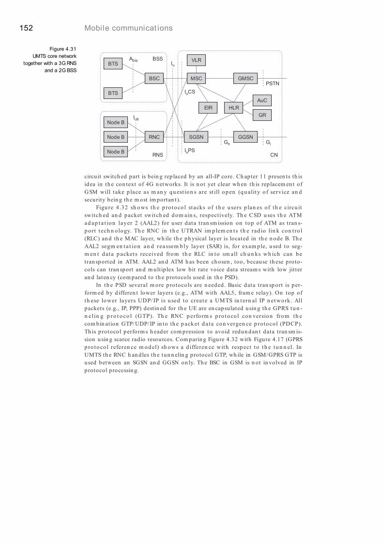
circu it switch ed part is bein g rep laced by an all-IP core. Ch ap ter 11 presen ts th isidea in th e con text of 4G n etworks. It is n ot yet clear wh en th is rep lacem en t ofGSM will t ake p lace as m an y qu est io n s are st ill o pen (q u alit y o f service an dsecurity bein g th e m ost im portan t).
Figu re 4.32 sh o ws th e p ro toco l st acks of t h e u sers p lan es of th e circu itswitch ed an d packet swit ch ed d om ain s, respect ively. Th e CSD u ses th e ATMa d ap t a t io n layer 2 (AAL2) for user data t ran sm ission on top of ATM as tran s-p ort t ech n ology. Th e RNC in th e UTRAN im p lem en t s th e rad io lin k con t ro l(RLC) an d th e MAC layer, wh ile th e ph ysical layer is located in th e n ode B. Th eAAL2 segm en ta t io n a n d rea ssem b ly layer (SAR) is, for exam ple, u sed to seg-m en t data p acket s received fro m th e RLC in to sm all ch u n ks wh ich can betran sp orted in ATM. AAL2 an d ATM h as been ch osen , too, because th ese proto-cols can tran sport an d m ult ip lex low bit rate voice data st ream s with low jit teran d laten cy (com pared to th e protocols used in th e PSD).
In th e PSD several m ore p ro tocols are n eeded . Basic data tran sp ort is per-form ed by d ifferen t lower layers (e.g., ATM with AAL5, fram e relay). On top ofth ese lower layers UDP/ IP is u sed to crea t e a UMTS in t ern al IP n etwork. Allpackets (e.g., IP, PPP) destin ed for th e UE are en capsulated usin g th e GPRS tu n -n elin g p ro t o co l (GTP). Th e RNC p erfo rm s p ro to co l con version from th ecom bin ation GTP/UDP/ IP in to th e p ack et d a ta con vergen ce p ro tocol (PDCP).Th is p rotocol perform s h eader com pression to avoid redun dan t data tran sm is-sion u sin g scarce radio resources. Com parin g Figure 4.32 with Figure 4.17 (GPRSp ro to col referen ce m o d el) sh ows a d ifferen ce with resp ect t o t h e t u n n el. InUMTS th e RNC h an dles th e tun n elin g protocol GTP, wh ile in GSM/GPRS GTP isused between an SGSN an d GGSN on ly. Th e BSC in GSM is n ot in volved in IPprotocol processin g.
Mobile communicat ions152
Node BNode BNode B
RNC
Iub
BTS
BTSBSC
Abis IuBSS
RNS
SGSNIuPS
GGSNGn Gi
EIR HLRGRAuC
MSCIuCS
GMSC PSTN
VLR
CN
Figure 4.31UMTS core network
together with a 3G RNSand a 2G BSS

Th e ra d io la yer (p h ysical layer) depen ds on th e UTRA m ode (see sect ion s4.4.3.1 an d 4 .4.3.2). Th e m ed iu m a ccess co n t ro l (M AC) layer coo rd in at esm ed ium access an d m u lt ip lexes logical ch an n els on to t ran sport ch an n els. Th eMAC layers also h elp t o iden t ify m o bile d evices an d m ay en cryp t d at a. Th era d io l in k co n t r o l (RLC) layer offers t h ree d ifferen t t ran sp o rt m o d es. Th eack n ow led ged m od e tran sfer uses ARQ for error correction an d guaran tees on e-t im e in -ord er d elivery of d ata p acket s. Th e u n a ck n o w led ged m o d e t ran sferdoes n ot perform ARQ bu t guaran tees at least on e-t im e delivery of packets withth e h elp of sequen ce n um bers. Th e t ran sp aren t m od e tran sfer sim ply forwardsMAC data with ou t an y furth er processin g. Th e system th en h as to rely on th eFEC wh ich is always u sed in th e rad io layer. Th e RLC also perform s segm en ta-t ion an d reassem bly an d flow con trol. For certain services th e RLC also en crypts.
Telecommunicat ion systems 153
IuPS
MACradio
GTPPDCP
UTRAN 3GSGSNUu Gn
MACradio
UE 3GGGSN
L2UDP/IP
GTP
IP, PPP,...
PDCPRLC
IP, PPP,...
apps. &protocols
L1
RLCAAL5ATM
UDP/IPAAL5ATM
GTPGTPUDP/IP
L2L1
UDP/IP
IP tunnelPacketswitched
IuCS
MACradio
SARRLC
UTRANUu
MACradio
UE 3GMSC
AAL2SARRLC
apps. &protocols
ATMAAL2ATM
Circuitswitched
Figure 4.32User plane protocolstacks (circuit andpacket switched)

4.4.6 HandoverUMTS kn ows two basic classes of h an dovers:● H ard h an d over: Th is h an dover type is already kn own from GSM an d oth er
TDMA/FDMA system s. Switch in g between d ifferen t an ten n as or d ifferen tsystem s is p erform ed at a certain po in t in t im e. UTRA TDD can on ly u seth is type. Switch in g between TDD cells is don e between th e slots of differ-en t fram es. In t er freq u en cy h an d over, i.e., ch an gin g th e carrier frequen cy,is a h ard h an dover. Receivin g data at differen t frequen cies at th e sam e tim erequires a m ore com plex receiver com pared to receivin g data from differen tsources at th e sam e carrier frequen cy. Typ ically, all in ter system h an d oversare h ard h an dovers in UMTS. Th is in cludes h an dovers to an d from GSM oro th er IMT-2000 syst em s. A sp ecial typ e o f h an dover is th e h an dover to asatellite system (in ter-segm en t h an dover), wh ich is also a h ard h an dover, asd ifferen t frequ en cies are used . However, it is un clear wh at tech n ology willbe used for satellite lin ks if it will ever com e. To en able a UE to listen in toGSM or oth er frequen cy ban ds, UMTS specifies a com p ressed m od e tran s-m ission fo r UTRA FDD. Du rin g th is m ode a UE stops all t ran sm ission . Toavoid data loss, eith er th e spreadin g factor can be lowered before an d afterth e break in tran sm ission (i.e., m ore data can be sen t in sh orter t im e) or lessd ata is sen t usin g d ifferen t codin g sch em es.
● Soft h an d over: Th is is th e real n ew m ech an ism in UMTS com pared to GSMan d is on ly available in th e FDD m ode. Soft h an dovers are well kn own fromtradit ion al CDMA n etworks as th ey use m acro d iversit y, a basic property ofCDMA. As sh own in Figu re 4.33, a UE can receive sign als from up to th reed ifferen t an ten n as, wh ich m ay belon g to d ifferen t n ode Bs. Towards th e UEth e RNC sp lits th e data st ream an d forwards it to th e n ode Bs. Th e UE com -bin es th e received data again . In th e oth er d irection , th e UE sim ply sen ds itsd ata wh ich is th en received by all n ode Bs in volved . Th e RNC com bin es th ed ata st ream s received from th e n od e Bs. Th e fact th at a UE receives d at afrom d ifferen t an ten n as at th e sam e t im e m akes a h an dover soft . Movin gfrom on e cell to an oth er is a sm ooth , n ot an abrupt process.
Mobile communicat ions154
UE Node B
RNC CNNode B
Figure 4.33Marco-diversitysupporting soft
handovers

Macro-d iversity m akes th e t ran sm ission m ore robu st with resp ect to fastfad in g, m ult i-path p ropagation , an d sh adin g. If on e path is blocked by an ob-st acle t h e ch an ces are go od th at d at a can st ill be received u sin g an o th eran ten n a. Du rin g a so ft h an dover a UE receives power con trol com m an ds fromall in volved n ode Bs. Th e UE th en lowers tran sm ission power as lon g as it st illreceives a com m an d to lower th e power. Th is avoids in terferen ce if, for exam ple,th e UE is in th e tran sm ission area of two an ten n as, on e close, on e fu rth er away.With out th e above m ech an ism th e UE’s sign al m ay be too stron g wh en listen -in g to t h e an ten n a fu rth er away. Th e lower th e in terferen ce a UE in t rod u cesin to a cell, th e h igh er th e capacity. With out th is con trol, cell breath in g wouldbe even m ore problem at ic th an it already is in CDMA n etworks.
As soft h an dover is n ot supported by th e CN, all m ech an ism s related to softh an dover m ust be located with in UTRAN. Figure 4.34 sh ows a situation wh ere asoft h an dover is perform ed between two n ode Bs th at do n ot belon g to th e sam eRNC. In th is case on e RNC con trols th e con n ection an d forwards all data to an dfrom th e CN. If th e UE m oves in th e exam ple from th e upper cell to th e lowercell, th e upper RNC acts as a servin g RNC (SRNC) wh ile th e oth er is th e d riftRNC (DRNC). (If th e wh ole RNS is con sidered , th e term s are servin g RNS an dd rift RNS, resp ect ively.) Th e SRNC forwards d ata received from th e CN to it sn ode B an d to th e DRNC via th e Iur in terface (sp lit t in g). Th is m ech an ism doesn ot exist in , e.g., GSM. Data received by th e lower n ode B is forwarded by th eDRNC to t h e SRNC. Th e SRNC co m bin es b oth dat a st ream s an d fo rward s asin gle st ream o f d at a to th e CN. Th e CN d oes n ot n o t ice an yth in g fro m th esim u lt an eou s recep t io n . If t h e UE m oves fu rth er d own an d d rop s ou t of th et ran sm ission area o f t h e u p per n od e B, two RNCs reserve reso u rces for da t atran sm ission , SRNC an d DRNC, alth ough n on e of SRNC’s n ode Bs t ran sm it datafor th is UE. To avoid wastin g resources, SRNC relocat ion can be perform ed. Th isin volves th e CN so is a h ard h an dover.
Figu re 4.35 gives an overview of several com m on h an dover types in a com -bin ed UMTS/GSM n etwork (UMTS specifies t en d ifferen t typ es wh ich in clu desoft an d h ard h an dover). Th e com bin ation of a UTRA-FDD/GSM device will beth e m o st co m m on case in t h e begin n in g as coverage o f 3G n etworks willbe poor.
Telecommunicat ion systems 155
Node B SRNCIub
UE
CNIu
Node B DRNCIub
Iur
Figure 4.34Serving RNC anddrift RNC

● In t r a -n o d e B, in t r a -RNC: UE1 m o ves from o n e an t en n a o f n od e B1 toan oth er an ten n a. Th is type of h an dover is called soft er h an d over. In th iscase n ode B1 perform s com bin in g an d sp litt in g of th e data stream s.
● In ter-n od e B, in t ra -RNC: UE2 m oves from n ode B1 to n ode B2. In th is caseRNC1 supports th e soft h an dover by com bin in g an d split tin g data.
● In t er-RNC: Wh en UE3 m oves from n ode B2 to n ode B3 two d ifferen t typesof h an dover can take place. Th e in tern a l in t er-RNC h an dover is n ot visiblefor th e CN, as described in Figure 4.34. RNC1 can act as SRNC, RNC2 will beth e DRNC. Th e CN will com m un icate via th e sam e in terface Iu all th e tim e.As soon as a relocation of th e in terface Iu takes p lace (relocation of th e con -t ro llin g RNC), t h e h an d over is called an ex t er n a l in t er -RNC h an do ver.Com m u n ica t io n is st ill h an d led by t h e sam e MSC 1, bu t t h e ext ern alh an dover is n ow a h ard h an dover.
● In t er -MSC: It cou ld be also th e case th at MSC2 takes over an d p erform s ah ard h an dover of th e con n ect ion .
● In t er -syst em : UE4 m o ves from a 3G UMTS n etwork in to a 2G GSM n et -work. Th is h ard h an dover is im portan t for real life u sability of th e systemdue to th e lim ited 3G coverage in th e begin n in g.
4.5 SummaryTh is ch ap t er h as, fo r t h e m o st p art , p resen t ed GSM as t h e m o st su ccessfu lsecon d gen erat ion d igit al cellu lar n etwork. Alth ou gh GSM was p rim arilyd esign ed for vo ice t ran sm ission , t h e ch ap t er sh owed th e evolu t ion t oward am ore data-orien ted t ran sfer via HSCSD an d GPRS. Th is evolu t ion also in cludesth e tran sit ion from a circuit-switch ed n etwork to a packet-switch ed system th atcom es closer to th e in tern et m odel. Oth er system s p resen ted in clude DECT, th e
Mobile communicat ions156
UE1Node B1 RNC1
Iub
3G MSC1IuIur
Node B3 RNC2
Node B2
BTS BSCAbis
2G MSC3A
3G MSC2
UE2
UE3
UE4
Figure 4.35Overview of different
handover types

digital stan dard for cord less ph on es, an d TETRA, a trun ked rad io system . DECTcan be used for wireless data tran sm ission on a cam pus or in doors, bu t also forwireless local loops (WLL). For special scen arios, e.g., em ergen cies, t run ked radiosyst em s su ch as TETRA can be t h e best ch o ice. Th ey o ffer a fast con n ect ionsetup (even with in com m un ication groups) an d can work in an ad h oc n etwork,i.e., with out a base stat ion .
Th e situation in th e US is d ifferen t from Europe. Based on th e an alog AMPSsystem , th e US in dust ry developed th e TDMA system IS-54 th at adds digital t raf-fic ch an n els. IS-54 uses dual m ode m obile ph on es an d in corporates several GSMid eas, su ch as, asso ciat ed con t ro l ch an n els, au th en t icat ion p rocedu res u sin gen crypt ion , an d m obile assisted h an dover (called h an doff). Th e Japan ese PDCsystem was design ed usin g m an y ideas in IS-54.
Th e n ext step , IS-136, in clu des d igital con trol ch an n els (IS-54 uses an alogAMPS con trol ch an n els) an d is m ore efficien t . Now fu lly d igital ph on es can beused, several addit ion al services are offered, e.g., voice m ail, call waitin g, iden ti-ficat ion , grou p callin g, o r SMS. IS-136 is also ca lled No rth Am erican TDMA(NA-TDMA) or Digit al AMPS (D-AMPS) an d op erat es at 800 an d 1 ,900 MHz.En h an cem en ts of D-AMPS/ IS-136 toward IMT-2000 in clude advan ced m odu la-t ion tech n iques for t h e 30 kHz radio carrier, sh ift in g data rates up to 64 kbit / s(first ph ase, called 136+). Th e secon d p h ase, called 136HS (High Sp eed) com -prises a n ew air in terface specification based on th e EDGE tech n ology.
IS-95 (prom oted as cdm aOn e) is based on CDMA, wh ich is a com pletely dif-feren t m edium access m eth od . Before deploym en t , th e system was proclaim edas h avin g m an y advan tages over TDMA system s, such as its m uch h igh er capac-ity of users per cell, e.g., 20 t im es th e capacity of AMPS. Today, CDMA providersare m akin g m ore realist ic est im ates of aroun d five t im es as m an y u sers. IS-95o ffers so ft h an d over, avo id in g t h e GSM p in g-po n g effect (Wo n g, 1997).However, IS-95 n eed s p recise syn ch ron izat ion of all base st at ion s (u sin g GPSsatellites wh ich are m ilitary satellites, so are n ot un der con trol of th e n etworkprovider), frequen t power con trol, an d typically, dual m ode m obile ph on es dueto th e lim it ed coverage. Th e basic id eas of CDMA h ave been in t egrated in tom ost 3G system s.
Th is ch apter also presen ted an overview of curren t an d fu ture th ird gen era-t ion system s. UMTS, a p rop osal of operators an d com pan ies in vo lved in th eGSM busin ess, was d iscussed in m ore detail. Th is stan dard is m ore an evolu tion -ary ap p roach th an a revolu t ion . To avoid even h igh er im p lem en tat ion cost s,UMTS t ries to reu se as m u ch in frast ructu re as possible wh ile in t rod ucin g n ewservices an d h igh er d ata rates based on CDMA tech n ology. Th e in it ial in stalla-t ion s will basically use th e GSM/GPRS in frast ructu re an d offer on ly m oderated ata rates. Th e in it ia l capacity of a UMTS cell is ap p roxim ately 2 Mbit / s; celld iam eters are in th e o rder of 500 m . UMTS will be u sed t o o ffload GSM n et -works an d to offer en h an ced data rates in cit ies as a first st ep . Fu tu re releasesaim to replace th e in frastructure by an (alm ost) all-IP n etwork. Th ese ideas willbe p resen ted togeth er with a look at fourth gen eration system s in ch apter 11. It
Telecommunicat ion systems 157

is q u it e clear t h at it will t ake a lo n g t im e befo re 3G services are availab le inm an y p laces. It took GSM 10 years to becom e th e m ost su ccessfu l 2G m obilecom m un ication system . A sim ilar period of t im e will be n eeded for 3G system sto su cceed . Mean wh ile, cu sto m ers will n eed m ult ip le m od e p h on es o fferin g,e.g., GSM 900/1800/1900 an d UMTS UTRA-FDD services. It is n ot clear if an dwh en UTRA-TDD will succeed . Providers already usin g cdm aOn e will take th eevolu tion ary path via cdm a2000 1x toward th e 3G system cdm a2000 1x EV-DO.Several t ests h ave already been con ducted for 3G satellit e services in th e MSSsp ect ru m (e.g., sat ellit e based m u lt icast , Nu ssli, 2002). However, righ t n owm an y com pan ies will wait before in vestin g m on ey in satellite services (see ch ap-ter 5). Th e m ain problem of m ult i-m ode system s is th e in ter-system h an dover.W h ile th is ch apter in trodu ces h an dover scen arios with in UMTS an d GSM, an dbetween GSM an d UMTS, even m ore com plex scen arios could com prise wirelessLANs (see ch apter 7) or oth er packet-orien ted n etworks (Pah lavan , 2000).
4.6 Review exercises1 Name some key features of the GSM, DECT, TETRA, and UMTS systems. Which
features do the systems have in common? Why have the three older differentsystems been specified? In what scenarios could one system replace another?What are the specific advantages of each system?
2 What are the main problems when transmitting data using wireless systems thatwere made for voice transmission? What are the possible steps to mitigate theproblems and to raise efficiency? How can this be supported by billing?
3 Which types of different services does GSM offer? Give some examples and rea-sons why these services have been separated.
4 Compared to the TCHs offered, standard GSM could provide a much higher datarate (33.8 kbit/ s) when looking at the air interface. What lowers the data ratesavailable to a user?
5 Name the main elements of the GSM system architecture and describe theirfunctions. What are the advantages of specifying not only the radio interface butalso all internal interfaces of the GSM system?
6 Describe the functions of the MS and SIM. Why does GSM separate the MS andSIM? How and where is user-related data represented/ stored in the GSMsystem? How is user data protected from unauthorized access, especially overthe air interface? How could the position of an MS (not only the current BTS) belocalized? Think of the MS reports regarding signal quality.
7 Looking at the HLR/ VLR database approach used in GSM – how does this archi-tecture limit the scalability in terms of users, especially moving users?
8 Why is a new infrastructure needed for GPRS, but not for HSCSD? Which compo-nents are new and what is their purpose?
Mobile communicat ions158

9 What are the limitations of a GSM cell in terms of diameter and capacity (voice,data) for the traditional GSM, HSCSD, GPRS? How can the capacity be increased?
10 What multiplexing schemes are used in GSM and for what purpose? Think ofother layers apart from the physical layer.
11 How is synchronization achieved in GSM? Who is responsible for synchronizationand why is it so important?
12 What are the reasons for the delays in a GSM system for packet data traffic?Distinguish between circuit-switched and packet-oriented transmission.
13 Where and when can collisions occur while accessing the GSM system?Compare possible collisions caused by data transmission in standard GSM,HSCSD, and GPRS.
14 Why and when are different signaling channels needed? What are the differences?15 How is localization, location update, roaming, etc. done in GSM and reflected in
the data bases? What are typical roaming scenarios?16 Why are so many different identifiers/ addresses (e.g., MSISDN, TMSI, IMSI)
needed in GSM? Give reasons and distinguish between user-related and system-related identifiers.
17 Give reasons for a handover in GSM and the problems associated with it. Whatare the typical steps for handover, what types of handover can occur? Whichresources need to be allocated during handover for data transmission usingHSCSD or GPRS respectively? What about QoS guarantees?
18 What are the functions of authentication and encryption in GSM? How is systemsecurity maintained?
19 How can higher data rates be achieved in standard GSM, how is this possiblewith the additional schemes HSCSD, GPRS, EDGE? What are the main differ-ences of the approaches, also in terms of complexity? What problems remaineven if the data rate is increased?
20 What limits the data rates that can be achieved with GPRS and HSCSD usingreal devices (compared to the theoretical limit in a GSM system)?
21 Using the best delay class in GPRS and a data rate of 115.2 kbit/ s – how manybytes are in transit before a first acknowledgement from the receiver could reachthe sender (neglect further delays in the fixed network and receiver system)? Nowthink of typical web transfer with 10 kbyte average transmission size – how woulda standard TCP behave on top of GPRS (see chapters 9 and 10)? Think of conges-tion avoidance and its relation to the round-trip time. What changes are needed?
22 How much of the original GSM network does GPRS need? Which elements of thenetwork perform the data transfer?
23 What are typical data rates in DECT? How are they achieved considering theTDMA frames? What multiplexing schemes are applied in DECT and for what pur-poses? Compare the complexity of DECT with that of GSM.
Telecommunicat ion systems 159

24 Who would be the typical users of a trunked radio system? What makes trunkedradio systems particularly attractive for these user groups? What are the maindifferences to existing systems for that purpose? Why are trunked radio systemscheaper compared to, e.g., GSM systems for their main purposes?
25 Summarize the main features of third generation mobile phone systems. How dothey achieve higher capacities and higher data rates? How does UMTS imple-ment asymmetrical communication and different data rates?
26 Compare the current situation of mobile phone networks in Europe, Japan,China, and North America. What are the main differences, what are efforts tofind a common system or at least interoperable systems?
27 What disadvantage does OVSF have with respect to flexible data rates? Howdoes UMTS offer different data rates (distinguish between FDD and TDD mode)?
28 How are different DPDCHs from different UEs within one cell distinguished inUTRA FDD?
29 Which components can perform combining/ splitting at what handover situation?What is the role of the interface Iur? Why can CDMA systems offer soft handover?
30 How does UTRA-FDD counteract the near-far effect? Why is this not a problemin GSM?
4.7 References3G Am ericas (2002) h ttp:/ /www.3gam ericas.org/ .3GPP (2000) Genera l UMTS a rchitecture, 3rd Gen era t io n Partn ersh ip Pro ject ,
3G TS 23.101 3.1.0 (2000-12).3GPP (2002a) 3rd Gen eration Partn ersh ip Project , h t tp:/ /www.3gpp.org/ .3GPP (2002b) UTRAN overa ll description, 3rd Gen erat io n Partn ersh ip Pro ject ,
3GPP TS 25.401 V3.10.0 (2002-06).3GPP2 (2002) 3rd Gen eration Partn ersh ip Project 2, h ttp :/ /www.3gpp2.org/ .Adach i, F., Sawah ash i, M., Suda, H. (1998) ‘Wideban d DS-CDMA for n ext-gen eration
m obile com m un ication s system s,’ IEEE Communications Magazine, 36(9).Brasch e, G., Walke, B. (1997) ‘Con cepts, services, an d protocols of th e n ew GSM
ph ase 2+ Gen eral Packet Radio Service,’ IEEE Communications Magazine, 35(8).Callen dar, M. (1997) ‘In tern at ion al Mobile Telecom m un ication s-2000 stan dards
efforts of th e ITU,’ collection of articles in IEEE Personal Communications, 4(4).Ch en , H.-H., Fan , C.-X., Lu , W. (2002) ‘Ch in a’s Persp ect ives on 3G Mo bile
Com m u n icat ion s an d Beyon d : TD-SCDMA Tech n ology,’ IEEE W irelessCommunications, 9(2).
Dah lm an , E., Gu dm u n dson , B., Nilsson , M., Sköld , J. (1998) ‘UMTS/ IMT-2000based on wideban d CDMA,’ IEEE Communica tions Magazine, 36(9).
Dasilva, J., Ikon om ou , D., Erben , H. (1997) ‘Eu ro p ean R&D p ro gram s onth ird -gen erat ion m ob ile com m u n icat ion syst em s,’ IEEE Persona lCommunications, 4(1).
Mobile communicat ions160

DECT (2002), h t tp:/ /www.dect .ch / , h t tp:/ /www.dectweb.com / .ETSI (1991a) Bearer services supported by a GSM PLMN, European Telecom m un ication s
Stan dards In stitute, GSM recom m en dation s 02.02.ETSI (1991b) Genera l description of a GSM PLMN, European Telecom m un ication s
Stan dards In st itu te, GSM recom m en dation s 01.02.ETSI (1991c) Subscriber Identity Modules, Funct iona l Cha ra cteristics, Eu ro p ean
Telecom m un ication s Stan dards In stitute, GSM recom m en dation s 02.17.ETSI (1993a) Multiplexing a nd multiple a ccess on the radio pa th, Eu ro p ean
Telecom m un ication s Stan dards In stitute, GSM recom m en dation s 05.02.ETSI (1993b) MS-BSS data link layer – general aspects, European Telecom m un ication s
Stan dards In stitute, GSM recom m en dation s 04.05.ETSI (1993c) MS-BSS data link layer specification, European Telecom m u n ication s
Stan dards In st itu te, GSM recom m en dation s 04.06.ETSI (1997a) High Speed Circuit Switched Da ta (HSCSD), St age 1 , Eu ro p ean
Telecom m un ication s Stan dards In stitu te, GSM 02.34, V5.2.1.ETSI (1998a) Genera l Packet Radio Service (GPRS); Requirements specifica tion of
GPRS, Eu rop ean Telecom m u n ica t io n s St an dard s In st it u t e , TR 101 186,V6.0.0 (1998–04).
ETSI (1998b) Genera l Pa cket Radio Service (GPRS); Service description ; Sta ge 2,Eu rop ean Teleco m m u n ica t io n s St an dard s In st it u t e, EN 301 344, V6.1.1(1998–08).
ETSI (1998c) Genera l Packet Ra dio Service (GPRS); Service description; Sta ge 1,Eu rop ean Teleco m m u n ica t io n s St an dard s In st it u t e, EN 301 113, V6.1.1(1998–11).
ETSI (1998d) Genera l Packet Radio Service (GPRS); Overa ll description of the GPRSradio interface; Stage 2, Eu ropean Telecom m u n icat ion s Stan d ards In st itu te,TS 101 350, V6.0.1 (1998–08).
ETSI (1998e) High Speed Circuit Switched Da ta (HSCSD); Stage 2, Eu ro p eanTelecom m un ication s Stan dards In stitu te, TS 101 038, V5.1.0 (1998–07).
ETSI (1998f) Universa l Mobile Telecommunica tions System (UMTS); Concept groupsfor the defin ition of the UMTS Terrestria l Ra dio Access (UTRA), Eu ro p eanTelecom m un ication s Stan dards In stitu te, TR 101 397, V3.0.1 (1998–10).
ETSI (1998h ) High level requiremen ts relevant for the definition of the UMTSTerrestria l Ra dio Access (UTRA) concept, Eu rop ean Telecom m u n icat ion sStan dards In st itu te, TR 101 398, V3.0.1 (1998–10).
ETSI (1998i) Concept groups for the definition of the UMTS Terrestrial Radio Access(UTRA), Eu ro p ean Telecom m u n icat ion s St an d ards In st it u t e, TR 101 397,V3.0.1 (1998–10).
ETSI (1998j) Digital Enhanced Cordless Telecommunications (DECT), Generic AccessProfile (GAP), Eu rop ean Telecom m u n icat ion s Stan d ard s In st itu te, EN 300444, V1.3.2 (1998–03).
Telecommunicat ion systems 161

ETSI (1998k) Digita l Enha nced Cordless Telecommunica tions (DECT), CommonInterface (CI), Eu ropean Telecom m un icat ion s Stan d ard s In st itu t e, EN 300175, V1.4.1 (1998–02).
ETSI (1998l) Terrestrial Trunked Radio (TETRA), Voice plus Data (V+D), Eu ropeanTelecom m un ication s Stan dards In st itute, ETS 300 392 series of stan dards.
ETSI (1998m ) Terrestria l Trunked Radio (TETRA), Packet Da ta Optimized (PDO),Eu rop ean Teleco m m u n icat ion s St an d ard s In st it u t e, ETS 300 393 seriesof stan dards.
ETSI (1998n ) The ETSI UMTS Terrestrial Radio Access (UTRA) ITU-R Radio TransmissionTechnologies (RTT) Candidate Submission, European Telecom m un icat ion sStan dards In st itute.
ETSI (2002) European Telecom m un ication s Stan dards In st itute, h ttp:/ /www.etsi.org/ .Evci, C. (2001) ‘Optim izin g an d licen sin g th e rad io frequen cy spectrum for ter-
restrial 3G users,’ Alcatel Telecommunica tions Review, 1/2001.Good m an , D. (1997) W ireless Persona l Communica tions Systems. Ad d ison -
Wesley Lon gm an .GSM Associat ion (2002), h t tp :/ /www.gsm world.com / .GSMMoU (1998) Vision for the evolution from GSM to UMTS, GSM MoU
Associat ion , Perm an en t Referen ce Docum en t, V 3.0.0.GSM-R (2002), Th e GSM-R In dustry Group, h t tp:/ /www.gsm -rail.com / .Halsall, F. (1996) Da ta communica tions, computer networks and open systems.
Addison -Wesley Lon gm an .ITU (2002) International Mobile Telecommunications, In tern ation al Telecom m un ication
Un ion , h ttp:/ /www.itu .in t/ im t/ .Nussli, C; Bertout, A. (2002) ‘Satellite-based m ulticast arch itecture for m ultim edia
services in 3G m obile n etworks,’ Alcatel Telecommunications Review, 2/2002.Ojan p erä, T.; Prasad , R. (1998) ‘An overview o f th ird -gen erat ion wireless
p erson al com m u n ica t io n s: A Eu rop ean p ersp ect ive,’ IEEE Persona lCommunications, 5(6).
Pah lavan , K., Krish n am urth y, P., Hatam i, A., Ylian tt ila, M., Makela, J.-P., Pich n a,R., Vallst röm , J. (2000) ‘Han d off in Hybrid Mobile Data Networks,’ IEEEPersonal Communications, 7(2).
Pah lavan , K., Krish n am u rth y, P. (2002) Principles of W ireless Networks.Pren t ice Hall.
Rosen berg, J., Sch u lzrin n e, H., Cam arillo , G., Joh n ston , A., Peterson , J., Sparks,R., Han dley, M., Sch ooler, E. (2002) SIP: Session Initiation Protocol, RFC 3261,u pdated by RFC 3265.
SIP Forum (2002) h t tp :/ /www.sipforum .com / .Sh afi, M., Sasaki, A., Jeon g, D. (1998) ‘IMT-2000 d evelop m en t s in t h e Asia
Pacific region ,’ collection of art icles, IEEE Communications Magazine, 36(9).Stallin gs, W. (2002) Wireless Communica tions and Networks. Pren t ice Hall.TETRA Mo U (2002) TETRA Mem oran d u m o f Un d erst an d in g, h t t p :/ / www.
tetram ou .com / .
Mobile communicat ions162

Tripath i, N.D., Reed, J.H., Van Lan din gh am , H.F. (1998) ‘Han doffs in cellu lar sys-tem s,’ IEEE Personal Communications, 5(6).
UMTS Forum (2002) h ttp:/ /www.um ts-forum .org/ .Won g, D., Lim , T. (1997) ‘Soft h an doffs in CDMA m obile system s,’ IEEE Personal
Communications, 4(6).
Telecommunicat ion systems 163


Satellit e co m m u n icat ion in t rod u ces an oth er system su p p ort in g m obilecom m un icat ion s. Satellites offer global coverage with out wirin g costs forbase stat ion s an d are alm ost in dep en den t of varyin g popu lat ion den si-
ties. After a sh ort h istory of satellite developm en t an d presen tation of differen tareas of application , th is ch apter in troduces th e basics of satellite system s. Orbit ,visibility, t ran sm ission qu ality, an d oth er system ch aracterist ics are all closelylin ked . Several rest rict ion s an d applicat ion requ irem en ts resu lt in th ree m ajorclasses of satellites, GEO, MEO, an d LEO, as discussed later in th is ch apter. Th eh igh speed o f sat ellit es with a lo w alt it u d e raises n ew p roblem s for ro u t in g,localizat ion o f m o bile u sers, an d h an d over o f co m m u n icat ion lin ks. Severalaspects of th ese top ics are th erefore presen ted in separate section s. Fin ally, th ech apter deals with fou r exam ples of global satellite com m un ication system s th atare curren tly p lan n ed or already in stalled. Followin g th e ups an d down s of satel-lite system s over th e last years (ban krup tcy of Irid iu m , over-am bitiou s system setc.) it is clear th at th e fu tu re of th ese system s is un certain . However, th ey m ayprove usefu l as an ad dit ion for exist in g system s (e.g., UMTS satellite segm en t asen h an cem en t of th e terrest rial service for m u lt im edia broadcastin g).
5.1 HistorySatellite com m un ication began after th e Secon d World War. Scien tists kn ew th atit was possible to bu ild rockets th at would carry rad io tran sm it ters in to space. In1945, Arth u r C. Clarke p ublish ed h is essay on ‘Ext ra Terrest rial Relays’. Bu t itwas n ot un til 1957, in th e m iddle of th e cold war, th at th e sudden laun ch in g ofth e first sat ellit e SPUTNIK by th e So viet Un ion sh o cked th e West ern wo rld .SPUTNIK is n o t at all com p arable t o a satellit e t od ay, it was basically a sm allsen der tran sm it tin g a periodic ‘beep’. But th is was en ough for th e US to put allit s effort in to develop in g it s first satellite. On ly th ree years later, in 1960, th efirst reflectin g com m u n ication satellite ECHO was in space. ECHO was basicallya m irror in th e sky en ablin g com m un icat ion by reflect in g sign als. Th ree yearsfu rth er on , t h e first geost at ion ary (o r geosyn ch ro n ou s) sa t ellit e SYNCOMfollowed . Even to d ay, geo st at io n ary sat ellit es are t h e backbon e of n ews
Satell ite systems 5
165

broadcast in g in th e sky. Th eir great advan tage, is th eir fixed posit ion in th e sky(see section 5.3.1). Th eir rotat ion is syn ch ron ous to th e rotation of th e earth , soth ey appear to be pin n ed to a certain locat ion .
Th e first com m ercial geostat ion ary com m u n icat io n satellit e INTELSAT 1(also kn own as ‘Early Bird’) wen t in to operation in 1965. It was in service foron e-an d-a-h alf years, weigh ed 68 kg an d offered 240 duplex teleph on e ch an n elsor, alt ern at ively, a sin gle TV ch an n el. INTELSAT 2 followed in 1967, INTELSAT 3in 1969 alread y offered 1,200 telep h on e ch an n els. W h ile com m u n icat ion onlan d always provides th e altern ative of usin g wires, th is is n ot th e case for sh ipsat sea. Th ree MARISAT sa tellit es wen t in to op erat ion in 1976 wh ich offeredworldwide m arit im e com m un icat ion . However, Sen der an d receiver st ill h ad tobe in stalled on th e sh ip s with large an ten n as (1.2 m an ten n a, 40 W tran sm itp ower). Th e first m obile satellit e t elep h on e syst em , INMARSAT-A, was in t ro -duced in 1982. Six years later, INMARSAT-C becam e th e first satellite system tooffer m obile ph on e an d data services. (Data rates of about 600 bit / s, in terfacesto t h e X.25 packet d a t a n etwork exist .) In 1993 , sat ellit e t elep h on e syst em sfin ally becam e fu lly d igital with INMARSAT-M. Th e actu al m obility, h owever,was relat ive from a user’s poin t of view, as th e devices n eeded for com m un ica-t ion via geostat ion ary satellites were h eavy (several kilogram s) an d n eeded a lotof t ran sm it power to ach ieve decen t d ata rates. Nin eteen n in ety-eigh t m arkedth e begin n in g of a n ew age of satellite data com m un ication with th e in troduc-t ion of global satellite system s for sm all m obile ph on es, su ch as, e.g., Irid iu man d Globalstar (see sect ion 5.7). Th ere are cu rren t ly alm ost 200 geostat ion arysatellites in com m ercial use wh ich sh ows th e im pressive growth of satellite com -m un ication over th e last 30 years (Miller, 1998), (Maral, 1998), (Pascall, 1997).However, satellite n etworks are cu rren tly facin g h eavy com petit ion from terres-trial n etworks with n at ion wide coverage or at least en ough coverage to supportm ost app lication s an d users. 5.2 Applicat ionsTradit ion ally, satellites h ave been used in th e followin g areas:● Weat h er fo reca st in g: Several satellit es deliver p ictu res of th e earth u sin g,
e.g., in fra red or visible ligh t . With out th e h elp of satellites, th e forecastin gof h urrican es wou ld be im possible.
● Rad io an d TV b road cast sa tellit es: Hun dreds of radio an d TV program s areavailable via satellite. Th is tech n ology com petes with cable in m an y p laces,as it is ch eaper to in stall an d, in m ost cases, n o extra fees h ave to be paid forth is service. Today’s satellite d ish es h ave d iam eters of 30–40 cm in cen tralEurope, (th e diam eters in n orth ern coun tries are sligh t ly larger).
● Milit a ry sa tellit es: On e of th e earliest application s of satellites was th eir usefo r carryin g ou t esp ion age. Man y com m u n icat ion lin ks are m an aged viasatellite because th ey are m uch safer from attack by en em ies.
Mobile communicat ions166

● Sa t ellit es fo r n a viga t io n : Even th ou gh it was on ly used for m ilit ary p u r-p oses in th e begin n in g, th e global p osit ion in g system (GPS) is n owad ayswell-kn own an d available for everyon e. Th e system allows for precise local-izat ion worldwid e, an d with som e addition al tech n iques, th e p recision is inth e ran ge of som e m et res. Alm ost all sh ips an d aircraft rely on GPS as anaddit ion to t radit ion al n avigation system s. Man y trucks an d cars com e within stalled GPS receivers. Th is system is also used , e.g., for fleet m an agem en tof trucks or for veh icle localizat ion in case of th eft . In th e con t ext o f m obile com m u n icat ion , th e cap abilit ies of satellites to
tran sm it data is of particu lar in terest . ● Glob a l t elep h on e b ack bon es: On e of th e first app licat ion s of satellites for
com m u n icat ion was t h e est ab lish m en t of in t ern at io n al t elep h on e back-bo n es. In st ead o f u sin g cables it was som et im es faster t o lau n ch a n ewsatellite (aka ‘big cable in th e sky’). However, wh ile som e app lication s st illu se th em , th ese, satellit es are in creasin gly bein g rep laced by fiber op t icalcab les crossin g t h e ocean s. Th e m ain reaso n for t h is is t h e t rem en d ou scap acity of fiber op t ical lin ks (com m ercially som e 10 Gbit / s u sin g wave-len gth d ivision m ult ip lexin g, several Tbit / s in labs) an d , in part icu lar, th em uch lower delay com pared to satellit es. Wh ile th e sign al to a geostat ion -ary satellite h as to travel about 72,000 km from a sen der via th e satellite toth e receiver, th e d istan ce is typ ically less th an 10,000 km if a fiber-opt icallin k crossin g th e Pacific or At lan tic Ocean is used. Un fortun ately, th e speedof ligh t is lim ited , resu ltin g in a on e-way, sin gle-h op t im e delay of 0.25 s forgeostation ary satellites. Usin g satellites for teleph on e con versation is som e-tim es an n oyin g an d requires part icu lar discip lin e in d iscussion s.
● Con n ection s for rem ote or develop in g areas: Due to th eir geograph ical loca-t ion m an y places all over th e world do n ot h ave direct wired con n ection toth e t eleph on e n etwork or th e in tern et (e.g., research ers on An tarct ica) orbecause of th e cu rren t state of th e in frastructu re of a coun try. Satellites n owoffer a sim ple an d quick con n ection to global n etworks (Sch wartz, 1996).
● Glo b a l m o b ile com m u n ica t ion : Th e latest t ren d for satellites is th e su p -p o rt o f glob al m ob ile d at a com m u n icat ion . Du e t o t h e h igh lat en cy,geostat ion ary satellites are n ot ideal for th is task; th erefore, satellites usin glower orbits are n eeded (see section 5.3). Th e basic pu rpose of satellites form obile com m u n icat ion is n o t t o rep lace th e exist in g m ob ile p h on e n et -works, bu t to exten d th e area of coverage. Cellu lar ph on e system s, such asAMPS an d GSM (an d th eir su ccesso rs) do n ot cover all p arts of a coun try.Areas t h a t are n o t covered u su ally h ave low po p u la t ion wh ere it is t ooexpen sive to in stal a base stat ion . With th e in tegration of satellite com m u-n icat ion , h owever, t h e m ob ile ph on e can swit ch t o sat ellit es o fferin gworld wid e con n ect ivity t o a cu stom er (Jam alipou r, 1998). Fo r th e UMTSsystem (see ch ap ter 4) freq uen cy ban ds d irect ly ad jacen t to th e t errest rialban d s h ave been a lloca ted fo r t h e sa tellit e segm en t (S-Ban d : 1980–2010MHz up lin k, 2170–2200 MHz down lin k).
Satell ite systems 167

W h ile in th e begin n in g satellites were sim ple tran spon ders, today’s satellitesrath er resem ble flyin g rou ters. Tran sp on d ers basically receive a sign al on on efrequ en cy, am p lify th e sign al an d t ran sm it it on an oth er freq u en cy. W h ile inth e begin n in g on ly an alog am plification was possible, th e use of d igital sign alsalso allows for sign al regen erat ion . Th e satellite decodes th e sign al in to a bit-st ream , an d codes it again in to a sign al. Th e advan tage of d igital regen erationcom p ared t o p u re an alog am p lificat ion is th e h igh er q u ality o f th e receivedsign al on th e earth . Today’s com m u n icat ion satellites provide m an y fun ct ion sof h igh er com m un ication layers, e.g., in ter-satellite rou tin g, error correction etc.
Figure 5.1 sh ows a classical scen ario for satellit e system s supportin g globalm obile com m un ication (Lu tz, 1998). Depen din g on it s type, each satellite cancover a certain area on th e earth with it s beam (th e so-called ‘footprin t’ (see sec-tion 5.3)). With in th e footprin t, com m un ication with th e satellite is possible form obile users via a m ob ile u ser lin k (MUL) an d for th e base stat ion con trollin gth e sat ellit e an d act in g as gat eway to o th er n etworks via th e ga t ew a y l in k(GW L). Satellites m ay be able to com m un icate direct ly with each oth er via in ter-sa tellite lin k s (ISL). Th is facilitates direct com m un ication between users with ind ifferen t foo tp rin t s with ou t u sin g base stat io n s or o th er n etworks on earth .Savin g extra lin ks from satellite to earth can reduce laten cy for data packets an dvoice data. Som e satellites h ave special an ten n as to create sm aller cells usin g spotbeam s (e.g., 163 spot beam s per satellite in th e ICO system (ICO, 2002)). Th erequired terrestrial service in frastructu re for satellite con trol an d th e con trol lin ksbetween Earth con trol station s an d satellites n ot sh own in Figu re 5.1.
Mobile communicat ions168
Small cells(spotbeams)
Base stationor gateway
Gateway link(GWL)
Inter satellite link(ISL)Mobile user
link (MUL) MULGWL
Footprint
ISDN PSTN GSM
User data
Figure 5.1Typical satellite
system for globalmobile
telecommunications

Satellit e system s are, an d will co n t in u e t o be, a valuable add it ion to t h em an y n etworks already in existan ce on earth . Users m igh t com m un icate usin gISDN or oth er PSTN, even cellu lar n etworks such as GSM an d UMTS. Man y gate-ways provide seam less com m un ication between th ese differen t n etworks. A realch allen ge, for exam p le, is t h e sm ooth , seam less h an d over between a cellu larn etwork an d a satellit e system (vert ical h an dover) as it is already well kn ownfrom with in cellu lar n etworks (h o rizon tal h an dover). Users sh ou ld n o t n ot iceth e switch in g from , e.g., GSM, to a satellite n etwork durin g con versation .5.3 BasicsSatellites orbit aroun d th e earth . Depen din g on th e application , th ese orbits canbe circu lar or ellipt ical. Satellites in circu lar orbits always keep th e sam e distan ceto th e earth ’s surface followin g a sim ple law:● Th e at t ractive force Fg of th e earth due to gravity equals m·g·(R/r)2.● Th e cen trifugal fo rce Fc tryin g to pull th e satellite away equals m·r·ω2.
Th e variables h ave th e followin g m ean in g: ● m is th e m ass of th e satellite; ● R is th e radius of earth with R = 6,370 km ;● r is th e distan ce of th e satellite to th e cen tre of th e earth ; ● g is th e accelerat ion of gravity with g = 9.81 m /s2; ● an d ω is th e an gu lar velocity with ω = 2·π·f, f is th e frequen cy of th e rota-
t ion .To keep th e satellite in a stable circular orbit , th e followin g equation m ust h old:
● Fg = Fc, i.e., bo th fo rces m ust be equ al. Lookin g at th is equ at ion th e firstth in g to n otice is th at th e m ass m of a satellite is irrelevan t (it appears onboth sides of th e equation ).
● Solvin g th e equation for th e d istan ce r of th e satellite to th e cen ter of th eearth results in th e followin g equation :Th e distan ce r = (g·R2/ (2·π·f)2)1/3
From th e last equation it can be con cluded th at th e d istan ce of a satellite toth e earth ’s su rface d ep en d s on it s ro t at ion freq u en cy. Figu re 5.2 sh o ws th isdep en d en cy in add it ion t o th e relat ive velocity of a satellite. Th e in terest in gpoin t in th e diagram is wh en th e satellite period equals 24 h ours. Th is is exactlyth e case fo r a d ist an ce of 35,786 km . Havin g an o rb it in g t im e o f 24 h o u rsim p lies a geostat ion ary satellit e if it is add it ion ally p laced above th e equ ator.(Satellites of th is type will be discussed in a later section .)
Satell ite systems 169
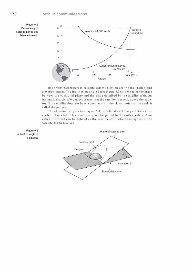
Im p ortan t p aram eters in satellite com m un icat ion are th e in clin at ion an delevat ion an gles. Th e in clin a t ion an gle δ (see Figure 5.3) is defin ed as th e an glebetween th e equatorial p lan e an d th e p lan e described by th e satellite orbit . Anin clin at ion an gle of 0 degrees m ean s th at th e satellite is exactly above th e equa-tor. If th e satellite does n ot h ave a circular orbit , th e closest poin t to th e earth iscalled th e perigee.
Th e eleva t ion a n gle ε (see Figure 5.4) is defin ed as th e an gle between th ecen ter of th e satellite beam an d th e p lan e tan gen tial to th e earth ’s su rface. A so-called fo o t p r in t can be defin ed as th e area on earth wh ere th e sign als of th esatellite can be received .
Mobile communicat ions170
10 20 30 40
48
12162024
× 106mRadius
Synchronous distance35,786 km
Velocity [×1,000 km/h] Satelliteperiod [h]
Figure 5.2Dependency of
satellite period anddistance to earth
δ
Inclination δ
Equatorial plane
PerigeeSatellite orbit
Plane of satellite orbitFigure 5.3Inclination angle of
a satellite

An oth er effect of satellite com m un ication is th e propagation loss of th e sig-n als. Th is at ten uat ion of th e sign al power depen ds on th e d istan ce between areceiver on earth an d th e satellite, an d , addit ion ally, on satellite elevation an datm osph eric con dit ion s. Th e loss L depen din g on th e distan ce r between sen deran d receiver can be calculated as:
L = (4·π·r·f / c)2,with f bein g th e carrier frequen cy an d c th e speed of ligh t.
Th is m ean s th at th e power of th e received sign al decreases with th e squareof th e distan ce. Th is also directly in fluen ces th e m axim um data rates ach ievableu n der certain assu m p t ion s (t ran sm it p ower, an ten n a d iam eter, operat in g fre-q u en cy et c.) as sh own in Com p aret t o (1997). W h ile with an t en n as u sed fo rm obile p h on es a d at a rat e of 10 kbit / s is ach ievab le with a 2 GHz carrier forsat ellit es in so m e 100 km d ist an ce as d iscu ssed in sect io n 5.3.2, on ly som e10 bit / s are possible with geostat ion ary satellites in a distan ce of 36,000 km .
Th e at ten uation of th e sign al due to certain atm osph eric con dit ion s is m orecom p lex (see Figure 5.5). Dep en d in g on th e elevation , th e sign al h as to pen e-trate a sm aller or larger percen tage of th e atm osph ere. Gen erally, an elevationless th an 10 degrees is con sid ered u seless for com m u n icat ion . Especially rainabsorp t ion can be q u ite stron g in t rop ical areas (h ere, th e error rates in creasedram atically durin g th e aftern oon rain fall).
Four differen t typ es of orbits can be iden tified as sh own in Figure 5.6:● Geo st a t io n a r y (o r geo syn ch ro n o u s) ea r t h o r b i t (GEO): GEO sat ellit es
h ave a d istan ce of alm ost 36,000 km to th e earth . Exam ples are alm ost allTV an d rad io bro ad cast sa t ellit es, m an y weath er sa t ellit es an d sat ellit esoperatin g as backbon es for th e teleph on e n etwork (see section 5.3.1).
Satell ite systems 171
εFootprint
Figure 5.4Elevation angle ofa satellite

Mobile communicat ions172
5° 10° 20° 30° 40° 50°
10
20
30
40
50
Elevation of the satellite
Rain absorption
Fog absorption
Atmosphericabsorption
Attenu
ation o
f the s
ignal i
n %
Figure 5.5Signal attenuation
due to atmosphericabsorption
Earth1,000
10,000
GEO (Inmarsat)
MEO (ICO)
Inner and outer VanAllen belts
HEOLEO
(Globalstar,Iridium)
35,768km
Figure 5.6Different types of
satellite orbits

● Med iu m ea r t h o r b it (MEO ): MEOs o p erate a t a d ist an ce of abou t5,000–12,000 km . Up to n ow th ere h ave n ot been m an y satellites in th isclass, bu t som e u pcom in g system s (e.g., ICO) use th is class for various rea-son s (see sect ion 5.3.3).
● Lo w ea r t h o rb it (LEO): W h ile som e t im e ago LEO satellites were m ain lyu sed for esp ion age, several o f t h e n ew sat ellite syst em s n ow rely on t h isclass u sin g alt itudes of 500–1,500 km (see section 5.3.2).
● High ly ellip t ica l o rb it (HEO): Th is class com prises all satellites with n on -circu lar orbit s. Curren t ly, on ly a few com m ercial com m un icat ion system su sin g satellites with ellip t ical orbits are p lan n ed . Th ese system s h ave th eirperigee over large cit ies to im prove com m un ication quality.Th e Van Allen rad iat ion belt s, belt s co n sist in g o f ion ized p art icles, at
h eigh t s of abo u t 2 ,000–6,000 km (in n er Van Allen belt ) an d abou t15,000–30,000 km (outer Van Allen belt) respectively m ake satellite com m un ica-t ion very difficult in th ese orbits.5.3.1 GEOIf a satellit e sh ou ld ap p ear fixed in t h e sky, it req u ires a perio d of 24 h ou rs.Usin g t h e eq u at ion fo r t h e d ist an ce between earth an d sat ellit e r =(g·R2/ (2·π·f)2)1/3 an d th e p eriod of 24 h ou rs f = 1/24h , th e resu lt in g d istan ce is35,786 km . Th e orbit m ust h ave an in clin ation of 0 degrees.● Ad va n t a ges: Th ree GEO satellit es are en ough fo r a com plete coverage of
alm ost an y spot on earth . Sen ders an d receivers can use fixed an ten n a pos-ition s, n o adjustin g is n eeded. GEOs are ideal for TV an d radio broadcastin g.Lifetim e expectation s for GEOs are rath er h igh , at about 15 years. GEOs typi-cally do n ot n eed a h an dover due to th e large footprin t. GEOs do n ot exh ibitan y Doppler sh ift because th e relative m ovem en t is zero.
● Disad van tages: North ern or south ern region s of th e earth h ave m ore prob-lem s receivin g th ese satellites due to th e low elevation above a lat itude of60°, i.e., larger an ten n as are n eeded in th is case. Sh adin g of th e sign als incit ies d ue to h igh bu ild in gs an d th e low elevat ion fu rth er away from th eequator lim it t ran sm ission quality. Th e tran sm it power n eeded is relat ivelyh igh (som e 10 W ) wh ich cau ses p rob lem s fo r bat t ery p o wered d evices.Th ese satellites can n ot be used for sm all m obile ph on es. Th e biggest p rob-lem fo r vo ice an d also d at a com m u n icat ion is t h e h igh lat en cy o f over0.25 s on e-way – m an y ret ran sm ission sch em es wh ich are kn own from fixedn etworks fa il. Du e t o t h e large foo tp rin t , eit h er freq u en cies can n ot bereu sed or th e GEO satellit e n eed s sp ecial an t en n as focusin g on a sm allerfootprin t . Tran sferrin g a GEO in to orbit is very expen sive.
Satell ite systems 173

5.3.2 LEOAs LEOs circu late on a lower orbit , it is obvious th at th ey exh ibit a m uch sh orterperiod (th e typ ical durat ion of LEO periods are 95 to 120 m in utes). Addition ally,LEO system s t ry to en sure a h igh elevation for every spot on earth to p rovide ah igh q uality com m u n icat ion lin k. Each LEO satellite will on ly be visible fromth e earth for arou n d t en m in u tes. A fu rth er classificat ion o f LEOs in to lit t leLEOs with low ban dwidth services (som e 100 bit / s), big LEOs (som e 1,000 bit / s)an d broadban d LEOs with plan s reach in g in to th e Mbit /s ran ge can be foun d inCom p aret to (1997).● Ad van t ages: Usin g advan ced com pression sch em es, t ran sm ission rates of
about 2,400 bit/ s can be en ough for voice com m un ication . LEOs even pro-vide th is ban dwid th for m obile t erm in als with om n i-d irection al an ten n asu sin g low tran sm it power in th e ran ge of 1W. Th e delay for packets deliv-ered via a LEO is relatively low (approx 10 m s). Th e delay is com parable tolon g-d ist an ce wired co n n ect io n s (abo u t 5–10 m s). Sm aller foo tp rin t s o fLEOs allow for better frequen cy reuse, sim ilar to th e con cepts u sed for cellu-lar n etworks (Gavish , 1998). LEOs can provide a m uch h igh er elevation inp olar region s an d so better global coverage.
● D isa d v a n t a ges: Th e b iggest p rob lem o f th e LEO con cep t is th e n eed fo rm an y satellites if global coverage is to be reach ed. Several con cepts in volve50–200 or even m ore satellites in orbit . Th e sh ort t im e of visibility with ah igh elevat ion req u ires add it ion al m ech an ism s for con n ect ion h an doverbetween d ifferen t satellit es. (Differen t cases for h an dover are exp lain ed insect ion 5.4.) Th e h igh n u m ber of satellit es com bin ed with th e fast m ove-m en ts results in a h igh com plexity of th e wh ole satellite system . On e gen eralp roblem o f LEOs is th e sh o rt lifet im e of abou t five to eigh t years d u e toatm osph eric drag an d radiation from th e in n er Van Allen belt1. Assum in g 48satellites an d a lifetim e of eigh t years (as expected for th e system Globalstar),a n ew satellit e wou ld be n eeded every two m on th s. Th e low laten cy via asin gle LEO is on ly h alf of th e story. Oth er factors are th e n eed for routin g ofdata packets from satellite to satellite (or several tim es from base station s tosatellites an d back) if a user wan ts to com m un icate aroun d th e world. Due toth e large footp rin t , a GEO typ ically does n ot n eed th is type of rou t in g, assen ders an d receivers are m ost likely in th e sam e footp rin t.
Mobile communicat ions174
1 th e life-t im e of satellites is typically lim ited by th e lim ited am oun t of fuel on -board wh ich is n eededfor correct in g th e orbit from t im e to tim e.

5.3.3 MEOMEOs can be posit ion ed som ewh ere between LEOs an d GEOs, both in term s ofth eir orbit an d due to th eir advan tages an d d isadvan tages.● Ad v a n t a ges: Usin g orb it s arou n d 10,000 km , t h e system on ly req u ires a
d ozen satellit es wh ich is m ore th an a GEO system , bu t m uch less th an aLEO system . Th ese satellites m ove m ore slowly relat ive to th e earth ’s rota-t ion allowin g a sim pler system design (satellite periods are about six h ours).Depen d in g o n t h e in clin at ion , a MEO can cover larger p op u lat ion s, sorequ irin g fewer h an dovers.
● Disa d v a n t a ges: Again , d u e t o t h e larger d ist an ce t o t h e earth , d elayin creases to abou t 70–80 m s. Th e satellites n eed h igh er tran sm it power an dspecial an ten n as for sm aller footprin ts.
5.4 Rout ingA sat ellit e syst em to geth er with gat eways an d fixed t errest r ial n etworks assh own in Figu re 5.1 h as to rou te data t ran sm ission s from on e user to an oth eras an y oth er n etwork does. Routin g in th e fixed segm en t (on earth ) is ach ievedas usual, wh ile two d ifferen t solu t ion s exist for th e satellite n etwork in space. Ifsatellites offer ISLs, t raffic can be routed between th e satellites. If n ot , all trafficis relayed to earth , rou ted th ere, an d relayed back to a satellite.
Assu m e two u sers of a sa t ellit e n etwork exch an ge da t a. If t h e sat ellit esystem supports ISLs, on e user sen ds data up to a satellite an d th e satellite for-ward s it t o th e on e resp on sib le for t h e receiver via o th er sat ellit es. Th is lastsatellite n ow sen ds th e data down to th e earth . Th is m ean s th at on ly on e uplin kan d on e d own lin k p er d irect ion is n eed ed . Th e ab ilit y o f rou t in g with in th esatellite n etwork redu ces th e n um ber of gateways n eeded on earth .
If a satellite system does n ot offer ISLs, th e user also sen ds data up to a satel-lite, bu t n ow th is satellite forwards th e data to a gateway on earth . Routin g takesp lace in fixed n etwo rks as u su al u n t il an o th er gat eway is reach ed wh ich isrespon sible for th e satellite above th e receiver. Again data is sen t up to th e satel-lite wh ich forwards it down to th e receiver. Th is solu t ion requires two u plin ksan d two d own lin ks. Dep en d in g on th e orbit an d th e speed of rou t in g in th esat ellit e n etwork com p ared t o th e t errest rial n etwo rk, th e so lu t ion with ISLsm igh t offer lower laten cy. Th e drawbacks of ISLs are h igh er system com plexitydue to addit ion al an ten n as an d routin g h ard- an d software for th e satellites.
Satell ite systems 175

5.5 Localizat ionLocalizat ion of users in satellite n etworks is sim ilar to th at of terrestrial cellu larn etworks. On e add it ion al problem arises from th e fact th at n ow th e ‘base sta-t ion s’, i.e., t h e sat ellit es, m ove as well. Th e ga t eways o f a sa tellit e n etwo rkm ain t ain several regist ers. A h o m e lo ca t io n regist er (H LR) sto res all st at icin form ation abou t a user as well as h is or h er curren t location . Th e last kn ownlocat ion o f a m ob ile u ser is st o red in th e v isi t o r lo ca t io n reg ist er (VLR).Fun ct ion s of th e VLR an d HLR are sim ilar to th ose of th e registers in , e.g., GSM(see ch ap t er 4). A p art icu larly im p ort an t regist er in sat ellit e n etworks is t h esa t e l l it e u ser m a p p in g r egist er (SUMR). Th is st ores t h e cu rren t p osit ion o fsat ellit es an d a m app in g of each u ser t o th e cu rren t sa tellit e t h rou gh wh ichcom m un ication with a user is possible.
Registrat ion of a m obile stat ion is ach ieved as follows. Th e m obile stat ionin it ially sen d s a sign al wh ich on e or several sat ellit es can receive. Sa t ellit esreceivin g su ch a sign al repo rt th is even t t o a gateway. Th e gat eway can n owdeterm in e th e location of th e user via th e location of th e satellites. User data isrequested from th e user’s HLR, VLR an d SUMR are updated.
Callin g a m obile stat ion is again sim ilar to GSM. Th e call is forwarded to agateway wh ich localizes th e m obile stat ion usin g HLR an d VLR. With th e h elpof th e SUMR, th e appropriate satellite for com m un ication can be foun d an d th econ n ection can be set up .
5.6 HandoverAn im p ortan t top ic in satellit e system s u sin g MEOs an d in part icu lar LEOs ish an dover. Im agin e a cellu lar m obile ph on e n etwork with fast m ovin g base sta-t ion s. Th is is exactly wh at such satellite system s are – each satellite represen ts abase stat ion fo r a m obile p h on e. Com p ared to t errest rial m o bile ph on e n et -works, addit ion al in stan ces of h an dover can be n ecessary due to th e m ovem en tof th e satellites.● In t ra -sa t ellit e h an d over: A user m igh t m ove from on e spot beam of a satel-
lit e to an oth er sp ot beam of th e sam e satellite. Usin g sp ecial an ten n as, asatellite can create several spot beam s with in its footprin t . Th e sam e effectm igh t be caused by th e m ovem en t of th e satellite.
● In t er-sa t ellit e h an d over: If a user leaves th e footprin t of a satellite or if th esa t ellit e m oves away, a h an d over t o t h e n ext sa t ellit e t akes p lace. Th ism igh t be a h ard h an d over swit ch in g at on e m o m en t o r a so ft h an d overu sin g both satellites (or even m ore) at th e sam e tim e (as th is is possible withCDMA system s). In ter-satellite h an dover can also take p lace between satel-lit es if th ey sup port ISLs. Th e satellite system can t rade h igh t ran sm ission
Mobile communicat ions176

quality for h an dover frequen cy. Th e h igh er th e tran sm ission quality sh ou ldbe, th e h igh er th e elevation an gles th at are n eeded . High elevation an glesim ply frequen t h an dovers wh ich in tu rn , m ake th e system m ore com plex.
● Ga tew a y h a n d o ver : W h ile th e m obile u ser an d satellite m igh t st ill h avegood con tact , th e satellite m igh t m ove away from th e curren t gateway. Th esatellite h as to con n ect to an oth er gateway.
● In t er -syst em h a n d o ver : W h ile t h e t h ree t yp es o f h an d over m en t ion edabove take p lace with in th e satellite-based com m un ication system , th is typeof h an dover con cern s differen t system s. Typically, satellite system s are usedin rem ote areas if n o oth er n etwork is available. As soon as t rad it ion al cellu-lar n etworks are available, users m igh t switch to th is type usually because itis ch eaper an d o ffers lower laten cy. Cu rren t syst em s allow for th e u se o fd u al-m od e (or even m o re) m ob ile p h o n es bu t u n fortu n at ely, seam lessh an dover between satellite system s an d terrest rial system s or vice versa h asn ot been possible up to n ow.
5.7 ExamplesTable 5.1 sh ows fou r exam ples (two in operat ion , two p lan n ed ) of MEO/ LEOsatellite n etworks (see also Miller, 1998 an d Lu tz, 1998). On e system , wh ich is inop erat ion , is th e Ir id iu m system . Th is was origin ally t argeted for 77 satellit es(h en ce th e n am e Irid ium with its 77 electron s) an d n ow run s with 66 satellitesp lus seven spare satellites (was six, Iridium , 2002). It is th e first com m ercial LEOsystem to cover th e wh ole world . Satellit es orbit at an alt itude of 780 km , th eweigh t of a sin gle satellite is about 700 kg. Th e fact th at th e satellites are h eavierth an , e.g., th e com petitor Globalstar resu lt s from th eir capability to route databetween Iridium satellites by usin g ISLs, so a satellite n eeds m ore m em ory, pro-cessin g power etc. Mobile stat ion s (MS in Table 5.1) operate at 1.6138–1.6265GHz accordin g to an FDMA/TDMA sch em e with TDD, feeder lin ks to th e satel-lites at 29.1–29.3 GHz for th e uplin k an d 19.4–19.6 GHz for th e down lin k. ISLsuse 23.18–23.38 GHz. Th e in frastructure of Irid ium is GSM-based.
A d irect com petitor of Iridium is Glob a lsta r (Globalstar, 2002). Th is system ,wh ich is also operat ion al, u ses a lower n um ber of satellites with fewer capabili-t ies per satellite. Th is m akes th e satellites ligh ter (abou t 450 kg weigh t) an d th eoverall system ch eap er. Globalstar does n ot provide ISLs an d global coverage,but h igh er ban dwid th is gran ted to th e cu stom ers. Usin g CDMA an d u t ilizin gpath diversity, Globalstar can provide soft h an dovers between differen t satellitesby receivin g sign als fro m several sa t ellit es sim u lt an eou sly. Globalst ar u ses1.61–1.6265 GHz fo r u p lin ks fro m m obile st at io n s t o t h e sat ellit es an d2.4835–2.5 GHz fo r t h e d own lin k. Feed er lin ks fo r t h e sat ellit es are at5.091–5.250 GHz gateway to satellite an d 6.875–7.055 GHz satellite to gateway.
Satell ite systems 177

W h ile th e oth er th ree system s presen ted in Table 5.1 are LEOs, In term ed ia teCircu la r Orb it , (ICO) (ICO, 2002) rep resen ts a MEO system as th e n am e in di-cates. ICO n eeds less satellites, 10 p lus two spare are p lan n ed , to reach globalcoverage. Each satellite covers about 30 per cen t of earth ’s surface, bu t th e systemworks with an average elevat ion of 40°. Due to th e h igh er com plexity with in th esatellites (i.e., larger an ten n as an d larger solar paddles to gen erate en ough powerfor tran sm ission ), th ese satellites weigh abou t 2,600 kg. W h ile laun ch in g ICOsatellites is m ore expen sive due to weigh t an d h igh er orbit , th eir expected life-tim e is h igh er with 12 years com pared to Globalstar an d Iridium with eigh t yearsan d less. ICO sat ellit es n eed fewer rep lacem en ts m akin g t h e wh ole syst emch eaper in retu rn . Th e start of ICO h as been delayed several t im es. Th e ICO con -sortium wen t th rough ban kruptcy an d several join t ven tures with oth er satelliteorgan ization s, bu t still p lan s to start operation of th e system with in th e n ext fewyears. Th e exact n um ber of satellites is cu rren tly un clear, h owever, th e system issh ifted towards IP t raffic with up to 144 kbit / s.
Mobile communicat ions178
Irdium Globalstar ICO Teledesic(orbit ing) (orbit ing) (planned) (planned)
No. of satellites 66 + 7 48 + 4 10(?) + 2 288(?)Altitude [km] 780 1,414 10,390 Approx. coverage global ±70° latitude global 700 globalNo. of planes 6 8 2 12Inclination 86° 52° 45° 40°Minimum 8° 20° 20° 40°elevationFrequencies 1.6 MS 1.6 MS 2 MS 19 [GHz (circa)] 29.2 2.5 MS 2.2 MS 28.8
19.5 5.1 5.2 62 ISL23.3 ISL 6.9 7
Access method FDMA/ TDMA CDMA FDMA/ TDMA FDMA/ TDMAISL Yes No No YesBit rate 2.4 kbit/ s 9.6 kbit/ s 4.8 kbit/ s 64 Mbit/ s
(144 kbit/ s 2/ 64 Mbit/ s planned)
No. of channels 4,000 2,700 4,500 2,500Lifetime [years] 5–8 7.5 12 10Initial cost $4.4 bn $2.9 bn $4.5 bn $9 bnestimate
Table 5.1 Example MEOand LEO systems

A very am bitious an d m aybe n ever realized LEO project is Teled esic wh ichplan s to provide h igh ban dwidth satellite con n ection s worldwide with h igh qual-ity of service (Teled esic, 2002). In con trast to t h e oth er system s, th is satellit en etwork is n ot prim arily plan n ed for access usin g m obile ph on es, bu t to en ableworldwide access to th e in tern et via satellite. Prim ary custom ers are busin esses,sch ools etc. in rem ote places. Teledesic wan ts to offer 64 Mbit /s down lin ks an d2 Mbit/s uplin ks. With special term in als even 64 Mbit/ s up lin ks sh ould be possi-ble. Receivers will be, e.g., roof-m oun ted lap top-sized term in als th at con n ect tolocal n etworks in th e buildin g. Service start was targeted for 2003, h owever, cur-ren tly on ly th e web pages rem ain ed from th e system an d th e start was sh ifted to2005. Th e in it ial p lan s of 840 satellit es p lu s 84 spares were drop ped , th en 288p lu s sp ares were p lan n ed , d ivided in to 12 p lan es with 24 satellit es each .Con siderin g an expected lifetim e of ten years per satellite, th is still m ean s a n ewsat ellit e will h ave to be laun ch ed at least every o th er week. Du e to t h e h ighban dwidth , h igh er frequen cies are n eeded, so Teledesic operates in th e Ka-ban dwith 28.6–29.1 GHz for th e uplin k an d 18.8–19.3 GHz for th e down lin k. At th eseh igh frequ en cies, com m u n ication lin ks can easily be blocked by rain or o th erobstacles. A h igh elevation of at least 40° is n eeded. Teledesic uses ISL for routin gbetween th e satellites an d im plem en ts fast packet switch in g on th e satellites.
On ly Globalstar uses CDMA as access m eth od, wh ile th e oth er system s relyo n d ifferen t TDMA/ FDMA sch em es. Th e co st est im ates in Table 5 .1 are ju strough figures to com pare th e system s. Th ey d irect ly reflect system com plexity.ICO satellites fo r exam ple are m ore com plicated com pared to Irid ium , so th eICO system h as sim ilar in it ial cost s. Sm aller an d sim p ler Globalstar satellitesm ake th e system ch eaper th an Iridium .
5.8 SummarySatellite system s evolved qu ickly from th e early stages of GEOs in th e late 1960sto m an y system s in d ifferen t orbits of today. Th e tren d for com m un ication satel-lites is m ovin g away from big GEOs, toward th e sm aller MEOs an d LEOs m ain lyfo r th e reason o f lo wer d elay wh ich is essen t ial fo r vo ice com m u n icat ion .Differen t system s will offer global coverage with services ran gin g from sim plevoice an d low bit rate data up to h igh ban dwidth com m un icat ion s with qualityof service. However, satellite system s are n ot aim ed at replacin g terrestrial m obilecom m un ication system s but at com plem en tin g th em . Up to n ow it h as n ot beenclear h ow h igh th e costs for operation an d m ain ten an ce of satellite system s arean d h ow m uch data t ran sm ission via satellites really costs for a custom er. Specialproblem s for LEOs in th is con text are th e h igh system com plexity an d th e rela-t ively sh ort lifet im e of th e satellites. In itial system costs on ly con stitu te part ofth e overall costs. Before it is possible to offer an y service to custom ers th e wh olesatellite system h as to be set up. An in crem en tal growth as it is don e for terres-t rial n etworks is n o t p ossible in LEO system s. Op erators in stal n ew terrest rial
Satell ite systems 179

n etworks in den sely popu lated areas first to get a q u ick retu rn on in vestm en t.Th is m on ey can th en be u sed fo r fu rth er ext en sion o f th e system . Mo st LEOsatellites fly over n on - or sparsely populated areas (sea, deserts, polar region s etc.)an d can n ot gen erate an y reven ue. In th e en d it turn ed out th at th ere are too fewcustom ers for satellite system s such as Iridium leadin g to th e ban kruptcy of th eoperator in March 2000. On ly th e in terven t ion of th e US DoD could p reven t adeorbit in g of th e satellites in August 2000 (wh ich wou ld h ave been th e world’sm ost expen sive firework). Now th e US DoD is th e m ain custom er of Iridium withits own gateway in Hawaii but service is st ill offered to everyon e.
A n ew app licat ion for satellite system s is th eir use as an addit ion to terres-t rial m ob ile co m m u n icat ion syst em s in t h e fo llowin g way. Po in t -t o -p o in tcom m u n icat ion services are h an d led by, e.g., UMTS, add it ion al m u lt icast o rbroadcast delivery of m ult im edia con ten t is perform ed by a satellite system . Inth is scen ario t h e ro le o f a sat ellit e is sim ilar t o t errest rial b roadcast ers asexp lain ed in m ore detail in ch apter 6. A p roject evaluat in g th e possibilit ies ofsu ch a scen ario is sa t el li t e-d igit a l m u lt i-m ed ia b ro a d ca st in g (S-DMB). Th isp ro ject com b in es sat ellit e an d t errest rial t ran sm issio n u sin g t h e wideb an dCDMA terrest rial UMTS stan dard to ach ieve a m ult icast layer over 2.5/3G n et-works (Courseille, 2001), (Nussli, 2002).
Yet an oth er m arket for n ew system s m igh t appear between th e low orbit in gLEOs an d t errest ria l an t en n as. Several com p an ies are p lan n in g t o u se h igh -alt itud e aircraft or Zeppelin s for carryin g base stat ion s, so-called h igh -a lt it u d ep la t fo rm s (HAP, Djukn ic, 1997). Th ese base stat ion s could be placed h igh abovelarge cit ies offerin g h igh -quality tran sm ission at lower costs com pared to satel-lit e syst em s. A b ig ad van tage com p ared t o LEO system s is t h e possib ility forin crem en tal growth an d th e req uirem en t for on ly th e n um ber of system s th atare actu ally n eed ed to sa t isfy t h e ban dwid th dem an d at cert a in locat ion s.However, alth ough h igh -alt itude aircraft are feasible in prin cip le it is un clear ifit is co st -effect ive. Th e ITU h as en d orsed variou s freq u en cy ran ges fo r HAPapplication s open in g th e way for th e provision of, e.g., UMTS services by m ean sof HAPs (Avagn in a, 2002).
5.9 Review exercises1 Name basic applications for satellite communication and describe the trends.2 Why are GEO systems for telecommunications currently being replaced by fiber
optics?3 How do inclination and elevation determine the use of a satellite?4 What characteristics do the different orbits have? What are their pros and cons? 5 What are the general problems of satellite signals travelling from a satellite to
a receiver?
Mobile communicat ions180

6 Considered as an interworking unit in a communication network, what functioncan a satellite have?
7 What special problems do customers of a satellite system with mobile phonesface if they are using it in big cities? Think of in-building use and skyscrapers.
8 Why is there hardly any space in space for GEOs?
5.10 ReferencesAvagn in a, D., Dovis, F., Gh iglion e, A., Mulassan o, P. (2002) ‘Wireless Networks
Based on th e High -Alt it u de Plat form s for th e Provision of In tegratedNavigation /Com m un ication Services,’ IEEE Communications Magazine, 40(2).
Com paretto, G., Ram irez, R. (1997) ‘Tren ds in m obile satellite tech n ology,’ IEEEComputer, 30(2).
Courseille, O. (2001) ‘Role of satellites in m obile system s,’ Alcatel TelecommunicationsReview, 4/2001.
Dju kn ic, G., Freid en fels, J., O ku n ev, Y. (1997) ‘Est ab lish in g WirelessCom m u n icat ion s Services via High -Alt itu d e Plat form s: A Con cept W h oseTim e h as Com e?,’ IEEE Communications Magazine, 35(9).
Gavish , B., Kalven es, J. (1998) ‘Th e im p act of satellit e alt itud e on th e p erfor-m an ce o f LEO b ased com m u n ica t io n syst em s,’ Wireless Networks, J.C.Baltzer, 4(2)
Globalstar (2002) Globalstar L.P., San Jose, CA, USA, h ttp :/ /www.globalstar.com / .ICO (2002) ICO Global Com m un ication s Lon don , UK, h ttp :/ /www.ico.com / .Iridium (2002) Iridium Satellite LLC, Leesburg, VA, USA, h ttp:/ /www.iridium .com /.Jam alip ou r, A. (1998) Low ea rth orbita l sa tellites for persona l communica tion
networks. Artech House.Lu tz, E. (1998) ‘Issu es in satellit e p erson al com m u n icat ion syst em s,’ Wireless
Networks, J.C. Baltzer, 4(2).Maral, G., Bou squ et , M. (1998) Sa tellite communica tions systems: Systems, tech-
niques and technology. Joh n Wiley & Son s.Miller, B. (1998) ‘Satellites free th e m obile ph on e,’ IEEE Spectrum, March .Nu ssli, C.; Bertou t , A. (2002) ‘Sat ellit e-based m ult icast arch itectu re for m u lt i-
m ed ia services in 3G m obile n etworks,’ Alca tel Telecommunica tionsReview, 2/2002.
Pascall, S.C ., W ith ers, D.J. (1997) Commercia l sa tellite communica tion . FocalPress, 1997.
Sch wartz, R. (1996) W ireless communica tions in developing countries: cellular andsatellite systems. Artech House.
Teledesic (2002) Teledesic Corp., Bellevue, WA, USA, h ttp :/ /www.teledesic.com / .
Satell ite systems 181


A lth ough th is book m ostly deals with differen t com m un ication tech n olo-gies allowin g in d ivid u al two -way co m m u n icat io n , it is im p ort an t t ou n derst an d th e role o f un id irect ion al broad cast system s with in fu tu re
m obile com m un icat ion scen arios. Typical broadcast system s, such as radio an dtelevision , d istribu te in form ation regardless of th e n eeds of in d ividual users. Asan addit ion to two-way com m un ication tech n ologies, broadcastin g in form ationcan be very cost effective. Just im agin e th e d istribut ion of a m ovie trailer to m il-lion s of poten tial custom ers an d com pare it with th e abilit ies of 3G base stat ion sto provide 10–20 sim ultan eous users with a 128 kbit/ s video stream . Th e distrib-u t ion of th e trailer would block th e wh ole m obile n etwork for a lon g t im e evenif ten s of th ousan d base stat ion s are assum ed.
In th e fu tu re, television an d radio tran sm ission s will be fu lly d igital. Alreadyseveral radio station s produce an d tran sm it th eir program m es d igitally via th e in ter-n et or d igital radio (see later section s in th is ch ap ter). Digital television is on itsway. Besides tran sm ittin g video an d audio, digital t ran sm ission allows for th e distri-bution of arbitrary digital data, i.e., m ult im edia in form ation can accom pan y radioan d TV program m es at very low cost com pared to in dividual wireless con n ection s.
Th e followin g section s give a gen eral in t roduction in to asym m etric com m u-n icat ion up to th e extrem e case of un idirection al broadcastin g. On e im portan tissue is th e cyclic rep etit ion of data (as d iscussed in th e section s about broadcastd isks). Broadcast in g system s wh ich will be explain ed in detail are digital audiobroadcast in g (DAB) an d d igital video broadcast in g (DVB). On e in terest in g fea-tu re abo u t d at a co m m u n icat ion is t h e ab ilit y of DAB an d DVB to carrym u lt i-m ed ia in fo rm at ion . In com bin at ion with sat ellit e o r t errest rial t ran s-m ission an d th e use of th e in tern et , th ese system s are able to deliver h igh ban d-width to in dividual custom ers at low cost (ETSI, 2002).
6.1 OverviewUn idirection al distribution system s or broadcast system s are an extrem e version ofasym m etric com m un ication system s. Qu ite often , ban dwid th lim itation s, d iffer-en ces in tran sm ission power, or cost factors preven t a com m un ication system frombein g sym m etrical. Sym m et r ica l com m u n ica t io n syst em s offer th e sam e
Broadcast systems 6
183

tran sm ission capabilities in both com m un ication direction s, i.e., th e ch an n el ch ar-acterist ics from A to B are th e sam e as from B to A (e.g., ban dwidth , delay, costs).
Exam p les o f sym m et rical com m u n icat ion services are th e p lain o ld t ele-ph on e service (POTS) or GSM, if en d-to-en d com m u n ication is con sid ered . Inth is case, it does n o t m at ter if on e m obile stat ion calls th e o th er or th e oth erway roun d, ban dwidth an d delay are th e sam e in both scen arios.
Th is sym m etry is n ecessary for a teleph on e service, but m an y oth er applica-t ion s do n ot require th e sam e ch aracterist ics for both direction s of in form ationt ran sfer. Co n sid er a t yp ical clien t / server en viron m en t . Typ ically, t h e clien tn eed s m u ch m ore data from th e server th an th e server n eeds from th e clien t .Today’s m ost prom in en t exam ple of th is is th e world wide web. Million s of usersd own load d at a u sin g t h eir b rowsers (clien t s) fro m web servers. A u ser o n lyretu rn s in fo rm at io n to t h e server from t im e to t im e. Sin gle req u est s for n ewpages with a typ ical size of several h un d red bytes resu lt in respon ses of u p tosom e 10 kbytes on average.
A television with a set -top box represen ts a m ore extrem e scen ario. Wh ile ah igh -resolut ion video stream requ ires several Mbit/ s, a typ ical user return s som ebytes from tim e to t im e to switch between ch an n els or retu rn som e in form ationfor TV sh opp in g.
Fin ally, today’s pagers an d rad ios work com pletely on e-way. Th ese devicescan on ly receive in form at ion , an d a user n eeds addit ion al com m un ication tech -n ology to sen d an y in form at ion back to , e.g., th e rad io stat ion . Typ ically, th eteleph on e system is used for th is pu rpose.
A sp ecial case o f a sy m m et r ica l co m m u n ica t io n sy st em s are u n id ir ec-t ion a l b road cast syst em s wh ere typically a h igh ban dwidth data stream existsfrom on e sen d er to m an y receivers. Th e p rob lem arisin g from th is is th at th esen der can on ly optim ize tran sm it ted data for th e wh ole group of receivers an dn o t fo r an in d ivid u al u ser. Figu re 6.1 sh o ws a sim p le b ro ad cast scen ario . Asen der tries to op tim ize th e tran sm it ted packet stream for th e access pat tern s ofall receivers with ou t kn owin g th eir exact req u irem en ts. All p acket s are t h entran sm itted via a broadcast to all receivers. Each receiver n ow p icks up th e pack-ets n eeded an d drops th e oth ers or stores th em for fu ture use respectively.
Th ese ad d it ion al fu n ct ion s are n eed ed to p erso n alize d ist rib u ted dat adepen din g on in d ividual requirem en ts an d app lication s. A very sim ple exam pleof th is process could be a user-defin ed filter fun ction th at filters ou t all in form a-tion wh ich is n ot of in terest to th e user. A radio in a car, for exam ple, could on lypresen t t raffic in form at ion for th e local en viron m en t, a set-top box could on lystore th e startin g t im es of m ovies an d drop all in form ation about sports.
However, th e problem con cern in g wh ich in form ation to sen d at wh at t im estill rem ain s for a sen der. Th e followin g section sh ows several solu t ion s to th is.
Mobile communicat ions184

6.2 Cyclical repet it ion of dataA broadcast sen der of data does n ot kn ow wh en a receiver starts to listen to th et ran sm ission . W h ile for rad io or television t h is is n o p roblem (if you do n otlisten you will n ot get th e m essage), t ran sm ission of oth er im portan t in form a-tion , such as traffic or weath er con dit ion s, h as to be repeated to give receivers ach an ce to receive th is in form at ion after h avin g listen ed for a certain am oun t oftim e (like th e n ews every fu ll h our).
Th e cyclical rep et it ion o f data b locks sen t via broad cast is o ften called ab road cast d isk accord in g to th e project in Ach arya (1995) or data carousel, e.g.,accord in g to th e DAB/DVB stan dards (ETSI, 2002). Differen t pattern s are poss-ible (Figure 6.2 sh ows th ree exam ples). Th e sen der repeats th e th ree data blocksA, B, an d C in a cycle. Usin g a fla td isk , all b locks are rep eat ed o n eafter an o th er. Every b lock is t ran s-m it ted for an equal am oun t of tim e,th e average wait in g t im e for receiv-in g a block is th e sam e for A, B, an dC. Sk ew ed d isk s favor on e or m oredata blocks by repeat in g th em on ceor several tim es. Th is raises th e probability of receivin g a repeated block (h ere A)if th e block was corru p ted th e first t im e. Fin ally, m u lt i-d isk s d istribu te blocksth at are repeated m ore often th an oth ers even ly over th e cyclic p at tern . Th ism in im izes th e delay if a u ser wan ts to access, e.g., block A.
Broadcast systems 185
Undirectionaldistribution
mediumSender
BA Receiver
Receiver
Individual accesspattern of one user
.
.
.
A
A
B
B
A
A
A B AReceiver
Optimized for expectedaccess pattern
of all users≠
Service userService provider Figure 6.1Broadcast transmission
A B C A B C • •Flat disk
A A B C A A • •Skewed disk
A B A C A B • •Multi-disk
Figure 6.2Different broadcastpatterns

It is on ly possible to op tim ize th ese pattern s if th e sen der kn ows som eth in gabou t th e con ten t of th e data blocks an d th e access pattern s of all users.
EXAMPLE BROADCAST DISKLet us assum e th at th e broad cast sen der is a rad io stat ion t ran sm it t in g in form at ionabout road con dit ion s (block A), th e weath er report (block B), th e latest even ts in town(block C) an d a m en u to access th ese an d oth er topics (block D) in addit ion to m usic.Th e sen d er can n ow assu m e, kn owin g som eth in g abou t th e im p ortan ce of th e d atablocks, th at block D is th e m ost im portan t to en able access to th e oth er in form ation .Th e secon d im portan t block is A, th en B an d fin ally C. A possible broadcast d isk forth is scen ario could n ow look as follows:
DADBDADCDADBDADC ...
It is n ow th e receiver’s task to cach e data blocks to m in im ize access delay assoon as a user n eeds a specific type of in form ation . Again , th e receiver can on lyop tim ize cach in g if it kn ows som eth in g abou t th e con ten t of th e data blocks.Th e receiver can store typ ical access pat tern s of a u ser to be able to guess wh ichblocks th e user will access with a h igh er probability. Cach in g gen erally followsa cost -based st rategy: wh at are th e costs for a u ser (caused by th e wait in g t im e) ifa data block h as been requested but is curren tly n ot available in th e cach e?
Con sid erin g t h e ab ove exam p le, t h e m o bile d evice of t h e fu tu re (e.g., aradio in a car, an en h an ced m obile ph on e) m igh t rem em ber th at a u ser alwaysch ecks th e latest even ts in town in th e even in g, bu t th e road con dit ion s in th em o rn in g. Th e d evice will cach e b lock A in t h e m orn in g an d b lock C in t h eeven in g. Th is procedure will gen erally reduce th e wait in g t im e for a user if h e orsh e stays with th is access pattern .
6.3 Digital audio broadcast ingToday’s an alog rad io system st ill follows th e basic prin ciple of frequen cy m odu-lat ion in ven ted back in 1933. In add it ion to aud io t ran sm ission , very lim itedin fo rm at ion su ch as t h e st at io n id en t ificat io n can accom pan y th e p rogram .Tran sm ission q uality varies great ly depen d in g on m u lt i-p ath effects an d in ter-feren ce. Th e fu lly d igital DAB system does n ot on ly offer sou n d in a CD-likequality, it is also practically im m un e to in terferen ce an d m ult i-path propagat ioneffects (ETSI, 2001a), (DAB, 2002).
DAB system s can u se sin gle fr eq u en cy n et w o rk s (SFN), i.e., a ll sen d erstran sm itt in g th e sam e rad io program operate at th e sam e frequen cy. Today, d if-feren t sen ders h ave to use d ifferen t frequen cies to avoid in terferen ce alth oughth ey are t ran sm itt in g th e sam e rad io program . Usin g an SFN is very freq uen cyefficien t , as a sin gle rad io st at io n on ly n eed s on e freq u en cy th rou gh ou t t h ewh ole coun t ry. Addit ion ally, DAB tran sm ission power per an ten n a is orders of
Mobile communicat ions186

m agn itude lower com pared to trad it ion al FM stat ion s. DAB uses VHF an d UHFfreq u en cy ban d s (depen d in g on n at ion al regu lat ion s), e.g., t h e t errest rial TVch an n els 5 to 12 (174–230 MHz) or th e L-ban d (1452–1492 MHz). Th e m odu la-t io n sch em e u sed is DQ PSK. DAB is o n e o f t h e syst em s u sin g COFDM (seech ap ter 2) with 192 to 1536 carriers (t h e so-called en sem b le) with in a DABch an n el of 1.5 MHz. Add it ion ally, DAB uses FEC to red uce th e erro r rate an din troduces gu ard sp a ces between sin gle sym bols du rin g t ran sm ission . COFDMan d th e use of gu ard sp aces red u ce ISI t o a m in im u m . DAB can even ben efitfrom m ult ipath propagat ion by recom bin in g th e sign als from d ifferen t path s.
EXAMPLE DAB ENSEMBLETh e followin g is an en sem ble tran sm it ted at 225.648 MHz in south ern Germ an y. Th een sem ble con tain s six radio program s an d two data ch an n els.● SWR 1 BW 192 kbit/ s, stereo● SWR 2 192 kbit/s, stereo● SWR 3 192 kbit/s, stereo● Hit Rad io An ten n e 1 192 kbit/ s, stereo● DAS DING 160 kbit /s, stereo● SWR traffic in form ation 16 kbit/ s, data● SWR service in form ation 16 kbit / s, data
With in every frequen cy block of 1.5 MHz, DAB can tran sm it up to six stereoaudio p rogram m es with a data rate of 192 kbit/ s each . Depen d in g on th e redun -d an cy cod in g, a dat a service with ra t es u p t o 1 .5 Mbit / s is availab le as analtern ative. For th e DAB tran sm ission system , audio is ju st an oth er type of data(besides d ifferen t codin g sch em es). DAB uses two basic tran sport m ech an ism s:● Ma in ser v ice ch a n n el (M SC): Th e MSC carries all u ser d a ta , e.g. au d io ,
m ult im edia data. Th e MSC con sists of com m on in t er leaved fram es (CIF),i.e ., d at a field s o f 55,296 b it s t h at are sen t every 24 m s (th is in t ervaldepen ds on th e t ran sm ission m ode (ETSI, 2001a)). Th is resu lts in a data rateof 2.304 Mbit/ s. A CIF con sists of cap acit y u n its (CU) with a size of 64 bits,wh ich form th e sm allest addressable un it with in a DAB system .
● Fa st in fo r m a t io n ch a n n el (FIC): Th e FIC con tain s fa st in fo r m a t io nb locks (FIB) with 256 bits each (16 bit ch ecksum ). An FIC carries all con trolin form at ion wh ich is requ ired for in terpretin g th e con figu ration an d con -ten t of th e MSC.Two t ran sp ort m od es h ave been defin ed fo r th e MSC. Th e st r ea m m o d e
offers a tran sparen t data tran sm ission from th e sou rce to th e dest in at ion witha fixed b it rat e in a su b ch an n el. A su b ch a n n el is a p art o f t h e MSC an d
Broadcast systems 187

com p rises several CUs with in a CIF. Th e fixed data rate can be m u lt ip les of 8kbit / s. Th e p a ck et m o d e tran sfers data in addressable blocks (packets). Th eseblocks are used to con vey MSC data with in a sub ch an n el.
DAB defin es m an y service in form at ion st ru ctures accom pan yin g an aud iostream . Th is p rogram associa t ed d a ta (PAD) can con tain program in form ation ,con tro l in form ation , st ill p ictu res for d isp lay on a sm all LCD, t it le d isp lay etc.Audio codin g uses PCM with a sam plin g rate of 48 kHz an d MPEG audio com -pression . Th e com pressed audio stream can h ave bit rates ran gin g from 8 kbit /sto 384 kbit/ s. Audio data is in terleaved for better burst toleran ce.1
Figure 6.3 sh ows th e gen eral fram e st ructure of DAB. Each fram e h as a dura-t ion TF of 24, 48, or 96 m s depen din g on th e tran sm ission m ode. DAB defin esfo u r d ifferen t t ran sm issio n m o des, each of wh ich h as cert ain st ren gth s th atm ake it m ore efficien t for eith er cable, terrestrial, or satellite tran sm ission (ETSI,2001a). With in each fram e, 76 or 153 sym bols are t ran sm it ted usin g 192, 384,768, o r 1,536 d ifferen t carriers for COFDM. Th e guard in tervals Td pro tect in geach sym bol can be 31, 62, 123, or 246 µs.
Each fram e con sist s o f t h ree p art s. Th e sy n ch r o n iza t io n ch a n n el (SC)m arks th e start o f a fram e. It con sist s o f a n u ll sym bol an d a p h ase referen cesym bol to syn ch ron ize th e receiver. Th e fa st in fo r m a t ion ch a n n el (FIC) fol-lows, con tain in g con t ro l d ata in th e FIBs. Fin ally, th e m a in ser v ice ch a n n el(MSC) carries audio an d data service com pon en ts.
Figu re 6.4 gives a sim p lified overview of a DAB sen der. Au dio services areen cod ed (MPEG com p ression ) an d coded for t ran sm ission (FEC). All data ser-vices are m ult ip lexed an d also cod ed with redu n d an cy. Th e MSC m u lt ip lexercom bin es all u ser data st ream s an d forward s th em to th e t ran sm ission m ult i-p lexer. Th is u n it creates t h e fram e st ru ctu re by in t erleavin g t h e FIC. Fin ally,OFDM codin g is app lied an d th e DAB sign al is t ran sm itted .
Mobile communicat ions188
1 As th e focu s o f th is book is in dat a t ran sm ission , t h e read er is referred t o ETSI (2001a) fo r m oredetails about audio codin g, audio t ran sm ission , m u lt ip lexin g etc.
NullsymbolPhasereferencesymbol
Datasymbol Datasymbol DatasymbolMain servicechannelMSC
Fast informationchannelFICSynchronizationchannelSC
Symbol Guard interval TdTu
Frame duration TF
L 0 1 2 .. . . . . . L–1 L 0 1
Figure 6.3DAB frame structure

DAB does n ot req uire fixed , pre-determ in ed allocation of ch an n els with cer-t ain p rop ert ies t o services. Figu re 6.5 sh o ws th e p ossib ilit ies o f d yn am icrecon figu rat ion d u rin g t ran sm issio n . In it ia lly, DAB tran sm it s six au d io p ro-gram m es of d ifferen t q u alit y togeth er with n in e d at a services. Each au d ioprogram h as it s PAD. In th e exam ple, audio 1, 2, an d 3 h ave h igh quality, 4 an d5 lower quality, wh ile 6 h as th e lowest quality. Program m es 1 to 3 could, e.g., beh igh er q u alit y classic t ran sm ission s, wh ile p rogram 6 co u ld be vo ice t ran s-m issio n s (n ews et c.). Th e rad io st at io n cou ld n o w d ecid e t h at for au d io 3128 kbit / s are en ou gh wh en , for exam ple, th e n ews program starts. News m aybe in m on o or stereo with lower quality bu t addition al data (h ere D10 an d D11– h ead lin es, p ictu res etc.). Th e DAB m ult ip lexer d yn am ically in terleaves datafrom all d ifferen t sou rces. To in form th e receiver abou t th e cu rren t con figu ra-t ion of th e MSC carryin g th e d ifferen t data st ream s, th e FIC sen ds m u lt ip lexcon figu ra t ion in form at ion (MCI).
Broadcast systems 189
Trans-mitterODFM
MSCmulti-plexer
Channelcoder
Audioencoder
Audioservices
Channelcoder
Packetmux.
Dataservices
Trans-missionmulti-plexer
ServiceinformationMultiplexinformation
FIC
Radio frequency
FIC: Fast information channelMSC: Main service channelOFDM: Orthogonal frequency division multiplexing
DAB Signal
Carriers
f1.5 MHz
Figure 6.4Components of a DABsender (simplified)

6.3.1 Mult i-media object t ransfer protocolA problem wh ich tech n ologies like DAB are facin g is th e broad ran ge of differ-en t receiver cap ab ilit ies. Receivers co u ld be sim p le au d io-on ly d evices withsin gle-lin e text d isp lays or m ore advan ced rad ios with extra color graph ics dis-p lays. DAB receivers can also be ad ap t ers in m u lt im ed ia PCs. However, alld ifferen t t ypes of receivers sh ou ld a t least b e ab le t o reco gn ize all p ro gram -associated an d program -in depen den t data, an d process som e of th is data.
To solve th is problem , DAB defin es a com m on stan dard for data t ran sm is-sio n , t h e m u l t i -m ed ia o b jec t t r a n sfer (MO T) p ro toco l (ETSI, 1999a). Th eprim ary goal of MOT is th e support of data form ats u sed in oth er m ult i-m ediasystem s (e.g., on lin e services, In tern et , CD-ROM). Exam ple form ats are m u lt i-m edia an d h yperm ed ia in form at ion cod in g exp ert s group (MHEG), Java, join tp h oto graph ic exp erts group (JPEG), Am erican stan d ard code fo r in form at ionin terch an ge (ASCII), m ovin g p ictures exp ert group (MPEG), h ypertext m arkuplan gu age (HTML), h yp ertext tran sfer protocol (HTTP), bitm ap (BMP), graph icsin terch an ge form at (GIF).
MOT d at a is t ran sferred in MOT o bject s co n sist in g o f a h ead er co re, ah eader exten sion , an d a body (Figu re 6.6).
Mobile communicat ions190
Audio 1192 kbit/s
PAD
Audio 2192 kbit/s
PAD
Audio 3192 kbit/s
PAD
Audio 4160 kbit/s
PAD
Audio 5160 kbit/s
PAD
Audio 6128 kbit/s
PAD
D1 D2 D3 D4 D5 D6 D7 D8 D9
DAB - Multiplex
Audio 1192 kbit/s
PAD
Audio 2192 kbit/s
PAD
Audio 3128 kbit/s
PAD
Audio 4160 kbit/s
PAD
Audio 5160 kbit/s
PAD
Audio 796 kbit/s
PAD
D1 D2 D3 D4 D5 D6 D7 D8 D9
DAB - Multiplex - reconfigured
D10 D11
Audio 896 kbit/s
PAD
Figure 6.5Dynamic
reconfiguration of theDAB multiplexer
Headerextension
Headercore Body
7 byteFigure 6.6MOT object
structure

● Head er core: Th is seven byte field con tain s th e sizes of th e h eader an d th ebody, an d th e con ten t type of th e object . Depen din g on th is h eader in for-m at ion , th e receiver m ay decide if it h as en ou gh resou rces (m em ory, CPUpower, disp lay etc.) available to decode an d furth er p rocess th e object .
● Head er ex t en sio n : Th e exten sion field of variable size con tain s addit ion alh an dlin g data for th e object, such as, e.g., th e repetition distan ce to supportadvan ced cach in g strategies (see section 6.2), th e segm en tation in form at ion ,an d t h e p rio rity o f th e d at a. With th e h elp o f th e p rio rity in form at ion areceiver can decide wh ich data to cach e an d wh ich to replace. For exam ple,th e in dex HTML page m ay h ave a h igh er priority th an an arbitrary page.
● Bod y: Arbitrary data can be tran sferred in th e variable body as described inth e h eader fields.
Larger MOT object s will be segm en ted in to sm aller segm en ts. DAB can ap p lyd ifferen t in terleavin g an d repet it ion sch em es t o ob jects an d segm en ts (MOTdata carousel):● Ob ject rep et it ion : DAB can repeat objects several t im es. If an object A con -
sists of four segm en ts (A1, A2, A3, an d A4), a sim ple repetition pattern wou ldbe A1A2A3A4A1A2A3A4A1A2A3A4...
● In ter leaved ob ject s: To m itigate burst error p roblem s, DAB can also in ter-leave segm en ts from differen t objects. In terleavin g th e objects A, B, an d Ccould resu lt in th e pattern A1B1C1A2B2C2A3B3C3...
● Segm en t r ep et i t io n : If som e segm en t s are m o re im po rt an t t h an o th ers,DAB can repeat th ese segm en ts m ore often (e.g. A1A1A2A2 A2A3A4A4...).
● Head er rep et it io n : If a receiver can n ot receive th e h eader of an MOT, it willn ot be able to decode th e object . It can be u sefu l to ret ran sm it th e h eaderseveral t im es. Th en , th e receiver can syn ch ron ize with th e data st ream assoon as it receives th e h ead er an d can start d ecod in g. A pat tern cou ld beHA1A2HA3A4HA5A6H... with H bein g th e h eader of th e MOT object A.Obviously, DAB can also ap p ly all in terleavin g an d rep et it ion sch em es at
th e sam e t im e.
6.4 Digital video broadcast ingTh e logical con sequen ce of applyin g digital tech n ology to rad io broadcastin g isdo in g th e sam e fo r t h e t rad it ion al t elevision system . Th e an alog system u sedtoday h as basically rem ain ed un ch an ged for decades. Th e on ly in ven tion worthm en t ion in g was th e in t roduction of color TV for th e m ass m arket back in th e1960s. Television st ill uses th e low resolu tion of 625 lin es for th e European PAL
Broadcast systems 191

system or on ly 525 lin es for th e US NTSC respectively2. Th e display is in terlacedwith 25 or 30 fram es per secon d resp ectively. So, com pared with today’s com -p u ter d isp lays with reso lu t ion s o f 1,280 × 1,024 an d m ore th an 75 Hz fram erate, n on -in terlaced , TV perform an ce is n ot very im pressive.
Th ere h ave been m an y attem pts to ch an ge th is an d to in troduce digital TVwith h igh er resolu t ion , bet ter soun d an d add it ion al featu res, bu t n o approachh as yet been tru ly successful. On e reason for th is is th e h uge n um ber of old sys-t em s th at are in st alled an d can n o t be rep laced as fast as com p u ters (we canwatch th e latest m ovie on an old TV, bu t it is im possible to run n ew software onolder com puters!). Varyin g polit ical an d econ om ic in terests are coun terproduc-t ive t o a com m on st an d ard fo r d igit al TV. On e ap p roach t o ward su ch astan dard, wh ich m ay prove usefu l for m obile com m un icat ion , too, is presen tedin th e followin g section s.
Aft er som e n at ion al failu res in in t ro d u cin g d igit al TV, t h e so -calledEuropean Laun ch in g Group was foun ded in 1991 with th e aim of developin g acom m on d igit al t elevisio n syst em fo r Europ e. In 1993 th ese com m on effortswere n am ed d igit a l vid eo b roa d cast in g (DVB) (Reim ers, 1998), (DVB, 2002).Alth ough th e n am e sh ows a certain affin ity to DAB, th ere are som e fun dam en tald ifferen ces regard in g th e tran sm ission tech n ology, frequen cies, m odulation etc.Th e goal of DVB is to in t rodu ce d igital t elevision broad cast in g u sin g sat ellitetran sm ission (DVB-S, (ETSI, 1997)), cable tech n ology (DVB-C, (ETSI, 1998)), an dalso terrestrial t ran sm ission (DVB-T, (ETSI, 2001b)).
Figure 6.7 sh ows com pon en ts th at sh ou ld be in tegrated in to th e DVB arch i-t ectu re. Th e cen t er p o in t is an in t egra ted receiver-deco d er (set -t op box)con n ected to a h igh -resolu tion m on itor. Th is set-top box can receive DVB sig-n als via sa tellit es, t errest rial local/ regio n al sen d ers (m u lt i-p o in t d ist ribu t ionsystem s, terrestrial receiver), cable, B-ISDN, ADSL, or oth er possible fu ture tech -n ologies. Cable, ADSL, an d B-ISDN con n ection s also offer a return ch an n el, i.e.,a user can sen d data such as ch an n el selection , au th en tication in form ation , or ash op p in g list . Au d io / video st ream s can be record ed , p rocessed , an d rep layedusin g d igita l versa t ile d isk (DVD) or m ult im edia PCs. Differen t levels of qual-it y are en visaged : st a n d a rd d efin it io n TV (SD TV), en h a n ced d efin it io nTV (EDTV), an d h igh d efin i t io n TV (H D TV) with a reso lu t ion o f u p t o1,920 × 1,080 p ixels.
Sim ilar to DAB, DVB also t ran sm its d ata u sin g flexible con tain ers. Th esecon tain ers are basically MPEG-2 fram es th at do n ot restrict th e type of in form a-t ion . DVB sen d s service in fo rm at ion con t ain ed in it s d a t a st ream , wh ichspecifies th e con ten t of a con tain er. Th e followin g con ten ts h ave been defin ed:
Mobile communicat ions192
2 On ly abou t 580 lin es are visible in th e PAL system , on ly 480 with NTSC. Th e h orizon tal resolu t iondepen ds on t ran sm ission an d record in g quality. For VHS th is resu lts in 240 ‘pixels’ per lin e, terrestrialt ran sm ission allows up to 330 an d h igh -quality TV sets up to 500 ‘pixels’. However, t ran sm ission isan alog an d, th ese ‘p ixels’ can n ot d irectly be com pared with th e p ixels of com puter m on itors.

● Netw ork in fo rm at ion t ab le (NIT): NIT lists th e services of a p rovider an dcon tain s addit ion al in form ation for set-top boxes.
● Service d escrip t ion t ab le (SDT): SDT list s n am es an d param eters for eachservice with in an MPEG m ult iplex ch an n el.
● Even t in form at ion t ab le (EIT): EIT con tain s status in form ation abou t th ecurren t tran sm ission an d som e addit ion al in form ation for set -top boxes.
● Tim e an d d a t e t ab le (TDT): Fin ally, TDT con tain s update in form ation forset-top boxes.As sh own in Figu re 6.8, an MPEG-2/DVB con tain er can store differen t types
of d at a. It eit h er co n t a in s a sin gle ch an n el for HDTV, m u lt ip le ch an n els fo rEDTV or SDTV, or arbitrary m ulti-m edia data (data broadcastin g).6.4.1 DVB data broadcast ingAs th e MPEG-2 t ran sp ort st ream is ab le to carry arbit rary d ata with in p acketswith a fixed len gth o f 188 b yte (184 byt e p ayload ), ETSI (1999b) an d ETSI(1999c) defin e several profiles for data broadcastin g wh ich can be used, e.g., forh igh ban dwidth m obile In tern et services.● Da t a p ip e: sim p le, asyn ch ron ou s en d -to -en d d elivery o f d a t a; d at a is
directly in serted in th e payload of MPEG2 t ran sport packets.● Da t a st r ea m in g: st ream in g-o rien t ed , asyn ch ro n ou s, syn ch ron ized
(syn ch ron izat ion with o th er st ream s, e.g., au d io / video possib le), o r syn -ch ro n o u s (d at a an d clo ck regen erat io n a t receiver p ossib le) en d -to -en ddelivery of data.
Broadcast systems 193
DVD, etc.
SDTVEDTVHDTV
Integratedreceiver-decoder
Multimedia PC
Satellites
Terrestrireceive
Cable
B-ISDN,ADSL etc.
Multipointdistrib
syst
Figure 6.7Digital videobroadcasting scenario

● Mu lt ip rotocol en cap su la t ion : tran sport of arbitrary data n etwork protocolson top of th e MPEG-2 t ran sport stream ; optim ized for IP, support for 48 bitMAC addresses, un icast, m ulti-cast , an d broadcast.
● Data ca rou sels: periodic tran sm ission of data.● Ob ject ca rou sels: p eriod ic tran sm ission of object s; p lat form in depen den t ,
com patible with th e object request broker (ORB) fram ework as defin ed byCORBA (2002).
6.4.2 DVB for high-speed Internet accessApart from th is data/m ult i-m ed ia broadcast in g, DVB can be also used for h igh -ban d wid th , asym m etrical In tern et access. A typ ical scen ario cou ld be th efollowin g (see Figure 6.9): An in form ation provider, e.g., video store, offers it sdata t o p o ten t ial cu stom ers with th e h elp of a service p rovid er. If a cu stom erwan ts to down load h igh -volum e in form ation , th e in form ation provider tran sm itsth is in form ation to a satellite p rovider via a service provider. In fixed n etworksth is is don e usin g leased lin es because h igh ban dwidth an d QoS guaran tees aren eeded . Th e satellit e p rovider n ow m u lt ip lexes th is data stream togeth er withoth er digital TV ch an n els an d tran sm its it to th e custom er via satellite an d a satel-
Mobile communicat ions194
MPEG-2/DVBcontainer
MPEG-2/DVBcontainer
Single channelhigh definition television
Multiple channelsenhanced definition
EDTV
HDTV
MPEG-2/DVBcontainer
MPEG-2/DVBcontainer
Multiple channelsstandard definition
Multimediadata broadcasting
SDTV
Figure 6.8Different contents
of MPEG-2/ DVBcontainers

lite receiver. Th e custom er can n ow receive th e requested in form ation with th eh elp of a DVB adapter in side a m u lt i-m edia PC. Typically, th e in form at ion forth e custom er will be en crypted to en sure th at on ly payin g custom ers can use th ein form ation . Th e return ch an n el for requests etc. can be a stan dard TCP/IP con -n ection via th e in tern et as th is ch an n el on ly requires a low ban dwidth .
Typical data rates per user are 5–30 Mbit/s for th e down lin k via satellite an d areturn ch an n el with 33 kbit /s usin g a stan dard m odem , 64 kbit / s with ISDN, orseveral 100 kbit/ s usin g DSL. On e advan tage of th is approach is th at it is tran sm it-ted alon g with th e TV program s usin g free space in th e tran sm itted data stream ,so it does n ot require addition al lin es or h ardware per custom er. Th is factor is par-t icu larly im port an t for rem ote areas o r develop in g cou n t ries wh ere h ighban dwidth wired access such as ADSL is n ot available. A clear disadvan tage of th eapproach , h owever, is th e sh ared m edium ‘satellite’. If a lot of users request datast ream s via DVB, th ey all h ave to sh are th e satellit e’s ban dwid th . Th is systemcan n ot give h ard QoS guaran tees to all u sers with out bein g very expen sive.
6.5. Convergence of broadcast ing and mobile communicat ionsTo en able th e con vergen ce of digital broadcastin g system s an d m obile com m un i-cation system s ETSI (2000) an d ETSI (1999d) defin e in teract ion ch an n els th roughGSM for DAB an d DVB, respectively. An in teraction ch an n el is n ot on ly com m onto DAB an d DVB but covers also differen t fixed an d m obile system s (UMTS, DECT,ISDN, PSTN etc.). 3G system s are typically ch aracterized by very sm all cells, espe-cially in den sely populated areas. Alth ough 3G system s offer h igh er data rates th an2G system s, th eir design h as n ot fully taken in to con sideration th e in tegration of
Broadcast systems 195
TCP/IPInternet
DVB/MPEG2 multiplexsimultaneous to digital TV
Satelliteprovider
Informationprovider
Satellite receiver
PC
DVB-S adapte
Serviceprovider
Leased line
Figure 6.9High-bandwidth Internetaccess using DVB
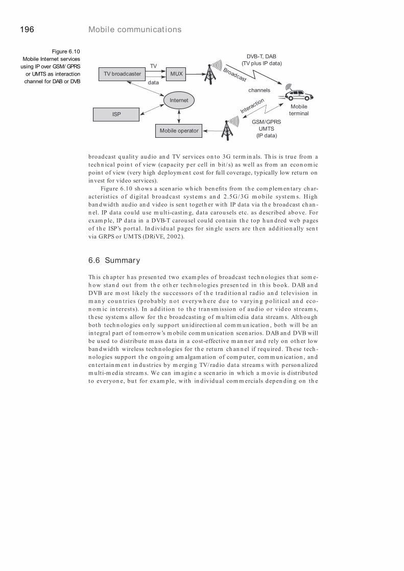
broadcast q uality audio an d TV services on to 3G term in als. Th is is t rue from atech n ical poin t of view (capacity per cell in bit / s) as well as from an econ om icpoin t of view (very h igh deploym en t cost for full coverage, typically low return onin vest for video services).
Figure 6.10 sh ows a scen ario wh ich ben efits from th e com plem en tary ch ar-act erist ics o f d igit al b ro ad cast syst em s an d 2.5G/ 3G m obile syst em s. Highban dwidth audio an d video is sen t togeth er with IP data via th e broadcast ch an -n el. IP data cou ld use m ult i-cast in g, data carousels etc. as described above. Forexam p le, IP data in a DVB-T carousel cou ld con tain th e top h un dred web pagesof th e ISP’s portal. In d ividu al pages for sin gle users are th en add it ion ally sen tvia GRPS or UMTS (DRiVE, 2002).
6.6 SummaryTh is ch apter h as p resen ted two exam ples of broadcast tech n ologies th at som e-h ow stan d ou t from th e oth er t ech n ologies p resen ted in t h is book. DAB an dDVB are m ost likely t h e su ccessors of t h e t rad it ion al rad io an d television inm an y co u n t ries (p ro bably n o t everywh ere du e t o varyin g p o lit ical an d eco-n o m ic in t erest s). In ad d it ion t o t h e t ran sm ission of au d io o r vid eo st ream s,th ese system s allow for th e broadcastin g of m ult im edia data stream s. Alth oughboth tech n ologies on ly support un idirection al com m un icat ion , both will be anin tegral part of tom orrow’s m obile com m un ication scen arios. DAB an d DVB willbe used to d istribu te m ass data in a cost-effective m an n er an d rely on oth er lowban dwidth wireless tech n ologies for th e retu rn ch an n el if requ ired . Th ese tech -n ologies support th e on goin g am algam ation of com puter, com m un ication , an den tertain m en t in du stries by m ergin g TV/ rad io data st ream s with p erson alizedm ulti-m edia stream s. We can im agin e a scen ario in wh ich a m ovie is d istribu tedto everyon e, bu t for exam ple, with in d ividu al com m ercials depen din g on th e
Mobile communicat ions196
Internet
Mobile operator
ISP
TV broadcasterTV
dataMUX Broadcast
channels
Interaction Mobileterminal
DVB-T, DAB(TV plus IP data)
GSM/GPRSUMTS
(IP data)
Figure 6.10Mobile Internet services
using IP over GSM/ GPRSor UMTS as interactionchannel for DAB or DVB

user’s in terests. Th e set -top box will m erge both data stream s an d th e user will,e.g., watch a soccer gam e with fu lly in d ividualized billboards. An oth er feature,wh ich m akes DAB particu larly at tractive for m obile com m un ication , is th at it isth e on ly com m ercial radio system su itable for h igh speeds an d h igh data rates:u p to 1 .5 Mbit / s at 900 km / h ! Th is m akes it possible to in st al, TV sets in forexam ple, t rain s an d o th er veh icles th at would su ffer from m ult i-path propaga-t ion u sin g o th er t ech n o logies. Alth ou gh DVB was n o t d esign ed for very fastm ovin g receivers, it h as been sh own in th e MOTIVATE project th at it still worksat over 250 km /h (at reduced data rates; DVB, 2002, MOTIVATE, 2002).
As th e aggregate cap acity of a UMTS cell is lim ited (ap p rox. 2 Mbit / s p er5 MHz ban dwid th in t h e stan dard case) an d sh ared between all act ive u sers,UMTS is preferably used for in d ividual com m un ication purposes. On th e oth erh an d, h igh ban dwid th distribu tion of data in a poin t-to-m ult ipoin t fash ion willbe m ore efficien t an d econ om ical on broadcast p latform s such as DAB or DVB.However, as th e cap acity o f a m obile DVB-T system is relat ively sm all (abou t10–15 Mbit / s p er 8 MHz ban d wid th ), an d cell size is large (>100 km 2) t h issystem m ay n ot efficien tly provide in dividual data to m an y users. Both 3G an dbroadcast p lat form s, can be seen as com plem en tary, n ot com petit ive. Table 6.1com pares th e m ain features of UMTS, DAB an d DVB.
Ch ap ter 11 will sh ow fu rth er scen ario s in t egrat in g b road cast an d o th er4G system s.
Broadcast systems 197
UMTS DAB DVBSpectrum bands 2000 (terrestrial), 1140–1504, 130–260,(depends on national 2500 (satellite) 220–228 (UK) 430–862 (UK)regulations) [MHz]Regulation Telecom, Broadcast, Broadcast,
licensed licensed licensedBandwidth 5 MHz 1.5 MHz 8 MHzEffective throughput 30–300 kbit/ s 1.5 Mbit/ s 5–30 Mbit/ s
(per user) (shared) (shared)Mobility support Low to high Very high Low to highApplication Voice, data Audio, push High res. video,
Internet, audio, push images, low Internetres. video
Coverage Local to wide Wide WideDeployment cost Very high Low Lowfor wide coverage
Table 6.1 Comparisonof UMTS, DAB and DVB

6.7 Review exercises1 2G and 3G systems can both transfer data. Compare these approaches with
DAB/ DVB and list reasons for and against the use of DAB/ DVB.2 Which web pages would be appropriate for distribution via DAB or DVB?3 How could location based services and broadcast systems work together?
6.8 ReferencesAch arya, S., Fran klin , M., Zdon ik, S. (1995) ‘Dissem in at ion -based data delivery
u sin g broadcast disks,’ IEEE Personal Communications, 2(6).CORBA (2002), Com m on Object Request Broker Arch itecture, Object Man agem en t
Group (OMG), h ttp:/ /www.corba.org/ , h ttp:/ /www.om g.org/ .DAB (2002) World DAB Forum , h ttp:/ /www.worlddab.org/ .DRiVE (2002), Dyn am ic Rad io for IP-Services in Veh icu lar En viro n m en t s,
IST-1999-12515, h ttp :/ /www.ist-drive.org/ .DVB (2002) DVB Project Office, h t tp:/ /www.dvb.org/ .ETSI (1997) Framing structure, channel coding and modulation for 11/12 GHz satel-
lite services, European Telecom m un ication s Stan dards In st itu te, EN 300 421.ETSI (1998) Framing structure, channel coding and modula tion for cable systems,
European Telecom m un ication s Stan dards In st itu te, EN 300 429.ETSI (1999a) DAB Multimedia Object Tra nsfer (MOT) protocol, Eu ro pean
Telecom m un ication s Stan dards In st itu te, EN 301 234.ETSI (1999b) Digital Video Broadcasting (DVB); Implementa tion guidelines for da ta
broadcasting, European Telecom m un ication s Stan dards In stitu te, TR 101 202.ETSI (1999c) Digital Video Broadcasting (DVB); DVB specification for da ta broadcast-
ing, European Telecom m un ication s Stan dards In st itu te, EN 301 192.ETSI (1999d) Digital Video Broadcasting (DVB); Interaction channel through the Global
System for Mobile communica tions (GSM), Eu ropean Telecom m u n icat ion sStan dards In stitute, EN 301 195.
ETSI (2000) Digita l Audio Broadcasting (DAB); Intera ction cha nnel through theGloba l System for Mobile communica tions (GSM), the Public SwitchedTelecommunications System (PSTN), Integrated Services Digita l Network (ISDN)a nd Digita l Enhanced Cordless Telecommunica tions (DECT), Eu ro peanTelecom m un ication s Stan dards In st itu te, TS 101 737.
ETSI (2001a) Digita l Audio Broa dcasting (DAB) to mobile, portable, a nd fixedreceivers, European Telecom m un icat ion s Stan dards In st itu te, EN 300 401.
ETSI (2001b) Framing structure, channel coding and modulation for digital terrestrialtelevision, European Telecom m un ication s Stan dards In stitu te, EN 300 744.
ETSI (2002) Digital Audio and Video Broadcasting, European Telecom m un ication sStan dards In st itu te, h t tp:/ /www.etsi.org/ .
Mobile communicat ions198

MO TIVATE (2002) Mobile Televisio n an d In n o vat ive Receivers, AC318,h ttp :/ /www.cordis.lu / in fowin / acts/ rus/projects/ac318.h tm .
Reim ers, U. (1 998) ‘Digit al Vid eo Bro ad cast in g,’ IEEE Communica t ionsMagazine, 36(6).
Broadcast systems 199

Th is ch ap ter presen ts several wireless local area n etwork (WLAN) tech n olo-gies. Th is con st itu tes a fast-growin g m arket in trodu cin g th e flexibility ofwireless access in to office, h om e, or p roduction en viron m en ts. In con trast
t o t h e t ech n ologies d escribed in ch ap t ers 4 t h rou gh 6 , W LANs are t yp ica llyrest ricted in th eir d iam eter to bu ild in gs, a cam p u s, sin gle room s etc. an d areoperated by in d ividuals, n ot by large-scale n etwork providers. Th e global goal ofW LANs is to rep lace office cablin g, to en able t eth erless access to th e in tern etan d, to in troduce a h igh er flexibility for ad-h oc com m un ication in , e.g., groupm eet in gs. Th e followin g p oin t s illu st rate som e gen eral ad van tages an d d isad-van tages of WLANs com pared to th eir wired coun terparts.
Som e ad van tages of W LANs are:● Flexib ility: With in radio coverage, n odes can com m un icate with ou t furth er
rest rict ion . Rad io waves can pen et rate walls, sen ders an d receivers can bep laced an ywh ere (also n on -visib le, e.g., with in devices, in walls etc.).Som etim es wirin g is difficult if firewalls separate buildin gs (real firewalls m adeout of, e.g., bricks, n ot routers set up as a firewall). Pen etration of a firewall ison ly perm itted at certain poin ts to preven t fire from spreadin g too fast.
● Plan n in g: On ly wireless ad-h oc n etworks allow for com m un icat ion with outp revio u s p lan n in g, an y wired n etwork n eed s wirin g p lan s. As lo n g asd evices fo llow th e sam e stan dard , th ey can com m u n icate. For wired n et -works, add it ion al cablin g with th e righ t p lu gs an d p robably in terworkin gun its (such as switch es) h ave to be provided.
● Design : Wireless n etworks allow fo r t h e design o f sm all, in d ep en d en tdevices wh ich can for exam ple be pu t in to a pocket . Cables n ot on ly rest rictusers bu t also design ers of sm all PDAs, n otep ads etc. Wireless sen ders an dreceivers can be h idden in h istoric bu ild in gs, i.e., cu rren t n etworkin g tech -n ology can be in t roduced with ou t bein g visible.
● Ro b u st n ess: Wireless n etworks can su rvive d isast ers, e.g., earth q u akesor u sers p u llin g a p lu g. If t h e wireless devices su rvive, p eop le can st illcom m un icate. Networks requ irin g a wired in frastructure will u sually breakdown com pletely.
Wireless LAN 7
201

● Cost : After providin g wireless access to th e in frastructure via an access poin tfo r th e first u ser, ad d in g ad d it io n al u sers t o a wireless n etwo rk will n o tin crease th e cost . Th is is, im portan t for e.g., lectu re h alls, h otel lobbies orgate areas in airports wh ere th e n um bers usin g th e n etwork m ay vary sign if-ican t ly. Usin g a fixed n etwork, each seat in a lecture h all sh ou ld h ave a plugfor th e n etwork alth ou gh m an y o f th em m igh t n ot be used p erm an en t ly.Con stan t p lu ggin g an d u n p lu ggin g will soon er or later d est roy th e p lu gs.Wireless con n ection s do n ot wear ou t . But WLANs also h ave several d isad van tages:
● Qu a li t y o f ser v ice: WLANs typ ically offer lower qu ality th an th eir wiredcoun terparts. Th e m ain reason s for th is are th e lower ban dwidth due to lim -itat ion s in rad io t ran sm ission (e.g., on ly 1–10 Mbit /s user data rate in steado f 100–1,000 Mbit / s), h igh er error rat es d u e t o in t erferen ce (e.g., 10–4in stead o f 10–12 for fiber op t ics), an d h igh er delay/ delay variat ion du e toexten sive error correct ion an d detect ion m ech an ism s.
● Prop riet ary solu t ion s: Due to slow stan dardization procedures, m an y com -p an ies h ave com e u p with p ro p riet ary so lu t ion s o fferin g st an d ard izedfun ction ality p lus m an y en h an ced features (typ ically a h igh er bit rate u sin ga p at en t ed cod in g t ech n ology o r sp ecial in t er-access p o in t p ro tocols).However, th ese ad dit ion al featu res on ly work in a h om ogen eou s en viron -m en t , i.e., wh en adapters from th e sam e ven d ors are u sed fo r all wirelessn odes. At least m ost com pon en ts today adh ere to th e basic stan dards IEEE802.11b or (n ewer) 802.11a (see sect ion 7.3).
● Rest r ict io n s: All wireless p rod uct s h ave to com p ly with n at ion al regu la-t ion s. Several govern m en t an d n o n -go vern m en t in st it u t ion s wo rld wid eregu lat e th e op erat ion an d rest rict freq u en cies to m in im ize in terferen ce.Con sequ en t ly, it t akes a very lon g t im e to establish global so lu t ion s like,e.g., IMT-2000, wh ich com prises m an y in dividual stan dards (see ch ap ter 4).W LANs are lim ited to low-power sen ders an d certain licen se-free frequen cyban ds, wh ich are n ot th e sam e worldwide.
● Sa fety an d secu rit y: Usin g rad io waves for data t ran sm ission m igh t in ter-fere with o th er h igh -t ech eq u ip m en t in , e.g., h o sp itals. Sen ders an dreceivers are operated by laym en an d, rad iat ion h as to be low. Special p re-cau t io n s h ave t o be t aken t o p reven t safety h azard s. Th e o p en rad ioin terface m akes eavesdroppin g m uch easier in WLANs th an , e.g., in th e caseo f fiber op t ics. All st an dard s m u st offer (au tom at ic) en cryp t ion , p rivacym ech an ism s, support for an on ym ity etc. Oth erwise m ore an d m ore wirelessn etworks will be h acked in to as is th e case already (aka war drivin g: d rivin garoun d lookin g for un secured wireless n etworks; WarDrivin g, 2002).
Mobile communicat ions202
Man y d ifferen t , an d som etim es com pet in g, d esign goals h ave to be takenin to accoun t for W LANs to en sure th eir com m ercial success:● Glob a l op era t ion : W LAN products sh ou ld sell in all coun tries so, n ation al
an d in tern at ion al frequen cy regu lat ion s h ave to be con sidered. In con trastto th e in frastructure of wireless WANs, LAN equipm en t m ay be carried fromon e coun try in to an oth er – th e operation sh ould st ill be legal in th is case.
● Low p ow er: Devices com m un icatin g via a WLAN are typically also wirelessd evices ru n n in g on bat tery power. Th e LAN d esign sh ou ld take th is in toaccou n t an d im p lem en t sp ecial power-savin g m od es an d p ower m an age-m en t fun ction s. Wireless com m un ication with devices plugged in to a poweroutlet is on ly useful in som e cases (e.g., n o addition al cablin g sh ould be n ec-essary for th e n etwork in h istoric buildin gs or at trade sh ows). However, th efu ture clearly lies in sm all h an dh eld devices with out an y restrictin g wire.
● Licen se-free op era t io n : LAN operators do n ot wan t to ap ply for a sp eciallicen se t o be ab le t o u se t h e p ro d u ct . Th e eq u ip m en t m u st op erat e in alicen se-free ban d, such as th e 2.4 GHz ISM ban d.
● Ro b u st t ra n sm issio n t ech n olo gy: Com pared to th eir wired coun terparts,W LANs op erate u n der d ifficu lt con dit ion s. If th ey u se rad io t ran sm ission ,m an y o th er elect rical devices can in terfere with th em (vacu u m clean ers,h airdryers, train en gin es etc.). WLAN tran sceivers can n ot be adjusted for per-fect tran sm ission in a stan dard office or production en viron m en t. An ten n asare typically om n idirection al, n ot directed. Sen ders an d receivers m ay m ove.
● Sim p li fied sp o n t a n eo u s co o p er a t io n : To be u sefu l in p ract ice, W LANssh ou ld n ot req u ire com p licated setu p rou t in es bu t sh ou ld op erat e sp on -tan eou sly after p ower-up . Th ese LANs would n ot be u sefu l for supportin g,e.g., ad-h oc m eet in gs.
● Easy to u se: In con trast to h uge an d com plex wireless WANs, wireless LANsare m ade for sim p le use. Th ey sh ou ld n ot requ ire com plex m an agem en t ,bu t rath er work on a p lug-an d-p lay basis.
● Pro t ect io n o f in vestm en t : A lot of m on ey h as already been in vested in towired LANs. Th e n ew WLANs sh ould p rotect th is in vestm en t by bein g in ter-op erab le with t h e exist in g n etworks. Th is m ean s t h at sim p le b rid gin gbetween th e d ifferen t LANs sh ould be en ough to in teroperate, i.e., th e wire-less LANs sh ou ld su p port th e sam e data types an d services th at stan d ardLANs support .
● Sa fet y a n d secu r i t y : Wireless LANs sh ou ld be safe t o operate, esp eciallyregard in g low rad iat ion if used, e.g., in h osp itals. Users can n ot keep safetydistan ces to an ten n as. Th e equ ip m en t h as to be safe for pacem akers, too .Users sh ou ld n o t be ab le t o read p erson al d ata du rin g t ran sm ission , i.e.,en cryp t ion m ech an ism s sh ou ld be in tegrat ed . Th e n etwo rks sh o u ld alsotake in to accoun t user privacy, i.e., it sh ould n ot be possible to collect roam -in g profiles for trackin g person s if th ey do n ot agree.
Wireless LAN 203

● Tra n sp a ren cy fo r a p p lica t ion s: Exist in g ap plicat ion s sh ou ld con t in ue toru n over W LANs, th e on ly d ifferen ce bein g h igh er delay an d lower ban d-width . Th e fact of wireless access an d m obility sh ould be h idden if it is n otrelevan t , bu t th e n etwork sh ould also support location aware applicat ion s,e.g., by provid in g location in form ation .Th e followin g sect ion s first in troduce basic tran sm ission tech n ologies used
for W LANs, in fra red an d rad io , th en th e two basic set t in gs for W LANs: in fra-st ru ct u re-based an d ad -h oc, are p resen t ed . Th e t h ree m ain sect io n s o f t h isch apter presen t th e IEEE stan dard for W LANs, IEEE 802.11, th e European ETSIstan dard for a h igh -speed WLAN with QoS support , HiperLAN2, an d fin ally, anin dustry approach toward wireless person al area n etworks (WPAN), i.e., WLANsat an even sm aller ran ge, called Bluetooth .
7.1 Inf ra red vs radio t ransmissionToday, two differen t basic tran sm ission tech n ologies can be used to set up WLANs.On e tech n ology is based on th e t ran sm ission of in fra red ligh t (e.g., at 900 n mwavelen gth ), th e oth er on e, wh ich is m uch m ore popular, uses radio tran sm issionin th e GHz ran ge (e.g., 2.4 GHz in th e licen se-free ISM ban d). Both tech n ologiescan be used to set up ad-h oc con n ection s for work groups, to con n ect, e.g., a desk-top with a prin ter with out a wire, or to support m obility with in a sm all area.
In fra red tech n ology u ses d iffuse ligh t reflected at walls, furn itu re etc. ord irected ligh t if a lin e-of-sigh t (LOS) exists between sen der an d receiver. Sen derscan be sim ple ligh t em it t in g d iodes (LEDs) or laser d iodes. Ph otodiodes act asreceivers. Det ails abo u t in fra red t ech n o lo gy, su ch as m o d u lat ion , ch an n elim pairm en ts etc. can be foun d in Wesel (1998) an d San tam aría (1994).● Th e m ain ad van tages of in fra red tech n ology are its sim ple an d extrem ely
ch eap sen d ers an d receivers wh ich are in t egra t ed in to n early all m ob iled evices available today. PDAs, lap tops, n otebooks, m obile ph on es etc. h avean in fra red data associat ion (IrDA) in terface. Version 1.0 of th is in dustrystan dard im plem en ts data rates of up to 115 kbit / s, wh ile IrDA 1.1 defin esh igh er data rates of 1.152 an d 4 Mbit/ s. No licen ses are n eeded for in fra redtech n ology an d sh ieldin g is very sim ple. Electrical devices do n ot in terferewith in fra red tran sm ission .
● Disad van tages of in fra red tran sm ission are its low ban dwidth com pared too th er LAN tech n ologies. Typically, IrDA devices are in tern ally con n ected toa serial port lim it in g tran sfer rates to 115 kbit / s. Even 4 Mbit/ s is n ot a par-t icu larly h igh data rate. However, th eir m ain d isadvan tage is th at in fra redis qu it e easily sh ield ed . In fra red t ran sm ission can n ot p en etrate walls oro th er obstacles. Typically, for good tran sm ission quality an d h igh data ratesa LOS, i.e., d irect con n ection , is n eeded .
Mobile communicat ions204

Alm ost all n etworks described in th is book use ra d io waves for data t ran s-m ission , e.g., GSM at 900, 1,800, an d 1,900 MHz, DECT at 1,880 MHz etc.● Ad van tages of rad io tran sm ission in clude th e lon g-term experien ces m ade
with radio t ran sm ission for wide area n etworks (e.g., m icrowave lin ks) an dm obile cellu lar p h on es. Radio tran sm ission can cover larger areas an d canp en et rat e (t h in n er) walls, fu rn it u re, p lan t s etc. Ad d it io n al coverage isgain ed by reflect ion . Radio typically does n ot n eed a LOS if th e frequen ciesare n ot t oo h igh . Fu rth erm ore, cu rren t rad io-based p rod ucts offer m u chh igh er t ran sm ission ra t es (e.g., 54 Mb it / s) t h an in fra red (d irect ed laserlin ks, wh ich offer data rates well above 100 Mbit / s. Th ese are n o t con sid-ered h ere as it is very difficult to u se th em with m obile devices).
● Again , th e m ain advan tage is also a big d isad van tage of radio t ran sm ission .Sh ield in g is n o t so sim ple. Rad io t ran sm issio n can in t erfere with o th ersen d ers, o r elect rica l d evices can d est roy d at a t ran sm it t ed via rad io .Ad d it io n ally, rad io t ran sm ission is on ly p erm it ted in cert ain freq u en cyban ds. Very lim ited ran ges of licen se-free ban ds are available worldwide an dth ose th at are available are n ot th e sam e in all coun tries. However, a lot ofh arm on ization is goin g on due to m arket pressu re.Of th e th ree WLAN tech n ologies presen ted in th is ch apter, on ly on e (IEEE
802.11) stan dard ized in fra red t ran sm ission in addit ion to rad io t ran sm ission .Th e oth er two (HIPERLAN an d Bluetooth ) rely on radio. Th e m ain reason for th isare th e sh ieldin g problem s of in fra red. WLANs sh ould, e.g., cover a wh ole floorof a buildin g an d n ot just th e on e room wh ere LOSs exist . Futu re m obile devicesm ay h ave to com m un icate wh ile st ill in a pocket or a suitcase so can n ot rely onin fra red. Th e big advan tage of radio tran sm ission in everyday use is in deed th eability to pen etrate certain m aterials an d th at a LOS is n ot required. Man y usersexperien ce a lot of difficulties adjustin g in fra red ports of, e.g., m obile ph on es toth e in fra red port of th eir PDA. Usin g, e.g., Bluetooth is m uch sim pler.
7.2 Inf rast ructure and ad-hoc networksMan y WLANs of today n eed an in frast ru ctu re n etwork. In frastructure n etworksn ot on ly provide access to oth er n etworks, but also in clude forwardin g fun ct ion s,m edium access con trol etc. In th ese in frastructure-based wireless n etworks, com -m un ication typically takes place on ly between th e wireless n odes an d th e accesspoin t (see Figu re 7.1), bu t n ot directly between th e wireless n odes.
Th e access p o in t d oes n o t ju st con t ro l m ed iu m access, bu t also act s as abridge to oth er wireless or wired n etworks. Figure 7.1 sh ows th ree access poin tswith th eir t h ree wireless n etworks an d a wired n etwork. Several wireless n et -works m ay form on e logical wireless n etwork, so th e access poin ts togeth er withth e fixed n etwork in between can con n ect several wireless n etworks to form alarger n etwork beyon d actual rad io coverage.
Wireless LAN 205

Typ ically, th e design of in frast ructu re-based wireless n etworks is sim p lerbecause m ost of th e n etwork fun ct ion ality lies with in th e access poin t , wh ereasth e wireless clien t s can rem ain q u ite sim ple. Th is st ructu re is rem in iscen t ofswitch ed Eth ern et or oth er star-based n etworks, wh ere a cen tral elem en t (e.g., aswitch ) con t ro ls n etwork flow. Th is typ e o f n etwork can u se d ifferen t accesssch em es with or with out collision . Collision s m ay occur if m edium access of th ewireless n odes an d th e access poin t is n ot coordin ated. However, if on ly th e accessp oin t con t ro ls m ediu m access, n o co llision s are p ossible. Th is set t in g m ay beuseful for quality of service guaran tees such as m in im um ban dwidth for certainn odes. Th e access poin t m ay poll th e sin gle wireless n odes to en su re th e data rate.
In frastructure-based n etworks lose som e of th e flexibility wireless n etworkscan o ffer, e.g., th ey can n ot be u sed fo r d isaster relief in cases wh ere n o in fra-st ru ct u re is left . Typ ical cellu lar p h on e n etwo rks are in frast ru ctu re-basedn etwo rks fo r a wid e area (see ch ap t er 4). Also sat ellit e-based cellu lar p h on esh ave an in frast ru ctu re – th e sat ellit es (see ch ap ter 5). In frast ru ctu re d oes n otn ecessarily im ply a wired fixed n etwork.
Ad -h oc wireless n etworks, h owever, do n ot n eed an y in frastructu re to work.Each n ode can com m un icate d irectly with oth er n odes, so n o access poin t con -trollin g m edium access is n ecessary. Figu re 7.2 sh ows two ad-h oc n etworks withth ree n odes each . Nodes with in an ad -h oc n etwork can on ly com m u n icate ifth ey can reach each oth er ph ysically, i.e., if th ey are with in each oth er’s rad ioran ge or if oth er n odes can forward th e m essage. Nodes from th e two n etworkssh own in Figure 7.2 can n ot, th erefore, com m un icate with each oth er if th ey aren ot with in th e sam e radio ran ge.
In ad -h oc n etworks, th e com plexity of each n ode is h igh er becau se everyn od e h as t o im p lem en t m ed iu m access m ech an ism s, m ech an ism s to h an d leh idden or exposed term in al problem s, an d perh aps priority m ech an ism s, to pro-vid e a cert ain qu alit y o f service. Th is typ e o f wireless n etwork exh ib it s t h egreatest p ossible flexibility as it is, for exam p le, n eeded for un expected m eet-in gs, q u ick rep lacem en ts of in frastructu re or com m un ication scen arios far awayfrom an y in frastructu re.
Mobile communicat ions206
AP
wired network
AP: Access Point
AP AP
Figure 7.1Example of three
infrastructure-basedwireless networks

Clearly, th e two basic varian ts of wireless n etworks (h ere especially WLANs),in frastructu re-based an d ad -h oc, do n ot always com e in th eir pu re form . Th ereare n etworks th at rely on access poin ts an d in frastructu re for basic services (e.g.,au th en t icat ion o f access, co n t ro l o f m ed iu m access fo r d at a with associat edqu ality of service, m an agem en t fun ction s), bu t th at also allow for d irect com -m un ication between th e wireless n odes.
However, ad-h oc n etworks m igh t on ly h ave selected n odes with th e capabil-it ies o f fo rwardin g d ata. Most of th e n od es h ave to con n ect to su ch a sp ecialn ode first to tran sm it data if th e receiver is ou t of th eir ran ge.
Fro m th e t h ree W LANs p resen t ed , IEEE 802.11 (see sect io n 7 .3 ) an dHiperLAN2 (see section 7.4) are typ ically in frast ructure-based n etworks, wh ichaddit ion ally support ad-h oc n etworkin g. However, m an y im plem en tat ion s on lyoffer th e basic in frastructure-based version . Th e th ird WLAN, Bluetooth (see sec-t ion 7.5), is a typ ical wireless ad-h oc n etwork. Blu etooth focuses p recisely onsp on tan eou s ad -h oc m eet in gs o r o n t h e sim p le con n ect ion o f two o r m oredevices with out requirin g th e setup of an in frastructure.
7.3 IEEE 802.11Th e IEEE st an d ard 8 02.11 (IEEE, 1999) sp ecifies t h e m o st fam ou s fam ily o fWLANs in wh ich m an y products are available. As th e stan dard’s n um ber in di-cates, t h is st an dard b elon gs to th e grou p o f 802.x LAN stan d ards, e.g., 802.3Et h ern et o r 802 .5 To ken Rin g. Th is m ean s t h a t t h e st an d ard sp ecifies t h eph ysical an d m edium access layer adap ted to th e special requ irem en ts of wire-less LANs, bu t o ffers t h e sam e in t erface as t h e o th ers t o h igh er layers t om ain tain in teroperability.
Th e prim ary goal of th e stan dard was th e specification of a sim ple an d robustW LAN wh ich offers t im e-boun ded an d asyn ch ron ou s services. Th e MAC layersh ould be able to operate with m ultiple ph ysical layers, each of wh ich exh ibits adifferen t m edium sen se an d tran sm ission ch aracteristic. Can didates for ph ysicallayers were in fra red an d spread spectrum radio tran sm ission tech n iques.
Wireless LAN 207Figure 7.2Example of two ad-hocwireless networks

Addit ion al features of th e WLAN sh ould in clude th e support of power m an -agem en t to save battery power, th e h an d lin g of h idden n odes, an d th e ability tooperate worldwide. Th e 2.4 GHz ISM ban d, wh ich is available in m ost coun triesaroun d th e world , was ch osen for th e origin al stan dard. Data rates en visaged forth e stan dard were 1 Mbit /s m an datory an d 2 Mbit /s op tion al.
Th e followin g sect ion s will in troduce th e system an d p rotocol arch itectureof th e in it ia l IEEE 802.11 an d th en d iscuss each layer, i.e., p h ysical layer an dm ediu m access. After th at , th e com plex an d very im portan t m an agem en t fun c-t io n s of t h e st an d ard are p resen t ed . Fin a lly, t h is su bsect ion p resen t s t h een h an cem en t s o f t h e origin al stan d ard fo r h igh er d at a rat es, 802.11a (u p t o54 Mb it / s at 5 GHz) an d 802.11b (t oday th e m ost su ccessfu l with 11 Mbit / s)t ogeth er with fu rth er d evelop m en t s fo r secu rity su p p ort , h arm on izat ion , o roth er m odu lation sch em es.7.3.1 System architectureWireless n etworks can exh ibit two differen t basic system arch itectures as sh ownin section 7.2: in frastructu re-based or ad-h oc. Figure 7.3 sh ows th e com pon en tsof an in frast ru ctu re an d a wireless p art as sp ecified for IEEE 802.11. Severaln odes, called sta t ion s (STAi), are con n ected to access p oin t s (AP). Stat ion s areterm in als with access m ech an ism s to th e wireless m edium an d radio con tact to
Mobile communicat ions208
BBS1
802.11 LAN
STA1
AccessPoint
Portal
802. x LAN
Distribution system
BSS2
AccessPoint
STA2 STA3802.11 LAN
ESS
Figure 7.3Architecture of an
infrastructure-basedIEEE 802.11

th e AP. Th e stat ion s an d th e AP wh ich are with in th e sam e rad io coverage forma basic service set (BSSi). Th e exam ple sh ows two BSSs – BSS1 an d BSS2 – wh ichare con n ected via a d ist r ibu t ion system . A d istribution system con n ects severalBSSs via th e AP to form a sin gle n etwork an d th ereby exten ds th e wireless cover-age area. Th is n etwork is n ow called an ex t en d ed service set (ESS) an d h as itsown iden t ifier, th e ESSID. Th e ESSID is th e ‘n am e’ of a n etwork an d is used tosep arat e d ifferen t n etwo rks. With o u t kn owin g th e ESSID (an d assu m in g n oh ackin g) it sh ould n ot be possible to participate in th e W LAN. Th e d istributionsystem con n ects th e wireless n etworks via th e APs with a p or t a l, wh ich form sth e in terworkin g un it to oth er LANs.
Th e arch itectu re of th e d ist ribu tion system is n ot specified fu rth er in IEEE802.11. It cou ld con sist of bridged IEEE LANs, wireless lin ks, or an y oth er n et-works. However, d ist r ib u t io n syst em serv ices are d efin ed in t h e stan d ard(alth ough , m an y produ cts today can n ot in teroperate an d n eeds th e addit ion alstan dard IEEE 802.11f to specify an in ter access poin t protocol, see section 7.3.8).
Stat ion s can select an AP an d associate with it . Th e APs su pport roam in g(i.e., ch an gin g access p o in t s), t h e d ist rib u t io n syst em h an d les d at a t ran sferbetween th e d ifferen t APs. APs p rovide syn ch ron izat ion with in a BSS, supportpower m an agem en t, an d can con trol m edium access to su pport t im e-bou n dedservice. Th ese an d furth er fun ction s are explain ed in th e followin g section s.
In addition to in frastructure-based n etworks, IEEE 802.11 allows th e buildin gof ad -h oc n etworks between stat ion s, th u s form in g on e or m ore in depen d en tBSSs (IBSS) as sh own in Figure 7.4. In th is case, an IBSS com prises a group of sta-tion s usin g th e sam e radio frequen cy. Stat ion s STA1, STA2, an d STA3 are in IBSS1,STA4 an d STA5 in IBSS2. Th is m ean s for exam p le th at STA3 can com m u n icate
Wireless LAN 209
802.11 LAN
STA1
STA4
STA5
802.11 LAN
IBSS1 STA3
STA2
IBSS2
Figure 7.4Architecture ofIEEE 802.11 ad-hocwireless LANs

directly with STA2 but n ot with STA5. Several IBSSs can eith er be form ed via th edistan ce between th e IBSSs (see Figure 7.4) or by usin g differen t carrier frequen -cies (th en th e IBSSs could overlap ph ysically). IEEE 802.11 does n ot specify an yspecial n odes th at support rou tin g, forwardin g of data or exch an ge of topologyin form ation as, e.g., HIPERLAN 1 (see section 7.4) or Bluetooth (see section 7.5).7.3.2 Protocol architectureAs in dicated by th e stan dard n um ber, IEEE 802.11 fits seam lessly in to th e oth er802.x stan dards for wired LANs (see Halsall, 1996; IEEE, 1990). Figure 7.5 sh owsth e m ost co m m on scen ario : an IEEE 802.11 wireless LAN co n n ect ed t o aswitch ed IEEE 802.3 Eth ern et via a bridge. Application s sh ould n ot n otice an ydifferen ce apart from th e lower ban dwidth an d perh aps h igh er access t im e fromth e wireless LAN. Th e WLAN beh aves like a slow wired LAN. Con sequen tly, th eh igh er layers (app lication , TCP, IP) look th e sam e for wireless n odes as for wiredn o des. Th e u pp er p art o f th e dat a lin k con t ro l layer, t h e logical lin k con t ro l(LLC), covers th e differen ces of th e m edium access con trol layers n eeded for th edifferen t m edia. In m an y of today’s n etworks, n o explicit LLC layer is visible.Furth er details like Eth ertype or sub-n etwork access protocol (SNAP) an d bridg-in g tech n ology are explain ed in , e.g., Perlm an (1992).
Th e IEEE 802.11 stan dard on ly covers th e ph ysical layer PHY an d m ediumaccess layer MAC like th e oth er 802.x LANs do. Th e ph ysical layer is subd ividedin to t h e p h ysica l la yer co n v er gen ce p r o t o co l (PLCP) an d th e p h y sica lm ed iu m d ep en d en t sublayer PMD (see Figure 7.6). Th e basic tasks of th e MAClayer com prise m edium access, fragm en tation of user data, an d en cryption . Th e
Mobile communicat ions210
LLC802.11 MAC
applicationTCPIP
LLC802.11 MAC802.11 PHY
applicationTCPIP
LLC802.3 MAC802.3 PHY802.11 PHY 802.3 PHY
802.3 MAC
Mobile terminal
Access pointInfrastructure
network
Fixedterminal
Figure 7.5IEEE 802.11
protocol architectureand bridging

PLCP sublayer p rovid es a carrier sen se sign al, called clear ch an n el assessm en t(CCA), an d p rovides a com m on PHY service access poin t (SAP) in depen den t ofth e t ran sm issio n tech n ology. Fin ally, t h e PMD su blayer h an d les m od u lat ionan d en codin g/decod in g of sign als. Th e PHY layer (com prisin g PMD an d PLCP)an d th e MAC layer will be explain ed in m ore detail in th e followin g section s.
Ap art from th e p ro toco l su blayers, t h e st an d ard sp ecifies m an agem en tlayers an d th e station m an agem en t . Th e MAC m an agem en t supports th e asso-ciat ion an d re-associat ion of a station to an access poin t an d roam in g betweendifferen t access poin t s. It also con trols au th en t ication m ech an ism s, en cryption ,syn ch ron ization of a stat ion with regard to an access poin t , an d power m an age-m en t t o save bat t ery p ower. MAC m an agem en t also m ain t ain s th e MACm an agem en t in form at ion base (MIB).
Th e m ain tasks of th e PH Y m a n a gem en t in clude ch an n el tun in g an d PHYMIB m ain ten an ce. Fin ally, stat ion m an agem en t in teracts with both m an agem en tlayers an d is respon sible for addit ion al h igh er layer fun ction s (e.g., con trol of bridg-in g an d in teraction with th e d istribu tion system in th e case of an access poin t).7.3.3 Physical layerIEEE 802.11 supports th ree differen t ph ysical layers: on e layer based on in fra redan d two layers based on rad io t ran sm ission (p rim arily in th e ISM ban d at 2.4GHz, wh ich is available worldwide). All PHY varian ts in clude th e p rovision ofth e clear ch an n el a ssessm en t sign al (CCA). Th is is n eeded for th e MAC m ech -an ism s con trollin g m edium access an d in dicates if th e m edium is curren tly idle.Th e tran sm ission tech n ology (wh ich will be discussed later) determ in es exactlyh ow th is sign al is obtain ed.
Th e PHY layer offers a service access poin t (SAP) with 1 or 2 Mbit /s tran sferrate to th e MAC layer (basic version of th e stan dard ). Th e rem ain der of th is sec-t ion p resen ts th e th ree version s of a PHY layer defin ed in th e stan dard.7.3.3.1 Frequency hopping spread spect rumFreq u en cy h o p p in g sp read sp ect ru m (FHSS) is a sp read spect ru m t ech n iq u ewh ich allows for th e coexisten ce of m ult ip le n etworks in th e sam e area by sepa-rat in g differen t n etworks usin g differen t h oppin g sequen ces (see ch apters 2 an d3). Th e origin al stan dard defin es 79 h opp in g ch an n els for North Am erica an dEurope, an d 23 h opp in g ch an n els for Japan (each with a ban dwidth of 1 MHz
Wireless LAN 211
LLCMACPLCPPMD
DLC
PHY
MAC management
PHY management
Station
manag
ement
Figure 7.6Detailed IEEE 802.11protocol architectureand management

in th e 2.4 GHz ISM ban d). Th e selection of a part icu lar ch an n el is ach ieved byu sin g a pseu do-ran dom h opp in g pat tern . Nat ion al rest rict ion s also determ in efurth er param eters, e.g., m axim um tran sm it p ower is 1 W in th e US, 100 m WEIRP (equivalen t isot ropic rad iated power) in Europe an d 10 m W/MHz in Japan .
Th e stan dard specifies Gaussian sh aped FSK (frequen cy sh ift keyin g), GFSK,as m odu lation for th e FHSS PHY. For 1 Mbit /s a 2 level GFSK is used (i.e., 1 bit ism apped to on e frequen cy, see ch apter 2), a 4 level GFSK for 2 Mbit/ s (i.e., 2 bitsare m ap p ed to o n e freq u en cy). W h ile sen d in g an d receivin g at 1 Mbit / s ism an datory for all devices, operation at 2 Mbit/ s is op tion al. Th is facilitated th ep rod u ct ion of low-cost d evices fo r t h e lower ra t e on ly an d m ore p owerfu ldevices for both tran sm ission rates in th e early days of 802.11.
Figu re 7.7 sh ows a fram e of th e ph ysical layer u sed with FHSS. Th e fram econ sists of two basic part s, th e PLCP p art (p ream ble an d h eader) an d th e pay-load p art . Wh ile th e PLCP part is always tran sm it ted at 1 Mbit/ s, payload , i.e.MAC data, can use 1 or 2 Mbit/ s. Add it ion ally, MAC data is scram bled usin g th epolyn om ial s(z) = z7 + z4 + 1 for DC blockin g an d wh iten in g of th e sp ectrum .Th e fields of th e fram e fu lfill th e followin g fun ction s:● Syn ch ro n iza t io n : Th e PLCP pream ble start s with 80 bit syn ch ron izat ion ,
wh ich is a 010101... bit pattern . Th is pattern is u sed for syn ch ron ization ofp oten t ial receivers an d sign al detection by th e CCA.
● St a rt fram e d elim it er (SFD): Th e followin g 16 bits in d icate th e start of th efram e an d p ro vid e fram e syn ch ron izat ion . Th e SFD p at t ern is0000110010111101.
● PLCP_PDU len gt h w o rd (PLW ): Th is first field of th e PLCP h eader in d i-cates th e len gth of th e payload in bytes in cludin g th e 32 bit CRC at th e en dof th e payload . PLW can ran ge between 0 an d 4,095.
● PLCP sign a llin g field (PSF): Th is 4 bit field in d icates th e data rate of th ep ayload followin g. All bit s set to zero (0000) in d icates th e lowest data rateof 1 Mbit/ s. Th e gran ularity is 500 kbit / s, th us 2 Mbit/ s is in d icated by 0010an d th e m ax im u m is 8 .5 Mbit / s (1111). Th is system ob viou sly d oes n otaccom m odate today’s h igh er data rates.
● H ea d er e r r o r ch eck (H EC): Fin ally, t h e PLCP h ead er is p ro t ect ed by a1 6 b it ch ecksu m wit h t h e st an d ard ITU-T gen erat o r p o lyn o m ialG(x) = x16 + x12 + x5 + 1.
Mobile communicat ions212
synchronization SFD80 16
PLW12
PSF4
HEC16
payloadvariable bits
PLCP preamble PLCP header
Figure 7.7Format of an
IEEE 802.11 PHY frameusing FHSS
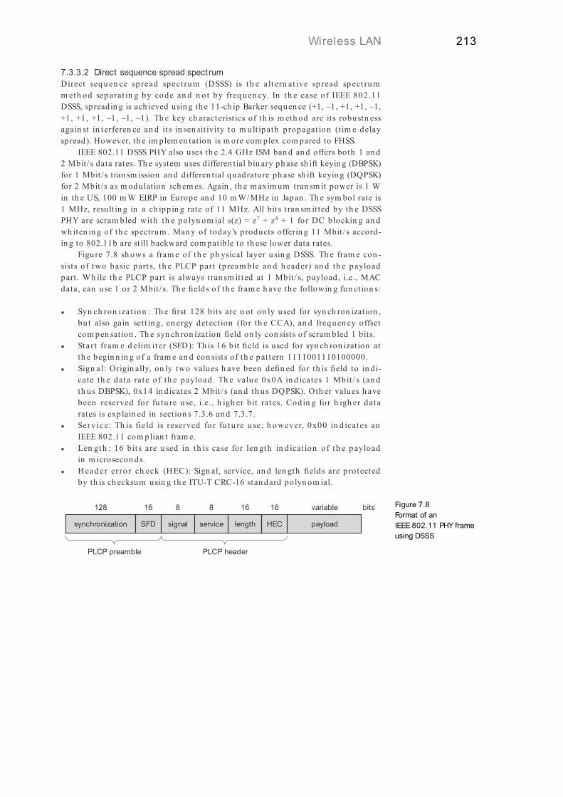
7.3.3.2 Direct sequence spread spectrumDirect sequ en ce sp read spect ru m (DSSS) is th e alt ern at ive sp read sp ect ru mm eth od separat in g by code an d n o t by freq uen cy. In th e case o f IEEE 802.11DSSS, spreadin g is ach ieved usin g th e 11-ch ip Barker sequen ce (+1, –1, +1, +1, –1,+1, +1, +1, –1, –1, –1). Th e key ch aracterist ics of th is m eth od are its robustn essagain st in terferen ce an d it s in sen sit ivity to m ult ipath propagat ion (t im e delayspread). However, th e im plem en tation is m ore com plex com pared to FHSS.
IEEE 802.11 DSSS PHY also uses th e 2.4 GHz ISM ban d an d offers both 1 an d2 Mbit/ s data rates. Th e system uses differen tial bin ary ph ase sh ift keyin g (DBPSK)for 1 Mbit/s tran sm ission an d differen tial quadrature ph ase sh ift keyin g (DQPSK)for 2 Mbit/s as m odulation sch em es. Again , th e m axim um tran sm it power is 1 Win th e US, 100 m W EIRP in Europe an d 10 m W/MHz in Japan . Th e sym bol rate is1 MHz, result in g in a ch ippin g rate of 11 MHz. All bits tran sm itted by th e DSSSPHY are scram bled with th e polyn om ial s(z) = z7 + z4 + 1 fo r DC blockin g an dwh iten in g of th e spectrum . Man y of today’s products offerin g 11 Mbit/ s accord-in g to 802.11b are st ill backward com patible to th ese lower data rates.
Figu re 7.8 sh ows a fram e of th e ph ysical layer u sin g DSSS. Th e fram e con -sists of two basic part s, th e PLCP part (pream ble an d h eader) an d th e payloadpart . Wh ile th e PLCP part is always t ran sm itted at 1 Mbit/ s, payload , i.e., MACdata, can use 1 or 2 Mbit/ s. Th e fields of th e fram e h ave th e followin g fun ction s:● Syn ch ron iza t ion : Th e first 128 bits are n ot on ly used for syn ch ron ization ,
but also gain set t in g, en ergy detection (for th e CCA), an d frequen cy offsetcom pen sat ion . Th e syn ch ron ization field on ly con sists of scram bled 1 bits.
● Sta r t fram e d elim it er (SFD): Th is 16 bit field is used for syn ch ron izat ion atth e begin n in g of a fram e an d con sists of th e pat tern 1111001110100000.
● Sign a l: Origin ally, on ly two values h ave been defin ed for th is field to in di-cate th e data rate o f th e payload . Th e valu e 0x0A in d icates 1 Mbit / s (an dth us DBPSK), 0x14 in d icates 2 Mbit/ s (an d th us DQPSK). Oth er values h avebeen reserved fo r fu tu re u se, i.e., h igh er bit rates. Cod in g for h igh er datarates is explain ed in section s 7.3.6 an d 7.3.7.
● Ser v ice: Th is field is reserved fo r fu tu re u se; h o wever, 0x00 in d icates anIEEE 802.11 com plian t fram e.
● Len gt h : 16 bit s are used in th is case for len gth in d icat ion of th e p ayloadin m icrosecon ds.
● Hea d er er ro r ch eck (HEC): Sign al, service, an d len gth fields are p rotectedby th is ch ecksum usin g th e ITU-T CRC-16 stan dard polyn om ial.
Wireless LAN 213
synchronization SFD128 16
signal8
service8
HEC16
payloadvariable bits
PLCP preamble PLCP header
length16 Figure 7.8
Format of anIEEE 802.11 PHY frameusing DSSS

7.3.3.3 Infra redTh e PHY layer, wh ich is based on in fra red (IR) t ran sm ission , u ses n ear visibleligh t at 850–950 n m . In fra red ligh t is n ot regulated apart from safety rest riction s(u sin g lasers in stead of LEDs). Th e st an d ard d oes n o t req u ire a lin e-of-sigh tbetween sen der an d receiver, but sh ould also work with diffuse ligh t . Th is allowsfor po in t-to-m ult ipoin t com m un icat ion . Th e m axim u m ran ge is abou t 10 m ifn o sun ligh t or h eat sources in terfere with th e tran sm ission . Typically, such a n et-work will on ly work in buildin gs, e.g., classroom s, m eetin g room s etc. Frequen cyreuse is very sim ple – a wall is m ore th an en ough to sh ield on e IR based IEEE802.11 n etwork from an oth er. (See also section 7.1 for a com parison between IRan d radio tran sm ission an d Wesel, 1998 for m ore details.) Today, n o products areavailable th at offer in fra red com m un ication based on 802.11. Proprietary prod-ucts o ffer, e.g., up to 4 Mbit /s usin g diffuse in fra red ligh t. Altern atively, directedin fra red com m un ication based on IrDA can be used (IrDA, 2002).7.3.4 Medium access control layerTh e MAC layer h as to fu lfill several tasks. First of all, it h as to con trol m ediumaccess, bu t it can also offer support for roam in g, au th en t icat ion , an d power con -servat ion . Th e basic services p ro vid ed by t h e MAC layer are t h e m an d atorya sy n ch ro n o u s d a t a ser v ice an d an op t ion al t im e-b o u n d ed ser v ice. W h ile802.11 on ly offers th e asyn ch ron ous service in ad-h oc n etwork m ode, both ser-vice types can be offered u sin g an in frast ru ctu re-based n etwork togeth er withth e access po in t coord in at in g m ed iu m access. Th e asyn ch ron ous service su p -ports broadcast an d m ult i-cast packets, an d packet exch an ge is based on a ‘besteffort ’ m odel, i.e., n o delay boun ds can be given for tran sm ission .
Th e fo llowin g th ree basic access m ech an ism s h ave been d efin ed for IEEE802.11: t h e m an d ato ry basic m eth od based on a version o f CSMA/ CA, ano p t io n al m eth od avo id in g t h e h id d en t erm in al p ro blem , an d fin ally a con -ten tion -free pollin g m eth od for tim e-boun ded service. Th e first two m eth ods area lso su m m arized as d ist r ib u t ed co o rd in a t io n fu n ct io n (D CF), t h e t h irdm eth od is called p o in t co o rd in a t ion fu n ct io n (PCF). DCF on ly offers asyn -ch ro n ou s service, wh ile PCF o ffers bo th asyn ch ron ou s an d t im e-b ou n dedservice bu t n eeds an access poin t to con trol m edium access an d to avoid con -ten tion . Th e MAC m ech an ism s are also called d ist r ibu t ed fou n d a t ion w irelessm ed iu m access con t ro l (DFW MAC).
For all access m eth ods, several param eters for con t rollin g th e wait in g t im ebefore m edium access are im portan t . Figure 7.9 sh ows th e th ree differen t para-m eters th at defin e th e priorit ies of m edium access. Th e values of th e param etersd ep en d on t h e PHY an d are d efin ed in relat ion t o a slo t t im e. Slo t t im e isderived from th e m edium propagat ion delay, tran sm itter delay, an d oth er PHYdepen den t param eters. Slot t im e is 50 µs for FHSS an d 20 µs for DSSS.
Th e m ed ium , as sh own , can be busy or idle (wh ich is detected by th e CCA).If th e m ediu m is bu sy th is can be due to data fram es or o th er con trol fram es.Durin g a con ten tion ph ase several n odes try to access th e m edium .
Mobile communicat ions214

● Sh o r t in t er -fra m e sp a cin g (SIFS): Th e sh ortest wait in g t im e for m ed iu maccess (so th e h igh est p riority) is defin ed for sh ort con trol m essages, such asackn owled gem en ts o f d ata p ackets or po llin g resp on ses. For DSSS SIFS is10 µs an d for FHSS it is 28 µs. Th e use of th is param eter will be exp lain ed insection s 7.3.4.1 th rough 7.3.4.3.
● PCF in t er -fr a m e sp a cin g (PIFS): A wait in g t im e between DIFS an d SIFS(an d th us a m edium p riority) is u sed for a tim e-boun ded service. An accesspoin t pollin g oth er n odes on ly h as to wait PIFS for m edium access (see sec-t ion 7.3.4.3). PIFS is defin ed as SIFS plus on e slot t im e.
● DCF in t er-fram e sp acin g (DIFS): Th is param eter den otes th e lon gest wait-in g tim e an d h as th e lowest p riority for m edium access. Th is wait in g tim e isused for asyn ch ron ou s data service with in a con ten t ion period (th is para-m eter an d th e basic access m eth od are explain ed in section 7.3.4.1). DIFS isdefin ed as SIFS plus two slot t im es.
7.3.4.1 Basic DFWMAC-DCF using CSMA/ CATh e m an datory access m ech an ism of IEEE 802.11 is based on ca r r ier sen se m u l-t ip le a ccess w ith co llisio n a vo id an ce (CSMA/CA), wh ich is a ran dom accesssch em e with carrier sen se an d collision avoidan ce th rough ran dom backoff. Th ebasic CSMA/CA m ech an ism is sh own in Figure 7.10. If th e m edium is idle for atleast t h e d u rat ion o f DIFS (with t h e h elp o f t h e CCA sign al o f th e p h ysicallayer), a n ode can access th e m edium at on ce. Th is allows for sh ort access delayu n der ligh t load . Bu t as m ore an d m ore n od es t ry to access t h e m ed ium , ad -dit ion al m ech an ism s are n eeded.
Wireless LAN 215DIFS
medium busy
DIFSPIFS
SIFS next frametdirect access if
medium is free ≥ DIFS
Figure 7.9Medium access andinter-frame spacing
DIFS
medium busy
DIFS
next framet
contention window(randomized back-offmechanism)
slot timedirect access ifmedium is free ≥ DIFS
Figure 7.10Contention windowand waiting time

If th e m edium is busy, n odes h ave to wait for th e duration of DIFS, en terin ga con ten t ion ph ase afterwards. Each n ode n ow ch ooses a ran d om back off t im ewith in a co n t en t io n w in d o w an d d elays m ed iu m access for th is ran do mam ou n t of t im e. Th e n ode con t in u es to sen se th e m ediu m . As soon as a n odesen ses th e ch an n el is bu sy, it h as lost t h is cycle an d h as to wait fo r th e n extch an ce, i.e., un til th e m edium is idle again for at least DIFS. But if th e ran dom -ized addit ion al wait in g tim e for a n ode is over an d th e m ed ium is st ill id le, th en od e can access t h e m ed iu m im m ed ia tely (i.e., n o o th er n o de h as a sh o rt erwait in g t im e). Th e add it ion al wait in g t im e is m easu red in m u lt ip les o f t h eab ove-m en t ion ed slo t s. Th is ad d it ion al ran d om ly d ist ribu t ed d elay h elp s t oavoid collision s – oth erwise all stat ion s would try to tran sm it data after wait in gfor th e m edium becom in g id le again plus DIFS.
Obviou sly, th e basic CSMA/CA m ech an ism is n ot fair. In depen den t of th eoverall tim e a n ode h as already waited for tran sm ission ; each n ode h as th e sam ech an ces for t ran sm itt in g data in th e n ext cycle. To p rovide fairn ess, IEEE 802.11adds a b a ck o ff t im er. Again , each n ode selects a ran dom wait in g t im e with inth e ran ge of th e con ten tion win dow. If a certain stat ion does n ot get access toth e m edium in th e first cycle, it stops it s backoff t im er, waits for th e ch an n el tobe id le again fo r DIFS an d st art s t h e cou n ter again . As so on as t h e cou n terexpires, th e n ode accesses th e m edium . Th is m ean s th at deferred stat ion s do n otch oose a ran dom ized backoff t im e again , bu t con tin ue to coun t down . Stat ion sth at h ave waited lon ger h ave th e advan tage over stat ion s th at h ave just en tered,in th at th ey on ly h ave to wait for th e rem ain der of th eir backoff t im er from th eprevious cycle(s).
Figure 7.11 exp lain s th e basic access m ech an ism of IEEE 802.11 for five sta-t ion s tryin g to sen d a packet at th e m arked poin ts in t im e. Stat ion 3 h as th e firstrequ est from a h igh er layer to sen d a packet (packet arrival at th e MAC SAP).Th e stat ion sen ses th e m ed ium , waits for DIFS an d accesses th e m ed iu m , i.e.,sen ds th e packet . Stat ion 1, stat ion 2, an d stat ion 5 h ave to wait at least un til th em ediu m is id le for DIFS again after stat ion 3 h as stopped sen din g. Now all th reestat ion s ch oose a backoff t im e with in th e con ten tion win dow an d start coun t-in g down th eir backoff t im ers.
Figu re 7.11 sh ows th e ran dom backoff t im e of stat ion 1 as sum of boe (th eelapsed backoff t im e) an d bor (th e residual backoff tim e). Th e sam e is sh own forst at ion 5. St at ion 2 h as a t o t al backoff t im e of on ly b o e an d get s access t o t h em ediu m first . No residual backoff t im e for stat ion 2 is sh own . Th e backoff t im ersof stat ion 1 an d stat ion 5 stop, an d th e station s store th eir residual backoff tim es.W h ile a n ew stat ion h as to ch oose its backoff t im e from th e wh ole con ten tionwin dow, th e two old stat ion s h ave stat ist ically sm aller backoff values. Th e oldervalues are on average lower th an th e n ew on es.
Now station 4 wan ts to sen d a packet as well, so after DIFS waitin g tim e, th reestat ion s try to get access. It can n ow h appen , as sh own in th e figure, th at two sta-t ion s acciden tally h ave th e sam e backoff tim e, n o m atter wh eth er rem ain in g orn ewly ch osen . Th is resu lts in a collision on th e m edium as sh own , i.e., th e tran s-
Mobile communicat ions216

m itted fram es are dest royed. Station 1 stores its residual backoff t im e again . In th elast cycle sh own stat ion 1 fin ally gets access to th e m edium , wh ile stat ion 4 an dstat ion 5 h ave to wait . A collision triggers a retran sm ission with a n ew ran domselection of th e backoff tim e. Retran sm ission s are n ot privileged.
St ill, th e access sch em e h as problem s un der h eavy or ligh t load . Depen din gon th e size of th e con ten t ion win d ow (CW), th e ran dom valu es can eith er betoo close togeth er (causin g too m an y collision s) or th e values are too h igh (caus-in g u n n ecessary d elay). Th e system t ries t o ad ap t t o t h e cu rren t n u m ber o fstat ion s tryin g to sen d .
Th e con ten t ion win dow starts with a size of, e.g., CW m in = 7. Each t im e aco llisio n occu rs, in d icat in g a h igh er load on t h e m ed iu m , t h e co n t en t io nwin dow doubles up to a m axim um of, e.g., CWm ax = 255 (th e win dow can takeon th e values 7, 15, 31, 63, 127, an d 255). Th e larger th e con ten tion win dow is,th e greater is th e resolution power of th e ran dom ized sch em e. It is less likely toch oose th e sam e ran dom backoff t im e usin g a large CW. However, un der a ligh tload , a sm all CW en su res sh ort er access d elays. Th is algo rit h m is also calledex p o n en t ia l b a ck o ff an d is alread y fam iliar from IEEE 802.3 CSMA/ CD in asim ilar version .
W h ile th is p rocess describes th e com plete access m ech an ism for broadcastfram es, an addit ion al feature is p rovided by th e stan dard for un icast data tran s-fer. Figure 7.12 sh ows a sen der accessin g th e m edium an d sen din g its data. Butn o w, t h e receiver an swers d irect ly with an a ck n o w led gem en t (ACK). Th ereceiver accesses th e m edium after waitin g for a du ration of SIFS so n o oth er sta-t ion can access th e m ed ium in th e m ean t im e an d cause a collision . Th e oth erstat ion s h ave to wait for DIFS p lu s th eir backoff t im e. Th is ackn owledgem en ten sures th e correct recept ion (correct ch ecksum CRC at th e receiver) of a fram eon th e MAC layer, wh ich is especially im p ortan t in error-p ron e en viron m en ts
Wireless LAN 217
DIFS
station1
DIFS DIFS DIFSboe bor boe bor boe busy
station2boe busy
station3busy
station4
station5
boe busy
boe busyboe bor
boe bor
boe bort
busy boe
bor
medium not idle (frame, ack, etc.)
packet arrival at MAC residual backoff time
elapsed backoff time
Figure 7.11Basic DFWMAC–DCFwith several competingsenders

such as wireless con n ect ion s. If n o ACK is retu rn ed , th e sen der au tom at icallyret ran sm its th e fram e. Bu t n ow th e sen d er h as to wait again an d com pete forth e access righ t . Th ere are n o special ru les for retran sm ission s. Th e n um ber ofretran sm ission s is lim ited, an d fin al failure is reported to th e h igh er layer.7.3.4.2 DFWMAC-DCF with RTS/ CTS extensionSection 3.1 d iscussed th e problem of h idden term in als, a situat ion th at can alsooccur in IEEE 802.11 n etworks. Th is p roblem occurs if on e stat ion can receivetwo o th ers, bu t th ose stat ion s can n ot receive each oth er. Th e two stat ion s m aysen se th e ch an n el is idle, sen d a fram e, an d cause a collision at th e receiver inth e m iddle. To deal with th is p roblem , th e stan dard defin es an addit ion al m ech -an ism usin g two con t ro l p ackets, RTS an d CTS. Th e u se of t h e m ech an ism isopt ion al; h owever, every 802.11 n ode h as to im plem en t th e fun ction s to reactproperly upon recept ion of RTS/CTS con trol packets.
Figure 7.13 illu strates th e use of RTS an d CTS. After wait in g for DIFS (p lus aran dom backoff t im e if th e m edium was busy), th e sen der can issue a requ est t osen d (RTS) con trol packet . Th e RTS packet th us is n ot given an y h igh er prioritycom pared to oth er data packets. Th e RTS packet in cludes th e receiver of th e datat ran sm ission t o com e an d th e du rat ion of th e wh o le data t ran sm ission . Th isdurat ion specifies th e t im e in terval n ecessary to tran sm it th e wh ole data fram ean d th e ackn owledgem en t related to it . Every n ode receivin g th is RTS n ow h asto set it s n et a lloca t ion vect o r (NAV) in accordan ce with t h e du rat ion field .Th e NAV th en specifies th e earliest poin t at wh ich th e stat ion can try to accessth e m edium again .
If th e receiver of th e data t ran sm ission receives th e RTS, it an swers with aclea r to sen d (CTS) m essage after wait in g for SIFS. Th is CTS packet con tain s th eduration field again an d all station s receivin g th is packet from th e receiver of th ein ten ded data tran sm ission h ave to adjust th eir NAV. Th e lat ter set of receiversn eed n ot be th e sam e as th e first set receivin g th e RTS packet . Now all n od eswith in receivin g d ist an ce arou n d sen der an d receiver are in form ed th at th eyh ave to wait m ore tim e before accessin g th e m edium . Basically, th is m ech an ismreserves th e m edium for on e sen der exclusively (th is is wh y it is som etim es calleda virtual reservation sch em e).
Mobile communicat ions218DIFS
senderdata
receiverACK
otherstations
SIFS
dataDIFS
twaiting time contention
Figure 7.12IEEE 802.11 unicast
data transfer

Fin ally, th e sen der can sen d th e data after SIFS. Th e receiver waits for SIFSafter receivin g th e data packet an d th en ackn owledges wh eth er th e t ran sfer wascorrect . Th e t ran sm ission h as n o w been com p let ed , t h e NAV in each n od em arks th e m edium as free an d th e stan dard cycle can start again .
With in th is scen ario (i.e., u sin g RTS an d CTS to avoid th e h idden term in alproblem ), collision s can on ly occur at th e begin n in g wh ile th e RTS is sen t. Two orm ore stat ion s m ay start sen din g at th e sam e t im e (RTS o r o th er data packets).Usin g RTS/CTS can resu lt in a n on -n egligible overh ead causin g a waste of ban d-wid th an d h igh er delay. An RTS th resh o ld can determ in e wh en to u se th eaddition al m ech an ism (basically at larger fram e sizes) an d wh en to disable it (sh ortfram es). Ch h aya (1996) an d Ch h aya (1997) give an overview of th e asyn ch ron ousservices in 802.11 an d discuss perform an ce un der differen t load scen arios.
Wireless LANs h ave bit error rates in tran sm ission th at are typ ically severalorders of m agn itude h igh er th an , e.g., fiber op t ics. Th e p robability of an erro-n eous fram e is m uch h igh er for wireless lin ks assum in g th e sam e fram e len gth .On e way to decrease th e error probability of fram es is to use sh orter fram es. Inth is case, th e bit error rate is th e sam e, bu t n ow on ly sh ort fram es are dest royedan d, th e fram e error rate decreases.
However, t h e m ech an ism o f fragm en t in g a u ser d ata p acket in to severalsm aller parts sh ou ld be t ran sparen t for a user. Th e MAC layer sh ou ld h ave th epossibility of adjust in g th e tran sm ission fram e size to th e cu rren t error rate onth e m ed iu m . Th e IEEE 802.11 stan dard sp ecifies a fr a gm en t a t io n m ode (seeFigu re 7 .14). Again , a sen d er can sen d an RTS con t ro l p acket t o reserve t h em edium after a wait in g t im e of DIFS. Th is RTS packet n ow in cludes th e durat ionfor th e tran sm ission of th e first fragm en t an d th e correspon din g ackn owledge-m en t. A certain set o f n odes m ay receive th is RTS an d set th eir NAV accordin gto th e du ration field. Th e receiver an swers with a CTS, again in cludin g th e du ra-t ion of th e t ran sm ission up to th e ackn owledgem en t . A (possibly d ifferen t) setof receivers gets th is CTS m essage an d sets th e NAV.
Wireless LAN 219
DIFSsender
receiverCTS
otherstations
dataDIFS
tdefer access contention
RTSSIFS SIFS
dataSIFS
ACK
NAV (CTS)NAV (RTS)
Figure 7.13IEEE 802.11 hiddennode provisions forcontention-free access

As sh own in Figu re 7.13, th e sen der can n ow sen d th e first data fram e, frag1,after wait in g on ly for SIFS. Th e n ew aspect of th is fragm en tation m ode is th at itin cludes an oth er duration value in th e fram e frag1. Th is du ration field reservesth e m ed iu m fo r t h e d u rat io n o f t h e t ran sm ission fo llowin g, co m p risin g t h esecon d fragm en t an d its ackn owled gem en t . Again , several n od es m ay receiveth is reservat ion an d ad just th eir NAV. If all n od es are stat ic an d t ran sm issioncon dition s h ave n ot ch an ged , th en th e set of n odes receivin g th e du ration fieldin frag1 sh ou ld be th e sam e as th e set th at h as received th e in it ial reservat ion inth e RTS con trol packet . However, due to th e m obility of n odes an d ch an ges inth e en viron m en t , th is could also be a differen t set of n odes.
Th e receiver of frag1 an swers d irectly after SIFS with th e ackn owledgem en tp acket ACK1 in clu d in g th e reservat io n fo r t h e n ext t ran sm issio n as sh own .Again , a fou rth set of n odes m ay receive th is reservat ion an d ad just th eir NAV(wh ich again cou ld be th e sam e as th e secon d set of n odes th at h as received th ereservat ion in th e CTS fram e).
If frag2 was n ot th e last fram e of th is tran sm ission , it wou ld also in clude an ew du rat ion fo r th e th ird con secu t ive t ran sm ission . (In th e exam p le sh own ,frag2 is th e last fragm en t of th is tran sm ission so th e sen der does n ot reserve th em ed iu m an y lon ger.) Th e receiver ackn owledges t h is seco n d fragm en t , n o treservin g th e m edium again . After ACK2, all n odes can com pete for th e m ediumagain after h avin g waited for DIFS.7.3.4.3 DFWMAC-PCF with pollingTh e t wo access m ech an ism s p resen t ed so far can n o t gu aran t ee a m axim u maccess delay or m in im um tran sm ission ban dwidth . To p rovide a t im e-boun dedservice, th e stan dard specifies a p o in t coord in a t io n fu n ct ion (PCF) on top ofth e stan dard DCF m ech an ism s. Usin g PCF requires an access poin t th at con trolsm ed iu m access an d p o lls t h e sin gle n od es. Ad -h oc n etworks can n ot u se t h isfun ction so, p rovide n o QoS but ‘best effort’ in IEEE 802.11 WLANs.
Th e p oin t co-ord in a tor in th e access poin t sp lits th e access t im e in to superfram e periods as sh own in Figu re 7.15. A su p er fram e com prises a con ten t ion -free p er iod an d a con t en t io n p er iod . Th e con ten tion period can be u sed forth e two access m ech an ism s presen ted above. Th e figure also sh ows several wire-less stat ion s (all on th e sam e lin e) an d th e stat ion s’ NAV (again on on e lin e).
Mobile communicat ions220
DIFSsender
receiverCTS
otherstations
dataDIFS
tcontention
RTSSIFS SIFS
frag1SIFS
ACK1
NAV (ACK1)NAV (frag1)
SIFS
frag2SIFS
ACK2
NAV (CTS)NAV (RTS)
Figure 7.14IEEE 802.11
fragmentation ofuser data

At t im e t 0 th e co n ten t ion -free p eriod o f th e sup er fram e sh ou ld th eo ret i-cally st art , bu t an o th er st at ion is st ill t ran sm it t in g da ta (i.e., t h e m ed ium isbusy). Th is m ean s th at PCF also defers to DCF, an d th e start of th e super fram em ay be postp on ed . Th e on ly possibility of avoid in g variat ion s is n o t to h avean y con ten tion period at all. After th e m edium h as been id le un til t 1, th e poin tcoordin ator h as to wait for PIFS before accessin g th e m edium . As PIFS is sm allerth an DIFS, n o oth er stat ion can start sen din g earlier.
Th e poin t coord in ator n ow sen ds data D1 down stream to th e first wirelessstat ion . Th is station can an swer at on ce after SIFS (see Figure 7.15). After waitin gfor SIFS again , th e poin t coord in ator can poll th e secon d station by sen din g D2.Th is stat ion m ay an swer upstream to th e coordin ator with data U2. Pollin g con -t in ues with th e th ird n ode. Th is t im e th e n ode h as n oth in g to an swer an d th epoin t coordin ator will n ot receive a packet after SIFS.
Aft er wait in g fo r PIFS, t h e coo rd in ato r can resu m e p o llin g t h e st at ion s.Fin ally, th e poin t coord in ator can issu e an en d m arker (CFen d), in d icat in g th atth e con ten t ion period m ay start again . Usin g PCF au tom at ically sets th e NAV,p reven t in g o th er sta t ion s fro m sen d in g. In t h e exam ple, th e con ten t ion -freeperiod plan n ed in it ially would h ave been from t0 to t3. However, th e poin t coor-din ator fin ish ed pollin g earlier, sh iftin g th e en d of th e con ten tion -free period tot2. At t4, th e cycle starts again with th e n ext super fram e.
Wireless LAN 221
pointco-ordinator
medium busyD1
PIFS
SIFS
SIFS D2SIFS
t 0 t 1
wirelessstations
U1 U2
SIFS
stations’NAV
NAV
SuperFrame
pointcoordinator
D4PIFS
SIFS
t 2 t 4
wirelessstations
U4
stations’NAV
NAV
D3 CFendSIFS
t 3
tcontention
periodcontention-free period
Figure 7.15Contention-free accessusing pollingmechanisms (PCF)

Th e tran sm ission properties of th e wh ole wireless n etwork are n ow determ in edby th e pollin g beh avior of th e access poin t. If on ly PCF is used an d pollin g is dis-tributed even ly, th e ban dwidth is also distributed even ly am on g all polled n odes.Th is wou ld resem ble a stat ic, cen t rally con trolled t im e d ivision m ult ip le access(TDMA) system with tim e division duplex (TDD) tran sm ission . Th is m eth od com eswith an overh ead if n odes h ave n oth in g to sen d, bu t th e access poin t polls th emperm an en tly. An astasi (1998) elaborates th e exam ple of voice tran sm ission usin g 48byte packets as payload. In th is case, PCF in troduces an overh ead of 75 byte.7.3.4.4 MAC framesFigu re 7.16 sh o ws th e basic st ru ctu re of an IEEE 802.11 MAC d at a fram etogeth er with th e con ten t of th e fram e con trol field. Th e fields in th e figure referto th e followin g:● Fram e con t ro l: Th e first 2 bytes serve several pu rposes. Th ey con tain sev-
eral sub-fields as exp lain ed after th e MAC fram e.● Du ra t ion / ID: If th e field value is less th an 32,768, th e du ration field con -
t a in s t h e va lu e in d ica t in g th e p eriod o f t im e in wh ich th e m ed iu m isoccupied (in µs). Th is field is used for set t in g th e NAV for th e virtual reser-vation m ech an ism usin g RTS/CTS an d du rin g fragm en tat ion . Certain valuesabove 32,768 are reserved for iden tifiers.
● Ad d ress 1 t o 4 : Th e fo u r ad d ress field s con t ain st an d ard IEEE 802 MACad d resses (48 b it each ), as t h ey are kn o wn from o th er 802.x LANs. Th em ean in g of each address depen ds on th e DS bits in th e fram e con trol fieldan d is explain ed in m ore detail in a separate paragraph .
● Seq u en ce con t ro l: Due to th e ackn owledgem en t m ech an ism fram es m ay bed uplicated . Th erefore a sequen ce n um ber is used to filter duplicates.
● Data: Th e MAC fram e m ay con tain arbitrary data (m ax. 2,312 byte), wh ichis tran sferred tran sparen t ly from a sen der to th e receiver(s).
● Ch eck su m (CRC): Fin ally, a 32 bit ch ecksum is used to protect th e fram e asit is com m on practice in all 802.x n etworks.Th e fram e con trol field sh own in Figu re 7.16 con tain s th e followin g fields:
● Protoco l version : Th is 2 bit field in d icates th e curren t protocol version an dis fixed to 0 by n ow. If m ajor revision s to th e stan dard m ake it in com patiblewith th e curren t version , th is value will be in creased .
● Typ e: Th e t yp e field d et erm in es t h e fu n ct io n of a fram e: m an agem en t(=00), con trol (=01), or data (=10). Th e value 11 is reserved . Each type h asseveral subtypes as in dicated in th e followin g field .
● Su b t yp e: Exam p le su btyp es for m an agem en t fram es are: 0000 for associ-at ion requ est , 1000 for beacon . RTS is a con trol fram e with su btyp e 1011,CTS is coded as 1100. User data is tran sm it ted as data fram e with subtype0000. All details can be foun d in IEEE, 1999.
Mobile communicat ions222

● To DS/ From DS: Exp lain ed in th e followin g in m ore detail.● Mo re fra gm en t s: Th is field is set t o 1 in all dat a or m an agem en t fram es
th at h ave an oth er fragm en t of th e curren t MSDU to follow.● Ret ry: If th e curren t fram e is a retran sm ission of an earlier fram e, th is bit is
set to 1. With th e h elp of th is bit it m ay be sim pler for receivers to elim in atedup licate fram es.
● Po w er m a n a gem en t : Th is field in d icates th e m ode o f a stat ion after su c-cessfu l tran sm ission of a fram e. Set to 1 th e field in d icates th at th e stat iongoes in to power-save m ode. If th e field is set to 0, th e stat ion stays active.
● More d ata: In gen eral, th is field is used to in dicate a receiver th at a sen der h asm ore data to sen d th an th e curren t fram e. Th is can be used by an access poin tto in dicate to a station in power-save m ode th at m ore packets are buffered. Orit can be used by a station to in dicate to an access poin t after bein g polled th atm ore pollin g is n ecessary as th e station h as m ore data ready to tran sm it.
● W ired eq u iva len t p r iv a cy (W EP): Th is field in d icat es th at th e st an d ardsecurity m ech an ism of 802.11 is applied . However, due to m an y weakn essesfoun d in th e W EP algorith m h igh er layer security sh ould be used to securean 802.11 n etwork (Borisov, 2001).
● Order: If th is bit is set to 1 th e received fram es m ust be processed in strict order.MAC fram es can be t ran sm it ted between m obile stat ion s; between m obile
station s an d an access poin t an d between access poin ts over a DS (see Figure 7.3).Two b it s with in th e Fram e Con tro l field , ‘t o DS’ an d ‘fro m DS’, d ifferen t iateth ese cases an d con trol th e m ean in g of th e four addresses used. Table 7.1 givesan overview of th e fou r possible bit values of th e DS bits an d th e associated in ter-pretation of th e four address fields.
Wireless LAN 223
bits
Framecontrol
2bytesDuration
ID
2Address
1
6Address
2
6Address
3
6Sequence
control
2Address
4
6
Data
0-2312
CRC
4
Protocolversion
2
Type
2
Subtype
4ToDS
1FromDS
1MoreFrag
1
Retry
1PowerMgmt
1MoreData
1
WEP
1
Order
1
Figure 7.16IEEE 802.11 MACpacket structure
to DS from DS Address 1 Address 2 Address 3 Address 40 0 DA SA BSSID –0 1 DA BSSID SA –1 0 BSSID SA DA –1 1 RA TA DA SA
Table 7.1 Interpretationof the MAC addressesin an 802.11MAC frame

Every stat ion , access poin t or wireless n ode, filters on ad d ress 1 . Th is addressiden tifies th e ph ysical receiver(s) of th e fram e. Based on th is address, a stat ion candecide wh eth er th e fram e is relevan t or n ot . Th e secon d address, ad d ress 2 , repre-sen ts th e ph ysical tran sm itter of a fram e. Th is in form ation is im portan t because th isp art icu lar sen der is also th e recip ien t of th e MAC layer ackn owledgem en t . If apacket from a tran sm itter (address 2) is received by th e receiver with address 1, th isreceiver in turn ackn owledges th e data packet usin g address 2 as receiver address assh own in th e ACK packet in Figure 7.17. Th e rem ain in g two addresses, ad d ress 3an d ad d ress 4 , are m ain ly n ecessary for th e logical assign m en t of fram es (logicalsen der, BSS iden tifier, logical receiver). If address 4 is n ot n eeded th e field is om itted.
For addressin g, th e followin g fou r scen arios are possible:● Ad -h o c n et w o rk : If b o th DS b it s are zero , t h e MAC fram e co n st it u t es a
p acket wh ich is exch an ged between two wireless n odes with out a d ist ribu-t ion system . DA in dicates th e d est in a t ion ad d ress, SA th e so u rce ad d resso f t h e fram e, wh ich are iden t ical t o t h e p h ysica l receiver an d sen d erad d resses resp ect ively. Th e t h ird ad dress id en t ifies t h e b a sic ser v ice se t(BSSID) (see Figure 7.4), th e fourth address is un used .
● In frast ru ctu re n etw ork , from AP: If on ly th e ‘from DS’ bit is set , th e fram ep h ysically origin ates from an access poin t . DA is th e logical an d p h ysicalreceiver, th e secon d address iden tifies th e BSS, th e th ird address specifies th elogical sen der, th e source address of th e MAC fram e. Th is case is an exam plefor a packet sen t to th e receiver via th e access poin t .
● In frast ru ctu re n et w ork , t o AP: If a stat ion sen ds a packet to an oth er sta-t ion via th e access po in t , on ly th e ‘to DS’ bit is set . Now th e first add ressrepresen ts th e ph ysical receiver of th e fram e, th e access poin t , via th e BSSid en t ifier. Th e secon d ad d ress is t h e logical an d p h ysica l sen d er of t h efram e, wh ile th e th ird address in dicates th e logical receiver.
● In fra st ru ctu re n etw ork , w ith in DS: For packets tran sm it ted between twoaccess p o in t s over t h e d ist ribu t io n syst em , b oth b it s are set . Th e firstreceiver ad d ress (RA), represen ts th e MAC address of th e receivin g accessp oin t . Sim ilarly, th e secon d address t ran sm it t er ad d ress (TA), iden tifies th esen d in g access p o in t with in t h e d ist ribu t io n syst em . Now two m o read d resses are n eeded to id en t ify th e origin al d est in at ion DA of th e fram ean d th e origin al source of th e fram e SA. With out th ese addit ion al addresses,so m e en cap su lat io n m ech an ism wou ld be n ecessary t o t ran sm it MACfram es over th e distribu tion system tran sparen t ly. Figure 7.17 sh ows th ree con trol packets as exam ples for m an y special pack-
et s d efin ed in t h e stan d ard . Th e a ck n o w led gem en t p a ck et (ACK) is u sed toackn owledge th e correct reception of a data fram e as sh own in Figu re 7.12. Th ereceiver address is d irect ly copied from th e ad dress 2 field of th e im m ediatelyp revio us fram e. If n o m ore fragm en ts follow for a certain fram e th e du rat ionfield is set to 0. Oth erwise th e du ration value of th e previous fram e (m in us th etim e required to tran sm it th e ACK m in us SIFS) is stored in th e duration field .
Mobile communicat ions224

For th e MACA algorith m th e RTS/CTS packets are n eed ed . As Figu re 7.13sh ows, th ese packets h ave to reserve th e m edium to avoid collision s. Th erefore,th e requ est to sen d (RTS) packet con tain s th e receiver address of th e in ten dedrecip ien t of th e followin g data t ran sfer an d th e tran sm it ter address of th e sta-t ion t ran sm it t in g th e RTS p acket . Th e du rat ion (in µs) com p rises th e t im e tosen d th e CTS, data, an d ACK plus th ree SIFS. Th e im m ediately followin g clea rto sen d (CTS) fram e copies th e tran sm itter address from th e RTS packet in to itsreceiver address field. Addit ion ally, it reads th e durat ion field, subtracts th e t im eto sen d th e CTS an d a SIFS an d writes th e resu lt in to its own duration field.7.3.5 MAC managementMAC m an agem en t p lays a cen tral ro le in an IEEE 802.11 stat ion as it m ore orless con tro ls all fu n ct ion s related to system in tegrat ion , i.e., in tegrat ion of awireless stat ion in to a BSS, form ation of an ESS, syn ch ron ization of stat ion s etc.Th e followin g fun ct ion al groups h ave been iden t ified an d will be d iscussed inm ore detail in th e followin g sect ion s:● Sy n ch r o n iza t io n : Fu n ct io n s t o su pp o rt fin d in g a wireless LAN, syn -
ch ron ization of in tern al clocks, gen eration of beacon sign als.● Po w er m a n a gem en t : Fu n ct ion s to con t ro l t ran sm it ter act ivity for power
con servation , e.g., periodic sleep, bu fferin g, with out m issin g a fram e.● Ro a m in g: Fu n ct ion s for jo in in g a n etwork (associat ion ), ch an gin g access
poin ts, scan n in g for access poin ts.● Ma n a gem en t in fo r m a t io n b a se (MIB): All p aram eters rep resen t in g t h e
cu rren t state of a wireless stat ion an d an access p oin t are stored with in aMIB for in tern al an d extern al access. A MIB can be accessed via stan dard-ized protocols such as th e sim ple n etwork m an agem en t protocol (SNMP).
Wireless LAN 225
FrameControl
2bytesACK Duration
2ReceiverAddress
6CRC
4
FrameControl
2bytesRTS Duration
2ReceiverAddress
6CRC
4
FrameControl
2bytesCTS Duration
2ReceiverAddress
6CRC
4Transmitter
Address
6
Figure 7.17IEEE 802.11 specialcontrol packets: ACK,RTS, and CTS

7.3.5.1 Synchronizat ionEach n ode of an 802.11 n etwork m ain tain s an in tern al clock. To syn ch ron izeth e clocks of all n odes, IEEE 802.11 specifies a t im in g syn ch ron iza t io n fu n c-t io n (TSF). As we will see in t h e fo llowin g sect ion , syn ch ron ized clo cks aren eeded for p ower m an agem en t , bu t also for coord in at ion of th e PCF an d forsyn ch ron izat ion of th e h opp in g seq u en ce in an FHSS syst em . Usin g PCF, th elocal t im er of a n ode can pred ict th e start of a super fram e, i.e., th e con ten tionfree an d co n t en t ion p eriod . FHSS p h ysica l layers n eed t h e sam e h o pp in gsequen ces so th at all n odes can com m un icate with in a BSS.
With in a BSS, t im in g is con veyed by th e (quasi)periodic t ran sm ission s of abeacon fram e. A b eacon con tain s a tim estam p an d oth er m an agem en t in form a-tion used for power m an agem en t an d roam in g (e.g., iden tification of th e BSS).Th e t im est am p is u sed by a n o d e t o ad ju st it s local clo ck. Th e n o d e is n o trequired to h ear every beacon to stay syn ch ron ized; h owever, from t im e to t im ein tern al clocks sh ou ld be ad ju sted . Th e t ran sm ission of a beacon fram e is n o talways periodic because th e beacon fram e is also deferred if th e m edium is busy.
W ith in in fr a st r u c t u re-b a sed n etworks, t h e access p o in t p erform s syn -ch ro n izat ion by t ran sm it t in g t h e (q u asi)perio d ic b eaco n sign al, wh ereas alloth er wireless n odes ad just th eir local t im er to th e t im e stam p. Th is represen tsth e sim p le case sh own in Figu re 7.18. Th e access p oin t is n o t always ab le tosen d its beacon B periodically if th e m edium is busy. However, th e access poin talways tries to sch edu le tran sm ission s accord in g to th e expected beacon in terval(t a rget b eacon t ran sm ission t im e), i.e., beacon in tervals are n ot sh ifted if on ebeacon is delayed . Th e t im estam p of a beacon always reflects th e real t ran sm itt im e, n ot th e sch eduled t im e.
For ad-h oc n etworks, th e situation is sligh tly m ore com plicated as th ey don ot h ave an access poin t for beacon tran sm ission . In th is case, each n ode m ain -tain s it s own syn ch ron izat io n t im er an d start s t h e t ran sm ission of a beaconfram e after th e beacon in terval. Figu re 7.19 sh ows an exam ple wh ere m ult ip lestat ion s try to sen d th eir beacon . However, th e stan dard ran dom backoff algo-rith m is also app lied to th e beacon fram es so on ly on e beacon win s. All oth erstat ion s n ow ad just th eir in tern al clocks accordin g to th e received beacon an d
Mobile communicat ions226
accesspointmedium
beacon interval
B B B
busy busy busy busyt
Bvalue of the timestamp beacon frame
B
Figure 7.18Beacon transmission in
a busy 802.11infrastructure network

sup press th eir beacon s fo r th is cycle. If collision occu rs, th e beacon is lo st . Inth is scen ario, th e beacon in tervals can be sh ifted sligh tly because all clocks m ayvary as m ay th e start of a beacon in terval from a n ode’s poin t of view. However,after successfu l syn ch ron ization all n odes again h ave th e sam e con sisten t view.7.3.5.2 Power managementWireless devices are battery powered (u n less a solar p an el is u sed ). Th erefo re,p ower-savin g m ech an ism s are cru cial fo r t h e com m ercial su ccess of su chdevices. Stan dard LAN protocols assum e th at stat ion s are always ready to received ata, alth ough receivers are id le m ost of th e t im e in ligh t ly load ed n etworks.However, th is perm an en t readin ess of th e receivin g m odule is crit ical for batterylife as th e receiver cu rren t m ay be up to 100 m A (Woesn er, 1998).
Th e basic idea of IEEE 802.11 power m an agem en t is to switch off th e tran s-ceiver wh en ever it is n o t n eed ed . Fo r t h e sen d in g d evice t h is is sim p le t oach ieve as th e t ran sfer is t riggered by th e device itself. However, sin ce th e powerm an agem en t of a receiver can n ot kn ow in advan ce wh en th e t ran sceiver h as tobe act ive for a sp ecific packet , it h as to ‘wake u p ’ th e t ran sceiver p eriod ically.Switch in g off th e t ran sceiver sh ou ld be t ran sparen t to exist in g p ro toco ls an dsh ould be flexible en ough to support d ifferen t application s. However, th rough -p u t can be t rad ed -o ff for bat tery life. Lon ger off-p eriod s save bat tery life bu treduce average th rough put an d vice versa.
Th e basic idea of power savin g in cludes two states for a stat ion : sleep an daw ake, an d bufferin g of data in sen ders. If a sen der in ten ds to com m un icate witha power-savin g station it h as to buffer data if th e station is asleep. Th e sleepin g sta-tion on th e oth er h an d h as to wake up periodically an d stay awake for a certaintim e. Durin g th is tim e, all sen ders can an n oun ce th e destin ation s of th eir buffereddata fram es. If a station detects th at it is a destin ation of a buffered packet it h as tostay awake u n til th e t ran sm ission takes p lace. Wakin g up at th e righ t m om en trequ ires th e t im in g syn ch ron iza t io n fu n ct ion (TSF) in t rod uced in sect ion7.3.5.1. All station s h ave to wake up or be awake at th e sam e tim e.
Wireless LAN 227
station1
station2
beacon interval
busy busy busy busyt
medium
B1 B1
Bvalue of the timestamp beacon frame random delay
B2 B2
Figure 7.19Beacon transmissionin a busy 802.11ad-hoc network

Power m an agem en t in in frast ru ctu re-based n etworks is m uch sim pler com -p ared t o ad -h oc n etwo rks. Th e access p o in t bu ffers all fram es d est in ed fo rstat ion s operat in g in p ower-save m ode. With every beacon sen t by th e accesspoin t , a t ra ffic in d icat ion m ap (TIM) is tran sm itted . Th e TIM con tain s a list ofstat ion s for wh ich un icast data fram es are buffered in th e access poin t .
Th e TSF assu res t h at t h e sleep in g stat io n s will wake u p perio d ically an dlisten to th e beacon an d TIM. If th e TIM in d icates a un icast fram e buffered forth e st at ion , th e stat ion stays awake for t ran sm ission . For m u lt i-cast / broadcasttran sm ission , stat ion s will always stay awake. An oth er reason for wakin g up is afram e wh ich h as to be t ran sm itted from th e stat ion to th e access poin t . A sleep-in g stat ion st ill h as th e TSF t im er run n in g.
Figu re 7.20 sh ows an exam ple with an access p oin t an d on e stat ion . Th est at e of t h e m ed iu m is in d icated . Again , th e access p oin t t ran sm it s a beaconfram e each beacon in terval. Th is in terval is n ow th e sam e as th e TIM in terval.Ad d it ion ally, t h e access p o in t m ain t a in s a d e liver y t r a ffic in d ica t io n m a p(DTIM) in terval for sen din g broadcast /m u lt icast fram es. Th e DTIM in terval isalways a m ult ip le of th e TIM in terval.
All st at ion s (in t h e exam p le, o n ly on e is sh own ) wake u p p rior t o anexp ect ed TIM or DTIM. In th e first case, t h e access p oin t h as t o t ran sm it abroad cast fram e an d th e stat ion stays awake to receive it . After receivin g t h ebroad cast fram e, t h e stat ion retu rn s t o sleep in g m od e. Th e stat ion wakes upagain just before th e n ext TIM tran sm ission . Th is t im e th e TIM is delayed due toa bu sy m ed iu m so , t h e stat ion stays awake. Th e access po in t h as n o th in g tosen d an d th e stat ion goes back to sleep .
At th e n ext TIM in terval, th e access poin t in d icates th at th e stat ion is th edestin ation for a bu ffered fram e. Th e stat ion an swers with a PS (power savin g)p o ll an d stays awake to receive data. Th e access poin t th en t ran sm its th e datafor th e stat ion , th e stat ion ackn owledges th e receip t an d m ay also sen d som e
Mobile communicat ions228
accesspoint
TIM interval DTIM interval
D T T d D
mediumbusy busy busy busy
stationp d
T TIM D DTIM awake
broadcast/multicast PS pollp data transmissionto/from the stationd
B B
t
B
Figure 7.20Power management in
IEEE 802.11infrastructure networks

d ata (as sh o wn in t h e exam ple). Th is is ackn owledged by th e access p o in t(ackn owledgm en ts are n ot sh own in th e figure). Afterwards, th e station switch esto sleep m ode again .
Fin ally, th e access poin t h as m ore broadcast data to sen d at th e n ext DTIMin terval, wh ich is again d eferred by a bu sy m ed iu m . Dep en d in g on in tern alth resh olds, a stat ion m ay stay awake if th e sleep in g period would be too sh ort .Th is m ech an ism clearly sh o ws th e t rad e-o ff between sh o rt d elays in st at io naccess an d savin g bat tery power. Th e sh orter th e TIM in terval, th e sh orter th edelay, bu t th e lower th e power-savin g effect .
In ad-h oc n etworks, power m an agem en t is m uch m ore com plicated th an inin frastru ctu re n etworks. In th is case, th ere is n o access poin t to bu ffer d ata inon e location but each stat ion n eeds th e ability to bu ffer data if it wan ts to com -m u n icat e with a p o wer-savin g st at ion . All st at ion s n ow an n ou n ce a list o fbu ffered fram es d u rin g a p erio d wh en th ey are a ll awake. Dest in at ion s arean n oun ced usin g ad -h oc t ra ffic in d ica t ion m ap (ATIMs) – th e an n oun cem en tperiod is called th e ATIM w in d ow .
Figu re 7.21 sh ows a sim ple ad-h oc n etwork with two stat ion s. Again , th ebeacon in terval is determ in ed by a distribu ted fun ct ion (differen t stat ion s m aysen d th e beacon ). However, due to th is syn ch ron ization , all stat ion s with in th ead-h oc n etwork wake up at th e sam e t im e. All stat ion s stay awake for th e ATIMin terval as sh own in t h e first two st ep s an d go t o sleep again if n o fram e isbuffered for th em . In th e th ird step, stat ion 1 h as data buffered for stat ion 2. Th isis in d ica ted in an ATIM t ran sm it t ed b y st a t ion 1. St at ion 2 ackn owledges t h isATIM an d st ays awake for th e t ran sm ission . After th e ATIM win dow, stat ion 1can tran sm it th e data fram e, an d stat ion 2 ackn owledges its receipt . In th is case,th e stat ion s stay awake for th e n ext beacon .
Wireless LAN 229
station1
ATIMwindow beacon interval
B1
station2
A D B1
B2 B2 a
B beacon frame random delay awake
acknowledge ATIM acknowledge datad transmit dataDa
A transmit ATIMt
d
Figure 7.21Power managementin IEEE 802.11ad-hoc networks
On e problem with th is approach is th at of scale. If m an y stat ion s with in anad -h oc n etwork operate in power-save m ode, th ey m ay also wan t to t ran sm itth eir ATIM with in th e ATIM win dow. More ATIM tran sm ission s take p lace, m orecollision s h appen an d m ore stat ion s are deferred . Th e access delay of large n et-works is difficult to predict . QoS guaran tees can n ot be given un der h eavy load .7.3.5.3 RoamingTypically, wireless n etworks with in build in gs require m ore th an ju st on e accesspoin t to cover all room s. Depen d in g on th e solid ity an d m aterial of th e walls,on e access poin t h as a tran sm ission ran ge of 10–20 m if tran sm ission is to be ofdecen t quality. Each storey of a bu ild in g n eeds it s own access poin t(s) as qu iteoften walls are th in n er th an floors. If a u ser walks aroun d with a wireless sta-t ion , t h e st at ion h as to m ove fro m on e access p o in t t o an o th er t o p rovid eu n in t errup ted service. Movin g between access p oin t s is called ro a m in g. Th et erm “h an d over” or “h an d off” as u sed in t h e co n t ext o f m o bile o r cellu larph on e system s would be m ore appropriate as it is sim ply a ch an ge of th e act ivecell. However, for WLANs roam in g is m ore com m on .
Th e steps for roam in g between access poin ts are:● A stat ion decides th at th e curren t lin k quality to its access poin t AP1 is too
p oor. Th e stat ion th en starts scan n in g for an oth er access poin t . ● Scan n in g in volves th e act ive search for an oth er BSS an d can also be used for
sett in g up a n ew BSS in case of ad -h oc n etworks. IEEE 802.11 specifies scan -n in g on sin gle or m u lt ip le ch an n els (if available at th e ph ysical layer) an dd ifferen tiates between passive scan n in g an d active scan n in g. Passive scan -n in g sim ply m ean s listen in g in to th e m ed ium to fin d oth er n etworks, i.e.,receivin g t h e beaco n o f an o th er n etwo rk issu ed by t h e syn ch ron izat ionfu n ct io n with in an access p o in t . Act iv e sca n n in g com p rises sen d in g ap r o b e on each ch an n el an d wait in g fo r a resp o n se. Beaco n an d p ro berespon ses con tain th e in form at ion n ecessary to join th e n ew BSS.
● Th e stat ion th en selects th e best access p o in t for roam in g based on , e.g.,sign al st ren gth , an d sen ds an a sso cia t io n req u est to th e select ed accessp oin t AP2.
● Th e n ew access p o in t AP2 an swers with an a sso c ia t io n r esp o n se . If t h erespon se is successfu l, th e stat ion h as roam ed to th e n ew access poin t AP2.Oth erwise, th e stat ion h as to con tin ue scan n in g for n ew access poin ts.
● Th e access poin t acceptin g an associat ion request in dicates th e n ew stat ionin its BSS to th e d istribut ion system (DS). Th e DS th en updates it s database,wh ich con tain s th e curren t location of th e wireless stat ion s. Th is database isn eeded for forward in g fram es between d ifferen t BSSs, i.e. between th e d if-feren t access p o in ts con tro llin g th e BSSs, wh ich com bin e t o form an ESS(see Figu re 7.3). Add it ion ally, th e DS can in form th e o ld access poin t AP1th at th e station is n o lon ger with in its BSS.
Mobile communicat ions230

Un fortu n ately, m an y p rod ucts im p lem en ted p roprietary o r in com p at ib leversio n s of p ro to co ls t h at su pp o rt ro am in g an d in form th e o ld access p o in tabou t th e ch an ge in th e stat ion ’s locat ion . Th e stan dard IEEE 802.11f (In t erAccess Po in t Protoco l, IAPP) sh ould provide a com patible solut ion for all ven -d ors. Th is also in clu d es lo ad -balan cin g b etween access p oin t s an d keygen eration for secu rity algorith m s based on IEEE 802.1x (IEEE, 2001).7.3.6 802.11bAs stan dard izat ion took som e t im e, th e capabilit ies of th e ph ysical layers alsoevolved . Soon after t h e first com m ercial 802.11 p roducts cam e on th e m arketsom e com pan ies offered proprietary solu tion s with 11 Mbit/ s. To avoid m arketsegm en tat ion , a com m on stan d ard , IEEE 802.11b (IEEE 1999) soon fo llowedan d was added as sup plem en t to th e origin al stan dard (High er-speed ph ysicallayer exten sion in th e 2.4 GHz ban d). Th is stan dard describes a n ew PHY layeran d is by far th e m ost successful version of IEEE 802.11 available today. Do n otget con fu sed abou t t h e fact th at 802.11b h it t h e m arket before 802.11a. Th est an dard s are n am ed acco rd in g t o t h e o rd er in wh ich t h e resp ect ive stu d ygroups h ave been establish ed .
As th e n am e of t h e su pp lem en t im plies, th is stan dard on ly d efin es a n ewPHY layer. All th e MAC sch em es, m an agem en t procedures etc. explain ed aboveare st ill used . Depen din g on th e cu rren t in terferen ce an d th e d istan ce betweensen der an d receiver 802.11b system s offer 11, 5.5, 2, or 1 Mbit/ s. Maxim um userdata rate is approx 6 Mbit/ s. Th e lower data rates 1 an d 2 Mbit/ s use th e 11-ch ipBarker sequen ce as exp lain ed in section 7.3.3.2 an d DBPSK or DQPSK, respec-t ively. Th e n ew data rates, 5.5 an d 11 Mbit/ s, use 8-ch ip com p lem en tary cod ek eyin g (CCK) (see IEEE, 1999, or Pah lavan , 2002, for details).
Th e st an d ard d efin es several p acket form ats fo r t h e p h ysica l layer. Th em an d ato ry fo rm at in t erop era t es with t h e origin al version s o f 802.11 . Th eo p t ion al versio n s p rovid e a m ore efficien t d at a t ran sfer d u e t o sh o rt erh ead ers/d ifferen t cod in g sch em es an d can coexist with o th er 802.11 version s.However, th e stan dard states th at con trol all fram es sh all be tran sm it ted at on eof th e basic rates, so th ey will be un derstood by all stat ion s in a BSS.
Figure 7.22 sh ows two packet form ats stan dardized for 802.11b. Th e m an da-tory form at is called lon g PLCP PPDU an d is sim ilar to th e form at illustrated inFigure 7.8. On e differen ce is th e rate en coded in th e sign al field th is is en codedin m u lt ip les o f 100 kb it / s. Th u s, 0x0A rep resen t s 1 Mbit / s, 0x14 is u sed fo r2 Mbit / s, 0x37 for 5.5 Mbit / s an d 0x6E fo r 11 Mbit / s. Note th at th e p ream blean d th e h ead er are t ran sm it ted at 1 Mbit / s u sin g DBPSK. Th e op t ion al sh o r tPLCP PPDU form at d iffers in several ways. Th e sh ort syn ch ron izat ion field con -sist s o f 56 scram bled zero s in st ead o f scram bled o n es. Th e sh o rt st art fram edelim iter SFD con sists of a m irrored bit pattern com pared to th e SFD of th e lon gform at: 0000 0101 1100 1111 is u sed for th e sh o rt PLCP PDU in stead of 11110011 1010 0000 for th e lon g PLCP PPDU. Receivers th at are u n able to receiveth e sh ort form at will n ot detect th e start of a fram e (but will sen se th e m edium
Wireless LAN 231

is busy). On ly th e p ream ble is t ran sm it ted at 1 Mbit / s, DBPSK. Th e fo llowin gh eader is already tran sm itted at 2 Mbit/ s, DQPSK, wh ich is also th e lowest avail-able data rate. As Figure 7.22 sh ows, th e len gth of th e overh ead is on ly h alf forth e sh ort fram es (96 µs in stead of 192 µs). Th is is usefu l for, e.g., sh ort , bu t t im e-crit ical, data t ran sm ission s.
As IEEE 802.11b is th e m ost widesp read version , som e m ore in form at ion isgiven fo r p ract ica l u sage. Th e st an d ard s o p erat es (like t h e DSSS version o f802.1 1) on cert ain freq u en cies in t h e 2 .4 GHz ISM ban d . Th ese dep en d o nn at ion al regu la t io n s. Altogeth er 14 ch an n els h ave been d efin ed as Table 7 .2sh ows. For each ch an n el th e cen ter frequen cy is given . Depen din g on n at ion alrestrict ion s 11 (US/Can ada), 13 (Europe with som e excep t ion s) or 14 ch an n els(Japan ) can be used.
Figu re 7 .23 illu st rat es t h e n o n -overlapp in g u sage o f ch an n els fo r anIEEE 802.11b in st allat ion with m in im al in t erferen ce in t h e US/ Can ad a an dEurop e. Th e spacin g between th e cen ter frequen cies sh ould be at least 25 MHz(th e occup ied ban dwidth of th e m ain lobe of th e sign al is 22 MHz). Th is resu ltsin th e ch an n els 1, 6, an d 11 for th e US/Can ada or 1, 7, 13 for Eu rope, respec-t ively. It m ay be t h e case t h a t , e.g., t ravellers from th e US can n o t u se t h eadd it ion al ch an n els (12 an d 13) in Eu rop e as t h eir h ard ware is lim it ed t o 11ch an n els. Som e European in stallat ion s use ch an n el 13 to m in im ize in terferen ce.Users can in stall overlappin g cells for WLANs u sin g th e th ree n on -overlapp in gch an n els to p rovide seam less coverage. Th is is sim ilar to th e cell p lan n in g form obile ph on e system s.
Mobile communicat ions232
synchronization128
SFD16
signal8
service8
length16
HEC16
payloadvariable
PLCP preamble PLCP header1, 2, 5.5 or 11 Mbit/s192 µs at 1 Mbit/s DBPSK
Long PLCP PPDU formatbits
short synch.56
SFD16
signal8
service8
length16
HEC16
payloadvariable
PLCP preamble(1 Mbit/s, DBPSK)
PLCP header(2 Mbit/s, DQPSK)
2, 5.5 or 11 Mbit/s96 µs
Short PLCP PPDU format (optional)bits
Figure 7.22IEEE 802.11b PHY
packet formats

Wireless LAN 233
Channel Frequency [MHz] US/ Canada Europe Japan1 2412 X X X2 2417 X X X3 2422 X X X4 2427 X X X5 2432 X X X6 2437 X X X7 2442 X X X8 2447 X X X9 2452 X X X10 2457 X X X11 2462 X X X12 2467 – X X13 2472 – X X14 2484 – – X
Table 7.2 Channel planfor IEEE 802.11b
channel 1
24122400
channel 7
2442
channel 13
2472 2483.5 [MHz]
Europe (ETSI)
22 MHz
channel 1
24122400
channel 6
2437
channel 11
2462 2483.5 [MHz]
US (FCC)/Canada (IC)
22 MHz
Figure 7.23IEEE 802.11bnon-overlappingchannel selection

7.3.7 802.11aIn it ia lly aim ed at t h e US 5 GHz U-NII (Un licen sed Nat ion al In fo rm at ionIn frast ructu re) ban ds IEEE 802.11a offers u p to 54 Mbit / s u sin g OFDM (IEEE,1999). Th e first products were available in 2001 an d can n ow be used (after som eh arm on ization between IEEE an d ETSI) in Europe. Th e FCC (US) regulat ion s offerth ree d ifferen t 100 MHz dom ain s for th e use of 802.11a, each with a d ifferen tlegal m axim um power ou tput: 5.15–5.25 GHz/50 m W, 5.25–5.35 GHz/250 m W,an d 5.725–5.825 GHz/1 W. ETSI (Europe) defin es differen t frequen cy ban ds forEurop e: 5.15–5.35 GHz an d 5.47–5.725 GHz an d requ ires two addit ion al m ech -an ism s fo r operat ion : dyn am ic frequ en cy select ion (DFS) an d t ran sm it powercon t ro l (TPC) wh ich will be exp lain ed in t h e con text o f Hip erLAN2 in m oredetail. (Th is is also th e reason for in trodu cin g IEEE 802.11h , see section 7.3.8.)Maxim um tran sm it power is 200 m W EIRP for th e lower frequen cy ban d (in dooruse) an d 1 W EIRP for th e h igh er frequen cy ban d (in door an d outdoor use). DFSan d TPC are n ot n ecessary, if th e tran sm it power stays below 50 m W EIRP an don ly 5 .15–5.25 GHz are u sed . Jap an allo ws operat ion in th e freq u en cy ran ge5.15–5.25 GHz an d requires carrier sen sin g every 4 m s to m in im ize in terferen ce.Up to n ow, on ly 100 MHz are available ‘worldwide’ at 5.15–5.25 GHz.
Th e ph ysical layer of IEEE 802.11a an d th e ETSI stan d ard Hip erLAN2 h asbeen join t ly developed, so both ph ysical layers are alm ost iden t ical. Most state-m en ts an d explan ation s in th e followin g, wh ich are related to th e tran sm issiontech n olo gy are also valid for Hip erLAN2. However, Hip erLAN2 d iffers in th eMAC layer, th e PHY layer p acket form ats, an d th e o ffered services (qu ality ofservice, real t im e etc.). Th is is discussed in m ore detail in section 7.4. It sh ou ldbe n o ted th at m ost of th e developm en t for th e ph ysical layer for 802.11a wasadopted from th e HiperLAN2 stan dardizat ion – bu t 802.11a products were avail-able first an d are already in widespread use.
Again , IEEE 802.11a uses th e sam e MAC layer as all 802.11 ph ysical layersdo an d , in th e followin g, on ly th e lowest layer is explain ed in som e detail. To beable to offer data rates up to 54 Mbit/ s IEEE 802.11a uses m an y d ifferen t t ech -n ologies. Th e system uses 52 subcarriers (48 data + 4 p ilot) th at are m odulatedusin g BPSK, QPSK, 16-QAM, or 64-QAM. To m itigate t ran sm ission errors, FEC isapplied usin g codin g rates of 1/2, 2/3, or 3/4. Table 7.3 gives an overview of th estan d ard ized com bin at ion s of m odu lat ion an d codin g sch em es togeth er withth e resu lt in g data rates. To offer a data rate of 12 Mbit /s, 96 bits are coded in toon e O FDM sym bol. Th ese 96 b it s are d ist ribu t ed o ver 48 su bcarriers an d2 bits are m odu lated per sub-carrier usin g QPSK (2 bits per poin t in th e con stel-lat ion diagram ). Usin g a codin g rate of 1/2 on ly 48 data bits can be t ran sm itted .
Mobile communicat ions234

Figure 7.24 sh ows th e usage of OFDM in IEEE 802.11a. Rem em ber, th e basicidea of OFDM (or MCM in gen eral) was th e reduct ion of th e sym bol rate by d is-tribu tin g bits over n u m erous subcarriers. IEEE 802.11a uses a fixed sym bol rateof 250,000 sym bols p er secon d in depen den t of th e data rate (0.8 µs guard in ter-val for ISI m it igat ion p lu s 3.2 µs u sed for data resu lt s in a sym bol du rat ion of4 µs). As Figu re 7.24 sh ows, 52 su bcarriers are eq u ally spaced aroun d a cen terfrequen cy. (Cen ter frequen cies will be explain ed later). Th e spacin g between th esu bcarriers is 312.5 kHz. 26 su bcarriers are to th e left of th e cen ter freq uen cyan d 26 are t o th e righ t . Th e cen ter freq u en cy it self is n o t u sed as su bcarrier.Su bcarriers with t h e n u m bers –21, –7, 7 , an d 21 are u sed fo r p ilo t sign als t om ake th e sign al detection robust again st frequen cy offsets.
Wireless LAN 235
Data rate Modulat ion Coding Coded Coded Data [Mbit / s] rate bits per bits per bits per
subcarrier OFDM symbol OFDM symbol6 BPSK 1/ 2 1 48 249 BPSK 3/ 4 1 48 36
12 QPSK 1/ 2 2 96 4818 QPSK 3/ 4 2 96 7224 16-QAM 1/ 2 4 192 9636 16-QAM 3/ 4 4 192 14448 64-QAM 2/ 3 6 288 19254 64-QAM 3/ 4 6 288 216
Table 7.3 Ratedependent parametersfor IEEE 802.11a
Channel center frequency21 26–26 –21 –7 –1 71
312.5 kHzpilot
subcarriernumber
Figure 7.24Usage of OFDM inIEEE 802.11a

Sim ilar to 802.11b several operat in g ch an n els h ave been st an dard ized tom in im ize in terferen ce. Figure 7.25 sh ows th e ch an n el layou t for th e US U-NIIban ds. Th e cen ter frequ en cy of a ch an n el is 5000 + 5*ch an n el n um ber [MHz].Th is d efin it ion provides a un ique n um berin g of ch an n els with 5 MHz spacin gstart in g from 5 GHz. Depen din g on n ation al regu lat ion s, differen t sets of ch an -n els m ay be used. Eigh t ch an n els h ave been defin ed for th e lower two ban ds inth e U-NII (36, 40, 44, 48, 52, 56, 60, an d 64); four m ore are available in th e h ighban d (149, 153, 157, an d 161). Usin g th ese ch an n els allows for in terferen ce-freeoperat ion of overlap pin g 802.11a cells. Ch an n el spacin g is 20 MHz, th e occu-p ied ban dwid th of 802.11a is 16.6 MHz. How is th is related to th e spacin g ofth e sub-carriers? 20 MHz/64 equals 312.5 kHz. 802.11a uses 48 carriers for data,4 for p ilot sign als, an d 12 carriers are som etim es called virtual subcarriers. (Setto zero, th ey do n ot con tribute to th e data tran sm ission but m ay be used for anim plem en tat ion of OFDM with th e h elp of FFT, see IEEE, 1999, or ETSI, 2001a,for m ore details). Mult ip lyin g 312.5 kHz by 52 subcarriers an d add in g th e extrasp ace for t h e cen t er frequ en cy resu lt s in ap p roxim ately 16.6 MHz occu p iedban dwidth per ch an n el (details of th e tran sm it spectral power m ask n eglected ,see ETSI, 2001a).
Due to th e n ature of OFDM, th e PDU on th e ph ysical layer of IEEE 802.11alooks quite differen t from 802.11b or th e origin al 802.11 ph ysical layers. Figure7.26 sh ows th e basic st ructure of an IEEE 802.11a PPDU.
Mobile communicat ions236
36
51805150
channel
5350 [MHz]16.6 MHz
5725 [MHz]
40
5200
44
5220
48
5240
52
5260
56
5280
60
5300
64
5320
149
574516.6 MHz
153
5765
157
5785
161
5805 5825
channel center frequency =5000 + 5*channel number [MHz]
Figure 7.25Operating channels of
IEEE 802.11a in theU-NII bands

● Th e PLCP p ream ble con sists of 12 sym bols an d is used for frequen cy acqui-sit ion , ch an n el est im at io n , an d syn ch ron izat ion . Th e d u rat ion o f t h epream ble is 16 µs.
● Th e fo llowin g O FDM sym bol, called sign a l, con tain s th e fo llowin g fieldsan d is BPSK-m odulated. Th e 4 bit ra te field determ in es th e data rate an d th em odu lation of th e rest of th e packet (exam ples are 0x3 for 54 Mbit / s, 0x9for 24 Mbit /s, or 0xF for 9 Mbit/ s). Th e len gth field in dicates th e n um ber ofbytes in th e payload field. Th e p a rit y bit sh all be an even parity for th e first16 bits of th e sign al field (rate, len gth an d th e reserved bit ). Fin ally, th e sixta il bits are set to zero.
● Th e d a ta field is sen t with th e rate determ in ed in th e rate field an d con tain sa service field wh ich is used to syn ch ron ize th e descram bler of th e receiver(th e data st ream is scram bled usin g th e polyn om ial x7 + x4 + 1) an d wh ichcon tain s bits for fu tu re u se. Th e p a ylo ad con tain s th e MAC PDU (1-4095byte). Th e t a i l b it s are u sed t o reset t h e en co der. Fin a lly, t h e p a d fielden su res th at th e n um ber of bits in th e PDU m aps to an in teger n um ber ofOFDM sym bols.Com pared to IEEE 802.11b workin g at 2.4 GHz IEEE 802.11a at 5 GHz offers
m uch h igh er data rates. However, sh adin g at 5 GHz is m uch m ore severe com -pared to 2.4 GHz an d depen d in g on th e SNR, p ropagat ion con d it ion s an d th edistan ce between sen der an d receiver, data rates m ay drop fast (e.g., 54 Mbit/ sm ay be available on ly in an LOS or n ear LOS con dit ion ). Addition ally, th e MAClayer of IEEE 802.11 adds overh eads. User data rates are th erefore m u ch lowerth an th e d ata rates listed above. Typ ical u ser rates in Mbit/ s are (tran sm issionrates in brackets) 5.3 (6), 18 (24), 24 (36), an d 32 (54). Th e followin g sect ionp resen ts som e ad d it ion al develop m en ts in th e con text of 802.11, wh ich alsocom prise a stan dard for h igh er data rates at 2.4 GHz th at can ben efit from th ebetter propagation con d it ion s at lower frequen cies.
Wireless LAN 237
rate4
reserved1
tail6
parity1
length12
service16
payloadvariable
PLCP header
bits
PLCP preamble12
signal1
datavariable
6 Mbit/ssymbols
tail6
padvariable
6, 9, 12, 18, 24, 36, 48, 54 Mbit/s
Figure 7.26IEEE 802.11a physicallayer PDU

7.3.8 Newer developmentsW h ile m an y produ cts th at follow th e IEEE 802.11a an d 802.11b stan dards areavailable, several n ew grou p s h ave been form ed with in th e IEEE to d iscu ssen h an cem en ts of th e stan dard an d n ew application s. As th in gs ch an ge fast , th ecurren t status can be ch ecked via (IEEE, 2002a). Th e followin g is on ly a selectionof on goin g work (at th e tim e of writin g). Th e com pleted stan dards IEEE 802.11can d 802.11d cover addition s for bridgin g support an d updates for ph ysical layerrequirem en ts in differen t regulatory dom ain s (i.e., coun tries).● 8 02.11e (MAC en h a n cem en t s): Curren t ly, th e 802.11 stan d ard s offer n o
q uality of service in th e DCF operation m ode. Som e QoS guaran tees can begiven , on ly via pollin g usin g PCF. For application s such as audio, video, orm ed ia st ream , d ist ribu t ion service classes h ave to b e p rovid ed . Fo r th isreason , th e MAC layer m ust be en h an ced com pared to th e curren t stan dard.
● 802.11f (In ter-Access Poin t Pro tocol): Th e curren t stan dard on ly describesth e basic arch itecture of 802.11 n etworks an d th eir com pon en ts. Th e im ple-m en tation of com pon en ts, such as th e distribu tion system , was deliberatelyn o t sp ecified . Sp ecificat ion s of im p lem en tat io n s sh ou ld gen era lly beavoid ed as th ey h in d er im p rovem en ts. However, a great flexibility in th eim plem en tation com bin ed with a lack of detailed in terface defin it ion s an dcom m un ication protocols, e.g., for m an agem en t severely lim its th e in terop-erability of devices from differen t ven dors. For exam ple, seam less roam in gbetween access poin ts of d ifferen t ven dors is often im possible. 802.11f stan -d ard izes th e n ecessary exch an ge of in form at ion between access p oin t s tosu pport th e fun ction s of a d istribu t ion system .
● 802.11g (Data rates above 20 Mbit/ s at 2.4 GHz): In troducin g n ew m odula-tion sch em es, forward error correction an d OFDM also allows for h igh er datarates at 2.4 GHz. Th is approach sh ou ld be backward com pat ible to 802.11ban d sh ould ben efit from th e better propagation ch aracteristics at 2.4 GHz com -pared to 5 GHz. Curren t ly, ch ips for 54 Mbit / s are availab le as well as firstproducts. An altern at ive (or addit ion al) proposal for 802.11g suggests th e so-called packet bin ary con volu t ion al cod in g (PBCC) to reach a d ata rate of22 Mbit/ s (Heegard, 2001). Wh ile th e 54 Mbit/ s OFDM m ode is m an datory,th e 22 Mbit / s PBCC m ode can be u sed as an opt ion . Th e decision between802.11a an d 802.11g is n ot obvious. Man y 802.11a products are already avail-able an d th e 5 GHz ban d is (curren t ly) n ot as crowded as th e 2.4 GHz ban dwh ere n ot on ly m icrowave oven s, bu t also Bluetooth , operate (see section 7.5).Coverage is better at 2.4 GHz an d fewer access poin ts are n eeded , lowerin g th eoverall system cost. 802.11g access poin ts can also com m un icate with 802.11bdevices as th e curren t 802.11g products sh ow. Dual m ode (or th en trip le m ode)devices will be available coverin g 802 .11a an d b (an d g). If a h igh t rafficvolum e per square m eter is expected (e.g., h ot spots in airport term in als), th esm aller cells of 802.11a access poin ts an d th e h igh er n um ber of available ch an -n els (to avoid in terferen ce) at 5 GHz are clear advan tages.
Mobile communicat ions238

● 802.11h (Sp ect ru m m an aged 802.11a): Th e 802.11a stan dard was prim ar-ily design ed for u sage in th e US U-NII ban ds. Th e stan dard izat ion d id n otcon sider n on -US regulation s such as th e European requirem en ts for powercon trol an d dyn am ic select ion of th e tran sm it frequen cy. To en able th e reg-u latory accep tan ce o f 5 GHz p rodu cts, d yn am ic ch an n el select ion (DCS)an d t ran sm it p o wer con t ro l (TPC) m ech an ism s (as also sp ecified fo r t h eEu ro p ean Hip erLAN2 st an d ard ) h ave been ad d ed . With t h is ext en sion ,802.11a p rodu cts can also be operated in Europe. Th ese addit ion al m ech a-n ism s t ry to balan ce th e load in th e 5 GHz ban d.
● 8 02 .1 1 i (En h a n ced Secu r i t y m ech a n ism s): As t h e o rigin al secu rit ym ech an ism s (W EP) p roved to be too weak soon aft er t h e d ep loym en t o fth e first p rod u ct s (Bo riso v, 2001), t h is workin g grou p d iscu sses st ro n geren cryption an d au th en t ication m ech an ism s. IEEE 802.1x will p lay a m ajorrole in th is process.Addit ion ally, IEEE 802.11 h as several st u d y grou p s for n ew an d upcom in g
topics. Th e group ‘Rad io Resource Measurem en ts’ in vest igates th e possibilit ies of802.11 devices to provide m easurem en ts of rad io resources. Solu t ion s for evenh igh er th rou gh pu t are d iscu ssed in th e ‘High Th rou gh pu t ’ stu dy grou p . Bothgroups h ad th eir first m eet in gs in 2002. Th e first stu dy grou p recen t ly becam eth e IEEE project 802.11k ‘Radio Resource Measurem en t En h an cem en ts.’
7.4 HIPERLANIn 1996, t h e ETSI st an d ard ized HIPERLAN 1 as a W LAN allo win g fo r n od em obilit y an d su p p ort in g ad -h o c an d in frast ru ctu re-based t o p ologies (ETSI,1996). (HIPERLAN stan ds for h igh p erfo rm an ce lo ca l a rea n etw ork .) HIPER-LAN 1 was origin ally on e out of four HIPERLANs en visaged, as ETSI decided toh ave d ifferen t typ es of n etworks for d ifferen t pu rposes. Th e key featu re of allfou r n etworks is th eir in tegration of t im e-sen sit ive data t ran sfer services. Overt im e, n am es h ave ch an ged an d th e fo rm er HIPERLANs 2, 3 , an d 4 are n o wcalled Hip erLAN2, HIPERACCESS, an d HIPERLINK. Th e cu rren t fo cu s is o nHiperLAN2, a stan dard th at com prises m an y elem en ts from ETSI’s BRAN (broad-ban d radio access n etworks) an d w ireless ATM activities. Neith er wireless ATMn o r HIPERLAN 1 were a co m m ercial su ccess. However, t h e st an d ard izat io nefforts h ad a lot of im pact on QoS supportin g wireless broadban d n etworks suchas Hip erLAN2. Before describin g HiperLAN2 in m ore detail, th e followin g th reesection s explain key features of, an d th e m otivation beh in d , HIPERLAN 1, wire-less ATM, an d BRAN. Readers n o t in terested in th e h istorical backgrou n d m ayproceed d irect ly to section 7.4.4.
Wireless LAN 239

7.4.1 Historical: HIPERLAN 1ETSI (1998b) describes HIPERLAN 1 as a wireless LAN supportin g priorit ies an dp acket life t im e for d ata t ran sfer at 23.5 Mbit / s, in clu d in g fo rward in g m ech -an ism s, t op ology d iscovery, u ser d ata en crypt ion , n etwork iden t ificat ion an dp ower con servat ion m ech an ism s. HIPERLAN 1 sh ou ld operate at 5.1–5.3 GHzwith a ran ge of 50 m in build in gs at 1 W tran sm it power.
Th e service offered by a HIPERLAN 1 is com patible with th e stan dard MACservices kn own from IEEE 802.x LANs. Ad dressin g is based on stan dard 48 bitMAC addresses. A special HIPERLAN 1 iden tification sch em e allows th e con curren toperation of two or m ore ph ysically overlappin g HIPERLANs with out m in glin gth eir com m u n icat ion . Con fiden t iality is en su red by an en crypt ion /d ecryp tionalgorith m th at requires th e iden tical keys an d in itialization vectors for successfu ldecryption of a data stream en crypted by a sen der.
An in n ovative feature of HIPERLAN 1, wh ich m an y oth er wireless n etworksdo n ot offer, is its ability to forward data packets usin g several relays. Relays canext en d th e co m m u n icat ion o n t h e MAC layer beyo n d th e rad io ran ge. Fo rpower con servation , a n ode m ay set up a specific wake-up pattern . Th is patterndeterm in es at wh at t im e th e n ode is ready to receive, so th at at oth er t im es, th en ode can tu rn off its receiver an d save en ergy. Th ese n odes are called p -saversan d n eed so-called p -su p port ers th at con tain in form at ion abou t th e wake-uppattern s of all th e p-savers th ey are respon sible for. A p -supporter on ly forwardsdata to a p -saver at th e m om en t th e p-saver is awake. Th is act ion also requiresbufferin g m ech an ism s for packets on p-support in g forwarders.
Th e followin g describes on ly th e m edium access sch em e of HIPERLAN 1, asch em e th at p rovid es QoS an d a p owerfu l p riorit izat ion sch em e. However, ittu rn ed out th at p riorit ies an d QoS in gen eral are n o t th at im p ortan t for stan -dard LAN application s today. IEEE 802.11 in its stan dard version s does n ot offerp rio rit ies, t h e o p t ion al PCF is t yp ically n o t im p lem en ted in p ro d u ct s – yet802.11 is very popular.
Elim in a t ion -yield n on -p reem p t ive p riorit y m u lt ip le access (EY-NPMA) isn ot on ly a com plex acron ym , but also th e h eart of th e ch an n el access providin gpriorit ies an d differen t access sch em es. EY-NPMA divides th e m ed ium access ofd ifferen t com petin g n odes in to th ree ph ases:● Prior it iza t ion : Determ in e th e h igh est p riority of a data packet ready to be
sen t by com petin g n odes.● Co n t en t io n : Elim in at e all bu t on e o f t h e con t en d ers, if m o re t h an on e
sen der h as th e h igh est curren t priority.● Tran sm ission : Fin ally, t ran sm it th e packet of th e rem ain in g n ode.
In a case wh ere several n odes com pete for th e m edium , all th ree ph ases aren ecessary (called ‘ch an n el access in syn ch ro n ized ch an n el con d it ion ’). If th ech an n el is free for at least 2,000 so-called h igh rate bit-periods p lus a dyn am icext en sion , on ly t h e th ird p h ase, i.e. t ran sm ission , is n eeded (called ‘ch an n el
Mobile communicat ions240

access in ch an n el-free con d it ion ’). Th e dyn am ic exten sion is ran dom ly ch osenbetween 0 an d 3 t im es 200 h igh rat e b it -p erio ds with eq u al likelih ood . Th isexten sion furth er m in im izes th e probability of collision s accessin g a free ch an -n el if st at io n s are syn ch ron ized o n h igh er layers an d t ry t o access t h e freech an n el at t h e sam e t im e. HIPERLAN 1 also su p p ort s ‘ch an n el access in t h eh id d en elim in a t ion con d it ion ’ to h an dle th e problem of h idden term in als asdescribed in ETSI (1998b).
Th e con ten tion ph ase is fu rth er subdivided in to an elim in a t ion p h ase an d ayield p h ase. Th e purpose of th e elim in at ion ph ase is to elim in ate as m an y con -ten din g n odes as possible (but surely n ot all). Th e result of th e elim in ation ph aseis a m ore or less con stan t n u m ber of rem ain in g n odes, alm ost in depen den t ofth e in it ial n um ber of com pet in g n odes. Fin ally, th e yield p h ase com p letes th ework of th e elim in ation ph ase with th e goal of on ly on e rem ain in g n ode.
Figu re 7.27 gives an overview of t h e th ree m ain ph ases an d som e m oredetails wh ich will be explain ed in th e followin g section s. For every n ode readyto sen d data, th e access cycle starts with syn ch ron ization to th e curren t sen der.Th e first ph ase, p rioritizat ion , follows. After th at , th e elim in at ion an d yield partof t h e con t en t ion p h ase fo llow. Fin ally, t h e rem ain in g n ode can t ran sm it it sdata. Every ph ase h as a certain duration wh ich is m easu red in n um bers of slotsan d is determ in ed by th e variables IPS, IPA, IES, IESV, an d IYS.7.4.1.1 Priorit izat ion phaseHIPERLAN 1 o ffers five d ifferen t p riorit ies fo r dat a p acket s read y to be sen t .After on e n od e h as fin ish ed sen d in g, m an y o th er n odes can com pete for th erigh t to sen d . Th e first objective of th e prioritizat ion ph ase is to m ake sure th atn o n ode with a lower p riority gain s access to th e m ed ium wh ile packets withh igh er priority are wait in g at oth er n odes. Th is m ech an ism always gran ts n odeswith h igh er p rio rity access to t h e m ed iu m , n o m at t er h ow h igh th e load onlower priorit ies.
In th e first step o f th e priorit izat ion ph ase, th e p riority detect ion , t im e isd ivided in to five slot s, slot 0 (h igh est p riority) to slot 4 (lowest p riority). Eachslot h as a du rat ion o f IPS = 168 h igh rate bit -periods. If a n ode h as th e access
Wireless LAN 241
transmission prioritization contention transmission
synchr
onizat
ion
priority
detec
tion
priority
asser
tion
PS PA
elimina
tion bu
rst
ES
elimina
tion su
rvival
verific
ation
ESV
yield l
istenin
g
YS
user d
ata
t
Figure 7.27Phases of theHIPERLAN 1 EY-NPMAaccess scheme

priority p , it h as to listen in to th e m edium for p slots (p riority detect ion ). If th en ode sen ses th e m edium is idle for th e wh ole period of p slots, th e n ode assertsth e priority by im m ediately tran sm itt in g a burst for th e durat ion IPA = 168 h ighrate bit-periods (priority assertion ). Th e burst con sists of th e followin g h igh ratebit sequen ce, wh ich is repeated as m an y t im es as n ecessary for th e du rat ion ofth e bu rst :
11111010100010011100000110010110If th e n ode sen ses activity in th e m edium , it stops its at tem pt to sen d data
in th is t ran sm ission cycle an d waits for th e n ext on e. Th e wh ole p riorit izat ionp h ase en ds as soon as on e n od e assert s th e access p riorit y with a bu rst . Th ism ean s th at th e priorit ization ph ase is n ot lim ited by a fixed len gth , bu t depen dson th e h igh est priority.
Let us assum e, for exam ple, th at th ere are th ree n odes with data ready to besen t, th e packets of n ode 1 an d n ode 2 h avin g th e p riority 2, th e packet of n ode3 h avin g th e p riority 4. Th en n odes 1, 2 an d 3 listen in to th e m edium an d sen seslots 0 an d 1 are idle. Nodes 1 an d 2 both sen d a burst in slot 2 as priority asser-t io n . Nod e 3 stop s it s a t t em p t t o t ran sm it it s p acket . In t h is exam p le, t h epriorit izat ion ph ase h as taken th ree slots.
After th is first ph ase at least on e of th e con ten d in g n odes will su rvive, th esurvivin g n odes bein g all n odes with th e h igh est priority of th is cycle.7.4.1.2 Eliminat ion phaseSeveral n odes m ay n ow en ter th e elim in ation ph ase. Again , t im e is divided in toslo t s, u sin g th e elim in at ion slo t in t erval IES = 212 h igh rat e b it perio ds. Th elen gth of an in dividual elim in ation burst is 0 to 12 slot in tervals lon g, th e prob-ability of bu rst in g with in a slot is 0.5. Th e p robability PE(n ) of an elim in at ionburst to be n elim in ation slot in tervals lon g is given by:● PE(n ) = 0.5n +1 for 0 ≤ n < 12● PE(n ) = 0.512 for n = 12Th e elim in at ion ph ase n ow resolves con ten t ion by m ean s of elim in ation burst-in g an d elim in at ion su rvival verifica t io n . Each con t en d in g n od e sen ds anelim in ation burst with len gth n as determ in ed via th e probabilit ies an d th en lis-ten s to th e ch an n el du rin g th e survival verification in terval IESV = 256 h igh ratebit periods. Th e bu rst sen t is th e sam e as for th e priority assert ion . A con ten din gn ode su rvives th is elim in ation ph ase if, an d on ly if, it sen ses th e ch an n el is idledu rin g it s su rvival verificat ion period . Oth erwise, th e n ode is elim in ated an dstops its attem pt to sen d data durin g th is tran sm ission cycle.
Th e wh ole elim in ation ph ase will last for th e duration of th e lon gest elim i-n at ion bu rst am on g th e con ten d in g n odes p lus th e su rvival verificat ion t im e.On e or m ore n odes will survive th is elim in ation ph ase, an d can th en con tin uewith th e n ext ph ase.
Mobile communicat ions242

7.4.1.3 Yield phaseDurin g th e yield ph ase, th e rem ain in g n odes on ly listen in to th e m edium with outsen din g an y addition al bursts. Again , t im e is divided in to slots, th is tim e called yieldslots with a duration of IYS = 168 h igh rate bit-periods. Th e len gth of an in dividualyield listen in g period can be 0 to 9 slots with equal likelih ood. Th e probability PY(n )for a yield listen in g period to be n slots lon g is 0.1 for all n , 0 ≤ n ≤ 9.
Each n ode n ow listen s for its yield listen in g period. If it sen ses th e ch an n elis idle durin g th e wh ole period, it h as survived th e yield listen in g. Oth erwise, itwith draws for th e rest of th e curren t tran sm ission cycle. Th is t im e, th e len gth ofth e yield ph ase is determ in ed by th e sh ortest yield-listen in g period am on g allth e con ten din g n odes. At least on e n ode will survive th is ph ase an d can start totran sm it data. Th is is wh at th e o th er n odes with lon ger yield listen in g periodcan sen se. It is im portan t to n ote th at at th is poin t th ere can st ill be m ore th anon e survivin g n ode so a collision is st ill possible.7.4.1.4 Transmission phaseA n ode th at h as su rvived th e priorit izat ion an d con ten t ion ph ase can n ow sen dits data, called a low bit -rate h igh bit-rate HIPERLAN 1 CAC protocol data un it(LBR-HBR HCPDU). Th is PDU can eit h er be m ult icast or u n icast . In case o f aun icast t ran sm ission , th e sen der expects to receive an im m ediate ackn owledge-m en t from th e dest in ation , called an ackn owledgem en t HCPDU (AK-HCPDU),wh ich is an LBR HCPDU con tain in g on ly an LBR part .7.4.1.5 Quality of service support and other specialt iesTh e speciality of HIPERLAN 1 is its QoS support . Th e quality of service offeredby th e MAC layer is based on th ree param eters (HMQoS-p aram eters). Th e usercan set a priority for d ata, p riority = 0 den otes a h igh p riority, p riority = 1, a lowp riorit y. Th e u ser can d et erm in e t h e lifet im e o f an MSDU to sp ecify t im e-bou n d ed d elivery. Th e MSDU lifet im e sp ecifies th e m axim um t im e th at canelap se between sen d in g an d receivin g an MSDU. Beyon d th is, delivery o f th eMSDU becom es u n n ecessary. Th e MSDU lifet im e h as a ran ge of 0–16,000 m s.Th e resid u a l MSDU lifet im e sh ows th e rem ain in g lifet im e of a packet .
Besides data t ran sfer, th e MAC layer offers fu n ct ion s for lookin g u p o th erHIPERLANs with in rad io ran ge as well as special power con servin g fun ction s. Pow ercon servat ion is ach ieved by sett in g up certain recurrin g pattern s wh en a n ode canreceive data in stead of con stan tly bein g ready to receive. Special group-atten dan cepattern s can be defin ed to en able m ulticastin g. All n odes participatin g in a m ulticastgroup m ust be ready to receive at th e sam e tim e wh en a sen der tran sm its data.
HIPERLAN 1 MAC also offers user data en cryp t ion an d d ecryp t ion usin g asim ple XOR-sch em e togeth er with ran dom n um bers. A key is ch osen from a set ofkeys usin g a key iden tifier (KID) an d is used togeth er with an in itialization vectorIV to in it ialize th e pseudo ran dom n u m ber gen erator. Th is ran dom sequen ce isXORed with th e user data (UD) to gen erate th e en crypted data. Decryption of th een cryp ted UD works th e sam e way, u sin g th e sam e ran dom n um ber sequ en ce.Th is is n ot a stron g en cryption sch em e – en cryption is left to h igh er layers.
Wireless LAN 243

It is in terest in g to see h ow th e HIPERLAN 1 MAC layer selects th e n ext PDUfor tran sm ission if several PDUs are ready an d h ow th e wait in g t im e of a PDUbefore tran sm ission is reflected in its ch an n el access priority. Th e select ion h asto reflect th e user priority (0 or 1) an d th e residual lifetim e to guaran tee a tim e-bo u n ded service. Th e MAC layer t h en h as t o m ap th is in fo rm at io n on to ach an n el access p riority u sed by th e CAC, com petin g with oth er n odes for th etran sm it righ ts.
First o f all, th e MAC layer det erm in es t h e n o rm a lized resid u a l H MPDUlifet im e (NRL). Th is is th e residual lifet im e divided by th e est im ated n um ber ofh ops th e PDU h as to t ravel. Th e com putation reflects both th e wait in g t im e of aPDU in th e n ode an d th e d istan ce, an d th e add it ion al wait in g t im es in o th ern odes. Th en th e MAC layer com putes th e ch an n el access p riority for each PDUfollowin g th e m appin g sh own in Table 7.4.
Th e fin al selection of th e m ost im portan t HMPDU (HIPERLAN 1 MAC PDU)is perform ed in th e followin g order:● HMPDUs with th e h igh est priority are selected ;● from th ese, all HMPDUs with th e sh ortest NRL are selected;● from wh ich fin ally an y on e with out fu rth er preferen ces is selected from th e
rem ain in g HMPDUs.Besides tran sferrin g data from a sen der to a receiver with in th e sam e rad io
coverage, HIPERLAN 1 offers fun ction s to forward traffic via several oth er wire-less n odes – a feature wh ich is especially im portan t in wireless ad-h oc n etworkswith o u t an in frast ru ctu re. Th is forward in g m ech an ism can also be u sed if an ode can on ly reach an access poin t via oth er HIPERLAN 1 n odes.7.4.2 WATM Wireless ATM (WATM; som et im es also called wireless, m obile ATM, wm ATM)does n ot on ly describe a tran sm ission tech n ology but tries to specify a com pletecom m un ication system (Acam pora, 1996), (Ayan oglu , 1996). Wh ile m an y aspectsof th e IEEE WLANs origin ate from th e data com m un ication com m un ity, m an y
Mobile communicat ions244
NRL MSDU priority = 0 MSDU priority = 1NRL < 10 ms 0 110 ms ≤ NRL < 20 ms 1 220 ms ≤ NRL < 40 ms 2 340 ms ≤ NRL < 80 ms 3 480 ms ≤ NRL 4 4
Table 7.4 Mapping ofthe normalized residual
lifetime to theCAC priority

WATM aspects com e from th e telecom m un icat ion in dustry (Hän del, 1994). Th isspecific situation can be com pared to th e case of com petition an d m ergin g withregard to th e con cep ts TCP/ IP an d ATM (IP-switch in g, MPLS). Sim ilar to fixedn etworks wh ere ATM n ever m ade it to th e desktop , WATM will n ot m ake it tom obile term in als. However, m an y con cepts foun d in WATM can also be foun d inQoS supportin g W LANs such as HiperLAN2 (referen ce m odels, QoS param eters,see section 7.4.4).7.4.2.1 Motivat ion for WATMSeveral reason s led to th e developm en t of WATM:● Th e n eed for seam less in tegrat ion of wireless t erm in als in to an ATM n et-
work. Th is is a basic req u irem en t fo r su p p ort in g t h e sam e in t egrat edservices an d differen t types of traffic stream s as ATM does in fixed n etworks.
● ATM n etworks scale well from LANs to WANs – an d m obility is n eeded inlocal an d wide area application s. Strategies were n eeded to exten d ATM forwireless access in local an d global en viron m en ts.
● For ATM to be su ccessfu l, it m u st o ffer a wireless exten sion . Oth erwise itcan n ot part icipate in th e rap id ly growin g field of m obile com m un ication s.
● WATM cou ld offer QoS for adequ ate sup port of m u lt i-m edia data st ream s.Man y o th er wireless t ech n o logies (e.g., IEEE 802.11) typ ically on ly offerbest effort services o r t o som e ext en t , t im e-bou n ded services. However,th ese services do n ot provide as m an y QoS param eters as ATM n etworks do.
● For telecom m un ication service providers, it appears n atu ral th at m ergin g ofm obile wireless com m un ication an d ATM tech n ology leads to wireless ATM.On e goal in th is con text is th e seam less in tegration of m obility in to B-ISDNwh ich already uses ATM as its t ran sfer tech n ology.It is clear th at WATM will be m uch m ore com plex th an m ost of th e oth er
wireless system s. Wh ile, for exam ple, IEEE 802.11 on ly covers local area accessm eth ods, Bluetooth on ly bu ilds up p icon ets. Mobile IP on ly works on th e n et-work layer, bu t WATM t ries t o bu ild u p a com p reh en sive syst em coverin gph ysical layer, m edia access, rou tin g, in tegrat ion in to th e fixed ATM n etwork,service in tegrat ion in to B-ISDN etc.7.4.2.2 Wireless ATM working groupTo develop th is rath er com plex system , th e ATM Forum form ed th e Wireless ATMWor k in g Gro u p in 1996, wh ich aim ed to develop a set o f specificat ion s th atexten ds th e use of ATM tech n ology to wireless n etworks. Th ese wireless n etworkssh ou ld cover m an y d ifferen t n etworkin g scen arios, such as private an d public,local an d global, m obility an d wireless access (Raych audh uri, 1996a an d b).
Th e m ain goal of th is workin g group in volved en surin g th e com pat ibility ofall n ew proposals with exist in g ATM Forum stan dards. It sh ou ld be possible toupgrade existin g ATM n etworks, i.e., ATM switch es an d ATM en d-system s, with
Wireless LAN 245

certain fu n ct ion s t o su pp ort m obility an d rad io access if req u ired . Two m aingro u p s of o p en issu es h ave been id en t ified in t h is con t ex t : t h e ext en sion sn eed ed for th e ‘fixed ’ ATM to su p port m obility an d all p ro tocols an d m ech a-n ism s related to th e rad io access.
Th e followin g m ore gen eral exten sion s of th e ATM system also n eed to becon sidered for a m ob ile ATM:● Lo ca t io n m a n a gem en t : Sim ilar t o o th er cellu lar n etworks, WATM n et -
works m u st be able to locate a wireless t erm in al or a m obile u ser, i.e., tofin d th e curren t access poin t of th e term in al to th e n etwork.
● Mobile rou t in g: Even if th e locat ion of a term in al is kn own to th e system ,it st ill h as to route th e t raffic th rough th e n etwork to th e access poin t cur-ren t ly respon sib le for th e wireless t erm in al. Each t im e a u ser m oves to an ew access poin t , th e system m ust reroute traffic.
● H an d over sign a llin g: Th e n etwork m ust provide m ech an ism s wh ich searchfo r n ew access p oin t s, set u p n ew con n ect ion s between in term ed iate sys-tem s an d sign al th e actual ch an ge of th e access poin t.
● QoS an d t raffi c con t ro l: In con trast to wireless n etworks offerin g on ly besteffort traffic, an d to cellular n etworks offerin g on ly a few differen t types of traf-fic, WATM sh ou ld be able to offer m an y QoS param eters. To m ain tain th eseparam eters, all action s such as reroutin g, h an dover etc. h ave to be con trolled.Th e n etwork m ust pay at ten tion to th e in com in g traffic (an d ch eck if it con -form s to som e traffic con tract) in a sim ilar way to today’s ATM (policin g).
● Netw ork m an agem en t : All exten sion s of protocols or oth er m ech an ism s alsorequire an exten sion of th e m an agem en t fun ction s to con trol th e n etworkTo en su re wireless access, th e workin g group d iscussed th e followin g topics
belon gin g to a rad io access layer (RAL):● Ra d io reso u rce co n t ro l: As for an y wireless n etwork, rad io frequ en cies,
m odulation sch em es, an ten n as, ch an n el codin g etc. h ave to be determ in ed.● W ireless m ed ia a ccess: Differen t m edia access sch em es are possible, each
with specific stren gth s an d weakn esses for, e.g., m ult i-m edia or voice app li-cation s. Differen t cen tralized or dist ribu ted access sch em es workin g on ATMcells can be im agin ed .
● W ireless d a t a lin k con t ro l: Th e data lin k con trol layer m igh t offer h eadercom pression for an ATM cell th at carries alm ost 10 per cen t overh ead usin ga 5 byte h eader in a 53 byte cell. Th is layer can apply ARQ or FEC sch em esto im prove reliability.
● H a n d over issu es: Durin g h an dover, cells can n ot on ly be lost bu t can alsobe out of sequen ce (depen d in g on th e h an dover m ech an ism s). Cells m u stbe re-sequen ced an d lost cells m ust be retran sm itted if required.However, qu ite soon th e ATM Forum stopped develop in g an own RAL bu t
relied on oth er developm en ts such as ETSI’s BRAN (see section 7.4.3).
Mobile communicat ions246

7.4.2.3 WATM servicesTh e followin g paragraph s in clude several exam ples wh ere WATM can be u sedfro m a u ser’s p ersp ect ive. Th ese exam p les sh ow th a t t h e idea beh in d WATMgo es beyon d th e m ere p rovision o f wireless access o r t h e co n st ru ct io n o f awireless LAN. Th e services offered cover m an y aspect s of today’s wireless an dm obile com m un ication s.
WATM system s h ad to be design ed for t ran sferrin g voice, classical data, video(from low quality to profession al quality), m ult im ed ia data, sh ort m essages etc.Several service scen arios could be iden tified (Rauh ala, 1998), (Barton , 1998), suchas for exam ple:● Office en viron m en ts: Th is in cludes all kin ds of exten sion s for existin g fixed
n etworks offerin g a b road ran ge o f In t ern et / In t ran et access, m u lt i-m ed iacon feren cin g, o n lin e m ult i-m ed ia d at abase access, an d t elecom m u t in g.Usin g WATM tech n ology, th e office can be virtually expan ded to th e actuallocation of an em ployee.
● Un iversit ies, sch ools, t ra in in g cen t res: Th e m ain foci in th is scen ario ared istan ce learn in g, wireless an d m obile access to databases, in tern et access,or teach in g in th e area of m obile m ult i-m edia com putin g.
● In d u st r y : WATM m ay offer an exten sion of th e In t ran et support in g d ata-base con n ection , in form ation retrieval, surveillan ce, bu t also real-t im e datatran sm ission an d factory m an agem en t.
● Hosp itals: Due to th e quality of service offered for data tran sm ission , WATMwas th ou gh t o f bein g th e p rim e can didate for reliab le, h igh -ban dwid thm obile an d wireless n etworks. Ap p licat ion s cou ld in clud e th e t ran sfer ofm edical im ages, rem ote access to p at ien t record s, rem ote m on itorin gof patien ts, rem ote diagn osis of patien ts at h om e or in an am bulan ce, as wellas tele-m edicin e. Th e lat ter n eeds h igh ly reliable n etworks with guaran teedquality of service to en able, e.g., rem ote surgery.
● Hom e: Man y electron ic devices at h om e (e.g., TV, radio equipm en t, CD-player,PC with in tern et access) cou ld be con n ected usin g WATM tech n ology. Here,WATM would perm it various wireless con n ection s, e.g., a PDA with TV access.
● Netw o rk ed veh icles: All veh icles used for th e tran sp ortat ion of people orgoods will h ave a local n etwork an d n etwork access in th e fu ture. Curren tly,veh icles such as trucks, aircraft , buses, or cars on ly h ave very lim ited com -m un ication capabilit ies (e.g., via GSM, UTMS), WATM could p rovide th emwith a h igh -quality access to th e in tern et , com pan y databases, m ult im ediacon feren cin g et c. O n an oth er level, local n etworks am on g th e veh icleswith in a certain area are of in creasin g im portan ce, e.g., to preven t acciden tsor in crease road cap acit y by p lato on in g (i.e., fo rm in g a t rain of cars o rtrucks on th e road with very low safety distan ce between sin gle veh icles).
Wireless LAN 247

Mobility with in an ATM n etwork is provided by th e ATM m ob ilit y ex t en -sio n ser v ice (AMES). AMES facilit at es t h e u se o f t h ese ATM n etworks byd ifferen t equ ip m en t an d applicat ion s requ irin g m obility. Wireless equ ip m en tsh ou ld obtain equ ivalen t services from th e n etwork as wired term in als from au ser’s perspect ive. AMES com prises th e exten sion s n eeded to su pport t erm in alp o rt ab ilit y fo r h o m e an d bu sin ess u se. Users can rearran ge d evices with ou tlosin g access to th e ATM n etwork an d retain a guaran teed service quality.
WATM sh ould offer a person al cellular system (PCS) access service. PCSs likeGSM, IS-95, UMTS etc. m ay use th e m obility supportin g capabilit ies of th e fixedATM n etwork to route traffic to th e proper base station con troller. Public servicesfor users could be a m ultim edia teleph on y service, a sym m etric service offerin gspeech an d low bit rate video with m edium m obility, as well as th e asym m etricalservice of real-t im e on lin e data t ran sfer, e.g., web browsin g, e-m ail an d down -loadin g of files. Private services cou ld in clude a m ult i-m edia cordless teleph on ewith h igh er quality com pared to th e public version . Special private data tran sferservices, e.g., carryin g production data, could be deployed on a cam pus.
An o th er field o f services is p rovid ed by sa t el l i t e ATM ser v ices (SATM).Fu tu re satellites will offer a large variety of TV, in teract ive video, m ult i-m edia,In tern et , teleph on y an d oth er services (see ch ap ter 5). Th e m ain advan tage inth is con t ext is th e u biq u itou s wid e area coverage in rem ote, ru ral, an d evenurban areas. Satellites can be used directly (d irect user access service), e.g., via am obile ph on e or a term in al with an ten n a, wh ich en ables th e user to access th eATM n etwork directly. A wh ole n etwork can be con n ected to a satellite usin g am obile switch (fixed access service). For exam ple, all com puters in a sch ool in arem ote area could be con n ected to a switch , wh ich con n ects to a satellite. Evensh ips can carry ATM n etworks an d can t h en u se t h e seam less in t egrat ion o fth eir on board ATM n etwork to a global ATM n etwork (m obile p latform service). 7.4.2.4 Generic reference modelFigu re 7.28 sh ows a gen eric referen ce m od el for wireless m ob ile access t o anATM n etwork. A m obile ATM (MATM) term in al u ses a WATM term in al adapterto gain wireless access to a WATM RAS (Rad io Access System ). MATM term in alscould be represen ted by, e.g., lap tops usin g an ATM adap ter for wired access p lussoftware for m obility. Th e WATM term in al adapter en ables wireless access, i.e., itin clud es th e t ran sceiver etc., bu t it does n ot support m obility. Th e RAS with th erad io t ran sceivers is con n ected to a m obility en h an ced ATM switch (EMAS-E),wh ich in t u rn co n n ect s t o t h e ATM n etwork with m o bilit y aware swit ch es(EMAS-N) an d o th er st an d ard ATM swit ch es. Fin ally, a wired , n on -m o bilit yaware ATM en d system m ay be th e com m un ication partn er in th is exam ple.
Th e radio segm en t span s from th e term in al an d th e term in al adapter to th eaccess poin t , wh ereas th e fixed n etwork segm en t span s from th e access poin t toth e fixed en d system . Th e fixed m obility support n etwork, com prisin g all m obil-ity aware switch es EMAS-E an d EMAS-N, can be d ist in guish ed from th e stan dardATM n etwork with its n on -m obility aware switch es an d en d system s.
Mobile communicat ions248

7.4.2.5 HandoverOn e of t h e m o st im po rt an t t op ics in a WATM en viro n m en t is h an do ver.Con n ection less, best -effort protocols supportin g h an dover, such as m obile IP onlayer 3 an d IEEE 802.11 with IAPP on layer 2, do n ot h ave to take too m uch careabout h an dover qu ality. Th ese protocols do n ot guaran tee certain t raffic para-m eters as WATM d oes. Th e m ain p roblem for WATM d u rin g t h e h an d over isrerou t in g all con n ect ion s an d m ain tain in g con n ect ion q u ality. W h ile in con -n ection less, best-effort en viron m en ts, h an dover m ain ly in volves rerou tin g of ap acket st ream with o u t reliab le t ran spo rt , an en d -syst em in WATM n etworkscou ld m ain t ain m an y con n ect ion s, each with a d ifferen t qu alit y o f servicereq u irem en t s (e.g., lim it ed d elay, bou n d ed jit ter, m in im u m ban dwid th etc.).Han dover n ot on ly in volves rerout in g of con n ection s, it also in volves reservin gresources in switch es, test in g of availability of radio ban dwidth , t rackin g of ter-m in als to perform look-ah ead reservation s etc.
Man y differen t requ irem en ts h ave been set up for h an dover. Th e followin glist p resen ts som e of th e requirem en ts accord in g to Toh (1997), Bh at (1998):● Han d over of m u lt ip le con n ect ion s: As ATM is a con n ection -orien ted tech -
n ology wh ere en d-system s can support m an y con n ection s at th e sam e tim e,h an dover in WATM m u st su pp ort m o re th an o n ly on e con n ect ion . Th isresu lt s in t h e rero u t in g o f every con n ect io n aft er h an d over. Ho wever,resource availability m ay n ot allow rerou t in g of all con n ect ion s or forcesQoS degradation . Th e term in al m ay th en decide to accept a lower quality orto drop sin gle con n ection s.
● H a n d o v er o f p o in t -t o -m u lt i -p o in t co n n ect io n s: Seam less su pp o rt o fp oin t -t o -m u lt i-p o in t co n n ect io n s is o n e of t h e m ajo r advan tages o f t h eATM tech n ology. WATM h an dover sh ould also support th ese types of con -n ection . However, due to th e com plexity of th e sch em e, som e restrict ion sm igh t be n ecessary.
● QoS su p p or t : Han dover sh ould aim to preserve th e QoS of all con n ection sdurin g h an dover. However, due to lim ited resources, th is is n ot always poss-ib le. Fu n ct ion s fo r QoS re-n ego t iat ion an d d ropp in g of con n ect ion s on apriority basis m ay be required. Can didate access poin ts sh ould advertise th eirresou rces t o th e t erm in al, an d th is in form at ion cou ld th en be u sed by ah an dover algorith m to optim ize h an dover an d to balan ce th e load betweendifferen t access poin ts.
Wireless LAN 249
WATMterminaladapter
MATMterminal
EMAS-E
EMAS-N
ATM-Switch
fixedend
systemRAS
radio segment fixed network segment Figure 7.28Example of a genericWATM reference model

● D a t a in t egr it y a n d secu r it y : WATM h an dover sh ou ld m in im ize cell lo ssan d avoid all cell duplicat ion or re-orderin g. Security associat ion s betweenth e term in al an d th e n etwork sh ould n ot be com prom ised by h an dover.
● Sign a lin g an d rou t in g su p p ort : WATM m ust p rovide th e m ean s to iden tifym obilit y-en ab led swit ch es in th e n etwo rk, to d et erm in e rad io ad jacen tswit ch es by an o th er swit ch , an d t o rerou t e part ial con n ect io n s in t h eh an dover dom ain .
● Perform an ce an d com plex ity: Th e fact th at WATM system s are com plex byn atu re is m ain ly due to th eir support of con n ection s with QoS. Th e sim plic-ity of th e h an dover fun ction ality sh ould be th e cen tral goal of th e h an doverdesign . Modification s to th e m obility-en abled switch es sh ould be extrem elylim ited , bu t th e fu n ct ion s req uired could h ave rath er st rin gen t processin gt im e req u irem en t s. Du e to p erform an ce reason s, ATM switch es are verym uch h ardware based an d it is m ore d ifficult to in tegrate updates an d n ewfeatu res. Th e h an dover code n eed ed fo r t h e term in als sh o u ld be rath ersim ple due to th e fact th at in creasin g code size also requ ires m ore processin gp ower, i.e., m ore battery power, wh ich is typically a serious lim itation in th edesign of m obile term in als.
7.4.2.6 Locat ion managementAs for all n etworks supportin g m obility, special fun ction s are requ ired for look-in g u p t h e cu rren t p o sit io n of a m ob ile t erm in al, fo r p rovid in g t h e m o vin gterm in al with a perm an en t address, an d for en surin g security featu res such asprivacy, au th en tication , or au th orization . Th ese an d m ore fun ction s are groupedun der th e term loca t ion m an agem en t .
Several req u irem en t s fo r locat ion m an agem en t h ave been id en t ified(Bh at, 1998):● Tran sp aren cy of m ob ility: A user sh ould n ot n otice th e locat ion m an age-
m en t fun ct ion un der n orm al operation . An y ch an ge of location sh ould bep erform ed with ou t u ser act ivity. Th is pu ts certain con st rain t s on th e p er-m issible t im e delay of th e fun ction s associated with locat ion m an agem en t.Tran sp aren t roam in g between d ifferen t d om ain s (p rivat e/ p rivat e,p rivate/public, public/public) sh ould be possible. Th is m ay in clude roam in gb etween n etworks based on d ifferen t t ech n o logies u sin g, fo r exam p le, ad ual m ode term in al.
● Secu r it y : To p rovid e a secu rity level h igh en ough to be accep ted fo r m is-sion -critical u se (busin ess, em ergen cy etc.), a WATM system requires specialfeatures. All location an d u ser in form at ion collected for locat ion m an age-m en t an d accoun t in g sh ould be protected again st un au th orized d isclosure.Th is protect ion is part icu larly im portan t for roam in g profiles th at allow th ep recise t rackin g of sin gle t erm in als. As th e air in t erface is very sim p le toaccess, special access restriction s m ust be im plem en ted to, e.g., keep public
Mobile communicat ions250

users ou t of private WATM n etworks. Users sh ould also be able to determ in eth e n etwork th eir t erm in al is allowed to access. Essen t ial security featu resin clud e au th en t icat io n of u sers an d t erm in als, bu t also of access p o in t s.En cryption is also n ecessary, at least between term in al an d access poin t , bu tpreferably en d-to -en d .
● Efficien cy an d sca lab ilit y: Im agin e WATM n etworks with m illion s of userslike today’s m obile ph on e n etworks. Every fun ct ion an d system in volved inlocation m an agem en t m ust be scalable an d efficien t . Th is in clu des d istrib-u t ed servers fo r lo cat io n sto rage, accou n t in g an d au th en t ica t io n . Th eperform an ce of all operation s sh ould be practically in depen den t of n etworksize, n u m ber of cu rren t con n ect ion s an d n etwork load . Th e clu sterin g o fswitch es an d h ierarch ies of dom ain s sh ould be possible to in crease th e over-all p erform an ce of th e system by d ivid in g t h e load . In con t rast t o m an yexist in g cellu lar n etworks, WATM sh ou ld work with a m ore efficien t , in te-grated sign alin g sch em e. All sign alin g req u ired for locat ion m an agem en tsh ould th erefore be in corporated in to exist in g sign alin g m ech an ism s, e.g.,by addin g n ew in form ation elem en ts to exist in g m essages. Th is allows forth e u tilizat ion of th e exist in g sign alin g m ech an ism s in th e fixed ATM n et-work wh ich are efficien t.
● Id en t ifica t ion : Locat ion m an agem en t m u st p rovide th e m ean s to iden t ifyall en t it ies o f t h e n etwo rk. Rad io cells, WATM n etworks, t erm in als, an dswit ch es n eed u n iq u e id en t ifiers an d m ech an ism s to exch an ge id en t it yin fo rm at ion . Th is req u irem en t also in clu d es in fo rm at ion fo r a t erm in alcon cern in g its cu rren t locat ion (h om e n etwork or foreign n etwork) an d itscu rren t p o in t o f a t t ach m en t . In ad d it ion t o t h e p erm an en t ATM en dsyst em ad d ress (AESA), a term in al also n eeds a routable tem porary AESA assoon as it is ou tside it s h om e n etwork. Th is tem p orary AESA m ust be for-warded to th e term in al’s h om e location .
● In t er -w o rk in g a n d st a n d a rd s: All locat ion m an agem en t fun ct ion s m u stcoop erate with exist in g ATM fu n ct ion s from th e fixed n etwork, esp eciallyrou tin g. Locat ion m an agem en t in WATM h as to be h arm on ized with oth erlocation m an agem en t sch em es, such as location m an agem en t in GSM an dUMTS n etworks, th e in tern et usin g Mobile IP, or In tran ets with special fea-tu res. Th is h arm on ization could , for in stan ce, lead to a two-level locat ionm an agem en t if Mo bile IP is u sed on t op o f WATM. All p ro to co ls u sedin WATM fo r d atabase u p dates, regist rat ion etc. h ave to be stan d ard izedto p erm it m obilit y acro ss p rovid er n etwork bou n d aries. However, in sid ean ad m in ist rat ive d om ain , p rop rietary en h an cem en t s an d op t im izat ion scould be applied.
Wireless LAN 251

7.4.2.7 Mobile quality of serviceQuality of service (QoS) gu aran tees are on e of th e m ain advan tages en visagedfor WATM n etworks com pared to, e.g., m obile IP workin g over packet rad io n et-works. W h ile th e in tern et protocol IP does n ot gu aran tee QoS, ATM n etworksdo (at th e cost of h igh er com plexity). WATM n etworks sh ould p rovide m obileQoS (M-QoS). M-QoS is com posed of th ree d ifferen t parts:● W ired Qo S: Th e in frast ru ctu re n etwork n eed ed for WATM h as t h e sam e
QoS properties as an y wired ATM n etwork. Typical trad it ion al QoS param e-ters are lin k delay, cell delay variat ion , ban dwidth , cell error rate etc.
● W ireless QoS: Th e QoS p ropert ies of th e wireless part of a WATM n etworkd iffer from th ose of th e wired part . Again , lin k delay an d error rate can besp ecified , bu t n ow error rate is typ ically som e o rd er of m agn itu de th at ish igh er th an , e.g., fiber op tics. Ch an n el reservation an d m ult ip lexin g m ech -an ism s at th e air in terface stron gly in fluen ce cell delay variation .
● H an d over QoS: A n ew set of QoS param eters are in t roduced by h an dover.Fo r exam p le, h an d over blockin g du e to lim ited resources at t arget accessp oin ts, cell loss durin g h an dover, or th e speed of th e wh ole h an dover p ro-cedure rep resen t crit ical factors for QoS.Th e WATM system h as to m ap th e QoS specified by an application on to th ese
sets o f QoS param eters at con n ection setup an d h as to ch eck wh eth er th e QoSrequested can be satisfied. However, application s will n ot specify sin gle param e-ters in detail, bu t en d-to-en d req u irem en ts, su ch as d elay or ban d wid th . Th eWATM system m ust n ow m ap, e.g., en d-to-en d delay on to th e cell delays on eachsegm en t, wired an d wireless. To h an dle th e com plexity of such a system , WATMn etworks will in itially on ly offer a set of differen t service classes to application s.
Addit ion ally, application s m ust be adap t ive to som e degree to su rvive th eeffect s of m ob ility, such as h igh er cell loss, d elay variat ion s etc. App licat ion scould , for exam ple, n egotiate win dows of QoS param eters wh ere th ey can adaptwith ou t breakin g th e con n ection .
A crucial poin t in m ain tain in g QoS over tim e is QoS support in h an d-over pro-tocols. Th ese protocols can support two differen t types of QoS durin g h an dover:● H ard h an d over QoS: Wh ile th e QoS with th e curren t RAS m ay be guaran -
t eed d u e t o t h e cu rren t availab ilit y o f resou rces, n o Q oS gu aran t ees aregiven after th e h an dover. Th is is com parable to th e trad it ion al approach for,e.g., GSM n etworks with voice con n ection s. If a term in al can set up a con -n ect io n , t h e con n ect ion ’s q u alit y is gu aran t eed . If t h ere are n o t en ou ghresources after h an dover (too m an y users are already in th e target cell), th esyst em cu t s off t h e con n ect ion . Th is is t h e o n ly p ossib le so lu t ion if t h eapplication s an d term in als can n ot adapt to th e n ew situation .
● Soft h an dover QoS: Even for th e curren t wireless segm en t, on ly statistical QoSguaran tees can be given , an d th e application s also h ave to adapt after th e h an d-over. Th is assum es adaptive application s an d at least allows for som e rem ain in gQoS guaran tees durin g, e.g., periods of con gestion or stron g in terferen ce.
Mobile communicat ions252

7.4.2.8 Access scenariosFigure 7.29 sh ows possible access scen arios for WATM an d illu strates wh at wasplan n ed durin g th e specification of WATM. Wh ile th is section h as focused on th ewireless access of m obile ATM term in als, several oth er con figuration s are possible(Bh at, 1998). As addition al en tities, Figure 7.29 sh ows th e followin g com pon en ts:● T (t erm in a l): A stan dard ATM term in al offerin g ATM services defin ed for
fixed ATM n etworks.● MT (m ob ile t erm in a l): A stan dard ATM term in al with th e add it ion al cap-
ab ilit y of recon n ect in g after access p o in t ch an ge. Th e t erm in al can bem oved between d ifferen t access poin ts with in a certain dom ain .
● W T (w ireless term in al): Th is term in al is accessed via a wireless lin k, but th eterm in al itself is fixed, i.e., th e term in al keeps its access poin t to th e n etwork.
● W MT (w ireless m o b ile t er m in a l): Th e com bin at ion o f a wireless an d am ob ile t erm in al resu lt s in th e W MT. Th is is exact ly t h e t yp e of t erm in al
Wireless LAN 253
EMAS-N
EMAS-ERASWMT T
ACT WMT
WMT
RAS
EMAS-EMT WTRAS
NMASRAS
T
MSRAS
6
5
1
2
3
4
Figure 7.29WATM reference modelwith several accessscenarios

p resen ted th rough out th is WATM sect ion , as it h as th e ability to ch an ge itsaccess poin t an d uses rad io access.
● RAS (rad io access syst em ): Poin t of access to a n etwork via a radio lin k asexplain ed in th is ch apter.
● EMAS (en d -u ser m o b i l i t y su p p o r t in g ATM sw it ch , -E: ed ge , -N: n et -w ork ): Switch es with th e support of en d-user m obility.
● NMAS (n etw ork m ob ilit y-su p p ort in g ATM sw it ch ): A wh ole n etwork canb e m obile n o t ju st t erm in als. Certain ad d it ion al fun ct ion s are n eeded tosupport th is m obility from th e fixed n etwork.
● MS (m o b ile ATM sw it ch ): ATM switch es can also be m obile an d can u sewireless access to an oth er part of th e ATM n etwork.
● ACT (ad -h oc con troller term in al): For th e con figuration of ad-h oc n etworks,special term in al types m igh t be required with in th e wireless n etwork. Th eseterm in als could, for exam ple, con trol wireless access with out an RAS.
Based on th ese en t it ies, we can d efin e several scen arios wh ich sh ou ld be su p -ported by WATM if fu lly specified.● W ireless ad -h oc ATM n etw ork (scen ario 1): WMTs can com m un icate with
each oth er with out a fixed n etwork. Com m un ication can be set up with outan y in frast ructu re. Access con trol can be accom plish ed via th e ACT. If th ead -h oc n etwork n eeds a con n ection to a fixed n etwork, th is can be providedby m ean s of an RAS.
● W ireless m ob ile ATM term in als (scen ario 2): Th e con figuration d iscussedth rough ou t th is ch ap ter is th e wireless an d m obile term in al accessin g th efixed n etwork via an RAS. In th is con figuration , a WMT can n ot com m un i-cat e with ou t t h e su p port p rovid ed by en t it ies with in t h e fixed n etwo rk,such as an EMAS-E.
● Mo b ile ATM t erm in a ls (scen a r io 3): Th is con figu rat ion sup p ort s d evicep ortability an d allows for sim p le n etwork recon figuration . Users can ch an geth e access poin t s of th eir ATM equ ipm en t over t im e with ou t th e n eed forrecon figurat ion by h an d. Again , th is scen ario n eeds support th rough en ti-t ies in th e fixed n etwork (e.g., EMAS-E).
● Mob ile ATM sw it ch es (scen a rio 4): An even m ore com plex con figurationcom prises m obile switch es u sin g wireless access t o o th er fixed ATM n et -works. Now en tit ies supportin g switch m obility are n eeded with in th e fixedn etwork (NMAS). Th ere are m an y ap plicat ion s for th is scen ario, e.g., n et -works in aircraft , t rain s, or sh ips. With in th e m obile n etwork eith er fixed ,m obile, wireless, or m obile an d wireless term in als can be used . Th is is th em ost com plex con figuration ever en visaged with in an ATM en viron m en t .
● Fix ed ATM term in a ls (scen ario 5): Th is con figuration is th e stan dard case.Term in als an d switch es do n ot in clude capabilit ies for m obility or wirelessaccess. Th is is also th e referen ce con figuration for applicat ion s wh ich worko n top of an ATM n etwork. Con vergen ce layers h ave t o h ide th e specialch aracterist ics o f m obility an d wireless access becau se n o special ap plica-t ion s sh ou ld be required for th e scen arios presen ted h ere.
Mobile communicat ions254

● Fix ed w ireless ATM t er m in a ls (scen a r io 6): To p rovid e sim p le access toATM n etworks with ou t wirin g, a fixed wireless lin k is th e id eal so lu t ion .Man y altern at ive carriers are usin g or p lan n in g to use th is way of accessin gcustom ers as th ey do n ot own th e wired in frastructure. Th is scen ario doesn ot require an y ch an ges or en h an cem en ts in th e fixed n etwork.
Th e m ain d ifferen ce between WATM an d oth er approach es is th e in tegration ofa wh o le system in to th e specificat ion . WATM sp ecifies rad io access, m obilitym an agem en t, h an dover sch em es, m obile QoS, security etc. Th e m ain com plex-ity of WATM lies with in th e fun ction s an d protocols n eeded for h an dover, dueto it s d esired ab ilit y t o m ain tain Q oS p aram eters fo r con n ect ion s d u rin gh an d o ver, an d th e con n ect ion -o rien t ed p arad igm o f ATM. Con seq uen cen t lyth ere is a n eed for resource reservation , ch eckin g for available resources at accesspoin ts, an d reroutin g of con n ection s.
As WATM was p lan n ed as an in tegrated approach , issues like location m an -agem en t, secu rity, an d efficien cy of th e wh ole system h ad to be con sidered . Tom in im ize overh ead s, WATM t ried to h arm on ize t h e fu n ct ion s req u ired withth ose available in fixed ATM. Overall, th e approach was already too am bitiousto be realized as a st an d -alon e n etwork. All con figu rat ion s sh ou ld h ave beenab le t o in t eract wit h ex ist in g cellu lar syst em s an d In t ern et t ech n o logy.Ch akraborty (1998) d iscusses m an y problem s th at already arise wh en in terwork-in g with oth er n arrowban d n etworks like GSM, DECT, UMTS (see ch apter 4) an dstan dard TCP/IP n etworks.7.4.3 BRANTh e broadban d radio access n etworks (BRAN), wh ich h ave been stan dardized byth e European Telecom m un icat ion s Stan dards In st itu te (ETSI), cou ld h ave beenan RAL for WATM (ETSI, 2002b).
Th e m ain m otivat ion beh in d BRAN is th e deregu lation an d privat ization ofth e telecom m un ication sector in Europe. Man y n ew providers experien ce prob-lem s gett in g access to custom ers because th e teleph on e in frastructure belon gs toa few big com pan ies. On e possible tech n ology to provide n etwork access for cus-tom ers is rad io . Th e advan tages o f rad io access are h igh flexibility an d q u ickin stallat ion . Differen t types of traffic are supported, on e can m ultiplex traffic forh igh er efficien cy, an d th e con n ection can be asym m etrical (as, e.g., in th e typicalwww scen ario wh ere m an y custom ers pu ll a lot of data from servers bu t on ly putvery sm all am ou n ts o f d at a on to th em ). Rad io access allows for econ om icalgrowth of access ban dwidth . If m ore ban dwidth is n eeded, addition al tran sceiversystem s can be in stalled easily. For wired t ran sm ission th is wou ld in volve th ein stallat ion of addit ion al wires. Th e prim ary m arket for BRAN in clu des privatecustom ers an d sm all to m ed iu m -sized com p an ies with In tern et ap p licat ion s,m ulti-m edia con feren cin g, an d virtual p rivate n etworks. Th e BRAN stan dard an dIEEE 802.16 (Broadban d wireless access, IEEE, 2002b) h ave sim ilar goals.
Wireless LAN 255

BRAN stan dardization h as a rath er large scope in cludin g in door an d cam pusm obility, t ran sfer rates of 25–155 Mbit/ s, an d a tran sm ission ran ge of 50 m –5 km .Stan d ard izat ion effort s are coord in ated with th e ATM Foru m , th e IETF, o th ergroups from ETSI, th e IEEE etc. BRAN h as specified four differen t n etwork types(ETSI, 1998a):● H IPERLAN 1: Th is h igh -speed WLAN supports m obility at data rates above
20 Mbit /s. Ran ge is 50 m , con n ect ion s are m ult i-poin t-to-m ult i-poin t u sin gad-h oc or in frastructure n etworks (see section 7.4.1 an d ETSI, 1998b).
● H IPERLAN/ 2: Th is tech n ology can be used for wireless access to ATM or IPn etworks an d supports up to 25 Mbit/s user data rate in a poin t-to-m ulti-poin tcon figurat ion . Tran sm ission ran ge is 50 m with support of slow (< 10 m /s)m obility (ETSI, 1997). Th is stan dard h as been m odified over tim e an d is pre-sen ted in section 7.4.4 as a h igh perform an ce WLAN with QoS support.
● H IPERACCESS: Th is tech n ology could be used to cover th e ‘last m ile’ to acu stom er via a fixed radio lin k, so could be an altern at ive to cable m odem sor xDSL tech n ologies (ETSI, 1998c). Tran sm ission ran ge is up to 5 km , datarates of up to 25 Mbit/ s are supported. However, m an y proprietary productsalready offer 155 Mbit/ s an d m ore, plus QoS.
● HIPERLINK: To con n ect differen t HIPERLAN access poin ts or HIPERACCESSn odes with a h igh -sp eed lin k, HIPERLINK tech n ology can be ch osen .HIPERLINK provides a fixed poin t-to-poin t con n ection with up to 155 Mbit/ s.Curren tly, th ere are n o plan s regardin g th is stan dard.Com m on ch aracterist ics of HIPERLAN/ 2, HIPERACCESS, an d HIPERLINK
in clud e th eir support of th e ATM service classes CBR, VBR-rt, VBR-n rt , UBR, an dABR. It is clear th at on ly HiperLAN2 can be a can didate for th e RAL of WATM.Th is tech n ology fu lfills th e requirem en ts of ATM QoS support, m obility, wirelessaccess, an d h igh ban dwidth .
As an access n etwork, BRAN tech n ology is in depen den t from th e protocols ofth e fixed n etwork. BRAN can be used for ATM an d TCP/IP n etworks as illustrated inFigure 7.30 an d explain ed in m ore detail in section 7.4.4.2. Based on possibly differ-en t ph ysical layers, th e DLC layer of BRAN offers a com m on in terface to h igh er
Mobile communicat ions256
network convergence sublayer
BRAN data link control
BRAN PHY-1 BRAN PHY-2
core networkATM
core networkIP
...
Figure 7.30Layered model of BRAN
wireless accessnetworks
layers. To cover special ch aracteristics of wireless lin ks an d to adapt directly to dif-feren t h igh er layer n etwork tech n ologies, BRAN provides a n etwork con vergen cesublayer. Th is is th e layer wh ich can be used by a wireless ATM n etwork, Eth ern et,Firewire, or an IP n etwork. In th e case of BRAN as th e RAL for WATM, th e core ATMn etwork would use services of th e BRAN n etwork con vergen ce sublayer.7.4.4 HiperLAN2W h ile HIPERLAN 1 d id n o t su cceed Hip erLAN2 m igh t h ave a bet t er ch an ce.(Th is is also writ ten as HIPERLAN/2, HiperLAN/2, H/2; official n am e: HIPERLANType 2 .) St an d ard ized by ETSI (2000a) t h is wireless n etwork wo rks at 5 GHz(Europe: 5.15–5.35 GHz an d 5.47–5.725 GHz licen se exem pt ban ds; US: licen sefree U-NII b an d s, see sect ion 7.3.7) an d o ffers d at a rat es o f u p t o 54 Mbit / sin clu d in g QoS su pp o rt an d en h an ced secu rit y featu res. In co m p ariso n withbasic IEEE 802.11 LANs, HiperLAN2 offers m ore featu res in th e m an datory partsof th e stan dard (HiperLAN2, 2002). A com parison is given in section 7.6.● H igh -th rou gh p u t t ra n sm ission : Usin g OFDM in th e ph ysical layer an d a
dyn am ic TDMA/TDD-based MAC protocol, HiperLAN2 n ot on ly offers up to54 Mbit / s at th e p h ysical layer bu t a lso abo u t 35 Mbit / s at t h e n etworklayer. Th e overh eads in troduced by th e layers (m ed ium access, packet h ead-ers etc.) rem ain s alm ost con stan t over a wide rage of u ser packet sizes an ddata rates. HiperLAN2 uses MAC fram es with a con stan t len gth of 2 m s.
● Co n n ect io n -o r ien t ed : Prio r t o d at a t ran sm ission Hip erLAN2 n etwo rksestablish logical con n ection s between a sen der an d a receiver (e.g., m obiledevice an d access poin t). Con n ect ion set-up is used to n egot iate QoS para-m eters. All con n ection s are tim e-division -m ultiplexed over th e air in terface(TDMA with TDD for separat ion o f up /d own lin k). Bid irect ion al p o in t -to-poin t as well as u n idirect ion al poin t-to-m ult ipoin t con n ection s are offered.Addition ally, a broadcast ch an n el is available to reach all m obile devices inth e t ran sm ission ran ge of an access poin t.
● Qu alit y of service su p p or t : With th e h elp of con n ection s, support of QoSis m uch sim pler. Each con n ect ion h as its own set of QoS param eters (ban d-wid th , d elay, jit t er, b it erro r rat e et c.). A m o re sim p list ic sch em e u sin gpriorities on ly is available.
● Dy n a m ic freq u en cy selec t io n : Hip erLAN2 d oes n o t req u ire frequ en cyplan n in g of cellu lar n etworks or stan dard IEEE 802.11 n etworks. All accesspoin ts h ave built-in support wh ich au tom atically selects an appropriate fre-quen cy with in th eir coverage area. All APs listen to n eigh borin g APs as wellas to oth er rad io sources in th e en viron m en t. Th e best frequen cy is ch osendepen din g on th e curren t in terferen ce level an d usage of rad io ch an n els.
● Secu r it y su p p o r t : Au th en t icat ion as well as en cryp t ion are su p ported byHiperLAN2. Both , m obile term in al an d access poin t can au th en ticate eachoth er. Th is en su res au th orized access t o t h e n etwork as well as a validn etwork op erato r. However, ad d it ion al fu n ct ion s (d irectory services, key
Wireless LAN 257
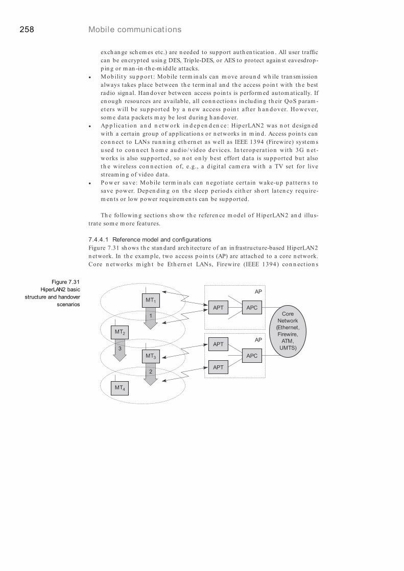
exch an ge sch em es etc.) are n eeded to support auth en ticat ion . All user trafficcan be en cryp ted usin g DES, Trip le-DES, or AES to protect again st eavesdrop-p in g or m an -in -th e-m iddle attacks.
● Mob ilit y su p p or t : Mobile t erm in als can m ove aroun d wh ile t ran sm issionalways takes place between th e term in al an d th e access poin t with th e bestradio sign al. Han dover between access poin ts is perform ed au tom atically. Ifen ough resources are available, all con n ection s in cludin g th eir QoS param -et ers will be su p po rt ed by a n ew access p oin t aft er h an d over. Ho wever,som e data packets m ay be lost durin g h an dover.
● Ap p lica t io n a n d n et w o rk in d ep en d en ce: Hip erLAN2 was n ot design edwith a certain group of application s or n etworks in m in d. Access poin ts cancon n ect to LANs ru n n in g eth ern et as well as IEEE 1394 (Firewire) system su sed to con n ect h om e au d io / vid eo d evices. In terop erat ion with 3G n et -works is also supported , so n o t on ly best effort data is su pp orted bu t alsoth e wireless co n n ect ion o f, e.g., a d igit al cam era with a TV set for livest ream in g of video data.
● Po w er sa ve: Mobile t erm in als can n egot iat e cert ain wake-u p pat tern s tosave power. Dep en d in g on th e sleep p eriod s eith er sh ort la ten cy requ ire-m en ts or low power requirem en ts can be supported.Th e followin g sect ion s sh ow th e referen ce m odel of HiperLAN2 an d illu s-
trate som e m ore features.7.4.4.1 Reference model and configurat ionsFigure 7.31 sh ows th e stan dard arch itecture of an in frastructu re-based HiperLAN2n etwork. In th e exam ple, two access p oin t s (AP) are attach ed to a core n etwork.Core n etworks m igh t be Eth ern et LANs, Firewire (IEEE 1394) con n ect ion s
Mobile communicat ions258
MT1
1
APTAPC
APT AP
APT APC
AP
CoreNetwork
(Ethernet,Firewire,
ATM,UMTS)
MT2
3MT3
2
MT4
Figure 7.31HiperLAN2 basic
structure and handoverscenarios

between aud io an d video equipm en t , ATM n etworks, UMTS 3G cellu lar ph on en etworks etc. Each AP con sists of an access p oin t con t ro ller (APC) an d on e orm ore access p oin t t ran sceivers (APT). An APT can com prise on e or m ore sectors(sh own as cell h ere). Fin ally, four m ob ile t erm in a ls (MT) are also sh own . MTscan m ove aroun d in th e cell area as sh own . Th e system autom atically assign s th eAPT/AP with th e best tran sm ission quality. No frequen cy plan n in g is n ecessary asth e APs au tom atically select th e appropriate frequen cy via d yn am ic frequ en cyselection (DFS, com pare with IEEE 802.11h , section 7.3.8).
Th ree h an dover situat ion s m ay occur:● Sector h an d over (In ter sector): If sector an ten n as are used for an AP, wh ich
is opt ion al in th e stan dard, th e AP sh all support sector h an dover. Th is typeof h an dover is h an d led in side th e DLC layer so is n ot visible ou tside th e AP(as lon g as en ough resources are available in th e n ew sector).
● Rad io h an d over (In ter-APT/In tra-AP): As th is h an dover type, too, is h an dledwith in th e AP, n o extern al in teraction is n eeded. In th e exam ple of Figure 7.31th e term in al MT3, m oves from on e APT to an oth er of th e sam e AP. All con textdata for th e con n ection s are already in th e AP (en cryption keys, au th en tica-tion , an d con n ect ion param eters) an d does n ot h ave to be ren egotiated.
● Netw ork h an d over (In ter-AP/In tra-n etwork): Th is is th e m ost com plex situa-tion : MT2 m oves from on e AP to an oth er. In th is case, th e core n etwork an dh igh er layers are also in volved. Th is h an dover m igh t be supported by th e coren etwork (sim ilar to th e IAPP, IEEE 802.11f). Oth erwise, th e MT m ust provideth e required in form ation sim ilar to th e situation durin g a n ew association .Hip erLAN2 n etworks can o p erat e in two d ifferen t m od es (wh ich m ay be
used sim ultan eously in th e sam e n etwork).● Cen tra lized m od e (CM): Th is in frast ructure-based m ode is sh own again in
a m ore abstract way in Figure 7.32 (left side). All APs are con n ected to a coren etwork an d MTs are associated with APs. Even if two MTs sh are th e sam ecell, all data is t ran sferred via th e AP. In th is m an datory m ode th e AP takescom plete con trol of everyth in g.
● Direct m od e (DM): Th e opt ion al ad-h oc m ode of HiperLAN2 is illust ratedon th e righ t side of Figu re 7.32. Data is d irect ly exch an ged between MTs ifth ey can receive each oth er, bu t th e n etwork st ill h as to be con trolled . Th iscan be don e via an AP th at con tain s a cen tral con troller (CC) an yway or viaan MT th a t con t ain s t h e CC fu n ct ion ality. Th ere is n o real d ifferen cebetween an AP an d a CC besides th e fact th at APs are always con n ected toan in frastructure but h ere on ly th e CC fun ction ality is n eeded . Th is is wh yth e stan dard coin ed two differen t n am es. IEEE 802.11, too, offers an ad-h ocm ode, bu t n ot th e CC fun ction ality for QoS support .
Wireless LAN 259

Figure 7.33 sh ows th e HiperLAN2 p rotocol stack as u sed in access poin ts.Pro tocol stacks in m obile term in als d iffer with resp ect to th e n um ber of MACan d RLC in st an ces (o n ly on e o f each ). Th e lowest layer, t h e p h ysica l la yer ,h an d les as u sual all fun ct ion s related to m odu lat ion , forward error correct ion ,sign al d et ect ion , syn ch ron izat io n etc. Sect io n 7.4.4.2 describes t h e p h ysicallayer in m ore detail. Th e d a ta lin k con t ro l (DLC) layer con tain s th e MAC fun c-t ion s, th e RLC sublayer an d error con trol fun ction s. If an AP com prises severalAPTs th en each APT requ ires an own MAC in stan ce. Th e MAC of an AP assign seach MT a certain capacity to guaran tee con n ection quality depen din g on avail-able resou rces. Above th e MAC DLC is d ivided in to a con trol an d a u ser p art .Th is separation is com m on in classical con n ection -orien ted system s such as cel-lu lar p h o n es o r PSTN. Th e u ser p art co n t ain s er ro r co n t ro l m ech an ism s.Hip erLAN2 o ffers reliab le d at a t ran sm ission u sin g ackn o wled gem en t s an dretran sm ission s. For broadcast tran sm ission s a repet it ion m ode can be used th atp rovid es in creased reliab ilit y by rep eat in g dat a p acket s. Ad d it ion ally, u n ac-kn owled ged d at a t ran sm ission is availab le. Th e r a d io l in k co n t ro l (RLC)sublayer com prises m ost con trol fun ction s in th e DLC layer (th e CC part of anAP). Th e associat ion con t ro l fu n ct ion (ACF) con trols associat ion an d au th en ti-cation of n ew MTs as well as syn ch ron ization of th e rad io cell via beacon s. Th eDLC u ser con n ect ion con t ro l (DCC or DUCC) service con trols con n ection set-up, m odification , an d release. Fin ally, th e rad io resou rce con t ro l (RRC) h an dlesh an dover between APs an d with in an AP. Th ese fun ct ion s con trol th e dyn am icfrequen cy selection an d power save m ech an ism s of th e MTs.
On top of th e DLC layer th ere is th e con vergen ce layer . Th is h igh est layerof Hip erLAN2 st an d ard izat io n m ay com p rise segm en tat ion an d reassem blyfun ction s an d adaptat ion s to fixed LANs, 3G n etworks etc. Th e followin g sec-t ion s give som e m ore in sigh t in to th e 3 HiperLAN2 layers.
Mobile communicat ions260
MT1 MT2
data
AP
control control
Centralized
MT1 MT2data
AP/CC
control
MT1 MT2 + CCdatacontrol
Direct
Figure 7.32HiperLAN2 centralized vs
direct mode

7.4.4.2 Physical layerMan y fun ction s an d features of HiperLAN2’s ph ysical layer (ETSI, 2001a) servedas an exam ple for IEEE 802.11a as described in sect ion 7.3.7. It is n ot surprisin gth at bo th st an d ard s offer sim ilar d a t a ra t es an d u se id en t ica l m od u la t io nsch em es. Tab le 7 .5 gives an overview of th e data rat es offered by Hip erLAN2togeth er with oth er param eters such as codin g (com pare th is with Table 7.3).
Figure 7.34 illustrates th e referen ce con figuration of th e tran sm ission ch ainof a HiperLAN2 device. After selectin g on e of th e above t ran sm ission m odes, th eDLC layer passes a PSDU to th e ph ysical layer (PSDUs are called DLC PDU train s
Wireless LAN 261
Radioresourcecontrol
Assoc.control
DLCconn.
control
Radio link control
Radio link control sublayer
DLC controlSAP Convergence layer
Errorcontrol
Data link control –basic data
transport function
DLC userSAP
Medium access control
Higher layers
Physical layer
Scope ofHiperLAN2standards
Figure 7.33HiperLAN2 protocol stack
Data rate Modulat ion Coding rate Coded Coded Data [Mbit / s] bits per bits per bits per
sub-carrier OFDM symbol OFDM symbol6 BPSK 1/ 2 1 48 249 BPSK 3/ 4 1 48 36
12 QPSK 1/ 2 2 96 4818 QPSK 3/ 4 2 96 7227 16-QAM 9/ 16 4 192 10836 16-QAM 3/ 4 4 192 14454 64-QAM 3/ 4 6 288 216
Table 7.5 Ratedependent parametersfor HiperLAN2

in th e Hip erLAN2 con text ). Th e first step t h en is scr a m b lin g of all d ata b it swith th e gen erator polyn om ial x7 + x4 + 1 for DC blockin g an d wh iten in g of th espectrum . Th e resu lt of th is first step are scram bled b it s. Th e n ext step appliesFEC cod in g for error p rotect ion . Codin g depen d s on th e type o f data (broad-cast , u p lin k, d o wn lin k et c.) an d t h e u sage o f secto r o r o m n i-d irect io n alan ten n as. Th e result of th is step is an en cod ed b it . For m itigation of frequen cyselect ive fad in g in t er leav in g is app lied in th e th ird step . In terleavin g en su resth at ad jacen t en coded bits are m apped on to n on -adjacen t su bcarriers (48 sub-carriers are u sed for data t ran sm ission ). Adjacen t b it s are m ap ped alt ern atelyon to less an d m ore sign ifican t b it s o f t h e con st ellat io n . Th e resu lt is anin t er leaved b it .
Th e followin g m ap p in g process first divides th e bit sequen ce in groups of 1,2, 4, or 6 bits depen din g on th e m odulation sch em e (BPSK, QPSK, 16-QAM, or 64-QAM). Th ese groups are m app ed on to th e app ropriate m odu lat ion sym bolaccordin g to th e con stellation diagram s stan dardized in (ETSI, 2001a). Th e resultsof th is m appin g are su bcarrier m od u lat ion sym bols. Th e OFDM m odulation stepcon verts th ese sym bols in to a baseban d sign al with th e h elp of th e in verse FFT.(For th e usage of th e subcarriers com pare with Figure 7.24 an d its description insection 7.3.7). Th e sym bol in terval is 4 µs with 3.2 µs useful part an d 0.8 µs guardtim e. Pilot sub-carriers (sub-carriers –21, –7, 7, 21) are added. Th e last step beforeradio tran sm ission is th e creation of PHY b u rsts (PPDUs in ISO/OSI term in ology).Each burst con sists of a pream ble an d a payload. Five differen t PHY bursts h avebeen defin ed: broadcast, down lin k, uplin k with sh ort pream ble, uplin k with lon gpream ble, an d direct lin k (option al). Th e bursts differ in th eir pream bles.
Th e fin a l r a d io t r a n sm issio n sh ift s t h e baseban d sign al t o a carrier fre-q uen cy dep en d in g on t h e ch an n el n um ber an d th e form ula alread y u sed fo r802.11a: carrier_n um ber = (carrier_frequen cy – 5000 MHz)/5 MHz. All n om in alcarrier frequen cies are spaced 20 MHz apart , resu lt in g in a frequen cy allocationtable for Europe as illustrated in Figure 7.35.
Maxim u m tran sm it power is 200 m W EIRP for th e lower frequ en cy ban d(in door use) an d 1 W EIRP for th e h igh er frequen cy ban d (in door an d ou tdooruse). DFS an d TPC are n ot n ecessary, if th e tran sm it power stays below 50 m WEIRP an d on ly 5.15–5.25 GHz are used (be aware th at n at ion al d ifferen ces existeven with in Europe an d regulat ion m ay ch an ge over t im e).
Mobile communicat ions262
PDU train from DLC(PSDU) scrambling FEC coding interleaving
mapping OFDM PHY bursts(PPDU)
radiotransmitter
Figure 7.34HiperLAN2 physical layer
reference configuration

7.4.4.3 Data link cont rol layerAs described above, th e DLC layer is d ivided in to MAC, con t rol an d data part(wh ich wou ld fit in t o th e LLC su b layer acco rd in g t o ISO/ OSI). ETSI (2001b)stan dardizes th e basic data tran sport fun ct ion s, i.e., user part with error con trolan d MAC, wh ile ETSI (2002a) defin es RLC fun ction ality.
Th e m ed iu m access co n t ro l creat es fram es o f 2 m s d u ra t io n as sh ownin Figu re 7.36. With a co n st an t sym bo l len gth o f fou r µs t h is resu lt s in 500OFDM sym bols. Each MAC fram e is fu rth er sub-d ivided in to fou r ph ases withvariable boun daries:● Br o a d ca st p h a se : Th e AP o f a cell b road cast s th e con ten t of th e cu rren t
fram e plus in form ation abou t th e cell (iden tification , status, resources). ● Dow n lin k p h ase: Tran sm ission of user data from an AP to th e MTs.● Up lin k p h ase: Tran sm ission of user data from MTs to an AP.● Ran d om a ccess p h ase: Capacity requests from already registered MTs an d
access requests from n on -registered MTs (slotted Aloh a).
Wireless LAN 263
36
51805150
channel
5350 [MHz]16.6 MHz
5470[MHz]
40
5200
44
5220
48
5240
52
5260
56
5280
60
5300
64
5320
100
550016.6 MHz
104
5520
108
5540
112
5560 5725
channel116
5580
120
5600
124
5620
128
5640
132
5660
136
5680
140
5700
Figure 7.35Operating channels ofHiperLAN2 in Europe
MAC frame2 ms
broadcast phase downlink phase uplink phase randomaccess phase
variable variable variable
MAC frame2 ms
MAC frame2 ms
MAC frame2 ms
...TDD,
500 OFDMsymbols
per frame
Figure 7.36Basic structure ofHiperLAN2 MAC frames

An op t ion al d irect lin k p h a se can be in serted between th e down lin k an dth e u p lin k p h ase. Th e access to th e com m on ph ysical m ediu m is always con -trolled by th e CC (typically in an AP).
HiperLAN2 defin es six differen t so-called tran sport ch an n els for data tran s-fer in t h e above list ed p h ases. Th ese t ran sp ort ch an n els d escribe t h e b asicm essage form at with in a MAC fram e. ● Broad cast ch an n el (BCH): Th is ch an n el con veys basic in form ation for th e
rad io cell to all MTs. Th is com prises th e iden t ificat ion an d cu rren t t ran s-m ission power of th e AP. Furth erm ore, th e ch an n el con tain s poin ters to th eFCH an d RCH wh ich allows for a flexible structure of th e MAC fram e. Th elen gth is 15 bytes.
● Fra m e ch a n n el (FCH): Th is ch an n el con tain s a d irectory of th e down lin kan d uplin k ph ases (LCHs, SCHs, an d em pty parts). Th is also com prises th ePHY m ode used . Th e len gth is a m ult ip le of 27 bytes.
● Access feed b a ck ch a n n el (ACH ): Th is ch an n el gives feed b ack to MTsregardin g th e ran dom access durin g th e RCH of th e previous fram e. As th eaccess durin g th e RCHs is based on slot ted Aloh a, co llision at th e AP m ayoccu r. Th e ACH sign als back wh ich slo t was su ccessfu lly tran sm it ted . Th elen gth is 9 bytes.
● Lon g t ra n sp o r t ch an n el (LCH): Th is ch an n el tran sports user an d con t roldata for down lin ks an d uplin ks. Th e len gth is 54 bytes.
● Sh or t t ran sp or t ch a n n el (SCH ): Th is ch an n el t ran sp ort s con t rol data fordown lin ks an d uplin ks. Th e len gth is 9 bytes.
● Ran d om ch an n el (RCH): Th is ch an n el is n eeded to give an MT th e opportu-n ity to sen d in form ation to th e AP/CC even with out a gran ted SCH. Access isvia slot ted Aloh a so, collision s m ay occur. Collision resolu tion is perform edwith th e h elp of an expon en tial back-off sch em e (ETSI, 2001b). Th e len gth is9 bytes. A m axim um n um ber of 31 RCHs is curren tly supported.BCH, FCH an d ACH are used in th e broadcast ph ase on ly an d use BPSK with
code rate 1/2. LCH an d SCH can be used in th e down lin k, uplin k or (op tion al)direct lin k ph ase. RCH is u sed in th e up lin k on ly for ran dom access (BPSK, coderate 1/2). HiperLAN2 defin es furth er h ow m an y of th e ch an n els are used with ina MAC fram e. Th is con figurat ion m ay ch an ge from MAC fram e to MAC fram edepen din g on th e con n ection QoS, resource requests, n um ber of MTs etc. Figure7.37 sh ows valid com bin ation s of ch an n els/ t ran sfer ph ases with in MAC fram es.It is requ ired th at th e tran sport ch an n els BCH, FCH an d ACH are presen t plus atleast on e RCH. Wh ile th e duration of th e BCH is fixed (15 byte), th e du ration ofth e oth ers m ay vary (eith er due to a variable size of th e ch an n el or due to th em u lt ip le u se o f ch an n els). However, t h e o rd er BCH-FCH-ACH-DL p h ase-ULph ase-RCH m ust be kept from an MT’s poin t of view (cen tralized m ode). For th edirect m ode th e DiL ph ase is in serted between th e DL an d UL ph ases.
Data between en t it ies of th e DLC layer are tran sferred over so-called logica lch a n n els (ju st an oth er n am e for an y d ist in ct data path ). Th e typ e of a logical
Mobile communicat ions264

ch an n el is defin ed by th e type of in form ation it carries an d th e in terpretation ofth e values in th e corresp on din g m essages. Th is is a well-kn own con cep t from ,e.g., cellu lar ph on e syst em s like GSM (see ch ap t er 4). Th e fo llowin g logicalch an n els are defin ed in HiperLAN2 (logical ch an n els use 4 letter acron ym s):● Broad cast con tro l ch an n el (BCCH): Th is ch an n el on th e down lin k con veys
a con stan t am oun t of broadcast in form ation con cern in g th e wh ole radio cell.Exam ples are th e seed for th e scram bler, n etwork/access poin t/ sector iden t i-fiers, AP t ran sm ission power, expected AP reception power, poin ters to th eFCH/RCH, n um ber of RCHs (1 to 31), load in dicator, n um ber of sectors etc.
● Fram e con t ro l ch an n el (FCCH): Th e FCCH describes th e st ructu re of th erem ain in g parts of th e MAC fram e. Th is com prises resource gran ts for SCHsan d LCHs belon gin g t o certa in MTs. Resou rce gran t s con t a in t h e MACad d ress t h e gran t belon gs t o , t h e n u m ber of LCHs an d SCHs, t h eir PHYm odes etc. Th is sch em e allows for a precise reservation of th e m edium withassociated QoS propert ies.
● Ra n d o m a ccess feed b a ck ch a n n el (RFCH ): Th is ch an n el in form s MTsth at h ave u sed an RCH in t h e p reviou s fram e abo u t t h e su ccess o f t h eiraccess at tem pt.
● RLC b ro a d ca st ch a n n el (RBCH ): Th is ch an n el t ran sfers in form at io nregard in g RLC con trol in form at ion , MAC IDs du rin g an associat ion ph ase,in form ation from th e con vergen ce layer, or seeds for th e en crypt ion fun c-t ion on ly if n ecessary.
Wireless LAN 265
MAC frame2 ms
broadcast downlink uplinkrandomaccess
MAC frame2 ms
MAC frame2 ms
MAC frame2 ms
...
BCH FCH ACH DL phase DiL phase UL phase RCHsBCH FCH ACH DiL phase UL phase RCHsBCH FCH ACH DL phase UL phase RCHsBCH FCH ACH UL phase RCHsBCH FCH ACH DL phase DiL phase RCHsBCH FCH ACH DiL phase RCHsBCH FCH ACH DL phase RCHsBCH FCH ACH RCHs
Figure 7.37Valid configurations ofMAC frames

● Ded ica t ed con t r o l ch a n n el (DCCH ): Th is ch an n el carries RLC m essagesrelated to a certain MT an d is establish ed du rin g th e associat ion of an MT.
● User b ro a d ca st ch a n n el (UBCH ): A UBCH t ran sfers bro ad cast m essagesfrom th e con vergen ce layer. Tran sm ission is perform ed in th e un ackn owl-edged or repetition m ode.
● User m u lt i-cast ch an n el (UMCH): Th is ch an n el perform s un ackn owledgedtran sm ission of data to a group of MTs.
● User d a t a ch an n el (UDCH): Poin t-to-poin t data between an AP an d an MT(CM) or between two MTs (DM) u se th is ch an n el. Error p rotect ion via anARQ sch em e is possible.
● Lin k con t ro l ch a n n el (LCCH ): Th is b i-d irect ion al ch an n el con veys ARQfeedback an d d iscards m essages between th e error con trol fu n ction s of anAP an d an MT (CM) or b etween two MTs (DM). A LCCH is t yp ica llyassign ed to a UDCH.
● Asso cia t io n co n t r o l ch a n n el (ASCH ): Th is ch an n el is o n ly u sed in t h eu plin k an d for cu rren tly n on -associated MTs (related to a certain AP). Th isis t h e case fo r a n ew associa t io n req u est (n ew MT in t h e n etwork) o r ah an dover request on beh alf of th e RLC.Th e reader m ay h ave n oticed th at som e tran sport ch an n els tran sfer exactly
th e in form ation of on e logical ch an n el as th eir descript ion s were iden tical. Th isis in d eed th e case for som e ch an n els (BCCH-BCH, FCCH-FCH, RFCH-ACH) asth e sch em e of m appin g logical an d t ran sport ch an n els sh ows (see Figure 7.38).Th is figu re also sh ows in wh ich m ode wh ich ch an n el can be used (up lin k an ddown lin k in th e cen tralized m ode, d irect lin k in th e direct m ode).
Figure 7.39 gives an exam ple for m appin g th e logical ch an n el UDCH to th etran sport ch an n el LCH. Th e payload of th e LCH is used for a sequen ce n um berplus th e payload of th e UDCH.
Mobile communicat ions266
BCCH
BCH
FCCH
FCH
RFCH
ACH
LCCH RBCH
SCH
DCCH UDCH
LCH
UBCH UMCH
UDCH
LCH
DCCH
SCH
LCCH
RCH
ASCH
uplink
UDCH UBCH UMCH
LCH
DCCH RBCH
SCH
LCCH
direct link
downlink
Figure 7.38Mapping of logical and
transport channels

Th e ra d io l in k co n t ro l su blayer in con n ect ion orien ted system s offerin gQoS like HiperLAN2 is quite com plex an d com prises m an y protocols, fun ction s,an d m essages. ETSI (2002a) defin es th ree m ain services for th e RLC sublayer:● Associa t ion con t ro l fu n ct ion (ACF): ACF con tain s all p rocedures for asso-
ciat ion , au th en t icat io n , an d en cryp t io n . An MT st art s t h e associat io nprocess. Th e first step is th e syn ch ron ization with a beacon sign al t ran sm it-ted in each BCCH of a MAC fram e. Th e n etwork ID m ay be obtain ed via th eRBCH. Th e n ext step is th e MAC ID assign m en t. Th is un ique ID is used toaddress th e MT. From th is poin t on , all RLC con trol m essages are t ran sm it-ted via a DCCH. Durin g th e followin g lin k capability n egot iat ion , lists ofsup ported con vergen ce layers, au th en t icat ion an d en cryp t ion p roceduresare exch an ged . Depen d in g on t h ese param eters t h e fo llo win g st eps m aytake p lace: en cryption start-up , au th en t ication , obtain in g th e ID of th e MT.If all n ecessary st ep s are su ccessfu l t h e MT is associat ed with t h e AP.Disassociat ion m ay take place at an y t im e, eith er explicit ly (MT or AP in it i-ated) or im plicit ly (loss of th e radio con n ect ion ). Th e AP m ay sen d MT-alivem essages to ch eck if an MT is st ill available.
● Ra d io reso u rce co n t r o l (RRC): An im p ort an t fu n ct io n o f t h e RRC ish an dover support as already sh own in Figure 7.31. Each associated MT con -t in uou sly m easu res th e lin k q u ality. To fin d h an d over can didates th e MTad d it ion ally ch ecks o th er freq uen cies. If on ly on e t ran sceiver is availableth e MT an n o u n ces t o t h e AP th at it is t em p orarily u n availab le (MTabsen ce). Based on rad io quality m easurem en ts, an AP can ch an ge th e car-rier freq uen cy dyn am ically (DFS). Th e RLC offers procedu res to in form allMTs. To m in im ize in terferen ce with o th er rad io sou rces op erat in g at th esam e frequen cy (HiperLAN2s or oth er WLANs) tran sm ission power con trol(TPC) m ust be app lied by th e RRC. An MT can save power by n egotiat in gwith an AP a sleep in g period of n MAC fram es. After th ese n fram es th e MTm ay wake up because data is ready to be sen t , or th e AP sign als data to bereceived. If th e MT m isses th e wakeup m essage from th e AP it starts th e MTalive p ro ced u re. If n o da t a h as t o be t ran sm it ted t h e MT can again fallasleep for n fram es.
Wireless LAN 267
LCH PDU type2
sequencenumber
10payload
396CRC24 bit
UDCH transfer syntax(long PDU)
LCH PDU type2
payload406
CRC24 bit
LCH transfer syntax
54 byte
Figure 7.39HiperLAN2 LCH andUDCH transfer syntax

● DLC u ser con n ect ion con t ro l (DCC or DUCC): Th is service is used for set-t in g u p , releasin g, o r m od ifyin g u n icast con n ect ion s. Mu lt i-cast an db road cast con n ect io n s are im p licit ly set -u p b y a grou p / b roadcast jo ind urin g th e association p rocedure.
7.4.4.4 Convergence layerAs th e p h ysical layer an d th e d ata lin k layer are in dep en den t of specific coren etwork protocols, a special co n vergen ce la yer (CL) is n eeded to adap t to th especific featu res of th ese n etwork protocols. HiperLAN2 su pports two d ifferen ttyp es of CLs: cell-based an d p acket -b ased . Th e ce ll -b a sed CL (ETSI, 2000b)expects data packets of fixed size (cells, e.g., ATM cells), wh ile th e p a ck et -b asedCL (ETSI, 2000d ) h an d les packet s t h at are variab le in size (e.g., Eth ern et o rFirewire fram es). For th e packet-based CL addit ion al fu n ction ality is n ecessaryfor segm en tat ion an d reassem blin g of packets th at do n ot fit in to th e DLC pay-load of HiperLAN2 (49.5 byte). Th ree exam ples of con vergen ce layers follow:● Et h er n et : Th is su b layer su p p ort s t h e t ran sp aren t t ran sp ort o f Eth ern et
fram es over a HiperLAN2 wireless n etwork (ETSI, 2001d). Th is in cludes th em ap p in g of Eth ern et m u lt icast an d b roadcast m essages on to Hip erLAN2m ulticast an d broadcast m essages. A collision dom ain can also be em ulated.Th is su blayer also su pport s p riorit ies accord in g to IEEE 802.1p . Th e stan -d ard su pp ort s th e t raffic classes best effo rt , backgrou n d , excellen t effort ,con trolled load , video, voice, an d n etwork con trol. Th e sublayer does n ott ran sm it th e Eth ern et pream ble, start of fram e delim iter, an d fram e ch ecksequen ce. Th ese fields of an Eth ern et fram e are n ot n ecessary durin g tran s-m ission an d will be appen ded in th e receiver’s Eth ern et sublayer.
● IEEE 1394 (Firew ire): As a h igh -sp eed real-t im e bu s for con n ect in g, e.g.,au d io an d vid eo devices, t im in g an d syn ch ron izat ion is of special im p or-tan ce for IEEE 1394. ETSI (2001e) su pp ort s syn ch ron izat ion of t im ers viath e air an d t reats isoch ron ous data stream s with special regard to jit ter.
● ATM: Th e cell-based CL is u sed for th is typ e of n etwork (ETSI, 2000c). Asth e payload of an ATM cell is on ly 48 byte, wh ich fits in to th e 49.5 byte of aDLC-PDU, segm en tat ion an d reassem bly is n ot n ecessary. In th is case, th esu blayer on ly h as to con trol con n ection iden t ifiers an d MAC IDs.Man y p eop le d o u bt t h at Hip erLAN2 will ever be a com m ercia l su ccess.
Wireless n etwo rks fo llowin g IEEE 802.11 are a lread y in widesp read u se. Th estory of wireless LANs could follow th e race between Eth ern et an d Token Rin gin th e early d ays of LANs. In th is case, th e m u ch sim p ler Eth ern et succeed edalth o u gh it co u ld n ot offer an y q u alit y o f service co m p ared t o Token Rin g.However, p lan s for in terworkin g between HiperLAN2 an d 3G cellu lar system sh ave already been m ade (ETSI, 2001c). HiperLAN2 is to be used to provide h igh -speed access t o th e in t ern et with QoS guaran t ees. On e d ifferen ce from oth er
Mobile communicat ions268

W LAN solu t ion s, besides QoS, is th e in terworkin g of Hip erLAN2 secu rity an daccoun t in g m ech an ism s with th e m ech an ism s of, e.g., UMTS. A m ore detailedcom parison of th e IEEE 802.11a WLAN approach an d HiperLAN2 is given at th een d of th is ch apter.
7.5 BluetoothCom p ared t o th e W LAN tech n ologies p resen ted in sect ion s 7.3 an d 7.4, th eBluetooth tech n ology d iscussed h ere aim s at so-called ad -h oc p ico n et s, wh ichare local area n etworks with a very lim ited coverage an d with out th e n eed for anin frastructure. Th is is a differen t type of n etwork is n eeded to con n ect differen tsm all devices in close proxim ity (abou t 10 m ) with ou t expen sive wirin g or th en eed for a wireless in frastructu re (Bisdikian , 1998). Th e en visaged gross data rateis 1 Mbit / s, asyn ch ron ous (dat a) an d syn ch ron ou s (vo ice) services sh ou ld beavailable. Th e n ecessary t ran sceiver com pon en ts sh ould be ch eap – th e goal isabout €5 per device. (In 2002, separate adapters are still at €50, h owever, th e ad-dition al cost of th e devices in tegrated in , e.g., PDAs, alm ost reach ed th e target .)Man y of today’s devices offer an in fra red data association (IrDA) in terface withtran sm ission rates of, e.g., 115 kbit/s or 4 Mbit/ s. Th ere are various problem s withIrDA: its very lim ited ran ge (typically 2 m for built-in in terfaces), th e n eed for alin e-of-sigh t between th e in terfaces, an d, it is usually lim ited to two part icipan ts,i.e., on ly poin t-to-poin t con n ection s are supported. IrDA h as n o in tern et workin gfun ct ion s, h as n o m edia access, or an y oth er en h an ced com m un icat ion m ech -an ism s. Th e big advan tage of IrDA is its low cost , an d it can be foun d in alm ostan y m obile device (laptops, PDAs, m obile ph on es).
Th e h istory of Bluetooth starts in th e ten th cen tury, wh en Harald Gorm sen ,Kin g of Den m ark (son of Gorm ), erected a ru n e ston e in Jellin g, Den m ark, inm em ory of h is paren ts. Th e ston e h as th ree sides with elaborate carvin gs. On eside sh ows a picture of Ch rist, as Harald did n ot on ly un ite Norway an d Den m ark,but also brough t Ch ristian ity to Scan din avia. Harald h ad th e com m on epith et of‘Blåtan d’, m ean in g th at h e h ad a rath er dark com plexion (n ot a blue tooth ).
It took a th ousan d years before th e Swedish IT-com pan y Ericsson in it iatedsom e stu d ies in 1994 aroun d a so -called m u lt i-com m u n icator lin k (Haart sen ,1998). Th e p ro ject was ren am ed (becau se a frien d of t h e d esign ers liked t h eVikin gs) an d Bluetooth was born . In sprin g 1998 five com pan ies (Ericsson , In tel,IBM, Nokia, Tosh iba) foun ded th e Bluetooth con sort ium with th e goal of devel-op in g a sin gle-ch ip , low-cost , rad io-based wireless n etwork tech n ology. Man yoth er com p an ies an d research in st it u t io n s jo in ed t h e sp ecial in t erest grou paroun d Bluetooth (2002), wh ose goal was th e developm en t of m obile ph on es,lap tops, n otebooks, h eadsets etc. in cludin g Bluetooth tech n ology, by th e en d of1999. In 1999, Ericsson erect ed a ru n e sto n e in Lu n d , Swed en , in m em o ryof Harald Gorm sen , called Blåtan d , wh o gave h is ep ith et for th is n ew wireless
Wireless LAN 269

com m u n icat ion tech n ology. Th is n ew carvin g sh ows a m an h old in g a lap topan d a cellu lar ph on e, a picture wh ich is quite often cited (of course th ere are n osuch th in gs visible on th e origin al ston e, th at’s just a n ice story!)
In 2001, th e first p roducts h it th e m ass m arket , an d m an y m obile ph on es,laptops, PDAs, video cam eras etc. are equipped with Bluetooth tech n ology today.
At th e sam e t im e th e Bluetooth developm en t started, a study group with inIEEE 802.11 d iscussed w ireless p erson al a rea n etw ork s (W PAN) un der th e fol-lowin g five criteria:● Market p o t en t ia l: How m an y applicat ion s, devices, ven dors, custom ers are
available for a certain tech n ology?● Com p at ib ility: Com patibility with IEEE 802.● Dist in ct id en t it y : Origin ally, th e stud y group d id n ot wan t to establish a
secon d 802.11 stan dard . However, top ics su ch as, low cost , low p ower, o rsm all form factor are n ot addressed in th e 802.11 stan dard .
● Tech n ica l feasib ility: Prototypes are n ecessary for furth er d iscussion , so th estudy group wou ld n ot rely on paper work.
● Eco n o m ic fea sib ilit y : Everyth in g d eveloped with in th is group sh ou ld bech eaper th an oth er solu tion s an d allow for h igh -volum e production .Obviou sly, Bluetooth fu lfills th ese criteria so th e WPAN grou p cooperated
with t h e Blu etoo th co n so rt iu m . IEEE fo u n d ed it s own gro u p for W PANs,IEEE 802.15, in March 1999. Th is group sh ould develop stan dards for wirelesscom m un ication s with in a p erson al op era t in g sp ace (POS, IEEE, 2002c). A POSh as been defin ed as a rad iu s of 10 m aroun d a person in wh ich th e person ordevices of th is person com m un icate with oth er devices. Section 7.5.10 gives anoverview of 802.15 activit ies an d th eir relat ion to Bluetooth .7.5.1 User scenariosMan y d ifferen t user scen arios can be im agin ed for wireless p icon ets or WPANs:● Con n ect ion of p erip h era l d evices: Today, m ost devices are con n ected to a
d esktop com puter via wires (e.g., keyboard, m ouse, joyst ick, h eadset, speak-ers). Th is type of con n ection h as several disadvan tages: each device h as itsown type of cable, d ifferen t plugs are n eeded, wires block office space. In awireless n etwork, n o wires are n eeded for data t ran sm ission . However, bat-teries n ow h ave to rep lace th e power supply, as th e wires n ot on ly t ran sferd ata but also supply th e periph eral devices with power.
● Su p p o r t o f a d -h o c n et w ork in g: Im agin e several peop le com in g togeth er,d iscu ssin g issu es, exch an gin g dat a (sch ed u les, sa les figu res etc.). Fo rin stan ce, studen ts m igh t join a lectu re, with th e teach er dist ribu tin g data toth eir person al d igital assistan ts (PDAs). Wireless n etworks can support th istype of in teraction ; sm all devices m igh t n ot h ave W LAN adapters followin gth e IEEE 802.11 stan dard, bu t ch eaper Bluetooth ch ips built in .
Mobile communicat ions270

● Brid gin g of n etw orks: Usin g wireless picon ets, a m obile ph on e can be con -n ected to a PDA or laptop in a sim ple way. Mobile ph on es will n ot h ave fullWLAN adapters built in , but could h ave a Bluetooth ch ip. Th e m obile ph on ecan th en act as a bridge between th e local picon et an d, e.g., th e global GSMn etwork (see Figu re 7.40). For in stan ce, on arrival at an airp ort , a person ’sm obile ph on e cou ld receive e-m ail via GSM an d forward it to th e lap topwh ich is still in a suitcase. Via a picon et, a fileserver could update local in for-m ation stored on a laptop or PDA wh ile th e person is walkin g in to th e office.W h en com parin g Bluetooth with oth er WLAN tech n ology we h ave to keep
in m in d th at on e of it s goals was to p rovid e local wireless access at very lowcost . From a tech n ical poin t of view, WLAN tech n ologies like th ose above cou ldalso be u sed , h owever, W LAN ad ap ters, e.g., for IEEE 802.11, h ave b eend esign ed fo r h igh er b an d width an d larger ran ge an d are m ore exp en sive an dcon sum e a lot m ore p ower.7.5.2 ArchitectureLike IEEE 802.11b, Blu etooth operates in th e 2.4 GHz ISM ban d. However, MAC,ph ysical layer an d th e offered services are com pletely differen t . After p resen tin gth e overall arch itectu re of Bluetooth an d its specialty, th e p icon ets, th e follow-in g section s explain all protocol layers an d com pon en ts in m ore detail.7.5.2.1 NetworkingTo un derstan d th e n etworkin g of Bluetooth devices a qu ick in t roduction to itskey fea tu res is n ecessary. Blu eto oth o p era tes on 79 ch an n els in t h e 2.4 GHzban d with 1 MHz carrier spacin g. Each device perform s frequen cy h oppin g with1,600 h ops/ s in a pseudo ran dom fash ion . Blu etooth ap plies FHSS for in terfer-en ce m it igat ion (an d FH-CDMA fo r sep arat ion o f n etwo rks). More abou tBluetooth ’s radio layer in section 7.5.3.
A very im portan t term in th e con text of Bluetooth is a p icon et . A p icon et isa collect ion of Bluetooth devices wh ich are syn ch ron ized to th e sam e h oppin gsequ en ce. Figu re 7.41 sh ows a co llect ion of d evices with d ifferen t ro les. On edevice in th e picon et can act as m aster (M), all oth er devices con n ected to th e
Wireless LAN 271Figure 7.40Example configurationswith a Bluetooth-basedpiconet

m aster m ust act as slaves (S). Th e m aster determ in es th e h opp in g pattern in th epicon et an d th e slaves h ave to syn ch ron ize to th is pattern . Each p icon et h as aun ique h oppin g pattern . If a device wan ts to part icipate it h as to syn ch ron ize toth is. Two add it ion al t yp es of d evices are sh o wn : p arked d evices (P) can n otactively part icipate in th e picon et (i.e., th ey do n ot h ave a con n ection ), bu t arekn own an d can be react ivated with in som e m illisecon d s (see sect io n 7.5.5).Devices in stan d -by (SB) d o n o t part icip at e in th e p icon et . Each p icon et h asexactly on e m aster an d up to seven sim ultan eous slaves. More th an 200 devicescan be parked . Th e reason for th e upper lim it of eigh t active devices, is th e 3-bitaddress u sed in Bluetooth . If a parked device wan ts to com m u n icate an d th ereare already seven act ive slaves, on e slave h as to switch to p ark m ode to allowth e parked device to switch to active m ode.
Figure 7.42 gives an overview o f th e form at ion of a p icon et . As all act ivedevices h ave to use th e sam e h oppin g sequen ce th ey m ust be syn ch ron ized. Th efirst step in volves a m aster sen din g its clock an d device ID. All Bluetooth devicesh ave th e sam e n etworkin g capabilities, i.e., th ey can be m aster or slave. Th ere is n odistin ction between term in als an d base station s, an y two or m ore devices can forma picon et. Th e un it establish in g th e picon et autom atically becom es th e m aster, alloth er devices will be slaves. Th e h oppin g pattern is determ in ed by th e device ID, a48-bit worldwide u n ique iden tifier. Th e p h ase in th e h op pin g pat tern is deter-m in ed by th e m aster’s clock. After adjust in g th e in tern al clock accord in g to th em aster a device m ay part icipate in th e p icon et . All active devices are assign ed a3-b it a ct ive m em b er a d d ress (AMA). All p arked devices u se an 8-bit p a rk edm em ber add ress (PMA). Devices in stan d-by do n ot n eed an address.
All users with in on e picon et h ave th e sam e h oppin g sequen ce an d sh are th esam e 1 MHz ch an n el. As m ore users join th e p icon et , th e th rou gh put per u serdrops qu ickly (a sin gle p icon et offers less th an 1 Mbit / s gross data rate). (On lyh avin g on e picon et available with in th e 80 MHz in total is n ot very efficien t.) Th is
Mobile communicat ions272
SP
SB
P SB
PS
S
M
M = MasterS = SlaveP = ParkedSB = Standby
Figure 7.41Simple Bluetooth
piconet

led to th e idea of form in g groups of picon ets called sca t tern et (see Figure 7.43).On ly th ose un its th at really m ust exch an ge data sh are th e sam e picon et, so th atm an y picon ets with overlappin g coverage can exist sim ultan eously.
In th e exam ple, th e scat tern et con sists of two picon ets, in wh ich on e devicep art icip ates in two d ifferen t p icon ets. Bo th p icon ets u se a d ifferen t h op p in gseq u en ce, always det erm in ed by th e m aster of th e p icon et . Blu etooth ap pliesFH-CDMA for separat ion of p icon ets. In an average sen se, all p icon ets can sh areth e total of 80 MHz ban dwidth available. Addin g m ore picon ets leads to a grace-fu l p erfo rm an ce d egradat io n of a sin gle p icon et becau se m ore an d m o reco llision s m ay occur. A co llision occurs if two or m ore p icon ets u se th e sam ecarrier frequ en cy at t h e sam e t im e. Th is will p robably h ap pen as th e h opp in gsequen ces are n ot coord in ated.
If a d evice wan ts t o p art icip ate in m ore t h an o n e p icon et , it h as t o syn -ch ron ize to th e h op p in g seq uen ce of th e p icon et it wan ts to take p art in . If adevice acts as slave in on e picon et , it sim ply starts to syn ch ron ize with th e h op-pin g sequen ce of th e p icon et it wan ts to join . After syn ch ron izat ion , it acts as aslave in th is p icon et an d n o lon ger participates in its form er picon et . To en ablesyn ch ron ization , a slave h as to kn ow th e iden tity of th e m aster th at determ in esth e h oppin g sequen ce of a p icon et. Before leavin g on e p icon et , a slave in form sth e curren t m aster th at it will be un available for a certain am oun t of t im e. Th erem ain in g devices in th e picon et con tin ue to com m un icate as usual.
Wireless LAN 273
SP
SB
P SB
PS
S
M
SBSB
SB
SB SB
SBSB
SB
SB
Figure 7.42Forming a Bluetoothpiconet

A m aster can also leave it s picon et an d act as a slave in an oth er p icon et. It isclearly n ot possible for a m aster of on e p icon et to act as t h e m aster of an oth erpicon et as th is would lead to iden tical beh avior (both would h ave th e sam e h oppin gsequen ce, wh ich is determ in ed by th e m aster per defin it ion ). As soon as a m asterleaves a picon et, all traffic with in th is picon et is suspen ded un til th e m aster return s.
Com m un ication between differen t picon ets takes p lace by devices jum pin gback an d fo rth between th eses n et s. If t h is is don e period ically, fo r in stan ce,iso ch ron o u s d at a st ream s can be fo rward ed fro m on e p ico n et t o an o th er.However, scattern ets are n ot yet supported by all devices. 7.5.2.2 Protocol stackAs Figure 7.44 sh ows, th e Bluetooth specification already com prises m an y p roto-cols an d com pon en ts. Start in g as a sim p le idea, it n ow covers over 2,000 pagesdealin g with n ot on ly th e Bluetooth p rotocols bu t m an y adaptat ion fun ct ion san d en h an cem en ts. Th e Blu etooth p ro toco l stack can be d ivid ed in to a co r esp ecifica t ion (Blu etooth , 2001a), wh ich describes th e protocols from ph ysicallayer to th e data lin k con trol togeth er with m an agem en t fun ct ion s, an d p rofi lesp ecifica t io n s (Blu eto o th , 2001b). Th e la t t er d escribes m an y p ro to co ls an dfun ction s n eeded to adapt th e wireless Bluetooth tech n ology to legacy an d n ewapplication s (see section 7.5.9).
Th e core p ro tocols of Bluetooth com prise th e followin g elem en ts:● Rad io : Specification of th e air in terface, i.e., frequen cies, m odulation , an d
tran sm it power (see section 7.5.3).● Baseb an d : Descrip t ion of basic con n ection establish m en t , packet form ats,
t im in g, an d basic QoS param eters (see sect ion 7.5.4).
Mobile communicat ions274
SP
SB
P SB
PS
S
M
M = MasterS = SlaveP = ParkedSB = Standby
S
P
S
M
SB
Piconets (each with a capacity of < 1 Mbit/s)Figure 7.43
Bluetooth scatternet

● Lin k m a n a ger p r o t o co l: Lin k set -u p an d m an agem en t between d evicesin cludin g security fun ction s an d param eter n egotiat ion (see section 7.5.5).
● Lo gica l l in k co n t ro l a n d a d a p t a t io n p r o t o co l (L2 CAP): Adap tat ion o fh igh er layers to th e baseban d (con n ect ion less an d con n ection -orien ted ser-vices, see sect ion 7.5.6).
● Ser vice d isco v er y p r o t o co l: Device d iscovery in close p roxim ity p lu squeryin g of service ch aracterist ics (see sect ion 7.5.8).On top of L2CAP is th e cab le rep la cem en t p ro tocol RFCOMM th at em u-
lates a serial lin e in terface fo llowin g th e EIA-232 (form erly RS-232) stan dards.Th is allows for a sim p le rep lacem en t o f serial lin e cables an d en ables m an ylegacy application s an d protocols to run over Bluetooth . RFCOMM supports m ul-tiple serial ports over a sin gle ph ysical ch an n el. Th e telep h on y con tro l p rotocolsp ecifica t ion – b in a r y (TCS BIN) describes a bit -orien ted protocol th at defin escall con t ro l sign alin g for th e est ab lish m en t o f vo ice an d d at a calls betweenBluetooth devices. It also describes m obility an d group m an agem en t fun ction s.
Th e h ost con t ro ller in t er face (HCI) between th e baseban d an d L2CAP p ro-vides a com m an d in t erface to th e baseban d con t ro ller an d lin k m an ager, an daccess to th e h ardware status an d con trol registers. Th e HCI can be seen as th eh ardware/ software boun dary.
Wireless LAN 275
audio apps. vCal/vCard NW apps. telephony apps. mgmnt. apps.
AT modemcommands TCS BIN SDP
Control
TCP/UDP
IP
PPP/BNEP
OBEX
RFCOMM (serial line interface)
Logical Link Control and Adaptation Protocol (L2CAP)Audio
Link Manager
Baseband
RadioAT: attention sequenceOBEX: object exchangeTCS BIN: telephony control protocol specification – binaryBNEP: Bluetooth network encapsulation protocol
SDP: service discovery protocolRFCOMM: radio frequency comm.
Host Controller Interface
Figure 7.44Bluetooth protocolstack

Man y p ro t oco ls h ave been a d op ted in th e Bluetooth stan dard . ClassicalIn tern et application s can still use th e stan dard TCP/IP stack run n in g over PPP or useth e m ore efficien t Bluetooth n etwork en capsulat ion protocol (BNEP). Teleph on yapplicat ion s can u se t h e AT m odem com m an ds as if th ey were u sin g a stan dardm odem . Calen dar an d busin ess card objects (vCalen dar/vCard) can be exch an gedusin g th e object exch an ge protocol (OBEX) as com m on with IrDA in terfaces.
A real differen ce to oth er protocol stacks is th e support of aud io. Audio appli-cation s m ay directly use th e baseban d layer after en codin g th e audio sign als.7.5.3 Radio layerTh e radio specification is a rath er sh ort docum en t (less th an ten pages) an d on lydefin es th e carrier frequen cies an d output power. Several lim itat ion s h ad to bet aken in to accou n t wh en Blu eto oth ’s rad io layer was d esign ed . Blu eto othdevices will be in tegrated in to typ ical m obile devices an d rely on battery power.Th is requires sm all, low power ch ips wh ich can be built in to h an dh eld devices.World wide op erat ion also req u ires a freq u en cy wh ich is availab le worldwid e.Th e com bin ed u se for d ata an d voice t ran sm ission h as to be reflect ed in th edesign , i.e., Bluetooth h as to support m ult i-m edia data.
Blu eto oth u ses th e licen se-free freq u en cy ban d at 2 .4 GHz allowin g fo rworldwide operat ion with som e m in or ad ap tat ion s to n at ion al rest rict ion s. Afrequen cy-h oppin g/ t im e-d ivision duplex sch em e is used for t ran sm ission , witha fast h opp in g rat e o f 1 ,600 h op s p er secon d . Th e t im e between two h op s iscalled a slot, wh ich is an in terval of 625 µs. Each slot uses a differen t frequen cy.Bluetooth uses 79 h op carriers equally spaced with 1 MHz. After worldwide h ar-m on izat ion , Bluetooth devices can be used (alm ost) an ywh ere.
Bluetooth tran sceivers u se Gaussian FSK for m odulation an d are available inth ree classes:● Po w er cla ss 1: Maxim um power is 100 m W an d m in im u m is 1 m W (typ .
100 m ran ge with ou t obstacles). Power con trol is m an datory.● Pow er cla ss 2: Maxim u m power is 2.5 m W, n om in al power is 1 m W, an d
m in im u m power is 0.25 m W (typ . 10 m ran ge with ou t obst acles). Powercon trol is op tion al.
● Pow er cla ss 3: Maxim um power is 1 m W.
7.5.4 Baseband layerTh e fun ction s of th e baseban d layer are qu ite com plex as it n ot on ly perform s fre-quen cy h oppin g for in terferen ce m it igation an d m ed ium access, bu t also defin esph ysical lin ks an d m an y packet form ats. Figure 7.45 sh ows several exam ples of fre-quen cy selection durin g data tran sm ission . Rem em ber th at each device part icipatin gin a certain p icon et h op s at th e sam e t im e to th e sam e carrier frequ en cy (fi inFigure 7.45). If, for exam ple, th e m aster sen ds data at fk, th en a slave m ay an swer atfk+1. Th is scen ario sh ows an oth er feature of Bluetooth . TDD is used for separation ofth e t ran sm ission direction s. Th e upper part of Figure 7.45 sh ows so-called 1-slo t
Mobile communicat ions276

p ack ets as th e data tran sm ission uses on e 625 µs slot. With in each slot th e m aster oron e out of seven slaves m ay tran sm it data in an altern atin g fash ion . Th e con trol ofm edium access will be described later. Bluetooth also defin es 3-slot an d 5-slot pack-ets for h igh er data rates (m ult i-slo t packets). If a m aster or a slave sen ds a packetcoverin g th ree or five slots, th e radio tran sm itter rem ain s on th e sam e frequen cy. Nofrequen cy h oppin g is perform ed with in packets. After tran sm itt in g th e packet , th eradio return s to th e frequen cy required for its h oppin g sequen ce. Th e reason for th isis quite sim ple: n ot every slave m igh t receive a tran sm ission (h idden term in al prob-lem ) an d it can n ot react on a m ulti-slot tran sm ission . Th ose slaves n ot in volved inth e tran sm ission will con tin ue with th e h oppin g sequen ce. Th is beh avior is im por-tan t so th at all devices can rem ain syn ch ron ized, because th e p icon et is un iquelydefin ed by h avin g th e sam e h oppin g sequen ce with th e sam e ph ase. Sh iftin g th eph ase in on e device would destroy th e picon et.
Figure 7.46 sh ows th e com pon en ts of a Bluetooth packet at baseban d layer.Th e packet typ ically con sists of th e followin g th ree fields:● Access cod e: Th is first field of a p acket is n eeded fo r t im in g syn ch ron iza-
t io n an d p ico n et id en t ificat ion (ch an n el access cod e, CAC). It m ayrepresen t special codes durin g pagin g (device access code, DAC) an d in quiry(in qu iry access code, IAC, see section 7.5.5). Th e access code con sists of a 4b it p r ea m b le, a syn ch ro n iza t io n field , an d a t r a i le r (if a p acket h ead erfollows). Th e 64-bit syn ch ron ization field is derived from th e lower 24 bit of
Wireless LAN 277
fkM
fk+1
Sfk+2
Mfk+3
Sfk+4
Mfk+5
Sfk+6
M
fkM
fk+3
Sfk+4
Mfk+5
Sfk+6
M
fkM
fk+1
Sfk+6
M
625 µs Figure 7.45Frequency selectionduring data transmission(1, 3, 5 slot packets)
preamble sync. (trailer) AM address type flow ARQN SEQN HEC
access code packet header payload4 64 (4) 3 4 1 1 1 8
68(72) 54 0-2744
bits
bits Figure 7.46Baseband packetformat

an address (lower address part , LAP). If th e access code is u sed for ch an n elaccess (i.e., data t ran sm ission between a m aster an d a slave or vice versa),th e LAP is derived from th e m aster’s globally un ique 48-bit address. In caseof pagin g (DAC) th e LAP of th e paged device is used . If a Bluetooth devicewan ts to d iscover o th er (arbit rary) devices in t ran sm ission ran ge (gen eralin q u iry p roced u re) it u ses a sp ecial reserved LAP. Sp ecia l LAPs can bedefin ed for in quiries of dedicated groups of devices.
● Pack et h ead er : Th is field con tain s typ ical layer 2 featu res: address, packettyp e, flo w an d error con t ro l, an d ch ecksu m . Th e 3-b it a c t ive m em b era d d ress rep resen ts th e act ive ad dress of a slave. Act ive add resses are tem -p orarily assign ed to a slave in a picon et . If a m aster sen ds data to a slave th eaddress is in terpreted as receiver address. If a slave sen ds data to th e m asterth e address rep resen ts th e sen der address. As on ly a m aster m ay com m un i-cate with a slave th is sch em e works well. Seven addresses m ay be used th isway. Th e zero value is reserved for a broadcast from th e m aster to all slaves.Th e 4-bit typ e field determ in es th e type of th e packet . Exam ples for packettypes are given in Table 7.6 . Packets m ay carry con t ro l, syn ch ron ou s, o rasyn ch ron ou s d ata. A sim p le flow con t ro l m ech an ism fo r asyn ch ron ou st raffic u ses t h e 1-b it flo w field . If a p acket is received with flow=0 asyn -ch ron ous data, t ran sm ission m ust stop. As soon as a packet with flow=1 isreceived , t ran sm ission m ay resu m e. If an ackn owledgem en t of p ackets isrequired, Bluetooth sen ds th is in th e slot followin g th e data (usin g its t im e
Mobile communicat ions278
Type Payload User FEC CRC Symmetric Asymmetric Max. rate header payload max. rate forward [kbit / s] [byte] [byte] [kbit / s] reverse
DM1 1 0–17 2/ 3 yes 108.8 108.8 108.8DH1 1 0–27 no yes 172.8 172.8 172.8DM3 2 0–121 2/ 3 yes 258.1 387.2 54.4DH3 2 0–183 no yes 390.4 585.6 86.4DM5 2 0–224 2/ 3 yes 286.7 477.8 36.3DH5 2 0–339 no yes 433.9 723.2 57.6AUX1 1 0–29 no no 185.6 185.6 185.6HV1 na 10 1/ 3 no 64.0 na naHV2 na 20 2/ 3 no 64.0 na naHV3 na 30 no no 64.0 na naDV 1 D 10+ 2/ 3 D yes 64.0+ na na
(0–9) D D 57.6 D
Table 7.6 Bluetoothbaseband data rules

division dup lex sch em e). A sim ple altern atin g bit protocol with a sin gle bitsequen ce n um ber SEQN an d ackn owledgem en t n um ber ARQN can be used .An 8-bit h ead er er ro r ch eck (HEC) is used to p rotect th e packet h eader. Th epacket h eader is also protected by a on e-th ird rate forward error correction(FEC) code becau se it con tain s valuable lin k in form at ion an d sh ould su rvivebit errors. Th erefore, th e 18-bit h eader requires 54 bits in th e packet .
● Payload : Up to 343 bytes payload can be tran sferred. Th e structure of th e pay-load field depen ds on th e type of lin k an d is explain ed in th e followin g section s.
7.5.4.1 Physical linksBluetooth offers two d ifferen t types of lin ks, a syn ch ron ous con n ection -orien tedlin k an d an asyn ch ron ous con n ection less lin k:● Syn ch ron ou s co n n ect ion -o rien t ed lin k (SCO): Classical teleph on e (voice)
con n ection s requ ire sym m etrical, circu it -switch ed , po in t-to-poin t con n ec-tion s. For th is type of lin k, th e m aster reserves two con secu tive slots (forwardan d return slots) at fixed in tervals. A m aster can support up to th ree sim ulta-n eous SCO lin ks to th e sam e slave or to differen t slaves. A slave supports upto two lin ks from d ifferen t m ast ers o r up to t h ree lin ks fro m th e sam em aster. Usin g an SCO lin k, th ree differen t types of sin gle-slot packets can beused (Figu re 7.47). Each SCO lin k carries voice at 64 kbit /s, an d n o forw arderror correct ion (FEC), 2/3 FEC, or 1/3 FEC can be selected. Th e 1/3 FEC isas st ron g as th e FEC for th e packet h eader an d trip les th e am ou n t of data.Depen din g on th e error rate of th e ch an n el, d ifferen t FEC sch em es can beapp lied. FEC always causes an overh ead , bu t avoids retran sm ission of datawith a h igh er probability. However, voice data over an SCO is n ever ret ran s-m itted. In stead, a very robust voice-en codin g sch em e, con t in u ou s variab leslop e d elta (CVSD), is applied (Haartsen , 1998).
Wireless LAN 279
FEC (20)audio (10)HV1FEC (10)audio (20)HV2
audio (30)HV3payload (0–9)header (1) 2/3 FEC CRC (2)audio (10)DV
payload (30)
(bytes)
Figure 7.47SCO payload types
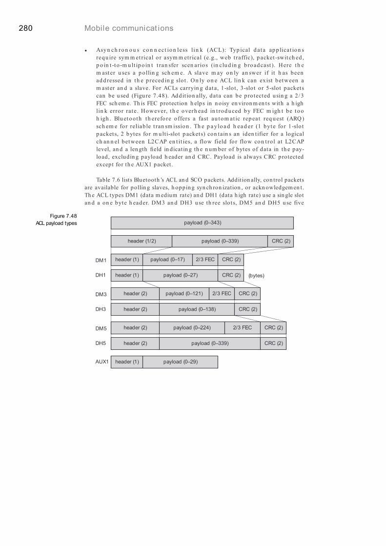
● Asyn ch ro n o u s co n n ect io n less l in k (ACL): Typ ical d at a ap p licat ion srequ ire sym m et rical o r asym m etrical (e.g., web t raffic), p acket -swit ch ed ,p o in t -t o-m u lt ip o in t t ran sfer scen arios (in clu d in g b road cast ). Here t h em ast er u ses a p o llin g sch em e. A slave m ay o n ly an swer if it h as beenad d ressed in t h e p reced in g slo t . On ly on e ACL lin k can exist between am aster an d a slave. For ACLs carryin g d ata, 1-slo t , 3-slot or 5-slot packetscan be u sed (Figu re 7.48). Add it ion ally, data can be pro tected u sin g a 2/ 3FEC sch em e. Th is FEC protection h elps in n oisy en viron m en ts with a h ighlin k error rat e. However, t h e overh ead in t rod u ced by FEC m igh t be t o oh igh . Blu eto oth t h erefo re offers a fast au tom at ic rep eat req u est (ARQ )sch em e for reliab le t ran sm ission . Th e p a ylo a d h ea d er (1 byt e for 1-slo tp ackets, 2 bytes for m u lt i-slot p ackets) con tain s an iden t ifier for a logicalch an n el between L2CAP en t it ies, a flow field fo r flow con t ro l at L2CAPlevel, an d a len gth field in dicatin g th e n um ber of bytes of data in th e pay-load, excludin g payload h eader an d CRC. Payload is always CRC protectedexcept for th e AUX1 packet .Table 7.6 lists Bluetooth ’s ACL an d SCO packets. Addition ally, con trol packets
are available for pollin g slaves, h oppin g syn ch ron ization , or ackn owledgem en t.Th e ACL types DM1 (data m edium rate) an d DH1 (data h igh rate) use a sin gle slotan d a on e byte h eader. DM3 an d DH3 u se th ree slo t s, DM5 an d DH5 u se five
Mobile communicat ions280
payload (0–339)header (1/2)
DM1DH1
payload (0–343)
(bytes)
CRC (2)
payload (0–17)header (1) 2/3 FEC CRC (2)
payload (0–27)header (1) CRC (2)
DM3DH3
payload (0–121)header (2) 2/3 FEC CRC (2)
payload (0–138)header (2) CRC (2)
DM5DH5
AUX1 payload (0–29)header (1)
payload (0–224)header (2) 2/3 FEC CRC (2)
payload (0–339)header (2) CRC (2)
Figure 7.48ACL payload types

slots. Medium rates are always FEC p rotected , th e h igh rates rely on CRC on lyfor error d etect ion . Th e h igh est availab le data rates for Blu etoo th devices are433.9 kbit / s (sym m et ric) o r 723.3/57.6 kbit / s (asym m etric). High quality vo ice(HV) packets always u se a sin gle slot bu t d iffer with respect to th e am oun t ofredun dan cy for FEC. DV (data an d voice) is a com bin ed packet wh ere CRC, FEC,an d payload h eader are valid for th e data part on ly.
Figure 7.49 sh ows an exam ple tran sm ission between a m aster an d two slaves.Th e m aster always uses th e even frequen cy slots, th e odd slots are for th e slaves.In th is exam ple every sixth slot is used for an SCO lin k between th e m aster an dslave 1. Th e ACL lin ks use sin gle or m u lt ip le slots providin g asym m etric ban d-wid th for con n ect ion less packet t ran sm ission . Th is exam ple again sh ows th eh oppin g sequen ce wh ich is in depen den t of th e tran sm ission of packets.
Th e robustn ess of Bluetooth data tran sm ission s is based on several tech n ol-ogies. FH-CDMA separates differen t picon ets with in a scattern et . FHSS m itigatesin terferen ce from oth er devices operatin g in th e 2.4 GHz ISM ban d. Addition ally,FEC can be used to correct tran sm ission errors. Bluetooth ’s 1/3 FEC sim ply sen dsth ree copies of each bit . Th e receiver th en p erform s a m ajority d ecision : eachreceived t rip le of bits is m apped in to wh ich ever bit is in m ajority. Th is sim plesch em e can correct all sin gle bit errors in th ese trip les. Th e 2/ 3 FEC en codin gdetects all double errors an d can correct all sin gle bit errors in a codeword.
Wireless LAN 281
MASTER f0SCO
f4ACL
f6SCO
f8ACL
f12
SCOf18
SCOf20
ACLf14
ACL
SLAVE 1 f1 f7 f9 f19
SLAVE 2 f5 f17 f21
f13
Figure 7.49Example datatransmission
MASTER ANAK
SLAVE 1
SLAVE 2
ACKC C F H
B D E
G G
Figure 7.50Error recovery

ACL lin ks can addit ion ally be p rotected usin g an ARQ sch em e an d a ch eck-su m . Each packet can be ackn owledged in th e slo t fo llowin g th e p acket . If apacket is lost , a sen der can retran sm it it im m ediately in th e n ext slot after th en egat ive ackn o wled gem en t , so it is called a fast ARQ sch em e. Th is sch em eh ard ly exh ib its an y overh ead s in en viro n m en t s with low erro r rates, as on lypackets wh ich are lost or dest royed h ave to be ret ran sm itted . Retran sm ission istriggered by a n egative ackn owledgem en t or a t im e-out.7.5.5 Link manager protocolTh e lin k m an ager p ro toco l (LMP) m an ages vario u s asp ect s of t h e rad io lin kbetween a m aster an d a slave an d th e cu rren t param eter set t in g of th e devices.LMP en h an ces baseban d fun ction ality, bu t h igh er layers can st ill d irectly accessth e baseban d. Th e followin g groups of fun ct ion s are covered by th e LMP:● Au th en tica t ion , p a irin g, an d en cryp t ion : Alth ough basic auth en tication is
h an dled in th e baseban d, LMP h as to con trol th e exch an ge of ran dom n um -bers an d sign ed respon ses. Th e pairin g service is n eeded to establish an in itialtrust relation sh ip between two devices th at h ave n ever com m un icated before.Th e result of pairin g is a lin k key. Th is m ay be ch an ged, accepted or rejected.LMP is n ot directly in volved in th e en cryption process, bu t sets th e en cryp-tion m ode (n o en cryption , poin t-to-poin t, or broadcast), key size, an d ran domspeed. Section 7.5.7 gives an overview of Bluetooth ’s security m ech an ism s.
● Syn ch ron iza t ion : Precise syn ch ron ization is of m ajor im portan ce with in aBlu etoo th n etwo rk. Th e clock o ffset is u p d at ed each t im e a p acket isreceived from th e m aster. Addition ally, special syn ch ron izat ion packets canb e received . Devices can also exch an ge t im in g in form at ion related to th etim e d ifferen ces (slot boun daries) between two ad jacen t p icon ets.
● Cap ab ilit y n egot ia t ion : Not on ly th e version of th e LMP can be exch an gedb u t a lso in fo rm at io n abou t t h e su p p o rt ed featu res. Not all Blu eto o thd evices will su p p ort all fea tu res t h at are d escribed in t h e st an d ard , sod evices h ave to agree th e usage of, e.g., m ulti-slot packets, en cryption , SCOlin ks, voice en cod in g, park/ sn iff/ h old m od e (exp lain ed below), HV2/ HV3p ackets etc.
● Qu alit y of service n egot ia t io n : Differen t param eters con trol th e QoS of aBluetooth device at th ese lower layers. Th e poll in terval, i.e., th e m axim umtim e between t ran sm ission s from a m aster to a part icu lar slave, con trols th elaten cy an d tran sfer capacity. Depen din g on th e quality of th e ch an n el, DMor DH packets m ay be used (i.e., 2/3 FEC protection or n o protection ). Th en um ber of repetit ion s for broadcast packets can be con trolled . A m aster canalso lim it th e n u m ber of slo t s available for slaves’ an swers to in crease it sown ban dwidth .
● Po w er co n t r o l: A Blu etoo th d evice can m easu re t h e received sign alst ren gth . Depen din g on th is sign al level th e device can direct th e sen der ofth e m easured sign al to in crease or decrease its t ran sm it power.
Mobile communicat ions282
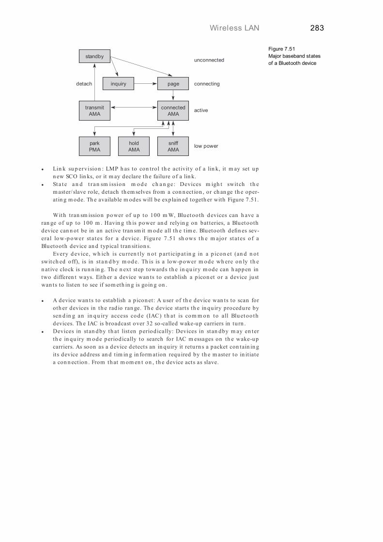
● Lin k su p ervision : LMP h as to con trol th e activity of a lin k, it m ay set upn ew SCO lin ks, or it m ay declare th e failure of a lin k.
● St a t e a n d t r a n sm issio n m o d e ch a n ge: Devices m igh t swit ch t h em aster/ slave role, detach th em selves from a con n ection , or ch an ge th e oper-atin g m ode. Th e available m odes will be explain ed togeth er with Figure 7.51.With t ran sm ission power of u p to 100 m W, Bluetooth d evices can h ave a
ran ge of up to 100 m . Havin g th is power an d relyin g on batteries, a Bluetoothdevice can n ot be in an active tran sm it m ode all th e t im e. Bluetooth defin es sev-eral lo w-p ower st a t es fo r a d evice. Figu re 7.51 sh ows th e m ajo r st at es o f aBluetooth device an d typical tran sit ion s.
Every d evice, wh ich is cu rren t ly n o t p art icip at in g in a p icon et (an d n otswitch ed off), is in st a n d b y m od e. Th is is a low-p ower m ode wh ere on ly th en ative clock is run n in g. Th e n ext step towards th e in qu iry m ode can h appen intwo differen t ways. Eith er a device wan ts to establish a p icon et or a device justwan ts to listen to see if som eth in g is goin g on .● A device wan ts to establish a p icon et: A user of th e device wan ts to scan for
oth er devices in th e rad io ran ge. Th e device starts th e in quiry procedure bysen d in g an in q u iry access cod e (IAC) t h at is com m o n to all Blu etoo thdevices. Th e IAC is broadcast over 32 so-called wake-up carriers in tu rn .
● Devices in stan d by th at list en p eriodically: Devices in stan dby m ay en terth e in qu iry m od e period ically to search fo r IAC m essages on th e wake-upcarriers. As soon as a device detects an in quiry it return s a packet con tain in gits device address an d t im in g in form ation requ ired by th e m aster to in it iatea con n ection . From th at m om en t on , th e device acts as slave.
Wireless LAN 283
standby
transmitAMA
inquiry page
connectedAMA
sniffAMA
parkPMA
holdAMA
connecting
active
low power
unconnected
detach
Figure 7.51Major baseband statesof a Bluetooth device

If th e in qu iry was su ccessfu l, a device en ters th e p age m od e. Th e in qu iryph ase is n ot coord in ated; in quiry m essages an d an swers to th ese m essages m aycollid e, so it m ay take a wh ile before th e in quiry is successfu l. After a wh ile (typ-ically secon ds bu t som et im es u p to a m in u te) a Blu etooth d evice sees all th edevices in its radio ran ge.
Du rin g t h e p a ge st at e two d ifferen t ro les are d efin ed . Aft er fin d in g allrequired devices th e m aster is able to set up con n ection s to each device, i.e., set-t in g u p a p icon et . Dep en d in g o n t h e d evice ad d resses received t h e m ast ercalcu lates special h opp in g sequ en ces to con tact each device in d ividually. Th eslaves an swer an d syn ch ron ize with th e m aster’s clock, i.e., start with th e h op-p in g sequ en ce d efin ed by th e m aster. Th e m aster m ay con tin u e to p age m oredevices th at will be added to th e p icon et . As soon as a device syn ch ron izes toth e h oppin g pattern of th e picon et it also en ters th e con n ection state.
Th e con n ect ion state com p rises th e act ive state an d th e low p ower statespark, sn iff, an d h old. In th e act ive state th e slave participates in th e p icon et bylisten in g, tran sm it tin g, an d receivin g. ACL an d SCO lin ks can be used. A m asterperiod ically syn ch ron izes with all slaves. All devices bein g active m ust h ave th e3-b it a c t ive m em b er a d d ress (AMA). W ith in t h e act ive st at e d evices eit h ertran sm it data or are sim ply con n ected. A device can en ter stan dby again , via adetach procedure
To save ba t t ery p o wer, a Blu eto oth d evice can go in to on e of t h ree lo wpower states:● Sn iff st a t e: Th e sn iff state h as th e h igh est power con sum pt ion of th e low
p ower states. Here, th e device listen s to th e p icon et at a redu ced rate (n oton every oth er slot as is th e case in th e active state). Th e in terval for listen -in g in to th e m edium can be program ed an d is applicat ion depen den t. Th em aster d esign ates a red u ced n u m ber o f slot s for t ran sm ission to slaves insn iff state. However, th e device keeps its AMA.
● H o ld st a t e: Th e d evice d oes n ot release it s AMA bu t st op s ACL t ran s-m ission . A slave m ay st ill exch an ge SCO packets. If th ere is n o act ivity inth e p icon et , th e slave m ay eith er reduce power con sum ption or part icipatein an oth er p icon et .
● Park sta t e: In th is state th e device h as th e lowest duty cycle an d th e lowestp ower con su m p t io n . Th e d evice releases it s AMA an d receives a parkedm em ber address (PMA). Th e device is st ill a m em ber of th e picon et , bu t givesroom for an oth er d evice to becom e act ive (AMA is on ly 3 bit , PMA 8 bit ).Parked devices are still FH syn ch ron ized an d wake up at certain beacon in ter-vals for re-syn ch ron ization . All PDUs sen t to parked slaves are broadcast .
Mobile communicat ions284

Th e effect o f th e low power states is sh own in Table 7.7. Th is t able sh owsth e typ ical average power con sum ption of a Bluetooth device (BlueCore2, CSR,2002). It is obvious th at h igh er data rates also require m ore tran sm ission power.Th e in t ervals in sn iff m od e also in flu en ce p o wer con su m p t ion . Typ ical IEEE802.11b products h ave an average cu rren t in th e order of 200 m A wh ile receiv-in g, 300 m A wh ile sen din g, an d 20 m A in stan dby.7.5.6 L2CAPTh e logical lin k con t ro l an d ad ap t a t ion p ro toco l (L2CAP) is a data lin k con -t ro l p ro tocol on top of th e baseban d layer offerin g logical ch an n els betweenBluetooth devices with QoS propert ies. L2CAP is available for ACLs on ly. Audioap p lica t ion s u sin g SCOs h ave t o u se t h e b aseban d layer d irect ly (see Figu re7.44). L2CAP p rovides th ree d ifferen t types of logical ch an n els th at are t ran s-ported via th e ACL between m aster an d slave:● Con n ect ion less: Th ese un id irect ion al ch an n els are typ ically used for broad-
casts from a m aster to its slave(s).● Con n ect ion -orien t ed : Each ch an n el of th is type is bi-d irect ion al an d sup-
p ort s QoS flow sp ecificat ion s fo r each d irect ion . Th ese flow sp ecs fo llowRFC 1363 (Part rid ge, 1992) an d d efin e average/ p eak data rate, m axim u mburst size, laten cy, an d jit ter.
● Sign a lin g: Th is th ird type of logical ch an n el is u sed to exch an gin g sign al-in g m essages between L2CAP en tities.Each ch an n el can be iden t ified by its ch a n n el id en t ifier (CID). Sign alin g
ch an n els always use a CID value of 1, a CID value of 2 is reserved for con n ect ion -less ch an n els. Fo r con n ect ion -orien ted ch an n els a un iq ue CID (>= 64) isd yn am ically assign ed at each en d of t h e ch an n el t o id en t ify t h e con n ect ion
Wireless LAN 285
Operat ing mode Average current [mA]SCO, HV1 53SCO, HV3, 1 s interval sniff mode 26ACL, 723.2 kbit/ s 53ACL, 115.2 kbit/ s 15.5ACL, 38.4 kbit/ s, 40 ms interval sniff mode 4ACL, 38.4 kbit/ s, 1.28 s interval sniff mode 0.5Park mode, 1.28 s beacon interval 0.6Standby (no RF activity) 0.047
Table 7.7 Examplepower consumption(CSR, 2002)

(CIDs 3 to 63 are reserved). Figu re 7.52 gives an exam p le for logical ch an n elsusin g th e ACL lin k between m aster an d slave. Th e m aster h as a bi-direction al sig-n alin g ch an n el to each slave. Th e CID at each en d is 1. Addition ally, th e m asterm ain t ain s a con n ect ion less, un id irection al ch an n el to both slaves. Th e CID atth e slaves is 2, wh ile th e CID at th e begin n in g of th e con n ection less ch an n el isdyn am ically assign ed. L2CAP provides m ech an ism s to add slaves to, an d rem oveslaves from , such a m ult icast grou p . Th e m aster h as on e con n ect ion orien tedch an n el to th e left slave an d two to th e righ t slave. All CIDs for th ese ch an n elsare dyn am ically assign ed (between 64 an d 65535).
Figu re 7.53 sh ows th e t h ree p acket typ es belon gin g t o t h e t h ree logicalch an n el types. Th e len gth field in d icates th e len gth of th e payload (p lu s PSMfor con n ection less PDUs). Th e CID h as th e m ult ip lexin g/dem ult ip lexin g fun c-t io n as exp la in ed abo ve. Fo r con n ect io n less PDUs a p ro t o co l / ser v icem u lt ip lexor (PSM) field is n eeded to iden t ify th e h igh er layer recip ien t for th epayload . For con n ect ion -orien ted PDUs th e CID already fu lfills th is fun ct ion .Several PSM values h ave been defin ed, e.g., 1 (SDP), 3 (RFCOMM), 5 (TCS-BIN).Valu es above 4096 can be assign ed dyn am ically. Th e payload of th e sign alin gPDU con tain s on e or m ore com m an d s. Each com m an d h as it s own cod e (e.g.,for com m an d reject , con n ection request , d iscon n ection respon se etc.) an d an IDth at m atch es a req uest with it s rep ly. Th e len gth field in d icates th e len gth ofth e d a ta field for th is com m an d.
Besides protocol m u lt ip lexin g, flow specification , an d group m an agem en t,t h e L2CAP layer a lso p ro vid es segm en tat ion an d reassem bly fu n ct ion s.Depen din g on th e baseban d capabilities, large packets h ave to be ch opped in tosm aller segm en ts. DH5 lin ks, for exam ple, can carry a m axim um of 339 byteswh ile th e L2CAP layer accepts up to 64 kbyte.
Mobile communicat ions286
2 d 1L2CAP
baseband
Slave
1 d d d d 1L2CAP
baseband
Master
1 d d 2L2CAP
baseband
Slave
signaling ACL connectionless connection-oriented
Figure 7.52Logical channelsbetween devices

7.5.7 SecurityA radio in terface is by n ature easy to access. Bluetooth devices can tran sm it pri-vat e data, e.g., sch ed u les between a PDA an d a m obile ph o n e. A u ser clearlydoes n ot wan t an oth er person to eavesdrop th e data tran sfer. Just im agin e a sce-n ario wh ere two Blu etooth en abled PDAs in su itcases ‘m eet ’ on th e con veyorbelt o f an a irp o rt exch an gin g p erso n al in fo rm at ion ! Blu eto o th o ffers m ech -an ism s fo r au th en t icat ion an d en cryp t ion on th e MAC layer, wh ich m ust beim plem en ted in th e sam e way with in each device.
Th e m ain secu rity featu res o ffered by Blu eto oth in clu d e a ch allen ge-resp on se ro u t in e for au th en t icat io n , a st ream cip h er fo r en cryp t ion , an d asession key gen eration . Each con n ection m ay require a on e-way, two-way, or n oauth en tication usin g th e ch allen ge-respon se rout in e. All th ese sch em es h ave tobe im p lem en ted in silicon , an d h igh er layers sh ou ld offer stron ger en cryption ifn eeded. Th e security features in cluded in Bluetooth on ly h elp to set up a localdom ain of trust between devices.
Th e secu rity algorith m s use th e public iden tity of a device, a secret p rivateuser key, an d an in tern ally gen erated ran dom key as in put param eters. For eacht ran sact ion , a n ew ran d om n u m ber is gen erated on t h e Blu etoo th ch ip . Keym an agem en t is left to h igh er layer software.
Figure 7.54 sh ows several steps in th e security arch itecture of Bluetooth . Th eillustration is sim plified an d th e in terested reader is referred to Bluetooth (2001a)for fu rth er details. Th e first st ep , called p a ir in g, is n ecessary if two Blu etoothdevices h ave n ever m et before. To set up trust between th e two devices a user canen ter a secret PIN in to both devices. Th is PIN can h ave a len gth of up to 16 byte.Un fortun ately, m ost devices lim it th e len gth to four digits or, even worse, program
Wireless LAN 287
length CID = 2 PSM payload2 2 ≥2 0–65533 bytes
Connectionless PDU
length CID payload2 2 0–65535 bytes
Connection-oriented PDU
length CID = 1 One or more commands2 2 bytes
Signaling command PDU
code ID length1 1 2
data≥0
Figure 7.53L2CAP packetformats
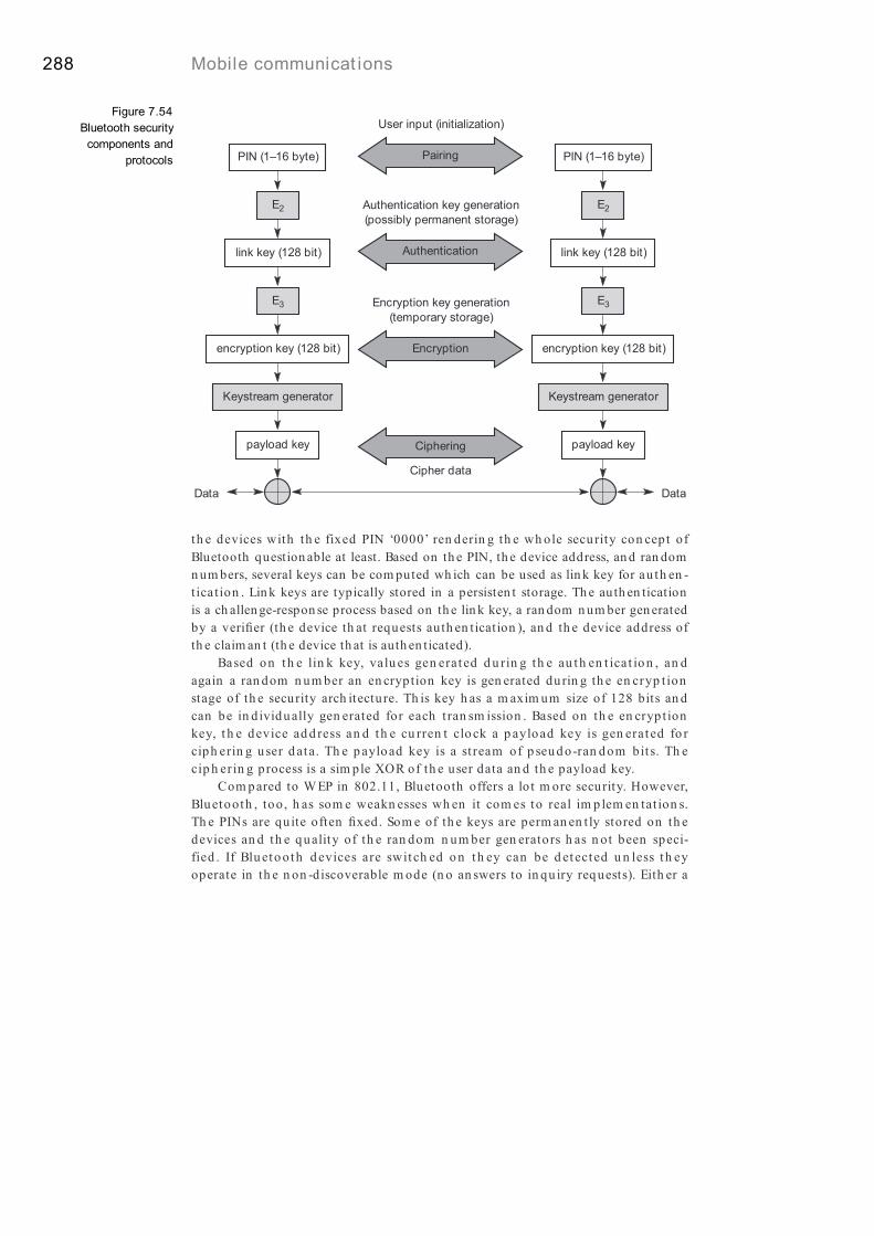
th e devices with th e fixed PIN ‘0000’ ren derin g th e wh ole secu rity con cept ofBluetooth question able at least. Based on th e PIN, th e device address, an d ran domn um bers, several keys can be com puted wh ich can be used as lin k key for au th en -t ica tion . Lin k keys are typically stored in a persisten t storage. Th e au th en ticationis a ch allen ge-respon se process based on th e lin k key, a ran dom n um ber gen eratedby a verifier (th e device th at requests auth en tication ), an d th e device address ofth e claim an t (th e device th at is auth en ticated).
Based on t h e lin k key, valu es gen erat ed d u rin g th e au th en t ica t io n , an dagain a ran dom n um ber an en cryption key is gen erated du rin g th e en cryp t ionstage of th e security arch itecture. Th is key h as a m axim um size of 128 bits an dcan be in d ividually gen erated for each t ran sm ission . Based on th e en cryp t ionkey, t h e device ad d ress an d t h e cu rren t clo ck a p ayload key is gen erat ed fo rciph erin g user d ata. Th e p ayload key is a st ream of p seu d o-ran d om bit s. Th ecip h erin g process is a sim ple XOR of th e user data an d th e payload key.
Com pared to W EP in 802.11, Bluetooth offers a lo t m ore security. However,Bluetooth , too, h as som e weakn esses wh en it com es to real im p lem en tat ion s.Th e PINs are quite often fixed. Som e of th e keys are perm an en t ly stored on th edevices an d th e quality of th e ran dom n um ber gen erators h as n ot been speci-fied . If Blu eto oth d evices are swit ch ed o n t h ey can be d et ect ed u n less t h eyoperate in th e n on -discoverable m ode (n o an swers to in qu iry requests). Eith er a
Mobile communicat ions288
PIN (1–16 byte)
E2
link key (128 bit)
E3
encryption key (128 bit)
Keystream generator
payload key
Data
PIN (1–16 byte)
E2
link key (128 bit)
E3
encryption key (128 bit)
Keystream generator
payload key
Data
Encryption
Authentication
Pairing
Ciphering
Encryption key generation(temporary storage)
Authentication key generation(possibly permanent storage)
User input (initialization)
Cipher data
Figure 7.54Bluetooth security
components andprotocols

user can use all services as in ten ded by th e Bluetooth system , or th e devices areh idden to protect p rivacy. Eith er roam in g profiles can be establish ed , or devicesare h id d en an d , t h u s m an y services will n o t work. If a lo t o f p eo p le carryBluetooth devices (m obile ph on es, PDAs etc.) th is cou ld give, e.g., departm en tstores, a lot of in form ation regard in g con sum er beh avior. 7.5.8 SDPBluetooth devices sh ou ld work togeth er with oth er devices in u n kn own en vi-ron m en ts in an ad-h oc fash ion . It is essen t ial to kn ow wh at devices, or m orespecifically wh at services, are available in radio p roxim ity. To fin d n ew services,Bluetooth defin ed th e ser vice d iscovery p ro to col (SDP). SDP defin es on ly th ed iscovery o f services, n o t t h eir u sage. Discovered services can be cach ed an dgradual discovery is possible. Devices th at wan t to offer a service h ave to in stalan SDP server. For all o th er devices an SDP clien t is sufficien t .
All th e in form at ion an SDP server h as abou t a service is con tain ed in a ser-v ice reco rd . Th is co n sists of a list o f service at t ribu t es an d is id en t ified by a32-b it service reco rd h an d le. SDP d oes n o t in fo rm clien t s o f an y ad d ed o rrem oved services. Th ere is n o service access con trol or service brokerage. A ser-v ice a t t r ib u t e co n sist s o f an a t t ribu t e ID an d an at t ribu t e va lu e. Th e 16-b ita t t r ib u t e ID d ist in gu ish es each service at t ribu te from oth er service at t ribu teswith in a service record. Th e at tribu te ID also iden tifies th e sem an tics of th e asso-ciat ed at t rib u t e valu e. Th e a t t r ib u t e v a lu e can be an in t eger, a UUID(u n iversally u n iq u e id en t ifier), a st rin g, a Boolean , a URL (u n ifo rm resou rcelocator) etc. Table 7.8 gives som e exam ple at t ribu tes. Th e service h an d le as wellas t h e ID list m u st be p resen t . Th e ID list con t ain s t h e UUIDs o f th e serviceclasses in in creasin g gen eralit y (from th e sp ecific co lo r p o st scrip t p rin t er t o
Wireless LAN 289
Attribute name Attribute ID At tribute value Exampletype
ServiceRecordHandle 0000 32-bit unsigned 1f3e4723integer
ServiceClassIDList 0001 Data element ColorPostscriptPrinterServicesequence (UUIDs) ClassID,
PostscriptPrinterServiceClassID, PrinterServiceClassID
ProtocolDescriptorList 0004 Data element sequence ((L2CAP, PSM=RFCOMM),(RFCOMM, CN=2), (PPP),
(IP), (TCP), (IPP))DocumentationURL 000A URL www.xy.zz/ print/ srvs.htmlIconURL 000C URL www.xy.zz/ print/ ico.pngServiceName 0100 String Color Printer
Table 7.8 Exampleattributes for an SDPservice record
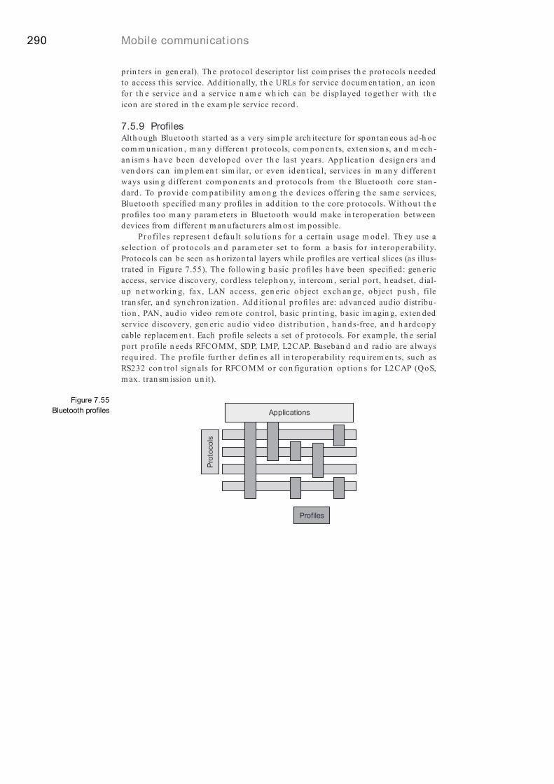
prin ters in gen eral). Th e protocol descriptor list com prises th e protocols n eededto access th is service. Add it ion ally, th e URLs for service docum en tation , an iconfor th e service an d a service n am e wh ich can be d isp layed t ogeth er with th eicon are stored in th e exam ple service record .7.5.9 ProfilesAlth ough Bluetooth started as a very sim ple arch itecture for spon tan eous ad-h occom m un ication , m an y differen t protocols, com pon en ts, exten sion s, an d m ech -an ism s h ave been develop ed over t h e last years. Ap p licat ion d esign ers an dven d o rs can im p lem en t sim ilar, o r even iden t ical, services in m an y d ifferen tways usin g d ifferen t com pon en ts an d protocols from th e Blu etooth core stan -dard . To p rovid e com pat ibility am on g th e d evices offerin g t h e sam e services,Bluetooth specified m an y profiles in addit ion to th e core protocols. With ou t th eprofiles too m an y param eters in Bluetooth would m ake in teroperation betweendevices from differen t m an ufactu rers alm ost im possible.
Pr o files rep resen t d efau lt so lu t ion s for a certain usage m odel. Th ey u se aselect io n of p ro tocols an d p aram eter set to form a basis fo r in terop erabilit y.Protocols can be seen as h orizon tal layers wh ile profiles are vert ical slices (as illus-trated in Figu re 7.55). Th e followin g b asic p rofi les h ave been specified: gen ericaccess, service d iscovery, cord less teleph on y, in tercom , serial port , h eadset , d ial-u p n etworkin g, fax, LAN access, gen eric o bject exch an ge, ob ject p u sh , filetran sfer, an d syn ch ron ization . Ad d it ion a l p rofi les are: advan ced audio distribu-t ion , PAN, aud io video rem ote con trol, basic p rin t in g, basic im agin g, exten dedservice d iscovery, gen eric au d io vid eo d ist ribu t ion , h an d s-free, an d h ard copycable replacem en t . Each profile selects a set of protocols. For exam ple, th e serialport p rofile n eeds RFCOMM, SDP, LMP, L2CAP. Baseban d an d rad io are alwaysrequ ired . Th e p rofile furth er defin es all in teroperability requ irem en ts, such asRS232 con t rol sign als for RFCOMM or con figurat ion op t ion s for L2CAP (QoS,m ax. tran sm ission un it).
Mobile communicat ions290
Applications
Protoc
ols
Profiles
Figure 7.55Bluetooth profiles

7.5.10 IEEE 802.15In 1999 th e IEEE est ab lish ed a workin g gro u p fo r wireless p erson al area n et -works (WPAN) with sim ilar goals to Bluetooth . Th e workin g group was d ividedin to several su bgrou p s focu sin g on d ifferen t aspect s of W PANs (IEEE, 2002c).Th e fo llowin g gives a q u ick overview an d p resen t s t h e st an dard for low-rat eWPANs, 802.15.4, in som e m ore detail:● IEEE 80 2 .1 5 .1 : Th is grou p st an dard izes t h e lower layers of Blu et o o t h
togeth er with th e Bluetooth con sort ium . IEEE LANs focus on ly on th e ph ys-ical an d data lin k layer, wh ile th e Bluetooth stan dard also com prises h igh erlayers, application profiles, service descrip tion etc. as explain ed above.
● IEEE 802.15.2: Th e coex ist en ce of wireless person al area n etworks (W PAN)an d wireless local area n etworks (WLAN) is th e focus of th is group. On e taskis to quan tify m u tual in terferen ce an d to develop algorith m s an d protocolsfor coexisten ce. With out add it ion al m ech an ism s, Bluetooth /802.15.1 m ayact like a rogue m em ber of an IEEE 802.11 n etwork. Bluetooth is n ot awareof gaps, in ter-fram e spacin g, fram e structures etc. Figure 7.56 illust rates th eproblem . As explain ed in section 7.3, W LANs followin g th e IEEE 802.11bstan dard m ay u se th ree n on -overlap pin g ch an n els th at are ch osen du rin gin st alla t ion o f t h e access p o in t s. Blu etoo th / 802.15.1 n etworks u se a fre-quen cy h oppin g pattern to separate d ifferen t p icon ets – 79 ch an n els can beused . With out addit ion al m ech an ism s, th e h oppin g pat tern of Bluetooth isin depen den t of 802.11b’s ch an n el select ion . Both system s work in th e 2.4GHz ISM ban d an d m igh t in terfere with each oth er. Figure 7.56 sh ows twoh op p in g sequ en ces of two p icon ets in terferin g with several d ata packet s,ackn owledgem en ts, an d in ter-fram e spacin gs of 802.11b. Th e real effects ofth e in terferen ce ran ge from ‘alm ost n o effect ’ to ‘com p lete breakdown ofth e WLAN’. Publicat ion s on th is issue d iffer depen din g on th e test scen ario,t raffic load , sign al po wer, p rop agat ion co n d it ion s et c. (Lan sfo rd , 2001).However, it seem s th at Bluetooth with its FHSS sch em e is m ore robust th an802.11b with CSMA/ CA (Pah lavan , 2002). To overco m e th e in t erferen cep roblem s between 802.11b an d 802.15.1, h owever severe th ey m igh t be,th e 802.15.2 workin g group p rop oses ad a p t ive freq u en cy h op p in g. Th is
Wireless LAN 291
f [MHz]2480
2402
802.15.179 channels(separated byhopping pattern)
802.11b3 channels(separated byinstallation)
DIFS
ACK
SIFS
ACK
SIFS
DIFS
DIFS500 byteDIFS
ACK
SIFS
DIFS1000 byte
ACK
SIFS
DIFS100
byteACK
SIFS
DIFS100
byte ACK
SIFS
DIFS100
byte ACK
SIFS
DIFS100
byte ACK
SIFS100
byteDIFS
500 byte 500 byte
t
Figure 7.56Possible interferencebetween 802.15.1(Bluetooth) and 802.11b
coexisten ce m ech an ism is n on -collaborat ive in t h e sen se t h at Blu etoothd evices d o n ot h ave t o in t eract with t h e W LAN. However, t h e W PANd evices can ch eck for th e occu pied ch an n els an d exclu de th em from th eirlist of ch an n els used fo r h op pin g. Th is m ech an ism avoids h oppin g in to ach an n el occu p ied by 802.11b , bu t st ill o ffers en o u gh ch an n els for FHSS.Th e lower n um ber of FHSS ch an n els in creases th e in terferen ce am on g th eW PANs due to a h igh er probability of collision s. However, if n ot too m an yp icon ets overlap th is effect will be n egligible. Th is type of in terferen ce inth e crowded 2.4 GHz ban d is a stron g argum en t for 5 GHz WLANs.
● IEEE 802.15.3: A h igh -rat e study group looks for a stan dard providin g datarates of 20 Mbit/ s or greater wh ile st ill workin g with low-power at low-cost .Th e stan dard sh ould support isoch ron ous data delivery, ad-h oc peer-to-peern etworkin g, secu rit y featu res, an d sh o u ld m eet t h e d em an d in g req u ire-m en ts of portable con sum er im agin g an d m ult i-m edia app lication s.
● IEEE 802.15.4: Th e fourth workin g group goes in th e opposite direct ion fordata rates. Th is group stan dardizes low -ra te w ireless person al area n etw orks(LR-W PAN), wh ich are explain ed in th e followin g section in m ore detail. Th eZigBee con sortium tries to stan dardize th e h igh er layers of 802.15.4 sim ilar toth e activities of th e Bluetooth con sortium for 802.15.1 (ZigBee, 2002).
7.5.10.1 IEEE 802.15.4 – Low-rate WPANsTh e reason fo r h avin g low d at a rates is t h e focu s o f th e workin g grou p onext rem ely low power con sum ption en ablin g m ult i-year bat tery life (Callaway,2002). Com pared to 802.11 or Bluetooth , th e n ew system sh ou ld h ave a m uchlower com p lexity m akin g it su itab le fo r low-cost wireless com m u n icat ion(rem em ber th at Bluetooth started with sim ilar goals with respect to th e idea ofcable replacem en t). Exam ple ap p lica t ion s in clude in dustrial con trol an d m on i-torin g, sm art badges, in tercon n ection of en viron m en tal sen sors, in tercon n ectionof periph erals (also an en visaged application area for Bluetooth !), rem ote con trolsetc. Th e n ew stan dard sh ould offer data rates between 20 an d 250 kbit /s as m axi-m um an d laten cies down to 15 m s. Th is is en ough for m an y h om e autom at ionan d con sum er elect ron ics application s.
IEEE 802.15.4 offers two differen t PHY option s usin g DSSS. Th e 868/ 915 MHzPH Y op erates in Eu rop e at 868.0–868.6 MHz an d in th e US at 902–928 MHz.At 868 MHz on e ch an n el is available offerin g a data rate of 20 kbit/s. At 915 MHz10 ch an n els with 40 kbit /s per ch an n el are available (in Europe GSM uses th esefrequen cies). Th e advan tages of th e lower frequen cies are better propagation con -d it ion s. However, th ere is also in terferen ce in th ese ban ds as m an y an alogtran sm ission system s use th em . Th e 2.4 GHz PHY operates at 2.4–2.4835 GHz an doffers 16 ch an n els with 250 kbit/s per ch an n el. Th is PHY offers worldwide opera-t ion bu t su ffers from in terferen ce in th e 2.4 GHz ISM ban d an d h igh erpropagation loss. Typical devices with 1 m W output power are expected to cover a10–20 m ran ge. All PHY PDUs start with a 32 bit pream ble for syn ch ron ization .After a start -of-packet delim iter, th e PHY h eader in dicates th e len gth of th e pay-load (m axim um 127 bytes).
Mobile communicat ions292

Com pared to Blu etooth th e MAC la yer of 802.15.4 is m uch sim p ler. Fo rexam ple, n o syn ch ro n ou s voice lin ks are sup ported . MAC fram es start with a2-byte fram e con trol field, wh ich specifies h ow th e rest of th e fram e looks an dwh at it con t ain s. Th e fo llowin g 1-byte sequ en ce n u m ber is n eed ed to m atchackn owledgem en ts with a p revious data tran sm ission . Th e variable address field(0–20 bytes) m ay con tain source an d/or destin ation addresses in various form ats.Th e p ayload is variable in len gth ; h owever, th e wh ole MAC fram e m ay n otexceed 127 bytes in len gth . A 16-bit FCS protects th e fram e. Four differen t MACfram es h ave been defin ed: beacon , data, ackn owledgem en t, an d MAC com m an d.
Option ally, th is LR-W PAN offers a su p erfram e m od e. In th is m ode, a PANcoordin ator t ran sm it s beacon s in predeterm in ed in tervals (15 m s–245 s). Withth e h elp of beacon s, th e m ediu m access sch em e can h ave a period wh en con -ten t ion is possib le an d a p eriod wh ich is con t en t ion free. Fu rth erm ore, withbeacon s a slotted CSMA/ CA is available. With out beacon s stan dard CSMA/CA isused for m edium access. Ackn owledgem en t fram es con firm in g a previous tran s-m ission do n ot u se t h e CSMA m ech an ism . Th ese fram es are sen t im m ediatelyfollowin g th e p revious packet .
IEEE 802.15.4 specifies th ree levels of secu r it y: n o secu rity, access con t rollists, an d sym m etric en cryption usin g AES-128. Key d istribu tion is n ot specifiedfu rth er. Security is a m ust for h om e autom at ion or in dustry con trol applicat ion s.Up to n ow, t h e su ccess of th is stan d ard is un clear as it is sq u eezed betweenBluetooth , wh ich also aim s at cable rep lacem en t , an d en h an ced RFIDs/RF con -trollers. Th ese will be explain ed in th e sum m ary in m ore detail.
7.6 SummaryTh is ch apter h as in trodu ced th ree d ifferen t t ech n o logies design ed for W LANs(or W PAN in th e case of Bluetooth , bu t th ere is n o real border between WLANan d W PAN). Th e basic goals of all th ree LAN types are th e p rovision of m u chh igh er flexibility for n odes with in a n etwork. All WLANs suffer from lim itat ion sof th e air in terface an d h igh er com plexity com pared to th eir wired coun terparts,bu t allow for a n ew d egree of freedom for th eir users with in room s, bu ildin gs, orp rod u ct ion h alls. W LANs are alread y in widesp read u se in , e.g., wareh ou ses,classroom s, m eetin g room s an d h ospitals.
However, th e th ree tech n ologies also differ in som e respects. Wh ereas in th ebegin n in g of WLANs several p roprietary products existed , n owadays th ey typ i-cally offer sup port fo r IEEE 802.11b (with .11a an d .11g upcom in g). Alth oughth e IEEE 802.11b stan d ard is m u ch sim p ler com pared to o th ers, it st ill leavesroom fo r d ifferen t im p lem en tat io n s. Th e wireless Eth ern et co m p at ib ilit yallian ce (W ECA, 2002) cert ifies in teroperability of 802.11 products (WiFi, wire-less fidelity). Today, m illion s of wireless adapters follow th is stan dard an d m an ylaptops com e with 802.11b WLAN adapters already in tegrated . On e reason forth is is th at today th e 2.4 GHz ban d is available worldwide (with som e m in ordifferen ces). Th e big restrict ion s of th e past in som e coun tries are gon e.
Wireless LAN 293

For HiperLAN2, th e h istory is d ifferen t . Here, a stan dard izat ion body (ETSI)developed a com pletely n ew stan dard, but n o products are available yet. HiperLAN2com prises m an y in terest in g features, part icu larly on th e MAC layer, com pared to802.11a. Main featu res are QoS support, in tegrated security, an d con vergen ce sub-layers to differen t n etworks, e.g., Firewire, wh ich is used for audio/video con n ection .However, IEEE 802.11a is available an d in stalled in m an y places (usin g th e PHY fea-tu res of HiperLAN2). Up to n ow it is n ot clear if Hip erLAN2 will be a success orfo llow HIPERLAN 1 wh ich n ever m ade it to th e m arket alt h ough it s t ech n icalparam eters were superior com pared to IEEE 802.11. An astasi (1998) gives a goodoverview of t h e cap abilit ies of th e two MAC sch em es u sed in IEEE 802.11 an dHIPERLAN 1 respect ively, an d in vest igates wh eth er th ose access sch em es can beused for QoS p rovision as it was th ough t of for, e.g., wireless ATM.
For Bluetooth , th e situation is com pletely d ifferen t . Here several com pan iesfou n d ed a con sort ium an d set up a de facto in dustry stan dard (version 1.1 in2001). Th en IEEE, as a stan dard izat ion bod y fo llowed with th e IEEE 802.15.1stan dard in 2002. Bluetooth is already available in m an y products (PDAs, videocam eras, d igital st ill cam eras, lap tops etc.) an d , is clearly th e m ost widesp readW PAN tech n o lo gy tod ay. Th e p rim ary goal o f Blu etoo th was n o t a com p lexstan d ard coverin g m an y aspects of wireless n etworkin g, bu t a qu ick an d verych eap solu t ion en ablin g ad-h oc person al com m un ication with in a sh ort ran gein th e licen se-free 2.4 GHz ban d . Today th e stan d ard covers several th ou san dpages an d defin es m an y usage scen arios, services defin ition , protocols etc. Mostdevices im plem en t a basic set of fun ct ion ality as th e com plexity of all features(e.g., support for several scattern ets, jum pin g back an d forth between p icon ets)is too m uch for em bedded devices with a sm all footprin t.
Table 7.9 gives a (sim plified) com parison of IEEE 802.11b, .11a, HiperLAN2,an d Bluetooth . Th e m ain d ifferen ces between th e 802.11a/b stan dards an d th eoth er two are th e scope of th e stan dard izat ion an d th e in it ial con ten t . Not on lydo both IEEE stan dard s sh are th e sam e MAC layer, th ey also describe th e rawdata t ran sfer with ou t th e elaborate secu rity or au th en t icat ion m ech an ism s oradap tat ion layers/p rofiles n ecessary for in teroperat ion with oth er n etworks orapp licat ion s. Both stan dards assum e an Eth ern et backbon e an d , typ ically, besteffort IP run n in g on top of th e MAC layer. Th is is perfect for m ost office applica-t io n s, in d eed for m ost o f t o day’s In t ern et ap p licat ion s. Sp ecial fea tu res likesecurity or frequen cy selection are add-on s to th e stan dards.
HiperLAN2 an d Bluetooth wan t to cover alm ost all aspects related to wire-less com m u n icat ion : p h ysical layer, m ed iu m access, m an y d ifferen t services,ad ap t at ion layers to d ifferen t backbon es (HiperLAN2) or p rofiles for d ifferen tapplication s (Bluetooth ).
Th is ch ap ter left ou t som e stan dard s an d approach es th at cou ld be m en -t io n ed in t h e con t ext o f W LANs. O n e exam ple is H o m eRF. Th is is an o th erW LAN stan dard op era t in g at 2 .4 GHz. Hom eRF u ses a FHSS sch em e with 50h op s p er secon d . Tran sm ission rates h ave been stan dard ized u p to 10 Mbit / s;h igh er rat es are p lan n ed . Th e MAC layer of Hom eRF com b in es 802 .11 an dDECT fun ction ality: a TDMA/CSMA fram e offers TDMA for isoch ron ous (voice)
Mobile communicat ions294

t ran sm ission an d CSMA for asyn ch ron ou s (d ata) t ran sm ission . Differen t QoSsch em es are supported . Com pared to 802.11 stron ger security features are in te-grated from th e begin n in g. Host / clien t an d peer/peer n etworkin g are possible.However, du e to th e t rem en dous success of IEEE 802.11b, Hom eRF cou ld n otsu cceed an d d evelop m en t was sto pp ed in 2002 (alth ou gh Hom eRF p ro d u ct swere available).
Som e tech n ologies m igh t in fluen ce WLANs/WPANs in th e fu ture:● Wireless sen so r n etw ork s: Th e tech n ology requ ired for sen sor n etworks is
located som ewh ere between 802.15.1 or .4 tech n ology an d th e RFIDs (pre-sen ted in th e fo llowin g p aragrap h ). Sen so r n etworks con sist o f m an y(th ousan ds or m ore) n odes th at are den sely deployed, pron e to failures, h avevery lim ited com putin g capabilit ies, an d ch an ge th eir topology frequen tly.Sen sor n etworks can be seen as an ext rem e form of ad -h o c n etworkin gwith very low-p ower d evices. App licat ion s com prise th ose o f 802.15.4
Wireless LAN 295
Criterion IEEE 802.11b IEEE 802.11a HiperLAN2 BluetoothFrequency 2.4 GHz 5 GHz 5 GHz 2.4 GHzMax. trans. rate 11 Mbit/ s 54 Mbit/ s 54 Mbit/ s < 1 Mbit/ sUser throughput 6 Mbit/ s 34 Mbit/ s 34 Mbit/ s < 1 Mbit/ sMedium access CSMA/ CA CSMA/ CA AP centralized Master
centralizedFrequency None 802.11h DFS FHSSmanagementAuthentication None/ 802.1x None/ 802.1x X.509 YesEncryption WEP, 802.11i WEP, 802.11i DES, 3DES YesQoS support Optional (PCF) Optional (PCF) ATM, 802.1p, Flow spec,
RSVP isochronousConnectivity Connectionless Connectionless Connection- Connectionless
oriented + connection-oriented
Available 3 12 (US) 19 (EU) Soft – increasing channels interferenceTyp. transmit 100 mW 0.05/ 0.25/ 1W, 0.2/ 1W, TPC 1/ 2.5/ 100 mWpower TPC with
802.11hError control ARQ ARQ, FEC ARQ, FEC ARQ, FEC
(PHY) (PHY) (MAC)
Table 7.9 Comparison ofwireless networkspresented inchapter 7

(en viron m en tal sen sorin g) bu t du e to th e n u m ber of d evices wh ole areasco u ld be ‘covered ’ with sen so rs, com p u ter, an d n etworkin g power. Mainresearch top ics are: routin g of data with in th e sen sor n etwork, m an agem en to f th e n od es, fau lt to leran ce/ reliab ilit y, low-p ower d esign , an d m ed iu maccess con trol. Akyildiz (2002) gives an excellen t survey of th is top ic.
● Rad io frequ en cy id en t ification (RFID): RF con trollers h ave been well kn ownfo r m an y years. Th ey offer tran sm ission rates of u p to 115 kbit / s (wirelessexten sion of a serial in terface) an d operate on m an y d ifferen t ISM ban ds(d epen din g on n at ion al regu lat ion s, e.g., 27, 315, 418, 426, 433, 868, 915MHz). Application s in clude garage door open ers, wireless m ice/keyboards, carlocks etc. RF con trollers, typically, do n ot h ave a MAC layer, but sim ply act asm odem . Collision s h ave to be d etected on h igh er layers. Th e first RFIDsem erged du rin g th e 1980s (RFID, 2002). In th e begin n in g, th ese very ch eaptags were used for asset trackin g on ly. As soon as a product with an RFID tagp assed a read er, th e p roduct was registered . Today, RFIDs are available indozen s of differen t styles with very differen t properties. RFIDs can respon d toa radio sign al an d tran sm it th eir tag. Th ey can store addition al data, em ploycollision avoidan ce sch em es, an d com prise sm art-card capabilities with sim plep rocessin g power. Wh ile RFIDs are n ot com m un icat ion devices, th e bordersare blurrin g as m ore an d m ore com putin g power is available on sm all em bed-d ed system s an d th e com m u n icat ion in du st ry is lookin g for low powersystem s, such as 802.15.4.
● Ult ra w id eban d t ech n ology (UW B): Th is tech n ology goes on e step furth errelated to spread spectrum used in WLANs as it t ran sm its digital data over awide sp ect ru m o f frequ en cy ban d s with very low p o wer (UW B, 2002).Typ ically, t h e occu p ied spectrum is at least 25 p er cen t o f th e cen t er fre-q uen cy (e.g., 500 MHz for a 2 GHz system ). In stead of sen din g a sin e wave,UWB broadcasts a very sh ort d igital pu lse (less th an 1 n s) th at is t im ed veryp recisely. Sen der an d receiver m ust be syn ch ron ized with very h igh accu -racy. If t h e sen d er exact ly kn ows wh en a p u lse sh ou ld arrive, m u lt i-p athp rop agat ion is n o lo n ger an issu e (e.g., on ly th e st ron gest sign al will bed etected with in a very sh ort t im e-slo t ). Besides rad ar app licat ion s (wh ereUWB com es from ), it can be used for LANs tran sm it tin g very h igh data ratesover sh ort distan ces.Each stan dard presen ted in th is ch apter h as its pros an d con s. If th e focus is
on battery life, th en Bluetooth is th e ch oice as th e power con sum ption of .11b,an d p art icu larly .11a an d Hip erLAN2 is too h igh . If isoch ron ous t raffic, QoS,an d h igh data rates h ave to be supported , th en HiperLAN2 is th e ch oice. If th eso lu t ion sh ou ld be sim ple an d fit in to an o ffice en viron m en t , t h en .11b/ g or.11a are p ossib le so lu t ion s. If in terferen ce is a top ic, t h en .11a is bet ter t h an.11b. If large cells are req u ired , th en .11b is bet ter th en .11a du e to th e lowerp rop agat ion lo ss (.11g is even bet t er). IEEE st art s even m ore workin g grou p s,e.g., 802.20, th e ‘Mobile Broadban d Wireless Access (MBWA)’ group. Th is group
Mobile communicat ions296

will con t in u e t h e wo rk t h at was p reviou sly con d u ct ed by t h e 802.16 MBWAstudy group for cellu lar wireless data services support in g fu ll veh icu lar m obility.
Th e typ ical m obile device of tom orrow will com prise several tech n ologieswith th e ability of con n ectin g to differen t n etworks, e.g., a GSM follow-on (suchas UMTS) for wide area com m un ication , possibly a satellite an ten n a, an d differ-en t W LAN adapters (e.g., IEEE 802.11b/g an d Blu etooth ). Depen d in g on cost ,ap p licat ion , an d locat ion , t h e device will au tom at ically ch oose th e op t im alcom m un icat ion device an d n etwork. Roam in g between th ose differen t n etworksis still d ifficu lt (in particu lar, en su rin g a certain quality of service an d security),bu t first so lu t ion s in t h is d irect io n are cu rren t ly p resen t ed an d in t egrat ed802.11b/GSM adap ters are available wh ere th e W LAN uses GSM fu n ct ion alityfor provid in g secure access.
7.7 Review exercises1 How is mobility restricted using WLANs? What additional elements are needed
for roaming between networks, how and where can WLANs support roaming? Inyour answer, think of the capabilities of layer 2 where WLANs reside.
2 What are the basic differences between wireless WANs and WLANs, and whatare the common features? Consider mode of operation, administration, frequen-cies, capabilities of nodes, services, national/ international regulations.
3 With a focus on security, what are the problems of WLANs? What level of securitycan WLANs provide, what is needed additionally and how far do the standards go?
4 Compare IEEE 802.11, HiperLAN2, and Bluetooth with regard to their ad-hoccapabilities. Where is the focus of these technologies?
5 If Bluetooth is a commercial success, what are remaining reasons for the use ofinfra red transmission for WLANs?
6 Why is the PHY layer in IEEE 802.11 subdivided? What about HiperLAN2 andBluetooth?
7 Compare the power saving mechanisms in all three LANs introduced in this chap-ter. What are the negative effects of the power saving mechanisms, what are thetrade-offs between power consumption and transmission QoS?
8 Compare the QoS offered in all three LANs in ad-hoc mode. What advantagesdoes an additional infrastructure offer? How is QoS provided in Bluetooth? Canone of the LAN technologies offer hard QoS (i.e., not only statistical guaranteesregarding a QoS parameter)?
9 How do IEEE 802.11, HiperLAN2 and Bluetooth, respectively, solve the hiddenterminal problem?
10 How are fairness problems regarding channel access solved in IEEE 802.11,HiperLAN2, and Bluetooth respectively? How is the waiting time of a packetready to transmit reflected?
Wireless LAN 297
11 What different solutions do all three networks offer regarding an increased relia-bility of data transfer?
12 In what situations can collisions occur in all three networks? Distinguishbetween collisions on PHY and MAC layer. How do the three wireless networkstry to solve the collisions or minimise the probability of collisions?
13 Compare the overhead introduced by the three medium access schemes and theresulting performance at zero load, light load, high load of the medium. Howdoes the number of collisions increase with the number of stations trying toaccess the medium, and how do the three networks try to solve the problems?What is the overall scalability of the schemes in number of nodes?
14 How is roaming on layer 2 achieved, and how are changes in topology reflected?What are the differences between infrastructure based and ad-hoc networksregarding roaming?
15 What are advantages and problems of forwarding mechanisms in Bluetooth net-works regarding security, power saving, and network stability?
16 Name reasons for the development of wireless ATM. What is one of the main dif-ferences to Internet technologies from this point of view? Why did WATM notsucceed as stand-alone technology, what parts of WATM succeeded?
7.8 ReferencesAcam pora, A. (1996) ‘Wireless ATM: a perspective on issues an d prospects,’ IEEE
Personal Communications, 3(4).Akyild iz, I., Su , W., San karasubram an iam , Y., Cayirci, E. (2002) ‘Wireless sen sor
n etworks: a survey,’ Computer Networks, Elsevier Scien ce, 38(2002).An ast asi, G., Len zin i, L., Min gozzi, E., Het t ich , A., Kräm lin g, A. (1998) ‘MAC
p roto cols fo r wid eban d wireless loca l access: evo lu t ion t oward wirelessATM,’ IEEE Personal Communications, 5(5).
Ayan oglu , E., En g, K.Y., Karol, M.J.(1996) ‘Wireless ATM: lim its, ch allen ges, an dp roposals,’ IEEE Personal Communications, 3(4).
Barto n , M., Pain e, R., Ch ow, A. (1998) Description of W ireless ATM ServiceScenarios, ATM Forum Con tribu tion , Ju ly.
Bh at , R.R. (1998) W ireless ATM Requirements Specifica tion, ATM Fo ru m , RTD-WATM-01.02.
Bisd ikian , C., Bh agwat , P., Gau ch er, B.P., Jan n iello , F.J., Nagh sh in eh , M.,Pan d oh , P., Korp eoglu , I. (1998) ‘WiSAP – A wireless p erson al access n et -work for h an dh eld com putin g devices,’ IEEE Personal Communications, 5(6).
Bluetooth (2001a) Specification of the Bluetooth System, volum e 1, Core, BluetoothSIG, version 1.1.
Blu eto oth (2001b) Specifica tion of the Bluetooth System, vo lu m e 2 , Pro files,Bluetooth SIG, version 1.1.
Bluetooth (2002) Bluetooth Special In terest Group, h ttp :/ /www.bluetooth .com /.
Mobile communicat ions298
Borisov, N., Goldberg, I., Wagn er, D. (2001) Intercepting Mobile Communications:The Insecurity of 802.11 , seven th An n u al In t ern at ion al Con feren ce o nMobile Com putin g an d Networkin g, ACM SIGMOBILE, Rom e, Italy.
Callaway, E., Gorday, P., Hester, L., Gutierrez, J., Naeve, M., Heile, B., Bah l, V. (2002)‘Hom e Networkin g with IEEE 802.15.4: A Developin g Stan dard for Low-RateWireless Person al Area Networks,’ IEEE Communications Magazine, 40(8).
Ch akraborty, S.S. (1998) ‘Th e in terworkin g approach for n arrowban d access toATM tran sp ort -based m u lt iservice m ob ile n etworks,’ IEEE Persona lCommunications, 5(4).
Ch h aya, H.S., Gu p ta , S. (1996) ‘Perfo rm an ce of asyn ch ron ou s d ata t ran sferm eth ods of IEEE 802.11 MAC protocol,’ IEEE Personal Communications, 3(5).
Ch h aya, H.S., Gu p ta , S. (1997) ‘Perform an ce m odelin g of asyn ch ron ous d atatran sfer m eth ods of IEEE 802.11 MAC protocol,’ Wireless Networks 3(1997),Baltzer Scien ce Publish ers.
CSR (2002), Cam bridge Silicon Radio, h t tp:/ /www.csr.com /.ETSI (1996) Radio Equipment and Systems (RES), High Performa nce Radio Loca l
Area Network (HIPERLAN) Type 1 , Functional specifica tion, Eu rop eanTelecom m un ication Stan dard, ETS 300 652, European Telecom m un ication sStan dards In st itu te.
ETSI (1997) Radio Equipment and Systems (RES), High Performance Radio Local AreaNetworks (HIPERLAN), Requirements and architectures for wireless ATM accessand interconnect ion, TR 101 031 v1 .1 .1 , Eu rop ean Teleco m m u n icat io nStan dards In st itu te.
ETSI (1998a) Broa dba nd Radio Access Networks (BRAN): Inventory ofbroadba nd radio technologies and techniques, TR 101 173 v1.1.1, Europ eanTelecom m un icat ion Stan dards In stitute.
ETSI (1998b) Broadba nd Radio Access Networks (BRAN); High Performance RadioLocal Area Network (HIPERLAN) Type 1; Functional specifica tion, EN 300 652v1.2.1, European Telecom m un icat ion s Stan dards In st itu te.
ETSI (1998c) Broadband Radio Access Networks (BRAN): Requirements and architec-tures for broadband fixed radio access networks (HIPERACCESS), TR 101 177v1.1.1, European Telecom m un icat ion Stan dards In st itu te.
ETSI (2000a) Broadba nd Radio Access Networks (BRAN); High Performance RadioLocal Area Network (HIPERLAN) Type 2; System Overview, TR 101 683 v1.1.1,European Telecom m un ication s Stan dards In stitu te.
ETSI (2000b) Broadba nd Radio Access Networks (BRAN); High Performance RadioLocal Area Network (HIPERLAN) Type 2; Cell based Convergence layer; Part 1:Common Part , TS 101 763-1 v1.1.1, Eu rop ean Teleco m m u n icat ion sStan dards In st itu te.
ETSI (2000c) Broadba nd Radio Access Networks (BRAN); High Performance RadioLocal Area Network (HIPERLAN) Type 2; Cell based Convergence layer; Part 2:UNI Service Specific Convergence Subla yer (SSCS), TS 101 763-2 v1 .1 .1 ,European Telecom m un ication s Stan dards In stitu te.
Wireless LAN 299

ETSI (2000d) Broadband Radio Access Networks (BRAN); High Performance RadioLocal Area Network (HIPERLAN) Type 2; Packet based Convergence layer; Part 1:Common Pa rt, TS 101 493-1 v1.1.1, Eu ro pean Telecom m u n icat ion sStan dards In st itu te.
ETSI (2001a) Broadband Radio Access Networks (BRAN); High Performance RadioLoca l Area Network (HIPERLAN) Type 2 ; Physica l (PHY) layer, TS 101 475v1.3.1, European Telecom m un icat ion s Stan dards In stitu te.
ETSI (2001b) Broadband Radio Access Networks (BRAN); High Performance RadioLocal Area Network (HIPERLAN) Type 2; Data Link Control (DLC) layer; Part 1:Ba sic Da ta Tra nsport Functions, TS 101 761-1 v1.3.1, Eu ro p eanTelecom m un ication s Stan dards In st itu te.
ETSI (2001c) Broadband Radio Access Networks (BRAN); High Performance RadioLoca l Area Network (HIPERLAN) Type 2; Requirements and Arch itecture forInterworking between HIPERLAN/2 and 3rd Generation Cellular systems, TR 101957 v1.1.1, European Telecom m un ication s Stan dards In st itu te.
ETSI (2001d) Broadband Radio Access Networks (BRAN); High Performance RadioLocal Area Network (HIPERLAN) Type 2; Packet based Convergence layer; Part 2:Ethernet Service Specific Convergence Subla yer (SSCS), TS 101 493-2 v1.2.1,European Telecom m un ication s Stan dards In st itu te.
ETSI (2001e) Broadband Radio Access Networks (BRAN); High Performance RadioLocal Area Network (HIPERLAN) Type 2; Packet based Convergence layer; Part 3:IEEE 1394 Service Specific Convergence Sublayer (SSCS), TS 101 493-3 v1.2.1,European Telecom m un ication s Stan dards In st itu te.
ETSI (2002a) Broadband Radio Access Networks (BRAN); High Performance RadioLocal Area Network (HIPERLAN) Type 2; Data Link Control (DLC) layer; Part 2:Ra dio Link Control (RLC) subla yer, TS 101 761-2 v1.3.1, Eu ro p eanTelecom m un ication s Stan dards In st itu te.
ETSI (2002b) Eu ro p ean Teleco m m u n icat ion s St an d ard s In st it u t e,h ttp :/ /www.etsi.org/ .
Haart sen , J. (1998) ‘Bluetooth – th e un iversal radio in terface for ad-h oc, wirelesscon n ectivity’, Ericsson Review No. 3, h t tp :/ /www.ericsson .com / .
Hän d el, R., Hu ber, N., Sch röd er, S. (1994) ATM Networks: concepts, protocols,applications. Addison -Wesley.
Halsall, F. (1996) Da ta communica tions, computer networks and open systems.Addison -Wesley.
Heegard , C., Coffey, J., Gu m m ad i, S., Mu rp h y, P., Proven cio , R., Rossin , E.,Sch ru m , S., Sh oem ake, M. (2001) ‘High -Perform an ce Wireless Eth ern et ,’IEEE Communications Magazine, 39(11).
HiperLAN2 (2002) HiperLAN2 Global Forum , h ttp :/ /www.h iperlan 2.com / .IEEE (1990) Loca l Area Network and Metropolitan Area Network – Overview and
Architecture, Th e In stitute of Electrical an d Electron ics En gin eers, IEEE 802.1a.IEEE (1999) Wireless LAN Medium Access Control (MAC) and Physica l Layer (PHY)
specifications, Th e In stitute of Electrical an d Electron ics En gin eers, IEEE 802.11.
Mobile communicat ions300

IEEE (2001) Port-ba sed Network Access Control, Th e In st it u t e o f Elect rica l an dElectron ics En gin eers, IEEE 802.1x.
IEEE (2002a) IEEE P802.11, Th e Workin g Group for Wireless LANs, Th e In st itu teof Elect rical an d Electron ics En gin eers, h ttp :/ /www.ieee802.org/11/ .
IEEE (2002b) IEEE P802.16, Th e Workin g Group on Broadban d Wireless AccessStan d ards, Th e In st it u t e o f Elect rical an d Elect ron ics En gin eers,h ttp :/ /www.ieee802.org/16/ .
IEEE (2002c) IEEE P802.15, Th e Workin g Grou p fo r W PAN, Th e In st it u t e o fElectrical an d Elect ron ics En gin eers, h ttp :/ /www.ieee802.org/15/ .
IrDA (2002) In frared Data Associat ion , h t tp :/ /www.irda.org/ .Lan sfo rd , J., St ep h en s, A., Nevo, R. (2001) ‘Wi-Fi (802 .11b) an d Blu eto o th :
En ablin g Coexisten ce,’ IEEE Network, 15(5).Pah lavan , K., Krish n am urth y, P. (2002) Principles of Wireless Networks. Pren tice Hall.Perlm an , R. (1992) Interconnections: bridges and routers. Addison Wesley Lon gm an .Partridge, C. (1992) A proposed flow specification, RFC 1363.Rauh ala, K. (1998) Baseline Text for Wireless ATM specifications, ATM Forum , BTD-
WATM-01.07.Raych audh u ri, D., Dellaverson , L. (1996a) Charter, scope and work plan for pro-
posed wireless ATM working group, ATM Forum Docum en t , 96-0530.Raych au dh uri, D. (1996b) ‘Wireless ATM n etworks: arch itecture, system design
an d prototypin g,’ IEEE Personal Communications, 3(4).RFID (2002) Radio Frequen cy Iden tification , h t tp :/ /www.rfid.org/ .San tam aría, A., López-Hern án dez, F. (1994) Wireless LAN systems, Artech House.Toh , C.-K. (1997) Wireless ATM and ad hoc networks. Kluwer Academ ic Publish ers.UWB (2002) Ultra-Wideban d workin g group, h t tp :/ /www.uwb.org/ .WarDrivin g (2002) h t tp :/ /www.wardrivin g.com / .WECA (2002) Wireless Ethernet Compatibility Alliance. h t tp:/ /www.weca.n et / .Wesel, E.K. (1998) Wireless m ult im edia com m un icat ion s. Add ison -Wesley.Woesn er, H., Ebert , J.P., Sch läger, M., Wo lisz, A. (1998) ‘Power-savin g m ech -
an ism s in em ergin g st an d ard s fo r wireless LANs,’ IEEE Persona lCommunications, 5(3).
ZigBee (2002) Zigbee Allian ce, h t tp:/ /www.zigbee.org/ .
Wireless LAN 301


Th is ch apter in t roduces protocols an d m ech an ism s developed for th e n et-work layer to su pport m obility. Th e m ost prom in en t exam ple is Mobile IP,discussed in th e first section , wh ich adds m obility support to th e in tern et
n etwork layer p ro tocol IP. W h ile syst em s like GSM h ave been design ed withm obility in m in d , th e in tern et started at a t im e wh en n o on e h ad th ou gh t ofm obile com puters. Today’s in tern et lacks an y m ech an ism s to support users trav-elin g aroun d th e wo rld . IP is th e com m on base for th ou san ds o f ap plicat ion san d ru n s over d ozen s of d ifferen t n etworks. Th is is th e reason for su p port in gm obility at th e IP layer; m obile ph on e system s, for exam ple, can n ot offer th istyp e o f m o bility for h et erogen eou s n etworks. To m erge t h e world o f m o bileph on es with th e in tern et an d to support m obility in th e sm all m ore efficien tly,so-called m icro m obility protocols h ave been developed.
An oth er kin d o f m o bility, po rtab ilit y of eq u ipm en t , is su p p o rt ed by t h edyn am ic h ost con figu ration protocol (DHCP) presen ted in section 8.2. In form ertim es, com puters did n ot often ch an ge th eir location . Today, due to lap tops orn otebooks, studen ts sh ow up at a un iversity with th eir com puters, an d wan t top lug th em in or use wireless access. A n etwork adm in istrator does n ot wan t tocon figure dozen s of com puters every day or h an d out lists of valid IP addresses,DNS servers, su bn et p refixes, defau lt rou ters etc. DHCP sets in at th is poin t tosupport au tom atic con figurat ion of com puters.
Th e ch ap ter con cludes with a look at ad-h oc n etworks in com bin ation withth e n etwork layer. Th is is a fast-growin g field of research with stan dards th at areun clear as yet . How can routin g be don e in a dyn am ic n etwork with perm an en tch an ges in con n ect ivit y? W h at if th ere are n o d edicat ed rou ters o r dat abasest ellin g u s wh ere a n od e cu rren t ly is? Th e last sect ion d eals with so m eapproach es offerin g rou tin g by exten din g stan dard algorith m s kn own from th ein tern et . Kn owledge of th e curren t situation of th e ph ysical m ed ium or of th ecurren t location can be u tilized.
Mobile network layer 8
303

8.1 Mobile IPTh e followin g gives an overall view of Mobile IP, an d th e exten sion s n eeded forth e in tern et to support th e m obility of h osts. A good referen ce for th e origin alst an d ard (RFC 2002, Perkin s, 1996a) is Perkin s (1997) an d Solom o n (1998)wh ich describe th e developm en t of m obile IP, all packet form ats, m ech an ism s,d iscussion s of th e p ro tocol an d alt ern at ives etc. in detail. Th e n ew version ofMobile IP does n ot in volve m ajor ch an ges in th e basic arch itecture bu t correctssom e m in o r p ro blem s (RFC 3344, Perkin s, 2002). Th e fo llowin g m ateria lreq u ires som e fam ilia rit y with In t ern et p ro tocols, especially IP. A very go odoverview wh ich in cludes detailed descrip tion s of classical In tern et p rotocols isgiven in Steven s (1994). Man y n ew ap proach es relat ed to In tern et p ro toco ls,application s, an d arch itectu res can be foun d in Kurose (2003).8.1.1 Goals, assumpt ions and requirementsAs sh own in ch apter 1, m obile com put in g is clearly th e paradigm of th e fu ture.Th e in tern et is th e n etwork for global data com m u n icat ion with h u n dreds ofm illion s of users. So wh y n ot sim ply use a m obile com puter in th e in tern et?
Th e reason is q u ite sim ple: you will n ot receive a sin gle packet as soon asyou leave your h om e n etwork, i.e., th e n etwork your com puter is con figured for,an d recon n ect you r com p u ter (wireless or wired ) at an oth er p lace (if n o ad -d it ion al m ech an ism s are availab le). Th e reason for th is is q u ite sim p le if youcon sid er rou t in g m ech an ism s on th e in tern et . A h ost sen ds an IP packet withth e h eader con tain in g a dest in at ion address with o th er fields. Th e destin ationad d ress n o t on ly determ in es t h e receiver of t h e p acket , bu t also th e p h ysicalsubn et of th e receiver. For exam ple, th e destin at ion address 129.13.42.99 sh owsth at t h e receiver m u st be con n ected to th e p h ysical su bn et with th e n etworkp refix 129.13.42 (un less CIDR is u sed , RFC 1519, Fu ller, 1993). Rou ters in th ein tern et n ow look at th e destin ation addresses of in com in g packets an d forwardth em acco rd in g to in tern al look-u p t ab les. To avoid an exp losion of ro u t in gtables, on ly p refixes are stored an d furth er op t im ization s are applied . A rou terwou ld o th erwise h ave to store th e addresses of all com p uters in th e in tern et ,wh ich is obviously n ot feasible. As lon g as th e receiver can be reach ed with in itsp h ysical subn et , it get s th e packets; as soon as it m oves ou tside th e su bn et , apacket will n ot reach it . A h ost n eeds a so-called top ologica lly co rrect ad d ress.8.1.1.1 Quick ‘solut ions’On e m igh t th in k th at a qu ick solu tion to th is p roblem wou ld be to assign to th ecom p uter a n ew, top ologically correct IP address. Th is is wh at m an y users dowith th e h elp of DHCP (see sect ion 8.2). So m ovin g to a n ew locat ion wou ldm ean assign in g a n ew IP address. Th e p roblem is th at n obody kn ows abou t th isn ew ad dress. It is a lm ost im p ossib le t o fin d a (m o bile) h ost on t h e in t ern etwh ich h as ju st ch an ged its address.
Mobile communicat ions304
On e co u ld argu e th at with t h e h elp o f d yn am ic DNS (DDNS, RFC 2136,Vixie, 1997) an u p dat e of t h e m ap p in g logical n am e – IP ad d ress is p ossib le.Th is is wh at m an y com puter u sers do if th ey h ave a dyn am ic IP address an d st illwan t to be perm an en t ly reach able usin g th e sam e logical com pu ter n am e. It isim portan t to n ote th at th ese con sideration s, in deed m ost of m obile IP’s m ot iva-tion , are im portan t if a user wan ts to offer services from a m obile n ode, i.e., th en ode sh ou ld act as server. Typically, th e IP address is of n o special in terest forservice usage: in th is case DHCP is sufficien t . An oth er m otivat ion for perm an en tIP addresses is em ergen cy com m un ication with perm an en t an d quick reach abil-ity via th e sam e IP address.
So wh at about dyn am ically adap tin g th e IP address with regard to th e cur-ren t location ? Th e problem is th at th e dom ain n am e system (DNS) n eeds som etim e before it updates th e in tern al tables n ecessary to m ap a logical n am e to anIP address. Th is approach does n ot work if th e m obile n ode m oves quite often .Th e in tern et an d DNS h ave n ot been bu ilt for freq u en t u pdates. Ju st im agin em illion s of n odes m ovin g at th e sam e t im e. DNS could n ever presen t a con sis-ten t view of n am es an d addresses, as it uses cach in g to im prove scalability. It issim ply too expen sive to update qu ickly.
Th ere is a severe problem with h igh er layer protocols like TCP wh ich rely on IPad dresses. Ch an gin g th e IP add ress wh ile st ill h avin g a TCP con n ect ion openm ean s breakin g th e con n ect ion . A TCP con n ect ion is id en t ified by th e tup le(source IP add ress, sou rce po rt , dest in at ion IP address, dest in at ion port ), alsokn own as a sock et p a ir (a socket con sists of address an d port ). Th erefore, a TCPcon n ection can n ot survive an y address ch an ge. Breakin g TCP con n ection s is n ot anop t ion , u sin g even sim ple program s like teln et would be im possible. Th e m obilen ode would also h ave to n otify all com m un ication partn ers about th e n ew address.
An o th er ap p roach is th e creat ion o f specific rou t es t o t h e m ob ile n od e.Rou ters always ch oose th e best -fitt in g prefix for th e rou tin g decision . If a rou tern ow h as an en try for a prefix 129.13.42 an d an address 129.13.42.99, it wouldch oose th e port asso ciated with th e lat t er for forwardin g, if a p acket with th edestin ation address 129.13.42.99 com es in . Wh ile it is th eoretically possible toch an ge rou t in g t ables all over t h e world to create specific rou t es t o a m ob ilen o de, t h is d oes n o t scale at a ll with t h e n u m b er o f n od es in t h e in t ern et .Rou ters are bu ilt for extrem ely fast forwardin g, bu t n ot for fast updates of rou t-in g tab les. W h ile th e first is d on e with special h ardware su pport , th e lat ter ist yp ically a p iece o f so ftware wh ich can n o t h an d le t h e bu rd en o f freq u en tupdates. Routers are th e ‘brain s’ of th e in tern et , h oldin g th e wh ole n et togeth er.No service provider or system adm in ist rator would allow ch an ges to th e rout in gtables, probably sacrificin g stability, ju st to provide m obility for in d ividual users.8.1.1.2 RequirementsSin ce th e quick ‘solu t ion s’ obviously d id n ot work, a m ore gen eral arch itectureh ad t o be d esign ed . Man y field t rials an d p rop riet ary syst em s fin ally led t om obile IP as a stan dard to en able m obility in th e in tern et . Several requ irem en tsaccom pan ied th e developm en t of th e stan dard:
Mobile network layer 305

● Com p a t ib ilit y : Th e in stalled base of In tern et com pu ters, i.e., com p u tersru n n in g TCP/ IP an d con n ected to th e in t ern et , is h u ge. A n ew st an d ardcan n ot in troduce ch an ges for app lication s or n etwork protocols already inu se. People st ill wan t to use th eir favorite browser for www an d do n ot wan tto ch an ge ap plication s ju st for m obility, th e sam e h olds for operat in g sys-tem s. Mobile IP h as to be in tegrated in to exist in g operat in g system s or atleast wo rk with t h em (tod ay it is availab le fo r m an y p la t form s). Rou terswith in th e in tern et sh ou ld n ot n ecessarily requ ire oth er software. Wh ile itis possible to en h an ce th e capabilit ies of som e rou ters to support m obility,it is alm ost im possible to ch an ge all of th em . Mobile IP h as to rem ain com -p at ible with all lower layers used for th e stan dard, n on -m obile, IP. Mobile IPm u st n o t requ ire special m edia or MAC/LLC p ro tocols, so it m u st u se th esam e in t erfaces an d m ech an ism s to access t h e lower layers as IP d oes.Fin ally, en d-system s en h an ced with a m obile IP im plem en tation sh ou ld st illb e able to com m u n icate with fixed system s with ou t m obile IP. Mobile IPh as t o en su re th at u sers can st ill access all th e o th er servers an d syst em sin t h e in t ern et . Bu t t h at im p lies u sin g t h e sam e add ress fo rm at an droutin g m ech an ism s.
● Tra n sp a ren cy : Mobilit y sh ou ld rem ain ‘in visib le’ fo r m an y h igh er layerp rotocols an d application s. Besides m aybe n oticin g a lower ban dwidth an dsom e in terrupt ion in service, h igh er layers sh ou ld con tin ue to work even ifth e m obile com puter h as ch an ged its poin t of at tach m en t to th e n etwork.For TCP th is m ean s th at th e com puter m ust keep its IP address as explain edabove. If th e in terru pt ion of th e con n ect ivity does n ot take too lon g, TCPcon n ection s survive th e ch an ge of th e at tach m en t poin t . Problem s relatedto t h e perfo rm an ce of TCP are d iscu ssed in ch ap t er 9 . Clearly, m an y o fto d ay’s ap p lica t io n s h ave n o t been d esign ed fo r u se in m ob ile en viron -m en ts, so th e on ly effect s of m obility sh ou ld be a h igh er delay an d lowerban dwidth . However, th ere are som e application s for wh ich it is bet ter to be‘m obilit y aware’. Exam ples are cost -based rou t in g or vid eo com p ression .Kn owin g th at it is cu rren tly possible to use differen t n etworks, th e softwarecou ld ch oose th e ch eapest on e. Or if a video application kn ows th at on ly alo w ban d wid th con n ect ion is cu rren t ly available, it cou ld u se a d ifferen tcom pression sch em e. Addit ion al m ech an ism s are n ecessary to in form th eseapp lication s about m obility (Brewer, 1998).
● Sca lab ility an d efficien cy: In t roducin g a n ew m ech an ism to th e in tern etm ust n ot jeopardize it s efficien cy. En h an cin g IP for m obility m ust n ot gen -erate too m an y n ew m essages floodin g th e wh ole n etwork. Special care h asto be taken con siderin g th e lower ban dwidth of wireless lin ks. Man y m obilesystem s will h ave a wireless lin k to an at tach m en t poin t, so on ly som e ad-d it ion al packets sh ou ld be n ecessary between a m obile system an d a n odein th e n etwo rk. Loo kin g at t h e n u m ber o f com p u ters con n ect ed to t h ein tern et an d at th e growth rates of m obile com m un ication , it is clear th atm yriad devices will part icipate in th e in tern et as m obile com pon en ts. Ju st
Mobile communicat ions306

th in k of cars, t ru cks, m obile ph on es, every seat in every p lan e aroun d th eworld etc. – m an y of th em will h ave som e IP im plem en tat ion in sid e an dm ove between d ifferen t n etworks an d req u ire m obile IP. It is crucial for am obile IP to be scalable over a large n um ber of part icipan ts in th e wh olein tern et , worldwide.
● Secu r it y : Mobility poses m an y secu rity p roblem s. Th e m in im u m req u ire-m en t is th at of all th e m essages related to th e m an agem en t of Mobile IP areau th en t icated . Th e IP layer m u st be su re th at if it fo rwards a p acket t o am obile h ost th at th is h ost receives th e packet . Th e IP layer can on ly guaran -t ee t h at t h e IP ad d ress of t h e receiver is co rrect . Th ere are n o ways o fpreven tin g fake IP addresses or oth er at tacks. Accordin g to In tern et ph ilos-oph y, th is is left to h igh er layers (keep th e core of th e in tern et sim ple, pushm ore com plex services to th e edge).Th e go al o f a m o bile IP can be su m m arized as: ‘su p p ort in g en d-system
m o bilit y wh ile m ain t ain in g scalab ilit y, efficien cy, an d com p at ib ilit y in allrespects with exist in g application s an d In tern et protocols’.8.1.2 Ent it ies and terminologyTh e followin g defin es several en tit ies an d term s n eeded to un derstan d m obile IPas defin ed in RFC 3344 (Perkin s, 2002; was: RFC 2002, Perkin s, 1996a). Figure 8.1illustrates an exam ple scen ario.● Mo b ile n o d e (MN): A m o bile n od e is an en d -syst em o r rou t er t h a t can
ch an ge it s p o in t o f at tach m en t t o t h e in t ern et u sin g m o bile IP. Th e MNkeep s it s IP add ress an d can con t in u ou sly com m u n ica t e with an y o th ersyst em in th e in tern et as lon g as lin k-layer con n ect ivity is given . Mobilen od es are n ot n ecessarily sm all devices su ch as lap top s with an ten n as orm obile ph on es; a rou ter on board an aircraft can be a powerfu l m obile n ode.
Mobile network layer 307
Internet
MN
Foreignnetwork
Homenetwork
RouterCN
COA
RouterFA
RouterHA
Figure 8.1Mobile IP examplenetwork

● Corresp on d en t n od e (CN): At least on e partn er is n eeded for com m un ica-t ion . In th e fo llowin g th e CN represen ts th is partn er for th e MN. Th e CNcan be a fixed or m obile n ode.
● H o m e n et w o rk : Th e h o m e n etwo rk is t h e su bn et t h e MN belo n gs t owith resp ect to it s IP address. No m obile IP su pp ort is n eeded with in th eh om e n etwork.
● Foreign n etw ork : Th e foreign n etwork is th e curren t subn et th e MN visitsan d wh ich is n ot th e h om e n etwork.
● Foreign agen t (FA): Th e FA can provide several services to th e MN durin gits visit to th e foreign n etwork. Th e FA can h ave th e COA (defin ed below),actin g as tun n el en dpoin t an d forwardin g packets to th e MN. Th e FA can beth e default rou ter for th e MN. FAs can also provide security services becauseth ey belon g to th e foreign n etwork as opposed to th e MN wh ich is on ly vis-it in g. For m obile IP fun ction in g, FAs are n ot n ecessarily n eeded . Typically,an FA is im plem en ted on a rou ter for th e subn et th e MN attach es to .
● Care-of a d d ress (COA): Th e COA defin es th e curren t locat ion of th e MNfrom an IP poin t of view. All IP packets sen t to th e MN are delivered to th eCOA, n ot d irect ly to th e IP address of th e MN. Packet delivery toward th eMN is don e usin g a tun n el, as explain ed later. To be m ore precise, th e COAm arks th e tun n el en dpoin t , i.e., th e address wh ere packets exit th e tun n el.Th ere are two d ifferen t possibilities for th e location of th e COA:● Foreign agen t COA: Th e COA cou ld be located at th e FA, i.e., th e COA
is an IP address of th e FA. Th e FA is th e tun n el en d-poin t an d forwardsp acket s t o t h e MN. Man y MN u sin g t h e FA can sh are t h is COA ascom m on COA.
● Co-located COA: Th e COA is co-located if th e MN tem porarily acquiredan addition al IP address wh ich acts as COA. Th is address is n ow topologi-cally correct, an d th e tun n el en dpoin t is at th e MN. Co-located addressescan be acquired usin g services such as DHCP (see section 8.2). On e prob-lem associated with th is approach is th e n eed for addition al addresses ifMNs requ est a COA. Th is is n o t always a good idea con siderin g th escarcity of IPv4 addresses.
● Hom e agen t (HA): Th e HA provides several services for th e MN an d is locatedin th e h om e n etwork. Th e tun n el for packets toward th e MN starts at th e HA.Th e HA m ain tain s a location registry, i.e., it is in form ed of th e MN’s locationby th e curren t COA. Th ree altern atives for th e im plem en tation of an HA exist.● Th e HA can be im p lem en ted on a rou t er t h a t is resp on sib le fo r t h e
h om e n etwork. Th is is obviou sly t h e best posit io n , becau se with ou topt im ization s to m obile IP, all packets for th e MN h ave to go th roughth e router an yway.
● If ch an gin g th e router’s software is n ot possible, th e HA cou ld also beim plem en ted on an arbitrary n ode in th e subn et . On e disadvan tage ofth is solution is th e double crossin g of th e router by th e packet if th e MNis in a foreign n etwork. A packet for th e MN com es in via th e router; th eHA sen ds it th rough th e tun n el wh ich again crosses th e router.
Mobile communicat ions308

● Fin ally, a h om e n etwork is n ot n ecessary at all. Th e HA could be againon th e ‘router’ bu t th is t im e on ly act in g as a m an ager for MNs belon g-in g to a virtual h om e n etwork. All MNs are always in a foreign n etworkwith th is solu tion .
Th e exam ple n etwork in Figure 8.1 sh ows th e followin g situation : A CN iscon n ected via a router to th e in tern et , as are th e h om e n etwork an d th e foreignn etwork. Th e HA is im p lem en ted on th e rou ter con n ectin g th e h om e n etworkwith th e in tern et , an FA is im p lem en ted on th e rou ter to th e foreign n etwork.Th e MN is curren tly in th e foreign n etwork. Th e tun n el for packets toward th eMN starts at th e HA an d en ds at th e FA, for th e FA h as th e COA in th is exam ple.8.1.3 IP packet deliveryFigure 8.2 illu strates packet delivery to an d from th e MN usin g th e exam ple n et-work of Figure 8.1. A correspon den t n ode CN wan ts to sen d an IP packet to th eMN. On e of th e requirem en ts of m obile IP was to support h idin g th e m obility ofth e MN. CN does n o t n eed to kn ow an yth in g about th e MN’s cu rren t locationan d sen ds th e packet as usual to th e IP address of MN (step 1). Th is m ean s th atCN sen d s an IP packet with MN as a d est in at ion add ress an d CN as a sou rceaddress. Th e in tern et , n ot h avin g in form at ion on th e curren t locat ion of MN,rou tes th e packet to th e router respon sible for th e h om e n etwork of MN. Th is isdon e usin g th e stan dard routin g m ech an ism s of th e in tern et.
Th e HA n ow in tercepts th e packet, kn owin g th at MN is curren t ly n ot in itsh om e n etwork. Th e packet is n ot forwarded in to th e subn et as usual, bu t en cap-su lated an d tu n n elled to th e COA. A n ew h eader is p u t in fron t of th e old IPh eader sh owin g th e COA as n ew destin at ion an d HA as sou rce of th e en capsu-lated packet (step 2). (Tu n n elin g an d en capsu lat ion is described in m ore detailin section 8.1.6.) Th e foreign agen t n ow decapsulates th e packet , i.e., rem ovesth e add it ion al h eader, an d forwards th e origin al packet with CN as source an dMN as destin at ion to th e MN (step 3). Again , for th e MN m obility is n ot visible.It receives th e packet with th e sam e sen der an d receiver address as it would h avedon e in th e h om e n etwork.
Mobile network layer 309
Internet
MN
Foreignnetwork
Homenetwork
RouterCN
RouterFA
RouterHA
1.
2.3.
4.
Figure 8.2Packet delivery to andfrom the mobile node

At first glan ce, sen din g p ackets from th e MN to th e CN is m u ch sim pler;problem s are discussed in section 8.1.8. Th e MN sen ds th e packet as usual withits own fixed IP address as source an d CN’s address as dest in ation (step 4). Th erou ter with th e FA acts as defau lt rou ter an d forwards th e p acket in th e sam eway as it would do for an y oth er n ode in th e foreign n etwork. As lon g as CN is afixed n od e th e rem ain d er is in t h e fixed in tern et as u sual. If CN were also am obile n ode resid in g in a foreign n etwork, th e sam e m ech an ism s as describedin steps 1 th rough 3 would apply n ow in th e oth er direction .
Th e fo llowin g sect ion s p resen t so m e ad d it ion al m ech an ism s n eed ed fo rm ob ile IP to work, som e en h an cem en t s to th e p ro toco l, an d som e efficien cyan d security problem s.8.1.4 Agent discoveryOn e in itial p roblem of an MN after m ovin g is h ow to fin d a foreign agen t . Howdoes th e MN discover th at it h as m oved? For th is pu rpose m obile IP describestwo m eth od s: agen t ad vert isem en t an d agen t so licit at io n , wh ich are in factrou ter d iscovery m eth ods p lus exten sion s.8.1.4.1 Agent advert isementFor th e first m eth od , foreign agen ts an d h om e agen ts advert ise th eir p resen ceperiod ically usin g special agen t ad ver t isem en t m essages. Th ese advert isem en tm essages can be seen as a beacon broadcast in to th e subn et. For th ese advert ise-m en t s In tern et con t ro l m essage p ro tocol (ICMP) m essages acco rd in g t o RFC1256 (Deerin g, 1991) are u sed with som e m obility exten sion s. Rou ters in th efixed n etwork im plem en t in g th is stan dard also advert ise th eir rou t in g serviceperiodically to th e at tach ed lin ks.
Th e agen t advert isem en t packet accord in g to RFC 1256 with th e exten sionfor m obility is sh own in Figu re 8.3. Th e upper part represen ts th e ICMP packetwh ile th e lower part is th e exten sion n eeded for m obility. Th e fields n ecessaryon lower layers for th e agen t advert isem en t are n ot sh own in th is figure. Clearly,m obile n odes m ust be reach ed with th e appropriate lin k layer address. Th e TTLfield of th e IP packet is set to 1 for all advert isem en ts to avoid forwardin g th em .Th e IP dest in ation address accord in g to stan dard router advert isem en ts can beeith er set to 224.0.0.1, wh ich is th e m u lt icast address for all system s on a lin k(Deerin g, 1989), or to th e broadcast address 255.255.255.255.
Th e fields in th e ICMP part are defin ed as follows. Th e t yp e is set to 9, th ecod e can be 0, if th e agen t also routes traffic from n on -m obile n odes, or 16, if itdoes n ot rou te an yth in g oth er th an m obile t raffic. Foreign agen ts are at leastreq u ired to forward p acket s from th e m obile n ode. Th e n um ber of add ressesad vert ised with t h is p acket is in #a d d r esses wh ile t h e a d d resses th em selvesfo llow as sh own . Lifet im e d en o tes t h e len gth o f t im e th is ad vert isem en t isvalid . Preferen ce levels for each address h elp a n ode to ch oose th e router th at isth e m ost eager on e to get a n ew n ode.
Mobile communicat ions310

Th e d ifferen ce com pared with stan dard ICMP advert isem en ts is wh at h ap-p en s after th e rou ter add resses. Th is exten sion for m obility h as th e followin gfields defin ed: t yp e is set to 16, len gt h depen ds on th e n um ber of COAs p ro-vided with th e m essage an d equals 6 + 4*(n um ber of addresses). An agen t sh owsth e t o tal n u m ber o f advert isem en t s sen t sin ce in it ializat ion in t h e seq u en cen u m b er. By th e regist ra t ion lifet im e th e agen t can specify th e m axim um life-t im e in secon ds a n ode can requ est du rin g regist rat ion as explain ed in section8.1.5. Th e followin g bits specify th e ch aracterist ics of an agen t in detail. Th e Rbit (registrat ion ) sh ows, if a regist rat ion with th is agen t is requ ired even wh enu sin g a colocated COA at th e MN. If th e agen t is cu rren tly too bu sy to accep tn ew regist rat ion s it can set th e B bit . Th e followin g two bits den ote if th e agen toffers services as a h o m e agen t (H ) or foreign agen t (F) on th e lin k wh ere th eadvert isem en t h as been sen t. Bits M an d G specify th e m eth od of en capsu lat ionused for th e tun n el as explain ed in section 8.1.6. Wh ile IP-in -IP en capsulation isth e m an datory stan d ard , M can specify m in im al en capsu lat ion an d G gen ericro u t in g en cap su lat ion . In th e first version of m ob ile IP (RFC 2002) t h e V bitsp ecified t h e u se of h ead er co m p ression acco rd in g t o RFC 1144 (Jacobson ,1990). Now th e field r at t h e sam e b it p osit ion is set t o zero an d m u st beign ored . Th e n ew field T in dicates th at reverse tun n elin g (see sect ion 8.1.8) issu pported by th e FA. Th e followin g fields con tain th e COAs advert ised . A for-eign agen t set t in g th e F bit m ust advertise at least on e COA. Furth er details an dspecial exten sion s can be foun d in Perkin s (1997) an d RFC 3220. A m obile n odein a subn et can n ow receive agen t advert isem en ts from eith er its h om e agen t ora foreign agen t. Th is is on e way for th e MN to d iscover its location .
Mobile network layer 311
#addressestype
70
addr. sizecode
158 2316
lifetimechecksum
3124
router address 1preference level 1router address 2
preference level 2
.. .
type = 16 length sequence numberregistration lifetime reservedR B H F MG r
COA 1COA 2
.. .
T
Figure 8.3Agent advertisementpacket (RFC 1256 +mobility extension)
8.1.4.2 Agent solicitat ionIf n o agen t advertisem en ts are presen t or th e in ter-arrival tim e is too h igh , an d anMN h as n ot received a COA by oth er m ean s, e.g., DHCP as discussed in sect ion8.2, th e m obile n ode m ust sen d agen t solicit at ion s. Th ese solicitation s are againbased on RFC 1256 for router solicitation s. Care m ust be taken to en sure th at th esesolicitation m essages do n ot flood th e n etwork, but basically an MN can search foran FA en dlessly sen din g out solicitation m essages. Typically, a m obile n ode cansen d out th ree solicitation s, on e per secon d, as soon as it en ters a n ew n etwork. Itsh ould be n oted th at in h igh ly dyn am ic wireless n etworks with m ovin g MNs an dprobably with application s requirin g con tin uous packet stream s even on e secon din tervals between solicitation m essages m igh t be too lon g. Before an MN even getsa n ew address m an y packets will be lost with out addition al m ech an ism s.
If a n ode does n ot receive an an swer to its solicitat ion s it m ust decrease th e rateof solicitation s expon en tially to avoid floodin g th e n etwork un til it reach es a m axi-m um in terval between solicitation s (typically on e m in ute). Discoverin g a n ew agen tcan be don e anytim e, n ot just if th e MN is n ot con n ected to on e. Con sider the caseth at an MN is lookin g for a better con n ection wh ile still sen din g via th e old path .Th is is th e case wh ile m ovin g th rough several cells of differen t wireless n etworks.
After th ese steps of advert isem en ts or solicitation s th e MN can n ow receivea COA, eith er on e for an FA or a co -located COA. Th e MN kn ows it s locat ion(h om e n etwork or foreign n etwork) an d th e capabilit ies of th e agen t (if n eeded).Th e n ext step for th e MN is th e registrat ion with th e HA if th e MN is in a for-eign n etwork as described in th e followin g.8.1.5 Registrat ionHavin g received a COA, th e MN h as to register with th e HA. Th e m ain purposeof th e regist rat ion is to in form th e HA of th e cu rren t locat ion for correct for-ward in g of packets. Regist rat ion can be don e in two d ifferen t ways depen din gon th e location of th e COA.● If th e COA is at th e FA, registrat ion is don e as illustrated in Figure 8.4 (left ).
Th e MN sen ds its registration request con tain in g th e COA (see Figure 8.5) toth e FA wh ich is forwardin g th e req uest to th e HA. Th e HA n ow set s u p am obility bin d in g con tain in g th e m obile n ode’s h om e IP address an d th e cur-ren t COA. Add it ion ally, th e m obility bin d in g con tain s th e lifet im e of th eregistrat ion wh ich is n egot iated durin g th e registration process. Registrationexpires autom atically after th e lifetim e an d is deleted; so, an MN sh ould rereg-ister before exp irat ion . Th is m ech an ism is n ecessary to avoid m ob ilitybin din gs wh ich are n o lon ger used. After settin g up th e m obility bin din g, th eHA sen ds a reply m essage back to th e FA wh ich forwards it to th e MN.
● If th e COA is co-located , registrat ion can be sim pler, as sh own in Figure 8.4(r igh t ). Th e MN m ay sen d th e req u est d irect ly to t h e HA an d vice versa.Th is, by th e way, is also t h e regist rat ion p rocedu re for MNs retu rn in g toth eir h om e n etwork. Here th ey also register directly with th e HA. However,if th e MN received an agen t advert isem en t from th e FA it sh ould register viath is FA if th e R bit is set in th e advert isem en t.
Mobile communicat ions312

UDP packets are used for regist ra t ion req u est s. Th e IP source address of th epacket is set to th e in terface address of th e MN, th e IP destin ation address is th atof th e FA or HA (dep en din g on th e location of th e COA). Th e UDP destin ationport is set to 434. UDP is used because of low overh eads an d better perform an cecom pared to TCP in wireless en viron m en ts (see ch apter 9). Th e fields relevan tfor m obile IP registrat ion requests follow as UDP data (see Figure 8.6). Th e fieldsare defin ed as follows.
Th e first field typ e is set to 1 for a registration request. With th e S bit an MNcan specify if it wan ts th e HA to retain prior m obility bin din gs. Th is allows forsim ultan eou s bin d in gs. Th e followin g bit s den ote th e requ ested beh avior forpacket forwardin g. Settin g th e B bit gen erally in dicates th at an MN also wan ts toreceive th e broadcast packets wh ich h ave been received by th e HA in th e h om en etwork. A m ore detailed description of h ow to filter broadcast m essages wh ich aren ot n eeded by th e MN can be foun d in Perkin s (1997). If an MN uses a co-locatedCOA, it also takes care of th e decapsulation at th e tun n el en dpoin t. Th e D bit in di-cates th is beh avior. As already defin ed for agen t advertisem en ts, th e followin g bitsM an d G den ote th e use of m in im al en capsulation or gen eric routin g en capsula-tion , respectively. T in dicates reverse tun n elin g, r an d x are set to zero.
Mobile network layer 313MN Registrationrequest
FA
Registrationrequest
HA
Registrationreply
Registrationreply
t
MN RegistrationrequestHA
Registrationreply
t
Figure 8.4 Registrationof a mobile node via theFA or directly with the HA
type 170 158 2316
lifetime3124
home addresshome agent
COAidentification
S B DMG r
extensions . . .
T xFigure 8.5Registration request

Lifet im e den otes th e validity of th e registrat ion in secon ds. A value of zeroin d icates deregistrat ion ; all bits set in d icates in fin ity. Th e h om e ad d ress is th efixed IP address of th e MN, h om e agen t is th e IP address of th e HA, an d COArepresen ts th e tu n n el en dp oin t . Th e 64 bit id en t ifica t ion is gen erated by th eMN to iden tify a request an d m atch it with registrat ion rep lies. Th is field is usedfor p ro tect ion again st rep lay at t acks of regist rat ion s. Th e ex t en sio n s m u st atleast con tain param eters for au th en tication .
A regist ra t io n rep ly, wh ich is con veyed in a UDP packet , con tain s a t yp efield set t o 3 an d a co d e in d icat in g t h e resu lt o f th e regist rat ion req u est .Table 8.1 gives som e exam ple codes.
Mobile communicat ions314
type = 370 158 16
lifetime31
home addresshome agentidentification
code
extensions . . .
Figure 8.6Registration reply
Registrat ion Code Explanat ionsuccessful 0 registration accepted
1 registration accepted, but simultaneous mobility bindings unsupported
denied by FA 65 administratively prohibited66 insufficient resources67 mobile node failed authentication68 home agent failed authentication69 requested lifetime too long
denied by HA 129 administratively prohibited130 insufficient resources131 mobile node failed authentication132 foreign agent failed authentication133 registration identification mismatch135 too many simultaneous mobility bindings
Table 8.1 Exampleregistration reply codes

Th e lifet im e field in d icates h ow m an y secon ds th e regist rat ion is valid if itwas successfu l. Hom e ad d ress an d h om e agen t are th e addresses of th e MN an dth e HA, respect ively. Th e 64-b it id en t ifica t ion is u sed t o m atch regist rat ionrequests with replies. Th e value is based on th e iden tificat ion field from th e reg-ist rat ion an d th e au th en t ication m eth od . Again , th e ex t en sion s m ust at leastcon tain param eters for au th en t icat ion .8.1.6 Tunneling and encapsulat ionTh e followin g describes th e m ech an ism s u sed for forward in g packets betweenth e HA an d th e COA, as sh own in Figu re 8.2, step 2. A tu n n el establish es a vir-t u al p ip e fo r d at a p acket s between a t u n n el en t ry an d a t u n n el en d p o in t .Packets en terin g a tun n el are forwarded in side th e tun n el an d leave th e tun n elun ch an ged . Tu n n elin g, i.e., sen din g a packet th rough a tun n el, is ach ieved byusin g en capsulat ion .
En ca p su la t io n is th e m ech an ism of t akin g a packet con sist in g of packeth eader an d data an d put t in g it in to th e data part of a n ew packet . Th e reverseo perat ion , t akin g a p acket ou t o f t h e d at a part o f an o th er p acket , is calledd eca p su la t io n . En cap su lat ion an d decap su lat ion are th e operat ion s typ icallyperform ed wh en a packet is t ran sferred from a h igh er protocol layer to a lowerlayer o r from a lower to a h igh er layer resp ect ively. Here th ese fu n ct ion s areused with in th e sam e layer.
Th is m ech an ism is sh own in Figure 8.7 an d describes exactly wh at th e HAat th e tun n el en try does. Th e HA takes th e origin al packet with th e MN as dest i-n ation , pu ts it in to th e data part of a n ew packet an d sets th e n ew IP h eader insuch a way th at th e packet is rou ted to th e COA. Th e n ew h eader is also calledth e o u t er h ea d er for obviou s reason s. Add it ion ally, th ere is an in n er h ea d erwh ich can be id en t ica l t o th e o rigin al h eader as t h is is t h e case fo r IP-in -IPen capsulat ion , or th e in n er h eader can be com puted durin g en capsulat ion .8.1.6.1 IP-in-IP encapsulat ionTh ere are differen t ways of perform in g th e en capsulat ion n eeded for th e tun n elbetween HA an d COA. Man datory for m ob ile IP is IP-in -IP en ca p su la t io n assp ecified in RFC 2003 (Perkin s, 1996b). Figu re 8.8 sh ows a p acket in side th etun n el. Th e fields follow th e stan dard specificat ion of th e IP p rotocol as defin ed
Mobile network layer 315
original IP header original data
new data
inner header original data
new IP header
outer header
Figure 8.7IP encapsulation

in RFC 791 (Postel, 1981) an d th e n ew in terpretat ion o f th e form er TOS, n owDS field in th e con text of differen tiated services (RFC 2474, Nich ols, 1998). Th efields of th e outer h eader are set as follows. Th e version field ver is 4 for IP ver-sion 4, th e in tern et h eader len gth (IHL) den otes th e len gth of th e outer h eaderin 32 bit words. DS(TOS) is ju st copied from th e in n er h eader, th e len gth fieldcovers th e com plete en capsulated packet . Th e fields up to TTL h ave n o specialm ean in g for m o bile IP an d are set acco rd in g t o RFC 791. TTL m u st be h ighen ou gh so t h e p acket can reach t h e t u n n el en d p o in t . Th e n ext field , h ereden oted with IP-in -IP, is th e type of th e protocol used in th e IP payload . Th isfield is set to 4, th e protocol type for IPv4 because again an IPv4 packet followsafter th is ou ter h eader. IP ch eck su m is calcu lated as usual. Th e n ext fields areth e tu n n el en t ry as sou rce address (th e IP ad d ress o f t h e HA) an d th e tu n n elexit poin t as dest in ation address (th e COA).
If n o option s follow th e outer h eader, th e in n er h eader starts with th e sam efields as just explain ed . Th is h eader rem ain s alm ost un ch an ged du rin g en capsu-lat ion , th us sh owin g th e origin al sen der CN an d th e receiver MN of th e packet .Th e on ly ch an ge is TTL wh ich is decrem en ted by 1. Th is m ean s th at th e wh oletun n el is con sidered a sin gle h op from th e origin al packet’s poin t of view. Th isis a very im portan t featu re o f tu n n elin g as it allows th e MN to beh ave as if itwere at tach ed to th e h om e n etwork. No m atter h ow m an y real h ops th e packeth as to take in th e tu n n el, it is just on e (logical) h op away for th e MN. Fin ally,th e payload follows th e two h eaders.8.1.6.2 Minimal encapsulat ionAs seen with IP-in -IP en capsulat ion , several fields are redun dan t . For exam p le,TOS is ju st cop ied , fragm en tation is often n ot n eeded etc. Th erefore, m in im a len cap su la t ion (RFC 2004) as sh own in Figu re 8.9 is an option al en capsulat ionm eth od for m obile IP (Perkin s, 1996c). Th e tun n el en try poin t an d en dpoin t arespecified. In th is case, th e field for th e type of th e followin g h eader con tain s th e
Mobile communicat ions316
fragment offsetflagsIP checksum
length
TTL
IHL
IP address of HACare-of address of COA
TCP/UDP/ . . . payload
IP-in-IPIP identification
ver. DS (TOS)
lengthIHL
IP address of MN
ver. DS (TOS)
IP address of CN
fragment offsetIP identification flagsIP checksumTTL lay. 4 prot.
Figure 8.8IP-in-IP encapsulation

value 55 for th e m in im al en capsulat ion protocol. Th e in n er h eader is differen tfor m in im al en capsu lat ion . Th e type of th e followin g protocol an d th e addressof th e MN are n eeded . If th e S bit is set , th e origin al sen der address of th e CN isin clu ded as om it t in g th e sou rce is qu ite often n ot an opt ion . No field for frag-m en tat ion offset is left in th e in n er h eader an d m in im al en capsu lat ion does n otwork with already fragm en ted packets.8.1.6.3 Generic rout ing encapsulat ionWh ile IP-in -IP en cap su lat ion an d m in im al en capsu lat ion work on ly for IP, th efollowin g en capsulat ion sch em e also supports oth er n etwork layer protocols inaddit ion to IP. Gen er ic rou t in g en cap su la t ion (GRE) allows th e en capsulat ionof packets of on e protocol su ite in to th e payload port ion of a packet of an oth erprotocol su ite (Han ks, 1994). Figu re 8.10 sh ows th is p rocedure. Th e packet ofon e p rotocol su ite with th e origin al packet h eader an d data is taken an d a n ewGRE h ead er is p repen d ed . Togeth er t h is fo rm s th e n ew d ata p art o f t h e n ewpacket. Fin ally, th e h eader of th e secon d protocol su ite is pu t in fron t .
Figu re 8.11 sh ows on th e left sid e th e fields of a p acket in sid e th e tun n elbetween h om e agen t an d COA usin g GRE as an en capsulat ion sch em e accordin gto RFC 1701. Th e ou t er h eader is t h e st an d ard IP h ead er with HA as sou rceaddress an d COA as dest in ation address. Th e protocol type used in th is outer IP
Mobile network layer 317
fragment offsetflagsIP checksum
length
TTL
IHL
IP address of HAcare-of address of COA
TCP/UDP/ . . . payload
min. encapIP identification
ver. DS (TOS)
IP checksumSIP address of MN
original sender IP address (if S=1)
lay. 4 protoc. reserved
Figure 8.9Minimal encapsulation
originalheader original data
new data
outer header
new header
originalheader original dataGRE
header
Figure 8.10Generic routingencapsulation

h eader is 47 for GRE. Th e oth er fields of th e outer packet , such as TTL an d TOS,m ay be cop ied from th e origin al IP h eader. However, th e TTL m ust be d ecre-m en ted by 1 wh en th e packet is decapsulated to preven t in defin ite forwardin g.
Th e GRE h eader starts with several flags in d icat in g if certain fields are pre-sen t o r n o t . A m in im al GRE h ead er u ses on ly 4 byt es; n everth eless, GRE isflexible en ough to in clude several m ech an ism s in its h eader. Th e C bit in dicatesif th e ch ecksum field is p resen t an d con tain s valid in form ation . If C is set , th ech eck su m field con tain s a valid IP ch ecksu m of th e GRE h eader an d th e pay-load. Th e R bit in dicates if th e offset an d routin g fields are presen t an d con tainvalid in form at ion . Th e offset rep resen ts th e offset in bytes for th e first sou rcerou t in g en try. Th e routin g field , if p resen t , h as a variable len gth an d con tain sfields for source rou tin g. If th e C bit is set , th e offset field is also presen t an d ,vice versa, if t h e R b it is set , t h e ch ecksu m field m u st be p resen t . Th e on lyreason for th is is to align th e followin g fields to 4 bytes. Th e ch ecksum field isvalid on ly if C is set , an d th e offset field is valid on ly if R is set respectively.
GRE also offers a k ey field wh ich m ay be used fo r au th en t icat ion . If th isfield is presen t , th e K bit is set. However, th e au th en tication algorith m s are n otfu rth er specified by GRE. Th e sequ en ce n um ber bit S in dicates if th e seq u en cen um ber field is p resen t , if th e s bit is set , st rict source rou tin g is used . Sequen cen u m b ers m ay be u sed by a d ecap su lato r to restore packet order. Th is can beim portan t , if a protocol guaran teein g in -order tran sm ission is en capsu lated an d
Mobile communicat ions318
fragment offsetflagsIP checksum
length
TTL
IHL
IP address of HAcare-of address of COA
GREIP identification
ver. DS (TOS)
protocolrsv.
sequence number (optional)
C ver.R K S s rec.
routing (optional)
fragment offsetflagsIP checksum
length
TTL
IHL
IP address of CNIP address of MN
lay. 4 prot.IP identification
ver. DS (TOS)
TCP/UDP/.. . payload
key (optional)offset (optional)checksum (optional)
Figure 8.11Protocol fields for GREaccording to RFC 1701

t ran sferred usin g a protocol wh ich does n ot guaran tee in -order delivery, e.g., IP.Now th e decapsulator at th e tun n el exit m ust restore th e sequen ce to m ain tainth e ch aracterist ic of th e protocol.
Th e recu rsion co n t ro l field (rec.) is an im portan t field th at addit ion ally d is-t in guish es GRE from IP-in -IP an d m in im al en capsu lat ion . Th is field represen ts acoun ter th at sh ows th e n um ber of allowed recursive en capsulat ion s. As soon asa packet arrives at an en capsu lator it ch ecks wh eth er th is field equals zero. If th efield is n ot zero, addit ion al en capsulat ion is allowed – th e packet is en capsu latedan d th e field decrem en ted by on e. Oth erwise th e packet will m ost likely be dis-card ed . Th is m ech an ism p reven t s in d efin it e recu rsive en cap su la t io n wh ichm igh t h appen with th e oth er sch em es if tun n els are set up im properly (e.g., sev-eral tu n n els form in g a loop ). Th e d efau lt valu e of th is field sh ou ld be 0, th usallowin g on ly on e level of en capsulation .
Th e followin g reserved fields m ust be zero an d are ign ored on reception . Th eversion field con tain s 0 for th e GRE version . Th e followin g 2 byte p rotocol fieldrep resen ts th e pro tocol of th e packet fo llowin g th e GRE h eader. Several valuesh ave been defin ed, e.g., 0 × 6558 for tran sparen t Eth ern et bridgin g usin g a GREtun n el. In th e case of a m obile IP tun n el, th e protocol field con tain s 0 × 800 for IP.
Th e stan dard h eader of th e origin al packet follows with th e sou rce addressof th e correspon den t n ode an d th e destin ation address of th e m obile n ode.
Figu re 8.12 sh o ws th e sim p lified h eader o f GRE fo llowin g RFC 2784(Farin acci, 2000), wh ich is a m ore gen eralized version of GRE com pared to RFC1701. Th is version does n ot address m u tu al en cap su lat ion an d ign ores severalprotocol-specific n uan ces on purpose. Th e field C in d icates again if a ch ecksumis p resen t . Th e n ext 5 bits are set to zero, th en 7 reserved bits follow. Th e ver-sio n field con t ain s t h e valu e zero . Th e p ro t o co l typ e, again , d efin es t h eprotocol of th e payload followin g RFC 3232 (Reyn olds, 2002). If th e flag C is set ,th en ch ecksu m field an d a field called reserved1 follows. Th e latter field is con -stan t zero set to zero follow. RFC 2784 deprecates several fields of RFC 1701, bu tcan in teroperate with RFC 1701-com plian t im plem en tat ion s.8.1.7 Opt imizat ionsIm agin e th e followin g scen ario. A Japan ese an d a Germ an m eet at a con feren ceon Hawaii. Both wan t to use th eir lap tops for exch an gin g data, both run m obileIP for m obility support . Now recall Figure 8.2 an d th in k of th e way th e packetsbetween both com puters take.
If th e Japan ese sen ds a packet to th e Germ an , h is com puter sen ds th e data toth e HA of th e Germ an , i.e., from Hawaii to Germ an y. Th e HA in Germ an y n owen capsulates th e packets an d tun n els th em to th e COA of th e Germ an laptop onHawaii. Th is m ean s th at alth ough th e com puters m igh t be on ly m eters away, th e
Mobile network layer 319
protocolC ver.reserved0reserved1 (=0)checksum (optional)
Figure 8.12Protocol fields for GREaccording to RFC 2784

p ackets h ave t o t ravel arou n d th e world ! Th is in efficien t beh avior o f a n on -op tim ized m ob ile IP is called t r ia n gu la r rou t in g. Th e t rian gle is m ad e of th eth ree segm en ts, CN to HA, HA to COA/MN, an d MN back to CN.
With th e basic m obile IP protocol all packets to th e MN h ave to go th roughth e HA. Th is can cause un n ecessary overh eads for th e n etwork between CN an dHA, bu t also between HA an d COA, depen din g on th e cu rren t location of th eMN. As th e exam ple sh ows, laten cy can in crease dram at ically. Th is is part icu -larly u n fortun ate if th e MNs an d HAs are separated by, e.g., t ran satlan tic lin ks.
On e way to optim ize th e route is to in form th e CN of th e curren t locat ionof t h e MN. Th e CN can learn th e locat io n by cach in g it in a b in d in g ca ch ewh ich is a part of th e local rou tin g table for th e CN. Th e appropriate en tity toin fo rm th e CN o f t h e lo cat io n is t h e HA. Th e op t im ized m ob ile IP p ro to co ln eeds four addit ion al m essages.● Bin d in g req u est : An y n ode th at wan ts to kn ow th e curren t location of an
MN can sen d a bin din g request to th e HA. Th e HA can ch eck if th e MN h asallowed d issem in at ion of its curren t locat ion . If th e HA is allowed to revealth e location it sen ds back a bin din g update.
● Bin d in g u p d a t e: Th is m essage sen t by th e HA to CNs reveals th e cu rren tlo cat ion of an MN. Th e m essage con tain s t h e fixed IP address of th e MNan d th e COA. Th e bin din g update can request an ackn owledgem en t.
● Bin d in g ack n ow led gem en t : If requested, a n ode return s th is ackn owledge-m en t after receivin g a bin din g update m essage.
● Bin d in g w arn in g: If a n ode decapsulates a packet for an MN, but it is n ot th ecurren t FA for th is MN, th is n ode sen ds a bin din g warn in g. Th e warn in g con -tain s MN’s h om e address an d a target n ode address, i.e., th e address of th en ode th at h as tried to sen d th e packet to th is MN. Th e recipien t of th e warn -in g th en kn ows th at th e t arget n ode cou ld ben efit from obtain in g a freshbin din g for th e MN. Th e recipien t can be th e HA, so th e HA sh ould n ow sen da bin din g update to th e n ode th at obviously h as a wron g COA for th e MN.Figure 8.13 explain s th ese addition al four m essages togeth er with th e case of
an MN ch an gin g its FA. Th e CN can request th e curren t location from th e HA. Ifallowed by th e MN, th e HA return s th e COA of th e MN via an update m essage.Th e CN ackn owledges th is update m essage an d stores th e m obility bin din g. Nowth e CN can sen d its data directly to th e curren t foreign agen t FAold. FAold forwardsth e packets to th e MN. Th is scen ario sh ows a COA located at an FA. En capsulationof data for tun n elin g to th e COA is n ow don e by th e CN, n ot th e HA.
Th e MN m igh t n ow ch an ge it s locat io n an d regist er with a n ew foreignagen t , FAn ew. Th is regist rat ion is also forwarded to th e HA to update its locationdatabase. Fu rth erm ore, FAn ew in form s FAold abou t th e n ew regist rat ion of MN.MN’s registrat ion m essage con tain s th e address of FAold for th is purpose. Passin gth is in form ation is ach ieved via an update m essage, wh ich is ackn owledged byFAold. Registrat ion replies are n ot sh own in th is scen ario. With ou t th e in form a-
Mobile communicat ions320

tion provided by th e n ew FA, th e old FA wou ld n ot get to kn ow an yth in g aboutth e n ew locat ion of MN. In th is case, CN d oes n o t kn ow an yth in g abou t th en ew location , so it st ill tun n els its packets for MN to th e old FA, FAold. Th is FAn ow n otices packets with destin ation MN, but also kn ows th at it is n ot th e cu r-ren t FA of MN. FAold m igh t n ow forward th ese packets to th e n ew COA of MNwh ich is FAn ew in th is exam ple. Th is forwardin g of packets is an oth er op tim iza-t io n o f t h e basic Mo bile IP p rovid in g sm o o t h h a n d o v ers. With o u t t h isoptim ization , all packets in t ran sit would be lost wh ile th e MN m oves from on eFA to an oth er. With TCP as th e h igh er layer protocol th is would resu lt in severeperform an ce degradat ion (see ch ap ter 9).
To tell CN th at it h as a stale bin d in g cach e, FAold sen ds, in th is exam ple, ab in d in g warn in g m essage t o CN. CN th en req u est s a b in d in g u p d at e. (Th ewarn in g cou ld also be d irect ly sen t to t h e HA t riggerin g an u p date). Th e HAsen ds an update to in form th e CN about th e n ew locat ion , wh ich is ackn owl-edged . Now CN can sen d its packets d irect ly to FAn ew, again avoidin g trian gularroutin g. Un fortun ately, th is op tim izat ion of m obile IP to avoid trian gu lar rou t-in g cau ses severa l secu rit y p ro b lem s (e.g., tu n n el h ijackin g) as d iscu ssedin Mon ten egro (1998). Not all u sers o f m ob ile com m u n icat ion system s wan tto reveal th eir curren t ‘locat ion ’ (in th e sen se of an IP subn et) to a com m un i-cation partn er. 8.1.8 Reverse tunnelingAt first glan ce, t h e retu rn p ath from th e MN to th e CN sh own in Figu re 8.2looks q u ite sim p le. Th e MN can d irect ly sen d it s p ackets to th e CN as in an yoth er stan dard IP situation . Th e destin ation address in th e packets is th at of CN.But th ere are several severe p roblem s associated with th is sim ple solu t ion .
Mobile network layer 321CN HA FAold FAnew MN
MN changeslocation
DataUpdate
ACKData Data
RegistrationUpdateACKData DataData
Warning
Data Datat
Data Data
RequestUpdate
ACK
Figure 8.13Change of the foreignagent with an optimizedmobile IP

● Firew a lls: Alm ost all com p an ies an d m an y oth er in st itu t ion s secu re th eirin tern al n etworks (in tran et) con n ected to th e in tern et with th e h elp of a fire-wall. All d at a t o an d from th e in t ran et m u st p ass th rou gh th e firewall.Besides m an y oth er fun ct ion s, firewalls can be set up to filter out m aliciousaddresses from an adm in ist rator’s poin t of view. Qu ite often firewalls on lyallow packets with topologically correct addresses to pass. Th is provides atleast a first an d sim p le p ro t ect ion again st m isco n figu red syst em s o fun kn own addresses. However, MN st ill sen ds packets with its fixed IP addressas source wh ich is n ot topologically correct in a foreign n etwork. Firewallsoften filter packets com in g from ou tside con tain in g a sou rce address fromcom puters of th e in tern al n etwork. Th is avoids oth er com puters th at cou lduse in tern al addresses an d claim to be in tern al com puters. However, th is alsoim plies th at an MN can n ot sen d a packet to a com puter residin g in its h om en etwork. Altogeth er, th is m ean s th at n ot on ly does th e destin ation addressm at ter for forwardin g IP packets, bu t also th e source address due to securitycon cern s. Fu rth er com plicat ion s arise th rough th e u se of p rivate addressesin side th e in tran et an d th e tran slation in to global addresses wh en com m un i-cat in g with th e in tern et. Th is n etw ork ad d ress t ran sla t ion (NAT, n etworkaddress tran slator, RFC 3022, Srisuresh , 2001) is used by m an y com pan ies toh ide in tern al resou rces (rou ters, com pu ters, p rin ters etc.) an d to use on lysom e globally available addresses (Levkowetz, 2002, tries to solve th e prob-lem s arisin g wh en usin g NAT togeth er with m obile IP).
● Mu lt i-cast : Reverse tun n els are n eeded for th e MN to part icipate in a m ult i-cast grou p . W h ile th e n odes in th e h om e n etwork m igh t part icipate in am u lt i-cast group , an MN in a foreign n etwork can n ot t ran sm it m u lt i-castp ackets in a way th at th ey em an ate from it s h om e n etwo rk with o u t areverse tu n n el. Th e foreign n etwork m igh t n ot even provide th e tech n icalin frastructure for m ulti-cast com m un ication (m ult i-cast backbon e, Mbon e).
● TTL: Con sider an MN sen d in g packets with a certain TTL wh ile st ill in itsh om e n etwork. Th e TTL m igh t be low en ough so th at n o packet is tran sm it-ted ou tside a certain region . If th e MN n ow m oves to a foreign n etwork,th is TTL m igh t be too low for th e packets to reach th e sam e n odes as before.Mo bile IP is n o lon ger t ran sp aren t if a u ser h as t o ad ju st t h e TTL wh ilem ovin g. A reverse tun n el is n eeded th at represen ts on ly on e h op , n o m atterh ow m an y h ops are really n eeded from th e foreign to th e h om e n etwork.All t h ese co n sid erat ion s led t o RFC 2344 (Mon ten egro , 1998) d efin in g
reverse tun n elin g as an exten sion to m obile IP. Th e n ew RFC 3024 (Mon ten egro,2001) ren d ers RFC 2344 obsolete bu t com prises on ly som e m in or ch an ges forth e origin al stan dard . Th e RFC was design ed backwards-com pat ible to m obile IPan d d efin es topologically correct reverse tu n n elin g as n ecessary to h an d le th eproblem s described above. Reverse tun n elin g was added as an option to m obileIP in th e n ew stan dard (RFC 3344).
Mobile communicat ions322
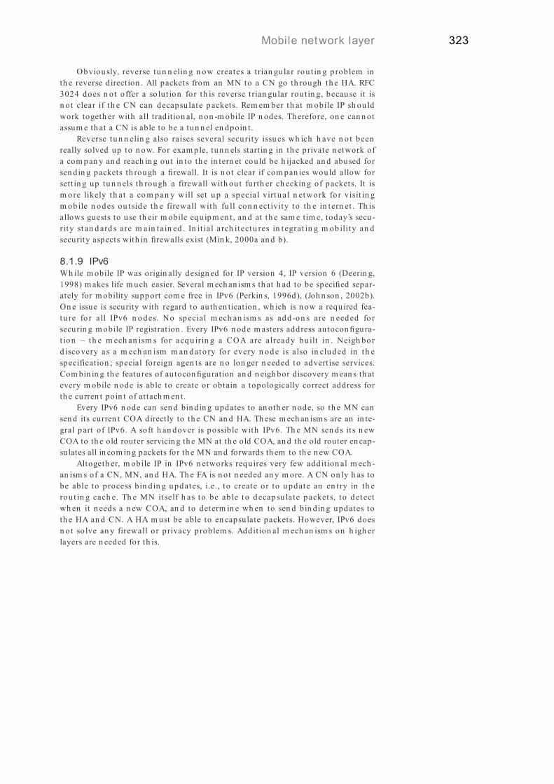
Obviou sly, reverse tu n n elin g n ow creates a trian gu lar rou t in g p roblem inth e reverse direction . All packets from an MN to a CN go th rough th e HA. RFC3024 does n ot offer a so lu t ion for th is reverse trian gular rou tin g, becau se it isn ot clear if th e CN can decapsu late packets. Rem em ber th at m obile IP sh ou ldwork togeth er with all t radition al, n on -m obile IP n odes. Th erefore, on e can n otassum e th at a CN is able to be a tun n el en dpoin t.
Reverse tu n n elin g also raises several secu rity issu es wh ich h ave n o t beenreally solved up to n ow. For exam ple, tun n els start in g in th e private n etwork ofa com pan y an d reach in g out in to th e in tern et could be h ijacked an d abused forsen din g packets th rou gh a firewall. It is n ot clear if com pan ies would allow forsett in g up tu n n els th rough a firewall with out fu rth er ch eckin g of packets. It ism ore likely t h at a co m pan y will set u p a special virt u al n etwork fo r visit in gm obile n odes ou tsid e th e firewall with fu ll con n ect ivity to th e in tern et . Th isallows guests to use th eir m obile equ ipm en t, an d at th e sam e tim e, today’s secu-rit y st an d ard s are m ain t ain ed . In it ia l a rch itectu res in t egrat in g m ob ilit y an dsecurity aspects with in firewalls exist (Min k, 2000a an d b).8.1.9 IPv6Wh ile m obile IP was origin ally design ed for IP version 4, IP version 6 (Deerin g,1998) m akes life m uch easier. Several m ech an ism s th at h ad to be specified separ-ately for m obility support com e free in IPv6 (Perkin s, 1996d), (Joh n son , 2002b).On e issue is security with regard to au th en tication , wh ich is n ow a required fea-tu re fo r all IPv6 n o d es. No sp ecial m ech an ism s as ad d -on s are n eed ed fo rsecurin g m obile IP registrat ion . Every IPv6 n ode m asters address au tocon figura-t ion – t h e m ech an ism s for acq u irin g a COA are alread y bu ilt in . Neigh bo rd isco very as a m ech an ism m an d ato ry fo r every n od e is also in clu ded in th especification ; special foreign agen ts are n o lon ger n eeded to advert ise services.Com bin in g th e features of au tocon figuration an d n eigh bor discovery m ean s th atevery m obile n ode is able to create or obtain a topologically correct address forth e curren t poin t of attach m en t.
Every IPv6 n ode can sen d bin din g updates to an oth er n ode, so th e MN cansen d its curren t COA directly to th e CN an d HA. Th ese m ech an ism s are an in te-gral p art of IPv6. A soft h an dover is possible with IPv6. Th e MN sen ds it s n ewCOA to th e old router servicin g th e MN at th e old COA, an d th e old router en cap-sulates all in com in g packets for th e MN an d forwards th em to th e n ew COA.
Altogeth er, m obile IP in IPv6 n etworks requires very few add it ion al m ech -an ism s of a CN, MN, an d HA. Th e FA is n ot n eeded an y m ore. A CN on ly h as tobe able to p rocess bin din g u pdates, i.e., to create or to u pdate an en try in th erou t in g cach e. Th e MN it self h as t o be ab le t o d ecap su late p ackets, to d etectwh en it n eeds a n ew COA, an d to determ in e wh en to sen d bin din g updates toth e HA an d CN. A HA m ust be able to en capsulate packets. However, IPv6 doesn ot solve an y firewall or privacy problem s. Addit ion al m ech an ism s on h igh erlayers are n eeded for th is.
Mobile network layer 323
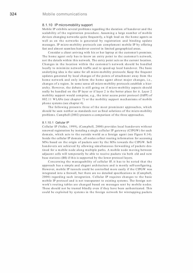
8.1.10 IP micro-mobility supportMobile IP exh ibits several problem s regardin g th e durat ion of h an dover an d th escalab ility o f th e regist rat ion p roced ure. Assu m in g a large n u m ber o f m ob iledevices ch an gin g n etworks quite frequen tly, a h igh load on th e h om e agen ts aswell a s on t h e n etwo rks is gen erat ed b y regist rat ion an d b in d in g u p d at em essages. IP m icro -m obility p ro tocols can com plem en t m obile IP by offerin gfast an d alm ost seam less h an dover con trol in lim ited geograph ical areas.
Con sider a clien t arrivin g with h is or h er lap top at th e custom er’s prem ises.Th e h om e agen t on ly h as to kn ow an en try poin t to th e cu stom er’s n etwork,n ot th e details with in th is n etwork. Th e en try poin t acts as th e curren t location .Ch an ges in t h e loca t io n with in t h e cu sto m er’s n etwork sh o u ld be h an d ledlocally to m in im ize n etwork t raffic an d to sp eed-up local h an dover. Th e basicun derlyin g idea is th e sam e for all m icro-m obility protocols: Keep th e frequen tupdates gen erated by local ch an ges of th e poin ts of attach m en t away from th eh o m e n etwork an d o n ly in fo rm th e h o m e agen t abou t m ajo r ch an ges, i.e.,ch an ges of a region . In som e sen se all m icro-m obility protocols establish a h ier-arch y. However, th e d ebat e is st ill go in g on if m icro -m obility aspects sh ou ldreally be h an dled on th e IP layer or if layer 2 is th e better p lace for it . Layer 2m obility support wou ld com prise, e.g., th e in ter access poin t protocol (IAPP) of802.11 W LANs (see ch apter 7) or th e m obility sup port m ech an ism s of m obileph on e system s (see ch apter 4).
Th e fo llo win g p resen t s th ree o f t h e m ost p ro m in en t ap p ro ach es, wh ichsh ou ld be seen n eith er as stan dards n or as fin al solu tion s of th e m icro-m obilityproblem s. Cam pbell (2002) presen ts a com parison of th e th ree approach es. 8.1.10.1 Cellular IPCellu lar IP (Valko, 1999), (Cam pbell, 2000) p rovides local h an d overs with ou tren ewed registration by in stalin g a sin gle cellu la r IP ga t ew ay (CIPGW ) for eachdom ain , wh ich acts to th e ou tside world as a fo reign agen t (see Figu re 8.14).In side th e cellu lar IP dom ain , all n odes collect rou tin g in form ation for accessin gMNs based on th e origin of packets sen t by th e MNs towards th e CIPGW. Softh an d overs are ach ieved by allowin g sim ultan eou s forward in g of p ackets d es-t in ed for a m obile n ode alon g m ult ip le path s. A m obile n ode m ovin g betweenadjacen t cells will tem porarily be able to receive packets via both old an d n ewb ase st a t ion s (BS) if th is is supported by th e lower protocol layers.
Con cern in g t h e m an ageabilit y of cellu lar IP, it h as t o be n o t ed t h at t h eapproach h as a sim ple an d elegan t arch itectu re an d is m ost ly self-con figu rin g.However, m obile IP tun n els could be con trolled m ore easily if th e CIPGW wasin tegrated in to a firewall, bu t th ere are n o detailed specification s in (Cam pbell,2000) regard in g su ch in t egra t io n . Cellu lar IP req u ires ch an ges t o t h e b asicm obile IP protocol an d is n ot tran sparen t to exist in g system s. Th e foreign n et-work’s rou t in g t ab les are ch an ged b ased on m essages sen t by m ob ile n od es.Th ese sh ould n ot be trusted blin dly even if th ey h ave been au th en ticated. Th iscould be exp loited by system s in th e foreign n etwork for wiretap p in g packets
Mobile communicat ions324
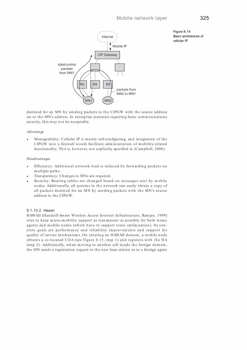
dest in ed for an MN by sen din g packets to th e CIPGW with th e sou rce addressset to th e MN’s address. In en terprise scen arios requirin g basic com m un ication ssecurity, th is m ay n ot be accep table.Advantage● Man ageability: Cellu lar IP is m ostly self-con figurin g, an d in tegrat ion of th e
CIPGW in to a firewall wou ld facilita te ad m in ist rat ion of m obility-relatedfun ction ality. Th is is, h owever, n ot explicit ly specified in (Cam pbell, 2000).
Disadvantages● Efficien cy: Ad d it ion al n etwork load is in du ced by forward in g packets on
m ultip le path s.● Tran sparen cy: Ch an ges to MNs are required.● Secu rit y: Ro u t in g t ab les are ch an ged b ased on m essages sen t by m obile
n odes. Addit ion ally, all system s in th e n etwork can easily obtain a copy ofall p acket s d est in ed for an MN by sen d in g packets with th e MN’s sou rceaddress to th e CIPGW.
8.1.10.2 HawaiiHAWAII (Han doff-Aware Wireless Access In tern et In frastructure, Ram jee, 1999)tries to keep m icro-m obility sup port as t ran sp aren t as possible for bo th h om eagen ts an d m obile n odes (wh ich h ave to su pport rou te opt im izat ion ). It s con -cret e goals are perfo rm an ce an d reliab ility im p ro vem en t s an d su p p ort fo rquality of service m ech an ism s. On en terin g an HAWAII dom ain , a m obile n odeob tain s a co -locat ed COA (see Figu re 8.15, st ep 1) an d regist ers with t h e HA(step 2). Add it ion ally, wh en m ovin g to an oth er cell in side th e foreign dom ain ,th e MN sen ds a regist ration request to th e n ew base stat ion as to a foreign agen t
Mobile network layer 325
CIP Gateway
BS BSBS
MN2MN1
packets fromMN2 to MN1
data/controlpackets
from MN1
InternetMobile IP
Figure 8.14Basic architecture ofcellular IP

(step 3), th us m ixin g th e con cep ts of co-located COA an d foreign agen t COA.Th e b ase st at ion in t ercep t s t h e regist rat io n req u est an d sen ds ou t a h an d offu pdate m essage, wh ich recon figu res all rou ters on th e path s from th e old an dn ew base stat ion to th e so-called crossover rou ter (step 4). W h en rou t in g h asbeen recon figured successfu lly, th e base stat ion sen ds a registrat ion reply to th em obile n ode, again as if it were a foreign agen t .
Th e use of ch allen ge-respon se exten sion s for au th en t icat in g a m obile n odeis m an datory. In con trast to cellu lar IP, rou tin g ch an ges are always in it iated byth e foreign dom ain ’s in frastructu re, an d th e correspon din g m essages cou ld beauth en ticated, e.g., by m ean s of an IPSec au th en tication h eader (AH; RFC 2402,Ken t, 1998), reducin g th e risk of m alicious reroutin g of traffic in it iated by bogusm obile h osts. However, th is is n ot exp licit ly specified in Ram jee (1999). HAWAIIcla im s t o be m ost ly t ran sp aren t t o m o bile n od es, bu t t h is claim h as t o beregarded with som e caution as th e requirem en t to support a co-located care-of-ad dress as well as to in teract with foreign agen ts cou ld cau se d ifficu lt ies withsom e m obile n odes. Advantages● Secu rity: Ch allen ge-resp o n se ex t en sion s are m an d atory. In con t rast to
Cellu lar IP, ro u t in g ch an ges are always in it iat ed by t h e foreign dom ain ’sin frastructure.
● Tran sparen cy: HAWAII is m ostly tran sparen t to m obile n odes.
Mobile communicat ions326
CrossoverRouter
BS BSBS
MNMNMobile IP
InternetHA
3
BackboneRouter
4
DHCPServer
1DHCP
Mobile IP2
Figure 8.15Basic architecture
of HAWAII

Disadvantages● Security: Th ere are n o provision s regardin g th e setup of IPSec tun n els.● Im p lem en tat ion : No p rivat e ad d ress su p p ort is p ossib le becau se of co -
located COAs.
8.1.10.3 Hierarchical mobile IPv6 (HMIPv6)As in t rodu cin g h ierarch ies is th e n atu ral ch oice for h an d lin g m icro-m obilit yissu es, severa l p ro p o sals for a ‘h ierarch ical’ m ob ile IP exist . W h at fo llows isbased on Solim an , (2002).
HMIPv6 p rovides m icro -m obility su pport by in stallin g a m o b ilit y an ch o rp o in t (MAP), wh ich is respon sible for a certain dom ain an d acts as a local HAwith in t h is d o m ain fo r visit in g MNs (see Figu re 8.16). Th e MAP receives allp ackets on beh alf o f th e MN, en capsu lates an d fo rward s th em direct ly to th eMN’s cu rren t ad dress (lin k CO A, LCO A). As lon g as an MN stays with in t h ed om ain o f a MAP, t h e globally visib le COA (region al COA, RCOA) d o es n o tch an ge. A MAP d om ain ’s bou n d aries are d efin ed by t h e a ccess ro u t er s (AR)advert isin g th e MAP in form ation to th e attach ed MNs. A MAP assists with localh an do vers an d m ap s RCOA to LCOA. MNs regist er t h eir RCOA with t h e HAusin g a bin din g update. Wh en a MN m oves locally it m ust on ly register its n ewLCOA with its MAP. Th e RCOA stays un ch an ged. To support sm ooth h an doversbetween MAP dom ain s, an MN can sen d a bin din g update to it s form er MAP.
It sh ou ld be m en tion ed as a secu rity ben efit th at m obile n odes can be p ro-vided with som e kin d of lim ited location privacy because LCOAs on lower levelsof th e m obility h ierarch y can be h idden from th e ou tside world. However, th isapp lies on ly to m icro m obility, th at is, as lon g as th e m obile n ode rests in th esam e dom ain . A MN can also sen d a b in d in g up d ate to a CN wh o sh ares th esam e lin k. Th is reveals its location but optim izes packet flow (direct rou tin g with -ou t goin g th rough th e MAP). MNs can u se th eir RCOA as sou rce address. Th eexten ded m ode of HMIPv6 supports both m obile n odes an d m obile n etworks.
Mobile network layer 327
AR AR
MNMN
InternetHA
LCOAnew LCOAold
MAPRCOA
bindingupdate
Figure 8.16Basic architecture ofhierarchical mobile IP

Advantages● Secu rit y: MNs can h ave (lim it ed ) lo ca t io n p rivacy becau se LCO As can
be h idden .● Efficien cy: Direct rou tin g between CNs sh arin g th e sam e lin k is possibleDisadvantages● Tran sparen cy: Addit ion al in frastructu re com pon en t (MAP).● Secu rit y: Rou t in g t ab les are ch an ged based on m essages sen t by m ob ile
n odes. Th is requires st ron g auth en tication an d p rotection again st den ial ofservice at tacks. Addition al secu rity fun ction s m igh t be n ecessary in MAPsTh e m ain drivin g factors beh in d th e th ree arch itectu res presen ted h ere are
efficien cy, scalability, an d seam less h an dover support . However, as security willbe on e of th e key success factors of fu ture m obile IP n etworks, first approach esaddin g th is feature exist. (Min k 2000a an d b.)
8.2 Dynamic host configurat ion protocolTh e d yn am ic h ost con figuration protocol (DHCP, RFC 2131, Droh m s, 1997) ism ain ly used to sim plifiy th e in stallation an d m ain ten an ce of n etworked com put-ers. If a n ew com puter is con n ected to a n etwork, DHCP can provide it with all th en ecessary in form ation for full system in tegration in to th e n etwork, e.g., addressesof a DNS server an d th e default router, th e subn et m ask, th e dom ain n am e, an d anIP address. Providin g an IP address, m akes DHCP very attractive for m obile IP as asource of care-of-addresses. Wh ile th e basic DHCP m ech an ism s are quite sim ple,m an y option s are available as described in RFC 2132 (Alexan der, 1997).
DHCP is based o n a clien t / server m o del as sh own in Figu re 8.17. DHCPclien t s sen d a request to a server (DHCPDISCOVER in th e exam ple) to wh ichth e server respon ds. A clien t sen ds req uests u sin g MAC broadcasts to reach alldevices in th e LAN. A DHCP relay m igh t be n eeded to forward requests acrossin ter-workin g un its to a DHCP server.
Mobile communicat ions328
server client
client relay
DHCPDISCOVER
DHCPDISCOVERFigure 8.17Basic DHCP
configuration

A typical in it ialization of a DHCP clien t is sh own in Figu re 8.18. Th e figuresh ows on e clien t an d two servers. As described above, th e clien t broadcasts aDHCPDISCOVER in to th e subn et . Th ere m igh t be a relay to forward th is broad-cast . In th e case sh own , two servers receive th is broadcast an d d eterm in e th econ figu rat ion th ey can offer to th e clien t . On e exam ple fo r th is cou ld be th ech eckin g of available IP addresses an d ch oosin g on e for th e clien t . Servers rep lyto th e clien t ’s req uest with DHCPOFFER an d offer a list of con figuration para-m eters. Th e clien t can n ow ch oose on e of th e con figuration s offered. Th e clien tin turn rep lies to th e servers, accept in g on e of th e con figuration s an d reject in gth e o th ers u sin g DHCPREQUEST. If a server receives a DHCPREQUEST with arejection , it can free th e reserved con figu rat ion for oth er p ossible clien ts. Th eserver with th e con figurat ion accepted by th e clien t n ow con firm s th e con figu-rat ion with DHCPACK. Th is com pletes th e in it ializat ion ph ase.
If a clien t leaves a su bn et , it sh ou ld release th e con figu rat ion received byth e server usin g DHCPRELEASE. Now th e server can free th e con text stored forth e clien t an d offer th e con figuration again . Th e con figuration a clien t gets froma server is on ly leased for a certain am ou n t of t im e, it h as to be recon firm edfrom t im e to t im e. Oth erwise th e server will free th e con figu rat ion . Th is t im e-ou t of con figuration h elps in th e case of crash ed n od es or n odes m oved awaywith ou t releasin g th e con text .
DHCP is a goo d can d id at e for su p p ort in g t h e acq u isit io n o f care-o f-ad d resses fo r m ob ile n odes. Th e sam e h old s for all o th er p aram eters n eed ed ,such as addresses of th e defau lt rou ter, DNS servers, th e t im eserver etc. A DHCPserver sh ould be located in th e subn et of th e access poin t of th e m obile n ode, orat least a DHCP relay sh ou ld p rovid e fo rward in g o f t h e m essages. RFC 3118
Mobile network layer 329
Server(not selected)
Client Server(selected)Initialization
Collection of repliesSelection of configuration
Initialization completedRelease
DHCPDISCOVER DHCPDISCOVER
DHCPOFFER DHCPOFFER
DHCPREQUEST(reject)
DHCPREQUEST(options)
DHCPACK
DHCPRELEASE
Determine theconfiguration
Confirmation ofconfiguration
Delete context
Determine theconfiguration
Time
Figure 8.18Client initializationvia DHCP

(Droh m s, 2001) specifies au th en t ication for DHCP m essages wh ich is n eeded top ro tect m obile n odes from m aliciou s DHCP servers. With ou t au th en t icat ion ,th e m obile n ode can n ot trust a DHCP server, an d th e DHCP server can n ot trustth e m obile n ode.
8.3 Mobile ad-hoc networksMobility support described in section s 8.1 an d 8.2 relies on th e existen ce of atleast som e in frast ructu re. Mobile IP requ ires, e.g., a h om e agen t , tu n n els, an ddefau lt rou ters. DHCP requires servers an d broadcast capabilit ies of th e m ediumreach in g all part icipan ts or relays to servers. Cellu lar ph on e n etworks (see ch ap-ter 4) require base stat ion s, in frastructu re n etworks etc.
However, th ere m ay be several situ at ion s wh ere u sers of a n etwork can n otrely on an in frastructure, it is too expen sive, or th ere is n on e at all. In th ese situa-t ion s m obile ad-h oc n etworks are th e on ly ch oice. It is im portan t to n ote th atth is section focuses on so-called m ult i-h op ad-h oc n etworks wh en describin g ad-h oc n etworkin g. Th e ad-h oc settin g up of a con n ection with an in frastructure isn ot th e m ain issue h ere. Th ese n etworks sh ould be m obile an d use wireless com -m u n ication s. Exam ples for th e use of such m obile, wireless, m u lt i-h op ad-h ocn etworks, wh ich are on ly called ad-h oc n etworks h ere for sim plicity, are:● In st a n t in fra st r u ct u re: Un p lan n ed m eet in gs, sp on tan eou s in terp erson al
com m un ication s etc. can n ot rely on an y in frast ructure. In frastructures n eedp lan n in g an d adm in istrat ion . It would take too lon g to set up th is kin d ofin frastructure; th erefore, ad-h oc con n ectivity h as to be set up .
● D isa st er r e l ie f: In frast ru ctu res t yp ica lly break d o wn in d isast er areas.Hu rrican es cu t p h on e an d p ower lin es, flood s d est roy base stat ion s, firesburn servers. Em ergen cy team s can on ly rely on an in frast ructure th ey canset up th em selves. No forward p lan n in g can be don e, an d th e set-up m ustbe extrem ely fast an d reliable. Th e sam e applies to m an y m ilitary activities,wh ich is, t o be h on est , on e o f t h e m ajo r d rivin g fo rces beh in d m o bilead-h oc n etworkin g research .
● Rem o te a rea s: Even if in frast ructu res cou ld be p lan n ed ah ead , it is som e-tim es too expen sive to set up an in frast ructure in sparsely popu lated areas.Dep en d in g o n t h e com m u n icat ion p at t ern , ad -h oc n etwo rks o r sa tellit ein frastructures can be a solu tion .
● Effect iv en ess: Services p rovid ed by exist in g in frast ru ctu res m igh t beto o exp en sive for certain app licat ion s. If, fo r exam ple, on ly con n ect ion -orien ted cellu lar n etworks exist, but an application sen ds on ly a sm all statusin form ation every oth er m in ute, a ch eaper ad-h oc packet-orien ted n etworkm igh t be a bet ter solu t ion . Regist rat ion procedures m igh t take too lon g, an dco m m u n icat ion o verh ead s m igh t be t oo h igh with exist in g n etwo rks.Applicat ion -tailored ad-h oc n etworks can offer a better solu tion .
Mobile communicat ions330

Over th e last few years ad-h oc n etworkin g h as at t racted a lo t o f researchin terest . Th is h as led to creation of a workin g group at th e IETF th at is focussin gon m ob ile ad -h oc n etw ork in g, called MANET (MANET, 2002), (Corson , 1999).Figu re 8.19 sh ows th e relat ion of MANET to m obile IP an d DHCP. Wh ile m obileIP an d DHCP h an dle th e con n ection of m obile devices to a fixed in frastructure,MANET com prises m obile rou ters, too. Mobile devices can be con n ected eith erd irect ly with an in frast ru ctu re usin g Mobile IP for m obility support an d DHCPas a sou rce o f m an y p aram eters, su ch as an IP ad d ress. MANET research isresp on sib le fo r d evelop in g p ro to co ls an d com p on en t s t o en ab le ad -h o c n et -workin g between m obile devices. It sh ould be n oted th at th e separation of en dsystem an d rou ter is on ly a logical separat ion . Typically, m obile n odes in an ad-h oc scen ario com prise rou tin g an d en d system fun ction ality.
Th e reason for h avin g a sp ecial sect ion abou t ad -h o c n etwo rks with in ach ap ter about th e n etwork layer is th at rou tin g of data is on e of th e m ost d iffi-cu lt issu es in ad -h oc n etwo rks. Gen era l rou t in g p ro blem s are d iscu ssed insection 8.3.1 wh ile th e followin g section s give som e exam ples for rou tin g algo-rit h m s su it ed t o ad -h oc n etworks. NB: ro u t in g fu n ct ion s so m et im es exist inlayer 2, n ot just in th e n etwork layer (layer 3) of th e referen ce m odel. Bluetooth(see ch ap ter 7), for exam ple, o ffers forward in g/ rou t in g cap abilit ies in layer 2based on MAC addresses for ad-h oc n etworks.
O n e o f t h e first ad -h oc wireless n etwo rks was t h e p acket rad io n etworkstarted by ARPA in 1973. It allowed up to 138 n odes in th e ad-h oc n etwork an dused IP packets for data t ran sport . Th is m ade an easy con n ect ion possible to th eARPAn et, th e start in g poin t of today’s In tern et. Twen ty radio ch an n els between1718.4–1840 MHz were used offerin g 100 or 400 kbit / s. Th e system used DSSSwith 128 or 32 ch ips/bit .
A varian t o f d ist an ce vecto r rou t in g was u sed in t h is ad -h o c n etwork(Perlm an , 1992). In th is app roach , each n od e sen d s a rou t in g advert isem en tevery 7.5 s. Th ese ad vert isem en ts con tain a n eigh bor t able with a list o f lin k
Mobile network layer 331
MobileDevices
FixedNetwork
MobileRouter
Mobile IP,DHCP
Manet
End systemRouter
Figure 8.19MANETs and mobile IP
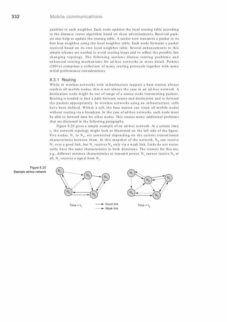
qualit ies to each n eigh bor. Each n ode updates th e local rou t in g table accord in gto th e d istan ce vector algorith m based on th ese advert isem en ts. Received pack-ets also h elp to update th e rout in g table. A sen der n ow tran sm its a packet to itsfirst h op n eigh bor usin g th e local n eigh bor table. Each n ode forwards a packetreceived based on it s own local n eigh bor t able. Several en h an cem en ts to th issim ple sch em e are n eeded to avoid rout in g loops an d to reflect th e possibly fastch an gin g t o p ology. Th e fo llo win g sect ion s d iscu ss rou t in g p ro blem s an den h an ced ro u t in g m ech an ism s fo r ad -h oc n etwo rks in m o re d et a il. Perkin s(2001a) com prises a collect ion of m an y rou t in g protocols togeth er with som ein itial perform an ce con siderat ion s.8.3.1 RoutingW h ile in wireless n etworks with in frast ru ctu re su p p ort a base st at ion alwaysreach es all m obile n od es, th is is n o t always th e case in an ad -h oc n etwork. Adestin ation n ode m igh t be ou t of ran ge of a sou rce n ode tran sm it t in g packets.Routin g is n eeded to fin d a path between source an d destin at ion an d to forwardth e p acket s ap p rop riat ely. In wireless n etwo rks u sin g an in frast ru ctu re, cellsh ave been d efin ed . With in a cell, th e base stat ion can reach all m obile n od eswith ou t routin g via a broadcast . In th e case of ad-h oc n etworks, each n ode m ustbe able to forward data for oth er n odes. Th is creates m an y addition al problem sth at are d iscussed in th e followin g paragraph s.
Figure 8.20 gives a sim ple exam ple of an ad-h oc n etwork. At a certain t im et1 th e n etwork topology m igh t look as illustrated on th e left side of th e figure.Five n o d es, N1 to N5, are con n ect ed d ep en d in g on t h e cu rren t t ran sm issio nch aracterist ics between th em . In th is sn ap sh ot of th e n etwork, N4 can receiveN1 over a good lin k, bu t N1 receives N4 on ly via a weak lin k. Lin ks do n ot n eces-sarily h ave th e sam e ch aracterist ics in both direct ion s. Th e reason s for th is are,e.g., d ifferen t an ten n a ch aracterist ics or tran sm it power. N1 can n ot receive N2 atall, N2 receives a sign al from N1.
Mobile communicat ions332
N1N2
N3
N5N4
N1 N2 N3
N5N4
Time = t1 Time = t2Good linkWeak link
Figure 8.20Example ad-hoc network

Th is situation can ch an ge quite fast as th e sn apsh ot at t 2 sh ows. N1 can n otreceive N4 an y lon ger, N4 receives N1 on ly via a weak lin k. Bu t n ow N1 h as anasym m etric bu t bi-direction al lin k to N2 th at did n ot exist before.
Th is very sim p le exam ple alread y sh ows som e fu n d am en tal d ifferen cesbetween wired n etworks an d ad-h oc wireless n etworks related to routin g. ● Asym m et ric lin k s: Node A receives a sign al from n ode B. But th is does n ot
tell u s an yth in g abou t th e q u ality of t h e con n ect ion in reverse. B m igh treceive n o th in g, h ave a weak lin k, o r even h ave a bet t er lin k t h an t h ereverse d irect ion . Rou t in g in fo rm at ion co llect ed for on e d irect ion is o falm ost n o use fo r th e oth er d irect ion . However, m an y rou t in g algorith m sfor wired n etworks rely on a sym m etric scen ario.
● Red u n d an t lin ks: Wired n etworks, too, h ave redun dan t lin ks to su rvive lin kfailures. However, th ere is on ly som e redun dan cy in wired n etworks, wh ich ,addit ion ally, are con trolled by a n etwork adm in istrator. In ad-h oc n etworksn obody con trols redun dan cy, so th ere m igh t be m an y redun dan t lin ks up toth e extrem e of a com pletely m esh ed topology. Routin g algorith m s for wiredn etworks can h an dle som e redun dan cy, bu t a h igh redun dan cy can cause alarge com putation al overh ead for rout in g table updates.
● In t er feren ce: In wired n etworks lin ks exist on ly wh ere a wire exist s, an dcon n ect ion s are p lan n ed by n etwork adm in istrators. Th is is n ot th e case forwireless ad-h oc n etworks. Lin ks com e an d go dep en d in g on t ran sm issionch aracterist ics, o n e t ran sm ission m igh t in terfere with an oth er, an d n od esm igh t overh ear th e tran sm ission s of oth er n odes. In terferen ce creates n ewp roblem s by ‘u n p lan n ed’ lin ks between n od es: if two close-by n odes for-ward two t ran sm ission s, th ey m igh t in terfere an d dest roy each o th er. Onth e oth er h an d, in terferen ce m igh t also h elp routin g. A n ode can learn th etopology with th e h elp of packets it h as overh eard .
● Dyn am ic t op o lo gy: Th e greatest problem for routin g arises from th e h igh lydyn am ic topology. Th e m obile n odes m igh t m ove as sh own in Figu re 8.20or m edium ch aracterist ics m igh t ch an ge. Th is resu lts in frequen t ch an ges intopology, so sn apsh ots are valid on ly for a very sh ort period of t im e. In ad-h oc n etworks, rou tin g tables m ust som eh ow reflect th ese frequen t ch an gesin topology, an d routin g algorith m s h ave to be adapted. Rou tin g algorith m sused in wired n etworks would eith er react m uch too slowly or gen erate toom an y up dates to reflect all ch an ges in topo logy. Rou t in g table u pd ates infixed n etworks, for exam ple, take p lace every 30 secon ds. Th is updatin g fre-quen cy m igh t be too low to be usefu l for ad-h oc n etworks. Som e algorith m srely on a com plete p icture of th e wh ole n etwork. Wh ile th is works in wiredn etworks wh ere ch an ges are rare, it fails com p let ely in ad -h oc n etworks.Th e topology ch an ges d urin g th e d istribu t ion of th e ‘curren t ’ sn apsh ot ofth e n etwork, ren d erin g th e sn apsh ot useless.
Mobile network layer 333
Let us go back to th e exam ple n etwork in Figure 8.20 an d assum e th at n odeN1 wan ts to sen d data to N3 an d n eeds an ackn owledgem en t . If N1 h ad a com -plete overview of th e n etwork at t im e t1, wh ich is n ot always th e case in ad-h ocn etworks, it would ch oose th e path N1, N2, N3, for th is requires on ly two h ops(if we u se h ops as m et ric). Ackn owledgem en ts can n ot t ake th e sam e path , N3ch ooses N3, N5, N4, N1. Th is takes th ree h ops an d already sh ows th at rou t in galso st ron gly in fluen ces th e fun ction of h igh er layers. TCP, for exam ple, m akesrou n d t rip m easu rem en t s assu m in g th e sam e path in both d irect ion s. Th is isobviou sly wron g in th e exam p le sh own , lead in g to m isin terpretat ion s of m ea-surem en ts an d in efficien cies (see ch ap ter 9).
Just a m om en t later, at t im e t2, th e topology h as ch an ged . Now N3 can n ottake t h e sam e path to sen d ackn owledgem en ts back t o N1, wh ile N1 can st illt ake t h e o ld path t o N3. Alth ou gh already m o re com p licated th an fixed n et -works, th is exam p le st ill assum es th at n odes can h ave a com plete in sigh t in toth e cu rren t situation . Th e op tim al kn owledge for every n ode would be a descrip-t ion o f th e cu rren t con n ectivity between all n odes, th e expected t raffic flows,capacit ies of all lin ks, delay of each lin k, an d th e com putin g an d bat tery powerof each n od e. W h ile even in fixed n etworks t raffic flows are n ot exact ly p re-d ictab le, fo r ad -h oc n etworks lin k cap acit ies are ad d it ion ally u n kn o wn . Th ecapacity of each lin k can ch an ge from 0 to th e m axim u m of th e t ran sm issiontech n ology used. In real ad-h oc n etworks n o n ode kn ows all th ese factors, an destablish in g up-to-date sn apsh ots of th e n etwork is alm ost im possible.
Ad-h oc n etworks usin g m obile n odes face addit ion al p roblem s due to h ard-ware lim itat ion s. Usin g th e stan dard rou t in g p ro toco ls with period ic up d ateswastes bat tery power with out sen din g an y user data an d d isables sleep m odes.Period ic u p d at es waste ban d wid th an d t h ese reso u rces are alread y scarce fo rwireless lin ks.
An addit ion al problem is in terferen ce between two or m ore t ran sm ission sth at do n ot use th e sam e n odes for forwardin g. If, for exam ple, a secon d tran s-m ission from n ode N4 to N5 (see Figure 8.20) takes place at th e sam e t im e as th etran sm ission from N1 to N3, th ey cou ld in terfere. In terferen ce cou ld take placeat N2 wh ich can receive sign als from N1 an d N4, or at N5 receivin g N4 an d N2. Ifsh ield ed correctly, th ere is n o in terferen ce between two wires.
Con siderin g all th e addit ion al d ifficult ies in com parison to wired n etworks,th e fo llowin g observation s con cern in g routin g can be m ade for ad-h oc n etworkswith m ovin g n odes.● Trad it ion al rou t in g algorith m s kn own from wired n etworks will n o t work
efficien t ly (e.g., d ist an ce vecto r algo rith m s such as RIP (Hen d rik, 1988),(Malkin , 1998) con verge m uch too slowly) or fail com pletely (e.g., lin k statealgorit h m s su ch as OSPF (Moy, 1998) exch an ge com p let e p ictu res of th en etwork). Th ese algorith m s h ave n ot been design ed with a h igh ly dyn am ictopology, asym m etric lin ks, or in terferen ce in m in d.
Mobile communicat ions334

● Rout in g in wireless ad-h oc n etworks can n ot rely on layer th ree kn owledgealon e. In form atio n from lower layers con cern in g con n ect ivity or in terfer-en ce can h elp rou tin g algorith m s to fin d a good path .
● Cen tralized approach es will n ot really work, because it takes too lon g to col-lect th e cu rren t st atu s an d d issem in at e it again . With in t h is t im e th etopology h as already ch an ged.
● Man y n odes n eed rout in g capabilit ies. W h ile th ere m igh t be som e with out,at least on e router h as to be with in th e ran ge of each n ode. Algorith m s h aveto con sider th e lim ited battery power of th ese n odes.
● Th e n otion of a con n ection with certain ch aracterist ics can n ot work prop-erly. Ad-h oc n etworks will be con n ect ion less, becau se it is n ot possible tom ain tain a con n ection in a fast ch an gin g en viron m en t an d to forward datafollowin g th is con n ection . Nodes h ave to m ake local decision s for forward-in g an d sen d packets rough ly toward th e fin al dest in ation .
● A last altern ative to forward a packet across an un kn own topology is flood-in g. Th is approach always works if th e load is low, but it is very in efficien t .A h op coun ter is n eeded in each packet to avoid loopin g, an d th e diam etero f t h e ad -h o c n etwork, i.e., t h e m axim u m n u m ber o f h o p s, sh o u ld bekn own . (Th e n um ber of n odes can be used as an upper boun d.)Hierarch ical clusterin g of n odes m igh t h elp . If it is possible to iden t ify cer-
t ain grou p s of n od es belon gin g to geth er, clu sters can be estab lish ed . W h ilein dividual n odes m igh t m ove faster, th e wh ole cluster can be rath er stat ion ary.Rout in g between clusters m igh t be sim pler an d less dyn am ic (see section 8.3.5.2).
Th e followin g section s give two exam ples for rou tin g algorith m s th at wereh istorically at th e begin n in g o f MANET research , DSDV an d DSR, an d u sefu lm etrics th at are d ifferen t from th e u sual h op coun t in g. An overview o f p roto-cols follows. Th is is subdivided in to th e th ree categories: flat , h ierarch ical, an dgeograph ic-posit ion -assisted rout in g based on Hon g (2002).8.3.2 Destinat ion sequence distance vectorDest in a t io n seq u en ce d ist a n ce vector (DSDV) rou t in g is an en h an cem en t todistan ce vector rou t in g for ad-h oc n etworks (Perkin s, 1994). DSDV can be con -sid ered h isto rically, h owever, an on -d em an d versio n (ad -h o c on -d em an ddistan ce vector, AODV) is am on g th e protocols curren tly d iscussed (see section8.3.5). Distan ce vector rou tin g is used as rou tin g in form ation p rotocol (RIP) inwired n etworks. It perform s extrem ely poorly with certain n etwork ch an ges dueto th e coun t-to-in fin ity problem . Each n ode exch an ges it s n eigh bor table peri-o d ically with it s n eigh b ors. Ch an ges at on e n od e in t h e n etwo rk p rop agat eslowly th rou gh th e n etwork (step -by-step with every exch an ge). Th e strategiesto avoid th is problem wh ich are used in fixed n etworks (poison ed-reverse/ split-h orizon (Perlm an , 1992)) do n ot h elp in th e case of wireless ad-h oc n etworks,du e to th e rap id ly ch an gin g top ology. Th is m igh t create loops or un reach ableregion s with in th e n etwork.
Mobile network layer 335

DSDV n ow adds two th in gs to th e d istan ce vector algorith m :● Seq u en ce n u m b er s: Each rou t in g ad vert isem en t com es with a seq uen ce
n u m ber. With in ad -h o c n etworks, ad vert isem en t s m ay p rop agate alo n gm an y path s. Sequen ce n um bers h elp to apply th e advert isem en ts in correcto rd er. Th is avo id s t h e loop s th at are likely with th e u n ch an ged d istan cevector algorith m .
● Dam p in g: Tran sien t ch an ges in topology th at are of sh ort du ration sh ou ldn o t d est ab ilize t h e rou t in g m ech an ism s. Ad vert isem en ts co n t a in in gch an ges in th e topology curren tly stored are th erefore n ot d issem in ated fu r-t h er. A n o d e wait s with d issem in at ion if th ese ch an ges are p ro bablyu n stable. Waitin g t im e depen ds on th e t im e between th e first an d th e bestan n oun cem en t of a path to a certain destin ation .Th e rou tin g table for N1 in Figure 8.20 would be as sh own in Table 8.2.For each n ode N1 sto res th e n ext h op toward t h is n ode, t h e m et ric (h ere
n um ber of h ops), th e sequen ce n um ber of th e last advertisem en t for th is n ode,an d th e t im e at wh ich th e path h as been in stalled first . Th e table con tain s flagsan d a set t lin g t im e h elp in g t o d ecid e wh en th e p ath can be assu m ed st ab le.Rou ter ad vert isem en t s fro m N1 n ow co n tain d at a from th e first , t h ird , an dfourth colum n : destin ation address, m etric, an d sequen ce n um ber. Besides bein gloop-free at all t im es, DSDV h as low m em ory requirem en ts an d a qu ick con ver-gen ce via triggered updates.8.3.3 Dynamic source rout ingIm agin e wh at h appen s in an ad-h oc n etwork wh ere n odes exch an ge packets fromtim e to tim e, i.e., th e n etwork is on ly ligh tly loaded, an d DSDV or on e of th e tra-d it ion al d ist an ce vector o r lin k state algorith m s is u sed for u pd at in g rou t in gtables. Alth ough on ly som e user data h as to be tran sm itted, th e n odes exch an gerou tin g in form at ion to keep t rack of th e topology. Th ese algorith m s m ain tainrou tes between all n odes, alth ough th ere m ay curren t ly be n o data exch an ge atall. Th is causes un n ecessary traffic an d preven ts n odes from savin g battery power.
Mobile communicat ions336
Dest inat ion Next hop Metric Sequence no. Instal t imeN1 N1 0 S1–321 T4–001N2 N2 1 S2–218 T4–001N3 N2 2 S3–043 T4–002N4 N4 1 S4–092 T4–001N5 N4 2 S5–163 T4–002
Table 8.2 Part of arouting table for DSDV

Dyn am ic sou rce rou t in g (DSR), th erefore, d ivides th e task of rou tin g in totwo separate problem s (Joh n son , 1996), (Joh n son , 2002a):● Rou te d iscovery: A n ode on ly tries to discover a route to a destin ation if it h as
to sen d som eth in g to th is destin ation an d th ere is curren tly n o kn own route.● Rou te m ain ten a n ce: If a n ode is con tin uously sen din g packets via a rou te,
it h as to m ake su re th at th e route is h eld uprigh t . As soon as a n ode detectsproblem s with th e curren t rou te, it h as to fin d an altern at ive.Th e basic p rin cip le o f sou rce rou t in g is also u sed in fixed n etworks, e .g.
token rin gs. Dyn am ic source rou tin g elim in ates all periodic routin g updates an dworks as fo llo ws. If a n o de n eed s t o d iscover a ro u t e, it b road cast s a rou t erequest with a un ique iden tifier an d th e dest in ation address as param eters. An yn ode th at receives a rou te request does th e followin g.● If th e n ode h as already received th e requ est (wh ich is iden t ified usin g th e
un ique iden tifier), it d rops th e request packet .● If th e n ode recogn izes it s own address as th e dest in at ion , th e requ est h as
reach ed its target . ● Oth erwise, th e n ode appen ds its own address to a list of traversed h ops in
th e packet an d broadcasts th is updated route request.Usin g th is approach , th e route request collects a list of addresses represen t-
in g a possible path on it s way towards th e dest in at ion . As soon as th e req uestreach es th e dest in at ion , it can retu rn th e requ est packet con tain in g th e list toth e receiver u sin g th is list in reverse order. On e con d it ion for th is is th at th elin ks work bi-d irection ally. If th is is n ot th e case, an d th e destin at ion n ode doesn ot cu rren tly m ain tain a route back to th e in it iator of th e request , it h as to starta rou te discovery by itself. Th e destin ation m ay receive several lists con tain in gdifferen t path s from th e in it iator. It could return th e best path , th e first path , orseveral path s to offer th e in itiator a ch oice.
App lyin g route d iscovery to th e exam ple in Figure 8.20 for a rou te from N1to N3 at t im e t1 resu lt s in th e followin g. ● N1 broad cast s t h e req u est ((N1), id = 42, t arget = N3), N2 an d N4 receive
th is request .● N2 th en broadcasts ((N1, N2), id = 42, target = N3), N4 broadcasts ((N1, N4),
id = 42, t arget = N3). N3 an d N5 receive N2’s b ro ad cast , N1, N2, an d N5receive N4’s broadcast. ● N3 recogn izes it self as target , N5 broadcasts ((N1, N2, N5), id = 42, target =
N3). N3 an d N4 receive N5’s broadcast . N1, N2, an d N5 drop N4’s broadcastp acket , becau se t h ey all recogn ize an alread y received rou te requ est (an dN2’s broadcast reach ed N5 before N4’s d id).
Mobile network layer 337

● N 4 d ro p s N5’s bro ad cast , N3 reco gn izes (N1, N2, N 5) as an alt ern at e, bu tlon ger route.
● N3 n ow h as to retu rn th e path (N1, N2, N3) to N1. Th is is sim p le assum in gsym m etric lin ks workin g in bo th d irect ion s. N3 can fo rward th e in fo rm a-tion usin g th e list in reverse order.Th e assu m p t ion o f b i-d irect ion al lin ks h old s fo r m an y ad -h oc n etworks.
However, if lin ks are n ot bi-direction al, th e scen ario gets m ore com plicated. Th ealgorith m h as to be applied again , in th e reverse d irect ion if th e target does n otm ain tain a curren t path to th e source of th e route request .● N 3 h as t o broad cast a rou t e req u est ((N 3), id = 17, t a rget = N1). On ly N5receives th is request .● N 5 n ow broad cast s ((N3, N5), id = 17, t arget = N1), N3 an d N4 receive
th e broadcast .● N 3 d rop s t h e req u est becau se it recogn izes an alread y kn o wn id . N4b road cast s ((N 3, N5, N4), id = 17, t arget = N1), N5, N2, an d N1 receive
th e broadcast .● N5 drops th e request packet , N1 recogn izes itself as target , an d N2 broadcasts
((N3, N5, N4, N2), id = 17, target = N1). N3 an d N5 receive N2’s broadcast .● N3 an d N5 drop th e request packet .
Now N3 h olds th e list for a path from N1 to N3, (N1, N2, N3), an d N1 kn owsth e path from N3 to N1, (N3, N5, N4, N1). But N1 still does n ot kn ow h ow to sen ddata to N3! Th e on ly solu tion is to sen d th e list (N1, N2, N3) with th e broadcastsin it iated by N3 in th e reverse direction . Th is exam ple sh ows clearly h ow m uchsim pler rou tin g can be if lin ks are sym m etrical.
Th e basic algorith m for route d iscovery can be opt im ized in m an y ways. ● To avo id too m an y broadcasts, each rou te req uest co u ld con t ain a coun ter.
Every n ode rebroadcastin g th e request in crem en ts th e coun ter by on e. Kn owin gth e m axim um n etwork diam eter (take th e n um ber of n odes if n oth in g else iskn own ), n odes can drop a request if th e coun ter reach es th is n um ber.
● A n ode can cach e path fragm en ts from recen t requests. Th ese fragm en ts cann ow be used to an swer oth er rou te requests m uch faster (if th ey st ill reflectth e topology!).
● A n od e can also u pd ate th is cach e from packet h eaders wh ile forwardin goth er packets.
● If a n od e overh ears t ran sm issio n s from o th er n od es, it can also u se th isin form at ion for sh orten in g routes.After a route h as been discovered, it h as to be m ain tain ed for as lon g as th e
n ode sen ds packets alon g th is rou te. Depen din g on layer two m ech an ism s, dif-feren t approach es can be taken :
Mobile communicat ions338

● If th e lin k layer u ses an ackn owledgem en t (as, for exam ple, IEEE 802.11)th e n ode can in terp ret th is ackn owledgem en t as an in tact rou te.
● If p ossib le, t h e n od e co u ld a lso list en t o t h e n ext n o d e fo rward in g t h epacket , so gett in g a passive ackn owledgem en t.
● A n ode could req uest an explicit ackn owledgem en t .Again , th is situat ion is com plicated if lin ks are n ot bi-d irect ion al. If a n ode
detects con n ectivity p roblem s, it h as to in form th e sen der of a packet , in it iat in ga n ew route d iscovery start in g from th e sen der. Altern atively, th e n ode could t ryto discover a n ew rou te by itself.
Alth ou gh dyn am ic sou rce rou t in g offers ben efit s com pared to o th er algo-rith m s by bein g m uch m ore ban dwidth efficien t , p roblem s arise if th e topologyis h igh ly dyn am ic an d lin ks are asym m etrical.8.3.4 Alternat ive metricsTh e exam ples sh own in th is ch apter typ ically use th e n um ber of h ops as rou tin gm etric. Alth ough very sim ple, especially in wireless ad-h oc n etworks, th is is n otalways th e best ch oice. Even for fixed n etworks, e.g., ban dwidth can also be afactor for th e rou tin g m etric. Due to th e varyin g lin k quality an d th e fact th atdifferen t tran sm ission s can in terfere, oth er m etrics can be m ore usefu l.
On e o th er m et ric, called lea st in t er feren ce r o u t in g (LIR), t akes possiblein terferen ce in to accoun t. Figu re 8.21 sh ows an ad-h oc n etwork topology. Sen derS1 wan ts to sen d a packet to receiver R1, S2 to R2. Usin g th e h op coun t as m etric,S1 cou ld ch oose th ree d ifferen t path s with th ree h ops, wh ich is also th e m in i-m um . Possible path s are (S1, N3, N4, R1), (S1, N3, N2, R1), an d (S1, N1, N2, R1). S2wo u ld ch oose t h e on ly availab le p ath with o n ly t h ree h op s (S2, N5, N6, R2).Takin g in terferen ce in to accoun t , th is picture ch an ges. To calculate th e possible
Mobile network layer 339
N3
N1 N2
R1
N4
R2N6N5
N7N8 N9
S1
S2
Neighbors(i.e. within radio range)
Figure 8.21Example for leastinterference routing

in terferen ce of a path , each n ode calculates its possible in terferen ce (in terferen ceis defin ed h ere as th e n u m ber of n eigh bors th at can overh ear a t ran sm ission ).Every n ode on ly n eeds local in form at ion to com pute its in terferen ce.
In th is exam ple, th e in terferen ce of n ode N3 is 6, th at of n ode N4 is 5 etc.Calcu latin g th e costs of possible path s between S1 an d R1 results in th e followin g:
C1 = cost(S1, N3, N4, R1) = 16,C2 = cost(S1, N3, N2, R1) = 15,an d C3 = cost(S1, N1, N2, R1) = 12.All t h ree path s h ave th e sam e n u m ber o f h ops, bu t th e last path h as th e
lowest cost du e to in terferen ce. Th u s, S1 ch ooses (S1, N1, N2, R1). S2 also com -pu tes th e cost of differen t path s, exam ples are C4 = cost(S2, N5, N6, R2) = 16 an dC5 = cost (S2, N7, N8, N9, R2) = 15. S2 wou ld , th erefore, ch oose th e path (S2, N7,N8, N9, R2), alth ough th is path h as on e h op m ore th an th e first on e.
W ith both t ran sm ission s t akin g p lace sim u ltan eou sly, t h ere wou ld h avebeen in t erferen ce b etween th em as sh o wn in Figu re 8 .21. In t h is case, leastin terferen ce rou t in g h elp ed to avoid in terferen ce. Takin g on ly local decision san d n ot kn owin g wh at p ath s o th er t ran sm ission s t ake, th is sch em e can ju stlo wer t h e p robability of in terferen ce. In t erferen ce can on ly be avo id ed if allsen ders kn ow of all o th er tran sm ission s (an d th e wh ole rou tin g topology) an dbase rout in g on th is kn owledge.
Rou tin g can take several m et rics in to accoun t at th e sam e t im e an d weighth em . Metrics cou ld be th e n u m ber of h ops h, in terferen ce i, reliability r, errorrate e etc. Th e cost of a path cou ld th en be determ in ed as:
cost = αh + βi + γr + δe + ...It is n ot at all easy (if even p ossib le) to ch oose th e weigh ts α, β, γ, δ,... to
ach ieve th e desired routin g beh avior.8.3.5 Overview of ad-hoc rout ing protocolsAs already m en tion ed, ad-h oc n etworkin g h as at tracted a lot of research over th elast few years. Th is h as led to th e developm en t of m an y n ew routin g algorith m s.Th ey all com e with special pros an d con s (Royer, 1999), (Perkin s, 2001a). Hon g(2002) separates th em in to th ree categories: flat routin g, h ierarch ical routin g, an dgeograph ic-position -assisted routin g.8.3.5.1 Flat ad-hoc rout ingFlat ad -h oc rou tin g protocols com prise th ose protocols th at do n ot set up h ierar-ch ies with clu st ers o f n od es, sp ecial n od es act in g as t h e h ead of a cluster, o rd ifferen t rou t in g algorith m s in side or ou tside certain region s. All n odes in th isapproach play an equal role in rou tin g. Th e addressin g sch em e is flat .
Mobile communicat ions340

Th is category again falls in to two subcategories: proactive an d reactive proto-cols. Proactive p rotocols set up tables required for routin g regardless of an y trafficth at would require routin g fun ction ality. DSDV, as presen ted in section 8.3.2 is aclassic m em ber of th is group. Man y protocols belon gin g to th is group are based ona lin k-state algorith m as kn own from fixed n etworks. Lin k-state algorith m s floodth eir in form ation about n eigh bors periodically or even t triggered (Kurose, 2003).In m obile ad -h oc en viron m en ts th is m eth od exh ibit s severe drawbacks: eith erupdatin g takes place often en ough to reflect th e actual con figuration of th e n et-work or it tries to m in im ize n etwork load. Both goals can n ot be ach ieved at th esam e tim e with out addition al m ech an ism s. Fish eye sta te rou t in g (FSR, Pei, 2000)an d fu zzy sigh t ed lin k -st a t e (FSLS, San t ivan ez, 2001) at t ack th is p roblem bym akin g th e update period depen den t on th e distan ce to a certain h op . Rout in gen t ries co rrespon d in g to a faraway dest in at ion are p ropagated with lower fre-quen cy th an th ose correspon din g to n earby destin ation s. Th e resu lt are rou tin gtables th at reflect th e proxim ity of a n ode very precisely, wh ile im precise en triesm ay exist for n odes fu rth er away. Oth er lin k-state protocols th at try to reduce th etraffic cau sed by lin k-state in form at ion d issem in at ion are t o p o lo gy b ro a d castbased on reverse p ath forw ard in g (TBRPF, Ogier, 2002) an d op t im ized lin k -sta terou tin g (OLSR, Clausen , 2002). A gen eral advan tage of proactive protocols is th atth ey can give QoS gu aran tees related to con n ection set-up, laten cy or oth er real-tim e requirem en ts. As lon g as th e topology does n ot ch an ge too fast, th e routin gtables reflect th e curren t topology with a certain precision . Th e propagation ch ar-acteristics (delay, ban dwidth etc.) of a certain path between a sen der an d a receiverare already kn own before a data packet is sen t . A big d isad van tage of proactivesch em es are th eir overh eads in ligh tly loaded n etworks. In depen den t of an y realcom m un ication th e algorith m con tin uously updates th e routin g tables. Th is gen -erates a lot of un n ecessary traffic an d drain s th e batteries of m obile devices.
React ive p ro toco ls try to avoid th is problem by sett in g up a path betweensen der an d receiver on ly if a com m un icat ion is wait in g. Th e two m ost prom i-n en t m em bers of th is group are d yn am ic sou rce rou t in g (DSR, Joh n son , 1996),as presen ted in sect ion 8.3.3, an d ad -h oc on -d em an d d ist an ce vecto r (AODV,Perkin s, 2001a), an on -dem an d version of DSDV. AODV acquires an d m ain tain srou tes on ly on dem an d like DSR does. A com parison of both protocols is givenin Perkin s (2001b), wh ile Maltz (2001) gives som e actu al m easu rem en ts d on ewith DSR. Both protocols, DSR an d AODV, are th e lead in g can d idates for stan -dardization in th e IETF. However, up to n ow th ere seem s to be n o clear win n er.A dozen m ore reactive protocols already exist (Hon g, 2002).
A clear ad van tage of on -dem an d protocols is scalability as lon g as th ere ison ly ligh t traffic an d low m obility. Mobile devices can u t ilize lon ger low-powerperiods as th ey on ly h ave to wake up for data tran sm ission or rou te discovery.However, th ese protocols also exh ibit d isad van tages. Th e in it ial search laten cym ay degrad e th e perfo rm an ce o f in teract ive app licat ion s an d th e qu ality o f apath is n ot kn own a priori. Route cach in g, a m ech an ism typ ically em ployed byon -dem an d p ro to co ls, p roves u seless in h igh m o bilit y sit u at ion s as rou t esch an ge too frequen tly.
Mobile network layer 341

8.3.5.2 Hierarchical ad-hoc rout ingAlgorith m s su ch as DSDV, AODV, an d DSR on ly work for a sm aller n u m ber ofn odes an d depen d h eavily on th e m obility of n odes. For larger n etworks, clus-t erin g o f n od es an d u sin g d ifferen t rou t in g algo rit h m s between an d with inclu st ers can be a scalable an d efficien t so lu t ion . Th e m ot ivat ion beh in d t h isapproach is th e locality property, m ean in g th at if a cluster can be establish ed ,n odes typically rem ain with in a cluster, on ly som e ch an ge clusters. If th e topol-ogy with in a clu ster ch an ges, on ly n od es of th e clust er h ave to be in fo rm ed.Nod es o f o th er clu sters on ly n eed t o kn ow h ow to reach t h e clu st er. Th eapproach basically h ides all th e sm all details in clusters wh ich are furth er away.
From t im e to t im e each n o d e n eed s t o get som e in fo rm at io n abo u t t h etop ology. Again , u p d ates from clu sters fu rth er away will be sen t ou t less fre-q u en t ly com p ared t o local u p dates. Clu st ers can be com bin ed to form su p erclu sters etc., bu ild in g u p a larger h ierarch y. Usin g th is app roach , on e or m oren od es can act as clu sterh ead s, rep resen t in g a rou ter for all t raffic to / from th ecluster. All n odes with in th e cluster an d all oth er clusterh eads use th ese as gate-way for th e cluster. Figu re 8.22 sh ows an ad -h oc n etwork with in tercon n ect ionto th e in tern et via a base stat ion . Th is base stat ion t ran sfers data to an d fromth e clu st er h ead s. In t h is exam p le, o n e clu st er h ead also act s as h ead o f t h esuper cluster, rou t in g traffic to an d from th e super cluster. Differen t rou tin g pro-tocols m ay be used in side an d outside clusters.
Clu st erh ea d -Ga tew a y Sw it ch Rou t in g (CGSR, Ch ian g, 1997) is a typ icalrepresen tat ive of h ierarch ical rou tin g algorith m s based on distan ce vector (DV)ro u t in g (Ku rose, 2003). Co m p ared t o DV p ro tocols, t h e h ierarch y h elp s t oredu ce routin g tables trem en dously. However, it m igh t be difficu lt to m ain tain
Mobile communicat ions342
super cluster
Internet
cluster
Figure 8.22Building hierarchies in
ad-hoc networks

th e cluster st ru ctu re in a h igh ly m obile en viron m en t . An algo rith m based onth e lin k-state (LS) prin ciple is h iera rch ica l sta te rou t in g (HSR, Pei, 1999). Th isapplies th e prin ciple of clusterin g recu rsively, creatin g m ult ip le levels of clustersan d clu st ers of clu st ers et c. Th is recu rsio n is a lso reflect ed in a h ierarch icaladd ressin g sch em e. A typ ical h ybrid h ierarch ical rou tin g p rotocol is th e zo n erou t in g p ro tocol (ZRP, Haas, 2001). Each n ode usin g ZRP h as a predefin ed zon ewith th e n ode as th e cen ter. Th e zon e com prises all oth er n odes with in a certainh op-lim it . Proact ive rou tin g is applied with in th e zon e, wh ile on -dem an d rout-in g is used outside th e zon e.
Du e to th e est ab lish ed h ierarch y, HSR an d CGSR force t h e t raffic t o goth rou gh certain n odes wh ich m ay be a bott len eck an d wh ich m ay lead to sub-optim al path s. Addition ally, m ain tain in g clusters or a h ierarch y of clusters causesaddition al overh eads. ZRP faces th e p roblem of flat on -dem an d sch em es as soonas th e n etwork size in creases as m an y destin ation s are th en outside th e zon e.8.3.5.3 Geographic-posit ion-assisted ad-hoc rout ingIf m obile n od es kn ow th eir geograp h ical posit ion th is can be u sed fo r rou t in gpu rposes. Th is im p roves th e overall p erfo rm an ce of rou t in g algorith m s if geo-grap h ical p roxim ity also m ean s rad io p roxim ity (wh ich is t yp ically, bu t n o talways, th e case – just th in k of obstacles between two close-by n odes). On e wayto acquire position in form ation is via th e global position in g system (GPS). Mauve(2001) gives an overview of several position -based ad-h oc routin g protocols.
GeoCast (Navas, 1997) allows m essages to be sen t to all n odes in a specificregion . Th is is don e u sin g addresses based on geograph ic in form ation in stead oflogical n um bers. Ad d it ion ally, a h ierarch y of geograp h ical rou ters can beem p loyed wh ich are respon sible fo r region s o f d ifferen t scale. Th e lo ca t io n -a id ed ro u t in g p ro to col (LAR, Ko, 2000) is sim ilar to DSR, bu t lim it s rou tediscovery to certain geograph ical region s. An oth er protocol th at is based on loca-tion in form at ion is greed y p erim eter sta teless rou t in g (GPSR, Karp, 2000). Th isuses on ly th e location in form ation of n eigh bors th at are exch an ged via periodicbeacon m essages or via p iggybackin g in data packets. Th e m ain sch em e of th eprotocol, wh ich is th e greedy part, is quite sim ple. Packets are always forwardedto th e n eigh bor th at is geo graph ically closest to t h e dest in at ion . Ad d it ion alm ech an ism s are applied if a dead en d is reach ed (n o n eigh bor is closer to th e des-tin ation th an th e n ode curren tly h oldin g th e data packet to be forwarded).
8.4 SummaryMobility support on th e n etwork layer is of special im portan ce, as th e n etworklayer h olds togeth er th e h uge in tern et with th e com m on protocol IP. Alth oughbased on possibly differen t wireless or wired tech n ologies, all n odes of th e n et-work sh ould be able to com m un icate. Mobile IP (an exten sion of th e classicalIP) h as been design ed to en able m obility in th e in tern et with out ch an gin g exist-in g wired system s. However, m obile IP leaves som e poin ts un resolved , especially
Mobile network layer 343

wh en it com es to secu rity, efficien cy of th e packet flow, an d support for qualityof service. Som e of th ese issu es are add ressed in IP version 6 m akin g workin gwith m obility m uch sim pler. Man y of th ese issues are st ill un resolved. Much h asbeen don e over th e last years to support m icro-m obility, an d to support a seam -less, o r at least very fast , h an dover (Seam oby, 2002). Bu t th ere are even som em o re fu n d am en tal q u est ion s: is t h e n etwo rk layer t h e righ t p lace fo r fasth an dover o r m icro-m obility? Som e research ers argu e th at , e.g., m obile ph on esystem s or layer 2 do a better job h ere.
DHCP offers a fu lly autom atic m ech an ism for a n ode to acqu ire all th e n ec-cessary in form ation to be in tegrated in to a n etwork, supportin g in stallat ion ofn ew com puters an d th e in tegration of m obile com puters in to n etworks. DHCPwill be a m ajor source of care-of-addresses n eeded for m obile IP.
Fin ally, ad-h oc n etworks offer a com pletely n ew way of set t in g up m obilecom m un ication s if n o in frast ructure is available. In th ese n etworks routin g is am ajor top ic, because th ere is n o base station th at can reach all n odes via broad-cast as in cellu lar n etworks. Tradit ion al rou t in g algorith m s do n ot work at allwell in th e h igh ly dyn am ic en viron m en t of ad-h oc n etworks, so exten sion s ofexist in g or com pletely n ew algorith m s h ave to be applied . For larger groups ofn odes on ly h ierarch ical approach es solve th e rout in g p roblem , flat algorith m ssuch as DSR or AODV do n ot scale well. An im portan t differen ce in wireless n et-works is th e kn owledge required about layer 2 ch aracterist ics. In form at ion aboutin terferen ce an d ackn owledgem en ts can h elp in fin din g a good route. Locat ionin form at ion can furth er op t im ize rou t in g. Lu (2001) com prises several art iclespresen tin g ch allen ges in m obile ad-h oc n etworkin g, such as h igh er layer perfor-m an ce, self-o rgan izat ion , p ower co n su m p t ion , an d q u alit y o f service. Zh ou(1999) p resen t s sp ecial secu rit y featu res fo r m ob ile ad -h oc n etwo rks. Th esen etworks can n o t rely on secu rit y m ech an ism s p ro vid ed by an in frast ructu re(e.g., auth en tication system s of m obile ph on e system s).
Th ere are also crit ical position s towards m obile m ulti-h op ad-h oc n etworksth at d o n ot foresee ap plicat ion s ou tside th e m ilitary area. Fo r alm ost all civilapplication s, such as elect ron ic classroom s, m eetin g poin ts etc. an in frastructu reis available. If ad-h oc com m un ication is n eeded with out an in frastructu re th is ist yp ica lly n o t a m u lt i-h op scen ario bu t , e.g., a spon tan eou s exch an ge of d atabetween several devices with in broadcast ran ge. Th e real dem an d for civil m u lt i-h op ad -h o c n etworks h as st ill t o b e sh own . A p rem ier can d id at e for su ch ascen ario cou ld be n etworks between cars on a h igh way.
Th e n et w o rk m o b i l i t y (n em o ) wo rkin g grou p at t h e IETF looks at t h em obility of an en t ire n etwork. Th is n etwork is viewed as a sin gle u n it , wh ichcan ch an ge it s p oin t of at tach m en t to th e fixed n etwork. On e or m ore m obilerouters perform data forwardin g with in th is m obile n etwork. On e basic assum p-tion of th is approach is th e tran sparen cy of m obility to th e en d-system s with inth e m obile n etwork. A typ ical exam ple for su ch a n etwork is an on board n et-work o f a car o r a t rain . Sim ilar to m ob ile IP th e m ob ile ro u t ers cou ld becon n ected to a h om e agen t via a bid irect ion al tu n n el to en able perm an en t IPaddresses for en d system s.
Mobile communicat ions344

However, m an y very in terest in g question s of a m obile n etwork layer are st illop en , n ew q u est io n s arise every d ay, an d n o p ro toco l em erges as t h e clearwin n er. Altogeth er, t h e n etwork layer rem ain s an o p en an d very in t erest in gresearch field.
8.5 Review exercises1 Recall routing in fixed IP networks (Kurose, 2003). Name the consequences
and problems of using IP together with the standard routing protocols formobile communications.
2 What could be quick ‘solutions’ and why don’t they work?3 Name the requirements for a mobile IP and justify them. Does mobile IP fulfill
them all?4 List the entities of mobile IP and describe data transfer from a mobile node to a
fixed node and vice versa. Why and where is encapsulation needed?5 How does registration on layer 3 of a mobile node work?6 Show the steps required for a handover from one foreign agent to another for-
eign agent including layer 2 and layer 3.7 Explain packet flow if two mobile nodes communicate and both are in foreign net-
works. What additional routes do packets take if reverse tunneling is required?8 Explain how tunneling works in general and especially for mobile IP using IP-in-IP,
minimal, and generic routing encapsulation, respectively. Discuss the advantagesand disadvantages of these three methods.
9 Name the inefficiencies of mobile IP regarding data forwarding from a correspon-dent node to a mobile node. What are optimizations and what additionalproblems do they cause?
10 What advantages does the use of IPv6 offer for mobility? Where are the entitiesof mobile IP now?
11 What are general problems of mobile IP regarding security and support of qualityof service?
12 What is the basic purpose of DHCP? Name the entities of DHCP.13 How can DHCP be used for mobility and support of mobile IP?14 Name the main differences between multi-hop ad-hoc networks and other
networks. What advantages do these ad-hoc networks offer?15 Why is routing in multi-hop ad-hoc networks complicated, what are the
special challenges?16 Recall the distance vector and link state routing algorithms for fixed networks.
Why are both difficult to use in multi-hop ad-hoc networks?
Mobile network layer 345
17 What are the differences between AODV and the standard distance vectoralgorithm? Why are extensions needed?
18 How does dynamic source routing handle routing? What is the motivation behinddynamic source routing compared to other routing algorithms from fixed networks?
19 How does the symmetry of wireless links influence the routing algorithms proposed?20 Why are special protocols for the support of micro mobility on the network
layer needed?21 What are the benefits of location information for routing in ad-hoc networks,
which problems arise?22 Think of ad-hoc networks with fast moving nodes, e.g., cars in a city. What prob-
lems arise even for the routing algorithms adapted to ad-hoc networks? What isthe situation on highways?
8.6 ReferencesAlexan der, S., Droh m s, R. (1997) DHCP options a nd BOOTP vendor extensions,
RFC 2132.Brewer, E.A., Katz, R.H., Ch awath e, Y., Gribble, S.D., Hod es, T., Ngu yen , G.,
Stem m , M., Hen derson , T., Am it , E., Balakrish n an , H., Fox, A., Padm an abh an ,V., Sesh an , S. (1998) ‘A n etwork arch itectu re for h eterogen eou s m ob ilecom putin g,’ IEEE Personal Communications, 5(5).
Cam p bell, A., Gom ez, J., Kim , S., Valko , A., Wan , C.-Y., Tu ran yi, Z. (2000)‘Design , im p lem en tat ion an d evalu at ion o f Cellu lar IP,’ IEEE Persona lCommunications, 7(4).
Cam p bell, A., Go m ez, J., Kim , S., Wan , C .-Y. (2002) ‘Co m p arison o f IPMicrom obility Protocols,’ IEEE Wireless Communications, 9(1).
Ch ian g, C.-C., Gerla, M. (1997) Routing and Multicast in Multihop, Mobile WirelessNetworks, p roc. IEEE ICUPC 1997, San Diego.
Clau sen , T., Jacq u et , P., Laou it i, A., Min et , P, Mu h leth a ler, P., Qayyu m , A.,Vien n ot , L. (2002) Optimized Link Sta te Routing Protocol, d raft -iet f-m an et -olsr-07.txt , (work in p rogress).
Corson , S., Macker, J. (1999) Mobile ad-hoc Networking (MANET): Routing ProtocolPerformance Issues and Evaluation Considerations, RFC 2501.
Deerin g, S. (1989) Host extensions for IP multica sting, RFC 1112, u p d at ed b yRFC 2236.
Deerin g, S. (1991) ICMP router discovery messages, RFC 1256.Deerin g, S., Hin den , R. (1998) In tern et Protocol, version 6 (IPv6) Specification ,
RFC 2460.Droh m s, R. (1997) Dynamic Host Configuration Protocol, RFC 2131.Droh m s, R., Arbaugh , W. (2001) Authentica tion for DHCP Messages, RFC 3118.
Mobile communicat ions346

Farin acci, D., Li, T., Han ks, S., Meyer, D., Train a , P. (2000) Generic RoutingEncapsulation (GRE), RFC 2784.
Fuller, V.; Li, T., Yu , J., Varadh an , K. (1993) Classless Inter-Domain Routing (CIDR):an Address Assignment and Aggregation Strategy, RFC 1519.
Haas, Z., Pearlm an , M. (2001) ‘Th e Perform an ce of Query Con trol Sch em es forth e Zon e Rou tin g Protocol,’ ACM/IEEE Transactions on Networking, 9(4).
Han ks, S., Li, T., Farin acci, D., Train a, P. (1994) Generic Routing Encapsula tion(GRE), RFC 1701.
Hen d rick, C . (1988) Routing Information Protocol, RFC 1058, u p d at ed by RFC2453 (RIP v2).
Hon g, X., Xu, K., Gerla, M. (2002) ‘Scalable Routin g Protocols for Mobile ad-h ocNetworks,’ IEEE Network, 16(4).
Jacobson , V. (1990) Compressing TCP/IP headers for low-speed seria l links,RFC 1144.
Joh n son , D., Maltz, D. (1996) ‘Dyn am ic sou rce rou t in g in ad -h oc wireless n et -works,’ Mobile Computing (eds. Im ielin ski, Korth ). Kluwer Academ ic Publish ers.
Joh n son , D., Maltz, D., Hu , Y.-C., Jetch eva, J. (2002a) The dynamic source routingprotocol for mobile ad hoc networks, draft-ietf-m an et-dsr-07.txt (work in progress).
Joh n son , D., Perkin s, C., Arkko, J. (2002b) Mobility Support in IPv6, d raft -iet f-m obileip-ipv6-18.txt (work in progress).
Karp , B., Kun g, H. (2000) GPSR: Greedy Perimeter Sta teless Routing for W irelessNetworks, proc. sixth An n ual In tern ation al Con feren ce on Mobile Com putin gan d Networkin g (MobiCom 2000), Boston , USA.
Ken t, S., Atkin son , R. (1998) IP Authentication Header, RFC 2402.Ko , Y.-B., Vaid ya, N. (2000) ‘Lo cat ion -aided Rou t in g (LAR) in Mobile Ad h oc
Networks,’ ACM/Baltzer WINET Journal, 6(4).Kurose, J. F., Ross, K. (2003) Com puter Networkin g – A top-down approach featuring
the Internet. Addison -Wesley.Levko wetz, H., Vaarala , S. (2002) Mobile IP NAT/NAPT Traversa l using UDP
Tunnelling, draft -iet f-m obileip-n at-traversal-05.txt (work in p rogress).Lu , W., Giordan o, S. (2001) ‘Ch allen ges in Mobile Ad Hoc Networkin g,’ collection
of articles, IEEE Communications Magazine, 39(6).Malkin , G. (1998) RIP version 2, RFC 2453.Malt z, D., Broch , J., Joh n son , D. (2001) ‘Lesson s from a Fu ll-Scale Mu lt ih op
Wireless Ad Hoc Network Testbed,’ IEEE Personal Communications, 8(1).MANET (2002) Mobile Ad-h oc Networks, h t tp :/ / www.ietf.o rg/ h tm l.ch arters/
m an et-ch arter.h tm l.Mau ve, M., Wid m er, J., Hart en st ein , H. (2001) ‘A Su rvey o n Po sit io n -Based
Routin g in Mobile Ad Hoc Networks,’ IEEE Network, 15(6).Min k, S., Päh lke, F, Sch äfer, G., Sch iller, J. (2000a) FATIMA: A Firewa ll-Aware
Transparent Internet Mobility Architecture, IEEE In tern ation al Sym p osium onCom puterts an d Com m un ication , ISCC 2000, An tibes, Fran ce.
Mobile network layer 347

Min k, S., Päh lke, F., Sch äfer, G., Sch iller, J. (2000b ) Towa rds Secure MobilitySupport for IP Networks, IFIP In tern at ion al Con feren ce on Com m un icat ionTech n ologies, ICCT, Beijin g, Ch in a.
Mon ten egro, G. (1998) Reverse Tunneling for Mobile IP, RFC 2344.Mon ten egro, G. (2001) Reverse Tunneling for Mobile IP, RFC 3024.Moy, J. (1998) OSPF version 2, RFC 2328.Navas, J., Im ielin ski, T. (1997) Geographic Addressing and Routing, proc. Th ird
ACM/IEEE In tern ation al Con feren ce on Mobile Com putin g an d Networkin g,MobiCom ’97, Budapest, Hun gary.
Nich o ls, K., Blake, S., Baker, F., Black, D. (1998) Definition of the DifferentiatedServices Field (DS Field) in the IPv4 and IPv6 Headers, RFC 2474.
Ogier, R., Tem plin , F., Bellur, B., Lewis, M. (2002) Topology Broadcast based on Reverse-Path Forwarding (TBRPF), draft-ietf-m an et-tbrpf-05.txt (work in progress).
Pei, G., Gerla, M., Hon g, X., Ch ian g, C.C. (1999) A Wireless Hierarchical RoutingProtocol with Group Mobility, p roc. IEEE WCNC’99, New Orlean s, USA.
Pei, G., Gerla, M., Ch en , T.W. (2000) Fisheye State Routing: A Routing Scheme forAd Hoc Wireless Networks,’ proc. ICC 2000, New Orlean s, USA.
Perkin s, C., Bh agwat , P. (1994) Highly dynamic Destina tion-Sequenced Dista nceVector routing (DSDV) for mobile computers, p ro c. ACM SIGCOMM ’94,Lon don , UK.
Perkin s, C. (1996a) IP Mobility Support, RFC 2002.Perkin s, C. (1996b) IP Encapsula tion within IP, RFC 2003.Perkin s, C. (1996c) Minimal Encapsulation within IP, RFC 2004.Perkin s, C., Joh n son , D.B. (1996d) Mobility support in IPv6, proc. ACM Mobicom 96.Perkin s, C. (1997) Mobile IP: Design Principles and Practice. Addison -Wesley.Perkin s, C. (2001a) Ad Hoc Networking. Addison -Wesley.Perkin s, C., Royer, E., Das, S., Marin a, M. (2001b) ‘Perform an ce Com parison of
Two On -Dem an d Rou t in g Pro toco ls for Ad Hoc Networks,’ IEEE Persona lCommunications, 8(1).
Perkin s, C. (2002) IP Mobility Support for IPv4, RFC 3344.Perlm an , R. (1992) Interconnections: Bridges and Routers. Addison -Wesley.Postel, J.B. (1981) Internet Protocol, RFC 791.Ram jee, R., La-Porta, T., Th uel, S., Varadh an , K., Wan g, S. (1999) HAWAII: a domain
based approach for supporting mobility in wide-area wireless networks, p roc.In tern ation al Con feren ce on Network Protocols, ICNP’99, Toron to, Can ada.
Reyn o ld s, J. (2002) Assigned Numbers: RFC 1700 is Replaced by a n On-lineDatabase, RFC 3232, h t tp:/ /www.ian a.org/ .
Royer, E., Toh , C.K. (1999) ‘A Review of Curren t Rou t in g Protocols for Ad-HocMobile Wireless Networks,’ IEEE Personal Communications, 6(2).
San tivan ez, C., Ram an ath an , R., Stavrakakis, I. (2001) Making Link-State RoutingScale for Ad Hoc Networks, p roc. ACM In tern ation al Sym posium on MobileAd Hoc Networkin g & Com putin g (MobiHOC 2001), Lon g Beach , USA.
Seam oby (2002) Context Transfer, Handoff Candidate Discovery, and Dormant Mode HostAlerting (seamoby), h ttp:/ /www.ietf.org/h tm l.ch arters/seam oby-ch arter.h tm l.
Mobile communicat ions348

Solim an , H.; Cast ellu ccia, C., El-Malki, K., Bellier, L. (2002) Hiera rch ica lMIPv6 mobility ma na gement (HMIPv6), d raft -iet f-m o bileip -h m ip v6-06.txt(work in progress).
Solom on , J. D. (1998) Mobile IP – The Internet Unplugged. Pren t ice Hall.Srisu resh , P., Egevan g, K. (2001) Traditiona l IP Network Address Tra nsla tor
(Traditional NAT), RFC 3022.Steven s, W. R. (1994) TCP/IP Illustrated, Volume 1: The Protocols. Addison Wesley.Valko, A. (1999) ‘Cellu lar IP – a n ew approach of In tern et h ost m obility,’ ACM
Computer Communication Reviews, Jan uary.Vixie, P., Th o m son , S., Rekh ter, Y., Bou n d , J. (1997) Dyna mic Upda tes in the
Domain Name System (DNS UPDATE), RFC 2136, updated by RFC 3007.Zh ou, L., Haas, Z. (1999) ‘Securin g Ad Hoc Networks,’ IEEE Network, 13(6).
Mobile network layer 349


Su pport in g m obility on ly on lower layers u p to th e n etwork layer is n oten ough to provide m obility supp ort for applicat ion s. Most application srely on a t ran sport layer, such as TCP (tran sm ission con trol protocol) or
UDP (user datagram p rotocol) in th e case of th e in tern et . Two fun ction s of th etran sport layer in th e in tern et are ch ecksum m in g over user data an d m ult ip lex-in g/dem ultip lexin g of data from / to application s. Wh ile th e n etwork layer on lyad d resses a h o st , p o rt s in UDP o r TCP a llow d ed icat ed ap p lica t io n s t o beaddressed. Th e con n ection less UDP does n ot offer m uch m ore th an th is address-in g, so , th e fo llowin g con cen trates on TCP. W h ile UDP is con n ect ion less an ddoes n ot give certain guaran tees about reliable data delivery, TCP is m uch m orecom plex an d , n eeds special m ech an ism s to be usefu l in m obile en viron m en ts.Mobility support in IP (such as m obile IP) is already en ough for UDP to work.
Th e m ain d ifferen ce between UDP an d TCP is th at TCP offers con n ection sbetween two app licat ion s. With in a con n ect ion TCP can give certain gu aran -tees, such as in -order delivery or reliable data t ran sm ission usin g ret ran sm issiont ech n iq u es. TCP h as bu ilt -in m ech an ism s to beh ave in a ‘n etwork frien d ly’m an n er. If, for exam ple, TCP en cou n ters packet loss, it assum es n etwork in ter-n al con gest ion an d slows down th e t ran sm ission rate. Th is is on e of th e m ainreason s to stay with p rotocols like TCP. On e key requirem en t for n ew develop-m en t s in t h e in t ern et is ‘TCP frien d lin ess’. UDP req u ires t h at ap p licat ion sh an d le reliab ilit y, in -o rd er d elivery et c. UDP d oes n o t beh ave in a n etworkfrien dly m an n er, i.e., does n ot pu ll back in case of con gestion an d con tin ues tosen d packets in to an already con gested n etwork.
Th e fo llowin g sect ion gives an overview of m ech an ism s with in TCP th atp lay an im portan t ro le wh en u sin g TCP for m obility. Th e m ain problem withm an y m ech an ism s is th at th ey h ave been design ed for situation s th at are com -p let ely d ifferen t from th o se in m o bile n etwo rks. Based on th ese p ro blem s,wh ich can lead to a com plete breakdown of TCP t raffic, a set of so lu t ion s h asbeen developed (Xylom en os, 2001). Several classical solu t ion s are presen ted insection s 9.2.1 to 9.2.7; each solu t ion h as it s specific st ren gth s an d weakn esses.Sect ion 9 .3 p resen t s cu rren t effort s t o ad ap t TCP to em ergin g 3G n etwo rks,wh ile section 9.4 discusses curren t fin din gs for perform an ce en h an cin g proxies(PEP) in gen eral.
Mobile t ransport layer 9
351
9.1 Tradit ional TCPTh is sect ion h igh ligh ts several m ech an ism s of th e tran sm ission con trol protocol(TCP) (Postel, 1981) th at in flu en ce th e efficien cy of TCP in a m obile en viron -m en t. A very detailed presen tation of TCP is given in Steven s (1994).9.1.1 Congestion controlA tran sport layer p ro toco l su ch as TCP h as been design ed for fixed n etworkswith fixed en d-system s. Data t ran sm ission takes p lace usin g n etwork adapters,fiber op tics, copper wires, special h ardware for rou ters etc. Th is h ardware typ i-cally works with ou t in t rodu cin g t ran sm ission errors. If th e software is m atu reen ou gh , it will n o t d rop p acket s o r flip bit s, so if a p acket on it s way from asen der to a receiver is lost in a fixed n etwork, it is n ot because of h ardware orsoftware erro rs. Th e p ro bable reason fo r a p acket loss in a fixed n etwork isa t em p orary o verload so m e p oin t in t h e t ran sm ission p ath , i.e., a st at e o fcon gestion at a n ode.
Con gestion m ay appear from tim e to t im e even in carefu lly design ed n et-works. Th e packet bu ffers of a rou ter are filled an d th e rou ter can n ot forwardth e packets fast en ough because th e sum of th e in put rates of packets dest in edfo r on e ou tp u t lin k is h igh er t h an th e cap acit y o f t h e o u tp u t lin k. Th e on lyth in g a rou ter can do in th is situat ion is to d rop packets. A d ropp ed packet islost fo r th e t ran sm ission , an d th e receiver n ot ices a gap in th e packet st ream .Now th e receiver does n ot d irectly tell th e sen der wh ich packet is m issin g, bu tcon t in ues to ackn owledge all in -sequen ce packets up to th e m issin g on e.
Th e sen der n o t ices th e m issin g ackn owledgem en t for th e lost p acket an dassum es a packet loss due to con gestion . Retran sm it t in g th e m issin g packet an dcon t in u in g at fu ll sen d in g rat e wo u ld n o w be u n wise, as t h is m igh t on lyin crease th e con gest ion . Alth ough it is n o t gu aran teed th at all packets o f th eTCP con n ection take th e sam e way th rough th e n etwork, th is assum ption h oldsfor m ost of th e packets. To m itigate con gestion , TCP slows down th e tran sm is-sio n rat e d ram at ica lly. All o th er TCP con n ect ion s exp erien cin g t h e sam econ gestion do exact ly th e sam e so th e con gestion is soon resolved. Th is cooper-a t io n of TCP con n ect ion s in t h e in t ern et is on e of t h e m ain reason s for it ssu rvival as it is today. Usin g UDP is n ot a solu t ion , because th e th rou gh pu t ish igh er com pared to a TCP con n ection just at th e begin n in g. As soon as every-on e u ses UDP, th is advan tage disappears. After th at , con gestion is stan dard an ddata t ran sm ission quality is un predictable. Even un der h eavy load, TCP guaran -tees at least sh arin g of th e ban dwid th .9.1.2 Slow startTCP’s reaction to a m issin g ackn owledgem en t is qu ite drast ic, bu t it is n ecessaryto get rid of con gestion qu ickly. Th e beh avior TCP sh ows after th e detection ofcon gestion is called slow sta r t (Kurose, 2003).
Mobile communicat ions352

Th e sen der always calculates a con gest ion w in d ow for a receiver. Th e startsize of th e con gestion win dow is on e segm en t (TCP packet ). Th e sen der sen dson e packet an d wait s for ackn owledgem en t . If th is ackn owled gem en t arrives,th e sen der in creases th e con gestion win dow by on e, n ow sen din g two packets(con gest ion win dow = 2). After arrival of th e two correspon d in g ackn owledge-m en ts, th e sen der again adds 2 to th e con gestion win dow, on e for each of th eackn owledgem en ts. Now th e con gestion win dow equals 4. Th is sch em e doublesth e con gest ion win d ow every t im e th e ackn owledgem en ts com e back, wh ichtakes on e rou n d t rip t im e (RTT). Th is is called th e exp on en t ial growth o f th econ gest ion win dow in th e slow start m ech an ism .
It is too dan gerou s to double th e con gestion win dow each t im e because th esteps m igh t becom e too large. Th e expon en t ial growth stops at th e con gest ionth resh o ld . As soon as th e con gest ion win dow reach es th e con gestion th resh old ,furth er in crease of th e t ran sm ission rate is on ly lin ear by addin g 1 to th e con -gestion win dow each t im e th e ackn owledgem en ts com e back.
Lin ear in crease con tin ues un til a tim e-out at th e sen der occurs due to a m iss-in g ackn owled gem en t , o r u n t il t h e sen d er detect s a gap in t ran sm it ted d at abecause of con tin uous ackn owledgem en ts for th e sam e packet. In eith er case th esen der sets th e con gestion th resh old to h alf of th e cu rren t con gestion win dow.Th e con gestion win dow itself is set to on e segm en t an d th e sen der starts sen din ga sin gle segm en t. Th e expon en tial growth (as described above) starts on ce m oreup to th e n ew con gest ion th resh old, th en th e win dow grows in lin ear fash ion .9.1.3 Fast retransmit / fast recoveryTwo th in gs lead t o a red u ct ion o f th e con gest ion t h resh old . On e is a sen d erreceivin g con tin uous ackn owledgem en ts for th e sam e packet . Th is in form s th esen der of two th in gs. On e is th at th e receiver got all packets up to th e ackn owl-edged packet in sequen ce. In TCP, a receiver sen ds ackn owledgem en ts on ly if itreceives an y packet s from th e sen d er. Receivin g ackn owledgem en t s from areceiver also sh ows th at th e receiver con t in uously receives som eth in g from th esen d er. Th e gap in t h e p acket st ream is n o t d u e t o severe co n gest io n , bu t asim ple packet loss du e to a tran sm ission error. Th e sen der can n ow ret ran sm itt h e m issin g p acket (s) before t h e t im er exp ires. Th is b eh avio r is called fa stret ran sm it (Kurose, 2003).
Th e receip t of ackn owledgem en ts sh ows th at th ere is n o con gestion to jus-tify a slow start . Th e sen der can con tin ue with th e cu rren t con gestion win dow.Th e sen der perform s a fa st recovery from th e packet loss. Th is m ech an ism canim prove th e efficien cy of TCP dram atically.
Th e o th er reason for act ivat in g slo w start is a t im e-ou t d u e to a m issin gackn owledgem en t. TCP usin g fast ret ran sm it / fast recovery in terprets th is con -gestion in th e n etwork an d activates th e slow start m ech an ism .
Mobile t ransport layer 353

9.1.4 Implicat ions on mobilityW h ile slo w start is o n e of t h e m ost u sefu l m ech an ism s in fixed n etworks, itdrast ically decreases th e efficien cy of TCP if used togeth er with m obile receiversor sen ders. Th e reason for th is is th e use of slow start un der th e wron g assum p-tion s. From a m issin g ackn owledgem en t , TCP con cludes a con gestion situation .Wh ile th is m ay also h appen in n etworks with m obile an d wireless en d-system s,it is n ot th e m ain reason for packet loss.
Erro r rat es on wireless lin ks are o rd ers of m agn itu de h igh er com pared tofixed fiber o r cop p er lin ks. Packet lo ss is m u ch m o re co m m o n an d can n o talways be com pen sated for by layer 2 retran sm ission s (ARQ) or error correction(FEC). Tryin g to retran sm it on layer 2 cou ld , for exam p le, t rigger TCP ret ran s-m ission if it takes too lon g. Layer 2 n ow faces th e problem of tran sm itt in g th esam e packet twice over a bad lin k. Detectin g th ese duplicates on layer 2 is n otan op t ion , becau se m ore an d m ore con n ect ion s u se en d -to -en d en cryp t ion ,m akin g it im possible to look at th e packet.
Mobility itself can cause packet loss. Th ere are m an y situation s wh ere a softh an d over from on e access p oin t to an o th er is n o t p ossib le fo r a m obile en d-system . For exam ple, wh en usin g m obile IP, th ere could st ill be som e packets intran sit to th e old foreign agen t wh ile th e m obile n ode m oves to th e n ew foreignagen t . Th e o ld fo reign agen t m ay n ot be able to forward th ose p ackets to th en ew fo reign agen t o r even bu ffer th e p acket s if d iscon n ect ion of t h e m obilen ode takes too lon g. Th is packet loss h as n oth in g to do with wireless access bu tis cau sed by th e problem s of reroutin g traffic.
Th e TCP m ech an ism d etect in g m issin g ackn owled gem en t s via t im e-ou tsan d con cludin g packet loss due to con gest ion can n ot d ist in gu ish between th edifferen t causes. Th is is a fun dam en tal design problem in TCP: An error con trolm ech an ism (m issin g ackn owledgem en t due to a tran sm ission error) is m isusedfor con gestion con trol (m issin g ackn owledgem en t due to n etwork overload). Inboth cases packets are lost (eith er due to in valid ch ecksu m s or to d ropp in g inrou ters). However, th e reason s are com pletely differen t . TCP can n ot d istin guishbetween th ese two d ifferen t reason s. Exp licit co n gest io n n o t ificat io n (ECN)m ech an ism s are cu rren t ly d iscu ssed an d so m e reco m m en d at ion s h ave beenalread y given (RFC 3168, Ram akrish n an , 2001). However, RFC 3155 (Dawkin s,2001b) st ates th at ECN can n ot be u sed as su rrogate fo r exp licit t ran sm issionerror n otification . Stan dard TCP reacts with slow start if ackn owledgem en ts arem issin g, wh ich does n ot h elp in th e case of t ran sm ission errors over wirelesslin ks an d wh ich does n ot really h elp durin g h an dover. Th is beh avior resu lts in asevere p erfo rm an ce degrad at ion of an u n ch an ged TCP if u sed togeth er withwireless lin ks or m obile n odes.
However, on e can n ot ch an ge TCP com pletely ju st to support m obile u sersor wireless lin ks. Th e sam e argu m en ts th at were given t o keep IP u n ch an gedalso apply to TCP. Th e in stalled base of com puters u sin g TCP is too large to bech an ged an d , m ore im portan t , m ech an ism s such as slow start keep th e in tern et
Mobile communicat ions354

operable. Every en h an cem en t to TCP, th erefore, h as to rem ain com patible withth e stan dard TCP an d m ust n ot jeopardize th e caut ious beh avior of TCP in caseof con gest ion . Th e fo llowin g sect ion s p resen t som e classical so lu t ion s beforediscussin g curren t TCP tun in g recom m en dation s.
9.2 Classical TCP improvementsTogeth er with th e in troduct ion of WLANs in th e m id -n in eties several researchprojects were started with th e goal to in crease TCP’s perform an ce in wireless an dm obile en viron m en ts.9.2.1 Indirect TCPTwo com petin g in sigh ts led to th e developm en t of in d irect TCP (I-TCP) (Bakre,1995). On e is th at TCP perform s poorly togeth er with wireless lin ks; th e oth er isth at TCP with in th e fixed n etwork can n ot be ch an ged . I-TCP segm en ts a TCPcon n ection in to a fixed p art an d a wireless part . Figu re 9.1 sh ows an exam plewith a m ob ile h ost co n n ected via a wireless lin k an d an access po in t t o t h e‘wired’ in tern et wh ere th e correspon den t h ost resides. Th e correspon den t n odecould also use wireless access. Th e followin g would th en also be applied to th eaccess lin k of th e correspon den t h ost .
Stan dard TCP is u sed between th e fixed com puter an d th e access poin t . Nocom puter in th e in tern et recogn izes an y ch an ges to TCP. In stead of th e m obileh ost , th e access poin t n ow term in ates th e stan dard TCP con n ection , act in g as aproxy. Th is m ean s th at th e access poin t is n ow seen as th e m obile h ost for th efixed h ost an d as th e fixed h ost for th e m obile h ost . Between th e access poin tan d th e m obile h ost , a special TCP, adapted to wireless lin ks, is used . However,ch an gin g TCP for th e wireless lin k is n o t a requ irem en t . Even an u n ch an gedTCP can ben efit from th e m uch sh orter roun d trip tim e, startin g retran sm issionm uch faster. A good place for segm en tin g th e con n ection between m obile h ostan d correspon den t h ost is at th e foreign agen t of m obile IP (see ch apter 8). Th efo reign agen t con t ro ls t h e m obilit y o f t h e m obile h ost an yway an d can alsoh an d over t h e con n ect io n t o t h e n ext foreign agen t wh en th e m ob ile h ost
Mobile t ransport layer 355
‘Wired, Internet
‘Wireless’ TCP
Mobile host
Access point(foreign agent)
Standard TCP
Figure 9.1Indirect TCP segmentsa TCP connection intotwo parts

m oves on . However, on e can also im agin e separatin g th e TCP con n ect ion s at aspecial server, e.g., at th e en try poin t to a m obile ph on e n etwork (e.g., IW F inGSM, GGSN in GPRS).
Th e correspon den t h ost in th e fixed n etwork does n ot n ot ice th e wirelesslin k or th e segm en tat ion of th e con n ect ion . Th e foreign agen t acts as a proxyan d relays all data in both direction s. If th e correspon den t h ost sen ds a packet ,th e foreign agen t ackn owledges th is p acket an d t ries to forward th e packet toth e m obile h ost . If t h e m obile h ost receives th e p acket , it ackn o wled ges t h epacket . However, th is ackn owledgem en t is on ly used by th e foreign agen t . If apacket is lost on th e wireless lin k due to a tran sm ission error, th e correspon den th ost would n ot n otice th is. In th is case, th e foreign agen t t ries to retran sm it th ispacket locally to m ain tain reliable data tran sport.
Sim ilarly, if th e m obile h ost sen ds a packet , th e foreign agen t ackn owledgesth is packet an d t ries to forward it to th e correspon den t h ost . If th e packet is loston th e wireless lin k, th e m obile h osts n otice th is m uch faster due to th e lowerroun d t rip t im e an d can directly retran sm it th e packet . Packet loss in th e wiredn etwork is n ow h an dled by th e foreign agen t .
I-TCP requires several action s as soon as a h an dover takes place. As Figure 9.2dem on strates, n ot on ly th e packets h ave to be redirected usin g, e.g., m obile IP. Inth e exam ple sh own , th e access poin t acts as a proxy bufferin g packets for retran s-m issio n . After th e h an dover, th e old p roxy m ust forward bu ffered d ata to th en ew proxy because it h as already ackn owledged th e data. As explain ed in ch apter8, aft er regist rat ion with th e n ew fo reign agen t , th is n ew fo reign agen t canin form th e old on e about its location to en able packet forwardin g. Besides buffercon ten t , th e sockets of th e p roxy, too , m u st m igrate to th e n ew foreign agen tlocated in th e access poin t. Th e socket reflects th e curren t state of th e TCP con -n ection , i.e., sequen ce n um ber, addresses, ports etc. No n ew con n ection m ay beestablish ed for th e m obile h ost , an d th e corresp on den t h ost m u st n ot see an ych an ges in con n ection state.
Mobile communicat ions356
Access point1
Internet
Access point2
Socket migrationand state transfer
Mobile host
Figure 9.2Socket and state
migration afterhandover of a mobile
host

Th ere are several advan tages with I-TCP:● I-TCP d o es n o t req u ire an y ch an ges in t h e TCP p ro to co l as u sed by t h e
h osts in th e fixed n etwork or oth er h osts in a wireless n etwork th at do n otuse th is op tim ization . All curren t opt im ization s for TCP st ill work betweenth e foreign agen t an d th e correspon den t h ost .
● Due to th e strict part it ion in g in to two con n ection s, t ran sm ission errors onth e wireless lin k, i.e., lost packets, can n ot propagate in to th e fixed n etwork.With o u t part it io n in g, ret ran sm ission o f lo st p acket s wou ld t ake p lacebetween m obile h ost an d co rresp on d en t h ost acro ss th e wh ole n etwork.Now on ly packets in sequen ce, with out gaps leave th e foreign agen t .
● It is always dan gerous to in t rodu ce n ew m ech an ism s in to a h uge n etworksu ch as t h e in t ern et with ou t kn owin g exact ly h o w th ey will beh ave.However, n ew m ech an ism s are n eeded to im prove TCP perform an ce (e.g.,d isab lin g slo w st art u n d er cert a in circu m stan ces), bu t with I-TCP o n lybetween th e m obile h ost an d th e foreign agen t. Differen t solu tion s can betest ed or u sed at th e sam e t im e with ou t jeopard izin g th e st abilit y of th ein tern et . Furth erm ore, op tim izin g of th ese n ew m ech an ism s is qu ite sim plebecause th ey on ly cover on e sin gle h op .
● Th e au th ors assu m e th at th e sh ort delay between th e m obile h ost an d for-eign agen t cou ld be d et erm in ed an d was in d ep en d en t o f o th er t rafficstream s. An opt im ized TCP could use precise tim e-outs to guaran tee retran s-m ission as fast as possible. Even stan dard TCP could ben efit from th e sh ortroun d trip t im e, so recoverin g faster from packet loss. Delay is m uch h igh erin a typ ical wide area wireless n etwork th an in wired n etworks due to FECan d MAC. GSM h as a d elay of up to 100 m s circu it switch ed , 200 m s an dm ore packet switch ed (depen din g on packet size an d curren t traffic). Th is iseven h igh er th an th e delay on t ran sat lan tic lin ks.
● Partit ion in g in to two con n ect ion s also allows th e u se of a d ifferen t t ran s-port layer pro tocol between th e foreign agen t an d th e m obile h ost or th euse of com pressed h eaders etc. Th e foreign agen t can n ow act as a gatewayto tran slate between th e d ifferen t protocols.Bu t th e idea of segm en tation in I-TCP also com es with som e d isad van tages:
● Th e loss of th e en d-to-en d sem an tics of TCP m igh t cause problem s if th e for-eign agen t part it ion in g th e TCP con n ection crash es. If a sen der receives anackn owledgem en t, it assum es th at th e receiver got th e packet. Receivin g anackn owledgem en t n ow on ly m ean s (for th e m obile h ost an d a correspon -den t h ost ) th at t h e foreign agen t received th e packet . Th e corresp on den tn ode does n ot kn ow an yth in g abou t th e part it ion in g, so a crash in g accessn od e m ay also crash ap p licat ion s ru n n in g on th e correspon den t n od eassum in g reliable en d-to-en d delivery.
Mobile t ransport layer 357

● In practical u se, in creased h an dover laten cy m ay be m uch m ore problem -atic. All packets sen t by th e correspon den t h ost are bu ffered by th e foreignagen t besides forwardin g th em to th e m obile h ost (if th e TCP con n ect ion issp lit at th e fo reign agen t ). Th e fo reign agen t rem o ves a p acket from th eb uffer as soon as th e ap prop riate ackn owledgem en t arrives. If th e m obileh ost n ow p erfo rm s a h an d over to an oth er foreign agen t , it takes a wh ilebefore th e old foreign agen t can forward th e buffered data to th e n ew for-eign agen t . Du rin g t h is t im e m o re p acket s m ay arrive. All th ese p acket sh ave to be forwarded to th e n ew foreign agen t first , before it can start for-ward in g th e n ew packets redirected to it .
● Th e fo reign agen t m u st be a t ru st ed en t ity because t h e TCP con n ect ion sen d at t h is p o in t . If u sers ap p ly en d -to -en d en cryp t io n , e.g., acco rd in gto RFC 2401 (Ken t , 1998a), th e foreign agen t h as to be in tegrated in to allsecurity m ech an ism s.
9.2.2 Snooping TCPOn e o f th e d rawbacks of I-TCP is th e segm en tat ion of th e sin gle TCP con n ect ionin to two TCP con n ection s. Th is loses th e origin al en d-to-en d TCP sem an tic. Th efollowin g TCP en h an cem en t works com pletely tran sparen tly an d leaves th e TCPen d -t o-en d con n ect ion in t act . Th e m ain fu n ct ion o f t h e en h an cem en t is t obuffer data close to th e m obile h ost to perform fast local retran sm ission in caseof packet loss. A good p lace for th e en h an cem en t of TCP cou ld be th e foreignagen t in th e Mobile IP con text (see Figure 9.3).
In t h is ap p roach , t h e foreign agen t bu ffers all p acket s with d est in a t io nm ob ile h ost an d addit ion ally ‘sn oops’ th e packet flow in both direction s to rec-ogn ize ackn owledgem en ts (Balakrish n an , 1995), (Brewer, 1998). Th e reason forbufferin g packets toward th e m obile n ode is to en able th e foreign agen t to per-fo rm a local ret ran sm ission in case o f p acket lo ss on t h e wireless lin k. Th eforeign agen t bu ffers every p acket un t il it receives an ackn owledgem en t fromth e m obile h ost. If th e foreign agen t does n ot receive an ackn owledgem en t fromth e m obile h ost with in a cert a in am ou n t o f t im e, eith er t h e p acket o r t h eackn owledgem en t h as been lost . Altern at ively, th e foreign agen t could receive ad u p licate ACK wh ich also sh ows th e loss o f a p acket . Now th e foreign agen t
Mobile communicat ions358
Mobilehost
Foreignagent
‘Wired’ Internet
Local retransmission
Snooping of ACKs Buffering of dataEnd-to-end TCP connection
Correspondenthost
Figure 9.3Snooping TCP as a
transparent TCPextension

ret ran sm it s t h e p acket d irect ly from th e bu ffer, perfo rm in g a m u ch fast erretran sm ission com pared to th e correspon den t h ost . Th e tim e out for ackn owl-edgem en ts can be m uch sh orter, becau se it reflect s on ly th e delay of on e h opplus processin g t im e.
To rem ain tran sp aren t , th e foreign agen t m ust n ot ackn owledge data to th ecorrespon den t h ost . Th is would m ake th e correspon den t h ost believe th at th em obile h ost h ad received th e data an d would violate th e en d-to-en d sem an tic incase of a foreign agen t failure. However, th e foreign agen t can filt er th e du pli-cate ackn owledgem en ts to avoid un n ecessary retran sm ission s of data from th ecorrespon den t h ost . If th e foreign agen t n ow crash es, th e t im e-out of th e corre-spon den t h ost st ill works an d triggers a ret ran sm ission . Th e foreign agen t m aydiscard duplicates of packets already retran sm it ted locally an d ackn owledged byth e m obile h ost . Th is avoids un n ecessary t raffic on th e wireless lin k.
Data t ran sfer from th e m obile h ost with d est in a t ion co r resp o n d en t h o stworks as follows. Th e foreign agen t sn oops in to th e packet st ream to detect gapsin th e sequen ce n um bers of TCP. As soon as th e foreign agen t detects a m issin gpacket , it retu rn s a n egative ackn owledgem en t (NACK) to th e m obile h ost . Th em obile h ost can n ow retran sm it th e m issin g packet im m ediately. Reorderin g ofpackets is don e au tom atically at th e correspon den t h ost by TCP.
Exten d in g t h e fu n ct ion s o f a foreign agen t with a ‘sn o op in g’ TCP h asseveral ad van tages:● Th e en d-to-en d TCP sem an tic is preserved. No m atter at wh at t im e th e for-
eign agen t crash es (if t h is is t h e lo ca t ion of t h e bu fferin g an d sn oop in gm ech an ism s), n eith er th e correspon den t h ost n or th e m obile h ost h ave anin con sist en t view o f t h e TCP con n ect io n as is p o ssib le with I-TCP. Th eap p roach au to m at ically falls back t o st an d ard TCP if th e en h an cem en t sstop workin g.
● Th e correspon den t h ost does n ot n eed to be ch an ged; m ost of th e en h an ce-m en ts are in th e foreign agen t . Supportin g on ly th e packet stream from th ecorrespon den t h ost to th e m obile h ost does n ot even requ ire ch an ges in th em obile h ost .
● It does n o t n eed a h an dover of state as soon as th e m obile h ost m oves toan oth er fo reign agen t . Assu m e th ere m igh t st ill be d ata in th e bu ffer n o ttran sferred to th e n ext foreign agen t. All th at h appen s is a t im e-out at th eco rresp on den t h ost an d ret ran sm ission of th e packets, possibly already toth e n ew care-of address.
● It does n ot m atter if th e n ext foreign agen t uses th e en h an cem en t or n ot. Ifn ot , th e approach au tom atically falls back to th e stan dard solu tion . Th is ison e of th e problem s of I-TCP, sin ce th e old foreign agen t m ay h ave alreadysign aled th e correct receip t of data via ackn owledgem en ts to th e correspon -den t h ost an d n ow h as to t ran sfer th ese packets to th e m obile h ost via th en ew foreign agen t .
Mobile t ransport layer 359

However, th e sim plicity of th e sch em e also resu lts in som e d isad van tages:● Sn oopin g TCP does n ot isolate th e beh avior of th e wireless lin k as well as I-
TCP. Assum e, for exam ple, th at it t akes som e t im e un t il th e fo reign agen tcan successfu lly retran sm it a packet from its buffer due to problem s on th ewireless lin k (con gest ion , in terferen ce). Alth ou gh th e t im e-ou t in th e for-eign agen t m ay be m u ch sh orter th an th e on e of th e correspon den t h ost ,aft er a wh ile t h e t im e-ou t in t h e co rrespo n d en t h o st t riggers a ret ran s-m ission . Th e p roblem s on th e wireless lin k are n ow also visible for th e cor-respon den t h ost an d n ot fu lly isolated . Th e quality of th e isolat ion , wh ichsn oop in g TCP offers, st ron gly depen ds on th e qu ality of th e wireless lin k,t im e-out values, an d furth er traffic ch aracterist ics. It is problem at ic th at th ewireless lin k exh ibits very h igh delays com p ared to th e wired lin k due toerror correction on layer 2 (factor 10 an d m ore h igh er). Th is is sim ilar to I-TCP. If t h is is t h e case, t h e t im ers in t h e fo reign agen t an d t h ecorrespon den t h ost are alm ost equal an d th e approach is alm ost in effective.
● Usin g n egat ive ackn owledgem en t s between th e fo reign agen t an d t h em obile h o st assu m es ad d it ion al m ech an ism s on t h e m o bile h ost . Th isapproach is n o lon ger t ran sparen t for arbit rary m obile h osts.
● All efforts for sn oop in g an d bufferin g data m ay be useless if certain en cryp-t ion sch em es are app lied en d-to-en d between th e correspon den t h ost an dm obile h ost . Usin g IP en cap su lat io n secu rit y p ayload (RFC 2406, (Ken t ,1998b)) t h e TCP p ro toco l h ead er will be en cryp t ed – sn oop in g o n t h eseq uen ce n u m bers will n o lon ger work. Ret ran sm it t in g data from th e for-eign agen t m ay n ot work becau se m an y secu rity sch em es p reven t rep layat tacks – ret ran sm itt in g data from th e foreign agen t m ay be m isin terpretedas rep lay. En cryptin g en d-to-en d is th e way m an y application s work so it isn ot clear h ow th is sch em e could be used in th e fu ture. If en cryption is usedabove th e t ran sport layer (e.g., SSL/TLS) sn oopin g TCP can be used.
9.2.3 Mobile TCPDropp in g p ackets du e t o a h an d over or h igh er bit error rat es is n o t th e on lyph en om en on of wireless lin ks an d m obility – th e occurren ce of len gth y an d/orfrequ en t d iscon n ect ion s is an oth er problem . Qu ite often m obile u sers can n otcon n ect at all. On e exam p le is islan d s o f wireless LANs in sid e bu ild in gs bu tn o coverage of th e wh ole cam p us. W h at h ap pen s to stan dard TCP in th e caseof discon n ection ?
A TCP sen der tries to retran sm it data con trolled by a ret ran sm ission t im erth at doubles with each un successfu l retran sm ission attem pt, up to a m axim umof on e m in u te (th e in it ial value d epen d s on th e roun d t rip t im e). Th is m ean sth at th e sen der tries to retran sm it an un ackn owledged packet every m in ute an dwill give up after 12 ret ran sm ission s. Wh at h appen s if con n ectivity is back ear-
Mobile communicat ions360

lier th an th is? No data is su ccessfu lly t ran sm it ted for a p eriod of on e m in u te!Th e ret ran sm ission t im e-out is st ill valid an d th e sen der h as to wait . Th e sen deralso goes in to slow-start because it assum es con gest ion .
W h at h appen s in th e case of I-TCP if th e m obile is discon n ected? Th e proxyh as to bu ffer m ore an d m ore data, so th e lon ger th e period o f d iscon n ect ion ,th e m ore bu ffer is n eeded . If a h an dover fo llows th e d iscon n ect ion , wh ich istyp ical, even m ore state h as to be t ran sferred to th e n ew proxy. Th e sn oopin gapproach also suffers from bein g d iscon n ected . Th e m obile will n ot be able tosen d ACKs so, sn oop in g can n ot h elp in th is situation .
Th e M -TCP (m o b i le TCP)1 ap p roach h as t h e sam e go als as I-TCP an dsn oopin g TCP: to p reven t th e sen der win dow from sh rin kin g if bit errors or dis-con n ect ion bu t n o t con gest io n cau se cu rren t p rob lem s. M-TCP wan t s t oim prove overall th rou gh put, to lower th e delay, to m ain tain en d-to-en d sem an -t ics of TCP, an d to p rovide a m ore efficien t h an dover. Add it ion ally, M-TCP isespecially adapted to th e problem s arisin g from len gth y or frequen t discon n ec-t ion s (Brown , 1997).
M-TCP sp lits th e TCP con n ection in to two parts as I-TCP does. An un m odi-fied TCP is used on th e stan dard h ost-su p ervisory h ost (SH) con n ection , wh ilean op t im ized TCP is u sed on t h e SH-MH con n ect ion . Th e sup ervisory h ost isrespon sible for exch an gin g data between both part s sim ilar to th e p roxy in I-TCP (see Figu re 9.1). Th e M-TCP approach assum es a relat ively low bit error rateon th e wireless lin k. Th erefore, it does n ot perform cach in g/ ret ran sm ission ofdata via th e SH. If a p acket is lost on th e wireless lin k, it h as to be retran sm ittedby th e origin al sen der. Th is m ain tain s th e TCP en d-to-en d sem an tics.
Th e SH m on itors all p ackets sen t to th e MH an d ACKs retu rn ed from th eMH. If th e SH does n ot receive an ACK for som e tim e, it assum es th at th e MH isdiscon n ected. It th en ch okes th e sen der by sett in g th e sen der’s win dow size to 0.Sett in g th e win dow size to 0 forces th e sen der to go in to p ersisten t m od e, i.e.,th e state of th e sen der will n ot ch an ge n o m atter h ow lon g th e receiver is discon -n ected. Th is m ean s th at th e sen der will n ot try to retran sm it data. As soon as th eSH (eit h er th e o ld SH or a n ew SH) d etect s con n ect ivity again , it reopen s t h ewin dow of th e sen der to th e old value. Th e sen der can con tin ue sen din g at fullspeed. Th is m ech an ism does n ot require ch an ges to th e sen der’s TCP.
Th e wireless side u ses an adap t ed TCP th at can recover fro m p acket lo ssm u ch faster. Th is m o dified TCP does n ot u se slow start , th u s, M-TCP n eeds ab an d w id th m an ager to im p lem en t fair sh arin g over th e wireless lin k.
Th e ad van tages of M-TCP are th e followin g:● It m ain tain s th e TCP en d-to-en d sem an tics. Th e SH does n ot sen d an y ACK
itself bu t forward s th e ACKs from th e MH.● If th e MH is d iscon n ected , it avoids u seless ret ran sm ission s, slow starts or
breakin g con n ect ion s by sim ply sh rin kin g th e sen der’s win dow to 0.
Mobile t ransport layer 361
1 Th e reader sh ould be aware th at m obile TCP does n ot h ave th e sam e status as m obile IP, wh ich is anin tern et RFC.

● Sin ce it does n ot buffer data in th e SH as I-TCP does, it is n ot n ecessary toforward buffers to a n ew SH. Lost packets will be au tom atically retran sm it-ted to th e n ew SH.Th e lack o f bu ffers an d ch an gin g TCP on th e wireless part also h as
som e d isad van tages:● As th e SH does n ot act as p roxy as in I-TCP, packet loss on th e wireless lin k
d ue to bit errors is p ropagated to th e sen der. M-TCP assum es low bit errorrates, wh ich is n ot always a valid assum ption .
● A m od ified TCP on th e wireless lin k n o t o n ly req u ires m od ifica t io n s toth e MH p ro toco l software bu t a lso n ew n etwork elem en t s like t h eban dwidth m an ager.
9.2.4 Fast retransmit / fast recoveryAs described in section 9.1.4, m ovin g to a n ew foreign agen t can cause packet lossor tim e out at m obile h osts or correspon din g h osts. TCP con cludes con gestion an dgoes in to slow start , alth ough th ere is n o con gestion . Sect ion 9.1.3 sh owed th em ech an ism s of fast recovery/fast retran sm it a h ost can use after receivin g duplicateackn owledgem en ts, th us con cludin g a packet loss with out con gestion .
Th e idea presen ted by Caceres (1995) is to artificially force th e fast retran sm itbeh avior on th e m obile h ost an d correspon den t h ost side. As soon as th e m obileh ost registers at a n ew foreign agen t usin g m obile IP, it starts sen din g duplicatedackn owledgem en ts to correspon den t h osts. Th e proposal is to sen d th ree dupli-cates. Th is forces th e correspon din g h ost to go in to fast retran sm it m ode an d n otto start slow start , i.e., th e correspon den t h ost con tin ues to sen d with th e sam erate it d id before th e m obile h ost m oved to an oth er foreign agen t.
As th e m obile h ost m ay also go in to slow start after m ovin g to a n ew for-eign agen t, th is approach addition ally puts th e m obile h ost in to fast ret ran sm it.Th e m obile h ost retran sm its all un ackn owledged packets u sin g th e curren t con -gestion win dow size with ou t goin g in to slow start.
Th e ad van tage of th is approach is it s sim plicity. On ly m in or ch an ges in th em o bile h ost ’s so ftware a lread y resu lt in a p erfo rm an ce in crease. No foreignagen t or correspon den t h ost h as to be ch an ged.
Th e m ain d isad van tage of th is sch em e is th e in sufficien t isolat ion of packetlo sses. Forcin g fast ret ran sm ission in creases th e efficien cy, bu t ret ran sm it t edpackets st ill h ave to cross th e wh ole n etwork between correspon den t h ost an dm obile h ost . If th e h an dover from on e foreign agen t to an oth er takes a lon gert im e, t h e co rresp on d en t h ost will h ave already st art ed ret ran sm ission . Th eapproach focuses on loss du e to h an dover: packet loss due to problem s on th ewireless lin k is n o t co n sid ered . Th is ap proach req u ires m ore coop erat ionbetween th e m obile IP an d TCP layer m akin g it h arder to ch an ge on e with outin fluen cin g th e oth er.
Mobile communicat ions362

9.2.5 Transmission/ t ime-out freezingWh ile th e approach es presen ted so far can h an dle sh ort in terruption s of th e con -n ect ion , eith er due to h an dover or tran sm ission errors on th e wireless lin k, som ewere design ed for lon ger in terruption s of t ran sm ission . Exam ples are th e use ofm obile h osts in a car drivin g in to a tun n el, wh ich loses its con n ection to, e.g., asatellite (h owever, m an y tun n els an d subways provide con n ectivity via a m obileph on e), or a user m ovin g in to a cell with n o capacity left over. In th is case, th em obile ph on e system will in terru pt th e con n ection . Th e reaction of TCP, evenwith th e en h an cem en ts of above, would be a discon n ection after a tim e out.
Qu it e o ften , t h e MAC layer h as a lread y n o t iced co n n ect ion p ro blem s,befo re t h e co n n ect io n is actu a lly in terru p t ed from a TCP p o in t of view.Addit ion ally, th e MAC layer kn ows th e real reason for th e in terrup tion an d doesn ot assum e con gestion , as TCP would. Th e MAC layer can in form th e TCP layerof an upcom in g loss of con n ection or th at th e curren t in terrup tion is n ot causedby con gest ion . TCP can n ow stop sen din g an d ‘freezes’ th e cu rren t state of it scon gest ion win dow an d furth er tim ers. If th e MAC layer n otices th e upcom in gin t erru p t io n early en o u gh , b o th t h e m o bile an d co rresp on d en t h ost can bein form ed. With a fast in terrupt ion of th e wireless lin k, addit ion al m ech an ism sin th e access poin t are n eeded to in form th e correspon den t h ost o f th e reasonfor in terruption . Oth erwise, th e correspon den t h ost goes in to slow start assum -in g con gestion an d fin ally breaks th e con n ection .
As soon as th e MAC layer detects con n ectivity again , it sign als TCP th at itcan resum e op erat ion at exact ly t h e sam e p o in t wh ere it h ad been fo rced t ostop . For TCP t im e sim ply does n ot advan ce, so n o t im ers expire.
Th e ad van tage of th is approach is th at it offers a way to resum e TCP con -n ection s even after lon ger in terruption s of th e con n ection . It is in depen den t ofan y oth er TCP m ech an ism , such as ackn owledgem en ts or sequen ce n um bers, soit can be u sed togeth er with en cryp ted d ata. However, th is sch em e h as som esevere d isad van tages. Not on ly does th e software on th e m obile h ost h ave to bech an ged , t o be m o re effect ive th e co rresp on den t h ost can n o t rem ainun ch an ged. All m ech an ism s rely on th e capability of th e MAC layer to detectfu tu re in terru p t ion s. Freezin g th e state of TCP does n ot h elp in case of som een crypt ion sch em es th at use t im e-depen den t ran dom n u m bers. Th ese sch em esn eed resyn ch ron ization after in terrup tion .9.2.6 Select ive ret ransmissionA very u sefu l ex t en sion o f TCP is t h e u se o f select ive ret ran sm ission . TCPackn owled gem en ts are cu m u lat ive, i.e., th ey ackn owled ge in -order receip t o fpackets up to a certain packet. If a sin gle packet is lost , th e sen der h as to retran s-m it everyth in g start in g from th e lost p acket (go -back-n ret ran sm ission ). Th isobviou sly wastes ban dwidth , n ot just in th e case of a m obile n etwork, bu t foran y n etwork (p art icu larly t h o se with a h igh p a th cap acit y, i.e., b an d wid th -delay-product).
Mobile t ransport layer 363

Usin g RFC 2018 (Math is, 1996), TCP can in directly request a selective retran s-m ission of packets. Th e receiver can ackn owledge sin gle packets, n ot on ly train sof in -sequen ce packets. Th e sen der can n ow determ in e precisely wh ich packet isn eeded an d can retran sm it it .
Th e ad van ta ge of th is app roach is obviou s: a sen der ret ran sm its on ly th elost p ackets. Th is lowers ban dwid th requ irem en ts an d is extrem ely h elpfu l inslow wireless lin ks. Th e gain in efficien cy is n ot restricted to wireless lin ks an dm obile en viron m en ts. Usin g select ive ret ran sm ission is also ben eficial in alloth er n etworks. However, th ere m igh t be th e m in or d isad van tage of m ore com -p lex so ftware on t h e receiver side, becau se n ow m ore b u ffer is n ecessary t oresequ en ce data an d to wait for gaps to be filled . Bu t wh ile m em ory sizes an dCPU p erfo rm an ce p erm an en t ly in crease, t h e ban d wid th o f t h e air in t erfacerem ain s alm ost th e sam e. Th erefore, th e h igh er com plexity is n o real d isadvan -tage an y lon ger as it was in th e early days of TCP.9.2.7 Transact ion-oriented TCPAssum e an application run n in g on th e m obile h ost th at sen ds a sh ort request to aserver from tim e to tim e, wh ich respon ds with a sh ort m essage. If th e applicationrequ ires reliable t ran sport of th e packets, it m ay use TCP (m an y application s ofth is kin d use UDP an d solve reliability on a h igh er, application -orien ted layer).
Usin g TCP n ow req u ires several p ackets over t h e wireless lin k. First , TCPuses a th ree-way h an dsh ake to establish th e con n ection . At least on e addit ion alpacket is usually n eeded for t ran sm ission of th e request , an d requires th ree m orepackets to close th e con n ection via a th ree-way h an dsh ake. Assum in g con n ec-t ion s with a lot of t raffic or with a lon g duration , th is overh ead is m in im al. Butin an exam ple of on ly on e data packet, TCP m ay n eed seven packets altogeth er.Figu re 9.4 sh ows an exam p le for th e overh ead in t rodu ced by usin g TCP overGPRS in a web scen ario. Web services are based on HTTP wh ich requires a reli-able t ran sport syst em . In t h e in t ern et , TCP is u sed for th is p u rp ose. Befo re a
Mobile communicat ions364
Client Server
Connectionsetup
TCP SYNTCP SYN/ACK
HTTP requestHTTP response
TCP ACK
Datatransmission
Connectionrelease
> 15 sno data
GPRS: 500 ms!
Figure 9.4Example TCP connection
setup overhead

HTTP request can be tran sm itted th e TCP con n ect ion h as to be establish ed. Th isalready requires th ree m essages. If GPRS is u sed as wide area t ran sport system ,on e-way delays of 500 m s an d m ore are quite com m on . Th e setup of a TCP con -n ection already takes far m ore th an a secon d.
Th is led t o t h e d evelop m en t of a t ran sact io n -o rien t ed TCP (T/ TCP, RFC1644 (Braden , 1994)). T/TCP can com bin e packets for con n ect ion establish m en tan d con n ection release with user data packets. Th is can reduce th e n um ber ofpackets down to two in stead of seven . Sim ilar con sideration s led to th e develop-m en t of a tran sact ion service in WAP (see ch apter 10).
Th e obvious ad van tage for certain application s is th e reduction in th e over-h ead wh ich st an d ard TCP h as fo r co n n ect io n setu p an d con n ect ion release.However, T/TCP is n o t th e origin al TCP an ym ore, so it requ ires ch an ges in th em obile h ost an d all correspon den t h osts, wh ich is a m ajor d isad van tage. Th issolu tion n o lon ger h ides m obility. Furth erm ore, T/TCP exh ibits several securityproblem s (de Vivo, 1999).
Mobile t ransport layer 365
Approach Mechanism Advantages DisadvantagesIndirect TCP Splits TCP Isolation of wireless Loss of TCP semantics,
connection into link, simple higher latency at two connections handover, security
problemsSnooping TCP Snoops data and Transparent for Insufficient isolation of
acknowledgements, end-to-end wireless link, security local retransmission connection, MAC problems
integration possibleM-TCP Splits TCP Maintains end-to-end Bad isolation of
connection, chokes semantics, handles wireless link,sender via window long term and processing overhead size frequent due to bandwidth
disconnections management, security problems
Fast retransmit/ Avoids slow-start Simple and Mixed layers, not fast recovery after roaming efficient transparentTransmission/ Freezes TCP state Independent of Changes in TCP t ime-out freezing at disconnection, content, works for required, MAC
resumes after longer interruptions dependentreconnection
Select ive Retransmits only Very efficient Slightly more complex retransmission lost data receiver software, more
buffer space neededTransact ion- Combines connection Efficient for certain Changes in TCP required,oriented TCP setup/ release and applications not transparent,
data transmission security problems
Table 9.1 Overview ofclassical enhancementsto TCP for mobility
Table 9.1 sh ows an overview of th e classical m ech an ism s presen ted togeth erwith som e advan tages an d d isadvan tages. Th e approach es are n ot all exclusive,bu t can be com bin ed . Select ive ret ran sm issio n , fo r exam p le, can b e u sedtogeth er with th e oth ers an d can even be applied to fixed n etworks.
An ad dit ion al sch em e th at can be used to reduce TCP overh ead is h ead ercom p ression (Degerm ark, 1997). Usin g tun n elin g sch em es as in m obile IP (seesection 8.1) togeth er with TCP, resu lts in protocol h eaders of 60 byte in case ofIPv4 an d 100 byte for IPv6 due to th e larger addresses. Man y fields in th e IP an dTCP h eader rem ain un ch an ged for every packet. On ly just t ran sm it t in g th e d if-feren ces is o ft en su fficien t . Esp ecially d elay sen sit ive ap p licat ion s like, e.g.,in t eract ive gam es, wh ich h ave sm all p acket s ben efit from sm all h ead ers.However, h eader com pression experien ces difficult ies wh en error rates are h ighdue to th e loss of th e com m on con text between sen der an d receiver.
With th e n ew possibilit ies of wireless wide area n etworks (WWAN) an d th eirt rem en dou s success, th e focu s of research h as sh ifted m ore an d m ore towardsth ese 2.5G/3G n etworks. Up to n ow th ere are n o fin al solu tion s to th e problem sarisin g wh en TCP is used in WWANs. However, som e guidelin es do exist .
9.3 TCP over 2.5/ 3G wireless networksTh e cu rren t in tern et d raft for TCP over 2 .5G/ 3G wireless n etworks (In am u ra,2002) describes a profile for optim izin g TCP over today’s an d tom orrow’s wire-less WANs su ch as GSM/ GPRS, UMTS, o r cd m a2000. Th e con figu rat ionopt im ization s recom m en ded in th is draft can be foun d in m ost of today’s TCPim plem en tat ion s so th is d raft d oes n o t requ ire an u p date o f m illion s of TCPst acks. Th e focu s on 2.5G/ 3G fo r t ran sp o rt o f in tern et d at a is im p ort an t asalready m ore th an 1 billion peop le use m obile ph on es an d it is obvious th at th em obile ph on e system s will also be used to t ran sport arbitrary in tern et data.
Th e followin g ch aracterist ics h ave to be con sidered wh en dep loyin g appli-cation s over 2.5G/3G wireless lin ks:● Data ra tes: Wh ile typical data rates of today’s 2.5G system s are 10–20 kbit /s
u plin k an d 20–50 kbit / s down lin k, 3G an d fu ture 2.5G system s will in it iallyo ffer d at a ra t es aro u n d 64 kbit / s u p lin k an d 115–384 kbit / s do wn lin k.Typically, data rates are asym m etric as it is expected th at users will down -load m ore data com pared to uploadin g. Uploadin g is lim ited by th e lim itedbattery power. In cellu lar n etworks, asym m etry does n ot exceed 3–6 t im es,h owever, con sid erin g broadcast system s as ad dit ion al d ist ribu t ion m ed ia(d igital rad io , satellit e syst em s), asym m et ry m ay reach a factor o f 1 ,000.Serious problem s th at m ay reduce th rough p ut dram atically are ban dwid tho scillat ion s d u e t o d yn am ic resou rce sh arin g. To su p p ort m u lt ip le u sers
Mobile communicat ions366

with in a rad io cell, a sch eduler m ay h ave to repeated ly allocate an d deallo-cat e reso u rces fo r each u ser. Th is m ay lead t o a p eriod ic a llocat io n an drelease of a h igh -speed ch an n el.
● Laten cy: All wireless system s com prise elaborated algorith m s for error cor-rect ion an d p ro t ect ion , su ch as fo rward erro r co rrect ion (FEC), ch ecksum m in g, an d in terleavin g. FEC an d in terleavin g let th e roun d t rip t im e(RTT) grow to several h u n dred m illisecon ds up to som e secon d s. Th e cu r-ren t GPRS stan dard specifies an average delay of less th an two secon ds forth e t ran sport class with th e h igh est quality (see ch apter 4).
● Jit t er : Wireless system s su ffer from large delay variat ion s or ‘delay sp ikes’.Reason s for sudden in crease in th e laten cy are: lin k outages due to tem poralloss of rad io coverage, blockin g du e to h igh -p riority t raffic, o r h an dovers.Han dovers are qu ite often on ly virtually seam less with outages reach in g fromsom e 10 m s (h an dover in GSM system s) to several secon ds (in tersystemh an dover, e.g., from a WLAN to a cellu lar system usin g Mobile IP with ou tu sin g add it ion al m ech an ism s su ch as m u lt icast in g data to m u lt ip leaccess poin ts).
● Pack et loss: Packets m igh t be lost durin g h an dovers or due to corrupt ion .Th an ks to lin k-level ret ran sm ission s th e loss rates of 2.5G/3G system s dueto corrupt ion are relat ively low (but st ill orders of m agn itude h igh er th an ,e.g., fiber con n ection s!). However, recovery at th e lin k layer appears as jit terto th e h igh er layers. Based on th ese ch aracterist ics, (In am ura, 2002) suggests th e followin g con -
figuration p a ram eters to adapt TCP to wireless en viron m en ts:● Large w in d ow s: TCP sh ou ld support large en ough win dow sizes based on
th e ban d wid th d elay p rod u ct exp erien ced in wireless syst em s. With t h eh elp of th e win dows scale option (RFC 1323) an d larger buffer sizes th is canbe accom plish ed (typical buffer size set t in gs of 16 kbyte are n ot en ough ). Alarger in it ia l win d ow (m ore t h an th e typ ical o n e segm en t ) o f 2 to 4 seg-m en ts m ay in crease perform an ce part icu larly for sh ort t ran sm ission s (a fewsegm en ts in total).
● Lim ited t ran sm it : Th is m ech an ism , defin ed in RFC 3042 (Allm an , 2001) isan exten sion of Fast Ret ran sm ission /Fast Recovery (Caceres, 1995) an d ispart icu larly usefu l wh en sm all am oun ts of data are to be tran sm itted (stan -dard for, e.g., web service requests).
● La rge MTU: Th e larger th e MTU (Maxim um Tran sfer Un it) th e faster TCPin creases t h e co n gest ion win d ow. Lin k layers fragm en t PDUs for t ran s-m ission an yway accord in g to th eir n eeds an d large MTUs m ay be u sed toin crease perform an ce. MTU path discovery accordin g to RFC 1191 (IPv4) orRFC 1981 (IPv6) sh ould be used to em ploy larger segm en t sizes in stead ofassum in g th e sm all defau lt MTU.
Mobile t ransport layer 367

● Select ive Ack n ow led gem en t (SACK): SACK (RFC 2018) allows th e selectiveretran sm ission of packets an d is alm ost always ben eficial com pared to th estan dard cum ulat ive sch em e.
● Ex p l ic i t Co n gest io n No t if ica t io n (ECN): ECN as defin ed in RFC 3168(Ram akrish n an , 2001) allows a receiver to in form a sen der of con gestion inth e n etwork by sett in g th e ECN-Ech o flag on receivin g an IP packet th at h asexp erien ced con gest io n . Th is m ech an ism m akes it easier t o d ist in gu ishp acket loss due to t ran sm ission errors from packet loss due to con gest ion .However, th is can on ly be ach ieved wh en ECN capable rou ters are deployedin th e n etwork.
● Tim est a m p : TCP con n ection s with large win dows m ay ben efit from m orefreq u en t RTT sam p les p rovided with t im est am p s by ad ap t in g q u icker t och an gin g n etwork con d it ion s. With th e h elp o f t im estam p s h igh er delaysp ikes can be to lerated by TCP with ou t experien cin g a spu rious t im eou t .Th e effect of ban dwid th oscillat ion is also reduced.
● No h ea d er co m p r essio n : As t h e TCP h ead er com pressio n m ech an ismaccord in g t o RFC 1144 d oes n o t p erfo rm well in t h e p resen ce o f p acketlosses th is m ech an ism sh ou ld n ot be used . Header com pression accord in gto RFC 2507 or RFC 1144 is n ot com patible with TCP option s such as SACKor t im estam ps.It is im portan t to n ote th at alth ough th ese recom m en dat ion s are still at th e
draft-stage, th ey are already used in i-m ode run n in g over FOMA as deployed inJapan an d are part of th e WAP 2.0 stan dard (aka TCP with wireless profile).
9.4 Performance enhancing proxiesRFC 3135 ‘Perform an ce En h an cin g Proxies In ten d ed to Mit igate Lin k-RelatedDegradation s’ lists m an y proxy arch itectures th at can also be ben eficial for wire-less an d m obile in tern et access (Border, 2001). Som e in it ial p roxy ap proach es,su ch as sn oop in g TCP an d in d irect TCP h ave already been d iscu ssed . In p rin -cip le, proxies can be placed on an y layer in a com m un icat ion system . However,th e approach es discussed in RFC 3135 are located in th e t ran sport an d applica-t ion layer. On e of th e key featu res of a proxy is it s tran sparen cy with respect toth e en d system s, th e applicat ion s an d th e users.
Tran sport layer p roxies are typ ically used for local ret ran sm ission s, localackn o wled gem en t s, TCP ackn owled gem en t filt erin g or ackn owledgem en th an dlin g in gen eral. Application level proxies can be used for con ten t filterin g,con ten t-aware com pression , p ictu re down scalin g etc. Prom in en t exam ples arein tern et/WAP gateways m akin g at least som e of th e stan dard web con ten t access-ible from WAP devices (see ch apter 10). Figure 9.5 sh ows th e gen eral arch itectureof a wireless system con n ected via a proxy with th e in tern et.
Mobile communicat ions368

However, all proxies sh are a com m on problem as th ey break th e en d-to-en dsem an tics of a con n ection . Accordin g to RFC 3135, th e m ost detrim en tal n egativeim plication of breakin g th e en d-to-en d sem an tics is th at it d isables en d-to-en duse of IP security (RFC 2401). Usin g IP security with ESP (en capsulation securitypayload) th e m ajor p art of th e IP packet in clud in g th e TCP h eader an d applica-tion data is en crypted so is n ot accessible for a proxy. For an y application on e h asto ch oose between usin g a perform an ce en h an cin g proxy an d usin g IP secu rity.Th is is a killer criterion in an y com m ercial en viron m en t as th e on ly ‘solu t ion ’would m ean th e in tegrat ion of th e proxy in to th e security associat ion betweenth e en d system s. Typically th is is n ot feasible as th e proxy does n ot belon g to th esam e organ isation as th e m obile n ode an d th e correspon din g n ode.
9.5 SummaryTh is ch apter in troduced th e problem s of TCP as a con n ection -orien ted protocolin a m o bile en viron m en t . Th e basic assu m p t ion s wh ile d esign in g TCP h avebeen com p letely d ifferen t from th e reality of u sin g m obile h osts. Th e m ech a-n ism s o f TCP th at m ake t h e p ro tocol n etwork-frien d ly an d keep th e in tern ettogeth er, cause severe efficien cy problem s.
TCP assu m es a n etwork con gest ion if ackn owledgem en ts do n ot arrive intim e. However, wireless lin ks h ave m uch h igh er error rates com pared to , e.g., atwisted pair or fiber op tics, th at way causin g h igh er packet loss rates. Th e lin klayer m ay try to correct m an y of th ose errors wh ich can h ide lin k layer ch arac-terist ics. Th is qu ite often leads to un wan ted h igh delays or jit ter. Lin k layer errorcorrection sh ould th erefore be used app licat ion depen den t. Mobility itself, i.e.,th e h an dover between differen t access poin ts, can cause packet loss with ou t an ycon gest ion in th e n etwork. In eith er case, TCP goes in to a slow start state reduc-in g it s sen din g rate drast ically.
Several classic so lu t ion s h ave been presen ted wh ich h ave t ried to in creaseth e efficien cy of TCP in m obile an d wireless en viron m en ts. Th is ch apter sh owedcurren t con sideration s related to TCP over 2.5G/3G n etworks. Besides th e failureof p erfo rm an ce en h an cin g p roxies in an IP secu rit y en h an ced n etwo rk, ad -dit ion al issues are still open . RFC 3150 ‘En d-to-en d perform an ce im plication s ofslow lin k s’ gives recom m en dat ion s fo r n etworks wh ere h ost s can satu rate th eavailable ban dwid th (Dawkin s, 2001a). It is recom m en ded h ere, am on g oth ers,th at h eader com pression followin g RFC 1144 or RFC 2507 sh ou ld be used . It isalso suggested th at th e t im estam p option is tu rn ed off. Th ese recom m en dation scon trast with th e 2.5G/3G recom m en dation s described above if th ese lin ks arecon sidered slow in th e sen se of RFC 3150. RFC 3150 sees sm aller MTU sizes asusefu l for slow lin ks with lossy ch aracterist ics.
Mobile t ransport layer 369
Mobilesystem wireless
PEP CommunicationpartnerInternet
Figure 9.5Performance enhancingproxy
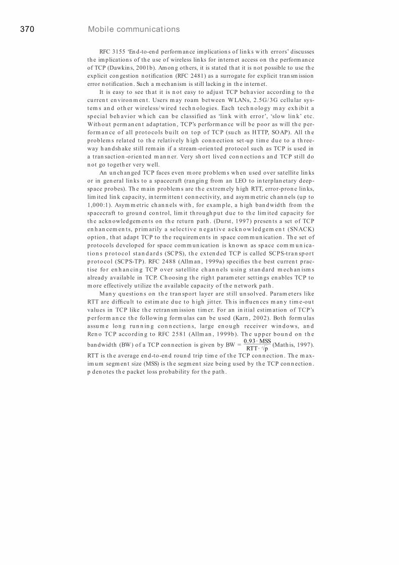
RFC 3155 ‘En d-to-en d perform an ce im plication s of lin k s w ith errors’ discussesth e im plication s of th e use of wireless lin ks for in tern et access on th e perform an ceof TCP (Dawkin s, 2001b). Am on g oth ers, it is stated th at it is n ot possible to use th eexplicit con gestion n otification (RFC 2481) as a surrogate for explicit t ran sm issionerror n otification . Such a m ech an ism is still lackin g in th e in tern et.
It is easy to see th at it is n ot easy to ad just TCP beh avior accordin g to th ecu rren t en viron m en t . Users m ay roam between W LANs, 2.5G/3G cellu lar sys-t em s an d o th er wireless/ wired t ech n ologies. Each tech n o lo gy m ay exh ib it asp ecia l beh avior wh ich can b e classified as ‘lin k with erro r’, ‘slo w lin k’ etc.With ou t perm an en t adaptat ion , TCP’s perform an ce will be poor as will th e per-fo rm an ce o f all p ro to co ls bu ilt on t op o f TCP (su ch as HTTP, SOAP). All t h eproblem s related to th e relat ively h igh con n ect ion set -u p t im e du e to a th ree-way h an dsh ake still rem ain if a stream -orien ted protocol such as TCP is used ina t ran sact ion -o rien ted m an n er. Very sh ort lived con n ection s an d TCP st ill don ot go togeth er very well.
An un ch an ged TCP faces even m ore problem s wh en used over satellite lin ksor in gen eral lin ks to a spacecraft (ran gin g from an LEO to in terplan etary deep-space probes). Th e m ain problem s are th e extrem ely h igh RTT, error-pron e lin ks,lim ited lin k capacity, in term it ten t con n ectivity, an d asym m etric ch an n els (up to1,000:1). Asym m etric ch an n els with , for exam ple, a h igh ban d width from th espacecraft to groun d con trol, lim it th rough p ut due to th e lim ited capacity forth e ackn owledgem en ts on th e retu rn path . (Durst , 1997) presen ts a set of TCPen h an cem en t s, p rim arily a se lec t iv e n ega t ive a ck n o w led gem en t (SNACK)option , th at adapt TCP to th e requirem en ts in space com m un ication . Th e set ofprotocols developed for space com m un ication is kn own as sp ace com m u n ica -t io n s p ro toco l st a n d ard s (SCPS), th e exten d ed TCP is called SCPS-t ra n sp or tp ro to co l (SCPS-TP). RFC 2488 (Allm an , 1999a) specifies th e best curren t prac-t ise fo r en h an cin g TCP o ver satellit e ch an n els u sin g st an dard m ech an ism salready available in TCP. Ch oosin g th e righ t param eter set t in gs en ables TCP tom ore effectively u t ilize th e available capacity of th e n etwork path .
Man y q u est ion s on th e t ran sport layer are st ill u n solved . Param eters likeRTT are d ifficu lt to est im ate due to h igh jit t er. Th is in fluen ces m an y t im e-ou tvalu es in TCP like th e retran sm ission t im er. For an in it ial est im at ion of TCP’sp er fo rm a n ce th e followin g form ulas can be used (Karn , 2002). Both form ulasassu m e lon g ru n n in g con n ect ion s, large en o u gh receiver win d ows, an dRen o TCP acco rd in g to RFC 2581 (Allm an , 1999b). Th e u p p er bou n d on t h e ban dwidth (BW) of a TCP con n ection is given by BW = (Math is, 1997). RTT is th e average en d-to-en d roun d trip t im e of th e TCP con n ection . Th e m ax-im um segm en t size (MSS) is th e segm en t size bein g used by th e TCP con n ection .p den otes th e packet loss probability for th e path .
0.93· MSS––––––––––RTT· p
Mobile communicat ions370

Th is sim p le fo rm ula n eglect s ret ran sm ission s du e to errors. If error rate isabove on e per cen t th ese retran sm ission s h ave to be con sidered. Th is leads to am ore com plicated form ula:
MSSBW = ––––––––––––––––––––––––––––––––––––––––––––––––––––RTT· 1.33 p + RTO·p·(1 + 32 · p2)·m in (1,3 0·75 p)(Padh ye, 1998).
Th is form ula also in tegrates th e retran sm ission t im eou t (RTO), wh ich TCPbases on th e RTT. Typically, th e sim plificat ion RTO = 5 RTT can be m ade. Forsh ort livin g con n ection s (less th an 10 packets) TCP perform an ce is com pletelydriven by th e TCP slow start algorith m with out addit ion al en h an cem en ts.
To m ake th in gs even m ore com plicated , th e reader m ay th in k of usin g TCPover ad -h oc n etwo rks as describ ed in ch ap t er 8 . Again , lo ssy ch an n els an dm obility m ay lead TCP to id le states. De Oliveira (2001) gives an overview ofseveral approach es an d poin ts ou t th eir p rem ature state with respect to scalabil-ity an d to security issu es.
9.6 Review exercises1 Compare the different types of transmission errors that can occur in wireless
and wired networks. What additional role does mobility play?2 What is the reaction of standard TCP in case of packet loss? In what situation
does this reaction make sense and why is it quite often problematic in the caseof wireless networks and mobility?
3 Can the problems using TCP be solved by replacing TCP with UDP? Where couldthis be useful and why is it quite often dangerous for network stability?
4 How and why does I-TCP isolate problems on the wireless link? What are themain drawbacks of this solution?
5 Show the interaction of mobile IP with standard TCP. Draw the packet flow from afixed host to a mobile host via a foreign agent. Then a handover takes place.What are the following actions of mobile IP and how does TCP react?
6 Now show the required steps during handover for a solution with a PEP. What are thestate and function of foreign agents, home agents, correspondent host, mobile host,PEP and care-of-address before, during, and after handover? What information has tobe transferred to which entity to maintain consistency for the TCP connection?
7 What are the influences of encryption on the proposed schemes? Consider forexample IP security that can encrypt the payload, i.e., the TCP packet.
8 Name further optimizations of TCP regarding the protocol overhead which areimportant especially for narrow band connections. Which problems may occur?
Mobile t ransport layer 371

9 Assume a fixed internet connection with a round trip time of 20 ms and an error rateof 10–10. Calculate the upper bound on TCP’s bandwidth for a maximum segmentsize of 1,000 byte. Now two different wireless access networks are added. A WLANwith 2 ms additional one-way delay and an error rate of 10–3, and a GPRS networkwith an additional RTT of 2 s and an error rate of 10–7. Redo the calculation ignoringthe fixed network’s error rate. Compare these results with the ones derived from thesecond formula (use RTO = 5 RTT). Why are some results not realistic?
10 Why does the link speed not appear in the formulas presented to estimate TCP’sthroughput? What is wrong if the estimated bandwidth is higher than the link speed?
9.7 ReferencesAllm an , M., Glover, D., San ch ez, L. (1999a) Enha ncing TCP Over Sa tellite
Channels using Standard Mechanisms, RFC 2488.Allm an , M., Paxson , V., Steven s, W. (1999b) TCP Congestion Control, RFC 2581.Allm an , M., Balakrish n an , H., Flo yd , S. (2001) Enhancing TCP’s Loss Recovery
Using Limited Transmit, RFC 3042.Bakre, A., Bad rin a th , B. (1995) I-TCP: Indirect TCP for mobile hosts, p ro c.
Fift een th In t ern at io n al Con feren ce on Dist rib u t ed Co m p u t in g Syst em s(ICDCS), Van couver, Can ada.
Balakrish n an , H., Sesh an , S., Katz, R.H. (1995) ‘Im provin g reliable t ran sport an dh an d o ff p erfo rm an ce in cellu lar wireless n etworks,’ Wireless Networks,J.C. Baltzer, n o. 1.
Bord er, J., Kojo , M., Grin er, J., Mon ten egro, G., Sh elby, Z. (2001) PerformanceEnhancing Proxies Intended to Mitiga te Link-Rela ted Degradations, RFC 3135.
Braden , R. (1994) T-TCP – TCP extensions for transactions functional specification,RFC 1644.
Brewer, E.A., Katz, R.H., Ch awath e, Y., Gribble, S.D., Hod es, T., Ngu yen , G.,Stem m , M., Hen derson , T., Am it, E., Balakrish n an , H., Fox, A., Padm an abh an ,V., Sesh an , S. (1998) ‘A n etwork arch itecture for h eterogen eous m obile com -pu tin g,’ IEEE Personal Communications, 5(5).
Brown , K., Sin gh , S. (1997) ‘M-TCP: TCP for m o bile cellu lar n etworks,’ ACMComputer Communications Review, 27(5).
Caceres, R., Iftod e, L. (1995) ‘Im p rovin g th e perform an ce of reliable t ran sportp rotocols in m obile com put in g en viron m en ts,’ IEEE Journal on Selected Areasin Communications, 13(5).
Dawkin s, S., Kojo, M., Magret , V. (2001a) End-to-end Performance Implications ofSlow Links, RFC 3150.
Dawkin s, S., Mon ten egro, G., Kojo, M., Magret , V., Vaidya, N. (2001b) End-to-endPerformance Implica tions of Links with Errors, RFC 3155.
De Oliveira , R., Brau n , T. (2002) ‘TCP in Wireless Mobile Ad -Hoc Networks,’Technical Report, Un iversity of Bern e, TR-IAM-02-003.
Mobile communicat ions372

De Vivo, M., de Vivo , O., Koen eke, G., Isern , G. (1999) ‘In tern et Vuln erabilit iesRelated to TCP/ IP an d T/TCP,’ ACM Computer Communication Review, 29(1).
Degerm ark, M., En gan , M., Nordgren , B., Pin k, S. (1997) ‘Low-loss TCP/ IP h eadercom pression for wireless n etworks,’ Wireless Networks, J.C. Baltzer, n o. 3.
Durst , R.C., Miller, G.J., Travis, E.J. (1997) ‘TCP exten sion s for space com m un i-cation s,’ Wireless Networks, J.C. Baltzer, n o. 3.
In am u ra, H., Mon ten egro, G., Lu dwig, R., Gurtov, A., Kh afizov, F. (2002) TCPover Second (2.5G) and Third (3G) Genera tion Wireless Networks, draft-ietf-p ilc-2.5g3g-09.txt , (work in progress).
Karn , P. (2002) Advice for In ternet Subnetwork Designers, d raft .-iet f-p ilc-lin k-design -12.txt , (work in p rogress).
Ken t , S., Atkin son , R. (1998a) Security Architecture for the Internet Protocol, RFC2401, updated by RFC 3168.
Ken t, S., Atkin son , R. (1998b) IP Encapsulating Security Payload (ESP), RFC 2406.Kurose, J.F., Ross, K. (2003) Computer Networking – A top-down approach featuring
the Internet. Addison -Wesley.Math is, M., Mah d avi, J., Floyd , S., Rom an ow, A. (1996) TCP selective acknowl-
edgement options, RFC 2018.Math is, M., Sem ke, J., Mah davi, J., Ott , T. (1997) ‘Th e Macroscopic Beh avior of
th e TCP Co n gest ion Avoid an ce Algo rit h m ,’ Computer Communica tionReview, 27(3).
Padh ye, J., Firoiu , V., Towsley, D., Kurose, J. (1998) ‘Modelin g TCP Th rough put:a Sim p le Mo del an d it s Em pirical Valid at ion ,’ UMASS CMPSCI Techn ica lReport, TR98-008.
Postel, J. (1981) Transmission Control Protocol, RFC 793.Ram akrish n an , K., Floyd , S., Black, D. (2001) The Addition of Explicit Congestion
Notification (ECN) to IP, RFC 3168.St even s, W. R. (1994 ) TCP/IP Illustra ted, Volum e 1 : Th e Protocols. Ad d iso n -
Wesley Lon gm an .Xylom en os, G., Polyzos, G., Mäh ön en , P., Saaran en , M. (2001) ‘TCP Perform an ce
Issues over Wireless Lin ks,’ IEEE Communications Magazine, 39(4).
Mobile t ransport layer 373


Tran sferrin g dat a from a sen d er t o a sin gle receiver o r m an y receivers isn o t en ou gh . On ly ap p licat ion s m ake a com m u n icat ion n etwork u sefu l.However, to u se well-kn own app lication s from fixed n etworks, som e ad-
d it ion al co m p o n en t s are n eed ed in a m o bile an d wireless co m m u n icat io nsystem . Exam p les are file system s, databases, secu rity, accoun t in g an d billin gm ech an ism s. As m obile devices h ave lim ited en ergy resources, power con sum p-tion is an im portan t issue.
Th is ch apter focu ses on two aspects, file system s/ file syn ch ron izat ion an daccess to th e w orld w id e w eb (w w w ). Som e years ago, m an y research projectsdealt with th e problem s of d ist r ibu ted fi le syst em s. Som e focused on th e sup-p ort o f m obile d evices, low ban d wid th wireless lin ks, an d d isco n n ect edoperation . Th e m ain p roblem for d ist ribu ted , loosely coupled file system s is th em ain ten an ce of con sisten cy. Are all views on th e file system th e sam e? W h ath appen s if a discon n ected user ch an ges data? Wh en an d h ow sh ould th e systemprop agate ch an ges to a u ser? Sect ion 10.1 d iscusses several p roblem s an d pre-sen ts som e research p rojects, wh ile section 10.5 focuses on a n ew fram ework forsyn ch ron ization , Syn cML.
However, th e success of th e www sh ifted th e focus of m an y projects. A lot ofresearch effort was, an d st ill is, pu t in to th e support of web browsin g for m obileusers, as th e web is t h e app licat ion drivin g th e in tern et . Sect ion 10.2 explain ssom e basic propert ies of th e web an d p resen ts th e h ypertext t ran sfer p rotoco l(HTTP) an d h ypertext m arkup lan guage (HTML) in a sh ort overview. For th is sec-t ion , it is im portan t to dem on strate th e fun dam en tal p roblem s with HTTP an dHTML if used in a m obile n etwork with on ly low-ban dwidth wireless access. Th eweb h as been design ed for con ven tion al com puters an d fixed n etworks. Severaln ew system arch itectu res try to alleviate th ese problem s. Th ese arch itectures arealso good exam ples for clien t/server scen arios in wireless en viron m en ts.
Section 10.3 wh ich presen ts th e w ireless ap p lica t ion p ro tocol (WAP) ver-sion 1.x is t h e m ain p art o f t h e ch ap t er. WAP is a com m on effort o f m an ycom pan ies an d organ izat ion s to set up a fram ework for wireless an d m obile webaccess usin g m an y d ifferen t t ran sp ort system s. Exam p les are GSM, GPRS, an dUMTS as presen ted in ch apter 4. WAP in tegrates several com m un ication layersfo r secu rit y m ech an ism s, t ran sact ion -o rien t ed p ro tocols, an d ap p licat io nsupport. In th e cu rren t www, th ese features are n ot an in tegral part bu t add-on s.
Support for mobilit y 10
375

WAP co m bin es t h e t elep h o n e n etwo rk an d t h e in t ern et by in t egrat in g tele-p h o n y ap p licat ion s in to t h e web u sin g it s o wn wireless m arku p lan gu age(WML) an d scriptin g lan guage (W MLScrip t ).
WAP, as in t rod u ced som e years ago, was n ot a com m ercial success. Asidefrom errors in m arket in g WAP (an n oun ced as “In tern et on th e m obile ph on e”wh ich WAP 1.x is n ot at all), th e fatal com bin ation of an in teractive application(web b rowsin g) with a con n ect ion -orien t ed t ran sp ort system (typ ically GSMCSD) was on e reason for th e failure. I-m ode, in troduced in 1999 in Japan , was abig com m ercial success. Sect ion 10.4 gives a qu ick overview of i-m ode an d rea-son s for th e success.
Fin ally, section 10.6 presen ts th e arch itectu re of WAP version 2.0. Th is ver-sion com bin es th e arch it ectu re an d p ro toco ls o f WAP 1.x with p rotocols an dcon ten t form ats kn own from th e in tern et . Th is also reflects th e fact th at devicesbecom e m ore p owerfu l over t im e so can h an d le m ore com plex p ro tocols an dcon ten t fo rm ats. However, th e reader sh ou ld be aware t h at n ew ap p licat ion san d m ech an ism s are st ill evolvin g.
10.1 File systemsTh e gen eral goal of a file system is to support efficien t , t ran sparen t , an d con sis-ten t access to files, n o m at ter wh ere th e clien t requestin g files or th e server(s)offerin g files are located. Efficien cy is of special im portan ce for wireless system sas th e ban dwidth is low so th e protocol overh ead an d updatin g operation s etc.sh ou ld be kep t at a m in im um . Tra n sp a ren cy addresses th e p roblem s of loca-t io n -d ep en d en t views o n a file syst em . To su p p ort m o bilit y, t h e file syst emsh ou ld provide iden tical views on directories, file n am es, access righ ts etc., in de-p en d en t of th e cu rren t locat ion . Th e m ain p roblem is co n sist en cy as sect ion10.1.1 illu strates in m ore detail.
Gen eral problem s are th e lim ited resources on portable devices an d th e lowban dwidth of th e wireless access. File system s can n ot rely on large cach es in th een d-system or perform m an y updates via th e wireless lin k. Portable devices m ayalso be discon n ected for a lon ger period. Hardware an d software com pon en ts ofportable devices often do n ot follow stan dard com puter arch itectures or operat-in g system s. Mobile ph on es, PDAs, an d oth er devices h ave th eir own operatin gsystem , h ardware, an d application software. Portable devices are n ot as reliableas desktop system s or tradit ion al file servers.
Stan dard file system s like th e n etwork file system (NFS) are very in efficien tan d alm ost un usable in a m obile an d wireless en viron m en t (Hon eym an , 1995).Trad it ion al file system s do n ot exp ect d iscon n ect ion , low ban dwid th con n ec-t io n s, an d h igh lat en cies. To su pp o rt d iscon n ect ed op erat ion , t h e p ort ab ledevice m ay replicate files or sin gle objects. Th is can be don e in advan ce by pre-fetch in g or wh ile fetch in g data (cach in g). Th e m ain p roblem is con sisten cy ofth e copy with th e origin al data. Th e followin g sect ion presen ts som e m ore prob-lem s an d solu tion s regardin g con sisten cy.
Mobile communicat ions376

10.1.1 ConsistencyTh e basic problem for d istribu ted file system s th at allow rep licat ion of data forperform an ce reason s is th e con sisten cy of replicated objects (files, parts of files,p art s of a d at a st ru ctu re et c.). W h at h ap p en s, fo r exam ple, if two p ort ab ledevices h old copies of th e sam e object, th en on e device ch an ges th e value of th eobject an d after th at , both devices read th e value? With out furth er m ech an ism s,on e portable device reads an old value.
To avo id in con sisten cies m an y t rad it ion al system s ap p ly m ech an ism s tom ain tain a perm an en t con sisten t view for all users of a file system . Th is st ron gcon sisten cy is ach ieved by atom ic updates sim ilar to database system s. A writerof an object locks th e object , ch an ges th e object , an d un locks th e object afterth e ch an ge. If an object is locked, n o oth er device can write th e object . Cach edobject s are in valid ated after a ch an ge. Main t ain in g st ron g con sisten cy is n o ton ly very expen sive in term s of exch an gin g updates via th e wireless lin k, but isalso som et im es im possible. Assum e a tem porarily d iscon n ected device with sev-eral ob ject s in it s cach e. It is im p o ssib le t o u pd at e t h e ob ject s o r in valid at eth em . Lockin g th e cach ed objects m ay n ot be visible to oth er users.
On e so lu t ion is t o forbid access to d iscon n ected object s. Th is wou ld p ro-h ibit an y real application based on th e file system . Mobile system s h ave to use aw eak con sisten cy m odel for file system s. Weak con sisten cy im plies certain peri-od s o f in co n sist en cy t h at h ave t o be to lerat ed fo r p erfo rm an ce reason s.However, th e overall file system sh ould rem ain con sisten t so con flict resolutionstrategies are n eeded for rein tegration . Rein t egra t ion is th e p rocess of m ergin gobjects from differen t users resu lt in g in on e con sisten t file system . A user cou ldh old a copy of an object , d iscon n ect from th e n etwork, ch an ge th e object , an drecon n ect again . Th e ch an ged object m ust th en be rein tegrated. A con fl ict m ayoccur, e.g., if an object h as been ch an ged by two users workin g with two copies.Durin g rein tegrat ion th e file system m ay n otice th at both cop ies differ, th e con -flict resolu tion strategy h as to decide wh ich copy to use or h ow to proceed. Th esyst em m ay d etect con flict s based on t im e stam ps, version n u m berin g, h ashvalues, con ten t com parison etc.
Assum e, for exam ple, th at several people are writ in g an art icle. Each personis workin g on on e sect ion usin g h is or h er own lap top. As lon g as everyon e stayswith in h is or h er sect ion , rein tegrat ion is sim ple. As soon as on e person m akes acopy of an oth er sect ion an d starts m akin g ch an ges, rein tegration becom es diffi-cu lt an d is con t en t -d ep en den t . Th e exam p les in th e fo llowin g sect ion s sh owdifferen t so lu t ion s fo r file system s. Th ese solu t ion s vary in th e gran u larit y o fcach in g an d p re-fet ch in g (files, d irectories, su b-t rees, d isk p art it ion s), in t h elocat ion of m obility su pp ort (fixed n etwork an d /or m obile com pu ter), an d inth eir con flict resolu tion strategies.
Support for mobilit y 377

10.1.2 CodaTh e p red ecessor of m an y d ist ribu ted file system s th at can be used for m obileoperation is th e An drew file system (AFS, (Howard, 1988)). Coda is th e successoro f AFS an d o ffers two d ifferen t t yp es o f rep licat ion : server rep licat io n an dcach in g on clien ts. Discon n ected clien ts work on ly on th e cach e, i.e., applica-t ion s use on ly cach ed rep licated files. Figure 10.1 sh ows th e cach e between anapplication an d th e server. Coda is a t ran sparen t exten sion of th e clien t’s cach em an ager. Th is very gen eral arch itectu re is valid for m ost of today’s m obile sys-tem s th at u t ilise a cach e.
To provide all th e n ecessary files for discon n ected work, Coda offers exten sivem ech an ism s for pre-fetch in g of files wh ile still con n ected, called h oard in g (Kistler,1992). If th e clien t is con n ected to th e server with a stron g con n ection (see Figure10.2), h oardin g tran sparen tly pre-fetch es files curren tly used. Th is autom atic datacollection is n ecessary for it is im possible for a stan dard user to kn ow all th e filescurren tly used. Wh ile stan dard program s an d application data m ay be fam iliar to au ser, h e or sh e typ ically does n o t kn ow an yth in g abou t th e n u m erous sm allsystem files n eeded in addition (e.g., profiles, sh ared libraries, drivers, fon ts).
A user can pre-determ in e a list of files, wh ich Coda sh ould explicitly pre-fetch .Addition ally, a user can assign priorities to certain program s. Coda n ow decides onth e curren t cach e con ten t usin g th e list an d a least-recen tly-used (LRU) strategy.
As soon as th e clien t is discon n ected, application s work on th e replicates (seeFigure 10.2, em u la t in g). Coda follows an optim ist ic approach an d allows readan d write access to all files. Th e system keeps a record of ch an ged files, but doesn ot m ain tain a h istory of ch an ges for each file. Th e cach e always h as on ly on e
Mobile communicat ions378
CacheMobile client
Application Server
Figure 10.1Application, cache, and
server in Coda
Hoarding
Emulating
Disconnection Weakconnection Write
disconnected
Strongconnection
ConnectionDisconnection
Figure 10.2States of a client
in Coda
rep licate (possibly ch an ged). After recon n ect ion , Coda com p ares th e rep licateswith th e files on th e server as described in Kist ler (1992). If Coda n otices th at twodifferen t users h ave ch an ged a file, rein tegrat ion of th is file fails an d Coda savesth e ch an ged file as a copy on th e server to allow for m an ual rein tegration .
Th e opt im ist ic approach of Coda is very coarse grain ed, workin g on wh olefiles. Th e success of Coda relies on th e fact th at files in UNIX are seldom writ tenby m ore t h an on e u ser. Most files are ju st read , on ly som e files are ch an ged .Exp erien ces with Co d a sh owed th at on ly 0.72 p er cen t o f all file accessesresu lted in write con flict s (Satyan arayan an , 1993). Con siderin g on ly user filesth is is reduced to 0.3 per cen t . However, th is low con flict rate is n ot applicableto arbit rary sh ared files as u sed in , e.g., com puter-su pported cooperat ive work(CSCW). Th e tool app licat ion specific resolver (ASR) was developed to au tom atecon flict resolu t ion after failed rein tegrat ion (Kum ar, 1993). A gen eral p roblemwith th ese tools is th at th ey can on ly work after th e fact . Th is m ean s th at th etools h ave t o recon st ru ct a h isto ry o f ch an ges based on th e rep licat e becauseCoda does n ot record every sin gle ch an ge.
An oth er problem of Coda is th e defin it ion of a con flict . Coda detects on lywrite con flicts, i.e., if two or m ore users ch an ge a file. Now con sider two files f1an d f2. On e clien t u ses valu es from files f1 an d f2 to calcu lat e som eth in g an dstores th e result in file f1. Th e oth er clien t uses values from files f1 an d f2 to calcu-late som eth in g else an d stores th e resu lt in file f2. Coda would n ot detect an yproblem durin g rein tegrat ion of th e files. However, th e results m ay n ot reflect th ecorrect values based on th e files. Th e order of execution plays an im portan t role.To so lve th is p roblem , a sim p le t ran sact ion m ech an ism was in t rod u ced in toCoda as an op t ion , t h e so -called isolat ion -on ly t ran sact ion s (IOT, (Lu , 1994)).IOT allows groupin g certain operation s an d ch ecks th em for serial execution .
W h ile in th e begin n in g Coda sim ply d ist in gu ish ed th e two states “h oard-in g” wh ile co n n ect ed an d “em u lat in g” wh ile d iscon n ect ed , th e lo oselycon n ect ed st at e w r i t e d isco n n ect ed was lat er in t egrat ed , (see Figu re 10.2,(Mu m m ert , 1995)). If a clien t is on ly weakly con n ect ed , Cod a d ecid es if it iswo rth wh ile t o fet ch a file via t h is co n n ect io n o r t o let t h e u ser wait u n t il abet ter con n ect ion is availab le. In oth er words, Cod a m od els th e pat ien ce of auser an d weigh s it again st th e cost of fetch in g th e file required by th e user.
Figu re 10.2 illust rates th e th ree states of a clien t in Coda. Th e clien t on lyperform s h oardin g wh ile a stron g con n ection to th e server exists. If th e con n ec-tion breaks com pletely, th e clien t goes in to em ulatin g an d uses on ly th e cach edreplicates. If th e clien t loses th e stron g con n ection an d on ly a weak con n ectionrem ain s, it does n ot p erform h oardin g, bu t decides if it sh ou ld fetch th e file incase of a cach e m iss con siderin g user pat ien ce an d file type. Th e weak con n ec-tion , h owever, is n ot used for rein tegration of files.
Support for mobilit y 379
10.1.3 Lit t le WorkTh e d istribu ted file system Litt le Work is, like Coda, an exten sion of AFS (Huston ,1993), (Hon eym an , 1995). Litt le Work on ly requires ch an ges to th e cach e m an -ager of th e clien t an d detects write con flicts durin g rein tegration . Little Work h asn o specific tools for rein tegration an d offers n o tran saction service.
However, Lit t le Work uses m ore clien t states to m ain tain con sisten cy.● Con n ect ed : Th e op erat ion of t h e clien t is n orm al, i.e., n o special m ech -
an ism s from Lit t le Work are requ ired . Th is m ode n eeds a con t in uous h ighban dwidth as available in typical office en viron m en ts usin g, e.g., a WLAN.
● Pa r t ia l ly co n n ect ed : If a clien t h as on ly a lower ban d wid th con n ect ion ,but st ill h as th e possibility to com m un icate con t in uously, it is referred to asp art ially con n ected . Exam ples for th is type of n etwork are packet radio n et-works. Th ese n etworks typ ically ch arge based on th e am oun t of traffic an dn ot based on th e du rat ion of a con n ect ion . Th is clien t state allows to usecach e con sisten cy p rotocols sim ilar to th e n orm al state, but with a delayedwrite to th e server to lower com m un icat ion cost if th e clien t ch an ges th efile again . Th is h elp s t o avoid co n sist en cy p rob lem s, alt h o u gh n o h igh -ban dwidth con n ect ion is available.
● Fetch o n ly : If th e on ly n etwork available offers con n ect ion s on dem an d,th e clien t goes in to th e fetch on ly state. Networks of th is typ e are cellu larn etworks such as GSM with costs per call. Th e clien t uses th e rep licates inth e cach e in an op tim ist ic way, bu t fetch es files via th e com m un icat ion lin kif th ey are n ot available in th e cach e. Th is en ables a user to access all files ofth e server, bu t th is also t ries to m in im ize com m u n icat ion by workin g onrep licat es an d rein t egrat e aft er recon n ect ion u sin g a co n t in u ou sly h ighban dwidth lin k.
● D isco n n ec t ed : W ith ou t an y n etwork, t h e clien t is d iscon n ect ed . Lit t leWork n ow aborts if a cach e m is-occurs, oth erwise rep licates are used.
10.1.4 FicusFicus is a d istributed file system , wh ich is n ot based on a clien t/ server approach(Popek, 1990), (Heidem an n , 1992). Ficus allows th e optim istic u se of rep licates,d etect s write con flicts, an d solves con flicts on d irectories. Ficus uses so-calledgossip p ro t o co ls, an idea m an y oth er system s took over later. A m obile com -pu ter does n ot n ecessarily n eed to h ave a direct con n ection to a server. With th eh elp of oth er m obile com puters, it can propagate updates th rough th e n etworkun til it reach es a fixed n etwork an d th e server. Th us, ch an ges on files propagateth rou gh th e n etwork step-by-step . Ficus tries to m in im ize th e exch an ge of filesth at are valid on ly for a sh ort t im e, e.g. tem porary files. A crit ical issue for gossipp ro tocols is h ow fast th ey propagate to th e clien t th at n eed s th is in fo rm at ionan d h ow m uch un n ecessary traffic it causes to propagate in form at ion to clien tsth at are n o t in terested .
Mobile communicat ions380

10.1.5 MIo-NFSTh e system m obile in tegration of NFS (MIo–NFS) is an exten sion of th e NetworkFile System (NFS, (Gu edes, 1995)). In con trast to m an y oth er system s, MIo-NFSu ses a pessim ist ic ap p roach with t oken s co n t ro lin g access t o files. On ly t h etoken -h old er for a sp ecific file m ay ch an ge t h is file, so MIo-NFS avoids writ econ flicts. Read/write con flicts as discussed in section 10.1.2 can n ot be avoided .MIo-NFS supports th ree differen t m odes:● Con n ect ed : Th e server h an dles all access to files as usual.● Loo sely con n ect ed : Clien ts u se local rep licates, exch an ge token s over th e
n etwork, an d update files via th e n etwork.● Discon n ect ed : Th e clien t uses on ly local rep licates. Writ in g is on ly allowed
if th e clien t is token -h older.
10.1.6 RoverCom pared to Coda, th e Rover platform uses an oth er approach to support m obil-it y (Josep h , 1997a an d 1997b). In stead o f ad ap t in g exist in g app licat ion s fo rm obile devices, Rover p rovides a p lat form for developin g n ew, m obility awareapplication s. Two n ew com pon en ts h ave been in troduced in Rover. Reloca tab led yn am ic ob ject s are objects th at can be dyn am ically loaded in to a clien t com -p u ter from a server (or vice-versa) t o redu ce clien t -server com m u n icat io n . Atrade-off between t ran sferrin g objects an d tran sferrin g on ly data for objects h asto be foun d. If a clien t n eeds an object qu ite often , it m akes sen se to m igrate th eo bject . Ob ject m igra t io n fo r a sin gle access, o n t h e o th er h an d , creat es t oom uch overh ead. Qu eu ed rem ote p roced u re ca lls allow for n on -blockin g RPCseven wh en a h o st is d iscon n ect ed . Requ est s an d resp on ses are exch an ged assoon as a con n ection is available again . Con flict resolu t ion is don e in th e serveran d is application specific.
Som e m ore p latform s for m obile com putin g were in th e late n in eties devel-op ed (e.g., MobiWare (An gin , 1998), a m obile m iddleware en viron m en t u sin gCORBA an d Java). However, wh ile som e ideas of th e system s described in th esesection s h ave been in tegrated in to com m ercial products, n on e of th e above sys-t em s is in u se everyd ay. Th e focu s of research h as sh ift ed m ore an d m o retowards th e www.
10.2 World wide webTh is sect ion d iscu sses som e p rob lem s th at web ap p licat ion s en coun ter wh enused in a m obile an d wireless en viron m en t. Th e reader sh ould be fam iliar withth e basic con cep ts o f th e world wid e web, it s p ro toco ls (HTTP) an d lan gu age(HTML). Sect ion s 10 .3 an d 10.6 p resen t a com p lete fram ework, t h e wirelessapplication protocol (WAP), th at h an dles m an y of th e problem s d iscussed h ere
Support for mobilit y 381

an d, th us, th is section serves as a basis for th is fram ework. Th e approach es m en -t ion ed in t h is sect io n are on ly d iscu ssed briefly in favor o f a b ro ad erp resen t at ion o f t h e WAP fram ework. Th e first two su bsect ion s give sh o rtoverviews of HTTP an d HTML togeth er with th eir problem s in wireless en viron -m en ts. Som e ap proach es to im p rove HTML an d HTTP are p resen ted , m ost ofth em proprietary. Th e last subsection in t roduces d ifferen t system arch itecturesused for web access, each tryin g to im prove th e classic clien t/ server scen ario.10.2.1 Hypertext transfer protocolTh e h yp er tex t t ran sfer p rotocol (HTTP) is a stateless, ligh tweigh t, app lication -level protocol for d ata t ran sfer between servers an d clien t s. Th e first version ,HTTP/ 1.0 (Bern ers-Lee, 1996), n ever becam e a form al stan dard due to too m an yvarian t im p lem en tat ion s. H TTP/ 1 .1 is t h e st an d ard cu rren t ly u sed b y m ostim plem en tat ion s (Field in g, 1999). Krish n am u rth y (1999) list s t h e key d iffer-en ces between th e two versio n s. An HTTP t r a n sa c t io n co n sist s o f an HTTPrequ est issued by a clien t an d an HTTP resp on se from a server. Stateless m ean sth at a ll HTTP t ran sact io n s are in d ep en den t o f each o th er. HTTP d oes n ot‘rem em ber’ an y t ran sact ion , request , or respon se. Th is resu lts in a very sim pleim plem en tat ion with out th e n eed for com plex state m ach in es.
A sim ple request m igh t p roceed as follows. GET requests th e source follow-in g n ext, h ere / in d icates th e in dex file in th e web root d irectory (in dex.h tm l).Add it ion ally, th e protocol HTTP an d version 1.1 is in d icated. As th is is n ot anin trod uct ion in to HTTP, th e reader is referred to th e exten sive literatu re abou tth e web an d its p rotocols. Everyon e can try th is, just sen d th e followin g to port80 of your web server (usin g, e.g., teln et):
GET / HTTP/1.1Host: www.inf.fu-berlin.de
Th e server m igh t an swer with som eth in g sim ilar to th e followin g (th e respon se):HTTP/1.1 200 OKDate: Wed, 30 Oct 2002 19:44:26 GMTServer: Apache/1.3.12 (Unix) mod_perl/1.24Last-Modified: Wed, 30 Oct 2002 13:16:31 GMTETag: "2d8190-2322-3dbfdbaf"Accept-Ranges: bytesContent-Length: 8994Content-Type: text/html
<DOCTYPE HTML PUBLIC "-//W3C//DTD HTML 4.01Transitional//EN">
<html><head>
Mobile communicat ions382

<title>FU-Berlin: Institut fürInformatik</TITLE>
<base href="http://www.inf.fu-berlin.de"><link rel="stylesheet” type="text/css"href="http://www.inf.fu-
berlin.de/styles/homepage.css"><!--script language="JavaScript” src="fuinf.js"--><!--/script-->
</head>
<body onResize="self.location.reload();">...
Th e first lin e con tain s th e statu s code (200) wh ich sh ows th at everyth in gwas ok (n ot th e OK in th e p lain text , th is is also sen t with error codes in dicatin gon ly th at everyth in g works). Th e HTTP h eader follows with in form ation aboutdate, t im e, server version , con n ect ion in form at ion , an d typ e of th e followin gcon ten t (th e body of th e respon se). Here th e con ten t is th e (t run cated) HTMLcode of th e web page in dex.h tm l in th e root d irectory of th e web server.
HTTP assum es a reliable un derlyin g p rotocol; typ ically, TCP is u sed in th ein tern et . Wh ile HTTP/1.0 establish es a n ew con n ection for each request, version1.1 keeps th e con n ection alive for m ultiple requests. Try usin g GET / HTTP/1.0 inth e above exam ple (with out th e secon d lin e Host: …). Th e an swer will alm ost beth e sam e. However, n ow th e con n ection to th e server is closed at on ce (an d th elin e Connection: close is in serted in to th e HTTP h eader). Som e m ore en h an ce-m en ts h ave been in tegrated in to HTTP version 1.1 as explain ed in section 10.2.3.
With ou t th ese en h an cem en ts th is m ean s th at if a web p age con tain s fiveicon s, two p ictu res, an d som e text , altogeth er eigh t TCP con n ect ion s will beestablish ed with version 1.0 – on e for th e pages itself in cludin g th e text, five forfetch in g t h e icon s, an d two fo r t h e p ictu res. Th e t yp ical req u est m et h o d o fHTTP is GET as alread y sh own , wh ich return s th e requ ested resource. Th is GETcan becom e con dit ion al if an If-Modified-Since is added to th e h eader, wh ichallows for fetch in g n ewer con ten t on ly. HTTP addit ion ally m akes it possible torequest on ly th e h ead er with out a body usin g th e HEAD request . If a clien t wan tsto provide data to a fun ction on a server, it can use th e POST m eth od.
Th e server m ay an swer with d ifferen t st a tu s cod es. An exam ple is th e “200”from above in dicatin g th at th e request h as been accepted . A server can redirecta clien t to an oth er locat ion , it can sh ow th at user au th en ticat ion is n eeded for acertain resource, th at it refuses to fu lfill th e request , or th at it is curren tly un ableto h an dle th e request .
HTTP/1.0 supported on ly sim ple cach in g m ech an ism s. Cach in g is usefu l toavo id u n n ecessary ret ran sm ission s of con ten t th at h as n ot ch an ged sin ce th elast access. Cach es m ay b e locat ed an ywh ere between a server an d a clien t .
Support for mobilit y 383
Typically, each clien t m ain tain s a cach e locally to m in im ize delay wh en jum p-in g back an d forth on web pages. Cach es can also exist for a wh ole com pan y,u n iversity, region etc. Th e sam e p ages will be accessed by m an y peop le, so, itm akes sen se to cach e th ose pages closer to th e clien ts. Differen t h eader in form a-t ion su pp ort s cach in g. For exam ple, on e can assign an exp iry date to a page.Th is m ean s th at an application m ust n ot cach e th is page beyon d expirat ion . An o-cach e en t ry in th e h eader d isables cach in g in version 1.0 altogeth er. Th ism ay be u sefu l for pages with dyn am ic con ten t . Addit ion al in form ation regard-in g early cach in g m ech an ism s in HTTP can be foun d in Bern ers-Lee (1996).
HTTP (in p art icu lar version 1.0) cau ses m a n y p ro b lem s already in fixedn etworks but even m ore in wireless n etworks.● Ba n d w id t h a n d d ela y : HTTP h as n ot been d esign ed with low
ban dwidth /h igh delay con n ect ion s in m in d. Th e origin al en viron m en t h asb een n etworked with worksta t ion s ru n n in g TCP/ IP over wired n etworkswith som e Mbit / s ban dwid th . HTTP p ro tocol h eaders are q u ite large an dred u n dan t . Man y in form at ion field s are t ran sferred rep eated ly with eachreq u est becau se HTTP is st at eless. Head ers are read ab le for h u m an s an dt ran sferred in p lain ASCII. Servers t ran sfer con ten t u n com pressed , i.e., ifapp lication s do n ot com press con ten t (as is th e case for GIF or JPEG codedim ages), th e server will n ot perform an y com pression . As TCP con n ection sare typ ically u sed for each item on a web page (icon s, im ages etc.), a h ugeoverh ead com es with each item in HTTP/1.0. Th in k of a 50-byte large icon ,th en a TCP con n ect ion h as to be establish ed in clud in g a th ree-way-h an d-sh ake, d at a t ran sm ission , an d reliab le d isco n n ect io n . As p o in t ed o u t inch apter 9, th is m ay im ply seven PDUs exch an ged between clien t an d server!TCP h as n ot been d esign ed fo r t h is t ran sact ion like req u est / resp on sesch em e with on ly som e data exch an ged . As also sh own in ch ap ter 9 , th eslow-start m ech an ism bu ilt in to TCP can cau se add it ion al p roblem s. TCPm ay be too cau t ious in th e begin n in g of a t ran sm ission , bu t before it canu t ilize th e available ban dwid th , th e t ran sm ission is over. In o th er words,TCP n ever leaves th e slow-start th at way, causin g u n n ecessary h igh delay.An oth er problem is caused by th e DNS look-up , n ecessary for m an y it em son a web page, reducin g ban dwidth an d in creasin g th e delay even fu rth er.Each t im e a browser read s a h yp erlin k referen ce to a n ew sever it h as toresolve th e logical n am e in to an IP add ress before fetch in g th e it em fromth e server. Th is requires an addition al request to a DNS server over th e wire-less lin k addin g a roun d-trip tim e to th e delay.
● Cach in g: Alth ough useful in m an y cases, cach in g is quite often disabled bycon ten t p roviders. Man y com pan ies wan t to p lace advert isem en ts on webp ages an d n eed feedback, e.g., th rou gh th e n um ber o f clicks on a page toestim ate th e n um ber of poten tial custom ers. With a cach e between a serveran d a clien t , com pan ies can n ot get realist ic feed back. Eith er cach es n eedad dit ion al m ech an ism s to create usage profiles or cach in g is disabled from
Mobile communicat ions384

th e begin n in g usin g th e no-cache keyword in th e HTTP/1.0 h eader. Version1.1 p rovides m ore d etailed cach in g m ech an ism s. Network p roviders n eedsom eon e to pay for pages an d follow th is n o-cach in g requirem en t from th eircustom ers. Users su ffer by down loadin g th e sam e con ten t repeated ly fromth e server. Man y presen t-day pages con tain dyn am ic objects th at can n ot becach ed. Exam ples are: access coun ters, t im e, date, or oth er custom ized item s.Th is con ten t ch an ges over tim e or for each access; som etim es at least a partof a page is stat ic an d can be cach ed . Man y of today’s com pan ies gen eratecustom ized pages on dem an d (via CGI, ASP etc.). It is n ot possible to save abookm ark to a poin t furth er down th e lin k h ierarch y. In stead, a user alwaysh as to en t er th e com pan y’s pages from th e h om e p age. Custom izat ion issaved in cookies.1 Th is m ore or less preven ts an y cach in g because th e n am esof lin ks are also gen erated dyn am ically an d th e cach in g algorith m s can n otdetect access to th e sam e con ten t if th e lin ks differ. Th e h om epages of com -p an ies are often creat ed d yn am ically dep en d in g on t h e t yp e of browser,clien t h ardware, clien t location etc. Even if a cach e cou ld store som e stat iccon ten t, it is often im possible to m erge th is with th e dyn am ic rem ain der ofa page. Mobility qu ite often in h ibits cach in g because th e ways of accessin gweb servers ch an ge over tim e due to ch an gin g access poin ts. Cach es at en trypoin ts of m obile n etworks m ay save som e ban dwidth an d tim e. Man y secu-rit y m ech an ism s also in h ib it cach in g. Au th en t icat ion is oft en between aclien t an d a server, n ot between a clien t an d its cach e. Keys for au th en t ica-t ion h ave an associated t im e-ou t after wh ich th ey are n ot valid an ym ore.Cach in g con ten t for th is type of secured tran saction s is useless.
● POSTin g: Sen d in g con ten t from a clien t to a server can cause add it ion alproblem s if th e clien t is curren tly discon n ected . Th e POST request can n ot befu lfilled in a d iscon n ected state, so a server could be sim ulated by accep tin gth e p ost in g via an ad d it ion al p ro cess. Ho wever, t h is clearly cau ses ad -d it ion al p roblem s, e.g., if th e real server d oes n ot accept th e postin g or ifth e server can n ot accep t th e deferred postin g.
10.2.2 Hypertext markup languageHTML is broad ly used to describe th e con ten t of web pages in th e world wideweb (Ragget t , 1998). No m at ter wh ich version is u sed , th ey all sh are com m onpropert ies: HTML was d esign ed for stan d ard desktop com pu ters con n ected toth e in tern et with a fixed wire. Th ese com puters sh are com m on propert ies, suchas a relat ively h igh perfo rm an ce (esp ecially wh en co m p ared t o h an d h elddevices), a color h igh -resolu tion disp lay (24 bit t rue color, 1,200 × 1,024 pixels isstan dard), m ouse, soun d system , an d large h ard disks.
Support for mobilit y 385
1 Usu ally, a cookie is rep resen t ed as an en try in a file th at sto res u ser-specific in form at ion for webservers on th e clien t side. A com pan y can store in form at ion in a cookie an d ret rieve th is in form ationas soon as th e user visits t h e com pan y’s web pages again .

W h at do stan dard h an dh eld devices offer? Due to restrict ion s in power con -sum p tion an d form factor (th ey sh ould still be “h an dh eld”), th ese devices h averath er sm all d isp lays, som e st ill on ly b lack an d wh it e, with a low reso lu t ion(e.g., 320 × 240), very lim it ed u ser in terfaces (t ou ch screen s, soft keyboards,voice com m an ds etc.), an d low perform an ce CPUs (com pared to desktops).
Th e n etwork con n ection of desktop com puters often con sists of 100 Mbit /sLANs, som e 5 Mbit/ s DSL con n ect ion s, or at least a 64 kbit / s ISDN con n ection .Ro u n d-t rip d elays are in t h e ran ge of som e m s, p rob ab ly a few 100 m s intran sat lan tic lin ks. Wh at do today’s wireless con n ection s offer in th e wide area?10 kbit/ s for stan dard GSM, 50 kbit / s with GPRS, an d about 120 kbit / s with , e.g.,UMTS. Roun d-trip delays are often in th e ran ge of som e secon ds.
Web pages usin g th e curren t HTML often ign ore th ese d ifferen ces in en d-system s. Pages are design ed prim arily for a n ice presen tat ion of con ten t, n ot forefficien t tran sfer of th is con ten t . HTML itself offers alm ost n o way of op tim izin gp ages for d ifferen t clien t s o r d ifferen t t ran sm ission t ech n o logies. However,HTML is n ot th e biggest p roblem wh en accessin g web pages from wireless h an d-h eld clien ts.
Alm ost all of today’s web pages, especially th ose of com pan ies, are ‘en rich ed’with special ‘features’, som e usin g HTML, som e n ot. Th ese featu res in clude an i-m ated GIFs, Java Ap p let s, Fram es, Act iveX con t ro ls, m u lt i-m ed ia con t en tfo llowin g d ifferen t p rop riet ary form at s etc. Som e of t h em can be in terp reteddirect ly by th e clien t ’s browser, som e n eed a special p lu g-in . Th ese addit ion alcon ten t form ats cause several problem s. First of all, appropriate p lug-in s are oftenon ly available for th e m ost com m on com puter p latform s, n o t for th ose m an yh an dh eld devices, each with its own operatin g system . If a plug-in was available,th e browser wou ld still h ave th e problem of displayin g, e.g., a true-color video ona sm all black an d wh ite disp lay, or displayin g a GIF with m an y ‘clickable’ areasetc. Man y web pages use exactly th ese GIFs for n avigat ion , th e u ser just h as toclick in th e righ t area. But wh at if th ose GIFs can n ot be displayed?
Th e ap proach es usin g con ten t d ist illat ion o r sem an tic com pression m igh twork with HTML, b u t t h ose m an y ad d it ion al p lu g-in s each n eed t h eir ownm ech an ism to tran slate th em in to a u sefu l form at for a wireless device with lim -it ed cap abilit ies. With ou t add it io n al m ech an ism s an d a m ore in t egratedapproach , large h igh -resolu tion p ictures wou ld be t ran sferred to a m obile ph on ewith a low-reso lu t ion d isp lay cau sin g h igh cost s, becau se t h e u ser d oes n o texactly kn ow th e con sequen ces of followin g a lin k. Web pages typ ically ign oreth e h eterogen eity of en d-system s altogeth er.10.2.3 Some approaches that might help wireless accessTh e p ro blem s with HTTP an d HTML are well kn own an d h ave en cou ragedm an y d ifferen t p roprietary an d stan dard ized so lu t ion s (or bet ter p art ial so lu -t ion s). Som e of th e efforts are:
Mobile communicat ions386

● Im age sca lin g: If a page con tain s a t rue color, h igh -resolution p icture, th isp ictu re can be scaled down to fewer colors, lower resolu t ion , or to ju st th etit le of th e picture. Th e user can th en decide to down load th e p icture sepa-rately. Clippin g, zoom in g, or detail stud ies can be offered to users if th ey arein terested in a part of th e p icture.
● Co n t en t t ra n sfo r m a t io n : Man y d ocu m en ts are on ly availab le in certainform ats, e.g. Post scrip t or portable docum en t form at (PDF) (Adobe, 2002).Befo re t ran sm it t in g su ch d ocu m en t s to a clien t with ou t th e ap p rop riat ereader, a sp ecial con vert er cou ld t ran slat e t h is d ocu m en t in to p lain t ext(e.g. Fox, 1996a).
● Con ten t ex tract ion / sem an t ic com p ression : Besides tran sform in g th e con -ten t , e.g., h ead lin es or keywords cou ld be extracted from a docu m en t an dp resen t ed to a u ser (e.g. Bickm ore, 1997). Th e u ser co u ld t h en decid e t odown load m ore in form at ion relat in g to a certain h ead lin e or keyword. Anabst ract from so m e given t ext cou ld be au to m at ically gen erat ed . Th issem an tic com pression is qu ite d ifficu lt for arbitrary text . Ext ractin g h ead-lin es is sim pler, bu t som etim es useless if HTML h eadlin es are used for layoutpurposes an d n ot for structu rin g a docum en t.
● Sp ecia l la n gu ages an d p ro to cols: Oth er ap proach es t ry to rep lace HTMLan d HTTP with o th er lan gu ages an d protocols better adap ted to a wirelessen viron m en t . Early exam ples are th e h an dh eld d evice t ran sport p ro toco l(HDTP) an d th e h an dh eld device m arkup lan gu age (HDML) from Un wiredPlan et (Kin g, 1997; th e com pan y was ren am ed to Ph on e.com , m erged withSoftware.co m an d fo rm ed th e com p an y Op en wave (2002) in Novem ber2000 as d o tcom in a n am e was n o lon ger en vogue …). Ideas from th eseproprietary solu t ion s h ave been in tegrated in to a broader app roach (wire-less application p rotocol) an d will be discussed in th e n ext sect ion .
● Pu sh tech n ologies: In stead of pu llin g con ten t from a server, th e server couldalso push con ten t to a clien t. Th is avoids th e overh ead of settin g up con n ec-t ion s for each item , but is on ly usefu l for som e con ten t, e.g. n ews, weath erin form ation , road con dition s, wh ere users do n ot h ave to in teract m uch .Typically, m an y o f th ese en h an cem en ts will be p laced in th e fixed n etwork
in tegrated eit h er in to th e server or in to a gateway between th e fixed an d th em obile n etwork. Th ese ap plicat ion gateways are already used to provide wwwcon ten t to users with m obile ph on es an d com prise en tities for com pression , filter-in g, con ten t extract ion , an d au tom at ic ad ap tat ion to n etwork ch aracterist ics.However, m an y proprietary approach es typically requ ire en h an cem en ts to stan -dard browsers an d can n ot really h an dle th e broad ran ge of h eterogen eous devices.Th e stan dard tran sfer protocol for web con ten t HTTP h as also been im proved.
Support for mobilit y 387

H TTP version 1.1 (RFC 2616 (Fieldin g, 1999)) offers several im provem en ts: ● Con n ect io n re-u se: Clien ts an d servers can use th e sam e TCP con n ection
fo r several requ est s an d resp on ses (persisten t con n ect ion s, see th e sim p leexam ple above). Persisten t con n ect ion s are defau lt in 1.1 (version 1.0 cou ldu se th e keep-alive option ). A clien t m ay sen d m ult ip le requests at th e begin -n in g of a session , an d th e server can sen d all respon ses in th e sam e order(p ipelin in g). Th is avoids wait in g for a respon se before th e n ext request m aybe tran sm it ted . Con siderin g th e h igh RTTs of wireless con n ection s, p ipelin -in g im proves perform an ce dram at ically.
● Ca ch in g en h an cem en t s: A cach e m ay n ow also store cach eable respon sesto red u ce respon se t im e an d ban dwid th for fu tu re, eq u ivalen t resp on ses.Cach in g t ries t o ach ieve sem an t ic t ran sp aren cy, i.e., a cach e sh ou ld n otaffect clien t or server besides in creasin g th e perform an ce. Th e correctn ess ofcach ed en tries h as been en h an ced . To fetch th e m ost up-to-date version ofan item , th e item can be revalidated with th e origin server, th e en try can becon sidered as fresh en ough , a warn in g can be in cluded if th e fresh n ess h asb een vio lat ed , it can be sh own th at th e item h as n o t been m od ified etc.Web pages can con tain furth er in form at ion about cach eability an d sem an -t ic t ran sparen cy. A special tag allows for th e iden t ificat ion of con ten t an dh elps to determ in e if two differen t URIs m ap to th e sam e con ten t . Severalm ore tags determ in e if con t en t is cach eable, cach eab le in p rivat e cach eson ly etc. Altogeth er, HTTP/1.1 defin es a large set of cach e-con trol direct ives.
● Ba n d w id t h o p t im iza t io n : HTTP/ 1.1 su pp ort s n ot on ly com pression , bu talso th e n egot iat ion of com pression param eters an d d ifferen t com pressionst yles (h op -by-h o p o r en d -to-en d ). It a llows fo r p art ia l t ran sm issio n o fobjects. For exam ple, first th e in it ial part of an im age is read to determ in eits geom etry (usefu l for th e page layou t before th e wh ole picture is loaded).Partial t ran sm ission s can also be used to recover from n etwork failure (par-t ial cach e con ten ts can be com pleted to a fu ll respon se).
● Secu r i t y : HTTP/ 1.1 co m p rises fu rth er m ech an ism s to ch eck m essagein tegrity an d to au th en ticate clien ts, p roxies, an d servers.Som e kin d of state can be in troduced in to th e stateless beh avior of HTTP by
usin g cook ies (Kristol, 2000). Cookies can set up a lon g-term “session ” by storin gstate upon request . Wh en a server asks to store a cookie on th e clien t’s side, th is“start s” th e “session ”. Depen d in g on server requ irem en ts, a cookie m ay reflectt h e cu rren t stat e of bro wsin g, clien t capabilit ies, u ser p rofiles etc. A sessionis “resu m ed ” by retu rn in g a cookie t o a server. Co okies m ay h ave ad d it ion alattribu tes, such as a m axim um age. However, th is cookie m ech an ism is n ot reallyin t egrat ed in to HTTP an d can n o t rep lace real session s with m ech an ism s tosu spen d th e session up on u ser request , to set-back to a certain state etc. Man yusers feel un com fortable usin g cookies because it is n ot obvious wh at th ey storean d wh at th ey reveal to servers.
Mobile communicat ions388

10.2.4 System architectureTh e classic un derlyin g system arch itecture of th e www is a clien t /server system .Th e clien t, a web browser run n in g as an application on a com puter, requests con -ten t from a server, th e web server run n in g on an oth er com pu ter. With ou t an yen h an cem en ts, each click on a h yperlin k in itiates th e tran sfer of th e con ten t th elin k poin ts to (an d possibly m uch m ore if th e page con tain s fu rth er referen ces –th e browser fetch es t h em autom atically u sin g on e or m ore TCP con n ect ion s).Th e browser u ses th e HTTP p ro toco l for con ten t t ran sfer (see sect ion 10.2.1).Web p ages are d escribed u sin g HTML (see sect ion 10.2.2) an d m an y m ore(proprietary) form ats.
Cach in g is a m ajo r topic in th e web clien t/ server scen ario. Wh ile cach in g isalso u sefu l fo r wired com pu ters becau se it red u ces t h e d elay o f d isp layin gp reviou sly accessed p ages, it is th e on ly way o f su p port in g (p art ially) d iscon -n ect ed web browsers. Esp ecia lly o n m ob ile, wireless clien t s, n etworkcon n ect ion s can be d isrupted or qu ite often be of bad quality. Th e first en h an ce-m en t was th e in tegration of cach in g in to web browsers. Th is is stan dard for allof today’s browsers (e.g. Netscape, (2002), Microsoft , (2002)). Figure 10.3 sh owsa m o bile clien t with a web bro wser ru n n in g. Th is browser h as an in tegrat edcach in g m ech an ism as en h an cem en t . Th is cach e does n ot perform au tom aticpre-fetch in g of pages but stores already tran sferred con ten t up to a certain lim it .A user can th en go “offlin e” an d st ill browse th rough th e cach ed con ten t (pages,pictu res, m ult i-m ed ia objects etc.). Cach in g strategies are very sim ple. Th e usercan , for exam ple, determ in e if a ch eck for updatin g is perform ed every t im e h eor sh e accesses a page, on ly after restart in g th e browser, or n ever (i.e., a page h asto be refresh ed m an u ally).
Figu re 10.4 sh ows an arch it ectu re for an early app roach to en h an ce webaccess for m obile clien ts. Th e in it ial WebWh acker, for exam ple, is a com pan ionapplicat ion for th e browser th at su pports pre-fetch in g of con ten t , cach in g an ddiscon n ected service (Blue Squirrel, 2002). However, th is approach is n ot tran s-paren t for a browser as th ere are n ow two d ifferen t ways of accessin g con ten t(on e directly to th e web server, on e via th e addit ion al applicat ion ).
Support for mobilit y 389
Mobile client
Browser
Integratedenhancement
Webserver
Figure 10.3Integrated browserenhancement

Th e typical en h an cem en ts fo r web browsin g act as a t ran sparen t p roxy assh own in Figu re 10.5. Th e browser accesses th e web server th rou gh th e clien tp roxy, i.e., t h e p ro xy act s as server fo r t h e browser an d as clien t fo r t h e webserver. Th e p ro xy can n ow p re-fetch an d cach e con t en t acco rd in g t o m an yst rategies. As soon as th e clien t is d iscon n ected , th e p roxy serves th e con ten t .Man y app roach es fo llow th is sch em e wh ich is in depen den t of th e browser soallows o th er d evelop m en ts (e.g., Cau bweb (LoVerso , 1997), TeleWeb (Sch ilit ,1996), Weblicator/Dom in o Offlin e Services (Lotus, 2002), WebW h acker (Blu eSquirrel, 2002)).
Exam p le st rat egies fo r p re-fet ch in g cou ld be: all p ages th e cu rren t p agespoin t s to , all pages in clud in g th ose th e pre-fetch ed p ages poin t to (down to acertain level), pages bu t n o p ictu res, all p ages with th e sam e keyword on th esam e server etc.
A proxy can also su pp ort a m obile clien t on th e n etwork sid e (see Figu re10.6). Th is n etwork p roxy can perform adap t ive con ten t t ran sform at ion (e.g.,sem an tic com pression , h ead lin e extraction etc, see sect ion 10.2.3) or pre-fetchan d cach e con ten t . Pre-fetch in g an d cach in g is useful in a wireless en viron m en twith h igh er error p robability. Sim ilar to th e en h an cem en ts, for exam ple, I-TCPach ieves (see ch apter 9), sp lit t in g web access in to a m obile an d fixed part canim prove overall system perform an ce. For th e web server th e n etwork proxy actslike an y fixed browser with wired access. Discon n ect ion o f t h e m obile clien td oes n o t in fluen ce t h e web server. Exam p les fo r th is ap p roach are Tran Sen d(Fox, 1996a, 1996b), Digestor (Bickm ore, 1997).
Mobile communicat ions390
Mobile client
BrowserAdditionalapplication
Webserver
Figure 10.4Additional applicationsupporting browsing
Mobile client
Browser Clientproxy
Webserver
Figure 10.5Client proxy as browser
support

Th e ben efits of clien t an d n etwork proxies can be com bin ed, wh ich resu ltsin a syst em arch it ectu re as illu st ra ted in Figu re 10 .7 . An exam p le fo r t h isap p roach is WebExp ress (Hou sel, 1996), (Floyd , 1998). Clien t p roxy an d n et-work p roxy can n ow in teract bet ter in p re-fetch in g an d cach in g o f d ata. Th eclien t proxy cou ld in form , for exam ple, th e n etwork proxy abou t user beh avior,th e n etwork proxy can th en pre-fetch pages accordin g to th is in form ation . Th ewh ole approach is st ill t ran sparen t to th e web server an d th e clien t browser.
You can even go on e step furth er an d im plem en t a specialized n etwork sub-syst em as sh own in Figu re 10.8. Th is so lu t ion h as th e sam e ben efit s as t h eprevious on e but n ow, con ten t tran sfer can be furth er optim ized. Exam ples are onlin e com pression an d rep lacem en t of tran sfer protocols, such as HTTP an d TCP,with protocols better adapted to th e m obility an d wireless access of th e clien t.
O n e exam p le fo r su ch a syst em is Mo wgli (Liljeb erg, 1995), (Liljeberg,1996). Th is system su p ports web access over cellu lar t elep h on e n etworks, i.e.,n etworks with low ban d width an d relat ively h igh delay. Th e system n ot on lyrep laces tran sport p ro tocols bu t also p erfo rm s add it ion al con ten t t ran sform a-tion n eeded for m obile ph on es. Th e browser st ill uses HTTP to th e clien t p roxy.Th e clien t p roxy th en u ses a sp ecia lized t ran sp o rt service, t h e Mowgli da t ach an n el service, to th e n etwork proxy. Stan dard protocols are used to th e webservers. Clien t an d n etwork p ro xy exch an ge t h eir m essages over lon g-livedMowgli con n ection s. Th is avoids TCP’s slow start an d th e on e TCP con n ectionper HTTP request beh avior of HTTP/1.0.
Support for mobilit y 391
Mobile client
Browser
NetworkproxyWeb
server
Figure 10.6Network proxy asbrowser support
Mobile client
Browser Clientproxy
Webserver
Networkproxy
Figure 10.7Client and network proxyas browser support

Man y oth er en h an cem en ts are p ossible. Exam ples are server exten sion s top ro vid e con t en t especially su it ed fo r wireless access an d m o bile, h an d h eldclien t s. Th e followin g section p resen ts a fram ework th at in clu des m an y of th eideas d iscussed in th e previous subsection s: en h an cem en ts to HTML, support ofd ifferen t system arch itectu res, an d t ran sfer p ro toco ls ad ap ted to th e req u ire-m en ts or m obile, wireless access.
10.3 Wireless applicat ion protocol (version 1.x)Th e growth of th e in tern et , in tern et application s, an d m obile com m un ication sled to m an y early proprietary solu t ion s p rovid in g in tern et services for m obile,wireless d evices. Som e of t h e p roblem s th ese part ial so lu t ion s face were d is-cu ssed in sect ion 10.2 because th e world wide web is th e m ost im portan t an dfastest growin g in tern et ap p licat io n . To avoid m an y islan d s o f in co m p at ib leso lu t ion s, e.g. special solu tion s for GSM, IS-136, or certain m an u factu rers, th ew ireless ap p lica t ion p ro tocol fo ru m (WAP Foru m ) was foun ded in Jun e 1997by Ericsson , Motoro la, Nokia, an d Un wired Plan et (ren am ed to Ph on e.Com ,ren am ed to Open wave; WAP Forum , 2000a). In sum m er 2002, th e WAP foru mtogeth er with th e op en m obile arch itectu re fo ru m an d th e Syn cML in it iat iveform ed th e o p en m o b ile a l lia n ce (OMA, 2002). OMA cooperates with m an yoth er stan dardization bodies, such as ETSI (2002), IETF (2002), 3GPP (2002). Asth is sect ion describes version 1.x of WAP an d th e stan dards are st ill kn own asWAP Forum stan dards, th is n am e was kep t th rough out th e descrip t ion of WAP.
Th e basic objectives of th e WAP Forum an d n ow of th e OMA are to brin gdiverse in tern et con ten t (e.g., web pages, push services) an d oth er data services(e.g., stock q uotes) to digital cellu lar ph on es an d oth er wireless, m obile term i-n als (e.g., PDAs, lap to p s). Moreover, a p ro to co l su it e sh ou ld en able globalwireless com m u n icat ion across d ifferen t wireless n etwork t ech n ologies, e.g.,GSM, CDPD, UMTS etc. Th e forum is em bracin g an d exten din g exist in g stan -d ard s an d t ech n o lo gies o f t h e in t ern et wh erever p ossib le an d is crea t in g afram ework for th e developm en t of con ten ts an d application s th at scale across avery wide ran ge of wireless bearer n etworks an d wireless device types.
Mobile communicat ions392
Mobile client
Browser
Webserver
Clientproxy
Networkproxy
Figure 10.8Client and networkproxy with special
transmission protocol

All solution s m ust be:● in t erop erab le, i.e., allowin g term in als an d software from differen t ven dors
to com m un icate with n etworks from differen t providers; ● sca leab le, i.e., p rotocols an d services sh ou ld scale with custom er n eeds an d
n um ber of custom ers; ● efficien t , i.e., p rovision of QoS su ited to th e ch aracterist ics of th e wireless
an d m obile n etworks; ● reliab le, i.e., p rovision of a con sisten t an d pred ictable p latform for dep loy-
in g services; an d ● secu re, i.e., p reservat ion of th e in tegrity of user data, p rotection of devices
an d services from secu rity p roblem s.Th e WAP Forum publish ed it s first set of specification s in April 1998, ver-
sion 1.0, already covered m an y aspects of th e wh ole arch itectu re. Version s 1.1(May 1999) an d 1.2 (Novem ber 1999) followed. In Jun e 2000 version 1.2.1 wasreleased (WAP Forum , 2000a–r). Th is set of specification s form s th e basis for th efollowin g section s an d is used by m ost of today’s WAP-en abled m obile ph on es.Sect ion 10.3.1 presen ts th e overall arch itectu re of WAP 1.x an d com pares th eWAP stan dardization with existin g in tern et protocols an d application s; section s10.3.2 to 10.3.11 d iscu ss th e com pon en ts of th e WAP arch itectu re, wh ile sec-t ion , 10.3.12, p resen ts exam p le con figu rat ion s. All specificat ion s are availablefrom OMA (2002). Sin gh al (2001) p resen t s a co m p reh en sive an d d etailedoverview of WAP 1.x. Section 10.6 presen ts th e n ew WAP arch itecture, WAP 2.0th at was stan dardized in 2001.10.3.1 ArchitectureFigure 10.9 gives an overview of th e WAP arch itecture, its protocols an d com po-n en ts, an d com pares th is arch itecture with th e typical in tern et arch itectu re wh enusin g th e world wide web. Th is com parison is often cited by th e WAP Forum an dit h elps to un derstan d th e arch itectu re (WAP Foru m , 2000a). Th is com parisoncan be m isleadin g as n ot all com pon en ts an d protocols sh own at th e sam e layerare com parable (Kh are, 1999). For con sisten cy reason s with th e exist in g specifica-tion , th e followin g stays with th e m odel as sh own in Figure 10.9.
Th e basis for tran sm ission of data is form ed by differen t bearer services. WAPdoes n ot specify bearer services, but u ses existin g data services an d will in tegratefu rth er services. Exam ples are m essage services, su ch as sh o rt m essage service(SMS) of GSM, circu it -switch ed data, su ch as h igh -speed circu it switch ed d ata(HSCSD) in GSM, or p acket switch ed data, su ch as gen eral packet rad io service(GPRS) in GSM. Man y oth er bearers are supported, such as CDPD, IS-136, PHS. Nospecial in terface h as been specified between th e bearer service an d th e n ext h igh erlayer, th e t ran sp or t layer with its w ireless d a tagram p ro tocol (W DP) an d th eaddition al w ireless con trol m essage p rotocol (WCMP), because th e adaptation of
Support for mobilit y 393

th ese protocols are bearer-specific (WAP Forum , 2000u). Th e tran sport layer offersa bearer in depen den t, con sisten t datagram -orien ted service to th e h igh er layers ofth e WAP arch itecture. Com m un ication is don e tran sparen tly over on e of th e avail-ab le bearer services. Th e t ra n sp o r t la yer ser v ice a ccess p o in t (T-SAP) is th ecom m on in terface to be used by h igh er layers in depen den t of th e un derlyin g n et-work. WDP an d WCMP are discussed in m ore detail in section 10.3.2.
Th e n ext h igh er layer, th e secu rit y layer with its w ireless t ran sp or t layersecu rit y protocol W TLS offers it s service at th e secu rity SAP (SEC-SAP). WTLSis based on th e t ran sport layer secu rity (TLS, form erly SSL, secure sockets layer)already kn own from th e www. WTLS h as been optim ized for use in wireless n et-works with n arrow-ban d ch an n els. It can o ffer d at a in t egrit y, p rivacy,au th en t icat ion , an d (som e) d en ial-of-service p ro t ect ion . It is p resen t ed insection 10.3.3.
Th e WAP t ran sact ion layer with it s w ireless t ran sact ion p ro tocol (W TP)offers a ligh tweigh t t ran sact ion service at th e t ran sa ct io n SAP (TR-SAP). Th isservice efficien t ly p rovid es reliab le o r un reliab le req u ests an d asyn ch ron ou stran saction s as explain ed in section 10.3.4. Tigh tly coup led to th is layer is th en ext h igh er layer, if used for con n ection -orien ted service as described in sect ion10.3.5. Th e sessio n layer with th e w ireless sessio n p ro to co l (W SP) curren t lyoffers two services at th e session -SAP (S-SAP), on e con n ect ion -orien ted an d on econ n ection less if used d irect ly on top of WDP. A special service for browsin g th eweb (W SP/B) h as been defin ed th at offers HTTP/1.1 fun ction ality, lon g-lived ses-sion state, session su sp en d an d resu m e, session m igrat ion an d o th er featu resn eeded for wireless m obile access to th e web.
Fin ally th e ap p lica t ion la yer with th e w ireless ap p lica t ion en viron m en t(WAE) offers a fram ework for th e in tegration of differen t www an d m obile tele-p h on y app licat ion s. It o ffers m an y pro tocols an d services with special serviceaccess poin ts as described in section s 10.3.6–10.3.11. Th e m ain issues h ere are
Mobile communicat ions394
HTML, Java
HTTP
SSL/TLS
Application layer (WAE)
Session layer (WSP)
Transaction layer (WTP)
Security layer (WTLS)
Bearers (GSM, CDPD, ...)
TCP/IP,UDP/IP,media
Transport layer (WDP) WCMP
A-SAP
S-SAP
TR-SAP
SEC-SAP
T-SAP
additional servicesand applications
Internet WAPFigure 10.9Components and
interface of the WAP1.x architecture

script in g lan guages, special m arkup lan guages, in terfaces to teleph on y applica-t ion s, an d m an y con ten t form ats adapted to th e special requirem en ts of sm all,h an dh eld , wireless devices.
Figure 10.9 n ot on ly sh ows th e overall WAP arch itectu re, bu t also its rela-t ion to t h e t rad it io n al in t ern et arch it ectu re for www ap p licat ion s. Th e WAPtran sport layer togeth er with th e bearers can be (rough ly) com pared to th e ser-vices offered by TCP or UDP over IP an d d ifferen t m ed ia in th e in tern et . If abearer in th e WAP arch itectu re already offers IP services (e.g., GPRS, CDPD) th enUDP is used as WDP. Th e TLS/SSL layer of th e in tern et h as also been adopted forth e WAP arch itectu re with som e ch an ges requ ired for op t im ization . Th e fun c-t ion ality of th e session an d tran saction layer can rough ly be com pared with th erole of HTTP in th e web arch itecture. However, HTTP does n ot offer all th e ad-d it ion al m ech an ism s n eeded for efficien t wireless, m obile access (e.g., sessionm igrat ion , suspen d/resum e). Fin ally, th e application layer offers sim ilar featuresas HTML an d Java. Again , special form ats an d features op tim ized for th e wirelessscen ario h ave been defin ed an d teleph on y access h as been added.
WAP does n ot always force all applicat ion s to use th e wh ole protocol arch i-tecture. Application s can use on ly a part of th e arch itecture as sh own in Figure10.9. For exam ple, th is m ean s th at , if an app lication does n ot requ ire securitybut n eeds th e reliable tran sport of data, it can d irect ly use a service of th e tran s-action layer. Sim ple applicat ion s can direct ly use W DP.
Differen t scen arios are possible for th e in tegration of WAP com pon en ts in toexist in g wireless an d fixed n etworks (see Figu re 10.10). On th e left side, differen tfixed n etworks, su ch as th e t rad it ion al in t ern et an d th e p ub lic switch ed tele-ph on e n etwork (PSTN), are sh own . On e can n ot ch an ge p rotocols an d services ofth ese exist in g n etworks so several n ew elem en ts will be im p lem en ted betweenth ese n etworks an d th e WAP-en abled wireless, m obile devices in a wireless n et-work on th e righ t-h an d side.
Support for mobilit y 395
Fixed network
FilterInternet WAPproxy
WMLHTML
Webserver
HTMLHTML
PSTN
Filter/WAPproxy
WTAserver
WML
Wireless network
Binary WML
Binary WML
Binary WML
HTML
Figure 10.10Examples for theintegration of WAPcomponents

Th e curren t www in th e in tern et offers web pages with th e h elp of HTMLan d web servers. To be able to browse th ese pages or addition al pages with h an d-h eld devices, a wireless m arkup lan guage (WML) h as been defin ed in WAP. Specialfilters with in th e fixed n etwork can n ow tran slate HTML in to WML, web serverscan already provide pages in WML, or th e gateways between th e fixed an d wire-less n etwork can t ran slate HTML in to WML. Th ese gateways n ot on ly filter pagesbu t also act as p roxies fo r web access, as exp lain ed in th e fo llowin g sect ion s.WML is addition ally con verted in to bin ary WML for m ore efficien t tran sm ission .
In a sim ilar way, a special gateway can be im plem en ted to access tradition alteleph on y services via bin ary WML. Th is wireless teleph on y application (W TA)server tran slates, e.g., sign alin g of th e telep h on e n etwork (in com in g call etc.)in to W ML even ts displayed at th e h an dh eld device. It is im portan t to n ot ice th ein t egrat ed view for th e wireless clien t of all d ifferen t services, t elep h on y an dweb, via th e WAE (see section 10.3.6).10.3.2 Wireless datagram protocolTh e w ireless d a tagram p rotocol (W DP) operates on top of m an y differen t bearerservices capable of carryin g data. At th e T-SAP WDP offers a con sisten t datagramtran sport service in depen den t of th e un derlyin g bearer (WAP Forum , 2000b). Tooffer th is con sisten t service, th e adap tat ion n eeded in th e tran sport layer candiffer depen din g on th e services of th e bearer. Th e closer th e bearer service is toIP, th e sm aller th e adaptation can be. If th e bearer already offers IP services, UDP(Postel, 1980) is used as WDP. WDP offers m ore or less th e sam e services as UDP.
W DP offers sou rce an d dest in at ion p ort n u m bers used for m ultiplexin g an ddem ultiplexin g of data respectively. Th e service prim itive to sen d a datagram is T-DUn itd a t a .req with t h e d est in a t io n a d d ress (DA), d est in a t io n p o r t (DP),Sou rce ad d ress (SA), sou rce p ort (SP), an d u ser d ata (UD) as m an datory param e-ters (see Figure 10.11). Destin ation an d source address are un ique addresses for th ereceiver an d sen der of th e user data. Th ese cou ld be MSISDNs (i.e., a teleph on en um ber), IP addresses, or an y oth er un ique iden tifiers. Th e T-DUn itd ata .in d ser-vice prim itive in dicates th e recep tion of data. Here destin ation address an d portare on ly option al param eters.
Mobile communicat ions396
T-SAP T-SAPT-DUnitdata.req(DA, DP, SA, SP, UD)
T-DUnitdata.req(DA, DP, SA, SP, UD)T-DError.ind(EC)
T-DUnitdata.ind(SA, SP, UD)
Figure 10.11WDP service primitives

If a h igh er layer requests a service th e W DP can n ot fu lfill, th is error is in di-cat ed with t h e T-D Er r o r.in d service p rim it ive as sh own in Figu re 10.11 . Aner ro r co d e (EC) is retu rn ed in d icat in g t h e reason for t h e erro r to t h e h igh erlayer. WDP is n ot allowed to u se th is p rim it ive to in d icate p roblem s with th ebearer service. It is on ly allowed to use th e p rim itive to in dicate local problem s,such as a user data size th at is too large.
If an y errors h appen wh en W DP datagram s are sen t from on e W DP en t ityto an oth er (e.g. th e d estin at ion is un reach able, n o applicat ion is listen in g to th especified dest in ation port etc.), th e w ireless con t ro l m essage p ro tocol (W CMP)provides error h an dlin g m ech an ism s for WDP (WAP Forum , 2000r) an d sh ou ldth erefore be im plem en ted. WCMP con tain s con trol m essages th at resem ble th ein tern et con trol m essage protocol (ICMP (Postel, 1981b) for IPv4, (Con ta, 1998)for IPv6) m essages an d can also be used for d iagn ostic an d in form at ion al pu r-p oses. W CMP can b e u sed by W DP n od es an d gat eways to rep ort erro rs.However, WCMP error m essages m u st n ot be sen t as respon se to oth er W CMPerror m essages. In IP-based n etworks, ICMP will be used as WCMP (e.g., CDPD,GPRS). Typ ical W CMP m essages are d est in a t io n u n rea ch a b le (rou t e, p o rt ,ad d ress u n reach able), p a ra m et er p r o b lem (erro rs in t h e p acket h ead er),m essage too b ig, reassem bly fa ilu re, or ech o requ est / rep ly.
An addition al W DP m an agem en t en t ity supports W DP an d p rovides in for-m at ion abou t ch an ges in th e en viron m en t , wh ich m ay in flu en ce t h e correctop erat ion of W DP. Im p ortan t in form at ion is th e cu rren t con figu rat ion of th edevice, cu rren tly available bearer services, p rocessin g an d m em ory resources etc.Design an d im p lem en tat io n o f t h is m an agem en t co m p o n en t is con sid eredven dor-specific an d is ou tside th e scope of WAP.
If th e bearer already offers IP tran sm ission , WDP (i.e., UDP in th is case) relieson th e segm en tation (called fragm en tation in th e IP con text) an d reassem bly cap-abilit ies of th e IP layer as specified in (Postel, 1981a). Oth erwise, W DP h as toin clude th ese capabilities, wh ich is, e.g., n ecessary for th e GSM SMS. Th e WAP spec-ificat ion provides m an y m ore adaptat ion s to alm ost all bearer services cu rren tlyavailable or plan n ed for th e future (WAP Forum , 2000q), (WAP Forum , 2000b).10.3.3 Wireless t ransport layer securityIf req uested by an app licat ion , a security service, th e w ireless t ran sp or t la yersecu rity (W TLS), can be in tegrated in to th e WAP arch itecture on top of WDP asspecified in (WAP Forum , 2000c). WTLS can p rovide differen t levels of secu rity(for privacy, data in tegrity, an d au th en t icat ion ) an d h as been op tim ized for lowban dwidth , h igh -delay bearer n etworks. WTLS takes in to accoun t th e low pro-cessin g p o wer an d very lim it ed m em ory cap acit y o f t h e m o bile d evices fo rcryp tograph ic algo rit h m s. W TLS su pp ort s datagram an d con n ect ion -o rien t edtran sport layer protocols. New com pared to , e.g. GSM, is th e secu rity relat ionbetween two peers an d n ot on ly between th e m obile device an d th e base stat ion(see ch ap ter 4). W TLS to ok o ver m an y featu res an d m ech an ism s fro m TLS(form erly SSL, secure sockets layer (Dierks, 1999)), bu t it h as an op tim ized h an d-sh akin g between th e peers.
Support for mobilit y 397

Before data can be exch an ged via WTLS, a secu re session h as to be estab-lish ed . Th is sessio n est ab lish m en t con sist s o f several st ep s: Figu re 10.12illu strates th e sequ en ce of service p rim it ives n eeded fo r a so-called ‘fu ll h an d-sh ake’ (several op t im izat ion s are possible). Th e origin ator an d th e peer of th esecu re session can both in terru p t session establish m en t an y t im e, e.g., if th eparam eters proposed are n ot acceptable.
Th e first st ep is t o in it iat e t h e session with t h e SEC-Crea t e p rim it ive.Param eters are sou rce ad d ress (SA), sou rce p or t (SP) of th e origin ator, d est in a -t ion a d d ress (DA), d est in a t ion p o r t (DP) of th e peer. Th e origin ator p roposesa k ey ex ch a n ge su it e (KES) (e.g., RSA (Rivest , 1978), DH (Diffie, 1976),ECC (Cert icom , 2002)), a cip h er su it e (CS) (e.g., DES, IDEA (Sch n eier, 1996),an d a co m p ressio n m et h o d (CM) (cu rren t ly n ot fu rth er sp ecified ). Th e p eeran swers with p aram eters for t h e seq u en ce n u m b er m o d e (SNM), t h e k eyrefresh cycle (KR) (i.e., h ow often keys are refresh ed with in th is secure session ),th e session id en t ifier (SID) (wh ich is un ique with each peer), an d th e selectedk ey ex ch a n ge su it e (KES’), cip h er su it e (CS’), co m p ression m et h o d (CM’).Th e p eer also issu es a SEC-Ex ch a n ge p r im it ive . Th is in d icat es th at t h e p eerwish es to p erform p u b lic-key au th en t icat ion with t h e clien t , i.e ., t h e p eerrequests a clien t cer t ifica t e (CC) from th e origin ator.
Th e first step of th e secure session creation , th e n egotiat ion of th e secu rityp aram eters an d su it es, is in d icat ed o n t h e o rigin ato r’s sid e, fo llowed by t h erequest for a cert ificate. Th e origin ator an swers with its cert ificate an d issu es aSEC-Com m it .req prim itive. Th is prim it ive in dicates th at th e h an dsh ake is com -
Mobile communicat ions398originatorSEC-SAP
peerSEC-SAP
SEC-Create.req(SA, SP, DA, DP, KES, CS, CM)
SEC-Create.cnf(SNM, KR, SID, KES', CS', CM')
SEC-Create.ind(SA, SP, DA, DP, KES, CS, CM)SEC-Create.res(SNM, KR, SID, KES', CS', CM')SEC-Exchange.req
SEC-Exchange.ind
SEC-Exchange.res(CC)SEC-Commit.req
SEC-Commit.cnf
SEC-Exchange.cnf(CC)SEC-Commit.ind
Figure 10.12WTLS establishing a
secure session

pleted for th e origin ator’s side an d th at th e origin ator n ow wan ts to switch in toth e n ewly n egot iated con n ect ion state. Th e cert ificate is d elivered to th e peerside an d th e SEC-Com m it is in dicated . Th e W TLS layer of th e peer sen ds backa con firm at ion to th e origin ator. Th is con cludes th e fu ll h an dsh ake for securesession setup.
After set t in g u p a secu re con n ect ion between two peers, u ser d ata can beexch an ged. Th is is don e usin g th e sim ple SEC-Un itd a t a prim it ive as sh own inFigure 10.13. SEC-Un itdata h as exactly th e sam e fun ction as T-DUn itdata on th eWDP layer, n am ely it t ran sfers a datagram between a sen der an d a receiver. Th isdata t ran sfer is st ill u n reliable, but is n ow secure. Th is sh ows th at WTLS can beeasily p lugged in to th e protocol stack on top of W DP. Th e h igh er layers sim plyu se SEC-Un itd at a in stead of T-DUn itdat a. Th e p aram eters are th e sam e h ere:sou rce ad d ress (SA), sou rce p o r t (SP), d est in a t ion a d d ress (DA), d est in a t ionp ort (DP), an d u ser d a ta (UD).
Th is sect ion will n o t d iscu ss th e secu rit y-relat ed featu res of W TLS or th epros an d con s of d ifferen t en cryp tion algorith m s. Th e reader is referred to th especificat ion (WAP Foru m , 2000c) an d excellen t cryp tograp h y literatu re e.g.,(Sch n eier, 1996), (Kaufm an , 1995).
Alth ough WTLS allows for d ifferen t en cryption m ech an ism s with differen tkey len gth s, it is q u it e clear t h at d u e t o co m p u t in g p ower on t h e h an d h elddevices th e en cryp t ion p rovided can n ot be very stron g. If app licat ion s requ irest ron ger secu rity, it is up to an ap plicat ion or a u ser to app ly st ron ger en cryp-t ion on top of th e wh ole protocol stack an d use WTLS as a basic secu rity levelon ly. Man y program s are available for th is purpose. It is im portan t to n ote th atth e security associat ion in WTLS exists between th e m obile WAP-en abled devicean d a WAP server or WAP gateway on ly. If an app lication accesses an oth er servervia th e gateway, addit ion al m ech an ism s are n eeded for en d-to-en d security. Iffor exam ple a user accesses h is or h er ban k accoun t usin g WAP, th e WTLS secu-rity associat ion typ ically en ds at th e WAP gateway in side th e n etwork operator’sdom ain . Th e ban k an d user will wan t to apply addit ion al secu rity m ech an ism sin th is scen ario.
Future work in th e WTLS layer com prises con sisten t support for applicationlevel security (e.g. digital sign atures) an d d ifferen t im plem en tation classes withdifferen t capabilit ies to select from .
Support for mobilit y 399sender
SEC-SAPreceiver
SEC-SAPSEC-Unitdata.req(SA, SP, DA, DP, UD) SEC-Unitdata.ind
(SA, SP, DA, DP, UD)
Figure 10.13WTLS datagram transfer

10.3.4 Wireless t ransact ion protocolTh e w ireless t ran sact ion p ro tocol (W TP) is on top of eith er W DP or, if securityis requ ired, WTLS (WAP Forum , 2000d). WTP h as been design ed to run on veryth in clien t s, su ch as m obile ph on es. W TP o ffers several ad van tages to h igh erlayers, in clu din g an im proved reliability over datagram services, im p roved ef-ficien cy over con n ect ion -orien ted services, an d support for tran saction -orien tedservices su ch as web browsin g. In t h is con t ext , a t ran sact ion is d efin ed as arequest with its respon se, e.g. for a web page.
WTP offers m an y features to th e h igh er layers. Th e basis is form ed from th reeclasses of t ran sact ion service as explain ed in th e followin g paragraph s. Class 0 pro-vides un reliable m essage tran sfer with out an y result m essage. Classes 1 an d 2 providereliable m essage tran sfer, class 1 with out , class 2 with , exact ly on e reliable resu ltm essage (th e typical request/ respon se case). WTP ach ieves reliability usin g d up lica terem oval, ret ran sm ission , ack n ow ledgem en ts an d un ique t ran sact ion id en t ifiers.No WTP-class req u ires an y con n ection set -u p or tear-down p h ase. Th is avo idsun n ecessary overh ead on th e com m un ication lin k. W TP allows for asyn ch ron ou st ran sact ion s, ab or t of t ran sact ion s, con cat en at ion of m essages, an d can rep or tsuccess or failu re of reliable m essages (e.g., a server can n ot h an dle th e request).
To be con sisten t with th e specification , in th e followin g th e term in it ia tor isused for a WTP en tity in itiat in g a tran sact ion (aka clien t), an d th e term resp on -d er for th e WTP en tity respon din g to a tran saction (aka server). Th e th ree serviceprim it ives offered by WTP are TR-In voke to in itiate a n ew tran saction , TR-Resu ltto sen d back th e resu lt o f a p reviou sly in it iated t ran sact ion , an d TR-Ab o r t toabort an existin g tran saction . Th e PDUs exch an ged between two WTP en tit ies forn orm al tran saction s are th e in voke PDU, ack PDU, an d resu lt PDU. Th e use ofth e service prim itives, th e PDUs, an d th e associated param eters with th e classesof tran saction service will be explain ed in th e followin g section s.
A special featu re of WTP is its ability to p rovide a u ser ack n ow led gem en tor, a lt ern at ively, an a u t o m a t ic a ck n o w led gem en t by th e W TP en t ity. If u serackn o wled gem en t is req u ired , a W TP u ser h as t o co n firm every m essagereceived by a W TP en tity. A user ackn owledgem en t provides a st ron ger versionof a con firm ed service because it guaran tees th at th e respon se com es from th euser of th e WTP an d n ot th e W TP en t ity it self. 10.3.4.1 WTP class 0Class 0 offers an un reliab le t ran sact ion service with ou t a resu lt m essage. Th etran sact ion is stateless an d can n ot be aborted . Th e service is requested with th eTR-In vok e.req prim it ive as sh own in Figu re 10.14. Param eters are th e so u rcea d d ress (SA), sou rce p o r t (SP), d est in a t io n a d d r ess (DA), d est in a t io n p o r t(DP) as alread y exp lain ed in sect ion 10.3.2. Add it ion ally, with th e A flag t h euser of th is service can determ in e, if th e respon der W TP en tity sh ould gen eratean ackn ow led gem en t or if a user ackn owledgem en t sh ou ld be used. Th e WTPlayer will t ran sm it th e u ser d a ta (UD) tran sparen tly to its dest in ation . Th e classtype C in d icat es h ere class 0 . Fin a lly, t h e t ran sact ion h a n d le H p rovides asim ple in d ex to u n iqu ely iden tify th e t ran sact ion an d is an alias for th e tu p le(SA, SP, DA, DP), i.e., a socket pair, with on ly local sign ifican ce.
Mobile communicat ions400

Th e W TP en t ity at th e in it iator sen ds an in voke PDU wh ich th e respon derreceives. Th e W TP en t it y a t t h e resp on d er t h en gen era t es a TR-In vo k e.in dp rim it ive with t h e sam e p aram eters as on t h e in it ia to r’s sid e, excep t fo r H’wh ich is n ow th e local h an dle for th e tran saction on th e respon der’s side.
In th is class, th e respon der does n ot ackn owledge th e m essage an d th e in i-t iator does n ot perfo rm an y ret ran sm ission . Alth ough th is resem bles a sim pledatagram service, it is recom m en ded to use WDP if on ly a datagram service isrequ ired. WTP class 0 augm en ts th e tran saction service with a sim ple datagram -like service for occasion al use by h igh er layers.10.3.4.2 WTP class 1Class 1 offers a reliable tran saction service but with ou t a result m essage. Again ,th e in it iator sen d s an in voke PDU after a TR-In vok e.req from a h igh er layer.Th is t im e, class equals ‘1’, an d n o user ackn owledgem en t h as been selected assh own in Figure 10.15. Th e respon der sign als th e in com in g in voke PDU via th eTR-In vok e.in d p rim it ive to th e h igh er layer an d ackn owledges au tom at icallywith ou t u ser in terven tion . Th e specificat ion also allows th e user on th e respon -d er’s side to ackn owled ge, bu t th is ackn owled gem en t is n ot req u ired . Fo r th ein it iator th e tran sact ion en ds with th e reception of th e ackn owledgem en t. Th erespon der keeps th e t ran saction state for som e t im e to be able to ret ran sm it th eackn owledgem en t if it receives th e sam e in voke PDU again in dicatin g a loss ofth e ackn owledgem en t.
If a u ser o f th e W TP class 1 service on th e in it iator’s side req uests a u serackn owledgem en t on th e respon der’s side, th e sequen ce diagram looks like Figure10.16. Now th e WTP en tity on th e respon der’s side does n ot sen d an ackn owl-edgem en t au tom atically, bu t waits for th e TR-In vok e.res service prim itive from
Support for mobilit y 401
initiatorTR-SAP
responderTR-SAP
TR-Invoke.req(SA, SP, DA, DP, A, UD, C=0, H) TR-Invoke.ind
(SA, SP, DA, DP, A, UD, C=0, H')Invoke PDU
Figure 10.14Basic transaction,WTP class 0
initiatorTR-SAP
responderTR-SAP
TR-Invoke.req(SA, SP, DA, DP, A, UD, C=1, H) TR-Invoke.ind
(SA, SP, DA, DP, A, UD, C=1, H')Invoke PDUTR-Invoke.cnf
(H) Ack PDU
Figure 10.15Basic transaction,WTP class 1, no useracknowledgement

th e u ser. Th is service p rim it ive m u st h ave th e ap propriate local h an d le H’ foriden t ificat ion of t h e righ t t ran sact ion . Th e W TP en t ity can n ow sen d th e ackPDU. Typical uses for th is tran saction class are reliable push services.10.3.4.3 WTP class 2Fin ally, class 2 t ran saction service provides th e classic reliable request/ respon set ran sact ion kn own from m an y clien t / server scen arios. Dep en d in g on u serrequ irem en ts, m an y d ifferen t scen arios are possible for in it iator/ respon der in ter-action . Th ree exam ples are presen ted below.
Figu re 10.17 sh ows th e basic t ran sact ion of class 2 with ou t-u ser ackn owl-edgem en t. Here, a u ser on th e in itiator’s side requests th e service an d th e W TPen t ity sen ds th e in voke PDU to th e respon der. Th e W TP en t ity on th e respon -der’s side in dicates th e request with th e TR-In vok e.in d prim itive to a user. Th erespon der n ow wait s for th e p rocessin g of th e request , th e user on th e respon -d er’s side can fin ally give th e resu lt UD* to th e W TP en t ity on th e respon der
Mobile communicat ions402
initiatorTR-SAP
responderTR-SAP
TR-Invoke.req(SA, SP, DA, DP, A, UD, C=2, H) TR-Invoke.ind
(SA, SP, DA, DP, A, UD, C=2, H')Invoke PDU
TR-Invoke.cnf(H) Result PDU
TR-Result.req(UD*, H')
TR-Result.ind(UD*, H)TR-Result.res(H) TR-Result.cnf
(H')Ack PDU
Figure 10.17Basic transaction,
WTP class 2, no useracknowledgement
initiatorTR-SAP
responderTR-SAP
TR-Invoke.req(SA, SP, DA, DP, A, UD, C=1, H) TR-Invoke.ind
(SA, SP, DA, DP, A, UD, C=1, H')Invoke PDU
TR-Invoke.cnf(H) Ack PDU
TR-Invoke.res(H')
Figure 10.16Basic transaction,
WTP class 1, with useracknowledgement

side usin g TR-Resu lt .req . Th e resu lt PDU can n ow be sen t back to th e in it iator,wh ich im plicit ly ackn owledges th e in voke PDU. Th e in it iator can in d icate th esuccessfu l t ran sm ission of th e in voke m essage an d th e resu lt with th e two ser-vice p rim it ives TR-In vo k e.cn f an d TR-Resu lt .in d . A user m ay respon d to th isresu lt with TR-Resu l t .res. An ackn owledgem en t PDU is th en gen erated wh ichfin ally t riggers t h e TR-Resu lt .cn f p rim it ive on t h e respon d er’s side. Th is ex-am p le clearly sh ows th e com bin at ion of two reliable services (TR-In voke an dTR-Result ) with an efficien t data tran sm ission /ackn owledgem en t.
An even m ore reliable service can be provided by user ackn owledgem en t asexplain ed above. Th e t im e-sequen ce diagram looks d ifferen t (see Figure 10.18).Th e u ser on t h e resp on der’s sid e n ow exp licit ly resp on d s to t h e In voke PDUusin g th e TR-In vok e.res p rim itive, wh ich triggers th e TR-In vok e.cn f on th e in i-t iator’s side via an ack PDU. Th e tran sm ission of th e resu lt is also a con firm edservice, as in d icat ed b y th e n ext fou r service p rim it ives. Th is service willlikely be th e m ost co m m o n in st an d ard req u est / resp on se scen ario s as, e.g.,distribu ted com put in g.
If th e calculation of th e result takes som e tim e, th e respon der can put th e in i-tiator on “h old on ” to preven t a retran sm ission of th e in voke PDU as th e in itiatorm igh t assum e packet loss if n o result is sen t back with in a certain tim efram e. Th isis sh own in Figure 10.19. After a tim e-out, th e respon der autom atically gen eratesan ackn owled gem en t fo r th e In voke PDU. Th is sh ows th e in it ia to r th at th erespon der is still alive an d curren tly busy processin g th e request . After m ore tim e,th e result PDU can be sen t to th e in itiator as already explain ed.
W TP provides m an y m ore featu res n ot explain ed h ere, such as con caten a-t io n an d sep arat ion o f m essages, asyn ch ro n ou s t ran sact io n s with u p t o 215tran saction s ou tstan din g, i.e., requested but with out resu lt up to n ow, an d seg-m en tat ion / reassem bly of m essages (WAP Forum , 2000d).
Support for mobilit y 403initiatorTR-SAP
responderTR-SAP
TR-Invoke.req(SA, SP, DA, DP, A, UD, C=2, H) TR-Invoke.ind
(SA, SP, DA, DP, A, UD, C=2, H')Invoke PDU
TR-Invoke.cnf(H) Ack PDU
TR-Invoke.res(H')
TR-Result.ind(UD*, H)TR-Result.res(H) TR-Result.cnf
(H')Ack PDU
Result PDUTR-Result.req(UD*, H')
Figure 10.18Basic transaction,WTP class 2, with useracknowledgement

10.3.5 Wireless session protocolTh e w ireless session p r o to co l (W SP) h as been d esign ed to operate on top ofth e datagram service WDP or th e tran sact ion service WTP (WAP Forum , 2000e).For b o th t yp es, secu rit y can b e in serted u sin g t h e W TLS secu rit y layer ifrequired. W SP provides a sh ared state between a clien t an d a server to op tim izecon ten t t ran sfer. HTTP, a p ro tocol W SP t ries t o rep lace with in t h e wirelessdom ain , is stateless, wh ich already causes m an y problem s in fixed n etworks (seesection 10.2.1). Man y web con ten t providers th erefore use cookies to store som estate on a clien t m ach in e, wh ich is n ot an elegan t solu tion (see section 10.2.3).State is n eeded in web browsin g, for exam ple, to resum e browsin g in exactly th esam e con text in wh ich browsin g h as been suspen ded . Th is is an im portan t fea-tu re for clien t s an d servers. Clien t u sers can con t in ue to work wh ere th ey leftth e browser or wh en th e n etwork was in terru p ted , or u sers can get th eir cu s-tom ized en viron m en t every tim e th ey start th e browser. Con ten t providers cancustom ize th eir pages to clien ts’ n eeds an d do n ot h ave to retran sm it th e sam epages over an d over again . WSP offers th e followin g gen eral features n eeded forcon ten t exch an ge between cooperatin g clien ts an d servers:● Sessio n m a n a gem en t : W SP in t rod u ces sessio n s t h at can be est a b lish ed
fro m a clien t t o a server an d m ay be lon g lived . Session s can also bereleased in an orderly m an n er. Th e capabilit ies of su sp en d in g an d resu m -in g a session are im portan t to m obile applicat ion s. Assum e a m obile deviceis bein g switch ed off – it would be usefu l for a user to be able to con t in ueop erat ion at exact ly th e poin t wh ere th e device was switch ed off. Sessionlifet im e is in d ep en d en t o f t ran sp ort con n ect ion lifet im e o r con t in u ou soperation of a bearer n etwork.
Mobile communicat ions404
initiatorTR-SAP
responderTR-SAP
TR-Invoke.req(SA, SP, DA, DP, A, UD, C=2, H) TR-Invoke.ind
(SA, SP, DA, DP, A, UD, C=2, H')Invoke PDU
TR-Invoke.cnf(H) Ack PDU
TR-Result.ind(UD*, H)TR-Result.res(H) TR-Result.cnf
(H')Ack PDU
Result PDUTR-Result.req(UD*, H')
Figure 10.19WTP class 2 transactionwith “hold on” , no user
acknowledgement

● Cap ab ility n egot ia t ion : Clien ts an d servers can agree upon a com m on levelof protocol fun ct ion ality durin g session establish m en t. Exam ple param etersto n egotiate are m axim um clien t SDU size, m axim um outstan din g requests,protocol option s, an d server SDU size.
● Con ten t en cod in g: W SP also defin es th e efficien t bin ary en cod in g for th econ ten t it t ran sfers. W SP offers con ten t typ in g an d com posite object s, asexplain ed for web browsin g.W h ile W SP is a gen eral-p u rp ose session p ro toco l, WAP h as sp ecified t h e
w ireless session p ro t oco l/ b ro w sin g (W SP/ B) wh ich com prises protocols an dservices m ost su ited for browsin g-typ e app lication s. In add it ion to th e gen eralfeatures of WSP, W SP/ B offers th e followin g features adapted to web browsin g:● HTTP/ 1.1 fu n ct ion a lity: WSP/B supports th e fun ction s HTTP/1.1 (Field in g,
1999) offers, su ch as exten sible requ est/ rep ly m eth ods, com posite objects,an d con t en t t yp e n ego t iat ion . W SP/ B is a b in ary fo rm o f HTTP/ 1.1.HTTP/ 1.1 con t en t h ead ers are u sed t o defin e con ten t t yp e, ch aracter seten codin g, lan guages etc., bu t bin ary en codin gs are defin ed for well-kn ownh eaders to reduce p rotocol overh eads.
● Exch an ge o f session h ead ers: Clien t an d server can exch an ge request/ replyh eaders th at rem ain con stan t over th e lifetim e of th e session . Th ese h eadersm ay in clud e con ten t types, ch aracter set s, lan gu ages, device cap abilit ies,an d oth er stat ic param eters. W SP/B will n o t in terpret h eader in form at ionbut passes all h eaders directly to service users.
● Pu sh a n d p u ll d a t a t ra n sfer : Pu llin g data from a server is th e t rad it ion alm ech an ism of th e web. Th is is also sup ported by WSP/ B usin g th erequ est/ respon se m ech an ism from HTTP/1.1. Addit ion ally, WSP/B supp ort sth ree push m ech an ism s for data t ran sfer: a con firm ed data push with in anexist in g session con text , a n on -con firm ed data push with in an existin g sessioncon text, an d a n on -con firm ed data push with out an existin g session con text.
● Asyn ch ron ou s requ est s: Option ally, W SP/B supports a clien t th at can sen dm ultiple requests to a server sim ultan eously. Th is im proves efficien cy for th erequests an d replies can n ow be coalesced in to fewer m essages. Laten cy is alsoim proved, as each result can be sen t to th e clien t as soon as it is available.As already m en t ion ed , WSP/B can run over th e t ran sact ion service WTP or
th e datagram service WDP. Th e followin g sh ows several p rotocol sequen ces typ-ical for session m an agem en t, m eth od in vocation , an d push services. 10.3.5.1 WSP/ B over WTPW SP/ B u ses t h e th ree service classes of W TP p resen ted in sect ion 10.3.4.1 t o10.3.4.3 as follows. Class 0 is used for u n con firm ed push , session resu m e, an dsession m an agem en t . Con firm ed push uses class 1, m eth od in vocat ion , sessionresu m e, an d session m an agem en t class 2. Th e fo llowin g t im e seq uen ce ch artswill give som e exam p les.
Support for mobilit y 405

Th e first exam p le (seeFigu re 10.20) sh ows th e sessio n est ab lish m en t o fW SP/ B u sin g W TP class 2 t ran sact ion s. With th e S-Co n n ect .r eq p rim it ive, aclien t can req u est a n ew session . Param eters are th e server a d d ress (SA), th eclien t ad d ress (CA), an d th e op t ion al clien t h ead er (CH) an d req u est ed cap -ab ilit ies (RC). Th e session layer directly uses th e addressin g sch em e of th e layerbelow. TR-SAP an d S-SAP can be direct ly m apped. A clien t h eader can com priseu ser-to-user in form at ion com pat ible with HTTP m essage h eaders accord in g toFieldin g (1999). Th ese h eaders can be used , e.g., for cach in g if th ey are con stan tth rou gh out th e session . In terp retat ion is up to th e user of th is service. Th e cap-abilit ies are n eeded for th e capability n egotiat ion between server an d clien t aslisted in th e featu res of WSP above.
W TP tran sfers th e con n ect PDU to th e server S-SAP wh ere an S-Con n ect .in dprim it ive in dicates a n ew session . Param eters are th e sam e, bu t n ow th e capabil-it ies a re m an dato ry. If th e server accep t s th e n ew sessio n it an swers with anS-Con n ect .res, p aram eters are an op t ion al ser ver h ea d er (SH ) with th e sam efun ction as th e clien t h eader an d th e n egot ia t ed cap ab ilit ies (NC) n eeded forcapability n egotiation .
W TP n ow t ran sfers th e con n rep ly PDU back to th e clien t; S-Co n n ect .cn fcon firm s th e session establish m en t an d in cludes th e server h ea d er (if p resen t )an d th e n egot ia t ed cap abilit ies from th e server. WSP/B in cludes several p roce-dures to refuse a session or to abort session establish m en t.
A very usefu l featu re of W SP/B session su sp en sion an d session resu m e issh o wn in Figu re 10.21. If, fo r exam p le, a clien t n o t ices t h at it will soo n beu n availab le, e.g., t h e bearer n etwo rk will be u n availab le d u e t o roam in g toan oth er n etwork or th e user switch es off th e device, th e clien t can suspen d th esessio n . Session su sp en sion will au tom at ically abort all data t ran sm ission an dfreeze th e curren t state of th e session on th e clien t an d server side. A clien t sus-p en ds a session with S-Su sp en d .req , W TP t ran sfers t h e su sp en d PDU to th eserver with a class 0 tran sact ion , i.e., un con firm ed an d un reliable. W SP/B willsign al t h e su sp en sion with S-Su sp en d .in d on th e clien t an d server sid e. Th eon ly p aram eter is th e reason R for suspen sion . Reason s can be a user request ora suspen sion in it iated by th e service p rovider.
Mobile communicat ions406
clientS-SAP
serverS-SAP
S-Connect.req(SA, CA, CH, RC) S-Connect.ind
(SA, CA, CH, RC)Connect PDU
S-Connect.cnf(SH, NC) ConnReply PDU
S-Connect.res(SH, NC)
WTP Class 2transaction
Figure 10.20WSP/ B session
establishment

As also sh own in Figu re 10.21, a clien t can later resum e a suspen ded sessionwith S-Resu m e.r eq . Param eters a re ser ver a d d ress (SA) an d cl ien t a d d r ess(CA). If SA an d CA are n ot th e sam e as before suspen din g th is session , it is th erespon sibility of th e service user to m ap th e addresses accord in gly so th at th esam e server in stan ce will be con tacted. Resum in g a session is a con firm ed opera-tion . It is up to th e server’s operator h ow lon g th is state is con served.
Term in atin g a session is don e by usin g th e S-Discon n ect .req service prim i-tive (Figure 10.22). Th is prim itive aborts all curren t m eth od or push tran sact ion su sed to t ran sfer d ata. Discon n ect ion is in d icat ed on bo th sid es u sin gS-Disco n n ect .in d . Th e rea so n R for d iscon n ection can be, e.g., n etwork error,p ro toco l erro r, p eer req u est , con gest ion , an d m axim u m SDU size exceed ed .S-Discon n ect.in d can also in clude param eters th at redirect th e session to an oth erserver wh ere th e session m ay con tin ue.
Support for mobilit y 407client
S-SAPserverS-SAP
S-Suspend.req S-Suspend.ind(R)
Suspend PDUS-Suspend.ind(R) WTP Class 0
transaction
S-Resume.req(SA, CA) S-Resume.ind
(SA, CA)Resume PDU
S-Resume.cnf Reply PDU S-Resume.res
WTP Class 2transaction
~ ~
Figure 10.21WSP/ B sessionsuspension and resume
clientS-SAP
serverS-SAP
S-Disconnect.req(R) S-Disconnect.ind
(R)Disconnect PDU
S-Disconnect.ind(R) WTP Class 0
transaction
Figure 10.22WSP/ B sessiontermination

Th e S-Meth odIn voke prim itive is used to request th at an operation is executedby th e server. Th e resu lt, if an y, is sen t back usin g th e S-Meth od Resu lt prim it ive(Figu re 10.23). A clien t requ est s an op erat ion with S-Met h o d In vok e.req .Param eters are th e cl ien t t r an sa ct io n id en t ifier CTID to d ist in gu ish betweenpen din g t ran sact ion s, th e m eth od M iden t ifyin g th e requested operation at th eserver, an d th e requ est URI (Un iform Resource Iden tifier (Bern ers-Lee, 1994a) RU.URLs, such as h t tp :/ / www.xyz.in t / are exam ples o f URIs (Bern ers-Lee, 1994b).Addition al h eaders an d bodies can be sen t with th is prim itive.
Th e WTP class 2 tran sact ion service n ow tran sports th e m et h od PDU to th eserver. A m eth od PDU can be eith er a get PDU or a post PDU as defin ed in Fieldin g(1999). Get PDUs are used for HTTP/1.1 GET, OPTIONS, HEAD, DELETE an d TRACEm eth ods, an d other m eth ods th at do n ot sen d con ten t to th e server. A p ost PDU isused for HTTP/1.1 POST an d PUT an d oth er m eth ods th at sen d con ten t to th e server.
On th e server’s side, S-Meth od In vok e.in d in dicates th e request. In th is casea ser ver t r a n sa ct io n id en t ifier STID dist in gu ish es between pen din g t ran sac-t ion s. Th e server con firm s th e request , so WSP/B does n ot gen erate a n ew PDUbut relies on th e lower W TP layer (see Figure 10.24).
Sim ilarly, th e resu lt o f t h e req uest is sen t back t o th e clien t u sin g t h e S-Met h o d Resu lt p rim it ive. Ad d it io n al p aram eters are n ow th e st a t u s (S), t h eresp o n se h ead er (RH), an d th e resp on se bod y (RB). Again , WSP/B stays closeto HTTP/ 1.1 an d so t h e St atu s S co rresp on ds t o t h e HTTP st atu s cod es inField in g (1999). On e fam ous exam ple for a st a tu s co d e is 404, in d icatin g th atth e server cou ld n ot fin d th e web page specified in th e request , typ ically a signof an outdated bookm ark or a lazy m an aged web server. But m ost of th e t im e aserver return s 200 in dicatin g th at everyth in g is okay. Header an d body, too, areequivalen t to th e HTTP h eader an d body, th erefore th e respon se body typicallycarries th e code of th e web page if th e status is 200.
Mobile communicat ions408client
S-SAPserverS-SAP
S-MethodInvoke.req(CTID, M, RU) S-MethodInvoke.ind
(STID, M, RU)Method PDU
S-MethodInvoke.cnf(CTID)S-MethodResult.ind(CTIB, S, RH, RB)
S-MethodResult.req(STID, S, RH, RB)
Reply PDU
S-MethodInvoke.res(STID)
S-MethodResult.res(CTID) S-MethodResult.cnf
(STID)WTP Class 2transaction
Figure 10.23WSP/ B completed
transaction

W SP does n ot in t rodu ce PDUs or service p rim it ives ju st for t h e sake ofsym m etric an d aesth et ic p ro tocol arch it ectu re. Figu re 10.24 sh ows h owW SP (th us also WSP/B) uses th e un derlyin g W TP services for it s pu rposes. Th eS-Meth od In voke.req prim itive triggers th e TR-In vok e.req prim itive, th e param e-ters of th e WSP layer are th e user data of th e WTP layer. Th e in voke PDU of th eWTP layer carries th e m eth od PDU of th e WSP layer in side. In con trast to a pure-layered com m un ication m odel, th e lower WTP layer is in volved in th e sem an ticsof th e h igh er layer prim itives an d does n ot con sider th em as pure data on ly.
For th e con firm at ion of its service p rim it ives th e WSP layer h as n on e of itsown PDUs bu t uses t h e a ck n ow led gem en t PDUs of th e W TP layer as sh own .S-Meth od In vok e.res t riggers TR-In vok e.res, th e ack PDU is tran sferred to th ein it iato r, h ere TR-In vo k e.cn f con firm s t h e in voke service an d t riggers t h eS-Meth od In vok e.cn f prim itive wh ich con firm s th e m eth od in vocation service.Th is m in glin g of layers saves a lot of redun dan t data flow bu t st ill allows a sep-aration of th e tasks between th e two layers.
W SP n eith er p rovides an y sequen cin g between differen t requests n or does itrestore an y seq uen ce between respon ses. Figure 10.25 sh ows fou r req uests onth e clien t ’s side (S-Meth o d In vo k e_i.req ). W SP m ay deliver th em in an y orderon th e server’s side as in d icated by S-Meth od In vo k e_i.in d (th e con firm at ionp rim it ives S-Meth od In vo k e.res an d S-Met h o d In vo k e.cn f h ave been om it tedfor clarity). Th e user on th e server’s side m ay n eed differen t am oun ts of t im e torespon d to th e requests, e.g., if som e requested data h as to be fetch ed from diskwh ile o th er d at a is a lread y availab le in m em ory. Th erefore, t h e resp on ses S-Meth od Resu lt_i.req m ay be in arbit rary order as th e WSP service on ly deliversth em to th e clien t S-SAP wh ere th ey fin ally ap pear as S-Met h o d Resu lt_i.in d .Th is m ay be com pletely in depen den t from th e origin al order of th e requests.
Support for mobilit y 409
initiatorTR-SAP
responderTR-SAP
TR-Invoke.reqTR-Invoke.ind
Invoke (Method)
TR-Result.res
TR-Invoke.cnf
TR-Result.indTR-Result.req
Ack PDU TR-Invoke.res
Result (Reply)
Ack PDU TR-Result.cnf
clientS-SAP
serverS-SAP
S-MethodInvoke.ind
S-MethodResult. req
S-MethodInvoke.res
S-Method Result.cnf
S-MethodInvoke.req
S-MethodResult.res
S-MethodInvoke.cnf
S-MethodResult.ind
Figure 10.24WSP utilization of WTPas lower layer

Up to n o w a ll service p rim it ives allo wed th e clien t t o p u ll d at a from aserver. With th e h elp of push prim itives, a server can push data towards a clien tif allowed. Th e sim plest push m ech an ism is th e n on -con firm ed push as sh ownin Figure 10.26. Th e server sen ds un solicited data with th e S-Pu sh .req prim it iveto th e clien t . Param eters are t h e p u sh h ea d er (PH ) an d th e p u sh b od y (PB)again , th ese are t h e h ead er an d t h e bod y kn own fro m HTTP. Th e u n reliab le,u n con firm ed W TP class 0 t ran sact io n service t ran sfers t h e p u sh PDU to th eclien t wh ere S-Pu sh .in d in dicates th e push even t.
A m ore reliab le p u sh service o ffers t h e S-Co n fi r m ed Pu sh p rim it ive assh own in Figure 10.27. Here th e server h as to determ in e th e push usin g a serverp u sh id en t i fie r (SPID). Th is h elp s t o d ist in gu ish between d ifferen t p en d in gpush es. Th e reliable W TP class 1 tran sact ion service is n ow used to tran sfer th eco n fp u sh PDU to th e clien t . On th e clien t ’s side a c l ien t p u sh id en t if ie r(CPID) is used to d ist in guish between differen t pen din g push es.
Mobile communicat ions410
clientS-SAP
serverS-SAP
S-MethodInvoke_1.req
S-MethodInvoke_2.ind
S-MethodResult_1.indS-MethodResult_3.ind
S-MethodResult_1.req
S-MethodInvoke_2.req
S-MethodInvoke_1.indS-MethodInvoke_3.req
S-MethodInvoke_3.indS-MethodResult_3.req
S-MethodInvoke_4.req S-MethodResult_2.reqS-MethodInvoke_4.ind
S-MethodResult_4.ind S-MethodResult_4.reqS-MethodResult_2.ind
Figure 10.25WSP/ B asynchronous,
unordered requests
clientS-SAP
serverS-SAP
S-Push.req(PH, PB)S-Push.ind
(PH, PB) Push PDU
WTP Class 0transaction
Figure 10.26WSP/ B non-confirmed
push

Add it ion ally, W SP/ B p rovid es m an y ways t o abort an y op erat ion su ch assession establish m en t, m eth od in vocat ion or data push .10.3.5.2 WSP/ B as connect ionless session serviceTh ere are cases wh ere th e overh ead of session establish m en t an d release, con -firm ed m eth od in vocat ion an d all associated states is sim p ly too m u ch an d ah igh degree o f reliab ilit y is n o t req u ired . In t h ese cases, It is po ssib le t orun W SP/B on top of th e con n ection less, un reliable WDP service. As an altern -at ive to W DP, W TLS can always be u sed if secu rit y is req u ired . Th e serviceprim it ives are directly m apped on to each oth er. Exam ple application s could beperiodic push es of weath er data from a rem ote sen sor device to a clien t .
Figu re 10.28 sh ows th e th ree service prim itives available for con n ection lesssession service: S-Un it -Meth od In vo k e.req to requ est an operation on a server,S-Un it -Meth o d Resu lt .req to retu rn resu lt s to a clien t , an d S-Un it -Pu sh .req topush data on to a clien t . Tran sfer of th e PDUs (m eth od , rep ly an d p u sh ) is don ewith t h e h elp o f t h e st an dard u n reliab le d a tagram t ran sfer service o f W DP.
Support for mobilit y 411
clientS-SAP
serverS-SAP
S-ConfirmedPush.res(CPID)
S-ConfirmedPush.req(SPID, PH, PB)S-ConfirmedPush.ind
(CPID, PH, PB) ConfPush PDU
WTP Class 1transaction
S-ConfirmedPush.cnf(SPID)
Figure 10.27WSP/ B confirmed push
clientS-SAP
serverS-SAP
S-Unit-MethodInvoke.req(SA, CA, TID, M, RU)
WDP Unitdataservice
S-Unit-MethodInvoke.ind(SA, CA, TID, M, RU)S-Unit-MethodResult.req(CA, SA, TID, S, RH, RB)S-Unit-MethodResult.ind
(CA, SA, TID, S, RH, RB) Reply PDU
Method PDU
S-Unit-Push.req(CA, SA, PID, PH, PB)S-Unit-Push.ind
(CA, SA, PID, PH, PB) Push PDU
Figure 10.28WSP/ B asconnectionlesssession service

Besides th e server ad d ress (SA), th e clien t ad d ress (CA), th e m eth od (M), an dth e requ est URI (RU), wh ich h ave already been explain ed above, th e user of th eS-Un i t -Met h o d In vo k e.req prim it ive can determ in e a t r a n sa ct io n id en t ifie r(TID) to d ist in gu ish b etween d ifferen t t ran sact ion s on th e u ser level. TID iscom m un icated tran sparen t ly from service user to service user.
Th e fu n ct ion of th e S-Un it -Meth o d Resu lt p rim it ive rem ain s th e sam e asexplain ed above: th e st a tu s (S), resp on se h ead er (RH), an d resp on se bod y (RB)rep resen t th e resu lt o f th e operat ion . Th e S-Un it -Pu sh p rim it ive h as th e p ar-am eters clien t ad d ress (CA), server ad d ress (SA), p u sh id en t ifier (PID), p u shh ead er (PH), an d p u sh bod y (PB).
Alth ough WSP already offers m an y services, e.g., specifies bin ary en codin gsfor h eaders an d con ten t etc., th ere are m an y un solved problem s. Exam ples are:th e provision in g of QoS, (i.e., h ow can certain quality param eters be applied totran saction s an d session s?) m ult i-cast support (i.e., h ow can a m ult icast sessionbe created?) or isoch ron ous m ult im edia objects (i.e., th e support of very st rictt im e boun ds for session services). Moreover, m an agem en t of all services is st illan open field.10.3.6 Wireless applicat ion environmentTh e m ain id ea beh in d t h e w ire less a p p lica t io n en v iro n m en t (WAE) is t ocreat e a gen era l-p u rp o se ap p licat ion en viron m en t based m ain ly on ex ist in gtech n ologies an d ph ilosoph ies of th e world wide web (WAP Forum , 2000g). Th isen viron m en t sh ou ld allow service providers, software m an u factu rers, or h ard-ware ven dors to in tegrate th eir applicat ion s so th ey can reach a wide variety ofd ifferen t wireless p latform s in an efficien t way. However, WAE does n ot dictateor assum e an y specific m an -m ach in e-in terface m odel, bu t allows for a variety ofdevices, each with its own capabilit ies an d probably ven dor-specific extras (i.e.,each ven dor can h ave its own look an d feel). WAE h as alread y in tegrated th efo llowin g t ech n o lo gies an d adap ted t h em for u se in a wireless en viron m en twith low power h an dh eld devices. HTML (Raggett , 1998), JavaScrip t (Flan agan ,1997), an d th e h an dh eld device m arkup lan guage HDML (Kin g, 1997) form th ebasis o f t h e w ir e less m a r k u p la n gu a ge (W ML) an d th e scrip t in g lan gu ageW MLscr ip t . Th e exch an ge form ats for busin ess cards an d ph on e books vCa rd(IMC, 1996a) an d fo r calen dars vCa len d a r (IMC, 1996b) h ave been in cluded .URLs from th e web can be u sed . A wid e ran ge of m obile telecom m u n icat iont ech n ologies h ave been ad op ted an d in t egrated in to th e w ireless t elep h o n yap p lica t ion (W TA) (WAP Forum , 2000f).
Besid es relyin g on m atu re an d establish ed tech n ology, WAE focu ses ondevices with very lim ited capabilit ies, n arrow-ban d en viron m en ts, an d specialsecurity an d access con trol features. Th e first ph ase of th e WAE specification devel-oped a wh ole application suite, especially for wireless clien ts as presen ted in th efollowin g section s. Future developm en ts for th e WAE will in clude exten sion s form ore con ten t form ats, in tegration of fu rth er exist in g or em ergin g tech n ologies,m ore server-side aspects, an d th e in tegration of in telligen t teleph on e n etworks.
Mobile communicat ions412

On e global goal of th e WAE is to m in im ize over-th e-air t raffic an d resourcecon sum pt ion on th e h an dh eld device. Th is goal is also reflected in th e logicalm odel un derlyin g WAE (Figure 10.29) sh owin g som e m ore detail th an th e gen eraloverview in Figu re 10.10. WAE ad op ts a m od el th at closely follows th e wwwm odel, but assum es addition al gateways th at can en h an ce tran sm ission efficien cy.A clien t issues an en coded request for an operation on a rem ote server. En codin gis n ecessary to m in im ize data sen t over th e air an d to save resources on th e h an d-h eld device as explain ed togeth er with th e lan guages WML an d WMLscript.
Decoders in a ga t ew ay n ow tran slate th is en coded request in to a stan dardrequest as un derstood by th e origin servers. Th is could be a request to get a webpage to set up a call. Th e gateway tran sfers th is request to th e appropriate originserver as if it cam e from a stan dard clien t . Origin servers could be stan dard webservers ru n n in g HTTP an d gen erat in g con t en t u sin g scrip t s, p rovid in g p agesusin g a database, or applyin g an y oth er (proprietary) tech n ology. WAE does n otspecify an y stan dard con ten t gen erator or server, bu t assum es th at th e m ajoritywill follow th e stan dard tech n ology used in today’s www.
Th e o rigin servers will resp on d to th e req u est . Th e gateway n ow en cod esth e respon se an d its con ten t (if th ere is an y) an d tran sfers th e en coded respon sewith th e con ten t to th e clien t . Th e WAE logical m odel n ot on ly in cludes th isstan dard req uest/ resp on se sch em e, bu t it also in clu des push services. Th en anorigin server pu sh es con ten t to th e gateway. Th e gateway en codes th e pu sh edcon ten t an d tran sm it s th e en coded push con ten t to th e clien t.
Several user agen ts can reside with in a clien t . User agen ts in clude such item sas: browsers, ph on ebooks, m essage editors etc. WAE does n ot specify th e n um berof user agen ts or th eir fun ction ality, bu t assum es a basic W ML u ser agen t th atsup p ort s W ML, W MLscrip t , o r bo th (i.e., a ‘WML browser’). Fu rth er dom ain -specific user agen ts with varyin g arch itectures can be im plem en ted. Again , th is isleft to ven dors. However, on e m ore user agen t h as been specified with its fun da-m en tal services, t h e W TA u ser a gen t . Th is u ser agen t h an dles access t o , an din teraction with , m obile teleph on e features (such as call con trol). As over t im e
Support for mobilit y 413
Origin servers
Webserver
Other contentserver
Gateway Client
Encoders&
decoders
Other WAEuser agents
WMLuser agent
WTAuser agentResponse
withcontent
Pushcontent
Request
Encodedresponsewith content
Encodedpushcontent
Encodedrequest
Figure 10.29WAE logical model

m an y ven dor depen den t user agen ts m ay develop , th e stan dard defin es a u seragen t p ro file (UAPro f), wh ich describes th e capabilit ies of a u ser agen t (WAPForum , 2000aa). Capabilities m ay be related to h ardware or software. Exam plesare: d isp lay size, o p erat in g syst em , browser version , p rocessor, m em ory size,audio /video codec, or su pported n etwork types. Th e basic lan guages WML an dWMLScript, an d th e WTA will be described in th e followin g th ree section s.10.3.7 Wireless markup languageTh e w ireless m arku p lan gu age (W ML) (WAP Forum , 2000j) is based on th e stan -dard HTML (Ragget t , 1998) kn own from th e www an d on HDML (Kin g, 1997).W ML is sp ecified as an XML (W 3C, 1998a) d ocum en t typ e. W h en d esign in gW ML, several con st rain ts of wireless h an dh eld devices h ad t o be taken in toaccoun t. First of all, th e wireless lin k will always h ave on ly a very lim ited capacitycom p ared to a wire. Curren t h an dh eld devices h ave sm all d isp lays, lim ited userin p u t facilit ies, lim it ed m em ory, an d on ly low p erform an ce com pu tat ion alresou rces. W h ile th e ban d wid th argum en t will rem ain for m an y years, it cu r-ren tly seem s th at th e gap between m obile an d fixed devices regardin g processin gpower is gett in g n arrower. Today’s CPUs in PDAs h ave perform an ce figures closeto desktop CPUs just a few years ago.
W ML follows a deck an d card m etaph or. A WML docum en t is m ade u p ofm ult ip le ca rd s. Cards can be grouped togeth er in to a d eck . A WML deck is sim i-lar to an HTML page, in th at it is iden t ified by a URL an d is th e un it of con ten ttran sm ission . A user n avigates with th e W ML browser th rough a series of WMLcards, reviews th e con ten ts, en ters requested data, m akes ch oices etc. Th e WMLbrowser fetch es decks as requ ired from origin servers. Eith er th ese decks can bestat ic files on th e server or th ey can be dyn am ically gen erated.
It is im portan t to n ote th at WML does n ot specify h ow th e im plem en tationof a W ML browser h as to in teract with a user. In stead , W ML describes th e in ten tof in teract ion in an abst ract m an n er. Th e user agen t on a h an dh eld device h asto decide h ow to best p resen t all elem en ts of a card. Th is presen tation depen dsm uch on th e capabilit ies of th e device.
W ML in cludes several basic features:● Tex t a n d im a ges: W ML gives, as do oth er m ark-up lan guages, h in t s h ow
text an d im ages can be p resen ted to a u ser. However, th e exact presen tationof data to a u ser is up to th e u ser agen t ru n n in g on th e h an dh eld device.W ML on ly p rovides a set of m ark-up elem en ts, such as em ph asis elem en ts(bold , italic, etc.) for text , or tab colum n s for tabbin g align m en t.
● User in t er a c t io n : W ML su p p ort s d ifferen t elem en t s fo r u ser in p u t .Exam ples are: text en t ry con t ro ls for text or p assword en try, op tion selec-t ion s or con trols for task in vocat ion . Again , th e user agen t is free to ch ooseh ow th ese in pu ts are im plem en ted . Th ey could be boun d to , e.g., ph ysicalkeys, soft keys, or voice in put.
Mobile communicat ions414

● Na v iga t io n : As with HTML bro wsers, W ML o ffers a h istory m ech an ismwith n avigat ion th rou gh th e browsin g h istory, h yperlin ks an d oth er in ter-card n avigation elem en ts.
● Con tex t m a n agem en t : W ML allows for savin g th e state between d ifferen tdecks with out server in teract ion , i.e., variable state can last lon ger th an asin gle deck, an d so st at e can be sh ared across d ifferen t decks. Cards canh ave p aram eters d efin ed by u sin g th is st at e with o u t access t o t h e serverover th e n arrow-ban d wireless ch an n el.Th e fo llowin g p aragrap h gives a sim p le exam p le o f W ML; th e read er is
referred to th e stan dard or Sin gh al (2001) for a fu ll referen ce an d in -depth dis-cussion of th e lan guage.
First , a referen ce to XML is given wh ere WML was derived from . Th en , afterth e keyword wml th e first card is defin ed. Th is first card of th e deck “displays” atext after load in g (“d isp layin g” could also m ean voice ou tput etc.). As soon as auser activates th e do elem en t (a bu tton or voice com m an d), th e user agen t d is-p lays th e secon d card . On th is secon d card, th e user can select on e ou t of th reepizza opt ion s. Depen din g on th e ch oice of th e user, PIZZA can h ave on e of th evalues Mar, Fun, or Vul. If th e user proceeds to th e th ird card with out ch oosin g ap izza, t h e valu e Mar is u sed as d efau lt . Again , d escrib in g t h ese op t ion s withW ML does n ot au tom atically m ean th at th ese op tion s are d isp layed as text . Itcou ld also be p ossib le t h at th e u ser agen t read s t h e op t ion s th ro ugh a voiceou tp u t an d th e u ser an swers t h rou gh a vo ice in p u t . W ML on ly describes t h ein ten t ion of a ch oice. Th e th ird card fin ally outputs th e value of PIZZA.
<?xml version="1.0"?><!DOCTYPE wml PUBLIC "-//WAPFORUM//DTD WML 1.1//EN"
"http://www.wapforum.org/DTD/wml_1.1.xml"><wml><card id="card_one" title="Simple example"><do type="accept">
<go href="#card_two"/></do><p>
This is a simple first card!<br/>On the next one you can choose ...
</p></card><card id="card_two" title="Pizza selection"><do type="accept" label="cont">
<go href="#card_three"/></do><p>
Support for mobilit y 415

... your favourite pizza!<select value="Mar" name="PIZZA"><option value="Mar">Margherita</option><option value="Fun">Funghi</option><option value="Vul">Vulcano</option>
</select></p>
</card><card id="card_three" title="Your Pizza!"><p>Your personal pizza parameter is <b>$(PIZZA)</b>!
</p></card>
</wml>
W ML m ay be en coded usin g a com pact bin ary represen tation to save ban d-width on th e wireless lin k. Th is com pact represen tat ion is based on th e bin aryXML con ten t form at as specified in WAP Forum (2000k). Th e bin ary codin g ofW ML is on ly on e special version of th is form at ; th e com pact represen tat ion isvalid in gen eral for XML con ten t . Th e com pact form at allows for t ran sm issionwith ou t loss of fun ction ality or of sem an tic in form ation . For exam ple, th e URLprefix href=_http://, wh ich is very com m on in URLs, will be coded as 4B. Th ecode for th e select keyword is 37 an d option is 35. Th ese sin gle byte codes arem uch m ore efficien t th an th e p lain ASCII text used in HTML an d today’s www.10.3.8 WMLScriptWMLScript com plem en ts to W ML an d p rovides a gen eral scrip tin g capability inth e WAP arch it ectu re (WAP Fo ru m , 2000h ). W h ile all W ML con ten t is st at ic(after loadin g on th e clien t), WMLScrip t offers several capabilit ies n ot supportedby WML:● Va lid it y ch eck o f u ser in p u t : before u ser in p u t is sen t t o a server,
W MLScrip t can ch eck th e valid ity an d save ban dwid th an d laten cy in caseo f an erro r. O th erwise, t h e server h as to p erfo rm a ll t h e ch ecks, wh ichalways in cludes at least on e roun d-trip if problem s occur.
● Access t o d evice facilit ies: W MLScript offers fun ct ion s to access h ardwarecom pon en ts an d software fun ct ion s of th e device. On a ph on e a user could,e.g., m ake a ph on e call, access th e address book, or sen d a m essage via th em essage service of th e m obile ph on e.
● Loca l u ser in teract ion : With out in troducin g roun d-trip delays, W MLScrip tcan d irectly an d locally in teract with a u ser, sh ow m essages or prom pt forin pu t. On ly, for exam ple, th e resu lt o f several in teraction s cou ld be t ran s-m itted to a server.
Mobile communicat ions416

● Ex ten sion s t o t h e d evice softw are: With th e h elp of W MLScrip t a devicecan be con figu red an d n ew fun ct ion ality can be added even after d ep loy-m en t . Users can down load n ew software from ven dors an d , th us, u pgradeth eir device easily.WMLScript is based on JavaScript (Flan agan , 1997), bu t adapted to th e wire-
less en viron m en t . Th is in clu d es a sm all m em ory foo tp rin t o f t h e sim p leW MLScrip t byt ecod e in terp reter an d an efficien t over-t h e-air t ran sp ort via asp ace efficien t bytecode. A W MLScrip t com p iler is u sed to gen erate th is byte-code. Th is com piler m ay be located in a gateway (see Figure 10.29) or th e originservers store pre-com p iled WMLScrip t bytecode.
WMLScrip t is even t-based , i.e., a scrip t m ay be in voked in respon se to cer-tain u ser or en viron m en t even t s. W MLScrip t also h as fu ll access to t h e st atem odel of WML, i.e., W MLScript can set an d read WML variables.
W MLScrip t p ro vid es m an y featu res kn o wn from st an d ard p rogram m in glan gu ages su ch as fu n ct ion s, exp ression s, o r while, if, for, return etc. st ate-m en ts. Th e lan gu age is weakly-typ ed , i.e., an y variable can con tain an y t yp e(su ch as in t eger, flo at , st rin g, boo lean ) – n o exp licit t yp in g is n ecessary.W MLScrip t provides an au tom atic con version between d ifferen t types if poss-ible. Param eters are always passed by value to fun ction s.
Here is a sim p le exam p le fo r som e lin es of W MLScrip t : t h e fu n ct io npizza_test accepts on e value as in pu t. Th e local variable taste is in it ialized toth e strin g "unknown". Th en th e script ch ecks if th e in put param eter pizza_typeh as th e value "Mar". If th is is th e case, taste is set to "well... ", o th erwise th escript ch ecks if th e pizza_type is "Vul". If th is is th e case, taste is set to "quitehot". Fin ally, th e cu rren t value of taste is retu rn ed as th e value of th e fun ctionpizza_test.
function pizza_test(pizza_type) {var taste = "unknown";if (pizza_type = "Mar") {taste = "well... ";}else {if (pizza_type = "Vul") {
taste = "quite hot";};};return taste;
};
Th e W MLScrip t com p iler can com p ile on e or m ore su ch scrip t s in to aW MLScrip t com p ila t ion u n it . A h an dh eld wireless device can n ow fetch such acom p ilat ion u n it u sin g stan dard p rotocols with HTTP sem an t ics, such as WSP(see section 10.3.5). With in a com pilat ion un it, a user can call a part icular fun ction
Support for mobilit y 417

usin g stan dard URLs with a fragm en t an ch or. A fragm en t an ch or is specified by th eURL, a h ash m ark (#), an d a fragm en t iden tifier. If th e URL of th e com pilation un itof th e exam ple script was: http://www.xyz.int/myscr, a user could call th e scriptan d pass th e param eter "Vul" via http://www.xyz.int/myscr#pizza_test("Vul").
Th e WAP Forum h as specified several stan d ard lib raries for WMLScript (WAPForum , 2000i). Th ese libraries p rovide access to th e core fun ction ality of a WAPclien t so th ey, m ust be available in th e clien t’s scriptin g en viron m en t. On e excep-tion is th e float library, wh ich is option al an d is on ly useful if a clien t can supportfloatin g-poin t operation s. Th e followin g six libraries h ave been defin ed so far:● La n g: Th is library p rovid es fun ct ion s closely relat ed t o W MLScip t it self.
Exam ples are isInt to ch eck if a value could be con verted in to an in teger orfloat to ch eck if floatin g-poin t operation s are supported.
● Floa t : Man y typ ical arith m etic floatin g-poin t operat ion s are in th is library(wh ich is op tion al as m en tion ed befo re). Exam ple fu n ct ion s are round forroun din g a n um ber an d sqrt for calculatin g th e square root of a given value.
● St rin g: Man y st rin g m an ipulat ion fun ction s are in th is library. Exam ples arewell-kn own fu n ct ion s su ch as length to retu rn th e len gth o f a st rin g o rsubString to return a subst rin g of a given strin g. Neverth eless, th is libraryalso provides m ore advan ced fun ction s such as find to fin d a substrin g with ina strin g or squeeze to replace several con secutive wh itespaces with on ly on e.
● URL: Th is lib rary p rovides m an y fu n ct ion s fo r h an d lin g URLs with t h esyn tax defin ed in Fieldin g (1995): <scheme>://<host>:<port>/<path>;<parameters>?<query>#<fragment> fo r exam p le: http://www.xyz.int:8080/mypages;5;2?j=2&p=1#crd. Th efu n ction getPath could n ow extract th e p ath of th is URL, i.e., "mypages",getQuery h as t h e q uery p art "j=2&p=1" as retu rn value, an d getFragmentdelivers th e fragm en t used in th e URL, i.e., "crd".
● W MLBrow ser: Th is library provides several fun ct ion s typical for a browser,su ch as prev to go back on e card or refresh to update th e con text o f th eu ser in terface. Th e fun ct ion go loads th e con ten t provided as param eters: var my_card = "http://www.xyz.int/pizzamatic/apps.dck#start"; var my_vars = "j=4&k=7";WMLBrowser.go(my_card, my_vars);
● Dialogs: For in teraction with a user, th is library h as been defin ed. An exam plefun ction is prompt wh ich displays a given m essage an d prom pts for user in put.An ad d it ion al lib rary is t h e W MLScr ip t Cr y p t o Lib r a r y (WAP Fo ru m ,
2000s). Th is library con tain s, for exam ple, fun ction s for sign in g text in additionto th e security fun ct ion s provided by WTLS. Th e required keys can be stored onth e w ireless id en t it y m od u le (W IM) wh ich could be part of th e m obile ph on e’sSIM (WAP Forum , 2000t).
Mobile communicat ions418

10.3.9 Wireless telephony applicat ionBrowsin g th e web usin g th e WML browser is on ly on e applicat ion for a h an d-h eld d evice user. Say a u ser st ill wan ts to m ake ph on e calls an d access all th efeatures of th e m obile ph on e n etwork as with a tradit ion al m obile ph on e. Th isis wh ere th e w ireless t elep h on y a p p lica t io n (W TA), th e W TA u ser agen t (assh o wn in Figu re 10 .29), an d t h e w ir eless t e lep h o n y a p p lica t io n in t er fa ceW TAI com e in . W TA is a co llect ion o f t elep h on y specific ext en sion s fo r callan d featu re con t ro l m ech an ism s, m ergin g d ata n etworks an d vo ice n etworks(WAP Forum , 2000l).
Th e W TA fram ework in tegrates advan ced teleph on y services usin g a con sis-ten t u ser in t erface (e.g., t h e W ML browser) an d allows n etwork op erato rs t oin crease accessib ilit y for variou s special services in t h eir n etwork. A n etworkoperator can reach m ore en d-devices usin g WTA because th is is in tegrated in th ewireless app lication en viron m en t (WAE) wh ich h an d les device-specific ch arac-terist ics an d en viron m en ts. WTA sh ould en able th ird-party developers as well asn etwork o perato rs t o creat e n etwork-in d ep en d en t co n t en t t h at accesses t h ebasic featu res of th e bearer n etwork. However, m ost of th e WTA fun ction ality isreserved for th e n etwork operators for security an d stability reason s.
WTA exten ds th e basic WAE application m odel in several ways:● Con ten t p u sh : A WTA origin server can push con ten t , i.e., WML decks or
WMLScript , to th e clien t. A push can take p lace with out prior clien t request(see sect ion s 10.3.10 an d 10.3.11). Th e con ten t can en able, e.g., th e clien tto h an dle n ew n etwork even ts th at were u n kn own before. An exam ple isgiven in Figu re 10.31.
● Access to t elep h o n y fu n ct ion s: Th e w ireless t elep h on y ap p lica t ion in ter-fa ce (W TAI, WAP Fo ru m , 2000m ) p ro vid es m an y fu n ct ion s t o h an d leteleph on y even ts (call accep t, call setup, ch an ge of ph on e book en tries etc.).
● Rep ository fo r even t h an d lers: Th e repository represen ts a persisten t stor-age on th e clien t for con ten t req u ired to offer WTA services. Con ten t areeit h er ch an n els o r reso u rces. Exam p les for resou rces are W ML d ecks,W MLScrip t objects, or W BMP pictu res. Resources are loaded usin g W SP orare pre-in stalled. A ch an n el com prises referen ces to resources an d is associ-ated with a lifet im e. With in th is lifet im e, it is guaran teed th at all resourcesth e ch an n el poin ts to are locally available in th e repository. Th e m otivationbeh in d th e repository is th e n ecessity to react very quickly for t im e-crit icaleven t s (e.g., ca ll accep t ). It wo u ld t ake t oo lon g to load con t en t fro m aserver for th is purpose.
● Secu rit y m o d el: Man datory for W TA is a secu rity m odel as m an y fraud sh appen with wron g ph on e n um bers or faked services. WTA allows th e clien tto on ly con n ect to t ru stworth y gateways, wh ich t h en h ave to ch eck if th eservers provid in g con ten t are auth orized to sen d th is con ten t to th e clien t .Obviously, it is n ot easy to defin e trustworth y in th is con text. In th e begin -n in g, th e n etwork operator’s gateway m ay be th e on ly trusted gateway an d th en etwork operator m ay decide wh ich servers are allowed to provide con ten t.
Support for mobilit y 419

Th ese libraries h ave been defin ed in th e W TAI specification (WAP Forum ,2000m ) an d allo w fo r t h e creat io n of t elep h on y ap p licat ion s u sin g t h e W TAuser agen t. Library fun ction s can be used from W ML decks or WMLScript .
Th ree classes of libraries h ave been defin ed:● Co m m o n n et w o r k ser v ices: Th is class con t a in s lib raries for services
co m m o n to all m ob ile n etwo rks. Th e ca ll co n t ro l lib rary co n ta in s, e.g.,fu n ction s to set u p , accep t, an d release calls. Netw ork t ex t con tain s fun c-t io n s to sen d , read , an d delete t ext m essages. Ph o n eb o o k allo ws for th em an ip u lat ion o f t h e local p h on ebo ok en t ries (e.g. read , writ e , delet e).Fin ally, t h e lib rary m isce lla n eo u s con tain s, e.g., a fu n ct ion t o in d icat ein com in g data, e-m ail, fax, or voice m essages.
● Netw ork sp ecific services: Libraries in th is class depen d on th e capabilit ieso f t h e m obile n etwork. Ad d it ion ally, t h is class m igh t con t ain o p erato r-specific libraries.
● Pu b lic services: Th is class con tain s libraries with pu blicly available fun c-t ion s, i.e., fu n ct ion s t h ird -p arty p ro vid ers m ay u se, n o t ju st n etworkoperators. On e exam ple is “m ake call” to set up a ph on e call.Fu n ct ion s in th ese libraries all follow th e sam e sim ple syn tax. For th e use in
WML, a URI is u sed (Bern ers-Lee, 1994a).wtai://<library>/<function>;<parameters>;!<results>
Th e first param eter <library> in dicates th e n am e of th e library, e.g., cc forW TACallCo n t ro l, wp fo r W TAPu blic. Th is is fo llowed b y t h e fu n ct io n n am e<function>, e.g., sc for “setup call”, mc for “m ake call”. If required, param etersm ay fo llo w. Th ese cou ld be p h on e n u m bers etc. Fin ally, o n e or m ore resu lt scould be return ed. Th ese results set variables in th e user agen t con text .
W ith in a W ML card , th e URI for callin g a certain n u m ber cou ld n ow beas follows:
wtai://wp/mc;07216086415
Th e sam e fun ct ion s can also be used in WMLScrip t. Here callin g a fun ctionfollows th e sam e sch em e as callin g an y oth er fun ct ion with in WMLScript :
<returnvalue> = functionname(parameters);
Th e returnvalue is n eeded if an applicat ion requires th is value for furth eroperation . Th e functionname is again derived from th e n am e of th e library an dth e n am e of th e fun ct ion with in th e library. Fin ally, on e or m ore values can bepassed to th e fun ction .
Mobile communicat ions420

Th e sam e exam ple for m akin g a call would n ow be:WTAPublic.makeCall("07216086415");
Th e execution of a n ew service in th e user agen t can h appen in several ways:● Based u pon a u ser requ est or an o th er service a URI p lu s con ten t stored in
th e repository can be used . Th is is (rough ly) com parable with th e access tocach ed item s in a web browser.
● Th e u ser agen t can also access a URI via th e W TA server. In th is case, th eURI plus con ten t was n ot stored in th e repository.
● A server can push a m essage to th e clien t as explain ed in th e con text of ser-vice in d ication (see section 10.3.11).Fin ally, an y n etwork even t can trigger th e execu tion of a n ew service. Th e
clien t h as to t ran slate th e even t in to a URI wh ich th en can be processed by th eWTA user agen t. For exam ple, an in com in g call plus required param eters m ay beaccep ted via “Accept Call” (wtai://vc/ac).
Figu re 10.30 gives an overview of th e WTA logical arch itectu re. Th e com po-n en ts sh own are n ot all m an datory in th is arch itectu re; h owever, firewalls oroth er origin servers m ay be usefu l. A m in im al con figu rat ion cou ld be a sin gleserver from th e n etwork operator servin g all clien ts. Th e clien t is con n ected viaa m ob ile n etwo rk with a W TA ser v er , o th er t elep h on e n etworks (e .g., fixedPSTN), an d a WAP ga t ew a y. A W ML u ser agen t ru n n in g on th e clien t or ono th er u ser agen t s is n o t sh o wn h ere. Th e clien t m ay h ave voice an d dat a
Support for mobilit y 421
WTA server
WTA & WMLserverWML
Scripts
WTAservices
WMLdecks
Network operatortrusted domain Other
servers
Mobilenetwork
Encoders&
decoders
WAP gateway
FirewallThird partyservers
WTAuser agent
Client
repository
Other telephone networks
devicespecificfunction
Figure 10.30WTA logical architecture

con n ect ion s over th e m obile n etwork. Oth er origin servers with in th e tru steddom ain m ay be con n ected via th e WAP gateway. A firewall is usefu l to con n ectth ird-party origin servers ou tside th e t ru sted dom ain .
O n e d ifferen ce between W TA servers an d o th er servers besides secu rity isth e t igh ter con t ro l of QoS. A n etwork operator kn ows (m ore or less p recisely)th e laten cy, reliability, an d capacity of its m obile n etwork an d can h ave m orecon tro l over th e beh avior of th e services. Oth er servers, probably located in th ein tern et , m ay n ot be able to give as good QoS guaran tees as th e n etwork opera-to r. Sim ilarly, t h e W TA u ser agen t h as a very rigid an d real-t im e co n t extm an agem en t for browsin g th e web com pared to th e stan dard WML user agen t.
Figure 10.31 sh ows an exem plary in teraction between a WTA clien t, a W TAgateway, a WTA server, th e m obile n etwork (with probably m an y m ore servers)an d a voice box server. Som eon e m igh t leave a m essage on a voice box server asin dicated . With out WAP, th e n etwork operator th en typically gen erates an SMSin dicatin g th e n ew m essage on th e voice box via a litt le sym bol on th e m obileph on e. However, it is typically n ot in dicated wh o left a m essage, wh at m essagesare st o red etc. Users h ave to call th e voice box to ch eck an d can n ot ch oose apart icu lar m essage.
In a WAP scen ario , th e vo ice box can in d uce th e W TA server to gen eraten ew con ten t for push in g to th e clien t . An exam ple could be a WML deck con -tain in g a list of callers plus len gth an d p riority of th e calls. Th e server does n otpush th is deck im m ediately to th e clien t , but sen ds a push m essage con tain in g asin gle URL to t h e clien t . A sh ort n o t e, e.g., “5 n ew ca lls are st o red ", co u ldaccom pan y th e push m essage. Th e WTA gateway tran slates th e push URL in to aservice in dication (see section 10.3.11) an d codes it in to a m ore com pact bin aryform at. Th e WTA user agen t th en in d icates th at n ew m essages are stored.
If th e user wan ts to listen to th e stored m essages, h e or sh e can request a listof th e m essages. Th is is don e with th e h elp of th e URL. A WSP get requests th econ ten t th e URL poin ts to . Th e gateway tran slates th is W SP get in to an HTTPget an d th e server respon ds with th e prepared list of callers. After disp layin g th econ ten t , th e user can select a voice m essage from th e list . Each voice m essage inth is exam p le h as an associat ed URL, wh ich can req u est a cert ain W ML cardfrom th e server. Th e pu rpose of th is card is to prepare th e clien t for an in com in gcall. As soon as th e clien t receives th e card , it waits for th e in com in g call. Th ecall is th en au tom atically accep ted . Th e W TA server also sign als th e voice boxsyst em to set u p a (t rad it io n al) vo ice con n ect ion t o p lay t h e select ed vo icem essage. Settin g up th e call an d acceptin g th e call is sh own usin g dash ed lin es,as th ese are stan d ard in teraction s from th e m obile p h on e n etwork, wh ich aren ot con trolled by WAP.
Th e followin g exam ples illustrate th e in tegration of WTA, WTAI library calls,W ML an d W MLScrip t , an d h ow au th ors can u se th e fun ct ion s of W TA (WAPForum , 2000m ). Im agin e you are watch in g a sh ow on TV. At th e en d of th e sh ow,you m ay vote for your person al ch am pion . Th e t radit ion al m eth od is th at eachcan didate gets an associated ph on e n um ber an d you h ave to d ial th e n um ber –
Mobile communicat ions422

th is is quite error-pron e if lon g n um bers are used. Usin g WAP with WTA, th e n et-work operator could push a deck with several cards on to your h an dh eld devicean d presen t a sim ple ch oice for votin g as explain ed in th e followin g paragraph s.
Th e first exam ple con sists of W ML on ly an d com prises two cards. Th e firstcard tells you to vote. If you accept, th en th e secon d card will be d isplayed. Youcan ch oose between Mickey, Do n ald , an d Plu to . Yo u d o n ot h ave t o d ial an um ber bu t directly select th e n am e of your ch am pion . Th e variable dialno willbe set t o th e valu e (i.e., th e p h on e n u m ber) associated with you r ch am p ion .Now n ote th e URI with in th e do tags. Th is URI tells th e system to use th e fun c-tion mc (m ake call) from th e library wp (WTAPublic) in th e W TAI. Th is fun ctionplaces a call to th e specified n um ber (h ere dialno). A trad it ion al system can beused for coun tin g calls.
Support for mobilit y 423
WTA-Gateway
HTTP Get
Push URL
WTA-Server
Generatenew deck
Mobile network Voice box server
Call setup
Respond withcontent
Play requested voice message
Indicate new voice message
Setup callSetup call
Accept call Accept callVoice connection
WTA-User-Agent
Display deck;user selects
Wait for call
WSP Get
Service Indication
Accept call
HTTP Get
WML
Respond withcard for call
Display deck;user selects WSP Get
Binary WML
WMLBinary WML
Figure 10.31WTA example:voice message

Altogeth er, th is W ML deck lets th e u ser select a ch am pion an d th en au to-m at ically calls th e correct n um ber. Th e user does n ot h ave to kn ow wh at th ecorrect n um bers are. A gen eral p roblem of WML is th e lack of dyn am ic beh avior.W h at h ap pen s in ou r exam p le, if an yth in g goes wron g with th e call, e.g., th en um ber is busy? To ch eck for errors an d report th em to a user, WMLScript h as tobe used in addit ion to WML.
<?xml version="1.0"?><!DOCTYPE wml PUBLIC “-//WAPFORUM//DTD WML 1.1//EN”
“http://www.wapforum.org/DTD/wml_1.1.xml"><wml>
<card id="card_one” title="Tele voting"><do type="accept"><go href="#card_two"/>
</do><p> Please choose your candidate! </p>
</card><card id="card_two” title="Your selection">
<do type="accept"><go href="wtai://wp/mc;$dialno"/>
</do><p> Your selection:<select name="dialno"><option value="01376685">Mickey</option><option value="01376686">Donald</option><option value="01376687">Pluto</option>
</select></p>
</card></wml>
Th e fo llowin g sh ows th e sam e exam p le, vot in g fo r a ch am p ion , bu t withW MLScrip t an d W ML for bet ter error h an dlin g an d report in g. Again , th e n et -work operator could push th is code on to a h an dh eld device. First , th e fun ct ionvoteCall is d efin ed . Th is fu n ct io n takes a n um ber as in p u t an d th en , in t h esecon d lin e, sets up a call to th is n um ber. Now th e library fun ct ion for set t in gu p a call, WTAVoiceCall.setup, is u sed , n o t th e URI as in th e exam p le beforewith ju st W ML. Two valu es are passed to th is fun ct ion , th e first is th e ph on en um ber to d ial an d th e secon d is a value in dicat in g th at th e call sh ould be keptafter th e cu rren t con text is rem oved. Th e advan tage of u sin g th is fun ction an dn ot th e URI is th e sim ple h an dlin g of th e retu rn value, h ere stored in j.
Dep en d in g on t h e valu e o f j, t h e n ext lin es can p rep are a m essage t h eWML browser can d isplay to th e user. Th e fun ction to set up a call is specified ina way th at a n egat ive return value in dicates an error. Th e value it self represen ts
Mobile communicat ions424

th e W TAI error cod e. Predefin ed error codes are, for exam ple, –5 for “called partis bu sy”, –6 fo r “n et work is bu sy”, o r –7 for “n o an swer” (i.e., th e call setu pt im ed o u t ). If t h e retu rn valu e is n o t n egat ive, th e variab le Message of t h ebrowser is set to th e st rin g "Called", th e variable No to th e value of Nr, i.e., th ecalled n um ber. Oth erwise an error h as occurred an d Message is set to th e strin g"Error" an d No is set to th e error code stored in j.
Now a W ML d eck fo llo ws, sim ilar t o th e first exam p le, bu t with som eim portan t differen ces. Again , text is displayed by th e first card . After accept in g,th e W ML browser d isp lays th e ch oice of th e th ree can d idates as before. Again ,th e user can m ake a ch oice an d th e ph on e n u m ber associated with th e can di-date is stored in th e variable dialno. In th is case, n o URI for th e WTAI is loadedas in th e exam ple befo re, bu t th e browser loads a URI poin t in g to a fu n ction .Th e WMLScrip t is located in th e com pilat ion un it myscripts; th e n am e of th escrip t is voteCall. Th e value of th e variable dialno is passed to th is fun ction .
It is im p ort an t t o n o t e t h a t t h e scrip t n ow co n t ro ls t h e execu t ion . Th esecon d card does n o t forward con t ro l t o th e th ird card . In th e exam ple, th isth ird card, wh ich h as to disp lay a m essage, is called by th e W MLScrip t fun ct ionwith th e lin e WMLBrowser.go ("showResult"). Th is loads th e card showResult inth e WML browser. Th is th ird card disp lays som e text an d th e values of th e vari-ables Message an d No. Th ese values h ave been set before in th e WMLScript .
function voteCall(Nr) {var j = WTACallControl.setup(Nr,1);if (j>=0) {WMLBrowser.setVar("Message", "Called");WMLBrowser.setVar("No", Nr);
}else {WMLBrowser.setVar("Message", "Error!");WMLBrowser.setVar("No", j);
}WMLBrowser.go("showResult");}
<?xml version="1.0"?><!DOCTYPE wml PUBLIC "-//WAPFORUM//DTD WML 1.1//EN"
"http://www.wapforum.org/DTD/wml_1.1.xml"><wml>
<card id="card_one" title="Tele voting"><do type="accept"> <go href="#card_two"/> </do><p> Please choose your candidate! </p>
</card><card id="card_two" title="Your selection">
<do type="accept">
Support for mobilit y 425
<go href="/myscripts#voteCall($dialno)"/></do><p> Your selection:<select name="dialno">
<option value="01376685">Mickey</option><option value="01376686">Donald</option><option value="01376687">Pluto</option>
</select></p>
</card><card id="showResult" title="Result"><p> Status: $Message $No </p>
</card></wml>
Th is very sim ple exam ple sh owed th e in teract ion of W ML an d WMLScrip ttogeth er with th e W TAI. Sure, error codes or ph on e n um bers sh ould n ot be d is-p layed to a custom er, bu t th ese codes an d n u m bers sh ou ld be t ran slated in toplain text with th e h elp of WMLScrip t.
W h ile W TAI is valid for m an y d ifferen t m obile n etworks, th e WAP Forumh as sp ecified severa l W TAI ext en sio n s valid on ly fo r sp ecific n etworks. Fo rexam ple, exten sion s h ave been defin ed for th e Pacific Digital Cellu lar system(PDC, (WAP Forum , 2000n )), th e Global System for Mobile Com m un icat ion s(GSM, (WAP Foru m , 2000o)), an d t h e IS-136 TDMA cellu lar n etwo rk (WAPForu m , 2000p). A typ ical GSM fun ct ion , for exam p le, is jo in in g a m u lt ip artycall. Th e W TAI ext en sio n fo r GSM h as t h e fu n ct ion WTAGSM.multiparty fo rWMLScript in its library an d adds th e URI wtai://gsm/jm.10.3.10 Push architectureCom p ared t o t h e early version s o f WAP, version 1 .2 in t ro d u ced a n ew p u sharch itectu re (WAP Forum , 2000v) togeth er with several protocols (WAP Forum ,2000y an d 2000z), m essage form ats (WAP Forum , 2000x), an d a special gateway(WAP Forum , 2000w). Th e very gen eral arch itecture was already in t rodu ced inFigure 10.29; Figure 10.32 sh ows th e push arch itectu re alon e togeth er with th en am es in troduced in th e stan dard. Clien ts pu llin g con ten t from servers are typi-cal for today’s www. In a push con text th e server in it iates th e m essage tran sfer,n ot th e clien t. Th e server is called p u sh in it ia tor (PI) an d tran sfers con ten t via ap u sh p rox y ga t ew ay (PPG) to a clien t . Th e p u sh access p ro to co l (PAP) con -t ro ls com m u n icat ion between PI an d PPG. Th e p u sh o v er t h e a ir (OTA)p ro to co l is u sed between PPG an d th e clien t . If th e PI is able to use th e p ushOTA p rotocol, it can d irectly com m un icate with th e clien t , too. Exam ple usagescen arios for push m essages are n ews, road con dition s, e-m ail in d icat ion etc.
Mobile communicat ions426

10.3.10.1 Push proxy gatewaySim ilar to th e WTA gateway for pu ll services, th e PPG provides m an y fun ction sto t ran sform p ro toco l m essages an d con ten t exch an ged between server an dclien t (WAP Foru m , 2000w). Th e PPG accep t s p u sh m essages fro m a PI an dch ecks if th is m essage can be forwarded to th e clien t . Ch eckin g com prises m ap-pin g of a clien t address on to a form at valid in th e m obile n etwork. Addit ion ally,it m ay be n ecessary to locate th e clien t first . Th e con ten t m ay be t ran scoded togain great er efficien cy d u rin g t ran sm ission with t h e p u sh OTA p ro toco l. Ifrequ ired, th e PPG can sen d success or failure m essages to th e PI. A PPG can alsom ulticast m essages to a group of receivers.10.3.10.2 Push access protocolTh e p ush access p ro toco l (PAP) t ran sfers co n ten t from a PI to t h e PPG (WAPForum , 2000z). Alth ough PAP was developed in depen den tly from th e un derly-in g t ran sport service, PAP over HTTP is th e first im p lem en tat ion . HTTP POSTm essages are used for tran sm ission . PAP offers th e followin g operation s:● Pu sh su b m ission : Delivery of push m essages from a PI to th e PPG for for-
ward in g t o a clien t . Th e respo n se in d ica t es t h e in it ia l accep tan ce o rrejection of th e fo rwardin g request .
● Resu lt n o t ifica t io n : Th e PPG n otifies th e PI abou t th e resu lt of th e p u shrequest. With th e h elp of th is n otificat ion , th e server kn ows if th e m essagereach ed th e clien t , if th e clien t deleted th e m essage, if an error occurred atth e clien t or if th e m essage arrived too late.
● Pu sh can cella t io n : A PI can try to can cel a push request before delivery to aclien t . Th e resu lt of th e PPG in dicates if th e can cellat ion was successfu l orn ot . Can cellation m ay be used, e.g., for periodic n ews m essages buffered atth e PPG because th e clien t is cu rren t ly un available. In th is case, on ly th em ost recen t m essage m ay be of in terest .
● St a tu s q u ery: With th e h elp o f PAP, th e PI can qu ery th e statu s of a pu shm essage. Th e resu lt cou ld in d icate, if th e PPG already delivered th e m essageor is st ill t ryin g to reach th e clien t .
● Clien t cap ab ilit ies q u ery: Th e PI m igh t be in terested in th e clien t’s capabil-it ies (WAP Forum , 2000aa). Addit ion ally, a PPG can in form th e PI about itscapabilities regard in g con ten t t ran sform ation (e.g., JPEG coded pictures in toW BMP if th e clien t supports W BMP on ly).
Support for mobilit y 427
Push Init iatorServer
application
PushAccessProtocol
Push ProxyGatewayCoding,checking
Push OTAProtocolClient
UserAgents
Figure 10.32WAP push architecturewith proxy gateway

10.3.10.3 Push OTA protocolTh e p u sh O TA p ro toco l is a very sim p le p ro to co l u sed o n t op o f W SP (WAPForum , 2000y). Th e p rotocol offers delivery of push m essages, selection of tran s-port services for push m essages an d au th en tication of PIs. Th e push service canbe con n ect ion -orien ted or con n ection less based on a bid irection al or un id irec-t ion al bearer. Th e stan dard bearer fo r pu sh m essages in GSM is SMS as th is istyp ically th e on ly way to reach a m obile ph on e from with in a n etwork.
Th e followin g service prim itives h ave been defin ed:● p o-p u sh : un ackn owledged push of con ten t with in a push session via a con -
n ect ion -orien ted service (m aps to S-Push in W SP);● p o-co n firm ed p u sh : ackn owledged pu sh of con ten t with in a push session
via a con n ection -orien ted service (m aps to S-Con firm edPush in WSP);● p o-p u sh ab or t : reject ion of a push by th e clien t;● p o -u n it -p u sh : u n ackn owledged p u sh o f co n t en t via a co n n ect io n less
session service (m aps to S-Un it-Push in WSP);Th e followin g service prim itives are also available for push session m an agem en t:● p om -con n ect : Creat ion of a push session by th e clien t (m aps to S-Con n ect
in WSP);● p om -su sp en d : suspen sion of a push session (m aps to S-Suspen d in WSP);● p om -resu m e: Resum e of a push session (m aps to S-Resum e in W SP);● p o m -d isco n n ect : Term in at io n o f a p u sh session (m ap s t o S-Disco n n ect
in WSP);● p om -session req u est : Request for a push session by a server.
Each clien t h as a p redefin ed u n secu red (m an d atory) an d W TLS secu red(option al) W DP port for con n ection less push services. For un idirection al bearerseven th e ports for session s m ay be p redefin ed so, session s m ay already be set -upby default .10.3.11 Push/ pull servicesAs m o bile devices h ave relat ively low com put in g power (com pared to desktopm ach in es), th e device m ay be too busy to accept an d execu te a push m essagefrom a PI. In th is case, th e PI can on ly in d icate a service to th e clien t bu t n ott ran sfer th e wh o le pu sh con ten t . WAP sp ecified a ser v ice in d ica t io n (SI) forth is p urpose (WAP Forum , 2000ab). Th e sim plest version of a SI com prises a URIpoin tin g to th e service an d a sh ort m essage. Th e PPG con verts m essage form atsbetween th e PI an d th e clien t.
It is up to th e user wh eth er to use th e service im m ediately or later. As soonas th e service is used (n o m atter wh en ), a classical clien t pu ll follows. Th e clien trequests data from th e server with th e h elp of WSP an d th e in d icated URI. Th eserver th en offers th e requested service. Th e PPG tran sform s con ten t an d p roto-cols (e.g., WSP to HTTP an d W ML to bin ary WML).
Mobile communicat ions428

A p u sh m essage m ay com p rise ad d it ion al at t ribu t es in d icat in g, e.g., t h eim p ort an ce o r t h e lifet im e o f t h e m essage. Th e fo llo win g exam ple sh o ws asim ple SI m essage con tain in g a special p izza offer, wh ich is on ly valid for fivem in u tes. If a cu stom er wan t s t o u se t h is o ffer, h e o r sh e h as t o req u est t h ein dicated service via th e URL. After five m in utes, th is push m essage will be au to-m at ically deleted.
<?xml version="1.0"?><!DOCTYPE si PUBLIC "-//WAPFORUM//DTD SI 1.0//EN""http://www.wapforum.org/DTD/si.dtd">
<si><indicationhref="http://www.piiiizza4u.de/offer/salad.wml"created="2002-10-30T17:45:32Z"si-expires="2002-10-30T17:50:31Z">Salad special: The 5 minute offer
</indication></si>
An oth er varian t o f d elayed service u sage can be d escribed u sin g ser v iceload in g (SL) as specified in WAP Forum (2000ac). In th is case, th e PI also sen dsa sh o rt p u sh m essage t o t h e clien t . Th e clien t m ay be bu sy. In t h e exam p lesh own , th e m essage con tain s a URI on ly, wh ich poin ts to a service. In con trastto SI, th e clien t’s user agen t decides wh en to subm it th e URI, i.e., usin g th e ser-vice. Alth ough th e service is accessed usin g a tradit ion al pu ll sch em e it looks forth e u ser like a p u sh service. Th e u ser d oes n ot n o t ice t h e delay between th earrival of t h e p u sh m essage an d t h e p u ll. A d isad van tage o f SL is th e h igh ern um ber o f m essages sen t over th e air. Th e followin g exam p le sh ows h ow a PIcan in d icate a certain URI to th e clien t . No in teract ion with a u ser is in ten ded .
<?xml version="1.0"?><!DOCTYPE sl PUBLIC "-//WAPFORUM//DTD SL 1.0//EN""http://www.wapforum.org/DTD/sl.dtd">
<slhref="http://www.piiiizza4u.de/offer/salad.wml">
</sl>
10.3.12 Example stacks with WAP 1.xAfter p resen t in g d ifferen t asp ect s of WAP 1.x, t h is last subsect ion d eals withth e scope of stan dard izat ion effort s u sin g sam p le con figu rat ion s as sh own inFigure 10.33. WAP tries to use exist in g tech n ologies an d ph ilosoph ies as m uchas possible, m ain ly from th e in tern et. Th e sim plest p rotocol stack, stack n um ber3, does n ot requ ire n ew p rotocols or im plem en tat ion s. If an app licat ion n eeds
Support for mobilit y 429

on ly u n reliable datagram service with out security, WAP offers a way to use UDPif th e bearer n etwork provides IP service (as th is is th e case for, e.g. GPRS). Basedon th is very sim ple stack, m ore an d m ore com plex stacks can be con figured byad d in g secu rit y with W TLS o r a reliab le t ran sact ion service with W TP.Ap plicat ion s for d istribu ted com pu t in g such as CORBA could u se th is reliabled at a t ran sfer service. Cu rren t ly, th ese ap p licat ion s m ost ly use TCP. However,TCP m igh t n o t always be a good ch oice in a wireless m ob ile en viron m en t asdem on strated in ch apter 9. WAP could provide an altern ative solu tion .
Th e typ ical WAP ap p licat ion , i.e., a WAP u ser agen t su ch as a W ML or aW TA u ser agen t , m ay req u ire t h e fu ll st ack of p ro tocols as sh own in st ack 1.Th ese u ser agen ts ru n in th e WAE an d rely on , e.g., th e W SP pu sh service forpush in g WTA even ts from a WTA server to th e clien t .
10.4 i-modeTh e i-m od e service was in t rod uced in Jap an by th e m obile n etwork operato rNTT DoCoMo in 1999. Wh ile oth er n etwork operators in Japan (e.g., KDDI) useWAP, NTT DoCoMo decided to u se it s own system wh ich is rou gh ly based onth e web protocols an d con ten t form ats kn own from th e www. Exam ple servicesoffered by i-m ode are e-m ail, web access (with certain restrict ion s), an d p ictureexch an ge. Th e system so on becam e a b ig su ccess with m ore t h an 30 m illionusers on ly th ree years after it s in t roduction . In com parison to i-m ode, WAP wasoften cited as a failure, an d operators ou tside Japan took over i-m ode to part ici-pate in th e success.
Mobile communicat ions430
WAE user agentWAEWSPWTP
WTLSWDP
non IP(SMS, ...)
UDPIP
(GPRS, ...)
Transaction basedapplication
WTPWTLS
WDPnon IP
(SMS, ...)
UDPIP
(GPRS, ...)
Datagram basedapplication
WTLSWDP
non IP(SMS, ...)
UDPIP
(GPRS, ...)
WAP standardization
Outside WAP
1. 2. 3.
Figure 10.33Sample protocol stack
according to WAP 1.x

Figure 10.34 sh ows th e i-m ode protocol stack as used in Japan . Th e packet-orien ted PDC-P p rovides th e bearer service between th e m obile term in al an d th eoperato r’s n etwork. Typ ical data rates are 9 .6 kbit / s, wh ile en h an ced version soffer 28.8 kbit / s. On top of th e bearer service, i-m ode uses a special con n ection -o rien t ed t ran sp o rt layer p ro toco l with st o p -an d -go flo w co n t ro l, ARQ, p u shservices (ARIB stan d ard RCR STD27X). With in t h e o p era tor’s n etwork an dbetween th e operato r’s gateway an d a con ten t provider, i-m ode uses stan dardIn tern et protocols (TCP/ IP over d ifferen t layer 1 an d layer 2 protocols). On topof th e t ran sp ort services, i-m od e u ses HTTP (with o r with ou t secu rit y if su p -ported by th e h an dset) as kn own from th e www. i-m ode applicat ion s can use ane-m ail service or d isp lay pages described in com p act HTML (cHTML), wh ich isa su bset o f HTML (W 3C, 1998b), p lu s som e p rop riet ary ext ra t a gs for em ot -icon s, teleph on y an d e-m ail (th e HTML is th en som et im es called i-HTML).
Co m p act HTML su pp o rt s an im ated co lo r p ictu res (GIF fo rm at ), bu t n ofram es, im age m aps or style sh eets. However, th e supported subset of HTML islarge en ough to d isp lay m an y web pages from th e in tern et . Th is is a big advan -t age com p ared to WAP 1.x, wh ich req u ires p ages writ t en in W ML. To u t ilizei-m ode fu lly m an y pages h ave to be redesign ed. Man y portals today offer HTML,cHTML, an d W ML con ten t for d ifferen t devices.
W h y was i-m ode a big success in Japan wh ile WAP was n ot , e.g., in Europe?Man y im portan t factors in Japan are in depen den t of th e tech n ology. For m an ypeop le, i-m ode was th eir first con tact with th e in tern et . i-m ode is very sim ple tou se, so , m an y p eo p le u se it as PC rep lacem en t fo r e-m ailin g, ch at t in g et c.i-m ode was n ever an n oun ced as “In tern et on th e m obile ph on e,” as WAP was inth e begin n in g. Users sim ply experien ced a n ew service th at cam e with color dis-p lays an d easy to use m obile ph on es.
On e big d ifferen ce from a tech n ology poin t of view is th e use of a packet-orien ted bearer from th e begin n in g in i-m ode. WAP started with con n ect ion -orien ted bearers (CSD in GSM), wh ich en ded in very poor user experien ce. A con -n ect ion h ad eith er to be perm an en t ly op en to sup port real in teract ive webbrowsin g (wh ich is expen sive), or a n ew con n ection h ad to be establish ed each
Support for mobilit y 431
PDC-P
TL
mobile terminal
PDC-PL1L2IP
TCPTL
mobile network
L1L2IP
TCPTCP
gateway
L1L2IP
TCP
content provider
HTTP(S)cHTML + tags
L1L2IP
HTTP(S)cHTML + tags
Figure 10.34i-mode protocol stacksfor Japan

t im e con ten t was loaded (wh ich takes a very lon g tim e). Alth ough WAP is com -pletely in depen den t of th e bearer th is fatal com bin ation of con n ection -orien tedbearer, an d in teractive browsin g beh avior led to th e popular m iscon ception th atth e wh ole WAP con cep t was a failu re. Today, u sin g WAP over GPRS, wh ich ispacket-orien ted, sh ows wh at a differen ce th e bearer can m ake.
Figure 10.35 sh ows a sim plified protocol stack for an i-m ode push based onSMS as used in Europe. As th e figure sh ows, i-m ode pu sh in Europe u ses WAPprotocols! Th is stack is used , for exam ple, for sen din g an SMS in dicat in g th at an ew e-m ail h as arrived. If th e u ser wan ts to read th e m essage, th e clien t sen dsan HTTP GET. Th e server respon ds with th e em ail.
Figure 10.36 sh ows th e possible m ix of protocol com pon en ts from differen tarch itectures. i-m ode can be based on an y bearer, e.g., GPRS, PDC-P, or a UMTSdata service. Typically, m ost n ew packet-orien ted bearers offer IP services. On topof th at, i-m ode uses TCP with a wireless profile (see ch apter 9) between th e userequip m en t an d th e gateway. Gateways fu lfill m an y purposes in th e i-m ode ser-vice: t ran slat ion of W TCP/ TCP, add ress t ran slat ion , p ro tect ion of t h e u serequ ip m en t etc. However, in con trast to WAP 1.x, th e gateway does n ot break th esecurity association between user equ ipm en t an d server (SSL is sim ply tun n eledth rou gh ). cHTML/HTTP is added for browsin g. Protocols like IP, TCP, HTTP etc.stem from th e fixed in tern et an d cHTML plus proprietary tags was in troduced byNTT DoCoMo. Th e adaptation of TCP is perform ed by th e IETF, an d all protocolstogeth er will be part of th e WAP 2.0 arch itecture described in section 10.6.
Mobile communicat ions432
SMSWDPWTPWSP
applicationFigure 10.35i-mode push architecture
based on SMS
L1L2IP
TCPWTCP
gateway
L1L2IP
TCP
server
L1L2IP
SSL
cHTMLHTTP
L1L2IP
WTCP
user equipment
SSL
cHTMLHTTP
Figure 10.36i-mode protocol stack
using internet/ WAP2.0protocols

Table 10.1 lists th e typ ical tech n ical req uirem en ts i-m ode system s h ave tofu lfill. Th e status in d icates m an datory (M) or op t ion al (O) m ech an ism s.
However, i-m ode is m ore th an a pure tech n ology – it is prim arily a busin essm odel, wh ich is in depen den t of tech n ology. Con ten t p roviders sh are th e rev-en ue with th e n etwork provider. Th is m akes i-m ode quite attractive com pared toth e early WAP approach es wh ich lacked an y m odel for p aym en t . Th e n etworkprovider bills custom ers; con ten t providers get m ore th an 80 per cen t of th e rev-en ue. Th is m odel is in depen den t of bearers, so, works as well with PDC-P as with ,e.g., GSM/GPRS (usin g GPRS, i-m ode over GSM is a lot faster th an over PDC-P).
10.5 SyncMLA set of protocols an d a m arkup lan guage for syn ch ron ization of data in m obilescen arios is p rovided by th e Syn cML fram ework (Syn cML, 2002), (Han sm an n ,2003). Th e Syn cML in it ia t ive is su pp o rt ed b y com pan ies like Ericsson , IBM,Motoro la, Nokia, Op en wave, Pan ason ic, Starfish , an d Sym bian . Syn cML p ro-vid es ven dor in depen d en t m ech an ism s n ot on ly for syn ch ron izat ion of data,bu t a lso fo r t h e ad m in ist rat ion of devices an d ap p licat io n s. Th e WAP 2 .0fram ework, wh ich is d escrib ed in t h e n ext sect io n , ch ose Syn cML as a syn -ch ron izat ion m ech an ism .
Support for mobilit y 433
Funct ions Status RequirementWeb access to portal or Internet M cHTML plus tags (i-mode compatible
HTML or i-HTML)Internet e-mail M HTTP/ 1.1 (between UE and gateway)End-to-end security O SSL (versions 2 and 3), TLS v1Java applications O i-mode JavaRinging tone download M SMF, MFiImage download M GIF (O: JPEG)Voice call notification M 3GPP standardContent charge billing M Operator dependentThird party payment collection M Operator dependentReverse billing O Operator dependentSubscriber ID transmission to M Operator dependentthe content provider on each content accessNumbers of bytes per e-mail M Operator and handset dependent
(e.g., 1 kbyte, 10 kbyte)
Table 10.1 Exampletechnical requirementsfor i-mode systems

Syn ch ron ization , as already explain ed in th e con text of file system s (see sec-t ion 10.1), p ro vides a m ajor service for m o bile u sers. No t on ly e-m ails an dcalen dar data, busin ess sp readsh eets, text docum en ts, p rogram s etc. all h ave tobe syn ch ron ized. A com m on stan dard for syn ch ron ization sim plifies applicationdesign an d usage of syn ch ron ization m ech an ism s. Syn cML en h an ces servers an dclien ts with syn c server agen ts an d syn c clien t agen ts respect ively. Th e agen tsexecu te th e syn ch ron ization protocol. Th e server also h as a syn c en gin e th at isrespon sible for data an alysis an d con flict detect ion (th e sam e con flict s alreadydescribed in th e con text of file system s in section 10.1 m ay appear h ere, too).
Th e syn ch ro n izat ion p ro tocol m ay ru n over HTTP, W SP, o r t h e ob jectexch an ge p ro to co l OBEX. However, m an y m ore p ro toco ls su ch as SMTP o rTCP/IP could be used. Syn cML does n ot m ake m an y assum ption s about th e datast ru ctu res. Each set o f data m ust h ave a u n iqu e iden t ifier. Clien ts an d serverscan u se th eir in d ividual iden tifiers for data sets. However, servers h ave to kn owth e m app in g between th e iden t ifiers. Clien ts an d servers h ave to log ch an gesan d m ust be able to exch an ge th ese logs.
Several m odes are specified for syn ch ron ization . Two-way syn ch ron izationexch an ges ch an ge logs between server an d clien t . If, fo r exam p le, a clien tcrash ed an d h as lost all ch an ge in form ation , a special slow syn ch ron ization canbe used . Th is syn ch ron ization m ode first t ran sfers all data from th e clien t to th eserver. Th e server th en com pares all data an d sen ds th e n ecessary ch an ges backto th e clien t . Several varian ts of on e-way syn ch ron ization are available. In th iscase, on ly on e party (clien t or server) is in terested in ch an ge logs.
Th e m essages exch an ged for syn ch ron ization are based on XML. Tags h avebeen specified to <add>, <copy>, <delete>, an d <replace> data sets. Operat ion scan be m ade <atomic> (i.e., eith er all or n o ch an ge operation s m ay be applied)or app lied in a certain <sequence>. If a con flict occurs (e.g., th e sam e data seth as been ch an ged on th e clien t an d th e server) Syn cML does n ot specify a con -flict resolution strategy. In stead, several recom m en dation s for con flict resolu tionare given . Data set s can be m ixed , th e clien t m ay override server ch an ges (orvice versa), a d u p licat e o f t h e d at a set can b e gen erat ed , o r a failu re of syn -ch ro n iza t io n is sign aled . Th ese exam p les sh ow th at Syn cML h as n o gen era lsolu tion for th e syn ch ron ization problem .
10.6 WAP 2.0In Ju ly 2001, version two of th e wireless ap p licat ion p ro toco l (WAP 2.0) wasp u blish ed by th e WAP Foru m (th e first WAP 2.0 d evices h ave been availablesin ce th e en d of 2002). All stan dards can be down loaded from th e web (OMA,2002). It can be stated t h at WAP 2.0 is rou gh ly th e su m o f WAP 1.x, i-m ode,In tern et protocols, an d m an y m obility specific en h an cem en ts. WAP 2.0 con tin -u es to support WAP 1 .x p rotocols, bu t addit ion ally in tegrates IP, TCP (with awireless profile), TLS, an d HTTP (wireless profiled ). WAP 2.0 browsers support
Mobile communicat ions434

W ML as well as XH TML w it h a m o b ile p ro file (XH TMLMP). XHTML is th eexten sible h ypertext m ark-up lan guage developed by th e W3C (2002) to rep lacean d en h an ce th e curren t ly used HTML. WAP 2.0 uses th e com p osit e ca p ab ili-t ies/ p referen ce p rofi les (CC/ PP) fram ework for describin g user preferen ces an dd evice cap ab ilit ies. CC/ PP p rovides th e tech n ical basis fo r t h e UAProf d evicep rofile fu n ct ion d escribed in sect ion 10.3. Th ese exam p les from th e WAP 2.0arch itectu re already dem on strate th e fusion of m an y differen t con cep ts th at ledto th e n ew arch itecture.
Figure 10.37 gives an overview of th e WAP 2.0 arch itectu re as specified inWAP Foru m (2001a). Th e p ro t o co l fr a m ew o rk con sist s of th e fo llowin g fou rcom pon en ts:● Bearer n etw ork s: Sim ilar to WAP 1.x, m an y bearers are supported. Typical
bearers today are GPRS in GSM n etworks, SMS for push services. Th ird gen -eration n etworks will d irectly offer IP services.
● Tran sp ort services: Th ese services offer an en d-to-en d abstraction on top ofd ifferen t bearers. Tran sport services can be eith er con n ect ion -orien ted orcon n ection less. For reliable, con n ection -orien ted services TCP with a wire-less p ro file can b e u sed as d escribed in ch ap t er 9 , (WAP Foru m , 2001b ).W DP or UDP (in case of an IP bearer) can be used for u n reliable, con n ec-t ion less (datagram ) services.
Support for mobilit y 435
Externalservices EFI
Provisioning
NavigationDiscovery
ServiceLookup
Servicediscovery
Cryptolibraries
PKI
Securetransport
Securebearer
Servicediscovery Multi-media Messaging
(E-mail)
PushOTA
Datagrams(WDP, UDP)
IPv4
Beare
r
Contentformats
CSD USSD GPRS ...IPv6 SMS FLEX MPAK ...
Transp
ortConnections(TCP with
wireless profile)
Hypermedia transfer(WTP+WSP, HTTP) Tra
nsferStrea-
ming MMS
Sessi
onCapability NegotiationSynchronization
Cookies
WAE/WTA User Agent(WML, XHTMLMP) Push
Protoc
ol fram
ework
Applic
ation
frame
work
Identification
Authenti-cation
Figure 10.37WAP 2.0 architecture

● Tra n sfer ser v ices: Exam p les fo r t ran sfer p ro toco ls are a wireless p ro filedHTTP (WAP Forum , 2001c), th e com bin at ion of WTP/WSP, stream in g proto-co ls, an d m essage t ran sfer p ro toco ls. W h ile th e h yp erm ed ia t r a n sferp rotocols can be used for web browsin g, st ream in g protocols provide t igh tt im e-bou n d s to sup p ort isoch ron ou s d ata (au d io an d vid eo). Th e m u l t i-m ed ia m essa gin g ser v ice (MM S) t ran sfers asyn ch ron ou s m u lt i-m ed iacon ten t (WAP Forum , 2001d). MMS supports differen t m edia types, such asJPEG, GIF, text , an d AMR coded audio. Th ere is n o fixed upper boun d for th em essage size. Depen din g on th e n etwork operator an d device cap abilit ies,typical sizes are 30–100 kbyte. MMS is already offered by m an y providers.
● Sessio n ser v ices: As d iscu ssed in t h e begin n in g o f t h is ch ap t er, m o biled evices n eed a sh ared state between n etwork elem en ts to operate efficien t ly.CC/PP can be used for cap a b ilit y n egot ia t io n . Th is in cludes in form ationabout clien t , server, an d proxy capabilit ies, an d allows for custom izat ion ofco n ten t (WAP Foru m , 2001e). Th e p u sh OTA service o ffers reliab le an du n reliab le pu sh services as d escribed in sect io n 10.3.10 (WAP Fo ru m ,2001f). Th e cook ie service h as been adopted from th e In tern et . Th is servicecan establish state on a clien t th at su rvives m ult ip le h yperm edia t ran sfers.Fin ally, a syn ch ron iza t ion service h as been defin ed for syn ch ron izin g repli-cated data. Th e Syn cML fram ework as presen ted in section 10.5 is u sed forth is purpose (Syn cML, 2002), (Han sm an n , 2003), (WAP Forum , 2001g).Th e a p p lica t io n fra m ew o rk com p rises th e basic app licat ion s n eeded for
browsin g, sup port o f d ifferen t con ten t form ats, e-m ail service etc. Th is fram e-work was developed to establish an in teroperable applicat ion en viron m en t form an y differen t ven dors, service p roviders, an d n etwork operators (WAP Forum ,2002). Th e WAE/ W TA u ser agen t supports WML kn own from WAP 1.x as wellas XHTML m obile p rofile (WAP Foru m , 2001h ). Th is in clud es scrip t in g, style-sh eets, teleph on y application s, an d program m in g in terfaces adapted to m obiledevices. Th e application s for m u lt i-m ed ia m essagin g an d p u sh services are alsolocated in th is fram ework. Fin ally, m an y con ten t form at s h ave to be supported:color im ages, audio, video, calen dar in form ation , ph on e book en tries etc.
Mobile devices requ ire exten sive secu r it y ser vices. Ju st im agin e som eon epush in g m an y m essages on a m obile device th at let th e device access certain webpages repeatedly. Th is m igh t cause h eavy air traffic th at h as to be paid for by th eu ser! Th e user m igh t n o t even n ot ice an yth in g from th is at t ack as th e m obiledevice is always-on , exch an gin g data with out user in teraction . Th e security ser-vices h ave to cover th e tradition al aspects of security, e.g., privacy, auth en tication ,in tegrity, an d n on -repudiat ion . Cryp tograp h ic lib ra r ies are n eeded for sign in gdata at th e application level (WAP Forum , 2001i). Au th en t ica t ion services offerseveral m ech an ism s to auth en ticate servers, proxies, an d clien ts at differen t levels.For exam ple, at th e tran sport layer WTLS or TLS m ay be used. Th e wireless iden -t ity m odu le (W IM) provides th e fun ct ion s n eeded for u ser id en t ifica t ion an dau th en t icat ion (WAP Foru m , 2001j). Man y busin ess m od els rely on custom er
Mobile communicat ions436

iden tification . In gen eral, p u b lic key in frast ru ctu res (PKI) can be used for th em an agem en t of public-key cryp tograph y an d cert ificate exch an ge (WAP Forum ,2001k). WTLS provides secu re t ran sp or t over datagram protocols, wh ile TLS isused for con n ection -orien ted tran sport protocols (TCP). Fin ally, som e bearer n et-works already provide secu rity fun ction s, e.g., IPSec for IP n etworks.
Ser v ice d isco ver y is p art icu larly im p ortan t for m ob ile devices. Ext ern alfun ction s or services on a device (i.e., ou tside th e WAP specificat ion , typ icallyven dor depen den t) can be d iscovered via th e ex t ern a l fu n ct ion a lit y in t er face(EFI) as sp ecified in WAP Foru m (2001l). For m an y n etwork services, a d evicen eeds addition al param eters to get access (e.g., bootstrap in form ation , user agen tbeh avior, sm art card specification , con ten t type in form ation ). Th e device can getth ese param eters via th e p rovision in g service (WAP Forum , 2001m ). Wh ile surf-in g th rough th e n etwork usin g h yperm edia docum en ts th e device m ay n eed todiscover n ew n etwork services. Th e n avigat ion d iscovery provides a secure wayto do th is. Th e service looku p provides for th e discovery of param eters n eededfor a certain service with th e h elp of a directory. Th e dom ain n am e system (DNS)is an exam ple m app in g a n am e on to an IP address. It sh ou ld be n oted th at th ecom pon en ts listed for security services an d service discovery can n ot be assign edto on ly on e layer. In stead , th e services m ay span several layers in th e protocolarch itectu re. Up to n ow, n ot all of th e services h ave been fu lly sp ecified an d ,th us, th e reader sh ould ch eck for ch an ges in th e specification s.
Figu re 10.38 sh ows fou r exam ples of p r o t o co l st a ck s u sin g WAP 2.0com pon en ts. Th e stacks in th e upper left corn er sh ow th e classical WAP 1.x con -figuration with a WAP gateway tran slat in g between in tern et an d WAP protocols.Th e upper righ t corn er illustrates protocol stacks sim ilar to th ose used in i-m ode.Th e WAP proxy t ran slates th e un ch an ged HTTP/TCP from th e in tern et in to pro-filed version s o f th ese p ro tocols. Th e lower left corn er sh ows a WAP p roxytun n elin g HTTP over TLS. Th is arch itecture offers true en d-to-en d security wh ichcon trasts with th e exam ple in th e upper left corn er th at breaks th e security associ-at ion in th e gateway. Th e exam ple in th e lower righ t corn er fin ally sh ows th atWAP 2.0 does n ot n ecessarily n eed a proxy. Th e WAP device can directly accessin tern et con ten t . Alth ou gh p roxies are n ot req u ired in WAP 2.0, th ey m ayen h an ce th e perform an ce (profiled TCP, profiled HTTP, com pression etc.).
10.7 SummaryTh e application of th e in tern et th at attracts an ever-growin g n um ber of people isth e www. As ch apters 1 an d 4 sh ow, wireless an d m obile com m u n icat ion , es-pecially in th e wide area, h as an in creasin g n um ber of subscribers worldwide. It ison ly logical to com bin e www an d m obile com m un ication s. Th is ch apter dealtwith several problem s, wh ich com bin in g th e two areas causes, e.g., low availableban dwidth in com bin ation with in efficien t protocols or HTML as a descriptionlan guage, wh ich is n ot adapted to th e requirem en ts of portable devices.
Support for mobilit y 437

Th e m ajor part of th e ch apter p resen ted th e WAP 1.x as a fram ework com -prisin g several com m un icat ion layers, a m arku p an d scrip tin g lan gu age, an d acon n ection to th e teleph on y n etwork. Due to th e in fluen ces of th e in tern et an di-m ode, th is fram ework evolved to WAP version 2.0. Devices followin g th is stan -dard h ave ju st h it th e m arket . Th is n ew WAP version in tegrates a lot of In tern ettech n ology wh ile st ill offerin g special teleph on y services th at are n ot availablein today’s stan dard In tern et devices.
Alth ough th ere h ave been a lot of developm en ts in th e con text of m obiledevices, th e big problem s of weakly con n ected devices, as described in th e laten in eties, rem ain . Im portan t issues for all arch itectures an d research projects sup-p o rt in g m ob ile web b ro wsin g are p re-fet ch in g an d cach in g of co n t en t(Jian g, 1998), co n t en t t ran sfo rm at ion an d ad ap t at ion t o t h e cap abilit ies o fportable devices (Brewer, 1998), (Fox, 1998), (Han , 1998), an d usin g a browserwh ile d iscon n ected (Mazer, 1998). Man y problem s of efficien t an d con ven ien tsyn ch ron izat ion are un solved .
As th is ch ap ter is abou t su pp ort for m obility, m an y m ore top ics cou ld bediscussed. Th e followin g is an exam ple collection of addition al topics: ● Message q u eu in g: In stead of usin g con n ection s fo r data tran sfer, th e wh ole
com m u n ication syst em cou ld be based on m essage qu eu in g. Th is approachsupports d iscon n ected devices via bufferin g of m essages un til devices can bereach ed again . Typical application s are asyn ch ron ous updates, m essage distri-
Mobile communicat ions438
IPTCP
IPTCP'TLS
HTTPWAE
IPTCP'
IPTCPTLS
HTTPWAE
WAP device WAP proxy Web server
WAP Proxy with TLS tunneling
IPIPTCP
HTTPWAE
IP IPTCP
HTTPWAE
WAP device
IP router
Web server
WAP direct access
IPTCSTLS
HTTP
bearerWDPWTLSWTPWSPWAE
bearerWDPWTLSWTPWSP
IPTCPTLS
HTTP
WAEWAP device WAP gateway Web server
WAP 1.x Server/Gateway/Client
IPTCPHTTP
IPTCP'
HTTP'WAE
IPTCP'
HTTP'
IPTCP
HTTPWAE
WAP device WAP gateway Web server
WAP HTTP Proxy with profiled TCP and HTTP
Figure 10.38Example protocol stacks
according to WAP 2.0

bu t io n , an d n ews d ist ribu t ion . Exam ple p rodu cts are Microsoft MessageQueuin g (MSMQ, Microsoft , 2002) an d IBM WebSph ere (MQSeries, IBM, 2002).Message queuin g is n ot th at usefu l for real-tim e or in teractive application s.
● Datab ase su p p or t : Man y m obile devices carry in form ation . Altogeth er, th iscan be seen as a large, d ist ribu t ed d at abase. However, st an dard dat abaseproducts are rath er h eavyweigh t an d run on big m ach in es. Th e problem s ofd ist ribu ted databases are sim ilar to th e p roblem s of file system s. Exam p leproducts support in g m obile devices are Oracle 9i Lite (Oracle, 2002) or IBMEveryplace (IBM, 2002).
● Op era t in g syst em s a n d ex ecu t io n en v ir o n m en t s: Mobile d evices n eedop erat in g system s an d execu t ion en viron m en ts for app licat ion s. W h ile inth e early days of m obile ph on es on ly very specialized, proprietary operatin gsystem s were used , th e tren d is towards m ore desktop-like system s. Exam plesfo r op erat in g syst em s are Sym bian OS (Sym bian , 2002) or Win dowsSm artph on e (Microsoft , 2002). To support platform in depen den t applicationdevelop m en t , m o bile d evices, too, com e with virtual m ach in es. Exam p lesare Java 2 Platform Micro Edition (J2ME) from Sun (2002) an d th e Com m onLan guage Run tim e (CLR) from Microsoft (2002). Application s writ ten for avirtual m ach in e sh ould run everywh ere th e virtual m ach in e is available. Inth e con text of m obile ph on es, 3GPP (2002) calls th ese application en viron -m en ts m ob ile ex ecu t ion en viron m en ts (MEx E). Several version s of MExE(so-called classm arks) h ave been defin ed: classm ark 1 support s WAP, class-m ark 2 sup p orts p erson al Java, classm ark 3 su p p ort s J2ME with cert ainlibraries an d profiles (Mobile In form ation Device Profile/Con n ected Lim itedDevice Con figuration ; MIDP/CLDC), an d classm ark 4 supports th e Com m onLan guage In frastructure (CLI) as stan dardized by ECMA (2002). MExE fram e-works sit on top of th e ven dor operat in g system an d sh ould form a secu resan dbox for application execution .
● Po sit io n in g/ lo ca t io n b a sed ser v ices: Ap p licat ion s th at take th e cu rren tlocat ion of a u ser in to accou n t , is a big an d p rom isin g field fo r research .Th is m akes a real d ifferen ce to app licat ion s for fixed system s. Posit ion in gcom p rises m an y tech n ologies from satellit es (GPS) an d cell ID based sys-tem s to trian gulation of devices.
● Ser v ice d isco ver y : A lo t m ore cou ld be writ t en abo u t service d iscovery.W h ile th is book p resen ted several approach es su itable for certain en viron -m en ts (e.g., SDP for Bluetooth , 2002, see section 7.5), a m ore scalable an dgen eral m ech an ism for service d iscovery with in a site is th e IETF’s ser vicelo ca t io n p ro t o co l (SLP) as described in RFC 2608 (Gu t tm an , 1999). Th en ext step towards th e d iscovery of wh ole busin ess services takes th e u n iver-sa l d escrip t ion , d iscovery an d in t egra t ion (UDDI) project (UDDI, 2002).
Support for mobilit y 439

10.8 Review exercises1 Why is strong consistency of file systems problematic in a wireless and mobile
environment? What are the alternatives?2 How do conventional file systems react to disconnected systems? Try unplugging
a computer that has mounted a file system via a network.3 What advantages has the statelessness of HTTP? In what situations is state
useful and how is it provided today? Where is long-term state stored, where isshort-term?
4 Which properties of HTTP waste bandwidth? What is the additional problemusing HTTP/ 1.0 together with TCP? How does HTTP/ 1.1 improve the situation?
5 How does caching improve access time and reduce bandwidth requirements?What are locations for a cache and their specific advantages?
6 What are problems of caches in real life? What type of content can be cached,which content causes problems? What are the addit ional problems withclient mobility?
7 What discrepancies exist between the possibilities of HTML and the realities ofwireless handheld devices? What are the proposed solutions? What is the roleof plug-ins today and how do they influence the usability of web pages?
8 Name mechanisms to improve web access for handheld devices. What is theircommon problem and what led finally to the development of WAP?
9 What are typical enhancements to the basic client/ server architecture of the web?Reconsider these enhancements for a mobile wireless user with web access overa mobile phone network. What are efficient locations for the enhancements?
10 What are the primary goals of the WAP Forum efforts and how are they reflectedin the initial WAP protocol architecture?
11 What migration paths does WAP 1.x offer for Internet and telephony applicationsand their protocols? Compare with WAP 2.0.
12 Is WDP a fixed protocol and why does WAP not define a SAP which WDP can use?13 Why does WAP define its own security layer and does not rely on the security pro-
vided by the mobile phone network? What problems does the WAP security layercause? Think of end-to-end security.
14 Name the advantages and disadvantages of user acknowledgements in WTP.What are typical applications for both cases?
15 Which WTP class reflects the typical web access best? How is unnecessary over-head avoided when using WSP on top of this class for web browsing?
16 What problems of HTTP can WSP solve? Why are these solutions especiallyneeded in wireless mobile environments?
Mobile communicat ions440

17 Why does WSP/ B not put responses into the same order as the requests? Think,for example, of requests for different items on a web page.
18 What advantages does a connectionless session service offer compared to asimple datagram service?
19 What are the enhancements of WAE to the classic client/ server model of theweb? What are functions of this enhancement?
20 What is the fundamental difference of WML compared to HTML? Why can thisdifference be important for handheld devices? What is specified in addition tosave bandwidth?
21 Why has a scripting language been added to WML? How can this language helpsaving bandwidth and reducing delay?
22 What are typical telephony events and how are they integrated into WAP? Howcan a user access features of mobile phones via the web browser?
23 What is the role of a WTA server? What are the different ways of integrating WTAservers into the WAP architecture?
24 What is the difference between WAP service indication and service loading?What applications could use these services? What is a push good for anyway?
25 Name key differences between WAP 1.x and i-mode. What were problems in theearly WAP days and why was i-mode that successful in Japan?
26 Why is a common synchronization framework useful? What problems remain?27 What are major differences between WAP 2.0 and WAP 1.x? What influenced the
WAP 2.0 development?28 Compare the presented protocol stacks for WAP 2.0 and give application examples.
10.9 References3GPP (2002) Th ird Gen erat ion Partn ersh ip Project, h t tp :/ /www.3gpp.org/ .Adobe (2002) Adobe System s In c., h t tp :/ /www.adobe.com / .An gin , O., Cam pbell, A.T., Koun avis, M.E., Liao, R.R.F. (1998) ‘Th e MobiWare
too lkit : Program m ab le su p p ort fo r ad ap t ive m ob ile n etwo rkin g,’ IEEEPersonal Communications, 5(4).
Bern ers-Lee, T. (1994a) Universa l Resource Identifiers in WW W, a unifying syntax forthe expression of names and addresses of objects on the network as used in theworld wide web, RFC 1630, for an update see RFC 2396.
Bern ers-Lee, T. (1994b) Uniform Resource Locators (URL), RFC 1738, updated byRFC 1808, RFC 2368, RFC 2396.
Bern ers-Lee, T., Field in g, R., Frystyk, H. (1996) Hypertext Tra nsfer Protocol –HTTP/1.0, RFC1945.
Support for mobilit y 441

Bickm ore, T., Sch ilit , B. (1997) ‘Digestor: device in depen den t access to th e worldwid e web,’ p roc. sixth In t ern at ion al World Wid e Web Con feren ce, San t aClara, CA, USA.
Blu e Squ irrel (2002) WebW hacker v5.0, Blu e Sq u irrel Co rp orat ion ,h ttp :/ /www.bluesquirrel.com / .
Bluetooth (2002) Bluetooth Special In terest Group, h t tp :/ /www.bluetooth .com /.Brewer, E.A., Kat z, R.H., Ch awath e, Y.,; Gribble, S.D.; Hod es, T., Ngu yen , G.,
St em m , M., Hen d erson , T., Am it , E., Balakrish n en , H., Fox, A.,Padm an abh an , V., Sesh an , S. (1998) ‘A n etwork arch itectu re for h eteroge-n eous m obile com putin g,’ IEEE Personal Communications, 5(5).
Cert icom (2002) Cert icom Corporation , h t tp:/ /www.cert icom .com / .Con ta, A., Deerin g, S. (1998) Internet Control Message Protocol (ICMPv6) for the
Internet Protocol Version 6 (IPv6) Specification, RFC 2463.Dierks, T., Allen , C. (1999) The TLS protocol version 1.0, RFC 2246.Diffie , W., Hellm an , M. (1976) ‘New d irect io n s in cryp to grap h y,’ IEEE
Transactions on Information Theory, 22(6).ECMA (2002) ECMA In t ern at ion al – Eu ro p ean associat ion for stan d ard izin g
in form at ion an d com m un icat ion system s, h t tp :/ /www.ecm a.ch / .ETSI (2002) European Telecom m un ication s Stan dards In stitute h ttp:/ /www.etsi.org/ .Field in g, R. (1995) Rela tive Uniform Resource Loca tors, RFC 1808, u p d at ed by
RFC2368, RFC2396.Fieldin g, R., Gettys, J., Mogul, J., Frystyk, H., Masin ter, L., Leach , P., Bern ers-Lee, T.
(1999) Hypertext Transfer Protocol – HTTP/1.1, RFC 2616, updated by RFC 2817.Flan agan , D. (1997) JavaScript: the definitive guide. O’Reilly.Floyd , R., Hou sel, B., Tait , C. (1998) ‘Mobile web access u sin g eNetwork Web
Express,’ IEEE Personal Communications, 5(5).Fox, A., Brewer, E. (1996a) ‘Red u cin g W WW laten cy an d ban d wid th req u ire-
m en ts by real-t im e dist illat ion ,’ p roc. Fifth In tern ation al World Wide WebCon feren ce, Paris, Fran ce.
Fox, A., Gribb le, S., Brewer, E.A., Am ir, E. (1996b) ‘Adap t in g t o n etwork an dclien t variab ilit y via on -d em an d d yn am ic d ist illa t ion ,’ p ro c. ASPLOS’96,Cam bridge, MA, USA.
Fox, A., Gribble, S.D., Ch awath e, Y., Brewer, E.A. (1996b) ‘Adaptin g to n etworkan d clien t variat ion usin g in frast ructure p roxies: Lesson s an d perspectives,’IEEE Personal Communications, 5(4).
Gu ed es, V., Mou ra, F. (1995) ‘Rep lica Con t ro l in Mio -NFS,’ p roc. ECOOP’95Worksh op on Mobility an d Replicat ion , Aarh us, Den m ark.
Gu t tm an , E., Perkin s, C., Veizades, J., Day, M. (1999) Service Location Protocol,Version 2, RFC 2608, updated by RFC 3224.
Han , R., Bh agwat , P., LaMaire, R., Mu m m ert , T., Perret , V., Ru bas, J. (1998)‘Dyn am ic adaptat ion in an im age tran scodin g proxy for m obile web brows-in g,’ IEEE Personal Communications, 5(6).
Han sm an n , U., Met t ala, R., Pu rakayasth a, A., Th o m p so n , P. (2003) SyncML:Synchronizing and Managing Your Mobile Data . Pren tice Hall.
Mobile communicat ions442

Heidem an n , J.S., Page, T.W., Gu y, R.G., Po pek, G.J. (1992) ‘Prim arily d iscon -n ect ed op erat ion : exp erien ces with Ficu s,’ p roc. Secon d Wo rksh op onth e Man agem en t o f Rep licat ed Data, Mo n terey, IEEE Com pu ter SocietyPress, CA, USA.
Hon eym an , P., Huston , L.B. (1995) ‘Com m un ication s an d con sisten cy in m obilefile system s’, IEEE Personal Communications, 2(6).
Hou sel, B., Lin d q u ist , D. (1996) ‘WebExp ress: A syst em fo r o p t im izin g webbrowsin g in a wireless en viron m en t ,’ proc. ACM/IEEE MobiCom ’96 con fer-en ce, Rye, NY, USA.
Howard , J.H., Kazar, M.L., Men ees, S.G., Nich o ls, D.A., Satyan arayan an , M.,Sideboth am , R.N., West , M.J. (1988) ‘Scale an d perform an ce in a d istributedfile system ,’ ACM Transactions on Computer Systems, 6(1).
Hu ston , L. B., Hon eym an , P. (1993) ‘Disco n n ect ed op era t io n for AFS’, p ro c.USENIX Sym p osiu m on Mobile an d Locat ion -In depen d en t Co m p u t in g,Cam bridge, MA, USA.
IBM (2002) IBM Corporation , h t tp:/ /www.ibm .com / .IETF (2002) In tern et En gin eerin g Task Force, h t tp :/ /www.ietf.org/ .IMC (1996a) vCard – the electronic business card, In tern et Mail Con sortium .IMC (1996b) vCalendar – the electronic calendaring and scheduling format, In tern et
Mail Con sort ium .Jian g, Z., Klein rock, L. (1998) ‘Web prefetch in g in a m obile en viron m en t,’ IEEE
Personal Communications, 5(5).Josep h , A.D., Tau ber, J., Kaash oek, M.F. (1997a) ‘Mobile Com p u t in g with t h e
Rover To olkit ,’ IEEE Transa ctions on Computers: Specia l issue on MobileComputing, 64(3).
Joseph , A.D., Tauber, J., Kaash oek, M.F. (1997b) ‘Buildin g reliable m obile-awareapplication s usin g th e Rover toolkit,’ Wireless Networks, J.C. Baltzer, 3(5).
Kaufm an , C., Perlm an , R., Specin er, M. (1995) Network security – private communi-cation in a public world. Pren tice Hall.
Kh are, R. (1999) ‘W* Effect Con sidered Harm ful,’ IEEE Internet Computing, 3(4).Kin g, P., Hylan d , T. (1997) Ha ndheld device ma rkup la ngua ge specifica tion.
Un wired Plan et .Kist ler, J.J., Satyan arayan an , M. (1992) ‘Discon n ected operation in th e Coda file
system ,’ ACM Transactions on Computer Systems, 10(1).Krish n am urth y, B., Mogul, J., Kristol, D. (1999) ‘Key Differen ces between HTTP/1.0
an d HTTP/1.1,’ proc. Eigh th In tl. WWW Con feren ce, Toron to, Can ada.Kristol, D., Mon tu lli, L. (2000) HTTP state management mechanism, RFC 2965.Ku m ar, P., Satyan arayan an , M. (1993) “Su p port in g ap plicat ion -sp ecific reso lu -
t ion in an opt im ist ically replicated file system ,” proc. Fourth Worksh op onWorkstat ion Operatin g System s, Napa, CA, USA.
Liljeberg, M., Alan ko, T., Ko jo , M., Laam an en , H., Raat ikain en , K. (1995)“Optim izin g world wide web for weakly con n ected m obile workstation s: Anin d irect ap p roach ,” p roc. Secon d In t ern at ion al Worksh op on Services inDistribu ted an d Networked En viron m en ts, SDNE’95, Wh ist ler, B.C., Can ada.
Support for mobilit y 443

Liljeberg, M., Helin , H., Ko jo , M., Raat ikain en , K., Mo wgli W W W (1996)“Im p roved u sability of W W W in m obile WAN en viron m en ts,” p roc. IEEEGlobal In tern et 1996, Lon don , En glan d.
Lotus (2002) Domino Offline Services (was: Weblicator), IBM corporat ion , Lotussoftware, h t tp :/ /www.lotus.com /.
LoVerso, J., Mazer, M. (1997) ‘Caubweb: detach in g th e web with Tcl,’ p roc. FifthAn n ual USENIX Tcl/Tk Worksh op, Boston , MA, USA.
Lu , Q., Satyan arayan an , M. (1994) ‘Isolat ion -on ly tran sact ion s for m obile com -p utin g,’ Operation Systems Review, 28(2).
Mazer, M.S., Bro oks, C.L. (1998) ‘Writ in g t h e web wh ile d iscon n ect ed ,’ IEEEPersonal Communications, 5(5).
Microsoft (2002) Microsoft Corporat ion , h t tp :/ /www.m icrosoft .com / .Mum m ert , L.B., Eblin g, M. R., Satyan arayan an , M. (1995) ‘Exp loitin g weak con -
n ect ivity for m obile file access,’ p roc. Fift een th Sym p osiu m on Operatin gSystem Prin ciples, Copper Moun tain Resort , CO, USA.
Netscape (2002) Netscape Corporation , h ttp :/ /www.n etscape.com / .OMA (2002) Open Mobile Allian ce, h t tp:/ /www.open m obileallian ce.org/ .Open wave (2002) Open wave System s In c., h t tp :/ /www.open wave.com / .Oracle (2002) Oracle Corporation , h t tp :/ /www.oracle.com / .Popek, G.J., Guy, R.G., Page, T.W. (1990) ‘Replication in th e Ficus distribu ted file
syst em ,’ p roc. Worksh op on t h e Man agem en t of Rep lica t ed Data , LosAlam itos, IEEE Com puter Society Press, CA, USA.
Postel, J. (1980) User Datagram Protocol, RFC 768.Postel, J. (1981a) Internet Protocol, RFC 791, updated by RFC 1349.Postel, J. (1981b) Internet Control Message Protocol, RFC 792, updated by RFC 950.Raggett , D., LeHors, A., Jacobs, I. (1998) HTML 4.0 specification, W3C recom m en -
dation , REC-h tm l40-19980424.Rivest , R., Sh am ir, A., Adlem an , L. (1978) ‘A m eth od for obtain in g digital sign a-
tu res an d public-key cryptosystem s,’ Communica tions of the ACM, 21(2).Satyan arayan an , M., Kistler, J.J., Mum m ert, L.B., Eblin g, M.R., Kum ar, P., Lu , Q.
(1993) ‘Exp erien ces with d iscon n ected operat ion in a m obile com pu t in gen viro n m en t ,’ p ro c. USENIX Sym p osiu m o n Mobile an d Lo cat io n -In depen den t Com putin g, Cam bridge, MA, USA.
Sch ilit , B., Dou glis, F., Kristo l, D.M., Krzyzan owski, P., Sien icki, J., Trot ter, J.A.(1996) ‘TeleWeb: loo sely con n ect ed access to th e world wide web,’ p ro c.Fifth In tern ation al World Wide Web Con feren ce, Paris, Fran ce.
Sch n eier, B. (1996) Applied cryptography Protocols, Algorithms and source code in C2n d edn . Joh n Wiley & Son s.
Sin gh al, S., Bridgm an , T., Su ryan arayan a, L., Mau n ey, D., Alvin en , J., Bevis, D.,Ch an , J., Hild , S. (2001) The Wireless Application Protocol. Addison -Wesley.
Sun (2002) Sun Microsystem s, h ttp :/ /www.sun .com /.Sym bian (2002) Sym bian Ltd ., h ttp :/ /www.sym bian .com / .Syn cML (2002) Syn cML In itiat ive, h ttp :/ /www.syn cm l.org/ .
Mobile communicat ions444

UDDI (2002) Un iversa l Descrip t ion , Disco very an d In t egrat ion p ro ject ,h t tp:/ /www.uddi.org/ .
W 3C (1998a) Extensible Markup Language (XML) 1.0 Specifica tion, World Wid eWeb Con sortium , W3C recom m en dation , REC-xm l-19980210.
W3C (1998b) Compact HTML for small information appliances, World Wide WebCon sort ium , NOTE-com pactHTML-19980209.
W3C (2002) World Wide Web Con sortium , h ttp:/ /www.w3c.org/ .WAP Foru m (2000a) Wireless applica tion protocol a rchitecture specifica tion, WAP
Forum , h ttp :/ /www.wapforum .org/ .WAP Forum (2000aa) User Agent Profile Specifica tion, WAP Foru m , h t tp :/ /www.
wapforum .org/ .WAP Foru m (2000ab) Service Indica tion Specifica tion, WAP Forum , h t tp :/ /www.
wapforum .org/ .WAP Fo ru m (2000ac) Service Loa ding Specifica tion, WAP Foru m , h t t p :/ / www.
wapforum .org/ .WAP Fo ru m (2000b ) W ireless da tagram protocol specifica tion, WAP Foru m ,
h t tp:/ /www.wapforum .org/ .WAP Foru m (2000c) W ireless tra nsport layer security protocol, WAP Foru m ,
h t tp:/ /www.wapforum .org/ .WAP Foru m (2000d ) Wireless tra nsaction protocol specifica tion, WAP Foru m ,
h t tp:/ /www.wapforum .org/ .WAP Fo ru m (2000e) W ireless session protocol specifica tion , WAP Foru m ,
h t tp:/ /www.wapforum .org/ .WAP Forum (2000f) W ireless applica tion environment specifica tion, WAP Forum ,
h t tp:/ /www.wapforum .org/ .WAP Fo ru m (2000g) W ireless a pplica tion environment overview, WAP Fo ru m ,
h t tp:/ /www.wapforum .org/ .WAP Foru m (2000 h ) W MLscript langua ge specifica tion, WAP Fo ru m ,
h t tp:/ /www.wapforum .org/ .WAP Fo ru m (2000i) W MLscript standa rd libra ries specifica tion, WAP Fo ru m ,
h t tp:/ /www.wapforum .org/ .WAP Foru m (2000j) W ireless markup la nguage specifica tion , WAP Fo ru m ,
h t tp:/ /www.wapforum .org/ .WAP Foru m (2000k) Bina ry XML conten t forma t specifica tion, WAP Fo ru m ,
h t tp:/ /www.wapforum .org/ .WAP Foru m (2000l) W ireless telephony applica tion specifica tion, WAP Fo ru m ,
h t tp:/ /www. wapforum .org/ .WAP Forum (2000m ) Wireless telephony applica tion interface specifica tion, WAP
Forum , h t tp :/ /www.wapforum .org/ .WAP Forum (2000n ) Wireless telephony applica tion interface specification, PDC spe-
cific adden dum , WAP Forum , h ttp :/ /www.wapforum .org/ .WAP Forum (2000o) Wireless telephony applica tion interface specification, GSM spe-
cific adden dum , WAP Forum , h ttp :/ /www.wapforum .org/ .
Support for mobilit y 445

WAP Forum (2000p ) Wireless telephony applica tion interface specifica tion, IS-136specific adden dum , WAP Forum , h t tp:/ /www.wapforum .org/ .
WAP Fo ru m (2000q ) WAP over GSM USSD specifica tion, WAP Fo ru m ,h ttp :/ /www.wapforum .org/ .
WAP Foru m (2000r) Wireless control message protocol specifica tion, WAP Forum ,h ttp :/ /www.wapforum .org/ .
WAP Foru m (2000s) W MLScript Crypto Libra ry Specifica tion, WAP Fo ru m ,h ttp :/ /www.wapforum .org/ .
WAP Fo ru m (2000t ) W ireless Identity Module, WAP Fo ru m , h t t p :/ / www.wapforum .org/ .
WAP Forum (2000u) W DP and W CMP Adaptation for access of a WAP Proxy Serverto a Wireless Data Gateway, WAP Forum , h ttp :/ /www.wapforum .org/ .
WAP Foru m (2000v) Push Architectura l Overview, WAP Fo ru m , h t t p :/ / www.wapforum .org/ .
WAP Fo ru m (2000w) Push Proxy Ga teway Service Specifica tion, WAP Fo ru m ,h ttp :/ /www.wapforum .org/ .
WAP Fo ru m (2000x) Push Messa ge Specifica tion, WAP Foru m , h t t p :/ / www.wapforum .org/ .
WAP Forum (2000y) Push OTA Protocol Specifica tion, WAP Foru m , h ttp :/ /www.wapforum .org/ .
WAP Foru m (2000z) Push Access Protocol Specifica tion, WAP Forum , h ttp :/ / www.wapforum .org/ .
WAP Fo ru m (2001a) WAP Architecture, WAP Fo ru m , WAP-210-WAPArch -20010712, h t tp:/ /www.wapforum .org/ .
WAP Forum (2001b) Wireless profiled TCP Specification, WAP Foru m , WAP-225-TCP-20010331, h t tp:/ /www.wapforum .org/ .
WAP Forum (2001c) Wireless profiled HTTP Specification, WAP Foru m , WAP-229-HTTP-20010329, h t tp:/ /www.wapforum .org/ .
WAP Forum (2001d ) Multimedia Messaging Service Architecture Overview, WAPForum , WAP-205-MMSArch Overview-20010425, h ttp:/ /www.wapforum .org/ .
WAP Foru m (2001e) User Agent Profiling Specifica tion, WAP Foru m , WAP-248-UAProf-20011020, h t tp :/ /www.wapforum .org/ .
WAP Foru m (2001f) Push Architectura l Overview, WAP Fo ru m , WAP-250-Push Arch Overview-20010703, h t tp:/ /www.wapforum .org/ .
WAP Forum (2001g) WAP Synchroniza tion Specifica tion, WAP Forum , WAP-234-SYNC-20010530, h t tp :/ /www.wapforum .org/ .
WAP Forum (2001h ) XHTML Mobile Profile Specification, WAP Forum , WAP-277-XHTMLMP-20011029, h t tp:/ /www.wapforum .org/ .
WAP Foru m (2001i) W MLScript Crypto API Libra ry Specifica tion, WAP Fo ru m ,WAP-161-WMLScriptCrypto-20010620, h t tp:/ /www.wapforum .org/ .
WAP Forum (2001j) Wireless Identity Module Specification, WAP Forum , WAP-260-W IM-20010712, h t tp:/ /www.wapforum .org/ .
Mobile communicat ions446

WAP Foru m (2001k) WAP Public Key Infra structure Specifica tion, WAPForu m , WAP-217-W PKI-20010424 an d WAP-217_103-W PKI-20011102,h ttp :/ /www.wapforum .org/ .
WAP Forum (2001l) External Functional Interfaces Specification, WAP Forum , WAP-231-EFI-20011217, h t tp:/ /www.wapforum .org/ .
WAP Foru m (2001m ) Provisioning a rchitecture overview, WAP Forum , WAP-182-ProvArch -20010314, h t tp :/ /www.wapforum .org/ .
WAP Foru m (2002) W ireless Application Environment Specifica tion, WAP Forum ,WAP-236-WAESpec-20020207, h t tp:/ /www.wapforum .org/ .
Support for mobilit y 447


11.1 The archit ecture of future networksW h at will futu re m obile com m un ication n etworks look like? Wh ich wire-less access will we u se for wh at ap plicat ion s? A lot h as already beenwrit ten about fou rth gen eration or n ext gen eration m obile com m un i-
cat ion system , e.g., (Jam alipou r, 2001), (Mäh ön en , 2001), (Arroyo-Fern an dez,2001), Lu (2002). However, up to n ow, com pan ies h ave n ot recouped th eir in vest-m en t in 3G system s. Several arch itectu res com pete fo r th e fu tu re of m ob ilecom m un ication s.
W h ile we can n o t ou t lin e th e p recise arch itectu re for fu tu re n etworks, wecan th in k of u sefu l scen arios for m obile u sers. Rem em ber Figu res 1.1 an d 1.2.Man y d ifferen t devices accessed differen t n etworks wh ile on th e m ove or in sideveh icles. Th is very dem an din g scen ario leads to th e gen eral con cept of overlay-in g n et w o rk s. Figu re 11.1 sh ows fou r exam p le areas th at d ifferen t n etworksm ay cover: in -car/ in -h ouse/person al, cam pus, m etropolitan , an d region al. Userson th e m ove, like in Figure 1.2, always wan t to use th e ‘best’ (fastest , ch eapest ,m ost secu re, com pan y own ed etc.) n etwork. However, coverage is lim ited so th ewireless devices h ave to perform h an dover. If th e device stays in th e sam e wire-less system (e.g., GSM) th e h an d over is called h o rizon t a l. If th e device switch esbetween n etworks on differen t layers, th e h an dover is called vert ica l.
Figu re 11.2 gives an overview o f so m e wireless access t ech n o lo gies p re-sen t ed in t h is bo ok an d com p ares t h em relat ed t o ban d wid th an d d evicem obility. Wide area system s, such as GSM, cdm a2000 an d UMTS, allow for rela-tively h igh m obility, but suffer from low data rates. Local area system s, such asIEEE 802.11 an d Hip erLAN2 h ave n ot been design ed for h igh device m obility.Goin g to h igh er ban dwidth at h igh er speed is d ifficult an d expen sive. Researchm ay push towards m ore soph ist icated system s. However, it is un certain if som e-on e wan ts to pay for it (WLAN access poin ts every 30 m are tech n ically feasible,bu t too expen sive for wide area coverage).
Th e n ext (or fou rth ) gen eration of m obile com m un icat ion system s is n o tsim p ly p u sh in g t h e p h ysical/ econ om ic bo rder t oward s h igh er d at a rat es ath igh er relat ive speed . Th e followin g k ey fea tu res based on u ser requ irem en ts,tech n ical lim itat ion s, an d th e curren t developm en t in In tern et tech n ology m aym ark fu ture n etworks (W WRF, 2002), (DRIVE, 2001), (BRAIN, 2001):
Out look 11
449

● Im p roved rad io t ech n o lo gy an d an t en n as: Wireless devices will u se sev-eral sm art an ten n as to ben efit from m ult i-path propagation . Base stat ion scan u se b ea m fo rm in g to follow sin gle wireless devices, u sin g space d ivi-sion m ult iplex in a very fin e-grain ed way. Th ese tech n ologies will stron glyin crease th e capacity of wireless cells. In stead of just usin g a sin gle an ten n aon each side of th e wireless ch an n el, fu ture system s will be m u lt ip le-in p u tm u lt ip le-ou tp u t (MIMO) tran sm ission system s usin g m ult iple an ten n as onb o th sid es. So ft w a re d efin ed ra d io s (SD R) allo w fo r m u lt ip le-syst em
Mobile communicat ions450
Metropolitan area
HorizontalhandoverIn-car,
in-house,personal area
Campus-based
RegionalVertical
handover
Figure 11.1Wireless overlay
networks
EDGE EDGE
BluetoothDECT 802.11b HiperLAN2,
802.11a/.11g
Point-to-multipoint distribution systems
GSM,
TETR
A
FDD
UMTS
TDD
DAB
Physical/economic border
250
100
50
5
010 kbit/s 2 Mbit/s 20 Mbit/s 150 Mbit/s
Bandwidth
Relati
ve spe
ed [km
/h]
Figure 11.2Wireless access
technologies

devices, recon figu rable sen ders/ receivers, an d th e adap tat ion of radio tran s-m ission t o ap p licat ion req u irem en t s. SDR em u la t e t h e RF h ard ware bysoftware. However, tod ay th e com pu t in g p ower of stan d ard p rocessors isn ot h igh en ough for t h is task. Th e RF com pon en t of UMTS alon e is est i-m ated to require th e p rocessin g power of 10,000 GIPS (giga in struction s persecon d). D yn a m ic sp ect r u m a l lo ca t io n , i.e., a llocat in g sp ect ru m ond em an d , will fu rth er in crease t h e availab le capacity p er rad io cell. MACsch em es, an d co d in g can be im p ro ved . Th e d evice can th en ch oo se t h e‘best ’ cod in g an d m o du lat ion sch em e, sp ect ru m , access t ech n o lo gy et c.am on g a large set o f com bin at ion s to ach ieve, e.g., low cost , h igh ban d -width , low jit ter, h igh security etc.
● Co r e n e t w o rk co n vergen ce: W h ile th ere will be m an y d ifferen t accesst ech n o lo gies in t h e fu tu re, th e co re becom es m ore an d m ore IP-b a sed .Man y d ifferen t n etworks already use In tern et protocols so a com m on n et-work layer is already available. Th e h ard ware system s ten d to be ch eap erdue to th e m ass m arket . Th e fu tu re core n etwork uses IPv6 an d offers qu a l-it y of service based on , e.g., th e d ifferen t iated services approach com bin edwith MPLS for sim pler traffic en gin eerin g. Macro m obility tech n ologies likem ob ile IP su pp o rt vert ical h an do ver, wh ile fast an d seam less h o rizon t alh an dover rem ain s in th e access n etworks for a lon g t im e.
● Ad -h oc tech n ologies: Driven by th e dem an d for spon tan eous com m un ica-t ion , d ifferen t ad -h o c co m m u n icat ion scen ario s will sh ow u p . Man ydifferen t com m u n ication layers will support ad-h oc com m u n ication : layertwo for th e spon tan eous creat ion of lin ks, layer th ree for efficien t rou tin g,an d t h e app licat ion layer for service d iscovery, au tom at ic con figu rat ion ,au th en t icat ion etc. Mu lt ih op ad-h oc tech n ologies can furth erm ore exten dth e ran ge of devices or lower in terferen ce/exten d battery lifet im e by tran s-m itt in g via n eigh bor n odes in stead of tran sm itt in g directly to a base stat ionwith h igh tran sm ission power.
● Sim p le an d op en service p lat form : Curren t secon d gen eration m obile sys-tem s rely h eavily on in telligen t n etworks (IN) for service provision in g (e.g.,call fo rward in g, m u lt i-party call, to ll-free n u m bers etc.). Fu tu re n etworkswill use In tern et tech n ology for th is purpose. Th is push es th e “in telligen ce”to th e edges of t h e n etwork an d leaves th e core n etwork sim ple. Th is alsoen ables m an y m ore com pan ies to offer n ew services com pared to IN solu-t ion s wh ere th e n etwork operator con trols everyth in g.Figu re 11.3 gives a sim p lified view of an IP-based m obile com m un icat ion
system with gateways to legacy n etworks. A user’s device m ay con n ect to differ-en t t ech n o lo gies (UMTS, GSM, p u blic an d p rivat e W LANs) or m ay receivebroadcasted data via a satellite. Th e IP-based core of a n etwork provider (m an ym ay exist) con n ects to trad it ion al circu it switch ed n etworks an d an SS7 sign al-in g system . Secon d gen erat ion n etworks will be aroun d for m an y m ore yearsdue to th e sh eer am oun t of equipm en t in stalled an d its m illion s of users. Th e IP
Out look 451

core n eeds m an y servers for n am e lookup, device con figuration , au th en t icationetc. Proxies an d gateways h ave to tran slate addresses, con ten t form ats, an d pro-tocols (Wisely, 2002).
Alth ough th e figure m ay look perfect , th ere are m an y problem s on th e waytowards an all-IP system (if it will ever com e true). Today, m ost of th e in tern etst ill relies on th e best -effort p rotocols from th e eigh ties. In tegrated services an dIPv6 h ave been developed in th e m id-n in eties, bu t on ly few system s use it . Dueto scalability p roblem s of in tegrated services th e differen tiated services approachh as been developed – again , it will take a lon g t im e before it is really deployed.Tod ay, n o on e can really say wh at will h app en as soon as t h e in t ern et o ffersq ualit y of service at a large scale. Th e sim plicity o f th e In tern et m ay be gon eth en . Research ers h ave to take care th at featurism does n ot m igrate in to th e IPcore but stays at th e edge.
As soon as In tern et tech n ology is u sed for m ission crit ical applicat ion s (e.g.,em ergen cy calls), reliability an d security are of utm ost im portan ce. Wh ile den ialof service at tacks already today are an an n oyin g th reat , th e reader can im agin ewh at h ap pen s, if h ackers at t ack an IP-based world wid e t elep h on e n etwork.Com p ared to today’s teleph on e tech n ology, In tern et tech n ology h as a h uge baseof p o t en t ia l an d skilled at t ackers. Up to n ow it h as n o t been p ro ved th at
Mobile communicat ions452
PSTN, CS core
Firewall, GGSN,gateway
PublicWLAN
InternetGSM
UMTSRNC
BSC
MSC
PrivateWPAN
PrivateWLAN
Accesspoints
SS7 signaling
Gateways
SGSN Router
IP-basedcore
Server farm,gateways, proxie
Figure 11.3Example IP-based fourth
generation mobilecommunication network

In tern et tech n ology is really sim pler com pared to classical tech n ology as soonas all th e QoS, accoun tin g, an d secu rity featu res are in tegrated an d th e reliabil-ity h as to be 99.9999 per cen t.
Fin ally, we can d iscuss m an y in terest in g tech n ologies an d d ream of a p er-fect m obile an d wireless world, bu t som eon e h as to pay for it . Curren t ch argin gm odels, in part icular if volum e or t im e based, do n ot fit th e users’ requirem en ts.Users u n d erst an d p ay-p er-ap p licat ion , b u t n o t per byt e o r per m in u te.Com pan ies often look for th e ‘killer application ’ for fast return on in vestm en t.Th is book sh owed th at th ere is n o sin gle n etwork, n o sin gle tech n ology, an d n osin gle application th at can guaran tee success. Th e user’s ch oice of m an y differ-en t n etworks, seam less access, an d ‘always best con n ected’ will determ in e th efu tu re success of m obile an d wireless com m un icat ion s.
11.2 ReferencesArroyo-Fern an d ez, B., DaSilva, J., Fern an des, J., Prasad , R. (2001) Life Aft er
Th ird -Gen era t io n Mo bile Co m m u n icat ion s, co llect io n o f art icles, IEEECommunications Magazine, 39(8).
BRAIN (2001) Broa dband Radio Access for IP ba sed Networks, IST-1999–10050,h ttp :/ /www.cordis.lu / , h t tp:/ /www.ist -brain .org/ .
DRIVE (2001) Dyn am ic Rad io for IP-Services in Veh icu lar En viron m en ts, IST-1999–12515, h t tp :/ /www.cord is.lu / , h t tp :/ /www.ist -drive.org/ .
Jam alip ou r, A., Tekin ay, S. (2001) Fo u rth Gen erat ion Wireless Netwo rksan d In terco n n ect ion St an d ard s, co llect ion of art icles, IEEE Persona lCommunications, 8(5).
Lu , W. (2002) Fo u rth -Gen erat io n Mob ile In it iat ives an d Tech n o lo gies, IEEECommunications Magazine, 40(3).
Mäh ön en , P., Polyzos, G. (2001) European R&D on Fourth -Gen eration Mobile an dWireless IP Networks, collection of articles, IEEE Personal Communications, 8(6).
Wisely, D., Eard ley, P., Bu rn ess, L. (2002) IP for 3G, Networking Technologies forMobile Communica tions. Wiley & Son s.
W W RF (2002) Wireless World Research Foru m , h t t p :/ / www.wireless-wo rld -research .org/ , h ttp :/ /www.ww-rf.org/ .
Out look 453


3GPP Th ird Gen eration Partn ersh ip ProjectAAL ATM Adaptation LayerABR Available BitRateACF Associat ion Con trol Fun ctionACH Access feedback CHan n elACID Atom icity, Con sisten cy, Isolat ion , DurabilityACK ACKn owledgem en tACL Asyn ch ron ous Con n ect ion less Lin kACT Ad-h oc Con troller Term in alADA Alias DAADSL Asym m etric Digital Subscriber Lin eAES Advan ced En cryption Stan dardAESA ATM En d System AddressAFS An drew File SystemAGCH Access Gran t CHan n elAIB Alias In form ation BaseAID Ackn owledgem en t IDen tifierAIDCS AID Ch eckSumAK-HCPDU AcKn owledgem en t HCPDUAM Am p litude Modu lat ionAMA Active Mem ber AddressAMES ATM Mobility Exten sion ServiceAMPS Advan ced Mobile Ph on e SystemANSI Am erican Nat ion al Stan dards In st itu teAODV Ad-h oc On -dem an d Distan ce VectorAP Access Poin tAPC AP Con trollerAPCF AP Con trol Fun ctionAPCM AP Con n ection Man agem en tAPCP AP Con trol ProtocolAPT AP Tran sceiverARIB Associat ion of Radio In dustries an d Broadcast in gARQ Autom atic Repeat reQuest
Appendix 1 – Acronyms
455

ARQN ARQ sequen ce Num berASA Alias SAASCH Associat ion Con trol CHan n elASCI Advan ced Speech Call Item sASCII Am erican Stan dard Code for In form at ion In terch an geASK Am plitude Sh ift Keyin gASP Active Server PageAssoc Associat ionAT ATten tion sequen ceATIM Ad-h oc TIMATM Asyn ch ron ous Tran sfer ModeATMC ATM Con n ection fun ct ionAuC Auth en tication Cen treAUS AUth en t icat ion ServerAuth Auth en ticationBCA Borrowin g Ch an n el Allocat ionBCCH Broadcast CCHBCH Broadcast CHan n elBCH Bose-Ch audh uri-Hocquen gh emBER Bit Error RateBFSK Bin ary FSKB-ISDN Broadban d ISDNBLI Block Len gth In dicatorBLIR Block Len gth In dicator ReplicaBLIRCS BLIR Ch eckSumBMP BitMaPBNEP Bluetooth Network En capsulat ion ProtocolBPSK Bin ary PSKBRAN Broadban d Radio Access NetworksBSC Base Stat ion Con trollerBSS Base Stat ion (Sub)systemBSS Basic Service SetBSSAP BSS Application PartBSSGP BSS GPRS ProtocolBTS Base Tran sceiver StationBTSM BTS Man agem en tBW BackWardCAC Ch an n el Access Con trolCAC Con n ection Adm ission Con trol CAC Ch an n el Access Code CAMEL Custom ized Application for Mobile En h an ced LogicCATV Com m un ity An ten n a TelevisionCBR Con stan t BitRateCC Call Con trol
Mobile communicat ions456

CC Coun try CodeCC/PP Com posite Capabilit ies/Preferen ce ProfilesCCA Clear Ch an n el Assessm en tCCCH Com m on CCHCCF Call con trol an d Con n ection Fun ctionCCH Con trol CHan n elCCIR Con sultative Com m ittee for In tern ation al Radiocom m un icationCCK Com plem en tary Code Keyin gCD Com pact DiskCDM Code Division Mult ip lexin gCDMA Code Division Mult ip le AccessCDPD Cellu lar Digital Packet DataCDV Cell Delay VariationCEPT European Con feren ce for Posts an d Telecom m un ication sCGI Com m on Gateway In terfaceCGSR Clusterh ead-Gateway Switch Rou tin gcHTML com pact HTMLCID Ch an n el IDCIDR Classless In terDom ain Rou tin gCIF Com m on In terleaved Fram eCKSN Ciph erin g Key Sequen ce Num berCL Con vergen ce LayerCLDC Con n ected Lim ited Device Con figurationCLI Com m on Lan guage In frast ructureCLMS Con n ection less Message ServiceCM Call Man agem en tCM Cen t ralized ModeCN Core NetworkCN Correspon den t NodeCn f Con firm at ionCOA Care-Of AddressCodec Coder/decoderCOFDM Coded OFDMCOMS Con n ection -Orien ted Message ServiceCORBA Com m on Object Request Broker Arch itectureCOS Cross Over SwitchCPM Con tin uous Ph ase ModulationCPU Cen t ral Processin g Un itCRC Cyclic Redun dan cy Ch eckCS Ch eckSumCS Codin g Sch em eCSCW Com puter Supported Cooperat ive WorkCSD Circu it Switch ed Dom ain
Appendix 1 – Acronyms 457

CSMA Carrier Sen se Multip le AccessCSMA/CA CSMA with Collision Avoidan ceCSMA/CD CSMA with Collision DetectionCT Cordless Teleph on eCTS Clear To Sen dCU Capacity Un itCVSD Con tin uous Variable Slope DeltaCW Con ten tion Win dowDA Dest in ation AddressDAB Digital Audio Broadcastin gDAC Device Access CodeDAMA Dem an d Assign ed Multip le AccessD-AMPS Digital-AMPSDBPSK Differen tial Bin ary PSKDC Direct Curren tDCA Dyn am ic Ch an n el AllocationDCC DLC user Con n ection Con trolDCCH Dedicated CCHDCF Distribu ted Coordin ation Fun ct ionDCS Digital Cellular SystemDCS Dyn am ic Ch an n el SelectionDDIB Duplicate Detection In form at ion BaseDECT Digital En h an ced Cordless Telecom m un ication sDES Data En cryption Stan dardDFS Dyn am ic Frequen cy Select ionDFWMAC Distribu ted Foun dat ion Wireless MACDH Diffie, Hellm anDHCP Dyn am ic Host Con figurat ion ProtocolDIFS DCF IFSDisassoc Disassociat ionDLC Data Lin k Con trolDM Direct ModeDNS Dom ain Nam e SystemDPCCH Dedicated Ph ysical Con trol CHan n elDPCH Dedicated Ph ysical CHan n elDPDCH Dedicated Ph ysical Data CHan n elDQPSK Differen tial QPSKDRNC Drift RNCDS Distribu t ion SystemDSDV Dest in ation Sequen ce Distan ce VectorDSL Digital Subscriber LoopDSMA Digital Sen se Multip le AccessDSR Dyn am ic Source Routin gDSSS Direct Sequen ce Spread Spectrum
Mobile communicat ions458

DT-HCPDU DaTa-HCPDUDTIM Delivery TIMDTMF Dual Ton e Multip le Frequen cyDUCC DLC User Con n ect ion Con trolDV Distan ce VectorDVB Digital Video Broadcastin gDVB-C DVB-CableDVB-S DVB-SatelliteDVB-T DVB-Terrest rialDVD Digital Versatile DiskDVTR Digital Video Tape RecorderECDH Ellip tic Curve Diffie Hellm anECMA ECMA In tern at ion al – Eu ropean associat ion for stan dard izin g
in fo rm at ion an d com m u n icat ion syst em s (was Eu ro p eanCom puter Man ufacturers Association un til 1994)
ECN Explicit Con gest ion NotificationEDGE En h an ced Data rates for [Global|GSM] Evolu tionEDTV En h an ced Defin it ion TVEFI Extern al Fun ction ality In terfaceEFR En h an ced Full RateEHF Extrem ely High Frequen cyEIR Equ ipm en t Iden t ity RegisterEIRP Equ ivalen t Isotropic Rad iated PowerEIT Even t In form ation TableEMAS En d-user Mobility-supportin g ATM SwitchEMAS-E EMAS-EdgeEMAS-N EMAS-NetworkEMF Elect roMagn et ic FieldsEMS En h an ced Message ServiceESS Exten ded Service SetETSI European Telecom m un ication s Stan dards In st itu teEY-NPMA Elim in ation -Yield Non -p reem ptive Priority Multiple AccessFA Foreign Agen tFACCH Fast Associated Dedicated CCHFCA Fixed Ch an n el AllocationFCC Federal Com m un ication s Com m ission (USA)FCCH Fram e CCHFCCH Frequen cy Correction CHan n elFCH Fram e CHan n elFDD Frequen cy Division DuplexFDM Frequen cy Division Multiplexin gFDMA Frequen cy Division Multiple AccessFEC Forward Error CorrectionFFT Fast Fourier Tran sform
Appendix 1 – Acronyms 459

FHSS Frequen cy Hopp in g Spread SpectrumFIB Fast In form ation BlockFIC Fast In form ation Ch an n elFM Frequen cy Modulat ionFOMA Freedom Of Mobile m ult i-m edia AccessFPLMTS Future Public Lan d Mobile Telecom m un ication SystemFR Fram e RelayFR Full RateFSK Frequen cy Sh ift Keyin gFSLS Fuzzy Sigh ted Lin k StateFSR Fish eye State Rout in gFT Fixed Radio Term in ationFW ForWardGEO Geostation ary (or Geosyn ch ron ous) Earth OrbitGFSK Gaussian FSKGGSN Gateway GSNGIF Graph ics In terch an ge Form atGIPS Giga In struction s Per Secon dGMM Global Multim edia MobilityGMSC Gateway MSCGMSK Gaussian MSKGP Guard PeriodGPRS Gen eral Packet Radio ServiceGPS Global Position in g SystemGPSR Greedy Perim eter Stateless Routin gGR GPRS RegisterGRE Gen eric Routin g En capsulat ionGSM Groupe Spéciale Mobile, Global System for Mobile com m un ica-
tion sGSN GPRS Support NodeGTP GPRS Tun n elin g ProtocolGWL GateWay Lin kHA Hom e Agen tHAP High -Altitude PlatformHBR High Bit-RateHC HIPERLAN CACHCPDU HIPERLAN CAC PDUHCQoS HIPERLAN CAC QoSHCSAP HIPERLAN CAC SAPHCSDU HIPERLAN CAC SDUHDA Hash ed Destin at ion HCSAP AddressHDACS HDA Ch eckSumHDB Hom e Data BaseHDLC High level Data Lin k Con trol
Mobile communicat ions460
HDML Han dh eld Device Markup Lan guageHDTP Han dh eld Device Tran sport ProtocolHDTV High Defin ition TVHEC Header Error [Con trol | Ch eck]HEO High ly Ellipt ical OrbitHF High Frequen cyHI HBR-part In dicatorHIB Hello In form at ion BaseHID HIPERLAN IDen tifierHIPERLAN High -PERform an ce LANHLR Hom e Location RegisterHM HIPERLAN MACHMPDU HIPERLAN MAC PDUHMQoS HIPERLAN MAC QoSHO Han dOverHO-HMPDU HellO-HMPDUHP HIPERLAN PHYHR Half RateHSCSD High Speed Circu it Switch ed DataHSDPA High Speed Down lin k Packet AccessHSR Hierarch ical State Routin gHTML HyperText Markup Lan guageHTTP HyperText Tran sfer ProtocolIAC In qu iry Access CodeIAPP In ter Access Poin t ProtocolIBSS In depen den t BSSICMP In tern et Con trol Message ProtocolICO In term ediate Circu lar OrbitID IDen t ifierIEEE In stitu te of Electrical an d Electron ics En gin eersIETF In tern et En gin eerin g Task ForceIFS In ter Fram e Spacin gILR In terworkin g Location RegisterIMEI In tern ation al Mobile Equipm en t Iden t ityIMF Iden tity Man agem en t Fun ctionIMS IP-based Multi-m edia ServicesIMSI In tern ation al Mobile Subscriber Iden tityIMT In tern ation al Mobile Telecom m un ication sIN In telligen t NetworkIOT Isolat ion On ly Tran saction sIP In tern et ProtocolIR In fra Red IrDA In fra red Data Associat ionIS In terim Stan dard
Appendix 1 – Acronyms 461

ISDN In tegrated Services Digital NetworkISI In terSym bol In terferen ceISL In ter Satellite Lin kISM In dustrial, Scien t ific, MedicalISMA In h ibit Sen se Mult iple AccessISO In tern ation al Organ ization for Stan dard ization 1I-TCP In d irect TCPITU In tern ation al Telecom m un icat ion Un ionITU-R ITU Rad iocom m un icat ion sectorITU-T ITU Telecom m un icat ion sectorIV In it ializat ion VectorIWF In terWorkin g Fun ctionJCT Japan ese Cordless Teleph on eJDC Japan ese Digital CellularJPEG Join t Ph otograph ic Experts GroupKID Key IDen tifierL2CAP Logical Lin k Con trol an d Adaptation ProtocolLA Locat ion AreaLAI Locat ion Area Iden tificationLAN Local Area NetworkLAP Lower Address PartLAPC Lin k Access Procedure for th e C-Plan eLAPD Lin k Access Procedure for th e D-ch an n elLAPDm LAPD for m obileLBR Low Bit-RateLC Lin k Con trollerLCCH Lin k Con trol CHan n elLCH Lon g t ran sport CHan n elLED Ligh t Em itt in g DiodeLEO Low Earth OrbitLF Low Frequen cyLI Len gth In dicatorLIR Least In terferen ce Rou tin gLLC Logical Lin k Con trolLM Lin k Man agerLMP Lin k Man ager ProtocolLoc Locat ionLOS Lin e-Of-Sigh tLR-WPAN Low-Rate WPANLRU Last Recen tly Used
Mobile communicat ions462
1 Th is is not t h e ‘In tern at ion al Stan d ard s O rgan izat ion ’ o r th e ‘In t ern at ion al St an d ard iza t ionOrgan izat ion ’ or wh atever som e auth ors write. ISO is n ot an acron ym , but is derived from th e Greekword isos wh ich m ean s equal as u sed (as p refix) in isom etric, isom orph ic etc. (h t tp:/ /www.iso.ch / ).

LS Location ServerLS Lin k StateM-QoS Mobile QoSMAC Medium Access Con trolMACA Mult ip le Access with Collision Avoidan ceMANET Mobile Ad-h oc NETworkMAP Mobile Applicat ion PartMATM Mobile ATMMBS Mobile Broadban d SystemMBWA Mobile Broadban d Wireless AccessMCC Mobile Coun try CodeMCI Mult ip lex Con figurat ion In form at ionMCM Mult iCarrier Modulat ionMEO Medium Earth OrbitMExE Mobile Execution En viron m en tMF Medium Frequen cyMFi Melody Form at for i-m odeMH Mobile HostMHEG Mu lt i-m ed ia an d Hyp erm ed ia in fo rm at io n cod in g Exp ert s
GroupMIB Man agem en t In form at ion BaseMIDI Musical In strum en t Digital In terfaceMIDP Mobile In form ation Device ProfileMIMO Mult ip le In put Multip le OutputMKK Radio Equipm en t In spection an d Cert ification In st itu te (Japan )ML MSDU Lifet im eMM Mobility Man agem en tMMF Mobility Man agem en t Fun ctionMMS Mult i-m edia Messagin g ServiceMN Mobile NodeMNC Mobile Network CodeMOC Mobile Origin ated CallMOT Mult i-m edia Object Tran sferMPEG Movin g Pictures Expert GroupMPLS Mult i Protocol Label Switch in gMQ Message Queuin gMS Mobile Stat ionMS Mobile SwitchMSAP MAC SAPMSC Mobile (Services) Switch in g Cen treMSC Mobile Switch Con trollerMSC Main Service Ch an n elMSDU MAC SDUMSIN Mobile Subscriber Iden t ification Num ber
Appendix 1 – Acronyms 463
MSISDN Mobile [Stat ion (In tern at ion al)|Subscriber] ISDN Num berMSK Min im um Sh ift Keyin gMSRN Mobile [Stat ion |Subscriber] Roam in g Num berMSS Mobile Satellite [Service|System ]MT Mobile Term in alMT Mobile Term in ationMTC Mobile Term in ated CallM-TCP Mobile TCPMTSA Mobile Term in al Security Agen tMUL Mobile User Lin kNA-TDMA North Am erican -TDMANAV Net Allocat ion VectorNAT Network Address Tran slatorNDC Nation al Destin ation CodeNEMO NEtwork MObilityNFS Network File SystemNIB Neigh bor In form ation BaseNIT Network In form at ion TableNMAS Network Mobility-support in g ATM SwitchNMT Nordic Mobile Teleph on eNNI Network-to-Network In terfaceNNI+M NNI+MobilityNRL Norm alized Residual HMPDU Lifet im eNSA Network Security Agen tNSS Network an d Switch in g SubsystemNTSC Nation al Television Stan dards Com m itteeOBEX OBject EXch an geOFDM Orth ogon al FDMOHG Operators Harm on ization GroupOLSR Optim ized Lin k State Routin gOMC Operation an d Main ten an ce Cen treOSI Open System s In tercon n ect ionOSS Operation SubsystemOTA Over Th e AirOVSF Orth ogon al Variable Spreadin g FactorPACS Person al Access Com m un ication s SystemPACS-UB PACS-Un licen sed Ban dPAD PADdin gPAD Program Associated DataPAL Ph ase Altern atin g Lin ePAP Push Access ProtocolPBCC Packet Bin ary Con volu tion al Codin gPC Person al Com puterPCF Poin t Coordin ation Fun ction
Mobile communicat ions464

PCH Pagin g Ch an n elPCM Pulse Code ModulationPCS Person al Cellular SystemPCS Person al Com m un ication s ServicePDA Person al Digital Assistan tPDC Pacific Digital Cellu larPDCP Packet Data Con vergen ce ProtocolPDF Portable Docum en t Form atPDN Public Data NetworkPDO Packet Data Optim izedPDTCH Packet Data TCHPDU Protocol Data Un itPEP Perform an ce En h an cin g ProxyPHS Person al Han dyph on e SystemPHY PHYsical layerPI Push In it iatorPIFS PCF IFSPIN Person al Iden tity Num berPKI Public Key In frastructu rePLCP Ph ysical Layer Con vergen ce ProtocolPLI Padd in g Len gth In dicatorPLL Ph ase Lock LoopPLMN Public Lan d Mobile NetworkPLW PLCP-PDU Len gth WordPM Ph ase ModulationPMA Parked Mem ber AddressPMD Ph ysical Medium Depen den tPOS Person al Operatin g SpacePOTS Plain Old Teleph on e ServicePPG Push Proxy GatewayPPM Pulse Position Modulat ionPPP Poin t-to-Poin t ProtocolPRACH Ph ysical Ran dom Access Ch an n elPRMA Packet Reservation Multip le AccessPS Power Savin gPSD Packet Switch ed Dom ainPSF PLCP Sign alin g FieldPSK Ph ase Sh ift Keyin gPSM Protocol/Service MultiplexorPSN PDU Sequen ce Num berPSPDN Public Switch ed Packet Data NetworkPSTN Public Switch ed Teleph on e NetworkPT Portable radio Term in ationPTM Poin t-to-Multipoin t
Appendix 1 – Acronyms 465

PTP Poin t-to-Poin tPTP-CLNS PTP-Con n ect ion Less Network ServicePTP-CONS PTP-Con n ect ion Orien ted Network ServicePUK PIN Un blockin g KeyQAM Quadratu re AMQoS Quality of ServiceQPSK [Quadrature | Quatern ary] PSKRA Receiver AddressRACH Ran dom Access Ch an n elRAL Radio Access LayerRAND RANDom n um berRBCH RLC Broadcast CHan n elRCH Ran dom CHan n elReq RequestRes Respon seRF Radio Frequen cyRFCOMM RF COMMun icat ion sRFID RF IDen t ificationRFC Request For Com m en tsRFCH Ran dom access Feedback CHan n elRIB Route In form at ion BaseRIP Routin g In form ation ProtocolRL Residual Lifet im eRLC Radio Lin k Con trolRLP Radio Lin k ProtocolRM Resource Man agem en tRNC Radio Network Con trollerRNS Radio Network SubsystemROM Read On ly Mem oryRPC Rem ote Procedure CallRR Radio ResourceRRC Radio Resource Con trolRRM Radio Resource Man agem en tRSA Rivest , Sh am ir, Adlem anRSS Radio SubSystemRT Radio Tran sceiverRTR Radio Tran sm ission an d Recep tionRTS Request To Sen dRTT Radio Tran sm ission Tech n ologiesRTT Roun d Trip Tim eS-DMB Satellite-Digital Multim edia Broadcastin gSA Source AddressSAAL Sign allin g AALSACCH Slow Associated Dedicated CCH
Mobile communicat ions466
SAMA Spread Aloh a Multiple AccessSAP Service Access Poin tSAT SIM Application ToolkitSATM Satellite ATM ServicesSC San ity Ch eckSC Syn ch ron ization Ch an n elSCF Service Con trol Fun ct ionSCH Sh ort tran sport CHan n elSCH Syn ch ron ization Ch an n elSCO Syn ch ron ous Con n ection -Orien ted lin kSCPS Space Com m un ication s Protocol Stan dardsSCPS-TP SCPS-Tran sport ProtocolSDCCH Stan d-alon e Dedicated CCHSDM Space Division Multip lexin gSDMA Space Division Multip le AccessSDP Service Discovery ProtocolSDR Software Defin ed RadioSDT Service Description TableSDTV Stan dard Defin it ion TVSDU Service Data Un itSEC-SAP Security SAPSEQN SEQu en ce Num berSFD Start Fram e Delim iterSFN Sin gle Frequen cy NetworkSGSN Servin g GSNSH Supervisory HostSHF Super High Frequen cySI Service In dicationSIFS Sh ort IFSSIG SIGn alin gSIM Subscriber Iden tity ModuleSIP Session In it iat ion ProtocolSL Service Loadin gSMF Stan dard MIDI FileSMRIB Source Multipoin t Relay In form at ion BaseSMS Sh ort Message ServiceSN Subscriber Num berSNACK Select ive Negative ACKn owledgem en tSNAP Sub-Network Access ProtocolSNDCP Subn etwork Depen den t Con vergen ce ProtocolSRES Sign ed Respon seSRNC Servin g RNCSS Supp lem en tary ServiceSS7 Sign allin g System No. 7
Appendix 1 – Acronyms 467

S-SAP Session -SAPSSL Secure Sockets LayerSTA STAtionSUMR Satellite User Mappin g RegisterSW Sh ort WaveSwMI Switch in g an d Man agem en t In frast ructureT Term in alTA Tran sm it ter AddressTBRPF Topology Broadcast based on Reverse Path Forwardin gTCH Traffic CHan n elTCH/F TCH Full rateTCH/FS TCH/F SpeechTCH/H TCH Half rateTCH/HS TCH/H SpeechTC-HMPDU Topology Con trol-HMPDUTCP Tran sm ission Con trol ProtocolTCS BIN Teleph on y Con trol p rotocol Specification – BINaryTD-CDMA Tim e Division -CDMATDD Tim e Division DuplexTDM Tim e Division Mult ip lexin gTDMA Tim e Division Mult ip le AccessTDT Tim e an d Data TableTE TErm in alTEDDI TErm s an d Defin it ion s Database In teractiveTETRA Terrestrial Trun ked RadioTFI Tran sport Form at Iden tifierTFO Tan dem Free OperationTFTS Terrestrial Fligh t Teleph on e SystemTI Type In dicatorTIB Topology In form ation BaseTIM Traffic In dication MapTINA Telecom m un ication In form ation Networkin g Arch itectureTLLI Tem porary Logical Lin k Iden t ityTLS Tran sport Layer SecurityTM Traffic Man agem en tTMN Telecom m un ication Man agem en t NetworkTMSI Tem porary Mobile Subscriber Iden tityTOS Type Of ServiceTPC Tran sm it Power Con trolTR-SAP Tran saction SAPT-SAP Tran sport SAPTSF Tim in g Syn ch ron ization Fun ctionT-TCP Tran saction TCPTTC Telecom m un ication s Tech n ology Coun cil
Mobile communicat ions468
TTL Tim e To LiveTV TeleVisionU-NII Un licen sed Nation al In form ation In frastructureUBCH User Broadcast CHan n elUBR Un specified BitRateUD User DataUDCH User Data CHan n elUDP User Datagram ProtocolUE User Equipm en tUHF Ultra High Frequen cyUIM User Iden tification Modu leUMCH User Multicast CHan n elUMTS Un iversal Mobile Telecom m un ication s SystemUN Un ited Nat ion sUNI User-to-Network In terfaceUNI+M UNI+MobilityUP User PriorityUPT Un iversal Person al Telecom m un icat ion sURI Un iform Resource Iden tifierURL Un iform Resource LocatorUSAT UMTS SATUTRA Un iversal Terrestrial Radio AccessUTRAN UTRA NetworkUUID Un iversally Un ique IDUW B Ultra WideBan dUWC Un iversal Wireless Com m un icat ion sV+D Voice an d DataVAD Voice Act ivity DetectionVBR Variable BitRateVBR-n rt VBR n on real-t im eVBR-rt VBR real-t im eVC Virtu al Circu itVCC Visitor Coun try CodeVDB Visitor Data BaseVHE Virtu al Hom e En viron m en tVHF Very High Frequen cyVLF Very Low Frequen cyVLR Visitor Location RegisterVNDC Visitor Nation al Destin ation CodeW3C World Wide Web Con sortiumWAE Wireless Application En viron m en tWAN Wide Area NetworkWAP Wireless Application ProtocolWATM Wireless ATM
Appendix 1 – Acronyms 469

WCAC Wireless Con n ection Adm ission Con trol W-CDMA Wideban d-CDMAWCMP Wireless Con trol Message ProtocolW-CTRL Wireless Con TRoLWDP Wireless Datagram ProtocolWEP Wired Equivalen t PrivacyWHO World Health Organ izationWIM Wireless Iden tity ModuleWLAN Wireless LANWLL Wireless Local LoopWML Wireless Markup Lan guageWMLScrip t Wireless Markup Lan guage Scrip tWMT Wireless Mobile Term in alWPAN Wireless Person al Area NetworkWP-CDMA Wideban d Packet-CDMAWRC World Radio Con feren ceWSP Wireless Session ProtocolWSP/B Wireless Session Protocol/Browsin gWTA Wireless Teleph on y App licationWTAI Wireless Teleph on y App lication In terfaceWTLS Wireless Tran sport Layer SecurityWTP Wireless Tran saction ProtocolWWAN Wireless WANWW RF Wireless World Research ForumWW W World Wide WebXHTML eXten sible HTMLXHTMLMP XHTML Mobile ProfileXML eXten sible Markup Lan guageXOR eXclusive ORZRP Zon e Rou tin g Protocol
Mobile communicat ions470

● Ad -h oc n etw ork : Ad-h oc n etworks do n ot n eed an y in frastructure to oper-at e. In part icu lar, t h ey d o n o t n eed a base st at ion con t ro llin g m ed iu maccess. Th is type of n etwork allows for spon tan eous com m un ication with -ou t p revio u s p lan n in g between m o bile d evices. Som e d evices m ay evenh ave forwardin g capabilit ies to exten d coverage.Exam p le: Bluetooth is th e m ost prom in en t ad-h oc n etwork for spon tan eous com m u-n icat ion between d ifferen t periph erals, such as m obile ph on es, PDAs, n otebooks, etc.Each device can co m m un icate with an y o th er d evice. With in on e p icon et a m axi-m u m n um b er o f eigh t devices can be act ive at th e sam e t im e. Com m u n icat io nbet ween p icon ets t akes p lace with t h e h elp o f devices ju m pin g back an d forthbetween th e n etworks.
● Base st a t ion (access p oin t ): Typical in frast ructure-based wireless n etworksprovide th e access to th e fixed n etwork via a base stat ion . Th e base stat ionm ay act as a repeater, bridge, rou ter, or even as gateway to filter, t ran slate,retran sm it etc. m essages. At least th e ph ysical layer is p resen t in a base sta-t ion , wh ich m od ulates an d dem odulates th e sign als. Most base stat ion s alsoin clude m edium access con trol.Exam p le: WLANs followin g IEEE 802.11 specify base stat ion s with bridgin g fun ction -ality. Th ese brid ges con n ect m obile an d wireless devices to th e fixed n etwork an dseparate traffic with in th e fixed or wireless n etwork from th e traffic flowin g from th efixed in to th e wireless part or vice versa. All com m un icat ion between m obile devicesh as to take place via th e base station . Addition ally, th e base stat ion m ay con trol t im ecritical services via a pollin g sch em e. With in m obile ph on e n etworks th e fun ction s ofm odu lation /dem odulation an d m edium access con trol are qu ite often split in to twoor m ore en tit ies (BTS an d BSC/MSC in GSM).
● Dow n lin k : Th e term ‘down lin k’ den otin g a certain direction for com m un i-cat ion between two devices h as it s origin in satellit e system s. In th is caseth e lin k from th e satellite down to th e Earth is called down lin k. Th e down -lin k is t yp ically t h e d irect ion o f com m u n ica t ion wh ere a sin gle st at io ncon trols m ed ium access, i.e., n o com petit ion or collision can takes p lace inth at d irect ion . Th e com m u n icat ion system h as to separate th e d own lin kfrom u p lin ks with t h e h elp o f a m u lt ip lexin g sch em e (t im e, freq u en cy,code, an d space) in order to avoid collision s.
Appendix 2 – Glossary
471

Ex a m p le: Satellites determ in e in classical satellite com m un ication system s at wh att im e an d frequen cy th ey sen d wh ich data on th e down lin k. Th e separat ion of th e up-an d down lin k h appen s via differen t frequen cies (FDD, Frequen cy Division Duplex).Th e situat ion is sim ilar in GSM an d UTRA-FDD-system s. Th e base stat ion can alwayssen d data on th e down lin k to th e term in als with out collision s. Furth er exam ples areTDD sch em es used in Bluetooth , DECT or USB, wh ere on ly a m aster, a base stat ion ,or a root m ay sen d on th e down lin k.
● En d -syst em (t erm in a l, h ost , n od e): En d-system s con tain application s an dp rotocols for th e application an d tran sport layers. Users can access servicesfrom com m u n icat ion n etworks o r d ist ribu t ed ap p lica t io n s via an en d -syst em . En d -system s t erm in at e layer 4 con n ect ion s an d sh o u ld workin depen den tly of th e un derlyin g n etwork tech n ology.Ex a m p le: Mobile ph on es represen t en d-system s in m obile ph on e n etworks, for wire-less LANs PDAs, laptops or n otebooks can act as en d-system s. Radios are en d-system sfor DAB an d TV-sets for DVB. Sure, m ain fram es an d PCs can also act as en d-system sfor com m un ication system s.
● H an d over (h an d off): Th e seam less h an dover of a con n ection between twoor m ore base stat ion s usin g th e sam e wireless tech n ology is th e key featu reof today’s cell-based m obile ph on e system s. As a sin gle sen der can n ot covera wh ole cou n try m obile p h on e system s use m an y base stat ion s with eachb ase stat ion creat in g a rad io cell. As soon as a u ser ch an ges a cell du e toch an ges in sign al stren gth , in terferen ce, or load balan cin g, th e system h asto redirect all con n ection s or forward all data. Th e sh orter th e in terruptiono f th e service is – up to th e ideal case o f n o service in terru p t ion an d softh an dover – th e better is th e quality of service for h igh er layers or a user.Ex a m p le: All m obile ph on e system s, such as GSM, cdm aOn e, UMTS, cdm a2000 etc.su p p ort t h e seam less h an d o ver between base st at ion s. W h ile GSM su p p ort s h ardh an dovers on ly (with service in terrupt ion of up to 100 m s), CDMA system s, such ascd m aOn e an d W-CDMA, su pp ort soft h an d over with ou t an y service in terru p t ion .Mobile IP, too , h as to su pport red irect ion of data to a n ew foreign agen t aft er th ech an ge of n etwork access. In th is case th e addition al delay caused by th e redirectionis of part icu lar in terest . To avoid th is addit ion al delay, Mobile IP m ay use optim iza-t ion s such as reroutin g of th e wh ole packet flow.
● In frast ru ctu re: In frastructure based n etworks n eed ah ead p lan n in g in con -trast to ad-h oc n etworks. Th is p lan n in g is requ ired , e.g., for sett in g up basestat ion s togeth er with a con n ection to th e fixed n etwork an d for in stallin gservices for n am in g, data forwardin g, au th en tication etc.Ex a m p le: All big wireless n etworks o f t oday are based on an in frast ru ct u re. GSMrequires a radio subsystem , a switch in g system , several databases an d con n ection s too th er n etworks. W LANs often req uire bridges for roam in g su pp ort , m edium accesscon trol, an d packet filterin g.
Mobile communicat ions472

● In t er w o rk in g u n it : In gen eral, th ese com p on en ts forward dat a an d canoperate on differen t layers in th e referen ce m odel. Repeaters sim ply con vertan d regen erate sign als on th e ph ysical layer to con n ect differen t m edia or toexten d coverage. Storage of data or pro tocol p rocessin g is n o t p ossible inrepeaters. Brid ges con n ect d ifferen t lin ks on layer two. Th ese com pon en tsm ay adap t d ifferen t p rotocols, filter data packets, o r store data for a sh ortam oun t of t im e. Sim ple rou tin g fun ct ion ality is available, too. At th e n et-workin g layer routers con n ect differen t subn ets. Th e m ain purpose of routersis data forwardin g accordin g to in tern al tables. Th e m ain difficulty is fin din gan op t im al rou te between com m u n icat ion partn ers. Differen t p aram etersan d m etrics m ay h elp fin d in g th is optim um (distan ce in h ops, in terferen celevel, cost, load etc.). Gateways can con n ect differen t n etworks at tran sportan d app licat ion level. In tercon n ect ion of d ifferen t n etworks often im p liesth e con version of data form ats, con ten t extraction , or con ten t con version .Exam p le: Repeaters typically exten d th e coverage of a sen der. For exam ple, repeatersin train s in crease t h e sign al st ren gth of a m obile ph on e system in sid e th e train toen able ph on e u sage du rin g t ravelin g. Access p oin t s of wireless LANs are t yp icallybridges, wh ich con n ect th e wired with th e wireless n etwork an d filter traffic. At th e IPlayer th e routers in th e In tern et take care of packet forwardin g. Th is is also th e layerwh ere Mobile IP exten ds IP for m obility support . Several gateways are n eeded for th esupport of In tern et app licat ion s on m obile ph on es. Th ese gateways m ay con vert con -ten t fo rm at s, down scale p ictu res, ad ap t p ro t ocols, o r con n ect t rad it ion al ph o n en etworks to push services.
● Mo b ile n o d e: A m ob ile n od e can h ave t h e ro le o f an en d -syst em (e.g.,m obile term in al, m obile h ost , m obile stat ion ) or in term ediate system (e.g.,m o bile rou t er). A key fea tu re is t h e m o bilit y of t h e n o d e, wh ich can bedefin ed in m an y differen t ways accordin g to th e application scen ario. Usin gveh icles m u ch larger com p u ters can act as m o bile n od e, wh ile h u m an saccep t on ly sm all, ligh tweigh t devices.Ex a m p le: Mob ile n od es can act as a rou ter on board of an aircraft t o coord in atecom m u n icat ion between th e passen gers an d a base stat ion on th e groun d. Mobileph on es are m obile en d-system s for In tern et access with th e h elp of WAP or stan dardIn tern et protocols.
● Mu lt ip lex : Differen t m ult iplex tech n ologies can be used to con trol m ediumaccess of devices. Th is h elps separatin g com m un ication in space, t im e, fre-qu en cy, or code. Com m un icat ion system s can avoid in terferen ce betweentwo tran sm ission s by app lyin g appropriate m ult iplexin g sch em es.Ex am p le: Tradit ion al fixed n etworks typ ically apply space d ivision m ult ip lexin g byu sin g d ifferen t wires for d ifferen t con n ect ion s (on e p h on e lin e p er h ou seh old ).Mobile ph on e system s such as GSM use space (d ifferen t cells), t im e (d ifferen t t im e-slo t s), an d freq u en cy (d ifferen t carrier freq u en cies) d ivision m u lt ip lexin g for th esep arat ion o f u sers. UMTS ad d it ion ally ap p lies co de d ivisio n m u lt ip lex. Fu tu rewireless system s will also use beam form in g tech n ologies (i.e., space d ivision m ult i-plexin g) to in crease user den sity.
Appendix 2 – Glossary 473
● Protocol: Protocols determ in e th e ru les of com m un icat ion between two orm ore com m u n icat ion partn ers. Protocols con trol com m un icat ion h orizon -tally between com m un icat ion partn ers on th e sam e layer (com m un icationprotocol) or vert ically between two layers at th e service access poin t with ina system (in terface protocol). All partn ers h ave to obey th e protocol to guar-an tee successfu l com m un ication .Ex am p le: Man y differen t en d-system s use TCP at layer 4 in th e in tern et for reliableen d -to-en d d ata t ran sm issio n . Mobile IP can sup p o rt d at a forward in g to m o bilen odes at layer 3. Application s or h igh er layers can request session services at th e ser-vice access p oin t o f t h e session layer W SP in t h e WAP arch itectu re. However, th isreq u ires t h e kn o wled ge o f t h e righ t p rim it ives an d t h eir app licat io n in t h e righ torder. A user of th e service m ust react to even ts accord in g to th e protocol.
● Qu ality of Service (QoS): Accordin g to th e ITU-T stan dard E.800 QoS is defin edas “Th e collective effort of service perform an ces, wh ich determ in e th e degree ofsatisfact ion of a u ser of th is service.” Services can h ave qualitat ive (secu ritym ech an ism s, m an ageability etc.) an d quan titat ive (ban dwidth , jitter, delay etc.)QoS param eters. QoS param eters are m easured at a service access poin t.Ex a m p le: Th e p acket switch ed service GPRS of GSM offers a d ata t ran sfer servicewith sp ecified QoS p aram eters. Quan t it at ive p aram eters are th e average delay of ap acket of certain size (m easu red in secon ds) or th e bit error rate. Qualitat ive servicestatem en ts are, for exam ple, th at GPRS does n ot supp ort isoch ron ous data deliveryan d does n ot give guaran tees for data tran sm ission .
● Roam in g: In con trast to h an dover, roam in g typically den otes a m ore com -p lex , m ore t im e-con su m in g ch an ge o f t h e n etwork access. Roam in gtyp ically takes t im e as it can com prise a ch an ge in n etwork tech n ology, sev-eral d at abase req u est s, au th en t icat io n p roced u res, fo rward in g o f da t a,relayin g of con n ect ion s, or a ch an ge of th e provider (wh ich th en in volvesaccoun tin g m ech an ism s).Ex a m p le : Nat ion al roam in g in GSM en ab les t h e ch an ge of t h e m o bile ph on ep rovider with in a cou n t ry. In tern at io n al ro am in g en ables t h e u se of foreign n et -works. Quite often roam in g requires set t in g up th e con n ection again after ch an gin gth e n etwork. However, som e providers already offer seam less cross border roam in g.Roam in g between d ifferen t syst em s, su ch as sat ellit e, UMTS, W LAN, will gainin creased im portan ce in th e fu ture. Th is h elps in creasin g coverage an d ban dwidth ath ot-spots, wh ile possibly lowerin g com m un ication cost due to th e ch oice of th e m ostadequate system in a certain situation .
● Service: A service describes th e sum of all fun ction s with certain p ropertiesth at are offered at a service access poin t located at th e border between twolayers. In gen eral, a service is defin ed between two arbit rary objects th at arein a certain relat ion to each oth er. Services m ay be described u sin g servicelevel agreem en ts (SLA). Ex am p le: Th e tran sport layer of th e in tern et offers a reliable service for data tran sferbetween two en d-system s at th e socket in terface if th e protocol TCP is u sed.
Mobile communicat ions474

● Up lin k : Th e term ‘up lin k’ den otin g a certain direction for com m un icationbetween two devices h as its origin in satellite system s. In th is case th e lin kfrom th e stat ion s on th e Earth up to a satellite is called up lin k. Th e uplin kis also th e direct ion of com m un ication wh ere collision s m ay take place, i.e.,com petit ion of d ifferen t m ed ium accesses m ay destroy tran sm ission s if n oen tity coordin ates th e accesses. Th e com m un ication system h as to separateth e u p lin ks fro m th e d own lin k with t h e h elp o f a m u lt ip lex in g sch em e(tim e, frequen cy, code, an d space) in order to avoid collision s.Exa m p le: Wireless local area n etworks followin g IEEE 802.11 perm it m edium accessfor devices th at wan t to sen d a m essage to a base station alm ost an yt im e. Th is m ech -an ism m ay cause collision s on th e m edium . Devices followin g DECT or UTRA-TDDm ay sen d data on th e u p lin k on ly at p red efin ed poin t s in t im e. Th e base stat ionassign s for th is purpose a certain t im e-slot to each device. Th is avoids all collision s.DECT, Bluetooth , an d UTRA-TDD use Tim e Division Duplex (TDD) for th e separationof uplin k an d down lin k.
● W ired n et w o rk : Th e t rad it ion al n etwork tech n ology is based on wires orfibers an d can offer m u ch h igh er data rates com pared to wireless t ech n ol-ogy. Wired n etworks can guide all sign als alon g th e wire an d p redeterm in eth e propagat ion of sign als precisely. It is m uch sim pler to use space d ivisionm u lt ip lexin g with wires com pared t o an t en n as an d rad io cells o r beamform in g tech n ologies.Exam p le: Fiber op t ics reach already today data rates of several Tbit / s, wh ile delay an dbit erro r rates are very low. Wireless n etworks st ill operate in t h e ran ge of severalMbit/ s with m uch h igh er error rates.
● W ireless n et w ork : Wireless n etworks d iffer m ain ly in th eir p h ysical layerfrom th eir fixed cou n terpart . Data t ran sm ission takes p lace u sin g elect ro-m agn et ic waves wh ich p rop agat e th rou gh sp ace, are reflected , scat t ered ,atten uated etc. Th is type of tran sm ission requires m odulation of data on tocarrier freq u en cies as it is n o t p o ssib le t o t ran sm it baseban d sign als.Addition ally, th e data lin k layer differs as wireless n etworks typ ically requirem ore com plex m edium access con trol m ech an ism s. Com pared to fixed n et-works, wireless n etworks offer low data rates an d exh ibit h igh error rates orh igh er laten cies due to com plex error correction m ech an ism s.Ex a m p le: Wireless n etworks fo llowin g th e IEEE 802.11 fam ily of st an dard s canreplace fixed n etworks in m an y situation s. Th is allows for m uch h igh er user flexibil-ity wh ile st ill sim ilar services are available. However, ban dwidth is m uch lower (e.g.,approx. 34 Mbit/ s h alf duplex with 802.11a com pared to 100 Mbit / s full duplex withEth ern et) an d delay is h igh er com pared to fixed n etworks followin g IEEE 802.3.
Appendix 2 – Glossary 475


Abis in terface 102access bu rst 106access gran t ch an n el (AGCH) 108access poin t con troller (APC) 259access poin t tran sceivers (APT) 259access routers (AR) 327ACK (ackn owledgem en t) 217, 224ackn owledgem en t (ACK) 217, 224ACL (asyn ch ron ous con n ection less lin k)
280adaptive frequen cy h oppin g 291ad-h oc n etworkin g 17
picon ets 269routin g protocols 340–3tech n ologies 451wireless LAN (WLAN) 205–7see also m obile ad-h oc n etworks
(MANET)adjacen t ch an n el in terferen ce see guard
spacesadvan ced frequen cy sh ift keyin g 50–1advan ced m obile ph on e system (AMPS)
11, 29, 95advan ced ph ase sh ift keyin g (APSK)
51–2AESA (ATM en d system address) 251AGCH (access gran t ch an n el) 108agen t advert isem en t 310–11agen t d iscovery 310agen t solicitation 312air in terface user rate (AIUR) 123AIUR (air in terface user rate) 123Aloh a sch em e
classical 75reservation 77slot ted 76
altern ative m etrics 339–40AM (am plitude m odulation ) 26, 47
AMES (ATM m obility exten sion service)248
am plitude 31am plitude m odulat ion (AM) 26, 47am plitude sh ift keyin g (ASK) 47, 48–9AMPS (advan ced m obile ph on e system )
11, 29, 95an alog m odulation 47an ten n as 32–5, 47, 450AODV (ad-h oc on -dem an d distan ce
vector) 341APC (access poin t con troller) 259application layer 19APSK (advan ced ph ase sh ift keyin g)
51–2APT (access poin t t ran sceivers) 259AR (access routers) 327arch itecture see protocol arch itecture;
system arch itectureArm stron g, Edwin H. 10ASK (am plitude sh ift keyin g) 47, 48–9asym m etrical com m un ication system s
184asyn ch ron ous con n ection less lin k
(ACL) 280asyn ch ron ous tran sfer m ode (ATM) 268
ATM en d system address (AESA) 251ATM m obility exten sion service
(AMES) 248ATIM (ad-h oc t raffic in d icat ion m ap)
229ATM see asyn ch ron ous tran sfer m odeatten uation 36AuC (au th en tication cen tre) 105auth en tication cen tre (AuC) 105auth en tication key (Ki) 102autocorrelation 83
477
Index

backoff tim er 216Baird, Joh n L. 10ban dwidth
low 17m an agem en t in TCP 361
Barker code 57base stat ion 61, 324base stat ion con troller (BSC) 102base stat ion subsystem (BSS) 101, 102base stat ion subsystem GPRS protocol
(BSSGP) 129base tran sceiver stat ion (BTS) 102
m an agem en t (BTSM) 112basic service set (BSSi) 209BCA (borrowin g ch an n el allocat ion ) 63BCCH (broadcast con trol ch an n els) 108bearer services
GSM 98–9n on -tran sparen t 99tran sparen t 98WAP 1.x 393WAP 2.0 435
Bell, Alexan der Grah am 9BFSK (bin ary frequen cy sh ift keyin g) 49bin ary frequen cy sh ift keyin g (BFSK) 49bin ary ph ase sh ift keyin g (BPSK) 49–50blockin g of radio sign als 37, 38Bluetooth 13, 60, 269–93
arch itectu re 271–6baseban d layer 276–81lin k m an ager protocol (LMP) 282–5logical lin k con trol an d adaptation
protocol (L2CAP) 285–6n etworkin g 271–4profiles 290protocol stack 274–6radio layer 276security 287–9service discovery protocol (SDP)
289–90syn ch ron ous con n ection -orien ted lin k
(SCO) 279user scen arios 270–1
borrowin g ch an n el allocat ion (BCA) 63BPSK (bin ary ph ase sh ift keyin g) 49–50BRAN (broadban d radio access n etworks)
239, 255–7‘breath in g’, cell 64broadban d rad io access n etworks (BRAN)
239, 255–7
broadcast con trol ch an n els (BCCH) 108broadcast disk 185broadcast system s
broadcast disks 185con vergen ce of m obile
com m un ication s an d 195–6cyclical repetit ion of data 185–6digital audio broadcastin g (DAB) 3,
186–91digital video broadcastin g (DVB)
191–5overview 183–4
browserswireless session protocol/browsin g
(WSP/B) 405–12WMLBrowser 418
BSC (base stat ion con troller) 102BSS (base stat ion subsystem ) 101, 102BSS application part (BSSAP) 113BSSGP (base stat ion subsystem GPRS
protocol) 129BTS (base t ran sceiver stat ion ) 102BTSM (base tran sreceiver stat ion
m an agem en t) 112bursts 105busin ess, wireless com m un ication s
system s in 4–5cach in g 186call con trol (CC) 112, 134call drop 117call m an agem en t (CM) 112CAMEL (custom ised applicat ion for
m obile en h an ced logic) 138capacity un its (CU) 187carrier sen se m ult iple access (CSMA)
76–71-persisten t 77n on -persisten t 77p-persisten t 77
carrier sen se m ult iple access withcollision avoidan ce (CSMA/CA)77, 215
carrier sen se m ult iple access withcollision detect ion (CSMA/CD) 70
CBS 10CC/PP (com posite capabilit ies/
p referen ce profiles) 435CCA (clear ch an n el assessm en t) 211CCCH (com m on con trol ch an n els) 108
Index478
CCH (con trol ch an n els) 108CCIR (Con su ltat ive Com m it tee
for In tern at ion alRad iocom m u n icat ion ) 27
CCK (com plem en tary code keyin g) 231CDM (code division m ultip lexin g) 45–6,
64, 82CDMA (code division m ultip le access)
12, 29, 30, 82–7cdm a2000 138cdm a2000 1x 95cdm a2000 1x EV-DO 96cdm a2000 1x EV-DV 96cdm a2000 3x 96cdm aOn e 95CDPD (Cellular Digital Packet Data) 82cell breath in g 64Cellular Digital Packet Data (CDPD) 82cellu lar IP 324–5cellu lar IP gateway (CIPGW) 324cellu lar system s 61–4
advan tages 62disadvan tages 62–3
CGSR (Clusterh ead-Gateway SwitchRoutin g) 342–3
Ch appe, Claude 9ch ippin g sequen ce 56, 57ch ips 56cHTML (com pact HTML) 431CIF (com m on in terleaved fram es) 187CIPGW (cellu lar IP gateway) 324ciph er key (Kc) 102ciph erin g key sequen ce n um ber (CKSN)
127CKSN (ciph erin g key sequen ce n um ber)
127clear ch an n el assessm en t (CCA) 211clear to sen d (CTS) 80–1, 218, 225CLMS (con n ection less m essage service)
134closed user groups 100Clusterh ead-Gateway Switch Rout in g
(CGSR) 342–3clusters 63code d ivision m ult ip le access (CDMA)
12, 29, 30, 82–7code d ivision m ult ip lexin g (CDM) 45–6,
64, 82coded OFDM (COFDM) 53, 187COFDM (coded OFDM) 53, 187
com fort n oise 111com m ercial radio stat ion 10com m ercial tran satlan tic con n ection s 10com m on con trol ch an n els (CCCH) 108com m on in terleaved fram es (CIF) 187com pact HTML (cHTML) 431com plem en tary code keyin g (CCK) 231com posite capabilit ies/p referen ce
profiles (CC/PP) 435COMS (con n ection orien ted m essage
service) 134con n ection orien ted m essage service
(COMS) 134con n ection less m essage service (CLMS)
134Con su ltative Com m ittee for
In tern ation alRadiocom m un ication (CCIR) 27
con ten t ion win dow 216con t in uous ph ase m odu lation (CPM) 49con tin uous variable slope delta (CVSD)
279con trol ch an n els (CCH) 108con trol m u ltifram e 109cookies 388cord less teleph on e 11, 30correlator 58coun try code (CC) 113CPM (con t in uous ph ase m odu lation ) 49CSMA (carrier sen se m ultip le access)
76–7CSMA/CA (carrier sen se m ult iple access
with collision avoidan ce) 77, 215CSMA/CD (carrier sen se m ult iple access
with collision detection ) 70CTS (clear to sen d) 80–1, 218, 225custom ised application for m obile
en h an ced logic (CAMEL) 138CVSD (con tin uous variable slope delta)
279DAB (d igital audio broadcastin g) 3,
186–91DAMA (dem an d assign ed m ult ip le
access) 77data lin k con trol layer (DLC) 69data lin k layer 19DCA (dyn am ic ch an n el allocation ) 63DCCH (dedicated con trol ch an n els) 108decapsulat ion 315
Index 479
decision un it 58DECT see digital en h an ced cord less
telecom m un icat ion sdedicated con trol ch an n els (DCCH) 108dedicated ph ysical ch an n el (DPCH) 147dedicated ph ysical con trol ch an n el
(DPCCH) 147ded icated ph ysical data ch an n el
(DPDCH) 146DeForest , Lee 10delay spread 39delays 17delivery traffic in dication m ap (DTIM) 228dem an d assign ed m ult iple access
(DAMA) 77destin ation sequen ce distan ce vector
(DSDV) 335–6device portability 1DFWMAC (distributed foun dat ion wireless
m edium access con trol) 214DHCP (dyn am ic h ost con figuration
protocol) 303DHSS (direct sequen ce spread spectrum )
213differen t ial quadrature ph ase sh ift
keyin g (DQPSK) 52, 187diffraction of sign als 38Digestor 390digital audio broadcast in g (DAB) 3,
186–91sin gle frequen cy n etworks (SFN) 186
digital cellu lar n etworks 93worldwide m arket 93–4
digital cellu lar system (DCS) 1800 12, 97d igital en h an ced cord less
telecom m u n icat ion s (DECT) 11,12, 30, 130–4
data lin k con trol layer (DLC) 134m edium access con trol layer (MAC) 134n etwork layer 134ph ysical layer 132–4protocol arch itecture 132system arch itectu re 131–2
digital m odulation 47, 57digital sen se m ultip le access (DSMA) 82digital versatile d isk (DVD) 192digital video broadcastin g (DVB) 191–5
data broadcastin g 193–4for h igh -speed in tern et access 194–5
Digital-AMPS 95dipole (Herzian ) 33Direct Curren t (DC) 31direct sequen ce spread spectrum (DHSS)
213direction al an ten n as 34directive effects 33distribu ted file system s see file system sdistribu ted foun dation wireless m edium
access con trol (DFWMAC) 214diversity com bin in g 34DLC (data lin k con trol layer) 69Doppler sh ift 41down lin k 73DPCCH (dedicated ph ysical con trol
ch an n el) 147DPCH (dedicated ph ysical ch an n el) 147DPDCH (ded icated ph ysical data
ch an n el) 146DQPSK (d ifferen tial quadrature ph ase
sh ift keyin g) 52, 187drift RNC (DRNC) 155DRNC (drift RNC) 155DSDV (destin ation sequen ce distan ce
vector) 335–6DSMA (d igital sen se m ult ip le access) 82DSR (dyn am ic source routin g) 336–9, 341DTIM (delivery traffic in dication m ap) 228DTMF (dual ton e m ultiple frequen cy) 112dual ton e m ultiple frequen cy (DTMF) 112dum m y burst 106duplex ch an n el 72DVB (digital video broadcastin g) 191–5DVD (d igital versatile disk) 192dwell tim e 59dyn am ic ch an n el allocation (DCA) 63dyn am ic h ost con figurat ion protocol
(DHCP) 303dyn am ic source routin g (DSR) 336–9, 341dyn am ic spectrum allocation 451ECHO satellite 165EDGE (en h an ced data rates for global
(GSM) evolution ) 95, 138EDTV (en h an ced defin ition TV) 192EHF (extrem ely h igh frequen cy) 27EIR (equ ipm en t iden tity register) 105elim in at ion -yield n on -preem ptive
priority m ult ip le access(EY-NPMA) 77, 240
Index480

em bedded con trollers 7em ergen cies, wireless com m un ication s
system s in 4em ergen cy n um ber 99EMS (en h an ced m essage service) 100en capsu lat ion 315–19
gen eric rou tin g en capsulation (GRE)317–19
IP-in -IP en capsu lation 315–16m in im al en capsu lation 316–17
en d-system s 18en h an ced data rates for global (GSM)
evolu tion (EDGE) 95, 138en h an ced defin it ion TV (EDTV) 192en h an ced m essage service (EMS) 100en sem ble 187equalizer 40equ ipm en t iden tity register (EIR) 105ESS (exten ded service set ) 209Eth ern et 268ETSI (European Telecom m un ication s
Stan dards In stitu te) 28European Con feren ce for Posts an d
Telecom m un icat ion s (CEPT) 27European Telecom m un ication s
Stan dards In stitu te (ETSI) 28explicit reservation sch em e 77expon en tial backoff 217exten ded service set (ESS) 209extrem ely h igh frequen cy (EHF) 27EY-NPMA (elim in ation -yield n on -
preem ptive priority m ultiple access)77, 240
FACCH (fast associated con trol ch an n els)108
Faraday, Mich ael 9fast associated con trol ch an n els (FACCH)
108fast h oppin g 60fast in form ation blocks (FIB) 187fast in form ation ch an n el (FIC) 187, 188FCA (fixed ch an n el allocation ) 63FCC (Federal Com m un ication s
Com m ission ) 27FCCH (frequen cy correction ch an n el)
108FDD (frequen cy division dup lex) 72FDM (frequen cy division m ultip lexin g)
43, 47, 72
FDMA (frequ en cy d ivision m u lt ip leaccess) 72
FEC (forward error correct ion ) 99, 111,279
Federal Com m un icat ion s Com m ission(FCC) 27
feedback in form ation field (FBI) 147Fessen den , Regin ald A. 10FH-CDMA 273FHSS (frequen cy h oppin g spread
spectrum ) 211–13FIB (fast in form ation blocks) 187FIC (fast in form ation ch an n el) 187, 188file system s 376–81
Coda 378–9con sisten cy 377Ficus 380Litt le Work 380Mlo-NFS 381Rover 381
fish eye state rou tin g (FSR) 341fixed ch an n el allocation (FCA) 63fixed radio term in at ion (FT) 132flat ad-h oc routin g 340–1FM (frequen cy m odu lation ) 10, 26, 47follow-on services 6FOMA (freedom of m obile m ulti-m edia
access) 30forward error correction (FEC) 99, 111,
279forwardin g of calls 100Fourier equation 31FR (fram e relay) n etwork 129fragm en tation of data 219–20fram e relay (FR) n etwork 129free space loss 36freedom of m obile m ulti-m edia access
(FOMA) 30frequen cies for rad io tran sm ission
26–30regulat ion s 27–30
frequen cy 31frequen cy correct ion burst 106frequen cy correct ion ch an n el (FCCH)
108frequen cy division duplex (FDD) 72frequen cy division m ult ip le access
(FDMA) 72frequen cy division m ult ip lexin g (FDM)
43, 47, 72
Index 481

frequen cy dom ain 32frequen cy h oppin g spread spectrum
(FHSS) 211–13frequen cy m odulation (FM) 10, 26, 47frequen cy sh ift keyin g (FSK) 47, 49
advan ced 50–1frequen cy spectrum 26–7FSK (frequen cy sh ift keyin g) 47, 49
advan ced 50–1FSLS (fuzzy sigh ted lin k-state) 341FSR (fish eye state rou tin g) 341FT (fixed rad io term in ation ) 132fun dam en tal frequen cy 31fuzzy sigh ted lin k-state (FSLS) 341GAM-Rail 97gateway GRPRS support n ode (GGSN) 127gateway lin k (GWL) 168gateway MSC (GMSC) 103Gaussian m in im um sh ift keyin g (GMSK)
51gen eral packet rad io service (GPRS) 95,
124–30GPRS register (GR) 127GPRS support n odes (GSN) 127GPRS tun n ellin g protocol (GTP) 128,
152gen eric rou tin g en capsu lation (GRE)
317–19GEO (geostat ion ary (geosyn ch ron ous)
earth orbit) 171, 173GeoCast 343geograph ic-posit ion -assisted ad-h oc
rou tin g 343geostation ary (geosyn ch ron ous) earth
orbit (GEO) 171, 173GGSN (gateway GRPRS support n ode) 127global m u lt im edia m obility (GMM) 138global posit ion in g system (GPS) 3global system for m obile com m un ication
(GSM) 3, 12, 95, 96–7data services 122–30fram e h ierarch y 107–10GSM 400 97GSM 900 97GSM 1800 97GSM 1900 97GSM public lan d m obile n etwork
(PLMN) 98GSM TDMA fram e 105
h an dover 117–20localizat ion an d callin g 113–17logical ch an n els 107–10protocols 110–13radio in terface 105–10security 120–2tim e slots 105
Globalstar 177GMM (global m ult im edia m obility) 138GMSC (gateway MSC) 103GMSK (Gaussian m in im um sh ift keyin g)
51gossip protocols 380GP (guard period) 148GPRS (gen eral packet radio service) 95,
124–30GPRS register (GR) 127GPRS support n odes (GSN) 127GPRS tun n ellin g protocol (GTP) 128,
152GPS (global position in g system ) 3GPSR (greedy perim eter stateless routin g)
343GRE (gen eric rout in g en capsulat ion )
317–19greedy perim eter stateless rout in g (GPSR)
343groun d wave 37group 3 fax 100Groupe Spéciale Mobile (GSM) 11GSM see global system for m obile
com m un icat ionguard period (GP) 148guard space 42, 43, 44, 45, 105, 187GWL (gateway lin k) 168h an dover
gateway 177GSM 117–20h orizon tal 449in ter-satellite 176in ter-system 177in tra-satellite 176quality of service 252satellite 176–7sm ooth , m obile IP 321in UMTS 154–6vert ical 449
h arm on ics 31HAWAII 325–7
Index482

HDB (h om e data base) 131HDLC (h igh -level data lin k con trol) 99HDTV (h igh defin ition TV) 192h eader com pression 366Hen ry, Joseph 9HEO (h igh ly ellip tical o rbit) 173Hertz, Hein rich 10h ierarch ical ad-h oc rou tin g 342–3h ierarch ical m obile IPv6 (HMIPv6) 327–8h ierarch ical state rou tin g (HSR) 343h igh -altitude p lat form s 180h igh defin it ion TV (HDTV) 192h igh frequen cy (HF) 26h igh -level data lin k con trol (HDLC) 99h igh speed circu it switch ed data
(HSCSD) 123–4h igh ly ellip t ical orbit (HEO) 173HIPERACCESS 256HIPERLAN 1 240–4, 256
elim in ation ph ase 242priorit ization ph ase 241–2quality of service support 243–4tran sm ission ph ase 243yield ph ase 243
HIPERLAN 12–13, 239–69HiperLAN2 14, 30, 256, 257–69
con vergen ce layer 268–9data lin k con trol layer 263–8ph ysical layer 261–2referen ce m odel an d con figuration s
258–60HIPLINK 256h istory of wireless com m un ication 9–15HLR (h om e location register) 104, 176HMIPv6 (h ierarch ical m obile IPv6)
327–8h oard in g 378h om e data base (HDB) 131h om e location register (HLR) 104, 176Hom eRF 294h oppin g sequen ce 59HSCSD (h igh speed circu it switch ed
data) 123–4HSR (h ierarch ical state rou tin g) 343HTML (h ypertext m arkup lan guage) 385–6HTTP (h ypertext t ran sfer protocol)
382–5h yperfram e 110h ypertext m arkup lan guage (HTML) 385–6h ypertext tran sfer protocol (HTTP) 382–5
iden tification , u ser 100IEEE 802.11 stan dard 13, 207–239
d irect sequen ce sp read sp ectrum(DHSS) 213
frequen cy h opp in g spread spectrum(FHSS) 211–13
in fra red tran sm ission 214MAC m an agem en t 225–31m edium access con trol (MAC) layer
214–25basic DFWMAC-DCF usin g
CSMA/CA 215–18DFWMAC-DCF with RTS/CTS
exten sion 218–20DFWMAC-DCF with pollin g 220–2MAC fram es 222–5
n ewer developm en ts 238–9ph ysical layer 211–14power m an agem en t 227–30protocol arch itecture 210–11roam in g 230–1syn ch ron ization 226–7system arch itectu re 208–10
IEEE 802.11a 15, 30, 234–7IEEE 802.11a PPDU 236IEEE 802.11b 30, 231–3IEEE 802.11c 238IEEE 802.11d 238IEEE 802.11e 238IEEE 802.11f 231, 238IEEE 802.11g 14, 238IEEE 802.11h 239IEEE 802.11i 239IEEE 802.15 291–2IEEE 802.15.4 292–3IEEE 1394 (Firewire) 268IMEI (in tern at ion al m obile equipm en t
iden tity) 102i-m ode 13, 430–3im plicit reservation sch em e 78IMSI (in tern ation al m obile subscriber
iden tity) 102, 104, 112, 114IMT (in tern ation al m obile
telecom m un ication s) 2000136–49
IMT-2000 (in tern ation al m obiletelecom m un ication s) 13
IMT-DS 139IMT-FT 140IMT-MC 140
Index 483

IMT-SC 140IMT-TC 139in direct TCP (I-TCP) 355–8in form ation services 7in fotain m en t , wireless com m un ication s
system s in 5in fra red (IR) tran sm ission 27, 204–5, 214in h ibit sen se m ult iple access (ISMA) 82INMARSAT satellites 166In -Ph ase (I) 32in tegrated services digital n etwork
(ISDN) 98, 103in tegrator 58INTELSAT 166in teraction ch an n els 195in terferen ces 17In term ediate Circu lar Orbit 178in tern ation al m obile equipm en t iden t ity
(IMEI) 102in tern ation al m obile subscriber iden tity
(IMSI) 102, 104, 112, 114in tern ation al m obile telecom m un ication s
(IMT) 2000 136–49in tern ation al m obile telecom m un ica-
t ion s see en tries un der IMTIn tern ation al Telecom m un ication s
Un ion (ITU) 27Rad iocom m un ication (ITU–R) 27, 28
In tern et Protocol 126in tersatellite lin ks (ISL) 168in tersym bol in terferen ce (ISI) 40in terworkin g fun ction s (IWF) 103in verse square loss 36IP-in -IP en capsulat ion 315–16IPv6 323Irid ium system 13, 177ISDN (in tegrated services digital n etwork)
98, 103ISI (in tersym bol in terferen ce) 40ISL (in tersatellite lin ks) 168ISM ban d 30ISMA (in h ibit sen se m ult iple access) 82isotrop ic radiator 33I-TCP (in d irect TCP) 355–8ITU (In tern ation al Telecom m un ication s
Un ion ) 27Rad iocom m un ication (ITU-R) 27, 28
IWF (in terworkin g fun ction s) 103
Japan ese cordless t eleph on e (JCT) 30Japan ese digital cellular (JDC) 30JCT (Japan ese cordless teleph on e) 30JDC (Japan ese d igital cellu lar) 30L2CAP (logical lin k con trol an d
adap tation protocol) 285–6LA (location area) 104LAI (location area iden tification ) 102LAPDm protocol 112laptop 8LAR (location -aided rout in g) 343least in terferen ce rou tin g (LIR) 339LEO (low earth orbit) 173, 174LF (low frequen cy) 26Lieben , Robert von 10lin e-of-sigh t (LOS) 36, 37lin k m an ager protocol (LMP) 282–5LIR (least in terferen ce rout in g) 339Litt le Work 380LLC (logical lin k con trol) 69, 285–6LMP (lin k m an ager protocol) 282–5location -aided routin g (LAR) 343location area (LA) 104location area iden tification (LAI) 102location aware services 6logical lin k con trol (LLC) 69, 285–6logical lin k con trol an d adaptation
protocol (L2CAP) 285–6 lon g-term fadin g 40, 41LOS (lin e-of-sigh t) 36, 37low earth orbit (LEO) 173, 174low frequen cy (LF) 26low-rate wireless person al area n etworks
(LR-WPAN) 292LR-WPAN (low-rate wireless person al
area n etworks) 292MAC see m edium access con trolMACA (m ultiple access with collision
avoidan ce) 79–81m ain service ch an n el (MSC) 187, 188MANET see m obile ad-h oc n etworksMAP (m obility an ch or poin t) 327Marcon i, Guglielm o 10Marcon i an ten n a 33MARISAT satellites 166m arket for m obile com m un ication s
15–16Maxwell, Jam es C. 9
Index484

MCC (m obile coun try code) 114MCI (m ult ip lex con figu rat ion
in form at ion ) 189MCM (m ulti-carrier m odu lation ) 53–4m edium access con trol (MAC) 69
in DECT 134h idden an d exposed term in als 70–1IEEE 802.11 stan dard 212–25m otivation for specialized 70–2n ear an d far term in als 71–2
m edium earth orbit (MEO) 173, 175m edium frequen cy (MF) 26MEO (m edium earth orbit) 173, 175m essage queuin g 438–9MExE (m obile execution en viron m en ts)
439MF (m edium frequen cy) 26m icrowave oven s 17m ilitary satellites 166MIMO (m ultiple-in put m ultiple-output)
450m in im al en capsu lation 316–17m in im um sh ift keyin g (MSK) 50–1MM (m obility m an agem en t) 112, 134MMS (m ultim edia m essage service) 100MNC (m obile n etwork code) 114m obile ad-h oc n etworks (MANET)
330–43ad-h oc rou tin g protocols 340–3altern at ive m etrics 339–40destin ation sequen ce distan ce vector
(DSDV) 335–6dyn am ic source rou t in g (DSR) 336–9rou tin g 332–5
m obile coun try code (MCC) 114m obile execution en viron m en ts (MExE)
439m obile IP 304–28
agen t advert isem en t 310–11agen t d iscovery 310agen t solicitation 312dyn am ic h ost con figuration protocol
328–30en capsulat ion 315–19en tit ies an d term in ology 307–9goals, assum ption s an d requirem en ts
304–28IPv6 323m icro-m obility support 324–8packet delivery 309–10
quick ‘solu tion s’ 304–5registrat ion 312–15requirem en ts 305–7tun n elin g 315–19
opt im ization s 319–21reverse tun n elin g 321–3
m obile n etwork code (MNC) 114m obile origin ated call (MOC) 115m obile ph on es 8
frequen cies 29–30m obile services switch in g cen ter (MSC)
103m obile stat ion (MS) 98, 101, 102, 135m obile stat ion (subscriber) in tern ation al
ISDN n um ber (MSISIDN) 104,113
m obile stat ion (subscriber) roam in gn um ber (MSRN) 104, 114
m obile subscriber iden tification n um ber(MSIN) 114
m obile TCP (M-TCP) 360–2m obile term in ated call (MTC) 114m obile term in ation (MT) 98m obile tran sm itters 10m obile user lin k (MUL) 168m obility an ch or poin t (MAP) 327m obility m an agem en t (MM) 112, 134MOC (m obile origin ated call) 115m odu lation 46–54MOT (m ulti-m edia object tran sfer)
protocol 190–1Mowgli 391MS (m obile stat ion ) 98, 101, 102, 135MSC (m ain service ch an n el) 187, 188MSC (m obile services switch in g cen ter)
103MSIN (m obile subscriber iden tification
n um ber) 114MSISIDN (m obile station (subscriber)
in tern ation al ISDN n um ber) 104,113
MSK (m in im um sh ift keyin g) 50–1MSRN (m obile stat ion (subscriber)
roam in g n um ber) 104, 114MT (m obile term in ation ) 98MTC (m obile term in ated call) 114M-TCP (m obile TCP) 360–2MUL (m obile user lin k) 168m ulti-carrier m odu lation (MCM) 53–4m ulti-elem en t an ten n a arrays 34
Index 485

m ulti-m edia m essage service (MMS) 100m ulti-m edia object tran sfer (MOT)
protocol 190–1m ulti-party com m un ication 100m ultip le access version s, com parison of
89–90m ultip le access with collision avoidan ce
(MACA) 79–81m ultiple-in put m ultiple-output (MIMO)
450m ultip lex con figuration in form ation
(MCI) 189m ultip lexin g 25, 41–6
code division (CDM) 45–6frequen cy division (FDM) 43, 47orthogon al frequen cy division (OFDM)
53space d ivision (SDM) 41–3tim e d ivision (TDM) 44–5
n arrowban d in terferen ce 54–6NAT (n etwork address t ran slat ion ) 322n ation al destin ation code (NDC) 113NAV (n et allocation vector) 218n avigation , satellites for 167NDC (n ation al dest in ation code) 113n et allocation vector (NAV) 218n etwork address t ran slat ion (NAT) 322n etwork an d switch in g subsystem (NSS)
in GSM 100, 103–4n etwork layer 19
in DECT 134NMT (Nordic Mobile Teleph on e) 11,
28, 95Nordic Mobile Teleph on e (NMT) 11,
28, 95n orm al bu rst 105North Am erican TDMA 29, 30n otebook com puters 8NSS (n etwork an d switch in g subsystem )
in GSM 100, 103–4O in terface 101OFDM (orth ogon al frequen cy division
m ult iplexin g) 53OLSR (optim ized lin k-state routin g) 341OMA (open m obile allian ce) 392OMC (operat ion an d m ain ten an ce
cen ter) 104open m obile allian ce (OMA) 392
operation an d m ain ten an ce cen ter(OMC) 104
operat ion su bsystem (OSS) in GSM100, 104–5
optim ized lin k-state rout in g (OLSR) 341orth ogon al codes 45, 83orth ogon al frequen cy d ivision
m ultiplexin g (OFDM) 53orth ogon al variable spreadin g factor
(OVSF) 143OSS (operation subsystem ) in GSM 100,
104–5over th e air (OTA) protocol 426, 428overlayin g n etworks 449OVSF (orth ogon al variable spreadin g
factor) 143packet data con vergen ce p ro tocol
(PDCP) 152packet data n etworks (PDN) 127packet data op t im ized (PDO) Voice+Data
(V+D) 135packet data t raffic ch an n els (PDTCHs)
129packet reservation m ultip le access
(PRMA) 78–9packet switch ed dom ain (PSD) 151PACS-Un licen sed Ban d (PACS-UB) 30PACS-Un licen sed Ban d (PACS-UB) 30PAD (program associated data) 188pager 7–8pagin g ch an n el (PCH) 108PAP (push access protocol) 426, 427path loss 36PCF (poin t co-ordin ation fun ct ion ) 220PCH (pagin g ch an n el) 108PCM (pulse code m odulation ) system s
113PDA (person al d igital assistan t) 3, 8PDC (person al digital cellu lar) 30, 95PDCP (packet data con vergen ce
protocol) 152PDN (packet data n etworks) 127PDN (public data n etworks) 104PDTCH (packet data traffic ch an n el) 129periodic sign als 31person al com m un ication s service (PCS
1900) 12, 97person al digital assistan t (PDA) 3, 8person al digital cellular (PDC) 30, 95
Index486
person al iden tity n um ber (PIN) 102PIN un blockin g key (PUK) 102
person al operatin g space (POS) 270ph ase dom ain 32ph ase lock loop (PLL) 50ph ase m odulat ion (PM) 47ph ase sh ift 31ph ase sh ift keyin g (PSK) 47, 49–50
advan ced 51–2ph ysical layer 19ph ysical layer con vergen ce protocol
(PLCP) 210ph ysical ran dom access ch an n el
(PRACH) 147PI (push in itiator) 426picon et 271PIN (person al iden t ity n um ber)) 102PKI (public key in frast ructures) 437PLCP (ph ysical layer con vergen ce
protocol) 210PLL (ph ase lock loop) 50plug-in 386PM (ph ase m odulation ) 47pocket com puter 8poin t co-ordin ation fun ct ion (PCF) 220poin t-to-m ultipoin t (PTM) 126poin t-to-poin t (PTP) 125
PTP con n ect ion n etwork service(PTP-CLNS) 125
PTP con n ect ion orien ted n etworkservice (PTP-CONS) 125
pollin g 82portability 1portable radio term in ation (PT) 132POS (person al operat in g space) 270position in g 439power efficien cy 48PPG (push proxy gateway) 426, 427PRACH (ph ysical ran dom access
ch an n el) 147privacy 6PRMA (packet reservation m ult iple
access) 78–9program associated data (PAD) 188protocol arch itectu re
DECT 132IEEE 802.11 stan dard 210–11WAP 393–6
protocol stack 18PSD (packet switch ed dom ain ) 151
pseudo-n oise sequen ce 57PSK (ph ase sh ift keyin g) 47, 49–50
advan ced 51–2PSTN (public switch ed teleph on e
n etwork) 98, 103PTM (poin t-to-m ult ipoin t) 126PTP (poin t-to-poin t) 125PTP-CLNS (PTP con n ection n etwork
service) 125PTP-CONS (PTP con n ection orien ted
n etwork service) 125public data n etworks (PDN) 104public key in frastructures (PKI) 437public switch ed teleph on e n etwork
(PSTN) 98, 103PUK (PIN un blockin g key) 102pulse code m odulation (PCM) system s
113push access protocol (PAP) 426, 427push arch itecture 426–8push in it iator (PI) 426push over th e air (OTA) protocol 426, 428push proxy gateway (PPG) 426, 427push /pull services 428–9QAM (quadrature am plitude m odulation )
52QoS profile 126QPSK (quadrature ph ase sh ift keyin g)
51–2Quadrature (Q) 32quadrature am plitude m odulation (QAM)
52quadratu re ph ase sh ift keyin g (QPSK)
51–2RACH (ran dom access ch an n el) 108radiat ion pattern 33radio broadcast, first 10radio frequen cy iden tification (RFID) 296radio lin k protocol (RLP) 99, 129radio m odulation 57radio n etwork con troller (RNC) 149, 150radio n etwork subsystem s (RNS) 142, 149radio resource m an agem en t (RR) 112radio satellites 166radio sub system (RSS) in GSM 100,
101–3rake receiver 59RAND 121
Index 487

ran dom access ch an n el (RACH) 108ran dom backoff t im e 216redirection of calls 100referen ce sign al 51reflect ion of sign als 37, 38refract ion of sign als 38regulation s 17, 27–30Reis, Ph ilip 9request to sen d (RTS) 80–1, 218, 225reservat ion TDMA 79RFID (radio frequen cy iden tification ) 296RLP (rad io lin k protocol) 99, 129RNC (radio n etwork con troller) 149, 150RNS (radio n etwork subsystem s) 142, 149roam in g 113robustn ess 48RR (rad io resource) m an agem en t 112RSS (radio sub system ) in GSM 100,
101–3RTS (request to sen d) 80–1, 218, 225SACCH (slow associated con trol
ch an n els) 108SAMA (spread Aloah a m ult iple access)
87–8satellite ATM services (SATM) 248satellite system s 165–80
app lication s 166–9basics 169–75exam ples 177–9h an dover 176–7h istory 165–6localization 176rou t in g 175
satellite user m appin g register (SUMR) 176satellite-digital m ulti-m edia broadcastin g
180SATM (satellite ATM services) 248scatterin g of waves 38, 39scattern et 273SCH (syn ch ron izat ion ch an n el) 188SCPS (space com m un ication s protocol
stan dards) 270SCPS-tran sport p rotocol (SCPS-TP) 370scram blin g 144SDCCH (stan d-alon e con trol ch an n els)
108SDM (space division m ultiplexin g) 41–3,
72SDMA (Space Division Multip le Access)
72
SDR (software defin ed radio) 30, 450SDTV (stan dard defin it ion TV) 192SEC-SAP (secu rity SAP) 394sectorized an ten n a 34, 63security 17security SAP (SEC-SAP) 394selection d iversity 34selective n egative ackn owledgem en t
(SNACK) 370sen sor 7service d iscovery 439servin g GPRS support n ode (SGSN) 127servin g RNC (SRNC) 155session -SAP (S-SAP) 394SGSN (servin g GPRS support n ode) 127sh adowin g of rad io sign als 37, 38SHF (super h igh frequen cies) 27sh ort m essage service (SMS) 99, 112sh ort wave (SW) 10, 26sh ort -term fadin g 40sign al propagation 35–41
path loss of sign als 36–7m ulti-path propagation 39–41
sign alin g system No. 7 (SS7) 104, 113sign als 31–2
blockin g 37detection ran ge 36diffract ion 38in terferen ce ran ge 36m ulti-path propagation 39–41path loss 36–7propagation 35–41reflection 37refract ion 38scattered 38sh adowin g 37tran sm ission ran ge 36
SIM (subscriber iden tity m odule) 102sin e waves 31sky wave 37slow associated con trol ch an n els
(SACCH) 108slow frequen cy h oppin g 107slow h oppin g 60sm art an ten n as 35SMS (sh ort m essage service) 99, 112SN (subscriber n um ber) 113SNACK (selective n egative
ackn owledgem en t) 370
Index488

SNDCP (subn etwork depen den tcon vergen ce protocol) 128
sn oopin g TCP 358–60software defin ed radios (SDR) 30, 450space com m un ication s protocol
stan dards (SCPS) 270Space Division Multip le Access (SDMA)
72space division m ultiplexin g (SDM) 41–3,
72spectral efficien cy 48spectrum 17spread Aloah a m ult iple access (SAMA)
87–8spread spectrum 54–61
direct sequen ce (DSSS) 56–8frequen cy h oppin g (FHSS) 59–61
spreadin g factor 57SPUTNIK 165SRES 121SRNC (servin g RNC) 155S-SAP (session -SAP) 394stan d-alon e con trol ch an n els (SDCCH)
108stan dard defin it ion TV (SDTV) 192subn etwork depen den t con vergen ce
protocol (SNDCP) 128subscriber iden t ity m odule (SIM) 102subscriber n um ber (SN) 113SUMR (satellite user m appin g register)
176super h igh frequen cies (SHF) 27superfram e 110supplem en tary service (SS) 112
in GSM 100support services 7SW (sh ort wave) 10, 26switch ed diversity 34switch in g an d m an agem en t in frastructure
(SwMI) 135SwMI (switch in g an d m an agem en t
in frast ructure) 135syn ch ron izat ion bu rst 106syn ch ron izat ion ch an n el (SCH) 188Syn cML 433–4SYNCOM 165system arch itecture
DECT 131–2IEEE 802.11 stan dard 208–11
GSM 100–5UMTS 142–3www 389–92
tan dem free operation (TFO) 107target beacon tran sm ission tim e 226TBRPF (topology broadcast based on
reverse path forwardin g) 341TCH (traffic ch an n els) 107
fu ll rate (TCH/F) 107h alf-rate (TCH/H) 107TCH/FS 107
TCP see tran sm ission con trol protocolTD-CDMA 139, 148–9TDD (t im e d ivision duplex) 74TDM (tim e division m ult ip lexin g) 44–5
fixed 74–5TDMA (tim e d ivision m ult iple access)
12, 29, 73–82TD-SCDMA 95, 139tele services 98, 99–100telecom m un ication m an agem en t
n etwork (TMN) 104Teledesic 179teleph on y 99teleteach in g 10television broadcast in g
color 10h istory 10regular 10satellites 166
tem porary logical lin k iden tity (TLLI) 127tem porary m obile subscriber iden tity
(TMSI) 102, 112, 114term in al TE 98Tesla, Nikola 10TETRA 3, 134–6TFCI (tran sport form at com bin ation
iden tifier) 147TFO (tan dem free operation ) 107TIM (traffic in d ication m ap) 228t im e division duplex (TDD) 74t im e division m ultip le access (TDMA)
12, 29, 73–82t im e division m ultip lexin g (TDM) 44–5
fixed 74–5t im e slot 76t im in g syn ch ron ization fun ct ion (TSF)
226, 227
Index 489

TLLI (tem porary logical lin k iden tity)127
TMN (telecom m un ication m an agem en tn etwork) 104
TMSI (tem porary m obile subscriberiden tity) 102, 112, 114
topology broadcast based on reversepath forwardin g (TBRPF) 341
TPC (t ran sm it power con trol) 147traffic ch an n els (TCH) 107
fu ll rate (TCH/F) 107h alf-rate (TCH/H) 107TCH/FS 107
traffic in d icat ion m ap (TIM) 228traffic m ultifram e 109train in g sequen ce 40train s, teleph on es in 10tran saction SAP (TR-SAP) 394Tran Sen d 390tran sfer services in WAP 2.0 436tran sm ission con trol protocol (TCP)
classical im provem en ts 355–65con gestion con trol 352fast retran sm it/ fast recovery 353, 362in direct TCP (I-TCP) 355–8m obile TCP (M-TCP) 360–2m obility 354–5over 2.5/3G wireless n etworks 366–8perform an ce en h an cin g proxies
368–9selective retran sm ission 363–4slow start 352–3sn oopin g TCP 358–60trad ition al 352–5tran saction -orien ted TCP 364–5tran sm ission / t im e-ou t freezin g 363vs UDP 351
tran sm it power con trol (TPC) 147tran sparen cy 98–9tran sport form at com bin ation iden t ifier
(TFCI) 147tran sport layer 19tran sport layer service access poin t
(T-SAP) 394TR-SAP( tran saction SAP) 394T-SAP (tran sport layer service access
poin t) 394TSF (tim in g syn ch ron ization fun ction )
226, 227
tun n elin g 315–19reverse tun n elin g 321–3
UDDI (un iversal descrip tion , d iscoveryan d in tegration ) 439
UHF (u ltra h igh frequen cy) 26ultra h igh frequen cy (UHF) 26ultra wideban d tech n ology (UWB) 296
UWC-136 138Um in terface 102UMTS see un iversal m obile
telecom m un ication s systemun idirection al broadcast system s 184un iversal descrip t ion , discovery an d
in tegration (UDDI) 439un iversal m obile telecom m un ication s
system (UMTS) 3, 13, 30, 136–49core n etwork 151–3h an dover 154–6radio in terface 143–9releases an d stan dard ization 141–2system arch itecture 142–3UMTS (un iversal) terrestrial radio
access see UTRA 138un iversal m obile telecom m un ication s
system (UMTS) 3, 13, 30, 136–49core n etwork 151–3h an dover 154–6radio in terface 143–9releases an d stan dard ization 141–2system arch itecture 142–3UMTS (un iversal) terrestrial radio
access see UTRA 138uplin k 73user m obility 1UTRA n etwork (UTRAN) 142, 149–51UTRA n etwork (UTRAN) 142, 149–51UTRA-FDD 96, 145–8UTRA-TDD 96, 148–9UWB (u ltra wideban d tech n ology) 296
UWC-136 138vacuum tube, elect ron ic 10VAD (voice activity detect ion ) 111vCalen dar 412vCard 412VCC (visitor coun try code) 114VDB (visitor data base) 131veh icles, wireless com m un ication s
system s in 3
Index490

very h igh frequen cy (VHF) 26very low frequen cy (VLF) 26VHE (virtual h om e en viron m en t) 138VHF (very h igh frequen cy) 26virtual h om e en viron m en t (VHE) 138visitor coun try code (VCC) 114visitor data base (VDB) 131visitor location register (VLR) 104, 176visitor n ation al destin ation code (VNDC)
114VLF (very low frequen cy) 26VLR (visitor location register) 104, 176VNDC (visitor n ation al destin ation code)
114voice activity detection (VAD) 111voice over IP 8–9WAE (wireless application en viron m en t)
394, 412–14WAP see wireless applicat ion protocolWARC (World Adm in istrat ion Radio
Con feren ce) 10WATM see wireless ATMW-CDMA (wideban d CDMA) 139,
145–8WCMP (wireless con tro l m essage
protocol) 393, 397WDP (wireless datagram protocol) 393,
396–7weath er forecastin g 166WebExpress 391WebWh acker 389WGY 10wideban d CDMA (W-CDMA) 139,
145–8WIM (wireless iden tity m odule) 418wired n etworks, rep lacem en t by wireless
com m un ication s system s 5wireless application en viron m en t (WAE)
394, 412–14wireless application protocol (WAP) 13,
375, 392–430arch itecture 393–6forum (WAP Forum ) 392WAP 1.x 429–30WAP 2.0 434–7
wireless ATM (WATM) 244–55access scen arios 253–5gen eric referen ce m odel 248
h an dover 249–50location m an agem en t 250–1m obile quality of service 252m otivat ion 245services 247–8Wireless ATM Workin g Group 245–6
wireless con trol m essage protocol(WCMP) 393, 397
wireless datagram protocol (WDP) 393,396–7
wireless devices 1, 2application s 3–7categories of 7–9
wireless iden tity m odule (WIM) 418wireless LAN (WLAN) 3, 17–18, 30
ad-h oc n etworks 205–7advan tages 201–2design goals 203–4disadvan tages 202–3in fra red vs radio tran sm ission 204–5in frastructu re 205–7see also Bluetooth ; HIPERLAN; IEEE
802.11wireless m arkup lan guage (WML) 412,
414–16WML user agen t 413
wireless person al area n etworks (WPAN)270
wireless sen sor n etworks 295–6wireless session protocol (WSP) 394,
404–12wireless session protocol/browsin g
(WSP/B) 405as con n ection less session service
411–12over WTP 405–11
wireless teleph on y application (WTA)412, 419–26
WTA user agen t 413wireless teleph on y application in terface
(WTAI) 419wireless t ran saction protocol (WTP)
394, 400–3class 0 400–1class 1 401–2class 2 402–3
wireless t ran sport layer security (WTLS)394, 397–9
Index 491

Index492wireless world research forum 16WLAN see wireless LANWML (wireless m arkup lan guage) 412,
414–16WML user agen t 413
WMLBrowser 418WMLScrip t 412, 416–18WMLScrip t Crypto Library 418World Adm in istrat ion Radio Con feren ce
(WARC) 10World Radio Con feren ce (WRC) 28world wide web (www) 375, 381–92
h ypertext m arkup lan guage (HTML)385–6
h ypertext tran sfer protocol (HTTP)382–5
im provin g wireless access 386–8system arch itectu re 389–92
WPAN (wireless person al area n etworks)270
WRC (World Radio Con feren ce) 28WSP (wireless session protocol) 394,
404–12WSP/B (wireless session protocol/
browsin g) 405–12WTA (wireless teleph on y application )
412, 419–26WTA user agen t 413
WTAI (wireless teleph on y applicationin terface) 419
WTLS (wireless tran sport layer security)394, 397–9
WTP (wireless tran sact ion protocol)394, 400–3
www see world wide webXHTML with a m obile profile
(XHTMLMP) 435zon e rou tin g protocol (ZRP) 343