
ITSM Enterprise Suite Release Notes - Support
621
HP ITSM Enterprise Suite Software Version: 2015 Release Notes Document Release Date: May 2015 Software Release Date: May 2015
-
Upload
khangminh22 -
Category
Documents
-
view
3 -
download
0
Transcript of ITSM Enterprise Suite Release Notes - Support

HP ITSM Enterprise SuiteSoftware Version: 2015
Release Notes
Document Release Date: May 2015Software Release Date: May 2015

Legal Notices
Release Notes
HP ITSM Enterprise Suite (2015) Page 2 of 621

WarrantyThe only warranties for HP products and services are set forth in the express warranty statements accompanying such products and services. Nothing herein should beconstrued as constituting an additional warranty. HP shall not be liable for technical or editorial errors or omissions contained herein.
The information contained herein is subject to change without notice.
Release NotesWarranty
HP ITSM Enterprise Suite (2015) Page 3 of 621
Restricted Rights LegendConfidential computer software. Valid license from HP required for possession, use or copying. Consistent with FAR 12.211 and 12.212, Commercial Computer Software,Computer Software Documentation, and Technical Data for Commercial Items are licensed to the U.S. Government under vendor's standard commercial license.
Copyright Notice© 2015 Hewlett-Packard Development Company, L.P.
Trademark NoticesMicrosoft® and Windows® are U.S. registered trademarks of Microsoft Corporation.
AMD is a trademark of Advanced Micro Devices, Inc.
Intel and Xeon are trademarks of Intel Corporation in the U.S. and other countries.
Oracle and Java are registered trademarks of Oracle and/or its affiliates.
Documentation UpdatesThe title page of this document contains the following identifying information:
l Software Version number, which indicates the software version.l Document Release Date, which changes each time the document is updated.l Software Release Date, which indicates the release date of this version of the software.
To check for recent updates or to verify that you are using the most recent edition of a document, go to: https://softwaresupport.hp.com
This site requires that you register for an HP Passport and sign in. To register for an HP Passport ID, go to: https://hpp12.passport.hp.com/hppcf/createuser.do
Or click the the Register link at the top of the HP Software Support page.
You will also receive updated or new editions if you subscribe to the appropriate product support service. Contact your HP sales representative for details.
SupportVisit the HP Software Support Online web site at: https://softwaresupport.hp.com
This web site provides contact information and details about the products, services, and support that HP Software offers.
HP Software online support provides customer self-solve capabilities. It provides a fast and efficient way to access interactive technical support tools needed to manage yourbusiness. As a valued support customer, you can benefit by using the support web site to:
l Search for knowledge documents of interestl Submit and track support cases and enhancement requestsl Download software patchesl Manage support contractsl Look up HP support contactsl Review information about available servicesl Enter into discussions with other software customersl Research and register for software training
Most of the support areas require that you register as an HP Passport user and sign in. Many also require a support contract. To register for an HP Passport ID, go to:
https://hpp12.passport.hp.com/hppcf/createuser.do
To find more information about access levels, go to:
https://softwaresupport.hp.com/web/softwaresupport/access-levels
HP Software Solutions Now accesses the HPSW Solution and Integration Portal Web site. This site enables you to explore HP Product Solutions to meet your business needs,includes a full list of Integrations between HP Products, as well as a listing of ITIL Processes. The URL for this Web site is http://h20230.www2.hp.com/sc/solutions/index.jsp
Release NotesRestricted Rights Legend
HP ITSM Enterprise Suite (2015) Page 4 of 621
Contents
Warranty 3
Restricted Rights Legend 4
Introduction 22
How to use this document 22
Components in the ITSM Enterprise Suite 24
System topology 25
Sizing requirements 30
Suggested administrator resources 33
Compability matrix 33
Installation guidance 34
Using Deployment Manager 34
Platform limitations 35
Create a Deployment Manager environment 35
Install Service Manager 36
Install and integrate Knowledge Management 38
Integrate Knowledge Management and the Service Portal 39
Install and integrate Smart Analytics 39
Install and connect UCMDB 40
Install Asset Manager 42
Installing Operations Manager i 43
Install Service Health Reporter 43
Preinstallation Tasks and Checklist 49
Install Business Service Management 76
Install Executive Scorecard 76
Enable the IT Business Analytics data sources and content packs 76
Integration guidance 78
Chapter 2: Integrate UCMDB and Service Manager using the enhanced adapter 79
Release NotesRestricted Rights Legend
HP ITSM Enterprise Suite (2015) Page 5 of 621
Introduction 79
Who Should Read this Guide 79
Purpose of the Integration 80
Supported Use Cases 80
Enabling ITIL Processes 81
Managing Planned Changes 81
Managing Unplanned Changes 82
Retrieving Service Manager Ticket Information 82
Retrieving Actual State of UCMDB CIs 82
Accessing UCMDB CIs from Service Manager 83
Core Features 83
Push 83
Federation 84
Population 84
How CI information is Synchronized Between UCMDB and Service Manager 84
CI Information Usage 85
High-Level Components of the Integration 86
Relationships Between Integration Components 86
What Information Is Stored in UCMDB 87
What Information Is Stored in Service Manager 87
Integration Setup 87
Integration Requirements 88
How to Migrate Your Integration 89
Upgrade Service Manager to Version 9.40 90
Upgrade UCMDB to Version 10.20 90
Enable the RESTful APIs for Custom CI Types in Service Manager 90
Reconfigure an Integration Point Using the Service Manager Enhanced GenericAdapter in UCMDB 93
Update the Configurations for Custom CI Types in UCMDB 94
Task 1. Convert the mapping scripts from XSLT to XML and Groovy. 94
Task 2. Update the configuration files. 99
Task 3. Enable Push, Population and Federation for CI types. 101
Integration Setup Overview 101
HP Service Manager Setup 101
How to Create an Integration User Account 102
How to Add the UCMDB Connection Information 103
Release NotesRestricted Rights Legend
HP ITSM Enterprise Suite (2015) Page 6 of 621

HP Universal CMDB Setup 104
How to Create an Integration Point in UCMDB 104
Centralized CI Management 107
Visual Mapping Tool 108
Populating UCMDB with Service Manager CI Data 109
How to Define Population Jobs in UCMDB 109
View Service Manager CI Data in UCMDB 112
How to Schedule CI Population Jobs 112
Pushing UCMDB CI Data to Service Manager 113
How to Define Data Push Jobs in UCMDB 113
How to Schedule Data Push Jobs 117
How to View UCMDB CI Data in Service Manager 118
How to View the Change History of the Primary CI of a Problem Record 119
Federating Service Manager Ticket Data to UCMDB 120
Federation Queries 120
Examples of Using Federation 120
Example 1: Federate All SM Incident Tickets 121
Example 2: Federate SM Incident Records that Affect a UCMDB Business ServiceCI 125
Example 3: Federate Incident, Change, and Problem Record Data from ServiceManager for UCMDB CIs 133
Example 4: Retrieve Service Manager Records Related to a UCMDB CI 136
Multi-Tenancy (Multi-Company) Setup 138
Multi-Tenancy (Multi-Company) Support 139
Implementing Multi-Tenancy in the UCMDB-SM Integration 139
Mandanten SM Security Layer 140
What Multi-Tenant Information is Stored in UCMDB 140
What Multi-Tenant Information is Stored in Service Manager 140
Unique Logical Names 141
Synchronization of Company Records 141
UCMDB Customer ID 143
UCMDB User ID and Password 143
Company Code 143
CI Reconciliation Rules 144
Company Information Pushed to CI and CI Relationship Records 144
Company Information Replicated to Incident Records 144
Schedule Records 144
Release NotesRestricted Rights Legend
HP ITSM Enterprise Suite (2015) Page 7 of 621

Tenant-Specific Discovery Event Manager (DEM) Rules 145
Multi-Tenancy Use Cases 145
Multi-Tenancy Requirements 146
Setting up the Multi-Tenancy Integration in UCMDB 147
How to Install a Separate Data Flow Probe for Each Tenant 147
How to Start Tenant-Specific Data Flow Probes 149
How to Configure IP Ranges for Tenant-Specific Data Flow Probes 149
Setting up the Multi-Tenancy Integration in Service Manager 150
How to Start the Schedule Process 151
How to Configure the Service Manager System Information Record 152
How to Add Tenant-Specific UCMDB User ID and Password Values 153
How to Add UCMDB Customer ID values to Existing Companies 154
How to Synchronize Existing Companies from Service Manager to UCMDB 154
How to View Whether Company Information Is in UCMDB 155
How to Resynchronize an Existing Company with UCMDB 156
How to Inactivate a Synchronized Company 157
How to Reactivate an Inactive Company 157
How to Add Tenant-Specific DEM Rules 158
Standards and Best Practices 158
UCMDB-SM Configuration Best Practices 158
CI Name Mapping Considerations 159
Bi-Directional Data Synchronization Recommendations 160
Push Scheduling Recommendations 162
Push in Clustered Environments 163
Dedicated Web Services 163
Step-by-Step Cluster Configuration Process 163
How to Configure Web Clients 164
How to Configure the Debugnode 164
Connecting to Multiple SM Processes 165
Initial Load Configurations 165
Push Performance in a Single-Threaded Environment 166
Implementing Multi-Threading 167
Push Performance in Multi-Threaded Environments 168
Push Performance in Multiple SM Processes Environments 168
How to Set up SM DEM Rules for Initial Loads 169
How to Configure Differential or Delta Load DEM Rules 170
Release NotesRestricted Rights Legend
HP ITSM Enterprise Suite (2015) Page 8 of 621
Fault Detection and Recovery for Push 171
How to Enable Lightweight Single Sign-On (LW-SSO) Configuration 172
Frequently Asked Questions 172
When Is a New CI Created in Service Manager? 173
Can I Analyze the Reason for a CI Deletion in SM? 174
How Do I Monitor Relationship Changes Between UCMDB and SM? 174
What Kinds of Relationships are Pushed from UCMDB to SM? 174
What is a Root CI Node? 175
What Is a Root Relationship? 175
What is the “Virtual-Compound” Relationship Type Used in a UCMDB-SM IntegrationQuery? 175
When Do I Need the Population Feature? 176
Can I Populate Physically Deleted CIs from SM to UCMDB? 176
How Do I Keep the Outage Dependency Setting of a CI Relationship in SM? 176
How Do I Create an XML Configuration File? 179
How Do I Use the Load Fields Button to Add Multiple Managed Fields? 180
What Is the Purpose of the <container> Element in the Population ConfigurationFile (smPopConf.xml)? 180
Can I Populate Sub-Item Deletions? 181
What Happens if a Population Job Failed or Completed? 181
Tailoring the Integration 182
Integration Architecture 182
Integration Class Model 183
Integration Queries 183
Queries for Push 183
Queries for Actual State 186
Queries for Federation 186
Queries for Population 187
Query Requirements 188
Service Manager Web Services 188
Managed Fields 189
Service Manager Reconciliation Rules 193
Performance Implications 194
Dependence on DEM Rules 194
Service Manager Discovery Event Manager Rules 195
Change the Conditions Under Which a DEM Rule Runs 195
Change the Action the DEM Rule Takes 195
Release NotesRestricted Rights Legend
HP ITSM Enterprise Suite (2015) Page 9 of 621
Create Custom JavaScript to Open Change or Incident Records 196
Default values to create a new CI 196
Default values to create a new change 196
Default values to create a new incident 197
Integration Tailoring Options 197
How to Update the Integration Adapter Configuration File (sm.properties) 198
How to Add DEM Reconciliation Rules 203
How to Add Discovery Event Manager Rules 205
DEM Rules 206
Action if matching record does not exist 206
Action if record exists but unexpected data discovered 207
Action if record is to be deleted 207
Duplication Rules 208
CI Attributes Displayed in Change and Incident Records 209
Searching for Change and Incident Records Opened by the Integration 210
How to Add a CI Attribute to the Integration for Data Push 210
How to Add the CI Attribute to the UCMDB Class Model 211
How to Add a CI Attribute to the Query Layout 212
How to Add a Web Service Field for the Service Manager CI Type 214
Add a Simple Attribute to the SM CI Type 215
Add an Array of Structure or Structure to the CI Type 217
How to Map the CI Attribute to a Service Manager Web Service Field 222
How to Add a CI Type to the Integration for Data Push 224
How to Add the CI Type to the UCMDB Class Model 225
How to Create a Query to Synchronize the CI Type 228
How to Add the CI Type’s Attributes to the Query Layout 232
How to Add the CI Type to Service Manager 234
How to Map the CI Type’s Attributes to Web Service Fields 237
How to Add a CI Relationship Type to the Integration for Data Push 241
How to Create a Query to Push a Relationship Type 242
How to Map a Relationship Type Query to the Service Manager Web ServiceObject 245
How to Create an XML Configuration File for a Relationship Type 246
How to Add a Custom Query to an Integration Job 248
Release NotesRestricted Rights Legend
HP ITSM Enterprise Suite (2015) Page 10 of 621

How to Add a CI Type, Attribute or Relationship Type to the Integration forPopulation 249
How to Enable or Disable UCMDB ID Pushback for a CI Type 249
How to Add an Attribute of a Supported CI Type for Federation 251
Troubleshooting 257
Troubleshooting Data Push Issues 257
How to Check the Error Message of a Failed Push Job 258
How to Check the Error Messages of Failed CIs or Relationships in a Push Job 260
How to Check the Push Log File 261
Typical Push Errors and Solutions 262
Query not Configured in smPushConf.xml 262
Mapping File not Well Formed 264
Troubleshooting Population Issues 267
How to Check the Error Message of a Failed Population Job 267
How to Check the Population Log File 267
Typical Population Error Messages and Solutions 268
No TQL Query Configured in smPopConf.xml 268
Nonexistent Mapping File Name Defined for a TQL Query in smPopConf.xml 271
Troubleshooting Federation Issues 272
How to Check the Error Message of a Failed Federation Request 272
Typical Federation Error Messages and Solutions 273
Wrong Configuration for a Federation CI Type in smFedConf.xml 273
Mapping File for the Federation TQL Query Is not Well Formed 275
Using Service Manager and UCMDB 278
Enable an integration to HP Universal CMDB 279
Configuration item actual states 281
View the actual state of a configuration item 281
Reconciling configuration items between HP Service Manager and HP Universal CMDB 282
Create a DEM reconciliation rule 283
Multi-tenant (multi-company) support 284
HP Universal CMDB Configuration Manager 285
HP Universal CMDB Browser 285
Discovery Event Manager 286
Discovery Event Manager managed fields 286
Add a managed field in Discovery Event Manager 287
View, modify, or delete a managed field in Discovery Event Manager 288
Release NotesRestricted Rights Legend
HP ITSM Enterprise Suite (2015) Page 11 of 621

Discovery Event Manager rules 289
Discovery Event Manager rule options 289
Add a rule in Discovery Event Manager 291
View or modify rules in Discovery Event Manager 292
Delete a set of rules in Discovery Event Manager 293
Add a configuration item in Discovery Event Manager 293
View, modify, or delete a configuration item in Discovery Event Manager 294
Customize changes in Discovery Event Manager 295
Customize incidents in Discovery Event Manager 295
Integrate uCMDB and Asset Manager 296
HP Asset Manager Integration with the AM Generic Adapter 296
Overview 297
Supported Versions 297
Architecture 297
How to Integrate UCMDB and Asset Manager 298
HP Asset Manager Setup 299
Validate Pre-Loaded Data in Asset Manager 299
Create an Account with Administrative Rights 299
Update Asset Manager Schema 300
Activate Workflows for Population 301
Prepare Asset Manager for Parallel Push 301
Create Asset Manager API Zip Package 302
HP UCMDB Setup 303
Deploy Asset Manager API Zip Package 303
Install a Database Client 303
Create an Integration Point in UCMDB 304
Out-of-Box Integration Jobs 306
Asset Manager Population Jobs 308
Asset Manager Push Jobs 310
Asset Manager Federation Configuration 317
Verify Out-of-Box Population and Push Jobs 319
Synchronize Data between UCMDB and Asset Manager 320
Release NotesRestricted Rights Legend
HP ITSM Enterprise Suite (2015) Page 12 of 621

How to View UCMDB Data in Asset Manager 322
Nodes 322
Business Elements 322
How to View Asset Manager Data in UCMDB 323
How to Federate Asset Manager Data in UCMDB 324
Integration Jobs Configuration 327
How to Schedule Data Integration Jobs 328
Edit Data Integration Jobs 329Standards and Concepts 330
Asset Manager Entity 330
Asset Manager Entity Definition Steps 332
Import Tables and Entity Definition 333
Out-of-Box Entity Definition 335UCMDB TQL 336
Groovy Functions 337
Basic Functions 338
AM Population Groovy 339
AM Push Groovy 341
Utility Functions 345
Reconciliation Functions 346Data Mapping Schema 346
Population and Federation 348
Criteria for Asset Manager Records to be Populated 349
Release NotesRestricted Rights Legend
HP ITSM Enterprise Suite (2015) Page 13 of 621
Transformation for Asset Manager Records to be Populated 350
Reconciliation 354
Population Condition and Push Back Definition 355
Built-in attributes from AM 356
Federation Tags 357
Population Tags 358Push and Reconciliation 358
Data Flow Architecture 359
Integration TQL Queries 360
Reconciliation Proposals 361
Asset Manager Rules and Flows 363
Mapping Attributes 364
Reconciliation 366
Target CI Validation 368
Reference Attribute 369
Attribute Reconciliation 370
Action on Delete 371
Enum Attribute 372
Ignored Attributes 373Deletion 373
Population Deletion Configuration 374
Release NotesRestricted Rights Legend
HP ITSM Enterprise Suite (2015) Page 14 of 621

Push Deletion Configuration 376Installed Software 376
HP Asset Manager Push Integration 380
Quick Start 381
Overview 381
Supported Versions 383
How to Integrate UCMDB and Asset Manager 384
Validate Pre-Loaded Data in Asset Manager 384
Set Up Asset Manager 384
Set Up UCMDB 390
Push CI Data from UCMDB to Asset Manager 393
How to View UCMDB Data in Asset Manager 398
Nodes 398
Business Elements 399
How to Schedule Data Push Jobs 399
Installed Software 401
How to Tailor the Integration 403
Integration Architecture 404
Data Flow Architecture 404
Integration TQL Queries 405
Reconciliation Proposals 405
Asset Manager Rules and Flows 406
Data Mapping 406
Push Mapping 407
Basic Information 408
Reconciliation 410
Target CI Validation 412
Reference Attribute 413
Attribute Reconciliation 414
Action on Delete 415
Release NotesRestricted Rights Legend
HP ITSM Enterprise Suite (2015) Page 15 of 621

Enum Attribute 416
Ignored Attributes 417How to Change Adapter Settings 417
How to Customize an Existing Mapping 418
How to Add a New Mapping to the Integration 420
Frequently Asked Questions 424
Troubleshooting and Limitations 427
Logs 432
HP Asset Manager Population Integration 433
Overview 434
Supported Versions 434
How to Integrate Asset Manager with UCMDB 434
Verify UCMDB to AM Configuration 440
What CI data is populated from AM to UCMDB? 441
Population TQLs 441
Criteria for AM records to be propagated 442
What is created in UCMDB during population? 445
Reconciliation 446
What happens when changes occur in AM during data population? 446
Supported CI Types 446
Supported CI attributes and the mapping with the AM fields 447
CI Type: Asset 447
CI Type: IpAddress 447
CI Type: Node 448
CI Type: CPU 449
CI Type: DiskDevice 450
CI Type: FileSystem 450
CI Type: InstalledSoftware 450
CI Type: Interface 450
CI Type: LogicalVolume 451
CI Type: Printer 451
CI Type: Location 451
CI Type: BusinessElement 451
The configuration files used by the integration 453
Where are the configuration files located 453
Release NotesRestricted Rights Legend
HP ITSM Enterprise Suite (2015) Page 16 of 621

discriminator.properties 453
server_virtual_distinguisher.properties 453
server_desktop_distinguisher.properties 454
fixed_values.txt 455
location_type_transformer.xml 456
condition_rules.xml 456
Global_id_mapping.properties 457
Integrate BSM and OMi 457
Integrate Service Manager to OMi 457
Incident Exchange (OMi - SM) integration 458
Incident Exchange (OMi - SM) integration setup 459
Create user accounts for the Incident Exchange (OMi - SM) integration 460
Configure the Service Manager server as a connected server in OperationsManager i (OMi) 461
Configure an event forwarding rule in Operations Manager i (OMi) 464
Enable incident drill-down from Operations Manager i (OMi) Event Browser 465
Configure SSL for the Incident Exchange (OMi - SM) integration 465
Configure the Instance Count in the SMOMi integration template 466
Add an integration instance for each Operations Manager i (OMi) server 467
Enable LW-SSO for the Incident Exchange (OMi - SM) integration 473
Configure automatic closure for OMi incidents 474
Change the default assignment group for OMi incidents 477
Synchronization of incident changes back to Operations Manager i (OMi) 478
Working with the Incident Exchange (OMi - SM) integration 479
View related OMi event details from an incident 479
Mark an incident for automatic closure 480
Operations Manager i - Service Manager Integration 481
Operations Manager i - Service Manager Integration Overview 482
Downtime Exchange Between Operations Manager i and Service Manager 484
Integration Overview 484
Step 1: Send OMi Downtime Events to SM 485
Step 2: Integrate SM Downtimes with OMi 487
Incident Exchange Between Service Manager and Operations Manager i 490
Step 1: Configure the SM Server as a Connected Server 490
Step 2: Configure an Event Forwarding Rule 494
Step 3: Configure a URL Launch of the Event Browser from SM 496
Release NotesRestricted Rights Legend
HP ITSM Enterprise Suite (2015) Page 17 of 621

Step 4: Configure a URL Launch of SM from the Event Browser 497
Step 5: Configure the SM Server 498
Step 6: Mapping and Customization 499
Step 7: Test the Connection 500
Step 8: Synchronize Attributes 501
Tips for Customizing Groovy Scripts 502
View Changes and Incidents in Service Health Using Standalone HP Universal CMDB 506
Prerequisite 507
Step 1: Load the .unl File to Provide External Access to Service Manager 507
Step 2: Configure the Service Desk Adapter Time Zone 508
Step 3: Configure UCMDB to Generate Global IDs 510
Step 4 (for SM 9.2x only): Add a Domain 510
Step 5: Configure SM Adapter in UCMDB 511
Step 6: Configure the SM-UCMDB Integration: Create an Integration Point 511
Step 7: Configure the SM-UCMDB Integration: Set Up Data Push Jobs 513
Step 8: Configure the SM-UCMDB Integration: Run Data Push Jobs 513
Step 9: Configure the SM-UCMDB Integration: Add UCMDB Connection Informationto SM 514
Step 10: Configure the OMi-UCMDB Integration: Deploy CMS_to_RTSM_Sync.zip onUCMDB 514
Step 11: Configure the OMi-UCMDB Integration: Create an Integration Point on OMi 515
Step 12: Configure the OMi-UCMDB Integration: Create an Integration Point on theCMS 517
Step 13 (Optional): Add CI Types to the Service Health Changes and IncidentsComponent 520
Step 14 (Optional): Map Siebel Application CITs 520
Troubleshooting 520
View Changes and Incidents in Service Health Using RTSM 522
Prerequisite 522
Step 1: Configure the Service Desk Adapter Time Zone 522
Step 2: Create an Integration User Account in Service Manager 524
Step 3: Add the OMi Connection Information in SM 525
Step 4: Create an Integration Point in OMi 525
Step 5: Create New Jobs to Synchronize Between OMi and SM 527
Step 6: Run the Job 527
Step 7: Test the Configuration 528
Release NotesRestricted Rights Legend
HP ITSM Enterprise Suite (2015) Page 18 of 621
Step 8 (Optional): Add CI Types to the Service Health Changes and IncidentsComponent 530
Troubleshooting 530
How to Customize the Changes and Incidents Component 531
Naming Constraints for New Request for Change TQLs 532
Naming Constraints for New Incident TQLs 533
Generate Incidents in SM When an OMi Alert is Triggered 534
Integrate BSM and SM 534
BSM - Service Manager Integration Overview 535
Downtime Exchange Between BSM and HP Service Manager 537
Integration Overview 537
Prerequisites 538
Step 1: Send BSM Downtime Events to Service Manager 539
Step 2: Integrate Service Manager Downtimes With BSM 542
Configuring HP Service Manager to Send Downtimes 542
Integrating SM RFC Downtimes with RTSM/uCMDB 544
Push CIT ScheduledDowntime to CIT BSMDowntime by BSMDowntimeAdapter 546
Incident Exchange between HP Operations Manager i and HP Service Manager 549
Step 1: Configure the HP Service Manager Server as a Connected Server 549
Step 2: Configure an Event Forwarding Rule 553
Step 3: Configure URL Launch of Event Browser from HP Service Manager 555
Step 4: Configure URL Launch of HP Service Manager from the Event Browser 556
Step 5: Configure HP Service Manager Server 557
Step 6: Mapping and Customization 558
Step 7: Test the Connection 559
Step 8: Synchronize Attributes 560
Tips for Customizing Groovy Scripts 561
View Changes and Incidents in Service Health Using Standalone HP Universal CMDB 565
Prerequisites 566
Step 1: Load .unl Files to Provide External Access to Service Manager 566
Step 2: Configure the Service Desk Adapter Time Zone 568
Step 3: Verify that the UCMDB is the Global ID Generator 569
Step 4 (for SM 9.20 and earlier only): Add a Domain 570
Step 5: Configure SM Adapter in UCMDB 570
Step 6: Configure the SM-UCMDB Integration: Create an Integration Point 571
Step 7: Configure the SM-UCMDB Integration: Set Up Data Push Jobs 572
Release NotesRestricted Rights Legend
HP ITSM Enterprise Suite (2015) Page 19 of 621

Step 8: Configure the SM-UCMDB Integration: Run Data Push Jobs 573
Step 9: Configure the SM-UCMDB Integration: Add UCMDB Connection Information toSM 573
Step 10: Configure the BSM-UCMDB Integration: Deploy CMS_to_RTSM_Sync.zip onUCMDB 574
Step 11: Configure the BSM-UCMDB Integration: Create an Integration Point on BSM 574
Step 12: Configure the BSM-UCMDB Integration: Create an Integration Point on theCMS 577
Step 13 (Optional): Add CI Types to the Service Health Changes and IncidentsComponent 579
Step 14 (Optional): Map Siebel Application CITs 579
Result 580
Troubleshooting 580
View Changes and Incidents in Service Health Using RTSM 581
Prerequisite 581
Step 1: Configure the Service Desk Adapter Time Zone 581
Step 2: Create an Integration User Account in Service Manager 583
Step 3: Add the BSM Connection Information in Service Manager 584
Step 4: Create an Integration Point in BSM 584
Step 5: Create New Jobs to Synchronize Between BSM and Service Manager 587
Step 6: Run the Job 587
Step 7: Test the Configuration 587
Step 8 (Optional): Add CI Types to the Service Health Changes and IncidentsComponent 590
Troubleshooting 590
How to Customize the Changes and Incidents Component 591
Naming Constraints for New Request for Change TQLs 592
Naming Constraints for New Incident TQLs 592
Generate Incidents in Service Manager When a BSM Alert is Triggered 594
CI Status Alerts 594
SLA Alerts 594
EUM Alerts 595
View Incident Data in BSM, and Manage SLAs Based on Service Manager 596
Overview: Understanding the Integration with EMS 596
Prerequisites 600
Step 1: Enable Access to HP Service Manager From Within Service Health 601
Step 2: Define HP Service Manager Tables for External Access to the Clocks 601
Release NotesRestricted Rights Legend
HP ITSM Enterprise Suite (2015) Page 20 of 621

Step 3: Correct the Clocks WSDL 602
Step 4: Add the Type Field to the logical.name Link Line 603
Step 5: Create a Corresponding HP Service Manager User 604
Step 6: Configure the HP Service Manager Monitor in SiteScope 604
Step 7: Specify the HP Service Manager Web Tier URL in the Infrastructure Settings 606
Step 8: Customize the HP Service Manager EMS Integration Adapter and Check theAssignment – Optional 606
Step 9: Specify the State and Severity of Open Incidents to Be Displayed – Optional 607
Step 10: Include HP Service Manager CIs in Service Level Management Agreements 608
Results 608
Integrate Service Health Reporter to BSM 609
Next steps 610
License information 611
Required licenses 611
ITSM Enterprise Suite file list 613
Glossary 618
Index 619
Send Documentation Feedback 620
Release NotesRestricted Rights Legend
HP ITSM Enterprise Suite (2015) Page 21 of 621

IntroductionThe HP ITSM Enterprise Suite provides an extensive service management solution that includes incidentmanagement, problem management, change management, request fulfillment, event management,and knowledge management, as well as service level management, service catalog management,service portfolio management and service asset & configuration management. In addition to coreprocess functionality, the suite includes extensive monitoring and reporting capabilities that supportproactive management activities and availability management.
The flexible design of the ITSM Enterprise Suite enables modules to be used independently whilst stillbeing completely relational. This allows customers to build on their service management capabilitieswithin timescale and budget constraints.
How to use this documentThe service management solution system described in this document is a very large and complex one.The Release Notes contains many complex and large products, each of which are complex systems intheir own right. Each of these products have their own documentation, installation and integrationsteps. Due to large volume of the documentation, it is not within the scope of this document to re-create all of that information. Instead, the purpose of this document is to provide an overall examplescheme of what a complete ITSM solution might look like. It will define a system topology includingmany of the products (but not all) contained within the ITSM Enterprise Suite, and how to deploy thoseproducts in such a way as to provide a complete service management solution.
As such, this document will provide guidance and installation steps that describes one possible servicemanagement solution. The intent is to show an example that can be tailored for your organization’sneeds. In many cases, this document will refer you to the associated product documentation. Forexample, this document will not describe all possible steps to install Operations Manager i or IT BusinessAnalytics. This document will refer you to the product documentation for the installation anddeployment of these products. Further, due to the use of Deployment Manager, it will not describe howto install Service Manager, instead relying on Deployment Manager.
Links to all referenced documentationService Manager:
l HP Service Manager Help Center
Release NotesIntroduction
HP ITSM Enterprise Suite (2015) Page 22 of 621

Asset Manager:
HP Asset Manager 9.50 Release Notes
https://softwaresupport.hp.com/group/softwaresupport/search-result/-/facetsearch/document/KM01446907
Universal Configuration Management Database:
HP Universal CMDB 10.20 Deployment Guide
https://softwaresupport.hp.com/group/softwaresupport/search-result/-/facetsearch/document/KM01364377
HP Universal CMDB 10.20 Support Matrix
https://softwaresupport.hp.com/group/softwaresupport/search-result/-/facetsearch/document/KM01364276
HP Universal CMDB 10.20 Discovery and Integrations Content - HP Integrations
https://softwaresupport.hp.com/group/softwaresupport/search-result/-/facetsearch/document/KM01367254
HP Universal CMDB 10.20 All PDFs
https://softwaresupport.hp.com/group/softwaresupport/search-result/-/facetsearch/document/KM01502033
Operations Manager i:
HPOperations Manager i 10.01 Installation and Upgrade Guide
https://softwaresupport.hp.com/group/softwaresupport/search-result/-/facetsearch/document/KM01223598
HP Operations Manager i Integrations Guide
https://softwaresupport.hp.com/group/softwaresupport/search-result/-/facetsearch/document/KM01223606
Business Service Management:
Business Service Management 9.25 Installation Guide
https://softwaresupport.hp.com/group/softwaresupport/search-result/-/facetsearch/document/KM01134334
Business Service Management 9.25 Integration: Service Manager Guide
Release NotesIntroduction
HP ITSM Enterprise Suite (2015) Page 23 of 621
https://softwaresupport.hp.com/group/softwaresupport/search-result/-/facetsearch/document/KM01446907
https://softwaresupport.hp.com/group/softwaresupport/search-result/-/facetsearch/document/KM01446907
https://softwaresupport.hp.com/group/softwaresupport/search-result/-/facetsearch/document/KM01364377
https://softwaresupport.hp.com/group/softwaresupport/search-result/-/facetsearch/document/KM01364377
https://softwaresupport.hp.com/group/softwaresupport/search-result/-/facetsearch/document/KM01364276
https://softwaresupport.hp.com/group/softwaresupport/search-result/-/facetsearch/document/KM01364276
https://softwaresupport.hp.com/group/softwaresupport/search-result/-/facetsearch/document/KM01367254
https://softwaresupport.hp.com/group/softwaresupport/search-result/-/facetsearch/document/KM01367254
https://softwaresupport.hp.com/group/softwaresupport/search-result/-/facetsearch/document/KM01502033
https://softwaresupport.hp.com/group/softwaresupport/search-result/-/facetsearch/document/KM01502033
https://softwaresupport.hp.com/group/softwaresupport/search-result/-/facetsearch/document/KM01223598
https://softwaresupport.hp.com/group/softwaresupport/search-result/-/facetsearch/document/KM01223598
https://softwaresupport.hp.com/group/softwaresupport/search-result/-/facetsearch/document/KM01223606
https://softwaresupport.hp.com/group/softwaresupport/search-result/-/facetsearch/document/KM01223606

https://softwaresupport.hp.com/group/softwaresupport/search-result/-/facetsearch/document/KM01357692
Business Service Management 9.25 System Requirements and Support Matrices
https://softwaresupport.hp.com/group/softwaresupport/search-result/-/facetsearch/document/KM01134344
Service Health Reporter:
Service Health Reporter 9.40 Interactive Installation Guide
https://softwaresupport.hp.com/group/softwaresupport/search-result/-/facetsearch/document/KM01273124
Service Health Reporter 9.40 Support Matrix
https://softwaresupport.hp.com/group/softwaresupport/search-result/-/facetsearch/document/KM01273123
Service Health Reporter 9.40 Integration Guide
https://softwaresupport.hp.com/group/softwaresupport/search-result/-/facetsearch/document/KM01403734
IT Business Analytics (formerly Executive Scorecard):
IT Business Analytics 9.50 Installation and Configuration Guide
https://softwaresupport.hp.com/group/softwaresupport/search-result/-/facetsearch/document/KM01275262
IT Business Analytics 9.50 Content Reference Guides
https://softwaresupport.hp.com/group/softwaresupport/search-result/-/facetsearch/document/KM01010240
IT Business Analytics 9.50 Support Matrix
https://softwaresupport.hp.com/group/softwaresupport/search-result/-/facetsearch/document/KM01010277
Components in the ITSM Enterprise SuiteThe ITSM Enterprise Suite provides a complete service management solution. It is comprised of thefollowing HP products:
Release NotesIntroduction
HP ITSM Enterprise Suite (2015) Page 24 of 621
https://softwaresupport.hp.com/group/softwaresupport/search-result/-/facetsearch/document/KM01357692
https://softwaresupport.hp.com/group/softwaresupport/search-result/-/facetsearch/document/KM01357692
https://softwaresupport.hp.com/group/softwaresupport/search-result/-/facetsearch/document/KM01134344
https://softwaresupport.hp.com/group/softwaresupport/search-result/-/facetsearch/document/KM01134344
https://softwaresupport.hp.com/group/softwaresupport/search-result/-/facetsearch/document/KM01273124
https://softwaresupport.hp.com/group/softwaresupport/search-result/-/facetsearch/document/KM01273124
https://softwaresupport.hp.com/group/softwaresupport/search-result/-/facetsearch/document/KM01273123
https://softwaresupport.hp.com/group/softwaresupport/search-result/-/facetsearch/document/KM01273123
https://softwaresupport.hp.com/group/softwaresupport/search-result/-/facetsearch/document/KM01403734
https://softwaresupport.hp.com/group/softwaresupport/search-result/-/facetsearch/document/KM01403734
https://softwaresupport.hp.com/group/softwaresupport/search-result/-/facetsearch/document/KM01275262
https://softwaresupport.hp.com/group/softwaresupport/search-result/-/facetsearch/document/KM01275262
https://softwaresupport.hp.com/group/softwaresupport/search-result/-/facetsearch/document/KM01010240
https://softwaresupport.hp.com/group/softwaresupport/search-result/-/facetsearch/document/KM01010240
l Service Manager Enterprise Suiten Service Manager 9.40, including HP SM Smart Analytics, Knowledge Management the Service
Portal.
n Universal Configuration Management Database 10.20
l HP Asset Manager Enterprise Suiten Asset Manager 9.50
l HP IT Business Analytics (Formerly IT Executive ScoreCard)n IT Business Analytics 9.50
l HP Operations Bridge Suite Premium Editionn Operations Manager i 10.01
n Service Health Reporter 9.40
n Business Service Management 9.25
n Also includes:o Operations Agent 11.14
o SiteScope 11.30
System topologyFor simplicity, in defining the system topology, we require that each of the products within the ITSMEnterprise Suite requires its own server. By doing this, we simplify the deployment model, presenting asclear and concise a system topology as possible, and limiting our exposure to hardware failure. In ourdeployment model, we used virtual machines (VMs) due to their flexibility and configurability. However,it is expected that your organization will adapt the model provided in this document for your own needs.
An overview of the system topology:
Release NotesIntroduction
HP ITSM Enterprise Suite (2015) Page 25 of 621

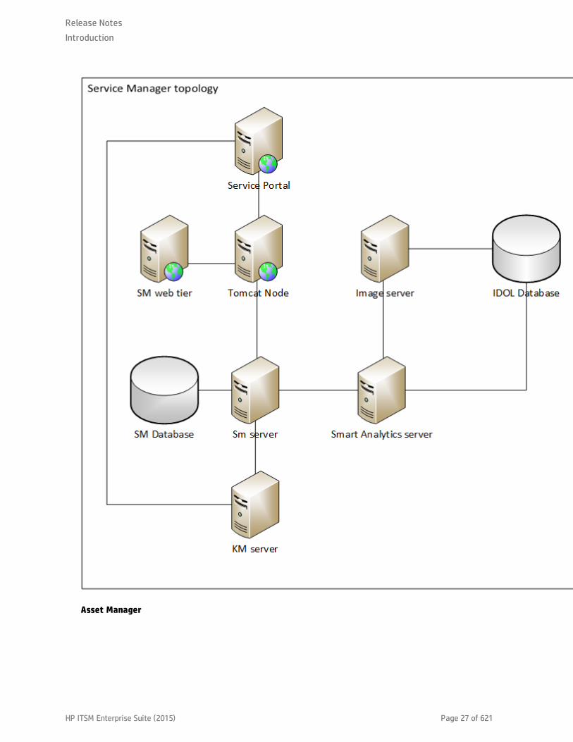
As indicated in the diagram, each component of the ITSM Enterprise Suite may itself contain othercomponents. For example, Service Manager alone includes the Service Manager server, the database,the Service Manager web tier (including Apache and tomcat nodes), the Service Portal, the knowledgemanagement server, and Smart Analytics, which itself may include the IDOL server and an image server.In fact, every node in the preceding diagram, contains at least its own application server and separatedatabase. These more detailed topologies are shown in the following diagrams.
Service Manager
Release NotesIntroduction
HP ITSM Enterprise Suite (2015) Page 26 of 621
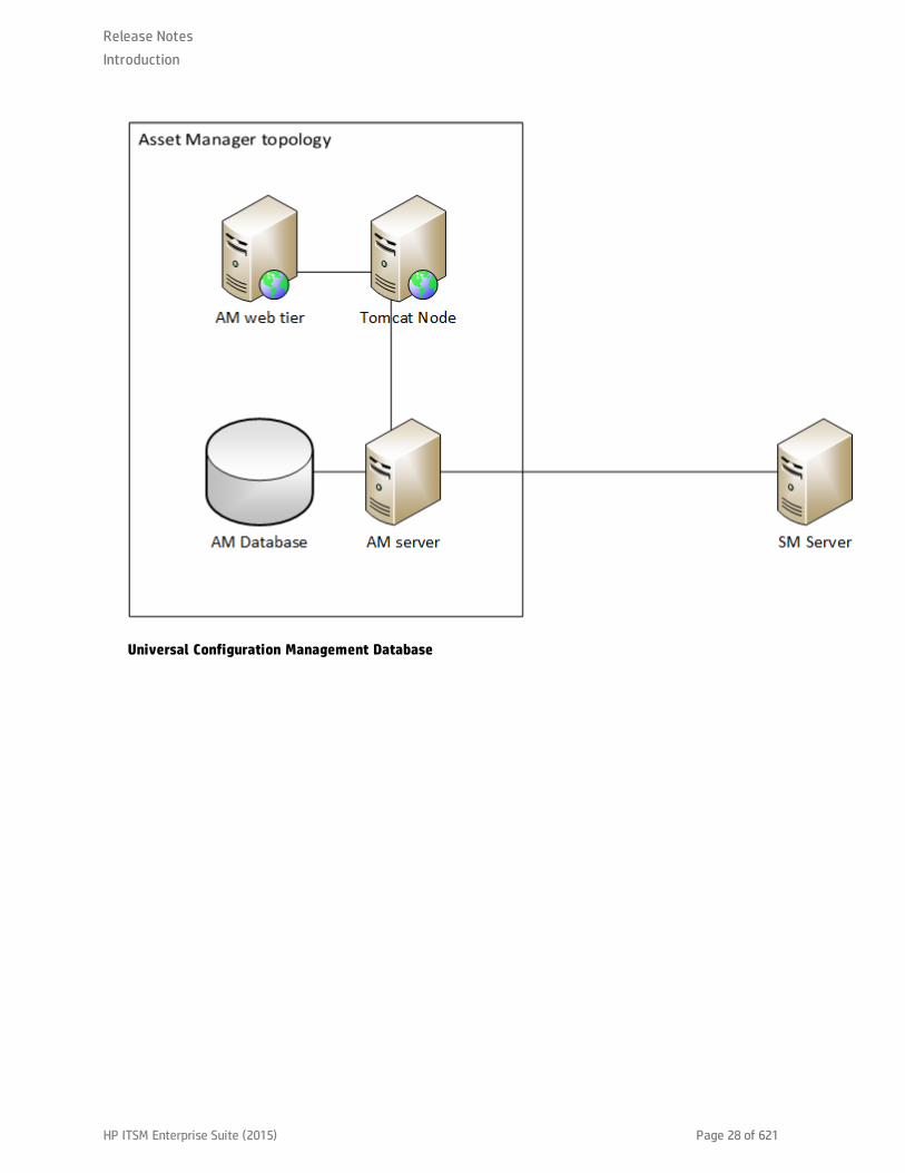
Asset Manager
Release NotesIntroduction
HP ITSM Enterprise Suite (2015) Page 27 of 621
Universal Configuration Management Database
Release NotesIntroduction
HP ITSM Enterprise Suite (2015) Page 28 of 621

Operations Bridge topology
Release NotesIntroduction
HP ITSM Enterprise Suite (2015) Page 29 of 621
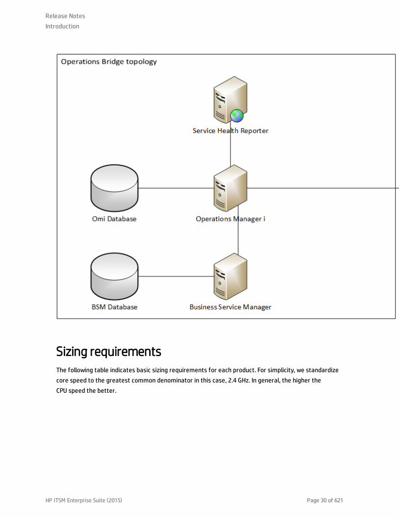
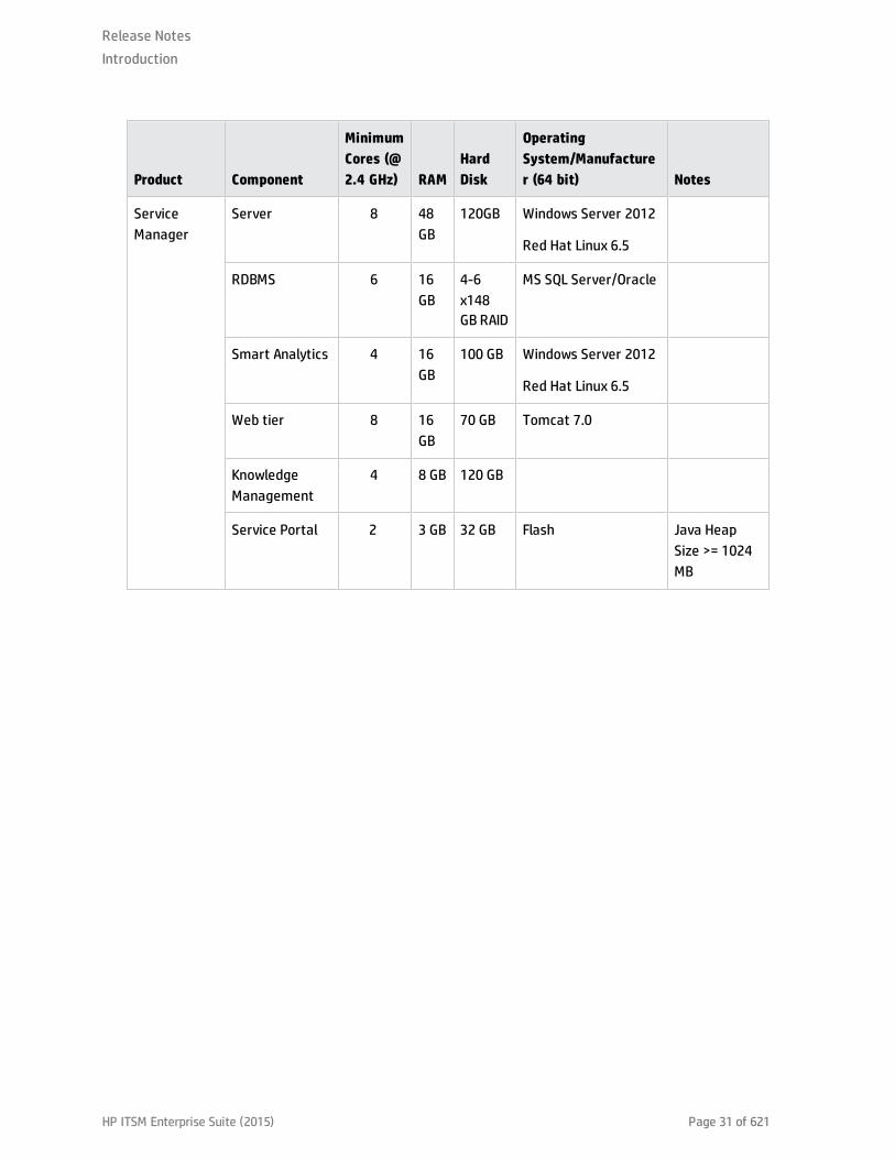
Sizing requirementsThe following table indicates basic sizing requirements for each product. For simplicity, we standardizecore speed to the greatest common denominator in this case, 2.4 GHz. In general, the higher theCPU speed the better.
Release NotesIntroduction
HP ITSM Enterprise Suite (2015) Page 30 of 621
Product Component
MinimumCores (@2.4 GHz) RAM
HardDisk
OperatingSystem/Manufacturer (64 bit) Notes
ServiceManager
Server 8 48GB
120GB Windows Server 2012
Red Hat Linux 6.5
RDBMS 6 16GB
4-6x148GB RAID
MS SQL Server/Oracle
Smart Analytics 4 16GB
100 GB Windows Server 2012
Red Hat Linux 6.5
Web tier 8 16GB
70 GB Tomcat 7.0
KnowledgeManagement
4 8 GB 120 GB
Service Portal 2 3 GB 32 GB Flash Java HeapSize >= 1024MB
Release NotesIntroduction
HP ITSM Enterprise Suite (2015) Page 31 of 621

Product Component
MinimumCores (@2.4 GHz) RAM
HardDisk
OperatingSystem/Manufacturer (64 bit) Notes
UniversalConfigurationManagementDatabase
Universal CMDB 8 16GB
Windows Server 2012
Red Hat Linux 6.5
n ThevirtualmemoryforWindows shouldbe atleast1.5timesthe sizeof thephysicalmemory.
n TheLinuxswapfile sizeshouldbeequal insize tothephysicalmemory.
Universal CMDBConfigurationManager
8 16GB
Windows Server 2012
Red Hat Linux 6.5
AssetManager
Server & Webtier
2 16GB
4-6x148GB RAID
Windows Server 2012
Red Hat Linux 6.5
IT BusinessAnalytics
SAPBusinessObjects EnterpriseServer
8 16GB
80 GB Windows Server 2012
Red Hat Linux 6.5
Release NotesIntroduction
HP ITSM Enterprise Suite (2015) Page 32 of 621

Product Component
MinimumCores (@2.4 GHz) RAM
HardDisk
OperatingSystem/Manufacturer (64 bit) Notes
DataWarehouseServer
8 16GB
120 GB Windows Server 2012
Red Hat Linux 6.5
ExecutiveScorecardServer
8 16GB
80 GB Windows Server 2012
Red Hat Linux 6.5
SQL Server 24 48GB
1 TB MS SQL Server 2012
OperationsBridge
OperationsManager i
4 16GB
250 GB Windows Server 2012
Red Hat Linux 6.5
Service HealthReporter(server)
16 32GB
500 Mb Windows Server 2012
Red Hat Linux 6.5
Service HealthReporter(Sybase IQ)
16 32GB
4.5 TB Windows Server 2008
Red Hat Linux 6.5
Service HealthReporter(Collectors)
4 8 GB 300 GB Maximum10,000 nodes.
BusinessServiceManagement
8 24GB
250 GB Windows Server 2012
Red Hat Linux 6.5
Suggested administrator resources
Compability matrixDelete this text and replace it with your own content.
Release NotesIntroduction
HP ITSM Enterprise Suite (2015) Page 33 of 621
Installation guidanceIn the following sections, we describe the simplest and most expedient method to install the HewlettPackard Enterprise ITSM Enterprise Suite. The content related to specific products is generally sourcedfrom the documentation for those products. However, for the purposes of this comprehensive suite, wehave made a number of arbitrary design decisions.
As a result, we leverage Deployment Manager wherever possible. IN cases where Deployment Manageris not used, we present only the single most common option for installing a specific product. Forexample, while the IT Business Analytics installation documentation describes two, three, and fourserver options to install IT Business Analytics and it’s associated components, we present only therecommended four server production environment installation instructions. Similar design choices havebeen made for all other products. At the beginning of each major section, a few paragraphs are devotedto explaining which choices were made for the subsequent installation method.
Using Deployment ManagerYou can use HP Deployment Manager to facilitate the installation and integration of Service Manager,Asset Manager, UCMDB and the other components of the ITSM Enterprise Suite. Deployment manager isa software package that can download, install, configure, and integrate several Hewlett Packardsoftware products. It was primarily designed to facilitate installation of Service Manager (SM) and itscore integrations. In the ITSM Enterprise Suite, we use it to install Service Manager (including KnowledgeManagement, Smart Analytics, and the Service Portal), Asset Manager (AM), Universal ConfigurationManagement Database (uCMDB) and configure the integrations between SM and uCMDB, KnowledgeManagement, the Service Portal, and Smart Analytics. By leveraging Deployment Manager, we canquickly and easily create and install the base ITSM system. After which, we will install and deploy theother components of the suite and integrate those components into the overall system architecture.
Note: Deployment Manager cannot handle the integration between Service Manager and AssetManager at this time.
Deployment Manager includes a number of embedded scripts that will download and install theappropriate packages. You can create an environment for the ITSM Enterprise Suite consisting ofmultiple servers. After creating the environment, you can select various packages and components,assign those packages to the various servers, specify the various integrations, and then simply executethe script. Deployment Manager will then automatically download all necessary packages, install all
Release NotesInstallation guidance
HP ITSM Enterprise Suite (2015) Page 34 of 621

software to the various servers, configure and deploy any appropriate web tiers, and integrate thevarious software packages.
For example, suppose you wanted to install Service Manager and uCMDB together on two separateservers. For the Service Manager installation, you want to create a database, install knowledgemanagement, and install the service portal. For the uCMDB installation, you need to install the database,install uCMDB, including the uCMDB data probe and the uCMDB Configuration Manager. To do this inDeployment Manager, you create a new environment, add the two servers to the environment. Then,select the “Install Service Manager” wizard, specify the appropriate server in the script, select the“Install uCMDB” wizard, and then specify the second server in the script. When you execute the scripts,deployment manager will automatically download the packages, install the base Service Manager anduCMDB on to the appropriate servers, including the databases, any Apache server and Tomcatapplication servers, and deploy any appropriate web applications. After the installation and deploymentof all components are complete, Deployment Manager will consider both the SM and uCMDB server sideintegrations. Additionally, if you later on decided to add Asset Manager into your environment, youwould simply add another server to your pre-existing Deployment Manager environment, and executethe “Install Asset Manager” script.
For the purposes of this document, we will not discuss how to install or configure Deployment Manager.To do that, refer to the Deployment Manager documentation.
Platform limitationsThe use of Deployment Manager imposes certain limitations on the deployment of the ITSM EnterpriseSuite. These are detailed in the following list:
l Deployment Manager only contains scripts for Microsoft Windows and Linux platforms. Therefore, ifyour organization is using HP UX or AIX you must manually install, configure, and integrate allproducts deployed by Deployment Manager. To do this, refer to the installation and configurationdocumentation for each individual product.
l If you plan on using multi-tenancy in the Universal Configuration Management Database, you cannotuse Deployment Manager. Therefore, you must use the installation and configurationdocumentation for the Universal CMDB to do this.
Create a Deployment Manager environmentTo create a new environment, follow these steps:
Release NotesInstallation guidance
HP ITSM Enterprise Suite (2015) Page 35 of 621
1. On the Environments tab, click the + icon on the left-hand pane to display the Environment Detailsdialog box.
2. Enter the name of your new environment. The name of the environment should be descriptive(such as "San Diego Development," "San Diego Production," or "San Diego UAT").
3. Select or clear the Visible to All option to determine whether the environment is visible to youonly or to all ITSM Deployment Manager users, and then click Save.
4. Click Add Server button to define the servers within the environment.
5. Enter an arbitrary name that will identify the server easily, such as "SM Web Tier 1" or "SM RTELoad Balancer."
6. Enter the IP address of the server. Currently, ITSM Deployment Manager does not supporthostnames or Fully Qualified Domain Names.
7. Enter the username and password of the server so that ITSM Deployment Manager cansuccessfully open a PowerShell session, and then click Save.
Note: You may not need to add username and password details if ITSM Deployment Managerand the target servers are located in the same Windows domain.
The servers are now recognized by ITSM Deployment Manager. A green label with an “Online” statusappears for each server that you have defined. If any servers display a red label and an "Offline" status,check that the server is powered on and that the specified IP address is correct. If any errors occurduring the process of adding a server, the errors are displayed in the server’s detailed information box
Install Service ManagerTo install Service Manager, follow these steps:
1. Log in to your instance of Deployment Manager, and then navigate to Environments.
2. Select your environment.
3. Click the HP Service Manager - Installation wizard.
4. Specify the following values as appropriate for your environment and licenses. The values specified
Release NotesInstallation guidance
HP ITSM Enterprise Suite (2015) Page 36 of 621
are examples based on the default licensing for the ITSM Enterprise Suite.
n SM version you want to install: SM 9.40
n Total number of users that will run concurrently on Service Manager Web? 100
n Total number of users that will run concurrently on Service Manager Mobility? 0
n Total number of users that will run concurrently on Service Request Catalog? 100
n Environment Mode: Deploy on a single server
Note: For larger environments, you may wish to deploy select Deploy on multiple servers.You will have the opportunity to install the Service Manager components in variouslocations on the several screens.
5. Click Next.
6. Select which server you want to host the Service Manager server.
7. Specify the drive on which you want to install the Service Manager server.
8. Click Next.
9. Select which server you want to host the Service Manager web tier.
10. Specify the drive on which you want to install the Service Manager web tier.
11. Click Next.
12. Select the database you will use ( SQL Server or Oracle).
13. Select which server you want to host the Service Manager database.
14. Optional: Specify an alternative name for the Windows Data Source Name (ODBC).
15. Optional: Specify an alternative name for the database.
16. Specify a user name for the database.
17. Specify a password for the database.
18. Click Next.
Release NotesInstallation guidance
HP ITSM Enterprise Suite (2015) Page 37 of 621
19. Optional: Click to install the Service Manager Help Center.
20. Click Install Later.
To execute this package immediately and install Service Manager server, web tier, databases, and theService Portal, follow these steps:
1. Navigate to the Packages tab, select your environment from the list, and then click on the InstallService Manager package.
2. Review the individual tasks.
3. When you are ready to install Service Manager, click Execute Package.
Install and integrate KnowledgeManagement
Deployment Manager automatically install and integrate the Knowledge Management component toService Manager and to the Service Portal. To install Knowledge Management, follow these steps:
1. Log in to your instance of Deployment Manager, and then navigate to Environments.
2. Select your environment and then click on More Wizards.
3. Click HP Service Manager - Knowledge Management.
4. Specify the following values for the Knowledge Management server:
n Which server should the master type of the SM Knowledge Management be installed on? <anyserver>
n KM version you want to install? SM 9.40
5. Click Next.
6. Select the SM Load balancer server.
7. Add a check to the other Service Manager servers.
8. Specify the User Name and Password.
Note: If you are not using the default user Name and Password of Falcon/, you may need to
Release NotesInstallation guidance
HP ITSM Enterprise Suite (2015) Page 38 of 621

specify an appropriate user name and password in Service Manager first.
9. Click Install Later
To execute this package immediately and install Knowledge Management, follow these steps:
1. Navigate to the Packages tab, select your environment from the list, and then click on the InstallHP Knowledge Management on... package.
2. Review the individual tasks.
3. When you are ready to install Knowledge Management, click Execute Package.
Integrate Knowledge Management and the Service Portal
To integrate Knowledge Management with the previously installed Service Portal (which was installedwhen you installed Service Manager), follow these steps:
1. Navigate to Packages.
2. Click the + icon to add a new package.
3. Specify a name for the package, select the environment on which you installed Service Managerand Knowledge Management, and then click save.
4. Click Execute Package.
Install and integrate Smart Analytics
To install Service Manager Smart Analytics, follow these steps:
1. Log in to your instance of Deployment Manager, and then navigate to Environments.
2. Select your environment and then click on More Wizards.
3. Click HP SM Smart Analytics Installation.
4. Specify the following values as appropriate for your environment:
Release NotesInstallation guidance
HP ITSM Enterprise Suite (2015) Page 39 of 621

n Select version to install: IDOL 10.7 (SM 940)
n Select the installation type: Standalone.
5. Check all boxes under, select the components you wish to install:
IDOL Server
Image Server.
6. Click Next.
7. Specify which server in your environment will host the IDOL server.
8. Specify which server in your environment will host the Image server.
9. Specify the server on which you installed Service Manager.
10. Click Install Later.
To execute this package immediately and install SM Smart Analytics, follow these steps:
1. Navigate to the Packages tab, select your environment from the list, and then click on the InstallSM Smart Analytics on... package.
2. Review the individual tasks.
3. When you are ready to install Knowledge Management, click Execute Package.
Install and connect UCMDB
Note:
l Deployment Manager does not fully integrate Service Manager and the Universal ConfigurationManagement Database. Push and population operations must still be performed manually. Forinformation on how to do this, see the "Using Service Manager and UCMDB" on page 278 and"Integrate UCMDB and Service Manager using the enhanced adapter" on page 79.
l If you plan to use multi-tenancy for the Universal Configuration Management Database, youmust configure multi-tenancy at the time of installation. In this case, you cannot use
Release NotesInstallation guidance
HP ITSM Enterprise Suite (2015) Page 40 of 621
Deployment Manager. Therefore, you should use the installation procedures described in theUniversal Configuration Management Database Installation Guide.
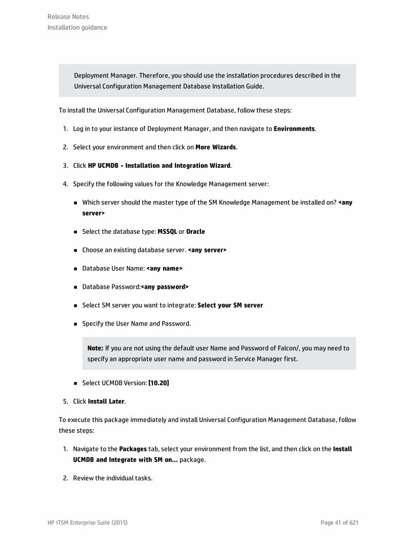
To install the Universal Configuration Management Database, follow these steps:
1. Log in to your instance of Deployment Manager, and then navigate to Environments.
2. Select your environment and then click on More Wizards.
3. Click HP UCMDB - Installation and Integration Wizard.
4. Specify the following values for the Knowledge Management server:
n Which server should the master type of the SM Knowledge Management be installed on? <anyserver>
n Select the database type: MSSQL or Oracle
n Choose an existing database server. <any server>
n Database User Name: <any name>
n Database Password:<any password>
n Select SM server you want to integrate: Select your SM server
n Specify the User Name and Password.
Note: If you are not using the default user Name and Password of Falcon/, you may need tospecify an appropriate user name and password in Service Manager first.
n Select UCMDB Version: [10.20]
5. Click Install Later.
To execute this package immediately and install Universal Configuration Management Database, followthese steps:
1. Navigate to the Packages tab, select your environment from the list, and then click on the InstallUCMDB and Integrate with SM on... package.
2. Review the individual tasks.
Release NotesInstallation guidance
HP ITSM Enterprise Suite (2015) Page 41 of 621
3. When you are ready to install Universal Configuration Management Database, click ExecutePackage.
Install Asset Manager
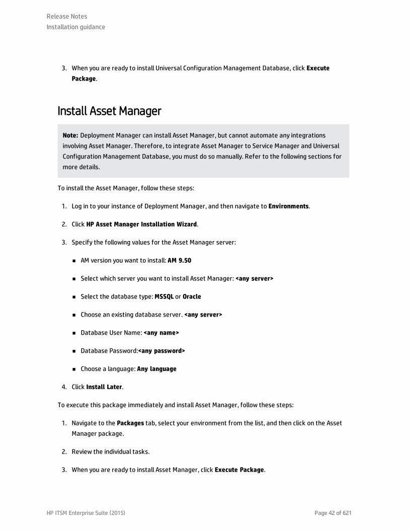
Note: Deployment Manager can install Asset Manager, but cannot automate any integrationsinvolving Asset Manager. Therefore, to integrate Asset Manager to Service Manager and UniversalConfiguration Management Database, you must do so manually. Refer to the following sections formore details.
To install the Asset Manager, follow these steps:
1. Log in to your instance of Deployment Manager, and then navigate to Environments.
2. Click HP Asset Manager Installation Wizard.
3. Specify the following values for the Asset Manager server:
n AM version you want to install: AM 9.50
n Select which server you want to install Asset Manager: <any server>
n Select the database type: MSSQL or Oracle
n Choose an existing database server. <any server>
n Database User Name: <any name>
n Database Password:<any password>
n Choose a language: Any language
4. Click Install Later.
To execute this package immediately and install Asset Manager, follow these steps:
1. Navigate to the Packages tab, select your environment from the list, and then click on the AssetManager package.
2. Review the individual tasks.
3. When you are ready to install Asset Manager, click Execute Package.
Release NotesInstallation guidance
HP ITSM Enterprise Suite (2015) Page 42 of 621

Installing Operations Manager i
Note: In general, you should follow the product documentation for each product to install andconfigure the product, and then read and implement the associated integration guides.
To install Operations Manager i, follow the steps in the HP Operations Manager i10.01 Installation andUpgrade Guide. The HP Operations Manager i10.01 Installation and Upgrade Guide is an interactiveinstallation document, which allows you to select various configuration items. For the HP ITSMEnterprise Suite example use case, which includes 250 to 900 nodes and is a smaller deployment, weuse the following options for the installation:
l Enterprise Deployment
l Install and configure OMi
l Single Server Environment
l PostgreSQL (embedded)
l Windows or Linux
You may additional choose to view instructions for additional options, such as Load balancing,hardening, and so on. When you click View, you will see a set of instructions for you to install OperationsManager i for your specific configuration.
Note: Verify the hardware and software requirements according to the documentation prior tobeginning the installation.
Install Service Health Reporter
Installation Prerequisites
These prerequisites apply to the system where you want to install HP Service Health Reporter and alsothe remote systems where you want to install the SHR data collector.
Hardware Requirements
For a list of hardware requirements, see the HP Service Health Reporter Support Matrix.
Release NotesInstallation guidance
HP ITSM Enterprise Suite (2015) Page 43 of 621

Disk Space Requirements
Ensure that you have required space as follows in /opt and /tmp directories:
l To download and merge the SHR media files, allocate at least 30 GB in the /tmp directory on eachsystem.
l To install SHR components, allocate at least 20 GB in the /opt directory on each system.
l To download and merge the SHR remote collector media files, allocate at least 15 GB in the /tmpdirectory on each system.
l To install SHR remote collector, allocate at least 10 GB in the /opt directory on each system.
n Do not start the installation directly from the mount point location.
n Do not download and merge the TAR files directly from the mount point location.
l If additional external storage space is required to be added, ensure that no other applications areinstalled in the /opt directory.
Software Requirements
For the complete list of software requirements, see the Requirements section in the HP Service HealthReporter Support Matrix.
Operating System Requirements
For the complete list of operating system requirements, see the Requirements section in the HP ServiceHealth Reporter Support Matrix.
Before you install SHR, you must update your operating system, apply all patches, establish networkconnectivity, and disable the anti-virus software.
Ensure that the following libraries are available on each system where you plan to install SHRcomponents.
Red Hat Enterprise Linux 6.x Red Hat Enterprise Linux 5.5
The list indicates the minimum required versions of required libraries. You can install a higher versionof each library, if available.
Release NotesInstallation guidance
HP ITSM Enterprise Suite (2015) Page 44 of 621

l compat-libstdc++-33-3.2.3-69.i686
l compat-libstdc++-33-3.2.3-69.x86_64
l libXext-1.1-3.i686
l libXext-1.1-3.x86_64
l libXext-devel-1.1-3.i686
l libXext-devel-1.1-3.x86_64
l libstdc++-4.4.4-13.x86_64
l libstdc++-4.4.4-13.i686
l libXtst-1.0.99.2-3.i686
l libXtst-1.0.99.2-3.x86_64
l libXau-1.0.5-1.i686
l libXau-1.0.5-1.x86_64
l libXdmcp-1.0.3-1.i686
l libxcb-1.5-1.x86_64
l libxcb-1.5-1.i686
l libXrender-0.9.5-1.i686
l libXrender-0.9.5-1.x86_64
l glibc-2.12-1.7.x86_64
l glibc-2.12-1.7.i686
l libgcc-4.4.1-13.i686
l libgcc-4.4.4-13.x86_64
l libX11-1.3-2.i686
l libX11-1.3-2.x86_64
l libXi-1.3-3.x86_64
l compat-libstdc++-33-3.2.3-61.x86_64
l compat-libstdc++-33-3.2.3-61.i386
l libXext-1.0.1-2.1.x86_64
l libXext-1.0.1-2.1.i386
l libXext-devel-1.0.1-2.1.x86_64
l libXext-devel-1.0.1-2.1.i386
l libstdc++-4.1.2-48.x86_64
l libstdc++-4.1.2-48.i386
l libXtst-1.0.1-3.1.x86_64
l libXtst-1.0.1-3.1.i386
l libXau-1.0.1-3.1.x86_64
l libXau-1.0.1-3.1.i386
l libXdmcp-1.0.1-2.1.i386
l libXrender-0.9.1-3.1.x86_64
l libXrender-0.9.1-3.1.i386
l glibc-2.5-47.i686
l glibc-2.5-47.x86_64
l libgcc-4.1.2-48.i386
l libgcc-4.1.2-48.x86_64
l libX11-1.0.3-11.x86_64
l libX11-1.0.3-11.i386
l libXi-1.0.1-3.1.x86_64
l libXi-1.0.1-3.1.i386
l alsa-lib-1.0.17-1.x86_64
Release NotesInstallation guidance
HP ITSM Enterprise Suite (2015) Page 45 of 621
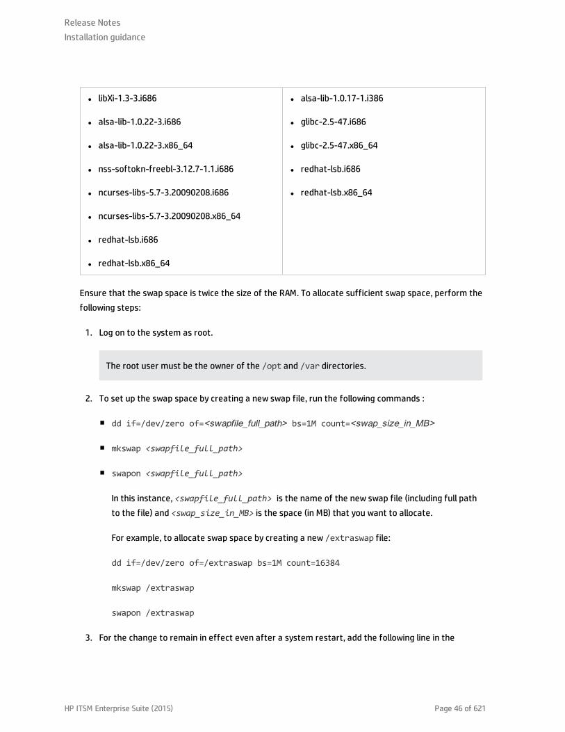
l libXi-1.3-3.i686
l alsa-lib-1.0.22-3.i686
l alsa-lib-1.0.22-3.x86_64
l nss-softokn-freebl-3.12.7-1.1.i686
l ncurses-libs-5.7-3.20090208.i686
l ncurses-libs-5.7-3.20090208.x86_64
l redhat-lsb.i686
l redhat-lsb.x86_64
l alsa-lib-1.0.17-1.i386
l glibc-2.5-47.i686
l glibc-2.5-47.x86_64
l redhat-lsb.i686
l redhat-lsb.x86_64
Ensure that the swap space is twice the size of the RAM. To allocate sufficient swap space, perform thefollowing steps:
1. Log on to the system as root.
The root user must be the owner of the /opt and /var directories.
2. To set up the swap space by creating a new swap file, run the following commands :
n dd if=/dev/zero of=<swapfile_full_path> bs=1M count=<swap_size_in_MB>
n mkswap <swapfile_full_path>
n swapon <swapfile_full_path>
In this instance, <swapfile_full_path> is the name of the new swap file (including full pathto the file) and <swap_size_in_MB> is the space (in MB) that you want to allocate.
For example, to allocate swap space by creating a new /extraswap file:
dd if=/dev/zero of=/extraswap bs=1M count=16384
mkswap /extraswap
swapon /extraswap
3. For the change to remain in effect even after a system restart, add the following line in the
Release NotesInstallation guidance
HP ITSM Enterprise Suite (2015) Page 46 of 621

/etc/fstab file:
<swapfile_full_path>swap swap defaults 0 0
In this instance, <swapfile_full_path>is the name of the newly created swap file in the previousstep.
For example:
/extraswap swap swap defaults 0 0
4. Restart the system.
Port Availability
SHR uses a number of default ports for different services. Ensure that the following ports are freebefore installing SHR components.
ServicePortNumber Protocol Inbound Outbound Description
HP PMDBPlatform DBLogger
21408 TCP Yes Yes The HP PMDB Platform DB Loggerservice persists logs in the databasethrough this port.
HP PMDBPlatformCollection
21409 TCP Yes Yes The JMX management port for theCollection service. The IM servicemonitors collection using thisinterface.
HP PMDBPlatform IM
21410 TCP Yes No The JMX management port for the IMservice.
HP PMDBPlatform Timer
No port NA NA NA The Timer service for SHR.
HP PMDBPlatformAdministrator
21411 TCP Yes No The SHR web application server port,which hosts the Administration webapplication. The Report cross-launchfunctionality depends on this service.
HP SoftwareCommunicationBroker
383 TCP Yes Yes SHR uses this port to communicatewith collectors installed on remoteservers.
Release NotesInstallation guidance
HP ITSM Enterprise Suite (2015) Page 47 of 621

ServicePortNumber Protocol Inbound Outbound Description
AdministrationConsole webserver
21416 TCP Yes Yes The JMX management port for theSHR administration web server.
HP PMDBPlatformCollection
21418 HTTP Yes No The connection port to the HTTPserver for the SiteScope generic dataintegration.
HP PMDBPlatformCollection
21419 HTTPS Yes No The connection port to the HTTPserver for the SiteScope generic dataintegration.
HP PMDBPlatformCollection
8080 HTTP No Yes The connection port to collect datafrom the SiteScope Data AcquisitionAPI.
HP PMDBPlatform SybaseService
21424 TCP Yes Yes Port for the Sybase IQ server.
Sybase IQ Agent15.4
21423 TCP Yes No Port for the Sybase IQ Agent.
HP-SHR-Postgre- PostgreSQLServer 9.0
21425 TCP Yes Yes Port for the PostgreSQL service.
Apache Tomcat 8080 TCP Yes No This is the SAP BusinessObjectsApplication Service port. The SAPBusinessObjects Central ManagementConsole and the SAP BusinessObjectsInfoView web applications are hostedon this port.
SAP BOBJ CentralManagementServer
6400 TCP Yes Yes This is the port for the SAPBusinessObjects Central ManagementServer, which is mainly used for SAPBusinessObjects authenticationpurposes.
ServerIntelligenceAgent(HOML01GEATON)
6410 TCP Yes Yes Port for the SAP BusinessObjectsServer Intelligence Agent, whichmanages all SAP BusinessObjects-related tasks.
Release NotesInstallation guidance
HP ITSM Enterprise Suite (2015) Page 48 of 621

ServicePortNumber Protocol Inbound Outbound Description
BOE120SQLAW 2638 TCP Yes Yes Port for the SAP BusinessObjectsrepository database.
RTSM 21212 TCP No Yes This is the port that is configured inthe Administration Console for theRTSM data source. Using this port,SHR connects to RTSM.
HPOM Any TCP No Yes This is the port that is configured inthe Administration Console for theHPOM database. SHR uses this port toconnect to the HPOM database.
HP OperationsAgent
383 TCP No Yes SHR uses this port to connect to theHP Operations agent.
HP BSM Profiledatabase
Any TCP No Yes This is the port that is configured inthe Administration Console for theProfile database.
SHR uses this port to connect to theProfile database and the OMidatabase.
Web Browser Requirements
To view the SHR Administration Console in Internet Explorer or Mozilla Firefox, you must enable theActiveX and the JavaScript controls. Follow the Help menu of the web browser for assistance withenabling them.
For a list of supported Web Browsers, see "Web Browsers and Plug-ins" in the HP Service Health ReporterSupport Matrix.
Preinstallation Tasks and Checklist
After ensuring that the installation prerequisites are fulfilled, you must perform a series of tasks toprepare the server for the SHR installation.
Task 1: Disable Anti-Virus
Anti-virus applications can hinder the installation of SHR. Temporarily disable any anti-virus softwarethat might be running.
Re-enable the anti-virus software after the installation is complete.
Release NotesInstallation guidance
HP ITSM Enterprise Suite (2015) Page 49 of 621

Task 2: Configure Firewall
If you use firewall software, ensure that the firewall allows traffic through the required ports (seeInstallation Prerequisites > Port Availability ) on the SHR system.
To disable the firewall, perform the following steps:
1. Log on as root and run the following commands:
Note: The root user must be the owner of the /opt and /var directories.
chkconfig iptables off
chkconfig ip6tables off
/etc/init.d/iptables stop
/etc/init.d/ip6tables stop
Task 3: Prepare the Linux System
On the Linux system, you must perform a set of additional steps.
Task 3.1: Disable SELinux
To disable SELinux, in the /etc/sysconfig/selinux file, set the parameter SELINUX = disabled.
Task 3.2: Configure the Kernel Parameters (only if you use Red Hat Enterprise Linux 6.x)
To configure the Kernel parameters, follow these steps:
1. Open the file /etc/sysctl.conf file.
2. Set the values of the parameters as given below:
Note: If higher values are specified for these parameters already, do not make any modifications.
l kernel.msgmnb = 65536
l kernel.msgmax = 65536
l kernel.shmmax = 68719476736
l kernel.shmall = 4294967296
Release NotesInstallation guidance
HP ITSM Enterprise Suite (2015) Page 50 of 621

l kernel.sem = 250 1024000 250 4096
l vm.max_map_count = 1000000
Task 3.3: Configure the Hostname
Log on to the SHR system, and configure the hostname in the /etc/hosts file.
If you configure a hostname, it should be added after these two lines as they appear by default.
127.0.0.1 localhost.localdomain localhost
192.168.0.1 server1.example.com server1
The naming convention for the hostname is: <IP address> <FQDN of SHR host system> <Short name ofSHR host system>
Task 3.4: Configure the limits.conf File
Open the /etc/security/limits.conf file and increase the number of open files by setting thefollowing values:
* soft nofile 65535
* hard nofile 65535
Task 3.5: Configure the 90-nproc.conf File (only if you use Red Hat Enterprise Linux 6.x)
Open the /etc/security/limits.d/90-nproc.conf file and comment out the following line (byadding a # character in the beginning):
#*soft nproc 1024
Restart the Linux system for all the changes to take effect.
Task 4: Verify the Fully Qualified Domain Name (FQDN) of the System
Before performing the SHR installation, you must verify that DNS lookup returns the accurate FQDN ofthe system. If the entry for the DNS lookup is different from the host name of the system, you mayexperience difficulties in logging on to the SHR Administration Console. This can occur because duringthe SAP BusinessObjects installation, the host name of the system is used for creating theservers/services and registering them.
To verify the FQDN of the host system, follow these steps:
1. Open the command line interface and type the following command to check the hostname of thesystem:
Release NotesInstallation guidance
HP ITSM Enterprise Suite (2015) Page 51 of 621

hostname -f
Note down the hostname of the system.
2. Type the following command to view the IP address of the system:
ifconfig
3. Type the following command to verify the FQDN of the displayed IP address:
nslookup<IP_address>
where, <IP address> is the IP address of the system.
Ensure that the name displayed after running the nslookup command matches the namedisplayed after running the HOSTNAME command. If the names do not match, you must change thehostname of the system.
Task 5: Assemble the media
On the HP software download web site, the SHR installation media for Linux is distributed as a collectionof the following three files:
HPSHR_940_Lin64.part1
HPSHR_940_Lin64.part2
HPSHR_940_Lin64.part3
Before you start installing SHR, you must download all three files, and then combine them into a single.tar file.
To create the SHR installation media, follow these steps:
Download the SHR media files into a temporary directory on the system where you want to install SHRcomponents.
1. To create a new directory for installing SHR, run the following command:
mkdir <directory name>
For example: mkdir /tmp/HPSHR_9.4-parts
2. To go to the directory that you created in the previous step, run the following command:
cd <temp location>
Release NotesInstallation guidance
HP ITSM Enterprise Suite (2015) Page 52 of 621
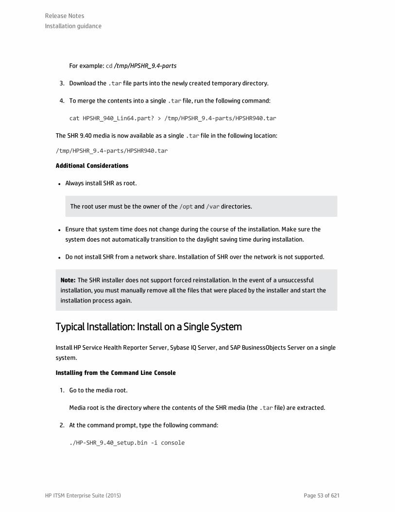
For example: cd /tmp/HPSHR_9.4-parts
3. Download the .tar file parts into the newly created temporary directory.
4. To merge the contents into a single .tar file, run the following command:
cat HPSHR_940_Lin64.part? > /tmp/HPSHR_9.4-parts/HPSHR940.tar
The SHR 9.40 media is now available as a single .tar file in the following location:
/tmp/HPSHR_9.4-parts/HPSHR940.tar
Additional Considerations
l Always install SHR as root.
The root user must be the owner of the /opt and /var directories.
l Ensure that system time does not change during the course of the installation. Make sure thesystem does not automatically transition to the daylight saving time during installation.
l Do not install SHR from a network share. Installation of SHR over the network is not supported.
Note: The SHR installer does not support forced reinstallation. In the event of a unsuccessfulinstallation, you must manually remove all the files that were placed by the installer and start theinstallation process again.
Typical Installation: Install on a Single System
Install HP Service Health Reporter Server, Sybase IQ Server, and SAP BusinessObjects Server on a singlesystem.
Installing from the Command Line Console
1. Go to the media root.
Media root is the directory where the contents of the SHR media (the .tar file) are extracted.
2. At the command prompt, type the following command:
./HP-SHR_9.40_setup.bin -i console
Release NotesInstallation guidance
HP ITSM Enterprise Suite (2015) Page 53 of 621
3. Press Enter to start the installation. The Choose Locale section appears.
Note: At any point in time during installation, you can type back to go to the previous pageand type quit to cancel the installation.
4. Choose the locale in which you want to install SHR, and press Enter. The installer shows theintroductory information in the console.
5. Press Enter.
6. The installer shows the license agreement details. Type Y to accept the agreement, and then pressEnter. The installer shows different installation options.
Note: Review the screen prompts carefully before pressing Enter each time. Pressing theEnter button continuously might take you through the next steps with the default selections.
7. Type 1 for Typical HP Service Health Reporter Installation to install SHR, Sybase IQ, and SAPBusinessObjects. Press Enter.
The installer performs necessary prerequisite checks and shows the result of the check in theconsole.
8. If the prerequisite check fails or shows warning messages, ensure that all the prerequisites aremet and start the installation again.
If the prerequisite check displays any missing libraries, check the list of missing libraries fromthe location /tmp/SHR-Missing-Patches.txt and install them. Start the SHR installationagain.
9. If the prerequisite check is successful, press Enter. The installer shows preinstallation summary inthe console.
10. Press Enter to start the installation.
11. After successful installation, run the following command:
hostname -f
Check if the hostname is displayed.
Release NotesInstallation guidance
HP ITSM Enterprise Suite (2015) Page 54 of 621
If the installation fails, click Rollback and wait till the product gets rolled back. Run the rollback utility asfollows:
1. In the command line console, go to the rollback utility path.
You will find the Rollback utility file in the location from where the installation setup files wereextracted for installation.
2. Run the following command:
sh rollback-utility.sh
Note: During SHR installation in Linux, SAP BusinessObjects client tools are also installed but notsupported on Linux. If SHR is installed on a Linux server, you must install the SAP BusinessObjectsclient tools on a Windows operating system for developing or customizing application content. Formore information, see Developing Content in Linux using CDE section of HP Service Health ReporterContent Development Guide.
To perform the post-installation configuration tasks, see the HP Service Health Reporter ConfigurationGuide.
Post-Installation Task for Sybase IQ
On a system with the Simplified Chinese or Japanese locale, manually delete the following files afterinstallation:
l $PMDB_HOME/Sybase/IQ-15_4/res/dblgzh_iq12_eucgb.res
l $PMDB_HOME/Sybase/IQ-15_4/res/dblgzh_iq12_cp936.res
l $PMDB_HOME/Sybase/IQ-15_4/res/dblgja_iq12_eucjis.res
l $PMDB_HOME/Sybase/IQ-15_4/res/dblgja_iq12_sjis.res
Validating SHR Installation
Perform the following to verify the success of installation on Linux operating system:
1. Log on as root.
2. Run the following command:
Release NotesInstallation guidance
HP ITSM Enterprise Suite (2015) Page 55 of 621
chkconfig --list
The command output lists the SHR services. Run the following commands for each of the servicesto ensure that they are running satisfactorily :
n service HP_PMDB_Platform_Administrator status
n service HP_PMDB_Platform_Collection status
n service HP_PMDB_Platform_DB_Logger status
n service HP_PMDB_Platform_IM status
n service HP_PMDB_Platform_PostgreSQL status
n service HP_PMDB_Platform_Sybase status
n service HP_PMDB_Platform_IA status
n service TrendTimer status
To check the status of the SAP BusinessObjects services, run the following commands at thecommand line console:
a. su - SHRBOADMIN
b. cd /opt/HP/BSM/BO/bobje
c. sh ccm.sh -display
The command output shows the status of SAP BusinessObjects services. All services must beenabled and running.
Note: If you have installed SHR on RHEL 6.6, after configuring SHR, ensure that you performManual Restart of Tomcat Services steps in HP Service Health Reporter Configuration Guide.
Installing the SHR Data Collector on a Remote System (Optional)
In the typical installation mode of SHR, the data collector is installed on the same system where SHR isinstalled. But, you can also install the data collector on a separate server. Also, you can install collectorson multiple systems as necessary.
Release NotesInstallation guidance
HP ITSM Enterprise Suite (2015) Page 56 of 621

To install a collector on a remote system running on Windows, perform the following steps:
1. All software requirements mentioned in the Prerequisites section must be met on the systemwhere you want to install the data collector.
2. In the system where you have installed SHR, browse to the SHR install directory %PMDB_HOME%,and locate the following file:
HP-SHR-09.40-RemotePoller_9.40_setup.exe
You can also find this EXE file in the packages\HP-SHR-09.40-RemoteCollector folder on theSHR media.
3. Copy the file to the system where you want to install the collector.
4. Log on to the system where you want to install the collector as administrator.
5. Ensure that the remote system and the SHR system are in the same time zone.
6. Ensure that the system is registered in the Domain Name System (DNS).
Alternatively, ensure that:
n The hosts file on the SHR system includes a entry of the collector system.
n The hosts file on the collector system includes a entry of the SHR system.
The hosts file is located at C:\Windows\System32\drivers\etc
7. Browse to the folder where you copied the HP-SHR-09.40-RemotePoller_9.40_setup.exe fileand run it.
8. The License Agreement page appears. Review the license agreement, select I accept..., and thenclick Next.
9. Review the folders in which the data collector would install. To change the installation folders, usethe adjoining Browse buttons. Click Next.
Note: Do not enter spaces or special characters other than the - (hyphen) in the non-defaultfolder name. The installation path must be less than 20 characters.
The installer performs checks for installation prerequisites and shows the result of the check onthe Install Check page.
Release NotesInstallation guidance
HP ITSM Enterprise Suite (2015) Page 57 of 621
10. On the Product Requirements page, if the checks are successful, click Next.
11. The Pre-Installation Summary page appears. Review the summary, and click Install.
12. After the installation is complete, click Done.
To install a collector on a remote system running on Linux, perform the following steps:
1. All software requirements mentioned in Prerequisites must be met on the system where you wantto install the data collector.
2. In the system where you have installed SHR, browse to the SHR install directory $PMDB_HOME andlocate the following file:
HP-SHR-09.40-RemoteCollector.tar.gz
3. Transfer the file to the system where you want to install the collector.
4. Log on to the system where you want to install the collector as root. The root user must be theowner of the /opt and /var directories.
5. Ensure that the remote system and the SHR system are in the same time zone.
6. Ensure that the system is registered in the Domain Name System (DNS).
Alternatively, ensure that:
n The hosts file on the SHR system includes a entry of the collector system.
n The hosts file on the collector system includes a entry of the SHR system.
The hosts file is located at /etc/hosts
7. Extract the contents of the HP-SHR-09.40-RemoteCollector.tar.gz file into a local directory byrunning the following command:
tar -xvf HP-SHR-09.40-RemoteCollector.tar.gz
The contents of the HP-SHR-09.40-RemoteCollector.tar file are extracted from the archive.
Installing from the Command Line Console
1. Run the following command in the command line console.
./HP-SHR-RemotePoller_9.40_setup.bin -i console
Release NotesInstallation guidance
HP ITSM Enterprise Suite (2015) Page 58 of 621
2. Press Enter to start the installation.
Tip: At any point in time during installation, you can type back to go to the previous page andtype quit to cancel the installation.
3. Choose the locale in which you want to install SHR, and press Enter.
4. The installer shows the introductory information in the console. Press Enter.
5. Review the license agreement details. Type Y to accept the agreement and press Enter.
The installer performs checks for installation prerequisites and shows the result of the check onthe Install Check page.
6. The installer shows preinstallation summary in the console. Press Enter to start the installation.
Note: The collector is enabled to collect data from data sources only after you configure thecollectors through SHR Administration Console.
Next Steps
have Task: Start the Sybase IQ Database
On the Linux system, run the following commands:
1. cd /etc/init.d
2. service HP_PMDB_Platform_Sybase status
If the command output shows that the HP_PMDB_Platform_Administrator service is stopped, run thefollowing command:
service HP_PMDB_Platform_Sybase start
Task: Configure SHR for Multiple Profile Database Support
Caution: Perform this task only if you want to configure RTSM as the topology source for SHR.
You can skip this task and proceed to Task 1: Launching the Administration Console section in theHP Service Health Reporter Configuration Guide if you want to configure HPOM or VMware vCenter asthe topology source.
Release NotesInstallation guidance
HP ITSM Enterprise Suite (2015) Page 59 of 621

SHR supports the configuration of and data collection from multiple Profile databases that aredeployed in your HP BSM/OMi environment.
However, to ensure that SHR identifies and displays all the existing Profile databases in theAdministration Console, follow these steps:
1. Log on to the HP BSM/OMi host system through remote access.
Note: If your HP BSM/OMi setup is distributed, you can access through the gateway server aswell as the data processing server. HP recommends that you use the gateway server.
2. Browse to the %topaz_home%\Conf folder.
3. Copy the following files from the %topaz_home%\Conf folder of the HP BSM/OMi host system tothe %PMDB_HOME%\config folder on the SHR system:
n encryption.properties
n seed.properties
Note: If you are configuring the Management/Profile database under Oracle RAC, you alsoneed to copy the file bsm-tnsnames.ora to the %PMDB_HOME%\config folder on the SHRsystem.
After copying the files, you need to start the HP PMDB Platform Administrator service. Perform thefollowing steps:
1. On the SHR system, click Start > Run. The Run dialog box appears.
2. In the Open field, type services.msc. The Services window appears.
3. On the right pane, right-click HP_PMDB_Platform_Administrator, and then click Restart.
4. Close the Services window.
Type the following command at the command prompt:
service HP_PMDB_Platform_Administrator restart
After installing SHR, you must perform configuration steps to configure SHR to use data sources. Formore information, see HP Service Health Reporter Configuration Guide.
Caution: Take a backup of the SHR database so that you can restore it later. If you fail to take a
Release NotesInstallation guidance
HP ITSM Enterprise Suite (2015) Page 60 of 621

data back up, you risk losing it permanently. For more information, see the "Database Backup andRecovery" section in the HP Service Health Reporter Configuration Guide.
Change the Default SAP BusinessObjects Database Password
SHR is installed with a default SAP BusinessObjects database password. Perform this task to change thedefault SAP BusinessObjects database password.
After installing SHR, follow these steps to modify the default password of the database embedded withSAP BusinessObjects:
1. Go to <BusinessObejcts installed drive>:\Program Files (x86)\BusinessObjects\SQLAnyWhere12\bin
2. Open the dbisqlc application.
3. Type the credentials as follows:
User name = DBA.
Password = pmdb_admin.
Server name = BOE120SQLAW_<shrshorthostname>.
Database name = BOE120.
4. Run the following command in the sql window:
ALTER USER <shrshorthostname> IDENTIFIED BY <new password>;
ALTER USER DBA IDENTIFIED BY <new password>;
5. Repeat the same steps for database BOE120_AUDIT.
After updating the password, follow these steps:
1. Go to CCM from Start > All Programs > BusinessObjects XI 3.1 > BusinessObjects Enterprise >Central Configuration Manager
2. Stop the Server Intelligence Agent (SIA); right-click and select Properties.
Release NotesInstallation guidance
HP ITSM Enterprise Suite (2015) Page 61 of 621

3. Go to the Configuration tab, you may see a error pop up click OK to proceed, and then click Specifyof BOE120.
4. Click on the Update Data Source Settings .
5. Click OK.
6. Select SQL Anywhere (ODBC) and click OK.
7. The Select Datasource window appears. Select Machine Data Source tab.
8. Double-click DSN BOE120 and provide the password that was changed and click OK.
9. Repeat from step 3 for BOE120_AUDIT database by selecting the BOE120_AUDIT.
10. Start the SIA.
To check if the password is modified, log in to the database using the new password.
SHR is installed with a default SAP BusinessObjects database password. Perform this task to change thedefault SAP BusinessObjects database password.
After installing SHR, follow these steps to modify the default password of the database embedded withSAP BusinessObjects:
1. Log in to the system as root.
2. Run the following command to switch to SHRBOADMIN user:
su -SHRBOADMIN
3. Go to /opt/HP/BSM/BO/bobje/SQLAW/Bin/.
4. Run the following command:
source /opt/HP/BSM/BO/bobje/setup/env.sh
5. Run the following command:
./dbisqlc
The credentials window appears. Click Cancel.
6. Select Command, and then click Connect.... The Connect credentials window appears.
Release NotesInstallation guidance
HP ITSM Enterprise Suite (2015) Page 62 of 621
7. Type the following details:
a. USER ID = DBA.
b. Password = pmdb_admin.
c. Database Name = <shrshorthostname>BOE120.
d. Server = <shrshorthostname>BOE120_SHR.
8. Run the following command in the sql window:
ALTER USER <shrshorthostname> IDENTIFIED BY <new password>;
ALTER USER DBA IDENTIFIED BY <new password>;
9. To modify the default password for BOE120_AUDIT, click Command, and then click Connect....
10. Type the following details:
a. USER ID = DBA.
b. Password = pmdb_admin.
c. Database Name = <shrshorthostname>BOE120_AUDIT.
d. Server = <shrshorthostname>BOE120_AUDIT_SHR.
11. Run the following command in the sql window:
ALTER USER <shrshorthostname> IDENTIFIED BY <new password>;
ALTER USER DBA IDENTIFIED BY <new password>;
After updating the password, follow these steps:
1. Go to /opt/HP/BSM/BO/bobje.
2. Run the following command:
./cmsdbsetup.sh
3. Provide the SIA name as PRD_SHR and click on Enter.
4. The prompt shows stop SIA. Type yes, and then click on Enter.
Release NotesInstallation guidance
HP ITSM Enterprise Suite (2015) Page 63 of 621

5. The prompt asks you to update. Type update, and then click on Enter.
6. Type yes and click Enter.
7. Type SQL Anywhere.
8. Type 2, and then click on Enter.
9. Type DSN as<shrshorthostname>BOE120, and then click on Enter.
10. Type user as SHR, and then click on Enter.
11. Type the new password, which you changed recently, and then click on Enter.
12. Repeat the above steps with the DSN as <shrshorthostname>BOE120_AUDIT DSN.
13. Run the following commands:
./stopservers
./startservers
To check if the password is modified, log in to the database using the new password.
Troubleshooting
Symptom: Installation Failure caused by SAP BusinessObjects Error
Description: While running the HP Software installer, the installation fails and the following errormessage is displayed:
SAP BusinessObjects is installed on the system. Please uninstall it before installing HP SH Reporter.
Resolution: If you have any component of SHR (such as SAP BusinessObjects or Sybase IQ) preinstalledor not cleanly uninstalled from a previous uninstall on your system, the SHR installation will fail becausethe installer tries to install the components that are bundled with the product.
To resolve this problem, you must clean up the existing components from the system and rerun theinstaller. For a virtual system, consider reimaging the VM, if feasible.
Symptom: Installation Failure caused by SAP BusinessObjects Error
Description: While running the HP Software installer, the installation fails and the following errormessage is displayed:
SAP BusinessObjects is installed on the system. Please uninstall it before installing HP SH Reporter.
Release NotesInstallation guidance
HP ITSM Enterprise Suite (2015) Page 64 of 621

Resolution: If you have any component of SHR (such as SAP BusinessObjects or Sybase IQ) preinstalledor not cleanly uninstalled from a previous uninstall on your system, the SHR installation will fail becausethe installer tries to install the components that are bundled with the product.
To resolve this problem, you must clean up the existing components from the system and rerun theinstaller. For a virtual system, consider reimaging the VM, if feasible.
Symptom: Installation failure due to missing libraries
Description: While installing SHR, if there any missing libraries the installation pre-check will fail.
Resolution: To resolve this problem, perform the following steps:
1. From the file /tmp/SHR-Missing-Patches.txt get the list of missing libraries.
2. Install the missing libraries.
3. Re-initiate SHRinstallation.
For more information, see the "Installation Prerequisites" section in this document.
Symptom: Unable to Bring up SHR Services after Successful Installation
Description: If SHR is installed on a virtual machine that is not restarted after the installation, theenvironment variables set by the installer will not be available to the user resulting in SHR services notcoming up in spite of multiple retry.
Resolution: After installing SHR, ensure that you restart the virtual machine.
Release NotesInstallation guidance
HP ITSM Enterprise Suite (2015) Page 65 of 621
Symptom: Remote Sybase IQ Database Creation Fails
In the HP Service Health Reporter Configuration Wizard, while trying to create the Sybase database fileon a remote system, the post-install fails and the following error message is displayed:
<time stamp>,018 ERROR, com.hp.bto.bsmr.dao.helper.CreateSybaseIQDatabase.executeSQL, Could notconnect to the database.
<time stamp>,049 ERROR, com.hp.bto.bsmr.dao.helper.CreateSybaseIQDatabase.executeSQL , Specifieddatabase not found
Resolution 1: This error occurs if the database file location specified in the HP Service Health ReporterConfiguration Wizard includes one or more spaces in the file path. To resolve this problem, make surethat the specified database file location exists on the remote system. In addition, make sure that thepath provided in the Post-Install wizard does not contain any spaces.
Resolution 2: This error can occur when adequate disk space is not available on the drive. The installerdoes not warn in case of a remote database. Increasing the disk space should resolve the issue.
Symptom: Sybase IQ Hangs
Description:SHR servers that have four or less CPUs, Sybase IQ hangs because of low iqgovernparameter value that is computed automatically.
Resolution:
Windows: Add "-iqgovern 50" parameter to the %PMDB_HOME%\config\pmdbConfig.cfg file andrestart the Sybase IQ database.
Linux: Add "-iqgovern 50" parameter to the $PMDB_HOME/config/pmdbConfig.cfg file and restartthe Sybase IQ database.
Symptom: SHR Fails to Create the Sybase Schema
Description: If SHR fails to create the Sybase schema after you complete the post-installationconfiguration tasks, an error message appears in the database log files. The Sybase database log files—
Release NotesInstallation guidance
HP ITSM Enterprise Suite (2015) Page 66 of 621

<hostname>.0001.srvlog and <hostname>.0001.stderr—are present in the/opt/HP/BSM/Sybase/IQ-16_0/logfiles directory on Linux.
The following error message appears in the Sybase database log files:
“utility_db" (utility_db) stopped
Only the Sybase database log files show the error message; no error messages appear in theAdministration console.
Resolution: Restart the Sybase service by running the following command:
service HP_PMDB_Platform_Sybase stop
service HP_PMDB_Platform_Sybase start
Symptom: SHR Fails to Create the Sybase Schema
Description: If SHR fails to create the Sybase schema after you complete the post-installationconfiguration tasks, an error message appears in the database log files. The Sybase database log files—<hostname>.0001.srvlog and <hostname>.0001.stderr—are present in the/opt/HP/BSM/Sybase/IQ-16_0/logfiles directory on Linux.
The following error message appears in the Sybase database log files:
“utility_db" (utility_db) stopped
Only the Sybase database log files show the error message; no error messages appear in theAdministration console.
Resolution: Restart the Sybase service by running the following command:
service HP_PMDB_Platform_Sybase stop
service HP_PMDB_Platform_Sybase start
Symptom: After Installation, User is Unable to Perform Post-Install Steps
Description: After installation, when user clicks Next, the subsequent page does not load despiteenabling Java scripts to run.
Resolution: This occurs when the system date on which SHR is installed is much older than that of theESX (in case of a VM). In such a scenario, the Tomcat server does not allow any requests from the client.Hence, it is always advisable to update the system date to current and install.
Perform the following steps:
Release NotesInstallation guidance
HP ITSM Enterprise Suite (2015) Page 67 of 621

1. Change system date to current.
2. Apply the permanent license.
When the system date is changed by more than three months, the license expires.
3. Restart Admin service, Tomcat server, and SAP BusinessObjects servers.
4. Log on and perform the post configuration again.
Symptom: After Installation, User is Unable to Perform Post-Install Steps
Description: After installation, when user clicks Next, the subsequent page does not load despiteenabling Java scripts to run.
Resolution: This occurs when the system date on which SHR is installed is much older than that of theESX (in case of a VM). In such a scenario, the Tomcat server does not allow any requests from the client.Hence, it is always advisable to update the system date to current and install.
Perform the following steps:
1. Change system date to current.
2. Apply the permanent license.
When the system date is changed by more than three months, the license expires.
3. Restart Admin service, Tomcat server, and SAP BusinessObjects servers.
4. Log on and perform the post configuration again.
Symptom: SHR Uninstall Fails
Description: Uninstalling SHR might not have completely uninstalled Sybase IQ Server.
Resolution: Uninstall Sybase IQ Server Suite 15.4 (64-bit) manually and restart your system.
Symptom: After Uninstalling SHR, Reinstall Fails
Description: After uninstalling SHR on a Windows system, when a reinstall is performed, the installerfails to launch and displays a Scripting Host not Found error.
Resolution: This error is encountered when the Path environment variable in Windows is corrupted. Addthe %systemroot%\System32 string to the Path environment variable by performing the followingsteps:
Release NotesInstallation guidance
HP ITSM Enterprise Suite (2015) Page 68 of 621

1. Right-click My Computer, and then click Properties.
2. Click the Advanced tab.
3. Click Environment Variables.
4. In the System Variable group, select Path.
5. Click Edit and add the string %systemroot%\System32 if missing.
Symptom: After Uninstalling SHR, Reinstall Fails
Description: After uninstalling SHR on a Windows system, when a reinstall is performed, the installerfails to launch and displays a Scripting Host not Found error.
Resolution: This error is encountered when the Path environment variable in Windows is corrupted. Addthe %systemroot%\System32 string to the Path environment variable by performing the followingsteps:
1. Right-click My Computer, and then click Properties.
2. Click the Advanced tab.
3. Click Environment Variables.
4. In the System Variable group, select Path.
5. Click Edit and add the string %systemroot%\System32 if missing.
Symptom: After interrupted installation, unable to continue reinstall with the installed components
Description: This issue may occur when you accidentally quit the SHR installation wizard and latercontinue to reinstall with the existing components.
Resolution: Perform the following steps to resolve this problem:
1. Start the installation wizard and review the Pre-Install Summary.
2. Select the Force repair of already installed component packages and click Install.
3. If the reinstall fails then, click Rollback in the pop-up message. The installed components willbe removed.
4. Now perform a new installation.
Symptom: After interrupted installation, unable to continue reinstall with the installed components
Release NotesInstallation guidance
HP ITSM Enterprise Suite (2015) Page 69 of 621
Description: This issue may occur when you accidentally quit the SHR installation wizard and latercontinue to reinstall with the existing components.
Resolution: Perform the following steps to resolve this problem:
1. Start the installation wizard and review the Pre-Install Summary.
2. Select the Force repair of already installed component packages and click Install.
3. If the reinstall fails then, click Rollback in the pop-up message. The installed components willbe removed.
4. Now perform a new installation.
Symptom: Data Collection Failure across all Configured Nodes
Description: Data collection in SHR fails with an Address already in use error logged in thetopologycollector.log file.
Resolution: This error occurs when the number of TCP/IP ports used exceeds the default value of 5000.To resolve this problem, you must make changes in the Windows Registry. Follow these steps:
1. Click Start > Run. The Run dialog box appears.
2. In the Open box, type regedit. The Registry Editor window appears.
3. On the left pane, expand HKEY_LOCAL_MACHINE, expand SYSTEM, expand CurrentControlSet,expand Services, expand Tcpip, and then click Parameters.
4. On the right pane, right-click anywhere, point to New, and then click DWORD Value to add a newentry. Add the following entries:
n MaxUserPort = 65535 (decimal)
n MaxFreeTcbs = 65535 (decimal)
n MaxHashTableSize = 65535 (decimal)
n TcpTimedWaitDelay = 30 (decimal)
Restart the system after making changes in the Registry Editor.
Symptom: Data Collection Failure across all Configured Nodes
Description: Data collection in SHR fails with an Address already in use error logged in thetopologycollector.log file.
Release NotesInstallation guidance
HP ITSM Enterprise Suite (2015) Page 70 of 621
Resolution: This error occurs when the number of TCP/IP ports used exceeds the default value of 5000.To resolve this problem, you must make changes in the Windows Registry. Follow these steps:
1. Click Start > Run. The Run dialog box appears.
2. In the Open box, type regedit. The Registry Editor window appears.
3. On the left pane, expand HKEY_LOCAL_MACHINE, expand SYSTEM, expand CurrentControlSet,expand Services, expand Tcpip, and then click Parameters.
4. On the right pane, right-click anywhere, point to New, and then click DWORD Value to add a newentry. Add the following entries:
n MaxUserPort = 65535 (decimal)
n MaxFreeTcbs = 65535 (decimal)
n MaxHashTableSize = 65535 (decimal)
n TcpTimedWaitDelay = 30 (decimal)
Restart the system after making changes in the Registry Editor.
Symptom: After uninstall a collector and reinstall it on a system, SHR fails to communicate withthe collector.
Description: If you uninstall a collector and reinstall it on a system, SHR fails to communicate with thecollector and error messages appear when you try to configure the collector in the AdministrationConsole.
You can occasionally experience this issue even after installing the collector for the first time.
Resolution: To resolve this, manually import the certificate from the SHR system to the collectorsystem by following these steps:
1. Log on to the collector system.
2. Run the following command:
ovcoreid
Note down the ID displayed in the console.
3. Log on to the SHR system.
4. Run the following command:
Release NotesInstallation guidance
HP ITSM Enterprise Suite (2015) Page 71 of 621

ovcm -issue -file <file> -name<node name>-coreid<core_ID>
In this instance, <core_ID> is the ID that you noted down in step 2.
The command prompts for a password. If you do not want to use a password, press Enter withouttyping anything.
In this instance, <file> is the name of the certificate file that you want to manually import to thecollector system; you must specify the file name with complete path to the directory where youwant to store the file. <node name> is the FQDN of the collector system.
5. Transfer the certificate file to the collector system.
6. Log on to the collector system.
7. Run the following command:
ovcert -importcert -file<file>
Symptom: After uninstall a collector and reinstall it on a system, SHR fails to communicate withthe collector.
Description: If you uninstall a collector and reinstall it on a system, SHR fails to communicate with thecollector and error messages appear when you try to configure the collector in the AdministrationConsole.
You can occasionally experience this issue even after installing the collector for the first time.
Resolution: To resolve this, manually import the certificate from the SHR system to the collectorsystem by following these steps:
1. Log on to the collector system.
2. Run the following command:
ovcoreid
Note down the ID displayed in the console.
3. Log on to the SHR system.
4. Run the following command:
ovcm -issue -file <file> -name<node name>-coreid<core_ID>
Release NotesInstallation guidance
HP ITSM Enterprise Suite (2015) Page 72 of 621
In this instance, <core_ID> is the ID that you noted down in step 2.
The command prompts for a password. If you do not want to use a password, press Enter withouttyping anything.
In this instance, <file> is the name of the certificate file that you want to manually import to thecollector system; you must specify the file name with complete path to the directory where youwant to store the file. <node name> is the FQDN of the collector system.
5. Transfer the certificate file to the collector system.
6. Log on to the collector system.
7. Run the following command:
ovcert -importcert -file<file>
Symptom: Installation fails for Management database package while installing as Domain user
Description:SHR installation fails with domain user during HPPmdbPostgreSQL package installation withthe following error in the install log.
C:/HP-SHR/Postgres/data ... initdb: could not change permissions of directory "C:/HP-SHR/Postgres/data":Permission denied in %temp%\install-postgresql.log (or) %temp%\bitrock_installer.log
Resolution: Uninstall SHR and create a local user that is a member of the Local Administrators groupwith administrator rights and install SHR again.
Symptom: Installer fails to display that installation is complete.
Description: This issue may appear while performing SHR installation, upgrade or installing RemoteCollectors. The installer progress bar shows that the installation is in process but the Done button isenabled. This is because the installer is not refreshed.
Resolution: Click Done to complete the process and check the install log files as follows to see if all thecomponents are installed.
Release NotesInstallation guidance
HP ITSM Enterprise Suite (2015) Page 73 of 621

l Windows: %temp%/../HP-SHR_9.40_HPOvInstaller.txt
l Linux: /tmp/HP-SHR_9.40_HPOvInstaller.txt
Symptom: Installer fails to display that installation is complete.
Description: This issue may appear while performing SHR installation, upgrade or installing RemoteCollectors. The installer progress bar shows that the installation is in process but the Done button isenabled. This is because the installer is not refreshed.
Resolution: Click Done to complete the process and check the install log files as follows to see if all thecomponents are installed.
l Windows: %temp%/../HP-SHR_9.40_HPOvInstaller.txt
l Linux: /tmp/HP-SHR_9.40_HPOvInstaller.txt
Symptom: Sybase IQ database removal failed after uninstall.
Description: This issue occurs while performing uninstall of SHR. The Sybase IQ database is not removedproperly, you will see a pop up as follows:
"Initialize action for HP Service Health Reporter 9.40 (Removing Sybase IQ schema) was not successful."
Resolution: You can move ahead with the uninstall and run the rollback utility. For the steps, see "PostUninstalling SHR" section in this guide.
Symptom: Uninstall is not clean.
Description: This issue occurs while performing uninstall of SHR, you will see a pop up saying there is afailure as follows:
"Initialize action for package HPPmdbCollector 9.40.000 (HP PMDB Collector) (Performing Collectionhousekeeping) was not successful."
Release NotesInstallation guidance
HP ITSM Enterprise Suite (2015) Page 74 of 621
Resolution: You can ignore the pop up and move ahead with the uninstall and run the rollback utility. Forthe steps, see "Post Uninstalling SHR" section in this guide.
Symptom: Failure in upgrade command.
Description: This issue may occur after upgrade of SHR, you will see a message saying there is a failurein the upgrade command.
Resolution: From the command line console run the following script:
%Ovinstalldir%\nonOV\perl\a\bin\perl %PMDB_HOME%\upgrade\940\applyPatch.pl %PMDB_HOME%\..\ “%ovinstalldir%” %PMDB_HOME%\upgrade\940
/opt/OV/nonOV/perl/a/bin/perl /opt/HP/BSM/PMDB/upgrade/940/applyPatch.pl/opt/HP/BSM/ /opt/OV/ /opt/HP/BSM/PMDB/upgrade/940/
Symptom: Failure in service precheck while upgrade.
Description: While upgrade, if all the SHR services are not stopped this issue may occur.
Resolution: From the PMDB_HOME\temp folder check the UpgradeServiceCheck.log file to find thecause of failure.
Symptom: After upgrade, few links in the Administration Console may fail to work.
Description: After upgrade, the CMC and InfoView links may fail to work SHR Administration Console.This issue may occur if the SAP BusinessObjects services are not running.
Resolution: Perform the following steps to stop the SAP BusinessObjects services:
1. Log on to the SHR system
2. Open the Services window
3. Start the Business Objects Webserver Service
1. Log on to the system as root.
2. Run the following command to start the webserver:
sh /opt/HP/BSM/BO/bobje/tomcatstartup.sh
Symptom: Installation with username having special character "&" requires system startup.
Description: While installing SHR with username having special character &then the system requests forstartup.
Resolution: Click Continue and proceed with your installation.
Symptom: Installation with username having special character "&" requires system startup.
Release NotesInstallation guidance
HP ITSM Enterprise Suite (2015) Page 75 of 621
Description: While installing SHR with username having special character & then the system requestsfor startup.
Resolution: Click Continue and proceed with your installation.
Symptom: After Uninstall, reinstall hangs on RHEL 5.5.
Description: After uninstall, when you reinstall SHR on Linux RHEL 5.5, the system hangs while installingBusinessObjects.
Resolution: Ensure that you perform SHR installation on a new Linux RHEL 5.5 system.
Symptom: YUM check warning after SHR installation
Description: After installing SHR and meeting all the pre-requisites, the following message appears witha list of missing libraries:
Found 42 pre-existing rpmdb problem(s), 'yum check' output follows:
Resolution: If you get a list of missing libraries while performing the YUM check, you can ignore theselibraries as they are not mandatory for SHR. This does not affect the functionality of SHR.
Install Business Service Management
Note: In general, you should follow the product documentation for each product to install andconfigure the product, and then read and implement the associated integration guides.
Install Executive Scorecard
Note: In general, you should follow the product documentation for each product to install andconfigure the product, and then read and implement the associated integration guides.
Enable the IT Business Analytics data sources and content packs
After you have completed the installation of all products, you should activate the IT Business Analyticsdata sources and content packs for each component you wish to report on. Because IT BusinessAnalytics reads data directly from the components RDBMS, you will need to know the connectioninformation for each database, such as the IP address, user name and password.
Note: The following sections are excerpted fromthe IT Business Analytics Administration Guide and
Release NotesInstallation guidance
HP ITSM Enterprise Suite (2015) Page 76 of 621

the IT Business Analytics Content Development Guide respectively.
Release NotesInstallation guidance
HP ITSM Enterprise Suite (2015) Page 77 of 621

Integration guidanceThe ITSM Enterprise Suite includes many possible integrations between its myriad components. Thoseintegrations and a brief description of their function are listed in the following table:
Products Description Guide
Service Manager- Universal Configuration Management Database
Universal Configuration Management Database - Asset Manager
Universal Configuration Management Database - Business ServiceManagement
Universal Configuration Management Database - Operations Manager i
Operations Manager i - Business Service Management
Operations Manager i - Service Health Reporter
Service Health Reporter - Service Manager
IT Business Analytics - Service Manager
IT Business Analytics - Business Service Management
IT Business Analytics - Asset Manager
Release NotesIntegration guidance
HP ITSM Enterprise Suite (2015) Page 78 of 621

Chapter 2: Integrate UCMDB and Service Managerusing the enhanced adapter
Note: The following sections are excerpted from the integrations section of the UniversalConfiguration Management Database Help Center. However, to ensure you have the latestinformation, you should reference the latest published version of the document in question.
This chapter includes:
Introduction 79
Integration Setup 87
Multi-Tenancy (Multi-Company) Setup 138
Standards and Best Practices 158
IntroductionThis chapter provides an overview of the HP Universal CMDB (UCMDB) - HP Service Manager (SM)integration (also referred to as the Universal CMDB (UCMDB) integration or UCMDB-SM integrationthroughout this document).
This chapter includes:
l "Who Should Read this Guide" below
l "Purpose of the Integration" on the next page
l "How CI information is Synchronized Between UCMDB and Service Manager" on page 84
Who Should Read this Guide
This guide is intended for a system implementer or system administrator who will be establishing andmaintaining a connection between the HP Universal CMDB (UCMDB) and Service Manager (SM) systems.This guide assumes that you have administrative access to both systems. The procedures in this guidemay duplicate information that is available in your UCMDB and Service Manager help systems, but isprovided here for your convenience.
HP ITSM Enterprise Suite (2015) Page 79 of 621
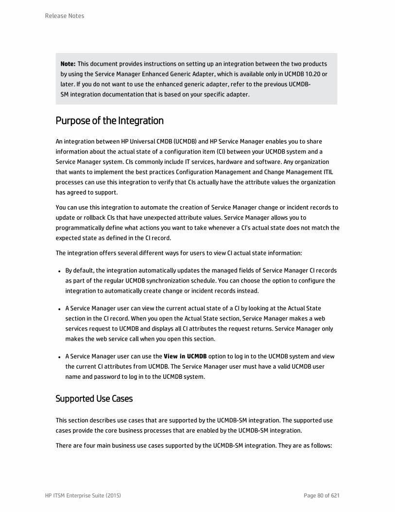
Note: This document provides instructions on setting up an integration between the two productsby using the Service Manager Enhanced Generic Adapter, which is available only in UCMDB 10.20 orlater. If you do not want to use the enhanced generic adapter, refer to the previous UCMDB-SM integration documentation that is based on your specific adapter.
Purpose of the Integration
An integration between HP Universal CMDB (UCMDB) and HP Service Manager enables you to shareinformation about the actual state of a configuration item (CI) between your UCMDB system and aService Manager system. CIs commonly include IT services, hardware and software. Any organizationthat wants to implement the best practices Configuration Management and Change Management ITILprocesses can use this integration to verify that CIs actually have the attribute values the organizationhas agreed to support.
You can use this integration to automate the creation of Service Manager change or incident records toupdate or rollback CIs that have unexpected attribute values. Service Manager allows you toprogrammatically define what actions you want to take whenever a CI’s actual state does not match theexpected state as defined in the CI record.
The integration offers several different ways for users to view CI actual state information:
l By default, the integration automatically updates the managed fields of Service Manager CI recordsas part of the regular UCMDB synchronization schedule. You can choose the option to configure theintegration to automatically create change or incident records instead.
l A Service Manager user can view the current actual state of a CI by looking at the Actual Statesection in the CI record. When you open the Actual State section, Service Manager makes a webservices request to UCMDB and displays all CI attributes the request returns. Service Manager onlymakes the web service call when you open this section.
l A Service Manager user can use the View in UCMDB option to log in to the UCMDB system and viewthe current CI attributes from UCMDB. The Service Manager user must have a valid UCMDB username and password to log in to the UCMDB system.
Supported Use Cases
This section describes use cases that are supported by the UCMDB-SM integration. The supported usecases provide the core business processes that are enabled by the UCMDB-SM integration.
There are four main business use cases supported by the UCMDB-SM integration. They are as follows:
Release Notes
HP ITSM Enterprise Suite (2015) Page 80 of 621

l Planned Change: A change created in SM through the formal SM change process.
l Unplanned Change: A change or incident that occurred in SM and does not conform to the formal SMchange process.
l Retrieving SM Ticket Information: The ability to view SM ticket information in UCMDB.
l Actual State: The ability to view the UCMDB CI information in SM.
All of the use cases provide important functionalities that enable the user to perform ITIL (ITInfrastructure Library) processes. The ITIL processes refer to a set of best practices that define andoutline how organizations should manage their IT.
Enabling ITIL Processes
By activating CI push from UCMDB to SM the user facilitates ITIL processes such as Incident, Problem andChange Management in SM.
SM utilizes the data pushed from UCMDB in the following modules:
l Incident Management: the Service Desk operator (SD Agent) selects the “Service” and the “AffectedCI” for the specific Incident record.
l Problem Management: the SD agent selects the “Service”, “Affected CI(s)”, and the “Primary CI” forthe specific Problem record.
l Change Management: the SD agent selects the “Service” and the “Affected CI(s)” for the specificChange record.
In each of the previously mentioned ITIL processes, SM utilizes CI information for Service, Affected CIsand Primary CIs that all originate in UCMDB.
Managing Planned Changes
The purpose of the “Planned Change” use case is to provide IT organizations a formal process by whichchanges to the IT infrastructure are introduced after thorough review and analysis. This is performedaccording to the “Change Management” process defined in ITIL.
A “Planned Change” is initiated by the SM user through the formal “Change Management” processmodule in SM. This is followed by the actual change implementation.
Release Notes
HP ITSM Enterprise Suite (2015) Page 81 of 621

The actual changes are discovered by a discovery tool such as HP DDMA, and then updated in UCMDBand the relevant modifications are pushed to SM. Once the user has validated the change, the usercloses the relevant planned change in SM.
Managing Unplanned Changes
The purpose of the “Unplanned Change” use case is to provide IT organizations a formal process bywhich all changes that occur to the IT infrastructure are both logged and conventionalized through theorganizations formal approval process.
An “Unplanned Change” is a change that is recognized by a Discovery tool such as DDMA. The change isfirst updated and visible in UCMDB and then the data is pushed to SM. SM recognizes the change and asa result an “Incident” or “Change” record is generated.
These Changes are seen also in the SM “Pending Changes” section in the Configuration Item form, onceapproved they are moved to the SM “Historic Changes” section.
Retrieving Service Manager Ticket Information
Retrieving SM ticket information from within UCMDB provides all HP Software applications users withaccess to this information by using UCMDB's federation capabilities and supporting APIs. Theseapplications include Business Service Management (BSM), Asset Manager (AM), OperationsOrchestration (OO), etc.
SM ticket data is accessed from within UCMDB using UCMDB federation capabilities. SM ticket dataincludes Incident, Problem and Change records as well as a key set of their attributes.
UCMDB enables users to create reports/views that combine the federated ticket data from SM with CIinformation from UCMDB.
Retrieving Actual State of UCMDB CIs
The purpose of “Actual State” is to enable SM users insight into CIs’ current state as detected by“Discovery Tools” and populated in UCMDB. This state provides up-to-date information that may varyfrom the information displayed in SM both in content and in scope.
The “Actual State” of the CI is displayed in SM in order to enable the user to validate the current state ofthe CI that resides in UCMDB or in another data repository.
SM users retrieve the Actual State of CIs from UCMDB or additional data sources by viewing the CI'sActual State section in the SM Configuration Item form.
Release Notes
HP ITSM Enterprise Suite (2015) Page 82 of 621

Accessing UCMDB CIs from Service Manager
SM users can open the UCMDB User Interface in the context of a specific CI, by clicking the View inUCMDB button in the SM CI record. When the user clicks the View in UCMDB button, a UCMDB loginscreen is displayed; After the user enters a UCMDB username and password, UCMDB displays atopological view of the specific CI together with all related CIs that are linked to it.
Tip: You can configure Lightweight Single Sign-On (LW-SSO) for the integration, so that ServiceManager web client users can bypass the UCMDB login screen after clicking the View in UCMDBbutton. For more information, see "How to Enable Lightweight Single Sign-On (LW-SSO)Configuration" on page 172.
If the UCMDB Browser URL is specified in the SM System Information Record, this button is replaced bythe View in UCMDB Browser button. When you click the View in UCMDB Browser button, a UCMDBBrowser login screen is displayed; After you enter a UCMDB Browser username and password, the CI isdisplayed in the UCMDB Browser user interface.
Core Features
This section explains the rudimentary concepts behind the Federation, Push, and Population features asthey pertain to the integration.
This section includes:
l "Push" below
l "Federation" on the next page
l " Population" on the next page
Push
UCMDB can automatically discover most types of CIs available in Service Manager. This integrationenables you to push these types of CIs from UCMDB to Service Manager.
The following figure shows how data is pushed from UCMDB to Service Manager (SM). The data isphysically pushed (copied) from UCMDB to SM. Once the data is physically located in SM, the data isutilized by the SM user that consumes this information in various SM processes.
Release Notes
HP ITSM Enterprise Suite (2015) Page 83 of 621

Note: CI Type and Attribute Push
Only information that is physically present in UCMDB can be pushed to SM.
Federation
With the federation feature, UCMDB pulls various ticket information (for example, Incident, Problem,and Change ticket information) from SM. This enables users to see Ticket information in UCMDB asTicket CIs that are connected to the relevant Nodes.
When data is federated (reflected or mirrored) from SM to UCMDB, the data is not physically present inUCMDB; instead it is passed over to UCMDB through Web Services.
Population
You can also use this integration to populate those types of CIs that UCMDB cannot automaticallydiscover or CIs that have been created in Service Manager before you have a UCMDB system deployed.For more information, see "When Do I Need the Population Feature?" on page 176.
Population is the reverse of Push. The following figure shows how data is populated from SM to UCMDB.One SM CI record with multiple attributes is transferred to UCMDB as multiple CI records.
How CI information is Synchronized Between UCMDB and ServiceManager
This section explains how CI information is transferred between the UCMDB and Service Managersystems.
Release Notes
HP ITSM Enterprise Suite (2015) Page 84 of 621
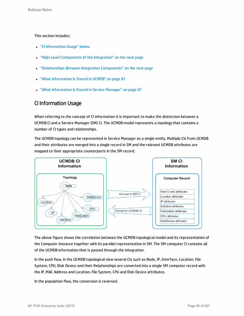
This section includes:
l "CI Information Usage" below
l "High-Level Components of the Integration" on the next page
l "Relationships Between Integration Components" on the next page
l "What Information Is Stored in UCMDB" on page 87
l "What Information Is Stored in Service Manager" on page 87
CI Information Usage
When referring to the concept of CI information it is important to make the distinction between aUCMDB CI and a Service Manager (SM) CI. The UCMDB model represents a topology that contains anumber of CI types and relationships.
The UCMDB topology can be represented in Service Manager as a single entity. Multiple CIs from UCMDBand their attributes are merged into a single record in SM and the relevant UCMDB attributes aremapped to their appropriate counterparts in the SM record.
The above figure shows the correlation between the UCMDB topological model and its representation ofthe Computer Instance together with its parallel representation in SM. The SM computer CI contains allof the UCMDB information that is passed through the integration.
In the push flow, in the UCMDB topological view several CIs such as Node, IP, Interface, Location, FileSystem, CPU, Disk Device and their Relationships are converted into a single SM computer record withthe IP, MAC Address and Location, File System, CPU and Disk Device attributes.
In the population flow, the conversion is reversed.
Release Notes
HP ITSM Enterprise Suite (2015) Page 85 of 621

High-Level Components of the Integration
The following diagram shows the high-level components of the integration, and illustrates theinteractions between UCMDB and Service Manager.
Relationships Between Integration Components
The following figure illustrates the relationships between the Service Manager Adapter components inUCMDB and the associated components in Service Manager.
The Service Manager Adapter includes configuration files, which are used to map UCMDB entities totheir counterparts in Service Manager during data push, as well as map Service Manager CIs to UCMDBentities during population.
The configuration files utilize UCMDB queries that define a superset of data relevant for the integration.
Release Notes
HP ITSM Enterprise Suite (2015) Page 86 of 621

What Information Is Stored in UCMDB
Your UCMDB system stores the actual state of CIs and CI relationships as CI attributes. Typically, UCMDBuses one or more integrations and discovery mechanisms (feeders) to automatically detect CI attributevalues. The UCMDB-SM integration only uses a subset of the CI attributes available in a UCMDB system.
For more information, see "Tailoring the Integration" on page 182.
What Information Is Stored in Service Manager
Your Service Manager system stores the managed or expected state of CIs and CI relationships asattribute values in a CI record. To be part of the integration, a CI attribute in your UCMDB system mustmap to a managed field in the Service Manager CI record. You can add, remove, or update the managedfields that are part of the integration by tailoring the Service Manager web services that manage theintegration.
Service Manager runs according to a set of rules that define what actions you want the system to takewhenever a CI’s actual state does not match the expected state as defined in the CI record. You definethese rules from the Discovery Event Manager (DEM) in Service Manager where you can do thefollowing:
l Automatically update a CI record to match the attribute values listed in the actual state. (This is thedefault behavior.)
l Automatically create a change record to review the differences between the actual state and themanaged state.
l Automatically create an incident record to review the differences between the actual state and themanaged state.
Integration SetupBefore implementing the integration in your production environment, you can set up the integration in atest environment using the out-of-the-box integration configurations. This chapter describes the basicintegration setup tasks without any tailoring or multi-tenancy configurations. It covers the followingtopics:
l "Integration Requirements" on the next page
l "How to Migrate Your Integration" on page 89
Release Notes
HP ITSM Enterprise Suite (2015) Page 87 of 621

l "Integration Setup Overview" on page 101
l "HP Service Manager Setup" on page 101
l "HP Universal CMDB Setup" on page 104
l "Populating UCMDB with Service Manager CI Data" on page 109
l "Pushing UCMDB CI Data to Service Manager" on page 113
l "Federating Service Manager Ticket Data to UCMDB" on page 120
Tip: Before you proceed to implementing the integration in your production environment, you canrefer to the following chapters for further information:
l "Multi-Tenancy (Multi-Company) Setup" on page 138, which describes how you set up theintegration in multi-tenancy mode.
l "Standards and Best Practices" on page 158, which describes best practices for implementingthe integration and also provides Frequently-Asked-Questions information.
l "Tailoring the Integration" on page 182, which describes how you can tailor the integration tobetter suit your business needs.
l "Troubleshooting" on page 257, which provides information on troubleshooting data push andpopulation issues.
Integration Requirements
The supported product versions of this integration are listed in the following table.
Service Manager UCMDB
9.40 10.20 or later
Supported product versions
Note: This document describes the integration based on the Service Manager Enhanced GenericAdapter, which has been introduced since UCMDB 10.20. If you are using a previous version ofUCMDB, you can use the XSLT-based adapter (Service Manager 9.x adapter) instead.
Release Notes
HP ITSM Enterprise Suite (2015) Page 88 of 621

You must set up the following required components to establish an integration between UCMDB andService Manager.
l HP Universal CMDB installationAdd a UCMDB Probe for the population feature if you do not already have one.
l HP Service Manager installationAdd the UCMDB URL to the System Information Record. See "How to Add the UCMDB ConnectionInformation" on page 103.
l Network connection between the HP Universal CMDB and HP Service Manager systems.
For instructions on installing and configuring your systems, see the UCMDB and Service Managerdocumentation.
How to Migrate Your Integration
Starting with version 10.20, UCMDB has introduced an adapter named Service Manager EnhancedGeneric Adapter, which is based on the enhanced UCMDB integration framework. This enhanced adaptercan work with Service Manager (SM) to additionally provide the following major features thatServiceManagerAdapter9-x does not support:
l A Visual Mapping tool: a tool that provides a graphic user interface for easy field mapping betweenUCMDB and SM, without the need to work with XSLT mapping files as you do with the previousadapters. This tool still provides an XML editor, which allows you to directly edit the mapping filecode lines.
l Centralized CI type customization. For more information, see "Centralized CI Management" onpage 107.
For more information about the Visual Mapping tool and the Generic Adapter framework, refer to theUniversal CMDB Help Center.
To use the Service Manager Enhanced Generic Adapter, existing customers need to migrate theirproduct systems and integration configurations. The migration process is as follows:
1. "Upgrade Service Manager to Version 9.40" on the next page
2. "Upgrade UCMDB to Version 10.20" on the next page
3. "Enable the RESTful APIs for Custom CI Types in Service Manager" on the next page
Release Notes
HP ITSM Enterprise Suite (2015) Page 89 of 621

4. "Reconfigure an Integration Point Using the Service Manager Enhanced Generic Adapter in UCMDB"on page 93
5. "Update the Configurations for Custom CI Types in UCMDB" on page 94
Upgrade Service Manager to Version 9.40
If you want to use the Service Manager Enhanced Generic Adapter (ServiceManagerEnhancedAdapter9-x) for the UCMDB-SM integration, you must upgrade Service Manager to version 9.40, which introducedthe following features that are required for the adapter to work:
l Restful APIs for Push, Population, and Federation
l Restful APIs for Device Type retrieval
l Restful APIs for Device Type synchronization
For information about how to upgrade Service Manager to version 9.40, see the Service Manager 9.40Installation and Upgrade Documentation Center.
Upgrade UCMDB to Version 10.20
The Service Manager Enhanced Generic Adapter (ServiceManagerEnhancedAdapter9-x) also relies onmany new features introduced in UCMDB 10.20 to work.
For information about how to upgrade your UCMDB system to version 10.20, see the UniversalCMDB 10.20 Deployment Guide.
Note: If you have upgraded one or both of your product systems but still want to stay with an oldadapter, refer to the previous UCMDB-SM integration documentation that is based on your specificadapter.
Enable the RESTful APIs for Custom CI Types in Service Manager
If your existing UCMDB-SM integration environment uses any custom CI types, you need to update theExternal Access Definition of each custom CI type in Service Manager to enable its RESTful API. TheService Manager Enhanced Generic Adapter requires the ucmdbIntegration RESTful APIs to work.
The following table describes the parameters that you need to update in each External AccessDefinition.
Release Notes
HP ITSM Enterprise Suite (2015) Page 90 of 621

Parameter DescriptionExampleValue
RESTful Enabled Enables the RESTful API (must be set to true to enable theRESTful API)
true
ResourceCollection Name
Specifies a unique name for the resource collection. Thefollowing convention is recommended: <WS Object Name>+'s'
ucmdbATMs
Resource Name Specifies a name for the resource. The following convention isrecommended: <WS Object Name>
ucmdbATM
Unique Keys Unique keys of the relevant device table logical.name
Max RecordsReturned in Query
Maximum number of returned records in one query 1000
ResourceCollection Actions -POST
Action to invoke for a POST request on the resource collection Create
Resource Actions -POST
Action to invoke for a POST request on the resource Create
Resource Actions -PUT
Action to invoke for a PUT request on the resource Update
Resource Actions -DELETE
Action to invoke for a DELETE request on the resource Delete
To access these parameters, follow these steps:
1. Open the External Access Definition for the custom CI type.a. Click Tailoring > Web Services > Web Service Configuration to open the External Access
Definition form.
b. In the Service Name field, type ucmdbIntegration.
c. In the Name field, select the table for the custom CI type.
d. In the Object Name field, type the relevant web service object name.
e. Click Search.
2. Click the Restful tab, and update the parameters.
Release Notes
HP ITSM Enterprise Suite (2015) Page 91 of 621
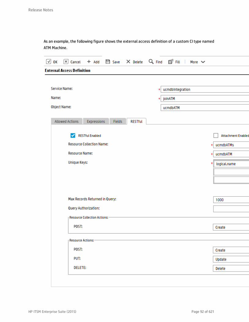
As an example, the following figure shows the external access definition of a custom CI type namedATM Machine.
Release Notes
HP ITSM Enterprise Suite (2015) Page 92 of 621
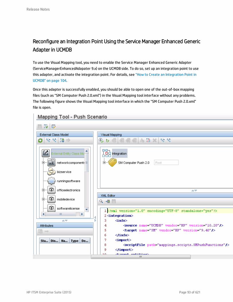
Reconfigure an Integration Point Using the Service Manager Enhanced GenericAdapter in UCMDB
To use the Visual Mapping tool, you need to enable the Service Manager Enhanced Generic Adapter(ServiceManagerEnhancedAdapater 9.x) on the UCMDB side. To do so, set up an integration point to usethis adapter, and activate the integration point. For details, see "How to Create an Integration Point inUCMDB" on page 104.
Once this adapter is successfully enabled, you should be able to open one of the out-of-box mappingfiles (such as "SM Computer Push 2.0.xml") in the Visual Mapping tool interface without any problems.The following figure shows the Visual Mapping tool interface in which the "SM Computer Push 2.0.xml"file is open.
Release Notes
HP ITSM Enterprise Suite (2015) Page 93 of 621
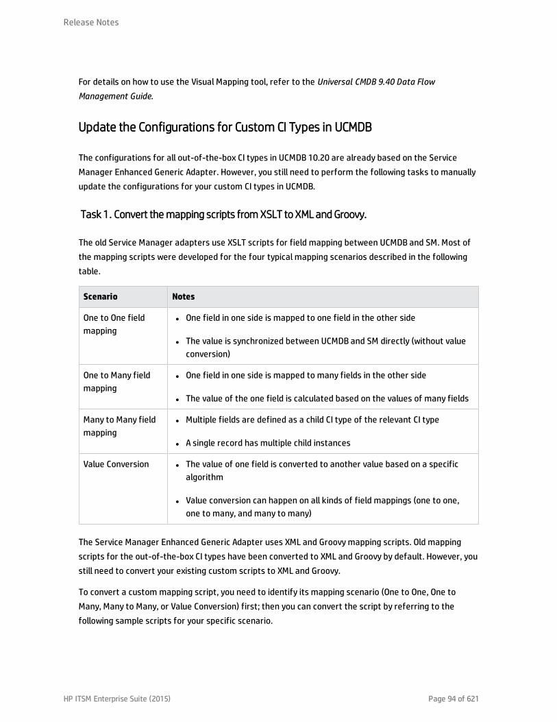
For details on how to use the Visual Mapping tool, refer to the Universal CMDB 9.40 Data FlowManagement Guide.
Update the Configurations for Custom CI Types in UCMDB
The configurations for all out-of-the-box CI types in UCMDB 10.20 are already based on the ServiceManager Enhanced Generic Adapter. However, you still need to perform the following tasks to manuallyupdate the configurations for your custom CI types in UCMDB.
Task 1. Convert the mapping scripts from XSLT to XML and Groovy.
The old Service Manager adapters use XSLT scripts for field mapping between UCMDB and SM. Most ofthe mapping scripts were developed for the four typical mapping scenarios described in the followingtable.
Scenario Notes
One to One fieldmapping
l One field in one side is mapped to one field in the other side
l The value is synchronized between UCMDB and SM directly (without valueconversion)
One to Many fieldmapping
l One field in one side is mapped to many fields in the other side
l The value of the one field is calculated based on the values of many fields
Many to Many fieldmapping
l Multiple fields are defined as a child CI type of the relevant CI type
l A single record has multiple child instances
Value Conversion l The value of one field is converted to another value based on a specificalgorithm
l Value conversion can happen on all kinds of field mappings (one to one,one to many, and many to many)
The Service Manager Enhanced Generic Adapter uses XML and Groovy mapping scripts. Old mappingscripts for the out-of-the-box CI types have been converted to XML and Groovy by default. However, youstill need to convert your existing custom scripts to XML and Groovy.
To convert a custom mapping script, you need to identify its mapping scenario (One to One, One toMany, Many to Many, or Value Conversion) first; then you can convert the script by referring to thefollowing sample scripts for your specific scenario.
Release Notes
HP ITSM Enterprise Suite (2015) Page 94 of 621

Tip: In all mapping scenarios, you can use the Visual Mapping tool to generate an XML scriptskeleton. Compared with the use of an old XSLT adapter, this is much easier as you can drag anddrop the mapped fields to generate the script instead of writing every code line from scratch. Fordetails about how to use XML and Groovy scripts in the UCMDB integration framework, see the HPUniversal CMDB 10.20 Developer Reference Guide.
Tip: The Service Manager Enhanced Generic Adapter has four out-of-the-box Groovy scripts, whichyou can use as a reference:
l SMUtils.groovy: defines common methods used for push, population, and federation.
l SMPushFunctions.groovy: defines the methods used in the out-of-the-box push mappingscripts.
l SMPopulateFunctions.groovy: defines the methods used in the out-of-the-box populationmapping scripts.
l SMFederationFunctions.groovy: defines the methods used in the out-of-the-box federationmapping scripts.
Additionally, the SMFederationConverter.groovy script defines value conversions for federation.
Field mapping must use the correct data type for each attribute. It is convenient to determine the datatype for an attribute by using the Visual Mapping tool. The following figure illustrates the data type forthe CIIdentifier attribute. You can either find the data type from the External Class Model Attributespane or simply drag and drop the attribute from that pane to the Visual Mapping area to automaticallyget the correct data type.
Release Notes
HP ITSM Enterprise Suite (2015) Page 95 of 621
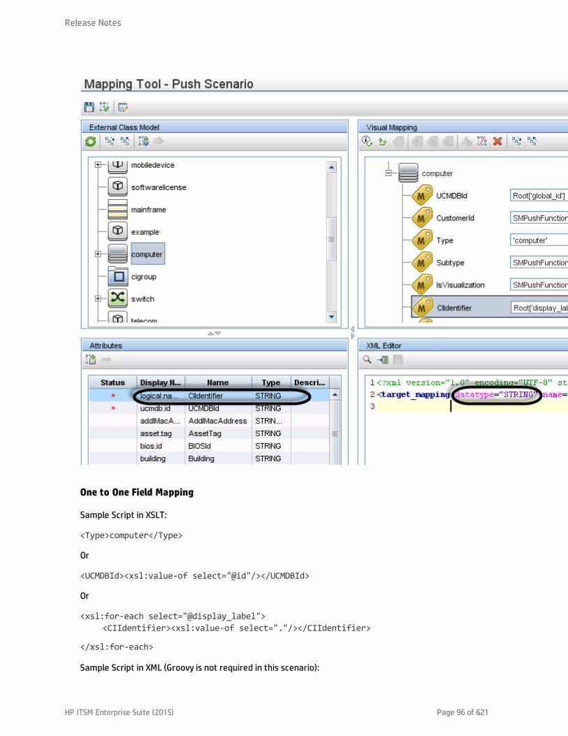
One to One Field Mapping
Sample Script in XSLT:
<Type>computer</Type>
Or
<UCMDBId><xsl:value-of select="@id"/></UCMDBId>
Or
<xsl:for-each select="@display_label"><CIIdentifier><xsl:value-of select="."/></CIIdentifier>
</xsl:for-each>
Sample Script in XML (Groovy is not required in this scenario):
Release Notes
HP ITSM Enterprise Suite (2015) Page 96 of 621

<target_mapping datatype="STRING" name="CIIdentifier" value="Root['display_label']"/>
Where: The datatype must be the correct data type defined in Service Manager for the attribute. Youcan find the data type from the Visual Mapping tool interface.
One to Many Field Mapping
Sample Script in XSLT:
<xsl:variable name="prefix" select="'Value>'"/><xsl:variable name="suffix" select="'</Value'"/><Subtype>
<xsl:choose><xsl:when test="contains(@node_role,concat($prefix,'desktop',$suffix))
">Desktop</xsl:when><xsl:when test="@os_family"><xsl:value-of select="@os_family"/></xsl:when><xsl:otherwise>Server</xsl:otherwise></xsl:choose>
</Subtype>
Sample Script in XML:
<target_mapping datatype="STRING" name="Subtype" value="SMPushFunctions.getSubType('computer',Root['node_role'],Root['os_family'])"/>
Sample Script in Groovy:
You must develop a groovy function to implement the mapping logic. Usually the relevant fields in thecounterpart system will be used as the parameters of the Groovy function.
Many to Many Field Mapping
Sample Script in XSLT:
<xsl:for-each select="cpus"><cpu>
<xsl:for-each select="cpu"><cpu>
<CpuID><xsl:value-of select="@cpu_id"/></CpuID><CpuName><xsl:value-of select="@name"/></CpuName><CpuClockSpeed>
<xsl:value-of select="@cpu_clock_speed"/></CpuClockSpeed>
</cpu></xsl:for-each>
Release Notes
HP ITSM Enterprise Suite (2015) Page 97 of 621

</cpu></xsl:for-each>
Sample Script in XML:
<for-each-source-entity count-index="i" source-entities="Root.Cpu"><target_entity name="cpu">
<target_mapping datatype="STRING" name="CpuID" value="Root.Cpu[i]['cpu_id']"/>
<target_mapping datatype="STRING" name="CpuName" value="Root.Cpu[i]['name']"/>
<target_mapping datatype="STRING" name="CpuClockSpeed" value="Root.Cpu[i]['cpu_clock_speed']"/>
</target_entity></for-each-source-entity>
Where: <source-entities> (Root Cpu) comes from the local TQL query structure, while <target_entityname> (cpu) comes from the <cpu> tag in the XSLT file.
Note: Groovy scripts are not required for this scenario.
Value Conversion
Sample Script in XSLT:
<xsl:if test="@customer_id"><xsl:variable name="ucmdbCustomerId" select="@customer_id"/><xsl:variable name="tenantMappingEntry" select="document('SM_MT_
mapping.xml')/list['TenantMapping']/entry[@ucmdb=$ucmdbCustomerId]"/><xsl:choose>
<xsl:when test="$tenantMappingEntry"><CustomerId><xsl:value-of
select="$tenantMappingEntry/@sm"/></CustomerId></xsl:when><xsl:otherwise>
<CustomerId><xsl:value-of select="@customer_id"/></CustomerId></xsl:otherwise>
</xsl:choose></xsl:if>
Or
<xsl:if test="contains(@node_role,concat($prefix,'virtualized_system',$suffix))"><IsVisualization>true</IsVisualization>
</xsl:if>
Sample Script in XML:
Release Notes
HP ITSM Enterprise Suite (2015) Page 98 of 621

<target_mapping datatype="STRING" name="CustomerId"value="SMPushFunctions.getCustomerId(CustomerInformation)"/>
Or
<target_mapping datatype="BOOLEAN" name="IsVisualization"value="SMPushFunctions.isVisualization(Root['node_role'])"/>
Note: Usually the relevant field in the counterpart system will be used as one of the parameters ofthe Groovy function.
Sample Scripts in Groovy:
/*** Priority Mapping* [uCMDB value : SM value ]*/private static final def PriorityMapping = [
"1_critical":"1","2_high":"2","3_average":"3","4_low":"4"];
/**
* Convert the Priority value from uCMDB to SM** @param priority uCMDB Priority value* @return SM Priority value*/public static String convertPriority(String priority, DataAdapterLogger log)
{return convertEnumValue(priority,"Priority");
}
Task 2. Update the configuration files.
Update the files as described in the following table.
Release Notes
HP ITSM Enterprise Suite (2015) Page 99 of 621

File Description
icon.properties This configuration file defines the UCMDB icons that will be displayed in themapping tool for Service Manager Device Types. If you have defined any customdevice types in SM, you can update this configuration file to assign themappropriate icons.
For more information, see the Universal CMDB Data Flow Management Guide.
sm.properties This is the integration adapter configuration file. If you have modified the out-of-the-box settings in your old sm.properties file (for example, the number ofconcurrent threads), you need to update this configuration file accordingly forthose options that are still valid in the Service Manager Enhanced Generic Adapter.
For more information, see "How to Update the Integration Adapter ConfigurationFile (sm.properties)" on page 198.
smFedConf.xml This configuration file is used for federation and is introduced by the ServiceManager Enhanced Generic Adapter. If you have any custom logic for thefederation feature, such as custom fields for federation CIs, you need to updatethis configuration file.
For more information, see "Troubleshooting Federation Issues" on page 272.
smPopConf.xml This configuration file is used for population and replaces the oldsmPopConfFile.xml configuration file. If you have any custom logic for thepopulation feature, such as custom query conditions, you need to update thisconfiguration file.
For more information, see the following topics:
"What Is the Purpose of the <container> Element in the Population ConfigurationFile (smPopConf.xml)?" on page 180
"No TQL Query Configured in smPopConf.xml " on page 268
smPushConf.xml This configuration file is used for relationship data push and replaces the oldsmSyncConfFile.xml configuration file.
For more information about this file, see the following topics:
"How to Map a Relationship Type Query to the Service Manager Web ServiceObject" on page 245
"Query not Configured in smPushConf.xml" on page 262
Release Notes
HP ITSM Enterprise Suite (2015) Page 100 of 621
Task 3. Enable Push, Population and Federation for CI types.
Once you have completed the tasks described above, you must edit your integration point to add Pushand Population jobs for the CI types, as well as enable Federation for supported CI types. For details, seethe following topics:
"How to Create an Integration Point in UCMDB" on page 104
"How to Define Data Push Jobs in UCMDB" on page 113
"How to Define Population Jobs in UCMDB" on page 109
"How to Add an Attribute of a Supported CI Type for Federation" on page 251
Integration Setup Overview
The integration requires setup on both the UCMDB and Service Manager systems.
This task includes the following steps:
1. Set up the Service Manager system.See "HP Service Manager Setup" below.
2. Set up the UCMDB system.See "HP Universal CMDB Setup" on page 104.
3. Run the UCMDB population jobs to synchronize CIs to UCMDB.See "Populating UCMDB with Service Manager CI Data" on page 109.
4. Run the UCMDB data push jobs to transfer CIs to Service Manager.See "Populating UCMDB with Service Manager CI Data" on page 109.
HP Service Manager Setup
You must complete the following tasks from your Service Manager system to support the integration.
1. Create a dedicated integration user account in Service Manager.See "How to Create an Integration User Account" on the next page.
2. Add the UCMDB connection information to the system information record.See "How to Add the UCMDB Connection Information" on page 103.
Release Notes
HP ITSM Enterprise Suite (2015) Page 101 of 621
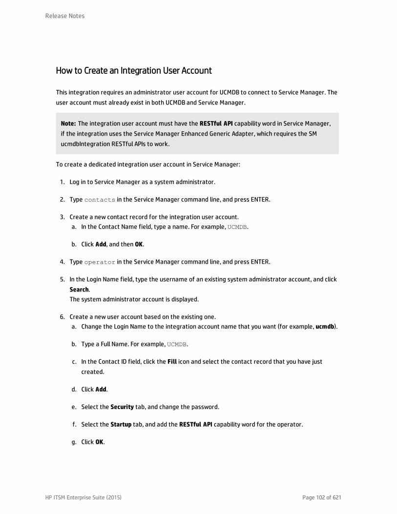
How to Create an Integration User Account
This integration requires an administrator user account for UCMDB to connect to Service Manager. Theuser account must already exist in both UCMDB and Service Manager.
Note: The integration user account must have the RESTful API capability word in Service Manager,if the integration uses the Service Manager Enhanced Generic Adapter, which requires the SMucmdbIntegration RESTful APIs to work.
To create a dedicated integration user account in Service Manager:
1. Log in to Service Manager as a system administrator.
2. Type contacts in the Service Manager command line, and press ENTER.
3. Create a new contact record for the integration user account.a. In the Contact Name field, type a name. For example, UCMDB.
b. Click Add, and then OK.
4. Type operator in the Service Manager command line, and press ENTER.
5. In the Login Name field, type the username of an existing system administrator account, and clickSearch.The system administrator account is displayed.
6. Create a new user account based on the existing one.a. Change the Login Name to the integration account name that you want (for example, ucmdb).
b. Type a Full Name. For example, UCMDB.
c. In the Contact ID field, click the Fill icon and select the contact record that you have justcreated.
d. Click Add.
e. Select the Security tab, and change the password.
f. Select the Startup tab, and add the RESTful API capability word for the operator.
g. Click OK.
Release Notes
HP ITSM Enterprise Suite (2015) Page 102 of 621

The integration user account is created. Later you will need to add this user account(username/password) in UCMDB, and then specify this user account in the Credentials ID field whencreating an integration point in UCMDB. See "How to Create an Integration Point in UCMDB" on the nextpage.
How to Add the UCMDB Connection Information
SM requires the UCMDB connection information to obtain CI attribute information from the UCMDBsystem, and display it in the Actual State section in the Service Manager configuration item form.
Caution: If you do not specify the correct connection information, an error, instead of UCMDB CIinformation, will be displayed in the Actual State section.
To add UCMDB connection information in Service Manager:
1. Log in to Service Manager as a system administrator.
2. Click System Administration > Base System Configuration > Miscellaneous > System InformationRecord.
3. Click the Active Integrations tab.
4. Select the HP Universal CMDB option.
5. In the UCMDB webservice URL field, type the URL to the HP Universal CMDB web service API. TheURL has the following format:http://<UCMDB server name>:<port>/axis2/services/ucmdbSMService
Replace <UCMDB server name> with the host name of your UCMDB server, and replace <port> withthe communications port that your UCMDB server uses.
6. In the UserId and Password fields, type the user credentials that are required to manage CIs on theUCMDB system. For example, the out-of-the-box administrator credentials are admin/admin.
7. Optionally, if you want to enable an integration to UCMDB Browser, in the UCMDB Browser URLfield, type your UCMDB Browser URL in the following format:http://<UCMDB browser server name>:<port>/ucmdb-browser
For example: http://myucmdbbrowserserver:8081/ucmdb-browser
Release Notes
HP ITSM Enterprise Suite (2015) Page 103 of 621

Note: If you specify the UCMDB Browser URL here, the View in UCMDB Browser button willreplace the View in UCMDB button in CI records synchronized from UCMDB; only when youleave this field empty, the View in UCMDB button will appear.
8. Click Save. Service Manager displays the message: Information record updated.
9. Log out of the Service Manager system.
10. Log back into the Service Manager system with an administrator account.
The Actual State section and the View in UCMDB Browser or View in UCMDB button will be available inCI records pushed from UCMDB.
HP Universal CMDB Setup
You must complete the following task from your UCMDB system to support the integration:
Create an integration point between UCMDB and Service Manager. See "How to Create an IntegrationPoint in UCMDB" below.
How to Create an Integration Point in UCMDB
A default UCMDB installation already includes the ServiceManagerEnhancedAdapter9-x package. To usethe integration package, you must create an integration point that lists the connection properties forthe integration.
Caution: For data population, this integration supports the use of only one probe for your ServiceManager system. In other words, you cannot run population jobs on different probes by setting upmultiple integration points with different probes for your Service Manager system. Only one probeis allowed for one Service Manager system.
To create an integration point, follow these steps:
1. Log in to UCMDB as an administrator.
2. Add the integration user account that you created in Service Manager.a. Click Administration > Users and Roles.
b. Click the Add New User icon .
Release Notes
HP ITSM Enterprise Suite (2015) Page 104 of 621
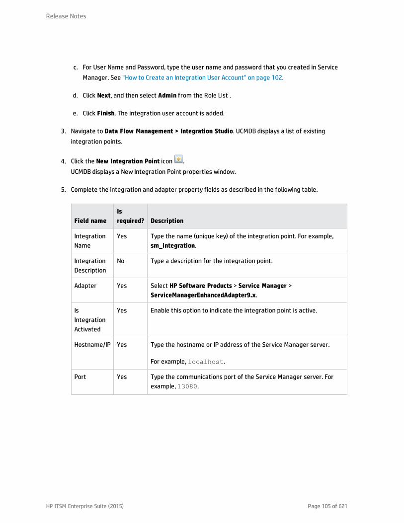
c. For User Name and Password, type the user name and password that you created in ServiceManager. See "How to Create an Integration User Account" on page 102.
d. Click Next, and then select Admin from the Role List .
e. Click Finish. The integration user account is added.
3. Navigate to Data Flow Management > Integration Studio. UCMDB displays a list of existingintegration points.
4. Click the New Integration Point icon .UCMDB displays a New Integration Point properties window.
5. Complete the integration and adapter property fields as described in the following table.
Field nameIsrequired? Description
IntegrationName
Yes Type the name (unique key) of the integration point. For example,sm_integration.
IntegrationDescription
No Type a description for the integration point.
Adapter Yes Select HP Software Products > Service Manager >ServiceManagerEnhancedAdapter9.x.
IsIntegrationActivated
Yes Enable this option to indicate the integration point is active.
Hostname/IP Yes Type the hostname or IP address of the Service Manager server.
For example, localhost.
Port Yes Type the communications port of the Service Manager server. Forexample, 13080.
Release Notes
HP ITSM Enterprise Suite (2015) Page 105 of 621
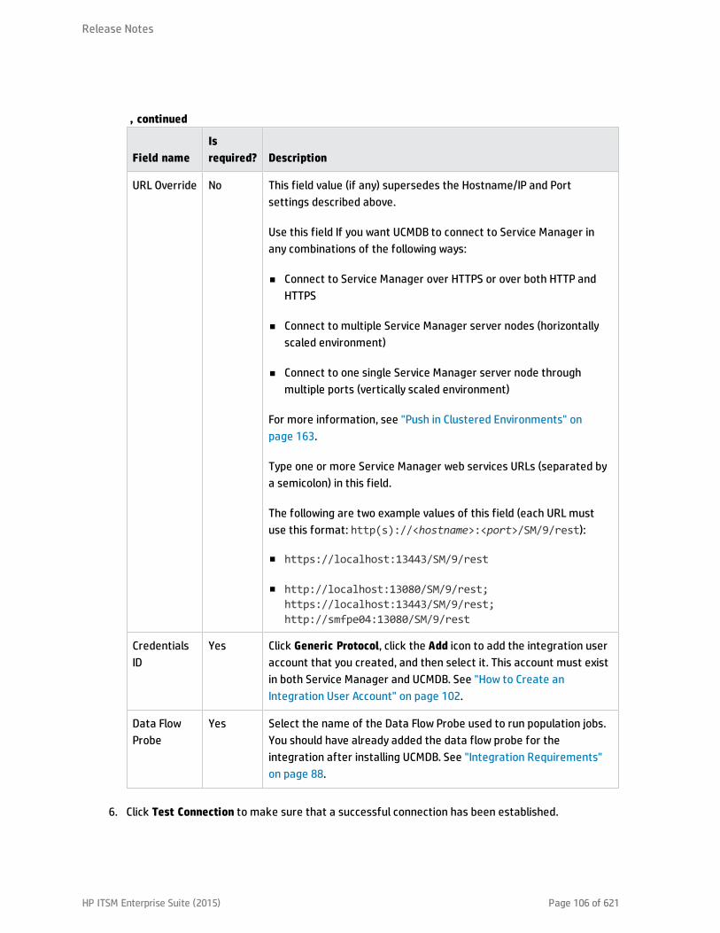
Field nameIsrequired? Description
URL Override No This field value (if any) supersedes the Hostname/IP and Portsettings described above.
Use this field If you want UCMDB to connect to Service Manager inany combinations of the following ways:
n Connect to Service Manager over HTTPS or over both HTTP andHTTPS
n Connect to multiple Service Manager server nodes (horizontallyscaled environment)
n Connect to one single Service Manager server node throughmultiple ports (vertically scaled environment)
For more information, see "Push in Clustered Environments" onpage 163.
Type one or more Service Manager web services URLs (separated bya semicolon) in this field.
The following are two example values of this field (each URL mustuse this format: http(s)://<hostname>:<port>/SM/9/rest):
n https://localhost:13443/SM/9/rest
n http://localhost:13080/SM/9/rest;https://localhost:13443/SM/9/rest;http://smfpe04:13080/SM/9/rest
CredentialsID
Yes Click Generic Protocol, click the Add icon to add the integration useraccount that you created, and then select it. This account must existin both Service Manager and UCMDB. See "How to Create anIntegration User Account" on page 102.
Data FlowProbe
Yes Select the name of the Data Flow Probe used to run population jobs.You should have already added the data flow probe for theintegration after installing UCMDB. See "Integration Requirements"on page 88.
, continued
6. Click Test Connection to make sure that a successful connection has been established.
Release Notes
HP ITSM Enterprise Suite (2015) Page 106 of 621
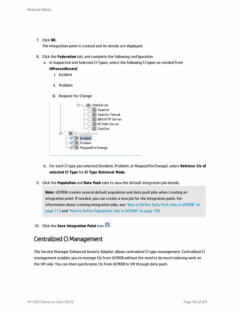
7. Click OK.The integration point is created and its details are displayed.
8. Click the Federation tab, and complete the following configuration.a. In Supported and Selected CI Types, select the following CI types as needed from
ItProcessRecord:i. Incident
ii. Problem
iii. Request for Change
b. For each CI type you selected (Incident, Problem, or RequestForChange), select Retrieve CIs ofselected CI Type for CI Type Retrieval Mode.
9. Click the Population and Data Push tabs to view the default integration job details.
Note: UCMDB creates several default population and data push jobs when creating anintegration point. If needed, you can create a new job for the integration point. Forinformation about creating integration jobs, see "How to Define Data Push Jobs in UCMDB" onpage 113 and "How to Define Population Jobs in UCMDB" on page 109.
10. Click the Save Integration Point icon .
Centralized CI Management
The Service Manager Enhanced Generic Adapter allows centralized CI type management. Centralized CImanagement enables you to manage CIs from UCMDB without the need to do much tailoring work onthe SM side. You can then synchronize CIs from UCMDB to SM through data push.
Release Notes
HP ITSM Enterprise Suite (2015) Page 107 of 621

Managing Out-Of-the-Box CI Types
SM and UCMDB provide out-of-the-box CI types, as well as mapping files for them. To modify an out-of-the-box CI type (for example, adding new attributes according to your business needs), you only need toopen the Visual Mapping tool, manually add new attributes to this CI type, and then apply the updatewithout leaving UCMDB. The new attribute will be automatically added to the relevant web service objecton the SM side.
Managing New Custom CI Types
When you create a new CI type in UCMDB, all relevant SM objects (DBDICT, JoinDef, Web Service API, DEMRule, and so on) for the new CI type are automatically created on the SM side, except the format (thenew CI type will use configurationItem as the default format).
To add a new CI type according to your business needs, you only need to add a new CI type and create aTQL query in UCMDB, and then create a matching SM CI type by using the Visual Mapping tool without theneed to leave UCMDB.
Note: The population feature enables you to synchronize CIs from SM to UCMDB. For informationabout the circumstances under which you need to use the population feature, see "When Do I Needthe Population Feature?" on page 176.
Visual Mapping Tool
The Service Manager Enhanced Generic Adapter comes with a Visual Mapping tool, which provides agraphic user interface for you to configure value and field mappings for complex data push orpopulation configurations.
The following table describes the panes of this graphic user interface.
Pane Description
Local Query Displays a hierarchical tree structure of the local TQL query in the CMDB.
Local QueryAttributes
This is the Attributes pane for the Local Query pane. It displays attributes of a localintegration TQL query.
VisualMapping
Allows you to establish mapping for items you select from the Local Query pane andthe External Class Model pane through a drag and drop.
XML Editor Allows to you edit XML mapping files in a text editor.
Release Notes
HP ITSM Enterprise Suite (2015) Page 108 of 621

Pane Description
ExternalClass Model
Displays a hierarchical tree structure of the external class model. For the UCMDB-SM integration, this pane displays supported CI types from the SM side.
ExternalClass ModelAttributes
The Attributes pane for the External Class Model pane displays attributes of anexternal class model. For the UCMDB-SM integration, this pane displays attributesfrom the SM side.
Populating UCMDB with Service Manager CI Data
In addition to pushing CI data from UCMDB to Service Manager, this integration also supports thepopulation of CI data (including CIs and CI relationships) from Service Manager to UCMDB. Theintegration can then update the list of CIs in UCMDB if new CIs or new attribute values are found inService Manager. The population of data from Service Manager to UCMDB is defined in the IntegrationStudio in UCMDB. You can manually run the population jobs, however HP recommends that you schedulethese jobs to keep your CIs and CI attributes up to date.
This task includes the following steps:
1. Define CI/CI Relationship population jobs in UCMDB.See "How to Define Population Jobs in UCMDB" below.
2. View the transferred CI/CI Relationship data in UCMDB.See "View Service Manager CI Data in UCMDB" on page 112.
3. Schedule CI population jobs to keep CIs and CI attributes up to date.See "How to Schedule CI Population Jobs" on page 112.
How to Define Population Jobs in UCMDB
A CI or relationship population job copies certain types of CIs or relationships from Service Manager toUCMDB.
To define a CI or CI relationship population job, follow these steps:
1. Log in to UCMDB as an administrator.
2. Navigate to Data Flow Management > Integration Studio. UCMDB displays a list of existingintegration points.
3. Open the integration point that you created for Service Manager.
Release Notes
HP ITSM Enterprise Suite (2015) Page 109 of 621
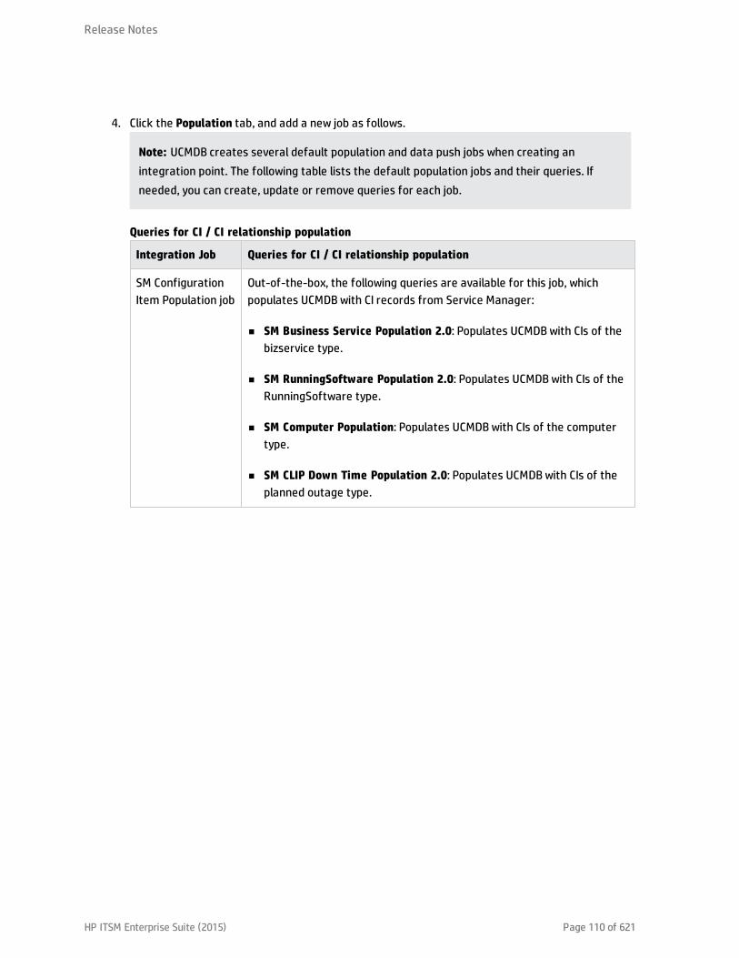
4. Click the Population tab, and add a new job as follows.
Note: UCMDB creates several default population and data push jobs when creating anintegration point. The following table lists the default population jobs and their queries. Ifneeded, you can create, update or remove queries for each job.
Integration Job Queries for CI / CI relationship population
SM ConfigurationItem Population job
Out-of-the-box, the following queries are available for this job, whichpopulates UCMDB with CI records from Service Manager:
n SM Business Service Population 2.0: Populates UCMDB with CIs of thebizservice type.
n SM RunningSoftware Population 2.0: Populates UCMDB with CIs of theRunningSoftware type.
n SM Computer Population: Populates UCMDB with CIs of the computertype.
n SM CLIP Down Time Population 2.0: Populates UCMDB with CIs of theplanned outage type.
Queries for CI / CI relationship population
Release Notes
HP ITSM Enterprise Suite (2015) Page 110 of 621
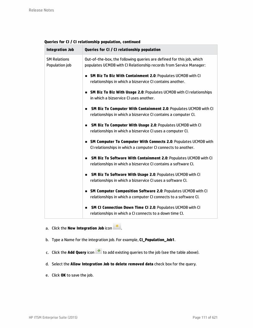
Integration Job Queries for CI / CI relationship population
SM RelationsPopulation job
Out-of-the-box, the following queries are defined for this job, whichpopulates UCMDB with CI Relationship records from Service Manager:
n SM Biz To Biz With Containment 2.0: Populates UCMDB with CIrelationships in which a bizservice CI contains another.
n SM Biz To Biz With Usage 2.0: Populates UCMDB with CI relationshipsin which a bizservice CI uses another.
n SM Biz To Computer With Containment 2.0: Populates UCMDB with CIrelationships in which a bizservice CI contains a computer CI.
n SM Biz To Computer With Usage 2.0: Populates UCMDB with CIrelationships in which a bizservice CI uses a computer CI.
n SM Computer To Computer With Connects 2.0: Populates UCMDB withCI relationships in which a computer CI connects to another.
n SM Biz To Software With Containment 2.0: Populates UCMDB with CIrelationships in which a bizservice CI contains a software CI.
n SM Biz To Software With Usage 2.0: Populates UCMDB with CIrelationships in which a bizservice CI uses a software CI.
n SM Computer Composition Software 2.0: Populates UCMDB with CIrelationships in which a computer CI connects to a software CI.
n SM CI Connection Down Time CI 2.0: Populates UCMDB with CIrelationships in which a CI connects to a down time CI.
Queries for CI / CI relationship population, continued
a. Click the New Integration Job icon .
b. Type a Name for the integration job. For example, CI_Population_Job1.
c. Click the Add Query icon to add existing queries to the job (see the table above).
d. Select the Allow Integration Job to delete removed data check box for the query.
e. Click OK to save the job.
Release Notes
HP ITSM Enterprise Suite (2015) Page 111 of 621
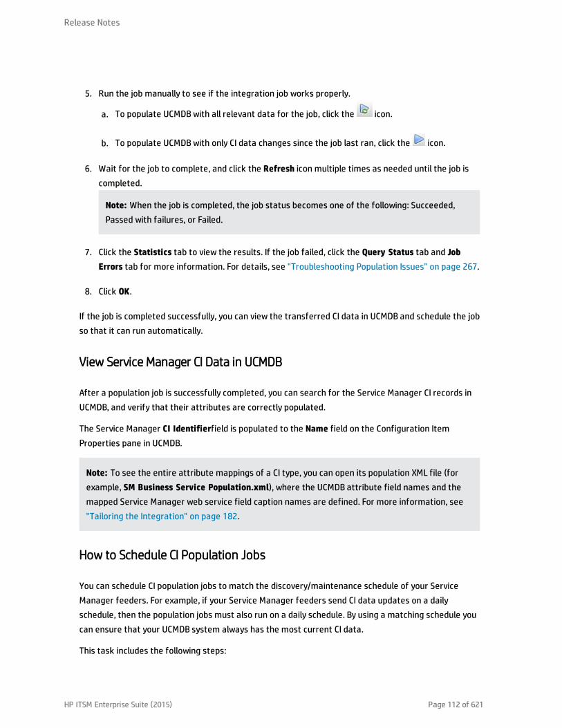
5. Run the job manually to see if the integration job works properly.
a. To populate UCMDB with all relevant data for the job, click the icon.
b. To populate UCMDB with only CI data changes since the job last ran, click the icon.
6. Wait for the job to complete, and click the Refresh icon multiple times as needed until the job iscompleted.
Note: When the job is completed, the job status becomes one of the following: Succeeded,Passed with failures, or Failed.
7. Click the Statistics tab to view the results. If the job failed, click the Query Status tab and JobErrors tab for more information. For details, see "Troubleshooting Population Issues" on page 267.
8. Click OK.
If the job is completed successfully, you can view the transferred CI data in UCMDB and schedule the jobso that it can run automatically.
View Service Manager CI Data in UCMDB
After a population job is successfully completed, you can search for the Service Manager CI records inUCMDB, and verify that their attributes are correctly populated.
The Service Manager CI Identifierfield is populated to the Name field on the Configuration ItemProperties pane in UCMDB.
Note: To see the entire attribute mappings of a CI type, you can open its population XML file (forexample, SM Business Service Population.xml), where the UCMDB attribute field names and themapped Service Manager web service field caption names are defined. For more information, see"Tailoring the Integration" on page 182.
How to Schedule CI Population Jobs
You can schedule CI population jobs to match the discovery/maintenance schedule of your ServiceManager feeders. For example, if your Service Manager feeders send CI data updates on a dailyschedule, then the population jobs must also run on a daily schedule. By using a matching schedule youcan ensure that your UCMDB system always has the most current CI data.
This task includes the following steps:
Release Notes
HP ITSM Enterprise Suite (2015) Page 112 of 621

1. Log in to UCMDB as an administrator.
2. Navigate to Data Flow Management > Integration Studio. UCMDB displays a list of integrationpoints.
3. Open the integration point for SM.
4. Click the Population tab, and select a population job from the list.
5. Click the Edit Integration Job icon.
6. Select the Scheduler enabled option.
7. Select the scheduling options that you want to use. For example, select Repeat every: Day andEnds: Never.
8. Select a Time Zone.
9. Click OK.
Pushing UCMDB CI Data to Service Manager
The integration requires a one-time transfer of CIs from UCMDB to Service Manager to populate theService Manager system with CIs. The integration will then update the list of CIs in Service Managerwhen UCMDB discovers new CIs or new attribute values. The integration accomplishes the push of CIdata using data push jobs in the UCMDB system. HP recommends that you schedule these jobs to keepyour CIs and CI attributes up to date.
This task includes the following steps:
1. Define CI/CI Relationship data push jobs.See "How to Define Data Push Jobs in UCMDB" below.
2. View the CI/CI Relationship data pushed from UCMDB.See "How to View UCMDB CI Data in Service Manager" on page 118.
3. Schedule data push jobs to keep CI/CI Relationship data up to date.See "How to Schedule Data Push Jobs" on page 117.
How to Define Data Push Jobs in UCMDB
Data push jobs copy CI or CI Relationship records from your UCMDB system to your Service Managersystem.
Release Notes
HP ITSM Enterprise Suite (2015) Page 113 of 621

To define a CI or CI relationship push job, follow these steps:
1. Log in to UCMDB as an administrator.
2. Navigate to Data Flow Management > Integration Studio. UCMDB displays a list of existingintegration points.
3. Select the Integration Point that you created for Service Manager. For example, sm_integration.
4. Click the Data Push tab.
5. Follow these steps to add a new data push job:
a. Click the New Integration Job icon .
Note: UCMDB creates a default data push job when creating an integration point. Thefollowing table lists the default data push job and its queries. If needed, you can create,update, or remove queries for the push job. To access these out-of-the-box queries for push,go to Modeling > Modeling Studio > Resources, select Queries for Resource Type, and thennavigate to Root > Integration > Push. For information about tailoring data push queries, see"How to Create a Query to Synchronize the CI Type" on page 228.
Integrationjob Queries
Integrationjob
Queries
Queries for CI / CI Relationship Push
Release Notes
HP ITSM Enterprise Suite (2015) Page 114 of 621

Integrationjob Queries
SM Pushjob
Out-of-the-box, the following queries are available for this job, which pushes CIrecords from UCMDB to Service Manager:
n SM Mainframe Push 2.0: pushes CIs of the mainframe type.
n SM Business Element Push 2.0: pushes CIs of the business application, andinfrastructure service types
n SM Network Component Push 2.0: pushes CIs of the network component type.
n SM Running Software Push 2.0: pushes CIs of the running software type.
n SM Business Service Push 2.0: pushes CIs of the business service type.
n SM Computer Push 2.0: pushes CIs of the computer type.
n SM Storage Push 2.0: pushes CIs of the storage type.
n SM Switch Push 2.0: pushes CIs of the switch type.
n SM Net Printer Push 2.0: pushes CIs of the net printer type.
n SM Cluster Push 2.0: pushes CIs of the cluster type.
n SM Mobile Device Push 2.0: pushes CIs of the mobile device type.
n SM Local Printer Push 2.0: pushes CIs of the local printer type.
Out-of-the-box, the following queries are available for this job, which pushes CIRelationship records from UCMDB to Service Manager:
n SM Layer2 Topology Relations Push 2.0: pushes compound CI relationshipsbetween nodes.
n SM Business Service Relations Push 2.0: pushes CI relationships whoseupstream CI type is business service.
n SM CRG Relations Push 2.0: pushes CI relationships whose upstream CI type iscluster.
n SM Node Relations Push 2.0: pushes direct CI relationships whose upstream CI
Queries for CI / CI Relationship Push , continued
Release Notes
HP ITSM Enterprise Suite (2015) Page 115 of 621

Integrationjob Queries
type is node.
Queries for CI / CI Relationship Push , continued
b. In the Name field, type a unique name for the job. For example, CI_Push_Job1.
c. Click the Add Query icon to add existing queries to the job.
d. Select the Allow Integration Job to delete removed data option for each query.
e. Click OK to save the job.
6. Run the job manually to verify that the integration job works properly.
Caution: If you have a huge amount of CI data in your UCMDB system, and this is your firsttime to push CI /CI Relationship data to Service Manager, it is recommended to select the “Addthe record” option instead of “Open a change” or “Open an incident” for “Action if matchingrecord does not exist” in each Discovery Event Manager Rules definition. Failure to do so maycause unnecessary performance problems. For details, see "How to Add Discovery EventManager Rules" on page 205.
a. To push all relevant data for the job, click the icon.
b. To push only data that was changed since the job last ran, click the icon.
Tip: You can stop a running push job by pressing the Stops the selected job icon .
7. Wait for the job to complete, and click the Refresh icon multiple times as needed until the job iscompleted.
Note: When the job is completed, the job status becomes one of the following depending onthe results: Completed successfully, Completed, or Failed.
8. Click the Statistics tab to view the results; if any errors occur click the Query Status tab and JobErrors tab for more information. For details, see "Troubleshooting Data Push Issues" on page 257.
9. Click OK.
Release Notes
HP ITSM Enterprise Suite (2015) Page 116 of 621
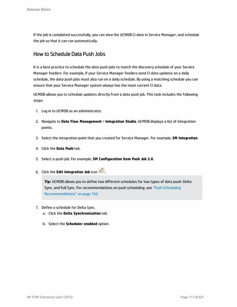
If the job is completed successfully, you can view the UCMDB CI data in Service Manager, and schedulethe job so that it can run automatically.
How to Schedule Data Push Jobs
It is a best practice to schedule the data push jobs to match the discovery schedule of your ServiceManager feeders. For example, if your Service Manager feeders send CI data updates on a dailyschedule, the data push jobs must also run on a daily schedule. By using a matching schedule you canensure that your Service Manager system always has the most current CI data.
UCMDB allows you to schedule updates directly from a data push job. This task includes the followingsteps:
1. Log in to UCMDB as an administrator.
2. Navigate to Data Flow Management > Integration Studio. UCMDB displays a list of integrationpoints.
3. Select the integration point that you created for Service Manager. For example, SM Integration.
4. Click the Data Push tab.
5. Select a push job. For example, SM Configuration Item Push Job 2.0.
6. Click the Edit Integration Job icon .
Tip: UCMDB allows you to define two different schedules for two types of data push: DeltaSync, and Full Sync. For recommendations on push scheduling, see "Push SchedulingRecommendations" on page 162.
7. Define a schedule for Delta Sync.a. Click the Delta Synchronization tab.
b. Select the Scheduler enabled option.
Release Notes
HP ITSM Enterprise Suite (2015) Page 117 of 621

c. Select the scheduling options that you want to use.
8. Click the Full Synchronization tab, and select the scheduling options that you want to use.
9. Click OK to save the data push job.
10. Repeat step 6 to step 9 for the rest of data push jobs of the integration point.
11. Save the integration point.
How to View UCMDB CI Data in Service Manager
After a push job is successfully completed, you can search for and verify the pushed CI/CI relationshipdata in Service Manager.
CI records pushed from UCMDB contains a View in UCMDB or View in UCMDB Browser button, whichenables you to access UCMDB or UCMDB Browser to view the CI information.
Note:l If you specified the UCMDB Browser URL in the System Information Record in SM, the View in
UCMDB Browser button is displayed; otherwise the View in UCMDB button is displayed.
l The UCMDB Browser is a lightweight UI designed for simple access to UCMDB configurationinformation. This is a tool for searching, locating and consuming configuration related data. It isan optional add-on to UCMDB. For more information, refer to the UCMDB Browserdocumentation.
To view UCMDB CI data in Service Manager:
Release Notes
HP ITSM Enterprise Suite (2015) Page 118 of 621
1. Log in to Service Manager as a system administrator.
2. Navigate to Configuration Management > Search CIs.
3. Open a CI record pushed from UCMDB.
4. If the View in UCMDB button is available, view the CI record in UCMDB.a. Click the View in UCMDB button. The UCMDB login screen opens.
b. Type a UCMDB username and password to log in.
The CI record opens in UCMDB. You can view its properties.
Note: You can enable Lightweight Single Sign-On (LW-SSO) for the integration so that ServiceManager web client users can bypass the UCMDB login screen. For details, see "How to EnableLightweight Single Sign-On (LW-SSO) Configuration" on page 172.
5. If the View in UCMDB Browser button is available, view the CI record in the UCMDB Browser.a. Click the View in UCMDB Browser button. The UCMDB Browser login screen opens.
b. Type a UCMDB Browser username and password to log in. The CI record opens in the UCMDBBrowser. You can view its properties and other information.
6. Open the Actual State section.Service Manager sends a web services request to UCMDB and displays all CI attributes that therequest returns.
Note: The web services request uses the UCMDB webservice URL and account (for example,admin/admin) defined in the System Information Record in Service Manager. See "How to Addthe UCMDB Connection Information" on page 103.
How to View the Change History of the Primary CI of a Problem Record
When integrated with UCMDB Browser, Service Manager displays a Primary CI History in UCMDB sectionin a problem record whose primary CI is synchronized from UCMDB. You can view the CI changes on thatprimary CI for root cause investigation.
For information about how to enable an integration with UCMDB Browser, see "How to Add the UCMDBConnection Information" on page 103.
To view the primary CI change history, follow these steps:
Release Notes
HP ITSM Enterprise Suite (2015) Page 119 of 621

1. Log in to Service Manager.
2. Navigate to Problem Management, and perform a search to open a problem record whose PrimaryCI is synchronized from UCMDB.
3. Click the Primary CI History in UCMDB tab.
Federating Service Manager Ticket Data to UCMDB
Federation does not physically copy data from Service Manager (SM) to UCMDB; it only retrieves SM datafor displaying in UCMDB. Out-of-the-box, the UCMDB-SM integration supports federation for theIncident, Problem, and RequestForChange external CI types in UCMDB. If you have enabled these CI typesfor federation when creating your integration point, in UCMDB you can retrieve Incident, Problem, andChange record data from SM.
Out-of-the-box, each of the CI types (Incident, Problem, or Change) supports federation of a subset oftheir attributes in Service Manager; however, the integration can federate more attributes if tailored assuch.
This section includes:
l "Federation Queries" below
l "Examples of Using Federation" below
l "How to Add an Attribute of a Supported CI Type for Federation" on page 251
Federation Queries
Federation uses queries to determine what data to retrieve from Service Manager. To retrieve specificticket data from Service Manager, you need to create a TQL query first.
The ServiceManagerEnhancedGenericAdapter9-x provides a bunch of sample federation queries, whichyou can use as a reference. They are available from the following path in UCMDB: Modeling > ModelingStudio > Resources > Integration > Service Manager > Federation.
Examples of Using Federation
You can use the federation feature in many different ways. The following are only examples of using thefeature.
This section describes four examples:
Release Notes
HP ITSM Enterprise Suite (2015) Page 120 of 621

l "Example 1: Federate All SM Incident Tickets" below
l "Example 2: Federate SM Incident Records that Affect a UCMDB Business Service CI" on page 125
l "Example 3: Federate Incident, Change, and Problem Record Data from Service Manager for UCMDBCIs" on page 133
l "Example 4: Retrieve Service Manager Records Related to a UCMDB CI" on page 136
Example 1: Federate All SM Incident Tickets
This example illustrates how you retrieve information of all Incident records that exist in ServiceManager.
1. Log in to UCMDB as an administrator.
2. Navigate to Modeling > Modeling Studio > Resources.
3. For Resource Type, select Queries from the list.
4. Click New > Query.
5. On the CI Types tab, navigate to ItProcessRecord > Incident, and drag it to the query pane on theright side.
Release Notes
HP ITSM Enterprise Suite (2015) Page 121 of 621
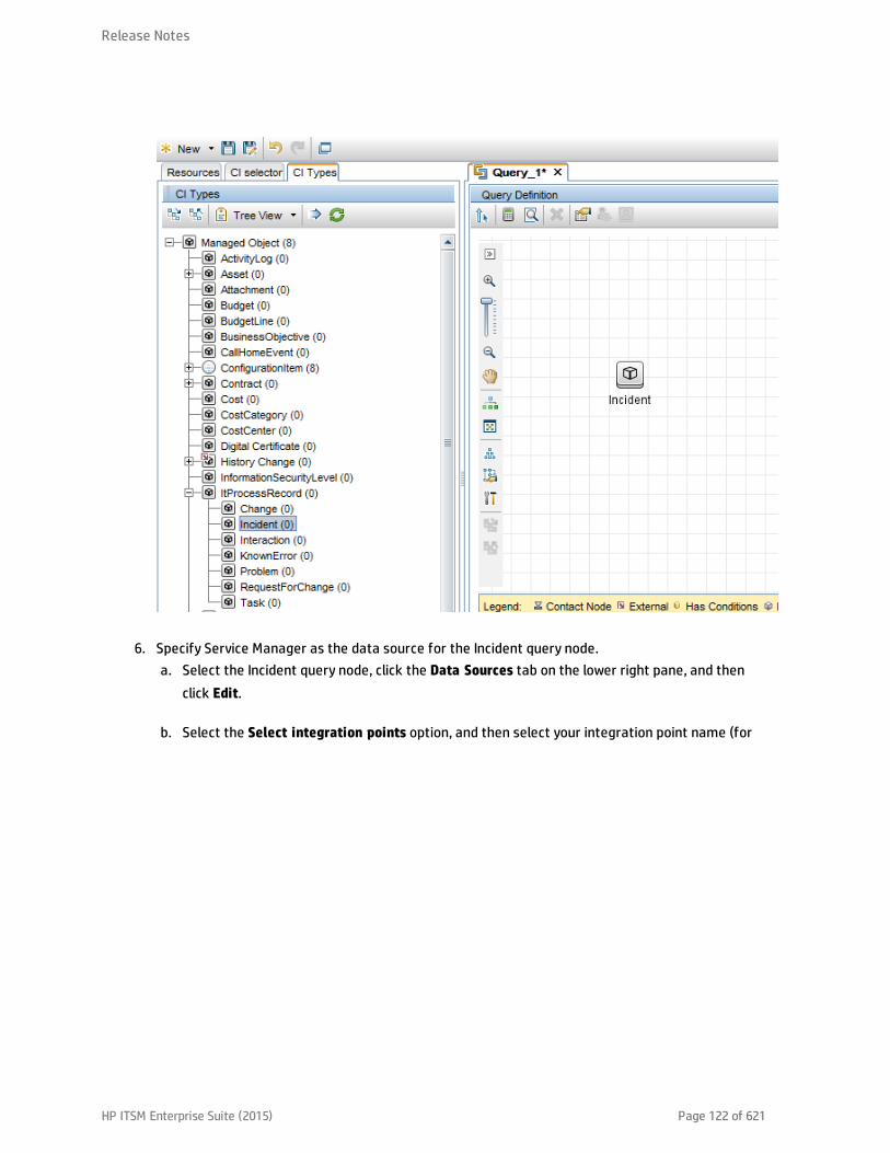
6. Specify Service Manager as the data source for the Incident query node.a. Select the Incident query node, click the Data Sources tab on the lower right pane, and then
click Edit.
b. Select the Select integration points option, and then select your integration point name (for
Release Notes
HP ITSM Enterprise Suite (2015) Page 122 of 621

example, sm_integration). Click OK.
7. Click the Save icon , and then type a query name and select a location in which to save the
query (for example, select the Root folder).
8. Select the Incident query node, and then click the Calculate Query Result Count icon .UCMDB returns the query result count. For example, the following figure shows that there are atotal of 116 Incident records in Service Manager.
Release Notes
HP ITSM Enterprise Suite (2015) Page 123 of 621

9. Right-click the Incident query node, and select Show Element Instances. UCMDB displays a list ofall Incident records that exist in Service Manager.
Release Notes
HP ITSM Enterprise Suite (2015) Page 124 of 621
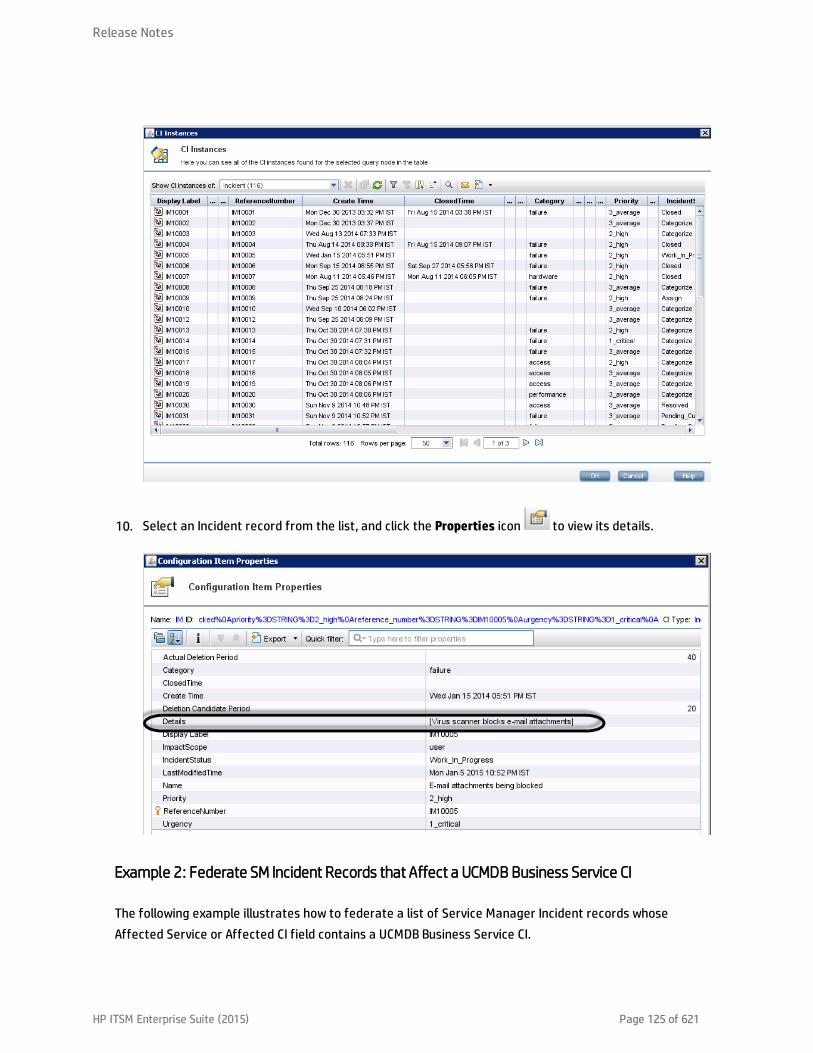
10. Select an Incident record from the list, and click the Properties icon to view its details.
Example 2: Federate SM Incident Records that Affect a UCMDB Business Service CI
The following example illustrates how to federate a list of Service Manager Incident records whoseAffected Service or Affected CI field contains a UCMDB Business Service CI.
Release Notes
HP ITSM Enterprise Suite (2015) Page 125 of 621

In this example, IM10005 in SM has an affected service named bizservice1, which was pushed fromUCMDB.
1. Log in to UCMDB as an administrator.
2. Navigate to Modeling > Modeling Studio > Resources.
3. For Resource Type, select Queries from the list.
4. Click New > Query.
5. On the CI Type tab, navigate to ConfigurationItem > BusinessElement > Service >BusinessService, and drag it to the query pane on the right side.
6. Navigate to ItProcessRecord > Incident, and drag the icon to the query pane.
Release Notes
HP ITSM Enterprise Suite (2015) Page 126 of 621

7. Click the Create Relationship icon .
8. Select the Incident query node, and drag the arrow from this node to the BusinessService node tocreate a regular relationship between the nodes.a. Select Regular Relationship, and click OK.
b. Select Membership, and optionally enter a relationship name (for example, Membership). Click
Release Notes
HP ITSM Enterprise Suite (2015) Page 127 of 621

OK.
9. Specify UCMDB as the data source for the BusinessService query node. To do this, follow thesesteps:a. Select the BusinessService query node.
b. On the lower right pane, click the Data Sources tab and then click Edit.
c. Make sure that the Local data source (UCMDB only) option is selected.
Release Notes
HP ITSM Enterprise Suite (2015) Page 128 of 621
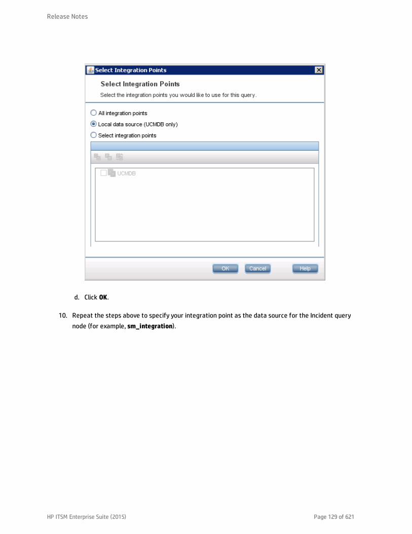
d. Click OK.
10. Repeat the steps above to specify your integration point as the data source for the Incident querynode (for example, sm_integration).
Release Notes
HP ITSM Enterprise Suite (2015) Page 129 of 621

11. Click the Calculate Query Result Count icon . The number of SM Incidents and the number of
their affected UCMDB Business Service CIs are displayed.
Release Notes
HP ITSM Enterprise Suite (2015) Page 130 of 621

12. Click the Preview icon to view the query results .
Release Notes
HP ITSM Enterprise Suite (2015) Page 131 of 621
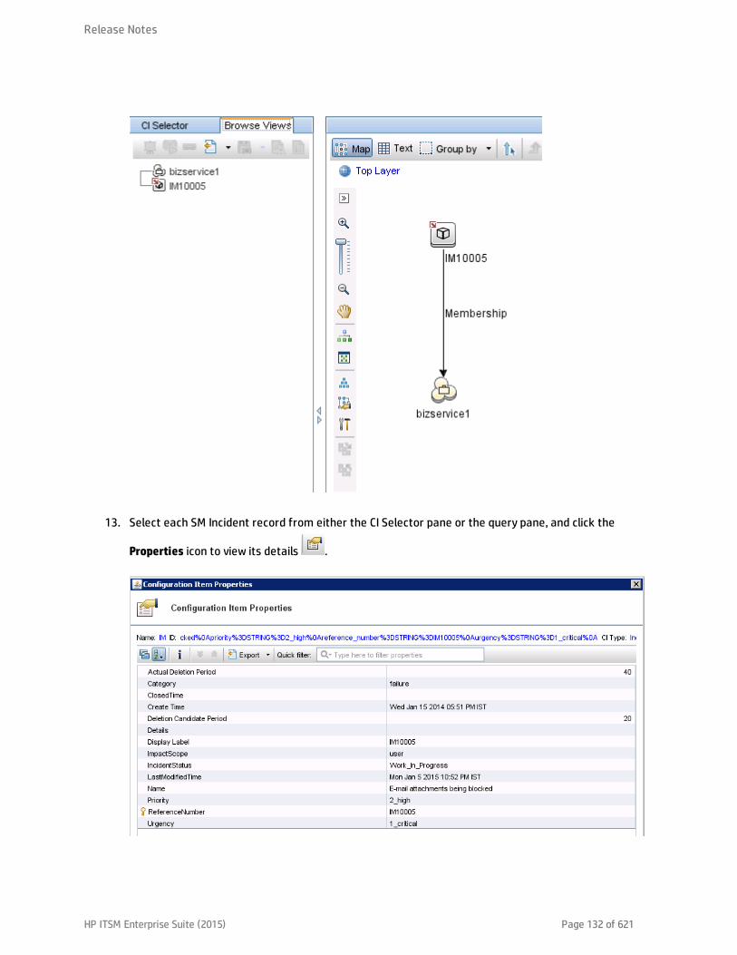
13. Select each SM Incident record from either the CI Selector pane or the query pane, and click the
Properties icon to view its details .
Release Notes
HP ITSM Enterprise Suite (2015) Page 132 of 621

14. Select each UCMDB CI record from the CI Selector pane, and click the Properties icon to view itsdetails.
Example 3: Federate Incident, Change, and Problem Record Data from Service Manager forUCMDB CIs
The following example illustrates how to retrieve information from the Incident, Change and Problemrecords in SM that affect a UCMDB Business Service CI.
1. Log in to UCMDB as an administrator.
2. Navigate to Modeling > Modeling Studio > Resources.
3. For Resource Type, select Queries from the list.
4. Click New > Query.
5. On the CI Type tab, go to ConfigurationItem > BusinessElement > Service > BusinessService, anddrag it to the query pane on the right side.
Release Notes
HP ITSM Enterprise Suite (2015) Page 133 of 621

6. Go to ItProcessRecord, and drag Incident, Problem, and RequestForChange to the query pane.
7. Click the Create Relationship icon to create regular relationships between the
BusinessService node and the other nodes, as shown in the following figure.
8. Select each node and click the Data Sources tab to specify a data source for each node.a. For the BusinessService node, specify UCMDB as the data source.
b. For the Incident, Problem, and RequestForChange nodes, specify your integration point as thedata source (sm_integration in this example).
9. Save the query.
10. Optionally, edit the BusinessService node properties as needed.a. Select the BusinessServic node, and click Edit on the lower right pane.
b. Click the Cardinality tab. The default Cardinality setting is displayed.
Release Notes
HP ITSM Enterprise Suite (2015) Page 134 of 621

c. If you wish, change either or both of the AND operators to OR. This will change the filtercriteria and therefore the query results.
11. Click the Preview icon to view the query results.
Release Notes
HP ITSM Enterprise Suite (2015) Page 135 of 621

12. Select each SM Incident record from either the CI Selector pane or the query pane, and click the
Properties icon to view its details.
13. Select each UCMDB CI record from either the CI Selector pane or the query pane, and on theRelated CIs tab click Show Related CIs to view its related CIs in both SM and UCMDB.
Example 4: Retrieve Service Manager Records Related to a UCMDB CI
The following example illustrates how to retrieve Service Manager records that are related to a UCMDBCI, by using the Get Related CIs functionality.
1. Log in to UCMDB as an administrator.
2. Navigate to Modeling > IT Universe Manager.
3. On the Search CIs tab, search for a UCMDB CI that has related records in Service Manager. Forexample, enter bizservice1 in the CI Name field, click Search, and then double-click the CI toopen it.
Release Notes
HP ITSM Enterprise Suite (2015) Page 136 of 621

4. If the Get Related CIs pane is not displayed, click the Show Get Related CIs pane icon .
5. Click the Select target Integration Points for related CIs icon .
6. Select the Select integration points option, and then select both UCMDB and your integrationpoint. Click OK.
7. Click Show Related CIs. The CI’s related SM records and UCMDB CIs are displayed.
Release Notes
HP ITSM Enterprise Suite (2015) Page 137 of 621

8. Select each SM record from the query pane, and click the Properties icon to view its details.
Multi-Tenancy (Multi-Company) Setup
Note: You cannot use the multi-tenancy configuration in the Universal CMDB, if you did notconfigure Universal CMDB for multi-tenancy at installtion.
The UCMDB-SM Integration supports a multi-tenancy configuration in which both the Service Managerand UCMDB systems track Configuration Items (CIs) and Configuration Item Relationships (CIRs) bycompany ID. In a multi-tenancy configuration, you can tailor the integration so that each tenant onlysees and works with the CIs and CIRs that match their company ID. Multi-tenancy is intended formanaged service providers (MSPs) who wish to offer Configuration Management as a service to multipletenants.
This chapter includes:
Release Notes
HP ITSM Enterprise Suite (2015) Page 138 of 621

l "Multi-Tenancy (Multi-Company) Support" below
l "Multi-Tenancy Requirements" on page 146
l "Setting up the Multi-Tenancy Integration in UCMDB" on page 147
l "Setting up the Multi-Tenancy Integration in Service Manager" on page 150
Multi-Tenancy (Multi-Company) Support
Multi-tenancy is when a single instance of software runs on a server, serving multiple clientorganizations (also referred to as tenants). Multi-tenancy contrasts with a multi-instance architecturewhere separate software instances or hardware systems are set up for different client organizations.
When implementing a multi-tenant architecture, a software application is designed to virtually partitionits data and configuration so that each client organization works with a customized virtual applicationinstance. The following figure illustrates an example multi-tenant integration deployment.
Every tenant configured in UCMDB works with the relevant tenant in SM. If UCMDB did not configuretenants, the tenant configuration must be activated in order to transfer the configuration from SM toUCMDB automatically. This function is performed once only by the system administrator.
In the event that UCMDB tenant configuration already exists and the SM configuration does not exist,SM tenants must be manually configured according to the UCMDB configuration.
Implementing Multi-Tenancy in the UCMDB-SM Integration
SM stores the company records that describe each tenant in the multi-tenant configuration. TheService Manager system is the definitive source for company records and pushes all new company IDsto the UCMDB system creating the equivalent entity in UCMDB.
Release Notes
HP ITSM Enterprise Suite (2015) Page 139 of 621
SM tracks the company ID of each CI and relationship in a multi-tenant configuration. CI records inheritthe company ID of the UCMDB feeder that discovered them. Relationship records inherit the company IDof the parent CI in the relationship.
Mandanten SM Security Layer
Mandanten is an SM software layer that is used to filter the customer ID from the CI information. SMuses the Mandanten to ensure that operators only see CI and relationship records where the CI'scompany ID matches the operator's company ID. If the view is restricted with Mandanten, then ServiceManager also restricts the view to all other related records such as change requests and incidents.
What Multi-Tenant Information is Stored in UCMDB
Your UCMDB system stores a company ID attribute for each CI and CIR. The company ID determines whatadapter and synchronization schedule your UCMDB system uses to update CI data. Each CI andrelationship record can only have one company ID. The UCMDB system obtains a company ID from theService Manager system.
If more than one tenant (company) shares the same CI, each tenant has their own unique CI recorddescribing the CI. In effect, the UCMDB system creates multiple CI records to track one managed asset.Each tenant’s CI record is unique to that tenant and lists the company's unique company ID.
What Multi-Tenant Information is Stored in Service Manager
Your Service Manager stores the company records that describe each tenant in the multi-tenantconfiguration. The Service Manager system is the definitive source of company IDs and pushes new andupdated information to your UCMDB system.
Service Manager tracks the company ID of each CI and relationship in a multi-tenant configuration. CIrecords inherit the company ID of the UCMDB feeder that discovered them. Relationship records inheritthe company ID of the parent CI in the relationship.
In a best practices implementation, Service Manager uses Mandanten to ensure that operators only seeCI and relationship records where the CI’s company ID matches the operator’s company ID. If you restrictthe view with Mandanten, then Service Manager also restricts the view to all other related records suchas change requests and incidents.
Release Notes
HP ITSM Enterprise Suite (2015) Page 140 of 621
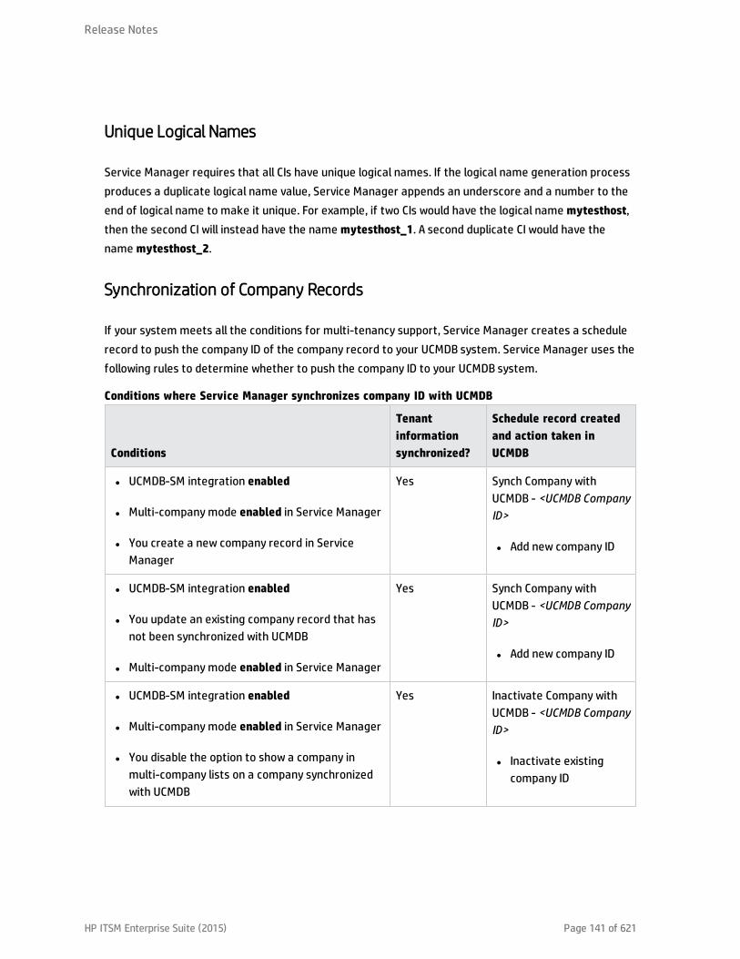
Unique Logical Names
Service Manager requires that all CIs have unique logical names. If the logical name generation processproduces a duplicate logical name value, Service Manager appends an underscore and a number to theend of logical name to make it unique. For example, if two CIs would have the logical name mytesthost,then the second CI will instead have the name mytesthost_1. A second duplicate CI would have thename mytesthost_2.
Synchronization of Company Records
If your system meets all the conditions for multi-tenancy support, Service Manager creates a schedulerecord to push the company ID of the company record to your UCMDB system. Service Manager uses thefollowing rules to determine whether to push the company ID to your UCMDB system.
Conditions
Tenantinformationsynchronized?
Schedule record createdand action taken inUCMDB
l UCMDB-SM integration enabled
l Multi-company mode enabled in Service Manager
l You create a new company record in ServiceManager
Yes Synch Company withUCMDB - <UCMDB CompanyID>
l Add new company ID
l UCMDB-SM integration enabled
l You update an existing company record that hasnot been synchronized with UCMDB
l Multi-company mode enabled in Service Manager
Yes Synch Company withUCMDB - <UCMDB CompanyID>
l Add new company ID
l UCMDB-SM integration enabled
l Multi-company mode enabled in Service Manager
l You disable the option to show a company inmulti-company lists on a company synchronizedwith UCMDB
Yes Inactivate Company withUCMDB - <UCMDB CompanyID>
l Inactivate existingcompany ID
Conditions where Service Manager synchronizes company ID with UCMDB
Release Notes
HP ITSM Enterprise Suite (2015) Page 141 of 621

Conditions
Tenantinformationsynchronized?
Schedule record createdand action taken inUCMDB
l UCMDB-SM integration enabled
l Multi-company mode enabled in Service Manager
l You select the option to resynchronize withUCMDB on an existing company record
Yes Synch Company withUCMDB - <UCMDB CompanyID>
l Add new company ID
l UCMDB-SM integration enabled
l Multi-company mode enabled in Service Manager
l You enable the option to show a company inmulti-company lists for an inactivated company
Yes Synch Company withUCMDB - <UCMDB CompanyID>
l Reactivate company ID
l UCMDB-SM integration disabled
l Multi-company mode enabled in Service Manager
l You update an existing company record that hasalready been synchronized with UCMDB
No None
l UCMDB-SM integration disabled
l Multi-company mode enabled in Service Manager
l You create a new company record in ServiceManager
No None
l UCMDB-SM integration enabled
l Multi-company mode enabled in Service Manager
l You disable the option to show a company inmulti-company lists on a company notsynchronized with UCMDB
No None
l UCMDB-SM integration enabled
l Multi-company mode disabled in Service Manager
l You create a new company record in ServiceManager
No None
Conditions where Service Manager synchronizes company ID with UCMDB, continued
Release Notes
HP ITSM Enterprise Suite (2015) Page 142 of 621
UCMDB Customer ID
When you enable the multi-tenancy integration, Service Manager displays a new field in each companyrecord called UCMDB Customer ID. In order to synchronize a company record with UCMDB, you must firstprovide a value for this field. After you provide a UCMDB Customer ID value this field becomes read-only.You cannot change a company's UCMDB Customer ID after you set it.
This field only accepts numeric data up to ten characters long. Service Manager requires the field valueto be a unique positive whole number. You cannot enter duplicate values or use decimals, negativenumbers, or zero.
Your UCMDB system automatically uses the UCMDB customer ID of 1 when running in single tenantmode. You can reuse this default value in your multi-tenant implementation by assigning a ServiceManager company to have this UCMDB customer ID value. Out-of-the-box, no Service Manager companyhas the UCMDB customer ID of 1.
UCMDB User ID and Password
When you enable the multi-tenancy integration, Service Manager displays two new fields in eachcompany record called UCMDB UserId and UCMDB Password. These fields allow you to specify theconnection information you want Service Manager to use when requesting information for the ActualState section. Any user name and password you enter in these fields must be valid for your UCMDBsystem.
The user name and password you provide in the Company Information record takes precedence overthe user name and password you provide in the System Information record. This allows managedservice providers to control access to the UCMDB system on a tenant-by-tenant basis. If you do notprovide a company-specific UCMDB user name and password, Service Manager uses the credentials youprovided in the System Information record.
Company Code
The multi-tenancy integration requires that each company record has a unique Company Code(company field) value. Since Company Code is a required field, your existing company records shouldalready have Company Code values. However you should ensure that each company record has a uniqueCompany Code value.
When using Service Manager Enhanced Generic Adapter for the UCMDB-SM integration, you must defineyour company codes in the ServiceManagerEnhancedAdapter9-x/mappings/scripts/SMUtils.groovy fileusing the following format (where a comma is used to separate mapping entries):
Release Notes
HP ITSM Enterprise Suite (2015) Page 143 of 621
["<UCMDB Company 1 Code>":"<SM Company 1 Code>", "<UCMDB Company 2 Code>":"<SM Company 2Code>"]
For example: ["1":"hp", "2":"sap"]
Caution: You should not change the Company Code value after you have enabled the multi-tenancyintegration because this will cause your Service Manager data to become out of synch.
CI Reconciliation Rules
When multi-tenancy is enabled, Service Manager only reconciles the CIs whose company ID matches thecompany ID in the data push job. For example, when pushing CIs from company 2, the reconciliation rulesonly apply to the Service Manager CI records that have the company code corresponding to companynumber 2.
Company Information Pushed to CI and CI Relationship Records
When you enable the multi-tenancy integration, Service Manager inserts the SM Company Code value inCI and relationship records during data push. Service Manager uses the UCMDB Customer ID to look upthe matching SM Company Code value.
Company Information Replicated to Incident Records
When you enable the multi-tenancy integration and select the option to create incidents when UCMDBdiscovers new, updated, or deleted CIs, Service Manager inserts the SM Company Code value in theincident record during replication. Service Manager uses the UCMDB Customer ID to look up thematching SM Company Code value.
Schedule Records
Service Manager uses the problem schedule process to manage the synchronization of company IDs toyour UCMDB system. You can manually enable the problem schedule process from the System Statusform.
When the synchronization criteria are met as described in Table "Conditions where Service Managersynchronizes company ID with UCMDB" on page 141, Service Manager creates a “Synch Company withUCMDB - <UCMDB Company ID>” schedule record (for example, “Synch Company with UCMDB -1234567890”). If you inactivate a company, Service Manager creates an “Inactivate Company withUCMDB - <UCMDB Company ID>” schedule record (for example, “Inactivate Company with UCMDB -1234567890”). The problem schedule process processes the new schedule record on the nextbackground process iteration.
Release Notes
HP ITSM Enterprise Suite (2015) Page 144 of 621

If your Service Manager system cannot connect to your UCMDB system for some reason, it willreschedule the company synchronization at the next scheduled interval (the out-of-the-box interval is 5minutes). The problem schedule process updates the schedule record with the status rescheduled. Ifthe Service Manager system receives any other error message while connecting to the UCMDB system,it updates the schedule record with the status “application failed due to error - check msglog forpossible messages.”
Tenant-Specific Discovery Event Manager (DEM) Rules
You can implement the condition field function in order to create SM DEM rules that are specific to aparticular tenant in a multi-tenancy UCMDB-SM integration.
Tenant rules vary according to SM tenant configuration requirements, for each record information typepushed from UCMDB to SM different tenants can configure different DEM tenant rules.
Each tenant can have its own set of unique requirements and therefore may implement differentprocesses through the integration.
One tenant may require the addition of CIs directly to SM while another tenant may require openingchanges for each CI.
The following table shows a sample set of DEM rules that illustrate how to accomplish this.
DEM rule ID Action on new CI Condition
ucmdbNode_advantage Add CI company in $L.file=”advantage”
ucmdbNode_hp Create change company in $L.file=”HP”
Tenant-specific DEM rules
Note: DEM Rules
When creating DEM rules make sure to create separate DEM rules for each tenant.
Multi-Tenancy Use Cases
The following table describes the necessary actions to perform in various deployment situations toaddress multi-tenancy issues.
Release Notes
HP ITSM Enterprise Suite (2015) Page 145 of 621

DeploymentIntegrationType Description
UCMDB withmulti-tenancyrules
SM withoutmulti-tenancyrules
When implementing a UCMDB-SM deployment that has existing multi-tenancy rules inUCMDB and does not have multi-tenancy rules configured in SM, the user createsmulti-tenancy rules in SM manually and according to the rules in UCMDB.
SM withmulti-tenancyrules
UCMDBwithoutmulti-tenancyrules
When implementing a UCMDB-SM deployment that has existing multi-tenancy rules inconfigured SM and does not have multi-tenancy rules configured in UCMDB, the usercreates multi-tenancy rules in UCMDB manually as well as according to the rulespreviously configured in SM.
UCMDBwithoutmulti-tenancyrules
SM withoutmulti-tenancyrules
When implementing a UCMDB-SM deployment that does not have multi-tenancy rulesconfigured in UCMDB or in SM, the user configures the rules in SM.
During the configuration process using the SM multi-tenancy wizard the user cancreate corresponding tenancy configuration in UCMDB. By creating correspondingtenancy configurations in SM the user also creates a corresponding tenant in UCMDB.
Multi-tenancy use cases
Multi-Tenancy Requirements
Your system must meet the following requirements in order for the integration to support multi-tenancy.
l HP Universal CMDB version 8.02 or later
l HP Service Manager version 9.20 or later
Release Notes
HP ITSM Enterprise Suite (2015) Page 146 of 621
l Integration enabled between UCMDB and Service Manager
l Multi-company mode enabled on the Service Manager system
l Problem schedule process running on the Service Manager system
For additional information about the multi-tenancy integration, you can visit the HP Software SupportOnline web site or refer to the Service Manager help.
Setting up theMulti-Tenancy Integration in UCMDB
You need to perform the following tasks in UCMDB to set up the multi-tenancy integration.
1. Install a separate data flow probe for each tenant the integration will support.See "How to Install a Separate Data Flow Probe for Each Tenant" below.
2. Start tenant-specific data flow probes.See "How to Start Tenant-Specific Data Flow Probes" on page 149.
3. Configure IP address ranges for tenant-specific data flow probes.See "How to Configure IP Ranges for Tenant-Specific Data Flow Probes" on page 149.
Caution: Multi-tenancy is not supported for population when the integration uses the ServiceManager Enhanced Generic Adapter.
How to Install a Separate Data Flow Probe for Each Tenant
If you plan to support a multi-tenant configuration, you must install a separate data probe for eachtenant. Out-of-the-box, the UCMDB installer only installs one data flow probe and service.
To install additional data flow probes and start them from your operating system command prompt:
1. Log in to the host of your UCMDB system as an administrator.
2. Insert the HP Universal CMDB Setup Windows DVD into the system disc drive.
3. Start the Data Flow Probe installer (HPUCMDB_DataFlowProbe_x.xx.exe).
4. Follow the on-screen instructions to complete the wizard, but use the following values for eachdata flow probe you wish to install.
Release Notes
HP ITSM Enterprise Suite (2015) Page 147 of 621
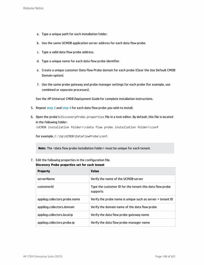
a. Type a unique path for each installation folder.
b. Use the same UCMDB application server address for each data flow probe.
c. Type a valid data flow probe address.
d. Type a unique name for each data flow probe identifier.
e. Create a unique customer Data Flow Probe domain for each probe (Clear the Use Default CMDBDomain option).
f. Use the same probe gateway and probe manager settings for each probe (for example, usecombined or separate processes).
See the HP Universal CMDB Deployment Guide for complete installation instructions.
5. Repeat step 3 and step 4 for each data flow probe you wish to install.
6. Open the probe’s DiscoveryProbe.properties file in a text editor. By default, this file is locatedin the following folder:<UCMDB installation folder>\<data flow probe installation folder>\conf
For example, C:\hp\UCMDB\DataFlowProbe\conf.
Note: The <data flow probe installation folder> must be unique for each tenant.
7. Edit the following properties in the configuration file.
Property Value
serverName Verify the name of the UCMDB server
customerId Type the customer ID for the tenant this data flow probesupports
appilog.collectors.probe.name Verify the probe name is unique such as server + tenant ID
applilog.collectors.domain Verify the domain name of the data flow probe
appilog.collectors.local.ip Verify the data flow probe gateway name
appilog.collectors.probe.ip Verify the data flow probe manager name
Discovery Probe properties set for each tenant
Release Notes
HP ITSM Enterprise Suite (2015) Page 148 of 621
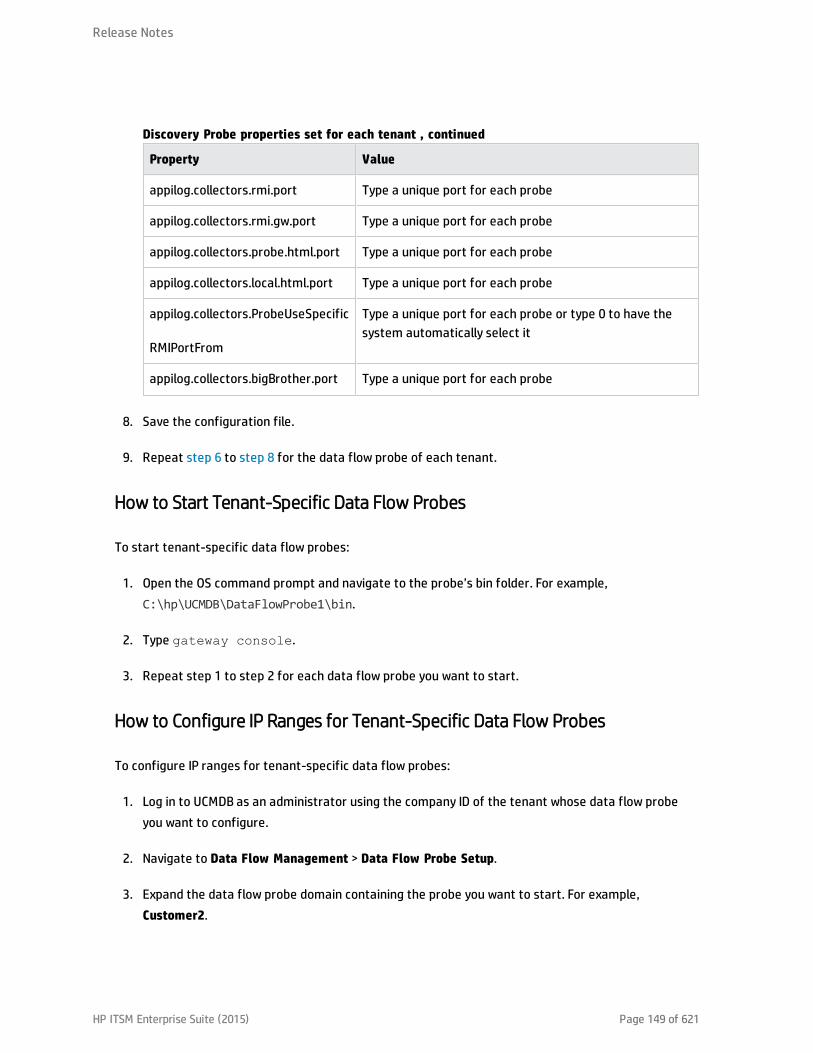
Property Value
appilog.collectors.rmi.port Type a unique port for each probe
appilog.collectors.rmi.gw.port Type a unique port for each probe
appilog.collectors.probe.html.port Type a unique port for each probe
appilog.collectors.local.html.port Type a unique port for each probe
appilog.collectors.ProbeUseSpecific
RMIPortFrom
Type a unique port for each probe or type 0 to have thesystem automatically select it
appilog.collectors.bigBrother.port Type a unique port for each probe
Discovery Probe properties set for each tenant , continued
8. Save the configuration file.
9. Repeat step 6 to step 8 for the data flow probe of each tenant.
How to Start Tenant-Specific Data Flow Probes
To start tenant-specific data flow probes:
1. Open the OS command prompt and navigate to the probe’s bin folder. For example,C:\hp\UCMDB\DataFlowProbe1\bin.
2. Type gateway console.
3. Repeat step 1 to step 2 for each data flow probe you want to start.
How to Configure IP Ranges for Tenant-Specific Data Flow Probes
To configure IP ranges for tenant-specific data flow probes:
1. Log in to UCMDB as an administrator using the company ID of the tenant whose data flow probeyou want to configure.
2. Navigate to Data Flow Management > Data Flow Probe Setup.
3. Expand the data flow probe domain containing the probe you want to start. For example,Customer2.
Release Notes
HP ITSM Enterprise Suite (2015) Page 149 of 621

4. Expand the Probe node and select the data flow probe you want to start. For example,Probe2Customer2.
5. Click the Add IP range icon .
6. Type an IP range you want the Data Flow Probe to scan. Optionally, add any IP ranges you want toexclude.
7. Click OK to save the IP range.
8. Repeat step 1 to step 7 for each data flow probe you want to configure.
Setting up theMulti-Tenancy Integration in Service Manager
You need to perform the following tasks in Service Manager to set up the multi-tenancy integration.
Multi-tenancy support is an optional feature of the integration intended for Managed Service Providers(MSPs) who want to offer Configuration Management as a service to their tenants. In a multi-tenancyconfiguration, each CI and CIR record has a corresponding company ID. Out-of-the-box, Service Managerallows all operators to view CI data regardless of the company ID. If you wish to restrict access to CI databy company ID, you must enable Mandanten and use the company ID field as a restricting query. See theService Manager help for more information about multi-company mode and Mandanten.
You must complete the following tasks from your Service Manager system to enable multi-tenancysupport for the integration.
1. Start the process schedule.See "How to Start the Schedule Process " on the next page.
2. Configure the Service Manager System Information Record.See "How to Configure the Service Manager System Information Record" on page 152.
3. Add tenant-specific UCMDB ID and password values to company records (optional).See "How to Add Tenant-Specific UCMDB User ID and Password Values" on page 153.
Release Notes
HP ITSM Enterprise Suite (2015) Page 150 of 621
4. Add UCMDB Customer ID values to existing company records.See "How to Add UCMDB Customer ID values to Existing Companies" on page 154.
5. Synchronize existing company records with UCMDB.See "How to Synchronize Existing Companies from Service Manager to UCMDB" on page 154.
6. Verify that Service Manager synchronized company records with UCMDB (optional).See "How to View Whether Company Information Is in UCMDB" on page 155.
7. Resynchronize existing company records with UCMDB (as needed).See "How to Resynchronize an Existing Company with UCMDB" on page 156.
8. Inactivate company records you do not want to be part of the integration (as needed).See "How to Inactivate a Synchronized Company" on page 157.
9. Reactivate inactive company records you want to be part of the integration (as needed).See "How to Reactivate an Inactive Company" on page 157
10. Add tenant-specific DEM rules.See "How to Add Tenant-Specific DEM Rules" on page 158.
How to Start the Schedule Process
This integration needs the problem schedule process in order to synchronize company records fromService Manager to UCMDB. Make sure that the process is started before you synchronize companyrecords.
To start the problem schedule process:
1. Log in to Service Manager as a system administrator.
2. From the System Navigator, click System Status to display a list of currently started schedules.
3. Click the Refresh Display button to refresh the list.
4. If the problem schedule process is not in the list, perform the following steps:a. Click the Start Scheduler button.
b. Double-click the problem schedule process.
A message is displayed, indicating that the problem schedule process is started.
Release Notes
HP ITSM Enterprise Suite (2015) Page 151 of 621
How to Configure the Service Manager System Information Record
To enable the integration to support multi-tenancy, you must provide additional information in theService Manager System Information Record.
Caution: In order to enable multi-tenancy support, you must use HP Universal CMDB version 8.02 orgreater. Earlier versions of HP Universal CMDB will produce an error message if you attempt to runthem in multi-tenancy mode.
To provide additional information in the Service Manager System Information Record:
1. Log in to Service Manager as a system administrator.
2. Navigate to System Administration > Base System Configuration > Miscellaneous > SystemInformation Record.
3. Click the General tab.
4. Enable the Run in Multi-Company Mode option.
5. Click the Active Integrations tab.
6. Select the HP Universal CMDB option.The form displays the UCMDB web service URL field.
7. In the UCMDB web service URL field, type the URL to the CI synchronization web service API. The URLhas the following format:http://<UCMDB server name>:<port>/axis2/services/ucmdbSMService
Replace <UCMDB server name> with the host name of your UCMDB server, and replace <port>with the communications port your UCMDB server uses.
8. In UserId and Password, type the user credentials required to manage CIs on the UCMDB system.For example, the out-of-the-box administrator credentials are admin/admin.
9. In the Multi-tenant web service URL field, type the URL to the company ID synchronization webservice API. The URL has the following format:http://<UCMDB server name>:<port>/axis2/services/UcmdbManagementService
Replace <UCMDB server name> with the host name of your UCMDB server, and replace <port>with the communications port your UCMDB server uses.
Release Notes
HP ITSM Enterprise Suite (2015) Page 152 of 621

10. Type the user name and password required to synchronize company IDs on the UCMDB system. Forexample, the out-of-the-box system administrator credentials for UCMDB are sysadmin/sysadmin.
11. Click Save. Service Manager displays the message: Information record updated.
12. Log out of the Service Manager system, and log in again with an administrator account.
13. Click System Status > Display Options > All Tasks.
14. Type k in the Command field next to the problem schedule process and click Execute Commands.Wait a few minutes for the problem schedule process to close.
15. Click Start Scheduler.
16. Double-click the problem schedule process. The system now supports multi-tenancy for UCMDB.
How to Add Tenant-Specific UCMDB User ID and Password Values
You can provide a tenant-specific UCMDB user name and password for Service Manager to use whenrequesting information for the Actual State section. If you provide no credentials, Service Manager usesthe credentials in the System Information Record for all tenants.
Note: Any credentials you provide in the company record take precedence over credentials youprovide in the System Information Record. The UCMDB UserId and UCMDB Password fields areavailable only when you have enabled the multi-tenancy integration.
To add tenant-specific UCMDB user name and password:
1. Log in to Service Manager as a system administrator.
2. Navigate to System Administration > Base System Configuration > Companies.
3. Type the search criteria you want to use to find company records. For example, leave the searchform blank to search all company records.
4. Click Search.
5. Type the user name you want this company to use to connect to UCMDB in the UCMDB UserId field.
6. Type the password for the UCMDB user name in the UCMDB Password field.
Release Notes
HP ITSM Enterprise Suite (2015) Page 153 of 621
7. Click Save.
8. Repeat step 3 through step 7 for each company for which you want to provide credentials.
How to Add UCMDB Customer ID values to Existing Companies
You can use the following steps to add a UCMDB Customer ID value to your existing Service Managercompany records.
1. Log in to Service Manager as a system administrator.
2. Navigate to System Administration > Base System Configuration > Companies.
3. Type the search criteria you want to use to find company records. For example, leave the searchform blank to search all company records.
4. Click Search.
5. Type a numeric value in the UCMDB Customer ID field for this company.
6. Click Save.
7. Service Manager prompts to confirm that you want to synchronize the record with UCMDB. ClickYes if you want to synchronize the company now, or click No if you want synchronize the companylater.
8. Click Next to go to the next company in the record list.
9. Repeat step 5 through step 8 for each company in the record list.
How to Synchronize Existing Companies from Service Manager to UCMDB
Your Service Manager system may already contain company records that you want to use with themulti-tenancy integration.
If you update any field in a company record that has not yet been synchronized to UCMDB, ServiceManager prompts whether you want to synchronize the company to UCMDB.
Note: Service Manager will not prompt you to synchronize the company record if you have disabledthe option to show the company in multi-company lists, or if there is a pending schedule recordassociated with the company. See "How to Inactivate a Synchronized Company" on page 157 for
Release Notes
HP ITSM Enterprise Suite (2015) Page 154 of 621

more information.
This task includes the following steps:
1. Log in to Service Manager as a system administrator.
2. Navigate to System Administration > Base System Configuration > Companies.
3. Type the search criteria you want to use to find company records. For example, leave the searchform blank to search all company records.
4. Click Search.
5. Select a company record to update.
6. Update the company record.
7. Click Save. Service Manager prompts you to confirm that you want to synchronize the record withUCMDB.
Note: Service Manager saves the company record regardless of your synchronization choice.
How to View Whether Company Information Is in UCMDB
When you enable the multi-tenancy integration, Service Manager displays a read-only field in eachcompany record that indicates whether or not the UCMDB Customer ID has been synchronized with yourUCMDB system.
Note: The UCMDB Customer ID field is visible only when you enable the multi-tenant UCMDBintegration.
To view whether company information is in UCMDB:
1. Log in to Service Manager as a system administrator.
2. Navigate to System Administration > Base System Configuration > Companies.
3. Type the search criteria you want to use to find company records. For example, leave the searchform blank to search all company records.
4. Click Search.
Release Notes
HP ITSM Enterprise Suite (2015) Page 155 of 621

5. Review the status of the Synched with UCMDB field.If the check box is checked, then Service Manager has already synchronized the company ID withyour UCMDB system. If the check box is unchecked, then Service Manager has yet to add thiscompany to your UCMDB system.
Note: For more information about synchronization failures, see "Schedule Records" onpage 144.
How to Resynchronize an Existing Company with UCMDB
Service Manager provides you a means to resynchronize company records with your UCMDB system incase you lose UCMDB data for some reason. For example, you might intentionally remove UCMDB dataduring integration testing, or you might need to recover data after a disaster. You can force ServiceManager to synchronize companies with your UCMDB system with the Re-synch with UCMDB option.
To resynchronize an existing company with UCMDB:
1. Log in to Service Manager as a system administrator.
2. Navigate to System Administration > Base System Configuration > Companies.
3. Type the search criteria you want to use to find company records. For example, leave the searchform blank to search all company records.
4. Click Search.
5. Select a company record to synchronize.
6. Click the Re-synch button next to the Synched with UCMDB check box.
Note: The Re-synch button is available only from company records that have already beensynchronized with UCMDB and have the Synched with UCMDB check box checked. If your UCMDBsystem already has a company with this ID value, it will ignore the resynchronization request.Service Manager will also ignore a resynchronization request if there is an existing schedule recordto resynchronize the company with UCMDB. In this case, it displays the message “A schedulerecord has already been added to re-synch this company with UCMDB.”
Release Notes
HP ITSM Enterprise Suite (2015) Page 156 of 621

How to Inactivate a Synchronized Company
After you have synchronized a company record with UCMDB you can no longer delete the record.Instead, you can inactivate a company record, which causes the UCMDB system to cease all further CIupdates for the company. Any existing CI data for the company remains in the UCMDB systemassociated with the inactive UCMDB Customer ID, but both the company and any associated CIs will nolonger be visible from the UCMDB system.
To inactivate a synchronized company:
1. Log in to Service Manager as a system administrator.
2. Navigate to System Administration > Base System Configuration > Companies.
3. Type the search criteria you want to use to find company records. For example, leave the searchform blank to search all company records.
4. Click Search.
5. Select a company record to inactivate.
6. Select No from Show Company in Multi-Company Lists.
7. Click Save.
8. If this company was previously synchronized with UCMDB, Service Manager prompts you to confirmthe inactivation.
9. Click Yes to confirm the inactivation or No to cancel your changes.
How to Reactivate an Inactive Company
You can reactivate any inactive companies on your Service Manager system to include them in themulti-tenancy integration. You must also synchronize the company with UCMDB for UCMDB to processany CI updates for this company.
To reactivate an inactive company:
1. Log in to Service Manager as a system administrator.
2. Navigate to System Administration > Base System Configuration > Companies.
Release Notes
HP ITSM Enterprise Suite (2015) Page 157 of 621

3. Type the search criteria you want to use to find company records. For example, leave the searchform blank to search all company records.
4. Click Search.
5. Select a company record to reactivate.
6. Select Yes from Show Company in Multi-Company Lists.
7. Click Save. Service Manager prompts you to reactivate the company with UCMDB.
8. Click Yes. Service Manager creates a schedule record to reactivate the company.
How to Add Tenant-Specific DEM Rules
You can use the condition field to create DEM rules that are specific to a particular tenant in a multi-tenancy UCMDB-SM integration. For example, one tenant may want to add CIs directly to ServiceManager while another tenant may want to open changes for each CI. The following sample DEM rulesillustrate how to accomplish this.
DEM rule Id Action on new CI Condition
ucmdbNode_advantage Add CI company in $L.file="advantage"
ucmdbNode_hp Create change company in $L.file="HP"
Tenant-specific DEM rules
Tip: It is a best practice to create a separate DEM rule for each tenant.
Standards and Best PracticesThis chapter includes:
l "UCMDB-SM Configuration Best Practices" below
l "Frequently Asked Questions" on page 172
UCMDB-SM Configuration Best Practices
This section provides best practices and recommendations for successfully implementing thisintegration in various environments. This section provides you with valuable understandings and
Release Notes
HP ITSM Enterprise Suite (2015) Page 158 of 621
techniques that will enhance the UCMDB-SM integration as well as solve common problems by providingsolutions and workarounds to these issues. These practices and recommendations may vary slightlyaccording to each implementation, as the specific system requirements and settings alter per systemenvironment.
This section includes:
l "CI Name Mapping Considerations" below
l "Bi-Directional Data Synchronization Recommendations" on the next page
l "Push Scheduling Recommendations" on page 162
l "Push in Clustered Environments" on page 163
l "Initial Load Configurations" on page 165
l "How to Configure Differential or Delta Load DEM Rules" on page 170
l "Fault Detection and Recovery for Push" on page 171
l "How to Enable Lightweight Single Sign-On (LW-SSO) Configuration" on page 172
CI Name Mapping Considerations
UCMDB allows duplicate CI names while Service Manager requires unique logical names. Before pushingUCMDB CIs, you need to define a correct CI name mapping for them. For example, many UCMDB CIs (suchas CIs of the Running Software, CRG, Switch, or Router type) have the same display label.
To prevent duplicate CI names from occurring in Service Manager when pushing UCMDB CIs, thefollowing mappings are provided out-of-the-box:
CRG mapping
Out-of-the-box, UCMDB CRG records are mapped to Service Manager as follows:
l If a Cluster exists for a CRG, the CRG is mapped to this CI logical name: <Cluster display label>_<CRGdisplay label>;
l If the CRG does not have a Cluster, but has several IP addresses, the CRG is mapped to the following(where the IP addresses are sorted alphabetically):<IpAddress1>_..._<IpAddressN>.<authoritativeDnsName>_<CRG display label> (whenIpAddress.authoritativeDnsName exists)
Release Notes
HP ITSM Enterprise Suite (2015) Page 159 of 621

<IpAddress1>_..._<IpAddressN>_<CRG display label> (when IpAddress.authoritativeDnsName doesnot exist)
l If neither a Cluster nor an IP address exists for the CRG, it is mapped directly to <CRG display label>.
Running Software mapping
Running Software CIs are prefixed with their root container node display label when mapped to aService Manager CI: <Node display label>_<Running Software display label>.
Switch and Router mapping
Switch or Router type CI records in UCMDB are prefixed with their MAC addresses when mapped to aService Manager CI: <MACAddress1>_..._<MACAddressN>_<Switch or Router display label>, where theMAC addresses are sorted alphabetically.
Bi-Directional Data Synchronization Recommendations
The UCMDB-SM integration supports bi-directional data synchronization between UCMDB and ServiceManager (SM). HP recommends that you follow the following best practices to avoid unnecessaryproblems due to improper use of the data push and population features:
l For CIs/CI Relationships that UCMDB can automatically discover, use UCMDB as the data source. Donot make changes to them in Service Manager; instead, always let UCMDB discover their changesand push the changes to SM.
l For CIs/CI Relationships that UCMDB cannot automatically discover, use SM as the data source. Donot make changes to them in UCMDB; instead, always make changes to them in SM and populate thechanges to UCMDB.
l For CIs/CI Relationships that are already created in SM and UCMDB can automatically discover, run aone-time population to synchronize them to UCMDB, and then use UCMDB as their data source.
Caution: Problems like the following may occur if you do not follow these best practices:
Problem 1:
[Population Adapter] After CIs/CI Relationships are pushed from UCMDB, if you directly makechanges in SM to these records without ever populating them back to UCMDB first, the changescannot be populated to UCMDB.
Workaround:
Release Notes
HP ITSM Enterprise Suite (2015) Page 160 of 621

Changing these UCMDB records in SM is not recommended; however if you need to do so you can dothe following to solve this issue: After the records are pushed to SM, populate them back to UCMDBfirst before making any changes to them in SM. This way the changes can then be populated toUCMDB.
Problem 2:
[Population Adapter] After a Composition relationship between a Node CI (node 1) and RunningSoftware CI is pushed to SM, if you change the upstream CI of the relationship from node 1 to node2 and then run a change population to populate this change, the Running Software CI will beremoved in UCMDB.
Workaround:
It is recommended that you remove the running software in UCMDB and create a new one insteadof directly replacing the container of the running software in SM. If you cannot avoid doing so, dothe following:
After you change the upstream CI of the relationship from node 1 to node 2, do not directly run thechange population. Follow these steps to avoid this issue:
1. Update the Running Software CI in SM (or simply save it to mark it as updated).
2. Run a Running Software CI change population. This will create node 2 (if it does not alreadyexist in UCMDB) and a new Composition relationship between node 2 and this RunningSoftware CI.
3. Run a delta population to synchronize the relationship change to UCMDB. The relationshipbetween node 1 and the Running Software CI will be removed, and the new relationshipcreated in step 2 will remain.
If you have run a delta population after changing the upstream CI of the relationship from node 1to node 2, and as a result the Running Software CI has been removed in UCMDB, follow these stepsto solve this issue:
1. Update the Running Software CI in SM (or simply save it to mark it as updated).
2. Run a Running Software CI change population. This will create the Running Software CI, node 2(if it does not already exist in UCMDB) and a new Composition relationship between node 2 andthis Running Software CI.
Release Notes
HP ITSM Enterprise Suite (2015) Page 161 of 621

Push Scheduling Recommendations
Push jobs are run using two main methods, the first of which is manually executing the push job and thesecond is scheduling the push job.
All push jobs can potentially produce a strain on the UCMDB and SM systems; HP recommends that youadhere to the following guidelines.
Scheduler time frames
It is important for you to understand the function of the Scheduler “time frame” concept. Running pushjobs creates an increase in system activity and may affect application responsiveness. In order toenable users to effectively interact with applications HP recommends the following guidelines:
In order to reduce system strain, schedule the UCMDB to SM push to run at non-peak usage hours,preferably when system usage is at a minimum.
Scheduler frequency
It is important to be aware of the business requirements when configuring the schedule frequency. Thescheduler frequency depends on infrastructure environment changes that must be synchronizedbetween UCMDB and SM.
Define the scheduling frequency based on the business requirements for consuming up-to-date CIinformation. Most implementations require a daily update. When scheduling small IT systems that areprone to frequent changes, the scheduling frequency may need to be increased.
Push Job dependencies
UCMDB Push Jobs do not support dependencies between each other. Each “Push Job” is considered aseparate task and users cannot define job dependencies. For example, that one job is dependent onanother or upon completion before the next job is run.
It is important that both CI queries and their dependent Relationship queries exist in the same Job inorder to avoid relationships not being pushed to Service Manager. You can change the position of eachquery in the list to define an appropriate execution sequence. See the following figure for an example.
Release Notes
HP ITSM Enterprise Suite (2015) Page 162 of 621

Push in Clustered Environments
A clustered SM environment is comprised of multiple servlets running in parallel with a load balancerthat dispatches user requests to any available servlet. You must configure the UCMDB-SM integration topoint to a specific servlet and not to the SM loadBalancer. In order to perform this, you must first createa dedicated web service listener.
This section includes:
l "Dedicated Web Services" below
l "Step-by-Step Cluster Configuration Process" below
l "Connecting to Multiple SM Processes" on page 165
DedicatedWeb Services
A Service Manager system configured for vertical or horizontal scaling uses a load balancer to redirectclient connection requests to an available SM process. However, most Web Services clients cannothandle a redirect request and will fail if they use the SM load balancer as the endpoint URL.
HP recommends creating one or more SM processes dedicated to Web Services requests. The user mustconfigure the relevant external web service clients to connect directly to the dedicated Service Managerprocesses.
Step-by-Step Cluster Configuration Process
This section describes the steps to configure a cluster environment for the integration.
Release Notes
HP ITSM Enterprise Suite (2015) Page 163 of 621

How to Configure Web ClientsTo configure the relevant external web clients:
1. Stop the Service Manager service.
2. Open the sm.cfg file, and create a dedicated SM process to listen for Web Services requests usingthe -debugnode parameter.The following entries create a dedicated process listening on ports 13085 and 13445.
Explanation
The code excerpt illustrates the various settings for each of the SM process listeners (webservices) that enable SM clients to connect to the SM service.
Line 01 defines the load balancer port (13080).
Lines 02 and 03 define the SM ports to which non-dedicated SM clients are redirected by the SMload balancer.
Line 04 defines the debugnode port that is utilized by the dedicated SM clients.
Note: Debugnode parameter
The debugnode parameter tells the SM load balancer not to forward any client connection requeststo this Service Manager process. Only clients that directly connect to the process can access thisport.
How to Configure the DebugnodeTo configure the debugnode:
Release Notes
HP ITSM Enterprise Suite (2015) Page 164 of 621

1. Start the SM service.
2. Configure any external web service clients to connect directly to the SM processes running indebugnode. When performing an integration by using UCMDB, the Service Manager Adapter for SMshould be configured to connect to the debugnode port.For example, for normal connections set the endpoint URL to:
http://<fully qualified host name>:13085/SM/9/rest/<Service Name>
and for SSL-encrypted connections set the URL to:
https://<fully qualified host name>:13445/SM/9/rest/<Service Name>
These clients may include UCMDB (for push purposes), Connect-It, and additional applications.
Connecting toMultiple SM Processes
If you want to improve performance, you can connect to multiple Service Manager processes. Theintegration supports both Service Manager vertical and horizontal load balancer environments.
You can create more than one SM process that is dedicated to Web Services requests, and configurethe URL Override field of the integration point with the dedicated SM processes. This field value (if any)overrides the Hostname/IP and Port settings.
The following is an example value of this field, which connects two SM processes:
http://<fully qualified host name1>:13080/SM/9/rest;http://<fully qualified hostname2>:13082/SM/9/rest
Initial Load Configurations
Before the configuration process can begin, you must first assess the amount of CI and relationshipdata to be transferred from UCMDB to SM and ascertain the iteration process that is required based onthe volume.
You must first assess whether or not all of the data can be pushed in a single iteration. This isascertained by the amount of data that is included in the push queries and the amount of time you haveto push this data.
This section includes:
Release Notes
HP ITSM Enterprise Suite (2015) Page 165 of 621
l "Push Performance in a Single-Threaded Environment" below
l "Implementing Multi-Threading" on the next page
l "Push Performance in Multi-Threaded Environments" on page 168
l "Push Performance in Multiple SM Processes Environments" on page 168
l "How to Set up SM DEM Rules for Initial Loads" on page 169
Note: The performance data presented in this document is based on tests that were performed atHP and is provided for reference only. The integration performance may significantly differ in yourenvironment depending on your hardware configuration.
Push Performance in a Single-Threaded Environment
The push of 22,500 UCMDB root CIs (roots in queries), relationships, or both in a single-threadedenvironment takes about an hour and is performed in a linear fashion. For more information, see thefollowing table.
Number of root CIs/CI Relationships Pushed perHour Multi-Threading Settings in sm.properties
22,500 number.of.concurent.sending.threads=1
min.objects.for.concurent.sending=50
number.of.chunks.per.thread=3
recommended.min.cis.per.chunk=50
Performance Data in a Single-Threaded Environment
To view or edit the sm.properties file in UCMDB, navigate to Data Flow Management > AdapterManagement > ServiceManagerEnhancedAdapter9-x > Configuration Files > sm.properties.
Number of Root CIs and Relationships/22,500
The push time (in hours) in any given environment is calculated as follows:
If the push of a single planned query has the potential of breaching the permitted time frame, the datamust be divided into several queries. Each query must be pushed individually.
This query division is performed by creating several queries, each with different node conditions thatenable data filtering. Once all queries are pushed for the first time, the Initial Load process is complete.
Release Notes
HP ITSM Enterprise Suite (2015) Page 166 of 621

Note: Applying node conditions
When applying node conditions to the various SM Sync Queries, you must make sure that all of theinformation is included in the queries, so that all relevant data is copied to SM.
Implementing Multi-Threading
In order to improve performance, the Service Manager adapter utilizes multiple threads to push CI andRelationship data to SM. The following section explains these settings and how to configure them formaximum performance.
The multi-threading configuration is defined in the sm.properties file on the UCMDB server. To view oredit the file in UCMDB, navigate to Data Flow Management > Adapter Management >ServiceManagerEnhancedAdapter9-x > Configuration Files > sm.properties.
The following are example multi-threading definitions in the sm.properties file:
01 number.of.concurrent.sending.threads=6
02 min.objects.for.concurrent.sending=50
03 number.of.chunks.per.thread=3
04 recommended.min.cis.per.chunk=50
Explanation
The code excerpt illustrates the relevant multi-threading settings on the UCMDB server.
l Line 01 defines the number of parallel threads UCMDB will open to SM for CI push. Setting thisparameter to 1 disables multi-threading, while a values of 2 or higher enables multi-threading.
l Line 02 defines the minimum number of SM objects needed to use multiple threads as opposed to asingle thread.
l Line 03 defines the number of chunks per thread. This number multiplied by the number of threadsgives you the total number of CI data chunks.
l Line 04 defines the recommended minimum number of CIs per CI data chunk.
The total number of chunks = number.of.chunks.per.thread * number.of.concurrent.sending.threads
The integration implements a queue mechanism as follows:
The data passed from UCMDB to SM is divided into equal chunks, and these chunks are placed in aqueue.
Release Notes
HP ITSM Enterprise Suite (2015) Page 167 of 621

Each available thread pulls the next chunk from the queue until all threads are available. Once thisprocess has completed, the push is complete.
The mechanism is designed to minimize the idle time of each thread. As each thread processes itschunk in parallel, some threads may finish before others, and it is inefficient for them to wait for eachother.
Caution: Defining too many threads
It is ineffective to over-increase the number of threads as this causes the SM server to overload. Inenterprise environments where the SM server processing the push data is very robust the numberof threads can be increased to 10 and in some cases even 20; however, you must take into accountthat increasing the number of threads raises CPU usage on the SM server during push, which mayreduce application performance.
Push Performance in Multi-Threaded Environments
The push of 60,000 UCMDB root CIs (roots in queries) and/or Relationships in an out-of-the-box multi-threaded environment takes about an hour and is performed in a linear fashion. See the following table.
Number of Root CIs/Relationships Pushed perHour
Multi-Threading Settings in sm.properties(Default)
60,000 number.of.concurrent.sending.threads=6
min.objects.for.concurrent.sending=50
number.of.chunks.per.thread=3
recommended.min.cis.per.chunk=50
Performance Data in an Out-Of-The-Box Multi-Threaded Environment
The push time (in hours) in any given environment is calculated as follows:
Number of Root CIs and Relationships/60,000
Push Performance in Multiple SM Processes Environments
The Push of 160,000 UCMDB root CIs (roots in queries), relationships, or both in a multi-threadedenvironment with multiple SM processes takes about an hour and is performed in a linear fashion. Formore information, see the following table.
Release Notes
HP ITSM Enterprise Suite (2015) Page 168 of 621
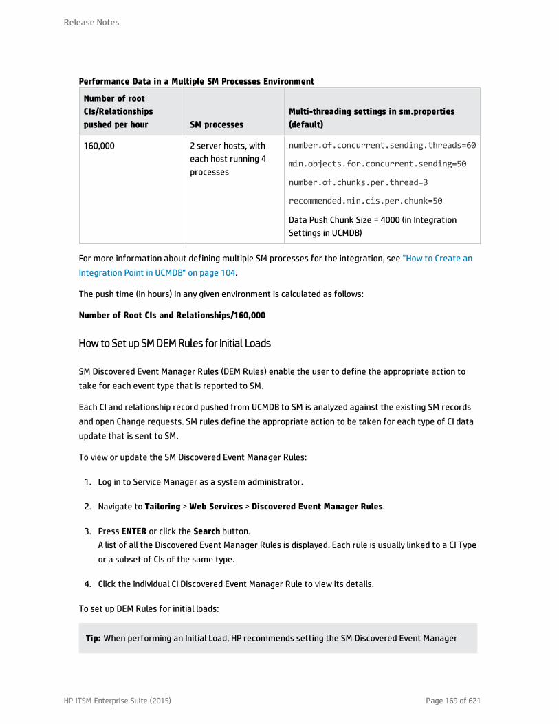
Number of rootCIs/Relationshipspushed per hour SM processes
Multi-threading settings in sm.properties(default)
160,000 2 server hosts, witheach host running 4processes
number.of.concurrent.sending.threads=60
min.objects.for.concurrent.sending=50
number.of.chunks.per.thread=3
recommended.min.cis.per.chunk=50
Data Push Chunk Size = 4000 (in IntegrationSettings in UCMDB)
Performance Data in a Multiple SM Processes Environment
For more information about defining multiple SM processes for the integration, see "How to Create anIntegration Point in UCMDB" on page 104.
The push time (in hours) in any given environment is calculated as follows:
Number of Root CIs and Relationships/160,000
How to Set up SM DEM Rules for Initial Loads
SM Discovered Event Manager Rules (DEM Rules) enable the user to define the appropriate action totake for each event type that is reported to SM.
Each CI and relationship record pushed from UCMDB to SM is analyzed against the existing SM recordsand open Change requests. SM rules define the appropriate action to be taken for each type of CI dataupdate that is sent to SM.
To view or update the SM Discovered Event Manager Rules:
1. Log in to Service Manager as a system administrator.
2. Navigate to Tailoring > Web Services > Discovered Event Manager Rules.
3. Press ENTER or click the Search button.A list of all the Discovered Event Manager Rules is displayed. Each rule is usually linked to a CI Typeor a subset of CIs of the same type.
4. Click the individual CI Discovered Event Manager Rule to view its details.
To set up DEM Rules for initial loads:
Tip: When performing an Initial Load, HP recommends setting the SM Discovered Event Manager
Release Notes
HP ITSM Enterprise Suite (2015) Page 169 of 621

Rules to add newly reported CIs as described below. This minimizes the “noise” of an Initial Load,which could potentially create tens of thousands of Changes or Incidents.
For each of the Discovered Event Manager Rules, perform the following steps:
1. Select the relevant Discovered Event Manager Rule.
2. Go to the Action if matching record does not exist section, select the Add the record option.
3. In the Action if record does not exist but unexpected data discovered section, select the LogResults and Update Record option.
4. In the Action if record is to be deleted section, select the Delete Record option.
5. Save the Discovered Event Manager Rule record.
How to Configure Differential or Delta Load DEM Rules
Tip: Once the “Initial Load” or “Data Load” of the CI data is completed, HP recommends applyingDifferential or Delta Load settings. These settings apply to all data loaded from UCMDB to SM.
These loads send only updates regarding modifications discovered in the IT infrastructure fromUCMDB to SM.
To set up the SM DEM Rules for Differential or Delta Loads:
1. Log in to Service Manager as a system administrator.
2. Navigate to Tailoring > Web Services > Discovered Event Manager Rules.
3. Press Enter or click the Search button.A list of all the Discovered Event Manager Rules in SM is displayed.
4. For each of the Discovered Event Manager Rules, perform the following steps:a. Select the relevant Discovered Event Manager Rule.
b. In the Action if matching record does not exist section, select the appropriate actionrequired for each newly detected CI. If uncertain, select the Add the record option.
c. In the Action if record does exist but unexpected data discovered section, select theappropriate action for each CI that was modified, resulting in an unexpected or incorrectresult. The recommended best practice is to select the Open a Change option.
Release Notes
HP ITSM Enterprise Suite (2015) Page 170 of 621

d. In the Action if record is to be deleted section, select the appropriate action required foreach CI that was removed. The recommended best practice is to select the Delete Recordoption for CI Relationships, and select the Update record to the selected status option for CIs.
e. Save the Discovered Event Manager Rule record.
Fault Detection and Recovery for Push
Universal CMDB has provided a fault detection and recovery mechanism since version 9.05: individual CIfailures no longer cause the entire push to fail, and you can review all failed CIs in the Universal CMDBstudio and then re-push them.
Duplicate logical.name issue
A typical fault you may encounter is the duplicate logical name issue, which is caused by the use ofdifferent unique key fields in Universal CMDB and Service Manager: CI logical.name in Service Manager isunique, and it usually maps to CI display label in Universal CMDB (which is not unique). HP recommendsthat you follow the following guidelines (listed from the highest to lowest priority) to resolve this issue:
l Make sure that each display label field value in UCMDB is unique;
l If uncertain of the above, in the adapter mapping configuration file avoid direct mapping betweenUniversal CMDB display label and SM logical name;
l Map SM logical name to another Universal CMDB field that is unique;
l Add a prefix or suffix to UCMDB display label values;
Note: Out-of-the-box, SM logical name of Running Software is mapped with a prefix of DNSname:
<target_mapping datatype="STRING" name="CIIdentifier"value="SMPushFunctions.getCIIdentifier(Root['display_label'],Root.Node*.getAt('display_label'))"/>
public static String getCIIdentifier(String name, def arr){ if( fIsEmpty(arr) ){ return name;}else{
return covertArray2String(arr)+name;}return name;
}
l If you cannot do any of the above, you can use the UCMDB Fault Detection and Recovery mechanismtogether with the “Duplication Rule” setting of DEM rules as described in the following.
Release Notes
HP ITSM Enterprise Suite (2015) Page 171 of 621

To set up DEM Rules for duplicate logical names:
1. Log in to Service Manager as a system administrator.
2. Navigate to Tailoring > Web Services > Discovered Event Manager Rules > Duplication Rule tab.
3. For each of the Discovered Event Manager Rules, perform the following steps:a. Go to the Action if logical name is duplicated section, and select the Return Error option.
b. Save the Discovered Event Manager Rule record.
Note: After you run a push job, CIs with a duplicate logical name are reported as failed CIs witha duplicate name exception. You can review the failed CIs in the Universal CMDB studio, fix theerrors by either changing the data in Universal CMDB or in the adapter mapping configurationfile (XML and Groovy), and then re-push the failed CIs.
How to Enable Lightweight Single Sign-On (LW-SSO) Configuration
You can enable LW-SSO for the integration so that users can directly view UCMDB CI records from theService Manager web client by clicking the View in UCMDB button, without providing a UCMDBusername and password.
Note: LW-SSO is not supported for the Service Manager Windows client.
To enable LW-SSO for the integration:
1. For each Service Manager user account that needs LW-SSO, create a user account in UCMDB withthe same username. The passwords in the two systems can be different.
2. Enable LW-SSO in the Service Manager Web tier. For details, see the Configure LW-SSO in theService Manager Web tier topic in the Service Manager help.
3. Enable LW-SSO in UCMDB. For details, see the HP Universal CMDB Deployment Guide.
Frequently Asked Questions
This section provides answers to frequently asked questions about the UCMDB-SM integration.
This section includes:
Release Notes
HP ITSM Enterprise Suite (2015) Page 172 of 621
l "When Is a New CI Created in Service Manager? " below
l "Can I Analyze the Reason for a CI Deletion in SM?" on the next page
l "How Do I Monitor Relationship Changes Between UCMDB and SM?" on the next page
l "What Kinds of Relationships are Pushed from UCMDB to SM?" on the next page
l "What is a Root CI Node?" on page 175
l "What Is a Root Relationship?" on page 175
l "What is the “Virtual-Compound” Relationship Type Used in a UCMDB-SM Integration Query?" onpage 175
l "When Do I Need the Population Feature?" on page 176
l "Can I Populate Physically Deleted CIs from SM to UCMDB?" on page 176
l "How Do I Keep the Outage Dependency Setting of a CI Relationship in SM?" on page 176
l "How Do I Create an XML Configuration File?" on page 179
l "How Do I Use the Load Fields Button to Add Multiple Managed Fields?" on page 180
l "What Is the Purpose of the <container> Element in the Population Configuration File(smPopConf.xml)?" on page 180
l "Can I Populate Sub-Item Deletions?" on page 181
l "What Happens if a Population Job Failed or Completed?" on page 181
When Is a New CI Created in Service Manager?
CIs are created in SM under the following circumstances:
l A CI is manually added to SM through the Configuration Management module.
l UCMDB reports a newly discovered CI according to the following:n When a new CI is reported and the Discovered Event Manager Rules are set to Add the Record.
n When a new CI is reported, the Discovered Event Manager Rules are set to Open an Incident andthe Incident has been closed.
Release Notes
HP ITSM Enterprise Suite (2015) Page 173 of 621

n When a new CI is reported, the Discovered Event Manager Rules are set to Open a Change andthe Change has been verified.
Can I Analyze the Reason for a CI Deletion in SM?
No.
SM opens a change request on the deleted CI and includes the following information:
“Delete event for CI “CI Name” triggered by discovery”.
Workaround
An SM change request does not contain a description of the reason for deletion, however it is possibleto extract specific information about CI deletions from the UCMDB History Database. UCMDB dataprovides information about the user or the discovery pattern that initiated the CI deletion.
How Do I Monitor Relationship Changes Between UCMDB and SM?
To understand the relationship change in SM, a distinction must be made between the various types ofRelationship Changes:
l The second endpoint of the relationship has Changed, so instead of CI X being linked to CI Y througha relationship, now CI X is related to CI Z.
l An attribute of the relationship has changed.
The first type of Relationship change is supported by the UCMDB-SM integration, therefore, such“Relationship Changes” can either invoke CI relationship updates, or perform the creation of Incidentsor Changes, which are then reviewed and monitored.
The second is also supported, but it is not covered out-of-the-box; you can configure the UniversalCMDB query to expose such attributes of the relationship, and configure the Service Manager WSDL toexpose the mapped field, and then configure the adapter mapping configuration in the XML and Groovy.However such a Relationship Attribute Change cannot perform the creation of Incidents or Changes, andonly supports invoking CI relationship updates directly.
What Kinds of Relationships are Pushed from UCMDB to SM?
Any kinds of relationships are pushed from UCMDB to SM under the following conditions:
Release Notes
HP ITSM Enterprise Suite (2015) Page 174 of 621
l The relationship appears in a Push Query located in the Service Manager > Push folder in the UCMDBQuery Manager.
l The relationship is named Root in the Push Query.
l The relationship is mapped to an appropriate target in SM in the UCMDB configuration files (XML andGroovy files).
The out-of-the-box relationships that are pushed from UCMDB to SM are relationships between two CIssuch as:
l Between Business Services and Applications;
l Between Business Service and Host;
l Between an Application and a Network Component; or
l Between Host, Network Components and Printers.
What is a Root CI Node?
A Root node is a TQL query node that represents the CI type that is created through push to SM fromthe TQL query structure. The rest of the TQL query structure contains information that can beincorporated within the Root CI type and is used to enrich the record in SM with additional informationand or attributes.
What Is a Root Relationship?
A Root relationship is a relationship within a query and created in SM through push. It represents arelationship between two Root CIs. Only the relationships marked with Root are pushed to SM.
What is the “Virtual-Compound” Relationship Type Used in a UCMDB-SMIntegration Query?
When more than two UCMDB CI entities are connected in series, the “Virtual-Compound” represents therelationship between the first and last entities. This is a virtual relationship, as no physicalrepresentation exists.
The “Virtual-Compound” relationship type is a relationship that links two CI type entities that have alogical relationship. See the following figure.
Release Notes
HP ITSM Enterprise Suite (2015) Page 175 of 621

Explanation
The illustration shows an example of a Virtual-Compound relationship. The relationship in SM is createddirectly between the Host and the Business Service.
When Do I Need the Population Feature?
You need the population feature under any of the following circumstances:
l You have done modeling in SM, especially when you are in the planning and design phases, and youwant your models to be reflected in UCMDB;
l You want to implement the UCMDB-SM integration, however you have already invested in your SMCMDB and do not want to lose that investment;
l You want to continue to maintain some parts of the SM CMDB while maturing your UCMDB/Discoveryimplementation.
Can I Populate Physically Deleted CIs from SM to UCMDB?
No.
Physical deletions of CIs are allowed in SM, but SM cannot get such “deletion changes” and thepopulation feature will not synchronize such changes to UCMDB.
Physical deletions of CIs can be considered as exceptions, which occur only after you create CIs bymistake. Normally, you delete a CI by setting its status to something like Retired/Consumed. In casesuch CIs have been populated to UCMDB, it is your responsibility to remove them manually from UCMDB.
How Do I Keep the Outage Dependency Setting of a CI Relationship in SM?
Out-of-the-box, CI relationships that are pushed from UCMDB to SM do not have outage dependencyinformation by default. If you need such information, you can set the DEM rule of the CI RelationshipWSDL as follows:
Release Notes
HP ITSM Enterprise Suite (2015) Page 176 of 621

1. Log in to Service Manager as a system administrator.
2. Navigate to Tailoring > Web Services > Discovered Event Manager Rules.
3. Open the ucmdbRelationship record.
4. On the Rules tab, select Add the record, and set dependency as true.
This will set the Outage Dependency of each CI Relationship to true, and set the number ofdependent downstream CIs to 1 (because UCMDB supports only one-to-one relationships).
If you want to set outage dependency only for some relationships (for example, if you want to configureoutage dependency for relationships that start from Business Service), you can configure the adapterconfiguration file (XML) and WSDL definition; you can also configure outage dependency per relationshiptype (UCMDB query).
Release Notes
HP ITSM Enterprise Suite (2015) Page 177 of 621
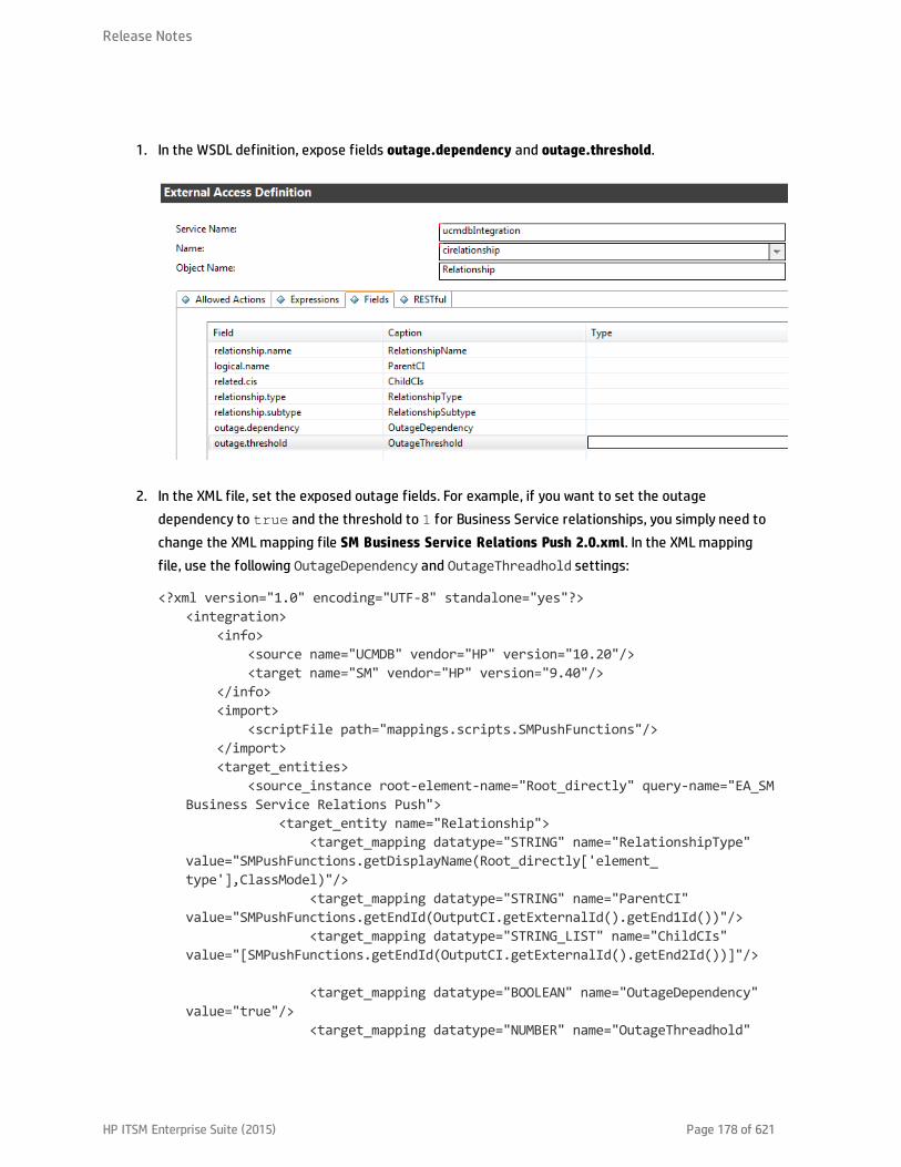
1. In the WSDL definition, expose fields outage.dependency and outage.threshold.
2. In the XML file, set the exposed outage fields. For example, if you want to set the outagedependency to true and the threshold to 1 for Business Service relationships, you simply need tochange the XML mapping file SM Business Service Relations Push 2.0.xml. In the XML mappingfile, use the following OutageDependency and OutageThreadhold settings:
<?xml version="1.0" encoding="UTF-8" standalone="yes"?><integration>
<info><source name="UCMDB" vendor="HP" version="10.20"/><target name="SM" vendor="HP" version="9.40"/>
</info><import>
<scriptFile path="mappings.scripts.SMPushFunctions"/></import><target_entities>
<source_instance root-element-name="Root_directly" query-name="EA_SMBusiness Service Relations Push">
<target_entity name="Relationship"><target_mapping datatype="STRING" name="RelationshipType"
value="SMPushFunctions.getDisplayName(Root_directly['element_type'],ClassModel)"/>
<target_mapping datatype="STRING" name="ParentCI"value="SMPushFunctions.getEndId(OutputCI.getExternalId().getEnd1Id())"/>
<target_mapping datatype="STRING_LIST" name="ChildCIs"value="[SMPushFunctions.getEndId(OutputCI.getExternalId().getEnd2Id())]"/>
<target_mapping datatype="BOOLEAN" name="OutageDependency"value="true"/>
<target_mapping datatype="NUMBER" name="OutageThreadhold"
Release Notes
HP ITSM Enterprise Suite (2015) Page 178 of 621

value="1"/>
</target_entity></source_instance>
</target_entities></integration>
How Do I Create an XML Configuration File?
You create an XML configuration file in Adapter Management. You can copy the content of an existingXML configuration file to the new file and then make necessary edits.
To create an XML configuration file, follow these steps:
1. Log in to UCMDB as an administrator.
2. Navigate to Data Flow Management > Adapter Management. ServiceManagerEnhancedAdapter9-x > Configuration Files.
3. Click the Create new resource icon .
4. Select New Configuration File.
5. Enter a name for the file. The file name should use this format: <AdapterID>/mappings/<SynchType>/<filename>. For example: ServiceManagerEnhancedAdapter9-x/mappings/push/SM Computer Push.xml.
6. Click OK.
UCMDB creates the new XML configuration file in the Configuration Files folder of the adapter.
7. Copy the content of an existing XML configuration file to the new file.
8. Make necessary edits to the new file.
Caution: Invalid XML
When removing XML elements from an XML file, keep in mind that the remaining elements mustconstitute a valid XML file, which will be used to translate the UCMDB Query Definition.
Release Notes
HP ITSM Enterprise Suite (2015) Page 179 of 621

How Do I Use the Load Fields Button to Add Multiple Managed Fields?
Service Manager stores a list of managed fields in the ucmdbIntegration web service, which consists ofa number of web services objects. You can add more managed fields to DEM Rules so that ServiceManager can monitor changes in more CI attributes in UCMDB and trigger the actions defined inrelevant DEM Rules.
You can manually add managed fields that are exposed in associated WSDL definitions to DEM Rules;however, you can use the Load Fields button to automatically (and therefore correctly) add managedfields to DEM Rules.
1. Click the Managed Fields tab of the DEM Rule.
2. Click the Load Fields button.
3. If the table (in the Table Name field) of the DEM rule record has only one WSDL definitionassociated to it, all fields exposed in the WSDL definition are immediately added to the ManagedFields list.A message is displayed: <XX> new fields loaded.
4. If the table has more than one WSDL definition associated to it, the Managed Fields Importingwizard opens, and a list of WSDL definitions (ucmdbIntegration web service objects) is displayed.a. Select one or more objects, and click Next. All new fields that can be added from the selected
web service objects are displayed.
b. If you want to add all of the fields, click Finish; if you want to ignore some of them, changetheir Action value from Add to Ignore, and then click Finish.A message is displayed: <XX> new fields loaded.
5. Save the DEM Rule record.
What Is the Purpose of the <container> Element in the PopulationConfiguration File (smPopConf.xml)?
Out-of-the-box, the smPopConf.xml file has a container element.
<tql name="SM RunningSoftware Population 2.0" citype="running_software"><request type="Retrieve" dataType="ci"resourceCollectionName="ucmdbRunningSoftwares"resourceName="ucmdbRunningSoftware"basicQueryCondition="type="runningsoftware""fullQueryCondition="istatus~="Retired/Consumed""
Release Notes
HP ITSM Enterprise Suite (2015) Page 180 of 621

changedCreationQueryCondition="created.by.date>'{fromDate}' andistatus~="Retired/Consumed""
changedUpdateQueryCondition="created.by.date<='{fromDate}' anddevicemodtime>'{fromDate}' and istatus~="Retired/Consumed""
changedDeletionQueryCondition="devicemodtime>'{fromDate}' andistatus="Retired/Consumed""/>
<container tql="SM Computer Population 2.0"keyFields="CIIdentifier"linkTql="SM Computer Composition Software 2.0"linkRetrieveCondition="downstreamci.logical.name="$$$" and
upstreamci.type="computer" anddownstreamci.type="runningsoftware" andrelationship.subtype="Composition""
linkRetrieveConditionKey="CIIdentifier"linkValueFields="upstreamci.logical.name"/>
</tql>
l In UCMDB, RunningSoftware CIs must exist together with a Root Container (Node); however, ServiceManager allows RunningSoftware CIs without a Node.
l The integration adapter synchronizes CIs and relationships separately; when populating aRunningSoftware CI, the integration does not check to see if a relationship exists between the CI anda Node.
When you use the <container> element, the integration populates RunningSoftware CIs together with acontainer.
Can I Populate Sub-Item Deletions?
Yes.
Service Manager and UCMDB store CI information in different data structures, and therefore one SM CImay be synchronized to UCMDB as several CIs. For example, during population, an SM computer CI recordis synchronized to a Node CI in UCMDB, and the computer CI’s attributes to CIs such as IP, Interface,Location, etc (which are referred to as sub-items of the Node CI.). In this case, the Node CI is the root CI.
The integration allows you to populate sub-item deletions to UCMDB. For example, if you delete the IPAddress attribute value of a computer, the corresponding IP CI record in UCMDB will be deleted too.
What Happens if a Population Job Failed or Completed?
When a population job failed
Release Notes
HP ITSM Enterprise Suite (2015) Page 181 of 621

The failure prevents the remaining population tasks from running. The next job run will start from thelast Success time. If pagination occurs (that is, the tasks are divided into multiple pages), the tasks willrun again and again within the first page from the last “Success” time (once the end of the first page isreached, no new tasks will be executed).
When a population job completed
When the status of a job is "completed" (but not "completed successfully"), warnings occurred. Awarning does not prevent the remaining population tasks from running. The next job run will run alltasks again starting from the last Success time. If pagination occurs (the tasks are divided into multiplepages), the tasks on all pages will be re-run (including those that successfully completed last time).
Tailoring the IntegrationYou can tailor the UCMDB-SM integration to meet your business needs by adding or removing managedCI types, attributes, and relationship types. This chapter describes the integration architecture andtailoring options for data push, population, and federation.
This section includes:
l "Integration Architecture" below
l "Integration Tailoring Options" on page 197
Integration Architecture
Before you tailor the integration, you should understand how the following components of the out-of-the-box integration work.
l "Integration Class Model" on the next page
l "Integration Queries" on the next page
l "Service Manager Web Services" on page 188
l "Service Manager Reconciliation Rules" on page 193
l "Service Manager Discovery Event Manager Rules" on page 195
Release Notes
HP ITSM Enterprise Suite (2015) Page 182 of 621
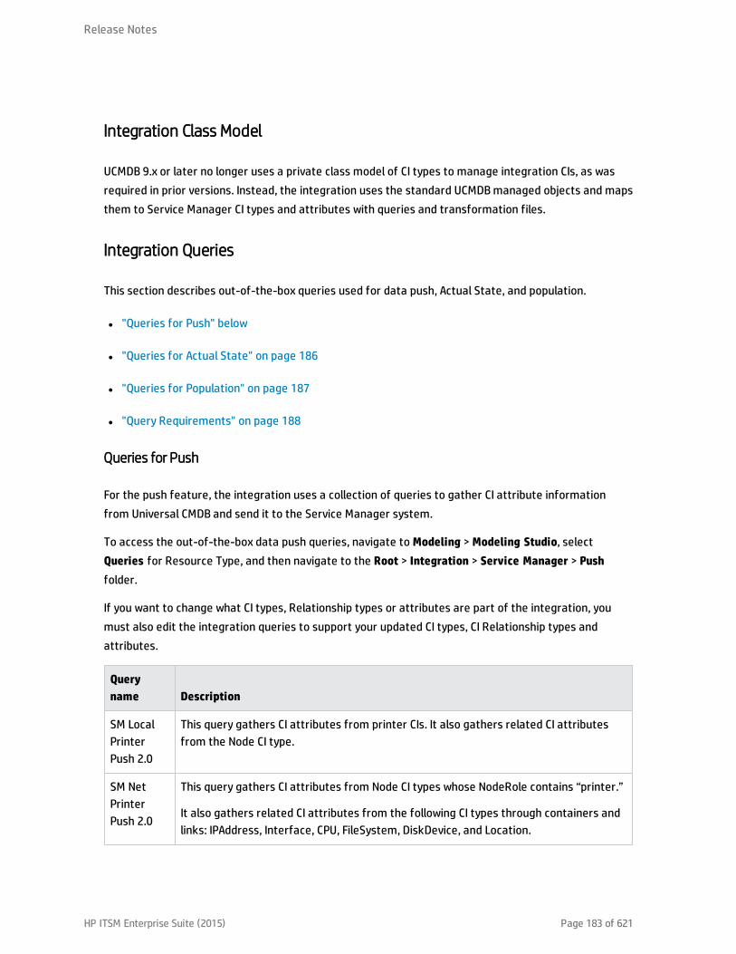
Integration Class Model
UCMDB 9.x or later no longer uses a private class model of CI types to manage integration CIs, as wasrequired in prior versions. Instead, the integration uses the standard UCMDB managed objects and mapsthem to Service Manager CI types and attributes with queries and transformation files.
Integration Queries
This section describes out-of-the-box queries used for data push, Actual State, and population.
l "Queries for Push" below
l "Queries for Actual State" on page 186
l "Queries for Population" on page 187
l "Query Requirements" on page 188
Queries for Push
For the push feature, the integration uses a collection of queries to gather CI attribute informationfrom Universal CMDB and send it to the Service Manager system.
To access the out-of-the-box data push queries, navigate to Modeling > Modeling Studio, selectQueries for Resource Type, and then navigate to the Root > Integration > Service Manager > Pushfolder.
If you want to change what CI types, Relationship types or attributes are part of the integration, youmust also edit the integration queries to support your updated CI types, CI Relationship types andattributes.
Queryname Description
SM LocalPrinterPush 2.0
This query gathers CI attributes from printer CIs. It also gathers related CI attributesfrom the Node CI type.
SM NetPrinterPush 2.0
This query gathers CI attributes from Node CI types whose NodeRole contains “printer.”
It also gathers related CI attributes from the following CI types through containers andlinks: IPAddress, Interface, CPU, FileSystem, DiskDevice, and Location.
Release Notes
HP ITSM Enterprise Suite (2015) Page 183 of 621

Queryname Description
SMMainframePush 2.0
This query gathers CI attributes from the following Node CI types: Mainframe LogicalPartition, and Mainframe CPC.
It also gathers related CI attributes from the following CI types through containers andlinks: IPAddress, Interface, CPU, FileSystem, DiskDevice, and Location.
SM MobileDevicePush 2.0
This query gathers CI attributes from Node CI types whose NodeRole contains “pda_handheld.”
It also gathers related CI attributes from the following CI types through containers andlinks: IPAddress, Interface, CPU, FileSystem, DiskDevice, and Location.
SMNetworkComponentPush 2.0
This query gathers CI attributes from Node CI types whose NodeRole contains router,adsl_modem, appletalk_gateway, bandwith_manager, cable_model, csu_dsu, ethernet,fddi, firewall, hub, kvm_switch, load_balancer, multicast_enabled_router, nat_router,token_ring, undefined_network_ component, voice_gateway, voice_switch, or vpn_gateway.
It also gathers related CI attributes from the following CI types through containers andlinks: IPAddress, Interface, CPU, FileSystem, DiskDevice, and Location.
SM ClusterPush 2.0
This query gathers CI attributes from the following Node CI type: ClusterResourceGroup.
It also gathers related CI attributes from the following CI types through containers andlinks: IPAddress, Interface, CPU, FileSystem, DiskDevice, Location, and Cluster.
SMComputerPush 2.0
This query gathers CI attributes from the node CI type with NodeRole containing“desktop”, “server”, “virtualized_system” or not set. It also gathers related CI attributesfrom the following CI types through containers and links: IPAddress, Interface, CPU,FileSystem, DiskDevice, and Location.
SM StoragePush 2.0
This query gathers CI attributes from the Node CI type whose NodeRole contains san_switch, san_gateway, san_router, or whose Display Name is Storage Array.
It also gathers related CI attributes from the following CI types through containers andlinks: IPAddress, Interface, CPU, FileSystem, DiskDevice, and Location.
SMRunningSoftwarePush 2.0
This query gathers CI attributes from Running Software CIs.
Release Notes
HP ITSM Enterprise Suite (2015) Page 184 of 621
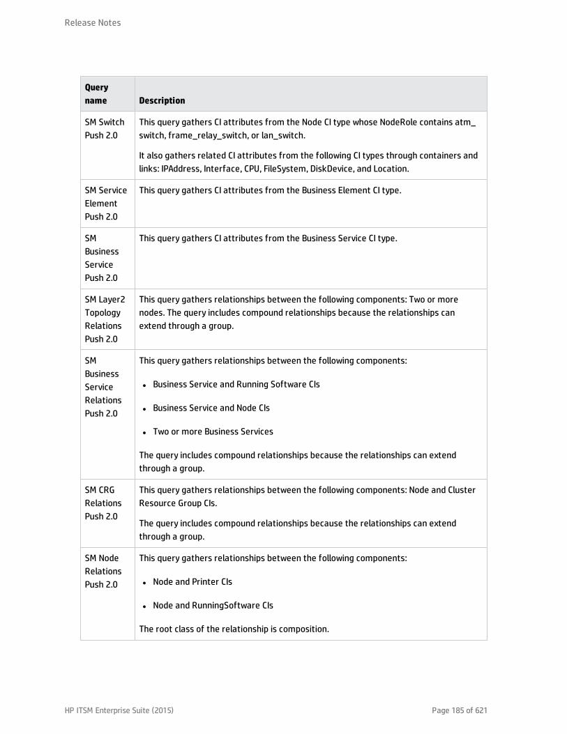
Queryname Description
SM SwitchPush 2.0
This query gathers CI attributes from the Node CI type whose NodeRole contains atm_switch, frame_relay_switch, or lan_switch.
It also gathers related CI attributes from the following CI types through containers andlinks: IPAddress, Interface, CPU, FileSystem, DiskDevice, and Location.
SM ServiceElementPush 2.0
This query gathers CI attributes from the Business Element CI type.
SMBusinessServicePush 2.0
This query gathers CI attributes from the Business Service CI type.
SM Layer2TopologyRelationsPush 2.0
This query gathers relationships between the following components: Two or morenodes. The query includes compound relationships because the relationships canextend through a group.
SMBusinessServiceRelationsPush 2.0
This query gathers relationships between the following components:
l Business Service and Running Software CIs
l Business Service and Node CIs
l Two or more Business Services
The query includes compound relationships because the relationships can extendthrough a group.
SM CRGRelationsPush 2.0
This query gathers relationships between the following components: Node and ClusterResource Group CIs.
The query includes compound relationships because the relationships can extendthrough a group.
SM NodeRelationsPush 2.0
This query gathers relationships between the following components:
l Node and Printer CIs
l Node and RunningSoftware CIs
The root class of the relationship is composition.
Release Notes
HP ITSM Enterprise Suite (2015) Page 185 of 621
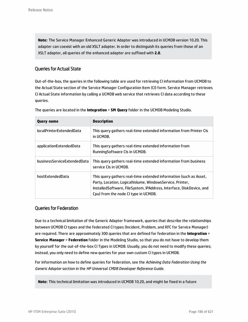
Note: The Service Manager Enhanced Generic Adapter was introduced in UCMDB version 10.20. Thisadapter can coexist with an old XSLT adapter. In order to distinguish its queries from those of anXSLT adapter, all queries of the enhanced adapter are suffixed with 2.0.
Queries for Actual State
Out-of-the-box, the queries in the following table are used for retrieving CI information from UCMDB tothe Actual State section of the Service Manager Configuration Item (CI) form. Service Manager retrievesCI Actual State information by calling a UCMDB web service that retrieves CI data according to thesequeries.
The queries are located in the Integration > SM Query folder in the UCMDB Modeling Studio.
Query name Description
localPrinterExtendedData This query gathers real-time extended information from Printer CIsin UCMDB.
applicationExtendedData This query gathers real-time extended information fromRunningSoftware CIs in UCMDB.
businessServiceExtendedData This query gathers real-time extended information from businessservice CIs in UCMDB.
hostExtendedData This query gathers real-time extended information (such as Asset,Party, Location, LogicalVolume, WindowsService, Printer,InstalledSoftware, FileSystem, IPAddress, Interface, DiskDevice, andCpu) from the node CI type in UCMDB.
Queries for Federation
Due to a technical limitation of the Generic Adapter framework, queries that describe the relationshipsbetween UCMDB CI types and the federated CI types (Incident, Problem, and RFC for Service Manager)are required. There are approximately 300 queries that are defined for federation in the Integration >Service Manager > Federation folder in the Modeling Studio, so that you do not have to develop themby yourself for the out-of-the-box CI Types in UCMDB. Usually, you do not need to modify these queries;instead, you only need to define new queries for your own custom CI types in UCMDB.
For information on how to define queries for federation, see the Achieving Data Federation Using theGeneric Adapter section in the HP Universal CMDB Developer Reference Guide.
Note: This technical limitation was introduced in UCMDB 10.20, and might be fixed in a future
Release Notes
HP ITSM Enterprise Suite (2015) Page 186 of 621
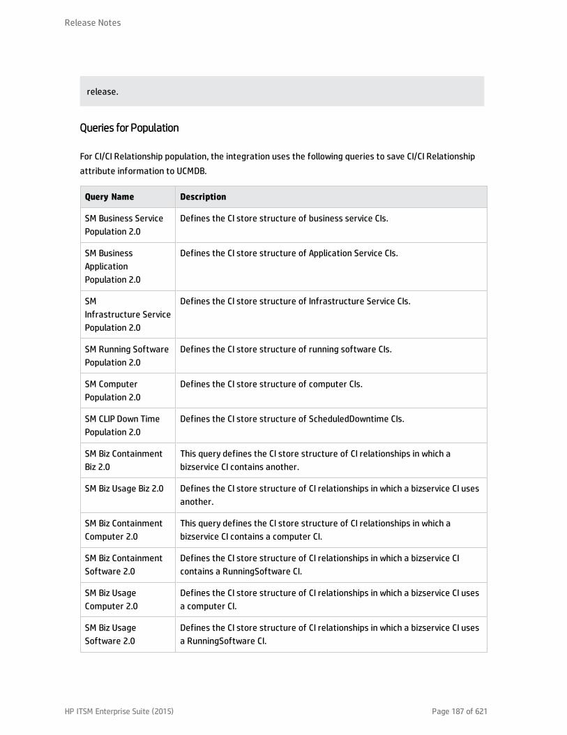
release.
Queries for Population
For CI/CI Relationship population, the integration uses the following queries to save CI/CI Relationshipattribute information to UCMDB.
Query Name Description
SM Business ServicePopulation 2.0
Defines the CI store structure of business service CIs.
SM BusinessApplicationPopulation 2.0
Defines the CI store structure of Application Service CIs.
SMInfrastructure ServicePopulation 2.0
Defines the CI store structure of Infrastructure Service CIs.
SM Running SoftwarePopulation 2.0
Defines the CI store structure of running software CIs.
SM ComputerPopulation 2.0
Defines the CI store structure of computer CIs.
SM CLIP Down TimePopulation 2.0
Defines the CI store structure of ScheduledDowntime CIs.
SM Biz ContainmentBiz 2.0
This query defines the CI store structure of CI relationships in which abizservice CI contains another.
SM Biz Usage Biz 2.0 Defines the CI store structure of CI relationships in which a bizservice CI usesanother.
SM Biz ContainmentComputer 2.0
This query defines the CI store structure of CI relationships in which abizservice CI contains a computer CI.
SM Biz ContainmentSoftware 2.0
Defines the CI store structure of CI relationships in which a bizservice CIcontains a RunningSoftware CI.
SM Biz UsageComputer 2.0
Defines the CI store structure of CI relationships in which a bizservice CI usesa computer CI.
SM Biz UsageSoftware 2.0
Defines the CI store structure of CI relationships in which a bizservice CI usesa RunningSoftware CI.
Release Notes
HP ITSM Enterprise Suite (2015) Page 187 of 621
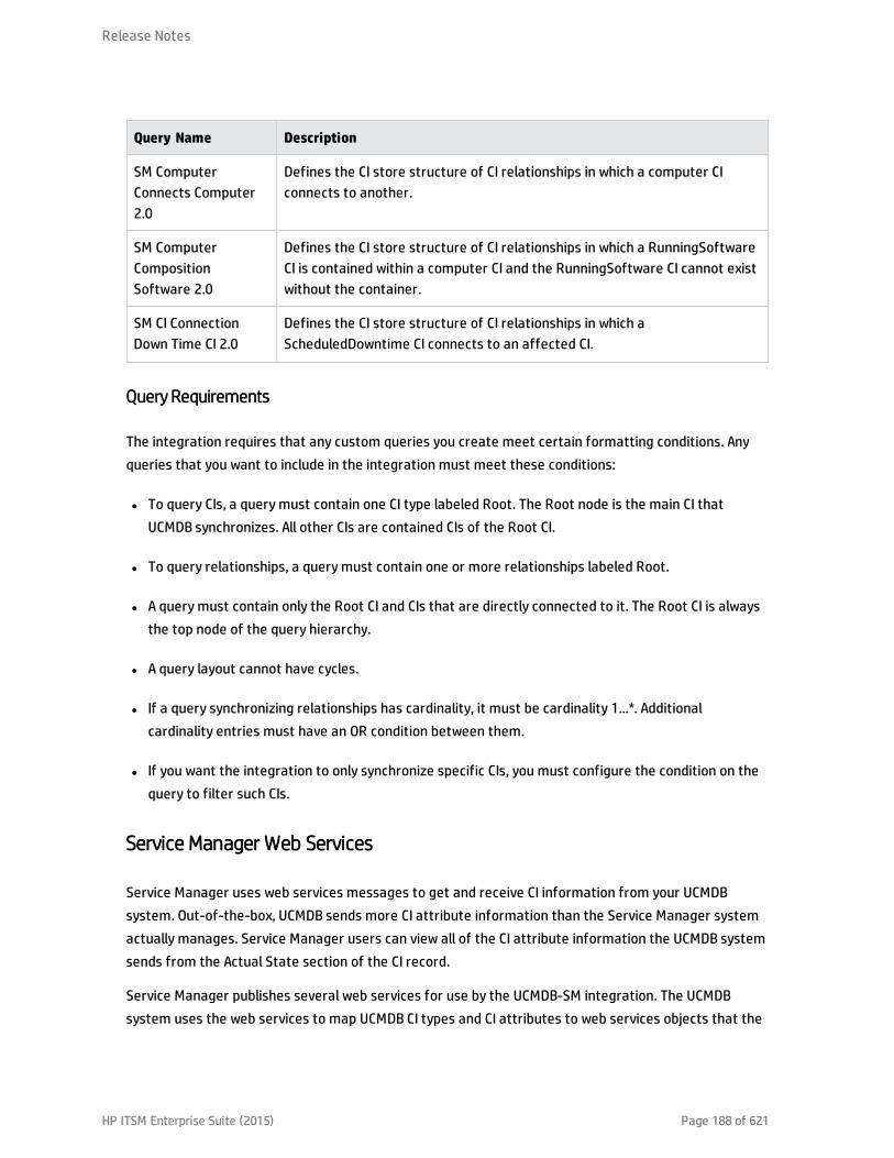
Query Name Description
SM ComputerConnects Computer2.0
Defines the CI store structure of CI relationships in which a computer CIconnects to another.
SM ComputerCompositionSoftware 2.0
Defines the CI store structure of CI relationships in which a RunningSoftwareCI is contained within a computer CI and the RunningSoftware CI cannot existwithout the container.
SM CI ConnectionDown Time CI 2.0
Defines the CI store structure of CI relationships in which aScheduledDowntime CI connects to an affected CI.
Query Requirements
The integration requires that any custom queries you create meet certain formatting conditions. Anyqueries that you want to include in the integration must meet these conditions:
l To query CIs, a query must contain one CI type labeled Root. The Root node is the main CI thatUCMDB synchronizes. All other CIs are contained CIs of the Root CI.
l To query relationships, a query must contain one or more relationships labeled Root.
l A query must contain only the Root CI and CIs that are directly connected to it. The Root CI is alwaysthe top node of the query hierarchy.
l A query layout cannot have cycles.
l If a query synchronizing relationships has cardinality, it must be cardinality 1...*. Additionalcardinality entries must have an OR condition between them.
l If you want the integration to only synchronize specific CIs, you must configure the condition on thequery to filter such CIs.
Service Manager Web Services
Service Manager uses web services messages to get and receive CI information from your UCMDBsystem. Out-of-the-box, UCMDB sends more CI attribute information than the Service Manager systemactually manages. Service Manager users can view all of the CI attribute information the UCMDB systemsends from the Actual State section of the CI record.
Service Manager publishes several web services for use by the UCMDB-SM integration. The UCMDBsystem uses the web services to map UCMDB CI types and CI attributes to web services objects that the
Release Notes
HP ITSM Enterprise Suite (2015) Page 188 of 621

Service Manager system recognizes. You can add UCMDB CI types or CI attributes that you want ServiceManager to manage by using the Visual Mapping tool, and the tool will automatically update one ormore of these web services to define web service objects.
Managed Fields
Note: Managed fields are used only for the data push feature.
A Service Manager managed field is a field where the system compares the CI attribute value in theincoming UCMDB web services message to the value in a Service Manager CI record. If the values in theweb services message do not match those in the CI record, Service Manager runs a Discovery EventManager (DEM) rule to determine what action to take. The DEM rule determines which of the fields thatare published as web services objects are fields managed by the integration. Only value changes inmanaged fields trigger the DEM rule.
The ucmdbIntegration web service consists of a set of web services objects, each of which defines a listof web service fields. Out-of-the-box, the integration uses only part of them (see the Mappings BetweenService Manager Web service Objects, Tables, and DEM Rules table), some of them (along with theirrelevant DEM Rules) have been deprecated (see the Deprecated ucmdbIntegration Web Service Objectsfor Data Push table), and some are used for population or federation (see the ucmdbIntegration WebService Objects Used for Population or Federation table).
This web service object Publishes fields from this table And uses this DEM rule ID
Relationship cirelationship ucmdbRelationship
ucmdbRunningSoftware device ucmdbRunningSoftware
ucmdbBusinessService joinbizservice ucmdbBusinessService
ucmdbNode joinnode ucmdbNode
Mappings between Service Manager Web Service Objects, Tables, and DEM Rules
This web service object Publishes fields from this table Recommended replacement (object)
ucmdbApplication device ucmdbRunningSoftware
ucmdbComputer ucmdbComputer ucmdbNode
UcmdbDevice device ucmdbRunningSoftware
ucmdbNetwork joinnetworkcomponents ucmdbNode
ucmdbPrinter joinofficeelectronics ucmdbNode
Deprecated ucmdbIntegration Web Service Objects for Data Push
Release Notes
HP ITSM Enterprise Suite (2015) Page 189 of 621
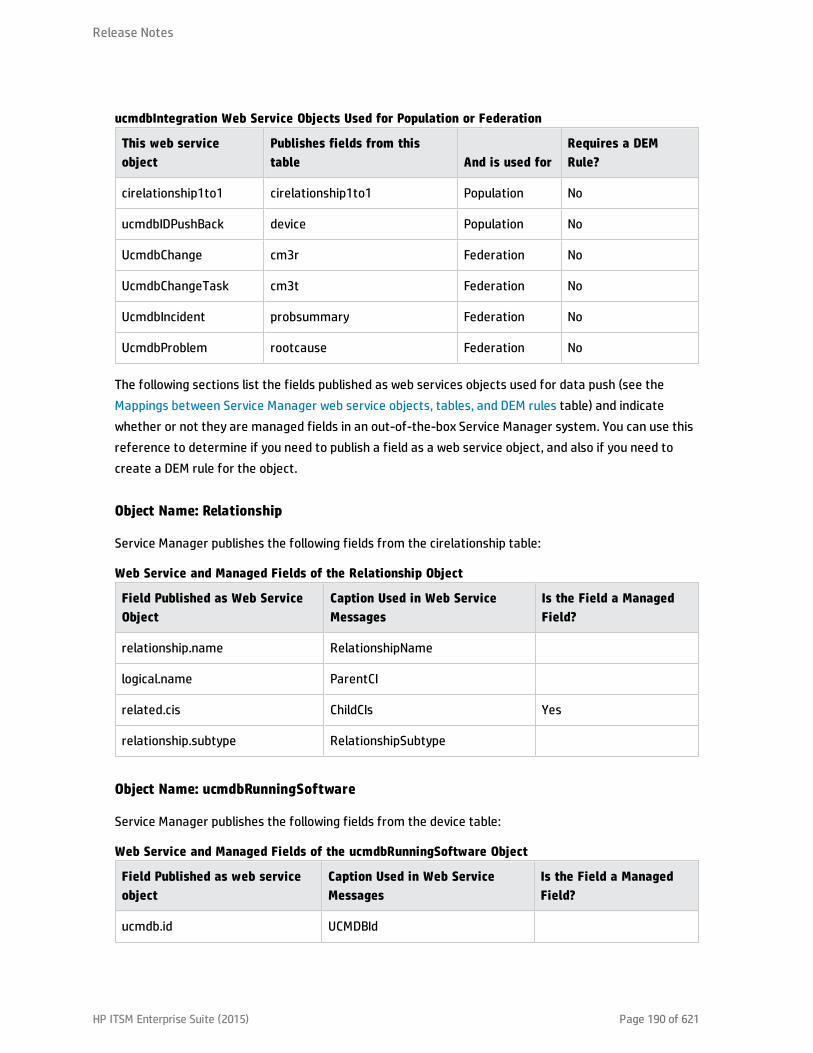
This web serviceobject
Publishes fields from thistable And is used for
Requires a DEMRule?
cirelationship1to1 cirelationship1to1 Population No
ucmdbIDPushBack device Population No
UcmdbChange cm3r Federation No
UcmdbChangeTask cm3t Federation No
UcmdbIncident probsummary Federation No
UcmdbProblem rootcause Federation No
ucmdbIntegration Web Service Objects Used for Population or Federation
The following sections list the fields published as web services objects used for data push (see theMappings between Service Manager web service objects, tables, and DEM rules table) and indicatewhether or not they are managed fields in an out-of-the-box Service Manager system. You can use thisreference to determine if you need to publish a field as a web service object, and also if you need tocreate a DEM rule for the object.
Object Name: Relationship
Service Manager publishes the following fields from the cirelationship table:
Field Published as Web ServiceObject
Caption Used in Web ServiceMessages
Is the Field a ManagedField?
relationship.name RelationshipName
logical.name ParentCI
related.cis ChildCIs Yes
relationship.subtype RelationshipSubtype
Web Service and Managed Fields of the Relationship Object
Object Name: ucmdbRunningSoftware
Service Manager publishes the following fields from the device table:
Field Published as web serviceobject
Caption Used in Web ServiceMessages
Is the Field a ManagedField?
ucmdb.id UCMDBId
Web Service and Managed Fields of the ucmdbRunningSoftware Object
Release Notes
HP ITSM Enterprise Suite (2015) Page 190 of 621
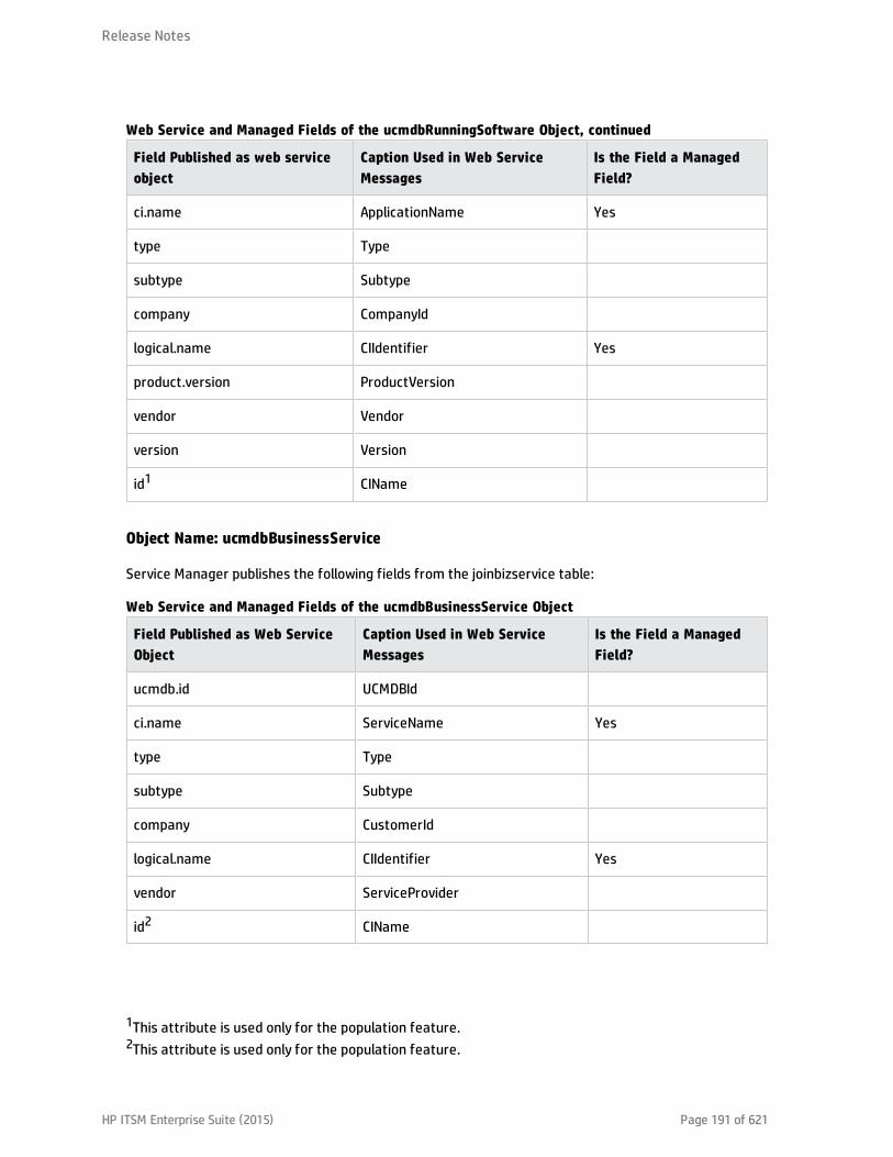
Field Published as web serviceobject
Caption Used in Web ServiceMessages
Is the Field a ManagedField?
ci.name ApplicationName Yes
type Type
subtype Subtype
company CompanyId
logical.name CIIdentifier Yes
product.version ProductVersion
vendor Vendor
version Version
id1 CIName
Web Service and Managed Fields of the ucmdbRunningSoftware Object, continued
Object Name: ucmdbBusinessService
Service Manager publishes the following fields from the joinbizservice table:
Field Published as Web ServiceObject
Caption Used in Web ServiceMessages
Is the Field a ManagedField?
ucmdb.id UCMDBId
ci.name ServiceName Yes
type Type
subtype Subtype
company CustomerId
logical.name CIIdentifier Yes
vendor ServiceProvider
id2 CIName
Web Service and Managed Fields of the ucmdbBusinessService Object
1This attribute is used only for the population feature.2This attribute is used only for the population feature.
Release Notes
HP ITSM Enterprise Suite (2015) Page 191 of 621

Object Name: ucmdbNode
Service Manager publishes the following fields from the joinnode table.
Field Published as Web ServiceObject
Caption Used in Web ServiceMessages
Is the Field a ManagedField?
ucmdb.id UCMDBId
type Type
subtype Subtype
company CustomerId
logical.name CIIdentifier Yes
default.gateway DefaultGateway Yes
network.name DNSName Yes
building Building Yes
room Room Yes
floor Floor Yes
location Location
addlIPAddr[addlIPAddress] AddlIPAddress Yes
addlIPAddr[addlSubnet] AddlSubnet Yes
addlMacAddress AddlMacAddress Yes
bios.id BIOSId Yes
operating.system OS Yes
os.version OSVersion Yes
physical.mem.total PhysicalMemory Yes
serial.no. SerialNo
vendor Vendor
cpu[cpu.id] CpuID
cpu[cpu.name] CpuName
Web Service and Managed Fields of the ucmdbNode Object
Release Notes
HP ITSM Enterprise Suite (2015) Page 192 of 621

Field Published as Web ServiceObject
Caption Used in Web ServiceMessages
Is the Field a ManagedField?
cpu[cpu.clock.speed] CpuClockSpeed
file.system[mount.point] MountPoint
file.system[disk.type] DiskType
file.system[file.system.type] FilesystemType
file.system[disk.size] DiskSize
asset.tag AssetTag
machine.name HostName Yes
disk.device[model.name] ModelName
disk.device[disk.vendor] DiskVendor
disk.device[disk.name] DiskName
id1 CIName
isVisualization IsVisualization
istatus AssetStatus
Web Service and Managed Fields of the ucmdbNode Object, continued
Service Manager Reconciliation Rules
Service Manager reconciliation rules allow the integration to identify CI records in your Service Managersystem that match CIs in your UCMDB system. Service Manager attempts to reconcile CI records withevery push of CI attributes from your UCMDB system. The integration uses the following workflow tomatch UCMDB CIs with Service Manager CIs.
1. The UCMDB system sends a web service message containing the latest CI attribute data to ServiceManager.
2. Service Manager scans the web service message for the CI ucmdb.id value.
Note: Out-of-the-box, Service Manager does not display the ucmdb.id field on CI record forms
1This attribute is used only for the population feature.
Release Notes
HP ITSM Enterprise Suite (2015) Page 193 of 621
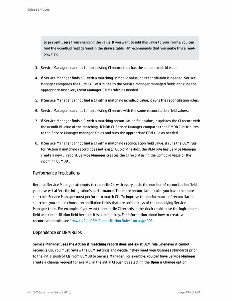
to prevent users from changing the value. If you want to add this value to your forms, you canfind the ucmdb.id field defined in the device table. HP recommends that you make this a read-only field.
3. Service Manager searches for an existing CI record that has the same ucmdb.id value.
4. If Service Manager finds a CI with a matching ucmdb.id value, no reconciliation is needed. ServiceManager compares the UCMDB CI attributes to the Service Manager managed fields and runs theappropriate Discovery Event Manager (DEM) rules as needed.
5. If Service Manager cannot find a CI with a matching ucmdb.id value, it runs the reconciliation rules.
6. Service Manager searches for an existing CI record with the same reconciliation field values.
7. If Service Manager finds a CI with a matching reconciliation field value, it updates the CI record withthe ucmdb.id value of the matching UCMDB CI. Service Manager compares the UCMDB CI attributesto the Service Manager managed fields and runs the appropriate DEM rule as needed.
8. If Service Manager cannot find a CI with a matching reconciliation field value, it runs the DEM rulefor “Action if matching record does not exist.” Out-of-the-box, the DEM rule has Service Managercreate a new CI record. Service Manager creates the CI record using the ucmdb.id value of theincoming UCMDB CI.
Performance Implications
Because Service Manager attempts to reconcile CIs with every push, the number of reconciliation fieldsyou have will affect the integration’s performance. The more reconciliation rules you have, the moresearches Service Manager must perform to match CIs. To improve the performance of reconciliationsearches, you should choose reconciliation fields that are unique keys of the underlying ServiceManager table. For example, if you want to reconcile CI records in the device table, use the logical.namefield as a reconciliation field because it is a unique key. For information about how to create areconciliation rule, see "How to Add DEM Reconciliation Rules" on page 203.
Dependence on DEM Rules
Service Manager uses the Action if matching record does not exist DEM rule whenever it cannotreconcile CIs. You must review the DEM settings and decide if they meet your business standards priorto the initial push of CIs from UCMDB to Service Manager. For example, you can have Service Managercreate a change request for every CI in the initial CI push by selecting the Open a Change option.
Release Notes
HP ITSM Enterprise Suite (2015) Page 194 of 621

Service Manager Discovery Event Manager Rules
You only need to create Discovery Event Manager (DEM) rules if you want to accomplish any of thefollowing custom actions:
l "Change the Conditions Under Which a DEM Rule Runs" below
l "Change the Action the DEM Rule Takes" below
l "Create Custom JavaScript to Open Change or Incident Records" on the next page
Change the Conditions UnderWhich a DEM Rule Runs
Service Manager will run a DEM rule only if the condition field evaluates to true. Out-of-the-box, no DEMrule has a condition statement that restricts when the rule runs, and all the integration DEM rules willalways run by default.
You can update a DEM rule's condition statements if you want to restrict when Service Manager runsyour DEM rules. For example, adding the following condition to the ucmdbNode DEM rule restricts therule to desktop CIs.
subtype in $L.file=”Desktop”
You can also use the condition field to create multiple DEM rules that apply to the same table name. Forexample, the following DEM rules both apply to the joinnode table.
DEM rule Id Table Name Condition
ucmdbNode joinnode subtype in $L.file!=”Desktop”
ucmdbDesktop joinnode subtype in $L.file=”Desktop”
DEM rules using different conditions to affect the same table
Typically, you will only need to add conditions if your business processes require the integration to takedifferent actions with certain CI types or SLAs.
Change the Action the DEM Rule Takes
Out-of-the-box, the integration DEM rules take the following actions:
Release Notes
HP ITSM Enterprise Suite (2015) Page 195 of 621
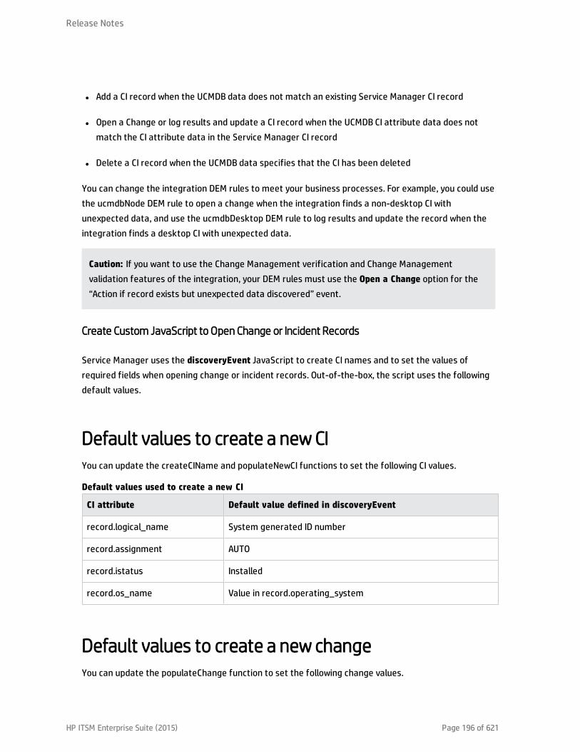
l Add a CI record when the UCMDB data does not match an existing Service Manager CI record
l Open a Change or log results and update a CI record when the UCMDB CI attribute data does notmatch the CI attribute data in the Service Manager CI record
l Delete a CI record when the UCMDB data specifies that the CI has been deleted
You can change the integration DEM rules to meet your business processes. For example, you could usethe ucmdbNode DEM rule to open a change when the integration finds a non-desktop CI withunexpected data, and use the ucmdbDesktop DEM rule to log results and update the record when theintegration finds a desktop CI with unexpected data.
Caution: If you want to use the Change Management verification and Change Managementvalidation features of the integration, your DEM rules must use the Open a Change option for the“Action if record exists but unexpected data discovered” event.
Create Custom JavaScript to Open Change or Incident Records
Service Manager uses the discoveryEvent JavaScript to create CI names and to set the values ofrequired fields when opening change or incident records. Out-of-the-box, the script uses the followingdefault values.
Default values to create a new CIYou can update the createCIName and populateNewCI functions to set the following CI values.
CI attribute Default value defined in discoveryEvent
record.logical_name System generated ID number
record.assignment AUTO
record.istatus Installed
record.os_name Value in record.operating_system
Default values used to create a new CI
Default values to create a new changeYou can update the populateChange function to set the following change values.
Release Notes
HP ITSM Enterprise Suite (2015) Page 196 of 621

CI attribute Default value defined in discoveryEvent
change.category Unplanned Change
change.reason Value in reason
change.initial_impact 3
change.severity 3
change.coordinator Change.Coordinator
change.requested_by discovery
change.status initial
Default values used to create a new change
Default values to create a new incidentYou can update the populateIncident function to set the following incident values.
CI attribute Default value defined in discoveryEvent
incident.category incident
incident.subcategory hardware
incident.product_type missing or stolen
incident.assignment Hardware
incident.initial_impact 3
incident.severity 3
incident.logical.name Value of id
incident.site_cateogry C
incident.contact_name ANALYST, INCIDENT
incident.affected_item MyDevices
Default values used to create a new incident
Integration Tailoring Options
The integration offers the following tailoring options:
Release Notes
HP ITSM Enterprise Suite (2015) Page 197 of 621

l "How to Update the Integration Adapter Configuration File (sm.properties)" below
l "How to Add DEM Reconciliation Rules" on page 203
l "How to Add Discovery Event Manager Rules" on page 205
l "How to Add a CI Attribute to the Integration for Data Push" on page 210
l "How to Add a CI Type to the Integration for Data Push" on page 224
l "How to Add a CI Relationship Type to the Integration for Data Push" on page 241
l "How to Add a Custom Query to an Integration Job" on page 248
l "How to Add a CI Type, Attribute or Relationship Type to the Integration for Population" on page 249
l "How to Enable or Disable UCMDB ID Pushback for a CI Type " on page 249
l "How to Add an Attribute of a Supported CI Type for Federation" on page 251
How to Update the Integration Adapter Configuration File (sm.properties)
The integration uses a properties file (sm.properties) as a configuration file of the adapter. Out-of-the-box, this file has been set up based on best practices, so usually you can keep the default parametervalues. Optionally, you can update the parameter values to better suit your needs.
To update the sm.properties file:
1. Log in to UCMDB as an administrator.
2. Navigate to Data Flow Management > Adapter Management >ServiceManagerEnhancedAdapter9-x > Configuration Files.
3. Click the properties configuration file: sm.properties.
4. Update the parameter values as needed. For a list of the parameters, see the following table.
#if true, will use globalId instead of ucmdbId in the SM integration.
use.global.id=true
# Type 0, the feature will be disabled
Release Notes
HP ITSM Enterprise Suite (2015) Page 198 of 621

# Type 1, the enum type will expand to "{value}"
# Type 2, the enum type will expand to "{index}-{value}"
type.of.expand.enum=2
#if false, will use the type directly instead of label of the type.
use.type.label=true
#parameter for populate data from service manager
pop.pagination.switch=on
pop.pagination.recordcount=1000
pop.createci.key=sm_id
# the property used as ucmdb id key for population in xslt files, it is treated as "global_id" byadapter if is.global.id is ture,otherwise it is treated as CMDB ID.
pop.ucmdb.id.key=ucmdb_id
#SM web service for push back uCMDB ID
ucmdbid.pushback.request=UpdateucmdbIDPushBackRequest
ucmdbid.pushback.xslt=ucmdbid_pushback.xslt
#whehter checking the soap connections to SM instances before running the job
check.sm.connections=false
#the external web service interface type. restful or soap
connector.type=restful
5.
6.
7.
Release Notes
HP ITSM Enterprise Suite (2015) Page 199 of 621

8.
Parameter Default value Comment
timeout.minutes 10 The integration connection timeoutvalue (in minutes)
number.of.concurrent.sending.threads
6 The number of concurrent threads usedfor the data push feature
n 1: Disabled
n 2 or higher: Enabled
Note: If you are connecting tomultiple Service Manager instancesto improve the CI data pushperformance (see the URL Overrideconfiguration in "How to Create anIntegration Point in UCMDB" onpage 104), you are recommendedto increase this value for optimizedperformance. For example, set it to12 if you are connecting to twoService Manager instances.
min.objects.for.concurrent.sending 50 The minimum number of ServiceManager objects that is required to useconcurrent sending instead of singlethread sending
Note: It is used for the pushfeature.
number.of.chunks.per.thread 3 The number of chunks per thread usedfor the push feature
Total of number of chunks =number.of.chunks.per.thread *number.of.concurrent.sending.threads
Parameters in the sm.properties file
Release Notes
HP ITSM Enterprise Suite (2015) Page 200 of 621
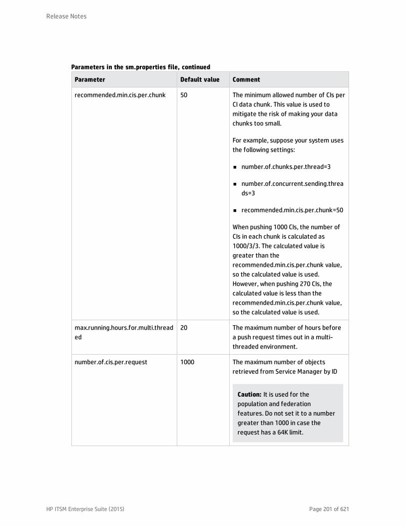
Parameter Default value Comment
recommended.min.cis.per.chunk 50 The minimum allowed number of CIs perCI data chunk. This value is used tomitigate the risk of making your datachunks too small.
For example, suppose your system usesthe following settings:
n number.of.chunks.per.thread=3
n number.of.concurrent.sending.threads=3
n recommended.min.cis.per.chunk=50
When pushing 1000 CIs, the number ofCIs in each chunk is calculated as1000/3/3. The calculated value isgreater than therecommended.min.cis.per.chunk value,so the calculated value is used.However, when pushing 270 CIs, thecalculated value is less than therecommended.min.cis.per.chunk value,so the calculated value is used.
max.running.hours.for.multi.threaded
20 The maximum number of hours beforea push request times out in a multi-threaded environment.
number.of.cis.per.request 1000 The maximum number of objectsretrieved from Service Manager by ID
Caution: It is used for thepopulation and federationfeatures. Do not set it to a numbergreater than 1000 in case therequest has a 64K limit.
Parameters in the sm.properties file, continued
Release Notes
HP ITSM Enterprise Suite (2015) Page 201 of 621
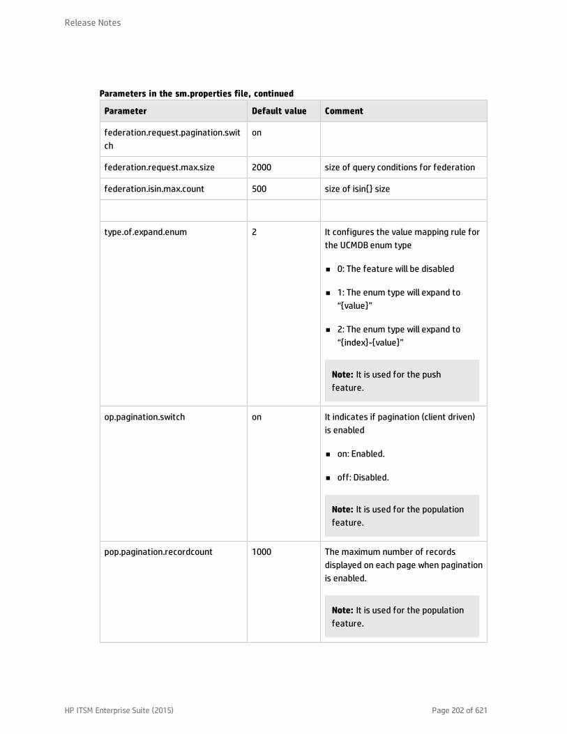
Parameter Default value Comment
federation.request.pagination.switch
on
federation.request.max.size 2000 size of query conditions for federation
federation.isin.max.count 500 size of isin{} size
type.of.expand.enum 2 It configures the value mapping rule forthe UCMDB enum type
n 0: The feature will be disabled
n 1: The enum type will expand to“{value}”
n 2: The enum type will expand to“{index}-{value}”
Note: It is used for the pushfeature.
op.pagination.switch on It indicates if pagination (client driven)is enabled
n on: Enabled.
n off: Disabled.
Note: It is used for the populationfeature.
pop.pagination.recordcount 1000 The maximum number of recordsdisplayed on each page when paginationis enabled.
Note: It is used for the populationfeature.
Parameters in the sm.properties file, continued
Release Notes
HP ITSM Enterprise Suite (2015) Page 202 of 621
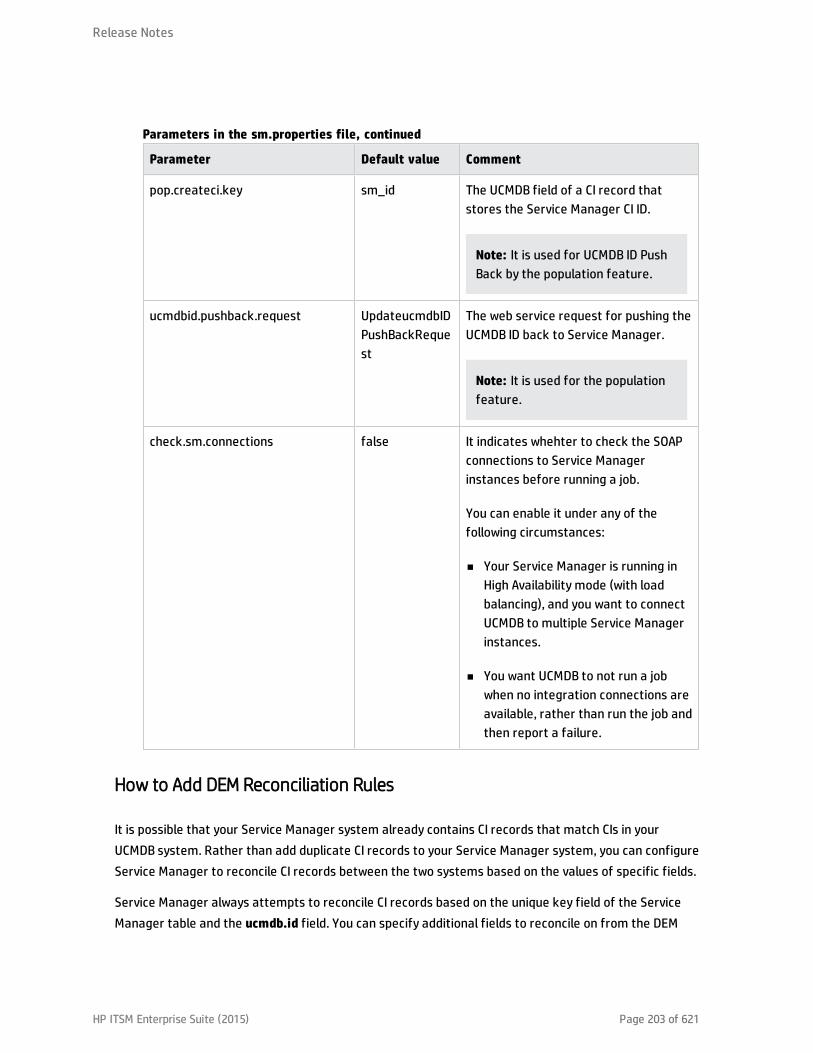
Parameter Default value Comment
pop.createci.key sm_id The UCMDB field of a CI record thatstores the Service Manager CI ID.
Note: It is used for UCMDB ID PushBack by the population feature.
ucmdbid.pushback.request UpdateucmdbIDPushBackRequest
The web service request for pushing theUCMDB ID back to Service Manager.
Note: It is used for the populationfeature.
check.sm.connections false It indicates whehter to check the SOAPconnections to Service Managerinstances before running a job.
You can enable it under any of thefollowing circumstances:
n Your Service Manager is running inHigh Availability mode (with loadbalancing), and you want to connectUCMDB to multiple Service Managerinstances.
n You want UCMDB to not run a jobwhen no integration connections areavailable, rather than run the job andthen report a failure.
Parameters in the sm.properties file, continued
How to Add DEM Reconciliation Rules
It is possible that your Service Manager system already contains CI records that match CIs in yourUCMDB system. Rather than add duplicate CI records to your Service Manager system, you can configureService Manager to reconcile CI records between the two systems based on the values of specific fields.
Service Manager always attempts to reconcile CI records based on the unique key field of the ServiceManager table and the ucmdb.id field. You can specify additional fields to reconcile on from the DEM
Release Notes
HP ITSM Enterprise Suite (2015) Page 203 of 621

Reconciliation Rules form. If Service Manager finds a matching value in any one of these fields, itupdates the Service Manager CI record with the attributes from the incoming UCMDB record.
When multi-tenancy is enabled, Service Manager only reconciles the CIs whose company ID matches thecompany ID in the data push job. For example, when pushing CIs from company 2, the reconciliation rulesonly apply to the Service Manager CI records that have the company code corresponding to companynumber 2.
In order to specify reconciliation fields, you will need to be familiar with the table and field names inboth your Service Manager and UCMDB systems. If you want to reconcile on a particular attribute fromthe UCMDB system, you should verify that there is a corresponding Service Manager managed field forthe attribute. Without such a mapping, Service Manager will not know to search for matching values inthe CI record.
Note: Not all UCMDB attributes have a corresponding field in Service Manager. You may need totailor your Service Manager system to add a matching field if one does not already exist.
Using join tables for reconciliation
When setting reconciliation rules, if the device type you are reconciling has a joindef definition (asdefined in the devtype table), use the join table name instead of the device table. For example, if youwant to reconcile computer CIs, use the joincomputer table instead of the device table.
Sequence of reconciliation
A reconciliation rule specifies what Service Manager table and field you want to search for matching CIvalues. It also specifies the sequence in which you want Service Manager to process reconciliation rules.By default, Service Manager processes rules in alphabetical order by field name. For example, ServiceManager will reconcile CIs against the asset.tag field before reconciling CIs on the ci.name field.
To change the order in which Service Manager reconciles CIs, you can add a numeric value to thesequence field. For example, the following reconciliation rules ensure that Service Manager processesCIs by the ci.name field prior to reconciling them against the asset.tag field.
Table Name Field Name Sequence
joincomputer ci.name 1
joincomputer asset.tag 2
Sample reconciliation rules ordered by sequence
A Discovery Event Manager (DEM) reconciliation rule allows you to specify which Service Manager fieldsyou want to use to determine if an existing CI record matches a CI in a UCMDB system. An administratortypically specifies reconciliation rules prior to starting UCMDB data push jobs so that Service Managerwill not create duplicate CI records.
Release Notes
HP ITSM Enterprise Suite (2015) Page 204 of 621
To create a DEM reconciliation rule:
1. Log in to Service Manager as a system administrator.
2. Navigate to Tailoring > Web Services > DEM Reconciliation Rules. Service Manager displays theDEM Reconcile Record form.
3. In Table Name, type the name of the Service Manager table containing the field you want toreconcile on.
4. In Field Name, type the name of the Service Manager field containing the values you want toreconcile on.
5. In Sequence, type a number to specify what order you want Service Manager to run this rule.
Note: If you do not specify a sequence value, Service Manager will process field namesalphabetically.
6. Click New. Service Manager creates the reconciliation rule.
How to Add Discovery Event Manager Rules
Service Manager uses Discovery Event Manager (DEM) to define the actions the system should performwhen the actual state of an incoming configuration item (CI) record differs from the managed state of aCI record in HP Service Manager. The DEM rules allow you to define whether the Service Manager systemadds, updates, or deletes CI records based on incoming UCMDB data.
For CI records only, the DEM rules also allow you to define how Service Manager should handle duplicatelogical names.
To access DEM rules in Service Manager, navigate to Tailoring > Web Services > Discovered EventManager Rules, and then click Search to view existing rules or click New to create new rules.
This section includes:
l "DEM Rules" on the next page
l "Duplication Rules" on page 208
l "CI Attributes Displayed in Change and Incident Records" on page 209
l "Searching for Change and Incident Records Opened by the Integration" on page 210
Release Notes
HP ITSM Enterprise Suite (2015) Page 205 of 621

DEM Rules
Service Manager offers the following rules options:
Action if matching record does not existThis is the action you want Service Manager to take if it cannot find a matching CI record.
l Add the record:(Default) Service Manager will add a CI record when it cannot find a matching record.See "How to Add DEM Reconciliation Rules" on page 203 to define what fields Service Manager usesto match CI records.
l Add the record, and set dependency as true: This option is available only for synchronization of CIrelationship data. Service Manager adds the CI relationship record and enables outage dependencyfor the record by doing the following:n Checks the Outage Dependency check box;
n Sets the number of dependent downstream CIs to 1. This is because UCMDB only supports one-to-one CI relationships.
Release Notes
HP ITSM Enterprise Suite (2015) Page 206 of 621

l Open an Incident:Service Manager opens an incident for someone to review the new CI record. Theincident enables someone to investigate whether the new CI record is compliant with your businesspractices.
l Open a Change:Service Manager opens an unplanned change for someone to review the new CIrecord. The change allows you to investigate whether the new CI record is compliant with yourbusiness practices. If the CI record is compliant, the change can be approved. If the CI record is notcompliant, then the change can be denied and the CI record removed. The change record lists boththe current and proposed attribute values.
Action if record exists but unexpected data discoveredThis is the action you want Service Manager to perform if it does not find a matching CI attribute value.
l Open a Change: (Default) Service Manager opens an unplanned change to review the actual state ofthe CI record. The change allows someone to investigate whether the new attribute value iscompliant with your business practices. If the value is compliant, the change can be approved. If thevalue is not compliant, then the change can be denied and the CI attribute value reverted to itsmanaged state.
l Log Results and update record:Service Manager logs the results of the actual state of the CI record,and then updates the CI record.
l Open an Incident:Service Manager opens an Incident to investigate the actual state of a CI recordand determines what actions must be performed or initiated to bring the record into compliancewith Service Manager.
Action if record is to be deletedThis is the action you want Service Manager to perform if an external event specifies that the recordneeds to be deleted.
l Delete record: (Default for CI Relationship records) This option is available for synchronization ofboth CI and CI Relationship records. Service Manager automatically deletes the CI/CI Relationshiprecord.
Release Notes
HP ITSM Enterprise Suite (2015) Page 207 of 621

l Open an Incident: This option is available only for synchronization of CI Relationship records. ServiceManager opens an incident to investigate the deleted record and determines which actions must beperformed or initiated to bring the record into compliance with Service Manager.
l Open a Change: This option is available only for synchronization of CI Relationship records. ServiceManager opens an unplanned change to review the deleted record. The change allows someone toinvestigate whether the deleted record is compliant with your business practices. If the record iscompliant, the change can be approved. If the record is not compliant, then the change can bedenied and the record added back to the system.
l Update record to the selected status: (Default for CI records) This option is available only forsynchronization of CI records. Service Manager updates the status of the CI record to a valueselected from the drop-down list (for example, Retired/Consumed), rather than delete the recordpermanently.
Note: Values available from the drop-down list are defined in the ICM Status global list.
l Open a Change to update record to the selected status: This option is available only forsynchronization of CI records. Service Manager opens an unplanned change to update the CI record’sstatus to a value selected from the drop-down list (for example, Retired/Consumed). The changeallows someone to investigate whether the requested status change is compliant with your businesspractices. Once the change has been approved and closed, Service Manager automatically changesthe CI record to the selected status. If the change has been denied, Service Manager makes nochanges to the CI record.
l Open an Incident to update record to the selected status: This option is available only forsynchronization of CI records. Service Manager opens an incident to update the record’s status to avalue selected from the drop-down list (for example, Retired/Consumed). Once the incident hasbeen closed, Service Manager automatically updates the CI record to the selected status.
Duplication Rules
UCMDB may create two completely separate yet legit CI records that happen to have the same “name.”The UCMDB name field is mapped to the logical.name field (which must be unique) in Service Manager.Pushing the two CI records to Service Manager would cause a duplicate logical name problem. You haveseveral ways to avoid this problem. See the following table.
Release Notes
HP ITSM Enterprise Suite (2015) Page 208 of 621

Productside Solution
UCMDB Change the names directly in UCMDB or change the UCMDB reconciliation rule to makesure the names are not the same.
This is highly recommended.
In the integration adapter mapping configuration (xslt) file, avoid mapping the UCMDBname field to the SM logical name field directly in either of these ways:
l Map another UCMDB unique attribute to the SM logical.name field, and map the UCMDBname field to another SM field;
l Add a prefix to the name. The following are examples.n UCMDB switches or routers are simply named as “Router” or “Switch” and identified
by their underlying MACs. You can configure their “SM logical name” to be “<MAC> +<name>”.
n UCMDB databases often have the same name (due to the implementation ofclusters and Oracle RACs). You can configure their “SM logic name” to be “<full DNSname> + <name>”.
ServiceManager
Use the duplication rule options in DEM Rules in Service Manager.
Solutions to the duplicate logical name problem
Service Manager offers the following duplication rule options on the Duplication Rule tab in each DEMrule with a Table Name other than “cirelationship”:
l Action if logical name is duplicated (CI with different uCMDB ID): This is the action you wantService Manager to perform if the logical name is already used by another CI record when a CI recordis added or updated.n Rename to <name>_[RENAMED]_1/2/3: (Default) Service Manager changes the logical name by
adding a suffix.
n Return Error: Service Manager returns a duplicate key error to UCMDB.
CI Attributes Displayed in Change and Incident Records
Service Manager displays a Change Details section on the corresponding change or a CMDB Changessection on the corresponding incident when you configure DEM to open either change records orincident records when it discovers CI attribute changes through the UCMDB-SM integration. ServiceManager only displays a tab for CI attributes when the UCMDB-SM integration is enabled and you have
Release Notes
HP ITSM Enterprise Suite (2015) Page 209 of 621
defined a rule in the Discovery Event Manager to create a change or incident record when a CI is added,updated, or deleted.
Both the Change Details and CMDB Changes sections display the current CI attribute values alongsidethe actual attribute values discovered by UCMDB. You can use this information to approve or deny achange or escalate an incident to the proper assignment group.
Searching for Change and Incident Records Opened by the Integration
You can use the following search criteria to find change and incident records opened by the UCMDB-SMintegration.
Record type Search option available
Change Search for records with the category unplanned change.
Incident Search for records using the Generated by UCMDB Integration option.
Search options available for change and incident records
How to Add a CI Attribute to the Integration for Data Push
You can use the following steps to add a CI attribute to the integration.
1. Does the CI attribute already exist in the UCMDB class model?Yes. Go to Step 3.
No. Go to Step 2.
2. Add the CI attribute to the UCMDB class model.See "How to Add the CI Attribute to the UCMDB Class Model" on the next page.
3. Add the CI attribute to the query layout.See "How to Add a CI Attribute to the Query Layout" on page 212.
4. Add a web service field for the Service Manager CI type.See "How to Add a Web Service Field for the Service Manager CI Type" on page 214.
5. Map the CI attribute to the SM web service field.
See "How to Map the CI Attribute to a Service Manager Web Service Field" on page 222.
Release Notes
HP ITSM Enterprise Suite (2015) Page 210 of 621
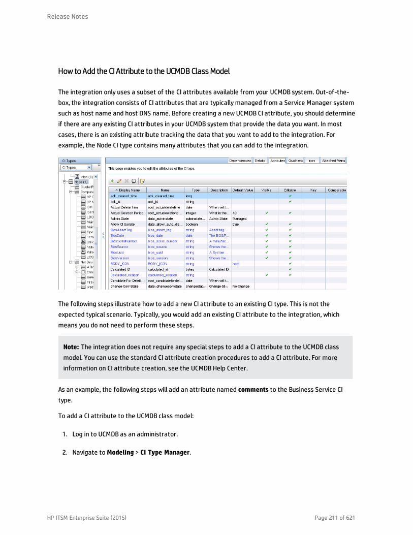
How to Add the CI Attribute to the UCMDB Class Model
The integration only uses a subset of the CI attributes available from your UCMDB system. Out-of-the-box, the integration consists of CI attributes that are typically managed from a Service Manager systemsuch as host name and host DNS name. Before creating a new UCMDB CI attribute, you should determineif there are any existing CI attributes in your UCMDB system that provide the data you want. In mostcases, there is an existing attribute tracking the data that you want to add to the integration. Forexample, the Node CI type contains many attributes that you can add to the integration.
The following steps illustrate how to add a new CI attribute to an existing CI type. This is not theexpected typical scenario. Typically, you would add an existing CI attribute to the integration, whichmeans you do not need to perform these steps.
Note: The integration does not require any special steps to add a CI attribute to the UCMDB classmodel. You can use the standard CI attribute creation procedures to add a CI attribute. For moreinformation on CI attribute creation, see the UCMDB Help Center.
As an example, the following steps will add an attribute named comments to the Business Service CItype.
To add a CI attribute to the UCMDB class model:
1. Log in to UCMDB as an administrator.
2. Navigate to Modeling > CI Type Manager.
Release Notes
HP ITSM Enterprise Suite (2015) Page 211 of 621

3. Select the CI type to which you want to add a new CI attribute from the CI Types navigation tree.For example, ConfigurationItem > BusinessElement > BusinessService.
4. Click the Attributes tab.
5. Click the Add icon.The Add Attribute window opens.
6. In Attribute Name, type the unique name you want to use for the new CI attribute. For example,comments.
Caution: The name cannot include any of the following characters: ‘ / \ [ ] : | < > +
= ; , ? *.
7. In Display Name, type the name that you want UCMDB to display in the interface. For example,Comments.
8. (Optional) In Description, type a description of the new CI attribute.
9. In Attribute Type, select Primitive or Enumeration/List depending on the data type of theattribute. For example, select Primitive and select string.
10. In Value Size, type the maximum character length that the attribute can have. For example, 300.
11. Select the Enable default value option, and enter a default value. Or, do not select this option toleave the default value blank.
12. Click OK to save the attribute.
13. Click the Save icon to save attribute changes to the CI type.
Now, the attribute has been added to the CI type. Next, you need to add the attribute to a query thatsynchronizes the CI type. See "How to Add a CI Attribute to the Query Layout" below.
How to Add a CI Attribute to the Query Layout
To add an existing CI attribute to the integration, you must add this attribute to the layout setting fromthe query that synchronizes the CI type. You must know which CI type contains the CI attributes that youwant to add to the integration.
To add a CI attribute to the query layout:
Release Notes
HP ITSM Enterprise Suite (2015) Page 212 of 621
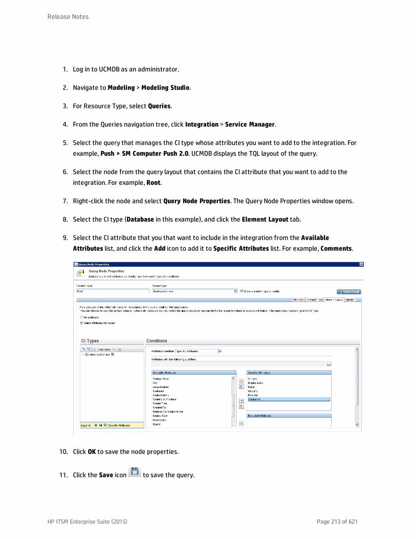
1. Log in to UCMDB as an administrator.
2. Navigate to Modeling > Modeling Studio.
3. For Resource Type, select Queries.
4. From the Queries navigation tree, click Integration > Service Manager.
5. Select the query that manages the CI type whose attributes you want to add to the integration. Forexample, Push > SM Computer Push 2.0. UCMDB displays the TQL layout of the query.
6. Select the node from the query layout that contains the CI attribute that you want to add to theintegration. For example, Root.
7. Right-click the node and select Query Node Properties. The Query Node Properties window opens.
8. Select the CI type (Database in this example), and click the Element Layout tab.
9. Select the CI attribute that you that want to include in the integration from the AvailableAttributes list, and click the Add icon to add it to Specific Attributes list. For example, Comments.
10. Click OK to save the node properties.
11. Click the Save icon to save the query.
Release Notes
HP ITSM Enterprise Suite (2015) Page 213 of 621

Now, the CI attribute has been added to the relevant query layout. Next, you need to add a ServiceManager web service field that will be mapped to this UCMDB CI attribute.
How to Add a Web Service Field for the Service Manager CI Type
The integration uses only a subset of the CI attributes available from your Service Manager (SM)system. CI attributes must be mapped between UCMDB and SM. Before creating a new SM CI attributethat will be mapped to the UCMDB CI attribute you added previously, you must determine if there areany existing CI attributes in your Service Manager system that provide the data you want. In most cases,there is an existing attribute tracking the data that you want to add to the integration. For example, theComputer CI type contains many attributes that you can add to the integration.
If you decide to use an existing attribute instead of creating a new one, you can directly modify the webservice definition in Service Manager to expose that attribute, and then map this SM attribute to theUCMDB attribute by using the UCMDB Visual Mapping tool (see "How to Map the CI Attribute to a ServiceManager Web Service Field" on page 222).
Release Notes
HP ITSM Enterprise Suite (2015) Page 214 of 621

If you decide to add a new attribute, follow the steps below. The steps vary depending on the data typeof the attribute: simple (string, for example), or complex (array of structure or structure).
Add a Simple Attribute to the SM CI TypeAs an example, the following steps illustrate how to add a simple attribute (comments) to an existing CItype (Business Service).
1. Log in to UCMDB as a system administrator.
2. Click Data Flow Management > Adapter Management, and then selectServiceManagerEnhancedAdapter 9-x to open the corresponding XML mapping file (SM BusinessService 2.0.xml in this example) with the Visual Mapping tool editor.
3. On the External Class Model pane, select the CI type (bizservice).
4. On the left-side Attributes pane (which displays the fields that are retrieved from the ServiceManager web service object for the Business Service CI type), click the Add New Attribute toSelected External Node icon.
5. Type a name and display label for the new attribute, and click OK.
Caution: If the you enter a name that duplicates or is part of an existing field name in theattribute table of the Service Manager CI type or in the device table, an error will occur
Release Notes
HP ITSM Enterprise Suite (2015) Page 215 of 621

indicating the attribute could not be created.
6. Click OK again to confirm the attribute creation.
The new attribute (mycomments) appears in the Service Manager attribute list.
Release Notes
HP ITSM Enterprise Suite (2015) Page 216 of 621

At the same time, UCMDB invokes the Service Manager Web Service API to add the new attribute,expose it in the Web Service API and set it as a managed field. You can open the web service objectin Service Manager to verify the new attribute (Tailoring > Web Services > Web ServiceConfiguration).
7. Save the configuration file.
Add an Array of Structure or Structure to the CI TypeService Manager uses an Array of Structure or Structure to store complex attributes, for example, theports of a Computer CI. You can also create such kind of complex attributes through the Visual Mappingtool in UCMDB.
The following steps illustrate how to add an attribute named comport to the Computer CI type.
1. Log in to UCMDB as a system administrator.
2. Open the corresponding XML mapping file (SM Computer Push 2.0.xml in this example), with theVisual Mapping tool editor.
Release Notes
HP ITSM Enterprise Suite (2015) Page 217 of 621
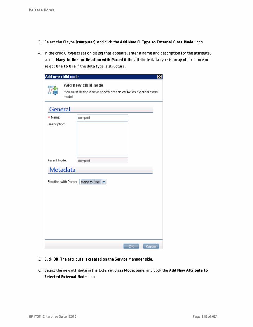
3. Select the CI type (computer), and click the Add New CI Type to External Class Model icon.
4. In the child CI type creation dialog that appears, enter a name and description for the attribute,select Many to One for Relation with Parent if the attribute data type is array of structure orselect One to One if the data type is structure.
5. Click OK. The attribute is created on the Service Manager side.
6. Select the new attribute in the External Class Model pane, and click the Add New Attribute toSelected External Node icon.
Release Notes
HP ITSM Enterprise Suite (2015) Page 218 of 621
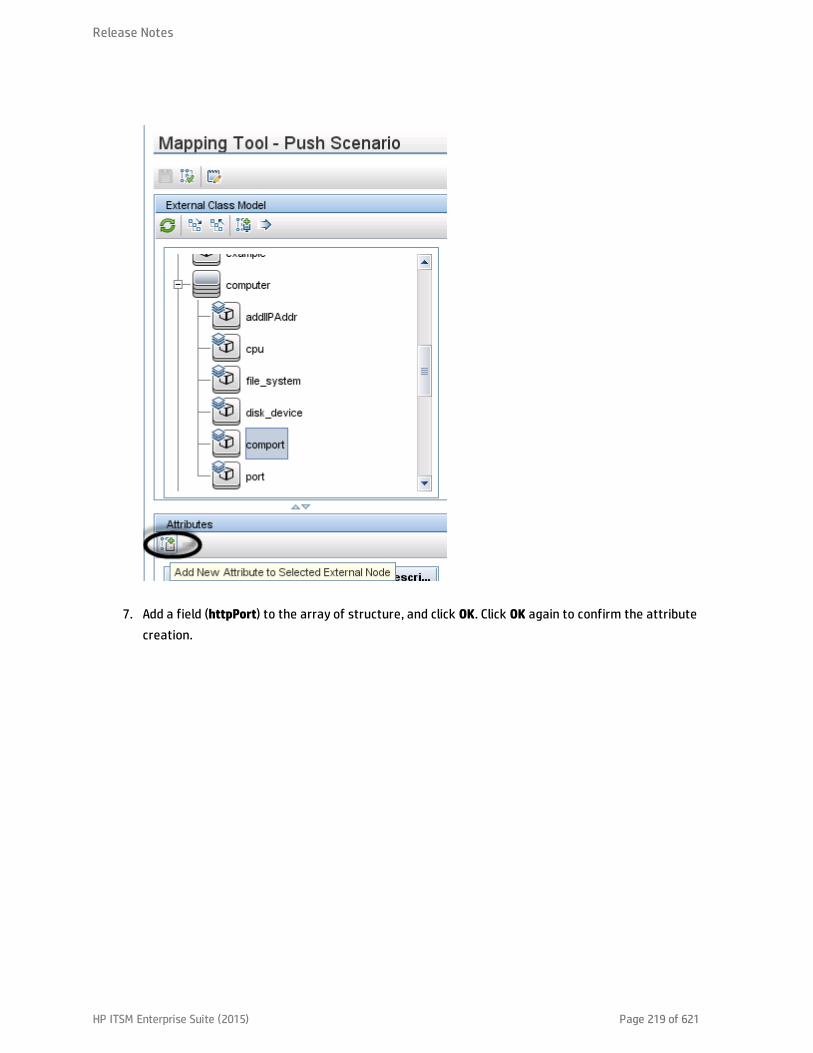
7. Add a field (httpPort) to the array of structure, and click OK. Click OK again to confirm the attributecreation.
Release Notes
HP ITSM Enterprise Suite (2015) Page 219 of 621

8. Repeat the previous two steps to add more fields to the array of structure as needed.
Release Notes
HP ITSM Enterprise Suite (2015) Page 220 of 621
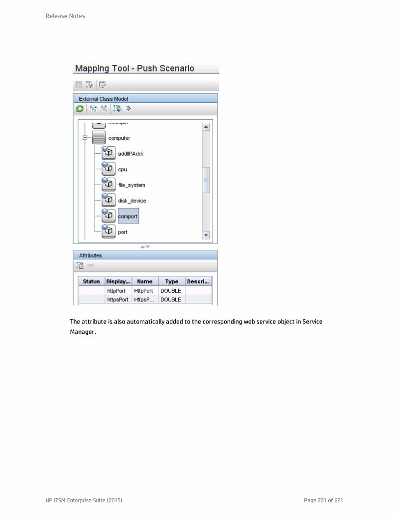
The attribute is also automatically added to the corresponding web service object in ServiceManager.
Release Notes
HP ITSM Enterprise Suite (2015) Page 221 of 621

9. Save the configuration file.
Next, you need to map this Service Manager CI type attribute to the one you added previously in UCMDB.
How toMap the CI Attribute to a Service ManagerWeb Service Field
The integration uses an adapter to transform UCMDB CI attributes to web services objects recognizedby Service Manager. The adapter in turn specifies what XML transformation files the integration shoulduse to convert UCMDB queries into properly formatted Service Manager web services messages.
Out-of-the-box, each integration query has a corresponding XML configuration file that maps to aparticular CI type in UCMDB. In addition, each attribute for which you enabled calculation requires itsown entry in the XML configuration file. Without an XML transformation entry, Service Manager cannotreceive any CI attribute updates from your UCMDB system.
Release Notes
HP ITSM Enterprise Suite (2015) Page 222 of 621

If you want to add a new attribute to the integration, you must edit the XML configuration file for theparent CI type and add an entry for the CI attribute. For information about which CI types each querymanages, see "Queries for Push" on page 183.
The following steps illustrate how to map UCMDB CI attribute Comments (which you added previously) tothe MyComments Service Manager attribute (which you created in the previous step).
To map a UCMDB CI attribute to an SM CI attribute:
1. Log in to UCMDB as an administrator.
2. Navigate to Data Flow Management > Adapter Management >ServiceManagerEnhancedAdapter9-x > Configuration Files.
3. Double-click the XML configuration file that manages the parent CI type of your CI attribute. Forexample, open SM Business Service Push 2.0.xml to add an attribute to the SM Business ServicePush 2.0 query.
4. Select the relevant CI type in the External Class Model pane (bizservice in this example), and dragand drop the attribute (mycomments) from the left-side Attributes pane into the Visual Mappingpane.
5. Select the relevant Node in the Local Query panel (Root in this example), and drag and drop theattribute (comments in this case) into the mapping entry that you created in the previous step.
Release Notes
HP ITSM Enterprise Suite (2015) Page 223 of 621
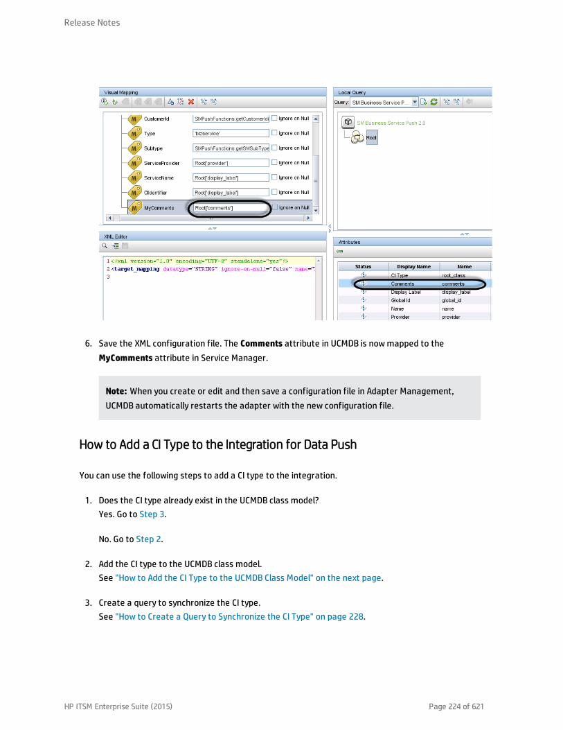
6. Save the XML configuration file. The Comments attribute in UCMDB is now mapped to theMyComments attribute in Service Manager.
Note: When you create or edit and then save a configuration file in Adapter Management,UCMDB automatically restarts the adapter with the new configuration file.
How to Add a CI Type to the Integration for Data Push
You can use the following steps to add a CI type to the integration.
1. Does the CI type already exist in the UCMDB class model?Yes. Go to Step 3.
No. Go to Step 2.
2. Add the CI type to the UCMDB class model.See "How to Add the CI Type to the UCMDB Class Model" on the next page.
3. Create a query to synchronize the CI type.See "How to Create a Query to Synchronize the CI Type" on page 228.
Release Notes
HP ITSM Enterprise Suite (2015) Page 224 of 621
4. Add the CI type’s attributes to the query layout.See "How to Add the CI Type’s Attributes to the Query Layout" on page 232.
5. Add the CI type to Service ManagerService Manager.See "How to Add the CI Type to Service Manager" on page 234.
6. Map the CI type’s attributes to web service fields.See "How to Map the CI Type’s Attributes to Web Service Fields" on page 237.
7. Add custom queries to integration data push jobs.See "How to Add a Custom Query to an Integration Job" on page 248.
How to Add the CI Type to the UCMDB Class Model
Before creating a new UCMDB CI type, you should determine if there are any existing CI types in yourUCMDB system that provide the CI attributes you want. In most cases, you can create links to one ormore existing CI types to create a new logical CI type for use by the integration.
The following steps illustrate how to create a new CI type called SM RDBMS based on an existing CI typecalled database.
Note: The integration does not require any special steps to add a CI type to the UCMDB class model.You can use the standard CI type creation procedures to add a CI type. For more information on CItype creation, see the UCMDB Help Center.
To add a CI type to the UCMDB class model:
1. Log in to UCMDB as an administrator.
2. Navigate to Modeling > CI Type Manager.
3. Select the base CI type you want to use for your new CI type from the CI Types navigation tree:Managed Object > ConfigurationItem > Infrastructure Element > Running Software > Database.
4. Click the New icon .The Create Configuration Item Type window opens.
5. In Name, type the unique name you want to use for the new CI type. For example, sm_rdbms.
Caution: The name cannot include any of the following characters: ‘ / \ [ ] : | < > +
= ; , ? *.
Release Notes
HP ITSM Enterprise Suite (2015) Page 225 of 621

6. In Display Name, type the name you want UCMDB to display in the interface. For example, SMRDBMS.
7. In Description, type a description of the new CI type. This is an optional field. For example, Hostsrunning relational databases.
8. In Base CI Type, verify that the proper base CI type is selected. Your new CI type will inherit theattributes of the base CI type you select here. For example, Database.
9. Click Next. The wizard displays a list of CI attributes from the base CI type.
10. Add, edit, or remove CI attributes as needed for the new CI type. For example, accept the defaultattributes inherited from Database.
11. Click Next. The wizard displays a list of qualifiers from the base CI type.
12. Add or remove qualifiers as needed for the new CI type. For example, accept the default qualifiers.
13. Click Next. The wizard displays a list of icons associated with the CI type.
14. Select the icons associated with this CI type. For example, accept the default abstract class icon.
15. Click Next to add any menu item properties or label definitions as needed. For example, accept thedefault settings from the base CI type.
16. Click Finish to create the CI type.
Release Notes
HP ITSM Enterprise Suite (2015) Page 226 of 621
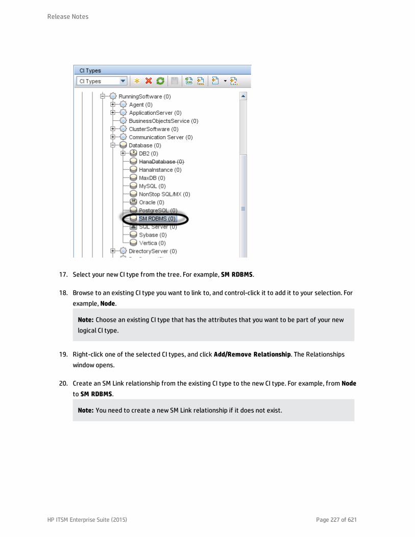
17. Select your new CI type from the tree. For example, SM RDBMS.
18. Browse to an existing CI type you want to link to, and control-click it to add it to your selection. Forexample, Node.
Note: Choose an existing CI type that has the attributes that you want to be part of your newlogical CI type.
19. Right-click one of the selected CI types, and click Add/Remove Relationship. The Relationshipswindow opens.
20. Create an SM Link relationship from the existing CI type to the new CI type. For example, from Nodeto SM RDBMS.
Note: You need to create a new SM Link relationship if it does not exist.
Release Notes
HP ITSM Enterprise Suite (2015) Page 227 of 621

21. Click OK to create the relationship.
22. Click the Save icon to save the CI type.
How to Create a Query to Synchronize the CI Type
The integration uses queries to gather CI attribute values and pass them to your Service Managersystem. You must create a query for any CI type you add to the integration. Any query you create mustconform to the "Query Requirements" on page 188.
The following steps illustrate how to create a new query named rdbmsData for the SM RDBMS CI typedescribed in previous sections.
1. Log in to UCMDB as an administrator.
2. Navigate to Modeling > Modeling Studio.
3. From the Queries navigation tree, click Integration > Service Manager.
4. Right-click Service Manager, and select the New > Query.The Query Definition window opens.
5. Find the CI type that will be the root node of your query from the CI Type Selector. This CI type istypically the one that provides the most attributes for the CI. For example, Managed Object >ConfigurationItem > InfrastructureElement > RunningSoftware > Database > SM RDBMS.
Release Notes
HP ITSM Enterprise Suite (2015) Page 228 of 621
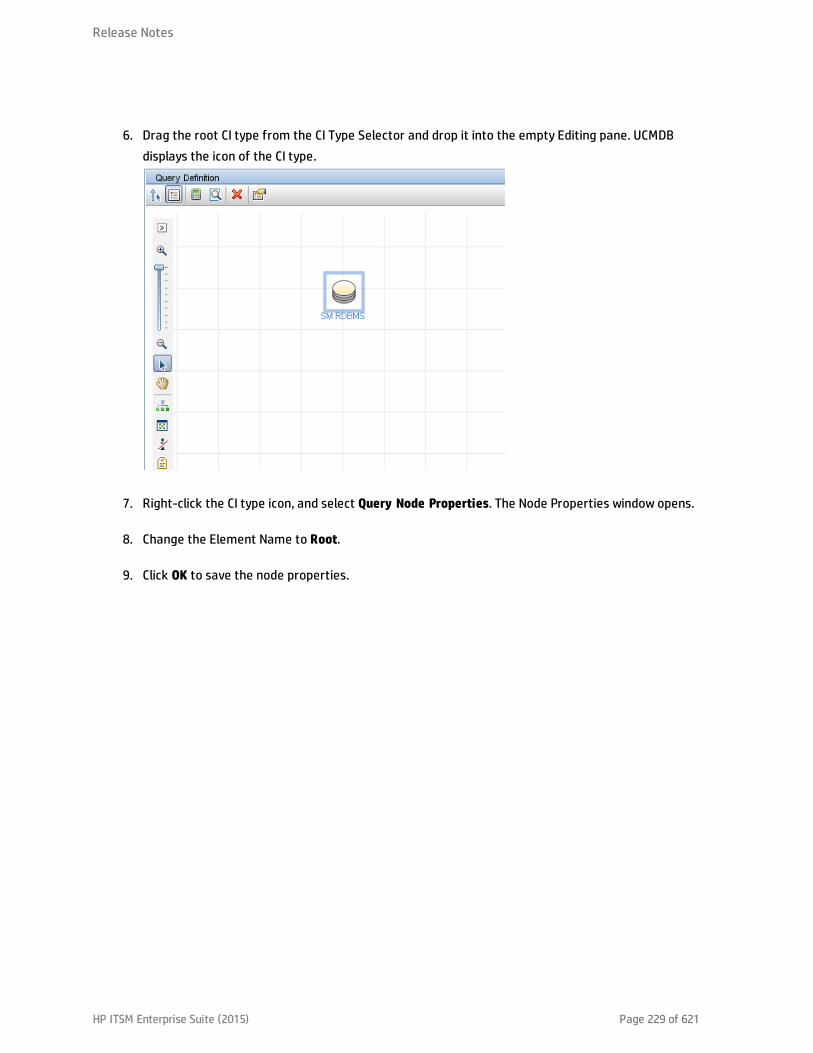
6. Drag the root CI type from the CI Type Selector and drop it into the empty Editing pane. UCMDBdisplays the icon of the CI type.
7. Right-click the CI type icon, and select Query Node Properties. The Node Properties window opens.
8. Change the Element Name to Root.
9. Click OK to save the node properties.
Release Notes
HP ITSM Enterprise Suite (2015) Page 229 of 621

10. Find any additional CI types you want to add to the query from the CI Type Selector. These CI typestypically provide additional CI attributes. For example, Managed Object > ConfigurationItem >Infrastructure Element > Node.
11. Drag the additional CI type from the CI Type Selector and drop it into the Query Definition pane.UCMDB displays the icon of the additional CI type.
Release Notes
HP ITSM Enterprise Suite (2015) Page 230 of 621

12. Create relationships between the Root CI type and the additional CI types as needed. For example,create an SM Link between Root and Node.a. Select Root and control-click the additional CI type. For example, Node.
b. Right-click one of the selected items, and click Add Relationship. The Add Relationship windowopens.
c. Type a Relationship Name. For example SM Link.
d. Select the relationship direction.
Release Notes
HP ITSM Enterprise Suite (2015) Page 231 of 621

e. Click OK to add the relationship.
13. Repeat step 10 to step 12 for each additional CI type you want to add to the query. For example,SM RDBMS does not need any additional CI types.
14. Click the Save icon to save the query.a. In Query Name, type the unique name you want to use for the new query. For example,
rdbmsData.
b. In the folder tree, select the folder in which you want to save the query. For example, Root >Integration > Service Manager > Push.
c. Click OK. UCMDB adds your new query to the query list.
How to Add the CI Type’s Attributes to the Query Layout
To add a CI attribute to the integration, you must enable the calculation layout setting from the querythat synchronizes the CI type. Because you must enable calculation for each attribute you want to addto the integration, you should be familiar with the integration CI types and their attributes.
Release Notes
HP ITSM Enterprise Suite (2015) Page 232 of 621
The following steps illustrate how to enable calculation for attributes of the SM RDBMS CI typedescribed in previous sections.
To add a CI type’s attributes to the query layout:
1. Log in to UCMDB as an administrator.
2. Navigate to Modeling > Modeling Studio.
3. From the Queries navigation tree, click Integration > Service Manager.
4. Double-click the query that manages the CI type whose attributes you want to add to theintegration. For example, rdbmsData. UCMDB displays the TQL layout of the query.
5. Right-click the Root node from the query layout, and then select Query Node Properties. TheQuery Node Properties window opens.
Caution: Your integration query must contain a node called Root. See "Query Requirements"on page 188 for more information.
6. Click the Element Layout tab, and select the Select attributes for layout option.
7. Select Specific Attributes from the Attributes condition list, and from the Available Attributes listselect the attributes you want and move them to the Specific Attributes list. For example, add theProduct Name, Application Version Description, The Database Instance Name, and Portattributes.
Release Notes
HP ITSM Enterprise Suite (2015) Page 233 of 621
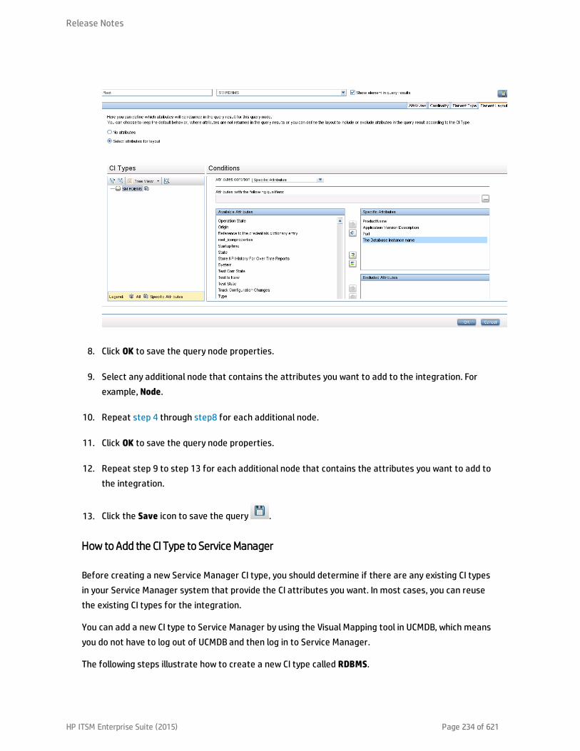
8. Click OK to save the query node properties.
9. Select any additional node that contains the attributes you want to add to the integration. Forexample, Node.
10. Repeat step 4 through step8 for each additional node.
11. Click OK to save the query node properties.
12. Repeat step 9 to step 13 for each additional node that contains the attributes you want to add tothe integration.
13. Click the Save icon to save the query .
How to Add the CI Type to Service Manager
Before creating a new Service Manager CI type, you should determine if there are any existing CI typesin your Service Manager system that provide the CI attributes you want. In most cases, you can reusethe existing CI types for the integration.
You can add a new CI type to Service Manager by using the Visual Mapping tool in UCMDB, which meansyou do not have to log out of UCMDB and then log in to Service Manager.
The following steps illustrate how to create a new CI type called RDBMS.
Release Notes
HP ITSM Enterprise Suite (2015) Page 234 of 621
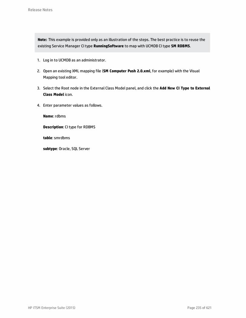
Note: This example is provided only as an illustration of the steps. The best practice is to reuse theexisting Service Manager CI type RunningSoftware to map with UCMDB CI type SM RDBMS.
1. Log in to UCMDB as an administrator.
2. Open an existing XML mapping file (SM Computer Push 2.0.xml, for example) with the VisualMapping tool editor.
3. Select the Root node in the External Class Model panel, and click the Add New CI Type to ExternalClass Model icon.
4. Enter parameter values as follows.
Name: rdbms
Description: CI type for RDBMS
table: smrdbms
subtype: Oracle, SQL Server
Release Notes
HP ITSM Enterprise Suite (2015) Page 235 of 621

5. Click OK.
6. Click OK again to confirm the CI type creation. The CI type is automatically created in ServiceManager, as shown in the following figure.
Release Notes
HP ITSM Enterprise Suite (2015) Page 236 of 621
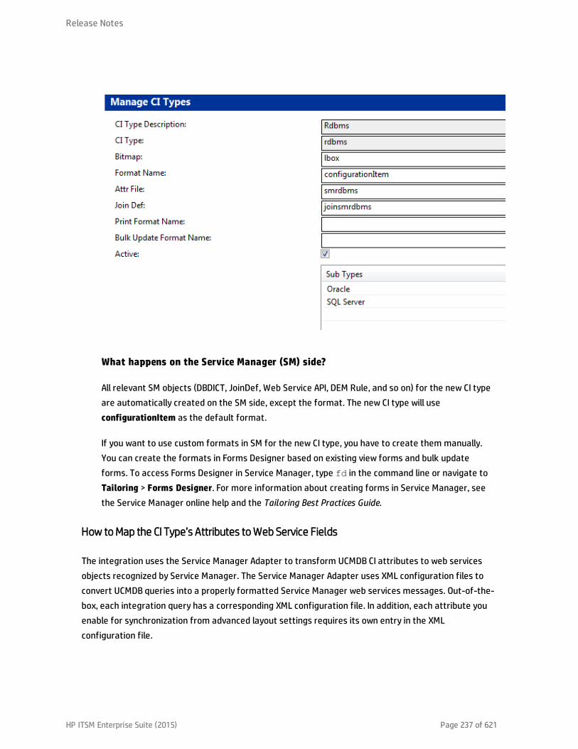
What happens on the Service Manager (SM) side?
All relevant SM objects (DBDICT, JoinDef, Web Service API, DEM Rule, and so on) for the new CI typeare automatically created on the SM side, except the format. The new CI type will useconfigurationItem as the default format.
If you want to use custom formats in SM for the new CI type, you have to create them manually.You can create the formats in Forms Designer based on existing view forms and bulk updateforms. To access Forms Designer in Service Manager, type fd in the command line or navigate toTailoring > Forms Designer. For more information about creating forms in Service Manager, seethe Service Manager online help and the Tailoring Best Practices Guide.
How toMap the CI Type’s Attributes toWeb Service Fields
The integration uses the Service Manager Adapter to transform UCMDB CI attributes to web servicesobjects recognized by Service Manager. The Service Manager Adapter uses XML configuration files toconvert UCMDB queries into a properly formatted Service Manager web services messages. Out-of-the-box, each integration query has a corresponding XML configuration file. In addition, each attribute youenable for synchronization from advanced layout settings requires its own entry in the XMLconfiguration file.
Release Notes
HP ITSM Enterprise Suite (2015) Page 237 of 621

If you want to add a CI type to the integration, you must create a matching XML configuration file thatdefines how the Service Manager Adapter transforms each CI type into a Service Manager web serviceobject. See "Integration Queries" on page 183 for information about the CI types each query manages.
The following steps illustrate how to create an XML configuration file for the rdbmsData querydescribed in previous sections.
To map a CI type’s attributes to web service fields:
1. Log in to UCMDB with an administrator account.
2. Navigate to Data Flow Management > Adapter Management >ServiceManagerEnhancedAdapter9-x, and select the adapter.
3. Click the Create New Resource icon .
4. Select New Configuration File.
5. Enter the full file name: <AdapterID>/mappings/push/<filename>. For example,ServiceManagerEnhancedAdapter9-x/mappings/push/SM RDBMS Push.xml.
6. Click OK. The mapping file is created.
7. Double-click the new mapping file to open it with the Visual Mapping tool editor.
8. In the Local Query pane, click the Add TQL Queries icon to add the rdbmsData query.
Release Notes
HP ITSM Enterprise Suite (2015) Page 238 of 621
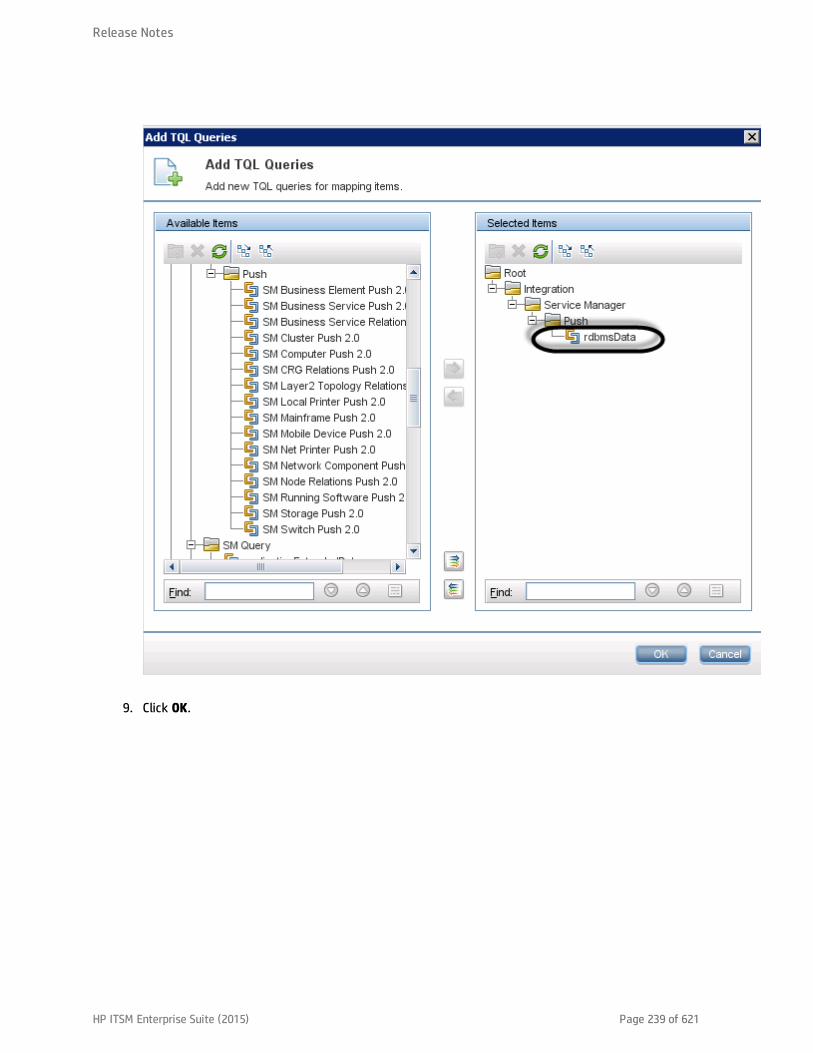
9. Click OK.
Release Notes
HP ITSM Enterprise Suite (2015) Page 239 of 621

10. Drag and drop the node “Root” from the Local Query pane into the mapping area.
11. Drag and drop the node “RDBMS” from the External Class Model pane into the mapping area.
12. Drag and drop SM attributes you want into the mapping area.
13. Drag and drop the relevant UCMDB attributes into the mapping area.
Release Notes
HP ITSM Enterprise Suite (2015) Page 240 of 621

14. Save the new mapping file.
Note: When you create or edit and then save a configuration file in Adapter Management,UCMDB automatically restarts the adapter with the new configuration file.
Using Groovy scripts in XML Configuration Files
The Service Manager Enhanced Generic Adapter uses XML and Groovy mapping scripts for four fieldmapping scenarios: One to One, One to Many, Many to Many, and Value Conversion. Groovy scripts haveto be used for complex scenarios. For more information, see "Update the Configurations for Custom CITypes in UCMDB" on page 94.
How to Add a CI Relationship Type to the Integration for Data Push
Once you have added a new CI type to the integration and have created relationships between it andother CI types in UCMDB, for each of these relationship types you need to perform the following tasks sothat UCMDB can push each type of relationships to Service Manager.
As an example, the following steps illustrate how you add a relationship type named Ownership(between the Cost and CostCategory CI types) to the integration for data push.
Note: These steps assume that you have already added the Cost and CostCategory CI types to the
Release Notes
HP ITSM Enterprise Suite (2015) Page 241 of 621
integration.
1. Create a query to push the relationship type.See "How to Create a Query to Push a Relationship Type" below.
2. Map the relationship query to a Service Manager web service object.See "How to Map a Relationship Type Query to the Service Manager Web Service Object" onpage 245.
3. Create an XML configuration file for the new relationship type.
See "How to Create an XML Configuration File for a Relationship Type" on page 246.
How to Create a Query to Push a Relationship Type
Once you have created a relationship between two CI types, you must create a query to push therelationship to Service Manager.
Note: Any query you create must conform to the "Query Requirements" on page 188.
To create a new query called Cost CostCategory Ownership Relations for Ownership relationshipsbetween the Cost and CostCategory CI types:
1. Log in to UCMDB as an administrator.
2. Navigate to Modeling > Modeling Studio.
3. Click New > Query. The Query Definition pane is displayed.
4. From the CI Type Selector, drag the Cost and CostCategory CI types to the query pane.
Release Notes
HP ITSM Enterprise Suite (2015) Page 242 of 621

5. Create an Ownership relationship from Cost to CostCategory.a. Click the Create Relationship icon.
b. Select the Cost node, and drag the arrow from it to the CostCategory node.
c. Select Regular Relationship, and click OK.
d. Select Connection > Ownership, enter Ownership for Relationship Name, and click OK. An
Release Notes
HP ITSM Enterprise Suite (2015) Page 243 of 621

Ownership relationship is created between the CI types.
6. Right-click the relationship arrow, and select Relationship Properties.
7. Change the element name from Ownership to Root (or a name starting with “Root_”), and thenclick OK.
Release Notes
HP ITSM Enterprise Suite (2015) Page 244 of 621

8. Click the Save icon, and save the query as described in the following.a. Enter a query name. For example, Cost CostCategory Ownership Relations Push.
b. Select the Integration > Service Manager > Push folder.
c. Click OK.
The query is now created. You are ready to add this query to the push configuration file(smPushConf.xml).
How toMap a Relationship Type Query to the Service ManagerWeb Service Object
Once you have created a query for a relationship type, you need to map the query to the Relationshipweb service object in SM as described in the following steps.
1. Navigate to Data Flow Management > Adapter Management >ServiceManagerEnhancedAdapter9-x > Configuration Files.
2. Click the smPushConf.xml file.
Release Notes
HP ITSM Enterprise Suite (2015) Page 245 of 621

3. Add a mapping entry by copying an existing one for relationship push. For example, add thefollowing mapping entry.
<tql name="SM Layer2 Topology Relations Push 2.0"resourceCollectionName="Relationships" resourceName="Relationship" />
4. Change the TQL query name to the name of the query you created for the relationship type. Forexample, Cost CostCategory Ownership Relations Push.
<tql name="Cost CostCategory Ownership Relations Push"resourceCollectionName="Relationships" resourceName="Relationship" />
5. Click Save to save the configuration file.
How to Create an XML Configuration File for a Relationship Type
To create an XML configuration file for a relationship type:
1. Log in to UCMDB with an administrator account.
2. Navigate to Data Flow Management > ServiceManagerEnhancedAdapter9-x, and select theadapter.
3. Click the Create New Resource icon .
4. Select New Configuration File.
5. Enter the full file name: <AdapterID>/mappings/push/<filename>. For example,ServiceManagerEnhancedAdapter9-x/mappings/push/SM Cost CostCategory
Ownership.xml.
6. Click OK to save to the new file. The new file appears in the list of configuration files.
7. Open the new file in the XML Editor of the Visual Mapping interface.
8. Copy the content from an existing mapping file to overwrite the content of the new file in the XMLEditor pane, and update query name to the name of the query you created (CostCostCategory Ownership Relations Push).
<?xml version="1.0" encoding="UTF-8"?><integration xmlns:xsi="http://www.w3.org/2001/XMLSchema-instance"xsi:noNamespaceSchemaLocation="../mappings_schema.xsd">
<info><source name="UCMDB" version="10.20" vendor="HP"/>
Release Notes
HP ITSM Enterprise Suite (2015) Page 246 of 621

<target name="SM" version="9.40" vendor="HP"/></info><import>
<scriptFile path="mappings.scripts.SMPushFunctions"/></import><!--
Push Cost to Cost Category Relations.--><target_entities>
<source_instance query-name="Cost CostCategory Ownership RelationsPush" root-element-name="Root">
<target_entity name="Relationship"><target_mapping name="RelationshipType" datatype="STRING"
value="SMPushFunctions.getDisplayName(Root['element_type'],ClassModel)"/><target_mapping name="ParentCI" datatype="STRING"
value="SMPushFunctions.getEndId(OutputCI.getExternalId().getEnd1Id())"/><target_mapping name="ChildCIs" datatype="STRING_LIST"
value="[SMPushFunctions.getEndId(OutputCI.getExternalId().getEnd2Id())]"/></target_entity>
</source_instance></target_entities>
</integration>
9. Click the Save icon to save the new configuration file.
Now, you have added the new relationship type to the integration. Next, you need to add the newrelationship query to a data push job, as shown in the following figure. For detailed steps, see "How toAdd a Custom Query to an Integration Job" on the next page.
Release Notes
HP ITSM Enterprise Suite (2015) Page 247 of 621

Caution: Before you run the relationship push job, make sure you have already added the relevantCI types (Cost and CostCategory in this example) to the integration and pushed the relevant CIs toService Manager.
How to Add a Custom Query to an Integration Job
In order for the integration to synchronize your custom CI types, attributes, and relationships betweenyour Service Manager and UCMDB systems, you must add your custom queries to a data push orpopulation job.
The following steps illustrate how to add an custom query named rdbmsData, which you createdpreviously (see "How to Create a Query to Synchronize the CI Type" on page 228), to a data push job. Thesteps for adding a population query to a population job are similar.
To add a custom query to a data push or population job:
1. Log in to UCMDB as an administrator.
2. Navigate to Data Flow Management > Integration Studio.
3. Click the name of your Service Manager integration point. For example, sm_integration.
4. Click the Data Push tab.
Note: To add a query to a population job, click the Population tab instead.
5. Click the name of the integration job. For example, SM Configuration Item Push job.
6. Click the Edit icon .
7. Click the Add icon.
8. Click Integration > Service Manager > Push > rdbmsData.
Note: For population, navigate to Integration > Service Manager > Population, and click thepopulation query instead.
9. Click OK to add the custom query.
Release Notes
HP ITSM Enterprise Suite (2015) Page 248 of 621
10. Enable the Allow Deletion option for the query to allow the integration job to delete removeddata.
11. Click OK to close the Update Job Definition window.
How to Add a CI Type, Attribute or Relationship Type to the Integration forPopulation
All out-of-the-box mapping files for Population can be found by navigating to Data Flow Management >Adapter Management > ServiceManagerEnhancedAdapter9-x > ServiceManagerEnhancedAdapter9-x/mappings/population/<Name of Mapping File>.
With the Visual Mapping tool, you can add a CI Type, CI attribute, or relationship to the integration forPopulation by following similar steps to those for data push. Additionally, you also need to add yourpopulation queries to a population job. Refer to the following steps for data push:
"How to Add a CI Attribute to the Integration for Data Push" on page 210
"How to Add a CI Type to the Integration for Data Push" on page 224
"How to Add a CI Relationship Type to the Integration for Data Push" on page 241
"How to Add a Custom Query to an Integration Job" on the previous page
How to Enable or Disable UCMDB ID Pushback for a CI Type
When a new CI is created in UCMDB, a UCMDB ID value is assigned to the CI. When CIs are synchronizedfrom SM to UCMDB through population, the UCMDB ID Pushback feature can push their UCMDB ID valuesback to SM. The UCMDB ID field is then used as a flag to indicate if a CI has already been synchronized toUCMDB through population.
There are also cases when you do not want to enable the UCMDB ID pushback feature. For example, thescheduled_downtime CI type in UCMDB does not physically exist in SM. Instead, the integration retrievesScheduled Downtime information from several entities in SM and then synchronizes the information toscheduled_downtime CIs in UCMDB. For this reason, the UCMDB ID Pushback feature is disabled bydefault for scheduled_downtime CIs; otherwise a pushback error will occur during population.
To enable UCMDB ID pushback for a CI type, follow these steps:
1. Add the following entries to your population configuration file for the CI type (for example, MyBusiness Service Population.xml).
Release Notes
HP ITSM Enterprise Suite (2015) Page 249 of 621

<target_mapping name="sm_id" datatype="STRING" value="bizservice['CIName']"/>
<target_mapping name="global_id" datatype="STRING" value="bizservice['UCMDBId']"/>
Note: In this example, bizservice is the CI Type display name defined in SM and also theexternal class model name displayed in the UCMDB Visual Mapping interface, as shown in thefollowing figures.
2. Save the XML configuration file.
3. Open the smPopConf.xml file, and make sure that the UCMDB ID Pushback setting for the CI type iseither not present or is set to true:
Release Notes
HP ITSM Enterprise Suite (2015) Page 250 of 621

<pushback>
<type name="business_service" enable="true"/>
</pushback>
Where: <type name> is the name of the CI type in UCMDB.
To disable UCMDB ID Pushback feature for a CI type, follow these steps:
1. Open the smPopConf.xml file.
2. In the <pushback> section, insert one line for the CI type:
<config><pushback>
<type name="scheduled_downtime" enable="false"/><type name="business_service" enable="false"/>
</pushback><mapping>
<tql name="SM Business Service Population 2.0">...</tql>…
</mapping></config>
How to Add an Attribute of a Supported CI Type for Federation
Out-of-the-box, the integration supports federation for three external CI types in UCMDB: Incident,Problem, and RequestForChange. For each of the supported CI types, there is a list of attributes inUCMDB that you can map to Service Manager web service objects for federation. The following figureshows the out-of-the-box UCMDB CI attributes available for the Incident CI type.
Release Notes
HP ITSM Enterprise Suite (2015) Page 251 of 621
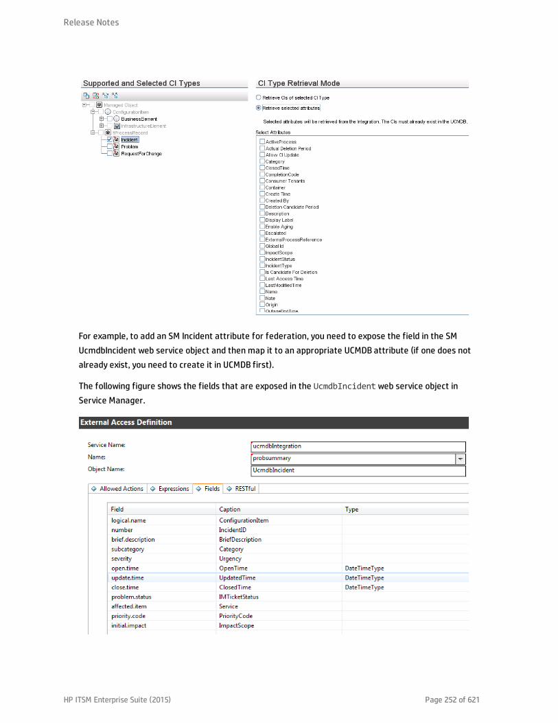
For example, to add an SM Incident attribute for federation, you need to expose the field in the SMUcmdbIncident web service object and then map it to an appropriate UCMDB attribute (if one does notalready exist, you need to create it in UCMDB first).
The following figure shows the fields that are exposed in the UcmdbIncident web service object inService Manager.
Release Notes
HP ITSM Enterprise Suite (2015) Page 252 of 621

You can expose more fields so that more Incident attributes can be federated to UCMDB. As an example,the following describes how to add the “action” field in the Service Manager probsummary (Incident) filefor federation, by mapping it to a new UCMDB attribute named details.
Note: On the Incident form in Service Manager, the “action” field is labeled “Description,” which isused to describe the incident record in more detail. See the following figure.
To add an attribute of a supported CI type for federation:
1. Add the SM attribute to its web service object.The following example describes how to expose the SM “action” field of Incident in theUcmdbIncident web service object.
a. Log in to Service Manager as a system administrator.
b. Navigate to Tailoring > Web Services > Web Service Configuration.
c. Enter the following field values, and then click Search.o Service Name: ucmdbIntegration
o Name: probsummary
The UcmdbIncident web service object is displayed.
d. On the Fields tab, add the following row:o Field: action
o Caption: Description
Release Notes
HP ITSM Enterprise Suite (2015) Page 253 of 621

e. Save the web service object.
2. Map the SM attribute to a UCMDB attribute.The following example describes how to map the SM “action” attribute to a new UCMDB attributenamed details.
a. Log in to UCMDB as an administrator.
b. Navigate to Modeling > CI Type Manager.
c. Navigate to ItProcessRecord > Incident, and open its properties pane.
d. Click the Add icon to add a new attribute named details to the Incident CI type.
o name: details
o Display Name: Details
o Description: Incident details
o Attribute Type: select Primitive > String
o Value Size: 500
Release Notes
HP ITSM Enterprise Suite (2015) Page 254 of 621

e. Save the Incident CI type record.
f. Navigate to Data Flow Management > Adapter Management >ServiceManagerEnhancedAdapter9-x > Configuration Files.
g. Edit the relevant federation mapping file (ServiceManagerEnhancedAdapter9-x/mappings/federation/SM Incident 2.0.xml) to add a mapping entry for the new attribute.
<target_entities><source_instance query-name="SM Incident 2.0" root-element-
name="ucmdbIncident"><target_entity name="incident">
<target_mapping name="reference_number"datatype="STRING" value="ucmdbIncident['IncidentID']"/>
<target_mapping name="name"datatype="STRING" value="ucmdbIncident['BriefDescription']"/>
<target_mapping name="priority"datatype="STRING" value="SMFederationFunctions.getEnumValue(ucmdbIncident['PriorityCode'],'Priority')"/>
Release Notes
HP ITSM Enterprise Suite (2015) Page 255 of 621

<target_mapping name="incident_status"datatype="STRING"value="SMFederationFunctions.firstLetterToLowerAndReplaceSpaceWithUnderscore(ucmdbIncident['IMTicketStatus'])"/>
<target_mapping name="category"datatype="STRING"value="SMFederationFunctions.replaceSpaceWithUnderscore(ucmdbIncident['Category'])"/>
<target_mapping name="closed_time"datatype="DATE" value="SMFederationFunctions.convertDate(ucmdbIncident['ClosedTime'])"/>
<target_mapping name="create_time"datatype="DATE" value="SMFederationFunctions.convertDate(ucmdbIncident['OpenTime'])"/>
<target_mapping name="last_modified_time"datatype="DATE" value="SMFederationFunctions.convertDate(ucmdbIncident['UpdatedTime'])"/>
<target_mapping name="impact_scope"datatype="STRING" value="SMFederationFunctions.getEnumValue(ucmdbIncident['ImpactScope'],'ImpactScope')"/>
<target_mapping name="urgency"datatype="STRING" value="SMFederationFunctions.getEnumValue(ucmdbIncident['Urgency'],'Urgency')"/>
<target_mapping name="details" datatype="STRING"value="ucmdbIncident['Description']"/>
</target_entity></source_instance>
</target_entities>
h. Click Save to save the file.
Now the Description (field name: action) attribute of SM Incident has been added to the integrationfor federation. You can run an Incident federation query in the UCMDB Modeling Studio to see if theSM Description data is properly federated. For information about how to run a federation query,see "Examples of Using Federation" on page 120.
The following figure shows an example where the Description of an SM incident record has beenfederated to UCMDB as Details.
Release Notes
HP ITSM Enterprise Suite (2015) Page 256 of 621

TroubleshootingWhen data push and population errors occur, you can check the error messages and the integration logfiles to identify the root causes and fix the errors. This chapter describes the general troubleshootingsteps, as well as typical errors and solutions.
This section includes:
l "Troubleshooting Data Push Issues" below
l "Troubleshooting Population Issues" on page 267
Troubleshooting Data Push Issues
When data push errors or problems occur, you can check the error messages and the log file to figureout the root causes and then fix the errors.
This integration uses the following error codes for data push.
SM Error Code Description UCMDB Error Code
-1 Server Application Error from SM 900008
-4 401 Authorization error from SM 900001
3 Data Locked Error from SM 900003
Release Notes
HP ITSM Enterprise Suite (2015) Page 257 of 621

SM Error Code Description UCMDB Error Code
9 Restful configuration not found 900009
51 Changed By Another Process Error from SM 900004
70 Invalid Action Error from SM 900005
71 Validation Check Failed error from SM 900002
881 Invalid Data Error from SM 900007
882 Cannot find CI in SM for relationship operation 900010
Failed to create message in SM 900013
Communication with SM Failed 900014
Other Error from SM 900099
When a data push job has failed, the job status becomes Failed. Troubleshoot the failed job as follows:
l Check the error messages of the failed job in the Universal CMDB studio.See "How to Check the Error Message of a Failed Push Job" below.
l Check the log file for more details.See "How to Check the Push Log File" on page 261.
When a data push job was completed with failures of partial records, the job status becomesCompleted. Troubleshoot the failed records as follows:
l Check the error messages of failed CIs in the Universal CMDB studio.See "How to Check the Error Messages of Failed CIs or Relationships in a Push Job" on page 260.
l Check the log file for more details.See "How to Check the Push Log File" on page 261.
How to Check the Error Message of a Failed Push Job
To check the error message of a failed job:
1. Log in to UCMDB as an administrator.
2. Navigate to Data Flow Management > Integration Studio.
3. Select the integration point for this integration from Integration Point list.
Release Notes
HP ITSM Enterprise Suite (2015) Page 258 of 621
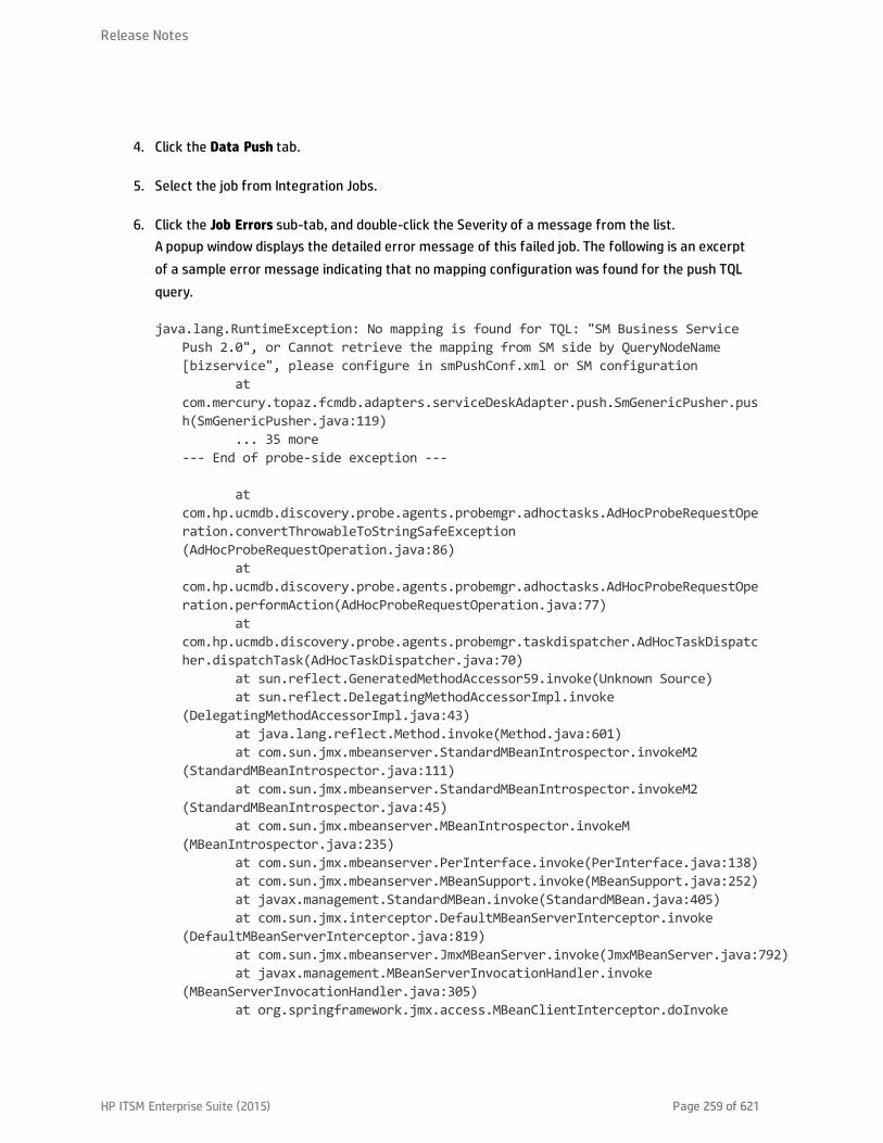
4. Click the Data Push tab.
5. Select the job from Integration Jobs.
6. Click the Job Errors sub-tab, and double-click the Severity of a message from the list.A popup window displays the detailed error message of this failed job. The following is an excerptof a sample error message indicating that no mapping configuration was found for the push TQLquery.
java.lang.RuntimeException: No mapping is found for TQL: "SM Business ServicePush 2.0", or Cannot retrieve the mapping from SM side by QueryNodeName[bizservice", please configure in smPushConf.xml or SM configuration
atcom.mercury.topaz.fcmdb.adapters.serviceDeskAdapter.push.SmGenericPusher.push(SmGenericPusher.java:119)
... 35 more--- End of probe-side exception ---
atcom.hp.ucmdb.discovery.probe.agents.probemgr.adhoctasks.AdHocProbeRequestOperation.convertThrowableToStringSafeException(AdHocProbeRequestOperation.java:86)
atcom.hp.ucmdb.discovery.probe.agents.probemgr.adhoctasks.AdHocProbeRequestOperation.performAction(AdHocProbeRequestOperation.java:77)
atcom.hp.ucmdb.discovery.probe.agents.probemgr.taskdispatcher.AdHocTaskDispatcher.dispatchTask(AdHocTaskDispatcher.java:70)
at sun.reflect.GeneratedMethodAccessor59.invoke(Unknown Source)at sun.reflect.DelegatingMethodAccessorImpl.invoke
(DelegatingMethodAccessorImpl.java:43)at java.lang.reflect.Method.invoke(Method.java:601)at com.sun.jmx.mbeanserver.StandardMBeanIntrospector.invokeM2
(StandardMBeanIntrospector.java:111)at com.sun.jmx.mbeanserver.StandardMBeanIntrospector.invokeM2
(StandardMBeanIntrospector.java:45)at com.sun.jmx.mbeanserver.MBeanIntrospector.invokeM
(MBeanIntrospector.java:235)at com.sun.jmx.mbeanserver.PerInterface.invoke(PerInterface.java:138)at com.sun.jmx.mbeanserver.MBeanSupport.invoke(MBeanSupport.java:252)at javax.management.StandardMBean.invoke(StandardMBean.java:405)at com.sun.jmx.interceptor.DefaultMBeanServerInterceptor.invoke
(DefaultMBeanServerInterceptor.java:819)at com.sun.jmx.mbeanserver.JmxMBeanServer.invoke(JmxMBeanServer.java:792)at javax.management.MBeanServerInvocationHandler.invoke
(MBeanServerInvocationHandler.java:305)at org.springframework.jmx.access.MBeanClientInterceptor.doInvoke
Release Notes
HP ITSM Enterprise Suite (2015) Page 259 of 621
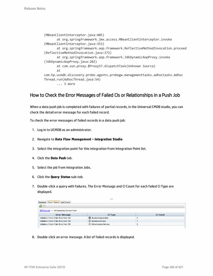
(MBeanClientInterceptor.java:405)at org.springframework.jmx.access.MBeanClientInterceptor.invoke
(MBeanClientInterceptor.java:353)at org.springframework.aop.framework.ReflectiveMethodInvocation.proceed
(ReflectiveMethodInvocation.java:172)at org.springframework.aop.framework.JdkDynamicAopProxy.invoke
(JdkDynamicAopProxy.java:202)at com.sun.proxy.$Proxy57.dispatchTask(Unknown Source)at
com.hp.ucmdb.discovery.probe.agents.probegw.managementtasks.adhoctasks.AdhocThread.run(AdhocThread.java:54)
... 3 more
How to Check the Error Messages of Failed CIs or Relationships in a Push Job
When a data push job is completed with failures of partial records, in the Universal CMDB studio, you cancheck the detail error message for each failed record.
To check the error messages of failed records in a data push job:
1. Log in to UCMDB as an administrator.
2. Navigate to Data Flow Management > Integration Studio.
3. Select the integration point for this integration from Integration Point list.
4. Click the Data Push tab.
5. Select the job from Integration Jobs.
6. Click the Query Status sub-tab.
7. Double-click a query with failures. The Error Message and CI Count for each failed CI Type aredisplayed.
8. Double-click an error message. A list of failed records is displayed.
Release Notes
HP ITSM Enterprise Suite (2015) Page 260 of 621
9. Double-click a failed record.The detailed error message of the record is displayed.
How to Check the Push Log File
You need to set the Development adapter log level to DEBUG or TRACE, so that you can check the pushresult tree nodes of UCMDB, and then send messages to and receive messages from Service Manager.Alternatively, you can set the log level to TRACE so as to check the conversion period based on amapping file.
Note: To troubleshoot push, population, and federation issues, you need to set the Developmentadapter log level to DEBUG or TRACE in the fcmdb.properties and fcmdb.push.properties files,which are located in the \conf\log folder of your Data Flow Probe or Integration Service installation.Additionally, you can view push, population and federation log information in thefcmdb.push.all.log file, which is located in the \runtime\log folder of your Data Flow Probe orIntegration Service installation. Your Data Flow Probe or Integration Service may be installed on thesame host as your UCMDB Server or on a separate host.
To set the Development adapter log level to DEBUG or TRACE:
1. Log in as an administrator to the host on which your UCMDB Data Flow Probe or Integration Serviceis installed.
2. Navigate to the <UCMDB installation folder>\DataFlowProbe\conf\log folder or the <UCMDBinstallation folder\UCMDBServer\integrations\conf\log. For example:
C:\hp\UCMDB\DataFlowProbe\conf\log\
Or C:\hp\UCMDB\UCMDBServer\integrations\conf\log
3. Open the fcmdb.properties file in a text editor, and change the log level to DEBUG or TRACE. Forexample:
#loglevel can be any of TRACE DEBUG INFO WARN ERROR FATALloglevel=DEBUGdef.file.max.size=5000KBdef.files.backup.count=10msg.layout=%d %-5p [%t] - %m%n
4. Open the fcmdb.push.properties files in a text editor, and change the log4j log level to DEBUG or
Release Notes
HP ITSM Enterprise Suite (2015) Page 261 of 621

TRACE. For example:
### UCMDB log4j Propertieslog.file.path=log/${log.folder.path.output}#loglevel can be any of TRACE DEBUG INFO WARN ERROR FATALloglevel=DEBUGdef.file.max.size=5000KBdef.files.backup.count=10msg.layout=%d %-5p [%t] - %m%n
5. Save the files.
To check the push log file:
1. Log in as an administrator to the host on which your UCMDB Data Flow Probe or Integration Serviceis installed.
2. Navigate to the <UCMDB installation folder>\DataFlowProbe\runtime\log folder or the <UCMDBinstallation folder\UCMDBServer\integrations\runtime\log folder.
3. Open the fcmdb.push.all.log file in a text editor.
Typical Push Errors and Solutions
This section describes typical error messages that may occur during data push, as well as theirsolutions.
This section includes:
l "Query not Configured in smPushConf.xml" below
l "Mapping File not Well Formed" on page 264
Query not Configured in smPushConf.xml
Sample Configuration
The TQL queries used for pushing relationships must be configured in the smPushConf.xml file.
<config><mapping>
<!--Wildcard is supported for TQL names while you configure the mapping now,you can add the '*' at the end of the TQL name while configuring the
mapping.
Release Notes
HP ITSM Enterprise Suite (2015) Page 262 of 621
We use the wildcard for mapping in OOTB, so each time you do save as to aTQL,
you could still push it to SM without manual changing the mapping.For e.g., if you have saved the <TQL_name> query to <TQL_name>_1, and <TQL_
name>_2,the TQL name is specified as <TQL_name>* in this configuration file, and
theintegration will automatically use this mapping entry on all of the three
TQLs.However, using the exact TQL name to configure the mapping is still
supported.-->
<tql name="SM Business Service Relations Push 2.0"resourceCollectionName="Relationships" resourceName="Relationship"/>
<tql name="SM CRG Relations Push 2.0"resourceCollectionName="Relationships" resourceName="Relationship"/>
<tql name="SM Node Relations Push 2.0"resourceCollectionName="Relationships" resourceName="Relationship"/>
<tql name="SM Layer2 Topology Relations Push 2.0"resourceCollectionName="Relationships" resourceName="Relationship"/>
</mapping></config>
Error Message
The push job fails with a “Failed” status. From both the log file and the detail error message of the failedjob in the Universal CMDB studio (see "How to Check the Error Message of a Failed Push Job" onpage 258), you receive an error like the following:
java.lang.RuntimeException: No mapping is found for TQL: "SM Business Service Push2.0", or Cannot retrieve the mapping from SM side by QueryNodeName [bizservice",please configure in smPushConf.xml or SM configuration
atcom.mercury.topaz.fcmdb.adapters.serviceDeskAdapter.push.SmGenericPusher.push(SmGenericPusher.java:119)
... 35 more--- End of probe-side exception ---
atcom.hp.ucmdb.discovery.probe.agents.probemgr.adhoctasks.AdHocProbeRequestOperation.convertThrowableToStringSafeException(AdHocProbeRequestOperation.java:86)
atcom.hp.ucmdb.discovery.probe.agents.probemgr.adhoctasks.AdHocProbeRequestOperation.performAction(AdHocProbeRequestOperation.java:77)
atcom.hp.ucmdb.discovery.probe.agents.probemgr.taskdispatcher.AdHocTaskDispatcher.dispatchTask(AdHocTaskDispatcher.java:70)
at sun.reflect.GeneratedMethodAccessor59.invoke(Unknown Source)
Release Notes
HP ITSM Enterprise Suite (2015) Page 263 of 621

at sun.reflect.DelegatingMethodAccessorImpl.invoke(DelegatingMethodAccessorImpl.java:43)
at java.lang.reflect.Method.invoke(Method.java:601)at com.sun.jmx.mbeanserver.StandardMBeanIntrospector.invokeM2
(StandardMBeanIntrospector.java:111)at com.sun.jmx.mbeanserver.StandardMBeanIntrospector.invokeM2
(StandardMBeanIntrospector.java:45)at com.sun.jmx.mbeanserver.MBeanIntrospector.invokeM
(MBeanIntrospector.java:235)at com.sun.jmx.mbeanserver.PerInterface.invoke(PerInterface.java:138)at com.sun.jmx.mbeanserver.MBeanSupport.invoke(MBeanSupport.java:252)at javax.management.StandardMBean.invoke(StandardMBean.java:405)at com.sun.jmx.interceptor.DefaultMBeanServerInterceptor.invoke
(DefaultMBeanServerInterceptor.java:819)at com.sun.jmx.mbeanserver.JmxMBeanServer.invoke(JmxMBeanServer.java:792)at javax.management.MBeanServerInvocationHandler.invoke
(MBeanServerInvocationHandler.java:305)at org.springframework.jmx.access.MBeanClientInterceptor.doInvoke
(MBeanClientInterceptor.java:405)at org.springframework.jmx.access.MBeanClientInterceptor.invoke
(MBeanClientInterceptor.java:353)at org.springframework.aop.framework.ReflectiveMethodInvocation.proceed
(ReflectiveMethodInvocation.java:172)at org.springframework.aop.framework.JdkDynamicAopProxy.invoke
(JdkDynamicAopProxy.java:202)at com.sun.proxy.$Proxy57.dispatchTask(Unknown Source)at
com.hp.ucmdb.discovery.probe.agents.probegw.managementtasks.adhoctasks.AdhocThread.run(AdhocThread.java:54)
... 3 more
Solution
Search for text string No mapping is found for TQL to find the name of the query that is not yetconfigured, and then add a mapping entry for the query in the smPushConf.xml file.
Mapping File notWell Formed
Sample Configuration
The "target_entity name" should be bizservice (which is the CI type display name defined in ServiceManager, and also the external class model name displayed in the UCMDB Visual Mapping toolinterface); however you have configured a wrong name businessservice.
<?xml version="1.0" encoding="UTF-8"?><integration xmlns:xsi="http://www.w3.org/2001/XMLSchema-instance"xsi:noNamespaceSchemaLocation="../mappings_schema.xsd">
Release Notes
HP ITSM Enterprise Suite (2015) Page 264 of 621

<info><source name="UCMDB" version="10.20" vendor="HP"/><target name="SM" version="9.40" vendor="HP"/>
</info><import>
<scriptFile path="mappings.scripts.SMPushFunctions"/></import><!--
Push uCMDB CIT to SM Business Service.--><target_entities>
<source_instance query-name="SM Business Service Push 2.0" root-element-name="Root" >
<target_entity name="businessservice"><target_mapping name="UCMDBId" datatype="STRING" value="Root
['global_id']"/><target_mapping name="CustomerId" datatype="STRING"
value="SMPushFunctions.getCustomerId(CustomerInformation)"/><target_mapping name="Type" datatype="STRING"
value="'bizservice'"/><target_mapping name="Subtype" datatype="STRING"
value="SMPushFunctions.getSMSubType(Root['element_type'],ClassModel,'BizService')"/>
<target_mapping name="ServiceProvider" datatype="STRING"value="Root['provider']"/>
<target_mapping name="ServiceName" datatype="STRING" value="Root['display_label']"/>
<target_mapping name="CIIdentifier" datatype="STRING"value="Root['display_label']"/>
</target_entity></source_instance>
</target_entities></integration>
Error Message
The data push job fails with a “Failed” status. From both the log file and the detailed error message ofthe failed job in the Universal CMDB studio (see "How to Check the Error Message of a Failed Push Job"on page 258), you receive an error like the following:
java.lang.RuntimeException: No mapping is found for TQL: "SM Business Service Push2.0", or Cannot retrieve the mapping from SM side by QueryNodeName[businessservice", please configure in smPushConf.xml or SM configuration
atcom.mercury.topaz.fcmdb.adapters.serviceDeskAdapter.push.SmGenericPusher.push(SmGenericPusher.java:119)
... 35 more--- End of probe-side exception ---
Release Notes
HP ITSM Enterprise Suite (2015) Page 265 of 621

atcom.hp.ucmdb.discovery.probe.agents.probemgr.adhoctasks.AdHocProbeRequestOperation.convertThrowableToStringSafeException(AdHocProbeRequestOperation.java:86)
atcom.hp.ucmdb.discovery.probe.agents.probemgr.adhoctasks.AdHocProbeRequestOperation.performAction(AdHocProbeRequestOperation.java:77)
atcom.hp.ucmdb.discovery.probe.agents.probemgr.taskdispatcher.AdHocTaskDispatcher.dispatchTask(AdHocTaskDispatcher.java:70)
at sun.reflect.GeneratedMethodAccessor59.invoke(Unknown Source)at sun.reflect.DelegatingMethodAccessorImpl.invoke
(DelegatingMethodAccessorImpl.java:43)at java.lang.reflect.Method.invoke(Method.java:601)at com.sun.jmx.mbeanserver.StandardMBeanIntrospector.invokeM2
(StandardMBeanIntrospector.java:111)at com.sun.jmx.mbeanserver.StandardMBeanIntrospector.invokeM2
(StandardMBeanIntrospector.java:45)at com.sun.jmx.mbeanserver.MBeanIntrospector.invokeM
(MBeanIntrospector.java:235)at com.sun.jmx.mbeanserver.PerInterface.invoke(PerInterface.java:138)at com.sun.jmx.mbeanserver.MBeanSupport.invoke(MBeanSupport.java:252)at javax.management.StandardMBean.invoke(StandardMBean.java:405)at com.sun.jmx.interceptor.DefaultMBeanServerInterceptor.invoke
(DefaultMBeanServerInterceptor.java:819)at com.sun.jmx.mbeanserver.JmxMBeanServer.invoke(JmxMBeanServer.java:792)at javax.management.MBeanServerInvocationHandler.invoke
(MBeanServerInvocationHandler.java:305)at org.springframework.jmx.access.MBeanClientInterceptor.doInvoke
(MBeanClientInterceptor.java:405)at org.springframework.jmx.access.MBeanClientInterceptor.invoke
(MBeanClientInterceptor.java:353)at org.springframework.aop.framework.ReflectiveMethodInvocation.proceed
(ReflectiveMethodInvocation.java:172)at org.springframework.aop.framework.JdkDynamicAopProxy.invoke
(JdkDynamicAopProxy.java:202)at com.sun.proxy.$Proxy57.dispatchTask(Unknown Source)at
com.hp.ucmdb.discovery.probe.agents.probegw.managementtasks.adhoctasks.AdhocThread.run(AdhocThread.java:54)
... 3 more
Solution
Search for the relevant CI type in Service Manager to find the correct display name, and then modify themapping file with the correct name.
Release Notes
HP ITSM Enterprise Suite (2015) Page 266 of 621
Tip: You can easily fix such kind of validation issues by using the UCMDB Visual Mapping tool togenerate the mapping file.
Troubleshooting Population Issues
When population errors or problems occur, you can check the error messages and the population logfile to identify the root causes and then solve the problems.
When a population job has failed, the job status becomes Failed. Troubleshoot the failed job as follows:
l Check the error message of the failed job in the Universal CMDB studio.See "How to Check the Error Message of a Failed Population Job" below and "Typical Population ErrorMessages and Solutions" on the next page.
l Check the log file for more details.See "How to Check the Population Log File" below.
How to Check the Error Message of a Failed Population Job
While a population job fails, you can check the detailed error messages in the Universal CMDB studio.
To check the error message of a failed population job:
1. Log in to UCMDB as an administrator.
2. Navigate to Data Flow Management > Integration Studio.
3. Select the integration point for this integration.
4. Click the Population tab.
5. Select the failed job from Integration Jobs, and click the Job Errors subtab.
6. Double-click an error message from the list.A pop-up window opens to display the error details.
How to Check the Population Log File
You can set the Development adapter log level to DEBUG so that you can check the population resulttree nodes of UCMDB, and send messages to and receive messages from Service Manager.Alternatively, you can set the log level to TRACE so as to check the conversion period based on amapping file.
Release Notes
HP ITSM Enterprise Suite (2015) Page 267 of 621

Note: To troubleshoot push, population, and federation issues, you need to set the Developmentadapter log level to DEBUG or TRACE in the fcmdb.properties and fcmdb.push.properties files,which are located in the \conf\log folder of your Data Flow Probe or Integration Service installation.Additionally, you can view push, population and federation log information in thefcmdb.push.all.log file, which is located in the \runtime\log folder of your Data Flow Probe orIntegration Service installation. Your Data Flow Probe or Integration Service may be installed on thesame host as your UCMDB Server or on a separate host.
To set the Development adapter log level and view the population log file, follow the steps described in"How to Check the Push Log File" on page 261.
Typical Population Error Messages and Solutions
The following describes typical error messages that may occur during population, and their solutions.
This section includes:
l "No TQL Query Configured in smPopConf.xml " below
l "Nonexistent Mapping File Name Defined for a TQL Query in smPopConf.xml" on page 271
No TQLQuery Configured in smPopConf.xml
Error Message
If you have not yet added a TQL query to your job, you cannot select this query from the list while youcreate or update your job.
If you have already added this TQL query to your job, but forgot to add the configuration for this query insmPopConf.xml, you will get a “Failed” status while you run this population job. In addition, in theUniversal CMDB studio, you will get an error message like the following (see "How to Check the ErrorMessage of a Failed Population Job" on the previous page).
running population. Destination ID: sm, Failed during query: SM BusinessApplication Population 2.0, all queries: [SM Business Application Population2.0, SM Business Service Population 2.0], finished queries: [].ERROR: com.mercury.topaz.cmdb.shared.base.CmdbException: [ErrorCode [802]General Integration Error{sm}]appilog.framework.shared.manage.impl.MamResponseException: [ErrorCode [802]General Integration Error{sm}]CMDB Operation Internal Error: classcom.mercury.topaz.cmdb.shared.fcmdb.dataAccess.exception.AdapterAccessGeneralException : Unsupported Query [SM Business Application Population 2.0], only
Release Notes
HP ITSM Enterprise Suite (2015) Page 268 of 621

population TQL is supported : operation Data Access Adapter Query: RetrieveChanged Data
atcom.mercury.topaz.cmdb.shared.manage.operation.impl.AbstractCommonOperation.execute(AbstractCommonOperation.java:160)
atcom.hp.ucmdb.dataAccess.manager.DataAccessAdapterManagerProbeImpl.executeOperation(DataAccessAdapterManagerProbeImpl.java:50)
atcom.hp.ucmdb.discovery.probe.agents.probemgr.adapters.DataAccessAdaptersFacade.invokeOperation(DataAccessAdaptersFacade.java:406)
atcom.hp.ucmdb.discovery.probe.services.dynamic.core.AdapterService.runChangesOnPopulateChangesAdapter(AdapterService.java:1262)
atcom.hp.ucmdb.discovery.probe.services.dynamic.core.AdapterService.runQueriesOnPopulateChangesAdapter(AdapterService.java:1102)
at com.hp.ucmdb.discovery.probe.services.dynamic.core.AdapterService.runQueries(AdapterService.java:354)
atcom.hp.ucmdb.discovery.probe.services.dynamic.core.AdapterService.runDiscovery(AdapterService.java:198)
at com.hp.ucmdb.discovery.probe.services.dynamic.core.AdapterService.discover(AdapterService.java:149)
atcom.hp.ucmdb.discovery.probe.agents.probemgr.taskexecuter.JobExecuter.launchTask(JobExecuter.java:1188)
atcom.hp.ucmdb.discovery.probe.agents.probemgr.taskexecuter.JobExecuter$JobExecuterWorker.launch(JobExecuter.java:945)
In the fcmdb.push.all.log file, you can find more details like the following:
2014-11-20 10:40:50,949 [JobExecuterWorker-0:DS_sm_SM BS pop] ERROR - sm >> Fail toCreate or Return PopulationConnectorOutputcom.hp.ucmdb.federationspi.exception.DataAccessGeneralException: UnsupportedQuery [SM Business Application Population 2.0], only population TQL is supported
at com.hp.ucmdb.adapter.smpush.ServiceManagerGenericAdapter.populate(ServiceManagerGenericAdapter.java:337)
at com.hp.ucmdb.adapters.GenericAdapter.getChanges(GenericAdapter.java:881)at
com.hp.ucmdb.dataAccess.operations.DataAccessAdapterQueryRetrieveChanges.getChangesResult(DataAccessAdapterQueryRetrieveChanges.java:50)
atcom.hp.ucmdb.dataAccess.operations.DataAccessAdapterQueryRetrieveChanges.doDataAccessQueryExecute(DataAccessAdapterQueryRetrieveChanges.java:38)
atcom.hp.ucmdb.dataAccess.operations.AbstractDataAccessLifeCycleAdapterQuery.doLifeCycleExecute(AbstractDataAccessLifeCycleAdapterQuery.java:34)
Release Notes
HP ITSM Enterprise Suite (2015) Page 269 of 621
atcom.hp.ucmdb.dataAccess.operations.AbstractDataAccessLifeCycleAdapterOperation.doDataAccessExecute(AbstractDataAccessLifeCycleAdapterOperation.java:57)
atcom.hp.ucmdb.dataAccess.operations.AbstractDataAccessAdapterOperation.dataAccessExecute(AbstractDataAccessAdapterOperation.java:59)
atcom.hp.ucmdb.dataAccess.operations.AbstractDataAccessAdapterOperation.doExecute(AbstractDataAccessAdapterOperation.java:37)
atcom.mercury.topaz.cmdb.shared.manage.operation.impl.AbstractFrameworkOperation.commonExecute(AbstractFrameworkOperation.java:17)
atcom.mercury.topaz.cmdb.shared.manage.operation.impl.AbstractCommonOperation$OperationExecuteFlowTrackingCommand.execute(AbstractCommonOperation.java:87)
atcom.mercury.topaz.cmdb.shared.manage.operation.impl.AbstractCommonOperation$OperationExecuteFlowTrackingCommand.execute(AbstractCommonOperation.java:60)
at com.mercury.topaz.cmdb.shared.manage.flowmanagement.api.FlowManager.execute(FlowManager.java:227)
atcom.mercury.topaz.cmdb.shared.manage.operation.flow.OperationInFlowDefaultExecutor.execute(OperationInFlowDefaultExecutor.java:23)
atcom.mercury.topaz.cmdb.shared.manage.operation.impl.AbstractCommonOperation.execute(AbstractCommonOperation.java:158)
atcom.hp.ucmdb.dataAccess.manager.DataAccessAdapterManagerProbeImpl.executeOperation(DataAccessAdapterManagerProbeImpl.java:50)
atcom.hp.ucmdb.discovery.probe.agents.probemgr.adapters.DataAccessAdaptersFacade.invokeOperation(DataAccessAdaptersFacade.java:406)
atcom.hp.ucmdb.discovery.probe.services.dynamic.core.AdapterService.runChangesOnPopulateChangesAdapter(AdapterService.java:1262)
atcom.hp.ucmdb.discovery.probe.services.dynamic.core.AdapterService.runQueriesOnPopulateChangesAdapter(AdapterService.java:1102)
at com.hp.ucmdb.discovery.probe.services.dynamic.core.AdapterService.runQueries(AdapterService.java:354)
atcom.hp.ucmdb.discovery.probe.services.dynamic.core.AdapterService.runDiscovery(AdapterService.java:198)
at com.hp.ucmdb.discovery.probe.services.dynamic.core.AdapterService.discover(AdapterService.java:149)
atcom.hp.ucmdb.discovery.probe.agents.probemgr.taskexecuter.JobExecuter.launchTask(JobExecuter.java:1188)
at
Release Notes
HP ITSM Enterprise Suite (2015) Page 270 of 621

com.hp.ucmdb.discovery.probe.agents.probemgr.taskexecuter.JobExecuter$JobExecuterWorker.launch(JobExecuter.java:945)
atcom.hp.ucmdb.discovery.probe.agents.probemgr.taskexecuter.JobExecuter$JobExecuterWorker.executeTask(JobExecuter.java:867)
atcom.hp.ucmdb.discovery.probe.agents.probemgr.taskexecuter.JobExecuter$JobExecuterWorker.run(JobExecuter.java:728)
Solution
Search for text string “Unsupported Query by this adapter” to find out the TQL query name that has notyet been configured, and then configure it in the smPopConf.xml file.
Nonexistent Mapping File Name Defined for a TQLQuery in smPopConf.xml
Error Message
You will get a “Failed” status while you run the population job. In addition, from the Universal CMDBstudio, you will get an error message like the following:
running population. Destination ID: sm, Failed during query: SM Business ServicePopulation 2.0, all queries: [SM Business Application Population 2.0, SMBusiness Service Population 2.0], finished queries: [SM Business ApplicationPopulation 2.0].ERROR: com.mercury.topaz.cmdb.shared.base.CmdbException: [ErrorCode [802]General Integration Error{sm}]appilog.framework.shared.manage.impl.MamResponseException: [ErrorCode [802]General Integration Error{sm}]CMDB Operation Internal Error: classcom.mercury.topaz.cmdb.shared.fcmdb.dataAccess.exception.AdapterAccessGeneralException : Query Definition [SM Business Service Population 2.0] has no matchingmapping. Make sure the mapping exist exists under folder 'mapping' and containsthe exact query name and root name. Available mappings:[QueryRoot{queryName='SM Business Application Population 2.0',rootName='bizservice'}] : operation Data Access Adapter Query: Retrieve ChangedData
atcom.mercury.topaz.cmdb.shared.manage.operation.impl.AbstractCommonOperation.execute(AbstractCommonOperation.java:160)
atcom.hp.ucmdb.dataAccess.manager.DataAccessAdapterManagerProbeImpl.executeOperation(DataAccessAdapterManagerProbeImpl.java:50)
atcom.hp.ucmdb.discovery.probe.agents.probemgr.adapters.DataAccessAdaptersFacade.invokeOperation(DataAccessAdaptersFacade.java:406)
at
Release Notes
HP ITSM Enterprise Suite (2015) Page 271 of 621
com.hp.ucmdb.discovery.probe.services.dynamic.core.AdapterService.runChangesOnPopulateChangesAdapter(AdapterService.java:1262)
atcom.hp.ucmdb.discovery.probe.services.dynamic.core.AdapterService.runQueriesOnPopulateChangesAdapter(AdapterService.java:1102)
at com.hp.ucmdb.discovery.probe.services.dynamic.core.AdapterService.runQueries(AdapterService.java:354)
atcom.hp.ucmdb.discovery.probe.services.dynamic.core.AdapterService.runDiscovery(AdapterService.java:198)
at com.hp.ucmdb.discovery.probe.services.dynamic.core.AdapterService.discover(AdapterService.java:149)
atcom.hp.ucmdb.discovery.probe.agents.probemgr.taskexecuter.JobExecuter.launchTask(JobExecuter.java:1188)
atcom.hp.ucmdb.discovery.probe.agents.probemgr.taskexecuter.JobExecuter$JobExecuterWorker.launch(JobExecuter.java:945)
atcom.hp.ucmdb.discovery.probe.agents.probemgr.taskexecuter.JobExecuter$JobExecuterWorker.executeTask(JobExecuter.java:867)
atcom.hp.ucmdb.discovery.probe.agents.probemgr.taskexecuter.JobExecuter$JobExecuterWorker.run(JobExecuter.java:728)
Solution
Search for text “has no matching mapping” to find out the missing mapping file name, and then add themapping file to the adapter package.
Troubleshooting Federation Issues
When a federation error occurs, you can check the error message in the federation log file to identifythe root cause and then solve the problem.
For more information, see the following:
"How to Check the Error Message of a Failed Federation Request" below
"Typical Federation Error Messages and Solutions" on the next page
How to Check the Error Message of a Failed Federation Request
When a federation query fails, a pop-up window similar to the following appears in the UCMDB studio.
Release Notes
HP ITSM Enterprise Suite (2015) Page 272 of 621

Note: To troubleshoot push, population, and federation issues, you need to set the Developmentadapter log level to DEBUG or TRACE in the fcmdb.properties and fcmdb.push.properties files,which are located in the \conf\log folder of your Data Flow Probe or Integration Service installation.Additionally, you can view push, population and federation log information in thefcmdb.push.all.log file, which is located in the \runtime\log folder of your Data Flow Probe orIntegration Service installation. Your Data Flow Probe or Integration Service may be installed on thesame host as your UCMDB Server or on a separate host.
To set the Development adapter log level and view the detailed error message of a failed federationquery, follow the steps described in "How to Check the Push Log File" on page 261.
Typical Federation Error Messages and Solutions
The following sections describe typical errors that may occur during federation and their solutions.
"Wrong Configuration for a Federation CI Type in smFedConf.xml" below
"Mapping File for the Federation TQL Query Is not Well Formed" on page 275
Wrong Configuration for a Federation CI Type in smFedConf.xml
Error Message
If you have not correctly configured a CI type in the smFedConf.xml file, UCMDB cannot federate CIs ofthis CI type. When you run a related federation query, the UCMDB studio will pop up an error window;additionally, you can find an error message that resembles the following in the federation log file:
2014-11-20 13:22:52,055 [AdHoc:AD_HOC_TASK_PATTERN_ID-51-1416460969254] ERROR - sm>> Failed to retrieve or parsing Root/parent CI message from SM side, exit fromfederation!java.lang.NullPointerException
atcom.mercury.topaz.fcmdb.adapters.serviceDeskAdapter.federation.SmGenericFederator.processRootCiQueryByPage(SmGenericFederator.java:461)
at
Release Notes
HP ITSM Enterprise Suite (2015) Page 273 of 621
com.mercury.topaz.fcmdb.adapters.serviceDeskAdapter.federation.SmGenericFederator.generateRootRtnResult(SmGenericFederator.java:162)
atcom.mercury.topaz.fcmdb.adapters.serviceDeskAdapter.federation.SmGenericFederator.generateFederationRtnResult(SmGenericFederator.java:131)
atcom.mercury.topaz.fcmdb.adapters.serviceDeskAdapter.federation.SmGenericFederator.generateFederationOutput(SmGenericFederator.java:120)
atcom.mercury.topaz.fcmdb.adapters.serviceDeskAdapter.federation.SmGenericFederator.getNextResultChunk(SmGenericFederator.java:578)
at com.hp.ucmdb.adapter.smpush.ServiceManagerGenericAdapter.populate(ServiceManagerGenericAdapter.java:363)
at com.hp.ucmdb.adapters.GenericAdapter.getDataResult(GenericAdapter.java:740)at
com.hp.ucmdb.discovery.probe.processor.FederationTopologyGetDataResultProbeRequestProcessor.processRequest(FederationTopologyGetDataResultProbeRequestProcessor.java:40)
atcom.hp.ucmdb.discovery.probe.processor.FederationTopologyGetDataResultProbeRequestProcessor.processRequest(FederationTopologyGetDataResultProbeRequestProcessor.java:26)
at com.hp.ucmdb.discovery.probe.processor.AbstractProbeProcessor.process(AbstractProbeProcessor.java:56)
at com.hp.ucmdb.discovery.probe.processor.AbstractProbeProcessor.process(AbstractProbeProcessor.java:19)
atcom.hp.ucmdb.discovery.probe.agents.probemgr.adhoctasks.AdHocProbeRequestOperation.performAction(AdHocProbeRequestOperation.java:63)
atcom.hp.ucmdb.discovery.probe.agents.probemgr.taskdispatcher.AdHocTaskDispatcher.dispatchTask(AdHocTaskDispatcher.java:70)
at sun.reflect.GeneratedMethodAccessor75.invoke(Unknown Source)at sun.reflect.DelegatingMethodAccessorImpl.invoke
(DelegatingMethodAccessorImpl.java:43)at java.lang.reflect.Method.invoke(Method.java:601)at com.sun.jmx.mbeanserver.StandardMBeanIntrospector.invokeM2
(StandardMBeanIntrospector.java:111)at com.sun.jmx.mbeanserver.StandardMBeanIntrospector.invokeM2
(StandardMBeanIntrospector.java:45)at com.sun.jmx.mbeanserver.MBeanIntrospector.invokeM
(MBeanIntrospector.java:235)at com.sun.jmx.mbeanserver.PerInterface.invoke(PerInterface.java:138)at com.sun.jmx.mbeanserver.MBeanSupport.invoke(MBeanSupport.java:252)at javax.management.StandardMBean.invoke(StandardMBean.java:405)at com.sun.jmx.interceptor.DefaultMBeanServerInterceptor.invoke
(DefaultMBeanServerInterceptor.java:819)at com.sun.jmx.mbeanserver.JmxMBeanServer.invoke(JmxMBeanServer.java:792)at javax.management.MBeanServerInvocationHandler.invoke
Release Notes
HP ITSM Enterprise Suite (2015) Page 274 of 621
(MBeanServerInvocationHandler.java:305)at org.springframework.jmx.access.MBeanClientInterceptor.doInvoke
(MBeanClientInterceptor.java:405)at org.springframework.jmx.access.MBeanClientInterceptor.invoke
(MBeanClientInterceptor.java:353)at org.springframework.aop.framework.ReflectiveMethodInvocation.proceed
(ReflectiveMethodInvocation.java:172)at org.springframework.aop.framework.JdkDynamicAopProxy.invoke
(JdkDynamicAopProxy.java:202)at com.sun.proxy.$Proxy51.dispatchTask(Unknown Source)at
com.hp.ucmdb.discovery.probe.agents.probegw.managementtasks.adhoctasks.AdhocThread.run(AdhocThread.java:54)
at org.eclipse.jetty.util.thread.QueuedThreadPool.runJob(QueuedThreadPool.java:599)
at org.eclipse.jetty.util.thread.QueuedThreadPool$3.run(QueuedThreadPool.java:534)
at java.lang.Thread.run(Thread.java:722)
Solution
Open the smFedConf.xml file (which is located in the Configuration Files folder of theServiceManagerEnhancedAdapter9-x adapter), and make sure the configuration for the CI type iscorrect.
Mapping File for the Federation TQLQuery Is notWell Formed
Error Message
There are cases where the mapping file for a federation TQL query is not well formed. For example,target_mapping_name “priority” in the following example federation mapping file specifies a wrongGroovy function name (SMFederationFunctions.getEnumValue1):
<?xml version="1.0" encoding="UTF-8"?><integration xmlns:xsi="http://www.w3.org/2001/XMLSchema-instance"xsi:noNamespaceSchemaLocation="../mappings_schema.xsd">
<info><source name="SM" version="9.40" vendor="HP"/><target name="UCMDB" version="10.20" vendor="HP"/>
</info><import>
<scriptFile path="mappings.scripts.SMFederationFunctions"/></import><target_entities>
<source_instance query-name="SM Incident 2.0" root-element-name="ucmdbIncident">
Release Notes
HP ITSM Enterprise Suite (2015) Page 275 of 621

<target_entity name="incident"><target_mapping name="reference_number" datatype="STRING"
value="ucmdbIncident['IncidentID']"/><target_mapping name="name" datatype="STRING"
value="ucmdbIncident['BriefDescription']"/><target_mapping name="priority" datatype="STRING"
value="SMFederationFunctions.getEnumValue1(ucmdbIncident['PriorityCode'],'Priority')"/>
<target_mapping name="incident_status" datatype="STRING"value="SMFederationFunctions.firstLetterToLowerAndReplaceSpaceWithUnderscore
(ucmdbIncident['IMTicketStatus'])"/><target_mapping name="category" datatype="STRING"
value="SMFederationFunctions.replaceSpaceWithUnderscore(ucmdbIncident['Category'])"/>
<target_mapping name="closed_time" datatype="DATE"value="SMFederationFunctions.convertDate(ucmdbIncident['ClosedTime'])"/>
<target_mapping name="create_time" datatype="DATE"value="SMFederationFunctions.convertDate(ucmdbIncident['OpenTime'])"/>
<target_mapping name="last_modified_time" datatype="DATE"value="SMFederationFunctions.convertDate(ucmdbIncident['UpdatedTime'])"/>
<target_mapping name="impact_scope" datatype="STRING"value="SMFederationFunctions.getEnumValue(ucmdbIncident['ImpactScope'],'ImpactScope')"/>
<target_mapping name="urgency" datatype="STRING"value="SMFederationFunctions.getEnumValue(ucmdbIncident
['Urgency'],'Urgency')"/></target_entity>
</source_instance></target_entities>
</integration>
When you try to federate incidents, no records are retrieved from Service Manager. If you check thefcmdb.push.all.log file, you can find a detailed error message that resembles the following for thefederation query:
2014-11-20 14:09:58,670 [AdHoc:AD_HOC_TASK_PATTERN_ID-66-1416463796366] ERROR - >>Failed executing value [SMFederationFunctions.getEnumValue1(ucmdbIncident['PriorityCode'],'Priority')] of mapping <target_mapping name="priority"><target_ci_type name="incident"> , Root cmdbId [null]groovy.lang.MissingMethodException: No signature of method: staticmappings.scripts.SMFederationFunctions.getEnumValue1() is applicable forargument types: (java.lang.String, java.lang.String) values: [1, Priority]Possible solutions: getEnumValue(java.lang.String, java.lang.String)
at groovy.lang.MetaClassImpl.invokeStaticMissingMethod(MetaClassImpl.java:1359)at groovy.lang.MetaClassImpl.invokeStaticMethod(MetaClassImpl.java:1345)at org.codehaus.groovy.runtime.callsite.StaticMetaClassSite.call
(StaticMetaClassSite.java:50)at org.codehaus.groovy.runtime.callsite.CallSiteArray.defaultCall
(CallSiteArray.java:42)
Release Notes
HP ITSM Enterprise Suite (2015) Page 276 of 621

at org.codehaus.groovy.runtime.callsite.AbstractCallSite.call(AbstractCallSite.java:108)
at org.codehaus.groovy.runtime.callsite.AbstractCallSite.call(AbstractCallSite.java:120)
at Mapping_4a8761e7adc009e8a7d268c2f1349ab4.run(Mapping_4a8761e7adc009e8a7d268c2f1349ab4.groovy:1)
atcom.hp.ucmdb.adapters.instance.mapping.AbstractResultTreeNodeMapper.calculateProperties(AbstractResultTreeNodeMapper.java:231)
atcom.hp.ucmdb.adapters.instance.mapping.AbstractResultTreeNodeMapper.processTargetEntity(AbstractResultTreeNodeMapper.java:301)
at com.hp.ucmdb.adapters.instance.mapping.RtnToRtnMapper.processTargetEntities(RtnToRtnMapper.java:214)
atcom.hp.ucmdb.adapters.instance.mapping.RtnToRtnMapper.processSourceInstanceWrapper(RtnToRtnMapper.java:101)
at com.hp.ucmdb.adapters.instance.mapping.RtnToRtnMapper.buildResultTreeNode(RtnToRtnMapper.java:76)
atcom.hp.ucmdb.adapters.GenericAdapter$PopulationFederationChunkProcessor.invoke(GenericAdapter.java:1213)
at com.hp.ucmdb.adapters.GenericAdapter.getDataResult(GenericAdapter.java:743)at
com.hp.ucmdb.discovery.probe.processor.FederationTopologyGetDataResultProbeRequestProcessor.processRequest(FederationTopologyGetDataResultProbeRequestProcessor.java:40)
atcom.hp.ucmdb.discovery.probe.processor.FederationTopologyGetDataResultProbeRequestProcessor.processRequest(FederationTopologyGetDataResultProbeRequestProcessor.java:26)
at com.hp.ucmdb.discovery.probe.processor.AbstractProbeProcessor.process(AbstractProbeProcessor.java:56)
at com.hp.ucmdb.discovery.probe.processor.AbstractProbeProcessor.process(AbstractProbeProcessor.java:19)
atcom.hp.ucmdb.discovery.probe.agents.probemgr.adhoctasks.AdHocProbeRequestOperation.performAction(AdHocProbeRequestOperation.java:63)
atcom.hp.ucmdb.discovery.probe.agents.probemgr.taskdispatcher.AdHocTaskDispatcher.dispatchTask(AdHocTaskDispatcher.java:70)
at sun.reflect.GeneratedMethodAccessor75.invoke(Unknown Source)at sun.reflect.DelegatingMethodAccessorImpl.invoke
(DelegatingMethodAccessorImpl.java:43)at java.lang.reflect.Method.invoke(Method.java:601)at com.sun.jmx.mbeanserver.StandardMBeanIntrospector.invokeM2
(StandardMBeanIntrospector.java:111)at com.sun.jmx.mbeanserver.StandardMBeanIntrospector.invokeM2
(StandardMBeanIntrospector.java:45)
Release Notes
HP ITSM Enterprise Suite (2015) Page 277 of 621
at com.sun.jmx.mbeanserver.MBeanIntrospector.invokeM(MBeanIntrospector.java:235)
at com.sun.jmx.mbeanserver.PerInterface.invoke(PerInterface.java:138)at com.sun.jmx.mbeanserver.MBeanSupport.invoke(MBeanSupport.java:252)at javax.management.StandardMBean.invoke(StandardMBean.java:405)at com.sun.jmx.interceptor.DefaultMBeanServerInterceptor.invoke
(DefaultMBeanServerInterceptor.java:819)at com.sun.jmx.mbeanserver.JmxMBeanServer.invoke(JmxMBeanServer.java:792)at javax.management.MBeanServerInvocationHandler.invoke
(MBeanServerInvocationHandler.java:305)at org.springframework.jmx.access.MBeanClientInterceptor.doInvoke
(MBeanClientInterceptor.java:405)at org.springframework.jmx.access.MBeanClientInterceptor.invoke
(MBeanClientInterceptor.java:353)at org.springframework.aop.framework.ReflectiveMethodInvocation.proceed
(ReflectiveMethodInvocation.java:172)at org.springframework.aop.framework.JdkDynamicAopProxy.invoke
(JdkDynamicAopProxy.java:202)at com.sun.proxy.$Proxy51.dispatchTask(Unknown Source)at
com.hp.ucmdb.discovery.probe.agents.probegw.managementtasks.adhoctasks.AdhocThread.run(AdhocThread.java:54)
at org.eclipse.jetty.util.thread.QueuedThreadPool.runJob(QueuedThreadPool.java:599)
at org.eclipse.jetty.util.thread.QueuedThreadPool$3.run(QueuedThreadPool.java:534)
at java.lang.Thread.run(Thread.java:722)
Solution
Search for word "Exception" in the fcmdb.push.all.log file to find the wrong method name, and thencorrect it in the corresponding federation mapping file.
Using Service Manager and UCMDBThe connection between Service Manager and Universal Configuration Management Database isperformed by Deployment Manager during installation of Universal Configuration ManagementDatabase.
Note: The following sections are excerpted from the integrations section of the Service ManagerHelp Center. However, to ensure you have the latest information, you should reference the latestpublished version of the document in question.
Release Notes
HP ITSM Enterprise Suite (2015) Page 278 of 621

Enable an integration to HP Universal CMDB
System Administrator
Applies to User Roles:
You must have the SysAdmin capability word to use this procedure.
You can configure Service Manager to display the actual state of CIs in the HP Universal CMDB server bydefining an active integration in the System Information Record. After you define this active integration,Service Manager displays the Actual State tab in Configuration Management forms, and displays theView in UCMDB or View in UCMDB Browser button in CI records synchronized from UCMDB.
Note: The UCMDB Browser is an optional add-on to UCMDB. For more information, see "HP UniversalCMDB Browser" on page 285.
To enable an integration to UCMDB in Service Manager:
1. Click System Administration > Base System Configuration > Miscellaneous > System InformationRecord.
2. Click the Active Integrations tab.
3. Select the HP Universal CMDB option.
4. Complete the following fields.
Field Description
UCMDBwebserviceURL
This is the URL to the HP Universal CMDB web service API. The URL has the followingformat:
http://<UCMDB server name>:<port>/axis2/services/ucmdbSMService
Replace <UCMDB server name> with the host name of your UCMDB server, andreplace <port> with the communications port your UCMDB server uses.
UserId
Password
This is the UCMDB account (user name/password) used to synchronize CIinformation with Service Manager. For example, admin/admin.
Release Notes
HP ITSM Enterprise Suite (2015) Page 279 of 621
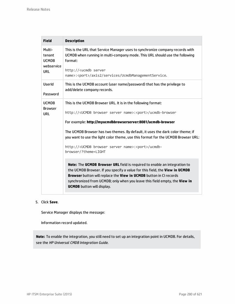
Field Description
Multi-tenantUCMDBwebserviceURL
This is the URL that Service Manager uses to synchronize company records withUCMDB when running in multi-company mode. This URL should use the followingformat:
http://<ucmdb servername>:<port>/axis2/services/UcmdbManagementService.
UserId
Password
This is the UCMDB account (user name/password) that has the privilege toadd/delete company records.
UCMDBBrowserURL
This is the UCMDB Browser URL. It is in the following format:
http://<UCMDB browser server name>:<port>/ucmdb-browser
For example: http://myucmdbbrowserserver:8081/ucmdb-browser
The UCMDB Browser has two themes. By default, it uses the dark color theme; ifyou want to use the light color theme, use this format for the UCMDB Browser URL:
http://<UCMDB browser server name>:<port>/ucmdb-browser/?theme=LIGHT
Note: The UCMDB Browser URL field is required to enable an integration tothe UCMDB Browser. If you specify a value for this field, the View in UCMDBBrowser button will replace the View in UCMDB button in CI recordssynchronized from UCMDB; only when you leave this field empty, the View inUCMDB button will display.
5. Click Save.
Service Manager displays the message:
Information record updated.
Note: To enable the integration, you still need to set up an integration point in UCMDB. For details,see the HP Universal CMDB Integration Guide.
Release Notes
HP ITSM Enterprise Suite (2015) Page 280 of 621

Configuration item actual statesBy default, HP Service Manager only stores and displays the expected or managed state of CIs. Theinformation Service Manager displays in the Configuration Management form is essentially thedefinitive list of attributes that the CI should have. However, the actual state of the CI may differ fromthe expected state.
To view the actual state of the CI, you must first create an integration to an HP Universal CMDB server.The HP Universal CMDB server periodically discovers the actual state of CIs and records the actual statein the Configuration Management database. Service Manager accesses the actual state information byusing a Web services connection. Service Manager sends the CI ID to the HP Universal CMDB server andreceives a full list of the attributes for that CI. Service Manager displays the CI attributes in the ActualState section of the Configuration Management form.
If a Service Manager CI does not have a matching CI in the HP Universal CMDB server, then ServiceManager does not display the Actual State section. For example, you may track office furnishing CIs inService Manager that cannot be discovered and tracked in the HP Universal CMDB.
View the actual state of a configuration item
Applies to User Roles:
Configuration Manager
Configuration Administrator
Configuration Auditor
This procedure requires that your HP Service Manager system has an active integration to an HPUniversal CMDB server.
To view the actual state of a configuration item, follow these steps:
1. Click Configuration Management > Search CI.
2. Use search or advanced search to find one or more records.
3. Select the CI with the actual state you want to see.
4. From the CI detail form, open the Actual State section. Service Manager displays the actual stateof the CI.
Release Notes
HP ITSM Enterprise Suite (2015) Page 281 of 621

Note: The Actual State section is only visible if your system has an active integration to an HPUniversal CMDB server and the CI has a matching entry in the Configuration Managementdatabase. Service Manager does not display the Actual State section if there is no matching CIin the HP Universal CMDB server.
Reconciling configuration items between HP ServiceManager and HP Universal CMDBSince both HP Service Manager and HP Universal CMDB contain information about configuration items(CIs), it is possible that your Service Manager system contains CIs that match CIs in the HP UniversalCMDB system. Rather than add duplicate CI records, you can configure Service Manager to reconcile CIrecords between the two systems based on the values of specific fields.
Service Manager always attempts to reconcile CI records based on the unique key field of the ServiceManager table and the ucmdb.id field. You can specify additional fields to reconcile on from the DEMReconciliation Rules form. If Service Manager finds a matching value in any one of these fields, itupdates the Service Manager CI record with the attributes from the incoming HP Universal CMDB record.
In order to specify reconciliation fields, you will need to be familiar with the table and field names inboth your Service Manager and HP Universal CMDB systems. If you want to reconcile on an attribute inthe HP Universal CMDB system, you must ensure that there is a corresponding Web Serivces Definitionfor the attribute in the Service Manager system. Without such a mapping, Service Manager will notknow to search for matching values in a Service Manager table and field name.
For example, suppose you want to reconcile CIs on the asset.tag field in your Service Manager system.You could update the ucmdbIntegration web service definition with the following field information.
Service Name Object Name Field Caption
ucmdbIntegration ucmdbComputer asset.tag AssetTag
You would then need to add an attribute and mapping for the asset.tag field in the HP Universal CMDBsystem. You would also probably want to add the new attribute to the regular discovery schedule sothat the HP Universal CMDB system picks up any updates to this attribute.
After you create a web services definition for the HP Universal CMDB attribute, you must then define aDiscovery Event Manager (DEM) reconciliation rule. The reconciliation rule specifies what ServiceManager table and field you want to search for matching CI values. In addition, you can specify thesequence you want Service Manager to process reconciliation rules. By default, Service Manager
Release Notes
HP ITSM Enterprise Suite (2015) Page 282 of 621

processes rules in alphabetical order by field name. Thus, Service Manager will reconcile CIs against theasset.tag field before reconciling CIs on the ci.name field.
To change the order in which Service Manager reconciles CIs, you can add a numeric value to thesequence field. For example, the following reconciliation rules ensure that Service Manager processesCIs by the ci.name field prior to reconciling them against the assest.tag field.
Table Name Field Name Sequence
device ci.name 1
device asset.tag 2
Create a DEM reconciliation rule
Applies to User Roles:
System Administrator
A Discovery Event Manager (DEM) reconciliation rule allows you to specify what Service Manager fieldsyou want to use to determine if an existing CI record matches a CI in a HP Universal CMDB system. Anadministrator typically specifies reconciliation rules prior to starting the integration to the HP UniversalCMDB system so that Service Manager will not create duplicate CI records.
To create a DEM reconciliation rule:
1. Click Tailoring > Web Services > DEM Reconciliation Rules.
Service Manager displays the DEM Reconcile Record form.
2. In Table Name, type the name of the Service Manager table containing the field you want toreconcile on.
3. In Field Name, type the name of the Service Manager field containing the values you want toreconcile on.
4. In Sequence, type a number to specify what order you want Service Manager to run this rule.
Note: If you do not specify a sequence value, Service Manager will process field namesalphabetically.
5. Click New.
Service Manager creates the reconciliation rule.
Release Notes
HP ITSM Enterprise Suite (2015) Page 283 of 621
Multi-tenant (multi-company) supportThe HP Universal CMDB (UCMDB) to HP Service Manager Integration supports a multitenancyconfiguration in which both the Service Manager and UCMDB systems track Configuration Items (CIs)and Configuration Item Relationships (CIRs) by company ID. In a multi-tenancy configuration, you cantailor the integration so that each tenant only sees and works with the CIs and CIRs that match theircompany ID. Multi-tenancy is intended for managed service providers (MSPs) who wish to offerConfiguration Management as a service to multiple tenants.
What multi-tenant information is stored in UCMDB?
Your UCMDB system stores a company ID attribute for each CI and CIR. The company ID determines whatadapter and synchronization schedule your UCMDB system uses to update CI data. Each CI andrelationship record can only have one company ID. The UCMDB system obtains a company ID from theService Manager system.
If more than one tenant (company) shares the same CI, each tenant has their own unique CI recorddescribing the CI. In effect, the UCMDB system creates multiple CI records to track one managed asset.Each tenant's CI record is unique to that tenant and lists the company's unique company ID.
What multi-tenant information is stored in Service Manager?
Your Service Manager stores the company records that describe each tenant in the multi-tenantconfiguration. The Service Manager system is the definitive source of company IDs and pushes new andupdated information to your UCMDB system.
Service Manager tracks the company ID of each CI and relationship in a multi-tenant configuration. CIrecords inherit the company ID of the UCMDB feeder that discovered them. Relationship records inheritthe company ID of the parent CI in the relationship.
In a best practices implementation, Service Manager uses Mandanten to ensure that operators only seeCI and relationship records where the CI's company ID matches the operator's company ID. If you restrictthe view with Mandanten, then Service Manager also restricts the view to all other related records suchas change requests and incidents.
For more information, refer to the HP Universal CMDB to HP Service Manager Integration Guide availablefrom the HP Software Product Manuals site.
Release Notes
HP ITSM Enterprise Suite (2015) Page 284 of 621

HP Universal CMDB Configuration ManagerHP Universal CMDB Configuration Manager (Configuration Manager) provides the tools to help thesystem manager better control the CMS (Configuration Management System) data. It focuses primarilyon analyzing and controlling the data in the CMS, as the ITIL directs. Configuration Manager provides anenvironment for controlling the CMS infrastructure, which encompasses many data sources and servesa variety of products and applications.
The Configuration Manager to Service Manager (CM-SM) integration provides a policy-based changecontrol solution that can handle configuration changes effectively. This solution is different from theUCMDB to Service Manager (UCMDB-SM) integration solution, which provides attribute modeling changecontrol. The UCMDB-SM integration solution provides the most control but requires manual attributedata entry and can generate a large amount of unplanned changes to be reviewed and accepted orbacked out. For customers that do not need change planning at this level of detail, the CM-SMintegration solution is recommended.
Using Configuration Manager, the UCMDB authorized state is pushed to Service Manager, and ServiceManager benefits from working with the same data that resides in the CMS and can be easily consumedby other parties. The data provided to Service Manager is already controlled and of high quality, andService Manager therefore no longer holds a distinct state of its CIs. As the state of a configurationitem is fully managed by the CMS (including actual, authorized, and historical states), the configurationcontrols implemented in the UCMDB-SM integration in which Service Manager must analyze which CIchanges require an RFC are not used. Service Manager now consumes both actual and authorized CIstates from UCMDB.
For more information about the CM-SM integration solution, refer to the following Universal CMDBConfiguration Manager documents:
l HP Universal CMDB Configuration Manager User Guide, which is available from the HP SoftwareManuals Site
l Technical white paper: Handle configuration changes effectively(http://h20195.www2.hp.com/V2/GetPDF.aspx/4AA0-7486ENW.pdf)
HP Universal CMDB BrowserUCMDB Browser is a lightweight web-based client to access UCMDB data. UCMDB Browser provides asimple and intuitive search for Configuration Items (CIs) in UCMDB and displays important data in thecontext of the selected CI. It is an ideal tool for providing quick access to specific CI information. For
Release Notes
HP ITSM Enterprise Suite (2015) Page 285 of 621

each CI, relevant data is presented and gathered into information widgets (for example, Properties,Environment, and Impact widgets). Data is presented by default in a Preview mode, with the option toview more comprehensive data in an Expanded mode.
You enable an integration to UCMDB Browser when enabling an integration to UCMDB. For details, see"Enable an integration to HP Universal CMDB" on page 279.
When integrated with UCMDB Browser, Service Manager provides the following two features:
l A View in UCMDB Browser button is displayed in each CI record that is synchronized from UCMDB.When a user clicks this button in the CI, a UCMDB Browser login screen is displayed; after the userlogs in with a UCMDB Browser account (username/password), the UCMDB Browser opens in thecontext of this CI.
l A Primary CI History in UCMDB section is displayed in a problem record whose primary CI issynchronized from UCMDB. Users can view the CI changes on that primary CI for root causeinvestigation.
Note: For accessibility support of the embedded UCMDB widget, refer to the UCMDB Browserdocumentation.
Discovery Event ManagerThe Discovery Event Manager tool provides you with information about configuration items (CIs) in useby your organization. Discovery Event Manager collects data from associated Web services, such as theHP Universal Configuration Management Database (UCMDB) for enterprise IT organizations. UCMDBcaptures, documents, and stores information about CIs, service dependencies, and relationships thatsupport business services. The Discovery Event Manager tool takes the information captured by UCMDBand compares the actual state of each incoming CI record (both existing and new) to the managed fieldstate of the CI record in HP Service Manager.
If the actual state of an incoming UCMDB CI record differs from the managed field state of the CI recordin Service Manager, the Discovery Event Manager tool works with Configuration Management andChange Management to perform any required changes to the incoming CI record according to the rulesyou have set in the Discovery Event Manager tool.
Discovery Event Manager managed fields
Managed fields are key fields in the HP Service Manager configuration item (CI) record types that theDiscovery Event Manager tool uses to validate the incoming CI records from Web services. By default,
Release Notes
HP ITSM Enterprise Suite (2015) Page 286 of 621

the fields of the incoming CI records should match the key fields in the Service Manager CI records.
If Discovery Event Manager discovers any discrepancies between the actual state of the incoming CIrecord fields and the Service Manager managed fields, these discrepancies are handled by ChangeManagement by default. Rules define what to do with a CI record to make it compliant with the CI recordtypes in Service Manager.
Add a managed field in Discovery Event Manager
Applies to User Roles:
System Administrator
Managed fields are key fields in HP Service Manager configuration item (CI) record types. They areimportant to helping the Discovery Event Manager tool to discover differences between the data in theincoming CI records from Web services versus what Service Manager is expecting to receive in thoserecords. If the incoming records do not match the managed key fields in Service Manager, the rules setin the Discovery Event Manager tool determine what will happen to those incoming CI records.
For example: If the joinbizservice table has three fields in the Managed Fields tab in Discovery EventManager and some of the expected information is different or missing from any of those fields, theDiscovery Event Manager tool will deal with that incoming CI record that is not compliant with theService Manager managed fields for that CI record type.
If you determine that a necessary field is not included in the existing discovery process, you can add amanaged field to the applicable table using the settings on the Managed Fields tab.
Note: If a managed field does not exist in an incoming CI record, the Discovery Event Manager tool is notable to find discrepancies based on that field.
Tips: The following steps describe how to manually add a managed field. If you want to automaticallyadd multiple or all fields from a table as managed fields, you can click the Load Fields button on theManaged Fields tab.
To add a managed field:
1. Click Tailoring > Web Services > Discovered Event Manager Rules. The Discovery Event Managerrules form is displayed.
2. Click Search to retrieve a list of CI ID types.
3. Select the ID type for the fields you want to view, and then select the Managed Fields tab. You cansee which fields are being managed for this CI type.
Release Notes
HP ITSM Enterprise Suite (2015) Page 287 of 621
4. To select a new field you want managed, do the following:a. Select the drop-down arrow in the next blank Field Name field. You will see the list of fields
related to this CI type.
b. Select the field you want to add to the Managed Fields tab for this CI type.
c. For a field that is part of an array of structures, choose a Structure and specify the field'sIndex value. For example, the CI type computer contains array elements, such as ports,printers, and scanners. Choose an array element within the structure, and then choose thecorresponding index number.
d. Click Save.
5. Repeat this process to add a managed field for another ID type.
6. Click OK.
View, modify, or delete a managed field in Discovery Event Manager
Applies to User Roles:
System Administrator
Managed fields are important to ensuring that the Discovery Event Manager tool can process incomingconfiguration item (CI) data from Web services. When the inventory of your organization changes, youcan add or update the CI types based on your new inventory requirements. You can also review themanaged fields for existing CI types to determine if the necessary fields exist and add, modify, or deletemanaged fields.
Warning: If you are deleting a field, make sure you select the field you want to delete. If you delete thewrong field, you must add the field back into the Managed Fields tab.
To view, modify, or delete a managed field:
1. Click Tailoring > Web Services > Discovered Event Manager Rules. The Discovery Event Managerform is displayed.
2. Click Search to retrieve a list of CI ID types.
3. Select the ID type for the fields you want to view, and then select the Managed Fields tab. A list ofmanaged fields for the selected CI type is displayed.
Release Notes
HP ITSM Enterprise Suite (2015) Page 288 of 621

4. Select the field you want to edit or delete.n Make any necessary changes.
n Click Delete to delete a field that is no longer valid.
n Click Save.
5. Click OK.
Discovery Event Manager rules
Discovery Event Manager processing is governed by rules that define what actions Discovery EventManager will perform when the actual state of an incoming configuration item (CI) record differs fromthe managed state of a CI record in HP Service Manager.
During initial configuration of Discovery Event Manager, you start with a basic set of rules for ChangeManagement. You can refine those rules as necessary. Each rule identifies a series of checks thatDiscovery Event Manager processes whenever a CI record is received from Web services. Depending onthe rule, Discovery Event Manager may add or delete the record, open a change, log the information, orupdate the record's status.
Service Manager opens a change or incident based on the settings defined in the populateChange orpopulateIncident function in the discoveryEvent ScriptLibrary record. You can override the defaultsettings by writing a custom JavaScript on the Change Customization or Incident Customization tab.
Discovery Event Manager rule options
Rules help to automate the process of managing incoming configuration item (CI) records. When youhave rules set up, you can manage whether a record is added, updated, or deleted to the CI records inHP Service Manager. The Discovery Event Manager tool checks the incoming CI records and determineswhat to do when the actual state of the CI records does not match the managed state of the CI recordsin HP Service Manager. When Discovery Event Manager finds the rule that applies to an incoming CIrecord type, the server checks the rule, and then updates the record according to the rules you have setup.
Example: If a user's machine has 4 GB of RAM added and the Discovery Event Manager tool discoversthat the actual state of the CI record does not match the HP Service Manager managed state for that CIrecord type, the Discovery Event Manager tool opens an unplanned change. This then gives the ChangeManager the opportunity to review the CI record and determine what tasks to complete.
Actions are required in the following cases:
Release Notes
HP ITSM Enterprise Suite (2015) Page 289 of 621

l Records that do not exist.
l Records that contain unexpected data.
l Records are marked for deletion.
The following options are available when configuring rules to meet your business needs:
l Action if matching record does not exist: If a CI record does not exist in Service Manager.n Add the record: (Default) When the information received from Web services through Discovery
Event Manager does not bring up a matching record in Service Manager, add the record.
n Add the record, and set dependency as true: This option is available only for synchronization ofCI relationship data. Service Manager will add the CI relationship record and enable outagedependency for the record by checking its Outage Dependency check box and setting its numberof dependent downstream CIs to 1.
n Open an Incident: Open an incident to investigate a new CI record that currently does not exist inService Manager to determine if it is compliant with Service Manager.
n Open a Change: Open an unplanned change to review the new CI record, because it currentlydoes not exist in Service Manager. This change gives the Service Manager Administrator anopportunity to deny the Change Management request and back it out by using the changemanagement process or to accept the actual state of the new CI record and assign tasksaccordingly.
l Action if record exists but unexpected data discovered: Changes to the information in an existingCI record raise a flag for the Discovery Event Manager tool. Some of the information is not part ofthe managed state in Service Manager. The unexpected data in the CI record must be logged orreviewed.n Open a Change: (Default) Open an unplanned change to review the actual state of the CI record.
This change gives the Service Manager Administrator an opportunity to deny the ChangeManagement request and back it out by using the change management process, or to accept theactual state of the existing CI record and assign tasks accordingly.
n Log Results and update record: Log the results of the actual state of the CI record, and thenupdate the record.
n Open an Incident: Open an Incident to investigate the actual state of a CI record and determinewhat actions must be performed or initiated to bring the record into compliance with ServiceManager.
Release Notes
HP ITSM Enterprise Suite (2015) Page 290 of 621

l Action if record is to be deleted: If an external event specifies that the record needs to be deleted.
n Delete record: (Default for CI relationship records) This option is available for synchronization ofboth CI and CI relationship records. Service Managerautomatically deletes the record.
n Open an Incident: This option is available only for synchronization of CI relationship records.Service Manager opens an incident to investigate the deleted record and determines whichactions must be performed or initiated to bring the record into compliance with Service Manager.
n Open a Change: This option is available only for synchronization of CI relationship records. ServiceManager opens an unplanned change to review the deleted record. The change allows someoneto investigate whether the deleted record is compliant with your business practices. If the recordis compliant, the change can be approved. If the record is not compliant, then the change can bedenied and the record added back to the system.
n Update record to the selected status: (Default) This option is available only for synchronizationof CI records. Service Manager updates the status of the CI record to a value selected from thedrop-down list (for example, Retired/Consumed), instead of deleting the record permanently.
n Open an Incident to update record to the selected status: This option is available only forsynchronization of CI records. Service Manager opens an incident to update the record’s status toa value selected from the drop-down list (for example,Retired/Consumed). Once the incident hasbeen closed, Service Manager automatically updates the CI record to the selected status.
n Open a Change to update record to the selected status: This option is available only forsynchronization of CI records. Service Manager opens an unplanned change to update the CIrecord’s status to a value selected from the drop-down list (for example, Retired/Consumed).The change allows someone to investigate whether the requested status change is compliantwith your business practices. Once the change has been approved and closed, Service Managerautomatically changes the CI record to the selected status. If the change has been denied,Service Manager makes no changes to the CI record.
Add a rule in Discovery Event Manager
Applies to User Roles:
System Administrator
Rules are the core of Discovery Event Manager processing. Based on your organization's requirements,you can refine the basic set of rules that are configured with the Discovery Event Manager tool byadding rules.
Release Notes
HP ITSM Enterprise Suite (2015) Page 291 of 621

To add a rule:
1. Click Tailoring > Web Services > Discovered Event Manager Rules. The Discovery Event Managerform opens.
2. Click New. The new rule form opens.
3. Enter the new rule name.
4. Select a table to be associated with the rule from the Table Name list, and then click Next.
5. Enter the condition for the rule. The rule is added to the records table.
6. Click Save.
7. Click OK.
View or modify rules in Discovery Event Manager
Applies to User Roles:
System Administrator
Rules help you to automate the change control process, so that incoming configuration item (CI) recordscan be updated to comply with the CI record fields in HP Service Manager. As you reevaluate yourorganization's requirements, you may view the rules that are set up and make changes as you see fit.
To view or modify existing rules:
1. Click Tailoring > Web Services > Discovered Event Manager Rules. The Discovery Event Managerform opens.
2. Click Search to retrieve a list of CI ID types.
3. Select the ID type for the rules you want to view.
4. Select the Rules tab. The existing rules settings for the selected CI type are displayed.
5. If you want to edit the rule, do the following:n Make the necessary changes. For example, if you choose to select a different action step for
records that do not exist, make your change.
n Click Save.
Release Notes
HP ITSM Enterprise Suite (2015) Page 292 of 621
6. Click the Duplication Rule tab. This tab specifies whether Service Manager renames the incomingCI record or returns an error if the record has a duplicated logical name. By default, ServiceManager renames the record by appending a suffix to the original CI name.
7. Click OK.
Delete a set of rules in Discovery Event Manager
Applies to User Roles:
System Administrator
Rules help to automate the change control process, so that incoming configuration item (CI) records canbe updated to comply with the CI record fields in HP Service Manager. As you reevaluate yourorganization's requirements, you may realize that the existing rules settings for a CI type are no longervalid. You can delete the existing rules settings to replace them with a new set of rules.
Warning: Make sure you are deleting the rules for the CI ID type you want deleted. If you delete thewrong set of rules by mistake, you will have to add the CI ID type and set up the rules for each actionthat needs to be taken.
To delete a set of rules:
1. Click Tailoring > Web Services > Discovered Event Manager Rules. The Discovery Event Managerform opens.
2. Click Search to retrieve a list of CI ID types.
3. Select the CI ID type, and then select the Rules tab. Existing rules settings for the selected CI typeare displayed.
4. After you determine that you want to delete the rules for this CI type, click Delete.
5. Click OK.
Add a configuration item in Discovery Event Manager
Applies to User Roles:
System Administrator
As inventory changes within your organization, you will need to add new configuration item (CI) types, orpossibly update or delete others, to keep your inventory records up-to-date for the Discovery EventManager tool. You can manage the CI types in the CI record type table.
Release Notes
HP ITSM Enterprise Suite (2015) Page 293 of 621

To add a configuration item in Discovery Event Manager:
1. Click Tailoring > Web Services > Discovered Event Manager Rules. The Discovery Event Managerform opens.
2. Click New.
3. Enter the name of the new CI record type.
4. Select a table from the table list, and then click Next.
5. Enter the Condition for the CI record type. The CI record type is added to the records table.
n The condition must ensure that only one rule is applied when the web service request isprocessed.
n An empty condition evaluates to true by default.
6. Click Save.
7. Click OK.
View, modify, or delete a configuration item in Discovery EventManager
Applies to User Roles:
System Administrator
As inventory changes within your organization, you will need to add, update, or delete configuration item(CI) types to keep your inventory records up-to-date for the Discovery Event Manager tool. You canmanage the CI types in the CI record type table.
To view, modify, or delete a configuration item in Discovery Event Manager:
Warning: If you are deleting a CI record type, make sure you select the CI record type you want todelete. If you delete the wrong record type, you must add the record back into the CI Record ID table.
1. Click Tailoring > Web Services > Discovered Event Manager Rules. The Discovery Event Managerform opens.
2. Click Search to retrieve a list of CI ID types.
Release Notes
HP ITSM Enterprise Suite (2015) Page 294 of 621
3. Select the ID type you want to view, and then click Previous or Next to scroll through the list ofrecords.
4. Select the Rules tab to view the rules that are set for the selected CI type.
5. Select the record you want to change and make any necessary changes.
6. Select the ID type you want to delete, and then click Delete.
7. Click Save.
8. Click OK.
Customize changes in Discovery Event Manager
Applies to User Roles:
System Administrator
If your best practice is to have an incoming configuration item (CI) record that is not compliant with themanaged state of that CI record in HP Service Manager go through the change management process,you can customize how you want the Discovery Event Manager tool to process those incoming CIrecords.
To customize the way changes are handled within Discovery Event Manager:
1. Click Tailoring > Web Services > Discovered Event Manager Rules. The Discovery Event Managerform opens.
2. Click Search to retrieve a list of Configuration Item (CI) ID types.
3. Select the ID type for the customization you want to make, and then select the ChangeCustomization tab.
4. Enter the customized script you want to override the default values set by the discoveryEventScriptLibrary record (the change record may be referenced as "change").
5. Click Save.
6. Click OK.
Customize incidents in Discovery Event Manager
Applies to User Roles:
Release Notes
HP ITSM Enterprise Suite (2015) Page 295 of 621

System Administrator
If your best practice is to have an incident logged against an incoming configuration item (CI) recordthat is not compliant with the managed state of a CI record in HP Service Manager, you can customizethe rules you set for automatically opening an incident record.
To customize the JavaScript for opening an incident record:
1. Click Tailoring > Web Services > Discovered Event Manager Rules. The Discovery Event Managerform opens.
2. Click Search to retrieve a list of Configuration Item (CI) ID types.
3. Select the ID type for the customization you want to make to incidents, and then select theIncident Customization tab.
4. Enter the customized script you have created to override the default values set by thediscoveryEventScriptLibrary record (the incident record may be referenced as "incident").
5. Click Save.
6. Click OK.
Integrate uCMDB and Asset Manager
Note: The following sections are excerpted from the integrations section of the UniversalConfiguration Management Database Help Center. However, to ensure you have the latestinformation, you should reference the latest published version of the document in question.
There are three primary integrations that you may want to consider between Universal ConfigurationManagement Database and Asset Manager:
HP Asset Manager Integration with the AM Generic AdapterThis chapter includes:
This is a mini TOC level 2
Release Notes
HP ITSM Enterprise Suite (2015) Page 296 of 621

Overview
Integration between HP Universal CMDB (UCMDB) and HP Asset Manager enables you to shareinformation between UCMDB and Asset Manager. Common use cases include pulling asset from AssetManager and pushing inventory CIs like hardware, installed software, and business services from UCMDBto Asset Manager.
You can use the integration to automate the creation and update of Asset and Portfolio information inAsset Manager through data push. This ensures that Asset Manager is kept up-to-date with real,accurate, and discovered data in your environment. On the other hand, it automates the creation andupdate of Node and Asset information in UCMDB by populating asset data from Asset Manager toUCMDB. It takes advantage of the built-in procurement and retirement processes of Asset Manager toenable UCMDB to manage IT assets which are not in operation and are undiscoverable.
Note: This Integration replaces the Connect-It Scenarios used for synchronizing hardware andsoftware information from DDMI 9.3x (and earlier versions) to Asset Manager. Also, this integrationreplaces the Connect-It Scenarios used for synchronizing Business Services and BusinessApplications from UCMDB to Asset Manager.
When referring to the concept of data information, it is important to distinguish between a UCMDB CI(Configuration Item) and an Asset Manager Asset. Both are defined in a different Data Model, and theremust be a conversion before transferring CIs in UCMDB to Assets in Asset Manager and vice versa.
Supported Versions
This integration supports HP Asset Manager 9.41 and later versions.
Architecture
Release Notes
HP ITSM Enterprise Suite (2015) Page 297 of 621

Asset Manager Generic Adapter is a new version of the AM adapter for exchanging data between AssetManager and UCMDB. It bundles 3 core features of the AM and UCMDB integration in a single adapter:population, federation, and push. The AM Generic Adapter is built on top of the Generic Adapter (GA),which is a unified framework for external systems to integrate with UCMDB. The GA framework providesa graphic user interface for integration developers and administrators to ease the creation andcustomization of data mapping files. In the graphic mapping UI , you can easily map attributes andrelationships between AM Entity and UCMDB CI.
AM Entity is a new layer introduced in the AM Generic Adapter. For more information, see "AssetManager Entity" on page 330.
Population and Federation
The AM Generic Adapter retrieves data from the AM database through the AM native APIs and createsAM entity objects with regards to the AM entity structure defined in am-entity-config.xml. Conditionsspecified in the file am-populate-config.xml filter the data retrieved from AM for a given entity.
The AM entity objects are converted to UCMDB CI structure according to the mapping script defined inmapping files. The Generic Adapter framework transits the mapped CIs to the UCMDB Data In engine forprocessing.
Push
UCMDB stores its information using CIs. The integration chooses which data to be pulled from UCMDB bydefining integration TQL queries. Each TQL query defines a superset of data relevant for the integration.
The UCMDB Push Engine:
l Retrieves the required data from UCMDB, using the given TQL query.
l Filters the data to include only the data that has changed since the last execution of thissynchronization.
l Splits the data into multiple chunks without breaking consistency.
l Sends the information to the Probe/Adapter.
The Generic Adapter framework allows easy mapping of the data from the UCMDB data model into theAsset Manager Data Model. It also allows transfer of this converted data into the AM Generic Adapter.
The AM Generic Adapter connects to the AM database through the AM native APIs to reconcile, push, andhandle the complex logic needed to synchronize data into Asset Manager.
How to Integrate UCMDB and Asset Manager
This section describes how to integrate UCMDB and Asset Manager.
Release Notes
HP ITSM Enterprise Suite (2015) Page 298 of 621

HP Asset Manager Setup
To set up Asset Manager for the integration, following the steps described in this section.
Validate Pre-Loaded Data in Asset Manager
For the integration to succeed, some basic data is required to exist in the Asset Manager database.
This data may either be imported during the database creation (using the Asset Manager ApplicationDesigner), or may be added later. For more information, see the Asset Manager Documentation –Administration.
For hardware synchronization the required data is:
l Shared Data
l UNSPSC Product Classification
l Portfolio – Line-of-business data
l Virtualization – Line-of-business data
l Business services management – Line-of-business data
For software synchronization the required data is:
l Software Asset Management – Line-of-business data
Create an Account with Administrative Rights
For the integration, any user with administrative rights will suffice. Asset Manager OOTB installationsinclude an administrator account.
The details of the default Administrator user are:
l User: Admin
l Password: <empty>
The following example shows how to create a new user (named Integration-Admin) with administrationrights, specifically for the integration.
Release Notes
HP ITSM Enterprise Suite (2015) Page 299 of 621

1. Log on to Asset Manager as the Administrator.
2. Go to Organization Management > User actions > Add a user.a. In ID #, type: Integration-Admin.
b. In Name, type: Integration-Admin.
c. In First, type: Integration-Admin.
d. Click Next.
e. Click Next.
f. Click Finish.
3. Go to Organization Management > Organization > Employees.
4. Select the newly created user and click the Profile tab.
5. In User name, type: Integration-Admin.
6. In Password, type: <A password you would like to use>.
7. In the Password Administration pane, ensure that Never Expires is selected.
8. In the Profile pane, ensure Administration rights is selected.
9. Click Modify.
Update Asset Manager Schema
By default, the Asset Manager database schema includes column lengths that may be significantlyshorter than their counterparts in the UCMDB database schema. For attributes used for reconciliation,this may be critical and may cause creation of multiple records.
To fix this issue, we recommend that you change the Asset Manager Column Sizes to the values shownin the following table of Asset Manager attributes.
Table Name Default Max Length New Value
amAsset SerialNo 128 250
amModel Name 128 250
amSoftInstall Field1 26 255
Release Notes
HP ITSM Enterprise Suite (2015) Page 300 of 621

Table Name Default Max Length New Value
amBrand Name 128 250
amEmplDept UserName 128 200
amEmplDept UserDomain 128 200
Note: The new values in the table are only a suggestion, and you may need to change themaccording to actual data per customer use case.
Note: For DB2, the default table space page size of 4K may be too small in some cases. Werecommend that you use 8K or higher larger.
Activate Workflows for Population
In Asset Manager, the amComputer is an overflow table to the amPortfolio table. Part of its attributesare stored in the amPortfolio table. For instance, seAssignment. Some other attributes are distributedto other tables, such as amAsset. By default, if you make changes to any other tables thanamComputer, its Last Modified Time does not change. As a result, when you run a delta sync on a job topopulate Node, the changes will not be captured. To solve this problem, you need to activate twoworkflows in Asset Manager. To do this, follow these steps.
1. Log on to the Asset Manager client.
2. On the Tools menu, point to Workflow, click Workflow schemes.
3. Locate the Update dtRecCreation (SQL name: sysCoreUpCrTime) workflow and the Update lastmodify time (SQL name: sysCoreUpMdifyTime) workflow.
4. On the General tab, empty the End field of the Validity pane.
5. Save the changes.
Prepare Asset Manager for Parallel Push
Enabling Parallel Push significantly improves the performance of the push. However, some advancedpreparations are necessary. Different actions are needed for different database types, as shown in thefollowing table.
Release Notes
HP ITSM Enterprise Suite (2015) Page 301 of 621

Database Action
DB2 Mandatory: Follow Eliminating locks and deadlocks in the Asset Manager Tuning Guide.
Oracle Optional: Follow Eliminating locks and deadlocks in the Asset Manager Tuning Guide.
SQL Server Mandatory: Follow the steps below.
Mandatory steps for SQL Server
1. Alter the SQLServer Schema isolation level. To do this, execute the following command on thedatabase, replacing <AMSchema> with the real schema name.
ALTER DATABASE <AMSchema> SET READ_COMMITTED_SNAPSHOT ON ALTER DATABASE <AMSchema> SET ALLOW_SNAPSHOT_ISOLATION ON GO
Note: If the execution takes too long, you may need to disconnect all connections to thedatabase. One possible way is to restart the database service, then execute the command. Ifyou restart SQL Server and an Integration Point has already been created in UCMDB, youshould restart the UCMDB Probe as well to avoid the issue of dead connections.
2. Alter Asset Manager database options:
a. Open the Asset Manager client and connect to the appropriate database schema.
b. Navigate on the top menus to Administration > Database options.
c. For the option Sql Server specifics’|‘Isolation command before starting a write transaction,change the current value to set transaction isolation level snapshot.
3. Follow Eliminating locks and deadlocks in the Asset Manager Tuning Guide.
Create Asset Manager API Zip Package
In order for the adapter to connect to the appropriate Asset Manager version, you must supply the DataFlow Probe/Integration Service with the appropriate Asset Manager API DLLs and Jars. To do this, followthese steps.
Release Notes
HP ITSM Enterprise Suite (2015) Page 302 of 621

1. Copy the files below:
n <Asset Manager Installation folder>\x64\*.dll
n <Asset Manager Installation folder>\websvc\lib\*.jar
2. Create a package named AMGenericAdapterAPI_<AM Version Number>.zip. For example, forversion 9.41 the package name is AMGenericAdapterAPI_9.41.zip.
3. Paste the copied files to:
AMGenericAdapterAPI_<AM VersionNumber>.zip\discoveryResources\AMGenericAdapter\amVersion\<AM Version Number>
For example, for version 9.41, the path is:
AMGenericAdapterAPI_9.41.zip\discoveryResources\AMGenericAdapter\amVersion\9.41
HP UCMDB Setup
To set up UCMDB for the integration, follow the steps detailed in this section.
Deploy Asset Manager API Zip Package
1. In the UCMDB client, go to Administration > Package Manager.
2. Deploy the AMGenericAdapterAPI_<AM Version Number>.zip package you created.
Install a Database Client
You must install the database client software according to the type of database the Asset Managerschema is installed on, as detailed in the following table.
Database Client Software
SQLServer
None required.
Release Notes
HP ITSM Enterprise Suite (2015) Page 303 of 621

Database Client Software
DB2 1. Download and Install “IBM Data Server Client” 64 bit for windows on your Data FlowProbe/Integration Service computer. This may be downloaded from:
http://www-01.ibm.com/support/docview.wss?rs=4020&uid=swg21385217
2. Create a connection to the DB2 database of Asset Manager.
You may create this using the DB2 Control Center.
Note: Remember the Database Alias you define in the connection, because youneed it when creating the integration point.
3. Copy the db2cli64.dll file from the DB2 client bin directory (By default: C:\ProgramFiles\IBM\SQLLIB\BIN) to the <Data Flow Probe/Integration Service>\lib folder.
4. Restart the Data Flow Probe/Integration Service.
Oracle Oracle client windows 64 bit
For example: Oracle Database 11g Release 2 Client (11.2.0.1.0) for Microsoft Windows(x64).
1. Download the client installation from:
http://www.oracle.com/technetwork/database/enterprise-edition/downloads/index.html
2. Install the client, in Administrator mode, on the Data Flow Probe/Integration Servicecomputer.
3. Copy oci.dll from the <Oracle Client installation directory> into:
<Probe/Integration Service installation directory>\lib.
4. Restart the Data Flow Probe/Integration Service.
Create an Integration Point in UCMDB
1. Log on to UCMDB as an administrator.
2. Go to Data Flow Management > Integration Studio. UCMDB displays a list of existing integrationpoints.
Release Notes
HP ITSM Enterprise Suite (2015) Page 304 of 621
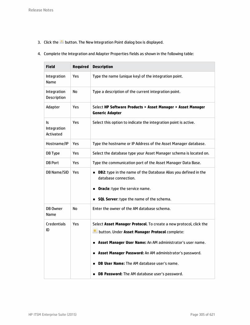
3. Click the button. The New Integration Point dialog box is displayed.
4. Complete the Integration and Adapter Properties fields as shown in the following table:
Field Required Description
IntegrationName
Yes Type the name (unique key) of the integration point.
IntegrationDescription
No Type a description of the current integration point.
Adapter Yes Select HP Software Products > Asset Manager > Asset ManagerGeneric Adapter
IsIntegrationActivated
Yes Select this option to indicate the integration point is active.
Hostname/IP Yes Type the hostname or IP Address of the Asset Manager database.
DB Type Yes Select the database type your Asset Manager schema is located on.
DB Port Yes Type the communication port of the Asset Manager Data Base.
DB Name/SID Yes n DB2: type in the name of the Database Alias you defined in thedatabase connection.
n Oracle: type the service name.
n SQL Server: type the name of the schema.
DB OwnerName
No Enter the owner of the AM database schema.
CredentialsID
Yes Select Asset Manager Protocol. To create a new protocol, click the
button. Under Asset Manager Protocol complete:
n Asset Manager User Name: An AM administrator's user name.
n Asset Manager Password: An AM administrator's password.
n DB User Name: The AM database user's name.
n DB Password: The AM database user's password.
Release Notes
HP ITSM Enterprise Suite (2015) Page 305 of 621

Field Required Description
AM Version Yes Select the version of Asset Manager this integration point is toconnect to.
AMPopulationPush Back ID
No Select True to allow the adapter to push the Global Id of UCMDB CIback to the corresponding AM entity.
AM OtherConnectionOptions
No Options can be used in the amdb.ini file. See Asset ManagerInstallation Guide, Chapter .ini, .cfg, and .res files > Amdb.ini FileEntries.
EnableParallel Push
No Select to allow parallel (multi-threaded) data push to Asset Manager.This improves performance. Note that you must configure SQL Server& DB2 to support parallel push. See "Prepare Asset Manager forParallel Push".
Data FlowProbe
Yes Select the name of the Data Flow Probe/Integration service used toexecute the synchronization from.
AdditionalProbes
No Select additional probes to use when pushing to AM in order toincrease redundancy.
5. Click Test Connection to make sure there is a valid connection.
6. Click OK.
The integration point is created and its detailed are displayed.
UCMDB creates a default data push job when creating the integration point. If needed you maycreate or edit the existing job. For more information, see "Work with Data Push Jobs" in the HPUniversal CMDB Data Flow Management Guide.
Out-of-Box Integration Jobs
AM Generic Adapter is shipped with out-of-box jobs for population and push between Asset Managerand UCMDB. Integration job is driven by UCMDB TQLs.
To access these TQLs, follow these steps.
Release Notes
HP ITSM Enterprise Suite (2015) Page 306 of 621

1. Log on to UCMDB as an administrator.
2. Go to Modeling > Modeling Studio > Resources, and then select Queries from the Resource Typedrop-down list.
3. Expand Root/Integration/AMGenericAdapter. There are 3 sub folders: federation, population andpush.n All queries under the federation folder federate CI data from AM to UCMDB.
n All queries under the population folder manage CI data synchronization from AM to UCMDB.
n All queries under the push folder manage CI data synchronization from UCMDB to AM.
Release Notes
HP ITSM Enterprise Suite (2015) Page 307 of 621

Asset Manager Population JobsIn the following table, all TQLs which are included in the default population job are listed. For each TQLquery, it describes the source AM entity type and the target CI types converted by the out-of-boxmapping XMLs. In the description column, it contains a summary of the TQL query, the out-of-boxmapping XML to convert the data, and the other data populations it depends on, which need to be runbeforehand.
TQL Query AM Entity UCMDB CI Type Description
AM Location Population2.0
Location Location
l Location
Populates location.
Mapping XML:
AM Location Population.xml
AM Node Population 2.0 ITEquipment Node
l Location
l Asset
Populates Node with Asset andLocation.
Mapping XML:
AM Node Population.xml
AM Interface Population2.0
NetworkCard Interface
l Node
l IpAddress
Populates Interface with IpAddressand Node relations.
Depends On:
AM Node Population 2.0
Mapping XML:
AM Interface Population.xml
AM BusinessElementPopulation 2.0
Asset BusinessElement
l Asset
Populate Business Element withAsset.
Mapping XML:
AM BusinessElementPopulation.xml
Release NotesAsset Manager Population Jobs
HP ITSM Enterprise Suite (2015) Page 308 of 621

TQL Query AM Entity UCMDB CI Type Description
AM BusinessElementRelations Population2.0
Client_Resource_Relationship
BusinessElement
l
BusinessElement
l Node
Populate Business Elementrelationship with Business Elementand Node.
Depends On:
l AM Node Population 2.0
l AM BusinessElementPopulation 2.0
Mapping XML:
AM BusinessElement RelationsPopulation.xml
AM Printer Population2.0
Portfolio_Printer
Printer
l Node
Populates Printer with the relationto Node.
Depends On:
AM Node Population 2.0
Mapping XML:
AM Printer Population.xml
Release NotesAsset Manager Population Jobs
HP ITSM Enterprise Suite (2015) Page 309 of 621

Asset Manager Push JobsThe below table lists all TQLs for data push contained in the out-of-box AM Generic Adapter. Some ofthem are included in the default push job. For each TQL query, it describes the source CI type and thetarget AM Entity type converted by the out-of-box mapping XMLs. In the description column, it containsa summary of the TQL query, the out of the box mapping XML to convert the data, and the other datapushes it depends on, which need to be run beforehand.
TQL Query AM Entity UCMDB CI Type Description
AM Node Push2.0
ITEquipment
l PhysicalDrives
l NetworkCards
l LogicalDrives
l ExtensionCardsAddOn (Printer,Monitor)
Node
l Asset
l CPU
l FileSystem
l LogicalVolume
l HardwareBoard
l DisplayMonitor
l DiskDevice
l InventoryScanner
l IpAddress
l Virtual Host Resource
l PhysicalPort
l VMWare Host Resource
l Printer
l Interface
Pushes nodes (Computers,Network Devices, etc.). Alsopushes IPs, Interfaces, DiskDevices, Physical Ports,Hardware Boards, DisplayMonitors, CPUs, Printers,Inventory Scanners, FileSystems, and Assets.
Minimal attributes forpushing a Node:
l Serial Number
l Vendor or DiscoveredVendor
l Model or DiscoveredModel
l Node Role
Note: These arerequired values, anddepend on thecapability of the datasource to report them.
Mapping XML:
AM Node Push.xml
Release NotesAsset Manager Push Jobs
HP ITSM Enterprise Suite (2015) Page 310 of 621
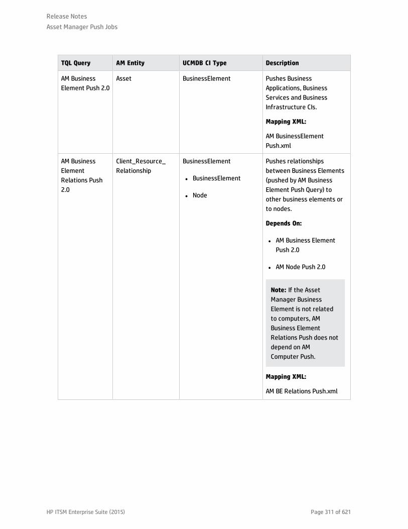
TQL Query AM Entity UCMDB CI Type Description
AM BusinessElement Push 2.0
Asset BusinessElement Pushes BusinessApplications, BusinessServices and BusinessInfrastructure CIs.
Mapping XML:
AM BusinessElementPush.xml
AM BusinessElementRelations Push2.0
Client_Resource_Relationship
BusinessElement
l BusinessElement
l Node
Pushes relationshipsbetween Business Elements(pushed by AM BusinessElement Push Query) toother business elements orto nodes.
Depends On:
l AM Business ElementPush 2.0
l AM Node Push 2.0
Note: If the AssetManager BusinessElement is not relatedto computers, AMBusiness ElementRelations Push does notdepend on AMComputer Push.
Mapping XML:
AM BE Relations Push.xml
Release NotesAsset Manager Push Jobs
HP ITSM Enterprise Suite (2015) Page 311 of 621
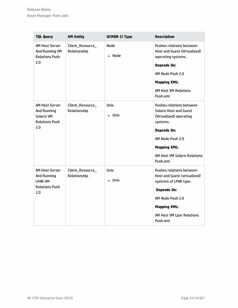
TQL Query AM Entity UCMDB CI Type Description
AM Host ServerAnd Running VMRelations Push2.0
Client_Resource_Relationship
Node
l Node
Pushes relations betweenHost and Guest (Virtualized)operating systems.
Depends On:
AM Node Push 2.0
Mapping XML:
AM Host VM RelationsPush.xml
AM Host ServerAnd RunningSolaris VMRelations Push2.0
Client_Resource_Relationship
Unix
l Unix
Pushes relations betweenSolaris Host and Guest(Virtualized) operatingsystems.
Depends On:
AM Node Push 2.0
Mapping XML:
AM Host VM Solaris RelationsPush.xml
AM Host ServerAnd RunningLPAR VMRelations Push2.0
Client_Resource_Relationship
Unix
l Unix
Pushes relations betweenHost and Guest (virtualized)systems of LPAR type.
Depends On:
AM Node Push 2.0
Mapping XML:
AM Host VM Lpar RelationsPush.xml
Release NotesAsset Manager Push Jobs
HP ITSM Enterprise Suite (2015) Page 312 of 621

TQL Query AM Entity UCMDB CI Type Description
AM ComputerRelations Push2.0
Client_Resource_Relationship
Node
l Node
Pushes relations betweenComputers to any node(Computers, NetworkDevices, etc.).
Depends On:
AM Node Push 2.0
Mapping XML:
AM Computer RelationsPush.xml
AM Net DeviceRelations Push2.0
Client_Resource_Relationship
Node
l Node
Pushes relations betweenNetwork Devices andNetwork Devices.
Depends On:
AM Node Push 2.0
Mapping XML:
AM NetDevice RelationsPush.xml
AM InstalledSoftware Push2.0
SoftwareInstallation InstalledSoftware
l Node
l InventoryScanner
l UserSoftwareUtilization
Pushes Installed Softwareand User_Software_Utilization CIs. TheseInstalled Software will benormalized in AM after push.
Depends On:
AM Node Push 2.0
Mapping XML:
AM InstalledSoftwareNormalize Push.xml
Release NotesAsset Manager Push Jobs
HP ITSM Enterprise Suite (2015) Page 313 of 621

TQL Query AM Entity UCMDB CI Type Description
AM InstalledSoftwareNormalized Push2.0
SoftwareInstallation InstalledSoftware
l Node
l InventoryScanner
l UserSoftwareUtilization
Pushes Installed Softwareand User_Software_Utilization CIs. TheseInstalled Software shouldalready be recognized bynormalization technology inUCMDB, for example, BDNA.They will not be normalizedin AM after push.
Depends On:
AM Node Push 2.0
Mapping XML:
AM InstalledSoftware Non-normalize Push.xml
AM SoftwareHypervisor Push2.0
SoftwareInstallation Hypervisor
l Node
Pushes Hypervisor InstalledSoftware.
Depends On:
AM Node Push 2.0
Mapping XML:
AM Hypervisor Push.xml
AM SoftwareSolaris Push 2.0
SoftwareInstallation Unix
l Unix
Pushes Solaris InstalledSoftware.
Depends On:
AM Node Push 2.0
Mapping XML:
AM Solaris Zone Push.xml
Release NotesAsset Manager Push Jobs
HP ITSM Enterprise Suite (2015) Page 314 of 621

TQL Query AM Entity UCMDB CI Type Description
AM Oracle LMSPush 2.0
MonitoredApplication Oracle
l Node
l InstalledSoftware
l AuditDocuement
Pushes the Oracle RunningSoftware and its Oracle LMSdata.
Depends On:
AM Node Push 2.0
Mapping XML:
AM Oracle LMS Push.xml
AM Cluster Push2.0
Cluster Cluster
l Asset
Pushes Cluster CIs. It is notincluded in the default pushjob.
Mapping XML:
AM Cluster Push.xml
AM Cluster NodeRelations Push2.0
Cluster_Component_Relationship
Cluster
l Node
Pushes cluster relationsbetween ComputerElements and Cluster.
Depends On:
AM Node Push 2.0 AM ClusterPush 2.0
Mapping XML:
AM Cluster Node RelationsPush.xml
AM ClusterRunningsoftwarePush 2.0
MonitoredApplication Runningsoftware
l Node
l Cluster
Pushes ClusterRunningsoftware CIs. Bydefault, it is not included inthe push job.
Depends On:
l AM Node Push 2.0
l AM Cluster Push 2.0
Mapping XML:
AM Cluster RunningSoftwarePush.xml
Release NotesAsset Manager Push Jobs
HP ITSM Enterprise Suite (2015) Page 315 of 621
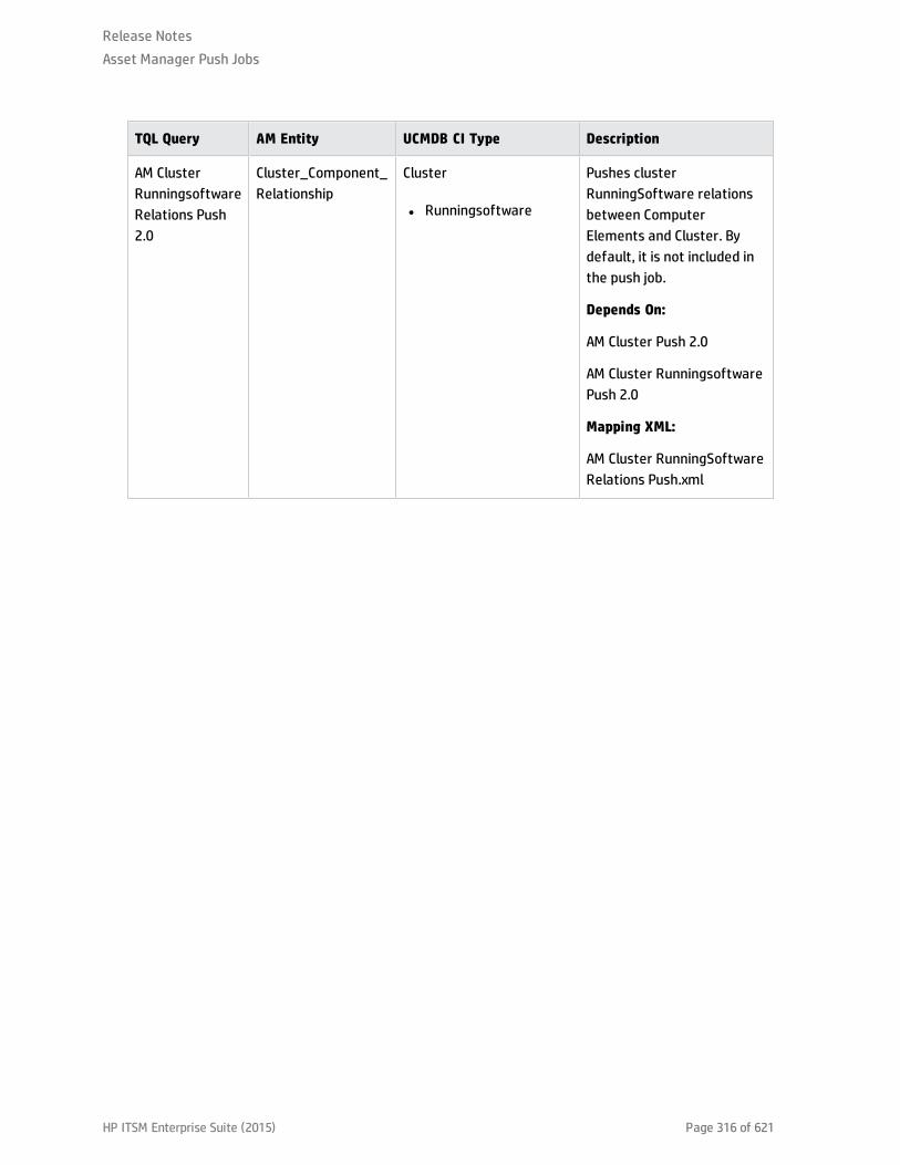
TQL Query AM Entity UCMDB CI Type Description
AM ClusterRunningsoftwareRelations Push2.0
Cluster_Component_Relationship
Cluster
l Runningsoftware
Pushes clusterRunningSoftware relationsbetween ComputerElements and Cluster. Bydefault, it is not included inthe push job.
Depends On:
AM Cluster Push 2.0
AM Cluster RunningsoftwarePush 2.0
Mapping XML:
AM Cluster RunningSoftwareRelations Push.xml
Release NotesAsset Manager Push Jobs
HP ITSM Enterprise Suite (2015) Page 316 of 621

Asset Manager Federation ConfigurationBy default, the following supported and selected CI types can be federated from Asset Manager:
l Node
l CPU
l DiskDevice
l FileSystem
l InstalledSoftware
l LogicalVolume
l Printer
The following table lists all TQLs for the data federation that are contained in the out-of-box AM GenericAdapter. For each TQL query, it describes the source AM Entity type and the target CI type converted bythe out-of-box mapping XMLs.
TQL Query AM Entity UCMDB CI Type Mapping XML
AM Federation cpu_12 2.0 ITEquipment CPU AM Cpu Federation.xml
Release NotesAsset Manager Federation Configuration
HP ITSM Enterprise Suite (2015) Page 317 of 621

TQL Query AM Entity UCMDB CI Type Mapping XML
AM Federation cpu_node2.0
ITEquipment CPU
l Node
AM Cpu Node RelationsFederation.xml
AM Federation disk_device_12 2.0
PhysicalDrive DiskDevice AM DiskDevice Federtion.xml
AM Federation disk_device_node 2.0
PhysicalDrive DiskDevice
l Node
AM DiskDevice NodeRelations Federtion.xml
AM Federation file_system_12 2.0
LogicalDrive FileSystem AM FileSystem Federtion.xml
AM Federation file_system_node 2.0
LogicalDrive FileSystem
l Node
AM FileSystem NodeRelations Federtion.xml
AM Federation installed_software_12 2.0
SoftwareInstallation InstalledSoftware AM InstalledSoftwareFedertion.xml
AM Federation installed_software_node 2.0
SoftwareInstallation InstalledSoftware
l Node
AM InstalledSoftware NodeRelations Federtion.xml
AM Federation logical_volume_12 2.0
LogicalDrive LogicalVolume AM LogicalVolumeFedertion.xml
AM Federation logical_volume_node 2.0
LogicalDrive LogicalVolume
l Node
AM LogicalVolume NodeRelations Federtion.xml
AM Federation printer_122.0
Portfolio_Printer Printer AM Printer Federtion.xml
AM Federation printer_node 2.0
Portfolio_Printer Printer
l Node
AM Printer Node RelationsFedertion.xml
Release NotesAsset Manager Federation Configuration
HP ITSM Enterprise Suite (2015) Page 318 of 621

Verify Out-of-Box Population and Push JobsThis section describes how to verify out-of-box population and push jobs.
Release NotesVerify Out-of-Box Population and Push Jobs
HP ITSM Enterprise Suite (2015) Page 319 of 621

Synchronize Data between UCMDB and AssetManagerThe AM Generic Adapter provides two types of jobs:
l Data push jobs copy CI or CI relationship records from your UCMDB system to your Asset Managersystem.
l Data population jobs copy Asset or Asset relationship records from your Asset Manager system toyour UCMDB system.
To run a data push/population job, follow these steps:
1. Log on to UCMDB as an administrator.
2. Go to Data Flow Management > Integration Studio. UCMDB displays a list of existing integrationpoints.
3. Select the integration point you created for Asset Manager.
4. Add a new data push/population job as follows:
a. Click the button on the right panel.
b. In the Name field, type a unique name for the job.
c. Click the button to add existing TQL queries to the job.
d. For push jobs, select or unselect the Allow Deletion option for each query. (The settingdetermines if this TQL query is allowed to delete data from Asset Manager, though the actualaction on delete is defined by CI type in the mapping xml.)
For population jobs, select the Allow Integration Job to Delete Removed Data according tothe requirement. (The setting determines if the population job is allowed to delete CIs fromUCMDB.)
e. Click OK.
f. Save the integration point.
Release NotesSynchronize Data between UCMDB and Asset Manager
HP ITSM Enterprise Suite (2015) Page 320 of 621

5. Manually run the job to see if the integration job works properly:
a. To push/populate all the relevant data for the job, click the button.
b. To push/populate only the changes in the data since the job last executed, click the
button.
6. Wait for the job to complete, click the button multiple times as needed until the job is
completed.
7. When the job is completed, the job status becomes one of the following depending on the results:
n Succeeded
n Completed
n Failed
8. Click the Statistics tab to view the results. If any errors occur, click the Query Status tab and JobErrors tab for more information. For more information about errors, see "Troubleshooting andLimitations".
Note: For details about these tabs and managing the integration, see Integration Jobs Pane inthe HP Universal CMDB Data Flow Management Guide .
If the job completes successfully, you can view the UCMDB CI data in Asset Manager.
Release NotesSynchronize Data between UCMDB and Asset Manager
HP ITSM Enterprise Suite (2015) Page 321 of 621
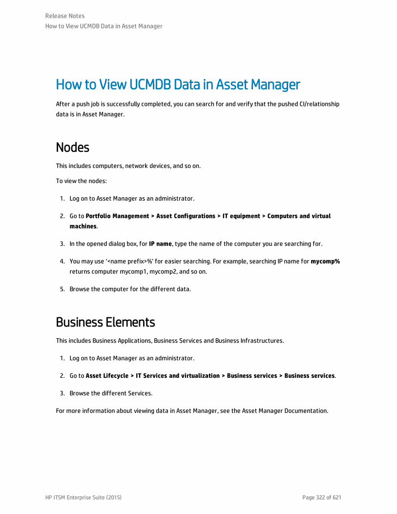
How to View UCMDB Data in Asset ManagerAfter a push job is successfully completed, you can search for and verify that the pushed CI/relationshipdata is in Asset Manager.
NodesThis includes computers, network devices, and so on.
To view the nodes:
1. Log on to Asset Manager as an administrator.
2. Go to Portfolio Management > Asset Configurations > IT equipment > Computers and virtualmachines.
3. In the opened dialog box, for IP name, type the name of the computer you are searching for.
4. You may use ‘<name prefix>%’ for easier searching. For example, searching IP name for mycomp%returns computer mycomp1, mycomp2, and so on.
5. Browse the computer for the different data.
Business ElementsThis includes Business Applications, Business Services and Business Infrastructures.
1. Log on to Asset Manager as an administrator.
2. Go to Asset Lifecycle > IT Services and virtualization > Business services > Business services.
3. Browse the different Services.
For more information about viewing data in Asset Manager, see the Asset Manager Documentation.
Release NotesHow to View UCMDB Data in Asset Manager
HP ITSM Enterprise Suite (2015) Page 322 of 621

How to View Asset Manager Data in UCMDBAfter a population job is successfully completed, you can search for and verify that the populated Assetdata is in UCMDB. To do this, follow these steps.
1. Log on to UCMDB.
2. Go to Modeling > IT Universe Manager.
3. Click the Search CIs tab and search for the name of the Asset populated from Asset Manager.
Release NotesHow to View Asset Manager Data in UCMDB
HP ITSM Enterprise Suite (2015) Page 323 of 621

How to Federate Asset Manager Data in UCMDBAfter Integration point of AM Generic Adapter is created and activated, you will find the supported CItypes in the Federation page.
To federate these supported CI in UCMDB, you can create a query in UCMDB client > Modeling>Modeling Studio > Resources. Then, add a supported CI to federate data from AM. For example:Printer.
Release NotesHow to Federate Asset Manager Data in UCMDB
HP ITSM Enterprise Suite (2015) Page 324 of 621

Click the CI icon, and then find Data Sources tab from the following area.
Edit Data Sources, select integration points from the following options, and then select integrationpoints, for example, AMGA941.
Release NotesHow to Federate Asset Manager Data in UCMDB
HP ITSM Enterprise Suite (2015) Page 325 of 621

Verify Calculate Query Result Count or Preview, you can federate those printers from AM server.
Release NotesHow to Federate Asset Manager Data in UCMDB
HP ITSM Enterprise Suite (2015) Page 326 of 621

Integration Jobs ConfigurationThis section describes the configurations to be made to the integration jobs.
Release NotesIntegration Jobs Configuration
HP ITSM Enterprise Suite (2015) Page 327 of 621
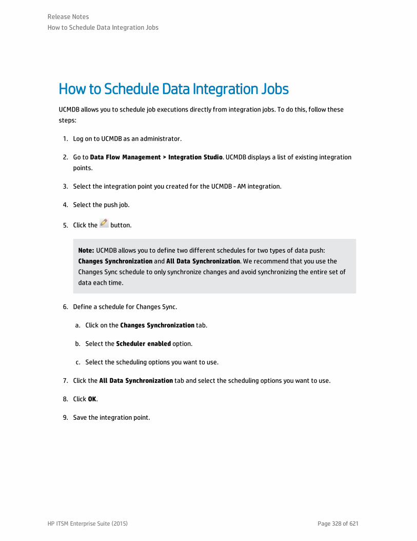
How to Schedule Data Integration JobsUCMDB allows you to schedule job executions directly from integration jobs. To do this, follow thesesteps:
1. Log on to UCMDB as an administrator.
2. Go to Data Flow Management > Integration Studio. UCMDB displays a list of existing integrationpoints.
3. Select the integration point you created for the UCMDB - AM integration.
4. Select the push job.
5. Click the button.
Note: UCMDB allows you to define two different schedules for two types of data push:Changes Synchronization and All Data Synchronization. We recommend that you use theChanges Sync schedule to only synchronize changes and avoid synchronizing the entire set ofdata each time.
6. Define a schedule for Changes Sync.
a. Click on the Changes Synchronization tab.
b. Select the Scheduler enabled option.
c. Select the scheduling options you want to use.
7. Click the All Data Synchronization tab and select the scheduling options you want to use.
8. Click OK.
9. Save the integration point.
Release NotesHow to Schedule Data Integration Jobs
HP ITSM Enterprise Suite (2015) Page 328 of 621

Edit Data Integration JobsWhen you create an AM Generic Adapter integration point, a default job is created for data populationand data push respectively. You can perform the following actions in the jobs.
l Add or remove TQLs.
l Clear cache (available only for population jobs)
l Show Results For Job (available only for population jobs)
Query Status
l Push selected failed data
l Suppress selected failures/warnings
l Up One Level/Down One Level
l View details
Release NotesEdit Data Integration Jobs
HP ITSM Enterprise Suite (2015) Page 329 of 621

Job Definition
l Allow Integration Job to delete removed data
l Add/Delete
l Move Query Up/Move Query Down
l Edit Query Resources
Standards and Concepts
This section describes standards and concepts.
Asset Manager Entity
The AM Generic Adapter introduces a new concept named AM Entity. The AM Entity is a type of objectthat represents a collection of attributes abstracted from an AM table. All entities defined in the AMGeneric Adapter make up the AM Class Model which represents the subset of AM objects that can beused in the population, push, as well as the graphic mapping UI. With the introduction of the AM ClassModel (i.e. Entity) as an additional layer on top of AM database API, population and push mappings donot need to directly specify exact AM database tables or views. Extending AM Class Model is as simple asdefining new entities by editing the am-entity-config.xml file. The entity name can be customized to avalue that best fits your preference.
The entity is used mainly in the following places.
l It is displayed in the external class model pane on the mapping UI.
l It is referenced in mapping scripts.
Release NotesEdit Data Integration Jobs
HP ITSM Enterprise Suite (2015) Page 330 of 621

l It is used in am-populate-config.xml for configuring initial AQL (AM Advanced Query Language)conditions to produce data from AM (used by population and federation).
l It is used in am-push-config.xml for reconciliation rule definition (used by push).
Release NotesEdit Data Integration Jobs
HP ITSM Enterprise Suite (2015) Page 331 of 621

Asset Manager Entity Definition Steps
The AM entity definition steps are as follows.
1. Import AM tables.
2. Create a new AM entity based on an imported AM table.
3. Define the entity's attributes and links to be used in the AM Generic Adapter.
The definition of the entities is saved in the am-entity-config.xml file. To access the file, go to DataFlow Management > Adapter Management > Packages > AMGenericAdapter > Configuration Files.
The am-entity-config.xml file consists of two sections.
l The Import Tables section contains the declaration of AM tables imported to the AM GenericAdapter, as well as what attributes and links in a table can be used in the adapter.
l The Entity Definition section contains the definition of AM entities which are used as the root levelentity for data mapping. An entity is based on a table imported in the Import Table section.Additionally, an entity can specify a subset of attributes and links in the imported table to limit itsown attributes and links.
Release NotesAsset Manager Entity Definition Steps
HP ITSM Enterprise Suite (2015) Page 332 of 621

Import Tables and Entity DefinitionThe following tables describe the schema of the am-entity-config.xml file.
Import Tables
Name Type Description
am-tables
Tag
name Attribute The SQL name of the AM database table.
attributes Tag Specifies attributes (SQL name) in the table that can be used in the adapter.Multiple attributes are separated by comma. Use * to import all attributes.
links Tag Specifies links (SQL name) in the table that can be used in the adapter.Multiple links are separated by comma. Use * to import all links.
Note: The table to which the link references must also be imported.
Entity Definition
Name Type Description
am-entities
Tag
am-root-entity
Tag
name Attribute AM entity name. The entity name is used to reference an entity in the datamapping, AM Class Model, configuration for push, and population. We stronglyrecommend that you give it a meaningful name.
table Attribute The SQL name of the AM database table where the entity's attributes andlinks come from. The table must be imported in the Import Tables section.
inherit-from-table
Attribute l True: merge attributes and links defined in the imported table to theentity.
l False: only attributes and links defined in the entity can be used. Thedefault value is False.
Release NotesImport Tables and Entity Definition
HP ITSM Enterprise Suite (2015) Page 333 of 621

Name Type Description
depth Attribute Defines the depth of level links in the entity can be extended. The defaultdepth is 4, which means the deepest remote link you can use isentity.linkA.linkB.linkC.linkD.
icon-type Attribute The icon to be displayed in the graphic mapping UI to represent the entity. Itrefers to the values from UCMDB > Modeling > CI Type Manager > Icon.
attributes Tag Specifies the attributes (SQL name) in the table that can be used in theadapter. Multiple attributes are separated by comma. Use * to import allattributes.
links Tag Specifies the links (SQL name) in the table that can be used in the adapter.Multiple links are separated by comma. Use * to import all links. Note: Thetable to which the link references must be imported.
Release NotesImport Tables and Entity Definition
HP ITSM Enterprise Suite (2015) Page 334 of 621

Out-of-Box Entity DefinitionThe following table covers all of the out-of-box entities defined in the AM Generic Adapter. For the list oftables imported to the adapter, see the am-entity-config.xml file.
AM Entity Name AM Table Comment
ITEquipment amComputer You can customize entity names by suffixing a sub CItype to define a more exact AM Entity. For example,
l ITEquipment_Windows
l ITEquipment_Unix
If you want to query an AM table with different AQLconditions, you need to separate entities.
Location amLocation
NetworkCard amNetworkCard
PhysicalDrive amPhysicalDrive
SoftwareInstallation amSoftInstall
Asset amAsset
LogicalDrive amLogicalDrive
Cluster amCluster
ClusterComponent amClusterComponent
ExtensionCard amExtensionCard
Monitor amMonitor
MonitoredApplication amMonitoredApp
EmployeeDepartment
amEmplDept
Release NotesOut-of-Box Entity Definition
HP ITSM Enterprise Suite (2015) Page 335 of 621

AM Entity Name AM Table Comment
Portfolio amPortfolio In practice, you can customize the entity name by AMnatures or models to define more exact AM entities.For example,
l Portfolio_NetworkHardware
l Portfolio_StorageConsumer
l Portfolio_StorageAggregation
l Portfolio_StorageProvider
l Portfolio_VirtualMachine
Cluster_Component_Relationship
amClusterComponent
Client_Resource_Relationship
amClientResource
Portfolio_Printer amPortfolio This entity is for local printers that only saved inamPortfolio table but not in the amComputer table. Itis used in the data population. Its query condition is:
Model.Nature.Code = 'PRN' AND lParentId <>0
UCMDB TQL
AM Generic Adapter communicates with UCMDB through TQL queries.
l For push operations, a TQL query produces CIs which are the source to be translated to AssetManager.
l For population, a TQL query defines CI types to be pulled from Asset Manager.
l For federation, a TQL query is used to configure the Data Sources of a CI node. For example, you canspecify the Integration Points of a CPU node to an AM Generic Adapter integration point.
l For graphic mapping UI, a TQL query displays the CI relation tree.
A TQL query used for the data push job must contain a root query node.
Release NotesOut-of-Box Entity Definition
HP ITSM Enterprise Suite (2015) Page 336 of 621

In the OOTB TQLs for data push, some query nodes are set with criteria to query valid CIs to betranslated to Asset Manager. For example, "Not NodeRole is null" is one of the conditions specified inthe Node CI of the AM Node Push TQL.
Any attribute used in the mapping flow must be marked in the selected layout of the query node. EachTQL query may only have one mapping. We recommend that you only add attributes which are used inthe data mapping to the selected layout. Add unused attributes to the selected layout may have impacton the performance.
You can customize TQLs, for example, add a condition to a query node or add a new query node .
TQL Naming Convention
All OOTB TQLs follow the naming convention below. We recommend that you use the same namingconvention when creating new TQLs for the AM Generic Adapter.
AM <CI Type> <Push | Population> <version #>
For example:
l AM Node Population 2.0
l AM Business Element Push 2.0
Groovy Functions
Groovy is an agile and dynamic language, natively supported by the Java Virtual Machine. It allows simplescripting capabilities, while maintaining all the strengths and capabilities of Java. It can execute simpleString manipulation, and use 3rd party libraries. For more information, see http://groovy.codehaus.org/.
Release NotesOut-of-Box Entity Definition
HP ITSM Enterprise Suite (2015) Page 337 of 621

Basic FunctionsThere are two basic function groovy files:
l AMPopulate.groovy
l AMPush.groovy
Basic functions in these two files are for implementing data conversion and transformation in mappingscripts, and they will simplify mapping scripts, although mapping scripts also support basic groovysyntax.
Release NotesBasic Functions
HP ITSM Enterprise Suite (2015) Page 338 of 621

AM Population GroovyThere are some functions in population groovy implement translation and discrimination logic. Thefollowing list shows all the functions in AMGenericAdapter/mappings/scripts/AMPopulate.groovy.
l convertlpAddressProperty
l getAssignment
l getCRState
l getHostDataCl
l getKpiComparisonOperator
l getLocationType
l getlpAddressProperty
l getlpAddressValue
l getNodeRole
l getNodeType
l getServiceClass
l isAcceptableNode
l isDebugEnabled
l isDeletedNode
l isDesktop
l isValidLocationParent
l isValidlp
l isValidNode
Release NotesAM Population Groovy
HP ITSM Enterprise Suite (2015) Page 339 of 621

l isVirtual
l setLog
Release NotesAM Population Groovy
HP ITSM Enterprise Suite (2015) Page 340 of 621

AM Push GroovyThere are some functions in push groovy implement business logic conversion, especially for AssetManager SAM calculation. The following list shows all the functions inAMGenericAdapter/mappings/scripts/AMPush.groovy.
l calculateComputerType
l convertCsvBytesToString
l fIsSAIValid
l fEDDIGetMACAddressEx
l fEDDIGetACComputerBrand
l fEDDIGetACWorkGroup
l fEDDIGetComputerManufacturer
l fEDDIGetDomainNameEx
l fEDDIGetSCLogicalName
l fEDDITruncate
l getAMPrimarylD
l getAMPrimarylD
l getAssetTagCRSystem
l getBrandName
l getCardlD
l getCardName
l getCardVendorName
l getClusterModelName
l getClusterTechnology
Release NotesAM Push Groovy
HP ITSM Enterprise Suite (2015) Page 341 of 621
l getCpulnternal
l getCpuType
l getCsvFile
l getDdEdition
l getDNSSuffix
l getDomainName
l getEnd1Externalld
l getEnd2Externalld
l getEnumValueByKey
l getExternalld
l getFinalModelld
l getFirstlpV4Address
l getFirstlpV6Address
l getFolder
l getLMSOptionStatus
l getLMSPacksStatus
l getlnterfaceDescription
l getLogicalCpuCount
l getlpAddress
l getlpAddress
l getlpV4SubnetMask
l getlpV6SubnetMask
l getlslnventModelExist
Release NotesAM Push Groovy
HP ITSM Enterprise Suite (2015) Page 342 of 621

l getlslnventModelResolved
l getModelldByBarCode
l getModelName
l getModelParentCode
l getMonitorCode
l getMonitorModelName
l getNatureCode
l getNatureCodeFromType
l getNatureNameFromType
l getNormalizedCPU
l getNormalizedModelName
l getOracleComponentList
l getOracleEditionShortName
l getOracleFolder
l getParentBarCodeFromType
l getParentName
l getPhysicalAddress
l getPrimarylpAddress
l getSafeAMPrimarylD
l getSoftwareBarCode
l getUserName
l getValueFromCsv
l getValueFromStringCsv
Release NotesAM Push Groovy
HP ITSM Enterprise Suite (2015) Page 343 of 621

l getVMType
l hasFinalModelld
l isDHCPEnabled
l isExtensionCardValid
l isLparVpar
l isSolarisZone
l nicelyPrintExternalld
l setLog
l shouldMapMonitor
l sortlpList
l validateAndRetrieveSingleUCaseAsset
Release NotesAM Push Groovy
HP ITSM Enterprise Suite (2015) Page 344 of 621

Utility FunctionsSome general logic and functions are the same in the utility groovy file. AMPopulate.groovy,AMPush.groovy, and AMReconcil.groovy are inherited from this groovy. So in push or populationmapping, even the utility groovy is not imported, all of the following functions inAMGenericAdapter/mappings/scripts/AMUtils.groovy can be used normally.
l boolTolnt
l compareDate
l containslgnoreCase
l Extractvalue
l fCleanValueWithDefault
l fisContainOne
l flsContainList
l flsEmpty
l flsEmptyOrZero
l isMatchVersion
l isNull
l leftPart
l rightPart
l toBoolean
l toSmart
l toStringList
l trimRight
l uCase
Release NotesUtility Functions
HP ITSM Enterprise Suite (2015) Page 345 of 621

Reconciliation FunctionsReconciliation groovy file provides advanced features about AM reconciliation proposal, insert or updatescript, and so on. The following list shows all the functions inAMGenericAdapter/mappings/scripts/AMReconcil.groovy.
l createReconcProposalAdvance
l getCurrDate
l getCurrDateLong
l getlndexByName
l getModelFromlnstalledSoftwareCl
l getShortHostName
l getSqlTextConst
l getValueBylndex
l getValueByName
l isDateAfter
l isResultEmpty
l setReconcProposallnvalidate
l setReconcProposalObsolete
l stringToDom
l updateMemorySize
Data Mapping Schema
AM Generic adapter is built on top of the Generic Adapter framework. Its data mapping schema followsthe standard schema in the framework. For more information, see HP Universal CMDB DeveloperReference Guide.
Release NotesReconciliation Functions
HP ITSM Enterprise Suite (2015) Page 346 of 621

The AM Generic Adapter uses some of the elements specifically to fit the AM-UCMDB integrationrequirement.
Automatic Creation of Relation CI in Data Population
When populating two CIs that are defined in TQL, their relation CIs are created in UCMDB automaticallyaccording to the TQL query definition. The explicit mapping for the relation between the two CIs is notrequired. For example, in the AM Interface Population XML, it does not define the data mapping for therelation between Interface and Node. However, the relation will be created automatically when you runthe AM Interface Population job.
If you want to create the relation CI with non-default values, you need to define a relation CI mapping inthe mapping XML file.
Define Reconciliation Rule for Target AM Entity in Push
The name attribute of the target_entity tag represents:
l The entity name defined in the am-entity-config.xml file when defining the target_entity for theroot CI.
l The link's SQL name in the AM Class Model when defining the target_entity for non-root CIs.
For example, in the AM Node Push.xml, the name of the target_entity for the root CI is set toITEquipment, which is an entity type based on the amComputer table. The name of the target_entity forthe Root.File_System CI is set to LogicalDrives, which is the SQL name of the link to the amLogicalDrivetable in the ITEquipment entity.
The type attribute of the target_entity tag represents an alias to be used in the am-push-config.xml fileto define the reconciliation rules for the data mapping. For more information about how to definereconciliation rules, see "Reconciliation" on page 366.
It is an optional attribute. When it is not given a value, it takes the value of the name attribute as itsvalue.
For example, in the AM Node Push.xml, the type of the target_entity for the Root.Display_Monitor CI isset to Monitor-amPortfolio. In the am-push-config.xml file, it uses the type value Monitor-amPortfolioto define the reconciliation rule for the mapping.
<am-mapping ci-type="Monitor-amPortfolio" name="AddOn" primary-key="lPortfolioItemId" operation-type="update_else_insert" parallel-push-allowed="true" merge-allowed="true" to-version="9.4*">
<reconciliation><reconciliation-keys>
<reconciliation-key>Folder</reconciliation-key><reconciliation-key>lParentId</reconciliation-key>
</reconciliation-keys>
Release NotesReconciliation Functions
HP ITSM Enterprise Suite (2015) Page 347 of 621

</reconciliation>…</am-mapping>
Specify Sub CI Type in Population Data Mapping
In the population data mapping, the type attribute of the target_entity is used to specify the sub typeof the target CI.
For example, in the AM Node Population.xml, the AM ITEquipment entity is mapped to the Node CI (theNode CI is set to Root in the TQL query). When the population job is running, the exact CI type theITEquipment entity is converted and is determined by the value of the type attribute. In the out-of-boxmapping, it calls a groovy function to set the value of the type attribute.
Determine the Deletion of AM Entities in Population
In the population data mapping, the is-deleted attribute of the target_entity tag is used to determine ifthe target UCMDB CI corresponding to the AM entity needs to be deleted.
Produce Log
You can use the Logger object to produce log in the before-mapping and after-mapping tag.
For example,
<before-mapping>Logger.debug('before')</before-mapping>
<after-mapping>Logger.debug('after')</after-mapping>
Population and Federation
AM Generic Adapter is able to retrieve data from AM database via AM DLL API. This section describes thedetailed criteria before query AM Entity.
Release NotesReconciliation Functions
HP ITSM Enterprise Suite (2015) Page 348 of 621
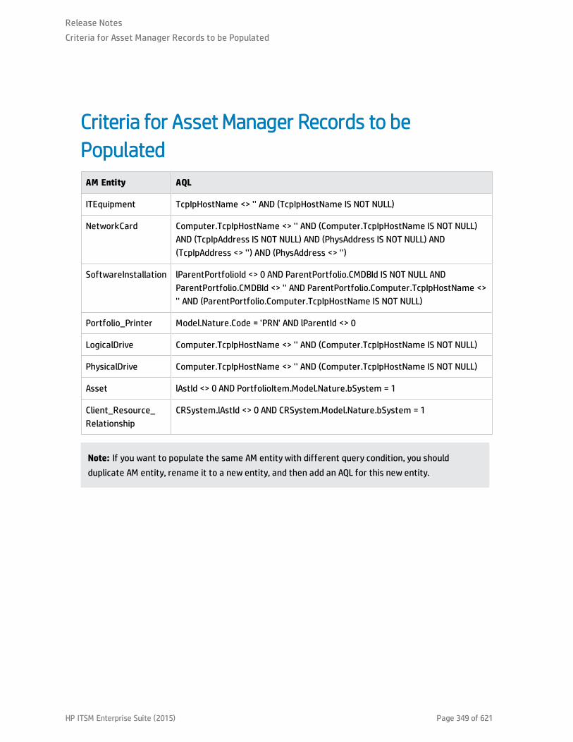
Criteria for Asset Manager Records to bePopulatedAM Entity AQL
ITEquipment TcpIpHostName <> '' AND (TcpIpHostName IS NOT NULL)
NetworkCard Computer.TcpIpHostName <> '' AND (Computer.TcpIpHostName IS NOT NULL)AND (TcpIpAddress IS NOT NULL) AND (PhysAddress IS NOT NULL) AND(TcpIpAddress <> '') AND (PhysAddress <> '')
SoftwareInstallation lParentPortfolioId <> 0 AND ParentPortfolio.CMDBId IS NOT NULL ANDParentPortfolio.CMDBId <> '' AND ParentPortfolio.Computer.TcpIpHostName <>'' AND (ParentPortfolio.Computer.TcpIpHostName IS NOT NULL)
Portfolio_Printer Model.Nature.Code = 'PRN' AND lParentId <> 0
LogicalDrive Computer.TcpIpHostName <> '' AND (Computer.TcpIpHostName IS NOT NULL)
PhysicalDrive Computer.TcpIpHostName <> '' AND (Computer.TcpIpHostName IS NOT NULL)
Asset lAstId <> 0 AND PortfolioItem.Model.Nature.bSystem = 1
Client_Resource_Relationship
CRSystem.lAstId <> 0 AND CRSystem.Model.Nature.bSystem = 1
Note: If you want to populate the same AM entity with different query condition, you shouldduplicate AM entity, rename it to a new entity, and then add an AQL for this new entity.
Release NotesCriteria for Asset Manager Records to be Populated
HP ITSM Enterprise Suite (2015) Page 349 of 621

Transformation for Asset Manager Records to bePopulatedIT equipment
The default population mapping will populate an IT equipment when its status is In use or In stock.
According to the IT equipment type, data will be populated to UCMDB as different CI types:
CI types in UCMDB IT Equipment Type in AM
host_node l Computer
l Desktop computers
l Computer servers
l Laptop
l Virtual Machine
l Smart phone
nt l Windows computer
l Windows desktop computer
l VMware VirtualCenter
unix l Unix server computer
l Unix desktop computer
l Solaris Zone server
vmware_esx_server VMware ESX Server
mainframe l Mainframe
l Mainframe CPC
lpar Mainframe Logical Partition
When a CI is populated to UCMDB, the Host is Virtual attribute of the CI is defined according to the valueof IT Equipment type for the CI in AM.
Release NotesTransformation for Asset Manager Records to be Populated
HP ITSM Enterprise Suite (2015) Page 350 of 621

Host is Virtual IT Equipment Type in AM
Yes l Virtual Machine
l Mainframe Logical Partition
No l Windows computer
l Windows desktop computer
l VMware VirtuaCenter
l VMware ESX server
l Unix server computer
l Unix desktop computer
l Solaris Zone Server
l Desktop computers
l Computer servers
l Laptop
l Mainframe
l ATM switch
l Firewall
l Router
l Switch
l Network printer
l Smart phone
l Mainframe CPC
When a CI is populated to UCMDB, the Host is Desktop attribute of the CI is defined according to thevalue of IT Equipment for the CI in AM.
Release NotesTransformation for Asset Manager Records to be Populated
HP ITSM Enterprise Suite (2015) Page 351 of 621

Host is Desktop IT Equipment Type in AM
Yes l Windows desktop computer
l Unix desktop computer
l Desktop computers
No l Windows computer
l VMware VirtuaCenter
l VMware ESX server
l Unix server computer
l Solaris Zone Server
l Computer servers
l Laptop
l Mainframe
l ATM switch
l Firewall
l Router
l Switch
l Network printer
l Smart phone
l Mainframe CPC
Business Element
In AM, only those business service assets with status (amAsset.Status) Built, Catalogued, Chartered,Designed , and Requested will be populated to UCMDB. If the status is retired, it will be removed fromUCMDB.
Relations between AM business service asset and CI types are as follows.
Release NotesTransformation for Asset Manager Records to be Populated
HP ITSM Enterprise Suite (2015) Page 352 of 621

Nature code CI Type
BIZSVC business_service
BIZAPP business_application
INFRASVC infrastructure_service
In AM Generic Adapter, all the transformers and discriminators are implemented in groovy functions. Formore information, see "Groovy Functions" on page 337.
Release NotesTransformation for Asset Manager Records to be Populated
HP ITSM Enterprise Suite (2015) Page 353 of 621

ReconciliationFor each CI Type, the data reconciliation is governed by the reconciliation rule set in UCMDB.
You can check the reconciliation rule for each CI Type on the Details tab of the CI Type. The field name isIdentification.
Release NotesReconciliation
HP ITSM Enterprise Suite (2015) Page 354 of 621

Population Condition and Push Back DefinitionName Type Description
am-populations
Tag
am-population
Tag
entity-name
Attribute AM Entity name
push-back-field
Tag The AM database field to hold the global id pushed from UCMDB CI back toAM. It supports AQL syntax, for example:
PortfolioItem.CMDBId
delta-sync-date-field
Tag It is used to define a time condition field for AQL in changes population. Bydefault, it is the field 'dtLastModif' that is from the AM entity which is usedas the 'root-element' in the population mapping.
query-condition
Tag The condition of the query to retrieve the entity data from AM. It supportsAM AQL. If the condition includes special characters, for example: >, <, 'surround with CDATA.
Release NotesPopulation Condition and Push Back Definition
HP ITSM Enterprise Suite (2015) Page 355 of 621

Built-in attributes from AMl AM_PUSHBACK_ID
This attribute is created by population adapter automatically from AM. It is used to identify which AMrecord is written with push back global id.
l LAST_SYNC_TIME
This attribute is created by population adapter automatically. It keeps the last job changes synctime in order to be used in population mapping.
Release NotesBuilt-in attributes from AM
HP ITSM Enterprise Suite (2015) Page 356 of 621

Federation TagsThe configuration must be provided if you want to use federation.
It defines all valid federation TQL names.
Name Type Description
supported-federation-queries Tag
tql-query Tag
name Attribute TQL name
Release NotesFederation Tags
HP ITSM Enterprise Suite (2015) Page 357 of 621

Population TagsThe configuration is used to define all valid population TQL names.
Name Type Description
supported-population-queries
Tag
enable Tag l True: only displays valid population TQL names for you, to selectrequired population TQLs for a population job.
l False: displays all TQL names from UCMDB for you, to selectrequired population TQLs for a population job.
tql-query Tag
name Attribute TQL name
Push and Reconciliation
This section describes push and reconciliation operations.
Release NotesPopulation Tags
HP ITSM Enterprise Suite (2015) Page 358 of 621
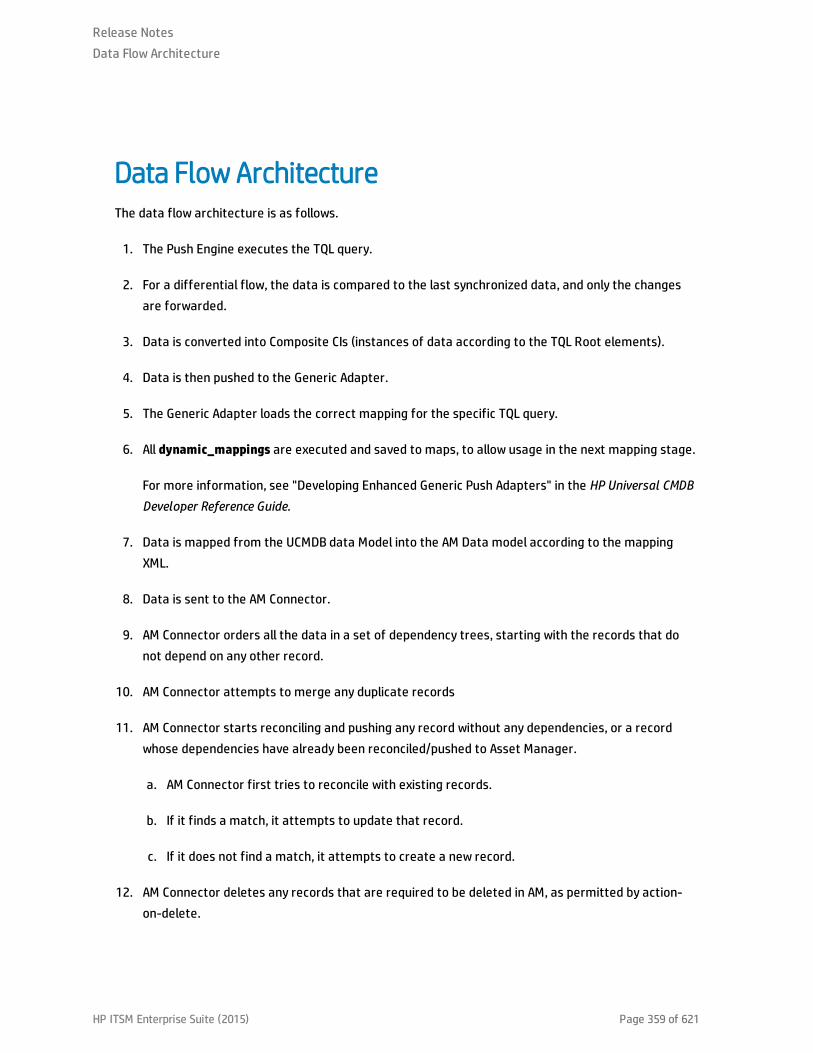
Data Flow ArchitectureThe data flow architecture is as follows.
1. The Push Engine executes the TQL query.
2. For a differential flow, the data is compared to the last synchronized data, and only the changesare forwarded.
3. Data is converted into Composite CIs (instances of data according to the TQL Root elements).
4. Data is then pushed to the Generic Adapter.
5. The Generic Adapter loads the correct mapping for the specific TQL query.
6. All dynamic_mappings are executed and saved to maps, to allow usage in the next mapping stage.
For more information, see "Developing Enhanced Generic Push Adapters" in the HP Universal CMDBDeveloper Reference Guide.
7. Data is mapped from the UCMDB data Model into the AM Data model according to the mappingXML.
8. Data is sent to the AM Connector.
9. AM Connector orders all the data in a set of dependency trees, starting with the records that donot depend on any other record.
10. AM Connector attempts to merge any duplicate records
11. AM Connector starts reconciling and pushing any record without any dependencies, or a recordwhose dependencies have already been reconciled/pushed to Asset Manager.
a. AM Connector first tries to reconcile with existing records.
b. If it finds a match, it attempts to update that record.
c. If it does not find a match, it attempts to create a new record.
12. AM Connector deletes any records that are required to be deleted in AM, as permitted by action-on-delete.
Release NotesData Flow Architecture
HP ITSM Enterprise Suite (2015) Page 359 of 621

Integration TQL QueriesA TQL query used for the integration must contain a root query node.
Any attribute using in the mapping flow of the data push must be marked in the selected layout of thequery node.
Each TQL query for data push job may only have one mapping.
For more information, see Data Flow Management > Integration > Integration Studio > IntegrationJobs Pane.
Release NotesIntegration TQL Queries
HP ITSM Enterprise Suite (2015) Page 360 of 621
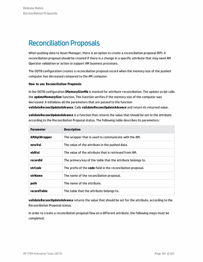
Reconciliation ProposalsWhen pushing data to Asset Manager, there is an option to create a reconciliation proposal (RP). Areconciliation proposal should be created if there is a change in a specific attribute that may need AMOperator validation or action to support AM business processes.
The OOTB configuration creates a reconciliation proposal record when the memory size of the pushedcomputer has decreased compared to the AM computer.
How to use Reconciliation Proposals
In the OOTB configuration lMemorySizeMb is marked for attribute-reconciliation. The update script callsthe updateMemorySize function. This function verifies if the memory size of the computer wasdecreased. It initializes all the parameters that are passed to the functionvalidateReconcUpdateAdvance. Calls validateReconcUpdateAdvance and return its returned value.
validateReconcUpdateAdvance is a function that returns the value that should be set to the attributeaccording to the Reconciliation Proposal status. The following table describes its parameters:
Parameter Description
AMApiWrapper The wrapper that is used to communicate with the AM.
newVal The value of the attribute in the pushed data.
oldVal The value of the attribute that is retrieved from AM.
recordId The primary key of the table that the attribute belongs to.
strCode The prefix of the code field in the reconciliation proposal.
strName The name of the reconciliation proposal.
path The name of the attribute.
recordTable The table that the attribute belongs to.
validateReconcUpdateAdvance returns the value that should be set for the attribute, according to theReconciliation Proposal status.
In order to create a reconciliation proposal flow on a different attribute, the following steps must becompleted:
Release NotesReconciliation Proposals
HP ITSM Enterprise Suite (2015) Page 361 of 621

1. Add the <attribute-reconciliation> tag for this attribute.
2. The update-script should call a new function that initializes the parameters passed tovalidateReconcUpdateAdvance, and returns the value returned fromvalidateReconcUpdateAdvance.
Note: We recommend that you use the updateMemorySize function as a reference.
Release NotesReconciliation Proposals
HP ITSM Enterprise Suite (2015) Page 362 of 621

Asset Manager Rules and FlowsAsset Manager has its own set of rules and flows that are enforced by the Asset Manager API. Somecustomizations may need to later these rules and flows as well. For more information, see the AssetManager documentation.
Release NotesAsset Manager Rules and Flows
HP ITSM Enterprise Suite (2015) Page 363 of 621
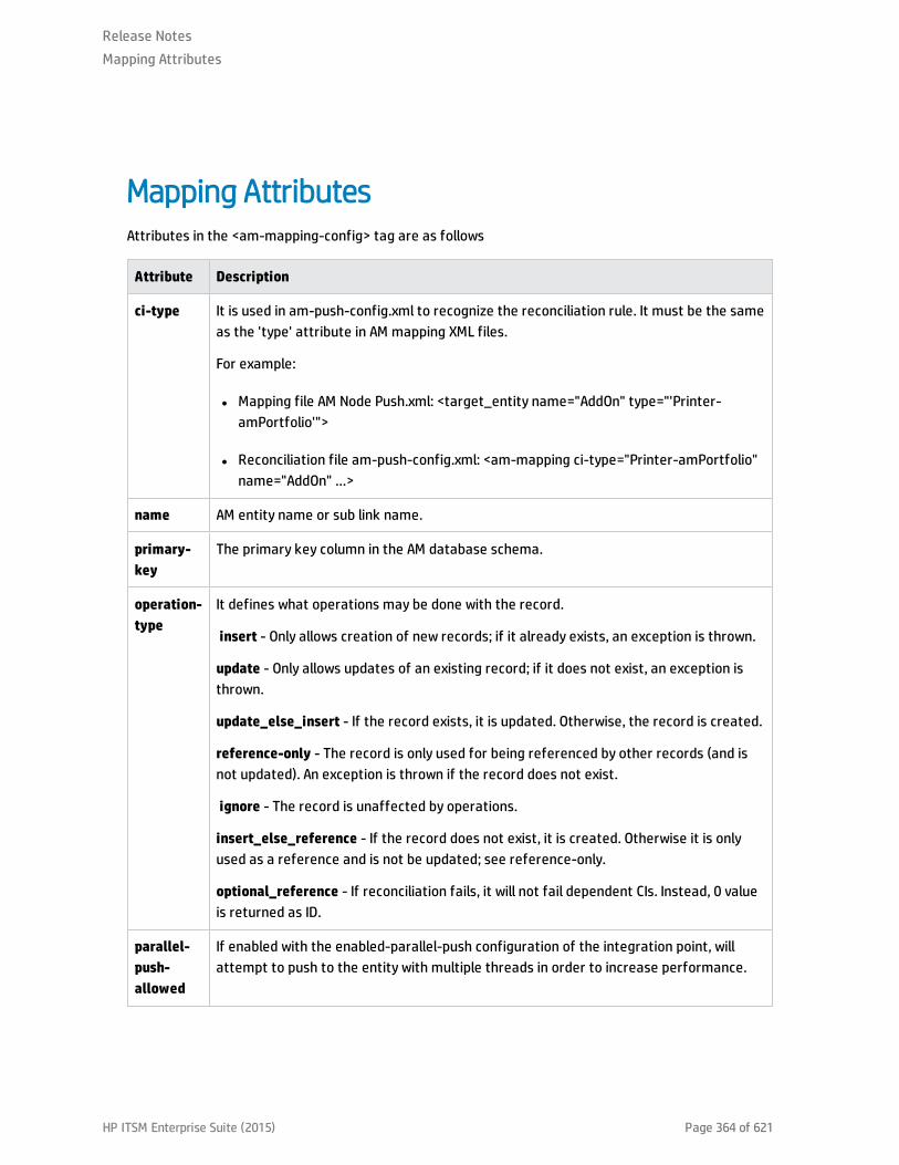
Mapping AttributesAttributes in the <am-mapping-config> tag are as follows
Attribute Description
ci-type It is used in am-push-config.xml to recognize the reconciliation rule. It must be the sameas the 'type' attribute in AM mapping XML files.
For example:
l Mapping file AM Node Push.xml: <target_entity name="AddOn" type="'Printer-amPortfolio'">
l Reconciliation file am-push-config.xml: <am-mapping ci-type="Printer-amPortfolio"name="AddOn" …>
name AM entity name or sub link name.
primary-key
The primary key column in the AM database schema.
operation-type
It defines what operations may be done with the record.
insert - Only allows creation of new records; if it already exists, an exception is thrown.
update - Only allows updates of an existing record; if it does not exist, an exception isthrown.
update_else_insert - If the record exists, it is updated. Otherwise, the record is created.
reference-only - The record is only used for being referenced by other records (and isnot updated). An exception is thrown if the record does not exist.
ignore - The record is unaffected by operations.
insert_else_reference - If the record does not exist, it is created. Otherwise it is onlyused as a reference and is not be updated; see reference-only.
optional_reference - If reconciliation fails, it will not fail dependent CIs. Instead, 0 valueis returned as ID.
parallel-push-allowed
If enabled with the enabled-parallel-push configuration of the integration point, willattempt to push to the entity with multiple threads in order to increase performance.
Release NotesMapping Attributes
HP ITSM Enterprise Suite (2015) Page 364 of 621
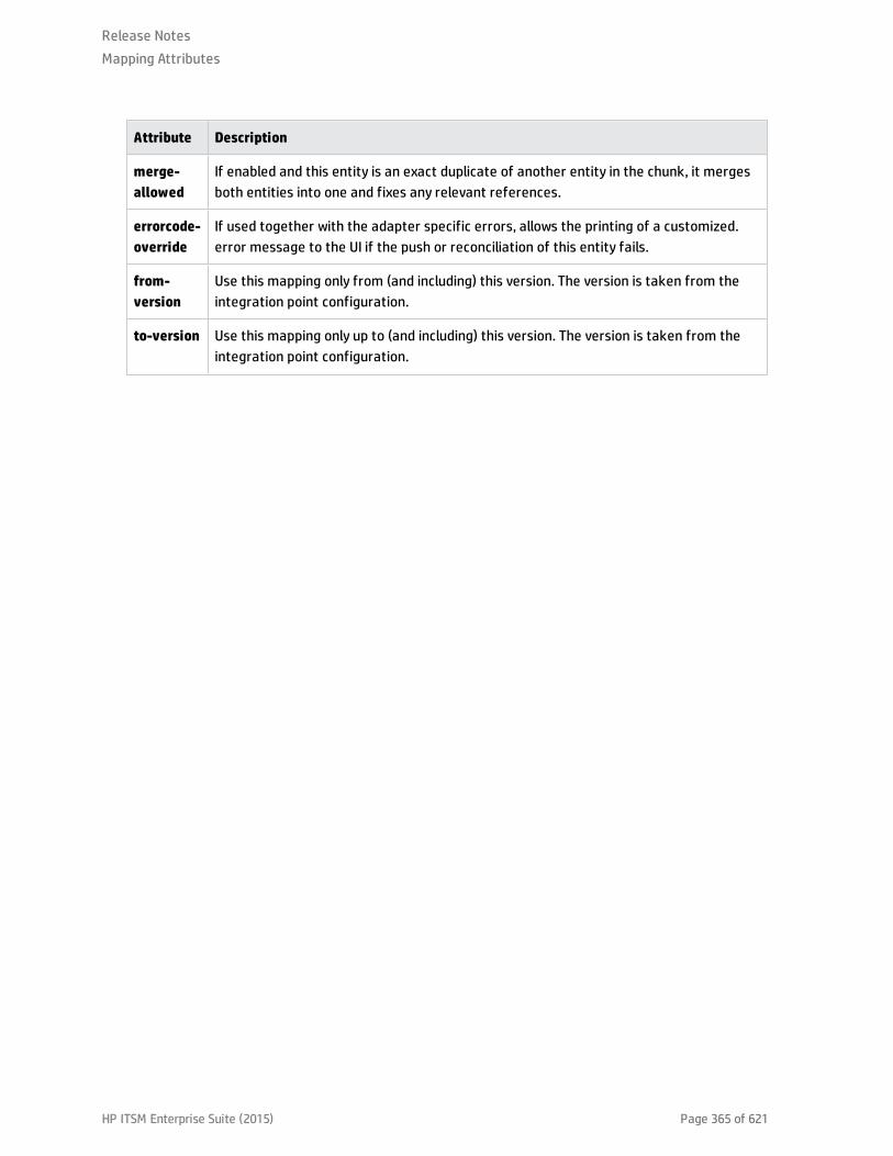
Attribute Description
merge-allowed
If enabled and this entity is an exact duplicate of another entity in the chunk, it mergesboth entities into one and fixes any relevant references.
errorcode-override
If used together with the adapter specific errors, allows the printing of a customized.error message to the UI if the push or reconciliation of this entity fails.
from-version
Use this mapping only from (and including) this version. The version is taken from theintegration point configuration.
to-version Use this mapping only up to (and including) this version. The version is taken from theintegration point configuration.
Release NotesMapping Attributes
HP ITSM Enterprise Suite (2015) Page 365 of 621

ReconciliationReconciliation defined for each mapping may include more than one set of reconciliation rules. Whenattempting to reconcile the record with existing ones in the AM database, the AM Connector tries eachof the reconciliation sets until it finds a matching record. Priority is defined by the order ofreconciliation rules. If no record in the AM database matches this record, an insert operation isperformed if the operation type permits it.
Name Type Description
reconciliation Tag Parent XML tag for all reconciliation configuration.
reconciliation-keys
Tag Represents a single reconciliation rule that may be made of one or moreattributes. All attributes inside the rule must match in order for thereconciliation of this rule to be successful.
reconciliation-key
Tag Represents a single attribute used for reconciliation as part of thereconciliation-keys rule.
Ignore-case Attribute Part of the reconciliation-key tag. Specifies that this attributecomparison ignores case.
reconciliation-advanced
Tag Allows definition of the reconciliation rule by manually defining theWHERE clause of the AQL (Asset Query Language). Uses GString (GroovyString) to generate the replacement String. Any variable or propertydefined in this record or its parent during the mapping stage (in the PushAdapter) may be used as a variable in the GString. (Seehttp://groovy.codehaus.org/Strings+and+GString for more information).
Note: AMPushAdvancesReconciliationException may be throwninside this tag to skip to the next rule.
follow-parent Tag Used to define overflow tables. See the AM documentation for moreinformation on overflow tables. When using follow-parent, no otherreconciliation may be used as this target CI has a 1:1 connection with itsparent, and it uses the parent reconciliation to push data to AM.
am-prefix Attribute Part of the follow-parent tag. Defines the name that the parent targetCI uses to reference to this table. (To find out the correct value, navigateto AM Application Designer > Edit Links).
Example:
Release NotesReconciliation
HP ITSM Enterprise Suite (2015) Page 366 of 621
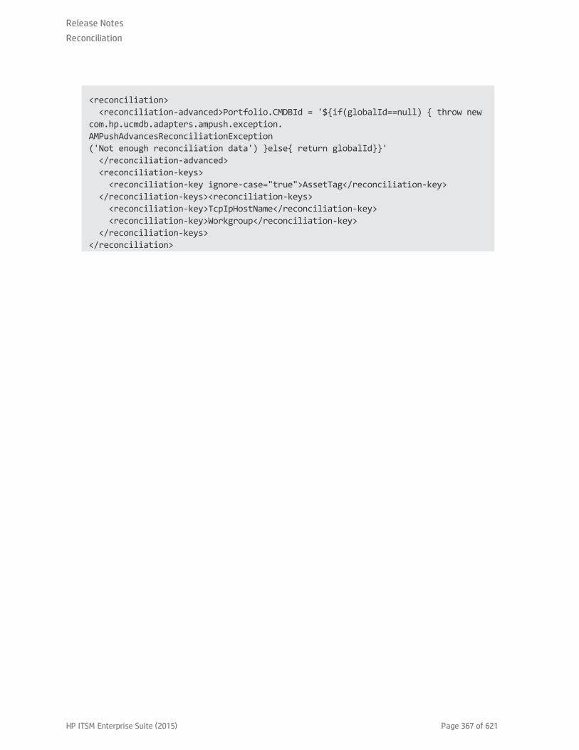
<reconciliation> <reconciliation-advanced>Portfolio.CMDBId = '${if(globalId==null) { throw newcom.hp.ucmdb.adapters.ampush.exception.AMPushAdvancesReconciliationException('Not enough reconciliation data') }else{ return globalId}}' </reconciliation-advanced> <reconciliation-keys> <reconciliation-key ignore-case="true">AssetTag</reconciliation-key> </reconciliation-keys><reconciliation-keys> <reconciliation-key>TcpIpHostName</reconciliation-key> <reconciliation-key>Workgroup</reconciliation-key> </reconciliation-keys></reconciliation>
Release NotesReconciliation
HP ITSM Enterprise Suite (2015) Page 367 of 621

Target CI ValidationThis tag allows the definition of a validation rule that is executed on specific attribute values: the newone held in memory, and the old one stored in the AM database.
The following table shows the attributes of the <target-ci-validation> tag:
Name Description
attribute-name
The attribute that you want to use for validation.
validation-script
A Groovy based script that returns true if this record is to be pushed, and false if it isnot to be pushed. The script may access any external Groovy code in the path in orderto run the evaluation.
l vNewVal - Attribute value of the record in memory.
l vOldVal - Attribute value of the record in the AM database.
failed-validation-error-code
This optional attribute holds the error code that appears if there is a validation failure.
The arguments that can be referenced in the error message are:
l {0} - The validated attribute name.
l {1} - The property value in UCMDB.
l {2} - The property value in Asset |Manager.
l {3} - The validation script.
l {4} - The additional message from the additional-failure-message attribute, or'null' if there is no additional message.
additional-failure-message
This optional attribute holds an additional error message that can be referenced bythe error message in the properties.error file. See failed-validation-error-code,above.
Example:
<target-ci-validation attribute-name="dtLastScan" validation-script="mappings.scripts.AMReconciliationAdvanced.isDateAfter(vNewVal,vOldVal)"/>
Release NotesTarget CI Validation
HP ITSM Enterprise Suite (2015) Page 368 of 621

Reference AttributeA reference attribute defines a column that references another record from a different or same table.This record is not pushed, or reconciled against existing AM database records, until this reference isresolved. Resolved references are replaced by a reference ID that represents the primary ID of thereferenced record.
The following table shows the attributes of the <reference-attribute> tag:
Name Description
ci-name The CI-type of the referenced record.
datatype The value type of the record.
name The column in the current record that is to be populated by the reference ID.
reference-direction
According to the tree created by the Push Adapter, the value specifies if thereferenced record is a parent or child of the current record.
Example:
<reference-attribute ci-name="SW_amModel" datatype="STRING"name="lModelId"reference-direction="child"/>
Release NotesReference Attribute
HP ITSM Enterprise Suite (2015) Page 369 of 621

Attribute ReconciliationThis tag allows the AM connector to decide what to do with an attribute value according to the existingvalue in the AM database.
The following table shows the attributes of the <attribute-reconciliation> tag:
Name Description
attribute-name
The attribute to be reconciled.
update-script
The script to execute in case of an update operation on the record. The returned value bythe groovy script will be push to AM as the value of this attribute.
l vNewVal - Attribute value of the record in memory.
l vOldVal - Attribute value of the record in the AM database.
Insert-script
The script to execute in case of an insert operation on the record. The value returned bythe Groovy script is pushed to AM as the value of this attribute.
vNewVal - Attribute value of the record in memory.
Example:
<attribute-reconciliation attribute-name="AssetTag" update-script="mappings.scripts.AMPushFunctions.fIsEmpty(vOldVal) ? vNewVal : vOldVal"/>
Release NotesAttribute Reconciliation
HP ITSM Enterprise Suite (2015) Page 370 of 621

Action on DeleteThis tag allows customization of the behavior on receipt of a delete notification for a record.
Note: No deletion occurs if the Allow Delete option in the job definition is disabled.
The following actions are possible
l <ignore> - Do nothing.
l <delete-ci> - Delete this record from the AM database.
l <set-attribute-value> - Change the value of one or more attributes in the AM database.
Example:
<action-on-delete> <set-attribute-value name="bMissing" datatype="BOOLEAN" value="1"/></action-on-delete>
Release NotesAction on Delete
HP ITSM Enterprise Suite (2015) Page 371 of 621

Enum AttributeThis tag allows a specific enum attribute to be pushed in a serial mode, when the adapter is configuredto push data in parallel mode.
Note: This option exists to prevent duplicate key exceptions occurring when several threads pushthe same enum value.
The following table shows the attributes of the <enum-attribute> tag:
Name Description
attribute-name The enum attribute name.
itemized-name The itemized list format (amOS) of the enum.
Release NotesEnum Attribute
HP ITSM Enterprise Suite (2015) Page 372 of 621

Ignored AttributesThis tag allows specific attributes to be ignored and not pushed to the AM database. This capability iscommonly used with the from-version and to-version attributes or tags, to ignore certain attributes forspecific versions of Asset Manager.
The following table shows the attributes of the <ignored-attributes> tag:
Name Description
from-version
Ignore this attribute only from (and including) this version. The version is taken from theintegration point configuration.
to-version
Ignore this attribute only up to (and including) this version. The version is taken from theintegration point configuration.
Example:
<ignored-attributes> <ignored-attribute>lSeq</ignored-attribute></ignored-attributes>
Deletion
To allow the AM Generic Adapter to delete CIs in UCMDB on data population or delete assets in AM ondata push, additional configurations are required. The following sections describes how to configure theAM Generic Adapter to allow data deletion in the AM-UCMDB integration.
Release NotesIgnored Attributes
HP ITSM Enterprise Suite (2015) Page 373 of 621
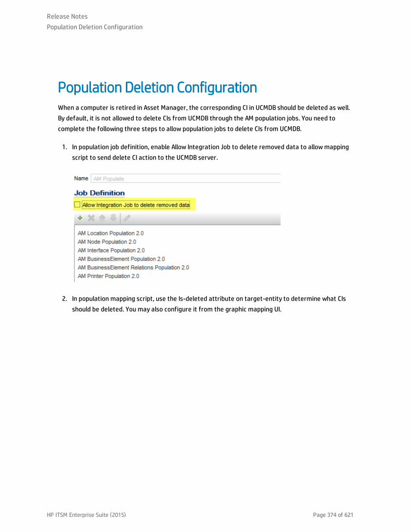
Population Deletion ConfigurationWhen a computer is retired in Asset Manager, the corresponding CI in UCMDB should be deleted as well.By default, it is not allowed to delete CIs from UCMDB through the AM population jobs. You need tocomplete the following three steps to allow population jobs to delete CIs from UCMDB.
1. In population job definition, enable Allow Integration Job to delete removed data to allow mappingscript to send delete CI action to the UCMDB server.
2. In population mapping script, use the Is-deleted attribute on target-entity to determine what CIsshould be deleted. You may also configure it from the graphic mapping UI.
Release NotesPopulation Deletion Configuration
HP ITSM Enterprise Suite (2015) Page 374 of 621
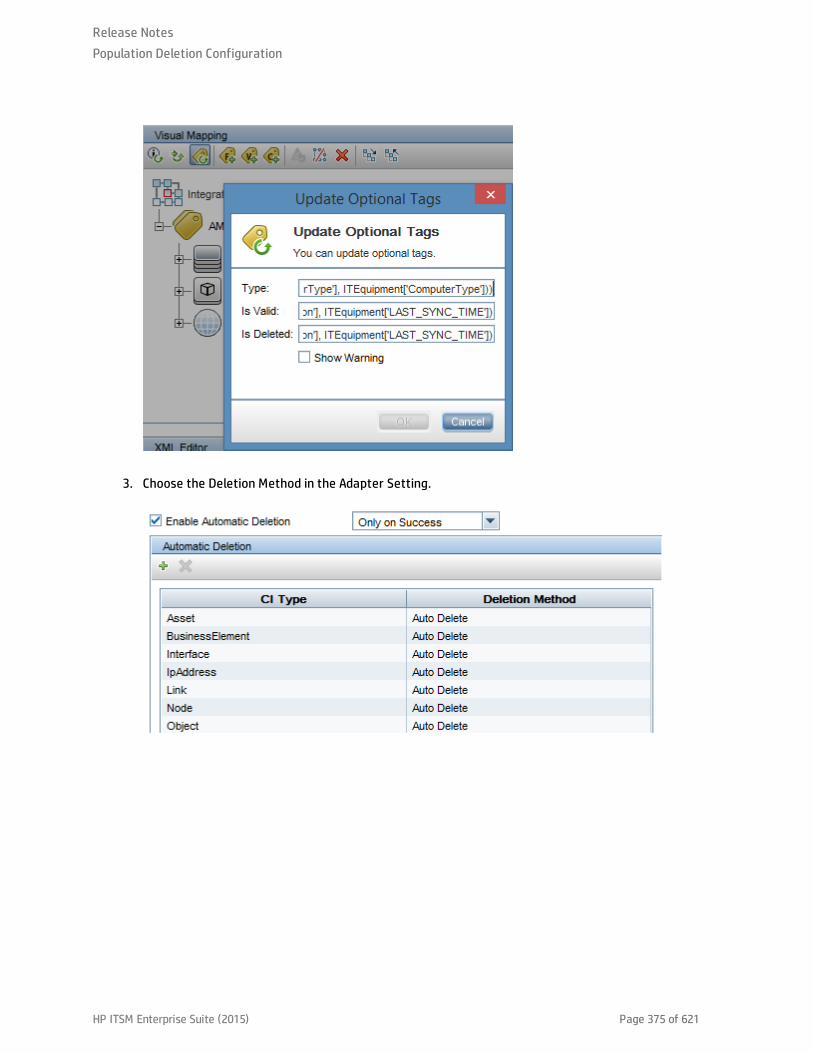
3. Choose the Deletion Method in the Adapter Setting.
Release NotesPopulation Deletion Configuration
HP ITSM Enterprise Suite (2015) Page 375 of 621
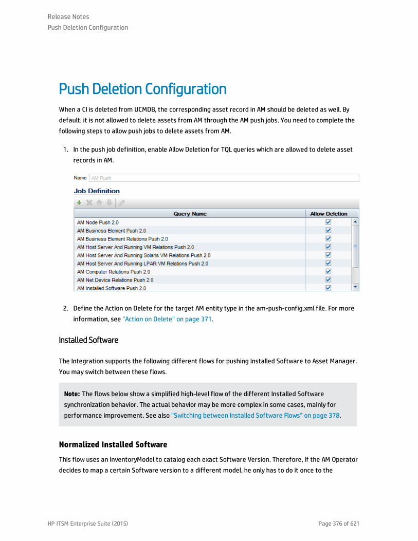
Push Deletion ConfigurationWhen a CI is deleted from UCMDB, the corresponding asset record in AM should be deleted as well. Bydefault, it is not allowed to delete assets from AM through the AM push jobs. You need to complete thefollowing steps to allow push jobs to delete assets from AM.
1. In the push job definition, enable Allow Deletion for TQL queries which are allowed to delete assetrecords in AM.
2. Define the Action on Delete for the target AM entity type in the am-push-config.xml file. For moreinformation, see "Action on Delete" on page 371.
Installed Software
The Integration supports the following different flows for pushing Installed Software to Asset Manager.You may switch between these flows.
Note: The flows below show a simplified high-level flow of the different Installed Softwaresynchronization behavior. The actual behavior may be more complex in some cases, mainly forperformance improvement. See also "Switching between Installed Software Flows" on page 378.
Normalized Installed Software
This flow uses an InventoryModel to catalog each exact Software Version. Therefore, if the AM Operatordecides to map a certain Software version to a different model, he only has to do it once to the
Release NotesPush Deletion Configuration
HP ITSM Enterprise Suite (2015) Page 376 of 621
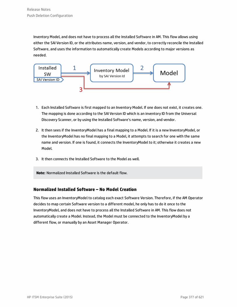
Inventory Model, and does not have to process all the Installed Software in AM. This flow allows usingeither the SAI Version ID, or the attributes name, version, and vendor, to correctly reconcile the InstalledSoftware, and uses the information to automatically create Models according to major versions asneeded.
1. Each Installed Software is first mapped to an Inventory Model. If one does not exist, it creates one.The mapping is done according to the SAI Version ID which is an inventory ID from the UniversalDiscovery Scanner, or by using the Installed Software's name, version, and vendor.
2. It then sees if the InventoryModel has a final mapping to a Model. If it is a new InventoryModel, orthe InventoryModel has no final mapping to a Model, it attempts to search for one with the samename and version. If one is found, it connects the InventoryModel to it; otherwise it creates a newModel.
3. It then connects the Installed Software to the Model as well.
Note: Normalized Installed Software is the default flow.
Normalized Installed Software – No Model Creation
This flow uses an InventoryModel to catalog each exact Software Version. Therefore, if the AM Operatordecides to map certain Software version to a different model, he only has to do it once to theInventoryModel, and does not have to process all the Installed Software in AM. This flow does notautomatically create a Model. Instead, the Model must be connected to the InventoryModel by adifferent flow, or manually by an Asset Manager Operator.
Release NotesPush Deletion Configuration
HP ITSM Enterprise Suite (2015) Page 377 of 621

1. Each Installed Software is first mapped to an Inventory Model. If one does not exist, it creates one.The mapping is done according to the SAI Version ID, which is an inventory ID from the UniversalDiscovery Scanner, or by using the Installed Software attributes: name, version, and vendor.
2. It then sees if the InventoryModel has a final mapping to a Model. If not, it chooses the temporarymodel (an Unknown Software Model).
3. It then connects the Installed Software to the Model found in the step 2.
4. Later, an Asset Manager Operator manually connects each Inventory Model to a final Model, as hewishes.
Non-Normalized Installed Software
This flow pushes Installed Software and Models only. (It does not map or use the Inventory Models in anyway).
Each Installed Software is mapped to a matching Model which is created if not found.
Switching between Installed Software Flows
There are two OOTB TQLs for the Installed Software push in the AM Generic Adapter.
l AM Installed Software Push 2.0 is the TQL that contains the Installed Software CIs which need to benormalized in Asset Manager. Running this TQL job triggers the installed software flow that isnormalized.
Release NotesPush Deletion Configuration
HP ITSM Enterprise Suite (2015) Page 378 of 621

l AM Installed Software Normalized Push 2.0 is the TQL contains the Installed Software CIs which arealready normalized in UCMDB and do not need to be normalized in Asset Manager. Running this TQLjob triggers the installed software flow that is not normalized.
Release NotesPush Deletion Configuration
HP ITSM Enterprise Suite (2015) Page 379 of 621

HP Asset Manager Push IntegrationThis chapter includes:
This is a mini TOC level 2
HP ITSM Enterprise Suite (2015) Page 380 of 621
Quick Start
Note: This section is only for advanced users who want to start using Asset Manager PushIntegration quickly, without reading the full documentation. It therefore provides the minimuminformation required before you run your first integration.
Before starting the integration for the first time, you must complete the following:
l "Validate Pre-Loaded Data in Asset Manager" on page 384
l "Update Asset Manager Schema" on page 386
l "Create AMPushAdapterAPI Package with Required AM API Files" on page 390
l "Install a Database Client" on page 390
Overview
Integration between HP Universal CMDB (UCMDB) and HP Asset Manager enables you to shareinformation from UCMDB with Asset Manager. Common use cases include Hardware, Installed Softwareand Business Services.
You can use the integration to automate the creation and update of Asset and Portfolio information inAsset Manager. This ensures Asset Manager is kept up to date with real, accurate, discovered data inyour environment.
Note: This Integration replaces the Connect-It Scenarios used for syncing Hardware and Softwareinformation from DDMI 9.3x and below to Asset Manager. Also, this integration replaces theConnect-It Scenarios used to sync Business Services and Business Applications from UCMDB toAsset Manager.
How Data is Synchronized Between UCMDB and Asset Manager
When referring to the concept of data information, it is important to distinguish between a UCMDB CI(Configuration Item) and an Asset Manager Asset. Both are defined in a different Data Model, and theremust be a conversion before transferring CIs in UCMDB to Assets in Asset Manager.
The following graphic shows the high-level components of the integration:
Release Notes
HP ITSM Enterprise Suite (2015) Page 381 of 621

Note: The Push Adapter and AM Connector are executed in the Data Flow Probe/Integration Serviceprocess.
UCMDB stores its information using CIs. The integration chooses which data to pull from UCMDB bydefining integration TQL queries. Each TQL query defines a superset of data relevant for the integration.
The UCMDB Push Engine:
l Retrieves the required data from UCMDB, using the given TQL query.
l Filters the data to include only the data that has changed since the last execution of thissynchronization.
l Splits the data into multiple chunks without breaking consistency.
l Sends the information to the Probe/Adapter
The Push Adapter is a generic framework for easily configuring push adapters, using only XML andGroovy1. It allows easy mapping of the data from the UCMDB data model into the Asset Manager Data
model, and the transfer of this converted data into the AM Connector. For more information, seeDeveloping Push Adapters in the HP Universal CMDB Developer Reference Guide.
The AM Connector is a component that connects to the Push Adapter, built specifically to reconcile,push, and handle the complex logic needed to synchronize data into Asset Manager.
1Groovy is an agile and dynamic language, natively supported by the Java Virtual Machine. It allowssimple scripting capabilities, while maintaining all the strengths and capabilities of Java. It can executesimple String manipulation, and use 3rd party libraries. For more information, see http://-groovy.codehaus.org/
Release Notes
HP ITSM Enterprise Suite (2015) Page 382 of 621

Supported Versions
This integration supports HP Asset Manager 9.30 and later versions.
Release Notes
HP ITSM Enterprise Suite (2015) Page 383 of 621

How to Integrate UCMDB and Asset Manager
To set up integration between UCMDB and Asset Manager, you must complete the following steps:
l "Validate Pre-Loaded Data in Asset Manager" below
l "Set Up Asset Manager" below
l "Set Up UCMDB" on page 390
l "Push CI Data from UCMDB to Asset Manager" on page 393
Validate Pre-Loaded Data in Asset Manager
For the integration to succeed, it requires there to be some basic data already in the Asset Managerdatabase.
This data may either be imported during the database creation (using the Asset Manager ApplicationDesigner), or may be added later. For more information, see the Asset Manager Documentation –Administration.
For hardware synchronization the required data is:
l Shared Data
l UNSPSC Product Classification
l Portfolio – Line-of-business data
l Virtualization – Line-of-business data
l Business services management – Line-of-business data
For software synchronization the required data is:
l Software Asset Management – Line-of-business data
Set Up Asset Manager
To set up Asset Manager you must complete the following steps:
Release Notes
HP ITSM Enterprise Suite (2015) Page 384 of 621
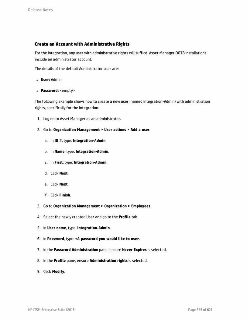
Create an Account with Administrative Rights
For the integration, any user with administrative rights will suffice. Asset Manager OOTB installationsinclude an administrator account.
The details of the default Administrator user are:
l User: Admin
l Password: <empty>
The following example shows how to create a new user (named Integration-Admin) with administrationrights, specifically for the integration.
1. Log on to Asset Manager as an administrator.
2. Go to Organization Management > User actions > Add a user.
a. In ID #, type: Integration-Admin.
b. In Name, type: Integration-Admin.
c. In First, type: Integration-Admin.
d. Click Next.
e. Click Next.
f. Click Finish.
3. Go to Organization Management > Organization > Employees.
4. Select the newly created User and go to the Profile tab.
5. In User name, type: Integration-Admin.
6. In Password, type: <A password you would like to use>.
7. In the Password Administration pane, ensure Never Expires is selected.
8. In the Profile pane, ensure Administration rights is selected.
9. Click Modify.
Release Notes
HP ITSM Enterprise Suite (2015) Page 385 of 621

Update Asset Manager Schema
The default Asset Manager database schema includes column lengths that may be significantly shorterthan their counterparts in the UCMDB database schema. For attributes used for reconciliation, this maybe critical and may cause creation of multiple records.
To fix this issue, you are recommended to change the Asset Manager Column Sizes to the values shownin the following table of Asset Manager Attributes.
Table Name Default Max Length New Value New Value as of AM 9.31[*]
amComputer TcpIpHostName 40 255 255
amComputer WorkGroup 40 250 250
amPortfolio Folder 128 250 250
amAsset SerialNo 36 250 250
amModel Name 80 250 250
amCompany Name 30 100 100
amSoftInstall Folder 128 255 255
amSoftInstall Field1 26 255 255
amSoftInstall TechnicalInfo 128 255 255
amBrand Name 64 250 250
amEmplDept UserName 100 200 200
amEmplDept UserDomain 100 200 200
amBrand FullName 500
amComputer FullName 500
amModel FullName 500
[*] Also available in Asset Manager versions 5.22 and 9.3 with an appropriate hotfix for column lengthlimit.
Note:
l The new values in the table are only a suggestion, and you may need to change them accordingto actual data per customer use case.
Release Notes
HP ITSM Enterprise Suite (2015) Page 386 of 621

l DB2 default table space page size of 4K may be too small in some cases; using 8K or higher isrecommended.
Release Notes
HP ITSM Enterprise Suite (2015) Page 387 of 621
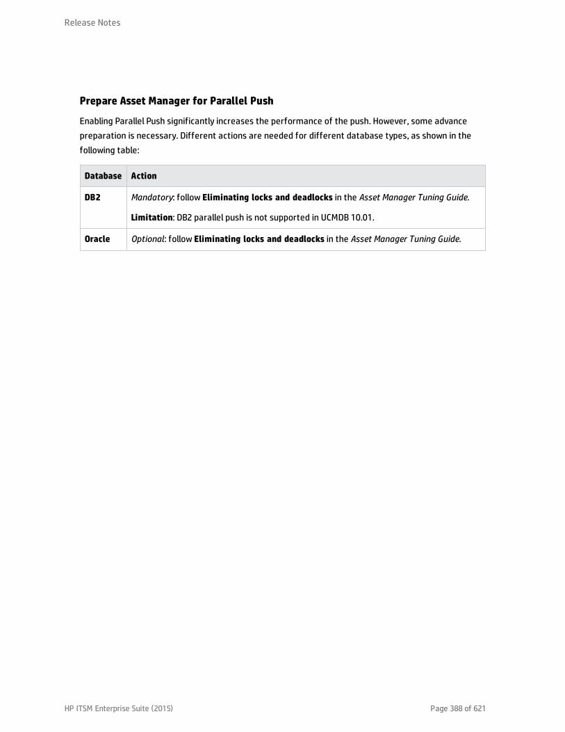
Prepare Asset Manager for Parallel Push
Enabling Parallel Push significantly increases the performance of the push. However, some advancepreparation is necessary. Different actions are needed for different database types, as shown in thefollowing table:
Database Action
DB2 Mandatory: follow Eliminating locks and deadlocks in the Asset Manager Tuning Guide.
Limitation: DB2 parallel push is not supported in UCMDB 10.01.
Oracle Optional: follow Eliminating locks and deadlocks in the Asset Manager Tuning Guide.
Release Notes
HP ITSM Enterprise Suite (2015) Page 388 of 621

Database Action
SQLServer
The following are all mandatory steps:
1. Alter the SQLServer Schema isolation level:
Execute the following command on the database, replacing <AMSchema> with thereal schema name:
ALTER DATABASE <AMSchema> SET READ_COMMITTED_SNAPSHOT ONALTER DATABASE <AMSchema> SET ALLOW_SNAPSHOT_ISOLATION ONGO
Note: If the execution takes too long, you may need to disconnect all connections tothe database. One possible way is to restart the database service, then execute thecommand. If you restart the SQL Server, and an Integration Point has already beencreated in UCMDB, you should restart the UCMDB Probe as well to avoid the issue ofdead connections.
2. Alter Asset Manager database options:
a. Open the Asset Manager Client and connect to the appropriate databaseschema
b. Navigate on the top menus to Administration > Database options
c. For option ‘Sql Server specifics’|‘Isolation command before starting a writetransaction’change the current value to set transaction isolation levelsnapshot
3. Create a table for each of the following counters, to do this, follow the instructionsin the Asset Manager Tuning Guide, Chapter Eliminating locks and deadlocks.
n amAsset_AssetTagn amBrand_BarCoden amModel_BarCoden amModel_ModelRefn amAssignment_Coden amEmplDept_BarCoden amComputer_Groupn amComputer_Domainn amComputer_Vmn amComputer_MDn amComputer_Namen amSoftInstall_Coden amMonitor_Serial
Release Notes
HP ITSM Enterprise Suite (2015) Page 389 of 621

Set Up UCMDB
To set up UCMDB you must complete the following steps:
Create AMPushAdapterAPI Package with Required AM API Files
Note: If you want to create several integrations to different versions of Asset Manager, followthis procedure for each version of Asset Manager you want to integrate to. Otherwise, see "Set UpUCMDB" above.
In order for the adapter to connect to the appropriate Asset Manager version, you must supply the DataFlow Probe/Integration Service with the appropriate Asset Manager API DLLs and Jars, as follows:
1. Copy the files below:
n <Asset Manager Installation folder>\x64\*.dll
n <Asset Manager Installation folder>\websvc\lib\*.jar
2. Create a package called AMPushAdapterAPI_<AM Version Number>.zip. For example, for version9.3 the package is AMPushAdapterAPI_9.3.zip.
3. Paste the copied files to:
<AMPushAdapterAPI_{AM VersionNumber}.zip>\discoveryResources\AMPushAdapter\amVersion\<AM Version Number>
For example, for version 9.3 the path is:
AMPushAdapterAPI_9.3.zip\discoveryResources\AMPushAdapter\amVersion\9.3
4. Add the subfolder AMPushAdapter/amVersion/<AM Version Number>/*.* to theadditionalClasspath property in the globalSettings.xml file.
5. Deploy the AMPushAdapterAPI_<AM Version Number>.zip package.
Install a Database Client
You must install database client software according to the type of database the Asset Manager schemais installed on, as detailed in the following table:
Release Notes
HP ITSM Enterprise Suite (2015) Page 390 of 621

Database Client Software
DB2 1. Download and Install “IBM Data Server Client” 64 bit for windows on your Data FlowProbe/Integration Service computer. This may be downloaded from:
http://www-01.ibm.com/support/docview.wss?rs=4020&uid=swg21385217
2. Create a connection to the DB2 database of Asset Manager.
You may create this using the DB2 Control Center.
Note: Remember the Database Alias you define in the connection, because youneed it when creating the integration point.
3. Copy the db2cli64.dll file from the DB2 client bin directory (By default: C:\ProgramFiles\IBM\SQLLIB\BIN) to the <Data Flow Probe/Integration Service>\lib folder.
4. Restart the Data Flow Probe/Integration Service.
Oracle Oracle client windows 64 bit
For example: Oracle Database 11g Release 2 Client (11.2.0.1.0) for Microsoft Windows(x64).
1. Download the client installation from:
http://www.oracle.com/technetwork/database/enterprise-edition/downloads/index.html
2. Install the client, in Administrator mode, on the Data Flow Probe/Integration Servicecomputer.
3. Copy oci.dll from the <Oracle Client installation directory> into:
<Probe/Integration Service installation directory>\lib.
4. Restart the Data Flow Probe/Integration Service.
SQLServer
None required.
Create an Integration Point in UCMDB
1. Log on to UCMDB as an administrator.
Release Notes
HP ITSM Enterprise Suite (2015) Page 391 of 621

2. Go to Data Flow Management > Integration Studio. UCMDB displays a list of existing integrationpoints.
3. Click the button. The New Integration Point dialog box is displayed.
4. Complete the Integration and Adapter Properties fields as shown in the following table:
Field Required Description
IntegrationName
Yes Type the name (unique key) of the integration point.
IntegrationDescription
No Type a description of the current integration point.
Adapter Yes Select HP Software Products > Asset Manager > Asset ManagerPush Adapter
IsIntegrationActivated
Yes Select this option to indicate the integration point is active.
Hostname/IP Yes Type the hostname or IP Address of the Asset Manager database.
DB Type Yes Select the database type your Asset Manager schema is located on.
DB Port Yes Type the communication port of the Asset Manager Data Base.
DB Name/SID Yes n DB2: type in the name of the Database Alias you defined in thedatabase connection.
n Oracle: type the service name.
n SQL Server: type the name of the schema.
CredentialsID
Yes Select Asset Manager Protocol. To create a new protocol, click the
button. Under Asset Manager Protocol complete:
n Asset Manager User Name: An AM administrator's user name.
n Asset Manager Password: An AM administrator's password.
n DB User Name: The AM database user's name.
n DB Password: The AM database user's password.
Release Notes
HP ITSM Enterprise Suite (2015) Page 392 of 621

Field Required Description
AM Version Yes Select the version of Asset Manager this integration point is toconnect to.
EnableParallel Push
Yes Select to allow parallel (multi-threaded) data push to Asset Manager.This improves performance. Note that you must configure SQL Server& DB2 to support parallel push. See "Prepare Asset Manager forParallel Push".
Data FlowProbe
Yes Select the name of the Data Flow Probe/Integration service used toexecute the synchronization from.
AdditionalProbes
No Select additional probes to use when pushing to AM in order toincrease redundancy.
Defaultowner name
No Not required for this integration point.
Note: This field only appears in a Multi-Tenant Enabled UCMDB.
5. Click Test Connection to make sure there is a valid connection.
6. Click OK.
The integration point is created and its detailed are displayed.
UCMDB creates a default data push job when creating the integration point. If needed you maycreate or edit the existing job. For more information, see "Work with Data Push Jobs" in the HPUniversal CMDB Data Flow Management Guide.
Push CI Data from UCMDB to Asset Manager
Data push jobs copy CI or CI relationship records from your UCMDB system to your Asset Managersystem. To run a data push job, complete the following steps:
1. Log on to UCMDB as an administrator.
2. Go to Data Flow Management > Integration Studio. UCMDB displays a list of existing integrationpoints.
3. Select the integration point you created for Asset Manager.
4. Add a new data push job as follows:
Release Notes
HP ITSM Enterprise Suite (2015) Page 393 of 621

a. Click the button on the right panel.
b. In the Name field, type a unique name for the job.
c. Click the button to add existing TQL queries to the job.
UCMDB Creates a default data push job when creating an integration point.The following tablelists the Topology Query Language (TQL) queries in the default data push job. If required, youmay create, update, or remove TQL queries for the push job. You may also need to update themapping. See "How to Customize an Existing Mapping" on page 418. To access these OOTB TQLqueries for push, go to Modeling > Modeling Studio > Resources, select Queries for ResourceType and then go to Root > Integration > AM Push.
Note: If you want to use cluster with Asset Manager, you must install the latest version ofthe SAM Best Practice package in Asset Manager.
TQL Query Description
AM BusinessElement Push
Pushes Business Applications, Business Services and BusinessInfrastructure CIs.
Mapping XML: pushMappingAMBusinessElement.xml
AM BusinessElementRelations Push
Pushes relationships between Business Elements (pushed by AMBusiness Element Push Query) to other business elements or to nodes.
Business Elements must have been pushed before this TQL querysynchronization in the ‘AM Business Element Push’ TQL querysynchronization.
Nodes must have been pushed before this TQL query synchronization inthe ‘AM Computer Push’ TQL query synchronization.
Mapping XML: pushMappingBeRelations.xml
Release Notes
HP ITSM Enterprise Suite (2015) Page 394 of 621

TQL Query Description
AM ComputerPush
Pushes nodes (Computers, Network Devices, etc.). Also pushes IPs,Interfaces, Disk Devices, Physical Ports, Hardware Boards, DisplayMonitors, CPUs, Printers, Inventory Scanners, File Systems, and Assets.
Minimal attributes for pushing a Node:
o Serial Number
o Vendor or Discovered Vendor
o Model or Discovered Model
o Node Role
Note: These are required values, and depend on the capabilityof the data source to report them.
Mapping XML: pushMappingAMCoumputer.xml
AM ComputerRelations Push
Pushes relationships between Computers to any node (Computers,Network Devices, etc.).
Nodes must have been pushed before this TQL query synchronization inthe ‘AM Computer Push’ TQL query synchronization.
Mapping XML: pushMappingAMComputerRelations.xml
AM Host ServerAnd Running LPARVM RelationsPush
Pushes relationships between Host and Guest (virtualized) systems ofLPAR type. Nodes must have been pushed before this TQL querysynchronization in the 'AM Computer Push' TQL query synchronization.
Mapping XML: pushMappingHostToVMLpar.xml
AM Host ServerAnd RunningSolaris VMRelations Push
Pushes relationships between Solaris Host and Guest (Virtualized)operating systems.
Nodes must have been pushed before this TQL query synchronization inthe ‘AM Computer Push’ TQL query synchronization.
Mapping XML: pushMappingHostToVMSolaris.xml
Release Notes
HP ITSM Enterprise Suite (2015) Page 395 of 621
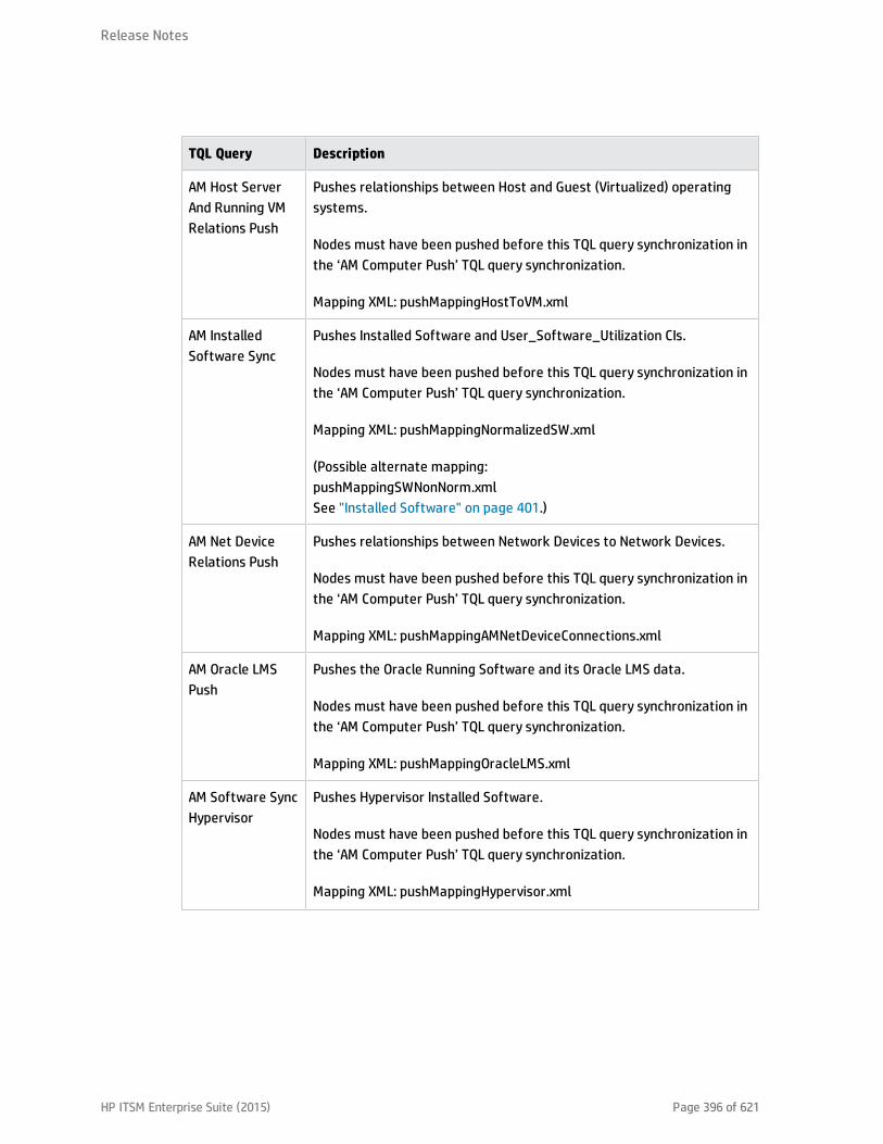
TQL Query Description
AM Host ServerAnd Running VMRelations Push
Pushes relationships between Host and Guest (Virtualized) operatingsystems.
Nodes must have been pushed before this TQL query synchronization inthe ‘AM Computer Push’ TQL query synchronization.
Mapping XML: pushMappingHostToVM.xml
AM InstalledSoftware Sync
Pushes Installed Software and User_Software_Utilization CIs.
Nodes must have been pushed before this TQL query synchronization inthe ‘AM Computer Push’ TQL query synchronization.
Mapping XML: pushMappingNormalizedSW.xml
(Possible alternate mapping:pushMappingSWNonNorm.xmlSee "Installed Software" on page 401.)
AM Net DeviceRelations Push
Pushes relationships between Network Devices to Network Devices.
Nodes must have been pushed before this TQL query synchronization inthe ‘AM Computer Push’ TQL query synchronization.
Mapping XML: pushMappingAMNetDeviceConnections.xml
AM Oracle LMSPush
Pushes the Oracle Running Software and its Oracle LMS data.
Nodes must have been pushed before this TQL query synchronization inthe ‘AM Computer Push’ TQL query synchronization.
Mapping XML: pushMappingOracleLMS.xml
AM Software SyncHypervisor
Pushes Hypervisor Installed Software.
Nodes must have been pushed before this TQL query synchronization inthe ‘AM Computer Push’ TQL query synchronization.
Mapping XML: pushMappingHypervisor.xml
Release Notes
HP ITSM Enterprise Suite (2015) Page 396 of 621

TQL Query Description
AM Cluster Push Pushes Cluster CIs
Nodes must have been pushed before this TQL query synchronization inthe ‘AM Computer Push’ TQL query synchronization.
Mapping XML: pushMappingCluster.xml
AM Cluster NodeRelations Push
Pushes cluster relations between Computer Elements (pushed by AMComputer Push) and Cluster.
Cluster Elements must have been pushed before this TQL querysynchronization in the ‘AM Cluster Push’ TQL query synchronization.
Nodes must have been pushed before this TQL query synchronization inthe ‘AM Computer Push’ TQL query synchronization.
Mapping XML: pushMappingClusterNodeRelations.xml
AM ClusterRunningsoftwarePush
Pushes Cluster Runningsoftware CIs
Nodes must have been pushed before this TQL query synchronization inthe ‘AM Cluster Push’ TQL query synchronization.
Mapping XML: pushMappingClusterRunningsoftware.xml
AM ClusterRunningsoftwareRelations Push
Pushes cluster runningsoftware relations between Computer Elements(pushed by AM Computer Push) and Cluster.
Cluster Runningsoftware Elements must have been pushed before thisTQL query synchronization in the ‘AM Cluster Runningsoftware Push’TQL query synchronization.
Nodes must have been pushed before this TQL query synchronization inthe ‘AM Computer Push’ TQL query synchronization.
Mapping XML: pushMappingClusterRunningsoftwareRelations.xml
d. Select or unselect the Allow Deletion option for each query. (The setting determines if thisTQL query is allowed to delete data from Asset Manager, though the actual action on delete isdefined by CI type in the mapping xml.)
Note: For scheduling configuration, see "How to Schedule Data Push Jobs" on page 399.
Release Notes
HP ITSM Enterprise Suite (2015) Page 397 of 621

e. Click OK.
f. Save the integration point.
5. Run the job manually to see if the integration job works properly:
a. To push all the relevant data for the job, click the button.
b. To push only the changes in the data since the job last executed, click the button.
6. Wait for the job to complete; click the button multiple times as needed until the job is
completed.
7. When the job is completed, the job status becomes one of the following depending on the results:
n Succeeded
n Completed
n Failed
8. Click the Statistics tab to view the results; if any errors occur, click the Query Status tab and JobErrors tab for more information. For more information about errors, see "Troubleshooting andLimitations".
Note: For details about these tabs and managing the integration, see Integration Jobs Pane inthe HP Universal CMDB Data Flow Management Guide .
If the job completes successfully, you can view the UCMDB CI data in Asset Manager.
How to View UCMDB Data in Asset Manager
After a push job is successfully completed, you can search for and verify that the pushed CI/relationshipdata is in Asset Manager.
Nodes
This includes computers, network devices, etc.
To view:
Release Notes
HP ITSM Enterprise Suite (2015) Page 398 of 621

1. Log on to Asset Manager as an administrator.
2. Go to Portfolio Management > Asset Configurations > IT equipment > Computers and virtualmachines.
3. In the opened dialog box, for IP name, type the name of the computer you are searching for.
4. You may use ‘<name prefix>%’ for easier searching. For example, searching IP name for mycomp%returns computer mycomp1, mycomp2, etc.
5. Browse the computer for the different data.
Business Elements
This includes Business Applications, Business Services and Business Infrastructures.
1. Log on to Asset Manager as an administrator.
2. Go to Asset Lifecycle > IT Services and virtualization > Business services > Business services.
3. Browse the different Services.
For more information about viewing data in Asset Manager, see the Asset Manager Documentation.
How to Schedule Data Push Jobs
UCMDB allows you to schedule job executions directly from a data push job.
1. Log on to UCMDB as an administrator.
2. Go to Data Flow Management > Integration Studio. UCMDB displays a list of existing integrationpoints.
3. Select the integration point you created for the UCMDB - AM integration.
4. Select the push job.
5. Click the button.
Note: UCMDB allows you to define two different schedules for two types of data push:
Release Notes
HP ITSM Enterprise Suite (2015) Page 399 of 621
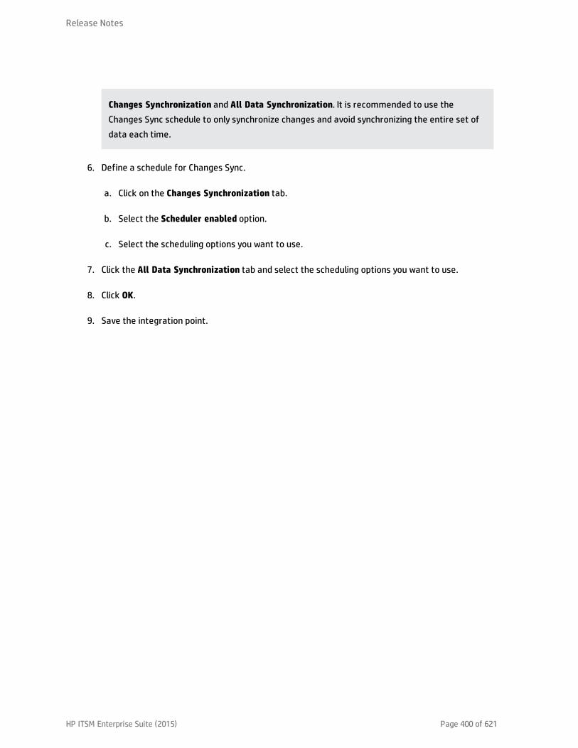
Changes Synchronization and All Data Synchronization. It is recommended to use theChanges Sync schedule to only synchronize changes and avoid synchronizing the entire set ofdata each time.
6. Define a schedule for Changes Sync.
a. Click on the Changes Synchronization tab.
b. Select the Scheduler enabled option.
c. Select the scheduling options you want to use.
7. Click the All Data Synchronization tab and select the scheduling options you want to use.
8. Click OK.
9. Save the integration point.
Release Notes
HP ITSM Enterprise Suite (2015) Page 400 of 621

Installed Software
The Integration supports the following different flows for pushing Installed Software to Asset Manager.You may switch between these flows.
Note: The flows below show a simplified high-level flow of the different Installed Softwaresynchronization behavior. The actual behavior may be more complex in some cases, mainly forperformance improvement. See also "Switching between Installed Software Flows" on page 403.
Normalized Installed Software
This flow uses an InventoryModel to catalog each exact Software Version. Therefore, if the AM Operatordecides to map a certain Software version to a different model, he only has to do it once to theInventory Model, and does not have to process all the Installed Software in AM. This flow allows usingeither the SAI Version ID, or the attributes name, version, and vendor, to correctly reconcile the InstalledSoftware, and uses the information to automatically create Models according to major versions asneeded.
1. Each Installed Software is first mapped to an Inventory Model. If one does not exist, it creates one.The mapping is done according to the SAI Version ID which is an inventory ID from the UniversalDiscovery Scanner, or by using the Installed Software's name, version, and vendor.
2. It then sees if the InventoryModel has a final mapping to a Model. If it is a new InventoryModel, orthe InventoryModel has no final mapping to a Model, it attempts to search for one with the samename and version. If one is found, it connects the InventoryModel to it; otherwise it creates a newModel.
3. It then connects the Installed Software to the Model as well.
Note: Normalized Installed Software is the default flow.
Release Notes
HP ITSM Enterprise Suite (2015) Page 401 of 621

Normalized Installed Software – No Model Creation
This flow uses an InventoryModel to catalog each exact Software Version. Therefore, if the AM Operatordecides to map certain Software version to a different model, he only has to do it once to theInventoryModel, and does not have to process all the Installed Software in AM. This flow does notautomatically create a Model. Instead, the Model must be connected to the InventoryModel by adifferent flow, or manually by an Asset Manager Operator.
1. Each Installed Software is first mapped to an Inventory Model. If one does not exist, it creates one.The mapping is done according to the SAI Version ID, which is an inventory ID from the UniversalDiscovery Scanner, or by using the Installed Software attributes: name, version, and vendor.
2. It then sees if the InventoryModel has a final mapping to a Model. If not, it chooses the temporarymodel (an Unknown Software Model).
3. It then connects the Installed Software to the Model found in the step 2.
4. Later, an Asset Manager Operator manually connects each Inventory Model to a final Model, as hewishes.
Non-Normalized Installed Software
This flow pushes Installed Software and Models only. (It does not map or use the Inventory Models in anyway).
Each Installed Software is mapped to a matching Model which is created if not found.
Release Notes
HP ITSM Enterprise Suite (2015) Page 402 of 621
Switching between Installed Software Flows
Switching to Normalized Installed Software Flow
This is the default flow, enabled OOTB for this integration. If the flow was changed and you would like toreturn to this flow:
l Change the Installed Software push TQL query name (original name: AM Software Push) toAM Installed Software Push.
Switching to Normalized Installed Software – No Model Creation
In Adapter Management, edit am-push-mapping.xml:
1. Go to ci-type="Complete_amModel"
2. Change operation-type to optional_reference
Switching to Non-Normalized Installed Software
Change the Installed Software push TQL query name (original name: AM Installed Software Push) nameto: AM Software Non Norm.
How to Tailor the Integration
This section includes:
l "Integration Architecture" on the next page
l "How to Change Adapter Settings" on page 417
l "How to Customize an Existing Mapping" on page 418
l "How to Add a New Mapping to the Integration" on page 420
Note: For more detailed information about customizing the mapping, see "Developing EnhancedGeneric Push Adapters" in the HP Universal CMDB Developer Reference Guide.
Release Notes
HP ITSM Enterprise Suite (2015) Page 403 of 621

Integration Architecture
This section contains details about the architecture of the integration.
l "Data Flow Architecture" below
l "Integration TQL Queries" on the next page
l "Reconciliation Proposals" on the next page
l "Asset Manager Rules and Flows" on page 406
l "Data Mapping" on page 406
l "Push Mapping" on page 407
Data Flow Architecture
1. The Push Engine executes the TQL query.
2. For a differential flow, the data is compared to the last synchronized data, and only the changesare forwarded.
3. Data is converted into Composite CIs (instances of data according to the TQL Root elements).
4. Data is then pushed to the Push Adapter.
5. The Push Adapter loads the correct mapping for the specific TQL query.
6. All dynamic_mappings are executed and saved to maps, to allow usage in the next mapping stage.
For more information, see "Developing Enhanced Generic Push Adapters" in the HP Universal CMDBDeveloper Reference Guide.
7. Data is mapped from the UCMDB data Model into the AM Data model according to the mappingXML.
8. Data is sent to the AM Connector.
9. AM Connector orders all the data in a set of dependency trees, starting with the records that donot depend on any other record.
Release Notes
HP ITSM Enterprise Suite (2015) Page 404 of 621
10. AM Connector attempts to merge any duplicate records
11. AM Connector starts reconciling and pushing any record without any dependencies, or a recordwhose dependencies have already been reconciled/pushed to Asset Manager.
a. AM Connector first tries to reconcile with existing records
b. If it finds a match, it attempts to update that record,
c. If it does not find a match, it attempts to create a new record.
12. AM Connector deletes any records it is required to delete in AM, as permitted by action-on-delete.
Integration TQLQueries
A TQL query used for the integration must contain a root query node.
Any attribute using in the mapping flow of the Push Adapter must be marked in the selected layout ofthe query node.
Each TQL query may only have one mapping.
For more information, see Data Flow Management > Integration > Integration Studio > IntegrationJobs Pane.
Reconciliation Proposals
When pushing data to Asset Manager, there is an option to create a reconciliation proposal (RP). Areconciliation proposal should be created if there is a change in a specific attribute that may need AMOperator validation or action to support AM business processes.
The OOTB configuration creates a reconciliation proposal record when the memory size of the pushedcomputer has decreased compared to the AM computer.
How to use Reconciliation Proposals
In the OOTB configuration lMemorySizeMb is marked for attribute-reconciliation. The update script callsthe updateMemorySize function. This function verifies if the memory size of the computer wasdecreased. It initializes all the parameters that are passed to the functionvalidateReconcUpdateAdvance. Calls validateReconcUpdateAdvance and return its returned value.
validateReconcUpdateAdvance is a function that returns the value that should be set to the attributeaccording to the Reconciliation Proposal status.The following table describes its parameters:
Release Notes
HP ITSM Enterprise Suite (2015) Page 405 of 621
Parameter Description
AMApiWrapper The wrapper that is used to communicate with the AM.
newVal The value of the attribute in the pushed data.
oldVal The value of the attribute that is retrieved from AM.
recordId The primary key of the table that the attribute belongs to.
strCode The prefix of the code field in the reconciliation proposal.
strName The name of the reconciliation proposal.
path The name of the attribute.
recordTable The table that the attribute belongs to.
validateReconcUpdateAdvancereturns the value that should be set for the attribute, according to theReconciliation Proposal status.
In order to create a reconciliation proposal flow on a different attribute, the following steps must becompleted:
1. Add the <attribute-reconciliation> tag for this attribute.
2. The update-script should call a new function that initializes the parameters passed tovalidateReconcUpdateAdvance, and returns the value returned fromvalidateReconcUpdateAdvance.
Note: It is suggested to use the updateMemorySize function as a reference.
Asset Manager Rules and Flows
Asset Manager has its own set of rules and flows that are enforced by the Asset Manager API. Somecustomizations may need to later these rules and flows as well. For more information, see the AssetManager documentation.
Data Mapping
For details, see Developing Push Adapters in the HP Universal CMDB Developer Reference Guide.
Release Notes
HP ITSM Enterprise Suite (2015) Page 406 of 621

PushMapping
This section includes tables explaining each XML tag and the attributes available for configuration.
l "Basic Information" on the next page
l "Reconciliation" on page 410
l "Target CI Validation" on page 412
l "Reference Attribute" on page 413
l "Attribute Reconciliation" on page 414
l "Action on Delete" on page 415
l "Ignored Attributes" on page 417
Release Notes
HP ITSM Enterprise Suite (2015) Page 407 of 621

Basic InformationAttributes in the <am-mapping> tag.
Attribute Description
ci-type Name used in push adapter mapping to recognize this record type.
primary-key
The primary key column in AM database schema.
operation-type
Defines what operations may be done with the record:
l insert Only allows creation of new records; if it already exists, an exception is thrown.
l update - Only allows updates of an existing record; if it does not exist, an exception isthrown.
l update_else_insert - If the record exists it is updated, otherwise the record iscreated.
l reference-only - The record is only used for referencing by other record (and is notupdated). An exception is thrown if the record does not exist.
l ignore - The record is unaffected by operations.
l insert_else_reference - If the record does not exist, it is created. Otherwise it is onlyused as a reference and is not be updated; see reference-only.
parallel-push-allowed
If enabled with the enabled-parallel-push configuration of the integration point, willattempt to push to the entity with multiple threads in order to increase performance.
merge-allowed
If enabled and this entity is an exact duplicate of another entity in the chunk, it mergesboth entities into one and fixes any relevant references.
errorcode-override
If used together with the adapter specific errors, allows the printing of a customizederror message to the UI if the push or reconciliation of this entity fails.
target-ci-type
Real name of the AM database table to push this record to. If missing , it uses ci-typeinstead.
Release NotesBasic Information
HP ITSM Enterprise Suite (2015) Page 408 of 621

Attribute Description
from-version
Use this mapping only from (and including) this version. The version is taken from theintegration point configuration.
to-version Use this mapping only up to (and including) this version. The version is taken from theintegration point configuration.
Release NotesBasic Information
HP ITSM Enterprise Suite (2015) Page 409 of 621

ReconciliationReconciliation defined for each mapping may include more than one set of reconciliation rules. Whenattempting to reconcile the record with existing ones in the AM database, the AM Connector tries eachof the reconciliation sets until it finds a matching record. Priority is defined by order of reconciliationrules. If no record in the AM database matches this record, an insert operation occurs if the operationtype permits it.
Name Type Description
reconciliation Tag Parent XML tag for all reconciliation configuration.
reconciliation-keys
Tag Represents a single reconciliation rule that may be made of one or moreattributes. All attributes inside the rule must match in order for thereconciliation of this rule to be successful.
reconciliation-key
Tag Represents a single attribute used for reconciliation as part of thereconciliation-keys rule.
Ignore-case Attribute Part of the reconciliation-key tag. Specifies that this attributecomparison ignores case.
reconciliation-advanced
Tag Allows definition of the reconciliation rule by manually defining theWHERE clause of the AQL (Asset Query Language). Uses GString (GroovyString) to generate the replacement String. Any variable or propertydefined in this record or its parent during the mapping stage (in the PushAdapter) may be used as a variable in the GString. (Seehttp://groovy.codehaus.org/Strings+and+GString for more information).
Note: AMPushAdvancesReconciliationException may be throwninside this tag to skip to the next rule.
follow-parent Tag Used for defining overflow tables. See the AM documentation for moreinformation on overflow tables. When using follow-parent, no otherreconciliation may be used as this target CI has a 1:1 connection with itsparent, and it uses the parent reconciliation to push data to AM.
am-prefix Attribute Part of the follow-parent tag. Defines the name that the parent targetCI uses to reference to this table. (To find out the correct value, navigateto AM Application Designer > Edit Links.)
Example:
Release NotesReconciliation
HP ITSM Enterprise Suite (2015) Page 410 of 621

<reconciliation> <reconciliation-advanced>Portfolio.CMDBId = '${if(globalId==null) { throw newcom.hp.ucmdb.adapters.ampush.exception.AMPushAdvancesReconciliationException('Not enough reconciliation data') }else{ return globalId}}' </reconciliation-advanced> <reconciliation-keys> <reconciliation-key ignore-case="true">AssetTag</reconciliation-key> </reconciliation-keys><reconciliation-keys> <reconciliation-key>TcpIpHostName</reconciliation-key> <reconciliation-key>Workgroup</reconciliation-key> </reconciliation-keys></reconciliation>
Release NotesReconciliation
HP ITSM Enterprise Suite (2015) Page 411 of 621
Target CI ValidationThis tag allows the definition of a validation rule that is executed on specific attribute values: the newone held in memory, and the old one stored in the AM database.
The following table shows the attributes of the <target-ci-validation> tag:
Name Description
attribute-name
The attribute that you want to use for validation.
validation-script
A Groovy based script that returns true if this record is to be pushed, and false if it isnot to be pushed. The script may access any external Groovy code in the path in orderto run the evaluation.
l vNewVal - Attribute value of the record in memory.
l vOldVal - Attribute value of the record in the AM database.
failed-validation-error-code
This optional attribute holds the error code that appears if there is a validation failure.
The arguments that can be referenced in the error message are:
l {0} - The validated attribute name.
l {1} - The property value in UCMDB.
l {2} - The property value in Asset |Manager.
l {3} - The validation script.
l {4} - The additional message from the additional-failure-message attribute, or'null' if there is no additional message.
additional-failure-message
This optional attribute holds an additional error message that can be referenced bythe error message in the properties.error file. See failed-validation-error-code,above.
Example:
<target-ci-validation attribute-name="dtLastScan" validation-script="mappings.scripts.AMReconciliationAdvanced.isDateAfter(vNewVal,vOldVal)"/>
Release NotesTarget CI Validation
HP ITSM Enterprise Suite (2015) Page 412 of 621

Reference AttributeA reference attribute defines a column that references another record from a different or same table.This record is not pushed, or reconciled against existing AM database records, until this reference isresolved. Resolved references are replaced by a reference ID that represents the primary ID of thereferenced record.
The following table shows the attributes of the <reference-attribute> tag:
Name Description
ci-name The CI-type of the referenced record.
datatype The value type of the record.
name The column in the current record that is to be populated by the reference ID.
reference-direction
According to the tree created by the Push Adapter, the value specifies if thereferenced record is a parent or child of the current record.
Example:
<reference-attribute ci-name="SW_amModel" datatype="STRING"name="lModelId"reference-direction="child"/>
Release NotesReference Attribute
HP ITSM Enterprise Suite (2015) Page 413 of 621
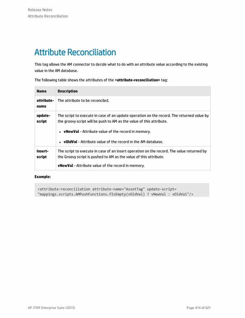
Attribute ReconciliationThis tag allows the AM connector to decide what to do with an attribute value according to the existingvalue in the AM database.
The following table shows the attributes of the <attribute-reconciliation> tag:
Name Description
attribute-name
The attribute to be reconciled.
update-script
The script to execute in case of an update operation on the record. The returned value bythe groovy script will be push to AM as the value of this attribute.
l vNewVal - Attribute value of the record in memory.
l vOldVal - Attribute value of the record in the AM database.
Insert-script
The script to execute in case of an insert operation on the record. The value returned bythe Groovy script is pushed to AM as the value of this attribute.
vNewVal - Attribute value of the record in memory.
Example:
<attribute-reconciliation attribute-name="AssetTag" update-script="mappings.scripts.AMPushFunctions.fIsEmpty(vOldVal) ? vNewVal : vOldVal"/>
Release NotesAttribute Reconciliation
HP ITSM Enterprise Suite (2015) Page 414 of 621

Action on DeleteThis tag allows customization of the behavior on receipt of a delete notification for a record.
Note: No deletion occurs if the Allow Delete option in the job definition is disabled.
The following actions are possible
l <ignore> - Do nothing.
l <delete-ci> - Delete this record from the AM database.
l <set-attribute-value> - Change the value of one or more attributes in the AM database.
Example:
<action-on-delete> <set-attribute-value name="bMissing" datatype="BOOLEAN" value="1"/></action-on-delete>
Release NotesAction on Delete
HP ITSM Enterprise Suite (2015) Page 415 of 621

Enum AttributeThis tag allows a specific enum attribute to be pushed in a serial mode, when the adapter is configuredto push data in parallel mode.
Note: This option exists to prevent duplicate key exceptions occurring when several threads pushthe same enum value.
The following table shows the attributes of the <enum-attribute> tag:
Name Description
attribute-name The enum attribute name.
itemized-name The itemized list format (amOS) of the enum.
Release NotesEnum Attribute
HP ITSM Enterprise Suite (2015) Page 416 of 621

Ignored AttributesThis tag allows specific attributes to be ignored and not pushed to the AM database. This capability iscommonly used with the from-version and to-version attributes or tags, to ignore certain attributes forspecific versions of Asset Manager.
The following table shows the attributes of the <ignored-attributes> tag:
Name Description
from-version
Ignore this attribute only from (and including) this version. The version is taken from theintegration point configuration.
to-version
Ignore this attribute only up to (and including) this version. The version is taken from theintegration point configuration.
Example:
<ignored-attributes> <ignored-attribute>lSeq</ignored-attribute></ignored-attributes>
How to Change Adapter Settings
1. Go to Data Flow Management > Adapter Management > AMPushAdapter > Adapters.
2. Right-click AMPushAdapter and click Edit Adapter Source.
3. Scroll down to the <adapter-settings> tag.
4. Edit the settings as required and click the Save button.
The following table shows the Settings relevant to the AM Push Adapter:
Release NotesIgnored Attributes
HP ITSM Enterprise Suite (2015) Page 417 of 621
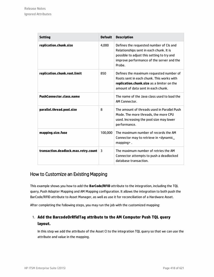
Setting Default Description
replication.chunk.size 4,000 Defines the requested number of CIs andRelationships sent in each chunk. It ispossible to adjust this setting to try andimprove performance of the server and theProbe.
replication.chunk.root.limit 850 Defines the maximum requested number ofRoots sent in each chunk. This works withreplication.chunk.size as a limiter on theamount of data sent in each chunk.
PushConnector.class.name The name of the Java class used to load theAM Connector.
parallel.thread.pool.size 8 The amount of threads used in Parallel PushMode. The more threads, the more CPUused. Increasing the pool size may lowerperformance.
mapping.size.fuse 100,000 The maximum number of records the AMConnector may to retrieve in <dynamic_mapping> .
transaction.deadlock.max.retry.count 3 The maximum number of retries the AMConnector attempts to push a deadlockeddatabase transaction.
How to Customize an Existing Mapping
This example shows you how to add the BarCode/RFID attribute to the integration, including the TQLquery, Push Adapter Mapping and AM Mapping configuration. It allows the integration to both push theBarCode/RFID attribute to Asset Manager, as well as use it for reconciliation of a Hardware Asset.
After completing the following steps, you may run the job with the customized mapping:
1. Add the BarcodeOrRfidTag attribute to the AM Computer Push TQL querylayout.
In this step we add the attribute of the Asset CI to the integration TQL query so that we can use theattribute and value in the mapping.
Release NotesIgnored Attributes
HP ITSM Enterprise Suite (2015) Page 418 of 621
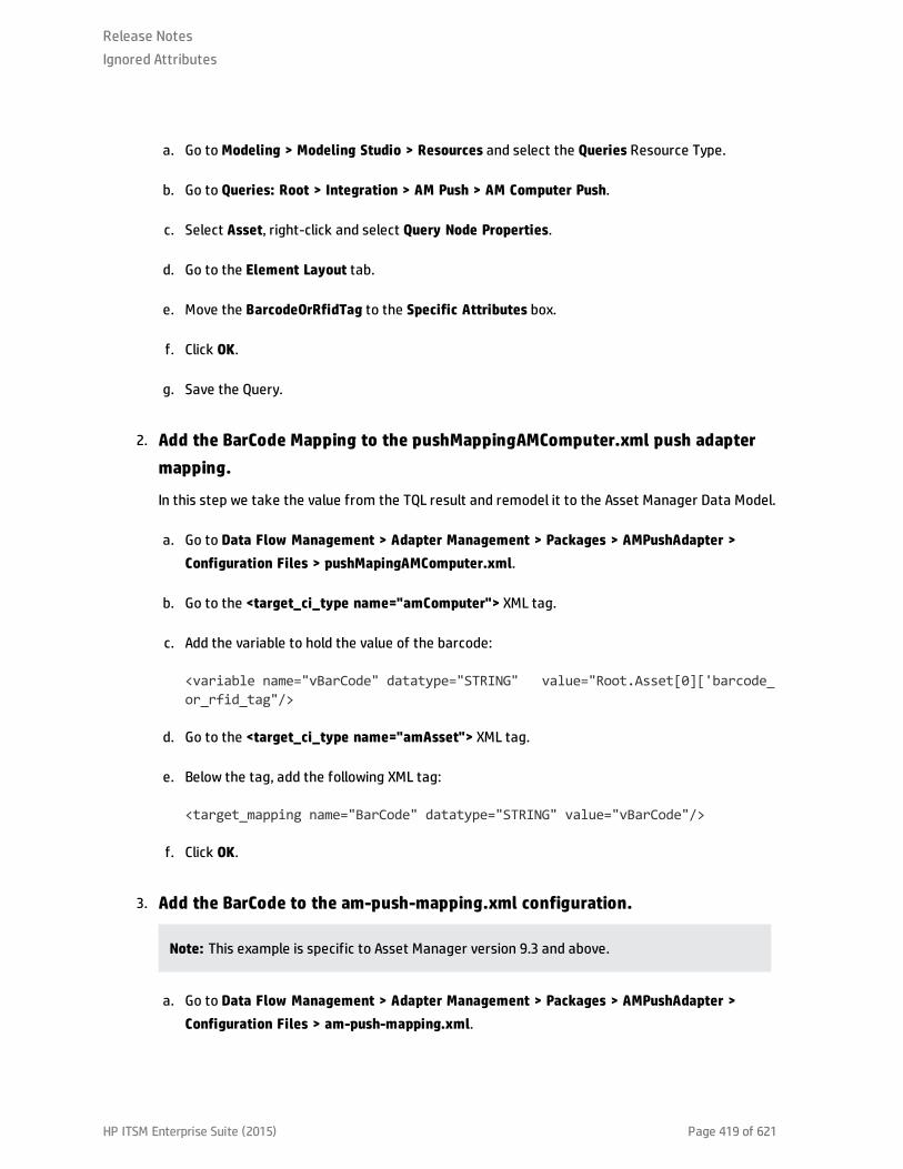
a. Go to Modeling > Modeling Studio > Resources and select the Queries Resource Type.
b. Go to Queries: Root > Integration > AM Push > AM Computer Push.
c. Select Asset, right-click and select Query Node Properties.
d. Go to the Element Layout tab.
e. Move the BarcodeOrRfidTag to the Specific Attributes box.
f. Click OK.
g. Save the Query.
2. Add the BarCode Mapping to the pushMappingAMComputer.xml push adaptermapping.
In this step we take the value from the TQL result and remodel it to the Asset Manager Data Model.
a. Go to Data Flow Management > Adapter Management > Packages > AMPushAdapter >Configuration Files > pushMapingAMComputer.xml.
b. Go to the <target_ci_type name="amComputer"> XML tag.
c. Add the variable to hold the value of the barcode:
<variable name="vBarCode" datatype="STRING" value="Root.Asset[0]['barcode_or_rfid_tag"/>
d. Go to the <target_ci_type name="amAsset"> XML tag.
e. Below the tag, add the following XML tag:
<target_mapping name="BarCode" datatype="STRING" value="vBarCode"/>
f. Click OK.
3. Add the BarCode to the am-push-mapping.xml configuration.
Note: This example is specific to Asset Manager version 9.3 and above.
a. Go to Data Flow Management > Adapter Management > Packages > AMPushAdapter >Configuration Files > am-push-mapping.xml.
Release NotesIgnored Attributes
HP ITSM Enterprise Suite (2015) Page 419 of 621

b. Go to the <am-mapping ci-type=”amComputer” from-version=”9.3”> XML tag.
c. Add the following rule to the advanced reconciliation rule:
<reconciliation-advanced> Portfolio.Asset.BarCode ='${if(vBarCode==null){ throw newcom.hp.ucmdb.adapters.ampush.exception.AMPushAdvancesReconciliationException ('Not enough reconciliation data') }else{ return vBarCode}}'</reconciliation-advanced>
This rule retrieves the computer whose asset has the same barCode value as vBarCode. If theVBarCode is null, an exception is thrown stating that there is insufficient reconciliation data.The exception thrown orders the AM Connector to try the next available reconciliation rule.
d. To avoid overwriting an existing value, add the following to <am-mapping ci-type="amAsset">:
<attribute-reconciliation attribute-name="BarCode" update-script="mappings.scripts.AMPushFunctions.fIsEmpty(vOldVal) ? vNewVal :vOldVal"/>
e. Click OK.
How to Add a New Mapping to the Integration
This example shows how to add a new TQL query, push-mapping, and am-mapping to the integration. Italso shows how to push Locations from UCMDB to Asset Manager. It consists of the following steps:
Step 1: Create a TQL Query
1. Go to Modeling > Modeling Studio > New > Query.
2. From the CI Types tab, add a Location CIT to the query.
3. Right-click the Location Query Node and select Query Node Properties.
4. Rename the Element Name to Root.
5. Go to the Element Layout tab.
Release NotesIgnored Attributes
HP ITSM Enterprise Suite (2015) Page 420 of 621

6. Select Select attributes for layout.
7. In the Attributes condition drop down, select Specific Attributes, and add the following attributes:
a. Name
b. LocationType
c. LocationBarCode
8. Click OK.
9. Save the query to Root > Integration > AM Push > AM Location Push.
Step 2: Create a Push-Mapping
1. Go to Data Flow Management > Adapter Management > AMPushAdapter.
2. Click the button and select New Configuration File.
3. Type the following Name: AMPushAdapter/mappings/hw/pushMappingAMLocation.xml.
4. Select the AMPushAdapter package.
5. Click OK.
6. Copy the following into the newly created XML file:
<integration xmlns:xsi="http://www.w3.org/2001/XMLSchema-instance"xsi:noNamespaceSchemaLocation="/am-push-adapter/src/main/resources/schema/am-push-adapter.xsd"> <info> <source name="UCMDB" versions="10.0" vendor="HP"/> <target name="AssetManager" versions="9.3" vendor="HP"/> </info> <import> <!--Allows the XMLs to use the AMPushFunctions groovy methods--> <scriptFile path="mappings.scripts.AMPushFunctions"/> </import> <targetcis> <!--Query: Location(Root) --> <source_instance_type query-name="AM Location Push" root-element-name="Root" > <!-- Single_amLocation is the name we will refer to this CI in the
Release NotesIgnored Attributes
HP ITSM Enterprise Suite (2015) Page 421 of 621

am-mapping.xml--> <target_ci_type name="Single_amLocation"> <!--Retrieve the LocationBarCode from the Location CI andplace it in the amLocation record--> <!—-‘name’ is the column name in Asset Manager’s table --> <!—-‘datatype’ is the type of the data of this column --> <!—-‘value’ the script to execute in order to retrieve thevalue of this target_mapping--> <target_mapping name="BarCode" datatype="STRING" value="Root['location_bar_code']"/> <target_mapping name="LocationType" datatype="STRING" value="Root['location_type']"/> <target_mapping name="Name" datatype="STRING" value="Root['name']"/><!--Marks the location as created on the fly (So we can distinguish from AMUI created Locations)--> <target_mapping name="bCreatedOnTheFly" datatype="BOOLEAN"value="1"/> </target_ci_type></source_instance_type> </targetcis></integration>
7. Click OK.
Step 3: Create an AM-Mapping
1. Go to Data Flow Management >Adapter Management > AMPushAdapter.
2. Click am-push-mapping.xml.
3. Insert the new mapping:
<!-- 'ci-type' is the name of the ci as appear in the mapping file.'target-ci-type' the actual table name in Asset Managerthis target ci is mapped to -->
<am-mapping ci-type="Single_amLocation" primary-key="lLocaId"target-ci-type="amLocation" operation-type="update_else_insert"parallel-push-allowed="true" from-version="9.3"><reconciliation><reconciliation-keys><!-- The reconciliation of 'location' will be done by thetwo attributes: Name, LocationType.Those are the two identifiers of Location CIT in UCMDB-->
<reconciliation-key>Name</reconciliation-key>
Release NotesIgnored Attributes
HP ITSM Enterprise Suite (2015) Page 422 of 621

<reconciliation-key>LocationType</reconciliation-key></reconciliation-keys>
</reconciliation> <!-- In case the CI has been deleted from the UCMDB, it won't effect the amLocation in Asset Manager --> <action-on-delete> <ignore/> </action-on-delete></am-mapping>
4. Click OK.
Step 4: Create a Job with the New TQL Query
1. Go to Data Flow Management > Integration Studio.
2. Create an integration point with Asset Manager:
a. In the Integration Jobs tab, click the button.
b. Insert a job name in the Name field.
c. Click the button, and choose the AM Location Push query.
d. Click OK.
Step 5: Run the Job
1. Click on the job created in "Step 4: Create a Job with the New TQL Query".
2. Click the button.
3. Wait for the job to finish. You should click the button to see progress.
4. Make sure that the status is Succeeded.
Step 6: View the Results
1. Go to the Asset Manager Client.
Release NotesIgnored Attributes
HP ITSM Enterprise Suite (2015) Page 423 of 621

2. Go to Organization Management > Organization > Location.
3. Validate that the Location pushed in the previous steps is displayed.
Frequently Asked Questions
What is a Root CI node?
A Root node is a TQL node that represents the CI type that is created via the push to Asset Managerfrom the TQL Structures. Usually the rest of the TQL structure contains information that can beincorporated within the Root CI type and is used to enrich the record in Asset Manager. The Root is theheart of the Composite CI (or Instance), and if it is deleted from UCMDB we send a delete notification toAsset Manager for the entire record.
When is a new Asset created in Asset Manager?
In the out of the box integration we create Assets for 4 types of UCMDB CIs:
l Nodes
l Business Elements
l Printers
l Display Monitors
Whenever UCMDB sends a CI of one of these types, the integration first tries to detect if this Assetalready exists in Asset Manager, using the defined reconciliation rules. If a matching Asset is found, it isupdated, otherwise a new Asset is created.
How do I control the action taken when a CI is deleted in UCMDB?
See "Action on Delete" on page 415.
I deleted a Node CI in UCMDB - Why isn’t it deleted in Asset Manager?
The default Action on Delete for nodes in the integration is to do nothing.
You may either change the action to delete the Asset in Asset Manager by changing the<action-on-delete> xml mapping in the am-push-mapping.xml:
<am-mapping ci-type="amComputer" …> …
Release NotesIgnored Attributes
HP ITSM Enterprise Suite (2015) Page 424 of 621

… <action-on-delete> <delete-ci/> </action-on-delete></am-mapping>
Or you may change the action to set the Asset as Missing in Asset Manager by changing the <action-on-delete> xml mapping in the am-push-mapping.xml:
<am-mapping ci-type="amComputer" …> … … <action-on-delete> <set-attribute-value name="Portfolio.seAssignment" datatype="INTEGER"value="6"/> </action-on-delete></am-mapping>
Validate that the Allow Delete check box in the job configuration is selected.
I deleted an Installed Software CI in UCMDB - Why isn’t it deleted in Asset Manager?
The default Action on delete for Installed Software in the integration is to mark it as missing.
You may change the action to delete the Soft Installed in Asset Manager, by changing the<action-on-delete> xml mapping in the am-push-mapping.xml:
<am-mapping ci-type="Complete_amSoftInstall" …> … … <action-on-delete> <delete-ci/> </action-on-delete></am-mapping>
Due to the complexity and amount of flows available for Installed Software you must also change thesemappings to match:
l SW_amSoftInstall
l Complete_amSoftInstall_User
l soft_Hyper_amSoftInstall
l SW_amSoftInstall_User
Release NotesIgnored Attributes
HP ITSM Enterprise Suite (2015) Page 425 of 621

Is it possible to avoid overwriting an attribute in Asset Manager?
Yes. By using the Attribute Reconciliation feature, you choose to never overwrite an existing value.
Example:
<attribute-reconciliation attribute-name="AssetTag" update-script="mappings.scripts.AMPushFunctions.fIsEmpty(vOldVal) ? vNewVal : vOldVal"/>
See "Integration Architecture" on page 404.
What is the different between the mapping XMLs and the am-push-mapping.xml?
The Mapping XMLs (for example: pushMappingAMBusinessElement.xml) define the way we convert thedata from the UCMDB data model into the Asset Manager Data Model and are executed by the PushAdapter.
For more information, see Developing Push Adapters in the HP Universal CMDB Developer ReferenceGuide.
The am-push-mapping.xml is the Asset Manager Connector configuration file. It configures the way wereconcile and handle the data, before we update Asset Manager with the record.
Should I select the ‘Enable Parallel' Feature?
Asset Manager configured over an Oracle database supports parallel push out of the box.
Asset Manager configured over an SQL Server database, needs some tuning before enabling thiscapability. See "Prepare Asset Manager for Parallel Push" on page 388.
Why does an integration point that synchronizes only the AM Installed SoftwarePush TQL query, keep failing?
The AM Installed Software Push TQL query contains both a query node of Installed Software and a querynode of Node. The Node in this mapping is only referenced, and is mapped to Asset Manager by savingits Asset Manager ID from an earlier run. Before pushing this TQL query, the same integration pointmust push the Node to Asset Manager (using the AM Computer Push TQL).
How can I push nodes without Model Name or Serial Number information, to AssetManager?
To avoid pushing nodes not yet fully discovered, we avoid sending ones without a Model Name or SerialNumber that provide us with a physical identification of the Asset. If you would like to push these nodes
Release NotesIgnored Attributes
HP ITSM Enterprise Suite (2015) Page 426 of 621

as well, simply remove the appropriate condition of the node from the AM Computer Push TQL query.
However removing the Node Role condition (filtering nodes without a Node Role) from the TQL query isnot recommended, as the integration will not know what type of an Asset/Portfolio to create in AssetManager.
Troubleshooting and Limitations
l Limitation: A single probe may only connect to one version of Asset Manager. (Use of multipleinstances of the same version is supported). This is due to the JVM limitation of loading only oneAsset Manager API per process.
l Limitation: The out of the box implementation does not support synchronization of mobile devices.
l Limitation: The Data Flow Probe or Integration Service must be installed on a Windows OS.
l Limitation: DB2 parallel push mode is not supported in UCMDB 10.01.
l Problem: Missing DDLs or jars.
When testing the connection of the integration point, an error with the following phrase appears:
Asset Manager DLLs and/or Jars are missing
Solution: See "Create AMPushAdapterAPI Package with Required AM API Files" on page 390
l Problem: First time synchronization has many failed CIs.
The first synchronization in the integration creates a large number of enum values in the AssetManager database. In some cases, when enabling the parallel push for the first synchronization, itmay cause a very large number of deadlocks during the push that is more than the Adapter’s autodeadlock handling mechanism can handle.
Solution 1: You may try to re-synchronize the failed CIs until they all pass.
Solution 2: Add the enum attribute that caused the duplicate key exception to am-mapping in theam-push-mapping.xml.
l Problem: A push integration fails with the error message 'Only one connected Asset CI isallowed'
Release NotesIgnored Attributes
HP ITSM Enterprise Suite (2015) Page 427 of 621

When running a push integration of Computers to Asset Manager, one of the reconciliationattributes used is Asset Tag. If there is more then one Asset CI connected to the Node CI, it meansthere is more then one Asset Tag for a single Node; this is not a valid state.
Solution: Remove the CIT Computer from the incorrect Asset CIs. This should ensure the Node isconnected to either one or no Asset CIs.
l Problem: Some CIs in a Relations Push fail.
The Relations flow (TQL query) assumes that you schedule (either in the same job, or in a differentjob) the different flows that this Relations push depends on, to run before this flow. The followingtable shows the dependencies:
TQL Query Depends On
AM Business ElementPush
AM Business ElementRelations Push
AM Business Element Push and AM Computer Push
Note: If the Asset Manager Business Element is not related tocomputers, AM Business Element Relations Push does notdepend on AM Computer Push.
AM Computer Push
AM Computer RelationsPush
AM Computer Push
AM Host Server AndRunning LPAR VMRelations Push
AM Computer Push
AM Host Server AndRunning Solaris VMRelations Push
AM Computer Push
AM Host Server AndRunning VM RelationsPush
AM Computer Push
AM Installed SoftwarePush
AM Computer Push
Release NotesIgnored Attributes
HP ITSM Enterprise Suite (2015) Page 428 of 621
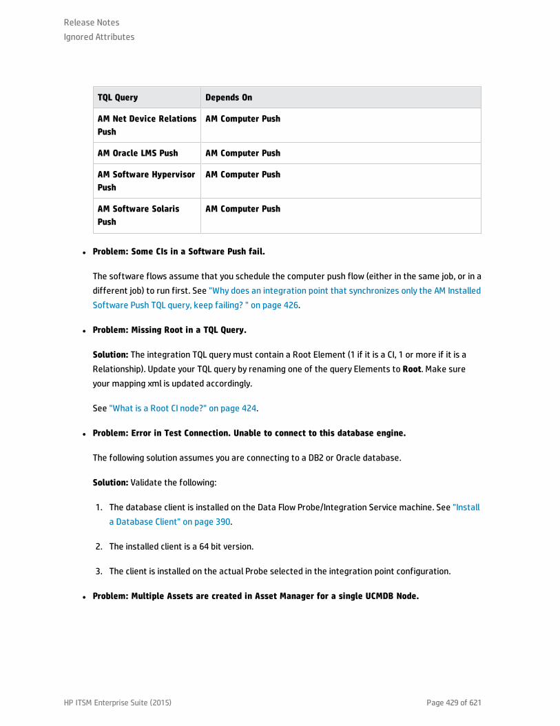
TQL Query Depends On
AM Net Device RelationsPush
AM Computer Push
AM Oracle LMS Push AM Computer Push
AM Software HypervisorPush
AM Computer Push
AM Software SolarisPush
AM Computer Push
l Problem: Some CIs in a Software Push fail.
The software flows assume that you schedule the computer push flow (either in the same job, or in adifferent job) to run first. See "Why does an integration point that synchronizes only the AM InstalledSoftware Push TQL query, keep failing? " on page 426.
l Problem: Missing Root in a TQL Query.
Solution: The integration TQL query must contain a Root Element (1 if it is a CI, 1 or more if it is aRelationship). Update your TQL query by renaming one of the query Elements to Root. Make sureyour mapping xml is updated accordingly.
See "What is a Root CI node?" on page 424.
l Problem: Error in Test Connection. Unable to connect to this database engine.
The following solution assumes you are connecting to a DB2 or Oracle database.
Solution: Validate the following:
1. The database client is installed on the Data Flow Probe/Integration Service machine. See "Installa Database Client" on page 390.
2. The installed client is a 64 bit version.
3. The client is installed on the actual Probe selected in the integration point configuration.
l Problem: Multiple Assets are created in Asset Manager for a single UCMDB Node.
Release NotesIgnored Attributes
HP ITSM Enterprise Suite (2015) Page 429 of 621
Solution 1: This can happen when the maximum length of an attribute is too short compared to theattribute's value in UCMDB. It causes the attribute value to truncate when pushed to Asset Manager.However, on a different execution, when attempting to reconcile the attribute, there will not be amatch because of the truncated value in asset Manager. Therefore, increase the attribute length.See "Update Asset Manager Schema" on page 386.
Solution 2: Check and fix customized or changed reconciliation rules.
l Problem: Error in test connection: Module Ssl : Unable to load dynamic library (libeay64.dll).
This error occurs when the Windows operating system of the probe is missing the Visual C++ 2008SP1 or later.
Solution 1: Download and install the Microsoft Visual C++ 2008 SP1 Redistributable Package (x64).You may download this from:http://www.microsoft.com/download/en/details.aspx?id=2092.
Thereafter, reboot Windows and restart the Probe.
Solution 2: Run Windows update and retrieve the Visual C++ 2008 SP1 or later update. Thereafter,reboot Windows and restart the Probe.
l Problem: Reconciliation gaps when pushing and populating Business Elements usingreconciliation by Global-ID.
Solution: To populate Business Elements using reconciliation by Global-ID, complete the following:
a. Go to Dataflow Management > Adapter Managent > Packages and select AMPushAdapter.
b. Select Configuration Files > pushMappingAMBusinessElement.xml.
c. Replace the file content with the following:
<integration xmlns:xsi="http://www.w3.org/2001/XMLSchema-instance"xsi:noNamespaceSchemaLocation="/am-push-adapter/src/main/resources/schema/am-push-adapter.xsd"><info> <source name="UCMDB" versions="10.0" vendor="HP"/> <target name="AssetManager" versions="9.3" vendor="HP"/></info><import> <scriptFile path="mappings.scripts.AMPushFunctions"/></import><targetcis>
Release NotesIgnored Attributes
HP ITSM Enterprise Suite (2015) Page 430 of 621

<!--Query: BusinessElement(root class = Business Service)(Root) --> <source_instance_type query-name="AM Business Element Push*" root-element-name="Root" > <target_ci_type name="IS_amAsset"> <variable name="globalId" datatype="STRING" value="Root['global_id']"/> <variable name="vAssetTag" datatype="STRING"value="AMPushFunctions.uCase(Root['name'])"/> <target_mapping name="AssetTag" datatype="STRING" value="vAssetTag"/> <target_mapping name="Label" datatype="STRING" value="Root['name']"/> <target_ci_type name="IS_amPortfolio"> <target_mapping name="CMDBId" datatype="STRING" value="globalId"/> <target_ci_type name="IS_amModel"> <target_mapping name="Name" datatype="STRING" value="Root['name']"/> <target_ci_type name="IS_amNature"> <target_mapping name="Code" datatype="STRING" value="'BIZSVC'"/> </target_ci_type> <target_ci_type name="IS_amModel-Parent"> <target_mapping name="BarCode" datatype="STRING"value="AMPushFunctions.getParentBarCodeFromType(Root['root_class'])"/> </target_ci_type> </target_ci_type> </target_ci_type> </target_ci_type> </source_instance_type> </targetcis></integration>
d. Click OK.
e. In the same directory select the am-push-mapping.xml file.
f. Delete the am-mapping of ci-type="IS_amAsset" and replace with the following:
<am-mapping ci-type="IS_amAsset" primary-key="lAstId" operation-type="update_else_insert" target-ci-type="amAsset" merge-allowed="true" parallel-push-allowed="true"> <reconciliation> <reconciliation-advanced>PortfolioItem.CMDBId = '${globalId}'</reconciliation-advanced> <reconciliation-keys> <reconciliation-key ignore-case="true">AssetTag</reconciliation-key> </reconciliation-keys> </reconciliation> <reference-attribute ci-name="IS_amPortfolio" datatype="STRING"name="PortfolioItem" reference-direction="child"/> <attribute-reconciliation attribute-name="AssetTag" update-script="mappings.scripts.AMPushFunctions.fIsEmpty(vOldVal) ? vNewVal :
Release NotesIgnored Attributes
HP ITSM Enterprise Suite (2015) Page 431 of 621

vOldVal"/> <action-on-delete> <delete-ci/> </action-on-delete></am-mapping>
<am-mapping ci-type="IS_amPortfolio" primary-key="lPortfolioItemId" target-ci-type="amPortfolio" operation-type="update_else_insert" parallel-push-allowed="true"> <reconciliation> <follow-parent am-prefix="PortfolioItem"/> </reconciliation> <reference-attribute ci-name="IS_amModel" datatype="STRING" name="lModelId"reference-direction="child"/> <action-on-delete> <delete-ci/> </action-on-delete></am-mapping>
g. Click OK.
Logs
The push adapter framework uses a different logs then the normal fcmdb.adapters.*.log files.
To change the level of the log files to debug, edit the following file:
l On the Data Flow Probe machine:..\DataFlowProbe\conf\log\fcmdb.push.properties
l If using the integration service, on the UCMDB server:..\UCMDB Server\Integrations\conf\log\fcmdb.push.properties
Change the log level to DEBUG:
loglevel=DEBUG
The integration generates fcmdb.push.* logs in the following folder:
l On the Data Flow Probe machine:..\DataFlowProbe\runtime\log\
l If using the integration service, on the UCMDB server:..\UCMDB Server\Integrations\runtime\log\
Release NotesIgnored Attributes
HP ITSM Enterprise Suite (2015) Page 432 of 621

HP Asset Manager Population IntegrationThis chapter includes:
HP ITSM Enterprise Suite (2015) Page 433 of 621

Overview
HP Asset Manager is an asset lifecycle management solution with modular components allowing an ITorganization to measure and communicate the value it provides to the business it supports.
UCMDB-Asset Manager integration is implemented by the Asset Manager adapter (AMAdapter) pullingCIs and relationships from Asset Manager to UCMDB.
Supported Versions
The Asset Manager adapter supports Asset Manager Versions 9.30 and later.
How to Integrate Asset Manager with UCMDB
This task consists of the following steps:
Step 1: Get the adapter content package
1. Log on to UCMDB.
2. Browse to Data Flow Management > Adapter Management.
3. Expand AMAdapter from the resources list.
4. Expand External resources and select AMadapter/Content.zip.
5. Export to the local server and extract all files from Content.zip. The AMdatakit and AMDBUpdatefolders are displayed. AMdatakit is used to sync dtLastModif among amAsset, amPortfolio, andamComputer tables.
Step 2: Activate workflows in AM
1. Log on to Asset Manager Client.
2. On the Tools menu, point to Workflow, click Workflow schemes.
3. Locate the Update dtRecCreation (SQL name: sysCoreUpCrTime) workflow and the Update lastmodify time (SQL name: sysCoreUpMdifyTime) workflow.
4. On the General tab, empty the End field of the Validity pane.
Release Notes
HP ITSM Enterprise Suite (2015) Page 434 of 621

5. Save the changes.
Step 3: Create SQL views in the AM database
Caution: This batch file can only be used on Windows computers, not UNIX computers.
The batch file should be run from a computer where the client layers of the DBMS (for example,Oracle Database 10g Client R2) used for the AM database are installed.
Running this batch file alters the AM database structure.
Administrative privileges are required at the DBMS level to create the SQL views.
1. Set the ORACLE_HOME environment variable.
2. Run the create view script.
a. Click start > Run.
b. Enter cmd.
c. Enter sqlplus <schema name>/<schema password>@<SID_Hostname of oracle server>.
d. Enter GRANT create ANY VIEW to <Username>.
e. Enter GRANT SELECT ANY TABLE to <Username>.
f. Enter GRANT create MATERIALIZED VIEW to <Username>.
g. Enter exit to exit Oracle.
3. Browse to the AMDBupdate folder.
4. If using an Oracle server, run the command CreateViews.bat Oracle <Oracle SID> <Username><Password>; for example, CreateViews.bat Oracle SSG_labm3amdb35 SACM4 topaz.
If using an SQL server, run the command CreateViews.bat [MSSQL2005|MSSQL2008] <Server><Database> <Username><Password>.
5. Confirm all views created in the AM database.
Release Notes
HP ITSM Enterprise Suite (2015) Page 435 of 621

Step 4: Make some CI attributes visible
1. Open a browser and log on to the UCMDB Server as an administrator.
2. From the left navigation bar, select Modeling.
3. Select CI Type Manager and select the CI Type that contains the CI attribute from the navigationtree.
4. On the Attributes tab, double click the attribute you want to modify.
By default, the following CI attributes are not visible:
CI Type Attribute
IpAddress IP Address
IP is DHCP
CPU CPU Speed
5. Select the Advanced tab, and select Visible.
Step 5: Create an integration point
1. Log on to UCMDB.
2. Browse to Data Flow Management > Integration Studio.
3. Click the New Integration Point button.
4. In the New Integration Point dialog box, fill in the following Integration Properties.
Name Recommended Value Description
IntegrationName
AM population Name given to the integrationpoint.
Adapter AM Population and FederationAdapter 9.30 and later versions
Adapter to be used for theintegration point.
Release Notes
HP ITSM Enterprise Suite (2015) Page 436 of 621

Name Recommended Value Description
Is IntegrationActivated
selected Select checkbox to create anactive integration point.
5. In the Adapter Properties, fill in the relevant details.
NameRecommendedValue Description
Hostname/IP <user defined> Enter the hostname or IP address of the database server. ForSQL Server with instance name, enter <hostname>\<instancename>
Port <user defined> Enter the database port default port for Oracle 1521 and SQL1433.
Release Notes
HP ITSM Enterprise Suite (2015) Page 437 of 621

NameRecommendedValue Description
CredentialsID
<user defined> Click the Add new connection details for selected protocol
type button.
Enter the following information:
n In Database Type, select the database type of your AssetManager schema:
o Microsoft SQL Server
o Oracle
o DB2
n In Port Number, type the communication port of the AssetManager Database.
n In Connection Timeout[msec], enter the timeout value setby the schema.
n In User Name, enter the user of the schema.
n In Password, enter the password of the schema.
n In Instance Name/ Database Name:
o DB2: type the name of the Database Alias you defined inthe database connection in Database Name.
o Oracle: type the service name in Instance Name.
o SQL Server: type the name of the schema in InstanceName.
DBName/SID
<user defined> Enter the database name. For Oracle, enter a service nameinstead of the SID.
Release Notes
HP ITSM Enterprise Suite (2015) Page 438 of 621

NameRecommendedValue Description
DB Type <user defined> Select on of the following the database types:
n Oracle
n SQL Server
Push BackIDs
Enabled Identify a unique CI if the feature is disabled and thereconciliation of CIs will not work.
Version <user defined> Version of Asset Manager to access
Data FlowProbe
<user defined> Select the correct Probe from the drop-down list.
6. Click Test connection and OK.
Release Notes
HP ITSM Enterprise Suite (2015) Page 439 of 621

Verify UCMDB to AM Configuration
Note: On first use, run the full population job. After any changes are made, only run the diffpopulation job.
In order to verify Asset Manager to UCMDB Population flow, we create an Asset in Asset Manager, andverify it is synchronized as a configuration item in UCMDB.
1. Log on to Asset Manager.
2. Create a new virtual machine in the IT equipment module, specifying its name and IT equipmenttype (in our case, Virtual Machine).
3. In the Assets view, add the serial number.
4. Log on to UCMDB.
5. Browse to Data Flow Management > Integration Studio.
6. Select the AM Population integration point.
7. In the Integration Jobs pane, select the Population tab and click the AM Population job.
8. Click the Full Synchronization - Runs the selected job, synchronizing all of the data button.
9. When the Confirm synchronizing window appears, click Yes.
10. Click the Refresh button and wait until the Succeeded message appears in the Status tab. Theupdated synchronization status appears.
11. Browse to Modeling > IT Universe Manager.
12. Select the Search CIs tab and search for the name of the virtual machine specified in step 2.
13. Confirm that a corresponding CI exists in UCMDB.
Note: Note its name as it will be used in the next section.
Release Notes
HP ITSM Enterprise Suite (2015) Page 440 of 621

What CI data is populated from AM to UCMDB?
This section describes the CI data that is populated from AM to UCMDB.
Population TQLs
The types of CIs that can be propagated from AM to UCMDB are defined by the following TQLs includedin the integration package.
l locationDataImport_930
This query is used to populate location data from AM.
l hostImport_930
This query is used to populate computer data from AM.
l networkImport_930
This query is used to populate network data from AM.
l printerImport_930
This query is used to populate printer data from AM.
l businessElementDataImport_930
This query is used to populate business service assets from AM.
l businessElementRelationsImport_930
This query is used to build relations between business service assets.
To access these TQLs:
1. Open a browser and connect to the UCMDB Server.
2. Click the Modeling tab.
3. Select Modeling Studio.
4. Click the Resources tab, and select Queries from the Resource Type drop-down list.
Release Notes
HP ITSM Enterprise Suite (2015) Page 441 of 621
5. Expand the Root/Integration/AM Data In menu. The TQLs located under the path are used tomanage CI data synchronization from AM to UCMDB. They have the same structure but managedifferent type of CI data.
Criteria for AM records to be propagated
Step 1: Node CIs
Node CIs in UCMDB correspond to records in the amComputer table in AM.
Out-of-the-box, the amComputer records need to satisfy the following conditions to be propagated toUCMDB as Node CIs:
l The status for the Portfolio Item linked to the amComputer record is in use or in stock(amPortfolio:seAssignment = In use or In stock).
This can be configured by modifying a configuration file (see "condition_rules.xml" on page 456.
l The amComputer:ComputerType field of the amComputer record must have a value that is presentin the third column of the following table.
Release Notes
HP ITSM Enterprise Suite (2015) Page 442 of 621
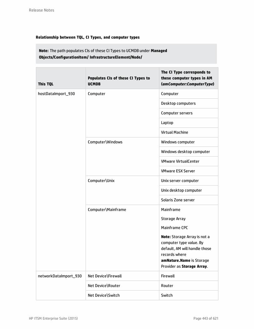
Relationship between TQL, CI Types, and computer types
Note: The path populates CIs of these CI Types to UCMDB under ManagedObjects/ConfigurationItem/ InfrastructureElement/Node/
This TQLPopulates CIs of these CI Types toUCMDB
The CI Type corresponds tothese computer types in AM(amComputer:ComputerType)
hostDataImport_930 Computer Computer
Desktop computers
Computer servers
Laptop
Virtual Machine
Computer\Windows Windows computer
Windows desktop computer
VMware VirtualCenter
VMware ESX Server
Computer\Unix Unix server computer
Unix desktop computer
Solaris Zone server
Computer\Mainframe Mainframe
Storage Array
Mainframe CPC
Note: Storage Array is not acomputer type value. Bydefault, AM will handle thoserecords whereamNature.Name is StorageProvider as Storage Array.
networkDataImport_930 Net Device\Firewall Firewall
Net Device\Router Router
Net Device\Switch Switch
Release Notes
HP ITSM Enterprise Suite (2015) Page 443 of 621

This TQLPopulates CIs of theseCI Types to UCMDB
The CI Type corresponds to these computertypes in AM (amComputer:ComputerType)
networkDataImport_930 Net Device\ATM Switch
Node:
ADSL Modem
Appletalk Gateway
Bandwidth Manager
Cable modem
CSU_DSU
Ethernet
FDDI
HUB
KVM Switch
Load Balancer
Multicast EnabledRouter
NAT Router
Token Ring
Undefined NetworkComponent
VoIP Gateway
VoIP Switch
VPN Gateway
Wireless Access Point,
Frame_relay_switch
San_gateway
San_router
San_switch
Pad_handhel
ATM switch
printerDataImport_930 Net Device\Net Printer Network printer
Release Notes
HP ITSM Enterprise Suite (2015) Page 444 of 621

Note: In addition to the Node CIs, each of the TQLs also populates information (if exists) such as IPaddess, interface, and locations from AM to UCMDB.
l The mapping between CI Type and computer type (value of the amComputer:ComputerTypefield) is defined in the discriminator.properties file (see "discriminator.properties" onpage 453).
Step 2: Business Element
In AM, only those business service asset whose status (amAsset.Status) in the list of built, catalogued,chartered, designed and requested will be populated to UCMDB. If the status is retired, it will beremoved from UCMDB.
Relationship between AM business service asset and CI types:
Nature code CI Type
BIZSVC business_service
BIZAPP business_application
INFRASVC infrastructure_service
What is created in UCMDB during population?
When an amComputer record (with the associated information) is populated from AM to UCMDB:
l A Node CI is created in UCMDB.
Its CI Type depends on the value of the amComputer:ComputerType field.
n Relationship between TQL, CI Types, and computer types.
l For each Networkcard record (amComputer:NetworkCards) attached to the AM Node CI, two CIs arecreated in UCMDB: IP address and Interface.
The values of the following AM amNetworkCard table field are used to create the IPaddress andInterface CIs:
n amNetworkCard:TcpIpAddress, together with other field values, is used to create an IP AddressCI.
Release Notes
HP ITSM Enterprise Suite (2015) Page 445 of 621
n amNetworkCard:PhysAddress, together with other field values, is used to create an Interface CI.
l If the AM amComputer data has an associated location which is comprised of several layers, thenone Location CI is created for each layer of location.
For example, in AM one computer has a location of /Ariane Building/31st Floor/030 – Office/, thenwhen the Node CI for the computer is populated to UCMDB, 3 location CIs are created for each layerin the location, representing the building, floor and room respectively.
Note: The layers of location in AM should be less than the layer defined in the TQL, which bydefault is 3. Otherwise, you need to add elements to the corresponding TQL to support it.
Reconciliation
For each CI Type, the data reconciliation is governed by the reconciliation rule set in UCMDB.
You can check the reconciliation rule for each CI Type on the Details tab of the CI Type. The field name isIdentification.
What happens when changes occur in AM during data population?
l If the value of the amPortfolio:seAssignment field has been changed to a value not present incondition.rules.xml (see "condition_rules.xml" on page 456), the corresponding CI is deleted fromUCMDB with the associated IPAddress CIs (if exists).
l However, if the IT equipment record is deleted from AM, the previously populated CI remains inUCMDB.
Supported CI Types
To find out the CI Types supported by the AM adapter out-of-the-box:
1. Start UCMDB Server.
2. Open a browser and connect to UCMDB Server as administrator.
3. From the left navigation bar, click the Data Flow Management tab.
4. Click Integration Studio.
Release Notes
HP ITSM Enterprise Suite (2015) Page 446 of 621
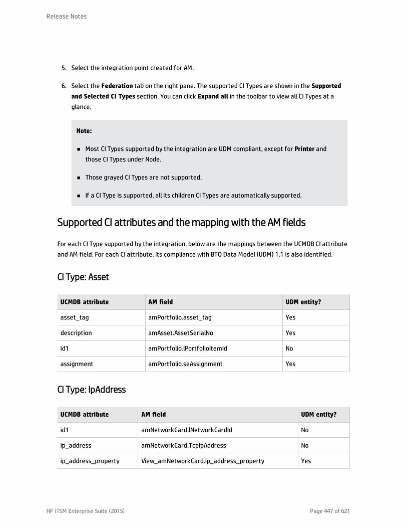
5. Select the integration point created for AM.
6. Select the Federation tab on the right pane. The supported CI Types are shown in the Supportedand Selected CI Types section. You can click Expand all in the toolbar to view all CI Types at aglance.
Note:
n Most CI Types supported by the integration are UDM compliant, except for Printer andthose CI Types under Node.
n Those grayed CI Types are not supported.
n If a CI Type is supported, all its children CI Types are automatically supported.
Supported CI attributes and themapping with the AM fields
For each CI Type supported by the integration, below are the mappings between the UCMDB CI attributeand AM field. For each CI attribute, its compliance with BTO Data Model (UDM) 1.1 is also identified.
CI Type: Asset
UCMDB attribute AM field UDM entity?
asset_tag amPortfolio.asset_tag Yes
description amAsset.AssetSerialNo Yes
id1 amPortfolio.lPortfolioItemId No
assignment amPortfolio.seAssignment Yes
CI Type: IpAddress
UCMDB attribute AM field UDM entity?
id1 amNetworkCard.lNetworkCardId No
ip_address amNetworkCard.TcpIpAddress No
ip_address_property View_amNetworkCard.ip_address_property Yes
Release Notes
HP ITSM Enterprise Suite (2015) Page 447 of 621

UCMDB attribute AM field UDM entity?
ip_address_value View_amNetworkCard.ip_address_value Yes
ip_dhcpdomainname amNetworkCard.DHCPServer No
ip_isdhcp amNetworkCard.BDHCPEnabled No
ip_netmask amNetworkCard.SubnetMask No
name amNetworkCard.TcpIpAddress Yes
CI Type: Node
All the children CIs of the Node CI inherit the same attribute from the Node CI. In particular these CITypes are relevant with the integration:
l Computer
l Windows
l Unix
l Mainframe
l Firewall
l Router
l Switch
l ATM Switch
l Net Printer
UCMDB attribute AM field UDM entity?
asset_tag amPortfolio.AssetTag Yes
create_time amPortfolio.dtRecCreation Yes
data_externalid amComputer.lComputerId No
data_note amPortfolio.seAssignment No
default_gateway_ip_address amNetworkCard.DefaultGateway Yes
Release Notes
HP ITSM Enterprise Suite (2015) Page 448 of 621
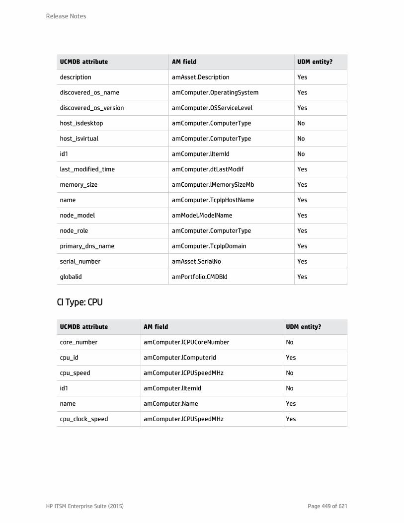
UCMDB attribute AM field UDM entity?
description amAsset.Description Yes
discovered_os_name amComputer.OperatingSystem Yes
discovered_os_version amComputer.OSServiceLevel Yes
host_isdesktop amComputer.ComputerType No
host_isvirtual amComputer.ComputerType No
id1 amComputer.lItemId No
last_modified_time amComputer.dtLastModif Yes
memory_size amComputer.lMemorySizeMb Yes
name amComputer.TcpIpHostName Yes
node_model amModel.ModelName Yes
node_role amComputer.ComputerType Yes
primary_dns_name amComputer.TcpIpDomain Yes
serial_number amAsset.SerialNo Yes
globalid amPortfolio.CMDBId Yes
CI Type: CPU
UCMDB attribute AM field UDM entity?
core_number amComputer.lCPUCoreNumber No
cpu_id amComputer.lComputerId Yes
cpu_speed amComputer.lCPUSpeedMHz No
id1 amComputer.lItemId No
name amComputer.Name Yes
cpu_clock_speed amComputer.lCPUSpeedMHz Yes
Release Notes
HP ITSM Enterprise Suite (2015) Page 449 of 621
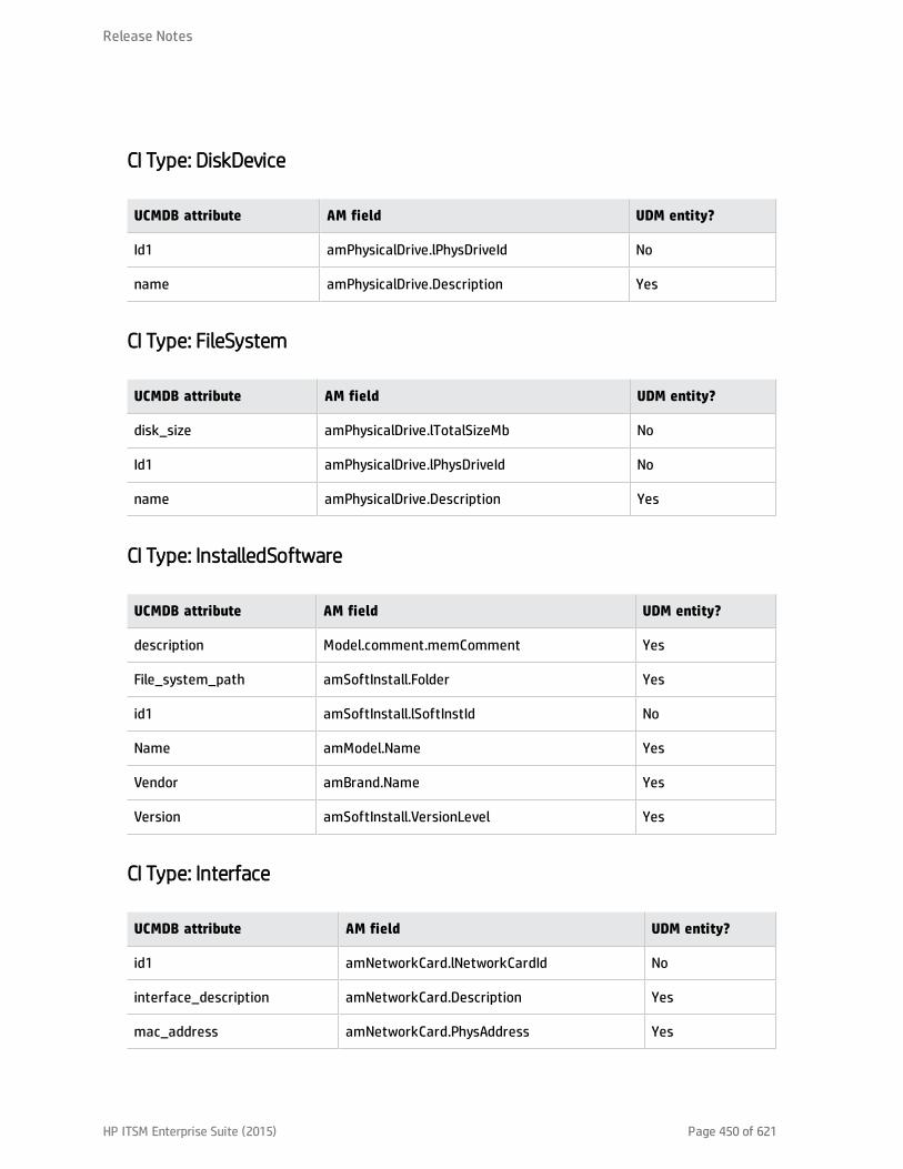
CI Type: DiskDevice
UCMDB attribute AM field UDM entity?
Id1 amPhysicalDrive.lPhysDriveId No
name amPhysicalDrive.Description Yes
CI Type: FileSystem
UCMDB attribute AM field UDM entity?
disk_size amPhysicalDrive.lTotalSizeMb No
Id1 amPhysicalDrive.lPhysDriveId No
name amPhysicalDrive.Description Yes
CI Type: InstalledSoftware
UCMDB attribute AM field UDM entity?
description Model.comment.memComment Yes
File_system_path amSoftInstall.Folder Yes
id1 amSoftInstall.lSoftInstId No
Name amModel.Name Yes
Vendor amBrand.Name Yes
Version amSoftInstall.VersionLevel Yes
CI Type: Interface
UCMDB attribute AM field UDM entity?
id1 amNetworkCard.lNetworkCardId No
interface_description amNetworkCard.Description Yes
mac_address amNetworkCard.PhysAddress Yes
Release Notes
HP ITSM Enterprise Suite (2015) Page 450 of 621
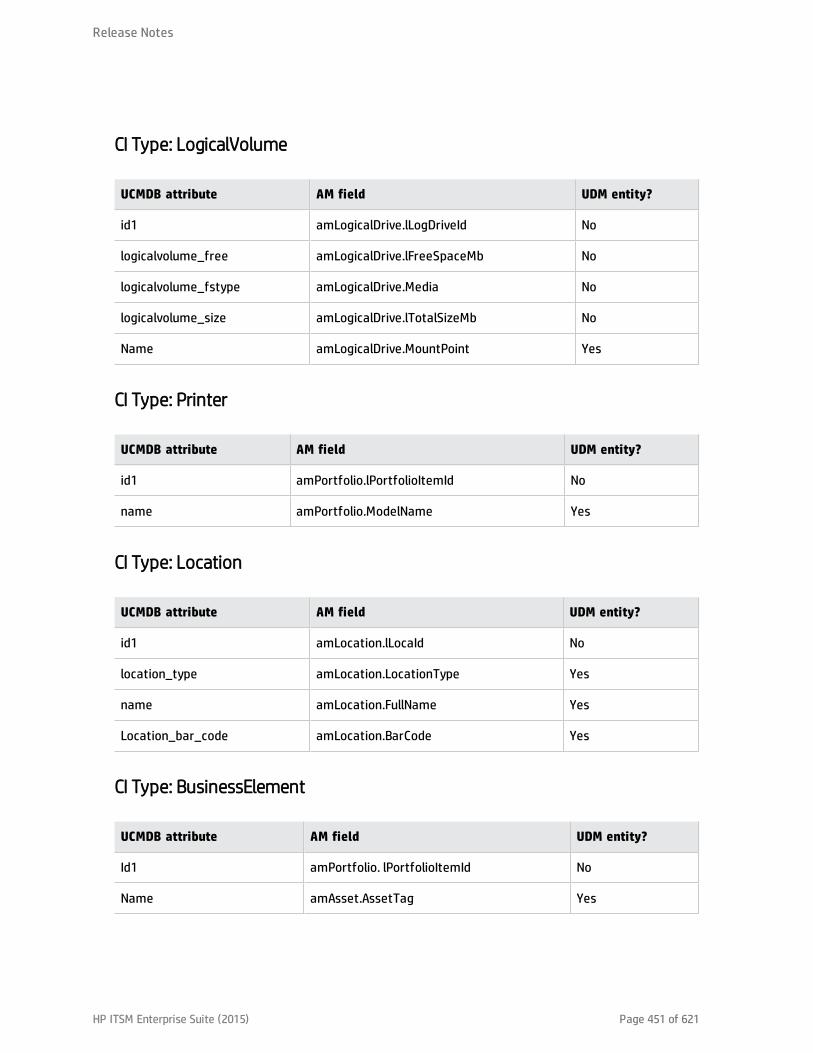
CI Type: LogicalVolume
UCMDB attribute AM field UDM entity?
id1 amLogicalDrive.lLogDriveId No
logicalvolume_free amLogicalDrive.lFreeSpaceMb No
logicalvolume_fstype amLogicalDrive.Media No
logicalvolume_size amLogicalDrive.lTotalSizeMb No
Name amLogicalDrive.MountPoint Yes
CI Type: Printer
UCMDB attribute AM field UDM entity?
id1 amPortfolio.lPortfolioItemId No
name amPortfolio.ModelName Yes
CI Type: Location
UCMDB attribute AM field UDM entity?
id1 amLocation.lLocaId No
location_type amLocation.LocationType Yes
name amLocation.FullName Yes
Location_bar_code amLocation.BarCode Yes
CI Type: BusinessElement
UCMDB attribute AM field UDM entity?
Id1 amPortfolio. lPortfolioItemId No
Name amAsset.AssetTag Yes
Release Notes
HP ITSM Enterprise Suite (2015) Page 451 of 621

UCMDB attribute AM field UDM entity?
last_modified_time amPortfolio.dtLastModif Yes
create_time amPortfolio.dtRecCreation Yes
description amAsset.Description Yes
data_note amAsset.Status No
global_id amPortfolio.CMDBId Yes
Release Notes
HP ITSM Enterprise Suite (2015) Page 452 of 621

The configuration files used by the integration
This section describes the configuration files used by the integration.
Where are the configuration files located
The configuration files that are relevant with the integration are located in the following path in UCMDB:
Data Flow Management\Adapter Management\AMAdapter\Configuration Files
discriminator.properties
When a CI is populated to UCMDB, its CI Type is defined according to the value ofamComputer:ComputerType in AM.
This file defines the mapping between the values of amComputer:ComputerType and the UCMDB CIType.
A summary of the mapping can be found at the following location: "What CI data is populated from AMto UCMDB?" on page 441.
server_virtual_distinguisher.properties
When a CI is populated to UCMDB, the Host is Virtual attribute of the CI is defined according to thevalue of amComputer:ComputerType for the CI in AM.
This file defines the mapping between the values of amComputer:ComputerType and the Host isVirtual attribute.
If the value of amComputer:ComputerType in AM is... the value of Host is Virtual in UCMDB is...
Virtual Machine Virtual Machine
Release Notes
HP ITSM Enterprise Suite (2015) Page 453 of 621

If the value of amComputer:ComputerType in AM is... the value of Host is Virtual in UCMDB is...
l Windows computer
l Windows desktop computer
l VMware Virtual Center
l VMware ESX server
l Unix server computer
l Unix desktop computer
l Solaris Zone Server
l Desktop computers
l Computer servers
l Laptop
l Mainframe
l ATM switch
l Firewall
l Router
l Switch
l Network printer
No
server_desktop_distinguisher.properties
When a CI is populated to UCMDB, the Host is Desktop attribute of the CI is defined according to thevalue of amComputer:ComputerType for the CI in AM.
Release Notes
HP ITSM Enterprise Suite (2015) Page 454 of 621
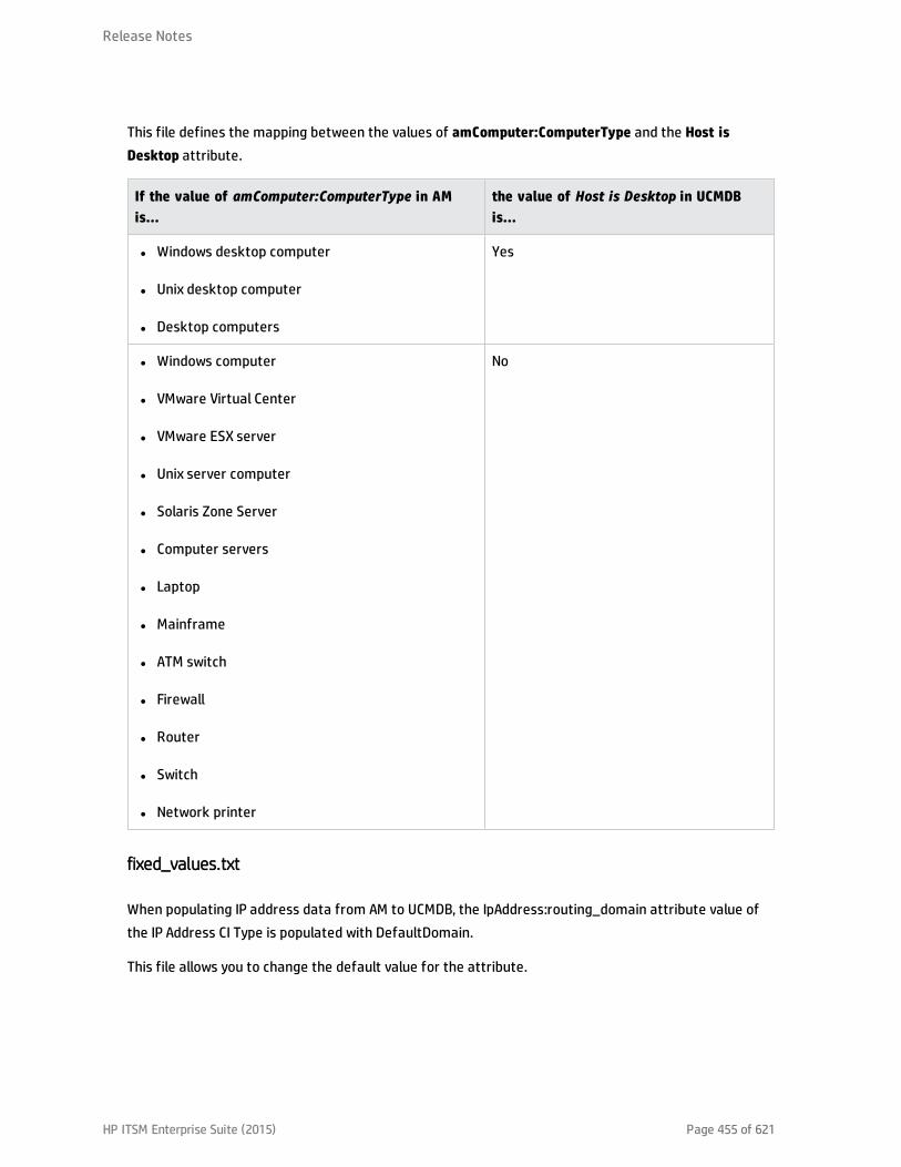
This file defines the mapping between the values of amComputer:ComputerType and the Host isDesktop attribute.
If the value of amComputer:ComputerType in AMis...
the value of Host is Desktop in UCMDBis...
l Windows desktop computer
l Unix desktop computer
l Desktop computers
Yes
l Windows computer
l VMware Virtual Center
l VMware ESX server
l Unix server computer
l Solaris Zone Server
l Computer servers
l Laptop
l Mainframe
l ATM switch
l Firewall
l Router
l Switch
l Network printer
No
fixed_values.txt
When populating IP address data from AM to UCMDB, the IpAddress:routing_domain attribute value ofthe IP Address CI Type is populated with DefaultDomain.
This file allows you to change the default value for the attribute.
Release Notes
HP ITSM Enterprise Suite (2015) Page 455 of 621

location_type_transformer.xml
This file contains all the mappings between location types in AM and UCMDB. Mapping for a location typeis represented by an entry like this:
<value cmdb-value= "room" external -db-value="room"/>
The UCDMB location type is the value for the cmdb-value attribute, while the AM location type is thevalue for the external-db-value attribute.
All the AM location types must be mapped with those in UCMDB for the data population to be successful.
condition_rules.xml
Out-of-the-box, this file defines the basic rules to decide what kind of CIs can be populated from AM toUCMDB and remove CIs from UCMDB.
Out-of-the-box, only amComputer records whose associated Portfolio Item is in stock(amPortfolio:seAssignment = In stock) can be populated to UCMDB as Node CIs.
This file allows you to customize the assignments (amPortfolio:seAssignment) computers could havefor them to be populated.
This configuration file uses values stored in the AM database to designate the value of theseAssignment field. Refer to the following table for the relationship between the value stored in thedatabase and the displayed value.
Value stored in the displayed Actual displayed text for seAssignment
0 In use
1 In stock
2 Retired
3 Awaiting receipt
4 Return for maintenance
5 Return to supplier
6 Missing
You can designate multiple values in this file to allow populating computers with different assignmentsto UCMDB.
Release Notes
HP ITSM Enterprise Suite (2015) Page 456 of 621
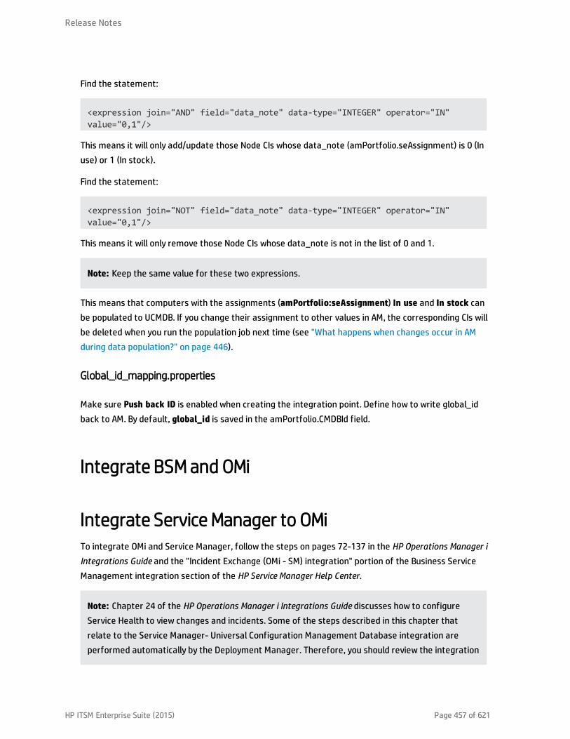
Find the statement:
<expression join="AND" field="data_note" data-type="INTEGER" operator="IN"value="0,1"/>
This means it will only add/update those Node CIs whose data_note (amPortfolio.seAssignment) is 0 (Inuse) or 1 (In stock).
Find the statement:
<expression join="NOT" field="data_note" data-type="INTEGER" operator="IN"value="0,1"/>
This means it will only remove those Node CIs whose data_note is not in the list of 0 and 1.
Note: Keep the same value for these two expressions.
This means that computers with the assignments (amPortfolio:seAssignment) In use and In stock canbe populated to UCMDB. If you change their assignment to other values in AM, the corresponding CIs willbe deleted when you run the population job next time (see "What happens when changes occur in AMduring data population?" on page 446).
Global_id_mapping.properties
Make sure Push back ID is enabled when creating the integration point. Define how to write global_idback to AM. By default, global_id is saved in the amPortfolio.CMDBId field.
Integrate BSM and OMi
Integrate Service Manager to OMiTo integrate OMi and Service Manager, follow the steps on pages 72-137 in the HP Operations Manager iIntegrations Guide and the "Incident Exchange (OMi - SM) integration" portion of the Business ServiceManagement integration section of the HP Service Manager Help Center.
Note: Chapter 24 of the HP Operations Manager i Integrations Guide discusses how to configureService Health to view changes and incidents. Some of the steps described in this chapter thatrelate to the Service Manager- Universal Configuration Management Database integration areperformed automatically by the Deployment Manager. Therefore, you should review the integration
Release Notes
HP ITSM Enterprise Suite (2015) Page 457 of 621

configuration carefully before proceeding.
Note: The following sections are excerpted from the integrations section of the Service ManagerHelp Center. However, to ensure you have the latest information, you should reference the latestpublished version of the document in question.
Incident Exchange (OMi - SM) integrationThe Incident Exchange (OMi - SM) integration is a bidirectional integration between incident records inHP Service Manager and events in HP Business Service Management (BSM) Operations Managementprovided by the Operations Manager i (OMi) license.
This integration requires configurations on both product sides. For details, see "Incident Exchange (OMi -SM) integration setup" on the next page.
Note: As of version 9.34, ITSM Enterprise Suite can integrate with multiple BSM OMi servers. Fordetails, see "Add an integration instance for each Operations Manager i (OMi) server" on page 467.
Service Manager can accept RESTful-based requests from OMi to create incidents in Service Manager,based on events information in OMi. When Service Manager accepts an incident creation request from aremote OMi server, it creates an incident record and automatically assigns it to an existing group basedon certain field values. Incident Management users can view the details of the related OMi event byclicking the View OMi Event menu option from the incident record. See "View related OMi event detailsfrom an incident" on page 479.
When an Incident Management user makes any changes to the incident record, Service Managerautomatically synchronizes the changes to the corresponding event in OMi, by sending an updaterequest to the OMi RESTful web service interface. In the event of a synchronization failure, a queuingmechanism will re-synchronize the changes. See "Synchronization of incident changes back toOperations Manager i (OMi)" on page 478.
System administrators can configure global settings that determine whether and when incident recordsopened from OMi events can be automatically closed. However, Incident Management users can markindividual OMi incident records as eligible or ineligible for automatic closure. See "Configure automaticclosure for OMi incidents" on page 474 and "Mark an incident for automatic closure" on page 480.
Release Notes
HP ITSM Enterprise Suite (2015) Page 458 of 621

Incident Exchange (OMi - SM) integration setup
The Incident Exchange (OMi - SM) integration requires the following configuration tasks be completedon the HP Service Manager and Business Service Management (BSM) systems.
1. "Create user accounts for the Incident Exchange (OMi - SM) integration" on the next page.
This task creates a user account on each product side for the two systems to connect to eachother and to synchronize data.
2. "Configure an event forwarding rule in Operations Manager i (OMi) " on page 464.
This task configures a rule for the OMi server to forward events to the Service Manager server.
3. "Configure the Service Manager server as a connected server in Operations Manager i (OMi)" onpage 461.
Perform this task in BSM OMi. If you need to integrate ITSM Enterprise Suite with more than oneOMi server, perform this task on each of the OMi servers.
4. "Enable incident drill-down from Operations Manager i (OMi) Event Browser" on page 465.
This task configures the Service Manager web tier in the sm:ServiceManagerAdapter script in OMi.
5. "Configure SSL for the Incident Exchange (OMi - SM) integration " on page 465.
This task is needed if your OMi server requires HTTPS connections. If SSL is not configured in thiscase, changes on incidents that are created from OMi will not be able to be synchronized back toOMi.
6. "Configure the Instance Count in the SMOMi integration template" on page 466.
This task is needed only when you have more than one OMi server. The Instance Count settingdefines the allowed number of SMOMi integration instances in Service Manager (default: 1).
7. "Add an integration instance for each Operations Manager i (OMi) server" on page 467.
This task creates and enables an instance of this integration in Integration Manager (SMIS). Aseparate integration instance is required for each OMi server.
8. "Enable LW-SSO for the Incident Exchange (OMi - SM) integration" on page 473.
Release Notes
HP ITSM Enterprise Suite (2015) Page 459 of 621

Lightweight Single Sign-On (LW-SSO is) optional but recommended for the Incident Exchange (OMi -SM) integration. This task includes enabling LW-SSO in the Service Manager server and Web tier, aswell as in BSM.
9. (Optional) "Configure automatic closure for OMi incidents" on page 474.
This task is optional. By default, automatic closure is disabled for OMi incidents. Systemadministrators can enable automatic closure and further configure under what conditions OMiincidents can be automatically closed.
10. (Optional) "Change the default assignment group for OMi incidents" on page 477.
This task is optional. When created, OMi incidents are automatically assigned with an assignmentgroup based on their certain field values and a predefined default assignment group. SystemAdministrators can change the default assignment group setting ( Application).
Create user accounts for the Incident Exchange (OMi - SM) integration
Applies to User Roles:
System Administrator
The Incident Exchange (OMi - SM) integration is bidirectional. Synchronizing events and incidentsbetween the HP Service Manager and BSM OMi systems requires integration accounts be set up for thetwo systems to access each other.
1. Create an operator record with system administration privileges in Service Manager.
This is the user account that the OMi server uses to access Service Manager and to forward eventsto Service Manager.
Later, when configuring the Service Manager server as a connected server in OMi, you need tospecify this operator's the login name and password on the Outgoing Connection tab. See"Configure the Service Manager server as a connected server in Operations Manager i (OMi)" on thenext page.
2. Create a user account with system administration privileges on each BSM OMi server. For details,see the BSM online help.
This is the user account that Service Manager uses to access the OMi server and to synchronizeincident changes back to the OMi server.
Release Notes
HP ITSM Enterprise Suite (2015) Page 460 of 621

Later, when configuring the Service Manager server as a connected server in OMi, you must specifythis user's login name as the Name of the Service Manager server on the General tab, and specifythis user's password as the Password on the Incoming Connection tab. See "Configure the ServiceManager server as a connected server in Operations Manager i (OMi)" below.
Also, you need to specify the same user account when adding an SMOMi integration instance foreach OMi server (the username and Password parameters). See "Add an integration instance foreach Operations Manager i (OMi) server" on page 467.
Configure the Service Manager server as a connected server in OperationsManager i (OMi)
Synchronizing changes between HP Business Service Management (BSM) Operations Managementevents and HP Service Manager incidents requires configuring a Connected Server within OMi tocorrectly identify the target Service Manager server instance.
To configure the Service Manager server as a target connected server, perform the following steps:
1. Log on to HP Business Service Management as a system administrator.
2. Navigate to the Connected Servers manager in the Operations Management user interface:
Admin > Operations Management > Setup > Connected Servers
3. Click the New button to open the Create New Server Connection dialog box.
4. In the Display Name field, enter a name for the Service Manager server.
The Name field is filled automatically. If the auto-completed value is not the user name of the BSMuser account you created for Service Manager to access the OMi server, change the value to thecorrect user name. See "Create user accounts for the Incident Exchange (OMi - SM) integration" onthe previous page.
Make a note of the Name of the new target server. You need to provide it later on as the usernamewhen configuring the Service Manager server to communicate with the OMi server. See "Add anintegration instance for each Operations Manager i (OMi) server" on page 467.
Optionally, enter a description for the new target server.
Make sure that you check the Active check box.
Release Notes
HP ITSM Enterprise Suite (2015) Page 461 of 621

Click Next.
5. Select External Event Processing to choose the server type suitable for an external incidentmanager like Service Manager.
Click Next.
6. Enter the Fully Qualified DNS Name of the target Service Manager server.
Click Next.
7. In the Integration Type dialog box, you can choose between using a Groovy script adapter, or theEvent Synchronization Web Service.
a. As an HP Service Manager Groovy script adapter is provided for integrating with ServiceManager, select Call Script Adapter.
b. In the Script Name field, select sm:ServiceManagerAdapter.
c. Click Next.
8. In the Outgoing Connection dialog, enter the credentials (user name, password, and port number)to connect to the Service Manager server and to forward events to that server.
a. In the User Name and Password fields, enter the Service Manager user credentials you createdfor the integration. See "Create user accounts for the Incident Exchange (OMi - SM)integration" on page 460.
b. Repeat the password entry in the Password (Repeat) field.
c. In the Port field, enter the communications port of the Service Manager server.
The Service Manager server configuration file (sm.ini) defines the http and http ports. Enterthe http port when Service Manager is running in http mode, or enter the https port when it isrunning in secure http mode.
Tip: Clicking Set default port automatically populates the Port field with the default port(13080 for http or 13443 for secure http). However, your actual Service Manager portsmay differ from the default values.
d. If the Service Manager server uses secure http (SSL) mode, select the Use Secure HTTP check
Release Notes
HP ITSM Enterprise Suite (2015) Page 462 of 621

box. If it uses http mode, make sure the check box is not checked.
e. If the Use Secure HTTP check box is selected, download and install a copy of the ServiceManager server’s SSL certificate by clicking the link Retrieve from Server, or Import from Fileif the certificate is available in a local file.
f. Make sure that the Enable Synchronize and Transfer Control check box is checked.
When the Enable Synchronize and Transfer Control flag is set, an Operations Managementoperator is then able to transfer ownership of the event to the target connected server. If theflag is not set, then the option Synchronize and Transfer Control does not appear in the list offorwarding types when configuring forwarding rules.
Also, note that if the Enable Synchronize and Transfer Control flag is not set for any targetconnected server, the Transfer Control to option does not appear at all in the Event Browsercontext menu.
If a specific server is configured without the Enable Synchronize and Transfer Control flagset, then that server is not available in the Event Browser context menu as a server to whichyou can transfer ownership.
g. Click Test Connection. A Success or ERROR hyperlink appears.
Click the link to get a more detailed message.
h. Click Next.
9. If, in addition to automatically generating Service Manager incidents from OMi events, you want toalso be able to drill-down into Service Manager, you need to specify the fully qualified DNS nameand port of the Service Manager web application server (for example, Tomcat).
Note: To enable incident drill-down to Service Manager, you must have the Service Managerweb tier deployed on a web application server.
In the Event Drilldown dialog box, configure the Fully Qualified DNS Name and Port of the webapplication server where the Service Manager web tier is deployed.
Note: If you do not specify a server in the Event Drilldown dialog box, it is assumed that theweb tier is deployed on the same machine as the Service Manager server.
Release Notes
HP ITSM Enterprise Suite (2015) Page 463 of 621

Click Next.
10. The next thing to do is to enable event changes to be synchronized back from Service Manager toOMi. For this you need to provide credentials for the Service Manager server to access the OMiserver in the Incoming Connection dialog box.
a. Select the Accept event changes from external processing server check box.
Note: If Enable Synchronize and Transfer Control was previously selected, the Acceptevent changes from external processing server option is assumed, and cannot bedisabled.
b. Enter the password of the user account that you created for the Service Manager server toaccess the OMi server. See "Create user accounts for the Incident Exchange (OMi - SM)integration" on page 460.
c. Make sure the User Name (auto-generated) matches the one of the user account you created.If not, click the General tab, and change the Name field to the correct value.
d. Click Finish. The target Service Manager server appears in the list of Connected Servers.
Configure an event forwarding rule in Operations Manager i (OMi)
Once you have configured the HP Service Manager server as a connected server in HP Business ServiceManagement (BSM) Operations Management i (OMi), you need to configure an event forwarding rule forthe OMi server to forward events to Service Manager.
1. Log on to BSM as a system administrator.
2. Navigate to Admin > Operations Management > Event Automation.
3. Click the New Item button.
4. In the Display Name field, enter a name for the rule. For example, smserver1.
5. In the Event Filter field, select Critical.
6. In the Target Servers field, select the Service Manager server you configured as a connectedserver, and then click the Add button.
Release Notes
HP ITSM Enterprise Suite (2015) Page 464 of 621
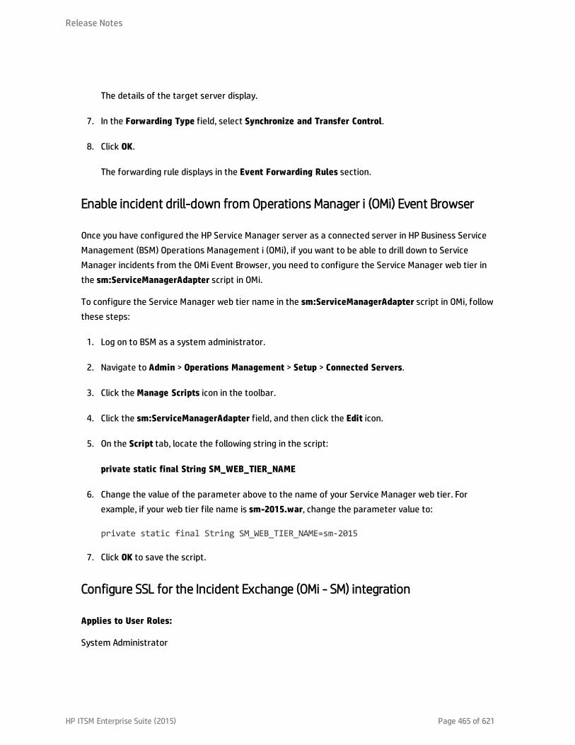
The details of the target server display.
7. In the Forwarding Type field, select Synchronize and Transfer Control.
8. Click OK.
The forwarding rule displays in the Event Forwarding Rules section.
Enable incident drill-down from Operations Manager i (OMi) Event Browser
Once you have configured the HP Service Manager server as a connected server in HP Business ServiceManagement (BSM) Operations Management i (OMi), if you want to be able to drill down to ServiceManager incidents from the OMi Event Browser, you need to configure the Service Manager web tier inthe sm:ServiceManagerAdapter script in OMi.
To configure the Service Manager web tier name in the sm:ServiceManagerAdapter script in OMi, followthese steps:
1. Log on to BSM as a system administrator.
2. Navigate to Admin > Operations Management > Setup > Connected Servers.
3. Click the Manage Scripts icon in the toolbar.
4. Click the sm:ServiceManagerAdapter field, and then click the Edit icon.
5. On the Script tab, locate the following string in the script:
private static final String SM_WEB_TIER_NAME
6. Change the value of the parameter above to the name of your Service Manager web tier. Forexample, if your web tier file name is sm-2015.war, change the parameter value to:
private static final String SM_WEB_TIER_NAME=sm-2015
7. Click OK to save the script.
Configure SSL for the Incident Exchange (OMi - SM) integration
Applies to User Roles:
System Administrator
Release Notes
HP ITSM Enterprise Suite (2015) Page 465 of 621

When Business Service Management (BSM) is configured to accept https connections only, you mustconfigure SSL for the integration. If you do not do so, changes on an incident that is created from OMicannot be synchronized back to BSM/OMi.
Note: The following steps describe how you do so by using the built-in keytool in Service Manager,and the file paths are for Windows only. Be sure to change the file paths accordingly if your ServiceManager system is running on Unix.
To configure SSL for the integration, follow these steps:
1. Import the BSM root certificate to the Service Manager server trusted keystore.
The following is an example of the command line:
<SM Install path>\server\RUN\jre\bin\keytool -import -alias myCA -file <.pemfile of your BSM root certificate> -keystore <SM Installpath>\Server\RUN\jre\lib\security\cacerts -storepass <changeit>
Note: Where: changeit is the default password of the trusted keystore. Change it to your ownpassword if you have changed it.
2. Add the following parameters to the Service Manager server configuration file (<SM installpath>\Server\RUN\sm.ini):
truststoreFile:<SM install path>\Server\RUN\jre\lib\security\cacerts
truststorePass:<changeit>
3. Restart the Service Manager Server service.
Configure the Instance Count in the SMOMi integration template
Applies to User Roles:
System Administrator
As of version 9.34, HP Service Manager can integrate with more than one BSM OMi server. However, bydefault, only one OMi server is allowed. If you need to integrate Service Manager with more than oneOMi server, you need to configure the Instance Count setting in the SMOMi integration template, asdescribed below.
Release Notes
HP ITSM Enterprise Suite (2015) Page 466 of 621

1. Log on to ITSM Enterprise Suite as a system administrator.
2. Type db in the command line, and press Enter.
3. In the Table field, type SMISRegistry, and click Search.
The SMIS integration template form opens.
4. Click Search.
A list of SMIS integration templates opens.
5. Select SMOMi from the list.
6. In the Instance Count field, change the value of 1 to the number of OMi servers that you want tointegrate with ITSM Enterprise Suite. For example, if you need two OMi servers, change the value to2.
7. Click Save.
Add an integration instance for each Operations Manager i (OMi) server
Applies to User Roles:
System Administrator
Once you have completed your configuration in HP Business Service Management OperationsManagement, and have changed the Instance Count setting in the SMOMi integration template (which isneeded only when you have multiple OMi servers), you are ready to add and enable a separateintegration instance in Service Manager for each OMi server. For example, if you have two OMi servers,you must configure two SMOMi integration instances.
Support of multiple OMi servers
As of version 9.34, Service Manager can integrate with multiple OMi servers. This is implementedthrough the Instance Count setting and the omi.mgr.id parameter in the SMOMi integration template.
By default, the SMOMi integration template supports only one integration instance. If you have multipleOMi servers, before you proceed, make sure you have already updated the Instance Count setting in theSMOMi integration template. For details, see "Configure the Instance Count in the SMOMi integrationtemplate" on the previous page.
When using the omi.mgr.id parameter, keep the following in mind:
Release Notes
HP ITSM Enterprise Suite (2015) Page 467 of 621

l If you have only one OMi server (and hence need only one SMOMi integration instance), you musteither correctly configure this parameter or clear the entire row of this parameter (both theparameter name and value) in the SMOMi integration instance, otherwise the integration will notwork.
l If you have multiple OMi servers (and hence need multiple SMOMi integration instances), you mustcorrectly configure this parameter in all SMOMi integration instances. Only those correctlyconfigured integration instances will work. If none of the SMOMi integration instances are correctlyconfigured, none of them will work.
l Users can view the OMi event details from an OMi incident record only when you specify theomi.mgr.id parameter correctly. If the value you specify in the corresponding SMOMi integrationinstance does not match the Universally Unique Identifier (UUID) which is automatically generated inthe OMi server for the target Service Manager server and stored in the Incident record, users will notsee the View OMi Event option from the Incident record.
To add and enable an Incident Exchange (OMi - SM) integration instance:
1. Log on to ITSM Enterprise Suite as a system administrator.
2. Click Tailoring > Integration Manager.
3. Click Add.
The Integration Template Selection wizard opens.
4. Select SMOMi from the Integration Template list.
Note: Ignore the Import Mapping check box, which has no effect on this integration.
5. Click Next.
6. Complete the integration instance information:
n Modify the Name and Version fields to the exact values you need.
n In the Interval Time (s) field, enter a value. For example: 600. If an OMi opened incident fails tobe synchronized back to OMi, Service Manager will retry the failed task at the specified interval(for example, 600 seconds).
Release Notes
HP ITSM Enterprise Suite (2015) Page 468 of 621

n In the Max Retry Times field, enter a value. For example: 10. This is the maximum allowednumber of retries for each failed task.
n (Optional) In the SM Server field, specify a display name for the Service Manager server host.For example: my_Local_SM.
n (Optional) In the Endpoint Server field, specify a display name for the BSM server host. Forexample: my_BSM_1.
n (Optional) In the Log File Directory field, specify a directory where log files of the integrationwill be stored. This must be a directory that already exists on the Service Manager server host.
n (Optional) In the Log Level field, change the log level from INFO (default) to another level. Forexample: WARNING.
n (Optional) If you want this integration instance to be automatically enabled when the ServiceManager Server service is started, select Run at system startup.
7. Click Next. The Integration Instance Parameters page opens.
8. On the General Parameters tab, complete the following fields as necessary:
Field Sample Value Description
omi.server.url http://<servername>:opr-gateway/rest/synchronization/event
This is the URL address of theOMi server's RESTful webservice. Replace <servername>with the fully qualified domainname of your OMi server.
http.conn.timeout 30 The HTTP connection timeoutsetting in seconds.
Note: The out-of-boxvalue is 30 (seconds), and15 (seconds) is used if thisfield is empty.
Release Notes
HP ITSM Enterprise Suite (2015) Page 469 of 621

Field Sample Value Description
http.rec.timeout 30 The HTTP receive timeoutsetting in seconds.
Note: The out-of-boxvalue is 30 (seconds), and15 (seconds) is used if thisfield is empty.
http.send.timeout 30 The HTTP send timeout settingin seconds.
Note: The out-of-boxvalue is 30 (seconds), and15 (seconds) is used if thisfield is empty.
sm.mgr.id 55436DBE-F81E-4799-BA05-65DE9404343B
The Universally UniqueIdentifier (UUID) automaticallygenerated for this instance ofService Manager.
Note: This field isautomatically completedeach time when you addan SMOMi integrationinstance. Do not change it,otherwise the integrationwill not work properly.
Release Notes
HP ITSM Enterprise Suite (2015) Page 470 of 621
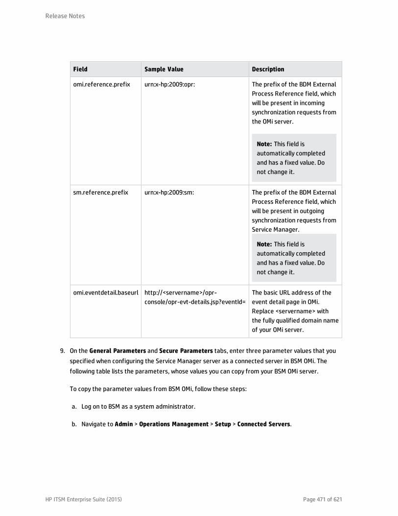
Field Sample Value Description
omi.reference.prefix urn:x-hp:2009:opr: The prefix of the BDM ExternalProcess Reference field, whichwill be present in incomingsynchronization requests fromthe OMi server.
Note: This field isautomatically completedand has a fixed value. Donot change it.
sm.reference.prefix urn:x-hp:2009:sm: The prefix of the BDM ExternalProcess Reference field, whichwill be present in outgoingsynchronization requests fromService Manager.
Note: This field isautomatically completedand has a fixed value. Donot change it.
omi.eventdetail.baseurl http://<servername>/opr-console/opr-evt-details.jsp?eventId=
The basic URL address of theevent detail page in OMi.Replace <servername> withthe fully qualified domain nameof your OMi server.
9. On the General Parameters and Secure Parameters tabs, enter three parameter values that youspecified when configuring the Service Manager server as a connected server in BSM OMi. Thefollowing table lists the parameters, whose values you can copy from your BSM OMi server.
To copy the parameter values from BSM OMi, follow these steps:
a. Log on to BSM as a system administrator.
b. Navigate to Admin > Operations Management > Setup > Connected Servers.
Release Notes
HP ITSM Enterprise Suite (2015) Page 471 of 621

c. Locate your ITSM Enterprise Suite server configuration entry and double-click anywhere on theentry pane.
d. On the General tab, copy the ID string at the bottom into the omi.mgr.id field in ServiceManager.
e. On the Incoming Connection tab, copy the User Name and Password to the username andPassword fields in Service Manager, respectively.
Field Sample Value Description
omi.mgr.id(on theGeneralParameterstab)
f3832ff4-a6b9-4228-9fed-b79105afa3e4
The Universally Unique Identifier (UUID) automatically generatedin OMi for the target Service Manager server.
Note: This parameter was introduced to support multipleOMi servers. Service Manager uses the UUID to identify fromwhich OMi server an incident was opened. Be aware that ifyou delete the connected server configuration for theService Manager server in OMi and then recreate the sameconfiguration, OMi generates a new UUID. You need toreconfigure the integration instance by changing the oldUUID to the new one.
Tip: If you have only one OMi server, you can simply removethis parameter (remove both the parameter name andvalue) from the integration instance. See "Support ofmultiple OMi servers" on page 467.
usernameomi.mgr.id(on theGeneralParameterstab)
SM_Server This is the user name that the ITSM Enterprise Suite server usesto synchronize incident changes back to the OMi server.
Password(on theSecureParameterstab)
SM_Server_Password
This is the password that the ITSM Enterprise Suite server usesto synchronize incident changes back to the OMi server.
Release Notes
HP ITSM Enterprise Suite (2015) Page 472 of 621

10. Click Next twice, and then click Finish.
Note: Leave the Integration Instance Mapping and Integration Instance Fields settings blank.This integration does not use these settings.
Service Manager creates the instance. You can edit, enable, disable, or delete it in IntegrationManager.
11. Enable the integration instance.
12. If you have multiple OMi servers, repeat the steps above for the rest of your OMi servers.
Next, you can optionally enable Lightweight Single Sign-On (LW-SSO) in both BSM and Service Managerso that users can bypass the log-in prompts. For details, see "Enable LW-SSO for the Incident Exchange(OMi - SM) integration" below.
Enable LW-SSO for the Incident Exchange (OMi - SM) integration
Applies to User Roles:
System Administrator
Lightweight Single Sign-On (LW-SSO) is optional but recommended for the Incident Exchange (OMi - SM)integration. You have different LW-SSO configuration choices depending on your needs. The followingdescribes how LW-SSO can be used in the Incident Exchange (OMi - SM) integration workflow.
When OMi creates an incident from an OMi event record
OMi creates an incident from an OMi event record by sending RESTful-based requests to ServiceManager. The incident ID is then stored in the event record.
LW-SSO is NOT needed in this process. A dedicated Service Manager user account was specified whenconfiguring the Service Manager integration in OMi. OMi uses this dedicated user account when callingthe Service Manager RESTful Web Service to create the incident.
When an OMi user views the incident details
The user can log in to Service Manager and view the incident details using the incident ID stored in theevent record. For more information, refer to the BSM documentation.
Release Notes
HP ITSM Enterprise Suite (2015) Page 473 of 621
If the user wants to view the incident details by clicking the incident link from the event record, LW-SSOcan be used; otherwise a Service Manager login prompt will appear.
LW-SSO is optional for this process. To enable LW-SSO for this process, configure LW-SSO in both theService Manager server and Web tier (because the server needs to trust the Web tier), as well as in BSM.
When Service Manager synchronizes the OMi incident status back to OMi
When a user has updated the OMi incident, Service Manager calls the OMi server's RESTful Web Serviceto update the incident changes to the OMi event record.
LW-SSO is NOT needed in this process. A dedicated OMi user account was specified when the IncidentExchange (OMi - SM) integration was set up in SMIS, and Service Manager uses this user account whencalling the OMi server's RESTful Web Service to synchronize the incident status back to the OMi eventrecord.
When a user views the event details from the OMi incident
The user clicks the View OMi Event option from the incident to view the event details.
LW-SSO is optional for this process. If you enable LW-SSO in the Service Manager Web tier and in BSM,the BSM login prompt is bypassed.
Configure automatic closure for OMi incidents
System Administrator
Applies to User Roles:
OMi incidents can be automatically closed after a predefined amount of time since they were lastupdated (or resolved if they have not been updated after being resolved).
The workflow is as follows:
1. An incident is opened from OMi.
2. If the Schedule Condition is met, the system creates a schedule record for the incident. Theschedule record will expire at a future time based on the Calc Expression.
3. A user updates the incident and saves the changes.
4. The Reset alerts if expression on the Alerts tab of the probsummary object definition isevaluated. If it evaluates to true, the Expiration time of the schedule record is updated based on
Release Notes
HP ITSM Enterprise Suite (2015) Page 474 of 621

the Calc Expression. By default, the expiration time of the schedule record is updated only whenthe incident has a category of incident.
5. When the schedule record expires, the Alert Condition is evaluated. If it evaluates to true, theincident is automatically closed.
To enable automatic closure for OMi incidents:
1. Configure the global settings in the Incident Management Environment record.a. Click System Administration > Ongoing Maintenance > Environment Records > Incident
Management Environment.
b. Change the following settings as necessary.
Field Value
Close IncidentAutomatically?
This option disables or enables the automatic closure of OMi incidentsat the global level.o If this option is not selected, no incidents will be automatically
closed.
o If this option is selected, incidents will be automatically closed underspecified conditions.
Default: Not selected
Closure Code This value will be copied to the Closure Code field of incidents whenthey are automatically closed.Default: Automatically Closed
Solution This description will be appended to the end of the Solution field ofincidents when they are automatically closed.Default: This incident which belongs to OMi has been closedautomatically.
c. lick Save.
d. Restart the Service Manager server.
Note: If you have made any changes to any of the configuration options in the IncidentManagement Environment record, the Service Manager server must be restarted for thechanges to take effect.
Release Notes
HP ITSM Enterprise Suite (2015) Page 475 of 621
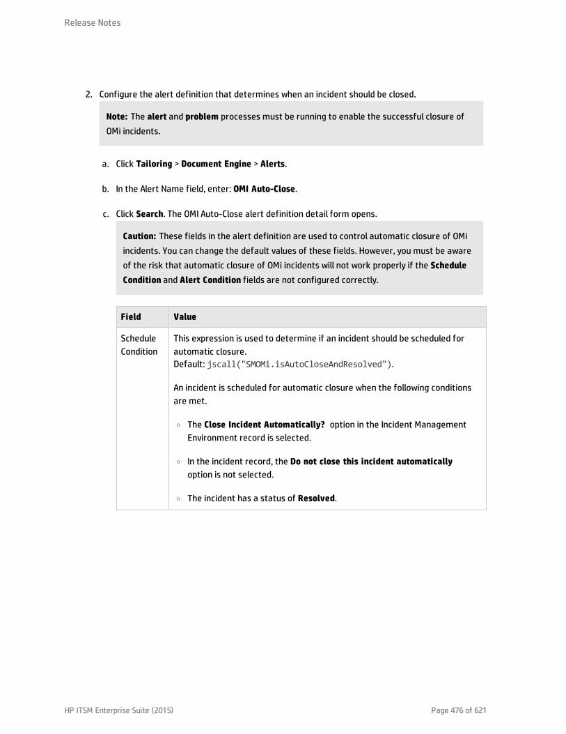
2. Configure the alert definition that determines when an incident should be closed.
Note: The alert and problem processes must be running to enable the successful closure ofOMi incidents.
a. Click Tailoring > Document Engine > Alerts.
b. In the Alert Name field, enter: OMI Auto-Close.
c. Click Search. The OMI Auto-Close alert definition detail form opens.
Caution: These fields in the alert definition are used to control automatic closure of OMiincidents. You can change the default values of these fields. However, you must be awareof the risk that automatic closure of OMi incidents will not work properly if the ScheduleCondition and Alert Condition fields are not configured correctly.
Field Value
ScheduleCondition
This expression is used to determine if an incident should be scheduled forautomatic closure.Default: jscall("SMOMi.isAutoCloseAndResolved").
An incident is scheduled for automatic closure when the following conditionsare met.
o The Close Incident Automatically? option in the Incident ManagementEnvironment record is selected.
o In the incident record, the Do not close this incident automaticallyoption is not selected.
o The incident has a status of Resolved.
Release Notes
HP ITSM Enterprise Suite (2015) Page 476 of 621

Field Value
AlertCondition
This expression is evaluated when an incident is about to be automaticallyclosed. If it evaluates to true, the incident is closed.Default: jscall("SMOMi.isAutoCloseEnabled").
An incident is closed when the following conditions are met.
o The Close Incident Automatically? option in the Incident ManagementEnvironment record is selected.
o In the incident record, the Do not close this incident automaticallyoption is not selected.
CalcExpression
This expression is used to determine how much time will elapse before anincident is automatically closed.
Default: $L.alert.time=update.time in $L.file+'7 00:00:00'.
The default value means the amount of time elapsed is equal to seven dayssince the incident was last updated.
3. Configure alert information in the probsummary object.The OMi autoclose alert definition is configured to only be used by OMi incidents. The closure timeis reset each time the incident is updated. If the closure time is reached without the incident beingupdated then Service Manager will automatically close the incident.
a. Click Tailoring > Document Engine > Objects.
b. In the File name field, enter probsummary and press ENTER. The probsummary objectdefinition is displayed.
c. Select the Alerts tab.
The Reset alerts if expression is used to reset the automatic closure time of OMi incidents.
Default: category in $L.file="incident" and not null(1 inexternal.process.reference in $L.file).
Change the default assignment group for OMi incidents
System Administrator
Applies to User Roles:
Release Notes
HP ITSM Enterprise Suite (2015) Page 477 of 621
HP Service Manager can accept REST based requests from BSM Operations Manager i (OMi) to createincidents based on events information in OMi. An incident opened from an OMi event is automaticallyassigned to an existing group based on the following field values, listed from the highest to lowestpriority:
l The Affected Service of the incident
l The Category of the incident
l The Affected CI of the incident
However, if none of the above field values is available, the incident is assigned to a default group namedApplication. If necessary, you can change this default group setting as follows:
1. Navigate to System Administration > Ongoing Maintenance > BDM Mapping Management. TheBDM mapping configuration search page opens.
2. Enter incident in the BDM Name field, select 1.1 in the Version field, and then click Search. TheBDM mapping record incident is displayed. The Incident Exchange (OMi - SM) integration uses thisBDM mapping record when creating an incident from an OMi event.
3. Select the Field Mapping tab, scroll down to the assignment field in the SM Object Field column,and click the SM Callback field in the same row.
4. Change Application in the following code to the name of another assignment group:
4) A default assignment group if no other criteria is metif( ! $result ) {
$result = "Application";}
5. Click Save. The default assignment group is now changed.
Synchronization of incident changes back to Operations Manager i(OMi)
After OMi opens an incident in HP Service Manager, Service Manager will synchronize the incidentchanges back to OMi.
Operations Manager i (OMi) can forward an event record to Service Manager as an incident by calling aService Manager Web Service. The incident ID is then stored in the event record.
Release Notes
HP ITSM Enterprise Suite (2015) Page 478 of 621
When a user has updated the incident opened from OMi, Service Manager calls an OMi server RESTfulWeb Service to update the incident changes to the OMi event record.
If Service Manager fails to synchronize the incident changes back to OMi for some reasons (for example,because of a network problem), Service Manager behaves as follows:
l Displays a warning message, indicating that the incident failed to be synchronized to OMi.
l Saves the failed task in the SMIS task queue, and retries the task to re-synchronize the changes toOMi based on an interval time and a maximum retry times configured when adding the IncidentExchange (OMi - SM) integration in SMIS. When the re-synchronization is successfully completed, thefailed task is removed from the task queue.
System Administrators can monitor failed tasks, and reset their retry times or rerun expired tasks.
Working with the Incident Exchange (OMi - SM) integration
Once the integration is set up, Service Manager Incident Management users with the right permissionscan view event details from OMi incidents and mark individual OMi incidents as eligible or ineligible forautomatic closure (if their system administrator has enabled automatic closure for OMi incidents).
View related OMi event details from an incident
If all of the following conditions are met, you can view the related Operations Manager i (OMi) eventdetails from an OMi incident:
l You are accessing the incident through the HP Service Manager standard Web client (not theemployee self-service (ESS) interface).
l One or more SMOMi integration instances are set up and enabled in Integration Manager.
l You are also a Business Service Management (BSM) user who has been granted the permissionEvents assigned to user including the required actions.
To view related OMi event details from an OMi incident:
1. Log on to the Service Manager Web client.
2. From Incident Management, search for the incident record created from OMi.
3. Click More and then select View OMi Event.
Release Notes
HP ITSM Enterprise Suite (2015) Page 479 of 621
Note: The View OMi Event option displays only when the omi.mgr.id parameter in thecorresponding SMOMi integration instance is set correctly.
If Lightweight Single Sign-On (LW-SSO) is enabled in both the Service Manager Web client and HPBusiness Service Management (BSM) , the OMi event detail page opens in a new browser window,displaying the details of the related event in OMi. If LW-SSO is not enabled, a BSM login page opens,and the related OMi event detail page displays after you log on to BSM.
Mark an incident for automatic closure
Applies to User Roles:
Incident Coordinator
You can mark an OMi incident as eligible or ineligible for automatic closure after a predefined amountof time since it was last updated.
To mark an incident as ineligible or eligible for automatic closure:
1. From Incident Management, search for an incident record opened from OMi.
2. Select or deselect the Do not close this incident automatically check box to mark this incident asineligible or eligible for automatic closure.
Note: By default, this check box is not selected.
Release Notes
HP ITSM Enterprise Suite (2015) Page 480 of 621

HP ITSM Enterprise Suite (2015) Page 481 of 621
Operations Manager i - Service Manager Integration
Note: The following sections are excerpted from the integrations section of the OperationsManager i Help Center. However, to ensure you have the latest information, you should referencethe latest published version of the document in question.

Operations Manager i - Service Manager Integration Overview
You can integrate HP Service Manager (SM) with one or more of the OMi components, as describedbelow. Each integration can be performed separately.
Note: In general, the information provided in this guide is for integrating OMi with SM 9.3x.
For instructions on integrating OMi with earlier versions of SM, seehttp://support.openview.hp.com/selfsolve/document/KM1303768/binary/BSM9.12_SM_Integration_Interactive_Docs.html. Download and extract the zip file contents, and then open theSM_interactive_document.htm file and follow the guidelines.
The options are as follows:
l Downtime exchange between OMi and SM. OMi enables you to forward downtimes (also known asoutages) from OMi to SM, and from SM to OMi. The downtime defined in OMi is converted to arequest for change in SM, and vice versa. For details, see "Downtime Exchange Between OperationsManager i and Service Manager" on page 484.
l Incident exchange between SM and OMi. OMi enables you to forward events from OMi to SM.Forwarded events and subsequent event changes are synchronized back from SM to OMi. You canalso drill down from OMi events to SM incidents. For details, see "Incident Exchange Between ServiceManager and Operations Manager i" on page 490.
l View planned changes and incident details in Service Health. This integration enables you to viewplanned changes and incident details in the Changes and Incidents tab in the 360° View page inService Health. For details, see "View Changes and Incidents in Service Health Using Standalone HPUniversal CMDB" on page 506 and "View Changes and Incidents in Service Health Using RTSM" onpage 522.
l Submit an incident through OMi alerts. Incidents are automatically opened in SM when a CI Statusalert is triggered in OMi. For details, see "Generate Incidents in SM When an OMi Alert is Triggered"on page 534.
l The Business Impact Report integration is described in the Closed Loop Incident Process (CLIP) Guide.When deployed as part of the OMi solution, Incident Management users can launch an impact reportfrom an incident in context with the incident's affected CI. Service Desk Agents can validate theupdated status of the Business Impact to categorize and prioritize the incident accordingly. Fordetails, see the CLIP page in the Solutions Portal at:
http://support.openview.hp.com/sc/solutions/index.jsp#tab=tab1
HP ITSM Enterprise Suite (2015) Page 482 of 621

Note:
l Service Manager Query Security. If you have set up an integration from OMi to SM, there is a CIcontext menu that enables you to access SM from OMi Service Health. This drill-down option isnot available if you have enabled Service Manager query security.
l Troubleshooting Multiple Domains. If OMi and SM are in different domains, and you are usingInternet Explorer as your browser, you may need to add the domains to the list of alloweddomains in the Privacy tab (Internet Options > Privacy > Sites).
Release Notes
HP ITSM Enterprise Suite (2015) Page 483 of 621
Downtime Exchange Between Operations Manager i and ServiceManager
OMi enables you to forward downtimes (also known as outages) from OMi to SM, and from SM to OMi.The downtime defined in OMi is converted to an incident in SM, and vice versa.
This chapter includes the following:
l "Integration Overview" below
l "Prerequisites" on the next page
l "Step 1: Send OMi Downtime Events to SM" on the next page
l "Step 2: Integrate SM Downtimes with OMi" on page 487
Integration Overview
The downtime integration between OMi and SM includes information exchanges in both of the followingdirections:
l SM > OMi. When you create a downtime RfC (request for change) in SM, the RfC includes the CI thatis under change and a start and end date/time of the downtime. If you do not want to waste effortwith false alarms in your operations center, and do not want to have these times included in serviceavailability reports, you can set up the integration so that these RfCs are translated to downtimes inOMi.
In this scenario, you install and set up a downtime adapter on your CMDB (depending on your setup,you might be working with a uCMDB as central CMS, or with an RTSM contained in your OMi). TheRfC creates a planned downtime CI in the CMDB, and the adapter sends the planned downtime CI toOMi to create a downtime.
l OMi > SM. When you define downtimes using OMi (for example, every Monday and Saturday from8:30 PM-9:30 PM) to proactively support end users, the help desk should be aware of suchoperational downtimes. After you set up the integration, downtimes in OMi trigger events, whichcreate corresponding incidents in SM.
In this scenario, when a downtime starts, OMi generates an event. Using the event forwardingmechanism, the event generates an incident in SM. When the downtime ends, an event is sent toclose the downtime incident.
HP ITSM Enterprise Suite (2015) Page 484 of 621

A single downtime can be defined on more than one CI. In the case of OMi > SM, a separate event is sentfor each CI in the downtime.
Prerequisites
Supported Platforms
To set up the downtime integration, you must meet the following prerequisites:
l Service Manager 9.31 and higher.
l uCMDB (RTSM/CMS) 9.05 CUP 5 and higher with content pack 11 update 2, or uCMDB 10.01 or higherwith content pack 12.
l Before deploying the adapter, verify that CP11 or higher is installed. If it is not, install the contentpack.
l If the adapter is installed on the RTSM, and the adapter is working behind a reverse proxy, the DPSmust have the correct certificates installed to send requests to the reverse proxy.
l If you are using CMS, make sure that the CMS integration is set up.
Global ID Generator
To enable the downtime integration, you must have a global ID generator configured in yourenvironment.
If you are working with RTSM, perform the following to configure the global ID generator:
1. Access the following location with your browser: http://<DPS name>:21212/jmx-console/HtmlAdaptor?action=inspectMBean&name=UCMDB:service=Multiple CMDB InstancesServices
2. In the setAsGlobalIdGenerator() method, fill the customerID parameter with the value of 1, andclick Invoke.
Step 1: Send OMi Downtime Events to SM
To enable OMi to send downtime definitions to SM, you must edit an infrastructure setting as describedbelow. This procedure generates events in OMi. You can then use the event forwarding mechanism togenerate incidents in SM when a downtime in OMi begins and ends.
Release Notes
HP ITSM Enterprise Suite (2015) Page 485 of 621
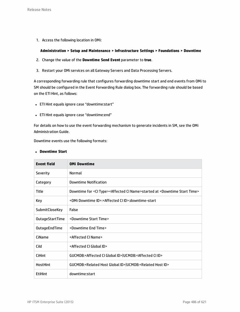
1. Access the following location in OMi:
Administration > Setup and Maintenance > Infrastructure Settings > Foundations > Downtime
2. Change the value of the Downtime Send Event parameter to true.
3. Restart your OMi services on all Gateway Servers and Data Processing Servers.
A corresponding forwarding rule that configures forwarding downtime start and end events from OMi toSM should be configured in the Event Forwarding Rule dialog box. The forwarding rule should be basedon the ETI Hint, as follows:
l ETI Hint equals ignore case “downtime:start”
l ETI Hint equals ignore case “downtime:end”
For details on how to use the event forwarding mechanism to generate incidents in SM, see the OMiAdministration Guide.
Downtime events use the following formats:
l Downtime Start
Event field OMi Downtime
Severity Normal
Category Downtime Notification
Title Downtime for <CI Type><Affected CI Name>started at <Downtime Start Time>
Key <OMi Downtime ID>:<Affected CI ID>:downtime-start
SubmitCloseKey False
OutageStartTime <Downtime Start Time>
OutageEndTime <Downtime End Time>
CiName <Affected CI Name>
CiId <Affected CI Global ID>
CiHint GUCMDB:<Affected CI Global ID>|UCMDB:<Affected CI ID>
HostHint GUCMDB:<Related Host Global ID>|UCMDB:<Related Host ID>
EtiHint downtime:start
Release Notes
HP ITSM Enterprise Suite (2015) Page 486 of 621
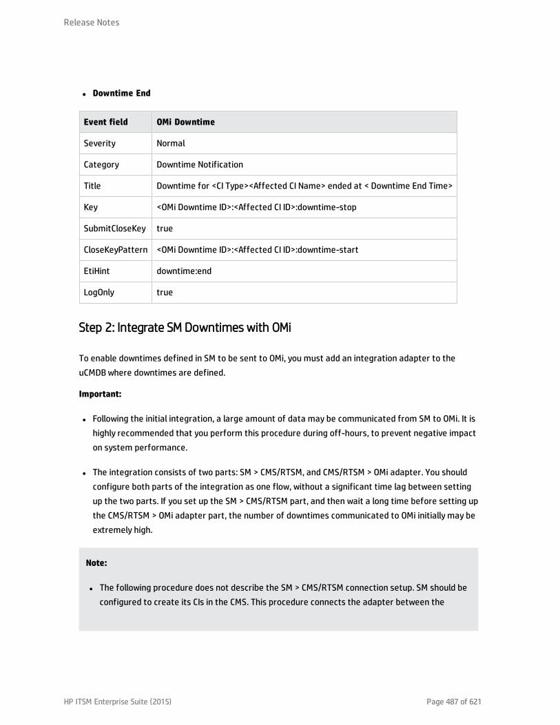
l Downtime End
Event field OMi Downtime
Severity Normal
Category Downtime Notification
Title Downtime for <CI Type><Affected CI Name> ended at < Downtime End Time>
Key <OMi Downtime ID>:<Affected CI ID>:downtime-stop
SubmitCloseKey true
CloseKeyPattern <OMi Downtime ID>:<Affected CI ID>:downtime-start
EtiHint downtime:end
LogOnly true
Step 2: Integrate SM Downtimes with OMi
To enable downtimes defined in SM to be sent to OMi, you must add an integration adapter to theuCMDB where downtimes are defined.
Important:
l Following the initial integration, a large amount of data may be communicated from SM to OMi. It ishighly recommended that you perform this procedure during off-hours, to prevent negative impacton system performance.
l The integration consists of two parts: SM > CMS/RTSM, and CMS/RTSM > OMi adapter. You shouldconfigure both parts of the integration as one flow, without a significant time lag between settingup the two parts. If you set up the SM > CMS/RTSM part, and then wait a long time before setting upthe CMS/RTSM > OMi adapter part, the number of downtimes communicated to OMi initially may beextremely high.
Note:
l The following procedure does not describe the SM > CMS/RTSM connection setup. SM should beconfigured to create its CIs in the CMS. This procedure connects the adapter between the
Release Notes
HP ITSM Enterprise Suite (2015) Page 487 of 621

CMS/RTSM and OMi.
l The default job synch frequency is one minute.
Create a new integration point as follows:
1. Create the integration point credentials:
a. If you have OMi, do the following on your OMi. If you use a CMS, do the following on your CMS:Access the Data Flow Probe Setup:
Administration > RTSM Administration > Data Flow Management > Data Flow Probe Setup
Alternatively, click Data Flow Probe Setup.
Note: You do not need a probe to perform this integration. Nevertheless you createcredentials using the Data Flow Probe Setup tab.
b. Click Add domain or probe, and enter a name and description of your choice.
c. Expand the submenus and select HTTP protocol.
d. Click the + sign (Add new connection details) and enter the OMi Gateway host name, Port 80,and the OMi username and password. Leave the Trust fields blank. When you are done, clickOK to save the credentials.
2. Create a new integration point:
a. If you have OMi, do the following on your OMi. If you use a CMS, do the following on your CMS:Access the Integration Studio:
Administration > RTSM Administration > Data Flow Management > Integration Studio
Alternatively, click Integration Studio.
b. Click New Integration Point, enter a name and description of your choice, and selectBSMDowntimeAdapter/SM scheduled Downtime Integration into BSM.
c. Enter the following information for the adapter: OMi Gateway hostname and port, theintegration point credentials you just created, communication protocol, and the context root
Release Notes
HP ITSM Enterprise Suite (2015) Page 488 of 621
(if you have a non-default context root).
d. Click OK, then click the Save button above the list of the integration points.
3. You can use the Statistics tab in the lower pane to track the number of downtimes that arecreated or updated. By default, the integration job runs every minute. If a job has failed, you canopen the Query Status tab and double-click the failed job to see more details on the error.
If there is an authentication error, verify the OMi credentials entered for the integration point.
If you receive an unclear error message with error code, this generally indicates a communicationproblem. Check the communication with OMi. If no communication problem is found, restart theMercuryAS process.
A failed job will be repeated until the problem is fixed.
Release Notes
HP ITSM Enterprise Suite (2015) Page 489 of 621

Incident Exchange Between Service Manager and OperationsManager i
OMi enables you to forward events from OMi to SM. Forwarded events and subsequent event changesare synchronized back from SM to OMi. You can also drill down from OMi events to SM incidents.
Note: HP recommends this integration option for new integrations with SM. However, existingintegrations that use other integration options are still supported.
This chapter includes the following:
l "Step 1: Configure the SM Server as a Connected Server" below
l "Step 2: Configure an Event Forwarding Rule" on page 494
l "Step 3: Configure a URL Launch of the Event Browser from SM" on page 496
l "Step 4: Configure a URL Launch of SM from the Event Browser" on page 497
l "Step 5: Configure the SM Server" on page 498
l "Step 6: Mapping and Customization" on page 499
l "Step 7: Test the Connection" on page 500
l "Step 8: Synchronize Attributes" on page 501
l "Tips for Customizing Groovy Scripts" on page 502
Step 1: Configure the SM Server as a Connected Server
Synchronizing events and event changes between OMi and SM incidents requires configuring aconnected server within OMi to correctly identify the target SM instance. The first step to achieve this isto configure HP Service Manager as a target connected server in the Connected Servers manager.
For full details about how to configure a connected server, see the OMi Administration Guide.
Note: Before you continue with the below procedure, set up an integration user with a user nameand password in SM. This is the user name and password needed by OMi to access the SM targetserver.
HP ITSM Enterprise Suite (2015) Page 490 of 621
To configure the SM server as a target connected server, perform the following steps:
1. Navigate to the Connected Servers manager:
Administration > Setup and Maintenance > Connected Servers
Alternatively, click Connected Servers.
2. Click the New button and select External Event Processing. The Create New Server Connection -External Event Processing dialog box opens.
3. In the General page, in the Display Name field, enter a name for the target SM server. By default,the Name field is filled automatically. For example, if you enter Service Manager 1 as the DisplayName for the target SM server, Service_Manager_1 is automatically inserted in the Name field.You can specify your own name in the Name field, if you want to change it from the one suggestedautomatically.
Note: Make a note of the name of the new target server (in this example, Service_Manager_1). You need to provide it later as the username when configuring the SM server tocommunicate with the server hosting OMi.
Optional: Enter a description for the new target server.
Make sure that you select the Active check box.
Click Next to open the Server Properties page.
4. In the Server Properties page, enter the Fully Qualified DNS Name of the SM target server.
Click Next to open the Integration Type page.
5. In the Integration Type page, complete the following information:
a. Select Call Script Adapter as the integration type.
b. From the Script Name menu, select the SM Groovy script adapter sm:ServiceManagerAdapter.
Note: In case the Test Connection fails and the error indicates that there could be aproblem with timeout, increase the timeout value. Otherwise, you can leave the default
Release Notes
HP ITSM Enterprise Suite (2015) Page 491 of 621

timeout value.
c. Click Next to open the Outgoing Connection page.
6. In the Outgoing Connection page, enter the credentials (user name, password, and port number)required to access the SM target server and to forward events to that server:
a. In the User Name field, enter the user name for the integration user you set up in SM.
b. In the Password field, enter the password for the user you specified. Repeat the passwordentry in the Verify Password field.
c. In the Port field, specify the port configured on the SM side for the integration with OMi.
To find the port number to enter:
o If you are using default ports in SM, select or clear Use Secure HTTP as appropriate, andthen click Set default port. The port is set automatically.
Note: If you do not want to use secure HTTP, make sure that the Use secure HTTPcheck box is cleared.
If the Use Secure HTTP check box is selected, download and install a copy of the targetserver’s SSL certificate using the Retrieve from Server or Import from File link, if thecertificate is available in a local file.
o If you need to find the port number, access the following file on your SM system:
<HP Service Manager root directory>/HP/Service Manager<version>/Server/RUN/sm.cfg
In the sm.cfg file, check for the sm -loadBalancer line and add the port entry at the endof the line. The line looks similar to this:
sm -loadBalancer -httpPort:13080
Enter the appropriate value of the port used by SM in the Port field of the OutgoingConnection page.
d. Select the Enable Synchronize and Transfer Control check box.
Release Notes
HP ITSM Enterprise Suite (2015) Page 492 of 621

If the Enable Synchronize and Transfer Control check box is selected, an OMi operator cantransfer ownership of the event to the target connected server using the Transfer Controloption in the Event Browser context menu.
If it is not selected, the Synchronize and Transfer Control option is not available from the EventBrowser context menu or from the list of forwarding types for configuring forwarding rules.
e. Test the connection by clicking the Test Connection link in the upper center of the dialog box.A Success or ERROR hyperlink is displayed. Click the link to get a more detailed message.
f. Click Next to open the Event Drilldown page.
7. If you want to drill down into SM, in addition to automatically generating SM incidents from OMievents, you need to specify the fully qualified DNS name and port of the SM system into which youwant to perform the incident drilldown.
Note: To enable incident drilldown to SM, you must install a web tier client for your SM serveraccording to your SM server installation or configuration instructions.
In the Event Drilldown page, configure the server where you installed the web tier client alongwith the configured port used.
If you do not specify a server in the Event Drilldown page, it is assumed that the web tier clientis installed on the server used for forwarding events and event changes to SM, and receivingevent changes back from SM.
If nothing is configured in the Event Drilldown dialog box, and the web tier client is not installedon the SM server machine, the web browser will not be able to find the requested URL.
Select or clear the Use Secure HTTP check box according to your configuration. In case the SMserver is configured for SSL access, click the Retrieve from Server link to import the certificatefrom the SM server to allow SSL encryption.
Click Next to open the Incoming Connection page.
8. To enable event changes to be synchronized back from SM to OMi, you must provide credentials forthe SM server to access the server hosting OMi.
a. In the Incoming Connection page, select the Accept event changes from external eventprocessing server check box, and then enter a password that the SM server requires to
Release Notes
HP ITSM Enterprise Suite (2015) Page 493 of 621
connect to the server hosting OMi.
Note: Make a note of this password. You need to provide it later when configuring the SMserver to communicate with the server hosting OMi. This password is associated with theserver name (Service_Manager_1) you configured in SM.
If Enable Synchronize and Transfer Control was previously selected, the Accept eventchanges from external event processing server option is assumed and cannot bedisabled.
b. Click Finish. The target SM server appears in the list of Connected Servers.
9. If you have SM 9.34 or higher, perform the following additional steps:
a. Reopen the SM connected server that you configured in the previous steps. To do so, double-click the connected server entry in the connected servers list.
b. Copy the ID of the connected server (displayed in the lower right corner of the General tab) andsave it. You need to specify this ID as omi.mgr.id on the SM system.
An example of a connected server ID is as follows:
ID: 22f42836-fd36-473e-afc9-a81290f4f73b
Step 2: Configure an Event Forwarding Rule
The next step is to configure an event forwarding rule that determines which events are forwardedautomatically to SM.
For details about configuring filters, see the OMi Administration Guide.
To configure a forwarding rule, follow these steps:
1. Navigate to the Forwarding Rules manager:
Administration > Event Processing > Automation > Event Forwarding
Alternatively, click Event Forwarding.
2. Click the New Item button to open the Create New Event Forwarding Rule dialog box.
3. Under General, in the Display Name field, enter a name for the forwarding rule, in this example
Release Notes
HP ITSM Enterprise Suite (2015) Page 494 of 621
Forward Critical (Sync and Transfer Control).
Optional. Enter a description for the forwarding rule you are creating.
4. Under Condition, click the browse button next to the Event Filter field. The Select an Event Filterdialog box opens.
In the Select an Event Filter dialog box, do one of the following:
n Select an existing filter
n Create a new filter as follows:
i. Click the New button to open the Filter Configuration dialog box. You can choose betweenNew Simple Filter or New Advanced Filter.
ii. In the Display Name field, enter a name for the new filter, in this example, FilterCritical.
Clear the check boxes for all severity levels except for the severity Critical.
Click OK.
iii. You should see your new filter in the Select an Event Filter dialog box (select it, if it is notalready highlighted).
Click OK.
5. Under Target Servers, select the target connected server you configured in "Step 1: Configure theSM Server as a Connected Server" on page 490. In this example, this is Service Manager 1.
Click the Add button next to the target servers selection field. You can now see the connectedserver’s details. In the Forwarding Type field, select the Synchronize and Transfer Controlforwarding type. Although other selections are technically possible, only Synchronize and TransferControl is supported by SM.
Click OK.
6. Make sure the Activate Rule after creation check box is selected. A rule must be active in orderfor its status to be available in SM.
Release Notes
HP ITSM Enterprise Suite (2015) Page 495 of 621

Step 3: Configure a URL Launch of the Event Browser from SM
Before operators are able to perform event drill-down from SM into the OMi user interface using a URLlaunch of the Event Browser, the operators must be set up as valid users with appropriate permissionsin OMi:
User account requirements
l If Single Sign-On (SSO) authentication is configured, set up each user in OMi with the same username that is used by the SM operator to log on to SM and to perform the URL call. (The password ofeach OMi user can be any string, but not empty.) After successfully logging on to SM, the OMi userscan launch the OMi Event Browser without further authentication.
For details on setting up SSO, see System Administration > Integrations > Service Managerintegration methods and tools > Integration Manager > Using LW-SSO with integrations in the SMdocumentation library.
l If SM is not configured to use SSO authentication, set up each user with the same user name that isused by the SM operator and specify a valid password. The users are required to enter their username and password when launching the OMi Event Browser.
Required user permissions
You must grant the permission Events assigned to user including the required actions to each OMiuser. To do so, select:
Administration > Users > Users, Groups, and Roles
Alternatively, click Users, Groups, and Roles.
Select a role or create a new one. In the Permissions section, go to the Operations Console category,select Events and specify the actions users can perform on Events assigned to user.
You can optionally grant the permission to view events not assigned to each user.
Note: Without valid user names, or if a user does not have the required viewing permissions, anyattempt to perform a URL launch of the OMi Event Browser from SM results in an empty browserwindow.
Release Notes
HP ITSM Enterprise Suite (2015) Page 496 of 621

Step 4: Configure a URL Launch of SM from the Event Browser
To be able to perform a URL launch of SM from the OMi Event Browser using the web tier client, performthe following:
1. Navigate to Connected Servers:
Administration > Setup and Maintenance > Connected Servers
Alternatively, click Connected Servers.
Click the Manage Scripts icon.
2. Select the sm:ServiceManagerAdapter script, and click the Edit Item button.
3. Click the Script tab and locate the following text in the Groovy script:
private static final String SM_WEB_TIER_NAME = 'webtier-9.30'
4. Change the value of webtier-9.30 to the value required to access the SM web tier client.
The drill-down URL is made up like this:
http://<FQDN of HP Service Manager web tier server>/<web path to HP ServiceManager>/<URL query parameters>
In this instance, <FQDN of HP Service Manager web tier server> is the fully qualified DNSname of the SM server where the web tier client is installed. This part of the URL is addedautomatically (together with http:// or https://) according to the values that you providedwhen you configured SM as a target connected server in the Connected Servers manager. Fordetails, see "Step 1: Configure the SM Server as a Connected Server" on page 490.
An example of a drill-down URL:
http://smserver.example.com/SM930/index.do?ctx=docEngine&file=probsummary&query=number%3D%22IM10216%22&queryHash=bf52f465
In this example, you need to replace webtier-9.30 with SM930. All the other parts of the URL areconfigured automatically.
5. When finished editing, save the new version of the script. Note that the script can always be
Release Notes
HP ITSM Enterprise Suite (2015) Page 497 of 621
reverted to its original version.
For details, see the OMi Administration Guide.
6. If you are using SM 9.34 or lower, set the value of the querySecurity parameter from the defaultvalue (true) to false in the SM web tier configuration file web.xml.
For more details, see the HP Service Manager online help:
Guides and reference > System Configuration Parameters > Security parameters > Parameter:querysecurity
and
Guides and reference > System Configuration Parameters > Client parameters for Web clients> Web parameter: querySecurity
Step 5: Configure the SM Server
The next step describes how to configure the SM server to integrate with OMi.
Note: If you want to configure more than one OMi server, you need to increase the connectioncount on the SM side:
System Administration > Integrations > HP Business Service Management (BSM) > IncidentExchange (OMi - SM) integration > Incident Exchange (OMi - SM) integration setup > Configurethe Instance Count setting in the SM-OMi integration template.
This functionality is only available for SM 9.34 and higher.
To configure the SM server, complete the following steps in the HP Service Manager user interface:
1. From the left hand pane, navigate to:
Tailoring > Integration Manager
2. Click Add to add a new configuration.
3. Select the SMOMi integration template from the Integration Template field. Click Next.
4. Optional. Change the log level to the desired value.
Release Notes
HP ITSM Enterprise Suite (2015) Page 498 of 621
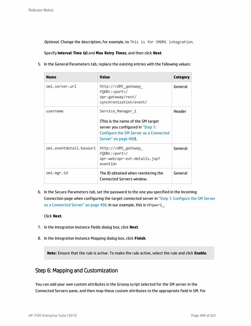
Optional. Change the description, for example, to This is for SMOMi integration.
Specify Interval Time (s) and Max Retry Times, and then click Next.
5. In the General Parameters tab, replace the existing entries with the following values:
Name Value Category
omi.server.url http://<OMi_gateway_FQDN>:<port>/opr-gateway/rest/synchronization/event/
General
username Service_Manager_1
(This is the name of the SM targetserver you configured in "Step 1:Configure the SM Server as a ConnectedServer" on page 490).
Header
omi.eventdetail.baseurl http://<OMi_gateway_FQDN>:<port>/opr-web/opr-evt-details.jsp?eventId=
General
omi.mgr.id The ID obtained when reentering theConnected Servers window.
General
6. In the Secure Parameters tab, set the password to the one you specified in the IncomingConnection page when configuring the target connected server in "Step 1: Configure the SM Serveras a Connected Server" on page 490. In our example, this is HPqwer1_.
Click Next.
7. In the Integration Instance Fields dialog box, click Next.
8. In the Integration Instance Mapping dialog box, click Finish.
Note: Ensure that the rule is active. To make the rule active, select the rule and click Enable.
Step 6: Mapping and Customization
You can add your own custom attributes in the Groovy script selected for the SM server in theConnected Servers pane, and then map these custom attributes to the appropriate field in SM. For
Release Notes
HP ITSM Enterprise Suite (2015) Page 499 of 621

details about groovy scripting, see the OMi Extensibility Guide.
You can also change how attributes are mapped from OMi to SM. The mapping is done in the BDMMapping Manager in SM:
System Administration > Ongoing Maintenance > BDM Mapping Management
For details about mapping attributes, see the HP Service Manager online help:
System Administration > Integrations > Service Manager integration methods and tools > BDMMapping Management
Step 7: Test the Connection
To test the connection, send an event to the server hosting OMi that matches the filter you defined (inour example filter, the severity value is Critical), and then verify that the event is forwarded to SM asexpected.
To test the connection, do the following:
1. On the Gateway Server system running OMi, open an Event Browser.
2. On the system running OMi, open a command prompt and change to the following directory:
<OMi_HOME>\opr\support
3. Send an event using the following command:
sendevent -s critical -t test111-1
4. Verify that the event appears in the OMi Event Browser.
5. Select the Forwarding tab.
6. In the External Id field, you should see a valid SM incident ID.
7. Verify that the incident appears in the Incident Details in HP Service Manager:
If the event drill-down connection is configured correctly, click the hyperlink created with theincident ID. A browser window opens, which takes you directly to the incident in the Incident Detailsin HP Service Manager.
If the event drill-down connection is not configured, do the following:
Release Notes
HP ITSM Enterprise Suite (2015) Page 500 of 621

a. In the Forwarding tab in the OMi Event Browser, copy or note the incident ID from the ExternalId field.
b. In the HP Service Manager user interface, navigate to:
Incident Management > Search Incidents
c. Paste or enter the incident ID in the Incident Id field.
d. Click the Search button. This takes you to the incident in the Incident Details.
8. Close the incident in HP Service Manager.
9. Verify that the change in the state of the incident (it is now closed) is synchronized back to OMi.You should not be able to see the event that was closed in SM in the active Event Browser, but itshould now be in the History Browser.
Step 8: Synchronize Attributes
Not all attributes are synchronized back from SM to OMi by default. When the SM incident is initiallycreated from an OMi event, event attributes are mapped to the corresponding SM incident attribute.Out of the box, after the initial incident creation, whenever the incident or event subsequently changes,only a subset of the changed event and incident attributes are synchronized. The following describeshow to customize the list of attributes to synchronize upon change.
Unidirectional Synchronization: OMi to SM
The following attributes are transferred to SM from OMi on a one-time basis, that is, when the eventwas initially created, and the transfer of control of the event was configured in the Connected Serversmanager.
These attributes support bidirectional synchronization, but are disabled out-of-the-box:
l Title
l Severity
l Priority
l Operator: the operator assigned to the event who forwarded the event
l Category
Release Notes
HP ITSM Enterprise Suite (2015) Page 501 of 621

l Subcategory
l Related CI
For the above attributes, there is no back synchronization from SM to OMi.
Bidirectional Synchronization
Attributes that support bidirectional synchronization between OMi and SM are:
l Description
l Lifecycle state (the state is only updated when the state changes to closed)
l Solution
l OMi event annotations are synchronized to SM activity log
l Contents under the Forwarding tab in the Event Details
Attribute Synchronization using Groovy Scripts
If you want to change the out-of-the-box behavior regarding which attributes are updated, you canspecify this in the Groovy script used on the OMi side for synchronization or incident creation. In theGroovy script, you can specify which fields are updated in SM, and which fields are updated in OMi. Youcan also specify custom attributes in the Groovy script.
Tips for Customizing Groovy Scripts
This section provides some tips about customizing Groovy scripts. It contains a few selected examplesof what you can customize. To see further items that can be modified, see the configuration section ofa Groovy script.
In the configuration section of the Groovy script, you can define and modify the attributes that are to besynchronized between OMi and SM. The configuration section of the Groovy script also contains thedefault value mappings for lifecycle state, severity, and priority. You can also modify these, and it ispossible to define the mappings for in-going and out-going requests differently.
More advanced configuration can be done in other parts of the Groovy script if required.
The beginning and the end of the configuration section of the Groovy script is marked as follows:
//
// configuration section to customize the Groovy script
Release Notes
HP ITSM Enterprise Suite (2015) Page 502 of 621

// BEGIN
...
...
//
// configuration section to customize the Groovy script
// END
Note: Modifications to Groovy scripts are not overwritten by patches and hotfixes. Your customizedversion of a script will remain after an update or a patch. If you want to use the newer version of ascript, make a copy of your version, revert back to the predefined version, and then reapply yourchanges.
The mapping from OMi to SM is compliant to BDM 1.1 incident web service specifications. The mappingof the BDM 1.1 incident web service to SM is specified in SM in the BDM Mapping Manager. For moreinformation about the BDM Mapping Manager, see the BDM Mapping Manager section of the HP ServiceManager online help.
Controlling Attribute Synchronization
You can control how updates to certain attributes are synchronized between OMi and SM by settingsome Boolean variables to true or false.
Examples:
l SyncAllProperties variable. By default, it is false. If you set it to true, all properties will besynchronized in both directions. The other variables will be ignored.
l private static final SyncTitleToSMOnUpdate = false;
This line of the Groovy script disables the synchronization of changes to the title made in OMi to SM.
l private static final Boolean SyncTitleToOPROnUpdate = false;
This line of the Groovy script disables the synchronization changes to the title made in SM to OMi.
The title is a required attribute in SM, and it is set, independently of the flags above, using the title givenin OMi during the creation of the incident.
Mapping OPR Lifecycle States to BDM Lifecycle States
Individual OPR event state and SM incident status changes may be selected for synchronization. Out of
Release Notes
HP ITSM Enterprise Suite (2015) Page 503 of 621

the box, only the "closed" state is synchronized in both directions. To change this behavior, add thedesired states to the appropriate list, SyncOPRStatesToSM or SyncSMStatusToOPR .
Examples:
l private static final Set SyncOPRStatesToSM = ["closed", "in_progress","resolved"]
l private static final Set SyncSMStatusToOPR = ["closed", "resolved"]
In the example, the OPR event lifecycle states closed, in_progress, and resolved are synchronized tothe SM incident status, and SM incident statuses closed and resolved are synchronized to the OPRevent state.
Note: The special state "*" denotes all states, so to synchronize all OPR event states to the SMincident status property, specify the following:
private static final Set SyncOPRStatesToSM = ["*"]
Additionally, two maps are used to specify the mapping of the OPR event lifecycle state to the BDMincident status. The maps are named MapOPR2SMStatus and MapSM2OPRState. Out of the box, allpossible states have a mapping.
Examples:
l private static final Map MapOPR2SMStatus = ["open": "open", "in_progress":"work-in-progress", "resolved": "resolved", "closed": "closed"]
l private static final Map MapSM2OPRState = ["accepted": "open", "assigned":"open", "open": "open", "reopened": "open",
"pending-change": "in_progress", "pending-customer": "in_progress", "pending-other": "in_progress",
"pending-vendor": "in_progress", "referred": "in_progress", "suspended": "in_progress",
"work-in-progress": "in_progress", "rejected": "resolved", "replaced-problem":"resolved",
"resolved": "resolved", "cancelled": "resolved", "closed": "closed"]
Release Notes
HP ITSM Enterprise Suite (2015) Page 504 of 621

Syntax Errors
If you get a syntax error when customizing your Groovy scripts, you will get an event in the eventbrowser with a detailed description of the error. In addition, you may view the opr-event-sync-adapter.log log file for information about how to resolve the error. You can find this log file at thefollowing location:
<Gateway Server root directory>/log/opr-event-sync-adapter.log
Release Notes
HP ITSM Enterprise Suite (2015) Page 505 of 621

View Changes and Incidents in Service Health Using Standalone HPUniversal CMDB
This integration enables you to view planned changes and incident details in the Changes & Incidentstab in the 360° View page in Service Health when you are using a standalone HP Universal CMDB.
Note: Beginning with UCMDB version 9.05, a new SM adapter (ServiceManagerAdapter9-x) issupplied with UCMDB out of the box, in addition to the legacy adapter (ServiceManagerAdapter7-1):
l For SM versions 9.3x, use ServiceManagerAdapter9.xx.
l For SM versions 9.2x, use ServiceManagerAdapter7-1.
This chapter includes the following:
l "Prerequisite" on the next page
l "Step 1: Load the .unl File to Provide External Access to Service Manager" on the next page
l "Step 2: Configure the Service Desk Adapter Time Zone" on page 508
l "Step 3: Configure UCMDB to Generate Global IDs" on page 510
l "Step 4 (for SM 9.2x only): Add a Domain" on page 510
l "Step 5: Configure SM Adapter in UCMDB" on page 511
l "Step 6: Configure the SM-UCMDB Integration: Create an Integration Point" on page 511
l "Step 7: Configure the SM-UCMDB Integration: Set Up Data Push Jobs" on page 513
l "Step 8: Configure the SM-UCMDB Integration: Run Data Push Jobs" on page 513
l "Step 9: Configure the SM-UCMDB Integration: Add UCMDB Connection Information to SM" onpage 514
l "Step 10: Configure the OMi-UCMDB Integration: Deploy CMS_to_RTSM_Sync.zip on UCMDB" onpage 514
l "Step 11: Configure the OMi-UCMDB Integration: Create an Integration Point on OMi" on page 515
HP ITSM Enterprise Suite (2015) Page 506 of 621

l "Step 12: Configure the OMi-UCMDB Integration: Create an Integration Point on the CMS" onpage 517
l "Step 13 (Optional): Add CI Types to the Service Health Changes and Incidents Component" onpage 520
l "Step 14 (Optional): Map Siebel Application CITs" on page 520
l "Troubleshooting" on page 520
Prerequisite
Trusted Sign-on and LW-SSO. If you want SM to use the SSL-based Trusted Sign-on protocol and LW-SSO, configure it according to the instructions in the HP Service Manager online help.
Step 1: Load the .unl File to Provide External Access to Service Manager
To enable OMi to query incidents and changes, you must apply the fix described inhttp://support.openview.hp.com/selfsolve/document/KM1015767. This is required because the .unl fileexpects the length of the name attribute in the EXTACCESSM1 table to be 50 in the database, but itsdefault out-of-the-box length is 100.
Therefore, you must reduce the size of the attribute, load the .unl file, and then increase the sizeagain:
Note: These steps are for the SQL Server, but you can see the KM document for the equivalentOracle syntax.
1. Reduce the length of the name attribute in the EXTACCESSM1 table:
a. Database field truncation may result in data loss if data in the field exceeds the default length,so first check the size of the data in the field:
Select NAME, LEN(NAME) from EXTACCESSM1 order by 2 desc
b. Reduce the size of the field:
alter table EXTACCESSM1 alter column NAME VARCHAR(50)
2. In SM, type db in the command line text widget in the menu bar at the top of the client display.
Release Notes
HP ITSM Enterprise Suite (2015) Page 507 of 621
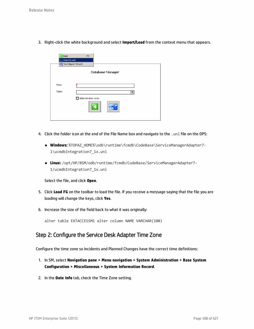
3. Right-click the white background and select Import/Load from the context menu that appears.
4. Click the folder icon at the end of the File Name box and navigate to the .unl file on the DPS:
n Windows: %TOPAZ_HOME%\odb\runtime\fcmdb\CodeBase\ServiceManagerAdapter7-1\ucmdbIntegration7_1x.unl
n Linux: /opt/HP/BSM/odb/runtime/fcmdb/CodeBase/ServiceManagerAdapter7-1/ucmdbIntegration7_1x.unl
Select the file, and click Open.
5. Click Load FG on the toolbar to load the file. If you receive a message saying that the file you areloading will change the keys, click Yes.
6. Increase the size of the field back to what it was originally:
alter table EXTACCESSM1 alter column NAME VARCHAR(100)
Step 2: Configure the Service Desk Adapter Time Zone
Configure the time zone so Incidents and Planned Changes have the correct time definitions:
1. In SM, select Navigation pane > Menu navigation > System Administration > Base SystemConfiguration > Miscellaneous > System Information Record.
2. In the Date Info tab, check the Time Zone setting.
Release Notes
HP ITSM Enterprise Suite (2015) Page 508 of 621
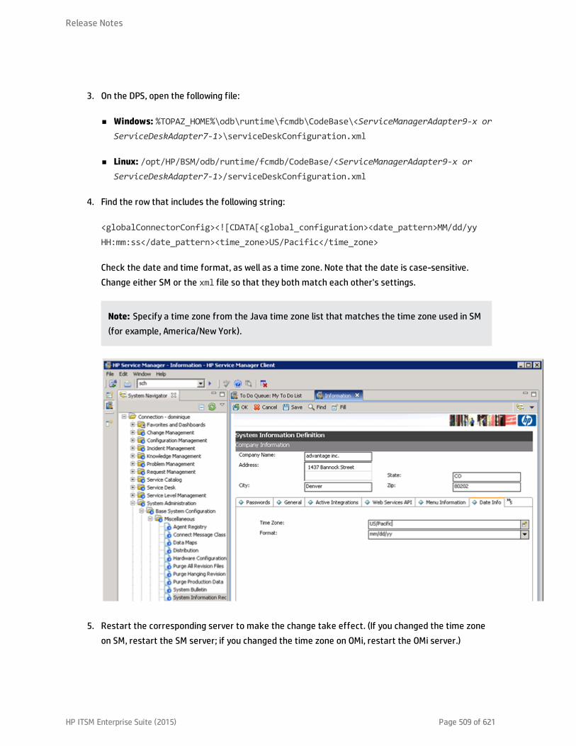
3. On the DPS, open the following file:
n Windows: %TOPAZ_HOME%\odb\runtime\fcmdb\CodeBase\<ServiceManagerAdapter9-x orServiceDeskAdapter7-1>\serviceDeskConfiguration.xml
n Linux: /opt/HP/BSM/odb/runtime/fcmdb/CodeBase/<ServiceManagerAdapter9-x orServiceDeskAdapter7-1>/serviceDeskConfiguration.xml
4. Find the row that includes the following string:
<globalConnectorConfig><
Step 3: Configure UCMDB to Generate Global IDs
1. On the UCMDB server, navigate to:
http://<UCMDB server name>:21212/jmx-console
2. Enter the user name and password.
3. In the UCMDB section, select UCMDB:service=Multiple CMDB Instances Services.
4. For setAsGlobalIdGenerator, click Invoke.
5. On the DPS, open the following file:
n Windows: %TOPAZ_HOME%\odb\runtime\fcmdb\CodeBase\<ServiceManagerAdapter9-x orServiceManagerAdapter7-1>\sm.properties
n Linux: /opt/HP/BSM/odb/runtime/fcmdb/CodeBase/<ServiceManagerAdapter9-x orServiceManagerAdapter7-1>/sm.properties
6. Set the use.global.id parameter to true.
For SM versions 9.2x, proceed with the next step. For SM versions 9.3x, skip to "Step 5: Configure SMAdapter in UCMDB" on the next page.
Step 4 (for SM 9.2x only): Add a Domain
1. In OMi, select Administration > RTSM Administration > Data Flow Management > Data FlowProbe Setup.
2. In the Domains and Probes pane, click .
3. In the Add New Domain dialog box, enter a new domain name, and then click OK. This creates anew domain and its protocols.
4. Within the domain you added, select Credentials > Generic Protocol, and then click the Add newconnection details button in the right pane. In the Add Protocol Parameter dialog box that opens,insert the SM administrator credentials.
Release Notes
HP ITSM Enterprise Suite (2015) Page 510 of 621
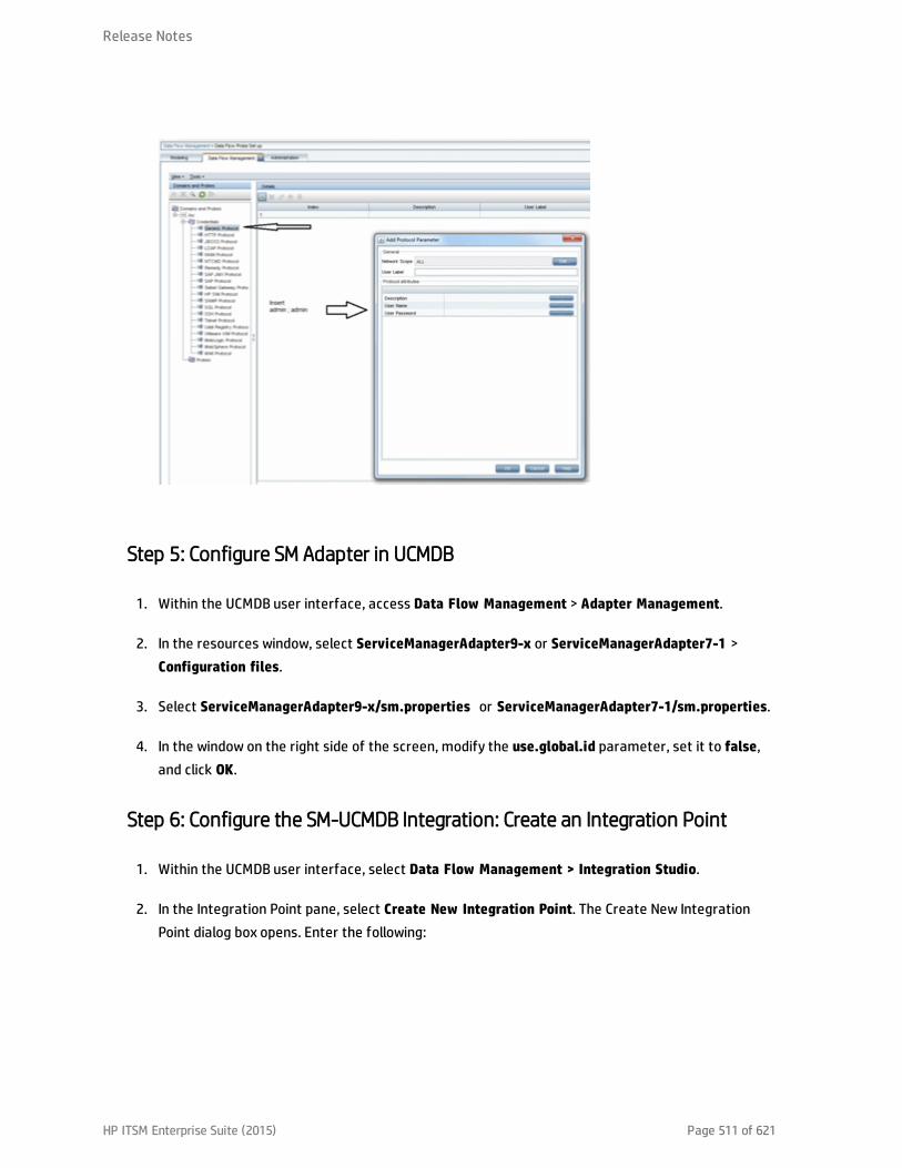
Step 5: Configure SM Adapter in UCMDB
1. Within the UCMDB user interface, access Data Flow Management > Adapter Management.
2. In the resources window, select ServiceManagerAdapter9-x or ServiceManagerAdapter7-1 >Configuration files.
3. Select ServiceManagerAdapter9-x/sm.properties or ServiceManagerAdapter7-1/sm.properties.
4. In the window on the right side of the screen, modify the use.global.id parameter, set it to false,and click OK.
Step 6: Configure the SM-UCMDB Integration: Create an Integration Point
1. Within the UCMDB user interface, select Data Flow Management > Integration Studio.
2. In the Integration Point pane, select Create New Integration Point. The Create New IntegrationPoint dialog box opens. Enter the following:
Release Notes
HP ITSM Enterprise Suite (2015) Page 511 of 621

NameRecommendedValue Description
Integration Name SMIntegration
The name you give to the integration point.
Adapter <userdefined>
Select the appropriate adapter for the version ofSM that you are using.
Is Integration Activated selected Select this check box to create an activeintegration point.
Hostname/IP <userdefined>
The name of the SM server.
Port <userdefined>
The port through which you access SM.
Credentials <userdefined>
n For SM 9.2x, select the user credentials createdin "Step 4 (for SM 9.2x only): Add a Domain" onpage 510.
n For SM 9.3x, in the default domain selectGeneric Protocol, and enter the credentials ofthe SM administrator.
Probe Name (forServiceManagerAdapter9-x only)
<userdefined>
If you are using ServiceManagerAdapter9-x, selectthe probe which reports to CMS (see "Prerequisite"on page 507).
Note: It is recommended to click the Test Connection button to verify that the details enteredare working before continuing.
If your SM backend server (SM Tomcat server) is configured to accept SSL connections, the portsetting is ignored and you must configure URL Override. For details, see the UCMDB documentation.
3. In the Integration Point pane, click the Integration Point you just created, and click the Federationtab in the right pane.
4. In the Supported and Selected CI Types area, verify that Incident, Problem, andRequestForChange are selected.
Release Notes
HP ITSM Enterprise Suite (2015) Page 512 of 621
Step 7: Configure the SM-UCMDB Integration: Set Up Data Push Jobs
Depending on your adapter version, perform the following:
For ServiceManagerAdapter9-x:
1. Edit the SM Push job, and select Scheduler Definition.
2. For the Repeat field, you can select Changes Sync/All Data Sync.
3. Set the Repeat Every field to 1 Day, and click OK.
For ServiceManagerAdapter7-1:
1. Edit the SM Topology Comparison Push job, and select Scheduler Definition.
2. For the Repeat field, select interval.
3. Set the Repeat Every field to 1 Day, and click OK.
4. Edit the SM History-based Push job, and select Scheduler Definition.
5. For the Repeat field, select interval.
6. Set the Repeat Every field to 1 Day, and click OK.
Step 8: Configure the SM-UCMDB Integration: Run Data Push Jobs
1. In the Integration Point pane, select the correct integration.
2. Select the Data Push tab. The Job Definition pane is displayed.
3. Select your job and click Synchronize All to run the push job.
Note: For ServiceManagerAdapter7-1, run this first for the SM History-based Push job, thenrepeat for the SM Topology Comparison Push job.
4. When the Confirm synchronizing window is displayed, click Yes.
5. Click the Statistics tab to view the progress of the synchronization.
6. Click Refresh to view the updated synchronization status.
Release Notes
HP ITSM Enterprise Suite (2015) Page 513 of 621

Step 9: Configure the SM-UCMDB Integration: Add UCMDB ConnectionInformation to SM
1. Log on to your UCMDB system as an administrator. Verify that all UCMDB services are running.
2. Log on to your SM system as an administrator.
3. Select System Administration > Base System Configuration > Miscellaneous > SystemInformation Record.
4. Select the Active Integrations tab.
5. Select the HP Universal CMDB option. The form displays the UCMDB Web service URL field.
6. In the UCMDB Web service URL field, enter the URL to the UCMDB Web service API. The URL has thefollowing format:
http://<UCMDB server name>:<port>/axis2/services/ucmdbSMService
7. In the UserId dialog box, enter your UCMDB user name and password and click Save.
Step 10: Configure the OMi-UCMDB Integration: Deploy CMS_to_RTSM_Sync.zip on UCMDB
1. Copy the CMS_to_RTSM_Sync.zip file located on the OMi-DPS machine file system under %TOPAZ_HOME%\odb\conf\factory_packages (Windows) or /opt/HP/BSM/odb/conf/factory_packages(Linux) to the file system on the UCMDB machine.
2. Within the UCMDB user interface, select the Administration tab.
3. Select Package Manager > Deploy Packages to server (from local disk).
4. Click the Add button and select the CMS_to_RTSM_Sync.zip file through the file system browser.
5. Select Deploy.
Release Notes
HP ITSM Enterprise Suite (2015) Page 514 of 621

Step 11: Configure the OMi-UCMDB Integration: Create an Integration Point onOMi
1. Within the OMi user interface, select Administration > RTSM Administration > Data FlowManagement > Integration Studio.
2. In the Integration Point pane, select Create New Integration Point. The Create New IntegrationPoint dialog box opens. Enter the following:
Name
Recommended
Value Description
Integration Name <userdefined>
The name you give to the integration point.
Adapter UCMDB 9.x Select the adapter type from the drop-down list.
Is Integration Activated selected Select this check box to create an activeintegration point.
Hostname/IP <userdefined>
The name of the UCMDB server, load balancer, orreverse proxy.
Port <userdefined>
The port through which you access UCMDB, loadbalancer, or reverse proxy.
Credentials <userdefined>
If credentials appear in the Credentials column,select them.
If no credentials appear, select Generic Protocoland click the Add new connection details forselected protocol type button.
Enter the following information:
n Description. Enter UCMDB.
n User Name. Enter the UCMDB user name. Thedefault value is admin.
n User Password. Enter and confirm a password.
Release Notes
HP ITSM Enterprise Suite (2015) Page 515 of 621

Name
Recommended
Value Description
Probe Name (forServiceManagerAdapter9-x only)
<userdefined>
If you are using ServiceManagerAdapter9-x, selectthe probe which reports to OMi (see "Prerequisite"on page 507).
3. Click the Add icon on the right side of the window and add Job definitions as follows:
a. Name the Job definition.
b. Select the Allow Delete check box.
c. Click the Add icon in the Job definition window.
d. From the pop-up window, browse to root - CMS sync and select the ActiveDirectory_sync joband click OK.
e. Select the Scheduler definition check box.
f. In the Repeat window, select Cron.
g. For the Cron expression, enter the following string: * 0/10 * * * ? * .
h. Adjust other settings as needed.
i. When finished, click OK and save the integration.
j. Repeat steps a to i and configure the following jobs:
o FailoverCluster_Sync
o IIS_Sync
o SOA_Sync
o BusinessAndFacilities_Sync
o ExchangeServer_Sync
o Virtualization_Sync
o Siebel_Sync
Release Notes
HP ITSM Enterprise Suite (2015) Page 516 of 621
o Credentials_Sync
o Basicinfrastructure_Sync
o J2EE_Sync
o SAP_Sync
4. Browse to UCMDB on port 21212 (for example, http://<DPS_host>.<domain>:21212), and select theJMX Console.
5. Log on to the JMX console.
6. From the UCMDB section, select UCMDB:service=Multiple CMDB Instances Services.
7. Invoke:
a. setAsGlobalIdGenerator and verify it succeeded.
b. getGlobalIdGeneratorScopes and verify it succeeded.
8. Within OMi, access Administration > RTSM Administration > Data Flow Management> Integration Studio.
9. Select the Integration Point that you have configured.
10. In the Job definition section, click Synchronize All to run the synchronization.
The Integration Point should be active and the jobs are displayed properly.
Step 12: Configure the OMi-UCMDB Integration: Create an Integration Point onthe CMS
1. Log on to UCMDB and select Data Flow Management > Integration Studio.
2. In the Integration Point pane, select Create New Integration Point. The Create New IntegrationPoint dialog box opens. Enter the following:
Release Notes
HP ITSM Enterprise Suite (2015) Page 517 of 621

Name
Recommended
Value Description
Integration Name <userdefined>
The name you give to the integration point.
Adapter UCMDB 9.x Select the adapter type from the drop-down list.
Is Integration Activated selected Select this check box to create an activeintegration point.
Hostname/IP <userdefined>
The name of the OMi server, load balancer, orreverse proxy.
Port <userdefined>
The port through which you access OMi, loadbalancer, or reverse proxy.
Credentials <userdefined>
If credentials appear in the Credentials column,select them.
If no credentials appear, select Generic Protocoland click the Add new connection details forselected protocol type button.
Enter the following information:
n Description. Enter UCMDB.
n User Name. Enter the UCMDB user name. Thedefault value is admin.
n User Password. Enter and confirm a password.
Probe Name (forServiceManagerAdapter9-x only)
<userdefined>
If you are using ServiceManagerAdapter9-x, selectthe probe which reports to the CMS (see"Prerequisite" on page 507).
3. Click the Add icon on the right side of the window and add Job definitions as follows:
a. Name the Job definition.
b. Select the Allow Delete check box.
c. Click the Add icon in the Job definition window.
Release Notes
HP ITSM Enterprise Suite (2015) Page 518 of 621
d. From the pop-up window, browse to root - CMS sync and select the ActiveDirectory_sync joband click OK.
e. Select the Scheduler definition check box.
f. In the Repeat window, select Cron.
g. For the Cron expression, enter the following string: * 0/10 * * * ? * .
h. Adjust other settings as needed.
i. When finished, click OK and save the integration.
j. Repeat steps a to i and configure the following jobs:
o FailoverCluster_Sync
o IIS_Sync
o SOA_Sync
o BusinessAndFacilities_Sync
o ExchangeServer_Sync
o Virtualization_Sync
o Siebel_Sync
o Credentials_Sync
o Basicinfrastructure_Sync
o J2EE_Sync
o SAP_Sync
4. Browse to UCMDB on port 8080 (for example, http://yourUCMDBhost.domain:8080), and select theJMX Console.
5. Log on to the JMX console.
6. From the UCMDB section, select UCMDB:service=Multiple CMDB Instances Services.
Release Notes
HP ITSM Enterprise Suite (2015) Page 519 of 621
7. Invoke:
a. setAsGlobalIdGenerator and verify it succeeded.
b. getGlobalIdGeneratorScopes and verify it succeeded.
8. Within UCMDB, access Data Flow Management > Integration Studio.
9. Select the Integration Point that you have configured.
10. In the Job definition section, click Synchronize All to run the synchronization.
The Integration Point should be active and the jobs are displayed properly.
Step 13 (Optional): Add CI Types to the Service Health Changes and IncidentsComponent
By default, OMi Service Health displays information on incidents and requests for change for thefollowing CI types: Business Service, Siebel Application, Business Application, and Node.
If you want to view change and incident information for other CITs, perform the procedure described in"How to Customize the Changes and Incidents Component" on page 531.
Step 14 (Optional): Map Siebel Application CITs
To create a mapping between the Hand Held Devices or Display Device CIT in SM with SiebelApplication CITs in OMi, perform one of the following procedures:
l In SM, select Main page > To Do > Queue: Configuration Item > New > New and click Device. In theConfiguration Item field, enter the exact name (case sensitive) of the OMi CI that corresponds to theSiebel Application CIT in OMi.
l Create a new population job that includes the Hand Held Devices or Display Device CIT. Those CITscorrespond to the Siebel application CITs. For details about how to create a population job, see theModeling Guide.
Troubleshooting
If you are not seeing expected incidents in OMi, perform the following:
Release Notes
HP ITSM Enterprise Suite (2015) Page 520 of 621

1. On the Data Processing Server, search the odb\odb\Error.log file for Error Code 802.
2. In this error message, locate the following string: property [<category or incident_status>=<attribute value>[STRING] ] is defined as attribute.
This indicates that a certain attribute value is missing in RTSM.
3. Access RTSM Administration > CI Type Manager.
4. From the CI Types menu, select System Type Manager, and open Category or Incident Status(depending on the error message) for editing.
5. Click the Add button (+), and add the missing attribute value (exactly as it appears in the errormessage) to the list of values.
Release Notes
HP ITSM Enterprise Suite (2015) Page 521 of 621

View Changes and Incidents in Service Health Using RTSM
This integration enables you to view planned changes and incident details in the Changes & Incidentstab in the 360° View page in Service Health when you are working with RTSM. For details, see the OMiUser Guide.
This chapter includes the following:
l "Prerequisite" below
l "Step 1: Configure the Service Desk Adapter Time Zone" below
l "Step 2: Create an Integration User Account in Service Manager" on page 524
l "Step 3: Add the OMi Connection Information in SM" on page 525
l "Step 4: Create an Integration Point in OMi" on page 525
l "Step 5: Create New Jobs to Synchronize Between OMi and SM" on page 527
l "Step 6: Run the Job" on page 527
l "Step 7: Test the Configuration" on page 528
l "Step 8 (Optional): Add CI Types to the Service Health Changes and Incidents Component" onpage 530
l "Troubleshooting" on page 530
Prerequisite
If you are using SM versions 9.3x, before you begin, you must install a data-flow probe with the OMiGateway Server as its target. When you configure the integration point, you will select this probe for theintegration.
Step 1: Configure the Service Desk Adapter Time Zone
Configure the time zone so Incidents and Planned Changes have the correct time definitions:
1. In SM, select Navigation pane > Menu navigation > System Administration > Base SystemConfiguration > Miscellaneous > System Information Record.
HP ITSM Enterprise Suite (2015) Page 522 of 621

2. In the Date Info tab, open the following file:
n Windows: %TOPAZ_HOME%\odb\runtime\fcmdb\CodeBase\<ServiceManagerAdapter9-x orServiceDeskAdapter7-1>\serviceDeskConfiguration.xml
n Linux: /opt/HP/BSM/odb/runtime/fcmdb/CodeBase/<ServiceManagerAdapter9-x orServiceDeskAdapter7-1>/serviceDeskConfiguration.xml
3. Find the row that includes the following string:
<globalConnectorConfig><
Step 2: Create an Integration User Account in Service Manager
This integration requires an administrator user account for OMi to connect to SM. This user accountmust already exist in both OMi and SM.
To create a dedicated integration user account in SM:
1. Log on to SM as a system administrator.
2. Type contacts in the SM command line, and press ENTER.
3. Create a new contact record for the integration user account.
a. In the Full Name field, type a full name. For example, RTSM.
b. In the Contact Name field, type a name. For example, RTSM.
c. Click Add, and then OK.
4. Type operator in the SM command line, and press ENTER.
5. In the Login Name field, type the user name of an existing system administrator account, and clickSearch.
The system administrator account displays.
6. Create a new user account based on the existing one:
a. Change the Login Name to the integration account name you want (for example, rtsm).
b. Type a Full Name. For example, RTSM.
c. In the Contact ID field, click the Fill button and select the contact record you have justcreated.
d. Click Add.
e. Select the Security tab, and change the password.
f. Click OK.
The integration user account is created. Later you will need to add this user account (username/password) in RTSM, and then specify this user account in the Credentials ID field when creatingan integration point in RTSM administration.
Release Notes
HP ITSM Enterprise Suite (2015) Page 524 of 621
Step 3: Add the OMi Connection Information in SM
The integration requires the OMi connection information to obtain CI attribute information from the OMisystem, and display it in the Actual State section in the SM configuration item form.
1. Log on to SM as a system administrator.
2. Click System Administration > Base System Configuration > Miscellaneous > SystemInformation Record.
3. Click the Active Integrations tab.
4. Select the HP Universal CMDB option.
The form displays the UCMDB web service URL field.
5. In the UCMDB web service URL field, type the URL to the HP Universal CMDB web service API. TheURL has the following format:
http://<UCMDB server name>:<port>/axis2/services/ucmdbSMService
Replace <UCMDB server name> with the host name of your OMi server, and replace <port> with thecommunications port your OMi server uses.
6. In UserId and Password, type the user credentials required to manage CIs on the OMi system. Forexample, the out-of-the-box administrator credentials are admin/admin.
7. Click Save. SM displays the message: Information record updated.
8. Log out of the SM system.
9. Log back into the SM system with an administrator account. The Actual State section will beavailable in CI records pushed from OMi.
Step 4: Create an Integration Point in OMi
A default RTSM installation already includes the ServiceManagerAdapter9-x package. To use theintegration package, you must create an integration point listing the connection properties for theintegration.
To create an integration point, follow these steps:
Release Notes
HP ITSM Enterprise Suite (2015) Page 525 of 621

1. Create a user in OMi and set the RTSM Permissions in the Create Role page. For details aboutcreating and configuring users, groups, and roles in OMi, see the OMi Administration Guide.
2. In OMi, select Administration > RTSM Administration > Data Flow Management > IntegrationStudio.
3. In the Integration Point pane, select Create New Integration Point. The Create New IntegrationPoint dialog box opens. Enter the following:
NameRecommendedValue Description
Integration Name SMIntegration
The name you give to the integration point.
Adapter <userdefined>
Select HP BTO Products > Service Manager >Service Manager 9.xx.
This adapter, which supports CI/ relationship DataPush from RTSM to Service Manager, andPopulation and Federation from Service Managerto RTSM.
Is Integration Activated selected Select this check box to create an activeintegration point.
Hostname/IP <userdefined>
The name of the SM server.
Port <userdefined>
The port through which you access SM.
Credentials <userdefined>
Click Generic Protocol, click the Add button to addthe integration user account you created in "Step2: Create an Integration User Account in ServiceManager" on page 524, and then select it. Thisaccount must exist in both Service Manager andOMi.
Probe Name (forServiceManagerAdapter9-x only)
<userdefined>
Select the probe that you installed for thisintegration.
Release Notes
HP ITSM Enterprise Suite (2015) Page 526 of 621

Note: It is recommended to click the Test Connection button to verify that the details enteredare working before continuing.
4. In the Integration Point pane, click the Integration Point you just created, and click the Federationtab in the right pane.
5. In the Supported and Selected CI Types area, verify that Incident, Problem, andRequestForChange are selected.
Step 5: Create New Jobs to Synchronize Between OMi and SM
1. In OMi, select Administration > RTSM Administration > Data Flow Management > IntegrationStudio.
2. Click the Data Push tab.
3. In the New Integration Job dialog box, click the + icon on the left.
4. In the Available Queries dialog box, select the relevant queries for the job.
Step 6: Run the Job
When you run the job, the CIs are synchronized between OMi and SM.
Release Notes
HP ITSM Enterprise Suite (2015) Page 527 of 621

Step 7: Test the Configuration
1. In OMi, select Administration > RTSM Administration > Modeling > IT Universe Manager.
2. In the CI Selector pane, select the relevant view, and click in the right pane.
3. In the New CI dialog box that opens, create a new CI with the BusinessService type.
4. Create a TQL that includes only BusinessService CI Types (CITs):
Administration > Service Health > KPIs in Views
Alternatively, click KPIs in Views.
5. Click the Calculate button. The relevant CI appears in view.
6. Click the Data Push tab, and run the job in order to synchronize with SM.A message that the job was successful should be issued.
7. In SM, create a new incident for the new CI that you created above:a. Select Incident Management > Open New Incident.
b. Important: Start by entering the name of the CI you want to attach to the incident in the
Release Notes
HP ITSM Enterprise Suite (2015) Page 528 of 621

Affected CI field. This creates the Incident Id.
c. Enter the CI name in the Affected Service field and click to search.
d. Enter any incident detail.
The incident is automatically attached to the CI.
8. In OMi, create a TQL with the CI Type you created connected to the Incident CI Type in amembership relationship link.
9. Click the Calculate button. One incident appears connected to the BusinessService CI Typebecause this test created it and it is synchronized automatically.
10. Delete the incident from the TQL and save the TQL to be a view. The TQL is only used for the test.
Release Notes
HP ITSM Enterprise Suite (2015) Page 529 of 621
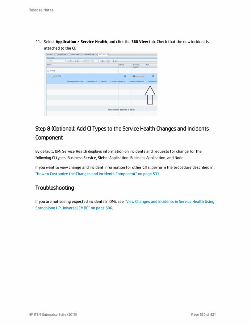
11. Select Application > Service Health, and click the 360 View tab. Check that the new incident isattached to the CI.
Step 8 (Optional): Add CI Types to the Service Health Changes and IncidentsComponent
By default, OMi Service Health displays information on incidents and requests for change for thefollowing CI types: Business Service, Siebel Application, Business Application, and Node.
If you want to view change and incident information for other CITs, perform the procedure described in"How to Customize the Changes and Incidents Component" on page 531.
Troubleshooting
If you are not seeing expected incidents in OMi, see "View Changes and Incidents in Service Health UsingStandalone HP Universal CMDB" on page 506.
Release Notes
HP ITSM Enterprise Suite (2015) Page 530 of 621
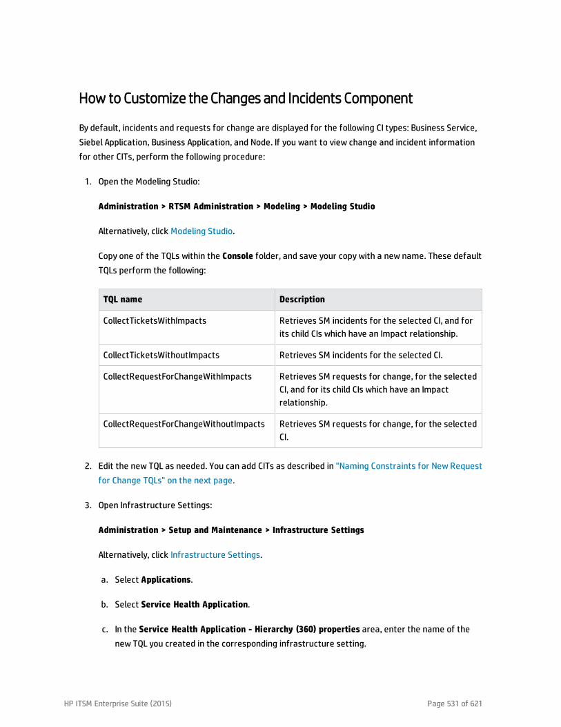
How to Customize the Changes and Incidents Component
By default, incidents and requests for change are displayed for the following CI types: Business Service,Siebel Application, Business Application, and Node. If you want to view change and incident informationfor other CITs, perform the following procedure:
1. Open the Modeling Studio:
Administration > RTSM Administration > Modeling > Modeling Studio
Alternatively, click Modeling Studio.
Copy one of the TQLs within the Console folder, and save your copy with a new name. These defaultTQLs perform the following:
TQL name Description
CollectTicketsWithImpacts Retrieves SM incidents for the selected CI, and forits child CIs which have an Impact relationship.
CollectTicketsWithoutImpacts Retrieves SM incidents for the selected CI.
CollectRequestForChangeWithImpacts Retrieves SM requests for change, for the selectedCI, and for its child CIs which have an Impactrelationship.
CollectRequestForChangeWithoutImpacts Retrieves SM requests for change, for the selectedCI.
2. Edit the new TQL as needed. You can add CITs as described in "Naming Constraints for New Requestfor Change TQLs" on the next page.
3. Open Infrastructure Settings:
Administration > Setup and Maintenance > Infrastructure Settings
Alternatively, click Infrastructure Settings.
a. Select Applications.
b. Select Service Health Application.
c. In the Service Health Application - Hierarchy (360) properties area, enter the name of thenew TQL you created in the corresponding infrastructure setting.
HP ITSM Enterprise Suite (2015) Page 531 of 621

Note: By default, these infrastructure settings contain the default TQL names. If you enter aTQL name that does not exist, the default value will be used instead.
After you modify the infrastructure setting, the new TQL will be used, and the Changes and Incidentscomponent will show this information for the CITs you defined.
Naming Constraints for New Request for Change TQLs
The following naming constraints should be followed in the request for change without impact TQL (seethe TQL example below, on the right side of the image):
l The request for change CI type should start with directPlannedChange.
l The CI type related to the request for change should start with trigger.
The following naming constraints should be followed in the request for change with impact TQL (see theTQL example below, on the left side of the image):
l impacterPlannedChange represents the request for change CI type.
l The CI type related to the request for change should start with impacter.
l triggerITUniverse represents the "impacted" child CIs.
Examples of request for change TQLs:
Release Notes
HP ITSM Enterprise Suite (2015) Page 532 of 621

Naming Constraints for New Incident TQLs
The following naming constraints should be followed in the incidents without impact TQL (see the TQLexample below, on the right side of the image):
l The incident CI type should start with directITIncident.
l The CI type related to the incident should start with trigger.
The following naming constraints should be followed in the incidents with impact TQL (see the TQLexample below, on the left side of the image):
l impacterITIncident represents the incident CI type.
l The CI type related to the incident should start with impacter.
l triggerITUniverse represents the "impacted" child CIs.
Examples of incident TQLs:
Release Notes
HP ITSM Enterprise Suite (2015) Page 533 of 621

Generate Incidents in SMWhen an OMi Alert is Triggered
This integration enables you to configure specific CI status alerts to automatically open a correspondingincident in SM. The alerts are mapped to the events using the Event Template.
The triggered alert forwards a corresponding event to OMi where (using the Incident exchange betweenthe SM and OMi integration) the event is changed into an incident and sent, using the Event ForwardingService, to SM to proactively alert the operator about a problem in the system.
By default, a CI status alert is mapped to an event using a default Event Template. You can modify thedefault Event Template or select a different Event Template as follows:
1. Access CI Status Alerts:
Administration > Service Health > CI Status Alerts
Alternatively, click CI Status Alerts.
Select a view and a CI and click New Alert or select an existing alert and click Edit.
2. In the Actions page, click the New Event Generation link in the Generate Events section.
3. In the CI Alert Template Repository dialog box that opens, select the template you want to use tomap the alert to an event and click Select. The template you selected is now listed in the GenerateEvents section.
For user interface details, see the OMi Administration Guide.
Integrate BSM and SM
Note: The following sections are excerpted from the integrations section of the Business ServiceManagement Help Center. However, to ensure you have the latest information, you shouldreference the latest published version of the document in question.
HP ITSM Enterprise Suite (2015) Page 534 of 621
BSM - Service Manager Integration OverviewYou can integrate HP Service Manager with one or more of the BSM components, as described below.Each integration can be performed separately.
Note: In general, the following document is for integrating BSM 9.2x with Service Manager 9.31.
For instructions on integrating BSM with earlier versions of Service Manager, seehttp://support.openview.hp.com/selfsolve/document/KM1303768/binary/BSM9.12_SM_Integration_Interactive_Docs.html. Download and extract the zip file contents; open the file sm_interactive_document.htm and follow the guidelines.
The options are as follows:
l Downtime exchange between BSM and Service Manager. BSM enables you to forward downtimes(also known as outages) from BSM to Service Manager, and from Service Manager to BSM. Thedowntime defined in BSM is converted to a request for change in Service Manager, and vice versa.For details, see "Downtime Exchange Between BSM and HP Service Manager" on page 537.
l Incident exchange between Service Manager and Operations Manager i. BSM enables you toforward events from Operations Management to Service Manager. Forwarded events andsubsequent event changes are synchronized back from Service Manager to OperationsManagement. You can also drill down from Operations Manager events to Service Managerincidents. For details, see "Incident Exchange between HP Operations Manager i and HP ServiceManager" on page 549.
l View planned changes and incident details in Service Health. This integration enables you to viewplanned changes and incident details in the Changes & Incidents tab in the 360° View page in ServiceHealth. For details, see "View Changes and Incidents in Service Health Using Standalone HP UniversalCMDB" on page 565 and "View Changes and Incidents in Service Health Using RTSM" on page 581.
l Submit an incident through BSM alerts. Incidents are automatically opened incidents in ServiceManager when a CI Status alert is triggered in BSM. For details, see "Generate Incidents in ServiceManager When a BSM Alert is Triggered" on page 594.
l View the Number of Open Incidents in Service Health and create SLAs (EMS). This integrationenables you to view the Number of Open Incidents in Service Health views and reports and tomanage, in Service Level Management, SLAs over Serviceability KPIs based on Service Manager
HP ITSM Enterprise Suite (2015) Page 535 of 621
incidents (EMS option). For details, see "View Incident Data in BSM, and Manage SLAs Based onService Manager" on page 596.
l The Business Impact Report integration is described in the Closed Loop Incident Process (CLIP) Guide.When deployed as part of the BSM solution, Incident Management users can launch an impact reportfrom an incident in context with the incident's affected CI. Service Desk Agents can validate theupdated status of the Business Impact to categorize and prioritize the incident accordingly. Fordetails, refer to the CLIP page in the Solutions Portal:http://support.openview.hp.com/sc/solutions/index.jsp#tab=tab1.
Note:l Service Manager Query Security. If you have set up an integration from BSM to Service
Manager, there is a CI context menu that enables you to access Service Manager fromBSM Service Health. This drill-down option is not available if you have enabled Service Managerquery security.
l Troubleshooting Multiple Domains. If BSM and SM are in different domains, and you are usingInternet Explorer as your browser, you may need to add the domains to the list of alloweddomains in the Privacy tab (Internet Options > Privacy > Sites).
Release Notes
HP ITSM Enterprise Suite (2015) Page 536 of 621

Downtime Exchange Between BSM and HP Service ManagerBSM enables you to forward downtimes (also known as outages) from BSM to Service Manager, andfrom Service Manager to BSM. The downtime defined in BSM is converted to an incident in ServiceManager, and vice versa.
This section includes the following:
l "Integration Overview" below
l "Prerequisites" on the next page
l "Step 1: Send BSM Downtime Events to Service Manager" on page 539
l "Step 2: Integrate Service Manager Downtimes With BSM" on page 542
Integration Overview
The downtime integration between BSM and Service Manager includes information exchanges in both ofthe following directions:
l Service Manager > BSM. When you create a downtime RfC (request for change) in Service Manager,the RfC includes the CI that is under change and a start and end date/time of the downtime. If youdo not want to waste effort with false alarms in your operations center, and do not want to havethese times included in service availability reports, you can set up the integration so that these RfCsare translated to downtimes in BSM.
In this scenario, you install and set up a downtime adapter on your CMDB (whether you are workingwith a stand-alone uCMDB, or with RTSM). The RfC creates a planned downtime CI in the CMDB, andthe adapter sends the planned downtime CI to BSM to create a downtime.
l BSM > Service Manager. When you define downtimes using BSM (for example, every Monday andSaturday from 8:30 PM-9:30 PM), in order to proactively support end users, the help desk should beaware of such operational downtimes. After you set up the integration, downtimes in BSM triggerevents, which create corresponding incidents in Service Manager.
In this scenario, when a downtime starts, BSM generates an event. Using the event forwardingmechanism, the event generates an incident in Service Manager. When the downtime ends, an eventis sent to close the downtime incident.
HP ITSM Enterprise Suite (2015) Page 537 of 621

A single downtime can be defined on more than one CI. In the case of BSM > Service Manager, aseparate event is sent for each CI in the downtime.
Prerequisites
Supported Platforms
To set up the downtime integration, you must meet the following prerequisites:
l Service Manager 9.31 and higher.
l uCMDB 9.05 CUP 5 and higher with content pack 11 update 2, or uCMDB 10.01 with content pack 12.
l Before deploying the adapter verify that CP11 is installed. If it is not, install the content pack. (Thisshould be done whether you have upgraded to BSM 9.22, or if you installed BSM 9.22 directly.)
Note: To see what version of RTSM is installed, access the RTSM JMX console: http://<BSMserver>:21212/jmx-console/. Click on DAL services and run getCmdbVersion to get the RTSMversion. Click Content Pack Services and run displayCurrentContentPackVersion to get thecontent pack version.
l If the adapter is installed on the RTSM, and the adapter is working behind a reverse proxy, the DPSmust have the correct certificates installed to send requests to the reverse proxy.
l If you have upgraded from BSM 9.1x, you need to manually redeploy the adapter. Open the PackageManager and delete the BSMDowntimeAdapter package. When it is deleted, redeploy the abovepackage from the packages folder.
Installing the Content Pack for uCMDB 9.05
The following section is only relevant if you are using uCMDB 9.05, or upgrading from BSM 9.20 (whichrequires the content pack to be installed). If you have not yet installed the content pack, perform thefollowing on your BSM/uCMDB machine:
1. From the content pack installation zip file, copy the content pack zip file to the following location(depending on your environment):
For RTSM: <BSM data processing installation folder>\odb\content\content_packs
For uCMDB: <Installation drive or folder>\HP\UCMDB\content\content_packs
The main BSM folder in Linux is located in: /opt/HP/BSM.
Release Notes
HP ITSM Enterprise Suite (2015) Page 538 of 621
2. Access the following location with your browser:
http://<BSM DPS or uCMDB hostname>:21212/jmx-console/HtmlAdaptor?action=inspectMBean&name=UCMDB:service=Content Pack Services
3. In the method installContentPack(), enter the parameters:
a. Fill the parameter customerID with the value of 1.
b. Enter the version number found in version.dat, located in the content pack zip file.
c. Invoke the method.
Global ID Generator
To enable the downtime integration, you must have a global ID generator configured in yourenvironment.
If you are working with RTSM, perform the following to configure the global ID generator:
1. Access the following location with your browser:
http://<BSM hostname>:21212/jmx-console/HtmlAdaptor?action=inspectMBean&name=UCMDB:service=Multiple CMDB Instances Services
2. In the method setAsGlobalIdGenerator(), assign the value 1 to the parameter customerID, andclick Invoke.
If you are working with uCMDB, perform the following to configure the global ID generator:
1. Access the following location with your browser: :
http://<uCMDB hostname>:8080/jmx-console/HtmlAdaptor?action=inspectMBean&name=UCMDB:service=MultipleCMDB Instances Services.
2. In the method setAsGlobalIdGenerator(), assign the value 1 to the parameter customerID, andclick Invoke.
Step 1: Send BSM Downtime Events to Service Manager
To enable BSM to send downtime definitions to Service Manager, you must edit an infrastructuresetting as described below. This procedure generates events in OMi; you can then use the eventforwarding mechanism to generate incidents in Service Manager when a downtime in BSM begins andends.
Release Notes
HP ITSM Enterprise Suite (2015) Page 539 of 621
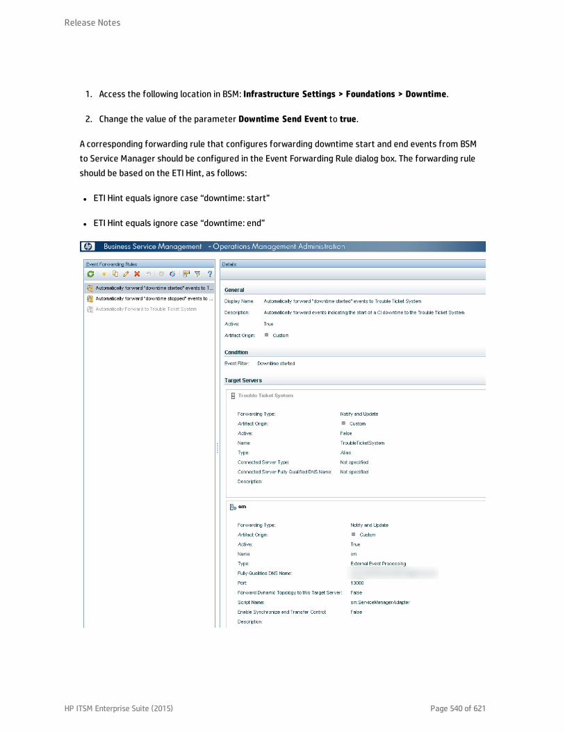
1. Access the following location in BSM: Infrastructure Settings > Foundations > Downtime.
2. Change the value of the parameter Downtime Send Event to true.
A corresponding forwarding rule that configures forwarding downtime start and end events from BSMto Service Manager should be configured in the Event Forwarding Rule dialog box. The forwarding ruleshould be based on the ETI Hint, as follows:
l ETI Hint equals ignore case “downtime: start”
l ETI Hint equals ignore case “downtime: end”
Release Notes
HP ITSM Enterprise Suite (2015) Page 540 of 621

For details on how to use the event forwarding mechanism to generate incidents in Service Manager,refer to the section "Event Forwarding" in the BSM Application Administration Guide.
Downtime events use the following formats:
l Downtime Start
Event field BSM Downtime
Severity Normal
Category Downtime Notification
Title Downtime for <CI Type><Affected CI Name>started at <Downtime Start Time>
Key <BSM Downtime ID>:<Affected CI ID>:downtime-start
SubmitCloseKey False
OutageStartTime <Downtime Start Time>
OutageEndTime <Downtime End Time>
CiName <Affected CI Name>
CiId <Affected CI Global ID>
CiHint GUCMDB:<Affected CI Global ID>|UCMDB:<Affected CI ID>
HostHint GUCMDB:<Related Host Global ID>|UCMDB:<Related Host ID>
EtiHint downtime:start
l Downtime End
Event field BSM Downtime
Severity Normal
Category Downtime Notification
Title Downtime for <CI Type><Affected CI Name> ended at < Downtime End Time>
Key <BSM Downtime ID>:<Affected CI ID>:downtime-stop
SubmitCloseKey true
CloseKeyPattern <BSM Downtime ID>:<Affected CI ID>:downtime-start
EtiHint downtime:end
Release Notes
HP ITSM Enterprise Suite (2015) Page 541 of 621

Event field BSM Downtime
LogOnly true
Step 2: Integrate Service Manager DowntimesWith BSM
Integrating Service Manager downtimes with BSM consists of:
l Creating an instance of the ScheduledDowntime CIT in RTSM/uCMDB
l Creating an instance of the BSMDowntime CIT in BSM
The following image shows the data flow when using RTSM:
SMBSM
CIT ScheduledDowntimeRTSM
BSM Downtime Service
CIT
BSM
Dow
ntim
e
Important:
l Following the initial integration, a large amount of data may be communicated from ServiceManager to BSM. We recommend that you perform this procedure during off-hours, to preventnegative impact on system performance.
l You should configure both parts of the integration as one flow, without a significant time lagbetween setting up the two parts. If you set up the Service Manager > uCMDB/RTSM part, and thenwait a long time before setting up the uCMDB/RTSM > BSM adapter part, the number of downtimescommunicated to BSM initially may be extremely high.
Configuring HP Service Manager to Send Downtimes
Note:
l The following provides the basic steps for HP Service Manager configuration. For details, seethe HP Service Manager documentation.
l SMBSM_DOWNTIME is available in HP Service Manager 9.32 and above.
Release Notes
HP ITSM Enterprise Suite (2015) Page 542 of 621

l This document provides a basic description of how to configure SMBSM_DOWNTIME integration.For details, see the HP Service Manager documentation.
1. Log in to HP Service Manager as System.Admin.
2. Click Tailoring > Integration Manager > Add to add the Service Manager Integration Suite (SMIS)configuration for SMBSM_DOWNTIME. The Integration Template Selection page appears.
3. From the Integration Template drop-down list, select SMBSM_DOWNTIME, and click Next. TheIntegration Instance Information page appears.
4. In the Interval Time(s) field, type the running frequency data. Set this value based on yourconfiguration item (CI) scheduled downtime data volume for the period.
5. In the Max Retry Times field, type the maximum number of retries. Since you are not connectingto another system, type 0.
6. In the Log File Directory field, type the full path for the log file. By default, the log name is sm.log.
7. Click Next. The Integration Instance Parameters page appears.
8. Click the General Parameters tab.
9. Configure the SMIS settings.
a. Assign a value for WithdrawDowntime (options are true or false). True means that when youmake a change using Change Phase, if the change has a valid outage, a prompt appearsenabling you to reject the outage.
b. In the Category column, assign the value Change for change categories and Task for taskcategories.
c. Assign values for the parameters in the Change category.
If you only want outages of one change category after your desired phase has been approved,in the Value column, set the phase.
If your category workflow has multiple paths with different final approval phases, use asemicolon (;) to separate the phases.
d. Assign a unique identifier for your Service Manager deployment to the sm.host parameter.This identifier represents your Service Manager server.
Release Notes
HP ITSM Enterprise Suite (2015) Page 543 of 621

Do not use a colon (:) in this field.
e. Assign a value to the sm.reference.prefix parameter. This value is used to populate theExternal Process Reference of Scheduled Downtime CI in UCMDB.
Service Manager automatically appends a colon (:) at the end of the value.
f. Click Next, Next, Finish.
g. Select the SMIS.
h. Click Enable.
i. Click Yes.
Integrating SM RFC Downtimes with RTSM/uCMDB
To integrate SM RFC downtimes with RTSM/uCMDB, populate (synchronize) RTSM/uCMDB with thedowntime CIs.
1. Log in to RTSM/uCMDB.
n In BSM, access Admin > RTSM Administration > Data Flow Management > Integration Studio
n In uCMDB, access Administration > Data Flow Management > Integration Studio
2. Verify that the integration point in front of the Service Manager exists and is active.
Release Notes
HP ITSM Enterprise Suite (2015) Page 544 of 621

3. Click Test connection and verify that the connection succeeds.
4. In the Population tab, add the following integration jobs:
n DT Population based on CLIP Down Time Population TQL
n DT Relationship based on CI To Down Time CI With Connection TQL
5. Log in to the Service Manager server. Select the Configuration Management tab and selectResources > Configuration Item Relationships.
6. Add a relation between the Upstream CI (for example, any business service instance) and theDownstream CI (the affected CI), and click Add.
7. In the Change Management tab, select Changes > Open New Change to open a new request forchange (RfC). Verify the Service, Affected CI, and Scheduled DownTime Start/End field are
Release Notes
HP ITSM Enterprise Suite (2015) Page 545 of 621

completed.
Note: The Service and Affected CI values should be equal to the Upstream/Downstream CIvalues you set in the previous step.
8. Click More > Change Phase. Move the RfC phase to the Change Approval phase.
9. Log in to Service Manager as user Change.Approver. Open the Approval In box and approve thechange.
10. Wait for SMBSM_DOWNTIME/DT Population/DT Relationship to run. By default, it runs everyminute.
11. Log in to RTSM/uCMDB.
n In BSM, access Admin > RTSM Administration > Data Flow Management > Modeling Studio
n In uCMDB, access Administration > Data Flow Management > Modeling Studio
12. In Modeling Studio, search for ScheduledDowntime CI. A downtime CI is created with a relationshipto the affected CI.
Push CIT ScheduledDowntime to CIT BSMDowntime by BSMDowntimeAdapter
1. If you are using uCMDB, deploy the adapter as follows:
a. In uCMDB, access Administration > Package Manager.
In BSM, access Admin > RTSM Administration > Administration > Package Manager.
b. Click Deploy package to server, and import the adapter’s zip file from <BSM DPSinstallation path>\odb\conf\factory_packages\BSMDowntimeAdapter.zip.
2. Create the integration point credentials:
a. In uCMDB, access Data Flow Management > Data Flow Probe Setup.
In BSM, access Admin > RTSM Administration > Data Flow Management > Data Flow ProbeSetup
Release Notes
HP ITSM Enterprise Suite (2015) Page 546 of 621
Note: You do not need a Probe to perform this integration; nevertheless you createcredentials using the Data Flow Probe Setup tab.
b. Click Add domain or probe, and enter a name and description of your choice.
c. Expand the submenus and select HTTP protocol.
d. Click the plus sign (Add new connection details) and enter the BSM Gateway host name, Port80, and the BSM username and password. Leave the Trust fields blank. When you are done,click OK to save the credentials.
3. Create a new integration point:
a. In uCMDB, access Data Flow Management > Integration Studio.
In BSM, access Admin > RTSM Administration > Data Flow Management > IntegrationStudio.
b. Click New integration point, enter a name and description of your choice, and select:
o In BSM: BSMDowntimeAdapter
o In uCMDB: SM scheduled Downtime Integration into BSM
c. Enter the following information for the adapter:
o BSM Gateway hostname and port
o Communication protocol
o The integration point credentials you just created
o Context root (if you have a non-default context root).
d. Click OK, then click the Save button above the list of the integration points.
4. Click the Statistics tab in the lower pane, to track the number of downtimes that are created orupdated. By default, the integration job runs every minute. If a job failed, you can click the QueryStatus tab and double-click the failed job to view more details about the error.
Troubleshooting
Release Notes
HP ITSM Enterprise Suite (2015) Page 547 of 621

l If there is an authentication error, verify that the BSM credentials entered for the integration pointare correct.
l An unclear error message with an error code generally indicates a communication problem. Checkthe communication with BSM. If no communication problem is found, restart the MercuryAS process.
Note:
l A failed job is repeated until the problem is fixed.
l Each BSMDowntime can be found in BSM Downtime Management (Admin > Platform >Downtime Management).
Release Notes
HP ITSM Enterprise Suite (2015) Page 548 of 621
Incident Exchange between HP Operations Manager i and HPService ManagerBSM enables you to forward events from Operations Management to HP Service Manager 9.30, 9.21, or9.20. Forwarded events and subsequent event changes are synchronized back from HP Service Managerto Operations Management. You can also drill down from Operations Manager events to HP ServiceManager incidents.
Note: HP recommends this integration option for new integrations with HP Service Manager 9.30,9.21, or 9.20. However, existing integrations that use other integration options are still supported.
This section includes the following:
l "Step 1: Configure the HP Service Manager Server as a Connected Server" below
l "Step 2: Configure an Event Forwarding Rule" on page 553
l "Step 3: Configure URL Launch of Event Browser from HP Service Manager" on page 555
l "Step 4: Configure URL Launch of HP Service Manager from the Event Browser" on page 556
l "Step 5: Configure HP Service Manager Server" on page 557
l "Step 6: Mapping and Customization" on page 558
l "Step 7: Test the Connection" on page 559
l "Step 8: Synchronize Attributes" on page 560
l "Tips for Customizing Groovy Scripts" on page 561
Step 1: Configure the HP Service Manager Server as a ConnectedServer
Synchronizing events and event changes between Operations Management events and HP ServiceManager incidents requires configuring a Connected Server within Operations Management to correctlyidentify the target HP Service Manager instance. The first step to achieve this is to configure HP ServiceManager as a target connected server in the Connected Servers manager.
HP ITSM Enterprise Suite (2015) Page 549 of 621

For full details about how to configure a connected server, see the Connecting Servers section of theOperations Management online help.
To configure the HP Service Manager server as a target connected server, perform the following steps:
1. Navigate to the Connected Servers manager in the Operations Management user interface:
Admin > Operations Management > Setup > Connected Servers
2. Click the New button to open the Create New Server Connection dialog box.
3. In the Display Name field, enter a name for the target HP Service Manager server. By default, theName field is filled automatically. For example, if you enter Service Manager 1 as the DisplayName for the target HP Service Manager server, Service_Manager_1 is automatically inserted inthe Name field. You can specify your own name in the Name field, if you want to change it from theone suggested automatically.
Note: Make a note of the name of the new target server (in this example, Service_Manager_1). You need to provide it later on as the username when configuring the Service Managerserver to communicate with the server hosting Operations Management.
Optional: Enter a description for the new target server.
Make sure that you check the Active checkbox.
Click Next.
4. Select External Event Processing to choose the server type suitable for an external incidentmanager like HP Service Manager.
Click Next.
5. Enter the Fully Qualified DNS Name of the HP Service Manager target server.
Click Next.
6. From the Integration Type dialog box:
a. Select Call Script Adapter as the integration type .
b. From the Script Name menu, select the HP Service Manager Groovy script adapter
Release Notes
HP ITSM Enterprise Suite (2015) Page 550 of 621
sm:ServiceManagerAdapter.
c. Click Next.
7. In HP Service Manager: Set up an Integration User with user name and password. This is the username and password needed by Operations Management to access the HP Service Manager targetserver and must be specified in the next step.
8. In the Operations Management user interface: In the Outgoing Connection dialog box, enter thecredentials (user name, password, and port number) required to access the HP Service Managertarget server and to forward events to that server:
a. In the User Name field, enter the user name for the Integration User you set up in HP ServiceManager.
b. In the Password field, enter the password for the user you just specified. Repeat the passwordentry in the Password (Repeat) field.
c. In the Port field, specify the port configured on the HP Service Manager side for the integrationwith Operations Management.
To find the port number to enter:
o If you are using default ports in Service Manager, select/deselect Use Secure HTTP asappropriate, then click Set default port. The port is set automatically.
Note: If you do not want to use secure HTTP, make sure that the Use secure HTTPcheckbox is not checked.
If Use Secure HTTP is selected, download and install a copy of the target server’s SSLcertificate using the link Retrieve from Server or Import from File, if the certificateis available in a local file.
o If you need to find the port number, access the following file on your HP Service Managersystem:
<HP Service Manager root directory>/HP/Service Manager<version>/Server/RUN/sm.ini
The sm.ini file contains two port entries:
Release Notes
HP ITSM Enterprise Suite (2015) Page 551 of 621

httpPort - default port number 13080
httpsPort - default port number 13443
The actual values for the ports can differ from these default values depending on how theyare configured.
Enter the appropriate value of the port used by Service Manager in the Port field of theOutgoing Connection dialog box.
d. Select Enable Synchronize and Transfer Control.
If Enable Synchronize and Transfer Control is selected, an Operations Management operatorcan transfer ownership of the event to the target connected server using the Transfer Controloption in the Event Browser context menu.
If it is not selected, the option Synchronize and Transfer Control is not available from the EventBrowser context menu or from the list of forwarding types for configuring forwarding rules.
e. Test the connection. A Success or ERROR hyperlink is displayed. Click the link to get a moredetailed message.
f. Click Next.
9. If, in addition to automatically generating HP Service Manager incidents from OMi events, you wantto also be able to drill down into HP Service Manager, you must specify the fully qualified DNS nameand port of the HP Service Manager system where you want to perform incident drilldown.
Note: To enable incident drilldown to HP Service Manager, you must install a web tier client foryour HP Service Manager server according to your HP Service Manager serverinstall/configuration instructions.
In the Event Drilldown dialog box of the Connected Servers manager, configure the serverwhere you installed the web tier client along with the configured port used.
If you do not specify a server in the Event Drilldown dialog box of the Connected Serversmanager, it is assumed that the web tier client is installed on the server used for forwardingevents and event changes to HP Service Manager, and receiving event changes back from HPService Manager.
Release Notes
HP ITSM Enterprise Suite (2015) Page 552 of 621
If nothing is configured in the Event Drilldown dialog box, and the web tier client is not installedon the HP Service Manager server machine, the web browser will not be able to find therequested URL.
Click Next.
10. To enable event changes to be synchronized back from HP Service Manager to OperationsManagement you must provide credentials for the HP Service Manager server to access the serverhosting Operations Management.
a. In the Incoming Connection dialog box, select the Accept event changes from externalprocessing server checkbox, and then enter a password that the HP Service Manager serverrequires to connect to the server hosting Operations Management.
Note: Make a note of this password. You need to provide it later on when configuring theHP Service Manager server to communicate with the server hosting OperationsManagement. This password is associated with the server name (Service_Manager_1)you configured in step 3.
If Supports Synchronize & Transfer Control was previously selected, the Accept eventchanges from external processing server option is assumed, and cannot be disabled.
b. Click Finish. The target HP Service Manager server appears in the list of Connected Servers.
11. For integrations with HP Service Manager 9.34 and later: Complete the following steps:
a. Reopen the Service Manager Connected Server that you configured in the previous steps(double-click the connected server entry in the connected servers list).
b. Copy the ID of the connected server (Displayed in the lower right corner of the General tab)and save this ID. You need to specify this ID as the omi.mgr.id on Service Manager system.
An example of a Connected Server ID is as follows: ID: 22f42836-fd36-473e-afc9-a81290f4f73b
Step 2: Configure an Event Forwarding Rule
The next step is to configure an event forwarding rule that determines which events are forwardedautomatically to HP Service Manager.
Refer to the Operations Management online help for full details about configuring filters.
Release Notes
HP ITSM Enterprise Suite (2015) Page 553 of 621
To configure a forwarding rule, carry out the following steps:
1. Navigate to the Forwarding Rules manager in the Operations Management user interface:
Admin > Operations Management > Event Automation > Event Forwarding
2. Click the New button to open the Create New Forwarding Rule dialog box.
3. In the Display Name field, enter a name for the forwarding rule, in this example ForwardCritical (Sync and Transfer Control).
Optional. Enter a description for the forwarding rule you are creating.
Make sure the Activate Rule after creation checkbox is checked. A rule must be active in order forits status to be available in HP Service Manager.
4. Click the browse button next to the Event Filter field. The Select an Event Filter dialog box opens.
In the Select an Event Filter dialog box, do one of the following:
n Select an existing filter
n Create a new filter as follows:
i. Click the New button to open the Filter Configuration dialog box.
ii. In the Filter Display Name field, enter a name for the new filter, in this example,FilterCritical.
Uncheck the checkboxes for all severity levels except for the severity Critical.
Click OK.
iii. You should see your new filter in the Select an Event Filter dialog box (select it, if it is notalready highlighted).
Click OK.
5. Under Target Servers, select the target connected server you configured in the section "Step 1:Configure the HP Service Manager Server as a Connected Server" on page 549. In this example, thisis Service Manager 1.
Click the Add button next to the target servers selection field. You can now see the connectedserver’s details. In the Forwarding Type field, select Synchronize and Transfer Control.
Release Notes
HP ITSM Enterprise Suite (2015) Page 554 of 621

Note: Although all other forwarding types can also be configured, they are not supported.When using any other forwarding type you will lose functionality of the integration. The onlysupported forwarding type for Service Manager Integration is Synchronize and TransferControl.
Click OK.
Step 3: Configure URL Launch of Event Browser fromHP ServiceManager
Before operators are able to perform event drill-down from HP Service Manager into the OperationsManagement user interface using a URL launch of the Event Browser, the operators must be set up asvalid users in BSM with appropriate permissions in Operations Manager i:
User account requirements
l If Single Sign-On (SSO) authentication is configured, set up each user in BSM with the same username that is used by the HP Service Manager operator to log onto HP Service Manager and toperform the URL call. (The password of each BSM user can be any string, but not empty.) Aftersuccessfully logging into HP Service Manager, the BSM users can launch the Operations ManagementEvent Browser without further authentication.
For details on setting up SSO, see Configuring HP Service Manager to Use the SSL-based Trusted Sign-On and LW-SSO in the Service Manager documentation library.
l If HP Service Manager is not configured to use SSO authentication, set up each user with the sameuser name that is used by the HP Service Manager operator and specify a valid password. The usersare required to enter their user name and password when launching the Operations ManagementEvent Browser.
Required user permissions
You must grant the permission Events assigned to user including the required actions to each BSMuser. You can optionally grant the permission to view events not assigned to each user.
Note: Without valid user names, or if a user does not have the required viewing permissions, anyattempt to perform a URL launch of the Operations Management Event Browser from HP ServiceManager results in an empty browser window.
Release Notes
HP ITSM Enterprise Suite (2015) Page 555 of 621

Step 4: Configure URL Launch of HP Service Manager from the EventBrowser
To be able to perform a URL launch of HP Service Manager from the Operations Management EventBrowser using the web tier client, perform the following:
1. Navigate to the Connected Server Admin screen, and click the Manage Scripts icon on the right.
2. Select the sm:ServiceManagerAdapter script, and click the Edit button.
3. Locate the following text in the Groovy script:
private static final String SM_WEB_TIER_NAME = 'webtier-9.30'
4. Change the value of webtier-9.30 to the value required to access the HP Service Manager webtier client.
The full drill-down URL is made up like this:
http://<FQDNS of HP Service Manager web tier server>/<web path to HP ServiceManager>/<URL query parameters>
where <FQDNS of HP Service Manager web tier server> is the fully qualified DNS name ofthe HP Service Manager server where the web tier client is installed. This part of the URL is addedautomatically (together with http://) according to the values that you provided when youconfigured the HP Service Manager as a target connected server in the Connected Serversmanager. For details, see "Step 1: Configure the HP Service Manager Server as a Connected Server"on page 549.
Here is an example of how the drill-down URL looks:
http://smserver.example.com/SM930/index.do?ctx=docEngine&file=probsummary&query=number%3D
So in this example, the you must replace webtier-9.30 with SM930. All the other parts of the URLare configured automatically.
5. When finished editing, save the new version of the script. (Note that the script can always bereverted to its original version.)
6. In the HP Service Manager web tier configuration file web.xml, set the value of the querySecurity
Release Notes
HP ITSM Enterprise Suite (2015) Page 556 of 621
parameter from the default value (true) to false.
For more details, see the section Web parameter: querySecurity in the HP Service Manager onlinehelp.
7. To integrate with Service Manager 9.34 or earlier, perform the following on the Service Managerside to fully enable the event drilldown from BSM/OMi to Service Manager:
In the web.xml configuration file of the Service Manager Tomcat server, search for querySecurityand set the value to false.
This will lower the security of Service Manager, but allow to drilldown from OMi directly to therelated incident in Service Manager. If this is not changed, trying to drill down to the incidentresults in an error. You can then use the menu entries on the left pane in Service Manager tonavigate to the related incident.
Step 5: Configure HP Service Manager Server
The next step is to configure HP Service Manager server to integrate with Operations Management.
To configure the HP Service Manager server, complete the following steps in the HP Service Manager:
1. From the left hand pane of the HP Service Manager user interface, navigate to:
Tailoring > Integration Manager
2. Click Add to add a new configuration.
3. Select the SMOMi integration template from the Integration Template field. Click Next.
4. Optional. Change the log level to the desired value.
Optional. Change the description, for example, to This is for SMOMi integration.
Click Next.
5. In the General Parameters tab, replace the existing entries with the following values:
Release Notes
HP ITSM Enterprise Suite (2015) Page 557 of 621
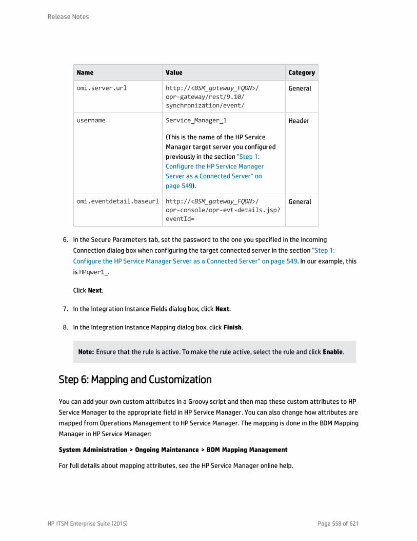
Name Value Category
omi.server.url http://<BSM_gateway_FQDN>/opr-gateway/rest/9.10/synchronization/event/
General
username Service_Manager_1
(This is the name of the HP ServiceManager target server you configuredpreviously in the section "Step 1:Configure the HP Service ManagerServer as a Connected Server" onpage 549).
Header
omi.eventdetail.baseurl http://<BSM_gateway_FQDN>/opr-console/opr-evt-details.jsp?eventId=
General
6. In the Secure Parameters tab, set the password to the one you specified in the IncomingConnection dialog box when configuring the target connected server in the section "Step 1:Configure the HP Service Manager Server as a Connected Server" on page 549. In our example, thisis HPqwer1_.
Click Next.
7. In the Integration Instance Fields dialog box, click Next.
8. In the Integration Instance Mapping dialog box, click Finish.
Note: Ensure that the rule is active. To make the rule active, select the rule and click Enable.
Step 6: Mapping and Customization
You can add your own custom attributes in a Groovy script and then map these custom attributes to HPService Manager to the appropriate field in HP Service Manager. You can also change how attributes aremapped from Operations Management to HP Service Manager. The mapping is done in the BDM MappingManager in HP Service Manager:
System Administration > Ongoing Maintenance > BDM Mapping Management
For full details about mapping attributes, see the HP Service Manager online help.
Release Notes
HP ITSM Enterprise Suite (2015) Page 558 of 621

Step 7: Test the Connection
To test the connection, send an event to the server hosting Operations Management that matches thefilter you defined (in our example filter, the severity value is Critical), and then verify that the event isforwarded to HP Service Manager as expected.
To test the connection, do the following:
1. On the Gateway Server system running Operations Management, open an Event Browser.
2. On the system running Operations Management, open a command prompt and change to thefollowing directory:
<HPBSM root directory>\opr\support
3. Send an event using the following command:
sendevent -s critical -t test111-1
4. Verify that the event appears in the Operations Management Event Browser.
5. Select the Forwarding tab.
6. In the External Id field, you should see a valid HP Service Manager incident ID.
7. Next, verify that the incident appears in the Incident Details in HP Service Manager:
If the event drill-down connection is configured correctly, click the hyperlink created with theIncident ID. A browser window opens, which takes you directly to the incident in the Incident Detailsin HP Service Manager.
If the event drill-down connection is not configured, do the following:
a. In the Forwarding tab in the Operations Management Event Browser, copy or note the incidentID from the External Id field.
b. In the HP Service Manager user interface, navigate to:
Incident Management→Search Incidents
c. Paste or enter the incident ID in the Incident Id field.
d. Click the Search button. This takes you to the incident in the Incident Details.
Release Notes
HP ITSM Enterprise Suite (2015) Page 559 of 621
8. Close the incident in HP Service Manager.
9. Verify that the change in the state of the incident (it is now closed) is synchronized back toOperations Management. You should not be able to see the event that was closed in HP ServiceManager in the active Event Browser, but it should now be in the History Browser.
Step 8: Synchronize Attributes
Not all attributes are synchronized back from Service Manager to Operations Management by default.When the Service Manager incident is initially created from an Operations Management event, allpossible event attributes are mapped to the corresponding Service Manager incident attribute. Out ofthe box, after the initial incident creation, whenever the incident or event subsequently changes, only asubset of the changed event and incident attributes are synchronized. The following describes how tocustomize the list of attributes to synchronize upon change.
Uni-directional Synchronization: Operations Management to HP Service Manager
The following attributes are transferred to HP Service Manager from Operations Management one aone-time basis, that is, when the event was initially created, and the transfer of control of the eventwas configured in the Connected Servers manager.
These attributes support bi-directional synchronization, but are disabled out-of-the-box:
l Title
l Severity
l Priority
l Operator: the operator assigned to the event who forwarded the event
l Category
l Subcategory
l Related CI
For the above attributes, there is no back synchronization from HP Service Manager to OperationsManagement.
Release Notes
HP ITSM Enterprise Suite (2015) Page 560 of 621
Bi-directional Synchronization
Attributes that support bi-directional synchronization between Operations Management and HP ServiceManager are:
l Description
l Lifecycle state (the state is only updated when the state changes to closed)
l Solution
l Operations Management event annotations are synchronized to HP Service Manager activity log
l Contents under the Forwarding tab in the Event Details
Attribute Synchronization using Groovy Scripts
If you want to change the out-of-the-box behavior regarding which attributes are updated, you canspecify this in a Groovy script. In the Groovy script, you would specify which fields are updated in HPService Manager, and which fields are updated in Operations Management. You can also specify customattributes in the Groovy script.
In the Groovy script, you would specify which fields are updated in HP Service Manager, and which fieldsare updated in Operations Management. You can also specify custom attributes in the Groovy script.
Tips for Customizing Groovy Scripts
This section provides some tips about customizing Groovy scripts. Below we show just a few selectedexamples of what you can customize. You can look at the configuration section of a Groovy script to seefurther items that can be modified.
In the configuration section of a Groovy script, you can define and modify the attributes that are to besynchronized between Operations Management and HP Service Manager. The configuration section of aGroovy script also contains the default value mappings for lifecycle state, severity, and priority. You canalso modify these, and it is possible to define the mappings for in-going and out-going requestsdifferently.
More advanced configuration can be done in other parts of the Groovy script if required.
The beginning and the end of the configuration section of a Groovy script is marked as follows:
//
// configuration section to customize the Groovy script
// BEGIN
Release Notes
HP ITSM Enterprise Suite (2015) Page 561 of 621

...
...
//
// configuration section to customize the Groovy script
// END
Note: As of BSM 9.20, modifications to Groovy scripts are not overwritten by patches and hotfixes;your customized version of a script will remain after an update/patch. If you want to use the newerversion of a script, make a copy of your version, revert back to the predefined version, and then re-apply your changes.
The mapping from Operations Management to HP Service Manager is compliant to BDM 1.1 incident webservice specifications. The mapping of the BDM 1.1 incident web service to HP Service Manager isspecified in HP Service Manager in the BDM Mapping Manager. For more information about the BDMMapping Manager, see the BDM Mapping Manager section of the HP Service Manager online help.
Controlling Attribute Synchronization
You can control how updates to certain attributes are synchronized between Operations Managementand HP Service Manager by setting some Boolean variables to true or false.
Here are two examples:
l As of BSM 9.21 there is a new variable called SyncAllProperties. By default it is false; if you set itto true, all properties will be synchronized in both directions. The other variables will be ignored.
Here are two additional examples:
l private static final SyncTitleToSMOnUpdate = false;
This line of the Groovy script disables the synchronization of changes to the title made in OperationsManagement to HP Service Manager.
l private static final Boolean SyncTitleToOPROnUpdate = false;
This line of the Groovy script disables the synchronization changes to the title made in HP ServiceManager to Operations Management.
The title is a required attribute in HP Service Manager, and is set, independently of the flags above,using the title given in Operations Management during the creation of the incident.
Release Notes
HP ITSM Enterprise Suite (2015) Page 562 of 621

Mapping OPR Lifecycle States to BDM Lifecycle States
Individual OPR event state and Service Manager incident status changes may be selected forsynchronization. Out of the box, only the "closed" state is synchronized in both directions. To change thisbehavior add the desired states to the appropriate list, SyncOPRStatesToSM or SyncSMStatusToOPR .
Here are two examples:
l private static final Set SyncOPRStatesToSM = ["closed", "in_progress","resolved"]
l private static final Set SyncSMStatusToOPR = ["closed", "resolved"]
In the example the OPR event lifecycle states closed, in_progress and resolved are synchronized to theService Manager incident status, and Service Manager incident status closed and resolved aresynchronized to the OPR event state.
Note: The special state "*" denotes all states, so to synchronize all OPR event states to the SMincident status property specify the following:
private static final Set SyncOPRStatesToSM = ["*"]
Additionally two maps are used to specify the mapping of OPR event lifecycle state to BDM incidentstatus. The maps are named MapOPR2SMStatus and MapSM2OPRState. Out of the box, all possiblestates have a mapping.
Here is an example:
l private static final Map MapOPR2SMStatus = ["open": "open", "in_progress":"work-in-progress", "resolved": "resolved", "closed": "closed"]
l private static final Map MapSM2OPRState = ["accepted": "open", "assigned":"open", "open": "open", "reopened": "open",
"pending-change": "in_progress", "pending-customer": "in_progress", "pending-other": "in_progress",
"pending-vendor": "in_progress", "referred": "in_progress", "suspended": "in_progress",
"work-in-progress": "in_progress", "rejected": "resolved", "replaced-problem":
Release Notes
HP ITSM Enterprise Suite (2015) Page 563 of 621

"resolved",
"resolved": "resolved", "cancelled": "resolved", "closed": "closed"]
Syntax Errors
If you get a syntax error when customizing your Groovy scripts, you will get an event in the eventbrowser with a detailed description of the error. In addition you may view the log file opr-event-sync-adapter.log for information about how to resolve the error. You can find the log file here:
<Gateway Server root directory>/log/opr-event-sync-adapter.log
Release Notes
HP ITSM Enterprise Suite (2015) Page 564 of 621

View Changes and Incidents in Service Health UsingStandalone HP Universal CMDBThis integration enables you to view planned changes and incident details in the Changes & Incidentstab in the 360° View page in Service Health, when you are using a standalone HP Universal CMDB.
This task describes how to configure the HP Service Manager - BSM federated integration in order toallow both products to share information and data.
Note: Beginning with UCMDB version 9.05, a new SM adapter (ServiceManagerAdapter9-x) issupplied with UCMDB out of the box, in addition to the legacy adapter (ServiceManagerAdapter7-1).
l For SM versions 9.30 and 9.31, use ServiceManagerAdapter9.xx.
l For SM versions 9.20 and earlier, use ServiceManagerAdapter7-1.
This section includes the following:
l "Prerequisites" on the next page
l "Step 1: Load .unl Files to Provide External Access to Service Manager" on the next page
l "Step 2: Configure the Service Desk Adapter Time Zone" on page 568
l "Step 3: Verify that the UCMDB is the Global ID Generator" on page 569
l "Step 4 (for SM 9.20 and earlier only): Add a Domain" on page 570
l "Step 5: Configure SM Adapter in UCMDB" on page 570
l "Step 6: Configure the SM-UCMDB Integration: Create an Integration Point" on page 571
l "Step 7: Configure the SM-UCMDB Integration: Set Up Data Push Jobs" on page 572
l "Step 8: Configure the SM-UCMDB Integration: Run Data Push Jobs" on page 573
l "Step 9: Configure the SM-UCMDB Integration: Add UCMDB Connection Information to SM" onpage 573
HP ITSM Enterprise Suite (2015) Page 565 of 621
l "Step 10: Configure the BSM-UCMDB Integration: Deploy CMS_to_RTSM_Sync.zip on UCMDB" onpage 574
l "Step 11: Configure the BSM-UCMDB Integration: Create an Integration Point on BSM" on page 574
l "Step 12: Configure the BSM-UCMDB Integration: Create an Integration Point on the CMS" onpage 577
l "Step 13 (Optional): Add CI Types to the Service Health Changes and Incidents Component" onpage 579
l "Step 14 (Optional): Map Siebel Application CITs" on page 579
l "Result" on page 580
l "Troubleshooting" on page 580
Prerequisites
l Data-Flow Probes (for SM 9.3x). If you are using SM 9.30 or 9.31, before you begin you must installtwo data-flow probes - one with UCMDB as its target, and another with the BSM Gateway Server asits target. When you configure the integration points, you will select these probes.
l Trusted Sign-on and LW-SSO. If you want HP Service Manager to use the SSL-based Trusted Sign-onprotocol and LW-SSO, configure it according to the instructions in the HP Service Manager onlinehelp if you have not already done so. In addition, see Configuring HP Service Manager to Use the SSL-based Trusted Sign-On and LW-SSO in the Service Manager documentation library.
Step 1: Load .unl Files to Provide External Access to Service Manager
This procedure enables BSM to query incidents and changes:
1. Copy the following files from the BSM 9.x DVD to a local directory:
n SM_Integration/SM_Unloads/SM7.1/ucmdbIntegration7_1x.unl
n SM_Integration/SM_Unloads/SM7.1/BACExtAccess_71_v1.unl
2. Before loading these .unl files, apply the fix described inhttp://support.openview.hp.com/selfsolve/document/KM1015767. This is required because the .unl
Release Notes
HP ITSM Enterprise Suite (2015) Page 566 of 621
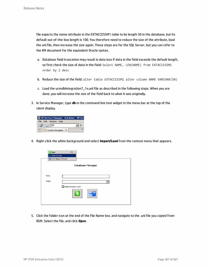
file expects the name attribute in the EXTACCESSM1 table to be length 50 in the database, but itsdefault out-of-the-box length is 100. You therefore need to reduce the size of the attribute, loadthe unl file, then increase the size again. These steps are for the SQL Server, but you can refer tothe KM document for the equivalent Oracle syntax.
a. Database field truncation may result in data loss if data in the field exceeds the default length,so first check the size of data in the field: Select NAME, LEN(NAME) from EXTACCESSM1order by 2 desc
b. Reduce the size of the field: alter table EXTACCESSM1 alter column NAME VARCHAR(50)
c. Load the ucmdbIntegration7_1x.unl file as described in the following steps. When you aredone, you will increase the size of the field back to what it was originally.
3. In Service Manager, type db in the command line text widget in the menu bar at the top of theclient display.
4. Right-click the white background and select Import/Load from the context menu that appears.
5. Click the folder icon at the end of the File Name box. and navigate to the .unl file you copied fromBSM. Select the file, and click Open.
Release Notes
HP ITSM Enterprise Suite (2015) Page 567 of 621

6. Click Load FG on the toolbar to load the file. If you receive a message saying "The file you areloading will change the keys...", click Yes.
7. Increase the size of the field back to what it was originally: alter table EXTACCESSM1 altercolumn NAME VARCHAR(100)
8. Repeat the above steps for the BACExtAccess_71_v1.unl file.
Step 2: Configure the Service Desk Adapter Time Zone
Configure the time zone so Incidents and Planned Changes have the correct time definitions:
1. In Service Manager, select Navigation pane > Menu navigation > System Administration > BaseSystem Configuration > Miscellaneous > System Information Record.
2. Within the Date Info tab, open the <BSM DPS rootdirectory>/odb/runtime/fcmdb/CodeBase/<ServiceManagerAdapter9-x or ServiceDeskAdapter7-1>/serviceDeskConfiguration.xml file.
3. Find the row that includes the following string:
<globalConnectorConfig><
and check the date and time format, and time zone. Note that the date is case-sensitive. Changeeither Service Manager or the xml file so that they both match each other's settings.
Note: Specify a time zone from the Java time zone list that matches the time zone used inService Manager; for example, America/New York.
4. Restart the corresponding server to make the change take effect. (If you changed the time zoneon SM, restart the Service Manager server; if you changed the time zone on BSM, restart the BSMserver.)
Step 3: Verify that the UCMDB is the Global ID Generator
1. Log in to the JMX Console (http://<UCMDB server>:8080/jmx-console/).
2. Go to Multiple UCMDB Instances Services.
3. Click getIsGlobalIdGenerator. Verify that the call returns true. For more details, refer to theRTSM Best Practices guide.
For SM versions 9.20 and earlier, proceed with the next step. For SM versions 9.30 and 9.31, skip to "Step5: Configure SM Adapter in UCMDB" on the next page.
Release Notes
HP ITSM Enterprise Suite (2015) Page 569 of 621

Step 4 (for SM 9.20 and earlier only): Add a Domain
1. In BSM, select Admin > RTSM Administration, click the Data Flow Management tab, and selectData Flow Probe Setup.
2. In the Domains and Probes pane, click .
3. In the Add New Domain dialog box, enter a new domain name and click OK. This creates a newdomain and its protocols.
4. Within the domain you added, select Credentials > Generic Protocol, and click the Add newconnection details button in the right pane. In the Add Protocol Parameter dialog box that opens,insert the SM administrator credentials.
Step 5: Configure SM Adapter in UCMDB
1. Within the UCMDB user interface, access Data Flow Management > Adapter Management.
2. In the resources window, select ServiceManagerAdapter9-x or ServiceManagerAdapter7-1 >Configuration files.
3. Select ServiceManagerAdapter9-x/sm.properties or ServiceManagerAdapter7-1/sm.properties.
Release Notes
HP ITSM Enterprise Suite (2015) Page 570 of 621
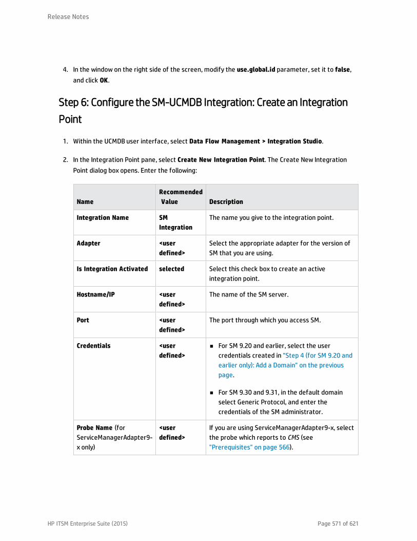
4. In the window on the right side of the screen, modify the use.global.id parameter, set it to false,and click OK.
Step 6: Configure the SM-UCMDB Integration: Create an IntegrationPoint
1. Within the UCMDB user interface, select Data Flow Management > Integration Studio.
2. In the Integration Point pane, select Create New Integration Point. The Create New IntegrationPoint dialog box opens. Enter the following:
NameRecommendedValue Description
Integration Name SMIntegration
The name you give to the integration point.
Adapter <userdefined>
Select the appropriate adapter for the version ofSM that you are using.
Is Integration Activated selected Select this check box to create an activeintegration point.
Hostname/IP <userdefined>
The name of the SM server.
Port <userdefined>
The port through which you access SM.
Credentials <userdefined>
n For SM 9.20 and earlier, select the usercredentials created in "Step 4 (for SM 9.20 andearlier only): Add a Domain" on the previouspage.
n For SM 9.30 and 9.31, in the default domainselect Generic Protocol, and enter thecredentials of the SM administrator.
Probe Name (forServiceManagerAdapter9-x only)
<userdefined>
If you are using ServiceManagerAdapter9-x, selectthe probe which reports to CMS (see"Prerequisites" on page 566).
Release Notes
HP ITSM Enterprise Suite (2015) Page 571 of 621
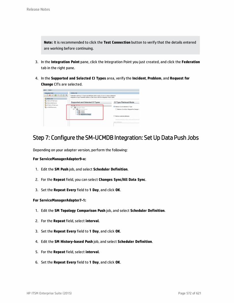
Note: It is recommended to click the Test Connection button to verify that the details enteredare working before continuing.
3. In the Integration Point pane, click the Integration Point you just created, and click the Federationtab in the right pane.
4. In the Supported and Selected CI Types area, verify the Incident, Problem, and Request forChange CITs are selected.
Step 7: Configure the SM-UCMDB Integration: Set Up Data Push Jobs
Depending on your adapter version, perform the following:
For ServiceManagerAdapter9-x:
1. Edit the SM Push job, and select Scheduler Definition.
2. For the Repeat field, you can select Changes Sync/All Data Sync.
3. Set the Repeat Every field to 1 Day, and click OK.
For ServiceManagerAdapter7-1:
1. Edit the SM Topology Comparison Push job, and select Scheduler Definition.
2. For the Repeat field, select interval.
3. Set the Repeat Every field to 1 Day, and click OK.
4. Edit the SM History-based Push job, and select Scheduler Definition.
5. For the Repeat field, select interval.
6. Set the Repeat Every field to 1 Day, and click OK.
Release Notes
HP ITSM Enterprise Suite (2015) Page 572 of 621

Step 8: Configure the SM-UCMDB Integration: Run Data Push Jobs
1. In the Integration Point pane, select the correct integration.
2. Select the Data Push tab. The Job Definition pane is displayed.
3. Select your job and click Synchronize All to run the push job.
Note: For ServiceManagerAdapter7-1, run this first for the SM History-based Push job, thenrepeat for the SM Topology Comparison Push job.
4. When the Confirm synchronizing window is displayed, click Yes.
5. Click the Statistics tab to view the progress of the synchronization.
6. Click Refresh to view the updated synchronization status.
Step 9: Configure the SM-UCMDB Integration: Add UCMDBConnection Information to SM
1. Log on to your UCMDB system as an administrator. Verify that all UCMDB services are running.
2. Log on to your SM system as an administrator.
3. Select System Administration > Base System Configuration > Miscellaneous > SystemInformation Record.
4. Select the Active Integrations tab.
5. Select the HP Universal CMDB option. The form displays the UCMDB Web service URL field.
6. In the UCMDB Web service URL field, enter the URL to the UCMDB Web service API. The URL has thefollowing format:
http://<UCMDB server name>:<port>/axis2/services/ucmdbSMService.
7. In the UserId dialog box, enter your UCMDB user name and password and click Save.
Release Notes
HP ITSM Enterprise Suite (2015) Page 573 of 621
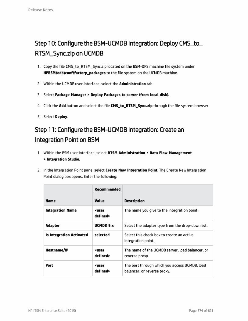
Step 10: Configure the BSM-UCMDB Integration: Deploy CMS_to_RTSM_Sync.zip on UCMDB
1. Copy the file CMS_to_RTSM_Sync.zip located on the BSM-DPS machine file system underHPBSM\odb\conf\factory_packages to the file system on the UCMDB machine.
2. Within the UCMDB user interface, select the Administration tab.
3. Select Package Manager > Deploy Packages to server (from local disk).
4. Click the Add button and select the file CMS_to_RTSM_Sync.zip through the file system browser.
5. Select Deploy.
Step 11: Configure the BSM-UCMDB Integration: Create anIntegration Point on BSM
1. Within the BSM user interface, select RTSM Administration > Data Flow Management> Integration Studio.
2. In the Integration Point pane, select Create New Integration Point. The Create New IntegrationPoint dialog box opens. Enter the following:
Name
Recommended
Value Description
Integration Name <userdefined>
The name you give to the integration point.
Adapter UCMDB 9.x Select the adapter type from the drop-down list.
Is Integration Activated selected Select this check box to create an activeintegration point.
Hostname/IP <userdefined>
The name of the UCMDB server, load balancer, orreverse proxy.
Port <userdefined>
The port through which you access UCMDB, loadbalancer, or reverse proxy.
Release Notes
HP ITSM Enterprise Suite (2015) Page 574 of 621

Name
Recommended
Value Description
Credentials <userdefined>
If credentials appear in the Credentials column,select them.
If no credentials appear, select Generic Protocoland click the Add new connection details forselected protocol type button.
Enter the following information:
n Description. Enter UCMDB.
n User Name. Enter the UCMDB user name. Thedefault value is admin.
n User Password. Enter and confirm a password.
Probe Name (forServiceManagerAdapter9-x only)
<userdefined>
If you are using ServiceManagerAdapter9-x, selectthe probe which reports to BSM (see"Prerequisites" on page 566).
3. Click the Add icon on the right side of the window and add Job definitions as follows:
a. Name the Job definition.
b. Select the Allow Delete check box.
c. Click the Add icon in the Job definition window.
d. From the pop up window, browse to root - CMS sync and select the ActiveDirectory_sync joband click OK.
e. Select the Scheduler definition check box.
f. In the Repeat window, select Cron.
g. For the Cron expression, enter the following string: * 0/10 * * * ? * .
h. Adjust other settings as needed.
i. When finished, click OK and save the integration.
Release Notes
HP ITSM Enterprise Suite (2015) Page 575 of 621

j. Repeat steps a to i and configure the following jobs:
o FailoverCluster_Sync
o IIS_Sync
o SOA_Sync
o BusinessAndFacilities_Sync
o ExchangeServer_Sync
o Virtualization_Sync
o Siebel_Sync
o Credentials_Sync
o Basicinfrastructure_Sync
o J2EE_Sync
o SAP_Sync
4. Browse to UCMDB on port 21212 (for example, http://<DPS_host>.<domain>:21212), and select theJMX Console.
5. Log on to the JMX console.
6. From the UCMDB section, select UCMDB:service=Multiple CMDB Instances Services.
7. Invoke:
a. setAsGlobalIdGenerator and verify it succeeded.
b. getGlobalIdGeneratorScopes and verify it succeeded.
8. Within BSM, access RTSM Administration > Data Flow Management > Integration Studio.
9. Select the Integration Point that you have configured.
10. In the Job definition section, click Synchronize All to run the synchronization.
The Integration Point should be active and the jobs are displayed properly.
Release Notes
HP ITSM Enterprise Suite (2015) Page 576 of 621
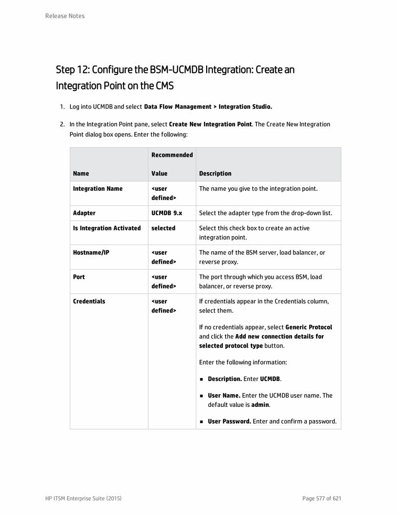
Step 12: Configure the BSM-UCMDB Integration: Create anIntegration Point on the CMS
1. Log into UCMDB and select Data Flow Management > Integration Studio.
2. In the Integration Point pane, select Create New Integration Point. The Create New IntegrationPoint dialog box opens. Enter the following:
Name
Recommended
Value Description
Integration Name <userdefined>
The name you give to the integration point.
Adapter UCMDB 9.x Select the adapter type from the drop-down list.
Is Integration Activated selected Select this check box to create an activeintegration point.
Hostname/IP <userdefined>
The name of the BSM server, load balancer, orreverse proxy.
Port <userdefined>
The port through which you access BSM, loadbalancer, or reverse proxy.
Credentials <userdefined>
If credentials appear in the Credentials column,select them.
If no credentials appear, select Generic Protocoland click the Add new connection details forselected protocol type button.
Enter the following information:
n Description. Enter UCMDB.
n User Name. Enter the UCMDB user name. Thedefault value is admin.
n User Password. Enter and confirm a password.
Release Notes
HP ITSM Enterprise Suite (2015) Page 577 of 621

Name
Recommended
Value Description
Probe Name (forServiceManagerAdapter9-x only)
<userdefined>
If you are using ServiceManagerAdapter9-x, selectthe probe which reports to the CMS (see"Prerequisites" on page 566).
3. Click the Add icon on the right side of the window and add Job definitions as follows:
a. Name the Job definition.
b. Select the Allow Delete check box.
c. Click the Add icon in the Job definition window.
d. From the pop up window, browse to root - CMS sync and select the ActiveDirectory_sync joband click OK.
e. Select the Scheduler definition check box.
f. In the Repeat window, select Cron.
g. For the Cron expression, enter the following string: * 0/10 * * * ? * .
h. Adjust other settings as needed.
i. When finished, click OK and save the integration.
j. Repeat steps a to i and configure the following jobs:
o FailoverCluster_Sync
o IIS_Sync
o SOA_Sync
o BusinessAndFacilities_Sync
o ExchangeServer_Sync
o Virtualization_Sync
o Siebel_Sync
Release Notes
HP ITSM Enterprise Suite (2015) Page 578 of 621

o Credentials_Sync
o Basicinfrastructure_Sync
o J2EE_Sync
o SAP_Sync
4. Browse to UCMDB on port 8080 (for example, http://yourUCMDBhost.domain:8080), and select theJMX Console.
5. Log on to the JMX console.
6. From the UCMDB section, select UCMDB:service=Multiple CMDB Instances Services.
7. Invoke:
a. setAsGlobalIdGenerator and verify it succeeded.
b. getGlobalIdGeneratorScopes and verify it succeeded.
8. Within UCMDB, access Data Flow Management > Integration Studio.
9. Select the Integration Point that you have configured.
10. In the Job definition section, click Synchronize All to run the synchronization.
The Integration Point should be active and the jobs are displayed properly.
Step 13 (Optional): Add CI Types to the Service Health Changes andIncidents Component
By default, BSM Service Health displays information on incidents and requests for change for thefollowing CI types: Business Service, Siebel Application, Business Application, and Node.
If you want to view change and incident information for other CITs, perform the procedure described in"How to Customize the Changes and Incidents Component" on page 591.
Step 14 (Optional): Map Siebel Application CITs
To create a mapping between the Hand Held Devices or Display Device CIT in Service Manager withSiebel Application CITs in BSM, perform one of the following procedures:
Release Notes
HP ITSM Enterprise Suite (2015) Page 579 of 621

l In Service Manager, select Main page > To Do > Queue: Configuration Item > New > New and clickDevice. In the Configuration Item field enter the exact name (case sensitive) of the BSM CI thatcorresponds to the Siebel Application CIT in BSM.
l Create a new population job that includes the Hand Held Devices or Display Device CIT. Those CITscorrespond to the Siebel application CITs. For details about how to create a population job, see "DataPush Tab" in the Modeling Guide.
Result
You can now view planned changes and incident details in the Changes & Incidents tab in the 360° Viewpage in Service Health.
Both products can now share information and data.
Troubleshooting
If you are not seeing expected incidents in BSM, perform the following:
1. On the Data Processing Server, search the odb\odb\Error.log file for Error Code 802.
2. In this error message, locate the following string: property [<category or incident_status>=<attribute value>[STRING] ] is defined as attribute.
This indicates that a certain attribute value is missing in RTSM.
3. Access RTSM Administration > CI Type Manager.
4. From the CI Types menu, select System Type Manager, and open Category or Incident Status(depending on the error message) for editing.
5. Click the Add button (+), and add the missing attribute value (exactly as it appears in the errormessage) to the list of values.
Release Notes
HP ITSM Enterprise Suite (2015) Page 580 of 621

View Changes and Incidents in Service Health Using RTSMThis integration enables you to view planned changes and incident details in the Changes & Incidentstab in the 360° View page in Service Health, when you are working with RTSM. For details, see "Changesand Incidents" in the Service Health part of the BSM User Guide.
This section includes the following:
l "Prerequisite" below
l "Step 1: Configure the Service Desk Adapter Time Zone" below
l "Step 2: Create an Integration User Account in Service Manager" on page 583
l "Step 3: Add the BSM Connection Information in Service Manager" on page 584
l "Step 4: Create an Integration Point in BSM" on page 584
l "Step 5: Create New Jobs to Synchronize Between BSM and Service Manager" on page 587
l "Step 6: Run the Job" on page 587
l "Step 7: Test the Configuration" on page 587
l "Step 8 (Optional): Add CI Types to the Service Health Changes and Incidents Component" onpage 590
l "Troubleshooting" on page 590
Prerequisite
If you are using SM versions 9.30 or 9.31, before you begin you must install a data-flow probe with theBSM Gateway Server as its target. When you configure the integration point, you will select this probefor the integration.
Step 1: Configure the Service Desk Adapter Time Zone
Configure the time zone so Incidents and Planned Changes have the correct time definitions:
1. In Service Manager, select Navigation pane > Menu navigation > System Administration > BaseSystem Configuration > Miscellaneous > System Information Record.
HP ITSM Enterprise Suite (2015) Page 581 of 621
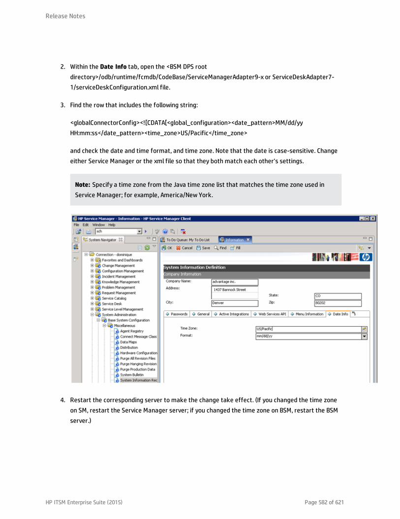
2. Within the Date Info tab, open the <BSM DPS rootdirectory>/odb/runtime/fcmdb/CodeBase/ServiceManagerAdapter9-x or ServiceDeskAdapter7-1/serviceDeskConfiguration.xml file.
3. Find the row that includes the following string:
<globalConnectorConfig><
Step 2: Create an Integration User Account in Service Manager
This integration requires an administrator user account for BSM to connect to Service Manager. Thisuser account must already exist in both BSM and Service Manager.
To create a dedicated integration user account in Service Manager:
1. Log in to Service Manager as a system administrator.
2. Type contacts in the Service Manager command line, and press ENTER.
3. Create a new contact record for the integration user account.
a. In the Full Name field, type a full name. For example, RTSM.
b. In the Contact Name field, type a name. For example, RTSM.
c. Click Add, and then OK.
4. Type operator in the Service Manager command line, and press ENTER.
5. In the Login Name field, type the username of an existing system administrator account, and clickSearch.
The system administrator account displays.
6. Create a new user account based on the existing one:
a. Change the Login Name to the integration account name you want (for example, rtsm).
b. Type a Full Name. For example, RTSM.
c. In the Contact ID field, click the Fill button and select the contact record you have justcreated.
d. Click Add.
e. Select the Security tab, and change the password.
f. Click OK.
The integration user account is created. Later you will need to add this user account(username/password) in RTSM, and then specify this user account in the Credentials ID field whencreating an integration point in RTSM administration.
Release Notes
HP ITSM Enterprise Suite (2015) Page 583 of 621

Step 3: Add the BSM Connection Information in Service Manager
The integration requires the BSM connection information to obtain CI attribute information from theBSM system, and display it in the Actual State section in the Service Manager configuration item form.
1. Log in to Service Manager as a system administrator.
2. Click System Administration > Base System Configuration > Miscellaneous > SystemInformation Record.
3. Click the Active Integrations tab.
4. Select the HP Universal CMDB option.
The form displays the UCMDB web service URL field.
5. In the UCMDB webservice URL field, type the URL to the HP Universal CMDB web service API. The URLhas the following format: http://<UCMDB server name>:<port>/axis2/services/ucmdbSMService
Replace <UCMDB server name> with the host name of your BSM server, and replace <port> withthe communications port your BSM server uses.
6. In UserId and Password, type the user credentials required to manage CIs on the BSM system. Forexample, the out-of-the-box administrator credentials are admin/ admin.
7. Click Save. Service Manager displays the message: Information record updated.
8. Log out of the Service Manager system.
9. Log back into the Service Manager system with an administrator account. The Actual State sectionwill be available in CI records pushed from BSM.
Step 4: Create an Integration Point in BSM
A default RTSM 9.05 installation already includes the ServiceManagerAdapter9-x package. To use theintegration package, you must create an integration point listing the connection properties for theintegration.
To create an integration point:
Release Notes
HP ITSM Enterprise Suite (2015) Page 584 of 621

1. Access the JMX console (in case of distributed deployment) on the DPS server.
2. Navigate to UCMDB:service=Security Services.
3. Create a new user with the name and password that you created in SM, using the JMX createUser:
n CustomerId = 1
n userName = <userName>
n password = <password>
4. Assign the user Administrator Role using the JMX setRolesForUser from the same section:
n CustomerId = 1
n userName = <userName>
n roles = Admin
5. In BSM, select Admin > RTSM Administration, click the Data Flow Management tab, and selectIntegration Studio.
6. In the Integration Point pane, select Create New Integration Point. The Create New IntegrationPoint dialog box opens. Enter the following:
NameRecommendedValue Description
Integration Name SMIntegration
The name you give to the integration point.
Adapter <userdefined>
Select HP BTO Products > Service Manager >Service Manager 9.xx.
This adapter, which supports CI/ relationship DataPush from RTSM to Service Manager, andPopulation and Federation from Service Managerto RTSM.
Is Integration Activated selected Select this check box to create an activeintegration point.
Release Notes
HP ITSM Enterprise Suite (2015) Page 585 of 621

NameRecommendedValue Description
Hostname/IP <userdefined>
The name of the SM server.
Port <userdefined>
The port through which you access SM.
Credentials <userdefined>
Click Generic Protocol, click the Add button to addthe integration user account you created in "Step2: Create an Integration User Account in ServiceManager" on page 583, and then select it. Thisaccount must exist in both Service Manager andBSM.
Probe Name (forServiceManagerAdapter9-x only)
<userdefined>
Select the probe that you installed for thisintegration.
Note: It is recommended to click the Test Connection button to verify that the details enteredare working before continuing.
7. In the Integration Point pane, click the Integration Point you just created, and click the Federationtab in the right pane.
8. In the Supported and Selected CI Types area, verify the Incident, Problem, and Request forChange CITs are selected.
Release Notes
HP ITSM Enterprise Suite (2015) Page 586 of 621
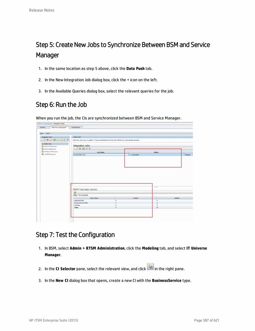
Step 5: Create New Jobs to Synchronize Between BSM and ServiceManager
1. In the same location as step 5 above, click the Data Push tab.
2. In the New Integration Job dialog box, click the + icon on the left.
3. In the Available Queries dialog box, select the relevant queries for the job.
Step 6: Run the Job
When you run the job, the CIs are synchronized between BSM and Service Manager.
Step 7: Test the Configuration
1. In BSM, select Admin > RTSM Administration, click the Modeling tab, and select IT UniverseManager.
2. In the CI Selector pane, select the relevant view, and click in the right pane.
3. In the New CI dialog box that opens, create a new CI with the BusinessService type.
Release Notes
HP ITSM Enterprise Suite (2015) Page 587 of 621
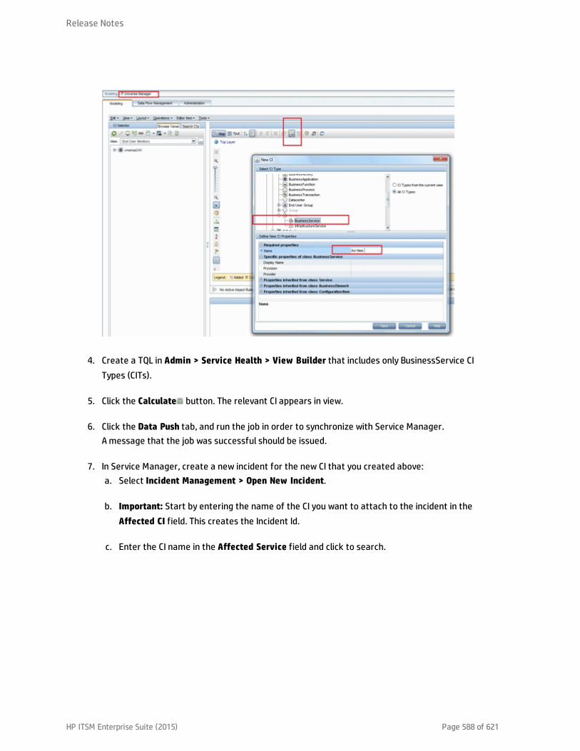
4. Create a TQL in Admin > Service Health > View Builder that includes only BusinessService CITypes (CITs).
5. Click the Calculate button. The relevant CI appears in view.
6. Click the Data Push tab, and run the job in order to synchronize with Service Manager.A message that the job was successful should be issued.
7. In Service Manager, create a new incident for the new CI that you created above:a. Select Incident Management > Open New Incident.
b. Important: Start by entering the name of the CI you want to attach to the incident in theAffected CI field. This creates the Incident Id.
c. Enter the CI name in the Affected Service field and click to search.
Release Notes
HP ITSM Enterprise Suite (2015) Page 588 of 621

d. Enter any incident detail.
The incident is automatically attached to the CI.
8. In BSM, create a TQL with the CI Type you created connected to the Incident CI Type in amembership relationship link.
9. Click the Calculate button. One incident appears connected to the BusinessService CI Typebecause this test created it and it is synchronized automatically.
10. Delete the incident from the TQL and save the TQL to be a view. The TQL is only used for the test.
11. Select Application > Service Health, and click the 360 View tab. Check that the new incident isattached to the CI.
Release Notes
HP ITSM Enterprise Suite (2015) Page 589 of 621
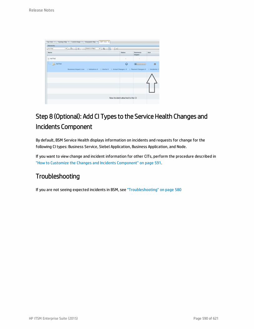
Step 8 (Optional): Add CI Types to the Service Health Changes andIncidents Component
By default, BSM Service Health displays information on incidents and requests for change for thefollowing CI types: Business Service, Siebel Application, Business Application, and Node.
If you want to view change and incident information for other CITs, perform the procedure described in"How to Customize the Changes and Incidents Component" on page 591.
Troubleshooting
If you are not seeing expected incidents in BSM, see "Troubleshooting" on page 580
Release Notes
HP ITSM Enterprise Suite (2015) Page 590 of 621
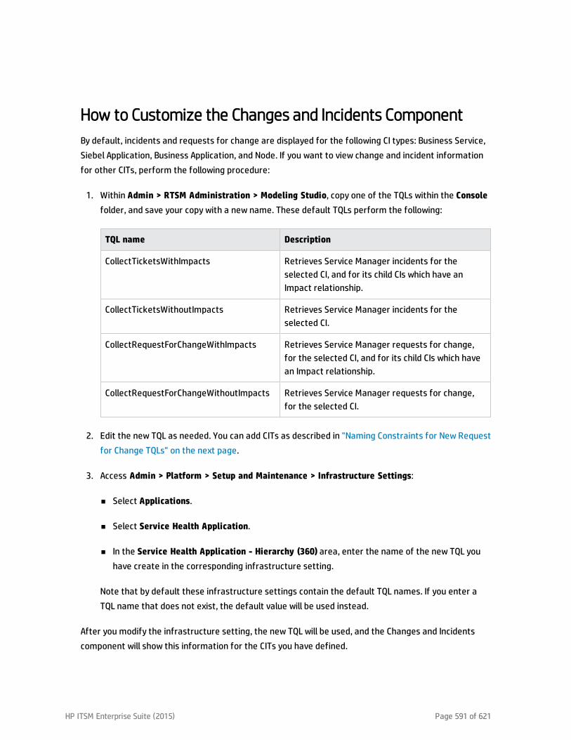
How to Customize the Changes and Incidents ComponentBy default, incidents and requests for change are displayed for the following CI types: Business Service,Siebel Application, Business Application, and Node. If you want to view change and incident informationfor other CITs, perform the following procedure:
1. Within Admin > RTSM Administration > Modeling Studio, copy one of the TQLs within the Consolefolder, and save your copy with a new name. These default TQLs perform the following:
TQL name Description
CollectTicketsWithImpacts Retrieves Service Manager incidents for theselected CI, and for its child CIs which have anImpact relationship.
CollectTicketsWithoutImpacts Retrieves Service Manager incidents for theselected CI.
CollectRequestForChangeWithImpacts Retrieves Service Manager requests for change,for the selected CI, and for its child CIs which havean Impact relationship.
CollectRequestForChangeWithoutImpacts Retrieves Service Manager requests for change,for the selected CI.
2. Edit the new TQL as needed. You can add CITs as described in "Naming Constraints for New Requestfor Change TQLs" on the next page.
3. Access Admin > Platform > Setup and Maintenance > Infrastructure Settings:
n Select Applications.
n Select Service Health Application.
n In the Service Health Application - Hierarchy (360) area, enter the name of the new TQL youhave create in the corresponding infrastructure setting.
Note that by default these infrastructure settings contain the default TQL names. If you enter aTQL name that does not exist, the default value will be used instead.
After you modify the infrastructure setting, the new TQL will be used, and the Changes and Incidentscomponent will show this information for the CITs you have defined.
HP ITSM Enterprise Suite (2015) Page 591 of 621
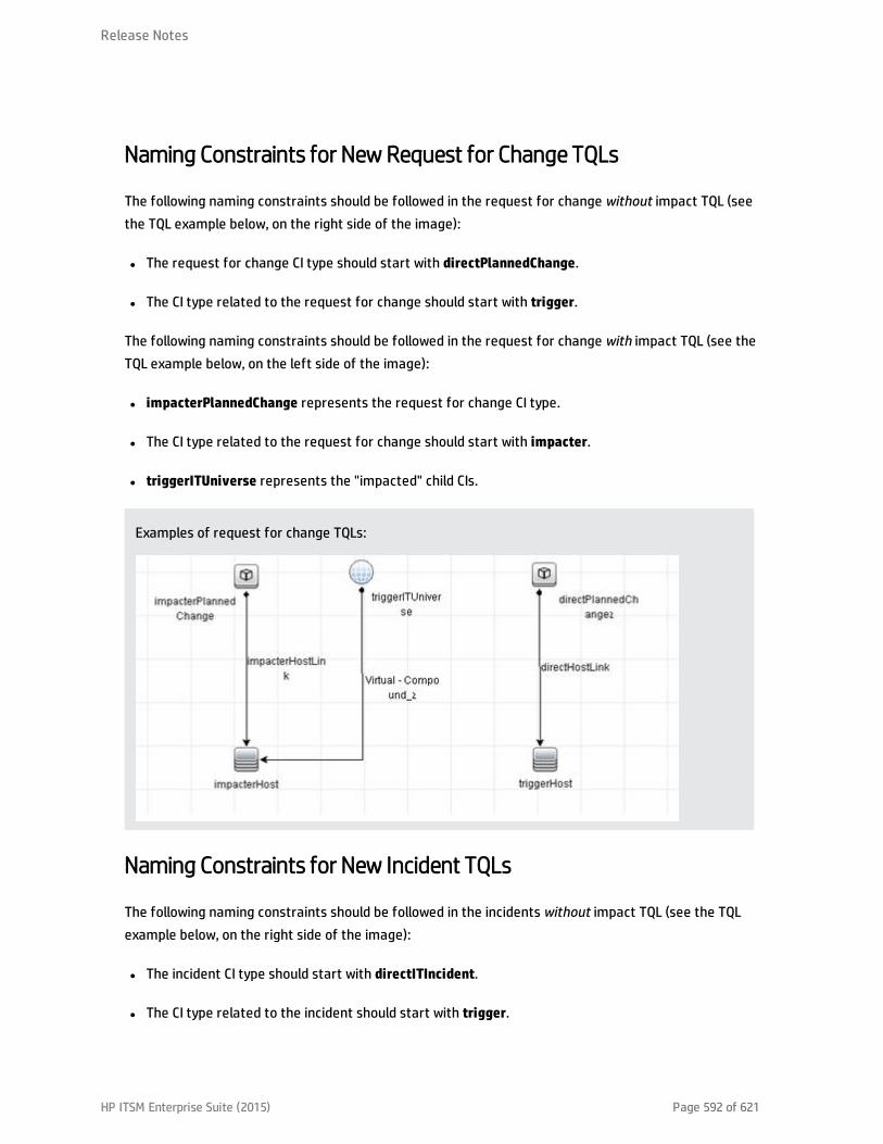
Naming Constraints for New Request for Change TQLs
The following naming constraints should be followed in the request for change without impact TQL (seethe TQL example below, on the right side of the image):
l The request for change CI type should start with directPlannedChange.
l The CI type related to the request for change should start with trigger.
The following naming constraints should be followed in the request for change with impact TQL (see theTQL example below, on the left side of the image):
l impacterPlannedChange represents the request for change CI type.
l The CI type related to the request for change should start with impacter.
l triggerITUniverse represents the "impacted" child CIs.
Examples of request for change TQLs:
Naming Constraints for New Incident TQLs
The following naming constraints should be followed in the incidents without impact TQL (see the TQLexample below, on the right side of the image):
l The incident CI type should start with directITIncident.
l The CI type related to the incident should start with trigger.
Release Notes
HP ITSM Enterprise Suite (2015) Page 592 of 621

The following naming constraints should be followed in the incidents with impact TQL (see the TQLexample below, on the left side of the image):
l impacterITIncident represents the incident CI type.
l The CI type related to the incident should start with impacter.
l triggerITUniverse represents the "impacted" child CIs.
Examples of incident TQLs:
Release Notes
HP ITSM Enterprise Suite (2015) Page 593 of 621

Generate Incidents in Service Manager When a BSM Alert isTriggeredThis integration enables you to configure specific CI Status alerts, SLA alerts, or EUM alerts toautomatically open a corresponding incident in HP Service Manager. The alerts are mapped to theevents using the Event Template.
The triggered alert forwards a corresponding event to OMi, where (using the Incident exchange betweenService Manager and Operations Manager I integration) the event is changed into an incident and sent,using the Event Forwarding Service, to HP Service Manager to proactively alert the operator about aproblem in the system..
To automatically forward an event when an alert is triggered, follow the steps described in this section.This section includes the following:
l "CI Status Alerts" below
l "SLA Alerts" below
l "EUM Alerts" on the next page
CI Status Alerts
By default, a CI Status alert is mapped to an event using a default Event Template. You can modify thedefault Event Template or select a different Event Template as follows:
1. Select Admin > Service Health > View Management > CI Status Alerts, select a view and a CI andclick New Alert or select an existing alert and click Edit.
2. In the Actions page, click the New Event Generation link in the Generate Events section.
3. In the CI Alert Template Repository dialog box that opens, select the template you want to use tomap the alert to an event and click Select. The template you selected is now listed in the GenerateEvents section. For user interface details, see "CI Status Template Repository Dialog Box" in theService Health part of the BSM Application Administration Guide.
SLA Alerts
By default, an SLA alert is mapped to an event using a default Event Template. You can modify thedefault Event Template or select a different Event Template as follows:
HP ITSM Enterprise Suite (2015) Page 594 of 621

1. Select Admin > Service Level Management > SLA Alerts, click New Alert or select an existingalert and click Edit.
2. In the Actions page, click the New Event Generation link in the Generate Events section.
3. In the SLA Template Repository dialog box that opens, select the template you want to use to mapthe alert to an event and click Select. The template you selected is now listed in the GenerateEvents section. For details, see "SLA Template Repository Dialog Box" in the Service LevelManagement part of the BSM Application Administration Guide.
EUM Alerts
By default, an EUM alert is mapped to an event using a default Event Template. You can modify thedefault Event Template or select a different Event Template as follows:
1. Select Admin > End User Management > Monitoring, select the view and the CI in the left pane,click the Alerts tab, and click the Press to create new alert button, or select one of the alerts,and click the Press to edit alert button.
2. In the Actions page, select the Generate Event option.
3. In the Definition Details area, in the Actions section, click the first link in the Generate events with<template name> template and <value> values Event Type Indicator, to select or modify thedefault template that maps the alert to the event in the Template Repository dialog box. For userinterface details, see "Notification Templates Dialog Box" in the End User Management part of theBSM Application Administration Guide.
4. Click the second link to open the Event Type Indicator dialog box, where you specify the ETI thatcorresponds to the alert. For user interface details, see "Event Type Indicator Dialog Box" in theEnd User Management part of the BSM Application Administration Guide.
Release Notes
HP ITSM Enterprise Suite (2015) Page 595 of 621

View Incident Data in BSM, and Manage SLAs Based onService ManagerThis integration enables you to view the Number of Open Incidents in Service Health, and manage SLAsover Serviceability KPIs based on SM incidents, using EMS configuration.
This section includes the following:
l "Overview: Understanding the Integration with EMS" below
l "Prerequisites" on page 600
l "Step 1: Enable Access to HP Service Manager From Within Service Health" on page 601
l "Step 2: Define HP Service Manager Tables for External Access to the Clocks" on page 601
l "Step 3: Correct the Clocks WSDL" on page 602
l "Step 4: Add the Type Field to the logical.name Link Line" on page 603
l "Step 5: Create a Corresponding HP Service Manager User" on page 604
l "Step 6: Configure the HP Service Manager Monitor in SiteScope" on page 604
l "Step 7: Specify the HP Service Manager Web Tier URL in the Infrastructure Settings" on page 606
l "Step 8: Customize the HP Service Manager EMS Integration Adapter and Check the Assignment –Optional" on page 606
l "Step 9: Specify the State and Severity of Open Incidents to Be Displayed – Optional" on page 607
l "Step 10: Include HP Service Manager CIs in Service Level Management Agreements" on page 608
l "Results" on page 608
Overview: Understanding the Integration with EMS
The following sections describe the capabilities provided by the integration of Business ServiceManagement and HP Service Manager with the EMS option.
Architecture
The architecture of the integration of Service Health and Service Level Management with HP Service
HP ITSM Enterprise Suite (2015) Page 596 of 621

Manager is as follows:
You can work with one or more of the following options:
l Number of Open Incidents KPI. You can view the Number of Open Incidents KPI (based on data fromHP Service Manager) at the business service level in the BSM Service Health views and reports. Fordetails about the views, see "View Topology" in the Service Health part of the BSM User Guide. Forexample: the Operator/Application support can get visibility and alerts based on the Number of OpenIncidents in BSM Service Health alongside operational KPIs.
l Drill down to HP Service Manager from EMS monitor level CIs. You can drill down from ServiceHealth views at the EMS monitor level business service level to HP Service Manager to view thedetails of the related incidents. For details about the available drill downs, see "Service Health MenuOptions" in the Service Health part of the BSM User Guide. For example: the support person can drilldown to HP Service Manager to view the details on the open incidents of the selected service. Basedon the number of incidents and their details, the support person can prioritize the issues that arethe most important.
Release Notes
HP ITSM Enterprise Suite (2015) Page 597 of 621
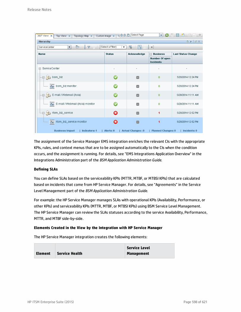
The assignment of the Service Manager EMS integration enriches the relevant CIs with the appropriateKPIs, rules, and context menus that are to be assigned automatically to the CIs when the conditionoccurs, and the assignment is running. For details, see "EMS Integrations Application Overview" in theIntegrations Administration part of the BSM Application Administration Guide.
Defining SLAs
You can define SLAs based on the serviceability KPIs (MTTR, MTBF, or MTBSI KPIs) that are calculatedbased on incidents that come from HP Service Manager. For details, see "Agreements" in the ServiceLevel Management part of the BSM Application Administration Guide.
For example: the HP Service Manager manages SLAs with operational KPIs (Availability, Performance, orother KPIs) and serviceability KPIs (MTTR, MTBF, or MTBSI KPIs) using BSM Service Level Management.The HP Service Manager can review the SLAs statuses according to the service Availability, Performance,MTTR, and MTBF side-by-side.
Elements Created in the View by the Integration with HP Service Manager
The HP Service Manager integration creates the following elements:
Element Service HealthService LevelManagement
Release Notes
HP ITSM Enterprise Suite (2015) Page 598 of 621

CIs EMS Monitor CIs for the monitored HP Service Manager system,based on the samples sent by the SiteScope HP Service ManagerMonitor.
Status for these CIs can be viewed in Service Health in the BusinessServices, Service Manager, and the Service Measurements views, andthe CIs are available to add to SLAs in Service Level Management.
Note: All HP Service Manager elements are currently mapped toBusiness Service CIs through EMS.
HealthIndicators
Ticketing EMS Monitor HI.
For more information, see "IndicatorRepository" in the Service Health partof the BSM Application AdministrationGuide.
MTBF EMS Monitor HI,MTBSI EMS Monitor HI, andMTTR EMS Monitor HI.
For more information, see"Indicator Repository" inthe Service LevelManagement part of theBSM ApplicationAdministration Guide.
KPIs Number of Open Incidents KPI.
For details, see "List of Service HealthKPIs" in the Service Health part of theBSM Application Administration Guide.
MTTR (Mean Time toRepair, MTBF (Mean TimeBetween Failures, andMTBSI (Mean TimeBetween System IncidentsKPIs.
For details, see "List ofService Level ManagementKPIs" in the Service LevelManagement part of theBSM ApplicationAdministration Guide.
Release Notes
HP ITSM Enterprise Suite (2015) Page 599 of 621

Rules andToolips
The Number of Open Incidents KPI(attached to an EMS Monitor CI) usesthe Number of Open Incidents monitorrule in Service Health and the Numberof Open Incidents Sentence tooltip. Therule handles the samples sent to BSMby the EMS system.
For details on the rule, see List ofCalculation Rules in Service Health" inthe Service Health part of the BSMApplication Administration Guide.
Each HP Service ManagerKPI (attached to an EMSMonitor CI) uses its ownmonitor rule.
For details on the rules,see "List of Service LevelManagement BusinessRule Parameters" in theService Level Managementpart of the BSM ApplicationAdministration Guide.
ContextMenu
The HP SC Menu.
For details on the context menu, see"List of Context Menus" in the ServiceHealth part of the BSM ApplicationAdministration Guide.
N/A
ContextMenuItem
The Service Manager context menuitem.
For details on the context menu, see"List of Context Menu Actions" in theService Health part of the BSMApplication Administration Guide.
N/A
Note: Only incidents for which you select a CI in the Affected CI field are retrieved by EMS. The CIlisted in the Affected CI field represents an incident-related item. The default EMS settings onlysupport the monitoring of Business Service CITs.
EMS does not count the incidents that were open through incident exchange (OMi events toSM incidents - part of CLIPv9 solution).
Prerequisites
The HP Service Manager server, Web tier, and Windows client components must be installed. For details,see HP Service Manager Installation guide.
Optional. If you want HP Service Manager to use the SSL-based Trusted Sign-on protocol, configure itaccording to the instructions in the HP Service Manager online help.
Optional. If you want HP Service Manager to use the LW-SSO, configure it according to the instructionsin the HP Service Manager online help. BSM must also be configured with LW-SSO.
Release Notes
HP ITSM Enterprise Suite (2015) Page 600 of 621

Note: Plan to put both the HP Service Manager Web tier and the webapp in the same container, soyou can use the same certificate for both.
Step 1: Enable Access to HP Service Manager FromWithin ServiceHealth
Disable the query security of the HP Service Manager application to enable accessing the application,through the right-click HP Service Manager menu option in Service Health. You still have the necessarycapabilities to properly secure your system without the query hash.
To enable accessing HP Service Manager from within Service Health:
1. After installing and configuring LW-SSO, edit the web.xml file. The location of the file depends onthe type of Web application server the Web tier is deployed on. It is usually located in the HPService Manager home directory under the Apache home directory. The web.xml file can be locatedat:\<J2EE webserver path>\webapps\<webtier>\WEB-INF.
2. In the file, locate the <!-- Specify the Service Manager server host and port location --> section.This section should appear after the honorUrlPort section.
3. Verify that the following strings exists in the section:<init-param><param-name>querysecurity</param-name><param-value>false</param-value></init-param>
4. Restart the Tomcat container using the Net stop tomcat and Net start tomcat commands.
Step 2: Define HP Service Manager Tables for External Access to theClocks
To enable the integration, load the appropriate .unl to provide external access to the clocks table in HPService Manager. This step enables the display of the Number of Incidents KPI in Service Health. This canbe done as follows (note that the probsummary table is accessed by default without .unl):
l In HP Service Manager, manually within HP Service Manager if the tables are used for other externalinternal integrations. For details, refer to the HP Service Manager documentation.
Release Notes
HP ITSM Enterprise Suite (2015) Page 601 of 621

l Using the configuration file supplied with HP Business Service Management to enable externalaccess to the clocks table:a. Locate the Clocks_extaccess_sm702_10Nov08.unl available in the Setup\SM_Unloads directory
on the BSM DVD or in the electronic download package, and copy it to a local directory.
b. Open the HP Service Manager client and connect to the server.
c. Select Tailoring > Database Manager.
d. In the menu on the upper right side of the Database Manager, select Import/Load.
e. Select the configuration file you copied to the local directory in the first step.
f. Click the Load FG button in the left top corner of the page.
g. Verify that the clocks table has the values described below. If the values do not match, edit theclocks table in HP Service Manager so that the values are the same as in the below table (fordetails on how to do that, see HP Service Manager documentation).
Field Caption Type
events[start] start DateTimeType
events[stop] stop DateTimeType
name name StringType
key.char clockId StringType
sysmodtime sysmodtime DateTimeType
type type StringType
Key.numeric clockKey DecimalType
Step 3: Correct the ClocksWSDL
Correct the clocks WSDL to enable the display of the Number of Incidents KPI in Service Health.
1. In the HP Service Manager client, select Tailoring > Web Services > Web Service Configuration,enter Clocks in the Service Name field, and click Search.
2. Click the Fields tab.
3. Add the following entry:
Release Notes
HP ITSM Enterprise Suite (2015) Page 602 of 621

Field Caption Type
Total temp StringType
Note: The values in the table have no meaning.
4. Click Save and OK.
5. Click Search again, click the Fields tab and clear the new entry.
6. Click Save and OK.
Step 4: Add the Type Field to the logical.name Link Line
This step enables EMS to count incidents that were manually opened in HP Service Manager and todisplay of the Number of Incidents KPI in Service Health.
Note:
l For new customers, EMS calculates ONLY incidents that were manually opened after the tailoringprocess was applied. For existing customers, the previous HP Service Manager version is populatingthese fields and the integration works even after you upgrade to HP Service Manager to 7.10. Skipthis step if you use other versions. Incidents opened by incident submission are always calculated.
l Perform this step before you configure the SiteScope HP Service Manager Monitor accessed in BSMby clicking Admin > Integrations > EMS Integration Admin. Only incidents that were opened afterthis step are displayed in BSM Service Health.
You add the Type field to the logical.name link line in the probsummary link record as follows:
In HP Service Manager, login with a System Administrator user (for example, falcon).
1. Select Tailoring > Tailoring Tools > Links.
2. Enter probsummary in the Name field and click Search.
3. Set the cursor on the first line that includes logical.name in the Source Field Name field (line 14).
4. Select Select Line in the More menu.
Release Notes
HP ITSM Enterprise Suite (2015) Page 603 of 621

5. Make sure the following entries are present in the table:
Source Field Target Field
logical.name logical.name
company company
type type
initial.impact default.impact
severity problem.priority
6. Click Save, Back, and then OK.
Step 5: Create a Corresponding HP Service Manager User
This step enables the display of the Number of Incidents KPI in Service Health.
1. Create a dedicated user in HP Service Manager. The user should be used solely for the purposes ofthe HP Business Service Management/SiteScope integration.
2. Make sure that the HP Service Manager machine and the SiteScope machine share the same timezone.
3. Make sure that the HP Service Manager machine and the SiteScope machine use the same dateformat (SiteScope date format): dd/mm/yy.
4. When configuring the monitor, use the value for the Username and Password fields that youcreated in HP Service Manager.
Step 6: Configure the HP Service Manager Monitor in SiteScope
Configure the HP Service Manager monitor in SiteScope as follows:
1. Synchronize HP Service Manager and SiteScope so their time zones are the same. Match theirSystem Time in the Windows or Unix operating system.
2. Make sure that the user you are using in SiteScope is the user you defined in "Step 5: Create aCorresponding HP Service Manager User" above.
Release Notes
HP ITSM Enterprise Suite (2015) Page 604 of 621
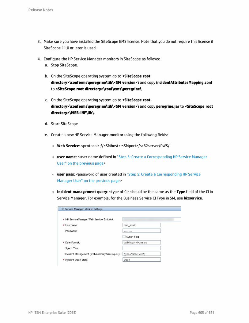
3. Make sure you have installed the SiteScope EMS license. Note that you do not require this license ifSiteScope 11.0 or later is used.
4. Configure the HP Service Manager monitors in SiteScope as follows:a. Stop SiteScope.
b. On the SiteScope operating system go to <SiteScope rootdirectory>\conf\ems\peregrine\lib\<SM version>\ and copy incidentAttributesMapping.confto <SiteScope root directory>\conf\ems\peregrine\.
c. On the SiteScope operating system go to <SiteScope rootdirectory>\conf\ems\peregrine\lib\<SM version>\ and copy peregrine.jar to <SiteScope rootdirectory>\WEB-INF\lib\.
d. Start SiteScope
e. Create a new HP Service Manager monitor using the following fields:
o Web Service: <protocol>://<SMhost>:<SMport>/sc62server/PWS/
o user name: <user name defined in "Step 5: Create a Corresponding HP Service ManagerUser" on the previous page>
o user pass: <password of user created in "Step 5: Create a Corresponding HP ServiceManager User" on the previous page>
o incident management query: <type of CI> should be the same as the Type field of the CI inService Manager. For example, for the Business Service CI Type in SM, use bizservice.
Release Notes
HP ITSM Enterprise Suite (2015) Page 605 of 621

Step 7: Specify the HP Service Manager Web Tier URL in theInfrastructure Settings
The HP Service Manager URL is used when drilling down from BSM to HP Service Manager using the HPSC Menu context menu item.
1. To specify the HP Service Manager URL, in BSM, select Admin > Platform > Setup andMaintenance > Infrastructure Settings, select Foundations, and select Integrations with otherapplications.
2. In the Integrations with other applications - HP ServiceCenter - Ticketing Integration table, enterthe appropriate URL in the ServiceCenter/Service Manager web tier URL entry, using thefollowing format: <protocol>://<host_name>:<port>/<web_app_name>/ where host_name is thename of the HP Service Manager server, port is the port number of the HP Service Manager server,and web_app_name is the name of the application.
The URL of HP Service Manager is, for example, http://fando:8080/sm7/.
Step 8: Customize the HP Service Manager EMS Integration Adapterand Check the Assignment – Optional
The HP Service Manager integration adapter is predefined. You can customize the configuration. Makesure that the assignment rule is running (it is running by default).
In BSM, select Admin > Integrations > EMS Integration Admin, select ServiceCenter and click Edit. Inthe Edit Integration dialog box:
Release Notes
HP ITSM Enterprise Suite (2015) Page 606 of 621

1. Configure the HP Service Manager Monitor – Optional. The monitor is used to retrieve data fromthe EMS system using System Availability Management Administration. The HP Service ManagerMonitor is added to a SiteScope monitor group created for this monitor and other IntegrationMonitor types. It is recommended that you configure Integrations Monitors only after a connectionbetween the SiteScope and HP Business Service Management is established. For details, go to "Howto Work with the HP Service Manager Integration" in Monitor Reference in the SiteScopedocumentation library.
Note: SiteScope cannot be deployed behind a firewall. SiteScope and the monitored system mustbe on the same LAN or special firewall configuration might be required.
2. Activate the data assignment rule. Make sure that the assignment rule is running.
When the EMS monitor sample includes open incidents in its data source, the Number of OpenIncidents KPI (2600), the Number of Open Incidents rule (2600), the HP SC Menu context menu(hpsc), the HP Service Manager context menu item, and the Number of Open Incidents tooltip(2600) are assigned to the EMS Monitor CI.
You can use the EMS Integrations application to customize an HP Service Manager integration. Theintegration forwards the retrieved data captured from the HP Service Manager system by theSiteScope HP Service Manager monitor to BSM, and creates the appropriate topology that is used todisplay the data in Service Health. For details on the possible customizations, see "Edit IntegrationDialog Box" in the Integrations Administration part of the BSM Application Administration Guide.
Step 9: Specify the State and Severity of Open Incidents to BeDisplayed – Optional
To modify the state and severity of the open incidents to be displayed, you can edit the parameters ofthe Number of Open Incidents rule parameters:
l For the Number of Open Incidents KPIs attached to a specific EMS Monitor CI. In BSM, selectAdmin > Service Health > Assignments > KPI Assignments, select the ServiceCenter view and theEMS Monitor CI, edit the Number of Open Incidents rule, and edit the Initial State, Final State, andSeverity parameters.
l Globally, for all KPIs defined with the Number of Open Incidents rule. In BSM, select Admin >Service Health > Repositories > Business Rules, clone or override the Number of Open Incidentsrule, and edit the Initial State, Final State, and Severity parameters.
Release Notes
HP ITSM Enterprise Suite (2015) Page 607 of 621
For details on the parameters, see "List of Calculation Rules in Service Health" in the Service Healthpart of the BSM Application Administration Guide.
Note: The values available for the Initial State, Final State, and Severity parameters reflect thevalues defined in HP Service Manager. BSM severity is correlated with HP Service Manager urgency.
Step 10: Include HP Service Manager CIs in Service Level ManagementAgreements
You can include HP Service Manager EMS Monitor CIs in your agreements in Service Level Management.Service Level Management contains KPIs and rules specifically configured for HP Service Manager EMSMonitor CIs. The MTTR, MTBF, and MTBSI KPIs and the MTTR, MTBF, and MTBSI rules are dedicated forthis integration.
You also configure the incident initial and final state in those rules. For details, see "Service LevelManagement KPIs for System Incidents" in the Service Level Management part of the BSM ApplicationAdministration Guide, and locate "Incident State and Severity Values".
Results
After the task is performed, HP Service Manager data is integrated into BSM. You can:
l View HP Service Manager Data in Service Health and Service Level Management:
SiteScope automatically creates the appropriate topology when HP Service Manager data isintegrated into BSM. HP Business Service Management adds the data to the Business Services,ServiceCenter, and Service Measurements views, and you can display these views in Service Health.The Business Service and EMS Monitor CIs are added to Service Level Management.
l Drill down to HP Service Manager from Service Health views:
In Service Health, in the ServiceCenter, and Service Measurements views, use the HP ServiceManager option available for EMS Monitor CIs under Business Service CIs, to access the relevantincident in the HP Service Manager application. For information about the HP Service Managerapplication, consult the HP Service Manager documentation.
Release Notes
HP ITSM Enterprise Suite (2015) Page 608 of 621
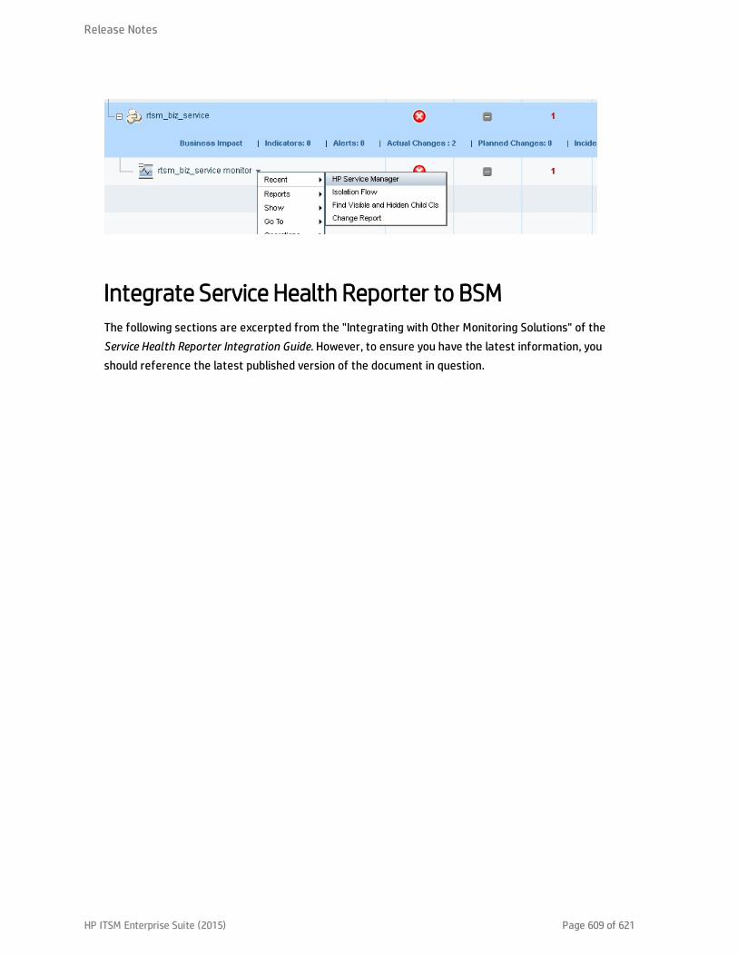
Integrate Service Health Reporter to BSMThe following sections are excerpted from the "Integrating with Other Monitoring Solutions" of theService Health Reporter Integration Guide. However, to ensure you have the latest information, youshould reference the latest published version of the document in question.
Release Notes
HP ITSM Enterprise Suite (2015) Page 609 of 621

Next stepsUpon completion of the previous procedures, you will have a complete and integrated system. However,it is important to note that significant work may need to be done in order to develop a production readysystem for your organization. Therefore, we recommend the following guidelines to develop aneffective solution for your organization.
Service ManagerDelete all out of box data
We recommend that your first step is to delete all demo data from the system. To do this, locate andthen execute the "Purge OOB data" script in the Service Manager script library.
Define and develop services according to business needs
Follow the ITIL service portfolio management process to define the services required by yourorganization. You should consider:
l Which supporting configuration items are required to run those services?
l Which services are required by your organization's people?
l What are the supporting service catalog items that should be available for users to order that arerelated to the service?
l What are the supporting service level agreements, operational level agreements, and underpinningcontracts that will support the services?
l What are the defining service level targets that enforce the service agreements?
Release NotesNext steps
HP ITSM Enterprise Suite (2015) Page 610 of 621
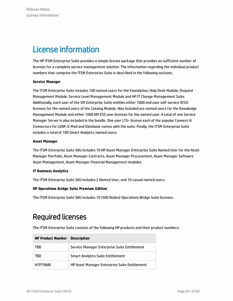
License informationThe HP ITSM Enterprise Suite provides a simple license package that provides an sufficient number oflicenses for a complete service management solution. The information regarding the individual productnumbers that comprise the ITSM Enterprise Suite is described in the following sections.
Service Manager
The ITSM Enterprise Suite includes 100 named users for the Foundation, Help Desk Module, RequestManagement Module, Service Level Management Module and HP IT Change Management Suite.Additionally, each user of the SM Enterprise Suite entitles either 1000 end user self-service (ESS)licenses for the named users of the Catalog Module. Also included are named users for the KnowledgeManagement Module and either 1000 KM ESS user licenses for the named user. A total of one ServiceManager Server is also included in the bundle. One user LTU- license each of the popular Connect-ItConnectors for LDAP, E-Mail and Database comes with the suite. Finally, the ITSM Enterprise Suiteincludes a total of 100 Smart Analytics named users.
Asset Manager
The ITSM Enterprise Suite SKU includes 10 HP Asset Manager Enterprise Suite Named User for the AssetManager Portfolio, Asset Manager Contracts, Asset Manager Procurement, Asset Manager SoftwareAsset Management, Asset Manager Financial Management modules.
IT Business Analytics
The ITSM Enterprise Suite SKU includes 2 Named User, and 10 casual named users.
HP Operations Bridge Suite Premium Edition
The ITSM Enterprise Suite SKU includes 10 (500 Nodes) Operations Bridge Suite licenses.
Required licensesThe ITSM Enterprise Suite consists of the following HP products and their product numbers:
HP Product Number Description
TBD Service Manager Enterprise Suite Entitlement
TBD Smart Analytics Suite Entitlement
H7P79AAE HP Asset Manager Enterprise Suite Entitlement
Release NotesLicense information
HP ITSM Enterprise Suite (2015) Page 611 of 621
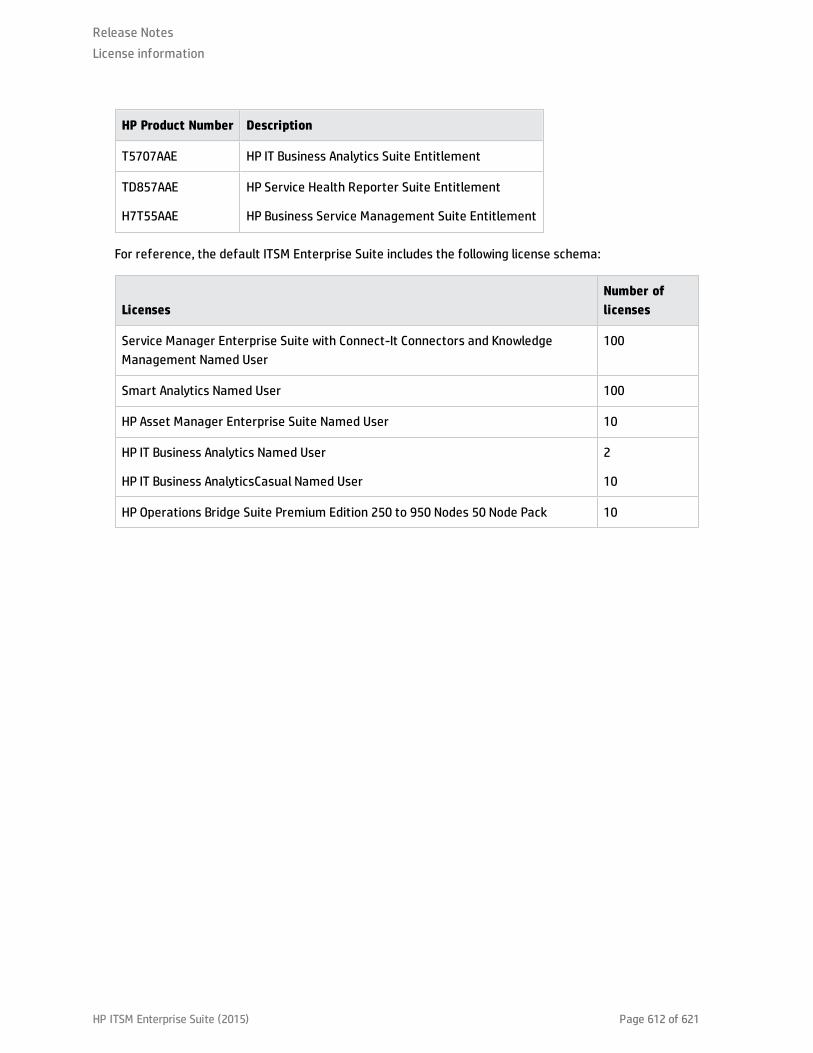
HP Product Number Description
T5707AAE HP IT Business Analytics Suite Entitlement
TD857AAE
H7T55AAE
HP Service Health Reporter Suite Entitlement
HP Business Service Management Suite Entitlement
For reference, the default ITSM Enterprise Suite includes the following license schema:
LicensesNumber oflicenses
Service Manager Enterprise Suite with Connect-It Connectors and KnowledgeManagement Named User
100
Smart Analytics Named User 100
HP Asset Manager Enterprise Suite Named User 10
HP IT Business Analytics Named User
HP IT Business AnalyticsCasual Named User
2
10
HP Operations Bridge Suite Premium Edition 250 to 950 Nodes 50 Node Pack 10
Release NotesLicense information
HP ITSM Enterprise Suite (2015) Page 612 of 621

ITSM Enterprise Suite file listFile File Name
OperationsManager i10.01
Readme aboutHP OMi 10.01installation
HP_OMi_10.01_ReadMeFirst.htm
Customer Letterfor HP OMi 10.00
Customer_Letter_OMi_10.00.pdf
HP OMi 10.01installation forLinux
HP_OMi_10.01_for_Linux.zip
HP OMi 10.01installation forWindows
HP_OMi_10.01_for_Windows.zip
Data Flow Probeinstallation
HP_OMi_10.01_DataFlowProbe.zip
HP BSMConnector 10.00installation for
Windows andLinux
HP_BSM_Connector_10.00.zip
HP OMi 10.01VirtualAppliance
HP_OMi_10.01_VirtualAppliance.ova
HP OMi 10.01VirtualAppliancesignature file
HP_OMi_10.01_VirtualAppliance.ova.sig
Release NotesITSM Enterprise Suite file list
HP ITSM Enterprise Suite (2015) Page 613 of 621

File File Name
HP OMi 10.01VirtualAppliancetechnicaldescription
HP_OMi_10.01_VirtualAppliance.pdf
SiteScope 11.30
Software, HPSiteScope 11.30for Windows64bit
T8354-15015.zip
Software, HPSiteScope 11.30for Linux 64bit
T8354-15016.zip
HP OperationsAgent 11.14
HP OperationsAgent v11.14
TC097-15040.iso
Service HealthReporter 9.40
ReassemblyInstructions SHR9.40-Windows
HPSHR_940_Reassembly_Win.pdf
ReassemblyInstructions SHR9.40-Linux
HPSHR_940_Reassembly_Lin.pdf
HP SHR 9.40 forWindows 1 of 3
HPSHR_940_Win64.part1
HP SHR 9.40 forWindows 2 of 3
HPSHR_940_Win64.part2
HP SHR 9.40 forWindows 3 of 3
HPSHR_940_Win64.part3
HP SHR 9.40 forLinux 1 of 3
HPSHR_940_Lin64.part1
Release NotesITSM Enterprise Suite file list
HP ITSM Enterprise Suite (2015) Page 614 of 621

File File Name
HP SHR 9.40 forLinux 2 of 3
HPSHR_940_Lin64.part2
HP SHR 9.40 forLinux 3 of 3
HPSHR_940_Lin64.part3
ServiceManager 9.40
Software, HPServiceManager 9.40#1
T5001-15076.iso
Software, HPServiceManager 9.40#2
T5001-15077.iso
Software, HPServiceManager 9.40#3
T5001-15078.iso
Software, HPServiceManager 9.40Multi- Language
T5001-15079.iso
Software, SCAutoApplications v4.03
T4581-15004.iso
Software,Release Controlv 9.2 media
T9770-15008.iso
Software, HPUCMDB/UD10.20 WindowsMLU
TF236-15009.iso
Release NotesITSM Enterprise Suite file list
HP ITSM Enterprise Suite (2015) Page 615 of 621

File File Name
Software, HPUCMDB/UD10.20 Linux MLU
TF236-15010.iso
Software, HPUCMDB/CM10.20 WindowsMLU
TF236-15011.iso
Software, HPUCMDB/CM10.20 Linux MLU
TF236-15012.iso
Software,Connect-It 9.60English
T4500-15030.iso
Asset Manager9.50
Software, HP AM9.50 English
AssetManager-9.50-English.zip)
Software, SAPBusinessObjectsEnterprise For
AM
AssetManager-CRS-9.50.zip
Software, SAPCrystal ReportsDesigner For AM
AssetManager-CRD-9.50.zip
Software,Connect-It 9.60English
T4500-15030.iso
Software, HPUCMDB/UD10.20 WindowsMLU
TF236-15009.iso
Software, HPUCMDB/UD10.20 Linux MLU
TF236-15010.iso
Release NotesITSM Enterprise Suite file list
HP ITSM Enterprise Suite (2015) Page 616 of 621

File File Name
Software, HPUCMDB/CM10.20 WindowsMLU
TF236-15011.iso
Software, HPUCMDB/CM10.20 Linux MLU
TF236-15012.iso
IT BusinessAnalytics 9.50
Formerly IT Executive ScoreCard
Note: IT Business Analytics 9.50 was previously known as IT ExecutiveScoreCard 9.50. The media for IT Business Analytics retains the previousname, IT Executive ScoreCard. Should newly mastered versions of the mediabe produced, the name change will be implemented then.
Batch file, ITExecutiveScorecard 9.50reassemble
IT_Executive_Scorecard_9.50_reassemble_TB812-15014.zip
Software, HP ITExecutiveScorecard 9.50Part 1 of 3
HP_IT_Executive_Scorecard_9.50_Part_1_of_3_TB812-15013.zip.001
Software, HP ITExecutiveScorecard 9.50Part 2 of 3
HP_IT_Executive_Scorecard_9.50_Part_2_of_3_TB812-15013.zip.002
Software, HP ITExecutiveScorecard 9.50Part 3 of 3
HP_IT_Executive_Scorecard_9.50_Part_3_of_3_TB812-15013.zip.003
Readme, HP ITExecutiveScorecard 9.50
TB812-88011.pdf
Release NotesITSM Enterprise Suite file list
HP ITSM Enterprise Suite (2015) Page 617 of 621

Page 618 of 621HP ITSM Enterprise Suite (2015)
Glossary
M
My TermMy definition

Index
HP ITSM Enterprise Suite (2015) Page 619 of 621

Send Documentation FeedbackIf you have comments about this document, you can contact the documentation team by email. If anemail client is configured on this system, click the link above and an email window opens with thefollowing information in the subject line:
Feedback on Release Notes (ITSM Enterprise Suite 2015)
Just add your feedback to the email and click send.
If no email client is available, copy the information above to a new message in a web mail client, andsend your feedback to [email protected].
We appreciate your feedback!
HP ITSM Enterprise Suite (2015) Page 620 of 621