IT9121E Power Meter User Manual - ITECH
61
IT9121E Power Meter User Manual Model: IT9121E Version:1.4
-
Upload
khangminh22 -
Category
Documents
-
view
2 -
download
0
Transcript of IT9121E Power Meter User Manual - ITECH

IT9121E Power Meter User Manual
Model: IT9121E Version:1.4

Notices © ItechElectronics, Co., Ltd. 2016 No part of this manual may be
reproduced in any form or by any means
(including electronic storage and
retrieval or translation into a foreign
language) without prior permission and
written consent from Itech Electronics,
Co., Ltd. as governed by international
copyright laws.
Manual Part Number
IT9121E-402145
Revision
1st Edition: September 22, 2016
Itech Electronics, Co., Ltd.
Trademarks
Pentium is U.S. registered trademarks
of Intel Corporation.
Microsoft, Visual Studio, Windows and
MS Windows are registered trademarks
of Microsoft Corporation in the United
States and/or other countries and
regions.
Warranty
The materials contained in this document are provided “as is”, and is subject to change, without prior notice, in future editions. Further, to the maximum extent permitted by applicable laws, ITECH disclaims all warrants, either express or implied, with regard to this manual and any information contained herein, including but not limited to the implied warranties of merchantability and fitness for a particular purpose. ITECH shall not be held liable for errors or for incidental or indirect damages in connection with the furnishing, use or application of this document or of any information contained herein. Should ITECh and the user enter into a separate written agreement with warranty terms covering the materials in this document that conflict with these terms, the warranty terms in the separate agreement shall prevail. Technology Licenses
The hardware and/or software
described herein are furnished under a
license and may be used or copied only
in accordance with the terms of such
license.
Restricted Rights Legend
U.S. Government Restricted Rights. Software and technical data rights granted to the federal government include only those rights customarily
provided to end user customers. ITECH provides this customary commercial license in software and technical data pursuant to FAR 12.211 (Technical Data) and 12.212 (Computer Software) and, for the Department of Defense, DFARS 252.227-7015 (Technical Data – Commercial Items) and DFARS 227.7202-3 (Rights in Commercial Computer Software or Computer Software Documentation).
Safety Notices
A CAUTION sign denotes a hazard. It calls attention to an operating procedure or practice that, if not correctly performed or adhered to, could result in damage to the product or loss of important data. Do not proceed beyond a CAUTION sign until the indicated conditions are fully understood and met.
A WARNING sign denotes a hazard. It calls attention to an operating procedure or practice that, if not correctly performed or adhered to, could result in personal injury or death. Do not proceed beyond a WARNING sign until the indicated conditions are fully
understood and met.
NOTE A NOTE sign denotes important hint. It calls attention to tips or supplementary information that is essential for users to refer to.
.

IT9121E User Manual
Copyright © Itech Electronics Co., Ltd. i
Quality Certification and Assurance We certify that IT9121E power meter meets all the published specifications.
Warranty ITECH warrants that the product will be free from defects in material and workmanship under normal use for a period of one (1) year from the date of delivery (except those described in the Limitation of Warranty below). For warranty service or repair, the product must be returned to a service center designated by ITECH.
The product returned to ITECH for warranty service must be shipped PREPAID. And ITECH will pay for return of the product to customer.
If the product is returned to ITECH for warranty service from overseas, all the freights, duties and other taxes shall be on the account of customer.
Limitation of Warranty This Warranty will be rendered invalid if the product is:
Damaged resulting from customer-wired circuits or customer-supplied parts or accessories;
Modified or repaired by customer without authorization;
Damaged resulting from customer-wired circuits or use in an environment not designated by us;
The product model or serial number is altered, deleted, removed or made illegible by customer;
Damaged as a result of accidents, including but not limited to lightning, moisture, fire, improper use or negligence.
Safety Symbols
Direct current
ON (power)
Alternating current OFF (power)
Both direct and alternating current
Power-on state
Protective earth (ground) terminal
Power-off state
Earth (ground) terminal
Reference terminal
Caution
Positive terminal
Warning (refer to this manual for specific Warning or Caution information)
Negative terminal
A chassis terminal - -

IT9121E User Manual
Copyright © Itech Electronics Co., Ltd. ii
Safety Precautions The following safety precautions must be observed during all phases of operation of this instrument. Failure to comply with these precautions or specific warnings elsewhere in this manual will constitute a default under safety standards of design, manufacture and intended use of the instrument. ITECH assumes no liability for the customer’s failure to comply with these precautions.
Do not use the instrument if it is damaged. Before operation, check the casing to see whether it cracks. Do not operate the instrument in the presence of inflammable gasses, vapors or dusts.
The maximum operating voltage and current of the instrument are 600V and 20A respectively. Exceeding these limits will lead to burnout of the instrument.
Make sure to use the power cord supplied by ITECH.
Check all marks on the instrument before connecting the instrument to power supply.
Turn off the instrument and the operation system before connecting to the I/O terminal.
Do not install alternative parts on the instrument or perform any unauthorized modification.Do not use the instrument if the detachable cover is removed or loosen.
Do not connect the instrument to any cable or terminal block before self-testing.
To prevent the possibility of accidental injuries, be sure to use the power adapter supplied by the manufacturer only.
Never use the instrument with a life-support system or any other equipment subject to safety requirements.
Failure to use the instrument as directed by the manufacturer may render its protective features void.
Always clean the casing with a dry cloth. Do not clean the internals.
Make sure the vent hole is always unblocked.
Environmental Conditions
The instrument is designed for indoor use and an area with low condensation. The table below shows the general environmental requirements for the instrument.
Environmental Conditions Requirements
Operating temperature 5°C-40°C Operating humidity humidity 20%-80%
(non-condensation) Storage temperature -20°C-50 °C
Altitude Operating up to 2,000 meters Installation category II Pollution degree Pollution degree 2

IT9121E User Manual
Copyright © Itech Electronics Co., Ltd. iii
NOTE
To make accurate measurements, allow the instrument to warm up for 30 min.
Regulatory Markings
The CE mark indicates that the product complies with all the relevant European legal directives. The specific year (if any) affixed refers to the year when the design was approved.
The instrument complies with the WEEE Directive (2002/96/EC) marking requirement. This affix product label indicates that you must not discard the electrical/electronic product in domestic household waste.
This symbol indicates the time period during which no hazardous or toxic substances are expected to leak or deteriorate during normal use. The expected useful life of the product is 10 years. The product can be used safely during the 10-year Environment Friendly Use Period (EFUP). Upon expiration of the EFUP, the product must be immediately recycled.
Waste Electrical and Electronic Equiment (WEEE) Directive
2002/96/EC Waste Electrical and Electronic Equipment (WEEE) Directive
This product complies with the WEEE Directive (2002/96/EC) marking requirement. This affix product label indicates that you must not discard the electrical/electronic product in domestic household waste. Product Category With reference to the equipment classifications described in the Annex 1 of the WEEE Directive, this instrument is classified as a “Monitoring and Control Instrument”. To return this unwanted instrument, contact your nearest ITECH office.
IT9121E User Manual
Copyright © Itech Electronics Co., Ltd. iv
Compliance Information Complies with the essential requirements of the following applicable European Directives, and carries the CE marking accordingly:
Electromagnetic Compatibility (EMC) Directive 2014/30/EU Low-Voltage Directive (Safety) 2014/35/EU
Conforms with the following product standards:
EMC Standard
IEC 61326-1:2012/ EN 61326-1:2013 ¹²³
Reference Standards CISPR 11:2009+A1:2010/ EN 55011:2009+A1:2010 (Group 1, Class A) IEC 61000-4-2:2008/ EN 61000-4-2:2009 IEC 61000-4-3:2006+A1:2007+A2:2010/ EN 61000-4-3:2006+A1:2008+A2:2010 IEC 61000-4-4:2004+A1:2010/ EN 61000-4-4:2004+A1:2010 IEC 61000-4-5:2005/ EN 61000-4-5:2006 IEC 61000-4-6:2008/ EN 61000-4-6:2009 IEC 61000-4-11:2004/ EN 61000-4-11:2004
1. The product is intended for use in non-residential/non-domestic environments. Use of the
product in residential/domestic environments may cause electromagnetic interference. 2. Connection of the instrument to a test object may produce radiations beyond the specified
limit. 3. Use high-performance shielded interface cable to ensure conformity with the EMC standards
listed above.
Safety Standard
IEC 61010-1:2010/ EN 61010-1:2010

IT9121E User Manual
Copyright © Itech Electronics Co., Ltd. v
Content
Quality Certification and Assurance .........................................................................................................................i Warranty .................................................................................................................................................................i Limitation of Warranty ............................................................................................................................................i Safety Symbols ........................................................................................................................................................i Safety Precautions .................................................................................................................................................. ii Environmental Conditions ...................................................................................................................................... ii Regulatory Markings ............................................................................................................................................. iii Waste Electrical and Electronic Equiment (WEEE) Directive ................................................................................... iii Compliance Information ........................................................................................................................................ iv
Chapter1 Introduction ..................................................................................................................................... 1
1.1 Brief Introduction ............................................................................................................................................ 1 1.2 Introduction of Front Panels ............................................................................................................................ 2 1.3 Introduction to keyboard ................................................................................................................................. 2 1.4 Introduction of Menu Function........................................................................................................................ 3 1.5 Introduction of Interface Display Information .................................................................................................. 5 1.6 Introduction of Interface Symbols.................................................................................................................... 5 1.7 Introduction of Rear Panels ............................................................................................................................. 6
Chapter2 Measurement Conditions ................................................................................................................. 7
2.1 Setting of Measurement Range ....................................................................................................................... 7 2.2 Setting of Measurement Interval ..................................................................................................................... 9 2.3 Setting of Filter and Crest Factor .................................................................................................................... 10 2.4 Setting of Averaging Function ........................................................................................................................ 12
Chapter3 Basic Measurement Functions ....................................................................................................... 15
3.1 Basic Concepts .............................................................................................................................................. 15 3.2 Setting of Measurement Function and Interface Display ................................................................................ 16
Chapter4 Waveform Display Function ........................................................................................................... 18
4.1 Basic Concepts .............................................................................................................................................. 18 4.2 Adjustment of Measurement Parameters ...................................................................................................... 21 4.3 Setting of Trigger Configuration ..................................................................................................................... 21
Chapter5 Integral Operation Function ........................................................................................................... 23
5.1 Basic Concepts .............................................................................................................................................. 23 5.2 Setting of Integral Measurement Configuration ............................................................................................. 27 5.3 Integration..................................................................................................................................................... 29
Chapter6 Harmonic Measurement Function .................................................................................................. 32
6.1 Enable the Harmonic Function ...................................................................................................................... 32 6.2 Basic Concepts .............................................................................................................................................. 32 6.3 Setting of Harmonic Measurement Configuration .......................................................................................... 35
Chapter7 Routine Maintenance ..................................................................................................................... 39
7.1 Self-Inspection............................................................................................................................................... 39 7.2 Error Information References ........................................................................................................................ 39 7.3 Daily maintenance ......................................................................................................................................... 41 7.4 Contact of ITECH Engineers............................................................................................................................ 42 7.5 Returning Your Power Meter for Service ........................................................................................................ 43
Chapter8 Technical Specifications .................................................................................................................. 44
8.1 General Specification ..................................................................................................................................... 44 8.2 Screen Display ............................................................................................................................................... 44 8.3 Input Parameters ........................................................................................................................................... 44 8.4 Voltage and Current Accuracy ........................................................................................................................ 46 8.5 Active Power Accuracy .................................................................................................................................. 46 8.6 Voltage Current and Power measurements.................................................................................................... 47

IT9121E User Manual
Copyright © Itech Electronics Co., Ltd. vi
8.7 Frequency Measurement............................................................................................................................... 48 8.8 Harmonic Measurement ................................................................................................................................ 49 8.9 Fundamental Frequency ................................................................................................................................ 50 8.10 Accuracy ...................................................................................................................................................... 50 8.11 Oscilloscope Function .................................................................................................................................. 51 8.12 Interface Specification ................................................................................................................................. 51

Introduction
Copyright © Itech Electronics Co., Ltd. 1
Chapter1 Introduction
1.1 Brief Introduction
The IT9121E power meter can provide the maximum input of 600Vrms and 20Arms and the measurement bandwidth of 100KHZ and thus can be easily used for measuring the parameters including voltage, current, power, frequency and harmonics. Standard configuration includes USB, GPIB, RS232 and LAN communication interfaces and also the interface for USB peripherals. The user can store the measured parameters in the external storage medium. The voltage and current precision is 0.1%. The instrument also has many integral functions, such as the active power. The product can be widely applied in motors, household appliances, UPS and other test fields.
Features
4.3-inch color liquid crystal display (TFT) The number of matrix columns to be displayed on the screen and the
commonly used measurement parameters can be set freely. Input range:600Vrms/20Arms The voltage, current, power, harmonics and other parameters can be
measured at the same time. The precision of voltage and current measurement is up to 0.1%. It has the harmonic measuring function and can measure 50-order harmonic
components at most. With the interface for USB peripherals, the user can store the interface in the
external storage medium. With many powerful integral functions, the bought/sold electricity can be
calculated. Frequency measurement function Built-in USB, GPIB, RS232 and LAN communication interfaces
Application advantages
Analysis of UPS power quality:
As an important backup power supply in the communication industry, the steady-state characteristics, dynamic characteristics, power quality and other parameters of UPS should be analyzed. With internal nonlinear elements, the UPS power supply will generate a large number of harmonic components during operation, which may affect operation of the communication system. The IT9121E power meter can measure such parameters as the AC/DC signal, power factor, harmonics, frequency and distortion factor, and systematically and comprehensively analyze the performance of the UPS power supply.
Test of performance of household appliances:
With promotion of the concept of using energy in a rational and environmentally friendly manner, more and more household appliances adopt the variable frequency control technology to reduce the power consumption. The IT9121E power meter can measure the inrush current, active power, crest factor, etc.
NOTE
The harmonic analyze function of IT9121E power meter is optional function, is limited by the license. If you need activate the harmonic analyze function, you can contact the ITECH agent and purchase this license.

Introduction
Copyright © Itech Electronics Co., Ltd. 2
1.2 Introduction of Front Panels
Schematic Diagram of Front Panel of IT9121E Series Power Meter and Diagram of Key Functions.
1 USB Interface 2. Display 3. Menu key 4.Waveform Display key 5 Basic functions 6. Harmonic key 7. Integrator key 8. Setting knob 9. Arrow keys 10. Hold/Esc key 11. Enter key 12. Image Save key 13 Parameter setting key 14. Menu key 15 Power switch
1.3 Introduction to keyboard
The functions of keys on the front panel of the IT9121E series power meter are shown in the following table.
Key tag Name and function
Waveform Display key When this key is pressed,the waveform corresponding to current measurement data will be displayed.
Harmonic Measurement key When this key is pressed, the harmonic measurement results and the menu of harmonic measurement parameter configuration will be displayed.
Basic Measurement key When this key is pressed, the measurement data of various items will be displayed.
Integral Measurement key When this key is pressed, the integral measurement results and the menu of integral measurement parameter configuration will be displayed.
Menu key, used for setting relevant measurement parameters of the power meter.
Enter key, used for saving the settings.
Image Save key
Cancel/ESC key The front panel keyboard can be locked/unlocked when the ESC key is constantly pressed for 5s. The remote control mode of the power meter can be switched to the panel operation mode when the ESC key is constantly pressed for 5s.

Introduction
Copyright © Itech Electronics Co., Ltd. 3
Key tag Name and function
Up/Down key and Left/Right key List Edit: those lines which are not displayed can be displayed by operating the Left/Right key. Those rows which are not displayed can be displayed by operating the Up/Down key. Menu Edit: the programming items can be rolled by operating the Up/Down key. Prompts of corresponding options are displayed on the right and options can be selected via the soft key. Digit Edit: the programming items can be rolled by operating the Up/Down key. The digit to be edited is selected by operating the Left/Right key or via the knob. Carrying can be completed automatically.
Soft key The contents on the left of the key and the menu function displayed above the key on the display screen may be subject to changes.
Knob key, used for setting the value indicated by the cursor, selecting the voltage and current range, adjusting the waveform, etc.
1.4 Introduction of Menu Function
Press this key to enter the system menu function. Menu is described as follows.
Menu Menu setting
SYSTEM
SYSTEM INFO Instrument system information
Model Instrument model
Serial Instrument SN
Cpu Version The version of CPU
Dsp Version The version of Digital Signal Processing
MAC address Network hardware address
Socket Port Port number
COMM CONFIG Communication configuration
R232
BAUD Rate Set the communication baud rate:4800/9600/19200/38400/57600/115200
Parity Chack Communication parity check bit: Default: NONE
Data bit Communication data bit: 8 (default)
Stop bit Communication stop bit: 1 (default)
USB Type B Connect
Select the USB communication interface.
GPIB GPIB Address The address is adjustable between 1 and 30.
LAN
IP mode IP mode: MANU/DHCP
IP Address IP address setting
Subnet mask Set the subnetmask.

Introduction
Copyright © Itech Electronics Co., Ltd. 4
Gateway Set the gateway.
SYSTEM CONFIG System configuration
Date (YY/MM/DD) System date: Year/Month/Day
Time (hh:mm:ss) System time: Hour/Minute/Second
Brightness Set the screen brightness.
Beep Set the keyboard sound
SELF TEST Self test
SYSTEM SELF_TEST Self test
INITIAL Initialize
SYSTEM INITIAL System initialization
SETUP
SETUP INFO Configuration information
Averag Average
Sync Source Synchronization
Line Filter Line filter
Update Rate Data updating rate
Freq Filter Frequency filter
Crest Factor Crest factor
ExSensor1 External current sensor 1 (range: CF=3:2.5V,5V,10V; CF=6:1.25V, 2.5V,5V.)
ExSensor2 External current sensor 2 (range: CF=3:50mV,100mV,200mV,500mV,1V,2V; CF=6:25 mV,50mV,100mV,250mV,0.5V,1V.)
Rate(V/A) Conversion ratio of external current sensor 1
Rate(mV/A) Conversion ratio of external current sensor 2
U_Range Voltage range
I_Range Current range
AVERAG SET Average function setting
State Status
Mode Mode
Type Loading Type
Count Counting cycle
EXT SEN SET External current sensor setting
EXSENSOR 1 Set the external current sensor 1: ON/OFF
Ratio(V/A) Set the conversion ratio of the external current sensor 1
EXSENSOR 2 Set the external current sensor 2: ON/OFF
Ratio(mV/A) Set the conversion ratio of the external current sensor 2
OTHER SET Other settings
Sync Source Select the synchronization source: U/I/OFF
Freq Filter Set the frequency filter: ON/OFF
Line Filter Set theline filter: ON/OFF
Crest Factor Set the crest factor: CF3/CF6
Update Rate Set the data updating rate: 0.1s/0.25s/0.5s/1s/2s/5s

Introduction
Copyright © Itech Electronics Co., Ltd. 5
INRUSH SET Inrush setting
State Status
Trig level(A) Trigger level
Delay time(ms) Delay time
Measure time(s) Measuring time
CAL ZERO Calibration Zero Zero point calibration
Calibration Zero Zero point calibration
RATIO SET
Voltage and Current Ratio Set VT/CT ratio constant
Voltage Ratio Set the external Voltage Transformer(VT) conversion ratio
Current Ratio Set the external Current Transformer(CT) conversion ratio
KEYGEN
KeyGen The key of harmonic function
Key1 High five bits in a key
Key2 Low five bits in a key
1.5 Introduction of Interface Display Information
The IT9121E power meter has four measurement modes. Below is the introduction of basic interface information, with the basic measurement interface as an example.
Basic measurement interface
Select the “Meter” button, and the initial interface of basic measurement as shown below will appear.
1.6 Introduction of Interface Symbols
The interface of the IT9121E power meter will display the following symbols.
Introduction
Copyright © Itech Electronics Co., Ltd. 6
Status Bar icon Status description
This icon appears when the line filter is switched on.
This icon appears when the frequency filter is switched on.
This icon appears when USB is inserted.
Over-voltage protection icon: this icon appears when over-voltage occurs.
Over-current protection icon: this icon appears when over-current occurs.
Key Lock: this icon appears when the keyboard is locked.
Remote Lock: this icon appears in remote operation and then local keys fail.
This icon appears in remote network connection.
1.7 Introduction of Rear Panels
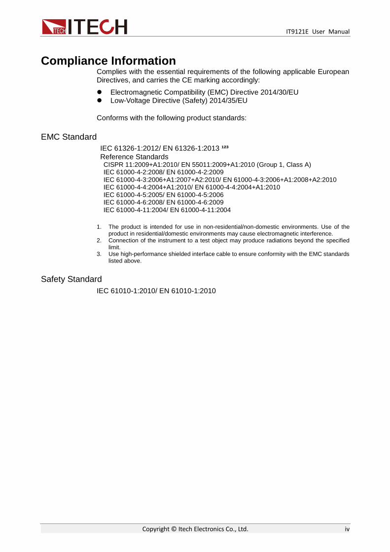
Schematic Diagram of Rear Panel of IT9121E Power Meter.
1. GPIB interface 2 Ethernet interface 3 USB Interface 4. RS232 interface 5. External synchronization signal interface 6 Power interface 7. External sensor interface 8. Voltage input terminal 9. Current input terminal
Warning: The external sensor interface (as shown in Fig. 7 above) of IT9121E power meter is installed with a protective jacket at ex-factory, which should be correctly installed at all circumstances unless an external sensor permitted by ITECH is used.

Measurement Conditions
Copyright © Itech Electronics Co., Ltd. 7
Chapter2 Measurement Conditions
This chapter describes details of relevant work to be finished before use of the IT9121E power meter.
2.1 Setting of Measurement Range
The appropriate measurement range (voltage and current range) must be set for accurate measurement. The selected range is effective for different measurement modes, such as waveform display, integral measurement and harmonic measurement.
Operation steps
1. In the “Meter” interface Press the soft key corresponding to “U-RANGE” or
“I-RANGE”, and use the knob or “ ” to select the voltage or current range.
2. Press the “Enter” key to confirm the setting. The instrument will automatically
confirm and exit the setting in case of no operation on the interface for more than 5s.
When the crest factor is 6:
Figure: Voltage Range
Figure: Current Range

Measurement Conditions
Copyright © Itech Electronics Co., Ltd. 8
When the crest factor is 3:
Figure: Voltage Range
Figure: Current Range
NOTE
When EX1 or EX2 is installed, the power meter has more current range options. See details in IT9121E Installation Guide.
Voltage and Current Range
Set the measurement range according to the level of the effective value. When the voltage or current signal is input into the input unit, there are two types of range: fixed and automatic.
Fixed Range
Select the required range from a number of options. After selection, the range will not change with the input signal. For the voltage range, when the crest factor is 3, the maximum option is “600V” and the minimum option is “15V”. When the crest factor is 6, the maximum option is “300V” and the minimum option is “7.5V”.
NOTE
During measurement of the distortion waveform and other non-sinusoidal wave signals, the accuracy of measurement can be improved by selecting the minimum range on the premise that the measured value does not exceed the range.

Measurement Conditions
Copyright © Itech Electronics Co., Ltd. 9
Auto-measuring Range
The range is switched automatically according to the input signal. The range types for switching are the same as those of the fixed range.
Principles of automatic range level increase:
The range level is increased when any one of the following conditions is satisfied.
Urms or Irms exceeds 110% of the current range setting.
The crest factor is 3. The value Upk or Ipk of the input signal exceeds 330% of the current range setting.
The crest factor is 6. The value Upk or Ipk of the input signal exceeds 660 % of the current range setting.
Principles of automatic range level decrease:
The range level is decreased when all of the following conditions are satisfied.
Urms or Irms is less than or equal to 30% of the current measurement range.
The crest factor is 3. The value Upk or Ipk of the input signal is less than 300% of the range at the following level.
The crest factor is 6. The value Upk or Ipk of the input signal is less than 600 % of the range at the following level.
NOTE
The selected automatic range may change when the input waveform is a pulse waveform of uncertain cycle. In this case, the fixed range should be selected.
2.2 Setting of Measurement Interval The time for acquisition of sampling data is determined by the measurement interval during measurement. The measurement interval is determined by the data updating rate and synchronization source. The synchronization source provides reference signals for measurement, and the data updating rate determines the updating cycle of sampling data.
Measurement interval
The measurement interval is determined by the data updating rate and synchronization source. (see “2.3 Setting of Filter and Crest Factor” for specific settings)
Synchronization IT9121E adopts the frequency measurement circuit to test the input signal cycle set in the measurement interval. The measurement interval is the integer times of the test cycle. The measured value of IT9121E is calculated by averaging sampling data in the measurement interval. The reference input signal used for defining the input signal measurement interval is called the synchronization source.
Measurement interval for conventional measurement The measurement interval of the reference input signal is the time from the
starting part of the rising slope (or descending slope) through the zero point (intermediate value of amplitude) to the ending point of the rising slope (or descending slope) through the zero point (intermediate value of amplitude). However, the measurement interval which determines the maximum voltage or current is within the overall data updating cycle. Therefore, the

Measurement Conditions
Copyright © Itech Electronics Co., Ltd. 10
measurement of Ipk+, Ipk-, Upk+, Upk-, Ucf and Icf calculated based on the maximum voltage and current also adopts the data updating cycle as the measurement interval.
The rising or descending edge is selected automatically to prolong the measurement interval.
If there is only one or no rising slope or descending slope within the data updating cycle, the data updating cycle is taken as the measurement interval.
The input signal to be used as the synchronization source can be set in each unit (for synchronization with the zero point of that input signal). The overall interval of the signal voltage, current or data updating cycle can be selected as the synchronization source for measurement.
NOTE The data updating cycle refers to the cycle used for calculating sampling data of the measurement function. It is identical to the set value of the data updating rate.
The slope refers to signal changes from low level to high level (rising edge) or from high level to low level (descending edge).
Measurement interval for harmonic measurement At the sampling frequency of harmonic measurement, the measurement interval refers to the first point 1024 from the data updating cycle. The sampling frequency of harmonic measurement is determined automatically by the signal cycle set as the PLL source in the instrument. The sampling data or measurement interval for calculation may be different from the sampling data or measurement interval of the measurement function in conventional measurement.
2.3 Setting of Filter and Crest Factor
Operation steps
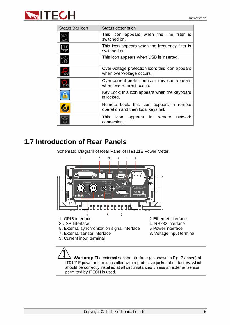
1. Select Menu > SET UP > OTHER SET and enter the OTHER configuration
page.
2. Press to select the parameter to be configured (blue font background),
Measurement Conditions
Copyright © Itech Electronics Co., Ltd. 11
and then press the soft key corresponding to the parameter on the right to set
the required value, as shown in the following diagram.
Character Function description
Sync Source Select the synchronization source: U/I/OFF. The overall interval of the signal voltage, current or data updating cycle can be selected as the synchronization source for measurement.
Freq Filter Set the status of the frequency filter. When “ON” is selected, the frequency filter is turned on. When “OFF” is selected, the frequency filter is turned off.
Line Filter Set the status of theline filter. When “ON” is selected, the line filter is turned on. When “OFF” is selected, the line filter is turned off.
Crest Factor Set the crest factor: CF3/CF6
Update Rate Data Updating Rate Setting key: when this key is pressed, the capture interval of the voltage, current, power and other data, i.e. data updating rate, can be set. When the data updating rate is increased, rapid load changes of the power system can be obtained. When the data updating rate is decreased, relative low-frequency signals can be measured. Options of the data updating rate: 0.1s/0.25s/0.5s/1s/2s/5s
3. Press the Enter key to save the settings.
Filter
Frequency filter: it is inserted in the frequency measurement circuit and may affect frequency measurement. It can be used for filtering high-frequency components of interference to make the measured frequency parameter more accurate. When the frequency filter is switched on, the voltage or current of no more than 200Hz can be measured. The cutoff frequency is 500HZ.
Line filter: it is inserted in the voltage and current measurement circuit and has direct influence on measurement of the voltage, current and power. When the line filter is switched on, noise and high-frequency components from the inverter or distortion waveform can be filtered. The cutoff frequency is 500HZ.
Crest factor
The crest factor is the ratio of the waveform peak to the effective value. The

Measurement Conditions
Copyright © Itech Electronics Co., Ltd. 12
crest factor of IT9121E is specified as the times of the crest value which can be input under the rated input conditions. The crest factor CF3 or CF6 can be selected in the interface “Menu > SETUP > OTHER SET”.
ranget Measuremen
input be can whichPeak value)(factor Crest CF
The crest factor can be set as 3 or 6. The crest factor can be measured under the following conditions:
value)(effective valueMeasured
6)or (3 CF of Set valueranget MeasuremenfactorCrest
)(CF
NOTE
The crest value of the input signal must be no more than the maximum allowable input value.
When the crest factor of the measured signal is larger than the crest factor in instrument specifications (based on the crest value of rated input), the signal with the crest factor larger than the specified value can be measured by setting a range including the value of the measured signal.
For example, when CF is set as 3 but the measured value (effective value) is less than 60% of the range, the signal with CF more than 5 can be measured.
When CF is 3, the signal with CF equal to 300 can be measured under minimum effective input (1% of the range) conditions.
The voltage range, current range, effective input range and measurement accuracy depend on the set crest factor.
2.4 Setting of Averaging Function
The user can set the averaging function via this menu. When the input signal frequency is low, the value is displayed unstably and cannot be read easily. In this case, the averaging function can be enabled to calculate and display the average value of several measurements.
Operation steps
1. Select Menu > SET UP > AVERAG SET to enter the configuration page of the
averaging function.
2. Press to select the parameter to be configured (blue font background),
and then press the soft key corresponding to the parameter on the right to set the
required value, as shown in the following diagram.

Measurement Conditions
Copyright © Itech Electronics Co., Ltd. 13
Parameter descriptions:
Character Function description
State Set the status of the averaging function. When “ON” is selected, the averaging function is enabled. When “OFF” is selected, the averaging function is disabled.
Type Set the linear averaging type. EXP: index averaging, often used for analysis of the non-stationary process. LINE: linear averaging, often used for measurement and analysis of the stationary random process. The deviation relative to the standard can be reduced by increasing the averaging times.
Tcontrol Set the mode of the averaging function. MOVING: moving averaging REPEAT: repeated averaging
Count Set the times of the averaging function. If the mode of the averaging function is set as EXP (index averaging), the attenuation constant can be set. If the mode of the averaging function is set as LINE (linear averaging), the averaging times can be set.
3. Press the Enter key to confirm the setting.
Averaging mode
Index averaging:
Computing formula: k
DMDD nn
nn1
1
Dn: the value displayed after the nth index averaging (D1, the value
displayed after the first averaging, is equal to M1)
Dn-1: the value displayed after the (n-1)th index averaging
Mn: the nth measured data.
K: attenuation constant (1-64)
Linear averaging
Computing formula:
m
MMMMD
nnnmn
n
121 ....
Dn: the value displayed after linear averaging of m values from the
(n-(m-1))th to nth value

Measurement Conditions
Copyright © Itech Electronics Co., Ltd. 14
Mn-(m-1): the (n-(m-1))th measured data
Mn-2: the (n-2)th measured data
Mn-1: the (n-1)th measured data
Mn: the nth measured data.
M: the number of average values (1-64)
When m can be divided exactly by n, the calculated value is the moving
average; when there is no particular relationship between m and n, the
calculated value is the repeated average.
NOTE
When index averaging is set, averaging is implemented under the harmonic measurement function.
When linear averaging is set, averaging can only be implemented in the conventional measurement function and this mode is not applicable to the harmonic measurement function.
Averaging function
Measurement function in conventional measurement The following measurement functions are subject to direct averaging. Data of the following measurement functions are obtained via operation in other modes, and the obtained measurement function is affected averaging. Urms, Umn, Udc, Urmn, Uac, Irms, Imn, Idc, Irmn, Iac, P, S and Q. Ucf, Icf, PF and WPAV are calculated by operation of the averaged Urms,
Irms, P and S. Measurement function in harmonic measurement
The following measurement functions are subject to direct averaging. Data of the following measurement functions are obtained via operation in other modes, and the obtained measurement function is affected averaging. U(k), I(k), P(k), S(k) and Q(k). PF(k) is calculated via operation of the averaged P(k) and Q(k). U(%r), I(%r), P(%r) , U(%f), I(%f) and P(%f) are calculated via operation of
the averaged U(k), I(k) and P(k). (k indicates the harmonic times.)
NOTE
When the averaging function is enabled, the average of a number of measurements are calculated and displayed. Therefore, in case of drastic changes of the input signal, the measured value will slowly affect these changes.
For both the attenuation constant of index averaging and the number of averaged values of linear averaging, the larger the set value is, the more stable the measured value is.
The following measurement functions will not be affected by averaging.
Conventional measurement functions: fU, fI, Ipk+, Ipk-, Upk+, Upk-, Time, WP, WP+,
WP-, q+, q-, q and Fsyn. Harmonic measurement functions: φ(k) , φUU(k) and φII(k) (k indicates the harmonic times).

Basic Measurement Functions
Copyright © Itech Electronics Co., Ltd. 15
Chapter3 Basic Measurement Functions
This chapter describes the features and use of the basic measurement functions of the IT9121E power meter in details.
3.1 Basic Concepts
The IT9121E power meter has rich basic power measurement functions and can be used for accurately measuring the voltage, current, power, AC/DC signal, power factor, harmonics, frequency, distortion factor and other parameters. The reliable data can provide a scientific basis for analysis of the power quality and performance of equipment.
Introduction of soft keys on the interface
Menu soft key
Instruction
U-RANGE Set the voltage range.
I-RANGE Set the current range.
RUN/HOLD Running/holding
RESET Reset soft key When this key is pressed, the instrument can immediately carry out measurement again.
VIEW 1 View (1): displaying 1 large value and 6 small values.
VIEW 4 View (4): displaying 4 large value and 6 small values.
VIEW 12 View (2): displaying 12 large values.
MAXHOLD (OFF/ON)
Maximum value holding (OFF/ON): the maximum value (MAX) of data can be held.
CONFIG Basic measurement configuration
Measured parameters
Parameters Parameter descriptions Parameters Parameter descriptions
P Active power [W] Imn Average rectified value after the current is calibrated to the effective value
Q Reactive power [var] Idc Average current
S Apparent power [VA] Ipk+ Positive current peak value [A]

Basic Measurement Functions
Copyright © Itech Electronics Co., Ltd. 16
Parameters Parameter descriptions Parameters Parameter descriptions
PF Power factor Ipk- Negative current peak value [A]
φ Phase difference of voltage and current
Ipp Current peak-to-peak value [A]
Fsyn Synchronization source frequency
Icf Current crest factor
Irms Current effective value [VA] fI Current frequency (Hz)
Iac AC current component Irush Inrush current
Irmn Average rectified current [A] Urms Voltage effective value [VA]
Umn Average rectified value after the voltage is calibrated to the effective value
Urmn Average rectified value of voltage [V]
Udc Average voltage [V] Uac AC voltage component
Upk+ Positive voltage peak value [V]
Upk- Negative voltage peak value [V]
Upp Voltage peak-to-peak value [V]
Ucf Voltage crest factor
fU Voltage frequency (Hz)
3.2 Setting of Measurement Function and Interface Display
The power meter has three interface display styles for measurement of basic parameters. At most five pages are displayed in each style. When one or more important measurement parameter(s) should be highlighted, the View1 or View4 mode can be freely enabled to design the humane display style. When you need to view all parameters at the same time in one interface, the View12 mode can be enabled.
Take power measurement as an example. The interface can display four parameters in the large font form: effective voltage, effective current, active power and power factor. Operating procedures are as below:
Operation steps
1. In the “Meter” interface when the soft key corresponding to “VIEW 4” is pressed,
10 measurement parameters can be displayed in total, 4 of which are displayed in an
amplified manner. Other measurement parameters can be viewed by pressing
key to turn pages, as shown in the figure below.

Basic Measurement Functions
Copyright © Itech Electronics Co., Ltd. 17
2. When the soft key corresponding to “CONFIG” is pressed, the
measurement function can be selected and the interface display information can be
set.
3. When the soft key corresponding to “FUNC” is pressed, the measurement
function can be selected. For example, when the “FUNC” key is pressed once, the
displayed measurement function will be switched once in the P/I/U sequence. Different
measurement parameters are displayed when different functions are selected. As
power measurement is taken as an example in this operation, P is selected.
P (power): P, Q, S, PF, φ and Fsyn
I (current): Irms, Imn, Irmn, Idc, Iac, Ipk+, Ipk-, Ipp, Icf, fI and Irush
U (voltage): Urms, Umn, Urmn, Udc, Uac, Upk+, Upk-, Upp, Ucf and fU
4. Press the “ ” key and move the cursor to select the parameter displayed
in the interface (blue font background). Press the right soft key corresponding to the
parameter to adjust the parameter displayed at present. P, Q, S and PFare set in
sequence.
NOTE
When the soft key corresponding to the parameter is pressed once, the parameter will be selected in sequence.
5. You can also press the “INSERT PAGE” to add a display page. At most five
pages are allowable. Press the “DELETE PAGE” to delete the display page. At least
one page should be left.

Waveform Display Function
Copyright © Itech Electronics Co., Ltd. 18
Chapter4 Waveform Display Function
This chapter describes the features and use of the waveform display function of the IT9121E power meter in details.
4.1 Basic Concepts
The IT9121E power meter has a waveform display function based on sampling data. The voltage and current waveform of the input unit can be displayed or hidden. Only the necessary waveform is displayed to facilitate observation. The waveform display interface includes the vertical axis and the horizontal axis.
Introduction of soft keys on the interface
When the button is pressed, the initial waveform display interface below appears.
Description of information of waveform display interface:
Parameter name Parameter descriptions
U_RANGE Voltage range setting: press the soft key corresponding to this parameter to set the voltage range.
I_RANGE Current range setting: press the soft key corresponding to this parameter to set the current range.
RUN/STOP Run/stop: press the soft key corresponding to this parameter to run or stop the waveform status.
SINGLE Single measurement key: when single measurement is performed under stop conditions, the stop status will be enabled again after one measurement according to the current data updating rate. When single measurement is performed under running conditions, one measurement will be performed immediately by the instrument and then the stop status will be enabled.
SCOPE(U/I/UI) Select the waveform to be displayed on the screen: voltage/current/voltage and current.

Waveform Display Function
Copyright © Itech Electronics Co., Ltd. 19
Parameter name Parameter descriptions
KNOB SEL (U/I/TL/TD/Td)
Knob selection: the following variables can be adjusted by rotating the knob: vertical voltage position/vertical current position/trigger level/trigger delay/level calibration.
AUTO Automatic adjustment key: when the soft key corresponding to this parameter is pressed, the power meter will automatically calibrate the input signal to display the best effect of the input signal.
TRIG SET Trigger setting
MEASURE SET Measurement setting
Introduction of waveform display interface
The trigger status is described as follows:
Trigger status
Instruction
Auto When the trigger mode is set as Auto, the trigger status Auto will be displayed after triggering.
Auto? When the trigger mode is set as Auto, the trigger status will be Auto in the case of no triggering?
Trig When the trigger mode is set as Normal, the trigger status Trig will be displayed after triggering.
Trig? When the trigger mode is set as Normal, the trigger status will be Trig in the case of no triggering?
Stop When the “Stop” soft key in the waveform display interface is pressed, the trigger status Stop will be displayed.

Waveform Display Function
Copyright © Itech Electronics Co., Ltd. 20
Vertical calibration
When the crest factor CF is 3, the selected voltage range and current range will be subject to vertical calibration (voltage/grid, current/grid). When CF is 6, the selected voltage range and current range will be subject to two-time vertical calibration (voltage/grid, current/grid).
Horizontal calibration
When the “KNOB SEL” soft key is pressed and “T/d” is selected, horizontal calibration (scanning speed) adjusted by rotating the knob. In this case, time/grid information changes can be observed on the screen by rotating the knob and changing the horizontal (time/grid) setting. When acquisition is run, the sampling rate can be changed by adjusting the horizontal calibration knob. When acquisition is stopped, sampling data can be amplified by adjusting the horizontal calibration knob.
Trigger delay
When the KNOB SEL soft key is pressed and “TD” is selected, the trigger delay can be adjusted by rotating the knob. In this case, when the knob is rotated, the trigger point will move horizontally and the delay time will be displayed on the
screen. When the delay time is changed, the trigger point ( ) will move horizontally, and the distance between the trigger point and the horizontal center will be indicated. The trigger point is displayed along the top of the display grid.
Trigger waveform
When the specified trigger conditions are satisfied, the trigger waveform will be displayed, and the triggering time point is called trigger point. The trigger point is generally displayed in the left of the display screen. Following the trigger point, the waveform is displayed on the display screen from left to right over time. Before using the trigger function, the user needs to configure the following parameters:
Trigger mode
The trigger mode refers to conditions for updating the contents displayed on the screen. Including the Auto model and Normal mode Auto mode: the displayed waveform is updated in case of triggering in the pause time and automatically updated in case of no triggering in the pause time. Normal mode: the displayed content is updated in case of triggering and not updated in case of no triggering.
Trigger source
The trigger source is used for generating triggering conditions. The user can select the trigger source from the input signal of the input unit and the external clock signal.
Trigger slope
The slope refers to signal changes from low level to high level (rising edge) or from high level to low level (descending edge). When used as a triggering condition, the slope is called trigger slope.
Trigger level
Level of trigger slope: triggering occurs when the level of the signal of the

Waveform Display Function
Copyright © Itech Electronics Co., Ltd. 21
trigger source reaches the set trigger level under the specified trigger slope conditions. When the “KNOB SEL” soft key is pressed and “TL” is selected, the trigger level can be adjusted by rotating the knob. In this case, the trigger level can be changed by rotating the knob, and changes in the trigger level can be observed on the screen.
4.2 Adjustment of Measurement Parameters
You can rotate the knob to adjust the vertical calibration, horizontal calibration, trigger delay and trigger level of the waveform display interface. Detailed steps are as follows:
Operation steps
1. Press “ ” to enter the waveform display interface.
2. In the waveform display interface Press the soft key corresponding to the “KNOB
SEL” parameter and select the parameter to be adjusted. When “KNOB SEL” is pressed
once, the parameter to be adjusted via the knob will be switched in sequence among
U/I/TL/TD/Td.
3. When the parameter is adjusted by rotating the knob, the interface will display
changes of the corresponding value.
4.3 Setting of Trigger Configuration
When you need to enable the trigger function, you should select the trigger source, trigger mode, trigger slope and other trigger-related configuration. Detailed steps are as follows:
Operation steps
1. Press “ ” to enter the waveform display interface.
2. In the waveform display interface Press the soft key corresponding to the
“TIRG SET” parameter to enter the trigger setting interface, as shown below.
3. Press the right soft key corresponding to the parameter to select the required
trigger configuration.

Waveform Display Function
Copyright © Itech Electronics Co., Ltd. 22
Source: trigger source
Mode: trigger mode
Slope: trigger slope
External trigger input (Ext)
When the trigger source is set as Ext, input the trigger signal into the external signal input interface (Synchronous) of the rear panel according to the following specifications.
Projects Specification
Interface type BNC interface
Input level TTL
Minimum pulse width 1µs
Trigger delay time Within (1μs + 3 sampling cycles)
NOTE When the voltage higher than 0-3.3V is applied on the external signal input interface (Synchronous), the instrument may be damaged.
Minimum pulse width: refers to the width of the high or low trigger level, at least 1µs.
Trigger delay time: refers to the delay between the appearance of the trigger level and the response of CPU, within (1μs + 3 sampling cycles).

Integral Operation Function
Copyright © Itech Electronics Co., Ltd. 23
Chapter5 Integral Operation Function
This chapter describes the features and use of the integral function of the IT9121E power meter in details.
5.1 Basic Concepts
The IT9121E power meter can be used for integral operation of the current and power of the input unit. Technical indicators can be calculated. In addition, the range can be switched automatically in the Buy and Sell modes according to the input level so as to accurately complete integrate measurement.
During operation of the air-conditioner, refrigerator, induction cook and other household appliances, the working status will change frequently, resulting in changes of the working current in a large scale. The current may decrease of dozens of amperes to a few milliamperes. Ordinary power measuring instruments can only be used for integral measurement within one range. If the measured value exceeds the current maximum range, the measurement result is inaccurate. You need to manually switch the range before integral measurement. Integral measurement of equipment subject to large current changes cannot be performed continuously. The IT9120 series power meter can automatically switch the range in the integral mode. Therefore, errors of integral measurement caused by manual range switching can be eliminated, and the power consumption of household appliances can be measured more accurately. See the schematic diagram below.
Introduction of soft keys on the interface
When the “Integ” button is pressed, the initial integral measurement interface below will appear.

Integral Operation Function
Copyright © Itech Electronics Co., Ltd. 24
Description of information of integral measurement interface:
Parameter name Parameter descriptions
U_RANGE Voltage range setting: press the soft key corresponding to this parameter to set the voltage range.
I_RANGE Current range setting: press the soft key corresponding to this parameter to set the current range.
RUN/HOLD Run/hold: press the soft key corresponding to this parameter to run or hold the integral function.
RESET Reset.
FUNC(WP/q/AV) Selection of the integral function: active power integral (WP), current integral (q) and average active power integral (AV).
LARGE(WP/WP+/WP-, q/q+/q-, WPAV)
Selection of the item to be displayed in a amplified manner: WP (watt hour, the sum of positive and minus watt hours), WP+ (the consumption of positive watt hours), WP- (the negative watt hours of feedback power), q (ampere hour, the sum of positive and negative ampere hours), q+ (the consumption of positive ampere hours), q- (the negative ampere hours of feedback power) and WPAV (average active powerintegral).
START Integral Start key In the manual start mode, the integral function can be enabled by pressing the soft key corresponding to this parameter.
STOP Integral Stop key In the manual stop mode, the integral function can be disabled by pressing the soft key corresponding to this parameter.
SETUP Set relevant parameters of integral measurement.

Integral Operation Function
Copyright © Itech Electronics Co., Ltd. 25
Integral measurement display information
Description of measurement information:
Character Function description
Mode Display the integral start and stop mode. Start mode: MANUAL and TIME Stop mode: MANUAL, TIME and TINTerval.
State Display the current status of the integral function. Start: displayed when the integral function is working. Stop: displayed when the integral function is interrupted, canceled or stopped. Ready: displayed in the ready state of the real-time start mode. Time Up: displayed when it reaches the specified time of the integral timer. Reset: displayed when the integral value and integral time are reset via integral resetting. Error: when the power supply is recovered, the integral function is stopped and the integral result before power failure is displayed. This integral state is called Error state.
Time Display the integral time.
St Display the set integral time.
Et Display the set integral ending time.
Timer Display the fixed integral time.
Integral operation
Active power integral
In watt hour, displayed as WP (watt hours, the sum of positive and negative watt hours), WP+ (the consumption of positive watt hours) and WP- (the negative watt hours of feedback power).
Current integral
In q, displayed as q (ampere hours, the sum of positive and negative ampere hours), q+ (the consumption of positive ampere hours) and q- (the negative ampere hours of feedback power)
Average active power integral
In watt, displayed as WPAV (average active power integral)

Integral Operation Function
Copyright © Itech Electronics Co., Ltd. 26
Integration time
Displayed as Time, in the format of hhhh:mm:ss.
Specification
Save in case of power failure
The integral result can be kept in the memory even in case of power failure during operation of the integral function. When the power supply is recovered and the integral function is disabled, the integral result before power failure is displayed. When the power supply is recovered and the integral is rest, the integral function is enabled again.
Display resolution
The maximum display resolution of the integral value is 99999. When the integral value reaches 100000, the decimal point will move automatically. For example, when 0.01mwh is added to 999.99mwh, 1.0000wh will be displayed.
Display in case of overflow
When the integral value meets the following overflow conditions, the integral function will be disabled, and the integral time and integral value at this point will be kept.
The integral time reaches the maximum value (10000 hours). The integral values of WP, q and WPAV reach the maximum/minimum
display integral values. Maximum/minimum display integral value
Active power integral (WP): ±99999 Mwh Current integral (q): ±99999 MAh Average power integral (WPAV): ±99999 Mw
Restricted implementation
Settings of the following functions cannot be changed during integral operation.
Function
Integration status
Integral resetting
Current integral status
Integral interruption
Functions related to settings of measurement parameters
Wiring Executable Unenforceable Unenforceable
Measurement range Executable Unenforceable Unenforceable
Filter Executable Unenforceable Unenforceable
Averaging function Executable Unenforceable Unenforceable
Synchronization Executable Unenforceable Unenforceable
Data updating rate Executable Unenforceable Unenforceable Integral function parameter setting
Integral mode Executable Unenforceable Unenforceable
Integral timer Executable Unenforceable Unenforceable
Integral operation
Integral start Executable Unenforceable Executable
Integral stop Unenforceable Executable Unenforceable
Integral resetting Executable Unenforceable Executable
Other operations
Save operation Executable Executable Executable
Hold operation Executable Executable Executable
Single measurement operation
Executable Executable Executable

Integral Operation Function
Copyright © Itech Electronics Co., Ltd. 27
NOTE
In addition to the above items, other settings (such as self-testing and date/time setting) or operations with influence on the integral cannot be executed; otherwise, errors may be caused.
5.2 Setting of Integral Measurement Configuration
You can set the start mode, stop mode, automatic zero setting, automatic calibration, watt-hour integration, current integration and other parameters of integral measurement. Specific steps are as follows:
Operation steps
1. Press “Integ” to enter the integral measurement interface.
2. Press the soft key corresponding to the “SETUP” parameter in the integral
measurement interface to enter the integral parameter configuration interface.
Press the “ ” key to select the required parameter, as shown in the figure
below.
Parameter descriptions:
Start: set in the MANUAL mode or TIME mode via the right soft key.
MANUAL: press the “START” soft key in the integral measurement
interface in the manual start mode to trigger the manual start of the integral
function.
TIME: the date on which the integral mode is started can be set in the
real-time start mode. Integration will be started on the set date. When the
time/date combination is set in the real-time start mode, integration will not
be started before the current time and date. Integration will be started
when the screen is updated once at least before the start time.
Stop: set in the MANUAL mode, TIME mode and TINTerval mode via the right
soft key.
MANUAL: press the “STOP” soft key in theintegral measurement interface
in the manual stop mode tomanually stop integration. When the integration

Integral Operation Function
Copyright © Itech Electronics Co., Ltd. 28
time reaches the maximum integration time (10,000 hours) or the integral
value reaches the maximum/minimum display value, integration will be
stopped, and the current integral time and integral value will be kept.
TIME: The date for stop of the integral mode can be set in the real-time
stop mode. Integration will be stopped on the set date. When it reaches the
set time or the integral value reaches the maximum/minimum display
integral value, integration will be stopped, and the current integral time and
integral value will be kept.
TINTerval: the integral measurement time can be set in the set-time stop
mode. When it reaches the set ending date and time or the integral value
reaches the maximum/minimum display integral value, integration will be
stopped, and the current integral time and integral value will be kept.

Integral Operation Function
Copyright © Itech Electronics Co., Ltd. 29
Auto Clear: used for enabling (ON) or disabling (OFF) the function of automatic
zero clearing of the integral. On: integration is restarted when the START key is
pressed to start integration. OFF: integration is restarted based on the integral
value at the end of previous integration when the START key is pressed to start
integration.
Auto Cal: used for enabling (ON) or disabling (OFF) the function of automatic
integral calibration. When automatic integral calibration is enabled, zero setting is
implemented. In this case, the power and current measured just now are subject
to integration.
WP type: used for selecting the integral mode for positive and negative watt
hours. There are four integral modes:
Charge/Discharge: used for measuring the DC positive and negative watt
hours (integration of sampling data).
Sold/Bought: used for measuring the AC positive and negative watt hours
(value integration in each data updating cycle).
q type: used for selecting the current integration mode. Options of the current
integration mode are as follows:
rms: Effective value;
mn: Calibration to the average rectified value of the effective value.
dc: Simple averaging;
rmn: Average rectified value;
ac: AC component
5.3 Integration
When the integral measurement function is enabled, you can keep the current integral information and carry out the following operations: exit, start and stop. Specific steps are as follows:
Integral Operation Function
Copyright © Itech Electronics Co., Ltd. 30
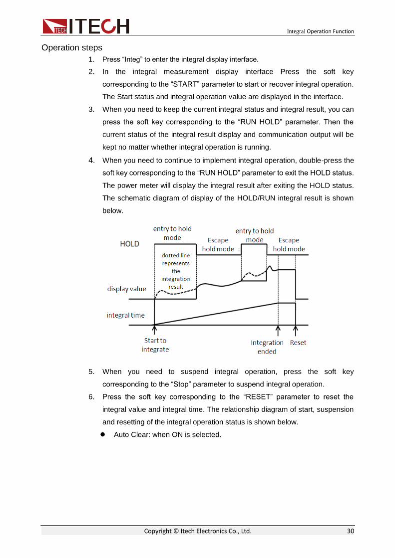
Operation steps
1. Press “Integ” to enter the integral display interface.
2. In the integral measurement display interface Press the soft key
corresponding to the “START” parameter to start or recover integral operation.
The Start status and integral operation value are displayed in the interface.
3. When you need to keep the current integral status and integral result, you can
press the soft key corresponding to the “RUN HOLD” parameter. Then the
current status of the integral result display and communication output will be
kept no matter whether integral operation is running.
4. When you need to continue to implement integral operation, double-press the
soft key corresponding to the “RUN HOLD” parameter to exit the HOLD status.
The power meter will display the integral result after exiting the HOLD status.
The schematic diagram of display of the HOLD/RUN integral result is shown
below.
5. When you need to suspend integral operation, press the soft key
corresponding to the “Stop” parameter to suspend integral operation.
6. Press the soft key corresponding to the “RESET” parameter to reset the
integral value and integral time. The relationship diagram of start, suspension
and resetting of the integral operation status is shown below.
Auto Clear: when ON is selected.

Integral Operation Function
Copyright © Itech Electronics Co., Ltd. 31
Auto Clear: when OFF is selected.

Harmonic Measurement Function
Copyright © Itech Electronics Co., Ltd. 32
Chapter6 Harmonic Measurement Function
This chapter describes the features and use of the harmonic measurement function of the IT9121E power meter in details.
6.1 Enable the Harmonic Function
The harmonic function of IT9121E is limited, users are required to purchase it separately. The license file of IT9121E power meter will be released along with the box by ITECH company when the function was purchased.
If harmonic function is not selected when users purchase the IT9121E power meter, you can contact ITECH company to buy and get the license to enable this function.
When users got the license, open the file and a key will be displayed, such as the key is 0123456789, users must remember it.Input the key in the instrument interface to enable harmonic function, the detailed procedures are as follows:
Operation Steps
1. Press [Menu] key to enter the system configure page. 2. Press [KEYGEN] key to enter the KeyGen page.
3. Choose key1, input 01234, and then choose key2, input 56789 through left key. 4. Press [Enter] key to comfirm, the harmonic function is enabled.
6.2 Basic Concepts
With the 100kHZ bandwidth, the IT9121E power meter can realize harmonic measurement of high speed and wide dynamic range. The voltage, current, active power, reactive power and phase of harmonics and total harmonic distortion (THD) factor can be tested in the harmonic mode. In addition, the IT9121E power meter can be used for multiple harmonic measurements, 50-order harmonics of the fundamental frequency at most.
The IT9121E power meter displays harmonic parameters in the list or bar chart form so as to provide clear analysis of test results.
Introduction of soft keys on the interface
Select the “ ” button, and the initial harmonic measurement interface

Harmonic Measurement Function
Copyright © Itech Electronics Co., Ltd. 33
below will appear.
Description of information of harmonic measurement interface:
Parameter name
Parameter descriptions
U_RANGE Voltage range setting: press the soft key corresponding to this parameter to set the voltage range.
I_RANGE Current range setting: press the soft key corresponding to this parameter to set the current range.
RUN/HOLD RUN/HOLD: press the soft key corresponding to this parameter to run/hold the harmonic status.
RESET Reset.
FUNC(P/I/U) Function options (power/current/voltage)
BAR Displayed in the bar chart form
LIST Displayed in the list form
SETUP Parameter setting.
Introduction of harmonic information
Description of harmonic bar chart interface
When the “BAR” button is selected in the harmonic measurement interface, the bar chart of harmonic measurement results will be displayed. The bar chart is used for displaying the percentage of different harmonics. Harmonics can be displayed in the whole sequence, odd sequence and even sequence. The following is the whole-sequence harmonic bar chart.

Harmonic Measurement Function
Copyright © Itech Electronics Co., Ltd. 34
Description of interface information:
Total harmonic parameter: including the total harmonic distortion (THD) factor and total harmonic content. When different measurement functions are selected, different harmonic parameters will be displayed. When the soft key corresponding to the “FUNC” parameter is pressed, different measurement functions can be selected. P/I/U can be selected as the measurement function in sequence when this key is pressed once. Parameter meanings of different functions are as follows:
Power (P): total harmonic distortion rate of power and total harmonic power
Current (I): total harmonic distortion rate of current and total harmonic current
Voltage (U): total harmonic distortion rate of voltage and total harmonic voltage
Single-order harmonic parameters: displaying the frequency, harmonic content, harmonic distortion factor and phase of single-order harmonics. The user can rotate the knob to select the single-order harmonics to be displayed. The selected harmonics are displayed in red in the bar chart form.
Description of harmonic list interface
When the “LIST” button is selected in the harmonic measurement interface, the list of harmonic measurement results will be displayed. This list is used for showing the voltage, current, active power, reactive power, phase and total harmonic distortion (THD) factor of different harmonics. Harmonic lists can be displayed in the whole sequence, odd sequence and even sequence. Below is a whole-sequence harmonic list.

Harmonic Measurement Function
Copyright © Itech Electronics Co., Ltd. 35
Harmonic content: this list is used for showing all harmonic contents of single-order harmonics, including the voltage, current and power. You can view other harmonic parameters by operating the Left/Right key to turn pages. In this case, the line scroll bar and current page are shown in bright white circles. Measurement parameters are described in the following table:
Abbreviations Instruction Abbreviations Instruction U(V) Voltage φUI(°) Phase difference of k-order
harmonic voltage and harmonic current
I(mA) Current φUU(°) Phase difference of harmonic voltage U(k) and fundamental wave U(1)
P(W) Active power
φII(°) Phase difference of harmonic current I(k) and fundamental waveI(1)
S(VA) Apparent power
U(%r)/ U(%f) Harmonic distortion factor of voltage
Q(var) Reactive power
I(%r)/ I(%f) Harmonic distortion factor of current
PF() Power factor P(%r)/ P(%f) Harmonic distortion factor of active power
Harmonic order list: this LIST can show the data of one-order to 50-order harmonic signals. These data can be displayed in the whole sequence, odd sequence and even sequence. The rows which are not displayed, i.e. single-order harmonic data which are not displayed, can be presented by operating the Up/Down key. In this case, the row scroll bar and current page in displayed in bright blue bars.
6.3 Setting of Harmonic Measurement Configuration
You can set the distortion factor calculation formula, PLL source, harmonic sequence and harmonic analysis times of harmonic measurement. Specific

Harmonic Measurement Function
Copyright © Itech Electronics Co., Ltd. 36
steps are as follows:
Operation steps
1. Press “ ” to enter the harmonic measurement interface.
2. Press the soft key corresponding to the “SETUP” parameter in the harmonic
measurement display interface to enter the harmonic parameter configuration
interface. Press the “ ” key to select the required parameter, as shown
in the figure below.
Parameter descriptions:
Parameters Instruction
THD Formal Distortion factor calculation formula. % r: displaying harmonics in the form of percentage to the overall current (voltage, power) amplitude of all harmonics. % f: displaying harmonics in the form of percentage to the fundamental wave current (voltage, power).
PLL Source Select the PLL (Phase Locked Loop) source: U/I/OFF. Used for determining the fundamental wave cycle as the reference for analysis of harmonic orders.
Serial Harmonic sequence: whole sequence/odd sequence/even sequences
Order Max Set the harmonic analysis orders (1-50). You can specify the harmonic measurement range. These specified analysis orders are used for calculating the value of the distortion factor.
Distortion factor calculation formula:
The following two formulas can be selected for calculation of the distortion factor.
%r: using all harmonic measurement data from the minimum harmonic order (0) to the maximum harmonic order (within the upper limit of analysis orders) as the denominator.
%f: using the data of fundamental wave (1-order) components as the denominator.

Harmonic Measurement Function
Copyright © Itech Electronics Co., Ltd. 37
The distortion factor calculation formulas and methods of different measurement functions are as follows:
Measurement function
Calculation formula and method
%r %f
Harmonic distortion factor of voltage
TotalU
kU
1U
kU
Harmonic distortion factor of current
TotalI
kI
1I
kI
Harmonic distortion factor of active power
TotalP
kP
1P
kP
Total harmonic distortion rate of voltage
TotalU
kUk
max
2
2
1
max
2
2
U
kUk
Total harmonic distortion rate of current
TotalI
kIk
max
2
2
1
max
2
2
I
kIk
Total harmonic distortion rate of active power
TotalP
kPk
max
2
1
max
2
P
kPk
NOTE
Total harmonics are calculated as follows:
max
0
2
k
kUTotalU ,
max
0
2
k
kITotalI ,
max
0k
kPTotalP . k indicates the harmonic order, and max indicates the upper limit of
analysis orders. max is determined by the frequency of PLL source automatically, 50 orders at most.
PLL source
In the harmonic mode, IT9121E adopts PLL to multiply the frequency of the input signal. The frequency multiplication output signal is used as the A/D sampling clock in the instrument so as to achieve the purpose of synchronous sampling. Therefore, the frequency of the signal of the PLL source can determine the A/D sampling clock in the instrument. However, the quality of the signal of the PLL source may affect the stability and accuracy of sampling data.
PLL source selection
The voltage or current of the input unit can be selected as the PLL source. Used for determining the fundamental wave cycle as the reference for analysis of harmonic orders. The fundamental wave frequency of the PLL source is 10Hz to 1.2kHz.
Considerations for selection of PLL source
Please select the signal with the same cycle as that of the harmonic measurement object signal. In order to stably measure harmonics, select the input signal with little distortion as the PLL source. If the fundamental wave frequency of the PLL source changes or the fundamental wave frequency cannot be measured as a result of waveform distortion, accurate measurement

Harmonic Measurement Function
Copyright © Itech Electronics Co., Ltd. 38
results may not be obtained. When the test object is a switch type power supply and the voltage signal is subject to less distortion than the current signal, it is recommended to use the voltage as the PLL source.
Signal level of PLL source
If the amplitude level of the signal input into the unit as the PLL source is small relative to the range, synchronization with PLL will fail. If the crest factor is set as 3, the amplitude level of the PLL source should exceed 50% of the range at least during setting of the range. If the crest factor is set as 6, the amplitude level of the PLL source should exceed 100 % of the range at least during setting of the range.
NOTE
When the fundamental wave frequency is no more than 200Hz, the frequency filter must be turned on.
When the fundamental wave frequency is lower than 440Hz and contains high-frequency components, it is recommended to turn on the frequency filter. This filter only applies to the frequency measurement circuit.
If the frequency of the PLL source changes, the correct measured value will be displayed after data are updated several times. The frequency of the PLL source needs to be tested again via the PLL circuit in the instrument in case of changes of the PLL source or its frequency, the correct measured value cannot be obtained at once.
Harmonic analysis order
The harmonic analysis order k is an integer number ranging from 0 to the upper limit of analysis orders. Zero indicates the DC component. The upper limit of analysis orders is automatically determined by the frequency of the PLL source.
The upper limit of harmonic analysis orders can be determined automatically or set manually. Take the smaller value. 50 orders at most The relationship between the upper limit of harmonic analysis orders and the fundamental wave frequency of the PLL source is shown in the table below.
Fundamental wave frequency of PLL source
Sampling rate Window width
Upper limit of analysis orders *
10Hz ~ 75Hz f*1024 1 50
75 Hz ~ 150 Hz f*512 2 32
150 Hz ~ 300 Hz f*256 4 16
300 Hz ~ 600 Hz f*128 8 8
600 Hz ~ 1200 Hz f*64 16 4
* The upper limit of analysis orders can be reduced.
NOTE
If the analysis window determined by the fundamental wave frequency of the PLL source is longer than the data updating cycle, no harmonic data will be detected. In this case, the data updating cycle should be reduced. For example, when the fundamental wave frequency of the PLL source is 10Hz (cycle: 100ms), the analysis window is one-wave long, and the data measurement interval is 100ms. In this case, the harmonic measurement time is approximately more than or equal to 150ms (data measurement interval and data processing time). Therefore, please select the data updating rate of 250ms or more for measurement and display of harmonic data.

Routine Maintenance
Copyright © Itech Electronics Co., Ltd. 39
Chapter7 Routine Maintenance
This chapter describes general maintenance items and maintenance methods of the IT9121E power meter.
7.1 Self-Inspection
The IT9121E power meter has a self-inspection function. See “Power-on Self-Test” of Chapter 3 “Inspecting the Instrument” of IT9121E Installation Guide for detailed steps of self-inspection.
7.2 Error Information References
The IT9121E power meter has a detailed error and prompt information function, so as to help the user to easily carry out positioning and measurement during measurement and use.
This section describes all error information of the IT9121E power meter as well as error causes and disposals. All prompt information is listed.
Prompt Message List
Prompt information Explanation of prompt information
Cal Zero is working! The instrument is calibrating the zero point.
Cal Zero is completed! The instrument has completed zero point calibration.
Test screen Self-inspection of LCD screen
Test dsp Self-inspection of DSP.
Test beep Self-inspection of the buzzer.
SelfTest is finished! The instrument has finished the self-test.
Softkey is not available The current soft key is not available.
Time set ok! The time setting is completed.
Meter Initialization Initialization of general measurement
Integ Initialization Initialization of integral function
Scope Initialization Initialization of the oscilloscope function
Harmonic Initialization Initialization of the harmonic function
Inrush Initialization Initialization of the inrush function
Setup Initialization Initialization of setup
System Initialization Initialization of the system
Initialization is finished! Initialization is finished.
Integ start Integration is started.
Integ stop Integration is stopped.
Integ time up The integral time is up.
Max page has been reached. It displays The maximum page has been reached.
One page should exist at least One page should exist at least.
Not used in current state The current operation is not available.
Please reset first Please reset first.

Routine Maintenance
Copyright © Itech Electronics Co., Ltd. 40
Error information list
Error information Error information explanation
usb is not detected [Error description] No USB peripheral is found. [Possible cause] No USB peripheral is inserted. [Disposal] Insert the U disc type USB peripheral and then copy the screen.
Save screen fail [Error description] The screen is not saved successfully. [Possible cause] USB is disconnected. [Disposal] Reinsert the USB peripheral.
Start time is less than current [Error description] The start time is less than the current time. [Possible cause] The integral setting is incorrect. [Disposal] Reset the integral start time.
End time is less than current [Error description] The ending time is less than the current time. [Possible cause] The integral setting is incorrect. [Disposal] Reset the integral ending time.
Timer must be larger than zero. [Error description] The set time must be larger than zero. [Possible cause] The set integral time is not correct. [Disposal] Reset the set integral time.
Harmonic open fail [Error description] The harmonic function cannot be enabled. [Possible cause] Communication abnormality [Disposal] Check the communication cable.
Integ open fail [Error description] The integral function cannot be enabled. [Possible cause] Communication abnormality [Disposal] Check the communication cable.
Integ start fail [Error description] The integral function cannot be started. [Possible cause] Communication abnormality [Disposal] Check the communication cable.
Integ stop fail [Error description] The integral function cannot be stopped. [Possible cause] Communication abnormality [Disposal] Check the communication cable.
Scope openfail [Error description] The oscilloscope function cannot be enabled. [Possible cause] Communication abnormality [Disposal] Check the communication cable.
Time set fail [Error description] Time setting fails. [Possible cause] Time setting is illegal. [Disposal] Reset the system time.

Routine Maintenance
Copyright © Itech Electronics Co., Ltd. 41
Cal zero fail [Error description] Zero calibration fails. [Possible cause] Communication abnormality [Disposal] Check the communication cable.
7.3 Daily maintenance
Introduce basic maintenance in daily use of equipment. Such as cleaning, self-maintenance allowed to be performed by the user, etc.
Equipment cleaning
Use dry cloth or slightly wet cloth to gently wipe the equipment. Do not arbitrarily wipe the inside of the instrument. Cut off the power supply before cleaning.
Initialize
When this operation is implemented, the system settings are recovered to the factory default values.
1. Select “SYSTEM > INITIAL” in the “Menu” interface to enter the system
initialization interface. See the following figure.
2. Select the menu items to be initialized (blue symbol background) via
key. Menu items with characters following should be initialized; indicates
that the items will not be initialized.
3. Press the soft key corresponding to the symbol on the right of the interface to
determine whether to initialize this menu item. Or use the soft key “ ” (for
initialization of all menu items) or “ ” (no initialization for all menu items)
in the lower part of the interface.
4. Press the “START” soft key to initialize system settings. Press the ESC to exit.

Routine Maintenance
Copyright © Itech Electronics Co., Ltd. 42
7.4 Contact of ITECH Engineers
This section describes operations to be carried out by the user in case of failure of the instrument.
Preparation before contact
When the instrument fails, you should make the following preparations before returning the instrument to ITECH for repair or contacting engineers.
1. Check all the items listed in the “Self-inspection of Equipment Faults” and
confirm whether there are still some problems.
2. If there are still some problems, carefully read the contents of warranty
services and warranty restrictions in the preface of the manual. Confirm that
our instrument complies with warranty service conditions.
3. If you want to send the instrument to the manufacturer for repair, refer to
instructions in “7.5 Returning Your Power Meter for Service”.
Self-inspection of equipment faults
In case of failure of the instrument, self-inspect the following items. If the instrument failure can be eliminated via simple inspection, the maintenance cost and time can be saved. Please check the following items before contacting the engineer of ITECH.
Check whether the power meter is powered up. Check whether the power meter is started normally. Check whether the instrument fuse is in good conditions. Check whether other connectors are in good conditions and whether cables,
plugs and other parts are connected properly. Check whether the system configuration of the instrument is correct during
use. Check whether self-inspection of the instrument is successful and whether
the specifications and performance are within the indicator ranges. Check whether the instrument displays error information. Use other instruments instead of this instrument for confirmation.
Collect the SN number
ITECH will constantly improve the product performance, availability and reliability. The service personnel of ITECH will record changes of each instrument. All relevant information is marked uniquely according to the serial number of each instrument. The equipment returned for repair must adopt the SN number as the tracking ID.
When you contact the engineer, the effective SN number of the instrument will be the effective guarantee for effective service and complete information. You can obtain the SN number of the instrument by the following ways:
1. Press the [Menu] key to enter the system setting page of the power meter.
2. Press the [SYSTEM] to enter “SYSTEM INFO” interface to view the product
model, product SN, software version number and other information.
Routine Maintenance
Copyright © Itech Electronics Co., Ltd. 43
7.5 Returning Your Power Meter for Service
When you want to return your power meter to ITECH company, please read the following information.
Packaging the Power Meter for Shipment
When instruments are required for factory maintenance, please refer to the following steps to pack the instruments which need to send out.
1. Please put the instrument for maintenance in the original packging materials, with the related accessories.
2. Please be as specified as possible about the nature problem. Send a copy of any or all of the following information:
Any error messages that appeared on the power meter display. Any information on the performance of the power meter.
Power meter damage can result from using packaging materials other than those
specified. Please use the special packing when shipment, and shall be carried out
in accordance with the delivery of packaging standard as far as possible.
Never use styrene pellets in any shape as packaging materials. They do not
adequately cushion the power meter or prevent it from shifting in the carton.
Styrene pellets cause power meter damage by generating static electricity and by
lodging in the rear panel.
3. Please pay attention to read the document preface about warranty service delivery cost in the relevant specification with the delivery.

Technical Specifications
Copyright © Itech Electronics Co., Ltd. 44
Chapter8 Technical Specifications
8.1 General Specification Model IT9121E
AC input voltage 100VAC-240VAC 50/60HZ
Warm-up time Apporx 30 minutes
Operating Environment Temperature:5°C-40°C
Humidity: 20%-80% (non-condensation)
Altitude: ≤2,000m
Storage Environment Temperature: -20°C -50°C
humidity 20%-80% (non-condensation)
Altitude: ≤2,000m
Installation Indoors
Safety IEC 61010-1、EN 61010-1 、Measurement CAT Ⅱ
Pollution degree Pollution degree 2
EMC IEC 61326
Maximum power consumption 50VA
Battery backup Backup the setting parameters
Dimension 214.5mmW×88.2mmH×354.6mmD
8.2 Screen Display Item Detailed Information
Display Interface Specification
Dimension 4.3-inch color liquid crystal display (TFT)
Full screen pixel 480(horizontal) × 272(vertical) points
Waveform display pixel
384(horizontal) × 194(vertical) points
Operating temperature
-20℃~ 70℃
Storage temperature
-30℃~ 80℃
Value display Currently set up as a matrix display.It is optional to display the array number.
8.3 Input Parameters Input parameter
Description
Input terminals type
Voltage
plug-in terminal(safety terminal)
Input type Current
Direct input large binding post
External current sensor input
DB9 connector
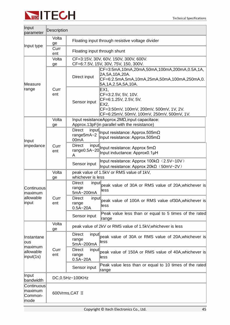
Technical Specifications
Copyright © Itech Electronics Co., Ltd. 45
Input parameter
Description
Input type
Voltage
Floating input through resistive voltage divider
Current
Floating input through shunt
Measure range
Voltage
CF=3:15V, 30V, 60V, 150V, 300V, 600V. CF=6:7.5V, 15V, 30V, 75V, 150, 300V.
Current
Direct input
CF=3:5mA,10mA,20mA,50mA,100mA,200mA,0.5A,1A,2A,5A,10A,20A. CF=6:2.5mA,5mA,10mA,25mA,50mA,100mA,250mA,0.5A,1A,2.5A,5A,10A.
Sensor input
EX1, CF=3:2.5V, 5V, 10V. CF=6:1.25V, 2.5V, 5V. EX2, CF=3:50mV, 100mV, 200mV, 500mV, 1V, 2V. CF=6:25mV, 50mV, 100mV, 250mV, 500mV, 1V.
Input impedance
Voltage
Input resistanceApprox.2MΩ,input capacitace: Approx.13pF(in parallel with the resistance)
Current
Direct input range5mA~200mA
Input resistance: Approx.505mΩ Input resistance: Approx.505mΩ
Direct input range0.5A~20A
Input resistance: Approx 5mΩ Input inductance: Approx0.1μH
Sensor input Input resistance: Approx 100kΩ(2.5V~10V)
Input resistance: Approx 20kΩ(50mV~2V)
Continuous maximum allowable input
Voltage
peak value of 1.5kV or RMS value of 1kV, whichever is less
Current
Direct input range 5mA~200mA
peak value of 30A or RMS value of 20A,whichever is less
Direct input range 0.5A~20A
peak value of 100A or RMS value of30A,whichever is less
Sensor input Peak value less than or equal to 5 times of the rated range
Instantaneous maximum allowable input(1s)
Voltage
peak value of 2kV or RMS value of 1.5kV,whichever is less
Current
Direct input range 5mA~200mA
peak value of 30A or RMS value of 20A,whichever is less
Direct input range 0.5A~20A
peak value of 150A or RMS value of 40A,whichever is less
Sensor input Peak value less than or equal to 10 times of the rated range
Input bandwidth
DC,0.5Hz~100KHz
Continuous maximum Common-mode
600Vrms,CAT Ⅱ

Technical Specifications
Copyright © Itech Electronics Co., Ltd. 46
Input parameter
Description
voltage
Line filter select OFF, cutoff frequency of 500Hz
Frequency filter
select OFF, cutoff frequency of 500Hz
Digital filter select OFF, cutoff frequency of 5KHz and 10KHz (this item has not been set up yet)
Range range of each unit can be set separately
A/D converter
Simultaneous conversion voltage an current inputs Resolution:18-bit Maximum conversion rate: 10μs
8.4 Voltage and Current Accuracy Item Specification
Requirements
temperature 23±5° C, hundity: 30 ~ 75%RH.
Input waveform Sine wave crest factor:3, common-mode voltage: 0V
Number of displayed digits
5digits (6 digits when including the decimal point)
Frequency filter Turn on to measure voltage or current of 200Hz
30 minutes after warm-up time has passed
After zero-level compensation or measurement range is changed
Accuracy (The following accuracy is the sum of the reading error and the range error) * f is the frequency of input signal in the reading error formula, the unit is kHz.
DC ±(0.1% of reading+0.2% of range)
0.5Hz≤f<45Hz ±(0.1% of reading+0.2% of range)
45Hz≤f≤ 66Hz ±(0.1% of reading+0.2% of range)
66Hz<f≤ 1kHz ±(0.1% of reading+0.2% of range)
1kHz<f≤10kHz ±(0.07*f)% of reading+0.3% of range)
10kHz<f≤100kHz ±(0.5% of reading+0.5% of range)±[{0.04×(f-10)}% of reading]
8.5 Active Power Accuracy Item Specification
Requirements same as the conditions for voltage and current. Power factor:1
Accuracy(The following accuracy is the sum of the reading error and the range error) * f is the frequency of input signal in the reading error formula, the unit is kHz.
DC ±(0.1% of reading+0.2% of range)
0.5Hz≤ f<45Hz ±(0.3% of reading+0.2% of range)
45Hz≤f ≤ 66Hz ±(0.1% of reading+0.1% of range)
66Hz<f ≤ 1kHz ±(0.2% of reading+0.2% of range)
1kHz<f≤10kHz ±(0.1% of reading+0.3% of range)±[{0.067×(f-1)}% of reading]

Technical Specifications
Copyright © Itech Electronics Co., Ltd. 47
Item Specification
10kHz<f≤100kHz ±(0.5% of reading+0.5% of range)±[{0.09×(f-10)}% of reading]
Influence of power factor
when power factor (PF)=0 (S:apparent power) • ±0.2% of S for 45Hz≤f≤66Hz • ±{(0.2+0.2×f)% of S }for up to 100kHz as reference data f is frequency of input signal in kHz when 0<PF<1(Φ:phase angle of the Voltage and current) (power reading )×[(power reading error%)+(power range %)× (power range/indicated apparent power value)+{tanΦ× (influence when PF=o)%}]
When the line filter is turned ON
45~66Hz:Add 0.3% of reading <45Hz:Add 1% of reading
Temperature coefficient same as the temperature coefficient for voltage and current
Accuracy when the crest factor is set to 6
accuracy obtained by doubling the measurement range error for the accuracy when the crest factor is set to 3
Accuracy of apparent power S
voltage accuracy +current accuracy
Accuracy of reactive power Q
accuracy of apparent power +(√1.0004-PF2)-(√1-PF2) ×100%
Accuracy of power Factor PF
±[(PF–PF/1.0002)+|cosØ-cos{Ø+sin-1(influence from the power factor when PF=0%/100) ±1digit when voltage and current are at the measurement range rated input.
Accuracy of phase difference Φ
±[|Ø-cos-1(PF/1.0002)|+sin-1{(influence from the power factor when PF=0%/100) ±1digit when voltage and current are at the measurement range rated input.
8.6 Voltage Current and Power measurements Item Specification
Measurement method
digital sampling method
Crest factor 3 or 6
Wiring system (one element model):single-phase ,two-wire(1P2W)
Range select select manual or auto ranging
Auto range
Range increase When meet any of the following conditions, the range will increase automatically. • Urms or Irms is greater than 110% of the current setting range • PF=3: the values of the input signal Upk and Ipk are greater than 330% of the current setting range • PF=6: the values of the input signal Upk and Ipk are greater than 660% of the current setting range Range decrease When meet any of the following conditions, the range will decrease automatically. • Urms or Irms is less than or equal to 30% of the current setting range • PF=3: the values of the input signal Upk and Ipk are less than 300% of the current setting range

Technical Specifications
Copyright © Itech Electronics Co., Ltd. 48
Item Specification
• PF=6: the values of the input signal Upk and Ipk are less than 600% of the current setting range
Name Symbols and meanings
Measurement parameters
voltage current
Select RMS(the true RMS value of voltage
andcurrent) 、MEAN:(the rectified mean
value calibrated to theRMS value of the voltage andthe true RMS value of the
current )、RMN (rectified mean value of
voltage and current DC:(simple average of voltage and
current)、
AC: alternating current、PP: (peak value
of voltage and peak value of current )
active power [W] P
reactive power [var] Q
apparent power [VA] S
power factor PF
phase difference (°) φ
frequency(Hz) fU (FreqU): voltage frequency、 fI (FreqI):
current frequency
max/mix of voltage (V)
Upk+: voltage positive peak、 Upk- : voltage
negative peak
max/mix of current (A)
Ipk+: current positive peak、Ipk- : current
negative peak
crest factor (The ratio of peak value and RMS)
Ucf: crest factor of voltage, Icf : crest factor of current
integration
TM:integration time 、 WP:sum of positive
and
negative watt hour 、 WP+:positive power
sum 、
WP-:negative power sum、q:sum of positive
and negative ampere-hour 、 q+:positive
ampere
-hour sum、q-:negative ampere-hour sum
Measurement synchronization source
Select voltage, current, or the entire period of the data updata interval for the signal used to achieve synchronization during measurement.
Line filter Select OFF or ON (cutoff frequency at 500Hz)
Peak measurement
Measures the peak (max,min) value of voltage,current or power from the instantaneous current or instantaneous power that is sampled.
8.7 Frequency Measurement Item Specification
Measurement item voltage or current frequencies applied to one selected input element can be measured
Frequency measurement range
vaties depending on the data update interval (see description given later)as follows

Technical Specifications
Copyright © Itech Electronics Co., Ltd. 49
Item Specification
Data update interval measurement range
0.1s 25Hz ≤ f ≤100kHz
0.25s 10Hz ≤ f ≤ 100kHz
0.5s 5Hz ≤ f ≤ 100kHz
1s 2.5Hz ≤ f ≤ 100kHz
2s 1.5Hz ≤ f ≤ 50kHz
5s 0.5Hz ≤ f ≤ 20kHz
Frequency filter select OFF or ON (cutoff frequency of 500Hz)
Accuracy
requirements : When the input signal level is 30% or moreof the measurement range if the crest factor is set to 3 (60% or more if the crest factor is set to 6) , frequency filter is ON when measuring voltage or current of 200Hz or less. Accuracy:±(0.06%of reading)
8.8 Harmonic Measurement Measured item all installed elements
Method PLL synchronization method
Frequency range fundamental frequency of the PLL source is in the range of 10Hz to 1.2kHz
PLL source
select voltage of current of each input element When PF=3, the input level is equal to or greater than 50% of the rated range When PF=6, the input level is equal to or greater than 100% of the rated range When fundamental frequency is less than or equal to 200Hz, the frequency filter must be opened.
FFT data length 1024
Measurement parameter
Name Symbols and meanings
Voltage(V) U(k): voltage effective value of Kth harmonic
U(Total): voltage effective value
Current(A) I(k): curent effective value of Kth harmonic
I(Total): curent effective value
Active power(W)
P(k): active power of Kth harmonic
P(Total): Active power
Apparent power(VA)
S(k): apparent power of Kth harmonic
S(Total): total apparent power
Reactive power(var)
Q(k): reactive power of Kth harmonic
Q(Total): total reactive power
Power factor
PF(k) : power factor of Kth harmonic
PF(Total): Total power factor
phase difference (°)
φ(k): phase difference between voltage and current of Kth harmonic\ φU(k): voltage phase difference Kth harmonic(UK) and fundamental wave(U1)
φ: total phase difference

Technical Specifications
Copyright © Itech Electronics Co., Ltd. 50
φI(k): phase difference current phase difference between Kth harmonic(IK) and fundamental wave(I1)
harmonic distortion factor (%)
Uhdf(k): Voltage ratio of Kth harmonic(Uk) and fundmental wave(U1) or total distortion wave(Utotal)
Ihdf(k): current ratio of Kth harmonic( Ik)and
fundmental wave(I1)or total distortion wave(Itotal)
Phdf(k): active power ratio of Kth harmonic(Pk)and fundmental wave or total distortion wave(Ptotal)
(THD)total harmonic distortion (%)
Uthd: voltage ratio of total harmonic and fundmental wave(U1) or total distortion wave(Utotal) Ithd: current ratio of total harmonic and fundmental wave(I1) or total distortion wave(Itotal) Pthd: active power ratio of total harmonic and fundmental wave(P1) or total distortion wave(Ptotal)
Window function
Rectangle
Note: K is a integer from 0 to upper limit of harmonic analyse times.0th means DC parameter. User can configure the maximum number of harmonic times manually or auto-decided by equipment, taking the minmum value between the two methods. IT9121E can measure up to 50th harmonic..
8.9 Fundamental Frequency Fundamental frequency
sample rate window width upper limit of* analysis orders*
10Hz ~ 75Hz f*1024 1 50
75Hz ~ 150Hz f*512 2 32
150Hz ~ 300Hz f*256 4 16
300Hz ~ 600Hz f*128 8 8
600Hz ~ 1200Hz f*64 16 4
*the upper limit of analysis orders can be decrease
8.10 Accuracy *When line filter is off, the accuracy shown below is the sum of reading and range errors.
Frequency Voltage Current Power
10Hz≤f<45Hz 0.15% of reading +0.35% of range
0.15% of reading +0.35% of range
0.15% of reading +0.50% of range
45Hz ≤ f ≤440Hz
0.15% of reading +0.35% of range
0.15% of reading +0.35% of range
0.20% of reading +0.50% of range
440Hz<f ≤1kHz
0.20% of reading +0.35% of range
0.20% of reading +0.35% of range
0.40% of reading +0.50% of range
1kHz<f ≤ 0.80% of reading +0.45% of range
0.80% of reading +0.45% of range
1.56% of reading +0.60% of range

Technical Specifications
Copyright © Itech Electronics Co., Ltd. 51
2.5kHz
2.5kHz<f ≤5kHz
3.05% of reading +0.45% of range
3.05% of reading +0.45% of range
5.77% of reading +0.60% of range
8.11 Oscilloscope Function Channel 2
Measurement Voltage and current
Bandwidth(-3dB) DC : 10 kHz
Sample rate 100kHz
Record length Each channel is 300 points
Horizontal system
The level of scale range
500us/case, 1ms/case, 2ms/case, 5ms/case, 10ms/case, 20ms/case, 50ms/case, 100ms/case, 200ms/case, 500ms/case
The accuracy of horizontal cursor
Each case is ±4.0%
Vertical system
Vertical scale range
CF=3: Range/case CF=6:Range*2/case
The accuracy of the vertical cursor
Each case is ±4.0%
Maximum input voltage
1800V (DC+AC peak)
Maximum input current
60A (DC+AC peak)
Triggle system
Trigger source Voltage, current and EXT
Trigger type Edge(rising edge, falling edge, arbitrary edge)
Trigger mode Automatic, Normal, Single
8.12 Interface Specification
USB Interface
Item Specification
Interface type Type B (socket)
Electrical and mechanical specifications USB 2.0
Transmission speed Maximum speed is 12Mbps
Port number 1
Power supply Self-powered
Support service Remote control
Support system Run PC with Windows 7(SP4 version or update version), Windows XP or Windows Vista,standard USB interface.
USB peripheral equipment interface
Item Specification

Technical Specifications
Copyright © Itech Electronics Co., Ltd. 52
Item Specification
Interface type Type A (socket)
Electrical and mechanical specifications USB 2.0
Transmission speed Maximum speed is 12Mbps
Port number 1
Power supply Power supply 5V、500mA2 (per port)
Support USB large capacity memory USB flash memory ( meet USB Mass Storage Class Specification)
Support system Run PC with Windows 7(SP4 version or update version), Windows XP or Windows Vista,standard USB interface.
GP-IB Interface
Item Specification
Available equipment America NI Company • AT-GPIB • PCI-GPIB or PCI-GPIB+ • PCMCIA-GPIB, PCMCIA-GPIB+ or PCIe-GPIB Drive program: NI-488.2M 1.60 or update version
Electrical and mechanical specifications IEEE St’d 488-1978 (JIS C 1901-1987)
Functional specification SH1, AH1, T6, L4, SR1, RL1, PP0, DC1, DT1, C0
Protocol IEEE St’d 488.2-1992
Encoding ISO (ASCII)
Mode The address mode can be set
Serial port(RS-232)
Item Specification
Electrical Specification Comply with EIA-232(RS-232) standard
Connection type Point to point
Communication type Full duplex
Synchronization Start and stop can be synchronized
Baud rate The baud rate can be set(Default:9600)
Start bit 1 bit
Data length 8 bits
Parity bit NONE
Stop bit 1 bit
Ethernet Communication
Item Specification
Port number 1
Interface RJ-45
Electrical and mechanical specifications IEEE802.3
Transmission system Ethernet (100BASE-TX)
Transmission speed Maximum speed: 100Mbps
Communication protocol TCP/IP
Support equipment FTP service、DHCP、DNS、Remote control
(VXI-11)

Contact US Thank you for purchasing ITECH products.If you have any doubt about this product, please contact us as follow. 1. Please refer to the CD-ROM of related user’s manual in package. 2. Visit ITECH website www.itechate.com . 3. Select the most convenient contact for further consultation.