
ISSN 1816-353X (Print) Vol. 18, No. 1 (Jan. 2016) ISSN 1816 ...
205
ISSN 1816-353X (Print) Vol. 18, No. 1 (Jan. 2016) ISSN 1816-3548 (Online)
-
Upload
khangminh22 -
Category
Documents
-
view
0 -
download
0
Transcript of ISSN 1816-353X (Print) Vol. 18, No. 1 (Jan. 2016) ISSN 1816 ...

ISSN 1816-353X (Print) Vol. 18, No. 1 (Jan. 2016)
ISSN 1816-3548 (Online)
Editor-in-Chief
Prof. Min-Shiang Hwang Department of Computer Science & Information Engineering, Asia University, Taiwan
Co-Editor-in-Chief:
Prof. Chin-Chen Chang (IEEE Fellow) Department of Information Engineering and Computer Science, Feng Chia University, Taiwan
Publishing Editors
Shu-Fen Chiou, Chia-Chun Wu, Cheng-Yi Yang
Board of Editors
Ajith Abraham
School of Computer Science and Engineering, Chung-Ang University (Korea)
Wael Adi
Institute for Computer and Communication Network Engineering, Technical University of Braunschweig (Germany)
Sheikh Iqbal Ahamed
Department of Math., Stat. and Computer Sc. Marquette University, Milwaukee (USA)
Vijay Atluri
MSIS Department Research Director, CIMIC Rutgers University (USA)
Mauro Barni
Dipartimento di Ingegneria dell’Informazione, Università di Siena (Italy)
Andrew Blyth
Information Security Research Group, School of Computing, University of Glamorgan (UK)
Soon Ae Chun
College of Staten Island, City University of New York, Staten Island, NY (USA)
Stefanos Gritzalis
University of the Aegean (Greece)
Lakhmi Jain
School of Electrical and Information Engineering, University of South Australia (Australia)
James B D Joshi
Dept. of Information Science and Telecommunications, University of Pittsburgh (USA)
Ç etin Kaya Koç
School of EECS, Oregon State University (USA)
Shahram Latifi
Department of Electrical and Computer Engineering, University of Nevada, Las Vegas (USA)
Cheng-Chi Lee
Department of Library and Information Science, Fu Jen Catholic University (Taiwan)
Chun-Ta Li
Department of Information Management, Tainan University of Technology (Taiwan)
Iuon-Chang Lin
Department of Management of Information Systems, National Chung Hsing University (Taiwan)
John C.S. Lui
Department of Computer Science & Engineering, Chinese University of Hong Kong (Hong Kong)
Kia Makki
Telecommunications and Information Technology Institute, College of Engineering, Florida International University (USA)
Gregorio Martinez
University of Murcia (UMU) (Spain)
Sabah M.A. Mohammed
Department of Computer Science, Lakehead University (Canada)
Lakshmi Narasimhan
School of Electrical Engineering and Computer Science, University of Newcastle (Australia)
Khaled E. A. Negm
Etisalat University College (United Arab Emirates)
Joon S. Park
School of Information Studies, Syracuse University (USA)
Antonio Pescapè
University of Napoli "Federico II" (Italy)
Zuhua Shao
Department of Computer and Electronic Engineering, Zhejiang University of Science and Technology (China)
Mukesh Singhal
Department of Computer Science, University of Kentucky (USA)
Nicolas Sklavos
Informatics & MM Department, Technological Educational Institute of Patras, Hellas (Greece)
Tony Thomas
School of Computer Engineering, Nanyang Technological University (Singapore)
Mohsen Toorani
Department of Informatics, University of Bergen (Norway)
Shuozhong Wang
School of Communication and Information Engineering, Shanghai University (China)
Zhi-Hui Wang
School of Software, Dalian University of Technology (China)
Chuan-Kun Wu
Chinese Academy of Sciences (P.R. China) and Department of Computer Science, National Australian University (Australia)
Chou-Chen Yang
Department of Management of Information Systems, National Chung Hsing University (Taiwan)
Sherali Zeadally
Department of Computer Science and Information Technology, University of the District of Columbia, USA
Jianping Zeng
School of Computer Science, Fudan University (China)
Justin Zhan
School of Information Technology & Engineering, University of Ottawa (Canada)
Mingwu Zhang
College of Information, South China Agric University (China)
Yan Zhang
Wireless Communications Laboratory, NICT (Singapore)
INTERNATIONAL JOURNAL OF NETWORK SECURITY
PUBLISHING OFFICE
Min-Shiang Hwang
Department of Computer Science & Information Engineering, Asia
University, Taichung 41354, Taiwan, R.O.C.
Email: [email protected]
International Journal of Network Security is published both in traditional
paper form (ISSN 1816-353X) and in Internet (ISSN 1816-3548) at
http://ijns.jalaxy.com.tw
PUBLISHER: Candy C. H. Lin
© Jalaxy Technology Co., Ltd., Taiwan 2005
23-75, P.O. Box, Taichung, Taiwan 40199, R.O.C.
International Journal of Network Security
Vol. 18, No. 1 (Jan. 1, 2016)
1. Design and Analysis of Lightweight Trust Mechanism for Secret Data using
Lightweight Cryptographic Primitives in MANETs
Adarsh Kumar, Krishna Gopal, Alok Aggarwal
1-18
2. Asynchronous Invariant Digital Image Watermarking in Radon Field for Resistant
Encrypted Watermark
Dhekra Essaidani, Hassene Seddik, and Ezzedine Ben Braiek 19-32
3. Provably Secure Group Key Exchange Protocol in the Presence of Dishonest Insiders
Ziba Eslami, Mahnaz Noroozi, and Saideh Kabiri Rad 33-42
4. A Quantitative and Qualitative Analysis-based Security Risk Assessment for
Multimedia Social Networks
Zhiyong Zhang, Lijun Yang, Hanman Li, and Fei Xiang 43-51
5. Reversible Data Hiding Based on Geometric Structure of Pixel Groups
Zhi-Hui Wang, Xu Zhuang, Chin-Chen Chang, Chuan Qin, Yan Zhu
52-59
6. Construction of Extended Multivariate Public Key Cryptosystems
Shuaiting Qiao, Wenbao Han, Yifa Li, and Luyao Jiao
60-67
7. A Key Based Secure Threshold Cryptography for Secret Image
Prabir Kr. Naskar, Hari Narayan Khan, and Atal Chaudhuri
68-81
8. An Improved RSA-based Certificateless Signature Scheme for Wireless Sensor
Networks
Gaurav Sharma, Suman Bala, Anil K. Verma
82-89
9. Secure and Efficient Identity-based Proxy Multi-signature Using Cubic Residues
Feng Wang, Chin-Chen Chang, Changlu Lin, Shih-Chang Chang
90-98
10. Practical Implementation of a Secure Email System Using Certificateless Cryptography
and Domain Name System
Suresh Kumar Balakrishnan, V. P. Jagathy Raj
99-107
11. Speeding up Pairing Computation Using Non-adjacent Form and ELM Method
Chao-Liang Liu, Gwoboa Horng, Du-Shiau Tsai
108-115
12. A Novel and Provable Authenticated Key Agreement Protocol with Privacy Protection
Based on Chaotic Maps towards Mobile Network
Hongfeng Zhu, Yifeng Zhang, Yan Zhang and Haiyang Li
116-123
13. A Secure Steganography Method Based on Integer Lifting Wavelet Transform
Seyyed Amin Seyyedi, Vasili Sadau, Nick Ivanov
124-132
14. A Survey of Public Auditing for Secure Data Storage in Cloud Computing
Wei-Fu Hsien, Chou-Chen Yang, and Min-Shiang Hwang
133-142
15. 3CAuth – A Novel Multi-Factor Authentication Scheme Using QR-Code
Harini Narasimhan and T. R. Padmanabhan
143-150
16. The Development of Deniable Authentication Protocol Based on The Bivariate
Function Hard Problem
Normahirah Nek Abd Rahman and Muhammad Rezal Kamel Ariffin
151-157
17. Analysis of Second Order Matrices Construction in MFE Public Key Cryptosystem
Xuyun Nie, Chuanyong Hou, Zhaohu Xu, Gang Lu
158-164
18. Cryptanalysis of an Identity Based Signcryption Scheme in the Standard Model
Yang Ming and Yumin Wang
165-171

19. Cryptanalysis and Efficient Dynamic ID Based Remote User Authentication Scheme in
Multi-server Environment Using Smart Card
Ruhul Amin
172-181
20. Malicious Behavior Monitoring for Android Applications
Quan Qian, Jing Cai, Mengbo Xie, Rui Zhang
182-192
21. Anonymous Network Information Acquirement Protocol for Mobile Users in
Heterogeneous Wireless Networks
Guangsong Li, Qi Jiang, Yanan Shi, and Fushan Wei
193-200

International Journal of Network Security, Vol.18, No.1, PP.1-18, Jan. 2016 1
Design and Analysis of Lightweight TrustMechanism for Secret Data using Lightweight
Cryptographic Primitives in MANETs
Adarsh Kumar1, Krishna Gopal1, and Alok Aggarwal2
(Corresponding author: Adarsh Kumar)
Computer Science Engineering and Information Technology Department, Jaypee Institute of Information Technology1
A-10, Sector-62, Noida, India
(Email: [email protected])
JP Institute of Engineering and Technology, Meerut2
Mawana Road, P.O. RAJPURA, Rajpura Meerut, Uttar Pradesh, India
(Received May 17, 2013; revised and accepted Apr. 20 & Nov. 6, 2014)
Abstract
Lightweight trust mechanism with lightweight cryptogra-phy primitives and post-quantum cryptosystems are hav-ing important concerns in resource constraint wireless sen-sor based Mobile Ad Hoc Networks (MANETs). In post-quantum cryptosystems, error correcting codes (ECC)help in code based cryptography for lightweight identifica-tion, authentication, distance bounding and tag with own-ership transfer protocols to provide security. In this work,a novel approach is designed to secure the RFID-Sensorbased MANET that uses ECC for assigning identificationto resource constrained mobile nodes. This assignmenthelps to create centralized environment with subgroups,groups and hierarchies. Group or subgroups boundariesare limited through distance bounding protocols. Trustmanagement plays the role of maintaining the relation-ship between nodes for long endeavor. Probability analy-sis of distance bounding protocol shows that the proposedapproach is protected from mafia fraud, distance fraud,terrorist fraud, and distance hijacking attacks. The suc-cess of these attacks on the proposed mechanism depen-dence on trust score: lesser trust score (≤ 50) increasesthe chances of these attacks whereas higher trust scoreprotects the network from these attacks and improves thenetwork performance as well. In performance analysis, itis observed that the Zone Routing Protocol (ZRP) out-performs the other MANET routing protocols in termsof network performance and security for the proposedscheme. However, the probabilistic analysis proves thatit is still possible to control outliers in the network de-spite the new inserted defenses with trust managementand limited resources.
Keywords: MANET, RFID, zone routing protocol
1 Introduction
Radio frequency identification (RFID) devices are the lowcost computing devices for automatic identification, lo-cating and tracking objects using radio frequency (RF).RFID networks are having many applications like: ac-cess rights, object tracking, inventory management, li-brary management etc. RFID devices are classified intothree major components: tag, reader and back-end sys-tem. Tag includes the identification mark and a smallmemory unit to store information about product, objector environment. Reader helps to write and/or read in-formation to tag. The read information is delivered tobackend system for storage, migration etc. Wireless sen-sor networks (WSNs) and RFIDs are the two complemen-tary technologies. WSNs consist of small sensing deviceswith wireless communication medium. In compliment toRFID, WSNs consist of multi-hop, smart sensing, track-ing and reprogrammable devices. However, integration ofWSNs and RFIDs provides sensors to read tags, intelli-gence, sensing, ad-hoc and wireless communication facil-ities. These facilities result in many advantages whichinclude: network-resource-data expandability, network-information scalability, portable readers extendability forspeeding the on spot and random data collection, reduc-ing hardware cost etc. [45, 74]. Requirements to inte-grate RFID-sensor network include accurate and reliablecommunication, energy efficiency and network mainte-nance [19, 74]. Various proposals are given to integrateRFID and sensor networks. In [72, 74], three types ofintegration mechanisms are proposed. In first integrationmechanism, RFID tags are integrated with sensor devices.In this mechanism, two approaches are suggested to inte-grate RFID tags and sensors. In first approach, tags areintegrated with sensor devices and communicate only withreaders. Second approach suggest to integrate tag with

International Journal of Network Security, Vol.18, No.1, PP.1-18, Jan. 2016 2
sensor devices and they communicate with each other toconstruct an ad hoc network. In second integration mech-anism, reader are integrated with sensor devices [24, 74].In this mechanism, readers attached with sensors collectdata from RFID tags. Readers-sensor attachment com-municates to route the information and construct an adhoc network. In [26], a commercial solution to integrateRFID and mobile devices is proposed. This solution helpsto construct MANET. In third integration mechanism, amixed architecture is proposed. In this architecture, tagsand sensor nodes are kept independent but coexist in samenetwork. Mixed architecture consist of smart stations,RFID tags and sensor nodes. Smart stations are com-posed of RFID reader, a microprocessor and a networkinterface. Both RFID and Sensor networks are pervasivenetworks and require more attention on all aspects of itssecurity. Security aspects in these networks include accessrights, identification, authentication, authorization, own-ership transfer, hardware cryptographic implementation,message delivery guarantee, security threats, tampering,forging etc. [5, 40]. Among WSNs, security and privacyissues include physical attacks, jamming, tampering atphysical layer, packet disruption and collision at data linklayer, spoofing, sybil, altering, replaying, wormhole andsinkhole attacks at network layer, flooding at transportlayer, cloning, incorrect location reference, data aggrega-tion, time synchronization and masquerading attacks inservice and application layer. Among RFIDs, security andprivacy issues include spoofing, cloning, tampering, track-ing, denial of service, etc. [62]. Solutions to these securityand privacy issues are achievable through cryptographyor detection and prevention mechanisms [62]. Cryptog-raphy is an art of writing or solving the codes which isclassified into symmetric and asymmetric cryptosystem.
Asymmetric cryptosystem is considered to be more se-cure than symmetric cryptosystem. In asymmetric cryp-tosystem, key can be easily shared between two partieswithout the need to pre-establish any key. But algo-rithms of asymmetric cryptosystem can be easily bro-ken using quantum computers [58]. Thus, Elliptic CurveCryptosystem (ECCr), ElGamal Cryptosystem, RSA, etc.are not considered to be secure against quantum com-puters [14]. Hence demand of designing secure sys-tem increases and it results to post quantum cryptosys-tem [51]. Post quantum cryptosystem can be classified as:Hash based, Lattice based, Coding based, Multivariate-quadratic and Secret key cryptosystem [11]. These sys-tems are considered to be secure against quantum com-puters. Both RFID and sensor based Mobile Ad HocNetworks (MANETs) are resource constraint devices andthus require lightweight cryptographic primitives. Theselightweight cryptographic aspects should be accommo-dated within one third of the total hardware available.This space may increase three to four times at lesser costin future [76]. Lightweight hierarchical error correctingcodes are an efficient approach for node interconnectionin resource constraint devices [10]. Such hierarchical sys-tems decrease the losses, errors, noises, implementation
overhead and improve performance, throughput, good-put, etc. In order to achieve complete security, lightweightcryptographic primitives can be integrated with hierarchi-cal distribution for achieving the necessary performanceand security.
For achieving complete system security, a three dimen-sional McCumber Cubes model suggests various cryp-tographic primitives: transmission, storage, processing,confidentiality, integrity, availability, human factor, pol-icy with practices and technology [47]. During thesephases various aspects are taken into consideration like:user rights and roles, usage policies, trust policies, pass-word policy, authentication policy, security policies, ed-ucating security policy, training policies, privacy rights,etc. Trust management is an important aspect of consid-eration. Trust is a behavior assessment and it is definedin many ways [4, 22, 23, 33, 46, 48, 64]. Trust can bemeasured based on various aspects like: integrity, abilityand benevolence, key generation, identification, informa-tion secrecy, simulator aspects, etc. [32, 69]. In this worktrust is used to establish and maintain relationships be-tween nodes.
The current study proceeds as follows. Section 2 pro-vides background on lightweight cryptographic primitives,protocols and trust management. Section 3 introducesthe assumption and premises used in this work. In sec-tion 4, proposed method for integrating lightweight identi-fication, lightweight authentication, lightweight distancebounding, lightweight tag and ownership transferred ispresented using lightweight trust management mecha-nism. Section 5 describes the probability based attackanalysis in distance bounding protocols. Simulation andprotocol policy analysis of proposed hierarchical networkis also presented in section 5. Finally, section 6 concludesthe work.
2 Background
Lightweight cryptography is classified as: lightweightprimitives and lightweight protocols [2]. Two majorclasses of lightweight primitives are: symmetric and asym-metric primitives. Symmetric primitives include block ci-pher, stream cipher, hash function, pseudo random num-ber generation and asymmetric primitives include numberbased system, discrete logarithmic construction and curvebased cryptosystem. Lightweight Protocols can be classi-fied as: identification, authentication, distance bounding,yoking, tag ownership protocols, etc. In resource con-straint devices, upto 30% of gate equivalents (GEs) areavailable for lightweight cryptographic primitives and pro-tocols [34, 53]. These GEs can increase with advancementof technology [49].
On radio frequency signal, authenticity and valid-ity of users and messages is achieved through crypto-graphic primitives, ultra-lightweight operations, EPC-global Class1 Generation2 protocols, physical primitives,etc. [2]. Unique serial number generation [35, 41, 44, 65]

International Journal of Network Security, Vol.18, No.1, PP.1-18, Jan. 2016 3
and plausibility check [44, 52] are the authenticationmechanisms without using tags. These protocols areapplication dependent solutions for authentication withproper justification. A leak in justification enhancesthe chance of un-authenticated users become part ofnetwork. Authentication solutions through cryptogra-phy avoid cloning. For example: encryption/decryption,hash-lock, hash based synchronous secret, Hopper andBlum (HB), pseudo random number based protocols, zeroknowledge device authentication, etc. are cryptographymechanisms for providing authentication [44]. In anothersolution [50], physical properties of product stores theunique and cryptography based data for avoiding coun-terfeiting and un-authorized access. Apart solutions fromcryptography, specific security model based requirementsfor authentication is considered to be a valid choice [13].Among these protocols, traceability, de-synchronization,man-in-middle, cracking codes using basic binary opera-tion, etc. are commonly found to be the attacks [6, 15, 61].Cryptography based authentication solutions are costlieralso. For example, although hash based solution are foundto be perfect in security but the hardware cost for im-plementing a hash based solution proposed is almost in-feasible solution [60]. Hash based solutions like: RIP,RAP, O-RAP, O-RAKE, etc. easily avoids the traceabil-ity attacks. Cryptography based stored information con-taining unique identification, anonymity and anti-cloningmechanism provides maximum security through hashingonly [12]. In [3], it is found that computational workloadand scalability are the major challenges in hash basedschemes. However, solutions has been proposed to in-creased the scalability and security of authentication pro-tocols through hashing. For example, Avoine mutual au-thentication protocol is a two phase hash based mech-anism and it is designed to increase the scalability andsecurity. Here, scalability is limited with distance bound-ing and removal of distance based frauds.In lightweightcryptography, various solutions for lightweight authenti-cation protocols are proposed. For example, LightweightMutual Authentication protocol (LMAP) [67]. LMAPprovides security against replay, forgery, anonymity, etc.However, this protocol is not secure against traceabilityattack. Protocol for Lightweight Authentication of IDen-tity (PLAID) provides authentication and enhances theprivacy through confidentiality and integrity [9]. Thissolution is designed for contactless smart card systems.Efficiency and reduction of costs are the real advantagesof this protocol. It also provides fast and strong securitybetween smart card and terminal devices. Strong securityis achieved by not leaking the identity information.
Trust Management involves trust measurement, trustpropagation, trust accumulation, trust prediction andtrust application [20, 28, 29]. Trust measurement isa subjective calculation that one node has to establishon another. Trust measurement among various nodesof a resource constraint network is another challenge.CuboidTrust is a positive or negative signal based globaltrust computational method [18]. This method also
helps to determine quality and contribution of nodes ina network. EigenTrust is satisfactory or unsatisfactorytransaction based method with malicious node identifica-tion [36].
Health of resource constraint mobile nodes plays animportant role in measuring the trust score. In thiswork, health is measured with the help of three com-ponents: lightweight energy measurements, lightweightroute acting algorithms and lightweight vibration signals.Lightweight energy conservation and measurement algo-rithms in lightweight mobile sensor networks with abilityof full coverage play an important role in trust compu-tation. Energy in ad hoc networks is consumed throughthree modes: transmitting, receiving or simply ”on” [25].Saving energy increases the lifetime and utilization of adhoc nodes. Transmitting data is major source of energyconsumption among three components [25]. Receiving orcollecting information is divided into four major compo-nents: discovery, data transfer, routing and motion con-trol [27]. Discovery information can be collected from ei-ther of the two methods: Mobility independent protocolsor knowledge based protocols. Mobility independent pro-tocols are further classified into three schemes: scheduledrendezvous, on-demand and asynchronous [27]. Sched-ules based protocols classification involve time slot, fre-quency based and spread spectrum codes [75]. In thesetypes of networks, slots are fixed for every node thus nochance of collision or overhead, easy to implement andenergy efficient but assigning numbers to nodes for spe-cific slot can prolonged delay. For example, Chakrabartiet. al. proposed a wake up mechanism on time sched-ule [17]. Zhang et. al. proposed ZebraNet based onglobal positioning system (GPS) and derivation of sched-ule mechanism [73]. Other examples of scheduling basedprotocols developed for sensor nodes are: TRAMA [56],FLAMA [55], SMACS [59], SRSA [68], R-MAC [71], DW-MAC [62, 75], etc. On-demand protocols are based onwakeup calls. Whenever some event signals to channel,it intimates to the sensor node and that node power upthe data radio and start transmission. In this type ofprotocols, two types of signals are required to completethe process: one for wakeup call and second for datatransmission. Various mechanisms are used to completethis functionality. Wakeup call could be performed usinglow frequency and data transmission through high fre-quency [57], wakeup call and data transmission call areperformed using separate messages [70].
3 Proposed Scheme
Table 1 shows the symbols used in this work.
3.1 Lightweight Identification
In order to reduce the computation cost, Reed-Muller
codes is used for identifying the tags. BCM
(a,b)
(c,d)
2n
International Journal of Network Security, Vol.18, No.1, PP.1-18, Jan. 2016 4
Table 1: Symbols
Symbol Quantity
M(a,b)(c,d)
cth mobile node in dth subgroup at ath layer with bth network. Here,a, b, c, dε1, 2...∞.
BCM
(a,b)
(c,d)
2n binary code selected for M(a,b)(c,d) .
SMHLa
(e,d) eth subgroup member in dth subgroup at ath layer.
CWBC
M(a,b)(c,d)
2n
codeword generated with length L and distance D.
SGHLa
d dth subgroup at ath layer. Selection of SGHLa
d is based on HEALTH, i.e. HEHMNa .
HEHMNaHEALTH,HEHMNaεfESMa , RASMa , V IB
SMHLa(e,d)
+ .ESMNa energy state
RASMNa router acting strength moment
V IBSMHLa
(e,d)
+ /V IBSMHLa
(e,d)
− positive/negative vibration signals send from subgroup member
PSMNa ath mobile node in its full energy and without being attacked
SGSCHLad
subgroup controller of dth subgroup at hierarchical layer HLa
is an ary code with elements (CWBC
M(a,b)(c,d)
2n
, L,D).
A new binary code for next node is generated as
BC(m)M
(a,b)
(c,d)
2n = BC(m1)M
(a,b)
(c,d)
2n ∗ BC(m2)M
(a,b)
(c,d)
2n =(X,X +
Y ), XεBC(m1)M
(a,b)
(c,d)
2n and Y εBC(m2)M
(a,b)
(c,d)
2n . Majorstrengths of this coding technique are: (i) with the helpof small key size it provides strong security, (ii) it reducesthe probability of cheating some node to a great extentand (iii) computational complexity is very less. Weaknessof this coding technique is that it is prone to structuralattack.
3.2 Lightweight Grouping
Trust management plays an important role for formingsecure local subgroups for information exchange. It isalso necessary to integrate additional trust security layerto resource constraint sensor nodes since cryptographicprimitives do not provide complete security and any extracomputation is not feasible on these nodes [37]. In orderto compute trust, following steps are followed: (a) gathernode information, (b) propagate information, (c) map totrust model and make trust decision [37].
3.2.1 Gather Node Information
Taarget node’s reliability for information transfer caneasily be calculated through neighboring nodes. Neigh-
bor node can send V IBSMHLa
(e,d)
+ or V IBSMHLa
(e,d)
− signal to-
wards SMHLa
(e,d) . Strength of signal can be calculated
through different ways such as: forwarded packets, in-tentionally dropped packets, intentionally forward packetthrough some legitimate intermediate node, imperson-ation or masquerading of data to bogus data, probabilityof some event, etc. Probability of finding an anomaly
in attending or reporting in a regular event is helpfulfor providing neighboring node information [43]. Now,probability of following a path from source (SR(x1,y1))to destination (DT (xn,yn)) is identified using Markov
chain. P (SR(x1,y1)1 , SR
(x2,y2)2 , SR
(x3,y3)3 .DT
(xn,yn)n ) =
P (SR(x1,y1)1 = SR
(x1,y1)1 ∗px1x2 ∗px2x3 .....∗pxn−1xn = PS ,
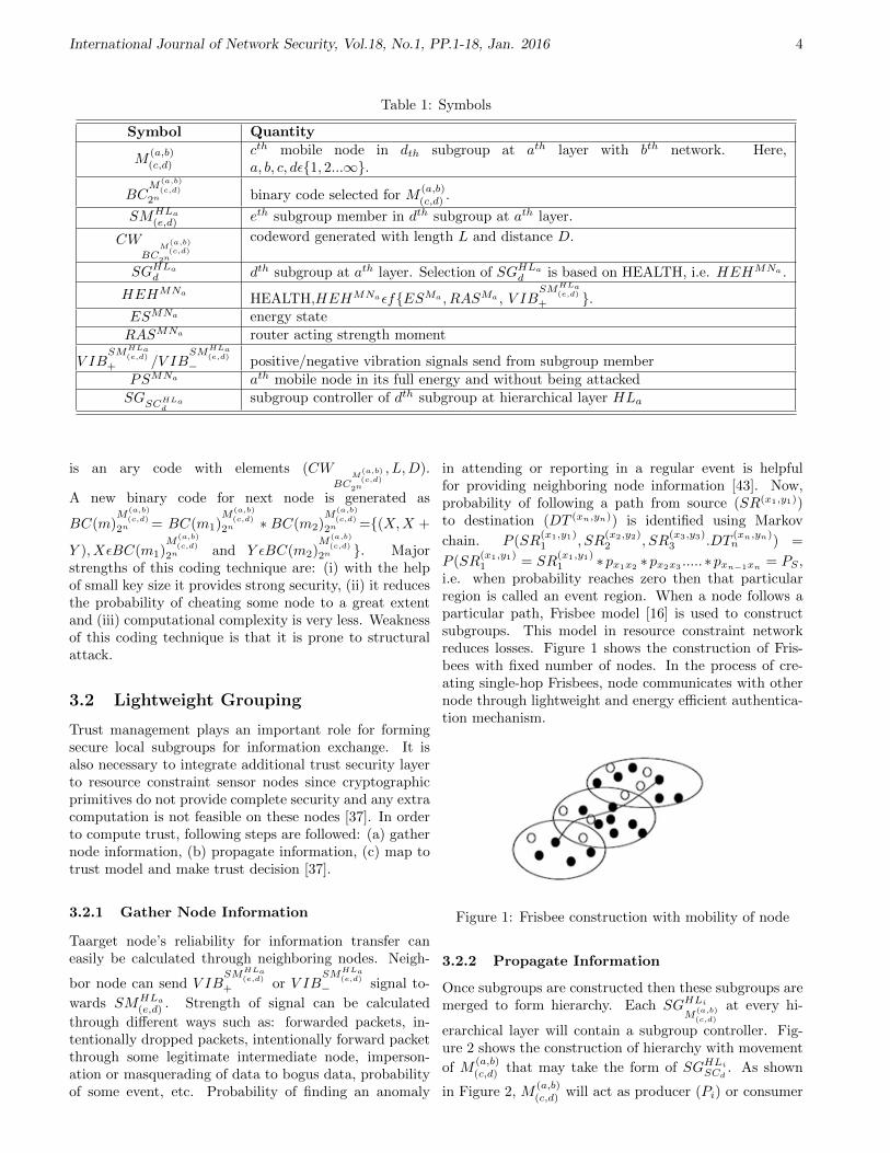
i.e. when probability reaches zero then that particularregion is called an event region. When a node follows aparticular path, Frisbee model [16] is used to constructsubgroups. This model in resource constraint networkreduces losses. Figure 1 shows the construction of Fris-bees with fixed number of nodes. In the process of cre-ating single-hop Frisbees, node communicates with othernode through lightweight and energy efficient authentica-tion mechanism.
Figure 1: Frisbee construction with mobility of node
3.2.2 Propagate Information
Once subgroups are constructed then these subgroups aremerged to form hierarchy. Each SGHLi
M(a,b)
(c,d)
at every hi-
erarchical layer will contain a subgroup controller. Fig-ure 2 shows the construction of hierarchy with movement
of M(a,b)(c,d) that may take the form of SGHLi
SCd. As shown
in Figure 2, M(a,b)(c,d) will act as producer (Pi) or consumer

International Journal of Network Security, Vol.18, No.1, PP.1-18, Jan. 2016 5
(C′
i or C′′
i ). These producer and consumer will perform
multiple tasks like: (i) distribution of BC(m1)M
(a,b)
(c,d)
2n , (ii)
with the help of BC(m)M
(a,b)
(c,d)
2n , SGHLi
SCdgenerate keys and
distribute to consumers and (iii) nodes exchange messagesusing lightweight encryption mechanism.
Figure 2: Hierarchical formation using real and virtualnodes
• During distribution of BC(m)M
(a,b)
(c,d)
2n , Pi will fetch thereed-muller binary code from the database and dis-tribute to C
′
i or C′′
i . The producer-consumer moduleto exchange reed-muller code using interface, portand channel is shown in Figure 3. Here, n-consumermodules are connected to single producer and eachproducer/consumer module is associated with an in-terface. These are writing and reading interfaces atproducer and consumer ends respectively. Since pro-ducers generate and consumers accept reed-mullercodes thus port associated with producer is outputand consumer is input.
• With the help of BC(m)M
(a,b)
(c,d)
2n , SGHLi
SCdgenerate keys
and distribute to consumers. In [42], efficient hier-archical threshold based symmetric group key man-agement protocol is proposed. It is found that inclu-sion of virtual nodes reduces the energy losses andjoining/leaving expenses of nodes. Extension to Teoand Tan‘s group key management protocol is inte-grated to generate and distribute a group symmetrickey ‘K ′ [42, 66]. Major strengths of this process are:(i) protected from forward and backward secrecy, (ii)strong authentication mechanism and (iii) efficient interms of small subgroup formation in close vicinity.
• With help of symmetric key ‘K ′, messages are ex-changed using protocol1 between smart nodes. Here,smart node is integration of RFID reader with mo-bile sensor node. Reader reads the information fromnearby tags and communicates to other sensor nodesthrough radio frequency. A microcontroller is usedto make the RFID reader data compatible for sensornode in a smart node.
Figure 3: Exchange of BC(m)M
(a,b)
(c,d)
2n , Pi using producer-consumer
Protocol 1: Messages exchange using lightweight en-cryption/decryption mechanisms.
Premise: Let EK , DK and H represents the lightweightencryption, decryption and hashing functions respec-tively.
1) SGHLi
SMj→ SGHLo
SMr: EKMessage, H(Message).
2) SGHLo
SMrverifies the message digest by regen-
erating it using H(DK(EKMessage)). IfH(DK(EKMessage)) = H(Message) then mes-sage is accepted otherwise rejected.
3) if message is accepted then SGHLo
SMr→ SGHLi
SMj:
EKAcknowledgement, H(Acknowledgement)and if message is rejected then SGHLo
SMr→
SGHLi
SMj: EKNegative Acknowledgement,
H(Negative Acknowledgement).
4) SGHLi
SMjverifies the receipt of mes-
sage through acknowledgement as:H(DK(EKAcknowledgement)).If H(DK(EKAcknowledgement)) =H(Acknowledgement) then message is acceptedotherwise retransmission start with timer.
These steps of message exchange ensures: (i)confidentiality of message exchange through en-cryption/decryption, (ii) message integrity throughlightweight hashing hashing, (iii) pre-image resistantand collision resistant properties of messages throughlightweight hashing, (iv) compression of message throughhashing and (v) retransmission of messages in case ofmessage loss or corruption.
International Journal of Network Security, Vol.18, No.1, PP.1-18, Jan. 2016 6
3.2.3 Map to Trust Model
As discussed, trust management includes trust gen-eration, trust propagation, trust accumulation, trustprediction and trust application [29]. Once subgroup isconstructed using protocol1 then it can be protected fromvarious attacks and maintains the relationships usingtrust management. Trust mechanism assumes everymember of constructed hierarchy as PSMNa and passesthrough following phases for maintaining relationships.
Trust Generation: Trust on a mobile node is calcu-lated from its HEHMNa score. Trust is directly pro-portional to HEHMNa score. Initially, all nodes are
considered to be PSMNa and vibrate V IBSMHLa
(e,d)
+ signalonly. Here, health is calculated from three factors i.e.
HEHMNaεfESMa , RASMa , V IBSMHLa
(e,d)
+ . Three com-ponent’s values are rated on grading scheme in order tocalculate the trust value of any node and this gradingprocess is explained as follows:
• RASMa ensures reliability and quality of service.Since all nodes are considered to be PSMNa thusreliability and quality of nodes is assumed tobe very high. Reliability of node is dependentupon delivery ratio, goodput, coverage, fairness,jitter and routing cost [54]. Quality of serviceis calculated from number and type of interac-tions, which is calculated as probability score value(PSV) and it is calculated as number of times the
P (SR(x1,y1)1 , SR
(x2,y2)2 , SR
(x3,y3)3 ····DT (xn,yn)
n ) of any
M(a,b)(c,d) reaches zero in some region ‘R’. Interactions
in this region may transmit very good, good, average,poor or very poor quality of transmissions.
• ESMa is measured in form of bursts and sleep time.These bursts are scaled based on traffic. Low trafficconsumes less energy and heavy traffic consumes highenergy. In order to rate energy levels, bursts are di-vided into four major categories: zero, low, mediumand high. Zero bursts do not consume energy and inthis state, nodes are assumed to be in sleep state.Low bursts are the minimum consumption states.Medium bursts are the frequent consumption statesbut do not increase its value with time as comparedto high bursts which are more frequent. Energy con-sumption increases with time if high bursts are con-tineously observed. Section 5 describes the energyconsumption analysis.
• V IBSMHLa
(e,d)
+ are the positive vibration signals andpresent experiences of neighboring nodes. A nodecan send positive or negative vibration signals. Pos-itive signals are used to indicate trust and negativefor un-trust. In this work, counts on positive signalsare made to measure the trust. This count valueranges from 1(Low) to 10 (High). Rating is the num-ber of trust response coming from neighboring nodes.
If number of neighboring nodes exceed ten then itis considered to be highly trusted but if numberof neighboring nodes response is less than ten then10 minus total response will give negative vibrationscore. Subgroup signal value is also calculated fromthe average score of it’s node’s trust vibration scores.Subgroup controller can debar any subgroup from hi-erarchy because of its malicious operations. Which iscalculated from its subgroup members health score.
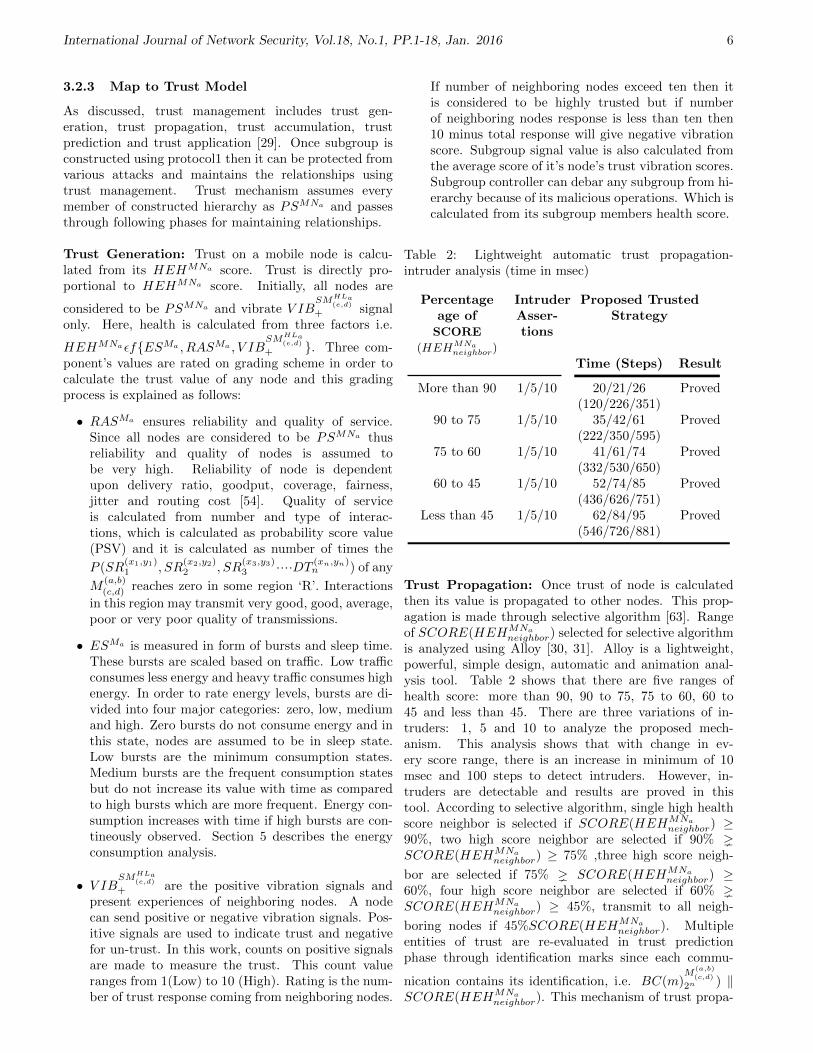
Table 2: Lightweight automatic trust propagation-intruder analysis (time in msec)
Percentageage ofSCORE
(HEHMNaneighbor)
IntruderAsser-tions
Proposed TrustedStrategy
Time (Steps) Result
More than 90 1/5/10 20/21/26 Proved(120/226/351)
90 to 75 1/5/10 35/42/61 Proved(222/350/595)
75 to 60 1/5/10 41/61/74 Proved(332/530/650)
60 to 45 1/5/10 52/74/85 Proved(436/626/751)
Less than 45 1/5/10 62/84/95 Proved(546/726/881)
Trust Propagation: Once trust of node is calculatedthen its value is propagated to other nodes. This prop-agation is made through selective algorithm [63]. Rangeof SCORE(HEHMNa
neighbor) selected for selective algorithmis analyzed using Alloy [30, 31]. Alloy is a lightweight,powerful, simple design, automatic and animation anal-ysis tool. Table 2 shows that there are five ranges ofhealth score: more than 90, 90 to 75, 75 to 60, 60 to45 and less than 45. There are three variations of in-truders: 1, 5 and 10 to analyze the proposed mech-anism. This analysis shows that with change in ev-ery score range, there is an increase in minimum of 10msec and 100 steps to detect intruders. However, in-truders are detectable and results are proved in thistool. According to selective algorithm, single high healthscore neighbor is selected if SCORE(HEHMNa
neighbor) ≥90%, two high score neighbor are selected if 90% SCORE(HEHMNa
neighbor) ≥ 75% ,three high score neigh-
bor are selected if 75% SCORE(HEHMNa
neighbor) ≥60%, four high score neighbor are selected if 60% SCORE(HEHMNa
neighbor) ≥ 45%, transmit to all neigh-
boring nodes if 45%SCORE(HEHMNa
neighbor). Multipleentities of trust are re-evaluated in trust predictionphase through identification marks since each commu-
nication contains its identification, i.e. BC(m)M
(a,b)
(c,d)
2n ) ‖SCORE(HEHMNa
neighbor). This mechanism of trust propa-

International Journal of Network Security, Vol.18, No.1, PP.1-18, Jan. 2016 7
gation through health score help in protecting the networkfrom various attacks.
Table 3: Lightweight automatic trust accumulation-intruder analysis (time in msec)
Percentageage ofSCORE
(HEHAV G)
IntruderAsser-tions
Proposed TrustedStrategy
Time (Steps) Result
More than 90 1/5/10 31/41/44 Proved(131/233/362)
90 to 80 1/5/10 42/52/71 Proved(222/362/493)
80 to 70 1/5/10 54/61/88 Proved(341/466/645)
70 to 60 1/5/10 64/81/101 Proved(531/771/823)
60 to 50 1/5/10 74/93/118 Proved(666/902/1120)
Less than 50 1/5/10 92/104/165 Proved(786/966/1481)
Trust Accumulation: At destination, trust valuesare accumulated and evaluated. Since, trust valuepasses through multiple paths hence source‘s trustvalue is predicted from health of the path followed.Health of each routed node is accumulated along withits trust value. Average of health is calculated using:HEHAVG = (HEHMN1+HEHMN2+..+HEHMNn)/N .Based on score(HEHAVG) value, path is se-lected and rated. Table 3 shows that there aresix range of score(HEHAVG). With decrease inscore(HEHAVG) of 10% there is an increase in min-imum of 10 msec and 100 steps to detect intruders.However, intruders are detectable and results areproved on alloy tool. This measurement is takento rate the path followed for trust accumulation. Ifscore(HEHAVG) ≥ 90%, then path is considered asexcellent, very good if 90% score(HEHAVG) ≥ 80%,good if 80% score(HEHAVG) ≥ 70%, averageif 70% score(HEHAVG) ≥ 60%, below aver-age if 60% score(HEHAVG) ≥ 50%, poor if50% score(HEHAVG).
Trust Prediction: Now, after transmitting the trustscore in the form of health, healthiness of route isdetermined. If route health is below average then trustis recomputed at destination using lightweight trustcomputation based on prejudice, experience and hearsay.It is calculated as: T i = C ∗ Exp. + (1 − C) ∗ Her.,where T, C, Exp. and Her. are respectively the trust,self confidence level, experience and hearsay values.Experience is the average value of current observationand immediate observation. Hearsay is calculated as:
H(MN j) = (Σni=1T
i)/N . Here, N is the number ofneighboring connected nodes to MNa and T i is the ith
response of trust.
Trust Application: Once basic trust relationship isestablished then application specific trust depends uponuser operations. Secure and safe transmission of informa-tion is necessary and confirmed through authenticationprocedures. Applications that are required to be operatedin basic trusted environment should have to produceapplication trust value (Ta). This trust value is comparedwith basic trust value (Ti). If Ta Ti then access toapplication fails. Failure or success of the applicationfor operation is broadcasted to other subgroup membersusing broadcasting mechanism. Protocol 2 describes thismechanism.
Protocol 2: Application trust broadcasting for accessrights.Goal: To compare trust value with required applicationtrust value. After this comparison, if application trustvalue is less then access to application is not allowed andthis information is broadcasted to all subgroup members.
1) SGHLi
SMj→ SGHLi
SMk: ”ALLOW” ‖ ”DENY ”.
2) SGHLi
SCk→ SG
HLi−1
SCk: ”ALLOW” ‖ ”DENY ”. This
step is repeated until top subgroup controller receivesthe message.
3) SGHLo
SCkinitiated the process of collecting information
about applications whose access rights are managedthrough trust comparison.
Here, ALLOW and DENY are single bit messages.These messages help to debar the applications that canmaliciously harm the network. If ‘h′ is the height of hier-archy constructed and ‘n′ is the total number of subgroupconstructed then total number of messages required tobroadcast this information are ‘h ∗n ∗ 10’. In this work, aset of two node based trust applications are integrated fordistance bounding. This trust application is explained innext sections.
3.3 Lightweight Trust Based DistanceBounding and Authentication
In this section, distance bounding and authenticationprotocols are integrated to hierarchical model for limitingthe distance between two nodes and to authenticate eachother. Distance bounding and authentication are two setof protocols but an integrated form of these protocols isused to reduce the hardware cost. In this work, modifiedform of Avoine mutual authenticated KA2 (MA-KA2)protocol is integrated with lightweight parameters [7].The modified form of this mechanism is explained inProtocol 3. There are two phases of protocol: slowand fast. In slow phase, nonce values are exchangedand in fast phase, authentication is performed using

International Journal of Network Security, Vol.18, No.1, PP.1-18, Jan. 2016 8
challenge-verify process.
Protocol 3: Modified MA-KA2 and Distance BoundingProtocol.
Premises: Let RM
(a,b)
(c,d) be the random number selectedby M
(a,b)(c,d) .NSGHLa
SCd
represents the nonce generated by dth
subgroup with its subgroup controller. Here, every sub-group member act as a prover or a verifier. When direc-
tion bitDIRi
M(a,b)
(c,d)
of some mobile node is zero thenM(a,b)(c,d)
sends a random challenge CHAi
M(a,b)
(c,d)
ε0, 1 towards an-
other mobile node M(a,b)(f,d) . Now, this mobile node replies
with verification process (V ERCHAi
M(a,b)
(f,d)
). When DIRi
M(a,b)
(c,d)
is one then M(a,b)(f,d) will send CHAi
M(a,b)
(f,d)
ε0, 1 and M(a,b)(c,d)
will verify. If the random number generated is not veri-
fied, i.e. RM
(a,b)
(c,d) 6= V ERCHAi
M(a,b)
(a,d)
then communication is put
in protected mode. This protected mode behaves differ-ently than regular rounds. In this mode, nodes have toregularly produce and verify the challenges. Let b and rare the number of bits used in direction bit and numberof rounds in two phases of distance bound mutual au-thentication protocol. T
M(a,b)
(c,d)
represents the timer from
M(a,b)(c,d) , TMAX is the maximum time elapsed for check-
ing distance bounding and H is a pseudorandom numberfunction.Goal: Limit the distance between two subgroup con-trollers or members and authenticate each other.Step 1: Slow Phase
1) Every subgroup member from both subgroups will se-
lect a random number, i.e. RM
(a,b)
(1,d) , RM
(a,b)
(2,d) ...RM
(a,b)
(9,d)
and RM
(a,b)
(1,e) , RM
(a,b)
(2,e) ...RM
(a,b)
(9,e) .
2) Since a symmetric key K is already shared betweensubgroup members thus nonce are generated using:
NSGHLaSCd
= H(K,RM
(a,b)
(1,d) ‖ RM(a,b)
(2,d) ‖ ... ‖ RM(a,b)
(9,d) )
and NSGHLaSCe
= H(K,RM
(a,b)
(1,e) ‖ RM
(a,b)
(2,e) ‖ ... ‖
RM
(a,b)
(9,e) ). Here, H is a lightweight cryptographic hashfunction.
3) Two subgroup controller exchanges these noncevalues as: SGHLa
SCd→ SGHLa
SCe: NSGHLa
SCd
, SGHLa
SCe→
SGHLa
SCd: NSGHLa
SCe
, DIRiSGHLa
SCd
‖
DIRiSGHLa
SCe
‖ V ERCHA0 ‖ V ERCHA1 ‖
V ERCHA2 = h(K,NSGHLaSCd
, NSGHLaSCe
Num-
ber of bits (DIRiSGHLa
SCd
) = Number of
bits(DIRiSGHLa
SCe
) = r, Number of bits (V ERCHA0
)
=Numberofbits(V ERCHA1
) = 2(b−r)−1, Number
of bits (V ERCHA2
) = 2b.
Step 2: Fast bit exchange phase
1) SGHLa
SCdcomputes COM1
SGHLaSCd
= DIR1SGHLa
SCd
and
start timer TSGHLaSCd
. During this time, it sends
COM1SGHLa
SCd
towards SGHLa
SCe.
2) SGHLa
SCechecks if COM1
SGHLaSCd
= DIR1SGHLa
SCd
then
computes COM1SGHLa
SCe
= V ERCHA2
1 . With start of
TSGHLaSCe
, SGHLa
SCesends COM1
SGHLaSCe
to SGHLa
SCd. But if
COM1SGHLa
SCd
6= DIR1SGHLa
SCd
then error is detected and
instead of sending random answers until end of theprotocol it check value ofHEHMNa
SGHLaSCe
andHEHAVG.
if any value is below satisfactory level then it addsthe communication in protected mode.
3) SGHLa
SCdstops TSGHLa
SCd
and compute DOM b−1SGHLa
SCe
=
COM b−1SGHLa
SCd
⊕ V ERCHA2
2b−3 .if DOM b−1SGHLa
SCe
=
DIRb−1SGHLa
SCe
then COM bSGHLa
SCd
= V ERCHA2
2b−2 ⊕
DIRbSGHLa
SCd
. Further, if DOM b−1SGHLa
SCe
6= DIRb−1SGHLa
SCd
then again it check for HEHMNa
SGHLaSCd
and HEHAVG.
If any of these values are unsatisfactory then it addsthe communication to protected mode. Also, SGHLa
SCd
sends COM bSGHLa
SCd
to SGHLa
SCeand start TSGHLa
SCd
.
4) SGHLa
SCestops TSGHLa
SCe
and compute DOM bSGHLa
SCd
=
COM bSGHLa
SCd
⊕ V ERCHA2
2b−2 . If DOM bSGHLa
SCd
6=
DIRbSGHLa
SCd
then HEHMNa
SGHLaSCd
and HEHAVG are
checked before sending unsatisfactory report for pro-tected mode. Also, SGHLa
SCestart TSGHLa
SCe
and send
DOM bSGHLa
SCd
to SGHLa
SCd.
5) SGHLa
SCdstops TSGHLa
SCd
and compute
DOM bSGHLa
SCe
= DOM bSGHLa
SCd
⊕ V ERCHA2
2b−1 .
If DOM bSGHLa
SCe
= DIRbSGHLa
SCe
then compute
COM b+1
SGHLaSCd
= V ERCHA2
2b ⊕ RM
(a,b)
(1,d) . Further,
if DOM bSGHLa
SCe
6= DIRbSGHLa
SCe
then HEHMNa
SGHLaSCd
and HEHAVG values are checked before sendingunsatisfactory report for protected mode. SGHLa
SCd
sends COM b+1
SGHLaSCd
to SGHLa
SCeand start TSGHLa
SCd
6) SGHLa
SCestops TSGHLa
SCe
and computes RM
(a,b)
(1,d) =
COM b+1
SGHLaSCd
⊕ V ERCHA2
2b−2 . If RM
(a,b)
(1,d) = 0 then
COM b+1
SGHLaSCe
= V ERCHA0 ⊕RM(a,b)
(1,e) else if RM
(a,b)
(1,d) =

International Journal of Network Security, Vol.18, No.1, PP.1-18, Jan. 2016 9
1 then COM b+1
SGHLaSCe
= V ERCHA1 ⊕ RM
(a,b)
(1,e) . Also,
SGHLa
SCestarts TSGHLa
SCe
and sends COM b+1
SGHLaSCe
to
SGHLa
SCd.
7) SGHLa
SCdstops TSGHLa
SCd
and computes RM
(a,b)
(r−b−1,e) =
DOM b−1SGHLa
SCd
⊕V ERCHAr−b−1
2r−2b−2 . Now, if RM
(a,b)
(r−1,e) = 0
then DOM bSGHLa
SCd
= V ERCHA02r−2b−1⊕RM
(a,b)
(r−b,d) else
if RM
(a,b)
(r−1,e) = 1 then COM bSGHLa
SCd
= V ERCHA1
2r−2b−1 ⊕
RM
(a,b)
(r−b,d) . Also, SGHLa
SCdstarts TSGHLa
SCd
and sends
COM bSGHLa
SCd
to SGHLa
SCe.
8) SGHLa
SCestops TSGHLa
SCe
and computes RM
(a,b)
(r−b−1,d) =
DOM bSGHLa
SCd
⊕V ERCHAr−b−1
2r−2b−2 . Now, if RM
(a,b)
(r−b,d) = 0
then COM bSGHLa
SCe
= V ERCHA0
2r−2b−1 ⊕ RM
(a,b)
(r−b,e) else if
RM
(a,b)
(r−b,d) = 1 then COM bSGHLa
SCe
= V ERCHA12r−2b−1⊕
RM
(a,b)
(r−b,e) . Also, SGHLa
SCesends COM b
SGHLaSCe
to
SGHLa
SCd.
9) SGHLa
SCdstops TSGHLa
SCd
.
Step 3: End of fast bit exchange phase and start checkfor processing delay.
1) SGHLa
SCdchecks for H(K,R
M(a,b)
(1,d) ‖ RM
(a,b)
(2,d) ‖
.... ‖ RM
(a,b)
(9,d) ) = NSGHLaSCd
and SGHLa
SCechecks for
H(K,RM
(a,b)
(1,e) ‖ RM(a,b)
(2,e) ‖ ... ‖ RM(a,b)
(9,e) = NSGHLaSCe
.
If both are true and time elapsed is less than TMAX
then communication is successful.
Major strengths of this protocol are: (i) one subgroupcontroller or member can put distance limit to anothersubgroup controller or member, (ii) unilateral authen-tication is provided to protect against dismantling at-tack, (iii) distance bounding protocols protects from lo-cation based attacks using cryptographic characteristicsintegrated with physical attributes of the nodes and (iv)attack analysis in section 5 shows that the modified proto-col is efficient, secure and having lowest False AcceptanceRate (FAR). The FAR is the rate of possibility of accep-tance of nodes when there are chances of attack.
4 Result Analysis
4.1 Attack Analysis
4.1.1 Distance Bounding Protocol Attack Anal-ysis
In this section, probability of success of mafia fraud, dis-tance fraud, terrorist fraud and distance hijacking attacksare analyzed on distance bounding protocols. The analy-sis is explained as follows:
Attack: Mafia Fraud Attack
Description: In this attack, a malicious subgroupcontroller (MSGHLa
M(a,b)
(c,d)
) and a malicious group member
(MM(a,b)(c,d) ) are inserted in subgroups. These malicious
entities communicate with original subgroup controllerand members and convince them to reveal secret in-formation [59, 68, 71]. MSGHLa
M(a,b)
(c,d)
and MM(a,b)(c,d) start
man-in-middle attack by sending MSGHLa
SCd→ SGHLa
SCe:
NMSGHLaSCd
and MSGHLa
SCe→ SGHLa
SCd: NMSGHLa
SCe
. This ef-
fects the rounds of fast bit exchange. Now, success proba-bility of this attack is determined by defining the followingevents:
• ANDiSGHLa
SCd
attack is not detected at ith round by
SGHLa
SCd.
• ADiSGHLa
SCd
attack is detected at ith round by SGHLa
SCd.
• HEH ANDMNa
SGHLaSCd
health score of SGHLa
SCdat time
when attack is not detected at ith round by SGHLa
SCd.
• UANDiSGHLa
SCd
attack is not detected at until the ith
round by SGHLa
SCd.
• ANDiSGHLa
SCe
attack is not detected at ith round by
SGHLa
SCe.
• ADiSGHLa
SCe
attack is detected at ith round by SGHLa
SCe.
• HEH ANDMNa
SGHLaSCe
health score of SGHLa
SCeat time
when attack is not detected at ith round by SGHLa
SCe.
• UANDiSGHLa
SCe
attack is not detected at until the ith
round by SGHLa
SCe.
• COLiSGHLa
SCd
is an event when collision occurs at
SGHLa
SCdside in ith round.
• COLiSGHLa
SCe
is an event when collision occurs at
SGHLa
SCeside in ith round.

International Journal of Network Security, Vol.18, No.1, PP.1-18, Jan. 2016 10
Now, success probability of Mafia fraud attack can becalculates as follows:
P [FAR]
= P [UANDiSGHLa
SCd
/UANDiSGHLa
SCe
]P [UANDiSGHLa
SCe
]
+
n∑i=1
P [UANDiSGHLa
SCe
/ADiSGHLa
SCd
]P [ADiSGHLa
SCd
]
+
n∑i=1
P [UANDiSGHLa
SCd
/ADiSGHLa
SCe
]P [ADiSGHLa
SCe
]
(1)
P [UANDiSGHLa
SCe
/ADiSGHLa
SCd
]P [ADiSGHLa
SCd
]
= Πi−1j=1P [
UANDiSGHLa
SCe
ANDiSGHLa
SCd
]HEH ANDMNa
SGHLaSCd
=satisfactory
Πi−1j=1P [
UANDiSGHLa
SCe
ADiSGHLa
SCd
]HEH ANDMNa
SGHLaSCd
=satisfactory
(2)
Now, there are five case when HEH ANDMNa
SGHLaSCd
=
satisfactory. Let 1p90, 1p80, 1p70, 1p60
and 1p50
are the
five case probabilities when HEH ANDMNa
SGHLaSCd
≥ 90%,
HEH ANDMNa
SGHLaSCd
≥ 80%, HEH ANDMNa
SGHLaSCd
≥ 70%,
HEH ANDMNa
SGHLaSCd
≥ 60%,and HEH ANDMNa
SGHLaSCd
≥
50% respectively. If 1pi−1
be the probability that colli-
sion is not detected until (i− 1)th round and 1pprotected
is
the probability of moving to protected mode then:
Πi−1j=1P [
UANDiSGHLa
SCe
ANDiSGHLa
SCd
]HEH ANDMNa
SGHLaSCd
=satisfactory
= (1
pj−1)j−1(
1
pprotected)j−1
+(1
p90+
1
p80+
1
p70+
1
p60+
1
p50)j−1.
Thus Equation (2) can be written as:
P [UANDiSGHLa
SCe
/ADiSGHLa
SCd
]P [ANDiSGHLa
SCd
]
= (1
pi−1)i−2(
1
pprotected)i−2
+(1
p90+
1
p80+
1
p70+
1
p60+
1
p50)i. (3)
Similarly,
n∑i=1
P [UANDiSGHLa
SCd
/ADiSGHLa
SCe
]P [ADiSGHLa
SCe
]
= (1
pi−1)i−2(
1
pprotected)i−2
+(1
p90+
1
p80+
1
p70+
1
p60+
1
p50)i. (4)
From Equations (3) and (4), one of the equation is usedto find error thus it reduces the probability of finding acollision to be 1
2 . After putting values of Equations (3)and (4) in (2), probability of false acceptance rate can becalculated as:
P [FARn] = (1
pi−1)n(
1
pprotected)n
+(1
p90+
1
p80+
1
p70+
1
p60+
1
p50)n
+
n∑i=1
((1
pi−1)n−i−2(
1
pprotected)n−i−2
+(1
p90+
1
p80+
1
p70+
1
p60+
1
p50)n−i−2).
(5)
Equation (5) gives the false acceptance probability.Higher value of this probability give less protectionagainst intruders at earlier stage. However, progression ofrelationship through trust decreases the probability andincreases the security of network for finding an attack. Ifhealth score does not permit to accept any subgroup con-troller or member then collision can stop the process ofcommunication at early stage.Attack: Distance Fraud AttackDescription: A malicious node can come closer to sub-group and make false claim to be the nearest node. [7,38, 39]. Let EV ENT i
SGHLaSCe
and EV ENT iSGHLa
SCd
are the
events when SGHLa
SCeand SGHLa
SCdfind collision. A collision
can occur when some bits are not verified. Now, successprobability of distance fraud attack can be calculated as:
P [EV ENT iSGHLa
SCe
∩ EV ENT iSGHLa
SCd
]
= (P [EV ENT 1SGHLa
SCe
]P [EV ENT 2
SGHLaSCe
EV ENT 1SGHLa
SCe
]
· · ·P [EV ENTn
SGHLaSCe
Πn−1i=1 EV ENT
iSGHLa
SCe
]HEH=satisfactory
+(P [EV ENT 1SGHLa
SCd
]P [
EV ENT 2SGHLa
SCd
EV ENT 1SGHLa
SCd
]
· · ·P [
EV ENTnSGHLa
SCd
Πn−1i=1 EV ENT
iSGHLa
SCd
]HEH=satisfactory.
Now, when DIR1SGHLa
SCd
or DIR1SGHLa
SCe
is zero then:
P [EV ENT iSGHLa
SCe
∩DIRiSGHLa
SCe
∩HEH ANDMNa
SGHLaSCd
= satisfactory]
=1
2(
1
p90+
1
p80+
1
p70+
1
p60+
1
p50)
= P [EV ENT iSGHLa
SCd
∩DIRiSGHLa
SCd
∩HEH ANDMNa
SGHLaSCd
= satisfactory]. (6)

International Journal of Network Security, Vol.18, No.1, PP.1-18, Jan. 2016 11
When DIR1SGHLa
SCd
or DIR1SGHLa
SCe
is one then:
P [EV ENT iSGHLa
SCe
∩DIR1SGHLa
SCe
∩HEH ANDMNa
SGHLaSCe
= satisfactory]
= P [EV ENT iSGHLa
SCe
∩DIRiSGHLa
SCe
]
P [HEH ANDMNa
SGHLaSCe
= satisfactory]
= P [(EV ENT iSGHLa
SCe
∩V ERCHA1
= h[K,NSGHLaSCd
, NSGHLaSCe
)]
P [DIRiSGHLa
SCe
]P [HEH ANDMNa
SGHLaSCe
= satisfactory]
+P [(EV ENT iSGHLa
SCe
∩V ERCHA1
6= h[K,NSGHLaSCd
, NSGHLaSCe
)]
P [DIRiSGHLa
SCe
]P [HEH ANDMNa
SGHLaSCe
= satisfactory]
= (3
4)i + (
n∑i=1
(1
pi−1)n−i−2 ∗ (
1
pprotected)n−i−2
+(1
p90+
1
p80+
1
p70+
1
p60+
1
p50)n−i−2). (7)
Since collision is found in one of the two sides thus inthis case also probability is considered to be 1
2 . Equa-tion (7) gives the value of acceptance rate of attack.Higher value of trust reduces the chances of this attack toa great extent.Attack: Terrorist Fraud Attack.Description:In this attack, existing M
(a,b)(c,d) act as mali-
cious entity. M(a,b)(c,d) collaborate with MM
(a,b)(c,d) and tries
to convince MSGHLa
M(a,b)
(c,d)
that he is nearby when he is
not [7, 39, 38]. This attack can be protected using secretsharing scheme [8]. P [success of terrorist fraud attack]
≥ P [success of mafia fraud attack]. Let P [M(a,b)(c,d) →
MM(a,b)(c,d) : Cert(MNHLi
SMj+1), NM , SKALM ] = 1
pterrorist .
P [MM(a,b)(c,d) → M
(a,b)(c,d) : Cert(V N
(a,b)(c,d) )]HEH ANDMNa
M(a,b)(c,d)
=
1pterrorist
+ 1p90
+ 1p80
+ 1p70
+ 1p60
+ 1p50
. Since symmet-
ric key K is known to all thus P [M(a,b)(c+1,d) → MM
(a,b)(c,d) :
EPKV N
(a,b)(c,d)
SKM
(a,b)
(c+1,d)
]HEH ANDMNa
M(a,b)(c,d)
= ( 1pterrorist
+
1p90
+ 1p80
+ 1p70
+ 1p60
+ 1p50
)2. and it is easy to mis-lead any communication by existing members. Withincrease in such communication chances of terroristfraud detection increases because trust score decreases.If probability of M
(a,b)(c,d) for self answered question is
marked as 1pself answered
then P [success of terrorist fraud
attack]=( 1pself answered
)q ∗ ( 1pterrorist
+ 1p90
+ 1p80
+ 1p70
+1
p60+ 1
p50+ (t − 1)/t + pself answered)q. where ‘t′ is the
total number of queries exchanged between M(a,b)(c,d) and
MM(a,b)(c,d) and collision does not found in q rounds.
Attack: Distance Hijacking AttackDescription: This attack is different from distance fraudand terrorist fraud attack. In distance fraud, a dishon-est prover and verifier are involved. In terrorist fraud,dishonest prover involves with other attacker but in thedistance hijacking attack, dishonest prover interacts withhonest prover and involves them for false distance [21].In distance hijacking attack, minimum single dishonestprover is involved with the other honest parties. If otherparties behave like dishonest prover or verifiers then thisattack become distance fraud attack. Now, P [Success ofdistance hijacking attack] ≤ P [Success of distance fraudattack] [38]. P [Success of distance hijacking attack] =P [honest nodes reveal secret information without be-ing dishonest]. Any dishonest node can behave as hon-est through masquerading, impersonation, taking falseownership, etc. This dishonest behavior in tags can bechecked through birthday paradox and trust score. Nowaccording to birthday paradox, probability of matchingtwo numbers when number of nodes are 10 in each sub-group is less than 1
8 . Further, trust score reduces theprobability of this attack to ( 1
p90+ 1
p80+ 1
p70+ 1
p60+ 1
p50).
This probability of success of distance hijacking attackdue to trust score is much less than 1
8 .
4.2 Performance Analysis
In this section, network performance is analyzed usingvarious QoS parameters: delivery ratio, goodput, cover-age, energy consumption and jitter. This analysis is per-formed using 150-nodes scenarios on ns-3 simulator. Inorder to construct MANET, a smart node is formed byintegrating RFID reader with mobile sensor node. Thesemobile smart nodes constitute a hierarchical Ad-hoc net-work as shown in Figure 2. Reader collects the data fromits local network and transmits to other nodes throughradio frequency antenna of sensor nodes. Performanceanalysis of QoS parameters is as follows.
Delivery Ratio. It is the ratio of number of sent pack-ets to number of delivered packets toward sink.Figure 4 shows the delivery ratios of 150 nodesover five MANETs routing protocols: Ad-hoc OnDemand Distance Vector (AODV), Destination Se-quenced Distance Vector (DSDV), Dynamic SourceRouting (DSR), Temporarily Ordered Routing Algo-rithm (TORA) and Zone Routing Protocol (ZRP).From both scenarios, it is observed that ZRP pro-tocol outperforms the other routing protocols. In150 nodes scenarios, delivery ratio decreases with in-crease in time for every protocol because the numberof available nodes for data transmission decreases andmore number of nodes are occupied for routing.
Goodput. Another non-overlapping term with deliveryratio is goodput. It is the total number of success-fully delivered packets to sink [54]. With addition ofmore number of packets and delay parameters, valueof goodput can be increased. Figure 5 and Figure 6

International Journal of Network Security, Vol.18, No.1, PP.1-18, Jan. 2016 12
Figure 4: Delivery ratio for 150 nodes over MANETs rout-ing protocols
Table 4: Lightweight node-packet delivery analysis usingalloy (time in msec)
Percentageof routed ordeliveredpackets
IntruderAsser-tions
Proposed TrustedStrategy
Time (Steps) Result
More than 75 1/5/10 10/21/32 Proved(80/113/131)
More than 65 1/5/10 60/94/145 Proved(150/173/224)
More than 55 1/5/10 113/146/211 Proved(170/210/563)
show the goodput for 150 nodes at offer load of 1packet/second and 5 packets/second respectively. In150-nodes scenarios, ZRP protocol outperforms thanany other protocol. Performance of ZRP protocol isaverage and it is increasing exponentially with timeat lesser rate, i.e. 1 pkt/sec.. In 5pkt/sec. for 150nodes, ZRP is having improved performance as com-pared to 1 pkt/sec. In these scenarios, other proto-cols also show increase in performance but this in-crease is lesser as compared to ZRP protocol. It isalso observed that in 150 nodes scenarios, growth ofthroughput for ZRP is linear than linear but for otherprotocol, it is linear or less.
Figure 5: Goodput for 150 nodes at 1 packet/second
Coverage. It is defined as number of nodes used per unit
Figure 6: Goodput for 150 nodes at 5 packets/second
time for successful transmission of packets. In Ta-ble 4, three scenarios are taken into consideration tofind the coverage range for proposed scheme. Re-sults shows that if a node deliver more than 75% ofpackets then intrusion detection take 50 msec and 70steps which is lesser than delivery percentage of 65.It takes a minimum difference of 100 msec. and 90steps when compared with 55% of delivery. Hence,a node is considered to be covered if it successfullydelivers 75% of packets it receive and loss 25% onlyfor performance analysis. Figure 7 and Figure 8 showthe coverage of 150 nodes at 1pkt/sec and 5 pkts/secrespectively. In 1pkt/sec and 5 pkts/sec. scenarios,DSR and TORA are having worst performance vari-ance. In both such scenarios, ZRP outperforms theother protocols because of its hybrid routing nature.This protocol, internally divides the nodes into zoneand these zones with energy saving Frisbee formationsave nodes energy for communication. Most of thenodes are silent during simulation initialization andthis property is common among all scenarios. Highcoverage is observed during peak hours which variesfrom protocol to protocol.
Energy Consumption. The evaluation of energy con-sumption in simulation environment is observedthrough throughput. Whenever radio of any nodeis on and a byte is transferred then energy of nodeis considered to be consumed. As discussed in sec-tion 4, this energy is calculated from RSSI and it is afunction of distance. More is the distance parametermore will be the energy consumption. Figure 9 showsthe average energy consumption for 150 nodes sce-nario. If bursts of any protocol are closer to the outerring then average energy consumption for that proto-col is higher and it is called as high burst (0.04-0.05Joules). Low bursts are the minimum consumptionvalues that are close to origin (0.01 Joules). Whereas,medium bursts are the intermediate values betweenhigh and low bursts (0.02-0.03 Joules). As shown inFigure 9, ZRP and TORA protocol are having higheraverage energy consumption than AODV, DSDV andDSR for o.1 pkt/sec, 1 pkt/sec. and 5 pkts/sec. InDSR and DSDV protocol, energy consumption shows

International Journal of Network Security, Vol.18, No.1, PP.1-18, Jan. 2016 13
Figure 7: Coverage for 150 nodes at 1 packets/second
Figure 8: Coverage for 150 nodes at 5 packets/second
Figure 9: Energy consumption for 150 nodes during sim-ulation time
variations with increases in packet/second. becauseof dynamic nature of routing protocol. Wheneverthere is need to transmit packets, then only nodesare activated and energy consumption starts.
Jitter. It is an average value of root mean square delay.Figure 10 shows the jitter values at different packetdelivery rates, i.e. 1 pkt/sec. and 5 pkts/sec. Jittervalues of TORA and AODV are worst as compared toother protocols. Since ZRP provides higher through-put but at minimum jitter thus it is considered to bethe best protocol. Jitter value decreases with increasein number of nodes because more nodes are availableto route the packets thus delay decreases. But thisdelay does not affect much on the performance be-cause the packet delivery rate also increases. Perfor-mance improvement because of increased number ofnodes is compensated by increase in packet delivery
ratio. Also, with increase in packet delivery ratio thejitter decreases because once routes are establishedthen it does not affect much on the performance.
Figure 10: Jitter for 150 nodes at different delivery rate
4.3 Lightweight Analysis
4.3.1 Lightweight Primitive Analysis
Confidentiality as well as authentication mechanisms areintegrated with protocol 1 and protocol 3 whereas onlyauthentication mechanism is integrated with protocol 2.Table 5 shows the comparative analysis of substitutionpermutation network (SPN) based lightweight primitivesfor Protocols 1, 2 and 3. Two lightweight primitivesare taken for analysis: LED and PHOTON. Result oflightweight primitives are compared with classical mech-anism, i.e. Advanced Encryption Standard (AES). Allthree are based on confusion and diffusion layer principlein SPNs. LED and AES are used to achieve confidential-ity and PHOTON is used for authentication. Alloy anal-ysis shows that the number of variable generated, clausesformed and computational time in Protocol 1 and Proto-col 3 for LED and PHOTON are much lesser than AES.Both confusion and diffusion layers are showing similar re-sults. Multiple challenges and verifications in Protocol 2increases the resource consumption and time required tocomplete the operations. Comparison of lightweight prim-itives with classical primitive shows that integration ofLED and PHOTON in proposed mechanism enhances theperformance of protocols as compared to AES based clas-sical confidentiality mechanism.
4.3.2 Lightweight Policy Analysis
Figure 11 shows the proposed trust policy for subgroupmember in proposed scheme. Trust based proposed mech-anism is having: subgroup controller, subgroup member,virtual subgroup member and virtual subgroup controller.Each entity in hierarchical model acts as either produceror consumer. While acting as producer or consumer, therewill be change of permissions. A subgroup controller willbe having READ, WRITE, ACCESS, USE, MODIFYpermissions for trust management. Whereas, a subgroup

International Journal of Network Security, Vol.18, No.1, PP.1-18, Jan. 2016 14
Table 5: Simple vs. lightweight primitive analysis for proposed schemeProtocol Primitives Layer Variables Clauses Time(msec)
Protocol1
LEDConfusion 22025 15174 1463Diffusion 20451 13012 1231
PHOTONConfusion 42314 44101 2112Diffusion 36110 23603 1642
AESConfusion 80178 25545 3463Diffusion 60145 160234 2654
Protocol2 PHOTONConfusion 44114 46045 2414Diffusion 37111 26032 2001
Protocol3
LEDConfusion 22544 160112 1513Diffusion 20653 13009 1213
PHOTONConfusion 41015 44023 2104Diffusion 36009 23112 1672
AESConfusion 81534 26123 3413Diffusion 62435 16144 2611
(MemberAssigned = (Interested s a r):- (Assigned s r) (AssignID a) (SubGroup r))
(MemberConflict = (Interested s a r):- (Conflicted s r) (RetrieveID a) (SubGroup r))
(MemberTrust = (TrustGeneration s a r):- (Assigned s r) (AssignID a) (SubGroup r))
(MemberTrust = (TrustPropagation s a r):- (Assigned s r) (AssignID a) (SubGroup r))
(MemberTrustConflict = (TrustAccumulation s a r):- (Conflicted s r) (SubGroup r))
(MemberTrust = (TrustPrediction s a r):- (Assigned s r) (AssignID a) (SubGroup r))
(MemberTrustConflict = (TrustEvaluate s a r):- (Conflicted s r) (SubGroup r))
(MemberTrustConflict = (TrustApplication s a r):- (Conflicted s r) (SubGroup r))
Figure 11: Margrave policy for access control in proposed scheme
member will be having READ, ACCESS, USE permis-sions only. So, each member will have its own policy in thenetwork. Figure 11 shows the subgroup member policyfor TrustGeneration, TrustPropagation, TrustAccumula-tion, TrustPrediction, TrustEvaluation and TrustApplica-tion. A subgroup member can act as producer to assignnew identification to new node or retrieve its identifica-tion. Trust generation, propagation and prediction arepermissible for subgroup member. Trust accumulationand application comparison are not allowed for memberbut these are considered to be the functions of subgroupcontroller. After designing and analyzing the policies ofevery member in proposed scheme, it is analyzed throughMargrave that there is no conflict in any policy [1].
5 Conclusions
The current study examines RFID-Sensor basedMANETs using ECCr in code based cryptography.MANETs are constructed by extending the trust man-agement approach in resource constraint environmentwith Teo and Tan protocol for key exchange usinghierarchical model [66] and Avoine MA-KA2 protocol
for distance bounding and mutual authentication [7].These approaches are perceived as efficient lightweightapproaches with strong protection against distancebounding attacks. QoS parameters taken for networkperformance analysis are: delivery ratio, goodput,coverage, energy consumption and jitter. In conclusion,150 nodes scenario shows that ZRP protocol outperformsany other protocol for proposed security system usingtrust management. Maximum goodput that is achievablethrough best routing protocol is approximately 80packets per second to minimum delay of 0.03 msec.Probability attack analysis is performed for mafia fraudattack, distance fraud attack, terrorist fraud attack anddistance hijacking attack in distance bounding protocol.In this analysis, fault acceptance rate of system is checkedand in result it is found that system is strong enoughagainst all these attacks. Lightweight primitives andpolicies for subgroup members are also analyzed. It isfound that integration of lightweight primitives reducecomputation and time complexity. Lightweight policyanalysis shows that there is no conflict in access domainsof any subgroup member.

International Journal of Network Security, Vol.18, No.1, PP.1-18, Jan. 2016 15
References
[1] The Margrave Policy Analyzer, Jan. 19, 2015.(http://www.margrave-tool.org)
[2] M. R. S. Abyaneh, Security Analysis of LightweightSchemes for RFID Systems, PhD thesis, Universityof Bergen, Norway, 2012.
[3] B. Alomair, A. Clark, J. Cuellar, and R. Poovendran,“Scalable RFID systems: A privacy-preversing protowith constant-time identification,” IEEE Transac-tions on Parallel Distribution Systems, vol. 23, no. 8,pp. 1536–1550, 2012.
[4] R. J. Anderson, Security Engineering: A guide toBuilding Dependable Distributed Systems, New York,USA, John Wiley & Sons, 2001.
[5] S. A. Anson and M. Ilyas, RFID handbook: Applica-tion, technology, security and privacy, Boca Raton,Florida, USA, CRC, 2008.
[6] P. D’Arco and A. De Santis, “On ultralightweightRFID authentication protocols,” IEEE Transactionson Dependable and Secure Computing, vol. 8, no. 4,pp. 548–563, 2011.
[7] G. Avoine and C. H. Kimh, “Improving programanalyses by structure untupling,” IEEE Transactionson Mobile Computing, vol. 12, no. 5, pp. 830–839,2013.
[8] G. Avoine, C. Lauradoux, and B. Martin, “Howsecret-sharing can defeat terrorist fraud,” in Proceed-ings of the 4th ACM Conference on Wireless NetworkSecurity, pp. 145–155, Hamburg, Germany, June 15-17, 2011.
[9] N. Bagheri and M. Safkhani, “Secret disclosure at-tack on kazahaya, a yoking-proof for low-cost RFIDtags,” Technical Report Cryptology ePrint Archive:Report 2013/453, July 2013.
[10] J. D. Bakos, D. M. Chiarulli, and S. P. Levitan,“Lightweight error correction coding for system-levelinterconnects,” IEEE Transactions on Computing,vol. 56, no. 3, pp. 289–304, 2007.
[11] D. J. Bernstein, J. Buchmann, and E. Dahmen, Post-Quantum Cryptography, Springer-Verlag Berlin Hei-delberg, New York, USA, Springer, 2009.
[12] M. Burmester, T. V. Le, and B. D. Medeirosn, “Uni-versally composable RFID identification and authen-tication protocols,” ACM Transaction on Informa-tion and Systems Security, vol. 12, no. 4, pp. 21:1–21:33, 2012.
[13] M. Burmester and J. Munilla, “Lightweight RFIDauthentication with forward and backward security,”ACM Transactions on Information and System Se-curity, vol. 14, no. 1, pp. 11:1–11:26, 2011.
[14] A. Canteaut and F. Chabaud, “Improvement of theattacks on cryptosystems based on error-correctingcodes,” Research Report: LIENS-95-21, Ecole Nor-male Superieure, Paris, July 1995.
[15] T. Cao, E. Bertino, and H. Lei, “Security analysis ofthe sasi protocol,” IEEE Transactions on Dependableand Secure Computing, vol. 6, no. 1, pp. 73–77, 2009.
[16] A. Cerpa, J. Elson, D. Estrin, L. Girod, M. Hamilton,and J. Zhao, “Habitat monitoring application driverfor wireless communication technology,” in Proceed-ings of the ACM SIGCOMM Workshop on DataCommunication in Latin America and the Caribean,pp. 20–41, San Jose, Costa Rica, Apr. 2001.
[17] A. Chakrabarti, A. Sabharwal, and B. Aazhang, “Us-ing predictable observer mobility for power efficientdesign of sensor networks,” in Proceedings of the 2ndInternational Workshop on Information Processingin Sensor Networks (IPSN-03), pp. 129–145, PaloAlto, CA, USA, Apr. 2003.
[18] R. Chen, X. Chao, L. Tang, J. Hu, and Z. Chen, “Aglobal reputation-based trust model in peer-to-peernetworks,” in 4th International Conference Auto-matic and Trusted Computing (ATC 2007), pp. 203–215, Hong Kong, China, 2007.
[19] J. Cho, Y. Shim, T. Kwon, and Y. Choi, “Sarif: Anovel framework for integrating wireless sensor andRFID networks,” IEEE Wireless Communications,vol. 14, no. 6, pp. 50–56, Dec. 2007.
[20] M. Conrad, T. French, and W. Huang, “Alightweight model of trust propagation in a multi-client network environment. to what extent doesexperience matter?,” in International Conferenceon Avaiability, Reliability and Security (ARES’06),pp. 482–487, Vienna University of Technology, Aus-tria, Apr. 20-22, 2006.
[21] C. Cremers, K. B. Rasmussen, B. Schmidt, andS. Capkun, “Distance hijacking attacks on distancebounding protocols,” in IEEE Symposium on Secu-rity and Privacy (SP’12), pp. 113 – 127, San Fran-cisco, CA, USA, 20-23 May 2012.
[22] D. Denning, “A new paradigm for trusted systems,”in Proceedings on the 1992-1993 Workshop on NewSecurity Paradigms, pp. 36–41, New York, NY, USA,1993.
[23] M. Deutch, “Cooperation and trust: Some theoret-ical notes,” in Nebraska Symposium on Motivation,pp. 275–319, University of Nebraska Press, LincolnNE, USA, 1962.
[24] C. Englund and H. Wallin, “RFID in wireless sen-sor network,” Master Thesis, Communication Sys-tems Group, Department of Signals and Systems,Chalmers University of Technology, Goteborg, Swe-den.
[25] A. Ephremides, “Energy concerns in wireless net-works,” IEEE Transactions on Wireless Communi-cation, vol. 9, no. 4, pp. 48–59, 2002.
[26] R. B. Ferguson, “Gentag patent addsRFID sensor network feature to mo-bile devices,” Dec. 2006. (http://www.eweek.com/c/a/Mobile-and-Wireless/
Gentag-Patent-Adds-RFID-Sensor-Network\
-Feature-to-Mobile-Devices\)[27] M. D. Francesco, S. K. Das, and G. Anastasi, “Data
collection in wireless sensor networks with mobile ele-ments: A survey,” ACM Transaction on Sensor Net-works, vol. 8, no. 1, pp. 7:1–7:31, 2011.

International Journal of Network Security, Vol.18, No.1, PP.1-18, Jan. 2016 16
[28] D. Gambetta, “Can we trust?,” in Trust: Makingand Breaking Cooperative Relations, vol. 13, pp. 213–237, Department of Sociology, University of Oxford,England, 2000.
[29] K. Govindan and P. Mohapatra, “Trust computa-tions and trust dynamics in mobile adhoc networks:A survey,” IEEE Communications Surveys and Tu-torials, vol. 14, no. 2, pp. 279–298, 2012.
[30] D. Jackson, “Alloy: a lightweight object modellingnotation,” ACM Transactions on Software Engineer-ing and Methodology, vol. 11, no. 2, pp. 256–290,2002.
[31] D. Jackson, “Micromodels of software: Lightweightmodelling and analysis with alloy,” Technical ReportMIT Lab Manual, Feb. 2002.
[32] S. Jarvenpaa, K. Knoll, and E. L. Dorothy, “Is any-body out there?: antecedents of trust in global vir-tual teams,” Journal of Management, vol. 14, no. 4,pp. 29–64, 1998.
[33] A. Josang, “The right type of trust for distributedsystems,” in Proceedings of the ACM New SecurityParadigm Workshop, pp. 119–131, Lake Arrowhead,CA, USA, 1996.
[34] A. Juel and S. Weis, “Authenticating pervasive de-vices with human protocols,” in Advances in cryptol-ogy (Crypto’05), pp. 293–298, Santa Barbara, Cali-fornia, USA, 2005.
[35] A. Juels, “RFID security and privacy: A researchsurvey,” IEEE Journal on Selected Areas in Com-munication, vol. 24, no. 2, pp. 381–394, 2005.
[36] S. Kamvar, M. Schlosser, and H. Garcia-Molina,“The eigentrust algorithm for reputation manage-ment in p2p networks,” in Proceedings of the Inter-national World Wide Web Conference (WWW’03),pp. 640–651, Budapest, Hungary, 2003.
[37] O. Khalid, U. S. Khan, S. A. Madani, et al., “Com-parative study of trust and reputation systems forwireless sensor networks,” International Journal onSecurity and Communication networks, vol. 6, no. 6,pp. 669–688, 2013.
[38] C. H. Kim, “Security analysis of ykhl distancebounding protocol with adjustable false acceptanceratio,” IEEE Communications Letters, vol. 15,no. 10, pp. 1078–1080, 2011.
[39] C. H. Kim and G. Avoine, “RFID distance bound-ing protocols with mixed challenges,” IEEE Trans-actions on Wireless Communications, vol. 10, no. 5,pp. 1618–1626, 2011.
[40] P. Kitsos and Y. Zhang, RFID security, techniques,protocols and system-on-chip design, New York,USA, Springer, 2008.
[41] R. Koh, E. Schuster, I. Chackrabarti, and A. Bell-man, “Securing the pharmaceutical supply chain,”White Paper, 2003.
[42] A. Kumar and A. Aggarwal, “Efficient hierarchicalthreshold symmetric group key management proto-col for mobile ad hoc networks,” in InternationalConference on Contemporary Computing (IC3’12),pp. 335–346, Noida, India, 2012.
[43] A. Kumar, K. Gopal, and A. Aggarwal, “Outlierdetection and treatment for lightweight mobile adhoc networks,” in Qshine’13, pp. 750–763, GreaterNoida, India, 2013.
[44] M. Lehtonem, T. Staake, F. Michahelles, andE. Fleisch, “From identification to authentication- areview of RFID product authentication techniues,”in Networked RFID Systems and Lightweight Cryp-tography, pp. 169–187, USA, 2007.
[45] A. Mason, A. Shaw, A. I. Al-Shamma’a, andT. Welsby, “RFID and wireless sensor integration forintelligent tracking systems,” in Proceedings of 2ndGERI Annual Research Symposium (GARS’06), Liv-erpool, U.K., 2006.
[46] R. C. Mayer, J. H. Davis, and F. D. Schoorman, “Anintegrative model of organizational trust,” Academyof Management Executive, vol. 20, no. 3, pp. 709–734, 1995.
[47] A. McCumber, Assessing and Managing SecurityRisk in IT Systems: A Structured Methodology, BocaRaton, Florida, USA, Auerbach Publications, 2005.
[48] D. H. McKnight and N. L. Chervany, “Trust anddistrust definitions: One bite at a time,” in Decep-tion, Fraud, and Trust in Agent Societies, pp. 27–54,Barcelona, Spain, 2000.
[49] G. E. Moore, “Cramming more components ontointegrated circuits,” Electronics Magazine, vol. 38,no. 8, pp. 114–117, 1965.
[50] Z. Nochta, T. Staake, and E. Fleisch, “Productspecific security features based on RFID technol-ogy,” in International Symposium on Applicationsand the Internet Workshops (SAINTW’06), pp. 72–75, Phoenix, AZ, USA, 2006.
[51] D. M. R. Overbeck, Public Key Cryptography basedon Coding Theory, Ph.D. Thesis, Technische Univer-sitat Darmstadt, 64277 Darmstadt, 2007.
[52] J. Pearson, “Securing the pharmaceutical supplychain with RFID and public key infrastructure (PKI)technologies,” White Paper, June 2005.
[53] P. Peris-Lopez, J. C. Hernandez-Castro, J. M.Esteveze-Tapiador, and A. Ribagorda, “RFID sys-tems: A survey on security threats and proposedsolutions,” in International Conference on PersonalWireless Communication (PWCA’06), pp. 159–170,Albacete, Spain, 2006.
[54] D. Puccinelli and M. Haenggi, “Reliable data deliv-ery in large scale low-power sensor networks,” IEEETransactions on Mobile Computing, vol. 6, no. 4,pp. 28:1–28:41, 2010.
[55] V. Rajendran, J. J. Garcia-Luna-Aceves, andK. Obraczka, “Energy-efficient, application-awaremedium access for wireless sensor networks,” inProceedings of the 2005 International Conferenceon Mobile Ad Hoc and Sensor Systems Conference(MASS’05), pp. 623–630, Washington, DC, USA,2005.
[56] V. Rajendran, K. Obraczka, and J. J. Garcia-Luna-Aceves, “Energy-efficient, collision free medium ac-

International Journal of Network Security, Vol.18, No.1, PP.1-18, Jan. 2016 17
cess control for wireless sensor networks,” WirelessNetworks, vol. 12, no. 1, pp. 63–78, 2006.
[57] C. Schurgers, V. Tsiatsis, S. Ganeriwal, and M. B.Srivastava, “Optimizing sensor networks in theenergy-latency-density design space,” IEEE Trans-actions on Mobile Computing, vol. 1, no. 1, pp. 70–80, 2002.
[58] P. W. Shor, “Algorithm for quantum computation:Discrete logarithms and factoring,” in 35th AnnualSymposium on Foundations of Computer Science,pp. 124–134, Santa Fe, New Mexico, USA, 1994.
[59] K. Sohrabi, J. Gao, V. Ailawadhi, and G. J. Pottie,“Protocols for self-organization of a wireless sensornetworks,” ACM Computer Communication Review,vol. 7, no. 5, pp. 16–27, 2000.
[60] A. W. Stephen, S. E. Sarma, R. L. Rivest, and D. W.Engels, “Security and privacy aspects of low-cost ra-dio frequency identification systems,” in First Inter-national Conference on Security in Pervasive Com-puting, pp. 201–212, Boppard, Germany, 2003.
[61] H. M. Sun, W. C. Ting, and K. H. Wang, “On thesecurity of chien’s ultralightweight RFID authenti-cation protocol,” IEEE Transactions on Dependableand Secure Computing, vol. 8, no. 2, pp. 315–317,2011.
[62] Y. Sun, S. Du, O. Gurewitz, and D. B. Johnson,“Dw-mac: A low latency energy efficient demandwakeup mac protocol for wireless sensor networks,”in proceedings of the 9th ACM International Sympo-sium on Mobile Ad Hoc Networking and Computing(MobiHoc’08), pp. 53–62, New York, USA, 2008.
[63] Y. Sun, W. Yu, Z. Han, and K. J. Ray Liu, “Informa-tion theoretic framework of trust modeling and eval-uation for ad hoc networks,” IEEE Journal of SelectArea on Communications, vol. 24, no. 2, pp. 305–317,2006.
[64] P. Sztompka, Trust: A sociological theory, Cam-bridge, United Kingdom: Cambridge UniversityPress, 1999.
[65] K. Takaragi, M. Usami, R. Imura, R. Itsuki, andT. Satoh, “An ultra small individual recognition se-curity chip,” IEEE Micro, vol. 21, no. 6, pp. 43–49,2001.
[66] J. C. M. Teo and C. H. Tan, “Energy-efficient andscalable group key agreement for large ad hoc net-works,” in ACM International Workshop on Perfor-mance Evaluation of Wireless Ad Hoc, Sensor, andUbiquitous Networks (PE-WASUN’05), pp. 114–121,Montreal, Qc. Canada, 2005.
[67] M. Najam ul islam U. Mujahid and J. Ahmed, “Ul-tralightweight cryptography for passive RFID sys-tems,” Technical Report Cryptology ePrint Archive:Report 2013/847, Dec. 2013.
[68] T. Wu and S. Biswas, “A self-reorganizing slot al-location protocol for multi-cluster sensor networks,”in proceedings of the 4th International Symposium onInformation Processing in Sensor Networks, pp. 309–316, Los Angeles, California, USA, 2005.
[69] R. Yahalom, B. Klein, and Th. Beth, “Trust relation-ships in secure systems- a distributed authenticationperspective,” in Proceedings 1993 IEEE Symposiumon Research in Security and Privacy, pp. 150–164,Oakland, CA, USA, 1993.
[70] X. Yang and N. Vaidya, “A wakeup scheme for sen-sor networks: Achieving balance between energy sav-ing and end-to-end delay,” in Proceedings of the 10thIEEE Real-Time and Embedded Technology and Ap-plications Symposium (RTAS’04), pp. 19–26, KingEdward, Toronto, Canada, 2004.
[71] S. Yessad, F. Nait-Abdesselam, T. Taleb, andB. Bensaou, “R-mac: Reservation medimum accesscontrol protocol for wireless sensor networks,” in Pro-ceedings of the 32nd IEEE conference on Local com-puter networks, pp. 719–724, Dublin, Ireland, 2007.
[72] L. Zhang and Z. Wang, “Integration of RFID intowireless sensor networks: Architectures, opportuni-ties and challenging problems,” in Proceedings of the5th International Conference on Grid and Cooper-ative Computing Workshops (GCCW’06), pp. 463–469, Changsha, China, 2006.
[73] P. Zhang, C. M. Sadler, S. A. Lyon, andM. Martonosi, “Hardware design experiences in ze-branet,” in Proceedings of the 2nd ACM Confer-ence on Embedded Networked Sensor Systems (Sen-Sys’04), pp. 227–238, Baltimore, Maryland, 2004.
[74] Y. Zhang, L. T. Yang, and J. Chen, RFID and Sen-sor Networks: Architectures, Protocols, Security andIntegrations, Boca Raton, London, New York: CRC,2009.
[75] Y. Z. Zhao, C. Miao, M. Ma, J. B. Zhang, and C. Le-ungi, “A survey and projection on medium accesscontrol protocols for wireless sensor networks,” ACMComputing Surveys, vol. 45, no. 1, pp. 7:1–7:37, 2012.
[76] L. Zhou and Z. J. Haas, “Securing ad hoc networks,”IEEE Network, vol. 13, no. 6, pp. 24–30, 1999.
Adarsh Kumar received his ME degree in softwareengineering from Thapar University, Patiala, Punjab,India, in 2003. Since 2003, he has been with the Depart-ment of Computer Science Engineering and InformationTechnology, Jaypee Institute of Information Technology,Noida, Uttar Pardesh, India, where he is now an assistantprofessor. His main research interests are cryptography,network security, and adhoc networks.
Krishna Gopal biography. received his BTECHdegree in electrical engineering from the Departmentof Electrical Engineering, IIT, Madras, India, in 1966and his MS and PhD degrees in engineering from theREC Kurukshetra, Kurukshetra, India, in 1972 and1979, respectively. Since 2011, he has been working asadean (Academic & Research) with Jaypee Institute ofInformation Technology, Noida, India. He has forty-fiveyears of teaching and research experience. He is amember of various professional bodies, such as the LifeMember System Society of India, the Indian Society for

International Journal of Network Security, Vol.18, No.1, PP.1-18, Jan. 2016 18
Technical Education, and the IEEE. .
Alok Aggarwal received his BTECH and MTECH de-grees in computer science engineering from the Depart-ment of Computer science, Kurukshetra University, In-dia, in 1995 and 2001, respectively and his PhD degree inengineering from IIT, Roorkee, India, in 2010. From 2009to 2012, he worked for the Jaypee Institute of InformationTechnology, Noida, India. Since 2012, he has been withthe JP Institute of Engineering and Technology, Meerut,India, where he is now a professor and director. His mainresearch interests are wired/wireless networks, security,and coding theory.

International Journal of Network Security, Vol.18, No.1, PP.19-32, Jan. 2016 19
Asynchronous Invariant Digital ImageWatermarking in Radon Field for Resistant
Encrypted Watermark
Dhekra Essaidani, Hassene Seddik, and Ezzedine Ben Braiek(Corresponding author: Dhekra Essaidani)
Product Research Center, CEREP Research Laboratory, ESSTT
5 Av. Taha Hussein, 1008, Tunis
(Email: [email protected])
(Received Aug. 19, 2013; revised and accepted Jan 10 & Mar. 15, 2014)
Abstract
With the rapid evolution of processing multimedia tech-nologies (text, audio, image and video) and its internetapplication (wide and easy transmission of digital multi-media contents), the copyright protection has been receiv-ing an increasing attention. Among the existing strate-gies to protect multimedia online, digital watermarkingprovides a promising way of protecting data online fromillegal manipulation and duplication. In this paper, a newimage of watermarking scheme is presented. It performsimperceptible watermarking of color image in the radondomain. The proposed algorithm can resist to geometri-cal attacks. Experimental results show that the proposedwatermarking approach not only can meet the demandon invisibility and robustness of the watermark, but alsopresents a good performance compared to other proposedmethods considered in the comparative study. A mathe-matical study is developed to demonstrate how and whythis approach is robust against geometric transforms.
Keywords: Asynchronous attacks, circular integrationtransform (CIT), color image watermarking, discreteradon transform, radial integration transform (RIT), ro-bustness
1 Introduction
The rapid development of processing data technologiesand internet applications has improved the ease of accessto information online. It also increases the problem of il-legal copying and redistribution of digital media. Encryp-tion and Stenography are the two techniques introducedto solve data on line. In 1992, the research suggested touse the watermarking technique in data protection.
Nowadays, image watermarking is a protection tech-nology that has attracted a lot of attention. The basicidea of watermarking involves integrating a message into
a digital content. This last covers the information to betransmitted in a holder in a way to be invisible and cor-rectly reversible (an algorithm allows the exact extrac-tion of the embedded watermark). Its algorithm requiresequilibrium between three constraints: imperceptibility,robustness and embedding capacity [2].
Image watermarking schemes have to keep the imagequality and to be robust against general image process-ing and geometric transformation (scaling, rotation andtranslation) [15]. There are many watermarking algo-rithms which have been presented in recent literature toprotect data against geometric attacks. They can be di-vided in three main categories. The first one includeswatermarking approach which is a watermark detectionperforming in an invariant domain to geometric attacks.The second category includes methods that detect andcorrect the geometric attack of the watermarked image inorder to perform the detection process. However, anotherapproach for resisting geometric attacks is based on syn-chronizing, in terms of position, orientation and scaling,use image features to embed and extract the correlatingwatermark [13].
Various watermarking schemes are proposed for thedigital multimedia protection. Most of the schemes per-form on the spatial domain where the watermarking tech-niques directly modify the intensities of selected pix-els [4, 5, 6, 8, 9]. Also, several schemes perform on thetransformation domain (Fourier-Mellin Transform, Dis-crete Cosine Transform (DCT), Discrete Fourier Trans-form (DFT), Discrete Wavelet Transform and the Com-plex Wavelet Transform (CWT)) where the watermark-ing algorithm modifies the selected transformed coeffi-cients [10, 16, 18]. In [18], authors used the propertiesof Fourier transform to develop a watermarking schemeresisting the unavoidable noise and cropping. This algo-rithm presents a robust watermark strategy for quantumimages. The watermark is embedded into the Fourier co-efficients of the quantum carrier image. Authors in [15]

International Journal of Network Security, Vol.18, No.1, PP.19-32, Jan. 2016 20
proposed a state-coding based on blind watermarking al-gorithm to embed color image watermark to color host im-age. This approach used the Integer Wavelet Transform(IWT) and the rules of state coding of the components, R,G and B, of color image watermark and the components,Y, Cr and Cb, of color host image. In the extraction pro-cess, authors used also the rules of state coding to recoverthe original watermark or original host image. In [11], au-thors proposed an invariant image watermarking schemeby introducing the Polar Harmonic Transform (PHT).This algorithm proposed to resist geometric transforma-tion. Furthermore, Xiao, Ma and Cui have been used forinvariance watermarking scheme against global geomet-ric that transforms the Radon field and pseudo-Fourier-Mellin transforms. This combination is named Radon andpseudo-Fourier-Mellin invariants (RPFMI) [17].
In order to resist geometric attacks, we propose anew watermarking algorithm for RGB color image. Theproposed approach belongs to the second of the cate-gories that were described above. Imperceptible water-mark embedding and detection are performed in the non-conventional radon domain. Our approach selects specificcoefficients based on their energy in Radon field to embedwatermark. The simulation results proved by mathemati-cal study proved the high efficiency and robustness of theproposed approach. This paper is organized as follows:Section 2 presents an overview of Radon Transformation(RT). Section 3 details our watermarking method. In Sec-tion 4, we study the robustness of this technique againstdifferent STIRMARK attacks, and we test the ability todetect the embedded watermark in the host image. Astudy of the watermarked image distortions before andafter different attacks is also presented. In Section 5,a mathematical study is developed to explain the resis-tance of the proposed method and prove the results found.A comparative study with recent published techniques isalso presented.
2 Mathematical Recall of RadonTransform
2.1 Generalized Radon Transform
In 1917, Radon, Austrian mathematician, defined the the-ory of Radon Transform. He proved the possibility to re-construct a function of a space from knowledge of its in-tegration along the hyper-plans in the same space. Thistheory establishes the reversibility of the Radon transformand the transition between the native function space andthe Radon space, or the space of projections [3]. In imageprocessing, the Radon Transform represents a collectionof projections along various directions [14]. The general-ized Radon transformation of a 2D continuous function isdefined in [1] by the following equation:
R(ρ, θ) =
∫ +∞
−∞
∫ +∞
−∞f(x, y)δ(x cos θ + y sin θ − ρ)dxdy,
where ρ represents the perpendicular distance of a straightline from the origin, and represents the angle between thedistance vector and the x-axis.
The literature proposed two categories of one-dimensional Radon transformation; the first is based onRadial Integration Transform (RIT) and the second isbased on the Circular Integration Transform (CIT).
2.1.1 One-Dimensional Radial IntegrationTransform
The RIT of a function f(x, y) is defined as the integral off(x, y) along a straight line that begins from the origin(x0, y0)and has angle θ with respect to the horizontal axis(see Figure 1). It is given by the following equation [13]:
Rf (θ) =
∫ +∞
0
f(x0 + u cos θ, y0 + u sin θ)du,
where u is the distance from the origin (x0, y0)and f(x, y)is presented by the integral along a straight line that be-gins from the origin (x0, y0) and has an angle with respectto the horizontal axis.
Figure 1: Representation of the radial integration trans-form
2.1.2 One-Dimensional Circular IntegrationTransform
The CIT of a function f(x, y) is defined as the integralof f(x, y) along a circle curve with center x0, y0 and ra-dius ρ(see Figure 2). It is given at [13] by the followingequation:
Cf (ρ) =
∫ 2π
0
f(x0 + ρ cos θ, y0 + ρ sin θ)ρdθ,
where dθ is the corresponding elementary angle andf(x, y) represents the circle integrated function aroundthe center (x0, y0)and by the radius ρ.
2.2 Discrete Radon Transform (DRT)
The discreet Radon transformation ’DRT’ of an imageI(x, y) can be defined by the following equations [13]:
R(t∆θ) = 1J
∑Jj=1 I(x0 + j∆s cos(t∆θ),
y0 + j∆s sin(t∆θ)).

International Journal of Network Security, Vol.18, No.1, PP.19-32, Jan. 2016 21
Figure 2: Representation of the circular integration trans-form
C(k∆ρ) = 1T
∑Tt=1 I(x0 + k∆ρ cos(t∆θ),y0 + k∆ρ sin(t∆θ)),
where dθ represents the angular variation step, ∆s is thescaling step, k∆p represents the radius of the smallestcircle that encircles the image, J represents the numberof samples on the radius with orientation θ, t = 1, ..., 360
∆θand k = 1, ..., 360
∆θ .The Radon transformation of the image I(x, y) of size
[MN ] generate a matrix R(ρ, θ) of a size equal to Nρ, Newith real coefficient representing the radon filed with:
Nρ =√N2 +M2 + 1
Mρ = θmax
∆θ .(1)
3 The Proposed WatermarkingApproach
The literature suggested that the Radon Transform prop-erties are much recommended in watermarking applica-tions in which resistance to geometric attacks. A water-mark embedding and detection scheme using these prop-erties are described in the proposed watermarking ap-proach. Also, due to the expansion of the projected imagematrix from its size [M,N ] to [Mρ, Ne] this filed allowsa higher amount of embedded data. In fact the DRTincreases the size of the transformed image (see Equa-tion (1)). The proposed method consists in embeddingthe watermark in selected coefficients in the radon field.These coefficients are chosen from the area of maximalenergy. They represent maxims in the Radon coefficientsand must respect the following three essential character-istics:
• These coefficients are set on the integral line of pro-jection, so they will be well recovered from the inverseradon transform.
• Secondly, they contain the most important detailsof the original images. Consequently, they are themost adapted to a code in a watermark with betterimperceptibility.
• Their high values enable us to hide the binary co-efficients of the watermark without any perceptualdegradation.
3.1 Details of the Proposed Algorithm
In the following Sections, we will note the original wa-termark as Wo, the encrypted embedded watermark asW , the recovered encrypted watermark as W
′,the recov-
ered decrypted watermark as W′
o, the Original RGB colorimage (support or host image) as I, the original blue ma-trix of the host image as Ib,the transformed channel blue(matrix blue) of the host image in Radon field as Rb,the watermarked channel blue (matrix blue) of the hostimage in Radon field as Rbw, the watermarked blue ma-trix in spatial field as Ibw, Iw represents the watermarkedspatial image and the transformed channel blue (matrixblue) of the watermarked host image in Radon field asR
′
bw. Likewise, (x, y) represents the spatial coordinates ofthe original image, (ρ, θ) represents the coordinates of thecolor image in the radon field and k and l are the codedbits representing the watermark, [MwNw] represents thesize of the original image, [M N ]represents the size of orig-inal watermark, [NρNθ] represents the size of the imagein radon domain and G is the embedding strength.
3.1.1 Watermark Embedding Process
The main concept of the watermark embedding process isshown in Figure 3.
Figure 3: Watermarking algorithm
For the RGB color image, the red, green and blue chan-nels are candidates for watermark embedding as humaneyes are not sensitive on the modification of blue channelthan the green and red channels. Besides, Watermark-ing in the blue channel allows good invisibility and higher

International Journal of Network Security, Vol.18, No.1, PP.19-32, Jan. 2016 22
embedding capacity. Therefore, we propose to embed thewatermark in the blue channel of the selected color im-age [7]. The proposed algorithm is described in the fol-lowing steps:
Step 1: Encrypt the watermark.In order to encrypt the watermark, we use the fol-lowing steps:
1) Transform the original watermark Wo into a onedimensional vector Vwater by the following equa-tion:
Wo(x, y)→ Vwater(l).
2) Decompose the watermark in N equal blocksBi, where
Vwater(N) = B1, B2, ..., BN .
3) Generate a key key0 witch its length is equal tothe length of the block Bi.
4) Encrypt the first block B1 by using the followingequation:
Bc1 = B1 ⊕ key0.
5) Encrypt the second block B2 by using the fol-lowing equation:
Bc2 = B2 ⊕Bc1.
6) Generally, after each encrypting iterates of eachblock Bi , the resulting encrypted blocks Bciis used to encrypt the next block Bci+1, wherei = 3, 4, 5, ..., N .
Bci = Bi ⊕Bci−1.
7) After encrypting the watermark by using thefunction ”XOR”, we applied Smax iterativelypermutations on the encrypted watermark vec-tor in order to improve the encryption system.The first permutated iteration is defined by thefollowing equation:
Ps=1(B1, ..., BN ) =Wo : BN/2, ..., B1, BN , ..., B((N/2)+1).
We continue the permutation process by apply-ing the defined function as follows:
Ps=α(Bc1, ..., BcN ) =Ps=α−1BcN , ..., Bc(N/2), Bc1, ..., Bc((N/2)+1),
where α = 2 → Smax and Smax represents thenumber of the permutation iteration. The en-crypted watermark vector Vc is obtained afterSmax permutations and it is defined as follows:
Vc(l) = Ps=20(l).
To obtain the encrypted watermark, we trans-formed the vector Vc to matrix with size equalto [MwNw] defined as follows:
Vc(l)→W (x, y).
Step 2: Select the radon coefficients to embed thewatermark.In this step, a discrete radon transform is appliedonly on the blue channel Ib of the color image I. A se-lection of a set of coefficients having the higher energyfrom this transformed matrix called Rb is done. Thenumber of the selected coefficient is equal to Mw×Nwwhich represents the length of the encrypted water-mark. For this reason, we transform the image ma-trix into a vector V by using the following equation:
Rb(ρ, θ)→ V (k).
Then, the vector V is organized in downward order.It is defined as fellows:
V (1) > V (2) > V (3) > ... > V (k − 1) > V (k),
where K = Mθ ∗Nθ Next, we select the used coeffi-cients to embed the watermark. They represent theMw ×Nw first highest coefficients in the matrix Rb.For this process, we use the following steps:
1) Define the threshold λopt : It represents the co-efficient number Mw ×Nw in the vector V :
λopt = V (Mw ∗Nw).
2) Select the coefficients to be used for watermarkcoding:
RE(ρ, θ) = Rb(ρ, θ) whereRb(ρ, θ) ≥ λopt.
So, the selected coefficient to encode the water-mark represent the Mw×Nw first coefficients inthe vector V :
RE(ρ, θ) = V (l).
Step 3: Embedding process.The embedding process is described in Figure 4.
Each selected coefficient coded one bits of the en-crypted watermark vector Vw. To embed watermarkin the selected coefficient of the matrix Rb, we usedthe following equation:Rbw(ρ, θ) = Rb(ρ, θ) +G if Vc(l) = 1Rbw(ρ, θ) = Rb(ρ, θ)−G if Vc(l) = 0.
Also, we use the vectors Er, Eρ and Eθ to save theamplitude, the position ρ and the position θ of eachselected coefficient Rb(ρ, θ). These vectors have thelength Mw ×Nw. They are used later to recover theembedding watermark. These vectors are filled byusing the following equations:
Er(c) = Rb(ρ, θ).

International Journal of Network Security, Vol.18, No.1, PP.19-32, Jan. 2016 23
Figure 4: Embedding process
Eθ(y) = θ
Eρ(x) = ρ.
Step 4: Watermarking image in spatial field.We transform the watermarking blue matrix Rbw bythe inverse DRT (IDRT) and we combine the RGBchannels of the image to create the watermarkedcolor image in spatial domain Iw.
3.1.2 Watermark Recovering Process
This algorithm represents the second principal algorithmin every watermarking approach. It serves to recover theembedded information with minimal loss. For this rea-son, it is necessary to respect the used parameter of theprocessing field and to use the details of the embeddingprogram in this approach. This process is detailed by theillustrated in Figure 5.
In this algorithm, we extract the blue channelIbw.Then, we apply a radon transform with the same pa-rameter used in the embedding process (step2 and step 3in paragraph 3.1.1) for the extracted channel. This trans-formation gives the watermarked blue channel in radonfield R
′
bw. Next, we use the two saved vectors Eρ andEθ detect the position of the used coefficient to embedthe encrypted watermark. The amplitudes of the detect-ing coefficients are saved in the vector E
′
r by using thefollowing equation:
Er′(cl) = R
′
bw(Eρ(cl), Eθ(cl)),
where cl = 1, 2, 3, ...,Mw ×Nw This vector contains theused coefficients in embedding the watermark. In orderto decide if the embedding bits is equal to 1 or 0. We
Figure 5: Watermark extraction process
compare the two saved vectors E′
r and Er bit by bits andits difference with the selected threshold T . In this step,we use the comparison test defined as follows:W
′(l) = 1 ifEr(l) ≥ Er′
(l) and Er′(l)− Er(l) > T
W′(l) = 0 else.
The recovered watermark W′
is a one-dimensional vec-tor which represents the encrypted watermark. To de-crypt it, we use the same algorithm used to encrypt theoriginal watermark with the same parameters and steps.It is defined as follows:
1) Decompose the recovered encrypted watermark vec-tor in N equal blocks B
′
i with length equal to thelength of the blocks Bi where i = 1, 2, ..., N :
V′
water(N) = B′
1, B′
2, ..., B′
N .
2) In order to recover the original watermark, we applySmax iteratively inverses permutations to the recoverencrypted watermark vector.The first inverse permu-tation is defined as follows:
P−1S′=1(B
′
1, B′
2, ..., B′
N )
= V′
water(B′
((N/2)+1, ..., B′
N , B′
(N/2), ..., B′
1).
The next of the inverse permutation process definedby the following equation:
P−1S′=α(B
′
1, B′
2, ..., B′
N )
= P−1S′=α−1(B
′
((N/2)+1, ..., B′
N , B′
(N/2), ..., B′
1),
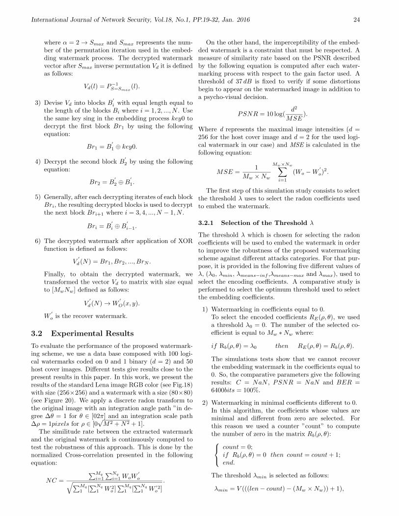
International Journal of Network Security, Vol.18, No.1, PP.19-32, Jan. 2016 24
where α = 2→ Smax and Smax represents the num-ber of the permutation iteration used in the embed-ding watermark process. The decrypted watermarkvector after Smax inverse permutation Vd it is definedas follows:
Vd(l) = P−1S=Smax
(l).
3) Devise Vd into blocks B′
i with equal length equal tothe length of the blocks Bi where i = 1, 2, ..., N . Usethe same key sing in the embedding process key0 todecrypt the first block Br1 by using the followingequation:
Br1 = B′
1 ⊕ key0.
4) Decrypt the second block B′
2 by using the followingequation:
Br2 = B′
2 ⊕B′
1.
5) Generally, after each decrypting iterates of each blockBri, the resulting decrypted blocks is used to decryptthe next block Bri+1 where i = 3, 4, ..., N − 1, N .
Bri = B′
i ⊕B′
i−1.
6) The decrypted watermark after application of XORfunction is defined as follows:
V′
d (N) = Br1, Br2, ..., BrN .
Finally, to obtain the decrypted watermark, wetransformed the vector Vd to matrix with size equalto [MwNw] defined as follows:
V′
d (N)→W′
O(x, y).
W′
o is the recover watermark.
3.2 Experimental Results
To evaluate the performance of the proposed watermark-ing scheme, we use a data base composed with 100 logi-cal watermarks coded on 0 and 1 binary (d = 2) and 50host cover images. Different tests give results close to thepresent results in this paper. In this work, we present theresults of the standard Lena image RGB color (see Fig.18)with size (256×256) and a watermark with a size (80×80)(see Figure 20). We apply a discrete radon transform tothe original image with an integration angle path ”in de-gree ∆θ = 1 for θ ∈ [02π] and an integration scale path∆ρ = 1pixels for ρ ∈ [0
√M2 +N2 + 1].
The similitude rate between the extracted watermarkand the original watermark is continuously computed totest the robustness of this approach. This is done by thenormalized Cross-correlation presented in the followingequation:
NC =
∑Mq
i=1
∑Nq
i=1WoW′
o√∑Mq
1 [∑Nq
1 W 2o ]∑Mq
1 [∑Nq
1 W ′2o ]
.
On the other hand, the imperceptibility of the embed-ded watermark is a constraint that must be respected. Ameasure of similarity rate based on the PSNR describedby the following equation is computed after each water-marking process with respect to the gain factor used. Athreshold of 37 dB is fixed to verify if some distortionsbegin to appear on the watermarked image in addition toa psycho-visual decision.
PSNR = 10 log(d2
MSE).
Where d represents the maximal image intensities (d =256 for the host cover image and d = 2 for the used logi-cal watermark in our case) and MSE is calculated in thefollowing equation:
MSE =1
Mw ×Nw
Mw×Nw∑i=1
(Wo −W′
o)2.
The first step of this simulation study consists to selectthe threshold λ uses to select the radon coefficients usedto embed the watermark.
3.2.1 Selection of the Threshold λ
The threshold λ which is chosen for selecting the radoncoefficients will be used to embed the watermark in orderto improve the robustness of the proposed watermarkingscheme against different attacks categories. For that pur-pose, it is provided in the following five different values ofλ, (λ0, λmin, λmeans−inf ,λmeans−max and λmax), used toselect the encoding coefficients. A comparative study isperformed to select the optimum threshold used to selectthe embedding coefficients.
1) Watermarking in coefficients equal to 0.To select the encoded coefficients RE(ρ, θ), we useda threshold λ0 = 0. The number of the selected co-efficient is equal to Mw ∗Nw where:
if Rb(ρ, θ) = λ0 then RE(ρ, θ) = Rb(ρ, θ).
The simulations tests show that we cannot recoverthe embedding watermark in the coefficients equal to0. So, the comparative parameters give the followingresults: C = NaN , PSNR = NaN and BER =6400bits = 100%.
2) Watermarking in minimal coefficients different to 0.In this algorithm, the coefficients whose values areminimal and different from zero are selected. Forthis reason we used a counter ”count” to computethe number of zero in the matrix Rb(ρ, θ): count = 0;
if Rb(ρ, θ) = 0 then count = count+ 1;end.
The threshold λmin is selected as follows:
λmin = V (((len− count)− (Mw ×Nw)) + 1),

International Journal of Network Security, Vol.18, No.1, PP.19-32, Jan. 2016 25
where len is the length V of the vector representingthe coefficients of the host radon image organized indownward order.The selected coefficient to embed watermark are:
RE(ρ, θ) = Rb(ρ, θ) whereRb(ρ, θ) ≤ λminand Rb(ρ, θ) 6= 0.
The simulations tests give a threshold λmin = 5073and they show that we can recover the embeddingwatermark by the following parameter quality re-sults: C = 0.3023, PSNR = 52.3670dB, BER =2413bits = 37.70 %. The visual results given in Fig-ures 6 and 7.
Figure 6: Watermark-ing image in radon field
Figure 7: Recoveredwatermark
3) Watermarking in maximal coefficients.The used process to define λmax is same of the definedprocess in step 2 of the paragraph 3.1.1 (watermarkembedding process) where λmax = λopt.
The simulations tests give a threshold λmax = 32208and they show that we can recover the embeddingwatermark by the following parameters quality re-sults: C = 1, PSNR = Inf and BER = 0bits = 0%. The visual results given in Figures 8 and 9.
Figure 8: Watermark-ing image in radon field
Figure 9: Recovered water-mark
4) Watermarking in the higher coefficients to λmeansand different to the maximal coefficients.In this algorithm the selected coefficient to embedwatermark are:
RE(ρ, θ) = Rb(ρ, θ)where Rb(ρ, θ) > λmeans andRb(ρ, θ) < λmax.
The used threshold in this algorithm is noted byλmeans−sup.The simulations results give λmeans =λmeans−sup = 18842 and λmax = 32208. The sim-ulation tests show that we can recover the embed-ding watermark by the following parameter qual-ity results: C = 0.9149, PSNR = 62.5942 andBER = 229bits = 3.57%. The visual results given inFigures 10 and 11.
Figure 10: Water-marking image inradon field
Figure 11: Recovered wa-termark
5) Watermarking in the less coefficients to λmeans anddifferent to the minimal coefficients.In this algorithm the selected coefficient to embedwatermark are:
RE(ρ, θ) = Rb(ρ, θ) where Rb(ρ, θ) < λmeansand Rb(ρ, θ) > λmin.
The used threshold in this algorithm is noted byλmeans−inf . The simulations results give λmeans =λmeans−inf = 18842 and λmin = 5073. The sim-ulation tests show that we can recover the embed-ding watermark by the following parameter qual-ity results: C = 0.7957, PSNR = 58.8606 andBER = 541bits = 8.45%. The visual results givenFigures 12 and 13.
Figure 12: Water-marking image inradon field
Figure 13: Recovered wa-termark
6) Comparative study to select λ.
Figures 14, 15, and 16 show the variation of the cor-relation, PSNR and BER of the recovered watermarkfor different values of threshold λ.

International Journal of Network Security, Vol.18, No.1, PP.19-32, Jan. 2016 26
Figure 14: Correlation variation of the recovered water-mark for different values of threshold λ
Figure 15: PSNR variation of the recovered watermarkfor different values of threshold λ
Figure 16: BER variation of the recovered watermark fordifferent values of threshold λ
Figures 14, 15, and 16 show that the more threshold λincreases the better the correlation of the recoveredwatermark becomes. So, the optimum threshold λis λopt = λmax.Generally, the robustness of the pro-posed method against synchronous and asynchronousattacks for the higher coefficient depends on the high-est energy of the radon region. The important peaksof radon domain are located at the points correspond-ing to the projection parameter. Besides, the coeffi-cients of the radon region in which the highest energyis located and set on the line of projection contain thesignificant information of the original image. So, theyallow a good recovery of the transformed informationwith inverse radon transform.
3.2.2 Robustness of the Proposed WatermarkingApproach
An example of an original and a watermarked image isillustrated in Figure 17 and 18. The set of Figures 19,20 and 21 illustrate respectively the original watermark,the encrypted one and the decrypted recovered watermarkfrom the radon field.
Figure 17: Original im-age
Figure 18: watermarkedimage
Figure 19:Originalwatermark
Figure 20:Encripted water-mark
Figure 21:Recovered wa-termark
In the simulation test, we use a factor gain G = 1000 toembed the watermark in the selected coefficient in radonfield. These coefficients are higher to λopt = 32208. Thisapplication gives a PSNR value between the original andthe watermarked host image equal to PSNR = 30.89dB.The normalized cross-correlation between original andcorrelating watermark is NC = 1. So, no visible differ-ences are detected between the original and the recoveredwatermark.
In order to improve the correction of the recovered wa-termark, we insist in this version that the embedded wa-termark is binary coded on 0 and 1. So, it allows just twodifferent intensities scale. Consequently, the used factord to compute the PSNR between original and recoveredwatermark is equal to 2 and gives the present results inTables 1 and 2.
Tables 1 and 2 show the effectiveness of the proposedwatermarking approach to resist the different STIR-MARK attacks. We note that the resistivity of the pro-posed approach against geometric attacks is very high.This efficiency is related to the properties of the DiscreetRadon Transform. Also, the effectiveness of the proposedmethod to resist common image processing attacks is re-lated to an accurate selection of the coefficients which areselected from the image in Radon field. These coefficientspresenting the highest energy in the Radon field contain

International Journal of Network Security, Vol.18, No.1, PP.19-32, Jan. 2016 27
Table 1: Resistance of the proposed method against thecommon image processing attacks
ATTACKS NC PSNR BERbits percent
Conv2 1 inf 0 0Median3 0.9878 71.0075 33 0.51Median5 0.9793 68.7107 56 0.875Median7 0.9841 69.8579 43 0.67PSNR0 0.9149 62.5942 229 3.578PSNR50 1 inf 0 0Noise20 0.9863 70.5106 37 0.578Noise40 0.9826 69.4716 47 0.73JPEG50 0.9413 63.9654 167 2.6JPEG70 0.9974 77.7416 7 0.109JPEG80 1 inf 0 0
the significant information of the original image, whichallow the withstanding against the common image pro-cessing attacks. These coefficients are located and set onthe line of projection, so they allow a good recuperationof transformed information with inverse radon transform.This robustness is mathematically proved in the followingSection. The following images illustrate zoomed views ofthe selected coefficients in the Radon field “Figure 22”and the coded watermark in these coefficients illustratedin the figure “Figure 23”.
Figure 22: The used sets of coefficient to embed water-mark in Radon field
Figure 23: The sets of watermarked coefficient the water-mark presence in the Radon field
In another hand, the watermarked image is illustratedin Figure 18. It represents an imperceptible watermark-
Table 2: Resistance of the proposed method against thegeometric attacks
ATTACKS NC PSNR BERbits percent
RESC90 0.9993 83.1828 2 0.03RESC75 0.9989 81.4214 3 0.046
RNDDIST1 1 inf 0 0LARDIST 1 inf 0 0RML10 1 inf 0 0RML40 0.9985 80.1720 4 0.06
AFFINE1 1 inf 0 0AFFINE8 0.9996 86.1926 1 0.015ROT51 1 inf 0 0ROT0.75 0.9952 75.0532 13 0.2ROT1 1 inf 0 0ROT90 1 inf 0 0
ROTCROP0.5 1 inf 0 0ROTCROP1 0.9996 86.1926 1 0.015ROTCROP10 1 inf 0 0ROTSCALE0.5 1 inf 0 0ROTSCALE1 1 inf 0 0SCALING0.9 0.9989 81.4214 3 0.046SCALING0.7 0.9896 71.7210 28 0.437
ing scheme. We will prove in the following mathemat-ical study why the watermarking system in radon fieldrepresents an imperceptible watermarking approach. Infact, embedding information in radon coefficient espe-cially in the higher radon coefficients under the percep-tibility threshold is defined by the Weber law. We notethe data loss ”error” between the recovered images af-ter inverse radon transform of the original image I ′(x, y)and the watermarked image I(x, y) by ε. The followingequations prove that error has no visual effect on the wa-termarked image.
I′(x, y)− Iw(x, y) = ε(x, y)
or the Weber law imposes that:
M∑i=1
N∑j=1
I′(i, j)− I(i, j)
I ′(i, j)≤ τ where τ ∼= (2%− 3%).
Since the simulation results proved that ε < τ . So, per-ceptually we can say that no visible changes are engen-dered by the watermarking approach in radon domain,then:
I′
= I and ε→ 0.
Figures 24, 25, and 26 illustrate an original and Radontransformed image followed by the positions (In red) ofthe imperceptible distortions introduced by applying theradon transform and recovering the image by the inverseRadon transform without any watermark embedding.
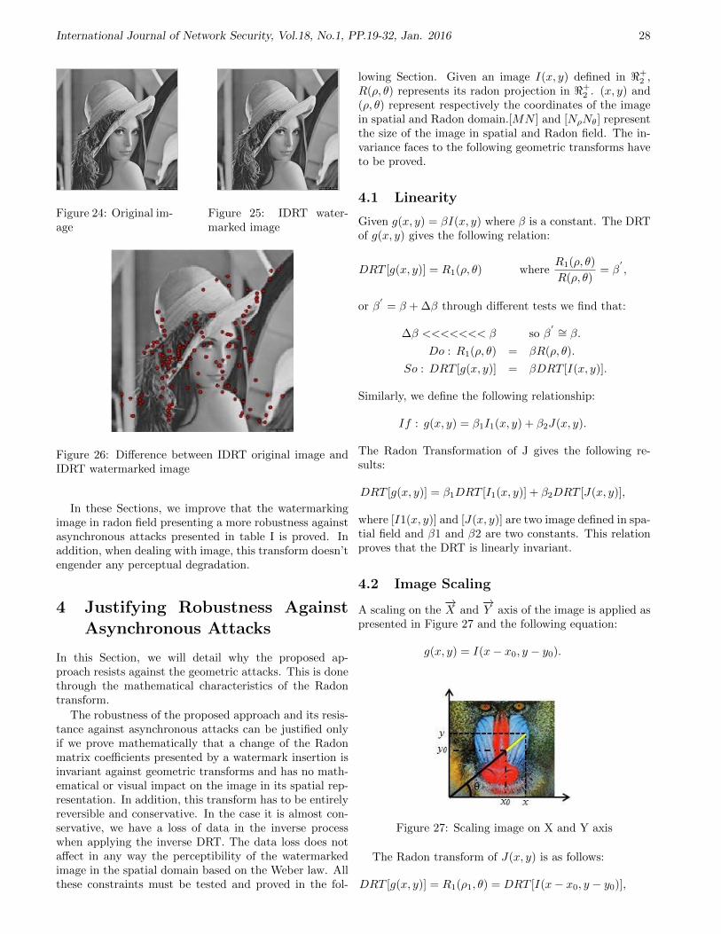
International Journal of Network Security, Vol.18, No.1, PP.19-32, Jan. 2016 28
Figure 24: Original im-age
Figure 25: IDRT water-marked image
Figure 26: Difference between IDRT original image andIDRT watermarked image
In these Sections, we improve that the watermarkingimage in radon field presenting a more robustness againstasynchronous attacks presented in table I is proved. Inaddition, when dealing with image, this transform doesn’tengender any perceptual degradation.
4 Justifying Robustness AgainstAsynchronous Attacks
In this Section, we will detail why the proposed ap-proach resists against the geometric attacks. This is donethrough the mathematical characteristics of the Radontransform.
The robustness of the proposed approach and its resis-tance against asynchronous attacks can be justified onlyif we prove mathematically that a change of the Radonmatrix coefficients presented by a watermark insertion isinvariant against geometric transforms and has no math-ematical or visual impact on the image in its spatial rep-resentation. In addition, this transform has to be entirelyreversible and conservative. In the case it is almost con-servative, we have a loss of data in the inverse processwhen applying the inverse DRT. The data loss does notaffect in any way the perceptibility of the watermarkedimage in the spatial domain based on the Weber law. Allthese constraints must be tested and proved in the fol-
lowing Section. Given an image I(x, y) defined in <+2 ,
R(ρ, θ) represents its radon projection in <+2 . (x, y) and
(ρ, θ) represent respectively the coordinates of the imagein spatial and Radon domain.[MN ] and [NρNθ] representthe size of the image in spatial and Radon field. The in-variance faces to the following geometric transforms haveto be proved.
4.1 Linearity
Given g(x, y) = βI(x, y) where β is a constant. The DRTof g(x, y) gives the following relation:
DRT [g(x, y)] = R1(ρ, θ) whereR1(ρ, θ)
R(ρ, θ)= β
′,
or β′
= β + ∆β through different tests we find that:
∆β <<<<<<< β so β′ ∼= β.
Do : R1(ρ, θ) = βR(ρ, θ).
So : DRT [g(x, y)] = βDRT [I(x, y)].
Similarly, we define the following relationship:
If : g(x, y) = β1I1(x, y) + β2J(x, y).
The Radon Transformation of J gives the following re-sults:
DRT [g(x, y)] = β1DRT [I1(x, y)] + β2DRT [J(x, y)],
where [I1(x, y)] and [J(x, y)] are two image defined in spa-tial field and β1 and β2 are two constants. This relationproves that the DRT is linearly invariant.
4.2 Image Scaling
A scaling on the−→X and
−→Y axis of the image is applied as
presented in Figure 27 and the following equation:
g(x, y) = I(x− x0, y − y0).
Figure 27: Scaling image on X and Y axis
The Radon transform of J(x, y) is as follows:
DRT [g(x, y)] = R1(ρ1, θ) = DRT [I(x− x0, y − y0)],

International Journal of Network Security, Vol.18, No.1, PP.19-32, Jan. 2016 29
where
ρ1 = (x− x0) cos θ + (y − y0) sin θ
= x cos θ − x0 cos θ + y sin θ − y0 sin θ
= x cos θ + y sin θ︸ ︷︷ ︸ρ
−x0 cos θ − y0 sin θ
= ρ− x0 cos θ − y0) sin θ.
So:
DRT [g(x, y)] = R1(ρ1, θ) = R(ρ− x0 cos θ − y0 sin θ, θ).
Also, the error defined by ∆ρ = −x0 cos θ − y0 sin θ, θ islower than the value of ρ. Since the variation ∆ρ cannotallow the projection of a pixel neighbor defined by itscoordinates (ρ, θ) due to its size ∆ρ <<<< ρ then, theradon transformation depends only on the value of ρ.
4.3 Image Rotation
Supposing that K(ρ, θ) represents the polar coordinateof I(x, y) and g(ρ, θ) = K(ρ, θ − ϕ) with ϕ representsthe angle of circular shifting. The results of rotating aspatial image in the radon field is studied and presentedin Figure 28 and the following equations:
DRT [g(ρ, θ)] = DRT [(ρ, θ − ϕ)] = R1(ρ1, θ1)= I(x cos θ cosϕ+ y sin θ sinϕ,
−y cos θ sinϕ+ y sin θ cosϕ).R1(ρ1, θ1) = I(x cos(θ − ϕ), y sin(θ − ϕ)).
= R(ρ, θ − ϕ).ρ1 = ρθ1 = θ − ϕ.
So,
DRT [g(ρ, θ)] = R1(ρ1, θ1) = R(ρ, θ − ϕ).
Figure 28: Circular shifted image by angle
This relation shows that the radon transform dependsonly on the value of θ− ϕ and its magnitude is constant.Consequently the projected pixel will change its locationin the Radon field according to the angular rotation ap-plied. This proves that angular rotations are conservedto generate the correspondent Radon coefficients.
4.4 Cropping Rotation and Scaling
In this section, we test the invariance of the DRT if dif-ferent asynchronous attacks are combined simultaneouslysuch as rotation and scaling or cropping without changingthe axis projection.
Case 1. Scaling on Y axis and circular shifting by anangle (See Figure 29).
DRT [g(ρ, θ)] = DRT [K(ρ, θ − ϕ)] = R1(ρ1, θ1)= I(x cos θ cosϕ+ x sin θ sinϕ,
−(y − y0)cosθ sinϕ+(y − y0) sin θ cosϕ.
R1(ρ1, θ1) = I(x cos(θ − ϕ), (y − y0) sin(θ − ϕ)).= R(ρ− y0 sin(θ − ϕ), θ − ϕ).
ρ1 = ρ− y0 sin(θ − ϕ)θ1 = θ − ϕ.
So, in this case:
DRT [K(ρ, θ − ϕ)] = R(ρ− y0 sin(θ − ϕ), θ − ϕ).
The error is defined by:
∆ρ = −y0 sin(θ − ϕ) <<<< ρ.
Experimental test proved that the error found is verysmall compared with ρ (∆ρ <<<< ρ).
Figure 29: Scaling on Y axis and circular shifting by anangle
Case 2. Scaling on Xaxis and circular shifted of crop inimage (See Figure 30).
DRT [g(ρ, θ)] = DRT [K(ρ, θ − ϕ)] = R1(ρ1, θ1)= I((x− x0) cos θ cosϕ
+(x− x0) sin θ sinϕ,−y cos θ sinϕ+ y sin θ cosϕ.
R1(ρ1, θ1) = I((x− x0) cos(θ − ϕ), ysin(θ − ϕ))= R(ρ− x0 cos(θ − ϕ), θ − ϕ)
ρ1 = ρ− x0 cos(θ − ϕ)θ1 = θ − ϕ.
So,
DRT [K(ρ, θ − ϕ)] = R(ρ− x0 cos(θ − ϕ), θ − ϕ).
The error is
∆ρ = −x0 cos(θ − ϕ) <<<< ρ.

International Journal of Network Security, Vol.18, No.1, PP.19-32, Jan. 2016 30
Figure 30: Scaling on Xaxis and circular shifted of cropin image
Case 3. Scaling on Xaxis and circular shifted of crop inimage (See Figure 31).
DRT [g(ρ, θ)] = DRT [K(ρ, θ − ϕ)] = R1(ρ1, θ1)= I((x− x0) cos θ cosϕ
+(x− x0) sin θ sinϕ,−(Y − Y0) cos θ sinϕ+(Y − Y0) sin θ cosϕ).
R1(ρ1, θ1) = I((x− x0) cos(θ − ϕ),(Y − Y0) sin(θ − ϕ)).
= R(ρ− x0 cos(θ − ϕ)−y0 sin(θ − ϕ), θ − ϕ).
ρ1 = ρ− x0 cos(θ − ϕ)− y0 sin(θ − ϕ)θ1 = θ − ϕ.
So, in this case:
DRT [K(ρ, θ − ϕ)]
= R(ρ− x0 cos(θ − ϕ),−y0 sin(θ − ϕ), θ − ϕ).
The error is defined by:
∆ρ = x0 cos(θ − ϕ)y0 sin(θ − ϕ).
Figure 31: Scaling on X and T axis and circular shiftedof crop in image
Due to its feeble value, the error ∆ρ cannot changethe original integer quantized coefficient in Radon field.So, the used coefficient to code the watermark does notchange and the watermark is correctly recovered. Asproved above, face to singular or composed geometrictransform, the Radon transform offers invariance to thetransformed image. Consequently, the distortions and ge-ometric transforms applied on the spatial watermarked
image have generally no effect on the embedded water-mark in the radon field since these variations are con-served over the Radon coefficients where the watermarkis coded.
5 Comparative Study
In order to prove the efficiency and high robustness ofthe proposed method, a comparison study illustrated inFigures 32 and 33 is conducted with recent proposed ap-proach in the literature exploiting the Radon domain [12]and [17].
Figure 32: Comparative study between our proposedmethod and the developed technique in [12]
Figure 33: Comparative study between our proposedmethod and the Wang method in [17]
Compared to the proposed methods in [12] and [17],Figure 32 and Figure 33 show that the robustness of theproposed watermarking scheme in the radon field is moreeffective than the previous schemes. This efficiency is dueto the propriety of radon field and its performance in de-tecting the important peaks by sing the inverse radontransform. The proposed watermarking scheme does notdegrade the visual perception of the watermarked imageand it is robust against the two categories of attacks.
6 Conclusions
In this paper a watermarking approach based on theRadon transform is presented. The watermark is codedin selected coefficients with respect to specific mathe-matical characteristics and the energy is characterized by

International Journal of Network Security, Vol.18, No.1, PP.19-32, Jan. 2016 31
higher robustness against various attacks types. The pro-posed scheme presents high robustness especially againstasynchronous attacks. This resistance against these ge-ometric attacks is studied and proved mathematically.Accordingly, the equilibrium between watermarking con-straints is achieved. Robustness and imperceptibility arerespected and the embedding capacity is increased.
Acknowledgments
This study was supported by CEREP Research labora-tory in College of Sciences and techniques in Tunisia. Theauthors gratefully acknowledge the anonymous reviewersfor their valuable comments.
References
[1] A. Averbuch, I. Sedelnikov, and Y. Shkolnisky, “CTreconstruction from parallel and Fan-Beam projec-tions by a 2-D discrete radon transform,” IEEETransactions on Image Processing, vol. 21, no. 2,pp. 733–741, 2012.
[2] L. Baisa and R. R. Manthalkar, “An overview oftransform domain robust digital image watermarkingalgorithms,” Journal of Emerging Trends in Comput-ing and Information Sciences, vol. 2, no. 1, pp. 2079–8407, 2010.
[3] G. Beylkin, “Discrete radon transform,” IEEETransactions on acoustics speech and signal process-ing, vol. 35, no. 2, pp 162–172, 1987.
[4] C. C. Chang, K. F. Hwang, and M. S. Hwang,“A digital watermarking scheme using human visualeffects,” Informatica: An International Journal ofComputing and Informatics, vol. 24, no. 4, pp. 505–511, 2000.
[5] C. C. Chang, K. F. Hwang, and M. S. Hwang, “AFeature-Oriented copyright owner proving techniquefor still images,” International Journal of SoftwareEngineering and Knowledge Engineering, vol. 12,no. 3, pp. 317–330, 2002.
[6] RSR. Channapragada, AS. Mantha, and Munaga V.N. K. Prasad, “Study of contemporary digital wa-termarking techniques,” IJCSI International Journalof Computer Science Issues, vol. 9, no. 1, pp. 1694–0814, 2012.
[7] Y. Fu, “Robust oblivious image watermarkingscheme based on coefficient relation,” InternationalJournal for Light and Electron Optics, vol. 124, no. 6,pp. 517–521, 2013.
[8] M. S. Hwang, C. C. Chang, and K. F. Hwang, “A wa-termarking technique based on One-way hash func-tions,” IEEE Transactions on Consumer Electronics,vol. 45, no. 2, pp. 286–294, 1999.
[9] M. S. Hwang, C. C. Chang, and K. F. Hwang, “Dig-ital watermarking of images using neural networks,”Journal of Electronic Imaging, vol. 9, no. 4, pp. 548–555, 2000.
[10] G. Dayalin Leena, S. Selva Dhayanithy, and M. S.Hwang, “Robust image watermarking in frequencydomain,” International Journal of Innovation andApplied Studies, vol. 2, no. 4, pp. 582–587, 2013.
[11] L. Li, S. Li, A. Abraham, and J. S. Pan, “Geometri-cally invariant image watermarking using polar har-monic transforms,” Information Sciences, vol. 199,pp. 1–19, 2012.
[12] I. Nasir, F. Khelifi, J. Jiang, and S. Ipson, “Robustimage watermarking via geometrically invariant fea-ture points and image normalisation,” in Proceedingof IET Image, vol. 6, pp. 354, 2012.
[13] D. Simitopoulos, D. E. Koutsonanos, and M. G.Strintzis, “Robust image watermarking based ongeneralized radon transformations,” IEEE Transac-tions on Circuits and Systems for Video Technology,vol. 13, no. 8, pp. 732–745, 2003.
[14] Q. Su, Y. Niu, X. Liu, and T. Yao, “A novel blinddigital watermarking algorithm for embedding colorimage into color image,” International Journal forLight and Electron Optics, vol. 124, no. 18, pp. 3254–3259, 2013.
[15] Q. Su, Y. Niu, X. Liu, and Y. Zhu, “A blind dualcolor image watermarking based on IWT and statecoding,” Optics Communications, vol. 285, no. 7,pp. 1717–1724, 2012.
[16] H. H. Tsaia, Y. J. Jhuanga, and Y. S. Lai, “An SVD-based image watermarking in wavelet domain usingSVR and PSO,” Applied Soft Computing, vol. 12,no. 8, pp. 2442–2453, 2012.
[17] E. Vahedi, R. A. Zoroofi, and M. Shiva, “Toward anew wavelet-based watermarking approach for colorimages using bio-inspired optimization principles,”Digital Signal Processing, vol. 22, no. 1, pp. 153–162,2012.
[18] W. W. Zhang, F. Gao, B. Liu, Q. Y. Wen, andH. Chen, “A watermark strategy for quantum im-ages based on quantum fourier transform,” QuantumInformation Processing, vol. 12, no. 2, pp. 793–803,2013.
Dhekra Essaidani was born in Bizerte, Tunis on 10January 1989. In 2010, she received the Fundamen-tal license in Electrical Engineering: Automatic andindustrial computer from the ESTI (Tunis College ofTechnology and Computer science in Tunis) in Tunisiaand Master degree in Electrical engineering (Automaticand industrial computer) from the ESSTT, in 2012.Since2012; she enrolled in a doctoral thesis in the Departmentof Electrical Engineering in College of Sciences andtechniques: CEREP Research laboratory. Here domainof interest is: Audio-image and video processing. Heremain research interests are the multimedia security.
Hassene Seddik is born in 15 October 1970 in Tunisia,he has obtained the electromechanical engineer degreein 1995 and followed by the master degree in signalprocessing: speaker recognition and the thesis degree inimage processing watermarking using non conventional

International Journal of Network Security, Vol.18, No.1, PP.19-32, Jan. 2016 32
transformations. He has over 14 international journalspapers and 65 conference papers. His domain of interestis: Audio-image and video processing applied in filtering,encryption and watermarking. He belongs to the CEREPresearch unit and supervises actually five thesis and 08masters in the field.
Ezzedine Ben Braiek obtained his HDR on 2008 inElectrical engineering from ENSET Tunisia. He is,presently, full professor in the department of electricalengineering at the National High School of Engineeringof Tunis (ENSIT) and manager of the research group onvision and image processing at the CEREP. His fields ofinterest include automatics, electronics, control, computervision, image processing and its application in handwrit-ten data recognition.

International Journal of Network Security, Vol.18, No.1, PP.33-42, Jan. 2016 33
Provably Secure Group Key Exchange Protocolin the Presence of Dishonest Insiders
Ziba Eslami, Mahnaz Noroozi, and Saideh Kabiri Rad(Corresponding author: Ziba Eslami)
Department of Computer Science, Shahid Beheshti UniversityG. C., Tehran, Iran
(Email: z [email protected])(Received July 16, 2013; revised and accepted Oct. 10 & Dec. 20, 2013)
Abstract
The most important security concern in group key ex-change protocols is the semantic security of the producedshared key which dictates that outsiders should not beable to learn anything about the key. It is also challeng-ing for these protocols to retain their security even in thepresence of dishonest insiders who do not follow the pro-tocol specifications. In this paper, we propose an identity-based group key exchange protocol which addresses thesesecurity concerns. We prove that our scheme achieves se-mantic security in a well-known adversarial model. Wethen show that the success probability of recognizing dis-honest insiders in the proposed scheme is almost one. Wefurther provide a comparison between our protocol andsome other schemes in terms of computation and commu-nication cost, as well as security properties.Keywords: Bilinear pairing, dishonest insiders, ellipticcurve, group key exchange, provable security
1 Introduction
In an Internet conference the participants communicatewith each other over an insecure network. In order to pre-vent the conference contents to be revealed, their commu-nications must be encrypted. Therefore, the participantsshould agree upon a common key and use it for encryptingthe messages. One solution to establish such a commonkey is using group key exchange protocols in which thegroup members compute a common key via an insecurepublic channel cooperatively [16, 20, 21, 36].
The first key exchange protocol was proposed in 1976by Diffie and Hellman [15]. The scheme enabled two par-ticipants to establish a common key and its security wasbased on the discrete logarithm problem. But it was notsuitable for groups of users. In 1982, Ingemaresson etal. [23] proposed the first group key exchange protocol.Both of these schemes were vulnerable against the man-in-the-middle attack, i.e., an adversary could impersonate
the participants without being detected. So the authenti-cation property was added to the key exchange protocols[25] and therefore, one could assure that he is establish-ing the key with legitimate participants [19, 30]. In otherwords, while security in key exchange protocols is consid-ered against a passive adversary who only eavesdrops, inauthenticated key exchange protocols, a stronger class ofadversaries is involved who is capable of controlling allcommunication in the network.
In 1984, Shamir [32] introduced the concept of identity-based cryptosystems. In this setting, a user’s private keyis generated by a trusted key generator center (KGC), en-abling any party to derive the user’s public key from hisidentity and thereby removing the need for public-key cer-tificates. An authenticated key exchange protocol is calledidentity-based if the users use an identity-based asymmet-ric key pair instead of a traditional public/private key pairfor authentication and determination of the establishedkey. Since identity-based systems simplify the process ofkey management (compared to the traditional public keysystems), they have been considered extensively for de-signing key exchange protocols [11, 33, 35].
In real world, it is not reasonable to assume that allparticipants are honest and in fact an important issue inkey exchange protocols is the presence of malicious insid-ers. Two types of malicious behavior are considered in theliterature. One is impersonation in which the maliciousparticipant impersonates another entity in the group whois not present [13]. Another type of malicious act which weconsider in the paper as of this point, pertains to partic-ipants who prohibit the group from computing the sameshared key by broadcasting fake information, i.e., valueswhich are not produced according to the protocol spec-ifications [18]. The word ”dishonest” refers to this kindof users throughout this paper. To deal with dishonestparticipants, the fault-tolerance property was introducedfor group key exchange protocols in 2002 [34]. This prop-erty ensures that honest participants are able to acquirea conference-key; no matter how many dishonest partic-ipants exist. Since then, some other fault-tolerant group
International Journal of Network Security, Vol.18, No.1, PP.33-42, Jan. 2016 34
key exchange protocols have been proposed [22, 37].So far and to the best of our knowledge, no formal se-
curity proof exists for the fault-tolerance property of theseschemes. It is one of the goals of this paper to introducea formal proof for security against dishonest insiders (seeSection 4.1). In fact, until recently, ’informal’ definitionsand proofs were widely used for group key exchange pro-tocols. Most of such definitions were originally stated fortwo-party protocols and then adapted to a group setting.The informal definitions serve as foundations for the sub-sequent formal security models for group key exchangeprotocols. Examples are notions like key privacy, known-key security, key freshness, forward and backward secrecy,entity authentication, unknown key-share resilience, keyconfirmation, and key control. For more details, the in-terested reader is referred to [31].
In the paradigm of provable security for key exchangeprotocols, a ’formal model’ must be defined. In thismodel, the capabilities of the adversary as well as theplayers should be captured. It has to be clearly statedwhat it means for the scheme to be secure and providea proof of its security. The security proof aims to showthat the scheme actually achieves the claimed securitygoals under computational assumptions. The proof usu-ally works via reduction to an underlying hard problem.
Bellare and Rogaway [3] in 1993 proposed the first com-putational security model for authenticated two-party keyexchange protocols. Since then some other security mod-els were proposed [1, 10]. In 2001, Bresson et al. [8]proposed the first computational (game-based) securitymodel for group key exchange protocols (referred to asthe BCPQ model) which builds on prior work from the2-party setting [2, 3, 4]. This model has been widely usedto analyze group key exchange protocols [6, 7].
In 1994, Burmester and Desmedt [9] proposed an effi-cient group key exchange protocol. A variant of this pro-tocol was later proposed in 2008 by Dutta and Barua [17].The variant has a lower communication cost and can han-dle the joining and leaving processes of the participants.However, this scheme has some weaknesses: (1) The au-thors claimed that their scheme could detect the presenceof dishonest participants. However, Eslami and Kabiriin [18] designed an attack to prove that this claim wasnot true and showed how two dishonest insiders couldprohibit legitimate participants from obtaining the sameshared key; (2) It is unable to identify dishonest partici-pants.
In this paper, we employ elliptic curves and bilinearpairings to propose a group key exchange protocol whichdoes not suffer from these weaknesses. The advantageof elliptic curve-based cryptosystems is their short keysize, high processing throughput, and low bandwidth. Weprove that our proposed scheme is secure in BCPQ model.Since this model does not consider dishonest participants,we design an experiment to formally prove the security ofour protocol in the presence of dishonest participants.
The rest of this paper is organized as follows: Section 2briefly explains preliminary concepts. Our proposed pro-
tocol is described in Section 3. In Section 4, we discussthe security concepts of the proposed protocol. Section 5is devoted to performance analysis and comparisons. Fi-nally, a conclusion is drawn in Section 6.
2 Preliminaries
We briefly describe the preliminaries needed in the paper.First, the definition of bilinear pairings is given. Then weintroduce elliptic curves. The computational problemsused for security analysis are listed afterwards. Finally,we describe the security model in which the security ofour group key exchange protocol is proven.
2.1 Bilinear Pairings
Let P denote a generator of G1 where G1 is an additivegroup of large order q and let G2 be a multiplicative group.A pairing is a map e : G1 × G1 → G2 which has thefollowing properties:
Bilinearity. For every S, Q,R ∈ G1 we have:
e(S + Q,R) = e(S, R) · e(Q, R).
e(S, Q + R) = e(S,Q) · e(S, R).
Non-degeneracy. There exist R,Q ∈ G1 such thate (R, Q) 6= 1G2 , where 1G2 is the identity elementof G2.
Computability. There exists an efficient algorithm tocompute e(R,Q) ∈ G2 for any R, Q ∈ G1.
Note that non-degeneracy means that if e(R, Q) is theidentity element of G2, then either R is the identity of G1
or Q is the identity of G1. (See [12], pp. 29)
2.2 Elliptic Curves
An elliptic curve defined over GF (q) is given by the equa-tion: E : y2 = x3 + ax + b, where a, b ∈ GF (q) and4a3 + 27b2 6= 0. The points of E (plus an infinite pointO) together with a special operator ”+”, form a finiteAbelian group.
2.3 Cryptographic Assumptions
Definition 1. (Elliptic Curve Discrete Logarithm(ECDL) Problem) Given kA where A is a point on el-liptic curve E, find k.
The advantage of a distinguisher A against the ECDLproblem is defined as
advECDLA,E = Pr[A(kA) = k].
Definition 2. (Elliptic Curve Discrete Logarithm(ECDL) Assumption) Given kA ∈ elliptic curve E,advECDL
A,E of a distinguisher A whose goal is to solve theECDL problem is negligible.

International Journal of Network Security, Vol.18, No.1, PP.33-42, Jan. 2016 35
Note that a negligible function f has the property thatfor every polynomial p(.) there exists an N such that forall integers n > N it holds that f(n) < 1
p(n) .
Definition 3. (Computational Diffie-Hellman (CDH)Problem) Given (P, aP, bP ) where P is the generator ofadditive group G from order q and a, b ∈ Z∗q , find abP .
The advantage of a distinguisher A against the CDHproblem is defined as
advCDHA,G = Pr[A(P, aP, bP ) = abP ].
Definition 4. (Computational Diffie-Hellman (CDH)Assumption) Given (P, aP, bP ), advCDH
A,G of a distin-guisher A whose goal is to solve the CDH problem isnegligible.
2.4 Security Model
We describe below the adversarial model following Bres-son et al.’s definition [8], denoted by BCPQ. We thenadopt it for the security analysis of our protocol. In thismodel, the process controlled by a player running on somemachine is modeled as an instance of the player. Thevarious types of attacks are modeled by queries to theseinstances and the security of the session key is modeledthrough semantic security. In the model, it is assumedthat players are honest. Therefore, the security in thepresence of dishonest participants is studied separately inSection 4.1. Note that we describe the model in the caseof a passive adversary.
Notations: Throughout this section, we use the follow-ing notations:
n: The number of participants;Ui: The ith participant;Πs
i : Instance s of Ui;LLi: The long-lived key of player Ui;SKs
i : The session key related to instance s of Ui.
Description. The model consists of protocol partici-pants (n players that should agree on a common keyin different sessions through protocol P ) and an adver-sary A (which is not a player in the formalization, andis given enormous capabilities). A player Ui can havemany instances called oracles, involved in distinct con-current executions of P . As defined in notations, we de-note instance s of player Ui as Πs
i with s ∈ N. Eachplayer Ui holds a long-lived key LLi which is a pair ofmatching public/private keys. The adversary A controlsall communications in a game Gameke(A, P ). This is agame between A and the oracles Πs
i involved in the exe-cutions of P . During the game, A can ask a set of queries(Execute, Reveal, Corrupt, Test) defined below with therestriction that the Test-query Test(Πs
i ) must be askedonly once. Moreover, it is only available if Πs
i is freshwhich means that Πs
i or its partners involved in the exe-cution of P , has not been asked for a Reveal-query, and
none of them has been asked for a Corrupt-query. We nowdescribe the queries that A can ask in Gameke(A, P ):
• Execute(Ul1 , s1, · · · , Ulm , sm): This query modelsadversary A initiating an execution of protocol P .This executes the protocol between the (unused) in-stances Πsi
li1≤i≤m≤n, and outputs the transcript of
the execution.
• Reveal(Πsi ): This query models the attacks resulting
in the session key being revealed. The Reveal-queryunconditionally forces Πs
i to release session key SKsi .
• Corrupt(Ui): This query models the attacks result-ing in the player Ui’s LL-key being revealed. Adver-sary A gets back LLi but does not get the internaldata of any instances of Ui executing P .
• Test(Πsi ): This query models the semantic security
of the session key SKsi . After flipping a coin b, A is
given SKsi if b = 1 or a random string if b = 0.
At the end of the game, adversary A outputs a bit b′ andwins the game if b = b′.
The security is now defined as follows:
Definition 5. The key exchange protocol P is A-secureif adversary A succeeds in Gameke(A, P ) with probabilitythat is at most negligibly greater than 1
2 .
For more details, the interested reader is referred to [8].
3 The Proposed Scheme
In this section, we propose an identity-based group keyexchange protocol based on elliptic curves. Suppose aset of n users U = U1, U2, · · · , Un wish to establisha common session key among themselves. We assumethat IDi is the identity of Ui. Our protocol involves fourphases:
1) The initialization phase in which the Key Gener-ation Center (KGC) outputs the public parametersand generates the private key of each user.
2) The information exchange phase which consists oftwo rounds.
3) The dishonest user elimination phase which elim-inates the dishonest user if such a person exists.
4) The key computation phase in which each usercomputes the common key.
Now, we explain these phases in details.
The initialization phase. In this phase which is exe-cuted once, the KGC performs the following steps:
1) Chooses an elliptic curve group G1, a multiplicativegroup G2 (both of prime order q), a generator P ∈G1, a bilinear pairing e : G1 ×G1 → G2, and a hashfunction H : 0, 1∗ → Z∗q .

International Journal of Network Security, Vol.18, No.1, PP.33-42, Jan. 2016 36
2) Chooses randomly s ∈ Z∗q (KGC’s private key).
3) Computes Ppub = sP (KGC’s public key).
4) Outputs the public parameters params =G1, G2, q, P,H, Ppub.
5) Computes Ui’private key Si = 1s+H(IDi)
P and sendsit to him securely.
The identity-based key pair produced in this phase willbe used in Section 4 to authenticate the exchanged infor-mation. This is done by applying the compiler proposedin [27].
The information exchange phase (round 1). Eachuser Ui(i = 1, · · · , n) performs the following steps:
1) Chooses randomly ki ∈ Z∗q .
2) Computes Pi as follows:
Pi = kiP.
3) Sends Pi to all other users.
The information exchange phase (round 2). Eachuser Ui(i = 1, · · · , n) performs the following steps:
1) Computes Yi using Pi−1 and Pi+1.
Yi = ki(Pi+1 − Pi−1).
2) Sends Yi to all other users.
The dishonest user elimination phase. Each userUi(i = 1, · · · , n) verifies the following equation:
e(Yj , P ) = e(Pj+1−Pj−1, Pj), (j = 1, · · · , i−1, i+1, · · · , n).(1)
If the equation does not hold for some j, then Uj will beconsidered dishonest. After eliminating dishonest partici-pants from the session, the honest participants restart theprotocol.
The key computation phase. Each user Ui(i =1, · · · , n) obtains the common key using the followingequation:
Ki = nkiPi−1 + (n− 1) Yi + (n− 2)Yi+1 + . . . + Yi+n−2.
It may be easily verified that all users compute the samekey: (k1k2 + k2k3 + · · ·+ knk1)P .
4 Security Analysis
In this section, we analyze security of the proposedscheme, denoted throughout this section by Π. The proofis presented in two parts. In Section 4.1, we prove thatΠ is capable of identifying dishonest participants, i.e.,participants who prohibit the group from computing acommon key by broadcasting fake values which are notproduced according to the protocol specifications. Re-call that the BCPQ model does not support such partic-ipants. Therefore, in this part of the proof, we design anexperiment which helps us formulate a suitable definitionof security for this purpose.
The second part of the proof is devoted to showingthat Π achieves security following the BCPQ model, i.e.,in the sense of Definition (5). This part is essentiallyadopted from [27]. Recall from Section 1, that securityin key exchange protocols is considered against a passiveadversary while in authenticated key exchange protocols,we must consider an active one. In [27], Katz and Yungpresented an efficient compiler that transforms any groupkey exchange protocol secure against a passive eavesdrop-per to an authenticated protocol which is secure againstan active adversary. This is achieved by adding a signa-ture scheme which is strongly unforgeable under adaptivechosen message attack. Therefore, we show in Section 4.2,that our protocol is a secure key exchange protocol follow-ing Definition 5. Then applying Katz and Yung’s compilerwith values produced in initialization phase, we concludethat our scheme is a provably secure protocol for authen-ticated group key exchange.
4.1 Identification of Dishonest Partici-pants
The aim of this section is to formally prove that in ourscheme it is impossible for a participant to prohibit groupmembers from obtaining a common key and remain unno-ticed. Although, there exist protocols having formal prooffor detecting dishonest participants [26], to the best of ourknowledge, the present paper is the first to demonstratea formal proof of security for the purpose of identifyingdishonest participants.
In existing research papers where only the detectionof dishonest participants is concerned, the approach is toshow that the success probability of an insider in disrupt-ing establishment of a key among honest participants isnegligible. However, since we are after identifying dis-honest insiders, we prefer to adopt the following defini-tion: Identification of dishonest insiders is achieved if thesuccess probability of an honest participant in recognizingdishonest insiders is negligibly less than 1.
We now propose the following experiment which is agame played between a user Ui and an imaginary testerwho wishes to see if Ui succeeds in distinguishing protocolvalues from fake ones. Therefore, a protocol has securityagainst dishonest insiders if the success probability of anyhonest participant playing this experiment is at most neg-
International Journal of Network Security, Vol.18, No.1, PP.33-42, Jan. 2016 37
ligibly less than 1.Formalizing the above notions, let Π be a group key
exchange protocol containing n users Uini=1, R rounds
of information exchange, and k as the security parameter.We define the following experiment:
Capability of identifying dishonest participantsexperiment GKEdisP
Ui,Π(k):
• A matrix of R×(n−1) random bits br,j ← 0, 1, r ∈1, · · · , R, j ∈ 1, 2, · · · , i−1, i+1, · · · , n is chosenby tester.
• The tester and Ui execute protocol Π where the testeressentially plays the role of all the users except Ui.This execution of the protocol results in a transcriptTrans containing all the messages exchanged amongparticipants during different rounds of the informa-tion exchange phase of the protocol. Let M0
r,j denotethe value produced honestly by Uj in round r (for ev-ery r ∈ 1, · · · , R, j ∈ 1, 2, · · · , i− 1, i +1, · · · , n)and let M1
r,j be the corresponding fake value, i.e.,M1
r,j is not computed following the protocol’s steps.
The tester computes Mbr,j
r,j as the value of round rproduced by Uj .
• At the end, Ui outputs a matrix containing b′r,j , r ∈
1, · · · , R, j ∈ 1, 2, · · · , i− 1, i + 1, · · · , n.• The output of the experiment is defined to be 1 if
b′r,j = br,j , ∀r ∈ 1, · · · , R, ∀j ∈ 1, 2, · · · , i − 1, i +
1, · · · , n and 0 otherwise. If GKEdisPUi,Π
(k) = 1, wesay that Ui succeeds.
Definition 6. A group key exchange scheme Π is capa-ble of identifying dishonest insiders if for all probabilisticpolynomial-time honest users Ui, there exists a negligiblefunction negl such that:
Pr[GKEdisPUi,Π(k) = 1] ≥ 1− negl(k).
We now show that the protocol is secure against dishonestparticipants with respect to this definition. The followingtwo lemmas form the basis of the proof.
Lemma 1. In round 1 of the information exchange phaseof the proposed protocol, the following holds for an honestparticipant Ui and for all j(6= i):
Pr[Ui(Trans,M01,j) = 0]− Pr[Ui(Trans, M1
1,j) = 0] = 1.
In other words, Ui is able to differentiate between M01,j
and M11,j in Trans with probability 1.
Proof. Suppose that Ui wants to determine the value ofb1,j by observing M
b1,j
1,j after executing round 1 of the
information exchange phase. Note that Mb1,j
1,j is the value
produced honestly in round 1 by Uj if and only if Mb1,j
1,j is
in G1. Therefore, Ui checks the membership of Mb1,j
1,j in
G1 and returns b′1,j = 0 if it is a member of that group,
and b′1,j = 1 otherwise. So Ui can distinguish M0
1,j fromM1
1,j with probability exactly 1.
Lemma 2. In round 2 of the information exchange phase,the following holds for an honest participant Ui and forall j(6= i):
Pr[Ui(Trans, M02,j) = 0]− Pr[Ui(Trans, M1
2,j) = 0] = 1.
In other words, Ui is able to differentiate between M02,j
and M12,j with probability equal to 1.
Proof. Suppose that Ui wants to determine the value ofb2,j by observing M
b2,j
2,j after executing round 2 of the
information exchange phase. We show that Mb2,j
2,j satis-fies Equation (1) if and only if it is the value producedhonestly in round 2 by Uj .
First assume that Mb2,j
2,j satisfies Equation (1). Then
we have: e(M b2,j
2,j , P ) = e(Pj+1 − Pj−1, Pj) = e(Pj+1 −Pj−1, kjP ) = e(kj(Pj+1 − Pj−1), P ). Therefore, we havetwo possibilities: either M
b2,j
2,j = kj(Pj+1 − Pj−1) = Yj or
there exists α such that Mb2,j
2,j = Yj +α where e(α, P ) = 1.But as mentioned in Section 2, e(α, P ) = 1 if and only if α
is the identity element of G1. So Mb2,j
2,j = Yj + identity =
Yj . It means that Mb2,j
2,j is the value produced honestly inround 2 by Uj .
Now, suppose that Mb2,j
2,j is the value produced hon-
estly in round 2 by Uj , i.e., Yj . Then we have: Mb2,j
2,j =
Yj = kj(Pj+1 − Pj−1). So we have: e(M b2,j
2,j , P ) =e(kj(Pj+1 − Pj−1), P ) = e(Pj+1 − Pj−1, kjP ) = e(Pj+1 −Pj−1, Pj), which means that M
b2,j
2,j satisfies Equation (1).
Therefore, it is enough for Ui to check if Mb2,j
2,j satis-
fies equation e(M b2,j
2,j , P ) = e(Pj+1 − Pj−1, Pj) and if soreturns b
′2,j = 0, otherwise b
′2,j = 1 is returned. So Ui
can distinguish M02,j from M1
2,j with probability equal to1.
Theorem 1. The proposed protocol (denoted by Π) iscapable of identifying dishonest participants.
Proof. Let Ui be a probabilistic polynomial-time honestuser. Using the definition of experiment GKEdisP
Ui,Π(k) we
have:
Pr[GKEdisPUi,Π(k) = 1] =
Pr[(b1,j = b′1,j∀j 6= i) ∧ (b2,j = b
′2,j∀j 6= i)].
So it’s sufficient to prove that Ui’s guesses are correct inround 1 and 2 of the information exchange phase. In otherwords, we should prove the following two claims:
Claim 1. In round 1 of the information exchange phase,we have: ∀j 6= i : Pr[b1,j = b
′1,j ] = 1.
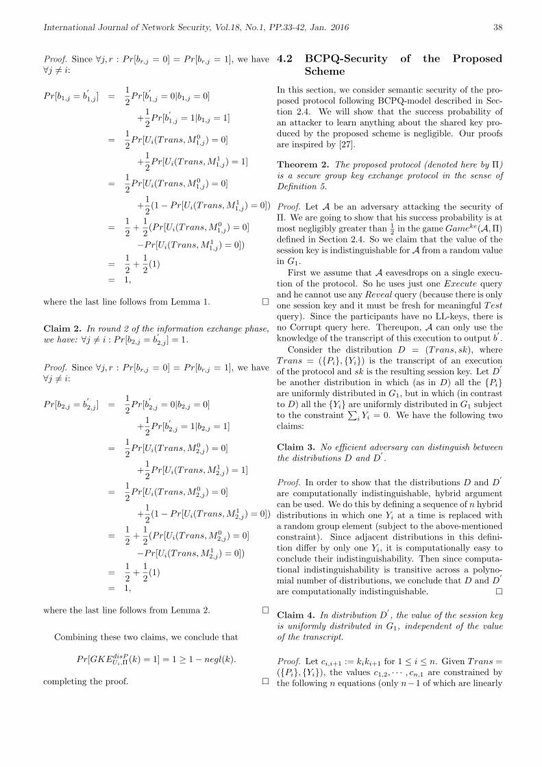
International Journal of Network Security, Vol.18, No.1, PP.33-42, Jan. 2016 38
Proof. Since ∀j, r : Pr[br,j = 0] = Pr[br,j = 1], we have∀j 6= i:
Pr[b1,j = b′1,j ] =
12Pr[b
′1,j = 0|b1,j = 0]
+12Pr[b
′1,j = 1|b1,j = 1]
=12Pr[Ui(Trans, M0
1,j) = 0]
+12Pr[Ui(Trans, M1
1,j) = 1]
=12Pr[Ui(Trans, M0
1,j) = 0]
+12(1− Pr[Ui(Trans,M1
1,j) = 0])
=12
+12(Pr[Ui(Trans, M0
1,j) = 0]
−Pr[Ui(Trans, M11,j) = 0])
=12
+12(1)
= 1,
where the last line follows from Lemma 1.
Claim 2. In round 2 of the information exchange phase,we have: ∀j 6= i : Pr[b2,j = b
′2,j ] = 1.
Proof. Since ∀j, r : Pr[br,j = 0] = Pr[br,j = 1], we have∀j 6= i:
Pr[b2,j = b′2,j ] =
12Pr[b
′2,j = 0|b2,j = 0]
+12Pr[b
′2,j = 1|b2,j = 1]
=12Pr[Ui(Trans, M0
2,j) = 0]
+12Pr[Ui(Trans, M1
2,j) = 1]
=12Pr[Ui(Trans, M0
2,j) = 0]
+12(1− Pr[Ui(Trans,M1
2,j) = 0])
=12
+12(Pr[Ui(Trans, M0
2,j) = 0]
−Pr[Ui(Trans, M12,j) = 0])
=12
+12(1)
= 1,
where the last line follows from Lemma 2.
Combining these two claims, we conclude that
Pr[GKEdisPUi,Π(k) = 1] = 1 ≥ 1− negl(k).
completing the proof.
4.2 BCPQ-Security of the ProposedScheme
In this section, we consider semantic security of the pro-posed protocol following BCPQ-model described in Sec-tion 2.4. We will show that the success probability ofan attacker to learn anything about the shared key pro-duced by the proposed scheme is negligible. Our proofsare inspired by [27].
Theorem 2. The proposed protocol (denoted here by Π)is a secure group key exchange protocol in the sense ofDefinition 5.
Proof. Let A be an adversary attacking the security ofΠ. We are going to show that his success probability is atmost negligibly greater than 1
2 in the game Gameke(A,Π)defined in Section 2.4. So we claim that the value of thesession key is indistinguishable for A from a random valuein G1.
First we assume that A eavesdrops on a single execu-tion of the protocol. So he uses just one Execute queryand he cannot use any Reveal query (because there is onlyone session key and it must be fresh for meaningful Testquery). Since the participants have no LL-keys, there isno Corrupt query here. Thereupon, A can only use theknowledge of the transcript of this execution to output b
′.
Consider the distribution D = (Trans, sk), whereTrans = (Pi, Yi) is the transcript of an executionof the protocol and sk is the resulting session key. Let D
′
be another distribution in which (as in D) all the Piare uniformly distributed in G1, but in which (in contrastto D) all the Yi are uniformly distributed in G1 subjectto the constraint
∑i Yi = 0. We have the following two
claims:
Claim 3. No efficient adversary can distinguish betweenthe distributions D and D
′.
Proof. In order to show that the distributions D and D′
are computationally indistinguishable, hybrid argumentcan be used. We do this by defining a sequence of n hybriddistributions in which one Yi at a time is replaced witha random group element (subject to the above-mentionedconstraint). Since adjacent distributions in this defini-tion differ by only one Yi, it is computationally easy toconclude their indistinguishability. Then since computa-tional indistinguishability is transitive across a polyno-mial number of distributions, we conclude that D and D
′
are computationally indistinguishable.
Claim 4. In distribution D′, the value of the session key
is uniformly distributed in G1, independent of the valueof the transcript.
Proof. Let ci,i+1 := kiki+1 for 1 ≤ i ≤ n. Given Trans =(Pi, Yi), the values c1,2, · · · , cn,1 are constrained bythe following n equations (only n−1 of which are linearly
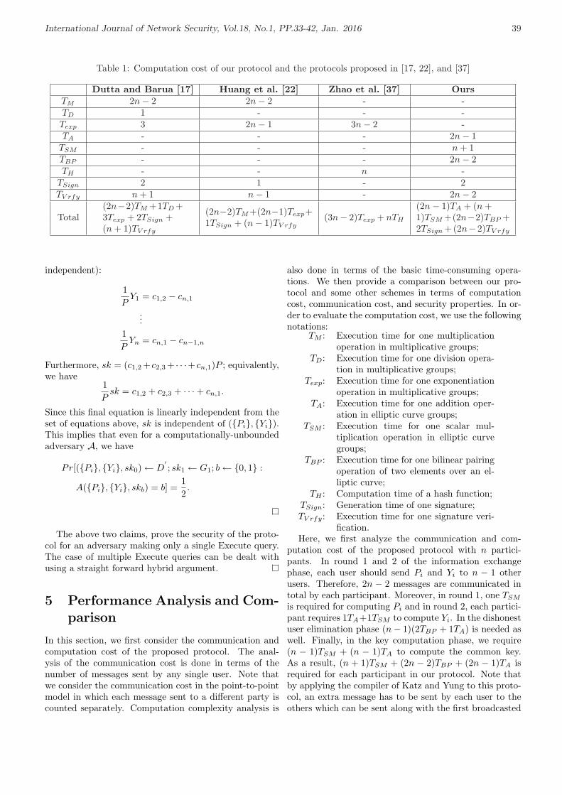
International Journal of Network Security, Vol.18, No.1, PP.33-42, Jan. 2016 39
Table 1: Computation cost of our protocol and the protocols proposed in [17, 22], and [37]
Dutta and Barua [17] Huang et al. [22] Zhao et al. [37] OursTM 2n− 2 2n− 2 - -TD 1 - - -Texp 3 2n− 1 3n− 2 -TA - - - 2n− 1
TSM - - - n + 1TBP - - - 2n− 2TH - - n -
TSign 2 1 - 2TV rfy n + 1 n− 1 - 2n− 2
Total(2n−2)TM +1TD +3Texp + 2TSign +(n + 1)TV rfy
(2n−2)TM +(2n−1)Texp+1TSign + (n− 1)TV rfy
(3n− 2)Texp + nTH
(2n− 1)TA + (n +1)TSM +(2n−2)TBP +2TSign +(2n−2)TV rfy
independent):
1P
Y1 = c1,2 − cn,1
...1P
Yn = cn,1 − cn−1,n
Furthermore, sk = (c1,2 +c2,3 + · · ·+cn,1)P ; equivalently,we have
1P
sk = c1,2 + c2,3 + · · ·+ cn,1.
Since this final equation is linearly independent from theset of equations above, sk is independent of (Pi, Yi).This implies that even for a computationally-unboundedadversary A, we have
Pr[(Pi, Yi, sk0) ← D′; sk1 ← G1; b ← 0, 1 :
A(Pi, Yi, skb) = b] =12.
The above two claims, prove the security of the proto-col for an adversary making only a single Execute query.The case of multiple Execute queries can be dealt withusing a straight forward hybrid argument.
5 Performance Analysis and Com-parison
In this section, we first consider the communication andcomputation cost of the proposed protocol. The anal-ysis of the communication cost is done in terms of thenumber of messages sent by any single user. Note thatwe consider the communication cost in the point-to-pointmodel in which each message sent to a different party iscounted separately. Computation complexity analysis is
also done in terms of the basic time-consuming opera-tions. We then provide a comparison between our pro-tocol and some other schemes in terms of computationcost, communication cost, and security properties. In or-der to evaluate the computation cost, we use the followingnotations:
TM : Execution time for one multiplicationoperation in multiplicative groups;
TD: Execution time for one division opera-tion in multiplicative groups;
Texp: Execution time for one exponentiationoperation in multiplicative groups;
TA: Execution time for one addition oper-ation in elliptic curve groups;
TSM : Execution time for one scalar mul-tiplication operation in elliptic curvegroups;
TBP : Execution time for one bilinear pairingoperation of two elements over an el-liptic curve;
TH : Computation time of a hash function;TSign: Generation time of one signature;TV rfy: Execution time for one signature veri-
fication.Here, we first analyze the communication and com-
putation cost of the proposed protocol with n partici-pants. In round 1 and 2 of the information exchangephase, each user should send Pi and Yi to n − 1 otherusers. Therefore, 2n − 2 messages are communicated intotal by each participant. Moreover, in round 1, one TSM
is required for computing Pi and in round 2, each partici-pant requires 1TA+1TSM to compute Yi. In the dishonestuser elimination phase (n− 1)(2TBP + 1TA) is needed aswell. Finally, in the key computation phase, we require(n − 1)TSM + (n − 1)TA to compute the common key.As a result, (n + 1)TSM + (2n − 2)TBP + (2n − 1)TA isrequired for each participant in our protocol. Note thatby applying the compiler of Katz and Yung to this proto-col, an extra message has to be sent by each user to theothers which can be sent along with the first broadcasted
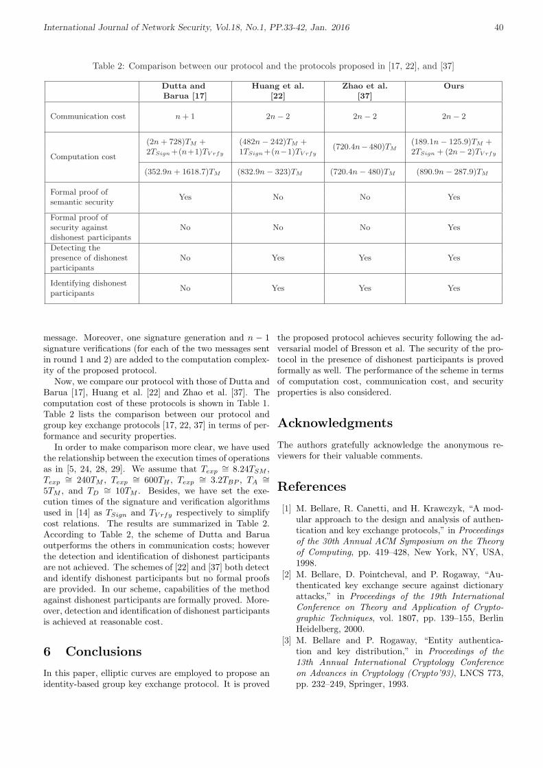
International Journal of Network Security, Vol.18, No.1, PP.33-42, Jan. 2016 40
Table 2: Comparison between our protocol and the protocols proposed in [17, 22], and [37]
Dutta and Huang et al. Zhao et al. OursBarua [17] [22] [37]
Communication cost n + 1 2n− 2 2n− 2 2n− 2
Computation cost
(2n + 728)TM +2TSign +(n+1)TV rfy
(482n− 242)TM +1TSign +(n−1)TV rfy
(720.4n−480)TM(189.1n− 125.9)TM +2TSign + (2n− 2)TV rfy
(352.9n + 1618.7)TM (832.9n− 323)TM (720.4n− 480)TM (890.9n− 287.9)TM
Formal proof ofsemantic security
Yes No No Yes
Formal proof ofsecurity againstdishonest participants
No No No Yes
Detecting thepresence of dishonestparticipants
No Yes Yes Yes
Identifying dishonestparticipants
No Yes Yes Yes
message. Moreover, one signature generation and n − 1signature verifications (for each of the two messages sentin round 1 and 2) are added to the computation complex-ity of the proposed protocol.
Now, we compare our protocol with those of Dutta andBarua [17], Huang et al. [22] and Zhao et al. [37]. Thecomputation cost of these protocols is shown in Table 1.Table 2 lists the comparison between our protocol andgroup key exchange protocols [17, 22, 37] in terms of per-formance and security properties.
In order to make comparison more clear, we have usedthe relationship between the execution times of operationsas in [5, 24, 28, 29]. We assume that Texp
∼= 8.24TSM ,Texp
∼= 240TM , Texp∼= 600TH , Texp
∼= 3.2TBP , TA∼=
5TM , and TD∼= 10TM . Besides, we have set the exe-
cution times of the signature and verification algorithmsused in [14] as TSign and TV rfy respectively to simplifycost relations. The results are summarized in Table 2.According to Table 2, the scheme of Dutta and Baruaoutperforms the others in communication costs; howeverthe detection and identification of dishonest participantsare not achieved. The schemes of [22] and [37] both detectand identify dishonest participants but no formal proofsare provided. In our scheme, capabilities of the methodagainst dishonest participants are formally proved. More-over, detection and identification of dishonest participantsis achieved at reasonable cost.
6 Conclusions
In this paper, elliptic curves are employed to propose anidentity-based group key exchange protocol. It is proved
the proposed protocol achieves security following the ad-versarial model of Bresson et al. The security of the pro-tocol in the presence of dishonest participants is provedformally as well. The performance of the scheme in termsof computation cost, communication cost, and securityproperties is also considered.
Acknowledgments
The authors gratefully acknowledge the anonymous re-viewers for their valuable comments.
References
[1] M. Bellare, R. Canetti, and H. Krawczyk, “A mod-ular approach to the design and analysis of authen-tication and key exchange protocols,” in Proceedingsof the 30th Annual ACM Symposium on the Theoryof Computing, pp. 419–428, New York, NY, USA,1998.
[2] M. Bellare, D. Pointcheval, and P. Rogaway, “Au-thenticated key exchange secure against dictionaryattacks,” in Proceedings of the 19th InternationalConference on Theory and Application of Crypto-graphic Techniques, vol. 1807, pp. 139–155, BerlinHeidelberg, 2000.
[3] M. Bellare and P. Rogaway, “Entity authentica-tion and key distribution,” in Proceedings of the13th Annual International Cryptology Conferenceon Advances in Cryptology (Crypto’93), LNCS 773,pp. 232–249, Springer, 1993.

International Journal of Network Security, Vol.18, No.1, PP.33-42, Jan. 2016 41
[4] M. Bellare and P. Rogaway, “Provably secure sessionkey distribution - the three party case,” in Proceed-ings of the 27th ACM Symposium on the Theory ofComputing, pp. 57–66, New York, NY, USA, 1995.
[5] G. M. Bertoni, L. Breveglieri, L. Chen, P. Fragneto,K. A. Harrison, and G. Pelosi, “A pairing SW imple-mentation for smart-cards,” Journal of Systems andSoftware, vol. 81, no. 7, pp. 1240–1247, 2008.
[6] C. Boyd and J. M. G. Nieto, “Round-optimal con-tributory conference key agreement,” in Proceedingsof the 6th International Workshop on Theory andPractice in Public Key Cryptography, LNCS 2567,pp. 161–174, Springer, 2003.
[7] E. Bresson, O. Chevassut, and D. Pointcheval, “Dy-namic group diffie-hellman key exchange under stan-dard assumptions,” in Proceedings of the Interna-tional Conference on the Theory and Applications ofCryptographic Techniques, LNCS 2332, pp. 321–336,Springer, 2002.
[8] E. Bresson, O. Chevassut, D. Pointcheval, and J. J.Quisquater, “Provably authenticated group Diffie-Hellman key exchange,” in Proceedings of the 8thACM Conference on Computer and CommunicationsSecurity, pp. 255–264, 2001.
[9] M. Burmester and Y. Desmedt, “A secure and effi-cient conference key distribution system,” in Proceed-ings of the Workshop on the Theory and Applicationof Cryptographic Techniques, LNCS 950, pp. 275–286, Springer, 1995.
[10] R. Canetti and H. Krawczyk, “Analysis of key-exchange protocols and their use for building se-cure channels,” in Proceedings of the InternationalConference on the Theory and Application of Cryp-tographic Techniques, LNCS 2045, pp. 453–474,Springer, 2001.
[11] X. Cao, W. Kou, and X. Du, “A pairing-free identity-based authenticated key agreement protocol withminimal message exchanges,” Information Sciences,vol. 180, no. 15, pp. 2895–2903, 2010.
[12] S. Chatterjee and P. Sarkar, Identity-Based Encryp-tion, Springer, 2011.
[13] K. Y. Choi, J. Y. Hwang, and D. H. Lee, “Id-basedauthenticated group key agreement secure against in-sider attacks,” IEICE Transactions on Fundamentalsof Electronics, Communications and Computer Sci-ences, vol. E91-A, no. 7, pp. 1828–1830, 2008.
[14] S. Cui, P. Duan, C. W. Chan, and X. Cheng, “An ef-ficient Identity-based signature scheme and its appli-cations,” International Journal of Network Security,vol. 5, no. 1, pp. 89–98, 2007.
[15] W. Diffie and M. Hellman, “New directions in cryp-tography,” IEEE Transactions on Information The-ory, vol. 22, no. 6, pp. 644–654, 1976.
[16] R. Dutta and R. Barua, “Password-Based encryptedgroup key agreement,” International Journal of Net-work Security, vol. 3, no. 1, pp. 23–34, 2006.
[17] R. Dutta and R. Barua, “Provably secure constantround contributory group key agreement in dynamic
setting,” IEEE Transactions on Information Theory,vol. 54, no. 5, pp. 2007–2025, 2008.
[18] Z. Eslami and S. Kabiri Rad, “Another securityweakness in an authenticated group key agreement,”Journal of Internet Technology, vol. 11, no. 4,pp. 573–576, 2010.
[19] A. A. Hafez, A. Miri, and L. O. Barbosa, “Authen-ticated group key agreement protocols for Ad-hocwireless networks,” International Journal of NetworkSecurity, vol. 4, no. 1, pp. 90–98, 2007.
[20] M. Hietalahti, “A clustering-based group key agree-ment protocol for Ad-hoc networks,” ElectronicNotes in Theoretical Computer Science, vol. 192,no. 2, pp. 43–53, 2008.
[21] S. Hong, “Queue-based group key agreement pro-tocol,” International Journal of Network Security,vol. 9, no. 2, pp. 135–142, 2009.
[22] K. H. Huang, Y. F. Chung, H. H. Lee, F. Lai, andT. S. Chen, “A conference key agreement protocolwith fault-tolerant capability,” Computer Standards& Interfaces, vol. 31, no. 2, pp. 401–405, 2009.
[23] I. Ingemaresson, D. T. Tang, and C. K. Wong, “Aconference key distribution system,” IEEE Transac-tion on Information Theory, vol. 28, no. 5, pp. 714–720, 1982.
[24] W.-S. Juang, “Ro-cash: An efficient and practical re-coverable pre-paid offline e-cash scheme using bilin-ear pairings,” The Journal of Systems and Software,vol. 83, no. 4, pp. 638–645, 2010.
[25] M. Just and S. Vaudenay, “Authenticated multi-party key agreement,” in Proceedings of The Inter-national Conference on the Theory and Applicationsof Cryptology and Information Security, pp. 36–49,London, UK, 1996.
[26] J. Katz and J. S. Shin, “Modeling insider attacks ongroup key-exchange protocols,” in Proceedings of the12th ACM conference on Computer and communi-cations security, pp. 180–189, New York, NY, USA,2005.
[27] J. Katz and M. Yung, “Scalable protocols for authen-ticated group key exchange,” Journal of Cryptology,vol. 20, no. 1, pp. 85–113, 2007.
[28] K. Lauter, “The advantages of elliptic curve cryptog-raphy for wireless security,” IEEE Wireless Commu-nications, vol. 11, no. 1, pp. 62–67, 2004.
[29] A. Lenstra, E. Tromer, A. Shamir, W. Kortsmit,B. Dodson, J. Hughes, and P. Leyland, “Factoringestimates for a 1024-bit RSA modulus,” in Proceed-ings of the 9th International Conference on the The-ory and Application of Cryptology and InformationSecurity, LNCS 2894, pp. 55–74, Springer, 2003.
[30] J. P. Lin and J. M. Fu, “Authenticated key agreementscheme with Privacy-Protection in the Three-partysetting,” International Journal of Network Security,vol. 15, no. 3, pp. 179–189, 2013.
[31] M. Manulis, Survey on Security Requirements andModels for Group Key Exchange, Technical ReportTR-HGI-2006-002, Ruhr-Universitat Bochum, Jan.5, 2008.

International Journal of Network Security, Vol.18, No.1, PP.33-42, Jan. 2016 42
[32] A. Shamir, “Identity-based cryptosystems and sig-nature schemes,” in Proceedings of Advances inCryptology (CRYPTO’84), LNCS 196, pp. 47–53,Springer, 1985.
[33] Z. Tan, “Efficient identity-based authenticated mul-tiple key exchange protocol,” Computers & ElectricalEngineering, vol. 37, no. 2, pp. 191–198, 2011.
[34] W. G. Tzeng, “A secure fault-tolerant conference keyagreement protocol,” IEEE Transactions on Com-puters, vol. 80, no. 4, pp. 373–379, 2002.
[35] S. Wang, Z. Cao, and F. Cao, “Efficient Identity-based authenticated key agreement protocol withPKG forward secrecy,” International Journal of Net-work Security, vol. 7, no. 2, pp. 181–186, 2008.
[36] Z. You and X. Xie, “A novel group key agreementprotocol for wireless mesh network,” Computers &Electrical Engineering, vol. 37, no. 2, pp. 218–239,2011.
[37] J. Zhao, D. Gu, and Y. Li, “An efficient fault-tolerantgroup key agreement protocol,” Computer Commu-nications, vol. 33, no. 7, pp. 890–895, 2010.
Ziba Eslami received her B.S., M.S., and Ph.D. inApplied Mathematics from Tehran University in Iran.She received her Ph.D. in 2000. From 1991 to 2000, shewas a resident researcher in the Institute for Studiesin Theoretical Physics and Mathematics (IPM), Iran.During the academic years 2000-2003, she was a PostDoctoral Fellow in IPM. She served as a non-residentresearcher at IPM during 2003-2005. Currently, sheis associate professor in the Department of ComputerSciences at Shahid Beheshti University in Iran. Herresearch interests include design theory, combinatorialalgorithms, cryptographic protocols, and steganography.
Mahnaz Noroozi received her B.S. degree in ComputerSciences in 2010 from Sharif University of Technology,Tehran, Iran. In 2012, she received her M.S. degree inComputer Sciences from Shahid Beheshti University,Tehran, Iran. She is currently doing research on crypto-graphic protocols and their security.
Saideh Kabiri Rad received the B.S. degree fromShahid Bahonar University, in Kerman and the M.S. de-gree from Shahid Beheshti University, in Tehran, both inComputer Science, Iran. She received the B.S. in 2007and M.S. in 2010. She is currently doing research on in-formation security and cryptography.

International Journal of Network Security, Vol.18, No.1, PP.43-51, Jan. 2016 43
A Quantitative and Qualitative Analysis-basedSecurity Risk Assessment for Multimedia Social
Networks
Zhiyong Zhang1, Lijun Yang1, Hanman Li1, and Fei Xiang2
(Corresponding author: Zhiyong Zhang)
Department of Computer Science, Information Engineering College, Henan University of Science and Technology1
Luoyang 471023, P. R. of China
(Email: [email protected])
Department of Electronic Technology, Electrical Engineering College, Henan University of Science and Technology2
(Received Apr. 29, 2013; revised Dec. 13, 2013; accepted Jan 29, 2014)
Abstract
The emerging Multimedia Social Network (MSN) pro-vides much more conveniences for the transmission andsharing of multimedia digital contents. However, the sce-nario on the distribution and spreading of copyrighteddigital contents between users at will brings about a burn-ing problem of Digital Rights Management (DRM). Inaddition, the open Internet and MSN platform are fac-ing the security risks of digital contents copyrights in-fringements. The paper proposed a quantitative andqualitative-based risk analysis and assessment method,considering potential paths existence in MSN. Several riskimpact factors was introduced, such as trust risk and userdemands. Specifically, Value at Risk, a risk calculationmethod widely used in the financial field, as a quantita-tive analysis, was employed here. While an expert scor-ing sheet, as a qualitative approach, is used to evaluatenon-quantifiable factors. Finally, the effectiveness of thesecurity risk assessment method and related algorithmwas verified by a well-designed experiment. We definedthe size of the community followed by the ”Rule of 150,”and construct a random non-overlapped multimedia socialnetwork by using YouTube dataset. The experiment indi-cates that the relationships of risk loss with average rateof risk occurrence and risk preference of content providersare revealed.
Keywords: Digital rights management, multimedia socialnetwork, qualitative and quantitative analysis, risk assess-ment
1 Introduction
With the rapid development of network socialization, alarge quantity of multimedia social network services andtools emerge, aiming at providing network tools, services
and applications for transmission and sharing of the digi-tal multimedia contents (such as digital images, audio andvideo, Java mobile applications, etc.) for MSN users. Atpresent, the popular multimedia social networks through-out the world include Youtube, SongTaste, Youku, etc.These networks that are organized by users’ social rela-tionships are mainly used for using, sharing, and dissem-inating digital media content. They show obvious advan-tages in directly, quickly and flexibly transmitting digitalcontents. But, it also brings some risks for insecure trans-mission and uncontrollable sharing of the copyrighted dig-ital contents. The unauthorized distribution, transmis-sion and misuse of the digital contents make the prob-lems of digital rights management increasingly promi-nent [14, 16, 17]. In the conditions of ubiquitous securityflaws and malicious attacks, security risk management be-longs to an effective way to ensure contents security andmitigate valuable digital asset risk. Therefore, the prob-lem as to how to evaluate the transmission risk of digitalrights under the multimedia social networks becomes ourfocus of concern. Further, DRM of multimedia social net-work will be better solved.
In recent years, the secure information spread and shar-ing in social networks, including multimedia social net-work and the special-purpose social network [7], has at-tracted much attention gradually. The research of DRMhas two major technical paths: the preventive DRM tech-nology and the reactive DRM technology. The preven-tive DRM technology is mainly based on the theory ofcryptography and the usage control technology. The re-active one employs digital watermarking to protect dig-ital contents and the corresponding copyrights. What-ever, for MSN scenario, the sharing strengthening of dig-ital contents increases their exposure and leads to greaterthreat. Recently, some researchers focus on the informa-tion spread risk of social network, and the main researchobjective is to evaluate the risks of the unauthorized in-

International Journal of Network Security, Vol.18, No.1, PP.43-51, Jan. 2016 44
formation access among users based on traditional ac-cess control policies. Different from the existing methods,this paper’s main contribution is to integrate quantita-tive with qualitative approaches to evaluating the risks ofpotential digital rights distribution in multimedia socialnetwork scenario.
The remaining parts are arranged as below: firstly,Section 2 introduces the relevant researches on social net-work DRM and risk assessment. Section 3 describes back-ground and theoretical knowledge involved in this article.Section 4 analyses the transmission risk of digital rights,and puts forward the risk assessment method by combin-ing the qualitative and quantitative approaches. Section5 provides Risk assessment algorithm. Section 6 makesan experiment by YouTube dataset and analyses the ex-perimental results. Finally, Section 7 summarizes thisresearch and shows the subsequent work.
2 Related Works
In recent years, some researchers have made extensive re-searches on social network platform and DRM. With re-gard to access control of digital contents for multimediasocial networks, Barbara et al. [1] pointed out that theenhanced social network access control system is the firststep to solve the existing security and privacy issues inonline social networks. In order to resolve the current lim-itations, they proposed an expandable, fine-grain accesscontrol model based on semantic, web-online social net-working. Sachan et al. [9] come up with an effective fine-grained access control model based on bit-vector trans-form. This model is able to convert certificates related tothe digital contents into an effective structure. Security,storage and execution efficiency of this scheme are ver-ified through mathematical and simulation experiment.Villegas [10] represented a personal data access control(PDAC) scheme. PDAC computes a ”trusted distance”measure between users that is composed of the hop dis-tance on the social network and an affine distance derivedfrom experiential data. For online social network, Parket al. [8] proposed a user-activity-centric framework foraccess control, which determines four key control behav-iors: attribute, policy, relation and session controls. Thisframe not only supports access control based on user rela-tions, but also applies to common attribute-based accesscontrol.
In order to improve media content copyright protec-tion and to diminish the illegal spread of media contentin social networks, Lian et al. [6] proposed a content dis-tribution and copyright authentication system based onthe media index and watermarking technology. The re-sults of the experiments confirmed that the system hadstrong robustness and stability. In addition, Chung etal. [3] proposed a novel video matching algorithm, as wellas developed an intelligent copyright protection systembased on this algorithm. Confirmed by experiments, theproposed algorithm can effectively conduct video match-
ing; and the proposed system was suitable for copyrightprotection for video sharing networks. With the intentionof solving the problem of content security in online socialnetworks, Yeh et al. [13] proposed a security model basedon multi-party authentication and key agreement. Thisproposed model can achieve user authentication betweencommunities with a strong non-repudiation and flexibility.We proposed a MSN trust model based on small-worldtheory [18]. This model can effectively evaluate and dy-namically update the value of trust between users, as wellas identify malicious share users.
Unfortunately, with the development of MSN, DRM-enabling digital contents are suffering from huge risksowing to increasingly serious copyright infringement andmisuse. More attention should be paid to security riskassessment for the social networks. A probability-basedmethod to evaluate unauthorized access risk (UAR) wasproposed in [2]. This scheme is capable of accurately com-puting the probability of information transmission in allconnected paths between two users, and the method prac-ticability has been proved by tests. In addition, Wanget al. [11] presented a statistical risk assessment methodto quantify the threats in the networks. The informa-tion flow between two users in the social information net-work scenarios is thus evaluated. For a generic securityrisk assessment, Huang et al. [5] proposed a novel ap-proach to addressing some implementation issues involvedin employing such an information security risk assess-ment standard of ISO/IEC 27005:2011(E), and use thechlorine processing system in a water treatment plant asan example to well indicate the effectiveness of the pro-posed method. We have ever tried to highlight a multi-disciplinary method for all-around examinations on risksto digital assets in the contents sharing scenario [15]. Themethod is a qualitative and quantitative fuzzy risk assess-ment, which is used for estimating a novel concept calledRisk-Controlled Utility (RCU) in DRM. Then, we em-phasize on an application case of the emerging trustedcomputing policy, and analyze the influences of differentcontent sharing modes.
Summarily, there is a lack of risk assessment methodfor potential digital rights distribution in multimedia so-cial network scenario, further better solved DRM issue.
3 Background Knowledge
Based on relations between users, the existing researcheshave mined potential transmission paths and credible po-tential paths for the multimedia social networks. Sincethe judgment of the credible potential paths is closely re-lated to user-defined trust threshold, and the setting ofthe trust threshold has certain risk, the copyrighted digi-tal contents transmitted and shared through the crediblepotential paths are still risky. For this reason, this ar-ticle mainly carries out researches on risk assessment ofdigital right transmission via the credible potential paths.Thus, the relevant concepts of MSN potential paths are

International Journal of Network Security, Vol.18, No.1, PP.43-51, Jan. 2016 45
Figure 1: The potential paths in MSN
introduced in the following.
3.1 The Potential Paths in MSN
A social network consists of several locally dense ”com-munities.” In social networks, each community representsan actual social organization formed on the basis of socialrelationship or interest. That is, the node-node connec-tion within community is relatively dense, but betweenwhich connections are very loose. A weak relation tendsto transfer non-recurring information between differentcommunities. Therefore, more alternation and informa-tion spread are performed between communities throughweak relations, hence making it become an ”informationbridge” [12].
As shown in Figure 1, the MSN are divided into threecommunities, and the relation between users in the samecommunity is very strong, whereas in different communi-ties are relatively weak. Nodes in the same communityhave an equivalence relation. The connected edge of anynodes in the same community is called equivalent edge.The weak connection edge for connecting different com-munities is called the bridge edge. Through the weakrelation between the communities, the rough relation willbe produced, such as < via, vjd >, < vjd, vkf > (as shownin the dotted line), what is called the rough edge. A pathcomposed by continuous rough edges refers to a potentialpath (PP). So, in Figure 1, < via, vjd >, < vjd, vkf > is apotential path from via to vkf . < vib, vjd >, < vjd, vke >is the potential path in S from vib to vke; and < vib, vjd >,< vjd, vkf > is the potential path in S from vib to vkf .
3.2 Trust Measurements of (Credible)Potential Paths
There is the direct trust between two users connectedequivalent-edge and bridge-edge. So, the equivalent-edgetrust calculation between communities is same to bridge-edge trust calculation, which can adopt a trust modelfor MSN in the reference [18]. Further, rough-edge trust
Figure 2: Potential path trust calculation
(RT) can be obtained by integrating equivalent-edge trust(EDT) and bridge-edge trust (BDT). The EDT in a com-munity is the direct trust between two nodes of connectedequivalent edges in that community. Bridge-edge directtrust (BDT) is the direct trust between two users with aweak connected edge. In Figure 2, the trust value of thepotential paths from W to U is shown as Equation (1).
RTuw = EDT v
w ·BDTuv . (1)
The definition of potential paths indicates that all edgeson the potential paths are rough-edges. The trust valueof the potential paths (expressed as Tpp) is a product ofall rough-edge trust values in the path, as shown in Equa-tion (2):
Tpp(v1, v2, · · · , vn) = Πni=1RT
vi+1vi
(i = 1, 2, · · · , n), (2)
where the relation between vi and vi+1 (i = 1, 2, · · · , n)is the rough relation.
Figure 2 also shows the definition of potential path, inwhich a potential path exists from W to T < W,U ><U, T >. Moreover, Equation (2) indicates that the trustvalue of this potential path Tpp(W,U, T ) = RTu
w · RT tU ,
where RTuw and RT t
u are rough-edge trust values. Thetrust value of potential paths is described in Equation (1).
Based on the trust value of potential paths, we try tofind the credible potential paths. The method is describedas follows: First, trust value Tpp of the potential path iscalculated. Second, the user defines a trust threshold,which is denoted by Tthreshold. Finally, there is a com-parison between Tpp and Tthreshold.
Definition 1 (Credible Potential Path, CPP). IfTppv1→vn
≥ Tthreshold, the potential path v1 to vn is calledas a credible potential path CPPv1→vn .

International Journal of Network Security, Vol.18, No.1, PP.43-51, Jan. 2016 46
4 Security Risk Assessment onPotential Digital Rights Distri-bution
In order to effectively control the risk of digital rightstransmission on the credible potential paths, the mainproblems focus on identification, quantification and eval-uation of transmission risk. Through effectively analyzingand calculating risk of digital content transmission on thepotential paths of multimedia social networks, and eval-uating possible loss brought by the risks, the rights areflexibly and safely shared and transmitted between users.Security of digital content transmission is enhanced forthe multimedia social networks.
4.1 Quantitative and Qualitative Ana-lytic Approach
In order to evaluate transmission risks of copyrighted dig-ital contents in multimedia social network, this articleadopts both quantitative and qualitative risk assessmentapproaches. In risk management, Annualized Loss Ex-pectancy (ALE) is a common quantitative analysis toolused for computing an expected loss for an annual unit,and in general it includes the following elements:
• Asset Value (AV) denotes a tangible or intangibleworth of digital assets by using monetary or otherstyles, and it is determined by the potential impactcaused by the loss of assets.
• Annual Rate of Risk Occurrence (ARRO) is a pre-diction of how often a specific risk event is likely tohappen each year.
• Exposure Factor (EF) indicates the impact of riskson a target system.
According to the transmission feature of digital rightsamong MSN users, we introduce Risk of Trust (RT),which refers to the transaction process by the trust re-lationship reflects the risk of the interactive event. Withregard to such a risk severity factor as user demands forcontents in DRM ecosystem, we introduce User Demand(UD). So, ALE is defined as Equation (3).
ALE = AV ·ARRO · EF · UD ·RT, (3)
where, for main parameters of ALE, Asset Value iseasily acquired and depicted by the monetary value ofdigital contents, ARRO is calculated by Poisson Distri-bution of the annual risk occurrence, EF and UD areyielded through the fuzzy assessments, and RT is quanti-fied through the relation between trust and risk.
4.1.1 VaR-based Calculation on MaximumARRO
Value at Risk (VaR) [4] denotes the maximum possibleloss of certain assets value in normal fluctuations of mar-ket. The basic idea is to take advantage of the historical
volatility information to infer future situation, and thisinference refers to a probability distribution. V aR is anessential calculation method for estimating the maximumrisk values based on a confidence degree (1−α) in a giventime period, and it was defined as
Prob(L ≤ V aR) = 1− α,
where L is an expected risk loss, V aR is the maximumloss, and α is determined by Content Providers’ opinionson risks to a specific DRM ecosystem, that is, 0 ≤ α < 0.5 Risk-averse
α = 0.5 Risk-neutral0.5 < α ≤ 1 Risk-seeking
(4)
Taking it into consideration that the Poisson Distri-bution is a common probability function depicting thelikelihood of random events occurrence, we attempted toemploy the Poisson Distribution and V aR to calculatethe ARRO, that is an estimation on the maximum oc-currence rate of a random copyrights infringement/illicitusage event of digital contents. Thus, the maximum oc-currence rate is in line with Poisson Distribution with theparameter λ. And then, by using Equation (5), the max-imum value of ARRO can be calculated.
Prob(x ≤MAXARRO) = 1− α. (5)
In this case, a Multimedia Social Network has the specificannual occurrence rate of copyrights infringements threat,as is compliant to Poison Distribution with λ that denotesthe average ARRO of random risky events. According toEquations (4) and (5), when λ respectively is equal to1.8, 5, 9, MAXARRO can be gained for three differentProviders’ opinions, that is,When λ = 1.8,
MAXARRO =
5 α = 0.03 Risk-averse2 α = 0.5 Risk-neutral1 α = 0.54 Risk-seeking
(6)
When λ = 5,
MAXARRO =
9 α = 0.03 Risk-averse4 α = 0.5 Risk-neutral2 α = 0.88 Risk-seeking
(7)
When λ = 9,
MAXARRO =
16 α = 0.01 Risk-averse8 α = 0.5 Risk-neutral3 α = 0.98 Risk-seeking
(8)
Obviously, the maximum of ARRO decreases with theincrease of α.
4.1.2 Fuzzy Assessments on EF and UD by UsingTriangular Fuzzy Number
With respect to two fundamental parameters EF and UD,we adopt the triangular fuzzy number-based subjection

International Journal of Network Security, Vol.18, No.1, PP.43-51, Jan. 2016 47
function to estimate risk factors influencing digital rightstransmission. Besides, about fuzzy assessments of UD andEF, there were six judges participating in the risk assess-ments. In this case, we firstly presented the assessmentscale and corresponding semantics of UD and EF, whichis shown by Table 1. And, a group of assessment valuesfor parameters UD and EF were given in Table 2.
Table 1: Five-level scale descriptions of UD and EF fac-tors
Level Scale UD Description EF Description1 90 Strong High2 70 Medium to Strong Medium to High3 50 Medium Medium4 30 Weak to Medium Low to Medium5 10 Weak Low
According to the fuzzy assessment method, UD andEF were calculated as follows:
• As UD is a single-factor assessment participatedby six reviewers, zetasi(x) = (
∑6t=1 ζsi(x
t))/6,si ∈ 90, 70, 50, 30, 10. According Table 2,the subjection degree vector of UD is SDUD =(0.333, 0.425, 0.167, 0.1, 0). In terms of the principlefor the maximum subjection degree, the optimal SDis 0.425, and UD is 70.
• EF is a multi-factor fuzzy assessment procedure,and the final value of SD should consider two fac-tors (Credible potential path length and the trustvalue of credible potential paths) and its weights,which are shown in Table 2. So we gained SDEF =(0.382, 0.286, 0.21, 0.123, 0). The optimal EF is 0.382,and EF is 90.
In the calculations of ALE, UD and EF was normalized.That is, UD is 0.7, and EF is 90.
4.2 Trust Risks of Credible PotentialPaths
Digital content sharing between users under multimediasocial networks is based on certain trust relation, whichwill directly affect sharing and transmission of digital con-tents. For multimedia social networks, trust is closelyassociated with the risk, i.e. the higher the trust valuebetween two users, the smaller the risk in sharing contentinformation. So trust values of two interacting parties canreflects the risks in interaction events. Other conditionsbeing equal, the higher the trust, the lower the risk wouldbe; otherwise, the higher the risk. So we can suppose thattrust value plus value-at-risk is approximately equivalentto 1. Based on the relation between trust and risk, trustrisk value RT of the credible potential paths is given byEquation (9):
RT = 1− Tpp(0 ≤ Tpp ≤ 1). (9)
5 Algorithm Design
Risk assessment process of digital right transmission formultimedia social network divides into the following steps:first, all potential paths between two user-nodes in differ-ent communities are identified, and then the trust valuesof the potential paths are calculated. The credible po-tential paths in the range of user-defined trust thresholdare found. Finally, the quantitative and qualitative ap-proaches are proposed in this article to evaluate the risksin the credible potential paths. The process of the algo-rithm is described as the follows Algorithm 1.
Algorithm 1 Mining and Risk Assessment of CrediblePotential Paths between any Two Nodes in MSN
1: Input: All the potential paths PPi→j from i to j; thenumber of share cycle ShareNum; the trust calcula-tion window size WindowSize; feedback weight factorRate; the trust threshold Tthreshold; Asset Value AV ;the value of Annual Rate of Risk Occurrence ARRO;the value of Exposure Factor EF ; the value of UserDemand UD.
2: Output: The trust values TPPi→j of PPi→j , all thecredible paths CPPi→j , and Annualized Loss Ex-pectancy (ALE).
3: Begin4: To calculate direct trust value between the nodes
from the same equivalence community class based onShareNum, WindowSize and Rate;
5: Based on the potential paths trust calculationmethod, trust value TPPi→j
of all potential paths be-tween i and j is computed;
6: The obtained trust value TPPi→j from Step 4 is com-pared with the trust threshold Tthreshold. Then, ac-cording Definition 1, CPPi→j will be obtained;
7: Return trust value TPPi→jand the credible potential
paths CPPi→j .8: To calculate ALE of the credible potential pathsCPPi→j according to Equation (3), here, RTPPi→j
is equal to (1− TPPi→j );9: Return ALE value of the credible potential pathsCPPi→j ;
10: End
6 Experiment and Analysis
In order to verify the effectiveness of the quantitative-and-qualitative-combined method for risk assessment, simula-tion experiment is made. The hardware of the simula-tion experiment is listed below: AMD Athlon(tm) X2 240Processor 2.8G, 2G, and Microsoft Windows 7 ultimate.We made an experiment based on a representative real-world MSN YouTube dataset (http://socialnetworks.m-pi-sws.org/data-imc2007.html), and further found a ran-dom multimedia social network with non-overlapped com-munities, as shown in Figure 3. Three sharing commu-

International Journal of Network Security, Vol.18, No.1, PP.43-51, Jan. 2016 48
Figure 3: Random non-overlapped multimedia social net-work found by using YouTube
nities is involved with the random MSN, and they arewritten by C1, C2, and C3, which are connected by someextra-community bridge edges called as weak ties com-pared with inner-community. We defined the size of thecommunity followed by the ”Rule of 150,” which indicatesthat the node number of each sharing community is 150or so for any user.
In Figure 3 networks, we accomplished the mining ofthe credible potential paths and their risk assessment.The experiment realizes that when two random nodesbelong to different communities are input into MSN, allcredible potential paths between these two nodes can befound, and risk loss expectation on the credible potentialpaths is evaluated.
Three groups of different data obtained from Equa-tions (6), (7), and (8) are experimented. Tables 3, 4,and 5 show all credible potential paths from the startingpoint 123 to the end point 256 along with ALE experimen-tal results. In the experiment, ALE is computed underVA=5000, EF=0.9 and UD=0.7. (Note: ”-” in the tablerefers to it is not a credible potential path).
Table 3 show annual loss expectation ALE correspond-ing to three different risk preferences when λ = 1.8. Theresults show that in this conditions ALE will increases
Figure 4: Effects of providers’ risks opinions on ALE (λ =1.8)
Figure 5: Effects of providers’ risks opinions on ALE (λ =5, λ = 9)
with α increasing.
Tables 4 and 5 show annual loss expectation ALE cor-responding to three different risk preferences when λ = 5and λ = 9, respectively. The results show that in thesetwo conditions ALE will first increases and then decreasewith α increasing. Based on the results listed by the tablesabove mentioned, we gained that ALE changing tendencyas the following Figures 4 and 5, when λ is constant.
According to the above tables and figures, the exper-imental results are observed to be different. In the firstcase, when λ = 1.8, ALE will increases with α increasing.If the content providers are risk-averse, the loss is the low-est; if they are risk-neutral, the loss is larger; if they arerisk-seeking, the loss is the maximum. In the second case,when λ = 5 and λ = 9, if the content providers are risk-averse, the loss is the lowest; if they are risk-seeking, theloss is larger; if they are risk-neutral, the loss is the max-imum. In Poisson distribution, λ is average occurrence ofrandom events within a limited time period. When thevalue of λ is higher, its probability distribution tends toshow a standard normal distribution.
Thus, the relationships between risk loss and averagerisk occurrence, risk preference of content providers canbe revealed: when the average risk occurrence is smaller,if the content providers are risk-averse, the loss is the

International Journal of Network Security, Vol.18, No.1, PP.43-51, Jan. 2016 49
Table 2: Qualitative assessments
Target/Factor(s) Assessment ScoresJ1 J2 J3 J4 J5 J6 Weights
UD 82 58 73 38 95 75 -Credible potential path length 88 39 79 50 69 85 0.6
The trust value of credible potential paths 77 84 92 30 81 52 0.4
Table 3: The credible potential paths and its ALE (λ = 1.8)
The credible potential paths from point 123 to 256 ALE of credible potential paths (λ = 1.8)α = 0.03 α = 0.5 α = 0.054
1 < 123, 341 >, < 341, 256 > 47.2452 425.207 472.4522 < 123, 420 >, < 420, 256 > 47.1301 424.171 471.3013 < 123, 381 >, < 381, 256 > 47.0412 423.371 470.4124 < 123, 387 >, < 387, 256 > 47.037 423.333 470.37... · · · · · · · · · · · ·
129 < 123, 383 >, < 383, 256 > 35.0675 315.608 350.675130 < 123, 353 >, < 353, 256 > 34.6403 311.763 346.403131 < 123, 377 >, < 377, 256 > 32.1209 289.088 321.209132 < 123, 256 > 16.5939 149.345 165.939
Table 4: The credible potential paths and its ALE (λ = 5)
The credible potential paths from point 123 to 256 ALE of credible potential paths (λ = 5)α = 0.03 α = 0.5 α = 0.88
1 < 123, 341 >, < 341, 256 > 62.9936 283.471 125.9872 < 123, 420 >, < 420, 256 > 62.8401 282.781 125.683 < 123, 381 >, < 381, 256 > 62.7216 282.247 125.4434 < 123, 387 >, < 387, 256 > 62.716 282.222 125.432... · · · · · · · · · · · ·
129 < 123, 383 >, < 383, 256 > 46.7567 210.405 93.5134130 < 123, 353 >, < 353, 256 > 46.1871 207.842 92.3743131 < 123, 377 >, < 377, 256 > 42.8279 192.726 85.6558132 < 123, 256 > 22.1252 99.5633 44.2504
Table 5: The credible potential paths and its ALE (λ = 9)
The credible potential paths from point 123 to 256 ALE of credible potential paths (λ = 9)α = 0.01 α = 0.5 α = 0.98
1 < 123, 341 >, < 341, 256 > 15.7484 204.729 31.49682 < 123, 420 >, < 420, 256 > 15.71 204.23 31.42013 < 123, 381 >, < 381, 256 > 15.6804 203.845 31.36084 < 123, 387 >, < 387, 256 > 15.679 203.827 31.358... · · · · · · · · · · · ·
129 < 123, 383 >, < 383, 256 > 11.6892 151.959 23.3784130 < 123, 353 >, < 353, 256 > 11.5468 150.108 23.0936131 < 123, 377 >, < 377, 256 > 10.707 139.191 21.414132 < 123, 256 > 5.53129 71.9068 11.0626

International Journal of Network Security, Vol.18, No.1, PP.43-51, Jan. 2016 50
lowest; if they are risk-neutral, the loss is larger; if theyare risk-seeking, the loss is the maximum. However, undera higher average risk occurrence, if the content providersare risk-averse, the loss is the lowest; if they are risk-seeking, the loss is larger; if they are risk-neutral, the lossis the maximum.
7 Conclusion
As transmission and sharing of digital content informationhas some potential threats due to openness and dynamiccharacteristics of the multimedia social networks, risk as-sessment for digital right transmission is an effective wayto address security problems. This article mainly evalu-ates security risks in the credible potential paths for themultimedia social networks, and then proposes a risk as-sessment method based on combination of quantitativeand qualitative approaches. Next, an algorithm is de-signed and later used to evaluate the risks in the crediblepotential paths through simulation experiment. The ex-perimental results show that the average risk occurrenceand risk preference of content providers jointly influencethe risk-associated loss. In the following work, we willprovide the specific security risk control model based onthe risk assessment results, so as to reduce piracy and mis-use risks of the digital contents protected by copyrightsin the multimedia social networks.
Acknowledgments
The work was sponsored by National Natural Sci-ence Foundation of China (Grant No. 61370220,No.61003234), Program for Innovative Research Team (inScience and Technology) in University of Henan ProvinceGrant No.15IRTSTHN010, Plan for Scientific InnovationTalent of Henan Province (Grant No. 134100510006),Key Program for Basic Research of The EducationDepartment of Henan Province (Grant No.13A520240,No.14A520048). We would like to thank the reviewersfor their valuable comments, questions, and suggestions.
References
[1] C. Barbara, F. Elena, H. Raymond, and K. Murat,“Semantic web-based social network access control”,Computers and Security, vol. 30, no. 2, pp. 108–115,2011.
[2] C. Barbara, F. Elena, M. Sandrol and T. Davide,“A probability-based approach to modeling the riskof unauthorized propagation of information in on-linesocial networks”, in Proceedings of the 1st ACM Con-ference on Data and Application Security and Pri-vacy, pp. 51–62, San Antonio, United States, Feb.2011.
[3] M. B. Chung and I. J. Ko, “Intelligent copyright pro-tection system using a matching video retrieval algo-
rithm”, Multimedia Tools and Applications, vol. 59,no. 1, pp. 383–401, 2012.
[4] M. A. H. Dempster, Risk Management: Value atRisk and Beyond, Cambridge: Cambridge UniversityPress, 2002.
[5] C. C. Huang, K. J. Farn, and F. Y. S. Lin, “A studyon implementations of information security risk as-sessment: Application to chlorine processing systemsof water treatment plants”, International Journal ofNetwork Security, vol. 16, no. 4, pp. 241–248, 2014.
[6] S. Q. Lian, X. Chen, and J. W. Wang, “Contentdistribution and copyright authentication based oncombined indexing and watermarking”, MultimediaTools and Applications, vol. 57, no. 1, pp. 49–66,2012.
[7] M. J. H. Lim, M. Negnevitsky, and J. Hartnett, “Per-sonality trait based simulation model of the e-mailsystem”, International Journal of Network Security,vol. 3, no. 2, pp. 172–190, 2006.
[8] J. Park, R. Sandhu, and Y. Cheng, “A User-Activity-centric framework for access control in online socialnetworks”, IEEE Internet Computing, vol. 15, no. 5,pp. 62–65, 2011.
[9] A. Sachan, S. Emmanuel, and M. Kankanhalli, “Anefficient access control method for multimedia socialnetworks”, in Proceedings of the 2nd ACM SIGMMWorkshop on Social Media, pp. 33–38, Firenze, Italy,Oct. 2010.
[10] W. Villegas, A Trust-Based Access Control Schemefor Social Networks, Montreal: McGill University,2008.
[11] T. Wang, M. Srivatsa, D. Agrawal, and L. Liu,“Modeling data flow in socio-information networks:A risk estimation approach”, in Proceedings of the16th ACM Symposium on Access Control Models andTechnologie, pp. 113–122, Innsbruck, Austria, June2011.
[12] L. J. Yang, Z. Y. Zhang, and J. X. Pu, “Rough setand trust assessment-based potential paths analysisand mining for multimedia social networks”, Inter-national Journal of Digital Content Technology & ItsApplications, vol. 6, no. 22, pp. 640–647, 2012.
[13] L. Y. Yeh, Y. L. Huang, A. D. Joseph, S. W. Shieh,and W. Tsaur, “A batch-authenticated and keyagreement framework for P2P-Based online socialnetworks”, IEEE Transactions on Vehicular Tech-nology, vol. 61, no. 4, pp. 1907–1924, 2012.
[14] Z. Y. Zhang, Q. Q. Pei, L. Yang and J. F. Ma, “Se-curity and trust in digital rights management: Asurvey”, International Journal of Network Security,vol. 9, no. 3, pp. 247–263, 2009.
[15] Z. Y. Zhang, S. G. Lian, Q. Q. Pei, and J. X.Pu, “Fuzzy risk assessments on security policies fordigital rights management”, Neural Network World,vol. 20, no. 3, pp. 265–284, 2010.
[16] Z. Y. Zhang, “Digital rights management ecosystemand its usage control: A survey”, International Jour-nal of Digital Content Technology & Its Applications,vol. 5, no. 3, pp. 255–272, 2011.
International Journal of Network Security, Vol.18, No.1, PP.43-51, Jan. 2016 51
[17] Z. Y. Zhang, Security, Trust and Risk in Digi-tal Rights Management Ecosystem, Beijing: SciencePress, 2012.
[18] Z. Y. Zhang and K. L. Wang, “A trust model formultimedia social networks”, Social Networks Anal-ysis and Mining, vol. 3, no. 4, pp. 969–979, 2013.
Zhiyong Zhang born in 1975, earned his Master, Ph.D.degrees in Computer Science from Dalian University ofTechnology and Xidian University, China, respectively.He has ever been post-doctoral fellowship of School ofManagement at Xi’an Jiaotong University, China. He iscurrently full-professor with Department of ComputerScience, Henan University of Science & Technology, andhis research interests include digital rights managementand multimedia social networks, trusted computing andaccess control, as well as security risk management andsoft computing. Recent years, he has published over80 scientific papers on the above research fields, held5 authorized patents and drafted 2 China NationalStandards. Prof. Zhang is ACM/IEEE Senior Member,IEEE Systems, Man, Cybermetics Society TechnicalCommittee on Soft Computing, World Federation on SoftComputing Young Researchers Committee. Besides, heis responsible for Topic Editor-in-Chief, Associate Editorand Guest Editor for several international journals,and Chair/Co-Chair and TPC Member for numerousinternational workshops/sessions.
Lijun Yang born in 1988, is a postgraduate majoring inComputer Science, at Department of Computer Science,Henan University of Science & Technology. Her researchinterests include digital rights management and roughset and soft computing, multimedia social networks andsecurity risk assessment.
Hanman Li born in 1990, is a postgraduate majoring inComputer Science, at Department of Computer Science,Henan University of Science & Technology. Her researchinterests include multimedia social networks analysis,mining and simulation.
Fei Xiang born in 1980, received her Master degree inTheory and New Technology of Electronic Engineeringfrom Huaqiao University, and earned her PhD. degree inCircuits and Systems at the Electronic and InformationEngineering College, South China University of Technol-ogy. She is nowadays an associate professor at ElectricalEngineering College, Henan University of Science & Tech-nology. Her research interests include Chaos cryptogra-phy and its applications.

International Journal of Network Security, Vol.18, No.1, PP.52-59, Jan. 2016 52
Reversible Data Hiding Based on GeometricStructure of Pixel Groups
Zhi-Hui Wang1, Xu Zhuang2, Chin-Chen Chang3,4, Chuan Qin4 and Yan Zhu5
(Corresponding author: Chin-Chen Chang)
School of Software, Dalian University of Technology1
Economy and Technology Development Area, Dalian 116620, China
Department of Computer Science and Technology, Southwest JiaoTong University2
Jinniu District, Chengdu, China, 610031
Department of Information Engineering and Computer Science, Feng Chia University3
Taichung, Taiwan, 40724
(Email: [email protected])
Department of Computer Science and Information Engineering, Asia University4
Taichung, Taiwan, 41354
Department of Computer Science and Technology, Southwest JiaoTong University5
Jinniu District, Chengdu 610031, China
(Received Sept. 23, 2013; revised and accepted Feb. 10 & May 10, 2014)
Abstract
Many reversible data hiding schemes have been developedin recent decades. Traditional schemes typically must dealwith the problem of overflow and underflow, or trans-mission of hiding parameters. The new reversible datahiding scheme proposed in this paper is based on a com-bination of pixel groups’ geometric structure and secretsharing mechanism. Experimental results confirm thatthe proposed scheme not only achieves the goal of hid-ing information without memorization of location map orany other parameter, but also generates very high qualitystego-images with very large capacity of secret informa-tion embedded.
Keywords: Data hiding, geometric structure, reversibledata embedding, watermarking
1 Introduction
Reversible data hiding conceals information (also calledpayload) into a cover image. Once an authentic user re-ceives a stego-image containing the hidden information,the user can extract the hidden information exactly andrecover the cover image without loss using a predefinedprocedure. Fridrich et al. [4] classified data hiding appli-cations into two groups depending on the relationship be-tween the hidden information and the cover image. Thefirst group is the set of applications for which there isno relationship between the cover image and the hiddeninformation. Both the coder and decoder are interested
only in the hidden information. In the second group, theinformation has a close relationship to the cover image.For example, in digital watermarking, the hidden infor-mation usually is embedded into the cover image as asupplement to the cover image. In such cases, especiallyin medical, art, and military applications, two basic re-quirements must be met: (1) the receiver can extract thehidden information correctly and (2) the cover image canbe recovered without distortion. The following three fac-tors are generally used to evaluate a reversible data hidingscheme:
1) Payload capacity. Payload capacity is the maximumamount of information that can be embedded. Thepayload capacity is usually determined by the em-bedding algorithm and the size and content of thecover image. Generally, researchers use bits per pixel(bpp) to evaluate the payload capacity.
2) Imperceptibility. Imperceptibility means that peoplecannot perceive the existence of the hidden informa-tion with their eyes directly. For example, a meaning-less image has no imperceptibility since it may readilyattract a thief. In addition, if a coder adds informa-tion to the cover image directly, it is not impercepti-ble because of its expanded size. Thus, imperceptibil-ity requires high similarity between the stego-imageand the cover image, which means the stego-imagehas low distortion compared with the cover image.Generally, researchers use the peak signal to noiseratio (PSNR) to evaluate the degree of distortion ofthe stego-image versus the cover image.

International Journal of Network Security, Vol.18, No.1, PP.52-59, Jan. 2016 53
3) Complexity of the algorithm. To indicate which pix-els or pixel groups are used to embed information,many proposed schemes [5, 6, 7, 12] need a locationmap. Typically, these schemes use a compressiontechnique to decrease the overhead of storing the lo-cation map. However, both the use of a location mapand the compression technique increase the complex-ity of the algorithm.
Many data hiding schemes have been proposed in re-cent decades. Fridrich et al. [4] proposed the RS methodfor uncompressed image formats. The RS method is basedon embedding messages in the status (regular or singular)of groups of pixels. However, as reported in [6], there aretwo drawbacks to the RS method. First, since the opti-mal size of a group is four pixels, the maximum bpp isonly 0.25. In addition, due to the overhead of embed-ding the comprised RS-vector, the actual bpp is alwayssmaller than the maximum bpp. Second, the RS methoddoes not use information of neighboring groups so thatit may lose useful information, which may increase itsperformance. Apart from these two drawbacks, the RSmethod also needs a lossless data compression technique,which increases the complexity of the algorithm. In 2003,Tian [12] proposed a difference expansion (DE) based al-gorithm. The DE method is based on the Haar wavelettransform, and it uses differences between two grayscalevalues in a pixel pair to embed information. Based on theexperimental results shown in [12], Tian’s algorithm canachieve very large hiding capacity. Kamstra et al. [6] de-veloped an LSB predication embedding technique that hasthe same main idea described in [4]. Both the LSB pred-ication embedding technique and the method describedin [4] find a subset that is losslessly compressed from thecover image and embed the payload into the excess spaceafter compression. Since it is difficult to construct a pred-ication function, although [6] used another function to es-timate the correctness of LSB predications, this methodachieves only a very low embedding capacity. Kamstra etal. [6] also proposed an improved scheme based on Tian’smethod [12] in which two issues were considered: one isthe capacity control problem and the other is the overheadcosts caused by the location map. Due to Tian’s excellentwork [12], there are many variants based on the DE trans-form [1, 2, 3, 5, 7]. However, all these schemes must dealwith the capacity problem and the overhead caused by thelocation map. In 2006, Ni et al. [9] proposed a reversibledata hiding scheme with high PSNR (greater than 48dB)and considerable pure payload. Their algorithm is alsolight since there is not any transform operation such asDCT and DWT. Based on this work, Tai et al. [11] andLi et al. [8] presented improved methods that can achievelarger hiding capacity but keep embedding distortion low.
In this paper, we present a reversible data hidingmethod for digital images based on a combination of pixelgroups’ geometric structure and secret sharing mecha-nism [10]. The proposed method has four main merits:(1) it has meaningful stego-images, (2) the meaningful
8
7
6
5
4
3
2
1
0
0 1 2 3 4 5 6 7 8
Figure 1: An example for illustrating data embeddingrules
stego-images have high image quality, which means lowdistortion compared with the original cover image, (3) theoriginal cover image can be recovered without loss, and(4) it can hide secrets with very large capacity withoutthe use of a location map or any other extra information.
The rest of the paper is organized as follows. The pro-posed algorithm is presented in Section 2. Experimentalresults and further discussions are given in Section 3. Fi-nally, conclusions are described in Section 4.
2 Proposed Algorithm
In this section, we provide an overview of our hiding al-gorithm, followed by a detailed presentation of the dataembedding process and data extraction process.
2.1 Overview
Our algorithm uses a cover image to produce two stego-images (also called shadow images in secret sharingschemes) based on the to-be-embedded information andthe cover image itself. We also call the to-be-embeddedinformation a secret message in this paper. Any authen-tic user who holds these two shadow images at the sametime can extract the secret message and recover the coverimage without data loss. Next, we introduce the mainidea of our method.
First, we create a two-dimensional pixel coordinate, asshown in Figure 1, and both the ordinate and abscissa ofthe pixel coordinate represent the grayscale value. Thenwe draw all the umbrellas in the pixel coordinate usinga predefined method. Each umbrella has a center pointcalled the embeddable point since just these points havethe ability to embed a secret message without causing anyconfusion at the receiver end. We then create two copies ofthe cover image as the two shadows and pair all the pixelsin these three images by a same pattern. Thus, each pairof the cover image can be located in the pixel coordinateas a point. In the data embedding process, if a pair of
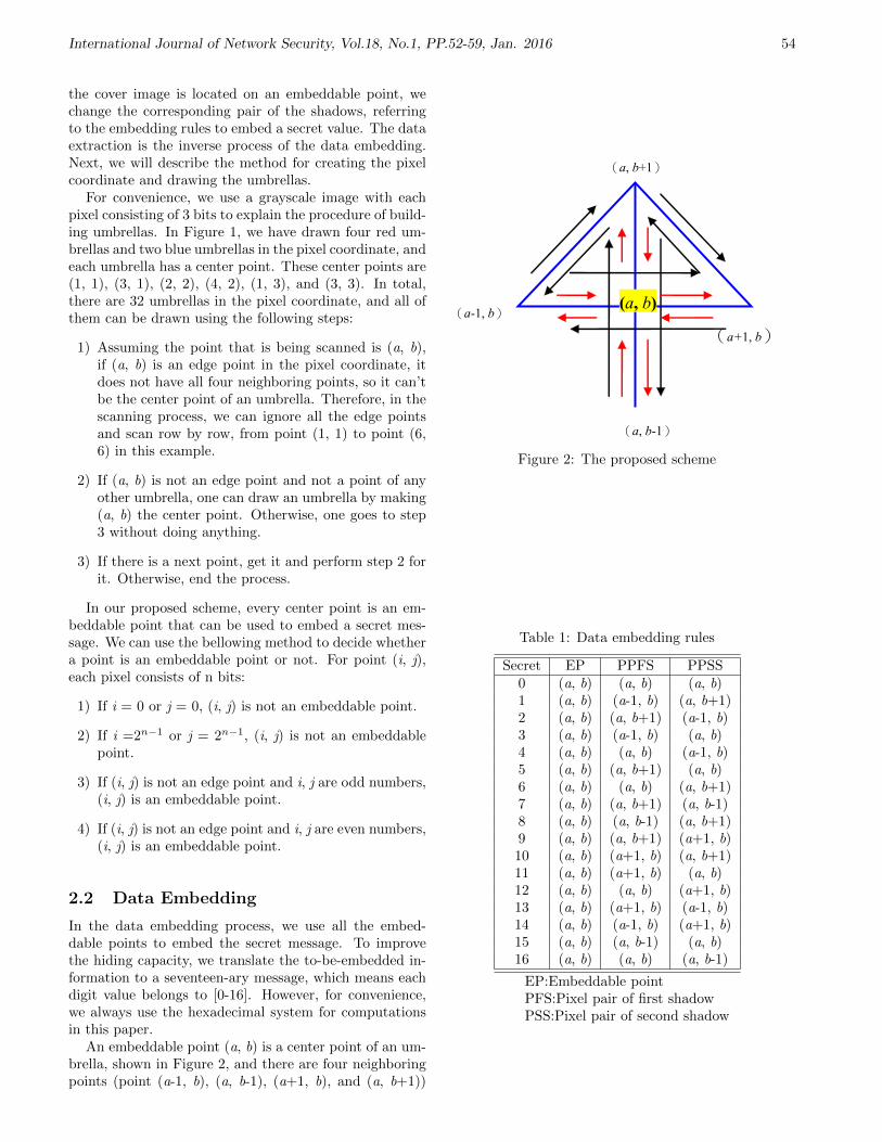
International Journal of Network Security, Vol.18, No.1, PP.52-59, Jan. 2016 54
the cover image is located on an embeddable point, wechange the corresponding pair of the shadows, referringto the embedding rules to embed a secret value. The dataextraction is the inverse process of the data embedding.Next, we will describe the method for creating the pixelcoordinate and drawing the umbrellas.
For convenience, we use a grayscale image with eachpixel consisting of 3 bits to explain the procedure of build-ing umbrellas. In Figure 1, we have drawn four red um-brellas and two blue umbrellas in the pixel coordinate, andeach umbrella has a center point. These center points are(1, 1), (3, 1), (2, 2), (4, 2), (1, 3), and (3, 3). In total,there are 32 umbrellas in the pixel coordinate, and all ofthem can be drawn using the following steps:
1) Assuming the point that is being scanned is (a, b),if (a, b) is an edge point in the pixel coordinate, itdoes not have all four neighboring points, so it can’tbe the center point of an umbrella. Therefore, in thescanning process, we can ignore all the edge pointsand scan row by row, from point (1, 1) to point (6,6) in this example.
2) If (a, b) is not an edge point and not a point of anyother umbrella, one can draw an umbrella by making(a, b) the center point. Otherwise, one goes to step3 without doing anything.
3) If there is a next point, get it and perform step 2 forit. Otherwise, end the process.
In our proposed scheme, every center point is an em-beddable point that can be used to embed a secret mes-sage. We can use the bellowing method to decide whethera point is an embeddable point or not. For point (i, j),each pixel consists of n bits:
1) If i = 0 or j = 0, (i, j) is not an embeddable point.
2) If i =2n−1 or j = 2n−1, (i, j) is not an embeddablepoint.
3) If (i, j) is not an edge point and i, j are odd numbers,(i, j) is an embeddable point.
4) If (i, j) is not an edge point and i, j are even numbers,(i, j) is an embeddable point.
2.2 Data Embedding
In the data embedding process, we use all the embed-dable points to embed the secret message. To improvethe hiding capacity, we translate the to-be-embedded in-formation to a seventeen-ary message, which means eachdigit value belongs to [0-16]. However, for convenience,we always use the hexadecimal system for computationsin this paper.
An embeddable point (a, b) is a center point of an um-brella, shown in Figure 2, and there are four neighboringpoints (point (a-1, b), (a, b-1), (a+1, b), and (a, b+1))
(a-1, b)
(a+1, b)
(a, b+1)
(a, b-1)
(a, b)
Figure 2: The proposed scheme
Table 1: Data embedding rules
Secret EP PPFS PPSS0 (a, b) (a, b) (a, b)1 (a, b) (a-1, b) (a, b+1)2 (a, b) (a, b+1) (a-1, b)3 (a, b) (a-1, b) (a, b)4 (a, b) (a, b) (a-1, b)5 (a, b) (a, b+1) (a, b)6 (a, b) (a, b) (a, b+1)7 (a, b) (a, b+1) (a, b-1)8 (a, b) (a, b-1) (a, b+1)9 (a, b) (a, b+1) (a+1, b)10 (a, b) (a+1, b) (a, b+1)11 (a, b) (a+1, b) (a, b)12 (a, b) (a, b) (a+1, b)13 (a, b) (a+1, b) (a-1, b)14 (a, b) (a-1, b) (a+1, b)15 (a, b) (a, b-1) (a, b)16 (a, b) (a, b) (a, b-1)
EP:Embeddable pointPFS:Pixel pair of first shadowPSS:Pixel pair of second shadow

International Journal of Network Security, Vol.18, No.1, PP.52-59, Jan. 2016 55
surrounding it. Thus, we can draw all arrows shown inFigure 2. That means there should be two different di-rection arrows between any two points linked by a blueline, e.g. (a-1, b) → (a, b), (a, b) → (a-1, b), (a, b+1)→ (a, b-1), (a, b-1) → (a, b+1), and so on. We call thepixel pairs that determine the arrows as arrow pairs, e.g.,((a-1, b), (a, b)) is an arrow pair and ((a, b), (a-1, b)) isanother arrow pair. Obviously, there are 16 arrow pairsin Figure 2 and we use these pairs to embed the secretmessage.
For an 8-bit grayscale cover image L and its two shad-ows L1 and L2, we first pair all the pixels in the coverimage. For convenience, we can pair the two neighboringpoints row by row or column by column directly. If thesize of the cover image is M×N, there are (M×N)/2 pixelpairs after pairing. Note that in this process, since thetwo shadows are copies of the cover image, all their pixelsshould be paired in the same way as the cover image. Weuse the following notations to represent the resultant setsof pairs for the cover image and its two shadows:
For cover image, PS=P1, P2,..., Pn.For the first shadow, PS1= P’1, P’2,..., P’n.For the second shadow, PS2= P”1, P”2, ..., P”n.Next, we scan PS, PS1, and PS2 simultaneously using
the same scanning pattern, e.g., from the first element tothe last sequentially. If a pixel pair in PS is an embed-dable point, we embed a secret value into it by changingthe corresponding pixel pairs of the two shadows in PS1and PS2 according to the embedding rules. Since we havetranslated the binary secret message to a seventeen-arymessage, we can use an embeddable point to embed aseventeen-ary value (0-16). Without losing generality, weuse Table 1 to illustrate the embedding rules for the em-beddable point (a, b). That means the pixel pairs of acertain arrow pair will be used to replace the correspond-ing original pixel pairs of these two shadows. In addition,the secret value 0 is mapped to the center point.
Now, we give an example of the data embedding pro-cess. We select the embeddable point (2, 2) in the pixelcoordinate shown in Figure 1 to explain how to embed thesecret message by using these umbrellas. Assuming thepoint (a, b) shown in Figure 2 is (2, 2), we can computethe four points surrounding (2, 2). They are (1, 2), (2,1), (3, 2), and (2, 3). Then we use the embedding rulesdescribed in Table 1 to map a secret value to an arrowpair based on the value (0-16) of the secret itself. Theembedding results are:
1) If secret = 0, (a1, b1) = (2, 2) and (a2, b2) = (2, 2);
2) If secret = 1, (a1, b1) = (1, 2) and (a2, b2) = (2, 3);
3) If secret = 2, (a1, b1) = (2, 3) and (a2, b2) = (1, 2);
4) If secret = 3, (a1, b1) = (1, 2) and (a2, b2) = (2, 2);
5) If secret = 4, (a1, b1) = (2, 2) and (a2, b2) = (1, 2);
6) If secret = 5, (a1, b1) = (2, 3) and (a2, b2) = (2, 2);
7) If secret = 6, (a1, b1) = (2, 2) and (a2, b2) = (2, 3);
8) If secret = 7, (a1, b1) = (2, 3) and (a2, b2) = (2, 1);
9) If secret = 8, (a1, b1) = (2, 1) and (a2, b2) = (2, 3);
10) If secret = 9, (a1, b1) = (2, 3) and (a2, b2) = (3, 2);
11) If secret = 10, (a1, b1) = (3, 2) and (a2, b2) = (2, 3);
12) If secret = 11, (a1, b1) = (3, 2) and (a2, b2) = (2, 2);
13) If secret = 12, (a1, b1) = (2, 2) and (a2, b2) = (3, 2);
14) If secret = 13, (a1, b1) = (3, 2) and (a2, b2) = (1, 2);
15) If secret = 14, (a1, b1) = (1, 2) and (a2, b2) = (3, 2);
16) If secret = 15, (a1, b1) = (2, 1) and (a2, b2) = (2, 2);
17) If secret = 16, (a1, b1) = (2, 2) and (a2, b2) = (2, 1).
By this way, we map a secret to a certain arrow pairbased on the value of the secret itself. After we use all theembeddable points of a cover image to embed the secretmessages, two shadows that have high similarity with thecover image are created. It is easy to extend this methodto the grayscale image with each pixel consisting of 8 bits.That means the pixel coordinate in Figure 1 has the sizeof 255×255.
Table 2: Data extraction rules
(a1,b1)-(a2,b2) Secret Recovering(0,0) 0 ((a1,b1)=((a1,b1)
(-1,-1) 1 ((a1,b1)=((a1+1,b1)(1,1) 2 ((a1,b1)=((a1,b1-1)
(-1,0) and (a2,b2)∗ 3 ((a1,b1)=((a2,b2)(1,0) and (a1,b1)∗ 4 ((a1,b1)=((a1,b1)(0,1) and (a2,b2)∗ 5 ((a1,b1)=((a2,b2)(0,-1) and (a1,b1)∗ 6 ((a1,b1)=((a1,b1)
(0,2) 7 ((a1,b1)=((a1,b1-1)(0,-2) 8 ((a1,b1)=((a1,b1+1)(-1,1) 9 ((a1,b1)=((a1,b1-1)(1,-1) 10 ((a1,b1)=((a1-1,b1)
(1,0) and (a2,b2)∗ 11 ((a1,b1)=((a2,b2)(-1,0) and (a1,b1)∗ 12 ((a1,b1)=((a1,b1)
(2,0) 13 ((a1,b1)=((a1-1,b1)(-2,0) 14 ((a1,b1)=((a1+1,b1)
(0,-1) and (a2,b2)∗ 15 ((a1,b1)=((a2,b2)(0,1) and (a1,b1)∗ 16 ((a1,b1)=((a1,b1)
The notation (a,b)* represents that (a,b) is an embed-dable point
2.3 Data Extraction
Once an authentic user receives two shadows, he/she canextract the embedded secret message and recover thecover image without loss using the following steps:
1) Pair all the pixels in these two shadows L1 and L2,respectively, according to the same pairing rule usedin the data embedding process. This step producestwo sets of pairs PS1 (for L1) and PS2 (for L2).

International Journal of Network Security, Vol.18, No.1, PP.52-59, Jan. 2016 56
Lena Lena's shadow1 Lena's shadow2
Figure 4: Cover image Lena and its two shadows
2) ScanPS1 and PS2 in the same order. To recover thecover image, we need to recover one of these twoshadows. For convenience, we always use the firstshadow for the recovery. We use the extraction rulesshown in Table 2 to extract the secret value and per-form a recovering operation for the first shadow.
After the above two steps, an authentic user can ex-tract all the embedded information correctly and recon-struct the cover image exactly.
We use an example to clarify these steps. Assumingthat the recevier is scanning the first pixel pairs in thetwo stego-images (denoted as L1 and L2), he gets (a1,b1)for L1 and (a2,b2) for L2. Then he performs a differenceoperation on these two pairs and gets the result (a1 - a2,b1- b2). Next he extracts the secret value and recovers theoriginal image using rules shown in Table 2. For exampe,(a1,b1) = (1,2) and (a2,b2) = (2,2), the recevier gets (a1- a2, b1- b2)=(-1, 0). From Table 2, he finds that he mustknow whether (a1,b1) is an embeddable point or (a2,b2)is an an embeddable point to decide the secret value is 3or 12. Based on the discussion in Section 2.1, (a2,b2) isan an embeddable point so that the embedded secret is3. The correspoding pixel pair of cover image is (a2,b2).Because recevier uses the first shadow image to recoverthe original image, he performs (a1,b1) = (a2,b2). Then,he scans next pairs in the same way as he done for thefirst pairs. Finally, he extracs all the secret values andthe first stego image is the cover image after performingall recovery operations.
3 Experimental Results and Dis-cussions
We used 12 standard cover images sized 512×512 pixelsfor the experiments. In our experiments, all pixels pairsare paired derectly row by row. Table 3 shows the exper-imental results and Figure 3 shows all the cover images;Figure 4 shows Lena and its shadows. From Table 3, wecan see that using the method proposed in the paper,all of these cover images have very large hiding capacitybut with low distortion shadows. All PSNR of shadowsshown in Table 3 are greater than 51dB and the smallestpayload size is also greater than 256kb. The comparisonwith some other schemes using Lena is shown in Table4. In Table 4, we compare the payload size of some oth-ers methods when they achieve their maximum PSNR.We use this method to compare our result because our
scheme always reach a very high PSNR so that we don’thave any data to compare with other schemes with rela-tive low PSNR. The detailed analyses of the experimentalresults are presented below.
Table 3: Experimental results
Images PSNR 1(db) PSNR 2(db) Payload(bits)Lena 52.05 52.07 524288
Baboon 51.48 51.50 524216Airplane 54.82 54.81 262172Goldhill 51.94 51.96 524288
Boat 55.12 55.12 261760Girl 51.41 51.42 348120
Woman 55.63 55.62 262964Crowd 55.05 55.05 300240Lake 55.12 55.11 262192
Barbara 55.56 55.55 263312Bridge 53.32 53.33 449368Couple 52.62 52.63 523752
PSNR 1: PSNR for fisrt shadowPSNR 2: PSNR for second shadow
Table 4: Comparison with other schemes of cover imageLena with size 512×512×8. In the comparison, the pay-load of our method is divided by two because two stego-images are used in our method.
Schemes Payload(bits) PSNRTian’s scheme [12] 39,566 44.20
Ni et al.’ scheme [5] 5460 48.2Tai et al.’s scheme [11] 24,377 48.35
Li et al.’s scheme APD1 [8] 32,995 50.82Li et al.’s scheme APD2 [8] 60,785 48.40
Our scheme 262,144 52.05
3.1 Imperceptibility
Since we use two shadows having high similarity with thecover image to embed the secret message, it is difficult foranyone to perceive the embedded information in these twoshadows with his/her eyes directly. As shown in Table 3,the lowest PSNR is 51.41dB among all the shadows, andit is already very high compared with other methods [1-4,10].
Consider an extreme situation where all the pixel pairsof the cover image are embeddable points. In the worstcase that each grayscale value of all pixels of the two shad-ows will be incremented or decremented by 1, the mostmean square error (MMSE) is equal to 1. Therefore, thePSNR of each shadow versus the original cover image is:
PSNR = 10× log10(255× 255
2) = 48.13db. (1)
The low limitation of PSNR of our method is alreadyvery high, and the experimental results show that the

International Journal of Network Security, Vol.18, No.1, PP.52-59, Jan. 2016 57
Lena Baboon Airplane Goldhill Boat Girl
Woman Crowd Lake Barbara Bridge Couple
Figure 3: All cover images
actual PSNR is usually greater than the low limitationfor 3dB-7dB. Thus, the two shadows produced by ouralgorithm have high performance in imperceptibility.
3.2 Capacity
For convenience, we think of the binary secret messageas transformed to hexadecimal instead of seventeen-ary.Thus, each pixel pair can embed four bits of information.The hiding capacity for each stego-image in the aboveextreme situation is equal to:
payload = 4× (512× 512
2× 2) = 262, 144 (bits). (2)
As you can see, in an ideal situation, our algorithm canachieve very high performance with both large capacityand high PSNR. The experimental results show that allthe pixel pairs of the cover images Lena and Goldhill areembeddable points so that these two images can achievethe maximum hiding capacity in our method.
3.3 Complexity
Assuming the size of the cover image is M×N, recall thatin the data embedding process we use two copies (shad-ows) of the cover image and then pair all the pixels inthese three images using the same pairing rule. Actu-ally, we can pair the cover image, assuming the resultantpair set is P = P1, P2, ..., Pn, and then produce twocopies P1 and P2 of the pair set P. In this way, we achievethe same purpose but the time complexity is reduced toO(MN).
For data extraction, we need to first pair the shadowsand then scan the resultant pair sets simultaneously. Thetime complexity of pairing is O(2MN) and of scanning isalso O(2MN).
Our proposed algorithm is very light since we don’tuse any complex transform operation (such as DWT andDCT) or any compression technique.
3.4 Capacity Control
We have assumed that all the embeddable points will beused to embed the secret value. Obviously, this is notpractical and we provide a simple answer to solve thisproblem.
We can use header information to indicate how manyembeddable points are used to embed the secret message.For a grayscale image sized M×N, the maximum numberof embeddable points is (M×N)/2. If we use the firstn embeddable points as the header information, for easyin calculation, we also use hexadecimal here; since eachembeddable point can embed four bits, we can choose nfor the inequality:
24n − 1 ≥ (M ×N)/2. (3)
For example, considering the grayscale image sized512×512, the maximum number of embeddable points inthis image is (512×512)/2 = 131072. Because 24×5− 1 ≥131072 , we select 5 as the value of n. That means ifthe size of the cover image is 512×512, the first five em-beddable points in the cover image are always used toindicate the number of embeddable points that are usedto embed information in the embedding process. Thus,for the data extraction process, the decoder needs to firstextract the header information and decide how many em-beddable points should be extracted.
3.5 Comparisons
Table 4 shows a simple comparison with the other schemessince these four papers present their experimental resultsfor Lena clearly. Tian’s DE method [12] can achievehigh embedding capacity when the capacity is larger than260,000 bits, but PSNR of the stego-image is lower than30dB. In such case, the imperceptibility of the stego-image decreases. As shown Table 4, when Tian’s methodachieves a high PSNR, its payload suddenly drops. Onthe other hand, because of the requirement for a locationmap, it is not easy for Tians method [12] to deal with

International Journal of Network Security, Vol.18, No.1, PP.52-59, Jan. 2016 58
the capacity control problem, so this method is not ca-pable of embedding small payloads with low distortionsas described in [6]. The RS method [4] cannot achievehigher performance in both capacity and imperceptibil-ity than our method since its maximum bpp is 0.25 dueto the optimal size of a group is four. The variants ofthe DE method, such as [5, 6, 7], also need to face upto the capacity control problem. Although these schemespropose new methods to decrease the size of the loca-tion map and control the embedding capacity, they arecomplex compared with our method since they usuallyneed a lossless data compression technique. Ni et al.’smethod [9] and Li et al.’s [8] can achieve very high PSNRcompared with many other schemes, but both the PSNRand the hiding capacity are lower than these in our pro-posed method. Based on the discussions and the experi-mental results shown in Table 4, our method can achievehigher performance in imperceptibility, embedding capac-ity, and algorithm complexity than all the other meth-ods [1, 2, 3, 4, 5, 6, 7, 9, 11, 12] mentioned in this paper.
4 Conclusions
In this paper, we proposed a reversible data hiding algo-rithm based on a combination of pixel groups’ geomet-ric structure and secret sharing mechanism. Since ourmethod does not need a location map to indicate whichpixel pairs are used to embed the secret message and eachpixel can be changed at most one value, our algorithm hashigh performance in both capacity and imperceptibility.As the embeddable points are not edge points in the pixelcoordinate, there would not be any overflow or under-flow in our scheme. The proposed scheme is also lightsince we do not use any image compression technique.Our experimental results confirm that the proposed re-versible data hiding algorithm outperforms all the otheralgorithms mentioned in the paper.
Acknowledgments
This work was supported by the National Nature ScienceFoundation of China under Grant No. 61272374.
References
[1] A. M. Alattar, “Reversible watermark using differ-ence expansion of triplets,” in Proceedings of In-ternational Conference on Image Processing, vol. 1,pp. 501–504, 2003.
[2] A. M. Alattar, “Reversible watermark using dif-ference expansion of a generalized integer trans-form,” IEEE Transactions on Image Process, vol. 13,pp. 1147–1156, 2004.
[3] A. M. Alattar, “Reversible watermark using differ-ence expansion of quads,” in Proceedings of IEEE In-
ternational Conference on Acoustics, vol. 3, pp. 337–380, 2004.
[4] J. Fridrich, M. Goljan, and R. Du, “Lossless dataembeddingnew paradigm in digital watermarking,”Journal of Applied Signal Processing, vol. 1, pp. 185–196, 2002.
[5] Y. J. Hu, H. K. Lee, and J. W. Li, “De-based re-versible data hiding with improved overflow locationmap,” IEEE Transactions on Circuits and Systemsfor Video Technology, vol. 19, pp. 250–260, 2009.
[6] L. Kamstra and H. J. A. M. Heijmans, “Reversibledata embedding into images using wavelet techniquesand sorting,” IEEE Transactions on Image Process,vol. 14, pp. 2082–2090, 2005.
[7] H. J. Kim, Y. Q. Shi, J. Nam, and H. G. Choo, “Anovel difference expansion transform for reversibledata embedding,” IEEE Transactions on Informa-tion Forensics and Security, vol. 3, pp. 456–465,2008.
[8] Y. C. Li, C. M. Yeh, and C. C. Chang, “Data hidingbased on the similarity between neighboring pixelswith reversibility,” Digital Signal Processing, vol. 20,pp. 1116–1128, 2010.
[9] Z. Ni, Y. Q. Shi, N. Ansari, and W. Su, “Reversibledata hiding,” IEEE Transactions on Circuits andSystems for Video Technology, vol. 16, pp. 354–362,2006.
[10] A. Shamir, “How to share a secret,” Communicationof the ACM, vol. 11, pp. 612–613, 1979.
[11] W. L. Tai, C. M. Yeh, and C. C. Chang, “Reversibledata hiding based on histogram modification of pixeldifferences,” IEEE Transactions on Circuits and Sys-tems for Video Technology, vol. 19, pp. 906–910,2009.
[12] J. Tian, “Reversible data embedding using a differ-ence expansion,” IEEE Transactions on Circuits Sys-tem Video Technology, vol. 13, pp. 890–896, 2012.
Zhi-Hui Wang received the BS degree in softwareengineering in 2004 from the North Eastern University,Shenyang, China. She received her MS degree in softwareengineering in 2007 and the PhD degree in softwareand theory of computer in 2010, both from the DalianUniversity of Technology, Dalian, China. Since November2011, she has been a visiting scholar of University ofWashington. Her current research interests includeinformation hiding and image compression.
Xu Zhuang received his B.S. degree in ComputerScience from Southwest Jiaotong University (SWJTU),Chengdu, China, in 2006, and is currently pursuing thePh.D. degree in the Software Engineering Laboratoryin Southwest Jiaotong University (SWJTU), Chengdu,China. His research interests include data mining, datahiding and information security.
Chin-Chen Chang received his Ph.D. degree incomputer engineering from National Chiao Tung Univer-sity. His first degree is Bachelor of Science in Applied

International Journal of Network Security, Vol.18, No.1, PP.52-59, Jan. 2016 59
Mathematics and master degree is Master of Science incomputer and decision sciences. Both were awarded inNational Tsing Hua University. Dr. Chang served inNational Chung Cheng University from 1989 to 2005. Histitle is Chair Professor in Department of Information En-gineering and Computer Science, Feng Chia University,from Feb. 2005. He is a Fellow of IEEE and a Fellow ofIEE, UK. His research interests include database design,computer cryptography, image compression and datastructures.
Chuan Qin received the B.S. and M.S. degrees in elec-tronic engineering from Hefei University of Technology,Anhui, China, in 2002 and 2005, respectively, and thePh.D. degree in signal and information processing fromShanghai University, Shanghai, China, in 2008. Since2008, he has been with the faculty of the School ofOptical-Electrical and Computer Engineering, Universityof Shanghai for Science and Technology, where he iscurrently a Lecturer. He also has been with Feng ChiaUniversity at Taiwan as a Postdoctoral Researcher fromJuly 2010 to June 2012. His research interests includeimage processing and multimedia security.
Yan Zhu received her B.S. and M.S. degrees in ComputerScience from Southwest Jiaotong University (SWJTU),Chengdu, China, in 1986 and 1989, respectively. She re-ceived her Ph.D. degree in Computer Science from Darm-stadt University of Technology, Germany in 2004. YanZhu is currently a professor of the School of InformationScience and Technology, SWJTU and the director of theLaboratory of Software Engineering. Her research inter-ests include data mining, Web information security, andWeb spam detection.

International Journal of Network Security, Vol.18, No.1, PP.60-67, Jan. 2016 60
Construction of Extended Multivariate PublicKey Cryptosystems
Shuaiting Qiao, Wenbao Han, Yifa Li, and Luyao Jiao(Corresponding author: Shuaiting Qiao)
Zhengzhou Information Science and Technology Institute
Zhengzhou, Henan Province, 450001, China
(Email: [email protected])
(Received Sep. 03, 2013; revised and accepted Jan. 20 & Mar. 23, 2014)
Abstract
Based on the ideas: “invertible cycle”, “tame trans-formation” and “special oil and vinegar”, three differ-ent nonlinear invertible transformations were constructedseparately. Then making use of the idea of the ex-tended multivariate public key cryptosystem, and combin-ing the nonlinear invertible transformations above withMatsumoto-Imai (MI) scheme, three methods of design-ing extended multivariate public key cryptosystem wereproposed. Next, the corresponding encryption and signa-ture algorithms were given. Analysis results demonstratethat the new extended cryptosystems inherit the meritof MI scheme, i.e., efficient computation. Meanwhile, thenew extended cryptosystems can also resist the lineariza-tion attack, differential attack and algebraic attack.
Keywords: Extended multivariate public key cryptosys-tem, invertible cycle, matsumoto-imai scheme, special oiland vinegar, tame transformation
1 Introduction
The 21st century is the era of information. With therapid development of electronic information science andtechnology, information security has become so impor-tant. After electronic information science and technology,quantum and other new information science are buildingup and developing [9]. But the development of quantumcomputers will pose a threat to the widely-used publickey cryptosystems, which are based on discrete logarithmproblem and large integer factorization problem [10, 16].Therefore, great attention has been paid to the post-quantum public key cryptography [2], and multivariatepublic key cryptosystems (MPKCs) develop rapidly inthis background. MPKC is considered to be a candidateof secure cryptosystems in post-quantum era for its higherefficiency, better security and easy access to the hardwareimplementation, etc. During the last twenty years, MP-KCs have received more and more attention.
The security of MPKCs depends on the difficulty ofsolving a set of nonlinear multivariate quadratic equationsover a finite field [7] and the isomorphism of polynomi-als problem [17]. Its research began in the 1990s. Ac-cording to different central maps, MPKCs have been di-vided into five schemes, which are Matsumoto-Imai (MI)scheme, Hidden Field Equation (HFE) scheme, Unbal-anced Oil and Vinegar (UOV) scheme, Stepwise Trian-gular Systems (STS) scheme and Medium Field Equa-tion (MFE) scheme [7]. Especially, in the past few years,many cryptosystems have emerged in sequence, such asthe CyclicRainbow cryptosystem [14], the Double-Layersquare cryptosystem [3], the Enhanced STS cryptosys-tem [19], etc, which make MPKCs develop and complete.Meanwhile, researchers have also applied MPKCs to iden-tification [15], special signatures [22, 24]and other fields.So far, MPKCs have been a hot topic in cryptography.
In 1988, Matsumoto and Imai proposed MI schemewith high efficiency, which was seen as the first scheme ofMPKCs [11]. In 1995, Patarin et al present linearizationattack aimed at MI scheme [12]. To resist linearizationattack, Jacques Patarin et al came up with the Flashcryptosystem in 2000 [13], and Ding Jin-tai et al putforward the PMI cryptosystem in 2004 [4], but both ofthem were vulnerable to differential attack [5, 8]. In2011, by incorporating the hash authentication techniqueand traditional multivariate public key cryptography al-gorithm, Wang Hou-zhen et al proposed Extended Multi-variate Public Key Cryptosystem (EMC), which can resistboth linearization attack and differential attack [20]. Theemerging of EMC pointed out a new idea to constructnovel multivariate public key cryptosystems.
In this work, on the base of the ideas: invertible cy-cle [6], tame transformation [21] and special oil and vine-gar [23], three different nonlinear invertible transforma-tions are built separately. Then by combining these non-linear invertible transformations above and MI scheme,three different methods to construct novel EMCs are pro-posed. Finally, the performance analysis and securityanalysis will be given.
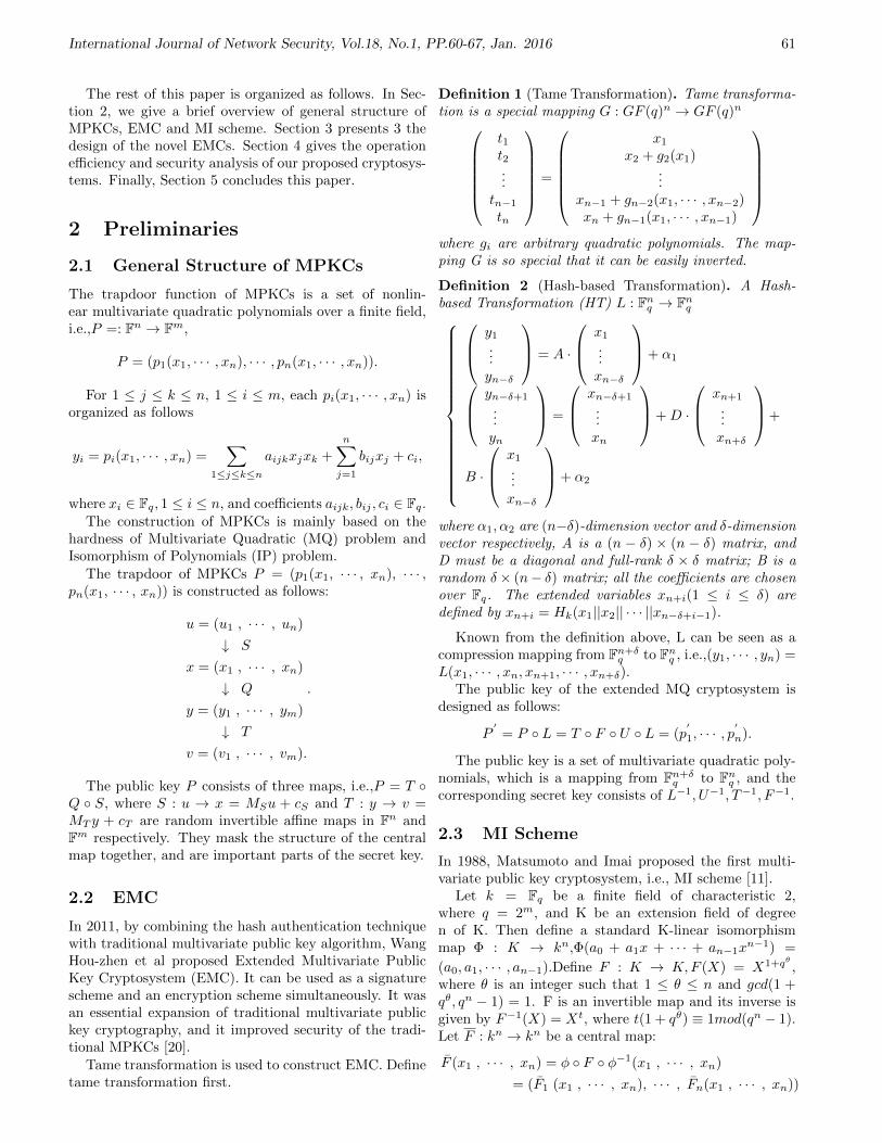
International Journal of Network Security, Vol.18, No.1, PP.60-67, Jan. 2016 61
The rest of this paper is organized as follows. In Sec-tion 2, we give a brief overview of general structure ofMPKCs, EMC and MI scheme. Section 3 presents 3 thedesign of the novel EMCs. Section 4 gives the operationefficiency and security analysis of our proposed cryptosys-tems. Finally, Section 5 concludes this paper.
2 Preliminaries
2.1 General Structure of MPKCs
The trapdoor function of MPKCs is a set of nonlin-ear multivariate quadratic polynomials over a finite field,i.e.,P =: Fn → Fm,
P = (p1(x1, · · · , xn), · · · , pn(x1, · · · , xn)).
For 1 ≤ j ≤ k ≤ n, 1 ≤ i ≤ m, each pi(x1, · · · , xn) isorganized as follows
yi = pi(x1, · · · , xn) =∑
1≤j≤k≤n
aijkxjxk +
n∑j=1
bijxj + ci,
where xi ∈ Fq, 1 ≤ i ≤ n, and coefficients aijk, bij , ci ∈ Fq.The construction of MPKCs is mainly based on the
hardness of Multivariate Quadratic (MQ) problem andIsomorphism of Polynomials (IP) problem.
The trapdoor of MPKCs P = (p1(x1, · · · , xn), · · · ,pn(x1, · · · , xn)) is constructed as follows:
u = (u1 , · · · , un)
↓ S
x = (x1 , · · · , xn)
↓ Q
y = (y1 , · · · , ym)
↓ T
v = (v1 , · · · , vm).
.
The public key P consists of three maps, i.e.,P = T Q S, where S : u → x = MSu + cS and T : y → v =MT y + cT are random invertible affine maps in Fn andFm respectively. They mask the structure of the centralmap together, and are important parts of the secret key.
2.2 EMC
In 2011, by combining the hash authentication techniquewith traditional multivariate public key algorithm, WangHou-zhen et al proposed Extended Multivariate PublicKey Cryptosystem (EMC). It can be used as a signaturescheme and an encryption scheme simultaneously. It wasan essential expansion of traditional multivariate publickey cryptography, and it improved security of the tradi-tional MPKCs [20].
Tame transformation is used to construct EMC. Definetame transformation first.
Definition 1 (Tame Transformation). Tame transforma-tion is a special mapping G : GF (q)n → GF (q)n
t1t2...
tn−1
tn
=
x1
x2 + g2(x1)...
xn−1 + gn−2(x1, · · · , xn−2)xn + gn−1(x1, · · · , xn−1)
where gi are arbitrary quadratic polynomials. The map-ping G is so special that it can be easily inverted.
Definition 2 (Hash-based Transformation). A Hash-based Transformation (HT) L : Fnq → Fnq
y1
...yn−δ
= A ·
x1
...xn−δ
+ α1 yn−δ+1
...yn
=
xn−δ+1
...xn
+D ·
xn+1
...xn+δ
+
B ·
x1
...xn−δ
+ α2
where α1, α2 are (n−δ)-dimension vector and δ-dimensionvector respectively, A is a (n − δ) × (n − δ) matrix, andD must be a diagonal and full-rank δ × δ matrix; B is arandom δ× (n− δ) matrix; all the coefficients are chosenover Fq. The extended variables xn+i(1 ≤ i ≤ δ) aredefined by xn+i = Hk(x1||x2|| · · · ||xn−δ+i−1).
Known from the definition above, L can be seen as acompression mapping from Fn+δ
q to Fnq , i.e.,(y1, · · · , yn) =L(x1, · · · , xn, xn+1, · · · , xn+δ).
The public key of the extended MQ cryptosystem isdesigned as follows:
P′
= P L = T F U L = (p′
1, · · · , p′
n).
The public key is a set of multivariate quadratic poly-nomials, which is a mapping from Fn+δ
q to Fnq , and thecorresponding secret key consists of L−1, U−1, T−1, F−1.
2.3 MI Scheme
In 1988, Matsumoto and Imai proposed the first multi-variate public key cryptosystem, i.e., MI scheme [11].
Let k = Fq be a finite field of characteristic 2,where q = 2m, and K be an extension field of degreen of K. Then define a standard K-linear isomorphismmap Φ : K → kn,Φ(a0 + a1x + · · · + an−1x
n−1) =
(a0, a1, · · · , an−1).Define F : K → K,F (X) = X1+qθ ,where θ is an integer such that 1 ≤ θ ≤ n and gcd(1 +qθ, qn − 1) = 1. F is an invertible map and its inverse isgiven by F−1(X) = Xt, where t(1 + qθ) ≡ 1mod(qn − 1).Let F : kn → kn be a central map:
F (x1 , · · · , xn) = φ F φ−1(x1 , · · · , xn)
= (F1 (x1 , · · · , xn), · · · , Fn(x1 , · · · , xn))

International Journal of Network Security, Vol.18, No.1, PP.60-67, Jan. 2016 62
where F i(x1, · · · , xn) are quadratic polynomials of n vari-ables.
Finally, let L1 and L2 be two randomly chosen invert-ible affine linear maps over kn.
F (x1, · · · , xn) = L1 F L2(x1, · · · , xn) =(F1(x1, · · · , xn), · · · , Fn(x1, · · · , xn)) is the ciphertextsuggested by MI scheme. The public key is F (x1, · · · , xn),and the secret key is (L−1
1 , L−12 , θ).
3 Design of the Novel EMCs
Nowadays most algorithms of MPKCs cannot be a sig-nature scheme and an encryption scheme simultaneouslyand most of them are under attack. How to construct asecure and efficient MPKC enabling both signature andencryption remain a hot topic and an open problem.
The key of our proposed cryptosystems is to build anonlinear and invertible transformation L. By making useof the idea of EMC and incorporating MI scheme withnonlinear invertible transformations L, the novel EMCsare produced:
F (x1 , · · · , xn) = F L(x1 , · · · , xn)
= L1 F L2 L(x1 , · · · , xn) (1)
3.1 Construction of L
Constructing nonlinear and invertible transformations Lis the key to design the novel EMCs. Three kinds of non-linear and invertible transformations will be introducedbased on different ideas below.
3.1.1 Construction of Invertible TransformationBased on “Invertible Cycle”
Assume the invertible transformation is L3, in order tofacilitate the inverse, L3 is defined in cases. Suppose theorder is n, to express properly the successor of 1, · · · , n,define
µ : 1, · · · , n → 1, · · · , n : µ(i) =
1 for i = n
i+ 1 otherwise
Lemma 1. For a fixed integer n ≥ 2, define a nonlin-ear transformation L3 : (x1, · · · , xn) → (t1, · · · , tn) asfollows:
t1 : =
c1x1x2 for n odd
c1x1qx2 for n even
,
ti : = cixixµ(i) for 2 6 i 6 n
Then the inverse image of (t1, · · · , tn),where ti ∈ F∗q :=
Fq\0, ∀i is given by
x1 : =
√√√√∏(n−1)/2i=0 t2i+1∏(n−1)/2i=1 t2i
·
√√√√ ∏(n−1)/2i=1 c2i∏(n−1)/2i=0 c2i+1
for n odd
q−1
√√√√∏n/2−1i=0 t2i+1∏n/2i=1 t2i
· q−1
√√√√ ∏n/2i=1 c2i∏n/2−1
i=0 c2i+1
for n even
xi : =ti
cixµ(i)for i = n , · · · , 2.
Remark 1. However, for some xi = 0 in the setx1, · · · , xn, the definition of L3 is the same as that ofLemma 1, so the conditions ti = 0 and ti+1 = 0 areset up. Take odd n for example, the inverse of L3, i.e.,(x1, · · · , xn) = L−1
3 (t1, · · · , tn) is organized as follows:Either xi = 0 or xµ(i) = 0 is set up, where ti = 0.
1) For xi = 0, choose xµ(i) = a ∈ Fq\0 randomly, andother xi can be worked out in sequence:
xµ(i)+1 =tµ(i)
cµ(i) a, · · · , xn =
tn−1
cn−1 xn−1for i = 1,
xµ(i)+1 =tµ(i)
cµ(i) a, · · · , xn =
tn−1
cn−1 xn−1, x1 =
tncn xn
for i = 2,
xµ(i)+1 =tµ(i)
cµ(i) a, · · · , xn =
tn−1
cn−1 xn−1, x1 =
tncn xn
· · · , xi−1 =ti−2
ci−2 xi−2for i = 3 , · · · , n.
2) For xµ(i) = 0, choose xi = b ∈ Fq\0 randomly, andother xi can be calculated in sequence:
xi−1 =ti−1
ci−1 b, · · · , x1 =
t1c1 x2
, · · · , xµ(i)+1 =
tµ(i)+1
cµ(i)+1 xµ(i)+2for i = n , n− 1 , · · · , 2,
xn =tncn b
, xn−1 =tn−1
cn−1 xn· · · , xµ(i)+1 =
tµ(i)+1
cµ(i)+1 xµ(i)+2for i = 1.
3) For xi = 0 and xµ(i) = 0, choose xµ(i)+1 = c ∈ Fq\0randomly, and do the following work:
xµ(i)+2 =tµ(i)+1
cµ(i)+1 c, · · · , xn =
tn−1
cn−1 xn−1for i = 1,
xµ(i)+2 =tµ(i)+1
cµ(i)+1 c, · · · , xn =
tn−1
cn−1 xn−1, x1 =
tncn xn
for i = 2,
xµ(i)+2 =tµ(i)+1
cµ(i)+1 c, · · · , xn =
tn−1
cn−1 xn−1, x1 =
tncn xn
, · · · , xi−1 =ti−2
ci−2 xi−2for i = 3 , · · · , n.
From the discussions above, it can be seen that ifthere exists a singularity, i.e.,x1, · · · , xn such that

International Journal of Network Security, Vol.18, No.1, PP.60-67, Jan. 2016 63
x1, · · · , xn|x1 = 0 ∨ · · · ∨ xn = 0, there must be someti = 0. In this situation, the inverse image of t1, · · · , tnis multiple, and the checksum need to be estimated. Asthe number of singularities is qn − (q − 1)n, the probabil-
ity of the existence of a singularity is p1 = 1 − (q−1)n
qn ,where q = 2m. Proper parameters can guarantee that theprobability is small enough and improve the decryption ef-ficiency. Under the parameters m = 12, n = 28, the prob-ability is p1 = 0.007; p2 = 0.002, for m = 14, n = 28;p1 = 0.0005, for m = 16, n = 27, so the parametersm = 16, n = 27 are recommended.
3.1.2 Construction of Invertible Transformationbased on Tame Transformation
Lemma 2. Suppose the invertible transformation to con-struct is L4. Choose positive integers n, d such thatn > 2d, and define the invertible transformation basedon tame transformation L4 : (x1, · · · , xn)→ (t1, · · · , tn)
t1 = x1 + xd+1xnt2 = x2 + xd+2xn−1
...td = xd + x2dxn−d+1
td+1 = xd+1
...tn = xn.
Then the inverse image of (t1, · · · , tn), i.e.,L−1
4 (t1, · · · , tn) = (x1, · · · , xn) is given by
x1 = t1 + td+1tnx2 = t2 + td+2tn−1
...xd = td + t2dtn−d+1
xd+1 = td+1
...xn = tn.
3.1.3 Construction of Invertible Transformationbased on “Special Oil and Vinegar”
Suppose the invertible transformation to construct is L5,and choose positive integers o, v and n such that o > vand n = o+v. Divide the variables x1, · · · , xn into twoparts:x1, · · · , xv, · · · , xo and xo+1, · · · , xn.
Lemma 3. Randomly choose ri ∈ Fq, i = 1, · · · , n and
define L5(x1, · · · , xn) = (t1, · · · , tn) as follows:
t1 = x1
...tv = xv...to = xoto+1 = (x1+r1)
xo+1
...
tn = (xv+rv)xn
where variables (t1, · · · , to) containing the first degreeparts can be seen as “oil variables”; and variables(to+1, · · · , tn) containing the quadratic parts can be seenas “vinegar variables”.
Then the inverse image of (t1, · · · , tn), i.e.,L−1
5 (t1, · · · , tn) = (x1, · · · , xn), where ti ∈ F∗q := Fq\0,
i = o+ 1, · · · , n is given by
x1 = t1...xv = tv...xo = toxo+1 = to+1
(t1+r1)
...xn = tn
(tv+rv) .
Remark 2. For some ti = 0, i = o+1, · · · , n, the inverseimage of (t1, · · · , tn), i.e.,L−1
5 (t1, · · · , tn) = (x1, · · · , xn)is obtained as follows.
For some ti = 0, either xi = 0 or xi−o + ri−o = 0 isset up. If xi−o + ri−o = 0, choose xi ∈ Fq, and solve(x1, · · · , xn) from (t1, · · · , tn) directly, otherwise, utilizeLemma 3.1.1.
In conclusion, the existence of ti = 0 makes the so-lution (x1, · · · , xn) not unique, the checksum need to becalculated. Similar to Section 3.1.1, the probability of the
existence of a singularity is p2 = 1− (q−1)n
qn , so it can lowerthe probability, and improve the decryption efficiency bychoosing proper parameters. For m = 16, n = 27, theprobability is p2 = 0.0005, so the parameters m = 16, n =27 are proper.
3.2 Construction of Three Kinds ofEMCs
By using the idea “function composition”, and combin-ing MI scheme with those nonlinear invertible transfor-mations Li in Section 3.1, the public key polynomials ofthe novel EMCs are deduced as follows:
Fi(x1 , · · · , xn) = L1 F L2 Li(x1 , · · · , xn)
= (Fi1(x1 , · · · , xn) , · · · , Fin(x1 , · · · , xn)),
i = 3 , 4 , 5 .

International Journal of Network Security, Vol.18, No.1, PP.60-67, Jan. 2016 64
Conversely, the secret keys consist of(L−1
1 , L−12 , L−1
i , θ), i = 3, 4, 5.
3.3 Encryption Algorithms
It can be seen that the secret keys of encryption algo-rithms are D = (L−1
1 , L−12 , L−1
i , θ), i = 3, 4, 5 from theconstruction process of the novel EMCs.
According to the construction of nonlinear transfor-mation L in Section 3.1, when there exists a singularityt1, · · · , tn|t1 = 0 ∨ · · · ∨ tn = 0, the inverse images of(t1, · · · , tn) : L−1
3 (t1, · · · , tn) and L−15 (t1, · · · , tn) can be
multiple. Therefore, the encryption process and the de-cryption process will be discussed in two cases.
1) When there does not exist a singularity, the solutionof L−1
i (t1, · · · , tn) is unique.
The encryption process. Given the plaintext(x1, · · · , xn) ∈ Fnq , use the public key Fi to calcu-
late the ciphertext (y1, · · · , yn) = Fi(x1, · · · , xn).
The decryption process. Received the ciphertext(y1, · · · , yn) ∈ Fnq , calculate the corresponding plain-text (x1, · · · , xn) as follows:
a. Compute (y′
1, · · · , y′
n) = L−11 (y1, · · · , yn);
b. Use the secret key θ to get the inversetransformation of the central map F , i.e.,(x′
1, · · · , x′
n) = F−1(y′
1, · · · , y′
n);
c. Compute (t1, · · · , tn) = L−12 (x
′
1, · · · , x′
n);
d. Finally, compute the corresponding plaintext(x1, · · · , xn) = L−1
i (t1, · · · , tn).
2) When there exists a singularity, i.e., the solution ofL−1i (t1, · · · , tn) isn’t unique.
The encryption process. Given the plaintext(x1, · · · , xn) ∈ Fnq , use the public key Fi to cal-culate the corresponding ciphertext (y1, · · · , yn) =Fi(x1, · · · , xn). Meanwhile, utilize the public hashfunction Hash1 to calculate the checksum of plain-text Hash1(x1, · · · , xn) = v.
The decryption process. Received the cipher-text (y1, · · · , yn) ∈ Fnq and the checksumHash1(x1, · · · , xn) = v, the plaintext can be ob-tained as follows:
a. Compute (y′
1, · · · , y′
n) = L−11 (y1, · · · , yn);
b. Use the secret key θ to get the inversetransformation of the central map F , i.e.,(x′
1, · · · , x′
n) = F−1(y′
1, · · · , y′
n);
c. Compute (t1, · · · , tn) = L−12 (x
′
1, · · · , x′
n);
d. Use the secret key L−1i to get
(x1, · · · , xn) = L−1i (t1, · · · , tn),and com-
pute Hash1(x1, · · · , xn) = v′. If v = v
′,
the corresponding solution (x1, · · · , xn) is theright plaintext, otherwise, discard the solution(x1, · · · , xn).
3.4 Signature Algorithms
The signature process. Suppose that the message Mis the document to sign, and compute (y1, · · · , yn) =Hash2(M). The secret keys of signature algorithms arethe same as those of encryption algorithms, so are theprocess of calculating the signature (x1, · · · , xn) and theencryption process in Section 3.3. The difference is thatwhether there exists a singularity. When the signatureisn’t unique, choose one of the signatures randomly.
The verification process. Received the message M andsignature (x1, · · · , xn), do the verification as follows:
1) Use another public Hash function Hash2 to computeHash2(M) = (y1, · · · , yn);
2) Compute F (x1, · · · , xn) = (y′
1, · · · , y′
n), then de-termine whether the condition (y
′
1, · · · , y′
n) =(y1, · · · , yn) is true, otherwise, discard the invalid sig-nature.
4 Operation Efficiency and Secu-rity Analysis
The operation efficiency and the security analysis of threenovel EMCs will be given in the next installment.
4.1 Operation Efficiency
Encryption (verification) efficiency. Compared to the en-cryption (verification) efficiency of the MI scheme, thenovel EMCs need simply do another operation Li, i =1, 2, 3. It can be seen that their efficiencies are high, andbarely affect the whole efficiency of our proposed cryp-tosystem from the construction of Li in Section 3.1.
Decryption (signature) efficiency. During the decryp-tion process, when there exists a singularity, the solutionisn’t unique, and the verification need to be done manytimes. But the existence of a singularity can be avoidedby choosing the proper parameters. During the signatureprocess, just choose one of the solutions.
Above all, under the proper parameters, the three novelEMCs inherit high efficiency of MI, and the whole opera-tion efficiency keeps high.
4.2 Security Analysis
Generally, attacks aimed at MPKCs are divided intotwo groups: structure-based attack and direct attack.Structure-based attack aims at the special structure ofMPKCs, and it mainly includes linearization attack anddifferential attack. Direct attack starts with the publickey polynomials of MPKCs. The common tools are com-prised of the Grobner base algorithm and the XL algo-rithm. Next, the security analysis of three EMCs will beperformed. To keep it simple, take the EMC based oninvertible cycle for example.

International Journal of Network Security, Vol.18, No.1, PP.60-67, Jan. 2016 65
4.2.1 Linearization Attack
In 1995, Patarin present a linearization attack to theMI scheme, which simplified linear equations and posedthreat to MI [12]. Next, it will be demonstrated that ourproposed cryptosystem can be resistant against lineariza-tion attack.
Definition 3. Let P = (p1, · · · , pm) be polynomials withn variables over Fq,with regard to P , a linearization equa-tion is organized as
n∑i=1
m∑j=1
aijxiyj +
n∑i=1
bixi +
m∑i=1
ciyi + d
∈ Fq[x1 , · · · , xn , y1 , · · · , ym]
s.t. when plugging pi into yi, a zero polynomial about(x1, · · · , xn) the variable are obtained:
n∑i=1
m∑j=1
aijxipj +
n∑i=1
bixi +
m∑i=1
cipi + d = 0.
According to the central map of MI F : X 7→ Xqθ+1,
the following special algebraic relation:Y qθ−1 = Xq2θ−1.
Multiply XY on both sides of the relation to acquire the
relation: XY qθ
= Y Xq2θ .Further, it can be easy to obtain n multivariate
quadratic equations over Fq by the isomorphic mappingφ. Each equation is organized as follows:
n∑i=1
n∑j=1
aijxiyj +
n∑i=1
bixi +
n∑i=1
ciyi + d = 0 (2)
Given O((n + 1)2) plaintext-ciphertext pairs(x1, · · · , xn, y1, · · · , yn), it is feasible to work out thecoefficients of the equation above. Once worked out allthe coefficients and given the ciphertext y = (y1, · · · , yn),n linear equations about the plaintext x = (x1, · · · , xn)can be obtained.
Theorem 1. The EMC based on invertible cycle puts for-ward the nonlinear invertible transformation L3, s.t. thestructure of public key polynomial will be changed to resistlinearization attack.
Proof. Similar to MI scheme, n multivariate quadraticequations of our proposed cryptosystem can be obtained,and each equation is organized as follows:
n∑i=1
n∑j=1
aijtiyj +
n∑i=1
biti +
n∑i=1
ciyi + d = 0 (3)
If given O((n + 1)2) plaintext-ciphertext pairs(t1, · · · , tn, y1, · · · , yn), the coefficients of the equationsabove can be calculated. However, since the cipher-text (y1, · · · , yn) is known, and the intermediate variables(t1, · · · , tn) remain unknown, the coefficients cannot becalculated when plugging the ciphertext (y1, · · · , yn) into
the equation. In the worst case that all the coefficientsare calculated, linear equations about ti can be obtainedby plugging (y1, · · · , yn) to Equation (3).
After plugging the expression of ti, multivariatequadratic equations about (x1, · · · , xn) will be derived.Solving this kind of equation is still a NP problem, soit can be concluded that: our proposed cryptosystem isresistant against linearization attack.
4.2.2 Differential Attack
Differential attack aims at the type such as MI scheme.Initially, it was used to attack PMI [5], and it wasalso used to attack the SFLASH cryptosystem, i.e.,C∗−scheme later [8]. Next, it will be proved that the novelcryptosystem can resist differential attack.
Definition 4. For any function F (x), its differential atpoint Fqθ is defined by DF (a, x) :
DF (a, x) = F (x+ a)− F (x)− F (a) + F (0).
When F is a quadratic function, if regard DF (a, x) as afunction of variables x and a, DF (a, x) is a symmetricbilinear function about x and a.
In MI scheme, the inner function is F (x) = x1+qθ , so
DF (a, x) = xaqθ
+ axqθ
. Obviously, is symmetric bilin-ear., the differential function has a very specific multi-plicative property:
DF (a , ξ · x) +DF (ξ · a , x) = (ξ + ξqθ
)DF (a , x) (4)
Similarly, the differential function of public key P =L1 F L2 is DP (a, x) = T DF (U(a), U(x)), whichsatisfies the following relation:
DP (ξa , x) +DP (a , ξx)
= L1 DF (ξ · L2(a) , L2(x))
+ L1 DF (L2(a) , ξ · L2(x))
= L1 (ξ + ξqθ
) L1−1 DP (a , x) (5)
Let PΠ = TΠ F L2 be the public key of the C∗−
scheme. It is entirely feasible to find the non-trivial mapNξ such that
P′
Π = PΠ Nξ = TΠ Mξ F L2 (6)
where Nξ and Mξ denote two linear maps with regard toξ.
Therefore, a new MI public key can be obtained bycomprising r equations randomly chosen from P
′Π with
(n− r) equations of the public key, and the probability ofsuccess is 1− 1/q. Then make use of linearization attackabove to forge the signature.

International Journal of Network Security, Vol.18, No.1, PP.60-67, Jan. 2016 66
Theorem 2. The EMC based on invertible cycle uti-lizes the idea function composition and adds the nonlin-ear transformation L3 to the MI scheme, therefore, it canbreak the special multiplicative property of MI and avoiddifferential attack.
Proof. Relative to MI scheme, the public key of thenovel EMC is transformed from P to P
′,
P′
= L1 F L2 L3 L′
2 = L2 L3 L1 F L′
2 (7)
Since L3 is a nonlinear transformation, L′2 in Re-
lation (7) is also a nonlinear transformation.∀x , ξ ∈GF (qn), there obviously exists the following relation:
ξ L′
2(x) 6= L′
2(ξx) (8)
To the novel EMC, the differential function of publickey P
′= L1 F L
′2 is
DP′(ξa , x) +DP
′(a , ξx)
= L1 DF (ξ · L′
2(a) , L′
2(x)) +
L1 DF (L′
2(a) , ξ · L′
2(x)) (9)
6= L1 (ξ + ξqθ
) L1−1 (DP
′(a , x) )
Expression (9) shows that the introduction of thetransformation L3 breaks the special multiplicative prop-erty of MI scheme.
In conclusion, our proposed cryptosystem can resistdifferential attack.
4.2.3 Algebraic Attack
The common tools of algebraic attack consist of theGrobner base algorithm and the XL algorithm. So far,the most efficient methods to computer Grobner basesare F4 and F5 algorithms.
According to the relations of the number of equationsm and the number of variables n, and algebraic attackin three cases are discussed: m > n, m < n, and m=n.The equations satisfying the relation m > n are calledoverdetermined equations [1], when m < n, underdeter-mined equations [18], and when m=n, permutation equa-tions [21]. In our cryptosystem, the public key polynomialP (x1 , · · · , xn) = (y1 , · · · , yn) satisfies the relationm=n. Therefore, the cases m > n and m < n are de-scribed no longer.
To the best of our knowledge, when K = GF (q) (q 6=2) is big, and m=n, the complexity to solve the permuta-tion equations is proved to be O(23m) [21].
In the novel cryptosystem, the corresponding equa-tions are expressed as follows:
p1(x1 , · · · , xn) = y1
...
pn(x1 , · · · , xn) = yn
(10)
where the number of equations is equal to the numberof variables. According to Section 4.1.1, the public key
pi(x1 , · · · , xn) is multivariate quartic polynomial. Thecomplexity to solve Equation (10) is much greater thanthe corresponding quadratic equations. Under the rec-ommended parameters n=27 and q = 216, the complexityto solve multivariate quadratic equations is about O(281),therefore, the complexity to solve the public key polyno-mials of the novel EMC is more than O(281), that is, ourproposed cryptosystem can be resistant against algebraicattack.
All in all, from Sections 4.2.1, 4.2.2, and 4.2.3, it can beconcluded that the EMC based on invertible cycle can re-sist linearization attack, differential attack and algebraicattack. Similarly, the EMC based on tame transforma-tion and the EMC based on special oil and vinegar arealso secure, and detailed proofs are not given here.
5 Conclusions
In this paper, three different nonlinear invertible transfor-mations are put forward. Incorporated with MI scheme,three novel EMCs are recommended. Next, the corre-sponding encryption and signature algorithms are pro-vided. Finally, the operation analyses and security analy-ses of three novel cryptosystems are implemented. It canbe demonstrated that our proposed cryptosystems can re-sist linearization attack, differential attack, and algebraicattack. Whether there is a new attack to our novel EMCsand the selection and optimized implementation of con-crete parameters need further research.
Acknowledgements
This work is supported by the National Natural ScienceFoundation of China (61003291).
References
[1] M. R. Albrecht, C. Cid, J. C. Faugere, and et al, “Onthe relation between the MXL family of algorithmsand groebner basis algorithms,” Journal of SymbolicComputation, vol. 47, no. 8, pp. 926–941, 2012.
[2] D. J. Bernstein, J. Buchmann, and E. Dahmen, Post-quantum Cryptography, Berlin: Springer Heidelberg,2009.
[3] C. L. Clough and J. Ding, “Secure variables of thesquare encryption scheme,” in Post-quantum cryp-tography, pp. 153–164, Springer Berlin Heidelberg,2010.
[4] J. Ding, “A new variant of the Matsumoto-Imai cryp-tosystem through perturbation,” in Public Key Cryp-tography (PKC’04), pp. 305–318, Springer BerlinHeidelberg, 2004.
[5] J. Ding and J. E. Gower, “Inoculating multivari-ate schemes against differential attacks,” in PublicKey Cryptography (PKC’06), pp. 290–301, SpringerBerlin Heidelberg, 2006.

International Journal of Network Security, Vol.18, No.1, PP.60-67, Jan. 2016 67
[6] J. Ding, C. Wolf, and B. Yang, “Invertible cycles formultivariate quadratic (MQ) public key cryptogra-phy,” in PKC’07, pp. 266–281, Beijing, China, 2007.
[7] J. T. Ding and B. Y. Yang, Multivariate Public KeyCryptography, Berlin: Springer Heidelberg, 2009.
[8] V. Dubois, P. A. Fouque, and J. Stern, “Cryptanal-ysis of sflash with slightly modified parameters,” inAdvances in Cryptology (Eurocrypt’07), pp. 264–275,Springer Berlin Heidelberg, 2007.
[9] D. S. A. Elminaam, H. M. Abdual-Kader, and M. M.Hadhoud, “Evaluating the performance of symmet-ric encryption algorithms,” International Journal ofNetwork Security, vol. 10, no. 3, pp. 216–222, 2010.
[10] X. Q. Fu, W. S. Bao, and C. Zhou, “Speeding up im-plementation for shor factorization quantum,” Chi-nese Sci Bull, vol. 55, no. 4-5, pp. 322–327, 2010.
[11] T. Matsumoto and H. Imai, “Public quadraticpolynomial-tuples for efficient signature verificationand message-encryption,” in Advances in Cryptology(Eurocrypt’88), pp. 419–453, Springer Berlin Heidel-berg, 1988.
[12] J. Patarin, “Cryptanalysis of the matsumoto andimai public key scheme of eurocrypt ’88,” in Ad-vances in Cryptology (Crypto’95), pp. 248–261,Springer Berlin Heidelberg, 1995.
[13] J. Patarin, N. Courtois, and L. Goubin, “Flash, a fastmultivariate signature algorithm,” in Topics in Cryp-tology (T-RSA’01), pp. 298–307, Springer Berlin Hei-delberg, 2001.
[14] A. Petzoldt, S. Bulygin, and J. Buchmann, “Cycl-icrainbow - a multivariate signature scheme with apartially cyclic public key,” in Progress in Cryptology(Indocrypt’10), pp. 33–48, Hyderabad, India, 2010.
[15] K. Sakumoto, “Public-Key identification schemesbased on multivariate cubic polynomials,” in Pub-lic Key Cryptography, pp. 172–189, Springer BerlinHeidelberg, 2012.
[16] P. Shor, “Polynomial-time algorithms for prime fac-torization and discrete logarithms on a quantumcomputer,” SIAM Review, vol. 41, no. 2, pp. 303–332, 1999.
[17] S. Tang and L. Xu, “Proxy signature scheme basedon isomorphisms of polynomials,” in Network andSystem Security, pp. 113–125, Springer Berlin Hei-delberg, 2012.
[18] E. Thomae and C. Wolf, “Solving underdeterminedsystems of multivariate quadratic equations revis-ited,” in Public Key Cryptography, pp. 156–171,Springer Berlin Heidelberg, 2012.
[19] S. Tsujii, M. Gotaishi, K. Tadaki, and et al, “Pro-posal of a signature scheme based on STS trap-door,” in Post-quantum Cryptography, pp. 201–217,Springer Berlin Heidelberg, 2010.
[20] H. Wang and H. Zhang, “Extended multivariate pub-lic key cryptosystems with secure encryption func-tion,” Science China Information Sciences, vol. 54,no. 6, pp. 1161– 1171, 2011.
[21] H. Wang, H. Zhang, and H. Guan, “Multivariate al-gebra theory and its application in cryptography,”Journal of Beijing University Technology, vol. 36,no. 5, pp. 9–17, 2010.
[22] S. Wang, R. Ma, Y. Zhang, and et al, “Ring signa-ture scheme based on multivariate public key cryp-tosystems,” Computers and Mathematics with Appli-cations, vol. 62, no. 10, pp. 3973–3979, 2012.
[23] C. Wolf and B. Preneel, Taxonomy of PublicKey Schemes Based on the Problem of MultivariateQuadratic Equations, Technical Report, CryptologyePrint Archive, Report 2005/077, Dec. 2005.
[24] G. Yang, S. Tang, and L. Yang, “A novel group signa-ture scheme based on MPKC,” in Information Secu-rity Practice and Experience, pp. 181–195, SpringerBerlin Heidelberg, 2011.
Shuaiting Qiao received his B.S. degree in appliedmathematics from the Henan university, Kaifeng,China,in 2011. He is currently pursuing his M.S degree indepartment of Information Research, Zhengzhou Infor-mation Science and Technology Institute, Zhengzhou,China. His research fields include multivariate public keycryptography and information security.
Wenbao Han received his Ph.D. degree in mathematicsfrom Sichuan University. He is currently a professor inthe Department of Information Research, Zhengzhou In-formation Science and Technology Institute, Zhengzhou,China. His research field is information security.
Yifa Li received his Ph.D. degree in applied mathematicsfrom the Zhengzhou Information Science and TechnologyInstitute, China.He is a associate professor in the Depart-ment of Information Research, Zhengzhou InformationScience and Technology Institute, Zhengzhou, China.His research field is information security.
Luyao Jiao received his B.S. degree in applied mathe-matics from the Henan university,Kaifeng, China, in 2010.His research field is multivariate public key cryptography.

International Journal of Network Security, Vol.18, No.1, PP.68-81, Jan. 2016 68
A Key Based Secure Threshold Cryptography forSecret Image
Prabir Kr. Naskar1, Hari Narayan Khan2, Atal Chaudhuri3
(Corresponding author: Prabir Kr. Naskar)
Department of Computer Science & Engineering, MCKV Institute of Engineering1
Liluah, Howrah-711204, West Bengal, India.
Department of Computer Science & Engineering, Regent Education and Research Foundation2
Barrackpore, Kolkata-700121, West Bengal, India.
Department of Computer Science & Engineering, Jadavpur University3
Jadavpur, Kolkata-700032, West Bengal, India.
(Email: [email protected], [email protected], [email protected])
(Received June 12, 2013; revised and accepted Jan, 22 & Apr. 29, 2014)
Abstract
This paper presents a key based secured (k, n) thresh-old cryptography where key is used to encrypt the secretand then the secret as well as key is shared among setof n participants. In sharing phase, each secret byte isselected randomly from secret fields depending upon thekey. That provides additional protection of the secretdata. Also, each share has some bytes missing and thesemissing bytes can be recovered from a set of exactly kshares. Thus a given byte position can be confirmed forany k shares, but not less than k. Hence k shares arerequired to give back the secret. As a result, the gener-ated shares are compressed and if k is closer to n then thecompression ratio is increased. That provides strong pro-tection of secret data. At the reconstruction phase onlywhen a qualified set of legitimate shares comes togetherthen reconstruction is possible. The proposed scheme isdescribed in detail along with its security analysis, suchas key sensitivity analysis and statistical analysis. Thisscheme has been tested using different images to provethat the scheme has great potential and has a good abil-ity to achieve the confidential security.
Keywords: Compression, image Sharing, key-basedthreshold cryptography, perfect secret sharing (PSS), ran-dom selection of secret bytes, statistical analysis
1 Introduction
Protection of sensitive data is an important issue, dur-ing transmission over internet. Many cryptographic tech-niques are there to protect secret data. However, a com-mon weakness of these technique is that an entire secretdata is kept in a single medium. The secret data can-not be revealed if the medium or key is lost or corrupted.
This is termed as a single point failure. To overcome thisdrawback secret sharing becomes more popular. In thesecret sharing scheme, there is one dealer and n partici-pants. The dealer gives a secret to the participants, butonly when specific conditions are fulfilled. The dealer ac-complishes this by giving each participant a share in sucha way that any group of k or more participants (i.e., qual-ified participant) reconstruct the secret but no group ofless than k players can. Such a system is called a (k, n)-threshold based secret sharing scheme. Threshold Secretsharing scheme thus says that: A secret is some data S.Our goal is to divide S into n shares V1, V2. · · · , Vn insuch a way that:
1) Knowledge of any k or more Vi shares makes S easilycomputable, where 1 ≤ i ≤ n and 2 < k ≤ n.
2) Knowledge of any k − 1 or fewer Vi shares leaves Scompletely undetermined (in the sense that all itspossible values are equally likely).
If k = n, then all the shares are required in the (n, n)-threshold scheme to recover the secret. However, the lostof any of the share produced using the (n, n)-thresholdscheme results in inaccessible secret messages. Figure 1shows the conceptual view of a (k, n)-threshold sharingscheme.
Well known secret sharing schemes (SSS) in the lit-erature include Shamir’s SSS [16] based on polynomialinterpolation, Blakley’s SSS [2] based on hyper plane ge-ometry, Asmuth-Bloom’s SSS [1] based on Chinese Re-mainder theorem. Karnin et al. [11] suggested the conceptof perfect secret sharing (PSS) where zero information ofthe secret is revealed for an unqualified group of (k − 1)or fewer members. Specifically, Karnin et al. [11] used aterm referred as information entropy (a measurement ofthe uncertainty of the secret), denoted as H(s) where s is

International Journal of Network Security, Vol.18, No.1, PP.68-81, Jan. 2016 69
Figure 1: Concept of shared cryptography
a secret shared among n participants. The claim of PSS(Perfect Secret Sharing) schemes must satisfy the follow-ing:
1) A qualified coalition of n or more participants, C canreconstruct the secret (s), s: H(s|C) = 0, ∀|C| ≥ k;
2) An unqualified coalition of (n − 1) or few partici-pants, C has no information about the secret (s), s:H(s|C) = H(s), ∀|C| < k.
For these requirements in PSS schemes, a secret haszero uncertainty if the secret can be discovered by n ormore participants. On the contrary, the secret, in PSSschemes, remains the same uncertainty for (k−1) or fewermembers. Therefore, there is no information exposed tothe (k − 1) or fewer members.
A shortcoming of above secret sharing schemes is theneed to reveal the secret shares during the reconstructionphase. The system would be more secure if the subjectfunction can be computed without revealing the secretshares or reconstructing the secret back. This is knownas function sharing problem where the function computa-tion is distributed according to underlying SSS such thatdistributed parts of computation are carried out by indi-vidual user and then the partial results can be combinedto yield the final result without disclosing the individ-ual secrets. Various function sharing protocols are beenproposed [4, 5, 6, 7, 10, 15, 17] mostly based on Shamirsecret sharing as the underlying scheme. A better im-age secret sharing approach was also proposed by Thien& Lin [18]. With some cryptographic computation, theycleverly used Shamir SSS to share a secret image. Chao etal. [3] proposed a method to extend (n, n) scheme to (k, n)scheme by using shadows-assignment matrix. Dong andKu [8] proposed a new (n, n) secret image sharing schemewith no pixel expansion. In their scheme reconstruction isbased on addition which has low computational complex-ity. Dong et al. [9] proposed a (2, n) secret sharing schemebased on Boolean operation. The reconstructed image istotally the same with the original secret image and thescheme has no pixel expansion and contrast value wasideal. Apart from above secret sharing schemes, we pro-pose a secret sharing scheme, where each share containspartial secret information. As a result, each generatedshares are compressed. That provides strong protectionof the secret data. In our scheme, each share containssecret data and header data as shared form. A header
structure is constructed by the key, k, n and total num-ber of bytes in secret and individual share number. Atthe reconstruction phase, only when k numbers of sharescome together, then original header is reconstructed thatis used to reconstruct the original secret. In our schemesecret reconstruction is not possible for less than thresh-old (k) number of shares; so it is Perfect Secret Sharingscheme.
2 Background and Related Work
2.1 Shamir’s Secret Sharing Scheme
Shamir’s secret sharing scheme [16] is based on (k, n)-threshold based secret sharing technique (k ≤ n). Thetechnique allows any k out of n shares to construct agiven secret, a (k − 1) degree polynomial is necessary.This polynomial function of order (k − 1) is constructedas,
F (x) = a0 + a1x + a2x2 + ... + ak−1x
k−1 mod p.
Now we can easily generate n number of shares by usingabove equation. Where a0 is the secret, p is a primenumber and all other coefficients are random elementsfrom the secret. Each of the n shares is a pair (xi, yi) ofnumbers satisfying f(xi) = yi and xi > 0, 1 ≤ i ≤n and0 < x1 < x2 < ... < xk ≤ p − 1. Given any k shares, thepolynomial is uniquely determined and hence the secreta0 can be computed via Lagrange interpolation. However,given k− 1 or fewer shares, the secret can be any elementin the field.
The polynomial function f(x) is destroyed after eachshareholder possesses a pair of values (xi, yi) so that nosingle shareholder knows the secret value a0. In fact, nogroups of k-1 or fewer shares can discover the secret a0.On the other hand, when k or more secret shares areavailable, then we may set at least k linear equations yi =f(xi) for the unknown ai. The unique solution to theseequations shows that the secret value a0 can be easilyobtained by using Lagrange interpolation.
2.2 Blakley’s Secret Sharing Scheme
Blakley’s [2] scheme is less space-efficient than Shamir’s,while Shamir’s shares are individually as large as the orig-inal secret. This scheme uses hyperplane geometry tosolve the secret sharing problem. The secret is a pointin a k-dimensional space and n shares are affine hyper-planes that pass through this point. An affine hyperplanein a k-dimensional space with coordinates in a field canbe described by a linear equation of the following form:
a1x1 + a2x2 + a3x3 + ... + akxk = b.
The intersection point is obtained by finding the in-tersection of any k of these hyperplanes. The secret canbe any of the coordinates of the intersection point or anyfunction of the coordinates. We take the secret to be thefirst coordinate of the point of intersection.
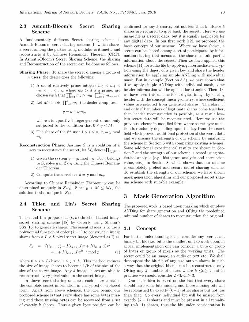
International Journal of Network Security, Vol.18, No.1, PP.68-81, Jan. 2016 70
2.3 Asmuth-Bloom’s Secret SharingScheme
A fundamentally different Secret sharing scheme isAsmuth-Bloom’s secret sharing scheme [1] which sharesa secret among the parties using modular arithmetic andreconstructs it by Chinese Remainder Theorem (CRT).In Asmuth-Bloom’s Secret Sharing Scheme, the sharingand Reconstruction of the secret can be done as follows.
Sharing Phase: To share the secret d among a group ofn users, the dealer does the following:
1) A set of relatively prime integers m0 < m1 <m2 < ... < mn where m0 > d is a prime, arechosen such that
∏ki=1 mi > m0
∏k−1i=1 mn−i+1;
2) Let M denote∏k
i=1 mi, the dealer computes,
y = d + am0,
where a is a positive integer generated randomlysubjected to the condition that 0 ≤ y < M .
3) The share of the ith user 1 ≤ i ≤ n, yi = y modmi.
Reconstruction Phase: Assume S is a coalition of kusers to reconstruct the secret, let Ms denote
∏i∈Smi .
1) Given the system y = yi mod mi. For i belongsto S, solve y in ZMS using the Chinese Remain-der Theorem.
2) Compute the secret as: d = y mod m0.
According to Chinese Remainder Theorem, y can bedetermined uniquely in ZMS . Since y < M ≤ MS , thesolution is also unique in ZM .
2.4 Thien and Lin’s Secret SharingScheme
Thien and Lin proposed a (k, n)-threshold-based imagesecret sharing scheme [18] by cleverly using Shamir’sSSS [16] to generate shares. The essential idea is to use apolynomial function of order (k−1) to construct n imageshares from a L× L pixel secret image (denoted as I) as
Sx = I(ik+1, j) + I(ik+2, j)x + I(ik+3, j)x2
+... + I(ik+k, j)xk−1 mod p, (1)
where 0 ≤ i ≤ L/k and 1 ≤ j ≤ L. This method reducesthe size of image shares to become 1/k of the size of thesize of the secret image. Any k image shares are able toreconstruct every pixel value in the secret image.
In above secret sharing schemes, each share containsthe complete secret information in encrypted or cipheredform. Apart from above schemes, the idea behind ourproposed scheme is that every share has some bytes miss-ing and these missing bytes can be recovered from a setof exactly k shares. Thus a given byte position can be
confirmed for any k shares, but not less than k. Hence kshares are required to give back the secret. Here we useimage file as a secret data, but it is equally applicable forany digital data. In our first work [12], we proposed thebasic concept of our scheme. Where we have shown, asecret can be shared among a set of participants by infor-mation sharing that means all the shares contain partialinformation about the secret. Then we have applied thisscheme [14] for audio file by applying intermediate encryp-tion using the digest of a given key and share the headerinformation by applying simple ANDing with individualmask. But in example (Section 3.3), we have shown thatif we apply simple ANDing with individual mask, someheader information will be opened for attacker. Then [13]we have used this scheme for a digital image by sharingheader with the concept linear geometry, where coefficientvalues are selected from generated shares. Therefore, ifand only if k numbers of legitimate shares come together,then header reconstruction is possible, as a result loss-less secret data will be reconstructed. Here we use theprevious scheme in modified form where secret byte selec-tion is randomly depending upon the key from the secretfield which provide additional protection of the secret dataand we discuss the strength of our scheme by analyzingthe scheme in Section 5 with comparing existing schemes.Some additional experimental results are shown in Sec-tion 7 and the strength of our scheme is tested using sta-tistical analysis (e.g. histogram analysis and correlationvalue, etc.) in Section 8, which shows that our schemeis completely prefect and secure secret sharing scheme.To establish the strength of our scheme, we have shownmask generation algorithm and our proposed secret shar-ing scheme with suitable example.
3 Mask Generation Algorithm
The proposed work is based upon masking which employsANDing for share generation and ORing the predefinedminimal number of shares to reconstruction the original.
3.1 Concept
For better understanding let us consider any secret as abinary bit file (i.e. bit is the smallest unit to work upon, inactual implementation one can consider a byte or groupof bytes or group of pixels as the working unit). Thesecret could be an image, an audio or text etc. We shalldecompose the bit file of any size onto n shares in sucha way that the original bit file can be reconstructed onlyORing any k number of shares where k ≤n≥ 2 but inpractice we should consider 2 ≤k<n≥ 3.
Our basic idea is based on the fact that every shareshould have some bits missing and those missing bits willbe replenished by exactly (k−1) other shares but not lessthan that. So every individual bit will be missed fromexactly (k − 1) shares and must be present in all remain-ing (n-k+1) shares, thus the bit under consideration is

International Journal of Network Security, Vol.18, No.1, PP.68-81, Jan. 2016 71
available in any set of k shares but not guaranteed in lessthan k shares. Now for a group of bits, for a particularbit position, (k − 1) number of shares should have thebit missed and (n− k + 1) number of shares should havethe bit present and similarly for different positions thereshould be different combinations of (k− 1) shares havingthe bits missed and (n−k+1) number of shares having thebits present. Clearly for every bit position there should beCn
k−1 such combinations and in our scheme thus forms themask of size Cn
k−1, which will be repeatedly ANDed overthe secret in any regular order. Different masks will pro-duce different shares from the secret. Thus 0 on the maskwill eliminate the bit from the secret and 1 in the maskwill retain the bit forming one share. Different maskshaving different 1 and 0 distributions will thus generatedifferent shares.
Next just ORing any k number of shares we get thesecret back but individual share having random numbersof 1′s and 0′s reflect no idea about the secret.
A possible set of masks for 5 shares with threshold of3 shares is shown below:
Share-1: 1 0 1 0 1 0 1 0 1 1Share-2: 1 0 1 1 1 1 0 1 0 0Share-3: 1 1 0 0 0 1 1 1 1 0Share-4: 0 1 1 1 0 0 1 1 0 1Share-5: 0 1 0 1 1 1 0 0 1 1
One can easily check that ORing any three or moreshares we get all 1′s but with less than three shares somepositions still have 0′s, i.e. remain missing.
3.2 Algorithm
Here we are presenting the algorithm for designing themasks for n shares with threshold k.
Step 1. List all row vectors of size n having the com-bination of (k − 1) numbers of 0′s and (n − k + 1)numbers of 1′s and arranged them in some predefinedorder in terms of their decimal equivalent and finallyorganized them in the form of a matrix. Obviousdimension of the matrix will be Cn
k−1 × n.
Step 2. Transpose the matrix generated in Step-1. Ob-vious dimension of the transposed matrix will ben × Cn
k−1. Each row of this matrix will be the in-dividual mask for n different shares. The size of eachmask is Cn
k−1 bits, i.e. the size of the mask varieswith the value of n and k.
Let us consider the previous example where n = 5 andk = 3.
Step 1. List of row vectors of size 5 bits with 2 numbersof 0′s and 3 numbers of 1′s, arranged in predefinedmanner as agreed during sharing phase in order toget masks identical to those used in share generationphase. (Here the arrangement is the highest followedby lowest then next highest followed by next lowest
Algorithm 1 Pseudo Code for mask generation
1: Input: n, k2: Output: mask[n][]3: Integer mask generator(n, k,mask[n][])4: 5: bin arr[][n]: Integer array;6: mask pattern len = 0;7: max val = 2n − 1;
// calculate decimal value of n numbers of 1s.8: for i = max val to 1 do9: Decimal to Binary(i, bin[][]);
// calculate binary equivalent of decimal i and storein bin arr[][] array.
10: if (Zero Check(bin[mask pattern len[n], k)))then
11: mask pattern len = mask pattern len + 1;// check whether (k−1) nos. of zero exist or not,if exist then increment mask pattern len by 1.
12: end if13: end for14: Rearrange Array(bin);
// rearrange the row of bin[][n] array.15: Transpose(mask, bin);
//take transpose matrix of bin[][n] and store inmask[n][].
16: Return mask pattern len;17: 18: End
and so on, which appears here as 28, 7, 26, 11, 25,13, 22, 14, 21, 19).
1 1 1 0 00 0 1 1 11 1 0 1 00 1 0 1 11 1 0 0 10 1 1 0 11 0 1 1 00 1 1 1 01 0 1 0 11 0 0 1 1
C5
2 × 5 = 10× 5
Step 2. Take the transpose of the above matrix and weget the desired masks for five shares as listed abovein the form of matrix of dimension 5×C5
2 , i.e. 5×10.There are five masks each of size 10 bits.
3.3 Example
Consider a secret message (M) is WBPRACSE27 and thesize of M is 10 bytes. Now by applying logical ANDing
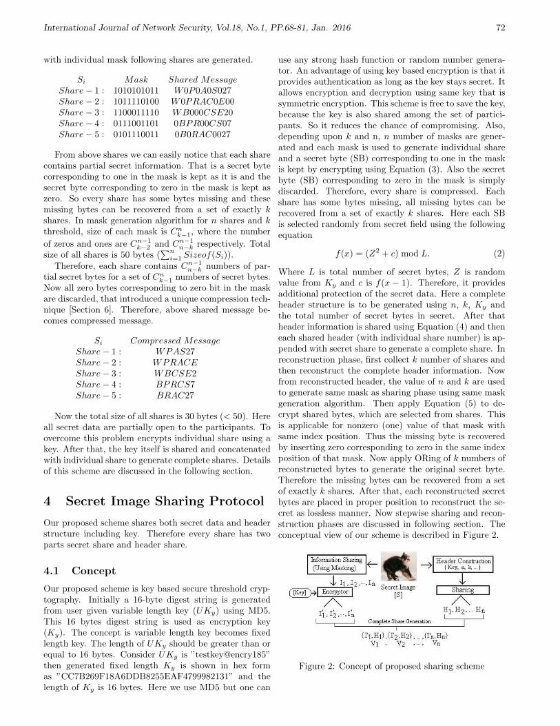
International Journal of Network Security, Vol.18, No.1, PP.68-81, Jan. 2016 72
with individual mask following shares are generated.
Si Mask Shared MessageShare− 1 : 1010101011 W0P0A0S027Share− 2 : 1011110100 W0PRAC0E00Share− 3 : 1100011110 WB000CSE20Share− 4 : 0111001101 0BPR00CS07Share− 5 : 0101110011 0B0RAC0027
From above shares we can easily notice that each sharecontains partial secret information. That is a secret bytecorresponding to one in the mask is kept as it is and thesecret byte corresponding to zero in the mask is kept aszero. So every share has some bytes missing and thesemissing bytes can be recovered from a set of exactly kshares. In mask generation algorithm for n shares and kthreshold, size of each mask is Cn
k−1, where the number
of zeros and ones are Cn−1k−2 and Cn−1
n−k respectively. Totalsize of all shares is 50 bytes (
∑ni=1 Sizeof(Si)).
Therefore, each share contains Cn−1n−k numbers of par-
tial secret bytes for a set of Cnk−1 numbers of secret bytes.
Now all zero bytes corresponding to zero bit in the maskare discarded, that introduced a unique compression tech-nique [Section 6]. Therefore, above shared message be-comes compressed message.
Si Compressed MessageShare− 1 : WPAS27Share− 2 : WPRACEShare− 3 : WBCSE2Share− 4 : BPRCS7Share− 5 : BRAC27
Now the total size of all shares is 30 bytes (< 50). Hereall secret data are partially open to the participants. Toovercome this problem encrypts individual share using akey. After that, the key itself is shared and concatenatedwith individual share to generate complete shares. Detailsof this scheme are discussed in the following section.
4 Secret Image Sharing Protocol
Our proposed scheme shares both secret data and headerstructure including key. Therefore every share has twoparts secret share and header share.
4.1 Concept
Our proposed scheme is key based secure threshold cryp-tography. Initially a 16-byte digest string is generatedfrom user given variable length key (UKy) using MD5.This 16 bytes digest string is used as encryption key(Ky). The concept is variable length key becomes fixedlength key. The length of UKy should be greater than orequal to 16 bytes. Consider UKy is ”testkey@encry185”then generated fixed length Ky is shown in hex formas ”CC7B269F18A6DDB8255EAF4799982131” and thelength of Ky is 16 bytes. Here we use MD5 but one can
use any strong hash function or random number genera-tor. An advantage of using key based encryption is that itprovides authentication as long as the key stays secret. Itallows encryption and decryption using same key that issymmetric encryption. This scheme is free to save the key,because the key is also shared among the set of partici-pants. So it reduces the chance of compromising. Also,depending upon k and n, n number of masks are gener-ated and each mask is used to generate individual shareand a secret byte (SB) corresponding to one in the maskis kept by encrypting using Equation (3). Also the secretbyte (SB) corresponding to zero in the mask is simplydiscarded. Therefore, every share is compressed. Eachshare has some bytes missing, all missing bytes can berecovered from a set of exactly k shares. Here each SBis selected randomly from secret field using the followingequation
f(x) = (Z2 + c) mod L. (2)
Where L is total number of secret bytes, Z is randomvalue from Ky and c is f(x − 1). Therefore, it providesadditional protection of the secret data. Here a completeheader structure is to be generated using n, k, Ky andthe total number of secret bytes in secret. After thatheader information is shared using Equation (4) and theneach shared header (with individual share number) is ap-pended with secret share to generate a complete share. Inreconstruction phase, first collect k number of shares andthen reconstruct the complete header information. Nowfrom reconstructed header, the value of n and k are usedto generate same mask as sharing phase using same maskgeneration algorithm. Then apply Equation (5) to de-crypt shared bytes, which are selected from shares. Thisis applicable for nonzero (one) value of that mask withsame index position. Thus the missing byte is recoveredby inserting zero corresponding to zero in the same indexposition of that mask. Now apply ORing of k numbers ofreconstructed bytes to generate the original secret byte.Therefore the missing bytes can be recovered from a setof exactly k shares. After that, each reconstructed secretbytes are placed in proper position to reconstruct the se-cret as lossless manner. Now stepwise sharing and recon-struction phases are discussed in following section. Theconceptual view of our scheme is described in Figure 2.
Figure 2: Concept of proposed sharing scheme

International Journal of Network Security, Vol.18, No.1, PP.68-81, Jan. 2016 73
4.2 Sharing Phase
The sharing phase of the proposed scheme is stated in thefollowing steps.
Input: threshold (k), total number of share (n), usergiven variable length key (UKy), secret image (SI).
Step 1. Initially generate 16 bytes digest from user givenvariable length key (UKy). This 16 bytes digeststring is used as encryption key (Ky). Here we useMD5 hash function to generate 16 bytes digest string.So variable length key becomes fixed length key.
Step 2. Now construct Header Structure (h) of five fieldsand put share number (Sn) in 1st field, total number(n) of shares in 2nd field, threshold number (k) in 3rd
field, key (Ky) in 4th field, and the total secret bytes(for image, only consider width) (W) in 5th field (SeeTable 1).
The size of this header structure is 23-bytes. Thisstructure or size of individual field may vary accord-ing to our requirements.
Step 3. Generate n masks for n individual shares us-ing the proposed mask generation algorithm [Sec-tion 3.2]. Consider the mask pattern length is ML.Therefore, ML = mask generator(n, k,mask[n][]).
Step 4. Calculate total number of secret bytes (L)present in SI using height and width (W). For otherdigital files such as text, audio the total number ofsecret bytes L will be equal to W (i.e. actual sizeof secret). Also consider an array of N location sayIndex[L] and initialize all the location by zero, i.e.Index[L] = 0, where zero indicates unread secretbyte at ith position and one indicates read ith secretbyte.
if
index[i] = 0, unread
index[i] = 1, read
Step 5. Now select specific secret byte (SB) from a ran-dom position (PS) using Algorithm 2.
The secret byte (SB) corresponding to zero in themask is simply discarded. Therefore, each share con-tains partial secret information and for each retainedsecret bytes apply Step 6 to generate confused secretbytes.
Step 6. Then the ith retained byte (Pi) is ciphered bythe jth byte (Kyj
) by the following operation:
Ri = Pi−1 ⊕ (Pi ×Kyj) mod 251, (3)
where i = 0, 1, 2, · · · , (L−1) and j = mod (i, 16) and251 is largest prime number in 8 bits.
0th retained byte is ciphered by the 0th byte of Ky.R0 = P−1 ⊕ (P0 ×Ky0
) mod 251, where P−1 iszero.
Algorithm 2 Secret byte (SB) selection and distribution
1: PS = 0;2: For j = 0 to (L− 1)3: PS = Ky[j%16]×Ky[(j + 1)%16] + PS;4: PS = PS%L;5: while (Index[PS]! = 0) do6: PS = (PS + 1)%L;7: end while8: Read secret byte (SB) from PSth position;9: Index[PS] = 1; // 0 for unread and 1 for read
10: For i = 1 to n11: if (mask[i][j%ML] = 1) then12: Apply Step-6 for ciphering the SB;13: Write the ciphered byte in ith share;14: end if15: End For;16: EndFor;17: End
1st retained byte is ciphered by the 1st byte of Ky.R1 = P0 ⊕ (P1 ×Ky1) mod 251.
2nd retained byte is ciphered by the 2nd byte of Ky.R2 = P1 ⊕ (P2 ×Ky2) mod 251,
· · ·Same as tth retained byte is ciphered by (t mod
16)th byte of Ky. Rt = Pt−1 ⊕ (Pt ×Ky(t mod 16)
) mod 251.
Step 7. Now from each of n ciphered shares collect knumbers of nonzero sample bytes from prefixed lo-cations and thus matrix (A) of dimension (n × k) isformed.
a[0,0] a[0,1] ... a[0,k−2] a[0,k−1]a[1,0] a[1,1] ... a[1,k−2] a[1,k−1]. . ... . .. . ... . .. . ... . .
a[n−2,0] a[n−2,1] ... a[n−2,k−2] a[n−2,k−1]a[n−1,0] a[n−1,1] ... a[n−1,k−2] a[n−1,k−1]
n×k
Step 8. The header (Table 1) excluding the leftmost fieldis also shared by applying following operation:-
Vi =
i=0,1,··· ,n−1∑j=0,1,··· ,k−1
(a[i, j]× h[j]). (4)
Step 9. Next each header share is appended with theshare number (Sn) in the first field and concatenatedwith the corresponding secret share, which forms onecomplete share for transmission. (For shared imagewe have to add extra single height to add the sharedheader, i.e. if height of SI is h, then shared imageheight will be (h + 1)).
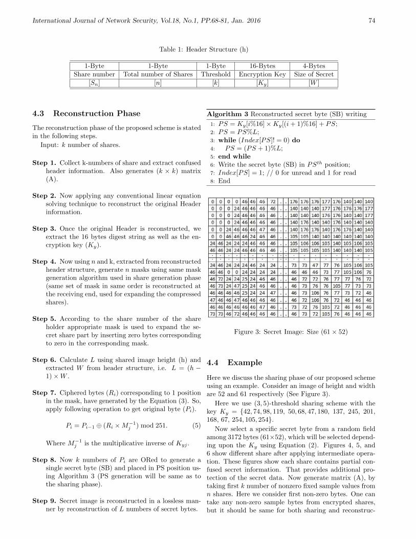
International Journal of Network Security, Vol.18, No.1, PP.68-81, Jan. 2016 74
Table 1: Header Structure (h)
1-Byte 1-Byte 1-Byte 16-Bytes 4-BytesShare number Total number of Shares Threshold Encryption Key Size of Secret
[Sn] [n] [k] [Ky] [W ]
4.3 Reconstruction Phase
The reconstruction phase of the proposed scheme is statedin the following steps.
Input: k number of shares.
Step 1. Collect k-numbers of share and extract confusedheader information. Also generates (k × k) matrix(A).
Step 2. Now applying any conventional linear equationsolving technique to reconstruct the original Headerinformation.
Step 3. Once the original Header is reconstructed, weextract the 16 bytes digest string as well as the en-cryption key (Ky).
Step 4. Now using n and k, extracted from reconstructedheader structure, generate n masks using same maskgeneration algorithm used in share generation phase(same set of mask in same order is reconstructed atthe receiving end, used for expanding the compressedshares).
Step 5. According to the share number of the shareholder appropriate mask is used to expand the se-cret share part by inserting zero bytes correspondingto zero in the corresponding mask.
Step 6. Calculate L using shared image height (h) andextracted W from header structure, i.e. L = (h −1)×W .
Step 7. Ciphered bytes (Ri) corresponding to 1 positionin the mask, have generated by the Equation (3). So,apply following operation to get original byte (Pi).
Pi = Pi−1 ⊕ (Ri ×M−1j ) mod 251. (5)
Where M−1j is the multiplicative inverse of Kyj .
Step 8. Now k numbers of Pi are ORed to generate asingle secret byte (SB) and placed in PS position us-ing Algorithm 3 (PS generation will be same as tothe sharing phase).
Step 9. Secret image is reconstructed in a lossless man-ner by reconstruction of L numbers of secret bytes.
Algorithm 3 Reconstructed secret byte (SB) writing
1: PS = Ky[i%16]×Ky[(i + 1)%16] + PS;2: PS = PS%L;3: while (Index[PS]! = 0) do4: PS = (PS + 1)%L;5: end while6: Write the secret byte (SB) in PSth position;7: Index[PS] = 1; // 0 for unread and 1 for read8: End
Figure 3: Secret Image: Size (61× 52)
4.4 Example
Here we discuss the sharing phase of our proposed schemeusing an example. Consider an image of height and widthare 52 and 61 respectively (See Figure 3).
Here we use (3, 5)-threshold sharing scheme with thekey Ky = 42, 74, 98, 119, 50, 68, 47, 180, 137, 245, 201,168, 67, 254, 105, 254.
Now select a specific secret byte from a random fieldamong 3172 bytes (61×52), which will be selected depend-ing upon the Ky using Equation (2). Figures 4, 5, and6 show different share after applying intermediate opera-tion. These figures show each share contains partial con-fused secret information. That provides additional pro-tection of the secret data. Now generate matrix (A), bytaking first k number of nonzero fixed sample values fromn shares. Here we consider first non-zero bytes. One cantake any non-zero sample bytes from encrypted shares,but it should be same for both sharing and reconstruc-
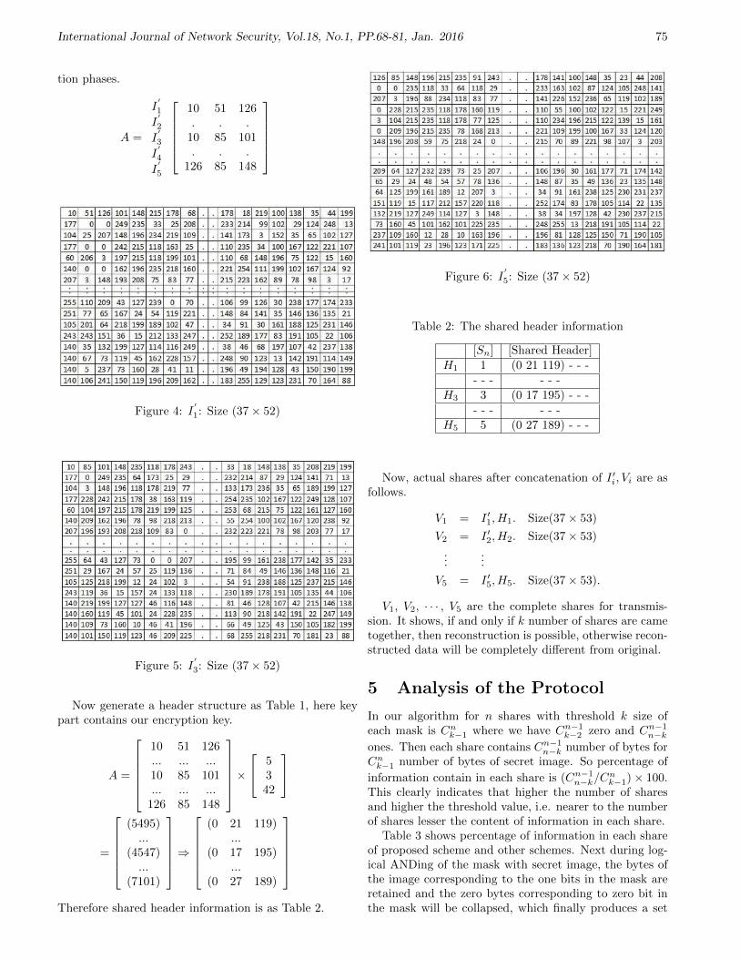
International Journal of Network Security, Vol.18, No.1, PP.68-81, Jan. 2016 75
tion phases.
A =
I′
1
I′
2
I′
3
I′
4
I′
5
10 51 126. . .
10 85 101. . .
126 85 148
Figure 4: I′
1: Size (37× 52)
Figure 5: I′
3: Size (37× 52)
Now generate a header structure as Table 1, here keypart contains our encryption key.
A =
10 51 126... ... ...10 85 101... ... ...
126 85 148
× 5
342
=
(5495)...
(4547)...
(7101)
⇒
(0 21 119)...
(0 17 195)...
(0 27 189)
Therefore shared header information is as Table 2.
Figure 6: I′
5: Size (37× 52)
Table 2: The shared header information
[Sn] [Shared Header]H1 1 (0 21 119) - - -
- - - - - -H3 3 (0 17 195) - - -
- - - - - -H5 5 (0 27 189) - - -
Now, actual shares after concatenation of I ′i, Vi are asfollows.
V1 = I ′1, H1. Size(37× 53)
V2 = I ′2, H2. Size(37× 53)
......
V5 = I ′5, H5. Size(37× 53).
V1, V2, · · · , V5 are the complete shares for transmis-sion. It shows, if and only if k number of shares are cametogether, then reconstruction is possible, otherwise recon-structed data will be completely different from original.
5 Analysis of the Protocol
In our algorithm for n shares with threshold k size ofeach mask is Cn
k−1 where we have Cn−1k−2 zero and Cn−1
n−kones. Then each share contains Cn−1
n−k number of bytes forCn
k−1 number of bytes of secret image. So percentage of
information contain in each share is (Cn−1n−k/C
nk−1)× 100.
This clearly indicates that higher the number of sharesand higher the threshold value, i.e. nearer to the numberof shares lesser the content of information in each share.
Table 3 shows percentage of information in each shareof proposed scheme and other schemes. Next during log-ical ANDing of the mask with secret image, the bytes ofthe image corresponding to the one bits in the mask areretained and the zero bytes corresponding to zero bit inthe mask will be collapsed, which finally produces a set

International Journal of Network Security, Vol.18, No.1, PP.68-81, Jan. 2016 76
Table 3: Percentage of information in each share for dif-ferent k, n
n k Cn−1n−k Cn
k−1 Our Scheme [16] [2] [1]
8 8 1 8 12.5 100 100 1008 7 7 28 25 100 100 1008 6 21 56 37.5 100 100 1008 5 35 70 50 100 100 1006 5 5 15 33.3 100 100 1006 4 10 20 50 100 100 1005 3 6 10 60 100 100 100
of scrambled bytes; effectively the retained information incompressed and thus being further ciphered.
Next the scrambled bytes are further ciphered usingmodulo multiplication techniques with the MD5 digest ofthe key given at the time of transmission (key). It maybe noted that instead of using the key directly we haveused the digest of the key for encryption, then the size ofthe key is immaterial which provides additional strengthagainst cryptanalysis for the key.
Finally here the key may be the session key, i.e. the keywill be varied with every transmission and our algorithmis free from key distribution hazard as the key itself isfurther shared in the secret shares.
Thus from individual shares there is hardly any leakageof information vis-a-vis unless minimal number of untam-pered share which is not tampered is collected nothingis revealed. Only when minimal number of valid shareis collected one can form the key and get the informa-tion about total number of shares created. After knowingnumber of shares and the threshold (which is known) onecan form the mask and from the key one can get the di-gest. From the digest using multiplicative inverse we getthe compressed shares and the actual shares using themasks. Finally ORing the shares we get the original se-cret.
6 Analysis of Compression
All masking pattern has equal number of zeros with dif-ferent distribution only. In every share we collapse allzero bytes corresponding to zero bit in the correspondingmask. It may be noted that as k is closer to n, more iscompression, i.e. maximum for k = n.
Next for lossless expanding, knowing n and k we canredesign all n masks using our original mask generationalgorithm. According to the share number of the shareholder appropriate mask is used to expand the secretshare by inserting zero bytes corresponding to zero bitin the corresponding mask.
In our example of (3, 5) the mask size is of 10 bitsand every mask has 4 zeroes, thus every secret can becompressed by approximately 40 percent, obviously thecompression varies with (k, n). In case of an example of
(5, 6) the mask size is 15 bits and every mask has 10zeroes, thus compression will be 66.6 % (See Table 4 andFigures 7 and 8).
Table 4: Compression rate for different k and nThreshold(k)
Length ofMaskingPattern
Numberof zero inmaskingpattern
ApproximateCompressionRate (per-cent)
2 5 1 203 10 4 404 10 6 605 5 4 80
Total number of Shares (n) = 5.Threshold(k)
Length ofMaskingPattern
Numberof zero inmaskingpattern
ApproximateCompressionRate (per-cent)
2 6 1 163 15 5 334 20 10 505 15 10 666 6 5 83
Total number of Shares (n) = 6.
Figure 7: Threshold vs. compression ratio
7 Experimental Result
7.1 Experimental Result for 24-bit bmpImage
Figure 9 shows a secret image (Figure 9(a)) is sharedamong 5 participants by the user given key (UKy)”2936451090872310”. Here threshold value is 3. At thereconstruction phase, if we collect only 3 or more shares

International Journal of Network Security, Vol.18, No.1, PP.68-81, Jan. 2016 77
Figure 8: Compression rate
then reconstructed secret is lossless, but less than 3 sharesare not sufficient to reconstruct the secret data. In thetime of reconstruction no need to remember the key, be-cause key as well as secret data is shared among set ofparticipants.
7.2 Experimental Result for Gray Image
Figure 10 shows a secret image (Figure 10(a)) of size181200 bytes is shared among 5 participants by the usergiven key ”2936451290874310” and the value of k is 3.Here generated shares size are less than secret image andwhich hold the partial secret information. That providesan additional protection of secret image.
8 Strength and Security Analysis
A secure shared cryptography algorithm should be robustagainst all types of attacks such as cryptanalytic, statisti-cal. Here we discuss the security analysis of the proposedalgorithm by addressing key sensitivity analysis and dif-ferent statistical analysis. The resistance against differenttypes of attack is useful measure of the performance of acryptosystem. Therefore some security analysis resultsare incorporated in the following section to prove the va-lidity of our proposed scheme.
8.1 Key Sensitivity Analysis
In our scheme, shared data is highly sensitive to the se-cret key. Here user given variable length key (UKy) isconverted as a fixed length key (16 bytes) using MD5hash function. Here we use MD5, but one can use anyhash function or random number generator. Now thisfixed length key is used as encryption key (Ky). Gen-erated shares are varied for a single bit/byte changes inthe key, because secret bytes are selected randomly fromsecret field depending upon the key and secret bytes arealso encrypted using the key. The merits of our schemeis that key based shared cryptography that introduce the
(a). Secret Img1.bmp(453 × 395) Size =537254 Bytes
(b). Img1−A.bmp(272 × 396) Size=323190 Bytes
(c). Img1−B.bmp(272× 396) Size =323190 Bytes
(d). Img1−C.bmp(272× 396) Size =323190 Bytes
(e). Img1−D.bmp(272× 396) Size =323190 Bytes
(f). Img1−E.bmp(272× 396) Size =323190 Bytes
(g). Decode.bmp(Noisy Image Con-struction usingImg1−B.bmp andImg1−E.bmp)
(h). Decode.bmp(Original ImageConstruction usingany three shares)
Figure 9: (3, 5)-Sharing and Reconstruction for 24-bitimage
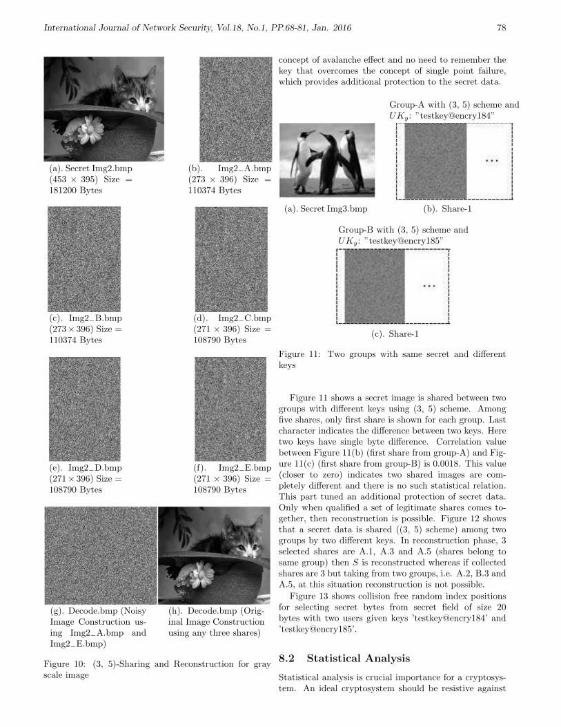
International Journal of Network Security, Vol.18, No.1, PP.68-81, Jan. 2016 78
(a). Secret Img2.bmp(453 × 395) Size =181200 Bytes
(b). Img2−A.bmp(273 × 396) Size =110374 Bytes
(c). Img2−B.bmp(273× 396) Size =110374 Bytes
(d). Img2−C.bmp(271 × 396) Size =108790 Bytes
(e). Img2−D.bmp(271× 396) Size =108790 Bytes
(f). Img2−E.bmp(271 × 396) Size =108790 Bytes
(g). Decode.bmp (NoisyImage Construction us-ing Img2−A.bmp andImg2−E.bmp)
(h). Decode.bmp (Orig-inal Image Constructionusing any three shares)
Figure 10: (3, 5)-Sharing and Reconstruction for grayscale image
concept of avalanche effect and no need to remember thekey that overcomes the concept of single point failure,which provides additional protection to the secret data.
Group-A with (3, 5) scheme andUKy: ”testkey@encry184”
(a). Secret Img3.bmp (b). Share-1
Group-B with (3, 5) scheme andUKy: ”testkey@encry185”
(c). Share-1
Figure 11: Two groups with same secret and differentkeys
Figure 11 shows a secret image is shared between twogroups with different keys using (3, 5) scheme. Amongfive shares, only first share is shown for each group. Lastcharacter indicates the difference between two keys. Heretwo keys have single byte difference. Correlation valuebetween Figure 11(b) (first share from group-A) and Fig-ure 11(c) (first share from group-B) is 0.0018. This value(closer to zero) indicates two shared images are com-pletely different and there is no such statistical relation.This part tuned an additional protection of secret data.Only when qualified a set of legitimate shares comes to-gether, then reconstruction is possible. Figure 12 showsthat a secret data is shared ((3, 5) scheme) among twogroups by two different keys. In reconstruction phase, 3selected shares are A.1, A.3 and A.5 (shares belong tosame group) then S is reconstructed whereas if collectedshares are 3 but taking from two groups, i.e. A.2, B.3 andA.5, at this situation reconstruction is not possible.
Figure 13 shows collision free random index positionsfor selecting secret bytes from secret field of size 20bytes with two users given keys ’testkey@encry184’ and’testkey@encry185’.
8.2 Statistical Analysis
Statistical analysis is crucial importance for a cryptosys-tem. An ideal cryptosystem should be resistive against

International Journal of Network Security, Vol.18, No.1, PP.68-81, Jan. 2016 79
Figure 12: Reconstruction of a Secret file using qualifiedset of legitimate shares
Figure 13: Random index positions for two keys
any statistical attack. To prove the robustness of the pro-posed algorithm, we have performed the following statis-tical test such as histogram analysis, correlation analysis,etc.
8.2.1 Histogram Analysis
The histogram analysis clarifies how pixels in an imageare distributed by plotting the number of pixels at eachintensity level. Histogram analysis of gray scale secretimage (SecretImg2.bmp) with respect to shared imagesis shown in Figure 14. The histogram of shared imageshas uniform distribution which is significantly differentfrom the original image and has no statistical similarityin appearance (See Figure 14).
8.2.2 Correlation Value
A secret shared cryptography scheme must generateshared images independent of the original secret image.Therefore, they must have a very low correlation coef-ficient value. Here, we have calculated the correlationbetween the shares. Also the correlation between origi-nal and reconstructed image is shown in Table 5. Thecorrelation value is calculated using Equation (6).
r =
∑m
∑n(Amn −A′)(Bmn −B′)√
(∑
m
∑n(Amn −A′)2
∑m
∑n(Bmn −B′)2)
, (6)
where A′
and B′
are mean of A and B respectively. Alow value of correlation coefficient shows that there is no
straight relation between the original and encrypted im-ages. Here generated shared images are compressed. Soit is impossible to show the correlation value between se-cret image and shared images. Following table (Table 5)shows the correlation value among shared images and se-cret image and reconstructed images.
(a). Histogram of Fig-ure 10(a)
(b). Histogram of Fig-ure 10(b)
(c). Histogram of Fig-ure 10(c)
(d). Histogram of Fig-ure 10(d)
(e). Histogram of Fig-ure 10(e)
(f). Histogram of Fig-ure 10(f)
Figure 14: Histogram of Secret image (Figure 10(a)) andShared images
Table 5: Correlation value
SL No. Images Correlation value1 Figure 10(b) and (c) : 0.51252 Figure 10(d) and (e) : 0.50573 Figure 10(d) and (f) : 0.17644 Figure 10(e) and (f) : 0.50585 Figure 10(a) and (g) : -0.00306 Figure 10(a) and (h) : 1
In the above table the 6th entry shows the correla-tion value between secret image (Figure 10(a)) and re-

International Journal of Network Security, Vol.18, No.1, PP.68-81, Jan. 2016 80
constructed image (Figure 10(h)) using 3 shares and thevalue is one, so the reconstruction is lossless. The 5th en-try shows a value close to zero for the correlation betweensecret image (Figure 10(a)) and reconstructed image (Fig-ure 10(g)) using 2 shares.
8.2.3 MSE and PSNR Measure
The Mean Square Error (MSE) and Peak Signal to NoiseRatio (PSNR) for the proposed technique have been com-puted for different images. The high value of MSE andlow value of PSNR cause the resulting encrypted imagemore randomness. MSE is calculated using the formula
MSE = (ΣNi−1ΣM
j=1[C(i, j)− C′(i, j)]2)/MN,
where, c(I, j) and c′(I, j) are the ith row and jth column
pixel of two images C and C′, respectively. M and N are
the number of rows and columns of an image. PSNR canbe computed by
PSNR = 10× log10[R2/MSE],
where R is 255 as grey image has been used in this experi-ment. Calculated results of MSE and PSNR are tabulatedin Table 6.
Table 6: MSE and PSNR value
SL No. Images MSE PSNR1 Figure 10(b) and (c) : 115.6822 27.49812 Figure 10(d) and (e) : 117.2003 27.44153 Figure 10(d) and (f) : 194.8199 25.23454 Figure 10(e) and (f) : 117.2881 27.43835 Figure 10(a) and (g) : 233.7130 24.44376 Figure 10(a) and (h) : 0 Infinity
High value MSE and low value PSNR indicate that twoimages are completely different. On the other hand, thehigh value of PSNR indicates the high quality image.
9 Conclusions
This paper shows a secured key based secret sharingscheme where key as well as secret data is shared amongset of participants. Here image is selected as a secret data,although proposed scheme is strongly applicable for otherdigital data, such as text, audio, etc. In the sharing phaseall secret bytes are selected randomly from secret field de-pending upon the key and each generated share holds par-tial secret information in scrambled and encrypted form.That provides additional protection of the secret imageand also reduces the bandwidth required for transmission.
In our scheme if and only if numbers of collecting sharesare equal to k or more and none of the share is tampered,then only the original secret image is reconstructed; other-wise reconstructed image will be completely ciphered, be-cause fewer shares cannot reconstruct the original header,
thus we cannot have either right key (Ky) or the infor-mation to construct the correct masking pattern. So ourproposed scheme can claim to be a Perfect Secret Shar-ing (PSS) Scheme. Not only that, if a legitimate groupof threshold number of shares comes together (i.e. sharesfrom different groups cannot mix as keys are different),then only the original secret is reconstructed. Moreover,key sensitivity analysis and statistical analysis prove thehigh acceptability of the proposed algorithm.
Acknowledgments
We are thankful to the department of Computer Science& Engineering of MCKV Institute of Engineering, RegentEducation & Research Foundation and Jadavpur Univer-sity, Kolkata for giving us the platform for planning anddeveloping this work in departmental laboratories.
References
[1] C. Asmuth and J. Bloom, “A modular approach tokey safeguarding,” IEEE Transaction on Informa-tion Theory, vol. 29, no. 2, pp. 208–210, 1983.
[2] G. R. Blakley, “Safeguarding cryptographic keys,”in Proceedings of AFIPS International Workshop onManaging Requirements Knowledge, pp. 313, 1979.
[3] K. Y. Chao and J. C. Lin, “Secret image sharing: aboolean-operations based approach combining bene-fits of polynomial-based and fast approaches,” Inter-national Journal of Pattern Recognition and Artifi-cial Intelligence, vol. 23, no. 2, pp. 263–285, 2009.
[4] Y. Desmedt, “Some recent research aspects of thresh-old cryptography,” in Proceedings of 1st Interna-tional Information Security Workshop (ISW’97),pp. 158–173, Ishikawa, Japan, 1997.
[5] Y. Desmedt and Y. Frankel, “Shared generation ofauthenticators and signatures,” in Advances in Cryp-tolog (RYPTO’91), LNCS 576, pp. 457–469, SpringerVerlag, 1992.
[6] Y. Desmedt and Y. Frankel, “Threshold cryptosys-tems,” in Proceedings on Advances in Cryptology(CRYPTO’89), LNCS 435, pp. 307–315, 1990.
[7] Y. Desmedt and Y. Frankel, “Homomorphic zeroknowledge threshold schemes over any finite abeliangroup,” SIAM Journal on Discrete Mathematics,vol. 7, no. 4, pp. 667–675, 1994.
[8] L. Dong and M. Ku, “Novel (n, n) secret imagesharing scheme based on addition,” in Sixth Inter-national Conference on Intelligent Information Hid-ing and Multimedia Signal Processing (IIH-MSP’10),pp. 583–586, 2010.
[9] L. Dong, D. Wang, M. Ku, and Y. Dai, “(2, n) secretimage sharing scheme with ideal contrast,” in Inter-national Conference on Computational Intelligenceand Security (CIS’10), pp. 421–424, 2010.
[10] H. F. Huang and C. C. Chang, “A novel efficient (t,n) threshold proxy signature scheme,” InformationSciences, vol. 176, no. 10, pp. 1338–1349, 2006.

International Journal of Network Security, Vol.18, No.1, PP.68-81, Jan. 2016 81
[11] E. D. Karnin, J. W. Greene, and M. E. Hellman, “Onsecret sharing systems,” IEEE Transactions on In-formation Theory, vol. IT-29, no. 1, pp. 35–41, 1983.
[12] P. K. Naskar, A. Chaudhuri, D. Basu, and A. Chaud-huri, “A novel image secret sharing scheme,” in Sec-ond International Conference on Emerging Applica-tions of Information Technology (EAIT’11), pp. 177–180, 2011.
[13] P. K. Naskar, H. N. Khan, U. Roy, A. Chaudhuri, andA. Chaudhuri, “Secret image sharing with embed-ded session key,” in Computer Information SystemsAnalysis and Technologies (CISIM’11), Communica-tions in Computer and Information Science, vol. 245,pp 286-294, 2011.
[14] P. K. Naskar, H. N. Khan, U. Roy, A. Chaudhuri, andA. Chaudhuri, “Shared cryptography with embeddedsession key for secret audio,” International Journalof Computer Applications, vol. 26, no. 8, pp. 5–9,2011.
[15] A. De Santis, Y. Desmedt, Y. Frankel, and M. Yung,“How to share a function securely?,” in Proceed-ings of the Twenty-Sixth Annual ACM Symposiumon Theory of Computing (STOC’94), pp. 522–533,1994.
[16] A. Shamir, “How to share a secret?,” Communica-tions of the ACM, vol. 22, no. 11, pp. 612–613, 1979.
[17] V. Shoup, “Practical threshold signatures,” in Pro-ceedings of Eurocrypt’00, LNCS 1807, pp. 207–220,Springer-Verlag, 2000.
[18] C. C. Thien and J. C. Lin, “Secret image sharing,”Computers and Graphics, vol. 26, no. 5, pp. 765–770,2002.
Prabir Kr. Naskar, B.Tech from Govt. College ofEngineering & Leather Technology (WBUT), West Ben-gal, India and M.Tech from Jadavpur University, WestBengal, India, is presently working as Assistant Professorin the Department of Computer Science & Engineering,MCKV Institute of Engineering, West Bengal, India.Currently he is doing his research work at JadavpurUniversity, West Bengal, India. His current researchinterests include: cryptography, information sharing,steganography, watermarking and image processing.
Hari Narayan Khan is an Assistant Professor in theDepartment of Computer Science & Engineering, RegentEducation & Research Foundation, West Bengal Univer-sity of Technology, Kolkata, India and presently pursuinghis research work at Jadavpur University, Kolkata, WestBengal, India. He completed his M.Tech in ComputerTechnology at Jadavpur University, Kolkata, India. Hecompleted his B.Tech in Electronics & CommunicationEngineering from Institute of Technology & MarineEngineering under West Bengal University of Tech-nology, Kolkata, India. His research interest includescryptography, network security, information sharing,steganography and watermarking.
Prof. Atal Chaudhuri, B.E., M.E. & PhD from Ja-davpur University, West Bengal, India, is working inthe Department of Computer Science & Engineering, Ja-davpur University, West Bengal, India for last 29 years.His current research interests include: embedded system,cryptography, information sharing, steganography, water-marking and data mining.

International Journal of Network Security, Vol.18, No.1, PP.82-89, Jan. 2016 82
An Improved RSA-based CertificatelessSignature Scheme for Wireless Sensor Networks
Gaurav Sharma, Suman Bala, and Anil K. Verma(Corresponding author: Gaurav Sharma)
Computer Science and Engineering Department, Thapar University, Patiala 147004, India
(Email: [email protected])
(Received Aug. 15, 2013; revised and accepted Jan. 7 & Apr. 28, 2014)
Abstract
The entire world is looking to fulfill the need of the hourin terms of security. Certificateless cryptography is an ef-ficient approach studied widely due to two reasons: first,it eliminates the need of certificate authority in publickey infrastructure and second, it can resolve key escrowproblem of ID-based cryptography. Recently, Zhang et al.proposed a novel security scheme based on RSA, applica-ble to real life applications but could not cope up with thewell defined attacks. This paper, presents an RSA-basedCertificateLess Signature (RSA-CLS) scheme applicableto wireless sensor networks. The security of RSA-CLS isbased on the hardness assumption of Strong RSA. Thescheme is proven to be secure against Type I and Type IIattack in random oracle model.
Keywords: Certificateless public key cryptography, digitalsignature, RSA
1 Introduction
Express progress in the field of technology made it feasi-ble to foster wireless sensor networks technology [1, 7, 21].Wireless Sensor Networks (WSN) are comprised of largenumber of tiny sensor nodes with constrained resourcesin terms of processing power, energy and storage. WSNcan be used in various applications mainly environmentalmonitoring, medical, military, and agriculture [1]. Since,devices used in sensor networks is not tamper resistant,so adversary can gain its physical access easily. Hence,the main objective is to protect the data from unautho-rized access, which can be done by using some securitymechanisms [6, 9, 29]. The technology faces lots of secu-rity problems as it has a wireless mode of communicationand access to such sensor devices is quite easy. There aretwo approaches to restrict the unauthorized access in tothe network: symmetric cryptography [39] and asymmet-ric cryptography [30]. Initially, symmetric algorithms arepreferable to asymmetric algorithms, as they are simpleand less computational for 8-bit micro-controller. Sym-metric algorithms need key pre-distribution. The prob-
lem with this approach is the number of keys stored ineach sensor node and the network is not forward secureafter the compromising of the key. Moreover, it causesgreater configuration effort before deployment and gener-ating ample traffic, thus consequently higher energy con-sumption [8]. As a result, researchers are redirecting theirattention to asymmetric algorithms but asymmetric algo-rithms are very challenging for constrained resources inWSN.
In traditional Public Key Infrastructure (PKI), theuser selects a public key but it needs to be validatedby a trusted third party known as Certificate Authority(CA) [3]. The CA provides a digital certificate to tag thepublic key with the user’s identity. PKI has a problem ofhigh computation and storage. To avoid this, Shamir [24]introduced the concept of Identity-based Infrastructure.It allows the user to choose a public key of its own choicesuch as email-id, phone number, name, etc. and the pri-vate key is generated by trusted third party server, Pri-vate Key Generator (PKG) causing a key escrow problem.Then, Al-Riyami et al. [2] presented a novel approach tosolve the key escrow problem familial to Identity-basedCryptography (IBC) and eliminated the use of certificatesin traditional Public Key Cryptography (PKC) known asCertificateLess Public Key Cryptography (CL-PKC). InCL-PKC, the trusted third party server, Key GenerationCentre (KGC) generates a partial private key for the userwherein user’s secret key and partial private key are usedto generate public key of the user. In other words, CL-PKC differs from IBC in terms of arbitrary public keyand when a signature is transmitted, user’s public key isattached with it but not certified by any of the trustedauthority. Thus, the KGC does not come to know thesecret key of the user.
Thereafter, lots of CertificateLess Signature (CLS)schemes based on Discrete Logarithm Problem (DLP)have been presented and cryptanalyzed [12, 15, 17, 36].Later, CLS schemes based on Elliptic Curve Discrete Log-arithm Problem (ECDLP) has been presented and crypt-analyzed such as [10, 27, 28, 35, 40, 41]. Xu et al. [33, 34]presented two CLS schemes for emergency mobile wireless

International Journal of Network Security, Vol.18, No.1, PP.82-89, Jan. 2016 83
cyber-physical systems and mobile wireless cyber-physicalsystems respectively. But Zhang et al. [37] proved it in-secure against public key replacement attack. Another,authenticated scheme for WSN was presented by Li etal. [19].
Since, the pairing operation is the most expensive op-eration among all, so there was a need to find the solution.In 2009, Wang et al. [31] presented a scheme which neednot to compute the pairing at the sign stage, rather it pre-computes and publishes as the system parameters. But,this is not the solution for the removal of pairing opera-tion. In 2011, He et al. [13] developed an efficient shortCLS scheme without pairing. After a while, few schemeshave been presented and cryptanalyzed based on ECDLPwithout pairing [11, 26].
Another aspect of pairing free CLS scheme was pre-sented by Zhang et al. [38] in 2012, based on Strong RSAassumption and proven to be secure against Super Type Iadversary in random oracle model. But, proved insecurein [14, 25] independently against key replacement attack.Watro et al. [32] initiated the concept of RSA based cryp-tography in public-key based protocols for wireless sensornetworks known as TinyPK. Bellare et al. [5] presentedan Identity-Based Multi-Signature (IBMS) scheme basedon RSA, which is secure under the one-wayness of RSAin the random oracle model.
This paper presents a new RSA-based CertificatelessSignature (RSA-CLS) scheme for WSN based Strong RSAassumption and proven to be secure against Super Type Iand Super Type II attacks in random oracle model.
1.1 Organization of the Paper
The rest of the paper is organized as follows: In thenext section, we will discuss motivation and our contri-bution. Section 2 describes preliminaries, which includescomplexity assumptions, formal model and security modelof CLS scheme. Section 3, describes the proposed RSA-based CertificateLess Signature (RSA-CLS) scheme. Sec-tion 4 discusses about the analysis of the proposed RSA-CLS scheme, including security proofs against Type I andType II adversary in the random oracle model and per-formance analysis w.r.t WSN followed by conclusion.
1.2 Motivation and Our Contribution
The real truth is far from imagination, i.e. there are manytheories proposed for secure transmission. At presentmost of the theories are on paper but far from the realapplication. RSA has been implemented already in var-ious applications like WSN, cloud computing etc. So, itwould be preferable to upgrade the existing system ratherimplementing a new system. In present scenario, CL-PKC is the most convincing approach to provide securecommunication. The main benefits of RSA based Certifi-cateLess Signature (RSA-CLS) scheme is to avoid pair-ing operations which is the most expensive operation forresource-constrained WSN. Zhang et al. [38] proposed a
scheme and claimed that their scheme based on StrongRSA assumption, is: (i) more practical as far as industrystandard goes, (ii) secure in random oracle model, (iii)more efficient than existing schemes as no pairing opera-tion is involved, (iv) secure against Super Type I (discussin Section 2.3) adversary [16] (which implies the securityagainst Strong and Normal Type both) and left an openproblem of designing of CLS scheme secure in standardmodel. Sharma et al. [25] and He et al. [14] independentlyfound that the scheme [38] is not secure against key re-placement attack. Sharma et al. [25] proved that the [38]is insecure against Strong Type I attack. In Strong Type Iattack, the adversary has a privilege to choose a privatekey, and query the challenger to replace the public keyand breach the security of the scheme. We have avoidsuch kind of attack in scheme [38], by modifying the valueof R1 = H0(ID)r1 to R1 = xeIDH0(ID)r1 and the corre-sponding value of u1.
2 Preliminaries
In this section, we briefly review some fundamental con-cepts akin to CLs, which includes formal model and secu-rity notions. We further state the hardness assumptionsrequired in the proposed RSA-CLS scheme.
2.1 Complexity Assumptions
In this section, we describe the complexity assumptionswhich are requisite for the security proof of the pro-posed scheme. The security of our proposed signaturescheme will be attenuated to the hardness of the StrongRSA Assumption [22] in the group in which the signatureis constructed. We briefly review the definition of theStrong RSA Assumption and Discrete Logarithm Prob-lem (DLP) [20]:
Definition 1. (Strong RSA Assumption). Let n = pqbe an RSA-like modulus and let G be a cyclic subgroupof Z∗n of order #G, dlog2(#G)e = lG. Given (n, e) andz ∈ G, the strong RSA problem consists of finding u ∈ Znsatisfying z = ue mod n.
Definition 2. (Discrete Logarithm Problem). Let n = pqbe a RSA modular number which satisfying p = 2p′ + 1,q = 2q′ + 1, g ∈ Z∗n is a generator of order p′q′, for givenelements g, y, n, its goal is to compute the exponent xsuch that y = gx mod n.
2.2 Formal Model of Certificateless Sig-nature Scheme
This section describes the formal model of a certificatelesssignature scheme, which consists of seven polynomial-timealgorithms. These are:
Setup. This algorithm is run by the KGC to initializethe system. It takes as input a security parameter1k and outputs a list of system parameters params

International Journal of Network Security, Vol.18, No.1, PP.82-89, Jan. 2016 84
and the master secret key d. The system parametersparams is public to all where as the master secretkey d is known to KGC only.
Partial-Private-Key-Extraction. This algorithm isrun by the KGC, takes the system parametersparams, master secret key d, and an identity ID ∈0, 1∗ as input, and outputs the partial private keydID, which is sent to the user via a secure channel.
Set-Secret-Value. This is a probabilistic algorithm, runby the user. It takes the system parameters paramsand the user’s identity ID as input and outputs asecret value xID.
Set-Private-Key. This is a deterministic algorithm, runby the user. It takes the system parameters params,a partial private key dID, and a secret value xID asinputs and outputs a full private key SKID .
Set-Public-Key. This is a deterministic algorithm, runby the user. It takes the system parameters params,the user’s identity dID, and the private key SKID =(dID, xID) as inputs and outputs a public key PKID.
CL-Sign. This algorithm is run by the user, takes thesystem parameters params, the user’s identity ID,and the private key SKID and a message M as inputand outputs a correct certificateless signature δ onmessage M .
CL-Verify. This algorithm is run by the user, takes thesystem parameters params, the user’s identity ID,public key PKID, message M , and the signature δas input and outputs true if the signature is correct,or else false.
2.3 Security Models
As for security model [16], a CLS scheme is different froman ordinary signature scheme. Certificateless signaturescheme is vulnerable to two types (Type I and Type II)of adversaries. The adversary AI in Type I representsa normal third party attacker against the CLS scheme.That is, AI is not allowed to access to the master keybut AI may request public keys and replace public keyswith values of its choice. The adversary AII in Type IIrepresents a malicious KGC who generates partial privatekeys of users. The adversary AII is allowed to have accessto the master-key but not replace a public key.
3 Proposed RSA-based Cer-tificateless Signature Scheme(RSA-CLS)
In this section, we describe the proposed certificatelesssignature scheme based on Strong RSA assumption. Thescheme works as follows.
Setup: Given a security parameter 1k as input, a RSAgroup (n, p, q, e, d) is generated, where p′ and q′ aretwo large prime numbers which satisfy p = 2p′ + 1and q = 2q′ + 1, n = pq is a RSA modular num-ber, e < φ(n) is the public key of Key Genera-tion Center (KGC) and satisfies gcd(e, φ(n) = 1 anded ≡ 1 mod φ(n), where φ(n) denotes the Euler To-tient function. Choose two cryptographic hash func-tions H and H0 which satisfy H0 : 0, 1∗ → Z∗n andH : Z4
n × 0, 1∗ → 0, 1l, where l is a security pa-rameter. The master secret key is d and the publicparameters of system is params = n, e,H,H0.
Partial-Key-Extract: For a user with identity ID ∈0, 1∗, KGC computes partial private key by usingthe master secret key as dID = H0(ID)d mod n.
Set-Secret-Value: Given params and an identity ID,the user randomly chooses xID ∈ Z2|n|/2−1 , where |n|denotes the binary length of n.
Set-Private-Key: Given the partial private key dID andthe secret value xID of a user with identity ID, out-put SKID = (xID, dID).
Set-Public-Key: Given the partial private key dID andthe secret value xID of a user with identity ID, out-put PKID = H0(ID)xID mod n.
Sign: Given a message m and system parametersparams, a user with identity ID computes the fol-lowing steps by using its private key.
1) Randomly choose two numbers r1, r2 ∈Z2|n|/2−1 .
2) Compute R1 = xeIDH0(ID)r1 mod n and R2 =H0(ID)r2 mod n.
3) Compute h = H(R1, R2, ID, PKID,m).
4) Set u1 = xIDdr1−hID mod n and u2 = r2 − xIDh.
5) Finally, the resultant certificateless signature onmessage m is δ = (u1, u2, h).
Verify: Given a certificateless signature δ = (u1, u2, h)on message m, a verifier executes as follows:
1) Compute R′1 = ue1H0(ID)h mod n and R′2 =H0(ID)u2PKh
ID mod n.
2) Accept, if and only if the followingequation holds h = H(ue1H0(ID)h modn,H0(ID)u2PKh
ID mod n, ID, PKID,m).
Correctness: In the following, we show that our schemeis correct and satisfies completeness.
H(ue1H0(ID)h, H0(ID)u2PKh
ID mod n, ID, PKID,m)
= H((xIDdr1−hID )eH0(ID)h,
H0(ID)r2−xIDhPKhID mod n, ID, PKID,m)
= H(xeIDH0(ID)d(r1−h)eH0(ID)h,
H0(ID)r2−xIDh+xIDh mod n, ID, PKID,m)
= H(xeIDH0(ID)r1 , H0(ID)r2 mod n, ID, PKID,m)
= h.

International Journal of Network Security, Vol.18, No.1, PP.82-89, Jan. 2016 85
4 Analysis of RSA-CLS Scheme
4.1 Security Analysis
In this section, we prove that the proposed scheme is se-cure against Type I and Type II adversaries defined inSection 2.3 in the random oracle model H0 and H. Thefollowing theorems are provided for the security.
Theorem 1. If there exists a Type I adversary AIwho can ask at most qH0
and qH Hash queries to ran-dom oracles H0 and H, qs Sign queries, qppk Partial-Private-Key-Extract queries, and qp Private-Key-Extract queries, and can break the proposed scheme inpolynomial time τ with success probability ε, then thereexists an algorithm β that solves the RSA problem with
advantage, η >(qs+1)(qs+qH0
)ε
2lqHτ(qppk+qp+qs+1).
Proof. If there exists an adversary AI , who can break theproposed certificateless signature scheme. Then, we canconstruct another adversary β, known as RSA adversary,such that β can use AI as a black-box and solve the RSAproblem. The aim is to find ye = z, where y ∈ Z∗n in nRSA modulus and (n, e, z) is an instance of RSA problem.
Setup: The adversary β selects two hash functions H0
and H as random oracle. d is the master secret key,which satisfies ed ≡ 1 mod φ(n) and is unknown toβ. The system parameters (e, n) is public to all. Theadversary β maintains three lists H0-list, H-list andKeyList, which are initially empty. The adversary βsends (e, n, z,H0, H) as a final output to the adver-sary AI .
Queries: At any time, AI is allowed to access the follow-ing oracles in a polynomial number of times. Then,β simulates the oracle queries of AI as follows:
1) H0-Hash Queries: AI can query the randomoracle H0 at any time with an identity ID. Inresponse to these queries, β flips a biased coin ∈0, 1 at random such that Pr[coin = 0] = ρ.Then, β randomly chooses tID ∈ Zn and com-pute h0ID = zcoint
eID and send it to AI . β add
(ID, h0, tID, coin) to the H0-list.
2) H-Hash Queries: AI can query the ran-dom oracle H at any time with h =H(R1, R2, ID, PKID,m). For each query(R1, R2, ID, PKID,m), β first checks the H-list :
a. If (R1, R2, ID, PKID,m, h) exists in the H-list, then β sets H(R1, R2, ID, PKID,m) =h and returns h to AI .
b. Else, β randomly chooses h ∈ Z∗n, and addthe record (R1, R2, ID, PKID,m, h) to theH-list. β sends h toAI as the correspondingresponse.
3) Partial-Private-Key-Extract Queries: Atany time, AI can query the oracle by givingan identity ID. β outputs a symbol ⊥ if ID
has not been created. Else, if ID has been cre-ated and coin = 0, then β returns tID to theadversary AI . Otherwise, β returns failure andterminates the simulation.
4) Public-Key-Request Queries: At any time,AI can query the oracle by giving an identityID. β randomly chooses xID ∈ Z2|n|/2−1 andsearches the H0-list for (ID, h0ID, tID, coin).Then, β adds (ID, PKID = h0ID
xID , xID, coin)to KeyList and send PKID to AI .
5) Private-Key-Extract: For a given identityID chosen by AI , β searches (ID, h0ID, tID,coin) in the H0-list. If coin = 1, then β abortsit, else, β searches (ID, PK = h0ID
xID , xID,coin) in the KeyList. β return SKID = (xID,tID) to AI as a final output.
6) Public-Key-Replace Queries: AI can re-quest a query to replace public key PKID ofan identity ID with a new public key PK ′IDchosen by AI itself. As a result, β replaces theoriginal public key PKID with PK ′ID if ID hasbeen created in the H0-list. Otherwise, output⊥.
7) Sign Queries: For each query on an in-put (m, ID), output ⊥ if ID has not beenqueried before. For any input (m, ID) withID which has already been queried, β searchesH0-list and KeyList for (ID, h0ID, tID, coin) and(ID, PKID, xID, coin). If coin = 0, then β pro-duces a certificateless signature δ on message mby the returned private key (xID, tID). Other-wise, β computes as follows:
a. β randomly chooses u1 ∈ Z∗n, h ∈ 0, 1l,and u2 ∈ Z2|n|/2−1 .
b. β computes R1 = ue1H0(ID)h and R2 =H0(ID)u2PKID
h, where PKID may be areplaced public key.
c. β searches whether (R1, R2, ID, PKID,m)exists in the H-list. If it exists, then abortit. Else, β sets H(R1, R2, ID, PKID,m) =h and adds (R1, R2, ID, PKID,m, h) in theH-list.
d. The resultant signature δ = (u1, u2, h) isreturned to AI .
Output: After all the queries, AI outputs a forgery(ID?, PK?
ID,m?, δ? = (u1
?, u2?, h?)) and win this
game. It must satisfy the following conditions:
1) If δ? is a valid forgery, then h? =H(R1
?, R2?, PKID? , ID?,m), which is in the H-
list, where R1? = u1
?eH0(ID?)h?
and R2? =
H0(ID?)u2
?
PKh?
ID?).
2) coin? = 1 of the record (ID?, h0ID? , tID? , coin?)in the H0-list.
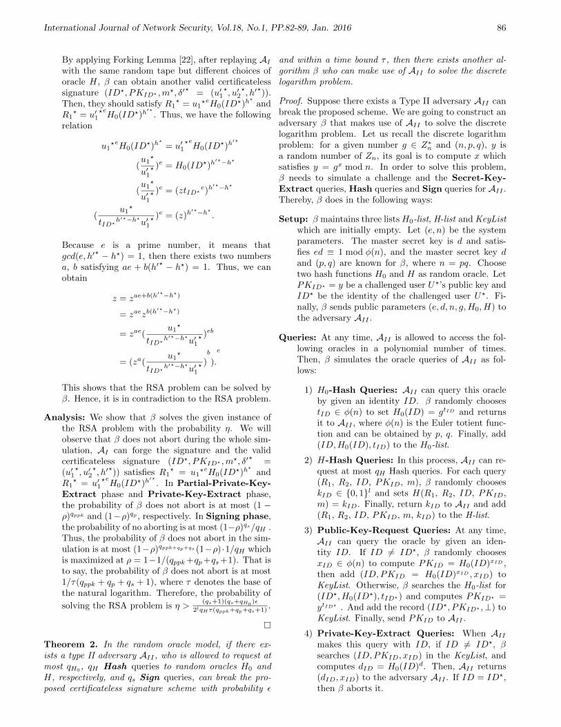
International Journal of Network Security, Vol.18, No.1, PP.82-89, Jan. 2016 86
By applying Forking Lemma [22], after replaying AIwith the same random tape but different choices oforacle H, β can obtain another valid certificatelesssignature (ID?, PKID? ,m?, δ′
?= (u′1
?, u′2
?, h′
?)).
Then, they should satisfy R1? = u1
?eH0(ID?)h?
andR1
? = u′1?eH0(ID?)h
′?. Thus, we have the following
relation
u1?eH0(ID?)h
?
= u′1?eH0(ID?)h
′?
(u1?
u′1? )e = H0(ID?)h
′?−h?
(u1?
u′1? )e = (ztID?
e)h′?−h?
(u1?
tID?h′?−h?
u′1? )e = (z)h
′?−h?
.
Because e is a prime number, it means thatgcd(e, h′
? − h?) = 1, then there exists two numbersa, b satisfying ae + b(h′
? − h?) = 1. Thus, we canobtain
z = zae+b(h′?−h?)
= zaezb(h′?−h?)
= zae(u1?
tID?h′?−h?
u′1? )eb
= (za(u1?
tID?h′?−h?
u′1? )b
).
e
This shows that the RSA problem can be solved byβ. Hence, it is in contradiction to the RSA problem.
Analysis: We show that β solves the given instance ofthe RSA problem with the probability η. We willobserve that β does not abort during the whole sim-ulation, AI can forge the signature and the validcertificateless signature (ID?, PKID? ,m?, δ′
?=
(u′1?, u′2
?, h′
?)) satisfies R1
? = u1?eH0(ID?)h
?
andR1
? = u′1?eH0(ID?)h
′?. In Partial-Private-Key-
Extract phase and Private-Key-Extract phase,the probability of β does not abort is at most (1 −ρ)qppk and (1−ρ)qp , respectively. In Signing phase,the probability of no aborting is at most (1−ρ)qs/qH .Thus, the probability of β does not abort in the sim-ulation is at most (1−ρ)qppk+qp+qs (1−ρ) ·1/qH whichis maximized at ρ = 1−1/(qppk+qp+qs+1). That isto say, the probability of β does not abort is at most1/τ(qppk + qp + qs + 1), where τ denotes the base ofthe natural logarithm. Therefore, the probability of
solving the RSA problem is η >(qs+1)(qs+qH0
)ε
2lqHτ(qppk+qp+qs+1).
Theorem 2. In the random oracle model, if there ex-ists a type II adversary AII , who is allowed to request atmost qH0
, qH Hash queries to random oracles H0 andH, respectively, and qs Sign queries, can break the pro-posed certificateless signature scheme with probability ε
and within a time bound τ , then there exists another al-gorithm β who can make use of AII to solve the discretelogarithm problem.
Proof. Suppose there exists a Type II adversary AII canbreak the proposed scheme. We are going to construct anadversary β that makes use of AII to solve the discretelogarithm problem. Let us recall the discrete logarithmproblem: for a given number g ∈ Z∗n and (n, p, q), y isa random number of Zn, its goal is to compute x whichsatisfies y = gx mod n. In order to solve this problem,β needs to simulate a challenge and the Secret-Key-Extract queries, Hash queries and Sign queries for AII .Thereby, β does in the following ways:
Setup: β maintains three listsH0-list, H-list and KeyListwhich are initially empty. Let (e, n) be the systemparameters. The master secret key is d and satis-fies ed ≡ 1 mod φ(n), and the master secret key dand (p, q) are known for β, where n = pq. Choosetwo hash functions H0 and H as random oracle. LetPKID? = y be a challenged user U?’s public key andID? be the identity of the challenged user U?. Fi-nally, β sends public parameters (e, d, n, g,H0, H) tothe adversary AII .
Queries: At any time, AII is allowed to access the fol-lowing oracles in a polynomial number of times.Then, β simulates the oracle queries of AII as fol-lows:
1) H0-Hash Queries: AII can query this oracleby given an identity ID. β randomly choosestID ∈ φ(n) to set H0(ID) = gtID and returnsit to AII , where φ(n) is the Euler totient func-tion and can be obtained by p, q. Finally, add(ID,H0(ID), tID) to the H0-list.
2) H-Hash Queries: In this process, AII can re-quest at most qH Hash queries. For each query(R1, R2, ID, PKID, m), β randomly chooseskID ∈ 0, 1l and sets H(R1, R2, ID, PKID,m) = kID. Finally, return kID to AII and add(R1, R2, ID, PKID, m, kID) to the H-list.
3) Public-Key-Request Queries: At any time,AII can query the oracle by given an iden-tity ID. If ID 6= ID?, β randomly choosesxID ∈ φ(n) to compute PKID = H0(ID)xID ,then add (ID, PKID = H0(ID)xID , xID) toKeyList. Otherwise, β searches the H0-list for(ID?, H0(ID?), tID?) and computes PKID? =ytID? . And add the record (ID?, PKID? ,⊥) toKeyList. Finally, send PKID to AII .
4) Private-Key-Extract Queries: When AIImakes this query with ID, if ID 6= ID?, βsearches (ID, PKID, xID) in the KeyList, andcomputes dID = H0(ID)d. Then, AII returns(dID, xID) to the adversary AII . If ID = ID?,then β aborts it.

International Journal of Network Security, Vol.18, No.1, PP.82-89, Jan. 2016 87
Table 1: Performance analysis of proposed RSA based certificateless signature schemeProcess Running Time (s) Energy Consumption (mJ) ROM (KB) RAM (Static + Stack) (KB)
Sign 1.45 34.8 1.7 2.3Verify 1.37 32.88 1.7 2.3
5) Sign Queries: For each query on an input(m, ID), if ID 6= ID?, then β firstly obtainsprivate key associated with ID by Private-Key-Extract queries on ID, then it producesa signature by using the obtained private key.If ID = ID?, then β computes as follows:
a. β randomly choose u1 ∈ Zn and h ∈ 0, 1l,u2 ∈ Zφ(n).
b. β computes R1 = u1eH0(ID)h and R2 =
H0(ID)u2PKhID.
c. β searches whether (R1, R2, ID, PKID,m)exists in the H-list. If it exists, then abortit. Otherwise, β sets H(R1, R2, ID, PKID,m) = h and adds H(R1, R2, ID, PKID, m,h) in the H-list.
d. The resultant signature δ = (u1, u2, h) isreturned to AII .
Output: After all the queries, AII outputs a forgery(ID?, PKID? ,m?, δ? = (u1
?, u2?, h?)) and win this
game. It must satisfy the following conditions:
1) If δ? is a valid forgery, then h? =H(R1
?, R2?, PKID? , ID?,m) which is in the H-
list, where R1? = u1
?eH0(ID?)h?
and R2? =
H0(ID?)u2?
PKh?
ID?).
2) ID? is the challenger’s identity and H0() isqueried by ID?.
By applying Forking Lemma [22], after replaying AIIwith the same random tape but different choices oforacle H, β can obtain another valid certificatelesssignature (ID?, PKID? ,m?, δ′
?= (u′1
?, u′2
?, h′
?)).
Then, they should satisfy R2? = H0(ID?)u2PKh?
ID?
and R2? = H0(ID?)u
′2PKh′?
ID? . Thus, we have thefollowing relation:
H0(ID?)u2PKh?
ID? = H0(ID?)u′2PKh′?
ID?
(H0(ID?))u2−u′2 = PKh′?−h?
ID?
(g)tID? (u2−u′2) = yh′?−h?
(g)tID? (u2−u′2)/h′?−h?
= y.
Obviously, the discrete logarithm of y to the base gis tID?(u2 − u′2)/h′
? − h?. It denotes that the dis-crete problem can be solved by β. Obviously, it is incontradiction to the difficulty of solving the discretelogarithm problem.
4.2 Performance Analysis
The proposed RSA based CLS scheme has been eval-uated for WSN based on few parameters like runningtime and energy consumption, ROM and RAM includ-ing static RAM and stack RAM. The results are shownin Table 1. The scheme has been implemented on MICAzplatform [23] using TinyOS-2.1.1 [18] operating systemfor embedded devices and RELIC-0.3.3 [4] cryptographiclibrary. The running time of the proposed scheme is 1.45seconds and 1.37 seconds in sign and verify phase respec-tively. The energy consumption is 34.8 milliJoules and32.88 milliJoules in sign and verify phase respectively.Further, the proposed scheme consumes 1.7 KB of ROMand 2.3 KB of RAM (static and stack) excluding the spaceused by cryptographic library.
5 Conclusion
RSA is a well defined industry implemented security ap-proach. Also certificateless schemes have their own ben-efits. In this paper, we proposed an RSA-based efficientcertificateless signature scheme and proved it to be secureunder some well-studied assumptions. We believe the newscheme is more suitable for systems with low-bandwidthchannels and/or low-computation power making it suit-able for WSN, on the basis of implementation results onWSN environment.
References
[1] I. F. Akyildiz, W. Su, Y. Sankarasubramaniam, andE. Cayirci, “Wireless sensor networks: A survey,”Computer Networks, vol. 38, pp. 393–422, Mar. 2002.
[2] S. Al-Riyami and K. Paterson, “Certificateless publickey cryptography,” in Advances in Cryptology (ASI-ACRYPT’03), LNCS 2894, pp. 452–473, Springer,2003.
[3] F. Amin, H. Jahangir, and H. Rasifard, “Analysis ofpublic-key cryptography for wireless sensor networkssecurity,” vol. 2, no. 5, pp. 403–408, 2008.
[4] D. Aranha and C. Gouvea, “RELIC is an EfficientLIbrary for Cryptography,” June 15, 2015. (http://code.google.com/p/relic-toolkit/)
[5] M. Bellare and G. Neven, “Identity-based multi-signatures from rsa,” in Topics in Cryptology (CT-RSA 2007), LNCS 4377, pp. 145–162, Springer, 2006.
[6] X. Chen, K. Makki, K. Yen, and N. Pissinou, “Sensornetwork security: A survey,” IEEE CommunicationsSurveys Tutorials, vol. 11, no. 2, pp. 52–73, 2009.

International Journal of Network Security, Vol.18, No.1, PP.82-89, Jan. 2016 88
[7] Y. Chen and Q. Zhao, “On the lifetime of wire-less sensor networks,” IEEE Communications Let-ters, vol. 9, no. 11, pp. 976–978, 2005.
[8] L. Chun-Ta, H. Min-Shiang, and C. Yen-Ping, “Im-proving the security of a secure anonymous routingprotocol with authenticated key exchange for ad hocnetworks,” International Journal of Computer Sys-tems Science and Engineering, vol. 23, no. 3, pp. 227–234, 2008.
[9] L. Chun-Ta, H. Min-Shiang, and C. Yen-Ping, “Asecure and efficient communication scheme with au-thenticated key establishment and privacy preservingfor vehicular ad hoc networks,” Computer Commu-nications, vol. 31, no. 12, pp. 2803–2814, 2008.
[10] H. Du and Q. Wen, “Efficient and provably-securecertificateless short signature scheme from bilin-ear pairings,” Computer Standards and Interfaces,vol. 31, no. 2, pp. 390–394, 2009.
[11] P. Gong and P. Li, “Further improvement of a certifi-cateless signature scheme without pairing,” Interna-tional Journal of Communication Systems, vol. 27,no. 10, pp. 2083–2091, Oct. 2014.
[12] M. Gorantla and A. Saxena, “An efficient certificate-less signature scheme,” in Computational Intelligenceand Security, LNCS 3802, pp. 110–116, Springer,2005.
[13] D. He, J. Chen, and R. Zhang, “An efficient andprovably-secure certificateless signature scheme with-out bilinear pairings,” International Journal of Com-munication Systems, vol. 25, no. 11, pp. 1432–1442,2012.
[14] D. He, M. Khan, and S. Wu, “On the security of arsa-based certificateless signature scheme,” Interna-tional Journal of Network Security, vol. 15, no. 6,pp. 408–410, 2013.
[15] B. Hu, D. Wong, Z. Zhang, and X. Deng, “Keyreplacement attack against a generic constructionof certificateless signature,” in Information Secu-rity and Privacy, LNCS 4058, pp. 235–246, Springer,2006.
[16] X. Huang, Y. Mu, W. Susilo, D. Wong, and W. Wu,“Certificateless signatures: New schemes and secu-rity models,” The Computer Journal, vol. 55, no. 4,pp. 457–474, 2012.
[17] X. Huang, W. Susilo, Y. Mu, and F. Zhang, “Onthe security of certificateless signature schemes fromasiacrypt 2003,” in Cryptology and Network Security,LNCS 3810, pp. 13–25, Springer, 2005.
[18] P. Levis, S. Madden, J. Polastre, R. Szewczyk,K. Whitehouse, A. Woo, D. Gay, J. Hill, M. Welsh,E. Brewer, and D. Culler, “Tinyos: An operatingsystem for sensor networks,” in Ambient Intelligence,pp. 115–148, 2005.
[19] C. Li, M. Hwang, and Y. Chu, “An efficientsensor-to-sensor authenticated path-key establish-ment scheme for secure communications in wirelesssensor networks,” International Journal of Innova-tive Computing, Information and Control, vol. 5,no. 8, pp. 2107–2124, 2009.
[20] K. McCurley, “Discrete logarithm problem,” in Pro-ceedings of Symposia Applied Mathematics, pp. 49–74, 1990.
[21] S. Olariu and Q. Xu, “Information assurance in wire-less sensor networks,” in Proceedings of the IEEE In-ternational Symposium on Parallel and DistributedProcessing, vol. 13, pp. 236a, Los Alamitos, CA,USA, 2005.
[22] D. Pointcheval and J. Stern, “Security proofs forsignature schemes,” in Advances in Cryptology (EU-ROCRYPT’96), LNCS 1070, pp. 387–398, Springer,1996.
[23] A. Rev, “MPR-MIB series user manual,” 2004.(http://www-db.ics.uci.edu/pages/research/quasar/MPR-MIB%20Series%20User%20Manual%
207430-0021-06_A.pdf)[24] A. Shamir, “Identity-based cryptosystems and signa-
ture schemes,” in Advances in Cryptology, LNCS 196,pp. 47–53, Springer, 1985.
[25] G. Sharma and A. Verma, “Breaking the rsa-basedcertificateless signature scheme,” Information-An In-ternational Interdisciplinary Journal, vol. 16, no. 11,pp. 7831–7836, 2013.
[26] J. Tsai, N. Lo, and T. Wu, “Weaknesses and improve-ments of an efficient certificateless signature schemewithout using bilinear pairings,” International Jour-nal of Communication Systems, vol. 27, no. 7, pp.1083–090, July 2014.
[27] R. Tso, X. Huang, and W. Susilo, “Strongly securecertificateless short signatures,” Journal of Systemsand Software, vol. 85, no. 6, pp. 1409–1417, 2012.
[28] R. Tso, X. Yi, and X. Huang, “Efficient and shortcertificateless signatures secure against realistic ad-versaries,” The Journal of Supercomputing, vol. 55,no. 2, pp. 173–191, 2011.
[29] J. Walters, Z. Liang, W. Shi, and V. Chaudhary, Se-curity in Distributed, Grid, and Pervasive Comput-ing, Chap. 17 Wireless Sensor Network security: Asurvey, pp. 1–51, CRC Press, 2007.
[30] A. Wander, N. Gura, H. Eberle, V. Gupta, andS. Shantz, “Energy analysis of public-key cryptog-raphy for wireless sensor networks,” in Proceed-ings of the 3rd IEEE International Conference onPervasive Computing and Communications (PER-COM’05), pp. 324–328, Washington, DC, USA, 2005.
[31] C. Wang, D. Long, and Y. Tang, “An efficient certifi-cateless signature from pairings,” International Jour-nal of Network Security, vol. 8, no. 1, pp. 96–100,2009.
[32] R. Watro, D. Kong, S. Cuti, C. Gardiner, C. Lynn,and P. Kruus, “Tinypk: Securing sensor networkswith public key technology,” in Proceedings of the2nd ACM Workshop on Security of Ad Hoc and Sen-sor Networks (SASN’04), pp. 59–64, New York, NY,USA, 2004.
[33] Z. Xu, X. Liu, G. Zhang, and W. He, “Mccls: Certifi-cateless signature scheme for emergency mobile wire-less cyber-physical systems,” International Journal

International Journal of Network Security, Vol.18, No.1, PP.82-89, Jan. 2016 89
of Computers Communications and Control, vol. 3,no. 4, pp. 395–411, 2008.
[34] Z. Xu, X. Liu, G. Zhang, W. He, G. Dai, and W. Shu,“A certificateless signature scheme for mobile wire-less cyber-physical systems,” in Proceedings of the8th International Conference on Distributed Comput-ing Systems Workshops (ICDCS’08), pp. 489–494,2008.
[35] W. Yap, S. Heng, and B. Goi, “An efficient certifi-cateless signature scheme,” in Emerging Directionsin Embedded and Ubiquitous Computing, LNCS 4097,pp. 322–331, Springer, 2006.
[36] D. Yum and P. Lee, “Generic construction of cer-tificateless signature,” in Information Security andPrivacy, LNCS 3108, pp. 200–211, Springer, 2004.
[37] F. Zhang, S. Li, S. Miao, Y. Mu, W. Susilo, andX. Huang, “Cryptanalysis on two certificateless sig-nature schemes,” International Journal of Comput-ers Communications and Control, vol. 5, no. 4,pp. 586–591, 2010.
[38] J. Zhang and J. Mao, “An efficient rsa-based certifi-cateless signature scheme,” Journal of Systems andSoftware, vol. 85, no. 3, pp. 638–642, 2012.
[39] X. Zhang, H. Heys, and L. Cheng, “Energy efficiencyof symmetric key cryptographic algorithms in wire-less sensor networks,” in 25th Biennial Symposiumon Communications (QBSC’10), pp. 168–172, 2010.
[40] Z. Zhang, D. Wong, J. Xu, and D. Feng, “Certifi-cateless public-key signature: Security model andefficient construction,” in Applied Cryptographyand Network Security, LNCS 3989, pp. 293–308,Springer, 2006.
[41] M. Zhou, M. Zhang, C. Wang, and B. Yang, “Cclas:A practical and compact certificateless aggregate sig-nature with share extraction,” International Journalof Network Security, vol. 16, no. 2, pp. 157–164, 2014.
Gaurav Sharma received his Ph.D and M.E degreein Computer Science & Engineering from Thapar Uni-versity, Patiala, India. He had received M. Sc. as wellas B. Sc. Degree from CCS University, Meerut, India.Presently he is working as an Asst. Professor at GalgotiasUniversity, India. His area of interests is routing andsecurity in Ad hoc networks.
Suman Bala received her Ph.D and M.E degree inComputer Science & Engineering from Thapar Univer-sity, Patiala, India. She had received B.Tech degreefrom Punjab Technical University, Jalandhar, India. Herareas of interest are: Wireless Sensor Networks, Security,Cryptography and Key Management.
Anil K. Verma is currently working as Associate Pro-fessor in the department of Computer Science and Engi-neering at Thapar University, Punjab (INDIA). He hasmore than 20 years of experience. He has published over150 papers in referred journals and conferences (India andAbroad). He is member of various program committeesfor different International/National Conferences and is onthe review board of various journals. He is a senior mem-ber (ACM), LMCSI (Mumbai), GMAIMA (New Delhi).He is a certified software quality auditor by MoCIT, Govt.of India. His research interests include wireless networks,routing algorithms and securing ad hoc networks.
International Journal of Network Security, Vol.18, No.1, PP.90-98, Jan. 2016 90
Secure and Efficient Identity-based ProxyMulti-signature Using Cubic Residues
Feng Wang1,2, Chin-Chen Chang2,3, Changlu Lin4, and Shih-Chang Chang5
(Corresponding author: Chin-Chen Chang)
College of Mathematics and Physics, Fujian University of Technology1
Fuzhou, Fujian,350108, ChinaDepartment of Information Engineering and Computer Science, Feng Chia University2
100 Wenhwa Rd., Seatwen, Taichung 40724, Taiwan(Email: [email protected])
Department of Computer Science and Information Engineering, Asia University3
Taichung 41354, TaiwanSchool of Mathematics and Computer Science, Fujian Normal University4
Fuzhou, Fujian, 350117, ChinaDepartment of Computer Science and Information Engineering, Notional Chung Cheng University5
160 San-Hsing, Ming-Hsiung, Chiayi 621,Taiwan(Received July 14, 2014; revised and accepted Jan. 16 & June 4, 2015)
Abstract
The term “proxy multi-signature” refers to the situa-tion in which a proxy signer is authorized to sign amessage on behalf of a group of original signers. Com-bined with identity-based cryptography, we proposed anefficient identity-based proxy multi-signature scheme us-ing cubic residues without bilinear pairing. Our schemeis secure against existential forgery on adaptive chosen-message and identity attacks under the hardness of integerfactorization assumption. Compared with elliptic curveor bilinear pairing, the integer factorization assumptionis more reliable and easier to use because it has been de-veloped 2500 years ago. Furthermore, our scheme is moreefficient than previous schemes based on bilinear pairing.Keywords: Cubic residues, identity-based signature, in-teger factorization, proxy multi-signature, random oraclemodel
1 Introduction
Shamir [15] introduced identity-based cryptography in1984 in order to simplify the key-management proce-dure of traditional, certificate-based, public-key infras-tructures. Shamir’s approach allowed an entity’s publickey to be derived directly from her or his identity, such asan email address, and the entity’s private key can be gen-erated by a trusted third party which is called the privatekey generator (PKG).
The notion of proxy signatures was proposed by
Mambo et al. [10] in 1996. They identified the signersinto two entities, i.e., the original signer and the proxysigner. The latter can sign a message on behalf of theformer with a warrant the former delegated. Proxy sig-natures have many practical applications, such as dis-tributed systems, grid computing, mobile agent appli-cations, distributed shared object systems, global distri-bution networks, and mobile communications [2]. Since1996, the proxy signature has been paid significant atten-tion [7] and various extensions of the proxy signature havebeen proposed [1, 9, 11, 19, 22], one of which is the proxymulti-signature [9, 19, 22].
In 2000, Yi et al. proposed the proxy multi-signature [22] in which a designated proxy signer can gen-erate a valid signature on behalf of a group of originalsigners. Proxy multi-signature can be used in the follow-ing scenario, i.e., a university wants to release a documentthat several departments may be involved, for example,the Deans Office, the Student Affairs Office, and the Hu-man Resources Department, etc.. The document must besigned by all of the above entities or by a proxy signer del-egated by those entities. Combined with identity-basedcryptography, Li and Chen [9] proposed the notion ofidentity-based proxy multi-signature (IBPMS) and con-structed a scheme using bilinear pairings in 2005. How-ever, most existing IBPMS schemes were based on bilinearpairing [4, 9, 14, 20], which required more computationalcost than normal operations, such as modular exponen-tiations in finite fields. Therefore, there was a strong in-terest in determining how to construct a secure schemewithout pairing. In 2011, Tiwari and Padhye [18] pro-

International Journal of Network Security, Vol.18, No.1, PP.90-98, Jan. 2016 91
posed a secure IBPMS scheme based on the elliptic curvediscrete logarithm problem. Although they claimed thattheir scheme was more efficient and had a smaller key sizethan pairing-based schemes, the security on which theirmethod was based on the elliptic curve discrete logarithmproblem assumption which was only a few decades old [6].
In this paper, we propose a new identity-based proxymulti-signature (IBPMS) scheme using cubic residueswithout bilinear pairing. The security of our method isbased on the integer factorization assumption which is2500 years old. We briefly introduce our contributions.First, our scheme is the first identity-based proxy multi-signature scheme using the cubic residues problem. Sec-ond, our scheme has been proven to be secure in the ran-dom oracle model under the hardness of integer factor-ization problem assumption. Third, our scheme is mademore efficient than Cao and Cao’s IBPMS scheme [4]based on bilinear pairing.
The rest of the paper is organized as follows. In Sec-tion 2, we introduce the cubic residues problem and in-teger factorization problem assumption. In Section 3, wegive the formal definition and security model of identity-based proxy multi-signature. In Section 4, we proposea new identity-based proxy multi-signature scheme usingcubic residues. In Section 5, we give the formal securityproof for the proposed scheme under the random oraclemodel. In Section 6, we compare the efficiency and perfor-mance of our scheme with Cao and Cao’s IBPMS scheme.Finally, we present our conclusions in Section 7.
2 Preliminaries
In this section, we review cubic residues and the methodof their construction mentioned in [21] and integer factor-ization problem assumption
2.1 Cubic Residues
Definition 1. For a positive integer n, if there is some xthat satisfies the expression x3≡C (mod n), we say thatC is a cubic residue modulo n, and x is called the cubicroot of C modulo n.
From [21], we have Lemma 1, Theorem 1, and Theo-rem 2.
Lemma 1. Let p be a prime number, 3p = gcd(3, p− 1),and C ∈ Z∗p . We say that C is a cubic residue modulo p
if and only if C(p−1)
3p (mod p) ≡ 1.
Obviously, if p is prime number and p ≡ 2 (mod 3),then every C ∈ Z∗p is a cubic residue modulo p.
If q is prime number, and q ≡ 4 or 7 (mod 9), forevery h ∈ Z∗p , we can construct a cubic residue modulo qas follows.
Let a be a non-cubic modulo q, we compute η =[(q − 1) (mod 9)] /3, λ = η (mod 2) + 1, β = (q − 1)/3,
ξ = aη·β (mod q), τ ≡ hλ·β (mod q), and
b =
0, if τ = 11, if τ = ξ
2, if τ = ξ2,
then C = ab · h is a cubic residue modulo q.
Theorem 1. Let p, q be as mentioned above and n =p · q. Then C = ab · h is a cubic residue modulo n, ands ≡ C [2η−1(p−1)(q−1)−3]/9 (mod n) is a cubic root of C−1.
Theorem 2. Let n = p · q. If there is s31 ≡ s3
2 ≡ C(mod n), and s1 6≡ s2 (mod n), then gcd(s1 − s2, n) is anon-trivial divisor of n.
2.2 Integer Factorization Problem As-sumption
The integer factorization problem assumption is one of thefundamental hardness problems, which has been studiedextensively and used to construct cryptographic schemes.We will analyze the security of our proposed scheme basedon this assumption. From [23], we have Definition 2 andDefinition 3.
Definition 2. Given n = p · q, where p and q are primenumbers and they are unknown publicly, the integer fac-torization problem is defined to output a prime numberp(1 < p < n) such that p can divide n.
Definition 3 (Integer factorization problem as-sumption). The integer factorization problem (IFP) isa (t
′, ε′)-hard assumption, if there is no polynomial time
algorithm in time at most t′, can solve the integer factor-
ization problem with probability at least ε′.
3 Formal Definition and SecurityModel
We give a formal definition and security model of theidentity-based proxy multi-signature scheme based on theworks of Cao and Cao [4], Singh and Verma [16], and Sunet al. [17].
3.1 Formal Definition of the Identity-based Proxy Multi-signature Scheme
In an identity-based proxy multi-signature scheme, thereare two entities named as a group of the original signersand the proxy signer. We use IDi, for i = 1, 2, · · · , n,to denote the identity of original signer i, and IDps todenote the identity of the proxy signer. From [4], we haveDefinition 4.
Definition 4. An identity-based proxy multi-signaturescheme (IBPMS) is a tuple of seven algorithms asIBPMS=(Setup, Extract, DelGen, DelVeri, PMK-Gen, PMSign, PMVeri).

International Journal of Network Security, Vol.18, No.1, PP.90-98, Jan. 2016 92
Setup. PKG takes a security parameter as input, andoutputs public parameter PP and its master keyMK.
Extract. PKG takes its master key MK and a user’sidentity IDi as inputs, and outputs the user’s publickey and secret key pair (HIDi
, sIDi).
DelGen. For i = 1, 2, · · · , n, the original signer i takesher or his secret key sIDi
and a warrant w as inputs,and outputs her or his delegation Di→ps to the proxysigner.
DelVeri. For i = 1, 2, · · · , n, the proxy signer takes del-egation Di→ps from the original signer i and her orhis identity IDi as inputs, and verifies whether ornot the delegation is valid.
PMKGen. The proxy signer takes her or his secret keysIDps
and delegations Di→ps, i = 1, 2, · · · , n, as in-puts, and generates her or his private signing keyskps.
PMSign. The proxy signer takes her or his signingkey skps, message m, and delegations Di→ps, i =1, 2, · · · , n, as inputs, and generates the proxy multi-signature σ of the message m.
PMVeri. The verifier takes the proxy multi-signatureσ and the original signers’ identities, IDi, i =1, 2, · · · , n, and the proxy signer’s identity IDps asinputs, and verifies whether or not the proxy multi-signature is valid.
3.2 Security Model
Compared with Cao and Cao’s method [4], and Sun etal.’s method [17], we use the security model of the proxymulti-signature which is described in [17]. And, we extendSun et al.’s model into an identity-based proxy multi-signature to prove the security of our scheme. The adver-saries in their model can be classified into three types asfollows:
Type 1. The adversary, A1, knows nothing except theidentities of the original signers and the proxy signer.
Type 2. The adversary, A2, knows the secret keys ofn − 1 original signers and proxy signer in additionto what A1 knows in Type 1.
Type 3. The adversary, A3, knows the secret keys of allof the original signers in addition to what A1 knowsin Type 1, but does not know the secret key of theproxy signer.
Obviously, if an adversary in Type 1 can forge a validsignature of the scheme, the adversary in Type 2 or Type3 also can forge a valid signature. So, we only considerthe Type 2 and Type 3 adversaries in this paper.
With regard to the Type 2 adversary A2, we can as-sume that she or he has all of the secret keys of the n− 1
original signers, except for signer n. If she or he has avalid delegation, Dn→ps, she or he can output a validproxy multi-signature herself or himself with the secretkeys of the other original signers and proxy signer. So,the objective of the Type 2 adversary is to output a validdelegation, Dn→ps.
With regard to the Type 3 adversary A3, since she orhe has all of the secret keys of the original signers, she orhe can output a valid delegation Di→ps, i = 1, 2, · · · , n,herself or himself. So, the objective of the Type 3 ad-versary is to output a valid proxy multi-signature underdelegations Di→ps, i = 1, 2, · · · , n.
Let an adversary At(t = 2 or 3) be a probabilistic Tur-ing machine, At takes public parameter PP and a randomtape as inputs and performs an experiment with the algo-rithm B. Inspired from [17], we define the following twodefinitions.
Definition 5. For an identity-based proxy multi-signature scheme, we define an experiment of the adver-sary At(t = 2 or 3) with the security parameter λ as fol-lows:
Step 1. Algorithm B runs the Setup algorithm and re-turns public parameter PP to the adversary At.
Step 2. B maintains several lists, e.g., Elist, Dlist,Slist, and initializes them as null.
Step 3. When the adversary At makes adaptive queriesfrom the algorithm B, B maintains several oraclesand answers as follows:
• Extract oracle: The oracle takes a user’s iden-tity IDi as input, returns her or his private keysIDi , and puts the tuple (IDi, sIDi) into Elist.
• DelGen oracle: The oracle takes the originalsigner’s identity IDi and the warrant w as in-puts, returns the delegation Di→ps, and puts thetuple (IDi, w, Di→ps) into Dlist.
• PMSign oracle: The oracle takes the messagem and the delegations Di→ps, i = 1, 2, · · · , n asinputs, returns a proxy multi-signature σ signedby the proxy signer and puts the tuple (m,w, σ)into Slist.
Step 4. Eventually, At outputs a forgery.
• If t = 2, then it is the Type 2 adversary A2.The forgery is of the tuple (IDn, w, Dn→ps), and(IDn, w, Dn→ps) is valid delegation of IDn withwarrant w, and IDn 6∈ Elist, (IDn, w) 6∈ Dlist.
• If t = 3, then it is the Type 3 adversary A3. Theforgery is of the tuple (m,w, σ), and (m,w, σ) isa valid proxy multi-signature, and IDp 6∈ Elist,(w, m) 6∈ Slist.
If the output satisfies one of the above two items, At’sattack was successful.

International Journal of Network Security, Vol.18, No.1, PP.90-98, Jan. 2016 93
Definition 6. For any polynomial adversary At (t =2 or 3), if the probability of At’s success in the aboveexperiment is negligible, then, the identity-based proxymulti-signature scheme is said to be secure against ex-istential forgery on adaptive chosen-message and identityattacks.
4 Our Proposed IBPMS Scheme
In this section, we describe a new identity-based proxymulti-signature scheme. We designed our scheme, whichextends the identity-based signature [21], based on the cu-bic residues. The proposed scheme includes the followingseven algorithms:
Setup. Given the security parameters k and l, PKG car-ries out the algorithm and returns public parametersPP and master key MK as follows:
1) Randomly generates two k-bits prime numbers pand q, satisfying p ≡ 2 (mod 3) and q ≡ 4 or 7(mod 9), respectively; then computes n = p · q.
2) Computes d = [2η−1 (p− 1) (q − 1) − 3]/9, η =[(q − 1) (mod 9)] /3, λ = η (mod 2) + 1, β =(q − 1)/3.
3) Randomly selects a non-cubic residue a moduloq and computes ξ ≡ aη·β (mod q).
4) Selects four hash functions H1 : 0, 1∗ →Z∗n,H2, H3 ,H4 : 0, 1∗ → 0, 1l.
PKG publishes (n, a, η, λ, H1,H2 ,H3 ,H4) as the pub-lic parameter PP and keeps (p, q, d, β) secret as themaster key MK.
Extract. Given public parameter PP , the master keyMK, and identity IDi of user i, for i = 1, 2, · · · , n,PKG computes the corresponding secret key as fol-lows:
1) Computes τ i ≡ H1 (IDi)λ·β (mod q).
2) Computes bi =
0, if τ i = 11, if τ i = ξ
2, if τ i = ξ2, and Ci =
abi ·H1 (IDi) (mod n), sIDi ≡ (Ci)d (mod n).
PKG transmits secret key (sIDi , bi), for i =1, 2, · · · , n to user i via a secure channel.
DelGen. Let IDi, for i = 1, 2, · · · , n, be the identity ofthe original signer i, and IDps be the identity of theproxy signer. The original signer i, for i = 1, 2, · · · , n,wants to delegate the proxy signer to get a warrantw of message m, so she or he takes her or his secretkey (sIDi , bi), and warrant w as inputs and outputsthe delegation Di→ps. Then, the original signer i, fori = 1, 2, · · · , n, continues as follows:
1) Randomly selects ri ∈ Z∗n, computes Ri ≡ r3i
(mod n), and broadcasts Ri to the other originalsigners.
2) Computes R ≡ ∏ni=1 Ri (mod n), hw =
H2(w, R), Vi ≡ ri · shw
IDi(mod n).
Each original signer i sends her or his delegationDi→ps = (IDi, bi, w,Ri, Vi) to the proxy signer.
DelVeri. To verify each delegation Di→ps with war-rant w, the proxy signer computes R ≡ ∏n
i=1 Ri
(mod n), hw = H2 (w, R), Ci ≡ abi · H1 (IDi)(mod n), and checks V 3
i · Cihw ≡ Ri (mod n) for
i = 1, 2, · · · , n. If the equation holds, she or he ac-cepts Di→ps as a valid delegation; otherwise, it isrejected.
PMKGen. If the proxy signer accepts all delegationsDi→ps, for i = 1, 2, · · · , n, she or he computeshps = H3(IDps, w, R), V ≡ ∏n
i=1 Vi (mod n),skps ≡ s
hps
IDps· V (mod n) and takes skps as her or
his private signing key.
PMSign. The proxy signer takes skps as inputand randomly selects rps ∈ Z∗n, computesRps ≡ r3
ps (mod n), hm = H4(IDps, w, m,Rps),Vps ≡ rps · skhm
ps (mod n). The tuple (ID1, ID2,· · · , IDn, IDps, b1, b2, · · · , bn, bps,m, w, R, Rps, Vps)is the proxy signature of message m on behalf of alloriginal signers i, for i = 1, 2, · · · , n.
PMVeri. In order to verify the proxy multi-signature (ID1, ID2, · · · , IDn, IDps, b1, b2, · · · , bn,bps,m, w, R, Rps, Vps) of message m under warrantw, the verifier conducts the following: computeshps = H3(IDps, w,R), hw = H2(w,R) , hm =H4(IDps,m,w, Rps), C ≡ ∏n
i=1 (abi · H1 (IDi))(mod n) , Cps ≡ abps · H1 (IDps) (mod n), thenchecks V 3
ps ·Cpshps·hm ·Chw·hm ≡ RPs ·Rhm (mod n);
if the equation holds, then she or he accepts it;otherwise, it is rejected.
Our scheme is correct because the following equationholds:
V 3ps · Cps
hps·hm · Chw·hm
≡ (rps · skhmps )
3 · Cpshps·hm · Chw·hm
≡ (rps · (dhps
IDps· V )
hm
)3
· Cpshps·hm · Chw·hm
≡ (rps · (dhps
IDps·∏n
i=1 ri · shw
IDi)hm
)3
·Cpshps·hm ·Chw·hm
≡ r3ps · ((d3
IDps)hps ·∏n
i=1 r3i ·
∏ni=1 (s3
IDi)hw
)hm
·Cps
hps·hm · Chw·hm
≡ r3ps · ((d3
IDps)hps ·∏n
i=1 r3i ·
∏ni=1 (s3
IDi)hw
)hm
·Cps
hps·hm · Chw·hm
≡ Rps · (Cps−hps ·R ·∏n
i=1 Ci−hw)
hm · Cpshps·hm ·
Chw·hm
≡ Rps ·Rhm (mod n).

International Journal of Network Security, Vol.18, No.1, PP.90-98, Jan. 2016 94
5 Security Proof of Our ProposedScheme
In this section, we give the security proof of our proposedscheme. We show that our scheme is secure against exis-tential forgery under adaptive chosen-message and iden-tity attacks in the random oracle model. We prove ourscheme against Type 2 adversaries and Type 3 adver-saries, respectively.
If a Type 2 adversary A2 has the ability to break ourscheme, we can construct a polynomial time algorithm B,by interacting with A2, to solve the integer factorizationproblem.
Theorem 3. Given a pair of security parameters(k, l), if the integer factorization problem is (t
′, ε′)-hard,
then our identity-based proxy multi-signature scheme is(t, qH2 , qD, ε2)-secure against existential forgery underadaptive chosen-message and identity attacks for the Type2 adversary A2, which satisfies:
ε′ ≥ 4
9·(
(ε2 − δ2)2
qH2 + 1− ε2 − δ2
2l
),
t′= 2t + O
(k2 · l + k3
),
where qH2 and qD denote the number of queries that A2
can ask to the random oracle H2 and DelGen oracle, re-spectively, and δ2 = qD·(qH2+qD)
3·2k .
Proof. Assuming that adversary A2 breaks the proposedscheme, we can construct an algorithm B to resolve theinteger factorization problem.
Given an integer n = p · q (for some unknown p andq), and a non-cubic residue a (mod n), we will designan algorithm B to output p and q with non-negligibleprobability.
Step 1. Algorithm B sends (n, a) to adversary A2 aspublic parameters.
Step 2. B maintains several lists, i.e., H1,list,H2,list,Elist, and Dlist and initializes them asnull.
Step 3. B responds to A2’s queries as follows:
• H1-oracle: A2 requests H1 on IDi, and Bchecks if IDi existed in H1,list. If not, B picksa random si ∈ Z∗n and bi ∈ 0, 1, 2, computesh1,i = H1 (IDi) ≡ s3
i
abi(mod n), and adds the
tuple (IDi, h1,i, si, bi) into H1,list; then, B re-turns h1,i to A2.
• H2-oracle: A2 requests H2 on (w, R), and Bchecks if (w, R) existed in H2,list. If not, B picksa random e ∈ 0, 1l, adds the tuple (w,R, e)into H2,list, then, B returns e to A2.
• Extract oracle: A2 requests Extract algo-rithm on IDi , and B checks if IDi existedin Elist. If not, B returns to H1-oracle andgets (IDi, h1,i, si, bi) of H1,list; then, B returns(si, bi) to A2 and adds the tuple (IDi, si, bi) intoElist.
• DelGen oracle: A2 requests delegation on(IDn, w). According to the assumption, A2
has the secret keys of the original signers i,i = 1, 2, · · · , n − 1, by requesting Extract ora-cle. For i = 1, 2, · · · , n− 1, A2 randomly selectsri ∈ Z∗n, computes Ri ≡ r3
i (mod n), and sendsRi, where i = 1, 2, · · · , n−1, to B. B randomlyselects Vn, τ ∈ 0, 1l, computes Rn ≡ V 3
n ·(abn · H1 (IDn))τ (mod n), and R ≡ ∏n
i=1 Ri
(mod n); if R already exists in H2,list, failure isreturned; else (IDn, bn, w,Rn, Vn) is returned asthe original signer n’s delegation to A2; also, τis returned for the sake of helping A2 completingthe delegation on (IDi, w) for i = 1, 2, · · · , n−1.B adds the tuple (IDn, bn, w, Rn, Vn) into Dlist
and adds (w, R, τ) into H2,list.
Step 4. A2 outputs a delegation forgery of warrant w∗
and ID∗n with D∗
n→ps = (ID∗n, b∗n, w∗, R∗n, V ∗
n ), which(ID∗
n, w∗) is not requested on the DelGen oracle, andID∗
n is not requested on the Extract oracle.
Step 5. Finally, we will show how B resolves the integerfactorization problem with A2’s delegation forgery.
We apply the oracle replay technique describes in Fork-ing Lemma [12, 13] to factor n, i.e., B resets A2 two times.For the first time, B records all the transcripts that inter-acted with A2. For the second time, B starts with the firsttime random tape and returns the same answers to A2,except H2-oracle. Each time, when A2 asks H2-oracle, Bchooses different random numbers, e∗,e∗∗, as the answer,respectively.
After two rounds of interacting with B, A2 forges twodelegations (ID∗
n, b∗n, w∗, R∗n, V ∗n ), (ID∗
n, b∗n, w∗, R∗n, V ∗∗n ),
together with delegations of original signers 1, 2, · · · , n−1,sends them to B. Then, B executes as follows:
• B computes R∗ ≡ ∏ni=1 R∗i (mod n), returns to the
previous three records of H2,list lists for (w∗, R∗), ob-tains, e∗, e∗∗, and checks whether or not they satisfy(e∗ − e∗∗) ≡ 0 (mod 3); if so, then B aborts it.
• Else B can obtain(V ∗n )3 · (C∗n)e∗ = R∗n, (V ∗∗
n )3 ·(C∗n)e∗∗ ≡ R∗n (mod n), where C∗n ≡ ab∗n ·H1 (ID∗
n)(mod n).
• B obtains (V ∗n /V ∗∗
n )3 ≡ (C∗n)e∗∗−e∗ (mod n).
• If (e∗∗ − e∗) ≡ 1 (mod 3), there is some x ∈ Z∗p sat-isfies the equation (e∗∗ − e∗) = 3x + 1. So we ob-tain (V ∗
n /V ∗∗n )3 ≡ (C∗n)3x+1 (mod n), and therefore
C∗n ≡(
V ∗nV ∗∗n ·(C∗n)x
)3
(mod n).

International Journal of Network Security, Vol.18, No.1, PP.90-98, Jan. 2016 95
• If (e∗∗ − e∗) ≡ 2 (mod 3), there is some x ∈ Z∗p sat-isfies the equation (e∗∗ − e∗) = 3x − 1. So we ob-tain (V ∗
n /V ∗∗n )3 ≡ (C∗n)3x−1 (mod n), and therefore
C∗n ≡(
V ∗∗n ·(C∗n)x
V ∗n
)3
(mod n).
Then, if (e∗∗ − e∗) 6≡ 0 (mod 3), B obtains the cubicroot of C∗n. And B can look up the list H1,list and obtainanother cubic root of C∗n. Then, B obtains two cubicroots of C∗n. If the two cubic roots are not equal, B canfactor n according to Theorem 2.
Since e∗, e∗∗ are picked randomly, the probability of(e∗∗ − e∗) 6≡ 0 (mod 3) is 2
3 , and the probability thatthe two cubic roots of C∗n are inequal is 2
3 .Next, we will analyze the probability of A2 successfully
forging two valid delegations similar to [3].Let ε∗2 denote the probability of A2 forging a delegation
in a single run, and ε2 denote the probability of A2 forginga delegation in the real attack.
In H2,list, all the records (w, R, e) are filled by H2-oracle query and DelGen oracle query. So there are, atmost qH2 + qD, different R’s. For every DelGen ora-cle, B randomly selects Vn, τ ∈ 0, 1l, computes Rn =V 3
n · (abn ·H1 (IDn))τ and R =∏n
i=1 Ri, therefore, R canbe considered as the random cubic residue modulo n. Ob-viously, the number of elements in cubic residues modulon is (3 · 2k). So the probability that R is in the H2,list
is, at most qH2+qD
3·2k . So the probability of A2 forging a
delegation in a single run is ε∗2 ≥ ε2 − qD·(qH2+qD)
3·2k .Let pi denote the probability of forgery based on the
ithH2-oracle query in a single run; then
ε∗2 =qH2+1∑
i=1
pi.
Let pi,s denote the probability of forgery togetherbased on ithH2-oracle query with input s, where s is aspecific random tape input of length m. Then
2m · pi =∑
s∈0,1m
pi,s.
For a specific random tape s, since twice valid forgeryneed different outputs of H2-oracle query, the probabilityof twice forgery based on the same ithH2-oracle query ispi,s · (pi,s − 2−l). Let Pi denote the probability of twiceforgery based on the same ithH2-oracle query in two runs;then
Pi =∑
s∈0,1m
2−m · pi,s · (pi,s − 2−l) ≥ p2i − 2−l · pi.
So, the probability of twice forgery based on the sameH2-oracle query in two runs is
∑qH2+1i=1 Pi. We have
qH2+1∑
i=1
Pi ≥qH2+1∑
i=1
p2i −
qH2+1∑
i=1
2−l · pi ≥ (ε∗2)2
qH2 + 1− ε∗2
2l
≥
(ε2 − qD·(qH2+qD)
(3·2k)
)2
qH2 + 1−
ε2 − qD·(qH2+qD)(3·2k)
2l.
Taking (e∗∗ − e∗) 6≡ 0 (mod 3) and the difference ofthe two cubic roots of C∗n into account, the probability offactoring n is ε
′ ≥ 49
∑qH2+1i=1 Pi ≥ 4
9 ·(
(ε2−δ2)2
qH2+1 − ε2−δ22l
),
where δ2 = qD·(qH2+qD)
3·2k . So, the theorem is proved.
As to the running time, according to [3], B has to runA2 twice and perform some other operations to factor n.So B should spend the time t
′= 2t + O(k2 · l + k3) to
factor n.
Theorem 4. Given a security parameter (k, l), ifthe integer factorization problem is (t
′, ε′)-hard, then
our identity-based proxy multi-signature scheme is(t, qH4 , qS , ε3)-secure against existential forgery underadaptive chosen-message and identity attacks for the Type3 adversary A3, which satisfies:
ε′ ≥ 4
9·(
(ε3 − δ3)2
qH4 + 1− 2−l · (ε3 − δ3)
)
t′= 2t + O
(k2 · l + k3
),
where qH4 and qS denote the number of queries thatA3 can ask to the random oracle H4 and PMSign, respec-tively, and δ3 = qS ·(qH4+qS)
3·2k .
Proof. This proof is similar to that of Theorem 3. So,we just describe the main difference with Theorem 3 asfollows:
Step 1. Algorithm B does the same as Step 1 of Theo-rem 3.
Step 2. B deletes Dlist list and adds H3,list, H4,list, Slist
lists, and initializes them as null.
Step 3. B deletes DelGen oracle and adds H3, H4 andPMSign oracle accordingly.
• H3-oracle: A3 requests H3 on (IDps, w, R), Bchecks if (IDps, w,R) existed in H3,list. If not,B picks a random µ ∈ 0, 1l and adds the tu-ple (IDps, w, R, µ) into H3,list; then B returnsH3(IDps, w, R) = µ to A3.
• H4-oracle: A3 requests H4 on (IDps, w, m,Rps), and B checks if (IDps, w, m, Rps) existedin H4,list. If not, B picks a random η ∈ 0, 1l
and adds the tuple (IDps, w, m, Rps, η) intoH4,list; then, B returns H4 (IDps, w, m, Rps) =η to A3.
• PMSign oracle: A3 requests PMSign algo-rithm on (w, m). A3 randomly selects ri ∈ Z∗nand computes Ri = r3
i (mod n), R =∏n
i=1 Ri
(mod n), and requests H2-oracle query and ob-tains H2(w, R) = e. Since A3 knows all the
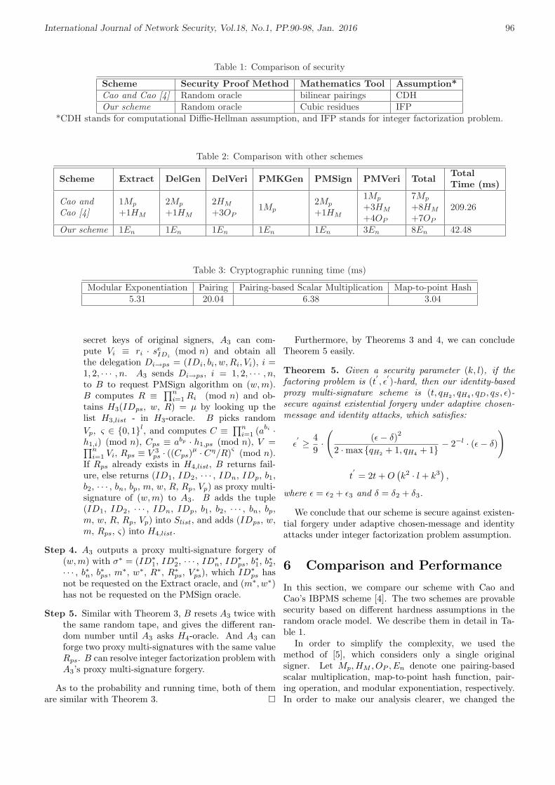
International Journal of Network Security, Vol.18, No.1, PP.90-98, Jan. 2016 96
Table 1: Comparison of security
Scheme Security Proof Method Mathematics Tool Assumption*Cao and Cao [4] Random oracle bilinear pairings CDHOur scheme Random oracle Cubic residues IFP
*CDH stands for computational Diffie-Hellman assumption, and IFP stands for integer factorization problem.
Table 2: Comparison with other schemes
Scheme Extract DelGen DelVeri PMKGen PMSign PMVeri TotalTotalTime (ms)
Cao andCao [4]
1Mp
+1HM
2Mp
+1HM
2HM
+3OP1Mp
2Mp
+1HM
1Mp
+3HM
+4OP
7Mp
+8HM
+7OP
209.26
Our scheme 1En 1En 1En 1En 1En 3En 8En 42.48
Table 3: Cryptographic running time (ms)
Modular Exponentiation Pairing Pairing-based Scalar Multiplication Map-to-point Hash5.31 20.04 6.38 3.04
secret keys of original signers, A3 can com-pute Vi ≡ ri · se
IDi(mod n) and obtain all
the delegation Di→ps = (IDi, bi, w, Ri, Vi), i =1, 2, · · · , n. A3 sends Di→ps, i = 1, 2, · · · , n,to B to request PMSign algorithm on (w, m).B computes R ≡ ∏n
i=1 Ri (mod n) and ob-tains H3(IDps, w, R) = µ by looking up thelist H3,list - in H3-oracle. B picks randomVp, ς ∈ 0, 1l, and computes C ≡ ∏n
i=1 (abi ·h1,i) (mod n), Cps ≡ abp · h1,ps (mod n), V =∏n
i=1 Vi, Rps ≡ V 3ps · ((Cps)
µ · Cη/R)ς (mod n).If Rps already exists in H4,list, B returns fail-ure, else returns (ID1, ID2, · · · , IDn, IDp, b1,b2, · · · , bn, bp, m, w, R, Rp, Vp) as proxy multi-signature of (w, m) to A3. B adds the tuple(ID1, ID2, · · · , IDn, IDp, b1, b2, · · · , bn, bp,m, w, R, Rp, Vp) into Slist, and adds (IDps, w,m, Rps, ς) into H4,list.
Step 4. A3 outputs a proxy multi-signature forgery of(w, m) with σ∗ = (ID∗
1, ID∗2, · · · , ID∗
n, ID∗ps, b∗1, b∗2,
· · · , b∗n, b∗ps, m∗, w∗, R∗, R∗ps, V ∗ps), which ID∗
ps hasnot be requested on the Extract oracle, and (m∗, w∗)has not be requested on the PMSign oracle.
Step 5. Similar with Theorem 3, B resets A3 twice withthe same random tape, and gives the different ran-dom number until A3 asks H4-oracle. And A3 canforge two proxy multi-signatures with the same valueRps. B can resolve integer factorization problem withA3’s proxy multi-signature forgery.
As to the probability and running time, both of themare similar with Theorem 3.
Furthermore, by Theorems 3 and 4, we can concludeTheorem 5 easily.
Theorem 5. Given a security parameter (k, l), if thefactoring problem is (t
′, ε′)-hard, then our identity-based
proxy multi-signature scheme is (t, qH2 , qH4 , qD, qS , ε)-secure against existential forgery under adaptive chosen-message and identity attacks, which satisfies:
ε′ ≥ 4
9·(
(ε− δ)2
2 ·max qH2 + 1, qH4 + 1 − 2−l · (ε− δ)
)
t′= 2t + O
(k2 · l + k3
),
where ε = ε2 + ε3 and δ = δ2 + δ3.
We conclude that our scheme is secure against existen-tial forgery under adaptive chosen-message and identityattacks under integer factorization problem assumption.
6 Comparison and Performance
In this section, we compare our scheme with Cao andCao’s IBPMS scheme [4]. The two schemes are provablesecurity based on different hardness assumptions in therandom oracle model. We describe them in detail in Ta-ble 1.
In order to simplify the complexity, we used themethod of [5], which considers only a single originalsigner. Let Mp, HM , OP , En denote one pairing-basedscalar multiplication, map-to-point hash function, pair-ing operation, and modular exponentiation, respectively.In order to make our analysis clearer, we changed the

International Journal of Network Security, Vol.18, No.1, PP.90-98, Jan. 2016 97
total computation cost into running time in the last col-umn of Table 2 according to Table 3, which is referred toreference [8].
According to Tables 1 and 2, our schemes total runningtime decreased drastically compared with Cao and Cao’sscheme [4]. The security of our scheme is based on in-teger factorization problem assumption without bilinearpairing. We note that the integer factorization problemassumption is 2500 years old.
7 Conclusions
Identity-based proxy multi-signature has proposed foryears, and several schemes have been proposed. However,most of the existing scheme is based on bilinear pairingor elliptic curve. In this paper, we propose an efficientidentity-based proxy multi-signature scheme using cubicresidues. The security of our scheme is based on the inte-ger factorization problem assumption, which is more reli-able and easier to use because it has been developed 2500years ago. Our scheme is prove security against existentialforgery under adaptive chosen-message and identity at-tacks. Furthermore, the efficiency of our scheme is higherthan the existing scheme based on bilinear pairing suchas Cao and Cao’s scheme etc.
Acknowledgments
The authors gratefully acknowledge the anonymous re-viewers for their valuable comments.
References
[1] M. R. Asaar, M. Salmasizadeh, and W. Susilo, “Anidentity-based multi-proxy multi-signature schemewithout bilinear pairings and its variant,” The Com-puter Journal, vol. 58 , no. 4, pp. 1021–1039, 2015.
[2] A. Boldyreva, A. Palacio, and B. Warinschi, “Se-cure proxy signature schemes for delegation of sign-ing rights,” Journal of Cryptology, vol. 25, no. 1,pp. 57–115, 2012.
[3] Z. C. Cai, X. L. Dong, and Z. F. Cao, “Identitybased signature scheme based on quadratic residues,”Science in China Series F: Information Sciences,vol. 39, no. 2, pp. 199–204, 2009.
[4] F. Cao, and Z. F. Cao, “A secure identity-basedproxy multi-signature scheme,” Information Sci-ences, vol. 179, no. 3, pp. 292–302, 2009.
[5] X. F. Cao, and W. D. Kou, “A pairing-free identity-based authenticated key agreement protocol withminimal message exchanges,” Information Sciences,vol. 180, no. 15, pp. 2895–2903, 2010.
[6] Cryptography Stack Exchange, Why Is EllipticCurve Cryptography Not Widely Used, Compared toRSA?, Nov. 15, 2011. (http://crypto.stackexchange.com/questions/1190/why-is-elliptic-curve-cryptography-not-widely-used-compared-to-rsa).
[7] M. L. Das, A. Saxena, and D. B. Phata, “Algorithmsand approaches of proxy signature: A survey,” Inter-national Journal of Network Security, vol. 9, no. 3,pp. 264–284, 2009.
[8] D. B. He, J. H. Chen, and R. Zhang, “Efficient andprovably-secure certificateless signature scheme with-out bilinear pairings,” International Journal of Com-munication Systems, vol. 25, no. 11, pp. 1432–1442,2012.
[9] X. X. Li, and K. F. Chen, “ID-based multi-proxysignature, proxy multi-signature and multi-proxymulti-signature schemes from bilinear pairings,” Ap-plied Mathematics and Computation, vol. 169, no. 1,pp. 437–450, 2005.
[10] M. Mambo, K. Usuda, and E. Oamoto, “Proxy sig-natures: delegation of the power to sign messages,”IEICE Transactions on Fundamentals of ElectronicCommunications and Computer Science, vol. E79-A,no. 9, pp. 1338–1354, 1996.
[11] C. H. Pan, S. P Li, Q. H. Zhu, C. Z. Wang, and M.W. Zhang, “Notes on proxy signcryption and multi-proxy signature schemes,” International Journal ofNetwork Security, vol. 17, no. 1, pp. 29–33, 2015.
[12] D. Pointcheval, and J. Stern, “Security proofs forsignature schemes,” in Advances in Cryptology (Eu-rocrypt’96), LNCS 1070, pp. 387–398, Springer, May1996.
[13] D. Pointcheval, and J. Stern, “Security argumentsfor digital signatures and blind signatures,” Journalof Cryptography, vol. 13, no. 3, pp. 361–396, 2000.
[14] R. A. Sahu, and S, Padhye, “Provable secureidentity-based multi-proxy signature scheme,” Inter-national Journal of Communication Systems, vol. 28,no. 3, pp. 497–512, 2015.
[15] A. Shamir, “Identity based cryptosystems and sig-nature schemes,” in Proceedings of Advances inCryptology (CRYPTO’84), LNCS 196, pp. 47–53,Springer, 1984.
[16] H. Singh, and G. K. Verma, “ID-based proxy sig-nature scheme with message recovery,” Journal ofSystems and Software, vol. 85, no. 1, pp. 209–214,2012.
[17] Y. Sun, C. X. Xu, Y. Yu, and B. Yang, “Improvementof a proxy multi-signature scheme without randomoracles,” Computer Communications, vol. 34, no. 3,pp. 257–263, 2011.
[18] N. Tiwari, and S. Padhye, “An ID-based proxy multisignature scheme without bilinear pairings,” in Pro-ceedings of First International Conference on Secu-rity Aspects in Information Technology, LNCS 7011,pp. 83–92, Springer, 2011.
[19] N. Tiwari, S. Padhye, and D. He “Provably secureproxy multi-signature scheme based on ECC,” In-formation Technology And Control, vol. 43, no. 2.pp. 198–203, 2014.
[20] Q. Wang, and Z. F. Cao, “Identity based proxy multi-signature,” Journal of Systems and Software, vol. 80,no. 7, pp. 1023–1029, 2007.

International Journal of Network Security, Vol.18, No.1, PP.90-98, Jan. 2016 98
[21] Z. W. Wang, L. C. Wag, S. H. Zheng, Y. X. Yang,and Z. M. Hu, “Provably secure and efficient identity-based signature scheme based on cubic residues”.International Journal of Network Security, vol. 14,no. 1, pp. 104–109, 2012.
[22] L. J. Yi, G. Q. Bai, and G. Z. Xiao, “Proxy multi-signature scheme: A new type of proxy signaturescheme,” Electronics Letters, vol. 36, no. 6, pp. 527–528, 2000.
[23] Y. Yu, Y. Mu, W. Susilo, Y. Sun, and Y. F. Ji,“Provably secure proxy signature scheme from fac-torization,” Mathematical and Computer Modelling,vol. 55, no. 3-4, pp. 1160–1168, 2012.
Feng Wang was born in Shandong province, China,in 1978. He received his B.S. degree in Mathematicsfrom Yantai Normal University (now named LudongUniversity), Yantai, in 2000 and the M.S. degree inApplied Mathematics from the Guangzhou University,Guangzhou, in 2006. Currently, he is a Lecturer in theCollege of Mathematics and Physics at Fujian Universityof Technology and a visiting scholar in Department ofInformation Engineering and Computer Science at FengChia University. His research interests include computercryptography and information security.
Changlu Lin received the BS degree and MS degree inmathematics from the Fujian Normal University, P.R.China, in 2002 and in 2005, respectively, and received thePh.D degree in information security from the state keylaboratory of information security, Graduate Universityof Chinese Academy of Sciences, P.R. China, in 2010.He works currently for the School of Mathematicsand Computer Science, and the Fujian Provincial KeyLaboratory of Network Security and Cryptology, FujianNormal University. He is interested in cryptography andnetwork security, and has conducted research in diverseareas, including secret sharing, public key cryptographyand their applications.
Shih-Chang Chang received his B.S. degree in 2005 andhis M.S. degree in 2007, both in Department of Informa-tion Engineering and Computer Science from Feng ChiaUniversity, Taichung, Taiwan. He is currently pursuinghis Ph.D. degree in Computer Science and InformationEngineering from National Chung Cheng University, Chi-ayi, Taiwan. His current research interests include elec-tronic commerce, information security, computer cryptog-raphy, and mobile communications.
Chin-Chen Chang received his Ph.D. degree incomputer engineering from National Chiao Tung Univer-sity. His first degree is Bachelor of Science in AppliedMathematics and master degree is Master of Science incomputer and decision sciences. Both were awarded inNational Tsing Hua University. Dr. Chang served inNational Chung Cheng University from 1989 to 2005.His current title is Chair Professor in Department ofInformation Engineering and Computer Science, FengChia University, from Feb. 2005. Prior to joiningFeng Chia University, Professor Chang was an associateprofessor in Chiao Tung University, professor in NationalChung Hsing University, chair professor in NationalChung Cheng University. He had also been VisitingResearcher and Visiting Scientist to Tokyo Universityand Kyoto University, Japan. During his service inChung Cheng, Professor Chang served as Chairmanof the Institute of Computer Science and InformationEngineering, Dean of College of Engineering, Provostand then Acting President of Chung Cheng Universityand Director of Advisory Office in Ministry of Educa-tion, Taiwan. Professor Chang has won many researchawards and honorary positions by and in prestigiousorganizations both nationally and internationally. He iscurrently a Fellow of IEEE and a Fellow of IEE, UK. Onnumerous occasions, he was invited to serve as VisitingProfessor, Chair Professor, Honorary Professor, HonoraryDirector, Honorary Chairman, Distinguished Alumnus,Distinguished Researcher, Research Fellow by universitiesand research institutes. His current research interestsinclude database design, computer cryptography, imagecompression and data structures.

International Journal of Network Security, Vol.18, No.1, PP.99-107, Jan. 2016 99
Practical Implementation of a Secure EmailSystem Using Certificateless Cryptography and
Domain Name System
Suresh Kumar Balakrishnan1 and V. P. Jagathy Raj2
(Corresponding author: Suresh Kumar Balakrishnan)
School of Computer and Information Sciences, Indira Gandhi National Open University (IGNOU)1
New Delhi 110068, India
(Email: [email protected])
School of Management Studies, Cochin University of Science and Technology2
Kochi, India
(Email: [email protected])
(Received Oct. 25, 2014; revised and accepted Jan. 16 & June 21, 2015)
Abstract
Email is currently the most widely used communica-tion system in daily life. To improve security and ef-ficiency, most email systems adopt Public Key Infras-tructure (PKI) as the mechanism to implement security,but PKI based systems suffer from expensive certificatemanagement and problems in scalability. Identity BasedCryptography (IBC) is another method, but it has the in-herent drawback of Key Escrow. This paper proposes animplementation of a practical, secure email system basedon certificateless cryptography, which uses Domain NameSystem (DNS) as the infrastructure for public key ex-change and a secure key token/fingerprint authenticationsystem for user authentication. The message payload isencrypted by a per-email symmetric key generated froma secret value, the public and private keys of both thesender and the receiver. The proposed mailing system issecure against standard security model.
Keywords: Certificateless cryptography, domain namesystem, identity based cryptography, multi-factor authen-tication, public key infrastructure, secure email system
1 Introduction
The main reason for using email is probably the conve-nience and speed with which it can be transmitted, ir-respective of geographical distances. Similar to a post-card, an email has open access to the systems on its path.If anyone wants to intercept, copy or alter information,they can easily do so. Confidential information, such as
bank statements, trade secrets, and even national secretinformation, is being exchanged through emails. There-fore, the contents of emails are more important and valu-able than ever, and their security has raised many con-cerns. The main reason for not using encryption in emailcommunications is that current email encryption solutionsrequire expensive operations and hard key management.Therefore, research on simple, highly secure and efficientemail systems are in great need.
Current email systems that use symmetric and asym-metric cryptographic schemes [12] suffer from keymanagement problems. Identity Based Cryptography(IBC) [4, 19, 30] systems, which have been proposed toaddress such key management issues, also suffer from thekey escrow problem, which violates the non-repudiationfeature that should be offered by security systems.
This paper proposes a practical implementation of asecure email system in an open standard as an alterna-tive technology for eliminating the problems with PKIand identity-based cryptographic mailing systems. Thissystem uses the certificateless public key cryptographyscheme by Al-Riyami and Paterson [29], Domain NameSystem (DNS) [11, 25, 26], for publishing a user’s publickey details and multi-factor user authentication for secureuser authentication with the system.
The rest of the paper is organized as follows. Relatedworks on existing email security systems and an intro-duction to certificateless cryptography are described inSection 2. Section 3 describes the design of the proposedsystem. Section 4 describes the implementation of thesystem. The security features of the paper are describedin Section 5. Finally, benchmarking and conclusions are

International Journal of Network Security, Vol.18, No.1, PP.99-107, Jan. 2016 100
given in Section 6.
2 Literature Review
2.1 Existing Schemes to Secure EmailSystems
The majority of client-based email security systems arebased on Identity-Based Cryptography or Public Key In-frastructure (PKI) [8, 9, 21] schemes. The above se-curity functions are implemented by these solutions, ofwhich the most competitive ones are S/MIME [27] andPGP [3, 32, 36]. PGP uses hash functions and publickey encryption algorithms, for example, RSA [12, 28] andMD5 [12], to enable encryption for content-protection anddigital signature for non-repudiation. RSA public keysare attached as PGP certificates along with the message.However, self-signed PGP certificates are used for mostusers and form a chain-based credential trust network.This trust mode of PGP is only suitable for small-scalegroups and is not suitable for large-scale groups or anony-mous user environments. Moreover, it is very difficult tonotify other users in the network, if the private key ofa PGP user has been compromised. S/MIME employsthe PKI framework. Due to the difficulty of certificatemanagement in PKI, S/MIME cannot ignore tedious op-erations, such as certificate revocation, verification, andso on. In addition, both S/MIME and PGP use RSA forencrypting and signing email contents. This results inlower efficiency compared with Elliptic Curve Cryptog-raphy (ECC) [2, 14] with the same level of security. Inthe IBC scheme, it is difficult to prove the self-identity ofthe Trust Authority (TA) or the Key Generation Center(KGC) [35]. The scheme also suffers from the problem ofkey escrow, where a central trusted authority issues a pri-vate key to a user. Because a central authority is respon-sible for private key generation, it is able to work as an au-thorized user and could maliciously decipher the incomingencrypted text or generate false signatures. Several meth-ods [7, 22, 34] have been proposed to solve the key escrowproblem in IBC, and they can be easily classified into twogroups based on the private key generation technique: (i)Multiple authority approach and (ii) User chosen secretkey information approach. As per our survey, numeroustechniques [5, 14, 15, 16, 24, 31] follow the multiple au-thority approach, while very few techniques [17, 29] arebased on the secret key information approach. In the mul-tiple authority approach, the critical task of private keygeneration is distributed among several authorities, andas a result, no single authority can perform any unauthen-ticated work. Although these methods successfully solvethe key escrow problem, they introduce extra overhead onsystems and lack of central control on key issuing policyand are not suited for email security systems. User chosensecret information approaches are either certificate basedor certificateless. The certificate based scheme completelyovercomes key escrow; however, it loses the advantage of
an ID based scheme. The secret key exchange protocolbased system is also not suited for email systems becausea receiver of the email system may not always be online.
Domain Keys Identified Mail (DKIM) [10] permitsusers to claim some responsibility for a message by as-sociating it with a domain name that they are authorizedto use. This claim is validated through a cryptographicsignature and by querying the Signer’s domain directly toretrieve the appropriate public key. The approach takenby DKIM differs from previous approaches to messagesigning such S/MIME and OpenPGP [3] in that:
• The message signature is written as a message headerfield instead of part of the message body, so that nei-ther human recipients nor existing MUA (Mail UserAgent) software are confused by signature-relatedcontent appearing in the message body.
• There is no dependency on well-known trusted au-thority public and private-key pairs.
A new concept called Lightweight Signatures for Email(LES) [1], proposed by Ben Adida, David Chau, SusanHohenberger, and Ronald L. Rivest, is an extension toDKIM. In LES, individual users authenticate within adomain, without requiring additional user authenticationinfrastructure. LES allows a user to send emails via anyoutgoing mail server, not just the official outgoing mailserver mandated by DKIM. LES also supports repudia-ble signatures to protect users’ privacy. Both DKIM andLES focus only on email authentication. LES requires amodified email client for authentication.
The Proxy based email system [6, 13, 18, 23] is anotherscheme that has the key escrow problem.
The scheme described as ”An End-to-End Secure MailSystem Based on Certificateless Cryptography in theStandard Security Model” [20] based on of Certificate-less Public Key Cryptography (CL-PKC) [29] is not suit-able for practical implementation with different domains.None of these works are satisfactory. Therefore, efficientemail security systems are in great need.
This paper proposes a practical implementation of a se-cure email system using certificateless cryptography as analternative technology for eliminating the problems withPKI and IBC based mailing systems.
2.2 Certificateless Public Key Cryptog-raphy
The concept of Certificateless Public Key Cryptography(CL-PKC) is introduced by Al-Riyami and Paterson [29]in 2003, to overcome the key escrow problem of identity-based cryptography. In CL-PKC, a trusted third party,called the Key Generation Center (KGC), supplies a userwith a partial private key. The user then obtains his/herfull private key by combining the partial private key witha secret value that is defined by the user and is unknownto the KGC. Thus, the KGC does not know the user’s pri-vate keys. Subsequently, the user combines the his/her se-

International Journal of Network Security, Vol.18, No.1, PP.99-107, Jan. 2016 101
cret value with the KGC’s public parameters to computehis/her public key.
Compared to identity based public key cryptography(IDPKC), the trust assumptions regarding the trustedthird party in this scheme are significantly reduced. InCL-PKC, users can generate any number of private-publickey pairs for the same partial private key. To guaranteethat the KGC does not replace a user’s public keys, theyproposed a binding technique to bind a user’s public keywith his/her private key. In their binding scheme, theuser first fixes his/her secret value and generates his/herpublic key and supplies the public key to KGC. Then,the KGC redefines the user identity as the user’s identityconcatenated with his/her public key. Using this bindingscheme, the replacement of a public key of a user in thesystem by the KGC is equivalent to certificate forgery bya CA in a traditional PKI system.
2.3 Al-Riyami and Paterson Scheme
In the proposed secure mailing system, the CL-PKC con-cept, as proposed by Al-Riyami and Paterson, is used.The general description of the algorithms introduced byAlriyami and Paterson is provided. These algorithmsare Setup, Set-Secret-Value, Partial-Private-Key-Extract,Set-Private-Key and Set-Public-Key.
Let k be a security parameter given to the Setup algo-rithm and IG be a Bilinear Diffie-Hellman Problem(BDH)parameter generator with input k.
Setup. (This operation is performed by the KGC): Thisalgorithm runs as follows:
1) Run IG on input k to generate output < G1,G2, e >, where G1 and G2 are groups of someprime order q and e: G1×G1 → G2 is a pairing.
2) Choose an arbitrary generator P ∈ G1.
3) Select a master-key s uniformly, at random,from Z∗
q , and set P0 = sP .
4) Choose cryptographic hash functions H1:0, 1∗ → G∗
1 and H2: G2 → 0, 1n, wheren is the bit-length of the plaintexts taken fromsome message space M = 0, 1n with a corre-sponding cipher text space C = G1 × 0, 1n.Then, the KGC publishes the system parame-ters params = < G1, G2, e, n, P, P0, H1, H2 >,while the secret master-key s is securely savedby the KGC.
Set-Secret-Value. (performed by the user): This algo-rithm takes as inputs params and entity m’s identi-fier IDm. Entity m selects xm ∈ Z∗
q at random andoutputs xm as m’s secret value. Then, it computesXm = xmP and sends Xm to the KGC.
Partial-Private-Key-Extract. (performed by theKGC): This algorithm takes as inputs an identifierIDm ∈ 0, 1∗ and Xm and carries out the following
steps to construct the partial private key for entitym with identifier IDm.
1) Compute Qm = H1(IDm||Xm).
2) Output the partial private key Dm = sQm ∈G1.
Entity m, when armed with its partial private keyDm, can verify the correctness of the partial privatekey Dm by checking e(Dm, P ) = e(Qm, Qm).
Set-Private-Key. (performed by the user): This algo-rithm takes as inputs params, entity m’s partial pri-vate key Dm and m’s secret value xm ∈ Z∗
q . Entitym transforms the partial private key Dm to privatekey Sm by computing
Sm = xmDm = xmsQm ∈ G1.
Set-Public-Key. (performed by the user): This algo-rithm takes as input params and entity m’s secretvalue xm ∈ Z∗
q and constructs m’s public key asPm =< Xm, Ym >, where Xm = xmP and Ym =xmQm = xmsP .
3 System Design
The proposed secure e-mail system should securely ex-change e-mail messages, be easy to use, make use of theexisting secure e-mail standards, and it should be appliedwithout making significant changes to the structure ofthe email communication system. In order to achieve thisgoals, some decisions are made before designing the sys-tem:
• The first question to be answered is whether to applysecurity to both the e-mail client and server, or justone of them. Any change in the e-mail servers is notrecommended, since this implies that all the e-mailservers around the world should be updated to im-plement the new changes. Hence, this design wouldapply security to email clients only, and this will al-low any organization to apply this system withouthaving to modify the underlying network architec-ture.
• The analysis of the current encryption schemes showsthat different aspects of the key distribution technol-ogy have attracted criticism, and shows that mostof these aspects are related directly to the digitalcertificates management complexity. On the otherhand, CLPKC provides a comparable security and anequivalent functionality, and does not need any digi-tal certificates. Thus, CLPKC represents an excellentreplacement to the existing email security technology,and it will be adopted in the design of this system.
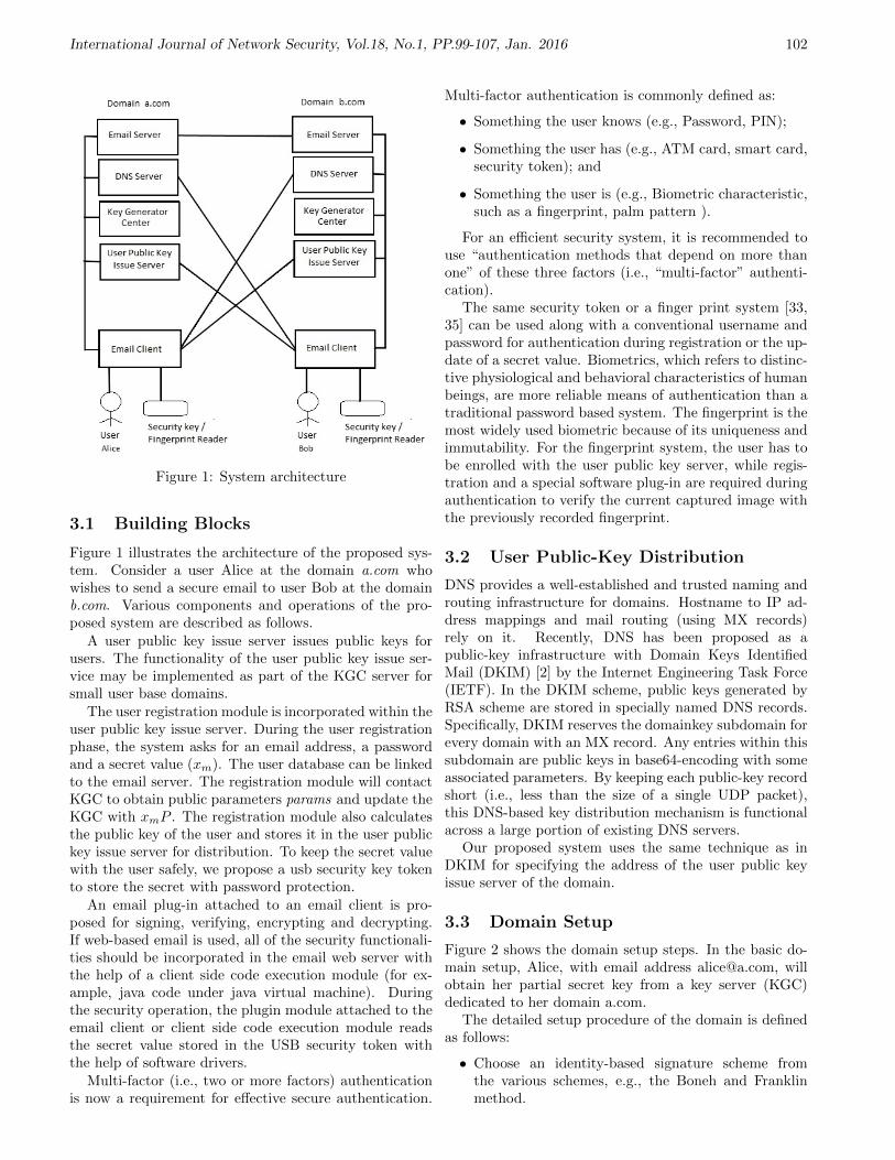
International Journal of Network Security, Vol.18, No.1, PP.99-107, Jan. 2016 102
Figure 1: System architecture
3.1 Building Blocks
Figure 1 illustrates the architecture of the proposed sys-tem. Consider a user Alice at the domain a.com whowishes to send a secure email to user Bob at the domainb.com. Various components and operations of the pro-posed system are described as follows.
A user public key issue server issues public keys forusers. The functionality of the user public key issue ser-vice may be implemented as part of the KGC server forsmall user base domains.
The user registration module is incorporated within theuser public key issue server. During the user registrationphase, the system asks for an email address, a passwordand a secret value (xm). The user database can be linkedto the email server. The registration module will contactKGC to obtain public parameters params and update theKGC with xmP . The registration module also calculatesthe public key of the user and stores it in the user publickey issue server for distribution. To keep the secret valuewith the user safely, we propose a usb security key tokento store the secret with password protection.
An email plug-in attached to an email client is pro-posed for signing, verifying, encrypting and decrypting.If web-based email is used, all of the security functionali-ties should be incorporated in the email web server withthe help of a client side code execution module (for ex-ample, java code under java virtual machine). Duringthe security operation, the plugin module attached to theemail client or client side code execution module readsthe secret value stored in the USB security token withthe help of software drivers.
Multi-factor (i.e., two or more factors) authenticationis now a requirement for effective secure authentication.
Multi-factor authentication is commonly defined as:
• Something the user knows (e.g., Password, PIN);
• Something the user has (e.g., ATM card, smart card,security token); and
• Something the user is (e.g., Biometric characteristic,such as a fingerprint, palm pattern ).
For an efficient security system, it is recommended touse “authentication methods that depend on more thanone” of these three factors (i.e., “multi-factor” authenti-cation).
The same security token or a finger print system [33,35] can be used along with a conventional username andpassword for authentication during registration or the up-date of a secret value. Biometrics, which refers to distinc-tive physiological and behavioral characteristics of humanbeings, are more reliable means of authentication than atraditional password based system. The fingerprint is themost widely used biometric because of its uniqueness andimmutability. For the fingerprint system, the user has tobe enrolled with the user public key server, while regis-tration and a special software plug-in are required duringauthentication to verify the current captured image withthe previously recorded fingerprint.
3.2 User Public-Key Distribution
DNS provides a well-established and trusted naming androuting infrastructure for domains. Hostname to IP ad-dress mappings and mail routing (using MX records)rely on it. Recently, DNS has been proposed as apublic-key infrastructure with Domain Keys IdentifiedMail (DKIM) [2] by the Internet Engineering Task Force(IETF). In the DKIM scheme, public keys generated byRSA scheme are stored in specially named DNS records.Specifically, DKIM reserves the domainkey subdomain forevery domain with an MX record. Any entries within thissubdomain are public keys in base64-encoding with someassociated parameters. By keeping each public-key recordshort (i.e., less than the size of a single UDP packet),this DNS-based key distribution mechanism is functionalacross a large portion of existing DNS servers.
Our proposed system uses the same technique as inDKIM for specifying the address of the user public keyissue server of the domain.
3.3 Domain Setup
Figure 2 shows the domain setup steps. In the basic do-main setup, Alice, with email address [email protected], willobtain her partial secret key from a key server (KGC)dedicated to her domain a.com.
The detailed setup procedure of the domain is definedas follows:
• Choose an identity-based signature scheme fromthe various schemes, e.g., the Boneh and Franklinmethod.
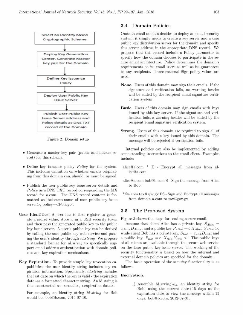
International Journal of Network Security, Vol.18, No.1, PP.99-107, Jan. 2016 103
Figure 2: Domain setup
• Generate a master key pair (public and master se-cret) for this scheme.
• Define key issuance policy Policy for the system.This includes definition on whether emails originat-ing from this domain can, should, or must be signed.
• Publish the user public key issue server details andPolicy as a DNS TXT record corresponding the MXrecord for a.com. The DNS record content is for-matted as ibclses=<name of user public key issueserver>, policy=<Policy>.
User Identities. A user has to first register to gener-ate a secret value, store it in a USB security tokenand then pass the generated public key to the publickey issue server. A user’s public key can be derivedby calling the user public key web service and pass-ing the user’s identity through id string. We proposea standard format for id string to specifically sup-port email address authentication with domain poli-cies and key expiration mechanisms.
Key Expiration. To provide simple key revocation ca-pabilities, the user identity string includes key ex-piration information. Specifically, id string includesthe last date on which the key is valid - the expirationdate -as a formatted character string. An id string isthus constructed as: <email>, <expiration date>.
For example, an identity string id string for Bobwould be: [email protected], 2014-07-10.
3.4 Domain Policies
Once an email domain decides to deploy an email securitysystem, it simply needs to create a key server and a userpublic key distribution server for the domain and specifythis server address in the appropriate DNS record. Wepropose that this record include a Policy parameter tospecify how the domain chooses to participate in the se-cure email architecture. Policy determines the domain’srequirements on its email users as well as its guaranteesto any recipients. Three external Sign policy values areused:
None. Users of this domain may sign their emails. If thesignature and verification fails, no warning headerwill be added by the recipient email signature verifi-cation system.
Basic. Users of this domain may sign emails with keysissued by this key server. If the signature and veri-fication fails, a warning header will be added by therecipient email signature verification system.
Strong. Users of this domain are required to sign all oftheir emails with a key issued by this domain. Themessage will be rejected if verification fails.
Internal policies can also be implemented by addingsome standing instructions to the email client. Examplesinclude:
[email protected] * E - Encrypt all messages from [email protected]
[email protected] [email protected] S - Sign the message from Aliceto Bob.
*@a.com [email protected] ES - Sign and Encrypt all messagesfrom domain a.com to [email protected]
3.5 The Proposed System
Figure 3 shows the steps for sending secure email.
Assume that client Alice has a private key, SAlice =xAliceDAlice, and a public key PAlice =< XAlice, YAlice >,while client Bob has a private key, SBob = xBobDBob, anda public key, PBob =< XBob, YBob >. The public keysof all clients are available through the secure web serviceon the User public key issue server. The working of thesecurity functionality is based on how the internal andexternal domain policies are specified for the domain.
The basic operation of the security functionality is asfollows:
Encryption.
1) Assemble id stringBob, an identity string forBob, using the current date+15 days as theexpiration date to view the message within 15days: [email protected], 2012-07-31.
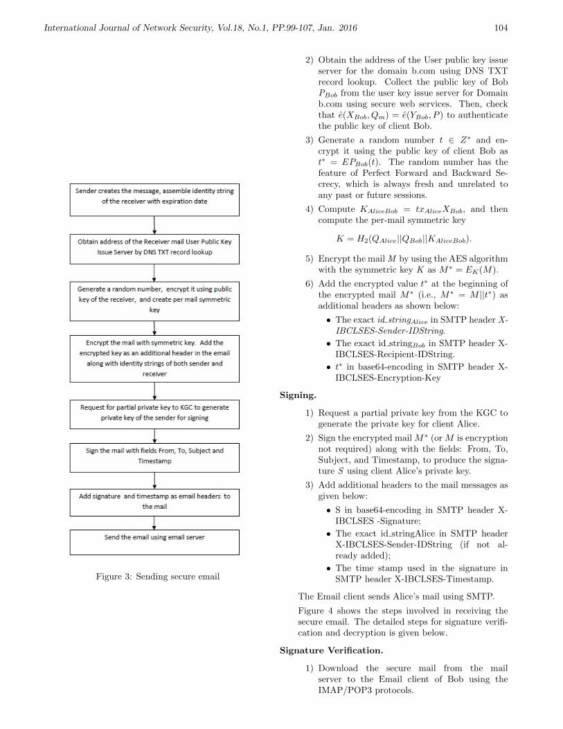
International Journal of Network Security, Vol.18, No.1, PP.99-107, Jan. 2016 104
Figure 3: Sending secure email
2) Obtain the address of the User public key issueserver for the domain b.com using DNS TXTrecord lookup. Collect the public key of BobPBob from the user key issue server for Domainb.com using secure web services. Then, checkthat e(XBob, Qm) = e(YBob, P ) to authenticatethe public key of client Bob.
3) Generate a random number t ∈ Z∗ and en-crypt it using the public key of client Bob ast∗ = EPBob(t). The random number has thefeature of Perfect Forward and Backward Se-crecy, which is always fresh and unrelated toany past or future sessions.
4) Compute KAliceBob = txAliceXBob, and thencompute the per-mail symmetric key
K = H2(QAlice||QBob||KAliceBob).
5) Encrypt the mail M by using the AES algorithmwith the symmetric key K as M∗ = EK(M).
6) Add the encrypted value t∗ at the beginning ofthe encrypted mail M∗ (i.e., M∗ = M ||t∗) asadditional headers as shown below:
• The exact id stringAlice in SMTP header X-IBCLSES-Sender-IDString.
• The exact id stringBob in SMTP header X-IBCLSES-Recipient-IDString.
• t∗ in base64-encoding in SMTP header X-IBCLSES-Encryption-Key
Signing.
1) Request a partial private key from the KGC togenerate the private key for client Alice.
2) Sign the encrypted mail M∗ (or M is encryptionnot required) along with the fields: From, To,Subject, and Timestamp, to produce the signa-ture S using client Alice’s private key.
3) Add additional headers to the mail messages asgiven below:
• S in base64-encoding in SMTP header X-IBCLSES -Signature;
• The exact id stringAlice in SMTP headerX-IBCLSES-Sender-IDString (if not al-ready added);
• The time stamp used in the signature inSMTP header X-IBCLSES-Timestamp.
The Email client sends Alice’s mail using SMTP.
Figure 4 shows the steps involved in receiving thesecure email. The detailed steps for signature verifi-cation and decryption is given below.
Signature Verification.
1) Download the secure mail from the mailserver to the Email client of Bob using theIMAP/POP3 protocols.
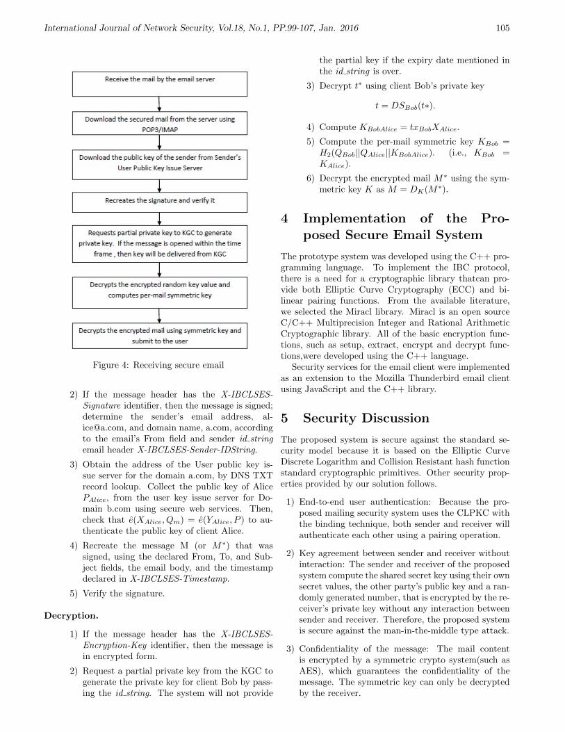
International Journal of Network Security, Vol.18, No.1, PP.99-107, Jan. 2016 105
Figure 4: Receiving secure email
2) If the message header has the X-IBCLSES-Signature identifier, then the message is signed;determine the sender’s email address, [email protected], and domain name, a.com, accordingto the email’s From field and sender id stringemail header X-IBCLSES-Sender-IDString.
3) Obtain the address of the User public key is-sue server for the domain a.com, by DNS TXTrecord lookup. Collect the public key of AlicePAlice, from the user key issue server for Do-main b.com using secure web services. Then,check that e(XAlice, Qm) = e(YAlice, P ) to au-thenticate the public key of client Alice.
4) Recreate the message M (or M∗) that wassigned, using the declared From, To, and Sub-ject fields, the email body, and the timestampdeclared in X-IBCLSES-Timestamp.
5) Verify the signature.
Decryption.
1) If the message header has the X-IBCLSES-Encryption-Key identifier, then the message isin encrypted form.
2) Request a partial private key from the KGC togenerate the private key for client Bob by pass-ing the id string. The system will not provide
the partial key if the expiry date mentioned inthe id string is over.
3) Decrypt t∗ using client Bob’s private key
t = DSBob(t∗).
4) Compute KBobAlice = txBobXAlice.
5) Compute the per-mail symmetric key KBob =H2(QBob||QAlice||KBobAlice). (i.e., KBob =KAlice).
6) Decrypt the encrypted mail M∗ using the sym-metric key K as M = DK(M∗).
4 Implementation of the Pro-posed Secure Email System
The prototype system was developed using the C++ pro-gramming language. To implement the IBC protocol,there is a need for a cryptographic library thatcan pro-vide both Elliptic Curve Cryptography (ECC) and bi-linear pairing functions. From the available literature,we selected the Miracl library. Miracl is an open sourceC/C++ Multiprecision Integer and Rational ArithmeticCryptographic library. All of the basic encryption func-tions, such as setup, extract, encrypt and decrypt func-tions,were developed using the C++ language.
Security services for the email client were implementedas an extension to the Mozilla Thunderbird email clientusing JavaScript and the C++ library.
5 Security Discussion
The proposed system is secure against the standard se-curity model because it is based on the Elliptic CurveDiscrete Logarithm and Collision Resistant hash functionstandard cryptographic primitives. Other security prop-erties provided by our solution follows.
1) End-to-end user authentication: Because the pro-posed mailing security system uses the CLPKC withthe binding technique, both sender and receiver willauthenticate each other using a pairing operation.
2) Key agreement between sender and receiver withoutinteraction: The sender and receiver of the proposedsystem compute the shared secret key using their ownsecret values, the other party’s public key and a ran-domly generated number, that is encrypted by the re-ceiver’s private key without any interaction betweensender and receiver. Therefore, the proposed systemis secure against the man-in-the-middle type attack.
3) Confidentiality of the message: The mail contentis encrypted by a symmetric crypto system(such asAES), which guarantees the confidentiality of themessage. The symmetric key can only be decryptedby the receiver.

International Journal of Network Security, Vol.18, No.1, PP.99-107, Jan. 2016 106
Figure 5: Pairing time
4) Message integrity and non-repudiation: Because thesender signs the email message using his/her privatekey, the integrity and non-repudiation feature of themessage can be verified, and the sender cannot dis-own the ownership of the email message.
5) Forward and backward secrecy: In the proposed sys-tem, each message session key during the messagetransmission is unique because both the sender andreceiver use the random number t, which is gener-ated by the sender and encrypted by the public keyof the receiver in each session. The random numberhas the feature of Perfect Forward and Backward Se-crecy, which is always fresh and unrelated to any pastor future sessions.
6 Benchmark and Conclusion
The most costly procedure of the proposed system is thepairing operation. Benchmarking tests were performed onthe operation, and the mean of 500 iterations was taken.The test only counts the time for a pairing, while therandom point generation part is not considered. We con-ducted the test on an Intel Core i5-2400 CPU @3.10 GHzwith 4GB RAM 1066MHz under the Windows 8 32 bit op-erating system and Oracle Linux 5.5 64-bit. For ECC 512bits, we obtained an average speed of 16.2 millisecondsin Linux and 26.5 milliseconds in Windows, and for 1024bits, we obtained 140.3 milliseconds in Linux and 284.24milliseconds in Windows. Detailed performance analysisis given in Figure 5. From the test results, it is clear thatwe get better performance in 64 bit Linux system than32-bit Windows and the proposed open standard systemis very efficient and can be used in secure messaging asan alternative to the certificate based conventional PKIsystem.
This paper proposed an end-to-end secure mailing sys-tem based on certificate-less public key Cryptography,with DNS as the mechanism to publish a user’s pub-lic key server address. The sender and receiver are ableto compute the same secure secret symmetric key with-out any message exchange between them. This avoidsa man-in-the-middle attack to obtain details of encryp-tion/decryption key and hence the contents of the email.
Additionally, the proposed mail system is based on El-liptic Curve Cryptography, which is very efficient com-pared to conventional RSA based email systems and isalso free from the heavy burden of certificate managementof PKI. It avoids the key escrow problem of IBC basedemail systems by incorporating a partial private key gen-eration system. The usability of IBE based systems aremuch better than PKI or PGP based systems. Moreover,the proposed system is based on standard cryptographicprimitives, which makes it secure against the standardsecurity model.
References
[1] B. Adida, D. Chau, S. Hohenberger, and R. L. Rivest,“Lightweight email signatures (extended abstract),”in Proceedings of the 5th international conference onSecurity and Cryptography for Networks (SCN’06),pp. 288–302, 2006.
[2] D. Boneh and M. Franklin, “Identity-based encryp-tion from the weil pairing,” in Advances in Cryp-tology (CRYPTO’01), LNCS 2139, Springer Verlag,pp. 213–229, 2001.
[3] J. Callas, L. Donnerhacke, H. Finney, and R. Thayer,Open PGP Message Format, Technical Report RFC2440, Nov. 1998.
[4] S. Chatterjee and P. Sarkar, Identity-based Encryp-tion, Springer Science+Business Media, LLC, 2011.
[5] L. Chen, K. Harrison, N. Smart, and D. Soldera,“Applications of multiple trust authorities in pair-ing based cryptosystems,” in International Confer-ence on Infrastructure Security (InfraSec’02), LNCS2437, Springer, pp. 260–275, 2002.
[6] T. Chen and S. Ma, “A secure email encryption proxybased on identity-based cryptography,” in Interna-tional Conference on MultiMedia and InformationTechnology (MMIT’08), pp. 284–286, 2008.
[7] S. S. M. Chow, “Removing escrow from identity-based encryption,” in Public Key Cryptography(PKC’09), LNCS 5443, Springer, pp. 256–276, 2009.
[8] M. Cooper, Internet X.509 Public Key Infrastructure(Latest Draft), IETF Internet Drafts, Jan. 2005.
[9] M. Crispin, Internet Mail Access Protocol (ver. 4),Technical Report RFC 1730, Dec. 1994.
[10] D. Crocker, T. Hansen, and M. Kucherawy, Do-mainkeys Identified Mail (DKIM) Signatures, Tech-nical Report RFC 6376, Sep. 2011.
[11] D. Eastlake, Domain Name System Security Exten-sions, Technical Report RFC 2535, Mar. 1999.
[12] B. A. Forouzan, Cryptography and Network Security,India: Tata McGraw-Hill Publishing Company Lim-ited, 2007.
[13] Fortinet, Forti Mail Identity Based Encryption, Jan.2014. (http://www. fortinet. com)
[14] M. Franklin and D. Boneh, “Identity based encryp-tion from the weil pairing,” Journal of Computing,vol. 32, no. 3, pp. 586–615, 2003.
International Journal of Network Security, Vol.18, No.1, PP.99-107, Jan. 2016 107
[15] R. Gangishetti, M. C. Gorantla, M. Das, andA. Saxena, “Threshold key issuing in identity-basedcryptosystems,” Computer Standards & Interfaces,vol. 29, no. 2, pp. 260–264, 2007.
[16] R. Gangishetti, M. C. Gorantla, M. L. Das, A. Sax-ena, and V. P. Gulati, “An efficient secure key issu-ing protocol in id-based cryptosystems,” in Proceed-ings of the IEEE International Conference on Infor-mation Technology: Coding and Computing (ITCC2005), pp. 674–678, Las Vegas, USA, Apr. 2005.
[17] C. Gentry, “Certificate-based encryption and the cer-tificate revocation problem,” in Advances in Cryp-tology (EUROCRYPT’03), LNCS 2656, Springer,pp. 272–293, 2003.
[18] E. Gerck, Secure Email Technologies X.509/PKI,PGP, IBE and Zmail: A Usability and SecurityComparison, ICFAI University Press, pp. 171–196,2007.
[19] C. Gu and Y. Zhu, “New efficient searchable encryp-tion schemes from bilinear pairings,” InternationalJournal of Network Security, vol. 10, no. 1, pp. 25–31, 2010.
[20] M. Hassouna, N. Mohamed, B. Barry, and E.Bashier, “An end-to-end secure mail system based oncertificateless cryptography in the standard securitymodel,” International Journal of Computer ScienceIssues, vol. 10, no. 2, pp. 264–271, 2013.
[21] P. Hoffman, SMTP Service Extension for SecureSMTP over Transport Layer Security, Technical Re-port RFC 3207, Feb. 2002.
[22] M. P. Hoyle and C. J. Mitchell, “On solutions tothe key escrow problem,” in State of the Art in Ap-plied Cryptography, LNCS 1528, Springer, pp. 277–306, 1998.
[23] HP, HP Security Voltage, Jan. 7, 2014. (http:// volt-age. com)
[24] S. Kwon and S. H. Lee, “Identity-based key issuingwithout secure channel in a broad area,” in Infor-mation Security Applications, LNCS 4298, Springer,pp. 30–44, 2007.
[25] P. Mockapetris, Domain Names - Concepts and Fa-cilities, Technical Report RFC 1034, Nov. 1987.
[26] P. Mockapetris, Domain Names - Implementationand Specification. IETF - Network Working Group,The Internet Society, Technical Report RFC 1035,Nov. 1987.
[27] B. Ramsdell, S/MIME Version 3 Message Specifica-tion, Technical Report RFC 2633, June 1999.
[28] RSA Laboratories, “What is public-key cryptogra-phy,” Jan. 20, 2014. (http://www. rsa. com/ rsal-abs/)
[29] A. R. Sattam and P. Kenneth, “Certificateless pub-lic key cryptography a full version,” in Asiacrypt’03,LNCS 2894, Springer, pp. 452–473, 2003.
[30] A. Shamir, “Identity based cryptosystems and signa-ture schemes,” Computer Science, vol. 196, pp. 47–53, 1984.
[31] D. Sharma and D. Jinwala, “Key generation protocolin IBC,” International Journal of Network Security,vol. 15, no. 5, pp. 341–349, 2013.
[32] T. S. Sobh and M. I. Amer, “PGP modification forsecuring digital envelope mail using COM+ and webservices,” International Journal of Network Security,vol. 13, no. 2, pp. 79–91, 2011.
[33] J. Tian, L. Li, and X. Yang, “Fingerprint-based iden-tity authentication and digital media protection innetwork environment,” Journal of Computer Scienceand Technology, vol. 21, no. 5, pp. 861–870, 2006.
[34] J. Wang, X. Bai, J. Yu, and D. Li, “Protectingagainst key escrow and key exposure in identity-based cryptosystem,” in Theory and Applicationsof Models of Computation (TAMC’07), LNCS 4484,Springer, pp. 148–158, 2007.
Lecture Notes in Computer Science Volume 4484,2007, pp 148-158
[35] Z. Wu, J. Tian, L. Li, C. P. Jiang, and X. Yang, “Asecure email system based on fingerprint authentica-tion,” in Scheme Intelligence and Security Informat-ics, pp. 250–253, 2007.
[36] P. Zimmerman, Pretty Good Privacy, Jan. 20, 2014.(http://www. pgp. com)
Mr. Suresh Kumar Balakrishnan, currently workingas an Engineer in Computer Division at Sree ChitraTirunal Institute for Medical Sciences & Technology,Thiruvananthapuram, India is an M.Tech holder inSoftware Engineering from Cochin University of Scienceand Technology, Kochi, India. He has well-versed experi-ence in implementing Computer Infrastructure, NetworkSecurity, Systems Management, Database Managementand Hospital Information System. He has more than 17years of experience in Computer Engineering fields. Heis pursuing Ph.D in Computer Science at Indira GandhiNational Open University, New Delhi, India.
Dr. V. P. Jagathy Raj, currently working as Profes-sor in Operations and Systems Management at School ofManagement Studies, Cochin University of Science andTechnology, Kochi. He is equally well-versed in both En-gineering and Management related areas. He has morethan 24 years of teaching and research experience in En-gineering and Management areas. He has more than 160research publications in National and International Jour-nals and Conference Proceedings to his credit in both En-gineering and Management related areas. He has alsopresented number of research papers in National and In-ternational conferences.

International Journal of Network Security, Vol.18, No.1, PP.108-115, Jan. 2016 108
Speeding up Pairing Computation UsingNon-adjacent Form and ELM Method
Chao-Liang Liu1, Gwoboa Horng2, and Du-Shiau Tsai3
(Corresponding author: Chao-Liang Liu)
Department of Applied Informatics and Multimedia, Asia University1
500, Lioufeng Rd., Wufeng, Taichung 41354, Taiwan R.O.C.Department of Computer Science and Engineering, National Chung-Hsing University2
250 Kuo Kuang Rd., Taichung, Taiwan R.O.C.Department of Information and Networking Technology, Hsiuping University of Science and Technology3
No.11 Gongye Rd, Dali Dist., Taichung City 412-80,Taiwan, R.O.C(Email: [email protected])
(Received Oct. 3, 2013; revised and accepted Jan. 15 & Mar. 26, 2014)
Abstract
The bilinear pairings such as Weil pairing and Tate pair-ing on elliptic curves have recently found many applica-tions in cryptography. The first efficient algorithm forcomputing pairing was originally proposed by Miller andmuch subsequent research has been directed at many dif-ferent aspects in order to improve efficiency. In 2003,Eisentrager, Lauter and Montgomery proposed a newpoint-double-addition method to speed up elliptic curvearithmetic computation and obtained a 7.8% performanceimprovement of the Miller algorithm of a general ellipticcurve. In 2006, Blake et al. proposed a new concept basedon the conjugate of a line to reduce the total number oflines in the Miller algorithm. In this paper we proposean enhancement of Eisentrager et al.’s algorithm for com-puting pairings. Our enhancement can further speed upthe pairing computation by 5.9%.Keywords: Elliptic curve cryptosystem, pairing-basedcryptosystem, pairing computation
1 Introduction
Elliptic curve cryptograph, introduced by Miller [21, 22]and Koblitz [13] independently around 1985, provides thesame level of security as the conventional public-key cryp-tography but with shorter keys. Numerous research ef-forts have been devoted to elliptic curve cryptographyand a lot of cryptosystems have been proposed. By us-ing Weil pairing, Menezes, Okamoto and Vanstone foundsome weak curves which contain cyclic groups that can betransformed into a finite field with small extension degree(MOV degree) [19]. Frey and Ruck extended their attackand found more weak curves with the Tate pairing [10].Basically, the Weil/Tate pairing is a mapping with non-
degenerate and bilinear properties, which will map a spe-cial pair of points on an elliptic curve to a certain mul-tiplicative subgroup of a finite field. In recent years, bi-linear pairings especially, Weil/Tate pairings, have foundpositive applications in cryptography. Indeed, many cryp-tographic applications based on pairings have been pro-posed, such as identity-based encryption systems [4], dig-ital signatures [5, 6, 25, 26], signcryption [16, 24] and keyagreement [12, 29]. As a result, the application of pairingsplays an important role in modern cryptography. There-fore, efficiently implementation of pairing computation isan important issue due to being the most costly operationin these cryptosystems. The first efficient algorithm forcomputing pairing was proposed by Miller [21, 22]. Themain idea of the Miller algorithm is to use lines to in-tegrate the divisors, which the algorithm has processed(see Section 2, for details). A lot of research has beenaimed in many different directions in order to improveefficiency [1, 2, 3, 7, 8, 10, 15, 17, 23, 27, 28, 33]. Theresearch of Barreto, Kim, Lynn and Scott [1], and Gal-braith, Harrison and Soldera [10] focuses particularly onthe Tate pairing over some special curves. The researchin [3, 8] can improve the performance of Weil/Tate pairingcomputation in general elliptic curves. We will continuein this direction.
It is well known that point subtraction and point ad-dition on an elliptic curve have the same cost. Non-adjacent form (NAF for short) has been widely used forthe scalar multiplication of nP for some point P on an el-liptic curve [11]. Through this property, the efficiency ofpairing computation can also be improved. For example,Eisentrager, Lauter and Montgomery gave a new point-addition/subtraction method (ELM method for short)to speed up scalar multiplication and pairing computa-tion [8]. The majority of research in [8] literacy has fo-

International Journal of Network Security, Vol.18, No.1, PP.108-115, Jan. 2016 109
cused on the double-addition/subtraction step when thebit of NAF representation of n is 1/-1. It is noticeable thatthe number of double step is twice the number of double-addition/subtraction step on average. With a parabolasubstitution, they get a 7.8% performance improvementof the Miller algorithm for a general elliptic curve (seeSection 2, for details).
In 2006, Blake et al. proposed a new concept based onthe conjugate of a line to reduce the total number of linesin the Miller algorithm [3]. Three different algorithmsare proposed for three cases namely, BMX-1, BMX-2 andBMX-3. The first algorithm, logn
2 field multiplicationsare eliminated when there are relatively more zero bits(or average cases) of the binary representation of integern. The second case is when there are relatively more onebits and 2H(n) field multiplications are removed whereH(n) is the number of bit 1. The third case saves logn
3
field multiplications when the characteristic of the field isthree. Some successive works further improving Blake etal.’s algorithms [14, 18, 31, 32].
In this paper, we propose an algorithm to eliminateone more field multiplication in a double step, which theELM method can not apply. Our new reduction methodcan reduce the number of lines, and hence improve theefficiency of pairing computation even further. The resultcan speed the computation of the Weil and Tate pairingby up to 5.9%, that is, combined with the ELM method,we can obtain a 13.3% performance improvement.
The rest of the paper is organized as follows. We brieflyreview some mathematical preliminaries, the Miller algo-rithm, the ELM method and Blake et al.’s formulae inSection 2. In Section 3 we describe our proposed algo-rithm. Its analysis is given in Section 4. Finally, someconcluding remarks are given in Section 5.
2 Background
2.1 Weil/Tate Pairing and Miller Algo-rithm
Let E be an elliptic curve over a finite field Fq where q is apower of a prime p. We can express E as the Weierstrassequation
E : y2 + a1xy + a3y = x3 + a2x2 + a4x + a6,
where a1, a2, a3, a4, a6 are all in Fq. If gcd(q, 6) = 1, anonsingular elliptic curve over the field Fq is given by anequation of the form
Es : y2 = x3 + ax + b
with a, b ∈ Fq and 4a3 + 27b2 6= 0. Let E(Fq) denotesthe set of points (x, y) ∈ F 2
q , satisfying Es together withthe point at infinity denoted as ∞. Then E(Fq) togetherwith point addition has a structure of an abelian groupwhich is denoted as E. Explicit formulas for computingthe coordinates of a point R = P +Q from the coordinates
of P and Q are well known [24, 26]. We give the formulaerelative to R = P +Q when P 6= ±Q. That is, R = (λ2−x1−x2, λx1−λx3− y1), where P = (x1, y1), Q = (x2, y2)and λ = (y2−y1)
(x2−x1).
A divisor D is a formal sum of symbols from the set(P ): P ∈ E with integer coefficients. That is D =∑
P∈K nP (P ). The set of all divisors, denoted by Div(E),is a free abelian group generated by E. Define the de-gree of a divisor D, deg(D), to be deg(D) =
∑P∈E nP .
We can define an important subgroup of Div(E), de-noted as Div0(E) = D ∈ Div(E): deg(D) = 0.The divisor of a nonzero rational function f is div(f) =∑
P∈E ordP (f)(P ), where ordP (f) is the order of f atP . It is well known that div(f) ∈ Div0(E) is called aprinciple divisor. If there exists a nonzero rational func-tion f such that D1 = D2 + div(f) then D1 and D2 aresaid to be equivalent, denoted as D1 ∼ D2. The sup-port of a divisor D is the set of points with nonzero co-efficients, that is, supp(D) = P ∈ E: nP 6= 0. Ifdiv(f) and D have disjoint support, then we can evaluatef(D) =
∏P∈E f(P )nP .
Let n be an integer relatively prime to q and P, Q ∈E[n], where E[n] is the n-torsion subgroup of E. Thenthere exist divisors DP , DQ such that DP ∼ (P ) − (∞)and DQ ∼ (Q) − (∞). Further, there exist functions fP ,fQ such that div(fP ) = nDP and div(fQ) = nDQ. IfDP and DQ have disjoint supports, then the Weil pair-ing is en(P,Q) = fP (DQ)
fQ(DP ) . And the Tate pairing of or-der n is the map τn: E(Fq)[n]E(Fqk)/nE(Fqk) → Fqk ,with τn(P, Q) = fn(DQ)(q
k−1)/n, where div(fn) = n(P )−n(∞). Hence, computing the Weil/Tate pairing can bereduced to the evaluation of fP (S), where S is in the sup-port of DQ.
We briefly describe the main idea of the Miller algo-rithm as follows: Let DP = (P+R)−(R) with an auxiliarypoint R and Dj
P = j(P +R)−j(R)−(jP )+(∞), and thenthere is a rational function fj such that div(fj) = Dj
P , foreach integer j, in particular, fn = fP . Hence
div(fj+k) = (j + k)(P + R)− (j + k)(R)−((j + k)P ) + (∞)
= [(j(P + R)− j(R)− (jP ) + (∞)]+[k(P + R)− k(R)− (kP ) + (∞)]+(jP ) + (kP )− ((j + k)P )− (∞)
= div(fj) + div(fk)+[(jP ) + (kP ) + (−(j + k)P − 3(∞)]−[((j + k)P ) + (−(j + k)P )− 2(∞)]
= div(fj) + div(fk) + div(LjP,kP )−div(L(j+k)P ),
where LjP,kP be a line through the points jP, kP and−(j + k)P . L(j+k)P be a vertical line through the points(j + k)P and −(j + k)P . Then, fj+k = fjfk( LjP,kP
L(j+k)P. As
a result, we can obtain fj+k from fj and fk with some”glue”: the appropriate lines, LjP,kP and L(j+k)P .

International Journal of Network Security, Vol.18, No.1, PP.108-115, Jan. 2016 110
We can compute fn(S) recursively with initial valuesf0 = 1 and f1 = LP+R
LR,R. We describe the following algo-
rithm, which is similar to the algorithm proposed in [1, 3].Note that we can perform the Miller algorithm to com-pute Tate pairing by changing the initial value f1 = 1,see [1] for details.
Algorithm 1 Miller algorithm
1: INPUT: Elliptic curve E, integer n =∑t
i=0 bi2i withbi ∈ 0, 1 and bt = 1, and points P , S ∈ E where Phas order n.
2: OUTPUT: f = fn(S).3: f ← f1; Z ← P ;4: for j ← t− 1 down to 0 do5: f ← f2 LZ,Z(S)
L2Z(S) ; Z ← 2Z;6: for j ← t− 1 down to 0 do7: f ← f2 LZ,Z(S)
L2Z(S) ; Z ← 2Z;8: if bj = 1 then9: f ← f1f
LZ,P (S)LZ+P (S) ; Z ← Z + P ;
10: return f ;11: End
2.2 ELM Method
In Algorithm 1, the cost of pairing computation consists oftwo main parts. One is a scalar multiplication of nP . Theother is an exponential computation and multiplicationwith the glue. To decrease the cost of point’s double-addition/subtraction of scalar multiplication, Eisentrageret al. eliminate two field multiplications through a newmethod to compute 2P + Q by computing P + Q and2P + Q = (P + Q) + P . Note that, we do not care aboutthe intermediate result P + Q. The explicit formulae aredescribed as follows:
λ1 =y2 − y1
x2 − x1, x3 = λ2
1 − x1 − x2
λ2 = −λ1 − 2y1
x3 − x1, x4 = λ2
2 − x1 − x3
y4 = (x1 − x4)λ2 − y1,
where P = (x1, y1), Q = (x2, y2), x1 6= x2, P + Q =(x3, y3), and 2P + Q = (x4, y4) on an elliptic curve ES .Moreover, λ1 is the slope of LP,Q and λ2 is the slope ofLP+Q,P .
To apply this point double-addition/subtractionmethod for the Miller algorithm, they construct aparabola to glue the Miller’s divisors, whenever the cor-responding bit is one, see [8] for detail.
Suppose we use the binary method in [11] to form nP ,where n has t bits. There are 2t/3 doubles and t/3 double-additions/subtractions. By way of estimating a divisionas 5.18 field multiplications, they compute the averagecost of the standard algorithm as
(16.18× 2t/3) + (31.36× t/3)t
= 21.24
field multiplications per bit, and the average cost of theirnew method is
(16.18× 2t/3) + (26.36× t/3)t
= 19.57
field multiplications per bit. The performance improve-ment ratio for their new method is 7.8%. It is noticeablethat these estimations are based on the computation ofTate pairing for which fn(Q1) and fn(Q2) are computedat the same time. Please see [8] or Section 4 for details.
We also need a divisor subtraction formula to use theNAF method to form fn(S) with respect to the Milleralgorithm. Therefore, they proposed the first divisor sub-traction formula:
div(fj−k) = (j − k)(P + R)− (j − k)(R)−((j − k)P ) + (∞)
= [(j(P + R)− j(R)− (jP ) + (∞))]−[k(P + R)− k(R)− (kP ) + (∞)]+(jP )− (kP )− ((j − k)P ) + (∞)
= div(fj)− div(fk)+[(jP ) + (−jP )− 2(∞)]−[(−jP ) + (kP ) + ((j − k)P )− 3(∞)]
= div(fj)− div(fk) + div(LjP )−div(L−jP,kP ),
Therefore,
fj−k =fj
fk· LjP
L−jP,kP. (1)
2.3 Blake et al’s Lemmas
From the analysis in [8], we know that if we can reduce oneline then at least one field multiplication is saved in theMiller algorithm. For this reason, Blake et al. proposedthree algorithms to reduce the number of lines. The firstalgorithm is suitable for every case. The second algorithmcan work well if the Hamming weight of n is high. Thethird algorithm is proposed for fields of characteristic 3.These algorithms are based on the following two lemmaswhich were proved in [3].
Lemma 1. If the line L(x, y) intersects with E at pointsP = (a, b), Q = (c, d) and −(P + Q) = (α, β), thenL(x, y)L(x, y) = −(x − a)(x − c)(x − α), where L(x, y)is the conjugate of L with L(R) = L(−R) for R ∈ E.
Lemma 2. Let Q ∈ E[n], S ∈ E and S 6= Q, 2Q, · · · ,nQ, then
1) LQ,Q(S)
L2Q(S)L2Q(S)
= −1LQ,Q(−S) .
2) For all integer k, we have L(k+1)Q,kQ(S)
L(k+1)Q(S)L(2k+1)Q(S) =
− LkQ(S)L(k+1)Q,kQ(−S) .
3) LQ,Q(S)L2Q,Q(S)L2Q(S)L3Q(S) = −LQ,Q(S)LQ(S)
L2Q,Q(−S) .

International Journal of Network Security, Vol.18, No.1, PP.108-115, Jan. 2016 111
They also remark that [3]:
1) Since div(f) = fiv(cf) for any nonzero constant c ∈K, the sign does not affect the pairing computationand therefore, minus signs will be omitted in the useof the above lemma.
2) The point P ∈ E[n] will be fixed and Q is taken to besome multiple of P . In order to satisfy the conditionof the lemma, it is sufficient to let S 6= P , 2P , · · · ,nP . This is also the requirement of the original Milleralgorithm.
3 A New Method for ComputingPairings
In Section 2, the ELM method concentrates on thedouble-addition/subtraction step in the point’s scalarmultiplication, however the number of double steps istwice the number of double-addition/subtraction steps.Therefore, we suggest a new algorithm to reduce one fieldmultiplication when the corresponding bit of n is 0 in theMiller algorithm. Before expressing this new algorithm,we briefly describe the limitations of their method to com-pute the pairing.
To compute 2P +Q via P +Q, where P , Q, P +Q and2P + Q on an elliptic curve Es but P 6= ±Q. Then thecapability and the limitations of their method are:
1) We have the x-coordinators of the points P , Q, P +Qand 2P + Q. But we do not have the x-coordinatorof the point 2P .
2) We have the y-coordinators of the points P , Q and2P + Q. But we do not have the y-coordinators ofP + Q and 2P .
3) We have the slopes for the lines LP,Q and LP+Q,P .
4) We can construct the linear functions LP,Q, LP+Q,P ,LP , LQ, LP+Q, and L2P+Q. But we cannot constructL2P,Q and L2P .
The detail description of the divisor subtraction for-mula (Equation (1)) with their point double-subtractionmethod in the Miller algorithm is
f ← f2
f1· LZ(S)LZ−P,Z(S)L−Z,P (S)L2Z−P (S)
;Z ← 2Z − P ;
when the bit of n is −1. Although the linear functionsLZ , LZ−P,Z , L2Z−P , and L−Z,P can be constructed, noparabola was revealed in [8]. It is well-known that thereare no consecutive nonzero bits in the NAF representationsuch that there is always a zero bit before -1. In [3],they have examined the reduction formulae of bit 0 andbit 1, however, there were few studies of the relationshipbetween bit 0 and bit -1. Therefore, we have to extendLemma 2.2 to Lemma 3.1 in order to establish a reductionformula for this case.
Lemma 3. Let Q ∈ E[n], S ∈ E and S 6= Q, 2Q, · · · , nQ,then L(k−1)Q,kQ(S)
LkQ(S)L(2k−1)Q(S) = L(k−1)Q(S)
L(k−1)Q,kQ(−S) .
Proof. For a point S ∈ E, we write S = (xS , yS), that is,xS is the x-coordinate of S and yS is the y-coordinate ofS. By Lemma 2, we have:
L(k − 1)Q, kQ(S)LkQ(S)L(2k−1)Q(S)
=L(k − 1)Q, kQ(S)L(k−1)Q,kQ(S)
LkQ(S)L(2k−1)Q(S)L(k−1)Q,kQ(S)
=−(xS − x(k−1)Q)(xS − xkQ)(xS − x(2k−1)Q
(xS − xkQ)(xS − x(2k−1)Q)L(k−1)Q,kQ(−S)
=L(k−1)Q(S)
L(k−1)Q,kQ(−S).
Consider the NAF representation of n =∑t
i=0 bi2i
with bi ∈ 0, 1, bt = 1 and bi+1 · bi = 0 for 0 ≤ i < t. Wegive the detail descriptions of the following three reduc-tion formulae by applying Lemma 2.2 and Lemma 3.1.These formulae play a key role in our algorithm. Sup-pose that the Miller algorithm is performed by an addi-tion/subtraction chain and glues the divisors in the traceof the point addition (Z±P )+Z after Z±P in the threecases. Note that, LQ(S) and L−Q(S) have the same valuefor points Q and S on an elliptic curve, and we can omitthe minus signs as remarked in Section 2.3.
1) Case (0, 0) performs:
f ← f2 LZ,Z(S)L2Z(S)
; Z ← 2Z;
f ← f2 L2Z,2Z(S)L4Z(S)
; Z ← 2Z;
Putting together, we have:
f ← (f2 LZ,Z(S)L2Z(S)
)2L2Z,2Z(S)L4Z(S)
= f4−L2
Z,Z(S)L2Z,2Z(−S)
Omitting the minus sign, we have:
f ← f4L2
Z,Z(S)L2Z,2Z(−S)
; Z ← 4Z.
2) Case (0,1) performs:
f ← f2 LZ,Z(S)L2Z(S)
;Z ← 2Z;
f ← f1f2 LZ,P (S)LZ+P,Z(S)LZ+P (S)L2Z+P (S)
; Z ← 2Z + P ;

International Journal of Network Security, Vol.18, No.1, PP.108-115, Jan. 2016 112
Putting together, we have:
f ← (f2 LZ,Z(S)L2Z(S)
)2 · f1L2Z,P (S)L2Z+P (S)
L2Z+P,2Z(S)L4Z+P (S)
= f1f4L2
Z,Z(S)L2
2Z(S)L2Z,P (S)L2Z+P (S)
·L2Z+P,2Z(S)L2Z+P,2Z(−S)L4Z+P (S)L2Z+P,2Z(−S)
= f1f4L2
Z,Z(S)L2
2Z(S)L2Z,P (S)L2Z+P (S)
·[−L2Z+P (S)L2Z(S)L4Z+P (S)L4Z+P (S)L2Z+P,2Z(−S)
= f1f4−L2
Z,Z(S)L2Z,P (S)L2Z(S)L2Z+P,2Z(−S)
.
Omitting the minus sign, we have:
f ← f1f4
L2Z,Z(S)L2Z,P (S)
L2ZL2Z+P,2Z(−S); Z ← 4Z + P.
3) Case (0, -1) performs:
f ← f2 LZ,Z(S)L2Z(S)
;Z ← 2Z;
f ← f2
f1
LZ(S)L−Z,P (S)
LZ−P,Z(S)L2Z−P (S)
; Z ← 2Z − P ;
Putting together, we have:
f ← (f2 LZ,Z(S)L2Z(S)
)2 · 1f1
L2Z(S)L2Z,P (S)
L2Z−P,2Z(S)L4Z−P (S)
=f4
f1
L2Z,Z(S)
L22Z(S)
L2Z(S)L−2Z,P (S)
·L2Z−P,2Z(S)L2Z−P,2Z(−S)L4Z−P (S)L2Z−P,2Z(−S)
=f4
f1
L2Z,Z(S)
L22Z(S)L−2Z,P (S)
·[−L2Z−P (S)L2Z(S)L4Z−P (S)L4Z−P (S)L2Z−P,2Z(−S)
=f4
f1
−L2Z,Z(S)L2Z−P (S)
L−2Z,P (S)L2Z−P,2Z(−S).
Omitting the minus sign, we have:
f ← f4
f1
L2Z,Z(S)L2Z−P (S)
L−2Z,P (S)L2Z−P,2Z(−S); Z ← 4Z − P.
From these formulae, there is only one line LZ,Z (orL2Z,2Z) which needs to be evaluated at point S whencethe relative bit of n is zero. That is, we can eliminate onefield multiplication when we glue the divisors in the threecases (0, 0), (0, 1) and (0, -1). These detail descriptions ofthe three cases also provide the correctness of an improvedMiller algorithm which we will describe in Algorithm 2.
Algorithm 2 The improved Miller algorithm
1: INPUT: Elliptic curve E, integer n =∑t
i=0 bi2i withbi ∈ 0, 1, bt = 1, bi+1 · bi = 0 for 0 ≤ i < t, andpoints P , S ∈ E where P has order n.
2: OUTPUT: f = fn(S).3: f ← f1; Z ← P ; i ← t− 1;4: while i > 0 do5: if (bi, bi−1) = (0, 0) then
6: f ← f4 L2Z,Z(S)
L2Z,2Z(−S) ; Z ← 4Z; i ← i− 2; Case 07: if (bi, bi−1) = (0, 1) then
8: f ← f1f4 L2
Z,Z(S)L2Z,P (S)
L2Z(S)L2Z+P,2Z(−S) ; Z ← 4Z + P ; i ← i− 2;Case 1
9: if (bi, bi−1) = (0,−1) then
10: f ← f4
f1
L2Z,Z(S)L2Z−P (S)
L−2Z,P (S)L2Z−P,2Z(−S) ; Z ← 4Z−P ; i ← i−2;Case 2
11: if (bi, bi−1) = (1, 0) then12: f ← f1f
2 LZ,P (S)LZ(S)LZ+P,Z(−S) ; Z ← 2Z + P ; i ← i− 1;
Case 313: if (bi, bi−1) = (−1, 0) then14: f ← f2
f1
LZ(S)LZ−P,Z(S)L−Z,P (S)L2Z−P (S) ; Z ← 2Z − P ; i ← i− 1;
Case 415: end-while16: if i = 0 then17: if bi = 1 then18: f ← f2LZ,Z(S); Z ← 2Z;19: if bi = 1 then20: f ← f1f
2 LZ,P (S)LZ(S)LZ+P,Z(−S) ; Z ← 2Z + P ;
21: if bi = −1 then22: f ← f2
f1
LZ(S)LZP ,Z(S)
L−Z,P (S) ; Z ← 2Z − P ;23: return f ;24: End
4 Analysis
In this section, detailed analysis of the improvement isgiven. Additionally, the estimation of the cost of the im-provement is in accordance with the rules which were dis-cussed in [8]. The basic concept of the improvement isthat it tries to find the maximum number of the pattern(0, 0) and only processes the first bit of the pattern (1,0) in Case 3 and the pattern (-1, 0) in Case 4. It isnoticeable that the methods of Case 3 and Case 4 canbe replaced with the parabola substitution method whichwas described in [8]. As a result, only one line has to beevaluated for each zero bit of n in our improvement.
As indicated in [1, 3, 8], in the actual implementationof pairing computation, the operations in the numeratorand denominator in each step are separated and performone division at the very end. In [8], they estimate thetotal cost of pairing computation with the following spec-ifications:
1) The pairing evaluates a quotient of the form fn(Q1)fn(Q2)
for two points Q1, Q2 on E, where n is a t bits integerwhich consists of 2t/3 zero bits and t/3 nonzero bits.

International Journal of Network Security, Vol.18, No.1, PP.108-115, Jan. 2016 113
2) The cost of each bit is counted as the total numberof field multiplications, but the cost of all field addi-tions/subtractions are omitted.
3) The cost of a division is estimated as 5.18 field mul-tiplications.
4) The cost of the standard algorithm is 16.18 field mul-tiplications for each zero bit and 31.36 field multipli-cations for each nonzero bit.
5) The cost of the ELM method is 16.18 field multiplica-tions for each zero bit and 26.36 field multiplicationsfor each nonzero bit.
For simplicity, our estimation follows the analysis in [8]which counts the cost in each case separately. Plus, onlythree different cases need to be analyzed between our im-provement and the ELM method. These are the cases ofthe cost of bit 0 and the cost of bit ±1 in (0, 1) and (0,-1):
1) The cost of bit 0 which appears in the patterns (0,0), (0, 1) and (0, -1): In these cases, we must performf ← f2LZ,Z(S) and Z ← 2Z for each bit 0.
a. A point doubling operation costs 3 field multi-plications and a division.
b. Evaluating LZ,Z at points Q1 and Q2 costs 2field multiplications.
c. Multiplying 4 fractions fnu, fde, LZ,Z(Q1), andLZ,Z(Q2) costs 4 field multiplications. Wherefnu is the numerator of f and fde is the de-nominator of f . That is, we must computefnu·fnu·LZ,Z(Q1)fde·fde·LZ,Z(Q2)
in the improvement whence therelative bit is 0.
The total cost of this case is 3 + 5.18 + 2 + 4 = 14.18field multiplications.
2) The cost of bit 1 of (0, 1): In this case, we must
perform f ← f1f4 L2
Z,Z(S)L2Z,P (S)
L2Z(S)L2Z+P,2Z(−S) and Z ← 4Z +P . Then they can be separated as:
f ← [f2L2Z,Z(S)]2f1
L2Z,P (S)L2Z(S)L2Z+P,2Z(−S)
and Z ← (2Z +P )+2Z. The cost of the first compo-nent is estimated in A. We estimate the cost of thesecond component as follows:
a. A point double-addition costs 3 field multiplica-tions and 2 divisions.
b. Evaluating L2Z,P at points Q1 and Q2 costs 2field multiplications. Evaluating L2Z+P,2Z atpoints −Q1 and −Q2 costs 2 field multiplica-tions.
c. Multiplying 10 fractions costs 10 field multipli-cations.
The total cost of this case is 3+10.36+4+10 = 27.36field multiplications.
3) The cost of bit -1 which appear in the pattern(0, -1): In this case, we must perform f ←f4
f1
L2Z,Z(S)L2Z−P (S)
L−2Z,P (S)L2Z−P,2Z(−S) AND Z ← 4Z − P . Thenthey can be separated as:
f ← [F 2lz,z(s)]2L2Z−P (S)
f1 · L−2Z,P (S)L2Z−P,2Z(−S)
and Z ← (2Z−P )+2Z. The cost of the first compo-nent is estimated in A. We estimate the cost of thesecond component as follows:
a. A point double-subtraction costs 3 field multi-plications and 2 divisions.
b. Evaluating L−2Z,P at points Q1 and Q2 costs2 field multiplications. Evaluating L2Z−P,2Z atpoints −Q1 and −Q2 costs another 2 field mul-tiplications.
c. Multiplying 10 fractions costs 10 field multipli-cations.
The total cost of this case is 3 + 10.36 + 2 + 2 + 10 =27.36 field multiplications.
Before we compute the average cost of our refinement,we define two sets, ODD and EV EN , for the patternw, which appears in the NAF representation of n, wheren =
∑ti=0 bi2i with bi ∈ 0, 1, bt = 1 and bi+1 · bi = 0 for
0 ≤ i < t. That is, ODD = w = bi+r+1(0, 0, · · · , 0)bi: ris odd, bi+r+1 ·bi 6= 0, 0 ≤ i < i+r+1 ≤ t and EV EN =w = bi+r+1(0, 0, · · · , 0)bi: r is even, bi+r+1 · bi 6= 0,0 ≤ i < i + r + 1 ≤ t.
Without lost of generality, assume |ODD| = |EV EN |.Accordingly, the total number of Case 1 and Case 2is estimated as the same as the total number of Case3 and Case 4 in Algorithm 2. That is, in half of allnonzero bits, each bit costs 27.36 field multiplicationsand each bit of the rest costs 26.36 field multiplica-tions. Therefore, the average cost of our improvementis 14.18×2t/3+27.36×t/6+26.36×t/6
t = 18.41 field multiplica-tions per bit. Compared to the standard algorithm, theimprovement is 21.24−18.41
21.24 = 13.3%. In other words, weenhance the ELM method to obtain a 19.57−18.41
19.57 = 5.9%improvement in performance.
5 Concluding Remarks
An improvement in the computation of the pairings hasbeen given and the corresponding performance has beenanalyzed. It is noticeable that this algorithm can be moreefficient if more lines belonging to the nonzero bits arereduced. We can achieve this purpose by recoding theNAF representation of n into many patterns, such as (0r),(0, 1, 0) and (0,−1, 0). But this is getting half the resultwith twice the effort. Therefore, we propose a concise

International Journal of Network Security, Vol.18, No.1, PP.108-115, Jan. 2016 114
algorithm which focuses on performance improvement ofthe zero bits and gives a simplified performance analysis.As a result, the proposed algorithm gains an improve-ment of 5.9% in performance when compared to the ELMmethod.
Acknowledgments
This study was supported by the Asia University, undergrant No. 98-NSC-02 and 101-ASIA-34. The authorsgratefully acknowledge the anonymous reviewers for theirvaluable comments.
References
[1] P. Barreto, H. Kim, B. Lynn, and M. Scott, “Ef-ficient algorithms for pairing-based cryptosystems,”in Advance in Cryptography (Crypt’02), LNCS 2442,pp. 354–368, Springer-Verlag, 2002.
[2] S. Basu, “A new parallel window-based implemen-tation of the elliptic curve point multiplication inmulti-core architectures,” International Journal ofNetwork Security, vol. 14, no. 2, pp. 101–108, 2012.
[3] I. Blake, V. Murty, and G. Xu, “Refinement ofMiller’s algorithm for computing the Weil/Tate pair-ing,” Journal of Algorithms, vol. 58, pp. 134–149,2006.
[4] D. Boneh, and M. Franklin, “Identity-base encryp-tion from the Weil pairing,” in Advance in Cryptogra-phy (Crypto’01), LNCS 2139, pp. 213–239, Springer-Verlag, 2001.
[5] D. Boneh, B. Lynn, and H. Shacham, “Short sig-nature from the weil pairing,” in Advance in Cryp-tography (Asiacrypt’01), LNCS 2248, pp. 514–532,2Springer-Verlag, 001.
[6] D. Boneh, X. Boyen, and H. Shacham, “Shortgroup signatures,” in Advance in Cryptography(Crypto’04), LNCS 3152, pp. 41–55, Springer-Verlag,2004.
[7] Y. Ding, K. W. Wong, and Y. M. Wang, “Jointsparse form of window three for Koblitz curve,” In-ternational Journal of Network Security, vol. 2, no. 2,pp. 126–130, 2006.
[8] K. Eisentr?ger, K. Lauter, and P. L. Montgomery,“Fast elliptic curve arithmetic and improved Weilpairing evaluation,” in Topics in Cryptology (CT-RSA’03), LNCS 2612, pp. 343–354, Springer-Verlag,2003.
[9] G. Frey and H. Ruck, “A remark concerning m-divisibility and the discrete logarithm in the divisorclass group of curves,” Mathematics of Computation,vol. 62, pp. 865–874, 1994.
[10] S. Galbraith, K. Harrison, and D. Soldera, “Imple-menting the tate pairing,” in Algorithm Number The-ory Symposium, LNCS 2369, pp. 324–337, Springer-Verlag, 2002.
[11] IEEE Computer Society, IEEE Standard Specifica-tions for Public-key Cryptography, IEEE Standard1363–2000, 2000.
[12] A. Joux, “A one round protocol for tripartiteDiffie-Hellman,” in Algorithmic Number Theory,LNCS 1838, pp. 385–393, Springer-Verlag, 2000.
[13] N. Koblitz, “Elliptic curve cryptosystems,” Mathe-matics of Computation, vol. 48, pp. 203–209, 1987.
[14] D. P. Le and C. L. Liu, “Refinements of Miller’s al-gorithm over weierstrass curves revisited,” The Com-puter Journal, vol. 54, no. 10, pp. 1582–1591, 2011.
[15] J. Lee, H. Kim, Y. Lee, S. M. Hong, and H. Yoon,“Parallelized scalar multiplication on elliptic curvesdefined over optimal extension field,” InternationalJournal of Network Security, vol. 4, no. 1, pp. 99–106, 2007.
[16] X. Li and K. Chen, “Identity based proxy-signcryption scheme from pairings,” in Proceedingsof 2004 IEEE International Conference on ServicesComputing (IEEE-SCC’04), pp. 494–497, 2004.
[17] T. C. Lin, “Algorithms on elliptic curves over fieldsof characteristic two with non-adjacent forms,” Inter-national Journal of Network Security, vol. 9, no. 2,pp. 117–120, 2009.
[18] C. Liu, G. Horng, and T. Chen. ”Further refine-ment of pairing computation based on Miller’s al-gorithm,” Applied Mathematics and Computation,vol. 189, no. 1, pp. 395–409, 2007.
[19] A. Menezes, T. Okamoto, and S. A. Vanstone, “Re-ducing elliptic curve logarithms to logarithms in afinite field,” IEEE Transaction on Information The-ory, vol. 39, pp. 1639–1646, 1993.
[20] A. Menezes, Elliptic Curve Cryptosystems, KluwerAcademic Publishers, 1993.
[21] V. Miller, “Use of elliptic curves in cryptosystems,”in Advance in Cryptography (Crypto’85), LNCS 218,pp. 417–426, Springer-Verlag, 1986.
[22] V. Miller, Short Programs for Functions onCurve, Sept. 2002. (http://www.researchgate.net/profile/Victor Miller/publication/2551688 Short Programs for functions on Curves/links/ 0c96052e065ca0bdbf000000.pdf)
[23] S. Moon, “A binary redundant scalar point multipli-cation in secure elliptic curve cryptosystems,” Inter-national Journal of Network Security, vol. 3, no. 2,pp. 132–137, 2006.
[24] D. Nalla and K. Reddy, “Signcryption scheme foridentity-based cryptosystems,” Cryptology ePrintArchive, Report, 2003/066, 2003.
[25] H. Sahu and B. K. Sharma, “An MSS based on theelliptic curve cryptosystem,” International Journalof Network Security, vol.11, no. 2, pp. 118, 2010.
[26] R. Sakai, K. Ohgishi, and M. Kasahara, “Cryptosys-tems based on pairing,” in SCIS’00, pp. 26–28, 2000.
[27] Z. J. Shi and H. Yun, “Software implementations ofelliptic curve cryptography,” International Journalof Network Security, vol. 7, no. 1, pp. 141–150, 2008.

International Journal of Network Security, Vol.18, No.1, PP.108-115, Jan. 2016 115
[28] S. M. Shohdy, A. B. El-Sisi, and N. Ismail, “Hard-ware implementation of efficient modified karat-suba multiplier used in elliptic curves,” InternationalJournal of Network Security, vol. 11, no. 3, pp. 155–162, 2010.
[29] N. P. Smart, “An identity based authenticated keyagreement protocol based on weil pairing,” Electron-ics Letters, vol. 38, pp. 630–632, 2002.
[30] J. H. Silverman, The Arithmetic of Elliptic Curves,Graduate Texts in Mathematics, vol. 106, Springer,New York, 1986.
[31] T. Wu, H. Du, M. Zhang, and R. Wang, “Improvedalgorithm of the tate pairing in characteristic three,”in The First International Symposium on Data, Pri-vacy, and E-Commerce, pp. 453–455, 2007.
[32] T. Wu, M. Zhang, X. Xu, and R. Wang, “Improvedalgorithm for tate pairing computation,” in Proceed-ings of The IEEE International Symposium on Elec-tronic Commerce and Security (ISECS’08), pp. 41–45, 2008.
[33] D. Yong, Y. F. Hong, W. T. Wang, Y. Y. Zhou,and X. Y. Zhao, “Speeding Scalar Multiplication ofElliptic Curve over GF (2mn),” International Journalof Network Security, vol. 11, no. 2, pp. 70–77, 2010.
Chao-Liang Liu was born in Hsinchu, Taiwan, in 1966.He completed his B.Sc. degree in mathematics fromNational Cheng-Kung University, Taiwan, in 1989, andthe Ph.D. degree in Institute of Computer Science fromNational Chung Hsing University, Taiwan, in 2007. Heis currently an assistant professor at the Department ofApplied Informatics and Multimedia, Asia University,Taiwan. His research interests include informationsecurity, cryptography, elliptic curve cryptosystem andpairing computation.
Gwoboa Horng received the B.S. degree in ElectricalEngineering from National Taiwan University in 1981and the M.S. and Ph.D. degrees from University ofSouthern California in 1987 and 1992 respectively, all inComputer Science. Since 1992, he has been on the facultyof the Department of Computer Science and Engineeringat National Chung-Hsing University, Taichung, Taiwan,R.O.C. His current research interests include artificialintelligence, cryptography and information security.
Du-Shiau Tsai received the B.S. degree in Departmentof Computer Science and Information Management fromProvidence University, Taiwan, in 1996 and the M.S. de-gree in Institute of Computer Science, National ChungHsing University, Taiwan, in 2003. Since 2005, he hasbeen on the faculty at Hsiuping University of Science andTechnology, Taiwan, ROC. He received the Ph.D. degreein the Institute of Computer Science, National Chung Hs-ing University, Taiwan, in 2007. His research interestsinclude cryptography, information security, secret imagesharing, image processing and digital watermarking.

International Journal of Network Security, Vol.18, No.1, PP.116-123, Jan. 2016 116
A Novel and Provable Authenticated KeyAgreement Protocol with Privacy Protection
Based on Chaotic Maps towards Mobile Network
Hongfeng Zhu, Yifeng Zhang, Yan Zhang and Haiyang Li(Corresponding author: Hongfeng Zhu)
Software College, Shenyang Normal University
No.253, HuangHe Bei Street, Huang Gu District, Shenyang, P.C 110034 - China
(Email:[email protected])
(Received Sept. 18, 2014; revised and accepted Jan. 16 & June 21, 2015)
Abstract
Key agreement is a crucial cryptographic primitive forbuilding secure communication channels between two par-ties in a network. In the research literature a typicalprotocol aims for key secrecy and mutual authentication.However, there are many important practical scenarioswhere privacy protection is more desirable, especially forsocial network. Network privacy security means that thepersonal data and online data are not peep, intrusion,interference, illegal collection and utilization. In our pa-per, we propose a robust chaotic maps-based authentica-tion key agreement scheme with privacy protection usingsmart cards. The key idea of our proposed scheme isto adopt chaotic maps for mutual authentication, not toencrypt/decrypt messages transferred between user andserver, which can make our proposed scheme much moreefficient. Next, we give the formal provable security un-der the random oracle model for our scheme. Finally, ourproposed scheme can not only achieve privacy protection,but also avoid time-consuming modular exponentiationand scalar multiplication on elliptic curves. Meanwhile,it can resist various common attacks, and provide prefectforward secrecy and known-key secrecy. In brief, com-pared with related schemes, our proposed scheme is moresecure, effective and practical.
Keywords: Chaotic maps, biometric, privacy protection,provable security, smart card
1 Introduction
1.1 Biometric Technology
At present, biometrics has widely used to certificate theidentities of users. What is called biometrics is thatthrough closely combining computer with the high-techmeans of optical, acoustics, biological sensor and biologi-cal statistical principles, using physiological features (such
as fingerprints, face, iris, etc) and behavior characteristics(such as voice, gait, etc) for certification of personal iden-tity. Therefore, compared with traditional identificationmethods, biometric technology is safer and more conve-nient. It is not easy to forget, different to be stolen orcounterfeit. In addition, it can be carry-on and availableanytime and anywhere.
1.2 Chaotic System
Nowadays, chaos theory has widely used to cryptography.Compared with other related systems, chaotic system hasnumerous advantages, such as extremely sensitive to ini-tial parameters, unpredictability, boundness, etc. Mean-while, chaotic sequence generated by chaotic system hasthe properties of non-periodicity and pseudo-randomness.In a word, chaos theory and chaotic system have exploiteda new way for cryptography.
1.3 Privacy Protection
In contemporary, with the rapid development of Internet,users can use personal computers or smart phones to lo-gin servers for a variety of services anytime and anywhere.However, in general, these intelligent terminals have au-tomatic memory function. They can remember the pass-words and identities of users. When these terminals ofusers are lost, stolen or being malicious attacked, the per-sonal information of users is easy to leak. In consequence,it is a hot topic to protect the user privacy.
1.4 Relevant Work
In a client-server environment, authentication mechanismplays an important role in a secure protocol to certifi-cate the identities of users. As everyone knows, in 1981,Lamport [12] firstly presented a remote authenticationscheme based on password tables to certificate authored

International Journal of Network Security, Vol.18, No.1, PP.116-123, Jan. 2016 117
users over insecure channel. Form then on, many au-thentication schemes were presented and analyzed to im-prove the safety performance or the efficiency perfor-mance [4, 6, 9, 11, 13, 21]. Usually, alphanumeric pass-words are widely used, and the security authentication ofusers is based on alphanumeric passwords. However, thiskind of passwords is easily got by an adversary if he/shehas enough time. Due to this reason, it is necessary to setup safer protection mechanisms to protect user informa-tion. Many existing schemes have been designed to solvethis problem.
In 2000, Hwang et al. [9] firstly proposed the remoteuser authentication scheme using smart cards withouta certification table to solve the problems of Lamportscheme [12]. But the passwords of users are maintainedby the system. However, Chan et al. [3], Shen et al. [18]had pointed out that the scheme of [9] had flaws. In thelast few years, many related schemes had been proposed,analyzed, and improved [1, 2, 7, 8, 10, 14, 15, 16, 19, 20,22, 23, 24]. However, some of them still had defects. In2009, Xu et al. [23] proposed a smart card based passwordauthentication scheme with provable security. However,in 2010, Song [19] showed that the smart card authenti-cation scheme [23] is vulnerable to internal and imperson-ation attacks, and proposed an efficient strong smart cardauthentication protocol. Unfortunately, Juan et al. [20]pointed out that the improved protocol by Song [19] can-not resist an off-line password guessing attack and alsohad some other weaknesses.
Then Juan et al. [20] proposed an advanced smartcard based password authentication protocol in 2011. Inthe same year, Awasthi et al. [1] proposed a timestamp-based remote user authentication scheme using smartcard without any verification table which can avoid po-tential risks of verification tables. In [1], remote serveronly kept a secret key for computing the passwords ofusers. Recently, many schemes based on chaos theoryare proposed [2, 8, 14]. Compared with the related otherschemes, these schemes based on chaotic maps avoid nu-merous complex operations. In 2013, Guo et al. [8] pro-posed a chaotic maps-based key agreement protocol whichavoided modular exponential computing and scalar mul-tiplication on elliptic curve.
Nowadays, with the fast development of Internet, pri-vacy protection of users is a hot issue. In 2014, Liu etal. [16] proposed a multi-function password mutual au-thentication key agreement scheme with privacy preserv-ing. However, this scheme was based on an elliptic curve.Its efficiency was lower than related scheme [15] based onchaotic maps because of modular exponential computingand scalar multiplication on elliptic curve. Consideredthe security and efficiency, we propose a robust mutualauthentication key agreement scheme with privacy pro-tection based on biometrics and chaotic maps using smartcard.
1.5 Contributions
(1) Our scheme can avoid modular exponential computingand scalar multiplication and resist various attacks. (2)In our scheme, the identities of users are hidden in securehash function. Users can anonymity login the server anddo not leak any personal information. (3) Our schemeis based on chaotic maps. However, we do not use it toencrypt any message. It is only used to certificate usersand server and establish a session key for their sessions.(4) Biometrics certification mechanism has many meritswhich can make our scheme faster and safer. Accordingto these, we can show that our proposed scheme is morepractical and effective.
1.6 Construction
The construction of our paper is organized as below: thetheoretical concepts of one-way hash function and Cheby-shev chaotic maps are explained in Section 2. Section 3describes our proposed scheme in detail. Section 4 ana-lyzes the security, functionality and efficiency of the pro-posed scheme. The paper is concluded in Section 5.
2 Theoretical Concepts
This section introduces the concepts of Chebyshev chaoticmaps and biometrics authentication in detail.
2.1 Chebyshev Chaotic Maps
Chebyshev polynomial and Chebyshev chaotic maps [22]have the following properties:
1) Let n and x be an integer and a variable, respectively.The value of x belongs to the interval [−1, 1]. Cheby-shev polynomial Tn(x): [−1, 1] → [−1, 1] is definedas
Tn(x) = cos(narccos(x)). (1)
In terms of Equation (1), the recurrence relation ofChebyshev polynomial is defined as
Tn(x) = 2xTn−1(x)− Tn−2(x), n ≥ 2,
where T0(x) = 1 and T1(x) = x.
2) Chebyshev polynomial has two properties: Thechaotic property: When n ≥ 1, Chebyshev poly-nomial map Tn(x): [−1, 1] → [−1, 1] of degree nis a chaotic map with its invariant density f∗(x) =1/(π√
1− x2), for positive Lyapunov exponent lnn.The semi-group property [25]: The semi-group prop-erty of Chebyshev polynomial defined on the interval(−∞,+∞) holds, as follows:
Tn(x) ≡ (2xTn−1(x)− Tn−2(x)) mod p

International Journal of Network Security, Vol.18, No.1, PP.116-123, Jan. 2016 118
where n ≥ 2, x ∈ (−∞,+∞), and p is a large primenumber. Evidently,
Tr(Ts(x)) ≡ Trs(x) ≡ Ts(Tr(x)) mod p.
Besides, the following problems are assumed to beintractable within polynomial time.
3) Chaotic Maps-based Discrete Logarithm problem(CMDLP): Given two variables x and y, it is in-tractable to find the integer s, such that Ts(x) = y.
4) Chaotic Maps-Based Diffie-Hellman problem(CMDHP): Given x, Tr(x), Ts(x), it is intractableto find Trs(x), such that Tr(Ts(x)) = Trs(x) orTs(Tr(x)) = Trs(x).
2.2 Biometrics certification
Figure 1 shows the flow chart of biometrics certificationin detail. In the user registration phase, user inputs thebiometrics in a biometric sensor, and then the system per-forms image processing, feature extraction, and generatestemplate stored in the database. When performs the au-thentication phase, all the steps are the same until havebeen generated template. After that, the system draws onthe database and compares the new generated templatewith the stored template, and then outputs the outputresult.
Figure 1: The composition of the proposed scheme
3 The Proposed Scheme
In this section, we introduce the proposed robust chaoticmaps-based authentication key agreement scheme withprivacy protection in detail. Firstly, we introduce thecomposition of the scheme. The proposed scheme is madeup of four phases: the initialization phase, the user reg-istration phase, the authentication key agreement phase,and the password and biometrics changing phase, respec-tively. Figure 2 shows the composition of the proposedscheme.
Next, we introduce the notations used in the proposedscheme. Notations are shown in Table 1.
Figure 2: The composition of the proposed scheme
Table 1: Notations
3.1 Initialization Phase
In this phase, the server S chooses (x, Tk(x)), k as its pub-lic key and secret key, and chooses a secure one-way hashfunction h(·); the ith user Ui chooses his/her identity IDi,password PWi and biometrics image sample Bi, respec-tively.
Additionally, Ui and S choose a symmetric parametricfunction d(·) and a predetermined threshold τ for biomet-rics certification. In each feature extraction, each differentazimuth or origin of force will make the new extracted bio-metrics and the stored biometrics to have different degreeof difference. d(·) is used to compute deviation degreebetween the results of feature extraction and the storedsamples. The meaning of τ is the biggest deviation degreecan be accepted.
3.2 User Registration Phase
1) Ui computes Mi = h(IDi||PWi), Ni = Mi ⊕ h(Bi),and sends Ni, h(Bi) to S via a secure channel.
2) S receives Ni, h(Bi), stores the subscript i of Ni asan index. The subscript i is wrote in a form doc-ument which is made up of < i, status − i > andstatus − i means the login status of Ui. Then Scomputes RUi
= h(h(Bi)||k), Zi = RUi⊕ Ni, stores
Zi, Ni, h(·), d(·), τ in a smart card, and gives the

International Journal of Network Security, Vol.18, No.1, PP.116-123, Jan. 2016 119
smart card to Ui via a secure channel. When Ui
obtains the smart card, Ui stores Bi in it.
3.3 Authentication key agreement phase
Figure 3 shows the authentication key agreement phaseas below:
1) Ui inserts the smart card into an intelligent cardreader, opens the access software, inputs the biomet-rics Bε
i via a sensor. Compared Bεi with the stored
Bi, if d(Bεi , Bi) ≥ τ , Ui gets a Login failed message;
if d(Bεi , Bi) < τ , Ui gets a Login successful message.
2) After biometrics Bi login successful, Ui inputshis/her identity IDi, password PWi, the smart cardcomputes Nε
i = h(IDi||PWi) ⊕ h(Bi), and then
checks whether Nεi
?=Ni or not. If it does not hold, Ui
gets a Wrong password message; If it holds, Ui com-putes RUi
= Zi ⊕Ni, and chooses a random integernumber m, computes C = TmTk(x), Vi = h(RUi
, C),and then sends Vi, h(Bi), Tm(x) to S.
Figure 3: The user registration and authenticated keyagreement phase
3) S reads the subscript i of Vi. If the correspondingstatus status−i of i is equal to one, S gives a Refusedto login request message to Ui; if status− i is equalto zero, S changes the status status − i from zeroto one, and then computes Rε
Ui= h(h(Bi)||k), Cε =
TkTm(x), V εi = h(Rε
Ui, Cε), and then checks whether
V εi
?=Vi or not. If it does not hold, S stops this phase;
If it holds, S chooses a random integer number n,computes sk = TnTm(x), Hi = h(Rε
Ui, sk), and then
sends Hi, Tn(x) to Ui.
4) Ui computes skε = TmTn(x), Hεi = h(RUi
, skε),
and then checks whether Hεi
?=Hi or not. If it does
not hold, Ui stop.s this phase; If it holds, Ui andS authenticate each other and the session key issk = TmTn(x).
Figure 4: The password and biometrics changing phase
3.4 Password and Biometrics ChangingPhase
Figure 4 shows the authentication key agreement phaseas below:
1) Ui inserts the smart card into an intelligent cardreader, opens the password and biometrics changingsoftware, and inputs biometrics B∗
i at a sensor.
2) The biometrics certification process stored in thesmart card compares B∗
i with Bi. If d (B∗i , Bi) ≥
τ holds, Ui gets a Refused to change message; ifd (B∗
i , Bi) < τ holds, Ui inputs the password PWi,the smart card computes N∗
i = h(IDi||PWi)⊕h(Bi),
and then checks whether N∗i
?=Ni or not. If it does
not hold, Ui gets a Refuse to change message; if itholds, Ui gets an Accept to change message.
If only changing the password PWi, Ui inputs thenew password PWnew
i , the smart card computesNnew
i = h(IDi||PWnewi
)⊕ h(Bi), Znewi = Zi ⊕Ni ⊕
Nnewi , and then replaces Zi, Ni by Znew
i , Nnewi , and
stores it.
If only changing the biometrics Bi, Ui in-puts the new biometrics Bnew
i , and computesNnew
i = h(IDi||PWi) ⊕ h(Bnewi ), and then sends
Zi, Ni, Nnewi , h(Bi), h(Bnew
i ) to S. S checks whether
h(h(Bi)||k)?=Zi⊕Ni, if it holds, S computes Rnew
Ui=
h(h(Bnewi )||k), Znew
i = RnewUi⊕Nnew
i , and then sendsZnewi to the smart card. Then smart card replaces
Zi, Bi, Ni, by Znewi , Bnew
i , Nnewi , and stores it.
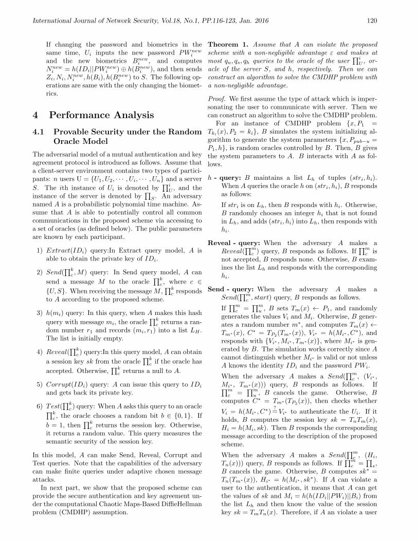
International Journal of Network Security, Vol.18, No.1, PP.116-123, Jan. 2016 120
If changing the password and biometrics in thesame time, Ui inputs the new password PWnew
i
and the new biometrics Bnewi , and computes
Nnewi = h(IDi||PWnew
i )⊕ h(Bnewi ), and then sends
Zi, Ni, Nnewi , h(Bi), h(Bnew
i ) to S. The following op-erations are same with the only changing the biomet-rics.
4 Performance Analysis
4.1 Provable Security under the RandomOracle Model
The adversarial model of a mutual authentication and keyagreement protocol is introduced as follows. Assume thata client-server environment contains two types of partici-pants: n users U = U1, U2, · · · , Ui, · · · , Un and a server
S. The ith instance of Ui is denoted by∏i
U , and theinstance of the server is denoted by
∏S . An adversary
named A is a probabilistic polynomial time machine. As-sume that A is able to potentially control all commoncommunications in the proposed scheme via accessing toa set of oracles (as defined below). The public parametersare known by each participant.
1) Extract(IDi) query:In Extract query model, A isable to obtain the private key of IDi.
2) Send(∏k
c ,M) query: In Send query model, A can
send a message M to the oracle∏k
c , where c ∈U, S. When receiving the message M ,
∏kc responds
to A according to the proposed scheme.
3) h(mi) query: In this query, when A makes this hash
query with message mi, the oracle∏k
c returns a ran-dom number r1 and records (mi, r1) into a list LH .The list is initially empty.
4) Reveal(∏k
c ) query:In this query model, A can obtain
a session key sk from the oracle∏k
c if the oracle has
accepted. Otherwise,∏k
c returns a null to A.
5) Corrupt(IDi) query: A can issue this query to IDi
and gets back its private key.
6) Test(∏k
c ) query: When A asks this query to an oracle∏kc , the oracle chooses a random bit b ∈ 0, 1. If
b = 1, then∏k
c returns the session key. Otherwise,it returns a random value. This query measures thesemantic security of the session key.
In this model, A can make Send, Reveal, Corrupt andTest queries. Note that the capabilities of the adversarycan make finite queries under adaptive chosen messageattacks.
In next part, we show that the proposed scheme canprovide the secure authentication and key agreement un-der the computational Chaotic Maps-Based DiffieHellmanproblem (CMDHP) assumption.
Theorem 1. Assume that A can violate the proposedscheme with a non-negligible advantage ε and makes atmost qu, qs, qh queries to the oracle of the user
∏iU , or-
acle of the server S, and h, respectively. Then we canconstruct an algorithm to solve the CMDHP problem witha non-negligible advantage.
Proof. We first assume the type of attack which is imper-sonating the user to communicate with server. Then wecan construct an algorithm to solve the CMDHP problem.
For an instance of CMDHP problem x, P1 =Tki
(x), P2 = ki, B simulates the system initializing al-gorithm to generate the system parameters x, Ppub−u =P1, h, is random oracles controlled by B. Then, B givesthe system parameters to A. B interacts with A as fol-lows.
h - query: B maintains a list Lh of tuples (stri, hi).When A queries the oracle h on (stri, hi), B respondsas follows:
If stri is on Lh, then B responds with hi. Otherwise,B randomly chooses an integer hi that is not foundin Lh, and adds (stri, hi) into Lh, then responds withhi.
Reveal - query: When the adversary A makes aReveal(
∏mc ) query, B responds as follows. If
∏mc is
not accepted, B responds none. Otherwise, B exam-ines the list Lh and responds with the correspondinghi.
Send - query: When the adversary A makes aSend(
∏mc , start) query, B responds as follows.
If∏m
c =∏m
u , B sets Tm(x) ← P1, and randomlygenerates the values Vi and Mi. Otherwise, B gener-ates a random number m∗, and computes Tm(x) ←Tm∗(x), C∗ = TP2
(Tm∗(x)), Vi∗ = h(Mi∗ , C∗), and
responds with Vi∗ ,Mi∗ , Tm∗(x), where Mi∗ is gen-erated by B. The simulation works correctly since Acannot distinguish whether Mi∗ is valid or not unlessA knows the identity IDi and the password PWi.
When the adversary A makes a Send(∏m
c , (Vi∗ ,Mi∗ , Tm∗(x))) query, B responds as follows. If∏m
c =∏m
u , B cancels the game. Otherwise, Bcomputes C∗ = Tm∗(TP2
(x)), then checks whether
Vi = h(Mi∗ , C∗)
?=Vi∗ to authenticate the Ui. If it
holds, B computes the session key sk = TnTm(x),Hi = h(Mi, sk). Then B responds the correspondingmessage according to the description of the proposedscheme.
When the adversary A makes a Send(∏m
c , (Hi,Tn(x))) query, B responds as follows. If
∏mc =
∏s,
B cancels the game. Otherwise, B computes sk∗ =Tn(Tm∗(x)), Hi∗ = h(Mi∗ , sk
∗). If A can violate auser to the authentication, it means that A can getthe values of sk and Mi = h(h(IDi||PWi)||Bi) fromthe list Lh and then know the value of the sessionkey sk = TmTn(x). Therefore, if A an violate a user
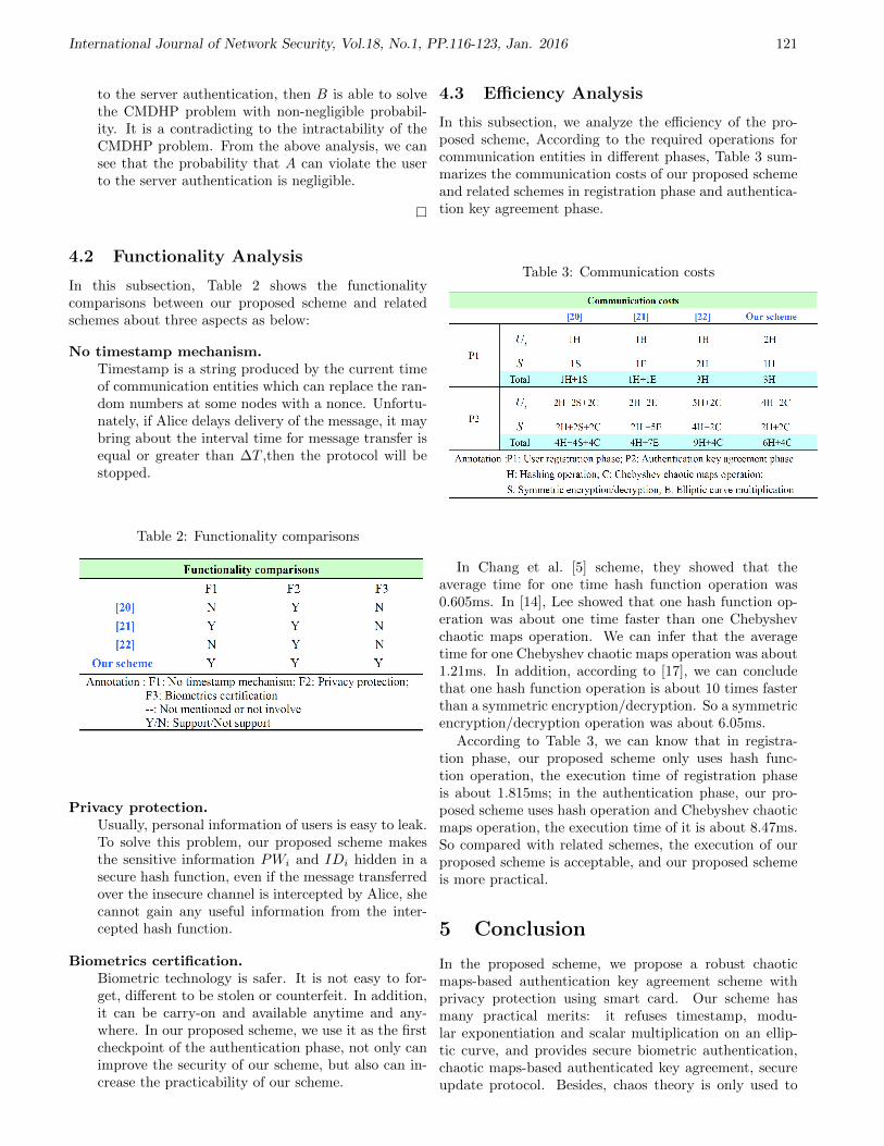
International Journal of Network Security, Vol.18, No.1, PP.116-123, Jan. 2016 121
to the server authentication, then B is able to solvethe CMDHP problem with non-negligible probabil-ity. It is a contradicting to the intractability of theCMDHP problem. From the above analysis, we cansee that the probability that A can violate the userto the server authentication is negligible.
4.2 Functionality Analysis
In this subsection, Table 2 shows the functionalitycomparisons between our proposed scheme and relatedschemes about three aspects as below:
No timestamp mechanism.Timestamp is a string produced by the current timeof communication entities which can replace the ran-dom numbers at some nodes with a nonce. Unfortu-nately, if Alice delays delivery of the message, it maybring about the interval time for message transfer isequal or greater than ∆T ,then the protocol will bestopped.
Table 2: Functionality comparisons
Privacy protection.Usually, personal information of users is easy to leak.To solve this problem, our proposed scheme makesthe sensitive information PWi and IDi hidden in asecure hash function, even if the message transferredover the insecure channel is intercepted by Alice, shecannot gain any useful information from the inter-cepted hash function.
Biometrics certification.Biometric technology is safer. It is not easy to for-get, different to be stolen or counterfeit. In addition,it can be carry-on and available anytime and any-where. In our proposed scheme, we use it as the firstcheckpoint of the authentication phase, not only canimprove the security of our scheme, but also can in-crease the practicability of our scheme.
4.3 Efficiency Analysis
In this subsection, we analyze the efficiency of the pro-posed scheme, According to the required operations forcommunication entities in different phases, Table 3 sum-marizes the communication costs of our proposed schemeand related schemes in registration phase and authentica-tion key agreement phase.
Table 3: Communication costs
In Chang et al. [5] scheme, they showed that theaverage time for one time hash function operation was0.605ms. In [14], Lee showed that one hash function op-eration was about one time faster than one Chebyshevchaotic maps operation. We can infer that the averagetime for one Chebyshev chaotic maps operation was about1.21ms. In addition, according to [17], we can concludethat one hash function operation is about 10 times fasterthan a symmetric encryption/decryption. So a symmetricencryption/decryption operation was about 6.05ms.
According to Table 3, we can know that in registra-tion phase, our proposed scheme only uses hash func-tion operation, the execution time of registration phaseis about 1.815ms; in the authentication phase, our pro-posed scheme uses hash operation and Chebyshev chaoticmaps operation, the execution time of it is about 8.47ms.So compared with related schemes, the execution of ourproposed scheme is acceptable, and our proposed schemeis more practical.
5 Conclusion
In the proposed scheme, we propose a robust chaoticmaps-based authentication key agreement scheme withprivacy protection using smart card. Our scheme hasmany practical merits: it refuses timestamp, modu-lar exponentiation and scalar multiplication on an ellip-tic curve, and provides secure biometric authentication,chaotic maps-based authenticated key agreement, secureupdate protocol. Besides, chaos theory is only used to
International Journal of Network Security, Vol.18, No.1, PP.116-123, Jan. 2016 122
authenticate which can improve the efficiency of the pro-posed scheme. In the same time, the proposed schemecan resist various common attacks. In a word, comparedwith related schemes, the proposed scheme is safer andmore practical.
References
[1] A. K. Awasthi, K. Srivastava, R. C. Mittal, “Animproved timestamp-based remote user authentica-tion scheme,” Computers and Electrical Engineering,vol. 37, no. 6, pp. 69–874, 2011.
[2] K. Chain, W. C. Kuo, “A new digital signaturescheme based on chaotic maps,” Nonlinear Dynam-ics, vol. 74, no. 4, pp. 003–1012, 2013.
[3] C. K. Chan, L. M. Cheng, “Cryptanalysis of a remoteuser authentication scheme using smart cards,” IEEETransactions on Consumer Electronics, vol. 46,pp. 992–993, 2000.
[4] C. C. Chang, J. S. Lee, “An efficient and securemulti-server password authentication scheme usingsmart cards,” in IEEE Information Conference onCyberworlds, pp. 417–422, 2004.
[5] C. C. Chang, C. Y. Sun, “A Secure and Effi-cient Authentication Scheme for E-coupon Systems,”Wireless Personal Communications, vol. 77, no. 4,pp. 2981–2996, 2014.
[6] F. Farhat, S. Salimi, A. Salahi, “An extended au-thentication and key agreement protocol of UMTS,”in Information Security Practice and Experience,LNCS 5451, pp. 230–244, Springer, 2009.
[7] P. Gong, P. Li, W. B. Shi, “A secure chaotic maps-based key agreement protocol without using smartcards,” Nonlinear Dynamics, vol. 70, no. 4, pp. 2401–2406, 2012.
[8] C. Guo, C. C. Chang, “Chaotic maps-basedpassword-authenticated key agreement using smartcards,” Communications in Nonlinear Science andNumerical Simulation, vol. 18, no. 6, pp. 1433–1440,2013.
[9] M. S. Hwang, L. H. Li, “A new remote user authen-tication scheme using smart cards,” IEEE Transac-tions on Consumer Electronics, vol. 46, no. 1, pp. 28–30, 2000.
[10] M. K. Khan, J. S. Zhang, X. M. Wang, “Chaotichash-based fingerprint biometric remote user authen-tication scheme on mobile devices,” Chaos, Solitonsand Fractals, vol. 35, no. 3, pp. 519–524, 2008.
[11] J. Kim, S. Jun, “Authentication and key agree-ment method for home networks using a smartcard,” in Computational Science and Its Applications(ICCSA’07), LNCS 4705, pp. 655–665, Springer,2007.
[12] L. Lamport, “Password authentication with inse-cure communication,” Communications of the ACM,vol. 24, no. 11, pp. 770–772, 1981.
[13] S. Laur, S. Pasini, “SAS-based group authentica-tion and key agreement protocols,” in Public Key
Cryptography (PKC’08), LNCS 4939, pp. 197–213,Springer, 2008.
[14] C. C. Lee, “A simple key agreement scheme based onchaotic maps for VSAT satellite communications,”International Journal of Satellite Communicationsand Networking, vol. 31, no. 4, pp. 177–186, 2013.
[15] C. C. Lee, C. L. Chen, C. Y. Wu, S. Y. Huang, “Anextended chaotic maps-based key agreement protocolwith user anonymity,” Nonlinear Dynamics, vol. 69,no. 1-2, pp. 79–87, 2012.
[16] T. H. Liu, Q. Wang, H. F. Zhu, “A multi-function password mutual authentication key agree-ment scheme with privacy preserving,” Journal ofInformation Hiding and Multimedia Signal Process-ing, vol. 5, no. 2, pp. 165–178, 2014.
[17] B. Schneier, Applied Cryptography, Protocols, Algo-rithms, and Source Code in C (2nd ed.), New York,Wiley, 1996.
[18] J. J. Shen, C. W. Lin, M. S. Hwang, “A modi-fied remote user authentication scheme using smartcards,” IEEE Transactions on Consumer Electron-ics, vol. 49, no. 2, pp. 414–416, 2003.
[19] R. Song, “Advanced smart card based password au-thentication protocol,” Journal of Computer Stan-dards and Interfaces, vol. 32, no. 5, pp. 321–325,2010.
[20] J. E. Tapiador, J. C. Hernandez-Castro, P. Peris-Lopez, J. A. Clark, “Cryptanalysis of Song’s ad-vanced smart card based password authenticationprotocol,” in Cryptography and Securityin, Nov. 11,2011. (http://www. docin. com/ p-380824051.html)
[21] S. B. Wu, C. S. Li, “Identity-based SIP authentica-tion and key agreement,” Advances in Intelligent andSoft Computing, vol. 146, pp. 765–771, 2012.
[22] Q. Xie, J. M. Zhao, X. Y. Yu, “Chaotic maps-based three-party password-authenticated key agree-ment scheme,” Nonlinear Dynamics, vol. 74, no. 4,pp. 1021–1027, 2013.
[23] J. Xu, W. T. Zhu, D. G. Feng, “An improved smartcard based password authentication scheme withprovable security,” Journal of Computer Standardsand Interfaces, vol. 31, no. 4, pp. 723–728, 2009.
[24] E. J. Yoon, K. Y. Yoo, “Robust biometrics-based multi-server authentication with key agree-ment scheme for smart cards on elliptic curve cryp-tosystem,” The Journal of Supercomputing, vol. 63,no. 1, pp. 235–255, 2013.
[25] L. H. Zhang, “Cryptanalysis of the public key en-cryption based on multiple chaotic systems,” Chaos,Solitons & Fractals, vol. 37, no. 3, pp. 669–674, 2008.
Hongfeng Zhu obtained his Ph.D. degree in InformationScience and Engineering from Northeastern University.Hongfeng Zhu is a full associate professor of the Kexinsoftware college at Shenyang Normal University. He isalso a master’s supervisor. He has research interests inwireless networks, mobile computing, cloud computing,social networks, network security and quantum cryptog-raphy. Dr. Zhu had published more than 50 international

International Journal of Network Security, Vol.18, No.1, PP.116-123, Jan. 2016 123
journal and international conference papers on the aboveresearch fields.
Yifeng Zhang, 24 years old, an undergraduate fromShenyang Normal University, major in informationsecurity management. During the four years of college,after completing her studies, he enjoys reading the bookrelated to this major. Under the guidance of the teacher,he has published two articles in EI journals.
Yan Zhang, 23 years old, an undergraduate fromShenyang Normal University, major in informationsecurity management. In the four years of college, aftercompleting her studies, she enjoys reading the bookrelated to this major. Under the guidance of the teacher,she has published two articles in EI journals.
Haiyang Lee, graduate, graduated from Liaoning Uni-versity Population Research Institute, Master demo-graphic now at Shenyang Normal University Dean’s OfficeExamination Management Division, lecturers title. He re-searches on labor and social security, wireless computernetworks, network security.

International Journal of Network Security, Vol.18, No.1, PP.124-132, Jan. 2016 124
A Secure Steganography Method Based onInteger Lifting Wavelet Transform
Seyyed Amin Seyyedi1,3, Vasili Sadau2, Nick Ivanov3
(Corresponding author: Seyyed Amin Seyyedi)
Department of Computer, Maku Branch, I.A.U, Maku, Iran1
5861993548, Maku, Iran
Department of Intelligent Systems, Belarusian State University2
No 4 St.Nezavisimosti, 220030, Minsk, Belarus
Department of Electronic Computing Machines, Belarusian State University of Informatics and Radioelectronics3
No 6 P.Brovki, 220013, Minsk, Belarus
(Email: [email protected])
(Received Nov. 18, 2013; revised and accepted July 20 & Nov 6, 2014)
Abstract
Steganography plays an important role in secret commu-nication in digital worlds and open environments like In-ternet. Undetectability and imperceptibility of confiden-tial data are major challenges of steganography methods.This article presents a secure steganography method infrequency domain based on partitioning approach. Thecover image is partitioned into 8×8 blocks and then inte-ger wavelet transform through lifting scheme is performedfor each block. The symmetric RC4 encryption method isapplied to secret message to obtain high security and au-thentication. Tree Scan Order is performed in frequencydomain to find proper location for embedding secret mes-sage. Secret message is embedded in cover image withminimal degrading of the quality. Experimental resultsdemonstrate that the proposed method has achieved su-perior performance in terms of high imperceptibility ofstego-image and it is secure against statistical attack incomparison with existing methods.
Keywords: Cryptography, discrete wavelet transform, lift-ing scheme, steganography, statistical attack, tree scan or-der
1 Introduction
With development of the Internet and information pro-cessing techniques, data hiding has attracted lots of at-tention. Data hiding is a science of concealing informa-tion in a host medium that can be text, image, audio,video, etc without leaving any remarkable trace on thehost medium [12, 35].Among the different kinds of digitalmedia, the digital image is commonly used as a host im-age to convey side information in it. Hence, image hidinginvestigating is actual issue. Depending on the relation-
ship between embedded information and the cover image,data hiding techniques are classified into steganographyand watermark methods [15]. The major goal of steganog-raphy is to enhance communication security by insertingsecret message into the digital image vs. copyright pre-serving; authentication and robustness are objectives ofwatermark techniques [9, 12].
Steganography is the art and science of transmissionthe secret message in such a way that the existence ofinformation in container is undetectable [19, 21]. Theword steganography is originally composed of two Greekwords ”steganos” and ”graphia”, which means ”covered”and ”writing” respectively. The notation of steganogra-phy was first introduced with the example of prisonerssecret message by Simmons in 1983 [35].
There are a number of steganographic schemes hidinga secret message in an image file; these schemes can beclassified according to the format of the cover image [13,20] or the method of hiding.
Steganographic schemes in term of hiding method canbe classified into two board categories namely spatial-domain techniques and frequency-domain techniques. Inspatial domain techniques, the secret messages are embed-ded directly into cover image [8, 11, 14, 18, 22, 33, 34, 36].The advantages of spatial domain methods are simple im-plementation, high payload and provide easy way to con-trol, stego-image quality. The limitation of this approachis vulnerable to every slight steganalysis methods. Fre-quency domain techniques are popular data hiding ap-proach [2, 6]. In frequency domain methods, the coverimage converted into frequency domain coefficients be-fore embedding the secret message in it. The most usedtransforms are the Fast Fourier Transforms (FFT), Dis-crete Cosines Transform (DCT), and Discrete WaveletTransforms (DWT). Ability for high resistance against

International Journal of Network Security, Vol.18, No.1, PP.124-132, Jan. 2016 125
steganalysis methods and signal processing manipulationsare advantages of frequency domain techniques to spatialdomain ones. But transformations into frequency domainare computationally complex. Wavelets transform is athriving branch of these methods. Some of these tech-niques try to achieve the high payload hiding and lowdistortion in cover image.
The effort to detect the presence of secret message iscalled steganalysis. The steganalyst is assumed to con-trol the transmission channel and watch out for suspi-cious material [19]. A steganalysis method is consideredas successful, and the respective steganographic system asbroken, if the steganalyst be able to detect the existenceof the secret message. The detection ability of statisticalanalysis scheme depends on the volume of hidden message[10, 23]. Hence, a secure transfer of secret message basedon wavelet transform with appropriate payload withoutruining the invisibility and detection by steganalyst is theaim of this study.
This study devoted to frequency domain issues; there-fore it is necessary to mention relevant methods in this do-main. Kang et al. [16] proposed a steganographic methodbased on wavelet and modulus function. First, an im-age is divided into blocks of prescribed size, and everyblock is decomposed into one-level wavelet. Then, thecapacity of the hidden secret data is coordinated withthe number of wavelet coefficients of larger magnitude.Finally, secret information is embedded by modulus func-tion. Lai et al. [17] proposed an adaptive data hidingmethod based on Haar wavelet transform. The cover im-age is divided into 8×8 non-overlapping blocks, then Haarwavelet transform is performed on each blocks. A datahiding capacity function is used to determine the volumeof embedding secret message in transformed sub bands.The secret message is embedded by LSB method. Safy etal. [27] to enlarge capacity of hidden data proposed themodification of Lai’s method. Abdelwahab et al. [1] pro-posed data hiding technique in DWT where 1-level DWTis applied to both cover and secret images. Each of subbands is divided into 4× 4 non-overlapping blocks. Blockof secret message is compared with cover blocks to deter-mine the best match. The disadvantage of this method isthat extracted data not totally identical to the embeddedversion. Raja et al. [25] proposed an adaptive steganog-raphy using integer wavelet transform. Their scheme em-beds the payload in non-overlapping 4 × 4 blocks of thelow frequency sub band. Two pixels at a time are chosenbased on condition number of each block one on eitherside of principal diagonal. Low embedding capacity andnot considering reliability of method against statistical at-tacks are disadvantages of this method. Bhattacharyya etal. [5] proposed a novel steganographic scheme based onInteger Wavelet Transform (IWT) through lifting scheme.The Pixel Mapping Method (PMM) is used to embed2 bits of secret message into selected sub band to formthe stego-image. The disadvantage of this method is lowquality of stego-image and low payload size. Reddy etal. [26] proposed wavelet based non LSB steganography.
The cover image is divided into 4 × 4 non-overlappingblocks, DWT/IWT applied to each block. The 2× 2 cellsof HH sub band are considered and manipulated with se-cret message bit pairs using identity matrix to generatestego-image. Seyedi et al. [28] proposed a new robustimage adaptive steganography method in frequency do-main. The proposed steganography method embeds thesecret data in the blocks of an image that seems to benoisy based on the bit plane complexity of each blockand does not destroy the co-occurrence matrix of waveletcoefficient. They used the one-third and rounding meth-ods for embedding data in wavelet coefficients, and re-tain the co-occurrence matrix of wavelet coefficient. Incomparison with methods mentioned earlier, our methodprovides better quality of image with reasonable payload,especially, high secrecy against steganalysis attacks.
This article presents frequency domain image steganog-raphy technique based on IWT through lifting scheme(LWT). In addition, to achieve higher security and au-thentication 56-bit key RC4 encryption method appliedto the secret message before embedding procedure. TreeScan Order (TSO) is performed in frequency domain tofind the proper location of secret message. Secret messageis embedded in cover image without degrading the qualityof the original image.
The rest of this article organized as follows. Sectiontwo discusses the IWT based on lifting scheme. Sec-tion three presents a cryptography method. Section fourpresents the proposed image steganography technique.Section five presents experimental results and analysis.Conclusion is given in section six.
2 Integer Wavelet TransformBased on Lifting Scheme
Wavelets are special functional base for signal decompo-sition. As shown in Figure 1, applying two dimensionalwavelet transform to an image represents it in four bandscalled LL, HL, HL, and HH. The LL band contains lowpass coefficients and three other bands represent high passcoefficients of the image, including horizontal, vertical anddiagonal features of the original image. The same decom-position can be applied to LL band.
Generally, wavelet filters have floating point coeffi-cients, hence, when the input data consist of a set of in-tegers (as in the case for images), the resulting filteredoutput has float point format, which does not allow ex-act reconstruction of the original image. However, ex-ploiting wavelet transform with integer output providesexact inverse transform. Particularly, lifting scheme canbe completely realised with integers. Above all, liftingscheme does not require temporary storage in the calcu-lation steps [31].
In this paper biorthogonal Cohen-Daubechies Feau-veau (CDF 2/2) lifting scheme was chosen as a case study.

International Journal of Network Security, Vol.18, No.1, PP.124-132, Jan. 2016 126
Figure 1: One level and two levels 2D wavelet transform
3 Cryptography and Steganogra-phy
One of the approaches to increasing security level ofsteganographic system is cryptography. Usually symmet-ric encryption method is recommended for steganographicmethods. The symmetric encryption is a method thatuses the identical key to encrypt and decrypt a secretmessage. In secure transmission of confidential data be-tween parties, each party must agree on shared secretkey. Based on Kerckhoffs principle [24], the security ofencrypted data depends on the secrecy of the key. If at-tacker gains knowledge of the secret key, he can use thekey to decrypt all the data. There are several algorithmsfor symmetric key encryption, one of them is RC4 [30].
In this paper symmetric encryption method RC4 with56-bit key is utilized to encrypt secret message.
4 Proposed Method
In this article, a wavelet domain steganography is adoptedfor hiding reasonable amount of secret data with highsecurity, good visibility and no loss of secret message.The cover image is partitioned into non-overlapping 8× 8blocks and 2D Integer LWT (IntLWT) is applied to eachblock. TSO is performed in transformed blocks to iden-tify proper location of secret message. In addition, toachieve higher security and authentication 56-bit key RC4encryption method is applied to the secret message beforeembedding it. The block diagram of proposed data em-bedding process is shown in Figure 3.
4.1 Embedding Region
The main idea behind the proposed algorithm is that se-cret message bits embed in proper frequency coefficientswithout visually degrading the quality of the original im-age. The TSO is applied to each transformed block toidentify proper location of secret message.
4.2 Tree Scan Order
In the wavelet transform of an image, the energy insub bands decreases as the level decomposition increases.Wavelet coefficients in upper sub bands have larger val-ues [29]. It is possible be an edge. For human vision,the edge region has higher priority to embed the datathan the smooth region. The trick is now to exploit thedependency between the wavelet coefficients across leveldecomposition. When 8× 8 block of an image is wavelettransformed in three levels, ten sub bands will obtain asshown in Figure 3. In tree scan order upper sub (LL3)band is main root sub band. Figure 3 shows tree scanningorder.
TSO use a series of decreasing thresholds and comparesthe wavelet coefficients with those thresholds. If the mag-nitude of a coefficient is smaller than a given threshold thenode is called insignificant with respect to given threshold.Otherwise, the coefficient is significant. Initial thresholdis calculated as:
T1 = 2blog2max(B(i,j)c (1)
Tn =Tn − 1
2(2)
here max(·) signifies the maximum coefficient value in8× 8 block of an image and B(i, j) denotes coefficients in8× 8 block.
In accordance to tree scan structure, there are spatiallyrelation between lowest insignificant frequency coefficientat the node and children of each tree node in the nextfrequency sub band. The TSO is developed based ondecreasing the wavelet coefficients with level of decom-position. The proposed method exploits this property forembedding secret message only into root coefficients. Thecoefficient is named as Root Coefficient (RC) if the valueof the coefficient and its descendants are less than thethreshold. RCs are the proper coefficients for embeddingsecret message. In proposed method threshold value foreach block is calculated in three levels (T3).
4.3 Embedding and Extracting Algo-rithms
Proposed secret message embedding algorithm for secu-rity point of view data transmission comprises the stepsshown in Algorithm 1.
The extraction procedure consists of steps shown inAlgorithm 2.
5 Experimental Results
Some experiments were conducted to assess the efficiencyof the proposed method based on data payload, fidelityand security benchmarks [19]. The method has been sim-ulated using the MATLAB 8.1 (R2013a) tools on Win-dows 7 version 6.1 platform. The secret message was gen-erated randomly and RC4 of Microsoft encryption utility

International Journal of Network Security, Vol.18, No.1, PP.124-132, Jan. 2016 127
Figure 2: Data embedding process
Figure 3: Tree scanning order

International Journal of Network Security, Vol.18, No.1, PP.124-132, Jan. 2016 128
Table 1: Calculation of varies image similarity metrics of proposed method
Similarity metrics Length of embedding message (byte)500 1000 5000 10000
512x512 Mean St.Dev. Mean St.Dev. Mean St.Dev. Mean St.Dev.PSNR 65.09 0.676 62.11 0.654 55.31 0.492 52.454 0.502MSE 0.02 0.003 0.04 0.006 0.19 0.022 0.37 0.043
Algorithm 1 Embedding algorithm
1: Input: Cover image C of size M ×N and secret mes-sage SE.
2: Output: Stego-image S.3: Begin4: Read cover image C.5: Read the secret message SE and perform the RC4
encryption method on SE.6: Partition C into 8× 8 non-overlapping blocks.7: Perform three levels IntLWT on each block.8: Apply TSO to find RC coefficients for embedding se-
cret message bits.9: Embed SE bit by bit into RCs.
10: Perform inverse wavelet transform to each block.11: Assemble stego-image S from blocks.12: End
Algorithm 2 Extracting algorithm
1: Input: Stego-image S of size M ×N .2: Output: Secret message SE.3: Begin4: Partition stego-image S into 8 × 8 non-overlapping
blocks.5: Apply three levels IntLWT to each block.6: Find RCs and extract 1-LSB in each RC.7: Decrypting extracted message by secret key.8: End
program was used to encrypt the secret message. All ex-periments were conducted on image database of GranadaUniversity [32].
Usually, data payload of steganographic method is oneof the evaluation criteria. Data payload refers to theamount of information that can be hidden in the coverimage. The embedding rate is usually given in absolutemeasurement such as the size of the secret message or inbits per pixel, etc. It depends on the embedding function,size of cover image, and may also depend on propertiesof the cover image. Figure 4 shows the maximum datapayload of proposed method.
Fidelity (imperceptibility) refers to inability of humaneyes to distinguish between cover image C and stego-image S. Usually the fidelity of stego-image measures byvarious image similarity metrics such as Mean Square Er-ror (MSE), and Peak Signal to Noise Ratio (PSNR). MeanSquare Error (MSE) is a simple non-perceptual error met-
Figure 4: Maximum data payload of proposed method forseveral images
ric that is obtained from the cover image C and stego-image S where lower value are assumed to be indicativeof lesser detectability. The is calculated using followingformula:
MSE =1
(M ×N)2
M∑i=1
N∑j=1
(Cij − Sij)2. (3)
The peak signal-to-noise ratio (PSNR) is calculated usingfollowing formula:
PSNR = 20log10Max
MSEdB, (4)
where Max denotes the maximum pixel value of the im-age. A higher PSNR value indicates the better qualityof stego algorithm. Human visual system is unable todistinguish the images with PSNR more than 36 [22].
Table 1 shows the imperceptibility metrics of proposedmethod with various payload sizes. In order to compareproposed method with the Bhattacharyya, Reddy, andLai methods several sizes of gray scale image Lena is used.Table 2 shows the various payloads vs. PSNR value ofproposed method, Bhattacharyya method, Reddy method

International Journal of Network Security, Vol.18, No.1, PP.124-132, Jan. 2016 129
Table 2: Comparison PSNR value after embedding in cover image of Lena image
Image sizeMessage(Byte)
CA(B) CH(B) CV(B) CD(B) Reddy MethodLai Method
(K=1)Proposed Method
128x128 100 53.29 54.91 54.66 58.83 41.16 56.39 59.02200 50.66 52.35 51.994 56.90 36.29 52.76 56.19400 47.89 49.34 48.97 54.49 35.95 48.36 53.65500 47.03 48.36 48.03 48.02 35.61 47.51 52.65
256x256 100 59.77 62.36 62.34 58.83 57.93 64.83 64.75200 56.73 58.74 58.75 56.90 50.38 60.24 62.33400 53.69 55.43 55.55 54.49 43.43 57.81 59.31800 50.77 52.66 52.31 51.84 38.83 53.42 56.371600 47.67 49.49 49.16 49.04 N/A 49.87 53.522000 47.77 48.56 51.09 48.12 N/A 48.74 52.58
and Lai method for 128× 128 and 256× 256 cover imageLena. CA (B), CH (B), CV (B), CD (B) in Table 2 re-spectively denotes Approximation Coefficient, HorizontalCoefficient, Vertical Coefficient, Diagonal Coefficient ofBhattacharyya method. As shown, proposed method re-sults are better related to the other methods in term ofquality of stego-image on the same payload.
Security of steganographic system is defined in term ofundetectability. There are many approaches in definingthe security of a steganographic method [19]. Zollner [8]theoretically proved that a steganographic system is se-cure, if secret message has a random nature and is inde-pendent from the cover image and stego-image. Cachin [7]defined a steganographic method (by Kullback-Leibler KLdivergence) to be ε-secure (ε ≥ 0), if the relative entropybetween probability distribution of cover image (PC) andstego-image (PS) are at most ε. The detectability (D) isdefined by:
D(PC ||PS) =
∫PC log
PC
PS. (5)
Thus, for a completely secure stego system D=0 and ifD ≤ ε, then stego method is named ε-secure. In short,security of a stego method is defined in terms of unde-tectability. A steganography method is said to be unde-tectable or secure if the existence statistical tests cannotdistinguish between the cover and the stego-image [17].
To compare the imperceptibility and security of pro-posed method with other methods, we did the experi-ments on the image data base [32]. Table 3 compares sim-ilarity and security metrics of proposed method with Laiand Reddy methods. According to it proposed method insame payload size is more imperceptible and secure thanReddy and Lai methods.
According to the results shown in Table 3, increasingthe payload rate make conflict with imperceptibility met-rics and security metrics.
5.1 Security Analysis of ProposedMethod through Image QualityMetrics
Steganographic method is said to be undetectable or se-cure if the existence statistical tests cannot distinguishbetween the cover and the stego-images. During the em-bedding process in the cover image some statistical varia-tions are arises. The stego-image is perceptually identicalbut is statistically different from the cover image. The at-tacker uses these statistical differences in order to detectthe secret message. Recently various types of steganaly-sis methods for specific purposes have been developed inorder to test the steganographic methods and detectingthe stego-image from the cover image [23].
Avcibas et al. [3, 4] showed that embedding of secretmessage leaves unique artifacts, which can be detectedusing Image Quality Metrics (IQMs). There are twentysix different measures that are categorized into six groupsas Pixel difference, Correlation, Edge, Spectral, Context,and Human visual system. Avcibas developed a discrim-inator for cover image and stego-image using a properset of IQMs. In order to select appropriate set of IQMs,they used analysis of variance techniques. The selectedIQMs for steganalysis are Minkowsky measures M1 andM2, Mean of the angle difference M4, Spectral magnitudedistance M7, Median block spectral phase distance M8,Median block weight spectral distance M9, Normalizedmean square HVS error M10. The IQMs scores are com-puted from images and their Gaussian filtered versionswith α = 0.5 and mask size 3× 3.
The variations in IQMs for proposed method, Lai andReddy methods with embedding the 4000 characters incover images are computed. From experimental results itcan be perceived that statistical difference between coverimages and stego-images of proposed method is less thanLai and Reddy methods. Therefore, proposed method ismore secured than Lai and Reddy methods. The wardencannot distinguish stego-image from cover image. Thevariations in IQMs for M7 and M9 are shown in Table 4.

International Journal of Network Security, Vol.18, No.1, PP.124-132, Jan. 2016 130
Table 3: Comparison similarity and security metrics of proposed method with Lai and Reddy methods
Payload
(Byte) MetricsLai Method
(K=1)Reddy Method Proposed Method
Mean St.Dev. Mean St.Dev. Mean St.Dev.500 PSNR 59.85 2.49 46.28 6.16 69.09 0.68
MSE 0.078 0.041 3.485 4.632 0.02 0.003D 3.81E-03 6.922E-03 1.460E-04 1.560E-04 1.02E-06 4.87E-07
1000 PSNR 56.62 2.47 42.40 5.55 62.12 0.65MSE 0.163 0.084 7.420 9.165 0.04 0.006
D 3.82E-03 6.99E-03 2.76E-04 2.69E-04 2.19E-06 1.12E-062000 PSNR 53.38 2.28 38.70 4.96 59.18 0.6
MSE 0.337 0.16 15.672 19.217 0.079 0.011D 3.83-03 6.989E-03 4.82E-04 3.69E-04 5.37E-06 4.3E-06
4000 PSNR 50.12 2.1 34.97 4.7 56.24 0.506MSE 0.7 0.311 35.932 45.768 0.115 0.018
D 3.85E-03 6.98E-03 9.88E-04 6.6E-04 1.36E-05 1.34E-05
Table 4: IQMs variation for M7, M9
M7: Spectral magnitude distanceImage
numberOriginal
ProposedMethod
ReddyMethod
LaiMethod
1 0.4723 0.4723 0.5089 0.47402 0.0685 0.0690 0.0753 0.06913 0.1258 0.1263 0.1368 0.12784 0.3477 0.3479 0.3781 0.33935 0.1207 0.1210 0.1296 0.12406 0.3208 0.3213 0.3420 0.30807 0.6414 0.6415 0.7169 0.62798 0.6084 0.6085 0.6584 0.60479 0.1862 0.1865 0.2008 0.186610 0.1566 0.1568 0.1714 0.1571
M9: Median block weight spectral distanceImage
numberOriginal
ProposedMethod
ReddyMEthod
LaiMethod
1 9.1477 9.1477 9.1479 9.14782 9.1045 9.1095 9.1112 9.10553 9.1269 9.1268 9.1304 9.12744 9.1400 9.1394 9.1404 9.13965 9.1191 9.1194 9.1214 9.11896 9.1392 9.1394 9.1398 9.13887 9.1481 9.1481 9.1486 9.14788 9.1472 9.1473 9.1482 9.14699 9.1485 9.1484 9.1505 9.147810 9.1236 9.1236 9.1284 9.1236
6 Conclusions
The major goal is addressed to security of stego algo-rithm. The proposed method exploited the property oftree scanning order under the integer wavelet transforma-tion with lifting scheme and blocking approach of coverimage. The confidential information could be sent in lossychannels using proposed method because it does providesufficient secrecy and stability against statistical attack.Two layers of security are used to preserve secrecy of em-bedded message. Furthermore, if an attacker successes toextract secret message he will not be able to read it. Thequality of stego-image occurs to be better in comparisonwith considered methods.
References
[1] A. A. Abdelwahab and L. A. Hassaan, “A discretewavelet transform based technique for image datahiding,” in International Conference on Networkingand Media Convergence, pp. 1–9, Tanta, Egypt, Mar.2008.
[2] A. Al-Ataby and A. Fawzi, “A modified high capac-ity image steganography technique based on wavelettransform,” The International Arab Journal of Infor-mation Technology, vol. 7, no. 4, pp. 358–364, 2010.
[3] I. Avcibas, N. Memon, M. Kharrazi, and B. Sankur,“Image steganalysis with binary similarity mea-sures,” EURASIP Journal on Advances in SignalProcessing, vol. 2005, no. 1, pp. 2749–2757, 2005.
[4] I. Avcibas, N. Memon, and B. Sankur, “Steganalysisusing image quality metrics,” IEEE Transaction onImage Processing, vol. 12, no. 3, pp. 221–229, 2003.
[5] S. Bhattacharyya and G. Sanyal, “Data hiding inimages in discrete wavelet domain using PMM,” In-ternational Journal of Electrical and Computer en-gineering, vol. 5, no. 6, pp. 597–606, 2010.

International Journal of Network Security, Vol.18, No.1, PP.124-132, Jan. 2016 131
[6] K. Blossom, K. Amandeep, and S. Jasdeep,“Steganographic approach for hiding image in DCTdomain,” International Journal of Advances in Engi-neering & Technology, vol. 1, no. 3, pp. 72–78, 2011.
[7] C. Cachin, “An information theoretic modelfor steganography,” Information and Computation,vol. 192, no. 1, pp. 41–56, 2004.
[8] C. K. Chan and L. M. Cheng, “Hiding data in imagesby simple LSB substitution,” Pattern Recognition,vol. 37, no. 3, pp. 496–474, 2003.
[9] R. Chandramouli, M. Kharrazi, and N. Memon, “Im-age steganography and steganalysis concepts andpractice,” in Digital Watermarking, pp. 35–49, Seoul,Korea, Oct. 2003.
[10] R. Chandramouli and N. D. Memon, “Steganog-raphy capacity: A steganalysis perspective,” Secu-rity Watermarking Multimedia Contents, SPIE 5020,pp. 173–177, 2003.
[11] C. C. Chang, J. Y. Hasiao, and C. S. Chan, “Find-ing optimal least significant bit substitution in imagehiding by dynamic programming strategy,” PatternRecognition, vol. 36, no. 7, pp. 1583–1598, 2003.
[12] A. Cheddad, J. Condell, K. Curran, and P. M. Ke-vitt, “Digital image steganography: Survey and anal-ysis of current methods,” Digital Signal Processing,vol. 90, no. 3, pp. 727–752, 2010.
[13] M. Fallahpour, D. Megias, and M. Ghanbari, “Re-versible and high-capacity data hiding in medical im-ages,” IET Image Process, vol. 5, no. 2, pp. 190–197,2011.
[14] W. Hong, T. S. Chen, and C. W. Luo, “Data em-bedding using pixel value differencing and diamondencoding with multiple-base notational system,” TheJournal of Systems and Software, vol. 85, pp. 1166–1175, 2012.
[15] L. Ch Huang, L. Y. Tseng, and M. S. Hwang, “Areversible data hiding method by histogram shiftingin high quality medical images,” Journal of Systemsand Software, vol. 86, no. 3, pp. 716–727, 2013.
[16] Z. Kang, J. Lin, and Y. He, “Steganography based onwavelet transform and modulus function,” Journal ofSystems Engineering and Electronics, vol. 18, no. 3,pp. 628–632, 2007.
[17] B. L. Lai and L. W. Chang, “Adaptive data hidingfor images based on harr discrete wavelet transform,”in Advances in Image and Video Technology,LectureNotes in Computer Science, pp. 1085–1093, Hsinchu,Taiwan, December 2006.
[18] Y. P. Lee, J. C. Lee, W. K. Chen, K. C. Chang, I. J.Su, and C. P. Chang, “High-payload image hidingwith quality recovery using tri-way pixel-value differ-encing,” Information Sciences, vol. 191, pp. 214–225,2012.
[19] B. Li, J. He, and J. Q. Shi, “A survey on imagesteganography and steganalysis,” Journal of Infor-mation Hiding and Multimedia Signal Processing,vol. 2, no. 2, pp. 142–172, 2010.
[20] G. Liang, S. Wang, and X. Zhang, “Steganographyin binary image by checking data-carrying eligibilityof boundary pixels,” Journal of Shanghai University,vol. 11, no. 3, pp. 272–277, 2007.
[21] C. S. Lu, Multimedia Security: Steganography andDigital Watermarking Techniques for Protection ofIntellectual Property. USA: Idea Group, 2005.
[22] H. C. Lu, Y. P. Chu, and M. S. Hwang, “Im-age steganographic scheme based on pixel-value dif-ferencing and LSB replacement methods,” A newsteganographic method of the pixel-value differencing,vol. 50, no. 5, pp. 424–426, 2006.
[23] A. Nissar and A. H. Mir, “Classification of steganal-ysis techniques,” Digital Signal Processing, vol. 90,no. 6, pp. 1758–1770, 2010.
[24] D. Omerasevic, N. Behlilovic, and S. Mrdovic,“Cryptostego a novel approach for creating cryp-tographic keys and messages,” in Signals and ImageProcessing (IWSSIP), pp. 83–86, Bucharest, Roma-nia, July 2013.
[25] K. B. Raja, S. Sindhu, T. D. Mahalakshmi, S. Ak-shatha, B. K. Nithin, M. Sarvajith, K. R. Venu-gopal, and L. M. Patnaik, “Robust image adaptivesteganography using integer wavelets,” in Commu-nication Systems Software and Middleware (COM-SWARE), pp. 614–621, Bangalore, India, Jan 2008.
[26] H. S. M. Reddy and K. B. Raja, “Wavelet basednon LSB steganography,” International Journal Ad-vanced Networking and Applications, vol. 3, no. 3,pp. 1203–1209, 2011.
[27] R. O. El Safy, H. H. Zaye, and A. El Dessouki, “Anadaptive steganographic technique based on integerwavelet transform,” in International Conference onNetworking and Media Convergence, pp. 111–117,Cario, Egypt, March 2009.
[28] S. H. Seyedi, H. Aghaeinia, and A. Sayadian, “Anew robust image adaptive steganography method inwavelet transform,” in IEEE Electrical Engineering,pp. 1–5, Tehran, Iran, May 2011.
[29] J. Shapiro, “Embedded image coding using zero treeof wavelet coefficients,” IEEE Transaction on SignalProcessing, vol. 41, no. 12, pp. 3445–3462, 1993.
[30] N. Smart, Cryptography: An Introduction. USA:McGraw-Hill College, 2004.
[31] W. Sweden, “The lifting scheme: A constructionof second generation wavelets,” SIAM Journal onMathematical Analysis, vol. 29, no. 2, pp. 511–546,1997.
[32] University of Granada, Miscelaneous GrayLevel Test Images (512 × 512), July 3, 2015.(http://decsai.ugr.es/cvg/dbimagenes/g512.php)
[33] C. M. Wang, N. I. Wu, C. S. Tsai, and M. S. Hwang,“A high quality steganographic method with pixel-value differencing and modulus function,” The Jour-nal of Systems and Software, vol. 81, no. 1, pp. 150–158, 2008.
[34] H. C. Wu, N. I. Wu, C. S. Tsai, and M. S. Hwang,“Image steganographic scheme based on pixel-value
International Journal of Network Security, Vol.18, No.1, PP.124-132, Jan. 2016 132
differencing and LSB replacement methods,” IEEEProceedings of Vision, Image and Signal Processing,vol. 152, no. 5, pp. 611–615, 2005.
[35] N. Wu and M. S. Hwang, “Data hiding: Current sta-tus and key issues,” International Journal of NetworkSecurity, vol. 4, no. 1, pp. 1–9, 2007.
[36] N. I. Wu, K. C. Wu, and C. M. Wang, “Exploringpixel-value differencing and base decomposition forlow distortion data embedding,” Applied Soft Com-puting, vol. 12, no. 2, pp. 942–960, 2012.
Seyyed Amin Seyyedi took his PhD degree in Meth-ods and Systems of Information Protection, InformationSecurity from Belarusian State University of Informaticsand Radioelectronics in 2014. He is a member ofcomputer department in Islamic Azad University. Hehas published one monograph and more than twentypublications in national and international scientificjournals and conferences.His research interests includeimage steganography and watermark.
Vasili Sadau took his PhD degree in engineeringscience from National Academy of Belarus in 1984.Now he is Professor of Belarusian State University.He has published one monograph and more than sixtypublications in national and international scientificjournals and conferences.His research interests includethe problems of information security in computer systems.
Nick Ivanov took his PhD degree in applied mathemat-ics from National Academy of Belarus in 1978. Now he isAssociate Professor of Belarusian State University Infor-matics and Radioelectronics. He was supervisor for sev-eral Graduate students. His research interests include dis-crete mathematics, image analysis, and image steganog-raphy.

International Journal of Network Security, Vol.18, No.1, PP.133-142, Jan. 2016 133
A Survey of Public Auditing for Secure DataStorage in Cloud Computing
Wei-Fu Hsien1, Chou-Chen Yang1, and Min-Shiang Hwang2,3
(Corresponding author: Min-Shiang Hwang)
Department of Management Information System, National Chung Hsing University1
Department of Computer Science and Information Engineering, Asia University2
No. 500, Lioufeng Rd., Wufeng, Taichung 41354, Taiwan
(Email: [email protected])
Department of Medical Research, China Medical University Hospital, China Medical University3
No. 91, Hsueh-Shih Road, Taichung 40402, Taiwan
(Received Mar. 15, 2015; revised and accepted May 11 & May 26, 2015)
Abstract
Cloud computing has been popular as the IT architecture.Cloud service providers offer many services based on cloudcomputing. Cloud storage service is the cloud serviceswhich can provide a huge storage space to solve the bot-tleneck of the storage space of local end users. However,cloud storage service may have data security because theusers’ data is not stored in their own storage. In this pa-per, we will focus on data integrity in the cloud storageservice. Public auditability is a model of outsourcing dataintegrity verification, which can achieve efficiency and se-curity. Therefore, we survey the previous researches ofdata integrity based on public auditability which includescollecting the basic requirements and evaluation metrics,providing the representative with approaches to analyzesecurity and efficiency. Finally, we propose some futuredevelopments.
Keywords: CGA generation algorithm, hash functions,multithreading
1 Introduction
Cloud computing is a computing technology, and the In-ternet has grown in recent years. It can share the soft-ware and hardware resources, and provide resources toa user’s computer or mobile device. The user can ob-tain a more efficient service because cloud computingcan integrate resources. Therefore, in order to achievecloud computing technology, it must satisfy five basicfeatures: On-demand self-service, Broad network access,Resource pooling, Rapid elasticity and Measured ser-vice [10]. However, is very difficult for general users orsmall and medium enterprises to construct cloud environ-ment because they cannot afford the huge costs. There-fore, many information technology companies are finding
business opportunities to cloud services. Thus, cloud ser-vice providers have joined to build cloud environmentsand provide services to the user. Cloud service providersoffer three services including Software as a Service (SaaS),Platform as a Service (PaaS) and Infrastructure as a Ser-vice (IaaS). The cost for users to rent cloud service ischeaper than the cost for users to build cloud environ-ment.
Cloud storage service is the most common and popu-lar service among many cloud services (e.g. Google Drive,Dropbox, Amazon S3 and Microsoft OneDrive) for gen-eral users. Users have a bottleneck in local storage spacebecause there are more and more users to save data incloud storage, so cloud storage service has high capacitywhich solves users’ difficult problem. Besides, cloud stor-age service provides high capacity space, and, in order toachieve ubiquitous service, it also provides to access cloudservices from web service or applications that utilize theapplication programming interface (API) by mobile de-vices (e.g. laptop, table computer and smart phones).
Although cloud storage service has many advantages,it brings a lot of challenging issues which include efficacyand security [5, 9]. One of the big challenges is verifyingthe integrity of the data because users cannot know howthe cloud storage service handles their data. These cloudstorage services are provided by commercial enterprises,so it cannot be fully trusted by users. Therefore, the cloudservice provider may hide data loss and data errors in theservice because their benefits. It is very serious when auser stores data in untrusted cloud storage, for example,a large size of the outsourced data and the client’s limitedresource capability, and the client how to find an efficientway to achieve integrity verifications without the localcopy of data files.
In order to solve the problem of data integrity verifi-cation in the cloud storage service, many studies present

International Journal of Network Security, Vol.18, No.1, PP.133-142, Jan. 2016 134
different systems and security models [1, 2, 4, 6, 7, 8, 12,13, 14, 15]. In these studies, the role of the verifier canfall into two categories: private auditability and publicauditability. Private auditability implies the data ownerdirectly verifying data in the cloud storage service is anefficient way. Public auditability implies the data ownerallowing other to verify the data owner’s data is ineffi-cient. In general, the data owner may have a lot of datafiles which are stored in cloud storage service. However,the data owner cannot frequently verify their data be-cause it will consume their resources which cannot processother action. In order to achieve an efficient verification ofdata integrity, the data owner can delegate a trusted thirdparty auditor (TPA) to assist the validation data reduc-tion to consume the data owner’s computing resources.
The rest of paper is organized as follows: In Section 2,we review the related work of public auditability. Weclassify the basic requirements of function, security andefficiency in Section 3. In Section 4, we discuss the rep-resentative approaches of public auditability in detail. InSection 5, we analyze the basic requirement in the repre-sentative approaches. Finally, we summarize and discussthe future work in Section 6.
2 Related Work
In recent years, many of the literatures have pursued thecontext of remotely stored data verification [1, 2, 4, 6, 7,8, 12, 13, 14, 15]. In 2007, Ateniese et al. [1] proposed theprovable data possession (PDP) model which can providepublic auditability and ensure possession of files on un-trusted storage. They use RSA-based homomorphic ver-ifiable tags to audit outsourced data. Their scheme firstprovides blockless verification and public verifiability atthe same time. However, Ateniese et al.’s scheme cannotsupport dynamic data verification because their schemeonly considers static data situation which means the clientstores outsourced data and will not modify it. Therefore,Ateniese et al. [2] proposed a scalable PDP scheme toimprove dynamic data verification in 2008. Nevertheless,their scheme cannot support fully dynamic data whichcannot support block insertions because their scheme onlyallows simple block operation which implies partially dy-namic data like block modification and block deletion.Wang et al. [14] proposed a challenge-response protocolwhich can determine the data correctness and locate pos-sible errors. However, their scheme only supports par-tially dynamic data operation. Erway et al. [4] proposeda dynamic provable data possession which extends thePDP model to support fully dynamic data. They use an-other authenticated data structure which is a rank-basedauthenticated skip lists to prove and update the remotestored data. However, their scheme cannot support pub-lic verification because they only considers to achieve fullydynamic data.
Juels and Kaliski [6] proposed the proof of retrievability(POR) model, where spot-checking and error-correcting
codes can make sure possession and retrievability of datafiles on remote archive service systems. However, theirscheme only suits static data storage because the numberof queries a client can perform is fixed a priori and em-bedding special blocks (call sentinels) which prevent thedevelopment of dynamic data updates. Shacham and Wa-ters [12] proposed an improved POR scheme which usesBLS signature [3] to replace the RSA-based signature toreduce the proof size. They use public verifiable homo-morphic linear authenticators that are built from BLSsignature and secure random oracle model. They provethat it is secure in a polynomial extraction algorithm toreveal message. However, they only consider static dataoperation.
In order to satisfy public verification and dynamic dataWang et al. [15] proposed a new scheme in the Fig-ure 1. Their scheme improves the index of data blockwhich can support fully dynamic data. They extendedtheir scheme to support batch auditing which can im-prove efficiency. Wang et al. [13] pointed out that Wanget al.’s scheme has data privacy issues which imply TPAcan get the client’s data information. Therefore, theyuse a random mask technology to avoid TPA learningknowledge on every verification process. Li et al. [7] con-sider that the client’s resource-constrained device is sim-ple and lightweight. Therefore, they propose a schemewhich can delegate TPA to execute high computing pro-cess and solve the client’s bottleneck. Liu et al. [8] thinkthat previous studies are not efficient in dynamic dataupdate because it is a fixed-size block update. Therefore,they propose a scheme which can support variable-sizeblocks in dynamic data update. In Section 4, we will de-scribe these representative approaches in detail.
3 Basic Requirements and Evalu-ation Metrics
According to [1, 2, 4, 6, 7, 8, 12, 13, 14, 15] studies, wherethey provide the basic requirements of security and per-formance. In our paper, we classify and describe theserequirements. Then we use these requirements to analyzethe existing scheme in Section 4.
1) Security Evaluation:
Blockless Verification. The auditor can verifydata blocks, and need not to retrieve all auditeddata blocks in the cloud storage service. State-less Verification: the auditor needs not to main-tain and update data situation because data sit-uation is maintained by the client and cloudstorage service together.
Batch Auditing. The auditor can verify the dataof different clients at the same time because theauditor can be delegated by a lot of clients.
Dynamic Data. The data owner can insert, mod-ify and delete data blocks in the cloud storage

International Journal of Network Security, Vol.18, No.1, PP.133-142, Jan. 2016 135
Figure 1: Public auditability in cloud data storage architecture
service because their data can be continuouslyupdated at any time.
Privacy Presenting. The auditor cannot getknowledge which is the delegated data from theresponse of the cloud storage service.
2) Performance Evaluation:
Computing Cost. In order to achieve an efficientpublic auditing, we will analyze the client, TPAand cloud storage service cost on the computingresources.
Storage Cost. Because the client will upload datato the cloud storage service without the localcopy of data files, we will analyze the client,TPA and cloud storage service cost on the stor-age spaces.
4 Representative Approaches
In the section we explain a preliminary concept and a sys-tem model before we introduce representative approaches.
4.1 Preliminary
Bilinear Pairing. Boneh et al. proposed a bilinear pair-ing mechanism to achieve a more efficient and secureverification. The mechanism will be explained as fol-lows: Let G be additive group and GT be a multi-plicative group, all of prime order p. There existsa bilinear map e : G × G → GT and satisfies thefollowing three properties [3]:
1) Bilinear: for all g1, g2 ∈ G and a, b ∈ Zp,e(ga1 , g
b2) = e(g1, g2)ab.
2) Non-degenerate: if g is the generator of G, ande(g, g) is the generator of GT . It needs to satisfye(g, g) 6= 1.
3) Computability: an efficient algorithm exists tocompute e(g1, g2) for any g1, g2 ∈ G.
Merkle Hash Tree. The Merkle Hash Tree (MHT) isan authenticated data structure intended to effi-ciently and securely prove that a set of elements are
undamaged and unaltered [11]. It is constructed asa binary tree where the leaves in the MHT are thehashes of authentic data values.
The MHT is demonstrated in Figure 2, and the ver-ifier wants to check whether a set of element areundamaged in outsourcing storage. First the ver-ifier randomly chooses number of elements (wherewe assume a set of element have eight nodes andonly chooses an element x2) to send to the prover.The prover responses the verifier with the aux-iliary authentication information (AAI) Ω2 =<h(x2), hd, hb >. The verifier computes h(x2), hc =h(h(x1)||h(x2)), ha = h(hc||hd) and hr = h(ha||hb)and then checks if the value hr is the same as theauthentic one. In public auditing, the MHT is usedto authenticate both the values and the positions ofdata blocks. The root is constructed by the leafnodes as the left-to-right sequence. Therefore, theleaf nodes positions can be uniquely determined bythe way of computing the root in MHT.
4.2 System Model
Client. an individual consumer or organization has a lotof data files and needs to store in the cloud. It de-pends on the cloud to manage data and computation,so it can reduce storage cost.
Cloud Storage Service (CSS). A cloud serviceprovider has huge storage space and computationresource to provide the clients’ data.
Third Party Auditor (TPA). A trusted organizationhas expertise and capabilities that the clients do nothave. It is responsible for assessing the clients’ dataon cloud storage service.
4.3 Public Auditing of Dynamic Data
Wang et al. [15] was the first to propose the scheme whichcan support public verification and fully dynamic data atthe same time because previous studies only supportedto modify and delete on a data file. They define publicauditability which implies public verification is delegatedby a trusted third party auditor (TPA) to verify.

International Journal of Network Security, Vol.18, No.1, PP.133-142, Jan. 2016 136
Figure 2: Merkle hash tree authentication of data elements. The leaf nodes h(x1), h(x2), · · · , h(xn) is arranged inleft-to-right sequence.
They propose a scheme to improve complex the fileindex information because this needs to consume a lot ofcomputed resource. For example, when a file is insertedinto the data block, this is required to recalculate thesignature of the new index in the all files under the datablock.
In order to solve the problem, they use H(mi) as thetag for block mi instead of H(name||i) [12] or H(v||i) [6],and then single data operation on any file block will notaffect the others. In the existing PDP or POR modelsH(name||i) [12] or H(v|i) [6] should be generated by theclient in the verification process. However, in their schemethe client has no capability to computeH(mi) without thedata file. In order to achieve blockless verification, thecloud storage service will process the computing H(mi)and then response it to the TPA. Because clients delegateaudit services more and more, how to perform efficientaudit service is a big problem. Therefore, in order toenhance the efficiency of audit services, they proposed abatch auditing protocol which can audit different clientdata files simultaneously. Their scheme is as follows:
1) Setup:
Setup 1. The client generates a signing key pairwhich is composed of signing public key (spk)and signing secret key (ssk). Then chooses arandom number α← Zp and computes v ← gα.Thus, client’s key pair is that the secret keyis sk = (α, ssk) and the public key is pk =(v, spk).
Setup 2. The client selects a file F which is splitn blocks as F = (m1,m2, · · · ,mn), chooses arandom element u ← G and computes the filetag t = name||n||u||SSigssk(name||n||u). Theclient computes signature σi = (H(mi) · umi)α
for each block and collects a signature set ofφ = σi1≤i≤n.
Setup 3. The client generates a root R from eachhash value H(mi) of block i as a leaf node bythe construction of the MHT. Then signs theroot R as Sigsk(H(R))← (H(R))α.
Setup 4. The client sends F, t, φ, sigsk(H(R)) toCSS. If CSS has received, the client will deleteF, φ, sigsk(H(R)) from local storage.
2) Default Integrity Verification:
Setup 1. TPA selects c elements as a subset I =s1, s2, · · · , sc from the auditing file, andchooses a random element vi ← Zp for eachblock in I. Then TPA sends the challenged mes-sage (i, vi)(i∈I) to CSS.
Setup 2. CSS receives the challenge of the clientbefore computes u =
∑sci=s1
vimi ∈ Zp andσ = Πsc
i=s1σvii ∈ G from the stored block mi
with corresponding vi. Then, CSS sends theproof u, σ,H(mi), ωis1≤i≤sc , sigsk(H(R))to TPA.
Setup 3. TPA generates the root R usingH(mi), ωis1≤i≤sc by checking
e(sigsk(H(R)), g) ?= e(H(R), gα).
If the result is true, TPA verifies
e(σ, g) ?= e(Πsc
i=s1H(mi)
vi · uU , v)
using the challenge message. Finally, if all re-sults are true, TPA can make sure the client’sdata integrity in CSS.
3) Dynamic Data Operation with Integrity Assurance:
Setup 1. The client wants to modify the ith blockmi to m′i and generates a new signature of block
σ′i = (H(m′i) · um′i)α. Then the client sends the
update request message (M, i,m′i, σ′i) to CSS.

International Journal of Network Security, Vol.18, No.1, PP.133-142, Jan. 2016 137
Setup 2. CSS receives modification request fromthe client, and replaces (mi, σi) with (m′i, σ
′i).
CSS computes a new root R′, and sendsωi, H(mi), sigsk(H(R)), R′ to the client.
Setup 3. The client generates root R usingωi, H(mi) and verifies
e(sigsk(H(R)), g) ?= e(H(R), gα).
If the result is true, the client generates newroot Rnew using ωi, H(m′i) and compares itwith R′. If the result is true, the client signs R′
as sigsk(H(R′)) and sends it to CSS.
Setup 4. CSS receives the new root signature andupdates it on the client file.
4) Batch Auditing:Assume there are K clients delegate TPA to au-dit their data in CSS, and each client k has datafiles Fi = (m(k,1),m(k,2), · · · ,m(k,n)), where k ∈1, 2, · · · ,K. Their batch auditing protocol is asfollows. In the setup and signature phase, one of theclients k chooses a random number xk ← Zp, andcomputes vk = gx, then the client’s secret key is sk =(xk) and the public key pk = (vk). Client k choosesa random element uk ← G and computes signatureσk,i = (H(m(k,i))·u
m(k,i)
k )xk ∈ G. In the proof phase,CSS receives the challenge message (i, vi)s1≤i≤scand computes uk =
∑(i,vi)s1≤i≤sc
vimk,i ∈ Zp
and σ = Πki=1(Π(i,vi)s1≤i≤sc
σvik,i) for each clientk (k ∈ 1, 2, · · · ,K). CSS sends the proofσ, uk1≤k≤K , ωk,i, H(mk,i) to TPA. In theverification phase, first TPA generates the rootsusing ωk,i, H(mk,i and verifies the roots foreach client’s file. If the result is true, TPA verifiese(σ, g) ?
= ΠKk=1e(Π(i,vi)s1≤i≤sc
(H(mk,i))vi · (uk)uk , vk)
using the challenge message to combine the bilinearmap. Finally, if all results are true, TPA can makesure the clients’ data integrity in CSS.
4.4 Public Auditing of Privacy-Preserving Data
Wang et al. [13] proposed a privacy protection schemewhich is considered user’s data privacy in the public au-ditability. Data privacy implies personally identifiable in-formation or sensitive information whether they can beshared with third parties. As far as users are concernedwhat they depend on TPA just for the outsourced stor-age security of their data. However, most studies do notconsider the protection of clients’ private information inthe auditing phase. This is a serious problem becausean auditor may leak information without the client’s au-thorization. Besides, there are legal regulations, suchas the Health Insurance Portability and AccountabilityAct (HIPPA), it guarantees patient confidentiality for allhealthcare-related data and demands the outsourced datanot to be leaked to external parties.
Because public auditing model allows third-party au-ditors to assist clients to verify their data integrity, TPAobtains partly data blocks and learns by each sample tocollect information in the auditing phase. For instance,Wang et al. [15] proposed a scheme where TPA sendsthe challenged message (i, vi)i∈I to CSS and CSS re-sponses the proof u, σ,H(mi), ωis1≤i≤sc , sigsk(H(R))to TPA. Therefore, TPA uses Homomorphic Linear Au-thenticator (HLA) characteristic to combine the blocksu =
∑sci=s1
vimi, and it can potentially reveal user’s data.TPA can gather the same set of c block (m1,m2, · · · ,mc)with corresponding random coefficients vi. TPA canget the user’s data (m1,m2, · · · ,mc) by computing differ-ent linear combinations (u1, u2, · · · , uc). Thus it can beseen that it infringes the privacy-preserving guarantee.
Wang et al. proposed to integrate the homomor-phic linear authenticator with random masking technique,and it achieves privacy-preserving public auditing. Be-cause the random masking technique affects TPA learningknowledge, it can avoid TPA getting user’s data. We arenot going to elaborate on their scheme because it is sim-ilar to Wang et al.’s scheme on dynamic data and batchauditing operation.
Their scheme is as follows:
1) Setup:
Setup 1. The client chooses a random signing keypair (spk, ssk), a random number x ← Zp, arandom element u← G, and computes v ← gx.The secret key is sk = (x, ssk) and the publickey is pk = (spk, v, g, u, e(u, v)).
Setup 2. The client computes signature σi =(H(Wi) · umi)x for each block where Wi =name||i is combined with the user’s identifi-cation name and the block index i. Then,the client collects a signature set of φ =σi1≤i≤n and computes the file tag t =name||SSigssk(name).
Setup 3. The client sends (F, φ, t) to CSS. If CSShas received, the client will delete (F, φ) fromlocal storage.
2) Integrity Verification:
Setup 1. TPA selects c elements as a subset I =s1, s2, · · · , sc from the auditing file, andchooses a random element vi ← Zp for eachblock in I. Then TPA sends the challenged mes-sage (i, vi)i∈I to CSS.
Setup 2. CSS receives challenge (i, vi)i∈I andgenerates a response proof of data storage cor-rectness. First, CSS computes u′i =
∑sci=s1
vimi
and σ = Πsci=s1
σvii which are corresponding tomi and σi in the CSS’s storage. Second, CSSrandomly chooses an element r ← Zp and com-putes R = e(u, v) ∈ GT and γ = H(R) ∈ Zp.

International Journal of Network Security, Vol.18, No.1, PP.133-142, Jan. 2016 138
Finally, CSS computes u = r + γ which is ran-dom masking technique, and sends u, σ,R toTPA.
Setup 3. TPA receives the response proof of storagecorrectness, and computes γ = H(R) to verifythe equation R · e(σγ , g) ?
= e((Πsci=s1
H(W vii )γ ·
uu, v). If the result is true, TPA can make surethe the client’s data integrity, and cannot learnany knowledge about the data content stored inCSS.
4.5 Public Auditing of Resource-constrained Devices
Li et al. [7] propose a public auditability scheme inresource-constrained devices. Li et al.’s cloud datastorage architecture is shown in Figure 3. Resource-constrained device is a simple and lightweight compo-sition. Thus, these devices have low computation andstorage capacity. However, these devices can achievehigh mobility which allows users to carry and easily touse. Because the client may require repeatedly modi-fied data in cloud storage service, this operation needsto compute in every update. Therefore, in the publicaudit model, the client needs a high burden of comput-ing resources to operate dynamic data (such as signatureσi = (H(mi) · umi)α [15]) which is required to performexponentiation and multiplication operation. In order toreduce the client’s computation Li et al. propose a schemewhich delegates trusted TPA to generate key, signatureand delete file tag function. The clients can effectivelyreduce the computing resources because they only uploaddata to TPA. Therefore, the client will not have to com-pute signature on data update every time. Their schemeis as follows:
1) Integrity Verification:
Setup 1. TPA selects c elements as a subset I =s1, s2, · · · , sc from the auditing file, andchooses a random element vi ← Zp for eachblock in I. Then TPA sends the challenged mes-sage (i, vi)i∈I to CSS.
Setup 2. CSS receives the challenge of the clientbefore computes uj =
∑1≤i≤c viMij ∈ Zp for
j = 1, 2, · · · , s and σ = Π1≤i≤cσvii ∈ G.
CSS also provides some relevant infor-mation to TPA to verify client’s data,and it includes H(Mi,Ωi)1≤i≤c andsigsk(H(R)). Finally, CSS responses P =uj1≤i≤s, σ, H(Mi,Ωi)1≤i≤c, sigsk(H(R))to TPA.
Setup 3. TPA receives the response proof of stor-age correctness. First TPA generates theroot R′ using H(Mi,Ωi)1≤i≤c and checkssigsk(H(R′)) ?
= sigsk(H(R)). Second TPAchecks e(t, g) ?
= e(H(R), v). Finally, TPAchecks whether e(σ, g) ?
= e(Π1≤i≤cH(Mi)vi ·
Πsj=1u
uj
j , v). If all results are true, TPA canmake sure the clients’ data integrity in CSS.
4.6 Authorized Public auditing of Fine-Grained Update
These schemes can support public auditing and dynamicdata update. However, these schemes [15, 13, 7] sup-port to insert, delete and modify operation in a fixed-sizeblock which is later termed as coarse-grained updates.For instance, when a data block is partially modified, theblock will be completely modified in coarse-grained up-dates. Therefore, this will cost additional resource. Liuet al. [8] propose a variable-size block scheme which islater termed as fine-grained updates in the public audit-ing. Their scheme can reduce an additional operation inpartially modified block update. They also consider anauthentication process to improve between the client andTPA because Wang et al.’s scheme [13] proposes challengeissues where TPA may learn the client’s data by the ver-ification process. Their scheme is as follows:
1) Integrity Verification:
Setup 1. TPA selects c elements as a subset I =s1, s2, · · · , sc from the auditing file, andchooses a random element vi ← Zp for eachblock in I. In order to achieve authenti-cation, they add sigAUTH and V IDPKCSS
where sigAUTH = Sigssk(AUTH||t||V ID)is include the client and TPA informa-tion and V IDPKCSS
is means use CSS’spublic key to encrypt TPA’s identification.Then TPA sends the challenged messagesigAUTH , V IDPKCSS
, (i, vi)i∈I to CSS.
Setup 2. CSS receives the challenge of the client be-fore verifies sigAUTH with AUTH, t, V ID andthe client’s public key. If these verificationare false, CSS reject it. Otherwise, CSS willcompute uk =
∑i∈I vimik, (k ∈ [1, w] and
w = maxsii∈I) and compute σ = Πi∈Iσvii .
CSS provides the client’s signature informationsig from cloud storage. Finally, CSS responsesP = ukk∈[1,w], H(mi,Ωi)i∈I , sig to TPA.
Setup 3. TPA receives the response proof of stor-age correctness. First TPA generates theroot R′ using H(mi,Ωi)i∈I and checkse(sig, g) ?
= e(H(R′), v). Second TPA checkse(σ, g) ?
= e(w, v). Finally, TPA checks whethere(σ, g) ?
= e(Πi∈IH(mi)vi ·Πk∈[1,w]u
uk
k , gα). If allresults are true, TPA can make sure the clients’data integrity in CSS.
2) Dynamic Data Operation with Integrity Assurance:
Setup 1. The client wants to partial modify the ithblock mi to mnew. Therefore, the client com-putes update length in the ith block mi. Then
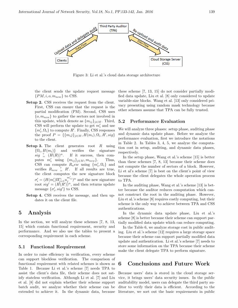
International Journal of Network Security, Vol.18, No.1, PP.133-142, Jan. 2016 139
Figure 3: Li et al.’s cloud data storage architecture
the client sends the update request messagePM, i, o,mnew to CSS.
Setup 2. CSS receives the request from the client.First, CSS can ensure that the request is thepartial modification (PM). Second, CSS useso,mnew to gather the sectors not involved inthis update, which denote as mijj∈M . Third,CSS will perform the update to get m′i and usem′i,Ωi to compute R′. Finally, CSS responsesthe proof P = mijj∈M , H(mi),Ωi, R
′, sigto the client.
Setup 3. The client generates root R usingΩi, H(mi) and verifies the signaturesig ?
= (H(R))α. If it success, then com-putes m′i using mijj∈M ,mnew. Thus,CSS can compute Rnew using m′i,Ωi andverifies Rnew
?= R′. If all results are true,
the client computes the new signature block
σ′i = (H(m′i)Πsij=1u
m′ijj )α and the new signature
root sig′ = (H(R′))α, and then returns updatemessage σ′i, sig′ to CSS.
Setup 4. CSS receives the message, and then up-dates it on the client file.
5 Analysis
In the section, we will analyze these schemes [7, 8, 13,15] which contain functional requirement, security andperformance. And we also use the tables to present acorresponding requirement in each scheme.
5.1 Functional Requirement
In order to raise efficiency in verification, every schemecan support blockless verification. The comparison offunctional requirement with related schemes is shown asTable 1. Because Li et al.’s scheme [7] needs TPA toassist the client’s data file, their scheme does not sat-isfy stateless verification. Although Li et al. [7] and Liuet al. [8] did not explain whether their scheme supportbatch audit, we analyze whether their scheme can beextended to achieve it. In the dynamic data, because
these scheme [7, 13, 15] do not consider partially modi-fied data update, Liu et al. [8] only considered to updatevariable-size blocks. Wang et al. [13] only considered pri-vacy presenting using random mask technology becauseother schemes assume that TPA can be fully trusted.
5.2 Performance Evaluation
We will analyze three phases: setup phase, auditing phaseand dynamic data update phase. Before we analyze theperformance evaluation, first we introduce the notationsin Table 2. In Tables 3, 4, 5, we analyze the computa-tion cost in setup, auditing, and dynamic data phases,respectively.
In the setup phase, Wang et al.’s scheme [15] is betterthan these schemes [7, 8, 13] because their scheme doesnot compute the number of sectors of a block. However,Li et al’s scheme [7] is best on the client’s point of viewbecause the client delegates the whole operation processto TPA.
In the auditing phase, Wang et al.’s scheme [13] is bet-ter because the auditor reduces computation which can-not construct the root in the auditing phase. However,Liu et al.’s scheme [8] requires costly computing, but theirscheme is the only way to achieve between TPA and CSSauthentications.
In the dynamic data update phase, Liu et al.’sscheme [8] is better because their scheme can support par-tially modified data update which can reduce computing.
In the Table 6, we analyze storage cost in public audit-ing. Liu et al.’s scheme [12] requires a large storage spacebecause their scheme can support partially modified dataupdate and authentication. Li et al.’s scheme [7] needs tostore some information on the TPA because their schememake the client delegate TPA to perform signature.
6 Conclusions and Future Work
Because users’ data is stored in the cloud storage ser-vice, it brings users’ data security issues. In the publicauditability model, users can delegate the third party au-ditor to verify their data is efficient. According to theliterature, we sort out the basic requirements in public

International Journal of Network Security, Vol.18, No.1, PP.133-142, Jan. 2016 140
Table 1: Comparison of functional requirements
Wang et al. [15] Wang et al. [13] Li et al. [7] Liu et al. [12]Blockless verification Yes Yes Yes YesStateless verification Yes Yes No Yes
Batch auditing Yes Yes Yes YesDynamic data Partial Partial Partial Yes
Privacy presenting No Yes No No
Table 2: Notations
Notation DescriptionTE/TD The computing time of asymmetric encryptions;
TGe The computing time of exponentiation in group operation;TBLS The computing time of BLS signature;TB The computing time of bilinear pairing;TM The computing time of multiplication;TA The computing time of addition;
TGM The computing time of multiplication in group operation;Th The computing time of hash function;n The number of block in a file;i The number of verified block;l The number of inside node that needed in MHT;o The number of auxiliary authentication information (AAI);s The number of sectors of a block;
smax The maximum number of sectors a block.
Table 3: Comparison of computation in Setup phase
Client TPAWang et al. [15] (n+ 3)TBLS + n(TGM + TGe) + (n+ l)Th NoWang et al. [13] (n+ 3)TBLS + n(TGM + TGe) + (2n+ l)Th No
Li et al. [7] No (n+ 3)TBLS + n(TGM + smaxTGe)) + (n+ l)ThLiu et al. [8] (n+ 3)TBLS + n(TGM + smaxTGe)) + (n+ l)Th No
Table 4: Comparison of computation in Auditing phase
TPA CSSWang et al. [15] oTh + 2TB i(TM + TA + TGe + TGM ) + (i+ o)ThWang et al. [13] Th + TB (i+ 1)(TGM + TA + TGe) + iTM + Th
Li et al. [7] oTh + 2TB i(TM + TA + TGe + TGM ) + (o+ i)ThLiu et al. [8] TE + oTh + 2TB TD + i(TM + TA + TGe + TGM ) + (o+ i)Th
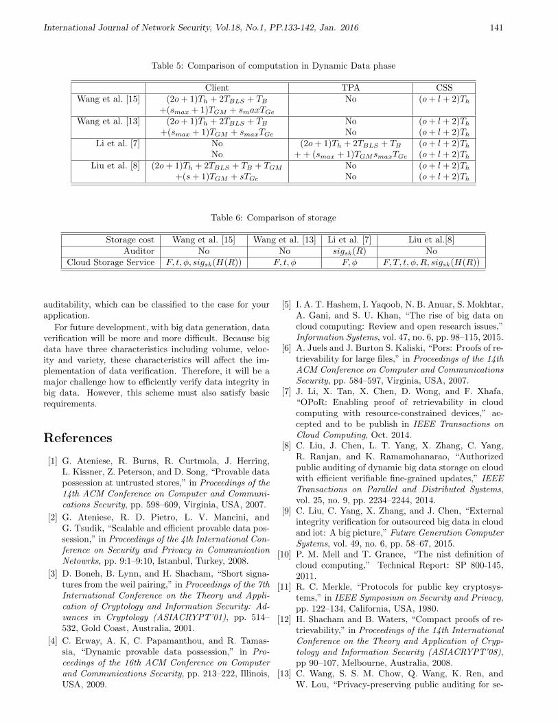
International Journal of Network Security, Vol.18, No.1, PP.133-142, Jan. 2016 141
Table 5: Comparison of computation in Dynamic Data phase
Client TPA CSSWang et al. [15] (2o+ 1)Th + 2TBLS + TB No (o+ l + 2)Th
+(smax + 1)TGM + smaxTGeWang et al. [13] (2o+ 1)Th + 2TBLS + TB No (o+ l + 2)Th
+(smax + 1)TGM + smaxTGe No (o+ l + 2)ThLi et al. [7] No (2o+ 1)Th + 2TBLS + TB (o+ l + 2)Th
No + + (smax + 1)TGMsmaxTGe (o+ l + 2)ThLiu et al. [8] (2o+ 1)Th + 2TBLS + TB + TGM No (o+ l + 2)Th
+(s+ 1)TGM + sTGe No (o+ l + 2)Th
Table 6: Comparison of storage
Storage cost Wang et al. [15] Wang et al. [13] Li et al. [7] Liu et al.[8]Auditor No No sigsk(R) No
Cloud Storage Service F, t, φ, sigsk(H(R)) F, t, φ F, φ F, T, t, φ,R, sigsk(H(R))
auditability, which can be classified to the case for yourapplication.
For future development, with big data generation, dataverification will be more and more difficult. Because bigdata have three characteristics including volume, veloc-ity and variety, these characteristics will affect the im-plementation of data verification. Therefore, it will be amajor challenge how to efficiently verify data integrity inbig data. However, this scheme must also satisfy basicrequirements.
References
[1] G. Ateniese, R. Burns, R. Curtmola, J. Herring,L. Kissner, Z. Peterson, and D. Song, “Provable datapossession at untrusted stores,” in Proceedings of the14th ACM Conference on Computer and Communi-cations Security, pp. 598–609, Virginia, USA, 2007.
[2] G. Ateniese, R. D. Pietro, L. V. Mancini, andG. Tsudik, “Scalable and efficient provable data pos-session,” in Proceedings of the 4th International Con-ference on Security and Privacy in CommunicationNetowrks, pp. 9:1–9:10, Istanbul, Turkey, 2008.
[3] D. Boneh, B. Lynn, and H. Shacham, “Short signa-tures from the weil pairing,” in Proceedings of the 7thInternational Conference on the Theory and Appli-cation of Cryptology and Information Security: Ad-vances in Cryptology (ASIACRYPT’01), pp. 514–532, Gold Coast, Australia, 2001.
[4] C. Erway, A. K, C. Papamanthou, and R. Tamas-sia, “Dynamic provable data possession,” in Pro-ceedings of the 16th ACM Conference on Computerand Communications Security, pp. 213–222, Illinois,USA, 2009.
[5] I. A. T. Hashem, I. Yaqoob, N. B. Anuar, S. Mokhtar,A. Gani, and S. U. Khan, “The rise of big data oncloud computing: Review and open research issues,”Information Systems, vol. 47, no. 6, pp. 98–115, 2015.
[6] A. Juels and J. Burton S. Kaliski, “Pors: Proofs of re-trievability for large files,” in Proceedings of the 14thACM Conference on Computer and CommunicationsSecurity, pp. 584–597, Virginia, USA, 2007.
[7] J. Li, X. Tan, X. Chen, D. Wong, and F. Xhafa,“OPoR: Enabling proof of retrievability in cloudcomputing with resource-constrained devices,” ac-cepted and to be publish in IEEE Transactions onCloud Computing, Oct. 2014.
[8] C. Liu, J. Chen, L. T. Yang, X. Zhang, C. Yang,R. Ranjan, and K. Ramamohanarao, “Authorizedpublic auditing of dynamic big data storage on cloudwith efficient verifiable fine-grained updates,” IEEETransactions on Parallel and Distributed Systems,vol. 25, no. 9, pp. 2234–2244, 2014.
[9] C. Liu, C. Yang, X. Zhang, and J. Chen, “Externalintegrity verification for outsourced big data in cloudand iot: A big picture,” Future Generation ComputerSystems, vol. 49, no. 6, pp. 58–67, 2015.
[10] P. M. Mell and T. Grance, “The nist definition ofcloud computing,” Technical Report: SP 800-145,2011.
[11] R. C. Merkle, “Protocols for public key cryptosys-tems,” in IEEE Symposium on Security and Privacy,pp. 122–134, California, USA, 1980.
[12] H. Shacham and B. Waters, “Compact proofs of re-trievability,” in Proceedings of the 14th InternationalConference on the Theory and Application of Cryp-tology and Information Security (ASIACRYPT’08),pp 90–107, Melbourne, Australia, 2008.
[13] C. Wang, S. S. M. Chow, Q. Wang, K. Ren, andW. Lou, “Privacy-preserving public auditing for se-
International Journal of Network Security, Vol.18, No.1, PP.133-142, Jan. 2016 142
cure cloud storage,” IEEE Transactions on Comput-ers, vol. 62, no. 2, pp. 362–375, 2013.
[14] C. Wang, Q. Wang, K. Ren, and W. Lou, “Ensur-ing data storage security in cloud computing,” inProceedings of the 17th International Workshop onQuality of Service (IWQoS’09), pp. 1–9, South Car-olina, USA, 2009.
[15] Q. Wang, C. Wang, K. Ren, W. Lou, and J. Li, “En-abling public auditability and data dynamics for stor-age security in cloud computing,” IEEE Transactionson Parallel and Distributed Systems, vol. 22, no. 5,pp. 847–859, 2011.
Wei-Fu Hsien received his B. S. in Department of In-formation Management from National Kaohsiung MarineUniversity, Kaohsiung, Taiwan, ROC, in 2013. He iscurrently pursuing the M.S. degree with the Departmentof Management Information Systems from NationalChung Hsing University. His research interests includesecurity and privacy of cloud computing, and appliedcryptography.
Chou-Chen Yang received his B.S. in Industrial Edu-cation from the National Kaohsiung Normal University,in 1980, and his M.S. in Electronic Technology from thePittsburg State University, in 1986, and his Ph.D. inComputer Science from the University of North Texas,in 1994. From 1994 to 2004, Dr. Yang was an associateprofessor in the Department of Computer Science andInformation Engineering, Chaoyang University of Tech-nology. Currently, he is a professor in the Departmentof Management Information Systems, National ChungHshing University. His research interests include networksecurity, mobile computing, and distributed system.
Min-Shiang Hwang received the B.S. in Electronic En-gineering from National Taipei Institute of Technology,Taipei, Taiwan, Republic of China, in 1980; the M.S. inIndustrial Engineering from National Tsing Hua Univer-sity, Taiwan, in 1988; and the Ph.D. in Computer and In-formation Science from National Chiao Tung University,Taiwan, in 1995. He also studied Applied Mathematicsat National Cheng Kung University, Taiwan, from 1984-1986. Dr. Hwang passed the National Higher Examina-tion in field “Electronic Engineer” in 1988. He also passedthe National Telecommunication Special Examination infield “Information Engineering”, qualified as advancedtechnician the first class in 1990. From 1988 to 1991, hewas the leader of the Computer Center at Telecommuni-cation Laboratories (TL), Ministry of Transportation andCommunications, ROC. He was also a project leader forresearch in computer security at TL in July 1990. He ob-tained the 1997, 1998, and 1999 Distinguished ResearchAwards of the National Science Council of the Republicof China. He is a member of IEEE, ACM, and ChineseInformation Security Association. His current research in-terests include database and data security, cryptography,image compression, and mobile communications.

International Journal of Network Security, Vol.18, No.1, PP.143-150, Jan. 2016 143
3C-Auth: A New Scheme for Enhancing Security
Narasimhan Harini and Tattamangalam R. Padmanabhan(Corresponding author: Narasimhan Harini)
Department of Computer Science and Engineering & Amrita University
Amritanagar P.O., Ettimadai, Coimbatore 641 112, India
(Email: [email protected])
(Received Aug. 1, 2013; revised and accepted May 20 & Nov. 3, 2014)
Abstract
A multi factor authentication scheme called ’3C-Auth’ isproposed in this paper. The scheme carries out a com-prehensive authentication process using the smart card,secret-pin, registered finger print, and registered mobilenumber of the user. The user’s password is neither trans-mitted in plaintext form nor revealed to the authenti-cation server. The scheme is shone to be proof againstphishing, password guessing, replay, or stolen-verifier at-tacks. Resistance to parallel session and denial of serviceattacks and the use of QR-Code in preference to SMS forOTP transfer together, make the scheme attractive for op-eration under peak loads. Integration of the “3C-Auth”into Multi-Layered Filtering (MLF) scheme leads to se-cure handling of peak loads on the server ensuring con-currency and availability as well. This clearly enhancesthe QoS in terms of making right admittance to right re-sources.
Keywords: Authentication, peak load, QR-code, smart-card
1 Introduction
As Internet services become more popular and pervasive,a serious problem that arises is managing the performanceof services under intense load. One of the most challeng-ing problems for public Internet is the delivery of per-formance targets to users given the randomness of Webaccesses. Internet has become indispensable for businessand more and more people rely on it for their day to dayactivities; in turn it evolves continuously and is subject tomore and more cyber security threats. Analysis of secu-rity breaches and other cyber security issues with particu-lar focus on personal privacy and data security have beenactive research issues over the past two decades. A mul-tifactor authentication scheme named “3C-Auth” is pre-sented in this paper that uses true authentication to pro-tect resources with high security requirements; it expectsthe user to possess all the tokens (smart-card, secret-pin,registered finger print and registered mobile phone) to
prove his/her identity.Rest of the paper is organized as follows: Relevant re-
search in literature which forms the motivation for thepresent work is reviewed in Section 2. Sections 3 and 4detail the proposed scheme and analyze its performance.Integration of the scheme with MLF (Multi Layer Fil-tering) architecture [2, 3] is presented in Section 5 andconclusions are in Section 6.
2 Related Work
2.1 Internet Architecture
The changeover from the academic Internet to a multi-functional business Internet puts much higher require-ments on the architectural supports to control and bal-ance the interests of all stake holders (like users, serviceproviders, data owners, etc.). Their hopes and expecta-tions for new applications and services demand new ar-chitectures that overcome the fundamental limitations ofInternet like lack of data identity, lack of methods for re-liable processing, real-time dispensation, scaling to dealwith flash crowds, and so on. Since its creation, the In-ternet is driven by a small set of fundamental design prin-ciples rather than being based on a proper formal archi-tecture that is created on a white board by a standard-ization or research group. The architectural principlesand design model of the Internet are all about processing,storing, transmitting and controlling data. This trend isbound to escalate in the future, pointing to a clear needfor extensions, enhancements, and re-engineering in In-ternet architecture. While improvements are needed ineach dimension, these should be cohesive demanding aholistic approach. The architecture can be generalized tosuit different categories of applications by integrating theadmittance control policies that provide metric based dif-ferentiation and consecutively maximize the profit earnedfor having serviced a certain class of requests [16]. Re-search in this area has identified some key approaches toface overload, such as admission control (per request, persession), request scheduling, service differentiation, ser-vice degradation, and resource management.

International Journal of Network Security, Vol.18, No.1, PP.143-150, Jan. 2016 144
2.2 Current State of Internet Servicesand Authentication Requirement
The following form the key features of the state of art ofinternet services:
• Generic nature;
• Accommodation of technological innovations;
• Robustness at times of overload.
As access to more and more services is pushed online,the range of sensitive information that a user must pro-tect widens with time. It is also equally important tounderstand that complicated security schemes will notachieve widespread adoption among Internet users. To-day hackers have the option of using many techniques tosteal passwords such as shoulder surfing, snooping, sniff-ing, guessing, etc. – Implying that businesses should usecommensurate secure approach. The challenge here is tobalance strong security with usability. One Time Pass-words (OTPs) for single session/transaction usage havebeen identified as the best way of protecting online trans-actions.
2.3 Authentication Schemes
In 1981, Lamport proposed a scheme to authenticate aremote user on a remote server over an insecure net-work. The requirement for storing verification tables usedby the scheme was overcome by a scheme proposed inby [7]. Later [10] proposed a new remote authenticationbased on ElGamal crypto scheme exploiting tamper re-sistance property of smart cards. Most of the remoteidentity based remote authentication schemes proposedby researchers [7, 10, 13, 16] rely primarily on passwordsfor security. The schemes are vulnerable to dictionaryattacks [6]. To overcome this problem random crypto-graphic secret key could be used [14]. However, such largekey values (are difficult to be remembered and hence)require to be stored somewhere. Further these strongpasswords and secret keys fail to provide non repudia-tion. An authentication scheme of Khan et al and Li etal uses biometric keys with advantages like “cannot belost”, “difficult to forge”, “cannot be guessed” etc. [10]proposed an efficient biometric based smart card authen-tication scheme. [7] showed that the scheme makes twoassumptions to ensure its correctness and security thatmay restrict its use for real time applications. [8] proposesa generic framework for preserving security in distributedsystems. The three factor authentication scheme in [7] isbased on password, smart card and biometric characteris-tics. The authors claim two benefits in the usage of fuzzyextractor:
• Elimination of the assumption of Li-Hwangs schemethat stores the hash of biometric template;
• Use of biometric authentication that supports rea-sonable tolerance.
In the analysis of their scheme the authors have shownhow their protocol is secured against attackers of Type I(smart card and biometric), Type II (password and Bio-metric), and Type III (smart card and Password). Al-though the generic construction proposed by Huang et alsatisfies the security requirements of three factor authenti-cation the system may fail to secure resources that requirevery high degree of security the reason being biometricsystems that are fast with the false rejection rate under1% (together with a reasonably low false acceptance rate)are rare even today.
2.4 Security with OTP
Authentication of users in a distributed environment isan increasingly difficult task. As network and softwaregrow in sophistication so do means and methods of ma-licious attackers. Today computer crackers use enormousresources to obtain information necessary to impersonateother users. Authentication systems based on one timepasswords [5] provide more reliability than those based onremembered/stored ones. Hence, security sensitive indus-tries (banks, government etc.) deploy one time passwordsystems to reduce the damage of phishing and spywareattacks.
2.4.1 SMS-OTP
Most of the two factor authentication schemes authenti-cate users based on what they know and what they have,incorporating token-less second factor (e.g. mobile). Eachmethod has a reason to exist based on design criteria forthe overall usage.
Online banking is a good example where strong remoteauthentication is guaranteed using two-factors as de factostandard. In practice, the first factor is usually in theform of PIN or password that the user types (for instance)into a web-based Internet application. The second factoris usually in the form of mobile phone that is known tobe able to receive OTP as SMS directed to a particularmobile phone number. If the user successfully retypes thisOTP into the web application, the second authenticationfactor is regarded as successfully verified (i.e. the userhas the mobile phone).
Security of the aforesaid scenario relies on the practicaldifficulty for an attacker to simultaneously compromisethe operating environment of both the particular phoneand the web browser where the user part of the servingapplication runs.
2.4.2 Problems with SMS-OTP
The main problems with the SMS-OTP design are underoverloaded situations. These are:
• Delay in delivery of SMS;
• Low Coverage Areas;
• Non-availability of Mobile Phone;

International Journal of Network Security, Vol.18, No.1, PP.143-150, Jan. 2016 145
• Downtime with SMS Gateway;
• Non-availability of service for roaming user;
• High Cost for roaming user;
• Complexity associated with sequence of operationsin obtaining OTP from SMS when mobile phone isused for connecting to the Internet.
2.4.3 Authentication Using QR Code
In 2002, Clarke et al. suggested the usage of camera-baseddevices as an alternative but more secured authenticationmethod for critical transactions with un-trusted comput-ers. With the explosive growth in the amount of camera-equipped smart phones around us mobile based authenti-cation [11] may become a popular authentication methodin the near future. QR-code (a two-dimensional barcode)- as introduced by Japanese company Denso-Wave in 1994is a more effective alternative. Its error correction capa-bility facilitates data restoration even under conditionswhen substantial parts of the code are damaged. Moderncellular phones are natively equipped with the QR-codedecoding software. Fortunately, for camera phones thatare not equipped with QR-code readers, Quick-Mark andi-nigma are free tools that are available for many manu-factured models and devices to decode QR-Codes free ofcost. Depending on the data recognized and the natureof the application.
2.4.4 Summary of Findings
Internet has become the most important platform forbusiness relations and social interactions. The rapidgrowth of Internet of Things and Services clearly showsthat the ever increasing amount of physical items ofour daily life which become addressable through a net-work could be made more easily manageable and usablethrough the use of Internet services. This course of ex-posed resources along with the level of privacy and valueof the information they hold, together with increase intheir usage, has led to the escalation in the number ofsecurity threats and violation attempts that existing sys-tems do not appear robust enough to address. Internetarchitecture of tomorrow must meet the changing require-ments of the Internet, ISPs (Internet Service Providers),Users etc. Perhaps one of the most compelling problemsof the modern Internet is the lack of a comprehensiveand unifying approach to deal with service concurrency,security, and availability particularly at times of over-loads. It is also important to understand that the internetand its users are under continuous attacks i.e., securityis the underlying problem for many of the Internet ser-vices. One has to clearly understand that the impact ofan attack can be major, and can include costly and em-barrassing service disruptions, down-time, lost productiv-ity, stolen data, regulatory fines, and irritated customers.Strong authentication has no precise definition; it is not a
strictly mathematical concept with quantitative measure-ments but rather a qualitative measure that is evaluatedusing a relative scale. The present sophistication level ofhackers, demands authentication schemes to be based onmore than one factor. Evaluating multi-factor authentica-tion solutions calls for a look into the following measures:
• Security and scalability of the technology;
• Hurdles to user adoption;
• Cost;
• Deployability.
3 Proposed Scheme
The primary goal here is to enhance the performanceof Multi-layered Filtering (MLF) scheme and enable realworld applications to take advantage of this added func-tionality.
A scheme that performs admission control with en-hanced multi factor authentication “called 3CAuth”, isproposed in this paper and the same evaluated for effi-ciency. The scheme provides true authentication by ex-pecting the user to possess all the relevant tokens (smartcard, secret-pin, registered finger print, and registeredmobile phone) to prove his/her identity.
The benefits of the scheme include:
• NOT revealing users password to the server;
• NOT transmitting passwords in plaintext over theInternet, and at the same time;
• RESISTING the major possible attacks like replayattack, password guessing attack, stolen-verifier at-tack, and phishing attack.
The scheme operates in two phases namely registrationand login-authentication. Table 1 is the notations used inthe two phases.
3.1 Registration Phase
Figure 1 depicts the activities in the registration process.As shown in Figure 1 it involves the steps/activities inAlgorithm 1.
The sequence of operations for registering ONE user isillustrated in Figure 2.
3.2 Login Phase
When Ui wishes to login to server (S), he/she must in-sert the smart card into a card reader, provide biometricdata BF ′i , capture the QR code displayed on the webpage, decrypt it using the software installed in the mo-bile, and present the OTP for authentication purpose.The sequence is shown in block diagram form in Figure 3.

International Journal of Network Security, Vol.18, No.1, PP.143-150, Jan. 2016 146
Table 1: Table of notations
Notations DescriptionUi ith User
IDi Unique Identifier of ith UserPWDi Password of the ith User
d Private key in RSAe Public key in RSAn Computed as product of chosen prime numbers (p and q)g Generator element primitive to GF (p) and GF (q)
SIDi Smart card Identifier of ith UserIMEI International Mobile Station Equipment IdentityIMSI International mobile subscriber identity
MIDi Unique Key for mobile of ith userR1 and R2 Random numbers chosen for verification
Ts Time at which the request is generatedBFi Biometric feature of ith userRc Random Challenge (in this context - One Time Password)
Figure 1: Registration process
Figure 2: Registration process
Figure 3: Login phase

International Journal of Network Security, Vol.18, No.1, PP.143-150, Jan. 2016 147
Algorithm 1 Steps in registration process
1: Begin2: The user Ui chooses a password PWDi and provides
his/her biometric feature BFi.3: The registration server sequences through the follow-
ing further steps:4: while More users to Register do5: Assigns an IDi for the user and generates two large
prime numbers p and q, and computes
n = p ∗ q.
For security reasons, the lengths of p and q are rec-ommended to be 512 bits at least.
6: Chooses integers e and d which satisfy
e ∗ d mod ((p− 1) ∗ (q − 1)) ≡ 1
Further it also finds an integer g which is a primitiveelement in both GF (p) and GF (q).
7: Generates a smart card identifier SIDi for the userUi. In addition it generates a mobile phone identi-fier: MIDi = (IMEI, IMSI) for the user Ui.
8: Calculates Ui’s secret information as
Si ≡ ID(SIDi∗d)i mod n
Vi ≡ g(d∗BFi) mod n
MSi ≡ ID(MIDi∗d)i mod n
MVi ≡ g(d∗PWDi) mod n.
9: Stores (IDi, SIDi, MIDi, Si, Vi, MSi, MVi, n,e, g) in the smart card, installs an application (forcapturing and decoding QR code after obtainingsecret pin from the user) in user’s mobile and issuesthe smart card to the user Ui over a secure channel.
10: end while11: End
3.3 Authentication Phase
The authentication phase (Figure 4) is executed by theremote host to determine whether Ui is allowed to loginor not. The steps in login process are shown in Figure 3.
The authentication server upon receiving the login re-quest from the user verifies the possession of smart card,biometric feature, and mobile phone as described in Al-gorithms 2 and 3.
4 Strengths of 3C-Auth
Resistance of the proposed method to different possiblesecurity attacks is explained here.
4.1 Parallel Session Attack
Here an attacker impersonates a legitimate user by inter-cepting the login request (IDi, SIDi, Si, Vi, Mi, Ni, n, e,
Figure 4: Authentication phase
Algorithm 2 Verification of possession of biometric char-acteristics and smart card1: Begin2: Check if IDi is a valid user identity and SIDi is a legal
smart card identity; if not reject the login request.3: Check if Ts is within the legal time interval limit
due to transmission delay (may be initialized in SLA-service level agreement); if not reject the login re-quest.
4: Verify if Y ie ?≡ (ID
(SIDi)i ∗XiTs mod n);
The above equation holds iff BFi = BF ′i .i.e. the correct biometric value is provided duringlogin phase. That is because
Y ie ≡ (Si ∗ V (R1∗Ts)i mod n)e
≡ ID(SIDi∗d∗e)i ∗ g(d∗BFi∗e∗R1) mod n.
(Since d ∗ e ≡ 1 mod n we have)
≡ ID(SIDi)i ∗ g(BFi∗R1) mod n
and
ID(SIDi)i ∗ (XiTs) ≡ ID
(SIDi)i ∗ g(BF ′i∗R1) mod n;
5: End
g, Ts) and attempting to modify it to succeed in authenti-cation. However the attacker has no way of obtaining theBiometric feature BFi, PWDi, and the random numbersR1 and R2; hence he/she cannot compute Mi, Ni, Xi,and Yi which are dependent on PWDi and R1; a validrequest cannot be created and the attempt fails. Hence itfollows that the proposed scheme is secured against thistype of attack.
4.2 Password Guessing Attack
The attacker attempts to guess user’s secret parametershere. Although, one can extract parameters (n, e, g, Si,Vi, SMi, VMi) from the user’s smart card, obtaining BFi
or PWDi from the smart card without the knowledge ofd from g(d∗BFi) and g(d∗BFi), is not possible. Thus thedifficulty of obtaining the discrete logarithm secures thescheme from password guessing attack even under stolensmart card situations.
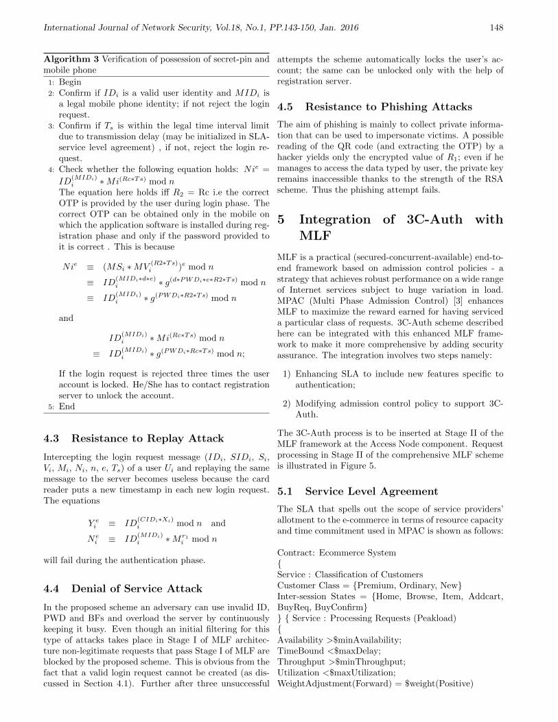
International Journal of Network Security, Vol.18, No.1, PP.143-150, Jan. 2016 148
Algorithm 3 Verification of possession of secret-pin andmobile phone
1: Begin2: Confirm if IDi is a valid user identity and MIDi is
a legal mobile phone identity; if not reject the loginrequest.
3: Confirm if Ts is within the legal time interval limitdue to transmission delay (may be initialized in SLA-service level agreement) , if not, reject the login re-quest.
4: Check whether the following equation holds: Nie =
ID(MIDi)i ∗Mi(Rc∗Ts) mod n
The equation here holds iff R2 = Rc i.e the correctOTP is provided by the user during login phase. Thecorrect OTP can be obtained only in the mobile onwhich the application software is installed during reg-istration phase and only if the password provided toit is correct . This is because
Nie ≡ (MSi ∗MV(R2∗Ts)i )e mod n
≡ ID(MIDi∗d∗e)i ∗ g(d∗PWDi∗e∗R2∗Ts) mod n
≡ ID(MIDi)i ∗ g(PWDi∗R2∗Ts) mod n
and
ID(MIDi)i ∗Mi(Rc∗Ts) mod n
≡ ID(MIDi)i ∗ g(PWDi∗Rc∗Ts) mod n;
If the login request is rejected three times the useraccount is locked. He/She has to contact registrationserver to unlock the account.
5: End
4.3 Resistance to Replay Attack
Intercepting the login request message (IDi, SIDi, Si,Vi, Mi, Ni, n, e, Ts) of a user Ui and replaying the samemessage to the server becomes useless because the cardreader puts a new timestamp in each new login request.The equations
Y ei ≡ ID
(CIDi∗Xi)i mod n and
Nei ≡ ID
(MIDi)i ∗Mr1
i mod n
will fail during the authentication phase.
4.4 Denial of Service Attack
In the proposed scheme an adversary can use invalid ID,PWD and BFs and overload the server by continuouslykeeping it busy. Even though an initial filtering for thistype of attacks takes place in Stage I of MLF architec-ture non-legitimate requests that pass Stage I of MLF areblocked by the proposed scheme. This is obvious from thefact that a valid login request cannot be created (as dis-cussed in Section 4.1). Further after three unsuccessful
attempts the scheme automatically locks the user’s ac-count; the same can be unlocked only with the help ofregistration server.
4.5 Resistance to Phishing Attacks
The aim of phishing is mainly to collect private informa-tion that can be used to impersonate victims. A possiblereading of the QR code (and extracting the OTP) by ahacker yields only the encrypted value of R1; even if hemanages to access the data typed by user, the private keyremains inaccessible thanks to the strength of the RSAscheme. Thus the phishing attempt fails.
5 Integration of 3C-Auth withMLF
MLF is a practical (secured-concurrent-available) end-to-end framework based on admission control policies - astrategy that achieves robust performance on a wide rangeof Internet services subject to huge variation in load.MPAC (Multi Phase Admission Control) [3] enhancesMLF to maximize the reward earned for having serviceda particular class of requests. 3C-Auth scheme describedhere can be integrated with this enhanced MLF frame-work to make it more comprehensive by adding securityassurance. The integration involves two steps namely:
1) Enhancing SLA to include new features specific toauthentication;
2) Modifying admission control policy to support 3C-Auth.
The 3C-Auth process is to be inserted at Stage II of theMLF framework at the Access Node component. Requestprocessing in Stage II of the comprehensive MLF schemeis illustrated in Figure 5.
5.1 Service Level Agreement
The SLA that spells out the scope of service providers’allotment to the e-commerce in terms of resource capacityand time commitment used in MPAC is shown as follows:
Contract: Ecommerce SystemService : Classification of CustomersCustomer Class = Premium, Ordinary, NewInter-session States = Home, Browse, Item, Addcart,BuyReq, BuyConfirm Service : Processing Requests (Peakload)Availability >$minAvailability;TimeBound <$maxDelay;Throughput >$minThroughput;Utilization <$maxUtilization;WeightAdjustment(Forward) = $weight(Positive)

International Journal of Network Security, Vol.18, No.1, PP.143-150, Jan. 2016 149
Figure 5: Request processing in Stage II of enhanced MLF (MLF+MPAC)
WeightAdjsutment(Backward) = $weight(zero,negative)The template can be modified to support 3C-Auth by including the following specifications:Security: AuthserviceService : Servicename /* Generic */Resource Class = Unclassified, secret,topsecretFactors Class = Password/PIN, Hardwaretoken, Bio-Hard, SofttokenProtocol Class None, 2CAuth,3C-Auth Service : News /* instance*/Resource Class UnclassifiedRegistration Factors ClassProtocol Class None Service : Internet Banking /* Announcements regarding new schemes for loansResources Class UnclassifiedRegistration Factors Class Protocol Class // Online bankingResources Class topsecretRegistration REQUIRED Factors Class PIN, Hardwaretoken (Smart card), Soft-tokenProtocol Class 2CAuth[3]
5.2 Admission Control Policy
MPAC uses a reward function defined by the applica-tion/service provider to improve the QoS using servicedifferentiation. It computes the Expected Reward and theCost Incurred in servicing the request and uses them as
basic parameters to prioritize customers for E-commerceapplications. The scheme can be made more comprehen-sive by re-computing priorities with authentication factorsas well, for better security assurances. This is achievedin the comprehensive MLF framework (MLF + MPAC +3C-Auth) as follows:
• Resources added to the pool are tagged with weights(based on SLA) that specify the number of factorsrequired to access it;
• Incoming requests from Stage I are directed to theAccess nodes by the public server for authentication;
• The access nodes proceed to authenticate users byassigning an initial weight of 0 to each request andupdating it as per the credentials (number of factors)validated;
• Possessed weights are compared with the taggedweights associated with resources and in case ofmatch in their weights access to the resource is per-mitted.
5.3 Results of Integration
The performance analysis demonstrated that the pre-sented scheme performs a comprehensive authenticationprocess satisfying the important requirements includingfriendliness, resistance to various kinds of sophisticatedattacks, and stolen credentials. Further resistance of-fered by the scheme to parallel session attack and de-nial of service attack made the scheme more suitable foroperation under peak loads. QR-Code based OTP hasbeen found to show improved performance at peak loadtimes compared to SMS-OTP method. With instanta-neous SMS delivery the performance was on par with thatof SMS-OTP scheme. The vulnerability associated withthe in-absentia verification of the user is effectively han-dled by the scheme. Moreover, the scheme was found tobe more user-friendly without sacrificing security assur-ances. With all these benefits contribution of the schemetowards improvement in QoS in terms of granting rightaccess to resources can be considered significant.

International Journal of Network Security, Vol.18, No.1, PP.143-150, Jan. 2016 150
6 Discussions and Conclusions
The proposed protocol is simple, fast and efficient if theuser provides valid credentials for authentication. A de-tailed analysis of the proposed scheme has clearly broughtout its advantages over authorization methods that useSMS to thwart attacks. Moreover, the scheme aptly fitsat the access nodes in the enhanced MLF architecturemaking it more user-friendly without sacrificing securityassurances. Improving in computational efficiency of thescheme is an interesting area of work; it can add substan-tially to its effectiveness.
References
[1] T. H. Feng, C. H. Ling, and M. S. Hwang, “Crypt-analysis of Tan’s improvement on a password authen-tication scheme for multi-server environments”, In-ternational Journal of Network Security, vol. 16, no.4, pp. 318–321, 2014.
[2] N. Harini and T. R. Padmanabhan, “A secured-concurrent-available architecture for improving per-formance of web servers”, in Proceedings of 6th In-ternational Conference on Information Processing(ICIP 2012), pp 621-631, Bangalore, India, Aug. 10-12, 2012.
[3] N. Harini and T. R. Padmanabhan, “Admission con-trol and request scheduling for secured-concurrent-available Architecture”, International Journal ofComputer Applications, vol. 63, no. 6, pp. 24–30,2013.
[4] N. Harini and T. R. Padmanabhan, “2CAuth: A newtwo factor authentication scheme using QR-code”,International Journal of Engineering and Technology(IJET), vol. 5, no. 2, pp. 1087–1094, 2013.
[5] N. Harini, T. R. Padmanabhan and C. K. Shyamala,Cryptography and Security, Wiley India, First Edi-tion, 2011.
[6] D. He, W. Zhao, and S. Wu, “Security analysis of adynamic ID-based authentication scheme for multi-server environment using smart cards”, InternationalJournal of Network Security, vol. 15, no. 5, pp. 350–356, 2013.
[7] C. H. Huang, J. S. Chou, Y. Chen, “Improved multi-server authentication protocol”, International jour-nal of Security and Communication Networks, vol. 5,no. 3, pp. 331–341, 2012.
[8] X. Huang, Y. Xiang, A. Chonka, J. Zhou, and R.H. Deng, “A generic framework for three-factor au-thentication: Preserving security and privacy in dis-tributed systems”, IEEE Transactions on Paralleland Distributed Systems, vol. 22, no. 8, pp. 1390–1397, 2011.
[9] Qi Jiang, J. Ma, G. Li, and Li Yang, “Robust two-factor authentication and key agreement preservinguser privacy”, International Journal of Network Se-curity, vol. 16, no. 3, pp. 229–240, 2014.
[10] C. T. Li and M. S. Hwang, “An efficient biometrics-based remote user authentication scheme using smartcards”, Journal of Network and Computer Applica-tions, vol. 33, no. 1, pp. 1–5, 2010.
[11] K. C. Liao and W. H. Lee, “A novel user authenti-cation scheme based on QR-code”, Journal of Net-works, vol. 5, no. 8, pp. 937–941, 2010.
[12] J. J. Shen and P. W. Hsu, “A fragile associative wa-termarking on 2D barcode for data authentication”,International Journal of Network Security, vol. 7,no. 3, pp. 301–309, 2008.
[13] J. J. Shen, C. W. Lin and M. S. Hwang, “Securityenhancement for the timestamp-based password au-thentication”, Computers and Security, vol. 22, no. 7,pp. 591–595, 2003.
[14] H. Tang, X. Liu, L. Jiang, “A robust and efficienttimestamp-based remote user authentication schemewith smart card lost attack resistance”, InternationalJournal of Network Security, vol. 15, no. 6, pp. 446–454, 2013.
[15] A. Totok, V. Karamcheti, “RDRP: Reward-drivenrequest prioritization for e-Commerce Web sites”,Electronic Commerce Research and Applications,vol. 9, pp. 549–561, 2010.
[16] Li Yang, J. F. Ma, and Qi Jiang, “Mutual authenti-cation scheme with smart cards and password undertrusted computing”, International Journal of Net-work Security, vol. 14, no. 3, pp. 156–163, 2012.
[17] X. Zhuang, C. C. Chang, Z. H. Wang, Y. Zhu, “Asimple password authentication scheme based on ge-ometric hashing function”, International Journal ofNetwork Security, vol. 16, no. 4, pp. 271–277, 2014.
N. Harini is an Assistant Professor in the departmentof Computer Science and Engineering, Amrita VishwaVidyapeetham. She has 3 years of industrial and 15 yearsof teaching and research experience. She is currently pur-suing her Ph D in Security. Her research interests includecryptography, security. She has currently co-authored abook on Cryptography and Security.
T. R. Padmanabhan with MTech and PhD at the IITKharagpur, was in the faculty there from 1964 to 1979.With 20 years of development experience in the indus-try and an equal period in academic institutions, he iscurrently a Professor Emeritus at the Amrita School ofEngineering. His research interests are security, digitalcommunication, and VLSI design. He has (co)authoredfive books.

International Journal of Network Security, Vol.18, No.1, PP.151-157, Jan. 2016 151
The Development of Deniable AuthenticationProtocol Based on The Bivariate Function Hard
Problem
Normahirah Nek Abd Rahman1 and Muhammad Rezal Kamel Ariffin1,2
(Corresponding author: Normahirah Nek Abd Rahman)
Al-Kindi Cryptography Research Laboratory, Institute for Mathematical Research, Universiti Putra Malaysia1
Department of Mathematics, Faculty of Science, Universiti Putra Malaysia2
43400 UPM Serdang, Selangor, Malaysia.(Email: mahirah [email protected], [email protected])
(Received Jan. 28, 2015; revised and accepted Apr. 25 & June 30, 2015)
Abstract
A deniable authentication protocol enables a receiverto identify the true source of a given message but notto prove the identity of the sender to the third party.Non-interactive protocol is more efficient than interactiveprotocol in terms of communication overhead, and thusseveral non-interactive deniable authentication protocolshave been proposed. So, it is very necessary to design adeniable authentication protocol which is non-interactive,secure and efficient. This paper proposes a deniable au-thentication protocol based on the bivariate function hardproblem (BFHP) cryptographic primitive. An improve-ment based on the BFHP is suggested since the problem ofthe BFHP provides the needed security elements plus itsfast execution time. At the same time, the proposed pro-tocol has properties of completeness, deniability, securityof forgery attack, security of impersonation attack andsecurity man-in-the-middle attack also has been proved.Keywords: Bivariate function hard problem, deniable au-thentication protocol, non-interactive protocol
1 Introduction
Deniability is a privacy property that ensures protocolparticipants can later deny taking part in a particularprotocol run while authentication is used to ensure thatusers are who they say they are. So, a deniable authen-tication protocol is a protocol that enables a receiver toidentify the true source of a given message, but not toprove the identity of the sender to a third party. Thereare many interactive and non-interactive deniable authen-tication protocols have been proposed. However, the in-teractive manner makes deniable protocols inefficient.
Deniable authentication has two characteristics thatdiffer from traditional authentication. The first one is
only the intended receiver can identify the true source ofa given message (i.e. able to identify the signature of thesender) and the second one is the receiver cannot provethe source of the message to a third party (i.e. unableto prove the signature of the sender to a third party thatthe signature belongs to the sender). In other words, oncethe receiver has obtained and authenticated the messagefrom the sender, the receiver cannot impersonate as thesender to a third party. Because of these two character-istics, the deniable authentication protocol is very usefulfor providing secure negotiation over internet.
For example, suppose that a customer wants to orderan item from a merchant, so the customer should make anoffer to the merchant and create an authenticator for theoffer because the merchant must be sure that this offerreally comes from the customer. However, the merchantwants to be able to prevent the customer from showingthis offer to another party in order to elicit a better deal.Therefore, we need a protocol that enables a receiver toidentify the source of a given message, but prevents athird party from learning the sender’s identity.
In 1998, Dwork et al. [4] proposed an interactive de-niable authentication protocol based on concurrent zeroknowledge proof while Aumann and Rabin [2] proposedan interactive deniable authentication protocol based onthe integer factorization problem (IFP). Later, Deng etal. (2001) [3] introduced two interactive deniable authen-tication protocols based on the discrete logarithm prob-lem (DLP) and IFP respectively. In 2002, Fan et al. [5]introduced another simple interactive deniable authenti-cation protocol based on Diffie-Hellman Key DistributionProtocol. However, there is a common weakness in thefour previous protocols which the sender does not knowto whom he proves the source of a given message. Thatis, a third party can impersonate the intended receiver toidentify the source of a given message. Meanwhile, thesefour protocols are interactive and less efficient.

International Journal of Network Security, Vol.18, No.1, PP.151-157, Jan. 2016 152
This scenario has led many cryptographers to come upwith non-interactive deniable authentication protocol inorder to enhance the efficiency. Shao (2004) [12] proposeda non-interactive deniable authentication protocol basedon generalized ElGamal signature scheme. Lu and Cao(2005) [10, 11] proposed two deniable authentication pro-tocols based on bilinear pairing and IFP respectively buttheir protocol is still unable to achieve the second char-acteristic of being a deniable authentication protocol.
Later, in 2008, Hwang and Ma [8] proposed deniableauthentication protocol with anonymous sender protec-tion. The sender’s anonymity is also used to protect thesender’s privacy. Though the sent message is forgeableby the receiver, but the sender can provide evidence toprove the message was really sent by him. Hence, to re-duce the computational cost of proposed protocols withanonymous sender protection, Hwang and Chao (2010) [7]proposed a new deniable authentication protocol withanonymous sender protection in an efficient way basedon Schnorr signature scheme.
Then, Zhang et al. (2011) [13] proposed a new non-interactive deniable authentication protocol based on gen-eralized ElGamal signature scheme, which is more effi-cient than the previous two protocols (Shao 2004, Leeet al. 2007) [9, 12] both in computation and commu-nication. To authenticate the source of a message, al-though the proposed protocol needs one more modularexponentiation than Shao’s protocol, but as to the lengthof the communicated messages, just 2|h| are required tobe transmitted compared to 3|h| in Shao’s protocol. Leeet al.’s protocol needs five exponentiation computationsaltogether compared to proposed protocol which needsonly four. The transmitted bits of the proposed protocolare reduced to 320 bits compared to Lee et al.’s protocolwhich is 1184 ∼ 2208 bits.
In this paper, we propose a new non-interactive deni-able authentication protocol based on the Bivariate Func-tion Hard Problem (BFHP) (Ariffin et al. 2013) [1]. Weprove our protocol is secure against forgery attack, imper-sonation attack and man-in-the-middle attack and provethe properties of completeness and deniability of this pro-tocol. With its guaranteed security, we also show that theperformance of the protocol requires reasonable numbersof operation in both sign and verify phases.
The layout of the paper is as follows. In Section 2, wewill first review the definition of the BFHP. Proof will begiven on the uniqueness and intractability of the BFHP.We will also review in this section, deniable authentica-tion protocol in the standard model. In Section 3, wepropose the standard model of the deniable authentica-tion protocol followed by the security analysis in whichproof is given. In Section 4, we provide efficiency anal-ysis and comparison of the protocol. In Section 5, theconclusion about our deniable authentication protocol ismade.
2 Preliminaries
2.1 Linear Diophantine Equations withInfinitely Many Solutions
Definition 1. The successful process of prf-solving a Dio-phantine equation which has infinitely many solutions isthe process of determining a preferred solution from a setof infinitely many solutions for the Diophantine equation.
To further understand and obtain the intuition of Def-inition 1, we will now observe a remark by Herrmannand May (2008) [6]. It discusses the ability to retrievevariables from a given linear Diophantine equation. Butbefore that we will put forward a famous theorem ofMinkowski that relates the length of the shortest vectorin a lattice to the determinant.
Theorem 1. In an ω-dimensional lattice, there is existsa non-zero vector with
‖υ‖ ≤ √ωdet(L)
1ω
We now put forward the remark.
Remark 1. There is a method for finding small roots oflinear modular equations a1x1+a2x2+...+anxn ≡ 0 (modN) with known modulus N . It is further assumed thatgcd(ai, N) = 1. Let Xi be upper bound on |xi|. The ap-proach to solve linear modular equation requires to solvethe shortest vector in a certain lattice. We assume thatthere is only one linear independent vector that fulfillsMinkowski bound (Theorem 1) for the shortest vector.Herrmann and May (2008) [6] showed that under heuris-tic assumption that the shortest vector yields the uniquevector (y1, ..., yn) whenever
n∏
i=1
Xi ≤ N.
If in turn we haven∏
i=1
Xi ≥ N1+ε.
Then the linear equation usually has N ε many solutions,which is exponential in the bit-size of N . So, there is nohope to find efficient algorithms that in general improveon this bound, since one cannot even output all roots inpolynomial time. We now put forward a corollary.
Corollary 1. A linear Diophantine equation
f(x1, x2, ..., xn) = a1x1 + a2x2 + ... + anxn
= N
withn∏
i=1
xi ≥ N1+ε
is able to ensure secrecy of the preferred sequence x =xi.

International Journal of Network Security, Vol.18, No.1, PP.151-157, Jan. 2016 153
Remark 2. In fact if one were to try to solve the linearDiophantine equation N = a1x1+a2x2+ ...+anxn, where
n∏
i=1
xi ≥ N1+ε
any method will first output a short vector x= xi as theinitial solution. Then there will be infinitely many valuesfrom this initial condition that is able to reconstruct N .
2.2 Bivariate Function Hard Problem
The following proposition gives a proper analyticaldescription of the Bivariate Function Hard Problem(BFHP).
Definition 2. We define Z+(2m−1,2m−1) as a set of pos-
itive integers in the interval as a set of positive inte-gers in the interval (2m−1, 2m − 1). In other words, ifx ∈ Z+
(2m−1,2m−1), then x is a m-bit positive integer.
Proposition 1. (Ariffin et.al (2013)) Let F (x1, x2, ..., xn)be a multiplicative one-way function that maps F :Zn → Z+
(2m−1,2m−1). Let F1 and F2 be such func-tion (either identical or non-identical) such that A1 =F (x1, x2, ..., xn), A2 = F (y1, y2, ..., yn) and gcd(A1, A2) =1. Let u, v ∈ Z+
(2n−1,2n−1). Let (A1, A2) be public param-eters and (u, v) be private parameters. Let
G(u, v) = A1u + A2v (1)
with the domain of the function G is Z2(2n−1,2n−1) since
the pair of positive integers (u, v) ∈ Z2(2n−1,2n−1) and
Z+(2m+n−1,2m+n−1) is the codomain of G since A1u+A2v ∈Z+
(2m+n−1,2m+n−1).If at minimum n−m− 1, where (n,m) is chosen such
that the value k results in 2k to be accepted as exponen-tially large for any probabilistic polynomial time (PPT)adversary to sieve through all possible answers, it is infea-sible to determine (u, v) over Z from G(u, v). Furthermore(u, v) is unique for G(u, v) with high probability.
Remark 3. We remark that the preferred pair (u, v) in Z,is prf-solution for Equation (1). The preferred pair (u, v)is one of the possible solutions for Equation (1) given by
u = u0 + A2t (2)
andv = v0 −A1t (3)
for any t ∈ Z.
Remark 4. Before we proceed with the proof, we remarkhere that the Diophantine equation given by G(u, v) issolved when the preferred parameters (u, v) over Z arefound. That is the BFHP is prf-solved when the preferredparameters (u, v) over Z are found.
Proof. We begin by proving that (u, v) is unique for eachG(u, v) with high probability. Let u1 6= u2 and v1 6= v2
such thatA1u1 + A2v1 = A1u2 + A2v2 (4)
We will then have
Y = v2 − v1 =A1(u1 − u2)
A2
Since gcd(A1, A2) = 1 and A2 ≈ 2m, the probability thatY = v1 − v2 is an integer solution not equal to zero is
2−m. Thus, we have v1 = v2 with probability 1 − 12m
.
(i.e. 1− 12m
is the probability that A2 divides u1 − u2).Next we proceed to prove that to prf-solve the Dio-
phantine equation given by Equation (1) is infeasible tobe prf-solved. From the general solution for G(u, v) isgiven by Equation (2) and Equation (3) for some integert to find u within the stipulated interval u ∈ (2n−1, 2n−1)we have to find the integer t such that the inequality2n−1 < u < 2n − 1 holds. This gives
2n−1 − u0
A2< t <
2n − 1− u0
A2.
Then, the difference between the upper and the lowerbound is
2n − 1− 2n−1
A2=
2n−1 − 1A2
≈ 2n−2
2m= 2n−m−2.
Since n−m−1 = k where 2k is exponentially large for anyprobabilistic polynomial time (PPT) adversary to sievethrough all possible answers, we conclude that the differ-ence is very large and finding the correct t is infeasible.This is also the same scenario for v.
Example 1. Let A1 = 191 and A2 = 229. Let u = 41234and v = 52167. Then G = 19821937. Here we take m = 8and n = 16. We now construct the parametric solutionfor this BFHP. The initial points are u0 = 118931622 andv0 = −99109685. The parametric general solution areu = u0 + A2t and v = v0 −A1t. There are approximately
286 ≈ 29 (i.e.216
229) values of t to try (i.e. difference
between upper and lower bound), while at minimum thevalue is t ≈ 216. In fact, the correct value is t = 519172 ≈219.
Case 1. For (t′, v′ /∈ Z), we can find the value of t′ whichu′ = u0 + A2t
′ such that u ≈ 2n. Let u′ = 43571 ≈ 28.Then t′ = 519161.7948 and the value of v′ /∈ Z since v′ =50217.79913 which clearly results v will not be integer ifu is not the prf-solution.
Case 2. For (t′, v′ ∈ Z), we will obtain v′ ∈ Z with
probability1
2mwhich u′ = u0 + A2t
′ such that t′ = t0
and u ≈ 2n. Let u′ = 44211 ≈ 28. Then the value ofv′ ∈ Z since v′ = 49684 for t′ = 519159. Even we get(t′, u′, v′ ∈ Z) but u′ 6= u and v′ 6= v. In fact there are 219
choices in the example.

International Journal of Network Security, Vol.18, No.1, PP.151-157, Jan. 2016 154
2.3 Deniable Authentication Protocol inStandard Model
A deniable authentication protocol in standard modelconsists of four phases (Setup, Key Generation, Signing,Verifying) which are defined as follows:
1) Setup: The authority determines the parametersthat can be used by sender and the receiver to gen-erate their private and public key.
2) Key Generation: An algorithm that generates pri-vate and public key. The private key which is ran-domly chosen and remain secret, to be used to gen-erate the public key that will be published in public.
3) Signing: An algorithm that generates message au-thentication code (MAC) from the original messagewhich involves hash function.
4) Verifying: An algorithm that involves verificationof the new MAC generated with the MAC that hasbeen sent by the sender. If both hold, the originalmessage is authentic and has not been altered.
3 The Standard Model of De-niable Authentication ProtocolBased on the BFHP
3.1 Proposed Deniable AuthenticationProtocol
Setup. The authority randomly chooses the followingpublic parameters:
1) p is a large prime number of n-bit size.
2) g is a primitive root in Zp.
3) H(·) is a collision free hash function with anoutput is n bits.
Key Generation. When a user wishes to join the sys-tem, he chooses a random number t ∈ Zp as his pri-vate key and compute v = gt(mod p) as his publickey. The public key of each user is certificated by cer-tification authority. The sender, S chooses his secretkey ts ∈ Z+
(22n−1,22n−1) and computes vs = gts(modp) as his public key. The reason why ts is chosen outof Zp can be observe in step 2(i) of signing phase inorder for BFHP to hold.
The receiver, R chooses his secret key tR ∈ Zp andcomputes vR = gtR(mod p) as his public key.
Signing. When S wants to deniably authenticate a mes-sage M to the intended receiver R, he computes thefollowing protocol:
1) Chooses randomly value α ∈ Z+(22n−1,22n−1).
2) Computes
a. σ = H1(M)ts + H2(M)α;
b. k1 = (vR)−H1(M)ts2(mod p);
c. k0 = (vR)αH2(M)ts(mod p);d. MAC = H(k0‖M).
Then, S sends (k1, σ,MAC) together with messageM to R.
Verifying. After receiving (k1, σ,MAC) together withmessage M from S, receiver, R computes
1) k1∗ = (vs)σtR ;
2) k0′ = k1 · k1
∗;
3) MAC = H(k0′‖M).
R verifies whether H(k0‖M) = H(k0′‖M). If two
equations hold, R accepts the received information.Otherwise, R rejects it. Note that ‖ is the concate-nate operator of strings.
Proposition 2. (Completeness) If the sender and thereceiver follow the protocol, the receiver is able to calculatek0′ and then identify the source of the message.
Proof. From the proposed protocol, we have
k0′ = k1 · k∗1= (vR)−H1(M)ts
2 · (vs)σtR(mod p)
= g−tRH1(M)ts2 · gts
2H1(M)tR · gH2(M)tsαtR(mod p)
= gH2(M)tsαtR(mod p)
= (vR)H2(M)tsα(mod p)= k0
So, H(k0′‖M) = H(k0‖M).
Example 2. The authority randomly chooses p = 137and g = 101 as a primitive root in Zp. The sender, Schooses his secret key ts = 781 and computes vs = 118as his public key. The receiver, R chooses his secret keytR = 157 and computes vR = 11.
When S wants to deniably authenticate a message M =888 to the intended receiver R, he chooses randomly valueof α = 813. He computes σ = 35228 since H1(M) =17 and H2(M) = 27. Then, he computes k1 = 37 andk0 = 36. Next, he generates MAC by applying the hashfunction to the concatenation between M and k0. He getsMAC = 1dfc4f553a94cfbf96633b16b2b6e1b5. Then, Ssends (k1, σ,MAC) together with message M to R.
After receiving (k1, σ,MAC) together with message Mfrom S, receiver, R computes k1
∗ = 38, k0′ = 36 and
MAC = 1dfc4f553a94cfbf96633b16b2b6e1b5 R verifieswhether H(k0‖M) = H(k0
′‖M ′). If two equations hold,R accepts the received information. Otherwise, R rejectsit.

International Journal of Network Security, Vol.18, No.1, PP.151-157, Jan. 2016 155
3.2 Security Analysis of Deniable Au-thentication Protocol
Proposition 3. The proposed protocol is deniable.
Proof. If the receiver can simulate all the transmitted in-formation between him and the sender, then he cannotprove to any third party where the message is from be-cause the third party cannot identify whether the messageis from the sender or is forged by receiver himself.
So, if the receiver tells a third party that the data isfrom the sender, then the sender can deny it and claimsthat the receiver himself forge the data. Hence the thirdparty cannot identify who tells the truth.
After receiving (k1, σ,MAC), the receiver can identifythe source of the (k1, σ,MAC) with his own private key,tR. However, he cannot prove the source of the messageto any party because the receiver can calculate k0, so hecan select any other message M ′ and construct MAC ′ =H(k0
′‖M ′) and tells the third party (k1, σ,MAC ′) is theinformation he gets from S.
Without the randomly selected α ∈ Z+(22n−1,22n−1), the
secret key ts of S and secret key tR of R, the third partycannot derive k0 and k′0. So he cannot prove whether thereceiver is telling the truth.
Proposition 4. If the attacker cannot personate as thesender by using another pair of (α′, ts′) in order to com-municate with the intended receiver, then the proposedprotocol can withstand forgery attack.
Proof. The attacker chooses his secret key ts′ ∈
Z+(22n−1,22n−1). When attacker wants to deniably authen-
ticate a message M ′ to the intended receiver R, he com-putes as follows:
1) Chooses randomly value α′ ∈ Z+(22n−1,22n−1).
2) Computes
a. σ = H1(M)ts′ + H2(M)α′;
b. k1 = (vR)−H1(M)(ts′)2(mod p);
c. k0 = (vR)α′H2(M)(ts′)(mod p);
d. MAC = H(k0‖M ′).
Then, attacker sends (k1, σ,MAC) together with messageM ′ to R. After receiving (k1, σ,MAC) together with mes-sage M ′ from attacker, receiver, R computes
1) k1∗ = (vs)σtR ;
2) k0′ = k1 · k1
∗;
3) MAC = H(k0′‖M ′).
Hence, H(k0‖M ′) 6= H(k0′‖M ′). The message authen-
tication code, H(k0‖M ′) 6= H(k0′‖M ′) since k0 6= k0
′
and the receiver always uses the sender?s public key vs
to calculate k1∗ and identify the source of the message as
follows:
k0′ = k1 · k∗1= (vR)−H1(M)(ts
′)2 · (vs)σtR(mod p)
= g−tRH1(M)(ts′)2 · gts(H1(M)ts
′+H2(M)α′)tR(mod p)
= g−tRH1(M)(ts′)2 · g(ts
′)tsH1(M)tR · gH2(M)tsα′tR(mod p)
= g−tRH1(M)(ts′)2 · g(ts
′)tsH1(M)tR · (vR)H2(M)tsα′(mod p)
6= k0
The session secret key k0 = (vR)H2(M)tsα(mod p) is pro-tected by BFHP. That is, the pair (α, ts) is protected byBFHP on σ. If the BFHP surrounding σ is prf-solved,then both (α, ts) are found. Hence, no third party canforge a valid k0 to cheat the receiver although he usesanother pair of (α, ts).
Remark 5. On the other hand, if the DLP is solved,ts ∈ Zp would be found. However, the correspondingpreferred α would not be obtained. In fact, both thepreferred integers (α, ts) is still not obtained.
Observed from vs = gts(mod p). Solving the DLP, wewill get ts0 ∈ Zp. If ts ≡ ts0(mod p), then the attackermay initiate search for ts since ts = ts0 + pj for somej ∈ Z. Observe that since ts0, p ∼ 2n and ts ∼ 22n, wehave j ∼ 2n Hence the probability to obtain the correct j
is12n
.
If ts 6≡ ts0(mod p), the attacker may not initiate searchfor ts since he cannot find j ∈ Z as j is the number oftime ts0 is reduced by p until ts is obtained.
The following is an example continued from Example 2in which we illustrated an attacker utilities attacked pa-rameters (t′s, α
′) as depicted in Proposition 4.
Example 3. The authority randomly chooses p = 137and g = 101 as a primitive root in Zp. The attacker, Achooses his secret key ts
′ = 727. The receiver, R chooseshis secret key tR = 157 and computes vR = 11.
When A wants to deniably authenticate a messageM ′ = 555 to the intended receiver R, he chooses randomlyvalue of α = 847. He computes σ = 35228 since H1(M) =17 and H2(M) = 27. Then, he computes k1 = 37 andk0 = 126. Next, he generates MAC by applying the hashfunction to the concatenation between M ′ and k0. He getsMAC = 7306b18193e101e4e2b9a5bff79241e1. Then, Asends (k1, σ,MAC) together with message M ′ to R.
After receiving (k1, σ,MAC) together with messageM ′ from A, receiver, R computes k∗1 = (vS)σtR us-ing sender’s public key, vs = 118. He gets k∗1 =38 and k0
′ = 36. Then he computes MAC =4eca496522032ec8a7132e441c6725d1. R verifies thatH(k0‖M ′) 6= H(k0
′‖M ′). Then, R does not accept theinformation he gets from attacker.
Proposition 5. If an attacker wants to impersonate asthe intended receiver in order to identify the source of agiven message, then the proposed protocol can withstandsuch an impersonation attack.

International Journal of Network Security, Vol.18, No.1, PP.151-157, Jan. 2016 156
Table 1: The comparison among deniable authentication protocols
Fan et al. protocol Zhang et al. protocol The proposed protocolS R S R S R
Exponentiation 2+1 2+2 2 3 2 1Hashing Computation 1+1 1+1 2 2 3 1
Data Transmission Overhead 2|n|+ 2|h| 2|h| 3|n|+ |r|Interactive Yes No No
Proof. In our protocol, any third party want to imperson-ate as the intended receiver cannot identify the source ofthe message even if he obtains (k1, σ,MAC). If he canverify the message authenticator, he must find k0 and k0
′.As we prove above, he cannot forge k0 and k0
′ as
k0′ = k1 · k∗1= (vR)−H1(M)ts
2 · (vs)σtR(mod p)
= g−tRH1(M)ts2 · gts
2H1(M)tR · gH2(M)tsαtR(mod p)
= gH2(M)tsαtR(mod p)
= (vR)H2(M)tsα(mod p).
It is shown that tR is required in each step to calculatek0′. Without the receiver’s private key, tR, it is impossible
for the attacker to forge k0′.
Proposition 6. The proposed protocol is secure againstman-in-the-middle attack if man-in-the-middle cannot es-tablish any session key with either the sender or the re-ceiver.
Proof. Objective of the man-in-the-middle attack is topretend to be the sender and cheat the receiver. In orderto pretend as a sender, he needs to compute σ′ for thecorresponding M ′. But this is infeasible because the pair(α, ts) is protected by BFHP within the initial σ. On theother hand, the man-in-the-middle cannot pretend to bethe receiver to cheat the sender because he needs to obtainthe receiver’s private key, tR to compute k1
∗ = (vS)σtR .This is also infeasible because tR is protected by the DLPwithin vR. Therefore, the attacker is unable to pretendto be the sender or the receiver.
4 Comparison
To study the performance of the proposed protocol, wecompare it with some previous proposed deniable authen-tication protocols. We make comparison against the mostknown efficient interactive protocol (Fan et al. 2002) andnon-interactive protocol (Y. Zhang et al. 2011). Thecomparison is summarized as in Table 1.
To authenticate the source of a message in Fan et al.’sinteractive protocol, two modular exponentiation compu-tation and one hashing computation are required by bothsender and receiver. In addition, the sender needs to com-pute a signature with a message recovery which requiresone modular and one hash function computation. The
receiver needs to verify the signature which requires twomodular exponentiation computation and one hash func-tion computation. The data transmission overhead forFan et al.’s protocol is 2|n|+ 2|h| bits which 2|n| is themodular size and 2|h| is output size of hash function.
Our proposed protocol is non-interactive so that thecommunication process is shorter than in any interactiveprotocol. In signing phase, the sender needs two modu-lar exponentiation computation and three hash functioncomputation. The receiver needs one modular exponen-tiation computation and one hash function computationin verifying phase. Data transmission overhead for ourproposed protocol is 3|n|+ |r| bits, |r| denotes the size ofα and ts while Y. Zhang et al.’s protocol is 2|h| bits.
5 Conclusion
A new deniable authentication protocol based on the bi-variate function hard problem has been developed. Onecan observe from the Table 1 that the number of expo-nentiation computation needed is less that known efficientdeniable authentication schemes. This suggested that theproposed method has better computational complexity onboth the sender and the receiver’s end.
The proposed protocol is proved to have the follow-ing characteristics which only intended receiver can beauthenticated and it is deniable. Some possible attackshave also been considered and we showed that our pro-posed protocol is secure against forgery attack, imperson-ation attack and man-in-the-middle attack. Hence, ourproposed deniable authentication protocol is more desir-able than existing schemes. In the future studies, we willfocus to improve the efficiency while still maintain thesecurity of the protocol.
Acknowledgment
The author gratefully acknowledged the financial supportof My PhD from the Ministry of Education Malaysia.
References
[1] M. R. K. Ariffin, M. A. Asbullah, N. A. Abu, andZ. Mahad, “A new efficient asymmetric cryptosystembased on the integer factorization problem of n =

International Journal of Network Security, Vol.18, No.1, PP.151-157, Jan. 2016 157
p2q,” Malaysian Journal of Mathematical Sciences,vol. 7, pp. 19–37, 2013.
[2] Y. Aumann and M. O. Rabin, “Authentication, en-hanced security and error correcting codes,” in Ad-vances in Cryptology (CRYPTO’98), LNCS 1462,pp. 299–303, Springer-Verlag, 1998.
[3] X. Deng, C. H. Lee, and H. Zhu, “Deniable authenti-cation protocol,” IEE Proceedings on Computer andDigital Techniques, vol. 148, no. 2, pp. 101–108, 2001.
[4] C. Dwork, M. Noar, and A. Sahai, “Concurrent zero-knowledge,” in Proceedings of 30th Annual ACMSympossium of Theory of Computing, pp. 409–418,1998.
[5] L. Fan, C. X. Xu, and J. H. Li, “Deniable authen-tication protocol based on diffie hellman algorithm,”Electronic Letters, vol. 38, no. 4, pp. 705–706, 2002.
[6] M. Herrmann and A. May, “Solving linear equa-tion modulo divisors: on factoring given anybits,” LAdvances in Cryptology (ASIACRYPT’08),LNCS 5350, pp. 406–424, Springer, 2008.
[7] S. J. Hwang and C. H. Chao, “An efficient non-interactive deniable authentication protocol withanonymous sender protection,” Journal of DiscreteMathematical Sciences and Cryptography, vol. 13,no. 3, pp. 219–231, 2010.
[8] S. J. Hwang and J. C. Ma, “Deniable authentica-tion protocol with anonymous sender protection,”in International Computer Symposium, pp. 412–419,Tamsui, Taiwan, 2008.
[9] W. B. Lee, C. C. Wu, and W. J. Tsaur, “A noveldeniable authentication protocol using generalizedElGamal signature scheme,” Information Sciences,vol. 177, pp. 1376–1381, 2007.
[10] R. Lu and Z. Cao, “Non-interactive deniable au-thentication protocol based form bilinear pairings,”Applied Mathematics and Computation, vol. 168,pp. 954–961, 2005.
[11] R. Lu and Z. Cao, “Non-interactive deniable au-thentication protocol based on factoring,” ComputerStandard & Interfaces, vol. 27, no. 4, pp. 401–405,2005.
[12] Z. Shao, “Efficient deniable authentication proto-col based on generalized elgamal signature scheme,”Computer Standard & Interface, vol. 26, no. 5,pp. 449–454, 2002.
[13] Y. Zhang, Q. Xu, and Z. Liu, “A new non-interactive deniable authentication protocol basedon generalized elgamal signature scheme,” in 20116th IEE Joint International Conference on Informa-tion Technology and Artificial Intelligence Confer-ence (ITAIC’11), pp. 193–197, Aug. 2011.
Normahirah Nek Abd Rahman received a Bach-elor’s degree and a Master’s degree in Mathematicsfrom Universiti Kebangsaan Malaysia in 2011 and 2012respectively, and currently doing a PhD in MathematicalCryptography in Universiti Putra Malaysia since 2013.Her current research topics include Diophantine equa-tion, new attack on RSA cryptosystem using continuedfraction and Coppersmith’s method.
Muhammad Rezal Kamel Ariffin received his PhD inMathematics from Universiti Kebangsaan Malaysia (Na-tional University of Malaysia) in 2009. He is a lecturer inthe Department of Mathematics, Faculty of Science, Uni-versiti Putra Malaysia (UPM). He is also an associateresearcher at the Institute for Mathematical Research,UPM conducting research mainly in the mathematical as-pects of cryptography. His current research interest is de-signing and analyzing number theoretic based cryptosys-tems.
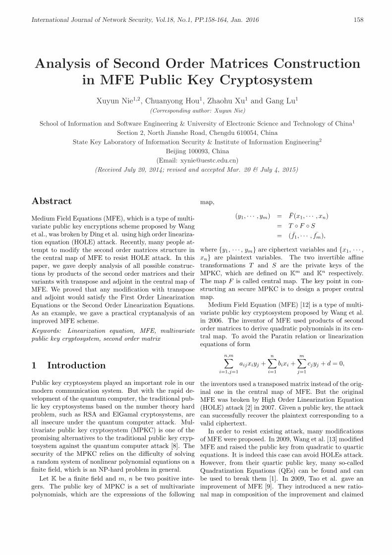
International Journal of Network Security, Vol.18, No.1, PP.158-164, Jan. 2016 158
Analysis of Second Order Matrices Constructionin MFE Public Key Cryptosystem
Xuyun Nie1,2, Chuanyong Hou1, Zhaohu Xu1 and Gang Lu1
(Corresponding author: Xuyun Nie)
School of Information and Software Engineering & University of Electronic Science and Technology of China1
Section 2, North Jianshe Road, Chengdu 610054, ChinaState Key Laboratory of Information Security & Institute of Information Engineering2
Beijing 100093, China(Email: [email protected])
(Received July 20, 2014; revised and accepted Mar. 20 & July 4, 2015)
Abstract
Medium Field Equations (MFE), which is a type of multi-variate public key encryptions scheme proposed by Wanget al., was broken by Ding et al. using high order lineariza-tion equation (HOLE) attack. Recently, many people at-tempt to modify the second order matrices structure inthe central map of MFE to resist HOLE attack. In thispaper, we gave deeply analysis of all possible construc-tions by products of the second order matrices and theirvariants with transpose and adjoint in the central map ofMFE. We proved that any modification with transposeand adjoint would satisfy the First Order LinearizationEquations or the Second Order Linearization Equations.As an example, we gave a practical cryptanalysis of animproved MFE scheme.Keywords: Linearization equation, MFE, multivariatepublic key cryptosystem, second order matrix
1 Introduction
Public key cryptosystem played an important role in ourmodern communication system. But with the rapid de-velopment of the quantum computer, the traditional pub-lic key cryptosystems based on the number theory hardproblem, such as RSA and ElGamal cryptosystems, areall insecure under the quantum computer attack. Mul-tivariate public key cryptosystem (MPKC) is one of thepromising alternatives to the traditional public key cryp-tosystem against the quantum computer attack [8]. Thesecurity of the MPKC relies on the difficulty of solvinga random system of nonlinear polynomial equations on afinite field, which is an NP-hard problem in general.
Let K be a finite field and m, n be two positive inte-gers. The public key of MPKC is a set of multivariatepolynomials, which are the expressions of the following
map,
(y1, · · · , ym) = F (x1, · · · , xn)= T F S
= (f1, · · · , fm),
where y1, · · · , ym are ciphertext variables and x1, · · · ,xn are plaintext variables. The two invertible affinetransformations T and S are the private keys of theMPKC, which are defined on Km and Kn respectively.The map F is called central map. The key point in con-structing an secure MPKC is to design a proper centralmap.
Medium Field Equation (MFE) [12] is a type of multi-variate public key cryptosystem proposed by Wang et al.in 2006. The inventor of MFE used products of secondorder matrices to derive quadratic polynomials in its cen-tral map. To avoid the Paratin relation or linearizationequations of form
n,m∑
i=1,j=1
aijxiyj +n∑
i=1
bixi +m∑
j=1
cjyj + d = 0,
the inventors used a transposed matrix instead of the orig-inal one in the central map of MFE. But the originalMFE was broken by High Order Linearization Equation(HOLE) attack [2] in 2007. Given a public key, the attackcan successfully recover the plaintext corresponding to avalid ciphertext.
In order to resist existing attack, many modificationsof MFE were proposed. In 2009, Wang et al. [13] modifiedMFE and raised the public key from quadratic to quarticequations. It is indeed this case can avoid HOLEs attack.However, from their quartic public key, many so-calledQuadratization Equations (QEs) can be found and canbe used to break them [1]. In 2009, Tao et al. gave animprovement of MFE [9]. They introduced a new ratio-nal map in composition of the improvement and claimed

International Journal of Network Security, Vol.18, No.1, PP.158-164, Jan. 2016 159
that the new scheme can resist SOLEs attack. But thereare still many SOLEs existing in this new scheme. Givena public key and a valid ciphertext, we can recover itscorresponding plaintext [14]. In 2009, Huang et al. gavean improvement of MFE by redesigning the central mapwith transpose matrix and adjoint matrix [3]. After the-oretical analysis, we found that it satisfied both SecondOrder Linearization Equations (SOLEs) and First OrderLinearization Equations (FOLEs) [6].
In this paper, we summarize the steps of HOLEs at-tack. And then, we analyzed the construction based onthe second order matrices in the central map of MFE. Wefound that if one want to remain degree two polynomi-als in the public key and ensure successfully decryption,one could only use the transpose matrices and the ad-joint matrices. Given a second order matrix M over afinite field of characteristic 2, there are only 8 second or-der matrices with the same determinant of M . And these8 matrices can be separated into two equivalent class withthe matrix M and its transpose MT . We list all possibleconstructions with a matrix M and its transpose MT inthe form of multiplication of two matrices. We found thatall constructions will satisfy the SOLEs or FOLEs. So itis impossible to improve MFE by changing the form ofsecond order matrices with their transpose and adjoint.
At last, we show how to find FOLEs satisfied by an im-provement of MFE scheme [3] proposed by Jiasen Huanget al. After finding all the FOLEs, we use linearizationequation attack breaking this improved version.
This paper is organized as follows. We introduce theMFE scheme, the idea of HOLEs attack on it and animprovement of MFE in Section 2. In Section 3, we givean analysis of the structure of the second order matricesin MFE scheme. Then we present a FOLEs attack on animprovement of MFE in Section 4. Finally, we concludethis paper in Section 5.
2 Preliminaries
In this section, we will introduce the MFE public keycryptosystem and the previous attack on MFE. Then, wewill introduce one modification of MFE.
2.1 MFE Public Key Cryptosystem
We use the same notations as in [12]. Let K be a finitefield of characteristic 2 and L be its degree r extensionfield. In MFE, we always identify L with Kr by a K-linearisomorphism π: L → Kr. Namely we take a basis of LoverK, θ1, · · · , θr, and define π by π(a1θ1+· · ·+arθr) =(a1, · · · , ar) for any a1, · · · ar ∈ K. It is natural to extendπ to two K-linear isomorphisms π1: L12 → K12r and π2:L15 → K15r.
In MFE, its encryption map F : K12r → K15r is acomposition of three maps φ1, φ2, φ3. Let
(u1, · · · , u12r) = φ1(x1, · · · , x12r),
(v1, · · · , v15r) = φ2(u1, · · · , u12r),
(y1, · · · , y15r) = φ3(v1, · · · , v15r),
where φ1 and φ3 are invertible affine maps, φ2 is its centralmap, which is equal to π1 φ2 π−1
2 .φ1 and φ3 are taken as the private key, while the ex-
pression of the map (y1, · · · , y15r) = F (x1, · · · , x12r) isthe public key.The map φ2: L12 → L15 is defined as fol-lows.
Y1 = X1 + X5X8 + X6X7 + Q1;Y2 = X2 + X9X12 + X10X11 + Q2;Y3 = X3 + X1X4 + X2X3 + Q3;Y4 = X1X5 + X2X7; Y5 = X1X6 + X2X8;Y6 = X3X5 + X4X7; Y7 = X3X6 + X4X8;Y8 = X1X9 + X2X11; Y9 = X1X10 + X2X12;Y10 = X3X9 + X4X11; Y11 = X3X10 + X4X12;Y12 = X5X9 + X7X11; Y13 = X5X10 + X7X12;Y14 = X6X9 + X8X11; Y15 = X6X10 + X8X12,
where Q1, Q2, and Q3 form a triple (Q1, Q2, Q3) whichis a triangular map from K3r to itself, more detail pleasesee [12].
The method of computing φ−12 is listed as follows:
Write X1, · · · , X12, Y4, · · · , Y15 as six 2× 2 matrices:
M1 =(
X1 X2
X3 X4
)
M2 =(
X5 X6
X7 X8
)
M3 =(
X9 X10
X11 X12
)
Z3 = M1M2 =(
Y4 Y5
Y6 Y7
)
Z2 = M1M3 =(
Y8 Y9
Y10 Y11
)
Z1 = MT2 M3 =
(Y12 Y13
Y14 Y15
).
Then
det(M1) · det(M2) = det(Z3),det(M1) · det(M3) = det(Z2),det(M2) · det(M3) = det(Z1).
When M1, M2, and M3 are all invertible, we can getvalues of det(M1), det(M2), and det(M3) from det(Z1),det(Z2), and det(Z3), for instance, det(M1) =
(det(Z2) ·
det(Z3)/det(Z1))1/2.
With the values of det(M1), det(M2), and det(M3),we can use the triangular form of the central map to getX1, X2, · · · , X12 in turn. Then we can recover the plain-text corresponding the given ciphertext. More detail ofdecryption are presented in [12].

International Journal of Network Security, Vol.18, No.1, PP.158-164, Jan. 2016 160
2.2 High Order Linearization Equation
High Order Linearization Equation (HOLE) is an type ofequation of the following form:
n,t∑i=1,j=1
aijxigj(y1, y2, · · · , ym)
+l∑
k=1
ckhk(y1, y2, · · · , ym) + d = 0,
(1)
where hk, 1 ≤ k ≤ l, gj , 1 ≤ j ≤ t, are polynomialfunctions in the ciphertext variables. The highest degreeof gj , 1 ≤ j ≤ l and hk, 1 ≤ k ≤ l is called the order ofthe HOLE.
For example, the First Order Linearization Equation(FOLE) and the Second Order Linearization Equation(SOLE) are of the following forms, respectively.
n,m∑
i=1,j=1
aijxiyj +n∑
i=1
bixi +m∑
j=1
cjyj + d = 0.
∑
i
xi
∑
j≤k
aijkyjyk +∑
j
bijyj + ci
+∑
j≤k
djkyjyk +∑
ejyj + f = 0.
Note that, given a valid ciphertext y′ = (y′1, y′2, · · · , y′m),
we can substitute it into Equation (1) to get a linear equa-tion in the plaintext variables. By finding all these equa-tions we get a linear system in the plaintext variables,which can be solved by Gaussian Elimination. After hav-ing found a solution, we can do elimination on the publickey or solve System (2).
F1(x1, · · · , xn) = y′1;· · ·
Fm(x1, · · · , xn) = y′m.(2)
Then, we can also check whether there are some HOLEssatisfied by the eliminated public key and the form ofHOLEs.
The steps of LE attack are listed in Algorithm 1.
2.3 Previous Attack on MFE
In designing the MFE scheme, the inventors have takeninto account the LE attack. They used MT
2 instead of M2
to avoid the FOLEs.But Ding et al. found that there are many SOLEs
satisfied by the MFE scheme. Denote by M∗ the adjointmatrix of a second order matrix. From
Z3 = M1M2, Z2 = M1M3,
we have
M3M∗3 M∗
1 M1M2 = M3Z∗2Z3 = det(Z2)M2. (3)
Expanding Equation (3), we get four equations of the form∑
a′ijkXiYjYk = 0. (4)
Algorithm 1 Steps of LE Attack1: Input: public key F of a MPKC, ciphertext y′ ∈ Km
2: Output: corresponding plaintext x′ ∈ Kn
3: Check whether there are some LEs satisfied by publickey.
4: Determine the form of LEs and find all the LEs.5: Substitute the ciphertext y′ into the linearization
equations and find all linear equations in the plaintextvariables. Solve the system to find linear relations be-tween plaintext variables. In other words, some plain-text variables can be written as linear expressions inthe remaining variables.
6: Substitute the linear expressions of plaintext variablesinto the public key polynomials to get a ”eliminated”public key expression (it is in fewer unknown plaintextcomponents).
7: Check whether there are some LEs satisfied by theeliminated public key. If there are, goto Step 2.
8: Directly solve the last eliminated System (2).9: Use the linear relations between plaintext variables to
get the values of remained plaintext components.
In [2], 24 equations of this form can be found.Substituting (X1, · · · , X12) = π−1
1 φ1(x1, · · · , x12r)and (Y1, · · · , Y15) = π−1
2 φ−13 (y1, · · · , y15r) into Equa-
tion (4), we get 24r equations of the form
∑i
xi
(∑j≤k
aijkyjyk +∑j
bijyj + ci
)
+∑j≤k
djkyjyk +∑j
ejyj + f = 0.
These equations are SOLEs.Given a public key and a valid ciphertext, after find-
ing all the SOLEs, one can recovered the correspondingplaintext efficiently.
2.4 Improvement of MFE
To avoid the SOLE, Jiasen Huang et al. proposed a modi-fication of MFE. They modified only the matrix equationsas follows.
M1, M2 and M3 are defined as same as the origin MFE,while Z1, Z2 and Z3 are defined as follows:
Z3 = M1M∗2 =
(Y4 Y5
Y6 Y7
),
Z2 = M∗1 M3 =
(Y8 Y9
Y10 Y11
),
Z1 = MT2 M∗
3 =(
Y12 Y13
Y14 Y15
),
where M∗i (1 ≤ i ≤ 3) are the adjoint matrices of M∗
i .These matrices are also satisfied
det(M1) · det(M2) = det(Z3),det(M1) · det(M3) = det(Z2),det(M2) · det(M3) = det(Z1).

International Journal of Network Security, Vol.18, No.1, PP.158-164, Jan. 2016 161
so the decryption process is very similar to the originalMFE. See [3] for more detail.
3 Analysis of the Structure Basedon Second Order Matrices
In this section, we consider the second order matrices overa finite field K of characteristic 2.
In order to resist HOLE, many people try to improvethe MFE scheme by modifying the second order matricesof the central map. To ensure the decryption successfully,they need keep the determinants unchanged.
Now we give two Propositions on the constructions byusing the second order matrices.
Proposition 1. Given a square matrix M =(X1 X2
X3 X4
), where X1, X2, X3, X4 ∈ K, there are eight
square matrices which satisfy:
1) Components in these matrices are all constituted ofX1, X2, X3, X4 ∈ K;
2) The determinants of these matrices are equal todet(M).
And all matrices above can be transformed by M or MT
through row transformations and column transformations.
Proof: Given X1, X2, X3, X4 ∈ K of characteristic 2,there are 24 different matrices. We can calculate theirdeterminate one by one. Clearly, there are eight matri-ces (including the matrix M) whose determinate equal todet(M). We list as follows:
(X1 X2
X3 X4
),
(X2 X1
X4 X3
),
(X3 X4
X1 X2
),
(X4 X3
X2 X1
),
(X1 X3
X2 X4
),
(X2 X4
X1 X3
),
(X4 X2
X3 X1
),
(X3 X1
X4 X2
).
Among the matrices above, the first four matrices canbe easily derived from the matrix M through row trans-formation and column transformation. And the last fourmatrices can be gotten from MT .
Let us consider the following equations:
Y4 = X1X5 + X2X7;Y5 = X1X6 + X2X8;Y6 = X3X5 + X4X7;Y7 = X3X6 + X4X8.
(5)
The Equation (5) can be expressed by the following
four matrices equations.(
Y4 Y5
Y6 Y7
)=
(X1 X2
X3 X4
)(X5 X6
X7 X8
),
(Y4 Y5
Y6 Y7
)=
(X2 X1
X4 X3
)(X7 X8
X5 X6
),
(Y6 Y7
Y4 Y5
)=
(X3 X4
X1 X2
)(X5 X6
X7 X8
),
(Y6 Y7
Y4 Y5
)=
(X4 X3
X2 X1
)(X7 X8
X5 X6
).
So, we can say that the matrices(
X2 X1
X4 X3
),
(X3 X4
X1 X2
),
(X4 X3
X2 X1
)are equivalent to the ma-
trix(
X1 X2
X3 X4
).
Similarly, the matrices(
X2 X4
X1 X3
),
(X4 X2
X3 X1
),
(X3 X1
X4 X2
)are equivalent to the matrix
(X1 X3
X2 X4
).
Notice that the matrix(
X4 X2
X3 X1
)is the adjoint ma-
trix of the matrix(
X1 X2
X3 X4
). So, we can only consider
a matrix and its transpose in the matrices form of the cen-tral map in MFE.
Proposition 2. Given a square matrix M =(X1 X2
X3 X4
), where X1, X2, X3, X4 ∈ K. Mi, i =
1, · · · , 4 are random second order matrices on finite fieldK, define a set as follows:
Q = MM1,M2M,MT M3,M4MT ,
then any two elements in Q can be deduced high orderlinearization equations in constructing the central map inMFE.
Proof: There are 6 forms of combination (Z1, Z2) in Q,we analysis of them respectively.
1) If Z1 = MM1, Z2 = M2M , we can derive
Z2M1 = M2Z1;
2) If Z1 = MM1, Z2 = MT M3, we can derive
ZT2 M1 = MT
3 Z1;
3) If Z1 = MM1, Z2 = M4MT , we can derive
det(Z2)M1 = MT4 (ZT
2 )∗Z1;
4) If Z1 = M2M,Z2 = MT M3, we can derive
det(Z1)(MT3 )∗ = M∗
2 Z1(ZT2 )∗;

International Journal of Network Security, Vol.18, No.1, PP.158-164, Jan. 2016 162
5) If Z1 = M2M, Z2 = M4MT , we can derive
Z1MT4 = M2Z
T2 ;
6) If Z1 = MT M3, Z2 = M4MT , we can derive
Z2M3 = M4Z1;
In Cases 1), 2), 5), and 6), we can derive FOLEs. In Cases3) and 4), we can derive SOLEs.
The original MFE scheme satisfied Case 3) and 4) inthe proof of Proposition 2.
As to the improved MFE, the matrices equation Z2 =M∗
1 M3 can be changed into(
Y10 Y11
Y8 Y9
)=
(X1 X3
X2 X4
)(X11 X12
X9 X10
).
This equation and Z3 = M1M∗2 satisfy Case 2). Simi-
larly, according to the Proposition 1, we can deduce thatthe central map of the improved MFE scheme satisfyCases 1), 5) and 6).
From Proposition 1 and Proposition 2 above, we canmake sure that all the modifications of MFE by changingthe form of matrices in MFE with their transpose andadjoint will fail to resist the HOLEs attack.
4 Linearization Equation Attackon Improvement of MFE
In this section, we give an example of Linearization Attackon Improvement of MFE. This work was presented on The10th International Conference on Cryptology and Net-work Security (CANS 2011). The authors of [3] claimedtheir improvement of MFE can resist SOLEs attack. Butaccording to Section 3, we know that this scheme satisfiedthe FOLEs. In this section, we will describe how to getthe FOLEs and present the whole FOLE attack on thisimprovement.
4.1 Finding FOLEs
Note that, for any square matrices M1 and M2, we have
(M∗1 )∗ = M1,
(M1M2)∗ = M∗2 M∗
1 ,
(M∗1 )T = (MT
1 )∗.
FromZ3 = M1M
∗2 , Z2 = M∗
1 M3
we can derive
M∗3 Z3 = M∗
3 M1M∗2 = (M∗
1 M3)∗M∗2 = Z∗2M∗
2
and hence,Z∗2M∗
2 = M∗3 Z3
Expanding it, we have(
Y11 −Y9
−Y10 Y8
)(X8 −X6
−X7 X5
)
=(
X12 −X10
−X11 X9
)(Y4 Y5
Y6 Y7
).
That is,
X8Y11 + X7Y9 = X12Y4 −X10Y6
−X6Y11 −X9Y5 = X12Y5 −X10Y7
−X8Y10 −X7Y8 = −X11Y4 + X9Y6
X6Y10 + X5Y8 = −X11Y5 + X9Y7.
(6)
Applying (X1, · · · , X12) = π1 φ1(x1, · · · , x12r) and(Y1, · · · , Y15) = π−1
2 φ−13 (y1, · · · , y15r) into Equation (6),
we get 4r equations of the form∑
i,j
aijxiyj +∑
i
bixi +∑
j
cjyj + d = 0, (7)
where the coefficients aij , bi, cj , d ∈ K, and the summa-tions are respectively over 1 ≤ i ≤ 12r and 1 ≤ j ≤ 15r.These equations are FOLEs. Apparently, these 4r equa-tions are linearly independent.
Using the same technique, we can derive other 8rSOLEs. Note that
Z1M1 = MT2 M∗
3 M1 = MT2 Z∗2
Z∗1MT1 = (MT
2 M∗3 )∗MT
1 = M3(MT2 )∗MT
1
= M3(M∗2 )T MT
1 = M3ZT3 .
That is,
Z1M1 = MT2 Z∗2
Z∗1MT1 = M3Z
T3 .
Expanding them and substituting (X1, · · · , X12) =π1 φ1(u1, · · · , u12r) and (Y1, · · · , Y15) = π−1
2 φ−1
3 (z1, · · · , z15r) into them, we get another linearly in-dependent 8r FOLEs.
To find all the FOLEs, we randomly generate sufficientplaintext/ciphertext pairs and substitute them into theFOLE to get a system of linear equations on the unknowncoefficients a1,1, · · · , a12r,15r, b1, · · · , b12r, c1, · · · , c15r, d.In this case, the number of unknown coefficients in theseequations is equal to
12r × 15r + 12r + 15r + 1 = 180r2 + 27r + 1.
Suppose we derive D linearly independent FOLEs. LetEk(1 ≤ k ≤ D) denote these equations:
12r,15r∑
i=1,j=1
a(k)ij xiyj +
12r∑
i=1
b(k)i xi +
15r∑
j=1
c(k)j yj + d(k) = 0.
We used computer experiments to find all linearizationequations. In one of our experiments, we choose K =GF (216), r = 4. In this case, the number of unknowncoefficients is equal to 2989.
Our experiments show that it take about 22 minuteson the execution of this step. And D = 48.
Note that, this step is independent of the value of theciphertext and can be done once for a given public key.

International Journal of Network Security, Vol.18, No.1, PP.158-164, Jan. 2016 163
4.2 Ciphertext-only Attack
Now we have derived all FOLEs. Our goal is to find cor-responding plaintext (x′1, · · · , x′12r) for a given valid ci-phertext (y′1, · · · , y′15r).
Substitute (y′1, · · · , y′15r) into basis equations Ek, wecan get k equations in following form:
∑i,j
a(k)ij xiy
′j +
∑i
b(k)i xi +
∑j
c(k)j y′j + d(k) = 0
1 ≤ k ≤ D.(8)
Suppose the dimension of the basis of System (8) so-lution space is s. Then, we can represent s variables ofx1, · · · , x12r by linear combinations of other 12r− s. De-note w1, · · · , w12r−s are remainder variables. Our exper-iments show s = 32, when r = 4.
Now substitute the expressions obtained above intoFj(x1, · · · , x12r), we can get 15r new quadratic functionsFj(w1, · · · , w12r−s), j = 1, · · · , 12r. Then, our attackturn to solve the following system:
Fi(w1, · · ·w12r−s) = y′i1 ≤ i ≤ 15r.
(9)
There are 4r unknowns and 15r equations in Sys-tem (9). We can solve this system by Grobner basismethod and recover the corresponding plaintext.
Our experiments show that it takes about 6 second tosolve System (9) and our experiments recover the corre-sponding plaintext successfully.
All of our experiments were performed on a normalcomputer, with Genuine Intel(R) CPU [email protected],504MB RAM by magma.
5 Conclusion
In this paper, we verified that all modifications of MFE bychanging the form of matrices with transpose and adjointwill satisfy the SOLEs or FOLEs. Hence, they are allinsecure.
In order to enhance the security of MPKCs, manyenhancement methods were proposed such as Piece inhand [10], Extended Multivariate public key Cryptosys-tems (EMC) [11] etc. All of these methods are subjectedto different levels of attacks [4, 5]. Recently, Qiao pro-posed three security enhancement methods on MPKC [7].The security of their methods will be considered in the fu-ture.
Acknowledgments
This work was supported by the National Key BasicResearch Program of China under grant 2013CB834203,the National Natural Science Foundation of China undergrant No. 61370026, 61472064. The authors gratefullyacknowledge the anonymous reviewers for their valuablecomments.
References
[1] W. W. Cao, X. Y. Nie, L. Hu, X. L. Tang, andJ. T. Ding, “Cryptanalysis of two quartic encryp-tion schemes and one improved mfe scheme,” inProceedings of The Third International Workshop(PQCrypto’10), pp. 41–60, Darmstadt, Germany,May 2010.
[2] J. T. Ding, L. Hu, X. Y. Nie, J. Y. Li, and J. Wag-ner, “High order linearization equation (hole) at-tack on multivariate public key cryptosystems,” inProceedings of The 10th International Conferenceon Practice and Theory in Public-Key Cryptography(PKC’07), pp. 233–248, Beijing, China, Apr. 2007.
[3] J. S. Huang, B. D. Wei, and H. Y. Ou, “An im-proved MFE scheme resistant against sole attacks,”in Proceedings of Asia Pacific Conference on Post-graduate Research in Microelectronics and Electron-ics (PrimeAsia’09), pp. 157–160, Shanghai, China,Jan. 2009.
[4] X. Y. Nie, A. Petzoldt, J. Buchmann, and F. G. Li,“Linearization equation attack on 2-layer nonlinearpiece in hand method,” IEICE Transactions on Fun-damentals, vol. E97-A, no. 9, pp. 1952–1961, 2014.
[5] X. Y. Nie, Z. H. Xu, and J. Buchmann, “Cryptanal-ysis of hash-based tamed transformation and minussignature scheme,” in Proceedings of The 5th Inter-national Workshop on Post-Quantum Cryptography(PQCrypto’13), pp. 115–164, Limoges, France, June2013.
[6] X. Y. Nie, Z. H. Xu, L. Lu, and Y. J. Liao, “Se-curity analysis of an improved MFE public keycryptosystem,” in Proceedings of The 10th Interna-tional Conference on Cryptology and Network Secu-rity (CANS’11), pp. 118–125, Sanya, China, Dec.2011.
[7] S. T. Qiao, W. B. Han, Y. F. Li, and L. Y. Jiao,“Construction of extended multivariate public keycryptosystems,” International Journal of NetworkSecurity, vol. 18, no. 1, pp. 60–67, 2016.
[8] P. W. Shor, “Polynomial-time algorithms for primefactorization and discrete logarithms on a quantumcomputer,” SIAM Review, vol. 41, no. 2, pp. 303–332, 1999.
[9] H. W. Tao and Y. X. Chen, “An improved medium-field multivariate public-key encryption scheme,”in Proceedings of The International Conference onComputational Intelligence and Software Engineer-ing, pp. 1–4, Wuhan, China, Dec. 2009.
[10] S. Tsujii, K. Tadaki, R. Fujita, M. Gotaishi, andT. Kaneko, “Security enhancement of various mpkcsby 2-layer nonlinear piece in hand method,” IEICETransactions on Fundamentals, vol. E92-A, no. 10,pp. 2438–2447, 2009.
[11] H. Z. Wang, H. G. Zhang, Z. Y. Wang, and M. Tang,“Extended multivariate public key cryptosystemswith secure encryption function,” Science China In-formation Sciences, vol. 54, no. 6, pp. 1161–1171,2011.
International Journal of Network Security, Vol.18, No.1, PP.158-164, Jan. 2016 164
[12] L. C. Wang, B. Y. Yang, Y. H. Hu, and F.P.Lai, “Medium-field multivariate public key encryp-tion scheme,” in Proceedings of The Cryptographers’Track at the RSA Conference, pp. 132–149, San Jose,CA, USA, Feb. 2006.
[13] X. Wang, F. Feng, X. M. Wang, and Q. Wang, “Amore secure mfe multivariate public key encryptionscheme,” International Journal of Computer Scienceand Applications, vol. 6, no. 3, pp. 1–9, 2009.
[14] Z. H. Xu, X. Y. Nie, H. Wang, and Y. J. Liao,“Cryptanalysis of an improved mfe public key cryp-tosystem,” International Journal of Security andNetworks, vol. 7, no. 3, pp. 174–180, 2012.
Xuyun Nie received the Ph.D. degree in Informationsecurity from Graduate university of Chinese Academyof Sciences, Beijing, China, in 2007. He is presently anAssociate Professor at University of Electronic Scienceand Technology of China (UESTC). His research interestsinclude cryptography and information security.
Chuanyong Hou received his Master Degree fromUniversity of Electronic Science and Technology of Chinain 2015. His research interests include cryptography andnetwork security.
Zhaohu Xu received his Master Degree from Universityof Electronic Science and Technology of China in 2013.His research interests include multivariate public keycryptography and network security.
Gang Lu is a PH.D candidate in University of ElectronicScience and Technology of China now. His research inter-ests include cryptography and security of big data.
International Journal of Network Security, Vol.18, No.1, PP.165-171, Jan. 2016 165
Cryptanalysis of an Identity Based SigncryptionScheme in the Standard Model
Yang Ming1, Yumin Wang2
(Corresponding author: Yang Ming)
School of Information Engineering, Chang’an University1
Xi’an, Shaanxi 710064, China
State Key Laboratory of ISN, Xidian University2
Xi’an, Shaanxi 710071, China
(Email: [email protected], [email protected])
(Received Sept. 9, 2013; revised and accepted Jan 10 & May 25, 2014)
Abstract
Identity based signcryption (IBSC) is a novel crypto-graphic primitive that simultaneously provides the au-thentication and encryption in a single logic step. TheIBSC has been shown to be useful in many applications,such as electronic commerce, mobile communications andsmart cards. Recently, Li et al. (2013) [16] proposeda new identity based signcryption scheme and claimedthat their scheme was provably secure in the standardmodel, i.e. (IND-IBSC-CCA2) semantically secure un-der adaptively chosen-ciphertext attack and (EUF-IBSC-CMA) existential unforgeable under adaptively chosen-message. However, in this paper, by giving concrete at-tacks, we show that Li et al’s scheme is not secure in theirsecurity model. Additionally, we further indicate that Liet al’s scheme also does not satisfy strongly existentialunforgeability.
Keywords: Existential unforgeability, identity-based sign-cryption, semantically security, signcryption, standardmodel
1 Introduction
Confidentiality, integrity, non-repudiation and authenti-cation are the important requirements for cryptographicapplications. A traditional approach to achieve these re-quirements is to sign-then-crypt the message. The con-cept of signcryption was first proposed by Zheng [31]. Theidea of this kind of primitive is to perform signature andencryption simultaneously in order to reduce the compu-tational costs and communication overheads.
The concept of identity-based (simply ID-based) pub-lic key cryptography (ID-PKC) was introduced byShamir [22] in 1984, which simplifies key managementprocedure of traditional certificate-based public key cryp-tography. The main idea of ID-PKC is that the user’s
public key can be calculated directly from his/her identitysuch as email addresses rather than being extracted froma certificate issued by a certificate authority (CA). Privatekeys are generated for the users by a trusted third party,called Private Key Generator (PKG) using some masterkey related to the global parameters for the system. Thedirect derivation of public keys in ID-PKC eliminates theneed for certificates and some of the problems associatedwith them.
Lee present the first identity based signcryption (IBSC)scheme [18]. Since then, many identity based sign-cryption schemes were proposed [1, 3, 6, 7, 8, 15, 17].To offer strong security guarantee, provable security isvery essential for IBSC schemes. However, the earlyschemes [1, 3, 6, 7, 8, 15, 17, 18, 23, 27] use random ora-cle model to achieve the security requirement. The ran-dom oracle model was introduced by Bellare and Rogawayin [2]. The model is a formal model in analyzing crypto-graphic schemes, where a hash function is considered asa black-box that contains a random function. Althoughthe model is efficient and useful, it has received a lot ofcriticism that the proofs in the random oracle model arenot proofs. Canetti et al. [5] have shown that securityin the random oracle model does not imply the securityin the real world in that a scheme can be secure in therandom oracle model and yet be broken without violat-ing any particular intractability assumption, and withoutbreaking the underlying hash functions.
Recently many efforts have been made to design prov-ably secure IBSC scheme in the standard model (with-out using random oracles). In 2009, based on Watersscheme [26], Yu et al. [28] proposed the first identity basedsigncryption scheme without random oracles. However,in 2010, Wang and Qian [24], Jin et al. [10], Zhang [29]and Zhang et al. [30] independently pointed out that Yuet al.’s scheme [28] cannot achieve indistinguishabilityagainst chosen plaintext attacks. To remedy the secu-rity problem, Jin et al. [10] and Zhang [29] proposed im-

International Journal of Network Security, Vol.18, No.1, PP.165-171, Jan. 2016 166
proved IBSC schemes, respectively. Meanwhile, Ren andGu [19] proposed a signcryption scheme based on Gentry’sIBE [9] but it was shown by Wang et al. [25] that it hadneither confidentiality nor existential unforgeability. In2011, Li et al. [11] showed that the scheme in [10] satisfiesneither confidentiality nor existentially unforgeability. Liand Takagi [14] further pointed out that the IBSC schemein [10, 29] did not have the IND-CCA2 property (not evenchosen plaintext attacks (IND-CPA)) and then present afully secure IBSC scheme in the standard model. Li etal. also proposed anther two IBSC schemes [12, 13] in thestandard model. But Selvi et al. [20] have also shown thatLi et al’s schemes [12, 13, 14] are not secure in the stan-dard model. In 2012, Selvi et al. [21] presented the firstprovably secure ID based signcryption scheme in the stan-dard model. This scheme satisfied the strongest notions ofsecurity available for the ID based signcryption schemes.In 2013, Li et al. [16] proposed a new identity-based sign-cryption scheme and claimed that their scheme is provento be semantically secure under chosen-ciphertext attackand unforgeable under chosen-message attack in the stan-dard model.
In this paper, using concrete attacks, we show thatthe Li et al’s ID-based signcryption scheme [16] is notsemantically secure under chosen-ciphertext attack andunforgeable under chosen-message attack. In addition,we indicate that this scheme is not strongly existentiallyunforgeable also.
2 Preliminaries
In this section, we briefly review the basic concepts onbilinear pairings, the formal definition and security modelof identity based signcryption scheme.
2.1 Bilinear Pairings
Let G and GT be two multiplicative cyclic groups of primeorder p and let g be a generator of G. The map e: G×G→GT is said to be an admissible bilinear pairing with thefollowing properties:
1) Bilinearity: e(ua, vb) = e(u, v)ab for all u, v ∈ Gand for all a, b ∈ Zp.
2) Non-degeneracy: e(g, g) 6= 1G.
3) Computability: There exists an efficient algorithmto compute e(u, v) for all u, v ∈ G.
We note the modified Weil and Tate pairings associatedwith supersingular elliptic curves as examples of such ad-missible pairings.
2.2 Definition of Identity Based Sign-cryption
An identity based signcryption scheme consists of the fol-lowing four functions:
Setup. Given a security parameter k, the privatekey generator (PKG) generates system parametersparams and a master key msk. params is madepublic while msk is kept secret.
Extract. Given an identity u, the PKG computes thecorresponding private key du and transmits it to uvia a secure channel.
Signcrypt. Given a message M , the sender’s private keyds, and the receiver’s identity ur, the sender com-putes Signcrypt(M,ds, ur) to obtain the ciphertextσ.
Unsigncrypt. When receiving σ, the receiver with iden-tity ur computes Unsigncrypt(σ, dr, us) and ob-tains the plaintext M or the symbol ⊥ if σ is aninvalid ciphertext between identities us and ur.
2.3 Security Model of Identity BasedSigncryption
Based on Malone-Lee model [18], Li et al. [16] defined thesecurity notions for identity based signcryption scheme.The notions are semantically secure (i.e. indistinguisha-bility against adaptive chosen ciphertext attacks, IND-IBSC-CCA2) and existentially unforgeable against adap-tive chosen messages attacks (EUF-IBSC-CMA).
Confidentiality Game: For confidentiality, we considerthe following game played between a challenger C andan adversary A.
Setup. The challenger C takes a security parameter kand runs Setup algorithm to generate system pa-rameters params and the master key msk. Then Csends params to A and keeps msk secret.
Phase 1. The adversary A can perform a polynomiallybounded number of the following queries. Thesequeries may be made adaptive, i.e. each query maydepend on the answers to the previous queries.
Extract Queries. The adversary A chooses an identityu, C computes du = Extract(u) and sends du to A.
Signcrypt Queries. The adversary A produces asender’s identity us, the receiver’s identity ur anda plaintext M . C computes ds = Extract(us) andσ = Signcrypt(M,ds, ur) and sends σ to A.
Unsigncrypt Queries. The adversary A produces asender’s identity us, the receiver’s identity urand a ciphertext σ. C generates the privatekey dr = Extract(ur) and sends the result ofUnsigncrypt(σ, dr, us) to A.
Challenge. The adversary A decides when phase 1 ends.A chooses two equal length plaintexts M0 and M1,a sender’s identity u∗s and the receiver’s identityu∗r on which to be challenged. The identity u∗r

International Journal of Network Security, Vol.18, No.1, PP.165-171, Jan. 2016 167
should not appear in any extract queries in phase1. C chooses randomly a bit b, computes σ∗ =Signcrypt(Mb, d
∗s, u∗r) and sends σ∗ to A.
Phase 2. The adversary A makes a polynomial numberof queries adaptively again as in phase 1 with therestriction that it cannot make extract query on u∗rand cannot make an unsigncrypt query on σ∗ underu∗r .
Guess. The adversary A produces a bit b′ and wins thegame if b′ = b.
The advantage of A is defined as AdvEnc(A) =2|Pr[b′ = b]− 1|, where Pr[b′ = b] denotes the probabilitythat b′ = b.
Definition 1. (Confidentiality): An identity based sign-cryption scheme is said to have the indistinguishabil-ity against adaptive chosen ciphertext attacks (IND-IBSC-CCA2) or semantically security if no polynomiallybounded adversary has a non-negligible advantage in theconfidentiality game.
Unforgeability Game: For unforgeability, we considerthe following game played between a challenger C andan adversary A.
Setup. The challenger C runs the Setup algorithm witha security parameter k obtains system parametersparams and the master secret key msk. C sendsparams to A.
Queries. The adversary A performs polynomiallybounded number of queries adaptively just like inthe confidentiality game.
Forgery. Finally, the adversary A produces a forgery(σ∗, u∗s, u
∗r). We say A wins the game if the following
are satisfied.
1) The ciphertext σ∗ is valid.
2) The private key of u∗s was not asked in the ex-tract queries.
3) The ciphertext σ∗ is not returned during thesigncrypt queries.
The advantage of A is defined as the probability ofsuccess in winning the above game.
Definition 2. (Unforgeability) An identity based sign-cryption scheme is said to have the existentially un-forgeable against adaptive chosen message attacks (EUF-IBSC-CMA) if no polynomially bounded adversary has anon-negligible advantage in the unforgeability game.
3 Review of Li et al. IdentityBased Signcryption Scheme
In this section, we review Li et al.’s identity based sign-cryption scheme [16]. This scheme consists of the follow-ing four functions.
Setup. Let (G,GT ) be bilinear groups such that |G| =|GT | = p for some prime p, and let g be a genera-tor of G. Given a bilinear map e : G × G → GTand a collision-resistant hash function H : 0, 1∗ →0, 1nm , the private key generator (PKG) randomlychooses α ∈ Z∗p and computes g1 = gα. In addi-tion, the PKG randomly picks up g2, u
′,m′ ∈ G andtwo vectors −→u = (ui),
−→m = (mi) of length andnu, nm, respectively. The system parameters areparams = (G,GT , e,H, g, g1, g2, u
′,m′,−→u ,−→m) andthe master key is msk = gα2 .
Extract. Let U ⊂ 1, · · ·, nu be the set of indices suchthat u[i] = 1, where u[i] is the i-th bit of u. Givenan identity u, PKG randomly picks up ku ∈ Z∗p andcomputes
du = (du1, du2) =
(gα2 (u′
∏i∈U
ui)ku , gku
).
Suppose that the strings us and ur of nu bits are theidentities of the sender and the receiver respectively.Let Us, Ur ⊂ 1, · · ·, nu be the set of indices thatus[i] = 1, ur[i] = 1, where us[i], ur[i] are the i-th bitof us, ur respectively. Therefore, the private keys forthe sender and the receiver are
ds = (ds1, ds2) =
(gα2 (u′
∏i∈Us
ui)ks , gks
)
dr = (dr1, dr2) =
(gα2 (u′
∏i∈Ur
ui)kr , gkr
).
Singcrypt. On input M ∈ GT , the receiver’s identityur, the sender with identity us uses his private keyds = (ds1, ds2) to do the following steps:
1) Randomly choose k ∈ Zp;2) Compute σ1 = M · e(g1, g2)k;
3) Compute σ2 = gk;
4) Compute σ3 = (u′∏i∈Ur
ui)k;
5) Compute σ4 = ds2;
6) Compute m = H(σ1, σ2, σ3, σ4, us, ur) and letM ⊂ 1, · · · , nm be the set of indices j suchthat m[j] = 1;
7) Compute σ5 = ds1 · (m′∏j∈M
mj)k;
8) Output the ciphertext σ = (σ1, σ2, σ3, σ4, σ5).
Unsigncrypt. On input the ciphertext σ = (σ1, σ2, σ3,σ4, σ5), the sender’s identity us, the receiver withprivate key dr = (dr1, dr2) decrypts the ciphertext asfollows:
1) Computem = H(σ1, sigma2, σ3, σ4, us, ur) andlet M ⊂ 1, · · · , nm be the set of indices j suchthat m[j] = 1, where m[j] is the j-th bit of m.

International Journal of Network Security, Vol.18, No.1, PP.165-171, Jan. 2016 168
2) Check whether the following equality holds:
e(σ5, g) = e(g1, g2) · e
(u′∏i∈Us
ui, σ4
)
·e
(m′∏i∈M
mj , σ2
).
If holds, output M = σ1 · e(dr2,σ3)e(dr1,σ2) and ⊥ other-
wise.
4 Cryptanalysis of Li et al.’s Iden-tity Based Signcryption Scheme
Although Li et al. [16] proved that their scheme is bothsemantically secure against adaptive chosen-ciphertextattacks (IND-IBSC-CCA2) and existentially unforgeableagainst adaptive chosen message attacks (EUF-IBSC-CMA). However, we will disprove their claims by givingthree concrete attacks.
4.1 Attack Against Semantical Security
Li et al. [16] claimed that their scheme is semanticallysecure against adaptive chosen-ciphertext attack in thestandard model, given that decisional bilinear Diffie-Hellman problem is hard. Unfortunately, this is not true.We show that his conclusion does not hold.
There exists a polynomial time adversary A who canalways win IND-IBSC-CCA2 game as follows:
Setup. An adversary A generates master key msk andsystem parameters params for challenger C. In par-ticular, A randomly chooses x′, y′, x1, · · · , xnu
, y1,· · · , ynm
∈ Zp and defines parameters u′,m′,−→u ,−→mas follows:
u′ = gx′, u1 = gx1 , · · · , unu
= gxnu
m′ = gy′,m1 = gy1 , · · · ,mnm
= gynm .
Phase 1. A need not issue any query.
Challenge. A generates two equal length plaintexts M0
and M1, and two identities u∗s and u∗r on which itwants to be challenged. When A receives the chal-lenge ciphertext σ∗ = Signcrypt(Mb, d
∗s, u∗r), where
b is the randomly bit chosen by the challenger. Recallthat A’s goal is to correctly guess the value b.
According to Signcrypt algorithm, the challenge ci-phertext σ∗ = (σ∗1 , σ
∗2 , σ∗3 , σ∗4 , σ∗5) is of the following
forms:
σ∗1 = Mb · e(g1, g2)k∗,
σ∗2 = gk∗,
σ∗3 = (u′∏i∈U∗r
ui)k∗ ,
σ∗4 = d∗s2,
σ∗5 = d∗s1 · (m′∏j∈M∗
mj)k∗ ,
where U∗r ⊂ 1, · · · , nu be the set of indices isuch that u∗r [i] = 1, M∗ ⊂ 1, · · · , nm be theset of indices j such that m∗[j] = 1 and m∗ =H(σ∗1 , σ
∗2 , σ∗3 , σ∗4 , u∗s, u∗r).
Phase 2. Firstly, the adversaryA randomly picks k ∈ Z∗pand defines another ciphertext σ = (σ1, σ2, σ3, σ4, σ5)as follows:
σ1 = σ∗1 · e(g1, g2)k,
σ2 = σ∗2 · gk,σ3 = σ∗3 · (u′
∏i∈U∗r
ui)k,
σ4 = σ∗4 ,
σ5 =σ∗5
(σ∗2)y′+
∑j∈M∗
yj· (σ∗2)
y′+∑
j∈Myj
· (m′∏j∈M
mj)k,
where M ⊂ 1, · · · , nm be the set of indices j suchthat m∗[j] = 1 and m = H(σ1, σ2, σ3, σ4, u
∗s, u∗r).
Indeed, σ = (σ1, σ2, σ3, σ4, σ5) is a valid ciphertextunder the same message Mb, the same sender withidentity u∗s and the receiver with identity u∗r .
Correctness.
σ1 = σ∗1 · e(g1, g2)k
= Mb · e(g1, g2)k∗· e(g1, g2)k
= Mb · e(g1, g2)k∗+k
σ2 = σ∗2 · gk
= gk∗· gk
= gk∗+k,
σ3 = σ∗3 · (u′∏i∈U∗r
ui)k
= (u′∏i∈U∗r
ui)k∗ · (u′
∏i∈U∗r
ui)k
= (u′∏i∈U∗r
ui)k∗+k
σ4 = σ∗4
= d∗s2,

International Journal of Network Security, Vol.18, No.1, PP.165-171, Jan. 2016 169
σ5 =σ∗5
(σ∗2)y′+
∑j∈M∗
yj· (σ∗2)
y′+∑
j∈Myj
· (m′∏j∈M
mj)k
=
d∗s1 · (m′∏
j∈M∗mj)
k∗
(σ∗2)y′+
∑j∈M∗
yj· (σ∗2)
y′+∑
j∈Myj
·(m′∏j∈M
mj)k
=
d∗s1 · (m′∏
j∈M∗mj)
k∗
(gk∗)y′+
∑j∈M∗
yj· (gk
∗)y′+
∑j∈M
yj
·(m′∏j∈M
mj)k
=
d∗s1 · (m′∏
j∈M∗mj)
k∗
(gy′+
∑j∈M∗
yj)k∗ ·
(gy′+
∑j∈M
yj)k∗
·(m′∏j∈M
mj)k
=
d∗s1 · (m′∏
j∈M∗mj)
k∗
(m′∏
j∈M∗mj)k
∗ · (m′∏j∈M
mj)k∗
·(m′∏j∈M
mj)k
= d∗s1 · (m′∏j∈M
mj)k∗ · (m′
∏j∈M
mj)k
= d∗s1 · (m′∏j∈M
mj)k∗+k
Then, the adversary A issues an unsigncrypt query bysubmitting the ciphertext σ under the sender with iden-tity u∗s and the receiver with identity u∗r . According tothe restrictions in IND-IBSC-CCA2 game, it is legal forA to issue this query on σ since σ 6= σ∗. So the challengerC has to return the underlying message Mb to A. Finally,A can certainly know the value b from the value Mb andwin the IND-IBSC-CCA2 game with probability 100%.
In conclusion, Li et al.’s scheme is not semanticallysecure against chosen-message attacks.
4.2 Attack Against Existential Unforge-ability
In this subsection, we show that Li et al.’s scheme [16]is not existentially unforgeable against chose message at-tacks. Given a ciphertext from the sender, the adversaryA can generate the private key of the sender. Thus, A canarbitrarily forge the ciphertext on any message on behalfof the sender.
There exists a polynomial time adversary A who canalways win EUF-IBSC-CMA game as follows:
Setup. The adversary A generates the master key mskand the system parameters params for challenger C.In particular, A randomly chooses y′, y1, ···, ynm
∈ Zpand defines parameters m′,−→m as follows:
m′ = gy′,m1 = gy1 , · · · ,mnm
= gynm
Query phase. A can issue a signcrypt query by sub-mitting a sender’s identity us, a receiver’s identityur and a message M . According to the EUF-IBSC-CMA game, the challenger C returns the ciphertextσ = (σ1, σ2, σ3, σ4, σ5) = Signcrypt(Mb, ds, ur).The ciphertext has following forms:
σ1 = M · e(g1, g2)k,
σ2 = gk,
σ3 = (u′∏i∈Ur
ui)k,
σ4 = ds2,
σ5 = ds1 · (m′∏j∈M
mj)k,
where Ur ⊂ 1, · · · , nu be the set of indices isuch that ur[i] = 1, M ⊂ 1, · · · , nm be theset of indices j such that m[j] = 1 and m =H(σ1, σ2, σ3, σ4, us, ur).
From σ2 = gk, σ4 = ds2 and σ5 = ds1 · (m′∏j∈M
mj)k,
we can obtain the private key ds1 = σ5
(σ2)y′+
∑j∈M
yjand
ds2 = σ4.
Correctness.
σ5
(σ2)y′+
∑j∈M
yj=
ds1 · (m′∏i∈M
mj)k
(σ2)y′+
∑j∈M
yj
=
ds1 · (m′∏j∈M
mj)k
(gy′+
∑j∈M
yj)k
=
ds1 · (m′∏j∈M
mj)k
(m′∏j∈M
mj)k
= ds1.
Then, A can forge the ciphertext for any message onbehalf of this sender and win the EUF-IBSC-CMAgame with the probability 100%.
Therefore, Li et al. scheme is not existential unforge-able against chosen-message attacks.
4.3 Attack Against Strongly ExistentialUnforgeability
Strongly existential unforgeability [4] means that the ad-versary cannot forge any signature different from those
International Journal of Network Security, Vol.18, No.1, PP.165-171, Jan. 2016 170
generated by the challenger. In practice, given a signa-ture on some message, no one can derive other signatureson the same message.
Similar to Subsection 4.2, the adversary A first ob-tains a valid ciphertext σ = (σ1, σ2, σ3, σ4, σ5) throughissuing a signcrypt query on any message M under thesender with identity us and the receiver with identityur. Then, we can easily obtain another valid cipher-text σ = (σ1, σ2, σ3, σ4, σ5) on the same message M un-der (us, ur) using the same method in Step 4 of Subsec-tion 4.1.
Therefore, the σ = (σ1, σ2, σ3, σ4, σ5) and σ = (σ1, σ2,σ3, σ4, σ5) are both valid ciphertexts of messageM . So, Liet al. scheme is also not strongly existentially unforgeable.
5 Conclusion
Li et al. [16] proposed the provably secure identity basedsigncryption scheme in the standard model. However, inthis paper, we show that their scheme still has securityweaknesses. By giving concrete attacks on their securitymodel, we prove that Li et al.’s scheme is neither seman-tically secure against adaptive chosen ciphertext attacknor existential unforgeable against adaptive chosen mes-sage attack. Finally, we demonstrate that this scheme isnot secure against strongly existential unforgeable model.
Acknowledgments
This work was supported by the National Natural Sci-ence Foundation of China (No.61202438), the China Post-doctoral Science Foundation (No.2011M501427), the KeyProject of Industry Science and Technology of ShaanxiProvince (No.2015GY014) and the Project of Technol-ogy Transfer Promoting Engineering of Xi’an City (No.CXY1437(10)).
References
[1] P. S. L. M. Barreto, B. Libert, N. McCullagh, andJ. J. Quisquater,“Efficient and provably-secure iden-tity based signatures and signcryption from bilin-ear maps,” in Advance in Cryptology (Asiacrypt’05),LNCS 3788, pp. 515–532, Springer-Verlag, 2005.
[2] M. Bellare and P. Rogaway, “The exact security ofdigital signatures-how to sign with RSA and Rabin,”in Advances in Cryptology (Eurocrypt’96), LNCS 950,pp. 399–416, Springer-Verlag, 1996.
[3] X. Boyen, “Multipurpose identity based signcryption:a Swiss army knife for identity based cryptography,”in Advance in Cryptology (Crypt’03), LNCS 2792, pp.383–399, Springer-Verlag, 2003.
[4] D. Boneh, E. Shen, and B. Waters, “Strongly un-forgeable signatures based on computational Diffie-Hellman,” in Proceedings of Public Key Cryptography(PKC’05), LNCS 3958, pp. 229–240, Springer-Verlag,2005.
[5] R. Canetti, O. Goldreich, and S. Halevi, “The ran-dom oracle methodology, revisited,” in Proceedings ofthe ACM Symposium on the Theory of Computing(STOC’98), pp. 209–218, 1998.
[6] H. Chen, Y. Li, and J. Ren, “A practical identity-based signcryption scheme,” International Journal ofNetwork Security, vol. 15, no. 6, pp. 484–489, 2013.
[7] L. Chen and J. Malone-Lee, “Improved identity-basedsigncryption,” in Proceedings of Public Key Cryptog-raphy (PKC’05), LNCS 3386, pp. 362–379, Springer-Verlag, 2005.
[8] S. S. M. Chow, S. M. Yiu, L. C. K. Hui, and K.P. Chow, “Efficient forward and provably secure ID-based signcryption scheme with public verifiabilityand public ciphertext authenticity,” in Proceedingsof Information Security and Cryptology (ICISC’03),LNCS 2971, pp. 352–369, Springer-Verlag, 2004.
[9] C. Gentry, “Practical identity-based encryption with-out random oracles,” in Advance in Cryptology (Eu-rocrypt’06), LNCS 4004, pp. 445–464 Springer-Verlag,2006.
[10] Z. Jin, Q. Wen, and H. Du, “An improvedsemantically-secure identity-based signcryptionscheme in the standard model,” Computers andElectrical Engineering, vol. 36, pp. 545–552, 2010.
[11] F. Li, Y. Liao, and Z. Qin, “Analysis of an identitybased signcryption scheme in the standard model,”IEICE Transations on Fundamentals of Electronics,Communications and Computer Sciences, vol. 94-A,no. 1, pp. 268–269, 2011.
[12] F. Li, Y. Liao, Z. Qin, and T. Takagi, “Further im-provement of an identity-based signcryption scheme inthe standard model,” Computers and Electrical Engi-neering, vol. 38, pp. 413–421, 2012.
[13] F. Li, F. B. Muhaya, M. Zhang, and T. Takagi,“Efficient identity-based signcryption in the standardmodel,” in Proceedings of International Conference onProvable Security (ProvSec’11), LNCS 6980, pp. 120–137, Springer-Verlag, 2011.
[14] F. Li and T. Takagi, “Secure identity-based signcryp-tion in the standard model,” Mathematical and Com-puter Modelling, vol. 57, no. 11-12, pp. 2685–2694,2013.
[15] F. Li, X. Xin, and Y. Hu, “ID-based signcryptionscheme with (t,n) shared unsigncryption,” Interna-tional Journal of Network Security, vol. 3, no. 2, pp.155–159, 2006.
[16] X. Li, H. Qian, J. Weng, and Y. Yu, “Fully secureidentity-based signcryption scheme with shorter sign-cryptext in the standard model,” Mathematical andComputer Modelling, vol. 57, pp. 503–511, 2013.
[17] B. Libert and J. J. Quisquator, “A new identitybased signcryption scheme from pairings,” in Proceed-ings of IEEE information theory workshop (ITW’03),pp. 155–158, Elsevier, 2003.
[18] J. Malone-Lee, “Identity based signcryption,” Cryp-tology ePrint Archive, Report 2002/098, 2002.

International Journal of Network Security, Vol.18, No.1, PP.165-171, Jan. 2016 171
[19] Y. Ren and D. Gu, “Efficient identity based signa-ture/signcryption scheme in the standard model,” inProceedings of The IEEE First International Sym-posium on Data, Privacy, and E-Commerce (IS-DPE’07), pp. 133–137, 2007.
[20] S. S. D. Selvi, S. S. Vivek, D. Vinayagamurthy, andC. P. Rangan, “On the security of ID based sign-cryption schemes,” Cryptology ePrint Archive, Report2011/664, 2011.
[21] S. S. D. Selvi, S. S. Vivek, D. Vinayagamurthy, andC. P. Rangan, “ID-based signcryption scheme in stan-dard model,” in Proceedings of International Confer-ence on Provable Security (ProvSec’12), LNCS 7496,Springer-Verlag, pp. 35–52, 2012.
[22] A. Shamir, “Identity-based cryptosystems and signa-ture schemes,” in Advances in Cryptology (Crypto’84),LNCS 196, pp. 47–53, Springer-Verlag, 1984.
[23] M. Toorani and A. A. B. Shirazi, “Cryptanalysis ofan elliptic curve-based signcryption scheme,” Interna-tional Journal of Network Security, vol. 10, no. 1, pp.51–56, 2010.
[24] X. Wang and H. Qian, “Attacks against twoidentity-based signcryption schemes,” in Proceedingsof IEEE International Conference on Networks Secu-rity, Wireless Communications and Trusted Comput-ing (NSWCTC’09), pp. 24–27, 2009.
[25] X. A. Wang, W. Zhong, and H. Luo, “Cryptanaly-sis of efficient identity based signature/signcryptionschemes in the standard model,” in Proceed-ings of IEEE International Symposium on Intelli-gence Information Processing and Trusted Computing(IPTC’10), pp. 622–625, 2010.
[26] R. Waters, “Efficient identity based encryption with-out random oracles,” in Advance in Cryptology (Euro-crypt’05), LNCS 3494, pp. 114–127, Springer-Verlag,2005.
[27] H. Xiong, J. Hu, and Z. Chen, “Security flaw of anECC-based signcryption scheme with anonymity,” In-ternational Journal of Network Security, vol. 15, no.4, pp. 317–320, 2013.
[28] Y. Yu, B. Yang, Y. Sun, and S. Zhu, “Identity basedsigncryption scheme without random oracles,” Com-puter Standards and Interfaces, vol. 31, pp. 56–62,2009.
[29] B. Zhang, “Cryptanalysis of an identity based sign-cryption scheme without random oracles,” Journal ofComputational Information Systems, vol. 6, no, 6, pp.1923–1931, 2010.
[30] M. Zhang, P. Li, B. Yang, H. Wang, and T. Tak-agi, “Towards confidentiality of ID-based signcryptionschemes under without random oracle model,” in Pro-ceedings of Pacific Asia Workshop on Intelligence andSecurity Informatics (PAISI’10), LNCS 6122, pp. 98–104, Springer-Verlag, 2010.
[31] Y. Zheng, “Digital signcryption or how to achievecost (signature encryption)? cost (signature) + cost(encryption),” in Advances in Cryptology (Crypto’97),LNCS 1294, pp. 165–179, Springer-Verlag, 1997.
Yang Ming was born in Shaanxi Province, Chinain 1979. He received the B.S. and M.S. degrees inmathematics from Xian University of Technology in2002 and 2005 respectively, and the Ph.D. degree incryptography from Xidian University in 2008. Currentlyhe is a supervisor of postgraduate and associate professorof Chang’an University. His research interests includecryptography and digital signature.
Yumin Wang was born in Beijing, China in 1936.He received the B.S. degree from the Department ofTelecommunication Engineering, Xidian University in1959. In 1979-1981, he was a visiting scholar in De-partment of Electronic Engineering, Hawaii University.Currently he is a doctoral supervisor and professor ofXidian University. He is a fellow member of the Boardof Governors of the Chinese Institute of Cryptography(preparatory committee) and a Senior Member (SM) ofIEEE. His research interests include information theory,coding, and cryptography.

International Journal of Network Security, Vol.18, No.1, PP.172-181, Jan. 2016 172
Cryptanalysis and Efficient Dynamic ID BasedRemote User Authentication Scheme in
Multi-server Environment Using Smart Card
Ruhul AminComputer Science and Technology, Jakir Hossain Institute of Polytechnic
Aurangabad, Murshidabad, West Bengal, India(Email: amin [email protected])
(Received Sept. 17, 2013; revised and accepted July 5, 2014 & Nov. 6, 2014)
Abstract
Resembling the single server environment, if the multi-server environment using smart card provides the usersto access the different servers after registering once withthe registration center and uses the same password andidentity for all the service provider’s servers, then secu-rity would be the matter of great concern. So, remoteuser authentication scheme becomes necessary to providea better security. In this regard, many dynamic ID-basedremote user authentication schemes in multi-server envi-ronment using smart card have been proposed in the lit-erature. In 2012, Sood proposed Dynamic Identity BasedAuthentication Protocol for Two-Server Architecture andclaimed that his scheme is more efficient in terms of secu-rity. But it is pointed out that Sood’s scheme is insecureagainst off-line identity guessing attack, off-line passwordguessing attack, privileged insider attack, user imperson-ation attack, session key recovery attack and many loggedin users’ attack. In 2012, Li et al.’s proposed a scheme forproviding better performance than Sood’s scheme. Butunfortunately Li et al.’s scheme also is insecure againstoff-line identity guessing attack, off-line password guess-ing attack, user impersonation attack and many logged inusers’ attack. To overcome the above mention attacks forboth the schemes and related attacks on remote user au-thentication like (identity and password guessing attack,user impersonation attack, server masquerading attack,insider attack, session key discloser attack, smart cardstolen attack, replay attack, many logged in users’ attackand stolen verifier attack etc.), we proposed an efficientdynamic ID-Based remote user authentication scheme inmulti-server environment using smart card. After perfor-mance analysis, the proposed scheme has lower compu-tation complexity, better communication cost and highersecurity that makes the authentication system more se-cure and efficient than both Sood’s and Li et al.’s schemespublished earlier.Keywords: Authentication, dynamic ID, multi-server
1 Introduction
It is terribly inefficient and difficult for the users to re-member different identities and passwords for accessingvarious remote servers repetitively, when users used manysingle-server environments. However, users can login thecontrol server only once and then access numerous dif-ferent remote service providing servers, if they use themulti-server authentication scheme [1, 4, 5, 7, 14]. In2000, first Ford and Kaliski [6] proposed password basedmulti-server authentication protocol that splits passwordamong different servers but the protocol has high compu-tation due to use of public keys by the servers. Then in2001, Jablon [10] improved Ford and Kaliski’s protocol,which do not use public keys. In 2003, Lin et. al.’s [16]proposed a multi-server authentication protocol based onthe ElGamal digital signature scheme. But the use ofpublic keys makes this protocol computation intensive. In2004, Juang [11] proposed a smart card based multi-serverauthentication protocol using asymmetric encryption al-gorithm without using any verification table. In the sameyear, Chang and Lee [3] proposed an improved schemeover Juang [11] scheme. In 2007, Hu et al. [9] proposed anefficient password authentication key agreement protocolfor multi-server architecture in which user can access mul-tiple servers using smart card and one weak password andalso provides mutual authentication and secret session keyfor secure communication. In 2008, Tsai [21] proposeda multi-server authentication protocol using smart cardsbased on the nonce and one-way hash function that doesnot require storing any verification table on the serverand the registration center. This protocol does not useany symmetric key or asymmetric key algorithm for im-plementation. In 2009, Liao and Wang [15] proposed adynamic identity based remote user authentication pro-tocol using smart cards to achieve users’ anonymity. Thisprotocol uses only cryptographic one-way hash functionfor the implementation. In the same year, Hsiang andShih [8] found that Liao and Wangs protocol is suscep-tible to insider attack, masquerade attack, server spoof-

International Journal of Network Security, Vol.18, No.1, PP.172-181, Jan. 2016 173
ing attack, registration center spoofing attack and doesnot provide mutual authentication as well. To overcomethese drawbacks, they proposed an improved scheme overLiao and Wang’s [15] scheme. Then in 2010, Sood etal. [20] showed that Hsiang and Shih’s [8] scheme is in-secure against replay attack, impersonation attack andstolen smart card attack.
The remainder of this paper is organized as follows:Section 2. briefly reviews the Sood’s [19] scheme. Sec-tion 3. shows cryptanalysis of Sood’s [19] scheme. Sec-tion 4. briefly reviews the Li et el.’s scheme. Section 5.describes cryptanalysis of Li et al.’s [13] scheme. Sec-tion 6. describes the proposed scheme. Section 7. showsthe cryptanalysis of the proposed scheme. Section 8. com-pares the performance analysis with related schemes pub-lished earlier. We conclude the paper in Section 9. Fi-nally, references are given in Section 10.
1.1 Contribution
In this paper, we have briefly reviewed Sood’s and Liet al.’s authentication protocol for multi-server environ-ment. Then, we demonstrated that both schemes suffersfrom several attacks described in Section 3 and Section 5respectively. Afterward, we proposed a remote user au-thentication protocol for multi-server environment. Aftercryptanalysis of the proposed protocol, it can be claimedthat the proposed protocol has no security weaknessesand takes minimum computational and communicationcost than related scheme.
1.2 Preliminaries
In this section, a briefly review the basic concepts of cryp-tographic one-way hash function and a related mathemat-ical problem are introduced.
Cryptographic One-way Hash Function: A crypto-graphic hash function maps a string of arbitrarylength to a string of fixed length called the hashedvalue. It can be symbolized as: h : X → Y , whereX = 0, 1∗, and Y = 0, 1n. X is binary stringof arbitrary length and Y is a binary string of fixedlength n. It is used in many cryptographic appli-cations such as digital signature, random sequencegenerators in key agreement, authentication proto-cols and so on. Cryptographic one-way hash functionsatisfies the following properties:
1) Preimage Resistant: It is hard to find m fromgiven y, where h(m) = y.
2) Second-Preimage Resistant: It is hard to findinput m′ ∈ X such that h(m) = h(m′) for giveninput m ∈ X and m′ 6= m.
3) Collision Resistant: It is hard to find a pair(m,m′) ∈ X×X such that h(m) = h(m′), wherem 6= m′.
4) Mixing-Transformation: On any input m ∈ X,the hashed value y = h(m) is computationallyindistinguishable from a uniform binary stringin the interval 0, 2n, where n is the outputlength of hash h(·).
Factorization Problem [18]: It is computationally in-feasible to find two large primes p and q each of lengthat least 1024-bits from given n (= p× q).
2 Brief Review of Sood’s Scheme
This section presents a brief description of Sood’s [19]dynamic ID-based remote user authentication scheme inmulti-server environment using smart card. The nota-tions used throughout this paper are summarized in Ta-ble 1.
Table 1: Notation used
CS −→ Control ServerSk −→ k − th Service Provider ServerUi −→ i− th user
IDi −→ Identity of Ui
PW i −→ Password chosen by Ui
x −→ Secret key of Control Server CSH(·) −→ Cryptographic one-way hash functionSK −→ Shared secret session key⊕ −→ Bitwise xor operation‖ −→ Concatenate operation
(·) −→ Multiplication operation
Sood’s [19] scheme consists of the following phases:Registration Phase, Login Phase, Authentication and Ses-sion Key Agreement Phase and Password Change Phase.
2.1 Registration Phase
In this phase, user Ui submits identity IDi and passwordPWi to the Control server over secure channel for registra-tion. After receiving IDi and PWi, Control server com-putes Zi = H(IDi ‖ PWi)⊕H2(x), Vi = yi⊕IDi⊕H(x),Bi = H(IDi, PWi)⊕PWi⊕yi and Ci = H(yi)⊕IDi⊕x,where x is the secret key of the control server and yi isthe random number chosen by the CS such that yi ⊕ xwill be unique for each user. Then, Control server CSstores yi ⊕ x in its database corresponding to Ci and is-sues a smart card for the user Ui by storing the securityparameter Zi, Vi, Bi,H(·) into the memory of smart card.
All service provider servers have to register themselveswith the control server CS and CS agrees on unique se-cret key SKk with each service provider Sk. Then, Sk re-members secret key SKk and CS store SKk by computingSKk⊕H(x ‖ SIDk) corresponding service provider iden-tity SIDk. The CS sends IDi and H(yi) corresponding tonewly registered user Ui to all service provider. Then, allthe service provider store IDi and H(yi) in the databasefor further use.

International Journal of Network Security, Vol.18, No.1, PP.172-181, Jan. 2016 174
2.2 Login Phase
In the login phase, user Ui insert his/her smart cardinto cardreader and submits ID∗
i and password PW ∗i and
choose the identity of service provider server SIDk. Then,smart card computes yi = Bi ⊕H(ID∗
i ‖ PW ∗i )⊕ PW ∗
i ,H(x) = Vi ⊕ yi ⊕ ID∗
i , Z∗i = H(ID∗i ‖ PW ∗
i ) ⊕ H2(x)and verifies whether computed Z∗i is equals with storedZi. If the verification holds, smart card generates randomnonce N1 and computes CIDi = Vi ⊕ yi ⊕ H(yi) ⊕ N1,Mi = H2(x) ⊕ N1 and Ei = H(yi ‖ H(x) ‖ N1 ‖IDi ‖ SIDk). Then, smart card sends login messageSIDk, CIDi,Mi, Ei to the service provider Sk throughpublic channel.
2.3 Authentication and Session KeyAgreement Phase
After receiving login request message SIDk, CIDi, Mi,Ei, server Sk generates random nonce N2 and computesGi = SKk · N2. Then, service provider server Sk sendslogin request message SIDk, CIDi,Mi, Ei, Gi to thecontrol server. After receiving it, control server com-putes N1 = Mi ⊕ H2(x), N2 = Gi ⊕ SKk and C∗i =CIDi ⊕ N1 ⊕ H(x) ⊕ x. Then, CS checks the condi-tion whether computed C∗i is identical with the storedCi in its database or not. If the condition does not hold,control server rejects the login request otherwise extractyi from yi ⊕ x stored in the database. Then, controlserver further computes IDi = Ci ⊕ H(yi) ⊕ x, E∗
i =H(yi ‖ H(x) ‖ N1 ‖ IDi ‖ SIDk) and compares E∗
i withthe received Ei to verify the legitimacy of the user Ui
and service provider Sk. If the condition holds, controlserver extracts SKk from SKk ⊕ H(x ‖ SIDk) storedin the database. Then, control server generates randomnonce N3 and computes Ai = N1 ⊕N3 ⊕H(SKk), Di =IDi ⊕ H(N1 ⊕ N2 ⊕ N3), Fi = H[H(N1 ⊕ N2 ⊕ N3) ‖IDi ‖ H(yi)], Ti = N2 ⊕ N3 ⊕H(yi ‖ IDi ‖ H(x) ‖ N1)and sends message Ai, Di, Fi, Ti to the service providerserver Sk.
Service provider server Sk then computes N1 ⊕ N3 =Ai⊕H(SKk), IDi = Di⊕H(N1⊕N2⊕N3) and extractsH(yi) corresponding IDi from its database. Afterward,server Sk computes F ∗i = H[H(N1 ⊕ N2 ⊕ N3) ‖ IDi ‖H(yi)] and compares F ∗i with Fi to verify the legitimacyof control server. If the above condition holds, server Sk
sends Fi and Ti to smart card of user Ui.After receiving Fi and Ti, smart card computes N2⊕N3
= Ti ⊕ H(yi ‖ IDi ‖ H(x) ‖ N1) and F ∗i = H[H(N1 ⊕N2 ⊕N3) ‖ IDi ‖ H(yi)]. Then, compares computed F ∗iwith received Fi to verify the legitimacy of control serverCS and service provider server Sk. If the above conditionholds, then login request is accepted, otherwise rejects thesession. Finally, user Ui, control server CS and serviceprovider server Sk agree on the common secret sessionkey as SK = H(IDi ‖ (N1 ⊕N2 ⊕N3) ‖ H(yi)).
2.4 Password Change Phase
This phase is invokes when Ui wants to change the pass-word. Ui inserts the smart card into the card reader andsubmits ID∗
i and PW ∗i . Then, card reader computes yi
= Bi ⊕H(ID∗i ‖ PW ∗
i ) ⊕ PW ∗i , H(x) = Vi ⊕ yi ⊕ ID∗
i ,Z∗i = H(ID∗
i ‖ PW ∗i ) ⊕ H2(x) and compares the com-
puted value of Z∗i with stored value of Zi. If identifies, Ui
enters a new password PWnewi . Then, card reader com-
putes Znewi = Zi ⊕ H(IDi ‖ PWi) ⊕ H(IDi ‖ PWnew
i )and Bnew
i = Bi ⊕ H(IDi ‖ PWi) ⊕ PWi ⊕ H(IDi ‖PWnew
i )⊕PWnewi . Then, stores Znew
i and Bnewi instead
of Zi and Bi into memory of smart card.
3 Security Analysis of Sood’sScheme
In this section, the cryptanalysis of Sood’s [19] scheme ispresented. To analyze the security weaknesses of Sood’sscheme, our assumptions are given as follows.
Assumption 1. It can be assumed that an attacker couldobtain the secret values stored in the smart card by moni-toring the power consumption [12, 17] and an attacker canintercept all communicating messages between the users,the service provider servers Sk and control server CS.
Assumption 2. Due to the low entropy of IDi and PWi
selected by Ui, we assume an adversary is able to off-lineguess Ui’s identity IDi and password PWi individually.However, he/she cannot off-line guess IDi and PWi si-multaneously in polynomial time as pointed out by Soodet al. [20].
Assumption 3. It can also be assumed that a valid usercan provide secret information of the control server CS toan attacker or a valid user can acts as an attacker afterderiving secret information of the control server.
Under these assumptions, it can be explained variousattacks on Sood’s [19] scheme such as off-line identityguessing attack, off-line password guessing attack, priv-ileged insider attack, user impersonation attack, sessionkey recovery attack and many logged in users’ attack.
3.1 Off-line Identity Guessing Attack
User’s identity can be either name, phone number, birth-day or some meaningful text which can be easily guessedbecause of the low entropy. To successfully launch off-lineidentity guessing attack, an attacker has to keep controlserver’s secret information H2(x) and H(x) which caneasily obtain under Assumption 3. After that, off-lineidentity guessing attack can be launched successfully asfollows.
Step 1. From login phase of the protocol, an attackercan derives N1a = Mi ⊕H2(x);

International Journal of Network Security, Vol.18, No.1, PP.172-181, Jan. 2016 175
Step 2. Attacker computes Ta = Vi ⊕H(x) = yi ⊕ IDi.So yi = Ta ⊕ IDi;
Step 3. Then, Attacker computes Za = CIDi⊕Vi⊕N1a
= yi ⊕H(yi) = Ta ⊕ IDi ⊕H(Ta ⊕ IDi);
Step 4. Now, attacker guess user’s identity IDguessi sep-
arately and verifies the correctness Za = Ta ⊕IDguess
i ⊕H(Ta ⊕ IDguessi );
Step 5. Continue the above step until correct identityis obtained. After some guessing attacker can easilyfind the correct user identity. Thus, an attacker cansuccessfully launch off-line identity guessing attack.
3.2 Off-line Password Guessing Attack
After launching successfully off-line identity guessing at-tack, an attacker can easily guess user’s password fromthe smart card parameters Zi in following steps:
Step 1. Attacker chooses PW guessi for the user Ui to find
the correct password PWi.
Step 2. Attacker then verifies the correctness of Zi =H(IDi ‖ PW guess
i ) ⊕ H2(x) where H2(x) is knownparameter to the attacker.
Step 3. The above steps will continue until the correctpassword obtained. After some guessing the attackercan easily find out the correct password. Thus,Sood’s scheme can not resists off-line password guess-ing attack.
3.3 Privileged Insider Attack
Generally, many users use the same password for theirconvenience of remembering and easy of use whenever re-quired. However, if the system manager or privileged in-sider of the server knows user’s password, he/she maytry to access user’s Ui other accounts in other server. InSood’s scheme, user Ui provides his/her password PW i tothe remote server. As a result, Sood’s scheme is insecureagainst insider attack, because system manager or priv-ileged insider of the server may try to access the user’sother accounts in other server using password PW i.
3.4 User Impersonation Attack
To impersonate as a legitimate user, an attacker attemptsto make a forged login request message which can be au-thenticated to a server. Under our assumption, Sood’sscheme can not resist user impersonation attack as fol-lows.
Step 1. Attacker can compute yi = Vi ⊕ IDi ⊕ H(x).Then, attacker can easily compute H(yi).
Step 2. Now, Attacker generates a random number Na
and can easily compute login message CID∗i =
Vi ⊕ yi ⊕ Na, M∗i = H2(x) ⊕ Na and E∗
i = H(yi ‖
H(x) ‖ Na ‖ IDi ‖ SIDk). Then attacker sendsCID∗
i ,M∗i , E∗
i to the service provider server Sk toproof himself as a valid user.
Step 3. It can be easily proved that the sending loginmessage by an attacker is valid to the service providerserver Sk. Then service provider server sends replymessages Fi and Ti to the attacker by computing Fi
= H[H(Na ⊕ N2 ⊕ N3) ‖ IDi ‖ H(yi)] and Ti =N2 ⊕ N3 ⊕ H(yi ‖ IDi ‖ H(x) ‖ Na), where N2
and N3 is random number chosen by service providerserver Sk and control server CS respectively.
Step 4. After receiving reply message from serviceprovider server Sk, attacker computes N2 ⊕ N3 =Ti ⊕ H(yi ‖ IDi ‖ H(x) ‖ Na). Then, attacker andservice provider server agree on the valid session keyby computing SK = H(IDi ‖ (N1 ⊕ N2 ⊕ N3) ‖H(yi)) which is used for secure communication.
3.5 Many Logged In Users’ Attack
Many logged in users’ attack can be successfully launchedafter successful performance of off-line identity guessingattack and off-line password guessing attack as describedin Section 3. After getting correct password of user Ui,an attacker can easily compute the value yi which is dif-ferent for all users. Then, attackers or non-registered usercan successfully access the service of the service providerserver Sk as follows.
Step 1. Attacker or non-registered user choose his/herdesired password PW a
i and computes Zai = H(IDi ‖
PW ai ) ⊕ H2(x), V a
i = yi ⊕ IDi ⊕ H(x) and Bai =
H(IDi ‖ PW ai ) ⊕ Pi ⊕ yi, where IDi is the valid
user’s identity which remains unchanged.
Step 2. Then, attacker or non-registered users storesZa
i , V ai , Ba
i ,H(·) into memory of new smart cardand it can be used by many attackers or non-registered users as a valid user.
The above attack proves that Sood’s scheme can notbe used for practical implementation in terms of securitybecause without stealing user’s smart card, many non-registered users can act as a valid user.
3.6 Session Key Recovery Attack
In Sood’s scheme, user’s Ui, service provider server Sk andcontrol server CS agree on the common session key SKwhich is based on the difficulty of cryptographic one-wayhash function. The Common secret session key SK de-pends on the secret parameter IDi, yi and random nonceN1, N2, N3. In the user impersonation attack in Section 3shows that an attacker can easily obtain IDi, yi and ran-dom nonce N1, N2, N3. So, after obtaining all these secretparameters attacker can compute secret session key for ev-ery transaction of user Ui. As a result, Sood’s scheme isinsecure against session key recovery attack.
International Journal of Network Security, Vol.18, No.1, PP.172-181, Jan. 2016 176
4 Brief Review of Li et al.’sScheme
This section presents brief description of Li et al.’s [13]dynamic ID based remote user authentication scheme inmulti-server environment using smart card. Li et al.’s [13]scheme consists of following phases: Registration phase,Login phase, Authentication and Session Key Agreementphase.
4.1 Registration Phase
Whenever a new user wants to get services from the re-mote server, he/she must have to register with controlserver CS as follows:
User Ui chose his/her desired identity IDi and pass-word PWi and generates a random nonce b. Then, Ui
computes PWBi = H((IDi ‖ PWi) ⊕ b) and sendsIDi, PWBi to the control server CS through secure chan-nel. After receiving registration messages from user Ui,CS first verifies Ui’s personal information and credit andif it is valid then computes TIDi = (Ti ‖ IDi), σi
= H(TIDi ‖ x) ⊕ H((IDi ‖ PWi) ⊕ b), where Ti isthe registration time of user Ui. Afterward, CS storesσi, H(TIDi), Ti,H(·) into memory of the smart cardand issues it for the user Ui. After getting smart card,user Ui stores b into memory of the smart card and keepsit secret for personal use.
4.2 Login Phase
Whenever user Ui wants to get service from server Sk,then user Ui inserts his/her smart card into the cardreader and submits IDi and password PWi and choosesthe identity of service provider server SIDk. Then, smartcard computes TID∗
i = (Ti ‖ IDi), PWBi = H((IDi ‖PWi)⊕b) and checks whether TID∗
i = TIDi or not. If itdoes not hold, the smart card terminates this login, oth-erwise generates a random number N1 and computes α1
= σi⊕PWBi⊕N1, α2 = H((TIDi ‖ SIDk)⊕N1). Then,sends TIDi, α1, α2 to the service provider server Sk.
After receiving login messages TIDi, α1, α2 fromuser Ui, server Sk computes β1 = H(SIDk ‖ x)⊕N2 andβ2 = H((SIDk ‖ TIDi) ⊕N2), where N2 is the randomnumber generated by service provider server Sk. Then,Sk sends TIDi, α1, α2, SIDk, β1, β2 to the controlserver CS through public channel.
4.3 Authentication and Session KeyAgreement Phase
After receiving login request messages TIDi, α1, α2,SIDk, β1, β2 from server Sk, control server CS checksthe validity of user’s TIDi and server’s SIDk. If bothdoes not hold, rejects the connection, otherwise CS com-putes N∗
1 = α1 ⊕ H(TIDi ‖ x) and verifies the fresh-ness of N∗
1 . If it does hold, CS further computes α∗2 =
H((TIDi ‖ SIDk)⊕N∗1 ) and further compares with com-
puted α∗2 equals with received α2. if it is holds, then CSbelieves that user Ui is authentic, otherwise terminatesthe connection. Then, CS computes N∗
2 = β1⊕H(SIDk ‖x) and checks the freshness of N∗
2 . If it does hold, CSfurther computes β∗2 = H((SIDk ‖ TIDi) ⊕ N∗
2 ) andfurther compares with computed β∗2 equals with receivedβ2. If it holds, then CS believes that service providerserver Sk is authentic, otherwise terminates the connec-tion. CS generates a random number N3 and computesα′= H(N∗
1 )⊕N∗2 ⊕N3, γu = H(H(TIDi ‖ x)⊕SK), β
′
= H(N∗2 ) ⊕N∗
1 ⊕N3 and γs = H(H(SIDk ‖ x) ⊕ SK),where SK is a common secret session key which is con-structed by computing SK = H(N∗
1 ⊕N∗2 ⊕N3). Finally,
CS sends α′ , γu, β′, γs to service provider server Sk.
After receiving the message from CS, server Sk com-putes β
′′= β
′ ⊕ H(N2), SKs = H(β′′ ⊕ N2), γ
′s =
H(H(SIDk ‖ x)⊕SKs) and compares computed γ′s with
received γs. If it is invalid, server Sk terminates the con-nection, otherwise server Sk believes that control serverCS is authentic and sends α′ , γu to the smart card userUi. It can be easily shown that SKs = SK common secretsession key between user Ui, server Sk and CS.
After receiving the response message from server Sk,smart card computes α
′′= α
′ ⊕H(N1), SKu = H(α′′ ⊕
N1), γ′u = H(H(TIDi ‖ x) ⊕ SKu) and compares com-
puted γ′u with received γu. If it is not valid, terminates
the connection, otherwise user believes that server Sk
and control server CS is authentic participants. Finally,three participants user, service provider server and con-trol server agree with a common secret session key SK= SKs = SKu which can be used in future for securecommunication.
5 Cryptanalysis of Li et al.’sScheme
In this section, the cryptanalysis of Li et al.’s [13] schemeis presented. To analyze the security weaknesses of Li etal.’s scheme, we assume Assumptions 1 and 2 which aredescribed in Section 3 of this paper.
5.1 Off-line Identity Guessing Attack
During the registration phase, user Ui usually chooses anidentity which is easily remembered for his/her conve-nience. These easy to remember identities are low en-tropy and thus attacker can easily guess user’s identity.Generally user’s identity is static and often confined to apredefined format, so it is more easily guessed by the at-tacker than the password. Li et al.’s scheme suffers fromidentity guessing attack as follows:
Step 1. An attacker extracts information H(TIDi), Ti
from the valid user’s smart card by monitoring powerconsumption.

International Journal of Network Security, Vol.18, No.1, PP.172-181, Jan. 2016 177
Step 2. Then, attacker chooses user’s identity IDai and
verifies the correctness H(TIDi) = H(Ti ‖ IDai ).
Step 3. Continue step 2 until correct identity is ob-tained. After some guessing, an attacker can findout the correct user’s identity IDi.
Thus, Li et al.’s scheme is insecure against off-line identityguessing attack.
5.2 Off-line Password Guessing Attack
In remote user authentication schemes, for the sake ofuser-friendliness, a user is often allow to select his/her de-sired password during the registration phase. Generally,the user chooses his/her password which is easy to remem-ber. But these easy to remember passwords are of low en-tropy and an attacker can guess the user’s password. Af-ter launching successfully off-line identity guessing attack,an attacker can easily guess user’s valid password usingstored smart card’s parameters σi, b and service providerserver’s login message TIDi, α1, α2, SIDk, β1, β2 asfollows:
Step 1. Attacker computes N1 = α1⊕σi⊕PWBi. Now,
α2 = H((TIDi ‖ SIDk)⊕N1)= H((TIDi ‖ SIDk)⊕ α1 ⊕ σi ⊕ PWBi)= H((TIDi ‖ SIDk)⊕ α1 ⊕ σi
⊕H((IDi ‖ PWi)⊕ b)).
Step 2. Now, Attacker chooses password PW guessi for
user Ui to find the correct password PWi. Then,attacker checks the correctness whether α2 =H((TIDi ‖ SIDk)⊕α1⊕σi⊕H((IDi ‖ PW guess
i )⊕b)), where IDi is the correct user identity by usingidentity guessing attack and all other parameters ofα2 is known to the attacker except password PWi.
Step 3. An attacker then repeats the above process untilthe correct password is obtained. After some guess-ing, an attacker can find out the correct password.Thus, Li et al.’s scheme is vulnerable to off-line pass-word guessing attack.
5.3 User Impersonation Attack
To impersonate as a legitimate user, an attacker attemptsto make a forged login request message which can be au-thenticated to a server. Under our assumption, Li et al.’sscheme can not resist user impersonation attack as fol-lows:
Step 1. Attacker can compute PWBai = H((IDi ‖
PWi) ⊕ b), where IDi, PWi is the user’s correctidentity and password by using off-line identity andpassword guessing attack respectively. Attacker fur-ther computes αa
1 = σi ⊕ PWB′i ⊕ Na
1 and αa2 =
H((TIDi ‖ SIDk) ⊕ Na1 ), where Na
1 is the ran-dom number generated by the attacker and attacker
knows σi, b from user’s smart card memory by mon-itoring power consumption.
Step 2. Then, attacker sends forged login messageTIDi, αa
1 , αa2 to the service provider server Sk.
It can be easily proved that the sending login mes-sage by an attacker is valid to the service providerserver Sk. Then, service provider server Sk sends lo-gin message TIDi, αa
1 , αa2 , SIDk, β1, β2 to the
control server CS after computing β1, β2.
Step 3. After receiving login message from serviceprovider server Sk, control server checks the validityof user’s TIDi and server’s SIDk. If both hold, CScomputes, Na
1 = αa1 ⊕ H(TIDi ‖ x) and checks the
freshness of N∗1 . If it holds, CS further computes α∗2
= H((TIDi ‖ SIDk)⊕Na1 ) and compares with com-
puted α∗2 equals with received αa2 . If it holds, then
CS believes that the sending messages are authen-tic, otherwise terminates the connection. Then, CSsends α
′, γu to the smart card user Ui through service
provider server Sk, where α′= H(Na
1 )⊕N∗2 ⊕N3 and
γu = H(H(TIDi ‖ x)⊕ SK).
Step 4. After receiving α′, γu from CS through ser-
vice provider server Sk, attacker derives N∗2 ⊕ N3
= H(Na1 ) ⊕ α
′and computes session key SKa =
H(N1 ⊕ N∗2 ⊕ N3) which is used for secure commu-
nication. Thus, Li et al.’s scheme is insecure againstuser impersonation attack.
5.4 Many Logged in Users’ Attack
Many logged in users’ attack can be successfully launchedafter successful performance of off-line identity guessingattack and off-line password guessing attack as describedin Section 5. After getting correct password and identityof user Ui, attackers or non-registered user can success-fully access the service of the server Sk as follows:
Step 1. Attacker can compute PWBai = H((IDi ‖
PWi)⊕b), where IDi, PWi is the user’s correct iden-tity and password by using off-line identity and pass-word guessing attack respectively. Then, computesH(TIDi ‖ x) = σi ⊕ PWBa
i .
Step 2. Now, Attacker chooses password PW ai and com-
putes σai = H(TIDi ‖ x) ⊕ H((IDi ‖ PW a
i ) ⊕ b),where attacker keeps unchanged H(TIDi), Ti whichcan be extracted from memory of smart card by mon-itoring power consumption.
Step 3. Then, attacker or non-registered users storesσa
i ,H(TIDi), Ti,H(·) into memory of the smartcard and it can be used by many attacker or non-registered users as a valid user.
Above attack proves that Li et al.’s scheme can not beused for practical implementation in terms of security. Itis because, without stealing user’s smart card, many non-registered users can acts as valid users.

International Journal of Network Security, Vol.18, No.1, PP.172-181, Jan. 2016 178
6 Proposed Scheme
In this paper, We have shown that Sood’s scheme and Liet al.’s scheme are insecure against various attacks. Toovercome these weaknesses, in this section, we proposedan efficient dynamic identity based remote user authenti-cation in multi-server environment using smart card. Itcan be assumed that control server CS is a trusted author-ity. The proposed scheme consists of four phases namelyregistration phase, login phase, authentication and ses-sion key agreement phase and password change phase.All these proposed phases are discussed as below:
6.1 Registration Phase
This phase is divided into two sub-phases: Server Regis-tration phase and User Registration phase.
Server Registration Phase. In this phase, serviceprovider server Sk selects his/her desired identitySIDk and submits it to control server CS over asecure channel. After receiving SIDk from Sk, CScomputes Pk = H(SIDk ‖ x) and sends it to theserver Sk through secure channel and Sk keeps it assecret, where x is the secret key of control server CS.
User Registration Phase. Whenever a new user wantsto get services from the service provider server, firsthe/she has to register with the control server CS.So, the user chooses his/her desired identity IDi
and password PWi and generates a random nonceb. Afterwards, user computes PWRi = H(PWi⊕ b),where H(·) is the secure one-way hash function likesecure MD5 and sends IDi, PWRi to control serverthrough secure channel for the registration. Af-ter receiving a registration message from user Ui,CS generates a random nonce yi for each user Ui
and computes CIDi = H(IDi ⊕ yi ⊕ x) such thatCIDi will be unique for each user Ui like bank ac-count number. So, after computing CIDi for userUi, CS checks whether the value of CIDi is existin CS’s database or not. If exists, CS chooses an-other random nonce y∗i and computes again CIDi =H(IDi ⊕ y∗i ⊕ x). CS again verifies whether CIDi
is exist or not in the database. If exists, then againcomputes CIDi with the new random nonce untilCIDi will be unique, otherwise control server CScomputes REGi = H(IDi ‖ PWRi ‖ CIDi) and Ti
= H(CIDi ‖ x)⊕PWRi and issues a smart card forUi after storing CIDi, REGi, Ti, yi, H(·) intomemory of user’s smart card. After getting smartcard, user Ui stores b into memory of smart card anduses it securely for taking services from Sk.
6.2 Login Phase
Whenever an existing user Ui wants to get the ser-vice(s) from the server Sk, first inserts his/her smart cardinto the card reader and submits ID∗
i and PW ∗i ; and
chooses server identity SIDk. Then, card reader com-putes PWR∗i = H(PW ∗
i ⊕ b) and REG∗i = H(ID∗i ‖
PW ∗i ‖ CIDi); and checks whether REG∗i equals stored
REGi holds or not. If the verification holds, it impliesID∗
i = IDi and PW ∗i = PW i. Then, smart card derives
L1 = Ti⊕PWR∗i and generates random numbers N1, N2
and further computes N3 = N1 ⊕N2, L2 = N2 ⊕ PWR∗iand L3 = H(L1 ‖ SIDk ‖ N1 ‖ L2 ‖ N3) and sends lo-gin request message CIDi, SIDk, Ti, L3, L2, N3 tocontrol server CS.
6.3 Authentication Phase
After receiving the login request message CIDi, SIDk,Ti, L3, L2, N3, control server first checks the formatof CIDi and SIDk. If it is valid then computes A1
= H(CIDi ‖ x) and derives PWR′i = Ti ⊕ A1, N
′2 =
L2 ⊕ PWR′i and N
′1 = N3 ⊕ N
′2. Further computes L
′3
= H(A1 ‖ SIDk ‖ N′1 ‖ L2 ‖ N3) and verifies whether
computed L′3 equals with received L3. If it does not hold,
CS terminates the session, otherwise CS believes that theuser Ui is authentic and also believes that SIDk is theregistered identity of service provider server Sk. Then,control server generates a random number N4 and com-putes A2 = H(SIDk ‖ x), A3 = A2⊕N4, N5 = N1
′⊕N4
and A4 = H(A2 ‖ N4 ‖ N1 ‖ CIDi). Then, CS sendsCIDi, A4, A3, N5 to the service provider server Sk ofthe corresponding identity SIDk through public channel.
After receiving messages CIDi, A4, A3, N5 fromCS, server Sk derives N
′4 = Pk ⊕ A3 and N
′1 = N
′4 ⊕ N5
and computes A′4 = H(Pk ‖ N
′4 ‖ N
′1 ‖ CIDi). Then,
server Sk compares A′4 with received A4. This equivalency
authenticates the legitimacy of the control server CS anduser Ui. Further, server Sk generates random number N6
and computes N7 = N′1 ⊕N6, SKs = H(SIDk ‖ CIDi ‖
N6 ‖ N′1), A5 = H(SKs ‖ N6) and sends SIDk, A5, N7
to the smart card user Ui through public channel.After receiving messages SIDk, A5, N7 from the
server Sk, the smart card derives N′6 = N7 ⊕ N1 and
computes SKu = H(SIDk ‖ CIDi ‖ N′6 ‖ N1), A
′5 =
H(SKu ‖ N′6). Then, smart card compares computed A
′5
equals with received A5. This equivalency authenticatesthe legitimacy of the service provider server Sk. It canbe easily shown that SKu = SKs which is the commonsecret session key between user Ui and service providerserver Sk.
6.4 Password Change Phase
This phase invokes when user Ui wants to change his/herpassword. Ui inserts the smart card into the card readerand submits ID∗
i and PW ∗i . Then, card reader computes
PWR∗i = H(PW ∗i ⊕ b) and REG∗i = H(ID∗
i ‖ PW ∗i ‖
CIDi); and checks whether REG∗i equals stored REGi
holds or not. If it holds positively, Ui enters a new pass-word PWnew
i . Then card reader computes PWRnewi =
H(PWnewi ⊕ b), REGnew
i = H(ID∗i ‖ PWRnew
i ‖ CIDi)and Tnew
i = Ti⊕PWR∗i ⊕PWRnewi and stores REGnew
i

International Journal of Network Security, Vol.18, No.1, PP.172-181, Jan. 2016 179
and Tnewi instead of REGi and Ti respectively into the
memory of the smart card. Thus, Ui can change the pass-word without taking any assistance from control server orservice provider server Sk.
7 Cryptanalysis of The ProposedScheme
This section describes cryptanalysis of the proposedscheme. To cryptanalyze the proposed scheme, it can beassumed that an attacker could obtain the secret valuesstored in the smart card by monitoring the power con-sumption [12, 17] and can intercept all communicatingmessages between the user, service providing server andthe control server. Under these assumption, we will showthat the proposed scheme resists different possible attacksrelated to remote user authentication.
7.1 Off-line Identity Guessing Attack
After getting secret values CIDi, REGi, Ti, yi, H(·)from user’s smart card memory and login request messageCIDi, SIDk, Ti, L3, L2, N3, an attacker attempts toderive or guess user’s identity IDi. To obtain user’s cor-rect identity IDi from CIDi, attacker has to guess x andIDi simultaneously which is not possible in polynomialtime, where x is the secret key of the control server. So,the proposed scheme resists off-line identity guessing at-tack.
7.2 Off-line Password Guessing Attack
After getting secret values CIDi, REGi, Ti, yi, H(·)from user’s smart card memory and login request messageCIDi, SIDk, Ti, L3, L2, N3, an attacker attempts toderive or guess user’s password PW i in off-line mode. Toget user’s correct password, attackers has to guess eithertwo secret parameters at a time which is not possible inpolynomial time or has to solve inversion of cryptographichash function which is also computationally hard. So,the proposed scheme is secure against off-line passwordguessing attack.
7.3 Privileged Insider Attack
The proposed scheme is secure against privileged insiderattack because, user Ui provides PWRi which equals withH(PW i⊕y) instead of PWi to the control server CS. As aresult, system manager or privileged insider of the servercan not derive valid user’s password. So, the proposedscheme resists privileged insider attack.
7.4 User Impersonation Attack
To impersonate as a legitimate user, an attacker at-tempts to make a forged login request message which
can be authenticated to a server. However, the at-tacker cannot impersonate as the legitimate user by forg-ing the login request message even if the attacker canextract the secret values CIDi, REGi, Ti, yi, H(·)stored in the users smart card, because the at-tacker cannot compute the valid login request messageCIDi, SIDk, Ti, L3, L2, N3 without knowing the se-cret password PWi of valid user Ui, control server secretkey x and valid user identity IDi. If the attacker wants toget these secret parameters, he/she must have to solve theinversion of cryptographic hash function which is compu-tationally hard. So, the proposed scheme is secure againstuser impersonation attack.
7.5 Many Logged-in Users’ Attack
The proposed scheme is secure against many logged-inusers’ attack because even if an attacker gets user’s smartcard then he/she has no way to derive or guess user’s cor-rect password PW i, user’s identity IDi and server secretkey x as described in Section 7. If the attacker wants toget the control server secret key x, user’s password PW i
and user’s identity IDi, he/she must have to solve theinversion of cryptographic one-way hash function whichis computationally hard. So the proposed scheme resistsmany logged-in users’ attack.
7.6 Smart Card Stolen Attack
We assume that the user Ui has either lost his/hersmart card or stolen by an attacker. After getting thesmart card, an attacker can extract the secret informa-tion CIDi, REGi, Ti, yi, H(·) from the user’s smartcard. We also assume that attacker stores the i − th lo-gin message CIDi, SIDk, Ti, L3, L2, N3 of the userUi. After getting all these parameters such as login mes-sage and smart card parameters, it is hard to derive user’spassword PWi, identity IDi and server secret key x by theattacker. As a result, attacker can not create the valid lo-gin message even after getting the valid user’s smart cardparameters. So, the proposed scheme is secure againstsmart card stolen attack.
7.7 Session Key Recovery Attack
In the proposed scheme, session key depends upon thedifficulty of cryptographic one-way hash function and therandom number N1 and N6. There is no way for an at-tacker to compute random number N1 and N6 from theknown parameters that is from all communicating mes-sage of the proposed scheme. So the proposed schemeresists session key recovery attack.

International Journal of Network Security, Vol.18, No.1, PP.172-181, Jan. 2016 180
Table 2: Comparison of computation cost of proposed scheme with related schemes
[19] [13] Proposed protocolLogin Phase 4Th 3Th 3Th
Authentication Phase 17Th + 1Tm 15Th 9Th
Total 21Th + 1Tm 18Th 12Th
Table 3: Comparison of communication and storage cost of proposed scheme with related schemes
[19] [13] Proposed protocolStorage Cost 512 bits 640 bits 768 bits
Communication Cost 1920 bits 1920 bits 1664 bits
Table 4: Security attack comparison of the proposed scheme with related schemes
[19] [13] Proposed protocolOff-line Identity Guessing Attack YES YES NO
Off-line Password Guessing Attack YES YES NOPrivileged Insider Attack YES NO NO
User Impersonation Attack YES YES NOMany Logged In Users’ Attack YES YES NO
Session Key Recovery Attack YES NO NO
8 Performance Analysis of theProposed Scheme
In this section, we evaluated the performance of proposedscheme comparing with both the Sood’s scheme and Li.et al’s scheme. We have compare login and authentica-tion phases of proposed scheme with both Sood’s schemeand Li et al’s scheme, because these phases are used fre-quently. Table 2 shows the computation over head andTable 3 shows the communication and storage cost ofproposed scheme and both the related [13, 19] scheme.In Table 2, Th is the time required for hashing opera-tion and Tm is the time required for multiplication op-eration. Though, proposed scheme resists different pos-sible attacks of both the related schemes, in spite of theproposed scheme which provides better computation costthan the related schemes.
It can be reasonably assumed that the length of IDi,PW i, SIDj , h(·) and random nonce returns 128 bits.The communication cost (capacity of transmitting mes-sage) of proposed scheme, Sood’s [19] scheme and Li etal.’s [13] scheme are 1664 bits = (13 × 128), 1920 bits =(15×128) and 1920 bits = (15×128) respectively for eachtransaction. Also the storage cost (stored into the mem-ory of smart card) takes almost same bits of proposedscheme and related schemes that is 768 bits, 512 bits and512 bits respectively. Table 4 shows that their scheme isinsecure against different possible attacks. Further pro-posed scheme provides strong authentication against dif-ferent attacks described in Section 7. After resisting allpossible attacks of related scheme, the proposed schemeprovides low computational and communication cost thanothers related schemes. Hence the proposed scheme ismore efficient and secure than both Sood’s scheme andLi. et al’s scheme.
9 Conclusion
We have shown that both Sood’s [19] and Li et al.’s [13]schemes have security weaknesses described in Section 3and Section 5 respectively. To overcome these weaknesses,we have proposed an Efficient Dynamic ID Based RemoteUser Authentication Scheme in Multi-server Environmentusing smart card. Further, we have shown that the pro-posed scheme using smart card which is more efficientin terms of computational and communication cost thanrelated schemes. Additionally, the proposed scheme pro-vides password change phase without taking any assis-tance of the control server and also provides strong mutualauthentication. Cryptanalysis of the proposed schemeshows that the authentication system is more authentic,secure and efficient than related schemes published ear-lier. In future, we can incorporate biometric features withpassword to provide high security system and also try toanalyze the security analysis of the proposed protocol us-ing BAN logic.
References
[1] R. Amin, T. Maitra, D. Giri, “An improved efficientremote user authentication scheme in multi-serverenvironment using smart card”, International Jour-nal of Computer Applications, vol. 69, no. 22, pp.1–6, 2013.
[2] C. C. Chang and T. F. Cheng, “A robust and efficientsmart card based remote login mechanism for multi-server architecture”, International Journal of Inno-vative Computing, Information and Control, vol. 7,no. 8, pp. 4589–4602, 2011.
[3] C. C. Chang, J. S. Lee, “An efficient and securemulti-server password authentication scheme using

International Journal of Network Security, Vol.18, No.1, PP.172-181, Jan. 2016 181
smart cards”, in Proceedings of the InternationalConference on Cyberworlds, pp. 417–422, 2004.
[4] Te-Yu Chen, C. C. Lee, M. S. Hwang, J. Ke Jan, “To-wards secure and efficient user authentication schemeusing smart card for multi-server environments,” TheJournal of Supercomputing, vol. 66, no. 2, pp. 1008–1032, Nov. 2013.
[5] T. H. Feng, C. H. Ling, and M. S. Hwang, “Crypt-analysis of Tan’s improvement on a password authen-tication scheme for multi-server environments,” In-ternational Journal of Network Security, vol. 16, no.4, pp. 318–321, 2014.
[6] W. Ford and B. S. Kaliski, “Server-assisted genera-tion of a strong secret from a password”, in Proced-ding of IEEE 9th International Workshop EnabilingTechnology, pp. 176–180, Washington, June 2000.
[7] D. He, W. Zhao, and S. Wu, “Security analysis ofa dynamic id-based authentication scheme for multi-server environment using smart cards”, InternationalJournal of Network Security, vol. 15, no. 5, pp. 350–356, 2013.
[8] H. C. Hsiang and W. K. Shih, “Improvement ofthe secure dynamic id based remote user authenti-cation scheme for multi-server environment”, Com-puter Standards and Interface, vol. 31, no. 6, pp.1118–1123, 2009.
[9] L. Hu, X. Niu, and Y. Yang, “An efficient multi-server password authenticated key agreement schemeusing smart cards”, in Proceedings of InternationalConference on Multimedia and Ubiquitous Engineer-ing (MUE’07), pp. 903–907, Apr. 2007.
[10] D. P. Jablon, “Password authentication using multi-ple servers”, in Proceedings of RSA Security Confer-ence, pp. 344–360, London, Apr. 2001.
[11] W. S. Juang, “Efficient multi-server password keyagreemented key exchange using smart cards”, IEEETransactions on Consumer Electronics, vol. 50, no. 1,pp. 251–255, 2004.
[12] P. Kocher, J. Jaffe, and B. Jun, “Differential poweranalysis”, in Proceedings of Advances in Cryptology,pp. 388–397, 1999.
[13] C. T. Li, C. Y. Weng, and C. I Fan, “Two-factoruser authentication in multi-server networks”, In-ternational Journal of Security and Its Applications,vol. 6, no. 2, pp. 261–267, 2012.
[14] H. Li, I. C. Lin, M. S. Hwang, “A remote passwordauthentication scheme for multi-server architectureusing neural networks”, IEEE Transactions on Neu-ral Networks, vol. 12, no. 6, pp. 1498–1504, 2001.
[15] Y. P. Liao and S. S. Wang, “A secure dynamic IDbased remote user authentication scheme for multi-server environment”, Computer Standard and Inter-face, vol. 31, no. 1, pp. 24–29, 2009.
[16] I. C. Lin, M. S. Hwang and L. H. Li, “A new remoteuser authentication scheme for multi-server archic-ture”, Future Generation Computer System, vol. 19,no. 1, pp. 13–22, 2003.
[17] T. S. Messerges, E. A. Dabbish, and R. H. Sloan,“Examining smart-card security under the threatof power analysis attacks”, IEEE Transactions onComputers, vol. 51, no. 5, pp. 541–552, 2002.
[18] R. L. Rivest, A. Shamir, and L. Adleman, “A methodfor obtaining digital signatures and public-key cryp-tosystems”, Communications of the ACM, vol. 21,no. 2, pp. 120–126, Feb. 1978.
[19] S. K. Sood, “Dynamic identity based authenticationprotocol for two-server architecture”, Journal of In-formation Security, vol. 3, pp. 326–334, 2012.
[20] S. K. Sood, A. K. Sarje, and K. Singh, “A securedynamic identity based authentication protocol formulti-server architecture”, Journal of Network andComputer Applications, vol. 34, no. 2, pp. 609–618,2011.
[21] J. L. Tsai, “Efficient multi-server authenticationscheme based on one-way hash function without ver-ification table”, Computers and Security, vol. 27, pp.115–121, 2008.
Ruhul Amin received his B.Tech and M.Tech Degreefrom West Bengal University of Technology in computerscience and engineering department in 2009 and 2013 re-spectively. He has qualified GATE in 2011 in computerscience. Currently, he is a lecturer of a polytechnic col-lege. He has published three (3) international journalon the topic of remote user authentication. His researchinterest are remote user authentication and security inwireless sensor network.

International Journal of Network Security, Vol.18, No.1, PP.182-192, Jan. 2016 182
Malicious Behavior Analysis for AndroidApplications
Quan Qian, Jing Cai, Mengbo Xie, Rui Zhang(Corresponding author: Quan Qian)
School of Computer Engineering & Science, Shanghai University
99 Shangda Rd., Baoshan District, Shanghai, China
(Email: [email protected])
(Received Oct.31, 2013; revised and accepted Jan. 10 & Mar. 4, 2015)
Abstract
Android, as a modern popular open source mobile plat-form, makes its security issues more prominent, especiallyin user privacy leakage. In this paper, we proposed a two-step model which combines static and dynamic analysisapproaches. During the static analysis, permission com-bination matrix is used to determine whether an appli-cation has potential risks. For those suspicious applica-tions, based on the reverse engineering, embed monitoringSmali code for those sensitive APIs such as sending SMS,accessing user location, device ID, phone number, etc.From experiments, it shows that almost 26% applicationsin Android market have privacy leakage risks. And ourproposed method is feasible and effective for monitoringthese kind of malicious behavior.
Keywords: Android security, malicious behavior monitor-ing, permissions filtering, privacy leakage
1 Introduction
With the rapid development of network technology, themobile Internet has been the development trend of theinformation age. According to the market research com-pany Canalys released data, the global intelligent mo-bile phone shipments in 2011 has outpaced PC, reached487,700,000 [6]. About the proportional share of thesmartphone, Android OS has been in a rising trend.The first quarter shipments report of smartphone fromCanalys showed that Android OS reached 75.6%, andthere has been some increase compared with 69.2% ofthe previous quarter [5]. With the popularity and rapiddevelopment of Android OS, its security issues are alsoincreasingly prominent. For instance, the security reportfrom NetQin Company shows that they detected morethan 65,227 new malware in 2012, a 263% increase over2011. And the vast majority of malicious software is de-signed to attack Android and Symbian devices. Moreover,Android devices accounted for the number of devices be-
ing attacked 94.8%, and software for the purpose of steal-ing user’s privacy data reached as high as 28%, rankingfirst in all types of malicious behavior [18].
The main purpose of this paper is to analyze the An-droid applications accurately and comprehensively basedon combining static and dynamic method to reveal themalicious behaviors of applications leaking user’s privacydata. Privacy leakage mentioned in this paper refers toAndroid applications using sensitive permissions grantedby user during the installation to collect user’s privacydata, including user’s device ID, IMEI, phone number,contacts, call records, location information, etc., and senduser’s privacy data via SMS or network.
Currently, the method for detecting user privacy dataleakage in intelligent mobile phone platform mainly hastwo categories, static and dynamic. Static analysis meth-ods mainly focused on the control flow, data flow andstructural analysis [15]. But Android application mostlywritten with Java, the program will inevitably exist alarge number of implicit function calls, and the staticanalysis methods cannot effectively handle it. At thesame time, static method can obtain the concrete execu-tion path of the application without executing the sourcecode, but it does not determine whether the path willactually be performed, which can only be verified by dy-namic method. Concerning about the dynamic method,there are traditional sandbox and dynamic taint trackingtechnology. Sandbox technology is a kind of isolated op-erating mechanism, is currently widely used in softwaretesting, virus detection and other software security relatedareas [2]. Some background research on Android securityis briefly introduced as follows.
Kui Luo proposed an byte code converter for maliciouscode of leakage privacy, converting DVM (Dalvik VirtualMachine ) byte code into Java code, and putting the Javacode into the Indus (a static analysis of Java code and slicetool) to analyze [17]. Leonid Batyuk proposed a methodby decompiling sample applications, in the premise of notaffecting the program core function, through modifyingthe binary code to separate the malcode [1]. Although

International Journal of Network Security, Vol.18, No.1, PP.182-192, Jan. 2016 183
this method can analyze the sample malcode effectively,it is unsatisfactory when the target program has been ob-fuscated. Enck implemented a Dalvik decompiler, DED,by using the static analysis package tool. The tool useFortify SCA (a kind of white-box source code securitytesting software) to analyze the application’s control flow,data flow, structure and semantics [19]. Qian et al alsodepends on Dalvik decompiling and gives a basic two-step-famework for Android malware behavior monitoring [22].ComDroid analyzes the DEX byte code disassembled byDedexer, and checks the Intent creation and transmis-sion to identify the program broadcast hijacking vulnera-bilities [7]. ScanDroid extracts the security specificationfrom configuration files of Android application and checksthe consistency between the application data flow and thespecification [10]. ScanDroid is based on the WALA anal-ysis framework, can only evaluate the open source appli-cations.
Static analysis method can help to identify Androidapplications that applied unnecessary extra permissionsor opened some interfaces for outer access without anyprotection. However, this method is easily confused by avariety of technologies, for instance obfuscation. Whiledynamic technology can make up for this. Enck pro-posed TaintDroid [8], which is a tracking framework todetect privacy leakage using dynamic taint. It modifiedthe DVM layer of Android to complete the function oftainting data, and add Hooks to API interface of taintedsources to achieve infecting the private data accessed byapplications, and finally got private data leakage throughmonitoring the socket of the network interface. In [3], itplaces a LKM module (Loadable Kernel Module) in theAndroid simulator, builds a sandbox system, interceptsand records all the underlying system calls from the ker-nel layer. However, modifying Linux kernel will lead tothe Android emulator running extremely unstable, andthe paper only uses automatic tools to simulate user in-teractions, not used in actual environment. Isohara uses akernel based behavior analysis which depends on a log col-lector in the Linux layer of Android device and logs anal-ysis application deployed on remote server [16]. However,the behavior understandability based on kernel level logis not good. Also, the server side uses regular expressionsbased signatures to detect the malware, but the signaturemaintenance and definition are difficult. Similarly, Penget al. analyzes Binder IPC data from the server side toidentify behaviors of different applications. By calculat-ing the TP (threat point) value of different applications toevaluate whether an application is a malware or not [21].However, Binder IPC based monitoring is a kernel basedmethod and the TP threshold is hard to pre-defined. AsafShabtai designs SELinux [24] and deploys in Android sys-tem, which makes up for the defects of high level processand the experiments in HTC G1 show the feasibility ofrunning SELinux in Android. However, SELinux policymaintenance is relatively cumbersome, and mobile phoneswith limited computing and storage capacity are not verysuitable for deploying this kind of system.
Android RuntimeLibraries
OpenGL | ES
Media Framework
SQLite
Core Libraries
DVM
Application Framework
Linux Kernel(Drivers)
Applications
Figure 1: A brief architecture of Android system
The organization of the paper are as follows: Section 2is about the Android basic framework and its security is-sues. Section 3 is the security analysis mechanism we pro-posed for android applications. Experiments are shown inSection 4. Section 5 summarizes the whole paper includ-ing the contributions and some future work.
2 Android Security Related Issues
2.1 Android Basic Architecture
Android, as a mobile operating system platform based onLinux kernel, was developed by the Google Open HandsetAlliance [12]. Android has a layered architecture, includ-ing the Linux kernel layer, middleware layer and appli-cation layer, which can provide a uniform service for theupper layer, masks the differences of the current lay andlower layer [12]. The core functions of a smartphone areprovided by the middleware layer, implemented by Javaor C/C++. Applications running on Android are writtenin Java, and then multiple .class files are converted to.dex format by the Android DX tool. Each Android ap-plication is as a separate instance to run in DVM, and hasa unique process identification number. Figure 1 gives abrief architecture of an Android system.
Among different components of Android, DVM [4], isthe core part of Android platform. It can support Javaapplications, which are converted to .dex (Dalvik Exe-cutable) format. The .dex format is designed for a com-pressed format of Dalvik, suitable for memory and proces-sor speed limited system. Dalvik is responsible for processisolation and threads management. Each Android appli-cation corresponds to a separate instance of Dalvik virtualmachine, and can be executed in a virtual machine underits interpretation.
2.2 Android Security Mechanisms
Android security mechanisms are similar to Linux [13].Android itself provides a series of mechanisms for the

International Journal of Network Security, Vol.18, No.1, PP.182-192, Jan. 2016 184
protection of privacy data. The core of Android securitymechanism mainly includes the sandbox, application sig-nature and permission mechanism. The permission mech-anism limits applications to access user’s privacy data (i.e.telephone numbers, contacts etc.), resources (i.e. log files)and system interface (i.e. Internet, GPS etc.). In per-mission mechanism, the phone’s resources are organizedby different categories, and each category corresponds toone kind of accessed resource. If an application requiresaccess to certain resources, it needs to have the corre-sponding permissions. Android permission mechanism iscoarse-grained and belongs to a kind of stated permissionsbefore installing. Although this mechanism is simple, italso has some defects that cannot protect the user’s pri-vacy information adequately. Early in the conference ofthe ACSAC in 2009, Ontang et al questioned Android se-curity model, and pointed out that the current Androidpermissions model cannot meet certain security require-ments [20]. Enck proposed Kirin [9], a detection tool,to enhance existing Android permissions model. Basedon a set of policy, Kirin is used to determine whetherto grant the requested permissions to applications, andthrough the analysis of the Android application’s Mani-fest file to ensure the granted permission in accordancewith system strategy. Android permissions mechanismis coarse-grained and inflexible [13]. The application re-quired permissions must be granted all before installedand cannot be changed after installation. This permis-sion model leads to certain potential security threats. Onthe one hand, permissions to access private data will bedecided by users. For those non-security awareness users,the permission granting process is casual and blind. Dur-ing the installation phase, if the program obtains permis-sions to access privacy information, then can be arbitraryabuse of user privacy sensitive data at any time; On theother hand, the mechanism cannot effectively prevent per-mission elevation attacks. Applications can take advan-tage of a combination of permissions to steal the user’ssensitive data.
In order to reveal Android apps leaking user privacyinformation behavior, according to the Android OS secu-rity mechanism, this paper proposed a malicious behavioranalysis model combining the dynamic and static method,which will be discussed in detail in the next sections.
3 Android Malicious BehaviorAnalysis Framework
Generally speaking, methods for malware analysis mainlyinclude static and dynamic approach. Static analysis is akind of method based on program’s source code. It hasthe advantages of being wide coverage and can analyzethe source code comprehensively. However static methodis based on source code. And if we cannot get the targetsource code, through decompiling or reverse engineering,it is hard to analyze the program accurately, especiallyin the occasion that the target program has been obfus-
APK
APK Static
Decompiler
AndroidManifest.xmlSmali Files
Permission Filter
Module
Match Security Policies ?
Dynamic Monitoring
Module
Monitoring
ReportDDMS Logs
Manual Analysis
YES
Figure 2: Malicious behavior analysis framework for an-droid App
cated. Dynamic analysis refers to the tracking and mon-itoring its run-time behavior through running the pro-gram. This kind of method is more accurate for capturingthe actual malicious program behavior. Meanwhile, thedynamic method has its own disadvantages because of itslimited execution coverage, that is to say we cannot guar-antee all of the running paths have been trigged duringthe test.
In this paper, we present a combination of static anddynamic security analysis model that can make up fortheir shortcomings with each other, enable the analysis ofmalicious behavior more comprehensively and accurately.Figure 2 shows the whole steps.
Before analyzing the Android application, APK (an-droid application package) needs to be statically de-compiled to get the corresponding configuration andSmali [14] files. Among them, the configuration file withthe format of AndroidManifest.xml is mainly used for per-missions filtering stage, and the Smali files are mainlyapplied to dynamic monitoring module. First of all, wechoose those suspicious applications with great potentialto leak user’s privacy. Then if a program is suspicious,enter into the dynamic monitoring module, where inputthe target Smali codes, embed some tracking code, re-package and re-sign the APK. In future, once the APKis running, we can dynamically monitor the behavior ofprivacy leakage and give immediate alarm for users. Andthose alerts or logs can be used for further detailed anal-

International Journal of Network Security, Vol.18, No.1, PP.182-192, Jan. 2016 185
ysis manually or automatically. Next, we will discuss thethree core components of the framework: APK StaticDecompiler, Permission Filtering Module and DynamicMonitoring Module.
3.1 APK Static Decompiler
Before permission filtering and dynamic monitoring, weneed to extract the Android application’s AndroidMan-ifest.xml file and Smali files corresponding to the targetAPK. The Android application is an installation packageended with suffix .apk (an acronym for Android Package).APK is similar to .exe executable file in PC, after installedcan be executed in Android OS immediately. APK is ac-tually a compressed file compliance with the ZIP format,which can be extracted by popular .zip compatible decom-pression tools. In addition, it must be noted that mostapplications are code-obfuscated, and the unzipped file isnot able to analyze directly. It should be decompiled toextract its resource, permissions, the intermediate repre-sentation files. In this paper, we use the apktool [23] fordecompiling. The file structure of Android applicationafter decompiled is shown in Table 1.
Table 1: The file structure after APK decompiled
Directory/File Description
resApplication’s resource file, in-cluding pictures, sound, videoand etc.
smaliDalvik register bytecode filesof APK
AndroidManifest.xml
The global configuration fileof APK including the pack-age name, permissions, refer-enced libraries and other re-lated information of the ap-plication.
Apktool.ymlThe configuration file of Ap-ktool
3.2 Permission Filtering Module
Some permissions may not exist risks by itself, but if thereare some permissions combined there may exist a securityrisk. For example, an application applies for permissionsto read phone state and sending messages, then there mayexist the threat of sending the phone number or IMEI out.Permissions filtering module is based on a set of securitypolicies to determine whether an application has somespecial risk permission combinations. For Android per-missions, there are four different security levels. Those areNormal,Dangerous, SignatureandSignatureOrSystem.
• Normal lower-risk permissions that present minimalrisk to Android apps and will be granted automat-
AndroidManifest.xml Permission set
Violate security
policies?
Security
matrix
Security
policies
Figure 3: The procedure of permissions filtering module
ically by the Android platform without asking foruser’s explicit approval.
• Dangerous higher-risk permissions that would giveaccess to the user’s personal sensitive data and evencontrol over the phone device that can negativelyimpact the user. Applications requesting dangerouspermissions can only be granted if the user approvesthe permission explicitly.
• Signature permissions that the system grants onlyif the requesting application is signed with the samecertificate as the application declared the permission.Signature permissions are automatically grant with-out user explicit approval if the certificates match.
• SignatureOrSystem permissions are only grantedto applications that are in the Android system imageor are signed with the same certificate as the appli-cation that declared the permission. Permissions inthis category are used for certain special situationwhere multiple vendors have applications built intoa system image and need to share specific featuresexplicitly because they are being built together.
From the above four permission levels, we mainly con-cern the Dangerous level which has great potential risksfor leaking user privacy data. Moreover, through ana-lyzing the malware samples, we find the process of pri-vacy leakage has two steps: read the privacy informa-tion and send out. Accordingly, the potential causingprivacy leakage permissions are also divided into two cat-egories. One is mainly used to read the privacy data,such as android.permission.READ PHONE STATE,which allows to read phone state, such as SIM card, phonenumbers, phone’s IMEI (International Mobile Equip-ment Identity) and some others. The other is mainlyused to send out privacy information. At present, weare only focused on two leakage ways, one is SMS(Short Message Service), and the other is network trans-mission, namely android.permission.SEND SMS andandroid.permission.INTERNET . Figure 3 shows theprocedure of permission filtering module.
In Figure 3, the security policy is the core part, whereeach security policy is a cross combination of the abovetwo kinds of permission set. The first one is READ P =a 1, a 2, ..., a n, n ∈ N and the second one SEND P =

International Journal of Network Security, Vol.18, No.1, PP.182-192, Jan. 2016 186
b 1, b 2, ..., b n, n ∈ N . The security policy is S i =a i, b i, i ∈ N . The set of all security policies areSECURITY P = S 1, S 2, ..., S n, n ∈ N . After thefirst step of static decompile, we can extract the applica-tion permissions set APP P = p 1, p 2, ..., p n, n ∈ Nfrom the App’s configuration file AndroidManifest.xml.We define a permission matrix, the column for accessingprivacy data permissions and the row for sending permis-sions. Through the values of matrix we can determinewhether some risky combination of two permissions ex-ists. Matrix model can represent a combination of per-missions, not only can reflect the presence or absence ofpermissions, but also can demonstrate the relationshipbetween permissions in detail. Matrix model is shown inTable 2.
Table 2: An example of permissions matrix model
Read PermissionSend Permission
SEND SMS INTERNET
ACCESS FINE LOCATION 1 0READ CALENDAR 0 0READ PHONE STATE 0 1READ OWNER DATA
READ SMS
... ... ...
During the static decompiling phase, we extract thepermissions set APP P form AndroidManifest.xml,and then classify APP P into two categories, read andsend defined above. We assume that if APP P set onmatrix has a valid value (here is 1), that is to say, theAPK requested permissions have the higher-risk, and thenthe app can be regarded as suspicious. For example,the second row of table 2, “0” means that the applica-tion did not violate the security policy of leaking usercalendar data risk because there are no permission com-binations of (READ CALENDAR,SEND SMS) and(READ CALENDAR,SEND INTERNET ). Con-versely, “1” indicates that the APP P set of an appli-cation holds the risk of phone state and user locationleakage.
3.3 Dynamic Monitoring Module
This module is to monitor the call information of sensitiveAPIs in APK. We implement dynamic real-time monitor-ing by inserting monitoring code to the decompiled APK.The Android developers write the application in Java,compiles it into Java bytecode, and finally transfers to theDalvik bytecode which can be executed in DVM. So it isstraightforward to do the monitoring reversely by convert-ing the Dalvik bytecode to Java bytecode, then rewritethe Java bytecode, and finally convert the rewritten Javabytecode back to Dalvik bytecode. However, this kindof approach sometimes does not work. First of all, there
Smali files
Smali files
APK Compiling Module
Running logs and
Monitoring reports
Embeding Monitoring
Smali bytecode module
LIBRARIES
Smali bytecode library
of sensitive APIs
Monitoring bytecode
library of APIs call
information
Figure 4: The procedure of dynamic monitoring module
are several important differences between JVM(Java Vir-tual Machine) and DVM. The most obvious one is thatJVM is based on stack whereas DVM is register based.Several tools, such as dex2jar [14] and ded [19], attemptto convert Dalvik bytecode back to Java bytecode. How-ever this is not a lossless converting, that is to say, someinformation from the Java bytecode is lost when beingconverted to Dalvik. These tools try to infer the missingdetails based on the context, but sometimes the inferenceis unreliable (as described by Reynaud et al. [23]). Eventhough these errors may not prevent static analysis onthe converted Java bytecode, in our experience they of-ten lead to invalid Java bytecode or later invalid Dalvikbytecode. In other words, after we converted an applica-tion’s Dalvik bytecode to Java bytecode (e.g. dex2jar)and then back to Dalvik bytecode, the resulting applica-tion sometimes failed to run. So the feasible way is todirectly use the Dalvik bytecode.
Smali and baksmali are an assembler and disassemblerrespectively for the dex format used by the DVM. Its syn-tax is loosely based on Jasmin’s syntax [11]. Smali is anintermediate representation of Dalvik bytecode. Smalican fully realized all the features of dex format (an-notations, debug information, thread information, etc.).Moreover, dex and Smali can convert lossless betweeneach other. So, in this paper in order to avoid the differ-ences between JVM and DVM, we try to directly rewriteDalvik bytecode, insert the monitoring Smali bytecodeinto the decompiled Smali files. The procedure of dy-namic monitoring module is shown in Figure 4.
In Figure 4, we can obtain Smali files from the staticdecompiling. Then locate the concrete position of thesensitive API, and embed monitoring Smali bytecode toeach different sensitive API. After that we use apktool torepackage the modified Smali bytecode to create a newAPK and use the signature tool to re-sign it. Runningthe new APK on Android emulator, we can use logcatto view the runtime logs. It can generate a log on SDcard which records the detailed call information of those
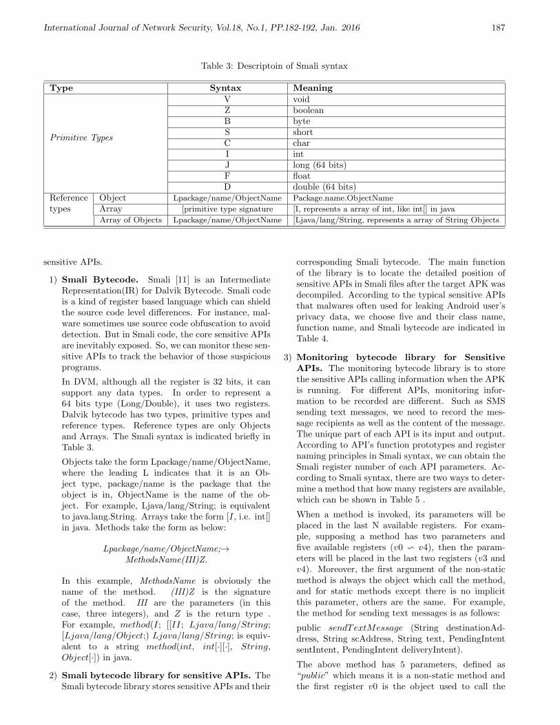
International Journal of Network Security, Vol.18, No.1, PP.182-192, Jan. 2016 187
Table 3: Descriptoin of Smali syntax
Type Syntax Meaning
Primitive Types
V voidZ booleanB byteS shortC charI intJ long (64 bits)F floatD double (64 bits)
Reference Object Lpackage/name/ObjectName Package.name.ObjectName
types Array [primitive type signature [I, represents a array of int, like int[] in java
Array of Objects Lpackage/name/ObjectName [Ljava/lang/String, represents a array of String Objects
sensitive APIs.
1) Smali Bytecode. Smali [11] is an IntermediateRepresentation(IR) for Dalvik Bytecode. Smali codeis a kind of register based language which can shieldthe source code level differences. For instance, mal-ware sometimes use source code obfuscation to avoiddetection. But in Smali code, the core sensitive APIsare inevitably exposed. So, we can monitor these sen-sitive APIs to track the behavior of those suspiciousprograms.
In DVM, although all the register is 32 bits, it cansupport any data types. In order to represent a64 bits type (Long/Double), it uses two registers.Dalvik bytecode has two types, primitive types andreference types. Reference types are only Objectsand Arrays. The Smali syntax is indicated briefly inTable 3.
Objects take the form Lpackage/name/ObjectName,where the leading L indicates that it is an Ob-ject type, package/name is the package that theobject is in, ObjectName is the name of the ob-ject. For example, Ljava/lang/String; is equivalentto java.lang.String. Arrays take the form [I, i.e. int[]in java. Methods take the form as below:
Lpackage/name/ObjectName;→MethodsName(III)Z.
In this example, MethodsName is obviously thename of the method. (III)Z is the signatureof the method. III are the parameters (in thiscase, three integers), and Z is the return type .For example, method(I; [[II; Ljava/lang/String;[Ljava/lang/Object;) Ljava/lang/String; is equiv-alent to a string method(int, int[·][·], String,Object[·]) in java.
2) Smali bytecode library for sensitive APIs. TheSmali bytecode library stores sensitive APIs and their
corresponding Smali bytecode. The main functionof the library is to locate the detailed position ofsensitive APIs in Smali files after the target APK wasdecompiled. According to the typical sensitive APIsthat malwares often used for leaking Android user’sprivacy data, we choose five and their class name,function name, and Smali bytecode are indicated inTable 4.
3) Monitoring bytecode library for SensitiveAPIs. The monitoring bytecode library is to storethe sensitive APIs calling information when the APKis running. For different APIs, monitoring infor-mation to be recorded are different. Such as SMSsending text messages, we need to record the mes-sage recipients as well as the content of the message.The unique part of each API is its input and output.According to API’s function prototypes and registernaming principles in Smali syntax, we can obtain theSmali register number of each API parameters. Ac-cording to Smali syntax, there are two ways to deter-mine a method that how many registers are available,which can be shown in Table 5 .
When a method is invoked, its parameters will beplaced in the last N available registers. For exam-ple, supposing a method has two parameters andfive available registers (v0 v v4), then the param-eters will be placed in the last two registers (v3 andv4). Moreover, the first argument of the non-staticmethod is always the object which call the method,and for static methods except there is no implicitthis parameter, others are the same. For example,the method for sending text messages is as follows:
public sendTextMessage (String destinationAd-dress, String scAddress, String text, PendingIntentsentIntent, PendingIntent deliveryIntent).
The above method has 5 parameters, defined as“public” which means it is a non-static method andthe first register v0 is the object used to call the
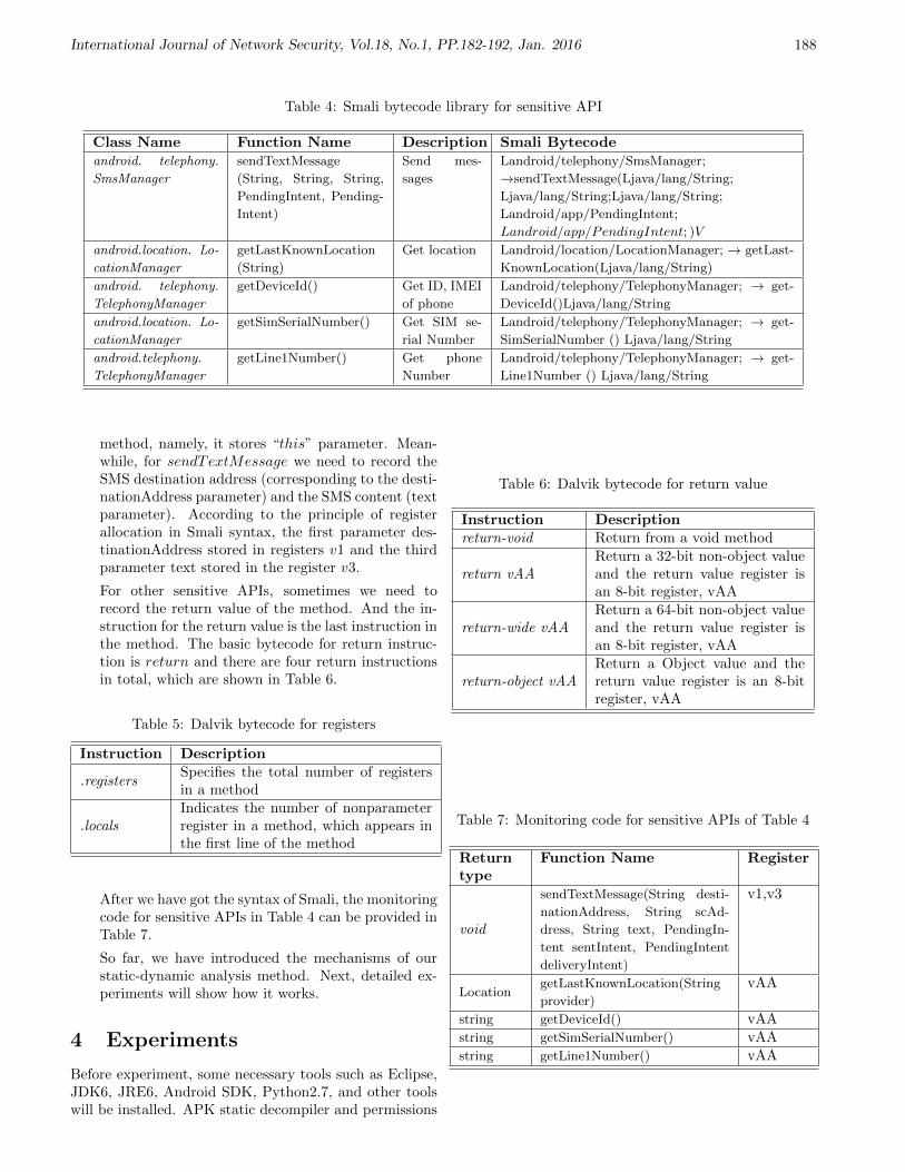
International Journal of Network Security, Vol.18, No.1, PP.182-192, Jan. 2016 188
Table 4: Smali bytecode library for sensitive API
Class Name Function Name Description Smali Bytecodeandroid. telephony.
SmsManager
sendTextMessage
(String, String, String,
PendingIntent, Pending-
Intent)
Send mes-
sages
Landroid/telephony/SmsManager;
→sendTextMessage(Ljava/lang/String;
Ljava/lang/String;Ljava/lang/String;
Landroid/app/PendingIntent;
Landroid/app/PendingIntent; )V
android.location. Lo-
cationManager
getLastKnownLocation
(String)
Get location Landroid/location/LocationManager; → getLast-
KnownLocation(Ljava/lang/String)
android. telephony.
TelephonyManager
getDeviceId() Get ID, IMEI
of phone
Landroid/telephony/TelephonyManager; → get-
DeviceId()Ljava/lang/String
android.location. Lo-
cationManager
getSimSerialNumber() Get SIM se-
rial Number
Landroid/telephony/TelephonyManager; → get-
SimSerialNumber () Ljava/lang/String
android.telephony.
TelephonyManager
getLine1Number() Get phone
Number
Landroid/telephony/TelephonyManager; → get-
Line1Number () Ljava/lang/String
method, namely, it stores “this” parameter. Mean-while, for sendTextMessage we need to record theSMS destination address (corresponding to the desti-nationAddress parameter) and the SMS content (textparameter). According to the principle of registerallocation in Smali syntax, the first parameter des-tinationAddress stored in registers v1 and the thirdparameter text stored in the register v3.
For other sensitive APIs, sometimes we need torecord the return value of the method. And the in-struction for the return value is the last instruction inthe method. The basic bytecode for return instruc-tion is return and there are four return instructionsin total, which are shown in Table 6.
Table 5: Dalvik bytecode for registers
Instruction Description
.registersSpecifies the total number of registersin a method
.localsIndicates the number of nonparameterregister in a method, which appears inthe first line of the method
After we have got the syntax of Smali, the monitoringcode for sensitive APIs in Table 4 can be provided inTable 7.
So far, we have introduced the mechanisms of ourstatic-dynamic analysis method. Next, detailed ex-periments will show how it works.
4 Experiments
Before experiment, some necessary tools such as Eclipse,JDK6, JRE6, Android SDK, Python2.7, and other toolswill be installed. APK static decompiler and permissions
Table 6: Dalvik bytecode for return value
Instruction Descriptionreturn-void Return from a void method
return vAAReturn a 32-bit non-object valueand the return value register isan 8-bit register, vAA
return-wide vAAReturn a 64-bit non-object valueand the return value register isan 8-bit register, vAA
return-object vAAReturn a Object value and thereturn value register is an 8-bitregister, vAA
Table 7: Monitoring code for sensitive APIs of Table 4
Returntype
Function Name Register
void
sendTextMessage(String desti-
nationAddress, String scAd-
dress, String text, PendingIn-
tent sentIntent, PendingIntent
deliveryIntent)
v1,v3
LocationgetLastKnownLocation(String
provider)
vAA
string getDeviceId() vAAstring getSimSerialNumber() vAAstring getLine1Number() vAA
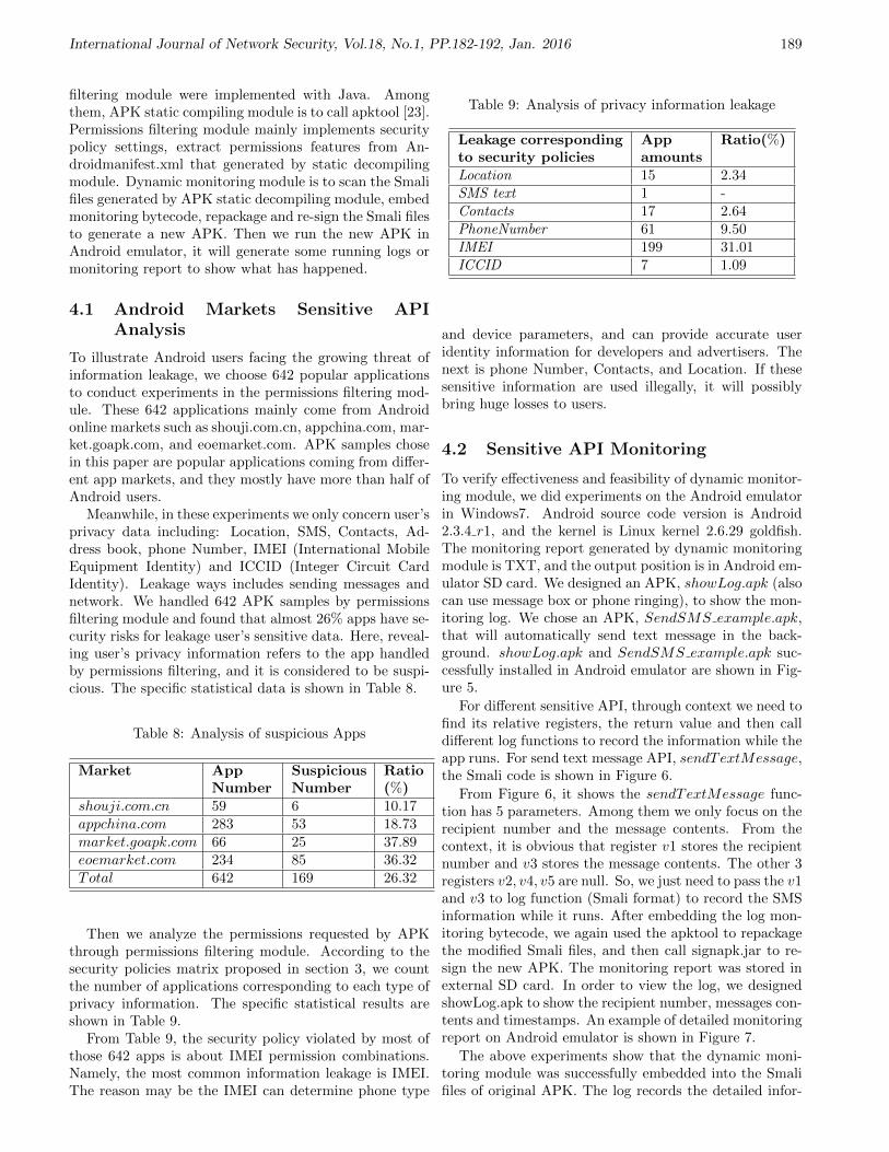
International Journal of Network Security, Vol.18, No.1, PP.182-192, Jan. 2016 189
filtering module were implemented with Java. Amongthem, APK static compiling module is to call apktool [23].Permissions filtering module mainly implements securitypolicy settings, extract permissions features from An-droidmanifest.xml that generated by static decompilingmodule. Dynamic monitoring module is to scan the Smalifiles generated by APK static decompiling module, embedmonitoring bytecode, repackage and re-sign the Smali filesto generate a new APK. Then we run the new APK inAndroid emulator, it will generate some running logs ormonitoring report to show what has happened.
4.1 Android Markets Sensitive APIAnalysis
To illustrate Android users facing the growing threat ofinformation leakage, we choose 642 popular applicationsto conduct experiments in the permissions filtering mod-ule. These 642 applications mainly come from Androidonline markets such as shouji.com.cn, appchina.com, mar-ket.goapk.com, and eoemarket.com. APK samples chosein this paper are popular applications coming from differ-ent app markets, and they mostly have more than half ofAndroid users.
Meanwhile, in these experiments we only concern user’sprivacy data including: Location, SMS, Contacts, Ad-dress book, phone Number, IMEI (International MobileEquipment Identity) and ICCID (Integer Circuit CardIdentity). Leakage ways includes sending messages andnetwork. We handled 642 APK samples by permissionsfiltering module and found that almost 26% apps have se-curity risks for leakage user’s sensitive data. Here, reveal-ing user’s privacy information refers to the app handledby permissions filtering, and it is considered to be suspi-cious. The specific statistical data is shown in Table 8.
Table 8: Analysis of suspicious Apps
Market AppNumber
SuspiciousNumber
Ratio(%)
shouji.com.cn 59 6 10.17appchina.com 283 53 18.73market.goapk.com 66 25 37.89eoemarket.com 234 85 36.32Total 642 169 26.32
Then we analyze the permissions requested by APKthrough permissions filtering module. According to thesecurity policies matrix proposed in section 3, we countthe number of applications corresponding to each type ofprivacy information. The specific statistical results areshown in Table 9.
From Table 9, the security policy violated by most ofthose 642 apps is about IMEI permission combinations.Namely, the most common information leakage is IMEI.The reason may be the IMEI can determine phone type
Table 9: Analysis of privacy information leakage
Leakage correspondingto security policies
Appamounts
Ratio(%)
Location 15 2.34SMS text 1 -Contacts 17 2.64PhoneNumber 61 9.50IMEI 199 31.01ICCID 7 1.09
and device parameters, and can provide accurate useridentity information for developers and advertisers. Thenext is phone Number, Contacts, and Location. If thesesensitive information are used illegally, it will possiblybring huge losses to users.
4.2 Sensitive API Monitoring
To verify effectiveness and feasibility of dynamic monitor-ing module, we did experiments on the Android emulatorin Windows7. Android source code version is Android2.3.4 r1, and the kernel is Linux kernel 2.6.29 goldfish.The monitoring report generated by dynamic monitoringmodule is TXT, and the output position is in Android em-ulator SD card. We designed an APK, showLog.apk (alsocan use message box or phone ringing), to show the mon-itoring log. We chose an APK, SendSMS example.apk,that will automatically send text message in the back-ground. showLog.apk and SendSMS example.apk suc-cessfully installed in Android emulator are shown in Fig-ure 5.
For different sensitive API, through context we need tofind its relative registers, the return value and then calldifferent log functions to record the information while theapp runs. For send text message API, sendTextMessage,the Smali code is shown in Figure 6.
From Figure 6, it shows the sendTextMessage func-tion has 5 parameters. Among them we only focus on therecipient number and the message contents. From thecontext, it is obvious that register v1 stores the recipientnumber and v3 stores the message contents. The other 3registers v2, v4, v5 are null. So, we just need to pass the v1and v3 to log function (Smali format) to record the SMSinformation while it runs. After embedding the log mon-itoring bytecode, we again used the apktool to repackagethe modified Smali files, and then call signapk.jar to re-sign the new APK. The monitoring report was stored inexternal SD card. In order to view the log, we designedshowLog.apk to show the recipient number, messages con-tents and timestamps. An example of detailed monitoringreport on Android emulator is shown in Figure 7.
The above experiments show that the dynamic moni-toring module was successfully embedded into the Smalifiles of original APK. The log records the detailed infor-

International Journal of Network Security, Vol.18, No.1, PP.182-192, Jan. 2016 190
Figure 5: Running interface of installed showLog.apk andSendSMS example.apk
iget-object v1, p0,
Lcom/example/sendsms_example/SendSMS_ExampleMainActivity; ->phoneNumber:Ljava/lang/String;
iget-object v3, p0,
Lcom/example/sendsms_example/SendSMS_ExampleMainActivity; ->SMSContext:Ljava/lang/String;
move-object v4, v2
move-object v5, v2 invoke-virtual/range v0 .. v5, Landroid/telephony/SmsManager;
->sendTextMessage(Ljava/lang/String;Ljava/lang/String;Ljava/lang/
String;Landroid/app/PendingIntent;Landroid/app/PendingIntent;)V
Figure 6: An example of Smali code for sendTextMessage
Figure 7: An Example of monitoring log for sendTextMes-sage
mation related to the sensitive API. Once we have foundthe suspicious behavior of an app, any further deep anal-ysis, such as DDMS (Dalvik Debug Monitor Server), cananalyze it more accurately and comprehensively.
5 Conclusion
A two-step malicious Android application detectionmethod was proposed in this paper. First of all, we usepermission combination matrix to discover those potentialrisk applications. And then those suspicious applicationsare further sent into the dynamic monitoring module totrack the call information of the sensitive APIs while itis running. As a conclusion, it shows some advantages ofour approach:
1) Using Smali bytecode, it is based on intermediatelanguage, which shows some advantages over Javasource code method and it possesses anti-obfuscationto a certain degree.
2) The method is simple, just insert some monitoringSmali bytecode, and the performance influence canbe ignored.
3) This method can be used in a wide scale, which candeploy remotely and provide monitoring service au-tomatically.
Further research directions include considering moresensitive APIs and provide a real App on Android marketfor fans to use. Also, we need integrate others malwaredetection method, such as dynamic taint analysis to con-duct some cross-field deep research.
Acknowledgments
This study was supported by Shanghai Municipal NaturalScience Foundation under grant No.13ZR1416100. Theauthors gratefully acknowledge the anonymous reviewersfor their valuable comments.
References
[1] L. Batyuk, M. Herpich, S. A. Camtepe, and K. Rad-datz, “Using static analysis for automatic assessmentand mitigation of unwanted and malicious activitieswithin android applications,” in Proceeding of the6th International Conference on Malicious and Un-wanted Software, pp. 66–72, Fajardo, Oct. 2011.
[2] A. R. Beresford, A. Rice, N. Skehin, and R. Sohan,“Mockdroid: Trading privacy for application func-tionality on smartphones,” in Proceedings of the 12thWorkshop on Mobile Computing Systems and Appli-cations, pp. 49–54, Phoenix, USA, Mar. 2011.

International Journal of Network Security, Vol.18, No.1, PP.182-192, Jan. 2016 191
[3] T. Blasing, L. Batyuk, A. D. Schmidt, S. A.Camtepe, and S. Albayrak, “An android applica-tion sandbox system for suspicious software detec-tion,” in Proceeding of the 5th International Confer-ence on Malicious and Unwanted Software, pp. 55–62, Nancy,France, Oct. 2010.
[4] D. Bornstein, Dalvik VM Internals, 2008.(https://sites.google.com/site/io/dalvik-vm-internals)
[5] Canalys, Mobile Device Shipments Survey Re-port in the First Session of 2013, May 2013.(http://cn.engadget.com/tag/canalys)
[6] Canalys, Smartphone Shipments Survey Reportin the Fourth Session of 2011, May 2013.(http://cn.engadget.com/tag/canalys)
[7] E. Chin, A. P. Felt, K. Greenwood, and D. Wagner,“Analyzing inter-application communication in an-droid,” in Proceedings of the 9th International Con-ference on Mobile Systems, Applications and Service,pp. 239–252, Washington, USA, June 2011.
[8] W. Enck, P. Gilbert, B. G. Chun, L. P. Cox, J. Jung,P. McDaniel, and A. N. Sheth, “Taintdroid: Aninformation-flow tracking system for realtime pri-vacy monitoring on smartphones,” in Proceedingsof the 9th USENIX Conference on Operating Sys-tems Design and Implementation, pp. 1–6, Vancou-ver, Canada, Oct. 2010.
[9] W. Enck, M. Ongtang, and P. McDaniel, “Onlightweight mobile phone application certification,”in Proceedings of the 16th ACM Conference on Com-puter and Communications Security, pp. 235–245,Chicago, USA, Nov. 2009.
[10] A. P. Fuchs, A.Chaudhuri, and J. S. Foster, “Scan-droid: automated security certification of androidapplications,” Technical Report of University ofMaryland, 2009. (http://www. cs. umd. edu/ avik/projects/ scandroidascaa)
[11] Google, Smali, July 11, 2015. (http://code. google.com/ p/ smali/)
[12] Google, Android Home Page, 2009. (http://www. an-droid. com)
[13] Google, Android Security and Permissions, 2013.(http://d.android.com/guide/topics /security /secu-rity.html)
[14] Google, Dex2jar: Tools to Work with Android .dexand java .classfiles, 2013. (http://code. google. com/p/ dex2jar/)
[15] P. Hornyack, S. Han, J. Jung, S. schechter, andD. Wetherall, “These aren’t the droids you’re lookingfor: Retrofitting android to protect data from impe-rious applications,” in Proceedings of the 18th ACMConference on Computer and Communications Se-curity, pp. 639–652, Chicago, USA, Oct. 2011.
[16] T. Isohara, K. Takemori, and A. Kubota, “Kernel-based behavior analysis for android malware detec-tion,” in Seventh International Conference on Com-putational Intelligence and Security, pp. 1011–1015,Hainan, China, Dec. 2011.
[17] K. Luo, “Using static analysis on android applica-tions to identify private information leaks,” MasterDissertation of Kansas State University, 2011.
[18] Netqin, Mobile Security Report in 2012, May 2013.(http://cn.nq.com/anquanbobao)
[19] D. Octeau, W. Enck, and P. McDaniel, The DEDDecompiler, 2011. (http://siis. cse. psu. edu/ ded/papers/ NAS-TR-0140-2010.pdf)
[20] M. Ongtang, S. McLaughlin, W. Enck, and P. Mc-Daniel, “Semantically rich application-centric secu-rity in android,” in Proceedings of the 25th An-nual Computer Security Applications Conference,pp. 340–349, Honolulu, USA, Dec. 2009.
[21] G. Peng, Y. Shao, T. Wang, X. Zhan, and H. Zhang,“Research on android malware detection and inter-ception based on behavior monitoring,” Wuhan Uni-versity Journal of Natural Sciences, vol. 17, no. 5,pp. 421–427, 2012.
[22] Q. Qian, J. Cai, and R. Zhang, “Android maliciousbehavior detection based on sensitive api monitor-ing,” in 2nd International Workshop on Security,pp. 54–57, Nov. 2013.
[23] D. Reynaud, D. Song, T. Magrino, E. Wu, andR. Shin, “Freemarket:shopping for free in androidapplications,” in 19th Annual Network & DistributedSystem Security Symposium, Hilton San Diego, USA,Feb. 2012.
[24] A. Shabtai, Y. Fledel, and Y. Elovici, “Secur-ing android-powered mobile devices using selinux,”IEEE Security & Privacy, vol. 8, no. 3, pp. 36–44,2010.
Quan Qian is a Professor in Shanghai University, China.His main research interests concerns computer networkand network security, especially in cloud computing, dataprivacy protection and wide scale distributed networkenvironments. He received his computer science Ph.D.degree from University of Science and Technology ofChina (USTC) in 2003 and conducted postdoc researchin USTC from 2003 to 2005. After that, he joinedShanghai University and now he is the lab director ofnetwork and information security.
Jing Cai is a master degree student in the school ofcomputer science, Shanghai University. Her researchinterests include Android security and software securityanalysis.
Mengbo Xie is a master degree student in the schoolof computer science, Shanghai University. Her researchinterests include data privacy, privacy based data mining,computer and network security.
Rui Zhang received her B.E. and Ph.D. degree fromDepartment of Electronic Engineering & Information Sci-ence, University of Science and Technology of China, in2003 and 2008, respectively. After that, she joined theSchool of Computer Engineering and Science, Shanghai

International Journal of Network Security, Vol.18, No.1, PP.182-192, Jan. 2016 192
University. Now, she is an associate professor and hermain research interests include computer networks, net-work coding for wireless networks and wireless communi-cation, etc.

International Journal of Network Security, Vol.18, No.1, PP.193-200, Jan. 2016 193
Anonymous Network Information AcquirementProtocol for Mobile Users in Heterogeneous
Wireless Networks
Guangsong Li1, Qi Jiang2, Yanan Shi1, and Fushan Wei1
(Corresponding author: Guangsong Li)
State Key Laboratory of Mathematical Engineering and Advanced Computing1
No. 62 of Science Road, Zhengzhou 450002, P. R. China
School of Computer Science and Technology, Xidian University2
No. 2 of Taibai Road, Xi’an 710071, P. R. China
(Email: [email protected])
(Received Dec. 10, 2013; revised and accepted Nov. 15 & Dec. 28, 2014)
Abstract
Media independent information service is one of the im-portant parts of the IEEE 802.21 standard to optimizevertical handover in wireless heterogeneous networks. Inthis paper, an anonymous network information acquire-ment protocol is proposed for a mobile user, which canbe used to establish a secure channel between the mo-bile user and the information server. Security and perfor-mance analysis shows that the proposed protocol is verysuitable for mobile environments.
Keywords: Anonymity, heterogeneous network, media in-dependent information service
1 Introduction
Communication in next generation wireless networks willuse multiple access technologies, creating a heterogeneousnetwork environment. Practically, a single network can-not cater for all different user needs or provide all services.Nowadays the availability of multimode mobile devicescapable of connecting to different wireless technologiesprovides users with the possibility to switch their net-work interfaces to different types of networks. Verticalhandovers among heterogeneous networks should be sup-ported to guarantee the service continuity. To achieve aseamless handover, a mobile user needs to obtain infor-mation of existing networks nearby, in order that he canchoose a suitable target network and do some prepara-tions for possible handover. However, the neighbor infor-mation discovery is the most time-consuming phase in thehandover process [15].
The IEEE 802.21 working group defines the Media In-dependent Handover (MIH) services [4] to facilitate han-dover between heterogeneous networks. Media Indepen-
dent Information Service (MIIS) is a very important partof MIH services, which specifies information about nearbynetworks and the query/response mechanism that allowsmobile nodes to get that information from informationservers. MIH messages will be exchanged over variouswireless media between mobile nodes and access networksin future heterogeneous networks. Thus the MIH servicesmay be a new target to attackers, which will be the mainconcerns for equipment vendors and service providers.Some typical threats about MIIS are listed in [9], which in-cludes identity spoofing, tampering, replay attack, denialof service and information disclosure. Note that an at-tacker may be able to trace a user’s movements or predictfuture movements by inspecting MIIS messages. Thus, itis desirable to hide the roaming user’s identity and move-ments from eavesdroppers. However, security mechanismsare not within the scope of the IEEE 802.21 standard.
IEEE 802.21a task group was set up to address se-curity issues of MIH services. As to MIH security, twoframeworks about MIH service access control were pro-posed [5, 8]: (i) 3-party case, the access control is ap-plied through EAP process (for instance, EAP-TLS [13])with an EAP server, where the information server plays apart of authenticator; (ii) 2-party case, the access controlis based on a pre-shared key or public key certification,where the user and the information server execute a mu-tual authentication and key establishment procedure likeTLS [2]. Saadat et al. [11] describe the main technicalrequirements to establish a secure channel between theuser and the information server. They also propose thatthe user should be authenticated by an authenticationserver and a shared key between the user and the infor-mation server should be generated by the authenticationserver. However, the specific authentication method isnot referred. Saha et al. [12] propose a PLA-MIH scheme

International Journal of Network Security, Vol.18, No.1, PP.193-200, Jan. 2016 194
to transport 802.21 messages over a secure network layerprotocol in a hop-by-hop manner. It has the advantagethat ensures very strong security of the signaling frame-work. However, it adds much overhead to all entities in-volved, for it needs every packet in MIH signaling to besigned. Won et al. propose another secure MIH messagetransport solution called MIHSec [14], which computesthe MIH keys by utilizing the keys generated from thedata link layer authentication procedure. Though MIHsechas a good performance for MIH message transportation,it introduces other issues. First, it is closely integratedwith date link layer authentication, thus it is not mediaindependent. Second, the access router may know the keyfor MIH messages encryption, which degrades the level ofsecurity.
We note that user anonymity is not addressed in allabove schemes. It is very important for a roaming userto keep his identity secret and movements untraceable.In [7], we propose an access authentication scheme withuser anonymity. The scheme provides an anonymous ac-cess authentication of MIIS considering that the accesscontrol for information is applied through an access au-thentication controller. The protocol can be used to es-tablish a secure channel between the mobile node and theinformation server. The solution has the advantages oflightweight computation and easy implementation, How-ever, it has the following weak points: first, it needs themobile user to require a service ticket from his home serverevery time before accessing MIIS, which may take a longtime if the user is far away from his home network; second,the home server has to be always online and available, soit is easy for the home server to become the bottleneck.
In order to achieve an efficient network informationdiscovery process with more security properties, this pa-per proposes a new Anonymous Network Information Ac-quirement (ANIA) protocol using an Schnorr like ID-based signature scheme [3]. The anonymous authentica-tion process does not involve the home server, which re-sulting a very short authentication latency. We also givea rigorous formal analysis of its security using a modularapproach.
Our contribution mainly includes:
• Quick mutual authentication with user anonymitybetween the user and the information server;
• A shared session key established for MIIS informa-tion secure transmitting;
• Lightweight computation and low communicationcost in the proposed protocol.
The rest of this paper is organized as follows. Section 2gives a quick review of eCK model. In Section 3 wepresent our new approach in detail. Section 4 gives a for-mal security proof of our protocol under the ECK model.Section 5 includes performance analysis. Finally, conclu-sions are drawn in Section 6.
2 Related Work
The extended Canetti-Krawczyk (eCK) model [6] is de-scribed as an experiment between an adversary ∆ and achallenger Σ. Initially, ∆ selects the identities of n honestparties, for whom Σ generates static private key/publickey pairs.
Execution of an Authenticated Key Exchange (AKE)protocol by one of these parties is called an AKE session.A session identifier sid is defined as
sid = (role, Φ, Ψ, comm),where role = I, R is the role (initiator/responder) of
the owner of the session, Φ is the identity of the owner,Ψ is the identity of the other party in the session, andcomm is the concatenation of communication messagesbetween the two parties. Two sessions sid = (role, Φ,Ψ, comm1) and sid* = (role, Φ, Ψ, comm2) are matchingsessions if role is the complement of role* and comm1 =comm2. A protocol execution between Φ and Ψ withoutthe intervention of an adversary produces two matchingsessions.
In the experiment, ∆ controls all communications be-tween the parties, and can reveal the static private key ofa party, the ephemeral private key in a session, and thesession key of a session. ∆ can make any sequence of thefollowing queries, which Σ needs to answer accordingly:
• Send(Φ, Ψ, comm). ∆ sends a message comm to Φon behalf of Ψ. Σ returns Φ’s response.
• StaticKeyReveal(Φ). Σ returns the static private keyof Φ.
• EphemeralKeyReveal(sid). Σ returns the ephemeralprivate key of the session sid.
• SessionKeyReveal(sid). Σ returns the session key ofthe session sid.
• Establish(Φ). Using this query, the adversary regis-ters an arbitrary public key on behalf of an adversarycontrolled party Φ. Σ only checks the validity of thepublic key, but does not need to check the possessionof the corresponding private key.
A session sid (role, Φ, Ψ, comm) is fresh if the fol-lowing conditions hold:
• Both Φ and Ψ are honest parties.
• ∆ did not query the session key of sid or its matchingsession sid* (if the matching session exists).
• ∆ did not query both the static private key of Φ andthe ephemeral private key of Φ in this session.
• If sid* exists, then ∆ did not query both the staticprivate key of Ψ and the ephemeral private key of Ψin this session.
• If sid* does not exist, then ∆ did not query the staticprivate key of Ψ.

International Journal of Network Security, Vol.18, No.1, PP.193-200, Jan. 2016 195
Security of an AKE is defined as follows. In an eCKexperiment, ∆ issues Send, StaticKeyReveal, Ephemer-alKeyReveal, SessionKeyReveal, and Establish queriespolynomial times (in a security parameter) in any se-quence. Then ∆ selects a completed session sid, andmakes a query Test(sid). To answer Test(sid), Σ choosesa bit b∈ 0, 1uniformly at random. If b = 1, then Σsets the session key of sid as K. Otherwise, Σ selectsK from the key space uniformly at random. Σ thenreturns K as the answer of Test(sid). ∆ continues toquery Send, StaticKeyReveal, EphemeralKeyReveal, Ses-sionKeyReveal, and Establish polynomial times. At last,∆ outputs a bit b∗, and terminates the game. If the se-lected test session is fresh and b∗ = b,then ∆ wins thegame.
The advantage of the adversary ∆ in the eCKexperiment with AKE protocol Π is defined asADVΠ(Ω) = Pr∆ wins−1/2.
eCK Security
An AKE protocol is secure (in the eCK model) if noefficient adversary ∆ has more than a negligible advan-tage in winning the above experiment, i.e., ADVΠ(∆) <1/Q(µ) for any polynomial Q(·) when µ sufficiently large.
3 Network Information Acquire-ment Protocol with UserAnonymity
This section focuses on a new proposal for anonymous net-work information acquirement using an efficient Schnorrlike ID-based signature scheme [3].
3.1 Network Initialization
We consider a network model as depicted in Figure 1. Amobile user (MU) roams into a visited network (V) andhe wants to get network information nearby for possiblehandover. We assume the MU registers with a home au-thentication server (HAS) in his home network (H) andhas a long term shared key kMH with the HAS. The MIISis provided by an information server (IS) in the Internet.Suppose there is an agreement between the IS and theHAS for MUs using MIIS to optimize handover. We alsoassume there is a time synchronization mechanism in thesystem.
In this phase, the HAS runs a setup algorithm andgenerates the system parameters, including a master se-cret key (s), and the corresponding master public key(PKHAS), by using a security parameter k. The HASperforms the following steps:
1) Specifies q, p, E/F p , P and G where q is a largeprime number and p is the field size, E/F p is anelliptic curve E over a finite field F p , P is a base pointof order q on the curve E and G is a cyclic group of
Figure 1: Network model
order q under the point addition “+” generated byP.
2) For the randomly chosen master secret key s∈ Z∗q ,
computes PKHAS as sP.
3) Chooses two hash function H 1: 0,1∗ −→ Z∗q , H 2:
0,1∗×G×0,1∗ −→ Z∗q .
4) Chooses one key derivation function f : G−→0,1k.
5) Outputs system parameters q, p, E/F p , P, G,PKHAS , H, f , and keeps s secret.
Later, the HAS computes the private keys of all usersand the IS. This algorithm takes the master secret keys and an identifier (ID) as input and generates a privatekey corresponding to that ID. In order to achieve MIISaccess anonymity, the HAS selects a pseudo-ID (PID) foreach MU and based on the PID a private key is gener-ated. The HAS works as follows for each MU with identi-fier PIDMU . It chooses at random rMU ∈R Z∗
q ,computeRMU = rMU P and hMU = H 1(PIDMU , RMU ). Then itcomputes sMU = rMU+hMU s. The MU’s private key isthe tuple (sMU , RMU ) and is transmitted to the MU viaa secure channel, namely encrypted by the key sharedbetween the HAS and the MU. The MU’s public keyis defined as PKMU =sMU P, which can also be com-puted with RMU , PIDMU , and PKHAS from the equa-tion: PKMU=RMU+H 1(PIDMU , RMU )PKHAS . TheHAS also generates a private key for the IS as above proce-dure using IDIS . The private key and public key of the ISare denoted as (sIS , RIS ) and PK IS=sISP, respectively.
3.2 Anonymous Secure Channel Estab-lishment
When a MU moves to a new place, it should contact theIS to get information about neighbor networks. Supposethat the MU is now in coverage area of network V and he
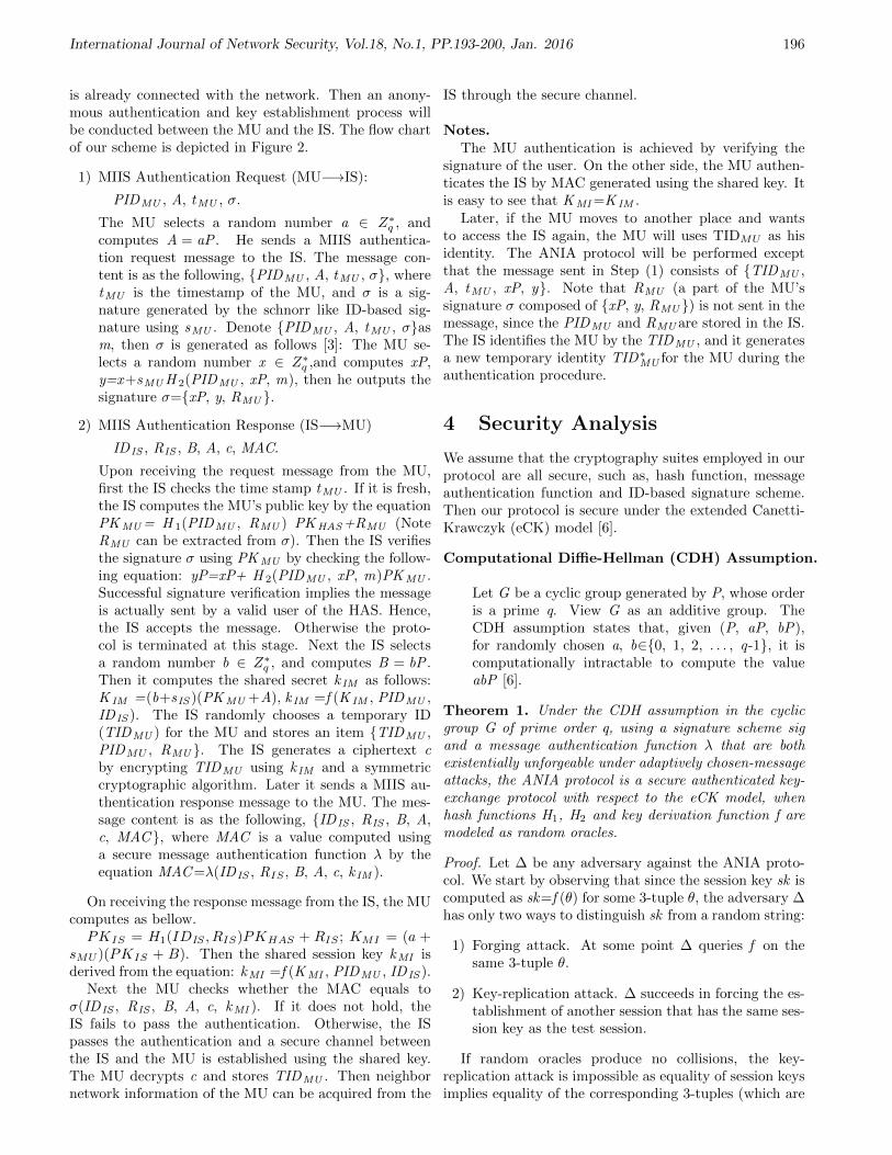
International Journal of Network Security, Vol.18, No.1, PP.193-200, Jan. 2016 196
is already connected with the network. Then an anony-mous authentication and key establishment process willbe conducted between the MU and the IS. The flow chartof our scheme is depicted in Figure 2.
1) MIIS Authentication Request (MU−→IS):
PIDMU , A, tMU , σ.
The MU selects a random number a ∈ Z∗q , and
computes A = aP . He sends a MIIS authentica-tion request message to the IS. The message con-tent is as the following, PIDMU , A, tMU , σ, wheretMU is the timestamp of the MU, and σ is a sig-nature generated by the schnorr like ID-based sig-nature using sMU . Denote PIDMU , A, tMU , σasm, then σ is generated as follows [3]: The MU se-lects a random number x ∈ Z∗
q ,and computes xP,y=x+sMU H 2(PIDMU , xP, m), then he outputs thesignature σ=xP, y, RMU .
2) MIIS Authentication Response (IS−→MU)
IDIS , RIS , B, A, c, MAC.
Upon receiving the request message from the MU,first the IS checks the time stamp tMU . If it is fresh,the IS computes the MU’s public key by the equationPKMU = H 1(PIDMU , RMU ) PKHAS+RMU (NoteRMU can be extracted from σ). Then the IS verifiesthe signature σ using PKMU by checking the follow-ing equation: yP=xP+ H 2(PIDMU , xP, m)PKMU .Successful signature verification implies the messageis actually sent by a valid user of the HAS. Hence,the IS accepts the message. Otherwise the proto-col is terminated at this stage. Next the IS selectsa random number b ∈ Z∗
q , and computes B = bP .Then it computes the shared secret k IM as follows:K IM =(b+sIS )(PKMU +A), k IM =f (K IM , PIDMU ,IDIS ). The IS randomly chooses a temporary ID(TIDMU ) for the MU and stores an item TIDMU ,PIDMU , RMU . The IS generates a ciphertext cby encrypting TIDMU using k IM and a symmetriccryptographic algorithm. Later it sends a MIIS au-thentication response message to the MU. The mes-sage content is as the following, IDIS , RIS , B, A,c, MAC, where MAC is a value computed usinga secure message authentication function λ by theequation MAC =λ(IDIS , RIS , B, A, c, k IM ).
On receiving the response message from the IS, the MUcomputes as bellow.PKIS = H1(IDIS , RIS)PKHAS + RIS ; KMI = (a +
sMU )(PKIS + B). Then the shared session key kMI isderived from the equation: kMI =f (KMI , PIDMU , IDIS ).
Next the MU checks whether the MAC equals toσ(IDIS , RIS , B, A, c, kMI ). If it does not hold, theIS fails to pass the authentication. Otherwise, the ISpasses the authentication and a secure channel betweenthe IS and the MU is established using the shared key.The MU decrypts c and stores TIDMU . Then neighbornetwork information of the MU can be acquired from the
IS through the secure channel.
Notes.The MU authentication is achieved by verifying the
signature of the user. On the other side, the MU authen-ticates the IS by MAC generated using the shared key. Itis easy to see that KMI =K IM .
Later, if the MU moves to another place and wantsto access the IS again, the MU will uses TIDMU as hisidentity. The ANIA protocol will be performed exceptthat the message sent in Step (1) consists of TIDMU ,A, tMU , xP, y. Note that RMU (a part of the MU’ssignature σ composed of xP, y, RMU ) is not sent in themessage, since the PIDMU and RMU are stored in the IS.The IS identifies the MU by the TIDMU , and it generatesa new temporary identity TID∗
MU for the MU during theauthentication procedure.
4 Security Analysis
We assume that the cryptography suites employed in ourprotocol are all secure, such as, hash function, messageauthentication function and ID-based signature scheme.Then our protocol is secure under the extended Canetti-Krawczyk (eCK) model [6].
Computational Diffie-Hellman (CDH) Assumption.
Let G be a cyclic group generated by P, whose orderis a prime q. View G as an additive group. TheCDH assumption states that, given (P, aP, bP),for randomly chosen a, b∈0, 1, 2, . . . , q-1, it iscomputationally intractable to compute the valueabP [6].
Theorem 1. Under the CDH assumption in the cyclicgroup G of prime order q, using a signature scheme sigand a message authentication function λ that are bothexistentially unforgeable under adaptively chosen-messageattacks, the ANIA protocol is a secure authenticated key-exchange protocol with respect to the eCK model, whenhash functions H1, H2 and key derivation function f aremodeled as random oracles.
Proof. Let ∆ be any adversary against the ANIA proto-col. We start by observing that since the session key sk iscomputed as sk=f (θ) for some 3-tuple θ, the adversary ∆has only two ways to distinguish sk from a random string:
1) Forging attack. At some point ∆ queries f on thesame 3-tuple θ.
2) Key-replication attack. ∆ succeeds in forcing the es-tablishment of another session that has the same ses-sion key as the test session.
If random oracles produce no collisions, the key-replication attack is impossible as equality of session keysimplies equality of the corresponding 3-tuples (which are

International Journal of Network Security, Vol.18, No.1, PP.193-200, Jan. 2016 197
Figure 2: Anonymous authentication and key establishment with IS for MU
used to produce session keys). In turn, distinct key ex-change sessions must have distinct 3-tuples. Therefore, ifrandom oracles produce no collisions, ∆ must perform aforging attack.
Case 1: Active attack. The adversary could break thesecurity of the protocol via insertion of a message ofits choice. In this case we will construct an adversaryΞ against the signature scheme sig or the messageauthentication function λ.
We only take the adversary against sig for example.The construction of attacker against λ is very similar.The input to Ξ consists of the parameters of the sig-nature scheme, which includes access to a signatureoracle. Ξ selects at random one party as MU. Forsession executed by MU, instead of using the MU’sprivate key to compute the signatures, Ξ will makeuse of the signature oracle that it has access to inthe signature security game that Ξ is simultaneouslyplaying. Therefore, if the active attack occurs, Ξsucceeds in breaking the unforgeability of sig. Byassumption forging a valid signature can only occurwith negligible probability, the protocol is resilientagainst active attacks.
Case 2: Passive attack. In this case, the Test sessionhas a matching session owned by another honestparty. We show that if the adversary performs asuccessful forging attack, the CDH problem couldbe solved by a solver Ξ. The input to the Ξ is aCDH problem instance (U = uP, V = vP), where u,v∈ Z∗
q and U, V∈ G. The goal of Ξ is to computeCDH(U,V ) = uvP. For simplicity, we use γ, ω and Γ,Ω denote the static secret keys sMU , sIS and publickeys PKMU , PK IS respectively.
The adversary ∆ is allowed to reveal a subset of (γ,
a, ω, b), but it is not allowed to reveal both (γ, a) orboth (ω, b). We only take the subcase for examplethat (γ, b) is revealed by ∆. Other subcases aresimilar.
Ξ selects random matching sessions executed by MUand IS, and modifies the experiment as follows. Ξsets the ephemeral public keys of MU in the testsession to be U, and sets the static public key ofIS in the matching session to be V (namely, A=U,Ω = V ). If ∆ wins the game, it must queries fon the same 3-tuple θ, thus it successfully forgesK =(γ+u)(v+b)P. Then Ξ can solve the CDH prob-lem as below: CDH(U,V )=K−γbP−γV−bU. Withthe hardness of the CDH assumption, the adversarycould not win the experiment and hence the protocolis secure.
In the following, we further discuss some security prop-erties of our protocol.
User Anonymity. In our scheme, the pseudo ID, in-stead of the MU’s real identity, is used in access MIISfor privacy protection.
Key Freshness. The session key kMI is computed froma function using random numbers from the MU andthe IS respectively, which assures the freshness of ses-sion key.
Forward Secrecy. The random numbers used in sessionkey generation are unpredictable for any party exceptthe MU or the IS. Even if the intruder attacks longterm secret information of the MU and the IS, hecan not compromise the past random numbers andthe past session keys.

International Journal of Network Security, Vol.18, No.1, PP.193-200, Jan. 2016 198
Resistance to Replay Attack. Replay attack involvesthe passive capture of data and its subsequent re-transmission to produce an unauthorized effect. Areplay attack can be prevented by checking the times-tamp or the MAC.
5 Performance Analysis
Computation and communication overheads are consid-ered as two important metrics of authentication proto-cols. We present performance comparison of 802.21a pro-posal [5], SAM protocol [7], and ANIA protocol accordingto the metrics.
The computation overhead is the time cost of allthe cryptography operations. Since the MU is alwaysresource-constraints, we primarily take the MU’s compu-tation overhead into account. We take EAP-TLS [13] andTLS [2] as 802.21a proposal instances for 3-party caseand 2-party case respectively. Here, TLS handshake isbased on public key certificate and Diffie-Hellman key ex-change. And public key related algorithms of 802.21a andSAM are all considered based on ECC, where ECDSA andECDH for 802.21a, and ECDH for SAM.
To evaluate computation overhead of the mobile node,we implemented all cryptographic operations required inthe two schemes using the Crypto++ Library (version5.6.2) [1]. The cryptographic experiments were executedon a laptop with PIII 1.0 GHz CPU and 128MB RAM.Here the key length of the ECC system is set as 160 bits.In the experiment, SHA-160(or its variation) is introducedto implement hash functions and key derivation function,and AES-128 is introduced as the symmetric cipher usedin the protocols. The mainly results are listed in Table 1.
Table 1: Mainly cryptographic operations and computa-tion costs
Computation operations NotationTime(ms)
point multiplication TPM 1.532random number generation TRG 0.072
symmetric encryption TSE 0.106symmetric decryption TSD 0.106
hash value computation THC 0.031key derivation TKD 0.031
Table 2 shows the MU’s computation costs of the fourschemes during the handover authentication procedure.In the ANIA protocol, the MU needs: 1THC and 1TPM forcomputing the IS’s public key; 1THC , 1TRG, and 1TPM
for message signature; 1TRG, 2TPM , 1TKD for key ex-change; 1THC for MAC verification; 1TSD for TID. Fromthe table, we can conclude that the ANIA protocol ismore efficient than 802.21a proposal, since 3 costly pointmultiplication operations are saved; and it is a little more
complex than the SAM protocol because of one additionalcostly point multiplication operation.
As to communication performance, the HAS is not in-volved during the authentication between the MU and theIS in both 802.21a proposal 2-party case and the ANIAscheme. The SAM protocol and 802.21a proposal 3-partycase both need the HAS to acts as an anchor for trustestablishment. Since the MU now roams to a visited net-work which may be far away from his home network, com-munication between the MU and the HAS could take along latency. Table 3 shows the message numbers neededbetween the related entities. From Table 3, we can seethat ANIA performs better than other schemes.
We carried out some simulation experiments of the fourschemes using OPNET 10.5 [10] to verify analysis above.For simplicity, only 2 WLANs (denoted as H and V) areused as the access network in the topology, and two ASsand one IS are deployed, where the servers are connectedto the Internet as in Figure 1. The simulations run with20˜100MUs and 10 APs uniformly distributed in eachWLAN area for 5 minutes of simulation time. For theMIIS authentication request pattern, assume 20 percentsof the MUs in one WLAN move into the other WLAN, andeach roaming MU makes 10 requests randomly distributedover the whole simulation period. The simulation param-eters are listed in Table 4. Here we mainly focus on themeasurements of average authentication latency and thenumber of messages delivered in the network. The com-putation costs of MUs are considered in the simulation,while the computation costs of the servers are neglectedbecause of their powerful processing abilities.
Figure 3 shows the average authentication latency ofthe four schemes as the number of MUs changes. Wecan see that the average authentication latency of thoseschemes become larger as the number of MUs increases.The reason is that the number of packets generated in thenetwork increases as the number of MUs increases, whichmakes packets collision and retransmission happen moreoften. The ANIA protocol gets the shortest average au-thentication latency among those protocols in all scenar-ios. This suggests that the ANIA protocol is highly effec-tive in authentication latency. Figure 4 shows the changesof the number of messages delivered in the network whenthe number of MUs changes. As we can see from theresults, the number of messages delivered of 802.21a-3increases sharply while that of other protocols increasessmoothly as the number of MUs increases. It shows thatthe ANIA protocol delivers the smallest messages in thenetwork in all scenarios. The simulation results indicatethat the ANIA protocol has advantages in communicationperformance compared with other protocols.
6 Conclusion
In this paper, we focus specifically on security of MIIS,and propose a new anonymous access authentication pro-tocol for MIIS. We apply an identity-based Schnorr like

International Journal of Network Security, Vol.18, No.1, PP.193-200, Jan. 2016 199
Table 2: Message numbers between the related entities
Computation costs802.21a(2-party)
802.21a(3-party)
SAM ANIA
3THC + 7TPM
+1TRG + 1TKD
3THC + 7TPM
+1TRG + 1TKD
4THC + 3TPM + 1TRG
+1TKD + 1TSE + 1TSD
3THC + 4TPM + 2TRG
+1TKD + 1TSD
Total (ms) 10.917 10.917 5.101 6.502
Table 3: MUs computation costs of the four schemes
Message numbers802.21a(2-party)
802.21a(3-party)
SAM ANIA
Between MU and HAS 0 6 2 0Between MU and IS 4 9 2 2
Table 4: Simulation parameters
WLAN areaThe number of APs in each WLANCoverage of APThe number of MUs in each WLANThe number of MIIS request for each MUSimulation time
300m∗300m10100m20∼ 100105 minutes
0 20 40 60 80 1000
0.5
1
1.5
2
2.5
3
Number of mobile users
Ave
rag
e a
uth
en
tica
tio
n la
ten
ce
y(s
)
802.21a−2
802.21a−3
SAM
ANIA
Figure 3: Comparison about average authentication la-tency
0 20 40 60 80 1000
1000
2000
3000
4000
5000
6000
Number of mobile users in each WLAN
Nu
mb
er
of
me
ssa
ge
s d
eliv
ere
d
802.21a−2
802.21a−3
SAM
ANIA
Figure 4: Comparison about number of messages deliv-ered

International Journal of Network Security, Vol.18, No.1, PP.193-200, Jan. 2016 200
signature for user authentication with a PID. The secu-rity and performance analysis shows that the proposedscheme has excellent performance. We will further ana-lyze the performance of the proposed scheme in the future.Now we are making an effort to put up a real test-bed toevaluate performance of our protocol.
Acknowledgments
The authors would like to thank the anonymous review-ers and the editor for their comments that will help themto improve this paper. This work is supported by theNational Natural Science Foundation of China (61201220,61202389, 61309016, 61379150), and the Fundamental Re-search Funds for the Central Universities (Program No.JB140302).
References
[1] Cryptopp, Crypto++ Library, July 11, 2015. (http://www.cryptopp.com/)
[2] T. Dierks and E. Rescorla, The Transport Layer Se-curity (TLS) Protocol Ver. 1.2, Technical ReportRFC 5246, 2008.
[3] D. Galindo and F. D. Garcia, “A schnorr-likelightweight identity-based signature scheme,” in Pro-ceedings of The Second International Conference onCryptology in Africa (Africacrypt 2009), pp. 135–148, 2009.
[4] IEEE, Media Independent Handover Services,IEEE 802.21 Standard, 2009.
[5] IEEE, IEEE Standard for Local and MetropolitanArea Networks: Media Independent Handover Ser-vices - Amendment for Security Extensions to MediaIndependent Handover Services and Protocol, IEEEStandard, May 2012.
[6] B. LaMacchia, K. Lauter, and A. Mityagin,“Stronger security of authenticated key exchange,”in Proceedings of The First International Conferenceon Provable Security (ProvSec 2007), pp. 1–16, 2007.
[7] G. Li, J. Ma, and Q. Jiang, “SAM: Secure accessof media independent information service with useranonymity,” EURASIP Journal on Wireless Com-munications and Networking, vol. 2010, pp. 12, Apr.2010.
[8] R. Marin-Lopez, F. Bernal-Hidalgo, S. Das, andet al., “A new standard for securing media inde-pendent handover: IEEE 802.21A,” IEEE WirelessCommunications, vol. 20, no. 6, pp. 82–90, 2013.
[9] T. Melia, G. Bajko, S. Das, N. Golmie, and J. Zu-niga, IEEE 802.21 Mobility Services Framework De-sign (MSFD), Technical Report RFC 5677, 2009.
[10] Opnet, Opnet, July 11, 2015. (http://www.opnet.com/)
[11] I. Saadat, F. Buiati, D. Ruperez Canas, L. Javier,and G.Villalba, “Overview of IEEE 802.21 secu-rity issues for mih networks,” in Proceedings of In-
ternational Conference on Information Technology(ICIT’11), pp. 196–214, 2011.
[12] S. Saha and D. Lagutin, “PLA-MIH: A secureIEEE 802.21 signaling scheme,” in Proceedings ofIEEE International Conference on Wireless and Mo-bile Computing, Networking and Communications(WiMob’09), pp. 252–257, 2009.
[13] D. Simon, B. Aboba, and R. Hurst, The EAPTLS Authentication Protocol, Technical Report RFC5216, 2008.
[14] J. Won, M. Vadapalli, C. Cho, and V. C. M. Leung,“Secure media independent handover message trans-port in heterogeneous networks,” EURASIP Jour-nal on Wireless Communications and Networking,vol. 2009, pp. 15, 2009.
[15] S. Yoo, D. Cypher, and N. Golmie, “Timely effectivehandover mechanism in heterogeneous wireless net-works,” Wireless Personal Communications, vol. 52,no. 3, pp. 449–475, 2010.
Guangsong Li received the B.S. degree in appliedmathematics from Information Engineering University,Zhengzhou, P. R. China in 1999, and M. S. degreein applied mathematics from Information EngineeringUniversity in 2002, and the Ph. D. degree in Cryp-tography from Information Science and TechnologyInstitute, Zhengzhou, P. R. China, in 2005. Now heis an associate professor of State Key Laboratory ofMathematical Engineering and Advanced Computing,Zhengzhou. His current interests include mobile commu-nication, wireless security, and digital rights management.
Qi Jiang received the B.S. degree in Computer Sciencefrom Shaanxi Normal University in 2005 and Ph.D.degree in Computer Science from Xidian University in2011. He is now an associate professor of the School ofComputer Science and Technology, Xidian University.His research interests include security protocols andwireless network security, etc.
Yanan Shi received his M.S. degrees in applied math-ematics from the Zhengzhou Information Science andTechnology Institute, China, in 2008. She is currentlya lecturer of State Key Laboratory of MathematicalEngineering and Advanced Computing, Zhengzhou,China. Her research fields include cryptography andinformation security.
Fushan Wei received his M.S. and Ph.D. degrees in ap-plied mathematics from the Zhengzhou Information Sci-ence and Technology Institute, China, in 2008 and 2011,respectively. He is currently a lecturer of State Key Labo-ratory of Mathematical Engineering and Advanced Com-puting, Zhengzhou, China. His research fields includecryptography and information security.

Guide for Authors International Journal of Network Security
IJNS will be committed to the timely publication of very high-quality, peer-reviewed, original papers that
advance the state-of-the art and applications of network security. Topics will include, but not be limited to,
the following: Biometric Security, Communications and Networks Security, Cryptography, Database
Security, Electronic Commerce Security, Multimedia Security, System Security, etc.
1. Submission Procedure Authors are strongly encouraged to submit their papers electronically by using online manuscript
submission at http://ijns.jalaxy.com.tw/.
2. General
Articles must be written in good English. Submission of an article implies that the work described has not
been published previously, that it is not under consideration for publication elsewhere. It will not be
published elsewhere in the same form, in English or in any other language, without the written consent of the
Publisher.
2.1 Length Limitation:
All papers should be concisely written and be no longer than 30 double-spaced pages (12-point font,
approximately 26 lines/page) including figures.
2.2 Title page
The title page should contain the article title, author(s) names and affiliations, address, an abstract not
exceeding 100 words, and a list of three to five keywords.
2.3 Corresponding author
Clearly indicate who is willing to handle correspondence at all stages of refereeing and publication. Ensure
that telephone and fax numbers (with country and area code) are provided in addition to the e-mail address
and the complete postal address.
2.4 References
References should be listed alphabetically, in the same way as follows:
For a paper in a journal: M. S. Hwang, C. C. Chang, and K. F. Hwang, ``An ElGamal-like cryptosystem for
enciphering large messages,'' IEEE Transactions on Knowledge and Data Engineering, vol. 14, no. 2, pp.
445--446, 2002.
For a book: Dorothy E. R. Denning, Cryptography and Data Security. Massachusetts: Addison-Wesley,
1982.
For a paper in a proceeding: M. S. Hwang, C. C. Lee, and Y. L. Tang, ``Two simple batch verifying multiple
digital signatures,'' in The Third International Conference on Information and Communication Security
(ICICS2001), pp. 13--16, Xian, China, 2001.
In text, references should be indicated by [number].
Subscription Information Individual subscriptions to IJNS are available at the annual rate of US$ 200.00 or NT 7,000 (Taiwan). The
rate is US$1000.00 or NT 30,000 (Taiwan) for institutional subscriptions. Price includes surface postage,
packing and handling charges worldwide. Please make your payment payable to "Jalaxy Technique Co.,
LTD." For detailed information, please refer to http://ijns.jalaxy.com.tw or Email to