IO-Link Safety - Test & Assessment; dV1.1.3
315
IO-Link Safety ‒ Test & Assessment Specification Related to IO-Link Safety ‒ System Extensions Specification V1.1.3 and IO-Link Test Specification V1.1.3 Version 1.1 March 2022 Order No: 10.162
-
Upload
khangminh22 -
Category
Documents
-
view
0 -
download
0
Transcript of IO-Link Safety - Test & Assessment; dV1.1.3
IO-Link Safety ‒ Test & Assessment
Specification
Related to IO-Link Safety ‒ System Extensions
Specification V1.1.3 and
IO-Link Test Specification V1.1.3
Version 1.1 March 2022
Order No: 10.162

IO-Link Safety Test Version 1.1 _____________________________________________________________________________________________________________________
_____________________________________________________________________________________________________________________ © Copyright IO-Link Community 2022 - All Rights Reserved Page 2 of 315
File name: IO-Link_Safety_Test-Spec_10162_V11_Mar22.docx This version 1.1 of the IO-Link Safety ‒ Test & Assessment specification has been prepared by the IO-Link Safety test team. It covers automated SCL test cases (tier1) and functional test cases (tier2).
Any comments, proposals, requests on this document are appreciated through the IO-Link CR database www.io-link-projects.com. Please provide name and email address. Login: IOLSafety-Test11 Password: Report Important notes: NOTE 1 The IO-Link Community Rules shall be observed prior to the development and marketing of IO-Link products.
The document can be downloaded from the www.io-link.com portal.
NOTE 2 Any IO-Link device shall provide an associated IODD file. Easy access to the file and potential updates shall be possible. It is the responsibility of the IO-Link device manufacturer to test the IODD file with the help of the IODD-Checker tool available per download from www.io-link.com.
NOTE 3 Any IO-Link device shall provide an associated manufacturer declaration on the conformity of the device. A corresponding form with references to relevant documents is available per download from www.io-link.com.
Disclaimer: The attention of adopters is directed to the possibility that compliance with or adoption of IO-Link Community specifi-
cations may require use of an invention covered by patent rights. The IO-Link Community shall not be responsible for identifying patents for which a license may be required by any IO-Link Community specification, or for conducting legal inquiries into the legal validity or scope of those patents that are brought to its attention. IO-Link Community specifications are prospective and advisory only. Prospective users are responsible for protecting themselves against liability for infringement of patents.
The information contained in this document is subject to change without notice. The material in this document details an IO-Link Community specification in accordance with the license and notices set forth on this page. This document does not represent a commitment to implement any portion of this specification in any company's products.
WHILE THE INFORMATION IN THIS PUBLICATION IS BELIEVED TO BE ACCURATE, THE IO-LINK COMMUNITY MAKES NO WARRANTY OF ANY KIND, EXPRESS OR IMPLIED, WITH REGARD TO THIS MATERIAL INCLUDING, BUT NOT LIMITED TO ANY WARRANTY OF TITLE OR OWNERSHIP, IMPLIED WARRANTY OF MERCHANTABILITY OR WARRANTY OF FITNESS FOR PARTICULAR PURPOSE OR USE.
In no event shall the IO-Link Community be liable for errors contained herein or for indirect, incidental, special, consequential, reliance or cover damages, including loss of profits, revenue, data or use, incurred by any user or any third party. Compliance with this specification does not absolve manufacturers of IO-Link equipment, from the requirements of safety and regulatory agencies (TÜV, IFA, UL, CSA, etc.).
® is registered trademark. The use is restricted for members of the IO-Link Community. More detailed terms for the use can be found in the IO-Link Community Rules on www.io-link.com.
Conventions: In this specification the following key words (in bold text) will be used: shall: indicates a mandatory requirement. Designers shall implement such mandatory requirements to ensure inter-
operability and to claim conformity with this specification. should: indicates flexibility of choice with a strongly preferred implementation. can: indicates flexibility of choice with no implied preference (possibility and capability). may: indicates a permission Publisher: IO-Link Community c/o PROFIBUS Nutzerorganisation e.V. Haid-und-Neu-Str. 7 76131 Karlsruhe Germany Phone: +49 721 / 96 58 590 Fax: +49 721 / 96 58 589 E-mail: [email protected] Web site: www.io-link.com © No part of this publication may be reproduced or utilized in any form or by any means, electronic or mechanical, including photocopying and microfilm, without permission in writing from the publisher.
IO-Link Safety Test – 3 – Version 1.1
CONTENTS
0 Introduction ................................................................................................................... 16 0.1 General ................................................................................................................. 16 0.2 Patent declaration ................................................................................................. 16
1 Scope ............................................................................................................................ 17 2 Normative references .................................................................................................... 17 3 Terms, definitions, symbols, abbreviated terms and conventions ................................... 18
3.1 Common terms and definitions .............................................................................. 18 3.2 IO-Link Safety: Additional terms and definitions .................................................... 22 3.3 Symbols and abbreviated terms ............................................................................ 23 3.4 Conventions .......................................................................................................... 24
3.4.1 Test case template ........................................................................................ 24 3.4.2 Naming of test cases ..................................................................................... 25 3.4.3 Categories and types of test cases ................................................................ 25 3.4.4 Naming of variables ....................................................................................... 26 3.4.5 Memory and transmission octet order ............................................................ 26 3.4.6 Behavioral descriptions.................................................................................. 27
4 Strategy for testing IO-Link Safety devices .................................................................... 27 4.1 Purpose of this test specification........................................................................... 27 4.2 Structure of this document .................................................................................... 27 4.3 Conformity classes ............................................................................................... 27
4.3.1 Overview ....................................................................................................... 27 4.3.2 FS-Devices with OSSDe ................................................................................ 28 4.3.3 FS-Devices without OSSDe ........................................................................... 28 4.3.4 FS-Master ..................................................................................................... 28 4.3.5 FS-Master with FS-DI/OSSDe support ........................................................... 28 4.3.6 FS-Master with Port Class B .......................................................................... 28
4.4 Test of FS-Devices ............................................................................................... 28 4.4.1 General ......................................................................................................... 28 4.4.2 Compatibility with non-safety Master (tester) Ports ........................................ 28 4.4.3 Physical Layer tests....................................................................................... 29 4.4.4 IODD and Dedicated Tool tests...................................................................... 30 4.4.5 FS-Device protocol and functions tests .......................................................... 31 4.4.6 Environment .................................................................................................. 32
4.5 Test of FS-Masters ............................................................................................... 33 4.5.1 General ......................................................................................................... 33 4.5.2 Physical Layer tests....................................................................................... 33 4.5.3 Port operations, protocol, and reference tests ................................................ 34 4.5.4 FS-Master Tool .............................................................................................. 35 4.5.5 Environment .................................................................................................. 35
5 Physical Layer (PL) tests ............................................................................................... 36 5.1 General ................................................................................................................. 36 5.2 Static characteristics of the FS-Master interface (FS-DI) ....................................... 37
5.2.1 Power1 switchable OFF/ON ........................................................................... 37 5.2.2 High-level input threshold voltage at I/Q ........................................................ 38 5.2.3 Low-level input threshold voltage at I/Q ......................................................... 39
Version 1.1 – 4 – IO-Link Safety Test
5.2.4 Input hysteresis voltage at I/Q ....................................................................... 40 5.2.5 Load current at I/Q ........................................................................................ 41
5.3 Static characteristics of the FS-Device interface ................................................... 42 5.3.1 General ......................................................................................................... 42 5.3.2 High-side residual voltage at FS-Device OSSD2 ............................................ 42 5.3.3 Low-side residual voltage at FS-Device OSSD2 ............................................. 43
5.4 Dynamic characteristics of the FS-Master interface ............................................... 44 5.4.1 FS-DI and OSSD sensor with and without READY pulse ................................ 44 5.4.2 FS-DI and discrepancy evaluation ................................................................. 45 5.4.3 Test pulse resilience ...................................................................................... 47 5.4.4 READY pulse detection ................................................................................. 48 5.4.5 Wake-up delay after Ready pulse .................................................................. 49
5.5 Dynamic characteristics of the FS-Device interface ............................................... 50 5.5.1 Equivalent switching and discrepancy time .................................................... 50 5.5.2 Test pulse duration ........................................................................................ 51 5.5.3 Ready pulse duration ..................................................................................... 52 5.5.4 End of Ready pulse to OSSD ......................................................................... 53
5.6 Test report templates ............................................................................................ 54 5.6.1 Template for the test report of PL tests .......................................................... 54 5.6.2 Test report summaries of automated test cases ............................................. 54
6 IODD and Dedicated Tool tests ..................................................................................... 55 6.1 Overview .............................................................................................................. 55 6.2 Requirements for the IODD Checker (expanded schema test for safety) ............... 55
6.2.1 Basic requirements and business rules for FS-Devices .................................. 55 6.2.2 XML snippets for the Common Profile ............................................................ 55 6.2.3 XML snippets for safety extensions................................................................ 55
6.3 IODD test via Checker Tool (conformity and CRC signatures) ............................... 56 6.4 Availability of the Dedicated Tool .......................................................................... 57
7 FS-Device configuration and parameterization tests ...................................................... 58 7.1 Overview .............................................................................................................. 58 7.2 FS-Device meta data ............................................................................................ 58
7.2.1 Manuals and safety assessment certificate .................................................... 58 7.2.2 Connector and cable information ................................................................... 59 7.2.3 FS-Device default behavior ............................................................................ 60
7.3 FSP parameter range limits and invalid values ...................................................... 61 7.3.1 Invalid value of parameter "FSP_Port" ........................................................... 61 7.3.2 Invalid value of signature "FSP_AuthentCRC" ............................................... 62 7.3.3 Invalid value of parameter "FSP_ProtVersion" ............................................... 63 7.3.4 Invalid value of parameter "FSP_ProtMode" .................................................. 64 7.3.5 Invalid range of parameter "FSP_Watchdog" ................................................. 65 7.3.6 Invalid value of signature "FSP_ProtParCRC" ................................................ 66
7.4 FST parameterization ........................................................................................... 67 7.4.1 Default FST parameter (for OSSDe operation) ............................................... 67 7.4.2 IODD versus FST parameters in FS-Device ................................................... 68 7.4.3 TechParCRC via Dedicated Tool ................................................................... 69 7.4.4 Switch to OSSDe operation after parameterization ........................................ 70
7.5 Setup operational modes (Annex G)...................................................................... 71 7.5.1 Setup "commissioning test" ........................................................................... 71 7.5.2 Setup "armed" ............................................................................................... 72

IO-Link Safety Test – 5 – Version 1.1
8 FS-Device safety measure tests .................................................................................... 73 8.1 Overview .............................................................................................................. 73 8.2 Verification (VerifyRecord) .................................................................................... 73
8.2.1 Correct VerifyRecord and FSP_TechParCRC ("armed") ................................. 73 8.2.2 Correct VerifyRecord and FSP_TechParCRC ("commissioning") .................... 74 8.2.3 Missing VerifyRecord at start-up ("armed") .................................................... 75 8.2.4 Missing VerifyRecord at start-up ("commissioning") ....................................... 76 8.2.5 Incorrect FSP_TechParCRC ("commissioning") ............................................. 77 8.2.6 Incorrect FSP_TechParCRC ("armed") .......................................................... 78 8.2.7 Unexpected authenticity 1 ("armed") .............................................................. 79 8.2.8 Unexpected authenticity 2 ("armed") .............................................................. 80 8.2.9 Unexpected Port ("armed") ............................................................................ 81 8.2.10 Incorrect authenticity CRC signature ("armed") .............................................. 82 8.2.11 Incorrect protocol parameter CRC signature ("armed") .................................. 83 8.2.12 Incorrect technology parameter CRC signature ("armed") .............................. 84 8.2.13 Incorrect IO structure CRC signature ("armed") ............................................. 85 8.2.14 Invalid watchdog time ("armed") .................................................................... 86 8.2.15 Invalid protocol version ("armed") .................................................................. 87 8.2.16 Invalid protocol mode ("armed") ..................................................................... 88
8.3 Special SCL tests ................................................................................................. 89 8.3.1 Principle of FS-Device watchdog timer test .................................................... 89 8.3.2 FS-Device watchdog timer test ...................................................................... 90 8.3.3 Watchdog retrigger and CRC exception (0 1).............................................. 91
9 FS-Device safety communication layer tests .................................................................. 92 9.1 Interface for the FS-Device SCL test scripts .......................................................... 92 9.2 FS-Device SCL test suite ...................................................................................... 94
9.2.1 Test script 1 .................................................................................................. 94 9.2.2 Test script 2 .................................................................................................. 96 9.2.3 Test script 3 .................................................................................................. 98 9.2.4 Test script 4 ................................................................................................ 100 9.2.5 Test script 5 ................................................................................................ 102 9.2.6 Test script 6 ................................................................................................ 103 9.2.7 Test script 7 ................................................................................................ 105 9.2.8 Test script 8 ................................................................................................ 106 9.2.9 Test script 9 ................................................................................................ 107 9.2.10 Test script 10 ............................................................................................... 108 9.2.11 Test script 11 ............................................................................................... 110 9.2.12 Test script 12 ............................................................................................... 112 9.2.13 Test script 13 ............................................................................................... 113 9.2.14 Test script 14 ............................................................................................... 114 9.2.15 Test script 15 ............................................................................................... 115 9.2.16 Test script 16 ............................................................................................... 117 9.2.17 Test script 17 ............................................................................................... 119 9.2.18 Test script 18 ............................................................................................... 120 9.2.19 Test script 19 ............................................................................................... 121 9.2.20 Test script 20 ............................................................................................... 122 9.2.21 Test script 21 ............................................................................................... 123 9.2.22 Test script 22 ............................................................................................... 124 9.2.23 Test script 23 ............................................................................................... 125
Version 1.1 – 6 – IO-Link Safety Test
9.2.24 Test script 24 ............................................................................................... 126 9.2.25 Test script 25 ............................................................................................... 127 9.2.26 Test script 26 ............................................................................................... 128 9.2.27 Test script 27 ............................................................................................... 129 9.2.28 Test script 28 ............................................................................................... 130 9.2.29 Test script 29 ............................................................................................... 131 9.2.30 Test script 30 ............................................................................................... 132 9.2.31 Test script 31 ............................................................................................... 133 9.2.32 Test script 32 ............................................................................................... 134 9.2.33 Test script 33 ............................................................................................... 135 9.2.34 Test script 34 ............................................................................................... 136 9.2.35 Test script 35 ............................................................................................... 137 9.2.36 Test script 36 ............................................................................................... 138 9.2.37 Test script 37 ............................................................................................... 139 9.2.38 Test script 38 ............................................................................................... 140 9.2.39 Test script 39 ............................................................................................... 141 9.2.40 Test script 40 ............................................................................................... 142 9.2.41 Test script 41 ............................................................................................... 143 9.2.42 Test script 42 ............................................................................................... 144 9.2.43 Test script 43 ............................................................................................... 145 9.2.44 Test script 44 ............................................................................................... 146 9.2.45 Test script 45 ............................................................................................... 147 9.2.46 Test script 46 ............................................................................................... 148 9.2.47 Test script 47 ............................................................................................... 149 9.2.48 Test script 48 ............................................................................................... 150 9.2.49 Test script 49 ............................................................................................... 151 9.2.50 Test script 50 ............................................................................................... 152 9.2.51 Test script 51 ............................................................................................... 153 9.2.52 Test script 52 ............................................................................................... 154 9.2.53 Test script 53 ............................................................................................... 155 9.2.54 Test script 54 ............................................................................................... 156 9.2.55 Test script 55 ............................................................................................... 157 9.2.56 Test script 56 ............................................................................................... 158 9.2.57 Test script 57 ............................................................................................... 159 9.2.58 Test script 58 ............................................................................................... 160 9.2.59 Test script 59 ............................................................................................... 161 9.2.60 Test script 60 ............................................................................................... 162 9.2.61 Test script 61 ............................................................................................... 163 9.2.62 Test script 62 ............................................................................................... 164 9.2.63 Test script 63 ............................................................................................... 165 9.2.64 Test script 64 ............................................................................................... 166 9.2.65 Test script 65 ............................................................................................... 167 9.2.66 Test script 66 ............................................................................................... 168 9.2.67 Test script 67 ............................................................................................... 170 9.2.68 Test script 68 ............................................................................................... 172 9.2.69 Test script 69 ............................................................................................... 173 9.2.70 Test script 70 ............................................................................................... 175 9.2.71 Test script 71 ............................................................................................... 177 9.2.72 Test script 72 ............................................................................................... 179
IO-Link Safety Test – 7 – Version 1.1
9.2.73 Test script 73 ............................................................................................... 181 9.2.74 Test script 74 ............................................................................................... 183 9.2.75 Test script 75 ............................................................................................... 185 9.2.76 Test script 76 ............................................................................................... 187 9.2.77 Test script 77 ............................................................................................... 189 9.2.78 Test script 78 ............................................................................................... 191 9.2.79 Test script 79 ............................................................................................... 193 9.2.80 Test script 80 ............................................................................................... 195 9.2.81 Test script 81 ............................................................................................... 197 9.2.82 Test script 82 ............................................................................................... 199 9.2.83 Test script 83 ............................................................................................... 201 9.2.84 Test script 84 ............................................................................................... 203 9.2.85 Test script 85 ............................................................................................... 205 9.2.86 Test script 86 ............................................................................................... 207 9.2.87 Test script 87 ............................................................................................... 209 9.2.88 Test script 88 ............................................................................................... 211 9.2.89 Test script 89 ............................................................................................... 213 9.2.90 Test script 90 ............................................................................................... 215 9.2.91 Test script 91 ............................................................................................... 217 9.2.92 Test script 92 ............................................................................................... 219 9.2.93 Test script 93 ............................................................................................... 221 9.2.94 Test script 94 ............................................................................................... 223 9.2.95 Test script 95 ............................................................................................... 225 9.2.96 Test script 96 ............................................................................................... 227
10 FS-Device in reference system tests ............................................................................ 229 10.1 Overview and reference systems ........................................................................ 229 10.2 Dedicated Tool.................................................................................................... 230
10.2.1 Invokability via registry ................................................................................ 230 10.2.2 Calculation of TechParCRC ......................................................................... 231 10.2.3 DTI communication/Back Channel ............................................................... 232 10.2.4 DTI communication to FS-Device ................................................................. 233
10.3 FS-Device replacement ....................................................................................... 234 10.3.1 General ....................................................................................................... 234 10.3.2 Correct FSP parameter values (Out-of-box) ................................................. 234 10.3.3 Incorrect FSP parameter values .................................................................. 235
10.4 Events ................................................................................................................ 236 10.4.1 Overview ..................................................................................................... 236 10.4.2 Events@communication .............................................................................. 237
11 FS-Master Port operations tests .................................................................................. 238 11.1 Overview ............................................................................................................ 238 11.2 FS-Master meta data .......................................................................................... 238
11.2.1 User manual and safety assessment certificate ........................................... 238 11.2.2 Connector and cable information ................................................................. 239 11.2.3 Default behavior (Power, OSSDe, configurations) ........................................ 240
11.3 FS-Master operations ......................................................................................... 241 11.3.1 Overview ..................................................................................................... 241 11.3.2 FS-Master identification ............................................................................... 241 11.3.3 FS-Master access and authenticity .............................................................. 242 11.3.4 Port power off/on ......................................................................................... 243
Version 1.1 – 8 – IO-Link Safety Test
11.3.5 PREOPERATE – verification ........................................................................ 244 11.3.6 PREOPERATE – misconnection .................................................................. 245 11.3.7 PREOPERATE – replacement ..................................................................... 246
12 FS-Master safety communication layer tests ................................................................ 247 12.1 Interface for the FS-Master SCL test scripts ........................................................ 247 12.2 FS-Master SCL test suite .................................................................................... 249
12.2.1 Test script 1 ................................................................................................ 249 12.2.2 Test script 2 ................................................................................................ 251 12.2.3 Test script 3 ................................................................................................ 253 12.2.4 Test script 4 ................................................................................................ 255 12.2.5 Test script 5 ................................................................................................ 257 12.2.6 Test script 6 ................................................................................................ 258 12.2.7 Test script 7 ................................................................................................ 260 12.2.8 Test script 8 ................................................................................................ 262 12.2.9 Test script 9 ................................................................................................ 264 12.2.10 Test script 10 ............................................................................................... 266 12.2.11 Test script 11 ............................................................................................... 268 12.2.12 Test script 12 ............................................................................................... 270 12.2.13 Test script 13 ............................................................................................... 271
13 FS-Master with reference FS-Devices tests ................................................................. 272 13.1 Overview ............................................................................................................ 272 13.2 Splitter/composer ................................................................................................ 272
13.2.1 Splitter in mixed PD mode (CRC32) ............................................................. 272 13.2.2 Splitter in mixed PD mode (CRC16) ............................................................. 273 13.2.3 Composer in mixed PD mode (CRC32) ........................................................ 274 13.2.4 Composer in mixed PD mode (CRC16) ........................................................ 275
13.3 SMI service tests (safety) .................................................................................... 276 13.3.1 Read back safety configuration .................................................................... 276 13.3.2 Safety Port status ........................................................................................ 277
13.4 Port with FS-DI/OSSDe (optional) ....................................................................... 277 13.5 Events ................................................................................................................ 278
13.5.1 Port specific Event ....................................................................................... 278 13.5.2 FS-Device Event .......................................................................................... 279
13.6 Safety function response time ............................................................................. 280 13.6.1 General concepts and accuracies ................................................................ 280 13.6.2 FS-Master watchdog test ............................................................................. 282 13.6.3 Integration aspects ...................................................................................... 283
14 FS-Master Tool tests ................................................................................................... 284 14.1 IODD import ........................................................................................................ 284 14.2 IODD conventions (PD headlines coloring).......................................................... 285 14.3 FS parameters visible completely ........................................................................ 286 14.4 FS-Device parameterization ................................................................................ 287 14.5 Dedicated Tool operation .................................................................................... 288 14.6 DDO exchange ................................................................................................... 289
15 Environmental tests ..................................................................................................... 290 15.1 General ............................................................................................................... 290 15.2 Product specific standards .................................................................................. 290 15.3 EMC tests ........................................................................................................... 290

IO-Link Safety Test – 9 – Version 1.1
15.4 Test report templates .......................................................................................... 290 Annex A (normative) Test configurations, principles, and tools........................................... 291
A.1 Measurement circuits / setups ............................................................................. 291 A.1.1 Measurement circuits for static FS-Master parameter tests .......................... 291 A.1.2 Measurement circuits for static FS-Device parameter tests .......................... 291 A.1.3 Measurement circuits for dynamic FS-Master parameter tests ..................... 291 A.1.4 Measurement circuits for dynamic FS-Device parameter tests ..................... 292
A.2 Test tools ............................................................................................................ 292 A.2.1 Overview ..................................................................................................... 292 A.2.2 OSSD signal generator ................................................................................ 293 A.2.3 Principles of SCL protocol conformance testing ........................................... 294 A.2.4 FS-Master tester system .............................................................................. 296 A.2.5 FS-Device tester (FSDT) ............................................................................. 297 A.2.6 IODD Checker Tool ..................................................................................... 297 A.2.7 Reference FS-Master/FS-Master Tool and FS-Devices ................................ 298 A.2.8 Responsibility of test equipment manufacturers ........................................... 298
A.3 Assessment and audits of test equipment ........................................................... 298 A.4 Components of FS-Master test cases .................................................................. 298
A.4.1 Overview ..................................................................................................... 298 A.4.2 EUT preconditions (FS-Master Port) ............................................................ 299 A.4.3 SMTU preconditions .................................................................................... 299 A.4.4 SafetyTestMacros (STM) of the FS-Master-Tester-Program ......................... 300 A.4.5 SMI Event handling ..................................................................................... 300 A.4.6 SMI ArgBlock parameter sets (ABPS) .......................................................... 300 A.4.7 SMTU instructions ....................................................................................... 302 A.4.8 Fictive IODD for SMTU ................................................................................ 303
Annex B (normative) Assessment and certification ............................................................. 304 B.1 General ............................................................................................................... 304 B.2 Safety policy ....................................................................................................... 304 B.3 Obligations for international business ................................................................. 304 B.4 Concept approval of IO-Link Safety ..................................................................... 305 B.5 Product assessment and certification .................................................................. 305
B.5.1 Overview ..................................................................................................... 305 B.5.2 Precertified software stacks ......................................................................... 305 B.5.3 Certified FS-Devices and stand-alone FS-Master ......................................... 305 B.5.4 Certified FS-Master integrated in FSCP ....................................................... 306
B.6 Grandfathering rules ........................................................................................... 306 Annex C (informative) Information on testing of FS-Devices and FS-Master/Tools ............. 307 Annex D (normative) Manufacturer declaration for safety devices ...................................... 308 Annex E (informative) Listing of FS test cases .................................................................... 309
E.1 Listing of FS test cases sorted by IDs ................................................................. 309 Bibliography ...................................................................................................................... 314 Figure 1 – Structure of the test case name ............................................................................ 25 Figure 2 – Memory and transmission octet order ................................................................... 26 Figure 3 – Step 1 of the FS-Device test sequence (PL) ......................................................... 30 Figure 4 – Step 2 of the FS-Device test sequence (IODD + Dedicated Tool) ......................... 30

Version 1.1 – 10 – IO-Link Safety Test
Figure 5 – Step 3 of the FS-Device test sequence (protocol + functions) ............................... 31 Figure 6 – Step 4 of the FS-Device test sequence (EMC)...................................................... 32 Figure 7 – Step 1 of the FS-Master test sequence (PL) ......................................................... 33 Figure 8 – Step 2 of the FS-Master test sequence (Protocol) ................................................ 34 Figure 9 – Step 3 of the FS-Master test sequence (FS-Master Tool) ..................................... 35 Figure 10 – Step 4 of the FS-Master test (EMC) .................................................................... 35 Figure 11 – Discrepancy behavior ......................................................................................... 46 Figure 12 – Principle of FS-Device watchdog timer test ........................................................ 89 Figure 13 – Influence of SCL sampling effects ...................................................................... 89 Figure 14 – Schema of steps and parameters/attributes ........................................................ 92 Figure 15 – Schema of steps and parameters/attributes ...................................................... 247 Figure 16 – SFRT of a stand-alone FS-Master with processing ........................................... 280 Figure 17 – SFRT including IOL-S and FSCP ...................................................................... 281 Figure 18 – Test of the FS-Master watchdog ....................................................................... 281 Figure A.1 – Measurement circuits for static FS-Master parameter tests ............................. 291 Figure A.2 – Measurement circuits for static FS-Device parameter tests ............................. 291 Figure A.3 – Measurement circuits for dynamic FS-Master parameter tests ........................ 292 Figure A.4 – Measurement circuits for dynamic FS-Device parameter tests ........................ 292 Figure A.5 – Example of an OSSD signal sequence description .......................................... 293 Figure A.6 – OSSD test pulses ........................................................................................... 293 Figure A.7 – Principle of FS-Master SCL testing ................................................................. 294 Figure A.8 – Remote Upper Tester (UT) as "test application" .............................................. 295 Figure A.9 – Upper Tester logic operations (copy) .............................................................. 295 Figure A.10 – Data transfer in safety and test control channel ............................................ 296 Figure A.11 – Principle of FS-Device SCL testing ............................................................... 296 Figure A.12 – FS-Master tester system ............................................................................... 297 Figure A.13 – FS-Device SCL protocol tester ...................................................................... 297 Figure A.14 – Components of FS-Master test cases ............................................................ 298 Figure B.1 – Assessment of FS-Device and stand-alone FS-Master .................................... 305 Figure B.2 – Assessment of FS-Master on FSCP ................................................................ 306 Table 1 – Test case template ................................................................................................ 24 Table 2 – Test case categories ............................................................................................. 25 Table 3 – Test case types ..................................................................................................... 26 Table 4 – Features of the dummy FS-Device ........................................................................ 28 Table 5 – Possible conflicts .................................................................................................. 29 Table 6 – Retrofitting of Device testers for IO-Link Safety ..................................................... 29 Table 7 – Physical layer tests ............................................................................................... 29 Table 8 – IODD and Dedicated Tool of FS-Device................................................................. 31 Table 9 – Set of protocol test cases for FS-Devices .............................................................. 31 Table 10 – Physical layer tests ............................................................................................. 33 Table 11 – FS-Master protocol tests ..................................................................................... 34 Table 12 – Power1 switchable OFF/ON................................................................................. 37

IO-Link Safety Test – 11 – Version 1.1
Table 13 – High-level input threshold voltage at I/Q .............................................................. 38 Table 14 – Low-level input threshold voltage at I/Q ............................................................... 39 Table 15 – Input hysteresis voltage at I/Q ............................................................................. 40 Table 16 – Load current at I/Q .............................................................................................. 41 Table 17 – High-side residual voltage at FS-Device OSSD2.................................................. 42 Table 18 – Low-side residual voltage at FS-Device OSSD2 .................................................. 43 Table 19 – FS-DI and OSSD sensor with and without READY pulse ..................................... 44 Table 20 – FS-DI and discrepancy evaluation ....................................................................... 45 Table 21 – Test pulse resilience ........................................................................................... 47 Table 22 – Ready pulse detection ......................................................................................... 48 Table 23 – Wake-up delay after Ready pulse ........................................................................ 49 Table 24 – Equivalent switching and discrepancy time .......................................................... 50 Table 25 – Test pulse duration .............................................................................................. 51 Table 26 – Ready pulse duration .......................................................................................... 52 Table 27 – End of Ready pulse to OSSD .............................................................................. 53 Table 28 – Template for the test report of PL tests................................................................ 54 Table 29 – IODD test via Checker Tool (conformity and CRC signatures) ............................. 56 Table 30 – Availability of the Dedicated Tool ........................................................................ 57 Table 31 – Manuals and safety assessment certificate .......................................................... 58 Table 32 – Connector and cable information ......................................................................... 59 Table 33 – FS-Device default behavior ................................................................................. 60 Table 34 – Invalid value of parameter "FSP_Port" ................................................................. 61 Table 35 – Invalid value of signature "FSP_AuthentCRC" ..................................................... 62 Table 36 – Invalid value of parameter "FSP_ProtVersion" ..................................................... 63 Table 37 – Invalid value of parameter "FSP_ProtMode" ........................................................ 64 Table 38 – Invalid range of parameter "FSP_Watchdog" ....................................................... 65 Table 39 – Invalid value of signature "FSP_ProtParCRC" ..................................................... 66 Table 40 – Default FST parameter (for OSSDe operation) .................................................... 67 Table 41 – IODD versus FST parameters in FS-Device ......................................................... 68 Table 42 – TechParCRC via Dedicated Tool ......................................................................... 69 Table 43 – Switch to OSSDe operation after parameterization .............................................. 70 Table 44 – Setup "commissioning test" ................................................................................. 71 Table 45 – Setup "armed" ..................................................................................................... 72 Table 46 – Correct VerifyRecord and FSP_TechParCRC ("armed")....................................... 73 Table 47 – Correct VerifyRecord and FSP_TechParCRC ("commissioning") ......................... 74 Table 48 – Missing VerifyRecord at start-up ("armed") .......................................................... 75 Table 49 – Missing VerifyRecord at start-up ("commissioning") ............................................. 76 Table 50 – Incorrect FSP_TechParCRC ("commissioning") ................................................... 77 Table 51 – Incorrect FSP_TechParCRC ("armed") ................................................................ 78 Table 52 – Unexpected authenticity 1 ("armed") .................................................................... 79 Table 53 – Unexpected authenticity 2 ("armed") .................................................................... 80 Table 54 – Unexpected Port ("armed") .................................................................................. 81 Table 55 – Incorrect authenticity CRC signature ("armed") .................................................... 82
Version 1.1 – 12 – IO-Link Safety Test
Table 56 – Incorrect protocol parameter CRC signature ("armed") ........................................ 83 Table 57 – Incorrect technology parameter CRC signature ("armed") .................................... 84 Table 58 – Incorrect IO structure CRC signature ("armed") ................................................... 85 Table 59 – Invalid watchdog time ("armed") .......................................................................... 86 Table 60 – Invalid protocol version ("armed") ........................................................................ 87 Table 61 – Invalid protocol mode ("armed")........................................................................... 88 Table 62 – FS-Device watchdog timer test ............................................................................ 90 Table 63 – FS-Device interface parameters .......................................................................... 92 Table 64 – FS-Device test script 1 ........................................................................................ 94 Table 65 – FS-Device test script 2 ........................................................................................ 96 Table 66 – FS-Device test script 3 ........................................................................................ 98 Table 67 – FS-Device test script 4 ...................................................................................... 100 Table 68 – FS-Device test script 5 ...................................................................................... 102 Table 69 – FS-Device test script 6 ...................................................................................... 103 Table 70 – FS-Device test script 7 ...................................................................................... 105 Table 71 – FS-Device test script 8 ...................................................................................... 106 Table 72 – FS-Device test script 9 ...................................................................................... 107 Table 73 – FS-Device test script 10 .................................................................................... 108 Table 74 – FS-Device test script 11 .................................................................................... 110 Table 75 – FS-Device test script 12 .................................................................................... 112 Table 76 – FS-Device test script 13 .................................................................................... 113 Table 77 – FS-Device test script 14 .................................................................................... 114 Table 78 – FS-Device test script 15 .................................................................................... 115 Table 79 – FS-Device test script 16 .................................................................................... 117 Table 80 – FS-Device test script 17 .................................................................................... 119 Table 81 – FS-Device test script 18 .................................................................................... 120 Table 82 – FS-Device test script 19 .................................................................................... 121 Table 83 – FS-Device test script 20 .................................................................................... 122 Table 84 – FS-Device test script 21 .................................................................................... 123 Table 85 – FS-Device test script 22 .................................................................................... 124 Table 86 – FS-Device test script 23 .................................................................................... 125 Table 87 – FS-Device test script 24 .................................................................................... 126 Table 88 – FS-Device test script 25 .................................................................................... 127 Table 89 – FS-Device test script 26 .................................................................................... 128 Table 90 – FS-Device test script 27 .................................................................................... 129 Table 91 – FS-Device test script 28 .................................................................................... 130 Table 92 – FS-Device test script 29 .................................................................................... 131 Table 93 – FS-Device test script 30 .................................................................................... 132 Table 94 – FS-Device test script 31 .................................................................................... 133 Table 95 – FS-Device test script 32 .................................................................................... 134 Table 96 – FS-Device test script 33 .................................................................................... 135 Table 97 – FS-Device test script 34 .................................................................................... 136 Table 98 – FS-Device test script 35 .................................................................................... 137
IO-Link Safety Test – 13 – Version 1.1
Table 99 – FS-Device test script 36 .................................................................................... 138 Table 100 – FS-Device test script 37 .................................................................................. 139 Table 101 – FS-Device test script 38 .................................................................................. 140 Table 102 – FS-Device test script 39 .................................................................................. 141 Table 103 – FS-Device test script 40 .................................................................................. 142 Table 104 – FS-Device test script 41 .................................................................................. 143 Table 105 – FS-Device test script 42 .................................................................................. 144 Table 106 – FS-Device test script 43 .................................................................................. 145 Table 107 – FS-Device test script 44 .................................................................................. 146 Table 108 – FS-Device test script 45 .................................................................................. 147 Table 109 – FS-Device test script 46 .................................................................................. 148 Table 110 – FS-Device test script 47 .................................................................................. 149 Table 111 – FS-Device test script 48 .................................................................................. 150 Table 112 – FS-Device test script 49 .................................................................................. 151 Table 113 – FS-Device test script 50 .................................................................................. 152 Table 114 – FS-Device test script 51 .................................................................................. 153 Table 115 – FS-Device test script 52 .................................................................................. 154 Table 116 – FS-Device test script 53 .................................................................................. 155 Table 117 – FS-Device test script 54 .................................................................................. 156 Table 118 – FS-Device test script 55 .................................................................................. 157 Table 119 – FS-Device test script 56 .................................................................................. 158 Table 120 – FS-Device test script 57 .................................................................................. 159 Table 121 – FS-Device test script 58 .................................................................................. 160 Table 122 – FS-Device test script 59 .................................................................................. 161 Table 123 – FS-Device test script 60 .................................................................................. 162 Table 124 – FS-Device test script 61 .................................................................................. 163 Table 125 – FS-Device test script 62 .................................................................................. 164 Table 126 – FS-Device test script 63 .................................................................................. 165 Table 127 – FS-Device test script 64 .................................................................................. 166 Table 128 – FS-Device test script 65 .................................................................................. 167 Table 129 – FS-Device test script 66 .................................................................................. 168 Table 130 – FS-Device test script 67 .................................................................................. 170 Table 131 – FS-Device test script 68 .................................................................................. 172 Table 132 – FS-Device test script 69 .................................................................................. 173 Table 133 – FS-Device test script 70 .................................................................................. 175 Table 134 – FS-Device test script 71 .................................................................................. 177 Table 135 – FS-Device test script 72 .................................................................................. 179 Table 136 – FS-Device test script 73 .................................................................................. 181 Table 137 – FS-Device test script 74 .................................................................................. 183 Table 138 – FS-Device test script 75 .................................................................................. 185 Table 139 – FS-Device test script 76 .................................................................................. 187 Table 140 – FS-Device test script 77 .................................................................................. 189 Table 141 – FS-Device test script 78 .................................................................................. 191

Version 1.1 – 14 – IO-Link Safety Test
Table 142 – FS-Device test script 79 .................................................................................. 193 Table 143 – FS-Device test script 80 .................................................................................. 195 Table 144 – FS-Device test script 81 .................................................................................. 197 Table 145 – FS-Device test script 82 .................................................................................. 199 Table 146 – FS-Device test script 83 .................................................................................. 201 Table 147 – FS-Device test script 84 .................................................................................. 203 Table 148 – FS-Device test script 85 .................................................................................. 205 Table 149 – FS-Device test script 86 .................................................................................. 207 Table 150 – FS-Device test script 87 .................................................................................. 209 Table 151 – FS-Device test script 88 .................................................................................. 211 Table 152 – FS-Device test script 89 .................................................................................. 213 Table 153 – FS-Device test script 90 .................................................................................. 215 Table 154 – FS-Device test script 91 .................................................................................. 217 Table 155 – FS-Device test script 92 .................................................................................. 219 Table 156 – FS-Device test script 93 .................................................................................. 221 Table 157 – FS-Device test script 94 .................................................................................. 223 Table 158 – FS-Device test script 95 .................................................................................. 225 Table 159 – FS-Device test script 96 .................................................................................. 227 Table 160 – Invokability via registry .................................................................................... 230 Table 161 – Calculation of TechParCRC ............................................................................. 231 Table 162 – DTI communication/Back Channel ................................................................... 232 Table 163 – DTI communication to FS-Device ..................................................................... 233 Table 164 – Correct FSP parameter values ......................................................................... 234 Table 165 – Incorrect FSP parameter values ...................................................................... 235 Table 166 – List of FS-Device Events in other test cases .................................................... 236 Table 167 – Events@communication .................................................................................. 237 Table 168 – User manual and safety assessment certificate ............................................... 238 Table 169 – Connector and cable information ..................................................................... 239 Table 170 – Default behavior (Power, OSDDe, configurations) ........................................... 240 Table 171 – FS-Master identification ................................................................................... 241 Table 172 – FS-Master authenticity ..................................................................................... 242 Table 173 – Port power off/on ............................................................................................. 243 Table 174 – PREOPERATE – verification ........................................................................... 244 Table 175 – PREOPERATE – misconnection ...................................................................... 245 Table 176 – PREOPERATE – replacement ......................................................................... 246 Table 177 – FS-Master interface parameters/attributes ....................................................... 248 Table 178 – FS-Master test script 1 .................................................................................... 249 Table 179 – FS-Master test script 2 .................................................................................... 251 Table 180 – FS-Master test script 3 .................................................................................... 253 Table 181 – FS-Master test script 4 .................................................................................... 255 Table 182 – FS-Master test script 5 .................................................................................... 257 Table 183 – FS-Master test script 6 .................................................................................... 258 Table 184 – FS-Master test script 7 .................................................................................... 260
IO-Link Safety Test – 15 – Version 1.1
Table 185 – FS-Master test script 8 .................................................................................... 262 Table 186 – FS-Master test script 9 .................................................................................... 264 Table 187 – FS-Master test script 10 .................................................................................. 266 Table 188 – FS-Master test script 11 .................................................................................. 268 Table 189 – FS-Master test script 12 .................................................................................. 270 Table 190 – FS-Master test script 13 .................................................................................. 271 Table 191 – Splitter in mixed PD mode (CRC32) ................................................................. 272 Table 193 – Splitter in mixed PD mode (CRC16) ................................................................. 273 Table 195 – Composer in mixed PD mode (CRC32) ............................................................ 274 Table 197 – Composer in mixed PD mode (CRC16) ............................................................ 275 Table 199 – Read back safety configuration ........................................................................ 276 Table 200 – Safety Port status ............................................................................................ 277 Table 201 – Port specific Event .......................................................................................... 278 Table 202 – FS-Device Event ............................................................................................. 279 Table 203 – Accuracies and tolerances for timings ............................................................. 280 Table 204 – FS-Master watchdog test ................................................................................. 282 Table 205 – IODD import .................................................................................................... 284 Table 206 – IODD conventions (PD headlines coloring) ...................................................... 285 Table 207 – FS parameters visible completely .................................................................... 286 Table 208 – FS-Device parameterization ............................................................................ 287 Table 209 – Dedicated Tool operation ................................................................................. 288 Table 210 – DDO exchange ................................................................................................ 289 Table A.1 – Description means for OSSD signal sequences ................................................ 293 Table A.2 – Test pulse symbols .......................................................................................... 294 Table A.3 – Preconditions of the EUT ................................................................................. 299 Table A.4 – Preconditions of the SMTU .............................................................................. 299 Table A.5 – SafetyTestMacros of the FS-Master-Tester-Program ........................................ 300 Table A.6 – ArgBlock Parameter Sets (ABPS) for safety ..................................................... 300 Table A.7 – SMTU instructions ............................................................................................ 302 Table E.1 – FS test cases sorted by IDs ............................................................................. 309
Version 1.1 – 16 – IO-Link Safety Test
0 Introduction 1
0.1 General 2
The single-drop digital communication interface (SDCI) technology described in part 9 of the 3 IEC 61131 series focuses on small sensors and actuators in factory automation, which are 4 nowadays using tiny little and cost-effective microcontrollers. With the help of the SDCI 5 technology, the existing limitations of traditional signal connection technologies such as 6 switching 0/24 V, analog 0 to 10 V, etc. can be turned into a smooth migration to pure digital 7 communication. Classic sensors and actuators are usually connected to a fieldbus system via 8 input/output modules in so-called remote I/O peripherals. The SDCI Master function enables 9 these peripherals to map SDCI Devices onto a fieldbus system or build up direct gateways. 10 Thus, parameter data can be transferred from the PLC level down to the sensor/actuator level 11 and diagnosis data transferred back in turn by means of the SDCI communication. This is a 12 contribution to consistent parameter storage and maintenance support within a distributed 13 automation system. SDCI is compatible to classic signal switching technology according to part 14 2 of the IEC 61131 series. 15
The functional safety extensions for SDCI in [4] provide the necessary technology preconditions 16 for Master and Devices to be turned into functional safety FS-Master and FS-Devices if they 17 are developed according to safety standards such as IEC 61508/ISO13849. 18
This document specifies the test cases and associated test equipment for such FS-Master and 19 FS-Devices. It provides the necessary preconditions for conformity testing to ensure inter-20 operability and allows manufacturers of FS-Master and FS-Devices to achieve a precondition 21 of an assessment by a safety assessment body. 22
23
0.2 Patent declaration 24
There are no known patents for the technologies specified in this document. However, attention 25 is drawn to the possibility that some of the elements of this document may be the subject of 26 patent rights. The IO-Link Community shall not be held responsible for identifying any or all 27 such patent rights. 28
The IO-Link Community maintains on-line data bases of patents relevant to their specifications. 29 Users are encouraged to consult the databases for the most up to date information concerning 30 patents. 31
IO-Link Safety Test – 17 – Version 1.1
IO-Link Safety – Test & Assessment 32
33
1 Scope 34
IEC 61131-9 specifies the Single-Drop digital Communication Interface (IO-Link™1) technology 35 as a generic interface for connecting sensors and actuators (called Devices) to a Master unit, 36 which may be combined with gateway capabilities to become a fieldbus remote I/O node (see 37 [1]). 38
The SDCI physical interface is backward compatible with the usual 24 V I/O signalling specified 39 in IEC 61131-2 and allows in addition digital point-to-point communication at transmission rates 40 of 4,8 kbit/s, 38,4 kbit/s and 230,4 kbit/s. 41
The SDCI technology specifies parameterization, cyclic exchange of process data, and 42 diagnosis as well as parameter Data Storage capabilities. It is also publicly available in [2]. 43
The document "IO-Link Safety System Extensions" (see [4]) provides the necessary extensions 44 to the basic IO-Link interface and system standard for functional safety communication 45 including compatibility to OSSDe based sensors and the necessary configuration management. 46 These extensions modify the architecture and behavior of Masters and thus turn them into FS-47 Masters. Devices are turned into FS-Devices. 48
This document specifies the test cases and associated test environments for FS-Master and 49 FS-Devices designed and developped according to [1], or [2], [4], and relevant resolved Change 50 Requests (CRs) within the Change Request Database described in [3]. It provides the 51 necessary preconditions for conformity testing to ensure interoperability and enables 52 manufacturers of FS-Master and FS-Devices to achieve conformity as a precondition of an 53 assessment by a safety assessment body. 54
This document refers to [9] as the common basis for testing the non-safety-related parts of FS-55 Master and FS-Device. The common test cases are only referenced in this document. The 56 current status of the Change-Request-Database shall be observed. 57
The structure of this document is described in clause 4.2. 58
In cases where conformance tests in accredited Test Centers unveil intentional implementation 59 deviations or unintentional incorrect implementations that may have tremendous commercial 60 effects, the rules in [10] apply. 61
Conformity with [4] cannot be claimed unless the requirements of this document are met. 62
2 Normative references 63
The following documents, in whole or in part, are normatively referenced in this document and 64 are indispensable for its application. For dated references, only the edition cited applies. For 65 undated references, the latest edition of the referenced document (including any amendments) 66 applies. 67
IEC 60947-5-3, Low-voltage switchgear and controlgear – Part 5-2: Control circuit devices and 68 switching elements – Proximity switches 69
IEC 61000-1-2, Electromagnetic compatibility (EMC) - Part 1-2: General - Methodology for the 70 achievement of functional safety of electrical and electronic systems including equipment with 71 regard to electromagnetic phenomena 72
1 IO-LinkTM is a trade name of the "IO-Link Community". This information is given for the convenience of users of
this specification and does not constitute an endorsement by the IO-Link Community of the trade name holder or any of its products. Compliance to this document does not require use of the registered logos for IO-LinkTM. Use of the registered logos for IO-LinkTM requires permission of the "IO-Link Community".
Version 1.1 – 18 – IO-Link Safety Test
IEC 61000-6-7, Electromagnetic compatibility (EMC) - Part 6-7: Generic standards - Immunity 73 requirements for equipment intended to perform functions in a safety-related system (functional 74 safety) in industrial locations 75
IEC 61131-2, Programmable controllers – Part 2: Equipment requirements and tests 76
IEC 61131-9, Programmable controllers – Part 9: Single-drop digital communication interface 77 for small sensors and actuators (SDCI) 78
IEC 61496-1, Safety of machinery – Electro-sensitive protective equipment – Part 1: General 79 requirements and tests 80
IEC 61508-2:2010, Functional safety of electrical/electronic/programmable electronic safety-81 related systems - Part 2: Requirements for electrical/electronic/programmable electronic safety-82 related systems 83
IEC 61508-3:2010, Functional safety of electrical/electronic/programmable electronic safety-84 related systems - Part 3: Software requirements 85
IEC 61784-3:2016, Industrial communication networks - Profiles - Part 3: Functional safety 86 fieldbuses - General rules and profile definitions 87
IEC 62061, Safety of machinery – Functional safety of safety-related electrical, electronic and 88 programmable electronic control systems 89
IEC 62453, Field device tool (FDT) interface specification 90
ISO 12100:2010, Safety of machinery – General principles for design – Risk assessment and 91 risk reduction 92
ISO 13849-1:2015, Safety of machinery – Safety-related parts of control systems – Part 1: 93 General principles for design 94
ISO 14119:2013, Safety of machinery – Interlocking devices associated with guards – 95 Principles for design and selection 96
3 Terms, definitions, symbols, abbreviated terms and conventions 97
3.1 Common terms and definitions 98
For the purposes of this document, the terms and definitions given in IEC 61131-1 and IEC 99 61131-2, as well as the following apply. 100
3.1.1 101 address 102 part of the M-sequence control to reference data within data categories of a communication 103 channel 104
3.1.2 105 application layer 106 AL 107 <SDCI>2 part of the protocol responsible for the transmission of Process Data objects and On-108 request Data objects 109
3.1.3 110 block parameter 111 consistent parameter access via multiple Indices or Subindices 112
2 Angle brackets indicate validity of the definition for the SDCI (IO-Link) technology

IO-Link Safety Test – 19 – Version 1.1
3.1.4 113 checksum 114 <SDCI> complementary part of the overall data integrity measures in the data link layer in 115 addition to the UART parity bit 116
3.1.5 117 CHKPDU 118 integrity protection data within an ISDU communication channel generated through XOR 119 processing the octets of a request or response 120
3.1.6 121 coded switching 122 SDCI communication, based on the standard binary signal levels of IEC 61131-2 123
3.1.7 124 COM1 125 SDCI communication mode with transmission rate of 4,8 kbit/s 126
3.1.8 127 COM2 128 SDCI communication mode with transmission rate of 38,4 kbit/s 129
3.1.9 130 COM3 131 SDCI communication mode with transmission rate of 230,4 kbit/s 132
3.1.10 133 COMx 134 one out of three possible SDCI communication modes COM1, COM2, or COM3 135
3.1.11 136 communication channel 137 logical connection between Master and Device 138
Note 1 to entry: Four communication channels are defined: process channel, page and ISDU channel (for 139 parameters), and diagnosis channel. 140
3.1.12 141 communication error 142 unexpected disturbance of the SDCI transmission protocol 143
3.1.13 144 cycle time 145 time to transmit an M-sequence between a Master and its Device including the following idle 146 time 147
3.1.14 148 Device 149 single passive peer to a Master such as a sensor or actuator 150
Note 1 to entry: Uppercase "Device" is used for SDCI equipment, while lowercase "device" is used in a generic 151 manner. 152
3.1.15 153 Direct Parameters 154 directly (page) addressed parameters transferred acyclically via the page communication 155 channel without acknowledgement 156
3.1.16 157 dynamic parameter 158 part of a Device's parameter set defined by on-board user interfaces such as teach-in buttons 159 or control panels in addition to the static parameters 160
Version 1.1 – 20 – IO-Link Safety Test
3.1.17 161 Event 162 instance of a change of conditions in a Device 163
Note 1 to entry: Uppercase "Event" is used for SDCI Events, while lowercase "event" is used in a generic manner. 164
Note 2 to entry: An Event is indicated via the Event flag within the Device's status cyclic information, then acyclic 165 transfer of Event data (typically diagnosis information) is conveyed through the diagnosis communication channel. 166
3.1.18 167 fallback 168 transition of a port from coded switching to switching signal mode 169
3.1.19 170 inspection level 171 degree of verification for the Device identity 172
3.1.20 173 interleave 174 segmented cyclic data exchange for Process Data with more than 2 octets through subsequent 175 cycles 176
3.1.21 177 ISDU 178 indexed service data unit used for acyclic acknowledged transmission of parameters that can 179 be segmented in a number of M-sequences 180
3.1.22 181 M-sequence 182 sequence of two messages comprising a Master message and its subsequent Device message 183
3.1.23 184 M-sequence control 185 first octet in a Master message indicating the read/write operation, the type of the 186 communication channel, and the address, for example offset or flow control 187
3.1.24 188 M-sequence error 189 unexpected or wrong message content, or no response 190
3.1.25 191 M-sequence type 192 one particular M-sequence format out of a set of specified M-sequence formats 193
3.1.26 194 Master 195 active peer connected through ports to one up to n Devices and which provides an interface to 196 the gateway to the upper-level communication systems or PLCs 197
Note 1 to entry: Uppercase "Master" is used for SDCI equipment, while lowercase "master" is used in a generic 198 manner. 199
3.1.27 200 message 201 <SDCI> sequence of UART frames transferred either from a Master to its Device or vice versa 202 following the rules of the SDCI protocol 203
3.1.28 204 On-request Data 205 acyclically transmitted data upon request of the Master application consisting of parameters or 206 Event data 207

IO-Link Safety Test – 21 – Version 1.1
3.1.29 208 physical layer 209 first layer of the ISO-OSI reference model, which provides the mechanical, electrical, functional 210 and procedural means to activate, maintain, and de-activate physical connections for bit 211 transmission between data-link entities 212
Note 1 to entry: Physical layer also provides means for wake-up and fallback procedures. 213
[SOURCE: ISO/IEC 7498-1, 7.7.2, modified – text extracted from subclause, note added] 214
3.1.30 215 port 216 communication medium interface of the Master to one Device 217
3.1.31 218 port operating mode 219 state of a Master's port that can be either INACTIVE, DO, DI, FIXEDMODE, or SCANMODE 220
3.1.32 221 Process Data 222 input or output values from or to a discrete or continuous automation process cyclically 223 transferred with high priority and in a configured schedule automatically after start-up of a 224 Master 225
3.1.33 226 Process Data cycle 227 complete transfer of all Process Data from or to an individual Device that may comprise several 228 cycles in case of segmentation (interleave) 229
3.1.34 230 single parameter 231 independent parameter access via one single Index or Subindex 232
3.1.35 233 SIO 234 port operation mode in accordance with digital input and output defined in IEC 61131-2 that is 235 established after power-up or fallback or unsuccessful communication attempts 236
3.1.36 237 static parameter 238 part of a Device's parameter set to be saved in a Master for the case of replacement without 239 engineering tools 240
3.1.37 241 switching signal 242 binary signal from or to a Device when in SIO mode (as opposed to the "coded switching" SDCI 243 communication) 244
3.1.38 245 system management 246 SM 247 <SDCI> means to control and coordinate the internal communication layers and the exceptions 248 within the Master and its ports, and within each Device 249
3.1.39 250 UART frame 251 <SDCI> bit sequence starting with a start bit, followed by eight bits carrying a data octet, 252 followed by an even parity bit and ending with one stop bit 253
3.1.40 254 wake-up 255 procedure for causing a Device to change its mode from SIO to SDCI 256
Version 1.1 – 22 – IO-Link Safety Test
3.1.41 257 wake-up request 258 WURQ 259 physical layer service used by the Master to initiate wake-up of a Device, and put it in a receive 260 ready state 261
262
3.2 IO-Link Safety: Additional terms and definitions 263
For the purposes of this document, the following additional terms and definitions apply. 264
3.2.1 265 error 266 discrepancy between a computed, observed, or measured value or condition and the true, 267 specified or theoretically correct value or condition 268
Note 1 to entry: Errors may be due to design mistakes within hardware/software and/or corrupted information due 269 to electromagnetic interference and/or other effects. 270
Note 2 to entry: Errors do not necessarily result in a failure or a fault. 271
SOURCE: [IEC 61508-4:2010], [IEC 61158] 272
3.2.2 273 failure 274 termination of the ability of a functional unit to perform a required function or operation of a 275 functional unit in any way other than as required 276
Note 1 to entry: The definition in IEC 61508-4 is the same, with additional notes. 277
Note 2 to entry: Failure may be due to an error (for example, problem with hardware/software design or message 278 disruption) 279
SOURCE: [IEC 61508-4:2010, modified], [ISO/IEC 2382-14.01.11, modified] 280
3.2.3 281 fault 282 abnormal condition that may cause a reduction in, or loss of, the capability of a functional unit 283 to perform a required function 284
Note 1 to entry: IEV 191-05-01 defines “fault” as a state characterized by the inability to perform a required 285 function, excluding the inability during preventive maintenance or other planned actions, or due 286 to lack of external resources. 287
SOURCE: [IEC 61508-4:2010, modified], [ISO/IEC 2382-14.01.10, modified] 288
3.2.4 289 FS-Device 290 single passive peer such as a functional safety sensor or actuator to a Master with functional 291 safety capabilities 292
3.2.5 293 FS-Master 294 active peer with functional safety capabilities connected through ports to one up to n Devices 295 or FS-Devices and which provides an interface to the gateway to the upper-level communication 296 systems (NSR or SR) or controllers with functional safety capabilities 297
3.2.6 298 FSP parameter 299 parameter set for the administration and operation of the IO-Link Safety protocol 300
3.2.7 301 FST parameter 302 parameter set for the safety-related technology of an FS-Device, for example light curtain 303
IO-Link Safety Test – 23 – Version 1.1
3.2.8 304 Safety PDU 305 Safety Protocol Data Unit 306 SPDU 307 PDU transferred through the safety communication channel 308
[SOURCE: IEC 61784-3:2021, 3.1.47, modified – Notes have been removed and admitted term 309 has been added.] 310
311
3.3 Symbols and abbreviated terms 312
AL application layer
BEP bit error probability
C/Q connection for communication (C) or switching (Q) signal (SIO)
CRC cyclic redundancy check
DDO Device data object
DI digital input
DL data link layer
DO digital output
DTI Device Tool Interface
FDI Field Device Integration [IEC 62769]
FDT Field Device Tool [IEC 62453]
FS functional safety
FSCP functional safety communication profile (for example IEC 61784-3-x series)
FSDT FS-Device tester
FS-AI functional safety analog input
FS-DI functional safety digital input
I/O input / output
IODD IO Device Description
IOPD IO-Link Parameterization & Diagnostic tool
IOL-S IO-Link Safety
L- power supply (-)
L+ power supply (+)
N24 24 V extra power supply (-); Port class B
NSR non-safety-related
OD On-request Data
OK "OK", values or state correct
OSSD output signal switching device (self-testing electronic device with built-in OSSD) [IEC 61496-1]
OSSDe output signal switching device (self-testing electronic device with built-in OSSD) [4]
OSSD1/2e pin assigment of both OSSDe signals [4]
OSSDm output signal switching device (relay and solid state outputs) [IEC 60947-5-5]
P24 24 V extra power supply (+); Port class B
PD Process Data
PDin functional safety input process data (from an FS-Master's view)
PDout functional safety output process data (from an FS-Master's view)
PDCT port and Device configuration tool
PFH (average) probability of a dangerous failure per hour
PID program interface description
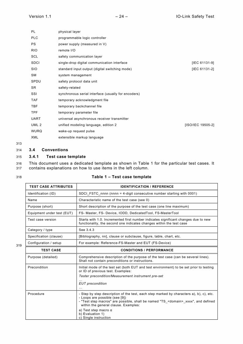
Version 1.1 – 24 – IO-Link Safety Test
PL physical layer
PLC programmable logic controller
PS power supply (measured in V)
RIO remote I/O
SCL safety communication layer
SDCI single-drop digital communication interface [IEC 61131-9]
SIO standard input output (digital switching mode) [IEC 61131-2]
SM system management
SPDU safety protocol data unit
SR safety-related
SSI synchronous serial interface (usually for encoders)
TAF temporary acknowledgment file
TBF temporary backchannel file
TPF temporary parameter file
UART universal asynchronous receiver transmitter
UML 2 unified modeling language, edition 2 [ISO/IEC 19505-2]
WURQ wake-up request pulse
XML extensible markup language
313
3.4 Conventions 314
3.4.1 Test case template 315
This document uses a dedicated template as shown in Table 1 for the particular test cases. It 316 contains explanations on how to use items in the left column. 317
Table 1 – Test case template 318
TEST CASE ATTRIBUTES IDENTIFICATION / REFERENCE
Identification (ID) SDCI_FSTC_nnnn (nnnn = 4-digit consecutive number starting with 0001)
Name Characteristic name of the test case (see 0)
Purpose (short) Short description of the purpose of the test case (one line maximum)
Equipment under test (EUT) FS- Master, FS- Device, IODD, DedicatedTool, FS-MasterTool
Test case version Starts with 1.0. Incremented first number indicates significant changes due to new functionality, the second one indicates changes within the test case
Category / type See 3.4.3
Specification (clause) [Bibliography, nn], clause or subclause, figure, table, chart, etc.
Configuration / setup For example: Reference-FS-Master and EUT (FS-Device) 319
TEST CASE CONDITIONS / PERFORMANCE
Purpose (detailed) Comprehensive description of the purpose of the test case (can be several lines). Shall not contain preconditions or instructions.
Precondition Initial mode of the test set (both EUT and test environment) to be set prior to testing or ID of previous test. Examples: Tester precondition/Measurement instrument pre-set … EUT precondition …
Procedure - Step by step description of the test, each step marked by characters a), b), c), etc. - Loops are possible (see [9]) - "Test step macros" are possible, shall be named "TS_<domain>_xxxx", and defined within the general clause. Examples: a) Test step macro α b) Evaluation 1) c) Single instruction
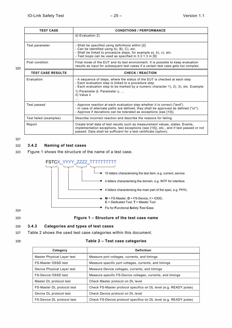
IO-Link Safety Test – 25 – Version 1.1
TEST CASE CONDITIONS / PERFORMANCE d) Evaluation 2) …
Test parameter - Shall be specified using definitions within [2] - Can be identified using A), B), C), etc. - Shall be linked to procedure steps, for example a), b), c), etc. - Test loops can be used as specified in 3.3.1.3 in [9]
Post condition Final mode of the EUT and its test environment. It is possible to keep evaluation results as input for subsequent test cases if a certain test case gets too complex.
320 TEST CASE RESULTS CHECK / REACTION
Evaluation - A sequence of steps, where the status of the EUT is checked at each step - Each evaluation step is linked to a procedure step - Each evaluation step to be marked by a numeric character 1), 2), 3), etc. Example: 1) Parameter β, Parameter γ, … 2) Value λ …
Test passed - Approve reaction at each evaluation step whether it is correct ("and") - In case of alternate paths are defined, they shall be approved as defined ("or"). - Approve if deviations can be tolerated as exceptions (see [10]).
Test failed (examples) Describe incorrect reaction and describe the reasons for failing
Report Create brief data of test results such as measurement values, states, Events, implementation exceptions, test exceptions (see [10]), etc., and if test passed or not passed. Data shall be sufficient for a test certificate (option).
321
3.4.2 Naming of test cases 322
Figure 1 shows the structure of the name of a test case. 323
324
Figure 1 – Structure of the test case name 325
3.4.3 Categories and types of test cases 326
Table 2 shows the used test case categories within this document. 327
Table 2 – Test case categories 328
Category Definition
Master Physical Layer test Measure port voltages, currents, and timings
FS-Master OSSD test Measure specific port voltages, currents, and timings
Device Physical Layer test Measure Device voltages, currents, and timings
FS-Device OSSD test Measure specific FS-Device voltages, currents, and timings
Master DL protocol test Check Master protocol on DL level
FS-Master DL protocol test Check FS-Master protocol specifics on DL level (e.g. READY pulse)
Device DL protocol test Check Device protocol on DL level
FS-Device DL protocol test Check FS-Device protocol specifics on DL level (e.g. READY pulse)
FSTCX_YYYY_ZZZZ_TTTTTTTTTT
Fix for Functional Safety Test Case
M = FS-Master, D = FS-Device, I = IODD, C = Dedicated Tool, T = Master Tool
4 letters characterising the main part of the spec, e.g. PHYL
4 letters characterising the domain, e.g. INTF for interface
10 letters characterising the test item, e.g. current, service
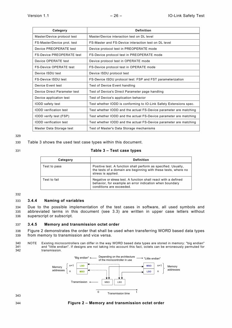
Version 1.1 – 26 – IO-Link Safety Test
Category Definition
Master/Device protocol test Master/Device interaction test on DL level
FS-Master/Device prot. test FS-Master and FS-Device interaction test on DL level
Device PREOPERATE test Device protocol test in PREOPERATE mode
FS-Device PREOPERATE test FS-Device protocol test in PREOPERATE mode
Device OPERATE test Device protocol test in OPERATE mode
FS-Device OPERATE test FS-Device protocol test in OPERATE mode
Device ISDU test Device ISDU protocol test
FS-Device ISDU test FS-Device ISDU protocol test: FSP and FST parameterization
Device Event test Test of Device Event handling
Device Direct Parameter test Test of Device's Direct Parameter page handling
Device application test Test of Device's application behavior
IODD safety test Test whether IODD is conforming to IO-Link Safety Extensions spec.
IODD verification test Test whether IODD and the actual FS-Device parameter are matching
IODD verify test (FSP) Test whether IODD and the actual FS-Device parameter are matching
IODD verification test Test whether IODD and the actual FS-Device parameter are matching
Master Data Storage test Test of Master's Data Storage mechanisms
329
Table 3 shows the used test case types within this document. 330
Table 3 – Test case types 331
Category Definition
Test to pass Positive test. A function shall perform as specified. Usually, the tests of a domain are beginning with these tests, where no stress is applied.
Test to fail Negative or stress test. A function shall react with a defined behavior, for example an error indication when boundary conditions are exceeded.
332
3.4.4 Naming of variables 333
Due to the possible implementation of the test cases in software, all used symbols and 334 abbreviated terms in this document (see 3.3) are written in upper case letters without 335 superscript or subscript. 336
3.4.5 Memory and transmission octet order 337
Figure 2 demonstrates the order that shall be used when transferring WORD based data types 338 from memory to transmission and vice versa. 339
NOTE Existing microcontrollers can differ in the way WORD based data types are stored in memory: "big endian" 340 and "little endian". If designs are not taking into account this fact, octets can be erroneously permuted for 341 transmission. 342
343
Figure 2 – Memory and transmission octet order 344
0 Transmission time t
MSO LSO
MSO
LSOn+1
n
Transmission
LSO
MSO n+1
n
"Big endian" "Little endian"Depending on the architecture of the microcontroller in use
Memoryaddresses
Memoryaddresses

IO-Link Safety Test – 27 – Version 1.1
3.4.6 Behavioral descriptions 345
The notations of UML 2 are used, mainly timing diagrams [7]. 346
4 Strategy for testing IO-Link Safety devices 347
4.1 Purpose of this test specification 348
This document specifies the test cases and the necessary test equipment for FS-Master and 349 FS-Devices in conjunction with its parent documents [9] and [4]. It covers OSSDe feature tests 350 as well as functional safety communication protocol tests. It covers also relevant test cases out 351 of [9] via references since both FS-Master and FS-Device are based on IO-Link Technology as 352 "black channel". 353
The functional safety communication protocol tests are derived from a UML state machine 354 simulation engine and automated to a large extent. 355
This document provides the necessary information for the development of test instructions for 356 a particular test set in test laboratories. 357
4.2 Structure of this document 358
Clause 5 specifies the test cases for the physical layer test of FS-Master and FS-Devices. They 359 mainly require individual manual tests of both signal channels Pin4 and Pin2 (OSSDe) with 360 variable power supplies, voltage and current meters as well as oscilloscopes. 361
Clause 6 specifies the XML schema and business rules tests for IODDs of FS-Devices using 362 XML snippet files and the IO-Link Checker Tool. Additional test cases verify the consistency of 363 the particular IODD and the actual FSP and FST parameters within the associated Device. 364
Clause 7 specifies additional test cases for FS-Devices verifying the consistency of the 365 particular IODD and the actual FSP and FST parameters within the associated FS-Device and 366 its operational modes. 367
Clause 8 specifies additional test cases for FS-Devices regarding safety measures such as the 368 VerifyRecord and the protocol watchdog. 369
Clause 9 contains the automatically generated test cases via UML modelling, model checking 370 and simulation for the safety communication layer (protocol) of the FS-Device. 371
Clause 10 specifies additional test cases for an FS-Device in a reference FS-Master system. 372
Clause 11 specifies the FS-Master Port operations test. 373
Clause 12 contains the automatically generated test cases via UML modelling, model checking 374 and simulation for the safety communication layer (protocol) of the FS-Master. 375
Clause 13 specifies additional test cases for an FS-Master with reference FS-Devices. 376
Clause 14 specifies additional test cases for an FS-Master Tool regarding IODD and Dedicted 377 Tool operations. 378
Clause 15 provides information on required environmental tests and relevant EMC standards 379 as well as special approaches for functional safety. 380
Annex A describes the test tools, their requirements, and the test configurations. Annex B 381 specifies requirements for safety assessments. Annex C provides information about support for 382 conformance testing. Annex D refers to the Manufacturer Declaration for FS-Master and FS-383 Device. Annex E provides an index on all test cases in this document. Annexes A, B, and D are 384 safety-related. 385
4.3 Conformity classes 386
4.3.1 Overview 387
All FS-Devices shall support ISDU and thus the rules in Clause 4.3.3 of [9] apply. 388

Version 1.1 – 28 – IO-Link Safety Test
4.3.2 FS-Devices with OSSDe 389
Safety devices with a single stop function such as e-stop buttons, two-hands control, mats, light 390 curtain, etc. are candidates to become an FS-Device with both OSSDe and digital safety 391 communication and thus serving the markets for FS-DI modules in both the classic remote I/Os 392 as well as the extended functionality with identification, parameterization, diagnosis, and Data 393 Storage features to participate in modern automation concepts when connected to an FS-394 Master. 395
4.3.3 FS-Devices without OSSDe 396
Safety devices with measurement capabilities such as for temperature, strain, torque, pressure, 397 object types, distance, position, rotation, or multi-sensing, or actuators such as motor starters, 398 drives, and mechatronics containing sensors and actuators such as door locks, grippers, low 399 voltage witch gears are candidates to become an FS-Device without OSSDe. 400
FS-Devices without OSSDe can benefit from extra 24 V power via class B. 401
4.3.4 FS-Master 402
FS-Master shall support all features specified in [4], which are not marked explicitly as optional. 403 All Ports shall provide power supply ≥ 200 mA, at least one Port shall supply 1000 mA. 404
4.3.5 FS-Master with FS-DI/OSSDe support 405
FS-Master can provide FS-DI/OSSDe support to benefit from existing safety devices on the 406 market as long as there are no versions available with SDCI-FS. 407
4.3.6 FS-Master with Port Class B 408
An FS-Master with Ports Class B is possible, however without FS-DI/OSSDe support. The rules 409 in Clause 5.4.2 of [2] apply. 410
4.4 Test of FS-Devices 411
4.4.1 General 412
In general, the rules in Clause 5.1 of [9] apply. 413
4.4.2 Compatibility with non-safety Master (tester) Ports 414
4.4.2.1 Device properties for the analysis of the test behavior 415
It may happen that an FS-Device is connected to a Port in the non-safety mode of an FS-416 Master/Master or a USB-Master. Since some start-up features of the FS-Devices such as ready 417 pulse and OSSDe are "unknown" to a non-safety Master Port, they may impair (test) 418 functionality. It is not possible, to avoid completely all possible conflicts due to the huge number 419 of deployments of Masters in the field and fortunately these cases do not occur very often. 420
However, this cannot be assumed for Device tester ("USB-Master") in general and therefore 421 the possible conflicts have been analyzed with the help of a dummy representing a typical FS-422 Device and a tester representing a typical Master Port. 423
Table 4 shows the characteristics of the dummy FS-Device for the analysis. 424
Table 4 – Features of the dummy FS-Device 425
Feature Characteristic/value Remark
Self-testing time 3 s –
Ready pulse Implemented as specified –
Switching to OSSDe mode 1.1 s after the Ready pulse as specified in [4]
After switching to OSSDe mode, the FS-Device shall not react on any wake-up or other disturbances.
No OSSDe mode 1. FS-Device is awaiting wake-up pulse 2. FS-Device reacts on "fallback" command
1. Regular behavior 2. FS-Device switches to SIO mode
426
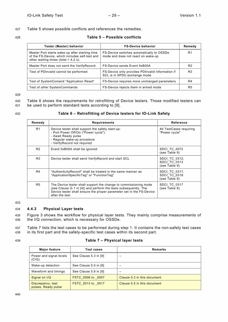
IO-Link Safety Test – 29 – Version 1.1
Table 5 shows possible conflicts and references the remedies. 427
Table 5 – Possible conflicts 428
Tester (Master) behavior FS-Device behavior Remedy
Master Port starts wake-up after starting time of the FS-Device, which includes self-test and other waiting times (total > 4,2 s).
FS-Device switches automatically to OSSDe mode and does not react on wake-up
R1
Master Port does not send the VerifyRecord. FS-Device sends Event 0xB00A R2
Test of PDInvalid cannot be performed FS-Device only provides PDInvalid information if SCL is in SPDU exchange mode
R3
Test of SystemComand "Application Reset" FS-Device requires more unchanged parameters R4
Test of other SystemCommands FS-Device rejects them in armed mode R5
429
Table 6 shows the requirements for retrofitting of Device testers. Those modified testers can 430 be used to perform standard tests according to [9]. 431
Table 6 – Retrofitting of Device testers for IO-Link Safety 432
Remedy Requirements Reference
R1 Device tester shall support the safety start-up: - Port Power Off/On ("Power cycle") - Await Ready pulse - Regular wake-up procedure - VerifyRecord not required
All TestCases requiring "Power cycle"
R2 Event 0xB00A shall be ignored SDCI_TC_0072 (see Table 9)
R3 Device tester shall send VerifyRecord and start SCL SDCI_TC_0312, SDCI_TC_0313 (see Table 9)
R4 "AuthenticityRecord" shall be treated in the same manner as "ApplicationSpecificTag" or "FunctionTag"
SDCI_TC_0317, SDCI_TC_0318 (see Table 9)
R5 The Device tester shall support the change to commissioning mode (see Clause G.1 in [4]) and perform the tests subsequently. The Device tester shall ensure the proper parameter set in the FS-Device after the test.
SDCI_TC_0317 (see Table 9)
433
4.4.3 Physical Layer tests 434
Figure 3 shows the workflow for physical layer tests. They mainly comprise measurements of 435 the I/Q connection, which is necessary for OSSDe. 436
Table 7 lists the test cases to be performed during step 1. It contains the non-safety test cases 437 in its first part and the safety-specific test cases within its second part. 438
Table 7 – Physical layer tests 439
Major feature Test cases Remarks
Power and signal levels (C/Q)
See Clause 5.3 in [9] –
Wake-up detection See Clause 5.5 in [9] –
Waveform and timings See Clause 5.6 in [9] –
Signal on I/Q FSTC_0006 to _0007 Clause 5.3 in this document
Discrepancy, test pulses, Ready pulse
FSTC_0013 to _0017 Clause 5.5 in this document
440
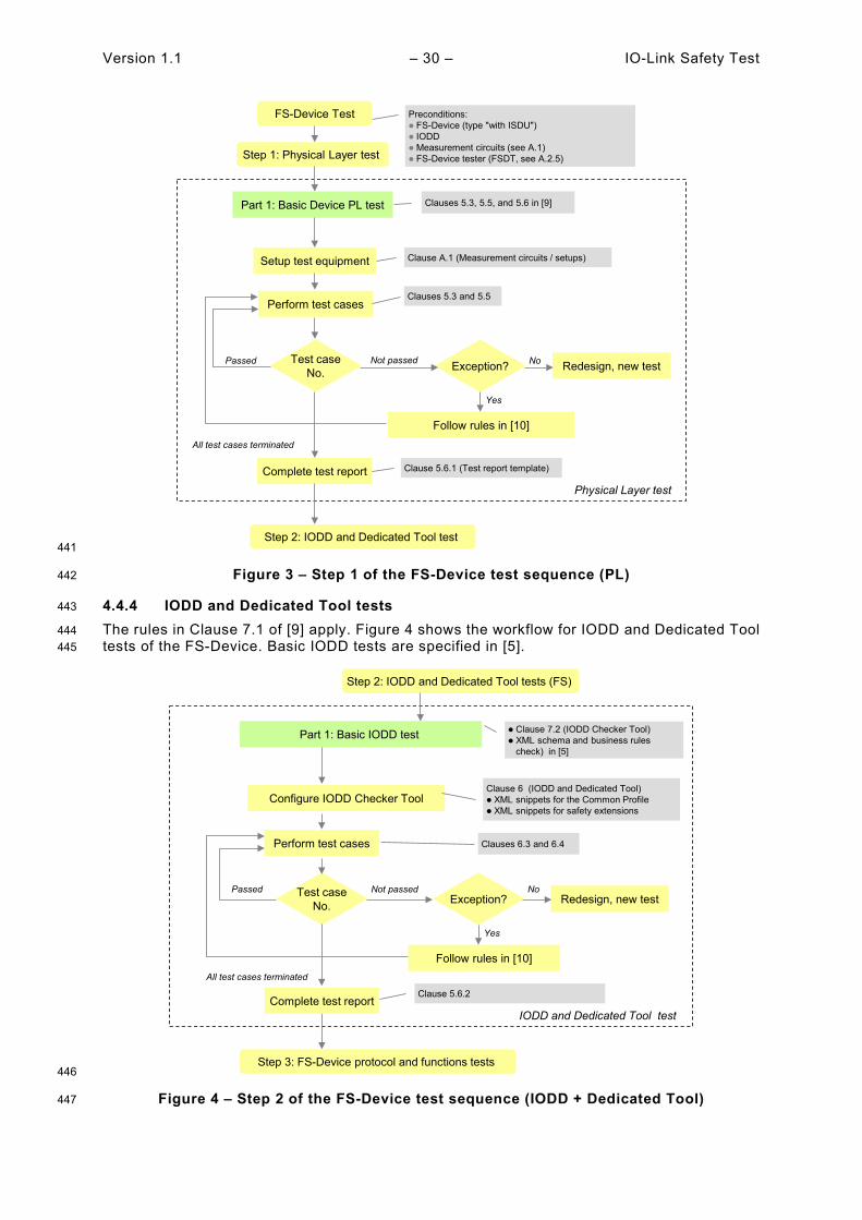
Version 1.1 – 30 – IO-Link Safety Test
441
Figure 3 – Step 1 of the FS-Device test sequence (PL) 442
4.4.4 IODD and Dedicated Tool tests 443
The rules in Clause 7.1 of [9] apply. Figure 4 shows the workflow for IODD and Dedicated Tool 444 tests of the FS-Device. Basic IODD tests are specified in [5]. 445
446
Figure 4 – Step 2 of the FS-Device test sequence (IODD + Dedicated Tool) 447
Complete test report
All test cases terminated
Physical Layer test
Step 1: Physical Layer test
Preconditions: FS-Device (type "with ISDU") IODD Measurement circuits (see A.1) FS-Device tester (FSDT, see A.2.5)
Clause 5.6.1 (Test report template)
Step 2: IODD and Dedicated Tool test
FS-Device Test
Part 1: Basic Device PL test Clauses 5.3, 5.5, and 5.6 in [9]
Setup test equipment
Perform test cases
Test caseNo.
Passed Exception? Redesign, new testNo
Follow rules in [10]
Yes
Clause A.1 (Measurement circuits / setups)
Clauses 5.3 and 5.5
Not passed
Part 1: Basic IODD test
Step 2: IODD and Dedicated Tool tests (FS)
Clause 7.2 (IODD Checker Tool) XML schema and business rules
check) in [5]
Step 3: FS-Device protocol and functions tests
Complete test report
All test cases terminated
IODD and Dedicated Tool test
Clause 5.6.2
Configure IODD Checker Tool
Perform test cases
Test caseNo.
PassedException? Redesign, new test
Not passed No
Follow rules in [10]
Yes
Clause 6 (IODD and Dedicated Tool) XML snippets for the Common Profile XML snippets for safety extensions
Clauses 6.3 and 6.4
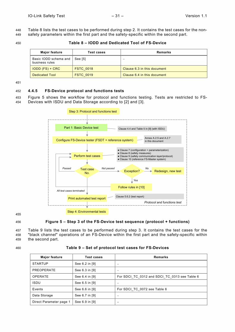
IO-Link Safety Test – 31 – Version 1.1
Table 8 lists the test cases to be performed during step 2. It contains the test cases for the non-448 safety parameters within the first part and the safety-specific within the second part. 449
Table 8 – IODD and Dedicated Tool of FS-Device 450
Major feature Test cases Remarks
Basic IODD schema and business rules
See [5] −
IODD (FS) + CRC FSTC_0018 Clause 6.3 in this document
Dedicated Tool FSTC_0019 Clause 6.4 in this document
451
4.4.5 FS-Device protocol and functions tests 452
Figure 5 shows the workflow for protocol and functions testing. Tests are restricted to FS-453 Devices with ISDU and Data Storage according to [2] and [3]. 454
455
Figure 5 – Step 3 of the FS-Device test sequence (protocol + functions) 456
Table 9 lists the test cases to be performed during step 3. It contains the test cases for the 457 "black channel" operations of an FS-Device within the first part and the safety-specific within 458 the second part. 459
Table 9 – Set of protocol test cases for FS-Devices 460
Major feature Test cases Remarks
STARTUP See 6.2 in [9] −
PREOPERATE See 6.3 in [9] −
OPERATE See 6.4 in [9] For SDCI_TC_0312 and SDCI_TC_0313 see Table 6
ISDU See 6.5 in [9] −
Events See 6.6 in [9] For SDCI_TC_0072 see Table 6
Data Storage See 6.7 in [9] −
Direct Parameter page 1 See 6.9 in [9] −
Part 1: Basic Device test
Step 3: Protocol and functions test
Clause 4.4 and Table 5 in [9] (with ISDU)
Step 4: Environmental tests
Print automated test report
All test cases terminated
Protocol and functions test
Clause 5.6.2 (test report)
Configure FS-Device tester (FSDT + reference system)
Perform test cases
Test caseNo.
PassedException? Redesign, new test
Not passed No
Follow rules in [10]
Yes
Annex A.2.5 and A.2.7in this document
Clause 7 (configuration + parameterization) Clause 8 (safety measures) Clause 9 (safety communication layer/protocol) Clause 10 (reference FS-Master system)

Version 1.1 – 32 – IO-Link Safety Test
Major feature Test cases Remarks
Predefined parameters See 6.10 in [9] −
Block parameter See 6.11 in [9] −
IODD based parameter verification
See 7.3 in [9] −
IODD based functional system tests
See 7.4 in [9] For SDCI_TC_0317 and SDCI_TC_0318 see Table 6
Configuration + parameterization
FSTC_0020 to _0034 Clause 7 in this document
Safety measures FSTC_0035 to _0051 Clause 8 in this document
Safety protocol (SCL) FSTC_0052 to _0147 Clause 9 in this document
Dedicated Tool, replacement, Events
FSTC_0148 to _0154 Clause 10 in this document
461
4.4.6 Environment 462
Figure 6 shows step 4 of the FS-Device test. It contains references to the relevant clauses in 463 this specification and consists of EMC tests according to generic or product-specific standards 464 specified in 15.2. A successfully terminated FS-Device test can be completed by a manufacturer 465 declaration as defined in Annex D. 466
467
Figure 6 – Step 4 of the FS-Device test sequence (EMC) 468
Setup EMC testing Clause 15.3 in this document Relevant clauses in EMC standards
Step 4: Environmental tests
Perform tests
Complete test report
EMC testNo.
All test cases terminated
Passed
Environmental test
Exception? Redesign, new testNot passed No
Description in safety manual
Yes
Forms in Clause 9.4 (EMC test report) in [9] can be used
Complete manufacturer declaration
Other relevantstandards? Perform tests
Not passedRedesign, new test
Yes
Annex D in this document (Manufacturer declaration)
End of FS-Device testing
PassedNo
Clause 15.4 lists relevant standards
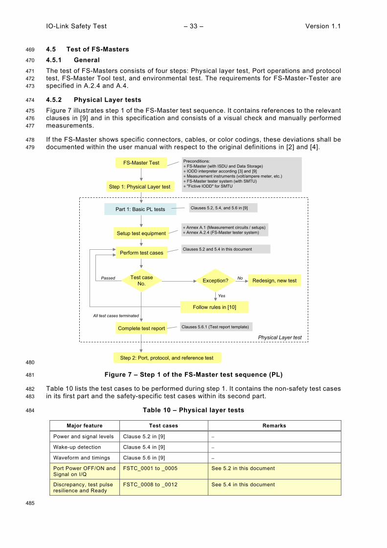
IO-Link Safety Test – 33 – Version 1.1
4.5 Test of FS-Masters 469
4.5.1 General 470
The test of FS-Masters consists of four steps: Physical layer test, Port operations and protocol 471 test, FS-Master Tool test, and environmental test. The requirements for FS-Master-Tester are 472 specified in A.2.4 and A.4. 473
4.5.2 Physical Layer tests 474
Figure 7 illustrates step 1 of the FS-Master test sequence. It contains references to the relevant 475 clauses in [9] and in this specification and consists of a visual check and manually performed 476 measurements. 477
If the FS-Master shows specific connectors, cables, or color codings, these deviations shall be 478 documented within the user manual with respect to the original definitions in [2] and [4]. 479
480
Figure 7 – Step 1 of the FS-Master test sequence (PL) 481
Table 10 lists the test cases to be performed during step 1. It contains the non-safety test cases 482 in its first part and the safety-specific test cases within its second part. 483
Table 10 – Physical layer tests 484
Major feature Test cases Remarks
Power and signal levels Clause 5.2 in [9] −
Wake-up detection Clause 5.4 in [9] −
Waveform and timings Clause 5.6 in [9] −
Port Power OFF/ON and Signal on I/Q
FSTC_0001 to _0005 See 5.2 in this document
Discrepancy, test pulse resilience and Ready
FSTC_0008 to _0012 See 5.4 in this document
485
Complete test report
All test cases terminated
Physical Layer test
Step 1: Physical Layer test
Preconditions: FS-Master (with ISDU and Data Storage) IODD interpreter according [3] and [9]Measurement instruments (volt/ampere meter, etc.) FS-Master tester system (with SMTU) "Fictive IODD" for SMTU
Clauses 5.6.1 (Test report template)
Step 2: Port, protocol, and reference test
FS-Master Test
Part 1: Basic PL tests Clauses 5.2, 5.4, and 5.6 in [9]
Setup test equipment
Perform test cases
Test caseNo.
Passed Exception? Redesign, new testNo
Follow rules in [10]
Yes
Annex A.1 (Measurement circuits / setups) Annex A.2.4 (FS-Master tester system)
Clauses 5.2 and 5.4 in this document
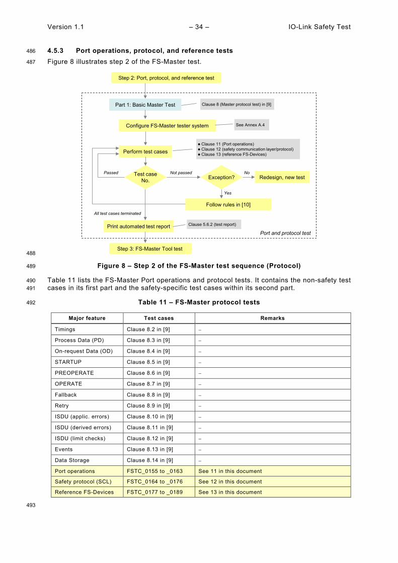
Version 1.1 – 34 – IO-Link Safety Test
4.5.3 Port operations, protocol, and reference tests 486
Figure 8 illustrates step 2 of the FS-Master test. 487
488
Figure 8 – Step 2 of the FS-Master test sequence (Protocol) 489
Table 11 lists the FS-Master Port operations and protocol tests. It contains the non-safety test 490 cases in its first part and the safety-specific test cases within its second part. 491
Table 11 – FS-Master protocol tests 492
Major feature Test cases Remarks
Timings Clause 8.2 in [9] −
Process Data (PD) Clause 8.3 in [9] −
On-request Data (OD) Clause 8.4 in [9] −
STARTUP Clause 8.5 in [9] −
PREOPERATE Clause 8.6 in [9] −
OPERATE Clause 8.7 in [9] −
Fallback Clause 8.8 in [9] −
Retry Clause 8.9 in [9] −
ISDU (applic. errors) Clause 8.10 in [9] −
ISDU (derived errors) Clause 8.11 in [9] −
ISDU (limit checks) Clause 8.12 in [9] −
Events Clause 8.13 in [9] −
Data Storage Clause 8.14 in [9] −
Port operations FSTC_0155 to _0163 See 11 in this document
Safety protocol (SCL) FSTC_0164 to _0176 See 12 in this document
Reference FS-Devices FSTC_0177 to _0189 See 13 in this document
493
Step 2: Port, protocol, and reference test
Part 1: Basic Master Test Clause 8 (Master protocol test) in [9]
Step 3: FS-Master Tool test
Print automated test report
All test cases terminated
Port and protocol test
Configure FS-Master tester system
Perform test cases
Test caseNo.
PassedException? Redesign, new test
Not passed No
Follow rules in [10]
Yes
See Annex A.4
Clause 11 (Port operations) Clause 12 (safety communication layer/protocol) Clause 13 (reference FS-Devices)
Clause 5.6.2 (test report)

IO-Link Safety Test – 35 – Version 1.1
4.5.4 FS-Master Tool 494
Figure 9 illustrates step 3 of the FS-Master test. It contains references to the relevant clauses 495 in [9] and in this specification and consists of tests regarding importability (CRC signature 496 check) and display conventions (yellow color), as well as parameter access via DTI and DDO 497 exchange. 498
499
Figure 9 – Step 3 of the FS-Master test sequence (FS-Master Tool) 500
4.5.5 Environment 501
Figure 10 illustrates step 4 of the FS-Master test. It contains references to the relevant clauses 502 in this specification and consists of EMC tests according to generic or product-specific 503 standards specified in 15.2. A successfully terminated FS-Master test can be completed by a 504 manufacturer declaration as defined in Annex D. 505
506
Figure 10 – Step 4 of the FS-Master test (EMC) 507
508
See Figure 9 in [9]
Step 4: Environmental tests
All tests terminated
FS-Master Tool
Part 1: Basic IODD Interpreter test
Print automated test reportClause 5.6.2 (Test report generated by the FS-Master Tester)
Check complete and correctIODD operations
No deviation
Redesign, new testNo
Description in safety user manual
Yes
Deviation
Exception?
Step 3: FS-Master Tool test
Clause 14 in this document: IODD import and safety conventions Visibility and operation of FS parameters Dedicated Tool operation DDO exchange
End of FS-Master testing
Fieldbus conformity test Relevant Fieldbus Integration specification Fieldbus test laboratory
Fieldbus Integration test
See FS-Device EMC testing in 4.4.5 Clause 15.3 in this document Relevant clauses in EMC standards
Step 4: Environmental tests
Environmental test
Complete manufacturer declaration Annex D in this document (Manufacturer declaration)
Version 1.1 – 36 – IO-Link Safety Test
5 Physical Layer (PL) tests 509
5.1 General 510
The approach, nature and coverage of the FS-Device and FS-Master physical layer tests are 511 described in 4.4.3 and 4.5.2. Figure 3 and Figure 7 illustrate the entire test procedure including 512 the safety part. 513
The tests of static characteristics of FS-Master Ports comprise Power OFF/ON and the I/Q pin, 514 which is required for OSSDe2 (FS-DI). The tests of dynamic characteristics of FS-Master Ports 515 comprise Ready pulse, discrepancy of OSSDe signals, OSSDe test pulses, and Wake-up delay. 516
The tests of static characteristics of FS-Devices comprise power consumption and residual 517 voltages at OSSDe2 (I/Q pin). The tests of dynamic characteristics of FS-Devices comprise 518 discrepancy of OSSDe signals, OSSDe test pulses, Ready pulse duration, and delay to 519 OSSDe operation. 520
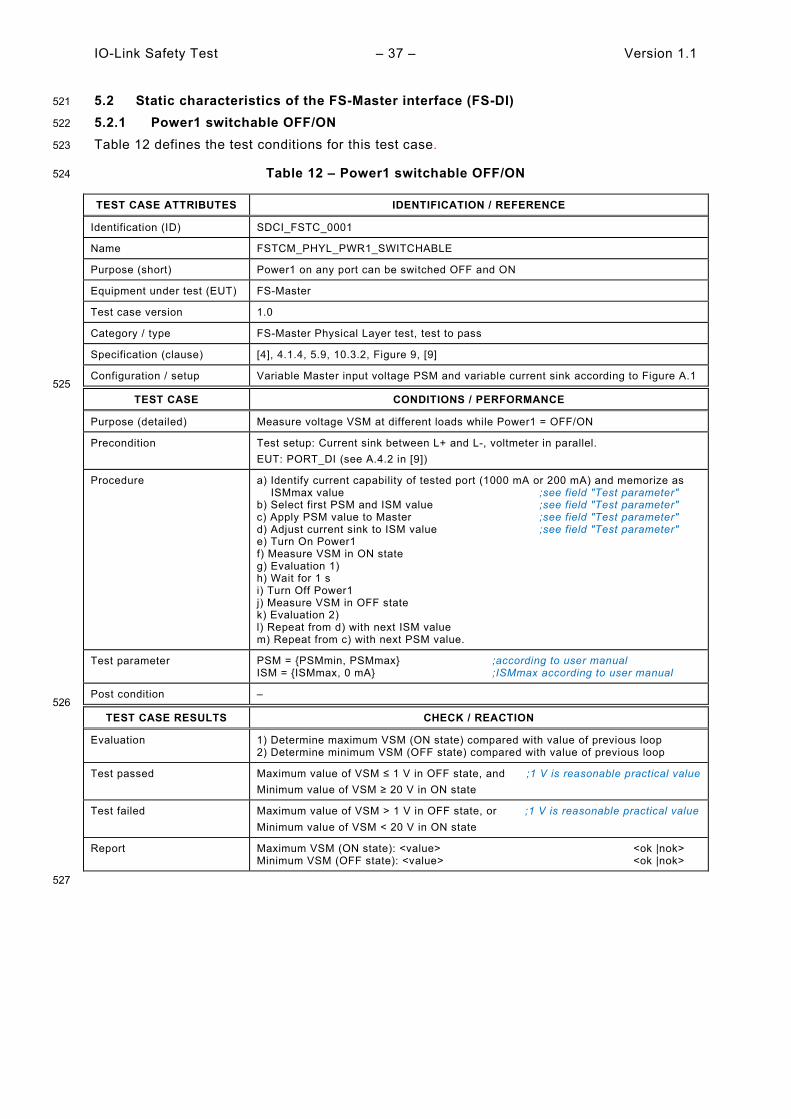
IO-Link Safety Test – 37 – Version 1.1
5.2 Static characteristics of the FS-Master interface (FS-DI) 521
5.2.1 Power1 switchable OFF/ON 522
Table 12 defines the test conditions for this test case. 523
Table 12 – Power1 switchable OFF/ON 524
TEST CASE ATTRIBUTES IDENTIFICATION / REFERENCE
Identification (ID) SDCI_FSTC_0001
Name FSTCM_PHYL_PWR1_SWITCHABLE
Purpose (short) Power1 on any port can be switched OFF and ON
Equipment under test (EUT) FS-Master
Test case version 1.0
Category / type FS-Master Physical Layer test, test to pass
Specification (clause) [4], 4.1.4, 5.9, 10.3.2, Figure 9, [9]
Configuration / setup Variable Master input voltage PSM and variable current sink according to Figure A.1 525
TEST CASE CONDITIONS / PERFORMANCE
Purpose (detailed) Measure voltage VSM at different loads while Power1 = OFF/ON
Precondition Test setup: Current sink between L+ and L-, voltmeter in parallel. EUT: PORT_DI (see A.4.2 in [9])
Procedure a) Identify current capability of tested port (1000 mA or 200 mA) and memorize as ISMmax value ;see field "Test parameter" b) Select first PSM and ISM value ;see field "Test parameter" c) Apply PSM value to Master ;see field "Test parameter" d) Adjust current sink to ISM value ;see field "Test parameter" e) Turn On Power1 f) Measure VSM in ON state g) Evaluation 1) h) Wait for 1 s i) Turn Off Power1 j) Measure VSM in OFF state k) Evaluation 2) l) Repeat from d) with next ISM value m) Repeat from c) with next PSM value.
Test parameter PSM = {PSMmin, PSMmax} ;according to user manual ISM = {ISMmax, 0 mA} ;ISMmax according to user manual
Post condition – 526
TEST CASE RESULTS CHECK / REACTION
Evaluation 1) Determine maximum VSM (ON state) compared with value of previous loop 2) Determine minimum VSM (OFF state) compared with value of previous loop
Test passed Maximum value of VSM ≤ 1 V in OFF state, and ;1 V is reasonable practical value Minimum value of VSM ≥ 20 V in ON state
Test failed Maximum value of VSM > 1 V in OFF state, or ;1 V is reasonable practical value Minimum value of VSM < 20 V in ON state
Report Maximum VSM (ON state): <value> <ok |nok> Minimum VSM (OFF state): <value> <ok |nok>
527
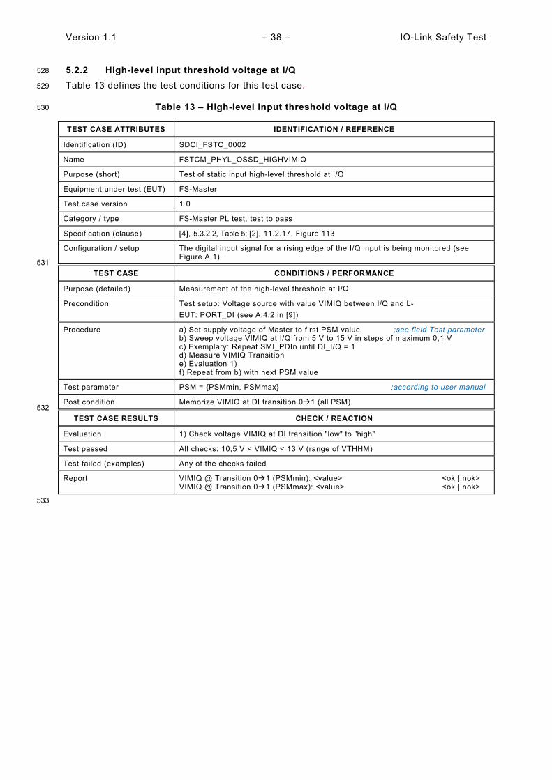
Version 1.1 – 38 – IO-Link Safety Test
5.2.2 High-level input threshold voltage at I/Q 528
Table 13 defines the test conditions for this test case. 529
Table 13 – High-level input threshold voltage at I/Q 530
TEST CASE ATTRIBUTES IDENTIFICATION / REFERENCE
Identification (ID) SDCI_FSTC_0002
Name FSTCM_PHYL_OSSD_HIGHVIMIQ
Purpose (short) Test of static input high-level threshold at I/Q
Equipment under test (EUT) FS-Master
Test case version 1.0
Category / type FS-Master PL test, test to pass
Specification (clause) [4], 5.3.2.2, Table 5; [2], 11.2.17, Figure 113
Configuration / setup The digital input signal for a rising edge of the I/Q input is being monitored (see Figure A.1)
531 TEST CASE CONDITIONS / PERFORMANCE
Purpose (detailed) Measurement of the high-level threshold at I/Q
Precondition Test setup: Voltage source with value VIMIQ between I/Q and L- EUT: PORT_DI (see A.4.2 in [9])
Procedure a) Set supply voltage of Master to first PSM value ;see field Test parameter b) Sweep voltage VIMIQ at I/Q from 5 V to 15 V in steps of maximum 0,1 V c) Exemplary: Repeat SMI_PDIn until DI_I/Q = 1 d) Measure VIMIQ Transition e) Evaluation 1) f) Repeat from b) with next PSM value
Test parameter PSM = {PSMmin, PSMmax} ;according to user manual
Post condition Memorize VIMIQ at DI transition 01 (all PSM) 532
TEST CASE RESULTS CHECK / REACTION
Evaluation 1) Check voltage VIMIQ at DI transition "low" to "high"
Test passed All checks: 10,5 V < VIMIQ < 13 V (range of VTHHM)
Test failed (examples) Any of the checks failed
Report VIMIQ @ Transition 01 (PSMmin): <value> <ok | nok> VIMIQ @ Transition 01 (PSMmax): <value> <ok | nok>
533

IO-Link Safety Test – 39 – Version 1.1
5.2.3 Low-level input threshold voltage at I/Q 534
Table 14 defines the test conditions for this test case. 535
Table 14 – Low-level input threshold voltage at I/Q 536
TEST CASE ATTRIBUTES IDENTIFICATION / REFERENCE
Identification (ID) SDCI_FSTC_0003
Name FSTCM_PHYL_OSSD_LOWVIMIQ
Purpose (short) Test of static input low-level threshold at I/Q
Equipment under test (EUT) FS-Master
Test case version 1.0
Category / type FS-Master PL test, test to pass
Specification (clause) [4], 5.3.2.2, Table 5; [2], 11.2.17, Figure 113
Configuration / setup The digital input signal for a falling edge of the I/Q input is being monitored (see Figure A.1)
537 TEST CASE CONDITIONS / PERFORMANCE
Purpose (detailed) Measurement of the low-level threshold at I/Q
Precondition Test setup: Voltage source with value VIMIQ between I/Q and L- EUT: PORT_DI (see A.4.2 in [9])
Procedure a) Set supply voltage of Master to first PSM value ;see field Test parameter b) Sweep voltage VIMIQ at I/Q from 15 V to 5 V in steps of maximum 0,1 V c) Exemplary: Repeat SMI_PDIn until DI_I/Q = 0 d) Measure VIMIQ Transition e) Evaluation 1) f) Repeat from b) with next PSM value
Test parameter PSM = {PSMmin, PSMmax} ;according to user manual
Post condition Memorize VIMIQ at DI transition 10 (all PSM) 538
TEST CASE RESULTS CHECK / REACTION
Evaluation 1) Check voltage VIMIQ at DI transition "high" to "low"
Test passed All checks: 8,0 V < VIMIQ < 11,5 V (range of VTHLM)
Test failed (examples) Any of the checks failed
Report VIMIQ @ Transition 10 (PSMmin): <value> <ok | nok> VIMIQ @ Transition 10 (PSMmax): <value> <ok | nok>
539
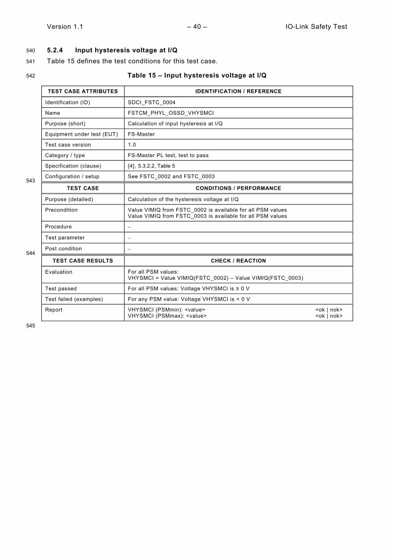
Version 1.1 – 40 – IO-Link Safety Test
5.2.4 Input hysteresis voltage at I/Q 540
Table 15 defines the test conditions for this test case. 541
Table 15 – Input hysteresis voltage at I/Q 542
TEST CASE ATTRIBUTES IDENTIFICATION / REFERENCE
Identification (ID) SDCI_FSTC_0004
Name FSTCM_PHYL_OSSD_VHYSMCI
Purpose (short) Calculation of input hysteresis at I/Q
Equipment under test (EUT) FS-Master
Test case version 1.0
Category / type FS-Master PL test, test to pass
Specification (clause) [4], 5.3.2.2, Table 5
Configuration / setup See FSTC_0002 and FSTC_0003 543
TEST CASE CONDITIONS / PERFORMANCE
Purpose (detailed) Calculation of the hysteresis voltage at I/Q
Precondition Value VIMIQ from FSTC_0002 is available for all PSM values Value VIMIQ from FSTC_0003 is available for all PSM values
Procedure −
Test parameter −
Post condition − 544
TEST CASE RESULTS CHECK / REACTION
Evaluation For all PSM values: VHYSMCI = Value VIMIQ(FSTC_0002) – Value VIMIQ(FSTC_0003)
Test passed For all PSM values: Voltage VHYSMCI is ≥ 0 V
Test failed (examples) For any PSM value: Voltage VHYSMCI is < 0 V
Report VHYSMCI (PSMmin): <value> <ok | nok> VHYSMCI (PSMmax): <value> <ok | nok>
545

IO-Link Safety Test – 41 – Version 1.1
5.2.5 Load current at I/Q 546
Table 16 defines the test conditions for this test case. 547
Table 16 – Load current at I/Q 548
TEST CASE ATTRIBUTES IDENTIFICATION / REFERENCE
Identification (ID) SDCI_FSTC_0005
Name FSTCM_PHYL_OSSD_LOADIQ
Purpose (short) Load current at I/Q of FS-Master Port
Equipment under test (EUT) FS-Master
Test case version 1.0
Category / type FS-Master PL test, test to pass
Specification (clause) [4], 5.3.2.3, Table 6
Configuration / setup The input current at I/Q of the FS-Master Port is being monitored (see Figure A.1). 549
TEST CASE CONDITIONS / PERFORMANCE
Purpose (detailed) Quiescent current at FS-Master Port I/Q in input mode. Monitor current flowing into I/Q.
Precondition Test setup: Voltage source with value VIMIQ between L- and I/Q EUT: PORT_DI (see A.4.2 in [9])
Procedure a) Set supply voltage of Master to first PSM value ;Test parameter b) Measure VSM c) Set voltage VIMIQ = 5V d) Measure current ILLM into I/Q e) Evaluation 1) f) Set voltage VIMIQ = 5,1 V g) Measure current ILLM into I/Q h) Evaluation 2) i) Set voltage VIMIQ = 15V j) Measure current ILLM into I/Q k) Evaluation 3) l) Set voltage VIMIQ = measured value of VSM in b) m) Measure current ILLM into I/Q n) Evaluation 4) o) Repeat from b) with next PSM value
Test parameter PSM = {PSMmin, PSMmax} (according to user manual)
Post condition − 550
TEST CASE RESULTS CHECK / REACTION
Evaluation 1) Check ILLM < 15 mA 2) Check 2 mA < ILLM < 15 mA 3) Check 2 mA < ILLM < 15 mA 4) Check 2 mA < ILLM < 15 mA
Test passed All checks OK
Test not passed (examples) Any of the checks above failed
Report ILLM (VIMIQ = 5 V, PSMmin): <value> <ok | nok> ILLM (VIMIQ = 5,1 V, PSMmin): <value> <ok | nok> ILLM (VIMIQ = 15 V, PSMmin): <value> <ok | nok> ILLM (VIMIQ = measured value of VSM, PSMmin): <value> <ok | nok> ILLM (VIMIQ = 5 V, PSMmax): <value> <ok | nok> ILLM (VIMIQ = 5,1 V, PSMmax): <value> <ok | nok> ILLM (VIMIQ = 15 V, PSMmax): <value> <ok | nok> ILLM (VIMIQ = measured value of VSM, PSMmax): <value> <ok | nok>
551

Version 1.1 – 42 – IO-Link Safety Test
5.3 Static characteristics of the FS-Device interface 552
5.3.1 General 553
Power consumption of an FS-Device is already tested via NSR tests according to [9]. Warnings 554 in case of current limits > 200 mA are checked via user manual in 7.2.3. 555
This clause focuses on tests of signal behavior on I/Q pin of an FS-Device. 556
5.3.2 High-side residual voltage at FS-Device OSSD2 557
Table 17 defines the test conditions for this test case. It is only applicable for Devices with 558 OSSD. 559
Table 17 – High-side residual voltage at FS-Device OSSD2 560
TEST CASE ATTRIBUTES IDENTIFICATION / REFERENCE
Identification (ID) SDCI_FSTC_0006
Name FSTCD_PHYL_OSSD_HSRESVOLT
Purpose (short) Static high-side driver capability
Equipment under test (EUT) FS-Device with OSSD output
Test case version 1.0
Category / type FS-Device PL test, test to pass
Specification (clause) [4], 5.4
Configuration / setup The high-side output level of the FS-Device OSSD2 output is measured while connected to a current sink (see Figure A.2, method )
561 TEST CASE CONDITIONS / PERFORMANCE
Purpose (detailed) Driver capability of the FS-Device high-side driver. Measurement of the voltage drop VIQ between L+ and I/Q (OSSD2) under load condition of 50 mA.
Precondition PL-Tester: Voltage source with value VSD between L+ and L- EUT: FS-Device in OSSD mode with signals in high state
Procedure a) Apply first supply voltage VSD to the Device ;Test parameter b) Apply current sink with 50 mA from I/Q (OSSD2) to L- c) Measure voltage VIQ between L+ and I/Q (OSSD2) d) Evaluation 1) e) Repeat from b) with next VSD value
Test parameter VSD = {18 V, 30 V}
Post condition – 562
TEST CASE RESULTS CHECK / REACTION
Evaluation 1) Check VIQ
Test passed For all VSD values: VIQ ≤ 3,0 V
Test not passed (examples) For any VSD value: VIQ > 3,0 V
Report VIQ (VSD = 18 V): <value> <ok | nok> VIQ (VSD = 30 V): <value> <ok | nok>
563

IO-Link Safety Test – 43 – Version 1.1
5.3.3 Low-side residual voltage at FS-Device OSSD2 564
Table 18 defines the test conditions for this test case. It is only applicable for Devices with 565 OSSD. 566
Table 18 – Low-side residual voltage at FS-Device OSSD2 567
TEST CASE ATTRIBUTES IDENTIFICATION / REFERENCE
Identification (ID) SDCI_FSTC_0007
Name FSTCD_PHYL_OSSD_LSRESVOLT
Purpose (short) Static low-side driver capability
Equipment under test (EUT) FS-Device with OSSD output
Test case version 1.0
Category / type FS-Device PL test, test to pass
Specification (clause) [4], 5.4
Configuration / setup The low-side output level of the FS-Device OSSD2 output is measured while connected to a current source (see Figure A.2, method )
568 TEST CASE CONDITIONS / PERFORMANCE
Purpose (detailed) Driver capability of the FS-Device low-side driver. Measurement of the voltage drop between negative supply L- and I/Q (OSSD2) output at source current of 50 mA
Precondition Test setup: Voltage source with value VSD between L+ and L- EUT: FS-Device in OSSD mode with signals in low state
Procedure a) Apply first supply voltage VSD to the FS-Device ;Test parameter b) Apply current source with 50 mA from I/Q (OSSD2) to L+ c) Measure voltage VIQ between I/Q (OSSD2) and L- d) Evaluation 1) e) Repeat from b) with next VSD value
Test parameter VSD = {18 V, 30 V}
Post condition – 569
TEST CASE RESULTS CHECK / REACTION
Evaluation 1) Check VIQ
Test passed For all VSD values: VIQ ≤ 3,0 V
Test not passed (examples) For any VSD value: VIQ > 3,0 V
Report VIQ (VSD = 18 V): <value> <ok | nok> VIQ (VSD = 30 V): <value> <ok | nok>
570

Version 1.1 – 44 – IO-Link Safety Test
5.4 Dynamic characteristics of the FS-Master interface 571
5.4.1 FS-DI and OSSD sensor with and without READY pulse 572
Table 19 defines the test conditions for this test case. 573
Table 19 – FS-DI and OSSD sensor with and without READY pulse 574
TEST CASE ATTRIBUTES IDENTIFICATION / REFERENCE
Identification (ID) SDCI_FSTC_0008
Name FSTCM_PHYL_INTF_OSSDSENS
Purpose (short) Start-up of FS-Master Port with OSSD sensor with and without READY pulse
Equipment under test (EUT) FS-Master
Test case version 1.0
Category / type FS-Master Physical Layer test, test to pass
Specification (clause) [4], 5.3.3, Figure 20, Figure 21; 5.4, Table 7
Configuration / setup OSSD signal generator (see A.2.2) connected to EUT 575
TEST CASE CONDITIONS / PERFORMANCE
Purpose (detailed) Test of FS-Master Port start-up when connected to FS-Devices with different OSSD behavior, e.g. without READY pulse, with READY pulse, or antivalent switching.
Precondition Test setup: OSSD signal generator EUT: Configured to "OSSDe" Port mode, FS-Master Tool with SMI_PortPowerOffOn and SMI_SPDUIn services
Procedure a) Select first OSSD-sequence ;Test parameter b) Apply first signal slot of OSSD-sequence c) Perform power cycle of FS-Master Port d) Read Process Data via SMI_SPDUIn service e) Apply next signal slot(s) of OSSD-sequence f) Read SR Process Data via SMI_FSPDInOut service ;returns ArgBlock "FSPDInOut" g) If OSSD sequence > OS 3: Wait on SMI_PortEvent ;returns ArgBlock "PortEvent" h) Evaluation 1) i) Repeat from b) with next OSSD-sequence ;Test parameter
Test parameter OSSD-sequences: OS 1 = {HH, LL}, OS 2 = {LL, HH}, OS 3 = {LL, HL(1 ms), LL(1 s), HH},
OS 4 = {LH, LH}, OS 5 = {HL, HL}, OS 6 = {LL, HL}, OS 7 = {HH, LH}.
Post condition – 576
TEST CASE RESULTS CHECK / REACTION
Evaluation 1) Check Argblock "FSPDInOut.SPDUIn0" 2) Check ArgBlock "PortEvent"
Test passed OS1: "Low" detected after transition to signal slot 2 <LL>. OS2: "High" detected after transition to slot 2 <HH>. OS3: "High" detected after transition to slot 4 <HH>. OS4: "Low" detected instantly and Port Event = 0x20F0 OS5: "Low" detected instantly and Port Event = 0x20F0 OS6: "Low" detected after transition to slot 2 (HL) and Port Event = 0x20F0 OS7: "Low" detected after transition to slot 2 (LH) and Port Event = 0x20F0
Test failed (examples) Any incorrect detection(s) during evaluation
Report "Low" (Demand) detected: <yes/no> <ok | nok> "High" (Activation) detected: <yes/no> <ok | nok> "Low" (Antivalent) detected: <yes/no> <ok | nok> Correct Port Event detected: <yes/no> <ok | nok>
577

IO-Link Safety Test – 45 – Version 1.1
5.4.2 FS-DI and discrepancy evaluation 578
Table 20 defines the test conditions for this test case. 579
Table 20 – FS-DI and discrepancy evaluation 580
TEST CASE ATTRIBUTES IDENTIFICATION / REFERENCE
Identification (ID) SDCI_FSTC_0009
Name FSTCM_PHYL_INTF_DISCREPANCY
Purpose (short) Behavior of Port at tolerable and intolerable discrepancy times (see Figure 11)
Equipment under test (EUT) FS-Master
Test case version 1.0
Category / type FS-Master Physical Layer test, test to pass
Specification (clause) [4], clause 5.4, Table 7
Configuration / setup OSSD signal generator (see A.2.2) connected to EUT 581
TEST CASE CONDITIONS / PERFORMANCE
Purpose (detailed) Behavior of Port at tolerable and intolerable discrepancy times
Precondition Test setup: OSSD signal generator EUT: Configured to "OSSDE" Port mode, FS-Master Tool with SMI_PortPowerOffOn and SMI_SPDUIn services
Procedure a) Select first value of tdis b) Power cycle of Master Port c) Run "OSSD startup sequence" ;Test parameter d) Run first "OSSD test sequence" ;Test parameter e) Read SR Process Data via SMI_FSPDInOut service ;returns ArgBlock "FSPDInOut" f) If tdis = 4 ms Wait on SMI_PortEvent service ;returns ArgBlock "PortEvent" g) Evaluation 1) h) Repeat from b) with next OSSD test sequence i) Repeat all OSSD test sequences from b) with next value of tdis
Test parameter OSSD startup sequence: {LL(2 s), HL(1 ms), LL(1 s)} ;Startup OSSD test sequences 1: {LL(2 s), HL(tdis), HH ;Low–High Transition 2: {LL(2 s), LH(tdis), HH ;Low–High Transition 3: {HH(2 s) HL(tdis), LL ;High–Low Transition 4: {HH(2 s) LH(tdis), LL ;High–Low Transition tdis = {0 ms, 2,5 ms, 4 ms}
Post condition – 582
TEST CASE RESULTS CHECK / REACTION
Evaluation 1) Check Argblock "FSPDInOut.SPDUIn0" 2) Check ArgBlock "PortEvent"
Test passed Expected "Low" or "High" without Port Event, and ;tdis = 0 ms Expected "Low" or "High" without Port Event, and ;tdis = 2,5 ms Expected "Low" with Port Event 0x20F0 ;tdis = 4 ms
Test failed (examples) Any incorrect detection(s) during evaluation
Report "Low" detected: <yes/no> <ok | nok> "Low" detected: <yes/no> <ok | nok> Correct Port Event detected: <yes/no> <ok | nok>
583
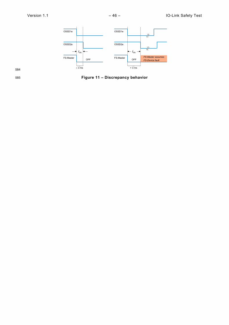
Version 1.1 – 46 – IO-Link Safety Test
584
Figure 11 – Discrepancy behavior 585
OSSD1e
OSSD2e
FS-Master
tdis
OSSD1e
OSSD2e
FS-Master
tdis
FS-Master assumesFS-Device faultOFFOFF
≤ 3 ms > 3 ms
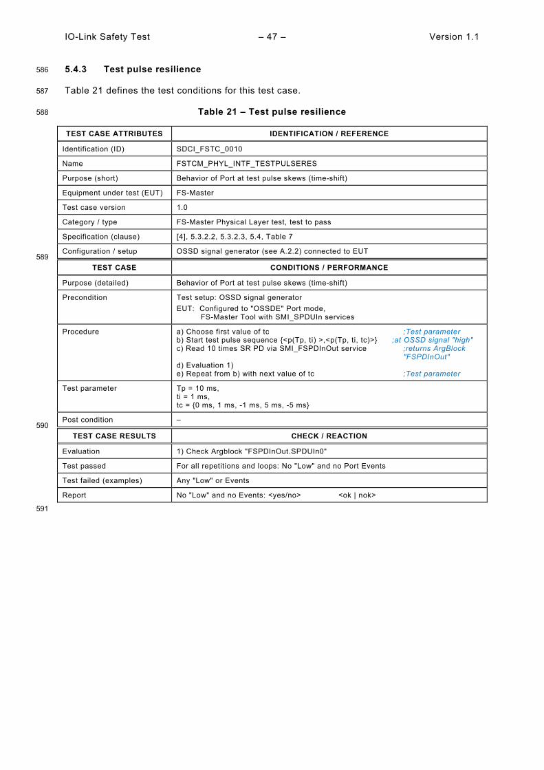
IO-Link Safety Test – 47 – Version 1.1
5.4.3 Test pulse resilience 586
Table 21 defines the test conditions for this test case. 587
Table 21 – Test pulse resilience 588
TEST CASE ATTRIBUTES IDENTIFICATION / REFERENCE
Identification (ID) SDCI_FSTC_0010
Name FSTCM_PHYL_INTF_TESTPULSERES
Purpose (short) Behavior of Port at test pulse skews (time-shift)
Equipment under test (EUT) FS-Master
Test case version 1.0
Category / type FS-Master Physical Layer test, test to pass
Specification (clause) [4], 5.3.2.2, 5.3.2.3, 5.4, Table 7
Configuration / setup OSSD signal generator (see A.2.2) connected to EUT 589
TEST CASE CONDITIONS / PERFORMANCE
Purpose (detailed) Behavior of Port at test pulse skews (time-shift)
Precondition Test setup: OSSD signal generator EUT: Configured to "OSSDE" Port mode, FS-Master Tool with SMI_SPDUIn services
Procedure a) Choose first value of tc ;Test parameter b) Start test pulse sequence {<p(Tp, ti) >,<p(Tp, ti, tc)>} ;at OSSD signal "high" c) Read 10 times SR PD via SMI_FSPDInOut service ;returns ArgBlock "FSPDInOut" d) Evaluation 1) e) Repeat from b) with next value of tc ;Test parameter
Test parameter Tp = 10 ms, ti = 1 ms, tc = {0 ms, 1 ms, -1 ms, 5 ms, -5 ms}
Post condition – 590
TEST CASE RESULTS CHECK / REACTION
Evaluation 1) Check Argblock "FSPDInOut.SPDUIn0"
Test passed For all repetitions and loops: No "Low" and no Port Events
Test failed (examples) Any "Low" or Events
Report No "Low" and no Events: <yes/no> <ok | nok>
591
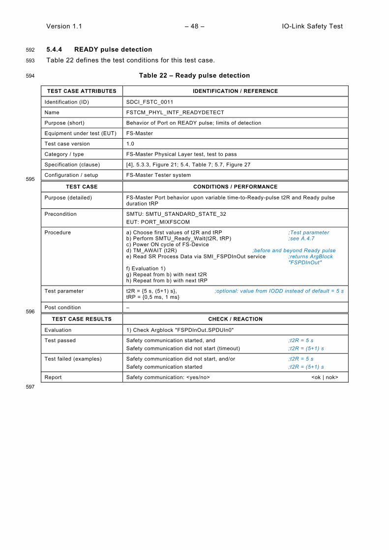
Version 1.1 – 48 – IO-Link Safety Test
5.4.4 READY pulse detection 592
Table 22 defines the test conditions for this test case. 593
Table 22 – Ready pulse detection 594
TEST CASE ATTRIBUTES IDENTIFICATION / REFERENCE
Identification (ID) SDCI_FSTC_0011
Name FSTCM_PHYL_INTF_READYDETECT
Purpose (short) Behavior of Port on READY pulse; limits of detection
Equipment under test (EUT) FS-Master
Test case version 1.0
Category / type FS-Master Physical Layer test, test to pass
Specification (clause) [4], 5.3.3, Figure 21; 5.4, Table 7; 5.7, Figure 27
Configuration / setup FS-Master Tester system 595
TEST CASE CONDITIONS / PERFORMANCE
Purpose (detailed) FS-Master Port behavior upon variable time-to-Ready-pulse t2R and Ready pulse duration tRP
Precondition SMTU: SMTU_STANDARD_STATE_32 EUT: PORT_MIXFSCOM
Procedure a) Choose first values of t2R and tRP ;Test parameter b) Perform SMTU_Ready_Wait(t2R, tRP) ;see A.4.7 c) Power ON cycle of FS-Device d) TM_AWAIT (t2R) ;before and beyond Ready pulse e) Read SR Process Data via SMI_FSPDInOut service ;returns ArgBlock "FSPDInOut" f) Evaluation 1) g) Repeat from b) with next t2R h) Repeat from b) with next tRP
Test parameter t2R = {5 s, (5+1) s}, ;optional: value from IODD instead of default = 5 s tRP = {0,5 ms, 1 ms}
Post condition – 596
TEST CASE RESULTS CHECK / REACTION
Evaluation 1) Check Argblock "FSPDInOut.SPDUIn0"
Test passed Safety communication started, and ;t2R = 5 s Safety communication did not start (timeout) ;t2R = (5+1) s
Test failed (examples) Safety communication did not start, and/or ;t2R = 5 s Safety communication started ;t2R = (5+1) s
Report Safety communication: <yes/no> <ok | nok>
597

IO-Link Safety Test – 49 – Version 1.1
5.4.5 Wake-up delay after Ready pulse 598
Table 22 defines the test conditions for this test case 599
Table 23 – Wake-up delay after Ready pulse 600
TEST CASE ATTRIBUTES IDENTIFICATION / REFERENCE
Identification (ID) SDCI_FSTC_0012
Name FSTCM_PHYL_INTF_WAKEUPTOREADYDELAY
Purpose (short) After Ready pulse, FS-Master waits tRW before Wake-up
Equipment under test (EUT) FS-Master
Test case version 1.0
Category / type FS-Master Physical Layer test, test to pass
Specification (clause) [4], 5.3.3, Figure 21; 5.4, Table 7; 5.7, Figure 27
Configuration / setup FS-Master Tester system 601
TEST CASE CONDITIONS / PERFORMANCE
Purpose (detailed) After Ready pulse, FS-Master waits a time tRW before Wake-up sequence
Precondition SMTU: SMTU_STANDARD_STATE_32 EUT: PORT_MIXFSCOM
Procedure a) Choose first value of tRP ;Test parameter b) Perform SMTU_Ready_Wait(2 s, tRP) ;see A.4.7 c) Power ON cycle of "FS-Device" d) Measure time tRW from falling edge of READY-pulse to rising edge of WURQ e) Repeat from b) with next tRP
Test parameter tRP = {0,5 ms, 1 ms}
Post condition – 602
TEST CASE RESULTS CHECK / REACTION
Evaluation 1) Check measurement value
Test passed tRW ≥ 50 μs
Test failed (examples) tRW < 50 μs
Report tRW ≥ 50 μs: <yes/no> <ok | nok>
603
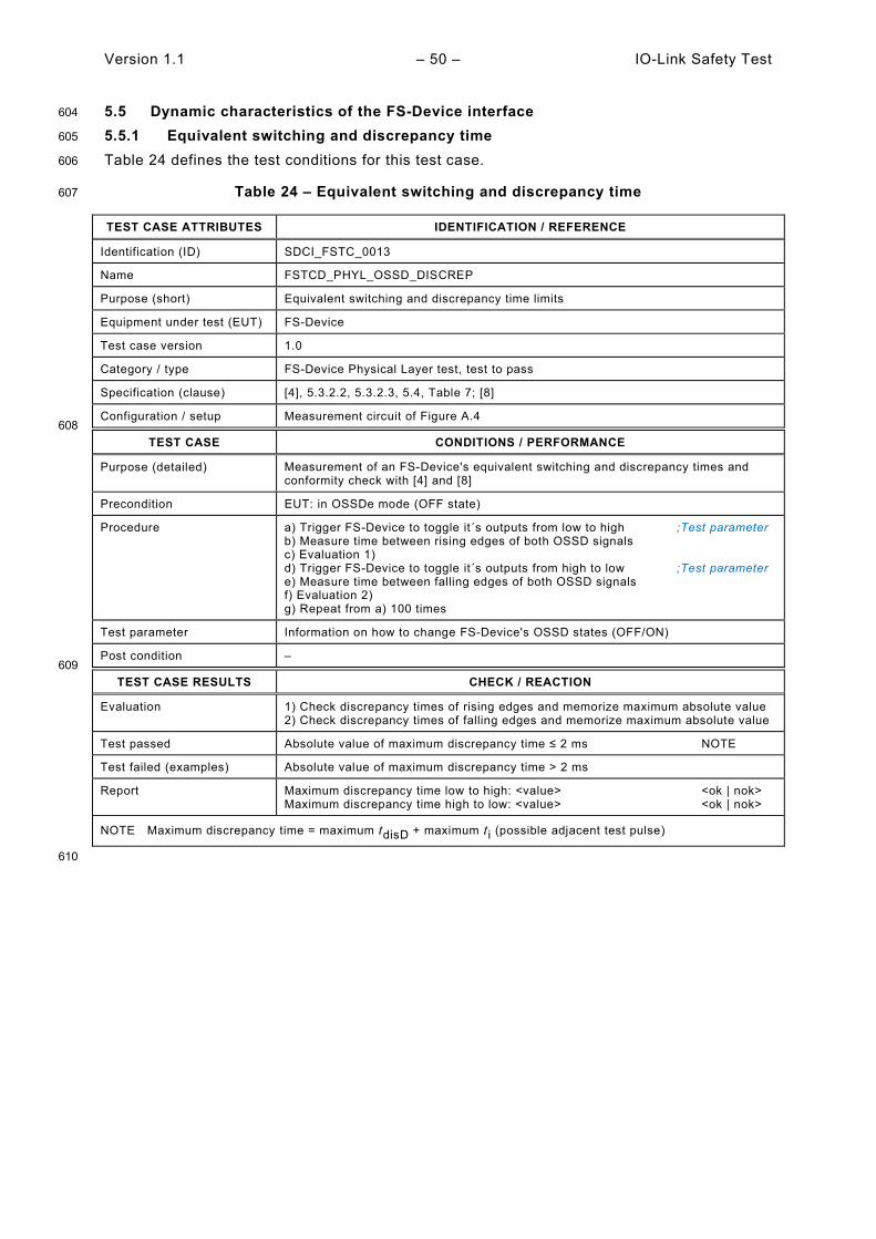
Version 1.1 – 50 – IO-Link Safety Test
5.5 Dynamic characteristics of the FS-Device interface 604
5.5.1 Equivalent switching and discrepancy time 605
Table 24 defines the test conditions for this test case. 606
Table 24 – Equivalent switching and discrepancy time 607
TEST CASE ATTRIBUTES IDENTIFICATION / REFERENCE
Identification (ID) SDCI_FSTC_0013
Name FSTCD_PHYL_OSSD_DISCREP
Purpose (short) Equivalent switching and discrepancy time limits
Equipment under test (EUT) FS-Device
Test case version 1.0
Category / type FS-Device Physical Layer test, test to pass
Specification (clause) [4], 5.3.2.2, 5.3.2.3, 5.4, Table 7; [8]
Configuration / setup Measurement circuit of Figure A.4 608
TEST CASE CONDITIONS / PERFORMANCE
Purpose (detailed) Measurement of an FS-Device's equivalent switching and discrepancy times and conformity check with [4] and [8]
Precondition EUT: in OSSDe mode (OFF state)
Procedure a) Trigger FS-Device to toggle it´s outputs from low to high ;Test parameter b) Measure time between rising edges of both OSSD signals c) Evaluation 1) d) Trigger FS-Device to toggle it´s outputs from high to low ;Test parameter e) Measure time between falling edges of both OSSD signals f) Evaluation 2) g) Repeat from a) 100 times
Test parameter Information on how to change FS-Device's OSSD states (OFF/ON)
Post condition – 609
TEST CASE RESULTS CHECK / REACTION
Evaluation 1) Check discrepancy times of rising edges and memorize maximum absolute value 2) Check discrepancy times of falling edges and memorize maximum absolute value
Test passed Absolute value of maximum discrepancy time ≤ 2 ms NOTE
Test failed (examples) Absolute value of maximum discrepancy time > 2 ms
Report Maximum discrepancy time low to high: <value> <ok | nok> Maximum discrepancy time high to low: <value> <ok | nok>
NOTE Maximum discrepancy time = maximum tdisD + maximum ti (possible adjacent test pulse)
610

IO-Link Safety Test – 51 – Version 1.1
5.5.2 Test pulse duration 611
Table 25 defines the test conditions for this test case. 612
Table 25 – Test pulse duration 613
TEST CASE ATTRIBUTES IDENTIFICATION / REFERENCE
Identification (ID) SDCI_FSTC_0015
Name FSTCD_PHYL_INTF_TESTPULSDURATION
Purpose (short) FS-Device's test pulses duration
Equipment under test (EUT) FS-Device
Test case version 1.0
Category / type FS-Device Physical Layer test, test to pass
Specification (clause) [4], 5.3.2.2, 5.3.2.3, Figure 19; 5.4, Table 7
Configuration / setup Measurement circuit of Figure A.4 614
TEST CASE CONDITIONS / PERFORMANCE
Purpose (detailed) Measurement of an FS-Device's test pulse duration and conformity check
Precondition EUT: in OSSDe mode (ON state) Measurement circuit: load = Type 1 input acc. IEC 61131-2
Procedure a) Apply first PSD value ;Test parameter b) Measure time between falling and rising edge of a test pulse on OSSDe1 c) Evaluation 1) d) Measure time between falling and rising edge of a test pulse on OSSDe2 e) Evaluation 2) f) Repeat from b) 100 times g) Repeat from b) with next PSD value
Test parameter PSD = {18 V, 30 V}
Post condition – 615
TEST CASE RESULTS CHECK / REACTION
Evaluation 1) Check duration of test pulse and memorize maximum value Ti1max
2) Check duration of test pulse and memorize maximum value Ti2max
Test passed Ti1max ≤ 1 ms, and
Ti2max ≤ 1 ms
Test failed (examples) Ti1max > 1 ms, or
Ti2max > 1 ms
Report Maximum duration of test pulses at OSSDe1: <value> <ok | nok> Maximum duration of test pulses at OSSDe2: <value> <ok | nok>
616

Version 1.1 – 52 – IO-Link Safety Test
5.5.3 Ready pulse duration 617
Table 26 defines the test conditions for this test case. 618
Table 26 – Ready pulse duration 619
TEST CASE ATTRIBUTES IDENTIFICATION / REFERENCE
Identification (ID) SDCI_FSTC_0016
Name FSTCD_PHYL_INTF_READYPULSDUR
Purpose (short) FS-Device's Ready pulse duration
Equipment under test (EUT) FS-Device
Test case version 1.0
Category / type FS-Device Physical Layer test, test to pass
Specification (clause) [4], 5.3.3, Figure 21; 5.4, Table 7; 5.7, Figure 27
Configuration / setup Measurement circuit of Figure A.4 620
TEST CASE CONDITIONS / PERFORMANCE
Purpose (detailed) Measurement of an FS-Device's Ready pulse duration and conformity check
Precondition EUT: Power off
Procedure a) Apply first PSD value ;Test parameter b) Measure time tRP between rising and falling edge of Ready pulse on OSSDe1 c) Evaluation 1) d) Repeat from b) with next PSD value
Test parameter PSD = {18 V, 30 V}
Post condition – 621
TEST CASE RESULTS CHECK / REACTION
Evaluation 1) Check and memorize tRP @ PSD = 18 V and 30 V
Test passed For both supply voltages: 500 µs ≤ tRP ≤ 1000 µs
Test failed (examples) Any of the values of tRP < 500 µs or > 1000 µs
Report tRP @ 18V: <value> <ok | nok> tRP @ 30V: <value> <ok | nok>
622
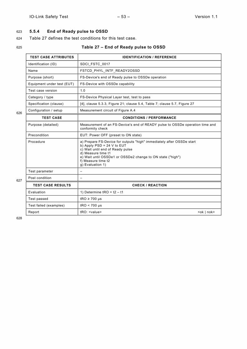
IO-Link Safety Test – 53 – Version 1.1
5.5.4 End of Ready pulse to OSSD 623
Table 27 defines the test conditions for this test case. 624
Table 27 – End of Ready pulse to OSSD 625
TEST CASE ATTRIBUTES IDENTIFICATION / REFERENCE
Identification (ID) SDCI_FSTC_0017
Name FSTCD_PHYL_INTF_READY2OSSD
Purpose (short) FS-Device's end of Ready pulse to OSSDe operation
Equipment under test (EUT) FS-Device with OSSDe capability
Test case version 1.0
Category / type FS-Device Physical Layer test, test to pass
Specification (clause) [4], clause 5.3.3, Figure 21; clause 5.4, Table 7; clause 5.7, Figure 27
Configuration / setup Measurement circuit of Figure A.4 626
TEST CASE CONDITIONS / PERFORMANCE
Purpose (detailed) Measurement of an FS-Device's end of READY pulse to OSSDe operation time and conformity check
Precondition EUT: Power OFF (preset to ON state)
Procedure a) Prepare FS-Device for outputs "high" immediately after OSSDe start b) Apply PSD = 24 V to EUT c) Wait until end of Ready pulse d) Measure time t1 e) Wait until OSSDe1 or OSSDe2 change to ON state ("high") f) Measure time t2 g) Evaluation 1)
Test parameter –
Post condition – 627
TEST CASE RESULTS CHECK / REACTION
Evaluation 1) Determine tRO = t2 – t1 Test passed tRO ≥ 700 µs
Test failed (examples) tRO < 700 µs
Report tRO: <value> <ok | nok>
628

Version 1.1 – 54 – IO-Link Safety Test
5.6 Test report templates 629
5.6.1 Template for the test report of PL tests 630
Table 28 shows the template for the test reports of PL tests. 631
Table 28 – Template for the test report of PL tests 632
Test Case ID Test report ok/ nok
Statement/ Exception
SDCI_FSTC_0001 Maximum VSM (ON state): <value> Minimum VSM (OFF state): <value>
SDCI_FSTC_0002 VIMIQ @ Transition 01 (PSMmin): <value> VIMIQ @ Transition 01 (PSMmax): <value>
SDCI_FSTC_0003 VIMIQ @ Transition 10 (PSMmin): <value> VIMIQ @ Transition 10 (PSMmax): <value>
SDCI_FSTC_0004 VHYSMCI (PSMmin): <value> VHYSMCI (PSMmax): <value>
SDCI_FSTC_0005 ILLM (VIMIQ = 5 V, PSMmin): <value> ILLM (VIMIQ = 5,1 V, PSMmin): <value> ILLM (VIMIQ = 15 V, PSMmin): <value> ILLM (VIMIQ = measured value of VSM, PSMmin): <value> ILLM (VIMIQ = 5 V, PSMmax): <value> ILLM (VIMIQ = 5,1 V, PSMmax): <value> ILLM (VIMIQ = 15 V, PSMmax): <value> ILLM (VIMIQ = measured value of VSM, PSMmax): <value>
SDCI_FSTC_0006 VIQ (VSD = 18 V): <value> VIQ (VSD = 30 V): <value>
SDCI_FSTC_0007 VIQ (VSD = 18 V): <value> VIQ (VSD = 30 V): <value>
SDCI_FSTC_0008 "Low" (Demand) detected: <yes/no> "High" (Activation) detected: <yes/no> "Low" (Antivalent) detected: <yes/no> Correct Port Event detected: <yes/no>
SDCI_FSTC_0009 "Low" detected: <yes/no> "Low" detected: <yes/no> Correct Port Event detected: <yes/no>
SDCI_FSTC_0010 No "Low" and no Events: <yes/no>
SDCI_FSTC_0011 Safety communication: <yes/no>
SDCI_FSTC_0012 tRW ≥ 50 μs: <yes/no>
SDCI_FSTC_0013 Maximum discrepancy time low to high: <value> Maximum discrepancy time high to low: <value>
SDCI_FSTC_0015 Maximum duration of test pulses at OSSDe1: <value> Maximum duration of test pulses at OSSDe2: <value>
SDCI_FSTC_0016 tRP @ 18V: <value> tRP @ 30V: <value>
SDCI_FSTC_0017 tRO: <value>
633
5.6.2 Test report summaries of automated test cases 634
Templates are defined by the particular tester equipments. The complete test reports shall 635 present at least the information of the report fields of the test cases. 636

IO-Link Safety Test – 55 – Version 1.1
6 IODD and Dedicated Tool tests 637
6.1 Overview 638
Any FS-Device comes with an IODD including FSP parameters for functional safe communi-639 cation and usually FST parameters for the possibility of adjusting the particular technology (e.g. 640 optical sensor) to user automation applications and optionally a Dedicated Tool. 641
Tests of an IODD shall be performed using the IODD Checker Tool, which can be downloaded 642 from the website indicated in Annex C. The extra requirements for the IODD Checker Tool due 643 to the safety extensions are specified in 6.2. These requirements include XML-Snippets for the 644 Common Profile and for IO-Link Safety. XML-Snippets support the presentation of user 645 interfaces and the automated IODD testing. 646
IODD test cases are specified in 6.3. 647
For FS-Devices without parameters for their individual technology (so-called FST parameter) 648 no other tool is required besides the IODD. FS-Devices with FST parameter also come with a 649 Dedicated Tool at least for the calculation of the TechParCRC value to be transfered into the 650 FSP_TechParCRC field of the FS-Master Tool. 651
Dedicated Tool test cases are specified in 10.2. 652
653
6.2 Requirements for the IODD Checker (expanded schema test for safety) 654
6.2.1 Basic requirements and business rules for FS-Devices 655
Basically, the requirements defined in [5] apply. Additional business rules for IODDs of FS-656 Devices to be checked are defined in 6.3. 657
6.2.2 XML snippets for the Common Profile 658
The XML snippets for the Common Profile are contained in its .zip file downloadable from the 659 website indicated in Annex C. The name of the corresponding draft XML file is IODD-660 CommonProfile_Snippets_V0.99.000.xml. 661
6.2.3 XML snippets for safety extensions 662
The XML snippets for safety extensions are specified in [4] and contained in an extra file named 663 IODD-SafetyProfile_Snippets0.90.xml. Both can be downloaded in a .zip file from the website 664 indicated in Annex C. 665

Version 1.1 – 56 – IO-Link Safety Test
6.3 IODD test via Checker Tool (conformity and CRC signatures) 666
Table 29 defines the test conditions for this test case. 667
Table 29 – IODD test via Checker Tool (conformity and CRC signatures) 668
TEST CASE ATTRIBUTES IDENTIFICATION / REFERENCE
Identification (ID) SDCI_FSTC_0018
Name FSTCI_IODD_FSPD_IODDPARAMDESCCRC
Purpose (short) Conformity of IODD of FS-Device and correct CRC signatures
Equipment under test (EUT) IODD of FS-Device
Test case version 1.0
Category / type IODD verify test
Specification (clause) [4], clause A.1, E.5.6; [6]
Configuration / setup IODD Checker Tool + XML snippets 669
TEST CASE CONDITIONS / PERFORMANCE
Purpose (detailed) Check conformity of IODD of FS-Device with the help of the Checker Tool downloadable from the official IO-Link website. Base checks are supplemented by extensions from Common Profile specification and IO-Link Safety specification (XML snippets). CRC signature across the entire IODD is checked as well as the CRC signature "FSP_ParamDescCRC". The IODD Checker Tool provides correct CRC signature values if found values have been identified as incorrect.
Precondition Up to date IODD Checker Tool downloaded from the Internet and XML snippet files
Procedure a) Perform conformance testing with the help of standard IODD Checker Tool using IODD XML schema based on IODD specification V1.1.3 b) Evaluation 1) c) Perform extended test on Common Profile parameters using the file "IODD-CommonProfile_Snippets_V1.1.0.xml" d) Evaluation 2) e) Perform extended test on Safety parameters using the file "IODD-SafetyProfile-Snippets1.1.3.xml" f) Evaluation 3) g) Perform extended test on Protocol Mode "Input/Output length" using ProcessData Collection (see [5]) h) Evaluation 4) i) Replace CRC signature value of FSP_ParamDescCRC in IODD with suggested value of the Tool if value was incorrect j) Perform IODD check again k) Evaluation 5)
Test parameter –
Post condition Value of FSP_ParamDescCRC 670
TEST CASE RESULTS CHECK / REACTION
Evaluation 1) Check Tool report 2) Check report on Common Profile parameters 3) Check report on Safety parameters 4) Check report on Protocol Mode 5) Check Tool report and value of "FSP_ParamDescCRC"
Test passed All reports OK and value correct
Test failed (examples) Any report NOK and/or value incorrect
Report IODD with correct "FSP_ParamDescCRC" parameter: <yes/no> <ok | nok>
671
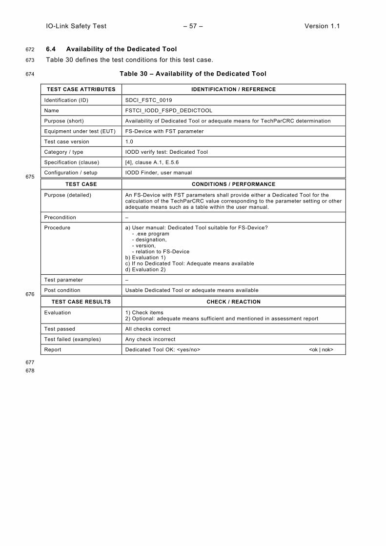
IO-Link Safety Test – 57 – Version 1.1
6.4 Availability of the Dedicated Tool 672
Table 30 defines the test conditions for this test case. 673
Table 30 – Availability of the Dedicated Tool 674
TEST CASE ATTRIBUTES IDENTIFICATION / REFERENCE
Identification (ID) SDCI_FSTC_0019
Name FSTCI_IODD_FSPD_DEDICTOOL
Purpose (short) Availability of Dedicated Tool or adequate means for TechParCRC determination
Equipment under test (EUT) FS-Device with FST parameter
Test case version 1.0
Category / type IODD verify test: Dedicated Tool
Specification (clause) [4], clause A.1, E.5.6
Configuration / setup IODD Finder, user manual 675
TEST CASE CONDITIONS / PERFORMANCE
Purpose (detailed) An FS-Device with FST parameters shall provide either a Dedicated Tool for the calculation of the TechParCRC value corresponding to the parameter setting or other adequate means such as a table within the user manual.
Precondition –
Procedure a) User manual: Dedicated Tool suitable for FS-Device? - .exe program - designation, - version, - relation to FS-Device b) Evaluation 1) c) If no Dedicated Tool: Adequate means available d) Evaluation 2)
Test parameter –
Post condition Usable Dedicated Tool or adequate means available 676
TEST CASE RESULTS CHECK / REACTION
Evaluation 1) Check items 2) Optional: adequate means sufficient and mentioned in assessment report
Test passed All checks correct
Test failed (examples) Any check incorrect
Report Dedicated Tool OK: <yes/no> <ok | nok>
677 678
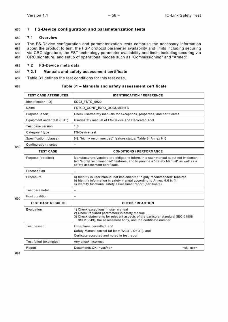
Version 1.1 – 58 – IO-Link Safety Test
7 FS-Device configuration and parameterization tests 679
7.1 Overview 680
The FS-Device configuration and parameterization tests comprise the necessary information 681 about the product to test, the FSP protocol parameter availability and limits including securing 682 via CRC signature, the FST technology parameter availability and limits including securing via 683 CRC signature, and setup of operational modes such as "Commissioning" and "Armed". 684
7.2 FS-Device meta data 685
7.2.1 Manuals and safety assessment certificate 686
Table 31 defines the test conditions for this test case. 687
Table 31 – Manuals and safety assessment certificate 688
TEST CASE ATTRIBUTES IDENTIFICATION / REFERENCE
Identification (ID) SDCI_FSTC_0020
Name FSTCD_CONF_INFO_DOCUMENTS
Purpose (short) Check user/safety manuals for exceptions, properties, and certificates
Equipment under test (EUT) User/safety manual of FS-Device and Dedicated Tool
Test case version 1.0
Category / type FS-Device test
Specification (clause) [4], "highly recommended" feature status, Table 8, Annex H.6
Configuration / setup – 689
TEST CASE CONDITIONS / PERFORMANCE
Purpose (detailed) Manufacturers/vendors are obliged to inform in a user manual about not implemen-ted "highly recommended" features, and to provide a "Safety Manual" as well as a safety assessment certificate.
Precondition –
Procedure a) Identify in user manual not implemented "highly recommended" features b) Identify information in safety manual according to Annex H.6 in [4] c) Identify functional safety assessment report (certificate)
Test parameter –
Post condition – 690
TEST CASE RESULTS CHECK / REACTION
Evaluation 1) Check exceptions in user manual 2) Check required parameters in safety manual 3) Check statements for relevant aspects of the particular standard (IEC 61508 /ISO13849), the assessment body, and the certificate number
Test passed Exceptions permitted, and Safety Manual correct (at least WCDT, OFDT), and Certicate accepted and noted in test report
Test failed (examples) Any check incorrect
Report Documents OK: <yes/no> <ok | nok>
691

IO-Link Safety Test – 59 – Version 1.1
7.2.2 Connector and cable information 692
Table 32 defines the test conditions for this test case. 693
Table 32 – Connector and cable information 694
TEST CASE ATTRIBUTES IDENTIFICATION / REFERENCE
Identification (ID) SDCI_FSTC_0021
Name FSTCD_CONF_INFO_CONNECTCABLE
Purpose (short) Check user/safety manuals for connector and cable information (OSSDe)
Equipment under test (EUT) User/safety manual of FS-Device and Dedicated Tool
Test case version 1.0
Category / type FS-Device test
Specification (clause) [4], 4.1.4, Figure 9
Configuration / setup – 695
TEST CASE CONDITIONS / PERFORMANCE
Purpose (detailed) Check user/safety manuals for connector and cable information for OSSDe operation.
Precondition –
Procedure a) Identify in user manual connector Pin layout in case of M type connector b) Identify cable recommendations with respect to robustness and loop resistence
Test parameter –
Post condition – 696
TEST CASE RESULTS CHECK / REACTION
Evaluation 1) Check Pin layout 2) Check recommendations on robustness and loop resistence
Test passed Pin layouts are correct, and Robustness recommendations for cable coating such as "tear proof" and "cut resistant" as well as for loop resistance such that minimum supply voltages are guaranteed at maximum supply current are available
Test failed (examples) Any check incorrect
Report Documents OK: <yes/no> <ok | nok>
697
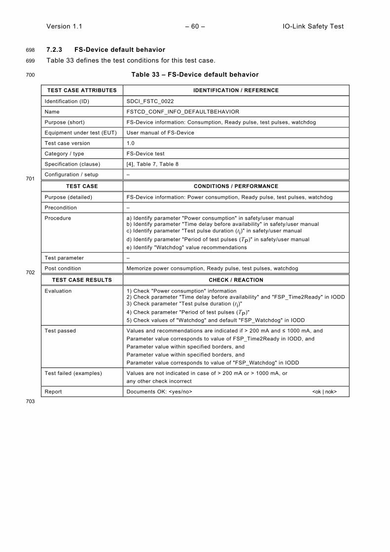
Version 1.1 – 60 – IO-Link Safety Test
7.2.3 FS-Device default behavior 698
Table 33 defines the test conditions for this test case. 699
Table 33 – FS-Device default behavior 700
TEST CASE ATTRIBUTES IDENTIFICATION / REFERENCE
Identification (ID) SDCI_FSTC_0022
Name FSTCD_CONF_INFO_DEFAULTBEHAVIOR
Purpose (short) FS-Device information: Consumption, Ready pulse, test pulses, watchdog
Equipment under test (EUT) User manual of FS-Device
Test case version 1.0
Category / type FS-Device test
Specification (clause) [4], Table 7, Table 8
Configuration / setup – 701
TEST CASE CONDITIONS / PERFORMANCE
Purpose (detailed) FS-Device information: Power consumption, Ready pulse, test pulses, watchdog
Precondition –
Procedure a) Identify parameter "Power consumption" in safety/user manual b) Identify parameter "Time delay before availability" in safety/user manual c) Identify parameter "Test pulse duration (ti)" in safety/user manual d) Identify parameter "Period of test pulses (TP)" in safety/user manual e) Identify "Watchdog" value recommendations
Test parameter –
Post condition Memorize power consumption, Ready pulse, test pulses, watchdog 702
TEST CASE RESULTS CHECK / REACTION
Evaluation 1) Check "Power consumption" information 2) Check parameter "Time delay before availability" and "FSP_Time2Ready" in IODD 3) Check parameter "Test pulse duration (ti)" 4) Check parameter "Period of test pulses (TP)" 5) Check values of "Watchdog" and default "FSP_Watchdog" in IODD
Test passed Values and recommendations are indicated if > 200 mA and ≤ 1000 mA, and Parameter value corresponds to value of FSP_Time2Ready in IODD, and Parameter value within specified borders, and Parameter value within specified borders, and Parameter value corresponds to value of "FSP_Watchdog" in IODD
Test failed (examples) Values are not indicated in case of > 200 mA or > 1000 mA, or any other check incorrect
Report Documents OK: <yes/no> <ok | nok>
703
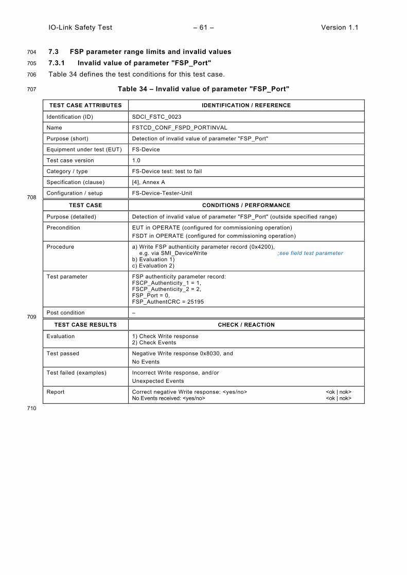
IO-Link Safety Test – 61 – Version 1.1
7.3 FSP parameter range limits and invalid values 704
7.3.1 Invalid value of parameter "FSP_Port" 705
Table 34 defines the test conditions for this test case. 706
Table 34 – Invalid value of parameter "FSP_Port" 707
TEST CASE ATTRIBUTES IDENTIFICATION / REFERENCE
Identification (ID) SDCI_FSTC_0023
Name FSTCD_CONF_FSPD_PORTINVAL
Purpose (short) Detection of invalid value of parameter "FSP_Port"
Equipment under test (EUT) FS-Device
Test case version 1.0
Category / type FS-Device test: test to fail
Specification (clause) [4], Annex A
Configuration / setup FS-Device-Tester-Unit 708
TEST CASE CONDITIONS / PERFORMANCE
Purpose (detailed) Detection of invalid value of parameter "FSP_Port" (outside specified range)
Precondition EUT in OPERATE (configured for commissioning operation) FSDT in OPERATE (configured for commissioning operation)
Procedure a) Write FSP authenticity parameter record (0x4200), e.g. via SMI_DeviceWrite ;see field test parameter b) Evaluation 1) c) Evaluation 2)
Test parameter FSP authenticity parameter record: FSCP_Authenticity_1 = 1, FSCP_Authenticity_2 = 2, FSP_Port = 0, FSP_AuthentCRC = 25195
Post condition – 709
TEST CASE RESULTS CHECK / REACTION
Evaluation 1) Check Write response 2) Check Events
Test passed Negative Write response 0x8030, and No Events
Test failed (examples) Incorrect Write response, and/or Unexpected Events
Report Correct negative Write response: <yes/no> <ok | nok> No Events received: <yes/no> <ok | nok>
710

Version 1.1 – 62 – IO-Link Safety Test
7.3.2 Invalid value of signature "FSP_AuthentCRC" 711
Table 35 defines the test conditions for this test case. 712
Table 35 – Invalid value of signature "FSP_AuthentCRC" 713
TEST CASE ATTRIBUTES IDENTIFICATION / REFERENCE
Identification (ID) SDCI_FSTC_0024
Name FSTCD_CONF_FSPD_AUTHENTCRCINVAL
Purpose (short) Detection of invalid value of signature "FSP_AuthentCRC"
Equipment under test (EUT) FS-Device
Test case version 1.0
Category / type FS-Device test: test to fail
Specification (clause) [4], Annex A
Configuration / setup FS-Device-Tester-Unit 714
TEST CASE CONDITIONS / PERFORMANCE
Purpose (detailed) Detection of invalid value of signature "FSP_AuthentCRC" (outside specified range)
Precondition EUT in OPERATE (commissioning operation, FSP_TechParCRC = 0) FSDT in OPERATE (commissioning operation)
Procedure a) Write FSP authenticity parameter record (0x4200), e.g. via SMI_DeviceWrite ;see field test parameter b) Evaluation 1) c) Evaluation 2)
Test parameter FSP authenticity parameter record: FSCP_Authenticity_1 = 1, FSCP_Authenticity_2 = 2, FSP_Port = 1, FSP_AuthentCRC = 11457
Post condition – 715
TEST CASE RESULTS CHECK / REACTION
Evaluation 1) Check Write response 2) Check Events
Test passed Negative Write response 0x8030, and No Events
Test failed (examples) Incorrect Write response, and/or Unexpected Events
Report Correct negative Write response: <yes/no> <ok | nok> No Events received: <yes/no> <ok | nok>
716
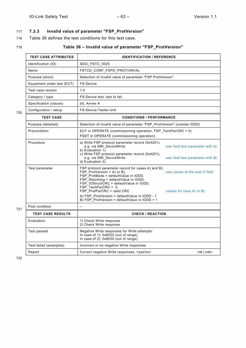
IO-Link Safety Test – 63 – Version 1.1
7.3.3 Invalid value of parameter "FSP_ProtVersion" 717
Table 36 defines the test conditions for this test case. 718
Table 36 – Invalid value of parameter "FSP_ProtVersion" 719
TEST CASE ATTRIBUTES IDENTIFICATION / REFERENCE
Identification (ID) SDCI_FSTC_0025
Name FSTCD_CONF_FSPD_PROTVINVAL
Purpose (short) Detection of invalid value of parameter "FSP ProtVersion"
Equipment under test (EUT) FS-Device
Test case version 1.0
Category / type FS-Device test: test to fail
Specification (clause) [4], Annex A
Configuration / setup FS-Device-Tester-Unit 720
TEST CASE CONDITIONS / PERFORMANCE
Purpose (detailed) Detection of invalid value of parameter "FSP_ProtVersion" (outside IODD)
Precondition EUT in OPERATE (commissioning operation, FSP_TechParCRC = 0) FSDT in OPERATE (commissioning operation)
Procedure a) Write FSP protocol parameter record (0x4201), e.g. via SMI_DeviceWrite ;see field test parameter with A) b) Evaluation 1) c) Write FSP protocol parameter record (0x4201), e.g. via SMI_DeviceWrite ;see field test parameter with B) d) Evaluation 2)
Test parameter FSP protocol parameter record for cases A) and B): FSP_ProtVersion = A) or B), ;see values at the end of field FSP_ProtMode = defaultValue in IODD, FSP_Watchdog = defaultValue in IODD, FSP_IOStructCRC = defaultValue in IODD, FSP_TechParCRC = 0, FSP_ProtParCRC = valid CRC ;values for case A) or B) A) FSP_ProtVersion = defaultValue in IODD - 1 B) FSP_ProtVersion = defaultValue in IODD + 1
Post condition – 721
TEST CASE RESULTS CHECK / REACTION
Evaluation 1) Check Write response 2) Check Write response
Test passed Negative Write responses for Write attempts: In case of 1): 0x8030 (out of range) In case of 2): 0x8030 (out of range)
Test failed (examples) Incorrect or no negative Write responses
Report Correct negative Write responses: <yes/no> <ok | nok>
722

Version 1.1 – 64 – IO-Link Safety Test
7.3.4 Invalid value of parameter "FSP_ProtMode" 723
Table 37 defines the test conditions for this test case. 724
Table 37 – Invalid value of parameter "FSP_ProtMode" 725
TEST CASE ATTRIBUTES IDENTIFICATION / REFERENCE
Identification (ID) SDCI_FSTC_0026
Name FSTCD_CONF_FSPD_PMODEINVAL
Purpose (short) Detection of invalid value of parameter "FSP_ProtMode"
Equipment under test (EUT) FS-Device
Test case version 1.0
Category / type FS-Device test: test to fail
Specification (clause) [4], Annex A
Configuration / setup FS-Device-Tester-Unit 726
TEST CASE CONDITIONS / PERFORMANCE
Purpose (detailed) Detection of invalid value of parameter "FSP_ProtMode" (outside specified range and IODD). This test also proves that test parameter values are not accepted by FS Device.
Precondition EUT in OPERATE (commissioning operation, FSP_TechParCRC = 0) FSDT in OPERATE (commissioning operation)
Procedure a) Write FSP protocol parameter record (0x4201), e.g. via SMI_DeviceWrite ;see field test parameter with A) b) Evaluation 1) c) Write FSP protocol parameter record (0x4201), e.g. via SMI_DeviceWrite ;see field test parameter with B) d) Evaluation 2) e) Write FSP protocol parameter record (0x4201), e.g. via SMI_DeviceWrite ;see field test parameter with C) f) Evaluation 3) g) Write FSP protocol parameter record (0x4201), e.g. via SMI_DeviceWrite ;see field test parameter with D) h) Evaluation 4)
Test parameter FSP protocol parameter record for cases A), B), C). and D): FSP_ProtVersion = defaultValue in IODD; FSP_ProtMode = A), B), C), or D), ;see values at the end of field FSP_Watchdog = defaultValue in IODD, FSP_IOStructCRC = defaultValue in IODD, FSP_TechParCRC = 0, FSP_ProtParCRC = valid CRC ;values for case A), B), C) or D) A) FSP_ProtMode = defaultValue in IODD - 1 B) FSP_ProtMode = defaultValue in IODD + 1 C) FSP_ProtMode = 0xF9 D) FSP_ProtMode = 0xFA
Post condition – 727
TEST CASE RESULTS CHECK / REACTION
Evaluation 1) Check Write response 2) Check Write response 3) Check Write response 4) Check Write response
Test passed Negative Write responses for Write attempts: In case of 1): 0x8030 (out of range) In case of 2): 0x8030 (out of range) In case of 3): 0x8030 (out of range) In case of 4): 0x8030 (out of range)
Test failed (examples) Incorrect or no negative Write responses
Report Correct negative Write responses: <yes/no> <ok | nok>
728
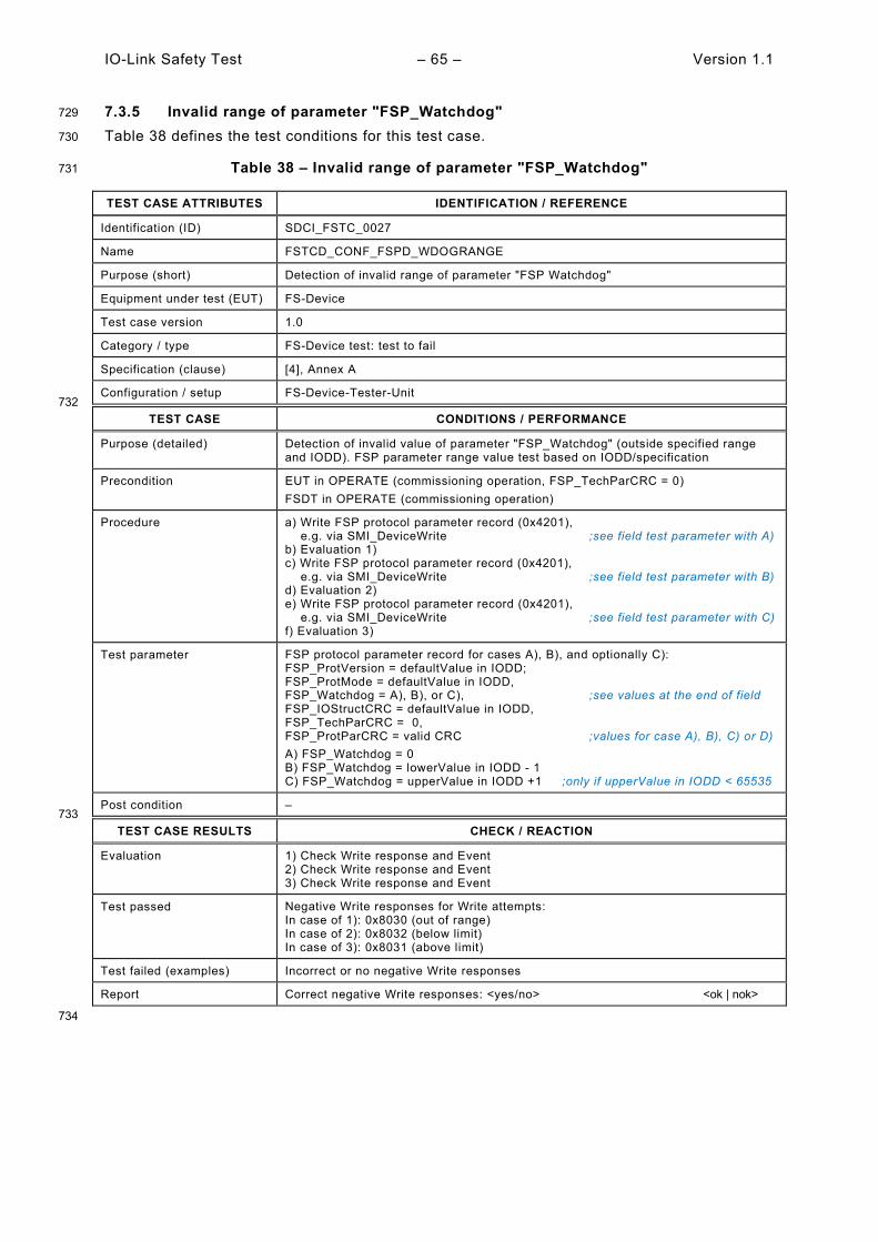
IO-Link Safety Test – 65 – Version 1.1
7.3.5 Invalid range of parameter "FSP_Watchdog" 729
Table 38 defines the test conditions for this test case. 730
Table 38 – Invalid range of parameter "FSP_Watchdog" 731
TEST CASE ATTRIBUTES IDENTIFICATION / REFERENCE
Identification (ID) SDCI_FSTC_0027
Name FSTCD_CONF_FSPD_WDOGRANGE
Purpose (short) Detection of invalid range of parameter "FSP Watchdog"
Equipment under test (EUT) FS-Device
Test case version 1.0
Category / type FS-Device test: test to fail
Specification (clause) [4], Annex A
Configuration / setup FS-Device-Tester-Unit 732
TEST CASE CONDITIONS / PERFORMANCE
Purpose (detailed) Detection of invalid value of parameter "FSP_Watchdog" (outside specified range and IODD). FSP parameter range value test based on IODD/specification
Precondition EUT in OPERATE (commissioning operation, FSP_TechParCRC = 0) FSDT in OPERATE (commissioning operation)
Procedure a) Write FSP protocol parameter record (0x4201), e.g. via SMI_DeviceWrite ;see field test parameter with A) b) Evaluation 1) c) Write FSP protocol parameter record (0x4201), e.g. via SMI_DeviceWrite ;see field test parameter with B) d) Evaluation 2) e) Write FSP protocol parameter record (0x4201), e.g. via SMI_DeviceWrite ;see field test parameter with C) f) Evaluation 3)
Test parameter FSP protocol parameter record for cases A), B), and optionally C): FSP_ProtVersion = defaultValue in IODD; FSP_ProtMode = defaultValue in IODD, FSP_Watchdog = A), B), or C), ;see values at the end of field FSP_IOStructCRC = defaultValue in IODD, FSP_TechParCRC = 0, FSP_ProtParCRC = valid CRC ;values for case A), B), C) or D) A) FSP_Watchdog = 0 B) FSP_Watchdog = lowerValue in IODD - 1 C) FSP_Watchdog = upperValue in IODD +1 ;only if upperValue in IODD < 65535
Post condition – 733
TEST CASE RESULTS CHECK / REACTION
Evaluation 1) Check Write response and Event 2) Check Write response and Event 3) Check Write response and Event
Test passed Negative Write responses for Write attempts: In case of 1): 0x8030 (out of range) In case of 2): 0x8032 (below limit) In case of 3): 0x8031 (above limit)
Test failed (examples) Incorrect or no negative Write responses
Report Correct negative Write responses: <yes/no> <ok | nok>
734

Version 1.1 – 66 – IO-Link Safety Test
7.3.6 Invalid value of signature "FSP_ProtParCRC" 735
Table 39 defines the test conditions for this test case. 736
Table 39 – Invalid value of signature "FSP_ProtParCRC" 737
TEST CASE ATTRIBUTES IDENTIFICATION / REFERENCE
Identification (ID) SDCI_FSTC_0028
Name FSTCD_CONF_FSPD_PRCRCINVAL
Purpose (short) Detection of invalid value of signature "FSP_ProtParCRC"
Equipment under test (EUT) FS-Device
Test case version 1.0
Category / type FS-Device test: test to pass
Specification (clause) [4], Annex A
Configuration / setup FS-Device-Tester-Unit 738
TEST CASE CONDITIONS / PERFORMANCE
Purpose (detailed) Detection of invalid value of signature "FSP_ProtParCRC" based on calculation
Precondition EUT in OPERATE (commissioning operation, FSP_TechParCRC = 0) FSDT in OPERATE (commissioning operation)
Procedure a) Write FSP protocol parameter record (0x4201), e.g. via SMI_DeviceWrite ;see field test parameter b) Evaluation 1) c) Evaluation 2)
Test parameter FSP protocol parameter record: FSP_ProtVersion = defaultValue in IODD; FSP_ProtMode = defaultValue in IODD, FSP_Watchdog = defaultValue in IODD, FSP_IOStructCRC = defaultValue in IODD, FSP_TechParCRC = 0, FSP_ProtParCRC = invalid CRC ;e.g. decrement calculated value
Post condition – 739
TEST CASE RESULTS CHECK / REACTION
Evaluation 1) Check Write response 2) Check Events
Test passed Negative Write response 0x8030, and No Events
Test failed (examples) Incorrect Write response, and/or Unexpected Events
Report Correct negative Write response: <yes/no> <ok | nok> No Events received: <yes/no> <ok | nok>
740
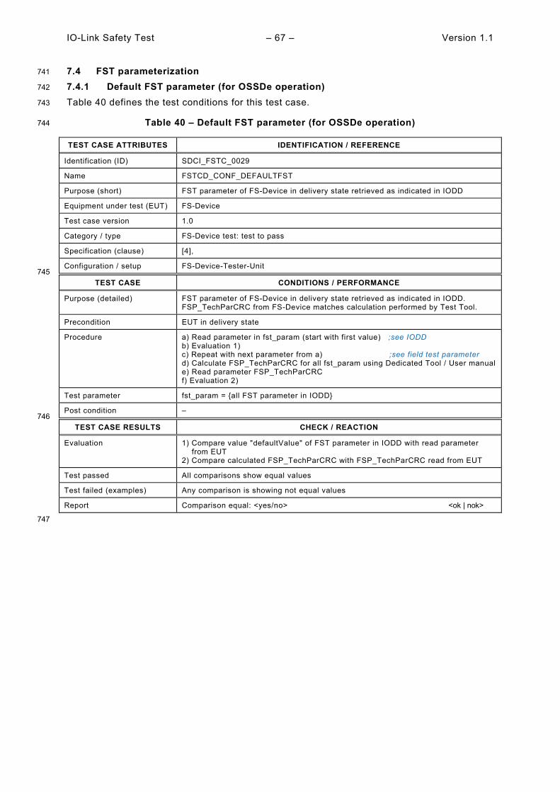
IO-Link Safety Test – 67 – Version 1.1
7.4 FST parameterization 741
7.4.1 Default FST parameter (for OSSDe operation) 742
Table 40 defines the test conditions for this test case. 743
Table 40 – Default FST parameter (for OSSDe operation) 744
TEST CASE ATTRIBUTES IDENTIFICATION / REFERENCE
Identification (ID) SDCI_FSTC_0029
Name FSTCD_CONF_DEFAULTFST
Purpose (short) FST parameter of FS-Device in delivery state retrieved as indicated in IODD
Equipment under test (EUT) FS-Device
Test case version 1.0
Category / type FS-Device test: test to pass
Specification (clause) [4],
Configuration / setup FS-Device-Tester-Unit 745
TEST CASE CONDITIONS / PERFORMANCE
Purpose (detailed) FST parameter of FS-Device in delivery state retrieved as indicated in IODD. FSP_TechParCRC from FS-Device matches calculation performed by Test Tool.
Precondition EUT in delivery state
Procedure a) Read parameter in fst_param (start with first value) ;see IODD b) Evaluation 1) c) Repeat with next parameter from a) ;see field test parameter d) Calculate FSP_TechParCRC for all fst_param using Dedicated Tool / User manual e) Read parameter FSP_TechParCRC f) Evaluation 2)
Test parameter fst_param = {all FST parameter in IODD}
Post condition – 746
TEST CASE RESULTS CHECK / REACTION
Evaluation 1) Compare value "defaultValue" of FST parameter in IODD with read parameter from EUT 2) Compare calculated FSP_TechParCRC with FSP_TechParCRC read from EUT
Test passed All comparisons show equal values
Test failed (examples) Any comparison is showing not equal values
Report Comparison equal: <yes/no> <ok | nok>
747
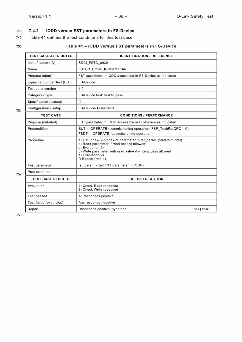
Version 1.1 – 68 – IO-Link Safety Test
7.4.2 IODD versus FST parameters in FS-Device 748
Table 41 defines the test conditions for this test case. 749
Table 41 – IODD versus FST parameters in FS-Device 750
TEST CASE ATTRIBUTES IDENTIFICATION / REFERENCE
Identification (ID) SDCI_FSTC_0030
Name FSTCD_CONF_IODDFSTPAR
Purpose (short) FST parameter in IODD accessible in FS-Device as indicated
Equipment under test (EUT) FS-Device
Test case version 1.0
Category / type FS-Device test: test to pass
Specification (clause) [4],
Configuration / setup FS-Device-Tester-Unit 751
TEST CASE CONDITIONS / PERFORMANCE
Purpose (detailed) FST parameter in IODD accessible in FS-Device as indicated
Precondition EUT in OPERATE (commissioning operation, FSP_TechParCRC = 0) FSDT in OPERATE (commissioning operation)
Procedure a) Get Index/Subindex of parameter in fst_param (start with first) b) Read parameter if read access allowed c) Evaluation 1) d) Write parameter with read value if write access allowed e) Evaluation 2) f) Repeat from a)
Test parameter fst_param = {all FST parameter in IODD}
Post condition – 752
TEST CASE RESULTS CHECK / REACTION
Evaluation 1) Check Read response 2) Check Write response
Test passed All responses positive
Test failed (examples) Any response negative
Report Responses positive: <yes/no> <ok | nok>
753
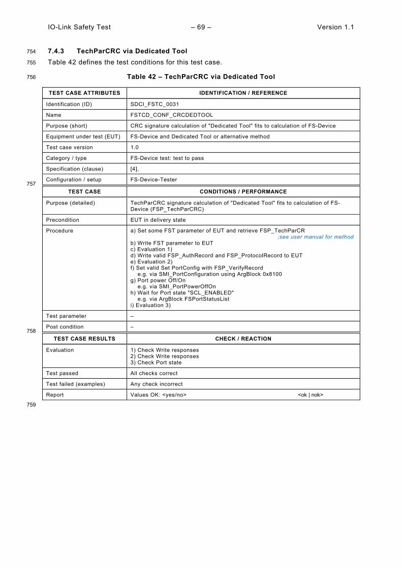
IO-Link Safety Test – 69 – Version 1.1
7.4.3 TechParCRC via Dedicated Tool 754
Table 42 defines the test conditions for this test case. 755
Table 42 – TechParCRC via Dedicated Tool 756
TEST CASE ATTRIBUTES IDENTIFICATION / REFERENCE
Identification (ID) SDCI_FSTC_0031
Name FSTCD_CONF_CRCDEDTOOL
Purpose (short) CRC signature calculation of "Dedicated Tool" fits to calculation of FS-Device
Equipment under test (EUT) FS-Device and Dedicated Tool or alternative method
Test case version 1.0
Category / type FS-Device test: test to pass
Specification (clause) [4],
Configuration / setup FS-Device-Tester 757
TEST CASE CONDITIONS / PERFORMANCE
Purpose (detailed) TechParCRC signature calculation of "Dedicated Tool" fits to calculation of FS-Device (FSP_TechParCRC)
Precondition EUT in delivery state
Procedure a) Set some FST parameter of EUT and retrieve FSP_TechParCR ;see user manual for method b) Write FST parameter to EUT c) Evaluation 1) d) Write valid FSP_AuthRecord and FSP_ProtocolRecord to EUT e) Evaluation 2) f) Set valid Set PortConfig with FSP_VerifyRecord e.g. via SMI_PortConfiguration using ArgBlock 0x8100 g) Port power Off/On e.g. via SMI_PortPowerOffOn h) Wait for Port state "SCL_ENABLED" e.g. via ArgBlock FSPortStatusList i) Evaluation 3)
Test parameter –
Post condition – 758
TEST CASE RESULTS CHECK / REACTION
Evaluation 1) Check Write responses 2) Check Write responses 3) Check Port state
Test passed All checks correct
Test failed (examples) Any check incorrect
Report Values OK: <yes/no> <ok | nok>
759
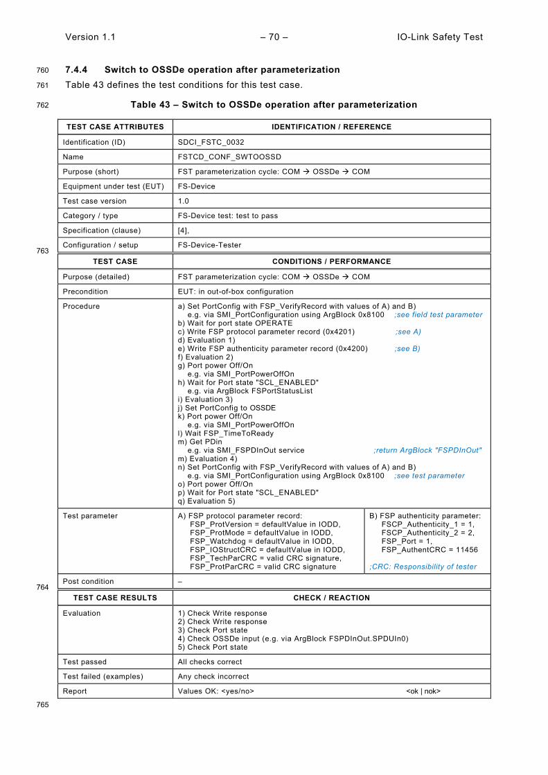
Version 1.1 – 70 – IO-Link Safety Test
7.4.4 Switch to OSSDe operation after parameterization 760
Table 43 defines the test conditions for this test case. 761
Table 43 – Switch to OSSDe operation after parameterization 762
TEST CASE ATTRIBUTES IDENTIFICATION / REFERENCE
Identification (ID) SDCI_FSTC_0032
Name FSTCD_CONF_SWTOOSSD
Purpose (short) FST parameterization cycle: COM OSSDe COM
Equipment under test (EUT) FS-Device
Test case version 1.0
Category / type FS-Device test: test to pass
Specification (clause) [4],
Configuration / setup FS-Device-Tester 763
TEST CASE CONDITIONS / PERFORMANCE
Purpose (detailed) FST parameterization cycle: COM OSSDe COM
Precondition EUT: in out-of-box configuration
Procedure a) Set PortConfig with FSP_VerifyRecord with values of A) and B) e.g. via SMI_PortConfiguration using ArgBlock 0x8100 ;see field test parameter b) Wait for port state OPERATE c) Write FSP protocol parameter record (0x4201) ;see A) d) Evaluation 1) e) Write FSP authenticity parameter record (0x4200) ;see B) f) Evaluation 2) g) Port power Off/On e.g. via SMI_PortPowerOffOn h) Wait for Port state "SCL_ENABLED" e.g. via ArgBlock FSPortStatusList i) Evaluation 3) j) Set PortConfig to OSSDE k) Port power Off/On e.g. via SMI_PortPowerOffOn l) Wait FSP_TimeToReady m) Get PDin e.g. via SMI_FSPDInOut service ;return ArgBlock "FSPDInOut" m) Evaluation 4) n) Set PortConfig with FSP_VerifyRecord with values of A) and B) e.g. via SMI_PortConfiguration using ArgBlock 0x8100 ;see test parameter o) Port power Off/On p) Wait for Port state "SCL_ENABLED" q) Evaluation 5)
Test parameter A) FSP protocol parameter record: FSP_ProtVersion = defaultValue in IODD, FSP_ProtMode = defaultValue in IODD, FSP_Watchdog = defaultValue in IODD, FSP_IOStructCRC = defaultValue in IODD, FSP_TechParCRC = valid CRC signature, FSP_ProtParCRC = valid CRC signature
B) FSP authenticity parameter: FSCP_Authenticity_1 = 1, FSCP_Authenticity_2 = 2, FSP_Port = 1, FSP_AuthentCRC = 11456 ;CRC: Responsibility of tester
Post condition – 764
TEST CASE RESULTS CHECK / REACTION
Evaluation 1) Check Write response 2) Check Write response 3) Check Port state 4) Check OSSDe input (e.g. via ArgBlock FSPDInOut.SPDUIn0) 5) Check Port state
Test passed All checks correct
Test failed (examples) Any check incorrect
Report Values OK: <yes/no> <ok | nok>
765
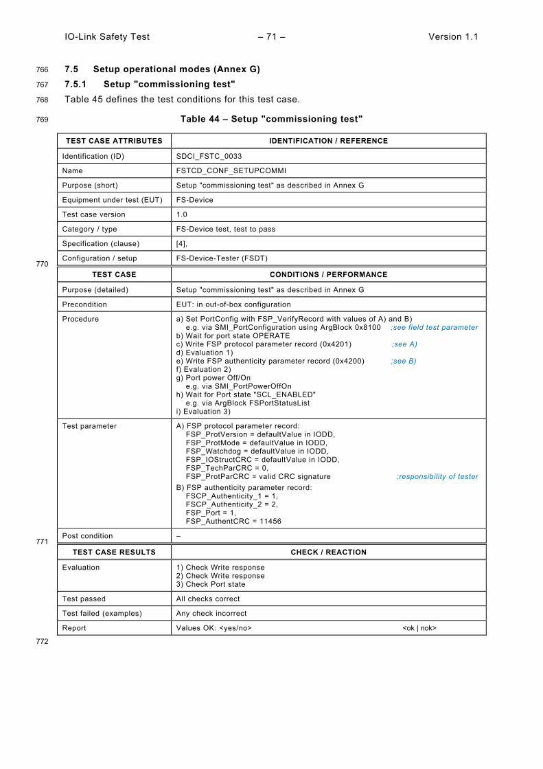
IO-Link Safety Test – 71 – Version 1.1
7.5 Setup operational modes (Annex G) 766
7.5.1 Setup "commissioning test" 767
Table 45 defines the test conditions for this test case. 768
Table 44 – Setup "commissioning test" 769
TEST CASE ATTRIBUTES IDENTIFICATION / REFERENCE
Identification (ID) SDCI_FSTC_0033
Name FSTCD_CONF_SETUPCOMMI
Purpose (short) Setup "commissioning test" as described in Annex G
Equipment under test (EUT) FS-Device
Test case version 1.0
Category / type FS-Device test, test to pass
Specification (clause) [4],
Configuration / setup FS-Device-Tester (FSDT) 770
TEST CASE CONDITIONS / PERFORMANCE
Purpose (detailed) Setup "commissioning test" as described in Annex G
Precondition EUT: in out-of-box configuration
Procedure a) Set PortConfig with FSP_VerifyRecord with values of A) and B) e.g. via SMI_PortConfiguration using ArgBlock 0x8100 ;see field test parameter b) Wait for port state OPERATE c) Write FSP protocol parameter record (0x4201) ;see A) d) Evaluation 1) e) Write FSP authenticity parameter record (0x4200) ;see B) f) Evaluation 2) g) Port power Off/On e.g. via SMI_PortPowerOffOn h) Wait for Port state "SCL_ENABLED" e.g. via ArgBlock FSPortStatusList i) Evaluation 3)
Test parameter A) FSP protocol parameter record: FSP_ProtVersion = defaultValue in IODD, FSP_ProtMode = defaultValue in IODD, FSP_Watchdog = defaultValue in IODD, FSP_IOStructCRC = defaultValue in IODD, FSP_TechParCRC = 0, FSP_ProtParCRC = valid CRC signature ;responsibility of tester B) FSP authenticity parameter record: FSCP_Authenticity_1 = 1, FSCP_Authenticity_2 = 2, FSP_Port = 1, FSP_AuthentCRC = 11456
Post condition – 771
TEST CASE RESULTS CHECK / REACTION
Evaluation 1) Check Write response 2) Check Write response 3) Check Port state
Test passed All checks correct
Test failed (examples) Any check incorrect
Report Values OK: <yes/no> <ok | nok>
772

Version 1.1 – 72 – IO-Link Safety Test
7.5.2 Setup "armed" 773
Table 45 defines the test conditions for this test case. 774
Table 45 – Setup "armed" 775
TEST CASE ATTRIBUTES IDENTIFICATION / REFERENCE
Identification (ID) SDCI_FSTC_0034
Name FSTCD_CONF_SETUPARMED
Purpose (short) Setup "armed" as described in Annex G
Equipment under test (EUT) FS-Device
Test case version 1.0
Category / type FS-Device test: test to pass
Specification (clause) [4],
Configuration / setup FS-Device-Tester-Unit 776
TEST CASE CONDITIONS / PERFORMANCE
Purpose (detailed) Setup "armed" as described in Annex G
Precondition EUT in OPERATE (commissioning operation, FSP_TechParCRC = 0) FSDT in OPERATE (commissioning operation)
Procedure a) Set PortConfig with FSP_VerifyRecord with values of A) and B) e.g. via SMI_PortConfiguration using ArgBlock 0x8100 ;see field test parameter b) Wait for Port state "SCL_ENABLED" e.g. via ArgBlock FSPortStatusList c) Write FSP protocol parameter record (0x4201) ;see A) d) Evaluation 1) e) Write FSP authenticity parameter record (0x4200) ;see B) f) Evaluation 2) g) Port power Off/On e.g. via SMI_PortPowerOffOn h) Wait for Port state "SCL_ENABLED" e.g. via ArgBlock FSPortStatusList i) Evaluation 3)
Test parameter A) FSP protocol parameter record: FSP_ProtVersion = defaultValue in IODD, FSP_ProtMode = defaultValue in IODD, FSP_Watchdog = defaultValue in IODD, FSP_IOStructCRC = defaultValue in IODD, FSP_TechParCRC = valid CRC signature ;responsibility of tester FSP_ProtParCRC = valid CRC signature ;responsibility of tester B) FSP authenticity parameter record: FSCP_Authenticity_1 = 1, FSCP_Authenticity_2 = 2, FSP_Port = 1, FSP_AuthentCRC = 11456
Post condition – 777
TEST CASE RESULTS CHECK / REACTION
Evaluation 1) Check Write response 2) Check Write response 3) Check Port state
Test passed All checks correct
Test failed (examples) Any check incorrect
Report Values OK: <yes/no> <ok | nok>
778

IO-Link Safety Test – 73 – Version 1.1
8 FS-Device safety measure tests 779
8.1 Overview 780
The FS-Device protocol tests comprise the various constellations of the VerifyRecord prior to 781 start of the Safety Communication Layer (SCL). It also comprises special tests such as the 782 protocol watchdog timer and evidence of correct implementation of the watchdog trigger as well 783 as the exceptional handling whenever a CRC signature calculation results in "0". 784
8.2 Verification (VerifyRecord) 785
8.2.1 Correct VerifyRecord and FSP_TechParCRC ("armed") 786
Table 46 defines the test conditions for this test case. It checks whether an FS-Device starts 787 SCL communication in "armed" mode (operation not monitored) after reception of a valid 788 VerifyRecord and FSP_TechParCRC ≠ 0. 789
Table 46 – Correct VerifyRecord and FSP_TechParCRC ("armed") 790
TEST CASE ATTRIBUTES IDENTIFICATION / REFERENCE
Identification (ID) SDCI_FSTC_0035
Name FSTCD_PARM_VRFY_ARMED
Purpose (short) Correct VerifyRecord and FSP_TechParCRC ("armed")
Equipment under test (EUT) FS-Device
Test case version 1.0
Category / type FS-Device PREOPERATE test: test-to-pass
Specification (clause) [4], clause 10.4.1, clause 10.4.3.1, clause 11.7.6, clause G.1
Configuration / setup FS-Device-Tester 791
TEST CASE CONDITIONS / PERFORMANCE
Purpose (detailed) Make sure that an FS Device is going to start SCL communication (“armed”) after reception of a valid VerifyRecord with FSP_TechParCRC ≠ 0.
Precondition EUT: Configured for armed operation ;see field test parameter FSDT: Port config DEACTIVATED
Procedure a) Set PortConfig with FSP_VerifyRecord with values of A) and B) e.g. via SMI_PortConfiguration using ArgBlock 0x8100 ;see field test parameter b) Wait for Port state "SCL_ENABLED" e.g. via ArgBlock FSPortStatusList c) Repeat SMI_FSPDInOut until change (observe <timeout>) ;ArgBlock FSPDInOut d) Evaluation 1)
Test parameter A) FSP protocol parameter record: FSP_ProtVersion = defaultValue in IODD, FSP_ProtMode = defaultValue in IODD, FSP_Watchdog = defaultValue in IODD, FSP_IOStructCRC = defaultValue in IODD, FSP_TechParCRC = valid CRC signature ;responsibility of tester FSP_ProtParCRC = valid CRC signature ;responsibility of tester B) FSP authenticity parameter record: FSCP_Authenticity_1 = 1, FSCP_Authenticity_2 = 2, FSP_Port = 1, FSP_AuthentCRC = 11456
Post condition – 792
TEST CASE RESULTS CHECK / REACTION
Evaluation 1) Check change
Test passed No <timeout>
Test failed (examples) <timeout>
Report SPDU exchange: <negative/positive> <ok | nok>
793
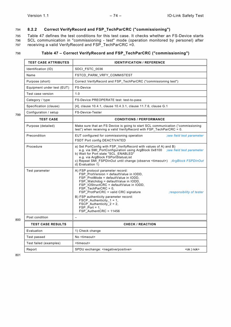
Version 1.1 – 74 – IO-Link Safety Test
8.2.2 Correct VerifyRecord and FSP_TechParCRC ("commissioning") 794
Table 47 defines the test conditions for this test case. It checks whether an FS-Device starts 795 SCL communication in "commissioning - test" mode (operation monitored by personel) after 796 receiving a valid VerifyRecord and FSP_TechParCRC =0. 797
Table 47 – Correct VerifyRecord and FSP_TechParCRC ("commissioning") 798
TEST CASE ATTRIBUTES IDENTIFICATION / REFERENCE
Identification (ID) SDCI_FSTC_0036
Name FSTCD_PARM_VRFY_COMMISTEST
Purpose (short) Correct VerifyRecord and FSP_TechParCRC ("commissioning test")
Equipment under test (EUT) FS-Device
Test case version 1.0
Category / type FS-Device PREOPERATE test: test-to-pass
Specification (clause) [4], clause 10.4.1, clause 10.4.3.1, clause 11.7.6, clause G.1
Configuration / setup FS-Device-Tester 799
TEST CASE CONDITIONS / PERFORMANCE
Purpose (detailed) Make sure that an FS Device is going to start SCL communication (“commissioning test”) when receiving a valid VerifyRecord with FSP_TechParCRC = 0.
Precondition EUT configured for commissioning operation ;see field test parameter FSDT Port config DEACTIVATED
Procedure a) Set PortConfig with FSP_VerifyRecord with values of A) and B) e.g. via SMI_PortConfiguration using ArgBlock 0x8100 ;see field test parameter b) Wait for Port state "SCL_ENABLED" e.g. via ArgBlock FSPortStatusList c) Repeat SMI_FSPDInOut until change (observe <timeout>) ;ArgBlock FSPDInOut d) Evaluation 1)
Test parameter A) FSP protocol parameter record: FSP_ProtVersion = defaultValue in IODD, FSP_ProtMode = defaultValue in IODD, FSP_Watchdog = defaultValue in IODD, FSP_IOStructCRC = defaultValue in IODD, FSP_TechParCRC = 0, FSP_ProtParCRC = valid CRC signature ;responsibility of tester B) FSP authenticity parameter record: FSCP_Authenticity_1 = 1, FSCP_Authenticity_2 = 2, FSP_Port = 1, FSP_AuthentCRC = 11456
Post condition – 800
TEST CASE RESULTS CHECK / REACTION
Evaluation 1) Check change
Test passed No <timeout>
Test failed (examples) <timeout>
Report SPDU exchange: <negative/positive> <ok | nok>
801

IO-Link Safety Test – 75 – Version 1.1
8.2.3 Missing VerifyRecord at start-up ("armed") 802
Table 48 defines the test conditions for this test case. It checks whether an FS-Device refuses 803 to start SCL communication when VerifyRecord is missing in "armed" mode (operation not 804 monitored). 805
Table 48 – Missing VerifyRecord at start-up ("armed") 806
TEST CASE ATTRIBUTES IDENTIFICATION / REFERENCE
Identification (ID) SDCI_FSTC_0037
Name FSTCD_PARM_VRFY_ARMEDNOVFY
Purpose (short) Missing VerifyRecord at start-up ("armed")
Equipment under test (EUT) FS-Device
Test case version 1.0
Category / type FS-Device PREOPERATE test: test-to-pass
Specification (clause) [4], clause 10.4.1, clause 10.4.3.1, clause 11.7.6, clause G.1
Configuration / setup FS-Device-Tester 807
TEST CASE CONDITIONS / PERFORMANCE
Purpose (detailed) Make sure that an FS-Device is not going to start SCL communication without receiving a valid and matching VerifyRecord within twice the time required for regular start-up.
Precondition EUT configured for armed operation ;see field test parameter FSDT Port config DEACTIVATED
Procedure a) Set PortConfig with FSP_VerifyRecord with values of A) and B) e.g. via SMI_PortConfiguration using ArgBlock 0x8100 ;see field test parameter FSDT: Do NOT send FSP_VerifyRecord b) Wait for Port state "OPERATE" e.g. via ArgBlock FSPortStatusList c) Evaluation 1) d) Evaluation 2)
Test parameter A) FSP protocol parameter record: FSP_ProtVersion = defaultValue in IODD, FSP_ProtMode = defaultValue in IODD, FSP_Watchdog = defaultValue in IODD, FSP_IOStructCRC = defaultValue in IODD, FSP_TechParCRC = valid CRC signature ;responsibility of tester FSP_ProtParCRC = valid CRC signature ;responsibility of tester B) FSP authenticity parameter record: FSCP_Authenticity_1 = 1, FSCP_Authenticity_2 = 2, FSP_Port = 1, FSP_AuthentCRC = 11456
Post condition – 808
TEST CASE RESULTS CHECK / REACTION
Evaluation 1) Check Port state 2) Check Events
Test passed Port state is “OPERATE”, and Event 0xB00A received
Test failed (examples) Any check incorrect
Report Port state OPERATE: <negative/positive> <ok | nok> Event 0xB00A received: <yes/no> <ok | nok>
809

Version 1.1 – 76 – IO-Link Safety Test
8.2.4 Missing VerifyRecord at start-up ("commissioning") 810
Table 49 defines the test conditions for this test case. It checks whether an FS-Device refuses 811 to start SCL communication when VerifyRecord is missing in "commissioning – test" mode 812 (monitored operation). 813
Table 49 – Missing VerifyRecord at start-up ("commissioning") 814
TEST CASE ATTRIBUTES IDENTIFICATION / REFERENCE
Identification (ID) SDCI_FSTC_0038
Name FSTCD_PARM_VRFY_TESTNOVFY
Purpose (short) Missing VerifyRecord at start-up ("commissioning test")
Equipment under test (EUT) FS-Device
Test case version 1.0
Category / type FS-Device PREOPERATE test: test-to-pass
Specification (clause) [4], clause 10.4.1, clause 10.4.3.1, clause 11.7.6, clause G.1
Configuration / setup FS-Device-Tester 815
TEST CASE CONDITIONS / PERFORMANCE
Purpose (detailed) Make sure that an FS Device is not going to start SCL communication (“commissioning test”) without receiving a valid VerifyRecord within twice the time required for regular start-up.
Precondition EUT configured for commissioning operation ;see field test parameter FSDT Port config DEACTIVATED
Procedure a) Set PortConfig with FSP_VerifyRecord with values of A) and B) e.g. via SMI_PortConfiguration using ArgBlock 0x8100 ;see field test parameter FSDT: Do NOT send FSP_VerifyRecord b) Wait for Port state "OPERATE" e.g. via ArgBlock FSPortStatusList c) Evaluation 1) d) Evaluation 2)
Test parameter A) FSP protocol parameter record: FSP_ProtVersion = defaultValue in IODD, FSP_ProtMode = defaultValue in IODD, FSP_Watchdog = defaultValue in IODD, FSP_IOStructCRC = defaultValue in IODD, FSP_TechParCRC = 0, FSP_ProtParCRC = valid CRC signature ;responsibility of tester B) FSP authenticity parameter record: FSCP_Authenticity_1 = 1, FSCP_Authenticity_2 = 2, FSP_Port = 1, FSP_AuthentCRC = 11456
Post condition – 816
TEST CASE RESULTS CHECK / REACTION
Evaluation 1) Check Port state 2) Check Events
Test passed Port state is “OPERATE”, and Event 0xB00A received
Test failed (examples) Any check incorrect
Report Port state OPERATE: <negative/positive> <ok | nok> Event 0xB00A received: <yes/no> <ok | nok>
817
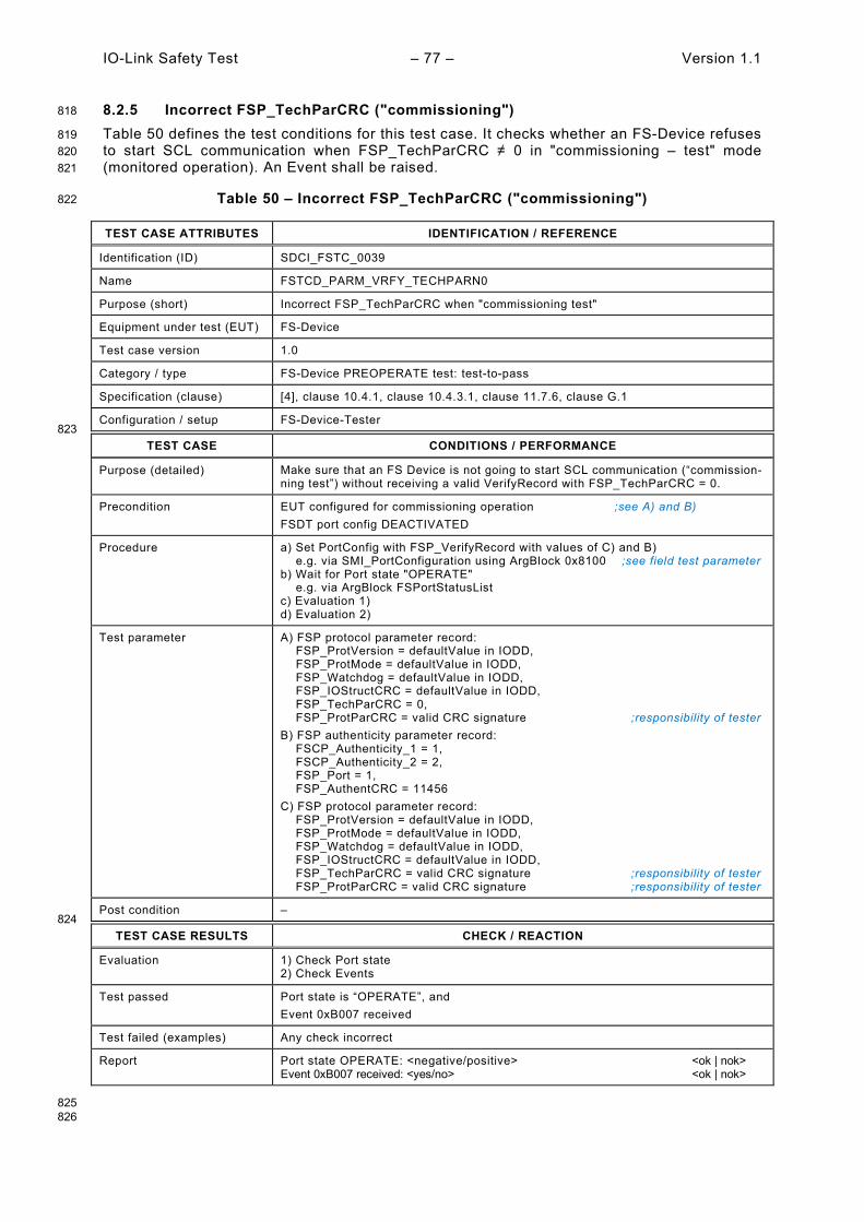
IO-Link Safety Test – 77 – Version 1.1
8.2.5 Incorrect FSP_TechParCRC ("commissioning") 818
Table 50 defines the test conditions for this test case. It checks whether an FS-Device refuses 819 to start SCL communication when FSP_TechParCRC ≠ 0 in "commissioning – test" mode 820 (monitored operation). An Event shall be raised. 821
Table 50 – Incorrect FSP_TechParCRC ("commissioning") 822
TEST CASE ATTRIBUTES IDENTIFICATION / REFERENCE
Identification (ID) SDCI_FSTC_0039
Name FSTCD_PARM_VRFY_TECHPARN0
Purpose (short) Incorrect FSP_TechParCRC when "commissioning test"
Equipment under test (EUT) FS-Device
Test case version 1.0
Category / type FS-Device PREOPERATE test: test-to-pass
Specification (clause) [4], clause 10.4.1, clause 10.4.3.1, clause 11.7.6, clause G.1
Configuration / setup FS-Device-Tester 823
TEST CASE CONDITIONS / PERFORMANCE
Purpose (detailed) Make sure that an FS Device is not going to start SCL communication (“commission-ning test”) without receiving a valid VerifyRecord with FSP_TechParCRC = 0.
Precondition EUT configured for commissioning operation ;see A) and B) FSDT port config DEACTIVATED
Procedure a) Set PortConfig with FSP_VerifyRecord with values of C) and B) e.g. via SMI_PortConfiguration using ArgBlock 0x8100 ;see field test parameter b) Wait for Port state "OPERATE" e.g. via ArgBlock FSPortStatusList c) Evaluation 1) d) Evaluation 2)
Test parameter A) FSP protocol parameter record: FSP_ProtVersion = defaultValue in IODD, FSP_ProtMode = defaultValue in IODD, FSP_Watchdog = defaultValue in IODD, FSP_IOStructCRC = defaultValue in IODD, FSP_TechParCRC = 0, FSP_ProtParCRC = valid CRC signature ;responsibility of tester B) FSP authenticity parameter record: FSCP_Authenticity_1 = 1, FSCP_Authenticity_2 = 2, FSP_Port = 1, FSP_AuthentCRC = 11456 C) FSP protocol parameter record: FSP_ProtVersion = defaultValue in IODD, FSP_ProtMode = defaultValue in IODD, FSP_Watchdog = defaultValue in IODD, FSP_IOStructCRC = defaultValue in IODD, FSP_TechParCRC = valid CRC signature ;responsibility of tester FSP_ProtParCRC = valid CRC signature ;responsibility of tester
Post condition – 824
TEST CASE RESULTS CHECK / REACTION
Evaluation 1) Check Port state 2) Check Events
Test passed Port state is “OPERATE”, and Event 0xB007 received
Test failed (examples) Any check incorrect
Report Port state OPERATE: <negative/positive> <ok | nok> Event 0xB007 received: <yes/no> <ok | nok>
825 826
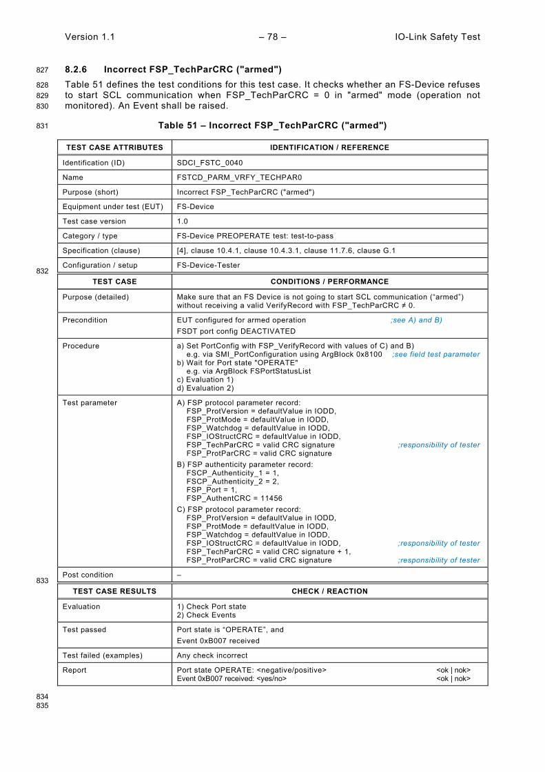
Version 1.1 – 78 – IO-Link Safety Test
8.2.6 Incorrect FSP_TechParCRC ("armed") 827
Table 51 defines the test conditions for this test case. It checks whether an FS-Device refuses 828 to start SCL communication when FSP_TechParCRC = 0 in "armed" mode (operation not 829 monitored). An Event shall be raised. 830
Table 51 – Incorrect FSP_TechParCRC ("armed") 831
TEST CASE ATTRIBUTES IDENTIFICATION / REFERENCE
Identification (ID) SDCI_FSTC_0040
Name FSTCD_PARM_VRFY_TECHPAR0
Purpose (short) Incorrect FSP_TechParCRC ("armed")
Equipment under test (EUT) FS-Device
Test case version 1.0
Category / type FS-Device PREOPERATE test: test-to-pass
Specification (clause) [4], clause 10.4.1, clause 10.4.3.1, clause 11.7.6, clause G.1
Configuration / setup FS-Device-Tester 832
TEST CASE CONDITIONS / PERFORMANCE
Purpose (detailed) Make sure that an FS Device is not going to start SCL communication (“armed”) without receiving a valid VerifyRecord with FSP_TechParCRC ≠ 0.
Precondition EUT configured for armed operation ;see A) and B) FSDT port config DEACTIVATED
Procedure a) Set PortConfig with FSP_VerifyRecord with values of C) and B) e.g. via SMI_PortConfiguration using ArgBlock 0x8100 ;see field test parameter b) Wait for Port state "OPERATE" e.g. via ArgBlock FSPortStatusList c) Evaluation 1) d) Evaluation 2)
Test parameter A) FSP protocol parameter record: FSP_ProtVersion = defaultValue in IODD, FSP_ProtMode = defaultValue in IODD, FSP_Watchdog = defaultValue in IODD, FSP_IOStructCRC = defaultValue in IODD, FSP_TechParCRC = valid CRC signature ;responsibility of tester FSP_ProtParCRC = valid CRC signature B) FSP authenticity parameter record: FSCP_Authenticity_1 = 1, FSCP_Authenticity_2 = 2, FSP_Port = 1, FSP_AuthentCRC = 11456 C) FSP protocol parameter record: FSP_ProtVersion = defaultValue in IODD, FSP_ProtMode = defaultValue in IODD, FSP_Watchdog = defaultValue in IODD, FSP_IOStructCRC = defaultValue in IODD, ;responsibility of tester FSP_TechParCRC = valid CRC signature + 1, FSP_ProtParCRC = valid CRC signature ;responsibility of tester
Post condition – 833
TEST CASE RESULTS CHECK / REACTION
Evaluation 1) Check Port state 2) Check Events
Test passed Port state is “OPERATE”, and Event 0xB007 received
Test failed (examples) Any check incorrect
Report Port state OPERATE: <negative/positive> <ok | nok> Event 0xB007 received: <yes/no> <ok | nok>
834 835
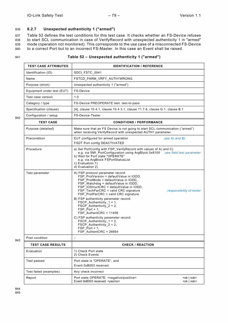
IO-Link Safety Test – 79 – Version 1.1
8.2.7 Unexpected authenticity 1 ("armed") 836
Table 52 defines the test conditions for this test case. It checks whether an FS-Device refuses 837 to start SCL communication in case of VerifyRecord with unexpected authenticity 1 in "armed" 838 mode (operation not monitored). This corresponds to the use case of a misconnected FS-Device 839 to a correct Port but to an incorrect FS-Master. In this case an Event shall be raised. 840
Table 52 – Unexpected authenticity 1 ("armed") 841
TEST CASE ATTRIBUTES IDENTIFICATION / REFERENCE
Identification (ID) SDCI_FSTC_0041
Name FSTCD_PARM_VRFY_AUTH1WRONG
Purpose (short) Unexpected authenticity 1 ("armed")
Equipment under test (EUT) FS-Device
Test case version 1.0
Category / type FS-Device PREOPERATE test: test-to-pass
Specification (clause) [4], clause 10.4.1, clause 10.4.3.1, clause 11.7.6, clause G.1, clause B.1
Configuration / setup FS-Device-Tester 842
TEST CASE CONDITIONS / PERFORMANCE
Purpose (detailed) Make sure that an FS Device is not going to start SCL communication (“armed”) when receiving VerifyRecord with unexpected AUTH1 parameter.
Precondition EUT configured for armed operation ;see A) and B) FSDT Port config DEACTIVATED
Procedure a) Set PortConfig with FSP_VerifyRecord with values of A) and C) e.g. via SMI_PortConfiguration using ArgBlock 0x8100 ;see field test parameter b) Wait for Port state "OPERATE" e.g. via ArgBlock FSPortStatusList c) Evaluation 1) d) Evaluation 2)
Test parameter A) FSP protocol parameter record: FSP_ProtVersion = defaultValue in IODD, FSP_ProtMode = defaultValue in IODD, FSP_Watchdog = defaultValue in IODD, FSP_IOStructCRC = defaultValue in IODD, FSP_TechParCRC = valid CRC signature ;responsibility of tester FSP_ProtParCRC = valid CRC signature B) FSP authenticity parameter record: FSCP_Authenticity_1 = 1, FSCP_Authenticity_2 = 2, FSP_Port = 1, FSP_AuthentCRC = 11456 C) FSP authenticity parameter record: FSCP_Authenticity_1 = 2, FSCP_Authenticity_2 = 2, FSP_Port = 1, FSP_AuthentCRC = 26664
Post condition – 843
TEST CASE RESULTS CHECK / REACTION
Evaluation 1) Check Port state 2) Check Events
Test passed Port state is “OPERATE”, and Event 0xB003 received
Test failed (examples) Any check incorrect
Report Port state OPERATE: <negative/positive> <ok | nok> Event 0xB003 received: <yes/no> <ok | nok>
844 845

Version 1.1 – 80 – IO-Link Safety Test
8.2.8 Unexpected authenticity 2 ("armed") 846
Table 53 defines the test conditions for this test case. It checks whether an FS-Device refuses 847 to start SCL communication in case of VerifyRecord with unexpected authenticity 2 in "armed" 848 mode (operation not monitored). This corresponds to the use case of a misconnected FS-Device 849 to a correct Port but to an incorrect FS-Master. In this case an Event shall be raised. 850
Table 53 – Unexpected authenticity 2 ("armed") 851
TEST CASE ATTRIBUTES IDENTIFICATION / REFERENCE
Identification (ID) SDCI_FSTC_0042
Name FSTCD_PARM_VRFY_AUTH2WRONG
Purpose (short) Unexpected authenticity 2 ("armed")
Equipment under test (EUT) FS-Device
Test case version 1.0
Category / type FS-Device PREOPERATE test: test-to-pass
Specification (clause) [4], clause 10.4.1, clause 10.4.3.1, clause 11.7.6, clause G.1, clause B.1
Configuration / setup FS-Device-Tester 852
TEST CASE CONDITIONS / PERFORMANCE
Purpose (detailed) Make sure that an FS Device is not going to start SCL communication (“armed”) when receiving VerifyRecord with unexpected AUTH2 parameter.
Precondition EUT configured for armed operation ;see A) and B) FSDT port config DEACTIVATED
Procedure a) Set PortConfig with FSP_VerifyRecord with values of A) and C) e.g. via SMI_PortConfiguration using ArgBlock 0x8100 ;see field test parameter b) Wait for Port state "OPERATE" e.g. via ArgBlock FSPortStatusList c) Evaluation 1) d) Evaluation 2)
Test parameter A) FSP protocol parameter record: FSP_ProtVersion = defaultValue in IODD, FSP_ProtMode = defaultValue in IODD, FSP_Watchdog = defaultValue in IODD, FSP_IOStructCRC = defaultValue in IODD, FSP_TechParCRC = valid CRC signature ;responsibility of tester FSP_ProtParCRC = valid CRC signature B) FSP authenticity parameter record: FSCP_Authenticity_1 = 1, FSCP_Authenticity_2 = 2, FSP_Port = 1, FSP_AuthentCRC = 11456 C) FSP authenticity parameter record: FSCP_Authenticity_1 = 1, FSCP_Authenticity_2 = 3, FSP_Port = 1, FSP_AuthentCRC = 24853
Post condition – 853
TEST CASE RESULTS CHECK / REACTION
Evaluation 1) Check Port state 2) Check Events
Test passed Port state is “OPERATE”, and Event 0xB003 received
Test failed (examples) Any check incorrect
Report Port state OPERATE: <negative/positive> <ok | nok> Event 0xB003 received: <yes/no> <ok | nok>
854
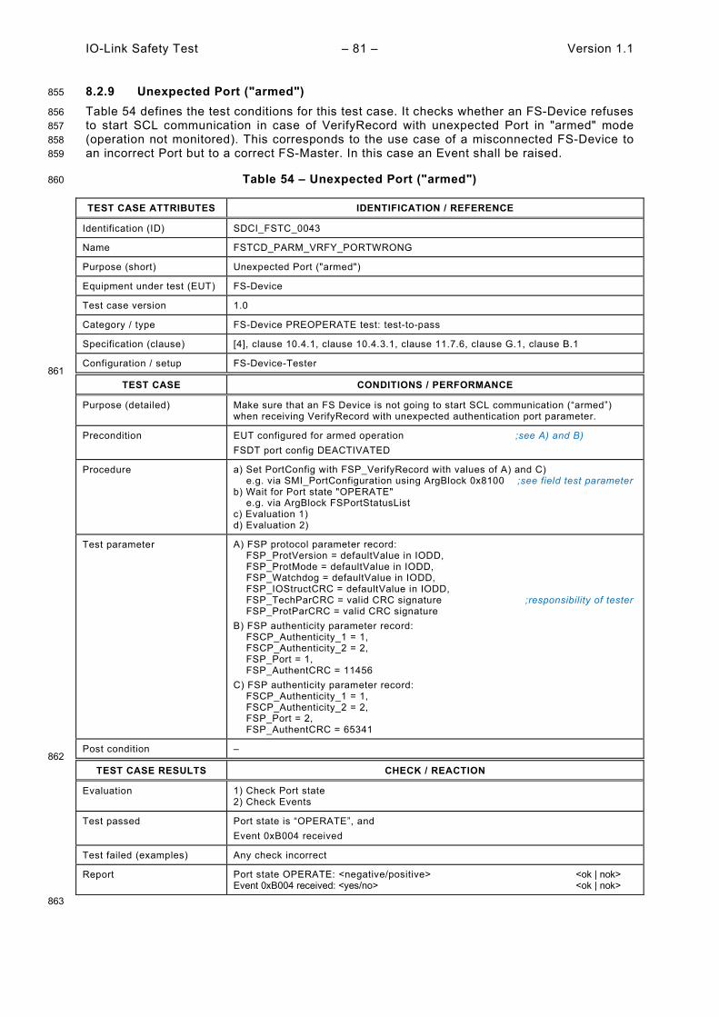
IO-Link Safety Test – 81 – Version 1.1
8.2.9 Unexpected Port ("armed") 855
Table 54 defines the test conditions for this test case. It checks whether an FS-Device refuses 856 to start SCL communication in case of VerifyRecord with unexpected Port in "armed" mode 857 (operation not monitored). This corresponds to the use case of a misconnected FS-Device to 858 an incorrect Port but to a correct FS-Master. In this case an Event shall be raised. 859
Table 54 – Unexpected Port ("armed") 860
TEST CASE ATTRIBUTES IDENTIFICATION / REFERENCE
Identification (ID) SDCI_FSTC_0043
Name FSTCD_PARM_VRFY_PORTWRONG
Purpose (short) Unexpected Port ("armed")
Equipment under test (EUT) FS-Device
Test case version 1.0
Category / type FS-Device PREOPERATE test: test-to-pass
Specification (clause) [4], clause 10.4.1, clause 10.4.3.1, clause 11.7.6, clause G.1, clause B.1
Configuration / setup FS-Device-Tester 861
TEST CASE CONDITIONS / PERFORMANCE
Purpose (detailed) Make sure that an FS Device is not going to start SCL communication (“armed”) when receiving VerifyRecord with unexpected authentication port parameter.
Precondition EUT configured for armed operation ;see A) and B) FSDT port config DEACTIVATED
Procedure a) Set PortConfig with FSP_VerifyRecord with values of A) and C) e.g. via SMI_PortConfiguration using ArgBlock 0x8100 ;see field test parameter b) Wait for Port state "OPERATE" e.g. via ArgBlock FSPortStatusList c) Evaluation 1) d) Evaluation 2)
Test parameter A) FSP protocol parameter record: FSP_ProtVersion = defaultValue in IODD, FSP_ProtMode = defaultValue in IODD, FSP_Watchdog = defaultValue in IODD, FSP_IOStructCRC = defaultValue in IODD, FSP_TechParCRC = valid CRC signature ;responsibility of tester FSP_ProtParCRC = valid CRC signature B) FSP authenticity parameter record: FSCP_Authenticity_1 = 1, FSCP_Authenticity_2 = 2, FSP_Port = 1, FSP_AuthentCRC = 11456 C) FSP authenticity parameter record: FSCP_Authenticity_1 = 1, FSCP_Authenticity_2 = 2, FSP_Port = 2, FSP_AuthentCRC = 65341
Post condition – 862
TEST CASE RESULTS CHECK / REACTION
Evaluation 1) Check Port state 2) Check Events
Test passed Port state is “OPERATE”, and Event 0xB004 received
Test failed (examples) Any check incorrect
Report Port state OPERATE: <negative/positive> <ok | nok> Event 0xB004 received: <yes/no> <ok | nok>
863

Version 1.1 – 82 – IO-Link Safety Test
8.2.10 Incorrect authenticity CRC signature ("armed") 864
Table 55 defines the test conditions for this test case. It checks whether an FS-Device refuses 865 to start SCL communication in case of VerifyRecord with incorrect authenticity CRC signature 866 in "armed" mode (operation not monitored). In this case an Event shall be raised. 867
Table 55 – Incorrect authenticity CRC signature ("armed") 868
TEST CASE ATTRIBUTES IDENTIFICATION / REFERENCE
Identification (ID) SDCI_FSTC_0044
Name FSTCD_PARM_VRFY_AUTHCRCWRG
Purpose (short) Incorrect authenticity CRC signature ("armed")
Equipment under test (EUT) FS-Device
Test case version 1.0
Category / type FS-Device PREOPERATE test: test-to-pass
Specification (clause) [4], clause 10.4.1, clause 10.4.3.1, clause 11.7.6, clause G.1, clause B.1
Configuration / setup FS-Device-Tester 869
TEST CASE CONDITIONS / PERFORMANCE
Purpose (detailed) Make sure that an FS Device is not going to start SCL communication (“armed”) when receiving VerifyRecord with incorrect FSP_AuthentCRC parameter.
Precondition EUT configured for armed operation ;see A) and B) FSDT Port config DEACTIVATED
Procedure a) Set PortConfig with FSP_VerifyRecord with values of A) and C) e.g. via SMI_PortConfiguration using ArgBlock 0x8100 ;see field test parameter b) Wait for Port state "OPERATE" e.g. via ArgBlock FSPortStatusList c) Evaluation 1) d) Evaluation 2)
Test parameter A) FSP protocol parameter record: FSP_ProtVersion = defaultValue in IODD, FSP_ProtMode = defaultValue in IODD, FSP_Watchdog = defaultValue in IODD, FSP_IOStructCRC = defaultValue in IODD, FSP_TechParCRC = valid CRC signature ;responsibility of tester FSP_ProtParCRC = valid CRC signature B) FSP authenticity parameter record: FSCP_Authenticity_1 = 1, FSCP_Authenticity_2 = 2, FSP_Port = 1, FSP_AuthentCRC = 11456 C) FSP authenticity parameter record: FSCP_Authenticity_1 = 1, FSCP_Authenticity_2 = 2, FSP_Port = 1, FSP_AuthentCRC = 11457
Post condition – 870
TEST CASE RESULTS CHECK / REACTION
Evaluation 1) Check Port state 2) Check Events
Test passed Port state is “OPERATE”, and Event 0xB005 received
Test failed (examples) Any check incorrect
Report Port state OPERATE: <negative/positive> <ok | nok> Event 0xB005 received: <yes/no> <ok | nok>
871
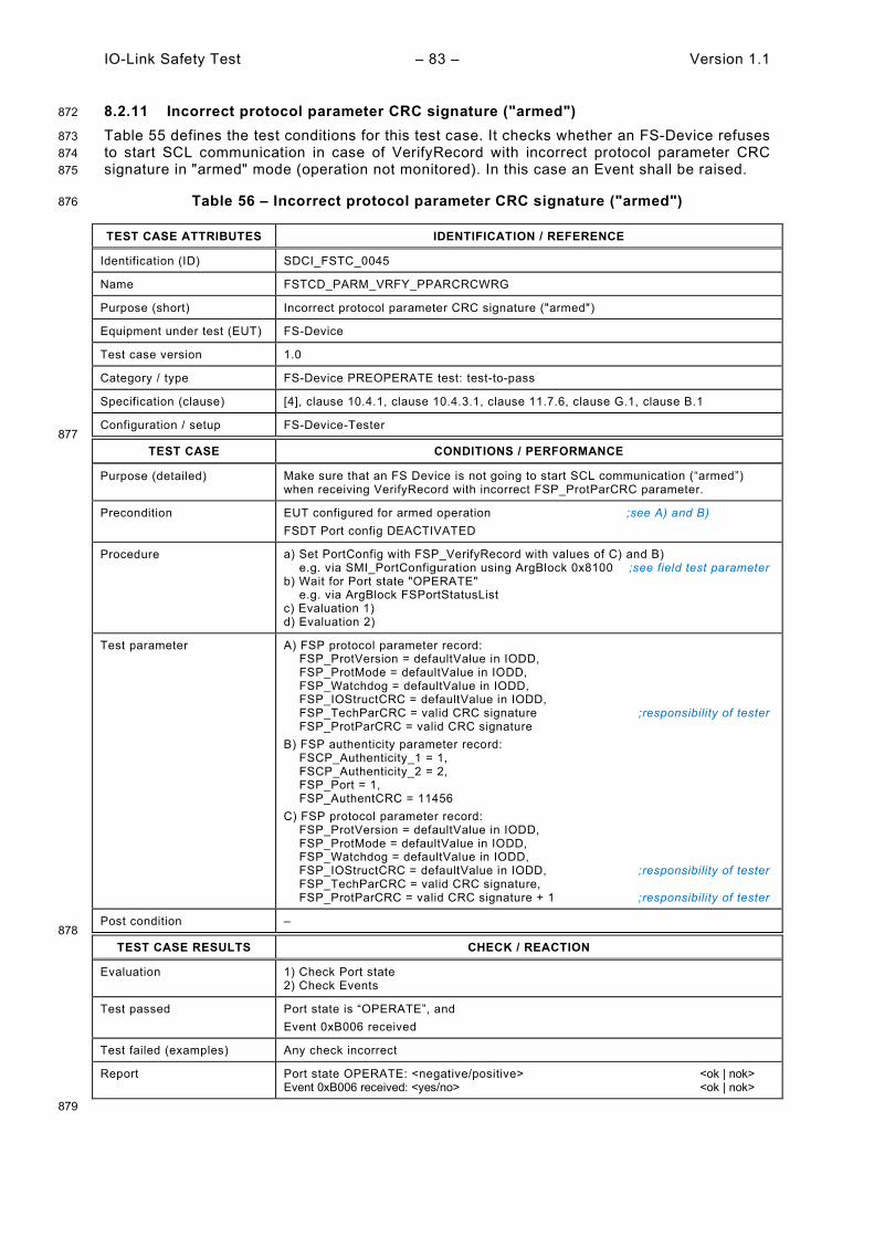
IO-Link Safety Test – 83 – Version 1.1
8.2.11 Incorrect protocol parameter CRC signature ("armed") 872
Table 55 defines the test conditions for this test case. It checks whether an FS-Device refuses 873 to start SCL communication in case of VerifyRecord with incorrect protocol parameter CRC 874 signature in "armed" mode (operation not monitored). In this case an Event shall be raised. 875
Table 56 – Incorrect protocol parameter CRC signature ("armed") 876
TEST CASE ATTRIBUTES IDENTIFICATION / REFERENCE
Identification (ID) SDCI_FSTC_0045
Name FSTCD_PARM_VRFY_PPARCRCWRG
Purpose (short) Incorrect protocol parameter CRC signature ("armed")
Equipment under test (EUT) FS-Device
Test case version 1.0
Category / type FS-Device PREOPERATE test: test-to-pass
Specification (clause) [4], clause 10.4.1, clause 10.4.3.1, clause 11.7.6, clause G.1, clause B.1
Configuration / setup FS-Device-Tester 877
TEST CASE CONDITIONS / PERFORMANCE
Purpose (detailed) Make sure that an FS Device is not going to start SCL communication (“armed”) when receiving VerifyRecord with incorrect FSP_ProtParCRC parameter.
Precondition EUT configured for armed operation ;see A) and B) FSDT Port config DEACTIVATED
Procedure a) Set PortConfig with FSP_VerifyRecord with values of C) and B) e.g. via SMI_PortConfiguration using ArgBlock 0x8100 ;see field test parameter b) Wait for Port state "OPERATE" e.g. via ArgBlock FSPortStatusList c) Evaluation 1) d) Evaluation 2)
Test parameter A) FSP protocol parameter record: FSP_ProtVersion = defaultValue in IODD, FSP_ProtMode = defaultValue in IODD, FSP_Watchdog = defaultValue in IODD, FSP_IOStructCRC = defaultValue in IODD, FSP_TechParCRC = valid CRC signature ;responsibility of tester FSP_ProtParCRC = valid CRC signature B) FSP authenticity parameter record: FSCP_Authenticity_1 = 1, FSCP_Authenticity_2 = 2, FSP_Port = 1, FSP_AuthentCRC = 11456 C) FSP protocol parameter record: FSP_ProtVersion = defaultValue in IODD, FSP_ProtMode = defaultValue in IODD, FSP_Watchdog = defaultValue in IODD, FSP_IOStructCRC = defaultValue in IODD, ;responsibility of tester FSP_TechParCRC = valid CRC signature, FSP_ProtParCRC = valid CRC signature + 1 ;responsibility of tester
Post condition – 878
TEST CASE RESULTS CHECK / REACTION
Evaluation 1) Check Port state 2) Check Events
Test passed Port state is “OPERATE”, and Event 0xB006 received
Test failed (examples) Any check incorrect
Report Port state OPERATE: <negative/positive> <ok | nok> Event 0xB006 received: <yes/no> <ok | nok>
879

Version 1.1 – 84 – IO-Link Safety Test
8.2.12 Incorrect technology parameter CRC signature ("armed") 880
Table 55 defines the test conditions for this test case. It checks whether an FS-Device refuses 881 to start SCL communication in case of VerifyRecord with incorrect technology parameter CRC 882 signature in "armed" mode (operation not monitored). In this case an Event shall be raised. 883
Table 57 – Incorrect technology parameter CRC signature ("armed") 884
TEST CASE ATTRIBUTES IDENTIFICATION / REFERENCE
Identification (ID) SDCI_FSTC_0046
Name FSTCD_PARM_VRFY_TPARCRCWRG
Purpose (short) Incorrect technology parameter CRC signature ("armed")
Equipment under test (EUT) FS-Device
Test case version 1.0
Category / type FS-Device PREOPERATE test: test-to-pass
Specification (clause) [4], clause 10.4.1, clause 10.4.3.1, clause 11.7.6, clause G.1, clause B.1
Configuration / setup FS-Device-Tester 885
TEST CASE CONDITIONS / PERFORMANCE
Purpose (detailed) Make sure that an FS Device is not going to start SCL communication (“armed”) when receiving VerifyRecord with incorrect FSP_TechParCRC parameter.
Precondition EUT configured for armed operation ;see A) and B) FSDT Port config DEACTIVATED
Procedure a) Set PortConfig with FSP_VerifyRecord with values of C) and B) e.g. via SMI_PortConfiguration using ArgBlock 0x8100 ;see field test parameter b) Wait for Port state "OPERATE" e.g. via ArgBlock FSPortStatusList c) Evaluation 1) d) Evaluation 2)
Test parameter A) FSP protocol parameter record: FSP_ProtVersion = defaultValue in IODD, FSP_ProtMode = defaultValue in IODD, FSP_Watchdog = defaultValue in IODD, FSP_IOStructCRC = defaultValue in IODD, FSP_TechParCRC = valid CRC signature ;responsibility of tester FSP_ProtParCRC = valid CRC signature B) FSP authenticity parameter record: FSCP_Authenticity_1 = 1, FSCP_Authenticity_2 = 2, FSP_Port = 1, FSP_AuthentCRC = 11456 C) FSP protocol parameter record: FSP_ProtVersion = defaultValue in IODD, FSP_ProtMode = defaultValue in IODD, FSP_Watchdog = defaultValue in IODD, FSP_IOStructCRC = defaultValue in IODD, ;responsibility of tester FSP_TechParCRC = 0, FSP_ProtParCRC = valid CRC signature ;responsibility of tester
Post condition – 886
TEST CASE RESULTS CHECK / REACTION
Evaluation 1) Check Port state 2) Check Events
Test passed Port state is “OPERATE”, and Event 0xB007 received
Test failed (examples) Any check incorrect
Report Port state OPERATE: <negative/positive> <ok | nok> Event 0xB007 received: <yes/no> <ok | nok>
887
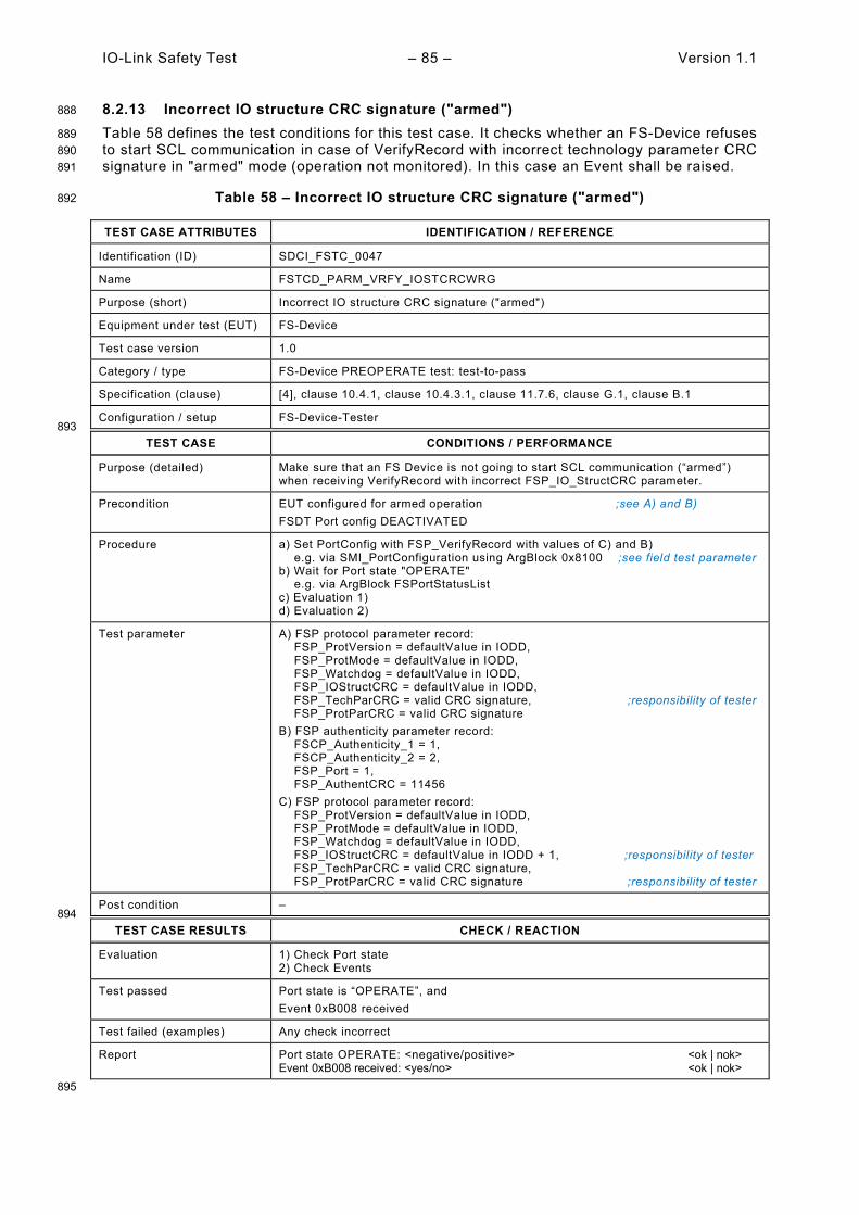
IO-Link Safety Test – 85 – Version 1.1
8.2.13 Incorrect IO structure CRC signature ("armed") 888
Table 58 defines the test conditions for this test case. It checks whether an FS-Device refuses 889 to start SCL communication in case of VerifyRecord with incorrect technology parameter CRC 890 signature in "armed" mode (operation not monitored). In this case an Event shall be raised. 891
Table 58 – Incorrect IO structure CRC signature ("armed") 892
TEST CASE ATTRIBUTES IDENTIFICATION / REFERENCE
Identification (ID) SDCI_FSTC_0047
Name FSTCD_PARM_VRFY_IOSTCRCWRG
Purpose (short) Incorrect IO structure CRC signature ("armed")
Equipment under test (EUT) FS-Device
Test case version 1.0
Category / type FS-Device PREOPERATE test: test-to-pass
Specification (clause) [4], clause 10.4.1, clause 10.4.3.1, clause 11.7.6, clause G.1, clause B.1
Configuration / setup FS-Device-Tester 893
TEST CASE CONDITIONS / PERFORMANCE
Purpose (detailed) Make sure that an FS Device is not going to start SCL communication (“armed”) when receiving VerifyRecord with incorrect FSP_IO_StructCRC parameter.
Precondition EUT configured for armed operation ;see A) and B) FSDT Port config DEACTIVATED
Procedure a) Set PortConfig with FSP_VerifyRecord with values of C) and B) e.g. via SMI_PortConfiguration using ArgBlock 0x8100 ;see field test parameter b) Wait for Port state "OPERATE" e.g. via ArgBlock FSPortStatusList c) Evaluation 1) d) Evaluation 2)
Test parameter A) FSP protocol parameter record: FSP_ProtVersion = defaultValue in IODD, FSP_ProtMode = defaultValue in IODD, FSP_Watchdog = defaultValue in IODD, FSP_IOStructCRC = defaultValue in IODD, FSP_TechParCRC = valid CRC signature, ;responsibility of tester FSP_ProtParCRC = valid CRC signature B) FSP authenticity parameter record: FSCP_Authenticity_1 = 1, FSCP_Authenticity_2 = 2, FSP_Port = 1, FSP_AuthentCRC = 11456 C) FSP protocol parameter record: FSP_ProtVersion = defaultValue in IODD, FSP_ProtMode = defaultValue in IODD, FSP_Watchdog = defaultValue in IODD, FSP_IOStructCRC = defaultValue in IODD + 1, ;responsibility of tester FSP_TechParCRC = valid CRC signature, FSP_ProtParCRC = valid CRC signature ;responsibility of tester
Post condition – 894
TEST CASE RESULTS CHECK / REACTION
Evaluation 1) Check Port state 2) Check Events
Test passed Port state is “OPERATE”, and Event 0xB008 received
Test failed (examples) Any check incorrect
Report Port state OPERATE: <negative/positive> <ok | nok> Event 0xB008 received: <yes/no> <ok | nok>
895

Version 1.1 – 86 – IO-Link Safety Test
8.2.14 Invalid watchdog time ("armed") 896
Table 59 defines the test conditions for this test case. It checks whether an FS-Device refuses 897 to start SCL communication in case of VerifyRecord with invalid watchdog time in "armed" mode 898 (operation not monitored). In this case an Event shall be raised. 899
Table 59 – Invalid watchdog time ("armed") 900
TEST CASE ATTRIBUTES IDENTIFICATION / REFERENCE
Identification (ID) SDCI_FSTC_0048
Name FSTCD_PARM_VRFY_WDTIMEINVL
Purpose (short) Invaild watchdog time ("armed")
Equipment under test (EUT) FS-Device
Test case version 1.0
Category / type FS-Device PREOPERATE test: test-to-pass
Specification (clause) [4], clause 10.4.1, clause 10.4.3.1, clause 11.7.6, clause G.1, clause B.1, A.2.6
Configuration / setup FS-Device-Tester 901
TEST CASE CONDITIONS / PERFORMANCE
Purpose (detailed) Make sure that an FS Device is not going to start SCL communication (“armed”) when receiving VerifyRecord with invalid "WD timeout" value.
Precondition EUT configured for armed operation ;see A) and B) FSDT Port config DEACTIVATED
Procedure a) Set PortConfig with FSP_VerifyRecord with values of C) and B) e.g. via SMI_PortConfiguration using ArgBlock 0x8100 ;see field test parameter b) Wait for Port state "OPERATE" e.g. via ArgBlock FSPortStatusList c) Evaluation 1) d) Evaluation 2)
Test parameter A) FSP protocol parameter record: FSP_ProtVersion = defaultValue in IODD, FSP_ProtMode = defaultValue in IODD, FSP_Watchdog = defaultValue in IODD, FSP_IOStructCRC = defaultValue in IODD, FSP_TechParCRC = valid CRC signature ;responsibility of tester FSP_ProtParCRC = valid CRC signature B) FSP authenticity parameter record: FSCP_Authenticity_1 = 1, FSCP_Authenticity_2 = 2, FSP_Port = 1, FSP_AuthentCRC = 11456 C) FSP protocol parameter record: FSP_ProtVersion = defaultValue in IODD, FSP_ProtMode = defaultValue in IODD, FSP_Watchdog = 0, FSP_IOStructCRC = defaultValue in IODD, ;responsibility of tester FSP_TechParCRC = valid CRC signature, FSP_ProtParCRC = valid CRC signature ;responsibility of tester
Post condition – 902
TEST CASE RESULTS CHECK / REACTION
Evaluation 1) Check Port state 2) Check Events
Test passed Port state is “OPERATE”, and Event 0xB009 received
Test failed (examples) Any check incorrect
Report Port state OPERATE: <negative/positive> <ok | nok> Event 0xB009 received: <yes/no> <ok | nok>
903
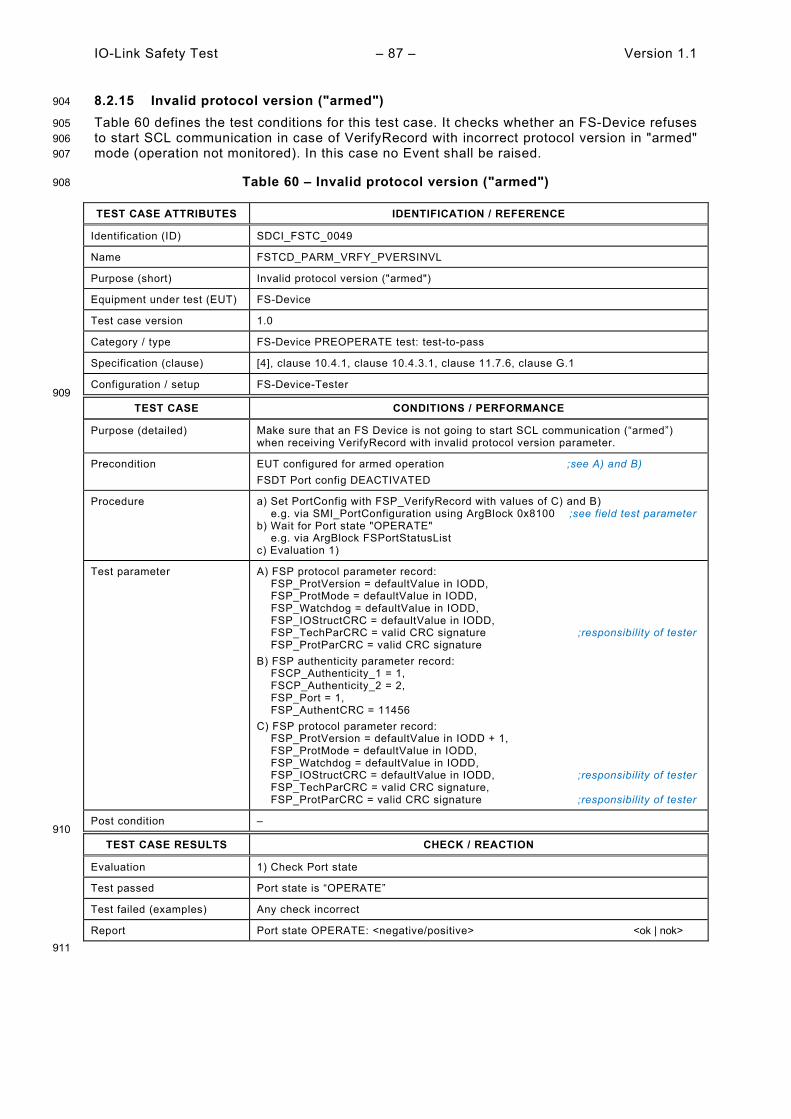
IO-Link Safety Test – 87 – Version 1.1
8.2.15 Invalid protocol version ("armed") 904
Table 60 defines the test conditions for this test case. It checks whether an FS-Device refuses 905 to start SCL communication in case of VerifyRecord with incorrect protocol version in "armed" 906 mode (operation not monitored). In this case no Event shall be raised. 907
Table 60 – Invalid protocol version ("armed") 908
TEST CASE ATTRIBUTES IDENTIFICATION / REFERENCE
Identification (ID) SDCI_FSTC_0049
Name FSTCD_PARM_VRFY_PVERSINVL
Purpose (short) Invalid protocol version ("armed")
Equipment under test (EUT) FS-Device
Test case version 1.0
Category / type FS-Device PREOPERATE test: test-to-pass
Specification (clause) [4], clause 10.4.1, clause 10.4.3.1, clause 11.7.6, clause G.1
Configuration / setup FS-Device-Tester 909
TEST CASE CONDITIONS / PERFORMANCE
Purpose (detailed) Make sure that an FS Device is not going to start SCL communication (“armed”) when receiving VerifyRecord with invalid protocol version parameter.
Precondition EUT configured for armed operation ;see A) and B) FSDT Port config DEACTIVATED
Procedure a) Set PortConfig with FSP_VerifyRecord with values of C) and B) e.g. via SMI_PortConfiguration using ArgBlock 0x8100 ;see field test parameter b) Wait for Port state "OPERATE" e.g. via ArgBlock FSPortStatusList c) Evaluation 1)
Test parameter A) FSP protocol parameter record: FSP_ProtVersion = defaultValue in IODD, FSP_ProtMode = defaultValue in IODD, FSP_Watchdog = defaultValue in IODD, FSP_IOStructCRC = defaultValue in IODD, FSP_TechParCRC = valid CRC signature ;responsibility of tester FSP_ProtParCRC = valid CRC signature B) FSP authenticity parameter record: FSCP_Authenticity_1 = 1, FSCP_Authenticity_2 = 2, FSP_Port = 1, FSP_AuthentCRC = 11456 C) FSP protocol parameter record: FSP_ProtVersion = defaultValue in IODD + 1, FSP_ProtMode = defaultValue in IODD, FSP_Watchdog = defaultValue in IODD, FSP_IOStructCRC = defaultValue in IODD, ;responsibility of tester FSP_TechParCRC = valid CRC signature, FSP_ProtParCRC = valid CRC signature ;responsibility of tester
Post condition – 910
TEST CASE RESULTS CHECK / REACTION
Evaluation 1) Check Port state
Test passed Port state is “OPERATE”
Test failed (examples) Any check incorrect
Report Port state OPERATE: <negative/positive> <ok | nok> 911

Version 1.1 – 88 – IO-Link Safety Test
8.2.16 Invalid protocol mode ("armed") 912
Table 61 defines the test conditions for this test case. It checks whether an FS-Device refuses 913 to start SCL communication in case of VerifyRecord with incorrect protocol mode in "armed" 914 mode (operation not monitored). In this case no Event shall be raised. 915
Table 61 – Invalid protocol mode ("armed") 916
TEST CASE ATTRIBUTES IDENTIFICATION / REFERENCE
Identification (ID) SDCI_FSTC_0050
Name FSTCD_PARM_VRFY_PMODEINVL
Purpose (short) Invalid protocol mode ("armed")
Equipment under test (EUT) FS-Device
Test case version 1.0
Category / type FS-Device PREOPERATE test: test-to-pass
Specification (clause) [4], clause 10.4.1, clause 10.4.3.1, clause 11.7.6, clause G.1
Configuration / setup FS-Device-Tester 917
TEST CASE CONDITIONS / PERFORMANCE
Purpose (detailed) Make sure that an FS Device is not going to start SCL communication (“armed”) when receiving VerifyRecord with invalid protocol mode parameter.
Precondition EUT configured for armed operation ;see A) and B) FSDT Port config DEACTIVATED
Procedure a) Set PortConfig with FSP_VerifyRecord with values of C) and B) e.g. via SMI_PortConfiguration using ArgBlock 0x8100 ;see field test parameter b) Wait for Port state "OPERATE" e.g. via ArgBlock FSPortStatusList c) Evaluation 1)
Test parameter A) FSP protocol parameter record: FSP_ProtVersion = defaultValue in IODD, FSP_ProtMode = defaultValue in IODD, FSP_Watchdog = defaultValue in IODD, FSP_IOStructCRC = defaultValue in IODD, FSP_TechParCRC = valid CRC signature ;responsibility of tester FSP_ProtParCRC = valid CRC signature B) FSP authenticity parameter record: FSCP_Authenticity_1 = 1, FSCP_Authenticity_2 = 2, FSP_Port = 1, FSP_AuthentCRC = 11456 C) FSP protocol parameter record: FSP_ProtVersion = defaultValue in IODD + 1, FSP_ProtMode = 10, FSP_Watchdog = defaultValue in IODD, FSP_IOStructCRC = defaultValue in IODD, ;responsibility of tester FSP_TechParCRC = valid CRC signature, FSP_ProtParCRC = valid CRC signature ;responsibility of tester
Post condition – 918
TEST CASE RESULTS CHECK / REACTION
Evaluation 1) Check Port state
Test passed Port state is “OPERATE”
Test failed (examples) Any check incorrect
Report Port state OPERATE: <negative/positive> <ok | nok> 919

IO-Link Safety Test – 89 – Version 1.1
8.3 Special SCL tests 920
8.3.1 Principle of FS-Device watchdog timer test 921
In 13.6.1, the general concepts on worst-case delay times (WCDT) and one fault delay times 922 (OFDT) as well as watchdog timer testing for FS-Master are explained. The test case for FS-923 Devices follows a similar concept. 924
Figure 12 illustrates, how the watchdog timer of an FS-Device is tested. The FS-Device Tester 925 controls the FS-Device in such a way that the FS-Master SPDU ("MCount = 4") is delayed 926 through artificial repetitions. For details see 8.3.2. 927
928
929
Figure 12 – Principle of FS-Device watchdog timer test 930
Usually, the SCL software is triggered by the IO-Link communication, which is determined by 931 the Master cycle time. Thus, the reaction of the SCL on expiration of the watchdog depends 932 on how the SCL software samples the IO-Link messages with SPDU as shown in Figure 13. 933
934
Figure 13 – Influence of SCL sampling effects 935
In best case, the expiration of the watchdog coincides with the sampling. In worst case, the 936 expiration is just behind sampling and the safety reaction is delayed correspondingly. 937
It is highly recommended for the designer of an FS-Device to choose the default value of the 938 parameter FSP_Watchdog in IODD such that one extra SCL cycle time is included. 939
FS-Device FS-Device Tester
Watchdogtime (min)
WatchdogTime (min)
Receiver AckTime
Assignedparametervalue
Sender AckTime
Assignedparametervalue
Sender AckTime
Watchdogexpired
SCL CycleTime
SDCI MasterCycleTime
Watchdogexpired
Use SDout,SDset =1
Artificialrepetitions
SCL cycles
Watchdog value 1
Watchdog value 2
Use SDSDset = 1DTimeout = 1
Use SDSDset = 1DTimeout = 1
t

Version 1.1 – 90 – IO-Link Safety Test
8.3.2 FS-Device watchdog timer test 940
Table 62 defines the test conditions for this test case. The base protocol watchdog function of 941 the SCL is tested in 9.2. 942
Table 62 – FS-Device watchdog timer test 943
TEST CASE ATTRIBUTES IDENTIFICATION / REFERENCE
Identification (ID) SDCI_FSTC_0051
Name FSTCD_SCLD_WATCHDOGANDIODD
Purpose (short) Check whether FS-Device watchdog timeout coincides with IODD value
Equipment under test (EUT) FS-Device and IODD
Test case version 1.0
Category / type FS-Device test, test to pass
Specification (clause) [4],
Configuration / setup FS-Device-Tester 944
TEST CASE CONDITIONS / PERFORMANCE
Purpose (detailed) Check whether FS-Device's safety reaction time upon watchdog timeout coincides with the FSP_Watchdog value in the IODD.
Precondition EUT: Configured for armed operation ;see field test parameter FSDT: Port config DEACTIVATED
Procedure a) Set PortConfig with FSP_VerifyRecord with values of A) and B) e.g. via SMI_PortConfiguration using ArgBlock 0x8100 ;see field test parameter b) Line monitor to measure timeouts for 1 min (Status Bit0 = 0, DTimeout) c) Evaluation 1) d) Reduce FSP_Watchdog value by 10 % and set PortConfig again e) Line monitor to measure timeouts for 1 min (Status Bit0 = 0, DTimeout) f) Evaluation 2)
Test parameter A) FSP protocol parameter record: FSP_ProtVersion = defaultValue in IODD, FSP_ProtMode = defaultValue in IODD, FSP_Watchdog = defaultValue in IODD, FSP_IOStructCRC = defaultValue in IODD, FSP_TechParCRC = valid CRC signature ;responsibility of tester FSP_ProtParCRC = valid CRC signature ;responsibility of tester B) FSP authenticity parameter record: FSCP_Authenticity_1 = 1, FSCP_Authenticity_2 = 2, FSP_Port = 1, FSP_AuthentCRC = 11456
Post condition – 945
TEST CASE RESULTS CHECK / REACTION
Evaluation 1) Check timeouts (default) 2) Check timeouts (- 10 %)
Test passed No timeouts occurred, and Timeouts can occur
Test failed (examples) Any check incorrect
Report Values OK: <yes/no> <ok | nok>
946

IO-Link Safety Test – 91 – Version 1.1
8.3.3 Watchdog retrigger and CRC exception (0 1) 947
8.3.1 defines the conditions for this test case. Some critical safety features cannot be tested by 948 IO-Link on-board equipment and shall be assessed during the development process via 949 verification and validation activities according to appropriate clauses in IEC 61508-3 as also 950 mentioned in 13.6.1. 951
Manufacturer to prove that the SCL watchdog timer is only retriggered when MCount has been 952 incremented and a calculated SPDU CRC signature of "0" will be changed to "1". 953

Version 1.1 – 92 – IO-Link Safety Test
9 FS-Device safety communication layer tests 954
9.1 Interface for the FS-Device SCL test scripts 955
The test scripts for the automated safety layer test are encoded as XML files. Each and every 956 test script ("FSDeviceSclTestCaseSteps") consists of test step instructions as described in 957 Table 63. The XML Schema of the interface parameters for the FS-Device automated safety 958 layer test is illustrated in Figure 14. It is similar to the XML format of the message types for the 959 FS-Master (see 12.1). 960
However, the test scripts for the FS-Device do not contain test data for the "technology" 961 interface. An upper tester is not intended for the FS-Device test. During the execution of the 962 test scripts, the "technology" data has always its configured initial value. 963
NOTE The general concept of SCL protocol conformance testing is described in A.2.3. The automated safety layer 964 tester for FS-Devices is described in A.2.5. 965
966
Figure 14 – Schema of steps and parameters/attributes 967
Table 63 defines the FS-Device interface parameters. 968
Table 63 – FS-Device interface parameters 969
Test step instructions Parameter Value range
FSDeviceSend (FS-Device Test System)
PDin SD –Test System expects SD values (= 0) PD – Test System expects PD values (> 0)
PortNum valid –Test System expects configured port number
DCount 0 to 7
SDset 0, 1
FS-Device
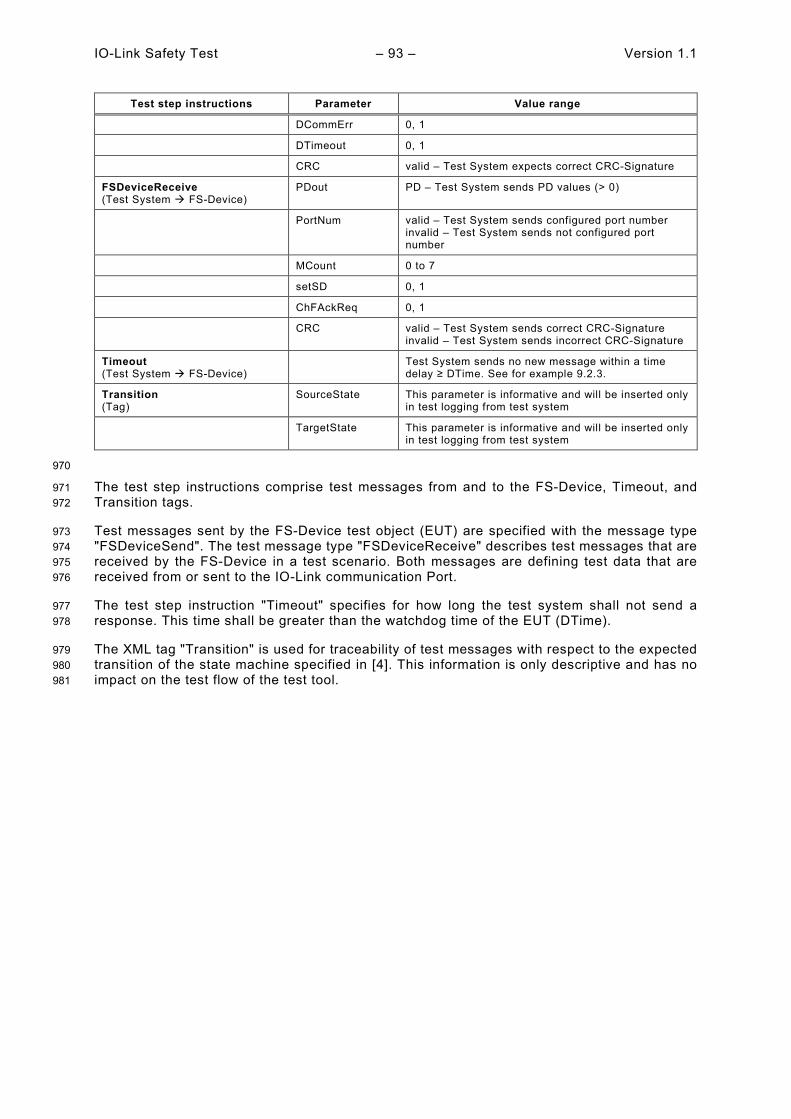
IO-Link Safety Test – 93 – Version 1.1
Test step instructions Parameter Value range
DCommErr 0, 1
DTimeout 0, 1
CRC valid – Test System expects correct CRC-Signature
FSDeviceReceive (Test System FS-Device)
PDout PD – Test System sends PD values (> 0)
PortNum valid – Test System sends configured port number invalid – Test System sends not configured port number
MCount 0 to 7
setSD 0, 1
ChFAckReq 0, 1
CRC valid – Test System sends correct CRC-Signature invalid – Test System sends incorrect CRC-Signature
Timeout (Test System FS-Device)
Test System sends no new message within a time delay ≥ DTime. See for example 9.2.3.
Transition (Tag)
SourceState This parameter is informative and will be inserted only in test logging from test system
TargetState This parameter is informative and will be inserted only in test logging from test system
970
The test step instructions comprise test messages from and to the FS-Device, Timeout, and 971 Transition tags. 972
Test messages sent by the FS-Device test object (EUT) are specified with the message type 973 "FSDeviceSend". The test message type "FSDeviceReceive" describes test messages that are 974 received by the FS-Device in a test scenario. Both messages are defining test data that are 975 received from or sent to the IO-Link communication Port. 976
The test step instruction "Timeout" specifies for how long the test system shall not send a 977 response. This time shall be greater than the watchdog time of the EUT (DTime). 978
The XML tag "Transition" is used for traceability of test messages with respect to the expected 979 transition of the state machine specified in [4]. This information is only descriptive and has no 980 impact on the test flow of the test tool. 981
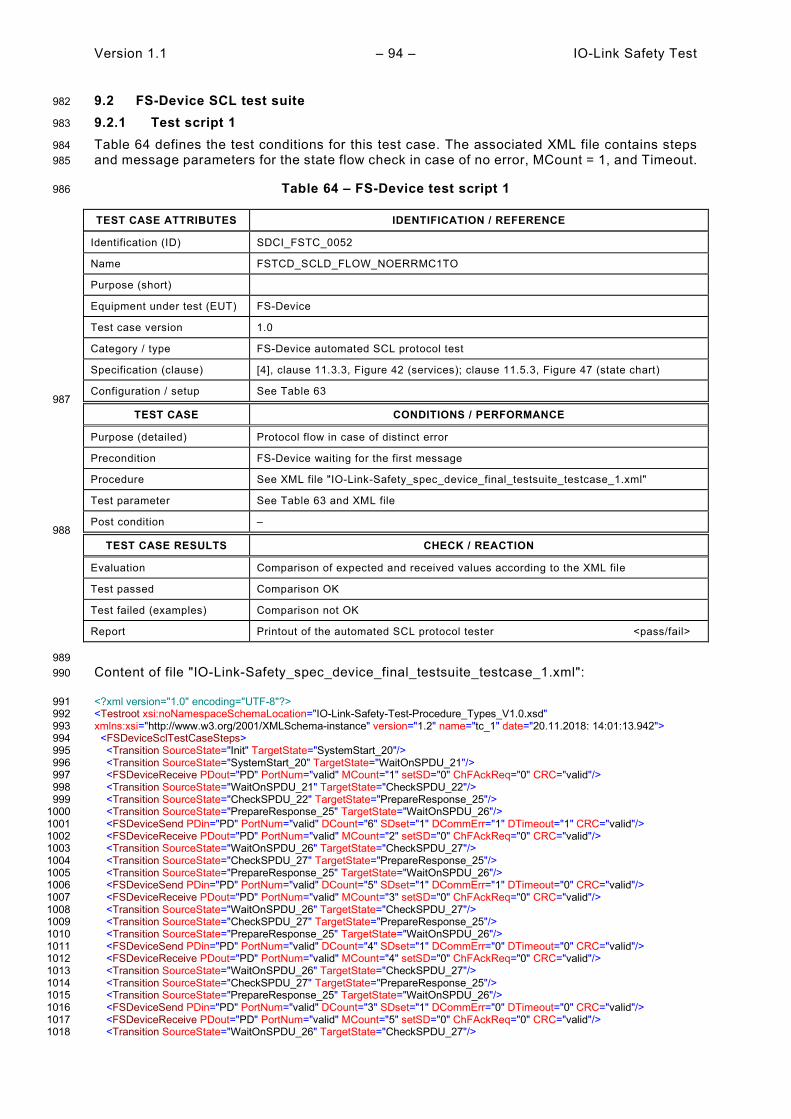
Version 1.1 – 94 – IO-Link Safety Test
9.2 FS-Device SCL test suite 982
9.2.1 Test script 1 983
Table 64 defines the test conditions for this test case. The associated XML file contains steps 984 and message parameters for the state flow check in case of no error, MCount = 1, and Timeout. 985
Table 64 – FS-Device test script 1 986
TEST CASE ATTRIBUTES IDENTIFICATION / REFERENCE
Identification (ID) SDCI_FSTC_0052
Name FSTCD_SCLD_FLOW_NOERRMC1TO
Purpose (short)
Equipment under test (EUT) FS-Device
Test case version 1.0
Category / type FS-Device automated SCL protocol test
Specification (clause) [4], clause 11.3.3, Figure 42 (services); clause 11.5.3, Figure 47 (state chart)
Configuration / setup See Table 63 987
TEST CASE CONDITIONS / PERFORMANCE
Purpose (detailed) Protocol flow in case of distinct error
Precondition FS-Device waiting for the first message
Procedure See XML file "IO-Link-Safety_spec_device_final_testsuite_testcase_1.xml"
Test parameter See Table 63 and XML file
Post condition – 988
TEST CASE RESULTS CHECK / REACTION
Evaluation Comparison of expected and received values according to the XML file
Test passed Comparison OK
Test failed (examples) Comparison not OK
Report Printout of the automated SCL protocol tester <pass/fail>
989 Content of file "IO-Link-Safety_spec_device_final_testsuite_testcase_1.xml": 990
<?xml version="1.0" encoding="UTF-8"?> 991 <Testroot xsi:noNamespaceSchemaLocation="IO-Link-Safety-Test-Procedure_Types_V1.0.xsd" 992 xmlns:xsi="http://www.w3.org/2001/XMLSchema-instance" version="1.2" name="tc_1" date="20.11.2018: 14:01:13.942"> 993 <FSDeviceSclTestCaseSteps> 994 <Transition SourceState="Init" TargetState="SystemStart_20"/> 995 <Transition SourceState="SystemStart_20" TargetState="WaitOnSPDU_21"/> 996 <FSDeviceReceive PDout="PD" PortNum="valid" MCount="1" setSD="0" ChFAckReq="0" CRC="valid"/> 997 <Transition SourceState="WaitOnSPDU_21" TargetState="CheckSPDU_22"/> 998 <Transition SourceState="CheckSPDU_22" TargetState="PrepareResponse_25"/> 999 <Transition SourceState="PrepareResponse_25" TargetState="WaitOnSPDU_26"/> 1000 <FSDeviceSend PDin="PD" PortNum="valid" DCount="6" SDset="1" DCommErr="1" DTimeout="1" CRC="valid"/> 1001 <FSDeviceReceive PDout="PD" PortNum="valid" MCount="2" setSD="0" ChFAckReq="0" CRC="valid"/> 1002 <Transition SourceState="WaitOnSPDU_26" TargetState="CheckSPDU_27"/> 1003 <Transition SourceState="CheckSPDU_27" TargetState="PrepareResponse_25"/> 1004 <Transition SourceState="PrepareResponse_25" TargetState="WaitOnSPDU_26"/> 1005 <FSDeviceSend PDin="PD" PortNum="valid" DCount="5" SDset="1" DCommErr="1" DTimeout="0" CRC="valid"/> 1006 <FSDeviceReceive PDout="PD" PortNum="valid" MCount="3" setSD="0" ChFAckReq="0" CRC="valid"/> 1007 <Transition SourceState="WaitOnSPDU_26" TargetState="CheckSPDU_27"/> 1008 <Transition SourceState="CheckSPDU_27" TargetState="PrepareResponse_25"/> 1009 <Transition SourceState="PrepareResponse_25" TargetState="WaitOnSPDU_26"/> 1010 <FSDeviceSend PDin="PD" PortNum="valid" DCount="4" SDset="1" DCommErr="0" DTimeout="0" CRC="valid"/> 1011 <FSDeviceReceive PDout="PD" PortNum="valid" MCount="4" setSD="0" ChFAckReq="0" CRC="valid"/> 1012 <Transition SourceState="WaitOnSPDU_26" TargetState="CheckSPDU_27"/> 1013 <Transition SourceState="CheckSPDU_27" TargetState="PrepareResponse_25"/> 1014 <Transition SourceState="PrepareResponse_25" TargetState="WaitOnSPDU_26"/> 1015 <FSDeviceSend PDin="PD" PortNum="valid" DCount="3" SDset="1" DCommErr="0" DTimeout="0" CRC="valid"/> 1016 <FSDeviceReceive PDout="PD" PortNum="valid" MCount="5" setSD="0" ChFAckReq="0" CRC="valid"/> 1017 <Transition SourceState="WaitOnSPDU_26" TargetState="CheckSPDU_27"/> 1018

IO-Link Safety Test – 95 – Version 1.1
<Transition SourceState="CheckSPDU_27" TargetState="PrepareResponse_23"/> 1019 <Transition SourceState="PrepareResponse_23" TargetState="WaitOnSPDU_24"/> 1020 <FSDeviceSend PDin="PD" PortNum="valid" DCount="2" SDset="0" DCommErr="0" DTimeout="0" CRC="valid"/> 1021 <FSDeviceReceive PDout="PD" PortNum="valid" MCount="6" setSD="1" ChFAckReq="0" CRC="valid"/> 1022 <Transition SourceState="WaitOnSPDU_24" TargetState="CheckSPDU_22"/> 1023 <Transition SourceState="CheckSPDU_22" TargetState="PrepareResponse_23"/> 1024 <Transition SourceState="PrepareResponse_23" TargetState="WaitOnSPDU_24"/> 1025 <FSDeviceSend PDin="PD" PortNum="valid" DCount="1" SDset="0" DCommErr="0" DTimeout="0" CRC="valid"/> 1026 <FSDeviceReceive PDout="PD" PortNum="valid" MCount="2" setSD="0" ChFAckReq="0" CRC="valid"/> 1027 <Transition SourceState="WaitOnSPDU_24" TargetState="CheckSPDU_22"/> 1028 <Transition SourceState="CheckSPDU_22" TargetState="PrepareResponse_25"/> 1029 <Transition SourceState="PrepareResponse_25" TargetState="WaitOnSPDU_26"/> 1030 <FSDeviceSend PDin="PD" PortNum="valid" DCount="5" SDset="1" DCommErr="1" DTimeout="0" CRC="valid"/> 1031 </FSDeviceSclTestCaseSteps> 1032 </Testroot> 1033
1034
1035

Version 1.1 – 96 – IO-Link Safety Test
9.2.2 Test script 2 1036
Table 65 defines the test conditions for this test case. The associated XML file contains steps 1037 and message parameters for the state flow check in case of a setSD error and MCount = 0. 1038
Table 65 – FS-Device test script 2 1039
TEST CASE ATTRIBUTES IDENTIFICATION / REFERENCE
Identification (ID) SDCI_FSTC_0053
Name FSTCD_SCLD_FLOW_SETSD1MC0
Purpose (short)
Equipment under test (EUT) FS-Device
Test case version 1.0
Category / type FS-Device automated SCL protocol test
Specification (clause) [4], clause 11.3.3, Figure 42 (services); clause 11.5.3, Figure 47 (state chart)
Configuration / setup See Table 63 1040
TEST CASE CONDITIONS / PERFORMANCE
Purpose (detailed) Protocol flow in case of distinct error
Precondition FS-Device waiting for the first message
Procedure See XML file "IO-Link-Safety_spec_device_final_testsuite_testcase_2.xml"
Test parameter See Table 63 and XML file
Post condition – 1041
TEST CASE RESULTS CHECK / REACTION
Evaluation Comparison of expected and received values according to the XML file
Test passed Comparison OK
Test failed (examples) Comparison not OK
Report Printout of the automated SCL protocol tester <pass/fail>
1042 Content of file "IO-Link-Safety_spec_device_final_testsuite_testcase_2.xml": 1043
<?xml version="1.0" encoding="UTF-8"?> 1044 <Testroot xsi:noNamespaceSchemaLocation="IO-Link-Safety-Test-Procedure_Types_V1.0.xsd" 1045 xmlns:xsi="http://www.w3.org/2001/XMLSchema-instance" version="1.2" name="tc_2" date="20.11.2018: 14:01:13.942"> 1046 <FSDeviceSclTestCaseSteps> 1047 <Transition SourceState="Init" TargetState="SystemStart_20"/> 1048 <Transition SourceState="SystemStart_20" TargetState="WaitOnSPDU_21"/> 1049 <FSDeviceReceive PDout="PD" PortNum="valid" MCount="0" setSD="1" ChFAckReq="0" CRC="valid"/> 1050 <Transition SourceState="WaitOnSPDU_21" TargetState="CheckSPDU_22"/> 1051 <Transition SourceState="CheckSPDU_22" TargetState="PrepareResponse_23"/> 1052 <Transition SourceState="PrepareResponse_23" TargetState="WaitOnSPDU_24"/> 1053 <FSDeviceSend PDin="PD" PortNum="valid" DCount="7" SDset="1" DCommErr="0" DTimeout="0" CRC="valid"/> 1054 <FSDeviceReceive PDout="PD" PortNum="valid" MCount="1" setSD="0" ChFAckReq="0" CRC="valid"/> 1055 <Transition SourceState="WaitOnSPDU_24" TargetState="CheckSPDU_22"/> 1056 <Transition SourceState="CheckSPDU_22" TargetState="PrepareResponse_23"/> 1057 <Transition SourceState="PrepareResponse_23" TargetState="WaitOnSPDU_24"/> 1058 <FSDeviceSend PDin="PD" PortNum="valid" DCount="6" SDset="1" DCommErr="0" DTimeout="0" CRC="valid"/> 1059 <FSDeviceReceive PDout="PD" PortNum="valid" MCount="2" setSD="0" ChFAckReq="0" CRC="valid"/> 1060 <Transition SourceState="WaitOnSPDU_24" TargetState="CheckSPDU_22"/> 1061 <Transition SourceState="CheckSPDU_22" TargetState="PrepareResponse_23"/> 1062 <Transition SourceState="PrepareResponse_23" TargetState="WaitOnSPDU_24"/> 1063 <FSDeviceSend PDin="PD" PortNum="valid" DCount="5" SDset="1" DCommErr="0" DTimeout="0" CRC="valid"/> 1064 <FSDeviceReceive PDout="PD" PortNum="valid" MCount="3" setSD="0" ChFAckReq="0" CRC="valid"/> 1065 <Transition SourceState="WaitOnSPDU_24" TargetState="CheckSPDU_22"/> 1066 <Transition SourceState="CheckSPDU_22" TargetState="PrepareResponse_23"/> 1067 <Transition SourceState="PrepareResponse_23" TargetState="WaitOnSPDU_24"/> 1068 <FSDeviceSend PDin="PD" PortNum="valid" DCount="4" SDset="0" DCommErr="0" DTimeout="0" CRC="valid"/> 1069 <FSDeviceReceive PDout="PD" PortNum="valid" MCount="4" setSD="0" ChFAckReq="0" CRC="valid"/> 1070 <Transition SourceState="WaitOnSPDU_24" TargetState="CheckSPDU_22"/> 1071 <Transition SourceState="CheckSPDU_22" TargetState="PrepareResponse_23"/> 1072 <Transition SourceState="PrepareResponse_23" TargetState="WaitOnSPDU_24"/> 1073

IO-Link Safety Test – 97 – Version 1.1
<FSDeviceSend PDin="PD" PortNum="valid" DCount="3" SDset="0" DCommErr="0" DTimeout="0" CRC="valid"/> 1074 <FSDeviceReceive PDout="PD" PortNum="valid" MCount="5" setSD="0" ChFAckReq="0" CRC="valid"/> 1075 <Transition SourceState="WaitOnSPDU_24" TargetState="CheckSPDU_22"/> 1076 <Transition SourceState="CheckSPDU_22" TargetState="PrepareResponse_23"/> 1077 <Transition SourceState="PrepareResponse_23" TargetState="WaitOnSPDU_24"/> 1078 <FSDeviceSend PDin="PD" PortNum="valid" DCount="2" SDset="0" DCommErr="0" DTimeout="0" CRC="valid"/> 1079 <FSDeviceReceive PDout="PD" PortNum="valid" MCount="3" setSD="0" ChFAckReq="0" CRC="valid"/> 1080 <Transition SourceState="WaitOnSPDU_24" TargetState="CheckSPDU_22"/> 1081 <Transition SourceState="CheckSPDU_22" TargetState="PrepareResponse_25"/> 1082 <Transition SourceState="PrepareResponse_25" TargetState="WaitOnSPDU_26"/> 1083 <FSDeviceSend PDin="PD" PortNum="valid" DCount="4" SDset="1" DCommErr="1" DTimeout="0" CRC="valid"/> 1084 </FSDeviceSclTestCaseSteps> 1085 </Testroot> 1086 1087

Version 1.1 – 98 – IO-Link Safety Test
9.2.3 Test script 3 1088
Table 66 defines the test conditions for this test case. The associated XML file contains steps 1089 and message parameters for the state flow check in case of no error, MCount = 5, and Timeout. 1090
Table 66 – FS-Device test script 3 1091
TEST CASE ATTRIBUTES IDENTIFICATION / REFERENCE
Identification (ID) SDCI_FSTC_0054
Name FSTCD_SCLD_FLOW_ SETSD0MC5TO
Purpose (short)
Equipment under test (EUT) FS-Device
Test case version 1.0
Category / type FS-Device automated SCL protocol test
Specification (clause) [4], clause 11.3.3, Figure 42 (services); clause 11.5.3, Figure 47 (state chart)
Configuration / setup See Table 63 1092
TEST CASE CONDITIONS / PERFORMANCE
Purpose (detailed) Protocol flow in case of distinct error
Precondition FS-Device waiting for the first message
Procedure See XML file "IO-Link-Safety_spec_device_final_testsuite_testcase_3.xml"
Test parameter See Table 63 and XML file
Post condition – 1093
TEST CASE RESULTS CHECK / REACTION
Evaluation Comparison of expected and received values according to the XML file
Test passed Comparison OK
Test failed (examples) Comparison not OK
Report Printout of the automated SCL protocol tester <pass/fail>
1094 Content of file "IO-Link-Safety_spec_device_final_testsuite_testcase_3.xml": 1095
<?xml version="1.0" encoding="UTF-8"?> 1096 <Testroot xsi:noNamespaceSchemaLocation="IO-Link-Safety-Test-Procedure_Types_V1.0.xsd" 1097 xmlns:xsi="http://www.w3.org/2001/XMLSchema-instance" version="1.2" name="tc_3" date="20.11.2018: 14:01:13.942"> 1098 <FSDeviceSclTestCaseSteps> 1099 <Transition SourceState="Init" TargetState="SystemStart_20"/> 1100 <Transition SourceState="SystemStart_20" TargetState="WaitOnSPDU_21"/> 1101 <FSDeviceReceive PDout="PD" PortNum="valid" MCount="5" setSD="0" ChFAckReq="0" CRC="valid"/> 1102 <Transition SourceState="WaitOnSPDU_21" TargetState="CheckSPDU_22"/> 1103 <Transition SourceState="CheckSPDU_22" TargetState="PrepareResponse_25"/> 1104 <Transition SourceState="PrepareResponse_25" TargetState="WaitOnSPDU_26"/> 1105 <FSDeviceSend PDin="PD" PortNum="valid" DCount="2" SDset="1" DCommErr="1" DTimeout="1" CRC="valid"/> 1106 <FSDeviceReceive PDout="PD" PortNum="valid" MCount="6" setSD="0" ChFAckReq="0" CRC="valid"/> 1107 <Transition SourceState="WaitOnSPDU_26" TargetState="CheckSPDU_27"/> 1108 <Transition SourceState="CheckSPDU_27" TargetState="PrepareResponse_25"/> 1109 <Transition SourceState="PrepareResponse_25" TargetState="WaitOnSPDU_26"/> 1110 <FSDeviceSend PDin="PD" PortNum="valid" DCount="1" SDset="1" DCommErr="1" DTimeout="0" CRC="valid"/> 1111 <Timeout/> 1112 <Transition SourceState="WaitOnSPDU_26" TargetState="PrepareResponse_25"/> 1113 <Transition SourceState="PrepareResponse_25" TargetState="WaitOnSPDU_26"/> 1114 <FSDeviceSend PDin="PD" PortNum="valid" DCount="1" SDset="1" DCommErr="1" DTimeout="1" CRC="valid"/> 1115 <FSDeviceReceive PDout="PD" PortNum="valid" MCount="7" setSD="0" ChFAckReq="0" CRC="valid"/> 1116 <Transition SourceState="WaitOnSPDU_26" TargetState="CheckSPDU_27"/> 1117 <Transition SourceState="CheckSPDU_27" TargetState="PrepareResponse_25"/> 1118 <Transition SourceState="PrepareResponse_25" TargetState="WaitOnSPDU_26"/> 1119 <FSDeviceSend PDin="PD" PortNum="valid" DCount="0" SDset="1" DCommErr="0" DTimeout="1" CRC="valid"/> 1120 <FSDeviceReceive PDout="PD" PortNum="valid" MCount="2" setSD="0" ChFAckReq="0" CRC="valid"/> 1121 <Transition SourceState="WaitOnSPDU_26" TargetState="CheckSPDU_27"/> 1122 <Transition SourceState="CheckSPDU_27" TargetState="PrepareResponse_25"/> 1123 <Transition SourceState="PrepareResponse_25" TargetState="WaitOnSPDU_26"/> 1124 <FSDeviceSend PDin="PD" PortNum="valid" DCount="5" SDset="1" DCommErr="1" DTimeout="0" CRC="valid"/> 1125

IO-Link Safety Test – 99 – Version 1.1
</FSDeviceSclTestCaseSteps> 1126 </Testroot> 1127 1128
1129
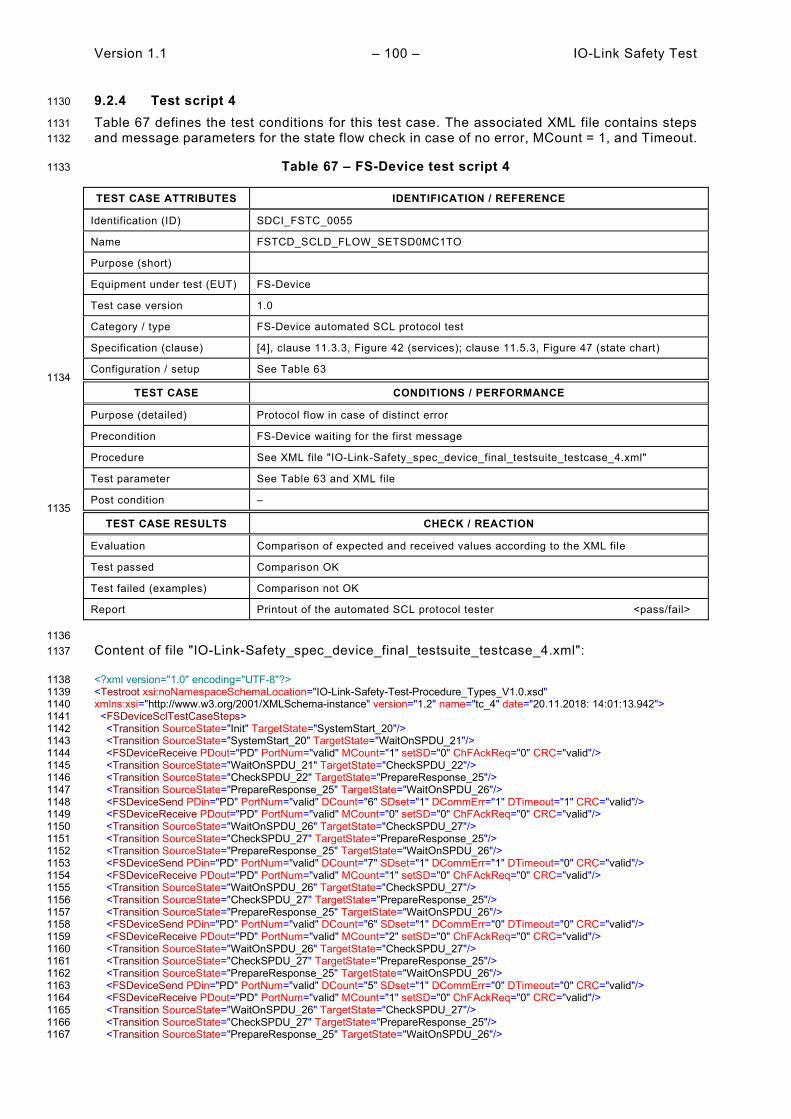
Version 1.1 – 100 – IO-Link Safety Test
9.2.4 Test script 4 1130
Table 67 defines the test conditions for this test case. The associated XML file contains steps 1131 and message parameters for the state flow check in case of no error, MCount = 1, and Timeout. 1132
Table 67 – FS-Device test script 4 1133
TEST CASE ATTRIBUTES IDENTIFICATION / REFERENCE
Identification (ID) SDCI_FSTC_0055
Name FSTCD_SCLD_FLOW_SETSD0MC1TO
Purpose (short)
Equipment under test (EUT) FS-Device
Test case version 1.0
Category / type FS-Device automated SCL protocol test
Specification (clause) [4], clause 11.3.3, Figure 42 (services); clause 11.5.3, Figure 47 (state chart)
Configuration / setup See Table 63 1134
TEST CASE CONDITIONS / PERFORMANCE
Purpose (detailed) Protocol flow in case of distinct error
Precondition FS-Device waiting for the first message
Procedure See XML file "IO-Link-Safety_spec_device_final_testsuite_testcase_4.xml"
Test parameter See Table 63 and XML file
Post condition – 1135
TEST CASE RESULTS CHECK / REACTION
Evaluation Comparison of expected and received values according to the XML file
Test passed Comparison OK
Test failed (examples) Comparison not OK
Report Printout of the automated SCL protocol tester <pass/fail>
1136 Content of file "IO-Link-Safety_spec_device_final_testsuite_testcase_4.xml": 1137
<?xml version="1.0" encoding="UTF-8"?> 1138 <Testroot xsi:noNamespaceSchemaLocation="IO-Link-Safety-Test-Procedure_Types_V1.0.xsd" 1139 xmlns:xsi="http://www.w3.org/2001/XMLSchema-instance" version="1.2" name="tc_4" date="20.11.2018: 14:01:13.942"> 1140 <FSDeviceSclTestCaseSteps> 1141 <Transition SourceState="Init" TargetState="SystemStart_20"/> 1142 <Transition SourceState="SystemStart_20" TargetState="WaitOnSPDU_21"/> 1143 <FSDeviceReceive PDout="PD" PortNum="valid" MCount="1" setSD="0" ChFAckReq="0" CRC="valid"/> 1144 <Transition SourceState="WaitOnSPDU_21" TargetState="CheckSPDU_22"/> 1145 <Transition SourceState="CheckSPDU_22" TargetState="PrepareResponse_25"/> 1146 <Transition SourceState="PrepareResponse_25" TargetState="WaitOnSPDU_26"/> 1147 <FSDeviceSend PDin="PD" PortNum="valid" DCount="6" SDset="1" DCommErr="1" DTimeout="1" CRC="valid"/> 1148 <FSDeviceReceive PDout="PD" PortNum="valid" MCount="0" setSD="0" ChFAckReq="0" CRC="valid"/> 1149 <Transition SourceState="WaitOnSPDU_26" TargetState="CheckSPDU_27"/> 1150 <Transition SourceState="CheckSPDU_27" TargetState="PrepareResponse_25"/> 1151 <Transition SourceState="PrepareResponse_25" TargetState="WaitOnSPDU_26"/> 1152 <FSDeviceSend PDin="PD" PortNum="valid" DCount="7" SDset="1" DCommErr="1" DTimeout="0" CRC="valid"/> 1153 <FSDeviceReceive PDout="PD" PortNum="valid" MCount="1" setSD="0" ChFAckReq="0" CRC="valid"/> 1154 <Transition SourceState="WaitOnSPDU_26" TargetState="CheckSPDU_27"/> 1155 <Transition SourceState="CheckSPDU_27" TargetState="PrepareResponse_25"/> 1156 <Transition SourceState="PrepareResponse_25" TargetState="WaitOnSPDU_26"/> 1157 <FSDeviceSend PDin="PD" PortNum="valid" DCount="6" SDset="1" DCommErr="0" DTimeout="0" CRC="valid"/> 1158 <FSDeviceReceive PDout="PD" PortNum="valid" MCount="2" setSD="0" ChFAckReq="0" CRC="valid"/> 1159 <Transition SourceState="WaitOnSPDU_26" TargetState="CheckSPDU_27"/> 1160 <Transition SourceState="CheckSPDU_27" TargetState="PrepareResponse_25"/> 1161 <Transition SourceState="PrepareResponse_25" TargetState="WaitOnSPDU_26"/> 1162 <FSDeviceSend PDin="PD" PortNum="valid" DCount="5" SDset="1" DCommErr="0" DTimeout="0" CRC="valid"/> 1163 <FSDeviceReceive PDout="PD" PortNum="valid" MCount="1" setSD="0" ChFAckReq="0" CRC="valid"/> 1164 <Transition SourceState="WaitOnSPDU_26" TargetState="CheckSPDU_27"/> 1165 <Transition SourceState="CheckSPDU_27" TargetState="PrepareResponse_25"/> 1166 <Transition SourceState="PrepareResponse_25" TargetState="WaitOnSPDU_26"/> 1167

IO-Link Safety Test – 101 – Version 1.1
<FSDeviceSend PDin="PD" PortNum="valid" DCount="6" SDset="1" DCommErr="1" DTimeout="0" CRC="valid"/> 1168 </FSDeviceSclTestCaseSteps> 1169 </Testroot> 1170 1171
1172
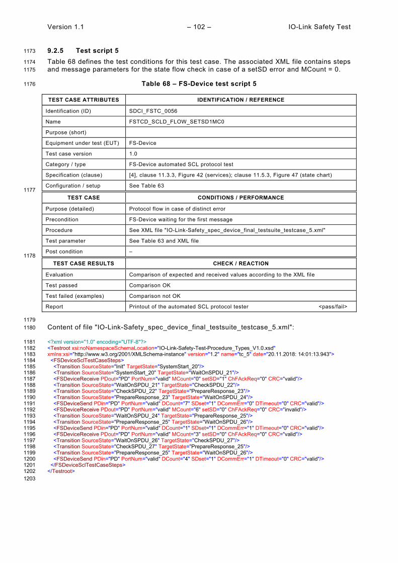
Version 1.1 – 102 – IO-Link Safety Test
9.2.5 Test script 5 1173
Table 68 defines the test conditions for this test case. The associated XML file contains steps 1174 and message parameters for the state flow check in case of a setSD error and MCount = 0. 1175
Table 68 – FS-Device test script 5 1176
TEST CASE ATTRIBUTES IDENTIFICATION / REFERENCE
Identification (ID) SDCI_FSTC_0056
Name FSTCD_SCLD_FLOW_SETSD1MC0
Purpose (short)
Equipment under test (EUT) FS-Device
Test case version 1.0
Category / type FS-Device automated SCL protocol test
Specification (clause) [4], clause 11.3.3, Figure 42 (services); clause 11.5.3, Figure 47 (state chart)
Configuration / setup See Table 63 1177
TEST CASE CONDITIONS / PERFORMANCE
Purpose (detailed) Protocol flow in case of distinct error
Precondition FS-Device waiting for the first message
Procedure See XML file "IO-Link-Safety_spec_device_final_testsuite_testcase_5.xml"
Test parameter See Table 63 and XML file
Post condition – 1178
TEST CASE RESULTS CHECK / REACTION
Evaluation Comparison of expected and received values according to the XML file
Test passed Comparison OK
Test failed (examples) Comparison not OK
Report Printout of the automated SCL protocol tester <pass/fail>
1179 Content of file "IO-Link-Safety_spec_device_final_testsuite_testcase_5.xml": 1180
<?xml version="1.0" encoding="UTF-8"?> 1181 <Testroot xsi:noNamespaceSchemaLocation="IO-Link-Safety-Test-Procedure_Types_V1.0.xsd" 1182 xmlns:xsi="http://www.w3.org/2001/XMLSchema-instance" version="1.2" name="tc_5" date="20.11.2018: 14:01:13.943"> 1183 <FSDeviceSclTestCaseSteps> 1184 <Transition SourceState="Init" TargetState="SystemStart_20"/> 1185 <Transition SourceState="SystemStart_20" TargetState="WaitOnSPDU_21"/> 1186 <FSDeviceReceive PDout="PD" PortNum="valid" MCount="0" setSD="1" ChFAckReq="0" CRC="valid"/> 1187 <Transition SourceState="WaitOnSPDU_21" TargetState="CheckSPDU_22"/> 1188 <Transition SourceState="CheckSPDU_22" TargetState="PrepareResponse_23"/> 1189 <Transition SourceState="PrepareResponse_23" TargetState="WaitOnSPDU_24"/> 1190 <FSDeviceSend PDin="PD" PortNum="valid" DCount="7" SDset="1" DCommErr="0" DTimeout="0" CRC="valid"/> 1191 <FSDeviceReceive PDout="PD" PortNum="valid" MCount="6" setSD="0" ChFAckReq="0" CRC="invalid"/> 1192 <Transition SourceState="WaitOnSPDU_24" TargetState="PrepareResponse_25"/> 1193 <Transition SourceState="PrepareResponse_25" TargetState="WaitOnSPDU_26"/> 1194 <FSDeviceSend PDin="PD" PortNum="valid" DCount="1" SDset="1" DCommErr="1" DTimeout="0" CRC="valid"/> 1195 <FSDeviceReceive PDout="PD" PortNum="valid" MCount="3" setSD="0" ChFAckReq="0" CRC="valid"/> 1196 <Transition SourceState="WaitOnSPDU_26" TargetState="CheckSPDU_27"/> 1197 <Transition SourceState="CheckSPDU_27" TargetState="PrepareResponse_25"/> 1198 <Transition SourceState="PrepareResponse_25" TargetState="WaitOnSPDU_26"/> 1199 <FSDeviceSend PDin="PD" PortNum="valid" DCount="4" SDset="1" DCommErr="1" DTimeout="0" CRC="valid"/> 1200 </FSDeviceSclTestCaseSteps> 1201 </Testroot> 1202 1203

IO-Link Safety Test – 103 – Version 1.1
9.2.6 Test script 6 1204
Table 69 defines the test conditions for this test case. The associated XML file contains steps 1205 and message parameters for the state flow check in case of a setSD error, MCount = 2, and 1206 Timeout. 1207
Table 69 – FS-Device test script 6 1208
TEST CASE ATTRIBUTES IDENTIFICATION / REFERENCE
Identification (ID) SDCI_FSTC_0057
Name FSTCD_SCLD_FLOW_SETSD0MC2TO
Purpose (short)
Equipment under test (EUT) FS-Device
Test case version 1.0
Category / type FS-Device automated SCL protocol test
Specification (clause) [4], clause 11.3.3, Figure 42 (services); clause 11.5.3, Figure 47 (state chart)
Configuration / setup See Table 63 1209
TEST CASE CONDITIONS / PERFORMANCE
Purpose (detailed) Protocol flow in case of distinct error
Precondition FS-Device waiting for the first message
Procedure See XML file "IO-Link-Safety_spec_device_final_testsuite_testcase_6.xml"
Test parameter See Table 63 and XML file
Post condition – 1210
TEST CASE RESULTS CHECK / REACTION
Evaluation Comparison of expected and received values according to the XML file
Test passed Comparison OK
Test failed (examples) Comparison not OK
Report Printout of the automated SCL protocol tester <pass/fail>
1211 Content of file "IO-Link-Safety_spec_device_final_testsuite_testcase_6.xml": 1212
<?xml version="1.0" encoding="UTF-8"?> 1213 <Testroot xsi:noNamespaceSchemaLocation="IO-Link-Safety-Test-Procedure_Types_V1.0.xsd" 1214 xmlns:xsi="http://www.w3.org/2001/XMLSchema-instance" version="1.2" name="tc_6" date="20.11.2018: 14:01:13.943"> 1215 <FSDeviceSclTestCaseSteps> 1216 <Transition SourceState="Init" TargetState="SystemStart_20"/> 1217 <Transition SourceState="SystemStart_20" TargetState="WaitOnSPDU_21"/> 1218 <FSDeviceReceive PDout="PD" PortNum="valid" MCount="2" setSD="0" ChFAckReq="0" CRC="valid"/> 1219 <Transition SourceState="WaitOnSPDU_21" TargetState="CheckSPDU_22"/> 1220 <Transition SourceState="CheckSPDU_22" TargetState="PrepareResponse_25"/> 1221 <Transition SourceState="PrepareResponse_25" TargetState="WaitOnSPDU_26"/> 1222 <FSDeviceSend PDin="PD" PortNum="valid" DCount="5" SDset="1" DCommErr="1" DTimeout="1" CRC="valid"/> 1223 <FSDeviceReceive PDout="PD" PortNum="valid" MCount="3" setSD="0" ChFAckReq="0" CRC="valid"/> 1224 <Transition SourceState="WaitOnSPDU_26" TargetState="CheckSPDU_27"/> 1225 <Transition SourceState="CheckSPDU_27" TargetState="PrepareResponse_25"/> 1226 <Transition SourceState="PrepareResponse_25" TargetState="WaitOnSPDU_26"/> 1227 <FSDeviceSend PDin="PD" PortNum="valid" DCount="4" SDset="1" DCommErr="1" DTimeout="0" CRC="valid"/> 1228 <FSDeviceReceive PDout="PD" PortNum="valid" MCount="4" setSD="0" ChFAckReq="0" CRC="valid"/> 1229 <Transition SourceState="WaitOnSPDU_26" TargetState="CheckSPDU_27"/> 1230 <Transition SourceState="CheckSPDU_27" TargetState="PrepareResponse_25"/> 1231 <Transition SourceState="PrepareResponse_25" TargetState="WaitOnSPDU_26"/> 1232 <FSDeviceSend PDin="PD" PortNum="valid" DCount="3" SDset="1" DCommErr="0" DTimeout="0" CRC="valid"/> 1233 <FSDeviceReceive PDout="PD" PortNum="valid" MCount="5" setSD="0" ChFAckReq="0" CRC="valid"/> 1234 <Transition SourceState="WaitOnSPDU_26" TargetState="CheckSPDU_27"/> 1235 <Transition SourceState="CheckSPDU_27" TargetState="PrepareResponse_25"/> 1236 <Transition SourceState="PrepareResponse_25" TargetState="WaitOnSPDU_26"/> 1237 <FSDeviceSend PDin="PD" PortNum="valid" DCount="2" SDset="1" DCommErr="0" DTimeout="0" CRC="valid"/> 1238 <FSDeviceReceive PDout="PD" PortNum="valid" MCount="6" setSD="0" ChFAckReq="0" CRC="valid"/> 1239 <Transition SourceState="WaitOnSPDU_26" TargetState="CheckSPDU_27"/> 1240

Version 1.1 – 104 – IO-Link Safety Test
<Transition SourceState="CheckSPDU_27" TargetState="PrepareResponse_23"/> 1241 <Transition SourceState="PrepareResponse_23" TargetState="WaitOnSPDU_24"/> 1242 <FSDeviceSend PDin="PD" PortNum="valid" DCount="1" SDset="0" DCommErr="0" DTimeout="0" CRC="valid"/> 1243 <FSDeviceReceive PDout="PD" PortNum="valid" MCount="7" setSD="1" ChFAckReq="0" CRC="valid"/> 1244 <Transition SourceState="WaitOnSPDU_24" TargetState="CheckSPDU_22"/> 1245 <Transition SourceState="CheckSPDU_22" TargetState="PrepareResponse_23"/> 1246 <Transition SourceState="PrepareResponse_23" TargetState="WaitOnSPDU_24"/> 1247 <FSDeviceSend PDin="PD" PortNum="valid" DCount="0" SDset="0" DCommErr="0" DTimeout="0" CRC="valid"/> 1248 <FSDeviceReceive PDout="PD" PortNum="valid" MCount="4" setSD="0" ChFAckReq="0" CRC="valid"/> 1249 <Transition SourceState="WaitOnSPDU_24" TargetState="CheckSPDU_22"/> 1250 <Transition SourceState="CheckSPDU_22" TargetState="PrepareResponse_25"/> 1251 <Transition SourceState="PrepareResponse_25" TargetState="WaitOnSPDU_26"/> 1252 <FSDeviceSend PDin="PD" PortNum="valid" DCount="3" SDset="1" DCommErr="1" DTimeout="0" CRC="valid"/> 1253 </FSDeviceSclTestCaseSteps> 1254 </Testroot> 1255 1256
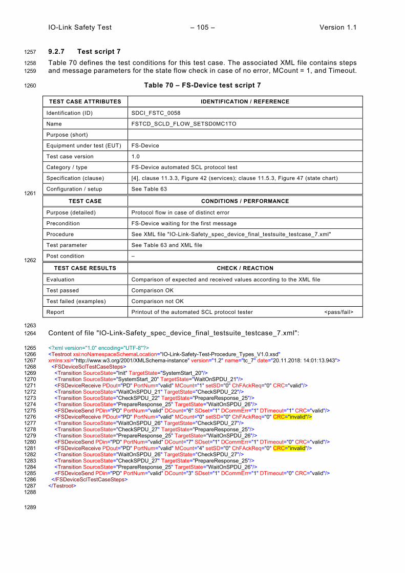
IO-Link Safety Test – 105 – Version 1.1
9.2.7 Test script 7 1257
Table 70 defines the test conditions for this test case. The associated XML file contains steps 1258 and message parameters for the state flow check in case of no error, MCount = 1, and Timeout. 1259
Table 70 – FS-Device test script 7 1260
TEST CASE ATTRIBUTES IDENTIFICATION / REFERENCE
Identification (ID) SDCI_FSTC_0058
Name FSTCD_SCLD_FLOW_SETSD0MC1TO
Purpose (short)
Equipment under test (EUT) FS-Device
Test case version 1.0
Category / type FS-Device automated SCL protocol test
Specification (clause) [4], clause 11.3.3, Figure 42 (services); clause 11.5.3, Figure 47 (state chart)
Configuration / setup See Table 63 1261
TEST CASE CONDITIONS / PERFORMANCE
Purpose (detailed) Protocol flow in case of distinct error
Precondition FS-Device waiting for the first message
Procedure See XML file "IO-Link-Safety_spec_device_final_testsuite_testcase_7.xml"
Test parameter See Table 63 and XML file
Post condition – 1262
TEST CASE RESULTS CHECK / REACTION
Evaluation Comparison of expected and received values according to the XML file
Test passed Comparison OK
Test failed (examples) Comparison not OK
Report Printout of the automated SCL protocol tester <pass/fail>
1263 Content of file "IO-Link-Safety_spec_device_final_testsuite_testcase_7.xml": 1264
<?xml version="1.0" encoding="UTF-8"?> 1265 <Testroot xsi:noNamespaceSchemaLocation="IO-Link-Safety-Test-Procedure_Types_V1.0.xsd" 1266 xmlns:xsi="http://www.w3.org/2001/XMLSchema-instance" version="1.2" name="tc_7" date="20.11.2018: 14:01:13.943"> 1267 <FSDeviceSclTestCaseSteps> 1268 <Transition SourceState="Init" TargetState="SystemStart_20"/> 1269 <Transition SourceState="SystemStart_20" TargetState="WaitOnSPDU_21"/> 1270 <FSDeviceReceive PDout="PD" PortNum="valid" MCount="1" setSD="0" ChFAckReq="0" CRC="valid"/> 1271 <Transition SourceState="WaitOnSPDU_21" TargetState="CheckSPDU_22"/> 1272 <Transition SourceState="CheckSPDU_22" TargetState="PrepareResponse_25"/> 1273 <Transition SourceState="PrepareResponse_25" TargetState="WaitOnSPDU_26"/> 1274 <FSDeviceSend PDin="PD" PortNum="valid" DCount="6" SDset="1" DCommErr="1" DTimeout="1" CRC="valid"/> 1275 <FSDeviceReceive PDout="PD" PortNum="valid" MCount="0" setSD="0" ChFAckReq="0" CRC="invalid"/> 1276 <Transition SourceState="WaitOnSPDU_26" TargetState="CheckSPDU_27"/> 1277 <Transition SourceState="CheckSPDU_27" TargetState="PrepareResponse_25"/> 1278 <Transition SourceState="PrepareResponse_25" TargetState="WaitOnSPDU_26"/> 1279 <FSDeviceSend PDin="PD" PortNum="valid" DCount="7" SDset="1" DCommErr="1" DTimeout="0" CRC="valid"/> 1280 <FSDeviceReceive PDout="PD" PortNum="valid" MCount="4" setSD="0" ChFAckReq="0" CRC="invalid"/> 1281 <Transition SourceState="WaitOnSPDU_26" TargetState="CheckSPDU_27"/> 1282 <Transition SourceState="CheckSPDU_27" TargetState="PrepareResponse_25"/> 1283 <Transition SourceState="PrepareResponse_25" TargetState="WaitOnSPDU_26"/> 1284 <FSDeviceSend PDin="PD" PortNum="valid" DCount="3" SDset="1" DCommErr="1" DTimeout="0" CRC="valid"/> 1285 </FSDeviceSclTestCaseSteps> 1286 </Testroot> 1287 1288
1289
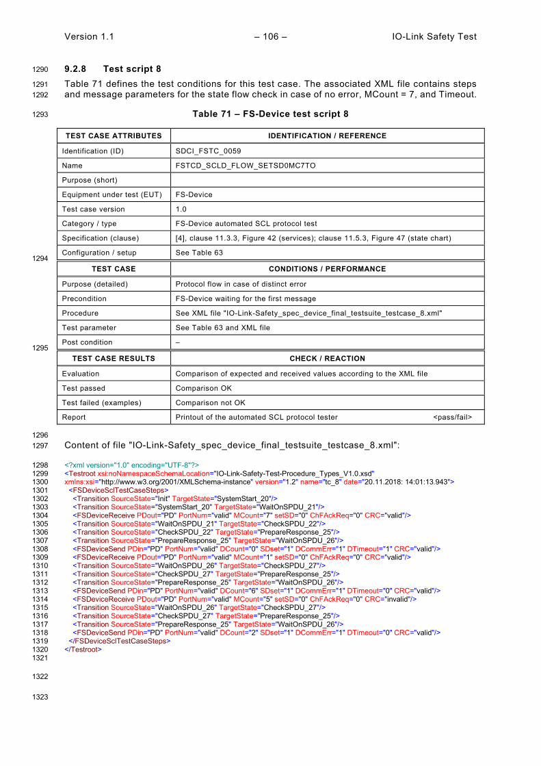
Version 1.1 – 106 – IO-Link Safety Test
9.2.8 Test script 8 1290
Table 71 defines the test conditions for this test case. The associated XML file contains steps 1291 and message parameters for the state flow check in case of no error, MCount = 7, and Timeout. 1292
Table 71 – FS-Device test script 8 1293
TEST CASE ATTRIBUTES IDENTIFICATION / REFERENCE
Identification (ID) SDCI_FSTC_0059
Name FSTCD_SCLD_FLOW_SETSD0MC7TO
Purpose (short)
Equipment under test (EUT) FS-Device
Test case version 1.0
Category / type FS-Device automated SCL protocol test
Specification (clause) [4], clause 11.3.3, Figure 42 (services); clause 11.5.3, Figure 47 (state chart)
Configuration / setup See Table 63 1294
TEST CASE CONDITIONS / PERFORMANCE
Purpose (detailed) Protocol flow in case of distinct error
Precondition FS-Device waiting for the first message
Procedure See XML file "IO-Link-Safety_spec_device_final_testsuite_testcase_8.xml"
Test parameter See Table 63 and XML file
Post condition – 1295
TEST CASE RESULTS CHECK / REACTION
Evaluation Comparison of expected and received values according to the XML file
Test passed Comparison OK
Test failed (examples) Comparison not OK
Report Printout of the automated SCL protocol tester <pass/fail>
1296 Content of file "IO-Link-Safety_spec_device_final_testsuite_testcase_8.xml": 1297
<?xml version="1.0" encoding="UTF-8"?> 1298 <Testroot xsi:noNamespaceSchemaLocation="IO-Link-Safety-Test-Procedure_Types_V1.0.xsd" 1299 xmlns:xsi="http://www.w3.org/2001/XMLSchema-instance" version="1.2" name="tc_8" date="20.11.2018: 14:01:13.943"> 1300 <FSDeviceSclTestCaseSteps> 1301 <Transition SourceState="Init" TargetState="SystemStart_20"/> 1302 <Transition SourceState="SystemStart_20" TargetState="WaitOnSPDU_21"/> 1303 <FSDeviceReceive PDout="PD" PortNum="valid" MCount="7" setSD="0" ChFAckReq="0" CRC="valid"/> 1304 <Transition SourceState="WaitOnSPDU_21" TargetState="CheckSPDU_22"/> 1305 <Transition SourceState="CheckSPDU_22" TargetState="PrepareResponse_25"/> 1306 <Transition SourceState="PrepareResponse_25" TargetState="WaitOnSPDU_26"/> 1307 <FSDeviceSend PDin="PD" PortNum="valid" DCount="0" SDset="1" DCommErr="1" DTimeout="1" CRC="valid"/> 1308 <FSDeviceReceive PDout="PD" PortNum="valid" MCount="1" setSD="0" ChFAckReq="0" CRC="valid"/> 1309 <Transition SourceState="WaitOnSPDU_26" TargetState="CheckSPDU_27"/> 1310 <Transition SourceState="CheckSPDU_27" TargetState="PrepareResponse_25"/> 1311 <Transition SourceState="PrepareResponse_25" TargetState="WaitOnSPDU_26"/> 1312 <FSDeviceSend PDin="PD" PortNum="valid" DCount="6" SDset="1" DCommErr="1" DTimeout="0" CRC="valid"/> 1313 <FSDeviceReceive PDout="PD" PortNum="valid" MCount="5" setSD="0" ChFAckReq="0" CRC="invalid"/> 1314 <Transition SourceState="WaitOnSPDU_26" TargetState="CheckSPDU_27"/> 1315 <Transition SourceState="CheckSPDU_27" TargetState="PrepareResponse_25"/> 1316 <Transition SourceState="PrepareResponse_25" TargetState="WaitOnSPDU_26"/> 1317 <FSDeviceSend PDin="PD" PortNum="valid" DCount="2" SDset="1" DCommErr="1" DTimeout="0" CRC="valid"/> 1318 </FSDeviceSclTestCaseSteps> 1319 </Testroot> 1320 1321
1322
1323

IO-Link Safety Test – 107 – Version 1.1
9.2.9 Test script 9 1324
Table 72 defines the test conditions for this test case. The associated XML file contains steps 1325 and message parameters for the state flow check in case of a CRC error and MCount = 0, and 1326 Timeout. 1327
Table 72 – FS-Device test script 9 1328
TEST CASE ATTRIBUTES IDENTIFICATION / REFERENCE
Identification (ID) SDCI_FSTC_0060
Name FSTCD_SCLD_FLOW_CRC1MC0TO
Purpose (short)
Equipment under test (EUT) FS-Device
Test case version 1.0
Category / type FS-Device automated SCL protocol test
Specification (clause) [4], clause 11.3.3, Figure 42 (services); clause 11.5.3, Figure 47 (state chart)
Configuration / setup See Table 63 1329
TEST CASE CONDITIONS / PERFORMANCE
Purpose (detailed) Protocol flow in case of distinct error
Precondition FS-Device waiting for the first message
Procedure See XML file "IO-Link-Safety_spec_device_final_testsuite_testcase_9.xml"
Test parameter See Table 63 and XML file
Post condition – 1330
TEST CASE RESULTS CHECK / REACTION
Evaluation Comparison of expected and received values according to the XML file
Test passed Comparison OK
Test failed (examples) Comparison not OK
Report Printout of the automated SCL protocol tester <pass/fail>
1331 Content of file "IO-Link-Safety_spec_device_final_testsuite_testcase_9.xml": 1332
<?xml version="1.0" encoding="UTF-8"?> 1333 <Testroot xsi:noNamespaceSchemaLocation="IO-Link-Safety-Test-Procedure_Types_V1.0.xsd" 1334 xmlns:xsi="http://www.w3.org/2001/XMLSchema-instance" version="1.2" name="tc_9" date="20.11.2018: 14:01:13.943"> 1335 <FSDeviceSclTestCaseSteps> 1336 <Transition SourceState="Init" TargetState="SystemStart_20"/> 1337 <Transition SourceState="SystemStart_20" TargetState="WaitOnSPDU_21"/> 1338 <FSDeviceReceive PDout="PD" PortNum="valid" MCount="0" setSD="0" ChFAckReq="0" CRC="invalid"/> 1339 <Transition SourceState="WaitOnSPDU_21" TargetState="CheckSPDU_22"/> 1340 <Transition SourceState="CheckSPDU_22" TargetState="PrepareResponse_25"/> 1341 <Transition SourceState="PrepareResponse_25" TargetState="WaitOnSPDU_26"/> 1342 <FSDeviceSend PDin="PD" PortNum="valid" DCount="7" SDset="1" DCommErr="1" DTimeout="1" CRC="valid"/> 1343 <Timeout/> 1344 <Transition SourceState="WaitOnSPDU_26" TargetState="PrepareResponse_25"/> 1345 <Transition SourceState="PrepareResponse_25" TargetState="WaitOnSPDU_26"/> 1346 <FSDeviceSend PDin="PD" PortNum="valid" DCount="7" SDset="1" DCommErr="1" DTimeout="1" CRC="valid"/> 1347 <FSDeviceReceive PDout="PD" PortNum="valid" MCount="6" setSD="0" ChFAckReq="0" CRC="valid"/> 1348 <Transition SourceState="WaitOnSPDU_26" TargetState="CheckSPDU_27"/> 1349 <Transition SourceState="CheckSPDU_27" TargetState="PrepareResponse_25"/> 1350 <Transition SourceState="PrepareResponse_25" TargetState="WaitOnSPDU_26"/> 1351 <FSDeviceSend PDin="PD" PortNum="valid" DCount="1" SDset="1" DCommErr="1" DTimeout="1" CRC="valid"/> 1352 </FSDeviceSclTestCaseSteps> 1353 </Testroot> 1354 1355
1356

Version 1.1 – 108 – IO-Link Safety Test
9.2.10 Test script 10 1357
Table 73 defines the test conditions for this test case. The associated XML file contains steps 1358 and message parameters for the state flow check in case of a setSD error, MCount = 0, and 1359 Timeout. 1360
Table 73 – FS-Device test script 10 1361
TEST CASE ATTRIBUTES IDENTIFICATION / REFERENCE
Identification (ID) SDCI_FSTC_0061
Name FSTCD_SCLD_FLOW_SETSD1MC0TO
Purpose (short)
Equipment under test (EUT) FS-Device
Test case version 1.0
Category / type FS-Device automated SCL protocol test
Specification (clause) [4], clause 11.3.3, Figure 42 (services); clause 11.5.3, Figure 47 (state chart)
Configuration / setup See Table 63 1362
TEST CASE CONDITIONS / PERFORMANCE
Purpose (detailed) Protocol flow in case of distinct error
Precondition FS-Device waiting for the first message
Procedure See XML file "IO-Link-Safety_spec_device_final_testsuite_testcase_10.xml"
Test parameter See Table 63 and XML file
Post condition – 1363
TEST CASE RESULTS CHECK / REACTION
Evaluation Comparison of expected and received values according to the XML file
Test passed Comparison OK
Test failed (examples) Comparison not OK
Report Printout of the automated SCL protocol tester <pass/fail>
1364 Content of file "IO-Link-Safety_spec_device_final_testsuite_testcase_10.xml": 1365
<?xml version="1.0" encoding="UTF-8"?> 1366 <Testroot xsi:noNamespaceSchemaLocation="IO-Link-Safety-Test-Procedure_Types_V1.0.xsd" 1367 xmlns:xsi="http://www.w3.org/2001/XMLSchema-instance" version="1.2" name="tc_10" date="20.11.2018: 14:01:13.943"> 1368 <FSDeviceSclTestCaseSteps> 1369 <Transition SourceState="Init" TargetState="SystemStart_20"/> 1370 <Transition SourceState="SystemStart_20" TargetState="WaitOnSPDU_21"/> 1371 <FSDeviceReceive PDout="PD" PortNum="valid" MCount="0" setSD="1" ChFAckReq="0" CRC="valid"/> 1372 <Transition SourceState="WaitOnSPDU_21" TargetState="CheckSPDU_22"/> 1373 <Transition SourceState="CheckSPDU_22" TargetState="PrepareResponse_23"/> 1374 <Transition SourceState="PrepareResponse_23" TargetState="WaitOnSPDU_24"/> 1375 <FSDeviceSend PDin="PD" PortNum="valid" DCount="7" SDset="1" DCommErr="0" DTimeout="0" CRC="valid"/> 1376 <FSDeviceReceive PDout="PD" PortNum="valid" MCount="1" setSD="0" ChFAckReq="0" CRC="valid"/> 1377 <Transition SourceState="WaitOnSPDU_24" TargetState="CheckSPDU_22"/> 1378 <Transition SourceState="CheckSPDU_22" TargetState="PrepareResponse_23"/> 1379 <Transition SourceState="PrepareResponse_23" TargetState="WaitOnSPDU_24"/> 1380 <FSDeviceSend PDin="PD" PortNum="valid" DCount="6" SDset="1" DCommErr="0" DTimeout="0" CRC="valid"/> 1381 <FSDeviceReceive PDout="PD" PortNum="valid" MCount="2" setSD="0" ChFAckReq="0" CRC="valid"/> 1382 <Transition SourceState="WaitOnSPDU_24" TargetState="CheckSPDU_22"/> 1383 <Transition SourceState="CheckSPDU_22" TargetState="PrepareResponse_23"/> 1384 <Transition SourceState="PrepareResponse_23" TargetState="WaitOnSPDU_24"/> 1385 <FSDeviceSend PDin="PD" PortNum="valid" DCount="5" SDset="1" DCommErr="0" DTimeout="0" CRC="valid"/> 1386 <Timeout/> 1387 <Transition SourceState="WaitOnSPDU_24" TargetState="PrepareResponse_25"/> 1388 <Transition SourceState="PrepareResponse_25" TargetState="WaitOnSPDU_26"/> 1389 <FSDeviceSend PDin="PD" PortNum="valid" DCount="5" SDset="1" DCommErr="0" DTimeout="1" CRC="valid"/> 1390 <FSDeviceReceive PDout="PD" PortNum="valid" MCount="7" setSD="0" ChFAckReq="0" CRC="invalid"/> 1391 <Transition SourceState="WaitOnSPDU_26" TargetState="CheckSPDU_27"/> 1392 <Transition SourceState="CheckSPDU_27" TargetState="PrepareResponse_25"/> 1393

IO-Link Safety Test – 109 – Version 1.1
<Transition SourceState="PrepareResponse_25" TargetState="WaitOnSPDU_26"/> 1394 <FSDeviceSend PDin="PD" PortNum="valid" DCount="0" SDset="1" DCommErr="1" DTimeout="1" CRC="valid"/> 1395 </FSDeviceSclTestCaseSteps> 1396 </Testroot> 1397 1398

Version 1.1 – 110 – IO-Link Safety Test
9.2.11 Test script 11 1399
Table 74 defines the test conditions for this test case. The associated XML file contains steps 1400 and message parameters for the state flow check in case of a setSD error and MCount = 0. 1401
Table 74 – FS-Device test script 11 1402
TEST CASE ATTRIBUTES IDENTIFICATION / REFERENCE
Identification (ID) SDCI_FSTC_0062
Name FSTCD_SCLD_FLOW_SETSD1MC0
Purpose (short)
Equipment under test (EUT) FS-Device
Test case version 1.0
Category / type FS-Device automated SCL protocol test
Specification (clause) [4], clause 11.3.3, Figure 42 (services); clause 11.5.3, Figure 47 (state chart)
Configuration / setup See Table 63 1403
TEST CASE CONDITIONS / PERFORMANCE
Purpose (detailed) Protocol flow in case of distinct error
Precondition FS-Device waiting for the first message
Procedure See XML file "IO-Link-Safety_spec_device_final_testsuite_testcase_11.xml"
Test parameter See Table 63 and XML file
Post condition – 1404
TEST CASE RESULTS CHECK / REACTION
Evaluation Comparison of expected and received values according to the XML file
Test passed Comparison OK
Test failed (examples) Comparison not OK
Report Printout of the automated SCL protocol tester <pass/fail>
1405 Content of file "IO-Link-Safety_spec_device_final_testsuite_testcase_11.xml": 1406
<?xml version="1.0" encoding="UTF-8"?> 1407 <Testroot xsi:noNamespaceSchemaLocation="IO-Link-Safety-Test-Procedure_Types_V1.0.xsd" 1408 xmlns:xsi="http://www.w3.org/2001/XMLSchema-instance" version="1.2" name="tc_11" date="20.11.2018: 14:01:13.944"> 1409 <FSDeviceSclTestCaseSteps> 1410 <Transition SourceState="Init" TargetState="SystemStart_20"/> 1411 <Transition SourceState="SystemStart_20" TargetState="WaitOnSPDU_21"/> 1412 <FSDeviceReceive PDout="PD" PortNum="valid" MCount="0" setSD="1" ChFAckReq="0" CRC="valid"/> 1413 <Transition SourceState="WaitOnSPDU_21" TargetState="CheckSPDU_22"/> 1414 <Transition SourceState="CheckSPDU_22" TargetState="PrepareResponse_23"/> 1415 <Transition SourceState="PrepareResponse_23" TargetState="WaitOnSPDU_24"/> 1416 <FSDeviceSend PDin="PD" PortNum="valid" DCount="7" SDset="1" DCommErr="0" DTimeout="0" CRC="valid"/> 1417 <FSDeviceReceive PDout="PD" PortNum="valid" MCount="1" setSD="0" ChFAckReq="0" CRC="valid"/> 1418 <Transition SourceState="WaitOnSPDU_24" TargetState="CheckSPDU_22"/> 1419 <Transition SourceState="CheckSPDU_22" TargetState="PrepareResponse_23"/> 1420 <Transition SourceState="PrepareResponse_23" TargetState="WaitOnSPDU_24"/> 1421 <FSDeviceSend PDin="PD" PortNum="valid" DCount="6" SDset="1" DCommErr="0" DTimeout="0" CRC="valid"/> 1422 <FSDeviceReceive PDout="PD" PortNum="valid" MCount="0" setSD="0" ChFAckReq="0" CRC="valid"/> 1423 <Transition SourceState="WaitOnSPDU_24" TargetState="CheckSPDU_22"/> 1424 <Transition SourceState="CheckSPDU_22" TargetState="PrepareResponse_23"/> 1425 <Transition SourceState="PrepareResponse_23" TargetState="WaitOnSPDU_24"/> 1426 <FSDeviceSend PDin="PD" PortNum="valid" DCount="7" SDset="1" DCommErr="0" DTimeout="0" CRC="valid"/> 1427 <FSDeviceReceive PDout="PD" PortNum="valid" MCount="1" setSD="0" ChFAckReq="0" CRC="valid"/> 1428 <Transition SourceState="WaitOnSPDU_24" TargetState="CheckSPDU_22"/> 1429 <Transition SourceState="CheckSPDU_22" TargetState="PrepareResponse_23"/> 1430 <Transition SourceState="PrepareResponse_23" TargetState="WaitOnSPDU_24"/> 1431 <FSDeviceSend PDin="PD" PortNum="valid" DCount="6" SDset="0" DCommErr="0" DTimeout="0" CRC="valid"/> 1432 <FSDeviceReceive PDout="PD" PortNum="valid" MCount="2" setSD="0" ChFAckReq="0" CRC="valid"/> 1433 <Transition SourceState="WaitOnSPDU_24" TargetState="CheckSPDU_22"/> 1434 <Transition SourceState="CheckSPDU_22" TargetState="PrepareResponse_23"/> 1435 <Transition SourceState="PrepareResponse_23" TargetState="WaitOnSPDU_24"/> 1436

IO-Link Safety Test – 111 – Version 1.1
<FSDeviceSend PDin="PD" PortNum="valid" DCount="5" SDset="0" DCommErr="0" DTimeout="0" CRC="valid"/> 1437 <FSDeviceReceive PDout="PD" PortNum="valid" MCount="1" setSD="0" ChFAckReq="0" CRC="valid"/> 1438 <Transition SourceState="WaitOnSPDU_24" TargetState="CheckSPDU_22"/> 1439 <Transition SourceState="CheckSPDU_22" TargetState="PrepareResponse_25"/> 1440 <Transition SourceState="PrepareResponse_25" TargetState="WaitOnSPDU_26"/> 1441 <FSDeviceSend PDin="PD" PortNum="valid" DCount="6" SDset="1" DCommErr="1" DTimeout="0" CRC="valid"/> 1442 </FSDeviceSclTestCaseSteps> 1443 </Testroot> 1444 1445
1446

Version 1.1 – 112 – IO-Link Safety Test
9.2.12 Test script 12 1447
Table 75 defines the test conditions for this test case. The associated XML file contains steps 1448 and message parameters for the state flow check in case of a setSD error, MCount = 0, and 1449 DCommErr. 1450
Table 75 – FS-Device test script 12 1451
TEST CASE ATTRIBUTES IDENTIFICATION / REFERENCE
Identification (ID) SDCI_FSTC_0063
Name FSTCD_SCLD_FLOW_SETSD1MC0DCE1
Purpose (short)
Equipment under test (EUT) FS-Device
Test case version 1.0
Category / type FS-Device automated SCL protocol test
Specification (clause) [4], clause 11.3.3, Figure 42 (services); clause 11.5.3, Figure 47 (state chart)
Configuration / setup See Table 63 1452
TEST CASE CONDITIONS / PERFORMANCE
Purpose (detailed) Protocol flow in case of distinct error
Precondition FS-Device waiting for the first message
Procedure See XML file "IO-Link-Safety_spec_device_final_testsuite_testcase_12.xml"
Test parameter See Table 63 and XML file
Post condition – 1453
TEST CASE RESULTS CHECK / REACTION
Evaluation Comparison of expected and received values according to the XML file
Test passed Comparison OK
Test failed (examples) Comparison not OK
Report Printout of the automated SCL protocol tester <pass/fail>
1454 Content of file "IO-Link-Safety_spec_device_final_testsuite_testcase_12.xml": 1455
<?xml version="1.0" encoding="UTF-8"?> 1456 <Testroot xsi:noNamespaceSchemaLocation="IO-Link-Safety-Test-Procedure_Types_V1.0.xsd" 1457 xmlns:xsi="http://www.w3.org/2001/XMLSchema-instance" version="1.2" name="tc_12" date="20.11.2018: 14:01:13.944"> 1458 <FSDeviceSclTestCaseSteps> 1459 <Transition SourceState="Init" TargetState="SystemStart_20"/> 1460 <Transition SourceState="SystemStart_20" TargetState="WaitOnSPDU_21"/> 1461 <FSDeviceReceive PDout="PD" PortNum="valid" MCount="0" setSD="1" ChFAckReq="0" CRC="valid"/> 1462 <Transition SourceState="WaitOnSPDU_21" TargetState="CheckSPDU_22"/> 1463 <Transition SourceState="CheckSPDU_22" TargetState="PrepareResponse_23"/> 1464 <Transition SourceState="PrepareResponse_23" TargetState="WaitOnSPDU_24"/> 1465 <FSDeviceSend PDin="PD" PortNum="valid" DCount="7" SDset="1" DCommErr="0" DTimeout="0" CRC="valid"/> 1466 <FSDeviceReceive PDout="PD" PortNum="valid" MCount="4" setSD="0" ChFAckReq="0" CRC="invalid"/> 1467 <Transition SourceState="WaitOnSPDU_24" TargetState="PrepareResponse_25"/> 1468 <Transition SourceState="PrepareResponse_25" TargetState="WaitOnSPDU_26"/> 1469 <FSDeviceSend PDin="PD" PortNum="valid" DCount="3" SDset="1" DCommErr="1" DTimeout="0" CRC="valid"/> 1470 <FSDeviceReceive PDout="PD" PortNum="valid" MCount="1" setSD="0" ChFAckReq="0" CRC="valid"/> 1471 <Transition SourceState="WaitOnSPDU_26" TargetState="CheckSPDU_27"/> 1472 <Transition SourceState="CheckSPDU_27" TargetState="PrepareResponse_25"/> 1473 <Transition SourceState="PrepareResponse_25" TargetState="WaitOnSPDU_26"/> 1474 <FSDeviceSend PDin="PD" PortNum="valid" DCount="6" SDset="1" DCommErr="1" DTimeout="0" CRC="valid"/> 1475 </FSDeviceSclTestCaseSteps> 1476 </Testroot> 1477 1478
1479

IO-Link Safety Test – 113 – Version 1.1
9.2.13 Test script 13 1480
Table 76 defines the test conditions for this test case. The associated XML file contains steps 1481 and message parameters for the state flow check in case of a setSD error, MCount = 0, and 1482 DCommErr. 1483
Table 76 – FS-Device test script 13 1484
TEST CASE ATTRIBUTES IDENTIFICATION / REFERENCE
Identification (ID) SDCI_FSTC_0064
Name FSTCD_SCLD_FLOW_SETSD1MC0DCE1
Purpose (short)
Equipment under test (EUT) FS-Device
Test case version 1.0
Category / type FS-Device automated SCL protocol test
Specification (clause) [4], clause 11.3.3, Figure 42 (services); clause 11.5.3, Figure 47 (state chart)
Configuration / setup See Table 63 1485
TEST CASE CONDITIONS / PERFORMANCE
Purpose (detailed) Protocol flow in case of distinct error
Precondition FS-Device waiting for the first message
Procedure See XML file "IO-Link-Safety_spec_device_final_testsuite_testcase_13.xml"
Test parameter See Table 63 and XML file
Post condition – 1486
TEST CASE RESULTS CHECK / REACTION
Evaluation Comparison of expected and received values according to the XML file
Test passed Comparison OK
Test failed (examples) Comparison not OK
Report Printout of the automated SCL protocol tester <pass/fail>
1487 Content of file "IO-Link-Safety_spec_device_final_testsuite_testcase_13.xml": 1488
<?xml version="1.0" encoding="UTF-8"?> 1489 <Testroot xsi:noNamespaceSchemaLocation="IO-Link-Safety-Test-Procedure_Types_V1.0.xsd" 1490 xmlns:xsi="http://www.w3.org/2001/XMLSchema-instance" version="1.2" name="tc_13" date="20.11.2018: 14:01:13.944"> 1491 <FSDeviceSclTestCaseSteps> 1492 <Transition SourceState="Init" TargetState="SystemStart_20"/> 1493 <Transition SourceState="SystemStart_20" TargetState="WaitOnSPDU_21"/> 1494 <FSDeviceReceive PDout="PD" PortNum="valid" MCount="0" setSD="1" ChFAckReq="0" CRC="valid"/> 1495 <Transition SourceState="WaitOnSPDU_21" TargetState="CheckSPDU_22"/> 1496 <Transition SourceState="CheckSPDU_22" TargetState="PrepareResponse_23"/> 1497 <Transition SourceState="PrepareResponse_23" TargetState="WaitOnSPDU_24"/> 1498 <FSDeviceSend PDin="PD" PortNum="valid" DCount="7" SDset="1" DCommErr="0" DTimeout="0" CRC="valid"/> 1499 <FSDeviceReceive PDout="PD" PortNum="valid" MCount="5" setSD="0" ChFAckReq="0" CRC="invalid"/> 1500 <Transition SourceState="WaitOnSPDU_24" TargetState="PrepareResponse_25"/> 1501 <Transition SourceState="PrepareResponse_25" TargetState="WaitOnSPDU_26"/> 1502 <FSDeviceSend PDin="PD" PortNum="valid" DCount="2" SDset="1" DCommErr="1" DTimeout="0" CRC="valid"/> 1503 <FSDeviceReceive PDout="PD" PortNum="valid" MCount="1" setSD="0" ChFAckReq="0" CRC="valid"/> 1504 <Transition SourceState="WaitOnSPDU_26" TargetState="CheckSPDU_27"/> 1505 <Transition SourceState="CheckSPDU_27" TargetState="PrepareResponse_25"/> 1506 <Transition SourceState="PrepareResponse_25" TargetState="WaitOnSPDU_26"/> 1507 <FSDeviceSend PDin="PD" PortNum="valid" DCount="6" SDset="1" DCommErr="1" DTimeout="0" CRC="valid"/> 1508 </FSDeviceSclTestCaseSteps> 1509 </Testroot> 1510 1511

Version 1.1 – 114 – IO-Link Safety Test
9.2.14 Test script 14 1512
Table 77 defines the test conditions for this test case. The associated XML file contains steps 1513 and message parameters for the state flow check in case of no error, MCount = 2, and 1514 DCommErr. 1515
Table 77 – FS-Device test script 14 1516
TEST CASE ATTRIBUTES IDENTIFICATION / REFERENCE
Identification (ID) SDCI_FSTC_0065
Name FSTCD_SCLD_FLOW_SETSD0MC2DCE1
Purpose (short)
Equipment under test (EUT) FS-Device
Test case version 1.0
Category / type FS-Device automated SCL protocol test
Specification (clause) [4], clause 11.3.3, Figure 42 (services); clause 11.5.3, Figure 47 (state chart)
Configuration / setup See Table 63 1517
TEST CASE CONDITIONS / PERFORMANCE
Purpose (detailed) Protocol flow in case of distinct error
Precondition FS-Device waiting for the first message
Procedure See XML file "IO-Link-Safety_spec_device_final_testsuite_testcase_14.xml"
Test parameter See Table 63 and XML file
Post condition – 1518
TEST CASE RESULTS CHECK / REACTION
Evaluation Comparison of expected and received values according to the XML file
Test passed Comparison OK
Test failed (examples) Comparison not OK
Report Printout of the automated SCL protocol tester <pass/fail>
1519 Content of file "IO-Link-Safety_spec_device_final_testsuite_testcase_14.xml": 1520
<?xml version="1.0" encoding="UTF-8"?> 1521 <Testroot xsi:noNamespaceSchemaLocation="IO-Link-Safety-Test-Procedure_Types_V1.0.xsd" 1522 xmlns:xsi="http://www.w3.org/2001/XMLSchema-instance" version="1.2" name="tc_14" date="20.11.2018: 14:01:13.944"> 1523 <FSDeviceSclTestCaseSteps> 1524 <Transition SourceState="Init" TargetState="SystemStart_20"/> 1525 <Transition SourceState="SystemStart_20" TargetState="WaitOnSPDU_21"/> 1526 <FSDeviceReceive PDout="PD" PortNum="valid" MCount="2" setSD="0" ChFAckReq="0" CRC="valid"/> 1527 <Transition SourceState="WaitOnSPDU_21" TargetState="CheckSPDU_22"/> 1528 <Transition SourceState="CheckSPDU_22" TargetState="PrepareResponse_25"/> 1529 <Transition SourceState="PrepareResponse_25" TargetState="WaitOnSPDU_26"/> 1530 <FSDeviceSend PDin="PD" PortNum="valid" DCount="5" SDset="1" DCommErr="1" DTimeout="1" CRC="valid"/> 1531 <FSDeviceReceive PDout="PD" PortNum="valid" MCount="3" setSD="0" ChFAckReq="0" CRC="valid"/> 1532 <Transition SourceState="WaitOnSPDU_26" TargetState="CheckSPDU_27"/> 1533 <Transition SourceState="CheckSPDU_27" TargetState="PrepareResponse_25"/> 1534 <Transition SourceState="PrepareResponse_25" TargetState="WaitOnSPDU_26"/> 1535 <FSDeviceSend PDin="PD" PortNum="valid" DCount="4" SDset="1" DCommErr="1" DTimeout="0" CRC="valid"/> 1536 <FSDeviceReceive PDout="PD" PortNum="valid" MCount="1" setSD="0" ChFAckReq="0" CRC="valid"/> 1537 <Transition SourceState="WaitOnSPDU_26" TargetState="CheckSPDU_27"/> 1538 <Transition SourceState="CheckSPDU_27" TargetState="PrepareResponse_25"/> 1539 <Transition SourceState="PrepareResponse_25" TargetState="WaitOnSPDU_26"/> 1540 <FSDeviceSend PDin="PD" PortNum="valid" DCount="6" SDset="1" DCommErr="1" DTimeout="0" CRC="valid"/> 1541 </FSDeviceSclTestCaseSteps> 1542 </Testroot> 1543 1544
1545

IO-Link Safety Test – 115 – Version 1.1
9.2.15 Test script 15 1546
Table 78 defines the test conditions for this test case. The associated XML file contains steps 1547 and message parameters for the state flow check in case of a setSD error, MCount = 0, and 1548 DCommErr. 1549
Table 78 – FS-Device test script 15 1550
TEST CASE ATTRIBUTES IDENTIFICATION / REFERENCE
Identification (ID) SDCI_FSTC_0066
Name FSTCD_SCLD_FLOW_SETSD1MC0DCE1
Purpose (short)
Equipment under test (EUT) FS-Device
Test case version 1.0
Category / type FS-Device automated SCL protocol test
Specification (clause) [4], clause 11.3.3, Figure 42 (services); clause 11.5.3, Figure 47 (state chart)
Configuration / setup See Table 63 1551
TEST CASE CONDITIONS / PERFORMANCE
Purpose (detailed) Protocol flow in case of distinct error
Precondition FS-Device waiting for the first message
Procedure See XML file "IO-Link-Safety_spec_device_final_testsuite_testcase_15.xml"
Test parameter See Table 63 and XML file
Post condition – 1552
TEST CASE RESULTS CHECK / REACTION
Evaluation Comparison of expected and received values according to the XML file
Test passed Comparison OK
Test failed (examples) Comparison not OK
Report Printout of the automated SCL protocol tester <pass/fail>
1553 Content of file "IO-Link-Safety_spec_device_final_testsuite_testcase_15.xml": 1554
<?xml version="1.0" encoding="UTF-8"?> 1555 <Testroot xsi:noNamespaceSchemaLocation="IO-Link-Safety-Test-Procedure_Types_V1.0.xsd" 1556 xmlns:xsi="http://www.w3.org/2001/XMLSchema-instance" version="1.2" name="tc_15" date="20.11.2018: 14:01:13.944"> 1557 <FSDeviceSclTestCaseSteps> 1558 <Transition SourceState="Init" TargetState="SystemStart_20"/> 1559 <Transition SourceState="SystemStart_20" TargetState="WaitOnSPDU_21"/> 1560 <FSDeviceReceive PDout="PD" PortNum="valid" MCount="0" setSD="1" ChFAckReq="0" CRC="valid"/> 1561 <Transition SourceState="WaitOnSPDU_21" TargetState="CheckSPDU_22"/> 1562 <Transition SourceState="CheckSPDU_22" TargetState="PrepareResponse_23"/> 1563 <Transition SourceState="PrepareResponse_23" TargetState="WaitOnSPDU_24"/> 1564 <FSDeviceSend PDin="PD" PortNum="valid" DCount="7" SDset="1" DCommErr="0" DTimeout="0" CRC="valid"/> 1565 <FSDeviceReceive PDout="PD" PortNum="valid" MCount="1" setSD="0" ChFAckReq="0" CRC="valid"/> 1566 <Transition SourceState="WaitOnSPDU_24" TargetState="CheckSPDU_22"/> 1567 <Transition SourceState="CheckSPDU_22" TargetState="PrepareResponse_23"/> 1568 <Transition SourceState="PrepareResponse_23" TargetState="WaitOnSPDU_24"/> 1569 <FSDeviceSend PDin="PD" PortNum="valid" DCount="6" SDset="1" DCommErr="0" DTimeout="0" CRC="valid"/> 1570 <FSDeviceReceive PDout="PD" PortNum="valid" MCount="2" setSD="0" ChFAckReq="0" CRC="valid"/> 1571 <Transition SourceState="WaitOnSPDU_24" TargetState="CheckSPDU_22"/> 1572 <Transition SourceState="CheckSPDU_22" TargetState="PrepareResponse_23"/> 1573 <Transition SourceState="PrepareResponse_23" TargetState="WaitOnSPDU_24"/> 1574 <FSDeviceSend PDin="PD" PortNum="valid" DCount="5" SDset="1" DCommErr="0" DTimeout="0" CRC="valid"/> 1575 <FSDeviceReceive PDout="PD" PortNum="valid" MCount="3" setSD="0" ChFAckReq="0" CRC="valid"/> 1576 <Transition SourceState="WaitOnSPDU_24" TargetState="CheckSPDU_22"/> 1577 <Transition SourceState="CheckSPDU_22" TargetState="PrepareResponse_23"/> 1578 <Transition SourceState="PrepareResponse_23" TargetState="WaitOnSPDU_24"/> 1579 <FSDeviceSend PDin="PD" PortNum="valid" DCount="4" SDset="0" DCommErr="0" DTimeout="0" CRC="valid"/> 1580 <FSDeviceReceive PDout="PD" PortNum="valid" MCount="1" setSD="0" ChFAckReq="0" CRC="valid"/> 1581 <Transition SourceState="WaitOnSPDU_24" TargetState="CheckSPDU_22"/> 1582

Version 1.1 – 116 – IO-Link Safety Test
<Transition SourceState="CheckSPDU_22" TargetState="PrepareResponse_25"/> 1583 <Transition SourceState="PrepareResponse_25" TargetState="WaitOnSPDU_26"/> 1584 <FSDeviceSend PDin="PD" PortNum="valid" DCount="6" SDset="1" DCommErr="1" DTimeout="0" CRC="valid"/> 1585 </FSDeviceSclTestCaseSteps> 1586 </Testroot> 1587 1588

IO-Link Safety Test – 117 – Version 1.1
9.2.16 Test script 16 1589
Table 79 defines the test conditions for this test case. The associated XML file contains steps 1590 and message parameters for the state flow check in case of a setSD error, MCount = 0, and 1591 DCommErr. 1592
Table 79 – FS-Device test script 16 1593
TEST CASE ATTRIBUTES IDENTIFICATION / REFERENCE
Identification (ID) SDCI_FSTC_0067
Name FSTCD_SCLD_FLOW_SETSD1MC0DCE1
Purpose (short)
Equipment under test (EUT) FS-Device
Test case version 1.0
Category / type FS-Device automated SCL protocol test
Specification (clause) [4], clause 11.3.3, Figure 42 (services); clause 11.5.3, Figure 47 (state chart)
Configuration / setup See Table 63 1594
TEST CASE CONDITIONS / PERFORMANCE
Purpose (detailed) Protocol flow in case of distinct error
Precondition FS-Device waiting for the first message
Procedure See XML file "IO-Link-Safety_spec_device_final_testsuite_testcase_16.xml"
Test parameter See Table 63 and XML file
Post condition – 1595
TEST CASE RESULTS CHECK / REACTION
Evaluation Comparison of expected and received values according to the XML file
Test passed Comparison OK
Test failed (examples) Comparison not OK
Report Printout of the automated SCL protocol tester <pass/fail>
1596 Content of file "IO-Link-Safety_spec_device_final_testsuite_testcase_16.xml": 1597
<?xml version="1.0" encoding="UTF-8"?> 1598 <Testroot xsi:noNamespaceSchemaLocation="IO-Link-Safety-Test-Procedure_Types_V1.0.xsd" 1599 xmlns:xsi="http://www.w3.org/2001/XMLSchema-instance" version="1.2" name="tc_16" date="20.11.2018: 14:01:13.944"> 1600 <FSDeviceSclTestCaseSteps> 1601 <Transition SourceState="Init" TargetState="SystemStart_20"/> 1602 <Transition SourceState="SystemStart_20" TargetState="WaitOnSPDU_21"/> 1603 <FSDeviceReceive PDout="PD" PortNum="valid" MCount="0" setSD="1" ChFAckReq="0" CRC="valid"/> 1604 <Transition SourceState="WaitOnSPDU_21" TargetState="CheckSPDU_22"/> 1605 <Transition SourceState="CheckSPDU_22" TargetState="PrepareResponse_23"/> 1606 <Transition SourceState="PrepareResponse_23" TargetState="WaitOnSPDU_24"/> 1607 <FSDeviceSend PDin="PD" PortNum="valid" DCount="7" SDset="1" DCommErr="0" DTimeout="0" CRC="valid"/> 1608 <FSDeviceReceive PDout="PD" PortNum="valid" MCount="1" setSD="0" ChFAckReq="0" CRC="valid"/> 1609 <Transition SourceState="WaitOnSPDU_24" TargetState="CheckSPDU_22"/> 1610 <Transition SourceState="CheckSPDU_22" TargetState="PrepareResponse_23"/> 1611 <Transition SourceState="PrepareResponse_23" TargetState="WaitOnSPDU_24"/> 1612 <FSDeviceSend PDin="PD" PortNum="valid" DCount="6" SDset="1" DCommErr="0" DTimeout="0" CRC="valid"/> 1613 <FSDeviceReceive PDout="PD" PortNum="valid" MCount="2" setSD="0" ChFAckReq="0" CRC="valid"/> 1614 <Transition SourceState="WaitOnSPDU_24" TargetState="CheckSPDU_22"/> 1615 <Transition SourceState="CheckSPDU_22" TargetState="PrepareResponse_23"/> 1616 <Transition SourceState="PrepareResponse_23" TargetState="WaitOnSPDU_24"/> 1617 <FSDeviceSend PDin="PD" PortNum="valid" DCount="5" SDset="1" DCommErr="0" DTimeout="0" CRC="valid"/> 1618 <FSDeviceReceive PDout="PD" PortNum="valid" MCount="3" setSD="0" ChFAckReq="0" CRC="valid"/> 1619 <Transition SourceState="WaitOnSPDU_24" TargetState="CheckSPDU_22"/> 1620 <Transition SourceState="CheckSPDU_22" TargetState="PrepareResponse_23"/> 1621 <Transition SourceState="PrepareResponse_23" TargetState="WaitOnSPDU_24"/> 1622 <FSDeviceSend PDin="PD" PortNum="valid" DCount="4" SDset="0" DCommErr="0" DTimeout="0" CRC="valid"/> 1623 <FSDeviceReceive PDout="PD" PortNum="valid" MCount="4" setSD="0" ChFAckReq="0" CRC="valid"/> 1624 <Transition SourceState="WaitOnSPDU_24" TargetState="CheckSPDU_22"/> 1625

Version 1.1 – 118 – IO-Link Safety Test
<Transition SourceState="CheckSPDU_22" TargetState="PrepareResponse_23"/> 1626 <Transition SourceState="PrepareResponse_23" TargetState="WaitOnSPDU_24"/> 1627 <FSDeviceSend PDin="PD" PortNum="valid" DCount="3" SDset="0" DCommErr="0" DTimeout="0" CRC="valid"/> 1628 <FSDeviceReceive PDout="PD" PortNum="valid" MCount="1" setSD="0" ChFAckReq="0" CRC="valid"/> 1629 <Transition SourceState="WaitOnSPDU_24" TargetState="CheckSPDU_22"/> 1630 <Transition SourceState="CheckSPDU_22" TargetState="PrepareResponse_25"/> 1631 <Transition SourceState="PrepareResponse_25" TargetState="WaitOnSPDU_26"/> 1632 <FSDeviceSend PDin="PD" PortNum="valid" DCount="6" SDset="1" DCommErr="1" DTimeout="0" CRC="valid"/> 1633 </FSDeviceSclTestCaseSteps> 1634 </Testroot> 1635
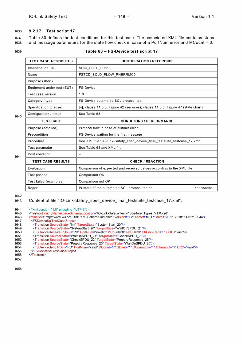
IO-Link Safety Test – 119 – Version 1.1
9.2.17 Test script 17 1636
Table 80 defines the test conditions for this test case. The associated XML file contains steps 1637 and message parameters for the state flow check in case of a PortNum error and MCount = 0. 1638
Table 80 – FS-Device test script 17 1639
TEST CASE ATTRIBUTES IDENTIFICATION / REFERENCE
Identification (ID) SDCI_FSTC_0068
Name FSTCD_SCLD_FLOW_PNERRMC0
Purpose (short)
Equipment under test (EUT) FS-Device
Test case version 1.0
Category / type FS-Device automated SCL protocol test
Specification (clause) [4], clause 11.3.3, Figure 42 (services); clause 11.5.3, Figure 47 (state chart)
Configuration / setup See Table 63 1640
TEST CASE CONDITIONS / PERFORMANCE
Purpose (detailed) Protocol flow in case of distinct error
Precondition FS-Device waiting for the first message
Procedure See XML file "IO-Link-Safety_spec_device_final_testsuite_testcase_17.xml"
Test parameter See Table 63 and XML file
Post condition – 1641
TEST CASE RESULTS CHECK / REACTION
Evaluation Comparison of expected and received values according to the XML file
Test passed Comparison OK
Test failed (examples) Comparison not OK
Report Printout of the automated SCL protocol tester <pass/fail>
1642 Content of file "IO-Link-Safety_spec_device_final_testsuite_testcase_17.xml": 1643
<?xml version="1.0" encoding="UTF-8"?> 1644 <Testroot xsi:noNamespaceSchemaLocation="IO-Link-Safety-Test-Procedure_Types_V1.0.xsd" 1645 xmlns:xsi="http://www.w3.org/2001/XMLSchema-instance" version="1.2" name="tc_17" date="20.11.2018: 14:01:13.944"> 1646 <FSDeviceSclTestCaseSteps> 1647 <Transition SourceState="Init" TargetState="SystemStart_20"/> 1648 <Transition SourceState="SystemStart_20" TargetState="WaitOnSPDU_21"/> 1649 <FSDeviceReceive PDout="PD" PortNum="invalid" MCount="0" setSD="0" ChFAckReq="0" CRC="valid"/> 1650 <Transition SourceState="WaitOnSPDU_21" TargetState="CheckSPDU_22"/> 1651 <Transition SourceState="CheckSPDU_22" TargetState="PrepareResponse_25"/> 1652 <Transition SourceState="PrepareResponse_25" TargetState="WaitOnSPDU_26"/> 1653 <FSDeviceSend PDin="PD" PortNum="valid" DCount="7" SDset="1" DCommErr="1" DTimeout="1" CRC="valid"/> 1654 </FSDeviceSclTestCaseSteps> 1655 </Testroot> 1656 1657
1658
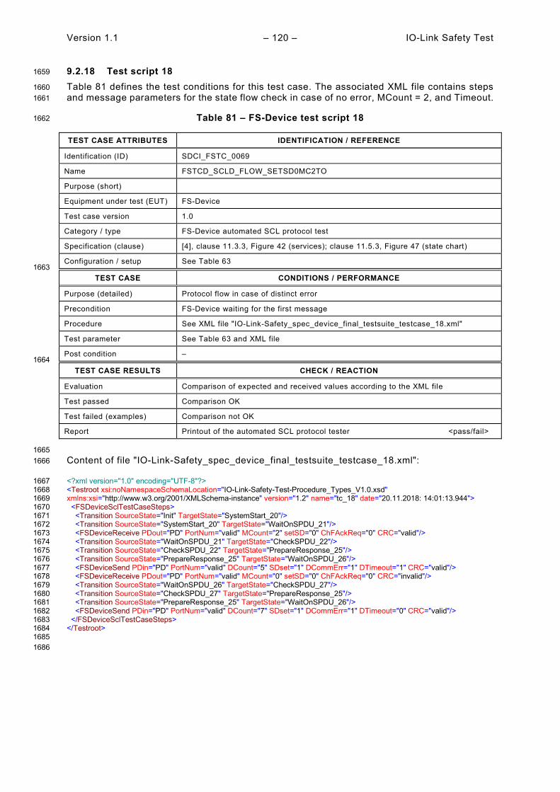
Version 1.1 – 120 – IO-Link Safety Test
9.2.18 Test script 18 1659
Table 81 defines the test conditions for this test case. The associated XML file contains steps 1660 and message parameters for the state flow check in case of no error, MCount = 2, and Timeout. 1661
Table 81 – FS-Device test script 18 1662
TEST CASE ATTRIBUTES IDENTIFICATION / REFERENCE
Identification (ID) SDCI_FSTC_0069
Name FSTCD_SCLD_FLOW_SETSD0MC2TO
Purpose (short)
Equipment under test (EUT) FS-Device
Test case version 1.0
Category / type FS-Device automated SCL protocol test
Specification (clause) [4], clause 11.3.3, Figure 42 (services); clause 11.5.3, Figure 47 (state chart)
Configuration / setup See Table 63 1663
TEST CASE CONDITIONS / PERFORMANCE
Purpose (detailed) Protocol flow in case of distinct error
Precondition FS-Device waiting for the first message
Procedure See XML file "IO-Link-Safety_spec_device_final_testsuite_testcase_18.xml"
Test parameter See Table 63 and XML file
Post condition – 1664
TEST CASE RESULTS CHECK / REACTION
Evaluation Comparison of expected and received values according to the XML file
Test passed Comparison OK
Test failed (examples) Comparison not OK
Report Printout of the automated SCL protocol tester <pass/fail>
1665 Content of file "IO-Link-Safety_spec_device_final_testsuite_testcase_18.xml": 1666
<?xml version="1.0" encoding="UTF-8"?> 1667 <Testroot xsi:noNamespaceSchemaLocation="IO-Link-Safety-Test-Procedure_Types_V1.0.xsd" 1668 xmlns:xsi="http://www.w3.org/2001/XMLSchema-instance" version="1.2" name="tc_18" date="20.11.2018: 14:01:13.944"> 1669 <FSDeviceSclTestCaseSteps> 1670 <Transition SourceState="Init" TargetState="SystemStart_20"/> 1671 <Transition SourceState="SystemStart_20" TargetState="WaitOnSPDU_21"/> 1672 <FSDeviceReceive PDout="PD" PortNum="valid" MCount="2" setSD="0" ChFAckReq="0" CRC="valid"/> 1673 <Transition SourceState="WaitOnSPDU_21" TargetState="CheckSPDU_22"/> 1674 <Transition SourceState="CheckSPDU_22" TargetState="PrepareResponse_25"/> 1675 <Transition SourceState="PrepareResponse_25" TargetState="WaitOnSPDU_26"/> 1676 <FSDeviceSend PDin="PD" PortNum="valid" DCount="5" SDset="1" DCommErr="1" DTimeout="1" CRC="valid"/> 1677 <FSDeviceReceive PDout="PD" PortNum="valid" MCount="0" setSD="0" ChFAckReq="0" CRC="invalid"/> 1678 <Transition SourceState="WaitOnSPDU_26" TargetState="CheckSPDU_27"/> 1679 <Transition SourceState="CheckSPDU_27" TargetState="PrepareResponse_25"/> 1680 <Transition SourceState="PrepareResponse_25" TargetState="WaitOnSPDU_26"/> 1681 <FSDeviceSend PDin="PD" PortNum="valid" DCount="7" SDset="1" DCommErr="1" DTimeout="0" CRC="valid"/> 1682 </FSDeviceSclTestCaseSteps> 1683 </Testroot> 1684 1685 1686

IO-Link Safety Test – 121 – Version 1.1
9.2.19 Test script 19 1687
Table 82 defines the test conditions for this test case. The associated XML file contains steps 1688 and message parameters for the state flow check in case of a setSD error, MCount = 0, and 1689 DCommErr. 1690
Table 82 – FS-Device test script 19 1691
TEST CASE ATTRIBUTES IDENTIFICATION / REFERENCE
Identification (ID) SDCI_FSTC_0070
Name FSTCD_SCLD_FLOW_SETSD1MC0DCE1
Purpose (short)
Equipment under test (EUT) FS-Device
Test case version 1.0
Category / type FS-Device automated SCL protocol test
Specification (clause) [4], clause 11.3.3, Figure 42 (services); clause 11.5.3, Figure 47 (state chart)
Configuration / setup See Table 63 1692
TEST CASE CONDITIONS / PERFORMANCE
Purpose (detailed) Protocol flow in case of distinct error
Precondition FS-Device waiting for the first message
Procedure See XML file "IO-Link-Safety_spec_device_final_testsuite_testcase_19.xml"
Test parameter See Table 63 and XML file
Post condition – 1693
TEST CASE RESULTS CHECK / REACTION
Evaluation Comparison of expected and received values according to the XML file
Test passed Comparison OK
Test failed (examples) Comparison not OK
Report Printout of the automated SCL protocol tester <pass/fail>
1694 Content of file "IO-Link-Safety_spec_device_final_testsuite_testcase_19.xml": 1695
<?xml version="1.0" encoding="UTF-8"?> 1696 <Testroot xsi:noNamespaceSchemaLocation="IO-Link-Safety-Test-Procedure_Types_V1.0.xsd" 1697 xmlns:xsi="http://www.w3.org/2001/XMLSchema-instance" version="1.2" name="tc_19" date="20.11.2018: 14:01:13.944"> 1698 <FSDeviceSclTestCaseSteps> 1699 <Transition SourceState="Init" TargetState="SystemStart_20"/> 1700 <Transition SourceState="SystemStart_20" TargetState="WaitOnSPDU_21"/> 1701 <FSDeviceReceive PDout="PD" PortNum="valid" MCount="0" setSD="1" ChFAckReq="0" CRC="valid"/> 1702 <Transition SourceState="WaitOnSPDU_21" TargetState="CheckSPDU_22"/> 1703 <Transition SourceState="CheckSPDU_22" TargetState="PrepareResponse_23"/> 1704 <Transition SourceState="PrepareResponse_23" TargetState="WaitOnSPDU_24"/> 1705 <FSDeviceSend PDin="PD" PortNum="valid" DCount="7" SDset="1" DCommErr="0" DTimeout="0" CRC="valid"/> 1706 <FSDeviceReceive PDout="PD" PortNum="valid" MCount="5" setSD="0" ChFAckReq="0" CRC="invalid"/> 1707 <Transition SourceState="WaitOnSPDU_24" TargetState="PrepareResponse_25"/> 1708 <Transition SourceState="PrepareResponse_25" TargetState="WaitOnSPDU_26"/> 1709 <FSDeviceSend PDin="PD" PortNum="valid" DCount="2" SDset="1" DCommErr="1" DTimeout="0" CRC="valid"/> 1710 <FSDeviceReceive PDout="PD" PortNum="valid" MCount="7" setSD="0" ChFAckReq="0" CRC="invalid"/> 1711 <Transition SourceState="WaitOnSPDU_26" TargetState="CheckSPDU_27"/> 1712 <Transition SourceState="CheckSPDU_27" TargetState="PrepareResponse_25"/> 1713 <Transition SourceState="PrepareResponse_25" TargetState="WaitOnSPDU_26"/> 1714 <FSDeviceSend PDin="PD" PortNum="valid" DCount="0" SDset="1" DCommErr="1" DTimeout="0" CRC="valid"/> 1715 </FSDeviceSclTestCaseSteps> 1716 </Testroot> 1717 1718
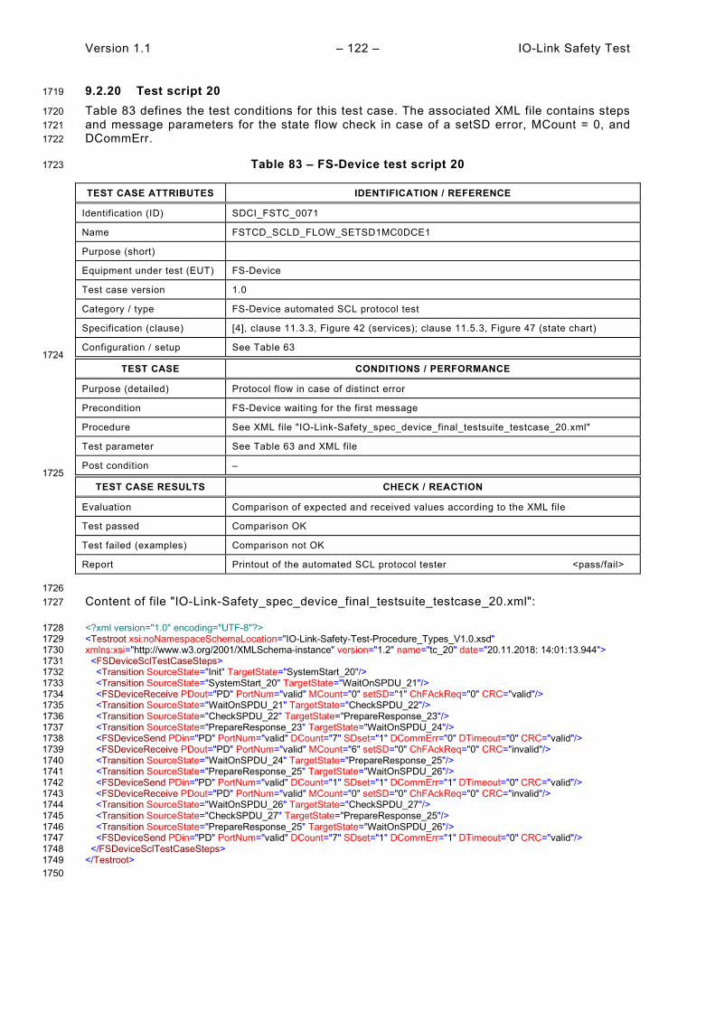
Version 1.1 – 122 – IO-Link Safety Test
9.2.20 Test script 20 1719
Table 83 defines the test conditions for this test case. The associated XML file contains steps 1720 and message parameters for the state flow check in case of a setSD error, MCount = 0, and 1721 DCommErr. 1722
Table 83 – FS-Device test script 20 1723
TEST CASE ATTRIBUTES IDENTIFICATION / REFERENCE
Identification (ID) SDCI_FSTC_0071
Name FSTCD_SCLD_FLOW_SETSD1MC0DCE1
Purpose (short)
Equipment under test (EUT) FS-Device
Test case version 1.0
Category / type FS-Device automated SCL protocol test
Specification (clause) [4], clause 11.3.3, Figure 42 (services); clause 11.5.3, Figure 47 (state chart)
Configuration / setup See Table 63 1724
TEST CASE CONDITIONS / PERFORMANCE
Purpose (detailed) Protocol flow in case of distinct error
Precondition FS-Device waiting for the first message
Procedure See XML file "IO-Link-Safety_spec_device_final_testsuite_testcase_20.xml"
Test parameter See Table 63 and XML file
Post condition – 1725
TEST CASE RESULTS CHECK / REACTION
Evaluation Comparison of expected and received values according to the XML file
Test passed Comparison OK
Test failed (examples) Comparison not OK
Report Printout of the automated SCL protocol tester <pass/fail>
1726 Content of file "IO-Link-Safety_spec_device_final_testsuite_testcase_20.xml": 1727
<?xml version="1.0" encoding="UTF-8"?> 1728 <Testroot xsi:noNamespaceSchemaLocation="IO-Link-Safety-Test-Procedure_Types_V1.0.xsd" 1729 xmlns:xsi="http://www.w3.org/2001/XMLSchema-instance" version="1.2" name="tc_20" date="20.11.2018: 14:01:13.944"> 1730 <FSDeviceSclTestCaseSteps> 1731 <Transition SourceState="Init" TargetState="SystemStart_20"/> 1732 <Transition SourceState="SystemStart_20" TargetState="WaitOnSPDU_21"/> 1733 <FSDeviceReceive PDout="PD" PortNum="valid" MCount="0" setSD="1" ChFAckReq="0" CRC="valid"/> 1734 <Transition SourceState="WaitOnSPDU_21" TargetState="CheckSPDU_22"/> 1735 <Transition SourceState="CheckSPDU_22" TargetState="PrepareResponse_23"/> 1736 <Transition SourceState="PrepareResponse_23" TargetState="WaitOnSPDU_24"/> 1737 <FSDeviceSend PDin="PD" PortNum="valid" DCount="7" SDset="1" DCommErr="0" DTimeout="0" CRC="valid"/> 1738 <FSDeviceReceive PDout="PD" PortNum="valid" MCount="6" setSD="0" ChFAckReq="0" CRC="invalid"/> 1739 <Transition SourceState="WaitOnSPDU_24" TargetState="PrepareResponse_25"/> 1740 <Transition SourceState="PrepareResponse_25" TargetState="WaitOnSPDU_26"/> 1741 <FSDeviceSend PDin="PD" PortNum="valid" DCount="1" SDset="1" DCommErr="1" DTimeout="0" CRC="valid"/> 1742 <FSDeviceReceive PDout="PD" PortNum="valid" MCount="0" setSD="0" ChFAckReq="0" CRC="invalid"/> 1743 <Transition SourceState="WaitOnSPDU_26" TargetState="CheckSPDU_27"/> 1744 <Transition SourceState="CheckSPDU_27" TargetState="PrepareResponse_25"/> 1745 <Transition SourceState="PrepareResponse_25" TargetState="WaitOnSPDU_26"/> 1746 <FSDeviceSend PDin="PD" PortNum="valid" DCount="7" SDset="1" DCommErr="1" DTimeout="0" CRC="valid"/> 1747 </FSDeviceSclTestCaseSteps> 1748 </Testroot> 1749 1750

IO-Link Safety Test – 123 – Version 1.1
9.2.21 Test script 21 1751
Table 84 defines the test conditions for this test case. The associated XML file contains steps 1752 and message parameters for the state flow check in case of a setSD error, MCount = 0, and 1753 DCommErr. 1754
Table 84 – FS-Device test script 21 1755
TEST CASE ATTRIBUTES IDENTIFICATION / REFERENCE
Identification (ID) SDCI_FSTC_0072
Name FSTCD_SCLD_FLOW_SETSD1MC0DCE1
Purpose (short)
Equipment under test (EUT) FS-Device
Test case version 1.0
Category / type FS-Device automated SCL protocol test
Specification (clause) [4], clause 11.3.3, Figure 42 (services); clause 11.5.3, Figure 47 (state chart)
Configuration / setup See Table 63 1756
TEST CASE CONDITIONS / PERFORMANCE
Purpose (detailed) Protocol flow in case of distinct error
Precondition FS-Device waiting for the first message
Procedure See XML file "IO-Link-Safety_spec_device_final_testsuite_testcase_21.xml"
Test parameter See Table 63 and XML file
Post condition – 1757
TEST CASE RESULTS CHECK / REACTION
Evaluation Comparison of expected and received values according to the XML file
Test passed Comparison OK
Test failed (examples) Comparison not OK
Report Printout of the automated SCL protocol tester <pass/fail>
1758 Content of file "IO-Link-Safety_spec_device_final_testsuite_testcase_21.xml": 1759
<?xml version="1.0" encoding="UTF-8"?> 1760 <Testroot xsi:noNamespaceSchemaLocation="IO-Link-Safety-Test-Procedure_Types_V1.0.xsd" 1761 xmlns:xsi="http://www.w3.org/2001/XMLSchema-instance" version="1.2" name="tc_21" date="20.11.2018: 14:01:13.944"> 1762 <FSDeviceSclTestCaseSteps> 1763 <Transition SourceState="Init" TargetState="SystemStart_20"/> 1764 <Transition SourceState="SystemStart_20" TargetState="WaitOnSPDU_21"/> 1765 <FSDeviceReceive PDout="PD" PortNum="valid" MCount="0" setSD="1" ChFAckReq="0" CRC="valid"/> 1766 <Transition SourceState="WaitOnSPDU_21" TargetState="CheckSPDU_22"/> 1767 <Transition SourceState="CheckSPDU_22" TargetState="PrepareResponse_23"/> 1768 <Transition SourceState="PrepareResponse_23" TargetState="WaitOnSPDU_24"/> 1769 <FSDeviceSend PDin="PD" PortNum="valid" DCount="7" SDset="1" DCommErr="0" DTimeout="0" CRC="valid"/> 1770 <FSDeviceReceive PDout="PD" PortNum="valid" MCount="6" setSD="0" ChFAckReq="0" CRC="invalid"/> 1771 <Transition SourceState="WaitOnSPDU_24" TargetState="PrepareResponse_25"/> 1772 <Transition SourceState="PrepareResponse_25" TargetState="WaitOnSPDU_26"/> 1773 <FSDeviceSend PDin="PD" PortNum="valid" DCount="1" SDset="1" DCommErr="1" DTimeout="0" CRC="valid"/> 1774 <FSDeviceReceive PDout="PD" PortNum="valid" MCount="7" setSD="0" ChFAckReq="0" CRC="invalid"/> 1775 <Transition SourceState="WaitOnSPDU_26" TargetState="CheckSPDU_27"/> 1776 <Transition SourceState="CheckSPDU_27" TargetState="PrepareResponse_25"/> 1777 <Transition SourceState="PrepareResponse_25" TargetState="WaitOnSPDU_26"/> 1778 <FSDeviceSend PDin="PD" PortNum="valid" DCount="0" SDset="1" DCommErr="1" DTimeout="0" CRC="valid"/> 1779 </FSDeviceSclTestCaseSteps> 1780 </Testroot> 1781 1782
1783
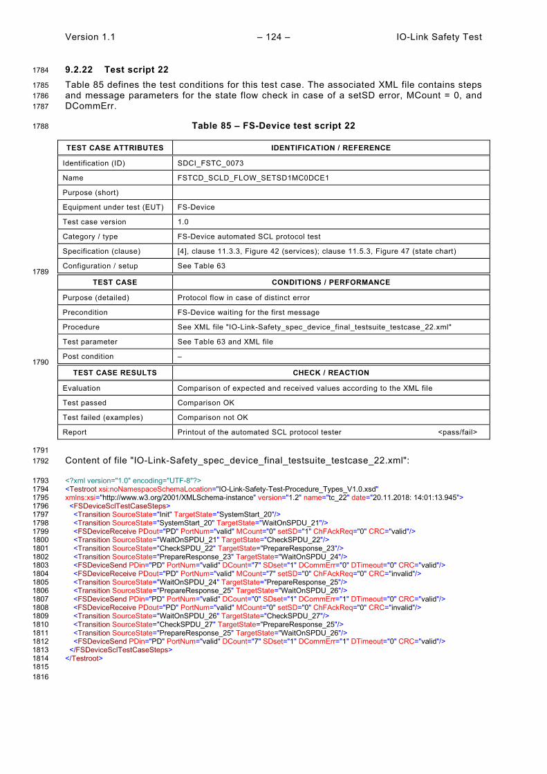
Version 1.1 – 124 – IO-Link Safety Test
9.2.22 Test script 22 1784
Table 85 defines the test conditions for this test case. The associated XML file contains steps 1785 and message parameters for the state flow check in case of a setSD error, MCount = 0, and 1786 DCommErr. 1787
Table 85 – FS-Device test script 22 1788
TEST CASE ATTRIBUTES IDENTIFICATION / REFERENCE
Identification (ID) SDCI_FSTC_0073
Name FSTCD_SCLD_FLOW_SETSD1MC0DCE1
Purpose (short)
Equipment under test (EUT) FS-Device
Test case version 1.0
Category / type FS-Device automated SCL protocol test
Specification (clause) [4], clause 11.3.3, Figure 42 (services); clause 11.5.3, Figure 47 (state chart)
Configuration / setup See Table 63 1789
TEST CASE CONDITIONS / PERFORMANCE
Purpose (detailed) Protocol flow in case of distinct error
Precondition FS-Device waiting for the first message
Procedure See XML file "IO-Link-Safety_spec_device_final_testsuite_testcase_22.xml"
Test parameter See Table 63 and XML file
Post condition – 1790
TEST CASE RESULTS CHECK / REACTION
Evaluation Comparison of expected and received values according to the XML file
Test passed Comparison OK
Test failed (examples) Comparison not OK
Report Printout of the automated SCL protocol tester <pass/fail>
1791 Content of file "IO-Link-Safety_spec_device_final_testsuite_testcase_22.xml": 1792
<?xml version="1.0" encoding="UTF-8"?> 1793 <Testroot xsi:noNamespaceSchemaLocation="IO-Link-Safety-Test-Procedure_Types_V1.0.xsd" 1794 xmlns:xsi="http://www.w3.org/2001/XMLSchema-instance" version="1.2" name="tc_22" date="20.11.2018: 14:01:13.945"> 1795 <FSDeviceSclTestCaseSteps> 1796 <Transition SourceState="Init" TargetState="SystemStart_20"/> 1797 <Transition SourceState="SystemStart_20" TargetState="WaitOnSPDU_21"/> 1798 <FSDeviceReceive PDout="PD" PortNum="valid" MCount="0" setSD="1" ChFAckReq="0" CRC="valid"/> 1799 <Transition SourceState="WaitOnSPDU_21" TargetState="CheckSPDU_22"/> 1800 <Transition SourceState="CheckSPDU_22" TargetState="PrepareResponse_23"/> 1801 <Transition SourceState="PrepareResponse_23" TargetState="WaitOnSPDU_24"/> 1802 <FSDeviceSend PDin="PD" PortNum="valid" DCount="7" SDset="1" DCommErr="0" DTimeout="0" CRC="valid"/> 1803 <FSDeviceReceive PDout="PD" PortNum="valid" MCount="7" setSD="0" ChFAckReq="0" CRC="invalid"/> 1804 <Transition SourceState="WaitOnSPDU_24" TargetState="PrepareResponse_25"/> 1805 <Transition SourceState="PrepareResponse_25" TargetState="WaitOnSPDU_26"/> 1806 <FSDeviceSend PDin="PD" PortNum="valid" DCount="0" SDset="1" DCommErr="1" DTimeout="0" CRC="valid"/> 1807 <FSDeviceReceive PDout="PD" PortNum="valid" MCount="0" setSD="0" ChFAckReq="0" CRC="invalid"/> 1808 <Transition SourceState="WaitOnSPDU_26" TargetState="CheckSPDU_27"/> 1809 <Transition SourceState="CheckSPDU_27" TargetState="PrepareResponse_25"/> 1810 <Transition SourceState="PrepareResponse_25" TargetState="WaitOnSPDU_26"/> 1811 <FSDeviceSend PDin="PD" PortNum="valid" DCount="7" SDset="1" DCommErr="1" DTimeout="0" CRC="valid"/> 1812 </FSDeviceSclTestCaseSteps> 1813 </Testroot> 1814 1815 1816
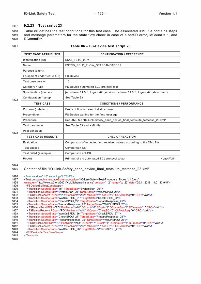
IO-Link Safety Test – 125 – Version 1.1
9.2.23 Test script 23 1817
Table 86 defines the test conditions for this test case. The associated XML file contains steps 1818 and message parameters for the state flow check in case of a setSD error, MCount = 1, and 1819 DCommErr. 1820
Table 86 – FS-Device test script 23 1821
TEST CASE ATTRIBUTES IDENTIFICATION / REFERENCE
Identification (ID) SDCI_FSTC_0074
Name FSTCD_SCLD_FLOW_SETSD1MC1DCE1
Purpose (short)
Equipment under test (EUT) FS-Device
Test case version 1.0
Category / type FS-Device automated SCL protocol test
Specification (clause) [4], clause 11.3.3, Figure 42 (services); clause 11.5.3, Figure 47 (state chart)
Configuration / setup See Table 63 1822
TEST CASE CONDITIONS / PERFORMANCE
Purpose (detailed) Protocol flow in case of distinct error
Precondition FS-Device waiting for the first message
Procedure See XML file "IO-Link-Safety_spec_device_final_testsuite_testcase_23.xml"
Test parameter See Table 63 and XML file
Post condition – 1823
TEST CASE RESULTS CHECK / REACTION
Evaluation Comparison of expected and received values according to the XML file
Test passed Comparison OK
Test failed (examples) Comparison not OK
Report Printout of the automated SCL protocol tester <pass/fail>
1824 Content of file "IO-Link-Safety_spec_device_final_testsuite_testcase_23.xml": 1825
<?xml version="1.0" encoding="UTF-8"?> 1826 <Testroot xsi:noNamespaceSchemaLocation="IO-Link-Safety-Test-Procedure_Types_V1.0.xsd" 1827 xmlns:xsi="http://www.w3.org/2001/XMLSchema-instance" version="1.2" name="tc_23" date="20.11.2018: 14:01:13.945"> 1828 <FSDeviceSclTestCaseSteps> 1829 <Transition SourceState="Init" TargetState="SystemStart_20"/> 1830 <Transition SourceState="SystemStart_20" TargetState="WaitOnSPDU_21"/> 1831 <FSDeviceReceive PDout="PD" PortNum="valid" MCount="1" setSD="0" ChFAckReq="0" CRC="valid"/> 1832 <Transition SourceState="WaitOnSPDU_21" TargetState="CheckSPDU_22"/> 1833 <Transition SourceState="CheckSPDU_22" TargetState="PrepareResponse_25"/> 1834 <Transition SourceState="PrepareResponse_25" TargetState="WaitOnSPDU_26"/> 1835 <FSDeviceSend PDin="PD" PortNum="valid" DCount="6" SDset="1" DCommErr="1" DTimeout="1" CRC="valid"/> 1836 <FSDeviceReceive PDout="PD" PortNum="valid" MCount="0" setSD="0" ChFAckReq="0" CRC="valid"/> 1837 <Transition SourceState="WaitOnSPDU_26" TargetState="CheckSPDU_27"/> 1838 <Transition SourceState="CheckSPDU_27" TargetState="PrepareResponse_25"/> 1839 <Transition SourceState="PrepareResponse_25" TargetState="WaitOnSPDU_26"/> 1840 <FSDeviceSend PDin="PD" PortNum="valid" DCount="7" SDset="1" DCommErr="1" DTimeout="0" CRC="valid"/> 1841 <FSDeviceReceive PDout="PD" PortNum="valid" MCount="0" setSD="0" ChFAckReq="0" CRC="valid"/> 1842 <Transition SourceState="WaitOnSPDU_26" TargetState="WaitOnSPDU_26"/> 1843 </FSDeviceSclTestCaseSteps> 1844 </Testroot> 1845 1846
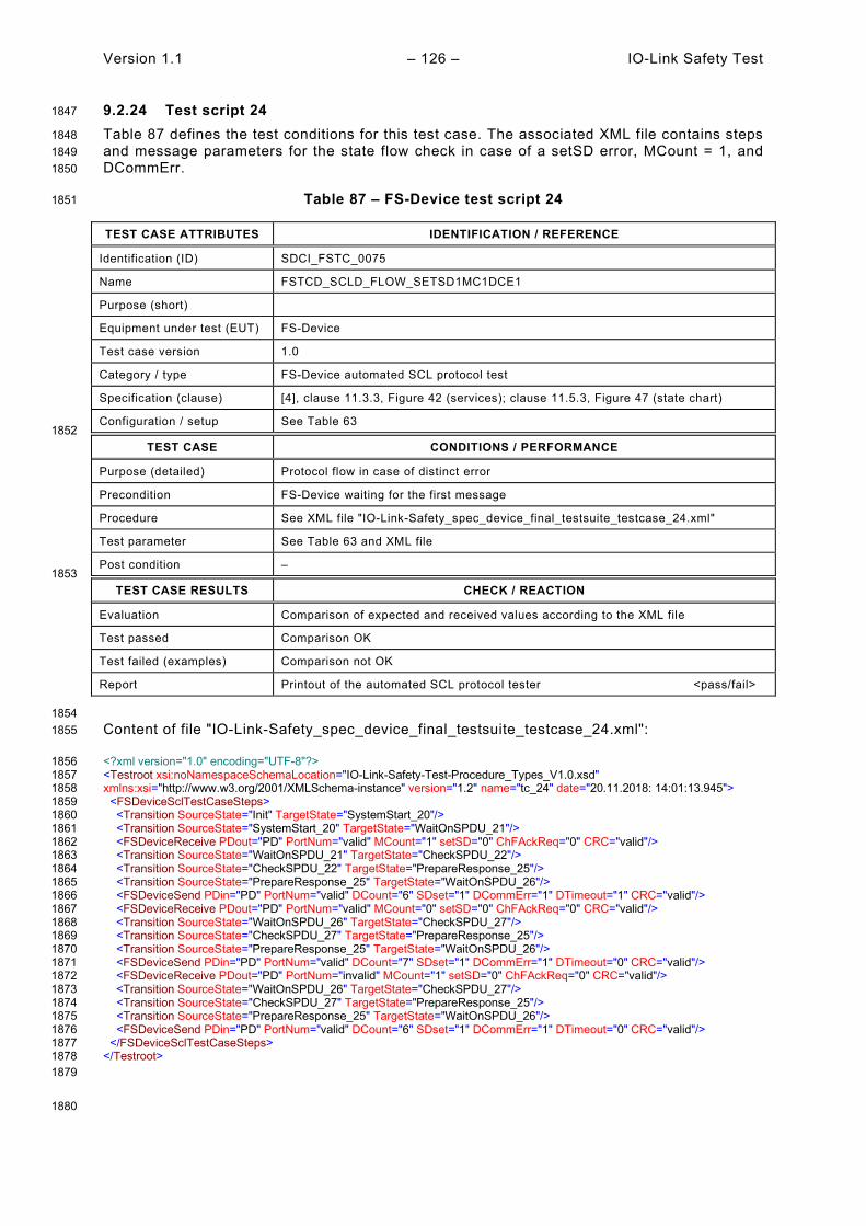
Version 1.1 – 126 – IO-Link Safety Test
9.2.24 Test script 24 1847
Table 87 defines the test conditions for this test case. The associated XML file contains steps 1848 and message parameters for the state flow check in case of a setSD error, MCount = 1, and 1849 DCommErr. 1850
Table 87 – FS-Device test script 24 1851
TEST CASE ATTRIBUTES IDENTIFICATION / REFERENCE
Identification (ID) SDCI_FSTC_0075
Name FSTCD_SCLD_FLOW_SETSD1MC1DCE1
Purpose (short)
Equipment under test (EUT) FS-Device
Test case version 1.0
Category / type FS-Device automated SCL protocol test
Specification (clause) [4], clause 11.3.3, Figure 42 (services); clause 11.5.3, Figure 47 (state chart)
Configuration / setup See Table 63 1852
TEST CASE CONDITIONS / PERFORMANCE
Purpose (detailed) Protocol flow in case of distinct error
Precondition FS-Device waiting for the first message
Procedure See XML file "IO-Link-Safety_spec_device_final_testsuite_testcase_24.xml"
Test parameter See Table 63 and XML file
Post condition – 1853
TEST CASE RESULTS CHECK / REACTION
Evaluation Comparison of expected and received values according to the XML file
Test passed Comparison OK
Test failed (examples) Comparison not OK
Report Printout of the automated SCL protocol tester <pass/fail>
1854 Content of file "IO-Link-Safety_spec_device_final_testsuite_testcase_24.xml": 1855
<?xml version="1.0" encoding="UTF-8"?> 1856 <Testroot xsi:noNamespaceSchemaLocation="IO-Link-Safety-Test-Procedure_Types_V1.0.xsd" 1857 xmlns:xsi="http://www.w3.org/2001/XMLSchema-instance" version="1.2" name="tc_24" date="20.11.2018: 14:01:13.945"> 1858 <FSDeviceSclTestCaseSteps> 1859 <Transition SourceState="Init" TargetState="SystemStart_20"/> 1860 <Transition SourceState="SystemStart_20" TargetState="WaitOnSPDU_21"/> 1861 <FSDeviceReceive PDout="PD" PortNum="valid" MCount="1" setSD="0" ChFAckReq="0" CRC="valid"/> 1862 <Transition SourceState="WaitOnSPDU_21" TargetState="CheckSPDU_22"/> 1863 <Transition SourceState="CheckSPDU_22" TargetState="PrepareResponse_25"/> 1864 <Transition SourceState="PrepareResponse_25" TargetState="WaitOnSPDU_26"/> 1865 <FSDeviceSend PDin="PD" PortNum="valid" DCount="6" SDset="1" DCommErr="1" DTimeout="1" CRC="valid"/> 1866 <FSDeviceReceive PDout="PD" PortNum="valid" MCount="0" setSD="0" ChFAckReq="0" CRC="valid"/> 1867 <Transition SourceState="WaitOnSPDU_26" TargetState="CheckSPDU_27"/> 1868 <Transition SourceState="CheckSPDU_27" TargetState="PrepareResponse_25"/> 1869 <Transition SourceState="PrepareResponse_25" TargetState="WaitOnSPDU_26"/> 1870 <FSDeviceSend PDin="PD" PortNum="valid" DCount="7" SDset="1" DCommErr="1" DTimeout="0" CRC="valid"/> 1871 <FSDeviceReceive PDout="PD" PortNum="invalid" MCount="1" setSD="0" ChFAckReq="0" CRC="valid"/> 1872 <Transition SourceState="WaitOnSPDU_26" TargetState="CheckSPDU_27"/> 1873 <Transition SourceState="CheckSPDU_27" TargetState="PrepareResponse_25"/> 1874 <Transition SourceState="PrepareResponse_25" TargetState="WaitOnSPDU_26"/> 1875 <FSDeviceSend PDin="PD" PortNum="valid" DCount="6" SDset="1" DCommErr="1" DTimeout="0" CRC="valid"/> 1876 </FSDeviceSclTestCaseSteps> 1877 </Testroot> 1878 1879
1880

IO-Link Safety Test – 127 – Version 1.1
9.2.25 Test script 25 1881
Table 88 defines the test conditions for this test case. The associated XML file contains steps 1882 and message parameters for the state flow check in case of no error, MCount = 1, and Timeout. 1883
Table 88 – FS-Device test script 25 1884
TEST CASE ATTRIBUTES IDENTIFICATION / REFERENCE
Identification (ID) SDCI_FSTC_0076
Name FSTCD_SCLD_FLOW_SETSD0MC1TO
Purpose (short)
Equipment under test (EUT) FS-Device
Test case version 1.0
Category / type FS-Device automated SCL protocol test
Specification (clause) [4], clause 11.3.3, Figure 42 (services); clause 11.5.3, Figure 47 (state chart)
Configuration / setup See Table 63 1885
TEST CASE CONDITIONS / PERFORMANCE
Purpose (detailed) Protocol flow in case of distinct error
Precondition FS-Device waiting for the first message
Procedure See XML file "IO-Link-Safety_spec_device_final_testsuite_testcase_25.xml"
Test parameter See Table 63 and XML file
Post condition – 1886
TEST CASE RESULTS CHECK / REACTION
Evaluation Comparison of expected and received values according to the XML file
Test passed Comparison OK
Test failed (examples) Comparison not OK
Report Printout of the automated SCL protocol tester <pass/fail>
1887 Content of file "IO-Link-Safety_spec_device_final_testsuite_testcase_25.xml": 1888
<?xml version="1.0" encoding="UTF-8"?> 1889 <Testroot xsi:noNamespaceSchemaLocation="IO-Link-Safety-Test-Procedure_Types_V1.0.xsd" 1890 xmlns:xsi="http://www.w3.org/2001/XMLSchema-instance" version="1.2" name="tc_25" date="20.11.2018: 14:01:13.945"> 1891 <FSDeviceSclTestCaseSteps> 1892 <Transition SourceState="Init" TargetState="SystemStart_20"/> 1893 <Transition SourceState="SystemStart_20" TargetState="WaitOnSPDU_21"/> 1894 <FSDeviceReceive PDout="PD" PortNum="valid" MCount="1" setSD="0" ChFAckReq="0" CRC="valid"/> 1895 <Transition SourceState="WaitOnSPDU_21" TargetState="CheckSPDU_22"/> 1896 <Transition SourceState="CheckSPDU_22" TargetState="PrepareResponse_25"/> 1897 <Transition SourceState="PrepareResponse_25" TargetState="WaitOnSPDU_26"/> 1898 <FSDeviceSend PDin="PD" PortNum="valid" DCount="6" SDset="1" DCommErr="1" DTimeout="1" CRC="valid"/> 1899 <FSDeviceReceive PDout="PD" PortNum="valid" MCount="2" setSD="0" ChFAckReq="0" CRC="valid"/> 1900 <Transition SourceState="WaitOnSPDU_26" TargetState="CheckSPDU_27"/> 1901 <Transition SourceState="CheckSPDU_27" TargetState="PrepareResponse_25"/> 1902 <Transition SourceState="PrepareResponse_25" TargetState="WaitOnSPDU_26"/> 1903 <FSDeviceSend PDin="PD" PortNum="valid" DCount="5" SDset="1" DCommErr="1" DTimeout="0" CRC="valid"/> 1904 <FSDeviceReceive PDout="PD" PortNum="valid" MCount="2" setSD="0" ChFAckReq="0" CRC="valid"/> 1905 <Transition SourceState="WaitOnSPDU_26" TargetState="WaitOnSPDU_26"/> 1906 </FSDeviceSclTestCaseSteps> 1907 </Testroot> 1908 1909
1910

Version 1.1 – 128 – IO-Link Safety Test
9.2.26 Test script 26 1911
Table 89 defines the test conditions for this test case. The associated XML file contains steps 1912 and message parameters for the state flow check in case of no error, MCount = 1, and Timeout. 1913
Table 89 – FS-Device test script 26 1914
TEST CASE ATTRIBUTES IDENTIFICATION / REFERENCE
Identification (ID) SDCI_FSTC_0077
Name FSTCD_SCLD_FLOW_SETSD0MC1TO
Purpose (short)
Equipment under test (EUT) FS-Device
Test case version 1.0
Category / type FS-Device automated SCL protocol test
Specification (clause) [4], clause 11.3.3, Figure 42 (services); clause 11.5.3, Figure 47 (state chart)
Configuration / setup See Table 63 1915
TEST CASE CONDITIONS / PERFORMANCE
Purpose (detailed) Protocol flow in case of distinct error
Precondition FS-Device waiting for the first message
Procedure See XML file "IO-Link-Safety_spec_device_final_testsuite_testcase_26.xml"
Test parameter See Table 63 and XML file
Post condition – 1916
TEST CASE RESULTS CHECK / REACTION
Evaluation Comparison of expected and received values according to the XML file
Test passed Comparison OK
Test failed (examples) Comparison not OK
Report Printout of the automated SCL protocol tester <pass/fail>
1917 Content of file "IO-Link-Safety_spec_device_final_testsuite_testcase_26.xml": 1918
<?xml version="1.0" encoding="UTF-8"?> 1919 <Testroot xsi:noNamespaceSchemaLocation="IO-Link-Safety-Test-Procedure_Types_V1.0.xsd" 1920 xmlns:xsi="http://www.w3.org/2001/XMLSchema-instance" version="1.2" name="tc_26" date="20.11.2018: 14:01:13.945"> 1921 <FSDeviceSclTestCaseSteps> 1922 <Transition SourceState="Init" TargetState="SystemStart_20"/> 1923 <Transition SourceState="SystemStart_20" TargetState="WaitOnSPDU_21"/> 1924 <FSDeviceReceive PDout="PD" PortNum="valid" MCount="1" setSD="0" ChFAckReq="0" CRC="valid"/> 1925 <Transition SourceState="WaitOnSPDU_21" TargetState="CheckSPDU_22"/> 1926 <Transition SourceState="CheckSPDU_22" TargetState="PrepareResponse_25"/> 1927 <Transition SourceState="PrepareResponse_25" TargetState="WaitOnSPDU_26"/> 1928 <FSDeviceSend PDin="PD" PortNum="valid" DCount="6" SDset="1" DCommErr="1" DTimeout="1" CRC="valid"/> 1929 <FSDeviceReceive PDout="PD" PortNum="valid" MCount="2" setSD="0" ChFAckReq="0" CRC="valid"/> 1930 <Transition SourceState="WaitOnSPDU_26" TargetState="CheckSPDU_27"/> 1931 <Transition SourceState="CheckSPDU_27" TargetState="PrepareResponse_25"/> 1932 <Transition SourceState="PrepareResponse_25" TargetState="WaitOnSPDU_26"/> 1933 <FSDeviceSend PDin="PD" PortNum="valid" DCount="5" SDset="1" DCommErr="1" DTimeout="0" CRC="valid"/> 1934 <FSDeviceReceive PDout="PD" PortNum="invalid" MCount="0" setSD="0" ChFAckReq="0" CRC="valid"/> 1935 <Transition SourceState="WaitOnSPDU_26" TargetState="CheckSPDU_27"/> 1936 <Transition SourceState="CheckSPDU_27" TargetState="PrepareResponse_25"/> 1937 <Transition SourceState="PrepareResponse_25" TargetState="WaitOnSPDU_26"/> 1938 <FSDeviceSend PDin="PD" PortNum="valid" DCount="7" SDset="1" DCommErr="1" DTimeout="0" CRC="valid"/> 1939 </FSDeviceSclTestCaseSteps> 1940 </Testroot> 1941 1942
1943

IO-Link Safety Test – 129 – Version 1.1
9.2.27 Test script 27 1944
Table 90 defines the test conditions for this test case. The associated XML file contains steps 1945 and message parameters for the state flow check in case of no error, MCount = 1, and Timeout. 1946
Table 90 – FS-Device test script 27 1947
TEST CASE ATTRIBUTES IDENTIFICATION / REFERENCE
Identification (ID) SDCI_FSTC_0078
Name FSTCD_SCLD_FLOW_SETSD0MC1TO
Purpose (short)
Equipment under test (EUT) FS-Device
Test case version 1.0
Category / type FS-Device automated SCL protocol test
Specification (clause) [4], clause 11.3.3, Figure 42 (services); clause 11.5.3, Figure 47 (state chart)
Configuration / setup See Table 63 1948
TEST CASE CONDITIONS / PERFORMANCE
Purpose (detailed) Protocol flow in case of distinct error
Precondition FS-Device waiting for the first message
Procedure See XML file "IO-Link-Safety_spec_device_final_testsuite_testcase_27.xml"
Test parameter See Table 63 and XML file
Post condition – 1949
TEST CASE RESULTS CHECK / REACTION
Evaluation Comparison of expected and received values according to the XML file
Test passed Comparison OK
Test failed (examples) Comparison not OK
Report Printout of the automated SCL protocol tester <pass/fail>
1950 Content of file "IO-Link-Safety_spec_device_final_testsuite_testcase_27.xml": 1951
<?xml version="1.0" encoding="UTF-8"?> 1952 <Testroot xsi:noNamespaceSchemaLocation="IO-Link-Safety-Test-Procedure_Types_V1.0.xsd" 1953 xmlns:xsi="http://www.w3.org/2001/XMLSchema-instance" version="1.2" name="tc_27" date="20.11.2018: 14:01:13.945"> 1954 <FSDeviceSclTestCaseSteps> 1955 <Transition SourceState="Init" TargetState="SystemStart_20"/> 1956 <Transition SourceState="SystemStart_20" TargetState="WaitOnSPDU_21"/> 1957 <FSDeviceReceive PDout="PD" PortNum="valid" MCount="1" setSD="0" ChFAckReq="0" CRC="valid"/> 1958 <Transition SourceState="WaitOnSPDU_21" TargetState="CheckSPDU_22"/> 1959 <Transition SourceState="CheckSPDU_22" TargetState="PrepareResponse_25"/> 1960 <Transition SourceState="PrepareResponse_25" TargetState="WaitOnSPDU_26"/> 1961 <FSDeviceSend PDin="PD" PortNum="valid" DCount="6" SDset="1" DCommErr="1" DTimeout="1" CRC="valid"/> 1962 <FSDeviceReceive PDout="PD" PortNum="valid" MCount="2" setSD="0" ChFAckReq="0" CRC="valid"/> 1963 <Transition SourceState="WaitOnSPDU_26" TargetState="CheckSPDU_27"/> 1964 <Transition SourceState="CheckSPDU_27" TargetState="PrepareResponse_25"/> 1965 <Transition SourceState="PrepareResponse_25" TargetState="WaitOnSPDU_26"/> 1966 <FSDeviceSend PDin="PD" PortNum="valid" DCount="5" SDset="1" DCommErr="1" DTimeout="0" CRC="valid"/> 1967 <FSDeviceReceive PDout="PD" PortNum="invalid" MCount="3" setSD="0" ChFAckReq="0" CRC="valid"/> 1968 <Transition SourceState="WaitOnSPDU_26" TargetState="CheckSPDU_27"/> 1969 <Transition SourceState="CheckSPDU_27" TargetState="PrepareResponse_25"/> 1970 <Transition SourceState="PrepareResponse_25" TargetState="WaitOnSPDU_26"/> 1971 <FSDeviceSend PDin="PD" PortNum="valid" DCount="4" SDset="1" DCommErr="1" DTimeout="0" CRC="valid"/> 1972 </FSDeviceSclTestCaseSteps> 1973 </Testroot> 1974 1975
1976

Version 1.1 – 130 – IO-Link Safety Test
9.2.28 Test script 28 1977
Table 91 defines the test conditions for this test case. The associated XML file contains steps 1978 and message parameters for the state flow check in case of no error, MCount = 2, and Timeout. 1979
Table 91 – FS-Device test script 28 1980
TEST CASE ATTRIBUTES IDENTIFICATION / REFERENCE
Identification (ID) SDCI_FSTC_0079
Name FSTCD_SCLD_FLOW_SETSD0MC2TO
Purpose (short)
Equipment under test (EUT) FS-Device
Test case version 1.0
Category / type FS-Device automated SCL protocol test
Specification (clause) [4], clause 11.3.3, Figure 42 (services); clause 11.5.3, Figure 47 (state chart)
Configuration / setup See Table 63 1981
TEST CASE CONDITIONS / PERFORMANCE
Purpose (detailed) Protocol flow in case of distinct error
Precondition FS-Device waiting for the first message
Procedure See XML file "IO-Link-Safety_spec_device_final_testsuite_testcase_28.xml"
Test parameter See Table 63 and XML file
Post condition – 1982
TEST CASE RESULTS CHECK / REACTION
Evaluation Comparison of expected and received values according to the XML file
Test passed Comparison OK
Test failed (examples) Comparison not OK
Report Printout of the automated SCL protocol tester <pass/fail>
1983 Content of file "IO-Link-Safety_spec_device_final_testsuite_testcase_28.xml": 1984
<?xml version="1.0" encoding="UTF-8"?> 1985 <Testroot xsi:noNamespaceSchemaLocation="IO-Link-Safety-Test-Procedure_Types_V1.0.xsd" 1986 xmlns:xsi="http://www.w3.org/2001/XMLSchema-instance" version="1.2" name="tc_28" date="20.11.2018: 14:01:13.945"> 1987 <FSDeviceSclTestCaseSteps> 1988 <Transition SourceState="Init" TargetState="SystemStart_20"/> 1989 <Transition SourceState="SystemStart_20" TargetState="WaitOnSPDU_21"/> 1990 <FSDeviceReceive PDout="PD" PortNum="valid" MCount="2" setSD="0" ChFAckReq="0" CRC="valid"/> 1991 <Transition SourceState="WaitOnSPDU_21" TargetState="CheckSPDU_22"/> 1992 <Transition SourceState="CheckSPDU_22" TargetState="PrepareResponse_25"/> 1993 <Transition SourceState="PrepareResponse_25" TargetState="WaitOnSPDU_26"/> 1994 <FSDeviceSend PDin="PD" PortNum="valid" DCount="5" SDset="1" DCommErr="1" DTimeout="1" CRC="valid"/> 1995 <FSDeviceReceive PDout="PD" PortNum="valid" MCount="3" setSD="0" ChFAckReq="0" CRC="valid"/> 1996 <Transition SourceState="WaitOnSPDU_26" TargetState="CheckSPDU_27"/> 1997 <Transition SourceState="CheckSPDU_27" TargetState="PrepareResponse_25"/> 1998 <Transition SourceState="PrepareResponse_25" TargetState="WaitOnSPDU_26"/> 1999 <FSDeviceSend PDin="PD" PortNum="valid" DCount="4" SDset="1" DCommErr="1" DTimeout="0" CRC="valid"/> 2000 <FSDeviceReceive PDout="PD" PortNum="valid" MCount="3" setSD="0" ChFAckReq="0" CRC="valid"/> 2001 <Transition SourceState="WaitOnSPDU_26" TargetState="WaitOnSPDU_26"/> 2002 </FSDeviceSclTestCaseSteps> 2003 </Testroot> 2004 2005
2006

IO-Link Safety Test – 131 – Version 1.1
9.2.29 Test script 29 2007
Table 92 defines the test conditions for this test case. The associated XML file contains steps 2008 and message parameters for the state flow check in case of no error, MCount = 2, and Timeout. 2009
Table 92 – FS-Device test script 29 2010
TEST CASE ATTRIBUTES IDENTIFICATION / REFERENCE
Identification (ID) SDCI_FSTC_0080
Name FSTCD_SCLD_FLOW_SETSD0MC2TO
Purpose (short)
Equipment under test (EUT) FS-Device
Test case version 1.0
Category / type FS-Device automated SCL protocol test
Specification (clause) [4], clause 11.3.3, Figure 42 (services); clause 11.5.3, Figure 47 (state chart)
Configuration / setup See Table 63 2011
TEST CASE CONDITIONS / PERFORMANCE
Purpose (detailed) Protocol flow in case of distinct error
Precondition FS-Device waiting for the first message
Procedure See XML file "IO-Link-Safety_spec_device_final_testsuite_testcase_29.xml"
Test parameter See Table 63 and XML file
Post condition – 2012
TEST CASE RESULTS CHECK / REACTION
Evaluation Comparison of expected and received values according to the XML file
Test passed Comparison OK
Test failed (examples) Comparison not OK
Report Printout of the automated SCL protocol tester <pass/fail>
2013 Content of file "IO-Link-Safety_spec_device_final_testsuite_testcase_29.xml": 2014
<?xml version="1.0" encoding="UTF-8"?> 2015 <Testroot xsi:noNamespaceSchemaLocation="IO-Link-Safety-Test-Procedure_Types_V1.0.xsd" 2016 xmlns:xsi="http://www.w3.org/2001/XMLSchema-instance" version="1.2" name="tc_29" date="20.11.2018: 14:01:13.945"> 2017 <FSDeviceSclTestCaseSteps> 2018 <Transition SourceState="Init" TargetState="SystemStart_20"/> 2019 <Transition SourceState="SystemStart_20" TargetState="WaitOnSPDU_21"/> 2020 <FSDeviceReceive PDout="PD" PortNum="valid" MCount="2" setSD="0" ChFAckReq="0" CRC="valid"/> 2021 <Transition SourceState="WaitOnSPDU_21" TargetState="CheckSPDU_22"/> 2022 <Transition SourceState="CheckSPDU_22" TargetState="PrepareResponse_25"/> 2023 <Transition SourceState="PrepareResponse_25" TargetState="WaitOnSPDU_26"/> 2024 <FSDeviceSend PDin="PD" PortNum="valid" DCount="5" SDset="1" DCommErr="1" DTimeout="1" CRC="valid"/> 2025 <FSDeviceReceive PDout="PD" PortNum="valid" MCount="3" setSD="0" ChFAckReq="0" CRC="valid"/> 2026 <Transition SourceState="WaitOnSPDU_26" TargetState="CheckSPDU_27"/> 2027 <Transition SourceState="CheckSPDU_27" TargetState="PrepareResponse_25"/> 2028 <Transition SourceState="PrepareResponse_25" TargetState="WaitOnSPDU_26"/> 2029 <FSDeviceSend PDin="PD" PortNum="valid" DCount="4" SDset="1" DCommErr="1" DTimeout="0" CRC="valid"/> 2030 <FSDeviceReceive PDout="PD" PortNum="invalid" MCount="1" setSD="0" ChFAckReq="0" CRC="valid"/> 2031 <Transition SourceState="WaitOnSPDU_26" TargetState="CheckSPDU_27"/> 2032 <Transition SourceState="CheckSPDU_27" TargetState="PrepareResponse_25"/> 2033 <Transition SourceState="PrepareResponse_25" TargetState="WaitOnSPDU_26"/> 2034 <FSDeviceSend PDin="PD" PortNum="valid" DCount="6" SDset="1" DCommErr="1" DTimeout="0" CRC="valid"/> 2035 </FSDeviceSclTestCaseSteps> 2036 </Testroot> 2037 2038
2039

Version 1.1 – 132 – IO-Link Safety Test
9.2.30 Test script 30 2040
Table 92 defines the test conditions for this test case. The associated XML file contains steps 2041 and message parameters for the state flow check in case of no error, MCount = 2, and Timeout. 2042
Table 93 – FS-Device test script 30 2043
TEST CASE ATTRIBUTES IDENTIFICATION / REFERENCE
Identification (ID) SDCI_FSTC_0081
Name FSTCD_SCLD_FLOW_SETSD0MC2TO
Purpose (short)
Equipment under test (EUT) FS-Device
Test case version 1.0
Category / type FS-Device automated SCL protocol test
Specification (clause) [4], clause 11.3.3, Figure 42 (services); clause 11.5.3, Figure 47 (state chart)
Configuration / setup See Table 63 2044
TEST CASE CONDITIONS / PERFORMANCE
Purpose (detailed) Protocol flow in case of distinct error
Precondition FS-Device waiting for the first message
Procedure See XML file "IO-Link-Safety_spec_device_final_testsuite_testcase_30.xml"
Test parameter See Table 63 and XML file
Post condition – 2045
TEST CASE RESULTS CHECK / REACTION
Evaluation Comparison of expected and received values according to the XML file
Test passed Comparison OK
Test failed (examples) Comparison not OK
Report Printout of the automated SCL protocol tester <pass/fail>
2046 Content of file "IO-Link-Safety_spec_device_final_testsuite_testcase_30.xml": 2047
<?xml version="1.0" encoding="UTF-8"?> 2048 <Testroot xsi:noNamespaceSchemaLocation="IO-Link-Safety-Test-Procedure_Types_V1.0.xsd" 2049 xmlns:xsi="http://www.w3.org/2001/XMLSchema-instance" version="1.2" name="tc_30" date="20.11.2018: 14:01:13.945"> 2050 <FSDeviceSclTestCaseSteps> 2051 <Transition SourceState="Init" TargetState="SystemStart_20"/> 2052 <Transition SourceState="SystemStart_20" TargetState="WaitOnSPDU_21"/> 2053 <FSDeviceReceive PDout="PD" PortNum="valid" MCount="2" setSD="0" ChFAckReq="0" CRC="valid"/> 2054 <Transition SourceState="WaitOnSPDU_21" TargetState="CheckSPDU_22"/> 2055 <Transition SourceState="CheckSPDU_22" TargetState="PrepareResponse_25"/> 2056 <Transition SourceState="PrepareResponse_25" TargetState="WaitOnSPDU_26"/> 2057 <FSDeviceSend PDin="PD" PortNum="valid" DCount="5" SDset="1" DCommErr="1" DTimeout="1" CRC="valid"/> 2058 <FSDeviceReceive PDout="PD" PortNum="valid" MCount="3" setSD="0" ChFAckReq="0" CRC="valid"/> 2059 <Transition SourceState="WaitOnSPDU_26" TargetState="CheckSPDU_27"/> 2060 <Transition SourceState="CheckSPDU_27" TargetState="PrepareResponse_25"/> 2061 <Transition SourceState="PrepareResponse_25" TargetState="WaitOnSPDU_26"/> 2062 <FSDeviceSend PDin="PD" PortNum="valid" DCount="4" SDset="1" DCommErr="1" DTimeout="0" CRC="valid"/> 2063 <FSDeviceReceive PDout="PD" PortNum="invalid" MCount="4" setSD="0" ChFAckReq="0" CRC="valid"/> 2064 <Transition SourceState="WaitOnSPDU_26" TargetState="CheckSPDU_27"/> 2065 <Transition SourceState="CheckSPDU_27" TargetState="PrepareResponse_25"/> 2066 <Transition SourceState="PrepareResponse_25" TargetState="WaitOnSPDU_26"/> 2067 <FSDeviceSend PDin="PD" PortNum="valid" DCount="3" SDset="1" DCommErr="1" DTimeout="0" CRC="valid"/> 2068 </FSDeviceSclTestCaseSteps> 2069 </Testroot> 2070 2071
2072
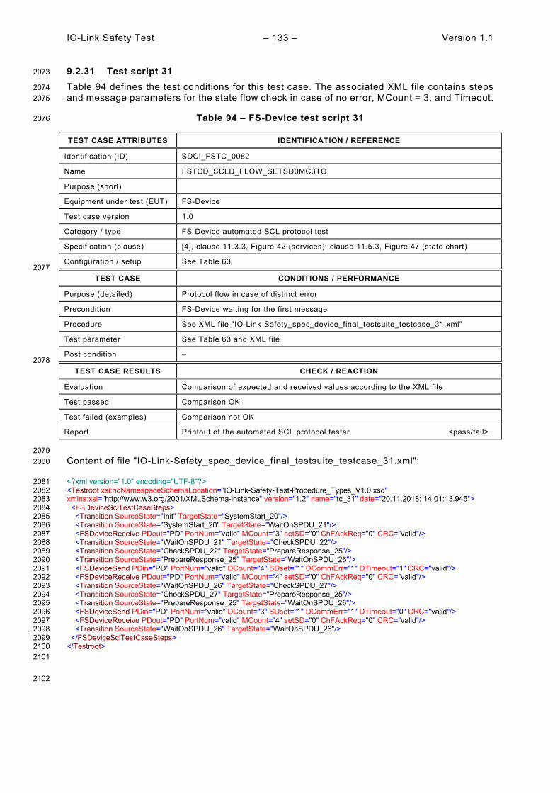
IO-Link Safety Test – 133 – Version 1.1
9.2.31 Test script 31 2073
Table 94 defines the test conditions for this test case. The associated XML file contains steps 2074 and message parameters for the state flow check in case of no error, MCount = 3, and Timeout. 2075
Table 94 – FS-Device test script 31 2076
TEST CASE ATTRIBUTES IDENTIFICATION / REFERENCE
Identification (ID) SDCI_FSTC_0082
Name FSTCD_SCLD_FLOW_SETSD0MC3TO
Purpose (short)
Equipment under test (EUT) FS-Device
Test case version 1.0
Category / type FS-Device automated SCL protocol test
Specification (clause) [4], clause 11.3.3, Figure 42 (services); clause 11.5.3, Figure 47 (state chart)
Configuration / setup See Table 63 2077
TEST CASE CONDITIONS / PERFORMANCE
Purpose (detailed) Protocol flow in case of distinct error
Precondition FS-Device waiting for the first message
Procedure See XML file "IO-Link-Safety_spec_device_final_testsuite_testcase_31.xml"
Test parameter See Table 63 and XML file
Post condition – 2078
TEST CASE RESULTS CHECK / REACTION
Evaluation Comparison of expected and received values according to the XML file
Test passed Comparison OK
Test failed (examples) Comparison not OK
Report Printout of the automated SCL protocol tester <pass/fail>
2079 Content of file "IO-Link-Safety_spec_device_final_testsuite_testcase_31.xml": 2080
<?xml version="1.0" encoding="UTF-8"?> 2081 <Testroot xsi:noNamespaceSchemaLocation="IO-Link-Safety-Test-Procedure_Types_V1.0.xsd" 2082 xmlns:xsi="http://www.w3.org/2001/XMLSchema-instance" version="1.2" name="tc_31" date="20.11.2018: 14:01:13.945"> 2083 <FSDeviceSclTestCaseSteps> 2084 <Transition SourceState="Init" TargetState="SystemStart_20"/> 2085 <Transition SourceState="SystemStart_20" TargetState="WaitOnSPDU_21"/> 2086 <FSDeviceReceive PDout="PD" PortNum="valid" MCount="3" setSD="0" ChFAckReq="0" CRC="valid"/> 2087 <Transition SourceState="WaitOnSPDU_21" TargetState="CheckSPDU_22"/> 2088 <Transition SourceState="CheckSPDU_22" TargetState="PrepareResponse_25"/> 2089 <Transition SourceState="PrepareResponse_25" TargetState="WaitOnSPDU_26"/> 2090 <FSDeviceSend PDin="PD" PortNum="valid" DCount="4" SDset="1" DCommErr="1" DTimeout="1" CRC="valid"/> 2091 <FSDeviceReceive PDout="PD" PortNum="valid" MCount="4" setSD="0" ChFAckReq="0" CRC="valid"/> 2092 <Transition SourceState="WaitOnSPDU_26" TargetState="CheckSPDU_27"/> 2093 <Transition SourceState="CheckSPDU_27" TargetState="PrepareResponse_25"/> 2094 <Transition SourceState="PrepareResponse_25" TargetState="WaitOnSPDU_26"/> 2095 <FSDeviceSend PDin="PD" PortNum="valid" DCount="3" SDset="1" DCommErr="1" DTimeout="0" CRC="valid"/> 2096 <FSDeviceReceive PDout="PD" PortNum="valid" MCount="4" setSD="0" ChFAckReq="0" CRC="valid"/> 2097 <Transition SourceState="WaitOnSPDU_26" TargetState="WaitOnSPDU_26"/> 2098 </FSDeviceSclTestCaseSteps> 2099 </Testroot> 2100 2101
2102

Version 1.1 – 134 – IO-Link Safety Test
9.2.32 Test script 32 2103
Table 95 defines the test conditions for this test case. The associated XML file contains steps 2104 and message parameters for the state flow check in case of no error, MCount = 3, and Timeout. 2105
Table 95 – FS-Device test script 32 2106
TEST CASE ATTRIBUTES IDENTIFICATION / REFERENCE
Identification (ID) SDCI_FSTC_0083
Name FSTCD_SCLD_FLOW_SETSD0MC3TO
Purpose (short)
Equipment under test (EUT) FS-Device
Test case version 1.0
Category / type FS-Device automated SCL protocol test
Specification (clause) [4], clause 11.3.3, Figure 42 (services); clause 11.5.3, Figure 47 (state chart)
Configuration / setup See Table 63 2107
TEST CASE CONDITIONS / PERFORMANCE
Purpose (detailed) Protocol flow in case of distinct error
Precondition FS-Device waiting for the first message
Procedure See XML file "IO-Link-Safety_spec_device_final_testsuite_testcase_32.xml"
Test parameter See Table 63 and XML file
Post condition – 2108
TEST CASE RESULTS CHECK / REACTION
Evaluation Comparison of expected and received values according to the XML file
Test passed Comparison OK
Test failed (examples) Comparison not OK
Report Printout of the automated SCL protocol tester <pass/fail>
2109 Content of file "IO-Link-Safety_spec_device_final_testsuite_testcase_32.xml": 2110
<?xml version="1.0" encoding="UTF-8"?> 2111 <Testroot xsi:noNamespaceSchemaLocation="IO-Link-Safety-Test-Procedure_Types_V1.0.xsd" 2112 xmlns:xsi="http://www.w3.org/2001/XMLSchema-instance" version="1.2" name="tc_32" date="20.11.2018: 14:01:13.945"> 2113 <FSDeviceSclTestCaseSteps> 2114 <Transition SourceState="Init" TargetState="SystemStart_20"/> 2115 <Transition SourceState="SystemStart_20" TargetState="WaitOnSPDU_21"/> 2116 <FSDeviceReceive PDout="PD" PortNum="valid" MCount="3" setSD="0" ChFAckReq="0" CRC="valid"/> 2117 <Transition SourceState="WaitOnSPDU_21" TargetState="CheckSPDU_22"/> 2118 <Transition SourceState="CheckSPDU_22" TargetState="PrepareResponse_25"/> 2119 <Transition SourceState="PrepareResponse_25" TargetState="WaitOnSPDU_26"/> 2120 <FSDeviceSend PDin="PD" PortNum="valid" DCount="4" SDset="1" DCommErr="1" DTimeout="1" CRC="valid"/> 2121 <FSDeviceReceive PDout="PD" PortNum="valid" MCount="4" setSD="0" ChFAckReq="0" CRC="valid"/> 2122 <Transition SourceState="WaitOnSPDU_26" TargetState="CheckSPDU_27"/> 2123 <Transition SourceState="CheckSPDU_27" TargetState="PrepareResponse_25"/> 2124 <Transition SourceState="PrepareResponse_25" TargetState="WaitOnSPDU_26"/> 2125 <FSDeviceSend PDin="PD" PortNum="valid" DCount="3" SDset="1" DCommErr="1" DTimeout="0" CRC="valid"/> 2126 <FSDeviceReceive PDout="PD" PortNum="invalid" MCount="1" setSD="0" ChFAckReq="0" CRC="valid"/> 2127 <Transition SourceState="WaitOnSPDU_26" TargetState="CheckSPDU_27"/> 2128 <Transition SourceState="CheckSPDU_27" TargetState="PrepareResponse_25"/> 2129 <Transition SourceState="PrepareResponse_25" TargetState="WaitOnSPDU_26"/> 2130 <FSDeviceSend PDin="PD" PortNum="valid" DCount="6" SDset="1" DCommErr="1" DTimeout="0" CRC="valid"/> 2131 </FSDeviceSclTestCaseSteps> 2132 </Testroot> 2133 2134
2135

IO-Link Safety Test – 135 – Version 1.1
9.2.33 Test script 33 2136
Table 96 defines the test conditions for this test case. The associated XML file contains steps 2137 and message parameters for the state flow check in case of no error, MCount = 3, and Timeout. 2138
Table 96 – FS-Device test script 33 2139
TEST CASE ATTRIBUTES IDENTIFICATION / REFERENCE
Identification (ID) SDCI_FSTC_0084
Name FSTCD_SCLD_FLOW_SETSD0MC3TO
Purpose (short)
Equipment under test (EUT) FS-Device
Test case version 1.0
Category / type FS-Device automated SCL protocol test
Specification (clause) [4], clause 11.3.3, Figure 42 (services); clause 11.5.3, Figure 47 (state chart)
Configuration / setup See Table 63 2140
TEST CASE CONDITIONS / PERFORMANCE
Purpose (detailed) Protocol flow in case of distinct error
Precondition FS-Device waiting for the first message
Procedure See XML file "IO-Link-Safety_spec_device_final_testsuite_testcase_33.xml"
Test parameter See Table 63 and XML file
Post condition – 2141
TEST CASE RESULTS CHECK / REACTION
Evaluation Comparison of expected and received values according to the XML file
Test passed Comparison OK
Test failed (examples) Comparison not OK
Report Printout of the automated SCL protocol tester <pass/fail>
2142 Content of file "IO-Link-Safety_spec_device_final_testsuite_testcase_33.xml": 2143
<?xml version="1.0" encoding="UTF-8"?> 2144 <Testroot xsi:noNamespaceSchemaLocation="IO-Link-Safety-Test-Procedure_Types_V1.0.xsd" 2145 xmlns:xsi="http://www.w3.org/2001/XMLSchema-instance" version="1.2" name="tc_33" date="20.11.2018: 14:01:13.945"> 2146 <FSDeviceSclTestCaseSteps> 2147 <Transition SourceState="Init" TargetState="SystemStart_20"/> 2148 <Transition SourceState="SystemStart_20" TargetState="WaitOnSPDU_21"/> 2149 <FSDeviceReceive PDout="PD" PortNum="valid" MCount="3" setSD="0" ChFAckReq="0" CRC="valid"/> 2150 <Transition SourceState="WaitOnSPDU_21" TargetState="CheckSPDU_22"/> 2151 <Transition SourceState="CheckSPDU_22" TargetState="PrepareResponse_25"/> 2152 <Transition SourceState="PrepareResponse_25" TargetState="WaitOnSPDU_26"/> 2153 <FSDeviceSend PDin="PD" PortNum="valid" DCount="4" SDset="1" DCommErr="1" DTimeout="1" CRC="valid"/> 2154 <FSDeviceReceive PDout="PD" PortNum="valid" MCount="4" setSD="0" ChFAckReq="0" CRC="valid"/> 2155 <Transition SourceState="WaitOnSPDU_26" TargetState="CheckSPDU_27"/> 2156 <Transition SourceState="CheckSPDU_27" TargetState="PrepareResponse_25"/> 2157 <Transition SourceState="PrepareResponse_25" TargetState="WaitOnSPDU_26"/> 2158 <FSDeviceSend PDin="PD" PortNum="valid" DCount="3" SDset="1" DCommErr="1" DTimeout="0" CRC="valid"/> 2159 <FSDeviceReceive PDout="PD" PortNum="invalid" MCount="5" setSD="0" ChFAckReq="0" CRC="valid"/> 2160 <Transition SourceState="WaitOnSPDU_26" TargetState="CheckSPDU_27"/> 2161 <Transition SourceState="CheckSPDU_27" TargetState="PrepareResponse_25"/> 2162 <Transition SourceState="PrepareResponse_25" TargetState="WaitOnSPDU_26"/> 2163 <FSDeviceSend PDin="PD" PortNum="valid" DCount="2" SDset="1" DCommErr="1" DTimeout="0" CRC="valid"/> 2164 </FSDeviceSclTestCaseSteps> 2165 </Testroot> 2166 2167

Version 1.1 – 136 – IO-Link Safety Test
9.2.34 Test script 34 2168
Table 97 defines the test conditions for this test case. The associated XML file contains steps 2169 and message parameters for the state flow check in case of no error, MCount = 4, and Timeout. 2170
Table 97 – FS-Device test script 34 2171
TEST CASE ATTRIBUTES IDENTIFICATION / REFERENCE
Identification (ID) SDCI_FSTC_0085
Name FSTCD_SCLD_FLOW_SETSD0MC4TO
Purpose (short)
Equipment under test (EUT) FS-Device
Test case version 1.0
Category / type FS-Device automated SCL protocol test
Specification (clause) [4], clause 11.3.3, Figure 42 (services); clause 11.5.3, Figure 47 (state chart)
Configuration / setup See Table 63 2172
TEST CASE CONDITIONS / PERFORMANCE
Purpose (detailed) Protocol flow in case of distinct error
Precondition FS-Device waiting for the first message
Procedure See XML file "IO-Link-Safety_spec_device_final_testsuite_testcase_34.xml"
Test parameter See Table 63 and XML file
Post condition – 2173
TEST CASE RESULTS CHECK / REACTION
Evaluation Comparison of expected and received values according to the XML file
Test passed Comparison OK
Test failed (examples) Comparison not OK
Report Printout of the automated SCL protocol tester <pass/fail>
2174 Content of file "IO-Link-Safety_spec_device_final_testsuite_testcase_34.xml": 2175
<?xml version="1.0" encoding="UTF-8"?> 2176 <Testroot xsi:noNamespaceSchemaLocation="IO-Link-Safety-Test-Procedure_Types_V1.0.xsd" 2177 xmlns:xsi="http://www.w3.org/2001/XMLSchema-instance" version="1.2" name="tc_34" date="20.11.2018: 14:01:13.945"> 2178 <FSDeviceSclTestCaseSteps> 2179 <Transition SourceState="Init" TargetState="SystemStart_20"/> 2180 <Transition SourceState="SystemStart_20" TargetState="WaitOnSPDU_21"/> 2181 <FSDeviceReceive PDout="PD" PortNum="valid" MCount="4" setSD="0" ChFAckReq="0" CRC="valid"/> 2182 <Transition SourceState="WaitOnSPDU_21" TargetState="CheckSPDU_22"/> 2183 <Transition SourceState="CheckSPDU_22" TargetState="PrepareResponse_25"/> 2184 <Transition SourceState="PrepareResponse_25" TargetState="WaitOnSPDU_26"/> 2185 <FSDeviceSend PDin="PD" PortNum="valid" DCount="3" SDset="1" DCommErr="1" DTimeout="1" CRC="valid"/> 2186 <FSDeviceReceive PDout="PD" PortNum="valid" MCount="5" setSD="0" ChFAckReq="0" CRC="valid"/> 2187 <Transition SourceState="WaitOnSPDU_26" TargetState="CheckSPDU_27"/> 2188 <Transition SourceState="CheckSPDU_27" TargetState="PrepareResponse_25"/> 2189 <Transition SourceState="PrepareResponse_25" TargetState="WaitOnSPDU_26"/> 2190 <FSDeviceSend PDin="PD" PortNum="valid" DCount="2" SDset="1" DCommErr="1" DTimeout="0" CRC="valid"/> 2191 <FSDeviceReceive PDout="PD" PortNum="valid" MCount="5" setSD="0" ChFAckReq="0" CRC="valid"/> 2192 <Transition SourceState="WaitOnSPDU_26" TargetState="WaitOnSPDU_26"/> 2193 </FSDeviceSclTestCaseSteps> 2194 </Testroot> 2195 2196

IO-Link Safety Test – 137 – Version 1.1
9.2.35 Test script 35 2197
Table 98 defines the test conditions for this test case. The associated XML file contains steps 2198 and message parameters for the state flow check in case of no error, MCount = 4, and Timeout. 2199
Table 98 – FS-Device test script 35 2200
TEST CASE ATTRIBUTES IDENTIFICATION / REFERENCE
Identification (ID) SDCI_FSTC_0086
Name FSTCD_SCLD_FLOW_SETSD0MC4TO
Purpose (short)
Equipment under test (EUT) FS-Device
Test case version 1.0
Category / type FS-Device automated SCL protocol test
Specification (clause) [4], clause 11.3.3, Figure 42 (services); clause 11.5.3, Figure 47 (state chart)
Configuration / setup See Table 63 2201
TEST CASE CONDITIONS / PERFORMANCE
Purpose (detailed) Protocol flow in case of distinct error
Precondition FS-Device waiting for the first message
Procedure See XML file "IO-Link-Safety_spec_device_final_testsuite_testcase_35.xml"
Test parameter See Table 63 and XML file
Post condition – 2202
TEST CASE RESULTS CHECK / REACTION
Evaluation Comparison of expected and received values according to the XML file
Test passed Comparison OK
Test failed (examples) Comparison not OK
Report Printout of the automated SCL protocol tester <pass/fail>
2203 Content of file "IO-Link-Safety_spec_device_final_testsuite_testcase_35.xml": 2204
<?xml version="1.0" encoding="UTF-8"?> 2205 <Testroot xsi:noNamespaceSchemaLocation="IO-Link-Safety-Test-Procedure_Types_V1.0.xsd" 2206 xmlns:xsi="http://www.w3.org/2001/XMLSchema-instance" version="1.2" name="tc_35" date="20.11.2018: 14:01:13.946"> 2207 <FSDeviceSclTestCaseSteps> 2208 <Transition SourceState="Init" TargetState="SystemStart_20"/> 2209 <Transition SourceState="SystemStart_20" TargetState="WaitOnSPDU_21"/> 2210 <FSDeviceReceive PDout="PD" PortNum="valid" MCount="4" setSD="0" ChFAckReq="0" CRC="valid"/> 2211 <Transition SourceState="WaitOnSPDU_21" TargetState="CheckSPDU_22"/> 2212 <Transition SourceState="CheckSPDU_22" TargetState="PrepareResponse_25"/> 2213 <Transition SourceState="PrepareResponse_25" TargetState="WaitOnSPDU_26"/> 2214 <FSDeviceSend PDin="PD" PortNum="valid" DCount="3" SDset="1" DCommErr="1" DTimeout="1" CRC="valid"/> 2215 <FSDeviceReceive PDout="PD" PortNum="valid" MCount="5" setSD="0" ChFAckReq="0" CRC="valid"/> 2216 <Transition SourceState="WaitOnSPDU_26" TargetState="CheckSPDU_27"/> 2217 <Transition SourceState="CheckSPDU_27" TargetState="PrepareResponse_25"/> 2218 <Transition SourceState="PrepareResponse_25" TargetState="WaitOnSPDU_26"/> 2219 <FSDeviceSend PDin="PD" PortNum="valid" DCount="2" SDset="1" DCommErr="1" DTimeout="0" CRC="valid"/> 2220 <FSDeviceReceive PDout="PD" PortNum="invalid" MCount="1" setSD="0" ChFAckReq="0" CRC="valid"/> 2221 <Transition SourceState="WaitOnSPDU_26" TargetState="CheckSPDU_27"/> 2222 <Transition SourceState="CheckSPDU_27" TargetState="PrepareResponse_25"/> 2223 <Transition SourceState="PrepareResponse_25" TargetState="WaitOnSPDU_26"/> 2224 <FSDeviceSend PDin="PD" PortNum="valid" DCount="6" SDset="1" DCommErr="1" DTimeout="0" CRC="valid"/> 2225 </FSDeviceSclTestCaseSteps> 2226 </Testroot> 2227 2228

Version 1.1 – 138 – IO-Link Safety Test
9.2.36 Test script 36 2229
Table 99 defines the test conditions for this test case. The associated XML file contains steps 2230 and message parameters for the state flow check in case of no error, MCount = 4, and Timeout. 2231
Table 99 – FS-Device test script 36 2232
TEST CASE ATTRIBUTES IDENTIFICATION / REFERENCE
Identification (ID) SDCI_FSTC_0087
Name FSTCD_SCLD_FLOW_SETSD0MC4TO
Purpose (short)
Equipment under test (EUT) FS-Device
Test case version 1.0
Category / type FS-Device automated SCL protocol test
Specification (clause) [4], clause 11.3.3, Figure 42 (services); clause 11.5.3, Figure 47 (state chart)
Configuration / setup See Table 63 2233
TEST CASE CONDITIONS / PERFORMANCE
Purpose (detailed) Protocol flow in case of distinct error
Precondition FS-Device waiting for the first message
Procedure See XML file "IO-Link-Safety_spec_device_final_testsuite_testcase_36.xml"
Test parameter See Table 63 and XML file
Post condition – 2234
TEST CASE RESULTS CHECK / REACTION
Evaluation Comparison of expected and received values according to the XML file
Test passed Comparison OK
Test failed (examples) Comparison not OK
Report Printout of the automated SCL protocol tester <pass/fail>
2235 Content of file "IO-Link-Safety_spec_device_final_testsuite_testcase_36.xml": 2236
<?xml version="1.0" encoding="UTF-8"?> 2237 <Testroot xsi:noNamespaceSchemaLocation="IO-Link-Safety-Test-Procedure_Types_V1.0.xsd" 2238 xmlns:xsi="http://www.w3.org/2001/XMLSchema-instance" version="1.2" name="tc_36" date="20.11.2018: 14:01:13.946"> 2239 <FSDeviceSclTestCaseSteps> 2240 <Transition SourceState="Init" TargetState="SystemStart_20"/> 2241 <Transition SourceState="SystemStart_20" TargetState="WaitOnSPDU_21"/> 2242 <FSDeviceReceive PDout="PD" PortNum="valid" MCount="4" setSD="0" ChFAckReq="0" CRC="valid"/> 2243 <Transition SourceState="WaitOnSPDU_21" TargetState="CheckSPDU_22"/> 2244 <Transition SourceState="CheckSPDU_22" TargetState="PrepareResponse_25"/> 2245 <Transition SourceState="PrepareResponse_25" TargetState="WaitOnSPDU_26"/> 2246 <FSDeviceSend PDin="PD" PortNum="valid" DCount="3" SDset="1" DCommErr="1" DTimeout="1" CRC="valid"/> 2247 <FSDeviceReceive PDout="PD" PortNum="valid" MCount="5" setSD="0" ChFAckReq="0" CRC="valid"/> 2248 <Transition SourceState="WaitOnSPDU_26" TargetState="CheckSPDU_27"/> 2249 <Transition SourceState="CheckSPDU_27" TargetState="PrepareResponse_25"/> 2250 <Transition SourceState="PrepareResponse_25" TargetState="WaitOnSPDU_26"/> 2251 <FSDeviceSend PDin="PD" PortNum="valid" DCount="2" SDset="1" DCommErr="1" DTimeout="0" CRC="valid"/> 2252 <FSDeviceReceive PDout="PD" PortNum="invalid" MCount="6" setSD="0" ChFAckReq="0" CRC="valid"/> 2253 <Transition SourceState="WaitOnSPDU_26" TargetState="CheckSPDU_27"/> 2254 <Transition SourceState="CheckSPDU_27" TargetState="PrepareResponse_25"/> 2255 <Transition SourceState="PrepareResponse_25" TargetState="WaitOnSPDU_26"/> 2256 <FSDeviceSend PDin="PD" PortNum="valid" DCount="1" SDset="1" DCommErr="1" DTimeout="0" CRC="valid"/> 2257 </FSDeviceSclTestCaseSteps> 2258 </Testroot> 2259 2260

IO-Link Safety Test – 139 – Version 1.1
9.2.37 Test script 37 2261
Table 100 defines the test conditions for this test case. The associated XML file contains steps 2262 and message parameters for the state flow check in case of no error, MCount = 5, and Timeout. 2263
Table 100 – FS-Device test script 37 2264
TEST CASE ATTRIBUTES IDENTIFICATION / REFERENCE
Identification (ID) SDCI_FSTC_0088
Name FSTCD_SCLD_FLOW_SETSD0MC5TO
Purpose (short)
Equipment under test (EUT) FS-Device
Test case version 1.0
Category / type FS-Device automated SCL protocol test
Specification (clause) [4], clause 11.3.3, Figure 42 (services); clause 11.5.3, Figure 47 (state chart)
Configuration / setup See Table 63 2265
TEST CASE CONDITIONS / PERFORMANCE
Purpose (detailed) Protocol flow in case of distinct error
Precondition FS-Device waiting for the first message
Procedure See XML file "IO-Link-Safety_spec_device_final_testsuite_testcase_37.xml"
Test parameter See Table 63 and XML file
Post condition – 2266
TEST CASE RESULTS CHECK / REACTION
Evaluation Comparison of expected and received values according to the XML file
Test passed Comparison OK
Test failed (examples) Comparison not OK
Report Printout of the automated SCL protocol tester <pass/fail>
2267 Content of file "IO-Link-Safety_spec_device_final_testsuite_testcase_37.xml": 2268
<?xml version="1.0" encoding="UTF-8"?> 2269 <Testroot xsi:noNamespaceSchemaLocation="IO-Link-Safety-Test-Procedure_Types_V1.0.xsd" 2270 xmlns:xsi="http://www.w3.org/2001/XMLSchema-instance" version="1.2" name="tc_37" date="20.11.2018: 14:01:13.946"> 2271 <FSDeviceSclTestCaseSteps> 2272 <Transition SourceState="Init" TargetState="SystemStart_20"/> 2273 <Transition SourceState="SystemStart_20" TargetState="WaitOnSPDU_21"/> 2274 <FSDeviceReceive PDout="PD" PortNum="valid" MCount="5" setSD="0" ChFAckReq="0" CRC="valid"/> 2275 <Transition SourceState="WaitOnSPDU_21" TargetState="CheckSPDU_22"/> 2276 <Transition SourceState="CheckSPDU_22" TargetState="PrepareResponse_25"/> 2277 <Transition SourceState="PrepareResponse_25" TargetState="WaitOnSPDU_26"/> 2278 <FSDeviceSend PDin="PD" PortNum="valid" DCount="2" SDset="1" DCommErr="1" DTimeout="1" CRC="valid"/> 2279 <FSDeviceReceive PDout="PD" PortNum="valid" MCount="6" setSD="0" ChFAckReq="0" CRC="valid"/> 2280 <Transition SourceState="WaitOnSPDU_26" TargetState="CheckSPDU_27"/> 2281 <Transition SourceState="CheckSPDU_27" TargetState="PrepareResponse_25"/> 2282 <Transition SourceState="PrepareResponse_25" TargetState="WaitOnSPDU_26"/> 2283 <FSDeviceSend PDin="PD" PortNum="valid" DCount="1" SDset="1" DCommErr="1" DTimeout="0" CRC="valid"/> 2284 <FSDeviceReceive PDout="PD" PortNum="valid" MCount="6" setSD="0" ChFAckReq="0" CRC="valid"/> 2285 <Transition SourceState="WaitOnSPDU_26" TargetState="WaitOnSPDU_26"/> 2286 </FSDeviceSclTestCaseSteps> 2287 </Testroot> 2288 2289

Version 1.1 – 140 – IO-Link Safety Test
9.2.38 Test script 38 2290
Table 101 defines the test conditions for this test case. The associated XML file contains steps 2291 and message parameters for the state flow check in case of no error, MCount = 5, and Timeout. 2292
Table 101 – FS-Device test script 38 2293
TEST CASE ATTRIBUTES IDENTIFICATION / REFERENCE
Identification (ID) SDCI_FSTC_0089
Name FSTCD_SCLD_FLOW_SETSD0MC5TO
Purpose (short)
Equipment under test (EUT) FS-Device
Test case version 1.0
Category / type FS-Device automated SCL protocol test
Specification (clause) [4], clause 11.3.3, Figure 42 (services); clause 11.5.3, Figure 47 (state chart)
Configuration / setup See Table 63 2294
TEST CASE CONDITIONS / PERFORMANCE
Purpose (detailed) Protocol flow in case of distinct error
Precondition FS-Device waiting for the first message
Procedure See XML file "IO-Link-Safety_spec_device_final_testsuite_testcase_38.xml"
Test parameter See Table 63 and XML file
Post condition – 2295
TEST CASE RESULTS CHECK / REACTION
Evaluation Comparison of expected and received values according to the XML file
Test passed Comparison OK
Test failed (examples) Comparison not OK
Report Printout of the automated SCL protocol tester <pass/fail>
2296 Content of file "IO-Link-Safety_spec_device_final_testsuite_testcase_38.xml": 2297
<?xml version="1.0" encoding="UTF-8"?> 2298 <Testroot xsi:noNamespaceSchemaLocation="IO-Link-Safety-Test-Procedure_Types_V1.0.xsd" 2299 xmlns:xsi="http://www.w3.org/2001/XMLSchema-instance" version="1.2" name="tc_38" date="20.11.2018: 14:01:13.946"> 2300 <FSDeviceSclTestCaseSteps> 2301 <Transition SourceState="Init" TargetState="SystemStart_20"/> 2302 <Transition SourceState="SystemStart_20" TargetState="WaitOnSPDU_21"/> 2303 <FSDeviceReceive PDout="PD" PortNum="valid" MCount="5" setSD="0" ChFAckReq="0" CRC="valid"/> 2304 <Transition SourceState="WaitOnSPDU_21" TargetState="CheckSPDU_22"/> 2305 <Transition SourceState="CheckSPDU_22" TargetState="PrepareResponse_25"/> 2306 <Transition SourceState="PrepareResponse_25" TargetState="WaitOnSPDU_26"/> 2307 <FSDeviceSend PDin="PD" PortNum="valid" DCount="2" SDset="1" DCommErr="1" DTimeout="1" CRC="valid"/> 2308 <FSDeviceReceive PDout="PD" PortNum="valid" MCount="6" setSD="0" ChFAckReq="0" CRC="valid"/> 2309 <Transition SourceState="WaitOnSPDU_26" TargetState="CheckSPDU_27"/> 2310 <Transition SourceState="CheckSPDU_27" TargetState="PrepareResponse_25"/> 2311 <Transition SourceState="PrepareResponse_25" TargetState="WaitOnSPDU_26"/> 2312 <FSDeviceSend PDin="PD" PortNum="valid" DCount="1" SDset="1" DCommErr="1" DTimeout="0" CRC="valid"/> 2313 <FSDeviceReceive PDout="PD" PortNum="invalid" MCount="1" setSD="0" ChFAckReq="0" CRC="valid"/> 2314 <Transition SourceState="WaitOnSPDU_26" TargetState="CheckSPDU_27"/> 2315 <Transition SourceState="CheckSPDU_27" TargetState="PrepareResponse_25"/> 2316 <Transition SourceState="PrepareResponse_25" TargetState="WaitOnSPDU_26"/> 2317 <FSDeviceSend PDin="PD" PortNum="valid" DCount="6" SDset="1" DCommErr="1" DTimeout="0" CRC="valid"/> 2318 </FSDeviceSclTestCaseSteps> 2319 </Testroot> 2320 2321

IO-Link Safety Test – 141 – Version 1.1
9.2.39 Test script 39 2322
Table 102 defines the test conditions for this test case. The associated XML file contains steps 2323 and message parameters for the state flow check in case of no error, MCount = 5, and Timeout. 2324
Table 102 – FS-Device test script 39 2325
TEST CASE ATTRIBUTES IDENTIFICATION / REFERENCE
Identification (ID) SDCI_FSTC_0090
Name FSTCD_SCLD_FLOW_SETSD0MC5TO
Purpose (short)
Equipment under test (EUT) FS-Device
Test case version 1.0
Category / type FS-Device automated SCL protocol test
Specification (clause) [4], clause 11.3.3, Figure 42 (services); clause 11.5.3, Figure 47 (state chart)
Configuration / setup See Table 63 2326
TEST CASE CONDITIONS / PERFORMANCE
Purpose (detailed) Protocol flow in case of distinct error
Precondition FS-Device waiting for the first message
Procedure See XML file "IO-Link-Safety_spec_device_final_testsuite_testcase_39.xml"
Test parameter See Table 63 and XML file
Post condition – 2327
TEST CASE RESULTS CHECK / REACTION
Evaluation Comparison of expected and received values according to the XML file
Test passed Comparison OK
Test failed (examples) Comparison not OK
Report Printout of the automated SCL protocol tester <pass/fail>
2328 Content of file "IO-Link-Safety_spec_device_final_testsuite_testcase_39.xml": 2329
<?xml version="1.0" encoding="UTF-8"?> 2330 <Testroot xsi:noNamespaceSchemaLocation="IO-Link-Safety-Test-Procedure_Types_V1.0.xsd" 2331 xmlns:xsi="http://www.w3.org/2001/XMLSchema-instance" version="1.2" name="tc_39" date="20.11.2018: 14:01:13.946"> 2332 <FSDeviceSclTestCaseSteps> 2333 <Transition SourceState="Init" TargetState="SystemStart_20"/> 2334 <Transition SourceState="SystemStart_20" TargetState="WaitOnSPDU_21"/> 2335 <FSDeviceReceive PDout="PD" PortNum="valid" MCount="5" setSD="0" ChFAckReq="0" CRC="valid"/> 2336 <Transition SourceState="WaitOnSPDU_21" TargetState="CheckSPDU_22"/> 2337 <Transition SourceState="CheckSPDU_22" TargetState="PrepareResponse_25"/> 2338 <Transition SourceState="PrepareResponse_25" TargetState="WaitOnSPDU_26"/> 2339 <FSDeviceSend PDin="PD" PortNum="valid" DCount="2" SDset="1" DCommErr="1" DTimeout="1" CRC="valid"/> 2340 <FSDeviceReceive PDout="PD" PortNum="valid" MCount="6" setSD="0" ChFAckReq="0" CRC="valid"/> 2341 <Transition SourceState="WaitOnSPDU_26" TargetState="CheckSPDU_27"/> 2342 <Transition SourceState="CheckSPDU_27" TargetState="PrepareResponse_25"/> 2343 <Transition SourceState="PrepareResponse_25" TargetState="WaitOnSPDU_26"/> 2344 <FSDeviceSend PDin="PD" PortNum="valid" DCount="1" SDset="1" DCommErr="1" DTimeout="0" CRC="valid"/> 2345 <FSDeviceReceive PDout="PD" PortNum="invalid" MCount="7" setSD="0" ChFAckReq="0" CRC="valid"/> 2346 <Transition SourceState="WaitOnSPDU_26" TargetState="CheckSPDU_27"/> 2347 <Transition SourceState="CheckSPDU_27" TargetState="PrepareResponse_25"/> 2348 <Transition SourceState="PrepareResponse_25" TargetState="WaitOnSPDU_26"/> 2349 <FSDeviceSend PDin="PD" PortNum="valid" DCount="0" SDset="1" DCommErr="1" DTimeout="0" CRC="valid"/> 2350 </FSDeviceSclTestCaseSteps> 2351 </Testroot> 2352 2353
2354
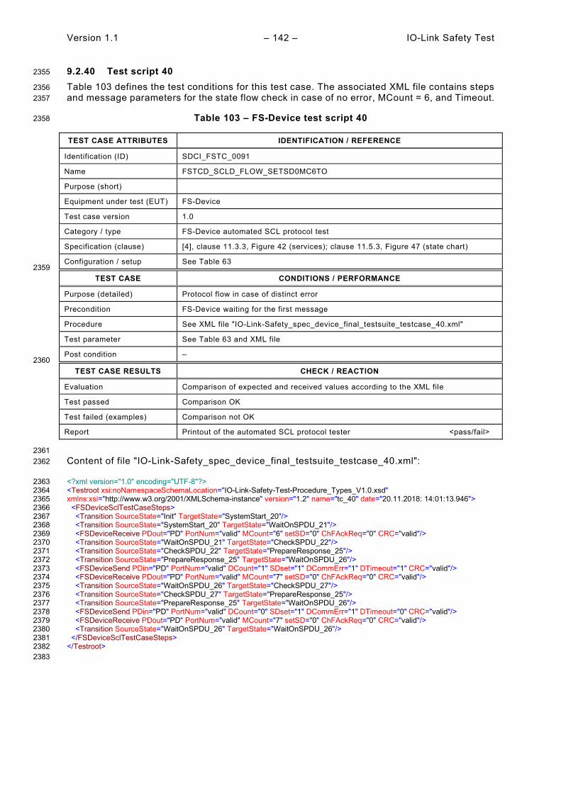
Version 1.1 – 142 – IO-Link Safety Test
9.2.40 Test script 40 2355
Table 103 defines the test conditions for this test case. The associated XML file contains steps 2356 and message parameters for the state flow check in case of no error, MCount = 6, and Timeout. 2357
Table 103 – FS-Device test script 40 2358
TEST CASE ATTRIBUTES IDENTIFICATION / REFERENCE
Identification (ID) SDCI_FSTC_0091
Name FSTCD_SCLD_FLOW_SETSD0MC6TO
Purpose (short)
Equipment under test (EUT) FS-Device
Test case version 1.0
Category / type FS-Device automated SCL protocol test
Specification (clause) [4], clause 11.3.3, Figure 42 (services); clause 11.5.3, Figure 47 (state chart)
Configuration / setup See Table 63 2359
TEST CASE CONDITIONS / PERFORMANCE
Purpose (detailed) Protocol flow in case of distinct error
Precondition FS-Device waiting for the first message
Procedure See XML file "IO-Link-Safety_spec_device_final_testsuite_testcase_40.xml"
Test parameter See Table 63 and XML file
Post condition – 2360
TEST CASE RESULTS CHECK / REACTION
Evaluation Comparison of expected and received values according to the XML file
Test passed Comparison OK
Test failed (examples) Comparison not OK
Report Printout of the automated SCL protocol tester <pass/fail>
2361 Content of file "IO-Link-Safety_spec_device_final_testsuite_testcase_40.xml": 2362
<?xml version="1.0" encoding="UTF-8"?> 2363 <Testroot xsi:noNamespaceSchemaLocation="IO-Link-Safety-Test-Procedure_Types_V1.0.xsd" 2364 xmlns:xsi="http://www.w3.org/2001/XMLSchema-instance" version="1.2" name="tc_40" date="20.11.2018: 14:01:13.946"> 2365 <FSDeviceSclTestCaseSteps> 2366 <Transition SourceState="Init" TargetState="SystemStart_20"/> 2367 <Transition SourceState="SystemStart_20" TargetState="WaitOnSPDU_21"/> 2368 <FSDeviceReceive PDout="PD" PortNum="valid" MCount="6" setSD="0" ChFAckReq="0" CRC="valid"/> 2369 <Transition SourceState="WaitOnSPDU_21" TargetState="CheckSPDU_22"/> 2370 <Transition SourceState="CheckSPDU_22" TargetState="PrepareResponse_25"/> 2371 <Transition SourceState="PrepareResponse_25" TargetState="WaitOnSPDU_26"/> 2372 <FSDeviceSend PDin="PD" PortNum="valid" DCount="1" SDset="1" DCommErr="1" DTimeout="1" CRC="valid"/> 2373 <FSDeviceReceive PDout="PD" PortNum="valid" MCount="7" setSD="0" ChFAckReq="0" CRC="valid"/> 2374 <Transition SourceState="WaitOnSPDU_26" TargetState="CheckSPDU_27"/> 2375 <Transition SourceState="CheckSPDU_27" TargetState="PrepareResponse_25"/> 2376 <Transition SourceState="PrepareResponse_25" TargetState="WaitOnSPDU_26"/> 2377 <FSDeviceSend PDin="PD" PortNum="valid" DCount="0" SDset="1" DCommErr="1" DTimeout="0" CRC="valid"/> 2378 <FSDeviceReceive PDout="PD" PortNum="valid" MCount="7" setSD="0" ChFAckReq="0" CRC="valid"/> 2379 <Transition SourceState="WaitOnSPDU_26" TargetState="WaitOnSPDU_26"/> 2380 </FSDeviceSclTestCaseSteps> 2381 </Testroot> 2382 2383

IO-Link Safety Test – 143 – Version 1.1
9.2.41 Test script 41 2384
Table 104 defines the test conditions for this test case. The associated XML file contains steps 2385 and message parameters for the state flow check in case of no error, MCount = 6, and Timeout. 2386
Table 104 – FS-Device test script 41 2387
TEST CASE ATTRIBUTES IDENTIFICATION / REFERENCE
Identification (ID) SDCI_FSTC_0092
Name FSTCD_SCLD_FLOW_SETSD0MC6TO
Purpose (short)
Equipment under test (EUT) FS-Device
Test case version 1.0
Category / type FS-Device automated SCL protocol test
Specification (clause) [4], clause 11.3.3, Figure 42 (services); clause 11.5.3, Figure 47 (state chart)
Configuration / setup See Table 63 2388
TEST CASE CONDITIONS / PERFORMANCE
Purpose (detailed) Protocol flow in case of distinct error
Precondition FS-Device waiting for the first message
Procedure See XML file "IO-Link-Safety_spec_device_final_testsuite_testcase_41.xml"
Test parameter See Table 63 and XML file
Post condition – 2389
TEST CASE RESULTS CHECK / REACTION
Evaluation Comparison of expected and received values according to the XML file
Test passed Comparison OK
Test failed (examples) Comparison not OK
Report Printout of the automated SCL protocol tester <pass/fail>
2390 Content of file "IO-Link-Safety_spec_device_final_testsuite_testcase_41.xml": 2391
<?xml version="1.0" encoding="UTF-8"?> 2392 <Testroot xsi:noNamespaceSchemaLocation="IO-Link-Safety-Test-Procedure_Types_V1.0.xsd" 2393 xmlns:xsi="http://www.w3.org/2001/XMLSchema-instance" version="1.2" name="tc_41" date="20.11.2018: 14:01:13.946"> 2394 <FSDeviceSclTestCaseSteps> 2395 <Transition SourceState="Init" TargetState="SystemStart_20"/> 2396 <Transition SourceState="SystemStart_20" TargetState="WaitOnSPDU_21"/> 2397 <FSDeviceReceive PDout="PD" PortNum="valid" MCount="6" setSD="0" ChFAckReq="0" CRC="valid"/> 2398 <Transition SourceState="WaitOnSPDU_21" TargetState="CheckSPDU_22"/> 2399 <Transition SourceState="CheckSPDU_22" TargetState="PrepareResponse_25"/> 2400 <Transition SourceState="PrepareResponse_25" TargetState="WaitOnSPDU_26"/> 2401 <FSDeviceSend PDin="PD" PortNum="valid" DCount="1" SDset="1" DCommErr="1" DTimeout="1" CRC="valid"/> 2402 <FSDeviceReceive PDout="PD" PortNum="valid" MCount="7" setSD="0" ChFAckReq="0" CRC="valid"/> 2403 <Transition SourceState="WaitOnSPDU_26" TargetState="CheckSPDU_27"/> 2404 <Transition SourceState="CheckSPDU_27" TargetState="PrepareResponse_25"/> 2405 <Transition SourceState="PrepareResponse_25" TargetState="WaitOnSPDU_26"/> 2406 <FSDeviceSend PDin="PD" PortNum="valid" DCount="0" SDset="1" DCommErr="1" DTimeout="0" CRC="valid"/> 2407 <FSDeviceReceive PDout="PD" PortNum="invalid" MCount="1" setSD="0" ChFAckReq="0" CRC="valid"/> 2408 <Transition SourceState="WaitOnSPDU_26" TargetState="CheckSPDU_27"/> 2409 <Transition SourceState="CheckSPDU_27" TargetState="PrepareResponse_25"/> 2410 <Transition SourceState="PrepareResponse_25" TargetState="WaitOnSPDU_26"/> 2411 <FSDeviceSend PDin="PD" PortNum="valid" DCount="6" SDset="1" DCommErr="1" DTimeout="0" CRC="valid"/> 2412 </FSDeviceSclTestCaseSteps> 2413 </Testroot> 2414 2415

Version 1.1 – 144 – IO-Link Safety Test
9.2.42 Test script 42 2416
Table 105 defines the test conditions for this test case. The associated XML file contains steps 2417 and message parameters for the state flow check in case of no error, MCount = 7, and Timeout. 2418
Table 105 – FS-Device test script 42 2419
TEST CASE ATTRIBUTES IDENTIFICATION / REFERENCE
Identification (ID) SDCI_FSTC_0093
Name FSTCD_SCLD_FLOW_SETSD0MC7TO
Purpose (short)
Equipment under test (EUT) FS-Device
Test case version 1.0
Category / type FS-Device automated SCL protocol test
Specification (clause) [4], clause 11.3.3, Figure 42 (services); clause 11.5.3, Figure 47 (state chart)
Configuration / setup See Table 63 2420
TEST CASE CONDITIONS / PERFORMANCE
Purpose (detailed) Protocol flow in case of distinct error
Precondition FS-Device waiting for the first message
Procedure See XML file "IO-Link-Safety_spec_device_final_testsuite_testcase_42.xml"
Test parameter See Table 63 and XML file
Post condition – 2421
TEST CASE RESULTS CHECK / REACTION
Evaluation Comparison of expected and received values according to the XML file
Test passed Comparison OK
Test failed (examples) Comparison not OK
Report Printout of the automated SCL protocol tester <pass/fail>
2422 Content of file "IO-Link-Safety_spec_device_final_testsuite_testcase_42.xml": 2423
<?xml version="1.0" encoding="UTF-8"?> 2424 <Testroot xsi:noNamespaceSchemaLocation="IO-Link-Safety-Test-Procedure_Types_V1.0.xsd" 2425 xmlns:xsi="http://www.w3.org/2001/XMLSchema-instance" version="1.2" name="tc_42" date="20.11.2018: 14:01:13.946"> 2426 <FSDeviceSclTestCaseSteps> 2427 <Transition SourceState="Init" TargetState="SystemStart_20"/> 2428 <Transition SourceState="SystemStart_20" TargetState="WaitOnSPDU_21"/> 2429 <FSDeviceReceive PDout="PD" PortNum="valid" MCount="7" setSD="0" ChFAckReq="0" CRC="valid"/> 2430 <Transition SourceState="WaitOnSPDU_21" TargetState="CheckSPDU_22"/> 2431 <Transition SourceState="CheckSPDU_22" TargetState="PrepareResponse_25"/> 2432 <Transition SourceState="PrepareResponse_25" TargetState="WaitOnSPDU_26"/> 2433 <FSDeviceSend PDin="PD" PortNum="valid" DCount="0" SDset="1" DCommErr="1" DTimeout="1" CRC="valid"/> 2434 <FSDeviceReceive PDout="PD" PortNum="valid" MCount="1" setSD="0" ChFAckReq="0" CRC="valid"/> 2435 <Transition SourceState="WaitOnSPDU_26" TargetState="CheckSPDU_27"/> 2436 <Transition SourceState="CheckSPDU_27" TargetState="PrepareResponse_25"/> 2437 <Transition SourceState="PrepareResponse_25" TargetState="WaitOnSPDU_26"/> 2438 <FSDeviceSend PDin="PD" PortNum="valid" DCount="6" SDset="1" DCommErr="1" DTimeout="0" CRC="valid"/> 2439 <FSDeviceReceive PDout="PD" PortNum="valid" MCount="1" setSD="0" ChFAckReq="0" CRC="valid"/> 2440 <Transition SourceState="WaitOnSPDU_26" TargetState="WaitOnSPDU_26"/> 2441 </FSDeviceSclTestCaseSteps> 2442 </Testroot> 2443 2444
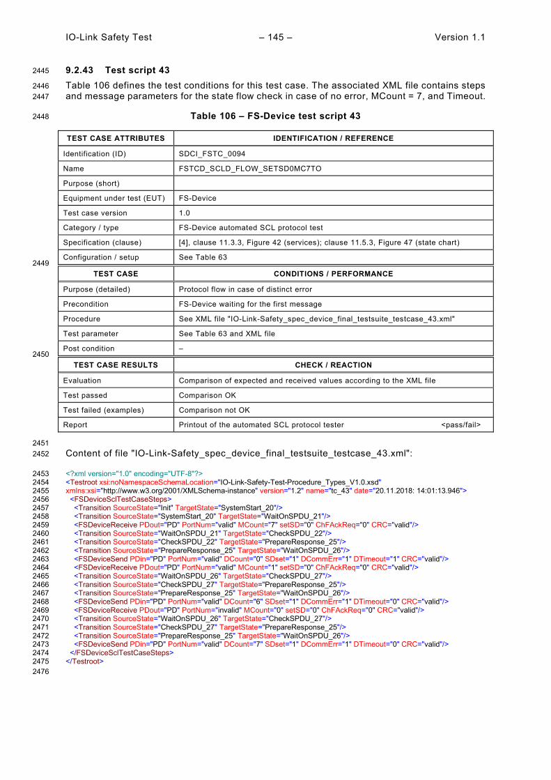
IO-Link Safety Test – 145 – Version 1.1
9.2.43 Test script 43 2445
Table 106 defines the test conditions for this test case. The associated XML file contains steps 2446 and message parameters for the state flow check in case of no error, MCount = 7, and Timeout. 2447
Table 106 – FS-Device test script 43 2448
TEST CASE ATTRIBUTES IDENTIFICATION / REFERENCE
Identification (ID) SDCI_FSTC_0094
Name FSTCD_SCLD_FLOW_SETSD0MC7TO
Purpose (short)
Equipment under test (EUT) FS-Device
Test case version 1.0
Category / type FS-Device automated SCL protocol test
Specification (clause) [4], clause 11.3.3, Figure 42 (services); clause 11.5.3, Figure 47 (state chart)
Configuration / setup See Table 63 2449
TEST CASE CONDITIONS / PERFORMANCE
Purpose (detailed) Protocol flow in case of distinct error
Precondition FS-Device waiting for the first message
Procedure See XML file "IO-Link-Safety_spec_device_final_testsuite_testcase_43.xml"
Test parameter See Table 63 and XML file
Post condition – 2450
TEST CASE RESULTS CHECK / REACTION
Evaluation Comparison of expected and received values according to the XML file
Test passed Comparison OK
Test failed (examples) Comparison not OK
Report Printout of the automated SCL protocol tester <pass/fail>
2451 Content of file "IO-Link-Safety_spec_device_final_testsuite_testcase_43.xml": 2452
<?xml version="1.0" encoding="UTF-8"?> 2453 <Testroot xsi:noNamespaceSchemaLocation="IO-Link-Safety-Test-Procedure_Types_V1.0.xsd" 2454 xmlns:xsi="http://www.w3.org/2001/XMLSchema-instance" version="1.2" name="tc_43" date="20.11.2018: 14:01:13.946"> 2455 <FSDeviceSclTestCaseSteps> 2456 <Transition SourceState="Init" TargetState="SystemStart_20"/> 2457 <Transition SourceState="SystemStart_20" TargetState="WaitOnSPDU_21"/> 2458 <FSDeviceReceive PDout="PD" PortNum="valid" MCount="7" setSD="0" ChFAckReq="0" CRC="valid"/> 2459 <Transition SourceState="WaitOnSPDU_21" TargetState="CheckSPDU_22"/> 2460 <Transition SourceState="CheckSPDU_22" TargetState="PrepareResponse_25"/> 2461 <Transition SourceState="PrepareResponse_25" TargetState="WaitOnSPDU_26"/> 2462 <FSDeviceSend PDin="PD" PortNum="valid" DCount="0" SDset="1" DCommErr="1" DTimeout="1" CRC="valid"/> 2463 <FSDeviceReceive PDout="PD" PortNum="valid" MCount="1" setSD="0" ChFAckReq="0" CRC="valid"/> 2464 <Transition SourceState="WaitOnSPDU_26" TargetState="CheckSPDU_27"/> 2465 <Transition SourceState="CheckSPDU_27" TargetState="PrepareResponse_25"/> 2466 <Transition SourceState="PrepareResponse_25" TargetState="WaitOnSPDU_26"/> 2467 <FSDeviceSend PDin="PD" PortNum="valid" DCount="6" SDset="1" DCommErr="1" DTimeout="0" CRC="valid"/> 2468 <FSDeviceReceive PDout="PD" PortNum="invalid" MCount="0" setSD="0" ChFAckReq="0" CRC="valid"/> 2469 <Transition SourceState="WaitOnSPDU_26" TargetState="CheckSPDU_27"/> 2470 <Transition SourceState="CheckSPDU_27" TargetState="PrepareResponse_25"/> 2471 <Transition SourceState="PrepareResponse_25" TargetState="WaitOnSPDU_26"/> 2472 <FSDeviceSend PDin="PD" PortNum="valid" DCount="7" SDset="1" DCommErr="1" DTimeout="0" CRC="valid"/> 2473 </FSDeviceSclTestCaseSteps> 2474 </Testroot> 2475 2476
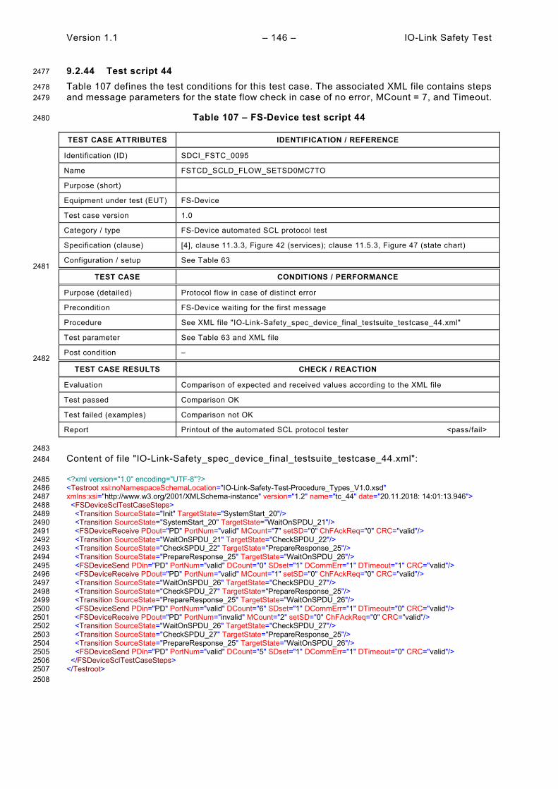
Version 1.1 – 146 – IO-Link Safety Test
9.2.44 Test script 44 2477
Table 107 defines the test conditions for this test case. The associated XML file contains steps 2478 and message parameters for the state flow check in case of no error, MCount = 7, and Timeout. 2479
Table 107 – FS-Device test script 44 2480
TEST CASE ATTRIBUTES IDENTIFICATION / REFERENCE
Identification (ID) SDCI_FSTC_0095
Name FSTCD_SCLD_FLOW_SETSD0MC7TO
Purpose (short)
Equipment under test (EUT) FS-Device
Test case version 1.0
Category / type FS-Device automated SCL protocol test
Specification (clause) [4], clause 11.3.3, Figure 42 (services); clause 11.5.3, Figure 47 (state chart)
Configuration / setup See Table 63 2481
TEST CASE CONDITIONS / PERFORMANCE
Purpose (detailed) Protocol flow in case of distinct error
Precondition FS-Device waiting for the first message
Procedure See XML file "IO-Link-Safety_spec_device_final_testsuite_testcase_44.xml"
Test parameter See Table 63 and XML file
Post condition – 2482
TEST CASE RESULTS CHECK / REACTION
Evaluation Comparison of expected and received values according to the XML file
Test passed Comparison OK
Test failed (examples) Comparison not OK
Report Printout of the automated SCL protocol tester <pass/fail>
2483 Content of file "IO-Link-Safety_spec_device_final_testsuite_testcase_44.xml": 2484
<?xml version="1.0" encoding="UTF-8"?> 2485 <Testroot xsi:noNamespaceSchemaLocation="IO-Link-Safety-Test-Procedure_Types_V1.0.xsd" 2486 xmlns:xsi="http://www.w3.org/2001/XMLSchema-instance" version="1.2" name="tc_44" date="20.11.2018: 14:01:13.946"> 2487 <FSDeviceSclTestCaseSteps> 2488 <Transition SourceState="Init" TargetState="SystemStart_20"/> 2489 <Transition SourceState="SystemStart_20" TargetState="WaitOnSPDU_21"/> 2490 <FSDeviceReceive PDout="PD" PortNum="valid" MCount="7" setSD="0" ChFAckReq="0" CRC="valid"/> 2491 <Transition SourceState="WaitOnSPDU_21" TargetState="CheckSPDU_22"/> 2492 <Transition SourceState="CheckSPDU_22" TargetState="PrepareResponse_25"/> 2493 <Transition SourceState="PrepareResponse_25" TargetState="WaitOnSPDU_26"/> 2494 <FSDeviceSend PDin="PD" PortNum="valid" DCount="0" SDset="1" DCommErr="1" DTimeout="1" CRC="valid"/> 2495 <FSDeviceReceive PDout="PD" PortNum="valid" MCount="1" setSD="0" ChFAckReq="0" CRC="valid"/> 2496 <Transition SourceState="WaitOnSPDU_26" TargetState="CheckSPDU_27"/> 2497 <Transition SourceState="CheckSPDU_27" TargetState="PrepareResponse_25"/> 2498 <Transition SourceState="PrepareResponse_25" TargetState="WaitOnSPDU_26"/> 2499 <FSDeviceSend PDin="PD" PortNum="valid" DCount="6" SDset="1" DCommErr="1" DTimeout="0" CRC="valid"/> 2500 <FSDeviceReceive PDout="PD" PortNum="invalid" MCount="2" setSD="0" ChFAckReq="0" CRC="valid"/> 2501 <Transition SourceState="WaitOnSPDU_26" TargetState="CheckSPDU_27"/> 2502 <Transition SourceState="CheckSPDU_27" TargetState="PrepareResponse_25"/> 2503 <Transition SourceState="PrepareResponse_25" TargetState="WaitOnSPDU_26"/> 2504 <FSDeviceSend PDin="PD" PortNum="valid" DCount="5" SDset="1" DCommErr="1" DTimeout="0" CRC="valid"/> 2505 </FSDeviceSclTestCaseSteps> 2506 </Testroot> 2507 2508

IO-Link Safety Test – 147 – Version 1.1
9.2.45 Test script 45 2509
Table 108 defines the test conditions for this test case. The associated XML file contains steps 2510 and message parameters for the state flow check in case of a setSD error, MCount = 0, and 2511 DCommErr. 2512
Table 108 – FS-Device test script 45 2513
TEST CASE ATTRIBUTES IDENTIFICATION / REFERENCE
Identification (ID) SDCI_FSTC_0096
Name FSTCD_SCLD_FLOW_SETSD1MC0DCE1
Purpose (short)
Equipment under test (EUT) FS-Device
Test case version 1.0
Category / type FS-Device automated SCL protocol test
Specification (clause) [4], clause 11.3.3, Figure 42 (services); clause 11.5.3, Figure 47 (state chart)
Configuration / setup See Table 63 2514
TEST CASE CONDITIONS / PERFORMANCE
Purpose (detailed) Protocol flow in case of distinct error
Precondition FS-Device waiting for the first message
Procedure See XML file "IO-Link-Safety_spec_device_final_testsuite_testcase_45.xml"
Test parameter See Table 63 and XML file
Post condition – 2515
TEST CASE RESULTS CHECK / REACTION
Evaluation Comparison of expected and received values according to the XML file
Test passed Comparison OK
Test failed (examples) Comparison not OK
Report Printout of the automated SCL protocol tester <pass/fail>
2516 Content of file "IO-Link-Safety_spec_device_final_testsuite_testcase_45.xml": 2517
<?xml version="1.0" encoding="UTF-8"?> 2518 <Testroot xsi:noNamespaceSchemaLocation="IO-Link-Safety-Test-Procedure_Types_V1.0.xsd" 2519 xmlns:xsi="http://www.w3.org/2001/XMLSchema-instance" version="1.2" name="tc_45" date="20.11.2018: 14:01:13.946"> 2520 <FSDeviceSclTestCaseSteps> 2521 <Transition SourceState="Init" TargetState="SystemStart_20"/> 2522 <Transition SourceState="SystemStart_20" TargetState="WaitOnSPDU_21"/> 2523 <FSDeviceReceive PDout="PD" PortNum="valid" MCount="0" setSD="1" ChFAckReq="0" CRC="valid"/> 2524 <Transition SourceState="WaitOnSPDU_21" TargetState="CheckSPDU_22"/> 2525 <Transition SourceState="CheckSPDU_22" TargetState="PrepareResponse_23"/> 2526 <Transition SourceState="PrepareResponse_23" TargetState="WaitOnSPDU_24"/> 2527 <FSDeviceSend PDin="PD" PortNum="valid" DCount="7" SDset="1" DCommErr="0" DTimeout="0" CRC="valid"/> 2528 <FSDeviceReceive PDout="PD" PortNum="valid" MCount="1" setSD="0" ChFAckReq="0" CRC="invalid"/> 2529 <Transition SourceState="WaitOnSPDU_24" TargetState="PrepareResponse_25"/> 2530 <Transition SourceState="PrepareResponse_25" TargetState="WaitOnSPDU_26"/> 2531 <FSDeviceSend PDin="PD" PortNum="valid" DCount="6" SDset="1" DCommErr="1" DTimeout="0" CRC="valid"/> 2532 <FSDeviceReceive PDout="PD" PortNum="valid" MCount="3" setSD="0" ChFAckReq="0" CRC="valid"/> 2533 <Transition SourceState="WaitOnSPDU_26" TargetState="CheckSPDU_27"/> 2534 <Transition SourceState="CheckSPDU_27" TargetState="PrepareResponse_25"/> 2535 <Transition SourceState="PrepareResponse_25" TargetState="WaitOnSPDU_26"/> 2536 <FSDeviceSend PDin="PD" PortNum="valid" DCount="4" SDset="1" DCommErr="1" DTimeout="0" CRC="valid"/> 2537 </FSDeviceSclTestCaseSteps> 2538 </Testroot> 2539 2540

Version 1.1 – 148 – IO-Link Safety Test
9.2.46 Test script 46 2541
Table 109 defines the test conditions for this test case. The associated XML file contains steps 2542 and message parameters for the state flow check in case of a setSD error, MCount = 0, and 2543 DCommErr. 2544
Table 109 – FS-Device test script 46 2545
TEST CASE ATTRIBUTES IDENTIFICATION / REFERENCE
Identification (ID) SDCI_FSTC_0097
Name FSTCD_SCLD_FLOW_SETSD1MC0DCE1
Purpose (short)
Equipment under test (EUT) FS-Device
Test case version 1.0
Category / type FS-Device automated SCL protocol test
Specification (clause) [4], clause 11.3.3, Figure 42 (services); clause 11.5.3, Figure 47 (state chart)
Configuration / setup See Table 63 2546
TEST CASE CONDITIONS / PERFORMANCE
Purpose (detailed) Protocol flow in case of distinct error
Precondition FS-Device waiting for the first message
Procedure See XML file "IO-Link-Safety_spec_device_final_testsuite_testcase_46.xml"
Test parameter See Table 63 and XML file
Post condition – 2547
TEST CASE RESULTS CHECK / REACTION
Evaluation Comparison of expected and received values according to the XML file
Test passed Comparison OK
Test failed (examples) Comparison not OK
Report Printout of the automated SCL protocol tester <pass/fail>
2548 Content of file "IO-Link-Safety_spec_device_final_testsuite_testcase_46.xml": 2549
<?xml version="1.0" encoding="UTF-8"?> 2550 <Testroot xsi:noNamespaceSchemaLocation="IO-Link-Safety-Test-Procedure_Types_V1.0.xsd" 2551 xmlns:xsi="http://www.w3.org/2001/XMLSchema-instance" version="1.2" name="tc_46" date="20.11.2018: 14:01:13.946"> 2552 <FSDeviceSclTestCaseSteps> 2553 <Transition SourceState="Init" TargetState="SystemStart_20"/> 2554 <Transition SourceState="SystemStart_20" TargetState="WaitOnSPDU_21"/> 2555 <FSDeviceReceive PDout="PD" PortNum="valid" MCount="0" setSD="1" ChFAckReq="0" CRC="valid"/> 2556 <Transition SourceState="WaitOnSPDU_21" TargetState="CheckSPDU_22"/> 2557 <Transition SourceState="CheckSPDU_22" TargetState="PrepareResponse_23"/> 2558 <Transition SourceState="PrepareResponse_23" TargetState="WaitOnSPDU_24"/> 2559 <FSDeviceSend PDin="PD" PortNum="valid" DCount="7" SDset="1" DCommErr="0" DTimeout="0" CRC="valid"/> 2560 <FSDeviceReceive PDout="PD" PortNum="valid" MCount="2" setSD="0" ChFAckReq="0" CRC="invalid"/> 2561 <Transition SourceState="WaitOnSPDU_24" TargetState="PrepareResponse_25"/> 2562 <Transition SourceState="PrepareResponse_25" TargetState="WaitOnSPDU_26"/> 2563 <FSDeviceSend PDin="PD" PortNum="valid" DCount="5" SDset="1" DCommErr="1" DTimeout="0" CRC="valid"/> 2564 <FSDeviceReceive PDout="PD" PortNum="valid" MCount="4" setSD="0" ChFAckReq="0" CRC="valid"/> 2565 <Transition SourceState="WaitOnSPDU_26" TargetState="CheckSPDU_27"/> 2566 <Transition SourceState="CheckSPDU_27" TargetState="PrepareResponse_25"/> 2567 <Transition SourceState="PrepareResponse_25" TargetState="WaitOnSPDU_26"/> 2568 <FSDeviceSend PDin="PD" PortNum="valid" DCount="3" SDset="1" DCommErr="1" DTimeout="0" CRC="valid"/> 2569 </FSDeviceSclTestCaseSteps> 2570 </Testroot> 2571 2572

IO-Link Safety Test – 149 – Version 1.1
9.2.47 Test script 47 2573
Table 110 defines the test conditions for this test case. The associated XML file contains steps 2574 and message parameters for the state flow check in case of a setSD error, MCount = 0, and 2575 DCommErr. 2576
Table 110 – FS-Device test script 47 2577
TEST CASE ATTRIBUTES IDENTIFICATION / REFERENCE
Identification (ID) SDCI_FSTC_0098
Name FSTCD_SCLD_FLOW_SETSD1MC0DCE1
Purpose (short)
Equipment under test (EUT) FS-Device
Test case version 1.0
Category / type FS-Device automated SCL protocol test
Specification (clause) [4], clause 11.3.3, Figure 42 (services); clause 11.5.3, Figure 47 (state chart)
Configuration / setup See Table 63 2578
TEST CASE CONDITIONS / PERFORMANCE
Purpose (detailed) Protocol flow in case of distinct error
Precondition FS-Device waiting for the first message
Procedure See XML file "IO-Link-Safety_spec_device_final_testsuite_testcase_47.xml"
Test parameter See Table 63 and XML file
Post condition – 2579
TEST CASE RESULTS CHECK / REACTION
Evaluation Comparison of expected and received values according to the XML file
Test passed Comparison OK
Test failed (examples) Comparison not OK
Report Printout of the automated SCL protocol tester <pass/fail>
2580 Content of file "IO-Link-Safety_spec_device_final_testsuite_testcase_47.xml": 2581
<?xml version="1.0" encoding="UTF-8"?> 2582 <Testroot xsi:noNamespaceSchemaLocation="IO-Link-Safety-Test-Procedure_Types_V1.0.xsd" 2583 xmlns:xsi="http://www.w3.org/2001/XMLSchema-instance" version="1.2" name="tc_47" date="20.11.2018: 14:01:13.946"> 2584 <FSDeviceSclTestCaseSteps> 2585 <Transition SourceState="Init" TargetState="SystemStart_20"/> 2586 <Transition SourceState="SystemStart_20" TargetState="WaitOnSPDU_21"/> 2587 <FSDeviceReceive PDout="PD" PortNum="valid" MCount="0" setSD="1" ChFAckReq="0" CRC="valid"/> 2588 <Transition SourceState="WaitOnSPDU_21" TargetState="CheckSPDU_22"/> 2589 <Transition SourceState="CheckSPDU_22" TargetState="PrepareResponse_23"/> 2590 <Transition SourceState="PrepareResponse_23" TargetState="WaitOnSPDU_24"/> 2591 <FSDeviceSend PDin="PD" PortNum="valid" DCount="7" SDset="1" DCommErr="0" DTimeout="0" CRC="valid"/> 2592 <FSDeviceReceive PDout="PD" PortNum="valid" MCount="3" setSD="0" ChFAckReq="0" CRC="invalid"/> 2593 <Transition SourceState="WaitOnSPDU_24" TargetState="PrepareResponse_25"/> 2594 <Transition SourceState="PrepareResponse_25" TargetState="WaitOnSPDU_26"/> 2595 <FSDeviceSend PDin="PD" PortNum="valid" DCount="4" SDset="1" DCommErr="1" DTimeout="0" CRC="valid"/> 2596 <FSDeviceReceive PDout="PD" PortNum="valid" MCount="5" setSD="0" ChFAckReq="0" CRC="valid"/> 2597 <Transition SourceState="WaitOnSPDU_26" TargetState="CheckSPDU_27"/> 2598 <Transition SourceState="CheckSPDU_27" TargetState="PrepareResponse_25"/> 2599 <Transition SourceState="PrepareResponse_25" TargetState="WaitOnSPDU_26"/> 2600 <FSDeviceSend PDin="PD" PortNum="valid" DCount="2" SDset="1" DCommErr="1" DTimeout="0" CRC="valid"/> 2601 </FSDeviceSclTestCaseSteps> 2602 </Testroot> 2603 2604

Version 1.1 – 150 – IO-Link Safety Test
9.2.48 Test script 48 2605
Table 111 defines the test conditions for this test case. The associated XML file contains steps 2606 and message parameters for the state flow check in case of setSD error, MCount = 0, and 2607 DCommErr. 2608
Table 111 – FS-Device test script 48 2609
TEST CASE ATTRIBUTES IDENTIFICATION / REFERENCE
Identification (ID) SDCI_FSTC_0099
Name FSTCD_SCLD_FLOW_SETSD1MC0DCE1
Purpose (short)
Equipment under test (EUT) FS-Device
Test case version 1.0
Category / type FS-Device automated SCL protocol test
Specification (clause) [4], clause 11.3.3, Figure 42 (services); clause 11.5.3, Figure 47 (state chart)
Configuration / setup See Table 63 2610
TEST CASE CONDITIONS / PERFORMANCE
Purpose (detailed) Protocol flow in case of distinct error
Precondition FS-Device waiting for the first message
Procedure See XML file "IO-Link-Safety_spec_device_final_testsuite_testcase_48.xml"
Test parameter See Table 63 and XML file
Post condition – 2611
TEST CASE RESULTS CHECK / REACTION
Evaluation Comparison of expected and received values according to the XML file
Test passed Comparison OK
Test failed (examples) Comparison not OK
Report Printout of the automated SCL protocol tester <pass/fail>
2612 Content of file "IO-Link-Safety_spec_device_final_testsuite_testcase_48.xml": 2613
<?xml version="1.0" encoding="UTF-8"?> 2614 <Testroot xsi:noNamespaceSchemaLocation="IO-Link-Safety-Test-Procedure_Types_V1.0.xsd" 2615 xmlns:xsi="http://www.w3.org/2001/XMLSchema-instance" version="1.2" name="tc_48" date="20.11.2018: 14:01:13.947"> 2616 <FSDeviceSclTestCaseSteps> 2617 <Transition SourceState="Init" TargetState="SystemStart_20"/> 2618 <Transition SourceState="SystemStart_20" TargetState="WaitOnSPDU_21"/> 2619 <FSDeviceReceive PDout="PD" PortNum="valid" MCount="0" setSD="1" ChFAckReq="0" CRC="valid"/> 2620 <Transition SourceState="WaitOnSPDU_21" TargetState="CheckSPDU_22"/> 2621 <Transition SourceState="CheckSPDU_22" TargetState="PrepareResponse_23"/> 2622 <Transition SourceState="PrepareResponse_23" TargetState="WaitOnSPDU_24"/> 2623 <FSDeviceSend PDin="PD" PortNum="valid" DCount="7" SDset="1" DCommErr="0" DTimeout="0" CRC="valid"/> 2624 <FSDeviceReceive PDout="PD" PortNum="valid" MCount="4" setSD="0" ChFAckReq="0" CRC="invalid"/> 2625 <Transition SourceState="WaitOnSPDU_24" TargetState="PrepareResponse_25"/> 2626 <Transition SourceState="PrepareResponse_25" TargetState="WaitOnSPDU_26"/> 2627 <FSDeviceSend PDin="PD" PortNum="valid" DCount="3" SDset="1" DCommErr="1" DTimeout="0" CRC="valid"/> 2628 <FSDeviceReceive PDout="PD" PortNum="valid" MCount="6" setSD="0" ChFAckReq="0" CRC="valid"/> 2629 <Transition SourceState="WaitOnSPDU_26" TargetState="CheckSPDU_27"/> 2630 <Transition SourceState="CheckSPDU_27" TargetState="PrepareResponse_25"/> 2631 <Transition SourceState="PrepareResponse_25" TargetState="WaitOnSPDU_26"/> 2632 <FSDeviceSend PDin="PD" PortNum="valid" DCount="1" SDset="1" DCommErr="1" DTimeout="0" CRC="valid"/> 2633 </FSDeviceSclTestCaseSteps> 2634 </Testroot> 2635 2636
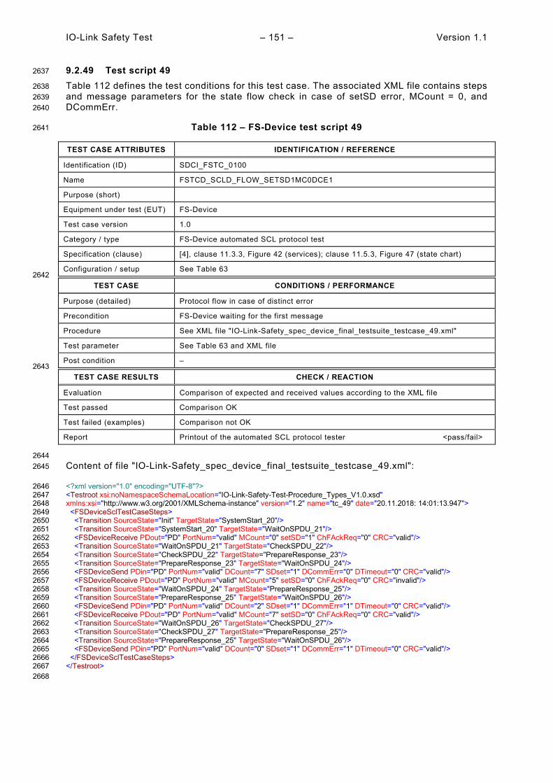
IO-Link Safety Test – 151 – Version 1.1
9.2.49 Test script 49 2637
Table 112 defines the test conditions for this test case. The associated XML file contains steps 2638 and message parameters for the state flow check in case of setSD error, MCount = 0, and 2639 DCommErr. 2640
Table 112 – FS-Device test script 49 2641
TEST CASE ATTRIBUTES IDENTIFICATION / REFERENCE
Identification (ID) SDCI_FSTC_0100
Name FSTCD_SCLD_FLOW_SETSD1MC0DCE1
Purpose (short)
Equipment under test (EUT) FS-Device
Test case version 1.0
Category / type FS-Device automated SCL protocol test
Specification (clause) [4], clause 11.3.3, Figure 42 (services); clause 11.5.3, Figure 47 (state chart)
Configuration / setup See Table 63 2642
TEST CASE CONDITIONS / PERFORMANCE
Purpose (detailed) Protocol flow in case of distinct error
Precondition FS-Device waiting for the first message
Procedure See XML file "IO-Link-Safety_spec_device_final_testsuite_testcase_49.xml"
Test parameter See Table 63 and XML file
Post condition – 2643
TEST CASE RESULTS CHECK / REACTION
Evaluation Comparison of expected and received values according to the XML file
Test passed Comparison OK
Test failed (examples) Comparison not OK
Report Printout of the automated SCL protocol tester <pass/fail>
2644 Content of file "IO-Link-Safety_spec_device_final_testsuite_testcase_49.xml": 2645
<?xml version="1.0" encoding="UTF-8"?> 2646 <Testroot xsi:noNamespaceSchemaLocation="IO-Link-Safety-Test-Procedure_Types_V1.0.xsd" 2647 xmlns:xsi="http://www.w3.org/2001/XMLSchema-instance" version="1.2" name="tc_49" date="20.11.2018: 14:01:13.947"> 2648 <FSDeviceSclTestCaseSteps> 2649 <Transition SourceState="Init" TargetState="SystemStart_20"/> 2650 <Transition SourceState="SystemStart_20" TargetState="WaitOnSPDU_21"/> 2651 <FSDeviceReceive PDout="PD" PortNum="valid" MCount="0" setSD="1" ChFAckReq="0" CRC="valid"/> 2652 <Transition SourceState="WaitOnSPDU_21" TargetState="CheckSPDU_22"/> 2653 <Transition SourceState="CheckSPDU_22" TargetState="PrepareResponse_23"/> 2654 <Transition SourceState="PrepareResponse_23" TargetState="WaitOnSPDU_24"/> 2655 <FSDeviceSend PDin="PD" PortNum="valid" DCount="7" SDset="1" DCommErr="0" DTimeout="0" CRC="valid"/> 2656 <FSDeviceReceive PDout="PD" PortNum="valid" MCount="5" setSD="0" ChFAckReq="0" CRC="invalid"/> 2657 <Transition SourceState="WaitOnSPDU_24" TargetState="PrepareResponse_25"/> 2658 <Transition SourceState="PrepareResponse_25" TargetState="WaitOnSPDU_26"/> 2659 <FSDeviceSend PDin="PD" PortNum="valid" DCount="2" SDset="1" DCommErr="1" DTimeout="0" CRC="valid"/> 2660 <FSDeviceReceive PDout="PD" PortNum="valid" MCount="7" setSD="0" ChFAckReq="0" CRC="valid"/> 2661 <Transition SourceState="WaitOnSPDU_26" TargetState="CheckSPDU_27"/> 2662 <Transition SourceState="CheckSPDU_27" TargetState="PrepareResponse_25"/> 2663 <Transition SourceState="PrepareResponse_25" TargetState="WaitOnSPDU_26"/> 2664 <FSDeviceSend PDin="PD" PortNum="valid" DCount="0" SDset="1" DCommErr="1" DTimeout="0" CRC="valid"/> 2665 </FSDeviceSclTestCaseSteps> 2666 </Testroot> 2667 2668

Version 1.1 – 152 – IO-Link Safety Test
9.2.50 Test script 50 2669
Table 113 defines the test conditions for this test case. The associated XML file contains steps 2670 and message parameters for the state flow check in case of no error, MCount = 2, and Timeout. 2671
Table 113 – FS-Device test script 50 2672
TEST CASE ATTRIBUTES IDENTIFICATION / REFERENCE
Identification (ID) SDCI_FSTC_0101
Name FSTCD_SCLD_FLOW_SETSD0MC2TO
Purpose (short)
Equipment under test (EUT) FS-Device
Test case version 1.0
Category / type FS-Device automated SCL protocol test
Specification (clause) [4], clause 11.3.3, Figure 42 (services); clause 11.5.3, Figure 47 (state chart)
Configuration / setup See Table 63 2673
TEST CASE CONDITIONS / PERFORMANCE
Purpose (detailed) Protocol flow in case of distinct error
Precondition FS-Device waiting for the first message
Procedure See XML file "IO-Link-Safety_spec_device_final_testsuite_testcase_50.xml"
Test parameter See Table 63 and XML file
Post condition – 2674
TEST CASE RESULTS CHECK / REACTION
Evaluation Comparison of expected and received values according to the XML file
Test passed Comparison OK
Test failed (examples) Comparison not OK
Report Printout of the automated SCL protocol tester <pass/fail>
2675 Content of file "IO-Link-Safety_spec_device_final_testsuite_testcase_50.xml": 2676
<?xml version="1.0" encoding="UTF-8"?> 2677 <Testroot xsi:noNamespaceSchemaLocation="IO-Link-Safety-Test-Procedure_Types_V1.0.xsd" 2678 xmlns:xsi="http://www.w3.org/2001/XMLSchema-instance" version="1.2" name="tc_50" date="20.11.2018: 14:01:13.947"> 2679 <FSDeviceSclTestCaseSteps> 2680 <Transition SourceState="Init" TargetState="SystemStart_20"/> 2681 <Transition SourceState="SystemStart_20" TargetState="WaitOnSPDU_21"/> 2682 <FSDeviceReceive PDout="PD" PortNum="valid" MCount="2" setSD="0" ChFAckReq="0" CRC="valid"/> 2683 <Transition SourceState="WaitOnSPDU_21" TargetState="CheckSPDU_22"/> 2684 <Transition SourceState="CheckSPDU_22" TargetState="PrepareResponse_25"/> 2685 <Transition SourceState="PrepareResponse_25" TargetState="WaitOnSPDU_26"/> 2686 <FSDeviceSend PDin="PD" PortNum="valid" DCount="5" SDset="1" DCommErr="1" DTimeout="1" CRC="valid"/> 2687 <FSDeviceReceive PDout="PD" PortNum="valid" MCount="3" setSD="0" ChFAckReq="0" CRC="valid"/> 2688 <Transition SourceState="WaitOnSPDU_26" TargetState="CheckSPDU_27"/> 2689 <Transition SourceState="CheckSPDU_27" TargetState="PrepareResponse_25"/> 2690 <Transition SourceState="PrepareResponse_25" TargetState="WaitOnSPDU_26"/> 2691 <FSDeviceSend PDin="PD" PortNum="valid" DCount="4" SDset="1" DCommErr="1" DTimeout="0" CRC="valid"/> 2692 <FSDeviceReceive PDout="PD" PortNum="valid" MCount="0" setSD="0" ChFAckReq="0" CRC="invalid"/> 2693 <Transition SourceState="WaitOnSPDU_26" TargetState="CheckSPDU_27"/> 2694 <Transition SourceState="CheckSPDU_27" TargetState="PrepareResponse_25"/> 2695 <Transition SourceState="PrepareResponse_25" TargetState="WaitOnSPDU_26"/> 2696 <FSDeviceSend PDin="PD" PortNum="valid" DCount="7" SDset="1" DCommErr="1" DTimeout="0" CRC="valid"/> 2697 </FSDeviceSclTestCaseSteps> 2698 </Testroot> 2699 2700

IO-Link Safety Test – 153 – Version 1.1
9.2.51 Test script 51 2701
Table 114 defines the test conditions for this test case. The associated XML file contains steps 2702 and message parameters for the state flow check in case of no error, MCount = 2, and 2703 DCommErr. 2704
Table 114 – FS-Device test script 51 2705
TEST CASE ATTRIBUTES IDENTIFICATION / REFERENCE
Identification (ID) SDCI_FSTC_0102
Name FSTCD_SCLD_FLOW_SETSD0MC2DCE1
Purpose (short)
Equipment under test (EUT) FS-Device
Test case version 1.0
Category / type FS-Device automated SCL protocol test
Specification (clause) [4], clause 11.3.3, Figure 42 (services); clause 11.5.3, Figure 47 (state chart)
Configuration / setup See Table 63 2706
TEST CASE CONDITIONS / PERFORMANCE
Purpose (detailed) Protocol flow in case of distinct error
Precondition FS-Device waiting for the first message
Procedure See XML file "IO-Link-Safety_spec_device_final_testsuite_testcase_51.xml"
Test parameter See Table 63 and XML file
Post condition – 2707
TEST CASE RESULTS CHECK / REACTION
Evaluation Comparison of expected and received values according to the XML file
Test passed Comparison OK
Test failed (examples) Comparison not OK
Report Printout of the automated SCL protocol tester <pass/fail>
2708 Content of file "IO-Link-Safety_spec_device_final_testsuite_testcase_51.xml": 2709
<?xml version="1.0" encoding="UTF-8"?> 2710 <Testroot xsi:noNamespaceSchemaLocation="IO-Link-Safety-Test-Procedure_Types_V1.0.xsd" 2711 xmlns:xsi="http://www.w3.org/2001/XMLSchema-instance" version="1.2" name="tc_51" date="20.11.2018: 14:01:13.947"> 2712 <FSDeviceSclTestCaseSteps> 2713 <Transition SourceState="Init" TargetState="SystemStart_20"/> 2714 <Transition SourceState="SystemStart_20" TargetState="WaitOnSPDU_21"/> 2715 <FSDeviceReceive PDout="PD" PortNum="valid" MCount="2" setSD="0" ChFAckReq="0" CRC="valid"/> 2716 <Transition SourceState="WaitOnSPDU_21" TargetState="CheckSPDU_22"/> 2717 <Transition SourceState="CheckSPDU_22" TargetState="PrepareResponse_25"/> 2718 <Transition SourceState="PrepareResponse_25" TargetState="WaitOnSPDU_26"/> 2719 <FSDeviceSend PDin="PD" PortNum="valid" DCount="5" SDset="1" DCommErr="1" DTimeout="1" CRC="valid"/> 2720 <FSDeviceReceive PDout="PD" PortNum="valid" MCount="3" setSD="0" ChFAckReq="0" CRC="valid"/> 2721 <Transition SourceState="WaitOnSPDU_26" TargetState="CheckSPDU_27"/> 2722 <Transition SourceState="CheckSPDU_27" TargetState="PrepareResponse_25"/> 2723 <Transition SourceState="PrepareResponse_25" TargetState="WaitOnSPDU_26"/> 2724 <FSDeviceSend PDin="PD" PortNum="valid" DCount="4" SDset="1" DCommErr="1" DTimeout="0" CRC="valid"/> 2725 <FSDeviceReceive PDout="PD" PortNum="valid" MCount="4" setSD="0" ChFAckReq="0" CRC="invalid"/> 2726 <Transition SourceState="WaitOnSPDU_26" TargetState="CheckSPDU_27"/> 2727 <Transition SourceState="CheckSPDU_27" TargetState="PrepareResponse_25"/> 2728 <Transition SourceState="PrepareResponse_25" TargetState="WaitOnSPDU_26"/> 2729 <FSDeviceSend PDin="PD" PortNum="valid" DCount="3" SDset="1" DCommErr="1" DTimeout="0" CRC="valid"/> 2730 </FSDeviceSclTestCaseSteps> 2731 </Testroot> 2732 2733

Version 1.1 – 154 – IO-Link Safety Test
9.2.52 Test script 52 2734
Table 115 defines the test conditions for this test case. The associated XML file contains steps 2735 and message parameters for the state flow check in case of no error, MCount = 3, and Timeout. 2736
Table 115 – FS-Device test script 52 2737
TEST CASE ATTRIBUTES IDENTIFICATION / REFERENCE
Identification (ID) SDCI_FSTC_0103
Name FSTCD_SCLD_FLOW_SETSD0MC3TO
Purpose (short)
Equipment under test (EUT) FS-Device
Test case version 1.0
Category / type FS-Device automated SCL protocol test
Specification (clause) [4], clause 11.3.3, Figure 42 (services); clause 11.5.3, Figure 47 (state chart)
Configuration / setup See Table 63 2738
TEST CASE CONDITIONS / PERFORMANCE
Purpose (detailed) Protocol flow in case of distinct error
Precondition FS-Device waiting for the first message
Procedure See XML file "IO-Link-Safety_spec_device_final_testsuite_testcase_52.xml"
Test parameter See Table 63 and XML file
Post condition – 2739
TEST CASE RESULTS CHECK / REACTION
Evaluation Comparison of expected and received values according to the XML file
Test passed Comparison OK
Test failed (examples) Comparison not OK
Report Printout of the automated SCL protocol tester <pass/fail>
2740 Content of file "IO-Link-Safety_spec_device_final_testsuite_testcase_52.xml": 2741
<?xml version="1.0" encoding="UTF-8"?> 2742 <Testroot xsi:noNamespaceSchemaLocation="IO-Link-Safety-Test-Procedure_Types_V1.0.xsd" 2743 xmlns:xsi="http://www.w3.org/2001/XMLSchema-instance" version="1.2" name="tc_52" date="20.11.2018: 14:01:13.947"> 2744 <FSDeviceSclTestCaseSteps> 2745 <Transition SourceState="Init" TargetState="SystemStart_20"/> 2746 <Transition SourceState="SystemStart_20" TargetState="WaitOnSPDU_21"/> 2747 <FSDeviceReceive PDout="PD" PortNum="valid" MCount="3" setSD="0" ChFAckReq="0" CRC="valid"/> 2748 <Transition SourceState="WaitOnSPDU_21" TargetState="CheckSPDU_22"/> 2749 <Transition SourceState="CheckSPDU_22" TargetState="PrepareResponse_25"/> 2750 <Transition SourceState="PrepareResponse_25" TargetState="WaitOnSPDU_26"/> 2751 <FSDeviceSend PDin="PD" PortNum="valid" DCount="4" SDset="1" DCommErr="1" DTimeout="1" CRC="valid"/> 2752 <FSDeviceReceive PDout="PD" PortNum="valid" MCount="4" setSD="0" ChFAckReq="0" CRC="valid"/> 2753 <Transition SourceState="WaitOnSPDU_26" TargetState="CheckSPDU_27"/> 2754 <Transition SourceState="CheckSPDU_27" TargetState="PrepareResponse_25"/> 2755 <Transition SourceState="PrepareResponse_25" TargetState="WaitOnSPDU_26"/> 2756 <FSDeviceSend PDin="PD" PortNum="valid" DCount="3" SDset="1" DCommErr="1" DTimeout="0" CRC="valid"/> 2757 <FSDeviceReceive PDout="PD" PortNum="valid" MCount="0" setSD="0" ChFAckReq="0" CRC="invalid"/> 2758 <Transition SourceState="WaitOnSPDU_26" TargetState="CheckSPDU_27"/> 2759 <Transition SourceState="CheckSPDU_27" TargetState="PrepareResponse_25"/> 2760 <Transition SourceState="PrepareResponse_25" TargetState="WaitOnSPDU_26"/> 2761 <FSDeviceSend PDin="PD" PortNum="valid" DCount="7" SDset="1" DCommErr="1" DTimeout="0" CRC="valid"/> 2762 </FSDeviceSclTestCaseSteps> 2763 </Testroot> 2764 2765

IO-Link Safety Test – 155 – Version 1.1
9.2.53 Test script 53 2766
Table 116 defines the test conditions for this test case. The associated XML file contains steps 2767 and message parameters for the state flow check in case of no error, MCount = 3, and Timeout. 2768
Table 116 – FS-Device test script 53 2769
TEST CASE ATTRIBUTES IDENTIFICATION / REFERENCE
Identification (ID) SDCI_FSTC_0104
Name FSTCD_SCLD_FLOW_SETSD0MC3TO
Purpose (short)
Equipment under test (EUT) FS-Device
Test case version 1.0
Category / type FS-Device automated SCL protocol test
Specification (clause) [4], clause 11.3.3, Figure 42 (services); clause 11.5.3, Figure 47 (state chart)
Configuration / setup See Table 63 2770
TEST CASE CONDITIONS / PERFORMANCE
Purpose (detailed) Protocol flow in case of distinct error
Precondition FS-Device waiting for the first message
Procedure See XML file "IO-Link-Safety_spec_device_final_testsuite_testcase_53.xml"
Test parameter See Table 63 and XML file
Post condition – 2771
TEST CASE RESULTS CHECK / REACTION
Evaluation Comparison of expected and received values according to the XML file
Test passed Comparison OK
Test failed (examples) Comparison not OK
Report Printout of the automated SCL protocol tester <pass/fail>
2772 Content of file "IO-Link-Safety_spec_device_final_testsuite_testcase_53.xml": 2773
<?xml version="1.0" encoding="UTF-8"?> 2774 <Testroot xsi:noNamespaceSchemaLocation="IO-Link-Safety-Test-Procedure_Types_V1.0.xsd" 2775 xmlns:xsi="http://www.w3.org/2001/XMLSchema-instance" version="1.2" name="tc_53" date="20.11.2018: 14:01:13.947"> 2776 <FSDeviceSclTestCaseSteps> 2777 <Transition SourceState="Init" TargetState="SystemStart_20"/> 2778 <Transition SourceState="SystemStart_20" TargetState="WaitOnSPDU_21"/> 2779 <FSDeviceReceive PDout="PD" PortNum="valid" MCount="3" setSD="0" ChFAckReq="0" CRC="valid"/> 2780 <Transition SourceState="WaitOnSPDU_21" TargetState="CheckSPDU_22"/> 2781 <Transition SourceState="CheckSPDU_22" TargetState="PrepareResponse_25"/> 2782 <Transition SourceState="PrepareResponse_25" TargetState="WaitOnSPDU_26"/> 2783 <FSDeviceSend PDin="PD" PortNum="valid" DCount="4" SDset="1" DCommErr="1" DTimeout="1" CRC="valid"/> 2784 <FSDeviceReceive PDout="PD" PortNum="valid" MCount="4" setSD="0" ChFAckReq="0" CRC="valid"/> 2785 <Transition SourceState="WaitOnSPDU_26" TargetState="CheckSPDU_27"/> 2786 <Transition SourceState="CheckSPDU_27" TargetState="PrepareResponse_25"/> 2787 <Transition SourceState="PrepareResponse_25" TargetState="WaitOnSPDU_26"/> 2788 <FSDeviceSend PDin="PD" PortNum="valid" DCount="3" SDset="1" DCommErr="1" DTimeout="0" CRC="valid"/> 2789 <FSDeviceReceive PDout="PD" PortNum="valid" MCount="5" setSD="0" ChFAckReq="0" CRC="invalid"/> 2790 <Transition SourceState="WaitOnSPDU_26" TargetState="CheckSPDU_27"/> 2791 <Transition SourceState="CheckSPDU_27" TargetState="PrepareResponse_25"/> 2792 <Transition SourceState="PrepareResponse_25" TargetState="WaitOnSPDU_26"/> 2793 <FSDeviceSend PDin="PD" PortNum="valid" DCount="2" SDset="1" DCommErr="1" DTimeout="0" CRC="valid"/> 2794 </FSDeviceSclTestCaseSteps> 2795 </Testroot> 2796 2797

Version 1.1 – 156 – IO-Link Safety Test
9.2.54 Test script 54 2798
Table 117 defines the test conditions for this test case. The associated XML file contains steps 2799 and message parameters for the state flow check in case of no error, MCount = 4, and Timeout. 2800
Table 117 – FS-Device test script 54 2801
TEST CASE ATTRIBUTES IDENTIFICATION / REFERENCE
Identification (ID) SDCI_FSTC_0105
Name FSTCD_SCLD_FLOW_SETSD0MC4TO
Purpose (short)
Equipment under test (EUT) FS-Device
Test case version 1.0
Category / type FS-Device automated SCL protocol test
Specification (clause) [4], clause 11.3.3, Figure 42 (services); clause 11.5.3, Figure 47 (state chart)
Configuration / setup See Table 63 2802
TEST CASE CONDITIONS / PERFORMANCE
Purpose (detailed) Protocol flow in case of distinct error
Precondition FS-Device waiting for the first message
Procedure See XML file "IO-Link-Safety_spec_device_final_testsuite_testcase_54.xml"
Test parameter See Table 63 and XML file
Post condition – 2803
TEST CASE RESULTS CHECK / REACTION
Evaluation Comparison of expected and received values according to the XML file
Test passed Comparison OK
Test failed (examples) Comparison not OK
Report Printout of the automated SCL protocol tester <pass/fail>
2804 Content of file "IO-Link-Safety_spec_device_final_testsuite_testcase_54.xml": 2805
<?xml version="1.0" encoding="UTF-8"?> 2806 <Testroot xsi:noNamespaceSchemaLocation="IO-Link-Safety-Test-Procedure_Types_V1.0.xsd" 2807 xmlns:xsi="http://www.w3.org/2001/XMLSchema-instance" version="1.2" name="tc_54" date="20.11.2018: 14:01:13.947"> 2808 <FSDeviceSclTestCaseSteps> 2809 <Transition SourceState="Init" TargetState="SystemStart_20"/> 2810 <Transition SourceState="SystemStart_20" TargetState="WaitOnSPDU_21"/> 2811 <FSDeviceReceive PDout="PD" PortNum="valid" MCount="4" setSD="0" ChFAckReq="0" CRC="valid"/> 2812 <Transition SourceState="WaitOnSPDU_21" TargetState="CheckSPDU_22"/> 2813 <Transition SourceState="CheckSPDU_22" TargetState="PrepareResponse_25"/> 2814 <Transition SourceState="PrepareResponse_25" TargetState="WaitOnSPDU_26"/> 2815 <FSDeviceSend PDin="PD" PortNum="valid" DCount="3" SDset="1" DCommErr="1" DTimeout="1" CRC="valid"/> 2816 <FSDeviceReceive PDout="PD" PortNum="valid" MCount="5" setSD="0" ChFAckReq="0" CRC="valid"/> 2817 <Transition SourceState="WaitOnSPDU_26" TargetState="CheckSPDU_27"/> 2818 <Transition SourceState="CheckSPDU_27" TargetState="PrepareResponse_25"/> 2819 <Transition SourceState="PrepareResponse_25" TargetState="WaitOnSPDU_26"/> 2820 <FSDeviceSend PDin="PD" PortNum="valid" DCount="2" SDset="1" DCommErr="1" DTimeout="0" CRC="valid"/> 2821 <FSDeviceReceive PDout="PD" PortNum="valid" MCount="0" setSD="0" ChFAckReq="0" CRC="invalid"/> 2822 <Transition SourceState="WaitOnSPDU_26" TargetState="CheckSPDU_27"/> 2823 <Transition SourceState="CheckSPDU_27" TargetState="PrepareResponse_25"/> 2824 <Transition SourceState="PrepareResponse_25" TargetState="WaitOnSPDU_26"/> 2825 <FSDeviceSend PDin="PD" PortNum="valid" DCount="7" SDset="1" DCommErr="1" DTimeout="0" CRC="valid"/> 2826 </FSDeviceSclTestCaseSteps> 2827 </Testroot> 2828 2829

IO-Link Safety Test – 157 – Version 1.1
9.2.55 Test script 55 2830
Table 118 defines the test conditions for this test case. The associated XML file contains steps 2831 and message parameters for the state flow check in case of setSD error, MCount = 0, and 2832 DCommErr. 2833
Table 118 – FS-Device test script 55 2834
TEST CASE ATTRIBUTES IDENTIFICATION / REFERENCE
Identification (ID) SDCI_FSTC_0106
Name FSTCD_SCLD_FLOW_SETSD1MC0DCE1
Purpose (short)
Equipment under test (EUT) FS-Device
Test case version 1.0
Category / type FS-Device automated SCL protocol test
Specification (clause) [4], clause 11.3.3, Figure 42 (services); clause 11.5.3, Figure 47 (state chart)
Configuration / setup See Table 63 2835
TEST CASE CONDITIONS / PERFORMANCE
Purpose (detailed) Protocol flow in case of distinct error
Precondition FS-Device waiting for the first message
Procedure See XML file "IO-Link-Safety_spec_device_final_testsuite_testcase_55.xml"
Test parameter See Table 63 and XML file
Post condition – 2836
TEST CASE RESULTS CHECK / REACTION
Evaluation Comparison of expected and received values according to the XML file
Test passed Comparison OK
Test failed (examples) Comparison not OK
Report Printout of the automated SCL protocol tester <pass/fail>
2837 Content of file "IO-Link-Safety_spec_device_final_testsuite_testcase_55.xml": 2838
<?xml version="1.0" encoding="UTF-8"?> 2839 <Testroot xsi:noNamespaceSchemaLocation="IO-Link-Safety-Test-Procedure_Types_V1.0.xsd" 2840 xmlns:xsi="http://www.w3.org/2001/XMLSchema-instance" version="1.2" name="tc_55" date="20.11.2018: 14:01:13.947"> 2841 <FSDeviceSclTestCaseSteps> 2842 <Transition SourceState="Init" TargetState="SystemStart_20"/> 2843 <Transition SourceState="SystemStart_20" TargetState="WaitOnSPDU_21"/> 2844 <FSDeviceReceive PDout="PD" PortNum="valid" MCount="0" setSD="1" ChFAckReq="0" CRC="valid"/> 2845 <Transition SourceState="WaitOnSPDU_21" TargetState="CheckSPDU_22"/> 2846 <Transition SourceState="CheckSPDU_22" TargetState="PrepareResponse_23"/> 2847 <Transition SourceState="PrepareResponse_23" TargetState="WaitOnSPDU_24"/> 2848 <FSDeviceSend PDin="PD" PortNum="valid" DCount="7" SDset="1" DCommErr="0" DTimeout="0" CRC="valid"/> 2849 <FSDeviceReceive PDout="PD" PortNum="valid" MCount="1" setSD="0" ChFAckReq="0" CRC="valid"/> 2850 <Transition SourceState="WaitOnSPDU_24" TargetState="CheckSPDU_22"/> 2851 <Transition SourceState="CheckSPDU_22" TargetState="PrepareResponse_23"/> 2852 <Transition SourceState="PrepareResponse_23" TargetState="WaitOnSPDU_24"/> 2853 <FSDeviceSend PDin="PD" PortNum="valid" DCount="6" SDset="1" DCommErr="0" DTimeout="0" CRC="valid"/> 2854 <FSDeviceReceive PDout="PD" PortNum="valid" MCount="3" setSD="0" ChFAckReq="0" CRC="valid"/> 2855 <Transition SourceState="WaitOnSPDU_24" TargetState="CheckSPDU_22"/> 2856 <Transition SourceState="CheckSPDU_22" TargetState="PrepareResponse_25"/> 2857 <Transition SourceState="PrepareResponse_25" TargetState="WaitOnSPDU_26"/> 2858 <FSDeviceSend PDin="PD" PortNum="valid" DCount="4" SDset="1" DCommErr="1" DTimeout="0" CRC="valid"/> 2859 </FSDeviceSclTestCaseSteps> 2860 </Testroot> 2861 2862

Version 1.1 – 158 – IO-Link Safety Test
9.2.56 Test script 56 2863
Table 119 defines the test conditions for this test case. The associated XML file contains steps 2864 and message parameters for the state flow check in case of setSD error and MCount = 0. 2865
Table 119 – FS-Device test script 56 2866
TEST CASE ATTRIBUTES IDENTIFICATION / REFERENCE
Identification (ID) SDCI_FSTC_0107
Name FSTCD_SCLD_FLOW_SETSD1MC0
Purpose (short)
Equipment under test (EUT) FS-Device
Test case version 1.0
Category / type FS-Device automated SCL protocol test
Specification (clause) [4], clause 11.3.3, Figure 42 (services); clause 11.5.3, Figure 47 (state chart)
Configuration / setup See Table 63 2867
TEST CASE CONDITIONS / PERFORMANCE
Purpose (detailed) Protocol flow in case of distinct error
Precondition FS-Device waiting for the first message
Procedure See XML file "IO-Link-Safety_spec_device_final_testsuite_testcase_56.xml"
Test parameter See Table 63 and XML file
Post condition – 2868
TEST CASE RESULTS CHECK / REACTION
Evaluation Comparison of expected and received values according to the XML file
Test passed Comparison OK
Test failed (examples) Comparison not OK
Report Printout of the automated SCL protocol tester <pass/fail>
2869 Content of file "IO-Link-Safety_spec_device_final_testsuite_testcase_56.xml": 2870
<?xml version="1.0" encoding="UTF-8"?> 2871 <Testroot xsi:noNamespaceSchemaLocation="IO-Link-Safety-Test-Procedure_Types_V1.0.xsd" 2872 xmlns:xsi="http://www.w3.org/2001/XMLSchema-instance" version="1.2" name="tc_56" date="20.11.2018: 14:01:13.947"> 2873 <FSDeviceSclTestCaseSteps> 2874 <Transition SourceState="Init" TargetState="SystemStart_20"/> 2875 <Transition SourceState="SystemStart_20" TargetState="WaitOnSPDU_21"/> 2876 <FSDeviceReceive PDout="PD" PortNum="valid" MCount="0" setSD="1" ChFAckReq="0" CRC="valid"/> 2877 <Transition SourceState="WaitOnSPDU_21" TargetState="CheckSPDU_22"/> 2878 <Transition SourceState="CheckSPDU_22" TargetState="PrepareResponse_23"/> 2879 <Transition SourceState="PrepareResponse_23" TargetState="WaitOnSPDU_24"/> 2880 <FSDeviceSend PDin="PD" PortNum="valid" DCount="7" SDset="1" DCommErr="0" DTimeout="0" CRC="valid"/> 2881 <FSDeviceReceive PDout="PD" PortNum="valid" MCount="1" setSD="0" ChFAckReq="0" CRC="valid"/> 2882 <Transition SourceState="WaitOnSPDU_24" TargetState="CheckSPDU_22"/> 2883 <Transition SourceState="CheckSPDU_22" TargetState="PrepareResponse_23"/> 2884 <Transition SourceState="PrepareResponse_23" TargetState="WaitOnSPDU_24"/> 2885 <FSDeviceSend PDin="PD" PortNum="valid" DCount="6" SDset="1" DCommErr="0" DTimeout="0" CRC="valid"/> 2886 <FSDeviceReceive PDout="PD" PortNum="valid" MCount="2" setSD="0" ChFAckReq="0" CRC="valid"/> 2887 <Transition SourceState="WaitOnSPDU_24" TargetState="CheckSPDU_22"/> 2888 <Transition SourceState="CheckSPDU_22" TargetState="PrepareResponse_23"/> 2889 <Transition SourceState="PrepareResponse_23" TargetState="WaitOnSPDU_24"/> 2890 <FSDeviceSend PDin="PD" PortNum="valid" DCount="5" SDset="1" DCommErr="0" DTimeout="0" CRC="valid"/> 2891 <FSDeviceReceive PDout="PD" PortNum="valid" MCount="2" setSD="0" ChFAckReq="0" CRC="valid"/> 2892 <Transition SourceState="WaitOnSPDU_24" TargetState="WaitOnSPDU_24"/> 2893 </FSDeviceSclTestCaseSteps> 2894 </Testroot> 2895 2896
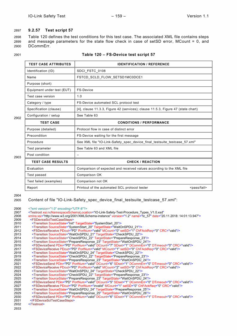
IO-Link Safety Test – 159 – Version 1.1
9.2.57 Test script 57 2897
Table 120 defines the test conditions for this test case. The associated XML file contains steps 2898 and message parameters for the state flow check in case of setSD error, MCount = 0, and 2899 DCommErr. 2900
Table 120 – FS-Device test script 57 2901
TEST CASE ATTRIBUTES IDENTIFICATION / REFERENCE
Identification (ID) SDCI_FSTC_0108
Name FSTCD_SCLD_FLOW_SETSD1MC0DCE1
Purpose (short)
Equipment under test (EUT) FS-Device
Test case version 1.0
Category / type FS-Device automated SCL protocol test
Specification (clause) [4], clause 11.3.3, Figure 42 (services); clause 11.5.3, Figure 47 (state chart)
Configuration / setup See Table 63 2902
TEST CASE CONDITIONS / PERFORMANCE
Purpose (detailed) Protocol flow in case of distinct error
Precondition FS-Device waiting for the first message
Procedure See XML file "IO-Link-Safety_spec_device_final_testsuite_testcase_57.xml"
Test parameter See Table 63 and XML file
Post condition – 2903
TEST CASE RESULTS CHECK / REACTION
Evaluation Comparison of expected and received values according to the XML file
Test passed Comparison OK
Test failed (examples) Comparison not OK
Report Printout of the automated SCL protocol tester <pass/fail>
2904 Content of file "IO-Link-Safety_spec_device_final_testsuite_testcase_57.xml": 2905
<?xml version="1.0" encoding="UTF-8"?> 2906 <Testroot xsi:noNamespaceSchemaLocation="IO-Link-Safety-Test-Procedure_Types_V1.0.xsd" 2907 xmlns:xsi="http://www.w3.org/2001/XMLSchema-instance" version="1.2" name="tc_57" date="20.11.2018: 14:01:13.947"> 2908 <FSDeviceSclTestCaseSteps> 2909 <Transition SourceState="Init" TargetState="SystemStart_20"/> 2910 <Transition SourceState="SystemStart_20" TargetState="WaitOnSPDU_21"/> 2911 <FSDeviceReceive PDout="PD" PortNum="valid" MCount="0" setSD="1" ChFAckReq="0" CRC="valid"/> 2912 <Transition SourceState="WaitOnSPDU_21" TargetState="CheckSPDU_22"/> 2913 <Transition SourceState="CheckSPDU_22" TargetState="PrepareResponse_23"/> 2914 <Transition SourceState="PrepareResponse_23" TargetState="WaitOnSPDU_24"/> 2915 <FSDeviceSend PDin="PD" PortNum="valid" DCount="7" SDset="1" DCommErr="0" DTimeout="0" CRC="valid"/> 2916 <FSDeviceReceive PDout="PD" PortNum="valid" MCount="1" setSD="0" ChFAckReq="0" CRC="valid"/> 2917 <Transition SourceState="WaitOnSPDU_24" TargetState="CheckSPDU_22"/> 2918 <Transition SourceState="CheckSPDU_22" TargetState="PrepareResponse_23"/> 2919 <Transition SourceState="PrepareResponse_23" TargetState="WaitOnSPDU_24"/> 2920 <FSDeviceSend PDin="PD" PortNum="valid" DCount="6" SDset="1" DCommErr="0" DTimeout="0" CRC="valid"/> 2921 <FSDeviceReceive PDout="PD" PortNum="valid" MCount="2" setSD="0" ChFAckReq="0" CRC="valid"/> 2922 <Transition SourceState="WaitOnSPDU_24" TargetState="CheckSPDU_22"/> 2923 <Transition SourceState="CheckSPDU_22" TargetState="PrepareResponse_23"/> 2924 <Transition SourceState="PrepareResponse_23" TargetState="WaitOnSPDU_24"/> 2925 <FSDeviceSend PDin="PD" PortNum="valid" DCount="5" SDset="1" DCommErr="0" DTimeout="0" CRC="valid"/> 2926 <FSDeviceReceive PDout="PD" PortNum="invalid" MCount="1" setSD="0" ChFAckReq="0" CRC="valid"/> 2927 <Transition SourceState="WaitOnSPDU_24" TargetState="PrepareResponse_25"/> 2928 <Transition SourceState="PrepareResponse_25" TargetState="WaitOnSPDU_26"/> 2929 <FSDeviceSend PDin="PD" PortNum="valid" DCount="6" SDset="1" DCommErr="1" DTimeout="0" CRC="valid"/> 2930 </FSDeviceSclTestCaseSteps> 2931 </Testroot> 2932 2933
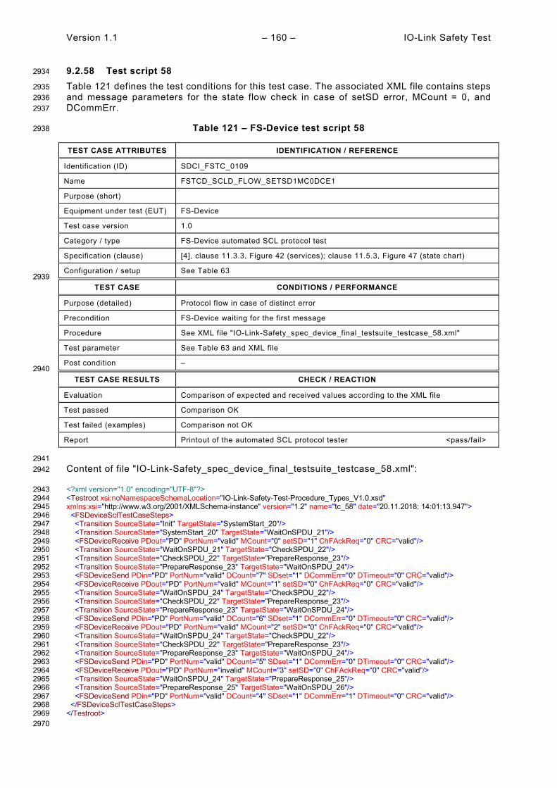
Version 1.1 – 160 – IO-Link Safety Test
9.2.58 Test script 58 2934
Table 121 defines the test conditions for this test case. The associated XML file contains steps 2935 and message parameters for the state flow check in case of setSD error, MCount = 0, and 2936 DCommErr. 2937
Table 121 – FS-Device test script 58 2938
TEST CASE ATTRIBUTES IDENTIFICATION / REFERENCE
Identification (ID) SDCI_FSTC_0109
Name FSTCD_SCLD_FLOW_SETSD1MC0DCE1
Purpose (short)
Equipment under test (EUT) FS-Device
Test case version 1.0
Category / type FS-Device automated SCL protocol test
Specification (clause) [4], clause 11.3.3, Figure 42 (services); clause 11.5.3, Figure 47 (state chart)
Configuration / setup See Table 63 2939
TEST CASE CONDITIONS / PERFORMANCE
Purpose (detailed) Protocol flow in case of distinct error
Precondition FS-Device waiting for the first message
Procedure See XML file "IO-Link-Safety_spec_device_final_testsuite_testcase_58.xml"
Test parameter See Table 63 and XML file
Post condition – 2940
TEST CASE RESULTS CHECK / REACTION
Evaluation Comparison of expected and received values according to the XML file
Test passed Comparison OK
Test failed (examples) Comparison not OK
Report Printout of the automated SCL protocol tester <pass/fail>
2941 Content of file "IO-Link-Safety_spec_device_final_testsuite_testcase_58.xml": 2942
<?xml version="1.0" encoding="UTF-8"?> 2943 <Testroot xsi:noNamespaceSchemaLocation="IO-Link-Safety-Test-Procedure_Types_V1.0.xsd" 2944 xmlns:xsi="http://www.w3.org/2001/XMLSchema-instance" version="1.2" name="tc_58" date="20.11.2018: 14:01:13.947"> 2945 <FSDeviceSclTestCaseSteps> 2946 <Transition SourceState="Init" TargetState="SystemStart_20"/> 2947 <Transition SourceState="SystemStart_20" TargetState="WaitOnSPDU_21"/> 2948 <FSDeviceReceive PDout="PD" PortNum="valid" MCount="0" setSD="1" ChFAckReq="0" CRC="valid"/> 2949 <Transition SourceState="WaitOnSPDU_21" TargetState="CheckSPDU_22"/> 2950 <Transition SourceState="CheckSPDU_22" TargetState="PrepareResponse_23"/> 2951 <Transition SourceState="PrepareResponse_23" TargetState="WaitOnSPDU_24"/> 2952 <FSDeviceSend PDin="PD" PortNum="valid" DCount="7" SDset="1" DCommErr="0" DTimeout="0" CRC="valid"/> 2953 <FSDeviceReceive PDout="PD" PortNum="valid" MCount="1" setSD="0" ChFAckReq="0" CRC="valid"/> 2954 <Transition SourceState="WaitOnSPDU_24" TargetState="CheckSPDU_22"/> 2955 <Transition SourceState="CheckSPDU_22" TargetState="PrepareResponse_23"/> 2956 <Transition SourceState="PrepareResponse_23" TargetState="WaitOnSPDU_24"/> 2957 <FSDeviceSend PDin="PD" PortNum="valid" DCount="6" SDset="1" DCommErr="0" DTimeout="0" CRC="valid"/> 2958 <FSDeviceReceive PDout="PD" PortNum="valid" MCount="2" setSD="0" ChFAckReq="0" CRC="valid"/> 2959 <Transition SourceState="WaitOnSPDU_24" TargetState="CheckSPDU_22"/> 2960 <Transition SourceState="CheckSPDU_22" TargetState="PrepareResponse_23"/> 2961 <Transition SourceState="PrepareResponse_23" TargetState="WaitOnSPDU_24"/> 2962 <FSDeviceSend PDin="PD" PortNum="valid" DCount="5" SDset="1" DCommErr="0" DTimeout="0" CRC="valid"/> 2963 <FSDeviceReceive PDout="PD" PortNum="invalid" MCount="3" setSD="0" ChFAckReq="0" CRC="valid"/> 2964 <Transition SourceState="WaitOnSPDU_24" TargetState="PrepareResponse_25"/> 2965 <Transition SourceState="PrepareResponse_25" TargetState="WaitOnSPDU_26"/> 2966 <FSDeviceSend PDin="PD" PortNum="valid" DCount="4" SDset="1" DCommErr="1" DTimeout="0" CRC="valid"/> 2967 </FSDeviceSclTestCaseSteps> 2968 </Testroot> 2969 2970

IO-Link Safety Test – 161 – Version 1.1
9.2.59 Test script 59 2971
Table 122 defines the test conditions for this test case. The associated XML file contains steps 2972 and message parameters for the state flow check in case of setSD error, MCount = 0, and 2973 DCommErr. 2974
Table 122 – FS-Device test script 59 2975
TEST CASE ATTRIBUTES IDENTIFICATION / REFERENCE
Identification (ID) SDCI_FSTC_0110
Name FSTCD_SCLD_FLOW_SETSD1MC0DCE1
Purpose (short)
Equipment under test (EUT) FS-Device
Test case version 1.0
Category / type FS-Device automated SCL protocol test
Specification (clause) [4], clause 11.3.3, Figure 42 (services); clause 11.5.3, Figure 47 (state chart)
Configuration / setup See Table 63 2976
TEST CASE CONDITIONS / PERFORMANCE
Purpose (detailed) Protocol flow in case of distinct error
Precondition FS-Device waiting for the first message
Procedure See XML file "IO-Link-Safety_spec_device_final_testsuite_testcase_59.xml"
Test parameter See Table 63 and XML file
Post condition – 2977
TEST CASE RESULTS CHECK / REACTION
Evaluation Comparison of expected and received values according to the XML file
Test passed Comparison OK
Test failed (examples) Comparison not OK
Report Printout of the automated SCL protocol tester <pass/fail>
2978 Content of file "IO-Link-Safety_spec_device_final_testsuite_testcase_59.xml": 2979
<?xml version="1.0" encoding="UTF-8"?> 2980 <Testroot xsi:noNamespaceSchemaLocation="IO-Link-Safety-Test-Procedure_Types_V1.0.xsd" 2981 xmlns:xsi="http://www.w3.org/2001/XMLSchema-instance" version="1.2" name="tc_59" date="20.11.2018: 14:01:13.947"> 2982 <FSDeviceSclTestCaseSteps> 2983 <Transition SourceState="Init" TargetState="SystemStart_20"/> 2984 <Transition SourceState="SystemStart_20" TargetState="WaitOnSPDU_21"/> 2985 <FSDeviceReceive PDout="PD" PortNum="valid" MCount="0" setSD="1" ChFAckReq="0" CRC="valid"/> 2986 <Transition SourceState="WaitOnSPDU_21" TargetState="CheckSPDU_22"/> 2987 <Transition SourceState="CheckSPDU_22" TargetState="PrepareResponse_23"/> 2988 <Transition SourceState="PrepareResponse_23" TargetState="WaitOnSPDU_24"/> 2989 <FSDeviceSend PDin="PD" PortNum="valid" DCount="7" SDset="1" DCommErr="0" DTimeout="0" CRC="valid"/> 2990 <FSDeviceReceive PDout="PD" PortNum="valid" MCount="1" setSD="0" ChFAckReq="0" CRC="valid"/> 2991 <Transition SourceState="WaitOnSPDU_24" TargetState="CheckSPDU_22"/> 2992 <Transition SourceState="CheckSPDU_22" TargetState="PrepareResponse_23"/> 2993 <Transition SourceState="PrepareResponse_23" TargetState="WaitOnSPDU_24"/> 2994 <FSDeviceSend PDin="PD" PortNum="valid" DCount="6" SDset="1" DCommErr="0" DTimeout="0" CRC="valid"/> 2995 <FSDeviceReceive PDout="PD" PortNum="valid" MCount="2" setSD="1" ChFAckReq="0" CRC="valid"/> 2996 <Transition SourceState="WaitOnSPDU_24" TargetState="CheckSPDU_22"/> 2997 <Transition SourceState="CheckSPDU_22" TargetState="PrepareResponse_23"/> 2998 <Transition SourceState="PrepareResponse_23" TargetState="WaitOnSPDU_24"/> 2999 <FSDeviceSend PDin="PD" PortNum="valid" DCount="5" SDset="1" DCommErr="0" DTimeout="0" CRC="valid"/> 3000 <FSDeviceReceive PDout="PD" PortNum="valid" MCount="1" setSD="0" ChFAckReq="0" CRC="invalid"/> 3001 <Transition SourceState="WaitOnSPDU_24" TargetState="PrepareResponse_25"/> 3002 <Transition SourceState="PrepareResponse_25" TargetState="WaitOnSPDU_26"/> 3003 <FSDeviceSend PDin="PD" PortNum="valid" DCount="6" SDset="1" DCommErr="1" DTimeout="0" CRC="valid"/> 3004 </FSDeviceSclTestCaseSteps> 3005 </Testroot> 3006 3007

Version 1.1 – 162 – IO-Link Safety Test
9.2.60 Test script 60 3008
Table 123 defines the test conditions for this test case. The associated XML file contains steps 3009 and message parameters for the state flow check in case of setSD error, MCount = 0, and 3010 DCommErr. 3011
Table 123 – FS-Device test script 60 3012
TEST CASE ATTRIBUTES IDENTIFICATION / REFERENCE
Identification (ID) SDCI_FSTC_0111
Name FSTCD_SCLD_FLOW_SETSD1MC0DCE1
Purpose (short)
Equipment under test (EUT) FS-Device
Test case version 1.0
Category / type FS-Device automated SCL protocol test
Specification (clause) [4], clause 11.3.3, Figure 42 (services); clause 11.5.3, Figure 47 (state chart)
Configuration / setup See Table 63 3013
TEST CASE CONDITIONS / PERFORMANCE
Purpose (detailed) Protocol flow in case of distinct error
Precondition FS-Device waiting for the first message
Procedure See XML file "IO-Link-Safety_spec_device_final_testsuite_testcase_60.xml"
Test parameter See Table 63 and XML file
Post condition – 3014
TEST CASE RESULTS CHECK / REACTION
Evaluation Comparison of expected and received values according to the XML file
Test passed Comparison OK
Test failed (examples) Comparison not OK
Report Printout of the automated SCL protocol tester <pass/fail>
3015 Content of file "IO-Link-Safety_spec_device_final_testsuite_testcase_60.xml": 3016
<?xml version="1.0" encoding="UTF-8"?> 3017 <Testroot xsi:noNamespaceSchemaLocation="IO-Link-Safety-Test-Procedure_Types_V1.0.xsd" 3018 xmlns:xsi="http://www.w3.org/2001/XMLSchema-instance" version="1.2" name="tc_60" date="20.11.2018: 14:01:13.948"> 3019 <FSDeviceSclTestCaseSteps> 3020 <Transition SourceState="Init" TargetState="SystemStart_20"/> 3021 <Transition SourceState="SystemStart_20" TargetState="WaitOnSPDU_21"/> 3022 <FSDeviceReceive PDout="PD" PortNum="valid" MCount="0" setSD="1" ChFAckReq="0" CRC="valid"/> 3023 <Transition SourceState="WaitOnSPDU_21" TargetState="CheckSPDU_22"/> 3024 <Transition SourceState="CheckSPDU_22" TargetState="PrepareResponse_23"/> 3025 <Transition SourceState="PrepareResponse_23" TargetState="WaitOnSPDU_24"/> 3026 <FSDeviceSend PDin="PD" PortNum="valid" DCount="7" SDset="1" DCommErr="0" DTimeout="0" CRC="valid"/> 3027 <FSDeviceReceive PDout="PD" PortNum="valid" MCount="1" setSD="0" ChFAckReq="0" CRC="valid"/> 3028 <Transition SourceState="WaitOnSPDU_24" TargetState="CheckSPDU_22"/> 3029 <Transition SourceState="CheckSPDU_22" TargetState="PrepareResponse_23"/> 3030 <Transition SourceState="PrepareResponse_23" TargetState="WaitOnSPDU_24"/> 3031 <FSDeviceSend PDin="PD" PortNum="valid" DCount="6" SDset="1" DCommErr="0" DTimeout="0" CRC="valid"/> 3032 <FSDeviceReceive PDout="PD" PortNum="valid" MCount="2" setSD="1" ChFAckReq="0" CRC="valid"/> 3033 <Transition SourceState="WaitOnSPDU_24" TargetState="CheckSPDU_22"/> 3034 <Transition SourceState="CheckSPDU_22" TargetState="PrepareResponse_23"/> 3035 <Transition SourceState="PrepareResponse_23" TargetState="WaitOnSPDU_24"/> 3036 <FSDeviceSend PDin="PD" PortNum="valid" DCount="5" SDset="1" DCommErr="0" DTimeout="0" CRC="valid"/> 3037 <FSDeviceReceive PDout="PD" PortNum="valid" MCount="3" setSD="0" ChFAckReq="0" CRC="invalid"/> 3038 <Transition SourceState="WaitOnSPDU_24" TargetState="PrepareResponse_25"/> 3039 <Transition SourceState="PrepareResponse_25" TargetState="WaitOnSPDU_26"/> 3040 <FSDeviceSend PDin="PD" PortNum="valid" DCount="4" SDset="1" DCommErr="1" DTimeout="0" CRC="valid"/> 3041 </FSDeviceSclTestCaseSteps> 3042 </Testroot> 3043 3044
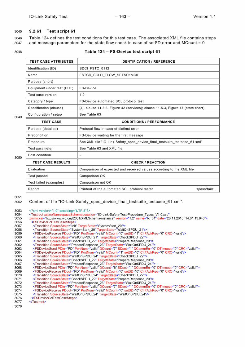
IO-Link Safety Test – 163 – Version 1.1
9.2.61 Test script 61 3045
Table 124 defines the test conditions for this test case. The associated XML file contains steps 3046 and message parameters for the state flow check in case of setSD error and MCount = 0. 3047
Table 124 – FS-Device test script 61 3048
TEST CASE ATTRIBUTES IDENTIFICATION / REFERENCE
Identification (ID) SDCI_FSTC_0112
Name FSTCD_SCLD_FLOW_SETSD1MC0
Purpose (short)
Equipment under test (EUT) FS-Device
Test case version 1.0
Category / type FS-Device automated SCL protocol test
Specification (clause) [4], clause 11.3.3, Figure 42 (services); clause 11.5.3, Figure 47 (state chart)
Configuration / setup See Table 63 3049
TEST CASE CONDITIONS / PERFORMANCE
Purpose (detailed) Protocol flow in case of distinct error
Precondition FS-Device waiting for the first message
Procedure See XML file "IO-Link-Safety_spec_device_final_testsuite_testcase_61.xml"
Test parameter See Table 63 and XML file
Post condition – 3050
TEST CASE RESULTS CHECK / REACTION
Evaluation Comparison of expected and received values according to the XML file
Test passed Comparison OK
Test failed (examples) Comparison not OK
Report Printout of the automated SCL protocol tester <pass/fail>
3051 Content of file "IO-Link-Safety_spec_device_final_testsuite_testcase_61.xml": 3052
<?xml version="1.0" encoding="UTF-8"?> 3053 <Testroot xsi:noNamespaceSchemaLocation="IO-Link-Safety-Test-Procedure_Types_V1.0.xsd" 3054 xmlns:xsi="http://www.w3.org/2001/XMLSchema-instance" version="1.2" name="tc_61" date="20.11.2018: 14:01:13.948"> 3055 <FSDeviceSclTestCaseSteps> 3056 <Transition SourceState="Init" TargetState="SystemStart_20"/> 3057 <Transition SourceState="SystemStart_20" TargetState="WaitOnSPDU_21"/> 3058 <FSDeviceReceive PDout="PD" PortNum="valid" MCount="0" setSD="1" ChFAckReq="0" CRC="valid"/> 3059 <Transition SourceState="WaitOnSPDU_21" TargetState="CheckSPDU_22"/> 3060 <Transition SourceState="CheckSPDU_22" TargetState="PrepareResponse_23"/> 3061 <Transition SourceState="PrepareResponse_23" TargetState="WaitOnSPDU_24"/> 3062 <FSDeviceSend PDin="PD" PortNum="valid" DCount="7" SDset="1" DCommErr="0" DTimeout="0" CRC="valid"/> 3063 <FSDeviceReceive PDout="PD" PortNum="valid" MCount="1" setSD="0" ChFAckReq="0" CRC="valid"/> 3064 <Transition SourceState="WaitOnSPDU_24" TargetState="CheckSPDU_22"/> 3065 <Transition SourceState="CheckSPDU_22" TargetState="PrepareResponse_23"/> 3066 <Transition SourceState="PrepareResponse_23" TargetState="WaitOnSPDU_24"/> 3067 <FSDeviceSend PDin="PD" PortNum="valid" DCount="6" SDset="1" DCommErr="0" DTimeout="0" CRC="valid"/> 3068 <FSDeviceReceive PDout="PD" PortNum="valid" MCount="0" setSD="0" ChFAckReq="0" CRC="valid"/> 3069 <Transition SourceState="WaitOnSPDU_24" TargetState="CheckSPDU_22"/> 3070 <Transition SourceState="CheckSPDU_22" TargetState="PrepareResponse_23"/> 3071 <Transition SourceState="PrepareResponse_23" TargetState="WaitOnSPDU_24"/> 3072 <FSDeviceSend PDin="PD" PortNum="valid" DCount="7" SDset="1" DCommErr="0" DTimeout="0" CRC="valid"/> 3073 <FSDeviceReceive PDout="PD" PortNum="valid" MCount="0" setSD="0" ChFAckReq="0" CRC="valid"/> 3074 <Transition SourceState="WaitOnSPDU_24" TargetState="WaitOnSPDU_24"/> 3075 </FSDeviceSclTestCaseSteps> 3076 </Testroot> 3077 3078

Version 1.1 – 164 – IO-Link Safety Test
9.2.62 Test script 62 3079
Table 124 defines the test conditions for this test case. The associated XML file contains steps 3080 and message parameters for the state flow check in case of setSD error, MCount = 0, and 3081 DCommErr. 3082
Table 125 – FS-Device test script 62 3083
TEST CASE ATTRIBUTES IDENTIFICATION / REFERENCE
Identification (ID) SDCI_FSTC_0113
Name FSTCD_SCLD_FLOW_SETSD1MC0DCE1
Purpose (short)
Equipment under test (EUT) FS-Device
Test case version 1.0
Category / type FS-Device automated SCL protocol test
Specification (clause) [4], clause 11.3.3, Figure 42 (services); clause 11.5.3, Figure 47 (state chart)
Configuration / setup See Table 63 3084
TEST CASE CONDITIONS / PERFORMANCE
Purpose (detailed) Protocol flow in case of distinct error
Precondition FS-Device waiting for the first message
Procedure See XML file "IO-Link-Safety_spec_device_final_testsuite_testcase_62.xml"
Test parameter See Table 63 and XML file
Post condition – 3085
TEST CASE RESULTS CHECK / REACTION
Evaluation Comparison of expected and received values according to the XML file
Test passed Comparison OK
Test failed (examples) Comparison not OK
Report Printout of the automated SCL protocol tester <pass/fail>
3086 Content of file "IO-Link-Safety_spec_device_final_testsuite_testcase_62.xml": 3087
<?xml version="1.0" encoding="UTF-8"?> 3088 <Testroot xsi:noNamespaceSchemaLocation="IO-Link-Safety-Test-Procedure_Types_V1.0.xsd" 3089 xmlns:xsi="http://www.w3.org/2001/XMLSchema-instance" version="1.2" name="tc_62" date="20.11.2018: 14:01:13.948"> 3090 <FSDeviceSclTestCaseSteps> 3091 <Transition SourceState="Init" TargetState="SystemStart_20"/> 3092 <Transition SourceState="SystemStart_20" TargetState="WaitOnSPDU_21"/> 3093 <FSDeviceReceive PDout="PD" PortNum="valid" MCount="0" setSD="1" ChFAckReq="0" CRC="valid"/> 3094 <Transition SourceState="WaitOnSPDU_21" TargetState="CheckSPDU_22"/> 3095 <Transition SourceState="CheckSPDU_22" TargetState="PrepareResponse_23"/> 3096 <Transition SourceState="PrepareResponse_23" TargetState="WaitOnSPDU_24"/> 3097 <FSDeviceSend PDin="PD" PortNum="valid" DCount="7" SDset="1" DCommErr="0" DTimeout="0" CRC="valid"/> 3098 <FSDeviceReceive PDout="PD" PortNum="valid" MCount="1" setSD="0" ChFAckReq="0" CRC="valid"/> 3099 <Transition SourceState="WaitOnSPDU_24" TargetState="CheckSPDU_22"/> 3100 <Transition SourceState="CheckSPDU_22" TargetState="PrepareResponse_23"/> 3101 <Transition SourceState="PrepareResponse_23" TargetState="WaitOnSPDU_24"/> 3102 <FSDeviceSend PDin="PD" PortNum="valid" DCount="6" SDset="1" DCommErr="0" DTimeout="0" CRC="valid"/> 3103 <FSDeviceReceive PDout="PD" PortNum="valid" MCount="0" setSD="0" ChFAckReq="0" CRC="valid"/> 3104 <Transition SourceState="WaitOnSPDU_24" TargetState="CheckSPDU_22"/> 3105 <Transition SourceState="CheckSPDU_22" TargetState="PrepareResponse_23"/> 3106 <Transition SourceState="PrepareResponse_23" TargetState="WaitOnSPDU_24"/> 3107 <FSDeviceSend PDin="PD" PortNum="valid" DCount="7" SDset="1" DCommErr="0" DTimeout="0" CRC="valid"/> 3108 <FSDeviceReceive PDout="PD" PortNum="invalid" MCount="2" setSD="0" ChFAckReq="0" CRC="valid"/> 3109 <Transition SourceState="WaitOnSPDU_24" TargetState="PrepareResponse_25"/> 3110 <Transition SourceState="PrepareResponse_25" TargetState="WaitOnSPDU_26"/> 3111 <FSDeviceSend PDin="PD" PortNum="valid" DCount="5" SDset="1" DCommErr="1" DTimeout="0" CRC="valid"/> 3112 </FSDeviceSclTestCaseSteps> 3113 </Testroot> 3114 3115

IO-Link Safety Test – 165 – Version 1.1
9.2.63 Test script 63 3116
Table 126 defines the test conditions for this test case. The associated XML file contains steps 3117 and message parameters for the state flow check in case of setSD error, MCount = 0, and 3118 DCommErr. 3119
Table 126 – FS-Device test script 63 3120
TEST CASE ATTRIBUTES IDENTIFICATION / REFERENCE
Identification (ID) SDCI_FSTC_0114
Name FSTCD_SCLD_FLOW_SETSD1MC0DCE1
Purpose (short)
Equipment under test (EUT) FS-Device
Test case version 1.0
Category / type FS-Device automated SCL protocol test
Specification (clause) [4], clause 11.3.3, Figure 42 (services); clause 11.5.3, Figure 47 (state chart)
Configuration / setup See Table 63 3121
TEST CASE CONDITIONS / PERFORMANCE
Purpose (detailed) Protocol flow in case of distinct error
Precondition FS-Device waiting for the first message
Procedure See XML file "IO-Link-Safety_spec_device_final_testsuite_testcase_63.xml"
Test parameter See Table 63 and XML file
Post condition – 3122
TEST CASE RESULTS CHECK / REACTION
Evaluation Comparison of expected and received values according to the XML file
Test passed Comparison OK
Test failed (examples) Comparison not OK
Report Printout of the automated SCL protocol tester <pass/fail>
3123 Content of file "IO-Link-Safety_spec_device_final_testsuite_testcase_63.xml": 3124
<?xml version="1.0" encoding="UTF-8"?> 3125 <Testroot xsi:noNamespaceSchemaLocation="IO-Link-Safety-Test-Procedure_Types_V1.0.xsd" 3126 xmlns:xsi="http://www.w3.org/2001/XMLSchema-instance" version="1.2" name="tc_63" date="20.11.2018: 14:01:13.948"> 3127 <FSDeviceSclTestCaseSteps> 3128 <Transition SourceState="Init" TargetState="SystemStart_20"/> 3129 <Transition SourceState="SystemStart_20" TargetState="WaitOnSPDU_21"/> 3130 <FSDeviceReceive PDout="PD" PortNum="valid" MCount="0" setSD="1" ChFAckReq="0" CRC="valid"/> 3131 <Transition SourceState="WaitOnSPDU_21" TargetState="CheckSPDU_22"/> 3132 <Transition SourceState="CheckSPDU_22" TargetState="PrepareResponse_23"/> 3133 <Transition SourceState="PrepareResponse_23" TargetState="WaitOnSPDU_24"/> 3134 <FSDeviceSend PDin="PD" PortNum="valid" DCount="7" SDset="1" DCommErr="0" DTimeout="0" CRC="valid"/> 3135 <FSDeviceReceive PDout="PD" PortNum="valid" MCount="1" setSD="0" ChFAckReq="0" CRC="valid"/> 3136 <Transition SourceState="WaitOnSPDU_24" TargetState="CheckSPDU_22"/> 3137 <Transition SourceState="CheckSPDU_22" TargetState="PrepareResponse_23"/> 3138 <Transition SourceState="PrepareResponse_23" TargetState="WaitOnSPDU_24"/> 3139 <FSDeviceSend PDin="PD" PortNum="valid" DCount="6" SDset="1" DCommErr="0" DTimeout="0" CRC="valid"/> 3140 <FSDeviceReceive PDout="PD" PortNum="valid" MCount="2" setSD="0" ChFAckReq="0" CRC="valid"/> 3141 <Transition SourceState="WaitOnSPDU_24" TargetState="CheckSPDU_22"/> 3142 <Transition SourceState="CheckSPDU_22" TargetState="PrepareResponse_23"/> 3143 <Transition SourceState="PrepareResponse_23" TargetState="WaitOnSPDU_24"/> 3144 <FSDeviceSend PDin="PD" PortNum="valid" DCount="5" SDset="1" DCommErr="0" DTimeout="0" CRC="valid"/> 3145 <FSDeviceReceive PDout="PD" PortNum="valid" MCount="4" setSD="0" ChFAckReq="0" CRC="valid"/> 3146 <Transition SourceState="WaitOnSPDU_24" TargetState="CheckSPDU_22"/> 3147 <Transition SourceState="CheckSPDU_22" TargetState="PrepareResponse_25"/> 3148 <Transition SourceState="PrepareResponse_25" TargetState="WaitOnSPDU_26"/> 3149 <FSDeviceSend PDin="PD" PortNum="valid" DCount="3" SDset="1" DCommErr="1" DTimeout="0" CRC="valid"/> 3150 </FSDeviceSclTestCaseSteps> 3151 </Testroot> 3152
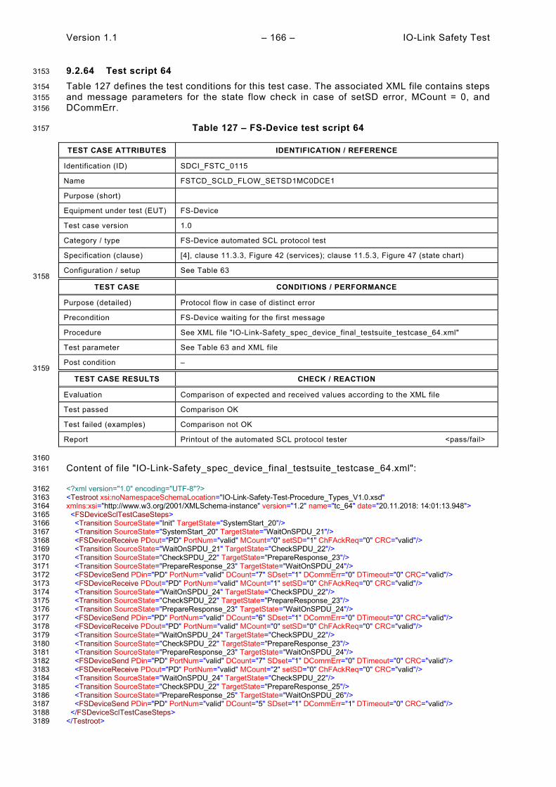
Version 1.1 – 166 – IO-Link Safety Test
9.2.64 Test script 64 3153
Table 127 defines the test conditions for this test case. The associated XML file contains steps 3154 and message parameters for the state flow check in case of setSD error, MCount = 0, and 3155 DCommErr. 3156
Table 127 – FS-Device test script 64 3157
TEST CASE ATTRIBUTES IDENTIFICATION / REFERENCE
Identification (ID) SDCI_FSTC_0115
Name FSTCD_SCLD_FLOW_SETSD1MC0DCE1
Purpose (short)
Equipment under test (EUT) FS-Device
Test case version 1.0
Category / type FS-Device automated SCL protocol test
Specification (clause) [4], clause 11.3.3, Figure 42 (services); clause 11.5.3, Figure 47 (state chart)
Configuration / setup See Table 63 3158
TEST CASE CONDITIONS / PERFORMANCE
Purpose (detailed) Protocol flow in case of distinct error
Precondition FS-Device waiting for the first message
Procedure See XML file "IO-Link-Safety_spec_device_final_testsuite_testcase_64.xml"
Test parameter See Table 63 and XML file
Post condition – 3159
TEST CASE RESULTS CHECK / REACTION
Evaluation Comparison of expected and received values according to the XML file
Test passed Comparison OK
Test failed (examples) Comparison not OK
Report Printout of the automated SCL protocol tester <pass/fail>
3160 Content of file "IO-Link-Safety_spec_device_final_testsuite_testcase_64.xml": 3161
<?xml version="1.0" encoding="UTF-8"?> 3162 <Testroot xsi:noNamespaceSchemaLocation="IO-Link-Safety-Test-Procedure_Types_V1.0.xsd" 3163 xmlns:xsi="http://www.w3.org/2001/XMLSchema-instance" version="1.2" name="tc_64" date="20.11.2018: 14:01:13.948"> 3164 <FSDeviceSclTestCaseSteps> 3165 <Transition SourceState="Init" TargetState="SystemStart_20"/> 3166 <Transition SourceState="SystemStart_20" TargetState="WaitOnSPDU_21"/> 3167 <FSDeviceReceive PDout="PD" PortNum="valid" MCount="0" setSD="1" ChFAckReq="0" CRC="valid"/> 3168 <Transition SourceState="WaitOnSPDU_21" TargetState="CheckSPDU_22"/> 3169 <Transition SourceState="CheckSPDU_22" TargetState="PrepareResponse_23"/> 3170 <Transition SourceState="PrepareResponse_23" TargetState="WaitOnSPDU_24"/> 3171 <FSDeviceSend PDin="PD" PortNum="valid" DCount="7" SDset="1" DCommErr="0" DTimeout="0" CRC="valid"/> 3172 <FSDeviceReceive PDout="PD" PortNum="valid" MCount="1" setSD="0" ChFAckReq="0" CRC="valid"/> 3173 <Transition SourceState="WaitOnSPDU_24" TargetState="CheckSPDU_22"/> 3174 <Transition SourceState="CheckSPDU_22" TargetState="PrepareResponse_23"/> 3175 <Transition SourceState="PrepareResponse_23" TargetState="WaitOnSPDU_24"/> 3176 <FSDeviceSend PDin="PD" PortNum="valid" DCount="6" SDset="1" DCommErr="0" DTimeout="0" CRC="valid"/> 3177 <FSDeviceReceive PDout="PD" PortNum="valid" MCount="0" setSD="0" ChFAckReq="0" CRC="valid"/> 3178 <Transition SourceState="WaitOnSPDU_24" TargetState="CheckSPDU_22"/> 3179 <Transition SourceState="CheckSPDU_22" TargetState="PrepareResponse_23"/> 3180 <Transition SourceState="PrepareResponse_23" TargetState="WaitOnSPDU_24"/> 3181 <FSDeviceSend PDin="PD" PortNum="valid" DCount="7" SDset="1" DCommErr="0" DTimeout="0" CRC="valid"/> 3182 <FSDeviceReceive PDout="PD" PortNum="valid" MCount="2" setSD="0" ChFAckReq="0" CRC="valid"/> 3183 <Transition SourceState="WaitOnSPDU_24" TargetState="CheckSPDU_22"/> 3184 <Transition SourceState="CheckSPDU_22" TargetState="PrepareResponse_25"/> 3185 <Transition SourceState="PrepareResponse_25" TargetState="WaitOnSPDU_26"/> 3186 <FSDeviceSend PDin="PD" PortNum="valid" DCount="5" SDset="1" DCommErr="1" DTimeout="0" CRC="valid"/> 3187 </FSDeviceSclTestCaseSteps> 3188 </Testroot> 3189
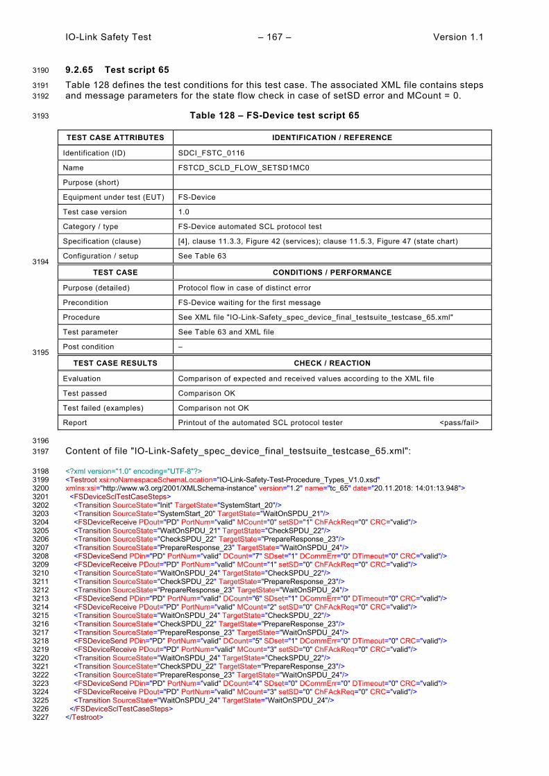
IO-Link Safety Test – 167 – Version 1.1
9.2.65 Test script 65 3190
Table 128 defines the test conditions for this test case. The associated XML file contains steps 3191 and message parameters for the state flow check in case of setSD error and MCount = 0. 3192
Table 128 – FS-Device test script 65 3193
TEST CASE ATTRIBUTES IDENTIFICATION / REFERENCE
Identification (ID) SDCI_FSTC_0116
Name FSTCD_SCLD_FLOW_SETSD1MC0
Purpose (short)
Equipment under test (EUT) FS-Device
Test case version 1.0
Category / type FS-Device automated SCL protocol test
Specification (clause) [4], clause 11.3.3, Figure 42 (services); clause 11.5.3, Figure 47 (state chart)
Configuration / setup See Table 63 3194
TEST CASE CONDITIONS / PERFORMANCE
Purpose (detailed) Protocol flow in case of distinct error
Precondition FS-Device waiting for the first message
Procedure See XML file "IO-Link-Safety_spec_device_final_testsuite_testcase_65.xml"
Test parameter See Table 63 and XML file
Post condition – 3195
TEST CASE RESULTS CHECK / REACTION
Evaluation Comparison of expected and received values according to the XML file
Test passed Comparison OK
Test failed (examples) Comparison not OK
Report Printout of the automated SCL protocol tester <pass/fail>
3196 Content of file "IO-Link-Safety_spec_device_final_testsuite_testcase_65.xml": 3197
<?xml version="1.0" encoding="UTF-8"?> 3198 <Testroot xsi:noNamespaceSchemaLocation="IO-Link-Safety-Test-Procedure_Types_V1.0.xsd" 3199 xmlns:xsi="http://www.w3.org/2001/XMLSchema-instance" version="1.2" name="tc_65" date="20.11.2018: 14:01:13.948"> 3200 <FSDeviceSclTestCaseSteps> 3201 <Transition SourceState="Init" TargetState="SystemStart_20"/> 3202 <Transition SourceState="SystemStart_20" TargetState="WaitOnSPDU_21"/> 3203 <FSDeviceReceive PDout="PD" PortNum="valid" MCount="0" setSD="1" ChFAckReq="0" CRC="valid"/> 3204 <Transition SourceState="WaitOnSPDU_21" TargetState="CheckSPDU_22"/> 3205 <Transition SourceState="CheckSPDU_22" TargetState="PrepareResponse_23"/> 3206 <Transition SourceState="PrepareResponse_23" TargetState="WaitOnSPDU_24"/> 3207 <FSDeviceSend PDin="PD" PortNum="valid" DCount="7" SDset="1" DCommErr="0" DTimeout="0" CRC="valid"/> 3208 <FSDeviceReceive PDout="PD" PortNum="valid" MCount="1" setSD="0" ChFAckReq="0" CRC="valid"/> 3209 <Transition SourceState="WaitOnSPDU_24" TargetState="CheckSPDU_22"/> 3210 <Transition SourceState="CheckSPDU_22" TargetState="PrepareResponse_23"/> 3211 <Transition SourceState="PrepareResponse_23" TargetState="WaitOnSPDU_24"/> 3212 <FSDeviceSend PDin="PD" PortNum="valid" DCount="6" SDset="1" DCommErr="0" DTimeout="0" CRC="valid"/> 3213 <FSDeviceReceive PDout="PD" PortNum="valid" MCount="2" setSD="0" ChFAckReq="0" CRC="valid"/> 3214 <Transition SourceState="WaitOnSPDU_24" TargetState="CheckSPDU_22"/> 3215 <Transition SourceState="CheckSPDU_22" TargetState="PrepareResponse_23"/> 3216 <Transition SourceState="PrepareResponse_23" TargetState="WaitOnSPDU_24"/> 3217 <FSDeviceSend PDin="PD" PortNum="valid" DCount="5" SDset="1" DCommErr="0" DTimeout="0" CRC="valid"/> 3218 <FSDeviceReceive PDout="PD" PortNum="valid" MCount="3" setSD="0" ChFAckReq="0" CRC="valid"/> 3219 <Transition SourceState="WaitOnSPDU_24" TargetState="CheckSPDU_22"/> 3220 <Transition SourceState="CheckSPDU_22" TargetState="PrepareResponse_23"/> 3221 <Transition SourceState="PrepareResponse_23" TargetState="WaitOnSPDU_24"/> 3222 <FSDeviceSend PDin="PD" PortNum="valid" DCount="4" SDset="0" DCommErr="0" DTimeout="0" CRC="valid"/> 3223 <FSDeviceReceive PDout="PD" PortNum="valid" MCount="3" setSD="0" ChFAckReq="0" CRC="valid"/> 3224 <Transition SourceState="WaitOnSPDU_24" TargetState="WaitOnSPDU_24"/> 3225 </FSDeviceSclTestCaseSteps> 3226 </Testroot> 3227

Version 1.1 – 168 – IO-Link Safety Test
9.2.66 Test script 66 3228
Table 129 defines the test conditions for this test case. The associated XML file contains steps 3229 and message parameters for the state flow check in case of setSD error and MCount = 0. 3230
Table 129 – FS-Device test script 66 3231
TEST CASE ATTRIBUTES IDENTIFICATION / REFERENCE
Identification (ID) SDCI_FSTC_0117
Name FSTCD_SCLD_FLOW_SETSD1MC0
Purpose (short)
Equipment under test (EUT) FS-Device
Test case version 1.0
Category / type FS-Device automated SCL protocol test
Specification (clause) [4], clause 11.3.3, Figure 42 (services); clause 11.5.3, Figure 47 (state chart)
Configuration / setup See Table 63 3232
TEST CASE CONDITIONS / PERFORMANCE
Purpose (detailed) Protocol flow in case of distinct error
Precondition FS-Device waiting for the first message
Procedure See XML file "IO-Link-Safety_spec_device_final_testsuite_testcase_66.xml"
Test parameter See Table 63 and XML file
Post condition – 3233
TEST CASE RESULTS CHECK / REACTION
Evaluation Comparison of expected and received values according to the XML file
Test passed Comparison OK
Test failed (examples) Comparison not OK
Report Printout of the automated SCL protocol tester <pass/fail>
3234 Content of file "IO-Link-Safety_spec_device_final_testsuite_testcase_66.xml": 3235
<?xml version="1.0" encoding="UTF-8"?> 3236 <Testroot xsi:noNamespaceSchemaLocation="IO-Link-Safety-Test-Procedure_Types_V1.0.xsd" 3237 xmlns:xsi="http://www.w3.org/2001/XMLSchema-instance" version="1.2" name="tc_66" date="20.11.2018: 14:01:13.948"> 3238 <FSDeviceSclTestCaseSteps> 3239 <Transition SourceState="Init" TargetState="SystemStart_20"/> 3240 <Transition SourceState="SystemStart_20" TargetState="WaitOnSPDU_21"/> 3241 <FSDeviceReceive PDout="PD" PortNum="valid" MCount="0" setSD="1" ChFAckReq="0" CRC="valid"/> 3242 <Transition SourceState="WaitOnSPDU_21" TargetState="CheckSPDU_22"/> 3243 <Transition SourceState="CheckSPDU_22" TargetState="PrepareResponse_23"/> 3244 <Transition SourceState="PrepareResponse_23" TargetState="WaitOnSPDU_24"/> 3245 <FSDeviceSend PDin="PD" PortNum="valid" DCount="7" SDset="1" DCommErr="0" DTimeout="0" CRC="valid"/> 3246 <FSDeviceReceive PDout="PD" PortNum="valid" MCount="1" setSD="0" ChFAckReq="0" CRC="valid"/> 3247 <Transition SourceState="WaitOnSPDU_24" TargetState="CheckSPDU_22"/> 3248 <Transition SourceState="CheckSPDU_22" TargetState="PrepareResponse_23"/> 3249 <Transition SourceState="PrepareResponse_23" TargetState="WaitOnSPDU_24"/> 3250 <FSDeviceSend PDin="PD" PortNum="valid" DCount="6" SDset="1" DCommErr="0" DTimeout="0" CRC="valid"/> 3251 <FSDeviceReceive PDout="PD" PortNum="valid" MCount="2" setSD="0" ChFAckReq="0" CRC="valid"/> 3252 <Transition SourceState="WaitOnSPDU_24" TargetState="CheckSPDU_22"/> 3253 <Transition SourceState="CheckSPDU_22" TargetState="PrepareResponse_23"/> 3254 <Transition SourceState="PrepareResponse_23" TargetState="WaitOnSPDU_24"/> 3255 <FSDeviceSend PDin="PD" PortNum="valid" DCount="5" SDset="1" DCommErr="0" DTimeout="0" CRC="valid"/> 3256 <FSDeviceReceive PDout="PD" PortNum="valid" MCount="3" setSD="0" ChFAckReq="0" CRC="valid"/> 3257 <Transition SourceState="WaitOnSPDU_24" TargetState="CheckSPDU_22"/> 3258 <Transition SourceState="CheckSPDU_22" TargetState="PrepareResponse_23"/> 3259 <Transition SourceState="PrepareResponse_23" TargetState="WaitOnSPDU_24"/> 3260 <FSDeviceSend PDin="PD" PortNum="valid" DCount="4" SDset="0" DCommErr="0" DTimeout="0" CRC="valid"/> 3261 <FSDeviceReceive PDout="PD" PortNum="invalid" MCount="1" setSD="0" ChFAckReq="0" CRC="valid"/> 3262 <Transition SourceState="WaitOnSPDU_24" TargetState="PrepareResponse_25"/> 3263 <Transition SourceState="PrepareResponse_25" TargetState="WaitOnSPDU_26"/> 3264 <FSDeviceSend PDin="PD" PortNum="valid" DCount="6" SDset="1" DCommErr="1" DTimeout="0" CRC="valid"/> 3265

IO-Link Safety Test – 169 – Version 1.1
</FSDeviceSclTestCaseSteps> 3266 </Testroot> 3267 3268
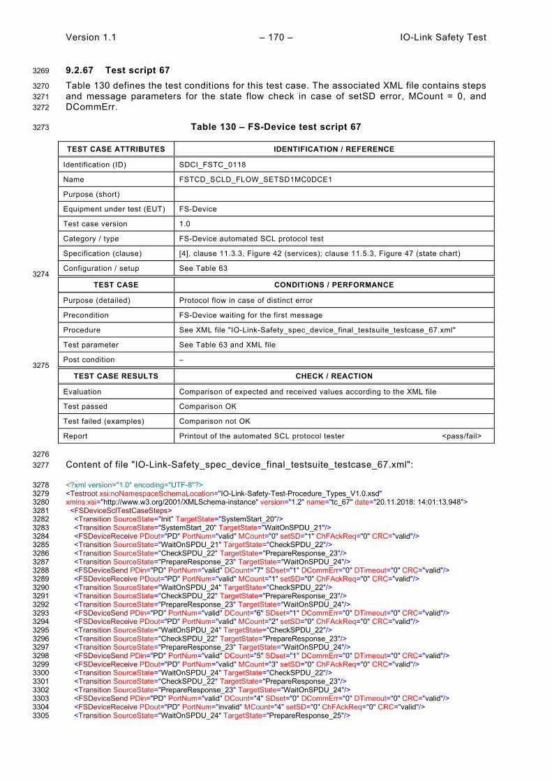
Version 1.1 – 170 – IO-Link Safety Test
9.2.67 Test script 67 3269
Table 130 defines the test conditions for this test case. The associated XML file contains steps 3270 and message parameters for the state flow check in case of setSD error, MCount = 0, and 3271 DCommErr. 3272
Table 130 – FS-Device test script 67 3273
TEST CASE ATTRIBUTES IDENTIFICATION / REFERENCE
Identification (ID) SDCI_FSTC_0118
Name FSTCD_SCLD_FLOW_SETSD1MC0DCE1
Purpose (short)
Equipment under test (EUT) FS-Device
Test case version 1.0
Category / type FS-Device automated SCL protocol test
Specification (clause) [4], clause 11.3.3, Figure 42 (services); clause 11.5.3, Figure 47 (state chart)
Configuration / setup See Table 63 3274
TEST CASE CONDITIONS / PERFORMANCE
Purpose (detailed) Protocol flow in case of distinct error
Precondition FS-Device waiting for the first message
Procedure See XML file "IO-Link-Safety_spec_device_final_testsuite_testcase_67.xml"
Test parameter See Table 63 and XML file
Post condition – 3275
TEST CASE RESULTS CHECK / REACTION
Evaluation Comparison of expected and received values according to the XML file
Test passed Comparison OK
Test failed (examples) Comparison not OK
Report Printout of the automated SCL protocol tester <pass/fail>
3276 Content of file "IO-Link-Safety_spec_device_final_testsuite_testcase_67.xml": 3277
<?xml version="1.0" encoding="UTF-8"?> 3278 <Testroot xsi:noNamespaceSchemaLocation="IO-Link-Safety-Test-Procedure_Types_V1.0.xsd" 3279 xmlns:xsi="http://www.w3.org/2001/XMLSchema-instance" version="1.2" name="tc_67" date="20.11.2018: 14:01:13.948"> 3280 <FSDeviceSclTestCaseSteps> 3281 <Transition SourceState="Init" TargetState="SystemStart_20"/> 3282 <Transition SourceState="SystemStart_20" TargetState="WaitOnSPDU_21"/> 3283 <FSDeviceReceive PDout="PD" PortNum="valid" MCount="0" setSD="1" ChFAckReq="0" CRC="valid"/> 3284 <Transition SourceState="WaitOnSPDU_21" TargetState="CheckSPDU_22"/> 3285 <Transition SourceState="CheckSPDU_22" TargetState="PrepareResponse_23"/> 3286 <Transition SourceState="PrepareResponse_23" TargetState="WaitOnSPDU_24"/> 3287 <FSDeviceSend PDin="PD" PortNum="valid" DCount="7" SDset="1" DCommErr="0" DTimeout="0" CRC="valid"/> 3288 <FSDeviceReceive PDout="PD" PortNum="valid" MCount="1" setSD="0" ChFAckReq="0" CRC="valid"/> 3289 <Transition SourceState="WaitOnSPDU_24" TargetState="CheckSPDU_22"/> 3290 <Transition SourceState="CheckSPDU_22" TargetState="PrepareResponse_23"/> 3291 <Transition SourceState="PrepareResponse_23" TargetState="WaitOnSPDU_24"/> 3292 <FSDeviceSend PDin="PD" PortNum="valid" DCount="6" SDset="1" DCommErr="0" DTimeout="0" CRC="valid"/> 3293 <FSDeviceReceive PDout="PD" PortNum="valid" MCount="2" setSD="0" ChFAckReq="0" CRC="valid"/> 3294 <Transition SourceState="WaitOnSPDU_24" TargetState="CheckSPDU_22"/> 3295 <Transition SourceState="CheckSPDU_22" TargetState="PrepareResponse_23"/> 3296 <Transition SourceState="PrepareResponse_23" TargetState="WaitOnSPDU_24"/> 3297 <FSDeviceSend PDin="PD" PortNum="valid" DCount="5" SDset="1" DCommErr="0" DTimeout="0" CRC="valid"/> 3298 <FSDeviceReceive PDout="PD" PortNum="valid" MCount="3" setSD="0" ChFAckReq="0" CRC="valid"/> 3299 <Transition SourceState="WaitOnSPDU_24" TargetState="CheckSPDU_22"/> 3300 <Transition SourceState="CheckSPDU_22" TargetState="PrepareResponse_23"/> 3301 <Transition SourceState="PrepareResponse_23" TargetState="WaitOnSPDU_24"/> 3302 <FSDeviceSend PDin="PD" PortNum="valid" DCount="4" SDset="0" DCommErr="0" DTimeout="0" CRC="valid"/> 3303 <FSDeviceReceive PDout="PD" PortNum="invalid" MCount="4" setSD="0" ChFAckReq="0" CRC="valid"/> 3304 <Transition SourceState="WaitOnSPDU_24" TargetState="PrepareResponse_25"/> 3305

IO-Link Safety Test – 171 – Version 1.1
<Transition SourceState="PrepareResponse_25" TargetState="WaitOnSPDU_26"/> 3306 <FSDeviceSend PDin="PD" PortNum="valid" DCount="3" SDset="1" DCommErr="1" DTimeout="0" CRC="valid"/> 3307 </FSDeviceSclTestCaseSteps> 3308 </Testroot> 3309 3310

Version 1.1 – 172 – IO-Link Safety Test
9.2.68 Test script 68 3311
Table 131 defines the test conditions for this test case. The associated XML file contains steps 3312 and message parameters for the state flow check in case of setSD error and MCount = 0. 3313
Table 131 – FS-Device test script 68 3314
TEST CASE ATTRIBUTES IDENTIFICATION / REFERENCE
Identification (ID) SDCI_FSTC_0119
Name FSTCD_SCLD_FLOW_SETSD1MC0
Purpose (short)
Equipment under test (EUT) FS-Device
Test case version 1.0
Category / type FS-Device automated SCL protocol test
Specification (clause) [4], clause 11.3.3, Figure 42 (services); clause 11.5.3, Figure 47 (state chart)
Configuration / setup See Table 63 3315
TEST CASE CONDITIONS / PERFORMANCE
Purpose (detailed) Protocol flow in case of distinct error
Precondition FS-Device waiting for the first message
Procedure See XML file "IO-Link-Safety_spec_device_final_testsuite_testcase_68.xml"
Test parameter See Table 63 and XML file
Post condition – 3316
TEST CASE RESULTS CHECK / REACTION
Evaluation Comparison of expected and received values according to the XML file
Test passed Comparison OK
Test failed (examples) Comparison not OK
Report Printout of the automated SCL protocol tester <pass/fail>
3317 Content of file "IO-Link-Safety_spec_device_final_testsuite_testcase_68.xml": 3318
<?xml version="1.0" encoding="UTF-8"?> 3319 <Testroot xsi:noNamespaceSchemaLocation="IO-Link-Safety-Test-Procedure_Types_V1.0.xsd" 3320 xmlns:xsi="http://www.w3.org/2001/XMLSchema-instance" version="1.2" name="tc_68" date="20.11.2018: 14:01:13.948"> 3321 <FSDeviceSclTestCaseSteps> 3322 <Transition SourceState="Init" TargetState="SystemStart_20"/> 3323 <Transition SourceState="SystemStart_20" TargetState="WaitOnSPDU_21"/> 3324 <FSDeviceReceive PDout="PD" PortNum="valid" MCount="0" setSD="1" ChFAckReq="0" CRC="valid"/> 3325 <Transition SourceState="WaitOnSPDU_21" TargetState="CheckSPDU_22"/> 3326 <Transition SourceState="CheckSPDU_22" TargetState="PrepareResponse_23"/> 3327 <Transition SourceState="PrepareResponse_23" TargetState="WaitOnSPDU_24"/> 3328 <FSDeviceSend PDin="PD" PortNum="valid" DCount="7" SDset="1" DCommErr="0" DTimeout="0" CRC="valid"/> 3329 <FSDeviceReceive PDout="PD" PortNum="valid" MCount="1" setSD="0" ChFAckReq="0" CRC="valid"/> 3330 <Transition SourceState="WaitOnSPDU_24" TargetState="CheckSPDU_22"/> 3331 <Transition SourceState="CheckSPDU_22" TargetState="PrepareResponse_23"/> 3332 <Transition SourceState="PrepareResponse_23" TargetState="WaitOnSPDU_24"/> 3333 <FSDeviceSend PDin="PD" PortNum="valid" DCount="6" SDset="1" DCommErr="0" DTimeout="0" CRC="valid"/> 3334 <FSDeviceReceive PDout="PD" PortNum="valid" MCount="0" setSD="0" ChFAckReq="0" CRC="valid"/> 3335 <Transition SourceState="WaitOnSPDU_24" TargetState="CheckSPDU_22"/> 3336 <Transition SourceState="CheckSPDU_22" TargetState="PrepareResponse_23"/> 3337 <Transition SourceState="PrepareResponse_23" TargetState="WaitOnSPDU_24"/> 3338 <FSDeviceSend PDin="PD" PortNum="valid" DCount="7" SDset="1" DCommErr="0" DTimeout="0" CRC="valid"/> 3339 <FSDeviceReceive PDout="PD" PortNum="valid" MCount="1" setSD="0" ChFAckReq="0" CRC="valid"/> 3340 <Transition SourceState="WaitOnSPDU_24" TargetState="CheckSPDU_22"/> 3341 <Transition SourceState="CheckSPDU_22" TargetState="PrepareResponse_23"/> 3342 <Transition SourceState="PrepareResponse_23" TargetState="WaitOnSPDU_24"/> 3343 <FSDeviceSend PDin="PD" PortNum="valid" DCount="6" SDset="0" DCommErr="0" DTimeout="0" CRC="valid"/> 3344 <FSDeviceReceive PDout="PD" PortNum="valid" MCount="1" setSD="0" ChFAckReq="0" CRC="valid"/> 3345 <Transition SourceState="WaitOnSPDU_24" TargetState="WaitOnSPDU_24"/> 3346 </FSDeviceSclTestCaseSteps> 3347 </Testroot> 3348

IO-Link Safety Test – 173 – Version 1.1
9.2.69 Test script 69 3349
Table 132 defines the test conditions for this test case. The associated XML file contains steps 3350 and message parameters for the state flow check in case of setSD error, MCount = 0, and 3351 DCommErr. 3352
Table 132 – FS-Device test script 69 3353
TEST CASE ATTRIBUTES IDENTIFICATION / REFERENCE
Identification (ID) SDCI_FSTC_0120
Name FSTCD_SCLD_FLOW_SETSD1MC0DCE1
Purpose (short)
Equipment under test (EUT) FS-Device
Test case version 1.0
Category / type FS-Device automated SCL protocol test
Specification (clause) [4], clause 11.3.3, Figure 42 (services); clause 11.5.3, Figure 47 (state chart)
Configuration / setup See Table 63 3354
TEST CASE CONDITIONS / PERFORMANCE
Purpose (detailed) Protocol flow in case of distinct error
Precondition FS-Device waiting for the first message
Procedure See XML file "IO-Link-Safety_spec_device_final_testsuite_testcase_69.xml"
Test parameter See Table 63 and XML file
Post condition – 3355
TEST CASE RESULTS CHECK / REACTION
Evaluation Comparison of expected and received values according to the XML file
Test passed Comparison OK
Test failed (examples) Comparison not OK
Report Printout of the automated SCL protocol tester <pass/fail>
3356 Content of file "IO-Link-Safety_spec_device_final_testsuite_testcase_69.xml": 3357
<?xml version="1.0" encoding="UTF-8"?> 3358 <Testroot xsi:noNamespaceSchemaLocation="IO-Link-Safety-Test-Procedure_Types_V1.0.xsd" 3359 xmlns:xsi="http://www.w3.org/2001/XMLSchema-instance" version="1.2" name="tc_69" date="20.11.2018: 14:01:13.948"> 3360 <FSDeviceSclTestCaseSteps> 3361 <Transition SourceState="Init" TargetState="SystemStart_20"/> 3362 <Transition SourceState="SystemStart_20" TargetState="WaitOnSPDU_21"/> 3363 <FSDeviceReceive PDout="PD" PortNum="valid" MCount="0" setSD="1" ChFAckReq="0" CRC="valid"/> 3364 <Transition SourceState="WaitOnSPDU_21" TargetState="CheckSPDU_22"/> 3365 <Transition SourceState="CheckSPDU_22" TargetState="PrepareResponse_23"/> 3366 <Transition SourceState="PrepareResponse_23" TargetState="WaitOnSPDU_24"/> 3367 <FSDeviceSend PDin="PD" PortNum="valid" DCount="7" SDset="1" DCommErr="0" DTimeout="0" CRC="valid"/> 3368 <FSDeviceReceive PDout="PD" PortNum="valid" MCount="1" setSD="0" ChFAckReq="0" CRC="valid"/> 3369 <Transition SourceState="WaitOnSPDU_24" TargetState="CheckSPDU_22"/> 3370 <Transition SourceState="CheckSPDU_22" TargetState="PrepareResponse_23"/> 3371 <Transition SourceState="PrepareResponse_23" TargetState="WaitOnSPDU_24"/> 3372 <FSDeviceSend PDin="PD" PortNum="valid" DCount="6" SDset="1" DCommErr="0" DTimeout="0" CRC="valid"/> 3373 <FSDeviceReceive PDout="PD" PortNum="valid" MCount="0" setSD="0" ChFAckReq="0" CRC="valid"/> 3374 <Transition SourceState="WaitOnSPDU_24" TargetState="CheckSPDU_22"/> 3375 <Transition SourceState="CheckSPDU_22" TargetState="PrepareResponse_23"/> 3376 <Transition SourceState="PrepareResponse_23" TargetState="WaitOnSPDU_24"/> 3377 <FSDeviceSend PDin="PD" PortNum="valid" DCount="7" SDset="1" DCommErr="0" DTimeout="0" CRC="valid"/> 3378 <FSDeviceReceive PDout="PD" PortNum="valid" MCount="1" setSD="0" ChFAckReq="0" CRC="valid"/> 3379 <Transition SourceState="WaitOnSPDU_24" TargetState="CheckSPDU_22"/> 3380 <Transition SourceState="CheckSPDU_22" TargetState="PrepareResponse_23"/> 3381 <Transition SourceState="PrepareResponse_23" TargetState="WaitOnSPDU_24"/> 3382 <FSDeviceSend PDin="PD" PortNum="valid" DCount="6" SDset="0" DCommErr="0" DTimeout="0" CRC="valid"/> 3383 <FSDeviceReceive PDout="PD" PortNum="invalid" MCount="0" setSD="0" ChFAckReq="0" CRC="valid"/> 3384 <Transition SourceState="WaitOnSPDU_24" TargetState="PrepareResponse_25"/> 3385

Version 1.1 – 174 – IO-Link Safety Test
<Transition SourceState="PrepareResponse_25" TargetState="WaitOnSPDU_26"/> 3386 <FSDeviceSend PDin="PD" PortNum="valid" DCount="7" SDset="1" DCommErr="1" DTimeout="0" CRC="valid"/> 3387 </FSDeviceSclTestCaseSteps> 3388 </Testroot> 3389 3390

IO-Link Safety Test – 175 – Version 1.1
9.2.70 Test script 70 3391
Table 133 defines the test conditions for this test case. The associated XML file contains steps 3392 and message parameters for the state flow check in case of setSD error, MCount = 0, and 3393 DCommErr. 3394
Table 133 – FS-Device test script 70 3395
TEST CASE ATTRIBUTES IDENTIFICATION / REFERENCE
Identification (ID) SDCI_FSTC_0121
Name FSTCD_SCLD_FLOW_SETSD1MC0DCE1
Purpose (short)
Equipment under test (EUT) FS-Device
Test case version 1.0
Category / type FS-Device automated SCL protocol test
Specification (clause) [4], clause 11.3.3, Figure 42 (services); clause 11.5.3, Figure 47 (state chart)
Configuration / setup See Table 63 3396
TEST CASE CONDITIONS / PERFORMANCE
Purpose (detailed) Protocol flow in case of distinct error
Precondition FS-Device waiting for the first message
Procedure See XML file "IO-Link-Safety_spec_device_final_testsuite_testcase_70.xml"
Test parameter See Table 63 and XML file
Post condition – 3397
TEST CASE RESULTS CHECK / REACTION
Evaluation Comparison of expected and received values according to the XML file
Test passed Comparison OK
Test failed (examples) Comparison not OK
Report Printout of the automated SCL protocol tester <pass/fail>
3398 Content of file "IO-Link-Safety_spec_device_final_testsuite_testcase_70.xml": 3399
<?xml version="1.0" encoding="UTF-8"?> 3400 <Testroot xsi:noNamespaceSchemaLocation="IO-Link-Safety-Test-Procedure_Types_V1.0.xsd" 3401 xmlns:xsi="http://www.w3.org/2001/XMLSchema-instance" version="1.2" name="tc_70" date="20.11.2018: 14:01:13.949"> 3402 <FSDeviceSclTestCaseSteps> 3403 <Transition SourceState="Init" TargetState="SystemStart_20"/> 3404 <Transition SourceState="SystemStart_20" TargetState="WaitOnSPDU_21"/> 3405 <FSDeviceReceive PDout="PD" PortNum="valid" MCount="0" setSD="1" ChFAckReq="0" CRC="valid"/> 3406 <Transition SourceState="WaitOnSPDU_21" TargetState="CheckSPDU_22"/> 3407 <Transition SourceState="CheckSPDU_22" TargetState="PrepareResponse_23"/> 3408 <Transition SourceState="PrepareResponse_23" TargetState="WaitOnSPDU_24"/> 3409 <FSDeviceSend PDin="PD" PortNum="valid" DCount="7" SDset="1" DCommErr="0" DTimeout="0" CRC="valid"/> 3410 <FSDeviceReceive PDout="PD" PortNum="valid" MCount="1" setSD="0" ChFAckReq="0" CRC="valid"/> 3411 <Transition SourceState="WaitOnSPDU_24" TargetState="CheckSPDU_22"/> 3412 <Transition SourceState="CheckSPDU_22" TargetState="PrepareResponse_23"/> 3413 <Transition SourceState="PrepareResponse_23" TargetState="WaitOnSPDU_24"/> 3414 <FSDeviceSend PDin="PD" PortNum="valid" DCount="6" SDset="1" DCommErr="0" DTimeout="0" CRC="valid"/> 3415 <FSDeviceReceive PDout="PD" PortNum="valid" MCount="0" setSD="0" ChFAckReq="0" CRC="valid"/> 3416 <Transition SourceState="WaitOnSPDU_24" TargetState="CheckSPDU_22"/> 3417 <Transition SourceState="CheckSPDU_22" TargetState="PrepareResponse_23"/> 3418 <Transition SourceState="PrepareResponse_23" TargetState="WaitOnSPDU_24"/> 3419 <FSDeviceSend PDin="PD" PortNum="valid" DCount="7" SDset="1" DCommErr="0" DTimeout="0" CRC="valid"/> 3420 <FSDeviceReceive PDout="PD" PortNum="valid" MCount="1" setSD="0" ChFAckReq="0" CRC="valid"/> 3421 <Transition SourceState="WaitOnSPDU_24" TargetState="CheckSPDU_22"/> 3422 <Transition SourceState="CheckSPDU_22" TargetState="PrepareResponse_23"/> 3423 <Transition SourceState="PrepareResponse_23" TargetState="WaitOnSPDU_24"/> 3424 <FSDeviceSend PDin="PD" PortNum="valid" DCount="6" SDset="0" DCommErr="0" DTimeout="0" CRC="valid"/> 3425 <FSDeviceReceive PDout="PD" PortNum="invalid" MCount="2" setSD="0" ChFAckReq="0" CRC="valid"/> 3426 <Transition SourceState="WaitOnSPDU_24" TargetState="PrepareResponse_25"/> 3427

Version 1.1 – 176 – IO-Link Safety Test
<Transition SourceState="PrepareResponse_25" TargetState="WaitOnSPDU_26"/> 3428 <FSDeviceSend PDin="PD" PortNum="valid" DCount="5" SDset="1" DCommErr="1" DTimeout="0" CRC="valid"/> 3429 </FSDeviceSclTestCaseSteps> 3430 </Testroot> 3431 3432

IO-Link Safety Test – 177 – Version 1.1
9.2.71 Test script 71 3433
Table 134 defines the test conditions for this test case. The associated XML file contains steps 3434 and message parameters for the state flow check in case of setSD error, MCount = 0, and 3435 DCommErr. 3436
Table 134 – FS-Device test script 71 3437
TEST CASE ATTRIBUTES IDENTIFICATION / REFERENCE
Identification (ID) SDCI_FSTC_0122
Name FSTCD_SCLD_FLOW_SETSD1MC0DCE1
Purpose (short)
Equipment under test (EUT) FS-Device
Test case version 1.0
Category / type FS-Device automated SCL protocol test
Specification (clause) [4], clause 11.3.3, Figure 42 (services); clause 11.5.3, Figure 47 (state chart)
Configuration / setup See Table 63 3438
TEST CASE CONDITIONS / PERFORMANCE
Purpose (detailed) Protocol flow in case of distinct error
Precondition FS-Device waiting for the first message
Procedure See XML file "IO-Link-Safety_spec_device_final_testsuite_testcase_71.xml"
Test parameter See Table 63 and XML file
Post condition – 3439
TEST CASE RESULTS CHECK / REACTION
Evaluation Comparison of expected and received values according to the XML file
Test passed Comparison OK
Test failed (examples) Comparison not OK
Report Printout of the automated SCL protocol tester <pass/fail>
3440 Content of file "IO-Link-Safety_spec_device_final_testsuite_testcase_71.xml": 3441
<?xml version="1.0" encoding="UTF-8"?> 3442 <Testroot xsi:noNamespaceSchemaLocation="IO-Link-Safety-Test-Procedure_Types_V1.0.xsd" 3443 xmlns:xsi="http://www.w3.org/2001/XMLSchema-instance" version="1.2" name="tc_71" date="20.11.2018: 14:01:13.949"> 3444 <FSDeviceSclTestCaseSteps> 3445 <Transition SourceState="Init" TargetState="SystemStart_20"/> 3446 <Transition SourceState="SystemStart_20" TargetState="WaitOnSPDU_21"/> 3447 <FSDeviceReceive PDout="PD" PortNum="valid" MCount="0" setSD="1" ChFAckReq="0" CRC="valid"/> 3448 <Transition SourceState="WaitOnSPDU_21" TargetState="CheckSPDU_22"/> 3449 <Transition SourceState="CheckSPDU_22" TargetState="PrepareResponse_23"/> 3450 <Transition SourceState="PrepareResponse_23" TargetState="WaitOnSPDU_24"/> 3451 <FSDeviceSend PDin="PD" PortNum="valid" DCount="7" SDset="1" DCommErr="0" DTimeout="0" CRC="valid"/> 3452 <FSDeviceReceive PDout="PD" PortNum="valid" MCount="1" setSD="0" ChFAckReq="0" CRC="valid"/> 3453 <Transition SourceState="WaitOnSPDU_24" TargetState="CheckSPDU_22"/> 3454 <Transition SourceState="CheckSPDU_22" TargetState="PrepareResponse_23"/> 3455 <Transition SourceState="PrepareResponse_23" TargetState="WaitOnSPDU_24"/> 3456 <FSDeviceSend PDin="PD" PortNum="valid" DCount="6" SDset="1" DCommErr="0" DTimeout="0" CRC="valid"/> 3457 <FSDeviceReceive PDout="PD" PortNum="valid" MCount="0" setSD="0" ChFAckReq="0" CRC="valid"/> 3458 <Transition SourceState="WaitOnSPDU_24" TargetState="CheckSPDU_22"/> 3459 <Transition SourceState="CheckSPDU_22" TargetState="PrepareResponse_23"/> 3460 <Transition SourceState="PrepareResponse_23" TargetState="WaitOnSPDU_24"/> 3461 <FSDeviceSend PDin="PD" PortNum="valid" DCount="7" SDset="1" DCommErr="0" DTimeout="0" CRC="valid"/> 3462 <FSDeviceReceive PDout="PD" PortNum="valid" MCount="1" setSD="0" ChFAckReq="0" CRC="valid"/> 3463 <Transition SourceState="WaitOnSPDU_24" TargetState="CheckSPDU_22"/> 3464 <Transition SourceState="CheckSPDU_22" TargetState="PrepareResponse_23"/> 3465 <Transition SourceState="PrepareResponse_23" TargetState="WaitOnSPDU_24"/> 3466 <FSDeviceSend PDin="PD" PortNum="valid" DCount="6" SDset="0" DCommErr="0" DTimeout="0" CRC="valid"/> 3467 <FSDeviceReceive PDout="PD" PortNum="valid" MCount="0" setSD="0" ChFAckReq="0" CRC="invalid"/> 3468 <Transition SourceState="WaitOnSPDU_24" TargetState="PrepareResponse_25"/> 3469

Version 1.1 – 178 – IO-Link Safety Test
<Transition SourceState="PrepareResponse_25" TargetState="WaitOnSPDU_26"/> 3470 <FSDeviceSend PDin="PD" PortNum="valid" DCount="7" SDset="1" DCommErr="1" DTimeout="0" CRC="valid"/> 3471 </FSDeviceSclTestCaseSteps> 3472 </Testroot> 3473 3474
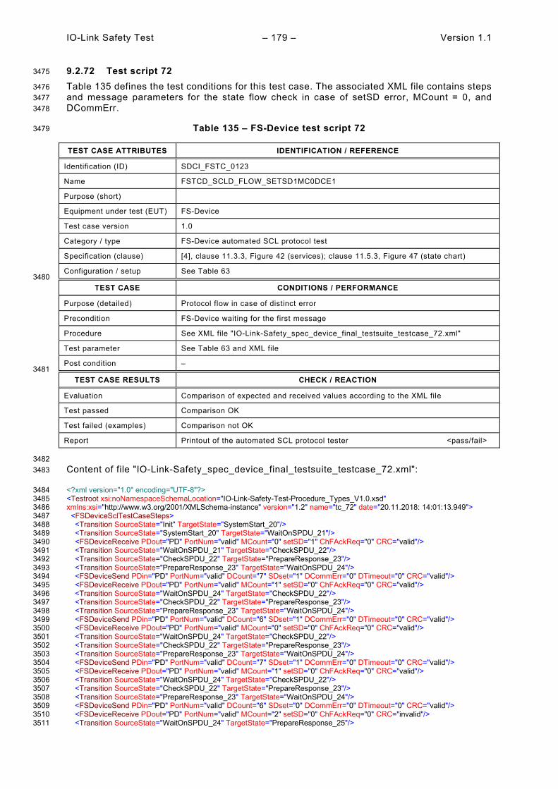
IO-Link Safety Test – 179 – Version 1.1
9.2.72 Test script 72 3475
Table 135 defines the test conditions for this test case. The associated XML file contains steps 3476 and message parameters for the state flow check in case of setSD error, MCount = 0, and 3477 DCommErr. 3478
Table 135 – FS-Device test script 72 3479
TEST CASE ATTRIBUTES IDENTIFICATION / REFERENCE
Identification (ID) SDCI_FSTC_0123
Name FSTCD_SCLD_FLOW_SETSD1MC0DCE1
Purpose (short)
Equipment under test (EUT) FS-Device
Test case version 1.0
Category / type FS-Device automated SCL protocol test
Specification (clause) [4], clause 11.3.3, Figure 42 (services); clause 11.5.3, Figure 47 (state chart)
Configuration / setup See Table 63 3480
TEST CASE CONDITIONS / PERFORMANCE
Purpose (detailed) Protocol flow in case of distinct error
Precondition FS-Device waiting for the first message
Procedure See XML file "IO-Link-Safety_spec_device_final_testsuite_testcase_72.xml"
Test parameter See Table 63 and XML file
Post condition – 3481
TEST CASE RESULTS CHECK / REACTION
Evaluation Comparison of expected and received values according to the XML file
Test passed Comparison OK
Test failed (examples) Comparison not OK
Report Printout of the automated SCL protocol tester <pass/fail>
3482 Content of file "IO-Link-Safety_spec_device_final_testsuite_testcase_72.xml": 3483
<?xml version="1.0" encoding="UTF-8"?> 3484 <Testroot xsi:noNamespaceSchemaLocation="IO-Link-Safety-Test-Procedure_Types_V1.0.xsd" 3485 xmlns:xsi="http://www.w3.org/2001/XMLSchema-instance" version="1.2" name="tc_72" date="20.11.2018: 14:01:13.949"> 3486 <FSDeviceSclTestCaseSteps> 3487 <Transition SourceState="Init" TargetState="SystemStart_20"/> 3488 <Transition SourceState="SystemStart_20" TargetState="WaitOnSPDU_21"/> 3489 <FSDeviceReceive PDout="PD" PortNum="valid" MCount="0" setSD="1" ChFAckReq="0" CRC="valid"/> 3490 <Transition SourceState="WaitOnSPDU_21" TargetState="CheckSPDU_22"/> 3491 <Transition SourceState="CheckSPDU_22" TargetState="PrepareResponse_23"/> 3492 <Transition SourceState="PrepareResponse_23" TargetState="WaitOnSPDU_24"/> 3493 <FSDeviceSend PDin="PD" PortNum="valid" DCount="7" SDset="1" DCommErr="0" DTimeout="0" CRC="valid"/> 3494 <FSDeviceReceive PDout="PD" PortNum="valid" MCount="1" setSD="0" ChFAckReq="0" CRC="valid"/> 3495 <Transition SourceState="WaitOnSPDU_24" TargetState="CheckSPDU_22"/> 3496 <Transition SourceState="CheckSPDU_22" TargetState="PrepareResponse_23"/> 3497 <Transition SourceState="PrepareResponse_23" TargetState="WaitOnSPDU_24"/> 3498 <FSDeviceSend PDin="PD" PortNum="valid" DCount="6" SDset="1" DCommErr="0" DTimeout="0" CRC="valid"/> 3499 <FSDeviceReceive PDout="PD" PortNum="valid" MCount="0" setSD="0" ChFAckReq="0" CRC="valid"/> 3500 <Transition SourceState="WaitOnSPDU_24" TargetState="CheckSPDU_22"/> 3501 <Transition SourceState="CheckSPDU_22" TargetState="PrepareResponse_23"/> 3502 <Transition SourceState="PrepareResponse_23" TargetState="WaitOnSPDU_24"/> 3503 <FSDeviceSend PDin="PD" PortNum="valid" DCount="7" SDset="1" DCommErr="0" DTimeout="0" CRC="valid"/> 3504 <FSDeviceReceive PDout="PD" PortNum="valid" MCount="1" setSD="0" ChFAckReq="0" CRC="valid"/> 3505 <Transition SourceState="WaitOnSPDU_24" TargetState="CheckSPDU_22"/> 3506 <Transition SourceState="CheckSPDU_22" TargetState="PrepareResponse_23"/> 3507 <Transition SourceState="PrepareResponse_23" TargetState="WaitOnSPDU_24"/> 3508 <FSDeviceSend PDin="PD" PortNum="valid" DCount="6" SDset="0" DCommErr="0" DTimeout="0" CRC="valid"/> 3509 <FSDeviceReceive PDout="PD" PortNum="valid" MCount="2" setSD="0" ChFAckReq="0" CRC="invalid"/> 3510 <Transition SourceState="WaitOnSPDU_24" TargetState="PrepareResponse_25"/> 3511

Version 1.1 – 180 – IO-Link Safety Test
<Transition SourceState="PrepareResponse_25" TargetState="WaitOnSPDU_26"/> 3512 <FSDeviceSend PDin="PD" PortNum="valid" DCount="5" SDset="1" DCommErr="1" DTimeout="0" CRC="valid"/> 3513 </FSDeviceSclTestCaseSteps> 3514 </Testroot> 3515 3516

IO-Link Safety Test – 181 – Version 1.1
9.2.73 Test script 73 3517
Table 136 defines the test conditions for this test case. The associated XML file contains steps 3518 and message parameters for the state flow check in case of setSD error, MCount = 0, and 3519 DCommErr. 3520
Table 136 – FS-Device test script 73 3521
TEST CASE ATTRIBUTES IDENTIFICATION / REFERENCE
Identification (ID) SDCI_FSTC_0124
Name FSTCD_SCLD_FLOW_SETSD1MC0DCE1
Purpose (short)
Equipment under test (EUT) FS-Device
Test case version 1.0
Category / type FS-Device automated SCL protocol test
Specification (clause) [4], clause 11.3.3, Figure 42 (services); clause 11.5.3, Figure 47 (state chart)
Configuration / setup See Table 63 3522
TEST CASE CONDITIONS / PERFORMANCE
Purpose (detailed) Protocol flow in case of distinct error
Precondition FS-Device waiting for the first message
Procedure See XML file "IO-Link-Safety_spec_device_final_testsuite_testcase_73.xml"
Test parameter See Table 63 and XML file
Post condition – 3523
TEST CASE RESULTS CHECK / REACTION
Evaluation Comparison of expected and received values according to the XML file
Test passed Comparison OK
Test failed (examples) Comparison not OK
Report Printout of the automated SCL protocol tester <pass/fail>
3524 Content of file "IO-Link-Safety_spec_device_final_testsuite_testcase_73.xml": 3525
<?xml version="1.0" encoding="UTF-8"?> 3526 <Testroot xsi:noNamespaceSchemaLocation="IO-Link-Safety-Test-Procedure_Types_V1.0.xsd" 3527 xmlns:xsi="http://www.w3.org/2001/XMLSchema-instance" version="1.2" name="tc_73" date="20.11.2018: 14:01:13.949"> 3528 <FSDeviceSclTestCaseSteps> 3529 <Transition SourceState="Init" TargetState="SystemStart_20"/> 3530 <Transition SourceState="SystemStart_20" TargetState="WaitOnSPDU_21"/> 3531 <FSDeviceReceive PDout="PD" PortNum="valid" MCount="0" setSD="1" ChFAckReq="0" CRC="valid"/> 3532 <Transition SourceState="WaitOnSPDU_21" TargetState="CheckSPDU_22"/> 3533 <Transition SourceState="CheckSPDU_22" TargetState="PrepareResponse_23"/> 3534 <Transition SourceState="PrepareResponse_23" TargetState="WaitOnSPDU_24"/> 3535 <FSDeviceSend PDin="PD" PortNum="valid" DCount="7" SDset="1" DCommErr="0" DTimeout="0" CRC="valid"/> 3536 <FSDeviceReceive PDout="PD" PortNum="valid" MCount="1" setSD="0" ChFAckReq="0" CRC="valid"/> 3537 <Transition SourceState="WaitOnSPDU_24" TargetState="CheckSPDU_22"/> 3538 <Transition SourceState="CheckSPDU_22" TargetState="PrepareResponse_23"/> 3539 <Transition SourceState="PrepareResponse_23" TargetState="WaitOnSPDU_24"/> 3540 <FSDeviceSend PDin="PD" PortNum="valid" DCount="6" SDset="1" DCommErr="0" DTimeout="0" CRC="valid"/> 3541 <FSDeviceReceive PDout="PD" PortNum="valid" MCount="2" setSD="0" ChFAckReq="0" CRC="valid"/> 3542 <Transition SourceState="WaitOnSPDU_24" TargetState="CheckSPDU_22"/> 3543 <Transition SourceState="CheckSPDU_22" TargetState="PrepareResponse_23"/> 3544 <Transition SourceState="PrepareResponse_23" TargetState="WaitOnSPDU_24"/> 3545 <FSDeviceSend PDin="PD" PortNum="valid" DCount="5" SDset="1" DCommErr="0" DTimeout="0" CRC="valid"/> 3546 <FSDeviceReceive PDout="PD" PortNum="valid" MCount="3" setSD="0" ChFAckReq="0" CRC="valid"/> 3547 <Transition SourceState="WaitOnSPDU_24" TargetState="CheckSPDU_22"/> 3548 <Transition SourceState="CheckSPDU_22" TargetState="PrepareResponse_23"/> 3549 <Transition SourceState="PrepareResponse_23" TargetState="WaitOnSPDU_24"/> 3550 <FSDeviceSend PDin="PD" PortNum="valid" DCount="4" SDset="0" DCommErr="0" DTimeout="0" CRC="valid"/> 3551 <FSDeviceReceive PDout="PD" PortNum="valid" MCount="5" setSD="0" ChFAckReq="0" CRC="valid"/> 3552 <Transition SourceState="WaitOnSPDU_24" TargetState="CheckSPDU_22"/> 3553

Version 1.1 – 182 – IO-Link Safety Test
<Transition SourceState="CheckSPDU_22" TargetState="PrepareResponse_25"/> 3554 <Transition SourceState="PrepareResponse_25" TargetState="WaitOnSPDU_26"/> 3555 <FSDeviceSend PDin="PD" PortNum="valid" DCount="2" SDset="1" DCommErr="1" DTimeout="0" CRC="valid"/> 3556 </FSDeviceSclTestCaseSteps> 3557 </Testroot> 3558 3559

IO-Link Safety Test – 183 – Version 1.1
9.2.74 Test script 74 3560
Table 137 defines the test conditions for this test case. The associated XML file contains steps 3561 and message parameters for the state flow check in case of setSD error, MCount = 0, and 3562 DCommErr. 3563
Table 137 – FS-Device test script 74 3564
TEST CASE ATTRIBUTES IDENTIFICATION / REFERENCE
Identification (ID) SDCI_FSTC_0125
Name FSTCD_SCLD_FLOW_SETSD1MC0DCE1
Purpose (short)
Equipment under test (EUT) FS-Device
Test case version 1.0
Category / type FS-Device automated SCL protocol test
Specification (clause) [4], clause 11.3.3, Figure 42 (services); clause 11.5.3, Figure 47 (state chart)
Configuration / setup See Table 63 3565
TEST CASE CONDITIONS / PERFORMANCE
Purpose (detailed) Protocol flow in case of distinct error
Precondition FS-Device waiting for the first message
Procedure See XML file "IO-Link-Safety_spec_device_final_testsuite_testcase_74.xml"
Test parameter See Table 63 and XML file
Post condition – 3566
TEST CASE RESULTS CHECK / REACTION
Evaluation Comparison of expected and received values according to the XML file
Test passed Comparison OK
Test failed (examples) Comparison not OK
Report Printout of the automated SCL protocol tester <pass/fail>
3567 Content of file "IO-Link-Safety_spec_device_final_testsuite_testcase_74.xml": 3568
<?xml version="1.0" encoding="UTF-8"?> 3569 <Testroot xsi:noNamespaceSchemaLocation="IO-Link-Safety-Test-Procedure_Types_V1.0.xsd" 3570 xmlns:xsi="http://www.w3.org/2001/XMLSchema-instance" version="1.2" name="tc_73" date="20.11.2018: 14:01:13.949"> 3571 <FSDeviceSclTestCaseSteps> 3572 <Transition SourceState="Init" TargetState="SystemStart_20"/> 3573 <Transition SourceState="SystemStart_20" TargetState="WaitOnSPDU_21"/> 3574 <FSDeviceReceive PDout="PD" PortNum="valid" MCount="0" setSD="1" ChFAckReq="0" CRC="valid"/> 3575 <Transition SourceState="WaitOnSPDU_21" TargetState="CheckSPDU_22"/> 3576 <Transition SourceState="CheckSPDU_22" TargetState="PrepareResponse_23"/> 3577 <Transition SourceState="PrepareResponse_23" TargetState="WaitOnSPDU_24"/> 3578 <FSDeviceSend PDin="PD" PortNum="valid" DCount="7" SDset="1" DCommErr="0" DTimeout="0" CRC="valid"/> 3579 <FSDeviceReceive PDout="PD" PortNum="valid" MCount="1" setSD="0" ChFAckReq="0" CRC="valid"/> 3580 <Transition SourceState="WaitOnSPDU_24" TargetState="CheckSPDU_22"/> 3581 <Transition SourceState="CheckSPDU_22" TargetState="PrepareResponse_23"/> 3582 <Transition SourceState="PrepareResponse_23" TargetState="WaitOnSPDU_24"/> 3583 <FSDeviceSend PDin="PD" PortNum="valid" DCount="6" SDset="1" DCommErr="0" DTimeout="0" CRC="valid"/> 3584 <FSDeviceReceive PDout="PD" PortNum="valid" MCount="2" setSD="0" ChFAckReq="0" CRC="valid"/> 3585 <Transition SourceState="WaitOnSPDU_24" TargetState="CheckSPDU_22"/> 3586 <Transition SourceState="CheckSPDU_22" TargetState="PrepareResponse_23"/> 3587 <Transition SourceState="PrepareResponse_23" TargetState="WaitOnSPDU_24"/> 3588 <FSDeviceSend PDin="PD" PortNum="valid" DCount="5" SDset="1" DCommErr="0" DTimeout="0" CRC="valid"/> 3589 <FSDeviceReceive PDout="PD" PortNum="valid" MCount="3" setSD="0" ChFAckReq="0" CRC="valid"/> 3590 <Transition SourceState="WaitOnSPDU_24" TargetState="CheckSPDU_22"/> 3591 <Transition SourceState="CheckSPDU_22" TargetState="PrepareResponse_23"/> 3592 <Transition SourceState="PrepareResponse_23" TargetState="WaitOnSPDU_24"/> 3593 <FSDeviceSend PDin="PD" PortNum="valid" DCount="4" SDset="0" DCommErr="0" DTimeout="0" CRC="valid"/> 3594 <FSDeviceReceive PDout="PD" PortNum="valid" MCount="5" setSD="0" ChFAckReq="0" CRC="valid"/> 3595 <Transition SourceState="WaitOnSPDU_24" TargetState="CheckSPDU_22"/> 3596

Version 1.1 – 184 – IO-Link Safety Test
<Transition SourceState="CheckSPDU_22" TargetState="PrepareResponse_25"/> 3597 <Transition SourceState="PrepareResponse_25" TargetState="WaitOnSPDU_26"/> 3598 <FSDeviceSend PDin="PD" PortNum="valid" DCount="2" SDset="1" DCommErr="1" DTimeout="0" CRC="valid"/> 3599 </FSDeviceSclTestCaseSteps> 3600 </Testroot> 3601 3602
3603

IO-Link Safety Test – 185 – Version 1.1
9.2.75 Test script 75 3604
Table 138 defines the test conditions for this test case. The associated XML file contains steps 3605 and message parameters for the state flow check in case of setSD error, MCount = 0, and 3606 DCommErr. 3607
Table 138 – FS-Device test script 75 3608
TEST CASE ATTRIBUTES IDENTIFICATION / REFERENCE
Identification (ID) SDCI_FSTC_0126
Name FSTCD_SCLD_FLOW_SETSD1MC0DCE1
Purpose (short)
Equipment under test (EUT) FS-Device
Test case version 1.0
Category / type FS-Device automated SCL protocol test
Specification (clause) [4], clause 11.3.3, Figure 42 (services); clause 11.5.3, Figure 47 (state chart)
Configuration / setup See Table 63 3609
TEST CASE CONDITIONS / PERFORMANCE
Purpose (detailed) Protocol flow in case of distinct error
Precondition FS-Device waiting for the first message
Procedure See XML file "IO-Link-Safety_spec_device_final_testsuite_testcase_75.xml"
Test parameter See Table 63 and XML file
Post condition – 3610
TEST CASE RESULTS CHECK / REACTION
Evaluation Comparison of expected and received values according to the XML file
Test passed Comparison OK
Test failed (examples) Comparison not OK
Report Printout of the automated SCL protocol tester <pass/fail>
3611 Content of file "IO-Link-Safety_spec_device_final_testsuite_testcase_75.xml": 3612
<?xml version="1.0" encoding="UTF-8"?> 3613 <Testroot xsi:noNamespaceSchemaLocation="IO-Link-Safety-Test-Procedure_Types_V1.0.xsd" 3614 xmlns:xsi="http://www.w3.org/2001/XMLSchema-instance" version="1.2" name="tc_75" date="20.11.2018: 14:01:13.950"> 3615 <FSDeviceSclTestCaseSteps> 3616 <Transition SourceState="Init" TargetState="SystemStart_20"/> 3617 <Transition SourceState="SystemStart_20" TargetState="WaitOnSPDU_21"/> 3618 <FSDeviceReceive PDout="PD" PortNum="valid" MCount="0" setSD="1" ChFAckReq="0" CRC="valid"/> 3619 <Transition SourceState="WaitOnSPDU_21" TargetState="CheckSPDU_22"/> 3620 <Transition SourceState="CheckSPDU_22" TargetState="PrepareResponse_23"/> 3621 <Transition SourceState="PrepareResponse_23" TargetState="WaitOnSPDU_24"/> 3622 <FSDeviceSend PDin="PD" PortNum="valid" DCount="7" SDset="1" DCommErr="0" DTimeout="0" CRC="valid"/> 3623 <FSDeviceReceive PDout="PD" PortNum="valid" MCount="1" setSD="0" ChFAckReq="0" CRC="valid"/> 3624 <Transition SourceState="WaitOnSPDU_24" TargetState="CheckSPDU_22"/> 3625 <Transition SourceState="CheckSPDU_22" TargetState="PrepareResponse_23"/> 3626 <Transition SourceState="PrepareResponse_23" TargetState="WaitOnSPDU_24"/> 3627 <FSDeviceSend PDin="PD" PortNum="valid" DCount="6" SDset="1" DCommErr="0" DTimeout="0" CRC="valid"/> 3628 <FSDeviceReceive PDout="PD" PortNum="valid" MCount="2" setSD="0" ChFAckReq="0" CRC="valid"/> 3629 <Transition SourceState="WaitOnSPDU_24" TargetState="CheckSPDU_22"/> 3630 <Transition SourceState="CheckSPDU_22" TargetState="PrepareResponse_23"/> 3631 <Transition SourceState="PrepareResponse_23" TargetState="WaitOnSPDU_24"/> 3632 <FSDeviceSend PDin="PD" PortNum="valid" DCount="5" SDset="1" DCommErr="0" DTimeout="0" CRC="valid"/> 3633 <FSDeviceReceive PDout="PD" PortNum="valid" MCount="3" setSD="0" ChFAckReq="0" CRC="valid"/> 3634 <Transition SourceState="WaitOnSPDU_24" TargetState="CheckSPDU_22"/> 3635 <Transition SourceState="CheckSPDU_22" TargetState="PrepareResponse_23"/> 3636 <Transition SourceState="PrepareResponse_23" TargetState="WaitOnSPDU_24"/> 3637 <FSDeviceSend PDin="PD" PortNum="valid" DCount="4" SDset="0" DCommErr="0" DTimeout="0" CRC="valid"/> 3638 <FSDeviceReceive PDout="PD" PortNum="valid" MCount="4" setSD="0" ChFAckReq="0" CRC="invalid"/> 3639 <Transition SourceState="WaitOnSPDU_24" TargetState="PrepareResponse_25"/> 3640

Version 1.1 – 186 – IO-Link Safety Test
<Transition SourceState="PrepareResponse_25" TargetState="WaitOnSPDU_26"/> 3641 <FSDeviceSend PDin="PD" PortNum="valid" DCount="3" SDset="1" DCommErr="1" DTimeout="0" CRC="valid"/> 3642 </FSDeviceSclTestCaseSteps> 3643 </Testroot> 3644 3645
3646

IO-Link Safety Test – 187 – Version 1.1
9.2.76 Test script 76 3647
Table 139 defines the test conditions for this test case. The associated XML file contains steps 3648 and message parameters for the state flow check in case of setSD error and MCount = 0. 3649
Table 139 – FS-Device test script 76 3650
TEST CASE ATTRIBUTES IDENTIFICATION / REFERENCE
Identification (ID) SDCI_FSTC_0127
Name FSTCD_SCLD_FLOW_SETSD1MC0
Purpose (short)
Equipment under test (EUT) FS-Device
Test case version 1.0
Category / type FS-Device automated SCL protocol test
Specification (clause) [4], clause 11.3.3, Figure 42 (services); clause 11.5.3, Figure 47 (state chart)
Configuration / setup See Table 63 3651
TEST CASE CONDITIONS / PERFORMANCE
Purpose (detailed) Protocol flow in case of distinct error
Precondition FS-Device waiting for the first message
Procedure See XML file "IO-Link-Safety_spec_device_final_testsuite_testcase_76.xml"
Test parameter See Table 63 and XML file
Post condition – 3652
TEST CASE RESULTS CHECK / REACTION
Evaluation Comparison of expected and received values according to the XML file
Test passed Comparison OK
Test failed (examples) Comparison not OK
Report Printout of the automated SCL protocol tester <pass/fail>
3653 Content of file "IO-Link-Safety_spec_device_final_testsuite_testcase_76.xml": 3654
<?xml version="1.0" encoding="UTF-8"?> 3655 <Testroot xsi:noNamespaceSchemaLocation="IO-Link-Safety-Test-Procedure_Types_V1.0.xsd" 3656 xmlns:xsi="http://www.w3.org/2001/XMLSchema-instance" version="1.2" name="tc_76" date="20.11.2018: 14:01:13.950"> 3657 <FSDeviceSclTestCaseSteps> 3658 <Transition SourceState="Init" TargetState="SystemStart_20"/> 3659 <Transition SourceState="SystemStart_20" TargetState="WaitOnSPDU_21"/> 3660 <FSDeviceReceive PDout="PD" PortNum="valid" MCount="0" setSD="1" ChFAckReq="0" CRC="valid"/> 3661 <Transition SourceState="WaitOnSPDU_21" TargetState="CheckSPDU_22"/> 3662 <Transition SourceState="CheckSPDU_22" TargetState="PrepareResponse_23"/> 3663 <Transition SourceState="PrepareResponse_23" TargetState="WaitOnSPDU_24"/> 3664 <FSDeviceSend PDin="PD" PortNum="valid" DCount="7" SDset="1" DCommErr="0" DTimeout="0" CRC="valid"/> 3665 <FSDeviceReceive PDout="PD" PortNum="valid" MCount="1" setSD="0" ChFAckReq="0" CRC="valid"/> 3666 <Transition SourceState="WaitOnSPDU_24" TargetState="CheckSPDU_22"/> 3667 <Transition SourceState="CheckSPDU_22" TargetState="PrepareResponse_23"/> 3668 <Transition SourceState="PrepareResponse_23" TargetState="WaitOnSPDU_24"/> 3669 <FSDeviceSend PDin="PD" PortNum="valid" DCount="6" SDset="1" DCommErr="0" DTimeout="0" CRC="valid"/> 3670 <FSDeviceReceive PDout="PD" PortNum="valid" MCount="2" setSD="0" ChFAckReq="0" CRC="valid"/> 3671 <Transition SourceState="WaitOnSPDU_24" TargetState="CheckSPDU_22"/> 3672 <Transition SourceState="CheckSPDU_22" TargetState="PrepareResponse_23"/> 3673 <Transition SourceState="PrepareResponse_23" TargetState="WaitOnSPDU_24"/> 3674 <FSDeviceSend PDin="PD" PortNum="valid" DCount="5" SDset="1" DCommErr="0" DTimeout="0" CRC="valid"/> 3675 <FSDeviceReceive PDout="PD" PortNum="valid" MCount="3" setSD="0" ChFAckReq="0" CRC="valid"/> 3676 <Transition SourceState="WaitOnSPDU_24" TargetState="CheckSPDU_22"/> 3677 <Transition SourceState="CheckSPDU_22" TargetState="PrepareResponse_23"/> 3678 <Transition SourceState="PrepareResponse_23" TargetState="WaitOnSPDU_24"/> 3679 <FSDeviceSend PDin="PD" PortNum="valid" DCount="4" SDset="0" DCommErr="0" DTimeout="0" CRC="valid"/> 3680 <FSDeviceReceive PDout="PD" PortNum="valid" MCount="4" setSD="0" ChFAckReq="0" CRC="valid"/> 3681 <Transition SourceState="WaitOnSPDU_24" TargetState="CheckSPDU_22"/> 3682 <Transition SourceState="CheckSPDU_22" TargetState="PrepareResponse_23"/> 3683 <Transition SourceState="PrepareResponse_23" TargetState="WaitOnSPDU_24"/> 3684

Version 1.1 – 188 – IO-Link Safety Test
<FSDeviceSend PDin="PD" PortNum="valid" DCount="3" SDset="0" DCommErr="0" DTimeout="0" CRC="valid"/> 3685 <FSDeviceReceive PDout="PD" PortNum="valid" MCount="4" setSD="0" ChFAckReq="0" CRC="valid"/> 3686 <Transition SourceState="WaitOnSPDU_24" TargetState="WaitOnSPDU_24"/> 3687 </FSDeviceSclTestCaseSteps> 3688 </Testroot> 3689 3690
3691
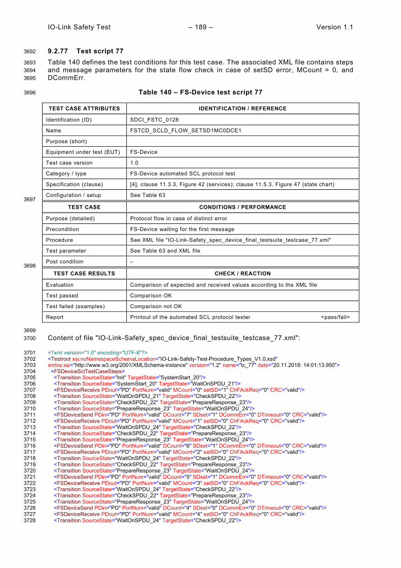
IO-Link Safety Test – 189 – Version 1.1
9.2.77 Test script 77 3692
Table 140 defines the test conditions for this test case. The associated XML file contains steps 3693 and message parameters for the state flow check in case of setSD error, MCount = 0, and 3694 DCommErr. 3695
Table 140 – FS-Device test script 77 3696
TEST CASE ATTRIBUTES IDENTIFICATION / REFERENCE
Identification (ID) SDCI_FSTC_0128
Name FSTCD_SCLD_FLOW_SETSD1MC0DCE1
Purpose (short)
Equipment under test (EUT) FS-Device
Test case version 1.0
Category / type FS-Device automated SCL protocol test
Specification (clause) [4], clause 11.3.3, Figure 42 (services); clause 11.5.3, Figure 47 (state chart)
Configuration / setup See Table 63 3697
TEST CASE CONDITIONS / PERFORMANCE
Purpose (detailed) Protocol flow in case of distinct error
Precondition FS-Device waiting for the first message
Procedure See XML file "IO-Link-Safety_spec_device_final_testsuite_testcase_77.xml"
Test parameter See Table 63 and XML file
Post condition – 3698
TEST CASE RESULTS CHECK / REACTION
Evaluation Comparison of expected and received values according to the XML file
Test passed Comparison OK
Test failed (examples) Comparison not OK
Report Printout of the automated SCL protocol tester <pass/fail>
3699 Content of file "IO-Link-Safety_spec_device_final_testsuite_testcase_77.xml": 3700
<?xml version="1.0" encoding="UTF-8"?> 3701 <Testroot xsi:noNamespaceSchemaLocation="IO-Link-Safety-Test-Procedure_Types_V1.0.xsd" 3702 xmlns:xsi="http://www.w3.org/2001/XMLSchema-instance" version="1.2" name="tc_77" date="20.11.2018: 14:01:13.950"> 3703 <FSDeviceSclTestCaseSteps> 3704 <Transition SourceState="Init" TargetState="SystemStart_20"/> 3705 <Transition SourceState="SystemStart_20" TargetState="WaitOnSPDU_21"/> 3706 <FSDeviceReceive PDout="PD" PortNum="valid" MCount="0" setSD="1" ChFAckReq="0" CRC="valid"/> 3707 <Transition SourceState="WaitOnSPDU_21" TargetState="CheckSPDU_22"/> 3708 <Transition SourceState="CheckSPDU_22" TargetState="PrepareResponse_23"/> 3709 <Transition SourceState="PrepareResponse_23" TargetState="WaitOnSPDU_24"/> 3710 <FSDeviceSend PDin="PD" PortNum="valid" DCount="7" SDset="1" DCommErr="0" DTimeout="0" CRC="valid"/> 3711 <FSDeviceReceive PDout="PD" PortNum="valid" MCount="1" setSD="0" ChFAckReq="0" CRC="valid"/> 3712 <Transition SourceState="WaitOnSPDU_24" TargetState="CheckSPDU_22"/> 3713 <Transition SourceState="CheckSPDU_22" TargetState="PrepareResponse_23"/> 3714 <Transition SourceState="PrepareResponse_23" TargetState="WaitOnSPDU_24"/> 3715 <FSDeviceSend PDin="PD" PortNum="valid" DCount="6" SDset="1" DCommErr="0" DTimeout="0" CRC="valid"/> 3716 <FSDeviceReceive PDout="PD" PortNum="valid" MCount="2" setSD="0" ChFAckReq="0" CRC="valid"/> 3717 <Transition SourceState="WaitOnSPDU_24" TargetState="CheckSPDU_22"/> 3718 <Transition SourceState="CheckSPDU_22" TargetState="PrepareResponse_23"/> 3719 <Transition SourceState="PrepareResponse_23" TargetState="WaitOnSPDU_24"/> 3720 <FSDeviceSend PDin="PD" PortNum="valid" DCount="5" SDset="1" DCommErr="0" DTimeout="0" CRC="valid"/> 3721 <FSDeviceReceive PDout="PD" PortNum="valid" MCount="3" setSD="0" ChFAckReq="0" CRC="valid"/> 3722 <Transition SourceState="WaitOnSPDU_24" TargetState="CheckSPDU_22"/> 3723 <Transition SourceState="CheckSPDU_22" TargetState="PrepareResponse_23"/> 3724 <Transition SourceState="PrepareResponse_23" TargetState="WaitOnSPDU_24"/> 3725 <FSDeviceSend PDin="PD" PortNum="valid" DCount="4" SDset="0" DCommErr="0" DTimeout="0" CRC="valid"/> 3726 <FSDeviceReceive PDout="PD" PortNum="valid" MCount="4" setSD="0" ChFAckReq="0" CRC="valid"/> 3727 <Transition SourceState="WaitOnSPDU_24" TargetState="CheckSPDU_22"/> 3728

Version 1.1 – 190 – IO-Link Safety Test
<Transition SourceState="CheckSPDU_22" TargetState="PrepareResponse_23"/> 3729 <Transition SourceState="PrepareResponse_23" TargetState="WaitOnSPDU_24"/> 3730 <FSDeviceSend PDin="PD" PortNum="valid" DCount="3" SDset="0" DCommErr="0" DTimeout="0" CRC="valid"/> 3731 <FSDeviceReceive PDout="PD" PortNum="invalid" MCount="1" setSD="0" ChFAckReq="0" CRC="valid"/> 3732 <Transition SourceState="WaitOnSPDU_24" TargetState="PrepareResponse_25"/> 3733 <Transition SourceState="PrepareResponse_25" TargetState="WaitOnSPDU_26"/> 3734 <FSDeviceSend PDin="PD" PortNum="valid" DCount="6" SDset="1" DCommErr="1" DTimeout="0" CRC="valid"/> 3735 </FSDeviceSclTestCaseSteps> 3736 </Testroot> 3737 3738
3739

IO-Link Safety Test – 191 – Version 1.1
9.2.78 Test script 78 3740
Table 141 defines the test conditions for this test case. The associated XML file contains steps 3741 and message parameters for the state flow check in case of setSD error, MCount = 0, and 3742 DCommErr. 3743
Table 141 – FS-Device test script 78 3744
TEST CASE ATTRIBUTES IDENTIFICATION / REFERENCE
Identification (ID) SDCI_FSTC_0129
Name FSTCD_SCLD_FLOW_SETSD1MC0DCE1
Purpose (short)
Equipment under test (EUT) FS-Device
Test case version 1.0
Category / type FS-Device automated SCL protocol test
Specification (clause) [4], clause 11.3.3, Figure 42 (services); clause 11.5.3, Figure 47 (state chart)
Configuration / setup See Table 63 3745
TEST CASE CONDITIONS / PERFORMANCE
Purpose (detailed) Protocol flow in case of distinct error
Precondition FS-Device waiting for the first message
Procedure See XML file "IO-Link-Safety_spec_device_final_testsuite_testcase_78.xml"
Test parameter See Table 63 and XML file
Post condition – 3746
TEST CASE RESULTS CHECK / REACTION
Evaluation Comparison of expected and received values according to the XML file
Test passed Comparison OK
Test failed (examples) Comparison not OK
Report Printout of the automated SCL protocol tester <pass/fail>
3747 Content of file "IO-Link-Safety_spec_device_final_testsuite_testcase_78.xml": 3748
<?xml version="1.0" encoding="UTF-8"?> 3749 <Testroot xsi:noNamespaceSchemaLocation="IO-Link-Safety-Test-Procedure_Types_V1.0.xsd" 3750 xmlns:xsi="http://www.w3.org/2001/XMLSchema-instance" version="1.2" name="tc_78" date="20.11.2018: 14:01:13.950"> 3751 <FSDeviceSclTestCaseSteps> 3752 <Transition SourceState="Init" TargetState="SystemStart_20"/> 3753 <Transition SourceState="SystemStart_20" TargetState="WaitOnSPDU_21"/> 3754 <FSDeviceReceive PDout="PD" PortNum="valid" MCount="0" setSD="1" ChFAckReq="0" CRC="valid"/> 3755 <Transition SourceState="WaitOnSPDU_21" TargetState="CheckSPDU_22"/> 3756 <Transition SourceState="CheckSPDU_22" TargetState="PrepareResponse_23"/> 3757 <Transition SourceState="PrepareResponse_23" TargetState="WaitOnSPDU_24"/> 3758 <FSDeviceSend PDin="PD" PortNum="valid" DCount="7" SDset="1" DCommErr="0" DTimeout="0" CRC="valid"/> 3759 <FSDeviceReceive PDout="PD" PortNum="valid" MCount="1" setSD="0" ChFAckReq="0" CRC="valid"/> 3760 <Transition SourceState="WaitOnSPDU_24" TargetState="CheckSPDU_22"/> 3761 <Transition SourceState="CheckSPDU_22" TargetState="PrepareResponse_23"/> 3762 <Transition SourceState="PrepareResponse_23" TargetState="WaitOnSPDU_24"/> 3763 <FSDeviceSend PDin="PD" PortNum="valid" DCount="6" SDset="1" DCommErr="0" DTimeout="0" CRC="valid"/> 3764 <FSDeviceReceive PDout="PD" PortNum="valid" MCount="2" setSD="0" ChFAckReq="0" CRC="valid"/> 3765 <Transition SourceState="WaitOnSPDU_24" TargetState="CheckSPDU_22"/> 3766 <Transition SourceState="CheckSPDU_22" TargetState="PrepareResponse_23"/> 3767 <Transition SourceState="PrepareResponse_23" TargetState="WaitOnSPDU_24"/> 3768 <FSDeviceSend PDin="PD" PortNum="valid" DCount="5" SDset="1" DCommErr="0" DTimeout="0" CRC="valid"/> 3769 <FSDeviceReceive PDout="PD" PortNum="valid" MCount="3" setSD="0" ChFAckReq="0" CRC="valid"/> 3770 <Transition SourceState="WaitOnSPDU_24" TargetState="CheckSPDU_22"/> 3771 <Transition SourceState="CheckSPDU_22" TargetState="PrepareResponse_23"/> 3772 <Transition SourceState="PrepareResponse_23" TargetState="WaitOnSPDU_24"/> 3773 <FSDeviceSend PDin="PD" PortNum="valid" DCount="4" SDset="0" DCommErr="0" DTimeout="0" CRC="valid"/> 3774 <FSDeviceReceive PDout="PD" PortNum="valid" MCount="4" setSD="0" ChFAckReq="0" CRC="valid"/> 3775 <Transition SourceState="WaitOnSPDU_24" TargetState="CheckSPDU_22"/> 3776

Version 1.1 – 192 – IO-Link Safety Test
<Transition SourceState="CheckSPDU_22" TargetState="PrepareResponse_23"/> 3777 <Transition SourceState="PrepareResponse_23" TargetState="WaitOnSPDU_24"/> 3778 <FSDeviceSend PDin="PD" PortNum="valid" DCount="3" SDset="0" DCommErr="0" DTimeout="0" CRC="valid"/> 3779 <FSDeviceReceive PDout="PD" PortNum="invalid" MCount="5" setSD="0" ChFAckReq="0" CRC="valid"/> 3780 <Transition SourceState="WaitOnSPDU_24" TargetState="PrepareResponse_25"/> 3781 <Transition SourceState="PrepareResponse_25" TargetState="WaitOnSPDU_26"/> 3782 <FSDeviceSend PDin="PD" PortNum="valid" DCount="2" SDset="1" DCommErr="1" DTimeout="0" CRC="valid"/> 3783 </FSDeviceSclTestCaseSteps> 3784 </Testroot> 3785 3786
3787

IO-Link Safety Test – 193 – Version 1.1
9.2.79 Test script 79 3788
Table 142 defines the test conditions for this test case. The associated XML file contains steps 3789 and message parameters for the state flow check in case of setSD error, MCount = 0, and 3790 DCommErr. 3791
Table 142 – FS-Device test script 79 3792
TEST CASE ATTRIBUTES IDENTIFICATION / REFERENCE
Identification (ID) SDCI_FSTC_0130
Name FSTCD_SCLD_FLOW_SETSD1MC0DCE1
Purpose (short)
Equipment under test (EUT) FS-Device
Test case version 1.0
Category / type FS-Device automated SCL protocol test
Specification (clause) [4], clause 11.3.3, Figure 42 (services); clause 11.5.3, Figure 47 (state chart)
Configuration / setup See Table 63 3793
TEST CASE CONDITIONS / PERFORMANCE
Purpose (detailed) Protocol flow in case of distinct error
Precondition FS-Device waiting for the first message
Procedure See XML file "IO-Link-Safety_spec_device_final_testsuite_testcase_79.xml"
Test parameter See Table 63 and XML file
Post condition – 3794
TEST CASE RESULTS CHECK / REACTION
Evaluation Comparison of expected and received values according to the XML file
Test passed Comparison OK
Test failed (examples) Comparison not OK
Report Printout of the automated SCL protocol tester <pass/fail>
3795 Content of file "IO-Link-Safety_spec_device_final_testsuite_testcase_79.xml": 3796
<?xml version="1.0" encoding="UTF-8"?> 3797 <Testroot xsi:noNamespaceSchemaLocation="IO-Link-Safety-Test-Procedure_Types_V1.0.xsd" 3798 xmlns:xsi="http://www.w3.org/2001/XMLSchema-instance" version="1.2" name="tc_79" date="20.11.2018: 14:01:13.951"> 3799 <FSDeviceSclTestCaseSteps> 3800 <Transition SourceState="Init" TargetState="SystemStart_20"/> 3801 <Transition SourceState="SystemStart_20" TargetState="WaitOnSPDU_21"/> 3802 <FSDeviceReceive PDout="PD" PortNum="valid" MCount="0" setSD="1" ChFAckReq="0" CRC="valid"/> 3803 <Transition SourceState="WaitOnSPDU_21" TargetState="CheckSPDU_22"/> 3804 <Transition SourceState="CheckSPDU_22" TargetState="PrepareResponse_23"/> 3805 <Transition SourceState="PrepareResponse_23" TargetState="WaitOnSPDU_24"/> 3806 <FSDeviceSend PDin="PD" PortNum="valid" DCount="7" SDset="1" DCommErr="0" DTimeout="0" CRC="valid"/> 3807 <FSDeviceReceive PDout="PD" PortNum="valid" MCount="1" setSD="0" ChFAckReq="0" CRC="valid"/> 3808 <Transition SourceState="WaitOnSPDU_24" TargetState="CheckSPDU_22"/> 3809 <Transition SourceState="CheckSPDU_22" TargetState="PrepareResponse_23"/> 3810 <Transition SourceState="PrepareResponse_23" TargetState="WaitOnSPDU_24"/> 3811 <FSDeviceSend PDin="PD" PortNum="valid" DCount="6" SDset="1" DCommErr="0" DTimeout="0" CRC="valid"/> 3812 <FSDeviceReceive PDout="PD" PortNum="valid" MCount="2" setSD="0" ChFAckReq="0" CRC="valid"/> 3813 <Transition SourceState="WaitOnSPDU_24" TargetState="CheckSPDU_22"/> 3814 <Transition SourceState="CheckSPDU_22" TargetState="PrepareResponse_23"/> 3815 <Transition SourceState="PrepareResponse_23" TargetState="WaitOnSPDU_24"/> 3816 <FSDeviceSend PDin="PD" PortNum="valid" DCount="5" SDset="1" DCommErr="0" DTimeout="0" CRC="valid"/> 3817 <FSDeviceReceive PDout="PD" PortNum="valid" MCount="3" setSD="0" ChFAckReq="0" CRC="valid"/> 3818 <Transition SourceState="WaitOnSPDU_24" TargetState="CheckSPDU_22"/> 3819 <Transition SourceState="CheckSPDU_22" TargetState="PrepareResponse_23"/> 3820 <Transition SourceState="PrepareResponse_23" TargetState="WaitOnSPDU_24"/> 3821 <FSDeviceSend PDin="PD" PortNum="valid" DCount="4" SDset="0" DCommErr="0" DTimeout="0" CRC="valid"/> 3822 <FSDeviceReceive PDout="PD" PortNum="valid" MCount="4" setSD="0" ChFAckReq="0" CRC="valid"/> 3823 <Transition SourceState="WaitOnSPDU_24" TargetState="CheckSPDU_22"/> 3824

Version 1.1 – 194 – IO-Link Safety Test
<Transition SourceState="CheckSPDU_22" TargetState="PrepareResponse_23"/> 3825 <Transition SourceState="PrepareResponse_23" TargetState="WaitOnSPDU_24"/> 3826 <FSDeviceSend PDin="PD" PortNum="valid" DCount="3" SDset="0" DCommErr="0" DTimeout="0" CRC="valid"/> 3827 <FSDeviceReceive PDout="PD" PortNum="valid" MCount="0" setSD="0" ChFAckReq="0" CRC="invalid"/> 3828 <Transition SourceState="WaitOnSPDU_24" TargetState="PrepareResponse_25"/> 3829 <Transition SourceState="PrepareResponse_25" TargetState="WaitOnSPDU_26"/> 3830 <FSDeviceSend PDin="PD" PortNum="valid" DCount="7" SDset="1" DCommErr="1" DTimeout="0" CRC="valid"/> 3831 </FSDeviceSclTestCaseSteps> 3832 </Testroot> 3833 3834
3835
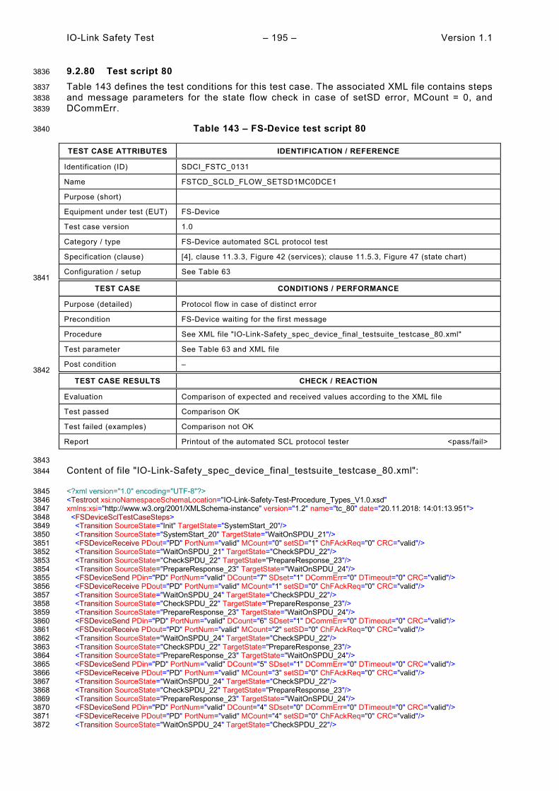
IO-Link Safety Test – 195 – Version 1.1
9.2.80 Test script 80 3836
Table 143 defines the test conditions for this test case. The associated XML file contains steps 3837 and message parameters for the state flow check in case of setSD error, MCount = 0, and 3838 DCommErr. 3839
Table 143 – FS-Device test script 80 3840
TEST CASE ATTRIBUTES IDENTIFICATION / REFERENCE
Identification (ID) SDCI_FSTC_0131
Name FSTCD_SCLD_FLOW_SETSD1MC0DCE1
Purpose (short)
Equipment under test (EUT) FS-Device
Test case version 1.0
Category / type FS-Device automated SCL protocol test
Specification (clause) [4], clause 11.3.3, Figure 42 (services); clause 11.5.3, Figure 47 (state chart)
Configuration / setup See Table 63 3841
TEST CASE CONDITIONS / PERFORMANCE
Purpose (detailed) Protocol flow in case of distinct error
Precondition FS-Device waiting for the first message
Procedure See XML file "IO-Link-Safety_spec_device_final_testsuite_testcase_80.xml"
Test parameter See Table 63 and XML file
Post condition – 3842
TEST CASE RESULTS CHECK / REACTION
Evaluation Comparison of expected and received values according to the XML file
Test passed Comparison OK
Test failed (examples) Comparison not OK
Report Printout of the automated SCL protocol tester <pass/fail>
3843 Content of file "IO-Link-Safety_spec_device_final_testsuite_testcase_80.xml": 3844
<?xml version="1.0" encoding="UTF-8"?> 3845 <Testroot xsi:noNamespaceSchemaLocation="IO-Link-Safety-Test-Procedure_Types_V1.0.xsd" 3846 xmlns:xsi="http://www.w3.org/2001/XMLSchema-instance" version="1.2" name="tc_80" date="20.11.2018: 14:01:13.951"> 3847 <FSDeviceSclTestCaseSteps> 3848 <Transition SourceState="Init" TargetState="SystemStart_20"/> 3849 <Transition SourceState="SystemStart_20" TargetState="WaitOnSPDU_21"/> 3850 <FSDeviceReceive PDout="PD" PortNum="valid" MCount="0" setSD="1" ChFAckReq="0" CRC="valid"/> 3851 <Transition SourceState="WaitOnSPDU_21" TargetState="CheckSPDU_22"/> 3852 <Transition SourceState="CheckSPDU_22" TargetState="PrepareResponse_23"/> 3853 <Transition SourceState="PrepareResponse_23" TargetState="WaitOnSPDU_24"/> 3854 <FSDeviceSend PDin="PD" PortNum="valid" DCount="7" SDset="1" DCommErr="0" DTimeout="0" CRC="valid"/> 3855 <FSDeviceReceive PDout="PD" PortNum="valid" MCount="1" setSD="0" ChFAckReq="0" CRC="valid"/> 3856 <Transition SourceState="WaitOnSPDU_24" TargetState="CheckSPDU_22"/> 3857 <Transition SourceState="CheckSPDU_22" TargetState="PrepareResponse_23"/> 3858 <Transition SourceState="PrepareResponse_23" TargetState="WaitOnSPDU_24"/> 3859 <FSDeviceSend PDin="PD" PortNum="valid" DCount="6" SDset="1" DCommErr="0" DTimeout="0" CRC="valid"/> 3860 <FSDeviceReceive PDout="PD" PortNum="valid" MCount="2" setSD="0" ChFAckReq="0" CRC="valid"/> 3861 <Transition SourceState="WaitOnSPDU_24" TargetState="CheckSPDU_22"/> 3862 <Transition SourceState="CheckSPDU_22" TargetState="PrepareResponse_23"/> 3863 <Transition SourceState="PrepareResponse_23" TargetState="WaitOnSPDU_24"/> 3864 <FSDeviceSend PDin="PD" PortNum="valid" DCount="5" SDset="1" DCommErr="0" DTimeout="0" CRC="valid"/> 3865 <FSDeviceReceive PDout="PD" PortNum="valid" MCount="3" setSD="0" ChFAckReq="0" CRC="valid"/> 3866 <Transition SourceState="WaitOnSPDU_24" TargetState="CheckSPDU_22"/> 3867 <Transition SourceState="CheckSPDU_22" TargetState="PrepareResponse_23"/> 3868 <Transition SourceState="PrepareResponse_23" TargetState="WaitOnSPDU_24"/> 3869 <FSDeviceSend PDin="PD" PortNum="valid" DCount="4" SDset="0" DCommErr="0" DTimeout="0" CRC="valid"/> 3870 <FSDeviceReceive PDout="PD" PortNum="valid" MCount="4" setSD="0" ChFAckReq="0" CRC="valid"/> 3871 <Transition SourceState="WaitOnSPDU_24" TargetState="CheckSPDU_22"/> 3872

Version 1.1 – 196 – IO-Link Safety Test
<Transition SourceState="CheckSPDU_22" TargetState="PrepareResponse_23"/> 3873 <Transition SourceState="PrepareResponse_23" TargetState="WaitOnSPDU_24"/> 3874 <FSDeviceSend PDin="PD" PortNum="valid" DCount="3" SDset="0" DCommErr="0" DTimeout="0" CRC="valid"/> 3875 <FSDeviceReceive PDout="PD" PortNum="valid" MCount="5" setSD="0" ChFAckReq="0" CRC="invalid"/> 3876 <Transition SourceState="WaitOnSPDU_24" TargetState="PrepareResponse_25"/> 3877 <Transition SourceState="PrepareResponse_25" TargetState="WaitOnSPDU_26"/> 3878 <FSDeviceSend PDin="PD" PortNum="valid" DCount="2" SDset="1" DCommErr="1" DTimeout="0" CRC="valid"/> 3879 </FSDeviceSclTestCaseSteps> 3880 </Testroot> 3881 3882
3883
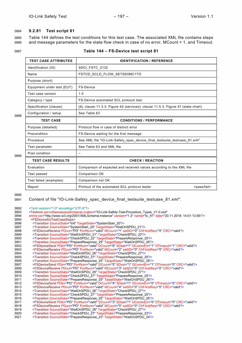
IO-Link Safety Test – 197 – Version 1.1
9.2.81 Test script 81 3884
Table 144 defines the test conditions for this test case. The associated XML file contains steps 3885 and message parameters for the state flow check in case of no error, MCount = 1, and Timeout. 3886
Table 144 – FS-Device test script 81 3887
TEST CASE ATTRIBUTES IDENTIFICATION / REFERENCE
Identification (ID) SDCI_FSTC_0132
Name FSTCD_SCLD_FLOW_SETSD0MC1TO
Purpose (short)
Equipment under test (EUT) FS-Device
Test case version 1.0
Category / type FS-Device automated SCL protocol test
Specification (clause) [4], clause 11.3.3, Figure 42 (services); clause 11.5.3, Figure 47 (state chart)
Configuration / setup See Table 63 3888
TEST CASE CONDITIONS / PERFORMANCE
Purpose (detailed) Protocol flow in case of distinct error
Precondition FS-Device waiting for the first message
Procedure See XML file "IO-Link-Safety_spec_device_final_testsuite_testcase_81.xml"
Test parameter See Table 63 and XML file
Post condition – 3889
TEST CASE RESULTS CHECK / REACTION
Evaluation Comparison of expected and received values according to the XML file
Test passed Comparison OK
Test failed (examples) Comparison not OK
Report Printout of the automated SCL protocol tester <pass/fail>
3890 Content of file "IO-Link-Safety_spec_device_final_testsuite_testcase_81.xml": 3891
<?xml version="1.0" encoding="UTF-8"?> 3892 <Testroot xsi:noNamespaceSchemaLocation="IO-Link-Safety-Test-Procedure_Types_V1.0.xsd" 3893 xmlns:xsi="http://www.w3.org/2001/XMLSchema-instance" version="1.2" name="tc_81" date="20.11.2018: 14:01:13.951"> 3894 <FSDeviceSclTestCaseSteps> 3895 <Transition SourceState="Init" TargetState="SystemStart_20"/> 3896 <Transition SourceState="SystemStart_20" TargetState="WaitOnSPDU_21"/> 3897 <FSDeviceReceive PDout="PD" PortNum="valid" MCount="1" setSD="0" ChFAckReq="0" CRC="valid"/> 3898 <Transition SourceState="WaitOnSPDU_21" TargetState="CheckSPDU_22"/> 3899 <Transition SourceState="CheckSPDU_22" TargetState="PrepareResponse_25"/> 3900 <Transition SourceState="PrepareResponse_25" TargetState="WaitOnSPDU_26"/> 3901 <FSDeviceSend PDin="PD" PortNum="valid" DCount="6" SDset="1" DCommErr="1" DTimeout="1" CRC="valid"/> 3902 <FSDeviceReceive PDout="PD" PortNum="valid" MCount="2" setSD="0" ChFAckReq="0" CRC="valid"/> 3903 <Transition SourceState="WaitOnSPDU_26" TargetState="CheckSPDU_27"/> 3904 <Transition SourceState="CheckSPDU_27" TargetState="PrepareResponse_25"/> 3905 <Transition SourceState="PrepareResponse_25" TargetState="WaitOnSPDU_26"/> 3906 <FSDeviceSend PDin="PD" PortNum="valid" DCount="5" SDset="1" DCommErr="1" DTimeout="0" CRC="valid"/> 3907 <FSDeviceReceive PDout="PD" PortNum="valid" MCount="3" setSD="0" ChFAckReq="0" CRC="valid"/> 3908 <Transition SourceState="WaitOnSPDU_26" TargetState="CheckSPDU_27"/> 3909 <Transition SourceState="CheckSPDU_27" TargetState="PrepareResponse_25"/> 3910 <Transition SourceState="PrepareResponse_25" TargetState="WaitOnSPDU_26"/> 3911 <FSDeviceSend PDin="PD" PortNum="valid" DCount="4" SDset="1" DCommErr="0" DTimeout="0" CRC="valid"/> 3912 <FSDeviceReceive PDout="PD" PortNum="valid" MCount="4" setSD="0" ChFAckReq="0" CRC="valid"/> 3913 <Transition SourceState="WaitOnSPDU_26" TargetState="CheckSPDU_27"/> 3914 <Transition SourceState="CheckSPDU_27" TargetState="PrepareResponse_25"/> 3915 <Transition SourceState="PrepareResponse_25" TargetState="WaitOnSPDU_26"/> 3916 <FSDeviceSend PDin="PD" PortNum="valid" DCount="3" SDset="1" DCommErr="0" DTimeout="0" CRC="valid"/> 3917 <FSDeviceReceive PDout="PD" PortNum="valid" MCount="5" setSD="0" ChFAckReq="0" CRC="valid"/> 3918 <Transition SourceState="WaitOnSPDU_26" TargetState="CheckSPDU_27"/> 3919 <Transition SourceState="CheckSPDU_27" TargetState="PrepareResponse_23"/> 3920 <Transition SourceState="PrepareResponse_23" TargetState="WaitOnSPDU_24"/> 3921

Version 1.1 – 198 – IO-Link Safety Test
<FSDeviceSend PDin="PD" PortNum="valid" DCount="2" SDset="0" DCommErr="0" DTimeout="0" CRC="valid"/> 3922 <FSDeviceReceive PDout="PD" PortNum="valid" MCount="5" setSD="0" ChFAckReq="0" CRC="valid"/> 3923 <Transition SourceState="WaitOnSPDU_24" TargetState="WaitOnSPDU_24"/> 3924 </FSDeviceSclTestCaseSteps> 3925 </Testroot> 3926 3927
3928

IO-Link Safety Test – 199 – Version 1.1
9.2.82 Test script 82 3929
Table 145 defines the test conditions for this test case. The associated XML file contains steps 3930 and message parameters for the state flow check in case of no error, MCount = 1, and Timeout. 3931
Table 145 – FS-Device test script 82 3932
TEST CASE ATTRIBUTES IDENTIFICATION / REFERENCE
Identification (ID) SDCI_FSTC_0133
Name FSTCD_SCLD_FLOW_SETSD0MC1TO
Purpose (short)
Equipment under test (EUT) FS-Device
Test case version 1.0
Category / type FS-Device automated SCL protocol test
Specification (clause) [4], clause 11.3.3, Figure 42 (services); clause 11.5.3, Figure 47 (state chart)
Configuration / setup See Table 63 3933
TEST CASE CONDITIONS / PERFORMANCE
Purpose (detailed) Protocol flow in case of distinct error
Precondition FS-Device waiting for the first message
Procedure See XML file "IO-Link-Safety_spec_device_final_testsuite_testcase_82.xml"
Test parameter See Table 63 and XML file
Post condition – 3934
TEST CASE RESULTS CHECK / REACTION
Evaluation Comparison of expected and received values according to the XML file
Test passed Comparison OK
Test failed (examples) Comparison not OK
Report Printout of the automated SCL protocol tester <pass/fail>
3935 Content of file "IO-Link-Safety_spec_device_final_testsuite_testcase_82.xml": 3936
<?xml version="1.0" encoding="UTF-8"?> 3937 <Testroot xsi:noNamespaceSchemaLocation="IO-Link-Safety-Test-Procedure_Types_V1.0.xsd" 3938 xmlns:xsi="http://www.w3.org/2001/XMLSchema-instance" version="1.2" name="tc_82" date="20.11.2018: 14:01:13.951"> 3939 <FSDeviceSclTestCaseSteps> 3940 <Transition SourceState="Init" TargetState="SystemStart_20"/> 3941 <Transition SourceState="SystemStart_20" TargetState="WaitOnSPDU_21"/> 3942 <FSDeviceReceive PDout="PD" PortNum="valid" MCount="1" setSD="0" ChFAckReq="0" CRC="valid"/> 3943 <Transition SourceState="WaitOnSPDU_21" TargetState="CheckSPDU_22"/> 3944 <Transition SourceState="CheckSPDU_22" TargetState="PrepareResponse_25"/> 3945 <Transition SourceState="PrepareResponse_25" TargetState="WaitOnSPDU_26"/> 3946 <FSDeviceSend PDin="PD" PortNum="valid" DCount="6" SDset="1" DCommErr="1" DTimeout="1" CRC="valid"/> 3947 <FSDeviceReceive PDout="PD" PortNum="valid" MCount="2" setSD="0" ChFAckReq="0" CRC="valid"/> 3948 <Transition SourceState="WaitOnSPDU_26" TargetState="CheckSPDU_27"/> 3949 <Transition SourceState="CheckSPDU_27" TargetState="PrepareResponse_25"/> 3950 <Transition SourceState="PrepareResponse_25" TargetState="WaitOnSPDU_26"/> 3951 <FSDeviceSend PDin="PD" PortNum="valid" DCount="5" SDset="1" DCommErr="1" DTimeout="0" CRC="valid"/> 3952 <FSDeviceReceive PDout="PD" PortNum="valid" MCount="3" setSD="0" ChFAckReq="0" CRC="valid"/> 3953 <Transition SourceState="WaitOnSPDU_26" TargetState="CheckSPDU_27"/> 3954 <Transition SourceState="CheckSPDU_27" TargetState="PrepareResponse_25"/> 3955 <Transition SourceState="PrepareResponse_25" TargetState="WaitOnSPDU_26"/> 3956 <FSDeviceSend PDin="PD" PortNum="valid" DCount="4" SDset="1" DCommErr="0" DTimeout="0" CRC="valid"/> 3957 <FSDeviceReceive PDout="PD" PortNum="valid" MCount="4" setSD="0" ChFAckReq="0" CRC="valid"/> 3958 <Transition SourceState="WaitOnSPDU_26" TargetState="CheckSPDU_27"/> 3959 <Transition SourceState="CheckSPDU_27" TargetState="PrepareResponse_25"/> 3960 <Transition SourceState="PrepareResponse_25" TargetState="WaitOnSPDU_26"/> 3961 <FSDeviceSend PDin="PD" PortNum="valid" DCount="3" SDset="1" DCommErr="0" DTimeout="0" CRC="valid"/> 3962 <FSDeviceReceive PDout="PD" PortNum="valid" MCount="5" setSD="0" ChFAckReq="0" CRC="valid"/> 3963 <Transition SourceState="WaitOnSPDU_26" TargetState="CheckSPDU_27"/> 3964 <Transition SourceState="CheckSPDU_27" TargetState="PrepareResponse_23"/> 3965 <Transition SourceState="PrepareResponse_23" TargetState="WaitOnSPDU_24"/> 3966

Version 1.1 – 200 – IO-Link Safety Test
<FSDeviceSend PDin="PD" PortNum="valid" DCount="2" SDset="0" DCommErr="0" DTimeout="0" CRC="valid"/> 3967 <FSDeviceReceive PDout="PD" PortNum="invalid" MCount="1" setSD="0" ChFAckReq="0" CRC="valid"/> 3968 <Transition SourceState="WaitOnSPDU_24" TargetState="PrepareResponse_25"/> 3969 <Transition SourceState="PrepareResponse_25" TargetState="WaitOnSPDU_26"/> 3970 <FSDeviceSend PDin="PD" PortNum="valid" DCount="6" SDset="1" DCommErr="1" DTimeout="0" CRC="valid"/> 3971 </FSDeviceSclTestCaseSteps> 3972 </Testroot> 3973 3974
3975
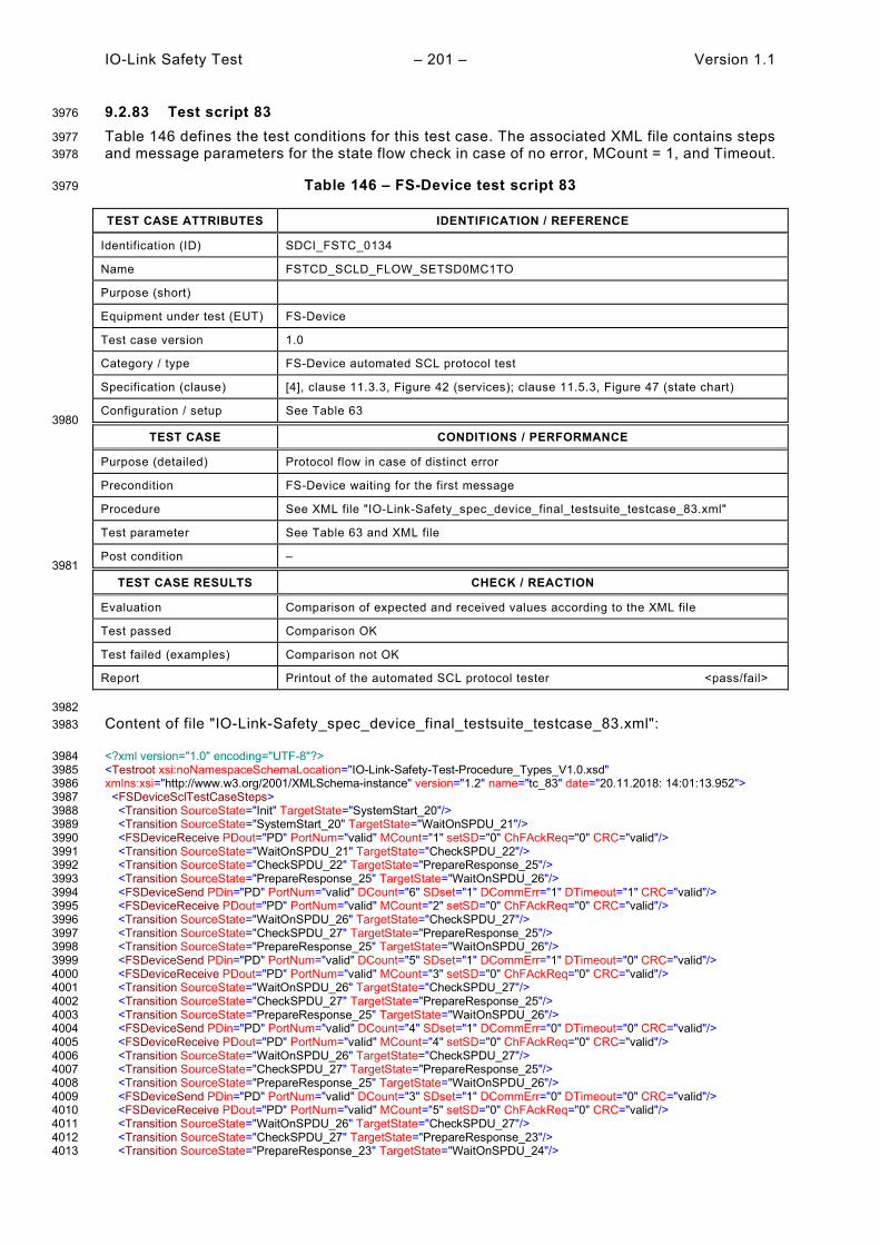
IO-Link Safety Test – 201 – Version 1.1
9.2.83 Test script 83 3976
Table 146 defines the test conditions for this test case. The associated XML file contains steps 3977 and message parameters for the state flow check in case of no error, MCount = 1, and Timeout. 3978
Table 146 – FS-Device test script 83 3979
TEST CASE ATTRIBUTES IDENTIFICATION / REFERENCE
Identification (ID) SDCI_FSTC_0134
Name FSTCD_SCLD_FLOW_SETSD0MC1TO
Purpose (short)
Equipment under test (EUT) FS-Device
Test case version 1.0
Category / type FS-Device automated SCL protocol test
Specification (clause) [4], clause 11.3.3, Figure 42 (services); clause 11.5.3, Figure 47 (state chart)
Configuration / setup See Table 63 3980
TEST CASE CONDITIONS / PERFORMANCE
Purpose (detailed) Protocol flow in case of distinct error
Precondition FS-Device waiting for the first message
Procedure See XML file "IO-Link-Safety_spec_device_final_testsuite_testcase_83.xml"
Test parameter See Table 63 and XML file
Post condition – 3981
TEST CASE RESULTS CHECK / REACTION
Evaluation Comparison of expected and received values according to the XML file
Test passed Comparison OK
Test failed (examples) Comparison not OK
Report Printout of the automated SCL protocol tester <pass/fail>
3982 Content of file "IO-Link-Safety_spec_device_final_testsuite_testcase_83.xml": 3983
<?xml version="1.0" encoding="UTF-8"?> 3984 <Testroot xsi:noNamespaceSchemaLocation="IO-Link-Safety-Test-Procedure_Types_V1.0.xsd" 3985 xmlns:xsi="http://www.w3.org/2001/XMLSchema-instance" version="1.2" name="tc_83" date="20.11.2018: 14:01:13.952"> 3986 <FSDeviceSclTestCaseSteps> 3987 <Transition SourceState="Init" TargetState="SystemStart_20"/> 3988 <Transition SourceState="SystemStart_20" TargetState="WaitOnSPDU_21"/> 3989 <FSDeviceReceive PDout="PD" PortNum="valid" MCount="1" setSD="0" ChFAckReq="0" CRC="valid"/> 3990 <Transition SourceState="WaitOnSPDU_21" TargetState="CheckSPDU_22"/> 3991 <Transition SourceState="CheckSPDU_22" TargetState="PrepareResponse_25"/> 3992 <Transition SourceState="PrepareResponse_25" TargetState="WaitOnSPDU_26"/> 3993 <FSDeviceSend PDin="PD" PortNum="valid" DCount="6" SDset="1" DCommErr="1" DTimeout="1" CRC="valid"/> 3994 <FSDeviceReceive PDout="PD" PortNum="valid" MCount="2" setSD="0" ChFAckReq="0" CRC="valid"/> 3995 <Transition SourceState="WaitOnSPDU_26" TargetState="CheckSPDU_27"/> 3996 <Transition SourceState="CheckSPDU_27" TargetState="PrepareResponse_25"/> 3997 <Transition SourceState="PrepareResponse_25" TargetState="WaitOnSPDU_26"/> 3998 <FSDeviceSend PDin="PD" PortNum="valid" DCount="5" SDset="1" DCommErr="1" DTimeout="0" CRC="valid"/> 3999 <FSDeviceReceive PDout="PD" PortNum="valid" MCount="3" setSD="0" ChFAckReq="0" CRC="valid"/> 4000 <Transition SourceState="WaitOnSPDU_26" TargetState="CheckSPDU_27"/> 4001 <Transition SourceState="CheckSPDU_27" TargetState="PrepareResponse_25"/> 4002 <Transition SourceState="PrepareResponse_25" TargetState="WaitOnSPDU_26"/> 4003 <FSDeviceSend PDin="PD" PortNum="valid" DCount="4" SDset="1" DCommErr="0" DTimeout="0" CRC="valid"/> 4004 <FSDeviceReceive PDout="PD" PortNum="valid" MCount="4" setSD="0" ChFAckReq="0" CRC="valid"/> 4005 <Transition SourceState="WaitOnSPDU_26" TargetState="CheckSPDU_27"/> 4006 <Transition SourceState="CheckSPDU_27" TargetState="PrepareResponse_25"/> 4007 <Transition SourceState="PrepareResponse_25" TargetState="WaitOnSPDU_26"/> 4008 <FSDeviceSend PDin="PD" PortNum="valid" DCount="3" SDset="1" DCommErr="0" DTimeout="0" CRC="valid"/> 4009 <FSDeviceReceive PDout="PD" PortNum="valid" MCount="5" setSD="0" ChFAckReq="0" CRC="valid"/> 4010 <Transition SourceState="WaitOnSPDU_26" TargetState="CheckSPDU_27"/> 4011 <Transition SourceState="CheckSPDU_27" TargetState="PrepareResponse_23"/> 4012 <Transition SourceState="PrepareResponse_23" TargetState="WaitOnSPDU_24"/> 4013

Version 1.1 – 202 – IO-Link Safety Test
<FSDeviceSend PDin="PD" PortNum="valid" DCount="2" SDset="0" DCommErr="0" DTimeout="0" CRC="valid"/> 4014 <FSDeviceReceive PDout="PD" PortNum="invalid" MCount="6" setSD="0" ChFAckReq="0" CRC="valid"/> 4015 <Transition SourceState="WaitOnSPDU_24" TargetState="PrepareResponse_25"/> 4016 <Transition SourceState="PrepareResponse_25" TargetState="WaitOnSPDU_26"/> 4017 <FSDeviceSend PDin="PD" PortNum="valid" DCount="1" SDset="1" DCommErr="1" DTimeout="0" CRC="valid"/> 4018 </FSDeviceSclTestCaseSteps> 4019 </Testroot> 4020 4021
4022

IO-Link Safety Test – 203 – Version 1.1
9.2.84 Test script 84 4023
Table 147 defines the test conditions for this test case. The associated XML file contains steps 4024 and message parameters for the state flow check in case of no error, MCount = 2, and Timeout. 4025
Table 147 – FS-Device test script 84 4026
TEST CASE ATTRIBUTES IDENTIFICATION / REFERENCE
Identification (ID) SDCI_FSTC_0135
Name FSTCD_SCLD_FLOW_SETSD0MC2TO
Purpose (short)
Equipment under test (EUT) FS-Device
Test case version 1.0
Category / type FS-Device automated SCL protocol test
Specification (clause) [4], clause 11.3.3, Figure 42 (services); clause 11.5.3, Figure 47 (state chart)
Configuration / setup See Table 63 4027
TEST CASE CONDITIONS / PERFORMANCE
Purpose (detailed) Protocol flow in case of distinct error
Precondition FS-Device waiting for the first message
Procedure See XML file "IO-Link-Safety_spec_device_final_testsuite_testcase_84.xml"
Test parameter See Table 63 and XML file
Post condition – 4028
TEST CASE RESULTS CHECK / REACTION
Evaluation Comparison of expected and received values according to the XML file
Test passed Comparison OK
Test failed (examples) Comparison not OK
Report Printout of the automated SCL protocol tester <pass/fail>
4029 Content of file "IO-Link-Safety_spec_device_final_testsuite_testcase_84.xml": 4030
<?xml version="1.0" encoding="UTF-8"?> 4031 <Testroot xsi:noNamespaceSchemaLocation="IO-Link-Safety-Test-Procedure_Types_V1.0.xsd" 4032 xmlns:xsi="http://www.w3.org/2001/XMLSchema-instance" version="1.2" name="tc_84" date="20.11.2018: 14:01:13.952"> 4033 <FSDeviceSclTestCaseSteps> 4034 <Transition SourceState="Init" TargetState="SystemStart_20"/> 4035 <Transition SourceState="SystemStart_20" TargetState="WaitOnSPDU_21"/> 4036 <FSDeviceReceive PDout="PD" PortNum="valid" MCount="2" setSD="0" ChFAckReq="0" CRC="valid"/> 4037 <Transition SourceState="WaitOnSPDU_21" TargetState="CheckSPDU_22"/> 4038 <Transition SourceState="CheckSPDU_22" TargetState="PrepareResponse_25"/> 4039 <Transition SourceState="PrepareResponse_25" TargetState="WaitOnSPDU_26"/> 4040 <FSDeviceSend PDin="PD" PortNum="valid" DCount="5" SDset="1" DCommErr="1" DTimeout="1" CRC="valid"/> 4041 <FSDeviceReceive PDout="PD" PortNum="valid" MCount="3" setSD="0" ChFAckReq="0" CRC="valid"/> 4042 <Transition SourceState="WaitOnSPDU_26" TargetState="CheckSPDU_27"/> 4043 <Transition SourceState="CheckSPDU_27" TargetState="PrepareResponse_25"/> 4044 <Transition SourceState="PrepareResponse_25" TargetState="WaitOnSPDU_26"/> 4045 <FSDeviceSend PDin="PD" PortNum="valid" DCount="4" SDset="1" DCommErr="1" DTimeout="0" CRC="valid"/> 4046 <FSDeviceReceive PDout="PD" PortNum="valid" MCount="4" setSD="0" ChFAckReq="0" CRC="valid"/> 4047 <Transition SourceState="WaitOnSPDU_26" TargetState="CheckSPDU_27"/> 4048 <Transition SourceState="CheckSPDU_27" TargetState="PrepareResponse_25"/> 4049 <Transition SourceState="PrepareResponse_25" TargetState="WaitOnSPDU_26"/> 4050 <FSDeviceSend PDin="PD" PortNum="valid" DCount="3" SDset="1" DCommErr="0" DTimeout="0" CRC="valid"/> 4051 <FSDeviceReceive PDout="PD" PortNum="valid" MCount="5" setSD="0" ChFAckReq="0" CRC="valid"/> 4052 <Transition SourceState="WaitOnSPDU_26" TargetState="CheckSPDU_27"/> 4053 <Transition SourceState="CheckSPDU_27" TargetState="PrepareResponse_25"/> 4054 <Transition SourceState="PrepareResponse_25" TargetState="WaitOnSPDU_26"/> 4055 <FSDeviceSend PDin="PD" PortNum="valid" DCount="2" SDset="1" DCommErr="0" DTimeout="0" CRC="valid"/> 4056 <FSDeviceReceive PDout="PD" PortNum="valid" MCount="6" setSD="0" ChFAckReq="0" CRC="valid"/> 4057 <Transition SourceState="WaitOnSPDU_26" TargetState="CheckSPDU_27"/> 4058 <Transition SourceState="CheckSPDU_27" TargetState="PrepareResponse_23"/> 4059 <Transition SourceState="PrepareResponse_23" TargetState="WaitOnSPDU_24"/> 4060

Version 1.1 – 204 – IO-Link Safety Test
<FSDeviceSend PDin="PD" PortNum="valid" DCount="1" SDset="0" DCommErr="0" DTimeout="0" CRC="valid"/> 4061 <FSDeviceReceive PDout="PD" PortNum="valid" MCount="6" setSD="0" ChFAckReq="0" CRC="valid"/> 4062 <Transition SourceState="WaitOnSPDU_24" TargetState="WaitOnSPDU_24"/> 4063 </FSDeviceSclTestCaseSteps> 4064 </Testroot> 4065 4066
4067

IO-Link Safety Test – 205 – Version 1.1
9.2.85 Test script 85 4068
Table 148 defines the test conditions for this test case. The associated XML file contains steps 4069 and message parameters for the state flow check in case of no error, MCount = 2, and Timeout. 4070
Table 148 – FS-Device test script 85 4071
TEST CASE ATTRIBUTES IDENTIFICATION / REFERENCE
Identification (ID) SDCI_FSTC_0136
Name FSTCD_SCLD_FLOW_SETSD0MC2TO
Purpose (short)
Equipment under test (EUT) FS-Device
Test case version 1.0
Category / type FS-Device automated SCL protocol test
Specification (clause) [4], clause 11.3.3, Figure 42 (services); clause 11.5.3, Figure 47 (state chart)
Configuration / setup See Table 63 4072
TEST CASE CONDITIONS / PERFORMANCE
Purpose (detailed) Protocol flow in case of distinct error
Precondition FS-Device waiting for the first message
Procedure See XML file "IO-Link-Safety_spec_device_final_testsuite_testcase_85.xml"
Test parameter See Table 63 and XML file
Post condition – 4073
TEST CASE RESULTS CHECK / REACTION
Evaluation Comparison of expected and received values according to the XML file
Test passed Comparison OK
Test failed (examples) Comparison not OK
Report Printout of the automated SCL protocol tester <pass/fail>
4074 Content of file "IO-Link-Safety_spec_device_final_testsuite_testcase_85.xml": 4075
<?xml version="1.0" encoding="UTF-8"?> 4076 <Testroot xsi:noNamespaceSchemaLocation="IO-Link-Safety-Test-Procedure_Types_V1.0.xsd" 4077 xmlns:xsi="http://www.w3.org/2001/XMLSchema-instance" version="1.2" name="tc_85" date="20.11.2018: 14:01:13.952"> 4078 <FSDeviceSclTestCaseSteps> 4079 <Transition SourceState="Init" TargetState="SystemStart_20"/> 4080 <Transition SourceState="SystemStart_20" TargetState="WaitOnSPDU_21"/> 4081 <FSDeviceReceive PDout="PD" PortNum="valid" MCount="2" setSD="0" ChFAckReq="0" CRC="valid"/> 4082 <Transition SourceState="WaitOnSPDU_21" TargetState="CheckSPDU_22"/> 4083 <Transition SourceState="CheckSPDU_22" TargetState="PrepareResponse_25"/> 4084 <Transition SourceState="PrepareResponse_25" TargetState="WaitOnSPDU_26"/> 4085 <FSDeviceSend PDin="PD" PortNum="valid" DCount="5" SDset="1" DCommErr="1" DTimeout="1" CRC="valid"/> 4086 <FSDeviceReceive PDout="PD" PortNum="valid" MCount="3" setSD="0" ChFAckReq="0" CRC="valid"/> 4087 <Transition SourceState="WaitOnSPDU_26" TargetState="CheckSPDU_27"/> 4088 <Transition SourceState="CheckSPDU_27" TargetState="PrepareResponse_25"/> 4089 <Transition SourceState="PrepareResponse_25" TargetState="WaitOnSPDU_26"/> 4090 <FSDeviceSend PDin="PD" PortNum="valid" DCount="4" SDset="1" DCommErr="1" DTimeout="0" CRC="valid"/> 4091 <FSDeviceReceive PDout="PD" PortNum="valid" MCount="4" setSD="0" ChFAckReq="0" CRC="valid"/> 4092 <Transition SourceState="WaitOnSPDU_26" TargetState="CheckSPDU_27"/> 4093 <Transition SourceState="CheckSPDU_27" TargetState="PrepareResponse_25"/> 4094 <Transition SourceState="PrepareResponse_25" TargetState="WaitOnSPDU_26"/> 4095 <FSDeviceSend PDin="PD" PortNum="valid" DCount="3" SDset="1" DCommErr="0" DTimeout="0" CRC="valid"/> 4096 <FSDeviceReceive PDout="PD" PortNum="valid" MCount="5" setSD="0" ChFAckReq="0" CRC="valid"/> 4097 <Transition SourceState="WaitOnSPDU_26" TargetState="CheckSPDU_27"/> 4098 <Transition SourceState="CheckSPDU_27" TargetState="PrepareResponse_25"/> 4099 <Transition SourceState="PrepareResponse_25" TargetState="WaitOnSPDU_26"/> 4100 <FSDeviceSend PDin="PD" PortNum="valid" DCount="2" SDset="1" DCommErr="0" DTimeout="0" CRC="valid"/> 4101 <FSDeviceReceive PDout="PD" PortNum="valid" MCount="6" setSD="0" ChFAckReq="0" CRC="valid"/> 4102 <Transition SourceState="WaitOnSPDU_26" TargetState="CheckSPDU_27"/> 4103 <Transition SourceState="CheckSPDU_27" TargetState="PrepareResponse_23"/> 4104 <Transition SourceState="PrepareResponse_23" TargetState="WaitOnSPDU_24"/> 4105

Version 1.1 – 206 – IO-Link Safety Test
<FSDeviceSend PDin="PD" PortNum="valid" DCount="1" SDset="0" DCommErr="0" DTimeout="0" CRC="valid"/> 4106 <FSDeviceReceive PDout="PD" PortNum="invalid" MCount="1" setSD="0" ChFAckReq="0" CRC="valid"/> 4107 <Transition SourceState="WaitOnSPDU_24" TargetState="PrepareResponse_25"/> 4108 <Transition SourceState="PrepareResponse_25" TargetState="WaitOnSPDU_26"/> 4109 <FSDeviceSend PDin="PD" PortNum="valid" DCount="6" SDset="1" DCommErr="1" DTimeout="0" CRC="valid"/> 4110 </FSDeviceSclTestCaseSteps> 4111 </Testroot> 4112 4113
4114
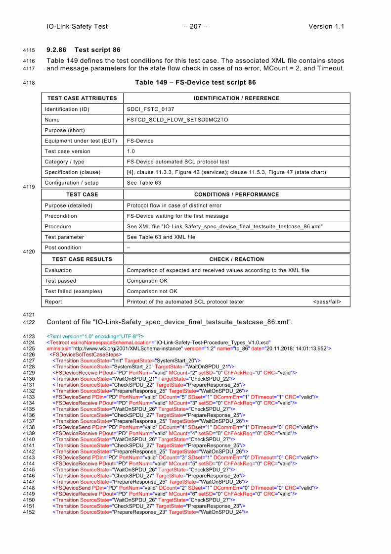
IO-Link Safety Test – 207 – Version 1.1
9.2.86 Test script 86 4115
Table 149 defines the test conditions for this test case. The associated XML file contains steps 4116 and message parameters for the state flow check in case of no error, MCount = 2, and Timeout. 4117
Table 149 – FS-Device test script 86 4118
TEST CASE ATTRIBUTES IDENTIFICATION / REFERENCE
Identification (ID) SDCI_FSTC_0137
Name FSTCD_SCLD_FLOW_SETSD0MC2TO
Purpose (short)
Equipment under test (EUT) FS-Device
Test case version 1.0
Category / type FS-Device automated SCL protocol test
Specification (clause) [4], clause 11.3.3, Figure 42 (services); clause 11.5.3, Figure 47 (state chart)
Configuration / setup See Table 63 4119
TEST CASE CONDITIONS / PERFORMANCE
Purpose (detailed) Protocol flow in case of distinct error
Precondition FS-Device waiting for the first message
Procedure See XML file "IO-Link-Safety_spec_device_final_testsuite_testcase_86.xml"
Test parameter See Table 63 and XML file
Post condition – 4120
TEST CASE RESULTS CHECK / REACTION
Evaluation Comparison of expected and received values according to the XML file
Test passed Comparison OK
Test failed (examples) Comparison not OK
Report Printout of the automated SCL protocol tester <pass/fail>
4121 Content of file "IO-Link-Safety_spec_device_final_testsuite_testcase_86.xml": 4122
<?xml version="1.0" encoding="UTF-8"?> 4123 <Testroot xsi:noNamespaceSchemaLocation="IO-Link-Safety-Test-Procedure_Types_V1.0.xsd" 4124 xmlns:xsi="http://www.w3.org/2001/XMLSchema-instance" version="1.2" name="tc_86" date="20.11.2018: 14:01:13.952"> 4125 <FSDeviceSclTestCaseSteps> 4126 <Transition SourceState="Init" TargetState="SystemStart_20"/> 4127 <Transition SourceState="SystemStart_20" TargetState="WaitOnSPDU_21"/> 4128 <FSDeviceReceive PDout="PD" PortNum="valid" MCount="2" setSD="0" ChFAckReq="0" CRC="valid"/> 4129 <Transition SourceState="WaitOnSPDU_21" TargetState="CheckSPDU_22"/> 4130 <Transition SourceState="CheckSPDU_22" TargetState="PrepareResponse_25"/> 4131 <Transition SourceState="PrepareResponse_25" TargetState="WaitOnSPDU_26"/> 4132 <FSDeviceSend PDin="PD" PortNum="valid" DCount="5" SDset="1" DCommErr="1" DTimeout="1" CRC="valid"/> 4133 <FSDeviceReceive PDout="PD" PortNum="valid" MCount="3" setSD="0" ChFAckReq="0" CRC="valid"/> 4134 <Transition SourceState="WaitOnSPDU_26" TargetState="CheckSPDU_27"/> 4135 <Transition SourceState="CheckSPDU_27" TargetState="PrepareResponse_25"/> 4136 <Transition SourceState="PrepareResponse_25" TargetState="WaitOnSPDU_26"/> 4137 <FSDeviceSend PDin="PD" PortNum="valid" DCount="4" SDset="1" DCommErr="1" DTimeout="0" CRC="valid"/> 4138 <FSDeviceReceive PDout="PD" PortNum="valid" MCount="4" setSD="0" ChFAckReq="0" CRC="valid"/> 4139 <Transition SourceState="WaitOnSPDU_26" TargetState="CheckSPDU_27"/> 4140 <Transition SourceState="CheckSPDU_27" TargetState="PrepareResponse_25"/> 4141 <Transition SourceState="PrepareResponse_25" TargetState="WaitOnSPDU_26"/> 4142 <FSDeviceSend PDin="PD" PortNum="valid" DCount="3" SDset="1" DCommErr="0" DTimeout="0" CRC="valid"/> 4143 <FSDeviceReceive PDout="PD" PortNum="valid" MCount="5" setSD="0" ChFAckReq="0" CRC="valid"/> 4144 <Transition SourceState="WaitOnSPDU_26" TargetState="CheckSPDU_27"/> 4145 <Transition SourceState="CheckSPDU_27" TargetState="PrepareResponse_25"/> 4146 <Transition SourceState="PrepareResponse_25" TargetState="WaitOnSPDU_26"/> 4147 <FSDeviceSend PDin="PD" PortNum="valid" DCount="2" SDset="1" DCommErr="0" DTimeout="0" CRC="valid"/> 4148 <FSDeviceReceive PDout="PD" PortNum="valid" MCount="6" setSD="0" ChFAckReq="0" CRC="valid"/> 4149 <Transition SourceState="WaitOnSPDU_26" TargetState="CheckSPDU_27"/> 4150 <Transition SourceState="CheckSPDU_27" TargetState="PrepareResponse_23"/> 4151 <Transition SourceState="PrepareResponse_23" TargetState="WaitOnSPDU_24"/> 4152

Version 1.1 – 208 – IO-Link Safety Test
<FSDeviceSend PDin="PD" PortNum="valid" DCount="1" SDset="0" DCommErr="0" DTimeout="0" CRC="valid"/> 4153 <FSDeviceReceive PDout="PD" PortNum="invalid" MCount="7" setSD="0" ChFAckReq="0" CRC="valid"/> 4154 <Transition SourceState="WaitOnSPDU_24" TargetState="PrepareResponse_25"/> 4155 <Transition SourceState="PrepareResponse_25" TargetState="WaitOnSPDU_26"/> 4156 <FSDeviceSend PDin="PD" PortNum="valid" DCount="0" SDset="1" DCommErr="1" DTimeout="0" CRC="valid"/> 4157 </FSDeviceSclTestCaseSteps> 4158 </Testroot> 4159 4160
4161

IO-Link Safety Test – 209 – Version 1.1
9.2.87 Test script 87 4162
Table 150 defines the test conditions for this test case. The associated XML file contains steps 4163 and message parameters for the state flow check in case of no error, MCount = 3, and Timeout. 4164
Table 150 – FS-Device test script 87 4165
TEST CASE ATTRIBUTES IDENTIFICATION / REFERENCE
Identification (ID) SDCI_FSTC_0138
Name FSTCD_SCLD_FLOW_SETSD0MC3TO
Purpose (short)
Equipment under test (EUT) FS-Device
Test case version 1.0
Category / type FS-Device automated SCL protocol test
Specification (clause) [4], clause 11.3.3, Figure 42 (services); clause 11.5.3, Figure 47 (state chart)
Configuration / setup See Table 63 4166
TEST CASE CONDITIONS / PERFORMANCE
Purpose (detailed) Protocol flow in case of distinct error
Precondition FS-Device waiting for the first message
Procedure See XML file "IO-Link-Safety_spec_device_final_testsuite_testcase_87.xml"
Test parameter See Table 63 and XML file
Post condition – 4167
TEST CASE RESULTS CHECK / REACTION
Evaluation Comparison of expected and received values according to the XML file
Test passed Comparison OK
Test failed (examples) Comparison not OK
Report Printout of the automated SCL protocol tester <pass/fail>
4168 Content of file "IO-Link-Safety_spec_device_final_testsuite_testcase_87.xml": 4169
<?xml version="1.0" encoding="UTF-8"?> 4170 <Testroot xsi:noNamespaceSchemaLocation="IO-Link-Safety-Test-Procedure_Types_V1.0.xsd" 4171 xmlns:xsi="http://www.w3.org/2001/XMLSchema-instance" version="1.2" name="tc_87" date="20.11.2018: 14:01:13.952"> 4172 <FSDeviceSclTestCaseSteps> 4173 <Transition SourceState="Init" TargetState="SystemStart_20"/> 4174 <Transition SourceState="SystemStart_20" TargetState="WaitOnSPDU_21"/> 4175 <FSDeviceReceive PDout="PD" PortNum="valid" MCount="3" setSD="0" ChFAckReq="0" CRC="valid"/> 4176 <Transition SourceState="WaitOnSPDU_21" TargetState="CheckSPDU_22"/> 4177 <Transition SourceState="CheckSPDU_22" TargetState="PrepareResponse_25"/> 4178 <Transition SourceState="PrepareResponse_25" TargetState="WaitOnSPDU_26"/> 4179 <FSDeviceSend PDin="PD" PortNum="valid" DCount="4" SDset="1" DCommErr="1" DTimeout="1" CRC="valid"/> 4180 <FSDeviceReceive PDout="PD" PortNum="valid" MCount="4" setSD="0" ChFAckReq="0" CRC="valid"/> 4181 <Transition SourceState="WaitOnSPDU_26" TargetState="CheckSPDU_27"/> 4182 <Transition SourceState="CheckSPDU_27" TargetState="PrepareResponse_25"/> 4183 <Transition SourceState="PrepareResponse_25" TargetState="WaitOnSPDU_26"/> 4184 <FSDeviceSend PDin="PD" PortNum="valid" DCount="3" SDset="1" DCommErr="1" DTimeout="0" CRC="valid"/> 4185 <FSDeviceReceive PDout="PD" PortNum="valid" MCount="5" setSD="0" ChFAckReq="0" CRC="valid"/> 4186 <Transition SourceState="WaitOnSPDU_26" TargetState="CheckSPDU_27"/> 4187 <Transition SourceState="CheckSPDU_27" TargetState="PrepareResponse_25"/> 4188 <Transition SourceState="PrepareResponse_25" TargetState="WaitOnSPDU_26"/> 4189 <FSDeviceSend PDin="PD" PortNum="valid" DCount="2" SDset="1" DCommErr="0" DTimeout="0" CRC="valid"/> 4190 <FSDeviceReceive PDout="PD" PortNum="valid" MCount="6" setSD="0" ChFAckReq="0" CRC="valid"/> 4191 <Transition SourceState="WaitOnSPDU_26" TargetState="CheckSPDU_27"/> 4192 <Transition SourceState="CheckSPDU_27" TargetState="PrepareResponse_25"/> 4193 <Transition SourceState="PrepareResponse_25" TargetState="WaitOnSPDU_26"/> 4194 <FSDeviceSend PDin="PD" PortNum="valid" DCount="1" SDset="1" DCommErr="0" DTimeout="0" CRC="valid"/> 4195 <FSDeviceReceive PDout="PD" PortNum="valid" MCount="7" setSD="0" ChFAckReq="0" CRC="valid"/> 4196 <Transition SourceState="WaitOnSPDU_26" TargetState="CheckSPDU_27"/> 4197 <Transition SourceState="CheckSPDU_27" TargetState="PrepareResponse_23"/> 4198 <Transition SourceState="PrepareResponse_23" TargetState="WaitOnSPDU_24"/> 4199

Version 1.1 – 210 – IO-Link Safety Test
<FSDeviceSend PDin="PD" PortNum="valid" DCount="0" SDset="0" DCommErr="0" DTimeout="0" CRC="valid"/> 4200 <FSDeviceReceive PDout="PD" PortNum="valid" MCount="7" setSD="0" ChFAckReq="0" CRC="valid"/> 4201 <Transition SourceState="WaitOnSPDU_24" TargetState="WaitOnSPDU_24"/> 4202 </FSDeviceSclTestCaseSteps> 4203 </Testroot> 4204 4205
4206

IO-Link Safety Test – 211 – Version 1.1
9.2.88 Test script 88 4207
Table 151 defines the test conditions for this test case. The associated XML file contains steps 4208 and message parameters for the state flow check in case of no error, MCount = 3, and Timeout. 4209
Table 151 – FS-Device test script 88 4210
TEST CASE ATTRIBUTES IDENTIFICATION / REFERENCE
Identification (ID) SDCI_FSTC_0139
Name FSTCD_SCLD_FLOW_SETSD0MC3TO
Purpose (short)
Equipment under test (EUT) FS-Device
Test case version 1.0
Category / type FS-Device automated SCL protocol test
Specification (clause) [4], clause 11.3.3, Figure 42 (services); clause 11.5.3, Figure 47 (state chart)
Configuration / setup See Table 63 4211
TEST CASE CONDITIONS / PERFORMANCE
Purpose (detailed) Protocol flow in case of distinct error
Precondition FS-Device waiting for the first message
Procedure See XML file "IO-Link-Safety_spec_device_final_testsuite_testcase_88.xml"
Test parameter See Table 63 and XML file
Post condition – 4212
TEST CASE RESULTS CHECK / REACTION
Evaluation Comparison of expected and received values according to the XML file
Test passed Comparison OK
Test failed (examples) Comparison not OK
Report Printout of the automated SCL protocol tester <pass/fail>
4213 Content of file "IO-Link-Safety_spec_device_final_testsuite_testcase_88.xml": 4214
<?xml version="1.0" encoding="UTF-8"?> 4215 <Testroot xsi:noNamespaceSchemaLocation="IO-Link-Safety-Test-Procedure_Types_V1.0.xsd" 4216 xmlns:xsi="http://www.w3.org/2001/XMLSchema-instance" version="1.2" name="tc_88" date="20.11.2018: 14:01:13.953"> 4217 <FSDeviceSclTestCaseSteps> 4218 <Transition SourceState="Init" TargetState="SystemStart_20"/> 4219 <Transition SourceState="SystemStart_20" TargetState="WaitOnSPDU_21"/> 4220 <FSDeviceReceive PDout="PD" PortNum="valid" MCount="3" setSD="0" ChFAckReq="0" CRC="valid"/> 4221 <Transition SourceState="WaitOnSPDU_21" TargetState="CheckSPDU_22"/> 4222 <Transition SourceState="CheckSPDU_22" TargetState="PrepareResponse_25"/> 4223 <Transition SourceState="PrepareResponse_25" TargetState="WaitOnSPDU_26"/> 4224 <FSDeviceSend PDin="PD" PortNum="valid" DCount="4" SDset="1" DCommErr="1" DTimeout="1" CRC="valid"/> 4225 <FSDeviceReceive PDout="PD" PortNum="valid" MCount="4" setSD="0" ChFAckReq="0" CRC="valid"/> 4226 <Transition SourceState="WaitOnSPDU_26" TargetState="CheckSPDU_27"/> 4227 <Transition SourceState="CheckSPDU_27" TargetState="PrepareResponse_25"/> 4228 <Transition SourceState="PrepareResponse_25" TargetState="WaitOnSPDU_26"/> 4229 <FSDeviceSend PDin="PD" PortNum="valid" DCount="3" SDset="1" DCommErr="1" DTimeout="0" CRC="valid"/> 4230 <FSDeviceReceive PDout="PD" PortNum="valid" MCount="5" setSD="0" ChFAckReq="0" CRC="valid"/> 4231 <Transition SourceState="WaitOnSPDU_26" TargetState="CheckSPDU_27"/> 4232 <Transition SourceState="CheckSPDU_27" TargetState="PrepareResponse_25"/> 4233 <Transition SourceState="PrepareResponse_25" TargetState="WaitOnSPDU_26"/> 4234 <FSDeviceSend PDin="PD" PortNum="valid" DCount="2" SDset="1" DCommErr="0" DTimeout="0" CRC="valid"/> 4235 <FSDeviceReceive PDout="PD" PortNum="valid" MCount="6" setSD="0" ChFAckReq="0" CRC="valid"/> 4236 <Transition SourceState="WaitOnSPDU_26" TargetState="CheckSPDU_27"/> 4237 <Transition SourceState="CheckSPDU_27" TargetState="PrepareResponse_25"/> 4238 <Transition SourceState="PrepareResponse_25" TargetState="WaitOnSPDU_26"/> 4239 <FSDeviceSend PDin="PD" PortNum="valid" DCount="1" SDset="1" DCommErr="0" DTimeout="0" CRC="valid"/> 4240 <FSDeviceReceive PDout="PD" PortNum="valid" MCount="7" setSD="0" ChFAckReq="0" CRC="valid"/> 4241 <Transition SourceState="WaitOnSPDU_26" TargetState="CheckSPDU_27"/> 4242 <Transition SourceState="CheckSPDU_27" TargetState="PrepareResponse_23"/> 4243 <Transition SourceState="PrepareResponse_23" TargetState="WaitOnSPDU_24"/> 4244

Version 1.1 – 212 – IO-Link Safety Test
<FSDeviceSend PDin="PD" PortNum="valid" DCount="0" SDset="0" DCommErr="0" DTimeout="0" CRC="valid"/> 4245 <FSDeviceReceive PDout="PD" PortNum="invalid" MCount="1" setSD="0" ChFAckReq="0" CRC="valid"/> 4246 <Transition SourceState="WaitOnSPDU_24" TargetState="PrepareResponse_25"/> 4247 <Transition SourceState="PrepareResponse_25" TargetState="WaitOnSPDU_26"/> 4248 <FSDeviceSend PDin="PD" PortNum="valid" DCount="6" SDset="1" DCommErr="1" DTimeout="0" CRC="valid"/> 4249 </FSDeviceSclTestCaseSteps> 4250 </Testroot> 4251 4252
4253

IO-Link Safety Test – 213 – Version 1.1
9.2.89 Test script 89 4254
Table 152 defines the test conditions for this test case. The associated XML file contains steps 4255 and message parameters for the state flow check in case of setSD error, MCount = 0, and 4256 DCommErr. 4257
Table 152 – FS-Device test script 89 4258
TEST CASE ATTRIBUTES IDENTIFICATION / REFERENCE
Identification (ID) SDCI_FSTC_0140
Name FSTCD_SCLD_FLOW_SETSD1MC0DCE1
Purpose (short)
Equipment under test (EUT) FS-Device
Test case version 1.0
Category / type FS-Device automated SCL protocol test
Specification (clause) [4], clause 11.3.3, Figure 42 (services); clause 11.5.3, Figure 47 (state chart)
Configuration / setup See Table 63 4259
TEST CASE CONDITIONS / PERFORMANCE
Purpose (detailed) Protocol flow in case of distinct error
Precondition FS-Device waiting for the first message
Procedure See XML file "IO-Link-Safety_spec_device_final_testsuite_testcase_89.xml"
Test parameter See Table 63 and XML file
Post condition – 4260
TEST CASE RESULTS CHECK / REACTION
Evaluation Comparison of expected and received values according to the XML file
Test passed Comparison OK
Test failed (examples) Comparison not OK
Report Printout of the automated SCL protocol tester <pass/fail>
4261 Content of file "IO-Link-Safety_spec_device_final_testsuite_testcase_89.xml": 4262
<?xml version="1.0" encoding="UTF-8"?> 4263 <Testroot xsi:noNamespaceSchemaLocation="IO-Link-Safety-Test-Procedure_Types_V1.0.xsd" 4264 xmlns:xsi="http://www.w3.org/2001/XMLSchema-instance" version="1.2" name="tc_89" date="20.11.2018: 14:01:13.953"> 4265 <FSDeviceSclTestCaseSteps> 4266 <Transition SourceState="Init" TargetState="SystemStart_20"/> 4267 <Transition SourceState="SystemStart_20" TargetState="WaitOnSPDU_21"/> 4268 <FSDeviceReceive PDout="PD" PortNum="valid" MCount="0" setSD="1" ChFAckReq="0" CRC="valid"/> 4269 <Transition SourceState="WaitOnSPDU_21" TargetState="CheckSPDU_22"/> 4270 <Transition SourceState="CheckSPDU_22" TargetState="PrepareResponse_23"/> 4271 <Transition SourceState="PrepareResponse_23" TargetState="WaitOnSPDU_24"/> 4272 <FSDeviceSend PDin="PD" PortNum="valid" DCount="7" SDset="1" DCommErr="0" DTimeout="0" CRC="valid"/> 4273 <FSDeviceReceive PDout="PD" PortNum="valid" MCount="1" setSD="0" ChFAckReq="0" CRC="valid"/> 4274 <Transition SourceState="WaitOnSPDU_24" TargetState="CheckSPDU_22"/> 4275 <Transition SourceState="CheckSPDU_22" TargetState="PrepareResponse_23"/> 4276 <Transition SourceState="PrepareResponse_23" TargetState="WaitOnSPDU_24"/> 4277 <FSDeviceSend PDin="PD" PortNum="valid" DCount="6" SDset="1" DCommErr="0" DTimeout="0" CRC="valid"/> 4278 <FSDeviceReceive PDout="PD" PortNum="valid" MCount="2" setSD="0" ChFAckReq="0" CRC="valid"/> 4279 <Transition SourceState="WaitOnSPDU_24" TargetState="CheckSPDU_22"/> 4280 <Transition SourceState="CheckSPDU_22" TargetState="PrepareResponse_23"/> 4281 <Transition SourceState="PrepareResponse_23" TargetState="WaitOnSPDU_24"/> 4282 <FSDeviceSend PDin="PD" PortNum="valid" DCount="5" SDset="1" DCommErr="0" DTimeout="0" CRC="valid"/> 4283 <FSDeviceReceive PDout="PD" PortNum="valid" MCount="3" setSD="0" ChFAckReq="0" CRC="valid"/> 4284 <Transition SourceState="WaitOnSPDU_24" TargetState="CheckSPDU_22"/> 4285 <Transition SourceState="CheckSPDU_22" TargetState="PrepareResponse_23"/> 4286 <Transition SourceState="PrepareResponse_23" TargetState="WaitOnSPDU_24"/> 4287 <FSDeviceSend PDin="PD" PortNum="valid" DCount="4" SDset="0" DCommErr="0" DTimeout="0" CRC="valid"/> 4288 <FSDeviceReceive PDout="PD" PortNum="valid" MCount="4" setSD="0" ChFAckReq="0" CRC="valid"/> 4289 <Transition SourceState="WaitOnSPDU_24" TargetState="CheckSPDU_22"/> 4290

Version 1.1 – 214 – IO-Link Safety Test
<Transition SourceState="CheckSPDU_22" TargetState="PrepareResponse_23"/> 4291 <Transition SourceState="PrepareResponse_23" TargetState="WaitOnSPDU_24"/> 4292 <FSDeviceSend PDin="PD" PortNum="valid" DCount="3" SDset="0" DCommErr="0" DTimeout="0" CRC="valid"/> 4293 <FSDeviceReceive PDout="PD" PortNum="valid" MCount="6" setSD="0" ChFAckReq="0" CRC="valid"/> 4294 <Transition SourceState="WaitOnSPDU_24" TargetState="CheckSPDU_22"/> 4295 <Transition SourceState="CheckSPDU_22" TargetState="PrepareResponse_25"/> 4296 <Transition SourceState="PrepareResponse_25" TargetState="WaitOnSPDU_26"/> 4297 <FSDeviceSend PDin="PD" PortNum="valid" DCount="1" SDset="1" DCommErr="1" DTimeout="0" CRC="valid"/> 4298 </FSDeviceSclTestCaseSteps> 4299 </Testroot> 4300 4301
4302
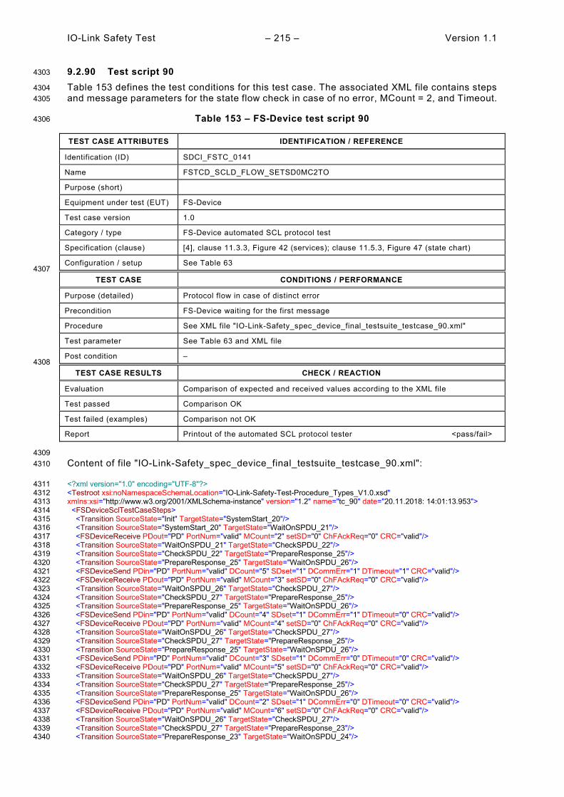
IO-Link Safety Test – 215 – Version 1.1
9.2.90 Test script 90 4303
Table 153 defines the test conditions for this test case. The associated XML file contains steps 4304 and message parameters for the state flow check in case of no error, MCount = 2, and Timeout. 4305
Table 153 – FS-Device test script 90 4306
TEST CASE ATTRIBUTES IDENTIFICATION / REFERENCE
Identification (ID) SDCI_FSTC_0141
Name FSTCD_SCLD_FLOW_SETSD0MC2TO
Purpose (short)
Equipment under test (EUT) FS-Device
Test case version 1.0
Category / type FS-Device automated SCL protocol test
Specification (clause) [4], clause 11.3.3, Figure 42 (services); clause 11.5.3, Figure 47 (state chart)
Configuration / setup See Table 63 4307
TEST CASE CONDITIONS / PERFORMANCE
Purpose (detailed) Protocol flow in case of distinct error
Precondition FS-Device waiting for the first message
Procedure See XML file "IO-Link-Safety_spec_device_final_testsuite_testcase_90.xml"
Test parameter See Table 63 and XML file
Post condition – 4308
TEST CASE RESULTS CHECK / REACTION
Evaluation Comparison of expected and received values according to the XML file
Test passed Comparison OK
Test failed (examples) Comparison not OK
Report Printout of the automated SCL protocol tester <pass/fail>
4309 Content of file "IO-Link-Safety_spec_device_final_testsuite_testcase_90.xml": 4310
<?xml version="1.0" encoding="UTF-8"?> 4311 <Testroot xsi:noNamespaceSchemaLocation="IO-Link-Safety-Test-Procedure_Types_V1.0.xsd" 4312 xmlns:xsi="http://www.w3.org/2001/XMLSchema-instance" version="1.2" name="tc_90" date="20.11.2018: 14:01:13.953"> 4313 <FSDeviceSclTestCaseSteps> 4314 <Transition SourceState="Init" TargetState="SystemStart_20"/> 4315 <Transition SourceState="SystemStart_20" TargetState="WaitOnSPDU_21"/> 4316 <FSDeviceReceive PDout="PD" PortNum="valid" MCount="2" setSD="0" ChFAckReq="0" CRC="valid"/> 4317 <Transition SourceState="WaitOnSPDU_21" TargetState="CheckSPDU_22"/> 4318 <Transition SourceState="CheckSPDU_22" TargetState="PrepareResponse_25"/> 4319 <Transition SourceState="PrepareResponse_25" TargetState="WaitOnSPDU_26"/> 4320 <FSDeviceSend PDin="PD" PortNum="valid" DCount="5" SDset="1" DCommErr="1" DTimeout="1" CRC="valid"/> 4321 <FSDeviceReceive PDout="PD" PortNum="valid" MCount="3" setSD="0" ChFAckReq="0" CRC="valid"/> 4322 <Transition SourceState="WaitOnSPDU_26" TargetState="CheckSPDU_27"/> 4323 <Transition SourceState="CheckSPDU_27" TargetState="PrepareResponse_25"/> 4324 <Transition SourceState="PrepareResponse_25" TargetState="WaitOnSPDU_26"/> 4325 <FSDeviceSend PDin="PD" PortNum="valid" DCount="4" SDset="1" DCommErr="1" DTimeout="0" CRC="valid"/> 4326 <FSDeviceReceive PDout="PD" PortNum="valid" MCount="4" setSD="0" ChFAckReq="0" CRC="valid"/> 4327 <Transition SourceState="WaitOnSPDU_26" TargetState="CheckSPDU_27"/> 4328 <Transition SourceState="CheckSPDU_27" TargetState="PrepareResponse_25"/> 4329 <Transition SourceState="PrepareResponse_25" TargetState="WaitOnSPDU_26"/> 4330 <FSDeviceSend PDin="PD" PortNum="valid" DCount="3" SDset="1" DCommErr="0" DTimeout="0" CRC="valid"/> 4331 <FSDeviceReceive PDout="PD" PortNum="valid" MCount="5" setSD="0" ChFAckReq="0" CRC="valid"/> 4332 <Transition SourceState="WaitOnSPDU_26" TargetState="CheckSPDU_27"/> 4333 <Transition SourceState="CheckSPDU_27" TargetState="PrepareResponse_25"/> 4334 <Transition SourceState="PrepareResponse_25" TargetState="WaitOnSPDU_26"/> 4335 <FSDeviceSend PDin="PD" PortNum="valid" DCount="2" SDset="1" DCommErr="0" DTimeout="0" CRC="valid"/> 4336 <FSDeviceReceive PDout="PD" PortNum="valid" MCount="6" setSD="0" ChFAckReq="0" CRC="valid"/> 4337 <Transition SourceState="WaitOnSPDU_26" TargetState="CheckSPDU_27"/> 4338 <Transition SourceState="CheckSPDU_27" TargetState="PrepareResponse_23"/> 4339 <Transition SourceState="PrepareResponse_23" TargetState="WaitOnSPDU_24"/> 4340

Version 1.1 – 216 – IO-Link Safety Test
<FSDeviceSend PDin="PD" PortNum="valid" DCount="1" SDset="0" DCommErr="0" DTimeout="0" CRC="valid"/> 4341 <FSDeviceReceive PDout="PD" PortNum="valid" MCount="0" setSD="0" ChFAckReq="0" CRC="invalid"/> 4342 <Transition SourceState="WaitOnSPDU_24" TargetState="PrepareResponse_25"/> 4343 <Transition SourceState="PrepareResponse_25" TargetState="WaitOnSPDU_26"/> 4344 <FSDeviceSend PDin="PD" PortNum="valid" DCount="7" SDset="1" DCommErr="1" DTimeout="0" CRC="valid"/> 4345 </FSDeviceSclTestCaseSteps> 4346 </Testroot> 4347 4348
4349

IO-Link Safety Test – 217 – Version 1.1
9.2.91 Test script 91 4350
Table 154 defines the test conditions for this test case. The associated XML file contains steps 4351 and message parameters for the state flow check in case of no error, MCount = 1, and Timeout. 4352
Table 154 – FS-Device test script 91 4353
TEST CASE ATTRIBUTES IDENTIFICATION / REFERENCE
Identification (ID) SDCI_FSTC_0142
Name FSTCD_SCLD_FLOW_SETSD0MC1TO
Purpose (short)
Equipment under test (EUT) FS-Device
Test case version 1.0
Category / type FS-Device automated SCL protocol test
Specification (clause) [4], clause 11.3.3, Figure 42 (services); clause 11.5.3, Figure 47 (state chart)
Configuration / setup See Table 63 4354
TEST CASE CONDITIONS / PERFORMANCE
Purpose (detailed) Protocol flow in case of distinct error
Precondition FS-Device waiting for the first message
Procedure See XML file "IO-Link-Safety_spec_device_final_testsuite_testcase_91.xml"
Test parameter See Table 63 and XML file
Post condition – 4355
TEST CASE RESULTS CHECK / REACTION
Evaluation Comparison of expected and received values according to the XML file
Test passed Comparison OK
Test failed (examples) Comparison not OK
Report Printout of the automated SCL protocol tester <pass/fail>
4356 Content of file "IO-Link-Safety_spec_device_final_testsuite_testcase_91.xml": 4357
<?xml version="1.0" encoding="UTF-8"?> 4358 <Testroot xsi:noNamespaceSchemaLocation="IO-Link-Safety-Test-Procedure_Types_V1.0.xsd" 4359 xmlns:xsi="http://www.w3.org/2001/XMLSchema-instance" version="1.2" name="tc_91" date="20.11.2018: 14:01:13.954"> 4360 <FSDeviceSclTestCaseSteps> 4361 <Transition SourceState="Init" TargetState="SystemStart_20"/> 4362 <Transition SourceState="SystemStart_20" TargetState="WaitOnSPDU_21"/> 4363 <FSDeviceReceive PDout="PD" PortNum="valid" MCount="1" setSD="0" ChFAckReq="0" CRC="valid"/> 4364 <Transition SourceState="WaitOnSPDU_21" TargetState="CheckSPDU_22"/> 4365 <Transition SourceState="CheckSPDU_22" TargetState="PrepareResponse_25"/> 4366 <Transition SourceState="PrepareResponse_25" TargetState="WaitOnSPDU_26"/> 4367 <FSDeviceSend PDin="PD" PortNum="valid" DCount="6" SDset="1" DCommErr="1" DTimeout="1" CRC="valid"/> 4368 <FSDeviceReceive PDout="PD" PortNum="valid" MCount="2" setSD="0" ChFAckReq="0" CRC="valid"/> 4369 <Transition SourceState="WaitOnSPDU_26" TargetState="CheckSPDU_27"/> 4370 <Transition SourceState="CheckSPDU_27" TargetState="PrepareResponse_25"/> 4371 <Transition SourceState="PrepareResponse_25" TargetState="WaitOnSPDU_26"/> 4372 <FSDeviceSend PDin="PD" PortNum="valid" DCount="5" SDset="1" DCommErr="1" DTimeout="0" CRC="valid"/> 4373 <FSDeviceReceive PDout="PD" PortNum="valid" MCount="3" setSD="0" ChFAckReq="0" CRC="valid"/> 4374 <Transition SourceState="WaitOnSPDU_26" TargetState="CheckSPDU_27"/> 4375 <Transition SourceState="CheckSPDU_27" TargetState="PrepareResponse_25"/> 4376 <Transition SourceState="PrepareResponse_25" TargetState="WaitOnSPDU_26"/> 4377 <FSDeviceSend PDin="PD" PortNum="valid" DCount="4" SDset="1" DCommErr="0" DTimeout="0" CRC="valid"/> 4378 <FSDeviceReceive PDout="PD" PortNum="valid" MCount="4" setSD="0" ChFAckReq="0" CRC="valid"/> 4379 <Transition SourceState="WaitOnSPDU_26" TargetState="CheckSPDU_27"/> 4380 <Transition SourceState="CheckSPDU_27" TargetState="PrepareResponse_25"/> 4381 <Transition SourceState="PrepareResponse_25" TargetState="WaitOnSPDU_26"/> 4382 <FSDeviceSend PDin="PD" PortNum="valid" DCount="3" SDset="1" DCommErr="0" DTimeout="0" CRC="valid"/> 4383 <FSDeviceReceive PDout="PD" PortNum="valid" MCount="5" setSD="0" ChFAckReq="0" CRC="valid"/> 4384 <Transition SourceState="WaitOnSPDU_26" TargetState="CheckSPDU_27"/> 4385 <Transition SourceState="CheckSPDU_27" TargetState="PrepareResponse_23"/> 4386 <Transition SourceState="PrepareResponse_23" TargetState="WaitOnSPDU_24"/> 4387

Version 1.1 – 218 – IO-Link Safety Test
<FSDeviceSend PDin="PD" PortNum="valid" DCount="2" SDset="0" DCommErr="0" DTimeout="0" CRC="valid"/> 4388 <FSDeviceReceive PDout="PD" PortNum="valid" MCount="0" setSD="0" ChFAckReq="0" CRC="invalid"/> 4389 <Transition SourceState="WaitOnSPDU_24" TargetState="PrepareResponse_25"/> 4390 <Transition SourceState="PrepareResponse_25" TargetState="WaitOnSPDU_26"/> 4391 <FSDeviceSend PDin="PD" PortNum="valid" DCount="7" SDset="1" DCommErr="1" DTimeout="0" CRC="valid"/> 4392 </FSDeviceSclTestCaseSteps> 4393 </Testroot> 4394 4395
4396

IO-Link Safety Test – 219 – Version 1.1
9.2.92 Test script 92 4397
Table 155 defines the test conditions for this test case. The associated XML file contains steps 4398 and message parameters for the state flow check in case of no error, MCount = 1, and Timeout. 4399
Table 155 – FS-Device test script 92 4400
TEST CASE ATTRIBUTES IDENTIFICATION / REFERENCE
Identification (ID) SDCI_FSTC_0143
Name FSTCD_SCLD_FLOW_SETSD0MC1TO
Purpose (short)
Equipment under test (EUT) FS-Device
Test case version 1.0
Category / type FS-Device automated SCL protocol test
Specification (clause) [4], clause 11.3.3, Figure 42 (services); clause 11.5.3, Figure 47 (state chart)
Configuration / setup See Table 63 4401
TEST CASE CONDITIONS / PERFORMANCE
Purpose (detailed) Protocol flow in case of distinct error
Precondition FS-Device waiting for the first message
Procedure See XML file "IO-Link-Safety_spec_device_final_testsuite_testcase_92.xml"
Test parameter See Table 63 and XML file
Post condition – 4402
TEST CASE RESULTS CHECK / REACTION
Evaluation Comparison of expected and received values according to the XML file
Test passed Comparison OK
Test failed (examples) Comparison not OK
Report Printout of the automated SCL protocol tester <pass/fail>
4403 Content of file "IO-Link-Safety_spec_device_final_testsuite_testcase_92.xml": 4404
<?xml version="1.0" encoding="UTF-8"?> 4405 <Testroot xsi:noNamespaceSchemaLocation="IO-Link-Safety-Test-Procedure_Types_V1.0.xsd" 4406 xmlns:xsi="http://www.w3.org/2001/XMLSchema-instance" version="1.2" name="tc_92" date="20.11.2018: 14:01:13.954"> 4407 <FSDeviceSclTestCaseSteps> 4408 <Transition SourceState="Init" TargetState="SystemStart_20"/> 4409 <Transition SourceState="SystemStart_20" TargetState="WaitOnSPDU_21"/> 4410 <FSDeviceReceive PDout="PD" PortNum="valid" MCount="1" setSD="0" ChFAckReq="0" CRC="valid"/> 4411 <Transition SourceState="WaitOnSPDU_21" TargetState="CheckSPDU_22"/> 4412 <Transition SourceState="CheckSPDU_22" TargetState="PrepareResponse_25"/> 4413 <Transition SourceState="PrepareResponse_25" TargetState="WaitOnSPDU_26"/> 4414 <FSDeviceSend PDin="PD" PortNum="valid" DCount="6" SDset="1" DCommErr="1" DTimeout="1" CRC="valid"/> 4415 <FSDeviceReceive PDout="PD" PortNum="valid" MCount="2" setSD="0" ChFAckReq="0" CRC="valid"/> 4416 <Transition SourceState="WaitOnSPDU_26" TargetState="CheckSPDU_27"/> 4417 <Transition SourceState="CheckSPDU_27" TargetState="PrepareResponse_25"/> 4418 <Transition SourceState="PrepareResponse_25" TargetState="WaitOnSPDU_26"/> 4419 <FSDeviceSend PDin="PD" PortNum="valid" DCount="5" SDset="1" DCommErr="1" DTimeout="0" CRC="valid"/> 4420 <FSDeviceReceive PDout="PD" PortNum="valid" MCount="3" setSD="0" ChFAckReq="0" CRC="valid"/> 4421 <Transition SourceState="WaitOnSPDU_26" TargetState="CheckSPDU_27"/> 4422 <Transition SourceState="CheckSPDU_27" TargetState="PrepareResponse_25"/> 4423 <Transition SourceState="PrepareResponse_25" TargetState="WaitOnSPDU_26"/> 4424 <FSDeviceSend PDin="PD" PortNum="valid" DCount="4" SDset="1" DCommErr="0" DTimeout="0" CRC="valid"/> 4425 <FSDeviceReceive PDout="PD" PortNum="valid" MCount="4" setSD="0" ChFAckReq="0" CRC="valid"/> 4426 <Transition SourceState="WaitOnSPDU_26" TargetState="CheckSPDU_27"/> 4427 <Transition SourceState="CheckSPDU_27" TargetState="PrepareResponse_25"/> 4428 <Transition SourceState="PrepareResponse_25" TargetState="WaitOnSPDU_26"/> 4429 <FSDeviceSend PDin="PD" PortNum="valid" DCount="3" SDset="1" DCommErr="0" DTimeout="0" CRC="valid"/> 4430 <FSDeviceReceive PDout="PD" PortNum="valid" MCount="5" setSD="0" ChFAckReq="0" CRC="valid"/> 4431 <Transition SourceState="WaitOnSPDU_26" TargetState="CheckSPDU_27"/> 4432 <Transition SourceState="CheckSPDU_27" TargetState="PrepareResponse_23"/> 4433 <Transition SourceState="PrepareResponse_23" TargetState="WaitOnSPDU_24"/> 4434

Version 1.1 – 220 – IO-Link Safety Test
<FSDeviceSend PDin="PD" PortNum="valid" DCount="2" SDset="0" DCommErr="0" DTimeout="0" CRC="valid"/> 4435 <FSDeviceReceive PDout="PD" PortNum="valid" MCount="6" setSD="0" ChFAckReq="0" CRC="invalid"/> 4436 <Transition SourceState="WaitOnSPDU_24" TargetState="PrepareResponse_25"/> 4437 <Transition SourceState="PrepareResponse_25" TargetState="WaitOnSPDU_26"/> 4438 <FSDeviceSend PDin="PD" PortNum="valid" DCount="1" SDset="1" DCommErr="1" DTimeout="0" CRC="valid"/> 4439 </FSDeviceSclTestCaseSteps> 4440 </Testroot> 4441 4442
4443

IO-Link Safety Test – 221 – Version 1.1
9.2.93 Test script 93 4444
Table 156 defines the test conditions for this test case. The associated XML file contains steps 4445 and message parameters for the state flow check in case of no error, MCount = 3, and Timeout. 4446
Table 156 – FS-Device test script 93 4447
TEST CASE ATTRIBUTES IDENTIFICATION / REFERENCE
Identification (ID) SDCI_FSTC_0144
Name FSTCD_SCLD_FLOW_SETSD0MC3
Purpose (short)
Equipment under test (EUT) FS-Device
Test case version 1.0
Category / type FS-Device automated SCL protocol test
Specification (clause) [4], clause 11.3.3, Figure 42 (services); clause 11.5.3, Figure 47 (state chart)
Configuration / setup See Table 63 4448
TEST CASE CONDITIONS / PERFORMANCE
Purpose (detailed) Protocol flow in case of distinct error
Precondition FS-Device waiting for the first message
Procedure See XML file "IO-Link-Safety_spec_device_final_testsuite_testcase_93.xml"
Test parameter See Table 63 and XML file
Post condition – 4449
TEST CASE RESULTS CHECK / REACTION
Evaluation Comparison of expected and received values according to the XML file
Test passed Comparison OK
Test failed (examples) Comparison not OK
Report Printout of the automated SCL protocol tester <pass/fail>
4450 Content of file "IO-Link-Safety_spec_device_final_testsuite_testcase_93.xml": 4451
<?xml version="1.0" encoding="UTF-8"?> 4452 <Testroot xsi:noNamespaceSchemaLocation="IO-Link-Safety-Test-Procedure_Types_V1.0.xsd" 4453 xmlns:xsi="http://www.w3.org/2001/XMLSchema-instance" version="1.2" name="tc_93" date="20.11.2018: 14:01:13.954"> 4454 <FSDeviceSclTestCaseSteps> 4455 <Transition SourceState="Init" TargetState="SystemStart_20"/> 4456 <Transition SourceState="SystemStart_20" TargetState="WaitOnSPDU_21"/> 4457 <FSDeviceReceive PDout="PD" PortNum="valid" MCount="3" setSD="0" ChFAckReq="0" CRC="valid"/> 4458 <Transition SourceState="WaitOnSPDU_21" TargetState="CheckSPDU_22"/> 4459 <Transition SourceState="CheckSPDU_22" TargetState="PrepareResponse_25"/> 4460 <Transition SourceState="PrepareResponse_25" TargetState="WaitOnSPDU_26"/> 4461 <FSDeviceSend PDin="PD" PortNum="valid" DCount="4" SDset="1" DCommErr="1" DTimeout="1" CRC="valid"/> 4462 <FSDeviceReceive PDout="PD" PortNum="valid" MCount="4" setSD="0" ChFAckReq="0" CRC="valid"/> 4463 <Transition SourceState="WaitOnSPDU_26" TargetState="CheckSPDU_27"/> 4464 <Transition SourceState="CheckSPDU_27" TargetState="PrepareResponse_25"/> 4465 <Transition SourceState="PrepareResponse_25" TargetState="WaitOnSPDU_26"/> 4466 <FSDeviceSend PDin="PD" PortNum="valid" DCount="3" SDset="1" DCommErr="1" DTimeout="0" CRC="valid"/> 4467 <FSDeviceReceive PDout="PD" PortNum="valid" MCount="5" setSD="0" ChFAckReq="0" CRC="valid"/> 4468 <Transition SourceState="WaitOnSPDU_26" TargetState="CheckSPDU_27"/> 4469 <Transition SourceState="CheckSPDU_27" TargetState="PrepareResponse_25"/> 4470 <Transition SourceState="PrepareResponse_25" TargetState="WaitOnSPDU_26"/> 4471 <FSDeviceSend PDin="PD" PortNum="valid" DCount="2" SDset="1" DCommErr="0" DTimeout="0" CRC="valid"/> 4472 <FSDeviceReceive PDout="PD" PortNum="valid" MCount="6" setSD="0" ChFAckReq="0" CRC="valid"/> 4473 <Transition SourceState="WaitOnSPDU_26" TargetState="CheckSPDU_27"/> 4474 <Transition SourceState="CheckSPDU_27" TargetState="PrepareResponse_25"/> 4475 <Transition SourceState="PrepareResponse_25" TargetState="WaitOnSPDU_26"/> 4476 <FSDeviceSend PDin="PD" PortNum="valid" DCount="1" SDset="1" DCommErr="0" DTimeout="0" CRC="valid"/> 4477 <FSDeviceReceive PDout="PD" PortNum="valid" MCount="7" setSD="0" ChFAckReq="0" CRC="valid"/> 4478 <Transition SourceState="WaitOnSPDU_26" TargetState="CheckSPDU_27"/> 4479 <Transition SourceState="CheckSPDU_27" TargetState="PrepareResponse_23"/> 4480 <Transition SourceState="PrepareResponse_23" TargetState="WaitOnSPDU_24"/> 4481

Version 1.1 – 222 – IO-Link Safety Test
<FSDeviceSend PDin="PD" PortNum="valid" DCount="0" SDset="0" DCommErr="0" DTimeout="0" CRC="valid"/> 4482 <FSDeviceReceive PDout="PD" PortNum="valid" MCount="1" setSD="0" ChFAckReq="0" CRC="valid"/> 4483 <Transition SourceState="WaitOnSPDU_24" TargetState="CheckSPDU_22"/> 4484 <Transition SourceState="CheckSPDU_22" TargetState="PrepareResponse_23"/> 4485 <Transition SourceState="PrepareResponse_23" TargetState="WaitOnSPDU_24"/> 4486 <FSDeviceSend PDin="PD" PortNum="valid" DCount="6" SDset="0" DCommErr="0" DTimeout="0" CRC="valid"/> 4487 </FSDeviceSclTestCaseSteps> 4488 </Testroot> 4489 4490
4491

IO-Link Safety Test – 223 – Version 1.1
9.2.94 Test script 94 4492
Table 157 defines the test conditions for this test case. The associated XML file contains steps 4493 and message parameters for the state flow check in case of no error, MCount = 1, and Timeout. 4494
Table 157 – FS-Device test script 94 4495
TEST CASE ATTRIBUTES IDENTIFICATION / REFERENCE
Identification (ID) SDCI_FSTC_0145
Name FSTCD_SCLD_FLOW_SETSD0MC1TO
Purpose (short)
Equipment under test (EUT) FS-Device
Test case version 1.0
Category / type FS-Device automated SCL protocol test
Specification (clause) [4], clause 11.3.3, Figure 42 (services); clause 11.5.3, Figure 47 (state chart)
Configuration / setup See Table 63 4496
TEST CASE CONDITIONS / PERFORMANCE
Purpose (detailed) Protocol flow in case of distinct error
Precondition FS-Device waiting for the first message
Procedure See XML file "IO-Link-Safety_spec_device_final_testsuite_testcase_94.xml"
Test parameter See Table 63 and XML file
Post condition – 4497
TEST CASE RESULTS CHECK / REACTION
Evaluation Comparison of expected and received values according to the XML file
Test passed Comparison OK
Test failed (examples) Comparison not OK
Report Printout of the automated SCL protocol tester <pass/fail>
4498 Content of file "IO-Link-Safety_spec_device_final_testsuite_testcase_94.xml": 4499
<?xml version="1.0" encoding="UTF-8"?> 4500 <Testroot xsi:noNamespaceSchemaLocation="IO-Link-Safety-Test-Procedure_Types_V1.0.xsd" 4501 xmlns:xsi="http://www.w3.org/2001/XMLSchema-instance" version="1.2" name="tc_94" date="20.11.2018: 14:01:13.954"> 4502 <FSDeviceSclTestCaseSteps> 4503 <Transition SourceState="Init" TargetState="SystemStart_20"/> 4504 <Transition SourceState="SystemStart_20" TargetState="WaitOnSPDU_21"/> 4505 <FSDeviceReceive PDout="PD" PortNum="valid" MCount="1" setSD="0" ChFAckReq="0" CRC="valid"/> 4506 <Transition SourceState="WaitOnSPDU_21" TargetState="CheckSPDU_22"/> 4507 <Transition SourceState="CheckSPDU_22" TargetState="PrepareResponse_25"/> 4508 <Transition SourceState="PrepareResponse_25" TargetState="WaitOnSPDU_26"/> 4509 <FSDeviceSend PDin="PD" PortNum="valid" DCount="6" SDset="1" DCommErr="1" DTimeout="1" CRC="valid"/> 4510 <FSDeviceReceive PDout="PD" PortNum="valid" MCount="2" setSD="0" ChFAckReq="0" CRC="valid"/> 4511 <Transition SourceState="WaitOnSPDU_26" TargetState="CheckSPDU_27"/> 4512 <Transition SourceState="CheckSPDU_27" TargetState="PrepareResponse_25"/> 4513 <Transition SourceState="PrepareResponse_25" TargetState="WaitOnSPDU_26"/> 4514 <FSDeviceSend PDin="PD" PortNum="valid" DCount="5" SDset="1" DCommErr="1" DTimeout="0" CRC="valid"/> 4515 <FSDeviceReceive PDout="PD" PortNum="valid" MCount="3" setSD="0" ChFAckReq="0" CRC="valid"/> 4516 <Transition SourceState="WaitOnSPDU_26" TargetState="CheckSPDU_27"/> 4517 <Transition SourceState="CheckSPDU_27" TargetState="PrepareResponse_25"/> 4518 <Transition SourceState="PrepareResponse_25" TargetState="WaitOnSPDU_26"/> 4519 <FSDeviceSend PDin="PD" PortNum="valid" DCount="4" SDset="1" DCommErr="0" DTimeout="0" CRC="valid"/> 4520 <FSDeviceReceive PDout="PD" PortNum="valid" MCount="4" setSD="0" ChFAckReq="0" CRC="valid"/> 4521 <Transition SourceState="WaitOnSPDU_26" TargetState="CheckSPDU_27"/> 4522 <Transition SourceState="CheckSPDU_27" TargetState="PrepareResponse_25"/> 4523 <Transition SourceState="PrepareResponse_25" TargetState="WaitOnSPDU_26"/> 4524 <FSDeviceSend PDin="PD" PortNum="valid" DCount="3" SDset="1" DCommErr="0" DTimeout="0" CRC="valid"/> 4525 <FSDeviceReceive PDout="PD" PortNum="valid" MCount="5" setSD="0" ChFAckReq="0" CRC="valid"/> 4526 <Transition SourceState="WaitOnSPDU_26" TargetState="CheckSPDU_27"/> 4527 <Transition SourceState="CheckSPDU_27" TargetState="PrepareResponse_23"/> 4528 <Transition SourceState="PrepareResponse_23" TargetState="WaitOnSPDU_24"/> 4529

Version 1.1 – 224 – IO-Link Safety Test
<FSDeviceSend PDin="PD" PortNum="valid" DCount="2" SDset="0" DCommErr="0" DTimeout="0" CRC="valid"/> 4530 <FSDeviceReceive PDout="PD" PortNum="valid" MCount="7" setSD="0" ChFAckReq="0" CRC="valid"/> 4531 <Transition SourceState="WaitOnSPDU_24" TargetState="CheckSPDU_22"/> 4532 <Transition SourceState="CheckSPDU_22" TargetState="PrepareResponse_25"/> 4533 <Transition SourceState="PrepareResponse_25" TargetState="WaitOnSPDU_26"/> 4534 <FSDeviceSend PDin="PD" PortNum="valid" DCount="0" SDset="1" DCommErr="1" DTimeout="0" CRC="valid"/> 4535 </FSDeviceSclTestCaseSteps> 4536 </Testroot> 4537 4538
4539

IO-Link Safety Test – 225 – Version 1.1
9.2.95 Test script 95 4540
Table 158 defines the test conditions for this test case. The associated XML file contains steps 4541 and message parameters for the state flow check in case of no error, MCount = 3, and Timeout. 4542
Table 158 – FS-Device test script 95 4543
TEST CASE ATTRIBUTES IDENTIFICATION / REFERENCE
Identification (ID) SDCI_FSTC_0146
Name FSTCD_SCLD_FLOW_SETSD0MC3TO
Purpose (short)
Equipment under test (EUT) FS-Device
Test case version 1.0
Category / type FS-Device automated SCL protocol test
Specification (clause) [4], clause 11.3.3, Figure 42 (services); clause 11.5.3, Figure 47 (state chart)
Configuration / setup See Table 63 4544
TEST CASE CONDITIONS / PERFORMANCE
Purpose (detailed) Protocol flow in case of distinct error
Precondition FS-Device waiting for the first message
Procedure See XML file "IO-Link-Safety_spec_device_final_testsuite_testcase_95.xml"
Test parameter See Table 63 and XML file
Post condition – 4545
TEST CASE RESULTS CHECK / REACTION
Evaluation Comparison of expected and received values according to the XML file
Test passed Comparison OK
Test failed (examples) Comparison not OK
Report Printout of the automated SCL protocol tester <pass/fail>
4546 Content of file "IO-Link-Safety_spec_device_final_testsuite_testcase_95.xml": 4547
<?xml version="1.0" encoding="UTF-8"?> 4548 <Testroot xsi:noNamespaceSchemaLocation="IO-Link-Safety-Test-Procedure_Types_V1.0.xsd" 4549 xmlns:xsi="http://www.w3.org/2001/XMLSchema-instance" version="1.2" name="tc_95" date="20.11.2018: 14:01:13.954"> 4550 <FSDeviceSclTestCaseSteps> 4551 <Transition SourceState="Init" TargetState="SystemStart_20"/> 4552 <Transition SourceState="SystemStart_20" TargetState="WaitOnSPDU_21"/> 4553 <FSDeviceReceive PDout="PD" PortNum="valid" MCount="3" setSD="0" ChFAckReq="0" CRC="valid"/> 4554 <Transition SourceState="WaitOnSPDU_21" TargetState="CheckSPDU_22"/> 4555 <Transition SourceState="CheckSPDU_22" TargetState="PrepareResponse_25"/> 4556 <Transition SourceState="PrepareResponse_25" TargetState="WaitOnSPDU_26"/> 4557 <FSDeviceSend PDin="PD" PortNum="valid" DCount="4" SDset="1" DCommErr="1" DTimeout="1" CRC="valid"/> 4558 <FSDeviceReceive PDout="PD" PortNum="valid" MCount="4" setSD="0" ChFAckReq="0" CRC="valid"/> 4559 <Transition SourceState="WaitOnSPDU_26" TargetState="CheckSPDU_27"/> 4560 <Transition SourceState="CheckSPDU_27" TargetState="PrepareResponse_25"/> 4561 <Transition SourceState="PrepareResponse_25" TargetState="WaitOnSPDU_26"/> 4562 <FSDeviceSend PDin="PD" PortNum="valid" DCount="3" SDset="1" DCommErr="1" DTimeout="0" CRC="valid"/> 4563 <FSDeviceReceive PDout="PD" PortNum="valid" MCount="5" setSD="0" ChFAckReq="0" CRC="valid"/> 4564 <Transition SourceState="WaitOnSPDU_26" TargetState="CheckSPDU_27"/> 4565 <Transition SourceState="CheckSPDU_27" TargetState="PrepareResponse_25"/> 4566 <Transition SourceState="PrepareResponse_25" TargetState="WaitOnSPDU_26"/> 4567 <FSDeviceSend PDin="PD" PortNum="valid" DCount="2" SDset="1" DCommErr="0" DTimeout="0" CRC="valid"/> 4568 <FSDeviceReceive PDout="PD" PortNum="valid" MCount="6" setSD="0" ChFAckReq="0" CRC="valid"/> 4569 <Transition SourceState="WaitOnSPDU_26" TargetState="CheckSPDU_27"/> 4570 <Transition SourceState="CheckSPDU_27" TargetState="PrepareResponse_25"/> 4571 <Transition SourceState="PrepareResponse_25" TargetState="WaitOnSPDU_26"/> 4572 <FSDeviceSend PDin="PD" PortNum="valid" DCount="1" SDset="1" DCommErr="0" DTimeout="0" CRC="valid"/> 4573 <FSDeviceReceive PDout="PD" PortNum="valid" MCount="7" setSD="0" ChFAckReq="0" CRC="valid"/> 4574 <Transition SourceState="WaitOnSPDU_26" TargetState="CheckSPDU_27"/> 4575 <Transition SourceState="CheckSPDU_27" TargetState="PrepareResponse_23"/> 4576 <Transition SourceState="PrepareResponse_23" TargetState="WaitOnSPDU_24"/> 4577

Version 1.1 – 226 – IO-Link Safety Test
<FSDeviceSend PDin="PD" PortNum="valid" DCount="0" SDset="0" DCommErr="0" DTimeout="0" CRC="valid"/> 4578 <FSDeviceReceive PDout="PD" PortNum="valid" MCount="0" setSD="0" ChFAckReq="0" CRC="invalid"/> 4579 <Transition SourceState="WaitOnSPDU_24" TargetState="PrepareResponse_25"/> 4580 <Transition SourceState="PrepareResponse_25" TargetState="WaitOnSPDU_26"/> 4581 <FSDeviceSend PDin="PD" PortNum="valid" DCount="7" SDset="1" DCommErr="1" DTimeout="0" CRC="valid"/> 4582 </FSDeviceSclTestCaseSteps> 4583 </Testroot> 4584 4585
4586

IO-Link Safety Test – 227 – Version 1.1
9.2.96 Test script 96 4587
Table 159 defines the test conditions for this test case. The associated XML file contains steps 4588 and message parameters for the state flow check in case of no error, MCount = 2, and Timeout. 4589
Table 159 – FS-Device test script 96 4590
TEST CASE ATTRIBUTES IDENTIFICATION / REFERENCE
Identification (ID) SDCI_FSTC_0147
Name FSTCD_SCLD_FLOW_SETSD0MC2TO
Purpose (short)
Equipment under test (EUT) FS-Device
Test case version 1.0
Category / type FS-Device automated SCL protocol test
Specification (clause) [4], clause 11.3.3, Figure 42 (services); clause 11.5.3, Figure 47 (state chart)
Configuration / setup See Table 63 4591
TEST CASE CONDITIONS / PERFORMANCE
Purpose (detailed) Protocol flow in case of distinct error
Precondition FS-Device waiting for the first message
Procedure See XML file "IO-Link-Safety_spec_device_final_testsuite_testcase_96.xml"
Test parameter See Table 63 and XML file
Post condition – 4592
TEST CASE RESULTS CHECK / REACTION
Evaluation Comparison of expected and received values according to the XML file
Test passed Comparison OK
Test failed (examples) Comparison not OK
Report Printout of the automated SCL protocol tester <pass/fail>
4593 Content of file "IO-Link-Safety_spec_device_final_testsuite_testcase_96.xml": 4594
<?xml version="1.0" encoding="UTF-8"?> 4595 <Testroot xsi:noNamespaceSchemaLocation="IO-Link-Safety-Test-Procedure_Types_V1.0.xsd" 4596 xmlns:xsi="http://www.w3.org/2001/XMLSchema-instance" version="1.2" name="tc_96" date="20.11.2018: 14:01:13.955"> 4597 <FSDeviceSclTestCaseSteps> 4598 <Transition SourceState="Init" TargetState="SystemStart_20"/> 4599 <Transition SourceState="SystemStart_20" TargetState="WaitOnSPDU_21"/> 4600 <FSDeviceReceive PDout="PD" PortNum="valid" MCount="2" setSD="0" ChFAckReq="0" CRC="valid"/> 4601 <Transition SourceState="WaitOnSPDU_21" TargetState="CheckSPDU_22"/> 4602 <Transition SourceState="CheckSPDU_22" TargetState="PrepareResponse_25"/> 4603 <Transition SourceState="PrepareResponse_25" TargetState="WaitOnSPDU_26"/> 4604 <FSDeviceSend PDin="PD" PortNum="valid" DCount="5" SDset="1" DCommErr="1" DTimeout="1" CRC="valid"/> 4605 <FSDeviceReceive PDout="PD" PortNum="valid" MCount="3" setSD="0" ChFAckReq="0" CRC="valid"/> 4606 <Transition SourceState="WaitOnSPDU_26" TargetState="CheckSPDU_27"/> 4607 <Transition SourceState="CheckSPDU_27" TargetState="PrepareResponse_25"/> 4608 <Transition SourceState="PrepareResponse_25" TargetState="WaitOnSPDU_26"/> 4609 <FSDeviceSend PDin="PD" PortNum="valid" DCount="4" SDset="1" DCommErr="1" DTimeout="0" CRC="valid"/> 4610 <FSDeviceReceive PDout="PD" PortNum="valid" MCount="4" setSD="0" ChFAckReq="0" CRC="valid"/> 4611 <Transition SourceState="WaitOnSPDU_26" TargetState="CheckSPDU_27"/> 4612 <Transition SourceState="CheckSPDU_27" TargetState="PrepareResponse_25"/> 4613 <Transition SourceState="PrepareResponse_25" TargetState="WaitOnSPDU_26"/> 4614 <FSDeviceSend PDin="PD" PortNum="valid" DCount="3" SDset="1" DCommErr="0" DTimeout="0" CRC="valid"/> 4615 <FSDeviceReceive PDout="PD" PortNum="valid" MCount="5" setSD="0" ChFAckReq="0" CRC="valid"/> 4616 <Transition SourceState="WaitOnSPDU_26" TargetState="CheckSPDU_27"/> 4617 <Transition SourceState="CheckSPDU_27" TargetState="PrepareResponse_25"/> 4618 <Transition SourceState="PrepareResponse_25" TargetState="WaitOnSPDU_26"/> 4619 <FSDeviceSend PDin="PD" PortNum="valid" DCount="2" SDset="1" DCommErr="0" DTimeout="0" CRC="valid"/> 4620 <FSDeviceReceive PDout="PD" PortNum="valid" MCount="6" setSD="0" ChFAckReq="0" CRC="valid"/> 4621 <Transition SourceState="WaitOnSPDU_26" TargetState="CheckSPDU_27"/> 4622 <Transition SourceState="CheckSPDU_27" TargetState="PrepareResponse_23"/> 4623 <Transition SourceState="PrepareResponse_23" TargetState="WaitOnSPDU_24"/> 4624

Version 1.1 – 228 – IO-Link Safety Test
<FSDeviceSend PDin="PD" PortNum="valid" DCount="1" SDset="0" DCommErr="0" DTimeout="0" CRC="valid"/> 4625 <FSDeviceReceive PDout="PD" PortNum="valid" MCount="7" setSD="0" ChFAckReq="0" CRC="invalid"/> 4626 <Transition SourceState="WaitOnSPDU_24" TargetState="PrepareResponse_25"/> 4627 <Transition SourceState="PrepareResponse_25" TargetState="WaitOnSPDU_26"/> 4628 <FSDeviceSend PDin="PD" PortNum="valid" DCount="0" SDset="1" DCommErr="1" DTimeout="0" CRC="valid"/> 4629 </FSDeviceSclTestCaseSteps> 4630 </Testroot> 4631 4632
4633
IO-Link Safety Test – 229 – Version 1.1
10 FS-Device in reference system tests 4634
10.1 Overview and reference systems 4635
The FS-Device in reference system tests comprise tests, where a complete (DTI) and approved 4636 FS-Master reference system including FS-Master Tool is available. Rules for reference systems 4637 are defined in A.2.7. 4638
IODD testing is specified in Clause 6 and therefore interoperability of the particular IODD of an 4639 FS-Device with the reference FS-Master system can be assumed. In case, an IODD tested with 4640 the help of the Checker Tool cannot be imported, the testing of the FS-Device shall be continued 4641 as far as possible, and in parallel, the manufacturer of the reference system shall be contacted 4642 for clarification. 4643
The availability of the Dedicated Tool has been checked in Clause 6.4. It is not necessary, 4644
• if an FS-Device has no parameters for its particular technology (no FST parameter), or 4645
• if the manufacturer of an FS-Device provides CRC signature values (TechParCRC) for any 4646 FST parameter combination (e.g. via user manual), which can be entered into the 4647 FSP_TechParCRC field of the FS-Master Tool. 4648
4649
The FS-Device in reference system tests comprise tests of the Dedicated Tool, behavior of the 4650 FS-Device in case of correct or incorrect FSP protocol parameter, and test of Events that are 4651 not covered by other test cases anyway. 4652
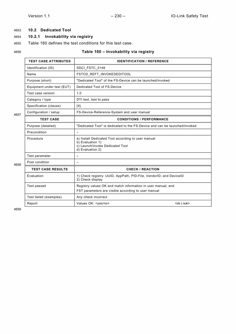
Version 1.1 – 230 – IO-Link Safety Test
10.2 Dedicated Tool 4653
10.2.1 Invokability via registry 4654
Table 160 defines the test conditions for this test case. 4655
Table 160 – Invokability via registry 4656
TEST CASE ATTRIBUTES IDENTIFICATION / REFERENCE
Identification (ID) SDCI_FSTC_0148
Name FSTCD_REFT_INVOKEDEDITOOL
Purpose (short) "Dedicated Tool" of the FS-Device can be launched/invoked
Equipment under test (EUT) Dedicated Tool of FS-Device
Test case version 1.0
Category / type DTI test, test to pass
Specification (clause) [4],
Configuration / setup FS-Device-Reference-System and user manual 4657
TEST CASE CONDITIONS / PERFORMANCE
Purpose (detailed) "Dedicated Tool" is dedicated to the FS-Device and can be launched/invoked
Precondition –
Procedure a) Install Dedicated Tool according to user manual b) Evaluation 1) c) Launch/invoke Dedicated Tool d) Evaluation 2)
Test parameter –
Post condition – 4658
TEST CASE RESULTS CHECK / REACTION
Evaluation 1) Check registry: UUID, AppPath, PID-File, VendorID, and DeviceID 2) Check display
Test passed Registry values OK and match information in user manual, and FST parameters are visible according to user manual
Test failed (examples) Any check incorrect
Report Values OK: <yes/no> <ok | nok>
4659

IO-Link Safety Test – 231 – Version 1.1
10.2.2 Calculation of TechParCRC 4660
Table 161 defines the test conditions for this test case. 4661
Table 161 – Calculation of TechParCRC 4662
TEST CASE ATTRIBUTES IDENTIFICATION / REFERENCE
Identification (ID) SDCI_FSTC_0149
Name FSTCD_REFT_CALCDEDITOOL
Purpose (short) Dedicated Tool presents FST parameter, calculates and displays TechParCRC value
Equipment under test (EUT) Dedicated Tool of FS-Device (no back channel in DTI communication)
Test case version 1.0
Category / type DTI test, test to pass
Specification (clause) [4],
Configuration / setup FS-Device-Reference-System 4663
TEST CASE CONDITIONS / PERFORMANCE
Purpose (detailed) Dedicated Tool presents FST parameter, recalculates TechParCRC upon parameter changes, and displays the TechParCRC signature value in decimal form.
Precondition –
Procedure a) Launch/invoke Dedicated Tool b) Evaluation 1) c) Modify FST parameter values d) Evaluation 2) e) Copy & Paste TechParCRC signature to FS-Master Tool f) Evaluation 3) g) Perform commissioning of FS-Device (EUT) h) Evaluation 4)
Test parameter –
Post condition – 4664
TEST CASE RESULTS CHECK / REACTION
Evaluation 1) Check availability of TechParCRC display (decimal value) 2) Check changes in TechParCRC display 3) Check reaction of FS-Master Tool (FSP_TechParCRC field) 4) Check behavior of reference system with connected FS-Device
Test passed All checks correct
Test failed (examples) Any check incorrect
Report Values OK: <yes/no> <ok | nok>
4665

Version 1.1 – 232 – IO-Link Safety Test
10.2.3 DTI communication/Back Channel 4666
Table 162 defines the test conditions for this test case. This test is optional. 4667
Table 162 – DTI communication/Back Channel 4668
TEST CASE ATTRIBUTES IDENTIFICATION / REFERENCE
Identification (ID) SDCI_FSTC_0150
Name FSTCD_REFT_BACKDEDITOOL
Purpose (short) Dedicated Tool presents FST parameter, calculates and displays TechParCRC value
Equipment under test (EUT) Dedicated Tool of FS-Device (with back channel in DTI communication)
Test case version 1.0
Category / type DTI test, test to pass
Specification (clause) [4],
Configuration / setup FS-Device-Reference-System 4669
TEST CASE CONDITIONS / PERFORMANCE
Purpose (detailed) FS-Master Tool invokes Dedicated Tool and passes over FST parameter via TPF. Subsequently, calculation of TechParCRC upon parameter changes takes place. Parameter values and TechParCRC are returned to FS-Master Tool via TBF ("Back Channel"). After parameter changes in FS-Master Tool, an update of the parameter values in the Dedicated Tool shall not occur automatically but only upon invocation of the Dedicated Tool.
Precondition –
Procedure a) Launch/invoke Dedicated Tool b) Evaluation 1) c) Try changing parameter values in FS-Master Tool d) Evaluation 2) e) Close Dedicated Tool f) Evaluation 3) g) Modify FST parameter values in FS-Master Tool h) Relaunch Dedicated Tool i) Evaluation 4) j) Evaluation 5) k) Perform commissioning of FS-Device (EUT) l) Evaluation 6)
Test parameter –
Post condition – 4670
TEST CASE RESULTS CHECK / REACTION
Evaluation 1) Check availability of TechParCRC display (decimal value) in Dedicated Tool (memorize CRC value) 2) Editing of values in FS-Master Tool shall be blocked 3) Check identical TechParCRC display (decimal value) in FS-Master Tool (see 1)) 4) Compare parameter values in displays of Dedicated Tool and FS-Master Tool (parameter values shall match) 5) Compare FST_TechParCRC on FS-Master Tool with TechParCRC of Dedicated Tool (CRC values should differ due to parameter changes) 6) Check behavior of reference system with connected FS-Device
Test passed All checks correct
Test failed (examples) Any check incorrect
Report Values OK: <yes/no> <ok | nok>
4671

IO-Link Safety Test – 233 – Version 1.1
10.2.4 DTI communication to FS-Device 4672
Table 163 defines the test conditions for this test case. This test is optional. 4673
Table 163 – DTI communication to FS-Device 4674
TEST CASE ATTRIBUTES IDENTIFICATION / REFERENCE
Identification (ID) SDCI_FSTC_0151
Name FSTCD_REFT_COMMDEDITOOL
Purpose (short) DTI communication from Dedicated Tool to FS-Device
Equipment under test (EUT) Dedicated Tool of FS-Device (with DTI communication and online access)
Test case version 1.0
Category / type DTI test, test to pass
Specification (clause) [4],
Configuration / setup FS-Device-Reference-System 4675
TEST CASE CONDITIONS / PERFORMANCE
Purpose (detailed) DTI communication from Dedicated Tool to FS-Device
Precondition User manual
Procedure a) Launch/invoke Dedicated Tool b) Evaluation 1) c) Get access to FS-Device d) Evaluation 2)
Test parameter –
Post condition – 4676
TEST CASE RESULTS CHECK / REACTION
Evaluation 1) Check availability of connection display 2) Check connection to FS-Device
Test passed All checks correct
Test failed (examples) Any check incorrect
Report Values OK: <yes/no> <ok | nok>
4677

Version 1.1 – 234 – IO-Link Safety Test
10.3 FS-Device replacement 4678
10.3.1 General 4679
Preparation of FS-Device? 4680
10.3.2 Correct FSP parameter values (Out-of-box) 4681
Table 164 defines the test conditions for this test case. 4682
Table 164 – Correct FSP parameter values 4683
TEST CASE ATTRIBUTES IDENTIFICATION / REFERENCE
Identification (ID) SDCI_FSTC_0152
Name FSTCD_REFT_CORRECTFSTVALUES
Purpose (short) Replace configured FS-Device by same FS-Device with out-of-box parameters
Equipment under test (EUT) FS-Device
Test case version 1.0
Category / type FS-Device test, test to pass
Specification (clause) [4],
Configuration / setup FS-Device-Tester 4684
TEST CASE CONDITIONS / PERFORMANCE
Purpose (detailed) Replace configured FS-Device by same FS-Device with out-of-box parameters
Precondition EUT in armed mode, FSP_TechParCRC valid) FSDT in OPERATE (armed operation)
Procedure a) Set FSDT Validation&Backup to 3: Backup + Restore e.g. via SMI_PortConfig b) Wait for Event 0xFF27 c) Set FSDT Validation&Backup to 4: Restore e.g. SMI_PortConfig d) Write System Command 131 "Back-to-box" e.g. SMI_DeviceWrite e) Evaluation 1) f) Port power Off/On e.g. via SMI_PortPowerOffOn g) Wait for Port state "SCL_ENABLED" e.g. via ArgBlock FSPortStatusList h) Evaluation 2)
Test parameter –
Post condition – 4685
TEST CASE RESULTS CHECK / REACTION
Evaluation 1) Check Write response 2) Check Port state
Test passed All checks correct
Test failed (examples) Any check incorrect
Report Values OK: <yes/no> <ok | nok>
4686

IO-Link Safety Test – 235 – Version 1.1
10.3.3 Incorrect FSP parameter values 4687
Table 165 defines the test conditions for this test case. 4688
Table 165 – Incorrect FSP parameter values 4689
TEST CASE ATTRIBUTES IDENTIFICATION / REFERENCE
Identification (ID) SDCI_FSTC_0153
Name FSTCD_REFT_INCORRECTFSPVALUES
Purpose (short) Replace configured FS-Device by same FS-Device with different parameters
Equipment under test (EUT) FS-Device
Test case version 1.0
Category / type FS-Device test, test to pass
Specification (clause) [4],
Configuration / setup FS-Device-Tester 4690
TEST CASE CONDITIONS / PERFORMANCE
Purpose (detailed) Replace configured FS-Device by same FS-Device with different parameters
Precondition EUT in armed mode, FSP_TechParCRC valid) FSDT in OPERATE (armed operation)
Procedure a) Read FSP protocol parameter record (0x4201) e.g. SMI_DeviceRead b) Evaluation 1) c) Change parameter in WDTime and set FSP_TechParCRC = 0 ;prepare values d) Write changed FSP protocol parameter record (0x4201) e.g. SMI_DeviceWrie e) Evaluation 2) f) Set FSP_TechParCRC to valid value ;prepare values g) Write changed FSP protocol parameter record (0x4201) e.g. SMI_DeviceWrie h) Evaluation 3) f) Port power Off/On e.g. via SMI_PortPowerOffOn g) Wait for Port state "OPERATE" e.g. ArgBlock PortStatusList h) Evaluation 4)
Test parameter –
Post condition – 4691
TEST CASE RESULTS CHECK / REACTION
Evaluation 1) Check Read response 2) Check Write response 3) Check Write response 4) Check Event
Test passed All ISDU responses OK, and Event 0xB009 received
Test failed (examples) Any check incorrect and/or Event 0xB009 not received
Report Values OK: <yes/no> <ok | nok>
4692

Version 1.1 – 236 – IO-Link Safety Test
10.4 Events 4693
10.4.1 Overview 4694
Most of the FS-Device Events are already covered within the context of other test cases. Table 4695 166 contains a list of Clauses and the concerned EventCodes. 4696
Table 166 – List of FS-Device Events in other test cases 4697
Clause EventCode Description
7.3.1, 8.2.7, 8.2.8, 11.3.6, 13.5.2 0xB003 Unexpected authentication code
7.3.2, 8.2.10 0xB005 Incorrect FSP_AuthentCRC
7.3.5, 10.3.3, 8.2.14 0xB009 Watchdog time out of specification (e.g. "0")
7.3.6, 8.2.11 0xB006 Incorrect FSP_ProtParCRC
8.2.3, 8.2.4 0xB00A No FSP_VerifyRecord received
8.2.5, 8.2.6, 8.2.12 0xB007 Incorrect FSP_TechtParCRC
8.2.9 0xB004 Unexpected authentication Port
8.2.13 0xB008 Incorrect FSP_IO_StructCRC
4698
Remaining Events are tested in 10.4.2. 4699

IO-Link Safety Test – 237 – Version 1.1
10.4.2 Events@communication 4700
Table 167 defines the test conditions for this test case. 4701
Table 167 – Events@communication 4702
TEST CASE ATTRIBUTES IDENTIFICATION / REFERENCE
Identification (ID) SDCI_FSTC_0154
Name FSTCD_REFT_COMMINTERRUPT
Purpose (short) Events when communication is interrupted due to errors at SPDU exchange
Equipment under test (EUT) FS-Device
Test case version 1.0
Category / type FS-Device test, test to pass
Specification (clause) [4],
Configuration / setup FS-Device-Tester 4703
TEST CASE CONDITIONS / PERFORMANCE
Purpose (detailed) Events when communication is interrupted due to errors at SPDU exchange
Precondition EUT: in armed mode FSDT: in OPERATE (armed operation)
Procedure a) FSDT send SPDU with wrong CRC b) Evaluation 1) c) FSDT send SPDU with correct CRC d) FSDT send SPDU with incorrect Counter e) Evaluation 2) f) FSDT send SPDU with correct Counter g) FSDT stop sending SPDUs h) Evaluation 3)
Test parameter –
Post condition – 4704
TEST CASE RESULTS CHECK / REACTION
Evaluation 1) Check for Event 0xB000 ;Transmission error (CRC signature) 2) Check for Event 0xB001 ;Transmission error (Counter) 3) Check for Event 0xB002 ;Transmission error (Timeout)
Test passed All Events received correctly
Test failed (examples) Any Event incorrect or missing
Report Event 0xB000 received: <yes/no> <ok | nok> Event 0xB001 received: <yes/no> <ok | nok> Event 0xB002 received: <yes/no> <ok | nok>
4705 4706

Version 1.1 – 238 – IO-Link Safety Test
11 FS-Master Port operations tests 4707
11.1 Overview 4708
The FS-Master Port operations test cases comprise the necessary information about the 4709 product to test, the basic FS-Master operations such as identification, authorization, and FSCP 4710 authenticity from an upper-level FSCP system. Other test cases deal with Port power OFF/ON, 4711 VerifyRecord for verification, detection of misconnection, and safe FS-Device replacement. 4712
11.2 FS-Master meta data 4713
11.2.1 User manual and safety assessment certificate 4714
"Highly recommended" feature exceptions. 4715
Table 168 defines the test conditions for this test case. 4716
Table 168 – User manual and safety assessment certificate 4717
TEST CASE ATTRIBUTES IDENTIFICATION / REFERENCE
Identification (ID) SDCI_FSTC_0155
Name FSTCM_INFO_DOCUMENTS
Purpose (short) Check user/safety manuals for exceptions, properties, and certificates
Equipment under test (EUT) User/safety manual of FS-Master and Master Tool
Test case version 1.0
Category / type FS-Master test, test to pass
Specification (clause) [4], "highly recommended" feature status, Annex H.6
Configuration / setup – 4718
TEST CASE CONDITIONS / PERFORMANCE
Purpose (detailed) Manufacturers/vendors are obliged to inform in a user manual about not implemen-ted "highly recommended" features and to provide a "Safety Manual" as well as a safety assessment certificate.
Precondition –
Procedure a) Identify in user manual not implemented "highly recommended" features b) Identify information in safety manual according to Annex H.6 in [4] c) Identify functional safety assessment certificate
Test parameter –
Post condition – 4719
TEST CASE RESULTS CHECK / REACTION
Evaluation 1) Check exceptions in user manual 2) Check required parameters in safety manual 3) Check statements for relevant aspects of particular standard (IEC 61508/ ISO13849), the assessment body, and the certificate number
Test passed Exceptions permitted, and Safety Manual available (for example "product mission time", "safety level - SIL/PL", "probability of a dangerous failure per hour – PFH", and statements on delay times for the calculation of safety function response times, and Certicate accepted and noted in test report
Test failed (examples) Any check incorrect
Report Documents OK: <yes/no> <ok | nok>
4720
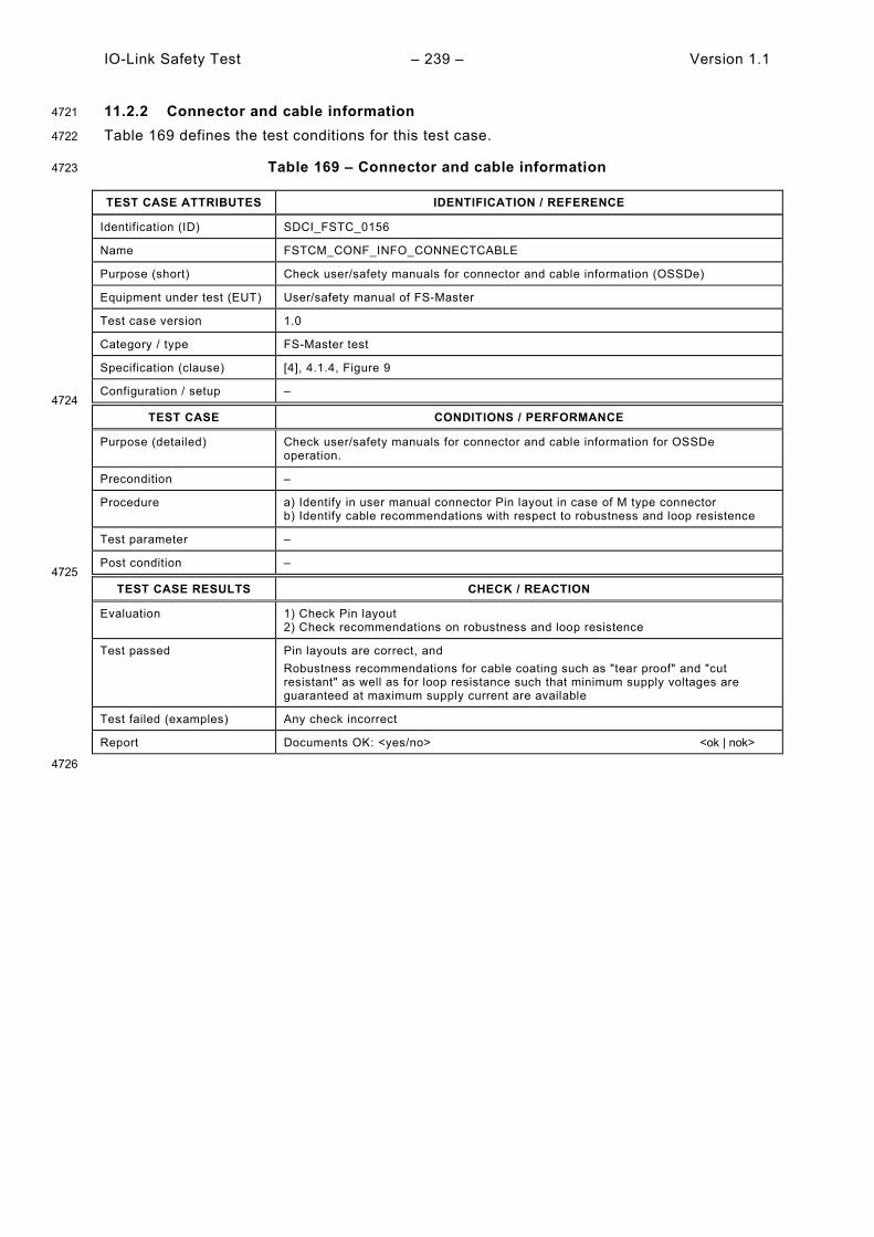
IO-Link Safety Test – 239 – Version 1.1
11.2.2 Connector and cable information 4721
Table 169 defines the test conditions for this test case. 4722
Table 169 – Connector and cable information 4723
TEST CASE ATTRIBUTES IDENTIFICATION / REFERENCE
Identification (ID) SDCI_FSTC_0156
Name FSTCM_CONF_INFO_CONNECTCABLE
Purpose (short) Check user/safety manuals for connector and cable information (OSSDe)
Equipment under test (EUT) User/safety manual of FS-Master
Test case version 1.0
Category / type FS-Master test
Specification (clause) [4], 4.1.4, Figure 9
Configuration / setup – 4724
TEST CASE CONDITIONS / PERFORMANCE
Purpose (detailed) Check user/safety manuals for connector and cable information for OSSDe operation.
Precondition –
Procedure a) Identify in user manual connector Pin layout in case of M type connector b) Identify cable recommendations with respect to robustness and loop resistence
Test parameter –
Post condition – 4725
TEST CASE RESULTS CHECK / REACTION
Evaluation 1) Check Pin layout 2) Check recommendations on robustness and loop resistence
Test passed Pin layouts are correct, and Robustness recommendations for cable coating such as "tear proof" and "cut resistant" as well as for loop resistance such that minimum supply voltages are guaranteed at maximum supply current are available
Test failed (examples) Any check incorrect
Report Documents OK: <yes/no> <ok | nok>
4726

Version 1.1 – 240 – IO-Link Safety Test
11.2.3 Default behavior (Power, OSSDe, configurations) 4727
Table 33 defines the test conditions for this test case. 4728
Table 170 – Default behavior (Power, OSDDe, configurations) 4729
TEST CASE ATTRIBUTES IDENTIFICATION / REFERENCE
Identification (ID) SDCI_FSTC_0157
Name FSTCM_CONF_INFO_DEFAULTPARAM
Purpose (short) FS-Master information: Power supply, OSSDe filter, Port configurations
Equipment under test (EUT) User manual of FS-Master
Test case version 1.0
Category / type FS-Master test
Specification (clause) [4], Table 7, Table 8
Configuration / setup – 4730
TEST CASE CONDITIONS / PERFORMANCE
Purpose (detailed) FS-Master information: Power supply (derating), OSSDe filter, Port configurations
Precondition –
Procedure a) Identify parameter "Port power supply" in safety/user manual b) Identify parameter "Discrepancy time" in safety/user manual c) Identify parameter "Filter time" in safety/user manual d) Identify "Port configurations" in safety/user manual e) Identify "Safety function response time" information
Test parameter –
Post condition Memorize power supply, OSSDe filter values, Port configurations, response time 4731
TEST CASE RESULTS CHECK / REACTION
Evaluation 1) Check "Port power supply" information 2) Check parameter "Discrepancy time" 3) Check parameter "Filter time" 4) Check possible Port configurations 5) Check SFRT information
Test passed At least one Port can provide a current of ISMmax ≥ 1000 mA, and Value of "Discrepancy time - tdis" = 3 ms, and
Value of "Filter time" = 1ms according to test pulse duration ti, and
Port configurations comply with specification, and SFRT information refers to integration specification and IEC 61784-3 if appropriate
Test failed (examples) Any check incorrect
Report Documents OK: <yes/no> <ok | nok>
4732

IO-Link Safety Test – 241 – Version 1.1
11.3 FS-Master operations 4733
11.3.1 Overview 4734
4735
11.3.2 FS-Master identification 4736
Table 171 defines the test conditions for this test case. 4737
Table 171 – FS-Master identification 4738
TEST CASE ATTRIBUTES IDENTIFICATION / REFERENCE
Identification (ID) SDCI_FSTC_0158
Name FSTCM_INFO_FSMIDENT
Purpose (short) Get FS-Master identification
Equipment under test (EUT) FS-Master + Tool
Test case version 1.0
Category / type FS-Master test, test to pass
Specification (clause) [4], E.2
Configuration / setup FS-Master-Tester-System 4739
TEST CASE CONDITIONS / PERFORMANCE
Purpose (detailed) Get FS-Master identification via service SMI_MasterIdentification
Precondition EUT: PORT_MIXFSCOM SMTU: SMTU_STANDARD_STATE_32
Procedure a) SMI_MasterIdentification(ArgBlock = 0x0001) ;returns Argblock "MasterIdent" b) Evaluation 1)
Test parameter –
Post condition VendorID, MasterID, MasterType, Features_1, MaxNumberOfPorts, PortTypes 4740
TEST CASE RESULTS CHECK / REACTION
Evaluation 1) Check Argblock "MasterIdent"
Test passed MasterIdent.VendorID corresponds to manual and IO-Link reference, and MasterIdent.MasterID corresponds to manual, and ;vendor specific MasterIdent.MasterType = 3, and ;FS-Master MasterIdent.Features_1.Bit 2 = 1, and ;PortPowerOffOn
MasterIdent.MaxNumberOfPorts corresponds to Manual, and ;max number = n
MasterIdent.PortTypes[0 to n] = {3, 4, or 5} ;no OSSD, OSSD, or Class B
Test failed (examples) Any check incorrect
Report Identification OK: <yes/no> <ok | nok>
4741 4742
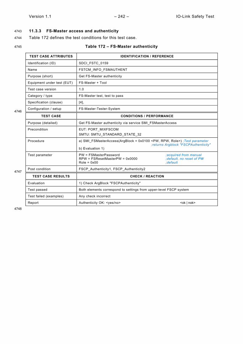
Version 1.1 – 242 – IO-Link Safety Test
11.3.3 FS-Master access and authenticity 4743
Table 172 defines the test conditions for this test case. 4744
Table 172 – FS-Master authenticity 4745
TEST CASE ATTRIBUTES IDENTIFICATION / REFERENCE
Identification (ID) SDCI_FSTC_0159
Name FSTCM_INFO_FSMAUTHENT
Purpose (short) Get FS-Master authenticity
Equipment under test (EUT) FS-Master + Tool
Test case version 1.0
Category / type FS-Master test, test to pass
Specification (clause) [4],
Configuration / setup FS-Master-Tester-System 4746
TEST CASE CONDITIONS / PERFORMANCE
Purpose (detailed) Get FS-Master authenticity via service SMI_FSMasterAccess
Precondition EUT: PORT_MIXFSCOM SMTU: SMTU_STANDARD_STATE_32
Procedure a) SMI_FSMasterAccess(ArgBlock = 0x0100 <PW, RPW, Role>) ;Test parameter ;returns Argblock "FSCPAuthenticity" b) Evaluation 1)
Test parameter PW = FSMasterPassword ;acquired from manual RPW = FSResetMasterPW = 0x0000 ;default, no reset of PW Role = 0x00 ;default
Post condition FSCP_Authenticity1, FSCP_Authenticity2 4747
TEST CASE RESULTS CHECK / REACTION
Evaluation 1) Check ArgBlock "FSCPAuthenticity"
Test passed Both elements correspond to settings from upper-level FSCP system
Test failed (examples) Any check incorrect
Report Authenticity OK: <yes/no> <ok | nok>
4748
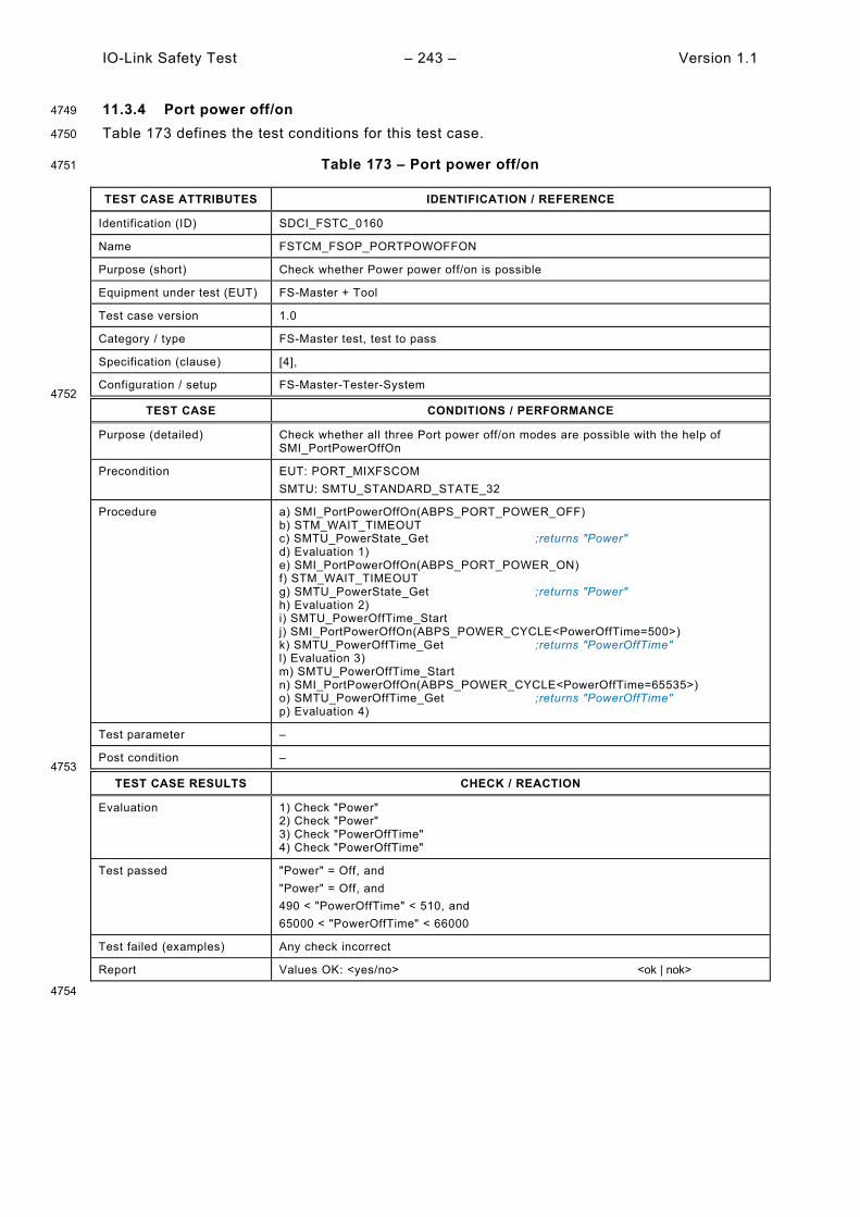
IO-Link Safety Test – 243 – Version 1.1
11.3.4 Port power off/on 4749
Table 173 defines the test conditions for this test case. 4750
Table 173 – Port power off/on 4751
TEST CASE ATTRIBUTES IDENTIFICATION / REFERENCE
Identification (ID) SDCI_FSTC_0160
Name FSTCM_FSOP_PORTPOWOFFON
Purpose (short) Check whether Power power off/on is possible
Equipment under test (EUT) FS-Master + Tool
Test case version 1.0
Category / type FS-Master test, test to pass
Specification (clause) [4],
Configuration / setup FS-Master-Tester-System 4752
TEST CASE CONDITIONS / PERFORMANCE
Purpose (detailed) Check whether all three Port power off/on modes are possible with the help of SMI_PortPowerOffOn
Precondition EUT: PORT_MIXFSCOM SMTU: SMTU_STANDARD_STATE_32
Procedure a) SMI_PortPowerOffOn(ABPS_PORT_POWER_OFF) b) STM_WAIT_TIMEOUT c) SMTU_PowerState_Get ;returns "Power" d) Evaluation 1) e) SMI_PortPowerOffOn(ABPS_PORT_POWER_ON) f) STM_WAIT_TIMEOUT g) SMTU_PowerState_Get ;returns "Power" h) Evaluation 2) i) SMTU_PowerOffTime_Start j) SMI_PortPowerOffOn(ABPS_POWER_CYCLE<PowerOffTime=500>) k) SMTU_PowerOffTime_Get ;returns "PowerOffTime" l) Evaluation 3) m) SMTU_PowerOffTime_Start n) SMI_PortPowerOffOn(ABPS_POWER_CYCLE<PowerOffTime=65535>) o) SMTU_PowerOffTime_Get ;returns "PowerOffTime" p) Evaluation 4)
Test parameter –
Post condition – 4753
TEST CASE RESULTS CHECK / REACTION
Evaluation 1) Check "Power" 2) Check "Power" 3) Check "PowerOffTime" 4) Check "PowerOffTime"
Test passed "Power" = Off, and "Power" = Off, and 490 < "PowerOffTime" < 510, and 65000 < "PowerOffTime" < 66000
Test failed (examples) Any check incorrect
Report Values OK: <yes/no> <ok | nok>
4754
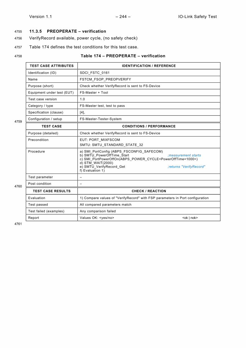
Version 1.1 – 244 – IO-Link Safety Test
11.3.5 PREOPERATE – verification 4755
VerifyRecord available, power cycle, (no safety check) 4756
Table 174 defines the test conditions for this test case. 4757
Table 174 – PREOPERATE – verification 4758
TEST CASE ATTRIBUTES IDENTIFICATION / REFERENCE
Identification (ID) SDCI_FSTC_0161
Name FSTCM_FSOP_PREOPVERIFY
Purpose (short) Check whether VerifyRecord is sent to FS-Device
Equipment under test (EUT) FS-Master + Tool
Test case version 1.0
Category / type FS-Master test, test to pass
Specification (clause) [4],
Configuration / setup FS-Master-Tester-System 4759
TEST CASE CONDITIONS / PERFORMANCE
Purpose (detailed) Check whether VerifyRecord is sent to FS-Device
Precondition EUT: PORT_MIXFSCOM SMTU: SMTU_STANDARD_STATE_32
Procedure a) SMI_PortConfig (ABPS_FSCONFIG_SAFECOM) b) SMTU_PowerOffTime_Start ;measurement starts c) SMI_PortPowerOffOn(ABPS_POWER_CYCLE<PowerOffTime=1000>) d) STM_WAIT(2000) e) SMTU_VerifyRecord_Get ;returns "VerifyRecord" f) Evaluation 1)
Test parameter –
Post condition – 4760
TEST CASE RESULTS CHECK / REACTION
Evaluation 1) Compare values of "VerifyRecord" with FSP parameters in Port configuration
Test passed All compared parameters match
Test failed (examples) Any comparison failed
Report Values OK: <yes/no> <ok | nok>
4761

IO-Link Safety Test – 245 – Version 1.1
11.3.6 PREOPERATE – misconnection 4762
Authenticity check 4763
Table 175 defines the test conditions for this test case. 4764
Table 175 – PREOPERATE – misconnection 4765
TEST CASE ATTRIBUTES IDENTIFICATION / REFERENCE
Identification (ID) SDCI_FSTC_0162
Name FSTCM_FSOP_PREOPMISSCONNECT
Purpose (short) FS-Master indicates FS-Device misconnection
Equipment under test (EUT) FS-Master + Tool
Test case version 1.0
Category / type FS-Master test, test to pass
Specification (clause) [4], Annex G.4
Configuration / setup FS-Master-Tester-System 4766
TEST CASE CONDITIONS / PERFORMANCE
Purpose (detailed) Check whether misconnection is detected
Precondition EUT: PORT_MIXFSCOM SMTU: SMTU_STANDARD_STATE_32
Procedure a) SMI_PortPowerOffOn(ABPS_PORT_OFF) b) SMTU_Authent_Set(Authent1=2, CRC=???) ;change FSCP_Authenticity1 c) SMI_PortPowerOffOn(ABPS_PORT_ON) d) Wait 3 s ;self test time = 2 s e) SMI_PortStatus(ArgBlock = 0x9100) ;returns ArgBlock "FSPortStatusList" f) Evaluation 1) g) Wait on SMI_DeviceEvent ;returns ArgBlock "DeviceEvent" h) Evaluation 2)
Test parameter –
Post condition – 4767
TEST CASE RESULTS CHECK / REACTION
Evaluation 1) Check ArgBlock "FSPortStatusList" 2) Check ArgBlock "DeviceEvent"
Test passed FSPortStatusList.PortStatusInfo = 4, and ;OPERATE EventCode = 0xB003 ;unexpected authentication code
Test failed (examples) Any other PortStatusInfo, or other Eventcodes, or no Event
Report Event: <yes/no> <ok | nok> FS-Device EventCode: <value> <ok | nok>
4768
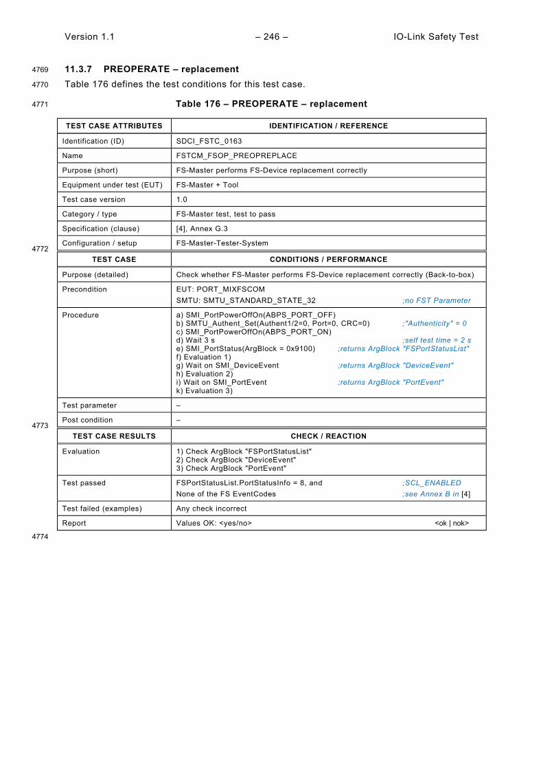
Version 1.1 – 246 – IO-Link Safety Test
11.3.7 PREOPERATE – replacement 4769
Table 176 defines the test conditions for this test case. 4770
Table 176 – PREOPERATE – replacement 4771
TEST CASE ATTRIBUTES IDENTIFICATION / REFERENCE
Identification (ID) SDCI_FSTC_0163
Name FSTCM_FSOP_PREOPREPLACE
Purpose (short) FS-Master performs FS-Device replacement correctly
Equipment under test (EUT) FS-Master + Tool
Test case version 1.0
Category / type FS-Master test, test to pass
Specification (clause) [4], Annex G.3
Configuration / setup FS-Master-Tester-System 4772
TEST CASE CONDITIONS / PERFORMANCE
Purpose (detailed) Check whether FS-Master performs FS-Device replacement correctly (Back-to-box)
Precondition EUT: PORT_MIXFSCOM SMTU: SMTU_STANDARD_STATE_32 ;no FST Parameter
Procedure a) SMI_PortPowerOffOn(ABPS_PORT_OFF) b) SMTU_Authent_Set(Authent1/2=0, Port=0, CRC=0) ;"Authenticity" = 0 c) SMI_PortPowerOffOn(ABPS_PORT_ON) d) Wait 3 s ;self test time = 2 s e) SMI_PortStatus(ArgBlock = 0x9100) ;returns ArgBlock "FSPortStatusList" f) Evaluation 1) g) Wait on SMI_DeviceEvent ;returns ArgBlock "DeviceEvent" h) Evaluation 2) i) Wait on SMI_PortEvent ;returns ArgBlock "PortEvent" k) Evaluation 3)
Test parameter –
Post condition – 4773
TEST CASE RESULTS CHECK / REACTION
Evaluation 1) Check ArgBlock "FSPortStatusList" 2) Check ArgBlock "DeviceEvent" 3) Check ArgBlock "PortEvent"
Test passed FSPortStatusList.PortStatusInfo = 8, and ;SCL_ENABLED None of the FS EventCodes ;see Annex B in [4]
Test failed (examples) Any check incorrect
Report Values OK: <yes/no> <ok | nok>
4774

IO-Link Safety Test – 247 – Version 1.1
12 FS-Master safety communication layer tests 4775
12.1 Interface for the FS-Master SCL test scripts 4776
The test scripts for the automated safety layer tests are encoded as XML files. Each and every 4777 test script ("FSMasterSclTestCaseSteps") consists of test step instructions as described in 4778 Table 177. The XML Schema of the interface parameters for the FS-Master automated safety 4779 layer test is illustrated in Figure 15. 4780
NOTE The general concept of SCL protocol conformance testing is described in A.2.3. The automated safety layer 4781 tester for FS-Masters is described in A.2.4. 4782
4783
Figure 15 – Schema of steps and parameters/attributes 4784
Table 177 defines the FS-Master interface parameters. 4785
FS-Master
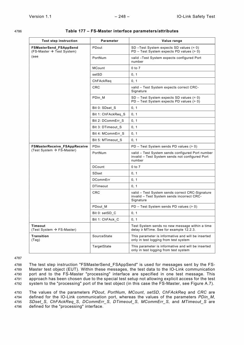
Version 1.1 – 248 – IO-Link Safety Test
Table 177 – FS-Master interface parameters/attributes 4786
Test step instruction Parameter Value range
FSMasterSend_FSAppSend (FS-Master Test System) (see
PDout SD –Test System expects SD values (= 0) PD – Test System expects PD values (> 0)
PortNum valid –Test System expects configured Port number
MCount 0 to 7
setSD 0, 1
ChFAckReq 0, 1
CRC valid – Test System expects correct CRC-Signature
PDin_M SD – Test System expects SD values (= 0) PD – Test System expects PD values (> 0)
Bit 0: SDset_S 0, 1
Bit 1: ChFAckReq_S 0, 1
Bit 2: DCommErr_S 0, 1
Bit 3: DTimeout_S 0, 1
Bit 4: MCommErr_S 0, 1
Bit 5: MTimeout_S 0, 1
FSMasterReceive_FSAppReceive (Test System FS-Master)
PDin PD – Test System sends PD values (> 0)
PortNum valid – Test System sends configured Port number invalid – Test System sends not configured Port number
DCount 0 to 7
SDset 0, 1
DCommErr 0, 1
DTimeout 0, 1
CRC valid – Test System sends correct CRC-Signature invalid – Test System sends incorrect CRC-Signature
PDout_M PD – Test System sends PD values (> 0)
Bit 0: setSD_C 0, 1
Bit 1: ChFAck_C 0, 1
Timeout (Test System FS-Master)
Test System sends no new message within a time delay ≥ MTime. See for example 12.2.3.
Transition (Tag)
SourceState This parameter is informative and will be inserted only in test logging from test system
TargetState This parameter is informative and will be inserted only in test logging from test system
4787
The test step instruction "FSMasterSend_FSAppSend" is used for messages sent by the FS-4788 Master test object (EUT). Within these messages, the test data to the IO-Link communication 4789 port and to the FS-Master "processing" interface are specified in one test message. This 4790 approach has been chosen due to the special test setup not allowing explicit access for the test 4791 system to the "processing" port of the test object (in this case the FS-Master, see Figure A.7). 4792
The values of the parameters PDout, PortNum, MCount, setSD, ChFAckReq and CRC are 4793 defined for the IO-Link communication port, whereas the values of the parameters PDin_M, 4794 SDset_S, ChFAckReq_S, DCommErr_S, DTimeout_S, MCommErr_S, and MTimeout_S are 4795 defined for the "processing" interface. 4796
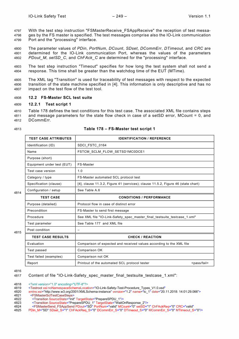
IO-Link Safety Test – 249 – Version 1.1
With the test step instruction "FSMasterReceive_FSAppReceive" the reception of test messa-4797 ges by the FS master is specified. The test messages comprise also the IO-Link communication 4798 Port and the "processing" interface. 4799
The parameter values of PDin, PortNum, DCount, SDset, DCommErr, DTimeout, and CRC are 4800 determined for the IO-Link communication Port, whereas the values of the parameters 4801 PDout_M, setSD_C, and ChFAck_C are determined for the "processing" interface. 4802
The test step instruction "Timeout" specifies for how long the test system shall not send a 4803 response. This time shall be greater than the watchdog time of the EUT (MTime). 4804
The XML tag "Transition" is used for traceability of test messages with respect to the expected 4805 transition of the state machine specified in [4]. This information is only descriptive and has no 4806 impact on the test flow of the test tool. 4807
12.2 FS-Master SCL test suite 4808
12.2.1 Test script 1 4809
Table 178 defines the test conditions for this test case. The associated XML file contains steps 4810 and message parameters for the state flow check in case of a setSD error, MCount = 0, and 4811 DCommErr. 4812
Table 178 – FS-Master test script 1 4813
TEST CASE ATTRIBUTES IDENTIFICATION / REFERENCE
Identification (ID) SDCI_FSTC_0164
Name FSTCM_SCLM_FLOW_SETSD1MC0DCE1
Purpose (short)
Equipment under test (EUT) FS-Master
Test case version 1.0
Category / type FS-Master automated SCL protocol test
Specification (clause) [4], clause 11.3.2, Figure 41 (services); clause 11.5.2, Figure 46 (state chart)
Configuration / setup See Table A.6 4814
TEST CASE CONDITIONS / PERFORMANCE
Purpose (detailed) Protocol flow in case of distinct error
Precondition FS-Master to send first message
Procedure See XML file "IO-Link-Safety_spec_master_final_testsuite_testcase_1.xml"
Test parameter See Table 177 and XML file
Post condition – 4815
TEST CASE RESULTS CHECK / REACTION
Evaluation Comparison of expected and received values according to the XML file
Test passed Comparison OK
Test failed (examples) Comparison not OK
Report Printout of the automated SCL protocol tester <pass/fail>
4816 Content of file "IO-Link-Safety_spec_master_final_testsuite_testcase_1.xml": 4817
<?xml version="1.0" encoding="UTF-8"?> 4818 <Testroot xsi:noNamespaceSchemaLocation="IO-Link-Safety-Test-Procedure_Types_V1.0.xsd" 4819 xmlns:xsi="http://www.w3.org/2001/XMLSchema-instance" version="1.2" name="tc_1" date="20.11.2018: 14:01:29.066"> 4820 <FSMasterSclTestCaseSteps> 4821 <Transition SourceState="Init" TargetState="PrepareSPDU_1"/> 4822 <Transition SourceState="PrepareSPDU_1" TargetState="WaitOnResponse_2"/> 4823 <FSMasterSend_FSAppSend PDout="SD" PortNum="valid" MCount="0" setSD="1" ChFAckReq="0" CRC="valid" 4824 PDin_M="SD" SDset_S="1" ChFAckReq_S="0" DCommErr_S="0" DTimeout_S="0" MCommErr_S="0" MTimeout_S="0"/> 4825

Version 1.1 – 250 – IO-Link Safety Test
<FSMasterReceive_FSAppReceive PDin="PD" PortNum="valid" DCount="7" SDset="0" DCommErr="1" DTimeout="0" 4826 CRC="valid" PDout_M="PD" setSD_C="0" ChFAck_C="0"/> 4827 <Transition SourceState="WaitOnResponse_2" TargetState="CheckSPDU_3"/> 4828 <Transition SourceState="CheckSPDU_3" TargetState="PrepareSPDU_6"/> 4829 <Transition SourceState="PrepareSPDU_6" TargetState="WaitOnResponse_7"/> 4830 <FSMasterSend_FSAppSend PDout="SD" PortNum="valid" MCount="1" setSD="1" ChFAckReq="0" CRC="valid" 4831 PDin_M="SD" SDset_S="1" ChFAckReq_S="0" DCommErr_S="1" DTimeout_S="0" MCommErr_S="0" MTimeout_S="0"/> 4832 <FSMasterReceive_FSAppReceive PDin="PD" PortNum="valid" DCount="6" SDset="0" DCommErr="0" DTimeout="0" 4833 CRC="invalid" PDout_M="PD" setSD_C="0" ChFAck_C="0"/> 4834 <Transition SourceState="WaitOnResponse_7" TargetState="CheckSPDU_8"/> 4835 <Transition SourceState="CheckSPDU_8" TargetState="PrepareSPDU_6"/> 4836 <Transition SourceState="PrepareSPDU_6" TargetState="WaitOnResponse_7"/> 4837 <FSMasterSend_FSAppSend PDout="SD" PortNum="valid" MCount="2" setSD="1" ChFAckReq="0" CRC="valid" 4838 PDin_M="SD" SDset_S="1" ChFAckReq_S="0" DCommErr_S="0" DTimeout_S="0" MCommErr_S="1" MTimeout_S="0"/> 4839 <FSMasterReceive_FSAppReceive PDin="PD" PortNum="valid" DCount="5" SDset="0" DCommErr="1" DTimeout="0" 4840 CRC="valid" PDout_M="PD" setSD_C="0" ChFAck_C="0"/> 4841 <Transition SourceState="WaitOnResponse_7" TargetState="CheckSPDU_8"/> 4842 <Transition SourceState="CheckSPDU_8" TargetState="PrepareSPDU_6"/> 4843 <Transition SourceState="PrepareSPDU_6" TargetState="WaitOnResponse_7"/> 4844 <FSMasterSend_FSAppSend PDout="SD" PortNum="valid" MCount="3" setSD="1" ChFAckReq="0" CRC="valid" 4845 PDin_M="SD" SDset_S="1" ChFAckReq_S="0" DCommErr_S="1" DTimeout_S="0" MCommErr_S="0" MTimeout_S="0"/> 4846 <FSMasterReceive_FSAppReceive PDin="PD" PortNum="invalid" DCount="4" SDset="0" DCommErr="0" DTimeout="1" 4847 CRC="valid" PDout_M="PD" setSD_C="0" ChFAck_C="0"/> 4848 <Transition SourceState="WaitOnResponse_7" TargetState="CheckSPDU_8"/> 4849 <Transition SourceState="CheckSPDU_8" TargetState="PrepareSPDU_6"/> 4850 <Transition SourceState="PrepareSPDU_6" TargetState="WaitOnResponse_7"/> 4851 <FSMasterSend_FSAppSend PDout="SD" PortNum="valid" MCount="4" setSD="1" ChFAckReq="0" CRC="valid" 4852 PDin_M="SD" SDset_S="1" ChFAckReq_S="0" DCommErr_S="0" DTimeout_S="1" MCommErr_S="1" MTimeout_S="0"/> 4853 <FSMasterReceive_FSAppReceive PDin="PD" PortNum="valid" DCount="3" SDset="0" DCommErr="0" DTimeout="0" 4854 CRC="valid" PDout_M="PD" setSD_C="0" ChFAck_C="0"/> 4855 <Transition SourceState="WaitOnResponse_7" TargetState="CheckSPDU_8"/> 4856 <Transition SourceState="CheckSPDU_8" TargetState="PrepareSPDU_6"/> 4857 <Transition SourceState="PrepareSPDU_6" TargetState="WaitOnResponse_7"/> 4858 <FSMasterSend_FSAppSend PDout="SD" PortNum="valid" MCount="5" setSD="1" ChFAckReq="1" CRC="valid" 4859 PDin_M="SD" SDset_S="1" ChFAckReq_S="1" DCommErr_S="0" DTimeout_S="0" MCommErr_S="0" MTimeout_S="0"/> 4860 <Transition SourceState="WaitOnResponse_7" TargetState="WaitOnResponse_7"/> 4861 <FSMasterReceive_FSAppReceive PDin="PD" PortNum="valid" DCount="2" SDset="0" DCommErr="0" DTimeout="0" 4862 CRC="valid" PDout_M="PD" setSD_C="1" ChFAck_C="1"/> 4863 <Transition SourceState="WaitOnResponse_7" TargetState="CheckSPDU_8"/> 4864 <Transition SourceState="CheckSPDU_8" TargetState="PrepareSPDU_4"/> 4865 <Transition SourceState="PrepareSPDU_4" TargetState="WaitOnResponse_5"/> 4866 <FSMasterSend_FSAppSend PDout="SD" PortNum="valid" MCount="6" setSD="1" ChFAckReq="0" CRC="valid" 4867 PDin_M="SD" SDset_S="1" ChFAckReq_S="0" DCommErr_S="0" DTimeout_S="0" MCommErr_S="0" MTimeout_S="0"/> 4868 <Transition SourceState="WaitOnResponse_5" TargetState="WaitOnResponse_5"/> 4869 <FSMasterReceive_FSAppReceive PDin="PD" PortNum="valid" DCount="1" SDset="1" DCommErr="0" DTimeout="0" 4870 CRC="valid" PDout_M="PD" setSD_C="0" ChFAck_C="0"/> 4871 <Transition SourceState="WaitOnResponse_5" TargetState="CheckSPDU_3"/> 4872 <Transition SourceState="CheckSPDU_3" TargetState="PrepareSPDU_4"/> 4873 <Transition SourceState="PrepareSPDU_4" TargetState="WaitOnResponse_5"/> 4874 <FSMasterSend_FSAppSend PDout="PD" PortNum="valid" MCount="7" setSD="0" ChFAckReq="0" CRC="valid" 4875 PDin_M="SD" SDset_S="1" ChFAckReq_S="0" DCommErr_S="0" DTimeout_S="0" MCommErr_S="0" MTimeout_S="0"/> 4876 <FSMasterReceive_FSAppReceive PDin="PD" PortNum="valid" DCount="0" SDset="0" DCommErr="0" DTimeout="0" 4877 CRC="invalid" PDout_M="PD" setSD_C="0" ChFAck_C="0"/> 4878 <Transition SourceState="WaitOnResponse_5" TargetState="CheckSPDU_3"/> 4879 <Transition SourceState="CheckSPDU_3" TargetState="PrepareSPDU_6"/> 4880 <Transition SourceState="PrepareSPDU_6" TargetState="WaitOnResponse_7"/> 4881 <FSMasterSend_FSAppSend PDout="SD" PortNum="valid" MCount="1" setSD="1" ChFAckReq="0" CRC="valid" 4882 PDin_M="SD" SDset_S="1" ChFAckReq_S="0" DCommErr_S="0" DTimeout_S="0" MCommErr_S="1" MTimeout_S="0"/> 4883 </FSMasterSclTestCaseSteps> 4884 </Testroot> 4885 4886

IO-Link Safety Test – 251 – Version 1.1
12.2.2 Test script 2 4887
Table 179 defines the test conditions for this test case. The associated XML file contains steps 4888 and message parameters for the state flow check in case of a setSD error, MCount = 0, and 4889 SDset. 4890
Table 179 – FS-Master test script 2 4891
TEST CASE ATTRIBUTES IDENTIFICATION / REFERENCE
Identification (ID) SDCI_FSTC_0165
Name FSTCM_SCLM_FLOW_SETSD1MC0SDSET1
Purpose (short)
Equipment under test (EUT) FS-Master
Test case version 1.0
Category / type FS-Master automated SCL protocol test
Specification (clause) [4], clause 11.3.2, Figure 41 (services); clause 11.5.2, Figure 46 (state chart)
Configuration / setup See Table A.6 4892
TEST CASE CONDITIONS / PERFORMANCE
Purpose (detailed) Protocol flow in case of distinct error
Precondition FS-Master to send first message
Procedure See XML file "IO-Link-Safety_spec_master_final_testsuite_testcase_2.xml"
Test parameter See Table 177 and XML file
Post condition – 4893
TEST CASE RESULTS CHECK / REACTION
Evaluation Comparison of expected and received values according to the XML file
Test passed Comparison OK
Test failed (examples) Comparison not OK
Report Printout of the automated SCL protocol tester <pass/fail>
4894 Content of file "IO-Link-Safety_spec_master_final_testsuite_testcase_2.xml": 4895
<?xml version="1.0" encoding="UTF-8"?> 4896 <Testroot xsi:noNamespaceSchemaLocation="IO-Link-Safety-Test-Procedure_Types_V1.0.xsd" 4897 xmlns:xsi="http://www.w3.org/2001/XMLSchema-instance" version="1.2" name="tc_2" date="20.11.2018: 14:01:29.066"> 4898 <FSMasterSclTestCaseSteps> 4899 <Transition SourceState="Init" TargetState="PrepareSPDU_1"/> 4900 <Transition SourceState="PrepareSPDU_1" TargetState="WaitOnResponse_2"/> 4901 <FSMasterSend_FSAppSend PDout="SD" PortNum="valid" MCount="0" setSD="1" ChFAckReq="0" CRC="valid" 4902 PDin_M="SD" SDset_S="1" ChFAckReq_S="0" DCommErr_S="0" DTimeout_S="0" MCommErr_S="0" MTimeout_S="0"/> 4903 <FSMasterReceive_FSAppReceive PDin="PD" PortNum="valid" DCount="7" SDset="0" DCommErr="0" DTimeout="0" 4904 CRC="valid" PDout_M="PD" setSD_C="0" ChFAck_C="0"/> 4905 <Transition SourceState="WaitOnResponse_2" TargetState="CheckSPDU_3"/> 4906 <Transition SourceState="CheckSPDU_3" TargetState="PrepareSPDU_4"/> 4907 <Transition SourceState="PrepareSPDU_4" TargetState="WaitOnResponse_5"/> 4908 <FSMasterSend_FSAppSend PDout="PD" PortNum="valid" MCount="1" setSD="0" ChFAckReq="0" CRC="valid" 4909 PDin_M="PD" SDset_S="0" ChFAckReq_S="0" DCommErr_S="0" DTimeout_S="0" MCommErr_S="0" MTimeout_S="0"/> 4910 <FSMasterReceive_FSAppReceive PDin="PD" PortNum="valid" DCount="6" SDset="1" DCommErr="0" DTimeout="0" 4911 CRC="valid" PDout_M="PD" setSD_C="0" ChFAck_C="0"/> 4912 <Transition SourceState="WaitOnResponse_5" TargetState="CheckSPDU_3"/> 4913 <Transition SourceState="CheckSPDU_3" TargetState="PrepareSPDU_4"/> 4914 <Transition SourceState="PrepareSPDU_4" TargetState="WaitOnResponse_5"/> 4915 <FSMasterSend_FSAppSend PDout="PD" PortNum="valid" MCount="2" setSD="0" ChFAckReq="0" CRC="valid" 4916 PDin_M="SD" SDset_S="1" ChFAckReq_S="0" DCommErr_S="0" DTimeout_S="0" MCommErr_S="0" MTimeout_S="0"/> 4917 <FSMasterReceive_FSAppReceive PDin="PD" PortNum="valid" DCount="5" SDset="0" DCommErr="0" DTimeout="0" 4918 CRC="valid" PDout_M="PD" setSD_C="0" ChFAck_C="0"/> 4919 <Transition SourceState="WaitOnResponse_5" TargetState="CheckSPDU_3"/> 4920 <Transition SourceState="CheckSPDU_3" TargetState="PrepareSPDU_4"/> 4921 <Transition SourceState="PrepareSPDU_4" TargetState="WaitOnResponse_5"/> 4922
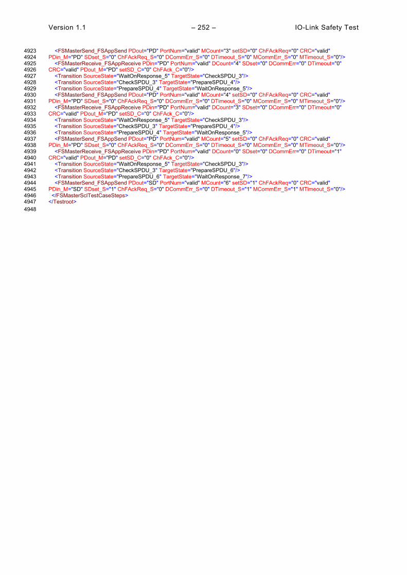
Version 1.1 – 252 – IO-Link Safety Test
<FSMasterSend_FSAppSend PDout="PD" PortNum="valid" MCount="3" setSD="0" ChFAckReq="0" CRC="valid" 4923 PDin_M="PD" SDset_S="0" ChFAckReq_S="0" DCommErr_S="0" DTimeout_S="0" MCommErr_S="0" MTimeout_S="0"/> 4924 <FSMasterReceive_FSAppReceive PDin="PD" PortNum="valid" DCount="4" SDset="0" DCommErr="0" DTimeout="0" 4925 CRC="valid" PDout_M="PD" setSD_C="0" ChFAck_C="0"/> 4926 <Transition SourceState="WaitOnResponse_5" TargetState="CheckSPDU_3"/> 4927 <Transition SourceState="CheckSPDU_3" TargetState="PrepareSPDU_4"/> 4928 <Transition SourceState="PrepareSPDU_4" TargetState="WaitOnResponse_5"/> 4929 <FSMasterSend_FSAppSend PDout="PD" PortNum="valid" MCount="4" setSD="0" ChFAckReq="0" CRC="valid" 4930 PDin_M="PD" SDset_S="0" ChFAckReq_S="0" DCommErr_S="0" DTimeout_S="0" MCommErr_S="0" MTimeout_S="0"/> 4931 <FSMasterReceive_FSAppReceive PDin="PD" PortNum="valid" DCount="3" SDset="0" DCommErr="0" DTimeout="0" 4932 CRC="valid" PDout_M="PD" setSD_C="0" ChFAck_C="0"/> 4933 <Transition SourceState="WaitOnResponse_5" TargetState="CheckSPDU_3"/> 4934 <Transition SourceState="CheckSPDU_3" TargetState="PrepareSPDU_4"/> 4935 <Transition SourceState="PrepareSPDU_4" TargetState="WaitOnResponse_5"/> 4936 <FSMasterSend_FSAppSend PDout="PD" PortNum="valid" MCount="5" setSD="0" ChFAckReq="0" CRC="valid" 4937 PDin_M="PD" SDset_S="0" ChFAckReq_S="0" DCommErr_S="0" DTimeout_S="0" MCommErr_S="0" MTimeout_S="0"/> 4938 <FSMasterReceive_FSAppReceive PDin="PD" PortNum="valid" DCount="0" SDset="0" DCommErr="0" DTimeout="1" 4939 CRC="valid" PDout_M="PD" setSD_C="0" ChFAck_C="0"/> 4940 <Transition SourceState="WaitOnResponse_5" TargetState="CheckSPDU_3"/> 4941 <Transition SourceState="CheckSPDU_3" TargetState="PrepareSPDU_6"/> 4942 <Transition SourceState="PrepareSPDU_6" TargetState="WaitOnResponse_7"/> 4943 <FSMasterSend_FSAppSend PDout="SD" PortNum="valid" MCount="6" setSD="1" ChFAckReq="0" CRC="valid" 4944 PDin_M="SD" SDset_S="1" ChFAckReq_S="0" DCommErr_S="0" DTimeout_S="1" MCommErr_S="1" MTimeout_S="0"/> 4945 </FSMasterSclTestCaseSteps> 4946 </Testroot> 4947 4948
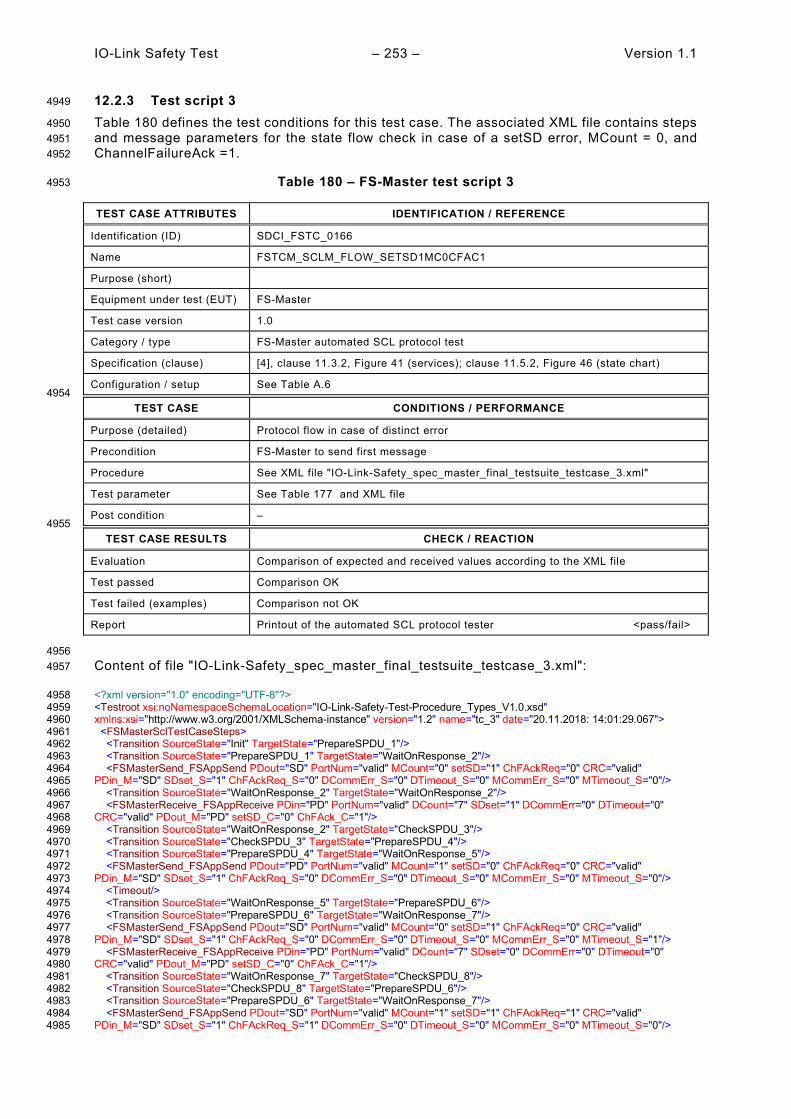
IO-Link Safety Test – 253 – Version 1.1
12.2.3 Test script 3 4949
Table 180 defines the test conditions for this test case. The associated XML file contains steps 4950 and message parameters for the state flow check in case of a setSD error, MCount = 0, and 4951 ChannelFailureAck =1. 4952
Table 180 – FS-Master test script 3 4953
TEST CASE ATTRIBUTES IDENTIFICATION / REFERENCE
Identification (ID) SDCI_FSTC_0166
Name FSTCM_SCLM_FLOW_SETSD1MC0CFAC1
Purpose (short)
Equipment under test (EUT) FS-Master
Test case version 1.0
Category / type FS-Master automated SCL protocol test
Specification (clause) [4], clause 11.3.2, Figure 41 (services); clause 11.5.2, Figure 46 (state chart)
Configuration / setup See Table A.6 4954
TEST CASE CONDITIONS / PERFORMANCE
Purpose (detailed) Protocol flow in case of distinct error
Precondition FS-Master to send first message
Procedure See XML file "IO-Link-Safety_spec_master_final_testsuite_testcase_3.xml"
Test parameter See Table 177 and XML file
Post condition – 4955
TEST CASE RESULTS CHECK / REACTION
Evaluation Comparison of expected and received values according to the XML file
Test passed Comparison OK
Test failed (examples) Comparison not OK
Report Printout of the automated SCL protocol tester <pass/fail>
4956 Content of file "IO-Link-Safety_spec_master_final_testsuite_testcase_3.xml": 4957
<?xml version="1.0" encoding="UTF-8"?> 4958 <Testroot xsi:noNamespaceSchemaLocation="IO-Link-Safety-Test-Procedure_Types_V1.0.xsd" 4959 xmlns:xsi="http://www.w3.org/2001/XMLSchema-instance" version="1.2" name="tc_3" date="20.11.2018: 14:01:29.067"> 4960 <FSMasterSclTestCaseSteps> 4961 <Transition SourceState="Init" TargetState="PrepareSPDU_1"/> 4962 <Transition SourceState="PrepareSPDU_1" TargetState="WaitOnResponse_2"/> 4963 <FSMasterSend_FSAppSend PDout="SD" PortNum="valid" MCount="0" setSD="1" ChFAckReq="0" CRC="valid" 4964 PDin_M="SD" SDset_S="1" ChFAckReq_S="0" DCommErr_S="0" DTimeout_S="0" MCommErr_S="0" MTimeout_S="0"/> 4965 <Transition SourceState="WaitOnResponse_2" TargetState="WaitOnResponse_2"/> 4966 <FSMasterReceive_FSAppReceive PDin="PD" PortNum="valid" DCount="7" SDset="1" DCommErr="0" DTimeout="0" 4967 CRC="valid" PDout_M="PD" setSD_C="0" ChFAck_C="1"/> 4968 <Transition SourceState="WaitOnResponse_2" TargetState="CheckSPDU_3"/> 4969 <Transition SourceState="CheckSPDU_3" TargetState="PrepareSPDU_4"/> 4970 <Transition SourceState="PrepareSPDU_4" TargetState="WaitOnResponse_5"/> 4971 <FSMasterSend_FSAppSend PDout="PD" PortNum="valid" MCount="1" setSD="0" ChFAckReq="0" CRC="valid" 4972 PDin_M="SD" SDset_S="1" ChFAckReq_S="0" DCommErr_S="0" DTimeout_S="0" MCommErr_S="0" MTimeout_S="0"/> 4973 <Timeout/> 4974 <Transition SourceState="WaitOnResponse_5" TargetState="PrepareSPDU_6"/> 4975 <Transition SourceState="PrepareSPDU_6" TargetState="WaitOnResponse_7"/> 4976 <FSMasterSend_FSAppSend PDout="SD" PortNum="valid" MCount="0" setSD="1" ChFAckReq="0" CRC="valid" 4977 PDin_M="SD" SDset_S="1" ChFAckReq_S="0" DCommErr_S="0" DTimeout_S="0" MCommErr_S="0" MTimeout_S="1"/> 4978 <FSMasterReceive_FSAppReceive PDin="PD" PortNum="valid" DCount="7" SDset="0" DCommErr="0" DTimeout="0" 4979 CRC="valid" PDout_M="PD" setSD_C="0" ChFAck_C="1"/> 4980 <Transition SourceState="WaitOnResponse_7" TargetState="CheckSPDU_8"/> 4981 <Transition SourceState="CheckSPDU_8" TargetState="PrepareSPDU_6"/> 4982 <Transition SourceState="PrepareSPDU_6" TargetState="WaitOnResponse_7"/> 4983 <FSMasterSend_FSAppSend PDout="SD" PortNum="valid" MCount="1" setSD="1" ChFAckReq="1" CRC="valid" 4984 PDin_M="SD" SDset_S="1" ChFAckReq_S="1" DCommErr_S="0" DTimeout_S="0" MCommErr_S="0" MTimeout_S="0"/> 4985
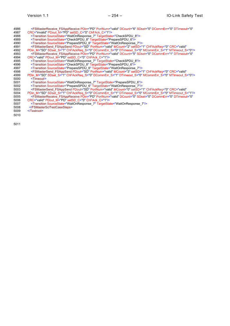
Version 1.1 – 254 – IO-Link Safety Test
<FSMasterReceive_FSAppReceive PDin="PD" PortNum="valid" DCount="6" SDset="0" DCommErr="0" DTimeout="0" 4986 CRC="invalid" PDout_M="PD" setSD_C="0" ChFAck_C="1"/> 4987 <Transition SourceState="WaitOnResponse_7" TargetState="CheckSPDU_8"/> 4988 <Transition SourceState="CheckSPDU_8" TargetState="PrepareSPDU_6"/> 4989 <Transition SourceState="PrepareSPDU_6" TargetState="WaitOnResponse_7"/> 4990 <FSMasterSend_FSAppSend PDout="SD" PortNum="valid" MCount="2" setSD="1" ChFAckReq="0" CRC="valid" 4991 PDin_M="SD" SDset_S="1" ChFAckReq_S="0" DCommErr_S="0" DTimeout_S="0" MCommErr_S="1" MTimeout_S="0"/> 4992 <FSMasterReceive_FSAppReceive PDin="PD" PortNum="valid" DCount="5" SDset="0" DCommErr="1" DTimeout="0" 4993 CRC="valid" PDout_M="PD" setSD_C="0" ChFAck_C="1"/> 4994 <Transition SourceState="WaitOnResponse_7" TargetState="CheckSPDU_8"/> 4995 <Transition SourceState="CheckSPDU_8" TargetState="PrepareSPDU_6"/> 4996 <Transition SourceState="PrepareSPDU_6" TargetState="WaitOnResponse_7"/> 4997 <FSMasterSend_FSAppSend PDout="SD" PortNum="valid" MCount="3" setSD="1" ChFAckReq="0" CRC="valid" 4998 PDin_M="SD" SDset_S="1" ChFAckReq_S="0" DCommErr_S="1" DTimeout_S="0" MCommErr_S="0" MTimeout_S="0"/> 4999 <Timeout/> 5000 <Transition SourceState="WaitOnResponse_7" TargetState="PrepareSPDU_6"/> 5001 <Transition SourceState="PrepareSPDU_6" TargetState="WaitOnResponse_7"/> 5002 <FSMasterSend_FSAppSend PDout="SD" PortNum="valid" MCount="0" setSD="1" ChFAckReq="0" CRC="valid" 5003 PDin_M="SD" SDset_S="1" ChFAckReq_S="0" DCommErr_S="1" DTimeout_S="0" MCommErr_S="0" MTimeout_S="1"/> 5004 <FSMasterReceive_FSAppReceive PDin="PD" PortNum="valid" DCount="0" SDset="0" DCommErr="0" DTimeout="0" 5005 CRC="valid" PDout_M="PD" setSD_C="0" ChFAck_C="1"/> 5006 <Transition SourceState="WaitOnResponse_7" TargetState="WaitOnResponse_7"/> 5007 </FSMasterSclTestCaseSteps> 5008 </Testroot> 5009 5010
5011
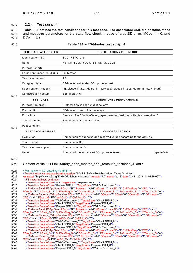
IO-Link Safety Test – 255 – Version 1.1
12.2.4 Test script 4 5012
Table 181 defines the test conditions for this test case. The associated XML file contains steps 5013 and message parameters for the state flow check in case of a setSD error, MCount = 0, and 5014 DCommErr. 5015
Table 181 – FS-Master test script 4 5016
TEST CASE ATTRIBUTES IDENTIFICATION / REFERENCE
Identification (ID) SDCI_FSTC_0167
Name FSTCM_SCLM_FLOW_SETSD1MC0DCE1
Purpose (short)
Equipment under test (EUT) FS-Master
Test case version 1.0
Category / type FS-Master automated SCL protocol test
Specification (clause) [4], clause 11.3.2, Figure 41 (services); clause 11.5.2, Figure 46 (state chart)
Configuration / setup See Table A.6 5017
TEST CASE CONDITIONS / PERFORMANCE
Purpose (detailed) Protocol flow in case of distinct error
Precondition FS-Master to send first message
Procedure See XML file "IO-Link-Safety_spec_master_final_testsuite_testcase_4.xml"
Test parameter See Table 177 and XML file
Post condition – 5018
TEST CASE RESULTS CHECK / REACTION
Evaluation Comparison of expected and received values according to the XML file
Test passed Comparison OK
Test failed (examples) Comparison not OK
Report Printout of the automated SCL protocol tester <pass/fail>
5019
Content of file "IO-Link-Safety_spec_master_final_testsuite_testcase_4.xml": 5020
<?xml version="1.0" encoding="UTF-8"?> 5021 <Testroot xsi:noNamespaceSchemaLocation="IO-Link-Safety-Test-Procedure_Types_V1.0.xsd" 5022 xmlns:xsi="http://www.w3.org/2001/XMLSchema-instance" version="1.2" name="tc_4" date="20.11.2018: 14:01:29.067"> 5023 <FSMasterSclTestCaseSteps> 5024 <Transition SourceState="Init" TargetState="PrepareSPDU_1"/> 5025 <Transition SourceState="PrepareSPDU_1" TargetState="WaitOnResponse_2"/> 5026 <FSMasterSend_FSAppSend PDout="SD" PortNum="valid" MCount="0" setSD="1" ChFAckReq="0" CRC="valid" 5027 PDin_M="SD" SDset_S="1" ChFAckReq_S="0" DCommErr_S="0" DTimeout_S="0" MCommErr_S="0" MTimeout_S="0"/> 5028 <FSMasterReceive_FSAppReceive PDin="PD" PortNum="valid" DCount="7" SDset="0" DCommErr="1" DTimeout="0" 5029 CRC="valid" PDout_M="PD" setSD_C="0" ChFAck_C="0"/> 5030 <Transition SourceState="WaitOnResponse_2" TargetState="CheckSPDU_3"/> 5031 <Transition SourceState="CheckSPDU_3" TargetState="PrepareSPDU_6"/> 5032 <Transition SourceState="PrepareSPDU_6" TargetState="WaitOnResponse_7"/> 5033 <FSMasterSend_FSAppSend PDout="SD" PortNum="valid" MCount="1" setSD="1" ChFAckReq="0" CRC="valid" 5034 PDin_M="SD" SDset_S="1" ChFAckReq_S="0" DCommErr_S="1" DTimeout_S="0" MCommErr_S="0" MTimeout_S="0"/> 5035 <FSMasterReceive_FSAppReceive PDin="PD" PortNum="valid" DCount="6" SDset="0" DCommErr="0" DTimeout="0" 5036 CRC="invalid" PDout_M="PD" setSD_C="0" ChFAck_C="0"/> 5037 <Transition SourceState="WaitOnResponse_7" TargetState="CheckSPDU_8"/> 5038 <Transition SourceState="CheckSPDU_8" TargetState="PrepareSPDU_6"/> 5039 <Transition SourceState="PrepareSPDU_6" TargetState="WaitOnResponse_7"/> 5040 <FSMasterSend_FSAppSend PDout="SD" PortNum="valid" MCount="2" setSD="1" ChFAckReq="0" CRC="valid" 5041 PDin_M="SD" SDset_S="1" ChFAckReq_S="0" DCommErr_S="0" DTimeout_S="0" MCommErr_S="1" MTimeout_S="0"/> 5042 <FSMasterReceive_FSAppReceive PDin="PD" PortNum="valid" DCount="5" SDset="0" DCommErr="1" DTimeout="0" 5043 CRC="valid" PDout_M="PD" setSD_C="0" ChFAck_C="0"/> 5044 <Transition SourceState="WaitOnResponse_7" TargetState="CheckSPDU_8"/> 5045 <Transition SourceState="CheckSPDU_8" TargetState="PrepareSPDU_6"/> 5046 <Transition SourceState="PrepareSPDU_6" TargetState="WaitOnResponse_7"/> 5047

Version 1.1 – 256 – IO-Link Safety Test
<FSMasterSend_FSAppSend PDout="SD" PortNum="valid" MCount="3" setSD="1" ChFAckReq="0" CRC="valid" 5048 PDin_M="SD" SDset_S="1" ChFAckReq_S="0" DCommErr_S="1" DTimeout_S="0" MCommErr_S="0" MTimeout_S="0"/> 5049 <FSMasterReceive_FSAppReceive PDin="PD" PortNum="invalid" DCount="4" SDset="0" DCommErr="0" DTimeout="1" 5050 CRC="valid" PDout_M="PD" setSD_C="0" ChFAck_C="0"/> 5051 <Transition SourceState="WaitOnResponse_7" TargetState="CheckSPDU_8"/> 5052 <Transition SourceState="CheckSPDU_8" TargetState="PrepareSPDU_6"/> 5053 <Transition SourceState="PrepareSPDU_6" TargetState="WaitOnResponse_7"/> 5054 <FSMasterSend_FSAppSend PDout="SD" PortNum="valid" MCount="4" setSD="1" ChFAckReq="0" CRC="valid" 5055 PDin_M="SD" SDset_S="1" ChFAckReq_S="0" DCommErr_S="0" DTimeout_S="1" MCommErr_S="1" MTimeout_S="0"/> 5056 <FSMasterReceive_FSAppReceive PDin="PD" PortNum="invalid" DCount="3" SDset="0" DCommErr="0" DTimeout="1" 5057 CRC="valid" PDout_M="PD" setSD_C="0" ChFAck_C="0"/> 5058 <Transition SourceState="WaitOnResponse_7" TargetState="CheckSPDU_8"/> 5059 <Transition SourceState="CheckSPDU_8" TargetState="PrepareSPDU_6"/> 5060 <Transition SourceState="PrepareSPDU_6" TargetState="WaitOnResponse_7"/> 5061 <FSMasterSend_FSAppSend PDout="SD" PortNum="valid" MCount="5" setSD="1" ChFAckReq="0" CRC="valid" 5062 PDin_M="SD" SDset_S="1" ChFAckReq_S="0" DCommErr_S="0" DTimeout_S="1" MCommErr_S="1" MTimeout_S="0"/> 5063 <FSMasterReceive_FSAppReceive PDin="PD" PortNum="invalid" DCount="2" SDset="0" DCommErr="0" DTimeout="1" 5064 CRC="valid" PDout_M="PD" setSD_C="0" ChFAck_C="0"/> 5065 <Transition SourceState="WaitOnResponse_7" TargetState="CheckSPDU_8"/> 5066 <Transition SourceState="CheckSPDU_8" TargetState="PrepareSPDU_6"/> 5067 <Transition SourceState="PrepareSPDU_6" TargetState="WaitOnResponse_7"/> 5068 <FSMasterSend_FSAppSend PDout="SD" PortNum="valid" MCount="6" setSD="1" ChFAckReq="0" CRC="valid" 5069 PDin_M="SD" SDset_S="1" ChFAckReq_S="0" DCommErr_S="0" DTimeout_S="1" MCommErr_S="1" MTimeout_S="0"/> 5070 <FSMasterReceive_FSAppReceive PDin="PD" PortNum="valid" DCount="1" SDset="0" DCommErr="0" DTimeout="0" 5071 CRC="valid" PDout_M="PD" setSD_C="0" ChFAck_C="0"/> 5072 <Transition SourceState="WaitOnResponse_7" TargetState="CheckSPDU_8"/> 5073 <Transition SourceState="CheckSPDU_8" TargetState="PrepareSPDU_6"/> 5074 <Transition SourceState="PrepareSPDU_6" TargetState="WaitOnResponse_7"/> 5075 <FSMasterSend_FSAppSend PDout="SD" PortNum="valid" MCount="7" setSD="1" ChFAckReq="1" CRC="valid" 5076 PDin_M="SD" SDset_S="1" ChFAckReq_S="1" DCommErr_S="0" DTimeout_S="0" MCommErr_S="0" MTimeout_S="0"/> 5077 <Transition SourceState="WaitOnResponse_7" TargetState="WaitOnResponse_7"/> 5078 <FSMasterReceive_FSAppReceive PDin="PD" PortNum="valid" DCount="0" SDset="0" DCommErr="0" DTimeout="0" 5079 CRC="valid" PDout_M="PD" setSD_C="1" ChFAck_C="1"/> 5080 <Transition SourceState="WaitOnResponse_7" TargetState="CheckSPDU_8"/> 5081 <Transition SourceState="CheckSPDU_8" TargetState="PrepareSPDU_4"/> 5082 <Transition SourceState="PrepareSPDU_4" TargetState="WaitOnResponse_5"/> 5083 <FSMasterSend_FSAppSend PDout="SD" PortNum="valid" MCount="1" setSD="1" ChFAckReq="0" CRC="valid" 5084 PDin_M="SD" SDset_S="1" ChFAckReq_S="0" DCommErr_S="0" DTimeout_S="0" MCommErr_S="0" MTimeout_S="0"/> 5085 <FSMasterReceive_FSAppReceive PDin="PD" PortNum="valid" DCount="0" SDset="0" DCommErr="0" DTimeout="0" 5086 CRC="valid" PDout_M="PD" setSD_C="1" ChFAck_C="1"/> 5087 <Transition SourceState="WaitOnResponse_5" TargetState="WaitOnResponse_5"/> 5088 </FSMasterSclTestCaseSteps> 5089 </Testroot> 5090
5091
5092
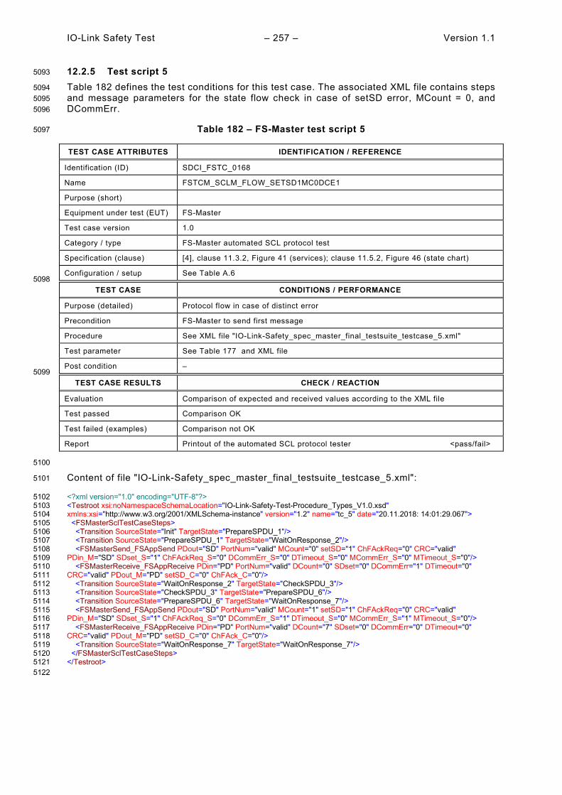
IO-Link Safety Test – 257 – Version 1.1
12.2.5 Test script 5 5093
Table 182 defines the test conditions for this test case. The associated XML file contains steps 5094 and message parameters for the state flow check in case of setSD error, MCount = 0, and 5095 DCommErr. 5096
Table 182 – FS-Master test script 5 5097
TEST CASE ATTRIBUTES IDENTIFICATION / REFERENCE
Identification (ID) SDCI_FSTC_0168
Name FSTCM_SCLM_FLOW_SETSD1MC0DCE1
Purpose (short)
Equipment under test (EUT) FS-Master
Test case version 1.0
Category / type FS-Master automated SCL protocol test
Specification (clause) [4], clause 11.3.2, Figure 41 (services); clause 11.5.2, Figure 46 (state chart)
Configuration / setup See Table A.6 5098
TEST CASE CONDITIONS / PERFORMANCE
Purpose (detailed) Protocol flow in case of distinct error
Precondition FS-Master to send first message
Procedure See XML file "IO-Link-Safety_spec_master_final_testsuite_testcase_5.xml"
Test parameter See Table 177 and XML file
Post condition – 5099
TEST CASE RESULTS CHECK / REACTION
Evaluation Comparison of expected and received values according to the XML file
Test passed Comparison OK
Test failed (examples) Comparison not OK
Report Printout of the automated SCL protocol tester <pass/fail>
5100
Content of file "IO-Link-Safety_spec_master_final_testsuite_testcase_5.xml": 5101
<?xml version="1.0" encoding="UTF-8"?> 5102 <Testroot xsi:noNamespaceSchemaLocation="IO-Link-Safety-Test-Procedure_Types_V1.0.xsd" 5103 xmlns:xsi="http://www.w3.org/2001/XMLSchema-instance" version="1.2" name="tc_5" date="20.11.2018: 14:01:29.067"> 5104 <FSMasterSclTestCaseSteps> 5105 <Transition SourceState="Init" TargetState="PrepareSPDU_1"/> 5106 <Transition SourceState="PrepareSPDU_1" TargetState="WaitOnResponse_2"/> 5107 <FSMasterSend_FSAppSend PDout="SD" PortNum="valid" MCount="0" setSD="1" ChFAckReq="0" CRC="valid" 5108 PDin_M="SD" SDset_S="1" ChFAckReq_S="0" DCommErr_S="0" DTimeout_S="0" MCommErr_S="0" MTimeout_S="0"/> 5109 <FSMasterReceive_FSAppReceive PDin="PD" PortNum="valid" DCount="0" SDset="0" DCommErr="1" DTimeout="0" 5110 CRC="valid" PDout_M="PD" setSD_C="0" ChFAck_C="0"/> 5111 <Transition SourceState="WaitOnResponse_2" TargetState="CheckSPDU_3"/> 5112 <Transition SourceState="CheckSPDU_3" TargetState="PrepareSPDU_6"/> 5113 <Transition SourceState="PrepareSPDU_6" TargetState="WaitOnResponse_7"/> 5114 <FSMasterSend_FSAppSend PDout="SD" PortNum="valid" MCount="1" setSD="1" ChFAckReq="0" CRC="valid" 5115 PDin_M="SD" SDset_S="1" ChFAckReq_S="0" DCommErr_S="1" DTimeout_S="0" MCommErr_S="1" MTimeout_S="0"/> 5116 <FSMasterReceive_FSAppReceive PDin="PD" PortNum="valid" DCount="7" SDset="0" DCommErr="0" DTimeout="0" 5117 CRC="valid" PDout_M="PD" setSD_C="0" ChFAck_C="0"/> 5118 <Transition SourceState="WaitOnResponse_7" TargetState="WaitOnResponse_7"/> 5119 </FSMasterSclTestCaseSteps> 5120 </Testroot> 5121 5122
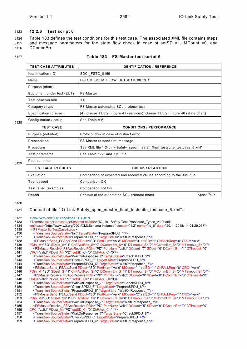
Version 1.1 – 258 – IO-Link Safety Test
12.2.6 Test script 6 5123
Table 183 defines the test conditions for this test case. The associated XML file contains steps 5124 and message parameters for the state flow check in case of setSD =1, MCount =0, and 5125 DCommErr. 5126
Table 183 – FS-Master test script 6 5127
TEST CASE ATTRIBUTES IDENTIFICATION / REFERENCE
Identification (ID) SDCI_FSTC_0169
Name FSTCM_SCLM_FLOW_SETSD1MC0DCE1
Purpose (short)
Equipment under test (EUT) FS-Master
Test case version 1.0
Category / type FS-Master automated SCL protocol test
Specification (clause) [4], clause 11.3.2, Figure 41 (services); clause 11.5.2, Figure 46 (state chart)
Configuration / setup See Table A.6 5128
TEST CASE CONDITIONS / PERFORMANCE
Purpose (detailed) Protocol flow in case of distinct error
Precondition FS-Master to send first message
Procedure See XML file "IO-Link-Safety_spec_master_final_testsuite_testcase_6.xml"
Test parameter See Table 177 and XML file
Post condition – 5129
TEST CASE RESULTS CHECK / REACTION
Evaluation Comparison of expected and received values according to the XML file
Test passed Comparison OK
Test failed (examples) Comparison not OK
Report Printout of the automated SCL protocol tester <pass/fail>
5130
Content of file "IO-Link-Safety_spec_master_final_testsuite_testcase_6.xml": 5131
<?xml version="1.0" encoding="UTF-8"?> 5132 <Testroot xsi:noNamespaceSchemaLocation="IO-Link-Safety-Test-Procedure_Types_V1.0.xsd" 5133 xmlns:xsi="http://www.w3.org/2001/XMLSchema-instance" version="1.2" name="tc_6" date="20.11.2018: 14:01:29.067"> 5134 <FSMasterSclTestCaseSteps> 5135 <Transition SourceState="Init" TargetState="PrepareSPDU_1"/> 5136 <Transition SourceState="PrepareSPDU_1" TargetState="WaitOnResponse_2"/> 5137 <FSMasterSend_FSAppSend PDout="SD" PortNum="valid" MCount="0" setSD="1" ChFAckReq="0" CRC="valid" 5138 PDin_M="SD" SDset_S="1" ChFAckReq_S="0" DCommErr_S="0" DTimeout_S="0" MCommErr_S="0" MTimeout_S="0"/> 5139 <FSMasterReceive_FSAppReceive PDin="PD" PortNum="valid" DCount="7" SDset="0" DCommErr="1" DTimeout="0" 5140 CRC="valid" PDout_M="PD" setSD_C="0" ChFAck_C="0"/> 5141 <Transition SourceState="WaitOnResponse_2" TargetState="CheckSPDU_3"/> 5142 <Transition SourceState="CheckSPDU_3" TargetState="PrepareSPDU_6"/> 5143 <Transition SourceState="PrepareSPDU_6" TargetState="WaitOnResponse_7"/> 5144 <FSMasterSend_FSAppSend PDout="SD" PortNum="valid" MCount="1" setSD="1" ChFAckReq="0" CRC="valid" 5145 PDin_M="SD" SDset_S="1" ChFAckReq_S="0" DCommErr_S="1" DTimeout_S="0" MCommErr_S="0" MTimeout_S="0"/> 5146 <FSMasterReceive_FSAppReceive PDin="PD" PortNum="valid" DCount="6" SDset="0" DCommErr="0" DTimeout="0" 5147 CRC="valid" PDout_M="PD" setSD_C="0" ChFAck_C="0"/> 5148 <Transition SourceState="WaitOnResponse_7" TargetState="CheckSPDU_8"/> 5149 <Transition SourceState="CheckSPDU_8" TargetState="PrepareSPDU_6"/> 5150 <Transition SourceState="PrepareSPDU_6" TargetState="WaitOnResponse_7"/> 5151 <FSMasterSend_FSAppSend PDout="SD" PortNum="valid" MCount="2" setSD="1" ChFAckReq="1" CRC="valid" 5152 PDin_M="SD" SDset_S="1" ChFAckReq_S="1" DCommErr_S="0" DTimeout_S="0" MCommErr_S="0" MTimeout_S="0"/> 5153 <Transition SourceState="WaitOnResponse_7" TargetState="WaitOnResponse_7"/> 5154 <FSMasterReceive_FSAppReceive PDin="PD" PortNum="valid" DCount="5" SDset="0" DCommErr="0" DTimeout="0" 5155 CRC="valid" PDout_M="PD" setSD_C="0" ChFAck_C="1"/> 5156 <Transition SourceState="WaitOnResponse_7" TargetState="CheckSPDU_8"/> 5157 <Transition SourceState="CheckSPDU_8" TargetState="PrepareSPDU_4"/> 5158 <Transition SourceState="PrepareSPDU_4" TargetState="WaitOnResponse_5"/> 5159

IO-Link Safety Test – 259 – Version 1.1
<FSMasterSend_FSAppSend PDout="PD" PortNum="valid" MCount="3" setSD="0" ChFAckReq="0" CRC="valid" 5160 PDin_M="PD" SDset_S="0" ChFAckReq_S="0" DCommErr_S="0" DTimeout_S="0" MCommErr_S="0" MTimeout_S="0"/> 5161 <FSMasterReceive_FSAppReceive PDin="PD" PortNum="valid" DCount="6" SDset="0" DCommErr="0" DTimeout="0" 5162 CRC="valid" PDout_M="PD" setSD_C="0" ChFAck_C="1"/> 5163 <Transition SourceState="WaitOnResponse_5" TargetState="CheckSPDU_3"/> 5164 <Transition SourceState="CheckSPDU_3" TargetState="PrepareSPDU_6"/> 5165 <Transition SourceState="PrepareSPDU_6" TargetState="WaitOnResponse_7"/> 5166 <FSMasterSend_FSAppSend PDout="SD" PortNum="valid" MCount="4" setSD="1" ChFAckReq="0" CRC="valid" 5167 PDin_M="SD" SDset_S="1" ChFAckReq_S="0" DCommErr_S="0" DTimeout_S="0" MCommErr_S="1" MTimeout_S="0"/> 5168 </FSMasterSclTestCaseSteps> 5169 </Testroot> 5170 5171

Version 1.1 – 260 – IO-Link Safety Test
12.2.7 Test script 7 5172
Table 184 defines the test conditions for this test case. The associated XML file contains steps 5173 and message parameters for the state flow check in case of setSD =1, MCount =0, and 5174 DCommErr. 5175
Table 184 – FS-Master test script 7 5176
TEST CASE ATTRIBUTES IDENTIFICATION / REFERENCE
Identification (ID) SDCI_FSTC_0170
Name FSTCM_SCLM_FLOW_SETSD1MC0DCE1
Purpose (short)
Equipment under test (EUT) FS-Master
Test case version 1.0
Category / type FS-Master automated SCL protocol test
Specification (clause) [4], clause 11.3.2, Figure 41 (services); clause 11.5.2, Figure 46 (state chart)
Configuration / setup See Table A.6 5177
TEST CASE CONDITIONS / PERFORMANCE
Purpose (detailed) Protocol flow in case of distinct error
Precondition FS-Master to send first message
Procedure See XML file "IO-Link-Safety_spec_master_final_testsuite_testcase_7.xml"
Test parameter See Table 177 and XML file
Post condition – 5178
TEST CASE RESULTS CHECK / REACTION
Evaluation Comparison of expected and received values according to the XML file
Test passed Comparison OK
Test failed (examples) Comparison not OK
Report Printout of the automated SCL protocol tester <pass/fail>
5179
Content of file "IO-Link-Safety_spec_master_final_testsuite_testcase_7.xml": 5180
<?xml version="1.0" encoding="UTF-8"?> 5181 <Testroot xsi:noNamespaceSchemaLocation="IO-Link-Safety-Test-Procedure_Types_V1.0.xsd" 5182 xmlns:xsi="http://www.w3.org/2001/XMLSchema-instance" version="1.2" name="tc_7" date="20.11.2018: 14:01:29.067"> 5183 <FSMasterSclTestCaseSteps> 5184 <Transition SourceState="Init" TargetState="PrepareSPDU_1"/> 5185 <Transition SourceState="PrepareSPDU_1" TargetState="WaitOnResponse_2"/> 5186 <FSMasterSend_FSAppSend PDout="SD" PortNum="valid" MCount="0" setSD="1" ChFAckReq="0" CRC="valid" 5187 PDin_M="SD" SDset_S="1" ChFAckReq_S="0" DCommErr_S="0" DTimeout_S="0" MCommErr_S="0" MTimeout_S="0"/> 5188 <FSMasterReceive_FSAppReceive PDin="PD" PortNum="valid" DCount="7" SDset="0" DCommErr="1" DTimeout="0" 5189 CRC="valid" PDout_M="PD" setSD_C="0" ChFAck_C="0"/> 5190 <Transition SourceState="WaitOnResponse_2" TargetState="CheckSPDU_3"/> 5191 <Transition SourceState="CheckSPDU_3" TargetState="PrepareSPDU_6"/> 5192 <Transition SourceState="PrepareSPDU_6" TargetState="WaitOnResponse_7"/> 5193 <FSMasterSend_FSAppSend PDout="SD" PortNum="valid" MCount="1" setSD="1" ChFAckReq="0" CRC="valid" 5194 PDin_M="SD" SDset_S="1" ChFAckReq_S="0" DCommErr_S="1" DTimeout_S="0" MCommErr_S="0" MTimeout_S="0"/> 5195 <FSMasterReceive_FSAppReceive PDin="PD" PortNum="valid" DCount="6" SDset="0" DCommErr="0" DTimeout="0" 5196 CRC="valid" PDout_M="PD" setSD_C="0" ChFAck_C="0"/> 5197 <Transition SourceState="WaitOnResponse_7" TargetState="CheckSPDU_8"/> 5198 <Transition SourceState="CheckSPDU_8" TargetState="PrepareSPDU_6"/> 5199 <Transition SourceState="PrepareSPDU_6" TargetState="WaitOnResponse_7"/> 5200 <FSMasterSend_FSAppSend PDout="SD" PortNum="valid" MCount="2" setSD="1" ChFAckReq="1" CRC="valid" 5201 PDin_M="SD" SDset_S="1" ChFAckReq_S="1" DCommErr_S="0" DTimeout_S="0" MCommErr_S="0" MTimeout_S="0"/> 5202 <Transition SourceState="WaitOnResponse_7" TargetState="WaitOnResponse_7"/> 5203 <FSMasterReceive_FSAppReceive PDin="PD" PortNum="valid" DCount="5" SDset="0" DCommErr="0" DTimeout="0" 5204 CRC="valid" PDout_M="PD" setSD_C="0" ChFAck_C="1"/> 5205 <Transition SourceState="WaitOnResponse_7" TargetState="CheckSPDU_8"/> 5206 <Transition SourceState="CheckSPDU_8" TargetState="PrepareSPDU_4"/> 5207 <Transition SourceState="PrepareSPDU_4" TargetState="WaitOnResponse_5"/> 5208

IO-Link Safety Test – 261 – Version 1.1
<FSMasterSend_FSAppSend PDout="PD" PortNum="valid" MCount="3" setSD="0" ChFAckReq="0" CRC="valid" 5209 PDin_M="PD" SDset_S="0" ChFAckReq_S="0" DCommErr_S="0" DTimeout_S="0" MCommErr_S="0" MTimeout_S="0"/> 5210 <FSMasterReceive_FSAppReceive PDin="PD" PortNum="valid" DCount="6" SDset="0" DCommErr="0" DTimeout="0" 5211 CRC="invalid" PDout_M="PD" setSD_C="0" ChFAck_C="1"/> 5212 <Transition SourceState="WaitOnResponse_5" TargetState="CheckSPDU_3"/> 5213 <Transition SourceState="CheckSPDU_3" TargetState="PrepareSPDU_6"/> 5214 <Transition SourceState="PrepareSPDU_6" TargetState="WaitOnResponse_7"/> 5215 <FSMasterSend_FSAppSend PDout="SD" PortNum="valid" MCount="4" setSD="1" ChFAckReq="0" CRC="valid" 5216 PDin_M="SD" SDset_S="1" ChFAckReq_S="0" DCommErr_S="0" DTimeout_S="0" MCommErr_S="1" MTimeout_S="0"/> 5217 </FSMasterSclTestCaseSteps> 5218 </Testroot> 5219 5220

Version 1.1 – 262 – IO-Link Safety Test
12.2.8 Test script 8 5221
Table 185 defines the test conditions for this test case. The associated XML file contains steps 5222 and message parameters for the state flow check in case of setSD =1, MCount =0, DCommErr, 5223 and Portnumber error. 5224
Table 185 – FS-Master test script 8 5225
TEST CASE ATTRIBUTES IDENTIFICATION / REFERENCE
Identification (ID) SDCI_FSTC_0171
Name FSTCM_SCLM_FLOW_SETSD1MC0DCE1PNERR
Purpose (short)
Equipment under test (EUT) FS-Master
Test case version 1.0
Category / type FS-Master automated SCL protocol test
Specification (clause) [4], clause 11.3.2, Figure 41 (services); clause 11.5.2, Figure 46 (state chart)
Configuration / setup See Table A.6 5226
TEST CASE CONDITIONS / PERFORMANCE
Purpose (detailed) Protocol flow in case of distinct error
Precondition FS-Master to send first message
Procedure See XML file "IO-Link-Safety_spec_master_final_testsuite_testcase_8.xml"
Test parameter See Table 177 and XML file
Post condition – 5227
TEST CASE RESULTS CHECK / REACTION
Evaluation Comparison of expected and received values according to the XML file
Test passed Comparison OK
Test failed (examples) Comparison not OK
Report Printout of the automated SCL protocol tester <pass/fail>
5228
Content of file "IO-Link-Safety_spec_master_final_testsuite_testcase_8.xml": 5229
<?xml version="1.0" encoding="UTF-8"?> 5230 <Testroot xsi:noNamespaceSchemaLocation="IO-Link-Safety-Test-Procedure_Types_V1.0.xsd" 5231 xmlns:xsi="http://www.w3.org/2001/XMLSchema-instance" version="1.2" name="tc_8" date="20.11.2018: 14:01:29.068"> 5232 <FSMasterSclTestCaseSteps> 5233 <Transition SourceState="Init" TargetState="PrepareSPDU_1"/> 5234 <Transition SourceState="PrepareSPDU_1" TargetState="WaitOnResponse_2"/> 5235 <FSMasterSend_FSAppSend PDout="SD" PortNum="valid" MCount="0" setSD="1" ChFAckReq="0" CRC="valid" 5236 PDin_M="SD" SDset_S="1" ChFAckReq_S="0" DCommErr_S="0" DTimeout_S="0" MCommErr_S="0" MTimeout_S="0"/> 5237 <FSMasterReceive_FSAppReceive PDin="PD" PortNum="valid" DCount="7" SDset="0" DCommErr="1" DTimeout="0" 5238 CRC="valid" PDout_M="PD" setSD_C="0" ChFAck_C="0"/> 5239 <Transition SourceState="WaitOnResponse_2" TargetState="CheckSPDU_3"/> 5240 <Transition SourceState="CheckSPDU_3" TargetState="PrepareSPDU_6"/> 5241 <Transition SourceState="PrepareSPDU_6" TargetState="WaitOnResponse_7"/> 5242 <FSMasterSend_FSAppSend PDout="SD" PortNum="valid" MCount="1" setSD="1" ChFAckReq="0" CRC="valid" 5243 PDin_M="SD" SDset_S="1" ChFAckReq_S="0" DCommErr_S="1" DTimeout_S="0" MCommErr_S="0" MTimeout_S="0"/> 5244 <FSMasterReceive_FSAppReceive PDin="PD" PortNum="valid" DCount="6" SDset="0" DCommErr="0" DTimeout="0" 5245 CRC="valid" PDout_M="PD" setSD_C="0" ChFAck_C="0"/> 5246 <Transition SourceState="WaitOnResponse_7" TargetState="CheckSPDU_8"/> 5247 <Transition SourceState="CheckSPDU_8" TargetState="PrepareSPDU_6"/> 5248 <Transition SourceState="PrepareSPDU_6" TargetState="WaitOnResponse_7"/> 5249 <FSMasterSend_FSAppSend PDout="SD" PortNum="valid" MCount="2" setSD="1" ChFAckReq="1" CRC="valid" 5250 PDin_M="SD" SDset_S="1" ChFAckReq_S="1" DCommErr_S="0" DTimeout_S="0" MCommErr_S="0" MTimeout_S="0"/> 5251 <Transition SourceState="WaitOnResponse_7" TargetState="WaitOnResponse_7"/> 5252 <FSMasterReceive_FSAppReceive PDin="PD" PortNum="valid" DCount="5" SDset="0" DCommErr="0" DTimeout="0" 5253 CRC="valid" PDout_M="PD" setSD_C="0" ChFAck_C="1"/> 5254 <Transition SourceState="WaitOnResponse_7" TargetState="CheckSPDU_8"/> 5255 <Transition SourceState="CheckSPDU_8" TargetState="PrepareSPDU_4"/> 5256 <Transition SourceState="PrepareSPDU_4" TargetState="WaitOnResponse_5"/> 5257

IO-Link Safety Test – 263 – Version 1.1
<FSMasterSend_FSAppSend PDout="PD" PortNum="valid" MCount="3" setSD="0" ChFAckReq="0" CRC="valid" 5258 PDin_M="PD" SDset_S="0" ChFAckReq_S="0" DCommErr_S="0" DTimeout_S="0" MCommErr_S="0" MTimeout_S="0"/> 5259 <FSMasterReceive_FSAppReceive PDin="PD" PortNum="invalid" DCount="6" SDset="0" DCommErr="0" DTimeout="0" 5260 CRC="valid" PDout_M="PD" setSD_C="0" ChFAck_C="1"/> 5261 <Transition SourceState="WaitOnResponse_5" TargetState="CheckSPDU_3"/> 5262 <Transition SourceState="CheckSPDU_3" TargetState="PrepareSPDU_6"/> 5263 <Transition SourceState="PrepareSPDU_6" TargetState="WaitOnResponse_7"/> 5264 <FSMasterSend_FSAppSend PDout="SD" PortNum="valid" MCount="4" setSD="1" ChFAckReq="0" CRC="valid" 5265 PDin_M="SD" SDset_S="1" ChFAckReq_S="0" DCommErr_S="0" DTimeout_S="0" MCommErr_S="1" MTimeout_S="0"/> 5266 </FSMasterSclTestCaseSteps> 5267 </Testroot> 5268 5269

Version 1.1 – 264 – IO-Link Safety Test
12.2.9 Test script 9 5270
Table 186 defines the test conditions for this test case. The associated XML file contains steps 5271 and message parameters for the state flow check in case of setSD =1 and MCount =0. 5272
Table 186 – FS-Master test script 9 5273
TEST CASE ATTRIBUTES IDENTIFICATION / REFERENCE
Identification (ID) SDCI_FSTC_0172
Name FSTCM_SCLM_FLOW_SETSD1MC0
Purpose (short)
Equipment under test (EUT) FS-Master
Test case version 1.0
Category / type FS-Master automated SCL protocol test
Specification (clause) [4], clause 11.3.2, Figure 41 (services); clause 11.5.2, Figure 46 (state chart)
Configuration / setup See Table A.6 5274
TEST CASE CONDITIONS / PERFORMANCE
Purpose (detailed) Protocol flow in case of distinct error
Precondition FS-Master to send first message
Procedure See XML file "IO-Link-Safety_spec_master_final_testsuite_testcase_9.xml"
Test parameter See Table 177 and XML file
Post condition – 5275
TEST CASE RESULTS CHECK / REACTION
Evaluation Comparison of expected and received values according to the XML file
Test passed Comparison OK
Test failed (examples) Comparison not OK
Report Printout of the automated SCL protocol tester <pass/fail>
5276 Content of file "IO-Link-Safety_spec_master_final_testsuite_testcase_9.xml": 5277
<?xml version="1.0" encoding="UTF-8"?> 5278 <Testroot xsi:noNamespaceSchemaLocation="IO-Link-Safety-Test-Procedure_Types_V1.0.xsd" 5279 xmlns:xsi="http://www.w3.org/2001/XMLSchema-instance" version="1.2" name="tc_9" date="20.11.2018: 14:01:29.068"> 5280 <FSMasterSclTestCaseSteps> 5281 <Transition SourceState="Init" TargetState="PrepareSPDU_1"/> 5282 <Transition SourceState="PrepareSPDU_1" TargetState="WaitOnResponse_2"/> 5283 <FSMasterSend_FSAppSend PDout="SD" PortNum="valid" MCount="0" setSD="1" ChFAckReq="0" CRC="valid" 5284 PDin_M="SD" SDset_S="1" ChFAckReq_S="0" DCommErr_S="0" DTimeout_S="0" MCommErr_S="0" MTimeout_S="0"/> 5285 <FSMasterReceive_FSAppReceive PDin="PD" PortNum="valid" DCount="7" SDset="0" DCommErr="0" DTimeout="0" 5286 CRC="valid" PDout_M="PD" setSD_C="0" ChFAck_C="0"/> 5287 <Transition SourceState="WaitOnResponse_2" TargetState="CheckSPDU_3"/> 5288 <Transition SourceState="CheckSPDU_3" TargetState="PrepareSPDU_4"/> 5289 <Transition SourceState="PrepareSPDU_4" TargetState="WaitOnResponse_5"/> 5290 <FSMasterSend_FSAppSend PDout="PD" PortNum="valid" MCount="1" setSD="0" ChFAckReq="0" CRC="valid" 5291 PDin_M="PD" SDset_S="0" ChFAckReq_S="0" DCommErr_S="0" DTimeout_S="0" MCommErr_S="0" MTimeout_S="0"/> 5292 <FSMasterReceive_FSAppReceive PDin="PD" PortNum="valid" DCount="6" SDset="1" DCommErr="0" DTimeout="0" 5293 CRC="valid" PDout_M="PD" setSD_C="0" ChFAck_C="0"/> 5294 <Transition SourceState="WaitOnResponse_5" TargetState="CheckSPDU_3"/> 5295 <Transition SourceState="CheckSPDU_3" TargetState="PrepareSPDU_4"/> 5296 <Transition SourceState="PrepareSPDU_4" TargetState="WaitOnResponse_5"/> 5297 <FSMasterSend_FSAppSend PDout="PD" PortNum="valid" MCount="2" setSD="0" ChFAckReq="0" CRC="valid" 5298 PDin_M="SD" SDset_S="1" ChFAckReq_S="0" DCommErr_S="0" DTimeout_S="0" MCommErr_S="0" MTimeout_S="0"/> 5299 <FSMasterReceive_FSAppReceive PDin="PD" PortNum="valid" DCount="5" SDset="0" DCommErr="0" DTimeout="0" 5300 CRC="valid" PDout_M="PD" setSD_C="0" ChFAck_C="0"/> 5301 <Transition SourceState="WaitOnResponse_5" TargetState="CheckSPDU_3"/> 5302 <Transition SourceState="CheckSPDU_3" TargetState="PrepareSPDU_4"/> 5303 <Transition SourceState="PrepareSPDU_4" TargetState="WaitOnResponse_5"/> 5304 <FSMasterSend_FSAppSend PDout="PD" PortNum="valid" MCount="3" setSD="0" ChFAckReq="0" CRC="valid" 5305 PDin_M="PD" SDset_S="0" ChFAckReq_S="0" DCommErr_S="0" DTimeout_S="0" MCommErr_S="0" MTimeout_S="0"/> 5306

IO-Link Safety Test – 265 – Version 1.1
<FSMasterReceive_FSAppReceive PDin="PD" PortNum="invalid" DCount="0" SDset="0" DCommErr="0" DTimeout="1" 5307 CRC="valid" PDout_M="PD" setSD_C="0" ChFAck_C="0"/> 5308 <Transition SourceState="WaitOnResponse_5" TargetState="CheckSPDU_3"/> 5309 <Transition SourceState="CheckSPDU_3" TargetState="PrepareSPDU_6"/> 5310 <Transition SourceState="PrepareSPDU_6" TargetState="WaitOnResponse_7"/> 5311 <FSMasterSend_FSAppSend PDout="SD" PortNum="valid" MCount="4" setSD="1" ChFAckReq="0" CRC="valid" 5312 PDin_M="SD" SDset_S="1" ChFAckReq_S="0" DCommErr_S="0" DTimeout_S="1" MCommErr_S="1" MTimeout_S="0"/> 5313 </FSMasterSclTestCaseSteps> 5314 </Testroot> 5315 5316

Version 1.1 – 266 – IO-Link Safety Test
12.2.10 Test script 10 5317
Table 187 defines the test conditions for this test case. The associated XML file contains steps 5318 and message parameters for the state flow check in case of setSD =1, MCount =0, Port number 5319 error, and CRC error. 5320
Table 187 – FS-Master test script 10 5321
TEST CASE ATTRIBUTES IDENTIFICATION / REFERENCE
Identification (ID) SDCI_FSTC_0173
Name FSTCM_SCLM_FLOW_PNERRCRCERR
Purpose (short)
Equipment under test (EUT) FS-Master
Test case version 1.0
Category / type FS-Master automated SCL protocol test
Specification (clause) [4], clause 11.3.2, Figure 41 (services); clause 11.5.2, Figure 46 (state chart)
Configuration / setup See Table A.6 5322
TEST CASE CONDITIONS / PERFORMANCE
Purpose (detailed) Protocol flow in case of distinct error
Precondition FS-Master to send first message
Procedure See XML file "IO-Link-Safety_spec_master_final_testsuite_testcase_10.xml"
Test parameter See Table 177 and XML file
Post condition – 5323
TEST CASE RESULTS CHECK / REACTION
Evaluation Comparison of expected and received values according to the XML file
Test passed Comparison OK
Test failed (examples) Comparison not OK
Report Printout of the automated SCL protocol tester <pass/fail>
5324 Content of file "IO-Link-Safety_spec_master_final_testsuite_testcase_10.xml": 5325
<?xml version="1.0" encoding="UTF-8"?> 5326 <Testroot xsi:noNamespaceSchemaLocation="IO-Link-Safety-Test-Procedure_Types_V1.0.xsd" 5327 xmlns:xsi="http://www.w3.org/2001/XMLSchema-instance" version="1.2" name="tc_10" date="20.11.2018: 14:01:29.068"> 5328 <FSMasterSclTestCaseSteps> 5329 <Transition SourceState="Init" TargetState="PrepareSPDU_1"/> 5330 <Transition SourceState="PrepareSPDU_1" TargetState="WaitOnResponse_2"/> 5331 <FSMasterSend_FSAppSend PDout="SD" PortNum="valid" MCount="0" setSD="1" ChFAckReq="0" CRC="valid" 5332 PDin_M="SD" SDset_S="1" ChFAckReq_S="0" DCommErr_S="0" DTimeout_S="0" MCommErr_S="0" MTimeout_S="0"/> 5333 <FSMasterReceive_FSAppReceive PDin="PD" PortNum="valid" DCount="7" SDset="0" DCommErr="1" DTimeout="0" 5334 CRC="valid" PDout_M="PD" setSD_C="0" ChFAck_C="0"/> 5335 <Transition SourceState="WaitOnResponse_2" TargetState="CheckSPDU_3"/> 5336 <Transition SourceState="CheckSPDU_3" TargetState="PrepareSPDU_6"/> 5337 <Transition SourceState="PrepareSPDU_6" TargetState="WaitOnResponse_7"/> 5338 <FSMasterSend_FSAppSend PDout="SD" PortNum="valid" MCount="1" setSD="1" ChFAckReq="0" CRC="valid" 5339 PDin_M="SD" SDset_S="1" ChFAckReq_S="0" DCommErr_S="1" DTimeout_S="0" MCommErr_S="0" MTimeout_S="0"/> 5340 <FSMasterReceive_FSAppReceive PDin="PD" PortNum="valid" DCount="6" SDset="0" DCommErr="0" DTimeout="0" 5341 CRC="invalid" PDout_M="PD" setSD_C="0" ChFAck_C="0"/> 5342 <Transition SourceState="WaitOnResponse_7" TargetState="CheckSPDU_8"/> 5343 <Transition SourceState="CheckSPDU_8" TargetState="PrepareSPDU_6"/> 5344 <Transition SourceState="PrepareSPDU_6" TargetState="WaitOnResponse_7"/> 5345 <FSMasterSend_FSAppSend PDout="SD" PortNum="valid" MCount="2" setSD="1" ChFAckReq="0" CRC="valid" 5346 PDin_M="SD" SDset_S="1" ChFAckReq_S="0" DCommErr_S="0" DTimeout_S="0" MCommErr_S="1" MTimeout_S="0"/> 5347 <FSMasterReceive_FSAppReceive PDin="PD" PortNum="valid" DCount="5" SDset="0" DCommErr="1" DTimeout="0" 5348 CRC="valid" PDout_M="PD" setSD_C="0" ChFAck_C="0"/> 5349 <Transition SourceState="WaitOnResponse_7" TargetState="CheckSPDU_8"/> 5350 <Transition SourceState="CheckSPDU_8" TargetState="PrepareSPDU_6"/> 5351 <Transition SourceState="PrepareSPDU_6" TargetState="WaitOnResponse_7"/> 5352

IO-Link Safety Test – 267 – Version 1.1
<FSMasterSend_FSAppSend PDout="SD" PortNum="valid" MCount="3" setSD="1" ChFAckReq="0" CRC="valid" 5353 PDin_M="SD" SDset_S="1" ChFAckReq_S="0" DCommErr_S="1" DTimeout_S="0" MCommErr_S="0" MTimeout_S="0"/> 5354 <FSMasterReceive_FSAppReceive PDin="PD" PortNum="invalid" DCount="4" SDset="0" DCommErr="0" DTimeout="1" 5355 CRC="valid" PDout_M="PD" setSD_C="0" ChFAck_C="0"/> 5356 <Transition SourceState="WaitOnResponse_7" TargetState="CheckSPDU_8"/> 5357 <Transition SourceState="CheckSPDU_8" TargetState="PrepareSPDU_6"/> 5358 <Transition SourceState="PrepareSPDU_6" TargetState="WaitOnResponse_7"/> 5359 <FSMasterSend_FSAppSend PDout="SD" PortNum="valid" MCount="4" setSD="1" ChFAckReq="0" CRC="valid" 5360 PDin_M="SD" SDset_S="1" ChFAckReq_S="0" DCommErr_S="0" DTimeout_S="1" MCommErr_S="1" MTimeout_S="0"/> 5361 <FSMasterReceive_FSAppReceive PDin="PD" PortNum="invalid" DCount="3" SDset="0" DCommErr="0" DTimeout="1" 5362 CRC="valid" PDout_M="PD" setSD_C="0" ChFAck_C="0"/> 5363 <Transition SourceState="WaitOnResponse_7" TargetState="CheckSPDU_8"/> 5364 <Transition SourceState="CheckSPDU_8" TargetState="PrepareSPDU_6"/> 5365 <Transition SourceState="PrepareSPDU_6" TargetState="WaitOnResponse_7"/> 5366 <FSMasterSend_FSAppSend PDout="SD" PortNum="valid" MCount="5" setSD="1" ChFAckReq="0" CRC="valid" 5367 PDin_M="SD" SDset_S="1" ChFAckReq_S="0" DCommErr_S="0" DTimeout_S="1" MCommErr_S="1" MTimeout_S="0"/> 5368 <FSMasterReceive_FSAppReceive PDin="PD" PortNum="invalid" DCount="2" SDset="0" DCommErr="0" DTimeout="1" 5369 CRC="valid" PDout_M="PD" setSD_C="0" ChFAck_C="0"/> 5370 <Transition SourceState="WaitOnResponse_7" TargetState="CheckSPDU_8"/> 5371 <Transition SourceState="CheckSPDU_8" TargetState="PrepareSPDU_6"/> 5372 <Transition SourceState="PrepareSPDU_6" TargetState="WaitOnResponse_7"/> 5373 <FSMasterSend_FSAppSend PDout="SD" PortNum="valid" MCount="6" setSD="1" ChFAckReq="0" CRC="valid" 5374 PDin_M="SD" SDset_S="1" ChFAckReq_S="0" DCommErr_S="0" DTimeout_S="1" MCommErr_S="1" MTimeout_S="0"/> 5375 <FSMasterReceive_FSAppReceive PDin="PD" PortNum="valid" DCount="1" SDset="0" DCommErr="0" DTimeout="0" 5376 CRC="valid" PDout_M="PD" setSD_C="0" ChFAck_C="0"/> 5377 <Transition SourceState="WaitOnResponse_7" TargetState="CheckSPDU_8"/> 5378 <Transition SourceState="CheckSPDU_8" TargetState="PrepareSPDU_6"/> 5379 <Transition SourceState="PrepareSPDU_6" TargetState="WaitOnResponse_7"/> 5380 <FSMasterSend_FSAppSend PDout="SD" PortNum="valid" MCount="7" setSD="1" ChFAckReq="1" CRC="valid" 5381 PDin_M="SD" SDset_S="1" ChFAckReq_S="1" DCommErr_S="0" DTimeout_S="0" MCommErr_S="0" MTimeout_S="0"/> 5382 <Transition SourceState="WaitOnResponse_7" TargetState="WaitOnResponse_7"/> 5383 <FSMasterReceive_FSAppReceive PDin="PD" PortNum="valid" DCount="0" SDset="0" DCommErr="0" DTimeout="0" 5384 CRC="valid" PDout_M="PD" setSD_C="1" ChFAck_C="1"/> 5385 <Transition SourceState="WaitOnResponse_7" TargetState="CheckSPDU_8"/> 5386 <Transition SourceState="CheckSPDU_8" TargetState="PrepareSPDU_4"/> 5387 <Transition SourceState="PrepareSPDU_4" TargetState="WaitOnResponse_5"/> 5388 <FSMasterSend_FSAppSend PDout="SD" PortNum="valid" MCount="1" setSD="1" ChFAckReq="0" CRC="valid" 5389 PDin_M="SD" SDset_S="1" ChFAckReq_S="0" DCommErr_S="0" DTimeout_S="0" MCommErr_S="0" MTimeout_S="0"/> 5390 <FSMasterReceive_FSAppReceive PDin="PD" PortNum="valid" DCount="6" SDset="0" DCommErr="1" DTimeout="0" 5391 CRC="valid" PDout_M="PD" setSD_C="1" ChFAck_C="1"/> 5392 <Transition SourceState="WaitOnResponse_5" TargetState="CheckSPDU_3"/> 5393 <Transition SourceState="CheckSPDU_3" TargetState="PrepareSPDU_6"/> 5394 <Transition SourceState="PrepareSPDU_6" TargetState="WaitOnResponse_7"/> 5395 <FSMasterSend_FSAppSend PDout="SD" PortNum="valid" MCount="2" setSD="1" ChFAckReq="0" CRC="valid" 5396 PDin_M="SD" SDset_S="1" ChFAckReq_S="0" DCommErr_S="1" DTimeout_S="0" MCommErr_S="0" MTimeout_S="0"/> 5397 </FSMasterSclTestCaseSteps> 5398 </Testroot> 5399 5400

Version 1.1 – 268 – IO-Link Safety Test
12.2.11 Test script 11 5401
Table 188 defines the test conditions for this test case. The associated XML file contains steps 5402 and message parameters for the state flow check in case of setSD =1, MCount =0, Port number 5403 error, and CRC error. 5404
Table 188 – FS-Master test script 11 5405
TEST CASE ATTRIBUTES IDENTIFICATION / REFERENCE
Identification (ID) SDCI_FSTC_0174
Name FSTCM_SCLM_FLOW_PNERRCRCERR
Purpose (short)
Equipment under test (EUT) FS-Master
Test case version 1.0
Category / type FS-Master automated SCL protocol test
Specification (clause) [4], clause 11.3.2, Figure 41 (services); clause 11.5.2, Figure 46 (state chart)
Configuration / setup See Table A.6 5406
TEST CASE CONDITIONS / PERFORMANCE
Purpose (detailed) Protocol flow in case of distinct error
Precondition FS-Master to send first message
Procedure See XML file "IO-Link-Safety_spec_master_final_testsuite_testcase_11.xml"
Test parameter See Table 177 and XML file
Post condition – 5407
TEST CASE RESULTS CHECK / REACTION
Evaluation Comparison of expected and received values according to the XML file
Test passed Comparison OK
Test failed (examples) Comparison not OK
Report Printout of the automated SCL protocol tester <pass/fail>
5408 Content of file "IO-Link-Safety_spec_master_final_testsuite_testcase_11.xml": 5409
<?xml version="1.0" encoding="UTF-8"?> 5410 <Testroot xsi:noNamespaceSchemaLocation="IO-Link-Safety-Test-Procedure_Types_V1.0.xsd" 5411 xmlns:xsi="http://www.w3.org/2001/XMLSchema-instance" version="1.2" name="tc_11" date="20.11.2018: 14:01:29.068"> 5412 <FSMasterSclTestCaseSteps> 5413 <Transition SourceState="Init" TargetState="PrepareSPDU_1"/> 5414 <Transition SourceState="PrepareSPDU_1" TargetState="WaitOnResponse_2"/> 5415 <FSMasterSend_FSAppSend PDout="SD" PortNum="valid" MCount="0" setSD="1" ChFAckReq="0" CRC="valid" 5416 PDin_M="SD" SDset_S="1" ChFAckReq_S="0" DCommErr_S="0" DTimeout_S="0" MCommErr_S="0" MTimeout_S="0"/> 5417 <FSMasterReceive_FSAppReceive PDin="PD" PortNum="valid" DCount="7" SDset="0" DCommErr="1" DTimeout="0" 5418 CRC="valid" PDout_M="PD" setSD_C="0" ChFAck_C="0"/> 5419 <Transition SourceState="WaitOnResponse_2" TargetState="CheckSPDU_3"/> 5420 <Transition SourceState="CheckSPDU_3" TargetState="PrepareSPDU_6"/> 5421 <Transition SourceState="PrepareSPDU_6" TargetState="WaitOnResponse_7"/> 5422 <FSMasterSend_FSAppSend PDout="SD" PortNum="valid" MCount="1" setSD="1" ChFAckReq="0" CRC="valid" 5423 PDin_M="SD" SDset_S="1" ChFAckReq_S="0" DCommErr_S="1" DTimeout_S="0" MCommErr_S="0" MTimeout_S="0"/> 5424 <FSMasterReceive_FSAppReceive PDin="PD" PortNum="valid" DCount="6" SDset="0" DCommErr="0" DTimeout="0" 5425 CRC="invalid" PDout_M="PD" setSD_C="0" ChFAck_C="0"/> 5426 <Transition SourceState="WaitOnResponse_7" TargetState="CheckSPDU_8"/> 5427 <Transition SourceState="CheckSPDU_8" TargetState="PrepareSPDU_6"/> 5428 <Transition SourceState="PrepareSPDU_6" TargetState="WaitOnResponse_7"/> 5429 <FSMasterSend_FSAppSend PDout="SD" PortNum="valid" MCount="2" setSD="1" ChFAckReq="0" CRC="valid" 5430 PDin_M="SD" SDset_S="1" ChFAckReq_S="0" DCommErr_S="0" DTimeout_S="0" MCommErr_S="1" MTimeout_S="0"/> 5431 <FSMasterReceive_FSAppReceive PDin="PD" PortNum="valid" DCount="5" SDset="0" DCommErr="1" DTimeout="0" 5432 CRC="valid" PDout_M="PD" setSD_C="0" ChFAck_C="0"/> 5433 <Transition SourceState="WaitOnResponse_7" TargetState="CheckSPDU_8"/> 5434 <Transition SourceState="CheckSPDU_8" TargetState="PrepareSPDU_6"/> 5435 <Transition SourceState="PrepareSPDU_6" TargetState="WaitOnResponse_7"/> 5436

IO-Link Safety Test – 269 – Version 1.1
<FSMasterSend_FSAppSend PDout="SD" PortNum="valid" MCount="3" setSD="1" ChFAckReq="0" CRC="valid" 5437 PDin_M="SD" SDset_S="1" ChFAckReq_S="0" DCommErr_S="1" DTimeout_S="0" MCommErr_S="0" MTimeout_S="0"/> 5438 <FSMasterReceive_FSAppReceive PDin="PD" PortNum="invalid" DCount="4" SDset="0" DCommErr="0" DTimeout="1" 5439 CRC="valid" PDout_M="PD" setSD_C="0" ChFAck_C="0"/> 5440 <Transition SourceState="WaitOnResponse_7" TargetState="CheckSPDU_8"/> 5441 <Transition SourceState="CheckSPDU_8" TargetState="PrepareSPDU_6"/> 5442 <Transition SourceState="PrepareSPDU_6" TargetState="WaitOnResponse_7"/> 5443 <FSMasterSend_FSAppSend PDout="SD" PortNum="valid" MCount="4" setSD="1" ChFAckReq="0" CRC="valid" 5444 PDin_M="SD" SDset_S="1" ChFAckReq_S="0" DCommErr_S="0" DTimeout_S="1" MCommErr_S="1" MTimeout_S="0"/> 5445 <FSMasterReceive_FSAppReceive PDin="PD" PortNum="invalid" DCount="3" SDset="0" DCommErr="0" DTimeout="1" 5446 CRC="valid" PDout_M="PD" setSD_C="0" ChFAck_C="0"/> 5447 <Transition SourceState="WaitOnResponse_7" TargetState="CheckSPDU_8"/> 5448 <Transition SourceState="CheckSPDU_8" TargetState="PrepareSPDU_6"/> 5449 <Transition SourceState="PrepareSPDU_6" TargetState="WaitOnResponse_7"/> 5450 <FSMasterSend_FSAppSend PDout="SD" PortNum="valid" MCount="5" setSD="1" ChFAckReq="0" CRC="valid" 5451 PDin_M="SD" SDset_S="1" ChFAckReq_S="0" DCommErr_S="0" DTimeout_S="1" MCommErr_S="1" MTimeout_S="0"/> 5452 <FSMasterReceive_FSAppReceive PDin="PD" PortNum="invalid" DCount="2" SDset="0" DCommErr="0" DTimeout="1" 5453 CRC="valid" PDout_M="PD" setSD_C="0" ChFAck_C="0"/> 5454 <Transition SourceState="WaitOnResponse_7" TargetState="CheckSPDU_8"/> 5455 <Transition SourceState="CheckSPDU_8" TargetState="PrepareSPDU_6"/> 5456 <Transition SourceState="PrepareSPDU_6" TargetState="WaitOnResponse_7"/> 5457 <FSMasterSend_FSAppSend PDout="SD" PortNum="valid" MCount="6" setSD="1" ChFAckReq="0" CRC="valid" 5458 PDin_M="SD" SDset_S="1" ChFAckReq_S="0" DCommErr_S="0" DTimeout_S="1" MCommErr_S="1" MTimeout_S="0"/> 5459 <FSMasterReceive_FSAppReceive PDin="PD" PortNum="valid" DCount="1" SDset="0" DCommErr="0" DTimeout="0" 5460 CRC="valid" PDout_M="PD" setSD_C="0" ChFAck_C="0"/> 5461 <Transition SourceState="WaitOnResponse_7" TargetState="CheckSPDU_8"/> 5462 <Transition SourceState="CheckSPDU_8" TargetState="PrepareSPDU_6"/> 5463 <Transition SourceState="PrepareSPDU_6" TargetState="WaitOnResponse_7"/> 5464 <FSMasterSend_FSAppSend PDout="SD" PortNum="valid" MCount="7" setSD="1" ChFAckReq="1" CRC="valid" 5465 PDin_M="SD" SDset_S="1" ChFAckReq_S="1" DCommErr_S="0" DTimeout_S="0" MCommErr_S="0" MTimeout_S="0"/> 5466 <Transition SourceState="WaitOnResponse_7" TargetState="WaitOnResponse_7"/> 5467 <FSMasterReceive_FSAppReceive PDin="PD" PortNum="valid" DCount="0" SDset="0" DCommErr="0" DTimeout="0" 5468 CRC="valid" PDout_M="PD" setSD_C="1" ChFAck_C="1"/> 5469 <Transition SourceState="WaitOnResponse_7" TargetState="CheckSPDU_8"/> 5470 <Transition SourceState="CheckSPDU_8" TargetState="PrepareSPDU_4"/> 5471 <Transition SourceState="PrepareSPDU_4" TargetState="WaitOnResponse_5"/> 5472 <FSMasterSend_FSAppSend PDout="SD" PortNum="valid" MCount="1" setSD="1" ChFAckReq="0" CRC="valid" 5473 PDin_M="SD" SDset_S="1" ChFAckReq_S="0" DCommErr_S="0" DTimeout_S="0" MCommErr_S="0" MTimeout_S="0"/> 5474 <FSMasterReceive_FSAppReceive PDin="PD" PortNum="valid" DCount="1" SDset="0" DCommErr="0" DTimeout="0" 5475 CRC="valid" PDout_M="PD" setSD_C="1" ChFAck_C="1"/> 5476 <Transition SourceState="WaitOnResponse_5" TargetState="CheckSPDU_3"/> 5477 <Transition SourceState="CheckSPDU_3" TargetState="PrepareSPDU_6"/> 5478 <Transition SourceState="PrepareSPDU_6" TargetState="WaitOnResponse_7"/> 5479 <FSMasterSend_FSAppSend PDout="SD" PortNum="valid" MCount="2" setSD="1" ChFAckReq="0" CRC="valid" 5480 PDin_M="SD" SDset_S="1" ChFAckReq_S="0" DCommErr_S="0" DTimeout_S="0" MCommErr_S="1" MTimeout_S="0"/> 5481 </FSMasterSclTestCaseSteps> 5482 </Testroot> 5483 5484

Version 1.1 – 270 – IO-Link Safety Test
12.2.12 Test script 12 5485
Table 189 defines the test conditions for this test case. The associated XML file contains steps 5486 and message parameters for the state flow check in case of a port number error and MCount 5487 =0. 5488
Table 189 – FS-Master test script 12 5489
TEST CASE ATTRIBUTES IDENTIFICATION / REFERENCE
Identification (ID) SDCI_FSTC_0175
Name FSTCM_SCLM_FLOW_PNERRMC0
Purpose (short)
Equipment under test (EUT) FS-Master
Test case version 1.0
Category / type FS-Master automated SCL protocol test
Specification (clause) [4], clause 11.3.2, Figure 41 (services); clause 11.5.2, Figure 46 (state chart)
Configuration / setup See Table A.6 5490
TEST CASE CONDITIONS / PERFORMANCE
Purpose (detailed) Protocol flow in case of distinct error
Precondition FS-Master to send first message
Procedure See XML file "IO-Link-Safety_spec_master_final_testsuite_testcase_12.xml"
Test parameter See Table 177 and XML file
Post condition – 5491
TEST CASE RESULTS CHECK / REACTION
Evaluation Comparison of expected and received values according to the XML file
Test passed Comparison OK
Test failed (examples) Comparison not OK
Report Printout of the automated SCL protocol tester <pass/fail>
5492 Content of file "IO-Link-Safety_spec_master_final_testsuite_testcase_12.xml": 5493
<?xml version="1.0" encoding="UTF-8"?> 5494 <Testroot xsi:noNamespaceSchemaLocation="IO-Link-Safety-Test-Procedure_Types_V1.0.xsd" 5495 xmlns:xsi="http://www.w3.org/2001/XMLSchema-instance" version="1.2" name="tc_12" date="20.11.2018: 14:01:29.068"> 5496 <FSMasterSclTestCaseSteps> 5497 <Transition SourceState="Init" TargetState="PrepareSPDU_1"/> 5498 <Transition SourceState="PrepareSPDU_1" TargetState="WaitOnResponse_2"/> 5499 <FSMasterSend_FSAppSend PDout="SD" PortNum="valid" MCount="0" setSD="1" ChFAckReq="0" CRC="valid" 5500 PDin_M="SD" SDset_S="1" ChFAckReq_S="0" DCommErr_S="0" DTimeout_S="0" MCommErr_S="0" MTimeout_S="0"/> 5501 <Transition SourceState="WaitOnResponse_2" TargetState="WaitOnResponse_2"/> 5502 <FSMasterReceive_FSAppReceive PDin="PD" PortNum="invalid" DCount="0" SDset="0" DCommErr="0" DTimeout="0" 5503 CRC="valid" PDout_M="PD" setSD_C="0" ChFAck_C="0"/> 5504 <Transition SourceState="WaitOnResponse_2" TargetState="CheckSPDU_3"/> 5505 <Transition SourceState="CheckSPDU_3" TargetState="PrepareSPDU_6"/> 5506 <Transition SourceState="PrepareSPDU_6" TargetState="WaitOnResponse_7"/> 5507 <FSMasterSend_FSAppSend PDout="SD" PortNum="valid" MCount="1" setSD="1" ChFAckReq="0" CRC="valid" 5508 PDin_M="SD" SDset_S="1" ChFAckReq_S="0" DCommErr_S="0" DTimeout_S="0" MCommErr_S="1" MTimeout_S="0"/> 5509 </FSMasterSclTestCaseSteps> 5510 </Testroot> 5511

IO-Link Safety Test – 271 – Version 1.1
12.2.13 Test script 13 5512
Table 190 defines the test conditions for this test case. The associated XML file contains steps 5513 and message parameters for the state flow check in case of CRC error and MCount =0. 5514
Table 190 – FS-Master test script 13 5515
TEST CASE ATTRIBUTES IDENTIFICATION / REFERENCE
Identification (ID) SDCI_FSTC_0176
Name FSTCM_SCLM_FLOW_CRCERRMC0
Purpose (short)
Equipment under test (EUT) FS-Master
Test case version 1.0
Category / type FS-Master automated SCL protocol test
Specification (clause) [4], clause 11.3.2, Figure 41 (services); clause 11.5.2, Figure 46 (state chart)
Configuration / setup See Table A.6 5516
TEST CASE CONDITIONS / PERFORMANCE
Purpose (detailed) Protocol flow in case of distinct error
Precondition FS-Master to send first message
Procedure See XML file "IO-Link-Safety_spec_master_final_testsuite_testcase_13.xml"
Test parameter See Table 177 and XML file
Post condition – 5517
TEST CASE RESULTS CHECK / REACTION
Evaluation Comparison of expected and received values according to the XML file
Test passed Comparison OK
Test failed (examples) Comparison not OK
Report Printout of the automated SCL protocol tester <pass/fail>
5518 Content of file "IO-Link-Safety_spec_master_final_testsuite_testcase_13.xml": 5519
<?xml version="1.0" encoding="UTF-8"?> 5520 <Testroot xsi:noNamespaceSchemaLocation="IO-Link-Safety-Test-Procedure_Types_V1.0.xsd" 5521 xmlns:xsi="http://www.w3.org/2001/XMLSchema-instance" version="1.2" name="tc_13" date="20.11.2018: 14:01:29.068"> 5522 <FSMasterSclTestCaseSteps> 5523 <Transition SourceState="Init" TargetState="PrepareSPDU_1"/> 5524 <Transition SourceState="PrepareSPDU_1" TargetState="WaitOnResponse_2"/> 5525 <FSMasterSend_FSAppSend PDout="SD" PortNum="valid" MCount="0" setSD="1" ChFAckReq="0" CRC="valid" 5526 PDin_M="SD" SDset_S="1" ChFAckReq_S="0" DCommErr_S="0" DTimeout_S="0" MCommErr_S="0" MTimeout_S="0"/> 5527 <FSMasterReceive_FSAppReceive PDin="PD" PortNum="valid" DCount="0" SDset="0" DCommErr="0" DTimeout="0" 5528 CRC="invalid" PDout_M="PD" setSD_C="0" ChFAck_C="0"/> 5529 <Transition SourceState="WaitOnResponse_2" TargetState="CheckSPDU_3"/> 5530 <Transition SourceState="CheckSPDU_3" TargetState="PrepareSPDU_6"/> 5531 <Transition SourceState="PrepareSPDU_6" TargetState="WaitOnResponse_7"/> 5532 <FSMasterSend_FSAppSend PDout="SD" PortNum="valid" MCount="1" setSD="1" ChFAckReq="0" CRC="valid" 5533 PDin_M="SD" SDset_S="1" ChFAckReq_S="0" DCommErr_S="0" DTimeout_S="0" MCommErr_S="1" MTimeout_S="0"/> 5534 </FSMasterSclTestCaseSteps> 5535 </Testroot> 5536 5537
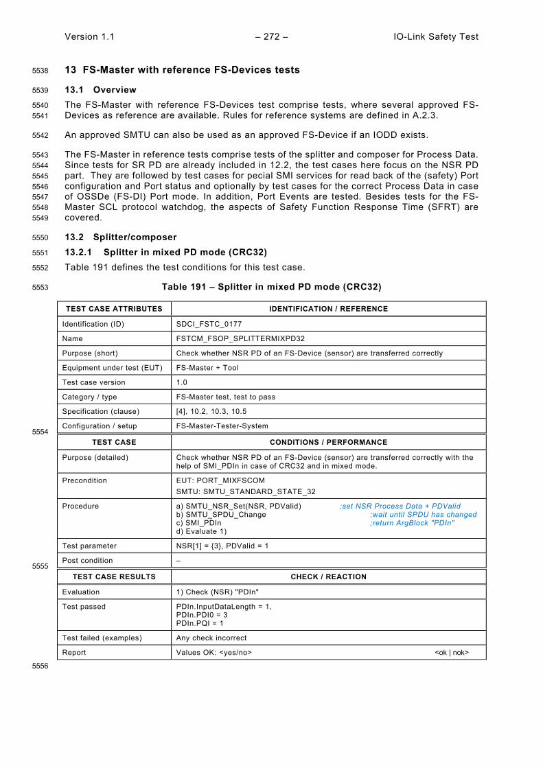
Version 1.1 – 272 – IO-Link Safety Test
13 FS-Master with reference FS-Devices tests 5538
13.1 Overview 5539
The FS-Master with reference FS-Devices test comprise tests, where several approved FS-5540 Devices as reference are available. Rules for reference systems are defined in A.2.3. 5541
An approved SMTU can also be used as an approved FS-Device if an IODD exists. 5542
The FS-Master in reference tests comprise tests of the splitter and composer for Process Data. 5543 Since tests for SR PD are already included in 12.2, the test cases here focus on the NSR PD 5544 part. They are followed by test cases for pecial SMI services for read back of the (safety) Port 5545 configuration and Port status and optionally by test cases for the correct Process Data in case 5546 of OSSDe (FS-DI) Port mode. In addition, Port Events are tested. Besides tests for the FS-5547 Master SCL protocol watchdog, the aspects of Safety Function Response Time (SFRT) are 5548 covered. 5549
13.2 Splitter/composer 5550
13.2.1 Splitter in mixed PD mode (CRC32) 5551
Table 191 defines the test conditions for this test case. 5552
Table 191 – Splitter in mixed PD mode (CRC32) 5553
TEST CASE ATTRIBUTES IDENTIFICATION / REFERENCE
Identification (ID) SDCI_FSTC_0177
Name FSTCM_FSOP_SPLITTERMIXPD32
Purpose (short) Check whether NSR PD of an FS-Device (sensor) are transferred correctly
Equipment under test (EUT) FS-Master + Tool
Test case version 1.0
Category / type FS-Master test, test to pass
Specification (clause) [4], 10.2, 10.3, 10.5
Configuration / setup FS-Master-Tester-System 5554
TEST CASE CONDITIONS / PERFORMANCE
Purpose (detailed) Check whether NSR PD of an FS-Device (sensor) are transferred correctly with the help of SMI_PDIn in case of CRC32 and in mixed mode.
Precondition EUT: PORT_MIXFSCOM SMTU: SMTU_STANDARD_STATE_32
Procedure a) SMTU_NSR_Set(NSR, PDValid) ;set NSR Process Data + PDValid b) SMTU_SPDU_Change ;wait until SPDU has changed c) SMI_PDIn ;return ArgBlock "PDIn" d) Evaluate 1)
Test parameter NSR[1] = {3}, PDValid = 1
Post condition – 5555
TEST CASE RESULTS CHECK / REACTION
Evaluation 1) Check (NSR) "PDIn"
Test passed PDIn.InputDataLength = 1, PDIn.PDI0 = 3 PDIn.PQI = 1
Test failed (examples) Any check incorrect
Report Values OK: <yes/no> <ok | nok>
5556

IO-Link Safety Test – 273 – Version 1.1
13.2.2 Splitter in mixed PD mode (CRC16) 5557
Table 192 defines the test conditions for this test case. 5558
Table 192 – Splitter in mixed PD mode (CRC16) 5559
TEST CASE ATTRIBUTES IDENTIFICATION / REFERENCE
Identification (ID) SDCI_FSTC_0179
Name FSTCM_FSOP_SPLITTERMIXPD16
Purpose (short) Check whether NSR PD of an FS-Device (sensor) are transferred correctly
Equipment under test (EUT) FS-Master + Tool
Test case version 1.0
Category / type FS-Master test, test to pass
Specification (clause) [4], 10.2, 10.3, 10.5
Configuration / setup FS-Master-Tester-System 5560
TEST CASE CONDITIONS / PERFORMANCE
Purpose (detailed) Check whether NSR PD of an FS-Device (sensor) are transferred correctly with the help of SMI_PDIn in case of CRC16
Precondition EUT: PORT_MIXFSCOM SMTU: SMTU_STANDARD_STATE_16
Procedure a) SMTU_NSR_Set(NSR, PDValid) ;set NSR Process Data + PDValid b) SMTU_SPDU_Change ;wait until SPDU has changed c) SMI_PDIn ;return ArgBlock "PDIn" d) Evaluate 1)
Test parameter NSR[4] = {3, 6, 9, 12}, PDValid = 1
Post condition – 5561
TEST CASE RESULTS CHECK / REACTION
Evaluation 1) Check (NSR) "PDin"
Test passed PDIn.InputDataLength = 4, PDIn.PDIi [i = 0, …, 3] = {3, 6, 9, 12}, PDIn.PQI = 1
Test failed (examples) Any check incorrect
Report Values OK: <yes/no> <ok | nok>
5562
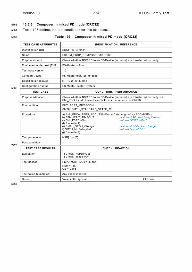
Version 1.1 – 274 – IO-Link Safety Test
13.2.3 Composer in mixed PD mode (CRC32) 5563
Table 193 defines the test conditions for this test case. 5564
Table 193 – Composer in mixed PD mode (CRC32) 5565
TEST CASE ATTRIBUTES IDENTIFICATION / REFERENCE
Identification (ID) SDCI_FSTC_0181
Name FSTCM_FSOP_COMPOSERMIXPD32
Purpose (short) Check whether NSR PD to an FS-Device (actuator) are transferred correctly
Equipment under test (EUT) FS-Master + Tool
Test case version 1.0
Category / type FS-Master test, test to pass
Specification (clause) [4], 10.2, 10.3, 10.5
Configuration / setup FS-Master-Tester-System 5566
TEST CASE CONDITIONS / PERFORMANCE
Purpose (detailed) Check whether NSR PD to an FS-Device (actuator) are transferred correctly via SMI_PDOut and checked via SMTU instruction case of CRC32.
Precondition EUT: PORT_MIXFSCOM SMTU: SMTU_STANDARD_STATE_32
Procedure a) SMI_PDOut(ABPS_PDOUT32<OutputDataLength=1>,<PDO=NSR>) b) STM_WAIT_TIMEOUT ;wait for FSP_Watchdog timeout c) SMI_FSPDInOut ;returns "FSPDInOut" d) Evaluate 1) e) SMTU_SPDU_Change ;wait until SPDU has changed f) SMTU_MixData_Get ;returns "mixed PD" g) Evaluate 2)
Test parameter NSR[1] = {3}
Post condition – 5567
TEST CASE RESULTS CHECK / REACTION
Evaluation 1) Check "FSPDInOut" 1) Check "mixed PD"
Test passed FSPDInOut.PDO0 = 3, and NSR = {3}, OE = Valid
Test failed (examples) Any check incorrect
Report Values OK: <yes/no> <ok | nok>
5568
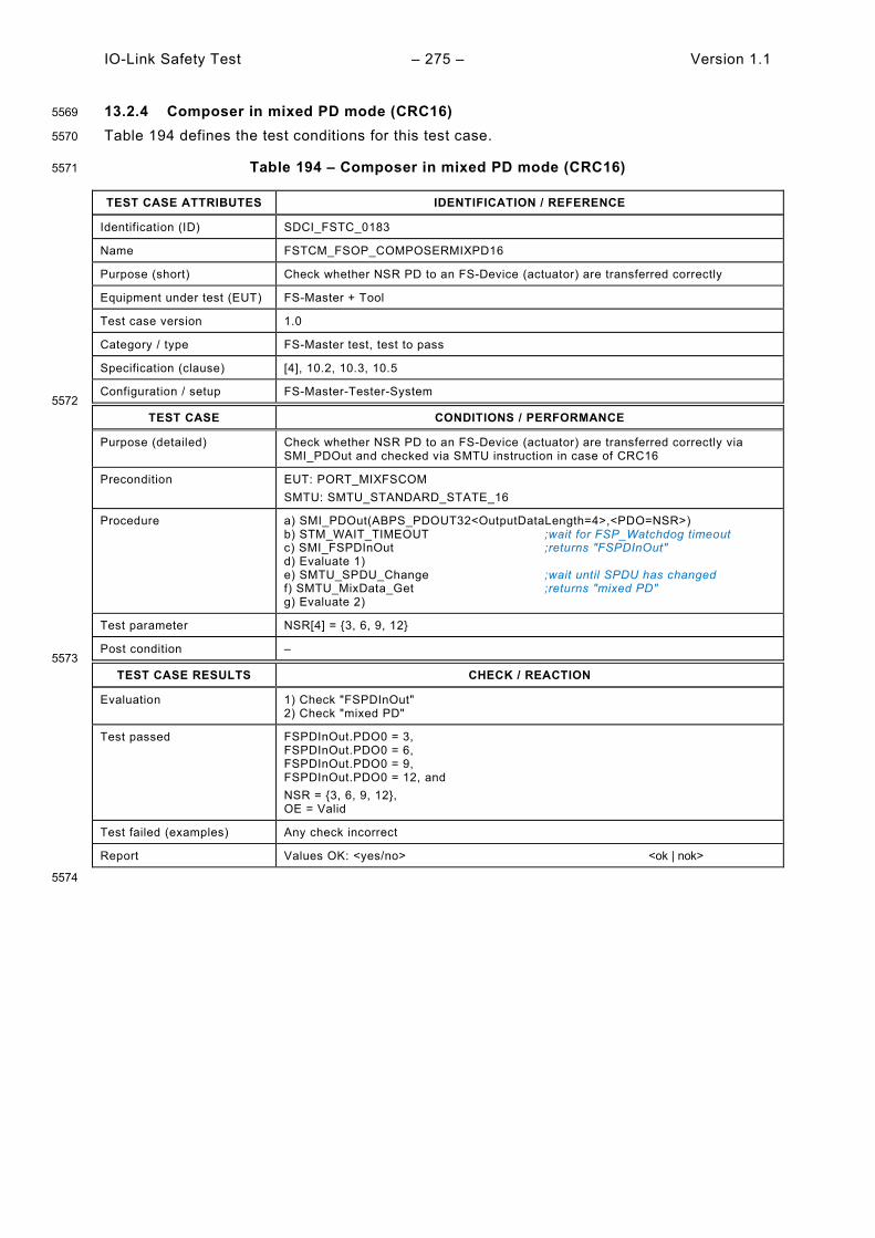
IO-Link Safety Test – 275 – Version 1.1
13.2.4 Composer in mixed PD mode (CRC16) 5569
Table 194 defines the test conditions for this test case. 5570
Table 194 – Composer in mixed PD mode (CRC16) 5571
TEST CASE ATTRIBUTES IDENTIFICATION / REFERENCE
Identification (ID) SDCI_FSTC_0183
Name FSTCM_FSOP_COMPOSERMIXPD16
Purpose (short) Check whether NSR PD to an FS-Device (actuator) are transferred correctly
Equipment under test (EUT) FS-Master + Tool
Test case version 1.0
Category / type FS-Master test, test to pass
Specification (clause) [4], 10.2, 10.3, 10.5
Configuration / setup FS-Master-Tester-System 5572
TEST CASE CONDITIONS / PERFORMANCE
Purpose (detailed) Check whether NSR PD to an FS-Device (actuator) are transferred correctly via SMI_PDOut and checked via SMTU instruction in case of CRC16
Precondition EUT: PORT_MIXFSCOM SMTU: SMTU_STANDARD_STATE_16
Procedure a) SMI_PDOut(ABPS_PDOUT32<OutputDataLength=4>,<PDO=NSR>) b) STM_WAIT_TIMEOUT ;wait for FSP_Watchdog timeout c) SMI_FSPDInOut ;returns "FSPDInOut" d) Evaluate 1) e) SMTU_SPDU_Change ;wait until SPDU has changed f) SMTU_MixData_Get ;returns "mixed PD" g) Evaluate 2)
Test parameter NSR[4] = {3, 6, 9, 12}
Post condition – 5573
TEST CASE RESULTS CHECK / REACTION
Evaluation 1) Check "FSPDInOut" 2) Check "mixed PD"
Test passed FSPDInOut.PDO0 = 3, FSPDInOut.PDO0 = 6, FSPDInOut.PDO0 = 9, FSPDInOut.PDO0 = 12, and NSR = {3, 6, 9, 12}, OE = Valid
Test failed (examples) Any check incorrect
Report Values OK: <yes/no> <ok | nok>
5574
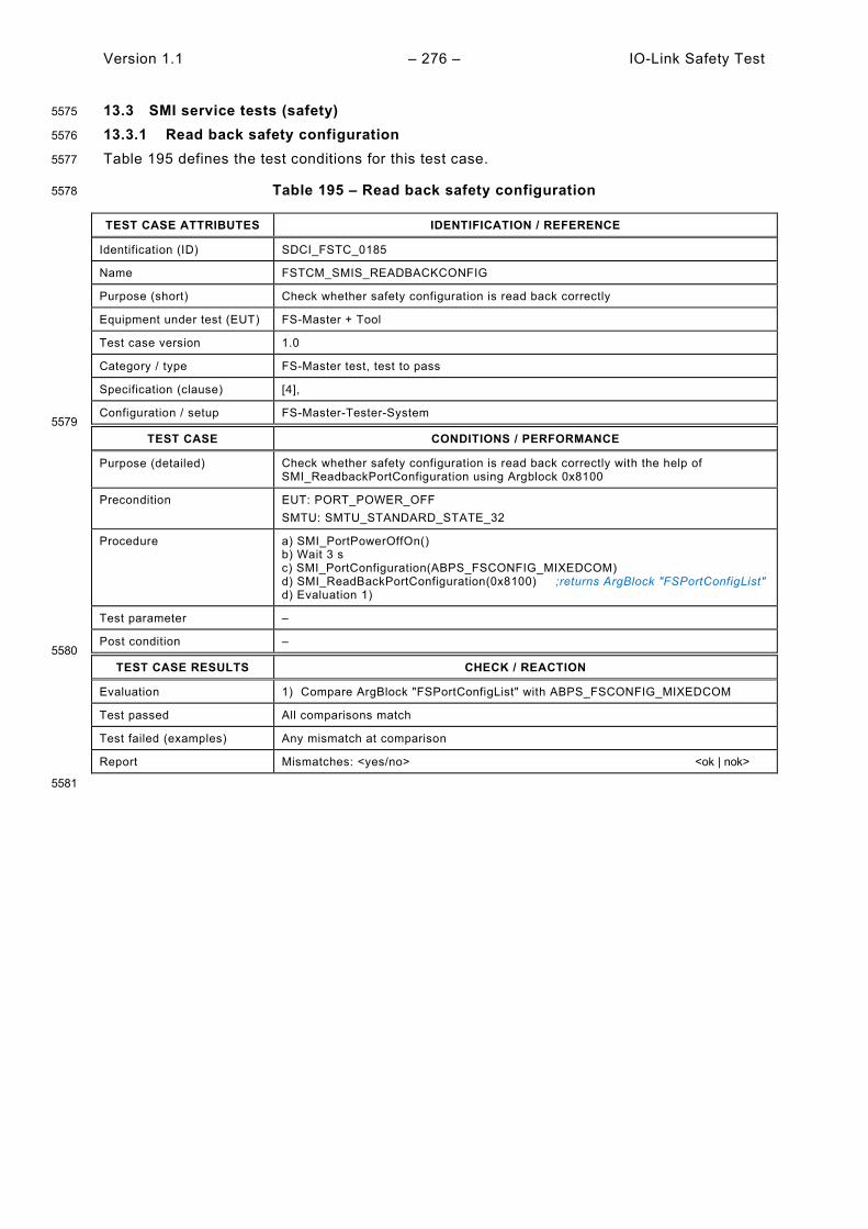
Version 1.1 – 276 – IO-Link Safety Test
13.3 SMI service tests (safety) 5575
13.3.1 Read back safety configuration 5576
Table 195 defines the test conditions for this test case. 5577
Table 195 – Read back safety configuration 5578
TEST CASE ATTRIBUTES IDENTIFICATION / REFERENCE
Identification (ID) SDCI_FSTC_0185
Name FSTCM_SMIS_READBACKCONFIG
Purpose (short) Check whether safety configuration is read back correctly
Equipment under test (EUT) FS-Master + Tool
Test case version 1.0
Category / type FS-Master test, test to pass
Specification (clause) [4],
Configuration / setup FS-Master-Tester-System 5579
TEST CASE CONDITIONS / PERFORMANCE
Purpose (detailed) Check whether safety configuration is read back correctly with the help of SMI_ReadbackPortConfiguration using Argblock 0x8100
Precondition EUT: PORT_POWER_OFF SMTU: SMTU_STANDARD_STATE_32
Procedure a) SMI_PortPowerOffOn() b) Wait 3 s c) SMI_PortConfiguration(ABPS_FSCONFIG_MIXEDCOM) d) SMI_ReadBackPortConfiguration(0x8100) ;returns ArgBlock "FSPortConfigList" d) Evaluation 1)
Test parameter –
Post condition – 5580
TEST CASE RESULTS CHECK / REACTION
Evaluation 1) Compare ArgBlock "FSPortConfigList" with ABPS_FSCONFIG_MIXEDCOM
Test passed All comparisons match
Test failed (examples) Any mismatch at comparison
Report Mismatches: <yes/no> <ok | nok>
5581

IO-Link Safety Test – 277 – Version 1.1
13.3.2 Safety Port status 5582
Table 196 defines the test conditions for this test case. 5583
Table 196 – Safety Port status 5584
TEST CASE ATTRIBUTES IDENTIFICATION / REFERENCE
Identification (ID) SDCI_FSTC_0186
Name FSTCM_SMIS_FSPORTSTATUS
Purpose (short) Check whether Port status is read back correctly
Equipment under test (EUT) FS-Master + Tool
Test case version 1.0
Category / type FS-Master test, test to pass
Specification (clause) [4],
Configuration / setup FS-Master-Tester-System 5585
TEST CASE CONDITIONS / PERFORMANCE
Purpose (detailed) Check whether the safety Port status can be read out using the SMI_PortStatus service and Argblock 0x9100.
Precondition EUT: PORT_MIXFSCOM SMTU: SMTU_STANDARD_STATE_32
Procedure a) SMI_PortStatus(0x9100) ;returns ArgBlock "FSPortStatusList" b) Evaluation 1)
Test parameter –
Post condition – 5586
TEST CASE RESULTS CHECK / REACTION
Evaluation 1) Compare ArgBlock "FSPortStatusList" with assignments in "PORT_MIXFSCOM"
Test passed PortStatusInfo = SCL_ENABLED PortQualityInfo.Bit0/1 = 0 ;all PD valid RevisionID = 0x11 TransmissionRate = COM2 MasterCycleTime = 0x28 ;4 ms InputDataLength = 0x20 ;PDInLength = 32 octets OutputDataLength = 0x20 ;PDOutLength = 32 octets VendorID = 0xFDE8 ;IO-Link Community DeviceID = 0x002BD2 ;Tester NumberofDiags = 0 DiagEntry0 = 0 DiagEntry1 = 0
Test failed (examples) Any check deviating
Report Values OK: <yes/no> <ok | nok>
5587
13.4 Port with FS-DI/OSSDe (optional) 5588
Testing of this functionality is covered by SDCI_FSTC_0008 in 5.4.1. 5589
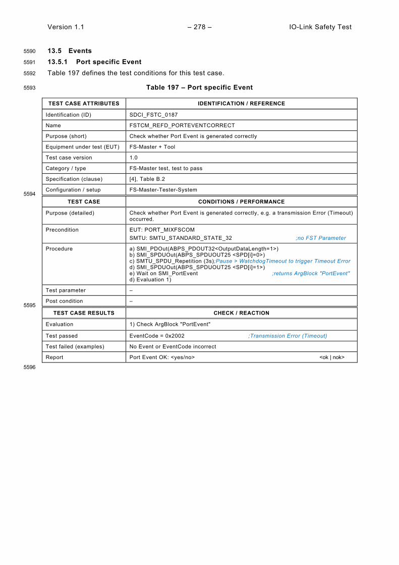
Version 1.1 – 278 – IO-Link Safety Test
13.5 Events 5590
13.5.1 Port specific Event 5591
Table 197 defines the test conditions for this test case. 5592
Table 197 – Port specific Event 5593
TEST CASE ATTRIBUTES IDENTIFICATION / REFERENCE
Identification (ID) SDCI_FSTC_0187
Name FSTCM_REFD_PORTEVENTCORRECT
Purpose (short) Check whether Port Event is generated correctly
Equipment under test (EUT) FS-Master + Tool
Test case version 1.0
Category / type FS-Master test, test to pass
Specification (clause) [4], Table B.2
Configuration / setup FS-Master-Tester-System 5594
TEST CASE CONDITIONS / PERFORMANCE
Purpose (detailed) Check whether Port Event is generated correctly, e.g. a transmission Error (Timeout) occurred.
Precondition EUT: PORT_MIXFSCOM SMTU: SMTU_STANDARD_STATE_32 ;no FST Parameter
Procedure a) SMI_PDOut(ABPS_PDOUT32<OutputDataLength=1>) b) SMI_SPDUOut(ABPS_SPDUOUT25 <SPD[i]=0>) c) SMTU_SPDU_Repetition (3s);Pause > WatchdogTimeout to trigger Timeout Error d) SMI_SPDUOut(ABPS_SPDUOUT25 <SPD[i]=1>) e) Wait on SMI_PortEvent ;returns ArgBlock "PortEvent" d) Evaluation 1)
Test parameter –
Post condition – 5595
TEST CASE RESULTS CHECK / REACTION
Evaluation 1) Check ArgBlock "PortEvent"
Test passed EventCode = 0x2002 ;Transmission Error (Timeout)
Test failed (examples) No Event or EventCode incorrect
Report Port Event OK: <yes/no> <ok | nok>
5596

IO-Link Safety Test – 279 – Version 1.1
13.5.2 FS-Device Event 5597
Table 198 defines the test conditions for this test case. 5598
Table 198 – FS-Device Event 5599
TEST CASE ATTRIBUTES IDENTIFICATION / REFERENCE
Identification (ID) SDCI_FSTC_0188
Name FSTCM_REFD_FSDEVICEEVENTCORRECT
Purpose (short) Check whether FS-Device Event is propagated correctly
Equipment under test (EUT) FS-Master + Tool
Test case version 1.0
Category / type FS-Master test, test to pass
Specification (clause) [4],
Configuration / setup FS-Master-Tester-System 5600
TEST CASE CONDITIONS / PERFORMANCE
Purpose (detailed) Check whether FS-Device Event is propagated correctly, e.g. unexpected authentication code (0xB003)
Precondition EUT: PORT_MIXFSCOM SMTU: SMTU_STANDARD_STATE_32 ;no FST Parameter
Procedure a) SMI_PortConfig (ABPS_FSCONFIG_SAFECOM<FSCP_Authenticity1=2>) b) Wait(1s) c) Wait on SMI_DeviceEvent ;returns ArgBlock "DeviceEvent" d) Evaluation 1)
Test parameter –
Post condition – 5601
TEST CASE RESULTS CHECK / REACTION
Evaluation 1) Check ArgBlock "DeviceEvent"
Test passed EventCode = 0xB003 ;Unexpected authentication code
Test failed (examples) No Event or EventCode incorrect
Report FS-Device Event OK: <yes/no> <ok | nok>
5602
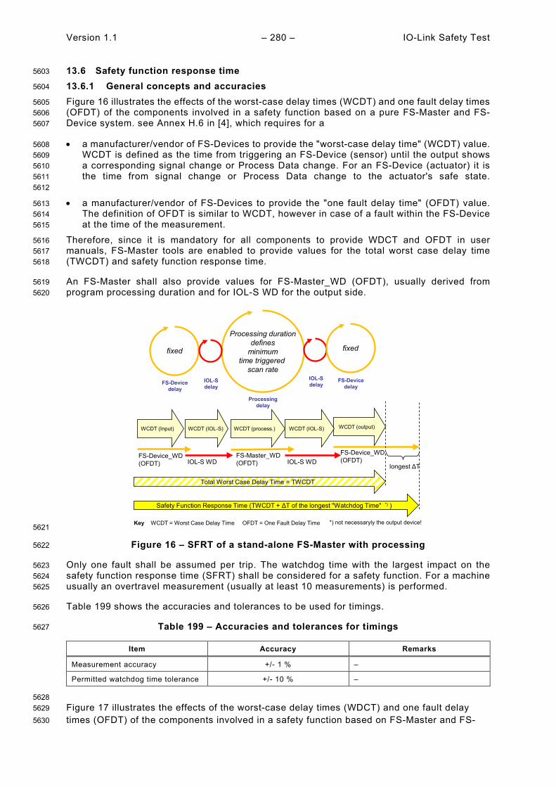
Version 1.1 – 280 – IO-Link Safety Test
13.6 Safety function response time 5603
13.6.1 General concepts and accuracies 5604
Figure 16 illustrates the effects of the worst-case delay times (WCDT) and one fault delay times 5605 (OFDT) of the components involved in a safety function based on a pure FS-Master and FS-5606 Device system. see Annex H.6 in [4], which requires for a 5607
• a manufacturer/vendor of FS-Devices to provide the "worst-case delay time" (WCDT) value. 5608 WCDT is defined as the time from triggering an FS-Device (sensor) until the output shows 5609 a corresponding signal change or Process Data change. For an FS-Device (actuator) it is 5610 the time from signal change or Process Data change to the actuator's safe state. 5611 5612
• a manufacturer/vendor of FS-Devices to provide the "one fault delay time" (OFDT) value. 5613 The definition of OFDT is similar to WCDT, however in case of a fault within the FS-Device 5614 at the time of the measurement. 5615
Therefore, since it is mandatory for all components to provide WDCT and OFDT in user 5616 manuals, FS-Master tools are enabled to provide values for the total worst case delay time 5617 (TWCDT) and safety function response time. 5618
An FS-Master shall also provide values for FS-Master_WD (OFDT), usually derived from 5619 program processing duration and for IOL-S WD for the output side. 5620
5621
Figure 16 – SFRT of a stand-alone FS-Master with processing 5622
Only one fault shall be assumed per trip. The watchdog time with the largest impact on the 5623 safety function response time (SFRT) shall be considered for a safety function. For a machine 5624 usually an overtravel measurement (usually at least 10 measurements) is performed. 5625
Table 199 shows the accuracies and tolerances to be used for timings. 5626
Table 199 – Accuracies and tolerances for timings 5627
Item Accuracy Remarks
Measurement accuracy +/- 1 % –
Permitted watchdog time tolerance +/- 10 % –
5628 Figure 17 illustrates the effects of the worst-case delay times (WDCT) and one fault delay 5629 times (OFDT) of the components involved in a safety function based on FS-Master and FS-5630
fixed
Processing durationdefines
minimumtime triggered
scan rate
fixed
FS-Devicedelay
IOL-Sdelay
Processingdelay
IOL-Sdelay
FS-Devicedelay
WCDT (IOL-S) WCDT (output)
IOL-S WD IOL-S WD
Total Worst Case Delay Time = TWCDT
WCDT (process.)
Safety Function Response Time (TWCDT + ΔT of the longest "Watchdog Time" *) )
WCDT (Input) WCDT (IOL-S)
FS-Device_WD(OFDT)
FS-Master_WD(OFDT)
FS-Device_WD(OFDT)
*) not necessaryly the output device!
longest ΔT
Key WCDT = Worst Case Delay Time OFDT = One Fault Delay Time

IO-Link Safety Test – 281 – Version 1.1
Devices integrated in a fieldbus functional safety communication profile (FSCP), see for 5631 example [11]. 5632
5633
Figure 17 – SFRT including IOL-S and FSCP 5634
Figure 18 illustrates, how the watchdog timer of an FS-Master is tested. The Safety Master 5635 Tester Unit (SMTU), playing the role of an FS-Devices, is controlled in such a way that the 5636 response SPDU ("DCount_i = 3") is delayed through artificial repetitions. For details see 5637 13.6.2. 5638
5639
Figure 18 – Test of the FS-Master watchdog 5640
The actual watchdog response time cannot be measured with IO-Link on-board equipment. 5641 This shall be measured by the manufacturer using development tools or determined via 5642 software analysis (safety assessment, see 8.3.3). 5643
fixed
Processing durationdefines
minimumtime triggered
scan rate
fixed
FS-Masterdelay
Busdelay
Processingdelay
Busdelay
FS-Masterdelay
WCDT(Bus)
BusWD
BusWD
Total Worst Case Delay Time = TWCDT
WCDT(F-Host)
Safety Function Response Time (TWCDT + ΔT of the longest "Watchdog Time" *) )
WCDT(FS-Master)
WCDT(Bus)
FS-MasterWD
F-HostWD
FS-Device WD longest ΔT
IOL-Sdelay
fixed
FS-Devicedelay
fixed
IOL-Sdelay
FS-Devicedelay
WCDT(IOL-S)
IOL-SWD
WCDT(Input)
FS-DeviceWD IOL-S
WD
WCDT(FS-Master
WCDT(IOL-S)
FS-MasterWD
WCDT(Output)
OFDT(Output)
*) not necessaryly the output device!Key WCDT = Worst Case Delay Time OFDT = One Fault Delay Time
SMTU (FS-Device) FS-Master
Watchdogtime (min)
WatchdogTime (min)
Receiver AckTime
Assignedparametervalue
Sender AckTime
Assignedparametervalue
Artificialrepetitions
Sender AckTime
Watchdogexpired
SCL CycleTime
SDCI MasterCycleTime

Version 1.1 – 282 – IO-Link Safety Test
13.6.2 FS-Master watchdog test 5644
Table 200 defines the test conditions for this test case. 5645
Table 200 – FS-Master watchdog test 5646
TEST CASE ATTRIBUTES IDENTIFICATION / REFERENCE
Identification (ID) SDCI_FSTC_0189
Name FSTCM_SCLM_WATCHDOGPRECISION
Purpose (short) Check whether FS-Master watchdog timeout coincides with IODD value
Equipment under test (EUT) FS-Master
Test case version 1.0
Category / type FS-Master test, test to pass
Specification (clause) [4],
Configuration / setup FS-Master-Tester-Unit (SMTU) 5647
TEST CASE CONDITIONS / PERFORMANCE
Purpose (detailed) Check whether FS-Master's safety reaction time upon watchdog timeout coincides with the FSP_Watchdog value in the IODD.
Precondition EUT: Port config DEACTIVATED; Transmission rate = COM2 SMTU: Configured for armed operation ;see field test parameter
Procedure a) Choose test parameter with first FSP_Watchdog value ;see field test parameter b) Set PortConfig with FSP_VerifyRecord with values of A) and B) e.g. via SMI_PortConfiguration using ArgBlock 0x8100 ;see field test parameter c) SMTU_Measure_WDtime ;returns "WD_time" f) Evaluation 1) g) Repeat from c) 3 times g) Choose test parameter with next FSP_Watchdog value h) Repeat from b)
Test parameter A) FSP protocol parameter record: FSP_ProtVersion = defaultValue in IODD, FSP_ProtMode = defaultValue in IODD, FSP_Watchdog = {50 ms, 100 ms}, FSP_IOStructCRC = defaultValue in IODD, FSP_TechParCRC = valid CRC signature ;responsibility of tester FSP_ProtParCRC = valid CRC signature ;responsibility of tester B) FSP authenticity parameter record: FSCP_Authenticity_1 = 1, FSCP_Authenticity_2 = 2, FSP_Port = 1, FSP_AuthentCRC = 11456
Post condition – 5648
TEST CASE RESULTS CHECK / REACTION
Evaluation 1) Check "WD_time", memorize maximum WD_time and minimum WD_time
Test passed Deviation of maximum/minimum WD_time less than 10 % @ 50 ms, and Deviation of maximum/minimum WD_time less than 10 % @ 100 ms
Test failed (examples) Any check incorrect
Report WD_time (min) @ 50 ms: <value> <ok | nok> WD_time(max) @ 50 ms: <value> <ok | nok> WD_time (min) @ 100 ms: <value> <ok | nok> WD_time (max) @ 100 ms: <value> <ok | nok>
5649
5650
5651
IO-Link Safety Test – 283 – Version 1.1
13.6.3 Integration aspects 5652
In 13.6.1, the general concepts are explained also for a more complex FS-Master integrated in 5653 a fieldbus's functional safety communication profile (FSCP) according to the IEC 61784-3 5654 series. In this case, usually the FS-Master plays only the role of a mapper of Process Data from 5655 one safety communication system to the other. 5656
The designer/manufacturer of such a mapping FS-Master/Gateway shall provide WCDT and 5657 OFDT for the mapping part to enable computer-aided approximation of a safety function 5658 response time. Integration specifications to FSCPs should comprise definitions and descriptions 5659 how to achieve these values. 5660
5661

Version 1.1 – 284 – IO-Link Safety Test
14 FS-Master Tool tests 5662
14.1 IODD import 5663
Table 201 defines the test conditions for this test case. 5664
Table 201 – IODD import 5665
TEST CASE ATTRIBUTES IDENTIFICATION / REFERENCE
Identification (ID) SDCI_FSTC_0190
Name FSTCM_TOOL_IODDIMPORT
Purpose (short) IODD of the SMTU can be imported into FS-Master Tool
Equipment under test (EUT) FS-Master + Tool
Test case version 1.0
Category / type FS-Master Tool test, test to pass
Specification (clause) [4],
Configuration / setup EUT + IODD of SMTU (or any FS-Device) 5666
TEST CASE CONDITIONS / PERFORMANCE
Purpose (detailed) Check whether IODD of the SMTU can be imported into FS-Master Tool and FSP_ParamDescCRC is correct
Precondition –
Procedure a) Import IODD b) Evaluation 1) c) Evaluation 2)
Test parameter IODD of SMTU
Post condition – 5667
TEST CASE RESULTS CHECK / REACTION
Evaluation 1) Check import status (CRC signature, Display) 2) Check FSP_ParamDescCRC
Test passed All checks correct
Test failed (examples) Any check incorrect
Report Values OK: <yes/no> <ok | nok>
5668

IO-Link Safety Test – 285 – Version 1.1
14.2 IODD conventions (PD headlines coloring) 5669
Table 202 defines the test conditions for this test case. 5670
Table 202 – IODD conventions (PD headlines coloring) 5671
TEST CASE ATTRIBUTES IDENTIFICATION / REFERENCE
Identification (ID) SDCI_FSTC_0191
Name FSTCM_TOOL_IODDCONVENTIONS
Purpose (short) IODD of the SMTU is displayed according to IODD rules
Equipment under test (EUT) FS-Master + Tool
Test case version 1.0
Category / type FS-Master Tool test, test to pass
Specification (clause) [4],
Configuration / setup EUT + IODD of SMTU 5672
TEST CASE CONDITIONS / PERFORMANCE
Purpose (detailed) Check whether IODD of the SMTU is displayed according to IODD rules, e.g. headers of Process Data and FS parameters in yellow color
Precondition –
Procedure a) Import and open IODD of the SMTU b) Evaluation 1)
Test parameter FS parameter in user manual
Post condition – 5673
TEST CASE RESULTS CHECK / REACTION
Evaluation 1) Check display
Test passed Headers of Process Data and FS parameters in yellow color according to IODD rules
Test failed (examples) Display not according to IODD rules
Report Values OK: <yes/no> <ok | nok>
5674

Version 1.1 – 286 – IO-Link Safety Test
14.3 FS parameters visible completely 5675
Table 203 defines the test conditions for this test case. 5676
Table 203 – FS parameters visible completely 5677
TEST CASE ATTRIBUTES IDENTIFICATION / REFERENCE
Identification (ID) SDCI_FSTC_0192
Name FSTCM_TOOL_IODDDISPLAYCOMPLETE
Purpose (short) IODD FS parameter of the SMTU are displayed completely and appropriately
Equipment under test (EUT) FS-Master + Tool
Test case version 1.0
Category / type FS-Master Tool test, test to pass
Specification (clause) [4],
Configuration / setup EUT + IODD of SMTU (or any FS-Device) + user manual 5678
TEST CASE CONDITIONS / PERFORMANCE
Purpose (detailed) IODD FS parameter of the SMTU are displayed completely and appropriately
Precondition –
Procedure a) Import and open IODD of the SMTU b) Display all FSP parameters c) Evaluation 1) d) Display all FST parameters e) Evaluation 2)
Test parameter FS parameter in user manual
Post condition – 5679
TEST CASE RESULTS CHECK / REACTION
Evaluation 1) Compare all FSP parameters with user manual 2) Compare all FST parameters with user manual
Test passed All comparisons correct or tolerable (no misunderstandings)
Test failed (examples) Any comparison incorrect
Report Comparisons OK: <yes/no> <ok | nok>
5680
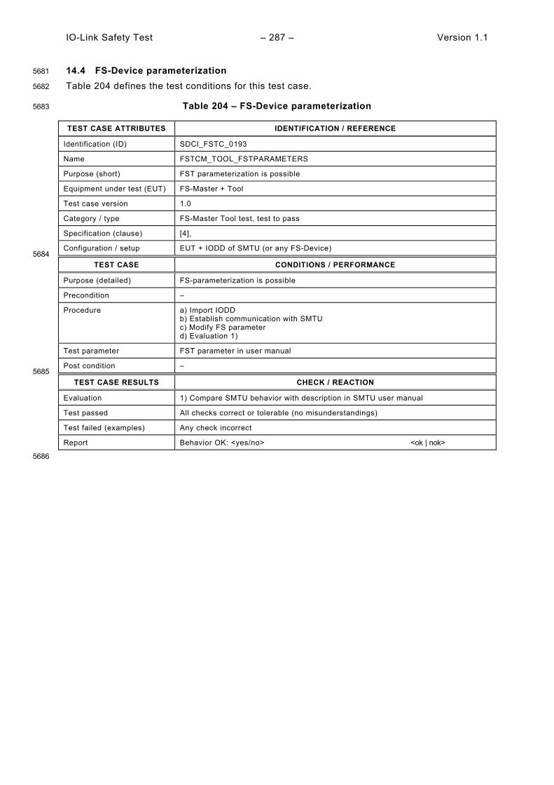
IO-Link Safety Test – 287 – Version 1.1
14.4 FS-Device parameterization 5681
Table 204 defines the test conditions for this test case. 5682
Table 204 – FS-Device parameterization 5683
TEST CASE ATTRIBUTES IDENTIFICATION / REFERENCE
Identification (ID) SDCI_FSTC_0193
Name FSTCM_TOOL_FSTPARAMETERS
Purpose (short) FST parameterization is possible
Equipment under test (EUT) FS-Master + Tool
Test case version 1.0
Category / type FS-Master Tool test, test to pass
Specification (clause) [4],
Configuration / setup EUT + IODD of SMTU (or any FS-Device) 5684
TEST CASE CONDITIONS / PERFORMANCE
Purpose (detailed) FS-parameterization is possible
Precondition –
Procedure a) Import IODD b) Establish communication with SMTU c) Modify FS parameter d) Evaluation 1)
Test parameter FST parameter in user manual
Post condition – 5685
TEST CASE RESULTS CHECK / REACTION
Evaluation 1) Compare SMTU behavior with description in SMTU user manual
Test passed All checks correct or tolerable (no misunderstandings)
Test failed (examples) Any check incorrect
Report Behavior OK: <yes/no> <ok | nok>
5686

Version 1.1 – 288 – IO-Link Safety Test
14.5 Dedicated Tool operation 5687
Table 205 defines the test conditions for this test case. 5688
Table 205 – Dedicated Tool operation 5689
TEST CASE ATTRIBUTES IDENTIFICATION / REFERENCE
Identification (ID) SDCI_FSTC_0194
Name FSTCM_TOOL_COMMDEDITOOL
Purpose (short) Dedicated Tool of the SMTU can communicate with Master Tool
Equipment under test (EUT) FS-Master + Tool
Test case version 1.0
Category / type FS-Master test, test to pass
Specification (clause) [4],
Configuration / setup EUT + IODD of SMTU + Dedicated Tool from SMTU 5690
TEST CASE CONDITIONS / PERFORMANCE
Purpose (detailed) FS-Master Tool invokes Dedicated Tool and passes over FST parameter via TPF. Subsequently, calculation of TechParCRC upon parameter changes takes place. Parameter values and TechParCRC are returned to FS-Master Tool via TBF ("Back Channel"). After parameter changes in FS-Master Tool, an update of the parameter values in the Dedicated Tool shall not occur automatically but only upon invocation of the Dedicated Tool. Check whether Dedicated Tool of the SMTU can communicate with FS-Master Tool.
Precondition –
Procedure a) Launch/invoke Dedicated Tool b) Evaluation 1) c) Try changing parameter values in FS-Master Tool d) Evaluation 2) e) Close Dedicated Tool f) Evaluation 3) g) Modify FST parameter values in FS-Master Tool h) Relaunch Dedicated Tool i) Evaluation 4) j) Evaluation 5) k) Perform commissioning of SMTU l) Evaluation 6)
Test parameter –
Post condition – 5691
TEST CASE RESULTS CHECK / REACTION
Evaluation 1) Check availability of TechParCRC display (decimal value) in Dedicated Tool (memorize CRC value) 2) Editing of values in FS-Master Tool shall be blocked 3) Check identical TechParCRC display (decimal value) in FS-Master Tool (see 1)) 4) Compare parameter values in displays of Dedicated Tool and FS-Master Tool (parameter values shall match) 5) Compare FST_TechParCRC on FS-Master Tool with TechParCRC of Dedicated Tool (CRC values should differ due to parameter changes) 6) Check behavior of FS-Master system with connected SMTU
Test passed All checks correct
Test failed (examples) Any check incorrect
Report Values OK: <yes/no> <ok | nok>
5692
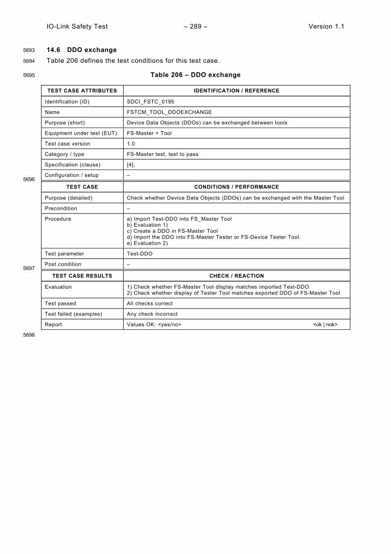
IO-Link Safety Test – 289 – Version 1.1
14.6 DDO exchange 5693
Table 206 defines the test conditions for this test case. 5694
Table 206 – DDO exchange 5695
TEST CASE ATTRIBUTES IDENTIFICATION / REFERENCE
Identification (ID) SDCI_FSTC_0195
Name FSTCM_TOOL_DDOEXCHANGE
Purpose (short) Device Data Objects (DDOs) can be exchanged between tools
Equipment under test (EUT) FS-Master + Tool
Test case version 1.0
Category / type FS-Master test, test to pass
Specification (clause) [4],
Configuration / setup – 5696
TEST CASE CONDITIONS / PERFORMANCE
Purpose (detailed) Check whether Device Data Objects (DDOs) can be exchanged with the Master Tool
Precondition –
Procedure a) Import Test-DDO into FS_Master Tool b) Evaluation 1) c) Create a DDO in FS-Master Tool d) Import the DDO into FS-Master Tester or FS-Device Tester Tool. e) Evaluation 2)
Test parameter Test-DDO
Post condition – 5697
TEST CASE RESULTS CHECK / REACTION
Evaluation 1) Check whether FS-Master Tool display matches imported Test-DDO 2) Check whether display of Tester Tool matches exported DDO of FS-Master Tool
Test passed All checks correct
Test failed (examples) Any check incorrect
Report Values OK: <yes/no> <ok | nok>
5698
Version 1.1 – 290 – IO-Link Safety Test
15 Environmental tests 5699
15.1 General 5700
Annex H in [2] defines the basic environmental tests (EMC) for the SDCI communication part 5701 of an FS-Master/FS-Device system. Clause 5.4.2 in [2] specifies environmental conditions (e.g. 5702 electrical safety) especially for FS-Master with Port Class B. 5703
It depends on the technology of an FS-Device and the countries of deployment, whether addi-5704 tional environmental tests are required to achieve for example a CE mark in Europe. 5705
15.2 Product specific standards 5706
Usually, the sector specific EMC standard IEC 61326-3-1 or the generic EMC standard 61000-5707 6-7 are relevant for FS-Master. 5708
For FS-Devices, there are several EMC standards, including but not limited to: 5709
• Product standard IEC 61496-1 (Electro-sensitive protective equipment) 5710
• Product standard IEC 60947-5-3 (Proximity switches) 5711
• Sector standard IEC 61326-3-1 (Factory automation) 5712
• Generic standard IEC 61000-6-7 (in case of no sector or product standard, such as in case 5713 of drives) 5714
The following rule applies: Product standards shall be observed if available, otherwise sector 5715 standard or then generic standard. 5716
15.3 EMC tests 5717
EMC tests in respect of a particular phenomenon are defined in the IEC 61000-4-x series. 5718 Details for the respective test set-ups are described in Annex H.1.6 in [2] and in 4.4 or 0. 5719
15.4 Test report templates 5720
Tests are required for the following phenomena: 5721
• Electrostatic discharge (ESD: IEC 61000-4-2) 5722
• Electromagnetic field (HF: IEC 61000-4-3) 5723
• Fast transients (Burst: IEC 61000-4-4) 5724
• Surge protection (Surge: IEC 61000-4-5): optional, depending on deployment 5725
• Conducted radio frequency (CRF: IEC 61000-4-6) 5726
5727
Usually, the test levels and durations exceed the values of NSR devices. A special performance 5728 criterion "DS" allows the devices to enter a Defined State at these extended "stress" tests, 5729 which is supposed to be safe in safety functions. 5730
A passed EMC test is a precondition for a Manufacturer Declaration of Conformity. It shall 5731 comprise statements on the results of the above EMC tests. The forms in [9] may be used if 5732 they contain the appropriate information. 5733

IO-Link Safety Test – 291 – Version 1.1
Annex A 5734
(normative) 5735
5736
Test configurations, principles, and tools 5737
5738
A.1 Measurement circuits / setups 5739
A.1.1 Measurement circuits for static FS-Master parameter tests 5740
Figure A.1 illustrates the measurement circuits for static FS-Master parameter tests in 5.2. 5741
5742
Figure A.1 – Measurement circuits for static FS-Master parameter tests 5743
A.1.2 Measurement circuits for static FS-Device parameter tests 5744
Figure A.2 illustrates the measurement circuits for static FS-Device parameter tests in 5.3. 5745 Method or can be applied. 5746
5747
Figure A.2 – Measurement circuits for static FS-Device parameter tests 5748
A.1.3 Measurement circuits for dynamic FS-Master parameter tests 5749
Figure A.3 illustrates the measurement circuits for dynamic FS-Master parameter tests in 5.4 5750
C/Q
L+
L-
I/Q Current meter
+−
Variable voltage
Current sink (load)
IO-Link
FS-Master (EUT)
variable PSM(PSMmin, PSMmax
e.g. 90 to 240 V AC,or 24 to 30 V DC)
Voltagemeter
24 V C/Q
L+
L-FS-Device (EUT)
I/Q
Currentsource
Voltagemeter
2 1
Voltagemeter
Currentsink
OSSD2

Version 1.1 – 292 – IO-Link Safety Test
5751
Figure A.3 – Measurement circuits for dynamic FS-Master parameter tests 5752
A.1.4 Measurement circuits for dynamic FS-Device parameter tests 5753
Figure A.4 illustrates the measurement circuits for dynamic FS-Device parameter tests in 5.5. 5754
5755
Figure A.4 – Measurement circuits for dynamic FS-Device parameter tests 5756
5757
A.2 Test tools 5758
A.2.1 Overview 5759
Seven tools have been identified supporting the performance of the test cases in this document: 5760
• "OSSD Signal Generator", see A.2.2 5761
• "Upper-Tester" (UT) for SCL protocol conformance testing, see A.2.3 5762
• "FS-Master tester system" including the "Safety Master Tester Unit" (SMTU), see A.2.4 5763
• "FS-Device tester" (FSDT), see A.2.5 5764
• "IODD Checker Tool", see A.2.6 5765
• Reference FS-Master/Tool and FS-Devices, see A.2.7 5766
• "EMC-Test tool" (optional) 5767
5768
Optional: Oscilloscope for recordings
C/Q
L+
L-
I/QIO-Link
FS-Master (EUT)
variable PSM(PSMmin, PSMmax
e.g. 90 to 240 V AC,or 24 to 30 V DC)
C/Q
L+
L-
OSSD-Signal-Generator
I/Q
OSSD1
OSSD2
Oscilloscope
24 V C/Q
L+
L-FS-Device (EUT)
I/Q
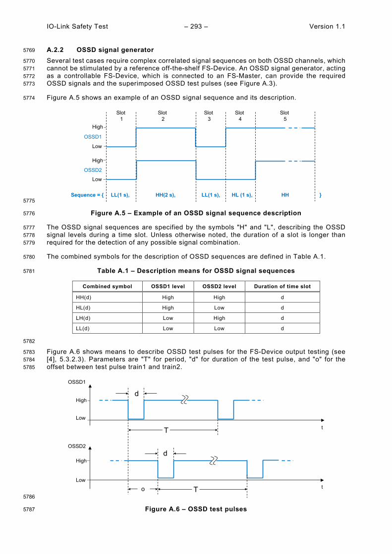
IO-Link Safety Test – 293 – Version 1.1
A.2.2 OSSD signal generator 5769
Several test cases require complex correlated signal sequences on both OSSD channels, which 5770 cannot be stimulated by a reference off-the-shelf FS-Device. An OSSD signal generator, acting 5771 as a controllable FS-Device, which is connected to an FS-Master, can provide the required 5772 OSSD signals and the superimposed OSSD test pulses (see Figure A.3). 5773
Figure A.5 shows an example of an OSSD signal sequence and its description. 5774
5775
Figure A.5 – Example of an OSSD signal sequence description 5776
The OSSD signal sequences are specified by the symbols "H" and "L", describing the OSSD 5777 signal levels during a time slot. Unless otherwise noted, the duration of a slot is longer than 5778 required for the detection of any possible signal combination. 5779
The combined symbols for the description of OSSD sequences are defined in Table A.1. 5780
Table A.1 – Description means for OSSD signal sequences 5781
Combined symbol OSSD1 level OSSD2 level Duration of time slot
HH(d) High High d
HL(d) High Low d
LH(d) Low High d
LL(d) Low Low d
5782
Figure A.6 shows means to describe OSSD test pulses for the FS-Device output testing (see 5783 [4], 5.3.2.3). Parameters are "T" for period, "d" for duration of the test pulse, and "o" for the 5784 offset between test pulse train1 and train2. 5785
5786
Figure A.6 – OSSD test pulses 5787
High
High
Low
Low
OSSD1
OSSD2
Slot 1
Slot 2
Slot 3
Slot 4
Slot 5
Sequence = { LL(1 s), HH(2 s), LL(1 s), HL (1 s), HH }
High
High
Low
Low
OSSD1
OSSD2
T
d
o
t
t
d
T
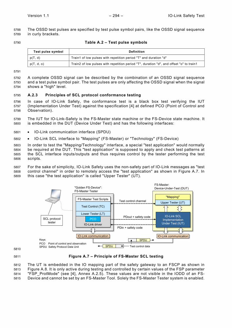
Version 1.1 – 294 – IO-Link Safety Test
The OSSD test pulses are specified by test pulse symbol pairs, like the OSSD signal sequence 5788 in curly brackets. 5789
Table A.2 – Test pulse symbols 5790
Test pulse symbol Definition
p(T, d) Train1 of low pulses with repetition period "T" and duration "d"
p(T, d, o) Train2 of low pulses with repetition period "T", duration "d", and offset "o" to train1
5791
A complete OSSD signal can be described by the combination of an OSSD signal sequence 5792 and a test pulse symbol pair. The test pulses are only affecting the OSSD signal when the signal 5793 shows a "high" level. 5794
A.2.3 Principles of SCL protocol conformance testing 5795
In case of IO-Link Safety, the conformance test is a black box test verifying the IUT 5796 (Implementation Under Test) against the specification [4] at defined PCO (Point of Control and 5797 Observation). 5798
The IUT for IO-Link-Safety is the FS-Master state machine or the FS-Device state machine. It 5799 is embedded in the DUT (Device Under Test) and has the following interfaces: 5800
• IO-Link communication interface (SPDU) 5801
• IO-Link SCL interface to "Mapping" (FS-Master) or "Technology" (FS-Device) 5802
In order to test the "Mapping/Technology" interface, a special "test application" would normally 5803 be required at the DUT. This "test application" is supposed to apply and check test patterns at 5804 the SCL interface inputs/outputs and thus requires control by the tester performing the test 5805 scripts. 5806
For the sake of simplicity, IO-Link Safety uses the non-safety part of IO-Link messages as "test 5807 control channel" in order to remotely access the "test application" as shown in Figure A.7. In 5808 this case "the test application" is called "Upper Tester" (UT). 5809
5810
Figure A.7 – Principle of FS-Master SCL testing 5811
The UT is embedded in the IO mapping part of the safety gateway to an FSCP as shown in 5812 Figure A.8. It is only active during testing and controlled by certain values of the FSP parameter 5813 "FSP_ProtMode" (see [4], Annex A.2.5). These values are not visible in the IODD of an FS-5814 Device and cannot be set by an FS-Master Tool. Solely the FS-Master Tester system is enabled. 5815
FS-Master Test Scripts
IO-Link communication
FS-Master:Device-Under-Test (DUT)
IO-Link communication
PDout + safety code
PDin + safety code
SCL protocoltester
"Mapping"
Upper Tester (UT)Test Control (TC)
Lower Tester (LT)
Test control channel
SPDU
SPDU
Test control data
IO-Link driver
PCO
Keys:PCO Point of control and observationSPDU Safety Protocol Data Unit
"Golden FS-Device":FS-Master Tester
IO-Link SCLImplementation
Under Test (IUT)
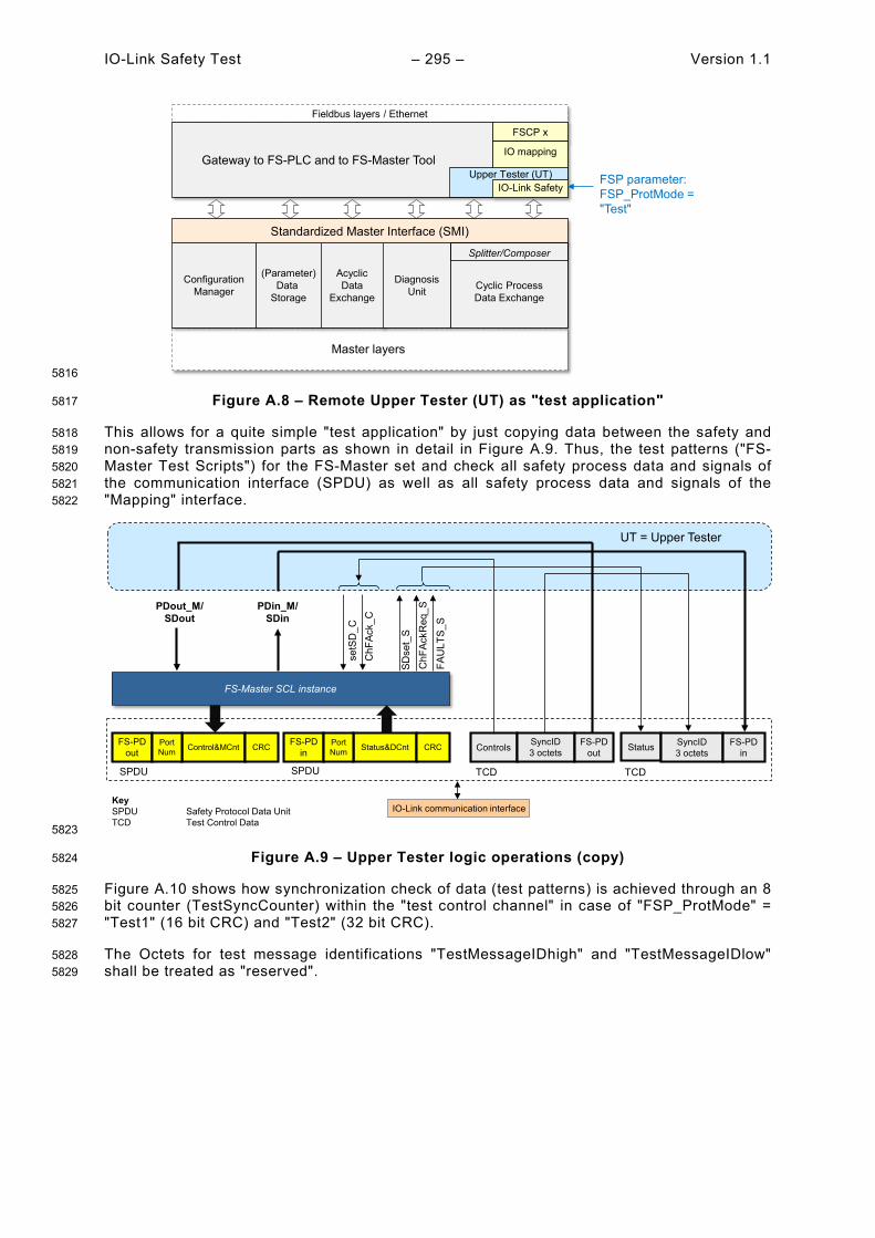
IO-Link Safety Test – 295 – Version 1.1
5816
Figure A.8 – Remote Upper Tester (UT) as "test application" 5817
This allows for a quite simple "test application" by just copying data between the safety and 5818 non-safety transmission parts as shown in detail in Figure A.9. Thus, the test patterns ("FS-5819 Master Test Scripts") for the FS-Master set and check all safety process data and signals of 5820 the communication interface (SPDU) as well as all safety process data and signals of the 5821 "Mapping" interface. 5822
5823
Figure A.9 – Upper Tester logic operations (copy) 5824
Figure A.10 shows how synchronization check of data (test patterns) is achieved through an 8 5825 bit counter (TestSyncCounter) within the "test control channel" in case of "FSP_ProtMode" = 5826 "Test1" (16 bit CRC) and "Test2" (32 bit CRC). 5827
The Octets for test message identifications "TestMessageIDhigh" and "TestMessageIDlow" 5828 shall be treated as "reserved". 5829
Fieldbus layers / Ethernet
Gateway to FS-PLC and to FS-Master Tool
FSCP x
Master layers
Standardized Master Interface (SMI)
ConfigurationManager
(Parameter)Data
Storage
AcyclicData
Exchange
DiagnosisUnit Cyclic Process
Data Exchange
Splitter/Composer
IO mapping
IO-Link SafetyFSP parameter: FSP_ProtMode = "Test"
Upper Tester (UT)
FS-Master SCL instance
PDout_M/SDout
PDin_M/SDin
setS
D_C
FS-PDout Control&MCnt CRC
ChF
AckR
eq_S
ChF
Ack_
C
IO-Link communication interface
SDse
t_S
FAU
LTS_
S
PortNum
FS-PDin Status&DCnt CRCPort
Num
SPDU SPDU
Controls SyncID3 octets
FS-PDout Status SyncID
3 octetsFS-PD
in
TCD TCD
UT = Upper Tester
KeySPDU Safety Protocol Data UnitTCD Test Control Data

Version 1.1 – 296 – IO-Link Safety Test
5830
Figure A.10 – Data transfer in safety and test control channel 5831
Details are defined for the actual FS-Master SCL protocol tester tool in A.2.4. 5832
Many FS-Device DUTs have a fixed technology application and limited resources such that no 5833 test control channel and no remote Upper Tester can be established. Thus, a simplified FS-5834 Device SCL testing has been chosen as shown Figure A.11. It results in the following 5835 restrictions for the test creation and performance. 5836
The test scripts for the FS-Device set and check all safety process data and signals of the 5837 communication interface (SPDU). A static configuration with safety process data >0 and 5838 SDset_DS =0 is defined for the parameters of the "Fixed technology" interface. An FS-Device 5839 shall always provide valid process data values for the test. 5840
5841
Figure A.11 – Principle of FS-Device SCL testing 5842
A.2.4 FS-Master tester system 5843
Figure A.12 shows the possible configurations for an FS-Master tester system including SCL 5844 testing. This configuration can be used for all test cases such as VerifyRecord, FS-Master/FS-5845 Device configuration, and SCL protocol test scripts, but not for physical layer tests. 5846
Octet6 Octet7 Octet8 Octet9 Octet10 Octet11
Cntrl+Cnt/ Status+Cnt, non-safe
TestSync Counter
Test Message IDhigh
Test Message IDlow
Process Data1 non-safe
Process Data2 non-safe
CSnon-safe Sync MessID1 MessID2 PDns1 PDns2
Octet8 Octet9 Octet10 Octet11 Octet12 Octet13
Cntrl+Cnt/ Status+Cnt, non-safe
TestSync Counter
Test Message IDhigh
Test Message IDlow
Process Data1 non-safe
Process Data2 non-safe
CSnon-safe Sync MessID1 MessID2 PDns1 PDns2
SyncID
SyncID
Octet0 Octet1 Octet2 Octet3 Octet4 Octet5
Process Data1 safe
Process Data2 safe
Port Number safe
Cntrl+Cnt/ Status+Cnt, safe
CRC 16-1 safe
CRC 16-2 safe
PDs1 PDs2 PNs CSsafe CRC1 CRC2
Octet0 Octet1 Octet2 Octet3 Octet4 Octet5 Octet6 Octet7
Process Data1 safe
Process Data2 safe
Port Number safe
Cntrl+Cnt/ Status+Cnt, safe
CRC 32-1 safe
CRC 32-2 safe
CRC 32-3 safe
CRC 32-4 safe
PDs1 PDs2 PNs CSsafe CRC1 CRC2 CRC3 CRC4
ProtMode "Test1"
ProtMode "Test 2"
IO-Link communication
FS-Device:Device-Under-Test (DUT)
IO-Link communication
IO-Link SCLImplementation
Under Test (IUT)
PDout + safety code
PDin + safety code
SCL protocoltester
"Fixed technology"FS-Device Test Scripts
Test Control (TC)
Lower Tester (LT)
SPDU
SPDU
IO-Link driverPCO
Keys:PCO Point of control and observationSPDU Safety Protocol Data Unit
"Golden FS-Master":FS-Device Tester
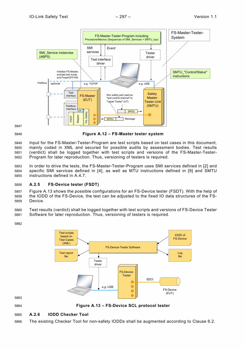
IO-Link Safety Test – 297 – Version 1.1
5847
Figure A.12 – FS-Master tester system 5848
Input for the FS-Master-Tester-Program are test scripts based on test cases in this document, 5849 mainly coded in XML and secured for possible audits by assessment bodies. Test results 5850 (verdict) shall be logged together with test scripts and versions of the FS-Master-Tester-5851 Program for later reproduction. Thus, versioning of testers is required. 5852
In order to drive the tests, the FS-Master-Tester-Program uses SMI services defined in [2] and 5853 specific SMI services defined in [4], as well as MTU instructions defined in [9] and SMTU 5854 instructions defined in A.4.7. 5855
A.2.5 FS-Device tester (FSDT) 5856
Figure A.13 shows the possible configurations for an FS-Device tester (FSDT). With the help of 5857 the IODD of the FS-Device, the test can be adjusted to the fixed IO data structures of the FS-5858 Device. 5859
Test results (verdict) shall be logged together with test scripts and versions of FS-Device Tester 5860 Software for later reproduction. Thus, versioning of testers is required. 5861
5862
5863
Figure A.13 – FS-Device SCL protocol tester 5864
A.2.6 IODD Checker Tool 5865
The existing Checker Tool for non-safety IODDs shall be augmented according to Clause 6.2. 5866
Testinterface Safety
Master-Tester-Unit
(SMTU)
e.g. USB
FS-Master-Tester-Program includingProcedure/Macros (Sequences of SMI_Services + SMTU_xyz)
Test interfacedriver
Testerdriver
e.g. TCP/IP
SMI services
FS-Master-Tester-System
SMTU_"Control/Status" instructions
SMI_Service instancies(ABPS)
Event
Fieldbus-Interface
FS-Master(EUT)
Fieldbus
Initialize FS-Master, activate test mode, and PowerOFF/ON
FSC
P
SPDU Message
SPDU
Non safety part used as"test control channel" to"Upper Tester" (UT)
Map
per
UT
optionalIO
L-Sa
fety
FS-Device-Tester
e.g. USB
SDCI
FS-Device-Tester Software
Test scriptsbased on
Test Cases(XML)
IODD ofFS-Device
Logfile
Test reportfile
Testerdriver
FS-Device(EUT)
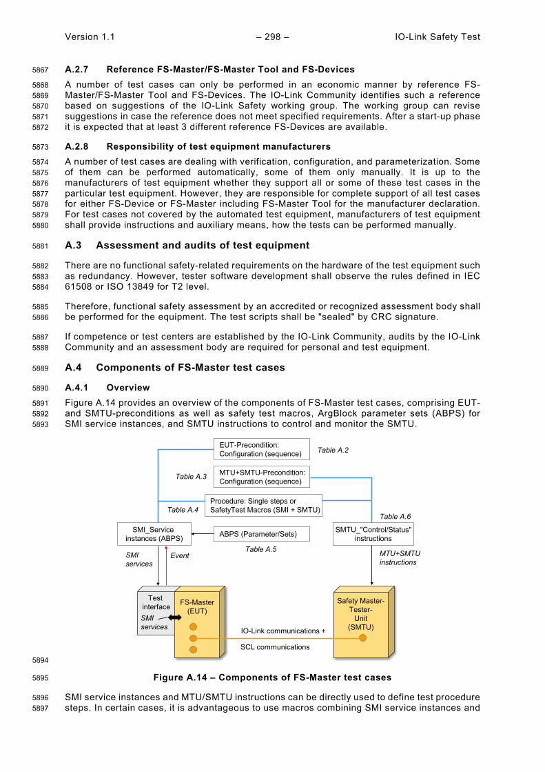
Version 1.1 – 298 – IO-Link Safety Test
A.2.7 Reference FS-Master/FS-Master Tool and FS-Devices 5867
A number of test cases can only be performed in an economic manner by reference FS-5868 Master/FS-Master Tool and FS-Devices. The IO-Link Community identifies such a reference 5869 based on suggestions of the IO-Link Safety working group. The working group can revise 5870 suggestions in case the reference does not meet specified requirements. After a start-up phase 5871 it is expected that at least 3 different reference FS-Devices are available. 5872
A.2.8 Responsibility of test equipment manufacturers 5873
A number of test cases are dealing with verification, configuration, and parameterization. Some 5874 of them can be performed automatically, some of them only manually. It is up to the 5875 manufacturers of test equipment whether they support all or some of these test cases in the 5876 particular test equipment. However, they are responsible for complete support of all test cases 5877 for either FS-Device or FS-Master including FS-Master Tool for the manufacturer declaration. 5878 For test cases not covered by the automated test equipment, manufacturers of test equipment 5879 shall provide instructions and auxiliary means, how the tests can be performed manually. 5880
A.3 Assessment and audits of test equipment 5881
There are no functional safety-related requirements on the hardware of the test equipment such 5882 as redundancy. However, tester software development shall observe the rules defined in IEC 5883 61508 or ISO 13849 for T2 level. 5884
Therefore, functional safety assessment by an accredited or recognized assessment body shall 5885 be performed for the equipment. The test scripts shall be "sealed" by CRC signature. 5886
If competence or test centers are established by the IO-Link Community, audits by the IO-Link 5887 Community and an assessment body are required for personal and test equipment. 5888
A.4 Components of FS-Master test cases 5889
A.4.1 Overview 5890
Figure A.14 provides an overview of the components of FS-Master test cases, comprising EUT- 5891 and SMTU-preconditions as well as safety test macros, ArgBlock parameter sets (ABPS) for 5892 SMI service instances, and SMTU instructions to control and monitor the SMTU. 5893
5894
Figure A.14 – Components of FS-Master test cases 5895
SMI service instances and MTU/SMTU instructions can be directly used to define test procedure 5896 steps. In certain cases, it is advantageous to use macros combining SMI service instances and 5897
Test interface FS-Master
(EUT)Safety Master-
Tester-Unit
(SMTU)IO-Link communications +
ABPS (Parameter/Sets)SMI_Serviceinstances (ABPS)
SMI services
SMI services
Event
SMTU_"Control/Status"instructions
Procedure: Single steps orSafetyTest Macros (SMI + SMTU)
EUT-Precondition:Configuration (sequence)
MTU+SMTU instructions
MTU+SMTU-Precondition:Configuration (sequence)
SCL communications
Table A.2
Table A.3
Table A.4
Table A.5
Table A.6
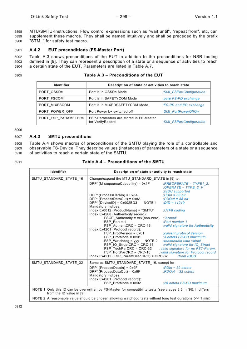
IO-Link Safety Test – 299 – Version 1.1
MTU/SMTU-Instructions. Flow control expressions such as "wait until", "repeat from", etc. can 5898 supplement these macros. They shall be named intuitively and shall be preceded by the prefix 5899 "STM_" for safety test macro. 5900
A.4.2 EUT preconditions (FS-Master Port) 5901
Table A.3 shows preconditions of the EUT in addition to the preconditions for NSR testing 5902 defined in [9]. They can represent a description of a state or a sequence of activities to reach 5903 a certain state of the EUT. Parameters are listed in Table A.7. 5904
Table A.3 – Preconditions of the EUT 5905
Identifier Description of state or activities to reach state
PORT_OSSDe Port is in OSSDe Mode ;SMI_FSPortConfiguration
PORT_FSCOM Port is in SAFETYCOM Mode ;pure FS-PD exchange
PORT_MIXFSCOM Port is in MIXEDSAFETYCOM Mode ;FS-PD and PD exchange
PORT_POWER_OFF Port Power L+ switched off ;SMI_PortPowerOffOn
PORT_FSP_PARAMETERS FSP-Parameters are stored in FS-Master for VerifyRecord ;SMI_FSPortConfiguration
5906
A.4.3 SMTU preconditions 5907
Table A.4 shows macros of preconditions of the SMTU playing the role of a controllable and 5908 observable FS-Device. They describe values (instances) of parameters of a state or a sequence 5909 of activities to reach a certain state of the SMTU. 5910
Table A.4 – Preconditions of the SMTU 5911
Identifier Description of state or activity to reach state
SMTU_STANDARD_STATE_16 Change/expand the MTU_STANDARD_STATE in [9] to: DPP1(M-sequenceCapability) = 0x1F ;PREOPERATE = TYPE1_2, ;OPERATE = TYPE_2_V ;ISDU supported DPP1(ProcessDataIn) = 0x8A ;PDIn = 88 bit DPP1(ProcessDataOut) = 0x8A ;PDOut = 88 bit DPP1(DeviceID) = 0x002BD3 NOTE 1 ;DID = 11219 Mandatory Indices: Index 0x0012 (ProductName) = "SMTU" ;UTF8 coding Index 0x4200 (Authenticity record): FSCP_Authencity = xxx(non-zero) ;"Armed" FSP_Port = 1 ;Port number 1 FSP_AuthentCRC = CRC-16 ;valid signature for Authenticity Index 0x4201 (Protocol record): FSP_ProtVersion = 0x01 ;current protocol version FSP_ProtMode = 0x01 ;3 octets FS-PD maximum FSP_Watchdog = yyy NOTE 2 ;reasonable time value! FSP_IO_StructCRC = CRC-16 ;valid signature for IO_Struct FSP_TechParCRC = CRC-32 ;valid signature for no FST-Param. FSP_PortParCRC = CRC-16 ;valid signature for Protocol record Index 0x4212 (FSP_ParamDescCRC) = CRC-32 ;from IODD
SMTU_STANDARD_STATE_32 Same as SMTU_STANDARD_STATE_16, except for: DPP1(ProcessDataIn) = 0x9F ;PDIn = 32 octets DPP1(ProcessDataOut) = 0x9F ;PDOut = 32 octets Mandatory Indices: Index 0x4201 (Protocol record): FSP_ProtMode = 0x02 ;25 octets FS-PD maximum
NOTE 1 Only this ID can be overwritten by FS-Master for compatibility tests (see clause 8.5 in [9]). It differs from the ID value in [9].
NOTE 2 A reasonable value should be chosen allowing watchdog tests without long test durations (<< 1 min)
5912
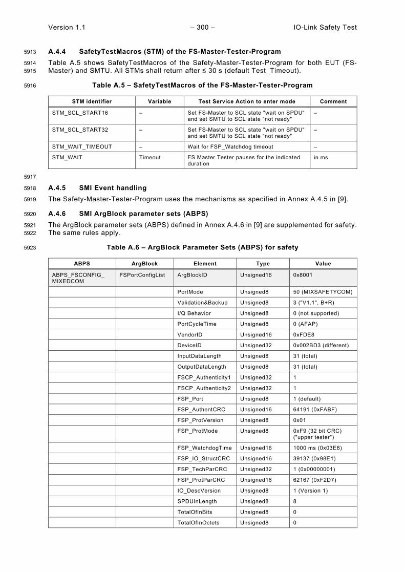
Version 1.1 – 300 – IO-Link Safety Test
A.4.4 SafetyTestMacros (STM) of the FS-Master-Tester-Program 5913
Table A.5 shows SafetyTestMacros of the Safety-Master-Tester-Program for both EUT (FS-5914 Master) and SMTU. All STMs shall return after ≤ 30 s (default Test_Timeout). 5915
Table A.5 – SafetyTestMacros of the FS-Master-Tester-Program 5916
STM identifier Variable Test Service Action to enter mode Comment
STM_SCL_START16 – Set FS-Master to SCL state "wait on SPDU" and set SMTU to SCL state "not ready"
–
STM_SCL_START32 – Set FS-Master to SCL state "wait on SPDU" and set SMTU to SCL state "not ready"
–
STM_WAIT_TIMEOUT – Wait for FSP_Watchdog timeout –
STM_WAIT Timeout FS Master Tester pauses for the indicated duration
in ms
5917
A.4.5 SMI Event handling 5918
The Safety-Master-Tester-Program uses the mechanisms as specified in Annex A.4.5 in [9]. 5919
A.4.6 SMI ArgBlock parameter sets (ABPS) 5920
The ArgBlock parameter sets (ABPS) defined in Annex A.4.6 in [9] are supplemented for safety. 5921 The same rules apply. 5922
Table A.6 – ArgBlock Parameter Sets (ABPS) for safety 5923
ABPS ArgBlock Element Type Value
ABPS_FSCONFIG_ MIXEDCOM
FSPortConfigList ArgBlockID Unsigned16 0x8001
PortMode Unsigned8 50 (MIXSAFETYCOM)
Validation&Backup Unsigned8 3 ("V1.1", B+R)
I/Q Behavior Unsigned8 0 (not supported)
PortCycleTime Unsigned8 0 (AFAP)
VendorID Unsigned16 0xFDE8
DeviceID Unsigned32 0x002BD3 (different)
InputDataLength Unsigned8 31 (total)
OutputDataLength Unsigned8 31 (total)
FSCP_Authenticity1 Unsigned32 1
FSCP_Authenticity2 Unsigned32 1
FSP_Port Unsigned8 1 (default)
FSP_AuthentCRC Unsigned16 64191 (0xFABF)
FSP_ProtVersion Unsigned8 0x01
FSP_ProtMode Unsigned8 0xF9 (32 bit CRC) ("upper tester")
FSP_WatchdogTime Unsigned16 1000 ms (0x03E8)
FSP_IO_StructCRC Unsigned16 39137 (0x98E1)
FSP_TechParCRC Unsigned32 1 (0x00000001)
FSP_ProtParCRC Unsigned16 62167 (0xF2D7)
IO_DescVersion Unsigned8 1 (Version 1)
SPDUInLength Unsigned8 8
TotalOfInBits Unsigned8 0
TotalOfInOctets Unsigned8 0
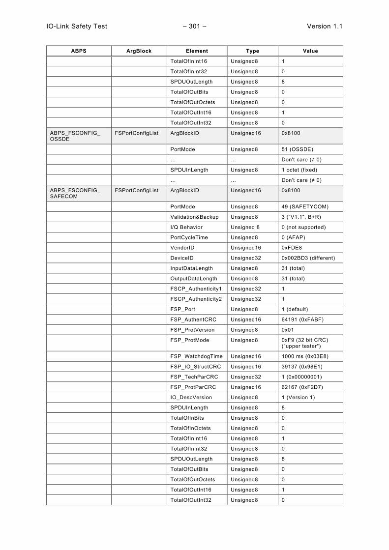
IO-Link Safety Test – 301 – Version 1.1
ABPS ArgBlock Element Type Value
TotalOfInInt16 Unsigned8 1
TotalOfInInt32 Unsigned8 0
SPDUOutLength Unsigned8 8
TotalOfOutBits Unsigned8 0
TotalOfOutOctets Unsigned8 0
TotalOfOutInt16 Unsigned8 1
TotalOfOutInt32 Unsigned8 0
ABPS_FSCONFIG_ OSSDE
FSPortConfigList ArgBlockID Unsigned16 0x8100
PortMode Unsigned8 51 (OSSDE)
… … Don't care (≠ 0)
SPDUInLength Unsigned8 1 octet (fixed)
… … Don't care (≠ 0)
ABPS_FSCONFIG_ SAFECOM
FSPortConfigList ArgBlockID Unsigned16 0x8100
PortMode Unsigned8 49 (SAFETYCOM)
Validation&Backup Unsigned8 3 ("V1.1", B+R)
I/Q Behavior Unsigned 8 0 (not supported)
PortCycleTime Unsigned8 0 (AFAP)
VendorID Unsigned16 0xFDE8
DeviceID Unsigned32 0x002BD3 (different)
InputDataLength Unsigned8 31 (total)
OutputDataLength Unsigned8 31 (total)
FSCP_Authenticity1 Unsigned32 1
FSCP_Authenticity2 Unsigned32 1
FSP_Port Unsigned8 1 (default)
FSP_AuthentCRC Unsigned16 64191 (0xFABF)
FSP_ProtVersion Unsigned8 0x01
FSP_ProtMode Unsigned8 0xF9 (32 bit CRC) ("upper tester")
FSP_WatchdogTime Unsigned16 1000 ms (0x03E8)
FSP_IO_StructCRC Unsigned16 39137 (0x98E1)
FSP_TechParCRC Unsigned32 1 (0x00000001)
FSP_ProtParCRC Unsigned16 62167 (0xF2D7)
IO_DescVersion Unsigned8 1 (Version 1)
SPDUInLength Unsigned8 8
TotalOfInBits Unsigned8 0
TotalOfInOctets Unsigned8 0
TotalOfInInt16 Unsigned8 1
TotalOfInInt32 Unsigned8 0
SPDUOutLength Unsigned8 8
TotalOfOutBits Unsigned8 0
TotalOfOutOctets Unsigned8 0
TotalOfOutInt16 Unsigned8 1
TotalOfOutInt32 Unsigned8 0
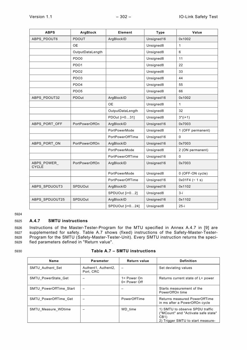
Version 1.1 – 302 – IO-Link Safety Test
ABPS ArgBlock Element Type Value
ABPS_PDOUT6 PDOUT ArgBlockID Unsigned16 0x1002
OE Unsigned8 1
OutputDataLength Unsigned8 6
PDO0 Unsigned8 11
PDO1 Unsigned8 22
PDO2 Unsigned8 33
PDO3 Unsigned8 44
PDO4 Unsigned8 55
PDO5 Unsigned8 66
ABPS_PDOUT32 PDOut ArgBlockID Unsigned16 0x1002
OE Unsigned8 1
OutputDataLength Unsigned8 32
PDOut [i=0…31] Unsigned8 3*(i+1)
ABPS_PORT_OFF PortPowerOffOn ArgBlockID Unsigned16 0x7003 PortPowerMode Unsigned8 1 (OFF permanent) PortPowerOffTime Unsigned16 0
ABPS_PORT_ON PortPowerOffOn ArgBlockID Unsigned16 0x7003 PortPowerMode Unsigned8 2 (ON permanent) PortPowerOffTime Unsigned16 0
ABPS_POWER_ CYCLE
PortPowerOffOn ArgBlockID Unsigned16 0x7003
PortPowerMode Unsigned8 0 (OFF-ON cycle) PortPowerOffTime Unsigned16 0x01F4 (~ 1 s)
ABPS_SPDUOUT3 SPDUOut ArgBlockID Unsigned16 0x1102
SPDUOut [i=0…2] Unsigned8 3-i
ABPS_SPDUOUT25 SPDUOut ArgBlockID Unsigned16 0x1102
SPDUOut [i=0…24] Unsigned8 25-i
5924
A.4.7 SMTU instructions 5925
Instructions of the Master-Tester-Program for the MTU specified in Annex A.4.7 in [9] are 5926 supplemented for safety. Table A.7 shows (fixed) instructions of the Safety-Master-Tester-5927 Program for the SMTU (Safety-Master-Tester-Unit). Every SMTU instruction returns the speci-5928 fied parameters defined in "Return value". 5929
Table A.7 – SMTU instructions 5930
Name Parameter Return value Definition
SMTU_Authent_Set Authent1, Authent2, Port, CRC
– Set deviating values
SMTU_PowerState_Get – 1= Power On 0= Power Off
Returns current state of L+ power
SMTU_PowerOffTime_Start – – Starts measurement of the PowerOffOn time
SMTU_PowerOffTime_Get – PowerOffTime Returns measured PowerOffTime in ms after a PowerOffOn cycle
SMTU_Measure_WDtime – WD_time 1) SMTU to observe SPDU traffic ("MCount" and "Activate safe state" CB1) 2) Trigger SMTU to start measure-
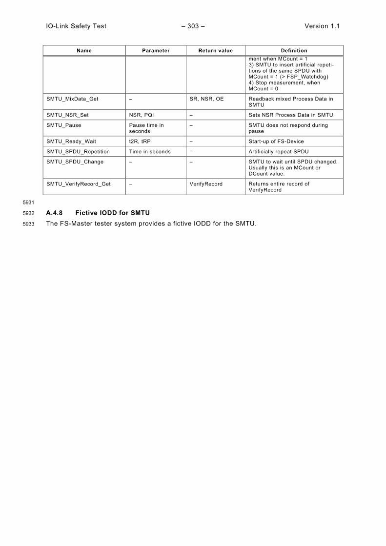
IO-Link Safety Test – 303 – Version 1.1
Name Parameter Return value Definition ment when MCount = 1 3) SMTU to insert artificial repeti-tions of the same SPDU with MCount = 1 (> FSP_Watchdog) 4) Stop measurement, when MCount = 0
SMTU_MixData_Get – SR, NSR, OE Readback mixed Process Data in SMTU
SMTU_NSR_Set NSR, PQI – Sets NSR Process Data in SMTU
SMTU_Pause Pause time in seconds
– SMTU does not respond during pause
SMTU_Ready_Wait t2R, tRP – Start-up of FS-Device
SMTU_SPDU_Repetition Time in seconds – Artificially repeat SPDU
SMTU_SPDU_Change – – SMTU to wait until SPDU changed. Usually this is an MCount or DCount value.
SMTU_VerifyRecord_Get – VerifyRecord Returns entire record of VerifyRecord
5931
A.4.8 Fictive IODD for SMTU 5932
The FS-Master tester system provides a fictive IODD for the SMTU. 5933
Version 1.1 – 304 – IO-Link Safety Test
Annex B 5934
(normative) 5935
5936
Assessment and certification 5937
B.1 General 5938
In case of safety for machinery, a manufacturer declaration is only sufficient for a product to be 5939 launched, if the manufacturer fulfils certain preconditions. Otherwise, functional safety 5940 assessments by assessment bodies are required based on international standards such as IEC 5941 61508, IEC 62061, or ISO 13849. There are three types of assessment objects in IO-Link 5942 Safety: 5943
• Specification (see [4]), 5944
• SCL-stacks and software tools, 5945
• Functional safety products such as FS-Device and FS-Master including Master-Tools. 5946
The actual assessment of IO-Link Safety can only comprise a concept approval of the 5947 specification ([4]) and companion documents as a precondition for the conformity of 5948 implementations (see B.4). 5949
Since it is possible to implement the safety communication layers (SCL) of IO-Link Safety in a 5950 completely hardware-independent manner, manufacturers can save quiet some effort and time 5951 if precertified SCL-stacks and software tools are available on the market. Preconditions are 5952 described in B.5.2. 5953
Procedures and constraints for functional safety products are described in detail in B.5. 5954
B.2 Safety policy 5955
In order to prevent and protect the manufacturers and vendors of FS-Masters and FS-Devices 5956 from possibly misleading understandings or wrong expectations and negligence actions regar-5957 ding safety-related developments and applications the following shall be observed and ex-5958 plained in each training, seminar, workshop and consultancy. 5959
• Any non-safety-related device automatically will not be applicable for safety-related appli-5960 cations just by using fieldbus or IO-Link communication and a safety communication layer. 5961 The safety technology part of a safety device shall be approved for a Safety Integrity Level 5962 (SIL) or Performance Level (PL) suitable for the intended safety functions. The IO-Link 5963 Safety part shall be implemented and approved for the same SIL/PL or better. 5964
• In order to enable a product for safety-related applications, appropriate development 5965 processes according to safety standards shall be observed (see IEC 61508, IEC 62061, ISO 5966 13849) and an assessment from a competent assessment body or authorized manufacturer 5967 department shall be achieved. 5968
• The manufacturer/vendor of a safety product is responsible for the correct implementation 5969 of the safety communication layer technology, the correctness and completeness of the 5970 product documentation and information. 5971
• Supplemental safety-related information to the regular specification in [4] shall be observed 5972 for implementation, test and assessment if applicable. Normally, this information is provided 5973 by the working group as response to a change request (CR) within the CR-database that is 5974 in state "implementation" and approved by an assessment body. The working group can 5975 decide to publish these CRs through a separate "Corrigendum" document for download on 5976 the IO-Link website. 5977
B.3 Obligations for international business 5978
As a rule, the international safety standards are accepted (ratified) globally. However, since 5979 safety technology in automation is relevant to occupational safety and the concomitant 5980 insurance risks in a country, recognition of the rules pointed out here is still a sovereign right. 5981
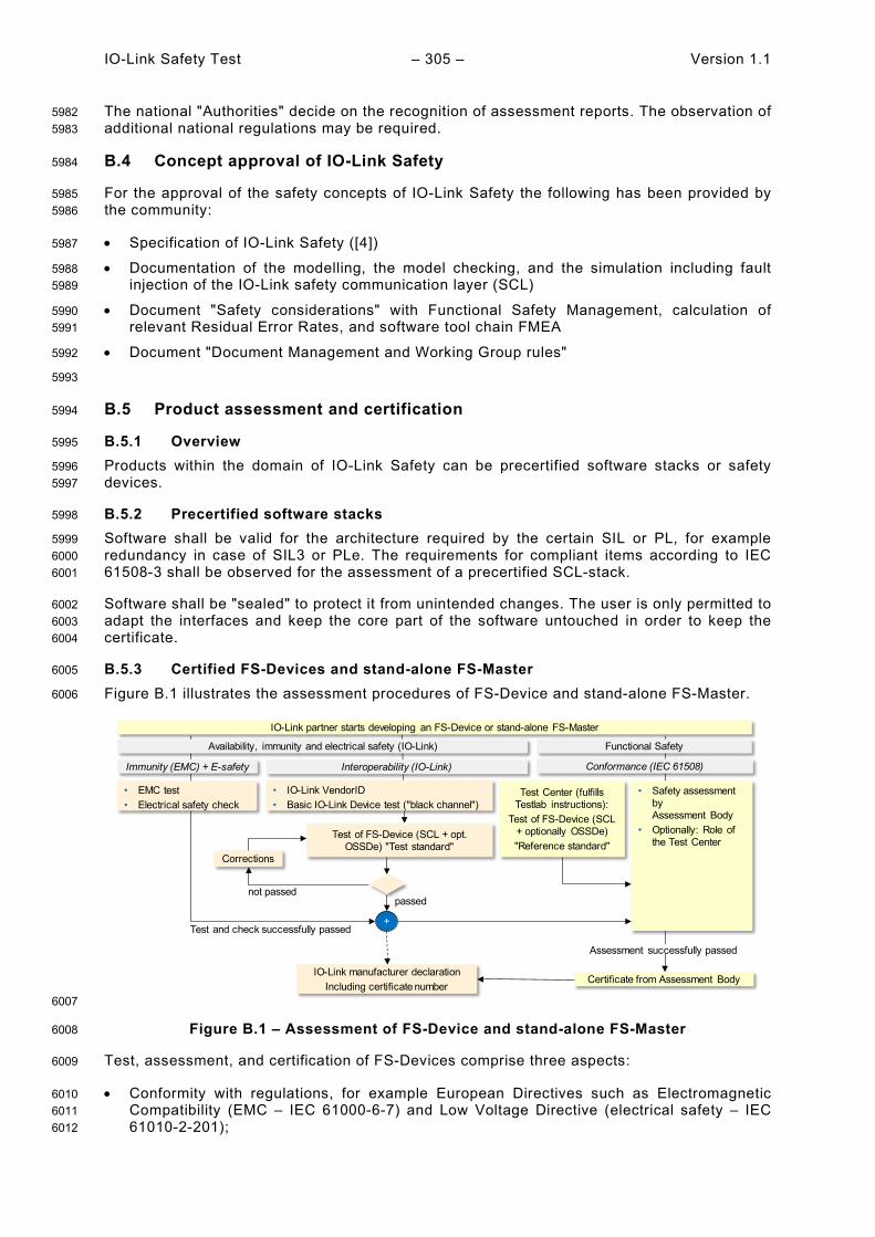
IO-Link Safety Test – 305 – Version 1.1
The national "Authorities" decide on the recognition of assessment reports. The observation of 5982 additional national regulations may be required. 5983
B.4 Concept approval of IO-Link Safety 5984
For the approval of the safety concepts of IO-Link Safety the following has been provided by 5985 the community: 5986
• Specification of IO-Link Safety ([4]) 5987
• Documentation of the modelling, the model checking, and the simulation including fault 5988 injection of the IO-Link safety communication layer (SCL) 5989
• Document "Safety considerations" with Functional Safety Management, calculation of 5990 relevant Residual Error Rates, and software tool chain FMEA 5991
• Document "Document Management and Working Group rules" 5992
5993
B.5 Product assessment and certification 5994
B.5.1 Overview 5995
Products within the domain of IO-Link Safety can be precertified software stacks or safety 5996 devices. 5997
B.5.2 Precertified software stacks 5998
Software shall be valid for the architecture required by the certain SIL or PL, for example 5999 redundancy in case of SIL3 or PLe. The requirements for compliant items according to IEC 6000 61508-3 shall be observed for the assessment of a precertified SCL-stack. 6001
Software shall be "sealed" to protect it from unintended changes. The user is only permitted to 6002 adapt the interfaces and keep the core part of the software untouched in order to keep the 6003 certificate. 6004
B.5.3 Certified FS-Devices and stand-alone FS-Master 6005
Figure B.1 illustrates the assessment procedures of FS-Device and stand-alone FS-Master. 6006
6007
Figure B.1 – Assessment of FS-Device and stand-alone FS-Master 6008
Test, assessment, and certification of FS-Devices comprise three aspects: 6009
• Conformity with regulations, for example European Directives such as Electromagnetic 6010 Compatibility (EMC – IEC 61000-6-7) and Low Voltage Directive (electrical safety – IEC 6011 61010-2-201); 6012
IO-Link partner starts developing an FS-Device or stand-alone FS-Master
• EMC test • Electrical safety check
• IO-Link VendorID• Basic IO-Link Device test ("black channel")
• Safety assessment by Assessment Body
• Optionally: Role of the Test Center
Test of FS-Device (SCL + opt. OSSDe) "Test standard"
not passed
IO-Link manufacturer declarationIncluding certificate number
Certificate from Assessment Body
Test and check successfully passed+
Immunity (EMC) + E-safety Interoperability (IO-Link) Conformance (IEC 61508)
Availability, immunity and electrical safety (IO-Link) Functional Safety
Corrections
passed
Assessment successfully passed
Test Center (fulfills Testlab instructions):
Test of FS-Device (SCL + optionally OSSDe)"Reference standard"

Version 1.1 – 306 – IO-Link Safety Test
• IO-Link Interoperability, that means conformity of the FS-Device with the IO-Link 6013 specifications: The IO-Link community arranged for "Test standards" (test tool suite) based 6014 on this document and supported by Technology Providers; 6015
• Conformance of functional safety development process with IEC 61508 (due to 6016 software/firmware involvement). 6017
While developers can use the IO-Link "Test Standards" during development to ensure a high 6018 degree of conformity/interoperability with IO-Link and IO-Link Safety, this is not enough for 6019 functional safety. IO-Link Safety requires Test Centers assessed by the IO-Link Community and 6020 an assessment body and audited periodically. These Test Centers are performing tests and 6021 checks according to approved "Test Lab Instructions" and using approved "Reference Stan-6022 dards". "Test Standards" and "Reference Standards" correspond to each other. However, while 6023 the "Test Standards" can be variable to a certain extent and be adjusted to customer require-6024 ments, the "Reference Tests" are fixed and "locked/sealed" by signature. 6025
Safety assessment bodies can play the role of a Test Center on behalf of the IO-Link Communi-6026 ty, thus reducing time and effort. 6027
After the final certificate of the Assessment Body, the FS-Device manufacturer can issue the 6028 IO-Link Safety Manufacturer declaration showing the certificate number of the assessment. 6029
B.5.4 Certified FS-Master integrated in FSCP 6030
Figure B.2 illustrates the assessment procedures of FS-Master on FSCP. 6031
6032
Figure B.2 – Assessment of FS-Master on FSCP 6033
Assessment and certification of FS-Masters on fieldbus/FSCP follows a similar concept: 6034
• EMC tests and electrical safety issues can be different depending on the standards to be 6035 considered (generic, domain, or product); 6036
• Usually, from a fieldbus/FSCP point-of-view, the FS-Master is a fieldbus device and shall 6037 be developed, tested, and assessed according to the interoperability/conformity rules of the 6038 particular fieldbus/FSCP. The result is a certificate of the fieldbus organization; 6039
• The remaining steps correspond to those of an FS-Device. 6040
B.6 Grandfathering rules 6041
In future releases of this document, grandfathering rules will be necessary once the "black 6042 channel", i.e. the IO-Link layer stack is changed in an FS-Master or in an FS-Device. 6043
Same is true for SCL stack changes in an FS-Master or in an FS-Device. 6044
IO-Link partner starts developing an FS-Master
• EMC test • Electrical safety check
• Prove Fieldbus and FSCP conformity• IO-Link VendorID• Basic IO-Link Master test ("black channel")
• Safety assessment by Assessment Body
• Optionally: Role of the Test Center
Test of FS-Master (SCL + opt. OSSDe) "Test standard"
not passed
IO-Link manufacturer declarationIncluding certificate number
Certificate from Assessment Body
Test and check successfully passed+
Immunity (EMC) + E-safety Interoperability (Fieldbus and IO-Link) Conformance (IEC 61508)
Availability, immunity and electrical safety (Fieldbus and IO-Link) Functional Safety
Corrections
passed
Assessment successfully passed
Test Center (fulfills Testlab instructions):
Test of FS-Master (SCL + optionally OSSDe)"Reference standard"

IO-Link Safety Test – 307 – Version 1.1
Annex C 6045
(informative) 6046
6047
Information on testing 6048
of FS-Devices and FS-Master/Tools 6049
Information about test laboratories, which test and validate the conformity of IO-Link Safety 6050 products such as FS-Masters and FS-Devices with IO-Link specifications can be obtained from 6051 the following organization: 6052
IO-Link Community 6053 c/o PROFIBUS Nutzerorganisation e.V. 6054 Haid-und-Neu-Str. 7 6055 76131 Karlsruhe 6056 GERMANY 6057 Phone: +49 721 9658 590 6058 Fax: +49 721 9658 589 6059 E-Mail: [email protected] 6060 URL: www.io-link.com 6061

Version 1.1 – 308 – IO-Link Safety Test
Annex D 6062
(normative) 6063
6064
Manufacturer declaration for safety devices 6065
A dedicated manufacturer declaration for FS-Devices and FS-Masters can be downloaded from 6066 the download area in www.io-link.com. 6067

IO-Link Safety Test – 309 – Version 1.1
Annex E 6068
(informative) 6069
Listing of FS test cases 6070
E.1 Listing of FS test cases sorted by IDs 6071
Table E.1 shows the Test cases and its references. 6072
Table E.1 – FS test cases sorted by IDs 6073
FSTC ID FSTC Name Reference
FSTC_0001 FSTCM_PHYL_PWR1_SWITCHABLE Table 12
FSTC_0002 FSTCM_PHYL_OSSD_HIGHVIMIQ Table 13
FSTC_0003 FSTCM_PHYL_OSSD_LOWVIMIQ Table 14
FSTC_0004 FSTCM_PHYL_OSSD_VHYSMCI Table 15
FSTC_0005 FSTCM_PHYL_OSSD_LOADIQ Table 16
FSTC_0006 FSTCD_PHYL_OSSD_HSRESVOLT Table 17
FSTC_0007 FSTCD_PHYL_OSSD_LSRESVOLT Table 18
FSTC_0008 FSTCM_PHYL_INTF_OSSDSENS Table 19
FSTC_0009 FSTCM_PHYL_INTF_DISCREPANCY Table 20
FSTC_0010 FSTCM_PHYL_INTF_TESTPULSERES Table 21
FSTC_0011 FSTCM_PHYL_INTF_READYDETECT Table 22
FSTC_0012 FSTCM_PHYL_INTF_WAKEUPTOREADYDELAY Table 23
FSTC_0013 FSTCD_PHYL_OSSD_DISCREP Table 24
FSTC_0014 FSTCD_PHYL_INTF_TESTPULSPERIOD Removed
FSTC_0015 FSTCD_PHYL_INTF_TESTPULSDURATION Table 25
FSTC_0016 FSTCD_PHYL_INTF_READYPULSDUR Table 26
FSTC_0017 FSTCD_PHYL_INTF_READY2OSSD Table 27
FSTC_0018 FSTCI_IODD_FSPD_IODDPARAMDESCCRC Table 29
FSTC_0019 FSTCI_IODD_FSPD_DEDICTOOL Table 30
FSTC_0020 FSTCD_CONF_INFO_DOCUMENTS Table 31
FSTC_0021 FSTCD_CONF_INFO_CONNECTCABLE Table 32
FSTC_0022 FSTCD_CONF_INFO_DEFAULTBEHAVIOR Table 33
FSTC_0023 FSTCD_CONF_FSPD_PORTINVAL Table 34
FSTC_0024 FSTCD_CONF_FSPD_AUTHENTCRCINVAL Table 35
FSTC_0025 FSTCD_CONF_FSPD_PROTVINVAL Table 36
FSTC_0026 FSTCD_CONF_FSPD_PMODEINVAL Table 37
FSTC_0027 FSTCD_CONF_FSPD_WDOGRANGE Table 38
FSTC_0028 FSTCD_CONF_FSPD_PRCRCINVAL Table 39
FSTC_0029 FSTCD_CONF_DEFAULTFST Table 40
FSTC_0030 FSTCD_CONF_IODDFSTPAR Table 41
FSTC_0031 FSTCD_CONF_CRCDEDTOOL Table 42
FSTC_0032 FSTCD_CONF_SWTOOSSD Table 43
FSTC_0033 FSTCD_CONF_SETUPCOMMI Table 44
FSTC_0034 FSTCD_CONF_SETUPARMED Table 45
FSTC_0035 FSTCD_PARM_VRFY_ARMED Table 46
FSTC_0036 FSTCD_PARM_VRFY_COMMISTEST Table 47

Version 1.1 – 310 – IO-Link Safety Test
FSTC_0037 FSTCD_PARM_VRFY_ARMEDNOVFY Table 48
FSTC_0038 FSTCD_PARM_VRFY_TESTNOVFY Table 49
FSTC_0039 FSTCD_PARM_VRFY_TECHPARN0 Table 50
FSTC_0040 FSTCD_PARM_VRFY_TECHPAR0 Table 51
FSTC_0041 FSTCD_PARM_VRFY_AUTH1WRONG Table 52
FSTC_0042 FSTCD_PARM_VRFY_AUTH2WRONG Table 53
FSTC_0043 FSTCD_PARM_VRFY_PORTWRONG Table 54
FSTC_0044 FSTCD_PARM_VRFY_AUTHCRCWRG Table 55
FSTC_0045 FSTCD_PARM_VRFY_PPARCRCWRG Table 56
FSTC_0046 FSTCD_PARM_VRFY_TPARCRCWRG Table 57
FSTC_0047 FSTCD_PARM_VRFY_IOSTCRCWRG Table 58
FSTC_0048 FSTCD_PARM_VRFY_WDTIMEINVL Table 59
FSTC_0049 FSTCD_PARM_VRFY_PVERSINVL Table 60
FSTC_0050 FSTCD_PARM_VRFY_PMODEINVL Table 61
FSTC_0051 FSTCD_SCLD_WATCHDOGANDIODD Table 62
FSTC_0052 FSTCD_SCLD_FLOW_NOERRMC1TO Table 64
FSTC_0053 FSTCD_SCLD_FLOW_SETSD1MC0 Table 65
FSTC_0054 FSTCD_SCLD_FLOW_ SETSD0MC5TO Table 66
FSTC_0055 FSTCD_SCLD_FLOW_SETSD0MC1TO Table 67
FSTC_0056 FSTCD_SCLD_FLOW_SETSD1MC0 Table 68
FSTC_0057 FSTCD_SCLD_FLOW_SETSD0MC2TO Table 69
FSTC_0058 FSTCD_SCLD_FLOW_SETSD0MC1TO Table 70
FSTC_0059 FSTCD_SCLD_FLOW_SETSD0MC7TO Table 71
FSTC_0060 FSTCD_SCLD_FLOW_CRC1MC0TO Table 72
FSTC_0061 FSTCD_SCLD_FLOW_SETSD1MC0TO Table 73
FSTC_0062 FSTCD_SCLD_FLOW_SETSD1MC0 Table 74
FSTC_0063 FSTCD_SCLD_FLOW_SETSD1MC0DCE1 Table 75
FSTC_0064 FSTCD_SCLD_FLOW_SETSD1MC0DCE1 Table 76
FSTC_0065 FSTCD_SCLD_FLOW_SETSD0MC2DCE1 Table 77
FSTC_0066 FSTCD_SCLD_FLOW_SETSD1MC0DCE1 Table 78
FSTC_0067 FSTCD_SCLD_FLOW_SETSD1MC0DCE1 Table 79
FSTC_0068 FSTCD_SCLD_FLOW_PNERRMC0 Table 80
FSTC_0069 FSTCD_SCLD_FLOW_SETSD0MC2TO Table 81
FSTC_0070 FSTCD_SCLD_FLOW_SETSD1MC0DCE1 Table 82
FSTC_0071 FSTCD_SCLD_FLOW_SETSD1MC0DCE1 Table 83
FSTC_0072 FSTCD_SCLD_FLOW_SETSD1MC0DCE1 Table 84
FSTC_0073 FSTCD_SCLD_FLOW_SETSD1MC0DCE1 Table 85
FSTC_0074 FSTCD_SCLD_FLOW_SETSD1MC1DCE1 Table 86
FSTC_0075 FSTCD_SCLD_FLOW_SETSD1MC1DCE1 Table 87
FSTC_0076 FSTCD_SCLD_FLOW_SETSD0MC1TO Table 88
FSTC_0077 FSTCD_SCLD_FLOW_SETSD0MC1TO Table 89
FSTC_0078 FSTCD_SCLD_FLOW_SETSD0MC1TO Table 90
FSTC_0079 FSTCD_SCLD_FLOW_SETSD0MC2TO Table 91
FSTC_0080 FSTCD_SCLD_FLOW_SETSD0MC2TO Table 92
FSTC_0081 FSTCD_SCLD_FLOW_SETSD0MC2TO Table 93
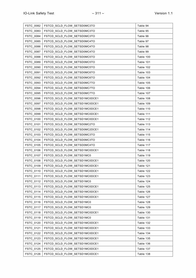
IO-Link Safety Test – 311 – Version 1.1
FSTC_0082 FSTCD_SCLD_FLOW_SETSD0MC3TO Table 94
FSTC_0083 FSTCD_SCLD_FLOW_SETSD0MC3TO Table 95
FSTC_0084 FSTCD_SCLD_FLOW_SETSD0MC3TO Table 96
FSTC_0085 FSTCD_SCLD_FLOW_SETSD0MC4TO Table 97
FSTC_0086 FSTCD_SCLD_FLOW_SETSD0MC4TO Table 98
FSTC_0087 FSTCD_SCLD_FLOW_SETSD0MC4TO Table 99
FSTC_0088 FSTCD_SCLD_FLOW_SETSD0MC5TO Table 100
FSTC_0089 FSTCD_SCLD_FLOW_SETSD0MC5TO Table 101
FSTC_0090 FSTCD_SCLD_FLOW_SETSD0MC5TO Table 102
FSTC_0091 FSTCD_SCLD_FLOW_SETSD0MC6TO Table 103
FSTC_0092 FSTCD_SCLD_FLOW_SETSD0MC6TO Table 104
FSTC_0093 FSTCD_SCLD_FLOW_SETSD0MC7TO Table 105
FSTC_0094 FSTCD_SCLD_FLOW_SETSD0MC7TO Table 106
FSTC_0095 FSTCD_SCLD_FLOW_SETSD0MC7TO Table 107
FSTC_0096 FSTCD_SCLD_FLOW_SETSD1MC0DCE1 Table 108
FSTC_0097 FSTCD_SCLD_FLOW_SETSD1MC0DCE1 Table 109
FSTC_0098 FSTCD_SCLD_FLOW_SETSD1MC0DCE1 Table 110
FSTC_0099 FSTCD_SCLD_FLOW_SETSD1MC0DCE1 Table 111
FSTC_0100 FSTCD_SCLD_FLOW_SETSD1MC0DCE1 Table 112
FSTC_0101 FSTCD_SCLD_FLOW_SETSD0MC2TO Table 113
FSTC_0102 FSTCD_SCLD_FLOW_SETSD0MC2DCE1 Table 114
FSTC_0103 FSTCD_SCLD_FLOW_SETSD0MC3TO Table 115
FSTC_0104 FSTCD_SCLD_FLOW_SETSD0MC3TO Table 116
FSTC_0105 FSTCD_SCLD_FLOW_SETSD0MC4TO Table 117
FSTC_0106 FSTCD_SCLD_FLOW_SETSD1MC0DCE1 Table 118
FSTC_0107 FSTCD_SCLD_FLOW_SETSD1MC0 Table 119
FSTC_0108 FSTCD_SCLD_FLOW_SETSD1MC0DCE1 Table 120
FSTC_0109 FSTCD_SCLD_FLOW_SETSD1MC0DCE1 Table 121
FSTC_0110 FSTCD_SCLD_FLOW_SETSD1MC0DCE1 Table 122
FSTC_0111 FSTCD_SCLD_FLOW_SETSD1MC0DCE1 Table 123
FSTC_0112 FSTCD_SCLD_FLOW_SETSD1MC0 Table 124
FSTC_0113 FSTCD_SCLD_FLOW_SETSD1MC0DCE1 Table 125
FSTC_0114 FSTCD_SCLD_FLOW_SETSD1MC0DCE1 Table 126
FSTC_0115 FSTCD_SCLD_FLOW_SETSD1MC0DCE1 Table 127
FSTC_0116 FSTCD_SCLD_FLOW_SETSD1MC0 Table 128
FSTC_0117 FSTCD_SCLD_FLOW_SETSD1MC0 Table 129
FSTC_0118 FSTCD_SCLD_FLOW_SETSD1MC0DCE1 Table 130
FSTC_0119 FSTCD_SCLD_FLOW_SETSD1MC0 Table 131
FSTC_0120 FSTCD_SCLD_FLOW_SETSD1MC0DCE1 Table 132
FSTC_0121 FSTCD_SCLD_FLOW_SETSD1MC0DCE1 Table 133
FSTC_0122 FSTCD_SCLD_FLOW_SETSD1MC0DCE1 Table 134
FSTC_0123 FSTCD_SCLD_FLOW_SETSD1MC0DCE1 Table 135
FSTC_0124 FSTCD_SCLD_FLOW_SETSD1MC0DCE1 Table 136
FSTC_0125 FSTCD_SCLD_FLOW_SETSD1MC0DCE1 Table 137
FSTC_0126 FSTCD_SCLD_FLOW_SETSD1MC0DCE1 Table 138
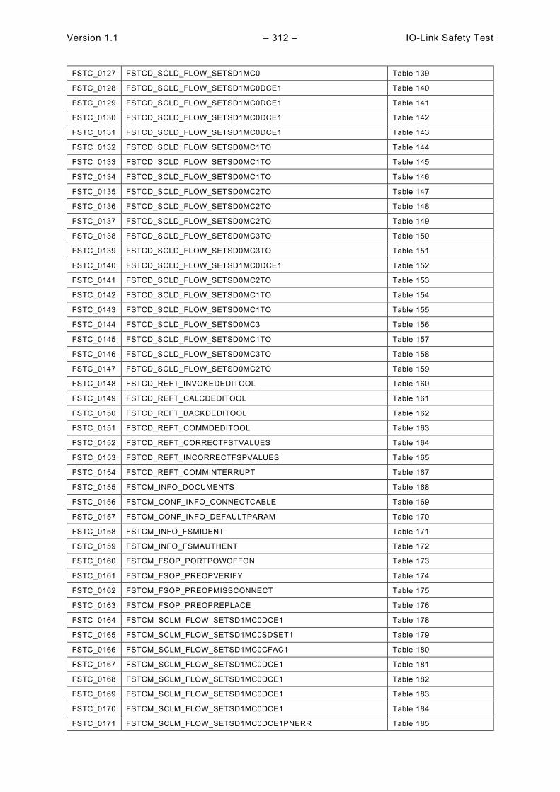
Version 1.1 – 312 – IO-Link Safety Test
FSTC_0127 FSTCD_SCLD_FLOW_SETSD1MC0 Table 139
FSTC_0128 FSTCD_SCLD_FLOW_SETSD1MC0DCE1 Table 140
FSTC_0129 FSTCD_SCLD_FLOW_SETSD1MC0DCE1 Table 141
FSTC_0130 FSTCD_SCLD_FLOW_SETSD1MC0DCE1 Table 142
FSTC_0131 FSTCD_SCLD_FLOW_SETSD1MC0DCE1 Table 143
FSTC_0132 FSTCD_SCLD_FLOW_SETSD0MC1TO Table 144
FSTC_0133 FSTCD_SCLD_FLOW_SETSD0MC1TO Table 145
FSTC_0134 FSTCD_SCLD_FLOW_SETSD0MC1TO Table 146
FSTC_0135 FSTCD_SCLD_FLOW_SETSD0MC2TO Table 147
FSTC_0136 FSTCD_SCLD_FLOW_SETSD0MC2TO Table 148
FSTC_0137 FSTCD_SCLD_FLOW_SETSD0MC2TO Table 149
FSTC_0138 FSTCD_SCLD_FLOW_SETSD0MC3TO Table 150
FSTC_0139 FSTCD_SCLD_FLOW_SETSD0MC3TO Table 151
FSTC_0140 FSTCD_SCLD_FLOW_SETSD1MC0DCE1 Table 152
FSTC_0141 FSTCD_SCLD_FLOW_SETSD0MC2TO Table 153
FSTC_0142 FSTCD_SCLD_FLOW_SETSD0MC1TO Table 154
FSTC_0143 FSTCD_SCLD_FLOW_SETSD0MC1TO Table 155
FSTC_0144 FSTCD_SCLD_FLOW_SETSD0MC3 Table 156
FSTC_0145 FSTCD_SCLD_FLOW_SETSD0MC1TO Table 157
FSTC_0146 FSTCD_SCLD_FLOW_SETSD0MC3TO Table 158
FSTC_0147 FSTCD_SCLD_FLOW_SETSD0MC2TO Table 159
FSTC_0148 FSTCD_REFT_INVOKEDEDITOOL Table 160
FSTC_0149 FSTCD_REFT_CALCDEDITOOL Table 161
FSTC_0150 FSTCD_REFT_BACKDEDITOOL Table 162
FSTC_0151 FSTCD_REFT_COMMDEDITOOL Table 163
FSTC_0152 FSTCD_REFT_CORRECTFSTVALUES Table 164
FSTC_0153 FSTCD_REFT_INCORRECTFSPVALUES Table 165
FSTC_0154 FSTCD_REFT_COMMINTERRUPT Table 167
FSTC_0155 FSTCM_INFO_DOCUMENTS Table 168
FSTC_0156 FSTCM_CONF_INFO_CONNECTCABLE Table 169
FSTC_0157 FSTCM_CONF_INFO_DEFAULTPARAM Table 170
FSTC_0158 FSTCM_INFO_FSMIDENT Table 171
FSTC_0159 FSTCM_INFO_FSMAUTHENT Table 172
FSTC_0160 FSTCM_FSOP_PORTPOWOFFON Table 173
FSTC_0161 FSTCM_FSOP_PREOPVERIFY Table 174
FSTC_0162 FSTCM_FSOP_PREOPMISSCONNECT Table 175
FSTC_0163 FSTCM_FSOP_PREOPREPLACE Table 176
FSTC_0164 FSTCM_SCLM_FLOW_SETSD1MC0DCE1 Table 178
FSTC_0165 FSTCM_SCLM_FLOW_SETSD1MC0SDSET1 Table 179
FSTC_0166 FSTCM_SCLM_FLOW_SETSD1MC0CFAC1 Table 180
FSTC_0167 FSTCM_SCLM_FLOW_SETSD1MC0DCE1 Table 181
FSTC_0168 FSTCM_SCLM_FLOW_SETSD1MC0DCE1 Table 182
FSTC_0169 FSTCM_SCLM_FLOW_SETSD1MC0DCE1 Table 183
FSTC_0170 FSTCM_SCLM_FLOW_SETSD1MC0DCE1 Table 184
FSTC_0171 FSTCM_SCLM_FLOW_SETSD1MC0DCE1PNERR Table 185

IO-Link Safety Test – 313 – Version 1.1
FSTC_0172 FSTCM_SCLM_FLOW_SETSD1MC0 Table 186
FSTC_0173 FSTCM_SCLM_FLOW_PNERRCRCERR Table 187
FSTC_0174 FSTCM_SCLM_FLOW_PNERRCRCERR Table 188
FSTC_0175 FSTCM_SCLM_FLOW_PNERRMC0 Table 189
FSTC_0176 FSTCM_SCLM_FLOW_CRCERRMC0 Table 190
FSTC_0177 FSTCM_FSOP_SPLITTERMIXPD32 Table 191
FSTC_0178 FSTCM_FSOP_SPLITTERSAFEPD32 Removed
FSTC_0179 FSTCM_FSOP_SPLITTERMIXPD16 Table 192
FSTC_0180 FSTCM_FSOP_SPLITTERSAFEPD16 Removed
FSTC_0181 FSTCM_FSOP_COMPOSERMIXPD32 Table 193
FSTC_0182 FSTCM_FSOP_COMPOSERSAFEPD32 Removed
FSTC_0183 FSTCM_FSOP_COMPOSERMIXPD16 Table 194
FSTC_0184 FSTCM_FSOP_COMPOSERSAFEPD16 Removed
FSTC_0185 FSTCM_SMIS_READBACKCONFIG Table 195
FSTC_0186 FSTCM_SMIS_FSPORTSTATUS Table 196
FSTC_0187 FSTCM_REFD_PORTEVENTCORRECT Table 197
FSTC_0188 FSTCM_REFD_FSDEVICEEVENTCORRECT Table 198
FSTC_0189 FSTCM_SCLM_WATCHDOGPRECISION Table 200
FSTC_0190 FSTCM_TOOL_IODDIMPORT Table 201
FSTC_0191 FSTCM_TOOL_IODDCONVENTIONS Table 202
FSTC_0192 FSTCM_TOOL_IODDDISPLAYCOMPLETE Table 203
FSTC_0193 FSTCM_TOOL_FSTPARAMETERS Table 204
FSTC_0194 FSTCM_TOOL_COMMDEDITOOL Table 205
FSTC_0195 FSTCM_TOOL_DDOEXCHANGE Table 206
6074

Version 1.1 – 314 – IO-Link Safety Test
Bibliography 6075
[1] IEC 61131-9:20223, Programmable controllers – Part 9: Single-drop digital communi-6076 cation interface for small sensors and actuators (SDCI), www.iec.ch 6077
[2] IO-Link Community, IO-Link Interface and System, V1.1.3, June 2019, Order No. 10.002 6078
[3] IO-Link Community, IO-Link Corrigendum & Package 2020, January 2021, Order No. 6079 10.122 6080
[4] IO-Link Community, IO-Link Safety System Extensions, V1.1.3, March 2022, Order No. 6081 10.092 6082
[5] IO-Link Community, IO Device Description (IODD), V1.1.3, January 2021, Order No. 6083 10.012 6084
[6] IO-Link Community, Common Profile, V 1.1, December 2021, Order No. 10.072 6085
[7] ISO/IEC 19505-2:2012, Information technology ‒ OMG Unified Modeling Language 6086 (OMG UML), Revision 2 6087
[8] Position Paper CB24I, Classification of Binary 24 V Interfaces − Functional Safety 6088 aspects covered by dynamic testing, Edition 2.0.1: 6089 https://www.zvei.org/verband/fachverbaende/fachverband-automation/schaltgeraete-6090 schaltanlagen-industriesteuerungen/ 6091
[9] IO-Link Community, IO-Link Test, V1.1.3, January 2021, Order No. 10.032 6092
[10] IO-Link Community, IO-Link Exceptions, V1.0, January 2020, Order No. 10.232 6093
[11] PI Profile Specification, IO-Link Safety Integration in PROFIsafe, V1.0, Februar 2022, 6094 Order No. 3.312 6095
________ 6096
3 Under preparation. Stage at the time of publication: IEC/AFDIS 61131-9:2022

Copyright by:
IO-Link Community c/o PROFIBUS Nutzerorganisation e.V. Haid-und-Neu-Str. 7 76131 Karlsruhe Germany Phone: +49 (0) 721 / 96 58 590 Fax: +49 (0) 721 / 96 58 589 e-mail: [email protected] http://www.io-link.com/