Invistigation on Alkylation process اﻟﺗﺣﻘق ﻣن ﻋﻣﻟﯾﺔ اﻻﻟﮐﻟﺔ
47
Sudan University of Science and Technology Collage of Petroleum Engineering Department Of Transport And Refining Project Submitted to College of Petroleum Engineering in Partial Fulfillment for the Degree of B.Sc in Refining Engineering Research Titled: Invistigation on Alkylation process كلةلن عملية اق م التحقPrepared By: 1. Ahmed Mohammed Osman Mohammed 2. Abdulhafeez Ahmed AbdulhafeezAwadalla 3. Mazin Salah AbdallateefSharef 4. Abobaker Mohammed Musa Abdalla 5. Omer AbdulazizDafallahAlshreef Supervisored by: Eng. Mohammed Edris Osman October, 2017
-
Upload
khangminh22 -
Category
Documents
-
view
0 -
download
0
Transcript of Invistigation on Alkylation process اﻟﺗﺣﻘق ﻣن ﻋﻣﻟﯾﺔ اﻻﻟﮐﻟﺔ
Sudan University of Science and Technology
Collage of Petroleum Engineering
Department Of Transport And Refining
Project Submitted to College of Petroleum Engineering in Partial Fulfillment for the
Degree of B.Sc in Refining Engineering
Research Titled:
Invistigation on Alkylation process
التحقق من عملية االلكلة
Prepared By:
1. Ahmed Mohammed Osman Mohammed
2. Abdulhafeez Ahmed AbdulhafeezAwadalla
3. Mazin Salah AbdallateefSharef
4. Abobaker Mohammed Musa Abdalla
5. Omer AbdulazizDafallahAlshreef
Supervisored by:
Eng. Mohammed Edris Osman
October, 2017

i
اآلية
:قال تعالى
بسه اهلل الرمحن الرحيه
وأنزل الله عليك الكتاب والحكنة وعلنك ما له تكن تعله ... }
{وكان فضل الله عليك عظينا

ii
Dedication
We would be honor to dedicate this project to our parents, the two persons that gave
the toolsand values necessary to be where we are standing today.
To all brothers,sisters, friends, teachers, colleague, relatives, & anyone who assisted,
advised, &supported us and our, project.

iii
AKNOWLEDGMENT
In the beginning, we would like to thank Allah for his grace & blessings on us to
achievethis work successfully,Also we would like to thank the consortium of
sudanuniversity for science & technology,without excluding anyone from teachers,
assistant teachers, colleagues, to personnel ofuniversity‟s libraries.
We would like to take this opportunity to express our deepest gratitude to our
supervisor,Eng.MohammedEdrisOsman who has given us his constant encouragement
constructive advices& his patience in monitoring our progress in this project.
Our appreciation & special thanks go for Miss. lsra Osman Mohammed for supplying
uswith the valuable information & for her cooperation with us which meant a lot to
us.Last but notleast to our families, all my lecturers, friends& collogues for their
encouragement & kindsupport when we need it most.

iv
ABSTRACT
This project study the implantation of alkylation unit in order to increase amount of
gasoline produced in Khartoum refinery using LPG produced from RFCC as a feed.
In this thesis simulation of unit has been done using HYSYS simulator also
conducting material balance, reactor design and cost estimation.
It was found that alkylation unit product 214 ton/dayof gasoline, which equivalent 6%
of the gasoline produced from Khartoum refinery. correlation calculation of material
balance was conducted, the results was compared with simulation results and it was
found that results show some variation also reactor design and calculation were
conducted.
Keywords: alkylation unit, simulation, gasoline,Khartoum refinery, reactor design,
costestimation,HYSYS.

v
التجريد
يدرس هذا المشروع اقامة وحدة الكمة في مصفاة م؛ من اجل زيادة كمية الجازولين المنتجة في مصفاة الخرطوفي هذا البحث تم عمل محاكاة لوحدة االلكمة باستخدام .RFCCـالمنتج من وحدة الLPGـ الخرطوم باستخادم ال
برنامج ال هايسيس باالضافة الى معادلة المادة وتصميم لممفاعل وتقدير لمتكاليف ووجد ان وحدة االلكمة تنتج . من انتاج مصفاة الخرطوم من الجازولين في اليوم%6يعادل في اليوم من الجازولين اى ما طن 214
تم عمل حسابات لموازنة المادة باستخدام لمعادالت وقورنت بنتائج المحاكاة ووجد ان النتائج تظهر بعض .االختالف وتم عمل تصميم لممفاعل الخاص بالوحدة

vi
LIST OF CONTENTS
i........................................................................................................................................... اآلية
Dedication .............................................................................................................................. ii
AKNOWLEDGMENT .......................................................................................................... iii
ABSTRACT .......................................................................................................................... iv
v ....................................................................................................................................... التجريد
LIST OF CONTENTS ........................................................................................................... vi
LIST OF FIGURES ............................................................................................................. viii
LIST OF TABLE ................................................................................................................... ix
Chapter 1 Introduction................................................................................................ 1
1.1 Introduction: .................................................................................................................... 1
1.2 Problem Statement: ......................................................................................................... 2
1.3 Objectives: ................................................................................................................... 2
1.4 Scope of study: ............................................................................................................ 2
Chapter 2 Literature Review ...................................................................................... 3
2.1 Introduction ..................................................................................................................... 3
2.2 History of Alkylation unit : ............................................................................................. 3
2.3 Alkylation Processes: ...................................................................................................... 5
2.4 Hydrofluoric Acid Alkylation: ........................................................................................ 5
2.5 Solid Catalyst Alkylation: ............................................................................................... 6
2.6 Alkyclean Process: .......................................................................................................... 7
2.7 Sulfuric acid alkylation : ................................................................................................. 8
2.7.1 The cascade alkylation process: ............................................................................... 8
2.7.1.1 Feed pretreatment: ..................................................................................................... 8
2.7.1.2 Reaction: .................................................................................................................... 8
2.7.1.3 Refrigeration: ............................................................................................................. 9
2.7.2 Stratco effluent refrigerated alkylation process : .................................................... 10
2.8 Effect of Operating Conditions: .................................................................................... 11
2.8.1 Olefin Type:............................................................................................................ 12
2.8.2 Iso-butane Concentration: ...................................................................................... 12
2.8.3 Acid Strength: ......................................................................................................... 13
2.8.4 Degree of Agitation: ............................................................................................... 13
2.8.5 Space Velocity: ....................................................................................................... 14
vii
2.8.6 Reaction Temperature: ........................................................................................... 15
Chapter 3 Methodology ............................................................................................. 17
3.1 Selection of case study: ................................................................................................. 18
3.2 Process Description: ...................................................................................................... 18
3.2.1 Hysys process simulator: ........................................................................................ 18
3.2.2 Simulation steps: .................................................................................................... 20
3.3 Material Balance : ......................................................................................................... 26
3.3.1 Material Balance equation : .................................................................................... 27
3.4 Design ............................................................................................................................ 27
3.5 Cost estimation: ............................................................................................................. 27
3.5.1 Types of Capital Cost Estimates:............................................................................ 28
3.5.2 COST INDEXES: ................................................................................................... 28
3.5.3Methodpower factor applied to plant – capacity ratio: ............................................ 28
3.5.4 Capital cost data for processing plant (1990): ........................................................ 30
3.5.5 Relative labor rate and productivity indexes in the chemical and allied products
industries for the United States (1989) : ......................................................................... 30
Chapter 4 Results and Discussions ........................................................................... 31
4.1 Material Balance: .......................................................................................................... 31
4.1.1 Results: ................................................................................................................... 31
4.1.2 Material Balance Discussion: ................................................................................. 33
4.2Design:............................................................................................................................ 33
4.2.1 Results: ................................................................................................................... 33
4.2.2 Design Discussion: ................................................................................................. 35
4.3 Cost estimation results:.................................................................................................. 35
Chapter 5 Conclusion and Recommendation .......................................................... 36
5.1 Conclusions: .................................................................................................................. 36
5.2 Recommendations: ........................................................................................................ 36
5.3 References: .................................................................................................................... 37

viii
LIST OF FIGURES
Figure (2.1)Simplified diagramof the Phillip‟sHFalkyation process ............................. 6
Figure (2. 2) AlkyClean process .................................................................................... 8
Figure (2. 3) Cascade auto-refrigerated alkylation process: ........................................ 10
Figure (2. 4) Stratco effluent refrigerated alkylation process: ..................................... 11
Figure (2. 5) Emulsion of hydrocarbon in sulphuric acid: ........................................... 14
Figure (2. 6) Alkylation unit location in refinery ........................................................ 15
Figure (2. 7) Block diagram of alkylation process ...................................................... 16
Figure (2. 8) Role of alkylation and polymerization units in the refinery: .................. 16

ix
LIST OF TABLE
Table (1.1) Solid acid alkylation processes ................................................................... 7
Table (1. 2 ) Effect of type of olefin on alkylate octane number .................................. 12
Table (3. 1 ) 1Volume and mass factors for alkylation conversions ............................ 26
Table (3. 2) Type of Capital Cost Estimates ................................................................ 28
Table (3. 3 ) Cost index................................................................................................. 29
Table (4. 1 ) overall Material balance ........................................................................... 31
Table (4. 2 ) Material Balance around the reactor ........................................................ 31
Table (4. 3) component material balance by factor ..................................................... 33
Table (4. 4 ) VOLUME DESIGN ................................................................................. 34

1
Chapter 1 Introduction
1.1 Introduction:
Todaygasoline is the most important product of a typical oil refinery,The entire
refineryprocess is designed to maximize its production.
Gasoline is a complex mixture of molecules with a boiling range of 85-195°C
including reformate, alkylate, aliphatic naphtha (light straight-run naphtha),
aromaticnaphtha (thermal and catalytic cracked naphtha) and additives.
Theimportant qualities for gasoline are octane number (antiknock), volatility
(starting and vapor lock), and vapor pressure (environmental control.) Additives are
often used to enhance performance and provide protectionagainst oxidation and rust
formation.
In general, gasolineare blended from several petroleum refinery process streams
that are derived bythe following methods, direct distillation of crude oil, catalytic and
thermalcracking, hydrocracking,catalytic reforming, alkylation, and polymerization.
One of the importance unit to produce high octane gasoline is Alkylation unit
Alkylation now produces the most important gasoline component in the
refinery. Alkylationunitsmake high-octane gasoline blending components that contain
little or no benzeneand otherundesirable constituents, making the process ideally
suited for producingreformulated gasoline..
Alkylation is a secondary refinery unit operation that many refineries have this
unit because it adds high octane hydrocarbons to motor and aviation gasoline. High
octane hydrocarbons are needed to help prevent autoignition of gasoline (knocking) in
an engine and to meet recommended engine octane ratings.
The process combines an unsaturated light hydrocarbon (propylene, also known
aspropene or butylenes, also known as butene) with iso-butane to produce alkylate.
Either sulfuric or hydrofluoric acid is used asthe catalyst for the alkylation
reaction.(U.S Energy information administration).

2
1.2Problem Statement:
There are amountsof gases in Khartoum refinery company that may have an
economic feasibility, Some of these important gases are iso-butane &olifenes. If it's
processed by alkylation unit,it wouldincrease the gasoline production and enhance it's
octane number.
1.3Objectives:
Increase the gasoline production in Khartoum refinery company and enhance it's
octane numberusingsulfuric acid alkylationunit.
1.4Scope of study:
The scope of this project is to give a comprehensive study for an alkylation unit.
The project will cover the following:
1-material balance
2-simulation
3-design unit
4-cost estimation
3
Chapter 2 Literature Review
2.1 Introduction
Alkylation is the process of producing gasoline range material (alkylates) from
olefins such as propylene (C3= ),butylenes (C4= ) and amylene (C5= ), and iso-butane.
Butylene is the most widely used olefin because of the high quality of the alkylate
produced.
The current trend toward elimination of methyl tertiary butyl ether (MTBE) has
resulted in increased attention to alkylation technology.An alternative process is the
polymerization process in which polymeric materials from un reacted olefins are
formed. Reformulated gasoline requires a low olefin content. This makes polymer
gasoline undesirable as a blending stock. The motor octane number of a polymer
gasoline is much lower than the corresponding values obtained from alkylation.This
has resulted in the shutdown of the polymerization units in refineries using
alkylation.(Fahim 2010).
Motor fuel alkylation in the petroleum refining industry refers to the acid catalyzed
conversion of C3-C5 olefins with iso-butane into highly branched C5-C12iso-
paraffinscollectively called alkylate, a valuable gasoline blending component.A major
constituent of alkylate is 2,2,4-trimethyl pentane which is defined as 100 on the
octane scale.
Alkylation reactions are catalyzed by liquid and solid acids, including H2SO4, AlCl3-
HCl, HF, HF-BF3, H2SO4-HSO3F (Fluorosulfuric acid), Trifluoromethane sulfonic
acid chloride Pt alumina, BF3 on alumina, zeolites, and ion exchange resins.
However, the catalysts and associated processes commercialized during WWII
foraviation gasoline, HF alkylation, and sulfuric acid alkylation, are the focus of this
section as these remain the primary commercial motor fuel alkylation processes.A
solid catalyst alkylation process (UOP Alkylene™) has been developed and is being
offered to the industry. (Jones 2015)
2.2 History of Alkylation unit :
In 1932–6, alkylationwas independently discovered byUOP,1 Shell, the Anglo
Iranian Oil Company (AIOC), and Texacowhose first publications issue in that
order.Herman Pines told the story of UOP‟s discovery of the alkylation of ethylene by

4
pentanes in 1932.2 At that time leading universities taught that iso-paraffins were
inert except at high temperatures and pressures.After finding anomalies in an olefin
assay based upon H2SO4 extraction Pines and his mentor V. I. Ipatieff hypothesized
that paraffins may not be inert to acids. Despite ridicule, they tested that hypothesis by
bubbling ethylene into chilled pentanes over AlCl3. All the ethylenewas converted
into saturated hydrocarbons. Over the next few years they tested AlCl3-HCl, H2SO4,
HF, and HFBF3 as alkylation catalysts.(Jones 2015)
Alkylate was found to have excellent aviation gasoline properties. It was the highest
octane fuel component then known, with high motor octane and excellent lead
response. All of the properties derive from the highly-branched paraffins that form its
composition.(Jones 2015)
Humble Oil built the first commercial H2SO4 alkylation unit in 1938 at Baytown,
Texas. Alkylation for aviation gasoline grew rapidly with the Allies war effort.In
1939, six petroleum companies formed a consortium to pool their alkylation
technology and develop both sulfuric acid and HF acid processes for 100 octane
aviation fuel.The first commercial HF alkylation unit started up in 1942. During the
war 60 alkylation units were built for the Allies‟ war effort. Half were built with
sulfuric acid as the catalyst and half with HF.(Jones 2015)
Following World War II, most alkylation operations were discontinued although a
few refiners continued to use the process for aviation and premium automobile
gasolines.(Jones 2015)
In the mid-1950s, use of higher performance automotive engines required the refining
industry to both increase gasoline production and quality. The development of
catalytic reforming, such as UOP Platforming™, provided refiners with an important
refining tool for production of high octane gasolines. However, the motor fuel
produced in such operations, called reformate, is highly aromatic with a higher
sensitivity (the spread between research and motor octane) and a lower lead response
than alkylate.Many refiners expanded their alkylation operations and began to
broaden the range of olefin feeds to both existing and new alkylation units to include
propylene and occasionally even some pentenes along with the butenes.(Jones 2015)
With the phase-out of leaded gasolines and the advent of environmental gasolines the
lead response of alkylate is no longer valued, but the importance of alkylate and its
production have both grown because of its other properties.Its high unleaded motor
octane, low volatility, low-sulfur, and nearly zero olefins and aromatics make alkylate

5
critical to the production of quality environmental gasolines.Alkylate can reach 60%
of low-sulfur reformulated premium Licensors of motor fuelHFAlkylation processes
areUOPLLCand Phillips. Licensors of H2SO4 alkylation processes are Exxon Mobil
and Stratco Engineering.(Jones 2015).
2.3 Alkylation Processes:
Alkylation is catalysed by a strong acid, either sulphuric (H2SO4) or
hydrofluoric (HF). In the absence of catalysts, alkylation between isobutene and
olefin must be run under severe conditions such as T = 500 C (932 F) and P=200–400
bars (2940–7080 psia). In the presence of an acid catalyst, the reaction temperature
will be lower than 50 C (122 F), and the pressure will be lower than 30 bars (441
psia). The major difference in using either acid is that iso-butane is quite insoluble in
H2SO4 but reasonably soluble in HF. This requires the use of high isobutene /olefin
ratios to compensate for low solubility in H2SO4. Furthermore, the reaction must
occur at low temperature.(Fahim 2010).
The alkylation process consists of running the hydrocarbons in liquid form (enough
pressure is used to ensure that) and at low temperature and with a high iso-butane (
iC4) to olefin (such as C4= ) ratio.The reaction products are sent to an acid settler
where the acid is recycled back to the reactor. Products are then separated into
gaseous LPG propane and n-butane and the desired product of alkylate. (Fahim 2010).
An overview of different types of alkylation processes is given the sections
underneath.
2.4 Hydrofluoric Acid Alkylation:
Two hydrofluoric acid (HF) alkylation processes are commonly available. These
are the Phillip process and the UOP process. The HF processes have no mechanical
stirring as in the sulphuric acid processes. The low viscosity of HF and the high
solubility of iso-butane in the acid allow for a simpler design. The emulsion was
obtained by injecting the hydrocarbon feed into the continuous HF phase through

6
nozzles at the bottom of a tubular reactor.Reaction temperature is about 30C (86 F),
allowing for the use of water as a coolant to the reactor.(Fahim 2010).
The two processes are quite similar. The residence time in the reactor is 20–40s.
The hydrocarbon phase is sent to the main fractionation column to obtain stabilized
alkylate. H2SO4 alkylation processes are favour over the HF processes because of the
recent concern about the mitigation of HF vapour.HF is a very hazardous material for
humans because it can penetrate and damage tissue and bone.(Fahim 2010).
Figure (2.)Simplified diagramof the Phillip‟sHFalkylation process
2.5 Solid Catalyst Alkylation:
Alkylation processes based on solid acids are not yet operated on an industrial
scale. However, several companies have developed processes or already offer
technology for licensing.The overall process scheme is similar to the liquid acid base
process scheme, except for the regeneration section, which is necessary for solid acid
catalysts because of rapid deactivation.Hydrogen has proven to be very effective for
the regeneration of the catalysts.Examples of solid acid alkylation technologies are
shown in Table. (Fahim 2010).

7
Table (1.) Solid acid alkylation processes
2.6 Alkyclean Process:
Lummus technology has developed a solid acid catalyst gasoline alkylation
technology (Amico et al. 2006).
The Alkyclean process employs a zeolite catalyst coupled with a novel reactor
processing to yield a high quality alkylate product.The process shown in Figure2.2
consists of four main sections: feedstock pretreatment, reaction, catalyst regeneration
and product distillation. An olefin feed is preheated and fed with the iso-butane
recycle to the reactor.The reactor operates at 50–90 C (122–194 F) with liquid phase
conditions. Multiple reactors are used to allow for the catalyst regeneration cycle.
During regeneration, olefin addition is stopped and hydrogen is added to achieve a
low reactor concentration of dissolved hydrogen while maintaining liquid phase
alkylation reaction conditions.This minimizes energy consumption during the
switching of the operation. The swingreactor coupled with long catalyst life allows
the refiner to work without theneed of taking the reactor off-line for moderate
temperature regeneration that restores the catalyst activity completely.(Fahim 2010).

8
Figure (2. 1) Alkyclean process
2.7 Sulfuric acid alkylation :
Today there are two processes for H2SO4 alkylation the Cascade process
licensed by Exxon Mobil and MW Kellogg and the Stratco effluent refrigerated
process. (Jones 2015)
2.7.1 The cascade alkylation process:
2.7.1.1 Feed pretreatment:
It usually consists of deethanizing andMerox-treating of FCC olefin. Some
refinershave added selective hydrogenation units (SHP) to saturate dienes and reduce
acid consumption. Feeds are generally not dried.(Jones 2015)
2.7.1.2 Reaction:
The FCC olefins are chilled and coalesced to remove water and injected
throughsparge rings to 3–6 agitated reaction zones in a large horizontal reactor/settler
vessel.

9
Recycle iso-butane from the deiso-butanizer and the refrigeration system and
recycleacid from the settler are fed to a pre-flash zone and “cascade” from one zone
through specially designed weirs from which the process name derives.Typical iso-
butene olefin ratios are 8–12 for the process.(Jones 2015)
The first zone in the cascade reactor has the lowest operating temperature and the
highest iso-butane concentration and produces the highest octane alkylate. As
additional olefin is injected in subsequent zones the temperature increases and iso-
butane concentration decreases and successively lower octanes are produced. Because
iso-butane and H2SO4 are highly immiscible, each zone requires a mixer with high
power inputs to produce a tight emulsion.(Jones 2015)
After the final reaction zone the emulsion is allowed to settle. The settler acid phase is
pumped back to the lead zone and the hydrocarbon phase effluent is pumped to
effluent treating.(Jones 2015)
2.7.1.3 Refrigeration:
The heat of reaction is removed by “auto-refrigeration” at reaction temperatures of35–
65F. While refrigeration is often viewed as costly, in this process it conserves the heat
of reaction to distill 4–5 moles of iso-butane recycle per mole of olefin alkylated and
concentrates propane. Iso-butane and propane vaporized from the reactor are
compressed, and condensed with cooling water and recycled as “refrigerant” to the
reactors.A fraction of the refrigerant is charged to the depropanizer to remove propane
contained in the feeds from the unit.(Jones 2015)
2.7.1.4 Effluent treating:
The hydrocarbon effluent containing alkylate and excess iso-butane is warmed by
chilling recycle iso-butane and feed and treated to remove traces of entrained acid and
ester reaction intermediates.Treating systems include washing with fresh acid and
aqueous caustic (as shown). Caustic and water washes, bauxite, and KOH pellets have
also been used.(Jones 2015)
2.7.1.5 Fractionation:
After effluent treating the balance of reactor iso-butane requirement is distilled
from the Alkylate and n-butane deiso-butanizer tower (DIB). Most refiners charge
saturated butanes from other units to the DIB forIso-butene/n-butane splitting. N-
butane is distilled from the Alkylate for control of product RVP in a debutanizer, and

10
in some cases an n-butane vapor draw from the DIB. Finally, in a few units, aviation
alkylate is produced by removing heavy ends in a Rerun column.(Jones 2015).
Figure (2. 2) Cascade auto-refrigerated alkylation process:
2.7.2 Stratco effluent refrigerated alkylation process :
In the Stratco process,the principal differences from the Cascade process are in
the reactor and refrigeration design and that the reaction is carried out without
vaporization.(Jones 2015)
2.7.2.1 Reaction:
Treated feeds and recycle iso-butane are first chilled and coalesced to remove
waterand charged to several Stratco contactors.Feed and iso-butane from the DIB
andrefrigeration and recycle acid from the settler are emulsified together by the high
power impeller of the Stratco Contactor. After reaction and chilling the emulsion
passes to the settler located above the contactors for acid separation.The acid phase is
recycled by gravity to the contactor impeller and the hydrocarbon phase (effluent)
routed in the tube-side of the contactor heat exchanger.(Jones 2015)

11
2.7.2.2 Refrigeration:
The heat of reaction is removed by chilling the emulsion in shell side of the contactor
heat exchanger by partially vaporizing settler effluent on the tube side. Refrigerant
vapor is separated from the effluent liquid in a flash drum, compressed, and
condensed. A portion of the condensed refrigerant is routed to a depropanizer. The
balance of the refrigeration and depropanizer bottoms are flash cooled and returned to
the reactors.(Jones 2015).
2.7.2.3 Effluent treating and fractionation:
These steps are essentially the same as in the Cascade process.
Figure (2. 3) Stratco effluent refrigerated alkylation process:
.
2.8 Effect of Operating Conditions:
The process conditions that influence the quality of alkylate product and acid
consumption rate are the olefin type, dilution ratio d (iC4/iC4=), mixing temperature,
impeller speed, space velocity (or residence time) and acid strength.(Fahim 2010).

12
2.8.1 Olefin Type:
The presence of propylene or pentene with butane will lower the octane number
and increase the acid consumption.The octane number of alkylates produced from
light olefins is given Table 2.1.
Butene in sulphuric acid as a catalyst gives the best octane numbers as shown in
Table2.1.
The presence of propylene with butene increases acid consumption and lowers
the alkylate octane number. In the case of a (C3=/iC5=) feed mixture, the trend is
interesting since sulphuric acid consumption decreases up to 82 vol% of the (C3=
/iC5=) mixture. However, the octane number also decreases. This might suggest that
at lower acid consumption, it is better to separate the (C3= /i C5=) mixture from C4=
and let it react with iC4 in a separate reactor (Kranz (1988)).
Table (1.) Effect of type of olefin on alkylate octane number
2.8.2 Iso-butane Concentration:
The iC4/C4= ratio has an important role regarding the quality of alkylate
produced and the amount of sulphuric acid consumption.The following reasons
explain the behavior.
High iso-butene concentration (iC4) prevents olefin polymerization which
results in low quality alkylate and high sulphuric acid consumption.

13
Solubility of iC4 is lower than𝑐1
44 . Thus high a concentration of iC4 is required
in the mixed hydrocarbons to compensate for its low solubility.
The conversion to alkylate (y) increases as (iC4/C4= ) is increased.
The rate of alkylate formation increases while the rate of formation of
undesirable heavy alkylates decreases as iC4 increases, as will be discussed
later.
As iso-butane increases, alkylate MON increases and sulphuric acid
consumptiondecreases.
For all these reasons, the iC4/C4 =ratio is kept in industrial operation between 5:1 and
15:1 as the external iso-butane to olefin (I/O) ratio. Inside a reactor with high
circulation, this ratio becomes 100–1000:1.(Fahim 2010)
2.8.3 Acid Strength:
An optimum value of acid strength of 90 wt% H2SO4 is maintained by adding
fresh concentrated acid (98–99 wt%).The spent acid is purged out of the system and
usually regenerated outside the refinery. As the strength of the acid decreases, the acid
consumption increases with the octane number decreases.
The minimum acid strength required to operate the system should not be lower
than 85 wt%. At lower strength, polymerization occurs and a „„runaway‟‟ condition
prevails.To provide a sufficient margin of safety, acid strength is kept around 90 wt%.
Although water lowers the acid activity, 1–2 wt% water is added to ionize the acid.
The acid strength decreases because of the formation of gums and other products
resulting from the reaction with other impurities. Thus, acid make-up has to be
added.(Fahim 2010)
2.8.4 Degree of Agitation:
When the hydrocarbons (iC4 and C=4 ) are dispersed in sulphuric acid, asshown
in Figure, the speed of the impeller determines the dispersedphase size (droplet
diameter) and hence, the interfacial contact area. Thereaction rate of iC4 and C4= is
quite fast, and the reaction is controlled by mass transfer. Side reactions cause the
formation of heavy alkylates as given by the following equation. (Rase (1977)

14
where [iC4]h is the concentration of iC4 in hydrocarbon phase, N is the impeller speed
(rpm), Ha is the fractional acid hold-up, (SV)o is the space olefin velocity (1/h),
RHeavy alkylate is the rate of formation of the undesirable heavy alkylate, and RiC8
is the rate of formation of the target alkylate iC8. This equation shows that the quality
of alkylate produced can be improved by increasing impeller velocity and iC4
concentration. The rate ratio on the left side of the equation can be maximized by
using a low acid hold-up and low olefin space velocity (SV)o. Since the solubility of
iC4 in the sulphuric acid is lower than that of C4= ,the reaction is controlled by the
rate of mass transfer and the dissolution rate of the iC4 in the acid.(Fahim 2010).
Figure (2. 4) Emulsion of hydrocarbon in sulphuric acid.
2.8.5 Space Velocity:
The olefin space velocity is defined as:
The residence time in the reactor is (1/(SV)o) and is defined as the residence
time of the fresh feed and externally recycled iso-butane in the reactionmixture. Since
the alkylation reaction is very fast, the residence time is not a limiting parameter.
However, as the space velocity increases, the octane number tends to decrease while
acid consumption tends to increase. Residence time for sulphuric acid is usually from
5 to 40 min, and for hydrofluoric acid, it is 5–25 min.(Fahim 2010)

15
2.8.6 Reaction Temperature:
The reaction thermodynamics and kinetics are favoured at low temperatures, as
shown before. Sulphuric acid alkylation units are operated at 5–10 C (40–50 F).
Above 10 C, oxidation and side reactions are promoted, and the deteriorate-alkylate
yield and quality while acid consumption increases.(Fahim 2010)
It is impossible to run the reaction below 0 C (32 F) because acid viscosity will be
too high and agitation becomes difficult. Above 21 C (70 F), the polymerization of
olefin will occur, and theoctane number of alkylate decrease, For HF alkylation the
reaction temperature is less significant and is between 21 and 38 C (70 and 100 F).
(Fahim 2010).
Figure (2. 5) Alkylation unit location in refinery

16
Figure (2. 6) Block diagram of alkylation process
Figure (2. 7) Role of alkylation and polymerization units in the refinery:

17
Chapter 3Methodology
In this chapter we will focus on the procedure by which the simulation process
willtake place and also we will get into the detailed design procedure for add the
alkylation unit.
Selection of case study
Process Description
Simulation procedure
Material balance
Process design
Cost estimation

18
3.1 Selection of case study:
Our case study is to attach an alkylation unit to Khartoum refinery to increase
the gasoline yield and to produce gasoline with high octane number.
3.2 Process Description:
A simplified process flow diagram for alkylation unit is shown in figure 3.1 .
the olefins and iso-butane that produced from RFCC unit of Khartoum refinery are
mixed and feed to H2SO4 alkylation reactor, the reactor operates at 15°c and 98 acid
strength, the reactor effluent is distilled in distillation column, with alkylate as the
bottom product, and light gases as top product.
3.2.1Hysys process simulator:
Hysys is a process simulation environment designed to serve many processing
industries especially oil and gas refining, rigorous steady state and dynamic models
for plant design, performance monitoring, troubleshooting, operational improvement
business planning and asset management can be created using HYSYS. The built-in
property packages in HYSYS provide accurate thermodynamic, physical and transport
property predictions for hydrocarbon, nonhydrocarbon, petrochemical and chemical
fluids. .
Figure (3.1)Sulfuric acid alkylation flowsheet

19
1-Selecting component
2- Define the fluid package,peng-robinson as
property package
3-Creating a flow sheet
4-Defining the streams (olefin &iso-butane )
5-Input equipment parameter
6-Running the simulation and reviewing the result
20
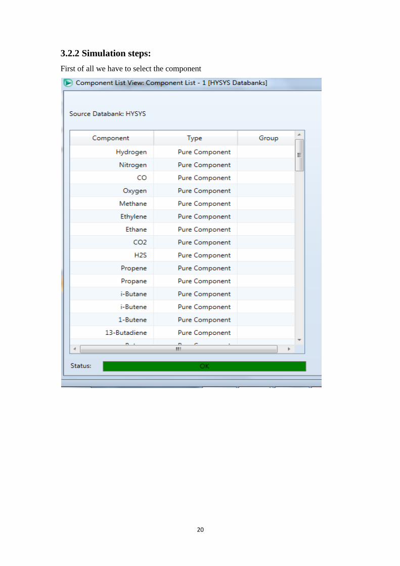
3.2.2 Simulation steps:
First of all we have to select the component

21
Selecting the fluid package :

22
Adding the olefin stream condition and composition :

23
Adding the iso– butane:

24
Now the Feed is readyfor reactor :
Results the reactor :

25
Alkylateproduct:
26
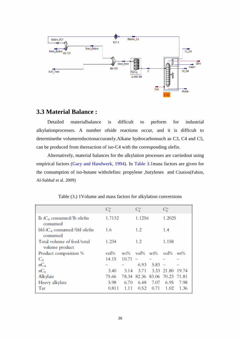
3.3 Material Balance :
Detailed materialbalance is difficult to perform for industrial
alkylationprocesses. A number ofside reactions occur, and it is difficult to
determinethe volumereductionaccurately.Alkane hydrocarbonsuch as C3, C4 and C5,
can be produced from thereaction of iso-C4 with the corresponding olefin.
Alternatively, material balances for the alkylation processes are carriedout using
empirical factors (Gary and Handwerk, 1994). In Table 3.1mass factors are given for
the consumption of iso-butane witholefins: propylene ,butylenes and Citation(Fahim,
Al-Sahhaf et al. 2009)
Table (3.) 1Volume and mass factors for alkylation conversions

27
3.3.1 Material Balance equation :
Input =out put +consumption
consumption =input – out put
Using the empirical factor for ,1-butene,listed in Table 3.1on volume basis:
bbl iso−butan consumed
𝑏𝑏𝑙 𝑜𝑙𝑒𝑓𝑖𝑛 𝑐𝑜𝑛𝑠𝑢𝑚𝑒𝑑= mass factors for alkylation conversions
3.4 Design
3.4.1 Space Velocity:
The olefin space velocity defined as:
The residence time in the reactor is 1
(SV )oand defined as the residence timeof the
fresh feed and externally recycled iso-butane in the reactionmixture. Sincethe
alkylation reaction is very fast, the residence time is not a limiting
parameter.However, as the space velocity increases, the octane number tends to
decreasewhile acid consumption tends to increase. Residence time for sulphuric acid
isusually from 5 to 40 min, and for hydrofluoric acid, it is 5–25 min.
τ = 𝑉𝑟
𝑣𝑜 OR(SV)○=
1
𝜏
SV =𝑣𝑜
VRVR =
𝑣𝑜
𝑆𝑉
3.5 Cost estimation:
The design engineer, by analyses of costs and profits, attempts to predict
whether capital should be invested in a particular project. After the investment is
made, records must be maintained to check on the actual financial results. These
records are kept and interpreted by accountants. The design engineer, of course, hopes

28
that the original predictions will agree with the facts reported by the accountant. There
is little chance for agreement, however, if both parties donot consider the same cost
factors, and comparison of the results is simplified ifthe same terminology is used by
the engineer and the accountant.
3.5.1 Types of Capital Cost Estimates:
These estimates are called by a variety of names, but the following five
categories represent the accuracy range and designation normally used for design
purposes.
Table (3. 1) Type of Capital Cost Estimates
Type of Capital cost Accuray
Order-of-magnitude estimate (ratio
estimate)
over± 30 percent.
Study estimate (factored estimate) up to ± 30 percent.
Preliminary estimate Within ± 20 percent.
Definitive estimate (project control
estimate)
within ± 10 percent.
Detailed estimate (contractor‟s
estimate)
within ± 5 percent.
3.5.2 COST INDEXES:
Most cost data which are available for immediate use in a preliminary or
predesign estimate are based on conditions at some time in the past. Because prices
may change considerably with time due to changes in economic conditions, some
method must be used for updating cost data applicable at a past date to costs that are
representative of conditions at a later time.? This can bedone by the use of cost
indexes
3.5.3Methodpower factor applied to plant – capacity ratio:
This method for study or order-of-magnitude estimates relates the fixed-capital
investment of a new process plant to the fixed-capital investment of similar previously

29
constructed plants by an exponential power ratio. That is, for certain similar process
plant configurations, the fixed-capital investment of the newfacility is equal to the
fixed-capital investment of the constructed facility C multiplied by the ratio R, to a
power Xmultiplaed by some factor.
Table (3.) Cost index

30
Cost index and annual average Marshallswift index:
Years All industry
2016 1611.1
2017 1637.1
3.5.4 Capital cost data for processing plant (1990):
process Process
remark
Typical plant
size (bbl/day)
Power
factor (X)
Alkylation
h2so4
calatyic 10000 0.6
3.5.5 Relative labor rate and productivity indexes in the chemical and
allied products industries for the United States (1989) :

31
Chapter 4 Results and Discussions
4.1 Material Balance:
4.1.1 Results:
4.1.1.1 Calculation by hysys:
4.1.1.1.1Over all material balances:
Table (4.) overall Material balance
Products ( 𝑏𝑏𝑙 𝑑𝑎𝑦 ) Feed ( 𝑏𝑏𝑙 𝑑𝑎𝑦 ) Component
0 301.9104 Butene
0 1518 Fresh iso-butane
1.376*107 1.377*107 RCY iso-butane
2.826 0 C3 out
1.682*104 0 C4 out
2379 0 Alkylate
13779211.83 13771819.91 Total
4.1.1.1.2 Material balance around reactor:
Input – output=consumption
Table (4.) Material Balance around the reactor
Consumption Output Input Comp
25135.98 1.407787218*
107
1.410300816*
107 Iso-butane
23313.1118 28323.2500 51636.3618 1-butene
32
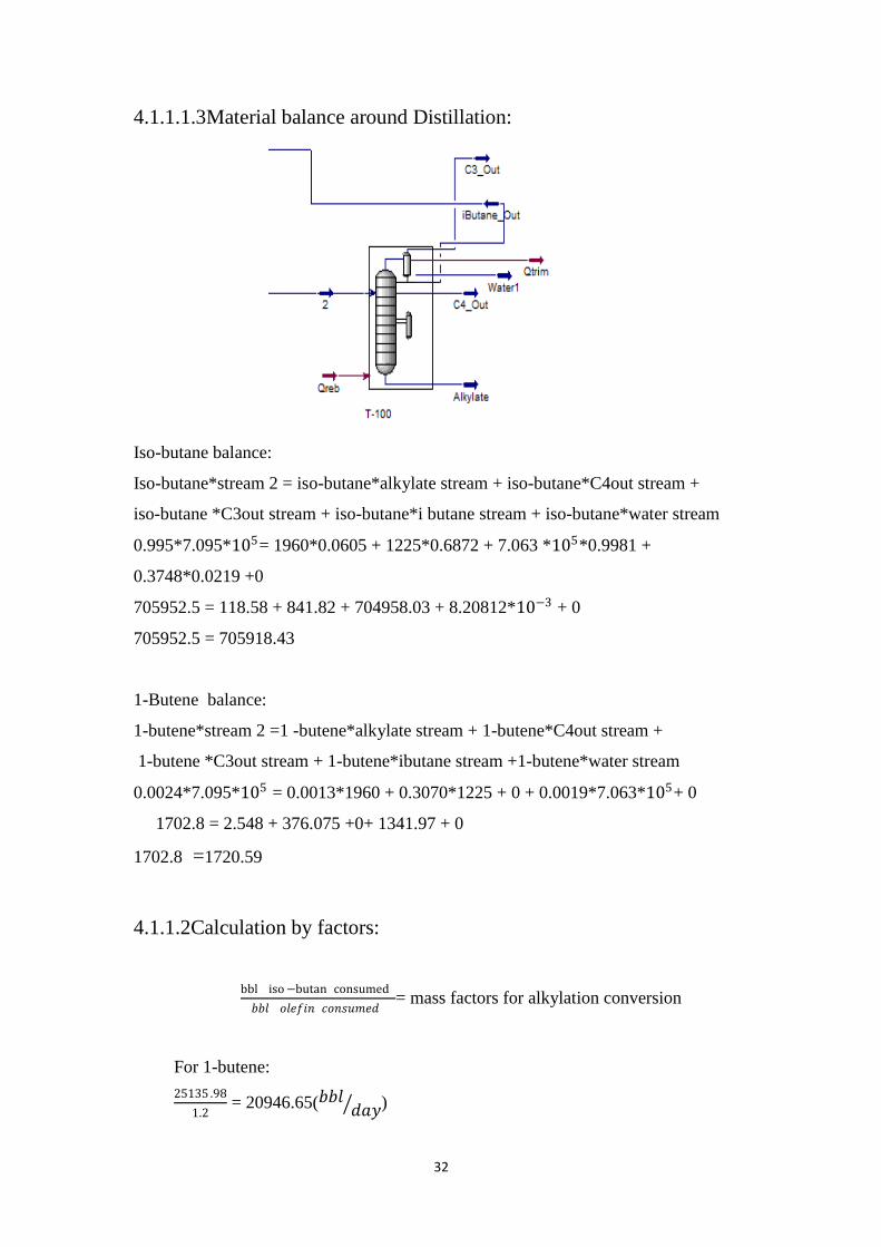
4.1.1.1.3Material balance around Distillation:
Iso-butane balance:
Iso-butane*stream 2 = iso-butane*alkylate stream + iso-butane*C4out stream +
iso-butane *C3out stream + iso-butane*i butane stream + iso-butane*water stream
0.995*7.095*105= 1960*0.0605 + 1225*0.6872 + 7.063 *105*0.9981 +
0.3748*0.0219 +0
705952.5 = 118.58 + 841.82 + 704958.03 + 8.20812*10−3 + 0
705952.5 = 705918.43
1-Butene balance:
1-butene*stream 2 =1 -butene*alkylate stream + 1-butene*C4out stream +
1-butene *C3out stream + 1-butene*ibutane stream +1-butene*water stream
0.0024*7.095*105 = 0.0013*1960 + 0.3070*1225 + 0 + 0.0019*7.063*105+ 0
1702.8 = 2.548 + 376.075 +0+ 1341.97 + 0
1702.8 =1720.59
4.1.1.2Calculation by factors:
bbl iso−butan consumed
𝑏𝑏𝑙 𝑜𝑙𝑒𝑓𝑖𝑛 𝑐𝑜𝑛𝑠𝑢𝑚𝑒𝑑= mass factors for alkylation conversion
For 1-butene:
25135 .98
1.2 = 20946.65(𝑏𝑏𝑙 𝑑𝑎𝑦 )

33
Table4.3 component material balance by factor :
Table (4. 1) component material balance by factor
Feed BPD
iC4 1.410300816*10^7
C4= 51636.3618
Total 14154644.52
Products
Remaining C4= 30689.7118
Alkylate 31628.04506
nC4 266127.1883
nC5 142472.1311
Heavy alkylate 248846.202
Tar 19969.13967
Total 739732.4179
4.1.2 Material Balance Discussion:
The amount of (iso-butane and 1-butene) consumed have been calculate by
using the input and output of this component from hysys.
This amount were recalculated by using another method (empirical factor) and results
were compared between hysys and empirical factor, and we found there is a little
different between them.10%
4.2Design:
4.2.1Results:
VR =𝑣𝑜
𝑆𝑉
Where :
VR =reactor volume
𝑣𝑜 =olifenvolummitric flow rate
𝑆𝑉= space velocity

34
Table (4.) VOLUME DESIGN
VR (𝑚3) 𝑣𝑜(𝑚3
ℎ𝑟) S V=(
1
τ )
1
ℎ𝑟
Residence
time (τ) (min)
0.166 2 12 5
0.333 2 6 10
0.666 2 3 20
1 2 2 30
1.333 2 1.5 40
We choose 40 min as a residence time there for our reactor volume is 1.333𝑚3
S V= 60
40= 1.5
volume reactor =2
1.5= 1.333 m3
Table (4.5) Effect of Volume on Alkylate Flow rate & Octane number:
MON RON Alkylate flow
rate (𝑚3
ℎ𝑟)
Reactor Volume
(𝑚3)
92.11 97.53 15.43 0.1666
92.11 97.53 15.48 0.333
92.11 97.53 15.57 0.666
92.11 97.53 15.66 1
92.11 97.53 15.76 1.333

35
4.2.2Design Discussion:
The volume of alkylation unit was calculated using the residence time or space
velocity and we found the volume of reactor increasing as the residence time
increased and decreasing with increasing of space velocity
4.3 Cost estimation results:
Correlation plant:
The capacity of similar constructed plant in Gulf country is 10,000 (bblday ),and it‟s
estimated cost is $35 million.
The capacity of new plant from simulation result :
Capacity =15.76(𝑚^3ℎ𝑟 )
=2379bbl/day
R=(𝐶𝑎𝑝𝑎𝑐𝑖𝑡𝑦 𝑜𝑓 𝑛𝑒𝑤 𝑝𝑙𝑎𝑛𝑡
𝑐𝑎𝑝𝑎𝑐𝑖𝑡𝑦 𝑜𝑓 𝑐𝑜𝑛𝑠𝑡𝑟𝑢𝑐𝑡𝑒𝑑 𝑝𝑙𝑎𝑛𝑡 )𝑋
R=(2379
10000)0.6 = 0.422
(FE) from marshallswift index
FE=(1637 .9
1611.1)
Cn=C Fe(𝑅)𝑋
Cn=35*(1637 .9
1611.1)(
2379
10000)0.6
Cn= 15 $ million

36
Chapter 5 Conclusion and Recommendation
5.1 Conclusions:
In this project we‟ve studied the effect of adding the alkylation unit to the
Khartoum refinery company and we‟ve found the product of alkylatyield from this
unit is economical. We‟ve also studied a correlation by(fundamentals of petroleum
refinery) to predict the amount of iso-butane and 1-butene consumed during reaction
and we‟ve found some variation in comparison with the real operation data and
simulation results.
5.2 Recommendations:
For further study of alkylation unit we suggest to use the hydrofluoric acid as a
catalyst to the unit and show the difference between it and sulfuric acid.
Also in this study we used the 1-butene as olefin to reacts with iso-butane to get the
alkylate, so for further study it can be replaced with other olefin such as propene or
iso-butene and show the difference.
Finally we recommend to add an alkylation unit to Khartoum refinery company in
order to obtain a high gasoline yield with high octane number.

37
5.3 References:
Amico et al. (2006). "Amico, V. D., Gieseman, J., Brockhoven, E., Rooijen, E., and
Nousiainen, H. (2006).
TheFahim, M. A. (2010). "Fundamentals of petroleum refining Includes index."
Fahim, M. A., et al. (2009). Fundamentals of petroleum refining, Elsevier.
Jones, D. S. J. (2015). "Introduction to Crude Oil and Petroleum Processing.
Kranz, K., and Graves ( (1988)). "Olefin interaction in sulfuric acid catalyzed
alkylation.215th National Meeting, American Chemical Society (Division of
Petroleum Chemistry),Dallas, TX.".
Rase, H. F. ( (1977).). "„Chemical Reactor Design for Process Plants,‟‟ vol. 1.Wiley-
Interscience,New York.".