Introductory Field Mapping Goals and Readings
25
1 Dr. Jacqueline Dohaney After the week’s activities, students should be able to... 1. Locate themselves on an air photo using notable locations, and geographic features. Add a scale and north arrow to a map. 2. Use an air photo to identify specific locations on the photo, through the process of triangulation. 3. Work as a team, and use topographic features and geologic tools to help you orienteer from one location to another. 4. Collaborate and communicate with other students to accomplish task specific goals. 5. Make and annotate a field sketch of geologic features at different scales. 6. Take quantitative measurements in the field (e.g., structural and textural measurements) 7. Make notes and observations in the field. Compile these data and plot onto a working geologic map. 8. Plan and navigate in the field, independently.
Transcript of Introductory Field Mapping Goals and Readings

1
Dr. Jacqueline Dohaney
After the week’s activities, students should be able to...
1. Locate themselves on an air photo using notable locations, and geographic features.
Add a scale and north arrow to a map.
2. Use an air photo to identify specific locations on the photo, through the process of
triangulation.
3. Work as a team, and use topographic features and geologic tools to help you orienteer
from one location to another.
4. Collaborate and communicate with other students to accomplish task specific goals.
5. Make and annotate a field sketch of geologic features at different scales.
6. Take quantitative measurements in the field (e.g., structural and textural
measurements)
7. Make notes and observations in the field. Compile these data and plot onto a working
geologic map.
8. Plan and navigate in the field, independently.

2

3
All students will hand-in a working bedrock map of your mapping area (in the form of Mylar) with a detailed geologic legend. Students may work together to collect geologic data, but will hand-in individual maps and legends. The geology map will include these features:
- Locations (where you made observations)
- Structural measurements (Strikes and dips)
- Geologic contacts (accurately drawn) - Geologic units
The geologic legend (to the map) will include these:
- Symbols (what do the points on your map mean?)
- Geologic Contacts (what do the lines on your map mean?)
- Geologic Unit descriptions and definitions (as defined by you!): Descriptions will include representative structure, texture and composition of each unit, any quantitative data you acquired
- Geologic Units should be in order of age (relative age, defined by field observations). - Include unconformities (if applicable)
Both the legend and the map will be:
- Neat - Easily read - Thorough - Organised

4
Day 1: Orienteering
After the day’s activities, students should be able to...
1. Become familiar with a Silva compass. Identify the north arrow, and orient to magnetic
north. Check and account for magnetic declination, to identify geographic (true) north.
2. Locate themselves onto an air photo, by deducing the scale (in metric), notable
locations, and geographic features.
3. Use an air photo to identify specific locations on the photo, through the process of
triangulation. Mark locations on the photo, and label and describe these into a
notebook.
4. Work as a team, and use topographic features to help you orienteer from one location
to another. Follow a set of tasks, and navigate to specific locations based on the
information provided.
5. Collaborate and communicate with other students to accomplish task specific goals.
Day 2: Sketches, Notes, and Strikes & Dips
After the day’s activities, students should be able to...
1. Make and annotate a field sketch of geologic features at different scales:
Landscape (large) scale
Outcrop scale
Small scale (sketch of minerals, fossils, textures)
2. Take organized, detailed, systematic notes of outcrops and features.
3. Record information that progresses from the larger scale to the smaller scale.
4. Take quantitative measurements of the minerals, grains, rocks and the units provided.
5. Separate your observations from your interpretations.
6. Use your own language when taking notes and rely on your own observations. Add
technical terms after you have made your initial observations. 7. Discuss your observations with your fellow classmates.
8. Revise a set of notes, and critique your work, compared to what is suggested. Think of
ways to improve your note-taking.
9. Take accurate strikes and dips of planar surfaces. Record the correct information in your
field notebooks.

5
Day 3: Mapping Day 1
After the day’s activities, students should be able to...
1. Improve on your navigation and triangulation skills by plotting accurate stations on your
maps.
2. Improve your geologic observations, sketches, notes and structural measurements
3. Differentiate and describe the “units” that you observed that day.
4. Mark working contacts on your maps.
5. Create/develop/eliminate mapping hypotheses of the area (E.g., What is the
relationship between units? What is the nature of the contacts in the area? What is the
landscape telling you?)
6. Take structural measurements and record these into your notebooks and onto your
working maps.
7. Discuss your observations, interpretations and hypotheses with your fellow classmates.
Day 4: Mapping Day 2
After the day’s activities, students should be able to...
1. Improve your geologic observations, sketches, notes and structural measurements
2. Continue marking structural measurements and contacts on your maps.
3. Create/develop/eliminate mapping hypotheses of the area.
4. Discuss your observations, interpretations and hypotheses with your fellow classmates.
Day 5: Final Map
After the day’s activities, students should be able to...
1. Improve your geologic observations, sketches, notes and structural measurements
2. Complete marking structural measurements and contacts on your maps.
3. Complete mapping hypotheses of the area.

6
4. Discuss your observations, interpretations and hypotheses with your fellow classmates.

7
(adapted from Compton’s Geology in the Field, 1962)
Measuring distances, with pacing
Pacing is the oldest form of distance measurement, dating back to Roman times. To measure your pace:
1. Set the distance to be measured by pace (e.g., 20, 50 or 100 meters, laid out with a measuring tap):
2. Count the number of comfortable footsteps (one at a time or as a set) that make up that
distance.
3. Each person should do the pace for the same distance, 5 times, to avoid miscounting and miscalculations. Calculate your average distance per step.
e.g., For measuring 50 meters (measuring tape), Sam took 71, 70, 72, and 71 steps (average of 71 steps per 50 meter distance). 50/71 = 0.70 m pace. Example of measuring distance with pace, compared to actual measured distance:

8
Magnetic Declination, True north, and Magnetic north. A compass is used to measure bearings and orientations of geologic features.
The first tasks when getting your compass to account for the magnetic declination (the difference between the magnetic north, and true or grid north) of the region. The declination can be found online, or a modern map of the region. Magnetic north on this image (below) at this location is 22.5 degrees East of Grid North (i.e., true north).
The north arrow that you put on maps is “grid” or true north.

9
Locating yourself on a Map; North Arrow and Scale Whether you use an airphoto, topographic or satellite
image – your starting point should be a known location
(or datum).
This can be known as location 0, or the first waypoint of
the day! At this datum, you should record the landmark,
elevation, and label this on your working map (on the
Mylar).
Reading the landscape (topography, vegetation) will
help you locate yourself. Identify high points on your map (often indicated by circular junctions of
topographic lines) (location C below). Follow the topographic contour lines (with your eyes, or even
your fingers) on the map, and then in real life. When a stream or valley intersects the topography it
creates a V (with the contour V pointing upsteam)
Photo of landscape Map view Travelling from one location to the next; and marking these locations on your map can be achieved by using bearings. By using specific known features, you can orient your map, with the view and the magnetic north to plot true north onto your map. Take a bearing to true north, and orient your map to the same “View”. The scale is the measured distance on your map (e.g., 1 cm) to real life (e.g., 1 cm = 1,000 m). Use pacing and measuring tape methods to discover the map scale.
10
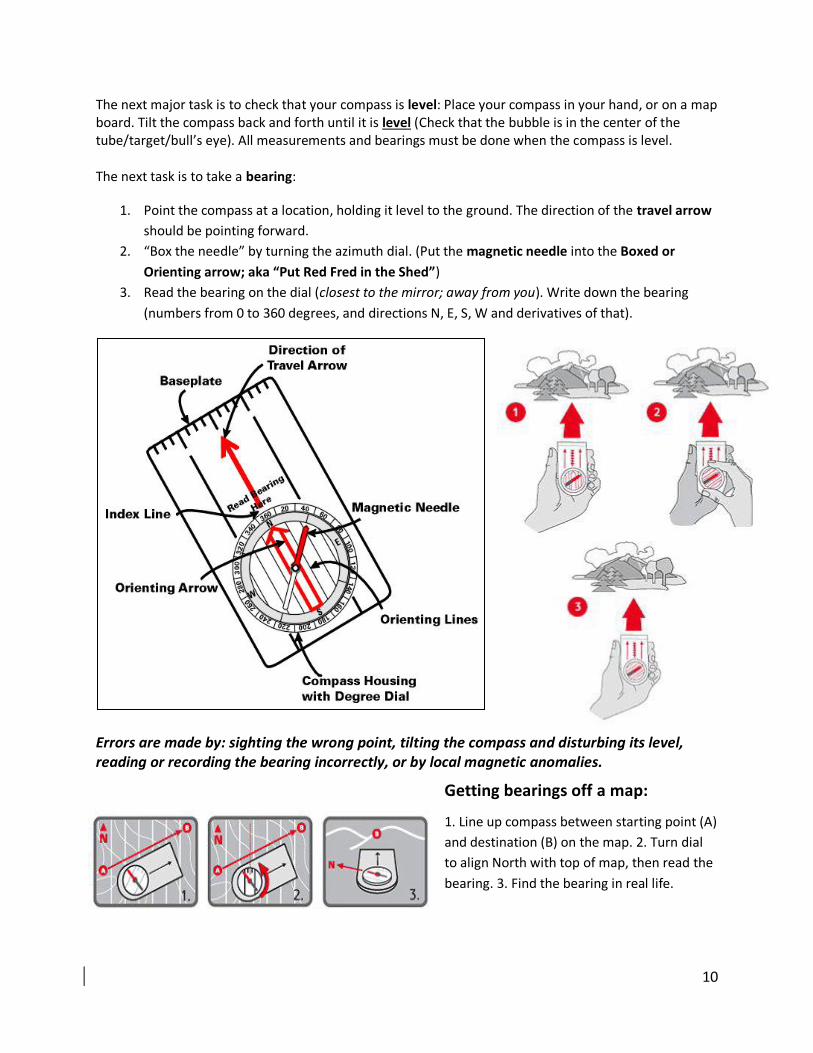
The next major task is to check that your compass is level: Place your compass in your hand, or on a map board. Tilt the compass back and forth until it is level (Check that the bubble is in the center of the tube/target/bull’s eye). All measurements and bearings must be done when the compass is level. The next task is to take a bearing:
1. Point the compass at a location, holding it level to the ground. The direction of the travel arrow
should be pointing forward.
2. “Box the needle” by turning the azimuth dial. (Put the magnetic needle into the Boxed or
Orienting arrow; aka “Put Red Fred in the Shed”)
3. Read the bearing on the dial (closest to the mirror; away from you). Write down the bearing
(numbers from 0 to 360 degrees, and directions N, E, S, W and derivatives of that).
Errors are made by: sighting the wrong point, tilting the compass and disturbing its level, reading or recording the bearing incorrectly, or by local magnetic anomalies.
Getting bearings off a map:
1. Line up compass between starting point (A)
and destination (B) on the map. 2. Turn dial
to align North with top of map, then read the
bearing. 3. Find the bearing in real life.

11
Triangulation
By using your compass, an airphoto (with geographic and topographic features) you can quite
accurately locate yourself. This process is called Triangulation:
1. Pick two distinct features in the landscape in front of you that you can easily identify on
your airphoto or map. Common items are trees, landmarks, buildings, intersections of
roads or streams.
2. Standing in your specific location, take a bearing* to feature 1 (being sure that your
compass is level). Record the bearing orientation in your notebook (e.g., 210 degrees),
and then the line onto your map. The bearing line will be a line that runs through the
feature along the given bearing.
3. Take the bearing from your location to feature 2. As in step 2, record the orientation
line. The place where these two lines (feature 1, and then feature 2) intersect is your
precise location.
4. Be sure to check that this is reasonable (e.g., if your intersecting lines have you standing
in a river, and you are indeed NOT, then check again.)
*the literature commonly calls these bearings as “antibearings” (how confusing is that?)
Figure: Triangulation using bearings. A. Use the side of your compass, ruler or protractor to
draw a bearing line (dark line) through where you are (point occupied ) to a specific feature
(point sighted). B. When you’ve plotted two bearings (to two or more different features in the
landscape), they will intersect to your specific location (Square).
Common error: Your initial north arrow is incorrect, which means your bearings are incorrect.

12
Making Field Sketches
Drawings often save time in note-taking and may be essential for recording complex shapes and relationships. Drawing contributes to observation by forcing one to look closely, especially at how specific features come together. Sketches should be clear, denoting shapes, patterns and structural information. If you are taking photos of the field area:Use labels to show where specific photos and samples are taken.
All sketches should contain: Outline of the outcrop/landscape A scale (actual or estimated) Bearing or direction that you are looking (e.g., Looking SW) Measurements of the features Labels, arrows and lines outlining specific features Annotations of the features on the sketch If the outcrop is very large, and complex – use a grid to differentiate parts of the outcrop. Measure the parts of the grid and then move from one side to the next. Be sure to back-away from the outcrop periodically to make sure you don’t lose sight of where you are in the landscape. Stick to the geological information, avoid extraneous information. A general rule is to keep the sketch simple, and easy to read. Annotate sections of the sketch as “blow-outs” (where you put a square in the sketch) and blow it up.

13
Taking Notes
All important information at an outcrop should be recorded in a notebook. The level of detail
required will be dependent on the aims of your study (detailed study versus regional study,
etc.).
You should use your own language, and include your observations in the way that they appear
to you. Technical terms can always be added later.
You should be organized. Note-taking is learned over time, and gets better with practice. It
should be done systematically. By taking a systematic approach, you can avoid missing
information.
As you take more notes, and see more outcrops, you will become more efficient. In the
beginning of any study you should take your time at the first few outcrops. Explore all of the
structural, textural and compositional aspects of the unit. This will pay off in the long term.
Separate OBSERVATIONS from INTERPRETATIONS, so that any later reader can derive
understanding from what you have drawn and observed.
In a regional study, note-taking progresses from complete outcrop descriptions to short,
abbreviated descriptions – noting differences between one location, to another. This allows you
to understand differences in distribution of the units (i.e., how one type of rock differs in place
and time).
Don’t forget to include photo and sample numbers.
Tips for photos:
1. Take overall views of outcrops, showing relationships to the outcrop and its surrounding
landscape.
2. Features showing age relations
3. Close-up views of primary and secondary structures
4. Well-exposed contacts
5. Compositional or textural variations in a rock, using a series of close-ups.
6. Don’t backlight or overexpose photos. Check to make sure photo shows intended
information before moving on.
Use the next section (Outline of Field Observations) as a guide to the information to be
included.

14
Outline of Field Observations
(Modified from: Vick et al., 1979) Step 1: Background Information: 1A) Location of the outcrop - Geographic name - GPS waypoints (if necessary) 1B) Station number 1C) Date and time of day 1D) Weather and visibility conditions (This information is really important for remembering details about your day, and the observations you made)
Step 2: Identification of Large Scale Features (i.e. Outcrop Scale) 2A) General topography of area (ridge, valley, plain, escarpment?) 2B) Size and shape of the outcrop (dimensions). Make an outcrop sketch. 2C) Major colours in/of the outcrop (can you break-up the outcrop by sections?) 2D) Overall, outcrop fabric (layered, folded, faulted or massive)
Step 3: Large Scale Feature Descriptions:* 3A) Identification of MAJOR “features”. Examples: layers, unconformities, folds, faults, dikes, joints, etc. 3B) Label features by number/code on your outcrop sketch. 3C) Size of features (dimensions, measure) 3D) Orientation (Linear and planar) 3E) Weathering/erosion of features (all weathering the same? Or differentially?) Cohesiveness of the rocks – consolidated? Unconsolidated? Soils? Hardness?
Step 4: Intermediate Scale Descriptions: 4A) Identification of individual layers or units. Shape of units: uniform, lens-like? Include: schistosity, thickness of beds or laminations, sedimentary or volcanic structures (e.g., pillow lavas, flow banding, cross bedding) 4B) Describe nature of contacts between beds (conformable) or contacts between different units (unconformities). Gradational or sharp? 4C) Describe nature of relative cross-cutting relationships. Are there veins or joints. Which bit is cutting which bit?
Step 5: Small Scale (i.e., hand sample) – Textures 5A) Description of individual layers or units – clastic or massive? 5B) Grain or crystal sizes and shapes. Use grain size comparator. 5C) If clastic: sorting, rounding, grading of rock 5D) Description of Fossils, if present (identification, sketch, and collection)
Step 6: Small Scale – Compositions 6A) Name the Minerals present. Use diagnostic features of minerals; e.g., cleavage, colour, shapes, hardness, etc 6B) Estimate Mineral or Clast percentages 6C) Composition of the cement (or matrix, if present). May use acid to determine if carbonate or silica dominated. 6D) Give the rocks names! Use classification charts. Base the rock classification on mineral proportions, clast sizes and populations. Can be a working name.
* Step 3 and 4 can sometimes overlap. If you are measuring what you think is dyke, you may also describe its texture simultaneously. This is only a suggested list. You can approach the outcrop in the way that is suited best to you.
15
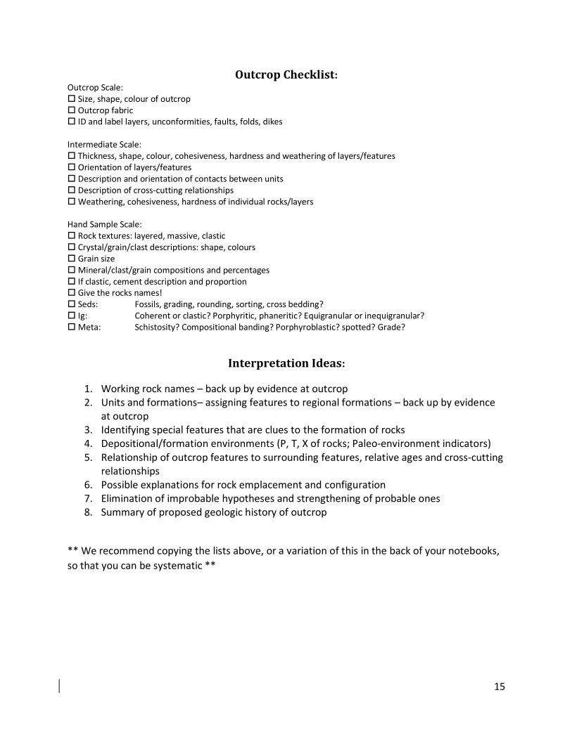
Outcrop Checklist: Outcrop Scale: Size, shape, colour of outcrop Outcrop fabric ID and label layers, unconformities, faults, folds, dikes Intermediate Scale: Thickness, shape, colour, cohesiveness, hardness and weathering of layers/features Orientation of layers/features Description and orientation of contacts between units Description of cross-cutting relationships Weathering, cohesiveness, hardness of individual rocks/layers Hand Sample Scale: Rock textures: layered, massive, clastic Crystal/grain/clast descriptions: shape, colours Grain size Mineral/clast/grain compositions and percentages If clastic, cement description and proportion Give the rocks names! Seds: Fossils, grading, rounding, sorting, cross bedding? Ig: Coherent or clastic? Porphyritic, phaneritic? Equigranular or inequigranular? Meta: Schistosity? Compositional banding? Porphyroblastic? spotted? Grade?
Interpretation Ideas:
1. Working rock names – back up by evidence at outcrop 2. Units and formations– assigning features to regional formations – back up by evidence
at outcrop 3. Identifying special features that are clues to the formation of rocks 4. Depositional/formation environments (P, T, X of rocks; Paleo-environment indicators) 5. Relationship of outcrop features to surrounding features, relative ages and cross-cutting
relationships 6. Possible explanations for rock emplacement and configuration 7. Elimination of improbable hypotheses and strengthening of probable ones 8. Summary of proposed geologic history of outcrop
** We recommend copying the lists above, or a variation of this in the back of your notebooks,
so that you can be systematic **

16
Taking Structural Measurements (Strikes & Dips)
Strikes and dips are structural
measures that describe the
orientation of planar geologic
features. These data are
essential for determining the
history and subsurface
relationships of rocks and
units.
You can measure the strike and dip of any planar feature:
Sedimentary bedding surfaces
Unit contacts
Joints and fractures in rocks
Foliation in metamorphic rocks
Fault planes
Planar dikes and sills
The accuracy and quality of a geological map is directly correlated to the amount of strike and
dip measurements you take: the more you have, the more accurate the map.
We must first visualize what the “attitude” of a planar surface is. This means that you must use
your hand, arm or map board and tilt your surface to match the orientation of the surface you
are measuring. Once you have determined the planar attitude, geologists use the right-hand-
rule to help take strikes and dips. The palm and fingers of your (right) hand is dipping in the
direction and at the angle of the surface; your thumb is the strike direction.

17
To measure the strike: You are measuring the bearing of a line (described by the intersection between a dipping planar surface and the horizontal plane).
1. Hold the compass, level, against the planar feature that you are measuring. (It is often good to use a mapboard to put your compass onto, to keep it level). (the compass should be in the direction of your thumb in right hand rule; matched to the white tick mark, near the bubble balance)
1. Without moving the compass, turn the dial and “box the needle” (move the dial until the magnetic needle is inside the hollow boxed arrow).
2. Record the measurement out of 360 degrees: For example: 000 (North), 045 (NE) (ALWAYS use three digits to avoid error when re-reading notes later)
To measure the dip: You are measuring the angle of a plane that is dipping in a particular direction. (Some people record this “dip direction”)
1. Turn the compass dial to West (matched with the white tick mark, near the bubble balance)
2. Turn the compass on its side, and the angle of the compass should be replicated by what you see (i.e., the compasses vertical orientation is the same angle as the planar feature).
3. Reading from the underside of the compass, record the angle (from 0 to 90 degrees), that is in line with the black arrow head (not the normal red needle).
4. Practice rotating the compass from 90 degrees (vertical) to 0 degrees.
18
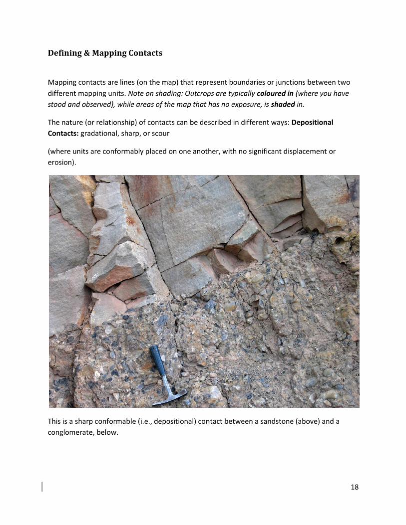
Defining & Mapping Contacts
Mapping contacts are lines (on the map) that represent boundaries or junctions between two
different mapping units. Note on shading: Outcrops are typically coloured in (where you have
stood and observed), while areas of the map that has no exposure, is shaded in.
The nature (or relationship) of contacts can be described in different ways: Depositional
Contacts: gradational, sharp, or scour
(where units are conformably placed on one another, with no significant displacement or
erosion).
This is a sharp conformable (i.e., depositional) contact between a sandstone (above) and a
conglomerate, below.

19
Or faults, intrusions and unconformities (where significant time or displacement has occurred
between the units): (An intrusion below between the lighter unit and the darker. Note the
irregularity of the contact).
There are several types of contacts which can be defined by the level of certainty the mapper
has:
Defined (a solid line; where you have visibly observed the contact between two units at the
outcrop);
Inferred Confident (Dashed; where you can trace a contact between locations, with accuracy
and certainty);
Inferred Concealed (Dotted; Where you are placing a contact based on a geologic model, but
where the contact is not accurate); and
Unknown Question marks; where your lack of geologic data and exposure does not allow for
any interpretation to be made)

20

21
Sedimentary Grain Size Rock Classification

22
Sandstone Compositional Ternary Diagram (after Folk 1974)
Carbonate Classification Scheme (Folk 1962)

23
Common Fossils of New Zealand

24
Sedimentary Structures
Planar bedding has little diagnostic importance but animal burrows or bed form irregularities my give an
indication of way-up and environment.
Current cross bedding gives clear way-up indication as bed are truncated by the next influx of sediment.
The orientation of the cross beds can also indicate the direction of water or wind currents.
Ripple-marked bedding indicates wave action and the ripple cusps point in the younging direction.
Wave action usually indicates shallow marine conditions but ripples can be found in freshwater
sediments also.
Imbricate bedding is the overlapping of fossil shells or platey pebbles and can be used as an indicator of
current direction.
Graded bedding usually fines upwards to give an indication of way-up. Graded units represent
individual pulses of sediment which may be seasonal or indicative of some other cyclic process.
Cut-and-fill bedding involves the reworking of sedimentary layers by new water channels. They provide
both way-up and current direction indicators and are common in stream fluvial deposits.

25
IUGS Igneous Classification Diagrams: