INTRODUCTION TO SILVER DIGIPLATE TECHNOLOGY
19
INTRODUCTION TO SILVER DIGIPLATE TECHNOLOGY Application of Silver Digiplate polyester - and paper printing plates Computer-to-Plate
-
Upload
khangminh22 -
Category
Documents
-
view
1 -
download
0
Transcript of INTRODUCTION TO SILVER DIGIPLATE TECHNOLOGY

INTRODUCTION TO SILVER DIGIPLATE TECHNOLOGY
Application of Silver
Digiplate polyester -
and paper
printing plates
Computer-to-Plate
Brief-Guide-2007_GB_2c.qxd 25.08.2008 15:27 Uhr Seite 1

3
CONTENTS
Introduction . . . . . . . . . . . . . . . . . . . . . . . . . . . . . . . . . . . . . . . . . . . . . . . . . . . . . . . . . 5
Product information: Silver Digiplate . . . . . . . . . . . . . . . . . . . . . . . . . . . . . . . . . . . . . 6
1.0 Output methods for Silver Digiplate . . . . . . . . . . . . . . . . . . . . . . . . . . . . . .71.1 Imagesetter . . . . . . . . . . . . . . . . . . . . . . . . . . . . . . . . . . . . . . . . . . . . . . . . . . 71.1.1 Output mode1.1.2 Resolution1.2 Calculating the optimum exposure . . . . . . . . . . . . . . . . . . . . . . . . . . . . . . . 71.2.1 Laser intensity1.2.2 Calibration1.2.3 Ongoing checking1.3 Processing . . . . . . . . . . . . . . . . . . . . . . . . . . . . . . . . . . . . . . . . . . . . . . . . . . . 111.4 Punching, cutting, bending . . . . . . . . . . . . . . . . . . . . . . . . . . . . . . . . . . . . . 121.4.1 Punching1.4.2 Bending polyester plates
2.0 Proofing-solutions and Color management for Silver Digiplate . . . . . . . 132.1 Application of the proofs . . . . . . . . . . . . . . . . . . . . . . . . . . . . . . . . . . . . . . 132.2 Workflow profiling . . . . . . . . . . . . . . . . . . . . . . . . . . . . . . . . . . . . . . . . . . . 132.2.1 Printing machine profiling2.2.2 Proof printer profiling2.2.3 Profiling principles2.3 Usage of the ICC-Profiles on Mitsubishi SDP-RIP . . . . . . . . . . . . . . . . . . . . 142.3.1 Different color gamuts through Rendering Intents2.3.2 Mitsubishi Proof-Colourdot – the simple way to the perfect proof2.3.3 Inkjet-Proof materials from Mitsubishi HiTec Paper
3. 0 Printing with Silver Digiplate . . . . . . . . . . . . . . . . . . . . . . . . . . . . . . . . . . . 173.1 Print settings . . . . . . . . . . . . . . . . . . . . . . . . . . . . . . . . . . . . . . . . . . . . . . . . 173.1.1 Setting the press3.1.2 Adjusting the dampening solution3.1.3 Additional dosing units
4.0 Dampening solution . . . . . . . . . . . . . . . . . . . . . . . . . . . . . . . . . . . . . . . . . . .184.1 Dampening Solution Additives . . . . . . . . . . . . . . . . . . . . . . . . . . . . . . . . . . 184.2 Additional Mitsubishi additives . . . . . . . . . . . . . . . . . . . . . . . . . . . . . . . . . 184.3 Dampening solution mixing plants . . . . . . . . . . . . . . . . . . . . . . . . . . . . . . 19
5.0 Inks . . . . . . . . . . . . . . . . . . . . . . . . . . . . . . . . . . . . . . . . . . . . . . . . . . . . . . . . 20
6.0 Cleaning solution and print dusting powder . . . . . . . . . . . . . . . . . . . . . . 206.1 Cleaning solution . . . . . . . . . . . . . . . . . . . . . . . . . . . . . . . . . . . . . . . . . . . . . 206.2 Print dusting powder . . . . . . . . . . . . . . . . . . . . . . . . . . . . . . . . . . . . . . . . . . 20
7.0 Starting up the press . . . . . . . . . . . . . . . . . . . . . . . . . . . . . . . . . . . . . . . . . . 217.1 Combined dampening Systems (e.g. DAHLGREN, ALCOLOR) . . . . . . . . . 217.2 Separate dampening Systems (e.g. KOMORIMATIC) . . . . . . . . . . . . . . . . 217.3 Restarting the press . . . . . . . . . . . . . . . . . . . . . . . . . . . . . . . . . . . . . . . . . . 22
8.0 Recommendations for non-standard presses . . . . . . . . . . . . . . . . . . . . . 22
CONTENTS
Brief-Guide-2007_GB_2c.qxd 25.08.2008 15:27 Uhr Seite 2

54
INTRODUCTION
Silver Digiplate (SDP) is an extremely advanced
offset-plate technology based on the same
principles as silver-halide photography; SDP plates
are exposed directly in a polyester plate
imagesetter or other film imagesetter, without
any intermediate processes.
Silver Digiplate is available in the form of polyester or paper-
based plates.
Silver Digiplate is distinguished by its excellent workability despi-
te the minimal process maintenance requirement. SDP is compa-
tible with the majority of laser imagesetters and is ideal for use
with conventional offset presses.
This manual describes the characteristics of the Mitsubishi Silver
Digiplate and provides potential users with recommendations
for integrating this method into their existing plant.
This manual may not be duplicated or reproduced without the
prior permission of Mitsubishi Paper Mills Ltd.
9.0 Plate clamping procedure . . . . . . . . . . . . . . . . . . . . . . . . . . . . . . . . . . . . . . 239.1 Plate cylinder backing . . . . . . . . . . . . . . . . . . . . . . . . . . . . . . . . . . . . . . . . . 239.2 Plate clamping bars . . . . . . . . . . . . . . . . . . . . . . . . . . . . . . . . . . . . . . . . . . . 239.3 Clamping the SDP plates on presses with no autoplate system . . . . . . . . 239.4 Clamping the SDP plate on presses wiht an autoplate system . . . . . . . . . 24
10.0 Multi-colour printing with SDP plates,taking the Heidelberg PM 46 /QM 46 as an example . . . . . . . . . . . . . . . .24
10.1 Basic machine settings and prerequisites . . . . . . . . . . . . . . . . . . . . . . . . . . 2410.2 Clamping the plates with an autoplate system . . . . . . . . . . . . . . . . . . . . . 2510.3 Start-up . . . . . . . . . . . . . . . . . . . . . . . . . . . . . . . . . . . . . . . . . . . . . . . . . . . . . 2510.4 Register with polyester plates . . . . . . . . . . . . . . . . . . . . . . . . . . . . . . . . . . 25
11.0 Four-colour printing with SDP plates,taking the RYOBI 3304H as an example . . . . . . . . . . . . . . . . . . . . . . . . . . 26
11.1 Basic machine settings and prerequisites . . . . . . . . . . . . . . . . . . . . . . . . . 2611.2 Optimising the register printing for Ryobi 3304 . . . . . . . . . . . . . . . . . . . . 26
12.0 Four-colour printing with SDP plates,taking the Heidelberg SM 52 as an example . . . . . . . . . . . . . . . . . . . . . . . 27
12.1 Basic machine settings and prerequisites . . . . . . . . . . . . . . . . . . . . . . . . . . 2712.2 Clamping the plates with an autoplate system . . . . . . . . . . . . . . . . . . . . . 2712.3 Start-up . . . . . . . . . . . . . . . . . . . . . . . . . . . . . . . . . . . . . . . . . . . . . . . . . . . . . 2812.4 Register with polyester plates . . . . . . . . . . . . . . . . . . . . . . . . . . . . . . . . . . 2812.5 Optimize register printing for SM 52 . . . . . . . . . . . . . . . . . . . . . . . . . . . . . 28
13.0 Four-colour printing with SDP plates,taking the RYOBI 524H as an example . . . . . . . . . . . . . . . . . . . . . . . . . . . . 29
13.1 Basic machine settings and prerequisites . . . . . . . . . . . . . . . . . . . . . . . . . . 29
14.0 Four-colour printing with SDP plates, taking the Ryobi 784 as an example . . . . . . . . . . . . . . . . . . . . . . . . . . . . . 30
14.1 Basic machine settings and prerequisites . . . . . . . . . . . . . . . . . . . . . . . . . . 30
15.0 Two- or four-colour printing with SDP plates, taking the Heidelberg SM74 as an example . . . . . . . . . . . . . . . . . . . . . . . 30
15.1 Basic machine settings and prerequisites . . . . . . . . . . . . . . . . . . . . . . . . . . 30
16.0 Troubleshooting . . . . . . . . . . . . . . . . . . . . . . . . . . . . . . . . . . . . . . . . . . . . . . 3116.1 Exposure problems (at plate production) . . . . . . . . . . . . . . . . . . . . . . . . . 3116.2 Faulty reproduction (causes associated with the processor) . . . . . . . . . . . 3116.3 Faulty reproduction (other causes) . . . . . . . . . . . . . . . . . . . . . . . . . . . . . . . 3116.4 Scumming problems (Prerequisite: well exposed printing plate) . . . . . . . 3216.5 Inferior rendering in the printing process
(Prerequisite: well exposed printing plate) . . . . . . . . . . . . . . . . . . . . . . . . 3216.6 Voids in printing area . . . . . . . . . . . . . . . . . . . . . . . . . . . . . . . . . . . . . . . . . 3316.7 Poor ink acceptance . . . . . . . . . . . . . . . . . . . . . . . . . . . . . . . . . . . . . . . . . . . 3316.8 Poor reproduction of screen ruling points . . . . . . . . . . . . . . . . . . . . . . . . . 3416. 9 Emulsification of ink . . . . . . . . . . . . . . . . . . . . . . . . . . . . . . . . . . . . . . . . . . 3416.10 Roller-stripping . . . . . . . . . . . . . . . . . . . . . . . . . . . . . . . . . . . . . . . . . . . . . . . 3416.11 Register alignment differences . . . . . . . . . . . . . . . . . . . . . . . . . . . . . . . . . 35
INTRODUCTIONCONTENTS
Brief-Guide-2007_GB_2c.qxd 25.08.2008 15:27 Uhr Seite 4

76
1.0 OUTPUT METHODS FOR SILVER DIGIPLATE
1.1 Imagesetter
1.1.1 Output mode:Images are output on Silver Digiplate in negative/right reading mode, i.e. the printing areas are unexposed (silver) and the nonprinting areas are exposed (black).
1.1.2 Resolution: The resolution of the imagesetter is depending on its specifications and the requested result.It is important to set a sufficient imagesetter resolution for the selected screen ruling, in order to be able to reproduce the required grey levels.
Special ruling processes such as "Extra Gray Values" from Harlequincan produce smooth runs and sufficient grey levels even with non-optimal combinations of screen ruling and resolution.
1.2 Calculating the optimum exposureThis important task is divided into three steps: setting the laserintensity, calibrating the screen ruling and continually checkingthe results.
1.2.1 Laser intensity:The laser intensity setting (density) has a considerable influence onthe quality of the printing results, particularly with four-colourprinting. For an imagesetter test, the processing chemicals shouldideally only be a few days old. The aim when calculating the opti-mum density setting is to find the point immediately precedingthe maximum blackening of the emulsion layer. It's difficult toprovide absolute guidelines for density values because the SilverDigiplate material works very abruptly and the range betweenover- and underexposure is very small.
OUTPUT METHODSPRODUCT INFORMATION
Product information: Silver Digiplate
Maximum screen ruling: 70 lines/cm (175 l/inch), 3-97%The material is available in rolls or sheets for all standard imagesetter specifications.
Designation Purpose Packaging unit Notes
SLM-AC Activator Processing chemical 10l canister Formulation:AC+water = 1 + 1
SLM-ST Stabilizer Processing chemical 10l canister Formulation:ST+water = 1 + 3
SLM-EAC Eco-Activator Processing chemical 10l canister Ready for use, for Eco Processor
SLM-EST Eco-Stabilizer Processing chemical 10l canister Ready for use, for Eco Processor
SDP-EACII Eco-Activator Processing Chemical 10l canister Ready for use, for Eco Processor
SDP-ESTII Eco-Stabilizer Processing Chemcial 10l canister Ready for use, for Eco Processor
SLM-OE III Pen Correction pen 3-Pack Narrow tip
SLM-OE Correction fluid 100 ml bottle x 2 Extensive correction
SLM-OHIII Pre-dampening 5l canister Fast ink/watersolution balance
SLM-OD30 Dampening solution 5l canister Conventional andadditive continuous-feed
dampening systems
SDP-FS Dampening solution 10l canister Alcohol-reducedadditive printing
SLM-OA1 Dampening solution 1l bottle Even emulgation ofadditive the printing ink
SLM-OA2 Dampening solution 1l bottle Increased dampingadditive on the plate surface
Designation Material Material Light source Max. Print runthickness
SDP-FRS175 Film 0.20 mm Red-LD (633-680 nm) 20,000 sheetsHe-Ne (633 nm)
SDP-FR100 Film 0.12 mm Red-LD(633-680 nm) 20,000 sheetsHe-Ne (633 nm)
SDP-RR 175 Paper 0.19 mm Red-LD(633-680 nm) 10,000 sheetsHe-Ne (633 nm)
SDP-FE175 Film 0.20 mm LED (670-680 nm) 20,000 sheets
SDP-FD100/175 Film 0.12/0.20 mm Infrared (780 nm) 20,000 sheets
SDP-RD175 Paper 0.19 mm Infrared (780 nm) 10,000 sheets
Brief-Guide-2007_GB_2c.qxd 25.08.2008 15:27 Uhr Seite 6

We recommend the following process:Carry out a test exposure of finepositive and negative lines, e.g.the Mitsubishi Test Chart (Fig. 1),This test job contains severalelements designed to help you tocheck the optimum exposure, e,g.fine vertical and horizontal linestructures, fine positive andnegative text, halftone patches,etc. The test should be carried outseveral times in succession withvarious different laser settings.The selected gradations shouldnot be too fine, so that a goodsetting may be roughly calculatedmore quickly. Free download available atwww.mitsubishi-paper.com.
The exposed plates might display the following results, whichshould be evaluated with a powerful magnifier (e.g. 20x):
In principle, positive and negative lines should be equally welldefined. For subsequent printing it is important to know thatslight overexposure (more blackening on the plate) helps to pre-vent background scumming and filling in. Slight underexposure
9
(silver image on the plate), on the other hand, helps to stabilizefine lines and prevent the image either from being too pinsharpor from disappearing. Alternatively, uncalibrated ruling dot percentage with 3% up to97% can be output. Thereby it must be insured that no calibrationis acti-vated, otherwise the result can be falsified. In case of theoptimum exposure the 3% and 97% dot area on the plate shouldbe reproduced very well.
The exposure values must be calculated individually for each expo-sure resolution. Often, lower resolutions require higher laser set-tings.
1.2.2 Calibration:The RIPs' calibration programmes offer various different ways ofinfluencing the output. For this reason, it is important to first esta-blish what the calibration is intended to achieve. In general, a cali-bration is intended to achieve repeatable results. Thereto two stages can be distinguished:
1st method: Linearization of the printing plate and determinationof the printing characteristics.After completion of linearization, the printing characteristics aredetermined on a print result. The characteristic then has to becorrected for the desired standard and stored in the RIP. With thismethod the preliminary stage and the print can be examinedseparately in the event of any changes in the dot gain.
2nd method: Determination of the printing characteristics on aprint proof (without linearization of the plate)The advantage of this method is that no printing plate measuringdevice is required. The disadvantage is that all the influencesrelevant to the dot percentages (CtP unit, printing plate, printingconditions and printing materials) are combined in a correctioncurveTo adapt the printing result of Silver Digiplate to available results(follow-up jobs), the following method is recommended:Produce a printing plate with a suitable test-chart with gradatedhalftone patches (e.g. Mitsubishi test chart), once conventionallywith film and once by CtP. Both will be printed under the sameconditions and compared one another. Afterwards the CtP resultcan be adapted by calibration to the conventional productionprinting result.
8
Fig. 1
OUTPUT METHODSOUTPUT METHODS
Exposure level
Underexposure Proper exposure Overexposure
Reproducibility of image with positive and negative thin lines
Scumming Thickening of dots and lines
Image blindingThinning of dots and lines
Determining the Exposure Level
Brief-Guide-2007_GB_2c.qxd 25.08.2008 15:27 Uhr Seite 8
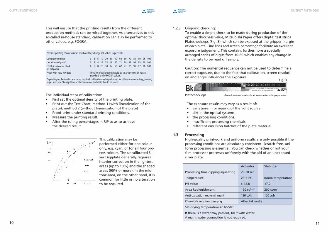
1.2.3 Ongoing checking:To enable a simple check to be made during production of theoptimal thickness value, Mitsubishi Paper offers digital test stripsPlatecheck.eps (Fig. 3), which can be exposed at the gripper marginof each plate. Fine lines and screen percentage facilitate an excellentexposure judgement. This contains furthermore a specially arranged series of digits from 10-80 which enables any change inthe density to be read off simply.
Caution: The numerical sequence can not be used to determine acorrect exposure, due to the fact that calibration, screen resoluti-on and angle influences the exposure.
Platecheck.eps (Free download available at www.mitsubishi-paper.com)
The exposure results may vary as a result of:• variations in or ageing of the light source.• dirt in the optical systems.• the processing conditions.• insufficient processing chemicals.• different emulsion batches of the plate material.
1.3 ProcessingHigh-quality printwork and uniform results are only possible if theprocessing conditions are absolutely consistent. Scratch-free, uni-form processing is essential. You can check whether or not yourfilm processor processes uniformly with the aid of an unexposedsilver plate.
Activator Stabilizer
Processing time:dipping-squeezing 20-30 sec.
Temperature 28-31°C Room temperature
PH-value > 12.8 <7.0
Area Replenishment 150 cc/m2 200 cc/m2
Anti oxidation replenishment 120 cc/h 120 cc/h
Chemicals require changing After 2-4 weeks
Set drying temperature at 40-50 C.
If there is a water-tray present, fill it with water. A mains water connection is not required.
This will ensure that the printing results from the differentproduction methods can be mixed together. As alternatives to thisso-called in-house standard, calibration can also be performed toother values, e.g. FOGRA.
The individual steps of calibration:• First set the optimal density of the printing plate.• Print out the Test Chart, method 1 (with linearization of the
plate), method 2 (without linearization of the plate)• Proof-print under standard printing conditions. • Measure the printing result.• Alter the ruling percentages in RIP so as to achieve
the desired result.
This calibration may beperformed either for one colouronly, e.g. cyan, or for all four pro-cess colours. The uncalibrated Sil-ver Digiplate generally requiresheavier correction in the lightestareas (up to 10%) and the shadedareas (90% or more). In the mid-tone area, on the other hand, it iscommon for little or no alterationto be required.
1110
Fig. 3
OUTPUT METHODSOUTPUT METHODS
Possible printing characteristics and how they change (all values in percent):
Computer settingsUncalibrated proofFOGRA values for blackon art paperProof with new RIP data The aim of calibration should be to archive the in-house standard or the FOGRA values.Depending on the tevel of a accurary required, calibration can be performed for different screen rulings, presses,paper sorts, etc. The right balance between cost and utility has to be found.
Brief-Guide-2007_GB_2c.qxd 25.08.2008 15:27 Uhr Seite 10

1.4 Punching, cutting, bending
1.4.1 PunchingThe current polyester imagesetters are cutting and punching theprinting plates fit for the printing machine.Some imagesetters possess a very accurate material guide, in orderthat the printing plates can be output without internal punching.In this case the specific punching profile will be manufactured inan aluminium plate punch.
Imagesetters with integrated triple-hole film punches (e.g. Bacher2000) require a re-punching device for the execution of the prin-ting-plate punching. The re-punching can be performed with aconventional hole-punch or with a special register-punch (e.g.from Beil Registersysteme GmbH).
1.4.2 Bending polyester plates:Several modern types of presses, equipped with an automatic pla-te-loading system, require the plates to be bended. Polyester pla-tes that are used in autoplate presses must be bended by thermalmeans. The Beil and Bacher bending units are recommended forthe 4- or 8-page format.
Fig. 5
13
2.0 PROOFING-SOLUTIONS AND COLOR MANAGEMENT FORSILVER DIGIPLATE
To check and to ensure a good printing result there are many and in partlow cost proof solutions. For this purpose advantageous Inkjet-printersare offered as well.
2.1 Application of the proofs
a. Process accompanying layout proof or color proof It gives a survey over color and completeness of the documents.The utilisation of color management offers advantages, but is notindispensable.b. Contract proof or simulation proofThe use of color management allows to originate correction printsas coupon according to the international Norm ISO 12647-7. c. Press or screen proofIn this place the utilisation of color management is alsorecommendable. Additionally the screened proof simulates the resolution of the printing process and its influence on theprinting result. In this way it's allowed to make defects viewable,e.g. Moirés.
2.2 Workflow profiling
To originate binding proofs for the four-color printing processthrough color management an ICC-profiling of all involved devicesis necessary:
2.2.1 Printing machine profilingThe profiling of the printing machi-ne occurs through the printing ofan IT8-Chart in the own standard(Illus.1). Consequently occurs themeasurement of the Test-Chart byway of a color-spectrometer andthe calculation of the ICC-Profile byway of software.Alternatively the standardized ICC-Profiles for printing from FOGRA,IFRA etc. can be used.
12
PROOFING-SOLUTIONS AND COLOR MANAGEMENTOUTPUT METHODS
Fig. 4)Thermal Bending System
Bacher 8752
Fig. 5)Beil Thermal
Bender TPB-T Fig. 4
Illus. 1
Brief-Guide-2007_GB_2c.qxd 25.08.2008 15:27 Uhr Seite 12

2.2.2 Proof printer profilingStarting from the linearization of the proof device through the prin-ting of taper gauges (Illus. 2) and densitometric examination, a tonalvalue wedges adjustment will be executed in the SDP-RIP (Illus. 3).The ICC-Profiling of the proof device happens through the printing ofthe IT8-Chart of the proof printer and the measurement by using thecolor-spectrometer (Illus. 4)
2.2.3 Profiling principlesIf the ICC-Profiles describes the color gamut of the printing processand the color gamut of the proof device in an accurate mode, thedigital-proof will be much more accurate.
2.3 Usage of the ICC-Profiles on Mitsubishi SDP-RIP The usage of the profiles in the Harlequin-based RIP-Software willbe controlled by the ColorPro Module. Input-, Emulation- and Out-put profiles can be defined (Illus. 5).For generation of a digital proof, based on individual profiles, it'srecommended to use as input-profile the standard-profile from
FOGRA for offset printing or the ICC-profile, selected and integrated by the manufacturer(CMYK or RGB). As emulation profile the indivi-dual profile of the printing machine is selected.
In the same way ICC-profiles can be processed forgrey-scale- and spot color printing.
15
2.3.1 Different color gamut calculation through Rendering Intents
The SDP-RIP offers thepossibility for illustrationof different RenderingIntents, activated andconfigured by the ColorRendering Intent Manager (Illus.6). Hereby it's allowed toreact on technical deve-lopment trends of impar-tial media productions.
Picture data are stored in an increasing degree as RGB- or Lab-Data in Media-databases (Content Management Systems) andafterwards provided with output-ICC-profiles for the respectiveoperation (Print, CD-ROM, Online etc.). These profiled data can beprocessed by the RIP-Software for their purpose. Every involveddevice can only reproduce a determined part of all visible colors.These different color-spaces can be transformed by way of fourdifferent conversion methods:
a. PerceptualThis method is particularly suitable for conversion of RGB- inCMYK-picture-data. The whole color range of the pattern will betransformed to the color range of the output-device. It's not com-mon with graphics or screenshots.b. Relative colorimetricEvery hue within the capability of both devices presentable rangewill be exactly rearranged. Hues outside of this range will beconverted to the nearest hue available. It's suitable for conversionof a CMYK in the CMYK of another device.c. Absolute colorimetricCorresponding in large parts to the relative colorimetric conversi-on, additionally the exhibition of a determined paper colorationwill be computed on the output-device.d. SaturationThis method will be used when bright colors should bereproduced. Employment fields are presentations and business-graphics, not often for printing.
14
PROOFING-SOLUTIONS AND COLOR MANAGEMENTPROOFING-SOLUTIONS AND COLOR MANAGEMENT
Illus. 2 Illus 3 Illus 4
Illus. 5
Illus. 6
Brief-Guide-2007_GB_2c.qxd 25.08.2008 15:27 Uhr Seite 14

2.3.2 Mitsubishi Proof-Colourdot – the simple way to the perfect proof:This software proofing solution offers everything for the profes-sional proof in accordance with the FOGRA media standard, theperfect stand proof and a brilliant photo proof. Proof-Colourdot is
based on a client/server concept, and so thesoftware can manage and control up to 15 printer queues of any Mac OSX orWindows 2000/XP computer. It uses a colourmanagement system based on ICC profiles.The basis for the ICC profiles is the coordinatedlinearization of the printer.Owing to various reference profiles containedin the scope of delivery or self-generatedprinter profiles, various printing processes,starting with the classic commercial printingdown to newspaper printing, can be simulated
with Proof-Colourdot. One important criterion here is the use ofthe appropriate Mitsubishi proofing paper.
The software to create your own linearizations is contained in thescope of delivery, suitable measuring devices can also be ordered.This provides all the conditions for the dedicated user to create hisown profiles. Special colours of a document are output directly viathe printer profile and not a reference profile. With the aid of thePCD Colour Editor supplied any special colours can be loaded andautomatically stored in a table. If, however, no printing process isto be simulated but pictures reproduced as accurately as possible,Proof-Colourdot offers the possibility of RGB photo printing. Mit-subishi proofing media are ideally matched to the recommendedproof systems. The results are perfect not only for visual proofingbut also for the FOGRA media quoin.
17
2.3.3 Inkjet-Proof materials from Mitsubishi HiTec PaperMitsubishi Paper Mills Ltd. is a big acknowledged manufacturer ofInkjet-papers as well; the German daughter company is MitsubishiHitec Paper GmbH. In the Mitsubishi Paper Technical Center Düs-seldorf following Inkjet-Media are in use:
MH1484 – 140g/sqm, 1-side silk-matt coated inkjet paper for layoutproof, color proof and register control. Advantageous for standand layout proofs, trial prints and presentations.G1699 respectively GF160 – 160 g/sqm, silk-matt coated inkjetpaper for the "legally binding contract proof". LAB values andmedia quoin results according to FOGRA paper class 1,2 and 4. The paper is a FOGRA certified proofing substrate. SM2574 P respectively FM170 – 255g/sqm, silk-matt coated micro-porous PE inkjet paper. LAB values and media quoin resultsaccording to FOGRA paper class 1,2 and 4. The paper is a FOGRAcertified proofing substrate.
A current overview of all by Mitsubishi HiTec Paper manufacturedInkjet-Media is available under: www.mitsubishi-paper.com
3.0 PRINTING with Silver Digiplate
3.1 Print settingsCare is required with the print settings because the water supplyto an SDP plate is not the same as that to a metal plate.
3.1.1 Setting the press:Use the default settings, especially for the dampening rollers andplate inking rollers.
3.1.2 Adjusting the dampening solution:When the press first starts up, the Silver Digiplate needs morewater than a conventional aluminium plate. During productionprinting the dampening solution requirements are similar toconventional plates.
3.1.3 Additional dosing units:Additional dosing units are available from Varn or Technotrans toprovide presses which feature cooling or winding mechanismswith an additional dose of Mitsubishi additives.
16
PROOFING-SOLUTIONS AND COLOR MANAGEMENT PRINTING
Illus. 7
Brief-Guide-2007_GB_2c.qxd 25.08.2008 15:27 Uhr Seite 16

4.3 Dampening solution mixing plants
Ideally the dampening solution has a water hardness of 8° to 12° dH and a pH of 4.8 to 5.5. 10-15°C are regarded as standard dampening solution temperatures. Here, it is important to knowthat too low temperatures cause condensation on tubes and dampening solution trays and may lead to the formation of waterdrops. Too high temperatures can result in toning and scummingproblems.
Modern dampening solution additives are made up so that thecorrect pH is set with the prescribed dose. Buffering prevents thepaper and ink from changing the pH.
A pH measurement is not very informative with regard to thedampening solution quality. It merely indicates whether an additi-ve is present or not. In order to determine the quality of the dam-pening solution, it is also imperative to determine the guide value.
Isopropanol, also designated IPA, lowers the surface tension,increases the viscosity of the dampening solution and thereforepromotes the formation of a film in the dampening unit. Thiscreates uniform dampening. IPA evaporates quickly. As a result,the ink dries more quickly and, at the same time, the printingunits are cooled by the evaporation cold. With the philosophy "Alot helps a lot", the printers often add considerably more IPA tothe dampening solution than would be necessary from a printingaspect. The maximum volume of alcohol to be aimed for is 5 – 10%. The IPA concentration and the dampening solution addi-tive should be checked once or twice a week.
In order to prevent printing difficulties, it is recommended to renew the dampening solution every 14 days.
4.0 DAMPENING SOLUTION
4.1 Dampening Solution AdditivesIt is recommended to add Mitsubishi Additives SDP-FS or SLM-OD30to the damping water. These Mitsubishi additives work in thefountain solution to help the polyester printing plates be hydrophilicand can also be used for printing with metal plates.Recommended Mixture:Conventional damping system:SDP-FS 3% or SLM-OD30 3-5%Continuous-feed damping systemSDP-FS 3% or SLM-OD30 3-5% + alcohol
Mitsubishi damping solution SDP-FS is for alcohol-reduced printingand should have a pH range between 5.0 and 5.5 which is favorablefor printing. Mitsubishi additive SLM-OD30 can not control the pH-value andshould only be applied in combination with conventional dampingsolution.
4.2 Additional Mitsubishi additivesThe Mitsubishi additives SLM-OA1 and SLM-OA2 can be addedwhen required to the Fountain Solutions SDP-FS or SLM-OD 30 atlow quantities (0.5 – 2%).
Features SLM-OA1SLM-OA1 helps to form a uniform emulsion, and acts mainly onthe ink. The effect is similar to that achieved with alcohol or alcohol substitutes.
Features SLM-OA 2SLM-OA 2 improves the water acceptability of the plate surfaceand binds the fountain more effectively to the non-printing areas.
1918
DAMPENING SOLUTION DAMPENING SOLUTION
Brief-Guide-2007_GB_2c.qxd 25.08.2008 15:27 Uhr Seite 18

5.0 INKS
In principle, all offset inks are suitable for printing from polyesterplates. High-tack inks are especially suitable, as low-tack printinginks are susceptible to scumming. The ink's tackiness can be esta-blished by tapping it on paper or between the fingers. If an inkadheres strongly to the paper or between the fingers, it is highlytacky, and long threads form. If the ink does not adhere strongly,it is described as short. This resistance on the part of the ink tocracking is called tackiness.
less tacky ink tacky inkproduces short threads produces long threads
For some special colours, the use of more highly pigmented prin-ting inks has proved very helpful. Using printing inks with a higherpigmentation, less printing ink can be used in the roller mill toobtain the same results.
6.0 CLEANING SOLUTION AND PRINT DUSTING POWDER
6.1 Cleaning solutionUse a cleaning solution containing solvents to clean polyester platesor Mitsubishi SLM-OHIII. We recommend dampening a cloth withwater and then adding a small amount of cleaning solution. Vegetable-oil-based detergents should not be used in the roller- orblanket-washing unit. Such detergents can leave behind an oilyfilm on the blanket which wears out the pores in the polyesterplates, leading to problems with scumming or smearing.
6.2 Print dusting powderBasically, there are print dusting powders that contain calcium car-bonate and those that contain potato starch or cornstarch. Printdusting powders that contain calcium carbonate, such as K 4 fromcompany KSL, are not suitable for printing with polyester plates,as this grain is very hard, and can destroy the polyester platesduring the second run (reprinting). For printing from polyesterplates, print dusting powders containing potato starch or cornst-arch are suitable.
For example, the print dusting powder S 5 from KSL is recommen-ded. The grain size depends on the material to be printed. In thecase of coarser print dusting powders (grain size 30 or 45), thepowder consists of potato starch, whereas with finer print dustingpowders (grain size 15 or 20), it consists of cornstarch. Printdusting powder from the S 5 WL series is not suitable for printingwith polyester plates. This powder contains calcium carbonate,and is hydrophobically treated in a special process. Print dustingpowders from the S 5 WL series are specially suited for printingfull glossy pages. This powder prevents so-called abrasive surfaces,which are created if a normal print dusting powder is used forglossy pages.
7.0 STARTING UP THE PRESS
7.1 Combined dampening Systems (e.g. DAHLGREN, ALCOLOR) Systems with a combined ink and dampening solution supply on asingle roller are usually connected to a transition roller and ductor-type roller (DAHLGREN, ALCOLOR). Dampen the plate with thedampening system before lowering the inking rollers onto it. Use your normal dampening solution.
1) DAHLGREN dampening systems possibly require a manual moistening with the prepared dampening solution.
2) The ALCOLOR and other similar continuous-feed dampening systems have a transition roller that connects the dampening system and the inking system together. The transition roller should be switched off.
7.2 Separate dampening Systems (e.g. KOMORIMATIC)Dampen the plate by lowering the dampening rollers onto it until it is thoroughly moistened (approx. 30 -40 seconds). Immediatelywhen the plate begins to glance turn on the ink rollers.
2120
STARTING UP THE PRESSINKS
CLEANING SOLUTION AND PRINT DUSTING POWDER
DAHLGREN dampening System
ALCOLOR dampening System
KOMORIMATIC dampening System
Brief-Guide-2007_GB_2c.qxd 25.08.2008 15:27 Uhr Seite 20

2322
7.3 Restarting the pressThe restart of the Silver Digiplate is comfortable; the samemethods as described in 7.1/7.2 are recommended.Oxidation does not occur on polyester plates.
8.0 RECOMMENDATIONS FOR NON-STANDARD PRESSES
Mitsubishi Paper has specific recommendations regarding settingsfor many types of press. The presses mentioned here are onlyexamples. Further information may be obtained from MitsubishiPaper or from your authorized specialist dealer (see chapter 9-12).
RECOMMENDATIONS FOR NON-STANDARD PRESSES PLATE CLAMPING PROCEDURE
9.0 PLATE CLAMPING PROCEDURE
The instructions below should be heeded, in order to prevent theSDP plate from becoming distorted:
9.1 Plate cylinder backingUse a calibrated backing sheet if necessary. If the press specificati-on stipulates a 0.30 mm thick metal plate and you want to use a0.20 mm thick SDP plate, you will need a backing sheet which hasto be mounted on the plate cylinder. Mitsubishi offers special solu-tions for this.
9.2 Plate clamping barsMake sure that the clamping bars are able to fix the SDP materialin position so that it cannot move. Adjust the pressure of theclamping bars if necessary. Mark the plate close to the clampingbars, in order to check whether it can slip out. If the mark is still inthe same place after the printing process, the pressure applied bythe clamping bars is sufficient.
9.3 Clamping the SDP plates on presses with no autoplate system1) Clamp the polyester plate onto the front bar. If the press has a
register system, the plate is fitted onto the register pins. If not, align the centre of the plate with the centre line on the clampingbar. Tighten the adjusting screws in the clamping bar, starting in the middle and working outwards. Make sure that there are no air bubbles underneath the plate. Avoid distortion of the plate during clamping.
2) Advance the press until you are able to fit the end of the plateinto the rear clamping bar. A slight tension prevents excessive play, while too much tension may cause the plate to become distorted.
3) After you have inserted the end of the plate into the rear clamping bar, close the latter. Tighten the plate as evenly as possible with the clamping screws.
NOTE: This process can be used for all sheet-fed offset presses provided the register tolerance is no more than 100 micrometres.
Brief-Guide-2007_GB_2c.qxd 25.08.2008 15:27 Uhr Seite 22

10.2 Clamping the plates with an autoplate systemPolyester plates on the PM 46 may be clamped in the same way asaluminium plates. In some cases, it has proved effective to use aguide such as an aluminium plate when loading the plate, to ensu-re that the polyester plate is aligned with the register pins. It isimportant that the plate does not lie unevenly in the crack in theclamping bar. This can cause inaccurate register settings.
10.3 Start-upWhen the press first starts up, polyester plates need more waterthan a conventional aluminium plate. They should therefore besufficiently dampened in advance. The following procedures haveproved effective in practice: Lift the dampening rollers manually for approx. 20-30 seconds.The normal set-up procedure can then be commenced.ORInterrupt the automatic process and print as soon as the plate issufficiently dampened.
10.4 Register with polyester platesAfter the press has been optimally set for polyester material, a line orgrid forme is printed out to check the register setting. The machine iscorrectly adjusted if it is in-register at both the start and end of theprint run. If the press is adjusted properly and is in a good condition,a very accurate alignment can be achieved. As the plates are subjectto a great deal of pulling when the press is started up, the use oftoo few waste paper sheets can lead to inaccurateresults. For this reason, a certain number of wastepaper sheets should be printed whenever the registermarks are corrected. It should also be borne in mindthat plates that are filling in because of smearing orscumming will use a correspondingly higher quantity ofink, and this may lead to register inaccuracies.
9.4 Clamping the SDP plates on presses with an autoplatesystemIn principle, polyester plates can be used on presses that areequipped with a semi-automatic plate loading system. There mustbe no distortion whatsoever when they are clamped in the frontbar, or the infeed function will not work correctly. At present, 0.20mm thick polyester plates are only partially suitable for presseswith multiplate Systems (fully automatic infeed).
10.0 MULTI-COLOUR PRINTING WITH SDP PLATES, TAKINGTHE HEIDELBERG PM 46/QM 46 AS AN EXAMPLE
10.1 Basic machine settings and prerequisitesThe basic prerequisites for printing from polyester plates are asfollows:
• The polyester plates must be the same size as conventionalplates (505 mm x 340 mm).
• Proof-print a line-forme corresponding to thesize of the run, to ensure that the press is correctly set andobtain a suitable register mark.
• Adjust the blanket to be level with bearer height. • The blanket backing should be shortened at its rear end,
so that it is not clamped in the cylinder canal. It is advisableto fan out the backing at the rear end.
• Adjust the ink rollers for polyester plates (approx. 2.5-3 mm).• Adjust the dampening roller for polyester plates
(approx. 3.5-4 mm)• The polyester plates and plate cylinder should be dry during
plate loading.• Darker ink should always be used in unit II.• Never completely tighten zone screws on the ink fountain,
also in the areas where no ink acceptance takes place.
24
MULTI-COLOUR PRINTING MULTI-COLOUR PRINTING
25
Brief-Guide-2007_GB_2c.qxd 25.08.2008 15:27 Uhr Seite 24

11.0 FOUR-COLOUR PRINTING WITH SDP PLATES, TAKING THE RYOBI 3304 AS AN EXAMPLE
11.1 Basic machine settings and prerequisites• The polyester plates must be the same size as conventional
plates (335 mm x 485 mm).• Proof-print a line-forme corresponding to the size of the run
to ensure that the press is correctly set and obtain a suitable register mark.
• Packing depth 2.5 mm (blanket 1.9 mm + backing 0.6 mm).• The blanket backing should be shortened at its rear end, so
that it is not clamped in the cylinder canal. It is advisable to fan out the backing at the rear end.
• The pressure of the plate on the blanket is adjustable.• Adjust the ink rollers for polyester plates (approx. 3 mm).• Adjust the dampening roller for polyester plates (approx. 3.5 mm).• The pre-dampening phase should be computer-controlled (adjustable).
11.2 Optimising the register printing for Ryobi 3304SDP gauge film (underlay sheet for the plate cylinder) fromMitsubishi is recommended for printing from polyester plates. This gauge film ensures that the polyester plate slides more smoothly on the plate cylinder during register setting. This gauge film can be purchased from Mitsubishi or Ryobi dealers.
12.0 FOUR-COLOUR PRINTING WITH SDP PLATES, TAKING THEHEIDELBERG SM 52 AS AN EXAMPLE
12.1 Basic machine settings and prerequisites Because polyester plates are more liable to stretch than metal plates,the press's basic settings must be adjusted carefully. The basic prerequisites for printing from polyester plates are as follows:
• Polyester plates for the SM 52 should not be bended. The length must be 454 mm, i.e. 5 mm shorter than the aluminium plate.
• Proof-print a line-forme corresponding to the size of the run to ensure that the press is correctly set and obtain a suitable register mark.
• Adjust the blanket to be level with the bearer height.• The blanket backing should be shortened at its rear end,
so that it is not clamped in the cylinder canal. It is advisable, to fan out the backing at the rear end.
• The connecting roller between the inking and dampening systems should be inactivated.
• Adjust the ink rollers for polyester plates (approx. 3 mm).• Adjust the dampening roller for polyester plates (approx. 4 mm).• Lateral distribution of the inking rollers must be inactivated.
12.2 Clamping the plates with an autoplate systemPolyester plates on the SM 52 may be clamped without thermalfolding on the rear edge. The polyester plate, which is just 5 mmshorter than a metal plate, is introduced onto the register pins inthe front clamping bar in the usual manner, so that it is in-regi-ster. It is important that the plate does not lie unevenly in thecrack in the clamping bar. This can cause inaccurate registersettings. To prevent this, the front clamping bar may be openedand closed several times using the botton. After this, the clampingprocedure can be completed by computer control.
FOUR-COLOUR PRINTINGFOUR-COLOUR PRINTING
26 27
Brief-Guide-2007_GB_2c.qxd 25.08.2008 15:27 Uhr Seite 26

12.3 Start-upWhen the press first starts up, polyester plates need more waterthan a conventional aluminium plate. They should therefore besufficiently dampened in advance. The following procedures haveproved effective in practice.
• Lift the dampening rollers manually for approx. 20-30 seconds.• The normal set-up procedure can then be commenced.
OR (if the speed of the pan roller is very high)bring the press to a constant speed of 8,000 rpm by turning the feeding device on.
• Lift the dampening rollers manually for approx. 20-30 seconds.• The normal set-up procedure can then be commenced.
In presses with adjustable pre- and post-dampening phases, indivi-dual settings may be made specially for use with polyester plates.
During short breaks in the printing during the set-up phase, or when the stack is being changed, it makes sense to leave the dampening rollers on the plate.
12.4 Register with polyester platesAfter the press has been optimally set for polyester material, a line or grid forme is printed out to check the register setting.The machine is correctly adjusted if it is in-register at both thestart and end of the print run. If the press is adjusted properly andis in a good condition, a very accurate alignment can be achieved.As the plates are subject to a great deal of pulling when the pressis started up, the use of too few waste paper sheets can lead toinaccurate results. For this reason, sufficient waste paper sheetsshould be printed whenever the register marks are corrected. It should also be borne in mind that plates that are filling inbecause of smearing or scumming will use a correspondingly higher quantity of ink, and this may lead to register inaccuracies.
12.5 Optimize register printing for SM 52At register problems Heidelberg recommends the employment offriction clips. These friction clips can be aquired at Heidelberg orMitsubishi International.The purpose of the friction clips is to increase the friction on theback of the printing plate and the lower clamps.
28
FOUR-COLOUR PRINTING FOUR-COLOUR PRINTING
29
Therefore sufficient support forces can beguaran-teed. Using metal plates the friction clipscan remain in the machine without unfavourableinfluence on the printing result.
13.0 FOUR-COLOUR PRINTING WITH SDP PLATES, TAKING THE RYOBI 524 AS AN EXAMPLE
13.1 Basic machine settings and prerequisites• Plate size 510 mm x 410 mm.• Packing depth 2.60 mm (blanket 1.9 mm + backing 0.7 mm).• Adjust the ink rollers for polyester plates (approx. 3 mm).• Adjust the dampening roller for polyester plates
(approx. 3.5 mm).• The connecting roller between the inking and dampening
systems should be switched off.• Further recommended settings as for the SM 52.
The AAC System offered by Ryobi (automatic dampening solutionquantity control) is not suitable for polyester plates.
In Series 524 Ryobi presses, the dampening roller can be adjustedso that it remains in contact with the plate during no-load Opera-tion. This setting means that the polyester plate is permanentlydampened during a print break, preventing over-dampeningwhen the press is restarted. For this reason it's very important thatthe transition roller hasn't any contact to the inking system.
The recommendations for the SM 52 can be applied for register setting.
Heidelberg Manual for SM52 friction clips
Brief-Guide-2007_GB_2c.qxd 25.08.2008 15:27 Uhr Seite 28

POLYESTER PRINTING PLATES TROUBLESHOOTING
3130
16.0 TROUBLESHOOTING
16.1 Exposure problems (at plate production)
Problem Probable cause Remedy
Voids in image (fine lines) Overexposure Reduce exposure, adjust imagesetter
Some voids in image Cloudy exposure due Identify cause of scattered light
to scattered light
Slight blackening of Underexposure Increase exposure
non-printing areas
Appearance of silver scan lines Underexposure Increase exposure
throughout non-printing area
16.2 Faulty reproduction (causes associated with the processor)
Problem Probable cause Remedy
Uneven image Fluctuations in processing Check processor, rollers
time in device and mechanism
Scratches Contact with foreign Check rollers and guides
bodies in the device for crystallisation
16.3 Faulty reproduction (other causes)
Problem Probable cause Remedy
Discoloured Plate exposed for an extended To prevent light penetration,
silver image time to an intense room the plates should be stored
illumination in a blackprotective case
Uneven thickness Fluctuation of laser energy, Clean, removing dust and
laser radiation foreign bodies
Activator becoming less effective Replace solution
Activator temperature too low Keep solution at 28- 31 "C
14.0 Four-colour printing with SDP plates, taking the Ryobi 784 as an example
14.1 Basic machine settings and prerequisites:- Plate size 745 mm x 605mm- Packing depth 2.55 mm (blanket 1.9 mm + underlay sheet
0.65 mm)- Adjust the ink rollers for polyester plates (approx. 3 – 4 mm)- Adjust the damping rollers for polyester plates (3 mm)- The connecting roller between the inking and damping system
should be inactivated- Polyester plates should not be bended. - SDP Gauge Film should be used as underlay foil for the plate
cylinder.
15.0 Two- or four-colour printing with SDP plates, taking theHeidelberg SM74 as an example
15.1 Basic machine settings and prerequisites - Plate size 745 mm x 605 mm- Adjust the blanket to be level with the bearer height - Adjust the ink rollers for polyester plates (approx. 3 mm)- Adjust the damping rollers for polyester plates (4 mm)- The connecting roller between the inking and damping system
should be inactivated.- Polyester plates should be bended by a thermal bender - Mitsubishi recommends a special packing foil as underlay foil
Brief-Guide-2007_GB_2c.qxd 25.08.2008 15:28 Uhr Seite 30

16.6 Voids in printing area
Problem Probable cause Remedy
Voids at start Ink tackiness Use less tacky ink
of print Processor chemical has run out Add new processor chemical
Long interruption to printing Use anti-drying agent,
or advance the press further
(waste paper sheets)
Voids during Tacky ink Use less tacky ink
printing Blanket worn out Renew the blanket
Blanket pressure too high Improve the blanket-pressure
Molleton blanket worn out Renew Molleton blanket, possibly
replace by a softer blanket
Paper dust Depends from paper, possibly
utilize different paper or utilize
an ink binder
Inking roller pressure too high Adjust inking roller pressure
Fog Press gear wheels Repair, or increase
deflected pressure slightly
Intermittent voids Processing chemicals have run out Add new chemicals/
check replenishment rate
Blanket pressure uneven Equalise pressure
Inking roller pressure uneven Equalise pressure
Dampening roller pressure uneven Equalise pressure
Dust or foreign bodies Remove
Dirty blanket used Use clean, soft blankets
for etching for moistening.
16.7 Poor ink acceptance
Problem Probable cause Remedy
Poor ink Used stabilisator solution Replace chemistry/
check replenishment rate
acceptance Tacky ink Use less tacky ink
Insufficient pressure between Increase blanket pressure
blanket and impression cylinder
Paper dust Clean blanket, consider
using a different paper
Exposed plates were stacked Dry thoroughly before storing
in a damp condition
during storage
Exposed plates Store in dark locations,
exposed to bright preferably in a black case
light during storage or drawer, etc.
32 33
TROUBLESHOOTING TROUBLESHOOTING
16.4 Scumming problems at printing (Precondition: well exposed printing plate)
Problem Probable cause Remedy
Scumming on Activator / Stabilizer inefficient Renew solution/check replenishment
the whole Insufficient ink, Use high-tacky inks
printing sheet or ink not tacky enough Add dampening solution
SLM-OA1 or SLM-OA2
Inking rollers shifting Prevent shifting
Dampening solution temperature too high Reduce temperature (10-15°C)
Too much varnish or thinner Limit to 2-3%
Filter dirty Change filter in cooling device
Incorrect proportion of thinner in Increase concentration and check for
dampening water suitability/ check alcohol content
Worn inking rollers Renew inking rollers
Molleton dirty or worn out Replace molleton
Dampening water additive not Change dampening water additive
adjusted to hardness of water and adjust to water hardness
Insufficient fountain solution fed in Increase amount of fountain solution infeed
Paper dust Depends on paper, consider
using different paper
Printing powder Restrict use of powder or use different
powder, especially for two print-runs
Scumming Ink susceptible to emulsification Use another ink
(staining from Too much dampening solution Reduce dampening solution infeed
emulsified ink) Excessive concentration of Reduce concentration
dampening water solution
Dirty molleton blanket Clean or change
Blanket Rollers worn out Wash with special cleaning
agent or change
Filled-in halftones Underexposed printing plate Adjust exposure
16.5 Inferior rendering in the printing process(Prerequisite: well exposed printing plate)
Problem Probable cause Remedy
Faulty Overexposed printing plates Adjust exposure
reproduction Activator/Stabiliser ineffective Replace solution/
check replenishment amount
Inking roller pressure too high/low Check inking roller settings
Blanket pressure too high/low Adjust blanket to be level with
bearer height
Inking roller pressure too high/low Check and adjust inking
roller pressure
Blanket damaged Replace blanket
Cleaning agent not completely Wipe away cleaning residues
removed from rollers and blanket
Before printing, ensure cleaning agent
has completely dried on blanket
and inking rollers
Dampening solution Empty storage container
contaminated with chemicals and clean it
Brief-Guide-2007_GB_2c.qxd 25.08.2008 15:28 Uhr Seite 32
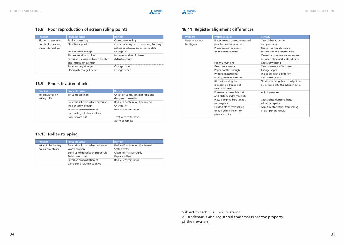
16.11 Register alignment differences
Problem Probable cause Remedy
Register cannot Plates are not correctly exposed, Check plate exposure
be aligned punched and re-punched and punching
Plates are not correctly Check whether plates are
on the plate cylinder correctly on the register bolt,
if necessary remove air enclosures
between plate and plate cylinder
Faulty unwinding Check unwinding
Excessive pressure Check pressure adjustment
Paper not flat enough Change paper
Printing material has Use paper with a different
wrong machine direction machine direction
Blanket backing sheet Shorten backing sheet, it might not
is becoming trapped at be clamped into the cylinder canal.
rear in channel
Pressure between blanket Adjust pressure
and plate cylinder too high
Plate clamping bars cannot Check plate clamping bars,
secure plate adjust or replace
Contact strips from inking Adjust contact strips from inking
or dampening rollers to or dampening rollers
plate too thick
Subject to technical modifications.All trademarks and registered trademarks are the propertyof their owners
16.8 Poor reproduction of screen ruling points
Problem Probable cause Remedy
Blurred screen ruling Faulty unwinding Correct unwinding
points (duplication, Plate has slipped Check clamping bars, if necessary fix spray
shadow formation) adhesive, adhesive tape, etc., to plate
Ink not tacky enough Change ink
Blanket tension too low Increase tension of blanket
Excessive pressure between blanket Adjust pressure
and impression cylinder
Paper curling at edges Change paper
Electrically charged paper Change paper
16.9 Emulsification of ink
Problem Probable cause Remedy
Ink emulsifies on pH value too high Check pH value, consider replacing
inking roller dampening solution
Fountain solution infeed excessive Reduce Fountain solution infeed
Ink not tacky enough Change ink
Excessive concentration of Reduce concentration
dampening solution additive
Rollers worn out Treat with restorative
agent or replace
16.10 Roller-stripping
Problem Probable cause Remedy
Ink not distributing, Fountain solution infeed excessive Reduce Fountain solution infeed
no ink acceptance Water too hard Soften water
Build-up of deposits on paper rule Clean rollers thoroughly
Rollers worn out Replace rollers
Excessive concentration of Reduce concentration
dampening solution additive
34 35
TROUBLESHOOTING TROUBLESHOOTING
Brief-Guide-2007_GB_2c.qxd 25.08.2008 15:28 Uhr Seite 34

INTRODUCTION TO SILVER DIGIPLATE
This manual describes the characteristics of theMitsubishi Silver Digiplate and provides potentialusers with recommendations for integrating this
method into their existing plant.
Mitsubishi International GmbHGraphic Art Materials Division
Kennedydamm 19D-40476 Düsseldorf, Germany
Tel.: + 49-211-4397-369Fax: + 49-211-4397-461
http://www.mitsubishicorp-de.com
Mitsubishi Paper GmbHAm Albertussee 1
D-40549 Düsseldorf, GermanyTel.: + 49-211-53596-200Fax: + 49-211-53596-222
http://www.mitsubishi-paper.com
Computer-to-Plate
Brief-Guide-2007_GB_2c.qxd 25.08.2008 15:28 Uhr Seite 36