Interoperability between Architectural and Structural BIM software in ...
199
UNIVERSITY OF MARIBOR FACULTY OF CIVIL ENGINEERING, TRANSPORTATION ENGINEERING AND ARCHITECTURE Drilon Rraci INTEROPERABILITY BETWEEN ARCHITECTURAL AND STRUCTURAL BIM SOFTWARE IN THE CASE OF A MALL PROJECT Master Thesis Maribor, December 2017
-
Upload
khangminh22 -
Category
Documents
-
view
2 -
download
0
Transcript of Interoperability between Architectural and Structural BIM software in ...

UNIVERSITY OF MARIBOR
FACULTY OF CIVIL ENGINEERING, TRANSPORTATION ENGINEERING AND
ARCHITECTURE
Drilon Rraci
INTEROPERABILITY BETWEEN ARCHITECTURAL AND STRUCTURAL BIM
SOFTWARE IN THE CASE OF A MALL PROJECT
Master Thesis
Maribor, December 2017

I
`
Smetanova ulica 17 2000 Maribor, Slovenija
INTEROPERABILITY BETWEEN ARCHITECTURAL AND STRUCTURAL BIM
SOFTWARE IN THE CASE OF A MALL PROJECT
Master’s thesis submitted to the University of Maribor in partial fulfillment of the requirements for
the degree of
Master of Science in
Civil Engineering
Student: Drilon RRACI
Study program: Master Degree, Civil Engineering
Department: Structures
Supervisor: doc. dr. Milan KUHTA, univ. dipl. inž. grad.
Co-supervisor: red. prof. dr. Danijel REBOLJ, univ. dipl. inž. grad.
Maribor, December 2017

II

III
`
GRATITUDE
To my beloved family, especially to my MOM,
who gave everything she had to support me at any
time!

IV
Quote
“At its heart, engineering is about using science to find creative solutions. It’s a noble
profession” – Queen Elizabeth II

V
`
Acknowledgment
Firstly, I am grateful to JoinEU-SEE>PENTA Programme, for their support and
opportunity to carry out my master degree at the University of Maribor. To me, the impact
of JoinEU-SEE>PENTA project has been indicated, both on an individual and institutional
level.
I express my deep sense of gratitude to my University supervisor doc. dr. Milan Kuhta,
univ. dipl. inž. grad., for his guidance and support in completing this work. He and his
teaching assistants gave me the motivation I needed to successfully finish my grads with
merits in the Department of Structural Engineering.
I would also like to thank my thesis co-supervisor red. prof. dr. Danijel Rebolj, univ. dipl.
inž. grad., building information modeling (BIM) researcher at FGPA, for his valuable
encouragement and guidance during my master thesis.
Last but not least, I would like to thank Gravitas, design and engineering company Ltd., for
their willingness to cooperate in this project.
Finally, I would like to thank my family members and my colleagues who have been a
constant source of support and encouragement in all respects during my entire thesis work.
-Drilon Rraci

VI
INTEROPERABILITY BETWEEN ARCHITECTURAL AND STRUCTURAL BIM
SOFTWARE IN THE CASE OF A MALL PROJECT
Keywords: Building Information Modeling (BIM), Interoperability, Data, Direct link, IFC,
DSTV (*.stp), Tekla, RFEM, Modeling, A&D, Mall Project.
UDK: 624.04:004.9(043.2)
Abstract
This master thesis deals with the effect of interoperability between architectural and
structural BIM software in the case of a Mall project. The research and most of the work
was performed on a BIM model of the Mall project that was modeled using Tekla BIM
software.
Since there is still a lack of investigations addressing interoperability issues in the
structural engineering domain, this thesis pretends to show the collaboration between
architectural and structural BIM software, taking into account a real and complex project.
A general overview and research regarding building information modeling (BIM) and
interoperability issues were done in this project. Various case studies were conducted,
where the entire BIM model and partial models of the Mall project were transferred from
BIM to FEM software using different data exchange methods. Structural analysis and
design in the case of the relevant partial models of the Mall project were performed with
the help of Dlubal-Structural Engineering Software for Analysis and Design. Such
analyses were made in the structural analysis program RFEM, to investigate if those
partial models are imported correctly.
The general conclusion based on the used case studies is that data exchange between BIM
and FEM software can be useful, but the ease of use depends on both the data exchange
method and the way how the relevant model has been created in Tekla BIM software.
Referring to these case studies, the most successful data exchange was achieved by using
the direct link between BIM and FEM software.
VII
`
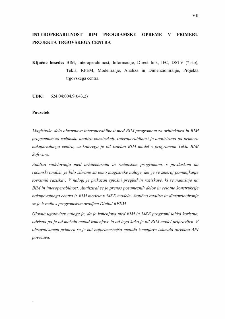
INTEROPERABILNOST BIM PROGRAMSKE OPREME V PRIMERU
PROJEKTA TRGOVSKEGA CENTRA
Ključne besede: BIM, Interoperabilnost, Informacije, Direct link, IFC, DSTV (*.stp),
Tekla, RFEM, Modeliranje, Analiza in Dimenzioniranje, Projekta
trgovskega centra.
UDK: 624.04:004.9(043.2)
Povzetek
Magistrsko delo obravnava interoperabilnost med BIM programom za arhitekturo in BIM
programom za računsko analizo konstrukcij. Interoperabilnost je analizirana na primeru
nakupovalnega centra, za katerega je bil izdelan BIM model s programom Tekla BIM
Software.
Analiza sodelovanja med arhitekturnim in računskim programom, s povdarkom na
računski analizi, je bilo izbrano za temo magistrske naloge, ker je še zmeraj pomanjkanje
tovrstnih raziskav. V nalogi je prikazan splošni pregled in raziskave, ki se nanašajo na
BIM in interoperabilnost. Analiziral se je prenos posameznih delov in celotne konstrukcije
nakupovalnega centra iz BIM modela v MKE modele. Statična analiza in dimenzioniranje
se je izvedlo s programskim orodjem Dlubal RFEM.
Glavna ugotovitev naloge je, da je izmenjava med BIM in MKE programi lahko koristna,
odvisna pa je od možnih metod izmenjave in od tega kako je bil BIM model pripravljen. V
obravnavanem primeru se je kot najprimernejša metoda izmenjave iskazala direktna API
povezava.

VIII
INTEROPERABILITY BETWEEN ARCHITECTURAL AND STRUCTURAL BIM
SOFTWARE IN THE CASE OF A MALL PROJECT
INTEROPERABILNOST BIM PROGRAMSKE OPREME V PRIMERU
PROJEKTA TRGOVSKEGA CENTRA
Daljši povzetek v slovenščini
UVOD
Ozadje in splošni pregled teze
Magistrsko delo obravnava sodelovanje in izmenjavo podatkov med BIM pregramom za
arhitekturo in BIM programom za računsko analizo konstrukcij. Interoperabilnost
(izmenjava informacij med BIM in FEM programi) je analizirana na primeru
nakupovalnega centra, za katerega je bil izdelan BIM model s programom Tekla BIM
software.
Tekla BIM software je 3D BIM program, ki se v gradbeništvu uporablja predvsem za
konstruiranje in modeliranje jeklenih ter betonskih konstrukcij. Z uporabo Tekla BIM
lahko kreiramo in upravljamo tudi z 3D arhitekturnimi in računski BIM modeli pri
sovprežnih konstrukcijah. Program je bil uporabljen tudi za izdelavo fizikalnega in
analitičnega modela trgovskega centra.
V delu, kjer smo analizirali zmožnosti interoperabilnosti med arhitekturnim in računskim
programom smo nadaljno obravnavali različne metode izmenjave podatkov. Za praktično
ponazoritev izmenjave podatkov smo s programom Dlubal-Structural Engineering
Software for Analysis and Design izdelali računsko analizo in dimenzioniranje za modele
posameznih konstrukcijskih elementov in celotni model trgovskega centra. Uporabljena je
bila trenutno zadnja študentska verzija obeh programov.

IX
`
MODELIRANJE TRGOVSKEGA CENTRA Z UPORABO TEKLA BIM SOFTVER
Namen magistrske naloge je bil analizirati Tekla BIM program.
Tekla BIM program ponuja tudi verzijo za študente, ki se imenuje Tekla Structures
Learning (TSL) in je bila uporabljena.
Opis modeliranja trgovskega centra
Celotni model zajema arhitekturne in konstrukcijske elemente trgovskega centra,
lociranega v Murski Soboti (Slika 1-1).
Slika 1-1: 3D Model trgovskega centra, narejen v TSL
Vse faze projekta so bile obravnavane. Večina elementov je bila obravnavana kot
konstrukcijski, nosilni elementi, kar je bilo nujno za ustrezno računsko analizo. Elementi
vsebujejo geometrijo, vozlišča elementov, podatke o materialih, geometrijske
karakteristike, podpore in tip načrtovane analize.
Ostali elementi, zajeti v modelu, kot so leseni in aluminijasti elementi fasade so bili
obravnavani kot arhitekturni elementi. Ti arhitekturni elementi so bili v TSL modelirani
kot nenosilni elementi.
Modeliranje trgovskega centra
Pri modeliranju trgovskega centra so bila uporabljena naslednja orodja znotraj TSL:

X
- Tekla Structures Learning Environments,
- Tekla Structures Learning standards and settings,
- Uvoz CAD datotek iz projekta podjetja Gravitas (Gravitas d.o.o, 2017),
- Tekla Warehouse.
Izdelava risb
Ker je dokumentacija še zmeraj zahtevana in potrebna na uradih, v projektivnih podjetjih,
na gradbiščih in v proizvodnih obratih ohranjajo risbe na papirju v gradbeništvu še zmeraj
pomembno vlogo. Zmeraj je torej nujno izdelati risbe, ki podajajo natančne informacije. Z
uporabo TSL je možno izdelati risbe posamezno, v skupinah ali pa avtomatično vse. Risbe,
ki so bile izdelane v okviru magistrske naloge so dodane v Prilogah.
Vizualizacija
Uporaba BIM modelov je v namen vizualizacije že skoraj običajna. V primerjavi z
tradicionalnimi risbami 3D BIM vizualizacija projekta pomaga k boljšemu razumevanju
koncepta objekta in njegovih detajlov. Primer vizualizacije v TSL je podan na sliki 1-2.
Slika 1-2: Vizualizacija - delni pogled na trgovski center.

XI
`
INTEROPERABILNOST MED TSL IN RFEM
To poglavje magistrske naloge opisuje splošne principe izmenjave podatkov med BIM in
MKE programi. V okviru magistrske naloge smo za analizo interoperabilnosti izbrali Tekla
Structures Learning (TSL) kot BIM program in Dlubal RFEM kot MKE program. Prikazan
je postopek izdelave različnih tipov analitičnih modelov v programu TSL.
Poleg tega so bile uporabljene različne metode izmenjave podatkov, kot so »direct link«,
»DSTV (*.stp) in »IFC data model exchange«, ki so bile podrobno analizirane in opisane.
Izmenjava podatkov na primeru prenosa konstrukcijskih jeklenih elementov iz TSL v
RFEM je prikazana na Sliki 1-3
Slika 1-3: Izmenjava podatkov pri prenosu analitičnega modela jeklenih konstrukcijskih
elementov iz TSL v RFEM.

XII
STATIČNA ANALIZA IN DIMENZIONIRANJE Z DLUBAL SOFTWARE
V tem poglavju je prikazana statična analiza in dimenzioniranje na primeru dveh različnih
delnih modelov projekta trgovskega centra. Zasnovano na raziskavi interoperabilnosti med
BIM in RFEM v tretjem poglavju naloge, sta bila za nadaljno analizo izbrana dva delna
modela in sicer betonska plošča v medetaži in jeklena nosilna konstrukcija. Slika 1-4
prikazuje rezultate statične analize, in sicer pomike, betonske plošče. Za betonsko ploščo je
bilo v predelu spuščene plošče potrebno narediti poenostavitev.
Slika 1-4: Pomiki plošče – program RFEM.
OPIS PO POGLAVJIH IN UGOTOVITVE
Z namenom celotne predstqavitve magistrske naloge je v prvem delu tega poglavja podan
kratek opis magistrske naloge po poglavjih, v drugem delu pa so opisane glavne
ugotovitve.
Začetek naloge vsebuje splošni pregled o informacijskem modeliranju objektov (BIM) in
interoperabilnosti. Namen teh uvodnih poglavij je bil raziskati in prikazati osnovne
informacije tega pomembnega področja. Za nadaljne delo se je to izkazalo kot zelo
koristno. V nalogi sta se z namenom raziskave interoperabilnosti uporabila dva programa.

XIII
`
TSL je bil uporabljen za modeliranje in pripravo analitičnih modelov, ki so bili uporabljeni
v nadaljevanju. Dlubal RFEM je bil uporabljen za uvoz analitičnih modelov in za statično
analizo in dimenzioniranje posameznih kosntrukcijskih elementov. V poglavju 4 je
prikazan splošni opis in pregled obeh programov.
Modeliranje trgovskega centra je bilo izvedeno s splošnimi funkcijami in nastavitvami, ki
jih ponuja TSL. Postopek modeliranja, izdelave risb in vizualizacija so prikazani in
komentirani v poglavju 5. Povdariti je potrebno, da je bilo modeliranje izvedeno na osnovi
projektne dokumentacije podjetja Gravitas (Gravitas d.o.o, 2017).
Najpomembnješi del naloge, ki se nanaša na bistvo naloge – na interoperabilnost, je zajet v
poglavju 6. Za različne analitične modele so prikazani splošen opis, postopek, zapleti in
njihova rešitev. Prikazane in analizirane so tudi različne metode izmenjave informacij in
posodabljanje modela na osnovi teh izmenjav.
Z namenom nadaljnih raziskav zmožnosti izmenjave podatkov in pomena uvoza
analitičnega modela iz TSL je bila narejena statična analiza in dimenzioniranje posameznih
konstrukcijskih elementov v programu RFEM. Kratek opis rezultatov statične analize in
rezultatov je podan v poglavju 7.
V zaključku naloge so podane ugotovitve, ki vsebujejo pregled glavnih ugotovitev in
priporočil iz analize interoperabilnosti na primeru obravnavanega trgovskega centra.
Za analizo interoperabilnosti med BIM in MKE programoma je bila nujna izdelava visoko
kvalitetnega BIM modela, ki je zajela vsak posamezen del projekta trgovskega centra. Po
uvozu v MKE program je bila nujna temeljita analiza uvoženega, neizogibna je bila tudi
izpeljava modifikacij pred statičnim izračunom. Po izvedbi omenjenih procesov je bila
izmenjava podatkov z interoperabilnostjo dobro izvedena in manj zahtevno statično analizo
in dimenzioniranje v pogramu RFEM je bilo možno izvesti z zadovoljivimi rezultati.

XIV
CONTENTS
1 INTRODUCTION ........................................................................................................ 1
1.1 BACKGROUND AND OVERVIEW OF THE THESIS ......................................................... 1
1.2 MOTIVATION AND PURPOSE ..................................................................................... 3
1.3 STRUCTURE OF THE THESIS ...................................................................................... 3
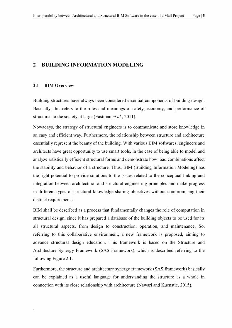
2 BUILDING INFORMATION MODELING ............................................................. 5
2.1 BIM OVERVIEW ...................................................................................................... 5
2.2 BIM CONCEPT AND AEC INDUSTRY ....................................................................... 7
2.3 DEFINITION OF DESIGN TOOLS AND PARAMETRIC OBJECTS .................................... 8
2.4 BIM FOR ARCHITECTS AND ENGINEERS .................................................................. 9
2.5 THE FUTURE OF BIM ............................................................................................. 10
3 INTEROPERABILITY ............................................................................................. 11
3.1 INTEROPERABILITY OVERVIEW .............................................................................. 11
3.2 LEVELS OF CONCEPTUAL INTEROPERABILITY (LCIM) .......................................... 14
3.3 DATA SHARING AND COLLABORATION ................................................................... 15
3.4 EXCHANGE FORMATS BACKGROUND ..................................................................... 16
3.5 BUILDINGSMART AND IFC ................................................................................... 18
3.6 OTHER BIM-RELATED STANDARDS OVERVIEW ...................................................... 21
3.6.1 Information Delivery Manual [IDM] ....................................................................... 21
3.6.2 International Framework for Dictionaries [IFD] .................................................... 22
3.6.3 OmniClass ................................................................................................................ 22
3.6.4 COBie ....................................................................................................................... 22
3.6.5 XML-Based Schemas ................................................................................................ 23
3.7 FUNCTIONALITY OF BIM SERVERS ........................................................................ 24
3.8 BIM AND STRUCTURAL ANALYSIS SOFTWARE IN THE CONTEXT OF DATA
EXCHANGE PROCESS ......................................................................................................... 25
4 INTRODUCTION TO BIM & STRUCTURAL ANALYSIS SOFTWARE ........ 29
4.1 TEKLA BIM SOFTWARE ......................................................................................... 29
4.1.1 Tekla Structures ........................................................................................................ 30
4.1.2 Tekla Collaboration .................................................................................................. 31
4.1.3 Tekla BIMsight ......................................................................................................... 34
4.2 DLUBAL - STRUCTURAL ENGINEERING SOFTWARE FOR ANALYSIS AND DESIGN ... 35
4.2.1 RFEM-Finite Element Analysis program ................................................................. 36
5 MODELING OF THE MALL PROJECT USING TEKLA BIM SOFTWARE . 37
5.1 DESCRIPTION OF THE MALL PROJECT ..................................................................... 37
5.2 MODELING OF THE MALL PROJECT ........................................................................ 48
5.2.1 Tekla Structures Learning Environments ................................................................. 48
5.2.2 Tekla Structures Learning standards and settings in the case of a Mall project ..... 52

XV
`
5.2.3 Importing CAD files as reference models ................................................................ 62
5.2.4 Tekla Warehouse ...................................................................................................... 65
5.3 CREATING DRAWINGS ........................................................................................... 68
5.3.1 Drawing types .......................................................................................................... 68
5.4 VISUALIZATION OF THE MALL PROJECT................................................................. 70
6 INTEROPERABILITY BETWEEN TEKLA STRUCTURES LEARNING AND
RFEM ................................................................................................................................. 71
6.1 PHYSICAL AND ANALYTICAL MODELS .................................................................... 71
6.1.1 Creating analytical models in Tekla Structures Learning ....................................... 71
6.2 DATA EXCHANGE METHODS ................................................................................... 74
6.2.1 Tekla Structures Learning– RFEM direct link ......................................................... 75
6.2.2 DSTV data exchange file format .............................................................................. 77
6.2.3 IFC data model exchange......................................................................................... 78
6.3 UPDATING TEKLA BIM MODEL USING DIRECT INTERFACE FROM RFEM ............... 81
6.4 CASE STUDIES BASED ON THE MALL PROJECT ........................................................ 83
6.4.1 Simple case – Concrete column ................................................................................ 83
6.4.2 Partial model 1 – Ground and intermediate floor slabs .......................................... 89
6.4.3 Partial model 2 – Structural steel elements ............................................................. 95
6.4.4 Partial model 3 – Structural concrete walls and columns ....................................... 99
6.4.5 Entire BIM model ................................................................................................... 107
7 STRUCTURAL ANALYSIS AND DESIGN USING DLUBAL SOFTWARE .. 115
7.1 A&D IN THE CASE OF THE PARTIAL MODELS (SIMPLIFIED MEZZANINE SLAB AND
STRUCTURAL STEEL ELEMENTS) OF THE MALL PROJECT ................................................. 115
7.1.1 General description of the problem ........................................................................ 115
7.1.2 Preliminary Analysis and Design (A&D) ............................................................... 118
7.1.3 Interpretation of basic results from RFEM ............................................................ 119
8 CONCLUSIONS....................................................................................................... 122
8.1 BRIEF DESCRIPTION AND PURPOSE OF THE THESIS ................................................ 122
8.2 SUMMARY OF RESULTS ........................................................................................ 123
9 REFERENCES ......................................................................................................... 127
10 APPENDICES ....................................................................................................... 130
10.1 LIST OF FIGURES .................................................................................................. 130
10.2 LIST OF TABLES .................................................................................................... 135
10.3 EXAMPLES OF DRAWING TYPES CREATED IN TSL ................................................ 136
10.3.1 GA drawing ............................................................................................................ 136
10.3.2 Single-part drawing ................................................................................................ 139
10.3.3 Assembly drawing .................................................................................................. 141
10.3.4 Cast unit drawing ................................................................................................... 143
10.3.5 Multidrawing .......................................................................................................... 145
10.4 ANALYSIS AND DESIGN (A&D) REPORT .............................................................. 147

XVI
10.4.1 Mechanical properties of materials and cross-sections ......................................... 147
10.4.2 Actions .................................................................................................................... 148
10.4.3 Load Analysis ......................................................................................................... 148
10.4.4 RFEM report in the case of the simplified mezzanine slab of the Mall project ...... 150
10.4.5 RFEM report in the case of the structural steel elements of the Mall project ........ 163
10.5 SHORT CV (CURRICULUM VITAE) ....................................................................... 179
10.6 DECLARATION OF AUTHORSHIP............................................................................ 179

XVII
`
ACRONYMS
BIM Building Information Modeling (Building Information Model)
CAD Computer-Aided Design
2D Two-dimensional
3D Three-dimensional
IFC Industry Foundation Class
API Application Programming Interface
FEA Finite Element Analysis
ISO International Standards Organization
SAS Structure and Architecture Synergy Framework
BDS Building Description System
AEC Architecture, Engineering, and Construction
B-rep Boundary Representation
CSG Constructive Solid Geometry
IEC International Electrotechnical Commission
IAI International Alliance for Interoperability
DXF Drawing eXchange Format
IGES Initial Graphic Exchange Specification
STEP STandard for the Exchange of Product
CIS/2 CIMsteel Integration Standard, Version 2
CIMsteel Computer Integrated Manufacturing in Constructional Steelwork
NBIMS National BIM Standard
SAT Standard ACIS Text
ACIS Alan, Charles, Ian's System

XVIII
BPMN Business Process Modeling Notation
XML Extensible Markup Language
LCIM Levels of Conceptual Interoperability Model
OSI Open System Interconnect
PDF Portable Document Format
NASA National Aeronautics and Space Administration
SQL Structured Query Language
IDM Information Delivery Manual
IFD International Framework for Dictionaries
SI International System of Units (French: Système international (d'unités))
ICIS International Construction Information Society
COBie Construction Operations Building Information Exchange
O&M Operations & Maintenance
CMMS Computerized Maintenance and Management System
FM Facility Management
HTML Hypertext Markup Language
DTD Document Type Declaration
XSD XML Schema Definition
RDF Resource Description Framework
OWL Web Ontology Language
GIS Geographic Implementation Specification
gbXML Green Building XML
agcXML Associated General Contractors XML
BCF BIM Collaboration Format
GML Geographic Markup Language

XIX
`
DWF Design Web Format
SDNF Steel Detailing Neutral Form
GUI Graphical User Interface
LOD Level of Detail/Development
MEP Mechanical, electrical, and plumbing
A&D Analysis and Design
RC Reinforced Concrete
TSL Tekla Structures Learning
UDA User-Defined Attributes
EXC Execution Classes
OSB Oriented Strand Board
GA General Arrangement
DSTV Deutscher STahlbau-Verband
NC Numerical Control
DIN (German: Deutsches Institut für Normung) or (English: German Institute for
Standardization)
FE Finite Element
EN European Standards

Interoperability between Architectural and Structural BIM Software in the case of a Mall Project Page | 1
`
1 INTRODUCTION
1.1 Background and overview of the thesis
In this thesis, the collaboration and exchange of data between architectural and structural
BIM software have been reflected. The procedure is mainly made based on the modeling of
a Mall project. Mall project represents a composite structure made of concrete, steel,
timber, aluminium, glass and other relevant insulation materials. It contains all main
architectural and structural elements such as beams, slabs, columns, walls, covering and
aesthetic elements.
The Architecture, Engineering and Construction (AEC) sector is gradually evolving away
from the use of two-dimensional (2D) computer-aided design (CAD) and paper for design
towards three-dimensional (3D), semantically rich, digital models. Traditionally,
information has been exchanged in the form of drawings and documents. Nowadays, the
use of BIM software within a construction industry provides a significant incentive to
instead use digital design models as the medium for exchanging information (Steel,
Drogemuller and Toth, 2009).
Therefore this thesis considers the use of BIM as a technology for supporting the
interoperability (exchange of information between BIM modeling and FEM analysis
software) on the example of a Mall project.
Tekla BIM software has been chosen as BIM software to be used in the case of modeling
architectural and structural elements of this project. Tekla BIM software is 3D building
information modeling (BIM) software mostly being used in the building and construction
industries for steel and concrete detailing. Thus, using Tekla BIM software we could create
and manage 3D architectural and structural BIM models in composite engineering
materials. It was also used to create physical and analytical models, relevant to this project.

Page | 2 Interoperability between Architectural and Structural BIM Software in the case of a Mall Project
In the section of analyzing the capabilities of the interoperability between architectural and
structural BIM software, different data exchange methods have been considered and
discussed further. To explain practically the results of such capabilities, relevant structural
analysis and design (A&D) in the case of partial analytical models of the Mall project were
performed with the help of Dlubal-Structural Engineering Software for Analysis and
Design.
The latest available student versions of the above-mentioned software (Tekla Structures
Learning 2017 and RFEM 5.10.01), were used in this project.
Various terms have been used to address the main purpose of this thesis. The main terms
applied in the project are presented and explained in Table 1.1.
Table 1.1: Representation of the most important terms used in this project.
BIM Model
An integrated information model, including structural and
architectural aspects of the building. To create a relevant BIM model
in the case of the Mall project, both architectural and structural
models have been used at the same time.
Structural
Model
A structural model has been created by modeling different structural
elements such as RC walls, RC columns, structural steel elements,
etc., in Tekla BIM software. Such elements are then exported as
load-bearing elements to RFEM, through an IFC export created in
Tekla BIM software.
Architectural
Model
A model created by architectural elements such as wood coverings,
ladder, etc., which are modeled as non-load bearing elements in
Tekla BIM software, is considered as an Architectural model. It is
not directly connected with the structural model but belongs more to
the aesthetic role of the building
Analytical
Model
A model created in Tekla BIM software, which has been used to
investigate the data exchange capabilities in the case of this project,
as well as for structural analysis and design purposes in RFEM.

Interoperability between Architectural and Structural BIM Software in the case of a Mall Project Page | 3
`
Physical Model
A model which is created in Tekla BIM software using different
structural elements, where every structural element could be
supported with a point support.
1.2 Motivation and purpose
Interoperability challenges are associated with the export and import capabilities of data
models among different software. Insufficient interoperability represents one of the barriers
to BIM advancement. From this point of view, we have been motivated to make a research,
aiming to present the collaboration between architectural and structural BIM software,
based on a real and complex project. Principally, this represents a connection between the
conversion challenge of architectural and structural model, using various analytical models
generated in the project. Thesis objectives are related with the following issues: to explore
best practice for the use of 3D BIM tools in collaboration and exchange of data between
BIM and FEM software, and to identify appropriate collaboration workflows and
additional information required to support them. Thus, these goals lead to the presentation
of various case studies in models-based interoperability, since the collaboration and the
exchange of data are deliberated as a vital part of the project and its whole implementation
process.
The thesis aims to identify, analyze, and discuss the basic issues of model-based
interoperability through exchanging building information models between relevant BIM
and FEM software, particularly using the ISO standardized IFC data format.
1.3 Structure of the thesis
After the introduction, in the second and third section, a literature review is used to give a
general overview regarding BIM and interoperability issues and to identify current research
trends within the topic of the thesis.
Hereto, considering Tekla BIM software as the appropriate tool to create various
architectural and structural models in the case of a Mall project, general overview and
basic features of this program are presented further in Section 4.

Page | 4 Interoperability between Architectural and Structural BIM Software in the case of a Mall Project
Afterwards, a general description of the Mall project and modeling of a BIM model
relevant to this project, are presented and elaborated in details in Section 5. The BIM
model of this project was created and detailed with the help of 2D CAD architectural
drawings as the input (reference drawings in Tekla BIM software), which were created by
Gravitas, design and engineering company Ltd (Gravitas d.o.o, 2017).
Some of the 2D CAD architectural drawings, which were used to prepare the entire BIM
model of the Mall project, can be found in the Appendices. Moreover, a general description
of creating different types of drawings and 3D visualization in Tekla BIM software,
relevant to this project has also been discussed in Section 5.
To provide the technical capabilities of the data exchange methods between BIM and FEM
software, several case studies made with increasing levels of structural complexity and
varying materials were considered in Section 6. The purpose of these case studies was to
examine what kind of data can be transferred from Tekla BIM software to RFEM software
and provide a general assessment regarding different methods of data exchange in terms of
technical and practical capability.
A general overview of each data exchange method used in the case of this project is first
presented and afterwards the encountered issues are discussed individually for each case.
An evaluation of each data exchange method is offered at the end of each study case,
relevant to BIM model of the Mall project.
In the last part of the thesis, some of the most important structural parts of the building
have been reviewed and structurally analyzed. It has been noted that in the case of
preparing the finite element analysis (FEA), which deals with two different partial models
of the Mall project, RFEM has been perceived as powerful and appropriate software for
quick and easy collaborating with Tekla BIM Software. Using different data exchange
methods we could import different analytical models from Tekla BIM software to RFEM
software, make necessary modifications and then calculate and show basic results
including global and local displacements, support reactions, basic internal forces, etc.
Given these points, a reflection of the basic issues of BIM standard development and
mostly the nature of collaboration and data exchange methods dealing with different case
studies, is offered as a conclusion of this project.
Interoperability between Architectural and Structural BIM Software in the case of a Mall Project Page | 5
`
2 BUILDING INFORMATION MODELING
2.1 BIM Overview
Building structures have always been considered essential components of building design.
Basically, this refers to the roles and meanings of safety, economy, and performance of
structures to the society at large (Eastman et al., 2011).
Nowadays, the strategy of structural engineers is to communicate and store knowledge in
an easy and efficient way. Furthermore, the relationship between structure and architecture
essentially represent the beauty of the building. With various BIM softwares, engineers and
architects have great opportunity to use smart tools, in the case of being able to model and
analyze artistically efficient structural forms and demonstrate how load combinations affect
the stability and behavior of a structure. Thus, BIM (Building Information Modeling) has
the right potential to provide solutions to the issues related to the conceptual linking and
integration between architectural and structural engineering principles and make progress
in different types of structural knowledge-sharing objectives without compromising their
distinct requirements.
BIM shall be described as a process that fundamentally changes the role of computation in
structural design, since it has prepared a database of the building objects to be used for its
all structural aspects, from design to construction, operation, and maintenance. So,
referring to this collaborative environment, a new framework is proposed, aiming to
advance structural design education. This framework is based on the Structure and
Architecture Synergy Framework (SAS Framework), which is described referring to the
following Figure 2.1.
Furthermore, the structure and architecture synergy framework (SAS framework) basically
can be explained as a useful language for understanding the structure as a whole in
connection with its close relationship with architecture (Nawari and Kuenstle, 2015).

Page | 6 Interoperability between Architectural and Structural BIM Software in the case of a Mall Project
Figure 2.1: Structure and architecture synergy framework (Nawari and Kuenstle, 2015).
Creating a BIM model means the creation of three-dimensional (3D) objects library of the
physical building. Thus, in essence, BIM provides the ability to construct a building
virtually before building it in the real world. BIM gives the opportunity to model with
structural components such as walls, columns, beams, doors, windows, ceilings, and roofs,
instead of using the primitives CAD form (points, lines, curves) (Nawari and Kuenstle,
2015).
When we look back to history, one of the first projects to successfully create a building
database was the Building Description System (BDS) which was the first software to
describe individual library elements which could be viewed and added to a model.
Furthermore, this program uses a graphical user interface, orthographic and perspective
views and a sortable database that allows the user to view information categorically by
attributes including material type and supplier. ArchiCAD was developed by Gábor Bojár
1982 in Budapest. While using similar technology as the Building Description System, the
software Radar CH was released in 1984 for the Apple Lisa Operating System. Later on,
this became ArchiCAD, which makes ArchiCAD the first BIM software that was made
available (Quirk, 2012).
Building information modeling (BIM) is one of the most encouraging advancements in the
architecture, engineering, and construction (AEC) industries. With BIM softwares, an
exact virtual model of a building is built digitally. Whenever finished, BIM software
generated models contain exact geometry and data needed to bolster the construction,
fabrication, and procurement activities based on which the building is realized (Eastman et
al., 2011).

Interoperability between Architectural and Structural BIM Software in the case of a Mall Project Page | 7
`
2.2 BIM Concept and AEC Industry
Building information modeling represents the process that fundamentally changes the role
of computation in building design. Thus, creating a BIM is different from making a
drawing in 2D or 3D computer-aided design (CAD). Unlike 2D or 3D CAD drawings,
when we make a revision or change in any element of the model, we have to change it only
once and all the views and details in the model are automatically updated (Nawari and
Kuenstle, 2015).
On the other hand, BIM is still a relatively new technology in an industry typically slow to
adopt change, but it is keen to rapidly change the way the construction industry produces
and communicates construction information. Anyway, today, BIM technology can be
found in the AEC industry everywhere through the world.
Building Information Modeling (BIM) concept and process have been described in Figure
2.2.
Figure 2.2: BIM Concept and process (Nawari and Kuenstle, 2015).
Referring to Figure 2.2, BIM means a shared digital representation of a facility founded on
open standards for practical interoperability (Nawari and Kuenstle, 2015).

Page | 8 Interoperability between Architectural and Structural BIM Software in the case of a Mall Project
One of the most common problems related to 2D-based communication amid the design
stage is the significant time and cost required to generate data about a proposed design,
cost estimates, energy-use analysis, structural details, etc. These analyses are typically
done last, when it is already too late to make vital improvements (Eastman et al., 2011).
The concept of organizational boundaries according to an AEC project team by a typical
diagram has been graphically illustrated in Figure 2.3.
Figure 2.3: Typical diagram concept of organizational boundaries based on AEC project
team (Eastman et al., 2011).
2.3 Definition of Design Tools and Parametric Objects
1980 was the year when object-based parametric modeling was developed in
manufacturing technology. It does not represent objects with fixed geometry and
properties. In the case of willing to model complex geometries, then custom parametric
objects make this possible, while those were previously not possible or not implementable.
When we look at how objects like a wall, slab, or roof can interact with other objects, this
shall be predefined by system-provided object classes. In this case, object attributes
represent a necessary parameter, which is needed to interface with structural analysis and
other applications, but these attributes must be firstly defined by the firm or software user.
On the other hand, current BIM design applications means carrying out specific tasks as a
tool, while they also give or represents a platform as a good way in case of managing the
data within a model for different uses (Eastman et al., 2011).

Interoperability between Architectural and Structural BIM Software in the case of a Mall Project Page | 9
`
Graphical 3D Modeling in its early stages of development, notifies basically two different
approaches, the (B-rep) approach which represented shapes as a closed, oriented set of
bounded surfaces in one hand, and on the other hand Constructive Solid Geometry (CSG)
as an alternative approach to define shapes as a set of functions (Figure 2.4). While taking
an overview at which approach is represented a better one, it was recognized that both of
them should be combined, allowing for editing within the CSG tree (sometimes called the
unevaluated shape) (Eastman et al., 2011).
Figure 2.4: Comparison of B-Rep and CSG paradigms (Saygi et al., 2013).
Furthermore, parametric object modeling represents a strong way to create and edit
geometry. On the other hand, most BIM softwares provide the means for extracting a
drawn section at the level of detail to which they are defined in the 3D model.
2.4 BIM for Architects and Engineers
Building information modeling is progressive in the way it changes architectural
representation by replacing drawings with 3D virtual building models. It transforms the
way that a representation is constructed, generally changing the line-by-line layout of old
and the idea processes that go with it. A project’s realization includes enormous levels of
coordination and collaboration. Coordination and collaboration involve different levels of

Page | 10 Interoperability between Architectural and Structural BIM Software in the case of a Mall Project
communication. At one level, it involves communication between people with respect to
values, context, and procedures. At another level, it likewise involves diverse device tool
representations and the need for data exchange between tools (Eastman et al., 2011).
Basically, in the case of using BIM in design processes for both Architectural and
Structural aspects, three major viewpoints shall be taken into consideration, as follows:
- Conceptual design,
- Design and analysis of structural systems using BIM,
- BIM use in developing construction-level information.
2.5 The Future of BIM
BIM is changing the way structures look, the way they function, and the ways in which
they are constructed (Eastman et al., 2011). BIM is being considered as the catalyst for
innovation in the construction industry (Brad Hardin, 2015).
BIM is a work in progress, which means BIM will contribute to a higher degree of
prefabrication, greater flexibility and variety in building methods and types, fewer
documents, far fewer errors, less waste, and higher productivity (Eastman et al., 2011).
The way the BIM is making progress, it is not very far that BIM will completely replace
CAD systems. Since the use of Cloud technology is growing, it would be easier for project
stakeholders to quickly access BIM model virtually everywhere (Azhar, Khalfan and
Maqsood, 2015).
On the other hand, there are several technological and managerial challenges ahead. The
technological challenges can be broadly classified into three categories (Azhar, Khalfan
and Maqsood, 2015), as follows:
- The need for well-defined transactional construction process models to eliminate
data interoperability issues,
- The requirement that digital design data be computable, and
- The need for well-developed practical strategies for the purposeful exchange and
integration of meaningful information among the building information model
components.

Interoperability between Architectural and Structural BIM Software in the case of a Mall Project Page | 11
`
3 INTEROPERABILITY
3.1 Interoperability overview
Interoperability is a characteristic of a product or framework, whose interfaces are totally
understood, to work with other products or frameworks, present or future, in either
implementation or access, with no confinement (GDT Interop, John McCreesh, 2017).
Interoperability is utilized to describe the capability of various programs to exchange data
via a common set of exchange formats, to read and write the same file formats, and to
utilize the same protocols (Wikipedia, 2016).
According to ISO/IEC 2382-01, Information Technology Vocabulary, Fundamental Terms,
interoperability is defined as follows: "The capability to communicate, execute programs,
or transfer data among various functional units in a manner that requires the user to have
little or no knowledge of the unique characteristics of those units" (ISO/IEC JTC 1, 2015).
BuildingSMART, formerly the International Alliance for Interoperability (IAI), is an
international organization, which intends to improve the exchange of information between
software applications used in the construction industry. It has created Industry Foundation
Classes (IFCs) as a neutral and open specification for Building Information Models (BIM)
(buildingSMART, 2016).
Interoperability is the ability to exchange information between applications, which
smoothes workflows and sometimes facilitates their automation. Interoperability has
traditionally relied on file-based exchange formats limited to geometry, for instance, DXF
(Drawing eXchange Format) and IGES (Initial Graphic Exchange Specification). Direct
links based on the Application Programming Interfaces (APIs) are the oldest and still
important route to interoperability. Beginning in the late 1980s, data models were
developed to bolster product and object model exchanges within different industries, led by
the ISO-STEP international standards effort (Eastman et al., 2011).

Page | 12 Interoperability between Architectural and Structural BIM Software in the case of a Mall Project
The two principal building product data model schemas are the Industry Foundation
Classes (IFC) – for building planning, design, construction and management, and CIMsteel
Integration Standard Version 2, (CIS/2) – for structural steel engineering and manufacture.
A related STEP schema is ISO-15926, for lifetime modeling of process plants. All of these
schemas represent different kinds of geometry, relations, procedures and material,
performance, fabrication, and different properties required for design and production. The
National BIM Standard (NBIMS) is being undertaken to standardize the data required for
particular exchanges. Interoperability, at the base, eliminates the need to manually copy
data already created in another application. Manual copying of partial project data
enormously discourages iteration during design, as required for discovering best solutions
to complex issues, such as structural design. People are used to geometry exchanges
between applications, utilizing translators such as DXF, IGES, or SAT. An integrated
model must carry much more information than a CAD file. This is an extensive change and
the supporting information technology methods and standards for achieving it are only
incrementally being set up (Eastman et al., 2011).
Interoperability supports different capabilities and addresses different problems in
exchanges of data across three types of BIM applications, as tools (manipulates a building
model for some defined purpose and produces a specific outcome), as platforms (generates
data for multiple uses and incorporates different tools directly or through interfaces with
varying levels of integration), and as environments (the functional capability embedded in
a BIM Server). Platform-to-tool exchange is the most basic type of interoperability and is
supported by both direct application-to-application exchange and furthermore through
shared neutral exchange formats, such as IFC. On the other hand, platform-to-tool data
exchange can be complex. While creating an analytical model by extracting the stick and
node model for further structural analysis and determining the adequate loads is not yet a
common automated translation, as it requires human expertise and judgment. More direct
are tool-to-tool exchanges. These are limited because of the limited data available within
the exporting tool (Eastman et al., 2011).
Furthermore, the real challenge of interoperability is a platform-to-platform exchange. This
includes platforms, for example, ArchiCAD, Revit, and Digital Project and fabrication
model platforms such as Tekla, SDS/2 Structureworks, and StruCad, CADPipe, and
CAMduct. Platforms not just incorporate a broad spectrum of data, they likewise

Interoperability between Architectural and Structural BIM Software in the case of a Mall Project Page | 13
`
incorporate rules that manage the integrity of the objects. It should be emphasized that the
exchange of fixed shape objects, as well as some simple extrusions, are not problems. At
some point in the future, a standard vocabulary of rules might be prepared, which could
prompt solving this platform-to-platform exchange of parametric models. More generally,
an issue related to interoperability is the need to manage the various representations of a
project, at the platform and tool levels. The need is, however, not to simply translate an
architectural model to another format, but to modify or extend the model information so
that it represents the design for different uses. Thus, referring to structural design aspect, it
indicates the knowledge required to translate a physical model of a structural design into a
model for structural analysis. In this case, derivation of a structural model from a physical
model involves many specialized considerations, dealing with structural codes, spans,
depth of beams, the behavior of connections, and especially loading conditions. Computer
scientists can, and have implemented the technological framework for interoperability, by
supplying the languages (e.g. EXPRESS1, BPMN, XML) that support exchange protocols
(Eastman et al., 2011).
The recent and current usage in BIM is the practice of the ‘exchange model.’ This
especially refers to the interoperability between different software packages that architects,
engineers, and contractors each use. In this case, it is more than important to verify the
interoperability of BIM software between working groups. In the past, interoperability
issues required a lot of software pieces and many workarounds that took much more time.
It is relatively clear that in the future we will see more success stories with open standards,
such as the IFC schema.
In summary, interoperability represents the process and the methods, which allow different
systems and organizations to work together without losing information. Thus, creating 3D
models defined in one system to be used in another is possible through interoperability. In
this thesis, interoperability is applied based on the Architectural model being used within a
structural modeling system in the case of a Mall project.
1 EXPRESS is a data specification language as defined in ISO 10303-1. It consists of language elements that
allow an unambiguous data definition and specification of constraints on the data defined (ISO 10303-11,
2004).

Page | 14 Interoperability between Architectural and Structural BIM Software in the case of a Mall Project
3.2 Levels of Conceptual Interoperability (LCIM)
The International Organization for Standards (ISO)/Open System Interconnect (OSI)
reference model introduced seven layers of interconnection, each with well-defined
protocols and responsibilities (Tolk, Bair and Diallo, 2013). The LCIM was proposed as a
reference model with well-defined layers of interoperation to better deal with challenges of
interoperability of simulation systems and composability of simulation models (Tolk, Bair
and Diallo, 2013). LCIM has been originally proposed by (Tolk and Muguira, 2003). After
continuous evolution, it forms the latest version illustrated in Figure 3.1.
According to (Tolk, Bair and Diallo, 2013) and (Tolk, Diallo and Turnitsa, 2007), the
current version of the LCIM exposes seven layers of interoperation as follows.
- Level 0 – No Interoperability: Stand-alone systems have No Interoperability.
Thus, information is used within each system in a proprietary way with no sharing.
- Level 1 – Technical Interoperability: On this level, a communication protocol
exists, enabling systems to exchange carriers of information. This layer is the
domain of integratability.
- Level 2 – Syntactic Interoperability: This level provides a common structure to
exchange information, for instance, a common protocol to structure the data is used.
In other words, this layer belongs to the domain of interoperability
- Level 3 – Semantic Interoperability: Introduces a common understanding of the
information exchange. On this level, the content of the information exchange
requests are defined. It describes the aligned static data.
- Level 4 – Pragmatic Interoperability: This level is reached when the
interoperating systems are aware of the methods and procedures that each other are
employing. In this context data are exchanged as applicable information. Thus, this
level represents the aligned dynamic data.
- Level 5 – Dynamic Interoperability: This layer recognizes different system states,
including the possibility for agile and adaptive systems. As a system operates on
data over time, the state of that system will change, and this includes the
assumptions and constraints that affect its data interchange.

Interoperability between Architectural and Structural BIM Software in the case of a Mall Project Page | 15
`
- Level 6 – Conceptual Interoperability: Finally, on this level, assumptions,
constraints, and simplifications need to be captured. This layer represents the
harmonized data.
Figure 3.1: The Levels of Conceptual Interoperability Model (Wang, Tolk and Wang,
2009).
3.3 Data sharing and collaboration
BIM as an advanced modeling process provides building information data which are
attached to each building object, thus creating comprehensive architectural and structural
content libraries plus mechanical, electrical, plumbing, landscape, and other libraries
(Nawari and Kuenstle, 2015).
According to (Nawari and Kuenstle, 2015), an internal collaboration between members of
one company can be established as follows:
- Prepare a central database file where all the virtual building data can be stored,
- Group members work on local copies,
- Team members must have the intended workspaces,
- Team members send and receive changes regularly using the previously created
centralized database file.
On the other hand, an external collaboration between various companies, which collaborate
in a project can be established by sharing the BIM data via different data formats that most
BIM tools support (Nawari and Kuenstle, 2015):

Page | 16 Interoperability between Architectural and Structural BIM Software in the case of a Mall Project
- IFC (Industry Foundation Classes),
- DXF/DWG2 (AutoCAD Drawing Exchange Format/Drawing),
- PDF (Portable Document Format),
- XML (Extensible Markup Language).
3.4 Exchange formats background
Even in the earliest days of 2D CAD in the late 1970s and early 1980s, the need to
exchange data between various applications was apparent. The most generally utilized
AEC CAD system at that time was Intergraph (Eastman et al., 2011). Later, in the post-
Sputnik period, NASA found that they were expending significant amounts of money
paying for interpreters among all their CAD engineers. Thus, resulting exchange standard
was reviewed, extended, and christened IGES (Initial Graphics Exchange Specification)
(Eastman et al., 2011). In general, data exchanges between applications depend on two
levels of definition, characterized in Figure 3.2.
Figure 3.2: Presentation of modern exchange formats which are based on a schema
defined in a schema language (Eastman et al., 2011).
Structured Query Language (SQL) is a prime example and the dominant schema definition
language for databases. The ISO-STEP-developed data modeling language, EXPRESS, is
the basis for a range of product modeling technologies and schemas, including Industry
Foundation Classes (IFC) and CIMsteel Integration Standard, version 2 (CIS/2). Another
2 DWG refers to both a technology environment and .dwg files, the native file format for Autodesk’s
AutoCAD® software (Autodesk, 2017).

Interoperability between Architectural and Structural BIM Software in the case of a Mall Project Page | 17
`
substantial set of exchanges is bolstered by XML (eXtensible Markup Language). The
different XML schemas support the exchange of many types of data between applications.
On the other hand, direct links use the Application Programming Interface (API) of one
system to extract data from that application and write the data using the receiving
application’s API. Direct links are implemented as programming level interfaces, typically
relying on C++3 or C#
4 languages (Eastman et al., 2011).
A summary of the most widely recognized exchange formats in the AEC area is listed in
Table 3.1. Table 3.1 groups file exchange formats with respect to their principal use.
Furthermore, below-listed formats represent information on very different semantic levels.
Table 3.1: Common Exchange Formats in AEC Applications (Eastman et al., 2011).
3 C++ is a general-purpose programming language. It has imperative, object-oriented and generic
programming features, while also providing facilities for low-level memory manipulation (Stroustrup, 1997).
4 C# is a multi-paradigm programming language encompassing strong typing, imperative, declarative,
functional, generic, object-oriented (class-based), and component-oriented programming disciplines (Novak,
2010).

Page | 18 Interoperability between Architectural and Structural BIM Software in the case of a Mall Project
3.5 buildingSMART and IFC
In late 1994, an industry consortium was initiated by Autodesk to advise the company on
the development of a set of C++ classes that could support integrated application
development. Initially defined as the Industry Alliance for Interoperability, changed its
name in 1997 to the International Alliance for Interoperability (Eastman et al., 2011).
The goal of the new Alliance was to publish the Industry Foundation Class (IFC) as a
neutral AEC product data model responding to the building lifecycle. In 2005, it was
thought that the IAI name was quite long and complex for people to understand. Thus, at a
meeting in Norway of the IAI Executive Committee, IAI was renamed buildingSMART
(Eastman et al., 2011).
The Industry Foundation Class (IFC) is a schema developed to define an extensible set of
consistent data representations of building information for exchange between AEC
software applications. It is based on the ISO-STEP EXPRESS language and concepts for
its definition, with a couple of minor restrictions on the EXPRESS language (Eastman et
al., 2011).
Since IFC was designed as an extensible “framework model”, its developers intended it to
provide broad, general definitions of objects and data from which more detailed and task-
specific models supporting particular exchanges could be defined. According to this, the
IFC has been designed to address all building information, over the whole building
lifecycle, from feasibility and planning, through design (including analysis and simulation),
construction, to occupancy and building operation (Eastman et al., 2011).
IFC's are the international openBIM standard (buildingSMART, 2016). As of 2010, a new
version of the IFC has been released, Version 2x4 (Eastman et al., 2011), while in March
2013 the long expected new edition of the main buildingSMART standard IFC has been
officially released: IFC4 (buildingSMART, 2016).
The current version of IFC is the IFC4 Add2, which is published on 15th July 2016 as a
buildingSMART Final Standard.
IFC data files are exchanged between applications using the following formats as shown in
Figure 3.3 and should be indicated by the published icons.

Interoperability between Architectural and Structural BIM Software in the case of a Mall Project Page | 19
`
Figure 3.3: IFC Data File Formats and Icons (buildingSMART, 2016).
The conceptual organization of IFC can be considered in several ways (Eastman et al.,
2011), while the data schema architecture of IFC defines four conceptual layers, each
individual schema is assigned to exactly one conceptual layer (buildingSMART, 2016).
The schema architecture perspective is diagrammed in Figure 3.4.
Figure 3.4: Data schema architecture with conceptual layers (buildingSMART, 2016).
Page | 20 Interoperability between Architectural and Structural BIM Software in the case of a Mall Project
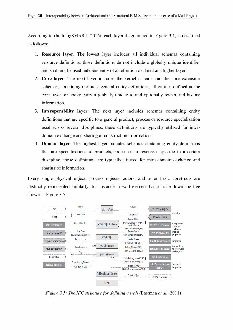
According to (buildingSMART, 2016), each layer diagrammed in Figure 3.4, is described
as follows:
1. Resource layer: The lowest layer includes all individual schemas containing
resource definitions, those definitions do not include a globally unique identifier
and shall not be used independently of a definition declared at a higher layer.
2. Core layer: The next layer includes the kernel schema and the core extension
schemas, containing the most general entity definitions, all entities defined at the
core layer, or above carry a globally unique id and optionally owner and history
information.
3. Interoperability layer: The next layer includes schemas containing entity
definitions that are specific to a general product, process or resource specialization
used across several disciplines, those definitions are typically utilized for inter-
domain exchange and sharing of construction information.
4. Domain layer: The highest layer includes schemas containing entity definitions
that are specializations of products, processes or resources specific to a certain
discipline, those definitions are typically utilized for intra-domain exchange and
sharing of information.
Every single physical object, process objects, actors, and other basic constructs are
abstractly represented similarly, for instance, a wall element has a trace down the tree
shown in Figure 3.5.
Figure 3.5: The IFC structure for defining a wall (Eastman et al., 2011).

Interoperability between Architectural and Structural BIM Software in the case of a Mall Project Page | 21
`
Each level of the tree in Figure 3.5, represents different attributes and relations to the wall
entity (Eastman et al., 2011). Basically, from this wall illustration, one gets a sense for how
all building elements in IFC are defined (Eastman et al., 2011).
3.6 Other BIM-related standards overview
IFC is representing only one piece of a huge puzzle related to conventions and standards in
the construction industry. Interoperability is a wider issue than addressed by IFC or any
current XML schema (Eastman et al., 2011).
According to (Eastman et al., 2011) and (buildingSMART, 2016), a quick reference and
overview of other BIM-related standards efforts is given in the following subsections.
3.6.1 Information Delivery Manual [IDM]
The ISO 29481-1:2010 “Building information modeling - Information delivery manual -
Part 1: Methodology and format” standard has been developed by buildingSMART in
order to have a methodology to capture and specify processes and information flow during
the lifecycle of a facility (buildingSMART, 2016).
IDM is intended to document existing or new processes and describe the associated
information that have to be exchanged between parties. The result can also be used to
define a more detailed specification that, if necessary, can form the basis for a software
development process.
In the event of willing to make an information delivery manual operational it has to be
supported by software. The main purpose of an information delivery manual is to make
sure that the relevant data are communicated in a way that can be interpreted by the
software at the receiving side (buildingSMART, 2016).
The concept is today explored and collaborative efforts are being made in order to make
IDMs that can be used. Despite the progress it is conclusive that it is a challenge to make
IDMs in some areas because there is a lack of structured and well-documented processes
(buildingSMART, 2016).

Page | 22 Interoperability between Architectural and Structural BIM Software in the case of a Mall Project
3.6.2 International Framework for Dictionaries [IFD]
The European Community early observed an issue in the naming of properties and object
classes since objects determined in IFC may have names and attributes in different
languages and their meanings need to be properly interpreted. Fortunately, IFC deals well
with measures in different units (SI and Imperial) (Eastman et al., 2011).
The International Framework for Dictionaries was formed to address these issues. It is
developing mappings of terms between various languages, for eventual wide use in
building models and interfaces. Another vital effort being attempted by IFD is the
advancement of standards for building product specifications, particularly specification
data (Eastman et al., 2011).
3.6.3 OmniClass
Construction Classification System (OmniClass or OCCS) is a classification system for the
construction industry. It is useful for organizing library materials, product literature,
project information, or a classification structure for database systems. OmniClass has been
developed by the International Organization for Standardization (ISO) and the International
Construction Information Society (ICIS) subcommittees and work-groups from the early-
1990s to the present (Eastman et al., 2011). Currently, it consists of 15 tables, as shown in
Figure 3.6.
Figure 3.6: OmniClass tables of classification terms (Eastman et al., 2011).
3.6.4 COBie
Construction Operations Building information exchange (COBie) addresses the handover
of data between the construction group and the owner. It deals with operations and

Interoperability between Architectural and Structural BIM Software in the case of a Mall Project Page | 23
`
maintenance (O&M), and also more general facility management information. COBie
outlines a standard strategy for collecting the required data throughout the design and
construction process, as part of the deliverable package to the owner during commissioning
and handover. It collects data from designers, as they define the design, and by contractors
as the building is built. It also classifies and structures the data in a practical and easy-to-
implement manner. COBie was updated at the beginning of 2010 and is now called
COBie2. COBie2 has been executed for the exchange of facility management data using
the buildingSMART Industry Foundation Class (IFC) open standard (or its ifcXML
proportionate). COBie2 has been developed to support the initial data entry into a
Computerized Maintenance and Management System (CMMS); MAXIMO, TOCMO,
Onuma, and Archibus support COBie2 as well as several European FM and design
applications (Eastman et al., 2011).
3.6.5 XML-Based Schemas
Extensible Markup Language (XML) gives alternate schema languages and transport
mechanisms, especially suited for Web use. XML is an extension to HTML, the language
used to send data over the Web. XML expands upon HTML by giving user-defined tags (a
tag tells what kind of data follows and is a primitive schema) to determine an intended
meaning for data transmitted. XML has turned out to be exceptionally well known for the
exchange of data between Web applications, for instance, to support e-commerce
transactions or collect data (Eastman et al., 2011).
There are different techniques for defining custom tags, including Document Type
Declarations (DTDs) that are developed for mathematical formulas, vector graphics, and
business processes, among numerous others. There are multiple approaches to define XML
schemas, including XML Schema Definition (XSD), RDF (Resource Description
Framework), and OWL Web Ontology Language (Eastman et al., 2011). These are shown
in Figure 3.2.
Using current readily available schema definition languages, some effective XML schemas
and processing methods have been developed in AEC areas.
According to (Eastman et al., 2011), some of the most important XML schemas in AEC
areas are: OpenGIS, gbXML (Green Building XML), ifcXML, aecXML, agcXML,
Page | 24 Interoperability between Architectural and Structural BIM Software in the case of a Mall Project
BIM Collaboration Format (BCF), and CityGML5. Each of these different XML
schemas characterizes its own entities, attributes and relations, and principles. In any case,
each of the XML schemas is different and incompatible.
ifcXML provides a global mapping to the IFC building-data model for cross-referencing.
On the other hand, efforts are in progress to harmonize the OpenGIS schema with IFC. The
longer-term issue is to harmonize the other XML schemas with equivalence mappings
amongst them and with data model representations (Eastman et al., 2011).
Two important XML formats for publishing building model data are DWF and 3D PDF.
These give lightweight mappings of building models for limited uses (Eastman et al.,
2011).
3.7 Functionality of BIM Servers
A BIM server is a database system whose schema is based on an object-based format,
related to building models. BIM servers allow query, transfer, updating and management of
individual project objects from a potentially heterogeneous set of applications. Thus, every
BIM server needs to support access control and information ownership. They need to
support the range of data required for its field of application (Eastman et al., 2011).
The general framework architecture and exchange flows of an idealized BIM server are
presented in Figure 3.7. BIM server services are complicated by the difficulties of storing
the required data in the appropriate format to archive and reproduce the native project files
required by the different BIM authoring and user tools (Eastman et al., 2011).
Neutral formats are insufficient to reproduce the native data formats used by applications,
except in a few limited cases. Therefore any neutral format exchange information, for
example, IFC model data, must be augmented by or associated with the native project files
produced by the BIM authoring tools. The requirements and exchanges shown in Figure
3.7 reflect the mixed formats that have to be managed (Eastman et al., 2011).
5 CityGML is an open standardised data model and exchange format to store digital 3D models of cities and
landscapes (CityGML, 2017).

Interoperability between Architectural and Structural BIM Software in the case of a Mall Project Page | 25
`
Figure 3.7: Example internal structure of exchanges supported by a BIM server (Eastman
et al., 2011).
3.8 BIM and Structural Analysis Software in the context of Data Exchange process
For construction software, the digital models trigger an important question about data
exchange and how these models can be used efficiently for various engineering software.
Pure physical geometry models are important, but a number of other models, which contain
additional structural components, should be taken into consideration. Thus, such models
consist of structural or analytical models which include mechanical material properties,
boundary conditions, or loads which cannot be easily recognized with a pure physical
model. So, these differences may affect the process when using BIM data exchange in
structural engineering. Furthermore, these hurdles represent a big challenge for the
developers of engineering software (Dlubal, 2017).
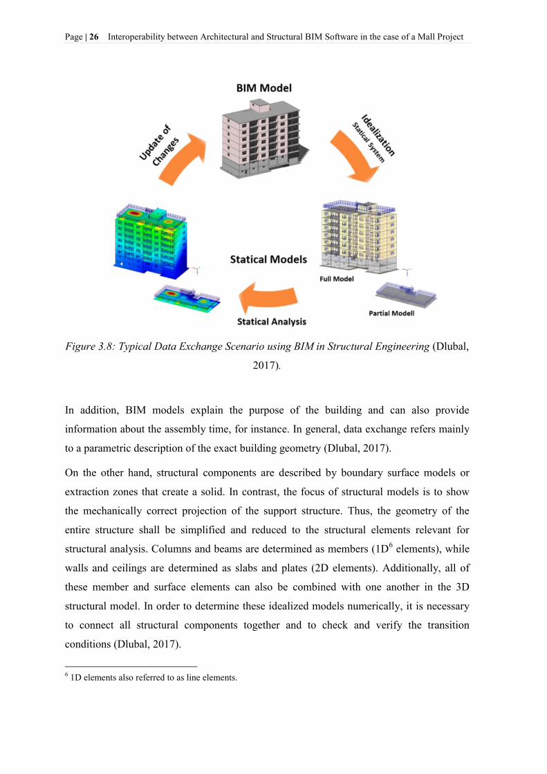
In the context of data exchange process, structural analysis, including any successive
changes must be efficient and reliable. Actual 3D BIM models can provide valuable data
input or means of communication and a better understanding regarding structural
engineering. This process has been illustrated in Figure 3.8.
Page | 26 Interoperability between Architectural and Structural BIM Software in the case of a Mall Project
Figure 3.8: Typical Data Exchange Scenario using BIM in Structural Engineering (Dlubal,
2017).
In addition, BIM models explain the purpose of the building and can also provide
information about the assembly time, for instance. In general, data exchange refers mainly
to a parametric description of the exact building geometry (Dlubal, 2017).
On the other hand, structural components are described by boundary surface models or
extraction zones that create a solid. In contrast, the focus of structural models is to show
the mechanically correct projection of the support structure. Thus, the geometry of the
entire structure shall be simplified and reduced to the structural elements relevant for
structural analysis. Columns and beams are determined as members (1D6 elements), while
walls and ceilings are determined as slabs and plates (2D elements). Additionally, all of
these member and surface elements can also be combined with one another in the 3D
structural model. In order to determine these idealized models numerically, it is necessary
to connect all structural components together and to check and verify the transition
conditions (Dlubal, 2017).
6 1D elements also referred to as line elements.

Interoperability between Architectural and Structural BIM Software in the case of a Mall Project Page | 27
`
Anyway, because of the component simplification from solids to center lines (for
members) and middle planes (for surfaces), automated intersection is not always available.
Geometrically identical modeling would also require the representation as a solid model in
structural engineering. However, even with the currently available computing capacity, it is
unthinkable to calculate a building as a solid model (Dlubal, 2017).
In the case when data is to be exchanged between architectural and structural BIM
software, the focus is on a different view of data. Only supporting elements such as
columns, walls, plates, etc., would be considered (Dlubal, 2017).
In case of additional information that would be required, such as the location of the
structural lines of action, elasticity of the element connections, or characterized mechanical
details of materials and cross-sections, will still be missing. This process is also known as
vertical data exchange (Figure 3.9).
Figure 3.9: An example of vertical data exchange (Dlubal, 2017).

Page | 28 Interoperability between Architectural and Structural BIM Software in the case of a Mall Project
According to (Dlubal, 2017), some of the key factors for successful and efficient data
exchange include:
- Early involvement of the structural engineer and consultation of the handover time
and content,
- Setting standards for materials and cross‑section descriptions (mapping tables),
- Functional and consistent creating of structural elements (columns, beams as
member objects, walls, plates as surface objects),
- Modeling of walls, plates, and columns in sections and levels,
- The decision whether only geometric dimensions and structural lines of action shall
be transferred, or other structural properties as well (supports or hinges),
- Avoiding editing the same components simultaneously,
- Ensure that the supported BIM and FEM software are compatible,
- Performing tests on manageable models using defined exchange objects, preferably
in several formats (IFC, proprietary file format of the software, DWG/DXF, SDNF,
STEP, or other formats),
- Extending alternatives for data exchange and allowing verification and comparison
of models.

Interoperability between Architectural and Structural BIM Software in the case of a Mall Project Page | 29
`
4 INTRODUCTION TO BIM & STRUCTURAL ANALYSIS
SOFTWARE
4.1 Tekla BIM Software
Moving back in the past, by the mid-1960s, computers and automatic data processing were
well established in Finland. Because of the ever-increasing amount of computing work and
lack of resources, a group of engineering offices established a joint software company
named Teknillinen Iaskenta Oy ("technical computing") located in Helsinki. In the spring
of 1966, the company trading name was abbreviated to Tekla.
In 2011 Tekla was acquired by Trimble7, an international technology company with
headquarters in Silicon Valley and offices worldwide. In 2016 Tekla Corporation
rebranded as Trimble (Tekla, 2017).
Tekla offers multiple divisions: Building and Construction, Infrastructure, and Energy. It
can be utilized as multi-user software, supporting multiple users working on the same
project model on a server. In the early 2000s, Tekla added precast concrete design and
fabrication-level detailing for structural and architectural precast (Eastman et al., 2011).
Tekla software offers a wide range of model-based software products for the architectural,
engineering, and construction (AEC) market: Tekla Structures, Tekla Structural Designer,
Tekla BIMsight, Tekla Tedds, Tekla Field3D and Tekla Civil. These products provide
users with state-of-the-art features and functionality for creating, analyzing, and changing
model-based information (Tekla, 2017).
7Trimble - Transforming the way the world works. Trimble is a company that enables enhancing safety,
boosting compliance, and reducing environmental impact (Trimble, 2017).

Page | 30 Interoperability between Architectural and Structural BIM Software in the case of a Mall Project
4.1.1 Tekla Structures
In 2004, Tekla Structures, structural engineering software was launched (Tekla, 2017).
Tekla Structures was formerly known as Xsteel (X as in X Window System8, the
foundation of the Unix9 GUI) (Wikipedia, 2017).
Tekla Structures is a 3D construction modeling software, with its basic functions similar to
other BIM applications for structural modeling and design. Models created with Tekla
Structures as BIM software contain accurate, reliable and detailed information required for
successful BIM and construction execution. In addition, Tekla Structures provides an
automated way to produce all structural documentation, including construction drawings,
steel and reinforcement detailed drawings, reports and material schedules (Tekla, 2017).
Tekla Structures works with a central database, aiming to show that all drawings and
reports are created from and stay linked to the model, get updated automatically, and stay
up to date despite the changes made in the model. Tekla Structures offers an extensive
component library, which enables users to create details in an efficient way. Furthermore,
using Tekla Structures software, it is possible to perform each stage of a design project
from conceptual design to construction planning and erection phase.
Tekla Structures is a comprehensive Building Information Modeling (BIM) solution
developed specifically for Structural Engineers. Tekla Structures provide solutions to
develop constructible, intelligent Building Information Models, which can contain a high
level of detail for increased accuracy and confidence. From the Level of Detail /
Development (LOD) point of view, using Tekla Structures, it is possible to create 3D
constructible models quickly, then visualize and explore how the structure will fit together
when built, before the project gets to site (Tekla, 2017).
Tekla Structures is available in different configurations that provide specialized sets of
functionalities to meet the construction industry requirements (Tekla, 2017). Referring to
interoperability as the main part of this thesis, its features included in different
configurations are shown in Table 4.1.
8 X Window System (X11, or shortened to simply X) is a windowing system for bitmap displays, common on
UNIX-like computer operating systems (Scheifler et al., 1997). 9 Unix (trademarked as UNIX) is a family of multitasking, multiuser computer operating systems that derive
from the original AT&T Unix, development starting in the 1970s at the Bell Labs research center by Ken
Thompson, Dennis Ritchie, and others (Ritchie and Thompson, 1978).

Interoperability between Architectural and Structural BIM Software in the case of a Mall Project Page | 31
`
Table 4.1: Interoperability features included in different configurations (Tekla, 2017).
In a summary, Tekla Structures gives engineers the opportunity to create a single building
model in order to collaborate efficiently with architects, mechanical & electrical engineers,
contractors and fabricators (Tekla, 2017).
4.1.2 Tekla Collaboration
Tekla solutions help structural engineers and drafters to coordinate seamlessly with
architects, service engineers, detailers and contractors at any stage of the project, using
industry standard file formats and custom integration links. This means that Tekla provides
an open approach to Building Information Modeling. Open BIM means interoperability
based on open standards and workflows, not only compatibility between two software
programs (Tekla, 2017).

Page | 32 Interoperability between Architectural and Structural BIM Software in the case of a Mall Project
According to (buildingSMART, 2016), open BIM supports a transparent, open workflow,
allowing project members to participate regardless of the software tools they use.
Actually, using IFC (Industry Foundation Classes) data model offers the most applicable
option for everyday open BIM. Thus, through IFC, Tekla is connected with AEC, MEP
and mostly with plant design software. Using collaborative workflows in an appropriate
way, we can reduce or minimize errors and maximize efficiency in the building and
construction industry. This process has been illustrated in Figure 4.1.
Figure 4.1: Open BIM information flow (Tekla, 2017).
Additionally, Tekla can be successfully integrated with other AEC industry software
solutions using Tekla Open API (Application Programming Interface), while maintaining
the highest levels of data integrity and accuracy. Tekla Open API works through
Microsoft.NET10
connection software and provides a state-of-the-art interface for
collaboration between software systems. Furthermore, Tekla Open API, also known as the
.NET API, enables an interface for third-party applications to interact with the model and
its objects in Tekla Structures (Tekla, 2017).
10
.NET Framework is a software framework developed by Microsoft that runs primarily on Microsoft
Windows. It provides language interoperability (each language can use code written in other languages)
across several programming languages (Wikipedia, 2015).

Interoperability between Architectural and Structural BIM Software in the case of a Mall Project Page | 33
`
While Tekla has an open API, it also supports a wide range of file exchange formats, some
native to other applications, as shown in Table 4.2.
Table 4.2: Exchange formats supported by Tekla (Eastman et al., 2011).
In a summary, according to (Tekla, 2017), the benefits of collaboration between all
construction parties, linking with analysis and design (A&D) packages include:
- Coordination and visualization of the model, drawings and reports,
- Both engineers and modelers can work on the same project model,
- Efficient change management keeps project info up-to-date.

Page | 34 Interoperability between Architectural and Structural BIM Software in the case of a Mall Project
4.1.3 Tekla BIMsight
In addition, Tekla offers a free tool known as Tekla BIMsight, which is a software
application for BIM model-based construction project collaboration. The entire structure
workflow can combine models, check for clashes, and share information using the same
easy-to-use BIM environment. Tekla BIMsight enables project participants to identify and
solve issues already in the design phase before construction (Tekla BIMsight, 2017).
During the process of modeling the Mall Project in Tekla Structures, an efficient way of
sharing information and project collaboration was able by using Tekla BIMsight. Thus, in
order to share relevant information regarding this project, two options are presented in this
section.
The first option is related to the IFC data model exchange method which is further
elaborated in Section 6.2.3.
Tekla BIMsight “Add-on module” in TSL is considered as the second option in this
process. Thus, to implement this process, the path: Export>Tekla BIMsight>Publish to
Tekla BIMsight is followed (Figure 4.2).
Figure 4.2: Publishing BIM model of the Mall project to Tekla BIMsight.

Interoperability between Architectural and Structural BIM Software in the case of a Mall Project Page | 35
`
In order to view the entire BIM model of the Mall project in Tekla BIMsight application,
the path: Published Project>View is followed as shown in Figure 4.3.
Figure 4.3: Viewing the BIM model of the Mall Project in Tekla BIMsight.
4.2 Dlubal - Structural Engineering Software for Analysis and Design
Since 1987, Dlubal Software company has been involved in the development of user-
friendly and powerful programs for structural and dynamic calculations and analyses as
well as for design of framework structures, such as RFEM and RSTAB (Dlubal, 2017).
In this thesis, RFEM is chosen to be used as a FEA program in order to perform structural
analysis of the partial model in the case of a Mall project, and is briefly described further in
this section.
In addition, Dlubal is considered as an advanced Structural Engineering Software for
Analysis and Design, which offers a wide range of solutions in the construction industry,
as shown in Figure 4.4.

Page | 36 Interoperability between Architectural and Structural BIM Software in the case of a Mall Project
Figure 4.4: Dlubal Software company solutions (Dlubal, 2017). Underlined sections refer
to the main requirements of this thesis, regardless of the partial performing of structural
analysis and design.
4.2.1 RFEM-Finite Element Analysis program
RFEM as a finite element analysis program is a powerful software for quick and easy
modeling, structural analysis and design of 2D and 3D models consisting of member, plate,
wall, folded plate, shell, solid, and contact elements. The structural analysis program
RFEM is the basis of a modular software system. It is used to define structures, materials,
and loads for planar and spatial structural systems. Using RFEM program it is also possible
to create combined structures as well as model solid and contact elements (Dlubal, 2017).
With RFEM Software it is possible to provide deformations, internal forces, stresses,
support forces, and soil contact stresses of the structure. In addition, for the subsequent
design, we could use various add-on modules taking into account material and standard-
specific conditions. In RFEM program, a model can be created in the GUI characteristic for
CAD programs, using tables, or in combination of both ways. Using RFEM to determine
internal forces, results can be superimposed in combinations (Dlubal, 2017).

Interoperability between Architectural and Structural BIM Software in the case of a Mall Project Page | 37
`
5 MODELING OF THE MALL PROJECT USING TEKLA BIM
SOFTWARE
To create a BIM model in the case of a Mall project we have decided to use Tekla BIM
Software. Tekla BIM Software offers also a BIM Software for students, called Tekla
Structures Learning (TSL).
Tekla Structures Learning is an educational student configuration of Tekla Structures BIM
software. It includes the functionality of Tekla Structures full configuration, excluding the
steel and precast fabrication functionality (Tekla, 2017).
5.1 Description of the Mall project
The entire structure includes architectural and structural elements which represent a center
Mall, located in Murska Sobota, Slovenia (Figure 5.1).
Figure 5.1: 3D Model of the Mall Project modeled using Tekla Structures Learning.

Page | 38 Interoperability between Architectural and Structural BIM Software in the case of a Mall Project
Aiming to describe and represent each element modeled in the case of a Mall project, we
broke up the entire BIM model of the Mall project, into smaller sections. This has been set
out using ‘Phase Manager’ tool, as shown in Figure 5.2.
Figure 5.2: Phase Manager Filter in TSL.
In this section, each phase of the Mall project as underlined in Figure 5.2 has been
described and discussed. Most of the elements included in phases 2-13 are considered as
structural elements. These elements are represented as load-bearing elements necessary for
proper structural design and include geometry, member nodes, material properties, element
cross-sections, external supports, nodal restraints, and type of analysis.
Overall floor size of the building is (74,83 x 32,35) m. The total gross area of the building
is approximately 2500 m2. The building consists of the ground floor and a mezzanine
(intermediate floor). Mezzanine is placed in the area between axes 3-5/I-M, which has the
floor size of approximately 190 m2
(Figure 5.3).

Interoperability between Architectural and Structural BIM Software in the case of a Mall Project Page | 39
`
Figure 5.3: Ground floor and mezzanine of Mall project.
The main floor height of the Mall area varies from 5,25 m to 6,45 m, while the maximum
height of storage and service area is about 7,05 m. The height of the intermediate floor is
approximately 3,10 m. The roof of the structure is considered as a single-leaf roof with an
inclination of 3.3° (Figure 5.4).
Figure 5.4: Height differences of the Mall project.

Page | 40 Interoperability between Architectural and Structural BIM Software in the case of a Mall Project
A substructure of the building as an underlying or supporting structure, represents a system
of strip foundations, mainly consisting of foot 100 cm wide and 40 cm thick. In addition,
considering the critical (max.) loads in the axes 3/C-N, the foundation width is supposed to
be 150 cm, while in the case of critical (min.) loads in the axes A/1-2, 1/A-B, 2/A-B, I/3-5
and 4/I-N, their width is supposed to be 80 cm. In the area where concentrated loads
(where the main steel columns are placed) appear, the foundations have been locally
expanded, being considered as pad footings. Thus, in the axes N/1 and N/3 a pad footing
(2,50 x 2,50 x 0,80) m is considered, while in the axes N/4 and M/5 a pad footing (1,60 x
1,60 x 0,60) m is used (Figure 5.5).
Figure 5.5: Foundation types of the Mall project.
The bottom level of the foundation is supposed to be placed at the height-level of -2,05 m
depending on the ground floor level of the structure (Figure 5.6).
Figure 5.6: Bottom level of the foundation.

Interoperability between Architectural and Structural BIM Software in the case of a Mall Project Page | 41
`
In addition, above the foundation footings, RC walls with the thickness of 30 cm and the
height of 129 cm are considered (Figure 5.7). Through these walls is carried out the ground
floor slab with the thickness of 25 cm.
Figure 5.7: RC walls above footing of the strip foundations.
A superstructure is considered as an upward part of the building above the ground level.
The height of the RC walls above the ground level varies from 5,40 m to 7,20 m (see
Figure 5.4), with the thickness of 26 cm and 30 cm, while in the case of interior parts,
respectively in the area of mezzanine (intermediate floor) of the structure, the thickness of
the RC walls is taken as 20 cm into consideration (Figure 5.8).
Figure 5.8: RC walls of the Mall project.

Page | 42 Interoperability between Architectural and Structural BIM Software in the case of a Mall Project
The walls which are placed in the technical area of the structure are considered as masonry
(brick) walls, with the thickness of 20 cm, being connected with reinforced concrete slabs.
Ceiling slabs which are placed above the technical area, as well as above the delivery area
were considered as RC slabs, consisting of the thickness of 20 cm (Figure 5.9).
Figure 5.9: Brick walls and ceiling slabs of the Mall project.
The roofing system of the structure has been carried out by glued timber beams. These
structural elements placed in the area between axes 1 and 3 consists of the width equal to
24 cm and the height of 140 cm, while those placed in the area between axes 3 and 5
consists of the same width as previous ones with the height of 64 cm (Figure 5.10).
Figure 5.10: Timber beams of the Mall project.

Interoperability between Architectural and Structural BIM Software in the case of a Mall Project Page | 43
`
In addition, timber panels as structural parts of the roof structure include the glued timber
beams consisting of the cross-section of 8/24 cm placed axially with the space of 70 cm,
and OSB timber plates which are placed on its upper and bottom side. In the area between
the glued timber beams as supports of the roof panel is considered the thermal insulation
with the thickness of 24 cm. A typical detail of this roofing system is modeled in TSL, as
shown in Figure 5.11.
Figure 5.11: Detail of the roof system modeled in TSL.
Furthermore, in the area of the main entrance of the Mall center between axes 5/L-N and
axis N, structural steel elements have been modeled (columns with the cross-section of
30/30 cm and HEA 500, and HEA 500 steel beam). In the axes 3/K-N a steel beam with
the cross-section of HEB 1000 is considered, while in the axes 4/J-L a steel beam with the
section of HEB 200 is used. Steel beam profiles RHS (18x26x0,8) cm, which must be
anchored in the walls of the structures between axes 3-5/E-I are considered. Steel profiles
of the Mall project have been shown in Figure 5.12.

Page | 44 Interoperability between Architectural and Structural BIM Software in the case of a Mall Project
Figure 5.12: Steel profiles of the Mall project.
RC columns with the cross-section of 30/30 cm, have been modeled as load-bearing
elements, as shown in Figure 5.13.
Figure 5.13: RC columns of the building.
In the case of modeling aluminium profiles and glass surfaces to cover the entrance of the
building, Schuco profiles (see Figure 5.44) adopted from Tekla Warehouse library are
taken into consideration. Modeling of these profiles is shown in Figure 5.14.

Interoperability between Architectural and Structural BIM Software in the case of a Mall Project Page | 45
`
Figure 5.14: Aluminium profiles and glass surfaces modeled in TSL.
A detail (Detail A) of modeled Schuco profiles in TSL is shown in Figure 5.15.
Figure 5.15: A detail of modeled Schuco profiles in TSL.
Furthermore, three types of stairs are modeled in this project, as shown in Figure 5.16.
Figure 5.16: Different types of stairs modeled in TSL.

Page | 46 Interoperability between Architectural and Structural BIM Software in the case of a Mall Project
Cooling cells consisting of masonry walls and rock wool insulation layers have been
modeled between axes 3-4/E-I, as shown in Figure 5.17.
Figure 5.17: Cooling cells of the Mall project.
Mesh elements which are modeled inside of the building area, are made of steel profiles.
These elements are shown in Figure 5.18.
Figure 5.18: Mesh elements made of steel profiles.
In addition, external structural elements such as RC slab, strip foundations, and RC walls,
have been modeled between axis 2-5/A-B, as shown in Figure 5.19.

Interoperability between Architectural and Structural BIM Software in the case of a Mall Project Page | 47
`
Figure 5.19: External structural elements of the Mall project.
Finally, elements included in the first phase of the Mall project (wood covering elements,
ladder, Schüco aluminium elements, etc.), have been considered as architectural elements.
These architectural elements are modeled as non-load-bearing elements in TSL, as shown
in Figure 5.20.
However, these elements have also been specified with materials, element cross sections,
and exterior/interior finishes that are not connected with the structural model but belongs
more to the aesthetic role of the building.
Figure 5.20: Architectural elements of the Mall project modeled as non-load-bearing
elements in TSL.

Page | 48 Interoperability between Architectural and Structural BIM Software in the case of a Mall Project
5.2 Modeling of the Mall project
5.2.1 Tekla Structures Learning Environments
In this thesis, we have paid a close attention while setting out the libraries of property for
different objects and materials, since those represent an integral part of a well-developed
BIM environment.
BIM environment includes object and assembly libraries for reuse, interfaces to the
applications the organization supports and links to collaborate management and accounting
systems (Eastman et al., 2011).
Currently, TSL offers a wide range of environments. Based on the country origin the
environments showed in Figure 5.21, offers adequate engineering standards that are
applicable in that country.
Figure 5.21: Tekla Structures Learning available Environments (Tekla, 2017).
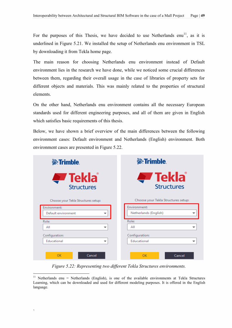
Interoperability between Architectural and Structural BIM Software in the case of a Mall Project Page | 49
`
For the purposes of this Thesis, we have decided to use Netherlands enu11
, as it is
underlined in Figure 5.21. We installed the setup of Netherlands enu environment in TSL
by downloading it from Tekla home page.
The main reason for choosing Netherlands enu environment instead of Default
environment lies in the research we have done, while we noticed some crucial differences
between them, regarding their overall usage in the case of libraries of property sets for
different objects and materials. This was mainly related to the properties of structural
elements.
On the other hand, Netherlands enu environment contains all the necessary European
standards used for different engineering purposes, and all of them are given in English
which satisfies basic requirements of this thesis.
Below, we have shown a brief overview of the main differences between the following
environment cases: Default environment and Netherlands (English) environment. Both
environment cases are presented in Figure 5.22.
Figure 5.22: Representing two different Tekla Structures environments.
11
Netherlands enu = Netherlands (English), is one of the available environments at Tekla Structures
Learning, which can be downloaded and used for different modeling purposes. It is offered in the English
language.

Page | 50 Interoperability between Architectural and Structural BIM Software in the case of a Mall Project
As it can be seen in Figure 5.22, the same Role and Configuration of the program TSL was
chosen, for both environment types. The Role was selected All, in the case of being able to
use all available functionalities that TSL offers. In addition, the Configuration of the
software remains Educational, which means that the created BIM model of the Mall in TSL
cannot be used for production purposes.
TSL options for defining the properties of different elements are offered in different
properties settings due to environments differences. Some of the main differences between
above-mentioned environments have been illustrated in figures below.
Figure 5.23: Concrete profile selection differences. Default environment (left side) and
Netherlands-English (right side).

Interoperability between Architectural and Structural BIM Software in the case of a Mall Project Page | 51
`
Figure 5.24: Applications and components differences. Default environment (left side) and
Netherlands-English (right side).

Page | 52 Interoperability between Architectural and Structural BIM Software in the case of a Mall Project
Figure 5.25: Important advance option differences. Default environment (upward side)
and Netherlands-English (downward side).
Additionally, some differences while using the above-mentioned environments at the same
project appeared also when drawing template layouts were automatically created. This
cleared the basic dilemma on which type of the above-mentioned environments should be
taken into consideration, in the case of this thesis.
Hence, Netherlands (English) environment appeared to be more useful and better
implemented for the overall purposes of this thesis.
5.2.2 Tekla Structures Learning standards and settings in the case of a Mall project
First, to create a BIM model in Tekla Structures Learning (TSL), the appropriate way of
setting out necessary and most important information of the project must be considered.
Thus, the path: Open Software>File>Project Properties is followed. The following dialog
box appears as shown in Figure 5.26.

Interoperability between Architectural and Structural BIM Software in the case of a Mall Project Page | 53
`
Figure 5.26: Tekla Structures Learning properties in the case of a Mall Project.
In addition, grid settings specified for the Mall project are set out as shown in Figure 5.27
(left side). Grids have been used to create plan and elevation views in TSL. As soon as we
have defined the grid lines, we could use them to create a series of so-called named views.
For instance, seven of the named views created by using a grid that was selected and then
moved over to the visible views section, are shown in Figure 5.27 (right side).

Page | 54 Interoperability between Architectural and Structural BIM Software in the case of a Mall Project
Figure 5.27: The grid settings (left side) and views along the grid lines (right side).
When we have already created grid and views, we continued to create the model using the
various tools for typical elements such as beams, polygon beams, columns, plates, slabs,
walls, etc. Basically, various tools appear to be grouped together into toolbars. For
instance, steel toolbar contains tools for modeling steel elements, the concrete toolbar
contains tools for creating concrete elements, then detailing toolbar contains tools for
editing elements etc. Moreover, TSL offers numerous additional toolbars containing tools
for creating connections, components, as well as tools for creating and managing views and
work planes. These toolbars are placed on top of the modeling window of TSL application,
as shown in Figure 5.28.
Figure 5.28: Main toolbars in TSL.

Interoperability between Architectural and Structural BIM Software in the case of a Mall Project Page | 55
`
In the first stage of creating the BIM model of the Mall project in TSL, we had the chance
to set out the execution class of the steel parts of the structure.
According to (CEN, 2008), four execution classes (EXC) are defined as follows: each class
provides its own set of requirements, with complexity increasing as the number rises, while
EXC2 is considered the most used specification for different kind of projects. The EXC
assigned to a structure is mostly generated and defined by the engineering effort required
to create and realized the project-specific design parameters.
Hence, the basic execution classes defined by (CEN, 2008), available at TSL, are described
based on their purpose of uses, as shown in Figure 5.29.
Figure 5.29: Examples of execution classes (Linde Group, 2014).
Since, the Mall project is considered as a commercial structure, than EXC2 is adopted as
an appropriate execution class for steel elements (Figure 5.30).

Page | 56 Interoperability between Architectural and Structural BIM Software in the case of a Mall Project
Figure 5.30: Execution class for steel elements dialog box.
Using TSL, we could define the properties of components before creating them, or modify
the properties after creation. An example is shown in Figure 5.31, where a concrete column
properties dialog box appears. Furthermore, we could choose the profile from an extensive
catalog of steel and concrete sections, and then select the material from a catalog of
industry standard types.
Figure 5.31: The Concrete Column Properties dialog boxes.
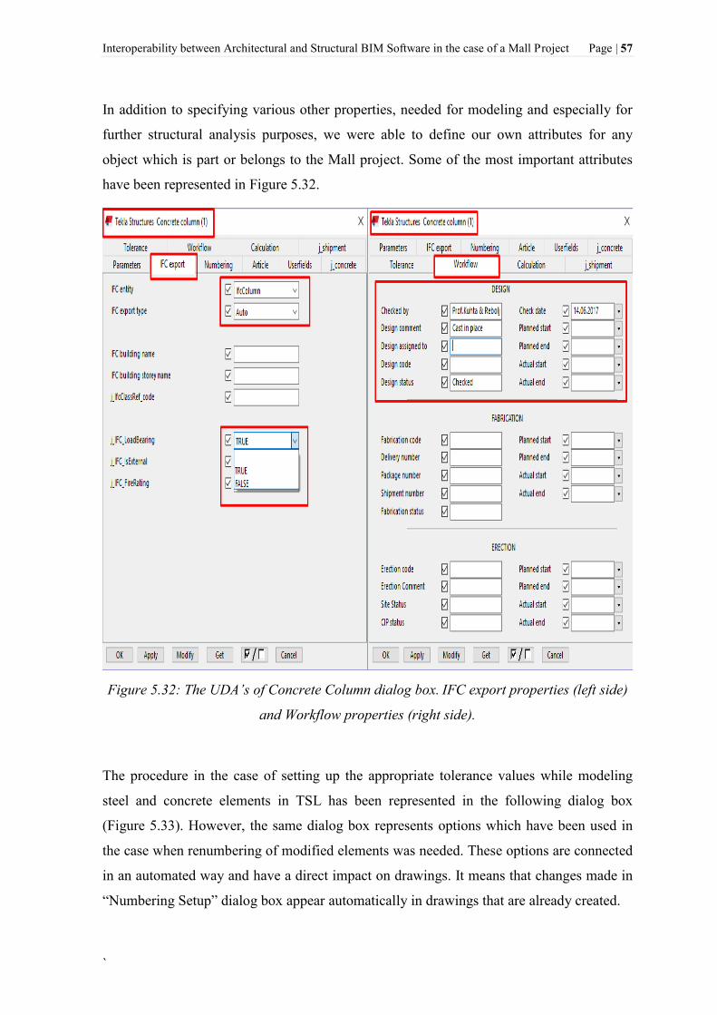
Interoperability between Architectural and Structural BIM Software in the case of a Mall Project Page | 57
`
In addition to specifying various other properties, needed for modeling and especially for
further structural analysis purposes, we were able to define our own attributes for any
object which is part or belongs to the Mall project. Some of the most important attributes
have been represented in Figure 5.32.
Figure 5.32: The UDA’s of Concrete Column dialog box. IFC export properties (left side)
and Workflow properties (right side).
The procedure in the case of setting up the appropriate tolerance values while modeling
steel and concrete elements in TSL has been represented in the following dialog box
(Figure 5.33). However, the same dialog box represents options which have been used in
the case when renumbering of modified elements was needed. These options are connected
in an automated way and have a direct impact on drawings. It means that changes made in
“Numbering Setup” dialog box appear automatically in drawings that are already created.

Page | 58 Interoperability between Architectural and Structural BIM Software in the case of a Mall Project
Figure 5.33: Numbering Setup dialog box.
.
In addition, the appropriate values of components, which were used directly in the
following stages of the project, have been set out using the following path:
Settings>Options>Components. These values appear in the following dialog box (Figure
5.34).
Figure 5.34: Default settings for components in Tekla Structures.

Interoperability between Architectural and Structural BIM Software in the case of a Mall Project Page | 59
`
Similarly, the path: Settings>Options>Clash checks is followed to set out necessary default
values in the case of detecting clash checks while modeling the Mall project, avoiding the
possibilities of making eventual mistakes. This has been connected and set out in
accordance with Eurocodes. The procedure is illustrated in Figure 5.35.
Figure 5.35: Default settings for clash checks in TSL.
Additionally, we used the following dialog boxes that appear in figures below, to set out
necessary settings for units and decimals, which are applicable and implementable in
accordance with Eurocodes. This was done using “options” for modeling and catalogs in
TSL, as shown in Figure 5.36 and Figure 5.37, respectively.

Page | 60 Interoperability between Architectural and Structural BIM Software in the case of a Mall Project
Figure 5.36: Units and decimals settings for modeling purposes.
Figure 5.37: Units and decimals settings for catalogs.

Interoperability between Architectural and Structural BIM Software in the case of a Mall Project Page | 61
`
Finally, the most important settings regarding dimensioning in the case of preparing
drawing types of this project have been underlined and shown in the following Figure 5.38.
Since such settings have been required through different phases of this project, the
procedure for creating and saving them as a new settings version such as ”Drilon settings”,
for instance, has also been shown in Figure 5.38. Other dimension properties included in
Figure 5.38 are left as default properties in TSL.
Figure 5.38: Dimension properties settings in the case of creating drawings for this
project.

Page | 62 Interoperability between Architectural and Structural BIM Software in the case of a Mall Project
5.2.3 Importing CAD files as reference models
Tekla Structures Learning offers tools that we were able to use in case of importing
reference models including the information they contained. In this case, we could import 2-
D CAD architectural drawings of Mall project, prepared by (Gravitas d.o.o, 2017). Thus,
we could use those reference models as a layout to directly build the model on.
In general, according to (Tekla, 2017), the following file types are supported in TSL as
reference models:
- AutoCAD files.dxf,
- AutoCAD files.dwg (supported version ACAD2014 and earlier),
- Cadmatic files.3dd,
- IFC files.ifc, .ifczip, .ifcxml,
- IGES files.igs, .iges,
- LandXML files.xml,
- MicroStation files.dgn, .prp,
- PDF files.pdf,
- Tekla Collaboration files.tczip,
- SketchUp files.skp (supported version SketchUp 2016 and earlier),
- STEP files.stp, .STEP.
Basically, this section involves importing of existing CAD data, respectively 2-D CAD
architectural drawings. To do this, we have imported CAD file first using the Insert tab
Reference Model command in TSL. This brought up the Import CAD Formats (Reference
Models) dialog box, which allowed us to browse a saved CAD file and then we used it as a
reference model in TSL (Figure 5.39).
Figure 5.39: Importing CAD files to Tekla Structures dialog box.

Interoperability between Architectural and Structural BIM Software in the case of a Mall Project Page | 63
`
In addition, imported 2-D CAD architectural drawings as reference models, have been
shown in Figure 5.40 and Figure 5.41, respectively. These figures include planar and
section view drawings.
Figure 5.40: Imported 2-D DWG Mall project files to TSL as Reference Model (3D View).
Figure 5.41: DWG foundation drawing imported to Tekla Structures as Reference Model
(Basic View).

Page | 64 Interoperability between Architectural and Structural BIM Software in the case of a Mall Project
The entire BIM model of the Mall project modeled with the help of 2D CAD architectural
drawings has been shown in Figure 5.42.
Figure 5.42: Overlaying DWG Mall project modeled in TSL.
In addition, according to (Tekla, 2017), limitations while importing DWG profiles to TSL,
are listed below:
- The profile must be the only object in the DWG file. The file must not contain any
titles, blocks or any other graphics,
- It is preferable for the profile to be a closed polyline,
- The profile needs to be scaled up,
- The DWG files imported with the DWG tool do not show the surfaces of the
imported objects, only the construction lines or lines converted to part profiles that
can be used to create a model. For instance, while we wanted to show the surfaces
of the objects, we had to import DWG files as reference models.

Interoperability between Architectural and Structural BIM Software in the case of a Mall Project Page | 65
`
5.2.4 Tekla Warehouse
Tekla Warehouse represents a free Tekla Structures BIM storage. It is very useful for the
following purposes: find, import, install, and share products and applications internally and
globally. Basically, it is an efficient store that produces high-quality models. In the case of
libraries of BIM elements, each BIM platform has various libraries of predefined objects
that can be imported for use (Tekla, 2017).
Tekla Warehouse offers applications, custom components, parts, profiles, materials like
steel and concrete grades, bolts, rebars, mesh, shapes, and templates which can be used in
Tekla Structures. Tekla Warehouse shows a centralized access to this content that can now
be taken into use in a streamlined way. The content in Tekla Warehouse is time by time
increasing (Tekla, 2017).
According to (Tekla, 2017), manufacturers can create their products and applications
available for being utilized. Thus, we could take the exact 3D product models straight into
our TSL model. Figure 5.43 shows the general opportunities that this tool offers for
worldwide costumers and Tekla BIM software users.
Figure 5.43: Tekla online service - Tekla Warehouse.

Page | 66 Interoperability between Architectural and Structural BIM Software in the case of a Mall Project
Using Tekla Warehouse made us finding approximately what we needed easy regardless
the content type we had to input in BIM model of the Mall project. This has been
illustrated in Figure 5.44. Profiles shown in Figure 5.44, were used in the case of modeling
aluminium and glass elements of the project.
Figure 5.44: Schüco Profiles used in the case of modeling steel/aluminum profiles in Tekla
Structures.
However, it is interesting to mention that Tekla Warehouse has some limitations in the case
of using some applications available online, since those require a valid license as a
customer user, to be able to download them. Examples of such cases are shown in Figure
5.45 and Figure 5.46, while we tried to download the following applications which could
have allowed us to model glass unit surfaces directly in Tekla Structures, respectively to
publish the thesis project to 3D PDF.

Interoperability between Architectural and Structural BIM Software in the case of a Mall Project Page | 67
`
Figure 5.45: UPB Glass Unit application for modeling aluminum and glass profiles in
TSL.
Figure 5.46: Tekla Warehouse Application for publishing BIM model to 3D PDF.

Page | 68 Interoperability between Architectural and Structural BIM Software in the case of a Mall Project
5.3 Creating Drawings
Since documents are still required in a construction site and manufacturing processes,
drawings play a very important role in the construction industry. Thus, it is always
necessary to create drawings that contain detailed information. Using TSL, it is possible to
create drawings one by one, in groups, or generate all drawings automatically.
5.3.1 Drawing types
First, to create a drawing in TSL, the path: Drawing and Reports >Create Drawings >Any
Drawing Type is followed (Figure 5.47).
Figure 5.47: The procedure for creating a drawing in TSL.
Referring to Figure 5.47, many types of drawings could be created in TSL, which are listed
and described below:
1. Single-part drawings: These drawing types are known as workshop drawings that
represent the fabrication information for one part (usually without welds). Single-
part drawings are usually prepared in small paper sizes, for example, A4. An
example of a single-part drawing is shown in Appendices, Section 10.3.2.

Interoperability between Architectural and Structural BIM Software in the case of a Mall Project Page | 69
`
2. Assembly drawings: Similarly to single-part drawings, assembly drawings also
represent workshop drawings that show the fabrication information for one
assembly. Usually, an assembly consists of the main part and secondary parts.
Thus, the secondary parts are connected to the main part by either welded or bolted.
These types of drawings are usually prepared in larger sheet sizes than previous
drawing types, for instance, A3. An assembly drawing example is shown in
Appendices, Section 10.3.3.
3. Cast unit drawings: Cast unit drawings are considered as dimensional, formwork,
or reinforcement drawings. In most cases, these drawing types are used in concrete
design and construction. They usually show the edge chamfers and hard or soft
insulation information.
Cast unit drawings that are created to represent cast-in-place concrete structures are
usually prepared in large sheet sizes, such as A1, while those created to show
precast structures are usually prepared to A3 paper size. An example of a cast unit
drawing is shown in Appendices, Section 10.3.4.
4. General arrangement drawings: Usually a GA drawing represents a contract
document, which contains information that is necessary to understand the general
arrangement structural elements of a project. According to (Tekla, 2017), a GA
drawing is created in BIM workflows from one or more model views, with
associated schedules, and on a project title sheet.
Often, GA drawings contain enlarged views of complex areas or details, and
additional information that can be useful in the approval process and during the
installation phase. GA drawings are usually prepared in large sheet sizes, such as
A1 or A0. An example of a GA drawing is shown in Appendices, Section 10.3.1.
5. Multidrawings: Like single-part and assembly drawings, these drawing types are
also considered as workshop drawings. Multidrawings are usually used to combine
several single-part or assembly drawings on one sheet. Thus, they usually require
large sheet sizes, for example, A1 or A0.
It is recommended to create multidrawings when one or more assembly drawings
appear on a sheet, and when a collection of multiple single-part drawings on a large
sheet is needed. A multidrawing example is shown in Appendices, Section 10.3.5.

Page | 70 Interoperability between Architectural and Structural BIM Software in the case of a Mall Project
5.4 Visualization of the Mall Project
One of the most obvious uses of a BIM model (Mall project model), is the use of the
project as a visualization tool. Comparing to traditional drawings, 3D visualization of the
project helped us to better understand the details of the design and its general concept. 3D
visualization is still being considered one of the most important parts of the project,
making design processes and construction tasks easier to understand especially for people
who have less knowledge or are not familiar with this field. Planning how to construct
complex details of the Mall Project is considered much easier using a 3D view, which
could be manipulated and cross-sectioned in multiple directions. Examples of 3D
visualization details created in the case of a Mall project in TSL are shown in Figure 5.48
and Figure 5.49, respectively.
Figure 5.48: Render of section view details of the Mall project.
Figure 5.49: 3D visualization details of the entrance elements of the Mall project.

Interoperability between Architectural and Structural BIM Software in the case of a Mall Project Page | 71
`
6 INTEROPERABILITY BETWEEN TEKLA STRUCTURES LEARNING AND
RFEM
This section describes the general process of data exchange between BIM and FEM
software. The following softwares that were chosen for this project: Tekla Structures
Learning as BIM modeling software and RFEM as FEM analysis software, represent the
interoperability features and findings between BIM and FEM softwares. In addition, the
data exchange methods included in Figure 6.4 that are used for various cases of this
project, are described and discussed in detail in this section.
6.1 Physical and analytical models
The analytical model of the structure is a simplified three-dimensional (3D) representation
of the full physical description of a structural model; all structural elements are connected
to each other continuously. An analytical model is known also as the ”stick model”. The
analytical model consists of those structural elements, geometry, material properties, nodal
restraints, external supports, and loads that together create a model for structural design.
Analytical models use the simplified assumptions, such as for connecting members (hinged
or rigid). It is important to emphasize that only analytical models of the structure can be
analyzed and not the real structure (Nawari and Kuenstle, 2015).
In the physical model, every structural element such as beam, column, slab, wall, etc., must
be supported with a point support. In other words, a supporting member must have a point
intersection with a supported member (Nawari and Kuenstle, 2015).
6.1.1 Creating analytical models in Tekla Structures Learning
Once we have created a physical model that can be used to analysis and design tools, we
could automatically use it to create various types of analytical models in TSL.

Page | 72 Interoperability between Architectural and Structural BIM Software in the case of a Mall Project
However, before creating a new analytical model, it is always recommended to check out
the analysis properties of each structural element, because sometimes some of the
properties are required to be manually set up. This process could be done by clicking “Part
and analysis properties” icon on the main toolbar in TSL (Figure 6.1). In other words, this
is considered a very important step before creating analytical models, since not every
process of the project could be implemented in an automated way in TSL.
Secondly, to create an analytical model, the path: Analysis & design>A&D models>Create
new models is followed. This procedure has been shown in Figure 6.1.
Figure 6.1: Procedure for creating an analytical model in TSL.
While creating a new analytical model, numerous of analysis properties appeared in the
dialog box as shown in Figure 6.2. It was not necessary to take all of them into account.
Therefore, the most important properties that are considered in the case of this project are
underlined and shown in Figure 6.2. Other properties included in this dialog box, are
mostly related to structural analysis and design of relevant model cases. Since Tekla BIM
software is not considered in the case of performing structural analysis of this project, these
properties were better left to be specified in Dlubal-Structural Engineering Software for
Analysis and Design.

Interoperability between Architectural and Structural BIM Software in the case of a Mall Project Page | 73
`
Three creation methods exist in the case of preparing an analytical model including: Full
model, by selected parts and loads, floor model by selected parts and loads (Figure 6.2).
The first two methods are considered the most common methods to create various
analytical models. Thus, these two creation methods have also been considered in the case
of this project, which are included in the third stage of creating analytical models and can
be seen in Figure 6.2.
Figure 6.2: Analysis Model Properties in the case of a Mall project.
The relationship between a physical and corresponding analytical partial model in the case
of a Mall project has been shown in Figure 6.3. Thus, Figure 6.3 (left side) shows the
physical partial model, while Figure 6.3 (right side) represents the corresponding analytical
partial model of this project. More detailed information for this partial model of the Mall
project has been further presented in Section 6.4.3.
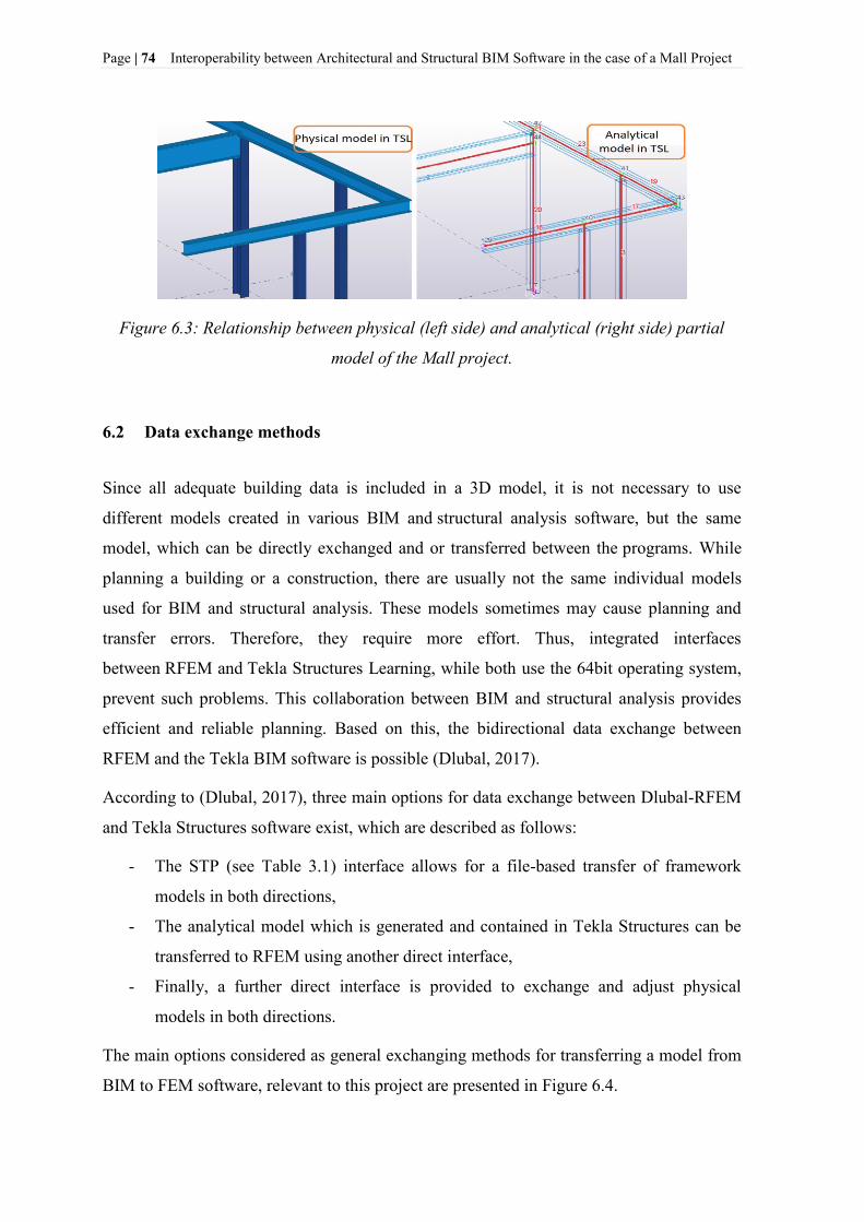
Page | 74 Interoperability between Architectural and Structural BIM Software in the case of a Mall Project
Figure 6.3: Relationship between physical (left side) and analytical (right side) partial
model of the Mall project.
6.2 Data exchange methods
Since all adequate building data is included in a 3D model, it is not necessary to use
different models created in various BIM and structural analysis software, but the same
model, which can be directly exchanged and or transferred between the programs. While
planning a building or a construction, there are usually not the same individual models
used for BIM and structural analysis. These models sometimes may cause planning and
transfer errors. Therefore, they require more effort. Thus, integrated interfaces
between RFEM and Tekla Structures Learning, while both use the 64bit operating system,
prevent such problems. This collaboration between BIM and structural analysis provides
efficient and reliable planning. Based on this, the bidirectional data exchange between
RFEM and the Tekla BIM software is possible (Dlubal, 2017).
According to (Dlubal, 2017), three main options for data exchange between Dlubal-RFEM
and Tekla Structures software exist, which are described as follows:
- The STP (see Table 3.1) interface allows for a file-based transfer of framework
models in both directions,
- The analytical model which is generated and contained in Tekla Structures can be
transferred to RFEM using another direct interface,
- Finally, a further direct interface is provided to exchange and adjust physical
models in both directions.
The main options considered as general exchanging methods for transferring a model from
BIM to FEM software, relevant to this project are presented in Figure 6.4.

Interoperability between Architectural and Structural BIM Software in the case of a Mall Project Page | 75
`
Figure 6.4: Data exchange methods between BIM and FEM software.
In addition, the IFC format could be opened with the Tekla BIMsight to view the model
and detect eventual errors, which is elaborated previously in Section 4.1.3.
6.2.1 Tekla Structures Learning– RFEM direct link
The process of data exchange based on the »direct link« exchange method has been
presented in Figure 6.5.
Figure 6.5: Data exchange between Tekla Structures Learning and RFEM using the direct
link.
The direct link between Tekla Structures Learning and RFEM represent a practical method
to exchange data and very easy to use. In the case of this project, the data exchange process
has been initiated in Tekla Structures Learning.
To implement this process both software applications have been installed on the same
computer and running simultaneously. However, to import a model created in TSL to
RFEM, the path: File>Import>Tekla Structures or the process by clicking the “Direct
import from Tekla Structures” icon in the main Toolbar of RFEM program could be
followed. This procedure is shown in Figure 6.6.

Page | 76 Interoperability between Architectural and Structural BIM Software in the case of a Mall Project
Figure 6.6: Importing models from TSL to RFEM.
The following dialog box appeared as shown in Figure 6.7.
Figure 6.7: Import options dialog box in RFEM program.
Both structural data and load data can be transferred while taking this exchange method
into account. Referring to Figure 6.7, only the structural data have been exchanged in this
project which includes members, member types, lines, nodes, cross-sections, materials,
nodal supports, eccentricities, rigid connection, etc.
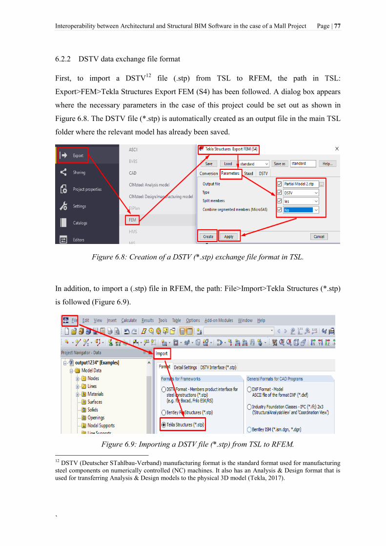
Interoperability between Architectural and Structural BIM Software in the case of a Mall Project Page | 77
`
6.2.2 DSTV data exchange file format
First, to import a DSTV12
file (.stp) from TSL to RFEM, the path in TSL:
Export>FEM>Tekla Structures Export FEM (S4) has been followed. A dialog box appears
where the necessary parameters in the case of this project could be set out as shown in
Figure 6.8. The DSTV file (*.stp) is automatically created as an output file in the main TSL
folder where the relevant model has already been saved.
Figure 6.8: Creation of a DSTV (*.stp) exchange file format in TSL.
In addition, to import a (.stp) file in RFEM, the path: File>Import>Tekla Structures (*.stp)
is followed (Figure 6.9).
Figure 6.9: Importing a DSTV file (*.stp) from TSL to RFEM.
12
DSTV (Deutscher STahlbau-Verband) manufacturing format is the standard format used for manufacturing
steel components on numerically controlled (NC) machines. It also has an Analysis & Design format that is
used for transferring Analysis & Design models to the physical 3D model (Tekla, 2017).

Page | 78 Interoperability between Architectural and Structural BIM Software in the case of a Mall Project
DSTV file (*.stp) is a data exchange file format mostly applicable for structural steel
projects. It saves the data elements such as end points, material, cross sections, references,
etc., as a standard DSTV file which could be used for importing and exporting models.
6.2.3 IFC data model exchange
Similarly as explained in the previous data exchange method, as a first step to import an
IFC file from TSL to RFEM, the path in TSL: Export>IFC>Export to IFC is considered.
The following dialog box appears as shown in Figure 6.10.
Figure 6.10: Creating an output IFC file in TSL.
Secondly, the necessary parameters could be set out in accordance with the requirements of
this project. Four export types could be chosen which are presented in Figure 6.11.
Figure 6.11: Types of export using IFC data model exchange in TSL.

Interoperability between Architectural and Structural BIM Software in the case of a Mall Project Page | 79
`
The Coordination view (Coordination view 2.0) targets the coordination between the
architectural, mechanical and structural engineering tasks during the design phase. It has
been the first view definition developed by buildingSMART International and is currently
the most implemented view of the IFC schema (buildingSMART, 2016).
Moreover, Coordination view 2.0 is considered as a compatible exchange format in TSL.
Examples of exchanging data between BIM and FEM software using IFC ”Coordination
view 2.0” export type, are included in the following case studies which are elaborated
further in Section 6.4.
In addition, surface geometry export type represent the format for viewing and clash
checking, while the last two types of export could only be used for Tekla BIMsight and
Tekla Structures.
Export of the existing model in TSL using IFC data model exchange could be either done
by choosing ”selected” or ”all objects” of the model as shown in Figure 6.12.
Figure 6.12: Different ways of exporting files using IFC exchange format.
In the third step of this process, ”Additional property sets” parameter based on a standard
XML data schema could be either left as default or modified using the following dialog
box shown in Figure 6.13.
Furthermore, creation and or modification of properties in this dialog box are directly
connected to UDA’s of the relevant element of this project. Hence, additional information
inserted to the “User fields” in the UDA’s dialog box, followed by the creation of “new
property sets” as shown in Figure 6.13, could be automatically seen in the model that is
already published to Tekla BIMsight.

Page | 80 Interoperability between Architectural and Structural BIM Software in the case of a Mall Project
Figure 6.13: Additional property sets dialog box in TSL.
Finally, before exporting the model using an IFC file format, it is recommended to specify
which object types of the model need to be exchanged between BIM and FEM software.
These object types appear in the advanced settings dialog box and could be set up in
accordance with the purposes of this project as shown in Figure 6.14.

Interoperability between Architectural and Structural BIM Software in the case of a Mall Project Page | 81
`
Figure 6.14: Export to IFC-Advanced settings dialog box.
6.3 Updating Tekla BIM model using direct interface from RFEM
When changes in structural planning are necessary, it is possible to use the direct interface
to promptly update the Tekla model by adjusting the modified materials, coordinates, and
cross-sections (Dlubal, 2017).
Hence, to reimport the model from RFEM to Tekla Structures Learning, two options could
be used. The path in RFEM: File>Export>Tekla Structures or the process by clicking the
“Direct export from Tekla Structures” tool in the main Toolbar of RFEM program could be
followed. Both options are shown in Figure 6.6.
Moreover, the necessary requirement to implement this process is that both software
applications must be running simultaneously.

Page | 82 Interoperability between Architectural and Structural BIM Software in the case of a Mall Project
Figure 6.15: Exporting models from RFEM to TSL.
After following the path described before, the dialog box appears as shown in Figure 6.7.
In addition, referring to Figure 6.16, different options to update an existing model in TSL
are presented, including the option to export internal forces if those could be required to
create further structural details of relevant structural elements in TSL.
Figure 6.16: Import options dialog box in RFEM program.

Interoperability between Architectural and Structural BIM Software in the case of a Mall Project Page | 83
`
6.4 Case studies based on the Mall project
Various case studies which provide data exchanges between TSL and RFEM in the case of
a Mall project are presented in this section. The entire and partial models of the Mall
project were examined to explore the basics of the data exchange and identify the methods
that have the most potential.
6.4.1 Simple case – Concrete column
To provide interoperability and data exchange methods between TSL and RFEM, which
are previously described, the first model was chosen to be a simple concrete column with
the cross-section of (b/h=30/26cm) and the height of 3,55 m. The BIM model of this
structural element, which includes information about the structural type, material and
section properties, ifc entity, etc., is shown in Figure 6.17.
Figure 6.17: BIM model and structural data of a concrete column.

Page | 84 Interoperability between Architectural and Structural BIM Software in the case of a Mall Project
The physical model of the concrete column modeled in TSL, which is afterward converted
to an analytical model using the creation method described in Section 6.1.1, is shown in
Figure 6.18.
Figure 6.18: Representation of the physical model of the concrete column converted to an
analytical model.
As it can be noticed in Figure 6.18, no warnings/errors appeared for this simple case,
which means that the analytical model of this element has been well created automatically
and the element is fully supported (Node 1 = fully supported, Node 2 = connected).
However, analysis properties in the case of this simple model could be manually modified
if needed (Figure 6.19).
Figure 6.19: Concrete Column Analysis Properties dialog box.

Interoperability between Architectural and Structural BIM Software in the case of a Mall Project Page | 85
`
Afterwards, the model of the concrete column was exported using the data exchange
methods described in Section 6.2. The imported analytical models to RFEM using are
presented in Figure 6.20.
Figure 6.20: Data exchange scenarios used in the case of a simple concrete column.
Referring to Figure 6.20, different results were obtained when each data exchange scenario
was performed in the case of this simple model. Thus, some of the most important results
of the data exchange are presented in Table 6.1.
Table 6.1: Data exchange results obtained for the simple case study of the Mall project.
Direct link DSTV (*.stp) IFC
Geometry
Nodes ✔ ✘ ✘
Line ✔ ✔ ✔
Material main properties
Material description ✔o ✔o
✔□
Modulus of Elasticity ✘ ✘ ✘*
Shear Modulus ✘ ✘ ✘*
Poisson's Ratio ✔ ✔ ✘*

Page | 86 Interoperability between Architectural and Structural BIM Software in the case of a Mall Project
Specific Weight ✔ ✔ ✘*
Coeff. of Th. Exp. ✔ ✔ ✘*
Partial Factor ✔ ✔ ✘*
Boundary conditions
Nodal supports ✔ ✘ ✘
Line supports ✔ ✔ ✔
Structural member type ✔** ✔**
✔**
Section properties
Cross-Section type ✔ ✘ ✘
Moments of inertia ✔ ✘+ ✘+
Cross-Sectional Areas ✔ ✔ ✔
Width b ✔ ✘ ✘
Height h ✔ ✘ ✘
✔ - The property has been imported correctly.
✔o - The material has been imported, but not according to EN standards. It was
interpreted according to DIN standards.
✔□ - The material has been imported, but it was not described according to which
standard it has been imported.
✘ - The property has not been imported correctly.
✔** - Representation of the member type has not been correctly imported, but it
has been well described in comments.
✘* - Property value was shown as zero.
✘+ - The property has been partially imported correctly.
It is already known that different software vendors use different material and cross-sections
types of elements, defined by various producers around the world. Thus, a software vendor
cannot always recognize a material and cross-section type in the same way that the other
one does. Such situations arose in the case of this project as well, while the data of material

Interoperability between Architectural and Structural BIM Software in the case of a Mall Project Page | 87
`
and cross section type of an element was transferring between TSL and RFEM, which are
shown in Table 6.1.
Hence, it was possible to use a conversion file to name each material and cross-section
type exactly as they are already defined in the relevant software vendors, before trying to
transfer the data from one to another software vendor. To implement this process in
RFEM, the path: File>Import>Detail Settings has been followed.
Furthermore, the necessary steps to create a conversion file, which could be followed and
implemented in the case of both software vendors, are shown in Figure 6.21.
Figure 6.21: Conversion files for materials (left side) and cross-sections (right side).
In addition, to describe and discuss the capabilities of updating a BIM model created in
TSL, using the direct interface from RFEM, this simple concrete column has been
considered. This example shows the possibilities of editing the cross-section of this simple
element in RFEM, and chances to automatically update the existing model in TSL.

Page | 88 Interoperability between Architectural and Structural BIM Software in the case of a Mall Project
First, to elaborate this process, the path in RFEM: Double click on the element>Edit cross-
section is followed. Afterwards, the relevant changes in the cross-section and material of
the element could be made in the following dialog box as shown in Figure 6.22.
Figure 6.22: Editing the cross-section properties of the concrete column in RFEM.
Additionally, in the case of updating the cross-section and material properties of the
existing element in TSL, using the direct interface from RFEM, the procedure elaborated in
Section 6.3, has been followed.
While editing this structural member type, additional comments such as “Changed
Column” could be added in RFEM, to represent the updated existing member type in TSL.
Thus, the updated existing structural element and the relevant comment added previously
in RFEM could be automatically seen afterward in TSL, as shown in Figure 6.23.

Interoperability between Architectural and Structural BIM Software in the case of a Mall Project Page | 89
`
Figure 6.23: A simple example of an updated existing model in TSL, using direct interface
from RFEM.
6.4.2 Partial model 1 – Ground and intermediate floor slabs
To further analyze and verify the capabilities of the data exchange methods a partial
structural model representing ground and intermediate floor slabs of the Mall project has
been examined. Two types of slab have been introduced in order to be dealt with the data
transfer issues which are already mentioned in Section 6.2.
A detailed physical model of both slab types (ground and intermediate floor slabs) created
in TSL, has been shown in Figure 6.24.
In addition, Figure 6.24 (enlarged views) shows that both, ground and intermediate slabs
have been modeled as depressed slabs.

Page | 90 Interoperability between Architectural and Structural BIM Software in the case of a Mall Project
Figure 6.24: Physical model of ground and intermediate floor slabs created in TSL.
There were no issues encountered during the process of creating the physical model of both
structural elements. However, when the analytical model was generated for the same parts,
some problems arose, which are further presented in Figure 6.25.
Figure 6.25: Display of problems encountered after creating the analytical model of this
case study.

Interoperability between Architectural and Structural BIM Software in the case of a Mall Project Page | 91
`
As it can be seen in Figure 6.25, almost every problem (warning/error) that arose during
this process was related to the boundary conditions of each analytical model created for
this study case.
However, the most important issue was related to the creation of depressed slabs. Different
ways to create a depressed slab in TSL could be used. Thus, a combination of two parts or
cutting the unwanted parts of a simple slab could be considered. Hence, the program TSL
could not well recognize separately each part used in the case of creating a depressed slab.
Therefore, the analytical model could not be correctly created in this case. The analytical
model of a depressed slab in the case of a ground and mezzanine floor is shown in Figure
6.26.
Figure 6.26: Analytical model in the case of a ground and mezzanine floor depressed slab.
Furthermore, the problem that arose during the creation of the analytical model in the case
of ceiling (intermediate) slabs was not very complicated in comparison with the problems
of depressed slabs. The problem was only related to the boundary conditions of these
structural elements. Thus, such problems could be manually fixed using the analysis
properties dialog box as it is shown in Figure 6.27. Two options could be used to make the
relevant elements as simply translated or fully supported elements.

Page | 92 Interoperability between Architectural and Structural BIM Software in the case of a Mall Project
Figure 6.27: Analytical model & Analysis properties of the ceiling (intermediate) slabs.
After following the necessary instructions shown in Figure 6.27, the number of problems
(warnings/errors) was reduced from 4 to 2 (Figure 6.28).
Figure 6.28: Improving the quality of the created analytical model by reducing the number
of displayed warnings/errors.
In addition, based on the above-mentioned problems that arose when the analytical model
of this partial model of the Mall project was created, it was obvious that the data could not
be correctly transferred between TSL and RFEM. In other words, results of data exchange
methods are strongly connected with the creation of an analytical model.

Interoperability between Architectural and Structural BIM Software in the case of a Mall Project Page | 93
`
Hence, from the three available data exchange methods, only “direct link” and “IFC data
model exchange” could be performed for this study case. The “DSTV (*.stp)” data
exchange method could not be implemented at all. The imported partial model from TSL to
RFEM using the “direct link” has been shown in Figure 6.29.
Figure 6.29: Importing the analytical model from TSL to RFEM using the direct link.
In addition, we could create an output IFC file of the analytical model for this study case in
TSL, after making some relevant modifications regarding additional property sets of each
element. Anyway, some element types of this file could not be imported in RFEM. The
imported parts and the reason why the other element types could not be imported and
stored are shown in Figure 6.30.
Figure 6.30: Importing the analytical model of this study case using IFC data model
exchange method.

Page | 94 Interoperability between Architectural and Structural BIM Software in the case of a Mall Project
As it can be noticed in Figure 6.30, in the case of performing further structural analysis of
such element types, it is advisable to avoid the export of physical model, since RFEM
supports only limited types of physical models.
A summarized overview of the results obtained when this partial model of the project was
transferred from TSL to RFEM, using already mentioned data exchange methods (direct
link as the most useful method in this case), has been presented in the following Table 6.2.
Table 6.2: Data exchange results obtained after transferring the partial model of this study
case from TSL to RFEM.
Direct link DSTV (*.stp) IFC
Structural elements of the
“Partial model 1”
* *
* - Not every structural element of this partial model (analytical model) of the
project was correctly imported. Geometry and properties of imported elements were
partially well recognized by RFEM.
- Structural elements of this partial model (physical and analytical models) of
the project could not be imported.
* - Not every structural element of this partial model (analytical model) of the
project was correctly imported. The majority of the geometry and properties of the
imported elements were not recognized by RFEM.
In summary, the main problem of this study case was related to the way the analytical
model of depressed slabs has been created in TSL. To eliminate such problems, a
simplified structural type of the slab could be used instead of a depressed slab.
Thus, regarding structural analysis and design, such modifications will be considered
necessary to be made in case of being able to correctly create the analytical model in TSL.
This process is further elaborated in Section 7.

Interoperability between Architectural and Structural BIM Software in the case of a Mall Project Page | 95
`
6.4.3 Partial model 2 – Structural steel elements
The following partial model of this project deals with the structural steel elements, which
are considered and discussed in this study case. The 3D BIM model of this partial model
has been previously presented in Figure 5.12. The analytical model of these structural steel
elements is shown in Figure 6.31.
Figure 6.31: The analytical model of structural steel elements.
The problem (warnings/errors) with some structural elements that arose when the
analytical model was created has been displayed in the following Figure 6.32.
Figure 6.32: Display of warnings/errors in the analytical model creation in the case of
structural steel elements.

Page | 96 Interoperability between Architectural and Structural BIM Software in the case of a Mall Project
As it can be seen in Figure 6.32, every warning/error issue in the created analytical model
for these relevant structural elements was related to their boundary conditions. Thus, these
structural steel elements were not fully connected or supported. Anyway, such problems
could be manually fixed by modifying the relevant boundary condition of each element
separately.
However, it was already supposed that these structural steel elements shall be anchored in
the RC walls of the building. Hence, these elements shall be considered as supported
elements. The following necessary modifications were made in this case (Figure 6.33).
Figure 6.33: Modification of the boundary conditions of structural elements in the
analytical model.
In addition, the effect of such modifications has been automatically seen in the “Analysis
& Design Models” dialog box, which is presented in Figure 6.34.
Figure 6.34: Display of warnings/errors after the necessary modifications that were made
for some relevant structural elements in the case of this analytical model.

Interoperability between Architectural and Structural BIM Software in the case of a Mall Project Page | 97
`
In addition, the exchange methods used to transfer the analytical model from TSL to
RFEM are implemented in the same way as it has been described in the previous case
studies. Different results were obtained when the analytical model of this study case was
imported from TSL to RFEM, using the three applicable data exchange methods, which
can be seen in Figure 6.35.
Figure 6.35: Data exchange methods used to transfer the analytical model of structural
steel elements from TSL to RFEM.

Page | 98 Interoperability between Architectural and Structural BIM Software in the case of a Mall Project
The basic results of the data exchange methods, which are used in the case of transferring
the analytical model of this study case from TSL to RFEM, are presented in Table 6.1.
Table 6.3: Data exchange results obtained after transferring the analytical model of this
study case from TSL to RFEM.
Direct link DSTV (*.stp) IFC
Structural steel elements *
*
Geometry
Nodes ✔ ✘ ✔*
Lines ✔ ✔* ✔*
Material properties
Material description ✔o ✔o
✔□
Modulus of Elasticity ✔ ✔ ✘*
Shear Modulus ✔ ✔ ✘*
Poisson's Ratio ✔ ✔ ✘*
Specific Weight ✔ ✔ ✘*
Coeff. of Th. Exp. ✔ ✔ ✘*
Partial Factor ✔ ✔ ✘*
Boundary conditions
Nodal supports ✔ ✘ ✘
Line supports ✔ ✘ ✘
Structural member type ✔** ✘**
✘**
Section properties
Cross-Section type ✔+ ✔+
✘
Moments of inertia ✔+ ✔+
✘
Cross-Sectional Areas ✔+ ✔+
✘
Width b ✔+ ✔+
✘

Interoperability between Architectural and Structural BIM Software in the case of a Mall Project Page | 99
`
Height h ✔+ ✔+
✘
- All structural steel elements were correctly imported.
* - Not every structural steel element was correctly imported.
✔ - The property has been imported correctly.
✔* - The property has been partially imported correctly.
✔o - The material has been imported, but not according to EN standards. It was
interpreted according to DIN standards.
✔□ - The material has been imported, but it was not described according to which
standard it has been imported.
✔+ - The property was not totally imported correctly. Property in the case of HEA
steel profiles was imported correctly, but in the case of RHS steel profiles, RFEM
did not recognize them in the same way that TSL does. Thus, the RHS profiles
were named differently in RFEM and the majority of their section properties could
not be imported at all.
✔**- Representation of some member types has not been imported correctly during
the transferring process, but they were well described separately in comments.
✘ - The property has not been imported correctly.
✘* - The property value was shown as zero.
✘**- Representation of some member types has not been imported correctly during
the transferring process, but they were well described separately in comments.
Some member types have not been imported at all.
6.4.4 Partial model 3 – Structural concrete walls and columns
In this study case, phases 5 and 6 of this project (see Figure 5.2) have been examined in the
case of providing a further investigation of the capabilities of using data exchange methods
to transfer the model from TSL to RFEM.
The physical model of structural concrete walls and columns is shown in Figure 6.36.
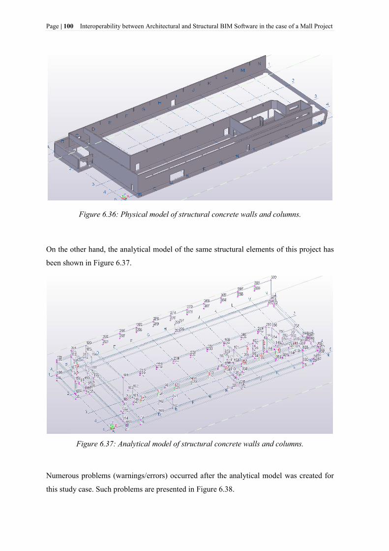
Page | 100 Interoperability between Architectural and Structural BIM Software in the case of a Mall Project
Figure 6.36: Physical model of structural concrete walls and columns.
On the other hand, the analytical model of the same structural elements of this project has
been shown in Figure 6.37.
Figure 6.37: Analytical model of structural concrete walls and columns.
Numerous problems (warnings/errors) occurred after the analytical model was created for
this study case. Such problems are presented in Figure 6.38.

Interoperability between Architectural and Structural BIM Software in the case of a Mall Project Page | 101
`
Figure 6.38: Warnings/errors of the analytical model created in the case of structural
concrete walls and columns.
Most of the problems underlined in Figure 6.38 were related to the boundary conditions of
each structural element of this study case. Only two of them had to do with the opposite
nodes of wall elements, which are placed close to each other. A detailed representation of
such problems has been shown in Figure 6.39.
Figure 6.39: A detailed representation of warnings/errors of the analytical model created
in the case of structural concrete walls and columns of this project.

Page | 102 Interoperability between Architectural and Structural BIM Software in the case of a Mall Project
To reduce or eliminate such problems, manual modifications were necessary to be made in
the case of every stick element of this analytical model. These types of modifications are
recommended to be made before trying to transfer the analytical model or verify the
capabilities of data exchange methods between TSL and RFEM. Thus, in the case of
eliminating the problem of boundary conditions of each structural element and the gaps
between them, the path in TSL: Double click on the stick element>Element Analysis
Properties>Position>Connectivity has been followed. Depending on the nature of the
problem, the connectivity has been changed from manual to automatic, and vice versa.
Connectivity between two elements (elimination of eventual gaps between them) could
also be realized by using the icon “Rigid link” in the main toolbar of TSL. Furthermore, in
the case of eliminating the problem of the nodes which were placed near each other, the
icon “Merge nodes” in the main toolbar of TSL, has been used.
Close attention had to be paid during the implementation of this process, because
sometimes manual modifications of relevant elements might cause additional unexpected
warnings/errors. After following and implementing this process step by step for each
element of this analytical model, the problems (warnings/errors) were eliminated and some
of the modified elements are shown in Figure 6.40.
Figure 6.40: Elimination of warnings/errors of the analytical model created in the case of
structural concrete walls and columns.
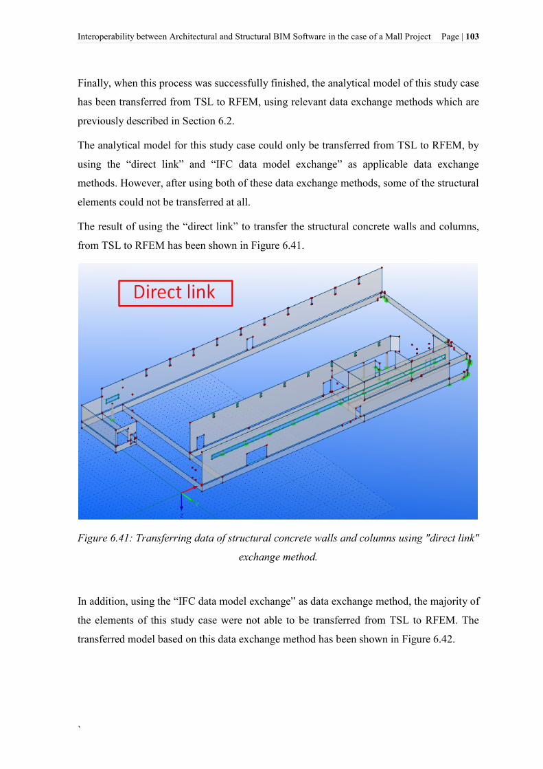
Interoperability between Architectural and Structural BIM Software in the case of a Mall Project Page | 103
`
Finally, when this process was successfully finished, the analytical model of this study case
has been transferred from TSL to RFEM, using relevant data exchange methods which are
previously described in Section 6.2.
The analytical model for this study case could only be transferred from TSL to RFEM, by
using the “direct link” and “IFC data model exchange” as applicable data exchange
methods. However, after using both of these data exchange methods, some of the structural
elements could not be transferred at all.
The result of using the “direct link” to transfer the structural concrete walls and columns,
from TSL to RFEM has been shown in Figure 6.41.
Figure 6.41: Transferring data of structural concrete walls and columns using "direct link"
exchange method.
In addition, using the “IFC data model exchange” as data exchange method, the majority of
the elements of this study case were not able to be transferred from TSL to RFEM. The
transferred model based on this data exchange method has been shown in Figure 6.42.

Page | 104 Interoperability between Architectural and Structural BIM Software in the case of a Mall Project
Figure 6.42: The analytical model of the structural concrete walls and columns transferred
from TSL to RFEM, using the IFC data model exchange method.
The reason why numerous of elements of this study case, could not be imported has been
noticed and underlined in Figure 6.42.
Furthermore, it must be mentioned that only the physical model of this study case, could be
transferred from TSL to RFEM, using the “DSTV (*.stp)” exchange format. The
transferred model in RFEM is presented in Figure 6.43.
Figure 6.43: Transferring the physical model of the structural concrete walls and columns
using the "DSTV (*.stp) file format.

Interoperability between Architectural and Structural BIM Software in the case of a Mall Project Page | 105
`
As it can be seen in Figure 6.43, not every physical element of this study case has been
imported. Some of the imported elements have changed their work plane from “Z” as they
were previously modeled in TSL, into “Y” in RFRM.
It is already mentioned in Section 6.2.2, that this data exchange method is mostly
applicable for structural steel projects. Therefore, since the structural elements of this study
case have been modeled as concrete elements, such problems were predictable. Hence, we
could not present results (geometry and properties of the elements) of this data exchange
method in the following Table 6.4.
The basic results, which are obtained after transferring the analytical model of the
structural concrete walls and columns from TSL to RFEM, using above-mentioned data
exchange methods, are presented in Table 6.1.
Table 6.4: Data exchange results obtained after transferring the analytical model of the
structural concrete walls and columns from TSL to RFEM. The results are only evidenced
and presented for the imported elements.
Direct link DSTV (*.stp) IFC
Structural concrete walls and columns *
**
*
Geometry
Nodes ✔ / ✘+
Lines ✔* / ✘+
Surfaces ✔* / ✘+
Openings ✔* / ✘
Material properties
Material description ✔o / ✔□
Modulus of Elasticity ✘ / ✘*
Shear Modulus ✘ / ✘*
Poisson's Ratio ✔ / ✘*
Specific Weight ✔ / ✘*
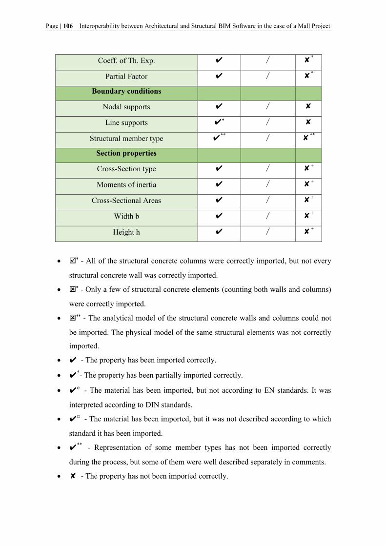
Page | 106 Interoperability between Architectural and Structural BIM Software in the case of a Mall Project
Coeff. of Th. Exp. ✔ / ✘*
Partial Factor ✔ / ✘*
Boundary conditions
Nodal supports ✔ / ✘
Line supports ✔* / ✘
Structural member type ✔** / ✘**
Section properties
Cross-Section type ✔ / ✘+
Moments of inertia ✔ / ✘+
Cross-Sectional Areas ✔ / ✘+
Width b ✔ / ✘+
Height h ✔ / ✘+
* - All of the structural concrete columns were correctly imported, but not every
structural concrete wall was correctly imported.
* - Only a few of structural concrete elements (counting both walls and columns)
were correctly imported.
** - The analytical model of the structural concrete walls and columns could not
be imported. The physical model of the same structural elements was not correctly
imported.
✔ - The property has been imported correctly.
✔*- The property has been partially imported correctly.
✔o - The material has been imported, but not according to EN standards. It was
interpreted according to DIN standards.
✔□ - The material has been imported, but it was not described according to which
standard it has been imported.
✔** - Representation of some member types has not been imported correctly
during the process, but some of them were well described separately in comments.
✘ - The property has not been imported correctly.

Interoperability between Architectural and Structural BIM Software in the case of a Mall Project Page | 107
`
✘* - The property value was shown as zero.
✘+ - The property of only a few elements was correctly imported.
✘**- Representation of some member types has not been imported correctly during
the process, but some of them were well described separately in comments. Some
member types have not been imported at all.
6.4.5 Entire BIM model
In this study case, the entire BIM model of the Mall project has been discussed. The entire
(BIM and/or physical) model of this project has been presented previously in Figure 5.1.
The entire BIM model of the mall project has been modeled in TSL in the way it has to be
built in real.
Comparing to the other case studies of this project, the model of this study case contains
the largest number of objects and information. Therefore, creation and transferring process
of the analytical model for this study case took longer time, and the number of problems
(warnings/errors) was larger in comparison with the other case studies.
The process of creating the analytical model in the case of the entire BIM model and other
case studies of this project has been shown in Figure 6.1. Hence, the analytical model for
this study case, created by using the »Full model« creation method has been shown in
Figure 6.44.
Figure 6.44: The analytical model of the "Entire BIM model" of the Mall project.

Page | 108 Interoperability between Architectural and Structural BIM Software in the case of a Mall Project
Referring to Figure 6.44 shown above, it is not possible to see clearly how the analytical
model of this study case has been created. Therefore, a detailed (enlarged view)
representation of some parts of this analytical model has been shown in Figure 6.45.
Figure 6.45: Enlarged view of the analytical model of some parts of the entire BIM model.
In addition to this study case, we have shown the number and the nature of problems that
arose during the process of creating the analytical model in the case of the entire BIM
model of this project.
First, it could be noticed that from the total number of objects (3688 objects) that were
identified in the physical model of the entire BIM model, only 3566 were counted in the
analytical model.
This problem and the number of warnings/errors that occurred after the analytical model
was created are shown in Figure 6.46.

Interoperability between Architectural and Structural BIM Software in the case of a Mall Project Page | 109
`
Figure 6.46: Basic problems occurred after the creation of the analytical model of the
entire BIM model of this project.
Referring to Figure 6.46, not every object of this model has been considered in the
analytical model. There was no automatic information from TSL to identify immediately
which objects were not included in the entire analytical model. Thus, this process had to be
manually analyzed by checking each object individually. A pad foundation of this project
has been considered as a potential example to describe this process. Thus, the identified
object (pad foundation) and the procedure of using manual modifications are shown in
Figure 6.47.

Page | 110 Interoperability between Architectural and Structural BIM Software in the case of a Mall Project
Figure 6.47: Manual identification and modification of the object which has not been
automatically recognized in the analytical model created in the case of the entire BIM
model of this project.
Related to the appearance of numerous of warnings/errors, it has already been mentioned
that a possible option to reduce or eliminate such problems is; the use of different kinds of
manual modifications to each element one by one. Since the number of warnings/errors is
enormous and the nature of such problems was not similar for each element, manual
modifications were impossible to be successfully finished. All we could do in this process
is that we were able to reduce the total number of warnings/errors, by implementing some
manual modifications which were applicable in this case (Figure 6.48).
Figure 6.48: Reduction of the number of warnings/errors in the case of the analytical
model of the entire BIM model.
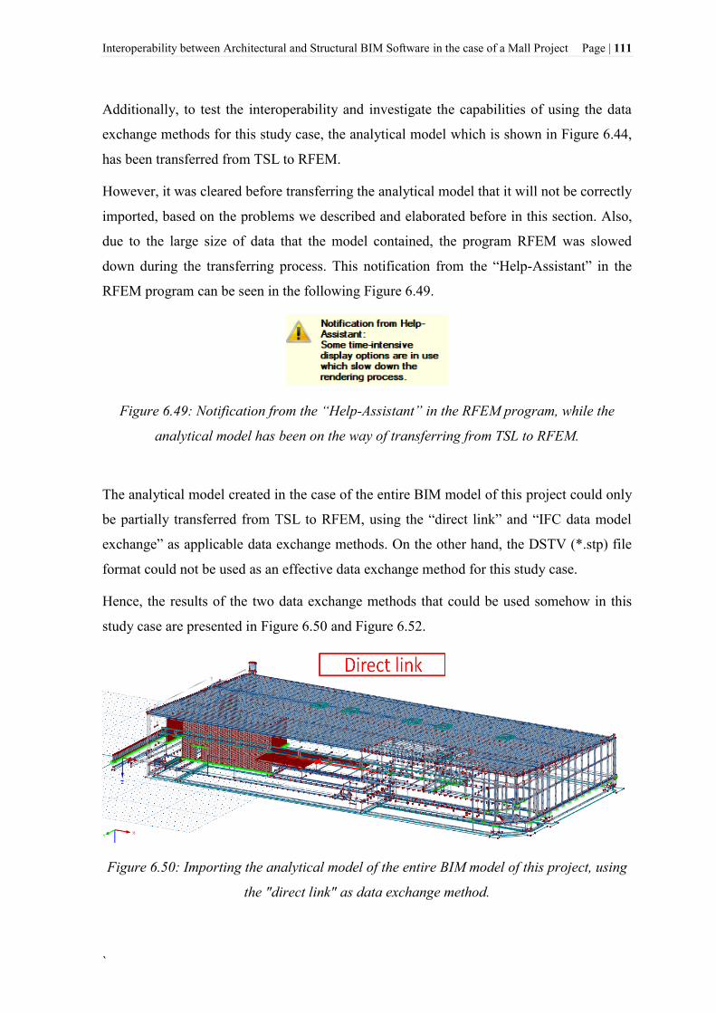
Interoperability between Architectural and Structural BIM Software in the case of a Mall Project Page | 111
`
Additionally, to test the interoperability and investigate the capabilities of using the data
exchange methods for this study case, the analytical model which is shown in Figure 6.44,
has been transferred from TSL to RFEM.
However, it was cleared before transferring the analytical model that it will not be correctly
imported, based on the problems we described and elaborated before in this section. Also,
due to the large size of data that the model contained, the program RFEM was slowed
down during the transferring process. This notification from the “Help-Assistant” in the
RFEM program can be seen in the following Figure 6.49.
Figure 6.49: Notification from the “Help-Assistant” in the RFEM program, while the
analytical model has been on the way of transferring from TSL to RFEM.
The analytical model created in the case of the entire BIM model of this project could only
be partially transferred from TSL to RFEM, using the “direct link” and “IFC data model
exchange” as applicable data exchange methods. On the other hand, the DSTV (*.stp) file
format could not be used as an effective data exchange method for this study case.
Hence, the results of the two data exchange methods that could be used somehow in this
study case are presented in Figure 6.50 and Figure 6.52.
Figure 6.50: Importing the analytical model of the entire BIM model of this project, using
the "direct link" as data exchange method.

Page | 112 Interoperability between Architectural and Structural BIM Software in the case of a Mall Project
Figure 6.51: Importing the analytical model of the entire BIM model of this project, using
the “IFC data model exchange” as data exchange method.
The reason why most of the objects could not be imported in RFEM, using the “IFC data
model exchange” as data exchange method has been shown in Figure 6.52.
Figure 6.52: The reason why numerous of objects from the analytical model of the entire
BIM model could not be imported into RFEM.
In addition, a summary of results, which were obtained after using the “direct link” and
“IFC data model exchange” as applicable data exchange methods to transfer the analytical
model of the entire BIM model of the Mall project from TSL to RFEM is given in Table
6.1.

Interoperability between Architectural and Structural BIM Software in the case of a Mall Project Page | 113
`
Table 6.5: Results of the data exchange methods used to transfer the analytical model of
the entire BIM model of the Mall project from TSL to RFEM. The results are only
evidenced and presented for the imported elements.
Direct link IFC
BIM model elements *
*
Geometry
Nodes ✔ ✘+
Lines ✔* ✘+
Surfaces ✔* ✘+
Openings ✔* ✘
Material properties
Material description ✔o ✔□
Modulus of Elasticity ✔* ✘*
Shear Modulus ✔* ✘*
Poisson's Ratio ✔* ✘*
Specific Weight ✔* ✘*
Coeff. of Th. Exp. ✔* ✘*
Partial Factor ✔* ✘*
Boundary conditions
Nodal supports ✔ ✘
Line supports ✔* ✘
Structural member type ✔** ✘**
Section properties
Cross-Section type ✔* ✘+
Moments of inertia ✔* ✘+
Cross-Sectional Areas ✔* ✘+
Width b ✔* ✘+
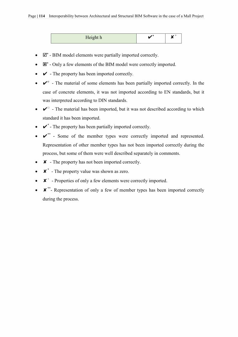
Page | 114 Interoperability between Architectural and Structural BIM Software in the case of a Mall Project
Height h ✔* ✘+
* - BIM model elements were partially imported correctly.
* - Only a few elements of the BIM model were correctly imported.
✔ - The property has been imported correctly.
✔o - The material of some elements has been partially imported correctly. In the
case of concrete elements, it was not imported according to EN standards, but it
was interpreted according to DIN standards.
✔□ - The material has been imported, but it was not described according to which
standard it has been imported.
✔* - The property has been partially imported correctly.
✔** - Some of the member types were correctly imported and represented.
Representation of other member types has not been imported correctly during the
process, but some of them were well described separately in comments.
✘ - The property has not been imported correctly.
✘* - The property value was shown as zero.
✘+ - Properties of only a few elements were correctly imported.
✘**- Representation of only a few of member types has been imported correctly
during the process.
Interoperability between Architectural and Structural BIM Software in the case of a Mall Project Page | 115
`
7 STRUCTURAL ANALYSIS AND DESIGN USING DLUBAL
SOFTWARE
In this section, Structural Analysis and Design (A&D) are performed in the case of two
different partial models of the Mall project. Based on the research regarding
interoperability between BIM and FEM software and results presented before in Section 6,
partial models such as “the simplified mezzanine slab” and “structural steel elements” of
the Mall project have been chosen as adequate models to be analyzed in this section.
The purpose of this section is not intended to present a detailed discussion of FEM analysis
or structural analysis methods, but to provide a brief presentation of results obtained after
performing such analysis in the transferred partial models from TSL to RFEM. Hence, this
section presents a preliminary structural analysis and design performed in the case of the
partial models of the Mall project. The structural analysis and design (A&D) and results
were analyzed and checked with the help of Dlubal-Structural Engineering Software for
Analysis and Design. Using RFEM the structural design has been implemented according
to European Standards (EN), and SIST EN (National Annex) relevant to Slovenia territory.
7.1 A&D in the case of the partial models (simplified mezzanine slab and structural
steel elements) of the Mall project
7.1.1 General description of the problem
Preliminary structural analysis and design (A&D) were performed in the case of two
different types of partial models of the Mall project, based on the interoperability
capabilities between BIM and FEM software shown before.
The first case deals with the structural mezzanine slab of the Mall project. Analytical and
physical model of this structural element has been previously discussed in details in
Section 6.4.2.

Page | 116 Interoperability between Architectural and Structural BIM Software in the case of a Mall Project
The main problem that encountered after the creation of the analytical model of this
element has been related to the form of the depressed slab. Therefore, in the case of
performing preliminary A&D of this structural element, we have decided to simplify the
form of the mezzanine slab from a depressed slab to a simple form of a slab, to avoid
(eliminate) the above-mentioned problems in Section 6.4.2. Hence, the simplified physical
model of the mezzanine slab has been shown in Figure 7.1.
Figure 7.1: The simplified physical model of the mezzanine slab in TSL.
Additionally, the analytical model of the simplified form of the mezzanine slab has been
presented in Figure 7.2.
Figure 7.2: Analytical model of the simplified form of the mezzanine slab in TSL.

Interoperability between Architectural and Structural BIM Software in the case of a Mall Project Page | 117
`
Referring to Figure 7.2, the previous problem due to the form (depressed slab) of this
structural element has been eliminated, and no warnings/errors appeared anymore. This
simplified model has been transferred from TSL to RFEM, using the data exchange
methods, which are previously mentioned and explained in details in Section 6.2. The
analytical model of this structural element, which is imported in RFEM using the “direct
link” exchange method as the most useful and practical method so far, has been shown in
Figure 7.3.
Figure 7.3: The analytical model of the simplified form of the mezzanine slab, transferred
from TSL to RFEM.
Before performing structural analysis and design in the case of this simplified analytical
model in RFEM, it was necessary to verify if the material and boundary conditions of this
structural element have been correctly transferred and well recognized in RFEM. Such
verification processes have been discussed in details in Section 6.4.2 and Table 6.2,
respectively. Thereby, manual modifications were necessary to carry out in this case. A not
well-recognized material had to be modified and edited in accordance with the European
Standards (EN).
In addition, since only nodal supports of this structural element could be created in TSL
and transferred afterward to RFEM, the line supports had to be manually set up in RFEM
(see Figure 7.4). Two types of slab supports could be defined in RFEM: supports created
when the slab was being supported by other elements in a structure model (walls, columns,
beams, etc.), and support types that could be defined directly in RFEM.

Page | 118 Interoperability between Architectural and Structural BIM Software in the case of a Mall Project
The second case that was chosen to be analyzed and discussed in this section is related to
the third case study of this project, which has been previously elaborated in details in
Section 6.4.3. This study case deals with the structural steel elements of the Mall project.
Referring to Figure 6.31, the most proper form of the analytical model of this partial model
was obtained, after it has been transferred from TSL to RFEM using the “direct link”
exchange method. Hence, no additional modifications in the analytical model (except
changes of unrecognized material and cross-section properties of the relevant elements)
were necessary to be set up.
7.1.2 Preliminary Analysis and Design (A&D)
Before running the finite element computation, the analytical model of the simplified form
of the mezzanine slab was modified in RFEM, and it is shown in Figure 7.4.
Figure 7.4: The modified analytical model of the simplified mezzanine slab, using relevant
slab supports defined in RFEM.
Referring to Figure 7.4, two basic types of supports (two nodal supports result from the
slab being supported by columns, and edge supports result from the slab being supported
by walls) have been considered in the case of this partial analytical model of the Mall
project.

Interoperability between Architectural and Structural BIM Software in the case of a Mall Project Page | 119
`
Another important step in the case of the simplified form of the mezzanine slab was to set
up the meshing parameters before performing the FEA (Finite Element Analysis). This
could be achieved by selecting the “Display FE Mesh” tab of the “Static Calculation” of
slabs tool in RFEM. Additionally, the characteristics of materials and cross-sections, which
are used in the case of these analytical models in RFEM, can be found in the Appendices
of this thesis. The load cases and load combinations which are considered in the case of
such models have been generated automatically in RFEM. They were set out in accordance
with Eurocode 0 (EN 1990) and relevant National annex (SIST EN) in compliance with the
corresponding combination expressions.
When all the necessary modifications were done, the structural analysis and design were
performed for both cases.
7.1.3 Interpretation of basic results from RFEM
After the FEA was performed in RFEM software the results obtained include global and
local displacements, support reactions, basic internal forces, etc. To represent the basic
results obtained in the case of the simplified model of the mezzanine slab, the local
displacement results (extreme values) and the required reinforcement (top) in the X
direction of the element, were chosen to be presented in this section. These results can be
seen in Figure 7.5 and Figure 7.6, respectively.
Figure 7.5: Local displacement results obtained in the case of the simplified model of the
mezzanine slab, using preliminary A&D in RFEM.

Page | 120 Interoperability between Architectural and Structural BIM Software in the case of a Mall Project
Figure 7.6: Required reinforcement (top) in the X direction of the simplified model of the
mezzanine slab.
Additionally, in the case of structural steel elements of the Mall project, global
displacements results (extreme values) and maximum design ration (utilization) of steel
profiles are shown in Figure 7.7 and Figure 7.8, respectively.
Figure 7.7: Global displacement results obtained in the case of steel elements in RFEM.

Interoperability between Architectural and Structural BIM Software in the case of a Mall Project Page | 121
`
Figure 7.8: Design ratio of steel profiles obtained in RFEM.
Referring to Figure 7.8, an optimization of most of the steel profiles used in the case of this
project could be further done. However, as already mentioned before, this section provides
only a preliminary structural analysis and design of the relevant chosen parts in the case of
the Mall project. Therefore, only preliminary results obtained in RFEM are presented in
this section.
The design of the simplified model of the mezzanine slab was done using the following
Add-on Module in RFEM: RF-CONCRETE Surfaces - Design of concrete surfaces. While,
in the case of designing the steel elements, Add-on module: RF-STEEL EC3 – Design of
steel members according to Eurocode 3 has been used. Basic results obtained in RFEM
software (including the used Add-on Modules), relevant to these partial models discussed
in this section, can be further found in the Appendices.

Page | 122 Interoperability between Architectural and Structural BIM Software in the case of a Mall Project
8 CONCLUSIONS
8.1 Brief description and purpose of the thesis
Before going into details of presenting key findings related to the main topic of this
project, a brief description of the work and purpose of this thesis is given.
Firstly, a general overview of Building Information Modeling (BIM) and interoperability
issues has been presented in the beginning sections of this thesis. The aim of these sections
was to introduce the basic information of such important areas, which were considered
very useful and applicable in the research we have done in this thesis.
In this thesis, two types of engineering software were used to cover the general purposes of
the research. Tekla BIM software was chosen as the appropriate BIM software, to cover
modeling and drawing parts, as well as creating relevant analytical models applied in the
case of the entire and partial BIM models of the Mall project. Dlubal-Structural
Engineering Software for Analysis and Design considered as FEM software, has been used
in the case of importing analytical models created in Tekla BIM software, related to the
case studies performed in this thesis. It was also utilized to perform further structural
analysis and design (A&D) calculations, in the case of the partial analytical models of this
project. A general description and overview of the used software have been introduced in
Section 4.
In addition, Mall project has been described with the help of modeling functionalities that
Tekla BIM softwares offers in general. Each phase of the Mall project has been modeled
using Tekla BIM software standards and settings, relevant to this project. They were
described and discussed in details in Section 5. Since documents and visualization of the
project plays a very important role in the construction industry, different types of drawings
and 3D visualization that contains detailed information were also described and included in
this section. However, it should be noted that the BIM model of this project has been

Interoperability between Architectural and Structural BIM Software in the case of a Mall Project Page | 123
`
created and detailed with the help of 2D CAD architectural drawings as the input, which
were prepared by Gravitas, design and engineering company Ltd (Gravitas d.o.o, 2017).
The most important parts of the research and major findings, related to the main topic of
this thesis have been discussed in Section 6. A general description and procedure of
creating different kinds of analytical models, relevant to entire and partial BIM models of
this project were presented. Every problem that arose after the creation of such analytical
models in TSL has been analyzed, and the relevant recommendations in case of avoiding or
eliminating such problems were given in details in this section. Additionally, in the case of
transferring analytical models from TSL to RFEM, various available data exchange
methods were presented and practically elaborated. A procedure for updating the existing
models in TSL using the direct interface from RFEM has also been included in the first
study case of this project. Key findings and recommendations of using the relevant data
exchange methods, related to the main topic of this thesis have been presented in this
section and results are further summarized in Table 8.1.
In order to further investigate the capabilities of data exchange methods and the importance
of importing the created analytical models in TSL, preliminary structural analysis and
design (A&D) in the case of partial analytical models of this project were performed in
RFEM. A brief description and some of the most important results obtained after
performing such analysis were presented in Section 7 of this thesis.
After summing up all contents of the whole chapters, a summary of results, related to the
key findings from the case studies used to explain the main topic of this thesis has been
further elaborated in details in Section 8.2.
8.2 Summary of results
In this section, a conclusion that incorporates a summary of the major findings and
recommendations from the case studies used in the case of a Mall project is presented.
In addition, the purpose of this section is to provide an evaluation of the case studies
examined in the case of the entire and partial BIM models of the Mall project for each data
exchange method separately.

Page | 124 Interoperability between Architectural and Structural BIM Software in the case of a Mall Project
An evaluation of results obtained after creating various types of analytical models for each
case study has also been presented in Table 8.1.
Table 8.1: Summary of results regarding major findings related to interoperability.
CASE STUDY Analytical
model
Data exchange method
Direct
link
DSTV
(*.stp) IFC
1. Simple case – Concrete column
+
±
-
2. Partial model 1 – Ground and
intermediate floor slabs *
3. Partial model 2 – Structural steel
elements
4. Partial model 3 – Structural concrete
walls and columns *
5. Entire BIM model **
The evaluation of the obtained results included in Table 8.1, related to the key findings and
recommendations for the case studies performed in the case of the Mall project, is given
below:
- The analytical models were generally correctly created.
No additional improvements were required to be made in the case of the concrete
column and structural steel elements of the project (except if the manual changes
regarding boundary conditions of the structural elements were needed).
Hence, before creating different kinds of analytical models in TSL, it is always
recommended to set up necessary analysis properties of each structural element of
the project individually, in a proper way that will decrease the number of manual
modifications in the future.
*- Half of the physical models could be correctly transformed into analytical
models.
The main problem that arose during the creation of the analytical models in the case
of the partial model 1 of this project was related to the depressed slabs. The way of
creating such elements was not well recognized in TSL. Therefore the analytical
model in the case of depressed slabs was not correctly created. It is recommended

Interoperability between Architectural and Structural BIM Software in the case of a Mall Project Page | 125
`
to avoid modeling of slabs in the form of depressed slabs when further structural
analysis and design (A&D) are required to be performed in such cases. Hence, the
depressed slab had to be simplified in the form as it is shown in Section 7.1.1, in
case of being able to further perform relevant structural analysis and design.
*- The analytical model could be partially correctly created.
Unavoidable manual modifications were necessary to be made. Since the entire
BIM model of this project has been created in the way that it shall be built in the
real world, the connectivity of the elements included in the case study (Partial
model 3 – Structural concrete walls and columns) was the main problem. To avoid
such problems it is recommended to connect every element in accordance with their
axes. Eventual gaps and the eccentricity of the elements, relevant to this study case,
could be eliminated and manipulated by using the rigid links in TSL.
**
- The analytical model could not be properly created.
In the case of the entire BIM model, the analytical model could be automatically
created, but the number of problems that arose afterward was enormous. The nature
of such problems was not manageable in an automated way in TSL. They could not
even be manually eliminated. Hence, it is always recommended to break up the
entire BIM model of the project into partial models, in case of being able to manage
easily the process of creating analytical models in TSL.
+- Analytical models could be generally correctly transferred from TSL to
RFEM, using the direct link data exchange method.
Based on the results obtained from the case studies performed in the case of this
project, it can be stated that the direct link was definitely the best of the data
exchange methods that were examined both in terms of technical capabilities and
ease of use. It was possible to transfer the majority of data that was needed to
perform further structural analysis and design. Only some of the unavoidable
manual modifications such as the conversion of the unrecognized materials and
cross-section types/properties between different software vendors and necessary
interventions regarding boundary conditions of individual elements were required
to be made before and after transferring relevant analytical models, using this data
exchange method.

Page | 126 Interoperability between Architectural and Structural BIM Software in the case of a Mall Project
±- The majority of the analytical models could not be correctly transferred from
TSL to RFEM, using the DSTV data exchange method.
Most of the elements included in different kinds of analytical models, relevant to
this project, could not be imported in RFEM at all. Numerous of manual
modifications were needed to be made in the case of the transferred elements. It
must be noted that this data exchange method is mostly applicable for steel
structures. Therefore, numerous of problems arose after using this data exchange in
most case studies of this project. The technical capabilities of the DSTV (*.stp) data
exchange method varies mostly based on the material used. Hence, it is
recommended to avoid using this data exchange method, when the majority of the
elements are not made of steel.
-- Not every element of different analytical models could be transferred from
TSL to RFEM using the IFC data exchange method.
Most of them could not be imported in a proper way. This means that some of the
elements (referring mostly to the material and cross-section properties of the used
elements) were not well recognized or could not be transferred at all. Numerous of
manual modifications were necessary to be made, before and after transferring
different analytical models created in the case of this project. Similarly to DSTV
(*.stp) data exchange method, this data exchange scenario varies also in the
material used. It must be stated that the IFC is a simple data exchange method and
easy to use, provided that the default and potential edited settings can be used. It is
advisable to avoid the use of this data exchange method when the BIM model such
as entire BIM model in the case of the Mall project contains different types of
materials, and the geometry of elements is complex.
In summary, a high-quality BIM model created in the case of each partial model of the
Mall project was essential for the interoperability between BIM and FEM software to
work. However, the imported partial models also needed to be thoroughly examined after
import, and the necessary modifications had to be implemented. Once all of the above-
mentioned processes could be well synchronized through the interoperability technique,
less-complicated structural calculations in RFEM could be performed and the results
obtained were satisfactory.

Interoperability between Architectural and Structural BIM Software in the case of a Mall Project Page | 127
`
9 REFERENCES
Autodesk (2017) What Is DWG? | DWG Viewers and File Format Info | Autodesk.
Available at: https://www.autodesk.com/products/dwg.
Azhar, S., Khalfan, M. and Maqsood, T. (2015) ‘Building information modelling (BIM):
now and beyond’, Construction Economics and Building, 12(4). doi:
10.5130/ajceb.v12i4.3032.
Brad Hardin, D. M. (2015) BIM and Construction Management - Proven tools, methods,
and workflows Secon, John Wiley & Sons, Inc., Indianapolis, Indiana 2015. doi:
10.1007/s13398-014-0173-7.2.
buildingSMART (2016) Home — Welcome to buildingSMART-Tech.org. Available at:
http://www.buildingsmart-tech.org/.
CEN (2008) BS-EN-1090-Execution of steel structures and aluminium structures-Part 2.
CityGML (2017) CityGML homepage. Available at: https://www.citygml.org/.
Dlubal (2017) Dlubal-Structural Engineering Software for Analysis and Design. Available
at: https://www.dlubal.com/en-US.
Eastman, C. et al. (2011) BIM Handbook: A Guide to Building Information Modelling For
Owners, Managers, Designers, Engineers and Contractors Second Edition, John Willey &
Son Inc. doi: 10.1002/9780470261309.
GDT Interop, John McCreesh, E. D. (2017) Definition of Interoperability. Available at:
http://interoperability-definition.info/en/.
Gravitas d.o.o (2017) Trgovski objekt Lidl Murska Sobota, PGD Projekt.
ISO/IEC JTC 1 (2015) ISO/IEC 2382:2015(en), Information technology — Vocabulary.
Available at: https://www.iso.org/obp/ui/#iso:std:iso-iec:2382:ed-1:v1:en.
ISO 10303-11 (2004) Industrial automation systems and integration -- Product data
representation and exchange -- Part 11: Description methods: The EXPRESS language

Page | 128 Interoperability between Architectural and Structural BIM Software in the case of a Mall Project
reference manual. Available at: https://www.iso.org/standard/38047.html.
Linde Group (2014) ‘EN 1090 Guideline’, (April), p. 24.
Nawari, N. O. and Kuenstle, M. (2015) Building Information Modeling: Framework for
Structural Design. doi: 10.1002/9780470432846.
Novak, I. (2010) Visual studio 2010 and .NET 4 : six-in-one. Wiley.
Quirk, V. (2012) ‘A Brief History of BIM’, ArchDaily. Available at:
http://www.archdaily.com/302490/a-brief-history-of-bim.
Ritchie, D. M. and Thompson, K. (1978) ‘The UNIX Time-Sharing System†’, Bell System
Technical Journal, 57(6). doi: 10.1002/j.1538-7305.1978.tb02136.x.
Saygi, G. et al. (2013) ‘Evaluation of Gis and Bim Roles for the Information Management
of Historical Buildings’, ISPRS Annals of Photogrammetry, Remote Sensing and Spatial
Information Sciences, II-5/W1(July 2015), pp. 283–288. doi: 10.5194/isprsannals-II-5-W1-
283-2013.
Scheifler, R. W. et al. (1997) X Window System : core and extension protocols : X version
11, releases 6 and 6.1. Digital Press.
Steel, J., Drogemuller, R. and Toth, B. (2009) ‘Model Interoperability in Building
Information Modeling’, pp. 1–12.
Stroustrup, B. (1997) The C++ programming language. Third. Addison-Wesley.
Tekla (2017) Tekla | Model-based software at the core of Trimble’s structural engineering
and construction offering. Available at: https://www.tekla.com/.
Tekla BIMsight (2017) Learn more | teklabimsight.com. Available at:
http://www.teklabimsight.com/learn-more.
Tolk, A., Bair, L. J. and Diallo, S. Y. (2013) ‘Supporting Network Enabled Capability by
extending the Levels of Conceptual Interoperability Model to an interoperability maturity
model’, The Journal of Defense Modeling and Simulation: Applications, Methodology,
Technology, 10(2), pp. 145–160. doi: 10.1177/1548512911428457.
Tolk, A., Diallo, S. Y. and Turnitsa, C. D. (2007) ‘Applying the Levels of Conceptual
Interoperability Model in Support of Integratability , Interoperability , and Composability
for System-of-Systems Engineering’, Journal of Systemics, Cybernetics and Informatics.

Interoperability between Architectural and Structural BIM Software in the case of a Mall Project Page | 129
`
Tolk, A. and Muguira, J. (2003) ‘The Levels of Conceptual Interoperability Model’, Fall
Simulation Interoperability Workshop, (September), pp. 1–9.
Trimble (2017) Trimble - Transforming the Way the World Works. Available at:
http://www.trimble.com/.
Wang, W., Tolk, A. and Wang, W. (2009) ‘The Levels of Conceptual Interoperability
Model: Applying Systems Engineering Principles to M&S’, SpringSim ’09 Proceedings of
the 2009 Spring Simulation Multiconference, p. 9. doi: 10.1145/1639809.1655398.
Wikipedia (2015) ‘.NET Framework’. Available at:
https://en.wikipedia.org/wiki/.NET_Framework.
Wikipedia (2016) ‘Interoperability’. Available at:
https://en.wikipedia.org/wiki/Interoperability.
Wikipedia (2017) ‘Tekla Structures’. Available at:
https://en.wikipedia.org/wiki/Tekla_Structures.

Page | 130 Interoperability between Architectural and Structural BIM Software in the case of a Mall Project
10 APPENDICES
10.1 List of figures
Figure 2.1: Structure and architecture synergy framework (Nawari and Kuenstle, 2015). .. 6
Figure 2.2: BIM Concept and process (Nawari and Kuenstle, 2015). .................................. 7
Figure 2.3: Typical diagram concept of organizational boundaries based on AEC project
team (Eastman et al., 2011). .................................................................................................. 8
Figure 2.4: Comparison of B-Rep and CSG paradigms (Saygi et al., 2013). ....................... 9
Figure 3.1: The Levels of Conceptual Interoperability Model (Wang, Tolk and Wang,
2009). ................................................................................................................................... 15
Figure 3.2: Presentation of modern exchange formats which are based on a schema defined
in a schema language (Eastman et al., 2011). ..................................................................... 16
Figure 3.3: IFC Data File Formats and Icons (buildingSMART, 2016). ............................ 19
Figure 3.4: Data schema architecture with conceptual layers (buildingSMART, 2016). ... 19
Figure 3.5: The IFC structure for defining a wall (Eastman et al., 2011). .......................... 20
Figure 3.6: OmniClass tables of classification terms (Eastman et al., 2011). ..................... 22
Figure 3.7: Example internal structure of exchanges supported by a BIM server (Eastman
et al., 2011). ......................................................................................................................... 25
Figure 3.8: Typical Data Exchange Scenario using BIM in Structural Engineering (Dlubal,
2017). ................................................................................................................................... 26
Figure 3.9: An example of vertical data exchange (Dlubal, 2017). .................................... 27
Figure 4.1: Open BIM information flow (Tekla, 2017). ..................................................... 32
Figure 4.2: Publishing BIM model of the Mall project to Tekla BIMsight. ....................... 34
Figure 4.3: Viewing the BIM model of the Mall Project in Tekla BIMsight. ..................... 35
Figure 4.4: Dlubal Software company solutions (Dlubal, 2017). Underlined sections refer
to the main requirements of this thesis, regardless of the partial performing of structural
analysis and design. ............................................................................................................. 36
Interoperability between Architectural and Structural BIM Software in the case of a Mall Project Page | 131
`
Figure 5.1: 3D Model of the Mall Project modeled using Tekla Structures Learning. ....... 37
Figure 5.2: Phase Manager Filter in TSL. ........................................................................... 38
Figure 5.3: Ground floor and mezzanine of Mall project. ................................................... 39
Figure 5.4: Height differences of the Mall project. ............................................................. 39
Figure 5.5: Foundation types of the Mall project. ............................................................... 40
Figure 5.6: Bottom level of the foundation. ........................................................................ 40
Figure 5.7: RC walls above footing of the strip foundations............................................... 41
Figure 5.8: RC walls of the Mall project. ............................................................................ 41
Figure 5.9: Brick walls and ceiling slabs of the Mall project. ............................................. 42
Figure 5.10: Timber beams of the Mall project. .................................................................. 42
Figure 5.11: Detail of the roof system modeled in TSL. ..................................................... 43
Figure 5.12: Steel profiles of the Mall project. .................................................................... 44
Figure 5.13: RC columns of the building. ........................................................................... 44
Figure 5.14: Aluminium profiles and glass surfaces modeled in TSL. ............................... 45
Figure 5.15: A detail of modeled Schuco profiles in TSL................................................... 45
Figure 5.16: Different types of stairs modeled in TSL. ....................................................... 45
Figure 5.17: Cooling cells of the Mall project..................................................................... 46
Figure 5.18: Mesh elements made of steel profiles. ............................................................ 46
Figure 5.19: External structural elements of the Mall project. ............................................ 47
Figure 5.20: Architectural elements of the Mall project modeled as non-load-bearing
elements in TSL. .................................................................................................................. 47
Figure 5.21: Tekla Structures Learning available Environments (Tekla, 2017). ................ 48
Figure 5.22: Representing two different Tekla Structures environments. ........................... 49
Figure 5.23: Concrete profile selection differences. Default environment (left side) and
Netherlands-English (right side). ......................................................................................... 50
Figure 5.24: Applications and components differences. Default environment (left side) and
Netherlands-English (right side). ......................................................................................... 51
Figure 5.25: Important advance option differences. Default environment (upward side) and
Netherlands-English (downward side). ............................................................................... 52
Figure 5.26: Tekla Structures Learning properties in the case of a Mall Project. ............... 53
Figure 5.27: The grid settings (left side) and views along the grid lines (right side). ......... 54
Figure 5.28: Main toolbars in TSL. ..................................................................................... 54

Page | 132 Interoperability between Architectural and Structural BIM Software in the case of a Mall Project
Figure 5.29: Examples of execution classes (Linde Group, 2014). .................................... 55
Figure 5.30: Execution class for steel elements dialog box. ............................................... 56
Figure 5.31: The Concrete Column Properties dialog boxes. ............................................. 56
Figure 5.32: The UDA’s of Concrete Column dialog box. IFC export properties (left side)
and Workflow properties (right side). ................................................................................. 57
Figure 5.33: Numbering Setup dialog box. ......................................................................... 58
Figure 5.34: Default settings for components in Tekla Structures. ..................................... 58
Figure 5.35: Default settings for clash checks in TSL. ....................................................... 59
Figure 5.36: Units and decimals settings for modeling purposes. ....................................... 60
Figure 5.37: Units and decimals settings for catalogs. ........................................................ 60
Figure 5.38: Dimension properties settings in the case of creating drawings for this project.
............................................................................................................................................. 61
Figure 5.39: Importing CAD files to Tekla Structures dialog box. ..................................... 62
Figure 5.40: Imported 2-D DWG Mall project files to TSL as Reference Model (3D View).
............................................................................................................................................. 63
Figure 5.41: DWG foundation drawing imported to Tekla Structures as Reference Model
(Basic View). ....................................................................................................................... 63
Figure 5.42: Overlaying DWG Mall project modeled in TSL. ........................................... 64
Figure 5.43: Tekla online service - Tekla Warehouse. ........................................................ 65
Figure 5.44: Schüco Profiles used in the case of modeling steel/aluminum profiles in Tekla
Structures. ............................................................................................................................ 66
Figure 5.45: UPB Glass Unit application for modeling aluminum and glass profiles in TSL.
............................................................................................................................................. 67
Figure 5.46: Tekla Warehouse Application for publishing BIM model to 3D PDF. .......... 67
Figure 5.47: The procedure for creating a drawing in TSL. ................................................ 68
Figure 5.48: Render of section view details of the Mall project. ........................................ 70
Figure 5.49: 3D visualization details of the entrance elements of the Mall project. ........... 70
Figure 6.1: Procedure for creating an analytical model in TSL. ......................................... 72
Figure 6.2: Analysis Model Properties in the case of a Mall project. ................................. 73
Figure 6.3: Relationship between physical (left side) and analytical (right side) partial
model of the Mall project. ................................................................................................... 74
Figure 6.4: Data exchange methods between BIM and FEM software. .............................. 75

Interoperability between Architectural and Structural BIM Software in the case of a Mall Project Page | 133
`
Figure 6.5: Data exchange between Tekla Structures Learning and RFEM using the direct
link. ...................................................................................................................................... 75
Figure 6.6: Importing models from TSL to RFEM. ............................................................ 76
Figure 6.7: Import options dialog box in RFEM program. ................................................. 76
Figure 6.8: Creation of a DSTV (*.stp) exchange file format in TSL. ................................ 77
Figure 6.9: Importing a DSTV file (*.stp) from TSL to RFEM. ......................................... 77
Figure 6.10: Creating an output IFC file in TSL. ................................................................ 78
Figure 6.11: Types of export using IFC data model exchange in TSL. .............................. 78
Figure 6.12: Different ways of exporting files using IFC exchange format. ....................... 79
Figure 6.13: Additional property sets dialog box in TSL. ................................................... 80
Figure 6.14: Export to IFC-Advanced settings dialog box. ................................................. 81
Figure 6.15: Exporting models from RFEM to TSL. .......................................................... 82
Figure 6.16: Import options dialog box in RFEM program. ............................................... 82
Figure 6.17: BIM model and structural data of a concrete column. .................................... 83
Figure 6.18: Representation of the physical model of the concrete column converted to an
analytical model. .................................................................................................................. 84
Figure 6.19: Concrete Column Analysis Properties dialog box. ......................................... 84
Figure 6.20: Data exchange scenarios used in the case of a simple concrete column. ........ 85
Figure 6.21: Conversion files for materials (left side) and cross-sections (right side). ....... 87
Figure 6.22: Editing the cross-section properties of the concrete column in RFEM. ......... 88
Figure 6.23: A simple example of an updated existing model in TSL, using direct interface
from RFEM.......................................................................................................................... 89
Figure 6.24: Physical model of ground and intermediate floor slabs created in TSL. ........ 90
Figure 6.25: Display of problems encountered after creating the analytical model of this
case study. ............................................................................................................................ 90
Figure 6.26: Analytical model in the case of a ground and mezzanine floor depressed slab.
............................................................................................................................................. 91
Figure 6.27: Analytical model & Analysis properties of the ceiling (intermediate) slabs. . 92
Figure 6.28: Improving the quality of the created analytical model by reducing the number
of displayed warnings/errors. .............................................................................................. 92
Figure 6.29: Importing the analytical model from TSL to RFEM using the direct link. .... 93

Page | 134 Interoperability between Architectural and Structural BIM Software in the case of a Mall Project
Figure 6.30: Importing the analytical model of this study case using IFC data model
exchange method. ................................................................................................................ 93
Figure 6.31: The analytical model of structural steel elements. .......................................... 95
Figure 6.32: Display of warnings/errors in the analytical model creation in the case of
structural steel elements. ..................................................................................................... 95
Figure 6.33: Modification of the boundary conditions of structural elements in the
analytical model. ................................................................................................................. 96
Figure 6.34: Display of warnings/errors after the necessary modifications that were made
for some relevant structural elements in the case of this analytical model. ........................ 96
Figure 6.35: Data exchange methods used to transfer the analytical model of structural
steel elements from TSL to RFEM. ..................................................................................... 97
Figure 6.36: Physical model of structural concrete walls and columns. ........................... 100
Figure 6.37: Analytical model of structural concrete walls and columns. ........................ 100
Figure 6.38: Warnings/errors of the analytical model created in the case of structural
concrete walls and columns. .............................................................................................. 101
Figure 6.39: A detailed representation of warnings/errors of the analytical model created in
the case of structural concrete walls and columns of this project. .................................... 101
Figure 6.40: Elimination of warnings/errors of the analytical model created in the case of
structural concrete walls and columns. .............................................................................. 102
Figure 6.41: Transferring data of structural concrete walls and columns using "direct link"
exchange method. .............................................................................................................. 103
Figure 6.42: The analytical model of the structural concrete walls and columns transferred
from TSL to RFEM, using the IFC data model exchange method. ................................... 104
Figure 6.43: Transferring the physical model of the structural concrete walls and columns
using the "DSTV (*.stp) file format. ................................................................................. 104
Figure 6.44: The analytical model of the "Entire BIM model" of the Mall project. ......... 107
Figure 6.45: Enlarged view of the analytical model of some parts of the entire BIM model.
........................................................................................................................................... 108
Figure 6.46: Basic problems occurred after the creation of the analytical model of the entire
BIM model of this project. ................................................................................................ 109

Interoperability between Architectural and Structural BIM Software in the case of a Mall Project Page | 135
`
Figure 6.47: Manual identification and modification of the object which has not been
automatically recognized in the analytical model created in the case of the entire BIM
model of this project. ......................................................................................................... 110
Figure 6.48: Reduction of the number of warnings/errors in the case of the analytical model
of the entire BIM model. ................................................................................................... 110
Figure 6.49: Notification from the “Help-Assistant” in the RFEM program, while the
analytical model has been on the way of transferring from TSL to RFEM. ..................... 111
Figure 6.50: Importing the analytical model of the entire BIM model of this project, using
the "direct link" as data exchange method. ........................................................................ 111
Figure 6.51: Importing the analytical model of the entire BIM model of this project, using
the “IFC data model exchange” as data exchange method. ............................................... 112
Figure 6.52: The reason why numerous of objects from the analytical model of the entire
BIM model could not be imported into RFEM. ................................................................ 112
Figure 7.1: The simplified physical model of the mezzanine slab in TSL. ....................... 116
Figure 7.2: Analytical model of the simplified form of the mezzanine slab in TSL. ........ 116
Figure 7.3: The analytical model of the simplified form of the mezzanine slab, transferred
from TSL to RFEM. .......................................................................................................... 117
Figure 7.4: The modified analytical model of the simplified mezzanine slab, using relevant
slab supports defined in RFEM. ........................................................................................ 118
Figure 7.5: Local displacement results obtained in the case of the simplified model of the
mezzanine slab, using preliminary A&D in RFEM. ......................................................... 119
Figure 7.6: Required reinforcement (top) in the X direction of the simplified model of the
mezzanine slab. .................................................................................................................. 120
Figure 7.7: Global displacement results obtained in the case of steel elements in RFEM.120
Figure 7.8: Design ratio of steel profiles obtained in RFEM. ........................................... 121
10.2 List of tables
Table 1.1: Representation of the most important terms used in this project. ........................ 2
Table 3.1: Common Exchange Formats in AEC Applications (Eastman et al., 2011). ...... 17
Table 4.1: Interoperability features included in different configurations (Tekla, 2017). .... 31

Page | 136 Interoperability between Architectural and Structural BIM Software in the case of a Mall Project
Table 4.2: Exchange formats supported by Tekla (Eastman et al., 2011). .......................... 33
Table 6.1: Data exchange results obtained for the simple case study of the Mall project. . 85
Table 6.2: Data exchange results obtained after transferring the partial model of this study
case from TSL to RFEM. .................................................................................................... 94
Table 6.3: Data exchange results obtained after transferring the analytical model of this
study case from TSL to RFEM. ........................................................................................... 98
Table 6.4: Data exchange results obtained after transferring the analytical model of the
structural concrete walls and columns from TSL to RFEM. The results are only evidenced
and presented for the imported elements. .......................................................................... 105
Table 6.5: Results of the data exchange methods used to transfer the analytical model of
the entire BIM model of the Mall project from TSL to RFEM. The results are only
evidenced and presented for the imported elements. ........................................................ 113
Table 8.1: Summary of results regarding major findings related to interoperability. ....... 124
10.3 Examples of drawing types created in TSL
10.3.1 GA drawing

I
I
C
C
2
2
J
J
A
A
B
B
D
D
E
E
F
F
G
G
H
H
K
K
L
L
M
M
N
N
5
5
4
4
3
3
1
1
3
3C
C
B
B
4
4
3d View1:100
RC WALL C25/30 890*790
WOOD640*240
COLUMN S235JR HEA500
FOOTING C25/30 BETON2500*2500
COLUMN S235JR RHS300*10
RC WALL C25/30 1290*300
WOOD640*240
BEAM S235JR HEA500
RC COLUMN C25/30 300*300
RC CONCRETE SLAB C30/37 250*74830
BEAM S235JR HEA500
RHS180*260*8
1643
BEAM GL24h WOOD640*240
447
RC COLUMN C25/30 300*300
WALL C25/30 4000*200
RHS180*260*8
RC COLUMN C25/30 300*300
WALL C25/30 1290*300
RC WALL C25/30 1290*300
RC WALL C25/30 1290*300
RC WALL C25/30 1290*300
WOOD640*240
FOOTING C25/30 BETON400*800
WALL C25/30 1290*370
RC WALL C25/30 3790*200
4180*200
FOOTING C25/30 BETON2500*2500
RC WALL C25/30 1090*790
FOOTING C25/30 BETON1600*1600
RC COLUMN C25/30 300*300
RC WALL C25/30 1290*500
FOUNDATION BEAM C25/30 BETON400*1000
RC WALL C25/30 1290*430
RC WALL C25/30 1090*780
FOOTING C25/30 BETON1600*1600
RC_SLAB C25/30 200*3150
WOOD640*240
RC COLUMN C25/30 300*300
BEAM GL24h WOOD1400*240BEAM GL24h WOOD1400*240
BEAM GL24h WOOD1400*240
RC WALL C25/30 7400*260
WALL C25/30 7400*300
COLUMN S235JR RHS300*10
RC WALL C25/30 6900*300
RHS180*260*8
RHS180*260*8
WALL C25/30 400*195
RC WALL C25/30 3550*200
CONCRETE_SLAB C25/30 200*5050
RC COLUMN C25/30 300*300
BEAM GL24h WOOD1400*240BEAM GL24h WOOD1400*240
BEAM GL24h WOOD1400*240BEAM GL24h WOOD1400*240
RC WALL C25/30 3550*200
RHS180*260*8
RHS180*260*8
BEAM GL24h WOOD1400*240
CONCRETE_SLAB C25/30 200*21040
RC COLUMN C25/30 300*300
WOOD640*240
WOOD640*240
RHS180*260*8
WALL C25/30 4300*200
RC COLUMN C25/30 300*300
RC WALL C25/30 3790*200
BEAM S235JR HEB200
RC WALL C25/30 3550*260
RC COLUMN C25/30 300*300
BEAM GL24h WOOD640*240
BEAM S235JR HEB1000
BEAM GL24h WOOD1400*240
BEAM GL24h WOOD1400*240
WALL C25/30 4000*200
COLUMN S235JR HEA500
RC COLUMN C25/30 300*300
RC WALL C25/30 890*900
RC WALL C25/30 1290*430
DETAIL A
142
5785
438
909
6158
1039
Detail A , 1:50
A 3D detail view representing some of the inner and outer elements of the Mall project
1-1Drawing:
ApprovedStatus:
Project:
G [1]Size:A0
Master Thesis Model V7 01.12.2017plotted onTekla Structures model
Drilon Rraci
3D GA Drawing
Master Thesis Model
Maribor, Slovenia
SUBJECT:
PROJECT:
Date:
Designer:
Scale:
BUILDER:
30.11.2017
See view
Projection:Welds a=4, unless mentioned different, according to NEN-EN-ISO 2553:2014. Bolt grade 8.8, unless mentioned differtent
Material types and grades: Plates and profiles according to NEN-EN 10025-2, tubes and RHS profiles: according to NEN-EN 10210-1 (hot rolled) according to NEN-EN 10219-1 (cold rolled)
Execution class:
Fabrication and erection acc. to
Effective tollerance class:
NEN-EN 1090-2:2008+A1:2011EXC2
XXX
Tekl
a St
ruct
ures
3D General Arrangement (GA) drawing - Structural elements of the Mall project
Tekla Structu
res Educational

G
G
J
J
F
F
3 3
B
B
A
A
C
C
D
D
E
E
H
H
I
I
K
K
L
L
M
M
N
N
5 5
4 4
2 2
1 1
2 2
+7260.00+5520.00
1 1
+4700.00
5 5
+6500.00
+3800.00
4 4
3 3
-2200.00-2050.00
-1650.00-1250.00
-360.00
-110.00
+0.00
+3100.00
+5230.00
+7810.00
H
H
C
C
-1650.00 -1650.00
M
M
-1250.00 -1250.00
B
B
-2200.00 -2200.00-2050.00 -2050.00
+7810.00 +7810.00
-360.00 -360.00-110.00 -110.00+0.00 +0.00
D
D
+3100.00 +3100.00
+3800.00 +3800.00
+4700.00 +4700.00+5230.00 +5230.00+5520.00 +5520.00
+6500.00 +6500.00
G
G
+7260.00 +7260.00
I
I
J
J
E
E
F
F
K
K
L
L
N
N
BEAM S235JR HEB200
PLAN +0.001:100
BEAM
GL2
4hW
OO
D14
00*2
40
RC COLUMN C25/30 400*400
B B
BEAM S235JR RHS180*260*8
BEAM S235JR RHS180*260*8
RC WALL C25/30 3790*200
FOOTING C25/30 BETON2500*2500
BEAM GL24h WOOD640*240
BEAM S235JR RHS180*260*8BEAM S235JR RHS180*260*8
BEAM GL24h WOOD640*240
BEAM
GL2
4hW
OO
D14
00*2
40
WALL C25/30 4180*200FOOTING C25/30 BETON1600*1600
BEAM
GL2
4hW
OO
D14
00*2
40
RC WALL C25/30 4000*200
FOOTING C25/30 BETON400*1000
RC CONCRETE SLAB C30/37 250*74830
RC WALL C25/30 1290*370
RC WALL C25/30 1290*430
FOUNDATION BEAM C25/30 BETON400*1000
BEAM
GL2
4hW
OO
D14
00*2
40
FOOTING C25/30 BETON2500*2500
BEAM
GL2
4hW
OO
D14
00*2
40
RC WALL C25/30 1090*790
RC WALL C25/30 1290*430
FOUNDATION BEAM C25/30 BETON400*1000
FOUNDATION BEAM C25/30 BETON400*1000
RC WALL C25/30 1290*500
BEAM GL24h WOOD640*240
RC WALL C25/30 1090*780
FOOTING C25/30 BETON1600*1600
RC_SLAB C25/30 200*3150
BEAM GL24h WOOD640*240
BEAM
GL2
4hW
OO
D14
00*2
40
RC WALL C25/30 6900*300
RC WALL C25/30 7400*300
RC WALL C25/30 7400*260
RC WALL C25/30 890*900
RC WALL C25/30 890*790
BEAM S235JR RHS180*260*8
BEAM GL24h WOOD640*240
BEAM GL24h WOOD640*240
RC WALL C25/30 400*195
CONCRETE_SLAB C25/30 200*21040
BEAM
GL2
4hW
OO
D14
00*2
40
BEAM GL24h WOOD640*240
BEAM
GL2
4hW
OO
D14
00*2
40
BEAM
GL2
4hW
OO
D14
00*2
40
BEAM S235JR RHS180*260*8
BEAM S235JR RHS180*260*8
RC WALL C25/30 4300*200
RC WALL C25/30 3790*200
BEAM
S235
JRH
EA50
0
RC WALL C25/30 4000*200
BEAM S235JR HEA500
BEAM S235JR HEB1000
BEAM
GL2
4hW
OO
D14
00*2
40
BEAM GL24h WOOD640*240
A
A
View A - A1:100
132
321
2030
0
1066
145
20
502
1099
129 9
540
300
1867
348
80161154
3132
925
2618
6710
205
500
30
100
View B - B1:100
80
1840
1172
205
477
8
290
283
767
6953
10040
261
1577
170
3054530
349
20
1328
58658658658658658658658615
4986
586586586586586586586586586507
4
287
21
170
261
2872872872872871519
30
6090
250
1-1Drawing:
ApprovedStatus:
Project:
G [2]Size:A0
Tekl
a St
ruct
ures
Master Thesis Model V7 01.12.2017plotted onTekla Structures model
Drilon Rraci
2D GA Drawing
Master Thesis Model
Maribor, Slovenia
SUBJECT:
PROJECT:
Date:
Designer:
Scale:
BUILDER:
01.12.2017
See view
Projection:Welds a=4, unless mentioned different, according to NEN-EN-ISO 2553:2014. Bolt grade 8.8, unless mentioned differtent
Material types and grades: Plates and profiles according to NEN-EN 10025-2, tubes and RHS profiles: according to NEN-EN 10210-1 (hot rolled) according to NEN-EN 10219-1 (cold rolled)
Execution class:
Fabrication and erection acc. to
Effective tollerance class:
NEN-EN 1090-2:2008+A1:2011EXC2
XXX
2D GA Drawing - Top and Section views of different elements of the Mall project
Tekla Structu
res Educational

Interoperability between Architectural and Structural BIM Software in the case of a Mall Project Page | 139
`
10.3.2 Single-part drawing

1
1
N N
245
245
0
30
5405
490
4900
245
490
COLUMN 32 HEA500
5405
5405
0A A
5375
5375
0
3.3°
23
View A-A1:10
23
COLUMN 32 HEA500
144
444
1214
4
300
490
1-1Drawing:
ApprovedStatus:
Project:
W [32]Size:A4
Execution class:
Fabrication and erection acc. to
Effective tollerance class:
NEN-EN 1090-2:2008+A1:2011EXC2
XXX
AssemblyPart NumberProfile Length32 321HEA500 5405
Total number: 1
Drilon Rraci
Single-part drawing
Master Thesis Model
Maribor, Slovenia
SUBJECT:
PROJECT:
Date:
Designer:
Scale:
BUILDER:
30.10.2017
1:10 1:25
Projection:Welds a=4, unless mentioned different, according to NEN-EN-ISO 2553:2014. Bolt grade 8.8, unless mentioned differtent
Material types and grades: Plates and profiles according to NEN-EN 10025-2, tubes and RHS profiles: according to NEN-EN 10210-1 (hot rolled) according to NEN-EN 10219-1 (cold rolled)
Tekl
a St
ruct
ures
in the case of the Mall project.Single Part Drawing - A column (steel profile)
Tekla
Stru
cture
s Edu
catio
nal

Interoperability between Architectural and Structural BIM Software in the case of a Mall Project Page | 141
`
10.3.3 Assembly drawing

1000
HEA500 S235JR - 76
Front View1:10
HEB1000 S235JR - 76
156 14705
30
14861
5830
844
127
6703
14561
300
300
Top View1:10
HEA500 S235JR - 76
HEB1000 S235JR - 76
300
A
A
9595
14561 156
490
144
14429276
14705
14861
View A-A1:50
95
3.3°
300
6689
6674
HEB1000 S235JR - 76
HEA500 S235JR - 76
30
6703
141
6830
490
95
Master Thesis Model V7 30.11.2017plotted onTekla Structures model
Tekl
a St
ruct
ures
Part Profile Material Length (mm) Weight (kg)NumberFinish:ASSEMBLY PART LIST Assembly: 76 Length (mm):
Number:148611
12 HEA500 S235JR 1 6703 1039.377 HEB1000 S235JR 1 14705 4617.4
5656.7Total per assembly
1-1Drawing:
ApprovedStatus:
Project:
A [76]Size:A3
Projection:Welds a=4, unless mentioned different, according to NEN-EN-ISO 2553:2014. Bolt grade 8.8, unless mentioned differtent
Material types and grades: Plates and profiles according to NEN-EN 10025-2, tubes and RHS profiles: according to NEN-EN 10210-1 (hot rolled) according to NEN-EN 10219-1 (cold rolled)
Drilon Rraci
Assembly drawing
Master Thesis Model
Maribor, Slovenia
SUBJECT:
PROJECT:
Date:
Designer:
Scale:
BUILDER:
23.11.2017
1:10 1:50
Execution class:
Fabrication and erection acc. to
Effective tollerance class:
NEN-EN 1090-2:2008+A1:2011EXC2
XXX
Assembly Drawing - Welded steel (column and beam) elements in the case of the Mall project.
Tekla Structu
res Educational

Interoperability between Architectural and Structural BIM Software in the case of a Mall Project Page | 143
`
10.3.4 Cast unit drawing

Front View
527
217
216 CONCRETE_SLAB C25/30
565
B
B
A A
710
387
120
217684
132
493
1072
1445
20
527
20
147
2052
7
398
2104
198
1157
493
217
View A - A1:100
20
952
38
216 CONCRETE_SLAB C25/30
20
527
690
132
257
18 20
2104
18
527
View B - B1:100
18
216 CONCRETE_SLAB C25/30
525
545
527
20
20
38
18
1072
Master Thesis Model V7 30.11.2017plotted onTekla Structures model
Drilon Rraci
CAST UNIT DRAWING
Master Thesis Model
Maribor, Slovenia
SUBJECT:
PROJECT:
Date:
Designer:
Scale:
BUILDER:
30.11.2017
1:1001-1Drawing:
ApprovedStatus:
Project:
C [216 - 1]Size:A3BENDING SCHEDULE WITH REBAR SHAPES
Partnr Grade Length Kg/p Bending shapeDiameter Number Weight
Finish castside:Finish moldside:
Env. class:Cover thickness:
BEND RADIUS BARS: till Ø16: 4*Øk and >Ø16: 5*Øk
PROJECTIONOVERLAP AND BENDS ACCORDING TO EC2
REINFORCEMENT: B500A, UNLESS MENTIONED DIFFERENT
Volume (m³):Weight (kg): 92304
38.4621040
Quantity:1Grade: C25/30
w*h*l216CASTUNIT:
200200 * *
Tekl
a St
ruct
ures
Cast unit drawing (excluding reinforcements) - Mezzanine ( Intermediate floor) slab of the Mall project
Tekla Structu
res Educational

Interoperability between Architectural and Structural BIM Software in the case of a Mall Project Page | 145
`
10.3.5 Multidrawing

Drawing [1]
Multidrawing - Structural steel elements in the case of the Mall project
No. 1, Marked 12
No. 1, Marked 219
No. 1, Marked 77
No. 1, Marked 9
8
BEAM 49 RHS180*260*8
260
180
View G - G1:25
COLUMN 9 RHS300*10
BB
7310
300
No. 1, Marked 10
View H - H1:25
15
BEAM 84 HEB200200
2009
COLUMN 10 RHS300*10
1870
55
D D
7073
3.3°
300
No. 1, Marked 32
10
View B - B1:25
COLUMN 9 RHS300*10
300
300
30
E
E
BEAM 219 HEA500
490
32101
32101
32072 30
BEAM 77 HEA500
F
F
490
8310
View F - F1:25
BEAM 77 HEA500
490
12
300
23
3.3°
COLUMN 12 HEA500
6703
6674
30
C C
490
6703
300
23
View C - C1:25
490
444
COLUMN 12 HEA500
23
View D - D1:25300
10
300
View E - E1:25
12
BEAM 219 HEA500
300
23
490
View A-A1:25
COLUMN 32 HEA500
12
490
300
144
144
2344423
5405
5405
0
490
4900
30
5405
COLUMN 32 HEA500
A A
5375
5375
0
3.3°
No. 7, Marked 49
10120
BEAM 49 RHS180*260*8
G
G
180
No. 1, Marked 84
4890 4890
0
BEAM 84 HEB200
8940 8940
0
H
H
3850 8940
200
5090
200
1-1Drawing:
ApprovedStatus:
Project:
M [2]Size:A1
Execution class:
Fabrication and erection acc. to
Effective tollerance class:
NEN-EN 1090-2:2008+A1:2011EXC2
XXX
AssemblyPart NumberProfile Length9 91RHS300*10 731010 101RHS300*10 707312 761HEA500 670332 321HEA500 540549 497RHS180*260*8 1012077 771HEA500 831084 841HEB200 8940219 2191HEA500 32131
Total number: 14
Drilon Rraci
Multidrawing
Master Thesis Model
Maribor, Slovenia
SUBJECT:
PROJECT:
Date:
Designer:
Scale:
BUILDER:
24.11.2017
1:25
Projection:Welds a=4, unless mentioned different, according to NEN-EN-ISO 2553:2014. Bolt grade 8.8, unless mentioned differtent
Material types and grades: Plates and profiles according to NEN-EN 10025-2, tubes and RHS profiles: according to NEN-EN 10210-1 (hot rolled) according to NEN-EN 10219-1 (cold rolled)
Tekl
a St
ruct
ures Tekla
Structures E
ducational

Interoperability between Architectural and Structural BIM Software in the case of a Mall Project Page | 147
`
10.4 Analysis and Design (A&D) report
10.4.1 Mechanical properties of materials and cross-sections
The characteristics of the materials used in the case of structural analysis and design of the
chosen partial models of the Mall project, such as concrete and structural steel are
presented below.
Materials used in the case of the structural partial models of the Mall project:
- Concrete C 25/30
- Structural steel S 235
In addition, characteristics of the cross-sections of the structural elements, such as columns
and beams, used in the case of structural steel elements of this project, are presented as
follows:
Cross-sections of structural elements:
- Steel columns HEA 500,
- Steel beams HEA 500,
- Steel beam HEB 1000,
- Steel beam HEB 200,
- Steel columns RHS 300/300/10 mm adopted as QRO 300x10 in RFEM,
- Steel beams RHS 260/180/8 mm adopted as PRO 260x180x8 in RFEM.
The characteristics of the materials and cross-sections of the partial elements, used to
perform (A&D) in the case of chosen partial models of this project are presented and
included in the relevant RFEM reports below (see Section 10.4.4 and Section 10.4.5).

Page | 148 Interoperability between Architectural and Structural BIM Software in the case of a Mall Project
10.4.2 Actions
Actions according to Eurocode 1 (EC 1)
Actions have been set out in accordance with the European Standard EN1991. Gamma
partial safety factors are set out as suggested values in the relevant part of Eurocode. They
were then added and generated in FEA software RFEM.
10.4.3 Load Analysis
Densities, self-weight, and imposed loads
Self-weight of construction elements
In the event of determining the self-weight of the partial structural elements, the RFEM
Software automatically takes them into account, once the adequate data of cross-sections of
line elements, as well as the relevant thickness of the planar components and the specific
weight, has been appropriately set out. Thus, in the case of reinforced concrete, it consists
of 25 kN/m3, while for the structural steel is taken as 78,5 kN/m
3.
Permanent loads
Additional permanent load based on the finishing, pavement, embedded services, partitions
acting as the pressure on the mezzanine (intermediate floor) slab have been taken into
consideration with the following value: g1 = 2,00 kN/m2.
In addition, the weight per square meter of glued timber panels as part of roofing elements
has been taken into consideration as approx. 0.80 kN/m2, while the weight of photovoltaic
cells placed on the roof is estimated at about 0,20 kN/m2, and the weight of installations
suspended in the area of roof structure consists of 0.20 kN/m2. Thus, the total weight of
this part consists of g2 = 1.20 kN/m2, which has been taken as additional permanent load
acting on the relevant steel member types of the structure.
Finally, permanent loads acting on the area as distributed loads in the relevant steel
members (RHS 260*180*8) are considered to be 1.00 kN/m2, while the loads result of the
equipment placed in the area of such structural elements has been considered as 2.00
kN/m2.

Interoperability between Architectural and Structural BIM Software in the case of a Mall Project Page | 149
`
Variable loads
Values of Imposed Loads
Values of imposed loads have been set out in accordance with EN1991-1.1, based on the
relevant National annex recommendations, adopted for the region of Slovenia (SIST EN).
In this case, values for qk and Qk are can be found below.
Since the mezzanine (intermediate floor) are of the Mall project is considered as an office
area, it was further categorized in the category B, and based on the Slovenian National
annex, the following value of imposed loads acting in this area have been taken into
consideration:
- Mezzanine (intermediate floor) slab qk,B = 3,0 kN/m2
NOTE: Where a range is given in this table 6.1., the value may be set by the National
annex. The recommended values, intended for separate application, are underlined. qk is
intended for the determination of general effects and Qk for local effects. The National
annex may define different conditions of use of this Table.
The load cases and load combinations which are considered in the case of the above-
mentioned partial models have been generated automatically and set out in accordance with
the structural analysis program RFEM. In this case, RFEM provided automatic generation
of load and result combinations according to Eurocode 0 (EN 1990) and the National
annex for Slovenia (SIST EN) in compliance with the corresponding combination
expressions.

Page | 150 Interoperability between Architectural and Structural BIM Software in the case of a Mall Project
10.4.4 RFEM report in the case of the simplified mezzanine slab of the Mall project
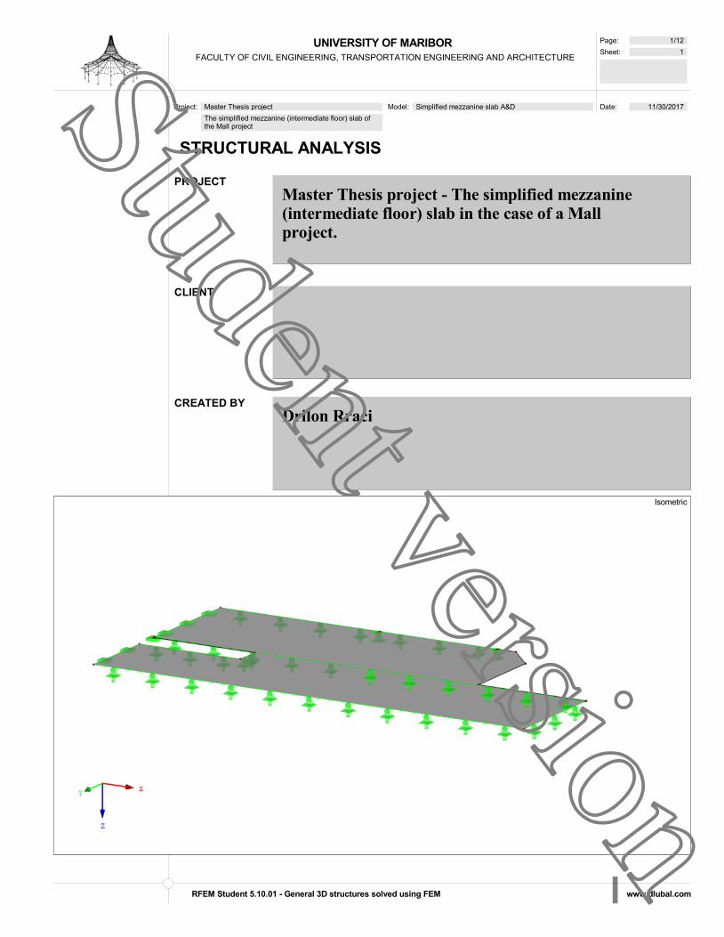
UNIVERSITY OF MARIBORFACULTY OF CIVIL ENGINEERING, TRANSPORTATION ENGINEERING AND ARCHITECTURE
Page: 1/12
Sheet: 1
Date: 11/30/2017 Project: Master Thesis project
The simplified mezzanine (intermediate floor) slab ofthe Mall project
Model: Simplified mezzanine slab A&D
STRUCTURAL ANALYSIS
PROJECTMaster Thesis project - The simplified mezzanine(intermediate floor) slab in the case of a Mallproject.
CLIENT
CREATED BYDrilon Rraci
Isometric
RFEM Student 5.10.01 - General 3D structures solved using FEM www.dlubal.com
Student version

UNIVERSITY OF MARIBORFACULTY OF CIVIL ENGINEERING, TRANSPORTATION ENGINEERING AND ARCHITECTURE
Page: 2/12
Sheet: 1
MODEL
Date: 11/30/2017 Project: Master Thesis project
The simplified mezzanine (intermediate floor) slab ofthe Mall project
Model: Simplified mezzanine slab A&D
MODEL - GENERAL DATAMODEL - GENERAL DATAGeneral Model name : Simplified mezzanine slab A&D
Project name : ExamplesProject description : Sample structuresType of model : 3DPositive direction of global axis Z : DownwardClassification of load cases and : According to Standard: EN 1990combinations National Annex: SIST - Slovenia
Automatically create combinations : Load Combinations
Options RF-FORM-FINDING - Find initial equilibrium shapes of membrane and cable structures
RF-CUTTING-PATTERN
Piping analysis
Use CQC Rule
Enable CAD/BIM model
Standard Gravityg : 10.00 m/s2
FE MESH SETTINGSFE MESH SETTINGSGeneral Target length of finite elements I FE : 50.0 cm
Maximum distance between a node and a line : 0.1 cmto integrate it into the lineMaximum number of mesh nodes (in thousands) : 500
Members Number of divisions of members with cable, : 10elastic foundation, taper, or plastic characteristic
Activate member divisions for large deformationor post-critical analysisUse division for members with node lying on them
Surfaces Maximum ratio of FE rectangle diagonals D : 1.80Maximum out-of-plane inclination of two finite : 0.50 °elementsShape direction of finite elements : Triangles and quadrangles
Same squares where possible
1.1 NODES1.1 NODESNode Reference Coordinate Node Coordinates
No. Node Type Node System X [cm] Y [cm] Z [cm] Comment1 Standard - Cartesian 5036.00 -372.00 -320.002 Standard - Cartesian 5036.00 -492.00 -320.003 Standard - Cartesian 4543.00 -492.00 -320.004 Standard - Cartesian 4543.00 -1057.00 -320.005 Standard - Cartesian 5988.00 -1057.00 -320.006 Standard - Cartesian 6120.00 -910.00 -320.007 Standard - Cartesian 6120.00 -512.00 -320.008 Standard - Cartesian 6647.00 -512.00 -320.009 Standard - Cartesian 6647.00 15.00 -320.0010 Standard - Cartesian 4543.00 15.00 -320.0011 Standard - Cartesian 4543.00 -372.00 -320.0012 Standard - Cartesian 6647.00 -502.00 -320.0013 Standard - Cartesian 4543.00 -502.00 -320.0031 Standard - Cartesian 5325.00 -1057.00 -320.0032 Standard - Cartesian 5325.00 -1042.00 -320.0033 Standard - Cartesian 5900.00 -1057.00 -320.0034 Standard - Cartesian 5900.00 -1042.00 -320.00
Cartesian
1.2 LINES1.2 LINESLine Line Length
No. Line Type Nodes No. L [cm] Comment1 Polyline 12,13 2104.00 X2 Polyline 13,4 555.00 Y3 Polyline 12,9 517.00 Y15 Polyline 11,1 493.00 X16 Polyline 1,2 120.00 Y17 Polyline 2,3 493.00 X18 Polyline 3,13 10.00 Y19 Polyline 4,31 782.00 X20 Polyline 5,6 197.57 XY21 Polyline 6,7 398.00 Y22 Polyline 7,8 527.00 X23 Polyline 8,12 10.00 Y24 Polyline 9,10 2104.00 X25 Polyline 10,11 387.00 Y26 Polyline 31,33 575.00 X
RFEM Student 5.10.01 - General 3D structures solved using FEM www.dlubal.com
Student version

UNIVERSITY OF MARIBORFACULTY OF CIVIL ENGINEERING, TRANSPORTATION ENGINEERING AND ARCHITECTURE
Page: 3/12
Sheet: 1
MODEL
Date: 11/30/2017 Project: Master Thesis project
The simplified mezzanine (intermediate floor) slab ofthe Mall project
Model: Simplified mezzanine slab A&D
1.2 LINES1.2 LINESLine Line Length
No. Line Type Nodes No. L [cm] Comment27 Polyline 33,5 88.00 X
1.3 MATERIALS1.3 MATERIALSMatl. Modulus Modulus Poisson's Ratio Spec. Weight Coeff. of Th. Exp. Partial Factor Material
No. E [MPa] G [MPa] [-] [kN/m3] [1/°C] M [-] Model
1 Concrete C25/30 | EN 1992-1-1:2004/A1:201431000.0 12916.7 0.200 25.00 1.00E-05 1.00 Isotropic Linear
ElasticC25/30
2 Masonry (Brick, Group 2, Standard Mortar, M2,5 - M9, <> 0,5 - 3 mm) | EN 1996-1-12700.0 1350.0 0.000 1.96 6.00E-06 1.00 Isotropic Linear
ElasticUser-Defined Material
1.4 SURFACES1.4 SURFACESSurface Surface Type Matl. Thickness Area Weight
No. Geometry Stiffness Boundary Lines No. No. Type d [cm] A [cm2] W [kg]2 Plane Standard 15-18,2,19,26,27,20-23,
3,24,251 Constant 20.00 1897610.00 94880.60
1.4.2 SURFACES - INTEGRATED OBJECTS1.4.2 SURFACES - INTEGRATED OBJECTSSurface Integrated Objects No.
No. Nodes Lines Openings Comment2 32,34 1
1.7 NODAL SUPPORTS1.7 NODAL SUPPORTSSupport Column Support Conditions
No. Nodes No. Axis System in Z uX uY uZ X Y Z
1 34 Global X,Y,Z2 32 Global X,Y,Z
1.7.1 NODAL SUPPORTS - COLUMNS1.7.1 NODAL SUPPORTS - COLUMNSSupport Column Type Height Model of Matl. Support Conditions Shear
No. Dimensions [cm] H [cm] Support by No. Head Base Stiffness1 b / h = 30 / 30 - Nodal by adapted FE mesh - - - -2 b / h = 30 / 30 - Nodal by adapted FE mesh - - - -
1.8 LINE SUPPORTS1.8 LINE SUPPORTSSupport Reference Rotation Wall Support Conditions
No. Lines No. System [°] in Z uX uY uZ X Y Z
1 2,18,25 Global9 1,3,15,16,19,24,26 Global
1.13 CROSS-SECTIONS1.13 CROSS-SECTIONSSection Matl. J [cm4] Iy [cm4] Iz [cm4] Principal Axes Rotation Overall Dimensions [cm]
No. No. A [cm2] Ay [cm2] Az [cm2] [°] ' [°] Width b Height h
1 Rectangle 30/30 1 113940.00 67500.00 67500.00 0.00 0.00 30.00 30.00
900.00 750.00 750.00300*300
Rectangle 30/30
RFEM Student 5.10.01 - General 3D structures solved using FEM www.dlubal.com
Student version

UNIVERSITY OF MARIBORFACULTY OF CIVIL ENGINEERING, TRANSPORTATION ENGINEERING AND ARCHITECTURE
Page: 4/12
Sheet: 1
RESULTS
Date: 11/30/2017 Project: Master Thesis project
The simplified mezzanine (intermediate floor) slab ofthe Mall project
Model: Simplified mezzanine slab A&D
GLOBAL DEFORMATIONS uZ, SUPPORT REACTIONS
0.350.24
38
7.0
05
65
.00
575.00
197.57
1445.00
2104.00
52
7.0
0
527.00
493.00
782.00
39
8.0
0
88.00
12
0.0
0
Global DeformationsuZ [cm]
0.35
0.32
0.28
0.25
0.22
0.18
0.15
0.12
0.08
0.05
0.01
-0.02
Max : 0.35Min : -0.02
In Z-directionRC 1: ULS (STR/GEO) - Permanent / transient - Eq. 6.10Global Deformations u-ZSupport Reactions[kN]Result Combinations: Max and Min Values
Factor of deformations: 630.00Max u-Z: 0.35, Min u-Z: -0.02 [cm] 261.96 cm
GLOBAL DEFORMATIONS uZ, SUPPORT REACTIONSGLOBAL DEFORMATIONS uZ, SUPPORT REACTIONS
RFEM Student 5.10.01 - General 3D structures solved using FEM www.dlubal.com
Student version
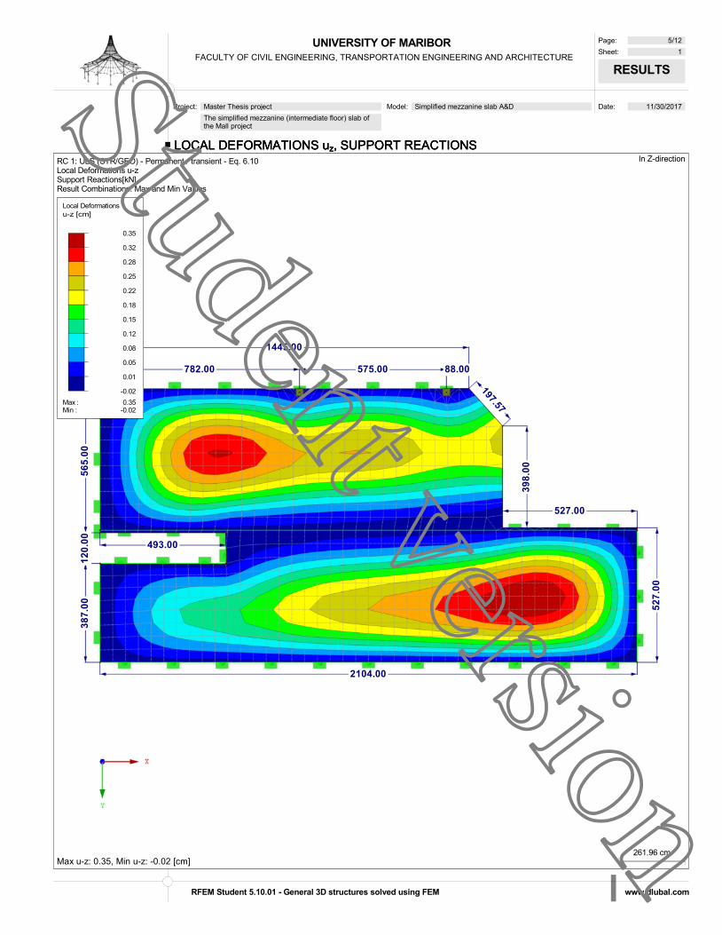
UNIVERSITY OF MARIBORFACULTY OF CIVIL ENGINEERING, TRANSPORTATION ENGINEERING AND ARCHITECTURE
Page: 5/12
Sheet: 1
RESULTS
Date: 11/30/2017 Project: Master Thesis project
The simplified mezzanine (intermediate floor) slab ofthe Mall project
Model: Simplified mezzanine slab A&D
LOCAL DEFORMATIONS uz, SUPPORT REACTIONS
39
8.0
0
2104.00
493.00
527.00
52
7.0
0
197.57
38
7.0
0
88.00
1445.00
56
5.0
01
20
.00
782.00 575.00
Local Deformationsu-z [cm]
0.35
0.32
0.28
0.25
0.22
0.18
0.15
0.12
0.08
0.05
0.01
-0.02
Max : 0.35Min : -0.02
In Z-directionRC 1: ULS (STR/GEO) - Permanent / transient - Eq. 6.10Local Deformations u-zSupport Reactions[kN]Result Combinations: Max and Min Values
Max u-z: 0.35, Min u-z: -0.02 [cm]261.96 cm
LOCAL DEFORMATIONS uz, SUPPORT REACTIONSLOCAL DEFORMATIONS uz, SUPPORT REACTIONS
RFEM Student 5.10.01 - General 3D structures solved using FEM www.dlubal.com
Student version

UNIVERSITY OF MARIBORFACULTY OF CIVIL ENGINEERING, TRANSPORTATION ENGINEERING AND ARCHITECTURE
Page: 6/12
Sheet: 1
RESULTS
Date: 11/30/2017 Project: Master Thesis project
The simplified mezzanine (intermediate floor) slab ofthe Mall project
Model: Simplified mezzanine slab A&D
BASE VALUES mx, SUPPORT REACTIONS
39
8.0
0
2104.00
493.00
527.00
52
7.0
0
197.57
38
7.0
0
88.00
1445.00
56
5.0
01
20
.00
782.00 575.00
Base valuesmx [kNm/cm]
0.230
0.170
0.110
0.050
-0.009
-0.069
-0.129
-0.189
-0.249
-0.309
-0.368
-0.428
Max : 0.230Min : -0.428
In Z-directionRC 1: ULS (STR/GEO) - Permanent / transient - Eq. 6.10Basic Internal Forces m-xSupport Reactions[kN]Result Combinations: Max and Min Values
Max m-x: 0.230, Min m-x: -0.428 [kNm/cm]261.96 cm
BASE VALUES mx, SUPPORT REACTIONSBASE VALUES mx, SUPPORT REACTIONS
RFEM Student 5.10.01 - General 3D structures solved using FEM www.dlubal.com
Student version

UNIVERSITY OF MARIBORFACULTY OF CIVIL ENGINEERING, TRANSPORTATION ENGINEERING AND ARCHITECTURE
Page: 7/12
Sheet: 1
RESULTS
Date: 11/30/2017 Project: Master Thesis project
The simplified mezzanine (intermediate floor) slab ofthe Mall project
Model: Simplified mezzanine slab A&D
BASE VALUES my, SUPPORT REACTIONS
39
8.0
0
2104.00
493.00
527.00
52
7.0
0
197.57
38
7.0
0
88.00
1445.00
56
5.0
01
20
.00
782.00 575.00
Base valuesmy [kNm/cm]
0.715
0.554
0.392
0.231
0.069
-0.092
-0.254
-0.415
-0.577
-0.738
-0.900
-1.061
Max : 0.715Min : -1.061
In Z-directionRC 1: ULS (STR/GEO) - Permanent / transient - Eq. 6.10Basic Internal Forces m-ySupport Reactions[kN]Result Combinations: Max and Min Values
Max m-y: 0.715, Min m-y: -1.061 [kNm/cm]261.96 cm
BASE VALUES my, SUPPORT REACTIONSBASE VALUES my, SUPPORT REACTIONS
RFEM Student 5.10.01 - General 3D structures solved using FEM www.dlubal.com
Student version

UNIVERSITY OF MARIBORFACULTY OF CIVIL ENGINEERING, TRANSPORTATION ENGINEERING AND ARCHITECTURE
Page: 8/12
Sheet: 1
RESULTS
Date: 11/30/2017 Project: Master Thesis project
The simplified mezzanine (intermediate floor) slab ofthe Mall project
Model: Simplified mezzanine slab A&D
BASE VALUES mxy, SUPPORT REACTIONS
39
8.0
0
2104.00
493.00
527.00
52
7.0
0
197.57
38
7.0
0
88.00
1445.00
56
5.0
01
20
.00
782.00 575.00
Base valuesmxy [kNm/cm]
0.170
0.129
0.087
0.045
0.003
-0.039
-0.080
-0.122
-0.164
-0.206
-0.248
-0.289
Max : 0.170Min : -0.289
In Z-directionRC 1: ULS (STR/GEO) - Permanent / transient - Eq. 6.10Basic Internal Forces m-xySupport Reactions[kN]Result Combinations: Max and Min Values
Max m-xy: 0.170, Min m-xy: -0.289 [kNm/cm]261.96 cm
BASE VALUES mxy, SUPPORT REACTIONSBASE VALUES mxy, SUPPORT REACTIONS
RFEM Student 5.10.01 - General 3D structures solved using FEM www.dlubal.com
Student version

UNIVERSITY OF MARIBORFACULTY OF CIVIL ENGINEERING, TRANSPORTATION ENGINEERING AND ARCHITECTURE
Page: 9/12
Sheet: 1
RESULTS
Date: 11/30/2017 Project: Master Thesis project
The simplified mezzanine (intermediate floor) slab ofthe Mall project
Model: Simplified mezzanine slab A&D
BASE VALUES vx, SUPPORT REACTIONS
39
8.0
0
2104.00
493.00
527.00
52
7.0
0
197.57
38
7.0
0
88.00
1445.00
56
5.0
01
20
.00
782.00 575.00
Base valuesvx [kN/cm]
4.638
3.873
3.108
2.343
1.577
0.812
0.047
-0.718
-1.483
-2.248
-3.013
-3.778
Max : 4.638Min : -3.778
In Z-directionRC 1: ULS (STR/GEO) - Permanent / transient - Eq. 6.10Basic Internal Forces v-xSupport Reactions[kN]Result Combinations: Max and Min Values
Max v-x: 4.638, Min v-x: -3.778 [kN/cm]261.96 cm
BASE VALUES vx, SUPPORT REACTIONSBASE VALUES vx, SUPPORT REACTIONS
RFEM Student 5.10.01 - General 3D structures solved using FEM www.dlubal.com
Student version

UNIVERSITY OF MARIBORFACULTY OF CIVIL ENGINEERING, TRANSPORTATION ENGINEERING AND ARCHITECTURE
Page: 10/12
Sheet: 1
RESULTS
Date: 11/30/2017 Project: Master Thesis project
The simplified mezzanine (intermediate floor) slab ofthe Mall project
Model: Simplified mezzanine slab A&D
BASE VALUES vy, SUPPORT REACTIONS
39
8.0
0
2104.00
493.00
527.00
52
7.0
0
197.57
38
7.0
0
88.00
1445.00
56
5.0
01
20
.00
782.00 575.00
Base valuesvy [kN/cm]
7.361
6.187
5.014
3.840
2.667
1.494
0.320
-0.853
-2.026
-3.200
-4.373
-5.546
Max : 7.361Min : -5.546
In Z-directionRC 1: ULS (STR/GEO) - Permanent / transient - Eq. 6.10Basic Internal Forces v-ySupport Reactions[kN]Result Combinations: Max and Min Values
Max v-y: 7.361, Min v-y: -5.546 [kN/cm]261.96 cm
BASE VALUES vy, SUPPORT REACTIONSBASE VALUES vy, SUPPORT REACTIONS
RFEM Student 5.10.01 - General 3D structures solved using FEM www.dlubal.com
Student version

UNIVERSITY OF MARIBORFACULTY OF CIVIL ENGINEERING, TRANSPORTATION ENGINEERING AND ARCHITECTURE
Page: 11/12
Sheet: 1
RF-CONCRETE Surfaces
Date: 11/30/2017 Project: Master Thesis project
The simplified mezzanine (intermediate floor) slab ofthe Mall project
Model: Simplified mezzanine slab A&D
1.1 GENERAL DATA1.1 GENERAL DATA
Design according to Standard: SIST EN 1992-1-1:2005/A101:2006
ULTIMATE LIMIT STATEResult combination for design: RC1 ULS (STR/GEO) - Permanent / transient - Eq. 6.10
Persistent and Transient
SERVICEABILITY LIMIT STATEResult combination for design: RC4 SLS - Quasi-permanent
Quasi-permanent, kt 0.600
Definition of Provided Additional Reinforcement Automatic arrangement according to the specifications in Table 1.4
Type of SLS method: Analytical MethodBy assuming an identical deformation ratio of the longitudinal reinforcement
Design ofConcrete Stress AnalysisSteel Stress AnalysisCrack widthsDeformation Analysis
Layout of longitudinal reinforcementRequired longitudinal reinforcement automatically increased for serviceability limit state design:
DETAILSAnalysis Method for Reinforcement Envelope MixedApply the internal forces without the rib components
Design Situation Settings for Serviceability Limit State ChecksLoad combination:Characteristic with direct load Checks: k1*fck, k3*fyk
Characteristic with imposed deformation Checks: k1*fck, k4*fyk
Frequent Checks: wk
Quasi-permanent Checks: k2*fck, wk, ul
RF-CONCRETE SurfacesCA1Reinforced concrete design
1.2 MATERIALS1.2 MATERIALSMaterial Material Description
No. Concrete Strength Class Steel Description Comment1 Concrete C25/30 B 500 S (A)
1.2.1 MATERIAL PARAMETERS1.2.1 MATERIAL PARAMETERSMaterial
No. Description Name Size Unit1 Concrete Strength Class: Concrete C25/30
Characteristic Cylinder Compressive Strength fck 25.000 MPa5 % Fractile of Axial Tensile Strength fctk,0.05 1.800 MPaCharacteristic for Nonlinear Calculations
Mean Secant Modulus of Elasticity Ecm 31000.000 MPaMean Cylinder Compressive Strength fcm 33.000 MPaMean Axial Tensile Strength fctm 2.600 MPaUltimate Strain for Pure Compression c1 -2.100 ‰Ultimate Strain at Failure c1u -3.500 ‰Shear Modulus G 12916.700 MPaPoisson's Ratio 0.200 -
Characteristic Strains for Parabolic-Rectangular DiagramUltimate Strain for Pure Compression c2 -2.000 ‰Ultimate Strain at Failure cu2 -3.500 ‰Parabola Exponent n 2.000 -
Specific Weight 25.00 kN/m^3Reinforcing Steel: B 500 S (A)
Modulus of Elasticity Es 200000.000 MPaYield Stress Mean Value fym 550.000 MPaCharacteristic Yield Stress fyk 500.000 MPaTensile Strength Mean Value ftm 551.250 MPaCharacteristic Tensile Strength ftk 525.000 MPaLimiting Strain uk 25.000 ‰
1.3 SURFACES1.3 SURFACESSurface Matl. fct,eff,wk fct,eff,As,min wk,+z (top) [cm] Effects due to Restraint
No. No. [MPa] [MPa] wk,-z (bottom) [cm] Apply kc [-] Notes
2 Thickness Type: Constant, Thickness: 20.000 cm1 2.600 2.600 0.030 var. 6)
0.030Notes:6) Calculation of minimum reinforcement for effects due to restraint
RFEM Student 5.10.01 - General 3D structures solved using FEM www.dlubal.com
Student version

UNIVERSITY OF MARIBORFACULTY OF CIVIL ENGINEERING, TRANSPORTATION ENGINEERING AND ARCHITECTURE
Page: 12/12
Sheet: 1
RF-CONCRETE Surfaces
Date: 11/30/2017 Project: Master Thesis project
The simplified mezzanine (intermediate floor) slab ofthe Mall project
Model: Simplified mezzanine slab A&D
2.1 REQUIRED REINFORCEMENT TOTAL2.1 REQUIRED REINFORCEMENT TOTALSurface Point Point Coordinates [cm] Required Reinforcement Basic Additional Reinforcement
No. No. X Y Z Symbol ULS SLS ULS/SLS Reinf. Required Provided Unit Notes2 M37 5915.000 -1027.000 -320.000 as,1,-z (top) 7.460 5.898 7.460 3.350 4.110 - cm2/m2 M150 - E12 5043.950 -502.000 -320.000 as,2,-z (top) 18.016 10.959 18.016 3.350 14.666 - cm2/m2 M46 5036.000 -432.000 -320.000 as,1,+z (bottom) 4.683 4.493 4.683 0.000 4.683 - cm2/m2 M46 5036.000 -432.000 -320.000 as,2,+z (bottom) 12.482 7.567 12.482 0.000 12.482 - cm2/m2 M2 5036.000 -492.000 -320.000 asw Not
designable
- Not designable
- - - cm2/m2 7)
2.2 REQUIRED REINFORCEMENT BY SURFACE2.2 REQUIRED REINFORCEMENT BY SURFACESurface Point Point Coordinates [cm] Required Reinforcement Basic Additional Reinforcement
No. No. X Y Z Symbol ULS SLS ULS/SLS Reinf. Required Provided Unit Notes2 M37 5915.000 -1027.000 -320.000 as,1,-z (top) 7.460 5.898 7.460 3.350 4.110 - cm2/m
M150 - E12 5043.950 -502.000 -320.000 as,2,-z (top) 18.016 10.959 18.016 3.350 14.666 - cm2/mM46 5036.000 -432.000 -320.000 as,1,+z (bottom) 4.683 4.493 4.683 0.000 4.683 - cm2/mM46 5036.000 -432.000 -320.000 as,2,+z (bottom) 12.482 7.567 12.482 0.000 12.482 - cm2/mM2 5036.000 -492.000 -320.000 asw Not
designable
- Not designable
- - - cm2/m2 7)
3.2 SERVICEABILITY CHECK BY SURFACE3.2 SERVICEABILITY CHECK BY SURFACESurface Point Point Coordinates [cm] Load Design
No. No. X Y Z Case Type Exist. Value Limit Value Unit Ratio Notes2 M1 5036.000 -372.000 -320.000 s Not designable 0.000 MPa 0.0 236) 239)
M3 4543.000 -492.000 -320.000 RC4 as,min 4.411 4.517 cm2/m 1.1 233)M128 - E727 6146.050 -502.000 -320.000 RC4 lim ds 0.829 1.408 cm 0.6 214) 235)
236)M462 6095.950 -191.800 -320.000 RC4 lim sl 16.007 19.174 cm 0.9 235) 236)M37 5915.000 -1027.000 -320.000 RC4 wk 0.022 0.030 cm 0.8 235) 236)
RFEM Student 5.10.01 - General 3D structures solved using FEM www.dlubal.com
Student version

Interoperability between Architectural and Structural BIM Software in the case of a Mall Project Page | 163
`
10.4.5 RFEM report in the case of the structural steel elements of the Mall project

UNIVERSITY OF MARIBORFACULTY OF CIVIL ENGINEERING, TRANSPORTATION ENGINEERING AND ARCHITECTURE
Page: 1/15
Sheet: 1
Date: 11/30/2017 Project: Master Thesis project
Structural steel elements of the Mall project
Model: A&D of steel elements of the Mall project
STRUCTURAL ANALYSIS
PROJECTMaster Thesis project - Structural steel elements inthe case of a Mall project
CLIENT
CREATED BYDrilon Rraci
Isometric
RFEM Student 5.10.01 - General 3D structures solved using FEM www.dlubal.com
Student version

UNIVERSITY OF MARIBORFACULTY OF CIVIL ENGINEERING, TRANSPORTATION ENGINEERING AND ARCHITECTURE
Page: 2/15
Sheet: 1
MODEL
Date: 11/30/2017 Project: Master Thesis project
Structural steel elements of the Mall project
Model: A&D of steel elements of the Mall project
MODEL - GENERAL DATAMODEL - GENERAL DATAGeneral Model name : A&D of steel elements of the Mall project
Project name : ExamplesProject description : Sample structuresType of model : 3DPositive direction of global axis Z : DownwardClassification of load cases and : According to Standard: EN 1990combinations National Annex: SIST - Slovenia
Automatically create combinations : Load Combinations
Options RF-FORM-FINDING - Find initial equilibrium shapes of membrane and cable structures
RF-CUTTING-PATTERN
Piping analysis
Use CQC Rule
Enable CAD/BIM model
Standard Gravityg : 10.00 m/s2
1.1 NODES1.1 NODESNode Reference Coordinate Node Coordinates
No. Node Type Node System X [cm] Y [cm] Z [cm] Comment1 Standard - Cartesian 7463.00 -3197.80 36.002 Standard - Cartesian 7073.00 -18.00 36.003 Standard - Cartesian 7463.00 -416.00 36.004 Standard - Cartesian 7463.00 -1037.65 36.005 Standard - Cartesian 2521.00 -1027.00 -298.006 Standard - Cartesian 2521.00 -15.00 -298.007 Standard - Cartesian 2808.00 -1027.00 -298.008 Standard - Cartesian 2808.00 -15.00 -298.009 Standard - Cartesian 3095.00 -1027.00 -298.0010 Standard - Cartesian 3095.00 -15.00 -298.0011 Standard - Cartesian 3382.00 -1027.00 -298.0012 Standard - Cartesian 3382.00 -15.00 -298.0013 Standard - Cartesian 3669.00 -1027.00 -298.0014 Standard - Cartesian 3669.00 -15.00 -298.0015 Standard - Cartesian 3956.00 -1027.00 -298.0016 Standard - Cartesian 3956.00 -15.00 -298.0017 Standard - Cartesian 4243.00 -1027.00 -298.0018 Standard - Cartesian 4243.00 -15.00 -298.0019 Standard - Cartesian 6647.00 -18.00 -719.5020 Standard - Cartesian 5988.40 -1037.65 -597.0021 Standard - Cartesian 5206.00 -502.00 -669.0022 Standard - Cartesian 6100.00 -502.00 -669.0023 Standard - Cartesian 7463.00 -3197.80 -527.5424 Standard - Cartesian 7073.00 -18.00 -719.5025 Standard - Cartesian 7463.00 -416.00 -695.4326 Standard - Cartesian 7463.00 -1037.65 -657.9127 Standard - Cartesian 7463.00 -18.00 -719.4628 Standard - Cartesian 7463.00 -1037.65 -597.00
Cartesian
1.2 LINES1.2 LINESLine Line Length
No. Line Type Nodes No. L [cm] Comment1 Polyline 21,22 894.00 X2 Polyline 20,28 1474.60 X3 Polyline 19,24 426.00 X4 Polyline 24,27 390.00 X5 Polyline 23,26 2164.08 YZ6 Polyline 26,25 622.78 YZ7 Polyline 25,27 398.73 YZ8 Polyline 17,18 1012.00 Y9 Polyline 15,16 1012.00 Y10 Polyline 13,14 1012.00 Y11 Polyline 11,12 1012.00 Y12 Polyline 9,10 1012.00 Y13 Polyline 7,8 1012.00 Y14 Polyline 5,6 1012.00 Y15 Polyline 4,28 633.00 Z16 Polyline 28,26 60.91 Z17 Polyline 3,25 731.43 Z18 Polyline 2,24 755.50 Z19 Polyline 1,23 563.54 Z
RFEM Student 5.10.01 - General 3D structures solved using FEM www.dlubal.com
Student version

UNIVERSITY OF MARIBORFACULTY OF CIVIL ENGINEERING, TRANSPORTATION ENGINEERING AND ARCHITECTURE
Page: 3/15
Sheet: 1
MODEL
Date: 11/30/2017 Project: Master Thesis project
Structural steel elements of the Mall project
Model: A&D of steel elements of the Mall project
1.3 MATERIALS1.3 MATERIALSMatl. Modulus Modulus Poisson's Ratio Spec. Weight Coeff. of Th. Exp. Partial Factor Material
No. E [MPa] G [MPa] [-] [kN/m3] [1/°C] M [-] Model
1 Steel S 235 | EN 1993-1-1:2005-05210000.0 80769.2 0.300 78.50 1.20E-05 1.00 Isotropic Linear
ElasticS235JR
1.7 NODAL SUPPORTS1.7 NODAL SUPPORTSSupport Column Support Conditions
No. Nodes No. Axis System in Z uX uY uZ X Y Z
1 1-22 Global X,Y,Z
1.13 CROSS-SECTIONS1.13 CROSS-SECTIONSSection Matl. J [cm4] Iy [cm4] Iz [cm4] Principal Axes Rotation Overall Dimensions [cm]
No. No. A [cm2] Ay [cm2] Az [cm2] [°] ' [°] Width b Height h
1 HE B 200 | Euronorm 53-62 1 59.50 5700.00 2000.00 0.00 0.00 20.00 20.00
78.10 50.04 15.35HEB200
2 HE B 1000 | Euronorm 53-62 1 1260.00 644700.00 16280.00 0.00 0.00 30.00 100.00
400.00 181.44 179.09HEB1000
3 HE A 500 | Euronorm 53-62 1 310.00 86970.00 10370.00 0.00 0.00 30.00 49.00
198.00 115.05 53.82HEA500
4 RRO 260x180x8 | EN 10219-2:2006 1 7267.00 6145.00 3493.00 0.00 0.00 18.00 26.00
65.60 21.00 36.14RHS180*260*8
5 QRO 300x10 | EN 10219-2:2006 1 24970.00 15520.00 15520.00 0.00 0.00 30.00 30.00
113.00 48.87 48.87RHS300*10
HE B 200 HE B 1000
HE A 500 RRO 260x180x8
QRO 300x10
1.17 MEMBERS1.17 MEMBERSMbr. Line Rotation Cross-Section Hinge No. Ecc. Div. Length
No. No. Member Type [°] Start End Start End No. No. L [cm]1 1 Beam Angle 180.00 1 1 - - - - 894.00 X
BEAM2 2 Beam Angle 180.00 2 2 - - - - 1474.60 X
BEAM3 3 Beam Angle 180.00 3 3 - - - - 426.00 X
BEAM4 4 Beam Angle 180.00 3 3 - - - - 390.00 X
BEAM5 5 Beam Angle 180.00 3 3 - - - - 2164.08 YZ
BEAM6 6 Beam Angle 180.00 3 3 - - - - 622.78 YZ
BEAM7 7 Beam Angle 180.00 3 3 - - - - 398.73 YZ
BEAM8 8 Beam Angle 0.00 4 4 - - - - 1012.00 Y
BEAM9 9 Beam Angle 0.00 4 4 - - - - 1012.00 Y
BEAM10 10 Beam Angle 0.00 4 4 - - - - 1012.00 Y
BEAM11 11 Beam Angle 0.00 4 4 - - - - 1012.00 Y
BEAM12 12 Beam Angle 0.00 4 4 - - - - 1012.00 Y
BEAM13 13 Beam Angle 0.00 4 4 - - - - 1012.00 Y
BEAM14 14 Beam Angle 0.00 4 4 - - - - 1012.00 Y
BEAM15 15 Beam Angle 90.00 3 3 - - - - 633.00 Z
COLUMN16 16 Beam Angle 90.00 3 3 - - - - 60.91 Z
COLUMN17 17 Beam Angle 0.00 5 5 - - - - 731.43 Z
COLUMN18 18 Beam Angle 0.00 5 5 - - - - 755.50 Z
COLUMN
RFEM Student 5.10.01 - General 3D structures solved using FEM www.dlubal.com
Student version

UNIVERSITY OF MARIBORFACULTY OF CIVIL ENGINEERING, TRANSPORTATION ENGINEERING AND ARCHITECTURE
Page: 4/15
Sheet: 1
MODEL
Date: 11/30/2017 Project: Master Thesis project
Structural steel elements of the Mall project
Model: A&D of steel elements of the Mall project
1.17 MEMBERS1.17 MEMBERSMbr. Line Rotation Cross-Section Hinge No. Ecc. Div. Length
No. No. Member Type [°] Start End Start End No. No. L [cm]19 19 Beam Angle 90.00 3 3 - - - - 563.54 Z
COLUMN
1.21 SETS OF MEMBERS1.21 SETS OF MEMBERSSet Set of Members Length
No. Description Type Member No. [cm] Comment1 BEAM Contin.
member1 894.00 383804472
2 BEAM Contin. member
2 1474.60 383804501
3 BEAM Contin. member
3,4 816.00 383804515
4 Contin. member
5-7 3185.59 383804529
5 BEAM Contin. member
8 1012.00 383804550
6 BEAM Contin. member
9 1012.00 383804564
7 BEAM Contin. member
10 1012.00 383804578
8 BEAM Contin. member
11 1012.00 383804592
9 BEAM Contin. member
12 1012.00 383804606
10 BEAM Contin. member
13 1012.00 383804620
11 BEAM Contin. member
14 1012.00 383804634
12 COLUMN Contin. member
15,16 693.91 383804648
13 COLUMN Contin. member
17 731.43 383804666
14 COLUMN Contin. member
18 755.50 383804680
15 COLUMN Contin. member
19 563.54 383804694
RFEM Student 5.10.01 - General 3D structures solved using FEM www.dlubal.com
Student version
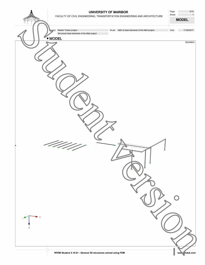
UNIVERSITY OF MARIBORFACULTY OF CIVIL ENGINEERING, TRANSPORTATION ENGINEERING AND ARCHITECTURE
Page: 5/15
Sheet: 1
MODEL
Date: 11/30/2017 Project: Master Thesis project
Structural steel elements of the Mall project
Model: A&D of steel elements of the Mall project
MODELIsometric
MODELMODEL
RFEM Student 5.10.01 - General 3D structures solved using FEM www.dlubal.com
Student version

UNIVERSITY OF MARIBORFACULTY OF CIVIL ENGINEERING, TRANSPORTATION ENGINEERING AND ARCHITECTURE
Page: 6/15
Sheet: 1
RESULTS
Date: 11/30/2017 Project: Master Thesis project
Structural steel elements of the Mall project
Model: A&D of steel elements of the Mall project
LOCAL DEFORMATIONS uz
0.01
-0.17
-1.77 -0.19-0.02-0.19
0.04
0.03
-0.13-0.20
-0.02
-0.01
-0.12
1.41
2.662.66
2.662.66
2.661.41
X
Z
Y
IsometricRC 1: ULS (STR/GEO) - Permanent / transient - Eq. 6.10Local Deformations u-zResult Combinations: Max and Min Values
Max u-z: 2.66, Min u-z: -1.77 [cm]
LOCAL DEFORMATIONS uzLOCAL DEFORMATIONS uz
RFEM Student 5.10.01 - General 3D structures solved using FEM www.dlubal.com
Student version

UNIVERSITY OF MARIBORFACULTY OF CIVIL ENGINEERING, TRANSPORTATION ENGINEERING AND ARCHITECTURE
Page: 7/15
Sheet: 1
RESULTS
Date: 11/30/2017 Project: Master Thesis project
Structural steel elements of the Mall project
Model: A&D of steel elements of the Mall project
INTERNAL FORCES Vz
22.813
22.756
-38.390
-21.746
-21.791
32.73541.977
-21.798
0.058
-1.935
1.970
-0.750
-16.437
-53.662
3.700
32.925
62.333
23.123
-62.333
-32.925
X
Z
Y
IsometricRC 1: ULS (STR/GEO) - Permanent / transient - Eq. 6.10Internal Forces V-zResult Combinations: Max and Min Values
Max V-z: 62.333, Min V-z: -62.333 [kN]
INTERNAL FORCES VzINTERNAL FORCES Vz
RFEM Student 5.10.01 - General 3D structures solved using FEM www.dlubal.com
Student version

UNIVERSITY OF MARIBORFACULTY OF CIVIL ENGINEERING, TRANSPORTATION ENGINEERING AND ARCHITECTURE
Page: 8/15
Sheet: 1
RESULTS
Date: 11/30/2017 Project: Master Thesis project
Structural steel elements of the Mall project
Model: A&D of steel elements of the Mall project
INTERNAL FORCES My
108.920
-19.549
108.920
-89.228
60.009
3.843
56.853
147.975
-91.122
-0.451
-86.281
-0.541
1.876
35.888158.143
-1.726
-2.7565.512
-105.134
-55.534
52.567
-105.134
-55.534
X
Z
Y
IsometricRC 1: ULS (STR/GEO) - Permanent / transient - Eq. 6.10Internal Forces M-yResult Combinations: Max and Min Values
Max M-y: 158.143, Min M-y: -105.134 [kNm]
INTERNAL FORCES MyINTERNAL FORCES My
RFEM Student 5.10.01 - General 3D structures solved using FEM www.dlubal.com
Student version
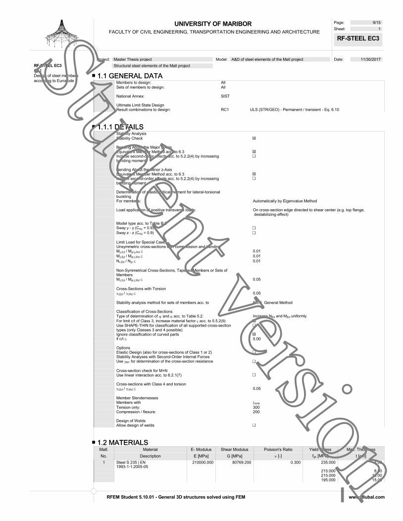
UNIVERSITY OF MARIBORFACULTY OF CIVIL ENGINEERING, TRANSPORTATION ENGINEERING AND ARCHITECTURE
Page: 9/15
Sheet: 1
RF-STEEL EC3
Date: 11/30/2017 Project: Master Thesis project
Structural steel elements of the Mall project
Model: A&D of steel elements of the Mall project
1.1 GENERAL DATA1.1 GENERAL DATAMembers to design: AllSets of members to design: All
National Annex: SIST
Ultimate Limit State DesignResult combinations to design: RC1 ULS (STR/GEO) - Permanent / transient - Eq. 6.10
RF-STEEL EC3CA1Design of steel membersaccording to Eurocode 3
1.1.1 DETAILS1.1.1 DETAILSStability AnalysisStability Check
Bending About the Major y-AxisEquivalent Member Method acc. to 6.3Include second-order effects acc. to 5.2.2(4) by increasing bending moment
Bending About the Minor z-AxisEquivalent Member Method acc. to 6.3Include second-order effects acc. to 5.2.2(4) by increasing bending moment
Determination of elastic critical moment for lateral-torsional bucklingFor members: Automatically by Eigenvalue Method
Load application of positive transverse loads: On cross-section edge directed to shear center (e.g. top flange, destabilizing effect)
Model type acc. to Table B.3Sway y - y (Cmy = 0.9)Sway z - z (Cmz = 0.9)
Limit Load for Special CasesUnsymmetric cross-sections with compression and bendingMy,Ed / Mpl,y,Rd 0.01Mz,Ed / Mpl,z,Rd 0.01Nc,Ed / Npl 0.01
Non-Symmetrical Cross-Sections, Tapered Members or Sets of MembersMz,Ed / Mpl,z,Rd 0.05
Cross-Sections with Torsiont,Ed / t,Rd 0.05
Stability analysis method for sets of members acc. to 6.3.4 General Method
Classification of Cross-SectionsType of determination of and acc. to Table 5.2: Increase NEd and MEd uniformlyFor limit c/t of Class 3, increase material factor acc. to 5.5.2(9)Use SHAPE-THIN for classification of all supported cross-section types (only Classes 3 and 4 possible) Ignore classification of curved partsif c/t 5.00
OptionsElastic Design (also for cross-sections of Class 1 or 2)Stability Analyses with Second-Order Internal ForcesUse M1 for determination of the cross-section resistance
Cross-section check for M+NUse linear interaction acc. to 6.2.1(7)
Cross-sections with Class 4 and torsiont,Ed / t,Rd 0.05
Member SlendernessesMembers with limit
Tension only: 300Compression / flexure: 200
Design of WeldsAllow design of welds
1.2 MATERIALS1.2 MATERIALSMatl. Material E- Modulus Shear Modulus Poisson's Ratio Yield Stress Max. Thickness
No. Description E [MPa] G [MPa] [-] fyk [MPa] t [cm]
1 Steel S 235 | EN 1993-1-1:2005-05
210000.000 80769.200 0.300 235.000 4.00
215.000 8.00215.000 10.00195.000 15.00
RFEM Student 5.10.01 - General 3D structures solved using FEM www.dlubal.com
Student version

UNIVERSITY OF MARIBORFACULTY OF CIVIL ENGINEERING, TRANSPORTATION ENGINEERING AND ARCHITECTURE
Page: 10/15
Sheet: 1
RF-STEEL EC3
Date: 11/30/2017 Project: Master Thesis project
Structural steel elements of the Mall project
Model: A&D of steel elements of the Mall project
1.2 MATERIALS1.2 MATERIALSMatl. Material E- Modulus Shear Modulus Poisson's Ratio Yield Stress Max. Thickness
No. Description E [MPa] G [MPa] [-] fyk [MPa] t [cm]
185.000 20.00175.000 25.00165.000 40.00
S235JR
1.3 CROSS-SECTIONS1.3 CROSS-SECTIONSSect. Matl. Cross-Section Cross-Section Max Design
No. No. Description Type Ratio Comment1 1 HE B 200 | Euronorm 53-62 I-section rolled 0.04 HEB2002 1 HE B 1000 | Euronorm 53-62 I-section rolled 0.10 HEB10003 1 HE A 500 | Euronorm 53-62 I-section rolled 0.82 HEA5004 1 RRO 260x180x8 | EN
10219-2:2006Box rolled 0.78 RHS180*260*8
5 1 QRO 300x10 | EN 10219-2:2006 Box rolled 0.03 RHS300*10
HE B 200 HE B 1000
HE A 500 RRO 260x180x8
QRO 300x10
STRESS POINTSSTRESS POINTS HE B 200 | Euronorm 53-62S-Point Coordinates [cm] Stat. Moments of Area [cm3] Thickness
No. y z Qy Qz t [cm]
1 -10.00 -10.00 0.00 0.00 1.502 -2.25 -10.00 -107.45 -71.19 1.503 0.00 -10.00 -139.34 -75.26 1.504 2.25 -10.00 -107.45 71.19 1.505 10.00 -10.00 0.00 0.00 1.506 -10.00 10.00 0.00 0.00 1.507 -2.25 10.00 -107.53 71.20 1.508 0.00 10.00 -139.34 75.26 1.509 2.25 10.00 -107.53 -71.20 1.5010 10.00 10.00 0.00 0.00 1.5011 0.00 -6.70 -301.08 0.00 0.9012 0.00 6.70 -301.10 0.00 0.9013 0.00 0.00 -321.28 0.00 0.90
1 2 3 4 5
6 7 8 9 10
11
12
13
HE B 200
STRESS POINTSSTRESS POINTS HE B 1000 | Euronorm 53-62S-Point Coordinates [cm] Stat. Moments of Area [cm3] Thickness
No. y z Qy Qz t [cm]
1 -15.00 -50.00 0.00 0.00 3.602 -3.95 -50.00 -1917.83 -376.90 3.603 0.00 -50.00 -2585.53 -405.78 3.604 3.95 -50.00 -1917.83 376.90 3.605 15.00 -50.00 0.00 0.00 3.606 -15.00 50.00 0.00 0.00 3.607 -3.95 50.00 -1917.40 376.92 3.608 0.00 50.00 -2585.53 405.78 3.609 3.95 50.00 -1917.40 -376.92 3.6010 15.00 50.00 0.00 0.00 3.6011 0.00 -43.40 -5630.30 0.00 1.9012 0.00 43.40 -5628.71 0.00 1.9013 0.00 0.00 -7427.58 0.00 1.90
1 2 3 5
6 7 8 10
13
HE B 1000
STRESS POINTSSTRESS POINTS HE A 500 | Euronorm 53-62S-Point Coordinates [cm] Stat. Moments of Area [cm3] Thickness
No. y z Qy Qz t [cm]
1 -15.00 -24.50 0.00 0.00 2.302 -3.30 -24.50 -627.63 -246.17 2.303 0.00 -24.50 -813.45 -259.81 2.304 3.30 -24.50 -627.63 246.17 2.305 15.00 -24.50 0.00 0.00 2.306 -15.00 24.50 0.00 0.00 2.307 -3.30 24.50 -628.35 246.23 2.308 0.00 24.50 -813.45 259.81 2.309 3.30 24.50 -628.35 -246.23 2.3010 15.00 24.50 0.00 0.00 2.3011 0.00 -19.50 -1746.29 0.00 1.2012 0.00 19.50 -1749.77 0.00 1.2013 0.00 0.00 -1974.44 0.00 1.20
1 2 3 4 5
6 7 8 9 10
13
HE A 500
RFEM Student 5.10.01 - General 3D structures solved using FEM www.dlubal.com
Student version

UNIVERSITY OF MARIBORFACULTY OF CIVIL ENGINEERING, TRANSPORTATION ENGINEERING AND ARCHITECTURE
Page: 11/15
Sheet: 1
RF-STEEL EC3
Date: 11/30/2017 Project: Master Thesis project
Structural steel elements of the Mall project
Model: A&D of steel elements of the Mall project
STRESS POINTSSTRESS POINTS RRO 260x180x8 | EN 10219-2:2006S-Point Coordinates [cm] Stat. Moments of Area [cm3] Thickness Cell Area
No. y z Qy Qz t [cm] A* [cm2]
1 9.00 -11.00 -94.64 -75.68 0.80 431.152 8.41 -12.41 -83.06 -84.11 0.80 431.153 7.00 -13.00 -70.56 -91.74 0.80 431.154 0.00 -13.00 0.00 -111.34 0.80 431.155 -7.00 -13.00 70.56 -91.74 0.80 431.156 -8.41 -12.41 82.99 -84.16 0.80 431.157 -9.00 -11.00 94.64 -75.68 0.80 431.158 -9.00 0.00 143.04 0.00 0.80 431.159 -9.00 11.00 94.64 75.68 0.80 431.1510 -8.41 12.41 83.06 84.11 0.80 431.1511 -7.00 13.00 70.56 91.74 0.80 431.1512 0.00 13.00 0.00 111.34 0.80 431.1513 7.00 13.00 -70.56 91.74 0.80 431.1514 8.41 12.41 -82.99 84.16 0.80 431.1515 9.00 11.00 -94.64 75.68 0.80 431.1516 9.00 0.00 -143.04 0.00 0.80 431.15
13456
8
912 13
16
RRO 260x180x8
STRESS POINTSSTRESS POINTS QRO 300x10 | EN 10219-2:2006S-Point Coordinates [cm] Stat. Moments of Area [cm3] Thickness Cell Area
No. y z Qy Qz t [cm] A* [cm2]
1 15.00 -12.50 -224.37 -181.25 1.00 837.422 14.27 -14.27 -203.70 -203.57 1.00 837.423 12.50 -15.00 -181.25 -224.37 1.00 837.424 0.00 -15.00 0.00 -302.50 1.00 837.425 -12.50 -15.00 181.25 -224.37 1.00 837.426 -14.27 -14.27 203.57 -203.70 1.00 837.427 -15.00 -12.50 224.37 -181.25 1.00 837.428 -15.00 0.00 302.50 0.00 1.00 837.429 -15.00 12.50 224.37 181.25 1.00 837.4210 -14.27 14.27 203.70 203.57 1.00 837.4211 -12.50 15.00 181.25 224.37 1.00 837.4212 0.00 15.00 0.00 302.50 1.00 837.4213 12.50 15.00 -181.25 224.37 1.00 837.4214 14.27 14.27 -203.57 203.70 1.00 837.4215 15.00 12.50 -224.37 181.25 1.00 837.4216 15.00 0.00 -302.50 0.00 1.00 837.42
13456
8
912 13
16
QRO 300x10
1.5 EFFECTIVE LENGTHS - MEMBERS1.5 EFFECTIVE LENGTHS - MEMBERSMember Buckling Buckling About Axis y Buckling About Axis z Lateral-Torsional Buckling
No. Possible Possible kcr,y Lcr,y [cm] Possible kcr,z Lcr,z [cm] Possible kz kw Lw [cm] LT [cm]
1 1.00 894.00 1.00 894.00 1.0 1.0 894.00 894.002 1.00 1474.60 1.00 1474.60 1.0 1.0 1474.60 1474.603 1.00 426.00 1.00 426.00 1.0 1.0 426.00 426.004 1.00 390.00 1.00 390.00 1.0 1.0 390.00 390.005 1.00 2164.08 1.00 2164.08 1.0 1.0 2164.08 2164.086 1.00 622.78 1.00 622.78 1.0 1.0 622.78 622.787 1.00 398.73 1.00 398.73 1.0 1.0 398.73 398.738 1.00 1012.00 1.00 1012.00 1.0 1.0 1012.00 1012.009 1.00 1012.00 1.00 1012.00 1.0 1.0 1012.00 1012.0010 1.00 1012.00 1.00 1012.00 1.0 1.0 1012.00 1012.0011 1.00 1012.00 1.00 1012.00 1.0 1.0 1012.00 1012.0012 1.00 1012.00 1.00 1012.00 1.0 1.0 1012.00 1012.0013 1.00 1012.00 1.00 1012.00 1.0 1.0 1012.00 1012.0014 1.00 1012.00 1.00 1012.00 1.0 1.0 1012.00 1012.0015 1.00 633.00 1.00 633.00 1.0 1.0 633.00 633.0016 1.00 60.91 1.00 60.91 1.0 1.0 60.91 60.9117 1.00 731.43 1.00 731.43 1.0 1.0 731.43 731.4318 1.00 755.50 1.00 755.50 1.0 1.0 755.50 755.5019 1.00 563.54 1.00 563.54 1.0 1.0 563.54 563.54
1.7 NODAL SUPPORTS1.7 NODAL SUPPORTSNodes Support Lateral Restraint Restraint Warping Eccentricity
No. No. Rotation [°] uY' X' Z' Restraint eX' [cm] eZ' [cm] Comment
Set of Members No. 1 - BEAM1 22 0.00 0.00 0.002 21 0.00 0.00 0.00
Set of Members No. 2 - BEAM1 20 0.00 0.00 0.002 28 0.00 0.00 0.00
Set of Members No. 3 - BEAM1 19 0.00 0.00 0.002 27 0.00 0.00 0.00
Set of Members No. 41 27 0.00 0.00 0.002 23 0.00 0.00 0.00
Set of Members No. 5 - BEAM1 18 0.00 0.00 0.00
RFEM Student 5.10.01 - General 3D structures solved using FEM www.dlubal.com
Student version

UNIVERSITY OF MARIBORFACULTY OF CIVIL ENGINEERING, TRANSPORTATION ENGINEERING AND ARCHITECTURE
Page: 12/15
Sheet: 1
RF-STEEL EC3
Date: 11/30/2017 Project: Master Thesis project
Structural steel elements of the Mall project
Model: A&D of steel elements of the Mall project
1.7 NODAL SUPPORTS1.7 NODAL SUPPORTSNodes Support Lateral Restraint Restraint Warping Eccentricity
No. No. Rotation [°] uY' X' Z' Restraint eX' [cm] eZ' [cm] Comment
2 17 0.00 0.00 0.00Set of Members No. 6 - BEAM
1 15 0.00 0.00 0.002 16 0.00 0.00 0.00
Set of Members No. 7 - BEAM1 14 0.00 0.00 0.002 13 0.00 0.00 0.00
Set of Members No. 8 - BEAM1 11 0.00 0.00 0.002 12 0.00 0.00 0.00
Set of Members No. 9 - BEAM1 9 0.00 0.00 0.002 10 0.00 0.00 0.00
Set of Members No. 10 - BEAM1 7 0.00 0.00 0.002 8 0.00 0.00 0.00
Set of Members No. 11 - BEAM1 6 0.00 0.00 0.002 5 0.00 0.00 0.00
Set of Members No. 12 - COLUMN1 4 0.00 0.00 0.002 26 0.00 0.00 0.00
Set of Members No. 13 - COLUMN1 3 0.00 0.00 0.002 25 0.00 0.00 0.00
Set of Members No. 14 - COLUMN1 2 0.00 0.00 0.002 24 0.00 0.00 0.00
Set of Members No. 15 - COLUMN1 1 0.00 0.00 0.002 23 0.00 0.00 0.00
1.12 PARAMETERS - MEMBERS1.12 PARAMETERS - MEMBERSMember
No. Description Parameter 1 Cross-Section 1 - HE B 200 | Euronorm 53-62
Shear panel Rotational restraint Cross-sectional area for tension design
2 Cross-Section 2 - HE B 1000 | Euronorm 53-62 Shear panel Rotational restraint Cross-sectional area for tension design
3 Cross-Section 3 - HE A 500 | Euronorm 53-62 Shear panel Rotational restraint Cross-sectional area for tension design
4 Cross-Section 3 - HE A 500 | Euronorm 53-62 Shear panel Rotational restraint Cross-sectional area for tension design
5 Cross-Section 3 - HE A 500 | Euronorm 53-62 Shear panel Rotational restraint Cross-sectional area for tension design
6 Cross-Section 3 - HE A 500 | Euronorm 53-62 Shear panel Rotational restraint Cross-sectional area for tension design
7 Cross-Section 3 - HE A 500 | Euronorm 53-62 Shear panel Rotational restraint Cross-sectional area for tension design
8 Cross-Section 4 - RRO 260x180x8 | EN 10219-2:2006 Shear panel Rotational restraint Cross-sectional area for tension design
9 Cross-Section 4 - RRO 260x180x8 | EN 10219-2:2006 Shear panel Rotational restraint Cross-sectional area for tension design
10 Cross-Section 4 - RRO 260x180x8 | EN 10219-2:2006 Shear panel Rotational restraint
RFEM Student 5.10.01 - General 3D structures solved using FEM www.dlubal.com
Student version
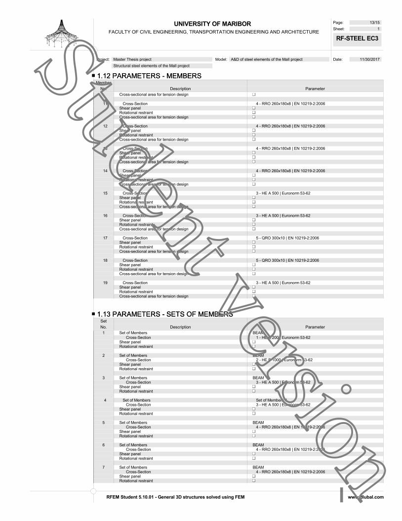
UNIVERSITY OF MARIBORFACULTY OF CIVIL ENGINEERING, TRANSPORTATION ENGINEERING AND ARCHITECTURE
Page: 13/15
Sheet: 1
RF-STEEL EC3
Date: 11/30/2017 Project: Master Thesis project
Structural steel elements of the Mall project
Model: A&D of steel elements of the Mall project
1.12 PARAMETERS - MEMBERS1.12 PARAMETERS - MEMBERSMember
No. Description Parameter Cross-sectional area for tension design
11 Cross-Section 4 - RRO 260x180x8 | EN 10219-2:2006 Shear panel Rotational restraint Cross-sectional area for tension design
12 Cross-Section 4 - RRO 260x180x8 | EN 10219-2:2006 Shear panel Rotational restraint Cross-sectional area for tension design
13 Cross-Section 4 - RRO 260x180x8 | EN 10219-2:2006 Shear panel Rotational restraint Cross-sectional area for tension design
14 Cross-Section 4 - RRO 260x180x8 | EN 10219-2:2006 Shear panel Rotational restraint Cross-sectional area for tension design
15 Cross-Section 3 - HE A 500 | Euronorm 53-62 Shear panel Rotational restraint Cross-sectional area for tension design
16 Cross-Section 3 - HE A 500 | Euronorm 53-62 Shear panel Rotational restraint Cross-sectional area for tension design
17 Cross-Section 5 - QRO 300x10 | EN 10219-2:2006 Shear panel Rotational restraint Cross-sectional area for tension design
18 Cross-Section 5 - QRO 300x10 | EN 10219-2:2006 Shear panel Rotational restraint Cross-sectional area for tension design
19 Cross-Section 3 - HE A 500 | Euronorm 53-62 Shear panel Rotational restraint Cross-sectional area for tension design
1.13 PARAMETERS - SETS OF MEMBERS1.13 PARAMETERS - SETS OF MEMBERSSet
No. Description Parameter1 Set of Members BEAM
Cross-Section 1 - HE B 200 | Euronorm 53-62 Shear panel Rotational restraint
2 Set of Members BEAM Cross-Section 2 - HE B 1000 | Euronorm 53-62 Shear panel Rotational restraint
3 Set of Members BEAM Cross-Section 3 - HE A 500 | Euronorm 53-62 Shear panel Rotational restraint
4 Set of Members Set of Members 4 Cross-Section 3 - HE A 500 | Euronorm 53-62 Shear panel Rotational restraint
5 Set of Members BEAM Cross-Section 4 - RRO 260x180x8 | EN 10219-2:2006 Shear panel Rotational restraint
6 Set of Members BEAM Cross-Section 4 - RRO 260x180x8 | EN 10219-2:2006 Shear panel Rotational restraint
7 Set of Members BEAM Cross-Section 4 - RRO 260x180x8 | EN 10219-2:2006 Shear panel Rotational restraint
RFEM Student 5.10.01 - General 3D structures solved using FEM www.dlubal.com
Student version
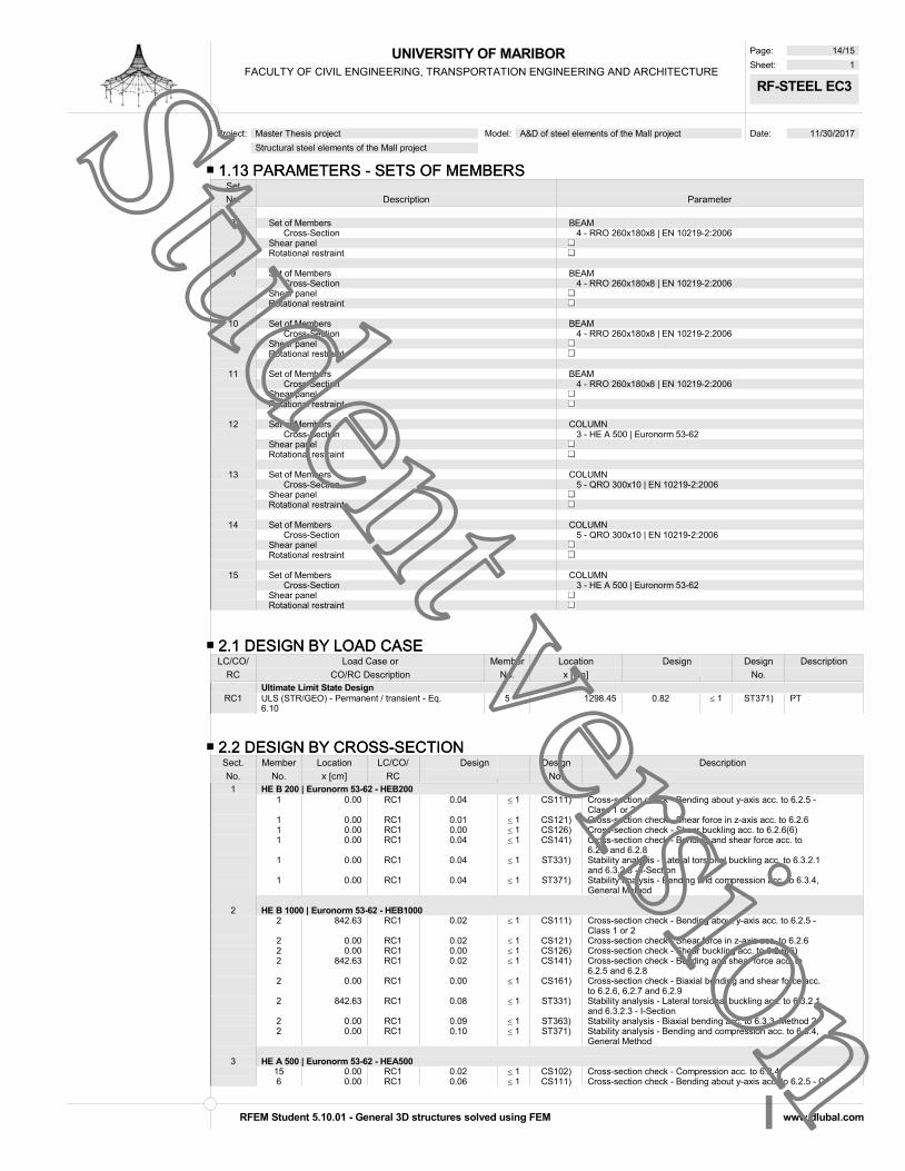
UNIVERSITY OF MARIBORFACULTY OF CIVIL ENGINEERING, TRANSPORTATION ENGINEERING AND ARCHITECTURE
Page: 14/15
Sheet: 1
RF-STEEL EC3
Date: 11/30/2017 Project: Master Thesis project
Structural steel elements of the Mall project
Model: A&D of steel elements of the Mall project
1.13 PARAMETERS - SETS OF MEMBERS1.13 PARAMETERS - SETS OF MEMBERSSet
No. Description Parameter
8 Set of Members BEAM Cross-Section 4 - RRO 260x180x8 | EN 10219-2:2006 Shear panel Rotational restraint
9 Set of Members BEAM Cross-Section 4 - RRO 260x180x8 | EN 10219-2:2006 Shear panel Rotational restraint
10 Set of Members BEAM Cross-Section 4 - RRO 260x180x8 | EN 10219-2:2006 Shear panel Rotational restraint
11 Set of Members BEAM Cross-Section 4 - RRO 260x180x8 | EN 10219-2:2006 Shear panel Rotational restraint
12 Set of Members COLUMN Cross-Section 3 - HE A 500 | Euronorm 53-62 Shear panel Rotational restraint
13 Set of Members COLUMN Cross-Section 5 - QRO 300x10 | EN 10219-2:2006 Shear panel Rotational restraint
14 Set of Members COLUMN Cross-Section 5 - QRO 300x10 | EN 10219-2:2006 Shear panel Rotational restraint
15 Set of Members COLUMN Cross-Section 3 - HE A 500 | Euronorm 53-62 Shear panel Rotational restraint
2.1 DESIGN BY LOAD CASE2.1 DESIGN BY LOAD CASELC/CO/ Load Case or Member Location Design Design Description
RC CO/RC Description No. x [cm] No.Ultimate Limit State Design
RC1 ULS (STR/GEO) - Permanent / transient - Eq. 6.10
5 1298.45 0.82 1 ST371) PT
2.2 DESIGN BY CROSS-SECTION2.2 DESIGN BY CROSS-SECTIONSect. Member Location LC/CO/ Design Design Description
No. No. x [cm] RC No.1 HE B 200 | Euronorm 53-62 - HEB200
1 0.00 RC1 0.04 1 CS111) Cross-section check - Bending about y-axis acc. to 6.2.5 - Class 1 or 2
1 0.00 RC1 0.01 1 CS121) Cross-section check - Shear force in z-axis acc. to 6.2.61 0.00 RC1 0.00 1 CS126) Cross-section check - Shear buckling acc. to 6.2.6(6)1 0.00 RC1 0.04 1 CS141) Cross-section check - Bending and shear force acc. to
6.2.5 and 6.2.81 0.00 RC1 0.04 1 ST331) Stability analysis - Lateral torsional buckling acc. to 6.3.2.1
and 6.3.2.3 - I-Section1 0.00 RC1 0.04 1 ST371) Stability analysis - Bending and compression acc. to 6.3.4,
General Method
2 HE B 1000 | Euronorm 53-62 - HEB10002 842.63 RC1 0.02 1 CS111) Cross-section check - Bending about y-axis acc. to 6.2.5 -
Class 1 or 22 0.00 RC1 0.02 1 CS121) Cross-section check - Shear force in z-axis acc. to 6.2.62 0.00 RC1 0.00 1 CS126) Cross-section check - Shear buckling acc. to 6.2.6(6)2 842.63 RC1 0.02 1 CS141) Cross-section check - Bending and shear force acc. to
6.2.5 and 6.2.82 0.00 RC1 0.00 1 CS161) Cross-section check - Biaxial bending and shear force acc.
to 6.2.6, 6.2.7 and 6.2.92 842.63 RC1 0.08 1 ST331) Stability analysis - Lateral torsional buckling acc. to 6.3.2.1
and 6.3.2.3 - I-Section2 0.00 RC1 0.09 1 ST363) Stability analysis - Biaxial bending acc. to 6.3.3, Method 22 0.00 RC1 0.10 1 ST371) Stability analysis - Bending and compression acc. to 6.3.4,
General Method
3 HE A 500 | Euronorm 53-62 - HEA50015 0.00 RC1 0.02 1 CS102) Cross-section check - Compression acc. to 6.2.46 0.00 RC1 0.06 1 CS111) Cross-section check - Bending about y-axis acc. to 6.2.5 - C
RFEM Student 5.10.01 - General 3D structures solved using FEM www.dlubal.com
Student version

UNIVERSITY OF MARIBORFACULTY OF CIVIL ENGINEERING, TRANSPORTATION ENGINEERING AND ARCHITECTURE
Page: 15/15
Sheet: 1
RF-STEEL EC3
Date: 11/30/2017 Project: Master Thesis project
Structural steel elements of the Mall project
Model: A&D of steel elements of the Mall project
2.2 DESIGN BY CROSS-SECTION2.2 DESIGN BY CROSS-SECTIONSect. Member Location LC/CO/ Design Design Description
No. No. x [cm] RC No.Class 1 or 2
3 0.00 RC1 0.01 1 CS116) Cross-section check - Bending about z-axis acc. to 6.2.5 - Class 1 or 2
5 2164.08 RC1 0.04 1 CS121) Cross-section check - Shear force in z-axis acc. to 6.2.63 213.00 RC1 0.00 1 CS126) Cross-section check - Shear buckling acc. to 6.2.6(6)6 0.00 RC1 0.06 1 CS141) Cross-section check - Bending and shear force acc. to
6.2.5 and 6.2.83 0.00 RC1 0.01 1 CS151) Cross-section check - Bending about z-axis and shear
force acc. to 6.2.5 and 6.2.84 0.00 RC1 0.01 1 CS161) Cross-section check - Biaxial bending and shear force acc.
to 6.2.6, 6.2.7 and 6.2.95 2164.08 RC1 0.16 1 CS181) Cross-section check - Bending, shear and axial force acc.
to 6.2.9.115 633.00 RC1 0.02 1 CS221) Cross-section check - Biaxial bending, shear and axial
force acc. to 6.2.10 and 6.2.95 2164.08 RC1 0.31 1 ST331) Stability analysis - Lateral torsional buckling acc. to 6.3.2.1
and 6.3.2.3 - I-Section6 622.78 RC1 0.06 1 ST363) Stability analysis - Biaxial bending acc. to 6.3.3, Method 219 0.00 RC1 0.13 1 ST364) Stability analysis - Bending and compression acc. to 6.3.3,
Method 25 1298.45 RC1 0.82 1 ST371) Stability analysis - Bending and compression acc. to 6.3.4,
General Method
4 RRO 260x180x8 | EN 10219-2:2006 - RHS180*260*89 0.00 RC1 0.78 1 CS111) Cross-section check - Bending about y-axis acc. to 6.2.5 -
Class 1 or 29 0.00 RC1 0.12 1 CS121) Cross-section check - Shear force in z-axis acc. to 6.2.68 0.00 RC1 0.00 1 CS126) Cross-section check - Shear buckling acc. to 6.2.6(6)9 0.00 RC1 0.78 1 CS141) Cross-section check - Bending and shear force acc. to
6.2.5 and 6.2.89 0.00 RC1 0.78 1 ST371) Stability analysis - Bending and compression acc. to 6.3.4,
General Method
5 QRO 300x10 | EN 10219-2:2006 - RHS300*1018 0.00 RC1 0.02 1 CS102) Cross-section check - Compression acc. to 6.2.418 755.50 RC1 0.01 1 CS181) Cross-section check - Bending, shear and axial force acc.
to 6.2.9.117 0.00 RC1 0.01 1 CS201) Cross-section check - Bending about z-axis, shear and
axial force acc. to 6.2.9.118 0.00 RC1 0.00 1 CS221) Cross-section check - Biaxial bending, shear and axial
force acc. to 6.2.10 and 6.2.918 0.00 RC1 0.03 1 ST364) Stability analysis - Bending and compression acc. to 6.3.3,
Method 218 755.50 RC1 0.03 1 ST371) Stability analysis - Bending and compression acc. to 6.3.4,
General Method
RFEM Student 5.10.01 - General 3D structures solved using FEM www.dlubal.com
Student version

Interoperability between Architectural and Structural BIM Software in the case of a Mall Project Page | 179
`
10.5 Short CV (Curriculum Vitae)
Born: 17.09.1989 in Gjakova (Kosovo)
Education: 1996 – 2005 Elementary School “Emin Duraku”
2005 – 2008 High School-Gymnasium “Hajdar Dushi”
2008 – 2011 Faculty of Civil Engineering and Architecture, University
of Prishtina, Bachelor Degree in Civil Engineering
2012 – 2013 University of Nordland, Part-time studies, FSV
2014 – 2017 Faculty of Civil Engineering, Transportation Engineering
and Architecture, University of Maribor, Master Degree
in Civil Engineering
10.6 Declaration of authorship