
INTERNSHIP REPORT ON BANGLADESH POWER ...
42
Undergraduate Internship 1 Department of Electrical and Electronic Engineering, East West University INTERNSHIP REPORT ON BANGLADESH POWER DEVELOPMENT BOARD, RAJSHAHI Submitted By Khan Faisal Ferdause Samrat (2013-2-80-089) Md. Golam Kibrea (2014-1-80-024) Md. Asif Uzzaman Saikat (2013-2-80-094) Submitted to the Department of Electrical and Electronic Engineering East West University In partial of the requirements for the degree of Bachelor of Science in Electrical and Electronic Engineering (B.Sc. in EEE) Spring 2018 Approved By …………………….. ……………………… Academic Advisor Department Chairperson Sohana Tanzeem Dr. Muhammad Mojammel Al Hakim
-
Upload
khangminh22 -
Category
Documents
-
view
2 -
download
0
Transcript of INTERNSHIP REPORT ON BANGLADESH POWER ...

Undergraduate Internship
1 Department of Electrical and Electronic Engineering, East West University
INTERNSHIP REPORT
ON
BANGLADESH POWER DEVELOPMENT BOARD, RAJSHAHI
Submitted By
Khan Faisal Ferdause Samrat (2013-2-80-089)
Md. Golam Kibrea (2014-1-80-024)
Md. Asif Uzzaman Saikat (2013-2-80-094)
Submitted to the
Department of Electrical and Electronic Engineering
East West University
In partial of the requirements for the degree of
Bachelor of Science in Electrical and Electronic Engineering
(B.Sc. in EEE)
Spring 2018
Approved By
…………………….. ………………………
Academic Advisor Department Chairperson
Sohana Tanzeem Dr. Muhammad Mojammel Al Hakim

Undergraduate Internship
2 Department of Electrical and Electronic Engineering, East West University

Undergraduate Internship
3 Department of Electrical and Electronic Engineering, East West University

Undergraduate Internship
4 Department of Electrical and Electronic Engineering, East West University

Undergraduate Internship
5 Department of Electrical and Electronic Engineering, East West University
ACKNOWLEDGEMENT
First of all we would like to thank the Almighty Allah for giving us the opportunity to complete
our internship and prepare the internship report.
We are very grateful to the management of Bangladesh Power Development Board for providing
us the opportunity to accomplish our industrial training in Rajshahi Training Center (BPDB). We
are very thankful to Engr. Hasina Dilruba, Director, and Engr. Md Hasibul Huda, Deputy Director
of Rajshahi Training Center. We also thank all the engineers and members of Rajshahi Training
Center for their guidance and suggestion during the internship. We would like to thank all
engineers and members of Katakhali Power Plant, Bheramara (HVDC) Substation, Barapukuria
Coal Based Thermal Power Plant, and Baghabari Gas Turbine Power Plant.
We would also like to thank our supervisor, Sohana Tanzeem, Senior Lecturer, Department of
Electrical and Electronic Engineering, East West University for providing us assistance and
encouraging us to prepare the internship report.
We would like to mention the name of Dr. Muhammad Mojammel Al Hakim, respectable
Professor and Chairperson of the Department of Electrical and Electronic Engineering, East West
University.
Finally, we want to thank all of our honorable teachers, friends and family for their inspiration and
co-operation throughout our whole academic life in East West University.

Undergraduate Internship
6 Department of Electrical and Electronic Engineering, East West University
EXECUTIVE SUMMARY
In the modern world, we cannot think a day without electricity. Day by day the demand for
electricity is increasing, but the generation of power is not increasing so much in Bangladesh. To
fulfill a significant amount of demand of electric power in Bangladesh, Barapukuria Coal Based
Thermal Power Plant (250MW), Baghabari Gas Turbine Power Plant (171MW), Recently
Bangladesh is importing 500 MW electricity from India by Bheramara(HVDC) substation, all are
playing a vital role in power generation in Bangladesh. Katakhali power plant (50MW) is also used
in emergency situation. A new unit of 275 MW is under construction in Barapukuria Coal Based
Thermal Power Plant.
We have done our internship at BPDB, Rajshahi. We visited four different types of the power plant
and two substations. Duration of our training was 100 hours for 15 days. In our internship, we
visited those power plants and substation to achieve a clear idea of the power generation, control,
and maintenance process. This report consists of a brief description of these processes. A lot of
steps are needed to complete the supply of the power to the grid. All the steps are described in this
report.
Thus internship training helped us with this opportunity to compare our theoretical knowledge
with practical applications. Finally, we think, the knowledge we have gathered here really helped
us to enhance our understanding of our academic knowledge.

Undergraduate Internship
7 Department of Electrical and Electronic Engineering, East West University
Training Schedule
The table of our training schedule in BPDB, Rajshshi is given below:
Date Division Mentor Time
17/12/2017
(Sunday)
HFO plants and
impact of IPP in
power sector
Engr. Shoayeeb
Muhammad Shaikh 9 am to 6 pm
18/12/2017
(Monday)
Live startup and
shutdown procedure
of Katakhali 50MW
Peaking Power Plant
Engr. Mahmudul
Islam 9 am to 6 pm
19/12/2017
(Tuesday)
Visit and discussion
on protection system
and auxiliary
System,Generator,
HFO engine of
Katakhali 50MW
Peaking Power Plant
Engr.Md. Tareq
Mosarraf 9 am to 6 pm
20/12/2017
(Wednesday)
Discussion on Power
Grid system of
Bangladesh at
132/33KV Grid
substation
Engr. Md. Shakhawat
Hossain 9 am to 6 pm
21/12/2017
(Thursday)
Discussion on Relay
Relays,circuit breaker
and other equipment
of HVDC Grid
substation
Engr. Md. Mostafizur
Rahman
9 am to 6 pm
22/12/2017
(Friday)
Bheramara (HVDC)
Grid Substation visit Engr. Md. Shakhawat
Hossain 9 am to 6 pm
23/12/2017
(Saturday)
Visit and
demonstration on
working principle Gas
turbine power plant of
Baghabari Gas
Turbine Power Plant
Engr. Punab Chandra
Kundu 9 am to 6 pm

Undergraduate Internship
8 Department of Electrical and Electronic Engineering, East West University
24/12/2017
(Sunday)
Demonstration of
maintenance
procedure of
Baghabari Gas
Turbine.
Engr. Md. Mamun-
ar-Rashid 9 am to 6 pm
25/12/2017
(Monday)
Start and Shutdown
procedure of Gas
turbine power plant
Engr.Md. Bozlurur
Rahman 9 am to 6 pm
26/12/2018
(Tuesday)
Discussion on
metering system
Engr. Abdullah-Al-
Mamun
9 am to 6 pm
27/12/2018
(Wednesday)
Discussion on working principle of thermal power plant
Engr.Muntasir
Mamun 9 am to 6 pm
28/12/2018
(Thursday)
Visit and
demonstration of
maintenance
procedure turbine
equipment f
Barapukuria Coal
based thermal power
plant
Engr.Md.
Kamaruzzaman 9 am to 6 pm
29/12/2018
(Friday)
Different stage of
turbine and
maintenance
procedure Of
Barapukuria thermal
power plant
Engr. Md. Hassan
Mahmud 9 am to 6 pm
30/12/2017
(Saturday)
Demonstration of
different types of
equipment and their
function at
Barapukuria thermal
power plant.
Engr. Md Mohsinul
Firoz Mamun 9 am to 6 pm
31/12/2017 Evaluation and open
discussion and closing
ceremony
Engr. Md. Hasibul
Huda 9 am to 6 pm

Undergraduate Internship
9 Department of Electrical and Electronic Engineering, East West University
Table of Contents
Training Certificate…………………………………………………………. 2
Acknowledgment………………………………………………………….. 5
Executive Summary…………………………………………………………. 6
Training Schedule………………………………………………………....... 7
Chapter 01: Introduction
1.1 Objective of the Internship…………………………………………….. 13
1.2 Company Profiles ………………………………………………............ 13
1.3 Power Station…………………………………………………………... 13
1.3.1 Katakhali Power Station……………………………………………..... 13
1.3.2 Barapukuria Power Station…………………………………………..... 13
1.3.3 Baghabari Power Station……………………………………………… 13
1.4 Bheramara (HVDC) Grid substation…………………………………... 14
1.5 Metering System………………………………………………………. 14
1.6 Company Mission…………………………………………………….. 14
1.7 Future Plan…………………………………………………………….. 14
1.8 Scope and Methodology………………………………………………. 14
Chapter 02: Barapukuria Power Station
2.1 Introduction……………………………………………………………. 15
2.2 Working Principle of a Steam Turbine Power Plant…………………........ 15
2.3 Production Capacity ……………………………………………………… 15
2.4 Coal Treatment….………………………………………………............... 15
2.4.1 Belt Type Coal Conveyer………………………………………………. 15
2.5 Boiler………….…………………………………………………….......... 16
2.5.1 Water tube boiler …………………………………………………........ 16
2.6 Furnace ………………………………………………………………….. 16
2.7 Circulating water pump………………………………………………….. 17
2.8 Feed Water Pump ……………………………………………………….. 17
2.9 Super heater 4.7.4………………………………………………………… 17
2.10 Economizer ….………………………………………………………........ 17
2.11 Steam turbine …………………………………………………………… 17
2.12 Generator ……………………………………………………………….. 18
2.13 Power transformer …………. …………………………………………. 19

Undergraduate Internship
10 Department of Electrical and Electronic Engineering, East West University
2.14 Cooling system …………………..…………………………………….. 19
2.15 Waste Management 3.2 AC networks …………………………………. 20
Chapter 03: Katakhali Power Plant
3.1 Introduction………………………………………………………………. 21
3.2 Working Principle……………………………………………………....... 21
3.3 Production Capacity…………………………………………………....... 21
3.4 Fuel Processing…………………………………………………………... 21
3.5 Diesel Engine ……………………………………………………............ 22
3.6 Generator.……………………………………………………………….. 23
3.7 Generated Voltage and supply Voltage…………………………………. 24
3.8 Auxiliary Systems……………………………………………………….. 25
3.9 Cooling System…………………………………………………………. 25
3.10 Protection system……………………………………………………….. 25
3.10.1 SF6 Circuit Breaker…………………………………………………… 26
3.10.2 Lightning Arrester…………………………………………………...... 26
3.10.3 Isolator……………………………………………………………....... 26
3.10.4 Current Transformer………………………………………………….. 26
3.10.5 Potential Transformer…………………………………………………. 27
3.11 Control Room…………………………………………………………… 27
Chapter 4: Baghabari Power Plant
4.1 Introduction…………………………………………………………….... 28
4.2 Working Principle………………………………………………….......... 28
4.2.1 Compressor………………………………………………………......... 28
4.2.2 Combustion Chamber…………………………………………………. 28
4.2.3 Turbine………………………………………………………………… 28
4.3 Regenerator…………………………………………………………….... 28
4.4 Alternator………………………………………………………………... 29
4.5 Starting Motor………………………………………………………….... 29
4.6 Air Intake Filter………………………………………………………….. 29
4.7 Auxiliary System………………………………………………………… 29
4.8 Protection System………………………………………………….......... 30
4.8.1 Prime Control………………………………………………………….. 30
4.8.2 Protection Control…………………………………………………….. 30
4.9 Shutdown Control…………………………………………………......... 30
4.9.1 Turbine over Temperature…………………………………………….. 30
4.9.2 Turbine over-speed……………………………………………………. 31
4.9.3 Low Lube Oil Pressure………………………………………………… 31
4.9.4 High Lube Oil Temperature…………………………………………… 31

Undergraduate Internship
11 Department of Electrical and Electronic Engineering, East West University
4.9.5 Excess Vibration………………………………………………………. 31
4.10 Control Room…………………………………………………………… 31
Chapter 5: Bheramara (HVDC) GRID Substation
5.1Introduction……………………………………………………………… 33
5.2 Main Data………………………………………………………………… 33
5.3 AC-DC-AC Back To Back Processing ………………………………….. 33
5.4 AC Networks…………………………………………………………….. 34
5.5 AC Filters………………………………………………………………… 34
5.6 AC Filter…………………………………………………………………. 34
5.7 HVDC Valves……………………………………………………………. 34
5.8 Valve cooling system (VCS)……………………………………………… 34
5.9 Lightning Arrester………………………………………………………… 35
5.10 Control room ……………………………………………………………… 36
Chapter 6: Metering System
6.1Introduction………………………………………………………………. 37
6.2 Types of Electric Meters………………………………………………….. 37
6.2.1 Single Phase Meter……………………………………………………… 37
6.2.2 Three Phase Meter……………………………………………………… 38
6.2.2.1 High Tension Meter…………………………………………………... 38
6.2.2.2 Low Tension Meter…………………………………………………... 38
6.3 Metering test……………………………………………………………... 39
6.3.1 Time Test………………………………………………………………. 39
6.4 Calculation of Error……………………………………………………… 39
Chapter 7: Conclusion
7.1 Discussion………………………………………………………………… 40
7.2 Problems………………………………………………………………….. 40
7.3 Recommendation…………………………………………………………. 40
References……………………………………………………………………. 41
Appendix (i)…………………………………………………………………... 42

Undergraduate Internship
12 Department of Electrical and Electronic Engineering, East West University
List of figures
Figure 2.1: Belt Type Coal Conveyer……………………………………….... 16
Figure 2.2: Turbine……………………………………………………………. 18
Figure 2.3: Generator…………………………………………………………. 18
Figure 2.4: Transformer………………………………………………………. 19
Figure 2.5: Water cooling towers of Barapukuria 125 MW unit…….……….. 20
Figure 2.6: Ash collector at Barapukuria Power Plant……………………….. 20
Figure 3.1: SF6 Circuit Breaker………………………………………………. 22
Figure 3.2: Control Room of Katakhali Power Plant………………................. 23
Figure 3.3: Generator at katakhali power plant………………………………. 24
Figure 3.4: 11/132KV transformer at Katakhali Power Plant………………… 25
Figure 3.5: SF6 Circuit Breaker………………………………………………. 26
Figure 3.6: Control room of Katakhali Power Plant………………………….. 27
Figure 4.1: Air Intake Filter…………………………………………………… 29
Figure 4.2: Control Room of 71MW unit………….…………………………. 32
Figure 4.3: Control room of 100MW unit……………………………………… 32
Figure 5.1 AC-DC-AC back to back processing in Bheramara HVDC……… 33
Figure 5.2: Cooling System……………………………………………………. 35
Figure 5.3: Lightning Arrester of (HVDC) Grid Substation ………………….. 36
Figure 5.4: Water treatment system monitoring in control room………………. 36
Figure 6.1: Single Phase Meter……………………………………….............. 37
Figure 6.2: High Tension Meter………………………………………………. 38
Figure 6.3: Low Tension Meter………………………………………………. 39
List of Tables
Table 5.1: Bangladesh Side……………………………………………………. 34
Table 5.2: India Side …..……………………………………………………… 34

Undergraduate Internship
13 Department of Electrical and Electronic Engineering, East West University
Chapter 01: Introduction
1.1 The objective of the Internship:
The aim of our internship was to get introduced practically to the power generation and
transmission process which involves getting a brief idea of all major machinery and systems that
are engaged in the process. It enhances our understanding of academic knowledge regarding a
power station and switchgear. We have also got introduced to the working environment of the
professional engineers there. During this internship, we have visited different power station and
substations. In this report, we briefly discuss the power station and substation.
1.2 Company Profiles:
In this report, we have discussed our visited power plant and substation the profile is given below.
1.3 Power Station:
We have visited four power stations that are Katakhali Peaking Power plant in Rajshahi,
Barapukuria Coal Based Thermal Power plant In Dinajpur, Baghabari power plant In Sirajganj
and Bheramara Power Plant in Kustia.
Now we will discuss the power station shortly.
1.3.1 Katakhali Power Station:
Katakhali is a peaking power plant situated in Rajshahi. It generates 50MW electricity. It is a diesel
based power plant. Here they used furnace oil and diesel as fuel.
1.3.2 Barapukuria Power Station:
Barapukuria is situated at Phulbari, Dinajpur district, Rajshahi, Bangladesh. It is a coal-based
thermal power plant. There are two units. Each unit generates 125MW of electricity. Coal type
fuel is used here. It is operated by Bangladesh power development board.
1.3.3 Baghabari Power Station:
Baghabari Power Plant is situated at Baghabari, Shirajganj. It is a gas turbine power plant. Here
natural gas and fuel oil are used to generate power. Its capacity is 171MW (1×71MW,
1×100MW).

Undergraduate Internship
14 Department of Electrical and Electronic Engineering, East West University
1.4 Bheramara (HVDC) Grid Substation:
Bangladesh-India current transmission center is located in Bheramara, Khustia.Understanding the
increase in demand for electricity for the social development of Bangladesh, the present
government has taken the initiative of importing electricity from India.
1.5 Metering System:
Electricity metering is the process of measuring the instantaneous voltage and current to calculate
the consumed electric energy which is typically calibrated into billing units such as kilowatt-hour
(kWh). Electricity metering is a broad term which includes both AC and DC metering.
1.6 Company Mission:
Every power plant has a common mission. It is to generate electricity with a reasonable price and
make some planning for future demand.
1.7 Future Plan:
i. Katakhali is a 50MW peaking power plant in our country. Its generation cost is very high.
Generation of electricity occurs here when the electricity demand is high.
ii. Barapukuria Coal Based Power Plant has a mission to construct a third unit, which is almost
done.
iii. Baghabari Power Plant is taking a mission to do a combined cycle generation soon.
1.8 Scope and Methodology:
The report is prepared based on the daily practical activities in power development company
Bangladesh. In this report, we have covered the total process of generation of electricity, power
transmission, and power distribution system. This report contains the description of the equipment
and machines used for power generation, transmission, and distribution.

Undergraduate Internship
15 Department of Electrical and Electronic Engineering, East West University
Chapter 02: Barapukuria Power Station
2.1 Introduction
Barapukuria is one of the largest coal-based power plant which is owned by the BPDB. It is
situated at Phulbari, Dinajpur district. The area of the plant is 290 acres. It has two 125 MW units
and one 275 MW units. It generates 13.8 KV. The annual coal consumption is 0.72 million metric
ton. The annual gas generation is 0.08 million metric ton. This is a power plant which has solved
the under voltage problem in the northern zone.
2.2 Working Principle of a Steam Turbine Power Plant
Barapukuria Coal Based Thermal Power Plant is a steam turbine power plant. Electrical energy
generated by three steps. At first, extracting thermal energy from the fuel. By burning fuel, heat is
produced. The heat is used to create steam from water. Then the thermal energy of the steam is
converted into kinetic energy. And the kinetic energy rotates the turbine which coupled with a
rotor. And at last mechanical energy of turbine converted into electrical energy by using a
generator.
2.3 Production Capacity
The installed capacity of Barapukuria power plant is 525MW. It has three units, the capacity of
two units is 125MW, and other one’s capacity is 275MW which is recently constructed. All units
are steam turbine based.
2.4 Coal Treatment
Coal treatment plays an important role in coal-based thermal power plant. The coal is carried
from Barapukuria Coal Mine by conveyer belts to the power plant. At first, coal passes through
a magnetic separator which separates metals from the coal. Then it sends to the coal crusher
which crushes the coal. After it send to the pulverizer which turns the coal into coal powders and
hot air is mixed with the coal powder. And at last, the coal is sent to the boiler for burning. The
quality of the coal used in the power plant is very high.
2.4.1 Belt Type Coal Conveyer
In figure 2.1 a belt-type conveyer is shown. In Barapukuria belt-type conveyer is used for carrying
the coal to the power station from a coal mine. The advantages of belt type coal conveyer are low
speed, uniform operation and noise free.

Undergraduate Internship
16 Department of Electrical and Electronic Engineering, East West University
Figure 2.1: Conveyer belts for coal transport at Barapukuria
2.5 Boiler
The steam boiler is an important part of the thermal power plant. It burns the coal and transfers
the heat to the water. By the boiler, we can control steam heat and pressure. Water is stored in
the boiler. By burning, hot fuel gasses are produced. Heat is transferred to the water and steam is
produced. Then this high-pressure steam is sent to the turbine which coupled with a generator.
There are two types of boiler
1. Fire tube boiler
2. Water tube boiler
2.5.1 Water tube boiler
In Barapukuria thermal power plant water tube boilers are used. In the water tube boiler, water
flows through the tubes and the hot gases flow over the tubes. There are some advantages to use
water tube boiler over fire tube boiler. It requires less space and provides high working pressure
due to the small drum.
2.6 Furnace
The furnace is a part of the boiler which is installed where coal is burned, and heat is produced.

Undergraduate Internship
17 Department of Electrical and Electronic Engineering, East West University
2.7 Circulating water pump Circulating water pump used to circulate the water in the boiler to support the operation of boiler.
Barapukuria power station has both, close and open water flow system. They pump out water from
the deep level of the surface.
2.8 Feed Water Pump The feed water pump is used to increase the pressure of the feed water which is necessary to enter
the boiler. It improves the overall efficiency. For boiler safety, the water is de-mineralized by
removing dissolved particle.
2.9 Super heater 4.7.4
Super heater converts the saturated steam into super-heated steam. The temperature of the super-
heated is 5380 C.
2.10 Economizer In economizer, the waste heat of the fuel gas is used to increase the temperature of feed water
which increase the boiler efficiency. The heat is recovered from flu gas.
2.11 Steam turbine
The steam turbine is the device which converts thermal energy into mechanical energy. In a
power plant, the steam turbine is attached to a generator to produce electrical power. The turbine
works as the major mechanical side of the system which provides rotary motion to the generator.
The turbine of Barapukuria 125 MW unit is shown in figure 2.2.

Undergraduate Internship
18 Department of Electrical and Electronic Engineering, East West University
Figure2.2: Turbine of Barapukuria 125 MW unit
Turbine Specification of 125MW at Barapukuria
• Model - N-125-14/535/535
• Type- High pressure, reheating combined HP&MP cylinders with the double flow, single
shaft
• Speed- 3000 (rpm)
• Rated Capacity- 125000KW
• Rotation- Clock wise
2.12 Generator
A generator converts mechanical energy into electrical energy in the form of altering current. For
simplicity, most of the alternators use magnetic field as rotor and armature as a stator. In power
stations generators are driven by turbine or engines. In Barapukuria the generators are driven by
the steam turbine. In figure 2.3, a picture of 125 MW unit’s generator is attached.
Figure2.3: Generator of Barapukuria 125 MW unit

Undergraduate Internship
19 Department of Electrical and Electronic Engineering, East West University
Turbine Specification of 125 MW at Barapukuria
• Type- QFS-125-2
• Rated Capacity- 156250KVR
• Active Power- 125000KW
• Stator Voltage -13.8KV
• Stator Current- 6537A
• Rotor Voltage- 275V
• Rotor Current- 1750A
• Speed-3000rpm
• Frequency- 50Hz
• Phase- Y
2.13 Power transformer
In Barapukuria step-up transformer is being used to step up the generated voltage from 13.8KV
to 230KV. In figure 2.4 a transformer of Barapukuria power plant is shown. The cooling system
of the transformer is oil filled cooling system. MVA rating is 156.25 MVA. This is a three-phase
transformer. The cooling system is ONAF. .
Figure2.4Power transformer of Barapukuria
2.14 Cooling system
In Barapukuria power plant the water type cooling system is installed. They have 14 deep tube
wells and cooling towers for the cooling purpose. Form figure 2.5 picture we can see the cooling
towers. In cooling, process water extract heat from the equipment’s and release it in the air. Water
is circulated inside the system through water jacket, and hot water is sent to the heat exchanger
then water cooled in the cooling tower and recirculates.

Undergraduate Internship
20 Department of Electrical and Electronic Engineering, East West University
Figure2.5: Water cooling towers of Barapukuria 125 MW unit
2.15 Waste Management 3.2 AC networks Waste management is very important in Barapukuria power plant because it is a coal-based power
plant and it produces ash. The power plant produces 0.08 million metric ton ash per year. So there
fly ash, and bottom ash collector device is installed to manage the ash. There are two ash ponds.
All ash are stored in the ash pond. From figure 2.6 we can see an ash collector of Barapukuria
power plant.
Figure 2.6: Ash collector at Barapukuria Power Plant

Undergraduate Internship
21 Department of Electrical and Electronic Engineering, East West University
Chapter 03: Katakhali Power Plant
3.1 Introduction:
Katakhali is a peaking power plant situated in Kathakali, Rajshahi. It generates 50MW electricity.
It is a diesel based power plant. Two types of oil are used in here. One is light fuel oil (LFO) and
the other is heavy fuel oil (HFO). HFO is cost effective, and it goes down the rate of the electricity
production per unit.
3.2 Working Principle:
In kathakali power plant at first, they start demineralized water pump. Then they start heat recovery
steam system power supply. After that, they start up the boiler supply and the compressor. Then
they open the compressor air valve after the air pressure raised 25 bars. When steam pressure raise
at 4 bars then they open the steam valve in HFO booster unit. After that, they start the LFO pump
from the control room. Then they start booster and viscosity pump. When these steps are all
complete, then they run the engine and produce electricity. After 30% load supplied HFO separator
turn off LFO supply and start HFO pump.
3.3 Production Capacity:
The Production capacity of kathakali power plant is 50 MW. It has six units; each unit has a
capacity of 8.7 MW.
3.4 Fuel Processing:
In engine based power plant Fuel processing system is a very important process. At Katakhali
power plant there are two types of fuel is used. One is HFO (heavy fuel oil) furnace oil and another
one is LFO (low fuel oil) diesel oil. Although Katakhali power plant is a diesel engine power plant,
it uses furnace oil as fuel to reduce the production cost. Diesel is only used when the power plant
is starting power generation and also when it is stopping. Here fuel processing is needed for the
furnace oil because the viscosity of the furnace oil is not enough to go through the engine for
production. For power generation, the temperature of furnace oil should be 1100C±50C. This
process is done under some criteria. At first, the furnace oil comes to the storage tank where the
temperature must be 400C-450C. For this, the furnace oil pipe coupled with hot water pipe to rise
the temperature of the furnace oil before storing in the tank. Then it goes to the buffer tank. In the
buffer tank, the temperature of the oil should be maximum 850 C. After this the oil goes to the day
tank through two pumps. When the oil comes into the day tank in between there is a separator to
separate the dust (hard particle and water) from the oil. This dust store in the slash tank and the
purified HFO oil store in the day tank. Then the oil goes to the booster unit where the temperature
is controlled at 110-1150C. This pure oil then goes to the engine through change over the unit.
Now the pure oil is ready to use. Diesel is again filtered before injecting it into the engine by the

Undergraduate Internship
22 Department of Electrical and Electronic Engineering, East West University
fuel injection pump. The fuel is supplied to the engine according to the load of the plant. Figure
3.1 shows HFO tanks where HFO oil is stored.
Figure 3.1: HFO tank at Katakhali power station.
3.5 Diesel Engine:
Katakhali power plant is an engine based power plant. The engine model is GSD 18 V 32/40 MAN.
These engines are manufactured by German MAN companies. It has 18 V-shaped cylinder that is
why it is called 18 V MAN. The generator is coupled to the diesel engine. The speed of rotation is
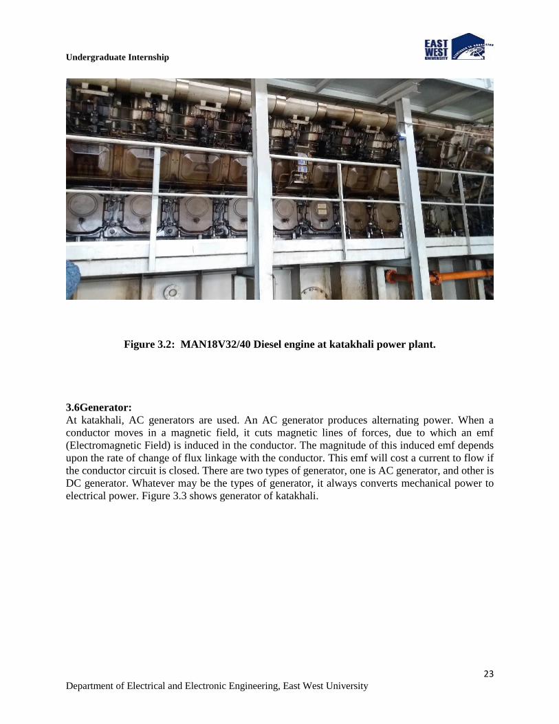
3000 rpm with two poles. Figure 3.2 shows MAN18V32/40 Diesel engine of katakhali power
plant.
Undergraduate Internship
23 Department of Electrical and Electronic Engineering, East West University
Figure 3.2: MAN18V32/40 Diesel engine at katakhali power plant.
3.6Generator:
At katakhali, AC generators are used. An AC generator produces alternating power. When a
conductor moves in a magnetic field, it cuts magnetic lines of forces, due to which an emf
(Electromagnetic Field) is induced in the conductor. The magnitude of this induced emf depends
upon the rate of change of flux linkage with the conductor. This emf will cost a current to flow if
the conductor circuit is closed. There are two types of generator, one is AC generator, and other is
DC generator. Whatever may be the types of generator, it always converts mechanical power to
electrical power. Figure 3.3 shows generator of katakhali.

Undergraduate Internship
24 Department of Electrical and Electronic Engineering, East West University
Figure 3.3: Generator at katakhali power plant.
3.7Generated Voltage and Supply Voltage:
At Katakhali power plant we observed the generated voltage is 11 KV. Each of the generators
generates 8.7 MW power and delivers 11 KV to the bus bar. From the bus bar, 11 kV line goes to
three single phase step-up transformer and make a 3 phase connection. This step-up transformer is
used to raise the voltage 11KV to 132 KV. Then this 132KV line goes to the SF6 circuit breaker
after that to the isolator then to the PT then to the lighting arrester and then to the PGCB sub-
station. This 132 KV is then sent to the national grid. From figure 2.6 we can see the transformers
of katakhali power plant.

Undergraduate Internship
25 Department of Electrical and Electronic Engineering, East West University
Figure 3.4: 11/132KV transformer at Katakhali Power Plant
3.8 Auxiliary Systems: At Katakhali power plant there are seven steam generators. Six of the steam generators are attached
with six engines, and another one is kept as a backup. The steam generators produce steam and
steam are used to raise the temperature of the HFO. The temperature of the HFO needs to be 110oC
for use as diesel. Here steam header pressure is 0.5MPa-0.6MPa. There are different kinds of
pumps are used in kathakali power plant. Fuel pumps, water circulation pumps, etc. There is some
compressor are used to compress the air. Compressed air is used on the piston to start the rotation
of the engine. The pressure of the compressed air is around 25bar-30bar. There is an emergency
diesel generator in katakhali for emergency purpose. To run the full auxiliary systems of Katakhali
power plant, it requires electricity of around 700KW. Which is come from the national grid.
3.9Cooling System:
There are water cooling, heat exchanger and lube oil cooling system. Demi water is used for water
cooling system. Water cooling system is used for the external cooling of the generator, and also
heat exchanger is used for that. Finally, lube oil used for internal cooling and protection of the
engine and the generator.
3.10 Protection System:
There is mainly water is used for external protection system. There are two types of pump one is
electrical pump another pump is the engine based pump. These pumps are used for water pumping.
Moreover, there are foam generator and fire extinguisher for fire protection. Auxiliary generator
is used to supply electricity at the time of the blackout. SF6 circuit barkers are used here for
electrical protection use.

Undergraduate Internship
26 Department of Electrical and Electronic Engineering, East West University
3.10.1 SF6 Circuit Breaker:
It is a type of circuit breaker which uses SF6 gas as an insulating medium. The gas has good
dielectric and arc extinguishing properties. The dielectric strength of SF6 is around three times than
the dielectric strength of air. What SF6 circuit breaker is, at the time of arc the SF6 gas is blown
axially at zero current to build up the insulating property for neutralizing the arc between the
contacts. Figure 3.5 shows the SF6 circuit breaker.
Figure 3.5: SF6 Circuit Breaker
3.10.2 Lightning Arrester:
A lightning arrester is a device used on electrical power systems to protect the insulation and
conductors of the system from the damaging effects of lightning. The typical lightning arrester has
a high-voltage terminal and a ground terminal. When a lightning surge (or switching surge, which
is very similar) travels along the power line to the arrester, the current from the surge is diverted
through the arrestor, in most cases to earth.
3.10.3 Isolator:
The Isolator is a mechanical switch which isolates a part of the circuit from the system as when
required. Electrical isolators separate a part of the system from rest for safe maintenance works.
Isolators are used to open a circuit with no load.
3.10.4 Current Transformer:
In electrical engineering, a current transformer (CT) is used for measurement of electric currents.
When the current in a circuit is too high to directly apply to measuring instruments, a current
transformer produces a reduced current accurately proportional to the current in the circuit, which

Undergraduate Internship
27 Department of Electrical and Electronic Engineering, East West University
can be conveniently connected to measuring and recording instruments. It is also used for
protection system. Current transformer gives information to relay to operate circuit breaker.
3.10.5 Potential Transformer:
The potential transformer is used to measure or monitor the voltage on transmission lines and to
isolate the metering equipment from the lines. It is also known as a voltage transformer (VT).
Potential Transformers are designed to have a precise voltage ratio to accurately step down high
voltages so that metering and protective relay equipment can be operated at a lower potential
3.11 Control Room:
In every power station, there is a control room. All components and machinery are controlled from
the control room. Generally, in every control room PLC is used to control overall the system.
Figure 3.2 shows the Control room of Katakhali Power Plant.
Figure 3.6: Control room of Katakhali Power Plant

Undergraduate Internship
28 Department of Electrical and Electronic Engineering, East West University
Chapter 04: Baghabari Power Plant
4.1 Introduction:
Baghabari Power Plant is situated at Baghabari, Shirajgonj. It is a gas turbine power plant. Here
natural gas and fuel oil are used to generate power. It has two units. One unit produces 71MW,
and another unit produces 100MW. The first unit was commissioned in 1991 and the last in 2001.
It is operated by Bangladesh Power Development Board (BPDB).
4.2 Working Principle:
The main component of the gas turbine power plant is:
1. Compressor
2. Combustion chamber
3. Turbine
4.2.1 Compressor:
The compressor of the plant is rotary type. The air at atmospheric pressure is drawn by the
compressor through the filter which removes the dust from the air. The rotary blades of the
compressor push the air between stationary blades to raise its pressure. Thus air at high pressure
is available at the output of the compressor.
4.2.2 Combustion Chamber:
The air at high pressure from the compressor is led to the combustion chamber through the
regenerator. In the combustion chamber, heat is added to the air by burning oil. The oil is injected
through the burner into the chamber at high pressure to ensure atomization of oil and its thorough
mixing with air. The result is that the chamber attains a very high temperature (about 3000℃). The
combustion gases are suitably cooled to 1300℃ to 1500℃ and then delivered to the gas turbine.
4.2.3 Turbine:
The products of combustion consisting of a mixture of gases at high temperature and pressure are
passed to the gas turbine. These gases in passing over the turbine blades expand and thus do the
mechanical work. The turbine rotates with 3000rpm with two poles. The temperature of the
exhaust gases from the turbine is about 575℃. Other components are regenerator, alternator and
starting the motor.
4.3 Regenerator:
A regenerator is a device which recovers heat from the exhaust gases of the turbine. The exhaust
is passed through the regenerator before wasting to the atmosphere. A regenerator consists of a

Undergraduate Internship
29 Department of Electrical and Electronic Engineering, East West University
nest of tubes contained in a shell. The compressed air from the compressor passes through the
tubes on its way to the combustion chamber. In this way, compressed air is heated by the hot
exhaust gases.
4.4 Alternator:
The gas turbine is coupled to the alternator. The alternator converts mechanical energy of the
turbine into electrical energy. The output from the alternator is given to the bus-bars through the
transformer, circuit breakers, and isolators.
4.5 Starting Motor:
Before starting the turbine, the compressor has to be started. For this purpose, an electric motor is
mounted on the same shaft as that of the turbine. The motor is energized by the batteries. Once the
unit starts, a part of the mechanical power of the turbine drives the compressor and then there is
no need for the motor.
4.6 Air Intake Filter:
Air intake filter is used to filter the atmospheric air from the dust and all kinds of impurities of the
environment. The main function of these filters is to supply air to the compressor and then to cool
the generator and turbine. Figure 4.1 shows the Air Intake Filter.
Figure 4.1: Air Intake Filter
4.7 Auxiliary System:
Auxiliary transformers supply power to the auxiliary equipment of power station. It takes power
from the grid. It is a step-down transformer 11/0.4 KV.

Undergraduate Internship
30 Department of Electrical and Electronic Engineering, East West University
4.8 Protection System:
The purpose of the gas turbine controls is to meet specific control requirements of users and safe
operation of the turbine. There are two types of controls. They are shown in bellow
(A) Prime control
(B) Protection control
4.8.1 Prime Control:
The objective of the prime control is to ensure the proper application of the turbine power to the
load. The users of the gas turbine have specific control requirements according to the users of the
gas turbine. The requirements might be to below:
a. The frequency of an ac generator
b. The capacity or head of a pump or compressor.
On gas turbine, ac generator set the prime objective of the control is to maintain the constant
electrical frequency irrespective of the load. This is achieved by selecting the primary controller
as a speed governor, which maintains the constant electrical loads. On the gas turbine is driven
pipeline compressor, the prime objective of the control is to maintain a constant pipeline pressure
downstream of the driven compressor. In this case, the pipeline is sensed, and turbine power is
varied to maintain a constant pipeline pressure for varying the flow conditions. There is a relatively
constant relationship between turbine power and fuel power. So in the prime control, the position
of fuel valve is controlled.
4.8.2 Protection Control:
The objective of protection control is to ensure adequate protection for the turbine in preventing
its operation under average conditions. Whenever unsafe operating conditions are approached, the
prime control is overtaken by the protective control to protect the turbine or driven equipment.
protection control is two types:
a. Shutdown control
b. Modulating control
4.9 Shutdown Control:
The shutdown type control detects a condition which can cause a serious malfunction and actuate
the shut-off valve to stop the turbine following the various types of shutdown control.
a. Turbine over temperature,
b. Turbine over speed,
c. Low lube oil pressure,
d. High lube oil temperature,
e. Excess vibration.
4.9.1 Turbine over Temperature:
Turbine over temperature maybe well sensed at the turbine inlet but the sensing device put at
turbine inlet goes wrong, and therefore it is sensed at the turbine exhaust, which is also an

Undergraduate Internship
31 Department of Electrical and Electronic Engineering, East West University
indication of turbine inlet temperature. The temperature sensor may be a thermocouple, bimetal or
mercury vapor. As soon as the turbine inlet/ exhaust temperature increases a predetermined value,
the relay system acts upon the shut-off valve and shut down the turbine by stopping the supply the
fuel completely to the combustion chamber.
4.9.2 Turbine over-speed:
The turbine over speed control is similar to the prime speed control. In this case, the reference
speed is the maximum allowable speed instead of rated speed. The speed sensor could help
centrifugal governor, a tachometer generator or magnetic pickup. If the speed increases a certain
fixed value, the speed acts upon the relay system to shut down the fuel valve.
4.9.3 Low Lube Oil Pressure:
It is essential to protect the turbine from low lube oil pressure to ensure proper lubrication and
cooling of the turbine bearing. This is accomplished by the use of a pressure switch in the lube oil
supply line. The switch operates an alarm signal or shut down fuel valve if the oil pressure drops
a safe valve.
4.9.4 High Lube Oil Temperature:
High lube oil temperature in the lubrication system is a dangerous signal as it is an indication of
low lube oil supply or failure in bearings, gears, etc. This protection is accomplished through the
use of a temperature-sensing device immersed in the lube oil. The sensing device is may be a
thermal switch, which triggers an alarm or shut down the turbine.
4.9.5 Excess Vibration:
A slight increase in vibration in a cause of warning protection against vibration is by stalling one
or moves vibration pick-ups. The output signal is fed to a monitoring device, which may shut down
the turbine if the vibration increases a certain valve.
4.10 Control Room:
In control room, the whole system is controlled by using PLC. Figure 4.2 & 4.3 shows The Control
Room of Baghabari Power Station, where operators can control & monitor all of the components
of the plant. From figure 4.2 and 4.3 we can see the control room computer monitor of 71 MW
and 100 MW unit.

Undergraduate Internship
32 Department of Electrical and Electronic Engineering, East West University
Figure 4.2: Control room of 71MW unit.
Figure 4.3: Control room of 100MW unit.

Undergraduate Internship
33 Department of Electrical and Electronic Engineering, East West University
Chapter 05: Bheramara (HVDC) Grid Substation
5.1 Introduction:
Bangladesh-India current transmission center is located in Bheramara, Khustia.Understanding the
increase in demand for electricity for the social development of Bangladesh, the present
government has taken the initiative of importing electricity from India.
5.2 Main Data:
AC system frequency 50Hz for both Bangladesh and India but the system voltage is the difference.
AC system voltage of Bangladesh is 230 KV, and for India it is 400KV. The rated power is
500MW. Direct voltage and current is 158.1 KV and 3189 A. Overload 1.1 up for 2 Hours and
1.33 up for 5 sec. There is three single phase 3 winding converter Transformer on both sides.
5.3 AC-DC-AC Back To Back Processing:
Figure : 5.1 AC-DC-AC back to back processing in Bheramara HVDC
India supply 500MW at 400 KV through the 100km transition line. Bheramara substation receive
the power and step down the voltage from 400 to 66.8 KV then it send to the rectifier. A rectifier
is an electrical device which converts alternating current to direct current and it flows in only one
direction. The rectifier output current is 3189 A at 158.1 KV at DC. This current pass through the
inverter after frequency stabilization. Inverter convert the DC current into AC current at 66.8 KV
and then it step-up to 230 KV for transition in Bangladesh.

Undergraduate Internship
34 Department of Electrical and Electronic Engineering, East West University
5.4 AC Networks:
Bangladesh Side:
Rated AC Side Valve Side, Y Valve Side, D
1 Phase
MVA 201 100.5 100.5
Voltage
KV
230
√3
66.8
√3
66.8
√3
Tapping
Range
-7% to +11%
(Step 1%) N/A N/A
Table 5.1: Bangladesh Side
India Side:
Rated AC Side Valve Side, Y Valve Side, D
1 Phase
MVA 201 100.5 100.5
Voltage
KV
400
√3
66.8
√3
66.8
√3
Tapping
Range
-7% to +11%
(Step 1%) N/A N/A
Table 5.2: India Side
5.5 AC Filter:
At India side, 4×91 MVAR, 12/24th Harmonic Filter and two shunt reactors of 63 MVAR are
installed on 400kv buses. At Bangladesh side, 2×91 MVAR, 12/24th and 2×91 MVAR, 3/24th
Harmonic Filter and 1×91 MVAR C-Shunt are installed. Two Shunt reactors of 35 MVAR are also
installed on 2 KV buses.
5.6 Bus Bar:
Bus bar is used to connect all the equipment in a substation. So when some lines operate at the same
voltage and both connected electrically, then it is known as a bus bar. In a substation, incoming and
outgoing lines are also connected to the bus bar.
5.7 HVDC Valves:
In quadruple structure, each valve consists of 26 No. 8 KV (5’’ LTT) thyristors connected in series.
Its structure suspended form top. High voltage bus on the lower side and the neutral bus are on
higher side.

Undergraduate Internship
35 Department of Electrical and Electronic Engineering, East West University
5.8 Valve cooling system (VCS):
Deionized water circulated in a close loop system and the valves are cooled by the system. The
conductivity of cooling water 0.5 µS/cm. The alarm system will be active if the conductivity rise
than 0.5 µS/cm. And the system will trip if the value is larger than 0.7 µS/cm for 2 minutes. Here
figure 5.1 shows the cooling system of HVDC.
Figure 5.2: Cooling System
5.9 Lightning Arrester:
A lightning arrester is a device used in electrical power systems and telecommunications systems
to protect the insulation and conductors of the system from the damaging effects of lightning. The
typical lightning arrester has a high-voltage terminal and a ground terminal. Here figure 5.2 shows
lightning arrester of HVDC.

Undergraduate Internship
36 Department of Electrical and Electronic Engineering, East West University
Figure 5.3: Lightning Arrester of (HVDC) Grid Substation
5.10 Control room:
In Bheramara (HVDC) Grid Substation there is a control room for controlling the whole station.
The control room is made by Germany-based Company Siemens. Which is very much well
equipped and they maintain heavy security for the control room. Figure 5.3 shows the water
treatment system which is monitoring in control room by the operator.
Figure 5.4: Water treatment system monitoring in control room

Undergraduate Internship
37 Department of Electrical and Electronic Engineering, East West University
Chapter 6: Metering System
6.1 Introduction:
Electricity metering is the process of measuring the instantaneous voltage and current to calculate
the consumed electric energy which is typically calibrated into billing units such as kilowatt-hour
(kWh). Electricity metering is a broad term which includes both AC and DC metering. The
metering system is one of the important parts of power generation.
6.2 Types of Electric Meters:
1. Single phase meter.
2. Three phase meter.
6.2.1 Single Phase Meter:
Single phase electricity is connected at 230 or 240 volts via two wires, active and neutral, and is
found in most domestic settings. There are both of analog, and digital meter are used in single
phase meter. The type of single meter is CELL-4. In a residential area, single phase meter is used.
Figure 6.1 shows The Single Phase Meter.
Figure 6.1: Single-Phase Meter

Undergraduate Internship
38 Department of Electrical and Electronic Engineering, East West University
6.2.2 Three Phase Meter:
Three-phase electricity is connected at 400 or 415 volts, by three active wires or phases and one
neutral. This is mostly used in industrial and large commercial settings where powerful appliances
are powered. There are two types three-phase meter. These are,
1. High tension meter.
2. Low tension meter.
6.2.2.1 High Tension Meter:
High tension meter is used when the supply ranges between 22kv and 66kv. Here the High tension
meter type is “Landis+Gyr-E650. Figure 6.2 shows High Tension Meter.
Figure 6.2: High Tension Meter
6.2.2.2 Low Tension Meter:
Low tension meter stands for the meter which is used for domestic and industries purpose which
is in the range of 220-400v. Figure 6.3 shows The Low Tension Meter.

Undergraduate Internship
39 Department of Electrical and Electronic Engineering, East West University
Figure 6.3: Low Tension Meter
6.3 Metering Test:
The metering test is very important because some people are cheating with the distribution
company. They damage the meter for that reason meter cannot read properly. As a result it this is
a huge loss of distributing company. Two types of test such as time test or power test and revolution
test are mainly used for the metering test.
6.3.1 Time Test:
Formula is given bellow
T(calculate)= 360×𝑇(𝑛𝑜.𝑜𝑓𝑟𝑒𝑣𝑜𝑙𝑢𝑡𝑖𝑜𝑛)
𝑝𝐹×𝑣𝑜𝑙𝑡𝑎𝑔𝑒×𝑐𝑢𝑟𝑟𝑒𝑛𝑡×𝑚𝑒𝑡𝑒𝑟𝑐𝑜𝑛𝑠𝑡𝑎𝑛𝑡
Where, T= number of revolution
6.4 Calculation of Error:
Error =Tcalculate−Tmeasured
Tmeasured×100 %

Undergraduate Internship
40 Department of Electrical and Electronic Engineering, East West University
Chapter 7: Conclusion
7.1 Discussion:
We have gathered experience and practical knowledge of generation and distribution of power
from our internship. Before this internship program we had only theoretical knowledge, but now
we can relate our academic knowledge with the practical field. The engineers of power sector are
very helpful. Their helpful behavior helped us and encouraged us to learn better and gather as
much as possible in these fifteen days of internship. It was a great opportunity for us to have an
experience of power generation process and see the practical work. During our internship, we have
observed four power stations and two substations. This experience will provide us confidence to
face interview and build our future career in the power sector.
7.2 Problems:
We have faced some problems here:
1. Our internship time was only for 15 days in BPDB, Rajshahi, which was not sufficient for
gaining proper practical knowledge.
2. We cannot participate in any practical work. We have just observed the system and
working procedure.
3. Due to privacy of administration, we could not collect some data or information.
7.3 Recommendation:
1. Before going to intern, students must complete the power station courses. They should have
to know the knowledge of boiler, turbine, generator, and substation
2. The duration of the internship should be increased.
3. Everyone should know the safety procedure of the power station.
.

Undergraduate Internship
41 Department of Electrical and Electronic Engineering, East West University
References:
1. https://www.scribd.com/document/350174939/Overview-of-Barapukuria
2. https://en.wikipedia.org/wiki/Natural_circulation_boiler
3. https://www.electrical4u.com/electrical-isolator-or-electrical-isolation-switch/
4. http://www.studyelectrical.com/2014/11/vacuum-circuit-breaker-vcb-working
construction.html
5. http://globalenergyobservatory.org/geoid/40468
6. http://enipedia.tudelft.nl/wiki/Bheramara_Powerplant
7. http://www.electricaledition.com/2015/12/minimum-oil-circuit-breakers-mocb-working-
construction-operation.html
8. http://www.electronicshub.org/current-transformer/
9. The principle of the power system, V.K-Mehta
10. https://www.electrical4u.com/principle-of-dc-generator/

Undergraduate Internship
42 Department of Electrical and Electronic Engineering, East West University
Appendix (i)
Abbreviations
BPDB: Bangladesh Power Development Board
ESP: Electrostatic Precipitator
CT: Current Transformer
PT: Potential Transformer
CB: Circuit Breaker
SF6: Sulfur Hexafluoride Gas
ONAN: Oil Natural Air Natural
ONAF: Oil Natural Air Forced
OFAF: Oil Forced Air Forced
OFWF: Oil Forced Water Forced
LFO: Light Fuel Oil
HFO: Heavy Fuel Oil
EMF: Electromagnetic Field