Interference and Diffraction of Light Equipment: Lase
11
1 PHYSICS 176 UNIVERSITY PHYSICS LAB II Experiment 12 Geometrical Optics: Interference and Diffraction of Light Equipment: Laser source, Single slit wheel, Double slit wheel, Large viewing screen,Two polarizers, polarizer holder, photometer, photometer attachment stand Introduction: The distances between the central maximum and the diffraction minima for a single slit are measured by scanning the laser pattern with a light sensor and plotting light intensity versus distance. Also, the distance between interference maxima for two or more slits is measured. These measurements are compared to theoretical values. Differences and similarities between interference and diffraction patterns are examined, including the effect of changing the wavelength of the light. Double Slit Interference Pattern
-
Upload
khangminh22 -
Category
Documents
-
view
1 -
download
0
Transcript of Interference and Diffraction of Light Equipment: Lase

1
PHYSICS 176
UNIVERSITY PHYSICS LAB II
Experiment 12
Geometrical Optics: Interference and Diffraction of Light
Equipment: Laser source, Single slit wheel, Double slit wheel, Large viewing screen,Two
polarizers, polarizer holder, photometer, photometer attachment stand
Introduction:
The distances between the central maximum and the diffraction minima for a single slit are
measured by scanning the laser pattern with a light sensor and plotting light intensity versus
distance. Also, the distance between interference maxima for two or more slits is measured.
These measurements are compared to theoretical values. Differences and similarities between
interference and diffraction patterns are examined, including the effect of changing the
wavelength of the light.
Double Slit Interference Pattern
2
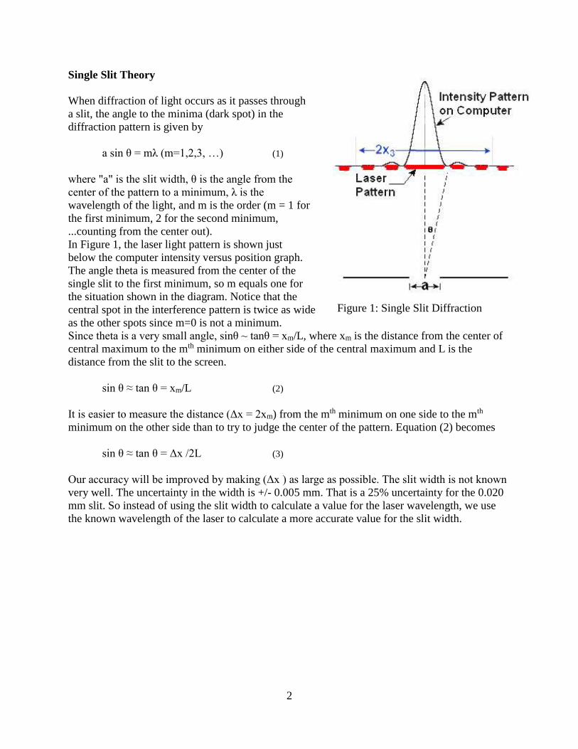
Single Slit Theory
When diffraction of light occurs as it passes through
a slit, the angle to the minima (dark spot) in the
diffraction pattern is given by
a sin θ = mλ (m=1,2,3, …) (1)
where "a" is the slit width, θ is the angle from the
center of the pattern to a minimum, λ is the
wavelength of the light, and m is the order (m = 1 for
the first minimum, 2 for the second minimum,
...counting from the center out).
In Figure 1, the laser light pattern is shown just
below the computer intensity versus position graph.
The angle theta is measured from the center of the
single slit to the first minimum, so m equals one for
the situation shown in the diagram. Notice that the
central spot in the interference pattern is twice as wide
as the other spots since m=0 is not a minimum.
Since theta is a very small angle, sinθ ~ tanθ = xm/L, where xm is the distance from the center of
central maximum to the mth minimum on either side of the central maximum and L is the
distance from the slit to the screen.
sin θ ≈ tan θ = xm/L (2)
It is easier to measure the distance (Δx = 2xm) from the mth minimum on one side to the mth
minimum on the other side than to try to judge the center of the pattern. Equation (2) becomes
sin θ ≈ tan θ = Δx /2L (3)
Our accuracy will be improved by making (Δx ) as large as possible. The slit width is not known
very well. The uncertainty in the width is +/- 0.005 mm. That is a 25% uncertainty for the 0.020
mm slit. So instead of using the slit width to calculate a value for the laser wavelength, we use
the known wavelength of the laser to calculate a more accurate value for the slit width.
Figure 1: Single Slit Diffraction
3
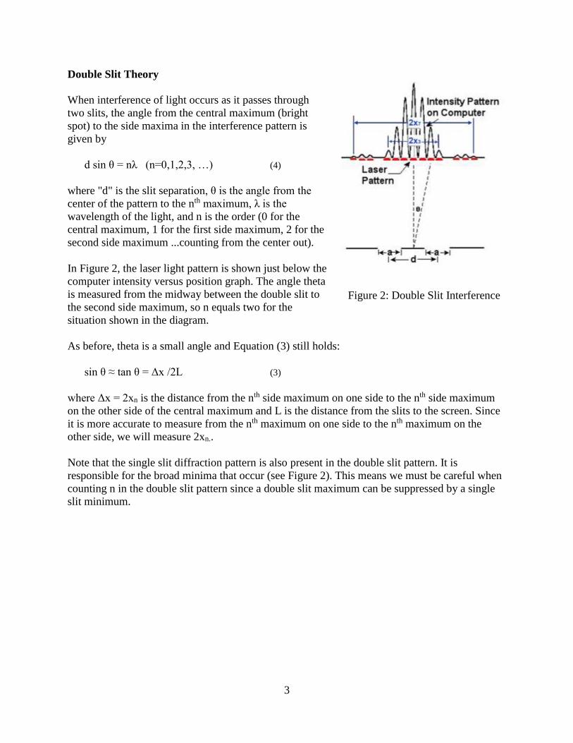
Double Slit Theory
When interference of light occurs as it passes through
two slits, the angle from the central maximum (bright
spot) to the side maxima in the interference pattern is
given by
d sin θ = nλ (n=0,1,2,3, …) (4)
where "d" is the slit separation, θ is the angle from the
center of the pattern to the nth maximum, λ is the
wavelength of the light, and n is the order (0 for the
central maximum, 1 for the first side maximum, 2 for the
second side maximum ...counting from the center out).
In Figure 2, the laser light pattern is shown just below the
computer intensity versus position graph. The angle theta
is measured from the midway between the double slit to
the second side maximum, so n equals two for the
situation shown in the diagram.
As before, theta is a small angle and Equation (3) still holds:
sin θ ≈ tan θ = Δx /2L (3)
where Δx = 2xn is the distance from the nth side maximum on one side to the nth side maximum
on the other side of the central maximum and L is the distance from the slits to the screen. Since
it is more accurate to measure from the nth maximum on one side to the nth maximum on the
other side, we will measure 2xn..
Note that the single slit diffraction pattern is also present in the double slit pattern. It is
responsible for the broad minima that occur (see Figure 2). This means we must be careful when
counting n in the double slit pattern since a double slit maximum can be suppressed by a single
slit minimum.
Figure 2: Double Slit Interference

4
Polarization
Diffraction and interference effects occur with any type of wave. However, since light is
a transverse electromagnetic wave, it exhibits one property not common to all waves.
This unique property is called polarization.
As a light wave travels through a medium, the electric and magnetic fields oscillate in a
plane perpendicular to the direction of travel. If all light waves from a given source are
such that their electric field vectors are parallel, the light is said to be plane polarized. If,
however, the individual light waves coming from a source have randomly oriented
electric vectors the light is said to be "randomly polarized" or "unpolarized."
Unpolarized light can be conveniently plane-polarized by use of a Polaroid sheet. This is
a sheet of transparent plastic in which special needlelike crystals of iodoquinine sulfate
have been embedded and oriented. The resulting sheet will allow light through it only if
the electric vector is vibrating in a specific direction. Hence, if unpolarized light is
incidence upon the sheet, the transmitted light will be plane-polarized and will consist of
the sum of the electric field components parallel to the permitted direction.
Consider what happens as unpolarized light is passed through two Polaroids as shown in
the two cases below. In the first case, the first Polaroid allows only the vertical vibrations
to pass. These are then transmitted by the second Polaroid, since it, too, is vertical.
However, in the second case, the polarizer has been rotated through 90 and allows only
horizontal vibrations to pass. These are completely stopped by the vertically oriented
Polaroid. Therefore, no light comes through the combination.
5
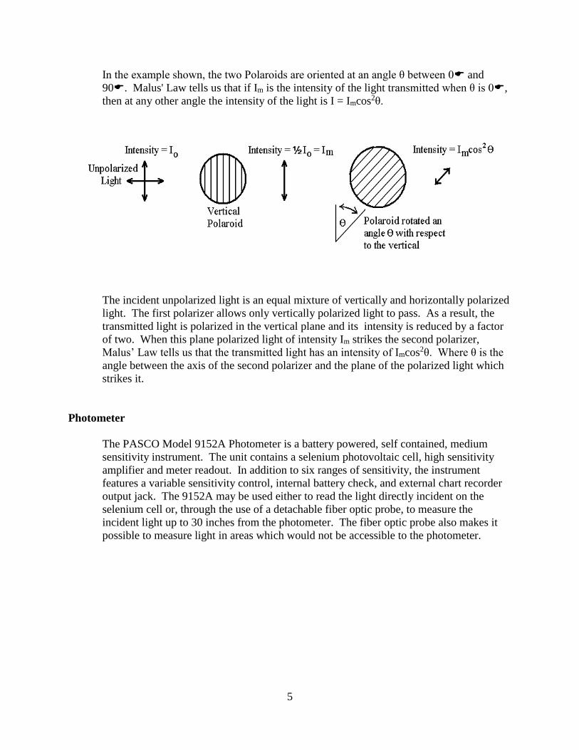
In the example shown, the two Polaroids are oriented at an angle θ between 0 and
90. Malus' Law tells us that if Im is the intensity of the light transmitted when θ is 0,
then at any other angle the intensity of the light is I = Imcos2θ.
The incident unpolarized light is an equal mixture of vertically and horizontally polarized
light. The first polarizer allows only vertically polarized light to pass. As a result, the
transmitted light is polarized in the vertical plane and its intensity is reduced by a factor
of two. When this plane polarized light of intensity Im strikes the second polarizer,
Malus’ Law tells us that the transmitted light has an intensity of Imcos2θ. Where θ is the
angle between the axis of the second polarizer and the plane of the polarized light which
strikes it.
Photometer
The PASCO Model 9152A Photometer is a battery powered, self contained, medium
sensitivity instrument. The unit contains a selenium photovoltaic cell, high sensitivity
amplifier and meter readout. In addition to six ranges of sensitivity, the instrument
features a variable sensitivity control, internal battery check, and external chart recorder
output jack. The 9152A may be used either to read the light directly incident on the
selenium cell or, through the use of a detachable fiber optic probe, to measure the
incident light up to 30 inches from the photometer. The fiber optic probe also makes it
possible to measure light in areas which would not be accessible to the photometer.
6
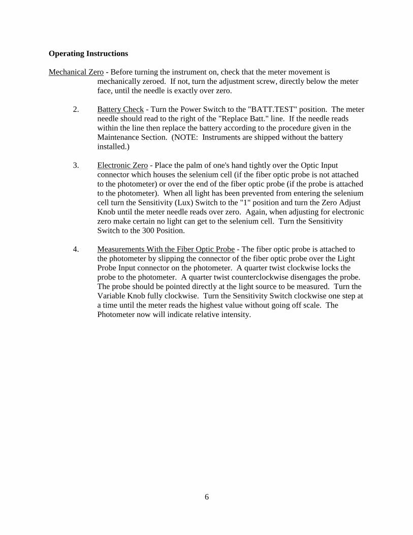
Operating Instructions
Mechanical Zero - Before turning the instrument on, check that the meter movement is
mechanically zeroed. If not, turn the adjustment screw, directly below the meter
face, until the needle is exactly over zero.
2. Battery Check - Turn the Power Switch to the "BATT.TEST" position. The meter
needle should read to the right of the "Replace Batt." line. If the needle reads
within the line then replace the battery according to the procedure given in the
Maintenance Section. (NOTE: Instruments are shipped without the battery
installed.)
3. Electronic Zero - Place the palm of one's hand tightly over the Optic Input
connector which houses the selenium cell (if the fiber optic probe is not attached
to the photometer) or over the end of the fiber optic probe (if the probe is attached
to the photometer). When all light has been prevented from entering the selenium
cell turn the Sensitivity (Lux) Switch to the "1" position and turn the Zero Adjust
Knob until the meter needle reads over zero. Again, when adjusting for electronic
zero make certain no light can get to the selenium cell. Turn the Sensitivity
Switch to the 300 Position.
4. Measurements With the Fiber Optic Probe - The fiber optic probe is attached to
the photometer by slipping the connector of the fiber optic probe over the Light
Probe Input connector on the photometer. A quarter twist clockwise locks the
probe to the photometer. A quarter twist counterclockwise disengages the probe.
The probe should be pointed directly at the light source to be measured. Turn the
Variable Knob fully clockwise. Turn the Sensitivity Switch clockwise one step at
a time until the meter reads the highest value without going off scale. The
Photometer now will indicate relative intensity.
7
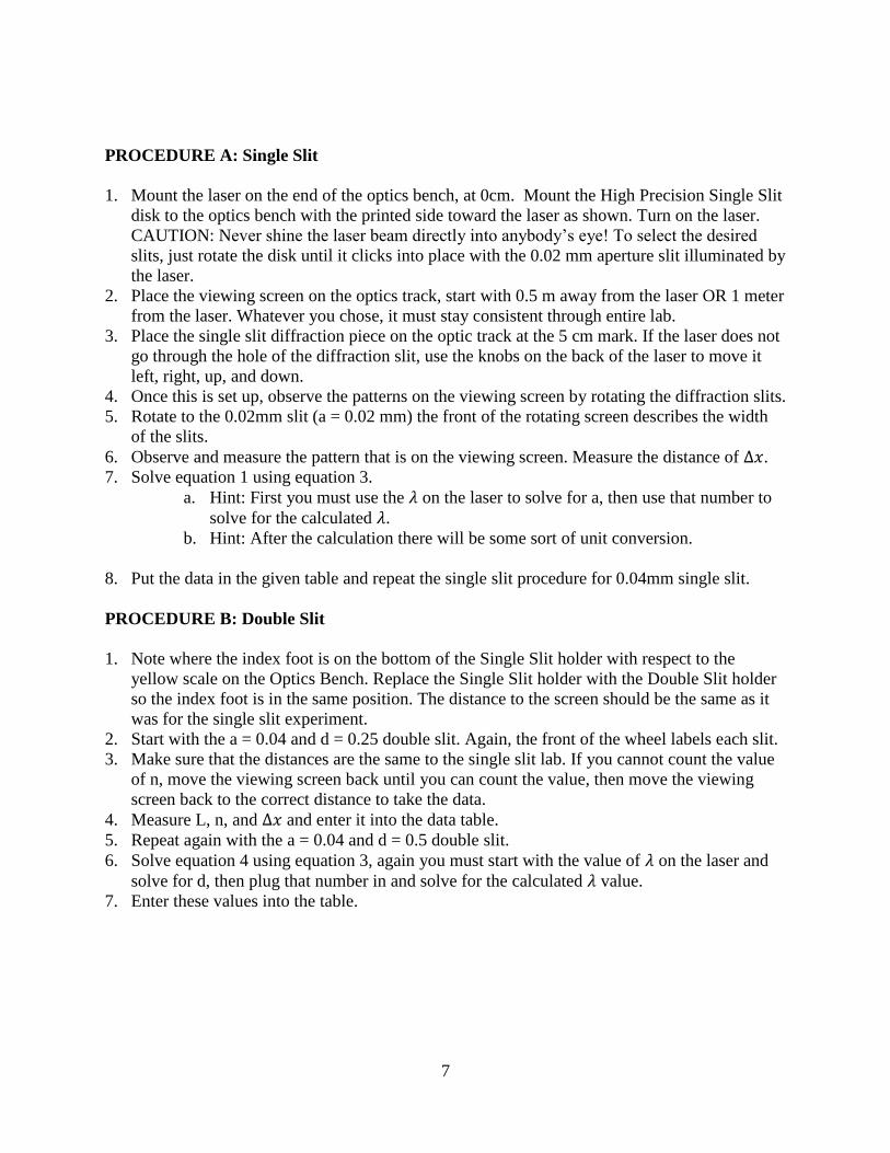
PROCEDURE A: Single Slit
1. Mount the laser on the end of the optics bench, at 0cm. Mount the High Precision Single Slit
disk to the optics bench with the printed side toward the laser as shown. Turn on the laser.
CAUTION: Never shine the laser beam directly into anybody’s eye! To select the desired
slits, just rotate the disk until it clicks into place with the 0.02 mm aperture slit illuminated by
the laser.
2. Place the viewing screen on the optics track, start with 0.5 m away from the laser OR 1 meter
from the laser. Whatever you chose, it must stay consistent through entire lab.
3. Place the single slit diffraction piece on the optic track at the 5 cm mark. If the laser does not
go through the hole of the diffraction slit, use the knobs on the back of the laser to move it
left, right, up, and down.
4. Once this is set up, observe the patterns on the viewing screen by rotating the diffraction slits.
5. Rotate to the 0.02mm slit (a = 0.02 mm) the front of the rotating screen describes the width
of the slits.
6. Observe and measure the pattern that is on the viewing screen. Measure the distance of ∆𝑥.
7. Solve equation 1 using equation 3.
a. Hint: First you must use the 𝜆 on the laser to solve for a, then use that number to
solve for the calculated 𝜆.
b. Hint: After the calculation there will be some sort of unit conversion.
8. Put the data in the given table and repeat the single slit procedure for 0.04mm single slit.
PROCEDURE B: Double Slit
1. Note where the index foot is on the bottom of the Single Slit holder with respect to the
yellow scale on the Optics Bench. Replace the Single Slit holder with the Double Slit holder
so the index foot is in the same position. The distance to the screen should be the same as it
was for the single slit experiment.
2. Start with the a = 0.04 and d = 0.25 double slit. Again, the front of the wheel labels each slit.
3. Make sure that the distances are the same to the single slit lab. If you cannot count the value
of n, move the viewing screen back until you can count the value, then move the viewing
screen back to the correct distance to take the data.
4. Measure L, n, and Δ𝑥 and enter it into the data table.
5. Repeat again with the a = 0.04 and d = 0.5 double slit.
6. Solve equation 4 using equation 3, again you must start with the value of 𝜆 on the laser and
solve for d, then plug that number in and solve for the calculated 𝜆 value.
7. Enter these values into the table.

8
The track should look like this, disregarding the lengths in-between each object.
PROCEDURE C: Polarization
1.Place the laser at 0cm and the viewing screen at 0.5 m on the track
2. Put the polarizer holder on the track along with the two polarizers. On the polarizer holder,
there is a plastic ‘dot’ on the bottom of the open circle, this is the marker that allows you to know
that degree the polarizer is at. So, to start place one polarizer at 0 degrees and the other at 180
degrees.
3. turn on the laser, and simply turn the polarizers and observe what you see.
4. Now, remove the viewing screen and place the aperture bracket in its place. Take the
photometer optical cable and place it in the open circle of the aperture bracket. If the open circle
isn’t there, turn the wheel to change its setting. Try to line up the edge of the aperture bracket to
the 0.5 m mark, it just needs to be around that point.
5. Make sure the laser is on and pointed at the optical cable, spin the knobs on the back of the
laser to move it left, up, right, and down.
6. Align the two polarizers so that both have the 0-180 axis vertical. Measure the intensity
of the light as measured by the photometer. Now carefully rotate the second polarizer so that the
angle θ between the two axes is 15, 30, 45, 60, 70, and 90. Record the intensity in each case
and compare with the prediction of Malus' Law.

9
Data Analysis A – B:
Label a
(mm)
d
(mm)
m n Δ𝑥
(m)
Calculated Slit
Width Calculated 𝜆
(nm)
% 𝜆
Diffference
0.02mm
0.04mm
0.04a-0.25d
0.04a-0.50d
Data Analysis C:
1.By visual inspection, under what conditions is the intensity of the light transmitted through the
two polarizers a maximum? A minimum?
2. Intensity of light when both polarizers are oriented vertically (0 and 180): Im = lux
θ I (measured in
lux)
I = Imcos2θ (lux)
15
30
45
60
75
90

10
QUESTIONS A - B:
1. Using your eyes, how does the single slit pattern change as you increase the slit size?
2. Using your eyes, how does the double slit pattern change as you increase the slit separation?
3. How does the Single Slit Diffraction change as you vary the slit width (a)? Does this agree
with your answer to Question 1 above?
4. How does the Double Slit pattern change as you vary the slit separation (d)? Does this agree
with your observations from Question 2 above?
5. How does the Double Slit pattern change as you vary the wavelength? Does this agree with
your answer to the pre-lab question?

11
QUESTIONS C:
Explain the transmission of light that you observe through the set of two polarizers, regarding the
angles that the polarizer is at, make sure to use your data.
Was Malus' Law prediction correct in calculating the intensity of light at the different non-
vertical and non-horizontal angles?