iiiC Store.Category.Electronic Component.Power Modules - Octopart
Upload
khangminh22Category
view
1download
0
MOTOROLA Freescale Semiconductor, Inc.
Order by AN1924/D
Semiconductor Application Note (Motorola Order Number) Rev. 0, 4/2001
ARCHIVED BY FREESCALE SEMICONDUCTOR, INC. 2005
Interfacing Serial LCDs to a DSP56F805’s SCI and Porting Code Using the Embedded SDK
Fre
esc
ale
Sem
icon
duct
or, In
c.
AR
CH
IVED
BY
FREE
SCA
LE S
EMIC
ON
DU
CTO
R, I
NC
. 200
5
Inte
rfaci
ng L
CD
s an
d Po
r ting
C
ode
Joseph R. Pasek
1. Introduction This application follows an earlier application note (“Some General DSP568xx Interface Examples using the Embedded SDK”, AN1921/D) that focused on interfacing the DSP56824 with an LCD, keypad and an SPI-based device, an 11-channel, 12-bit A/D converter (TLC2543). That note described interfacing via the SPI port, either directly, or with the MAX3100 chip that converts SPI signals to a compatible RS-232 format.
This note will show the relative ease of interfacing either NetMedia’s LCD+, including a keypad, or Crystalfontz’s 634 Intelligent Serial Display to the Serial Communication Interface (SCI) port of a DSP56F805. The demonstration code will be written in C and will use Motorola’s Embedded SDK libraries.
The SCI is a three-line interface, consisting of a transmit line (TXD), a receive line (RXD), and a ground line (GND). The interface allows for asynchronous communication with peripheral devices and other MCUs. The protocol is very similar to an RS-232-based interface, except that the voltage range is that of TTL.
This note will also show the modifications required to convert the program for the DSP56824 featured in Application Note AN1921/D to the DSP56F805, using the Embedded SDK. The modifications are relatively minor and made only to the respective processor’s SDK-supported interface code.
Contents 1. Introduction .....................................1 2. Interface Description .......................2 3. Descriptions of the Intelligent
LCD Modules ............................3 3.1 Crystalfontz’s 634 Intelligent
Serial LCD Module ......................... 4 3.2 NetMedia’s LCD+ Serial LCD
Module............................................. 5 4. Interfacing the LCDs to the
DSP56F805 ................................5 4.1 Connecting the 634 LCD to the
DSP56F805...................................... 5 4.2 Software for the 634 LCD and the
DSP56F805...................................... 6 4.3 Connecting the LCD+ to the
DSP56F805...................................... 7 4.4 Software for the LCD+ and the
DSP56F805...................................... 8 5. Converting SDK-Based Code .......10 6. Conclusions ...................................15 7. References .....................................15 Appendix A. NetMedia’s Serial
LCD+ ......................................16
© Motorola, Inc., 2001 For More Information On This Product,
Go to: www.freescale.com
Bec
ause
of a
n or
der f
rom
the
Uni
ted
Sta
tes
Inte
rnat
iona
l Tra
de C
omm
issi
on, B
GA
-pac
kage
d pr
oduc
t lin
es a
nd p
art n
umbe
rs in
dica
ted
here
cur
rent
ly a
re n
ot
avai
labl
e fro
m F
rees
cale
for i
mpo
rt or
sal
e in
the
Uni
ted
Sta
tes
prio
r to
Sep
tem
ber 2
010:
DS
P56
F807
VF8
0, D
SP
56F8
07V
F80E
Interface Description Interface Description ARCHFIVreEDesBYcaFRleEESSCeAmLEicSoEnMdICuOcNDtoUCr,TOInRc, IN. C. 2005 ARCHFIVreEDesBYcaFRleEESSCeAmLEicSoEnMdICuOcNDtoUCr,TOInRc, IN. C. 2005
2. Interface DAeRsCcHrIVipEDtiBoYnFREESCALE SEMICONDUCTOR, INC. 2005 2. Interface DAeRsCcHrIVipEDtiBoYnFREESCALE SEMICONDUCTOR, INC. 2005
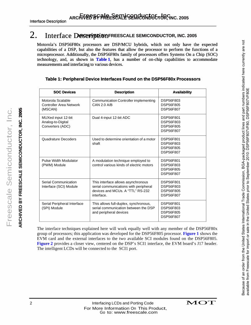
Motorola’s DSP56F80x processors are DSP/MCU hybrids, which not only have the expected capabilities of a DSP, but also the features that allow the processor to perform the functions of a microprocessor. Additionally, the DSP56F80x family of processors offers Systems On a Chip (SOC) technology, and, as shown in Table 1, has a number of on-chip capabilities to accommodate measurements and interfacing to various devices.
Motorola’s DSP56F80x processors are DSP/MCU hybrids, which not only have the expected capabilities of a DSP, but also the features that allow the processor to perform the functions of a microprocessor. Additionally, the DSP56F80x family of processors offers Systems On a Chip (SOC) technology, and, as shown in Table 1, has a number of on-chip capabilities to accommodate measurements and interfacing to various devices.
Table 1: Peripheral Device Interfaces Found on the DSP56F80x Processors Table 1: Peripheral Device Interfaces Found on the DSP56F80x Processors
SOC Devices SOC Devices Description Description Availability Availability
Motorola Scalable Controller Area Network (MSCAN)
Communication Controller implementing CAN 2.0 A/B
DSP56F803 DSP56F805 DSP56F807
MUXed input 12-bit Analog-to-Digital Converters (ADC)
Dual 4-input 12-bit ADC DSP56F801 DSP56F803 DSP56F805 DSP56F807
Quadrature Decoders Used to determine orientation of a motor shaft
DSP56F801 DSP56F803 DSP56F805 DSP56F807
Pulse Width Modulator (PWM) Module
A modulation technique employed to control various kinds of electric motors
DSP56F801 DSP56F803 DSP56F805 DSP56F807
Serial Communication Interface (SCI) Module
This interface allows asynchronous serial communications with peripheral devices and MCUs. A “TTL” RS-232 interface.
DSP56F801 DSP56F803 DSP56F805 DSP56F807
Serial Peripheral Interface (SPI) Module
This allows full-duplex, synchronous, serial communication between the DSP and peripheral devices
DSP56F801 DSP56F803 DSP56F805 DSP56F807
Fre
esc
ale
Sem
icon
duct
or, In
c.
AARR
CCHH
IIVVEEDD
BBYY
FFRREEEE
SSCCAA
LLEE SS
EEMMIICC
OONN
DDUU
CCTTOO
RR,, II
NNCC
.. 220000
55
The interface techniques explained here will work equally well with any member of the DSP56F80x group of processors; this application was developed for the DSP56F805 processor. Figure 1 shows the EVM card and the external interfaces to the two available SCI modules found on the DSP56F805. Figure 2 provides a closer view, centered on the DSP’s SCI1 interface, the EVM board’s J17 header. The intelligent LCDs will be connected to the SCI1 port.
2 Interfacing LCDs and Porting Code MOT For More Information On This Product,
Go to: www.freescale.com
Bec
ause
of a
n or
der f
rom
the
Uni
ted
Sta
tes
Inte
rnat
iona
l Tra
de C
omm
issi
on, B
GA
-pac
kage
d pr
oduc
t lin
es a
nd p
art n
umbe
rs in
dica
ted
here
cur
rent
ly a
re n
ot
avai
labl
e fro
m F
rees
cale
for i
mpo
rt or
sal
e in
the
Uni
ted
Sta
tes
prio
r to
Sep
tem
ber 2
010:
DS
P56
F807
VF8
0, D
SP
56F8
07V
F80E

ARCHFIVreEDesBYcaFRleEESSCeAmLEicSoEnMdICuOcNDtoUCr,TOInRc, IN. C. 2005 ARCHFIVreEDesBYcaFRleEESSCeAmLEicSoEnMdICuOcNDtoUCr,TOInRc, IN. C. 2005 Descriptions of the Intelligent LCD Modules Descriptions of the Intelligent LCD Modules
ARCHIVED BY FREESCALE SEMICONDUCTOR, INC. 2005 ARCHIVED BY FREESCALE SEMICONDUCTOR, INC. 2005
Fre
esc
ale
Sem
icon
duct
or, In
c.
AARR
CCHH
IIVVEEDD
BBYY
FFRREEEE
SSCCAA
LLEE SS
EEMMIICC
OONN
DDUU
CCTTOO
RR,, II
NNCC
.. 220000
55
Figure 1. Motorola’s DSP56F805 EVM Board
Figure 2. The J17 Header (SCI1 Port) on the DSP56F805 EVM Board
3. Descriptions of the Intelligent LCD Modules Specifications of the two intelligent serial LCD devices which will be interfaced to the DSP56F805’s SCI1 port are contained in this section.
MOT Interfacing LCDs and Porting Code 3 For More Information On This Product,
Go to: www.freescale.com
Bec
ause
of a
n or
der f
rom
the
Uni
ted
Sta
tes
Inte
rnat
iona
l Tra
de C
omm
issi
on, B
GA
-pac
kage
d pr
oduc
t lin
es a
nd p
art n
umbe
rs in
dica
ted
here
cur
rent
ly a
re n
ot
avai
labl
e fro
m F
rees
cale
for i
mpo
rt or
sal
e in
the
Uni
ted
Sta
tes
prio
r to
Sep
tem
ber 2
010:
DS
P56
F807
VF8
0, D
SP
56F8
07V
F80E

ARCHFIVreEDesBYcaFRleEESSCeAmLEicSoEnMdICuOcNDtoUCr,TOInRc, IN. C. 2005 ARCHFIVreEDesBYcaFRleEESSCeAmLEicSoEnMdICuOcNDtoUCr,TOInRc, IN. C. 2005 Descriptions of the Intelligent LCD Modules Descriptions of the Intelligent LCD Modules
3.1 Crystalfontz’s 634AIRnCteHllIiVgeEnDt BSeYriFaRl ELECSDCMALoEduSlEe MICONDUCTOR, INC. 2005 3.1 Crystalfontz’s 634AIRnCteHllIiVgeEnDt BSeYriFaRl ELECSDCMALoEduSlEe MICONDUCTOR, INC. 2005
This LCD module has attracted attention for its capability of interfacing as either an RS-232 device or as an SPI device. As it comes from the factory, it is set up for 9600 Baud RS-232 operation. To use it as an SPI device, the Jumper JPA must be soldered closed. However, the throughput of the LCD’s SPI port is very slow (Fclk.max=18 kHz) and SPI ports on the DSP56F80x family are incapable of such
This LCD module has attracted attention for its capability of interfacing as either an RS-232 device or as an SPI device. As it comes from the factory, it is set up for 9600 Baud RS-232 operation. To use it as an SPI device, the Jumper JPA must be soldered closed. However, the throughput of the LCD’s SPI port is very slow (Fclk.max=18 kHz) and SPI ports on the DSP56F80x family are incapable of such slow speed without extraordinary manipulation of the DSP chip’s clocking rate. Therefore, interface as slow speed without extraordinary manipulation of the DSP chip’s clocking rate. Therefore, interface as an RS-232 device is recommended. an RS-232 device is recommended.
These are the features of the 634: These are the features of the 634:
• RS-232 interface (1200, 2400, 4800, and 9600 Baud) • RS-232 interface (1200, 2400, 4800, and 9600 Baud) • DB9 connector provided for a simple RS-232 hookup • DB9 connector provided for a simple RS-232 hookup • Available with bright, even, software-adjustable LED backlighting or in a low-power
reflective model • Available with bright, even, software-adjustable LED backlighting or in a low-power
reflective model • Available as either 20x4 (Model 634) or 16x2 (Model 632) display • Available as either 20x4 (Model 634) or 16x2 (Model 632) display
Fre
esc
ale
Sem
icon
duct
or, In
c.
AARR
CCHH
IIVVEEDD
BBYY
FFRREEEE
SSCCAA
LLEE SS
EEMMIICC
OONN
DDUU
CCTTOO
RR,, II
NNCC
.. 220000
55
• Software-controlled contrast • Software-controlled contrast • “Gapless” horizontal contrast • “Gapless” horizontal contrast • Software-controlled, terminal-style automatic scrolling and line wrapping • Software-controlled, terminal-style automatic scrolling and line wrapping • Unique “Scrolling Marquees” feature continuously scrolls a message across the display
without host intervention • Unique “Scrolling Marquees” feature continuously scrolls a message across the display
without host intervention • Low-speed “SPI” and “Inverted TTL” RS-232 for embedded application • Low-speed “SPI” and “Inverted TTL” RS-232 for embedded application • Buffered communication • Buffered communication • Low power: Non-backlight operation will self-power from the DTR and RTS lines of most
serial ports • Low power: Non-backlight operation will self-power from the DTR and RTS lines of most
serial ports
A microcontroller is built into the LCD’s support and a ROM stores the necessary code for its operation. Further information is available from Crystalfontz’s web site: www.crystalfontz.coA microcontroller is built into the LCD’s support and a ROM stores the necessary code for its operation. Further information is available from Crystalfontz’s web site: www.crystalfontz.com. Figure 3 shows the 634’s display on power-up.
Figure 3. Crystalfontz’s 634 Intelligent Serial LCD Module Display 3.2 NetMedia’s LCD+ Serial LCD Module
NetMedia’s intelligent LCD was featured in the application note, “General DSP568xx Interface Examples Using the Embedded SDK”, AN1921/D. The LCD+ comes with a 20x4 display and a built-in port capable of supporting a keypad up to 4x4 in size. It supports an RS-232 interface that can work at either normal or TTL voltage levels.
4 Interfacing LCDs and Porting Code MOT For More Information On This Product,
Go to: www.freescale.com
Bec
ause
of a
n or
der f
rom
the
Uni
ted
Sta
tes
Inte
rnat
iona
l Tra
de C
omm
issi
on, B
GA
-pac
kage
d pr
oduc
t lin
es a
nd p
art n
umbe
rs in
dica
ted
here
cur
rent
ly a
re n
ot
avai
labl
e fro
m F
rees
cale
for i
mpo
rt or
sal
e in
the
Uni
ted
Sta
tes
prio
r to
Sep
tem
ber 2
010:
DS
P56
F807
VF8
0, D
SP
56F8
07V
F80E
ARCHFIVreEDesBYcaFRleEESSCeAmLEicSoEnMdICuOcNDtoUCr,TOInRc, IN. C. 2005 ARCHFIVreEDesBYcaFRleEESSCeAmLEicSoEnMdICuOcNDtoUCr,TOInRc, IN. C. 2005 Interfacing the LCDs to the DSP56F805 Interfacing the LCDs to the DSP56F805
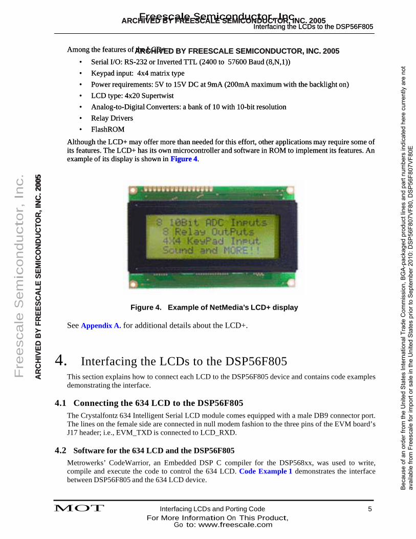
Among the features of AthRe CLHCDIV+E:D BY FREESCALE SEMICONDUCTOR, INC. 2005 Among the features of AthRe CLHCDIV+E:D BY FREESCALE SEMICONDUCTOR, INC. 2005 • Serial I/O: RS-232 or Inverted TTL (2400 to 57600 Baud (8,N,1)) • Serial I/O: RS-232 or Inverted TTL (2400 to 57600 Baud (8,N,1)) • Keypad input: 4x4 matrix type • Keypad input: 4x4 matrix type • Power requirements: 5V to 15V DC at 9mA (200mA maximum with the backlight on) • Power requirements: 5V to 15V DC at 9mA (200mA maximum with the backlight on) • LCD type: 4x20 Supertwist • LCD type: 4x20 Supertwist • Analog-to-Digital Converters: a bank of 10 with 10-bit resolution • Analog-to-Digital Converters: a bank of 10 with 10-bit resolution • Relay Drivers • Relay Drivers • FlashROM • FlashROM
Although the LCD+ may offer more than needed for this effort, other applications may require some of its features. The LCD+ has its own microcontroller and software in ROM to implement its features. An example of its display is shown in Figure 4.
Although the LCD+ may offer more than needed for this effort, other applications may require some of its features. The LCD+ has its own microcontroller and software in ROM to implement its features. An example of its display is shown in Figure 4.
Fre
esc
ale
Sem
icon
duct
or, In
c.
AARR
CCHH
IIVVEEDD
BBYY
FFRREEEE
SSCCAA
LLEE SS
EEMMIICC
OONN
DDUU
CCTTOO
RR,, II
NNCC
.. 220000
55
Figure 4. Example of NetMedia’s LCD+ display
See Appendix A. for additional details about the LCD+.
4. Interfacing the LCDs to the DSP56F805
This section explains how to connect each LCD to the DSP56F805 device and contains code examples demonstrating the interface.
4.1 Connecting the 634 LCD to the DSP56F805
The Crystalfontz 634 Intelligent Serial LCD module comes equipped with a male DB9 connector port. The lines on the female side are connected in null modem fashion to the three pins of the EVM board’s J17 header; i.e., EVM_TXD is connected to LCD_RXD.
4.2 Software for the 634 LCD and the DSP56F805
Metrowerks’ CodeWarrior, an Embedded DSP C compiler for the DSP568xx, was used to write, compile and execute the code to control the 634 LCD. Code Example 1 demonstrates the interface between DSP56F805 and the 634 LCD device.
MOT Interfacing LCDs and Porting Code 5 For More Information On This Product,
Go to: www.freescale.com
Bec
ause
of a
n or
der f
rom
the
Uni
ted
Sta
tes
Inte
rnat
iona
l Tra
de C
omm
issi
on, B
GA
-pac
kage
d pr
oduc
t lin
es a
nd p
art n
umbe
rs in
dica
ted
here
cur
rent
ly a
re n
ot
avai
labl
e fro
m F
rees
cale
for i
mpo
rt or
sal
e in
the
Uni
ted
Sta
tes
prio
r to
Sep
tem
ber 2
010:
DS
P56
F807
VF8
0, D
SP
56F8
07V
F80E

Interfacing the LCDs to the DSP56F805
Code Example 1. LCD634_sci_test.c // LCD634_sci_test.c program tests the interface between a DSP // 56805 using its SCI port and a LCD (Crystalfontz // 634 Intelligent serial display - March 1, 2001 )
#include "port.h" #include "io.h" #include "bsp.h"
#include "fcntl.h" #include "sci.h" #include "stdio.h" #include "assert.h" #include "string.h" #include "timer.h"
int main() {
UWord16 I; int SciFD; sci_sConfig SciConfig; struct timespec FiveSeconds = {5,0};
char aastring[]={" DSP56F805-SCI "}; char bstring[]={" LCD 634 Disp Test "}; char input, inputarray[8]; UWord16 NewScr[2]= {12,0}; // Clear Screen on LCDchar astring[20]; UWord16 temp;
/* Set-up parameter for SCI port - 8 bit, no parity, TX_inverted */
6 Interfacing LCDs and Porting Code MOT
Bec
ause
of a
n or
der f
rom
the
Uni
ted
Sta
tes
Inte
rnat
iona
l Tra
de C
omm
issi
on, B
GA
-pac
kage
d pr
oduc
t lin
es a
nd p
art n
umbe
rs in
dica
ted
here
cur
rent
ly a
re n
ot
avai
labl
e fro
m F
rees
cale
for i
mpo
rt or
sal
e in
the
Uni
ted
Sta
tes
prio
r to
Sep
tem
ber 2
010:
DS
P56
F807
VF8
0, D
SP
56F8
07V
F80E

ARCHFIVreEDesBYcaFRleEESSCeAmLEicSoEnMdICuOcNDtoUCr,TOInRc, IN. C. 2005 Interfacing the LCDs to the DSP56F805
/* Display some AnuRmCbeHrIsVEonD dBiYspFlRayEE*S/CALE SEMICONDUCTOR, INC. 2005
nanosleep(&FiveSeconds, NULL); /* Wait five seconds */
write( SciFD, NewScr, 1 ); /* Wipe clean LCD’s Display */ for ( I=0; I < 29; I++ ) /* Write some numbers to LCD */ {
sprintf(astring, "%d ", I ); write (SciFD, astring, strlen(astring));
}
nanosleep(&FiveSeconds, NULL); /* Wait five seconds */
write( SciFD, NewScr, 1 ); /* Wipe clean LCD’s Display */ temp = ’A’; for ( I=0; I<26; I++ ) /* Write capital letters to LCD */
Fre
esc
ale
Sem
icon
duct
or, In
c.
AARR
CCHH
IIVVEEDD
BBYY
FFRREEEE
SSCCAA
LLEE SS
EEMMIICC
OONN
DDUU
CCTTOO
RR,, II
NNCC
.. 220000
55
{ sprintf( astring, "%c", temp++); write (SciFD, astring, strlen(astring) );
} temp = ’a’; for ( I=0; I<26; I++ ) /* Write small letters to LCD */ {
sprintf( astring, "%c", temp++); write (SciFD, astring, strlen(astring) );
}
nanosleep(&FiveSeconds, NULL); /* Wait five seconds */ }
4.3 Connecting the LCD+ to the DSP56F805 In AN1921/D, the LCD+ device was interfaced to one of the DSP56824’s SPI ports using the Maxim MAX3100 UART chip’s bi-directional capability to convert data conveyed by an SPI port to an RS-232 format. However, the DSP56F80x’s SCI port can be connected directly to an RS-232 device using the TTL voltage option compatible with NetMedia’s LCD+, making additional hardware unnecessary.
The LCD+ has a much faster processor and the ability to support baud rates up to 57600. It also provides support for a 4x4 matrix keypad which allos user input, resulting in two-way communication between the LCD+ and the DSP56F805.
4.4 Software for the LCD+ and the DSP56F805
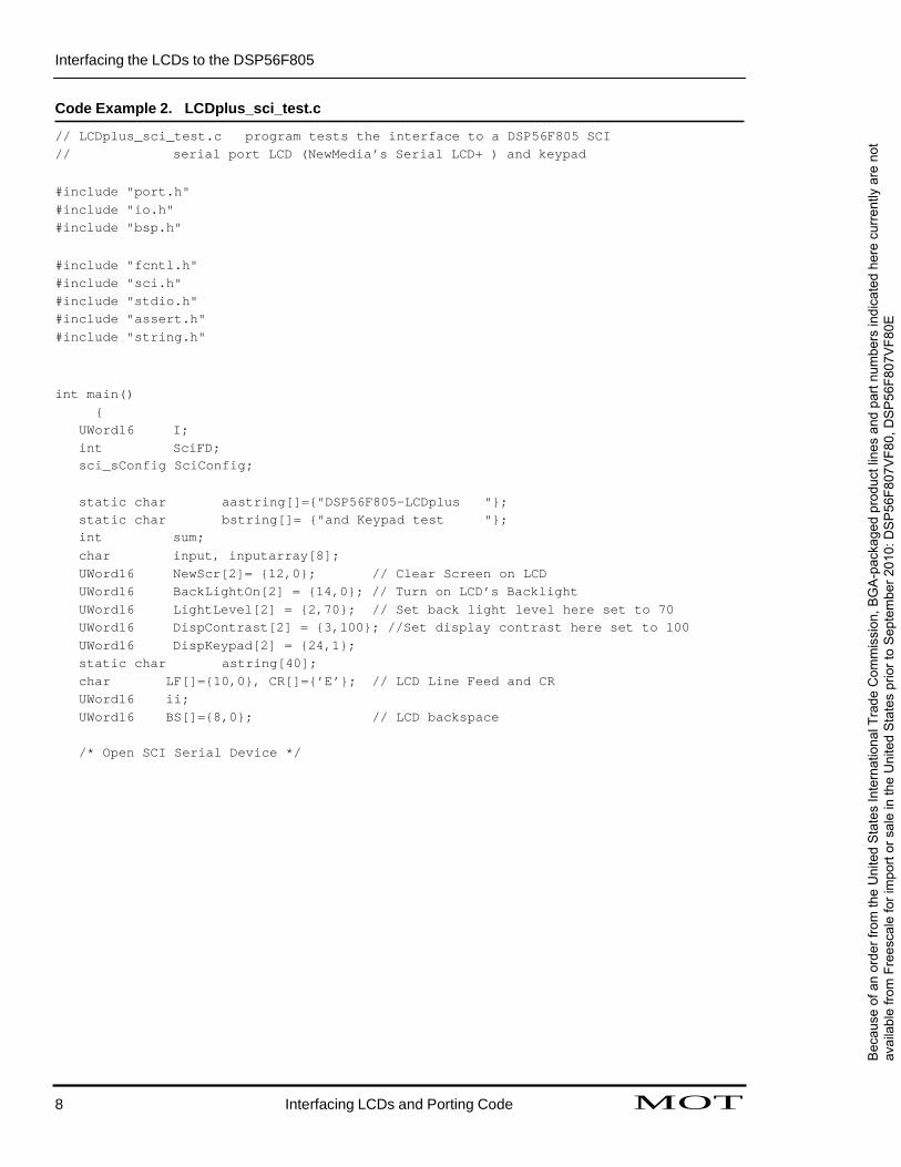
The software is written in C and makes full use of the SCI support provided in the Embedded SDK. Code Example 2 demonstrates the interface between the DSP56F805 and NetMedia’s LCD+ serial display.
MOT Interfacing LCDs and Porting Code 7
For More Information On This Product, Go to: www.freescale.com
Bec
ause
of a
n or
der f
rom
the
Uni
ted
Sta
tes
Inte
rnat
iona
l Tra
de C
omm
issi
on, B
GA
-pac
kage
d pr
oduc
t lin
es a
nd p
art n
umbe
rs in
dica
ted
here
cur
rent
ly a
re n
ot
avai
labl
e fro
m F
rees
cale
for i
mpo
rt or
sal
e in
the
Uni
ted
Sta
tes
prio
r to
Sep
tem
ber 2
010:
DS
P56
F807
VF8
0, D
SP
56F8
07V
F80E
Interfacing the LCDs to the DSP56F805
Code Example 2. LCDplus_sci_test.c // LCDplus_sci_test.c program tests the interface to a DSP56F805 SCI // serial port LCD (NewMedia’s Serial LCD+ ) and keypad
#include "port.h" #include "io.h" #include "bsp.h"
#include "fcntl.h" #include "sci.h" #include "stdio.h" #include "assert.h" #include "string.h"
int main()
{ UWord16 I; int SciFD; sci_sConfig SciConfig;
static char aastring[]={"DSP56F805-LCDplus "};static char bstring[]= {"and Keypad test "};int sum; char input, inputarray[8]; UWord16 NewScr[2]= {12,0}; // Clear Screen on LCD UWord16 BackLightOn[2] = {14,0}; // Turn on LCD’s Backlight UWord16 LightLevel[2] = {2,70}; // Set back light level here set to 70 UWord16 DispContrast[2] = {3,100}; //Set display contrast here set to 100 UWord16 DispKeypad[2] = {24,1}; static char astring[40]; char LF[]={10,0}, CR[]={’E’}; // LCD Line Feed and CR UWord16 ii; UWord16 BS[]={8,0}; // LCD backspace
/* Open SCI Serial Device */
8 Interfacing LCDs and Porting Code MOT
Bec
ause
of a
n or
der f
rom
the
Uni
ted
Sta
tes
Inte
rnat
iona
l Tra
de C
omm
issi
on, B
GA
-pac
kage
d pr
oduc
t lin
es a
nd p
art n
umbe
rs in
dica
ted
here
cur
rent
ly a
re n
ot
avai
labl
e fro
m F
rees
cale
for i
mpo
rt or
sal
e in
the
Uni
ted
Sta
tes
prio
r to
Sep
tem
ber 2
010:
DS
P56
F807
VF8
0, D
SP
56F8
07V
F80E

ARCHFIVreEDesBYcaFRleEESSCeAmLEicSoEnMdICuOcNDtoUCr,TOInRc, IN. C. 2005 Converting SDK-Based Code
write (SciFD, bstriAngR,CsHtIrVlEenD(bBsYtrFiRngE)E)S;CALE SEMICONDUCTOR, INC. 2005
read (SciFD, &input, 1);
/* Display some numbers on display */
write( SciFD, NewScr, 1 );
strcpy( bstring, "Input at key (’0000’ to exit) \n"); write( SciFD, bstring , strlen(bstring));
strcpy( bstring, "Hit key to start"); strcat( bstring, LF ); write( SciFD, bstring , strlen(bstring)); write( SciFD, NewScr, 1 );
Fre
esc
ale
Sem
icon
duct
or, In
c.
AARR
CCHH
IIVVEEDD
BBYY
FFRREEEE
SSCCAA
LLEE SS
EEMMIICC
OONN
DDUU
CCTTOO
RR,, II
NNCC
.. 220000
55
/* The following loop polls keypad input, until "0000" is input */ /* Keypad entries are displayed on both LCD and in IDE’s
text window */
ii = 0;
while ( true ) {
read( SciFD, &inputarray[ii], 1); if ( inputarray[ii] == CR[0] ) {
inputarray[ii] = 0; sprintf(bstring, " Input- %s\n", inputarray ); write ( SciFD, bstring, strlen(bstring)); ii = 0;
} else {
write( SciFD, &inputarray[ii], 1); ii++;
} if ( strcmp(inputarray,"0000") == 0 ) break;
}
write( SciFD, NewScr, 1 ); strcpy( bstring, " Done! "); write(SciFD, bstring, strlen(bstring) );
close(SciFD);
}
5. Converting SDK-Based Code
In AN1921/D, an application was developed that employed a serial LCD, keypad, and analog-to-digital converter (ADC) attached to the SPI ports of the DSP56824. This section will describe the code modifications required to convert that application to work on the DSP56F805.
MOT Interfacing LCDs and Porting Code 9 For More Information On This Product,
Go to: www.freescale.com
Bec
ause
of a
n or
der f
rom
the
Uni
ted
Sta
tes
Inte
rnat
iona
l Tra
de C
omm
issi
on, B
GA
-pac
kage
d pr
oduc
t lin
es a
nd p
art n
umbe
rs in
dica
ted
here
cur
rent
ly a
re n
ot
avai
labl
e fro
m F
rees
cale
for i
mpo
rt or
sal
e in
the
Uni
ted
Sta
tes
prio
r to
Sep
tem
ber 2
010:
DS
P56
F807
VF8
0, D
SP
56F8
07V
F80E
Converting SDK-Based Code
First, the SDK serial support native to the DSP56824 is not available or needed in the DSP56F805 environment. As shown previously, NetMedia’s LCD+ serial device and its associated keypad work very well with the DSP56F805’s SCI port. The serial-related DSP56824’s IntFaceBaro.c is shown in Code Example 3, which details setup of the interface to the LCD and keypad using the DSP56824’s SDK serial library.
Code Example 3. Establishment of Interface /* Open Serial Port via SPI1 and EVM UART */
Uart = open( BSP_DEVICE_NAME_SERIAL_0, 0 );
10 Interfacing LCDs and Porting Code MOT
Bec
ause
of a
n or
der f
rom
the
Uni
ted
Sta
tes
Inte
rnat
iona
l Tra
de C
omm
issi
on, B
GA
-pac
kage
d pr
oduc
t lin
es a
nd p
art n
umbe
rs in
dica
ted
here
cur
rent
ly a
re n
ot
avai
labl
e fro
m F
rees
cale
for i
mpo
rt or
sal
e in
the
Uni
ted
Sta
tes
prio
r to
Sep
tem
ber 2
010:
DS
P56
F807
VF8
0, D
SP
56F8
07V
F80E
ARCHFIVreEDesBYcaFRleEESSCeAmLEicSoEnMdICuOcNDtoUCr,TOInRc, IN. C. 2005 Converting SDK-Based Code
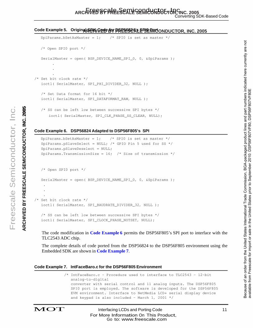
Code Example 5. OriginAalRSCDHKIVCEodDeBfoYr FDRSPE5E6S8C24A’sLESPSI0EPMoICrtONDUCTOR, INC. 2005 SpiParams.bSetAsMaster = 1; /* SPI0 is set as master */
/* Open SPI0 port */
SerialMaster = open( BSP_DEVICE_NAME_SPI_0, 0, &SpiParams );
.
.
. /* Set bit clock rate */
ioctl( SerialMaster, SPI_PHI_DIVIDER_32, NULL );
/* Set Data format for 16 bit */ ioctl( SerialMaster, SPI_DATAFORMAT_RAW, NULL );
Fre
esc
ale
Sem
icon
duct
or, In
c.
AARR
CCHH
IIVVEEDD
BBYY
FFRREEEE
SSCCAA
LLEE SS
EEMMIICC
OONN
DDUU
CCTTOO
RR,, II
NNCC
.. 220000
55 /* SS can be left low between successive SPI bytes */
ioctl( SerialMaster, SPI_CLK_PHASE_SS_CLEAR, NULL);
Code Example 6. DSP56824 Adapted to DSP56F805’s SPI
SpiParams.bSetAsMaster = 1; /* SPI0 is set as master */ SpiParams.pSlaveSelect = NULL; /* GPIO Pin 5 used for SS */ SpiParams.pSlaveDeselect = NULL; SpiParams.TransmissionSize = 16; /* Size of transmission */
/* Open SPI0 port */
SerialMaster = open( BSP_DEVICE_NAME_SPI_0, 0, &SpiParams ); . . .
/* Set bit clock rate */ ioctl( SerialMaster, SPI_BAUDRATE_DIVIDER_32, NULL );
/* SS can be left low between successive SPI bytes */ ioctl( SerialMaster, SPI_CLOCK_PHASE_NOTSET, NULL);
The code modification in Code Example 6 permits the DSP56F805’s SPI port to interface with the TLC2543 ADC chip.
The complete details of code ported from the DSP56824 to the DSP56F805 environment using the Embedded SDK are shown in Code Example 7.
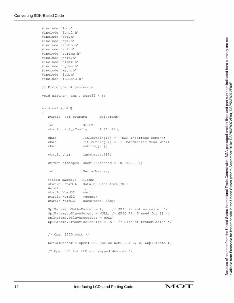
Code Example 7. IntFaceBaro.c for the DSP56F805 Environment
/* IntFaceBaro.c - Procedure used to interface to TLC2543 - 12-bit analog-to-digital converter with serial control and 11 analog inputs. The DSP56F805 SPI0 port is employed. The software is developed for the DSP56F805 EVM environment. Interface to NetMedia LCD+ serial display device and keypad is also included - March 1, 2001 */
MOT Interfacing LCDs and Porting Code 11 For More Information On This Product,
Go to: www.freescale.com
Bec
ause
of a
n or
der f
rom
the
Uni
ted
Sta
tes
Inte
rnat
iona
l Tra
de C
omm
issi
on, B
GA
-pac
kage
d pr
oduc
t lin
es a
nd p
art n
umbe
rs in
dica
ted
here
cur
rent
ly a
re n
ot
avai
labl
e fro
m F
rees
cale
for i
mpo
rt or
sal
e in
the
Uni
ted
Sta
tes
prio
r to
Sep
tem
ber 2
010:
DS
P56
F807
VF8
0, D
SP
56F8
07V
F80E
Converting SDK-Based Code
#include "io.h" #include "fcntl.h" #include "bsp.h" #include "spi.h" #include "stdio.h" #include "sci.h" #include "string.h" #include "port.h" #include "timer.h" #include "types.h" #include "math.h" #include "lcd.h" #include "TLC2543.h"
// Prototype of procedure
void BaroAdj( int , Word32 * );
void main(void) {
static spi_sParams SpiParams;
int SciFD; static sci_sConfig SciConfig;
char TitleString1[] = {"DSP Interface Demo"}; char TitleString2[] = {" Barometric Meas.\n"}; char astring[20];
static char inputarray[8];
struct timespec OneMillisecond = {0,1000000};
int SerialMaster;
static UWord16 ADcmd; static UWord16 Datain, DataStore[70]; Word16 i, ii; static Word32 sum; static Word32 Vcount; static Word32 BaroPress, BAdj;
SpiParams.bSetAsMaster = 1; /* SPI0 is set as master */ SpiParams.pSlaveSelect = NULL; /* GPIO Pin 5 used for SS */ SpiParams.pSlaveDeselect = NULL; SpiParams.TransmissionSize = 16; /* Size of transmission */
/* Open SPI0 port */
SerialMaster = open( BSP_DEVICE_NAME_SPI_0, 0, &SpiParams );
/* Open SCI for LCD and keypad devices */
12 Interfacing LCDs and Porting Code MOT
Bec
ause
of a
n or
der f
rom
the
Uni
ted
Sta
tes
Inte
rnat
iona
l Tra
de C
omm
issi
on, B
GA
-pac
kage
d pr
oduc
t lin
es a
nd p
art n
umbe
rs in
dica
ted
here
cur
rent
ly a
re n
ot
avai
labl
e fro
m F
rees
cale
for i
mpo
rt or
sal
e in
the
Uni
ted
Sta
tes
prio
r to
Sep
tem
ber 2
010:
DS
P56
F807
VF8
0, D
SP
56F8
07V
F80E
Converting SDK-Based Code
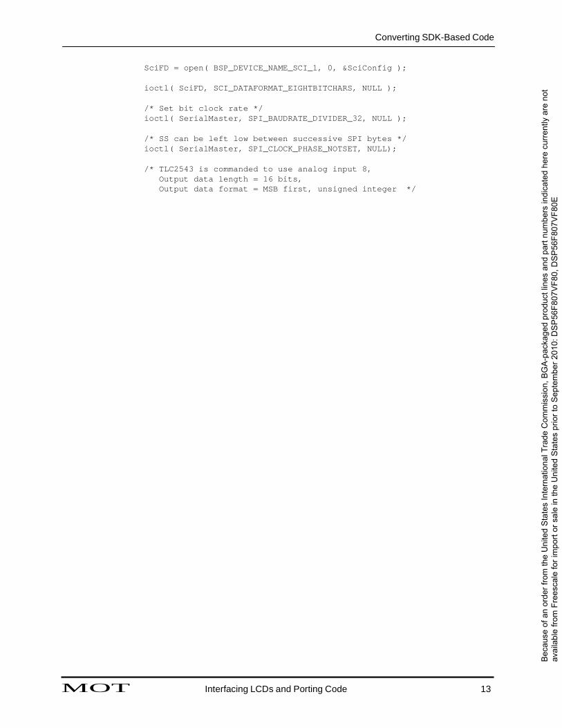
SciFD = open( BSP_DEVICE_NAME_SCI_1, 0, &SciConfig );
ioctl( SciFD, SCI_DATAFORMAT_EIGHTBITCHARS, NULL );
/* Set bit clock rate */ ioctl( SerialMaster, SPI_BAUDRATE_DIVIDER_32, NULL );
/* SS can be left low between successive SPI bytes */ ioctl( SerialMaster, SPI_CLOCK_PHASE_NOTSET, NULL);
/* TLC2543 is commanded to use analog input 8,
Output data length = 16 bits, Output data format = MSB first, unsigned integer */
MOT Interfacing LCDs and Porting Code 13
Bec
ause
of a
n or
der f
rom
the
Uni
ted
Sta
tes
Inte
rnat
iona
l Tra
de C
omm
issi
on, B
GA
-pac
kage
d pr
oduc
t lin
es a
nd p
art n
umbe
rs in
dica
ted
here
cur
rent
ly a
re n
ot
avai
labl
e fro
m F
rees
cale
for i
mpo
rt or
sal
e in
the
Uni
ted
Sta
tes
prio
r to
Sep
tem
ber 2
010:
DS
P56
F807
VF8
0, D
SP
56F8
07V
F80E
ARCHFIVreEDesBYcaFRleEESSCeAmLEicSoEnMdICuOcNDtoUCr,TOInRc, IN. C. 2005 Converting SDK-Based Code
A/*RCprHoIcVeEsDs BslYeeFpRsEfEoSrC1ALmsEecS.EM*/ICONDUCTOR, INC. 2005 nanosleep( &OneMillisecond, NULL );
DataStore[i] = Datain; sum += Datain; /* accumulate measurements for */
/* batch averaging */ }
Vcount = (sum >> 6);
/* Compute Barometric pressure in millibars, the following
expression uses 32-bit arithmetic and 10 bit left on all coefficients, equation scaled for millibars and a 12 bit ADC is
P = 0,271267*Vcount + 105.56
Fre
esc
ale
Sem
icon
duct
or, In
c.
AARR
CCHH
IIVVEEDD
BBYY
FFRREEEE
SSCCAA
LLEE SS
EEMMIICC
OONN
DDUU
CCTTOO
RR,, II
NNCC
.. 220000
55 Equation taken from MPX4115A Tech Data sheet */
BaroPress = (278 * Vcount + 108093) >> 10;
BaroPress += BAdj;
PosCursor[1] = 42; /* Set Cursor position in LCD */ write( SciFD, PosCursor, 2); /* Send result to LCD */ sprintf( astring, "P = %ld mbars", BaroPress ); write( SciFD, astring, strlen(astring) );
}
close(SerialMaster);
}
/* This procedure is called when it is determined that the user desires to enter a correction term to the barometric pressure measurement to compensate fo the altitude above sea-level of the sensor. It is expected that the user will provide the pressure adjustment in millibars. */
void BaroAdj( int SciFD, Word32 *padj ) {
char astring[]={"Baro Height Adj\n"}; char bstring[]={"Enter (mb) = "}; char iarray[8]; int icount, temp, i, tenpow;
write( SciFD, NewScr, 1 ); PosCursor[1] = 22; write( SciFD, PosCursor, 2); write( SciFD, astring, strlen(astring)); PosCursor[1] = 42; write( SciFD, PosCursor, 2); write( SciFD, bstring, strlen(bstring));
icount = 0; while (true) {
read( SciFD, &iarray[icount], 1 );
14 Interfacing LCDs and Porting Code MOT For More Information On This Product,
Go to: www.freescale.com
Bec
ause
of a
n or
der f
rom
the
Uni
ted
Sta
tes
Inte
rnat
iona
l Tra
de C
omm
issi
on, B
GA
-pac
kage
d pr
oduc
t lin
es a
nd p
art n
umbe
rs in
dica
ted
here
cur
rent
ly a
re n
ot
avai
labl
e fro
m F
rees
cale
for i
mpo
rt or
sal
e in
the
Uni
ted
Sta
tes
prio
r to
Sep
tem
ber 2
010:
DS
P56
F807
VF8
0, D
SP
56F8
07V
F80E
ARCHFIVreEDesBYcaFRleEESSCeAmLEicSoEnMdICuOcNDtoUCr,TOInRc, IN. C. 2005 Conclusions
ifAR( CiHarIVraEyD[iBcoYunFtR]E=E=SCCRA[L0]E )SEbMreICakO;NDUCTOR, INC. 2005 if ( (iarray[icount] >= ’0’) && (iarray[icount] < ’9’)) {
write( SciFD, &iarray[icount], 1 ); icount++;
}
}
iarray[icount] = 0; sscanf(iarray, "%d", &temp );
*padj = (Word32)temp;
}
6. Conclusions
Fre
esc
ale
Sem
icon
duct
or, In
c.
AARR
CCHH
IIVVEEDD
BBYY
FFRREEEE
SSCCAA
LLEE SS
EEMMIICC
OONN
DDUU
CCTTOO
RR,, II
NNCC
.. 220000
55
This application note was written to describe the interface capabilities of the Motorola DSP56F80x. It has shown that by using the higher-order C language and the facilities provided by the Embedded SDK, a user can easily interface a serial-based intelligent LCD with a built-in keypad support to the processor’s SCI port without additional hardware. The code examples demonstrated that with one brand of LCD, serial module bi-directional communication was established and maintained effectively and reliably.
Additionally, the software program IntFaceBaro.c, generated for the DSP56824 in Application Note AN1921/D, was converted quickly and efficiently to operate the serial LCD and keypad, and an SPI-based analog-to-digital converter was interfaced to an absolute atmospheric pressure sensor from a DSP56F805. Most of the code remained the same; changes were required only to the code that controlled the SCI and SPI ports.
7. References 1. Some General DSP568xx Interface Examples using the Embedded SDK, AN1921/D
2. DSP5680x User’s Manual, DSP56F801-7UM/D
3. DSP56F805 Evaluation Module Hardware User’s Manual, DSP56F805EVMUM/D
4. Embedded SDK (Software Development Kit) Programmer’s Guide, SDK122/D
MOT Interfacing LCDs and Porting Code 15 For More Information On This Product,
Go to: www.freescale.com
Bec
ause
of a
n or
der f
rom
the
Uni
ted
Sta
tes
Inte
rnat
iona
l Tra
de C
omm
issi
on, B
GA
-pac
kage
d pr
oduc
t lin
es a
nd p
art n
umbe
rs in
dica
ted
here
cur
rent
ly a
re n
ot
avai
labl
e fro
m F
rees
cale
for i
mpo
rt or
sal
e in
the
Uni
ted
Sta
tes
prio
r to
Sep
tem
ber 2
010:
DS
P56
F807
VF8
0, D
SP
56F8
07V
F80E
ARCHFIVreEDesBYcaFRleEESSCeAmLEicSoEnMdICuOcNDtoUCr,TOInRc, IN. C. 2005 ARCHFIVreEDesBYcaFRleEESSCeAmLEicSoEnMdICuOcNDtoUCr,TOInRc, IN. C. 2005 NetMedia’s Serial LCD+ NetMedia’s Serial LCD+
Appendix AA.RCHNIVEeDtMBYeFdRiEaE’SsCSALeEriSaElMILCOCNDDU+CTOR, INC. 2005 Appendix AA.RCHNIVEeDtMBYeFdRiEaE’SsCSALeEriSaElMILCOCNDDU+CTOR, INC. 2005
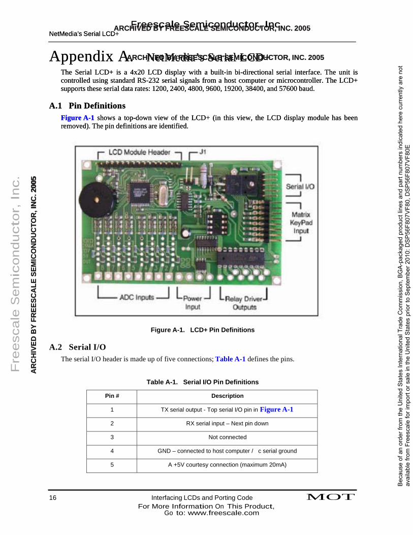
The Serial LCD+ is a 4x20 LCD display with a built-in bi-directional serial interface. The unit is controlled using standard RS-232 serial signals from a host computer or microcontroller. The LCD+ supports these serial data rates: 1200, 2400, 4800, 9600, 19200, 38400, and 57600 baud.
The Serial LCD+ is a 4x20 LCD display with a built-in bi-directional serial interface. The unit is controlled using standard RS-232 serial signals from a host computer or microcontroller. The LCD+ supports these serial data rates: 1200, 2400, 4800, 9600, 19200, 38400, and 57600 baud.
A.1 Pin Definitions A.1 Pin Definitions
Figure A-1 shows a top-down view of the LCD+ (in this view, the LCD display module has been removed). The pin definitions are identified. Figure A-1 shows a top-down view of the LCD+ (in this view, the LCD display module has been removed). The pin definitions are identified.
Fre
esc
ale
Sem
icon
duct
or, In
c.
AARR
CCHH
IIVVEEDD
BBYY
FFRREEEE
SSCCAA
LLEE SS
EEMMIICC
OONN
DDUU
CCTTOO
RR,, II
NNCC
.. 220000
55
Figure A-1. LCD+ Pin Definitions A.2 Serial I/O
The serial I/O header is made up of five connections; Table A-1 defines the pins.
Table A-1. Serial I/O Pin Definitions
Pin # Description
1 TX serial output - Top serial I/O pin in Figure A-1
2 RX serial input – Next pin down
3 Not connected
4 GND – connected to host computer / c serial ground
5 A +5V courtesy connection (maximum 20mA)
16 Interfacing LCDs and Porting Code MOT For More Information On This Product,
Go to: www.freescale.com
Bec
ause
of a
n or
der f
rom
the
Uni
ted
Sta
tes
Inte
rnat
iona
l Tra
de C
omm
issi
on, B
GA
-pac
kage
d pr
oduc
t lin
es a
nd p
art n
umbe
rs in
dica
ted
here
cur
rent
ly a
re n
ot
avai
labl
e fro
m F
rees
cale
for i
mpo
rt or
sal
e in
the
Uni
ted
Sta
tes
prio
r to
Sep
tem
ber 2
010:
DS
P56
F807
VF8
0, D
SP
56F8
07V
F80E
ARCHFIVreEDesBYcaFRleEESSCeAmLEicSoEnMdICuOcNDtoUCr,TOInRc, IN. C. 2005 ARCHFIVreEDesBYcaFRleEESSCeAmLEicSoEnMdICuOcNDtoUCr,TOInRc, IN. C. 2005 NetMedia’s Serial LCD+ NetMedia’s Serial LCD+
A.3 Power Input A.3 Power Input ARCHIVED BY FREESCALE SEMICONDUCTOR, INC. 2005 ARCHIVED BY FREESCALE SEMICONDUCTOR, INC. 2005 The power input section consists of four through holes (Solder pads). The two holes marked GND are grounds. The hole marked +5.5V to +15V is tied to the onboard regulator of the LCD+ module. The hole marked +5V ties to the +5V bus and is used to bypass the LCD+’s onboard regulator when a regulated +5V source is supplied.
The power input section consists of four through holes (Solder pads). The two holes marked GND are grounds. The hole marked +5.5V to +15V is tied to the onboard regulator of the LCD+ module. The hole marked +5V ties to the +5V bus and is used to bypass the LCD+’s onboard regulator when a regulated +5V source is supplied.
A.4 ADC Inputs A.4 ADC Inputs
The eight ADC inputs are labeled 1 – 8. By default, all ADC inputs are set to read voltage in the 0 to The eight ADC inputs are labeled 1 – 8. By default, all ADC inputs are set to read voltage in the 0 to +5V range. +5V range.
A.5 Relay Driver Outputs A.5 Relay Driver Outputs
There are nine Relay Driver connections (Labeled on the underside of the board as R1-8 and RLY_VDC). The connections labeled R1-8 are the relay driver chip outputs; the RLY+VDC connection provides access to the ULN2803A driver chip’s internal back EMF protection diodes.
There are nine Relay Driver connections (Labeled on the underside of the board as R1-8 and RLY_VDC). The connections labeled R1-8 are the relay driver chip outputs; the RLY+VDC connection provides access to the ULN2803A driver chip’s internal back EMF protection diodes.
Fre
esc
ale
Sem
icon
duct
or, In
c.
AARR
CCHH
IIVVEEDD
BBYY
FFRREEEE
SSCCAA
LLEE SS
EEMMIICC
OONN
DDUU
CCTTOO
RR,, II
NNCC
.. 220000
55
A.6 Matrix KeyPad Input A.6 Matrix KeyPad Input
The keypad input connections (visible in Figure A-1) are the upper-most eight of the 8x2 header connection. The lower eight of the 8x2 header connection (which are not visible in Figure A-1) are used by the factory for programming and should be left unconnected.
The keypad input connections (visible in Figure A-1) are the upper-most eight of the 8x2 header connection. The lower eight of the 8x2 header connection (which are not visible in Figure A-1) are used by the factory for programming and should be left unconnected.
A.7 Interfacing the LCD+ A.7 Interfacing the LCD+
The LCD+ can be controlled using any computer or microprocessor supporting 1200-57600 baud data rates with an 8,N,1 data format (8 data bits, No parity, 1 stop bit). The LCD+ can be controlled using any computer or microprocessor supporting 1200-57600 baud data rates with an 8,N,1 data format (8 data bits, No parity, 1 stop bit).
A.8 Keypad Interface A.8 Keypad Interface
The keypad interface supports matrix keypads up to 4x4 in size (16 keys). Instead of predefining the keypad’s key serial data format as 0 through 15, each of the keypad’s keys is serially represented by a user-definable byte value. This user-definable value, or “Tag”, is stored within the LCD+ EEPROM as a 0-15 byte array. Each byte of the array corresponds to a key on the keypad (i.e., key 0 corresponds to byte 0 of the array). When a key is pressed, the stored byte representation for that key number is sent serially.
The keypad interface supports matrix keypads up to 4x4 in size (16 keys). Instead of predefining the keypad’s key serial data format as 0 through 15, each of the keypad’s keys is serially represented by a user-definable byte value. This user-definable value, or “Tag”, is stored within the LCD+ EEPROM as a 0-15 byte array. Each byte of the array corresponds to a key on the keypad (i.e., key 0 corresponds to byte 0 of the array). When a key is pressed, the stored byte representation for that key number is sent serially.
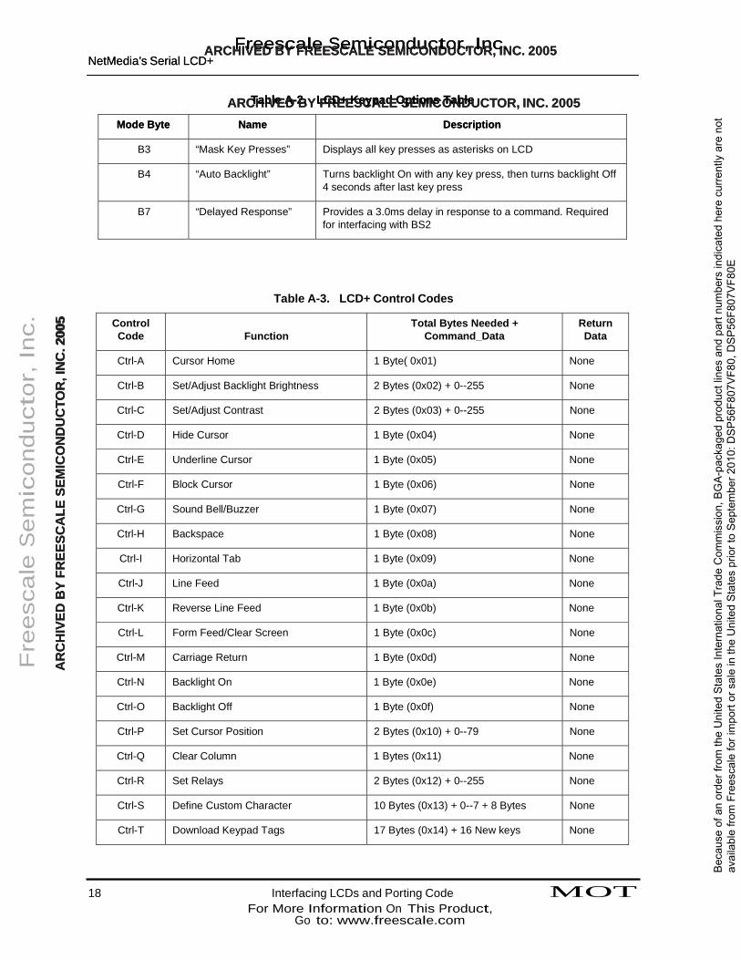
A.9 Keypad Options A.9 Keypad Options
Various keypad options are supported by six user-definable options, or “modes”. These modes are set by sending CTRL-X, followed by the user’s command byte containing the desired modes. As shown in Table A-2, placing a “1” in any one of the bits turns its corresponding option On, and a “0” turns it Off
Various keypad options are supported by six user-definable options, or “modes”. These modes are set by sending CTRL-X, followed by the user’s command byte containing the desired modes. As shown in Table A-2, placing a “1” in any one of the bits turns its corresponding option On, and a “0” turns it Off
Table A-2. LCD+ Keypad Options Table Table A-2. LCD+ Keypad Options Table
Mode Byte Mode Byte Name Name Description Description
B0 “Key Beeps” Beep buzzer during each key press
B1 “Key Press Format” Sends one byte for key down and one for key up
B2 “LCD Echo” Echoes key press data, ASCII representation to LCD display MOT Interfacing LCDs and Porting Code 17
For More Information On This Product, Go to: www.freescale.com
Bec
ause
of a
n or
der f
rom
the
Uni
ted
Sta
tes
Inte
rnat
iona
l Tra
de C
omm
issi
on, B
GA
-pac
kage
d pr
oduc
t lin
es a
nd p
art n
umbe
rs in
dica
ted
here
cur
rent
ly a
re n
ot
avai
labl
e fro
m F
rees
cale
for i
mpo
rt or
sal
e in
the
Uni
ted
Sta
tes
prio
r to
Sep
tem
ber 2
010:
DS
P56
F807
VF8
0, D
SP
56F8
07V
F80E
ARCHFIVreEDesBYcaFRleEESSCeAmLEicSoEnMdICuOcNDtoUCr,TOInRc, IN. C. 2005 ARCHFIVreEDesBYcaFRleEESSCeAmLEicSoEnMdICuOcNDtoUCr,TOInRc, IN. C. 2005 NetMedia’s Serial LCD+ NetMedia’s Serial LCD+
ARCTHaIbVleEAD-2B.YLFCRDE+EKSeCyApaLdEOSpEtiMonICs OTaNbDleUCTOR, INC. 2005 ARCTHaIbVleEAD-2B.YLFCRDE+EKSeCyApaLdEOSpEtiMonICs OTaNbDleUCTOR, INC. 2005
Mode Byte Mode Byte Name Name Description Description
B3 “Mask Key Presses” Displays all key presses as asterisks on LCD
B4 “Auto Backlight” Turns backlight On with any key press, then turns backlight Off 4 seconds after last key press
B7 “Delayed Response” Provides a 3.0ms delay in response to a command. Required for interfacing with BS2
Table A-3. LCD+ Control Codes
Fre
esc
ale
Sem
icon
duct
or, In
c.
AARR
CCHH
IIVVEEDD
BBYY
FFRREEEE
SSCCAA
LLEE SS
EEMMIICC
OONN
DDUU
CCTTOO
RR,, II
NNCC
.. 220000
55 Control Code
Function
Total Bytes Needed + Command_Data
Return Data
Ctrl-A Cursor Home 1 Byte( 0x01) None
Ctrl-B Set/Adjust Backlight Brightness 2 Bytes (0x02) + 0--255 None
Ctrl-C Set/Adjust Contrast 2 Bytes (0x03) + 0--255 None
Ctrl-D Hide Cursor 1 Byte (0x04) None
Ctrl-E Underline Cursor 1 Byte (0x05) None
Ctrl-F Block Cursor 1 Byte (0x06) None
Ctrl-G Sound Bell/Buzzer 1 Byte (0x07) None
Ctrl-H Backspace 1 Byte (0x08) None
Ctrl-I Horizontal Tab 1 Byte (0x09) None
Ctrl-J Line Feed 1 Byte (0x0a) None
Ctrl-K Reverse Line Feed 1 Byte (0x0b) None
Ctrl-L Form Feed/Clear Screen 1 Byte (0x0c) None
Ctrl-M Carriage Return 1 Byte (0x0d) None
Ctrl-N Backlight On 1 Byte (0x0e) None
Ctrl-O Backlight Off 1 Byte (0x0f) None
Ctrl-P Set Cursor Position 2 Bytes (0x10) + 0--79 None
Ctrl-Q Clear Column 1 Bytes (0x11) None
Ctrl-R Set Relays 2 Bytes (0x12) + 0--255 None
Ctrl-S Define Custom Character 10 Bytes (0x13) + 0--7 + 8 Bytes None
Ctrl-T Download Keypad Tags 17 Bytes (0x14) + 16 New keys None
18 Interfacing LCDs and Porting Code MOT For More Information On This Product,
Go to: www.freescale.com
Bec
ause
of a
n or
der f
rom
the
Uni
ted
Sta
tes
Inte
rnat
iona
l Tra
de C
omm
issi
on, B
GA
-pac
kage
d pr
oduc
t lin
es a
nd p
art n
umbe
rs in
dica
ted
here
cur
rent
ly a
re n
ot
avai
labl
e fro
m F
rees
cale
for i
mpo
rt or
sal
e in
the
Uni
ted
Sta
tes
prio
r to
Sep
tem
ber 2
010:
DS
P56
F807
VF8
0, D
SP
56F8
07V
F80E
ARCHFIVreEDesBYcaFRleEESSCeAmLEicSoEnMdICuOcNDtoUCr,TOInRc, IN. C. 2005 ARCHFIVreEDesBYcaFRleEESSCeAmLEicSoEnMdICuOcNDtoUCr,TOInRc, IN. C. 2005 NetMedia’s Serial LCD+ NetMedia’s Serial LCD+
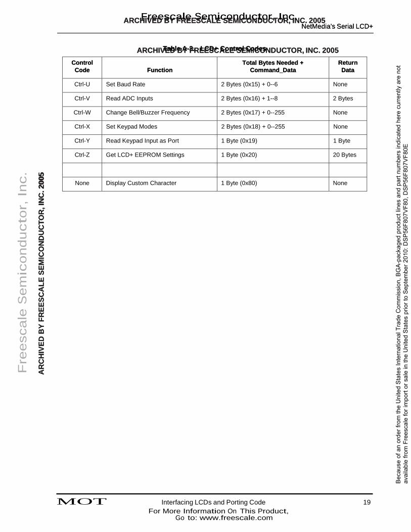
ARCHIVTEaDbleBAY-3F.RELECSDC+ ACLonEtrSoEl CMoICdeOsNDUCTOR, INC. 2005 ARCHIVTEaDbleBAY-3F.RELECSDC+ ACLonEtrSoEl CMoICdeOsNDUCTOR, INC. 2005
Control Control Code Code
Function Function
Total Bytes Needed + Command_Data
Total Bytes Needed + Command_Data
Return Return Data Data
Ctrl-U Set Baud Rate 2 Bytes (0x15) + 0--6 None
Ctrl-V Read ADC Inputs 2 Bytes (0x16) + 1--8 2 Bytes
Ctrl-W Change Bell/Buzzer Frequency 2 Bytes (0x17) + 0--255 None
Ctrl-X Set Keypad Modes 2 Bytes (0x18) + 0--255 None
Ctrl-Y Read Keypad Input as Port 1 Byte (0x19) 1 Byte
Ctrl-Z Get LCD+ EEPROM Settings 1 Byte (0x20) 20 Bytes
None Display Custom Character 1 Byte (0x80) None
Fre
esc
ale
Sem
icon
duct
or, In
c.
AARR
CCHH
IIVVEEDD
BBYY
FFRREEEE
SSCCAA
LLEE SS
EEMMIICC
OONN
DDUU
CCTTOO
RR,, II
NNCC
.. 220000
55
MOT Interfacing LCDs and Porting Code 19
For More Information On This Product, Go to: www.freescale.com
Bec
ause
of a
n or
der f
rom
the
Uni
ted
Sta
tes
Inte
rnat
iona
l Tra
de C
omm
issi
on, B
GA
-pac
kage
d pr
oduc
t lin
es a
nd p
art n
umbe
rs in
dica
ted
here
cur
rent
ly a
re n
ot
avai
labl
e fro
m F
rees
cale
for i
mpo
rt or
sal
e in
the
Uni
ted
Sta
tes
prio
r to
Sep
tem
ber 2
010:
DS
P56
F807
VF8
0, D
SP
56F8
07V
F80E

ARCHFIVreEDesBYcaFRleEESSCeAmLEicSoEnMdICuOcNDtoUCr,TOInRc, IN. C. 2005
ARCHIVED BY FREESCALE SEMICONDUCTOR, INC. 2005
Fre
esc
ale
Sem
icon
duct
or, In
c.
AARR
CCHH
IIVVEEDD
BBYY
FFRREEEE
SSCCAA
LLEE SS
EEMMIICC
OONN
DDUU
CCTTOO
RR,, II
NNCC
.. 220000
55
OnCETM is a registered trademark of Motorola, Inc.
Motorola reserves the right to make changes without further notice to any products herein. Motorola makes no warranty, representation or guarantee regarding the suitability of its products for any particular purpose, nor does Motorola assume any liability arising out of the application or use of any product or circuit, and specifically disclaims any and all liability, including without limitation consequential or incidental damages. “Typical” parameters which may be provided in Motorola data sheets and/or specifications can and do vary in different applications and actual performance may vary over time. All operating parameters, including “Typicals” must be validated for each customer application by customer’s technical experts. Motorola does not convey any license under its patent rights nor the rights of others. Motorola products are not designed, intended, or authorized for use as components in systems intended for surgical implant into the body, or other applications intended to support or sustain life, or for any other application in which the failure of the Motorola product could create a situation where personal injury or death may occur. Should Buyer purchase or use Motorola products for any such unintended or unauthorized application, Buyer shall indemnify and hold Motorola and its officers, employees, subsidiaries, affiliates, and distributors harmless against all claims, costs, damages, and expenses, and reasonable attorney fees arising out of, directly or indirectly, any claim of personal injury or death associated with such unintended or unauthorized use, even if such claim alleges that Motorola was negligent regarding the design or manufacture of the part. Motorola and are registered trademarks of Motorola, Inc. Motorola, Inc. is an Equal Opportunity/Affirmative Action Employer.
How to reach us: USA/EUROPE/Locations Not Listed: Motorola Literature Distribution: P.O. Box 5405, Denver, Colorado 80217. 1-303-675-2140 or 1-800-441-2447
JAPAN: Motorola Japan Ltd.; SPS, Technical Information Center, 3-20-1 Minami-Azabu. Minato-ku, Tokyo 106-8573 Japan. 81-3-3440-3569
ASIA/PACIFIC: Motorola Semiconductors H.K. Ltd.; Silicon Harbour Centre, 2 Dai King Street, Tai Po Industrial Estate, Tao Po, N.T., Hong Kong. 852-26668334
Technical Information Center: 1-800-521-6274
HOME PAGE: http://motorola.com/semiconductors/dsp MOTOROLA HOME PAGE: http://motorola.com/semiconductors/
For More Information On This Product, Go to: www.freescale.com
AN1924/D
Bec
ause
of a
n or
der f
rom
the
Uni
ted
Sta
tes
Inte
rnat
iona
l Tra
de C
omm
issi
on, B
GA
-pac
kage
d pr
oduc
t lin
es a
nd p
art n
umbe
rs in
dica
ted
here
cur
rent
ly a
re n
ot
avai
labl
e fro
m F
rees
cale
for i
mpo
rt or
sal
e in
the
Uni
ted
Sta
tes
prio
r to
Sep
tem
ber 2
010:
DS
P56
F807
VF8
0, D
SP
56F8
07V
F80E
Copyright © 2022 FDOKUMEN