Interface for use in BACnet - Amazon AWS
220
EDMT72-749B DESIGN GUIDE Monitoring & control for VRV and Heat Reclaim Ventilator BACnet ® is a registered trademark of ASHRAE. BACnet Explorer is the software tool for system integrators by Cimetrics Inc. Interface for use in BACnet ®
-
Upload
khangminh22 -
Category
Documents
-
view
3 -
download
0
Transcript of Interface for use in BACnet - Amazon AWS

EDMT72-749B
DESIGN GUIDE
Monitoring & control for VRV and
Heat Reclaim Ventilator
BACnet® is a registered trademark of ASHRAE.BACnet Explorer is the software tool for system integrators by Cimetrics Inc.
Interface for use
in BACnet®


EDMT72-749B
1
2
3
4
5
6
7
8
9
Table of Contents
Part 1 Interface for use in BACnet® .............................................11. BACnet® Interface...................................................................................2
1.1 Outline and Features................................................................................21.2 System Outline .........................................................................................21.3 System Configuration ...............................................................................31.4 Specifications ...........................................................................................41.5 Components .............................................................................................41.6 Dimensions...............................................................................................41.7 BACnet® Object List .................................................................................61.8 Names and Functions of Each Part..........................................................71.9 Electric Wiring ..........................................................................................91.10 Functions................................................................................................131.11 Backup Systems for Troubles ................................................................151.12 BMS (Building Management System) ....................................................161.13 Adopting “Super Wiring System” ............................................................16
Part 2 Functional Specifications ................................................171. Introduction ...........................................................................................192. Network Topology .................................................................................193. Air Conditioner Monitor/Control Items ...................................................204. Supported Models and Monitor/Control Items.......................................215. BACnet® Protocol Implementation Conformance Statement (PICS) ....226. BACnet® Interoperability Building Blocks Supported (BIBBs)...............23
6.1 Data Sharing BIBBs ...............................................................................236.2 Alarm and Event Management BIBBs....................................................236.3 SCHEDuling BIBBs ................................................................................246.4 Trending BIBBs ......................................................................................246.5 Device Management BIBBs ...................................................................246.6 Network Management BIBBs .................................................................25
7. Objects ..................................................................................................267.1 Supported Object Type ..........................................................................267.2 Member Objects .....................................................................................27
8. Properties..............................................................................................328.1 Accumulator Object Type .......................................................................328.2 Analog Input Object Type.......................................................................338.3 Analog Value Object Type......................................................................358.4 Binary Input Object Type (Supported Intrinsic Reporting)......................368.5 Binary Input Object Type (Non-supported Intrinsic Reporting)...............378.6 Binary Output Object Type .....................................................................398.7 Binary Value Object Type.......................................................................408.8 Device Object Type ................................................................................428.9 Multi-state Input Object Type .................................................................438.10 Multi-state Output Object Type...............................................................44
Table of Contents i

EDMT72-749B
9. Report Function.....................................................................................459.1 COV Notification.....................................................................................459.2 Event Notification ...................................................................................46
10.Error Response in BACnet® Communication........................................4811.Detailed Description of Objects.............................................................49
11.1 Common to All Objects...........................................................................4911.2 Start/Stop (Setting).................................................................................5011.3 Start/Stop (Status)..................................................................................5011.4 Alarm ......................................................................................................5111.5 Malfunction Code ...................................................................................5111.6 Air-conditioning Mode (Setting) ..............................................................5211.7 Air-conditioning Mode (Status) ...............................................................5211.8 Airflow Rate Level (Setting)....................................................................5311.9 Airflow Rate Level (Status).....................................................................5311.10Measured Room Temperature...............................................................5411.11Set Room Temperature .........................................................................5511.12Filter Sign Signal....................................................................................5611.13Filter Sign Signal Reset .........................................................................5611.14Remote Controller Enable/Disable (Start/Stop) .....................................5711.15Remote Controller Enable/Disable (Air-conditioning Mode) ..................5711.16Remote Controller Enable/Disable (Set Temperature) ..........................5711.17Central Control (Lower Central Control Disable) ...................................5811.18Accumulated Power...............................................................................5811.19Communication Status...........................................................................5911.20Forced System Stop ..............................................................................5911.21Air Direction (Setting).............................................................................6011.22Air Direction (Status)..............................................................................6011.23Forced Thermostat Disable (Setting).....................................................6111.24Forced Thermostat Disable (Status)......................................................6111.25Energy Saving (Setting).........................................................................6111.26Energy Saving (Status)..........................................................................6111.27Thermostat Status .................................................................................6211.28Compressor Status ................................................................................6211.29Indoor Fan Status ..................................................................................6211.30Heater Operation Status ........................................................................6211.31Ventilation Mode (Setting) .....................................................................6311.32Ventilation Mode (Status) ......................................................................6311.33Ventilation Amount (Setting) ..................................................................6411.34Ventilation Amount (Status) ...................................................................64
12.Others ...................................................................................................6512.1 Initial Status at Start-up ..........................................................................6512.2 BACnet® Network Layer.........................................................................6512.3 Time Adjustment ....................................................................................6512.4 Device Communication Control Service.................................................65
13.Appendix A: PICS (D-BACS Interface for use in BACnet® Ver. 6.10) ................................6713.1 BACnet® Protocol Implementation Conformance Statement .................67
14.Appendix B: PICS (D-BACS Interface for use in BACnet® Ver. 6.20) ................................7314.1 BACnet® Protocol Implementation Conformance Statement .................73
15.Appendix C: PICS (D-BACS Interface for use in BACnet® Ver. 6.30) ................................79
ii Table of Contents

EDMT72-749B
1
2
3
4
5
6
7
8
9
15.1 BACnet® Protocol Implementation Conformance Statement .................79
Part 3 Point List ..........................................................................851. BACnet® Point List ................................................................................86
Part 4 Daikin’s Agreement ..........................................................951. Daikin's Interface for use in BACnet® Agreement.................................96
Part 5 Test Operation Manual.....................................................971. BACnet® Object System Diagram of Interface for use in BACnet® ......982. Specifications of Interface for use in BACnet® (1) ................................993. Specifications of Interface for use in BACnet® (2) ..............................1004. Before Visiting the Site........................................................................101
4.1 Check the Specifications of the PC and Communication Cable Used for the Trial Operation as well as the Version of the Trial Operation Program.................................................................101
4.2 Obtaining Object Information................................................................1024.3 Setting the Trial Operation PC Modem
(When Connecting the Interface for use in BACnet® and the Trial Operation PC Using RS232C Communication)......................105
5. Work Procedure for the Interface for use in BACnet®.........................1155.1 Connect the Trial Operation PC and Interface for use in BACnet® Via the
RS232C Cross Cable or the Hub Using the 100BASE-TX Straight Cable ..........................................................116
5.2 Start the Trial Operation Program. (On the Trial Operation PC, Double-click SetupBACnet®.) Enter the IP Address ............................118
5.3 Setting ..................................................................................................1205.4 Reset the Interface for use in BACnet®................................................1315.5 Start the Trial Operation Program ........................................................1345.6 Select the Operation Status Menu and Check the Following ...............1365.7 Check the Registration of Management Point Types ...........................1375.8 Check the All Points from the Central Control Panel............................138
6. Reference: Items which do not Need to be Changed from the Factory Settings .........................................................140
7. Q & A...................................................................................................147
Part 6 Test Run Manual (PPD) ..................................................1531. Test Run Procedures ..........................................................................1562. Connection between Service PC and Interface for use in BACnet® ...157
2.1 Wiring ...................................................................................................1572.2 Setting of IP Address (Windows 2000).................................................158
3. Setting of Pulse Rate (Using SetupBACnet®.exe) ..............................1604. Startup of PPD Test Run Tools (Using SetupPPD.exe)......................1645. Initializing ............................................................................................1656. Setting of Ports....................................................................................1667. Hardware Setting ................................................................................167
7.1 Automatic Setting .................................................................................1687.2 Manual Setting .....................................................................................169
Table of Contents iii

EDMT72-749B
8. Power Distribution Group Setting........................................................1708.1 Power Distribution Group Editing .........................................................171
9. Confirmation of Operation ...................................................................1729.1 Detailed Explanation for Confirmation Window ....................................1739.2 Confirmation Window, Normal Model...................................................1749.3 Confirmation of the Type of Wattmeter ................................................1789.4 Confirmation of Pulse Input ..................................................................1799.5 Confirmation of Integrated Values, Normal Model ...............................180
10.Error Messages...................................................................................182
Part 7 Installation Manual ........................................................1831. Installation Manual ..............................................................................184
1.1 DMS502B51 .........................................................................................1841.2 DAM411B51 (Option DIII Board)..........................................................1901.3 DAM412B51 (Option Di Board) ............................................................193
Part 8 Troubleshooting .............................................................1971. Troubleshooting Interface for use in BACnet® with LED indication.....198
1.1 Troubleshooting with CPU ALIVE LED, CPU ALRM (ALARM) LEDs .................................................................198
1.2 Troubleshooting with ETHER LINK LED, ETHER RCV LEDs .............2001.3 Troubleshooting with DIII-1-4 LEDs .....................................................2011.4 Troubleshooting with RS232C-1 TxD, RxD LEDs ................................2021.5 Troubleshooting with RS232C-2 TxD, RxD LEDs ................................203
Part 9 Interface for use in BACnet® Project Job Flow .............2051. Interface for use in BACnet® Project Job Flow ...................................206
1.1 Engineering Flow of Interface for use in BACnet® until Installation......2061.2 Initial Settings Required Items for Interface for use in BACnet® ..........208
iv Table of Contents

EDMT72-749B
Interface for use in BACnet® 1
1Part 1Interface for use in
BACnet®
1. BACnet® Interface...................................................................................21.1 Outline and Features................................................................................21.2 System Outline .........................................................................................21.3 System Configuration ...............................................................................31.4 Specifications ...........................................................................................41.5 Components .............................................................................................41.6 Dimensions...............................................................................................41.7 BACnet® Object List .................................................................................61.8 Names and Functions of Each Part..........................................................71.9 Electric Wiring ..........................................................................................91.10 Functions................................................................................................131.11 Backup Systems for Troubles ................................................................151.12 BMS (Building Management System) ....................................................161.13 Adopting “Super Wiring System” ............................................................16

BACnet® Interface EDMT72-749B
1. BACnet® Interface1.1 Outline and Features
1. Managing the information on 128 groups of air-conditioners (main units only).2. Up to 256 groups manageable and controllable at once by adding the optional DIII board3. Packaging of air-conditioner objects
* Compatible with BACnet® (ANSI / ASHRAE-135)* Compatible with BACnet® / IP (ISO16484-5)
4. Conforming to European, Oceanian, Safety and EMC rules and regulations.
1.2 System Outline
Outline of air-conditioner management system control devices
Note:1. A group consists of several indoor units that can be started or stopped simultaneously. As shown in the figure
above, a group consists of several indoor units wired to the same remote controller. For units without a remote controller, each unit is treated as a group.
2. Several groups are registered as a zone with the central remote controller. By pressing 1 button of the central remote controller, all groups within the same zone can be turned on or off simultaneously.
Interface for use in BACnet®(DMS502B51)
Interface unit to allow communications between VRV and BMS. Operation and monitoring of air conditioning systems through BACnet® communication.
Optional DIII board (DAM411B51)
Expansion kit, installed on DMS502B51 to provide 2 more DIII-NET communication ports. Not usable independently.
Optional Di board (DAM412B51)
Expansion kit, installed on DMS502B51 to provide 12 more wattmeter pulse input points. Not usable independently.
Typical BACnet® application
Local Controller
OutdoorUnit
Maximum of 10 outdoor units
Maximum of 64 Groups
Daikin's A / C infrastructure
BMS
BuildingControlnetwork
IndoorUnit
Remote Controller
HRV
DMS502B51
BA
Cn
et® /
Eth
ern
et
Fire alarm Security Power supply facility Elevator Pump Lighting ...etc
2 Interface for use in BACnet®
EDMT72-749B BACnet® Interface
1
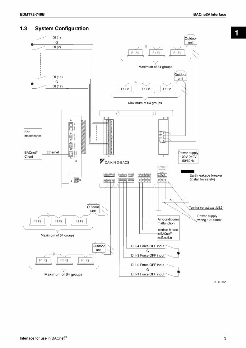
1.3 System Configuration1P191170D
DIII-4 Force OFF input
DIII-3 Force OFF input
Air-conditionermalfunction
Interface for use in BACnet®
malfunction
G
DI (1)
DI (2)
G
DI (11)
DI (12)
Maximum of 64 groups
Maximum of 64 groups
Outdoorunit
Outdoorunit
F1 F2
F1 F2 F1 F2 F1 F2
F1 F2 F1 F2
10BA
SE
-T100B
AS
E-TX
RS
-232C-2
LINE
PH
ON
ER
S-232C
-1
Formaintenance
EthernetBACnet®
ClientD
III -
3D
III -
4
Di
165
134
GG
11G
6G
15G
314
G12
G1
210
97
G8 F
1F
2F
1F
2
AC100-240V~
50/60Hz
T-Do-2
B1RS-485 Do-1
F1 R+ LDiF2 B2A1
DIII-2DIII-1
POWER
T+ A2F2 NR-F1 4GG 21 3
DAIKIN D-BACS
Terminal contact size : M3.5
Power supplywiring : 2.00mm2
Earth leakage breaker(install for safety)
Power supply100V-240V
50/60Hz
Outdoorunit
Outdoorunit
Maximum of 64 groups
Maximum of 64 groups
F1 F2 F1 F2 F1 F2
F1 F2F1 F2F1 F2
G
DIII-2 Force OFF input
DIII-1 Force OFF inputG
Interface for use in BACnet® 3

BACnet® Interface EDMT72-749B
1.4 Specifications
1.5 ComponentsThe following parts are attached to this unit.Make sure to check them before installation.
1.6 DimensionsOutside drawing of DMS502B51
Unit (mm)
C: 3D056945B
Rated Electrical Conditions Rated Voltage and Frequency Single Phase AC 100~240V, 50/60 Hz
Rated Power Maximum 20W
Conditions for Use Power Supply Fluctuation ±10% of the Rated Value
Outdoor Air Temperature -10~+50°C
Ambient Humidity 0~90% (Sweating is not acceptable)
Preservation Temperature -15~+60°C
Performance Insulation Resistance 50MΩ or more by DC500 megaohmmeter
Mass 2.8 kg
Colour of the Unit Stainless steel
BACnet® Interface 1 set
INSTALLATION MANUAL 1 copy
1) Rated electrical conditions(1) Rated voltage and frequency : Single phase AC100-240V,
50/60Hz(2) Rated power : Maximum 20W
2) Conditions for use(1) Power supply fluctuation : ±10% of the rated value(2) Outdoor air temperature : -10~ +50˚C(3) Ambient humidity : 0~90% (Sweating is not acceptable)(4) Preservation temperature : -15~ +60˚C
3) Performance Insulation resistance :50MΩ or more by DC500 megohmmeter
4) Mass : 2.8Kg5) Colour of the unit : Stainless steel
( *1 ) The drawing within the dotted line showshow the OPTION DIII BOARD(DAM411B51) is installed
( *2 ) The drawing within the dotted line showshow the OPTION Di BOARD(DAM412B51) is installed
Detailed drawing of fixing hole
R2.254.5
9
φ 10
68.5 ± 1
4-M3.5(13) ± 1
PC
MC
IAB
AC
KU
P
D-SUB 9Pin(male)
24-M2.5
(15) ± 1
260
± 1
275
± 1
(* 2) (* 1)
130 ± 1
263 ± 1
4-M3.54-M3.5
10-M2.5
3-M3.5
DAIKIN D-BACS
4 Interface for use in BACnet®

EDMT72-749B BACnet® Interface
1
Outline of functions of DAM411B51C: 1P191165C
Outline of functions of DAM412B51
1P191166D
30 ± 3
(104.5)14
0 ±
1.2
(27)
Master central setting connector
(12.7)
Outside dimension of PCB
PbF
DIII
-4D
III-3
H8A
LIV
E
D3R
CV
D3R
CV
Unit (mm)
This unit is for adding 2 port to the DIII-NET communication port by installing it on the Interface for use in BACnet® DMS502B51.
Make sure to connect the unit with DIII-NET master(Do not remove the master central setting connector.)When using together with other centralized control equipment such as central remote controllers or ON/OFF controllers, remove the master central setting connectors of the central remote controllers or ON/OFF controllers
This unit is for 12 points of Di input (no voltage contact input) by installing it on the Interface for use in BACnet® DMS502B51.
(28.86) (8.5)
Outside dimension of PCB
30 ± 3
140
± 1
.2
(104.5)
PbF
H8A
LIV
E
Unit (mm)
Interface for use in BACnet® 5

BACnet® Interface EDMT72-749B
1.7 BACnet® Object ListEach air conditioner management point is mapped to the corresponding BACnet® object's instance number.The BACnet® object uses the data field of the instance number 22 as shown below.
The air conditioner number represents the number used by the air conditioner line to manage each air conditioner and the BACnet® clients (HIM and other ICONT devices) use this number to specify the air conditioner.Each member number corresponds to each management item for the air conditioner, as defined in the following object list.
Central control (lower central control disable) and forced system stop are only available for 000, 064, 128, and 192.
Note:1. The room temperature is measured with the suction air. Since the indoor unit fan stops when the thermostat is disabled or the air conditioner is stopped, or in a special operation such as defrosting, temperature measurement may be affected by the heat exchanger, and may detect and transmit a different temperature from the actual room temperature. For this reason, this value should be considered as a reference for the room temperature.If the building management system manufacturer uses this value for system control (e.g., switching the air-conditioning mode or preset temperature), the manufacturer must take on the whole responsibility.
2. The air conditioner saves the settings for the temperature, start/stop status, air-conditioning mode, air direction, and airflow rate in the nonvolatile memory each time they are changed, so that the settings will not be lost when a power cut occurs. This nonvolatile memory has a write count limit and may cause a failure if it is written exceeding the limit count.Therefore when the temperature, start/stop status, air-conditioning mode, air direction, and airflow rate of each indoor unit are automatically controlled from the central monitoring panel, be sure that the number of changes for each setting should not exceed 7, 000 times per year.
3. If the operation mode is set to "Dry", any indoor unit with no cooling/heating selection right for the same refrigerant system will not change to the "Dry" mode except in the cooling mode.
4. Member number 18 is for Japanese market only.CB07A004G
31 22 21 16 15 8 7 0
BACnet® object type Not used (zero) Air conditioner number Member number
Member number
Standard name Object name(XXX represents the air conditioner number.)
Object type
UnitInactive ActiveText-1 Text-2 Text-3 Text-4 Text-5 Text-6
1 Start/stop (setting) (Note 2) StartStopCommand_XXX BO Stop Operation2 Start/stop (status) StartStopStatus_XXX BI Stop Operation3 Alarm Alarm_XXX BI Normal Malfunction4 Malfunction code MalfunctionCode_XXX MI Normal Manufacturer specific5 Air-conditioning mode (setting)
(Note 2) (Note 3)AirConModeCommand_XXX MO Cooling Heating Fan Auto Dry
6 Air-conditioning mode (status) AirConModeStatus_XXX MI Cooling Heating Fan (Not used) Dry7 Airflow rate level (setting) (Note 2) AirFlowRateCommand_XXX MO Low High Middle Auto8 Airflow rate level (status) AirFlowRateStatus_XXX MI Low High Middle Auto9 Measured room temperature (Note 1) RoomTemp_XXX AI °C/°F10 Set room temperature (Note 2) TempAdjust_XXX AV °C/°F11 Filter sign signal FilterSign_XXX BI No Yes12 Filter sign signal reset FilterSignReset_XXX BV Reset13 Remote controller enable/disable (start/stop) RemoteControlStart_XXX BV Enabled Disabled14 Remote controller enable/disable
(air-conditioning mode)RemoteControlAirConModeSet_XXX
BV Enabled Disabled
15 Blank16 Remote controller enable/disable
(set temperature)RemoteControlTempAdjust_XXX
BV Enabled Disabled
(*)17 Central control (lower central control disable) CL_Rejection_XXX BV Enabled Disabled18 Accumulated gas (Note 4) Gas TotalPower_XXX Accumulator m3
19 Accumulated power ElecTotalPower_XXX Accumulator kWh20 Communication status CommunicationStatus_XXX BI Normal
communicationCommunication error
(*)21 Forced system stop SystemForcedOff_XXX BV Clearance Forced stop22 Air direction (setting) (Note 2) AirDirectionCommand_XXX AV23 Air direction (status) AirDirectionStatus_XXX AI24 Forced thermostat disable (setting) ForcedThermoOFFCommand_XXX BO Clearance Set25 Forced thermostat disable (status) ForcedThermoOFFStatus_XXX BI Clearance Set26 Energy saving (setting) EnergyEfficiencyCommand_XXX BO Clearance Set27 Energy saving (status) EnergyEfficiencyStatus_XXX BI Clearance Set28 Thermostat status ThermoStatus_XXX BI OFF ON29 Compressor status CompressorStatus_XXX BI Stop Operation30 Indoor fan status IndoorFanStatus_XXX BI Stop Operation31 Heater operation status HeaterStatus_XXX BI Stop Operation32 Ventilation Mode (setting) VentilationModeCommand_XXX MO Bypass ER Ventilation Auto33 Ventilation Mode (status) VentilationModeStatus_XXX MI Bypass ER Ventilation Auto34 Ventilation Amount (setting) VentilationAmountCommand_XXX MO Low High Auto Low
(fresh up)High (fresh up)
Auto (fresh up)
35 Ventilation Amount (status) VentilationAmountStatus_XXX MI Low High Auto Low(fresh up)
High (fresh up)
Auto (fresh up)
6 Interface for use in BACnet®

EDMT72-749B BACnet® Interface
1
1.8 Names and Functions of Each PartUnit (mm)
1P191169D
130 ± 1
(15)
275
± 1
68.5 ± 2
263 ± 1
Turn this switch toON when using
Power supply switch
(13)
260
± 1
Terminal block for DIII-NETcommunication (option)
Terminal block for contact output
Terminal block forcommunication withair conditioners
Do-1 : ON when the unit malfunctionsDo-2 : ON when an air conditioner
malfunctions
Power supplyterminal block
Terminal block for DIII-NETcommunication
Earth terminal block
Make sure to connectthe earth wire
RS-232C connector forPC communication
Connect the lineswith AC100-240V
This is used when distributionthe power supply to indoor units (No Voltage)(option model name : DAM412B51)
Terminal block forwatt hour meter (option)
Terminal block for communicationwith air conditioners(option model name : DAM411B51)
This is used when stopping theindoor units compulsorily bycontact input (No Voltage)
Connector for BACnet®
communication
Terminal block for force stopinput of indoor unit
Connector for connectingwith PC for commissioning
10BA
SE
-T100B
AS
E-T
XR
S-232C
-2P
HO
NE
RS
-232C-1
LINE
PC
MC
IAB
AC
KU
PP
OW
ER
OF
FO
N
L
AC100-240V~
50/60Hz
POWER
N
DAIKIN D-BACS
Di B
OA
RD G
104
86
G12
52
G15
1116
14G
GG
G3
G9
713
Di
1
DIII
-4R
CV
DIII
-3R
CV
DIII
BO
AR
D
F2
F1
F1
F2
DIII
-3D
III-4
-1
2
Do-2T- R-3
-2RS485
ETHERDIII
F1
ALRM
A2F2 G
RCV
LINKALIVE
RS-485 Do-1
RxD
4 R+F2 B2G1
ETHER
TxD
-2
T+ B1A1Di
-1
F1
RS-232C
DIII-1 DIII-2
CPU
Detailed drawing of fixing hole
R2.254.5
9
φ 10
This connector is used for communicating with a client by BACnet® communication system
Interface for use in BACnet® 7

BACnet® Interface EDMT72-749B
1P191169D
It flashes when it receives/transmits data from/to theequipment connected with DIII-3 such as air conditioners
It flashes when it receives/transmits data from/to theequipment connected with DIII-4 such as air conditioners
LED display
DIII-4 RCV
DIII-3 RCV
DIII
-4R
CV
DIII
-3R
CV
DIII
BO
AR
D
F2
F1
F1
F2
DIII
-3D
III-4
L
AC100-240V~
50/60Hz
POWER
N
RS-232C
TxD-1
ETHER
RxD
-2RS485
DAIKIN D-BACS
F1 F2F2 A2Do-1 Do-2
B2B1A1T- R-3GRS485
4 R+G1 T+F1DIII-1 DIII-2
ALRM LINKALIVEETHERCPU
-1DIII
RCV-2
Di2
116
GG
515
610
2G
8G
4G
Di
3G
711
G12
G14
913
Di B
OA
RD
RCV
-2
ETHERCPU
ETHERDIII
RS-232C
-2
RxD
RS-485ALIVE
TxD
-1
-1
ALRM LINK
LED display
It flashes when it receives/transmits data from/to theequipment connected with DIII-2 such as air conditioners
It flashes when it receives/transmits data from/to theequipment connected with DIII-1 such as air conditioners
This LED display cannot be used with this unit
This LED display cannot be used with this unit
It flashes when it receives/transmits data from/toBACnet® client
It lights when the 10BASE-T cable or 100BASE-TX cable
This LED display cannot be used with this unit.
This LED display cannot be used with this unit.
It flashes when it transmits data to PC
It flashes when it receives data to PC
It flashes when the unit is abnormal operation.
It flashes when the unit is normal operation.
Ether RCV
RS-232C-2 (T×D)
RS-232C-2(R×D)
RS-485 (R×D)
RS-232C-1 (T×D)
Ether Link
RS-232C-1 (R×D)
RS-485 (T×D)
CPU ALIVE
CPU ALRM
DIII-1
DIII-2
8 Interface for use in BACnet®

EDMT72-749B BACnet® Interface
1
1.9 Electric Wiring1.9.1 [DIII-NET Master] Setting1.9.2 System Wiring
C: 1P191170D
Make sure to connect the unit with [DIII-NET master](Do not remove the master central setting connector.)When using together with other centralized control equipment such as central remote controllers or ON/OFF controllers, remove the master central setting connectors of the central remote controllers or ON/OFF controllers.
DIII-4 Force OFF input
DIII-3 Force OFF input
Air-conditionermalfunction
Interface for use in BACnet®
malfunction
G
DI (1)
DI (2)
G
DI (11)
DI (12)
Maximum of 64 groups
Maximum of 64 groups
Outdoorunit
Outdoorunit
F1 F2
F1 F2 F1 F2 F1 F2
F1 F2 F1 F2
10BA
SE
-T100B
AS
E-TX
RS
-232C-2
LINE
PH
ON
ER
S-232C
-1
Formaintenance
EthernetBACnet®
Client
DIII
- 3
DIII
- 4
Di
165
134
GG
11G
6G
15G
314
G12
G1
210
97
G8 F
1F
2F
1F
2
AC100-240V~
50/60Hz
T-Do-2
B1RS-485 Do-1
F1 R+ LDiF2 B2A1
DIII-2DIII-1
POWER
T+ A2F2 NR-F1 4GG 21 3
DAIKIN D-BACS
Terminal contact size : M3.5
Power supplywiring : 2.00mm2
Earth leakage breaker(install for safety)
Power supply100V-240V
50/60Hz
Outdoorunit
Outdoorunit
Maximum of 64 groups
Maximum of 64 groups
F1 F2 F1 F2 F1 F2
F1 F2F1 F2F1 F2
G
DIII-2 Force OFF input
DIII-1 Force OFF inputG
Interface for use in BACnet® 9

BACnet® Interface EDMT72-749B
1.9.3 Electric Wiring ConnectionsEverything relating with field wiring must be supplied in the field.
1. DIII-NET Wiring
1P191170D
Outdoorunit
Outdoorunit
Outdoorunit
Outdoorunit
F1
Terminal contact size : M3.5
F2
F1
F2
F1
DMS502B51Recommended wire size 0.75~1.25mm2
Recommended wire size 0.75~1.25mm2
polarity : No
polarity : No
polarity : No
polarity : No
F2
Terminal contact size : M3.5
DIII – 1
DIII – 2
DIII – 3
DIII – 4
F2
DAM411B51(Option)
F1
F1 F2 F1 F2 F1 F2 F1 F2
F1 F2 F1 F2 F1 F2 F1 F2
F1 F2 F1 F2 F1 F2 F1 F2
F1 F2 F1 F2 F1 F2 F1 F2
Cautions for wiring1. Do not use multicore cables with three or more cores2. Use wires of sizes between 0.75mm2 and 1.25mm2
3. Do not bind the wire for DIII-NET4. Wirings for DIII-NET must be isolated from the power lines5. Wire length : Max 1000m
10 Interface for use in BACnet®

EDMT72-749B BACnet® Interface
1
2. No Voltage Contact Input WiringC: 1P191170D
40~400msec
100msec over
DMS502B51
Di
1
G
2
3
G
4
Di
Di
1
G
2
3
G
4
11
G
12
13
G
G
14
15
16
The pulse of watt hour meter
watt hour meter
watt hour meter
watt hour meter
watt hour meter
watt hour meter
watt hour meter
DIII-1Force OFF input
DIII-2Force OFF input
DIII-3Force OFF input
DIII-4Force OFF input
Note: Use a meter that outputs one pulse of a width from 40~400msec, per 1 kWh.
Recommended wire size 0.75~1.25mm2
Cautions for wiring
1. The input are all the no voltage contact2. Use a contact which can guarantee minimum application load DC16V and 10mA3. Do not use multicore cables with 3 or more cores4. Use wires of sizes between 0.75mm2 and 1.25mm2
5. Do not bind the wire for control6. Wirings for control must be isolated from the power lines7. Terminals G are inter-connected. Connecting to either one is allowed, but the number of cables connectable
to one terminal is limited to 2 pieces8. Wire length : Max 150m
Recommended wire size 0.75~1.25mm2
* This connector cannot be used with this unit
(Note)
DAM412B51
Interface for use in BACnet® 11

BACnet® Interface EDMT72-749B
3. No Voltage Contact Output Wiring
4. Ethernet Communication Wiring
1P191170D
B2
Do-1 : ON when the unit malfunctionsDo-2 : ON when an air-conditioner
malfunctions
DMS502B51
Terminal contact size : M3.5
B1
A2
Cautions for wiring
1. Do not use multicore cables with 3 or more cores.2. Use wires of sizes between 0.75mm2 and 2mm2.3. Do not bind the wire for control.4. Wirings for control must be isolated from the power lines.5. Wire length : Max 150m
Do-2
Do-1 Lamp or the like
Recommended wire size 0.75~2mm2
Lamp or the like
No voltage contact output contact specification is as follows:Allowable current 10mA~1A:Allowable voltage MAX. AC250V
A1
Cautions for wiring
Do not clamp these cables together with high voltage cables.Failure to observe this instruction would cause control error.
10BASE-T/100BASE-TXstraight cable
BACnet®
client
DMS502B51
Ethernet10BASE-T100BASE-TX
HUB
Field supply
12 Interface for use in BACnet®

EDMT72-749B BACnet® Interface
1
1.10 Functions1.10.1 Air Conditioner Monitor / Control ItemsThe table below lists the air conditioner items that can be monitored and controlled via the BACnet® communication.
Note: 1. The room temperature is measured with the suction air. Since the indoor unit fan stops when the thermostat is
disabled or the air conditioner is stopped, or in a special operation such as defrosting, temperature measurement may be affected by the heat exchanger, and may detect and transmit a different temperature from the actual room temperature.For this reason, this value should be considered as a reference for the room temperature.If the building management system manufacturer uses this value for system control (e.g., switching the air-conditioning mode or preset temperature), the manufacturer must take on the whole responsibility.
2. The air conditioner saves the settings for the temperature, start/stop status, air-conditioning mode, air direction, and air flow rate in the nonvolatile memory each time they are changed, so that the settings will not be lost when a power cut occurs.This nonvolatile memory has a write count limit and may cause a failure if it is written exceeding the limit count.Therefore when the temperature, start/stop status, air-conditioning mode, air direction, and airflow rate of each indoor unit are automatically controlled from the central monitoring panel, be sure that the number of changes for each setting should not exceed 7, 000 times per year.
CB07A004G
Function Description
Mon
itor
Start/stop status Monitors the start/stop status of the air conditioner.
Alarm Monitors whether or not the air conditioner is operating normally, and issues an alarm if the air conditioner has a malfunction.
Malfunction code Displays a malfunction code specified by the manufacturer if an air conditioner in the system has a malfunction.
Air-conditioning mode Monitors if the air conditioner is cooling, heating, ventilating or dry.
Room temperature (Note 1) Monitors and displays the room temperature.
Filter sign Checks if the filter is clogged and monitors whether or not it can still be used.
Thermostat status Monitors whether or not the air conditioner is properly controlling the temperature.
Compressor status Monitors if the compressor of the outdoor unit connected to the indoor unit is properly operating.
Indoor fan status Monitors if the indoor unit's fan is properly operating.
Heater operation status Monitors if the indoor unit's heater is properly operating.
Ventilation mode status Monitors the ventilation mode status of the Heat Reclaim Ventilator.
Ventilation amount status Monitors the ventilation amount status of the Heat Reclaim Ventilator.
Accumulated power Outputs indoor unit's accumulated power consumption.
Ope
ratio
n, c
onfig
urat
ion,
and
mon
itorin
g
Start/stop operation (Note 2) Starts/stops the air conditioner and monitors the result.
Air-conditioning mode setting (Note 2) Sets the cooling/heating/ventilating/auto/dry air-conditioning mode and monitors the result.
Room temperature setting (Note 2) Sets the room temperature of the air conditioner and monitors the result.
Filter sign and reset Checks if the filter is clogged and resets the status as required.
Remote controller enable/disable Enables or disables the remote controller so that it can or cannot be used to control the air conditioner's start/stop/air-conditioning mode/room temperature.
Lower central device operation enable/disable
Enables or disables operation of a central device connected to the D III network.
Airflow rate setting (Note 2) Sets the airflow rate and monitors the result.
Air direction setting (Note 2) Sets the air direction and monitors the result.
Forced system stop In response to the forced stop command, checks whether clearance or setting is required and performs the required action.
Forced thermostat disable In response to the forced thermostat disable command, checks whether clearance or setting is required and performs the required action.
Energy saving In response to the energy saving command, checks whether clearance or setting is required and performs the required action.
Ventilation mode setting Sets the ventilation mode and monitors the result.
Ventilation amount setting Sets the ventilation amount and monitors the result.
Interface for use in BACnet® 13

BACnet® Interface EDMT72-749B
1.10.2 Major Functions of Air Conditioner Devices (Incl. Adaptors) to be ConnectedSupported models include the VRV System, SkyAir, Heat Reclaim Ventilator, Outdoor air processing unit, Industrial-use air conditioner, Wiring adaptor for other air conditioner and Split. The table below lists the air conditioner items that can be monitored and controlled for each model.
Note:1. Notification is not sent to the upper devices if the setting was made from the remote control unit.
Therefore, monitoring from the upper devices is not possible.2. Supported by certain models only.3. If the operating mode is Auto, the set temperature cannot be changed. 4. Fan, Dry, and Auto are not supported.5. The remote-control mode setting of Split is follow the list in below.
6. The Split have varied available ranges of set temperatures depending on the model.In the event a value outside the available ranges of set temperatures is commanded from the central monitoring panel, the air conditioner will not operate under the commanded set temperature.
When commanding the minimum or maximum set temperature to the Split from the central monitoring panel, first check the minimum or maximum value of the corresponding Split within the product catalog or the instruction manual before commanding the set temperature.
Even within the available ranges of set temperatures, In the event the only value "61°F" for set temperatures is commanded from the central monitoring panel, the return value from the air conditioner is "60°F". Therefore when the set temperature is automatically controlled from the central monitoring panel, do not keep commanding the set temperature until the commanded value matches the return value.
Function VRV System
SkyAir (interface
adaptor for SkyAir series)
Heat Reclaim
Ventilator
Outdoor air processing
unit
Industrial-use air conditioner (central control
adaptor)
Wiring adaptor for
other air conditioner
Split (KRP928)
Start/stop operation and monitoringAir conditioner malfunction notificationRoom temperature monitoring × (Suction
temperature)×
Temperature setting and monitoring × × × (Note3) (Note6)
Air-conditioning mode setting and monitoring × × (Note4)Remote-control mode setting and monitoring × (Note5)Filter sign monitoring and reset × × ×Thermostat status monitoring × × × ×Compressor operation status monitoring
× × × ×
Indoor fan operation status monitoring × × ×Heater operation status monitoring × × × ×Air direction setting and monitoring × × × × ×Airflow rate setting and monitoring (Monitoring only) × × × ×Forced thermostat disable setting and monitoring
(Note1)
× × × ×
Energy saving (set temperature shift) × × × × × ×Accumulated power (Note2) (Note2) (Note2) × × ×Ventilation Mode × × × × × ×Ventilation Amount × × × × × ×
S1 terminal operation mode
Operation prohibit setting from central monitoring panel Operation from remote controller
Start/stop Operating mode
Temp. setting
Operation timer Stop
Operating mode, room temp. adjustment
Air direction, airflow rate
Instantaneous contact mode, normally contact mode
Prohibited Permitted Permitted × ×Prohibited × ×
Prohibited Permitted × × ×Prohibited × × ×
Instantaneous contact mode
Permitted Permitted PermittedProhibited
Prohibited Permitted × ×Prohibited × ×
Normally contact mode
Permitted Permitted × ×Prohibited × ×
Prohibited Permitted × × ×Prohibited × × ×
Forced stop Unrelated to settings × × × ×: Operation is possible.
× : Operation is not possible
14 Interface for use in BACnet®

EDMT72-749B BACnet® Interface
1
1.11 Backup Systems for Troubles1.11.1 Failure in the System and its Backup OperationNote:1. ( ) indicates that backup operation of all or part of functions within the scope of influence by equipment failure is
possible.“Corresponding group” is a group of air conditioner controlled by local remote controller, where the failure is occurred.“Corresponding system” is a group of air conditioner controlled by Interface for use in BACnet®, where the failure is occurred.
2. The chance that all local remote controllers and Interface for use in BACnet® becomes out of order is almost negligible, so that the case is not included in the above.
No.
Place of failure Scope of influence by
failure (Note 1.)
Operation when failure occurs. (description of backup)
BMSInterface for use in BACnet®
Central remote
controller
Local remote
controller
Air-conditioning
unit
1 Corresponding air-conditioning unit
Corresponding air-conditioning unit is shut-down. The details of failure is converted into code and transferred to BMS by the status change notification system. The contents of failure is displayed on local remote controller or central remote controller.
2 (Corresponding group)
Operation, setting and monitoring is not possible by local remote controller. Disconnect the power of the indoor unit once and turn the power on again, so that the backup operation is carried out by central remote controller.
3 (Corresponding system)
Operation, setting and monitoring is not possible by the central remote controller. The backup operation is carried out by BMS or local remote controller.
4 (Corresponding system)
Operation, setting and monitoring is not possible by BMS. Central remote controller and local remote controller can backup the operation.
5 (Corresponding system)
Operation, setting and monitoring is not possible by BMS. Central remote controller and local remote controller can backup the operation.
6 (Entire system) Operation, setting and monitoring is not possible by BMS. Central remote controller and local remote controller can backup the operation.
7 (Corresponding system)
Operation, setting and monitoring is not possible by central remote controller and local remote controller. Disconnect the power of the indoor unit once and turn the power on again, so that the backup operation is carried out by central remote controller.
8 (Corresponding system)
Operation, setting and monitoring is not possible by BMS and the central remote controller. The backup operation is carried out by local remote controller.
9 Communication line between indoor unit and local remote controller is shorted or disconnected.
(Corresponding group)
Operation, setting and monitoring is not possible by local remote controller. Disconnect the power of the indoor unit once and turn the power on again, so that the backup operation is carried out by central remote controller.
10 Communication line between Interface for use in BACnet® and indoor unit is shorted or disconnected.
(Corresponding system)
Operation, setting and monitoring is not possible by BMS and the central remote controller. The backup operation is carried out by local remote controller.
11 Communication line between Interface for use in BACnet® is shorted or disconnected.
(Entire system) Operation, setting and monitoring is not possible by BMS. Central remote controller and local remote controller can backup the operation.
Interface for use in BACnet® 15

BACnet® Interface EDMT72-749B
1.12 BMS (Building Management System)Connecting with BMS, versatile system development can be achieved.
System architecture
1.13 Adopting “Super Wiring System”In case of (10HP) ×2 system
This system reduces the number of wiring by integrating the control wiring between indoor and outdoor unit and the transmission wiring to central remote controller into one common wiring.
16 Interface for use in BACnet®

EDMT72-749B
2
Part 2Functional Specifications
1. Introduction ...........................................................................................192. Network Topology .................................................................................193. Air Conditioner Monitor/Control Items ...................................................204. Supported Models and Monitor/Control Items.......................................215. BACnet® Protocol Implementation Conformance Statement (PICS) ....226. BACnet® Interoperability Building Blocks Supported (BIBBs)...............23
6.1 Data Sharing BIBBs ...............................................................................236.2 Alarm and Event Management BIBBs....................................................236.3 SCHEDuling BIBBs ................................................................................246.4 Trending BIBBs ......................................................................................246.5 Device Management BIBBs ...................................................................246.6 Network Management BIBBs .................................................................25
7. Objects ..................................................................................................267.1 Supported Object Type ..........................................................................267.2 Member Objects .....................................................................................27
8. Properties..............................................................................................328.1 Accumulator Object Type .......................................................................328.2 Analog Input Object Type.......................................................................338.3 Analog Value Object Type......................................................................358.4 Binary Input Object Type (Supported Intrinsic Reporting)......................368.5 Binary Input Object Type (Non-supported Intrinsic Reporting)...............378.6 Binary Output Object Type .....................................................................398.7 Binary Value Object Type.......................................................................408.8 Device Object Type ................................................................................428.9 Multi-state Input Object Type .................................................................438.10 Multi-state Output Object Type...............................................................44
9. Report Function.....................................................................................459.1 COV Notification.....................................................................................459.2 Event Notification ...................................................................................46
10.Error Response in BACnet® Communication........................................4811.Detailed Description of Objects.............................................................49
11.1 Common to All Objects...........................................................................4911.2 Start/Stop (Setting).................................................................................5011.3 Start/Stop (Status)..................................................................................5011.4 Alarm ......................................................................................................5111.5 Malfunction Code ...................................................................................5111.6 Air-conditioning Mode (Setting) ..............................................................5211.7 Air-conditioning Mode (Status) ...............................................................5211.8 Airflow Rate Level (Setting)....................................................................5311.9 Airflow Rate Level (Status).....................................................................5311.10Measured Room Temperature...............................................................5411.11Set Room Temperature .........................................................................55
CB07A004G
Functional Specifications 17

EDMT72-749B
11.12Filter Sign Signal....................................................................................5611.13Filter Sign Signal Reset .........................................................................5611.14Remote Controller Enable/Disable (Start/Stop) .....................................5711.15Remote Controller Enable/Disable (Air-conditioning Mode) ..................5711.16Remote Controller Enable/Disable (Set Temperature) ..........................5711.17Central Control (Lower Central Control Disable) ...................................5811.18Accumulated Power...............................................................................5811.19Communication Status...........................................................................5911.20Forced System Stop ..............................................................................5911.21Air Direction (Setting).............................................................................6011.22Air Direction (Status)..............................................................................6011.23Forced Thermostat Disable (Setting).....................................................6111.24Forced Thermostat Disable (Status)......................................................6111.25Energy Saving (Setting).........................................................................6111.26Energy Saving (Status)..........................................................................6111.27Thermostat Status .................................................................................6211.28Compressor Status ................................................................................6211.29Indoor Fan Status ..................................................................................6211.30Heater Operation Status ........................................................................6211.31Ventilation Mode (Setting) .....................................................................6311.32Ventilation Mode (Status) ......................................................................6311.33Ventilation Amount (Setting) ..................................................................6411.34Ventilation Amount (Status) ...................................................................64
12.Others ...................................................................................................6512.1 Initial Status at Start-up ..........................................................................6512.2 BACnet® Network Layer.........................................................................6512.3 Time Adjustment ....................................................................................6512.4 Device Communication Control Service.................................................65
13.Appendix A: PICS (D-BACS Interface for use in BACnet® Ver. 6.10) ................................6713.1 BACnet® Protocol Implementation Conformance Statement .................67
14.Appendix B: PICS (D-BACS Interface for use in BACnet® Ver. 6.20) ................................7314.1 BACnet® Protocol Implementation Conformance Statement .................73
15.Appendix C: PICS (D-BACS Interface for use in BACnet® Ver. 6.30) ................................7915.1 BACnet® Protocol Implementation Conformance Statement .................79
18 Functional Specifications

EDMT72-749B Introduction
2
1. Introduction
2. Network Topology
CB07A004G
The D-BACS Interface for use in BACnet®
net® net®
(Japanese version: MasterStation III) operates as the BACnet® server that uses the services defined by the BACnet® to return the status of the air conditioners connected to the D III network as
well as to receive configuration commands to them, in response to requests from a central monitoring device (i.e.,
BAC client) which support the BAC (ISO16484-5, ANSI/ASHRAE135) protocol.
Any BACnet® client which supports the BACnet® (ISO16484-5, ANSI/ASHRAE135) protocol can be directly connected to the network via a general Ethernet hub, as illustrated below.
The Data Link Layer options support the BACnet® /IP protocol.
Centralremote
D -NET, max. 4 ports (max. 256 groups)
D-BACS Interface for use in
BACnet®
Ethernet (BACnet® /IP)
HUB
HUB
VRV indoor units Heat Reclaim Ventilator
D -NET max. 64 groups of indoor
Outdoor unit
Central
remote
Heat Reclaim Ventilator
D -NET max. 64 groups of indoor
Outdoor unit
Remote Controller
Remote Controller Group
controller
controller
BMS
Functional Specifications 19

Air Conditioner Monitor/Control Items EDMT72-749B
3. Air Conditioner Monitor/Control Items
CB07A004G
20 Functional Specifications

EDMT72-749B Supported Models and Monitor/Control Items
2
4. Supported Models and Monitor/Control Items
CB07A004G
Supported models include the VRV System, SkyAir, Heat Reclaim Ventilator, Outdoor air processing unit, Industrial-use air conditioner, Wiring adaptor for other air conditioner and Split. The table below lists the air conditioner items that can be monitored and controlled for each model.
Function VRV System
SkyAir (interface adaptor for SkyAir series)
Heat Reclaim Ventilator
Outdoor air processing unit
Industrial-use air conditioner (central control adaptor)
Wiring adaptor for other air conditioner
Split (KRP928)
Start/stop operation and monitoring
Air conditioner malfunction notification
Room temperature monitoring
(Suction temperature)
Temperature setting and monitoring
(Note3) (Note6)
Air-conditioning mode setting and monitoring
(Note4)
Remote-control mode setting and monitoring
(Note5)
Filter sign monitoring and reset
Thermostat status monitoring
Compressor operation status monitoring
Indoor fan operation status monitoring
Heater operation status monitoring
Air direction setting and monitoring
A i rfl o w rat e sett i ng an d mo n i t o ri n g
(Monitoring only)
Forced thermostat disable setting and monitoring
(Note1)
Energy saving (set temperature shift)
Accumulated power (Note2) (Note2) (Note2)
Ventilation Mode (Note7)
Ventilation Amount (Note7)
Notes) 1. Notification is not sent to the upper devices if the setting was made from the remote control unit.
Therefore, monitoring from the upper devices is not possible. 2. Supported by certain models only. 3. If the operating mode is Auto, the set temperature cannot be changed. 4. Fan, Dry, and Auto are not supported. 5. The remote-control mode setting of Split is follow the list in below.
S1 terminal operation mode
Operation prohibit setting from central monitoring panel
Operation from remote controller
Start/stop Operating
mode Temp. setting
Operation timer
Stop Operating mode,
room temp. adjustment
Air direction, airflow rate
Instantaneous contact mode, normally contact mode
Prohibited Permitted
Permitted Prohibited
Prohibited Permitted Prohibited
Instantaneous contact mode
Permitted
Permitted Permitted Prohibited
Prohibited Permitted Prohibited
Normally contact mode Permitted
Permitted Prohibited
Prohibited Permitted Prohibited
Forced stop Unrelated to settings
: Operation is possible.
: Operation is not possible
Functional Specifications 21

BACnet® Protocol Implementation Conformance Statement (PICS) EDMT72-749B
5. BACnet® Protocol Implementation Conformance Statement (PICS)
CB07A004G
Notes) 6. The Split have varied available ranges of set temperatures depending on the model. In the event a value outside the available ranges of set temperature is commanded from the central monitoring panel, the air conditioner will not operate under the commanded set temperature.
When commanding the minimum or maximum set temperature to the Split from the central monitoring
panel, first check the minimum or maximum value of the corresponding Split within the product catalog or the instruction manual before commanding the set temperature.
Even within the available ranges of set temperatures, in the event the only value 61 for set
temperatures is commanded from the central monitoring panel, the return value from the air conditioner 60 . Therefore when the set temperature is automatically controlled from the central monitoring
panel, do not keep commanding the set temperature until the commanded value matches the return value. 7. Supported by later the GA type models.
Refer to the appendices.
22 Functional Specifications

EDMT72-749B BACnet® Interoperability Building Blocks Supported (BIBBs)
2
6. BACnet® Interoperability Building Blocks Supported (BIBBs)
6.1 Data Sharing BIBBs
6.2 Alarm and Event Management BIBBs
CB07A004G
BIBB Type Supported BACnet® Service Initiate Execute
DS-RP-A Data Sharing-ReadProperty A ReadProperty X
DS-RP-B Data Sharing-ReadProperty B ReadProperty X
DS-RPM-A Data Sharing-ReadPropertyMultiple A ReadPropertyMultiple X
DS-RPM-B Data Sharing-ReadPropertyMultiple B ReadPropertyMultiple X
DS-RPC-A Data Sharing-ReadPropertyConditiona A ReadPropertyConditional X
DS-RPC-B Data Sharing-ReadPropertyConditional B ReadPropertyConditional X
DS-WP-A Data Sharing-WriteProperty A WriteProperty X
DS-WP-B Data Sharing-WriteProperty B WriteProperty X
DS-WPM-A Data Sharing-WritePropertyMultiple A WritePropertyMultiple X
DS-WPM-B Data Sharing-WritePropertyMultiple B WritePropertyMultiple X
DS-COV-A Data Sharing-COV A
SubscribeCOV X
ConfirmedCOVNotification X
UnconfirmedCOVNotification X
DS-COV-B Data Sharing-COV B SubscribeCOV X
ConfirmedCOVNotification X
UnconfirmedCOVNotification X
DS-COVP-A Data Sharing-COVP A
SubscribeCOV X
ConfirmedCOVNotification X
UnconfirmedCOVNotification X
DS-COVP-B Data Sharing-COVP B
SubscribeCOV X
ConfirmedCOVNotification X
UnconfirmedCOVNotification X
DS-COVU-A Data Sharing-COV-Unsolicited A UncofirmedCOVNotification X
DS-COVU-B Data Sharing-COV-UnsolicitedvB UncofirmedCOVNotification X
BIBB Type Supported BACnet® Service Initiate Execute
AE-N-A Alarm and Event-Notification A ConfirmedEventNotification X
UnconfirmedEventNotification X
AE-N-I-B Alarm and Event-Notification Internal B ConfirmedEventNotification X
UnconfirmedEventNotification X
AE-N-E-B Alarm and Event-Notification External B ConfirmedEventNotification X
UnconfirmedEventNotification X
AE-ACK-A Alarm and Event-ACK A AcknowledgeAlarm X
AE-ACK-B Alarm and Event-ACK B AcknowledgeAlarm X
AE-ASUM-A Alarm and Event-Summary A GetAlarmSummary X
AE-ASUM-B Alarm and Event-Summary B GetAlarmSummary X
AE-ESUM-A Event-Summary A GetEnrollmentSummary X
AE-ESUM-B Event-Summary B GetEnrollmentSummary X
AE-INFO-A Alarm and Event-Information A GetEventInformation X
AE-INFO-B Alarm and Event-Information B GetEventInformation X
AE-LS-A Alarm and Event-LifeSafety A LifeSafetyOperation X
AE-LS-B Alarm and Event-LifeSafety B LifeSafetyOperation X
Functional Specifications 23

BACnet® Interoperability Building Blocks Supported (BIBBs) EDMT72-749B
6.3 SCHEDuling BIBBs
6.4 Trending BIBBs
6.5 Device Management BIBBs
CB07A004G
BIBB Type Supported BACnet® Service Initiate Execute
SCHED-A Scheduling A
(must support DS-RP-A and DS-WP-A)
SCHED-I-B Scheduling-Internal B
(shall support DS-RP-B and DS-WP-B)
(shall also support ether DM-TS-B or DS-UTC-B)
SCHED-E-B Scheduling-External B
(shall support SCHED-I-B and DS-WP-A)
BIBB Type Supported BACnet® Service Initiate Execute
T-VMT-A Trending - Viewing and Modifying Trends A ReadRange X
T-VMT-I-B Trending - Viewing and Modifying Trends Internal B ReadRange X
T-VMT-E-B Trending - Viewing and Modifying Trends External B ReadRange X
T-ATR-A Trending - Automated Trend Retrieval A ConfirmedEventNotification X
ReadRange X
T-ATR-B Trending - Automated Trend Retrieval B ConfirmedEventNotification X
ReadRange X
BIBB Type Supported BACnet® Service Initiate Execute
DM-DDB-A Device Management - Dynamic Device Binding A Who-Is X
I-Am X
DM-DDB-B Device Management - Dynamic Device Binding B Who-Is X
I-Am X
DM-DOB-A Device Management - Dynamic Object Binding A Who-Has X
I-Have X
DM-DOB-B Device Management - Dynamic Object Binding B Who-Has X
I-Have X
DM-DCC-A Device Management - DeviceCommunicationControl A DeviceCommunicationControl X
DM-DCC-B Device Management - DeviceCommunicationControl B DeviceCommunicationControl X
DM-PT-A Device Management - PrivateTransfer A ConfirmedPrivateTransfer X
UnconfirmedPrivateTransfer X
DM-PT-B Device Management - PrivateTransfer B ConfirmedPrivateTransfer X
UnconfirmedPrivateTransfer X
DM-TM-A Device Management - Text Message A ConfirmedTextMessage X
UnconfirmedTextMessage X
DM-TM-B Device Management - Text Message B ConfirmedTextMessage X
UnconfirmedTextMessage X
DM-TS-A Device Management - TimeSynchronization A TimeSynchronization X
DM-TS-B Device Management - TimeSynchronization B TimeSynchronization X
DM-UTC-A Device Management - UTCTimeSynchronization A UTCTimeSynchronization X
DM-UTC-B Device Management - UTCTimeSynchronization B UTCTimeSynchronization X
DM-RD-A Device Management - ReinitializeDevice A ReinitializeDevice X
DM-RD-B Device Management - ReinitializeDevice B ReinitializeDevice X
DM-BR-A Device Management - Backup and Restore A AtomicReadFile X
AtomicWriteFile X
CreateObject X
ReinitializeDevice X
24 Functional Specifications

EDMT72-749B BACnet® Interoperability Building Blocks Supported (BIBBs)
2
6.6 Network Management BIBBs
CB07A004G
DM-BR-B Device Management - Backup and Restore B AtomicReadFile X
AtomicWriteFile X
ReinitializeDevice X
DM-R-A Device Management - Restart A UnconfimedCOVNotification X
DM-R-B Device Management - Restart B UnconfimedCOVNotification X
DM-LM-A Device Management - List Manipulation A AddListElement X
RemoveListElement X
DM-LM-B Device Management - List Manipulation B AddListElement X
RemoveListElement X
DM-OCD-A Device Management - Object Creation and Deletion A CreateObject X
DeleteObject X
DM-OCD-B Device Management - Object Creation and Deletion B CreateObject X
DeleteObject X
DM-VT-A Device Management - Virtual Terminal A VT-Open X
VT-Close X X
VT-Data X X
DM-VT-B Device Management - Virtual Terminal B VT-Open X
VT-Close X X
VT-Data X X
BIBB Type Supported BACnet® Network Layer Message Initiate Execute
NM-CE-A Network Management - Connection Establishment A Establish-Connection-To-Network X
Disconnect-Connection-To-Network X
NM-CE-B Network Management - Connection Establishment B Establish-Connection-To-Network X
Disconnect-Connection-To-Network X
NM-RC-A Network Management - Router Configuration A Who-Is-Router-To-Network X
I-Am-Router-To-Network X
I-Could-Be-Router-To-Network X
Initialize-Routing-Table X
Initialize-Routing-Table-Ack X
NM-RC-B Network Management - Router Configuration B Who-Is-Router-To-Network X X
I-Am-Router-To-Network X X
Initialize-Routing-Table X
Initialize-Routing-Table-Ack X
Functional Specifications 25

Objects EDMT72-749B
7. Objects7.1 Supported Object Type
CB07A004G
Supported air conditioner monitoring/control items are mapped to the standard object types defined by the BACnet®, as listed below.
Object Type Supported Air conditioner management point
Accumulator 23 Accumulated power, accumulated gas
Analog-Input 0 Measured room temperature, air direction level (status)
Analog-Output 1
Analog-Value 2 Set room temperature, air direction level (setting)
Averaging 18
Binary-Input 3
Start/stop (status), alarm, filter sign status, forced thermostat disable (status), energy saving (status), thermostat status, compressor status, indoor fan operation status, heater operation status, communication status
Binary-Output 4 Start/stop (setting), forced thermostat disable (setting), energy saving (setting)
Binary-Value 5 Filter sign reset, remote controller setting (start/stop /air-conditioning mode/set
temperature), lower central control system, forced stop
Calendar 6
Command 7
Device 8
Event-Enrollment 9
File 10
Group 11
Life-Safety-Point 21
Life-Safety-Zone 22
Loop 12
Multistate-Input 13
Air-conditioning mode (status), malfunction code, air flow rate level (status)
Ventilation Mode(status), Ventilation Amount(status)
Multistate-Output 14
Air-conditioning mode (setting), airflow rate level (setting)
Ventilation Mode(setting), Ventilation Amount(setting)
Multistate-Value 19
Notification-Class 15 Alarm notification recipient information
Program 16
Schedule 17
Trend-Log 20
26 Functional Specifications

EDMT72-749B Objects
2
7.2 Member Objects
CB07A004G
Each air conditioner management point is mapped to the corresponding BACnet® object's instance number. The BACnet® object uses the data field of the instance number 22 as shown below.
31 22 21 16 15 8 7 0 BACnet® object typ e Not used (zero) Air conditioner number Member number
The air conditioner number represents the number used by the air conditioner line to manage each air conditioner and the BACnet® clients (HIM and other ICONT devices) use this number to specify the air conditioner. Each member number corresponds to each management item for the air conditioner, as defined in the following object list.
Member number
Standard name Object name (XXX represents the air conditioner number.)
Object type
Unit Inactive Active Text-1 Text-2 Text-3 Text-4 Text-5
1 Start/stop (setting) (Note 2)
StartStopCommand_XXX BO Stop Operation
2 Start/stop (status) StartStopStatus_XXX BI Stop Operation 3 Alarm Alarm_XXX BI Normal Malfunction 4 Malfunction code MalfunctionCode_XXX MI Normal Manufacturer specific 5 Air-conditioning mode
(setting) (Note 2) (Note 3) AirConModeCommand_XXX MO Cooling Heating Fan Auto
6 Air-conditioning mode (status)
AirConModeStatus_XXX MI Cooling Heating Fan (Not used)
7 Air flow rate level (setting) (Note 2)
AirFlowRateCo mmand_XXX MO Low High Auto
8 Air flow rate level (status)
AirFlowRateStatus_XXX MI Low High Auto
9 Measured room temperature (Note 1)
RoomTemp_XXX AI °C
10 Set room temperature (Note 2)
Temp Adjust_XXX AV °C
11 Filter sign signal FilterSign_XXX BI No Yes 12 Filter sign signal reset FilterSignReset_XXX BV Reset 13 Remote controller
enable/disable (start/stop)
RemoteControlStart_XXX BV Enabled Disabled
14 Remote controller enable/disable (air-conditioning mode)
RemoteControlAirConModeSet_XXX BV Enabled Disabled
15 Blank 16 Remote controller
enable/disable (set temperature)
RemoteControlTempAdjust_XXX BV Enabled Disabled
(*)17 Central control (lower central control disable)
CL_Rejection_XXX BV Enabled Disabled
18 Accumulated gas(Note 4)
Gas TotalPower_XXX Accu- mulator
3
19 Accumulated power ElecTotalPower_XXX Accu- mulator
kWh
20 Communication status CommunicationStatus_XXX BI Normal communication
Communication error
(*)21 Forced system stop SystemForcedOff_XXX BV Clearance Forced stop
22 Air direction (setting) (Note 2)
AirDirectionCommand_XXX AV
23 Air direction (status) AirDirectionStatus_XXX AI 24 Forced thermostat
disable (setting) ForcedThermoOFFCommand_XXX BO Clearance Set
25 Forced thermostat disable (status)
ForcedThermoOFFStatus_XXX BI Clearance Set
26 Energy saving (setting) EnergyEfficiencyCommand_XXX BO Clearance Set 27 Energy saving (status) EnergyEfficiencyStatus_XXX BI Clearance Set 28 Thermostat status ThermoStatus_XXX BI OFF ON 29 Compressor status CompressorStatus_XXX BI Stop Operation 30 Indoor fan status IndoorFanStatus_XXX BI Stop Operation 31 Heater operation status HeaterStatus_XXX BI Stop Operation
addition Dry
Dry
Middle
Middle
/°F
/°F
Functional Specifications 27

Objects EDMT72-749B
CB07A004G
28 Functional Specifications

EDMT72-749B Objects
2
CB07A004G
Objects can be mapped to each of the supported models as shown in the table below. List of Interface for use in BACnet® control item DIII-NET codes
Mem
ber n
umbe
r
Standard name Object name (XXX represents the air conditioner number.)
Object Type
VRV System
SkyAir (interface adapter for SkyAir series)
Heat Reclaim Ventilator
Outdoor air processing unit
Industrial-use air conditioner (central control adapter)
Wiring adapter for other air conditioner
Split (KRP928)
1 Start/stop (setting) StartStopCommand_XXX BO 2 Start/stop (status) StartStopStatus_XXX BI 3 Alarm Alarm_XXX BI 4 Malfunction code MalfunctionCode_XXX MI 5 Air-conditioning mode (setting) AirConModeCommand_XXX MO (Note4) 6 Air-conditioning mode (status) AirConModeStatus_XXX MI (Note4) 7 Air flow rate level (setting) AirFlowRateCommand_XXX MO 8 Air flow rate level (status) AirFlowRateStatus_XXX MI
9 Measured room temperature
RoomTemp_XXX AI (Suction temperature)
10 Set room temperature TempAdjust_XXX AV (Note3) (Note6)
11 Filter sign signal FilterSign_XXX BI 12 Filter sign signal reset FilterSignReset_XXX BV 13 Remote controller
enable/disable (start/stop) RemoteControlStart_XXX BV (Note5)
14 Remote controller enable/disable (air-conditioning mode)
RemoteControlAirConModeSet_XXX
BV (Note5)
15 Blank 16 Remote controller
enable/disable (set temperature) RemoteControlTempAdjust_XXX BV (Note5)
17 Central control (lower central control disable)
CL_Rejection_XXX BV
18 Blank 19 Accumulated power ElecTotalPower_XXX Accumu-lat
or (Note2) (Note2) (Note2)
20 Communication status CommunicationStatus_XXX BI 21 Forced system stop SystemForcedOff_XXX BV 22 Air direction (setting) AirDirectionCommand_XXX AV 23 Air direction (status) AirDirectionStatus_XXX AI 24 Forced thermostat disable (setting) F orc e dThe r m o OF F C om m a nd_ XX X BO 25 Forced thermostat disable (status) ForcedThermoOFFStatus_XXX BI (Note
1) 26 Energy saving (setting) EnergyEfficiencyCommand_XXX BO 27 Energy saving (status) EnergyEfficiencyStatus_XXX BI 28 Thermostat status ThermoStatus_XXX BI 29 Compressor status CompressorStatus_XXX BI 30 Indoor fan status IndoorFanStatus_XXX BI 31 Heater operation status HeaterStatus_XXX BI 32 Ventilation Mode
(setting) VentilationModeCommand_XXX
MO (Note7)
33 Ventilation Mode (status)
VentilationModeStatus_XXX MI (Note7)
34 Ventilation Amount (setting)
VentilationAmountCommand_XXX
MO (Note7)
35 Ventilation Amount (status)
VentilationAmountStatus_XXX
MI (Note7)
Notes) 1. Notification is not sent to the upper devices if the setting was made from the remote control unit.
Therefore, monitoring from the upper devices is not possible. 2. Supported by certain models only. 3. If the operating mode is Auto, the set temperature cannot be changed. 4. Fan, Dry, and Auto are not supported. 5. The remote-control mode setting of Split is follow the list in below. ( : Operation is possible. : Operation is not possible)
Functional Specifications 29

Objects EDMT72-749B
CB07A004G
S1 terminal operation mode
Operation prohibit setting from central monitoring panel Operation from remote controller
Start/stop Operating mode
Temp. setting
Operation timer Stop
Operating mode, room temp. adjustment
Air direction,
airflow rate Instantaneous contact mode, normally contact mode
Prohibited Permitted Permitted
Prohibited
Prohibited Permitted Prohibited
Instantaneous contact mode
Permitted
Permitted Permitted Prohibited
Prohibited Permitted Prohibited
Normally contact mode
Permitted Permitted Prohibited
Prohibited Permitted Prohibited
Forced stop Unrelated to settings Notes) 6. The Split have varied available ranges of set temperatures depending on the model.
In the event a value outside the available ranges of set temperatures is commanded from the central monitoring panel, the air conditioner will not operate under the commanded set temperature.
When commanding the minimum or maximum set temperature to the Split from the central monitoring
panel, first check the minimum or maximum value of the corresponding Split within the product catalog or the instruction manual before commanding the set temperature.
Even within the available ranges of set temperatures, in the event the only value 61 for set
temperatures is commanded from the central monitoring panel, the return value from the air conditioner 60 . Therefore when the set temperature is automatically controlled from the central monitoring
panel, do not keep commanding the set temperature until the commanded value matches the return value. 7. Supported by later the GA type models.
30 Functional Specifications

EDMT72-749B Objects
2
CB07A004G
Some complicated calculation is required to determine the object IDs for the monitor/control items from the D III addresses of actual air conditioners. For example, the object ID for the start/stop (setting) object of each air conditioner is calculated as shown below.
D3 address Air conditioner number Object Name ObjectID
Unit D3-1
1-00 000 StartStopCommand_000 BO(4) + 0*256 + 1 BO + 1 16777217
1-01 001 StartStopCommand_001 BO(4) + 1*256 + 1 BO + 257 16777473
4-15 063 StartStopCommand_063 BO(4) + 63*256 + 1 BO + 16129 16793345
Extension D3-2
1-00 064 StartStopCommand_064 BO(4) + 64*256 + 1 BO + 16385 16793601
1-01 065 StartStopCommand_065 BO(4) + 65*256 + 1 BO + 16641 16793857
4-15 127 StartStopCommand_127 BO(4) + 127*256 + 1 BO + 32513 16809729
Extension D3-3
1-00 128 StartStopCommand_128 BO(4) + 128*256 + 1 BO + 32769 16809985
1-01 129 StartStopCommand_129 BO(4) + 129*256 + 1 BO + 33025 16810241
4-15 191 StartStopCommand_191 BO(4) + 191*256 + 1 BO + 48897 16826113
Extension D3-4
1-00 192 StartStopCommand_192 BO(4) + 192*256 + 1 BO + 49153 16826369 1-01 193 StartStopCommand_193 BO(4) + 193*256 + 1 BO + 49409 16826625
4-15 255 StartStopCommand_255 BO(4) + 255*256 + 1 BO + 65281 16842497
As mentioned above, since the object type is represented with the upper 10 bits of 32 bits, the instance number of each object type is calculated as shown below.
Object type Object number Hexadecimal format Decimal format
AI 0 0
AO 1 4,194,304
AV 2 8,388,608
BI 3 12,582,912
BO 4 16,777,216
BV 5 20,971,520
MI 13 54,525,952
MO 14 58,720,256
Accumulator 23 96,468,992
Functional Specifications 31

Properties EDMT72-749B
8. Properties
8.1 Accumulator Object Type
CB07A004G
This section lists properties for each object type in separate tables. Note that properties shown in parentheses are optional and not supported with the standard setting. These properties need to be enabled by our service personnel.
Property Identifier Property Datatype BACnet® MS III Note
Object_Identifier BACnetObjectIdentifier R R
Object_Name CharacterString R R
Object_Type BACnetObjectType R R ACCUMULATOR (23)
Present_Value Unsigned R1 R Integer value in 0.1kWh
Description CharacterString O -
Device_Type CharacterString O -
Status_Flags BACnetStatusFlags
R R
IN_ALARM (always FALSE) FAULT (TRUE: Communication malfunction) OVERRIDDEN (always FALSE) OUT_OF_SERVICE (TRUE: Maintenance)
Event_State BACnetEventState R R NORMAL fixed
Reliability BACnetReliability
O R
NO_FAULT_DETECTED: Normal communication UNRELIABLE_OTHER: Communication malfunction
Out_Of_Service BOOLEAN R R FALSE FIXED
Scale BACnetScale R R
IntegerScale = -1 (Accumulated value = Present_Value×10-1)
Units BACnetEngineeringUnits
R R
kilowatt-hours(19)
(In case of accumulated gas:
cubic-meters(80))
Prescale BACnetPrescale O -
Max_Pres_Value Unsigned R R 999999
Value_Change_Time BACnetDateTime O2 -
Value_Before_Change Unsigned O2, 3 -
Value_Set Unsigned O2, 3 -
Logging_Record BACnetAccumulatorRecord O -
Logging_Object BACnetObjectIdentifier O -
Pulse_Rate Unsigned O1.4 -
High_Limit Unsigned O4 -
Low_Limit Unsigned O4 -
Limit_Monitoring_Interval Unsigned O4 -
Notification_Class Unsigned O4 -
Time_Delay Unsigned O4 -
Limit_Enable BACnetLimitEnable O4 -
Event_Enable BACnetEventTransitionBits O4 -
Acked_Transitions BACnetEventTransitionBits O4 -
Notify_Type BACnetNotifyType O4 -
Event_Time_Stamps BACnetARRAY[3] of
BACnetTimeStamp O4 -
Profile_Name CharacterString O -
32 Functional Specifications

EDMT72-749B Properties
2
8.2 Analog Input Object Type
CB07A004G
(1) Analog Input: Room temperature (measured suction temperature) Propert y Identifier Propert y Datatype BACnet® MS III Note
Object_Identifier BACneObjectIdentifier R R
Object_Name CharacterString R R
Object_Type BACnetObjectType R R ANALOG_INPUT
Present_Value REAL R1 R
Description CharacterString O -
Device_Type CharacterString O -
Status_Flags BACnetStatusFlags
R R
IN_ALARM (TRUE: Upper/lower limit malfunction occurring) FAULT (TRUE: Communication malfunction or sensor malfunction) OVERRIDDEN (always FALSE) OUT_OF_SERVICE (always FALSE)
Event_State BACnetEventState
R R
NORMAL: Normal FAULT: Communication malfunction/sensor malfunction LOW_LIMIT: Lower limit malfunction occurring HIGH_LIMIT: Upper limit malfunction occurring
Reliability BACnetReliability
O R
NO_FAULT_DETECTED: Normal communication NO_SENSOR: sensor malfunction UNRELIABLE_OTHER: Communication malfunction
Out_Of_Service BOOLEAN R R Always FALSE
Update_Interval Unsigned O -
Units BACnetEngineeringUnits R R C:degree-Celsius(62)/ F:degree-Fahrenheit(64)
Min_Pres_Value REAL O -
Max_Pres_Value REAL O -
Resolution REAL O -
COV_Increment REAL O2 R 1.0 fixed
Time_Delay Unsigned O3 (R) 0 fixed
Notification_Class Unsigned O3 (R) 3 fixed
High_Limit REAL O3 (W) Default: C:+80.0 F: +180.0
Low_Limit REAL O3 (W) Default: C:-80.0 F: -120.0
Deadband REAL O3 (W) Default: C:+5.0 F: +10.0
Limit_Enable BACnetLimitEnable O3 (W) Default is all FALSE.
Event_Enable BACnetEventTransitionBits O3 (R) B'101' fixed
Acked_Transitions BACnetEventTransitionBits O3 (R) All TRUE fixed
Notify_Type BACnetNotifyType O3 (R) ALARM fixed
Event_Time_Stamps BACnetARRAY[3] of BACnetTimeStamp
O3 (R)
Reset by power off At start-up No event occurred: Time undefined Event occurring: Time of detection
Profile_Name CharacterString O -
Functional Specifications 33

Properties EDMT72-749B
CB07A004G
(2) Analog Input: Air direction (status) Propert y Identifier Propert y Datatype BACnet® MS III Note
Object_Identifier BACneObjectIdentifier R R
Object_Name CharacterString R R
Object_Type BACnetObjectType R R ANALOG_INPUT
Present_Value REAL R1 R
Description CharacterString O -
Device_Type CharacterString O -
Status_Flags BACnetStatusFlags
R R
IN_ALARM (always FALSE) FAULT (TRUE: Communication malfunction) OVERRIDDEN (always FALSE) OUT_OF_SERVICE (always FALSE)
Event_State BACnetEventState R R NORMAL fixed
Reliability BACnetReliability O R
NO_FAULT_DETECTED: Normal communication UNRELIABLE_OTHER: Communication malfunction
Out_Of_Service BOOLEAN R R Always FALSE
Update_Interval Unsigned O -
Units BACnetEngineeringUnits R R
Min_Pres_Value REAL O -
Max_Pres_Value REAL O -
Resolution REAL O -
COV_Increment REAL O2 R 1.0 fixed
Time_Delay Unsigned O3 -
Notification_Class Unsigned O3 -
High_Limit REAL O3 -
Low_Limit REAL O3 -
Deadband REAL O3 -
Limit_Enable BACnetLimitEnable O3 -
Event_Enable BACnetEventTransitionBits O3 -
Acked_Transitions BACnetEventTransitionBits O3 -
Notify_Type BACnetNotifyType O3 -
Event_Time_Stamps BACnetARRAY[3] of BACnetTimeStamp
O3 -
Profile_Name CharacterString O -
34 Functional Specifications

EDMT72-749B Properties
2
8.3 Analog Value Object Type
CB07A004G
Propert y Identifier Propert y Datatype BACnet® MS Note
Object_Identifier BACneObjectIdentifier R R
Object_Name CharacterString R R
Object_Type BACnetObjectType R R ANALOG_VALUE
Present_Value REAL W W
Description CharacterString O -
Status_Flags BACnetStatusFlags
R R
IN_ALARM (always FALSE) FAULT (TRUE: Communication malfunction) OVERRIDDEN (always FALSE) OUT_OF_SERVICE (always FALSE)
Event_State BACnetEventState R R NORMAL fixed
Reliability BACnetReliability O R
NO_FAULT_DETECTED: Normal communication UNRELIABLE_OTHER: Communication malfunction
Out_Of_Service Boolean R R Always FALSE
Units BACnetEngineeringUnits R R
(Note) Set room temperature only.
C:degree-Celsius(62)/ F:degree-Fahrenheit(64)
PriorityArray BACnetPriorityArray O1 R
RelinquishDefault REAL O1 R
(Note) Set room temperature only.
C:25 F:75
COV_Increment REAL O2 R 1.0 fixed
Time_Delay Unsigned O2 -
Notification_Class Unsigned O3 -
High_Limit REAL O3 -
Low_Limit REAL O3 -
Deadband REAL O3 -
Limit_Enable BACnetLimitEnable O3 -
Event_Enable BACnetEventTransitionBits O3 -
Acked_Transitions BACnetEventTransitionBits O3 -
Notify_Type BACnetNotifyType O3 -
Event_Time_Stamps BACnetARRAY[3] of BACnetTimeStamp
O3 -
Profile_Name CharacterString O -
Functional Specifications 35

Properties EDMT72-749B
8.4 Binary Input Object Type (Supported Intrinsic Reporting)
CB07A004G
Propert y Identifier Propert y Datatype BACnet® MS III Note
Object_Identifier BACneObjectIdentifier R R
Object_Name CharacterString R R
Object_Type BACnetObjectType R R BINARY_INPUT
Present_Value BACnetBinaryPV R1 R
Description CharacterString O R*
Support Alarm object only. Represents malfunction code with 2 ASC II codes.
Device_Type CharacterString O -
Status_Flags BACnetStatusFlags
R R
IN_ALARM (TRUE: Malfunction occurring) FAULT (TRUE: Communication malfunction) (Exception: FALSE fixed for Communication status object) OVERRIDDEN (always FALSE) OUT_OF_SERVICE (always FALSE)
Event_State BACnetEventState R R NORMAL: Malfunction not occurred
OFF_NORMAL: Malfunction occurring
Reliability BACnetReliability O R
NO_FAULT_DETECTED: Normal communication UNRELIABLE_OTHER: Communication malfunction
Out_Of_Service Boolean R R Always FALSE
Polarity BACnetPolarity R R NORMAL fixed
Inactive_Text CharacterString O2 -
Active_Text CharacterString O2 -
Change_Of_State_Time BACnetDateTime O3 -
Chgange_Of_State_Count Unsigned O3 -
Time_Of_State_Count_Reset BACnetDateTime O3 -
Elapsed_Active_Time Unsigned32 O4 -
Time_Of_Active_Time_Reset BACnetDateTime O4 -
Time_Delay Unsigned O5 (R) 0 fixed
Notification_Class Unsigned O5 (R) 3 fixed
Alarm_Value BACnetBinaryPV O5 (R) ACTIVE fixed
Event_Enable BACnetEventTransitionBits O5 (R) B'101' fixed
Acked_Transitions BACnetEventTransitionBits O5 (R) All TRUE fixed
Notify_Type BACnetNotifyType O5 (R) ALARM fixed
Event_Time_Stamps BACnetARRAY[3] of BACnetTimeStamp O5 (R)
Reset by power off At start-up Event not occurred: Time undefined Event occurring: Time of detection
Profile_Name CharacterString O -
36 Functional Specifications

EDMT72-749B Properties
2
8.5 Binary Input Object Type (Non-supported Intrinsic Reporting)
CB07A004G
(1) Binary Input: Start/stop (status) Propert y Identifier Propert y Datatype BACnet® MS III Note
Object_Identifier BACneObjectIdentifier R R
Object_Name CharacterString R R
Object_Type BACnetObjectType R R BINARY_INPUT
Present_Value BACnetBinaryPV R1 R
Description CharacterString O -
Device_Type CharacterString O -
Status_Flags BACnetStatusFlags
R R
IN_ALARM (always FALSE) FAULT (TRUE: Communication malfunction) OVERRIDDEN (always FALSE) OUT_OF_SERVICE (always FALSE)
Event_State BACnetEventState R R NORMAL fixed
Reliability BACnetReliability O R
NO_FAULT_DETECTED: Normal communication UNRELIABLE_OTHER: Communication malfunction
Out_Of_Service Boolean R R Always FALSE
Polarity BACnetPolarity R R NORMAL fixed
Inactive_Text CharacterString O2 -
Active_Text CharacterString O2 -
Change_Of_State_Time BACnetDateTime O3 R
Change_Of_State_Count Unsigned O3 W 0-4294967295 (X'FFFFFFFF')
Time_Of_State_Count_Reset BACnetDateTime O3 R
Elapsed_Active_Time Unsigned32 O4 W 0-4294967295 (X'FFFFFFFF')
Time_Of_Active_Time_Reset BACnetDateTime O5 R
Time_Delay Unsigned O5 -
Notification_Class Unsigned O5 -
Alarm_Value BACnetBinaryPV O5 -
Event_Enable BACnetEventTransitionBits O5 -
Acked_Transitions BACnetEventTransitionBits O5 -
Notify_Type BACnetNotifyType O5 -
Event_Time_Stamps BACnetARRAY[3] of BACnetTimeStamp
O5 -
Profile_Name CharacterString O -
Functional Specifications 37

Properties EDMT72-749B
CB07A004G
(2) Binary Input: Other Propert y Identifier Propert y Datatype BACnet® MS III Note
Object_Identifier BACneObjectIdentifier R R
Object_Name CharacterString R R
Object_Type BACnetObjectType R R BINARY_INPUT
Present_Value BACnetBinaryPV R1 R
Description CharacterString O -
Device_Type CharacterString O -
Status_Flags BACnetStatusFlags
R R
IN_ALARM (always FALSE) FAULT (TRUE: Communication malfunction) OVERRIDDEN (always FALSE) OUT_OF_SERVICE (always FALSE)
Event_State BACnetEventState R R NORMAL fixed
Reliability BACnetReliability O R
NO_FAULT_DETECTED: Normal communication UNRELIABLE_OTHER: Communication malfunction
Out_Of_Service Boolean R R Always FALSE
Polarity BACnetPolarity R R NORMAL fixed
Inactive_Text CharacterString O2 -
Active_Text CharacterString O2 -
Change_Of_State_Time BACnetDateTime O3 -
Change_Of_State_Count Unsigned O3 -
Time_Of_State_Count_Reset BACnetDateTime O3 -
Elapsed_Active_Time Unsigned32 O4 -
Time_Of_Active_Time_Reset BACnetDateTime O5 -
Time_Delay Unsigned O5 -
Notification_Class Unsigned O5 -
Alarm_Value BACnetBinaryPV O5 -
Event_Enable BACnetEventTransitionBits O5 -
Acked_Transitions BACnetEventTransitionBits O5 -
Notify_Type BACnetNotifyType O5 -
Event_Time_Stamps BACnetARRAY[3] of BACnetTimeStamp
O5 -
Profile_Name CharacterString O -
38 Functional Specifications
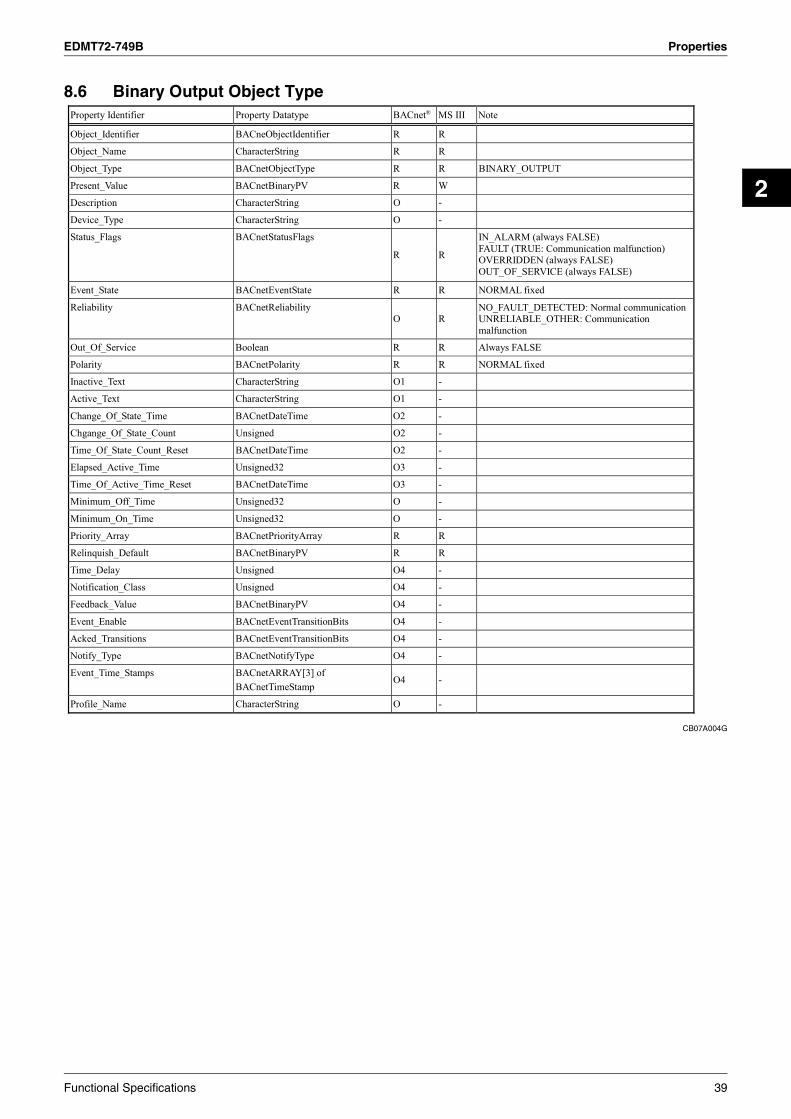
EDMT72-749B Properties
2
8.6 Binary Output Object Type
CB07A004G
Propert y Identifier Propert y Datatype BACnet® MS III Note
Object_Identifier BACneObjectIdentifier R R
Object_Name CharacterString R R
Object_Type BACnetObjectType R R BINARY_OUTPUT
Present_Value BACnetBinaryPV R W
Description CharacterString O
Device_Type CharacterString O -
Status_Flags BACnetStatusFlags
R R
IN_ALARM (always FALSE) FAULT (TRUE: Communication malfunction) OVERRIDDEN (always FALSE) OUT_OF_SERVICE (always FALSE)
Event_State BACnetEventState R R NORMAL fixed
Reliability BACnetReliability O R
NO_FAULT_DETECTED: Normal communication UNRELIABLE_OTHER: Communication malfunction
Out_Of_Service Boolean R R Always FALSE
Polarity BACnetPolarity R R NORMAL fixed
Inactive_Text CharacterString O1 -
Active_Text CharacterString O1 -
Change_Of_State_Time BACnetDateTime O2 -
Chgange_Of_State_Count Unsigned O2 -
Time_Of_State_Count_Reset BACnetDateTime O2 -
Elapsed_Active_Time Unsigned32 O3 -
Time_Of_Active_Time_Reset BACnetDateTime O3 -
Minimum_Off_Time Unsigned32 O -
Minimum_On_Time Unsigned32 O -
Priority_Array BACnetPriorityArray R R
Relinquish_Default BACnetBinaryPV R R
Time_Delay Unsigned O4 -
Notification_Class Unsigned O4 -
Feedback_Value BACnetBinaryPV O4 -
Event_Enable BACnetEventTransitionBits O4 -
Acked_Transitions BACnetEventTransitionBits O4 -
Notify_Type BACnetNotifyType O4 -
Event_Time_Stamps BACnetARRAY[3] of BACnetTimeStamp
O4 -
Profile_Name CharacterString O -
-
Functional Specifications 39

Properties EDMT72-749B
8.7 Binary Value Object Type
CB07A004G
(1) Binary Value: Filter sign reset Propert y Identifier Propert y Datatype BACnet® MS III Note
Object_Identifier BACneObjectIdentifier R R
Object_Name CharacterString R R
Object_Type BACnetObjectType R R BINARY_VALUE
Present_Value BACnetBinaryPV R1 W
Description CharacterString O -
Status_Flags BACnetStatusFlags
R R
IN_ALARM (TRUE: Filter sign ON) FAULT (TRUE: Communication malfunction) OVERRIDDEN (always FALSE) OUT_OF_SERVICE (always FALSE)
Event_State BACnetEventState R R NORMAL other
OFF_NORMAL: Filter sign ON
Reliability BACnetReliability O R
NO_FAULT_DETECTED: Normal communication UNRELIABLE_OTHER: Communication malfunction
Out_Of_Service Boolean R R Always FALSE
Inactive_Text CharacterString O2 -
Active_Text CharacterString O2 -
Change_Of_State_Time BACnetDateTime O3 -
Chgange_Of_State_Count Unsigned O3 -
Time_Of_State_Count_Reset BACnetDateTime O3 -
Elapsed_Active_Time Unsigned32 O4 -
Time_Of_Active_Time_Reset BACnetDateTime O4 -
Minimum_Off_Time Unsigned32 O -
Minimum_On_Time Unsigned32 O -
Priority_Array BACnetPriorityArray R5 R
Relinquish_Default BACnetBinaryPV R5 R
Time_Delay Unsigned O6 (R) 0 fixed
Notification_Class Unsigned O6 (R) 3 fixed
Alarm_Value BACnetBinaryPV O6 (R) ACTIVE fixed
Event_Enable BACnetEventTransitionBits O6 (R) B'101' fixed
Acked_Transitions BACnetEventTransitionBits O6 (R) All TRUE fixed
Notify_Type BACnetNotifyType O6 (R) ALARM fixed
Event_Time_Stamps BACnetARRAY[3] of BACnetTimeStamp O6 (R)
Reset by power off At start-up Event not occurred: Time undefined Event occurring: Time of detection
Profile_Name CharacterString O -
40 Functional Specifications

EDMT72-749B Properties
2
CB07A004G
(2) Binary Value: Other Propert y Identifier Propert y Datatype BACnet® MS III Note
Object_Identifier BACneObjectIdentifier R R
Object_Name CharacterString R R
Object_Type BACnetObjectType R R BINARY_VALUE
Present_Value BACnetBinaryPV R1 W
Description CharacterString O -
Status_Flags BACnetStatusFlags
R R
IN_ALARM (always FALSE) FAULT (TRUE: Communication malfunction) OVERRIDDEN (always FALSE) OUT_OF_SERVICE (always FALSE)
Event_State BACnetEventState R R NORMAL fixed
Reliability BACnetReliability O R
NO_FAULT_DETECTED: Normal communication UNRELIABLE_OTHER: Communication malfunction
Out_Of_Service Boolean R R Always FALSE
Inactive_Text CharacterString O2 -
Active_Text CharacterString O2 -
Change_Of_State_Time BACnetDateTime O3 -
Chgange_Of_State_Count Unsigned O3 -
Time_Of_State_Count_Reset BACnetDateTime O3 -
Elapsed_Active_Time Unsigned32 O4 -
Time_Of_Active_Time_Reset BACnetDateTime O4 -
Minimum_Off_Time Unsigned32 O -
Minimum_On_Time Unsigned32 O -
Priority_Array BACnetPriorityArray R5 O R
Relinquish_Default BACnetBinaryPV R5 O R
Time_Delay Unsigned O6 -
Notification_Class Unsigned O6 -
Alarm_Value BACnetBinaryPV O6 -
Event_Enable BACnetEventTransitionBits O6 -
Acked_Transitions BACnetEventTransitionBits O6 -
Notify_Type BACnetNotifyType O6 -
Event_Time_Stamps BACnetARRAY[3] of BACnetTimeStamp O6 -
Profile_Name CharacterString O -
Functional Specifications 41

Properties EDMT72-749B
8.8 Device Object Type
CB07A004G
Propert y Identifier Propert y Datatype BACnet® MS III Note
Object_Identifier BACneObjectIdentifier R R Can be set with Trial Operation tool
Object_Name CharacterString R R
Object_Type BACnetObjectType R R DEVICE
System_Status BACnetDeviceStatus R R D3 initializing: DOWNLOAD_IN_PROGRESS
Normal: OPERATIONAL
Vendor_Name CharacterString R R DAIKIN Industries LTD
Vendor_Identifier Unsigned16 R R 53(=DAIKIN) fixed
Model_Name CharacterString R R -BACS Interface for use in BACnet® fixed
Firmware_Revision CharacterString R R 3000
Application_Software_Version CharacterString R R 3000
Location CharacterString O -
Description CharacterString O -
Protocol_Version Unsigned R R 1 fixed
Protocol_Revision Unsigned R R 4
Protocol_Conformance_Class Unsigned(1 6) - R 3 fixed
Protocol_Services_Supported BACnetServiceSupported
R R
SubCOV, RP, RPM, WP, WPM, I-Am, I-Have, TimeSync, Who-Is, Who-Has, UTCTimeSync (DeviceCommunicationControl *Ver 6.20 or later)
(AddList, RemoveList * When event notification is supported)
Protocol_Object_Types_Supported BACnetObjectTypesSupported R R AI, AO, AV, BI, BO, BV, MI, MO, NotificationClass
Object_List BACnetARRAY[N] of BACnetObjectIdentifier
R R
Max_APDU_Length_Accepted Unsigtned R R BACnetIP 1024
Segmentation_Supported BACnetSegmentation R R SEGMENTED_BOTH
Max_Segments_Accepted Unsigtned O1 R 100 fixed
VT_Class_Supported List of BACnetVTClass O1 -
Active_VT_Sessions List of BACnetVTSession O2 -
Local_Time Time O3, 4 R
Local_Date Date O3, 4 R
UTC_Offset Signed O4 R Can be set with Trial Operation tool
Default: -540
Daylight_Saving_Status Boolean O4 R FALSE fixed
APDU_Segment_Timeout Unsigned O1 R
Can be set with Trial Operation tool within the range form 1000 to 10000 Default: 2000 (msec)
APDU_Timeout Unsigned R R
Can be set with Trial Operation tool within the range form 1000 to 120000 Default: 3000 (msec)
Number_Of_APDU_Retries Unsigned R R
Can be set with Trial Operation tool within the range from 0 to 7 Default: 3 (times)
List_Of_Session_Keys List of BACnetSessionKey O -
Time_Synchronization_Recipients List of BACnetRecipient O5 -
Max_Master O6 -
Max_Info_Frames Unsigned O6 -
Device_Adress_Binding List of BACnetAddressBinding R R
Database_Revision Unsigned R R
Configuration_Files BACnetARRAY[N] of BACnetObjectIdentifier
O7 -
Last_Restore_Time BACnetDateTime O7 -
Backup_Failure_Timeout Unsigned16 O8 -
Active_COV_Subscriptions List of BACnetCOVSubscription O9 R Supported by Ver 6.20 or later
Profile_Name CharacterString O -
42 Functional Specifications

EDMT72-749B Properties
2
8.9 Multi-state Input Object Type
CB07A004G
Propert y Identifier Propert y Datatype BACnet® MS III Note
Object_Identifier BACneObjectIdentifier R R
Object_Name CharacterString R R
Object_Type BACnetObjectType R R MULTI-STATE_INPUT
Present_Value Unsigned R1 R
Description CharacterString O R* Support malfunction code only.
Represents failure code with 2 ASCII codes .
Device_Type CharacterString O -
Status_Flags BACnetStatusFlags
R R
IN_ALARM (always FALSE) FAULT (TRUE: Communication malfunction) OVERRIDDEN (always FALSE) OUT_OF_SERVICE (always FALSE)
Event_State BACnetEventState R R NORMAL fixed
Reliability BACnetReliability O2 R
NO_FAULT_DETECTED: Normal communication UNRELIABLE_OTHER: Communication malfunction
Out_Of_Service Boolean R R
Number_Of_States Unsigned R R
State_Text BACnetARRAY[N] of CharacterString
O -
Time_Delay Unsigned O3 -
Notification_Class Unsigned O3 -
Alarm_Values List of Unsigned O3 -
Fault_Values List of Unsigned O3 -
Event_Enable BACnetEventTransitionBits O3 -
Acked_Transitions BACnetEventTransitionBits O3 -
Notify_Type BACnetNotifyType O3 -
Event_Time_Stamps BACnetARRAY[3] of BACnetTimeStamp
O3 -
Profile_Name CharacterString O -
Functional Specifications 43

Properties EDMT72-749B
8.10 Multi-state Output Object Type
CB07A004G
Propert y Identifier Propert y Datatype BACnet® MS III Note
Object_Identifier BACneObjectIdentifier R R
Object_Name CharacterString R R
Object_Type BACnetObjectType R R MULTI-STATE_OUTPUT
Present_Value Unsigned W W
Description CharacterString O -
Device_Type CharacterString O -
Status_Flags BACnetStatusFlags
R R
IN_ALARM (always FALSE) FAULT (TRUE: Communication malfunction) OVERRIDDEN (always FALSE) OUT_OF_SERVICE (always FALSE)
Event_State BACnetEventState R R NORMAL fixed
Reliability BACnetReliability O R
NO_FAULT_DETECTED: Normal communication UNRELIABLE_OTHER: Communication malfunction
Out_Of_Service Boolean R R
Number_Of_States Unsigned R R
State_Text BACnetARRAY[N] of CharacterString
O -
Priority_Array BACnetPriorityArray R R
Relinquish_Default Unsigned R R
Time_Delay Unsigned O1 -
Notification_Class Unsigned O1 -
Feedback_Value Unsigned O1 -
Event_Enable BACnetEventTransitionBits O1 -
Acked_Transitions BACnetEventTransitionBits O1 -
Notify_Type BACnetNotifyType O1 -
Event_Time_Stamps BACnetARRAY[3] of BACnetTimeStamp
O1 -
Profile_Name CharacterString O -
44 Functional Specifications

EDMT72-749B Report Function
2
9. Report Function9.1 COV Notification
CB07A004G
The COV notification with subscription (DS-COV-B) and no subscription (DS-COVU B) are supported.
9.1.1. COV notification with subscription (subscribed COV)
COV subscription request is received by the SubscribeCOV service. (1) Setting COV generation with/without confirmation
Supported as defined in the BACnet® specifications. (2) Validity period for notification
Supported as defined in the BACnet® specifications. When executing COV notification at status change, the system calculates the difference between the current time and registered time, then it will delete the COV notification if the difference is larger than the validity period. Therefore, if the clock is changed, the actual validity period may differ from the defined period.
(3) Memorization at power off Not supported. Since the subscribed information is not saved, it will be deleted at power off. The BACnet® specifications do not require memorization at power off.
(4) Notification recipient information
The notification recipient information is not visible from the BACnet®. The BACnet® specifications do not require network visibility.
(5) Number of notification recipients 5 clients per object. Specifying more than 5 recipients will return ErrorPDU of Error Class = SERVICES, Error Code = COV_SUBSCRIPTION_FAILED.
COV notification is supported for all the objects (except for accumulated power) for the air conditioner.
9.1.2. Unsubscribed COV notification (Unsolicitated COV)
Unsubscribed COV (equivalent to BIBB's DS-COVU B) is supported by configuring the Daikin Trial Operation tool in advance. COV notification is supported for all the objects (except for accumulated power) for the air conditioner.
Functional Specifications 45

Report Function EDMT72-749B
9.2 Event Notification
CB07A004G
Event notification only supports the intrinsic notification. Since this is an optional function, it must be enabled using the Trial Operation tool. (It is disabled by default.)
9.2.1. Event notification recipient information
Only one Notification Class object is generated and referenced from all the objects supporting intrinsic notification. A notification recipient registered with this Notification Class object is notified of events from all the objects.
(1) Instance number of notification class Fixed to 3.
(2) Priority
Fixed to 255. (3) Ack_Required
Fixed to FALSE (not to expect the AcknowledgeAlarm service for events).
9.2.2. Event notification recipient registration
The notification recipient is registered in the Recipient_List property of the Notification Class object using the AddListElement service. The notification recipient information is registered as BACnetDestination, which consists of the following information:
(1) Effective date
In accordance with the BACnet® specifications. Specify the day of the week and whether or not to notify events.
(2) Effective time
In accordance with the BACnet® specifications. Specify the time zone and whether or not to notify events. (3) Process ID
In accordance with the BACnet® specifications. Use the process ID registered with event notification. (4) Notification recipient address information
In accordance with the BACnet® specifications. The device object ID or BACnetAddress can be specified. When specifying the device object ID, the correspondence between the device object ID and BACnetAddress must be made clear (with the I-Am service, for example) before the event notification. The correspondence information is stored in the device object's Device_Address_Binding property. At start-up, the Who-Is service is transmitted and I-Am is received. If this information is missing for some reason, the event notification will be cancelled. If no BACnet® packet is received from the other party for 10 minutes, that BACnet® device is considered to be disconnected from the network. If the I-A m service is not received after that, the device object ID becomes undefined, and the notification recipient with that device object ID specified will not be notified of the event.
(5) Confirmation
In accordance with the BACnet® specifications. Event notification can be registered with or without confirmation.
(6) Transitions Although the value is retained, processing is ignored.
(7) Maximum number of notification recipients registered
10 clients. Specifying more than 10 recipients will return ErrorPDU of ErrorClass = RESOURCES, Error Code = NO_SPACE_TO_WRITEPROPERTY (for WriteProperty, WritePropertyMultiple) or NO_SPACE_TO_ADD_LIST_ELEMENT (for AddListElement)
9.2.3. Event notification recipient deletion
Notification recipient can be deleted from the Notification Class object with the RemoveListElement service. Process ID and corresponding notification recipient address are required to delete a recipient. A recipient with the same notification recipient address but different process ID is not deleted.
46 Functional Specifications

EDMT72-749B Report Function
2
CB07A004G
9.2.4. Event notification recipient re-registration
If an event with the same process ID and notification recipient address as an existing event is re-registered, the existing information is overwritten. Therefore, effective date/time or confirmation settings will be updated.
9.2.5. Event notification recipient memorization
Registered event notification recipients are saved in the nonvolatile memory and the event notification information is initialized with the saved recipient information at start up. Event notification recipient information is updated in 5 seconds after addition or deletion.
9.2.6. Event confirmation
The event confirmation defined by the BACnet® specifications is not supported, as mentioned below. (1) The AcknowledgeAlarm service is not supported. (2) The Notification Class object's Ack_Required is all fixed to FALSE. (3) The Event sending object's Ack_Transition is all fixed to TRUE.
To retain events occurring when a notification recipient is offline or disconnected from the network, the time stamp for event occurrence is maintained, but not retained at power off. If an event has already occurred at power up, the time when the event has been detected is used for the time stamp.
Functional Specifications 47

Error Response in BACnet® Communication EDMT72-749B
10.Error Response in BACnet® Communication
CB07A004G
If a request from the BACnet® client cannot be handled, one of the ErrorPDUs listed below will be returned.
Error PDU
Error PDU Error Class Error Code
Read for the list of object initializing on the D3 network. DEVICE (0) CONFIGURATION_IN_PROGRESS (2)
Access request for unimplemented object. OBJECT (1) UNKNOWN_OBJECT (31)
Access request for unimplemented property. PROPERTY (2) UNKNOWN_PROPERTY (32)
Write request for a write-inhibited property. PROPERTY (2) WRITE_ACCESS_DENIED (40)
Write request with wrong type for a property. PROPERTY (2) NVALID_DATATYPE (9)
Access request with out-of-range index specification for an array-type property.
PROPERTY (2) INVALID_ARRAY_INDEX (42)
Access request with index specification for non-array-type property.
PROPERTY (2) PROPERTY_IS_NOT_AN_ARRAY(50)
Write request with out-of-range value. PROPERTY (2) VALUE_OUT_OF_RANGE (37)
COV registration for an object not supporting COV notification.
SERVICES (5) OTHER (0)
5th COV recipient registration request SERVICES (5) COV_SUBSCRIPTION_FAILED (43) 11th event registration request (for AddListElement) RESOURCES (3) NO_SPACE_TO_ADD_LIST_ELEMENT (19) 11th event registration request (for WriteProperty(Multiple))
RESOURCES (3) NO_SPACE_TO_WRITE_PROPERTY(20)
Delete request for an element not in the list. SERVICES (5) OTHER (0)
Execution request of the AddListElement/RemoveListElement service for non-list-type property.
SERVICES (5) PROPERTY_IS_NOT_A_LIST (22)
Reject PDU
Reject PDU Reject Reason
Property ID or value is missing for WritePropertyMultiple. INCONSISTENT_PARAMETER (2)
Argument type is different for the service. INVALID_PARAMETER_DATA_TYPE (3)
Error was detected in tag decoding. INVALID_TAG (4)
Parameter is missing in service execution. MISSING_REQUIRED_PARAMETER (5)
Arguments are too many for the service. TOO_MANY_ARGUMENTS (7)
Execution of unsupported service with confirmation. UNRECOGNIZED_SERVICE (9)
Abort PDU
Abort PDU Abort Reason
- Process overflow due to too many requests. - Response message size exceeded the longest possible size (100 segments).
BUFFER_OVERFLOW (1)
Unexpected APDU has been received during segment processing and processing aborted.
INVALID_APDU_IN_THIS_STATE (2)
Respondent does not support segments in segment response. SEGMENTATION_NOT_SUPPORTED (4)
48 Functional Specifications

EDMT72-749B Detailed Description of Objects
2
11.Detailed Description of Objects11.1 Common to All Objects
CB07A004G
Functional Specifications 49
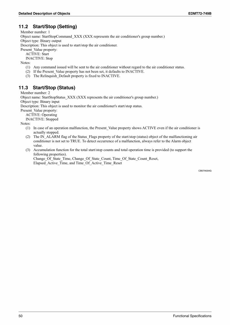
Detailed Description of Objects EDMT72-749B
11.2 Start/Stop (Setting)
11.3 Start/Stop (Status)
CB07A004G
Member number: 1
Object name: StartStopCommand_XXX (XXX represents the air conditioner's group number.) Object type: Binary output Description: This object is used to start/stop the air conditioner. Present_Value property:
ACTIVE: Start INACTIVE: Stop
Notes: (1) Any command issued will be sent to the air conditioner without regard to the air conditioner status. (2) If the Present_Value property has not been set, it defaults to INACTIVE. (3) The Relinquish_Default property is fixed to INACTIVE.
Member number: 2
Object name: StartStopStatus_XXX (XXX represents the air conditioner's group number.) Object type: Binary input Description: This object is used to monitor the air conditioner's start/stop status. Present_Value property:
ACTIVE: Operating
INACTIVE: Stopped
Notes: (1) In case of an operation malfunction, the Present_Value property shows ACTIVE even if the air conditioner is
actually stopped. (2) The IN_ALARM flag of the Status_Flags property of the start/stop (status) object of the malfunctioning air
conditioner is not set to TRUE. To detect occurrence of a malfunction, always refer to the Alarm object value.
(3) Accumulation function for the total start/stop counts and total operation time is provided (to support the following properties). Change_Of_State_Time, Change_Of_State_Count, Time_Of_State_Count_Reset, Elapsed_Active_Time, and Time_Of_Active_Time_Reset
50 Functional Specifications

EDMT72-749B Detailed Description of Objects
2
11.4 Alarm
11.5 Malfunction Code
CB07A004G
Member number: 3
Object name: Alarm_XXX (XXX represents the air conditioner's group number.) Object type: Binary input Description: This object is used to monitor the air conditioner's normal/malfunction status. Present_Value property:
ACTIVE: Malfunction
INACTIVE: Normal Notes:
(1) This object supports the Intrinsic Reporting function, and if events are registered, it will generate an appropriate event when the Present_Value property changes the value. (Since this is an optional function, it must be enabled using the Trial Operation tool.)
(2) Detailed information is stored in the following properties: Time_Delay property: Malfunction notification delay is fixed to 0 and this property cannot be written. Notify_Type property: Event notification is fixed to ALARM. Event_Time_Stamps property: Indicates the time of occurrence (To-OFFNORMAL)/recovery (To-NORMAL). At start-up:
Event not occurred: Time is not undefined. Event occurring: Event detection time is written at start-up.
When power is off, the time is determined at start-up. (3) Malfunction means that the air conditioner is stopped for some trouble, and does not include Alarm or
Warning which may be caused by other reasons. However, whether Alarm is included in Malfunction can be selected with a test operation PC. By default, Alarm is included in Malfunction.
(4) To stop the malfunction signal from a malfunctioning air conditioner, send the Stop command to that air conditioner. However, since the malfunction status persists, sending the Start command results in another malfunction.
(5) The Description property represents a failure code defined by Daikin with two ASCII characters.
Member number: 4
Object name: MalfunctionCode_XXX (XXX represents the air conditioner's group number.) Object type: Multistate Input Description: This object is used to monitor the malfunction details of an air conditioner in malfunction status. Present_Value property:
1 - 512 (mapped to a failure code) Notes:
(1) The Description property represents a failure code defined by Daikin with 2 ASCII characters. (2) Refer to the mapping table at the end of this specifications manual for the correspondence between the
Present_Value property values and failure codes.
Functional Specifications 51

Detailed Description of Objects EDMT72-749B
11.6 Air-conditioning Mode (Setting)
11.7 Air-conditioning Mode (Status)
CB07A004G
Member number: 5
Object name: AirConModeCommand_XXX (XXX represents the air conditioner's group number.) Object type: Multistate Output Description: This object is used to set an air conditioner's air-conditioning mode. Present_Value property:
1: Cooling mode 2: Heating mode 3: Ventilating mode
4: Auto mode 5: Dry mode
Notes: (1) If the Present_Value property has not been set, it defaults to "1: Cooling mode". (2) The Relinquish_Default property is fixed to "1: Cooling mode". (3) A command sent to this object of an air conditioner which cannot select the air-conditioning mode is ignored.
The control/monitor system must not use this object for an air conditioner which cannot select the air-conditioning mode.
(4) When "4: Auto mode" is selected, the air-conditioning mode (status) object shows the actual mode in which the air conditioner is operating, but not "Auto".
(5) When "5: Dry mode" is selected, any indoor unit with no cooling/heating selection right for the same refrigerant system will not change to the "Dry" mode except in the cooling mode.
Member number: 6
Object name: AirConModeStatus_XXX (XXX represents the air conditioner's group number.) Object type: Multistate Input Description: This object is used to monitor an air conditioner's air-conditioning mode. Present_Value property:
1: Cooling mode 2: Heating mode 3: Fan mode 4: (Not used)
5: Dry mode
Notes: (1) If the air-conditioning mode (setting) object is set to "Auto", the current operation mode (Cooling, Heating,
Fan or Dry) is returned with this property.
52 Functional Specifications

EDMT72-749B Detailed Description of Objects
2
11.8 Airflow Rate Level (Setting)
11.9 Airflow Rate Level (Status)
CB07A004G
Member number: 7
Object name: AirFlowRateCommand_XXX (XXX represents the air conditioner's group number.) Object type: Multistate Output Description: This object is used to set an air conditioner's airflow rate level. Present_Value property:
1: "Low" 2: "High" 3: "Middle" 4: "Auto"
Notes: (1) Since the air conditioner has two values for the airflow rate (for cooling and heating), this object sets the
airflow rate level for the current air-conditioning mode. (2) If "Middle" is set for an air conditioner with 2-level airflow rate, it operates with the "High" setting. (3) If "Auto" is set for an air conditioner without automatic airflow rate, it returns an ErrorPDU with
ErrorClass = PROPERTY and ErrorCode = OTHER.
Member number: 8
Object name: AirFlowRateStatus_XXX (XXX represents the air conditioner's group number.) Object type: Multistate Input Description: This object is used to monitor the air conditioner's airflow rate level. Present_Value property:
1: "Low" 2: "High" 3: "Middle" 4: "Auto"
Notes: (1) The air conditioner has 2 values for the airflow rate (for cooling and heating). (2) Since the airflow rate level notification returns the airflow rate currently set with the air conditioner, without
regard to the start/stop status.
Functional Specifications 53

Detailed Description of Objects EDMT72-749B
11.10 Measured Room Temperature
CB07A004G
Member number: 9
Object name: RoomTemp_XXX (XXX represents the air conditioner's group number.) Object type: Analog Input Description: This object is used to monitor the room temperature detected by the air conditioner. The room temperature detected by the air conditioner slightly varies according to the location of the temperature sensor. Present_Value property:
The room temperature detected by the air conditioner. Notes:
(1) The value is in degrees centigrade or degrees fahrenheit. Interface for use in BACnet® outputs the measured temperature notified from the air conditioner as it is.
(2) If it is subscribed with COV, the COV_Increment property is fixed to 1.0 and it cannot be written. When a temperature change larger than 1.0 degree( C/ F) is detected, COV is reported. Then, when the Present_Value property value further changes for 1.0 degree( C/ F) or more, another COV will be reported.
(3) This object supports the Intrinsic Reporting function, and if events are registered, it will generate an appropriate event when the temperature goes over the specified upper limit or under the lo wer limit. T he event is generated as defined in the B ACnet specificatio ns. ( Since this is an o ptional function, it must be enabled using the Trial Operation tool.)
(4) The upper/lower limit values are stored in the following properties: High_Limi propertyt: Upper limit value. This property can be written with a new value, which is stored in this property in 5 seconds after the write operation. Low_Limi propertyt: Lower limit value. This property can be written with a new value, which is stored in this property in 5 seconds after the write operation. Deadband property: Insensitive temperature zone. This property can be written with a new value, which is stored in this property in 5 seconds after the write operation.
Default values shown in the following table. property
Representation High_Limit property Low_Limit property Deadband property
Celsius +80.0 C -80.0 C +5.0 C Fahrenheit +180.0 F -120.0 F +10.0 F
Time_Delay property: Upper/lower limit malfunction notification delay is fixed to 0 and this property cannot be written. Notify_Type property: Event notification is fixed to ALARM. Event_Time_Stamps property: Indicates the time of occurrence (To-OFFNORMAL)/recovery (To-NORMAL).
At start-up: Event not occurred: Time is not undefined. Event occurring: Event detection time is written at start-up.
When power is off, the time is determined at start-up. (5) If the air conditioner does not have the room temperature sensor, the Present_Value property shows 0.0. (6) If the room temperature sensor is removed, the Reliability property changes to NO_SENSOR and the FAULT
flag of the Status_Flags property changes to TRUE. The Present_Value property retains the last value. (7) The room temperature is measured with the suction air. Since the indoor unit fan stops when the thermostat
is disabled or the air conditioner is stopped, or in a special operation such as defrosting, temperature measurement may be affected by the heat exchanger, and may detect and transmit a different temperature from the actual room temperature. For this reason, this value should be considered as a reference for the room temperature. If the building management system manufacturer uses this value for system control (e.g., switching the air-conditioning mode or preset temperature), the manufacturer must take on the whole responsibility.
(8) The units property is fixed to degrees-Celsius(62)/degrees-Fahrenheit(64) .
54 Functional Specifications
EDMT72-749B Detailed Description of Objects
2
11.11 Set Room Temperature
CB07A004G
Member number: 10
Object name: TempAdjest_XXX (XXX represents the air conditioner's group number.) Object type: Analog Value Description: This object is used to set the air conditioner's temperature. Present_Value property:
Air conditioner's set temperature Notes:
(1) The value is in degrees centigrade or degrees fahrenheit. Its range depends on the types of the indoor and outdoor units. For the VRV, for example, the value ranges from approximately 20 C to 35 C for cooling and approximately 15 C to 30 C for heating.
(2) If it is subscribed with COV, the COV_Increment property is fixed to 1.0 and it cannot be written. When a temperature change larger than 1 degree( C/ F) is detected, COV is reported. Then, when the Present_Value property value further changes for 1 degree( C/ F) or more, another COV will be reported.
(3) The available upper and lower limit values depend on the type of the air conditioner and the current air-conditioning mode. A value outside the available range can be specified, however, the air conditioner automatically rounds the specified value to the nearest limit value.
(4) The air conditioner has 2 set temperatures (for cooling and heating). When changing the air-conditioning mode and set temperature, first set the air-conditioning mode, then change the set temperature after the air-conditioning mode has bee settled. For example, if you want to change from 28 C (82 F) for cooling to 20 C (68 F) for heating, changing the set temperature first to 20 C will change the value for cooling, and when you change the air-conditioning mode to heating, the air conditioner will operate at the set temperature for heating stored in the nonvolatile memory.
(5) The units property is fixed to degrees-Celsius(62)/degrees-Fahrenheit(64) . (6) Relinqush_Default property is fixed to 25(in the case of Celsius)/75(in the case of Fahrenheit) . (7) When the set temperature in Fahrenheit is commanded from the central monitoring panel, the value must be
given in "integer increments" as the air conditioner is controlled in integer increments for Fahrenheit. (8) When the set temperature in Fahrenheit is commanded from the central monitoring panel in first decimal
place increments, the commanded value to the air conditioner may not match the return value from the air conditioner. Therefore when the set temperature is automatically controlled from the central monitoring panel, do not keep commanding the set temperature until the commanded value matches the return value.
When the set temperature in Fahrenheit is commanded from the central monitoring panel in first decimal place increments, the displayed value on the central monitoring panel may differ from the displayed value on our controller products and remote controllers.
Functional Specifications 55

Detailed Description of Objects EDMT72-749B
11.12 Filter Sign Signal
11.13 Filter Sign Signal Reset
CB07A004G
Member number: 11
Object name: FilterSign_XXX (XXX represents the air conditioner's group number.) Object type: Binary input Description: This object is used to monitor the air conditioner's filter sign status. Present_Value property:
ACTIVE: Filter sign signal is ON. (Signal for any of the normal filter, L/L filter, super L/L filter, or dust element is ON.)
INACTIVE: Filter sign signal is OFF. Notes:
(1) This object supports the Intrinsic Reporting function, and if events are registered, it will generate an appropriate event when the Present_Value property changes the value. (Since this is an optional function, it must be enabled using the Trial Operation tool.)
(2) Detailed information is stored in the following properties: Time_Delay property: Malfunction notification delay is fixed to 0 and this property cannot be written. Notify_Type property: Event notification is fixed to ALARM. Event_Time_Stamps property: Indicates the time of occurrence (To-OFFNORMAL)/recovery (To-NORMAL).
At start-up: Event not occurred: Time is not undefined. Event occurring: Event detection time is written at start-up.
When power is off, the time is determined at start-up.
Member number: 12
Object name: FilterSignReset_XXX (XXX represents the air conditioner's group number.) Object type: Binary Value
Description: This object is used to reset the air conditioner's filter sign signal. Present_Value property:
INACTIVE: Resets the filter sign signal Notes:
(1) When reading the Present_Value property, it is always the same value as the filter sign signal object. (2) The filter sign signal which is ON is reset only when INACTIVE is written to the Present_Value property.
ACTIVE written to this property is ignored. (3) This object supports the Intrinsic Reporting function, and if events are registered, it will generate an
appropriate event when the Present_Value property changes the value. (Since this is an optional function, it must be enabled using the Trial Operation tool.)
(4) Detailed information is stored in the following properties: Time_Delay property: Malfunction notification delay is fixed to 0 and this property cannot be written. Notify_Type property: Event notification is fixed to ALARM. Event_Time_Stamps property: Indicates the time of occurrence (To-OFFNORMAL)/recovery (To-NORMAL).
At start-up: Event not occurred: Time is not undefined. Event occurring: Event detection time is written at start-up.
When power is off, the time is determined at start-up.
56 Functional Specifications

EDMT72-749B Detailed Description of Objects
2
11.14 Remote Controller Enable/Disable (Start/Stop)
11.15 Remote Controller Enable/Disable (Air-conditioning Mode)
11.16 Remote Controller Enable/Disable (Set Temperature)
CB07A004G
Member number: 13
Object name: RemoteControlStart_XXX (XXX represents the air conditioner's group number.) Object type: Binary Value
Description: This object is used to enable or disable the remote controller to start/stop the air conditioner. Present_Value property:
ACTIVE: Disable the remote controller to start/stop the air conditioner. INACTIVE: Enable the remote controller to start/stop the air conditioner.
Note: (1) If a remote controller group is used, remote controller enable/disable monitor/control is not available for the
controllers other than the master remote controller (i.e., child controllers). Although each of other air conditioners other than the one with the master remote controller has this object, do not use it for mapping on other BACnet® devices.
Member number: 14 Object name: RemoteContorlAirConModeSet_XXX (XXX represents the air conditioner's group number.) Object type: Binary Value Description: This object is used to enable or disable the remote controller to change the air conditioner's air-conditioning mode. Present_Value property:
ACTIVE: Disable the remote controller to change the air conditioner's air-conditioning mode. INACTIVE: Enable the remote controller to change the air conditioner's air-conditioning mode.
Note: (1) If a remote controller group is used, remote controller enable/disable monitor/control is not available for the
controllers other than the master remote controller (i.e., child controllers). Although each of other air conditioners other than the one with the master remote controller has this object, do not use it for mapping on other BACnet® devices.
Member number: 16 Object name: RemoteControlTempAdjust_XXX (XXX represents the air conditioner's group number.) Object type: Binary Value Description: This object is used to enable or disable the remote controller to set the air conditioner's temperature. Present_Value property:
ACTIVE: Disable the remote controller to set the air conditioner's temperature. INACTIVE: Enable the remote controller to set the air conditioner's temperature.
Note: (1) If a remote controller group is used, remote controller enable/disable monitor/control is not available for the
controllers other than the master remote controller (i.e., child controllers). Although each of other air conditioners other than the one with the master remote controller has this object, do not use it for mapping on other BACnet® devices.
Functional Specifications 57

Detailed Description of Objects EDMT72-749B
11.17 Central Control (Lower Central Control Disable)
11.18 Accumulated Power
CB07A004G
Member number: 17 Object name: CL_Rejection_XXX (XXX can be 000, 064, 128, or 192, corresponding to the port number.) Object type: Binary Value Description: This object is used to disable or enable control by the central control device connected to the specified port on the D3 network. Present_Value property:
ACTIVE: Disable central control by lower device INACTIVE: Enable central control by lower device
Member number: 19 Object name: ElecTotalPower_XXX (XXX represents the air conditioner number.) Description: This object is used to instruct the air conditioner to perform the proportional power distribution trial operation, then calculates the power consumed by the air conditioner in the operation. Object type: Accumulator Present_Value property:
This property represents the accumulated power in 0.1 kWh. A value smaller than 0.1kWh is rounded up. The effective number of digits is 6 (000000 - 999999), and the value returns to 000000 after 999999. The accumulated power for an air conditioner which does not perform the proportional power distribution trial operation, or which is not the recipient of the operation is shown as "0". Unit property: kilowatt-hours (19)
Scale property: 0.1
Notes: (1) The value is updated at every hour on the hour. Therefore, the last accumulated value can be read until the
next every hour. (2) Initialization of the value (i.e., adjustment of meter value) is not supported. (3) Only the normal (non-storage) air conditioner is supported, and the storage air conditioner is not supported.
(Note) In general, child remote controllers are not monitored by upper central control devices and therefore do not have air conditioner addresses. However, they are taken into account in the proportional power distribution operation and need the air conditioner addresses. In this system, all the monitor/control objects of a remote controller which has the air conditioner address are visible from the central control device and those objects which are not necessary for the remote controller's control/monitor are also accessible. Thus, when performing the proportional power distribution operation, do not map (to an upper central control device) any objects other than the accumulated power object for the child remote controller.
58 Functional Specifications

EDMT72-749B Detailed Description of Objects
2
11.19 Communication Status
11.20 Forced System Stop
CB07A004G
Member number: 20 Object name: CommunicationStatus_XXX (XXX represents the air conditioner's group number.) Object type: Binary input Description: This object is used to monitor the air conditioner's D3 network communication status. Present_Value property:
ACTIVE: Air conditioner is communicating abnormally. INACTIVE: Air conditioner is communicating normally.
Notes: (1) This object supports the Intrinsic Reporting function, and if events are registered, it will generate an
appropriate event when the Present_Value property changes the value. (Since this is an optional function, it must be enabled using the Trial Operation tool.)
(2) Detailed information is stored in the following properties: Time_Delay property: Malfunction notification delay is fixed to 0 and this property cannot be written. Notify_Type property: Event notification is fixed to ALARM. Event_Time_Stamps property: Indicates the time of occurrence (To-OFFNORMAL)/recovery (To-NORMAL).
At start-up: Event not occurred: Time is not undefined. Event occurring: Event detection time is written at start-up.
When power is off, the time is determined at start-up. (3) Even when the air conditioner's communication malfunction occurs, the Reliability property does not change
to UNRELIABLE_OTHER and remains NO_FAULT_DETECTED. Therefore, the Fault flag of the Status_Flags property also remains FALSE.
Member number: 21
Object name: SystemForcedOff_XXX ((XXX can be 000, 064, 128, or 192, corresponding to the port number.) Object type: Binary Value Description: This object is used to stop all the air conditioners connected to the specified D3 network port and disable/enable remote controller for them. Present_Value property:
ACTIVE: Enable forced system stop. INACTIVE: Clear forced system stop.
Notes: (1) When the forced system stop is enabled, the Stop and Remote controller disable to start commands are sent
to the air conditioner (the remote controller can be used to stop the air conditioner). (2) When the forced system stop is cleared, the remote controller setting returns to the remote controller
enable/disable status before the forced stop command. The air conditioner remains stopped and does not automatically restart. The host must instruct the air conditioner to restart.
(3) After the forced system stop, the air conditioner may not accept the forced system stop clear and restart commands until it confirms that all the other air conditioners have been stopped (due to delay).
Functional Specifications 59
Detailed Description of Objects EDMT72-749B
11.21 Air Direction (Setting)
11.22 Air Direction (Status)
CB07A004G
Member number: 22 Object name: AirDirectionCommand_XXX (XXX represents the air conditioner's group number.) Object type: Analog Value Description: This object is used to change the air conditioner's air direction Present_Value property:
0, 1, 2, 3, 4, or 7 can be specified. 0 - 3: Horizontal 4: Vertical 7: Swing
Notes: (1) Since the air conditioner has 2 air direction values (for cooling and heating), the air direction value may
change when the air conditioner's air-conditioning mode is changed. (2) When reading the air direction status, the value set with the air conditioner is returned.
Member number: 23 Object name: AirDirectionStatus_XXX (XXX represents the air conditioner's group number.) Object type: Analog Input Description: This object is used to monitor the air conditioner's air direction setting. Present_Value property:
The value can be 0, 1, 2, 3, 4, or 7. 0 - 3: Horizontal 4: Vertical 7: Swing
Notes: (1) The value returned is always the same as that of the airflow rate (setting) object's Present_Value. (2) Since the airflow rate notification object returns the airflow rate value set with the remote controller, it does
not change to 0 even when the air conditioner is stopped.
(3) Since the air conditioner has 2 air direction values (for cooling and heating), the air direction value may change when the air conditioner's air-conditioning mode is changed.
60 Functional Specifications

EDMT72-749B Detailed Description of Objects
2
11.23 Forced Thermostat Disable (Setting)
11.24 Forced Thermostat Disable (Status)
11.25 Energy Saving (Setting)
11.26 Energy Saving (Status)
CB07A004G
Member number: 24 Object name: ForcedThermoOFFCommand_XXX (XXX represents the air conditioner's group number.) Object type: Binary output Description: This object is used to forcibly instruct the air conditioner to operate with or without temperature control. Present_Value property:
ACTIVE: Enable forced thermostat disable mode INACTIVE: Disable forced thermostat disable mode
Notes: (1) Any command issued will be sent to the air conditioner without regard to the air conditioner status. (2) If the Present_Value property has not been set, it defaults to INACTIVE. (3) The Relinquish_Default property is fixed to INACTIVE.
Member number: 25 Object name: ForcedThermoOFFStatus_XXX (XXX represents the air conditioner's group number.) Object type: Binary input Description: This object is used to monitor whether or not the air conditioner is forced to operate with or without temperature control. Present_Value property:
ACTIVE: Forced thermostat disable mode is enabled INACTIVE: Forced thermostat disable mode is disabled
Member number: 26 Object name: EnergyEfficiencyCommand_XXX (XXX represents the air conditioner's group number.) Object type: Binary output Description: This object is used to instruct the air conditioner to operate at a temperature shifted by 2 degrees from the set temperature for saving energy.
Because this set temperature shit is controlled in the air conditioner. In addition, the set temperature notified t Present_Value property:
ACTIVE: Enable energy saving INACTIVE: Disable energy saving
Notes: (1) Any command issued will be sent to the air conditioner without regard to the air conditioner status. (2) If the Present_Value property has not been set, it defaults to INACTIVE. (3) The Relinquish_Default property is fixed to INACTIVE.
Member number: 27 Object name: EnergyEfficiencyCommand_XXX (XXX represents the air conditioner's group number.) Object type: Binary input Description: This object is used to monitor whether or not the air conditioner is operating at a temperature shifted by 2 degrees from the set temperature for saving energy.
. Because this set temperature shit is controlled in the air conditioner. In addition, the set Present_Value property:
ACTIVE: Energy saving enabled INACTIVE: Energy saving disabled
Functional Specifications 61
Detailed Description of Objects EDMT72-749B
11.27 Thermostat Status
11.28 Compressor Status
11.29 Indoor Fan Status
11.30 Heater Operation Status
CB07A004G
Member number: 28 Object name: ThermoStatus_XXX (XXX represents the air conditioner's group number.) Object type: Binary input Description: This object is used to monitor whether or not the air conditioner is controlling temperature. Present_Value property:
ACTIVE: air conditioner is controlling temperature (thermostat enable) INACTIVE: air conditioner is not controlling temperature (thermostat disable)
Member number: 29 Object name: CompressorStatus_XXX (XXX represents the air conditioner's group number.) Object type: Binary input Description: This object is used to monitor whether or not the compressor of the outdoor unit connected to the indoor unit is operating. Present_Value property:
ACTIVE: Compressor of the outdoor unit connected to the air conditioner is operating. INACTIVE: Compressor of the outdoor unit connected to the air conditioner is stopped.
Member number: 30 Object name: IndoorFanStatus_XXX (XXX represents the air conditioner's group number.) Object type: Binary input Description: This object is used to monitor whether or not the air conditioner's fan is operating. Present_Value property:
ACTIVE: Indoor fan is operating. INACTIVE: Indoor fan is stopped.
Member number: 31
Object name: HeaterStatus_XXX (XXX represents the air conditioner's group number.) Object type: Binary input Description: This object is used to monitor whether or not the indoor unit's built-in heater is operating. Present_Value property:
ACTIVE: Air conditioner's built-in heater is operating. INACTIVE: Air conditioner's built-in heater is stopped.
62 Functional Specifications

EDMT72-749B Detailed Description of Objects
2
11.31 Ventilation Mode (Setting)
11.32 Ventilation Mode (Status)
CB07A004G
Member number: 32 Object name: VentilationModeCommand_XXX (XXX represents the air conditioner's group number.) Object type: Multistate Output Description: This object is used to set a s Ventilation Mode. Present_Value property:
1: Bypass
2: ERVentilation
3:Auto
Notes: (1) Equipments, which are incompatible with Ventilation Mode "Auto", cannot be set to "Auto" even if the
(2) If a remote controller group is used, Ventilation mode setting is not available for the controllers other than the master remote controller (i.e., child controllers). Although each of other air conditioners other than the one with the master remote controller has this object, do not use it for mapping on other BACnet® devices.
Member number: 33 Object name: VentilationModeStatus_XXX (XXX represents the air conditioner's group number.) Object type: Multistate Input Description: This object is used to monitor a Heat Reclaim Ventilator's Ventilation Mode. Present_Value property:
1: Bypass
2: ERVentilation
3:Auto
Notes:
(1) If a remote controller group is used, Ventilation mode(status) monitor is not available for the controllers other than the master remote controller (i.e., child controllers). Although each of other air conditioners other than the one with the master remote controller has this object, do not use it for mapping on other BACnet® devices.
Functional Specifications 63
Detailed Description of Objects EDMT72-749B
11.33 Ventilation Amount (Setting)
11.34 Ventilation Amount (Status)
CB07A004G
Member number: 34 Object name: VentilationAmountCommand_XXX (XXX represents the air conditioner's group number.) Object type: Multistate Output Description: This object is used to set a s Ventilation Amount. Present_Value property:
1: Low
2: High
3: Auto
4: Low(fresh up)
5: High(fresh up)
6: Auto(fresh up)
Notes: (1) Equipments, which are incompatible with Ventilation Amount "Auto", cannot be set to "Auto" even if the
command is sent. Instead, they may be switched to a different value. (2) The "fresh up" setting is disabled even if it is set for equipments which are incompatible with the Ventilation
Amount "fresh up" function. (3) If a remote controller group is used, Ventilation amount setting is not available for the controllers
other than the master remote controller (i.e., child controllers). Although each of other air conditioners other than the one with the master remote controller has this object, do not use it for mapping on other BACnet® devices.
Member number: 35 Object name: VentilationAmountStatus_XXX (XXX represents the air conditioner's group number.) Object type: Multistate Input Description: This object is used to monitor a Heat Reclaim Ventilator's Ventilation Amount.. Present_Value property:
1: Low
2: High
3: Auto
4: Low(fresh up)
5: High(fresh up)
6: Auto(fresh up) Notes: (1) If a remote controller group is used, Ventilation Amount(status) monitor is not available for the controllers
other than the master remote controller (i.e., child controllers). Although each of other air conditioners other than the one with the master remote controller has this object, do not use it for mapping on other BACnet® devices.
64 Functional Specifications

EDMT72-749B Others
2
12.Others12.1 Initial Status at Start-up
12.2 BACnet® Network Layer
12.3 Time Adjustment
12.4 Device Communication Control Service
CB07A004G
Since the system automatically recognizes connected air conditioners, approximately 1 minute is required to recognize them after power on. During this period, accessing a connected air conditioner may return ErrorPDU of ErrorClass = OBJECT, ErrorCode = UNKNOWN_OBJECT. Also, trying to read the ObjectList property of the Device object during this period will return ErrorPDU of ErrorClass = DEVICE, ErrorCode = CONFIGATION_IN_PROGRESS if the air conditioner has not been recognized. At this time, the System_Status property of the Device object is DOWNLOAD_IN_PROGRESS, and it will change to OPERATIONAL when the air conditioner has been recognized.
Although the BACnet® network layer address can be specified, the total number of BACnet® networks available for communication is limited to 100.
Use the TimeSynconization service to adjust the time with local time, and the UTCTimeSynconization service to adjust the time with UTC standard time. The Trial Operation tool allows to specify a time difference.
(1) Supported version
Ver.6.20 or later
(2) Service parameters Supported and unsupported DeviceCommunicationControl service parameters are shown below. Refer to the BACnet® standard specifications for the details of the parameters.
(3) Note: If no response is sent back for BACnet® request If no response is sent back for a BACnet® request even when the device is powered on and the ping command returns a response (i.e., the network connection is established), BACnetGateway's BACnetcommunication is disabled by the DeviceCommunicationControl service. In this case, use the DeviceCommunicationControl service to enable the communication.
Password is ignored even if specified.
-
-
Note
Unsupported Password parameter
Supported Enable/disable parameter
Supported
Supported/unsupported
TimeDuration parameter
Parameter
Functional Specifications 65

Others EDMT72-749B
CB07A004G
[Reference] Mapping between the Present_Value properties and failure codes of the malfunction code object
PV Code PV Code PV Code PV Code PV Code PV Code PV Code PV Code PV Code PV Code
1 00 49 E0 97 J0 145 U0 193 70 241 40 289 10 337 M0 385 T0 433 X0
2 01 50 E1 98 J1 146 U1 194 71 242 41 290 11 338 M1 386 T1 434 X1
3 02 51 E2 99 J2 147 U2 195 72 243 42 291 12 339 M2 387 T2 435 X2
4 03 52 E3 100 J3 148 U3 196 73 244 43 292 13 340 M3 388 T3 436 X3
5 04 53 E4 101 J4 149 U4 197 74 245 44 293 14 341 M4 389 T4 437 X4
6 05 54 E5 102 J5 150 U5 198 75 246 45 294 15 342 M5 390 T5 438 X5
7 06 55 E6 103 J6 151 U6 199 76 247 46 295 16 343 M6 391 T6 439 X6
8 07 56 E7 104 J7 152 U7 200 77 248 47 296 17 344 M7 392 T7 440 X7
9 08 57 E8 105 J8 153 U8 201 78 249 48 297 18 345 M8 393 T8 441 X8
10 09 58 E9 106 J9 154 U9 202 79 250 49 298 19 346 M9 394 T9 442 X9
11 0A 59 EA 107 JA 155 UA 203 7A 251 4A 299 1A 347 MA 395 TA 443 XA
12 0H 60 EH 108 JH 156 UH 204 7H 252 4H 300 1H 348 MH 396 TH 444 XH
13 0C 61 EC 109 JC 157 UC 205 7C 253 4C 301 1C 349 MC 397 TC 445 XC
14 0J 62 EJ 110 JJ 158 UJ 206 7J 254 4J 302 1J 350 MJ 398 TJ 446 XJ
15 0E 63 EE 111 JE 159 UE 207 7E 255 4E 303 1E 351 ME 399 TE 447 XE
16 0F 64 EF 112 JF 160 UF 208 7F 256 4F 304 1F 352 MF 400 TF 448 XF
17 A0 65 H0 113 L0 161 90 209 60 257 30 305 G0 353 N0 401 V0 449 Y0
18 A1 66 H1 114 L1 162 91 210 61 258 31 306 G1 354 N1 402 V1 450 Y1
19 A2 67 H2 115 L2 163 92 211 62 259 32 307 G2 355 N2 403 V2 451 Y2
20 A3 68 H3 116 L3 164 93 212 63 260 33 308 G3 356 N3 404 V3 452 Y3
21 A4 69 H4 117 L4 165 94 213 64 261 34 309 G4 357 N4 405 V4 453 Y4
22 A5 70 H5 118 L5 166 95 214 65 262 35 310 G5 358 N5 406 V5 454 Y5
23 A6 71 H6 119 L6 167 96 215 66 263 36 311 G6 359 N6 407 V6 455 Y6
24 A7 72 H7 120 L7 168 97 216 67 264 37 312 G7 360 N7 408 V7 456 Y7
25 A8 73 H8 121 L8 169 98 217 68 265 38 313 G8 361 N8 409 V8 457 Y8
26 A9 74 H9 122 L9 170 99 218 69 266 39 314 G9 362 N9 410 V9 458 Y9
27 AA 75 HA 123 LA 171 9A 219 6A 267 3A 315 GA 363 NA 411 VA 459 YA
28 AH 76 HH 124 LH 172 9H 220 6H 268 3H 316 GH 364 NH 412 VH 460 YH
29 AC 77 HC 125 LC 173 9C 221 6C 269 3C 317 GC 365 NC 413 VC 461 YC
30 AJ 78 HJ 126 LJ 174 9J 222 6J 270 3J 318 GJ 366 NJ 414 VJ 462 YJ
31 AE 79 HE 127 LE 175 9E 223 6E 271 3E 319 GE 367 NE 415 VE 463 YE
32 AF 80 HF 128 LF 176 9F 224 6F 272 3F 320 GF 368 NF 416 VF 464 YF
33 C0 81 F0 129 P0 177 80 225 50 273 20 321 K0 369 R0 417 W0 465 Z0
34 C1 82 F1 130 P1 178 81 226 51 274 21 322 K1 370 R1 418 W1 466 Z1
35 C2 83 F2 131 P2 179 82 227 52 275 22 323 K2 371 R2 419 W2 467 Z2
36 C3 84 F3 132 P3 180 83 228 53 276 23 324 K3 372 R3 420 W3 468 Z3
37 C4 85 F4 133 P4 181 84 229 54 277 24 325 K4 373 R4 421 W4 469 Z4
38 C5 86 F5 134 P5 182 85 230 55 278 25 326 K5 374 R5 422 W5 470 Z5
39 C6 87 F6 135 P6 183 86 231 56 279 26 327 K6 375 R6 423 W6 471 Z6
40 C7 88 F7 136 P7 184 87 232 57 280 27 328 K7 376 R7 424 W7 472 Z7
41 C8 89 F8 137 P8 185 88 233 58 281 28 329 K8 377 R8 425 W8 473 Z8
42 C9 90 F9 138 P9 186 89 234 59 282 29 330 K9 378 R9 426 W9 474 Z9
43 CA 91 FA 139 PA 187 8A 235 5A 283 2A 331 KA 379 RA 427 WA 475 ZA
44 CH 92 FH 140 PH 188 8H 236 5H 284 2H 332 KH 380 RH 428 WH 476 ZH
45 CC 93 FC 141 PC 189 8C 237 5C 285 2C 333 KC 381 RC 429 WC 477 ZC
46 CJ 94 FJ 142 PJ 190 8J 238 5J 286 2J 334 KJ 382 RJ 430 WJ 478 ZJ
47 CE 95 FE 143 PE 191 8E 239 5E 287 2E 335 KE 383 RE 431 WE 479 ZE
48 CF 96 FF 144 PF 192 8F 240 5F 288 2F 336 KF 384 RF 432 WF 480 ZF
481 - 512 are reserved.
66 Functional Specifications

EDMT72-749B Appendix A: PICS (D-BACS Interface for use in BACnet® Ver. 6.10)
2
13.Appendix A: PICS (D-BACS Interface for use in BACnet® Ver. 6.10)
13.1 BACnet® Protocol Implementation Conformance Statement
CB07A004G
Functional Specifications 67

Appendix A: PICS (D-BACS Interface for use in BACnet® Ver. 6.10) EDMT72-749B
CB07A004G
68 Functional Specifications
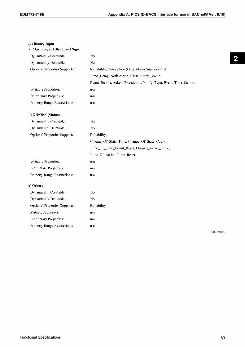
EDMT72-749B Appendix A: PICS (D-BACS Interface for use in BACnet® Ver. 6.10)
2
CB07A004G
Functional Specifications 69

Appendix A: PICS (D-BACS Interface for use in BACnet® Ver. 6.10) EDMT72-749B
CB07A004G
70 Functional Specifications

EDMT72-749B Appendix A: PICS (D-BACS Interface for use in BACnet® Ver. 6.10)
2
CB07A004G
Functional Specifications 71

Appendix A: PICS (D-BACS Interface for use in BACnet® Ver. 6.10) EDMT72-749B
CB07A004G
72 Functional Specifications
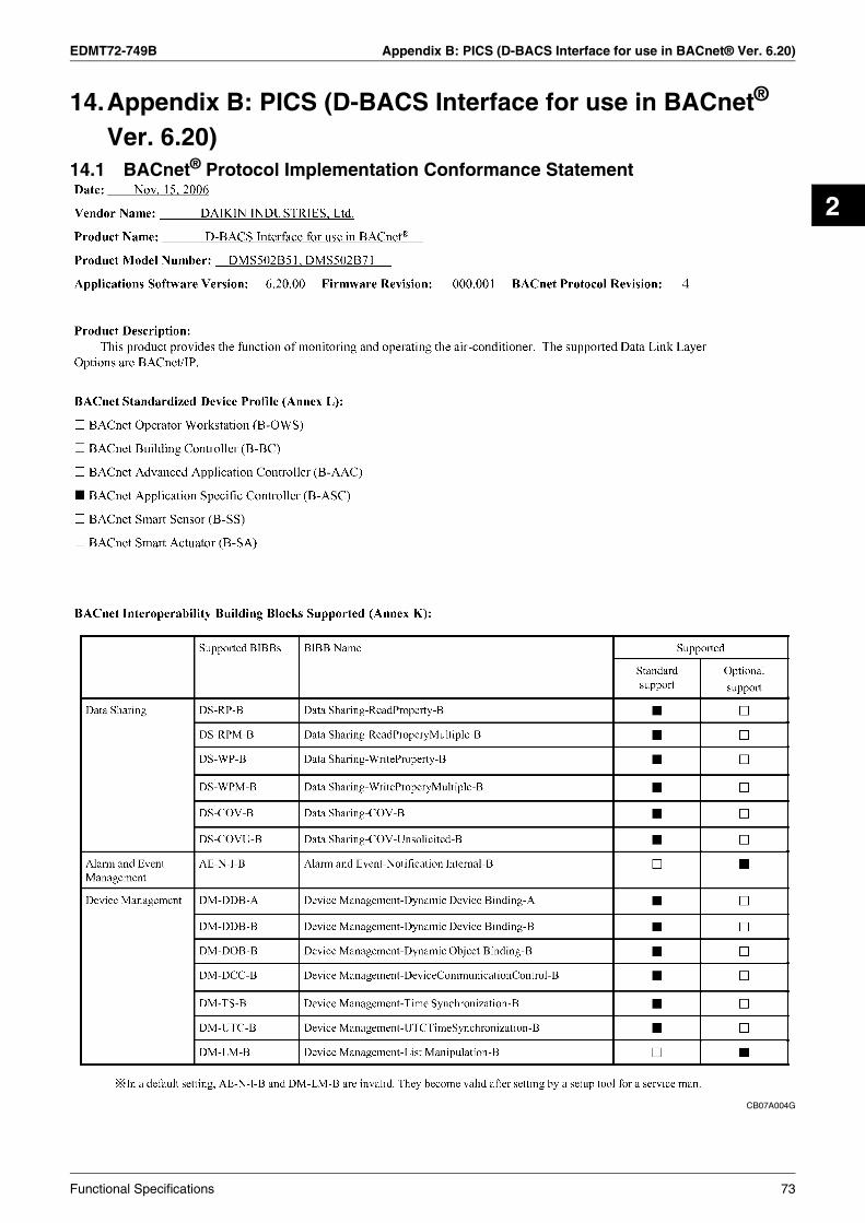
EDMT72-749B Appendix B: PICS (D-BACS Interface for use in BACnet® Ver. 6.20)
2
14.Appendix B: PICS (D-BACS Interface for use in BACnet® Ver. 6.20)
14.1 BACnet® Protocol Implementation Conformance Statement
CB07A004G
Functional Specifications 73

Appendix B: PICS (D-BACS Interface for use in BACnet® Ver. 6.20) EDMT72-749B
CB07A004G
74 Functional Specifications

EDMT72-749B Appendix B: PICS (D-BACS Interface for use in BACnet® Ver. 6.20)
2
CB07A004G
Functional Specifications 75

Appendix B: PICS (D-BACS Interface for use in BACnet® Ver. 6.20) EDMT72-749B
CB07A004G
76 Functional Specifications

EDMT72-749B Appendix B: PICS (D-BACS Interface for use in BACnet® Ver. 6.20)
2
CB07A004G
Functional Specifications 77

Appendix B: PICS (D-BACS Interface for use in BACnet® Ver. 6.20) EDMT72-749B
CB07A004G
78 Functional Specifications

EDMT72-749B Appendix C: PICS (D-BACS Interface for use in BACnet® Ver. 6.30)
2
15.Appendix C: PICS (D-BACS Interface for use in BACnet® Ver. 6.30)
15.1 BACnet® Protocol Implementation Conformance Statement
CB07A004G
Functional Specifications 79

Appendix C: PICS (D-BACS Interface for use in BACnet® Ver. 6.30) EDMT72-749B
CB07A004G
80 Functional Specifications

EDMT72-749B Appendix C: PICS (D-BACS Interface for use in BACnet® Ver. 6.30)
2
CB07A004G
Functional Specifications 81

Appendix C: PICS (D-BACS Interface for use in BACnet® Ver. 6.30) EDMT72-749B
CB07A004G
82 Functional Specifications

EDMT72-749B Appendix C: PICS (D-BACS Interface for use in BACnet® Ver. 6.30)
2
CB07A004G
Functional Specifications 83

Appendix C: PICS (D-BACS Interface for use in BACnet® Ver. 6.30) EDMT72-749B
CB07A004G
84 Functional Specifications

EDMT72-749B
Point List 85
3
Part 3Point List
1. BACnet® Point List ................................................................................86
CB03A096C

BACnet® Point List EDMT72-749B
1. BACnet® Point List
CB03A096C
86 Point List

EDMT72-749B BACnet® Point List
3
CB03A096C
Point List 87

BACnet® Point List EDMT72-749B
CB03A096C
88 Point List

EDMT72-749B BACnet® Point List
3
CB03A096C
Point List 89

BACnet® Point List EDMT72-749B
CB03A096C
90 Point List

EDMT72-749B BACnet® Point List
3
CB03A096C
Point List 91

BACnet® Point List EDMT72-749B
CB03A096C
92 Point List

EDMT72-749B BACnet® Point List
3
CB03A096C
Point List 93

BACnet® Point List EDMT72-749B
CB03A096C
94 Point List

EDMT72-749B
Daikin's Agreement 95
4
Part 4Daikin’s Agreement
1. Daikin's Interface for use in BACnet® Agreement.................................96

Daikin's Interface for use in BACnet® Agreement EDMT72-749B
96 Daikin's Agreement
1. Daikin's Interface for use in BACnet® Agreement1. JMT — (Joint Matching Test) This is necessary for every independent BMS.
The case where a JMT is not necessary is where previously a successful JMT has been carried out and the BMS system has not been updated by software or hardware changes. In the case that the BMS has updated their system by either changes, a following JMT will be required.
2. D-BACS setup-tool — Use of Daikin's D-BACS setup-tool is for confirming the operation / state of connected A / C units & address ID's, prior to connection with the BMS system.
3. BMS Engineering — Creating of the Points. This is NOT to be done by Daikin since it is directly related to the BMS side. The BMS engineer is to carry out the engineering of the Point, however Daikin is responsible for providing the method of how the points are calculated.
4. Commission — First step, only using Daikin's Interface for use in BACnet®, without connecting BMS. This is to be carried out by Daikin engineering staff with the use of the D-BACS set up tool.
5. Discrepancy of operation of gateway by BMS — In the case that the BMS maker feels that the Interface for use in BACnet® is not functioning correctly via the BACnet® Protocol, a test with the use of Daikin's BACnet® Client software can confirm this. (This test is generally not required.)
RS-232C forD-BACS set uptool
Daikin Engineering Side
BACnet®BACnet®
BMSHUB
PC with D-BACSsetup tool
1. Creating of the A/Cpoints.
2. Test of all units andoperations.DIII-NET
Daikin's A/CSimulation Boards for JMT or site
units for test of operation
BMS Engineering Side

EDMT72-749B
Test Operation Manual 97
5
Part 5Test Operation Manual
1. BACnet® Object System Diagram of Interface for use in BACnet® ......982. Specifications of Interface for use in BACnet® (1) ................................993. Specifications of Interface for use in BACnet® (2) ..............................1004. Before Visiting the Site........................................................................101
4.1 Check the Specifications of the PC and Communication Cable Used for the Trial Operation as well as the Version of the Trial Operation Program.................................................................101
4.2 Obtaining Object Information................................................................1024.3 Setting the Trial Operation PC Modem
(When Connecting the Interface for use in BACnet® and the Trial Operation PC Using RS232C Communication)......................105
5. Work Procedure for the Interface for use in BACnet®.........................1155.1 Connect the Trial Operation PC and Interface for use in BACnet® Via the
RS232C Cross Cable or the Hub Using the 100BASE-TX Straight Cable ..........................................................116
5.2 Start the Trial Operation Program. (On the Trial Operation PC, Double-click SetupBACnet®.) Enter the IP Address ............................118
5.3 Setting ..................................................................................................1205.4 Reset the Interface for use in BACnet®................................................1315.5 Start the Trial Operation Program ........................................................1345.6 Select the Operation Status Menu and Check the Following ...............1365.7 Check the Registration of Management Point Types ...........................1375.8 Check the All Points from the Central Control Panel............................138
6. Reference: Items which do not Need to be Changed from the Factory Settings .........................................................140
7. Q & A...................................................................................................147
CB06A069E

BACnet® Object System Diagram of Interface for use in BACnet® EDMT72-749B
1. BACnet® Object System Diagram of Interface for use in BACnet®
CB06A069E
98 Test Operation Manual

EDMT72-749B Specifications of Interface for use in BACnet® (1)
5
2. Specifications of Interface for use in BACnet® (1)
CB06A069E
130 ± 1
(15)
275
± 1
68.5 ± 2
263 ± 1
Turn this switch toON when using
Power supply switch
(13)
260
± 1
Terminal block for DIII-NETcommunication (option)
Terminal block for contact output
Terminal block forcommunication withair conditioners
Do-1 : ON when the unit malfunctionsDo-2 : ON when an air conditioner
malfunctions
Power supplyterminal block
Terminal block for DIII-NETcommunication
Earth terminal block
Make sure to connectthe earth wire
RS-232C connector forPC communication
Connect the lineswith AC100-240V
This is used when distributionthe power supply to indoor units (No Voltage)(option model name : DAM412B51)
Terminal block forwatt hour meter (option)
Terminal block for communicationwith air conditioners(option model name : DAM411B51)
This is used when stopping theindoor units compulsorily bycontact input (No Voltage)
Connector for BACnet®
communication
Terminal block for force stopinput of indoor unit
Connector for connectingwith PC for commissioning
10BA
SE
-T100B
AS
E-T
XR
S-232C
-2P
HO
NE
RS
-232C-1
LINE
PC
MC
IAB
AC
KU
PP
OW
ER
OF
FO
N
L
AC100-240V~
50/60Hz
POWER
N
DAIKIN D-BACS
Di B
OA
RD G
104
86
G12
52
G15
1116
14G
GG
G3
G9
713
Di
1
DIII
-4R
CV
DIII
-3R
CV
DIII
BO
AR
D
F2
F1
F1
F2
DIII
-3D
III-4
-1
2
Do-2T- R-3
-2RS485
ETHERDIII
F1
ALRM
A2F2 G
RCV
LINKALIVE
RS-485 Do-1
RxD
4 R+F2 B2G1
ETHER
TxD
-2
T+ B1A1Di
-1
F1
RS-232C
DIII-1 DIII-2
CPU
Detailed drawing of fixing hole
R2.254.5
9
φ 10
This connector is used for communicating with a client by BACnet® communication system
Test Operation Manual 99

Specifications of Interface for use in BACnet® (2) EDMT72-749B
3. Specifications of Interface for use in BACnet® (2)
CB06A069E
It flashes when it receives/transmits data from/to theequipment connected with DIII-3 such as air conditioners
It flashes when it receives/transmits data from/to theequipment connected with DIII-4 such as air conditioners
LED display
DIII-4 RCV
DIII-3 RCV
DIII
-4R
CV
DIII
-3R
CV
DIII
BO
AR
D
F2
F1
F1
F2
DIII
-3D
III-4
L
AC100-240V~
50/60Hz
POWER
N
RS-232C
TxD-1
ETHER
RxD
-2RS485
DAIKIN D-BACS
F1 F2F2 A2Do-1 Do-2
B2B1A1T- R-3GRS485
4 R+G1 T+F1DIII-1 DIII-2
ALRM LINKALIVEETHERCPU
-1DIII
RCV-2
Di2
116
GG
515
610
2G
8G
4G
Di
3G
711
G12
G14
913
Di B
OA
RD
RCV
-2
ETHERCPU
ETHERDIII
RS-232C
-2
RxD
RS-485ALIVE
TxD
-1
-1
ALRM LINK
LED display
It flashes when it receives/transmits data from/to theequipment connected with DIII-2 such as air conditioners
It flashes when it receives/transmits data from/to theequipment connected with DIII-1 such as air conditioners
This LED display cannot be used with this unit
This LED display cannot be used with this unit
It flashes when it receives/transmits data from/toBACnet® client
It lights when the 10BASE-T cable or 100BASE-TX cable
This LED display cannot be used with this unit.
This LED display cannot be used with this unit.
It flashes when it transmits data to PC
It flashes when it receives data to PC
It flashes when the unit is abnormal operation.
It flashes when the unit is normal operation.
Ether RCV
RS-232C-2 (T×D)
RS-232C-2(R×D)
RS-485 (R×D)
RS-232C-1 (T×D)
Ether Link
RS-232C-1 (R×D)
RS-485 (T×D)
CPU ALIVE
CPU ALRM
DIII-1
DIII-2
100 Test Operation Manual

EDMT72-749B Before Visiting the Site
5
4. Before Visiting the Site4.1 Check the Specifications of the PC and Communication Cable Used for the
Trial Operation as well as the Version of the Trial Operation Program
CB06A069E
Test Operation Manual 101

Before Visiting the Site EDMT72-749B
4.2 Obtaining Object Information
CB06A069E
102 Test Operation Manual

EDMT72-749B Before Visiting the Site
5
CB06A069E
Test Operation Manual 103
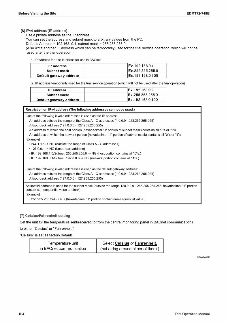
Before Visiting the Site EDMT72-749B
CB06A069E
104 Test Operation Manual

EDMT72-749B Before Visiting the Site
5
4.3 Setting the Trial Operation PC Modem(When Connecting the Interface for use in BACnet® and the Trial Operation PC Using RS232C Communication)
4.3.1 Set Up the Modem
CB06A069E
Test Operation Manual 105

Before Visiting the Site EDMT72-749B
CB06A069E
106 Test Operation Manual

EDMT72-749B Before Visiting the Site
5
CB06A069E
Test Operation Manual 107

Before Visiting the Site EDMT72-749B
CB06A069E
108 Test Operation Manual

EDMT72-749B Before Visiting the Site
5
CB06A069E
Test Operation Manual 109

Before Visiting the Site EDMT72-749B
4.3.2 Setting Up the Dial-Up Adaptor
CB06A069E
110 Test Operation Manual

EDMT72-749B Before Visiting the Site
5
CB06A069E
Test Operation Manual 111

Before Visiting the Site EDMT72-749B
CB06A069E
112 Test Operation Manual

EDMT72-749B Before Visiting the Site
5
CB06A069E
Test Operation Manual 113

Before Visiting the Site EDMT72-749B
CB06A069E
114 Test Operation Manual

EDMT72-749B Work Procedure for the Interface for use in BACnet®
5
5. Work Procedure for the Interface for use in BACnet®
CB06A069E
Test Operation Manual 115

Work Procedure for the Interface for use in BACnet® EDMT72-749B
5.1 Connect the Trial Operation PC and Interface for use in BACnet® Via the RS232C Cross Cable or the Hub Using the 100BASE-TX Straight Cable
CB06A069E
116 Test Operation Manual

EDMT72-749B Work Procedure for the Interface for use in BACnet®
5
CB06A069E
Test Operation Manual 117

Work Procedure for the Interface for use in BACnet® EDMT72-749B
5.2 Start the Trial Operation Program. (On the Trial Operation PC, Double-click SetupBACnet®.) Enter the IP Address
CB06A069E
118 Test Operation Manual

EDMT72-749B Work Procedure for the Interface for use in BACnet®
5
CB06A069E
Test Operation Manual 119

Work Procedure for the Interface for use in BACnet® EDMT72-749B
5.3 Setting5.3.1 Select Protocol
CB06A069E
120 Test Operation Manual

EDMT72-749B Work Procedure for the Interface for use in BACnet®
5
5.3.2 Set Port Number
CB06A069E
Test Operation Manual 121

Work Procedure for the Interface for use in BACnet® EDMT72-749B
5.3.3 Instance Number
CB06A069E
122 Test Operation Manual
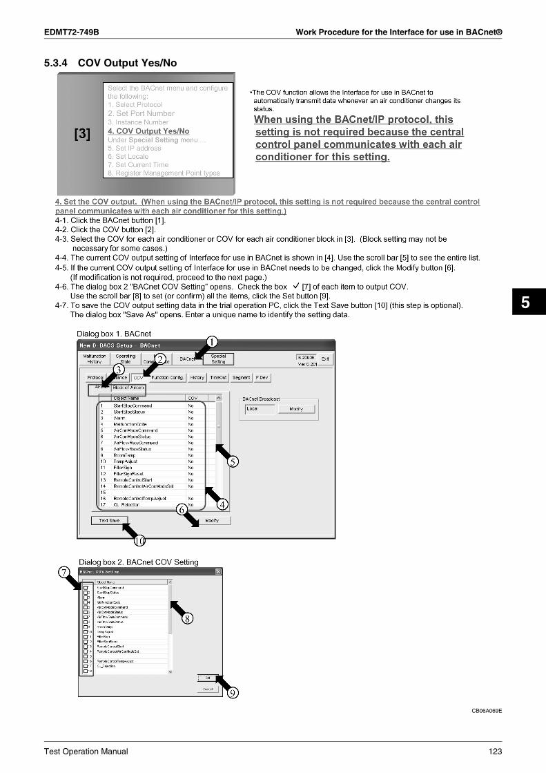
EDMT72-749B Work Procedure for the Interface for use in BACnet®
5
5.3.4 COV Output Yes/No
CB06A069E
Test Operation Manual 123

Work Procedure for the Interface for use in BACnet® EDMT72-749B
CB06A069E
124 Test Operation Manual

EDMT72-749B Work Procedure for the Interface for use in BACnet®
5
5.3.5 Set IP Address
CB06A069E
Test Operation Manual 125

Work Procedure for the Interface for use in BACnet® EDMT72-749B
CB06A069E
126 Test Operation Manual

EDMT72-749B Work Procedure for the Interface for use in BACnet®
5
5.3.6 Set Locale
CB06A069E
Test Operation Manual 127

Work Procedure for the Interface for use in BACnet® EDMT72-749B
5.3.7 Set Current Time
CB06A069E
128 Test Operation Manual

EDMT72-749B Work Procedure for the Interface for use in BACnet®
5
5.3.8 Register Management Point Types
CB06A069E
Test Operation Manual 129

Work Procedure for the Interface for use in BACnet® EDMT72-749B
CB06A069E
130 Test Operation Manual
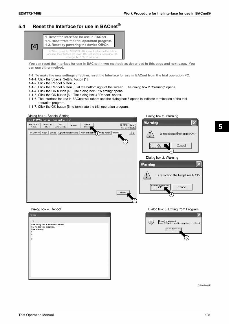
EDMT72-749B Work Procedure for the Interface for use in BACnet®
5
5.4 Reset the Interface for use in BACnet®
CB06A069E
Test Operation Manual 131
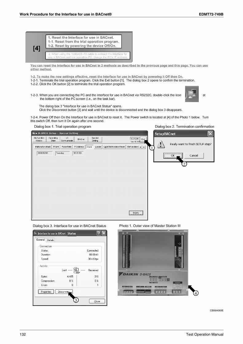
Work Procedure for the Interface for use in BACnet® EDMT72-749B
CB06A069E
132 Test Operation Manual

EDMT72-749B Work Procedure for the Interface for use in BACnet®
5
CB06A069E
Test Operation Manual 133

Work Procedure for the Interface for use in BACnet® EDMT72-749B
5.5 Start the Trial Operation Program
CB06A069E
134 Test Operation Manual
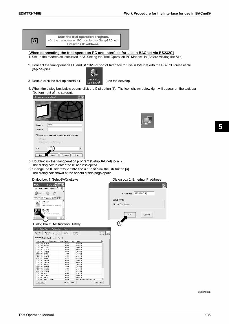
EDMT72-749B Work Procedure for the Interface for use in BACnet®
5
CB06A069E
Test Operation Manual 135

Work Procedure for the Interface for use in BACnet® EDMT72-749B
5.6 Select the Operation Status Menu and Check the Following
CB06A069E
136 Test Operation Manual

EDMT72-749B Work Procedure for the Interface for use in BACnet®
5
5.7 Check the Registration of Management Point Types
CB06A069E
Test Operation Manual 137

Work Procedure for the Interface for use in BACnet® EDMT72-749B
5.8 Check the All Points from the Central Control Panel
CB06A069E
138 Test Operation Manual

EDMT72-749B Work Procedure for the Interface for use in BACnet®
5
CB06A069E
Test Operation Manual 139

Reference: Items which do not Need to be Changed from the Factory Settings EDMT72-749B
6. Reference: Items which do not Need to be Changed from the Factory Settings
CB06A069E
140 Test Operation Manual

EDMT72-749B Reference: Items which do not Need to be Changed from the Factory Settings
5
CB06A069E
Test Operation Manual 141

Reference: Items which do not Need to be Changed from the Factory Settings EDMT72-749B
CB06A069E
142 Test Operation Manual

EDMT72-749B Reference: Items which do not Need to be Changed from the Factory Settings
5
CB06A069E
Test Operation Manual 143

Reference: Items which do not Need to be Changed from the Factory Settings EDMT72-749B
CB06A069E
144 Test Operation Manual

EDMT72-749B Reference: Items which do not Need to be Changed from the Factory Settings
5
CB06A069E
Test Operation Manual 145

Reference: Items which do not Need to be Changed from the Factory Settings EDMT72-749B
CB06A069E
146 Test Operation Manual

EDMT72-749B Q & A
5
7. Q & A
CB06A069E
Test Operation Manual 147

Q & A EDMT72-749B
CB06A069E
148 Test Operation Manual

EDMT72-749B Q & A
5
CB06A069E
Test Operation Manual 149

Q & A EDMT72-749B
CB06A069E
150 Test Operation Manual

EDMT72-749B Q & A
5
CB06A069E
Test Operation Manual 151

Q & A EDMT72-749B
CB06A069E
152 Test Operation Manual

EDMT72-749B
Test Run Manual (PPD) 153
6
Part 6Test Run Manual (PPD)
1. Test Run Procedures ..........................................................................1562. Connection between Service PC and Interface for use in BACnet® ...157
2.1 Wiring ...................................................................................................1572.2 Setting of IP Address (Windows 2000).................................................158
3. Setting of Pulse Rate (Using SetupBACnet®.exe) ..............................1604. Startup of PPD Test Run Tools (Using SetupPPD.exe)......................1645. Initializing ............................................................................................1656. Setting of Ports....................................................................................1667. Hardware Setting ................................................................................167
7.1 Automatic Setting .................................................................................1687.2 Manual Setting .....................................................................................169
8. Power Distribution Group Setting........................................................1708.1 Power Distribution Group Editing .........................................................171
9. Confirmation of Operation ...................................................................1729.1 Detailed Explanation for Confirmation Window ....................................1739.2 Confirmation Window, Normal Model...................................................1749.3 Confirmation of the Type of Wattmeter ................................................1789.4 Confirmation of Pulse Input ..................................................................1799.5 Confirmation of Integrated Values, Normal Model ...............................180
10.Error Messages...................................................................................182
CB06A070B

EDMT72-749B
[Introduction]
CB06A070B
154 Test Run Manual (PPD)

EDMT72-749B
6
[Precautions]
CB06A070B
Test Run Manual (PPD) 155

Test Run Procedures EDMT72-749B
1. Test Run Procedures
CB06A070B
156 Test Run Manual (PPD)

EDMT72-749B Connection between Service PC and Interface for use in BACnet®
6
2. Connection between Service PC and Interface for use in BACnet®
2.1 Wiring
CB06A070B
Test Run Manual (PPD) 157

Connection between Service PC and Interface for use in BACnet® EDMT72-749B
2.2 Setting of IP Address (Windows 2000)
CB06A070B
158 Test Run Manual (PPD)
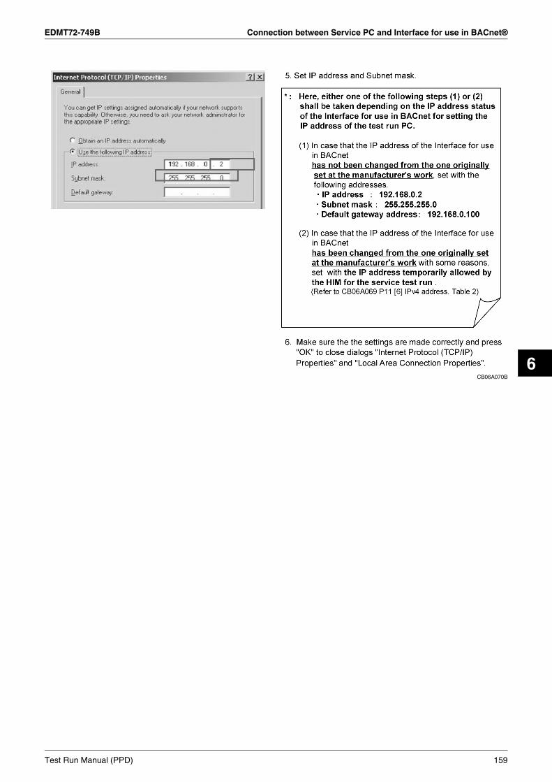
EDMT72-749B Connection between Service PC and Interface for use in BACnet®
6
CB06A070BTest Run Manual (PPD) 159

Setting of Pulse Rate (Using SetupBACnet®.exe) EDMT72-749B
3. Setting of Pulse Rate (Using SetupBACnet®.exe)
CB06A070B
160 Test Run Manual (PPD)

EDMT72-749B Setting of Pulse Rate (Using SetupBACnet®.exe)
6
CB06A070B
Test Run Manual (PPD) 161

Setting of Pulse Rate (Using SetupBACnet®.exe) EDMT72-749B
CB06A070B
162 Test Run Manual (PPD)

EDMT72-749B Setting of Pulse Rate (Using SetupBACnet®.exe)
6
CB06A070B
Test Run Manual (PPD) 163

Startup of PPD Test Run Tools (Using SetupPPD.exe) EDMT72-749B
4. Startup of PPD Test Run Tools (Using SetupPPD.exe)
CB06A070B
164 Test Run Manual (PPD)

EDMT72-749B Initializing
6
5. Initializing
CB06A070B
Test Run Manual (PPD) 165

Setting of Ports EDMT72-749B
6. Setting of Ports
CB06A070B
166 Test Run Manual (PPD)

EDMT72-749B Hardware Setting
6
7. Hardware Setting
CB06A070B
Test Run Manual (PPD) 167

Hardware Setting EDMT72-749B
7.1 Automatic Setting
CB06A070B
168 Test Run Manual (PPD)

EDMT72-749B Hardware Setting
6
7.2 Manual Setting
CB06A070B
Test Run Manual (PPD) 169

Power Distribution Group Setting EDMT72-749B
8. Power Distribution Group Setting
CB06A070B
170 Test Run Manual (PPD)

EDMT72-749B Power Distribution Group Setting
6
8.1 Power Distribution Group Editing
CB06A070B
Test Run Manual (PPD) 171

Confirmation of Operation EDMT72-749B
9. Confirmation of Operation
CB06A070B
172 Test Run Manual (PPD)

EDMT72-749B Confirmation of Operation
6
9.1 Detailed Explanation for Confirmation Window
CB06A070B
Test Run Manual (PPD) 173

Confirmation of Operation EDMT72-749B
9.2 Confirmation Window, Normal Model
CB06A070B
174 Test Run Manual (PPD)

EDMT72-749B Confirmation of Operation
6
CB06A070B
Test Run Manual (PPD) 175

Confirmation of Operation EDMT72-749B
CB06A070B
176 Test Run Manual (PPD)

EDMT72-749B Confirmation of Operation
6
CB06A070B
Test Run Manual (PPD) 177

Confirmation of Operation EDMT72-749B
9.3 Confirmation of the Type of Wattmeter
CB06A070B
178 Test Run Manual (PPD)

EDMT72-749B Confirmation of Operation
6
9.4 Confirmation of Pulse Input
CB06A070B
Test Run Manual (PPD) 179

Confirmation of Operation EDMT72-749B
9.5 Confirmation of Integrated Values, Normal Model
CB06A070B
180 Test Run Manual (PPD)

EDMT72-749B Confirmation of Operation
6
CB06A070B
Test Run Manual (PPD) 181

Error Messages EDMT72-749B
10.Error Messages
CB06A070B
182 Test Run Manual (PPD)

EDMT72-749B
Installation Manual 183
7
Part 7Installation Manual
1. Installation Manual ..............................................................................1841.1 DMS502B51 .........................................................................................1841.2 DAM411B51 (Option DIII Board)..........................................................1901.3 DAM412B51 (Option Di Board) ............................................................193
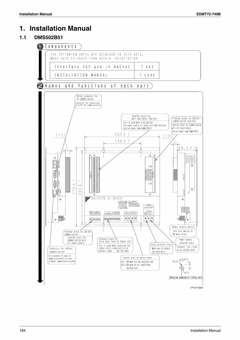
Installation Manual EDMT72-749B
1. Installation Manual1.1 DMS502B51
1P191169D
184 Installation Manual

EDMT72-749B Installation Manual
7
1P191169D
Installation Manual 185

Installation Manual EDMT72-749B
1P191169D
186 Installation Manual

EDMT72-749B Installation Manual
7
1P191170D
Installation Manual 187

Installation Manual EDMT72-749B
C: 1P191170D
188 Installation Manual

EDMT72-749B Installation Manual
7
1P191170D
Installation Manual 189

Installation Manual EDMT72-749B
1.2 DAM411B51 (Option DIII Board)
1P191165C
190 Installation Manual

EDMT72-749B Installation Manual
7
1P191165C
Installation Manual 191

Installation Manual EDMT72-749B
1P191165C
192 Installation Manual

EDMT72-749B Installation Manual
7
1.3 DAM412B51 (Option Di Board)
1P191166D
Installation Manual 193

Installation Manual EDMT72-749B
1P191166D
194 Installation Manual

EDMT72-749B Installation Manual
7
C: 1P191166D
Installation Manual 195

Installation Manual EDMT72-749B
196 Installation Manual

EDMT72-749B
Troubleshooting 197
8
Part 8Troubleshooting
1. Troubleshooting Interface for use in BACnet® with LED indication.....1981.1 Troubleshooting with CPU ALIVE LED,
CPU ALRM (ALARM) LEDs .................................................................1981.2 Troubleshooting with ETHER LINK LED, ETHER RCV LEDs .............2001.3 Troubleshooting with DIII-1-4 LEDs .....................................................2011.4 Troubleshooting with RS232C-1 TxD, RxD LEDs ................................2021.5 Troubleshooting with RS232C-2 TxD, RxD LEDs ................................203

Troubleshooting Interface for use in BACnet® with LED indication EDMT72-749B
1. Troubleshooting Interface for use in BACnet® with LED indication
1.1 Troubleshooting with CPU ALIVE LED, CPU ALRM (ALARM) LEDs
CPU ALIVE Blinks in a 0.4-second cycle.
CPU ALRM Off
YES
No
Normal status
CPU ALIVE Off
CPU ALRM Blinks in a 0.4-second cycle.
YES
No
CPU ALIVE Blinks in a 0.4-second cycle.
CPU ALRM Blinks in a 0.4-second cycle.
YES
No
CPU ALIVE Off
CPU ALRM Off
YES
No
CPU ALIVE
CPU ALRM On
YES
Continued onto next page
· Program is not written.⇒ Write the program onto the card.
· A card with a code other than the program is inserted in the PCMCIA card slot on the right side of the unit.⇒ Remove the card.
· The battery backup switch of Interface for use in BACnet® is turned off.⇒ Turn on the battery backup switch (i.e.,
set the switch knob to the lower position) on the right side of the unit.
· Check if Interface for use in BACnet® is powered on.⇒ If not, power on the iPU (and ensure that
the voltage is within 100 to 240V). · Interface for use in BACnet®'s internal CPU
or boot IC is malfunctioning.⇒ Perform the power-on reset and recheck
the operation.
· Interface for use in BACnet®'s internal memory or serial circuit is malfunctioning.⇒ Perform the power-on reset and recheck
the operation.
· Repeats blinking in a 0.2-second cycle for 2 through 5 times then turning off for 1 second.
198 Troubleshooting

EDMT72-749B Troubleshooting Interface for use in BACnet® with LED indication
8
CPU ALIVE Blinks in a 0.4-second cycle.
CPU ALRM Blinks in a 0.2-second cycle.
YES
Continued onto next page
Communication error of all the indoor units on the DIII-NET has been detected.
DIII-NET
Powerproportionaldistribution
Error condition NoteItem
No response from any air-conditioner
Overlapping parentcentral devices
DIII-NET polarity detection circuit error
Calculation overflow for current day
Backup start
BCC error
A central device which cannot co-exist with Interface for use in BACnet® exists on the DIII-NET.
Provisional power consumption is 1000 kWh or more and pulse 0
Multiple Interfaces for use in BACnet® exist, or iPU or DMS-IF exists on the same DIII-NET.
· Multiple Interfaces for use in BACnet® are installed.· A central device which cannot co-exist with Interfaces for use in BACnet® exists (with the same communication address) :DMS-IFiPU
Multiple devices are specified as "parent" on the DIII-NET.⇒ Only Interface for use in BACnet® should be
specified as "parent".
A polarity detection error has occurred on the DIII-NET.⇒ For instance, the DIII-NET line was connected
with the unit powered on.
A unification adaptor for computerized control or parallel interface has been detected on the DIII-NET.
Power proportional distribution calculator has detected the provisional power consumption 1000 kWh or more and pulse 0.
Power proportional distribution calculator has detected a calculation overflow for the current day.
Power proportional distribution calculator has executed a backup start.
Power proportional distribution calculator has detected a BCC error.
Occurs when BBRAMand Flash memorycontents are destroyed.
Occurs when the pulseinput is disconnected.
Automatically recoverswhen thecommunication errordisappears.
Troubleshooting 199

Troubleshooting Interface for use in BACnet® with LED indication EDMT72-749B
1.2 Troubleshooting with ETHER LINK LED, ETHER RCV LEDs
ETHER LINK
ETHER RCV Blinks
On
Constantly Off
On
YES
No
Normal status
ETHER LINK Off
OffETHER RCV
YES
No
ETHER LINK
ETHER RCV
YES
· Ethernet cable is not connected.⇒ Connect the Ethernet cable.
· HUB is not powered on.⇒ Power on the HUB.
· Ethernet cable is broken.⇒ Replace the Ethernet cable.
· BMS has not started.⇒ The problem will disappear when BMS starts
correctly.· Cable is not connected between BMS and HUB,
or it is broken.⇒ Connect the cable correctly.
* ETHER RCV LED blinks while data is being transmitted over the Ethernet.
200 Troubleshooting
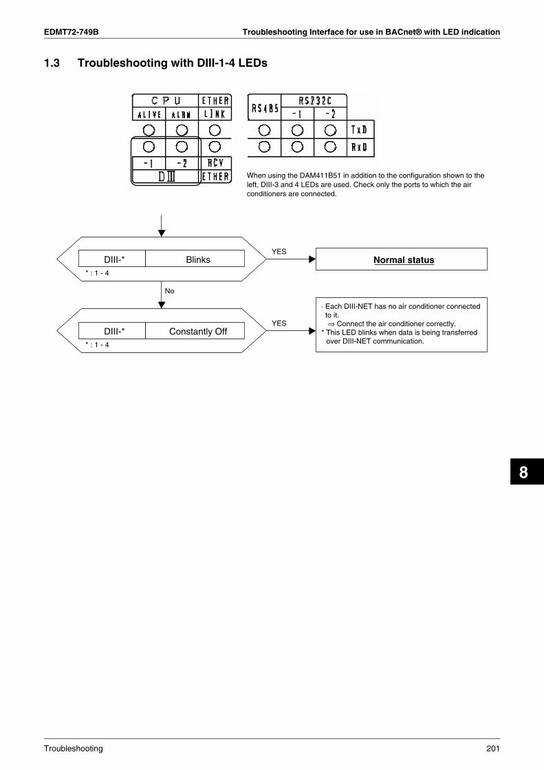
EDMT72-749B Troubleshooting Interface for use in BACnet® with LED indication
8
1.3 Troubleshooting with DIII-1-4 LEDs
DIII-* BlinksYES
No
Normal status
YES
· Each DIII-NET has no air conditioner connected to it.⇒ Connect the air conditioner correctly.
* This LED blinks when data is being transferred over DIII-NET communication.
When using the DAM411B51 in addition to the configuration shown to the left, DIII-3 and 4 LEDs are used. Check only the ports to which the air conditioners are connected.
* : 1 - 4
DIII-* Constantly Off* : 1 - 4
Troubleshooting 201

Troubleshooting Interface for use in BACnet® with LED indication EDMT72-749B
1.4 Troubleshooting with RS232C-1 TxD, RxD LEDs
RS232C-1 TxD, RxD Blinks at times.YES
No
YES
· Test operation PC has not been set for modem and dial-up connection.⇒ Perform the necessary settings.
· Communication cable is not connected to the RS232C-1 port.⇒ Connect the cable correctly.
· RS232C cable type is wrong.⇒ Check the cable type and replace the cable
with a correct one.
Normal status (when test operation PC is connected)[When test operation tool cannot be connected]<Cases where diagnosis is required>· Dial-up connection is not available, or· Test operation tool cannot be connected after
establishing dial-up connection.<Diagnosis method>Immediately after connecting to the testoperation PC via dial-up connection or afterestablishing dial-up connection, start thetest operation tool, enter the IP address toconnect to MS3, then check if the LEDsblink.<If LEDs do not blink>· Check if the cable is connected to the RS232C-
1 port.· Check if the cable conforms to the
specifications.· Check if the dial-up connection settings are
correct.· Check if the correct IP address (192.168.3.1)
was entered from the test operation tool.* A wrong IP address causes the tool to access to
the LAN interface and the RS232C LED does not blink.
* Check these LEDs only when the test operation PC is connected to Interface for use in BACnet® via RS232C.
RS232C-1 TxD blinks when Interface for use in BACnet® is transmitting data.RS232C-1 RxD blinks when Interface for use in BACnet® is receiving data from the test operation PC.
RS232C-1 TxD, RxD Off
202 Troubleshooting

EDMT72-749B Troubleshooting Interface for use in BACnet® with LED indication
8
1.5 Troubleshooting with RS232C-2 TxD, RxD LEDs
RS232C-2 TxD, RxD BlinksYES
No
Normal status(when BMS is connected via RS232C)
YES
· BMS is not powered on.⇒ Instruct to power on BMS properly.
· Communication cable is not connected to the RS232C-2 port.⇒ Connect the cable correctly.
· RS232C cable type is wrong.⇒ Check the cable type and replace the cable
with a correct one.
* Check these LEDs only when the Interface for use in BACnet® is connected to BMS via RS232C.
RS232C-2 TxD blinks when Interface for use in BACnet® is transmitting data.RS232C-2 RxD blinks when Interface for use in BACnet® Interface is receiving data from BMS.
RS232C-2 TxD, RxD Off
* RS485 is not used and LED off is the normal status.
Troubleshooting 203

Troubleshooting Interface for use in BACnet® with LED indication EDMT72-749B
204 Troubleshooting

EDMT72-749B
Job Flow 205
9
Part 9Interface for use in BACnet®
Project Job Flow
1. Interface for use in BACnet® Project Job Flow ...................................2061.1 Engineering Flow of Interface for use in BACnet® until Installation......2061.2 Initial Settings Required Items for Interface for use in BACnet® ..........208
CB07A006C

Interface for use in BACnet® Project Job Flow EDMT72-749B
1. Interface for use in BACnet® Project Job Flow1.1 Engineering Flow of Interface for use in BACnet® until Installation
CB07A006C
206 Job Flow

EDMT72-749B Interface for use in BACnet® Project Job Flow
9
CB07A006C
Job Flow 207

Interface for use in BACnet® Project Job Flow EDMT72-749B
1.2 Initial Settings Required Items for Interface for use in BACnet®
CB07A006C
208 Job Flow

EDMT72-749B Interface for use in BACnet® Project Job Flow
9
CB07A006C
Job Flow 209

Interface for use in BACnet® Project Job Flow EDMT72-749B
CB07A006C
210 Job Flow

EDMT72-749B Interface for use in BACnet® Project Job Flow
9
CB07A006C
Job Flow 211


All rights reserved 06/13 FSc
1. Air conditioners should not be installed in areas where corrosive gases, such as acid gas or alkaline gas, are produced.2. If the outdoor unit is to be installed close to the sea shore, direct exposure to the sea breeze should be avoided. If you need to install the outdoor unit close to the sea shore, contact your local distributor.
Cautions on product corrosion
Warning Ask a qualified installer or contractor to install this product. Do not try to install the product yourself. Improper installation can result in water or refrigerant leakage, electrical shock, fire or explosion.
Use only those parts and accessories supplied or specified by Daikin. Ask a qualified installer or contractor to install those parts and accessories. Use of unauthorised parts and accessories or improper installation of parts and accessories can result in water or refrigerant leakage, electrical shock, fire or explosion.
Read the User's Manual carefully before using this product. The User's Manual provides important safety instructions and warnings. Be sure to follow these instructions and warnings.
If you have any enquiries, please contact your local importer, distributor and/or retailer.
Specifications, designs and other content appearing in this brochure are current as of June 2013 but subject to change without notice.