Interchassis Session Recovery - Cisco
34
Interchassis Session Recovery This chapter describes how to configure Interchassis Session Recovery (ICSR). The product Administration Guides provide examples and procedures for configuration of basic services on the system. You should select the configuration example that best meets your service model, and configure the required elements for that model as described in the respective product Administration Guide, before using the procedures described below. ICSR is a licensed Cisco feature that requires a separate license. Contact your Cisco account representative for detailed information on specific licensing requirements. For information on installing and verifying licenses, refer to the Managing License Keys section of Software Management Operations. Important This chapter discusses the following: • Overview, page 1 • ICSR Operation, page 6 • Configuring ICSR, page 6 • Troubleshooting ICSR Operation, page 21 • Updating the Operating System, page 22 Overview The ICSR feature provides the highest possible availability for continuous call processing without interrupting subscriber services. ICSR allows the operator to configure gateways for redundancy purposes. In the event of a gateway failure, ICSR allows sessions to be transparently routed around the failure, thus maintaining the user experience. ICSR also preserves session information and state. The system supports ICSR between two instances that support ICSR in the same StarOS release. For combination VMs where more than one service type is in use, only those services that support ICSR can make use of ICSR. ICSR can provide redundancy for site/row/rack/host outages and major software faults. The two instances must be run on non-overlapping hosts and network interconnects. ICSR is only supported between identically configured VPC-DI or VPC-SI instances. UGP supports both L2 and L3 ICSR. Ultra Gateway Platform System Administration Guide, Release 5.8 1
-
Upload
khangminh22 -
Category
Documents
-
view
1 -
download
0
Transcript of Interchassis Session Recovery - Cisco

Interchassis Session Recovery
This chapter describes how to configure Interchassis Session Recovery (ICSR). The product AdministrationGuides provide examples and procedures for configuration of basic services on the system. You should selectthe configuration example that best meets your service model, and configure the required elements for thatmodel as described in the respective product Administration Guide, before using the procedures describedbelow.
ICSR is a licensed Cisco feature that requires a separate license. Contact your Cisco account representativefor detailed information on specific licensing requirements. For information on installing and verifyinglicenses, refer to theManaging License Keys section of Software Management Operations.
Important
This chapter discusses the following:
• Overview, page 1
• ICSR Operation, page 6
• Configuring ICSR, page 6
• Troubleshooting ICSR Operation, page 21
• Updating the Operating System, page 22
OverviewThe ICSR feature provides the highest possible availability for continuous call processing without interruptingsubscriber services. ICSR allows the operator to configure gateways for redundancy purposes. In the eventof a gateway failure, ICSR allows sessions to be transparently routed around the failure, thus maintaining theuser experience. ICSR also preserves session information and state.
The system supports ICSR between two instances that support ICSR in the same StarOS release. Forcombination VMs where more than one service type is in use, only those services that support ICSR can makeuse of ICSR.
ICSR can provide redundancy for site/row/rack/host outages and major software faults. The two instancesmust be run on non-overlapping hosts and network interconnects. ICSR is only supported between identicallyconfigured VPC-DI or VPC-SI instances.
UGP supports both L2 and L3 ICSR.
Ultra Gateway Platform System Administration Guide, Release 5.8 1

ICSR is implemented through the use of redundant virtual chassis. The virtual chassis for each UGP instanceare configured as primary and backup, with one being active and one standby. Both virtual chassis are connectedto the same AAA server. A checkpoint duration timer controls when subscriber data is sent from the activechassis to the standby chassis. If the active chassis handling the call traffic goes out of service, the standbychassis transitions to the active state and continues processing the call traffic without interrupting the subscribersession.
The virtual chassis determine which is active through a proprietary TCP-based connection known as theService Redundancy Protocol (SRP) link. The SRP link is used to exchange Hello messages between theactive CFs in the primary and backup chassis and must be maintained for proper system operation. Foradditional information, refer to the Session Recovery chapter.
ICSR licenses are currently supported for the following services:
• GGSN Gateway GPRS Support Node
• P-GW Packet Data Network Gateway
• S-GW Serving Gateway
• SAE-GW System Architecture Evolution Gateway
L2TP Access Concentrator (LAC) functionality for ICSR is supported by the following protocol and services:
• eGTP enhanced GPRS Tunneling Protocol
• GGSN Gateway GPRS Support Node
• P-GW Packet Data Network Gateway
• SAEGW System Architecture Evolution Gateway
L2TP Access Concentrator (LAC) functionality for ICSR is not supported by the following service:
• PMIP Proxy Mobile IP
L2TP Network Server (LNS) functionality for ICSR is not supported by any services.
ICSR support for LAC requires a separate LAC license, as well as an Inter-Chassis Session Recoverylicense.
Note
Contact your Cisco account representative to verify whether a specific service supports ICSR as an option.Note
Interchassis CommunicationIn situations where the SRP link goes out of service, a priority scheme is used to determine which chassisprocesses the session. The following priority scheme is used:
• route modifier
• chassis priority
Ultra Gateway Platform System Administration Guide, Release 5.82
Interchassis Session RecoveryInterchassis Communication

• MIO/UMIO/MIO2 MAC address
Checkpoint MessagesFor additional information, refer to the ICSR Checkpointing appendix.
SRP CLI Commands
Exec Mode CLI CommandsExec mode srp CLI configuration commands can be used to enable, disable and initiate SRP functions. Thetable below lists and briefly describes these commands. For complete information see theExecMode Commands(D-S) chapter of the Command Line Interface Reference.
Table 1: srp CLI Commands
DescriptionCommand
Disables the sending of NACK messages from the standby chassisthat may trigger a full checkpoint from the active chassis. Sendingfull checkpoints increases SRP bandwidth. This command disablesthe NACK feature for a specific micro-checkpoint which is failingcontinuously.
srp disable nack micro-chkpt-cmd
Initiates a forced audit between ICSR chassis. This audit ensuresthat two ICSR peers are synchronized and identifies any discrepanciesprior to scheduled or unscheduled switchover events.
srp initiate-auditmanual-with-sync
Executes a forced switchover from active to inactive.When executedon the active chassis, this command switches the active chassis tothe inactive state and the inactive chassis to an active state. See Notebelow.
srp initiate-switchover
Resets the auth probe monitor failure information to 0.srp reset-auth-probe-fail
Resets the Diameter monitor failure information to 0.srp reset-diameter-fail
Forcibly terminates post-switchover processing.srp terminate-post-process
Validates the configuration for an active chassis.srp validate-configuration
Validates that both active and standby chassis are ready for a plannedSRP switchover.
srp validate-switchover
Ultra Gateway Platform System Administration Guide, Release 5.8 3
Interchassis Session RecoveryCheckpoint Messages

For release 20.0 and higher, ICSRwill verify sessionmanager connectivity on both chassis prior to allowinga manual switchover. If one or more of the session managers in the active chassis is not connected on thestandby chassis, the switchover will not be initiated. An error message will appear on the screen notingthe number of session managers that are mismatched. The force keyword can be used to initiate theswitchover despite the mismatch(es). The output of the show checkpoint statistics verbose commandwill not indicate "Ready" for a session manager instance ("smgr inst") in the "peer conn" column for anyinstance that is not connected to the peer chassis.
Important
show CommandsExec mode show srp commands display a variety of information related to SRP functions. The table belowlists and briefly describes these commands. For complete information on these commands, see the Exec Modeshow Commands (Q-S) chapter of the Command Line Interface Reference.
Table 2: show srp Commands
DescriptionCommand
Displays statistics of an external audit.show srp audit-statistics
Displays the history of calls lost during switchover.show srp call-loss statistics
Displays check pointing statistics on session redundancy data (sessionmanagers, current call recovery records, etc.).
show srp checkpoint statistics
Displays Service Redundancy Protocol information (context, chassisstate, peer, connection state, etc.).
show srp info
Displays SRP monitor information.show srp monitor
Displays SRP statistics (hellomessages sent, configuration validation,resource messages, switchovers, etc.).
show srp statistics
For additional information about the output of show srp commands, see the Statistics and Counters Reference.
AAA MonitorAAA servers are monitored using the authentication probe mechanism. AAA servers are considered Up if theauthentication-probe receives a valid response. AAA servers are considered Down when themax-retriescount specified in the configuration of the AAA server has been reached. SRP initiates a switchover whennone of the configured AAA servers responds to an authentication probe. AAA probing is only performed onthe active chassis.
A switchover event caused by an AAA monitoring failure is non-revertible.Important
If the newly active chassis fails to monitor the configured AAA servers, it remains as the active chassis untilone of the following occurs:
Ultra Gateway Platform System Administration Guide, Release 5.84
Interchassis Session RecoveryAAA Monitor

• a manual switchover
• another non-AAA failure event causes the system to switchover
• a CLI command is used to clear the AAA failure flag and allow the chassis to switch to standby
BGP InteractionThe Service Redundancy Protocol implements revertible switchover behavior via a mechanism that adjuststhe route modifier value for the advertised loopback/IP Pool routes. The initial value of the route modifiervalue is determined by the chassis' configured role and is initialized to a value that is higher than a normaloperational value. This ensures that in the event of an SRP link failure and an SRP task failure, the correctchassis is still preferred in the routing domain.
For ICSR youmust configure busyout ip pool commands in the same order on Active and Standby chassisto avoid SRP validation failures.
Important
The Active and Standby chassis share current route modifier values. When BGP advertises the loopback andIP pool routes, it converts the route modifier into an autonomous systems (AS) path prepend count. The Activechassis always has a lower route modifier, and thus prepends less to the AS-path attribute. This causes theroute to be preferred in the routing domain.
If communication on the SRP link is lost, and both chassis in the redundant pair are claiming to be Active,the previously Active chassis is still preferred since it is advertising a smaller AS-path into the BGP routingdomain. The route modifier is incremented as switchover events occur. A threshold determines when the routemodifier should be reset to its initial value to avoid rollover.
RequirementsICSR configurations require the following:
• Three contexts:
◦Redundancy – to configure the primary and backup chassis redundancy.
◦Source –AAA configuration of the specified nas-ip-address must be the IP address of an interfacebound to an HA, or any core network service configured within the same context.
◦Destination – to configure monitoring and routing to the PDN.
• Border Gateway Protocol (BGP) – ICSR uses the route modifier to determine the chassis priority.
ICSR is a licensed Cisco feature. Verify that each chassis has the appropriate license before using theseprocedures. To do this, log in to both chassis and execute a show license information command. Lookfor "Inter-Chassis Session Recovery". If the chassis is not licensed, please contact your Cisco accountrepresentative.
Important
RADIUS and Diameter protocols can be monitored to trigger a switchover.
Ultra Gateway Platform System Administration Guide, Release 5.8 5
Interchassis Session RecoveryBGP Interaction
The following figure shows an ICSR network.
ICSR OperationThis section shows operational flows for ICSR.
The following figure shows an ICSR process flow due to a primary failure.
Figure 1: ICSR Process Flow (Primary Failure)
The following figure shows an ICSR process flow due to a manual switchover.
Figure 2: ICSR Process Flow (Manual Switchover)
Chassis Initialization
Chassis OperationThis section describes how the chassis communicate, maintain subscriber sessions, and perform chassisswitchover.
Chassis Communication
Chassis Switchover
Configuring ICSR
The ICSR configuration must be the same on the primary and backup chassis. If each chassis has a differentService Redundancy Protocol (SRP) configuration, the session recovery feature does not function andsessions cannot be recovered when the active chassis goes out of service.
Important
This section describes how to configure basic ICSR on each chassis. For information on commands thatconfigure additional parameters and options, refer to the Command Line Interface Reference.
For releases prior to StarOS 17.0, ICSR should not be configured for chassis supporting L2TP calls.Important
The procedures described below assume the following:
• The chassis have been installed and configured with core network services.For more configuration information and instructions on configuring services, refer to the respectiveproduct Administration Guide.
Ultra Gateway Platform System Administration Guide, Release 5.86
Interchassis Session RecoveryICSR Operation

• In addition, the IP address pools must be srp activated.
• AAA server is installed, configured and accessible by both chassis.
For more information on configuring the AAA server, refer to the AAA Interface Administration andReference.
• BGP router installed and configured. See Routing for more information on configuring BGP services.
To configure ICSR on a primary and/or backup chassis:
Step 1 Configure the SRP context by applying the example configuration in Configuring the Service Redundancy Protocol(SRP) Context, on page 7.
Step 2 Modify the source context of the core network service by applying the example configuration in Modifying the SourceContext for ICSR, on page 17.
Step 3 Modify the destination context of core network service by applying the example configuration inModifying the DestinationContext for ICSR, on page 19.
Step 4 Optional: Disable bulk statistics collection on the standby system by applying the example configuration in DisablingBulk Statistics Collection on a Standby System, on page 20.
Step 5 Verify your primary and backup chassis configuration as described in Verifying the Primary and Backup Configuration,on page 20.
Step 6 Save your configuration as described in Verifying and Saving Your Configuration.
Configuring the Service Redundancy Protocol (SRP) ContextTo configure the system to work with ICSR:
Step 1 Create the chassis redundancy context and bind it to the IP address of the primary chassis by applying the exampleconfiguration in Creating and Binding the SRP Context, on page 8. For VPC-DI instances, this should be the IP addressof the active CF in the primary VPC-DI intance.
Step 2 Configure the chassis redundancy context with priority, chassis mode, hello interval, dead-interval and peer IP addressby applying the example configuration in Configuring SRP Context Parameters, on page 8.
Step 3 Configure the SRP context with interface parameters (including interface name, IP address and port number) for interchassiscommunication by applying the example configuration in Configuring the SRP Context Interface Parameters, on page14.
Step 4 Verify your SRP context configuration as described in Verifying SRP Configuration, on page 17.Step 5 Save your configuration as described in Verifying and Saving Your Configuration.
Ultra Gateway Platform System Administration Guide, Release 5.8 7
Interchassis Session RecoveryConfiguring the Service Redundancy Protocol (SRP) Context

Creating and Binding the SRP Context
ICSR is configured on two VPC-DI instances. Be sure to create the redundancy context on both systems.CLI commands must be executed on both systems. Log onto both active CFs before continuing. Alwaysmake configuration changes on the active CF in the primary VPC-DI instance first. Before starting thisconfiguration, identify which VPC-DI to configure as the primary and use that login session.
Important
configurecontext srp_ctxt_name [-noconfirm]service-redundancy-protocolbind address ip_addressend
Notes:
• ICSR should be configured and maintained in a separate context.
Configuring SRP Context Parameters
CLI commands must be executed on both VPC instances. Log onto both active CFs before continuing.Always make configuration changes on the primary VPC instance first.
Important
Basic Parameters
This configuration assigns a chassis mode and priority, and also configures the redundancy link between theprimary and backup chassis:configurecontext srp_ctxt_nameservice-redundancy-protocolchassis-mode { primary | backup }priority prioritypeer-ip-address ip_addresshello-interval dur_secdead-interval dead_dur_secend
Notes:
• ICSR should be configured and maintained in a separate context.
•When assigning the chassis mode on the backup chassis be sure to enter the backup keyword.
• The checkpoint command sets the amount of time the chassis waits before check pointing an existingcall session. Checkpoints can be set for IMS (VoLTE) and/or non-IMS sessions. The checkpoint is asnapshot of the current application state that can be used to restart its execution in case of failure. Thedefault setting is 60 seconds.
Ultra Gateway Platform System Administration Guide, Release 5.88
Interchassis Session RecoveryConfiguring the Service Redundancy Protocol (SRP) Context

• The priority determines which chassis becomes active in the event that both chassis are misconfiguredwith the same chassis mode; see Chassis Initialization, on page 6. The higher priority chassis has thelower number. Be sure to assign different priorities to each chassis.
• Enter the IP chassis of the backup chassis as the peer-ip-address to the primary chassis. Assign the IPaddress of the primary chassis as the peer-ip-address to the backup chassis.
• The dead-intervalmust be at least three times greater than the hello-interval. For example, if the hellointerval is 10, the dead interval should be at least 30. System performance is severely impacted if thehello interval and dead interval are not set properly. An optional delay-interval command allows youto delay the start dead-interval for an interval following the loading of configuration files.
SRP Redundancy, AAA and Diameter Guard Timers
Guard timers ensure that local failures, such as reboots and task restarts, do not result in ICSR events whichcan be disruptive.
The guard timer command configures the redundancy-guard-period and monitor-damping-period for SRPservice monitoring.configurecontext context_nameservice-redundancy-protocol variableguard-timer { aaa-switchover-timers { damping-period seconds | guard-period seconds } |
diameter-switchover-timers { damping-period seconds | guard-period seconds } | srp-redundancy-timers{ aaa { damping-period seconds | guard-period seconds } | bgp { damping-period seconds |guard-period seconds } | diam { damping-period seconds | guard-period seconds } }
end
Notes:
• aaa-switchover-timers – sets timers that prevent back-to-back ICSR switchovers due to an AAA failure(post ICSR switchover) while the network is still converging.
◦damping-period – configures a delay time to trigger an ICSR switchover due to a monitoringfailure within the guard-period.
◦guard-period – configures the local-failure-recovery network-convergence timer.
• diameter-switchover-timers – sets timers that prevent a back-to-back ICSR switchover due to a Diameterfailure (post ICSR switchover) while the network is still converging.
◦damping-period – configures a delay time to trigger an ICSR switchover due to a monitoringfailure within the guard-period.
◦guard-period – configures the local-failure-recovery network-convergence timer.
• srp-redundancy-timers – sets timers that prevent an ICSR switchover while the system is recoveringfrom a local card-reboot/critical-task-restart failure.
◦aaa – local failure followed by AAA monitoring failure
◦bgp – local failure followed by BGP monitoring failure
◦diam – local failure followed by Diameter monitoring failure
Ultra Gateway Platform System Administration Guide, Release 5.8 9
Interchassis Session RecoveryConfiguring the Service Redundancy Protocol (SRP) Context

DSCP Marking of SRP Messages
You can enable separate DSCPmarking of SRP control and checkpoint messages. The dscp-marking commandsets DSCP marking values for SRP control and checkpoint (session maintenance) messages.configurecontext context_nameservice-redundancy-protocoldscp-marking { control | session } dscp_value
Notes:
• dscp_value can be:
◦af11 – Assured Forwarding Class 1 low drop PHB (Per Hop Behavior)
◦af12 – Assured Forwarding Class 1 medium drop PHB
◦af13 – Assured Forwarding Class 1 high drop PHB
◦af21 – Assured Forwarding Class 2 low drop PHB
◦af22 – Assured Forwarding Class 2 medium drop PHB
◦af23 – Assured Forwarding Class 2 high drop PHB
◦af31 – Assured Forwarding Class 3 low drop PHB
◦af32 – Assured Forwarding Class 3 medium drop PHB
◦af33 – Assured Forwarding Class 3 high drop PHB
◦af41 – Assured Forwarding Class 4 low drop PHB
◦af42 – Assured Forwarding Class 4 medium drop PHB
◦af43 – Assured Forwarding Class 4 high drop PHB
◦be – Best effort Per-Hop-Behaviour (default)
◦cs1 – Class selector 1 PHB
◦cs2 – Class selector 2 PHB
◦cs3 – Class selector 3 PHB
◦cs4 – Class selector 4 PHB
◦cs5 – Class selector 5 PHB
◦cs6 – Class selector 6 PHB
◦cs7 – Class selector 7 PHB
◦ef – Expedited Forwarding PHB, for low latency traffic
Optimizing Switchover TransitionsThere are several SRP configuration options that reduce the transition time from the active to standby gateways(primarily P-GW) in support of VoLTE traffic.
Ultra Gateway Platform System Administration Guide, Release 5.810
Interchassis Session RecoveryConfiguring the Service Redundancy Protocol (SRP) Context

These features require an updated ICSR license to support the enhancements. Contact your Cisco accountrepresentative for additional information.
Important
Allow Non-VoLTE Traffic During ICSR Switchover
The ICSR framework reduces switchover disruption for VoLTE traffic by enabling VoLTE traffic on thenewly active gateway prior to reconciling the billing information and enabling communication with the newlyactive gateway when accounting is not deemed critical.
This functionality extends to all other traffic, including data sessions and default bearer traffic for IMS/e911,The following ICSR functionality is provided for all non-VoLTE data traffic:
•When a switchover occurs, the newly active gateway forwards all traffic themoment the gateway becomesactive.
• External communication with billing servers is deferred. See the traffic flow diagram below.
Ultra Gateway Platform System Administration Guide, Release 5.8 11
Interchassis Session RecoveryConfiguring the Service Redundancy Protocol (SRP) Context
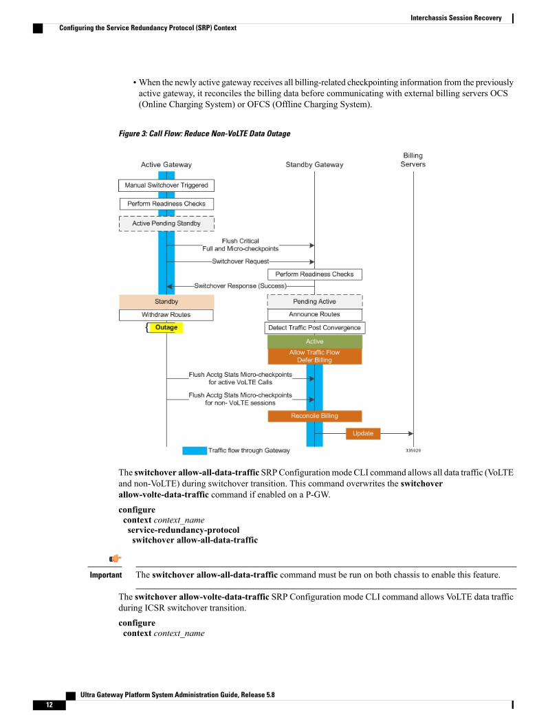
•When the newly active gateway receives all billing-related checkpointing information from the previouslyactive gateway, it reconciles the billing data before communicating with external billing servers OCS(Online Charging System) or OFCS (Offline Charging System).
Figure 3: Call Flow: Reduce Non-VoLTE Data Outage
The switchover allow-all-data-traffic SRPConfigurationmode CLI command allows all data traffic (VoLTEand non-VoLTE) during switchover transition. This command overwrites the switchoverallow-volte-data-traffic command if enabled on a P-GW.configurecontext context_nameservice-redundancy-protocolswitchover allow-all-data-traffic
The switchover allow-all-data-traffic command must be run on both chassis to enable this feature.Important
The switchover allow-volte-data-traffic SRP Configuration mode CLI command allows VoLTE data trafficduring ICSR switchover transition.configurecontext context_name
Ultra Gateway Platform System Administration Guide, Release 5.812
Interchassis Session RecoveryConfiguring the Service Redundancy Protocol (SRP) Context

service-redundancy-protocolswitchover allow-volte-data-traffic [ maintain-accounting ]
Notes:
•Whenmaintain-accounting is enabled, accounting accuracy is maintained for VoLTE calls.VoLTEdata is allowed on the active gateway after VoLTE accounting statistics are flushed.
Allow All Data Traffic
The SRP Configuration mode switchover allow-all-data-traffic command allows all data traffic (VoLTEand non-VoLTE) during switchover transition. This command overwrites the switchoverallow-volte-data-traffic command if enabled on a P-GW. This feature reduces data traffic outage during theswitchover.
This CLI command must be run on both the active and standby chassis to enable this feature.Important
All data traffic is allowed on the active chassis during flushing and internal auditing. The billing informationis reconciled in the background once the flush is complete.
Allow Early Active Transition
The SRP Configuration mode switchover allow-early-active-transition command enables early transitionto active state during an ICSR switchover. By default this feature is disabled.
Use this command in concert with the switchover allow-all-data-traffic or allow-volte-data-traffic (withoutmaintain accounting option) command to further reduce data outage during a planned switchover. The outagewindow is the amount time between initiating an ICSR switchover and when the newly active chassis startsprocessing data.
You must enable one of the commands identified above on both ICSR chassis prior to enabling thiscommand.
Important
Graceful Cleanup of ICSR After Audit of Failed Calls
During an Audit on the gateways (P-GW/S-GW/GGSN/SAE-GW) after Session Recovery or an ICSR event,if any critical information, internally or externally related to a subscriber session seems inconsistent, ICSRwill locally purge the associated session information.
Since external gateways (peer nodes) are unaware of the purging of this session, the UE session may bemaintained at other nodes. This leads to hogging of resources external to the gateway and an unreachable UEfor VoLTE calls.
When this feature is enabled, graceful cleanup for an ICSR audit of failed calls occurs. External signalingnotifies peers of session termination before purging the session. The gateway will attempt to notify externalpeers of the removal of the session. External nodes to the local gateway include S-GW, P-GW, SGSN, MME,AAA, PCRF and IMSA.
Audit failure can occur because of missing or incomplete session information. Therefore, only the peers forwhich the information is available will be notified.
Ultra Gateway Platform System Administration Guide, Release 5.8 13
Interchassis Session RecoveryConfiguring the Service Redundancy Protocol (SRP) Context

The require graceful-cleanup-during-audit-failure Global Configuration mode CLI command enables ordisables the graceful cleanup feature.configurerequire graceful-cleanup-during-audit-failure [ del-cause non-ims-apn { system-failure | none } ]
Optimization of Switchover Control Outage Time
The ICSR framework minimizes control outage time associated with the flushing of critical full checkpointstatistics, network convergence and internal auditing.
The amount of time consumed by the following activities affects control outage time during switchover:
• Critical Flush –During the Active to Pending-Standby transition, all sessmgrs flush any pending criticalFCs (Full Checkpoints). During this time, the active chassis drops all control packets. If control signalingis allowed during this stage, a call may get disconnected based on the control message type and accountinginformation will be lost.
• Network Convergence – This encompasses the amount of time taken to update routes and sendcontrol/data to the newly active chassis. Control messages are dropped during the transition.
• Accounting Flush – During this flush stage data counts are synchronized between chassis. If controlsignaling is allowed during this flush, the call may get disconnected based on the control message type,and accounting information will be lost for calls that existed before switchover.
• Audit – During audit new calls are not allowed because synchronization of call resources may result inclearing of the calls.
The switchover control-outage-optimization CLI command allows new calls during the Accounting Flush,as soon as the Audit is completed. This SRP Configuration mode command enables the quicker restorationof control traffic (call-setup, modification, deletion) following an ICSR switchover.configurecontext context_nameservice-redundancy-protocolswitchover control-outage-optimizationend
Configuring the SRP Context Interface ParametersThis procedure configures the communication interface with the IP address and port number within the SRPcontext. This interface supports interchassis communication.
CLI commands must be executed on both chassis. Log onto both chassis before continuing. Always makeconfiguration changes on the primary chassis first.
Important
configurecontext vpn_ctxt_name [-noconfirm]
interface srp_if_nameip-address { ip_address | ip_address/mask }exit
exitport ethernet slot_num/port_numdescription des_string
Ultra Gateway Platform System Administration Guide, Release 5.814
Interchassis Session RecoveryConfiguring the Service Redundancy Protocol (SRP) Context

medium { auto | speed { 10 | 100 | 1000 } duplex { full | half } }no shutdownbind interface srp_if_name srp_ctxt_nameend
Configuring NACK Generation for SRP Checkpoint Messaging Failures
Enabling NACK Messaging from the Standby Chassis
Transport (TCP) level re-transmission is supported on the SRP link between ICSR chassis. SRP configurationalso supports optional application level checks to ensure checkpoints are received at the Standby chassis.Failed attempts to receive and apply checkpoints send NACK messages to the Active chassis.
When this feature is enabled and the standby chassis sends a NACK in response to the receipt of amicro-checkpoint (MC) that fails to be successfully applied, the standby chassis sends another NACK. Thestandby chassis will send more NACKs (configurable, default = 3) within a 10-minute window if amacro-checkpoint (FC) is not received. NACKs will continue to be sent and the 10-minute reset until an FCis received and applied, or the configured number of max-responses is reached.
You can also specify the number of times a NACK is sent within the 10-minute window in response to a failedMC or FC (Default = 3).
A nack keyword in the SRPConfigurationmode checkpoint session command allows you to enable generationof NACK messages in response to checkpoint message failures on a Standby ICSR chassis.
The nack keyword will only appear if a special ICSR optimization feature license has been purchasedand installed. Contact your Cisco account representative for assistance.
Important
configurecontext context_nameservice-redundancy-protocol variablecheckpoint session nack { macro | micro } [ max-response number ]no checkpoint session nack { macro | micro }end
Notes:
• max-response is the number of times a NACK is sent within the 10-minute window in response to afailed MC or FC expressed as an integer from 0 through 65535 (Default = 3).
A periodic-interval keyword in the SRP Configuration mode checkpoint session command allows you toconfigure the interval between the sending of macro-checkpoints (FCs) between the active and standby chassis.
The periodic-interval keyword will only appear if a special ICSR optimization feature license has beenpurchased and installed. Contact your Cisco account representative for assistance.
Important
configurecontext context_nameservice-redundancy-protocol variablecheckpoint session periodic-interval minutesdefault checkpoint session periodic-interval
Ultra Gateway Platform System Administration Guide, Release 5.8 15
Interchassis Session RecoveryConfiguring the Service Redundancy Protocol (SRP) Context

no checkpoint session periodic-intervalend
Selective Disabling of NACK Messaging
The NACK mechanism sends a NACK message for any ICSR checkpoint failure on the standby chassis.Every NACK sent from the standby chassis triggers a full checkpoint from the active chassis.
If the micro-checkpoint is failing continuously and sending NACKs, the active chassis keeps sendingfull-checkpoints. This increases SRP bandwidth.
CLI commands allow an operator to selectively disable and re-enable NACK messages for specificmicro-checkpoints.
The Execmode srp disable nackmicro-chkpt-cmd disables the sending of a NACK from the standby chassis.
srp disable nack micro-chkpt-cmd chkpt_number
chkpt_number specifies the checkpoint number to be disabled as an integer from 1 through 255. You canobtain checkpoint numbers (CMD IDs) from the output of the show srp checkpoint info command.
You can re-enable the micro-checkpoint using the srp enable nack micro-chkpt-cmd command.
srp enable nack micro-chkpt-cmd chkpt_number
Configuring LZ4 Compression AlgorithmYou can optionally enable LZ4 compression algorithm for SRPmessaging payload. The zlib algorithm remainsas the default.
LZ4 is a very fast lossless compression algorithm with near-linear scalability for multi-threaded applications.
The compression keyword in the SRP Configuration mode checkpoint session command allows you toenable the use of the LZ4 compression algorithm.
The compression keyword will only appear if a special ICSR optimization feature license has beenpurchased and installed. Contact your Cisco account representative for assistance.
Important
The following command sequence enables the use of LZ4 compression:configurecontext context_nameservice-redundancy-protocolcheckpoint session compression lz4end
LZ4 compression is effective only if both chassis are configured with LZ4. If any one chassis has zlib (default)configured, the compression algorithm reverts to zlib. The algorithm is negotiated only during initial socketestablishment. Once agreed no more negotiation takes place until the TCP socket connection is reset.
Reducing Sync-Up Time with Standby ICSR ChassisThe default method for synchronizing the SRP database requires tens of seconds of delay whenever the TCPconnection between the Active and Standby session managers is established. Once the TCP connection isestablished, heart beat messages are exchanged between both ICSR chassis every 3 seconds. The standby
Ultra Gateway Platform System Administration Guide, Release 5.816
Interchassis Session RecoveryConfiguring the Service Redundancy Protocol (SRP) Context

chassis waits for seven heart beat messages from the active chassis before it is ready to accept data. This maycause significant delay in session manager database synchronization on the standby chassis.
You can enable an aggressive method for synchronizing the session manager database reduces recovery timein the following scenarios:
• Standby Session Manager crash
• Packet processing card failure on Standby chassis
• Standby chassis reboot
• Temporary loss and recovery of SRP connection
The aggressive method reduces the number of heartbeat messages and amount of housekeeping informationexchanged between ICSR chassis.
The SRP Configuration mode standby database-recovery aggressive command allows you to select normalor aggressive restoration of the SRP database.
The following command sequence enables the aggressive recovery mode:configurecontext context_nameservice-redundancy-protocolstandby database-recovery aggressiveend
The default form of this command restores the normal mode of SRP database recovery.
Verifying SRP ConfigurationVerify that your SRP contexts were created and configured properly by running the show srp info command(Exec Mode) on each chassis.
Notes:
• The interval is specified as an integer divisible by 15 in the range from 30 through 1440 (Default = 45minutes). The interval range for sending full checkpoints is 30 minutes to 24 hours (1140 minutes).
Modifying the Source Context for ICSRTo modify the source context of core service:
Step 1 Add the Border Gateway Protocol (BGP) router AS-path and configure the gateway IP address, neighbor IP address,remote IP address in the source context where the core network service is configured, by applying the exampleconfiguration in Configuring BGP Router and Gateway Address, on page 18.
Step 2 Configure the service redundancy context with the BGP neighbor context and IP address to monitor the BGP link activityby applying the example configuration in Configuring the SRP Context for BGP, on page 18.
Step 3 Verify your BGP context configuration by following the steps in Verifying BGP Configuration, on page 18.Step 4 Save your configuration as described in Verifying and Saving Your Configuration.
Ultra Gateway Platform System Administration Guide, Release 5.8 17
Interchassis Session RecoveryModifying the Source Context for ICSR

Configuring BGP Router and Gateway AddressUse the following example to create the BGP context and network addresses.configurecontext source_ctxt_namerouter bgp AS_numnetwork gw_ip_addressneighbor neighbor_ip_address remote-as AS_numend
Notes:
• source_ctxt_name is the context where the core network service is configured.
Configuring the SRP Context for BGPUse the following example to configure the BGP context and IP addresses in the SRP context.configurecontext srp_ctxt_nameservice-redundancy-protocolmonitor bgp context source_ctxt_name neighbor_ip_addressend
neighbor_ip_address can be entered in IPv4 dotted-decimal or IPv6 colon-separated-hexadecimal notation.Multiple IP addresses can be added per context as IPv4 and/or IPv6 IP addresses.
An ICSR failover is triggered when all BGP peers within a context are down.
Optionally, you can configure SRP peer groups within a context. ICSR failover would then occur if all peerswithin a group fail. This option is useful in deployments in which a combination of IPv4 and IPv6 peers arespread across multiple paired VLANs, and IPv4 or IPv6 connectivity is lost by all members of a peer group.
A sample configuration for SRP peer groups within a context ("PGWin") appears below.monitor bgp context PGWin 10.1.1.16 group 1monitor bgp context PGWin 10.1.1.17 group 1monitor bgp context PGWin 69.2.215.0 group 2monitor bgp context PGWin 69.2.215.1 group 2monitor bgp context PGWin 2001:4333:201:1102:103:2a1:: group 3monitor bgp context PGWin 2001:4333:201:1102:103:2a1:0:1 group 3
In the above sample configuration, ICSR failover would occur if both addresses in group 1, 2 or 3 lostconnectivity.
For additional information refer to the description of themonitor bgp, monitor diameter andmonitorauthentication-probe commands in the Service Redundancy Protocol ConfigurationMode Commands chapterof the Command Line Interface Reference.
Verifying BGP ConfigurationVerify your BGP configuration by entering the show srp monitor bgp command (Exec Mode).
Ultra Gateway Platform System Administration Guide, Release 5.818
Interchassis Session RecoveryModifying the Source Context for ICSR

Modifying the Destination Context for ICSRTo modify the destination context of core service:
Step 1 Add the BGP router and configure the gateway IP address, neighbor IP address, remote IP address in the destinationcontext where the core network service is configured, by applying the example configuration in Configuring BGPRouterand Gateway Address in Destination Context, on page 19.
Step 2 Configure the service redundancy context with BGP neighbor context and IP address to monitor the BGP link activityby applying the example configuration in Configuring SRP Context for BGP for Destination Context, on page 19.
Step 3 Set the subscriber mode to default by following the steps in Setting Subscriber to Default Mode, on page 19.Step 4 Verify your BGP context configuration by following the steps in Verifying BGP Configuration in Destination Context,
on page 20.Step 5 Save your configuration as described in Verifying and Saving Your Configuration.
Configuring BGP Router and Gateway Address in Destination ContextUse the following example to create the BGP context and network addresses.configurecontext dest_ctxt_namerouter bgp AS_numnetwork gw_ip_addressneighbor neighbor_ip_address remote-as AS_numend
Notes:
• AS_num is the autonomous systems path number for this BGP router.
Configuring SRP Context for BGP for Destination ContextUse the following example to configure the BGP context and IP addresses in the SRP context.configurecontext srp_ctxt_nameservice-redundancy-protocolmonitor bgp context dest_ctxt_name neighbor_ip_addressend
Setting Subscriber to Default ModeUse the following example to set the subscriber mode to default.configurecontext dest_ctxt_namesubscriber defaultend
Ultra Gateway Platform System Administration Guide, Release 5.8 19
Interchassis Session RecoveryModifying the Destination Context for ICSR

Verifying BGP Configuration in Destination ContextVerify your BGP configuration by entering the show srp monitor bgp command (Exec Mode).
Disabling Bulk Statistics Collection on a Standby SystemYou can disable the collection of bulk statistics from a system when it is in the standby mode of operation.
When this feature is enabled and a system transitions to standby state, any pending accumulated statisticaldata is transferred at the first opportunity. After that no additional statistics gathering takes place until thesystem comes out of standby state.
Important
Use the following example to disable the bulk statistics collection on a standby system.configurebulkstat modeno gather-on-standbyend
Repeat this procedure for both systems.
Verifying the Primary and Backup ConfigurationThis section describes how to compare the ICSR configuration on the primary and backup systems.
Step 1 Enter the show configuration srp command on each system (Exec mode).Step 2 Verify that both chassis have the same SRP configuration information.
The output looks similar to following:configcontext sourceinterface haservice loopbackip address 172.17.1.1 255.255.255.255 srp-activate
#exitradius attribute nas-ip-address address 172.17.1.1radius server 192.168.83.2 encrypted key 01abd002c82b4a2c port 1812radius accounting server 192.168.83.2 encrypted key 01abd002c82b4a2c port 1813ha-service ha-pdsnmn-ha-spi spi-number 256 encrypted secret 6c93f7960b726b6f6c93f7960b726b6f hash-algorithm md5fa-ha-spi remote-address 192.168.82.0/24 spi-number 256 encrypted secret 1088bdd6817f64dfbind address 172.17.1.1
#exit#exitcontext destinationip pool dynamic 172.18.0.0 255.255.0.0 public 0 srp-activateip pool static 172.19.0.0 255.255.240.0 static srp-activate
#exitcontext srpservice-redundancy-protocol
Ultra Gateway Platform System Administration Guide, Release 5.820
Interchassis Session RecoveryDisabling Bulk Statistics Collection on a Standby System

#exit#exit
Configuring Subscriber State Management Audit ProcessThis audit is to ensures that two ICSR peers are in synch and identifies any discrepancies prior to any scheduledor unscheduled switchover events.
Step 1 Enter the SRP Context mode and enter the service-redundancy-protocol command.Step 2 Enter the audit daily-start-time command. Specify the daily start time as an hour and minute. For example, a start time
of 06 00 indicates that the audit will begin at 6:00 AM.Step 3 Enter the audit periodicity command. Specify the interval in minutes for generating SRP audit statistics as an integer
from 60 through 1440. For example, a periodicity of 90 indicates that SRP audit statistics will be generated every 90minutes beginning at the specified start time. Default = 60.A sample configuration sequence appears below.configcontext srpservice-redundancy-protocolaudit daily-start-time 06 00audit periodicity 90end
Troubleshooting ICSR OperationSSD
StarOS supports an ICSR-specific show support details (SSD) command that outputs the results from a seriesof Exec mode show commands.This mini SSD reduces capture time when debugging ICSR timing issuesbetween the Active and Standby chassis, facilitating quicker resolution of the problem.
The show support details icsr command produces a mini SSD that contains the output of the following showcommands:
• show srp info
• show srp checkpoint statistics
• show srp checkpoint statistics verbose
• show srp checkpoint statistics debug-info
• show srp checkpoint statistics sessmgr all
• show srp checkpoint statistics sessmgr all debug-info
Ultra Gateway Platform System Administration Guide, Release 5.8 21
Interchassis Session RecoveryConfiguring Subscriber State Management Audit Process

• show srp checkpoint statistics ipsecmgr all
• show srp checkpoint statistics sessmgr all write-list-stats
• show srp checkpoint info
• show srp monitor
• show srp monitor all
• show srp monitor diameter debug
• show srp statistics
• show srp call-loss statistics
• show srp audit-statistics
• show session subsystem facility sessmgr all debug-info
The SSD output can be directed to a file that can be stored to /flash or off the chassis. For additional information,see the Command Line Interface Reference.
show srp details
The Exec mode show srp details command displays comprehensive information used by TAC personnel totroubleshoot ICSR/SRP issues.
Updating the Operating SystemUpdating the operating system (StarOS™) on an ICSR system is performed separately on each system whileit is in standby mode. Traffic disruption is minimal since an active system will be handling call sessions whilethe standby system is being updated.
The general upgrade sequence is as follows:
1 Download the StarOS software image and copy/transfer it to both the active and standby system.
2 Save the currently running configurations on both systems.
3 Update the standby backup system first.
4 Initiate an SRP switchover from the active primary system to make the standby backup system active.
5 Update the standby primary system.
6 Initiate an SRP switchover from the active backup system to make the standby primary system active.
The four-part flowchart below shows a more complete view of all the procedures required to complete theStarOS upgrade process.
Ultra Gateway Platform System Administration Guide, Release 5.822
Interchassis Session RecoveryUpdating the Operating System
Enabling the Demux on MIO/UMIO/MIO2 feature changes resource allocations within the system. Thisdirectly impacts an upgrade or downgrade between StarOS versions in ICSR configurations. Contact CiscoTAC for procedural assistance prior to upgrading or downgrading your ICSR deployment.
Caution
Figure 4: ICSR Software Upgrade – Part 1
Ultra Gateway Platform System Administration Guide, Release 5.8 23
Interchassis Session RecoveryUpdating the Operating System

Figure 5: ICSR Software Upgrade – Part 2
Ultra Gateway Platform System Administration Guide, Release 5.824
Interchassis Session RecoveryUpdating the Operating System

Figure 6: ICSR Software Upgrade – Part 3
Ultra Gateway Platform System Administration Guide, Release 5.8 25
Interchassis Session RecoveryUpdating the Operating System

Figure 7: ICSR Software Upgrade – Part 4
Ultra Gateway Platform System Administration Guide, Release 5.826
Interchassis Session RecoveryUpdating the Operating System

Both ICSR SystemsPerform the tasks described below on both the primary (active) and backup (standby) ICSR systems.
Downloading and Transferring the StarOS Image
Step 1 Verify that there is enough free space on the /flash device to accommodate the new operating system image file byentering the following Exec mode command:[local]host_name directory /flash
Step 2 Access to the Cisco support site and download facility is username and password controlled. Download the softwareimage to a network location or local drive from which it can be uploaded to the /flash device.
Step 3 Transfer the new operating system image file to the /flash device using one of the following methods:
Ultra Gateway Platform System Administration Guide, Release 5.8 27
Interchassis Session RecoveryBoth ICSR Systems
a) Copy the file from a network location or local drive using the copy command[local]host_name copy from_url to_url [-noconfirm]
b) Transfer the file to the /flash device using an FTP client with access to the system. The FTP client must be configuredto transfer the file using binary mode.
c) Transfer the file to the /flash device using an SFTP client with access to the system.
Step 4 Verify that the image file was successfully transferred to the /flash device by running the following Exec mode command:[local]host_name directory /flash
Step 5 Run the show version /flash/image_filename command to verify the build information. For example:local]host_name show version /flash/image_filename.bin
Any CRC errors will be displayed in the output of the above command. If any errors appear, check the buildand re-transfer it onto the chassis. Confirm that the correct image version and build description is displayed
Note
Standby ICSR SystemPerform the tasks described below on the backup or standby ICSR system.
Performing Health ChecksHealth checks are a series of Exec mode show commands to determine the readiness of the system to handlea software update.
Step 1 Run show card table all |grep unknown. No output should be displayed.Step 2 Run show card table |grep offline. No output should be displayed.Step 3 Run show resources |grep Status. The output should display "Within acceptable limits".Step 4 Run show alarm outstanding. Review the output for any issues that may preclude performing the software update.
Performing SRP ChecksService Redundancy Protocol (SRP) checks verify that the mechanism for monitoring ICSR system status isoperational.
Step 1 Run show srp monitor all.Step 2 Review the output for any issues that may preclude performing the software update.
Ultra Gateway Platform System Administration Guide, Release 5.828
Interchassis Session RecoveryStandby ICSR System

Performing BGP ChecksBorder Gateway Protocol (BGP) checks are only required when BGP is used to support redundant interchassiscommunication. These checks are run per context and per service type.
Step 1 For each BGP-enabled context, run show ip bgp summary. Verify that the BGP peers are connected and that IPv4 andIPv6 peers are up. Repeat for all BGP-enable contexts.
Step 2 Run show service_name all |grep "Service Status:". The service should be "Started". Repeat for all services runningon the chassis.
Updating the Boot RecordYou must add a new boot stack entry for the recently downloaded software image (.bin) file.
Step 1 Run the Exec mode show boot command to verify that there are less than 10 entries in the boot.sys file and that a higherpriority entry is available (minimally there is no priority 1 entry in the boot stack).
Step 2 Create a new boot stack entry for the new file group, consisting of the new operating system image file and the currentlyused CLI configuration file by entering the following Global Configuration command:[local]host_name(config)# boot system priority number image image_url /flash/filename config cfg_url/flash/filename
Step 3 Assign the next highest priority to this entry, by using the <N-1> method, wherein you assign a priority number that isone number less than your current highest priority.If priority 1 is in use, you must renumber the existing entries to ensure that at least that priority is available. The maximumnumber of boot stack entries that can be contained in the boot.sys file is 10. If there are already 10 entries in the bootstack, you must delete at least one of these entries (typically, the lowest priority) and, if necessary, renumber some orall of the other entries before proceeding. Use the no boot system priority command to delete a book stack entry.Forinformation on using the boot system priority command, refer to the Adding a New Boot Stack Entry section in thisguide
Synchronizing File SystemsSynchronize the local file systems by entering the following Exec mode command:
[local]host_name# filesystem synchronize all
Reboot StarOSReboot the StarOS by entering the following command:
[local]host_name# reload [-noconfirm]
Ultra Gateway Platform System Administration Guide, Release 5.8 29
Interchassis Session RecoveryStandby ICSR System

As the system reboots, it loads the new operating system software image and its corresponding CLIconfiguration file using the new boot stack entry configured earlier.
After the system reboots, establish a CLI session and enter the show version command to verify that the activesoftware version is correct.
Optional for PDSN: If you are using the IP Pool Sharing Protocol during your upgrade, refer to ConfiguringIPSP Before the Software Upgrade in the PDSN Administration Guide.
Updating the Configuration FileFeatures in the new operating system may require changes to the configuration file. These changes can bedone manually or facilitated by custom scripts prepared by Cisco TAC. Make whatever changes are necessaryprior to saving the updated configuration file.
Verifying the Software VersionAfter the system has successfully booted, verify that the new StarOS version is running by executing the Execmode show version command.
You can run the Exec mode show build command to display additional information about the StarOS buildrelease.
Saving the Configuration FileUse the Exec mode save configuration command to save the currently running configuration to the /flashdevice and to an off-chassis location (external memory device or network URL). The off-chassis copy assuresthat you will have a fallback, loadable configuration file should a problem be encountered.
Completing the Update ProcessRepeat the following tasks to complete the upgrade process on the standby secondary chassis:
• Synchronizing File Systems, on page 29
• Performing Health Checks, on page 28
• Performing SRP Checks, on page 28
• Performing BGP Checks, on page 29
Ultra Gateway Platform System Administration Guide, Release 5.830
Interchassis Session RecoveryStandby ICSR System

Waiting for Session SynchronizationAllow time for session synchronization to occur between the ICSR chassis before preceding to the next steps.
Step 1 Run the show session recovery status verbose command on both chassis. Proceed to the next steps only when no errorsare seen in the output of this command.
Step 2 On the standby chassis, run show srp checkpoint statistics |more.Step 3 On active chassis, run show subs summary |grep Total.Step 4 Compare the number of subscribers on the active chassis and the number of Current pre-allocated calls: on the standby
chassis. They should be similar (within 5%). Allow a few minutes for systems to complete synchronization.
Primary SystemPerform the tasks described below on the primary (active) ICSR system.
Initiating an SRP SwitchoverAn SRP switchover places the primary chassis in standby mode and makes the backup chassis active. Thesecondary chassis is now processing sessions with the upgraded software.
Step 1 On the primary chassis run the srp initiate-switchover command. All existing sessions will be migrated to the backupchassis and it begins servicing new session requests. Allow the switchover process to complete.
Step 2 On the primary chassis, run the show srp info command. Chassis State should indicate Standby when switchover iscomplete.
Step 3 On the backup chassis, confirm the switchover is complete by running the show srp info command. Chassis State shouldindicate Active when switchover is complete.
Checking AAA Monitor Status on the Newly Active SystemIf your network deployment requires communication with AAA servers, log into the newly active system andperform an AAA monitor check. You will be checking for the existence of any SNMP traps that indicate thesystem cannot communicate with AAA servers (starSRPAAAUnreachable).
Step 1 Run the Exec mode command show snmp trap history |grep starSRPAAAUnreachable.Step 2 There should be no output for this command, or no very recent SNMP trap notifications (based on the event timestamp).Step 3 If the active system cannot communicate with one or more AAA servers, refer to AAAMonitor for additional information.
Ultra Gateway Platform System Administration Guide, Release 5.8 31
Interchassis Session RecoveryPrimary System

Completing the Software UpdateLog into the backup (standby) system and repeat the following tasks to complete the upgrade process on thebackup (standby) system:
• Updating the Boot Record, on page 29
• Reboot StarOS, on page 29
• Updating the Configuration File, on page 30
• Verifying the Software Version, on page 30
• Saving the Configuration File, on page 30
• Synchronizing File Systems, on page 29
• Performing Health Checks, on page 28
• Performing SRP Checks, on page 28
• Performing BGP Checks, on page 29
•Waiting for Session Synchronization, on page 31
Initiating an SRP SwitchoverThis SRP switchover places the primary system in active mode and returns the backup system to the standby.The primary chassis is now processing sessions with the upgraded software.
Step 1 On the backup chassis run the srp initiate-switchover command. All existing sessions will be migrated to the primarychassis which begins servicing new session requests. Allow the switchover process to complete.
Step 2 On the backup system, run the show srp info command. Chassis State should indicate Standby when switchover iscomplete.
Step 3 On the primary system, confirm the switchover is complete by running the show srp info command. Chassis State shouldindicate Active when switchover is complete.
Making Test CallsOnce the chassis state is verified and subscribers are migrated, perform new call testing to make sure callsare successful.
Ultra Gateway Platform System Administration Guide, Release 5.832
Interchassis Session RecoveryPrimary System

Fallback ProcedureTo revert to the previous configuration and software build, perform the following steps as a user withadministrative privileges.
Step 1 Run the Exec mode show boot command. The topmost lowest numbered entry of the displayed output should be thenew configuration with the new software build. The second topmost entry should be the backup configuration.
Step 2 Remove the topmost boot entry n, and synchronize the configuration across the management cards.[local]host_name# config[local]host_name(config)# no boot system priority n[local]host_name(config)# end[local]host_name# filesystem synchronize all
Step 3 Reboot the system to load its previous configuration.[local]host_name# reload
Step 4 Perform health checks as described in Performing Health Checks, on page 28
Ultra Gateway Platform System Administration Guide, Release 5.8 33
Interchassis Session RecoveryFallback Procedure

Ultra Gateway Platform System Administration Guide, Release 5.834
Interchassis Session RecoveryFallback Procedure