
Intel Quartus Prime Standard Edition User Guide
206
Intel ® Quartus ® Prime Standard Edition User Guide Design Compilation Updated for Intel ® Quartus ® Prime Design Suite: 18.1 Online Version Send Feedback UG-20176 ID: 683283 Version: 2021.10.22
-
Upload
khangminh22 -
Category
Documents
-
view
0 -
download
0
Transcript of Intel Quartus Prime Standard Edition User Guide

Intel® Quartus® Prime StandardEdition User GuideDesign Compilation
Updated for Intel® Quartus® Prime Design Suite: 18.1
Online Version
Send Feedback UG-20176
ID: 683283
Version: 2021.10.22

Contents
1. Intel® Quartus® Prime Incremental Compilation for Hierarchical and Team-BasedDesign....................................................................................................................... 71.1. About Intel® Quartus® Prime Incremental Compilation............................................... 71.2. Deciding Whether to Use an Incremental Compilation Flow..........................................7
1.2.1. Flat Compilation Flow with No Design Partitions............................................. 71.2.2. Incremental Compilation Flow With Design Partitions...................................... 81.2.3. Team-Based Design Flows and IP Delivery...................................................11
1.3. Incremental Compilation Summary........................................................................ 131.3.1. Incremental Compilation Single Intel Quartus Prime Project Flow....................131.3.2. Steps for Incremental Compilation............................................................. 131.3.3. Creating Design Partitions......................................................................... 14
1.4. Common Design Scenarios Using Incremental Compilation........................................ 151.4.1. Reducing Compilation Time When Changing Source Files for One Partition....... 151.4.2. Optimizing a Timing-Critical Partition.......................................................... 161.4.3. Adding Design Logic Incrementally or Working With an Incomplete Design.......171.4.4. Debugging Incrementally With the Signal Tap Logic Analyzer......................... 181.4.5. Functional Safety IP Implementation.......................................................... 19
1.5. Deciding Which Design Blocks Should Be Design Partitions........................................ 261.5.1. Impact of Design Partitions on Design Optimization...................................... 291.5.2. Design Partition Assignments Compared to Physical Placement Assignments.... 301.5.3. Using Partitions With Third-Party Synthesis Tools..........................................301.5.4. Assessing Partition Quality........................................................................ 31
1.6. Specifying the Level of Results Preservation for Subsequent Compilations....................321.6.1. Netlist Type for Design Partitions................................................................331.6.2. Fitter Preservation Level for Design Partitions.............................................. 341.6.3. Where Are the Netlist Databases Saved?..................................................... 341.6.4. Deleting Netlists...................................................................................... 351.6.5. What Changes Initiate the Automatic Resynthesis of a Partition?.................... 35
1.7. Exporting Design Partitions from Separate Intel Quartus Prime Projects...................... 371.7.1. Preparing the Top-Level Design..................................................................391.7.2. Project Management— Making the Top-Level Design Available to Other
Designers............................................................................................... 401.7.3. Exporting Partitions..................................................................................421.7.4. Viewing the Contents of a Intel Quartus Prime Exported Partition File (.qxp).... 431.7.5. Integrating Partitions into the Top-Level Design............................................43
1.8. Team-Based Design Optimization and Third-Party IP Delivery Scenarios...................... 461.8.1. Using an Exported Partition to Send to a Design Without Including Source
Files.......................................................................................................461.8.2. Creating Precompiled Design Blocks (or Hard-Wired Macros) for Reuse............471.8.3. Designing in a Team-Based Environment.....................................................491.8.4. Enabling Designers on a Team to Optimize Independently............................. 511.8.5. Performing Design Iterations With Lower-Level Partitions.............................. 54
1.9. Creating a Design Floorplan With LogicLock Regions................................................. 561.9.1. Creating and Manipulating LogicLock Regions...............................................571.9.2. Changing Partition Placement with LogicLock Changes.................................. 57
1.10. Incremental Compilation Restrictions.................................................................... 581.10.1. When Timing Performance May Not Be Preserved Exactly............................ 58
Contents
Intel Quartus Prime Standard Edition User Guide: Design Compilation Send Feedback
2

1.10.2. When Placement and Routing May Not Be Preserved Exactly........................ 581.10.3. Using Incremental Compilation With Intel Quartus Prime Archive Files...........591.10.4. Formal Verification Support......................................................................591.10.5. Signal Probe Pins and Engineering Change Orders...................................... 591.10.6. Signal Tap Logic Analyzer in Exported Partitions......................................... 601.10.7. External Logic Analyzer Interface in Exported Partitions...............................601.10.8. Assignments Made in HDL Source Code in Exported Partitions...................... 611.10.9. Design Partition Script Limitations............................................................ 611.10.10. Restrictions on IP Core Partitions............................................................ 631.10.11. Restrictions on Intel Arria® 10 Transceiver............................................... 631.10.12. Register Packing and Partition Boundaries................................................631.10.13. I/O Register Packing............................................................................. 64
1.11. Scripting Support...............................................................................................641.11.1. Tcl Scripting and Command-Line Examples................................................ 64
1.12. Document Revision History..................................................................................69
2. Best Practices for Incremental Compilation Partitions and Floorplan Assignments.......712.1. About Incremental Compilation and Floorplan Assignments........................................712.2. Incremental Compilation Overview......................................................................... 71
2.2.1. Recommendations for the Netlist Type........................................................ 722.3. Design Flows Using Incremental Compilation........................................................... 73
2.3.1. Using Standard Flow.................................................................................732.3.2. Using Team-Based Flow........................................................................... 732.3.3. Combining Design Flows.......................................................................... 732.3.4. Project Management in Team-Based Design Flows........................................ 74
2.4. Why Plan Partitions and Floorplan Assignments?...................................................... 752.4.1. Partition Boundaries and Optimization.........................................................75
2.5. Guidelines for Incremental Compilation...................................................................782.5.1. General Partitioning Guidelines.................................................................. 782.5.2. Design Partition Guidelines........................................................................802.5.3. Consider a Cascaded Reset Structure..........................................................922.5.4. Design Partition Guidelines for Third-Party IP Delivery...................................93
2.6. Checking Partition Quality..................................................................................... 972.6.1. Incremental Compilation Advisor................................................................982.6.2. Design Partition Planner............................................................................982.6.3. Viewing Design Partition Planner and Floorplan Side-by-Side........................ 1002.6.4. Partition Statistics Report........................................................................ 1012.6.5. Report Partition Timing in the Timing Analyzer........................................... 1012.6.6. Check if Partition Assignments Impact the Quality of Results........................101
2.7. Including SDC Constraints from Lower-Level Partitions forThird-Party IP Delivery.....................................................................................1022.7.1. Creating an .sdc File with Project-Wide Constraints..................................... 1032.7.2. Creating an .sdc with Partition-Specific Constraints..................................... 1042.7.3. Consolidating the .sdc in the Top-Level Design........................................... 105
2.8. Introduction to Design Floorplans......................................................................... 1062.8.1. The Difference between Logical Partitions and Physical Regions.................... 1062.8.2. Why Create a Floorplan?......................................................................... 1072.8.3. When to Create a Floorplan..................................................................... 108
2.9. Design Floorplan Placement Guidelines..................................................................1092.9.1. Flow for Creating a Floorplan................................................................... 1092.9.2. Assigning Partitions to LogicLock Regions.................................................. 110
Contents
Send Feedback Intel Quartus Prime Standard Edition User Guide: Design Compilation
3

2.9.3. How to Size and Place Regions.................................................................1102.9.4. Modifying Region Size and Origin..............................................................1112.9.5. I/O Connections.....................................................................................1122.9.6. LogicLock Resource Exclusions................................................................. 1122.9.7. Creating Non-Rectangular Regions............................................................114
2.10. Checking Floorplan Quality................................................................................ 1142.10.1. Incremental Compilation Advisor............................................................ 1152.10.2. LogicLock Region Resource Estimates......................................................1152.10.3. LogicLock Region Properties Statistics Report........................................... 1152.10.4. Locate the Intel Quartus Prime Timing Analyzer Path in the Chip Planner..... 1152.10.5. Inter-Region Connection Bundles............................................................1152.10.6. Routing Utilization................................................................................ 1152.10.7. Ensure Floorplan Assignments Do Not Significantly Impact Quality of Results115
2.11. Recommended Design Flows and Application Examples..........................................1162.11.1. Create a Floorplan for Major Design Blocks.............................................. 1162.11.2. Create a Floorplan Assignment for One Design Block with Difficult Timing.... 1172.11.3. Create a Floorplan as the Project Lead in a Team-Based Flow..................... 117
2.12. Document Revision History................................................................................ 118
3. Intel Quartus Prime Integrated Synthesis.................................................................. 1203.1. Design Flow.......................................................................................................120
3.1.1. Intel Quartus Prime Integrated Synthesis Design and Compilation Flow......... 1223.2. Language Support..............................................................................................123
3.2.1. Verilog and SystemVerilog Synthesis Support.............................................1243.2.2. VHDL Synthesis Support......................................................................... 1283.2.3. AHDL Support........................................................................................1293.2.4. Schematic Design Entry Support.............................................................. 1303.2.5. State Machine Editor...............................................................................1303.2.6. Design Libraries..................................................................................... 1303.2.7. Using Parameters/Generics......................................................................133
3.3. Incremental Compilation..................................................................................... 1373.3.1. Partitions for Preserving Hierarchical Boundaries.........................................1383.3.2. Parallel Synthesis................................................................................... 1383.3.3. Intel Quartus Prime Exported Partition File as Source.................................. 139
3.4. Intel Quartus Prime Synthesis Options.................................................................. 1393.4.1. Setting Synthesis Options........................................................................1393.4.2. Optimization Technique........................................................................... 1433.4.3. Auto Gated Clock Conversion................................................................... 1433.4.4. Enabling Timing-Driven Synthesis.............................................................1453.4.5. SDC Constraint Protection....................................................................... 1453.4.6. PowerPlay Power Optimization..................................................................1453.4.7. Limiting Resource Usage in Partitions........................................................1453.4.8. Restructure Multiplexers..........................................................................1473.4.9. Synthesis Effort..................................................................................... 1483.4.10. Fitter Intial Placement Seed................................................................... 1483.4.11. State Machine Processing...................................................................... 1483.4.12. Safe State Machine...............................................................................1523.4.13. Power-Up Level.................................................................................... 1533.4.14. Power-Up Don’t Care............................................................................ 1543.4.15. Remove Duplicate Registers...................................................................1543.4.16. Preserve Registers................................................................................154
Contents
Intel Quartus Prime Standard Edition User Guide: Design Compilation Send Feedback
4

3.4.17. Disable Register Merging/Don’t Merge Register.........................................1553.4.18. Noprune Synthesis Attribute/Preserve Fan-out Free Register Node.............. 1563.4.19. Keep Combinational Node/Implement as Output of Logic Cell..................... 1573.4.20. Disabling Synthesis Netlist Optimizations with dont_retime Attribute........... 1583.4.21. Disabling Synthesis Netlist Optimizations with dont_replicate Attribute........ 1583.4.22. Maximum Fan-Out................................................................................ 1593.4.23. Controlling Clock Enable Signals with Auto Clock Enable Replacement and
direct_enable.........................................................................................1603.5. Inferring Multiplier, DSP, and Memory Functions from HDL Code............................... 161
3.5.1. Multiply-Accumulators and Multiply-Adders................................................ 1613.5.2. Shift Registers....................................................................................... 1623.5.3. RAM and ROM........................................................................................1623.5.4. Resource Aware RAM, ROM, and Shift-Register Inference.............................1633.5.5. Auto RAM to Logic Cell Conversion............................................................1643.5.6. RAM Style and ROM Style—for Inferred Memory......................................... 1643.5.7. RAM Style Attribute—For Shift Registers Inference......................................1663.5.8. Disabling Add Pass-Through Logic to Inferred RAMs no_rw_check Attribute.... 1673.5.9. RAM Initialization File—for Inferred Memory...............................................1693.5.10. Multiplier Style—for Inferred Multipliers................................................... 1693.5.11. Full Case Attribute................................................................................1713.5.12. Parallel Case........................................................................................1723.5.13. Translate Off and On / Synthesis Off and On.............................................1743.5.14. Ignore translate_off and synthesis_off Directives...................................... 1743.5.15. Read Comments as HDL........................................................................ 1753.5.16. Use I/O Flipflops...................................................................................1753.5.17. Specifying Pin Locations with chip_pin.....................................................1773.5.18. Using altera_attribute to Set Intel Quartus Prime Logic Options.................. 178
3.6. Analyzing Synthesis Results.................................................................................1803.6.1. Analysis & Synthesis Section of the Compilation Report............................... 1813.6.2. Project Navigator................................................................................... 181
3.7. Analyzing and Controlling Synthesis Messages....................................................... 1813.7.1. Intel Quartus Prime Messages..................................................................1813.7.2. VHDL and Verilog HDL Messages.............................................................. 182
3.8. Node-Naming Conventions in Intel Quartus Prime Integrated Synthesis..................... 1853.8.1. Hierarchical Node-Naming Conventions..................................................... 1853.8.2. Node-Naming Conventions for Registers (DFF or D Flipflop Atoms)................1853.8.3. Register Changes During Synthesis...........................................................1863.8.4. Preserving Register Names...................................................................... 1883.8.5. Node-Naming Conventions for Combinational Logic Cells............................. 1883.8.6. Preserving Combinational Logic Names..................................................... 189
3.9. Scripting Support...............................................................................................1903.9.1. Adding an HDL File to a Project and Setting the HDL Version........................ 1903.9.2. Assigning a Pin...................................................................................... 1923.9.3. Creating Design Partitions for Incremental Compilation................................192
3.10. Document Revision History................................................................................ 193
4. Reducing Compilation Time.........................................................................................1964.1. Compilation Time Advisor....................................................................................1964.2. Strategies to Reduce the Overall Compilation Time................................................. 196
4.2.1. Running Rapid Recompile........................................................................ 1964.2.2. Enabling Multi-Processor Compilation........................................................197
Contents
Send Feedback Intel Quartus Prime Standard Edition User Guide: Design Compilation
5

4.2.3. Using Incremental Compilation.................................................................1984.2.4. Using Block-Based Compilation................................................................ 199
4.3. Reducing Synthesis Time and Synthesis Netlist Optimization Time............................ 1994.3.1. Settings to Reduce Synthesis Time and Synthesis Netlist Optimization Time... 1994.3.2. Use Appropriate Coding Style to Reduce Synthesis Time.............................. 200
4.4. Reducing Placement Time....................................................................................2004.4.1. Fitter Effort Setting................................................................................ 2004.4.2. Placement Effort Multiplier Settings.......................................................... 2004.4.3. Physical Synthesis Effort Settings............................................................. 2014.4.4. Preserving Placement with Incremental Compilation....................................201
4.5. Reducing Routing Time....................................................................................... 2014.5.1. Identifying Routing Congestion with the Chip Planner..................................201
4.6. Reducing Static Timing Analysis Time................................................................... 2034.7. Setting Process Priority....................................................................................... 2034.8. Reducing Compilation Time Revision History.......................................................... 203
A. Intel Quartus Prime Standard Edition User Guides......................................................205
Contents
Intel Quartus Prime Standard Edition User Guide: Design Compilation Send Feedback
6

1. Intel® Quartus® Prime Incremental Compilation forHierarchical and Team-Based Design
1.1. About Intel® Quartus® Prime Incremental Compilation
This manual provides information and design scenarios to help you partition yourdesign to take advantage of the Quartus® II incremental compilation feature.
The ability to iterate rapidly through FPGA design and debugging stages is critical. TheIntel® Quartus® Prime software introduced the FPGA industry’s first true incrementaldesign and compilation flow, with the following benefits:
• Preserves the results and performance for unchanged logic in your design as youmake changes elsewhere.
• Reduces design iteration time by an average of 75% for small changes in largedesigns, so that you can perform more design iterations per day and achievetiming closure efficiently.
• Facilitates modular hierarchical and team-based design flows, as well as designreuse and intellectual property (IP) delivery.
Intel Quartus Prime incremental compilation supports the Arria®, Stratix®, andCyclone® series of devices.
1.2. Deciding Whether to Use an Incremental Compilation Flow
The Intel Quartus Prime incremental compilation feature enhances the standard IntelQuartus Prime design flow by allowing you to preserve satisfactory compilation resultsand performance of unchanged blocks of your design.
1.2.1. Flat Compilation Flow with No Design Partitions
In the flat compilation flow with no design partitions, all the source code is processedand mapped during the Analysis and Synthesis stage, and placed and routed duringthe Fitter stage whenever the design is recompiled after a change in any part of thedesign. One reason for this behavior is to ensure optimal push-button quality ofresults. By processing the entire design, the Compiler can perform globaloptimizations to improve area and performance.
You can use a flat compilation flow for small designs, such as designs in CPLD devicesor low-density FPGA devices, when the timing requirements are met easily with asingle compilation. A flat design is satisfactory when compilation time and preservingresults for timing closure are not concerns.
683283 | 2021.10.22
Send Feedback
Intel Corporation. All rights reserved. Intel, the Intel logo, and other Intel marks are trademarks of IntelCorporation or its subsidiaries. Intel warrants performance of its FPGA and semiconductor products to currentspecifications in accordance with Intel's standard warranty, but reserves the right to make changes to anyproducts and services at any time without notice. Intel assumes no responsibility or liability arising out of theapplication or use of any information, product, or service described herein except as expressly agreed to inwriting by Intel. Intel customers are advised to obtain the latest version of device specifications before relyingon any published information and before placing orders for products or services.*Other names and brands may be claimed as the property of others.
ISO9001:2015Registered

1.2.1.1. Incremental Capabilities Available When A Design Has No Partitions
The Intel Quartus Prime software has incremental compilation features available evenwhen you do not partition your design, including Smart Compilation, Rapid Recompile,and incremental debugging. These features work in either an incremental or flatcompilation flow.
1.2.1.1.1. With Smart Compilation
In any Intel Quartus Prime compilation flow, you can use Smart Compilation to allowthe Compiler to determine which compilation stages are required, based on thechanges made to the design since the last smart compilation, and then skip anystages that are not required. For example, when Smart Compilation is turned on, theCompiler skips the Analysis and Synthesis stage if all the design source files areunchanged. When Smart Compilation is turned on, if you make any changes to thelogic of a design, the Compiler does not skip any compilation stage. You can turn onSmart Compilation on the Compilation Process Settings page of the Setting dialogbox.
Note: Arria 10 devices do not support the smart compilation feature.
Related Information
Smart Compilation online help
1.2.1.1.2. With Rapid Recompile
The Intel Quartus Prime software also includes a Rapid Recompile feature thatinstructs the Compiler to reuse the compatible compilation results if most of thedesign has not changed since the last compilation. This feature reduces compilationtimes for small and isolated design changes. You do not have control over which partsof the design are recompiled using this option; the Compiler determines which parts ofthe design must be recompiled. The Rapid Recompile feature preserves performanceand can save compilation time by reducing the amount of changed logic that must berecompiled.
1.2.1.1.3. With Signal Tap Logic Analyzer
During the debugging stage of the design cycle, you can add the Signal Tap to yourdesign, even if the design does not have partitions. To preserve the compilation netlistfor the entire design, instruct the software to reuse the compilation results for theautomatically-created "Top" partition that contains the entire design.
1.2.2. Incremental Compilation Flow With Design Partitions
In the standard incremental compilation design flow, the top-level design is dividedinto design partitions, which can be compiled and optimized together in the top-levelIntel Quartus Prime project. You can preserve fitting results and performance forcompleted partitions while other parts of the design are changing, which reduces thecompilation times for each design iteration.
If you use the incremental compilation feature at any point in your design flow, it iseasier to accommodate the guidelines for partitioning a design and creating a floorplanif you start planning for incremental compilation at the beginning of your design cycle.
1. Intel® Quartus® Prime Incremental Compilation for Hierarchical and Team-Based Design
683283 | 2021.10.22
Intel Quartus Prime Standard Edition User Guide: Design Compilation Send Feedback
8

Incremental compilation is recommended for large designs and high resource densitieswhen preserving results is important to achieve timing closure. The incrementalcompilation feature also facilitates team-based design flows that allow designers tocreate and optimize design blocks independently, when necessary.
To take advantage of incremental compilation, start by splitting your design along anyof its hierarchical boundaries into design blocks to be compiled incrementally, and seteach block as a design partition. The Intel Quartus Prime software synthesizes eachindividual hierarchical design partition separately, and then merges the partitions intoa complete netlist for subsequent stages of the compilation flow. When recompilingyour design, you can use source code, post-synthesis results, or post-fitting results topreserve satisfactory results for each partition.
In a team-based environment, part of your design may be incomplete, or it may havebeen developed by another designer or IP provider. In this scenario, you can add thecompleted partitions to the design incrementally. Alternatively, other designers or IPproviders can develop and optimize partitions independently and the project lead canlater integrate the partitions into the top-level design.
Related Information
• Team-Based Design Flows and IP Delivery on page 11
• Incremental Compilation Summary on page 13
• Best Practices for Incremental Compilation Partitions and Floorplan Assignmentsdocumentation on page 71
1.2.2.1. Impact of Using Incremental Compilation with Design Partitions
Table 1. Impact Summary of Using Incremental Compilation
Characteristic Impact of Incremental Compilation with Design Partitions
Compilation Time Savings Typically saves an average of 75% of compilation time for small designchanges in large designs when post-fit netlists are preserved; thereare savings in both Intel Quartus Prime Integrated Synthesis and theFitter. (1)
Performance Preservation Excellent performance preservation when timing critical paths arecontained within a partition, because you can preserve post-fittinginformation for unchanged partitions.
Node Name Preservation Preserves post-fitting node names for unchanged partitions.
Area Changes The area (logic resource utilization) might increase because cross-boundary optimizations are limited, and placement and registerpacking are restricted.
fMAX Changes The design’s maximum frequency might be reduced becausecross-boundary optimizations are limited. If the design is partitionedand the floorplan location assignments are created appropriately, theremight be no negative impact on fMAX.
(1) Intel Quartus Prime incremental compilation does not reduce processing time for the early"pre-fitter" operations, such as determining pin locations and clock routing, so the featurecannot reduce compilation time if runtime is dominated by those operations.
1. Intel® Quartus® Prime Incremental Compilation for Hierarchical and Team-Based Design
683283 | 2021.10.22
Send Feedback Intel Quartus Prime Standard Edition User Guide: Design Compilation
9

1.2.2.2. Intel Quartus Prime Design Stages for Incremental Compilation
Figure 1. Design Stages for Incremental Compilation
SystemVHDL(.vhd)
AHDL(.tdf)
BlockDesign File
(.bdf)
EDIFNetlist(.edf)
VQMNetlist(.vqm)
Analysis & SynthesisSynthesize Changed Partitions,
Preserve Others
Partition MergeCreate Complete Netlist Using Appropriate Source Netlists for Each
Partition (Post-Fit, Post-Synthesis, or Imported Netlist)
Single Netlist forComplete Design
One Post-FitNetlist perPartition
One Post-SynthesisNetlist per Partition
Single Post-Fit Netlist for Complete Design
FitterPlace-and-Route Changed Partitions,
Preserve Others
Create Individual Netlists andComplete Netlists
Assembler
Settings & Assignments
Make Design &Assignment Modifications
Settings & Assignments
Design Partition Assignments
FloorplanLocation
Assignments
RequirementsSatisfied?
Yes
No
Program/Configure Device
Partition Top
Partition 1Partition 2
(1)
VerilogHDL(.sv)
Timing Analyzer in parallel
Note: When you use EDIF or VQM netlists created by third-party EDA synthesis tools,Analysis and Synthesis creates the design database, but logic synthesis andtechnology mapping are performed only for black boxes.
1. Intel® Quartus® Prime Incremental Compilation for Hierarchical and Team-Based Design
683283 | 2021.10.22
Intel Quartus Prime Standard Edition User Guide: Design Compilation Send Feedback
10

1.2.2.2.1. Analysis and Synthesis Stage
The figure above shows a top-level partition and two lower-level partitions. If any partof the design changes, Analysis and Synthesis processes the changed partitions andkeeps the existing netlists for the unchanged partitions. After completion of Analysisand Synthesis, there is one post-synthesis netlist for each partition.
1.2.2.2.2. Partition Merge Stage
The Partition Merge step creates a single, complete netlist that consists ofpost-synthesis netlists, post-fit netlists, and netlists exported from other Intel QuartusPrime projects, depending on the netlist type that you specify for each partition.
1.2.2.2.3. Fitter Stage
The Fitter then processes the merged netlist, preserves the placement and routing ofunchanged partitions, and refits only those partitions that have changed. The Fittergenerates the complete netlist for use in future stages of the compilation flow,including timing analysis and programming file generation, which can take place inparallel if more than one processor is enabled for use in the Intel Quartus Primesoftware. The Fitter also generates individual netlists for each partition so that thePartition Merge stage can use the post-fit netlist to preserve the placement androuting of a partition, if specified, for future compilations.
1.2.2.2.4. How to Compare Incremental Compilation Results with Flat Design Results
If you define partitions, but want to check your compilation results without partitionsin a “what if” scenario, you can direct the Compiler to ignore all partitions assignmentsin your project and compile the design as a "flat" netlist. When you turn on theIgnore partitions assignments during compilation option on the IncrementalCompilation page, the Intel Quartus Prime software disables all design partitionassignments in your project and runs a full compilation ignoring all partitionboundaries and netlists. Turning off the Ignore partitions assignments duringcompilation option restores all partition assignments and netlists for subsequentcompilations.
1.2.3. Team-Based Design Flows and IP Delivery
The Intel Quartus Prime software supports various design flows to enable team-baseddesign and third-party IP delivery. A top-level design can include one or morepartitions that are designed or optimized by different designers or IP providers, as wellas partitions that will be developed as part of a standard incremental methodology.
1.2.3.1. With a Single Intel Quartus Prime Project
In a team-based environment, part of your design may be incomplete because it isbeing developed elsewhere. The project lead or system architect can create emptyplaceholders in the top-level design for partitions that are not yet complete. Designersor IP providers can create and verify HDL code separately, and then the project leadlater integrates the code into the single top-level Intel Quartus Prime project. In thisscenario, you can add the completed partitions to the design incrementally, however,the design flow allows all design optimization to occur in the top-level design foreasiest design integration. Altera recommends using a single Intel Quartus Primeproject whenever possible because using multiple projects can add significant up-frontand debugging time to the development cycle.
1. Intel® Quartus® Prime Incremental Compilation for Hierarchical and Team-Based Design
683283 | 2021.10.22
Send Feedback Intel Quartus Prime Standard Edition User Guide: Design Compilation
11

1.2.3.2. With Multiple Intel Quartus Prime Projects
Alternatively, partition designers can design their partition in a copy of the top-leveldesign or in a separate Intel Quartus Prime project. Designers export their completedpartition as either a post-synthesis netlist or optimized placed and routed netlist, orboth, along with assignments such as LogicLock™ regions, as appropriate. The projectlead then integrates each design block as a design partition into the top-level design.Altera recommends that designers export and reuse post-synthesis netlists, unlessoptimized post-fit results are required in the top-level design, to simplify designoptimization.
1.2.3.2.1. Additional Planning Needed
Teams with a bottom-up design approach often want to optimize placement androuting of design partitions independently and may want to create separate IntelQuartus Prime projects for each partition. However, optimizing design partitions inseparate Intel Quartus Prime projects, and then later integrating the results into atop-level design, can have the following potential drawbacks that require carefulplanning:
• Achieving timing closure for the full design may be more difficult if you compilepartitions independently without information about other partitions in the design.This problem may be avoided by careful timing budgeting and special design rules,such as always registering the ports at the module boundaries.
• Resource budgeting and allocation may be required to avoid resource conflicts andoveruse. Creating a floorplan with LogicLock regions is recommended when designpartitions are developed independently in separate Intel Quartus Prime projects.
• Maintaining consistency of assignments and timing constraints can be moredifficult if there are separate Intel Quartus Prime projects. The project lead mustensure that the top-level design and the separate projects are consistent in theirassignments.
1.2.3.3. Collaboration on a Team-Based Design
A unique challenge of team-based design and IP delivery for FPGAs is the fact that thepartitions being developed independently must share a common set of resources. Tominimize issues that might arise from sharing a common set of resources, you candesign partitions within a single Intel Quartus Prime project or a copy of the top-leveldesign. A common project ensures that designers have a consistent view of the top-level project framework.
For timing-critical partitions being developed and optimized by another designer, it isimportant that each designer has complete information about the top-level design inorder to maintain timing closure during integration, and to obtain the best results.When you want to integrate partitions from separate Intel Quartus Prime projects, theproject lead can perform most of the design planning, and then pass the top-leveldesign constraints to the partition designers. Preferably, partition designers can obtaina copy of the top-level design by checking out the required files from a source controlsystem. Alternatively, the project lead can provide a copy of the top-level projectframework, or pass design information using Intel Quartus Prime-generated designpartition scripts. In the case that a third-party designer has no information about thetop-level design, developers can export their partition from an independent project ifrequired.
1. Intel® Quartus® Prime Incremental Compilation for Hierarchical and Team-Based Design
683283 | 2021.10.22
Intel Quartus Prime Standard Edition User Guide: Design Compilation Send Feedback
12

Related Information
• Exporting Design Partitions from Separate Intel Quartus Prime Projects on page37
• Project Management— Making the Top-Level Design Available to Other Designerson page 40
1.3. Incremental Compilation Summary
1.3.1. Incremental Compilation Single Intel Quartus Prime Project Flow
The figure illustrates the incremental compilation design flow when all partitions arecontained in one top-level design.
Figure 2. Top-Down Design Flow
Perform Elaboration
Repeat as NeededDuring Design, Verification,& Debugging Stages
(Optional) Create Floorplan LocationAssignments using LogicLock Regions
Perform Complete Compilation(All Partitions are Compiled)
Set Netlist Type for Each Partition
Make Changes to Design
Perform Incremental Compilation(Partitions are Compiled if Required)
Prepare Design for Incremental Compilation
1.3.2. Steps for Incremental Compilation
For an interactive introduction to implementing an incremental compilation designflow, refer to the Getting Started Tutorial on the Help menu in the Intel QuartusPrime software.
1.3.2.1. Preparing a Design for Incremental Compilation
1. Elaborate your design, or run any compilation flow (such as a full compilation) thatincludes the elaboration step. Elaboration is the part of the synthesis process thatidentifies your design’s hierarchy.
2. Designate specific instances in the design hierarchy as design partitions.
3. If required for your design flow, create a floorplan with LogicLock regions locationassignments for timing-critical partitions that change with future compilations.Assigning a partition to a physical region on the device can help maintain qualityof results and avoid conflicts in certain situations.
1. Intel® Quartus® Prime Incremental Compilation for Hierarchical and Team-Based Design
683283 | 2021.10.22
Send Feedback Intel Quartus Prime Standard Edition User Guide: Design Compilation
13

Related Information
• Creating Design Partitions on page 14
• Creating a Design Floorplan With LogicLock Regions on page 56
1.3.2.2. Compiling a Design Using Incremental Compilation
The first compilation after making partition assignments is a full compilation, andprepares the design for subsequent incremental compilations. In subsequentcompilations of your design, you can preserve satisfactory compilation results andperformance of unchanged partitions with the Netlist Type setting in the DesignPartitions window. The Netlist Type setting determines which type of netlist or sourcefile the Partition Merge stage uses in the next incremental compilation. You can choosethe Source File, Post-Synthesis netlist, or Post-Fit netlist.
Related Information
Specifying the Level of Results Preservation for Subsequent Compilations on page 32
1.3.3. Creating Design Partitions
There are several ways to designate a design instance as a design partition.
Related Information
Deciding Which Design Blocks Should Be Design Partitions on page 26
1.3.3.1. Creating Design Partitions in the Project Navigator
You can right-click an instance in the list under the Hierarchy tab in the ProjectNavigator and use the sub-menu to create and delete design partitions.
1.3.3.2. Creating Design Partitions in the Design Partitions Window
The Design Partitions window, available from the Assignments menu, allows you tocreate, delete, and merge partitions, and is the main window for setting the netlisttype to specify the level of results preservation for each partition on subsequentcompilations.
The Design Partitions window also lists recommendations at the bottom of the windowwith links to the Incremental Compilation Advisor, where you can view additionalrecommendations about partitions. The Color column indicates the color of eachpartition as it appears in the Design Partition Planner and Chip Planner.
You can right-click a partition in the window to perform various common tasks, suchas viewing property information about a partition, including the time and date of thecompilation netlists and the partition statistics.
When you create a partition, the Intel Quartus Prime software automatically generatesa name based on the instance name and hierarchy path. You can edit the partitionname in the Design Partitions Window so that you avoid referring to them by theirhierarchy path, which can sometimes be long. This is especially useful when usingcommand-line commands or assignments, or when you merge partitions to give thepartition a meaningful name. Partition names can be from 1 to 1024 characters inlength and must be unique. The name can consist of alphanumeric characters and thepipe ( | ), colon ( : ), and underscore ( _ ) characters.
1. Intel® Quartus® Prime Incremental Compilation for Hierarchical and Team-Based Design
683283 | 2021.10.22
Intel Quartus Prime Standard Edition User Guide: Design Compilation Send Feedback
14

Related Information
Netlist Type for Design Partitions on page 33
1.3.3.3. Creating Design Partitions With the Design Partition Planner
The Design Partition Planner allows you to view design connectivity and hierarchy, andcan assist you in creating effective design partitions that follow Altera’s guidelines.
The Design Partition Planner displays a visual representation of design connectivityand hierarchy, as well as partitions and entity relationships. You can explore theconnectivity between entities in the design, evaluate existing partitions with respect toconnectivity between entities, and try new partitioning schemes in "what if" scenarios.
When you extract design blocks from the top-level design and drag them into theDesign Partition Planner, connection bundles are drawn between entities, showing thenumber of connections existing between pairs of entities. In the Design PartitionPlanner, you can then set extracted design blocks as design partitions.
The Design Partition Planner also has an Auto-Partition feature that createspartitions based on the size and connectivity of the hierarchical design blocks.
Related Information
Best Practices for Incremental Compilation Partitions and Floorplan Assignmentsdocumentation on page 71
1.3.3.4. Creating Design Partitions With Tcl Scripting
You can also create partitions with Tcl scripting commands.
Related Information
Scripting Support on page 64
1.3.3.5. Automatically-Generated Partitions
The Compiler creates some partitions automatically as part of the compilation process,which appear in some post-compilation reports. For example, the sld_hub partition iscreated for tools that use JTAG hub connections, such as the SignalTap II LogicAnalyzer. The hard_block partition is created to contain certain "hard" or dedicatedlogic blocks in the device that are implemented in a separate partition so that they canbe shared throughout the design.
1.4. Common Design Scenarios Using Incremental Compilation
Related Information
Steps for Incremental Compilation on page 13
1.4.1. Reducing Compilation Time When Changing Source Files for OnePartition
Scenario background: You set up your design to include partitions for several of themajor design blocks, and now you have just performed a lengthy compilation of theentire design. An error is found in the HDL source file for one partition and it is being
1. Intel® Quartus® Prime Incremental Compilation for Hierarchical and Team-Based Design
683283 | 2021.10.22
Send Feedback Intel Quartus Prime Standard Edition User Guide: Design Compilation
15

fixed. Because the design is currently meeting timing requirements, and the fix is notexpected to affect timing performance, it makes sense to compile only the affectedpartition and preserve the rest of the design.
Use the flow in this example to update the source file in one partition without havingto recompile the other parts of the design. To reduce the compilation time, instruct thesoftware to reuse the post-fit netlists for the unchanged partitions. This flow alsopreserves the performance of these blocks, which reduces additional timing closureefforts.
Perform the following steps to update a single source file:
1. Apply and save the fix to the HDL source file.
2. On the Assignments menu, open the Design Partitions window.
3. Change the netlist type of each partition, including the top-level entity, to Post-Fitto preserve as much as possible for the next compilation.
• The Intel Quartus Prime software recompiles partitions by default whenchanges are detected in a source file. You can refer to the Partition DependentFiles table in the Analysis and Synthesis report to determine which partitionswere recompiled. If you change an assignment but do not change the logic ina source file, you can set the netlist type to Source File for that partition toinstruct the software to recompile the partition's source design files and itsassignments.
4. Click Start Compilation to incrementally compile the fixed HDL code. Thiscompilation should take much less time than the initial full compilation.
5. Simulate the design to ensure that the error is fixed, and use the Timing Analyzerreport to ensure that timing results have not degraded.
Related Information
List of Compilation and Simulation Reports online help
1.4.2. Optimizing a Timing-Critical Partition
Scenario background: You have just performed a lengthy full compilation of a designthat consists of multiple partitions. The Timing Analyzer reports that the clock timingrequirement is not met, and you have to optimize one particular partition. You want totry optimization techniques such as raising the Placement Effort Multiplier and runningDesign Space Explorer II. Because these techniques all involve significant compilationtime, you should apply them to only the partition in question.
Use the flow in this example to optimize the results of one partition when the otherpartitions in the design have already met their requirements. You can use this flowiteratively to lock down the performance of one partition, and then move on tooptimization of another partition.
Perform the following steps to preserve the results for partitions that meet their timingrequirements, and to recompile a timing-critical partition with new optimizationsettings:
1. Open the Design Partitions window.
2. For the partition in question, set the netlist type to Source File.
1. Intel® Quartus® Prime Incremental Compilation for Hierarchical and Team-Based Design
683283 | 2021.10.22
Intel Quartus Prime Standard Edition User Guide: Design Compilation Send Feedback
16

• If you change a setting that affects only the Fitter, you can save additionalcompilation time by setting the netlist type to Post-Synthesis to reuse thesynthesis results and refit the partition.
3. For the remaining partitions (including the top-level entity), set the netlist type toPost-Fit.
• You can optionally set the Fitter Preservation Level on the Advanced tab inthe Design Partitions Properties dialog box to Placement to allow for themost flexibility during routing.
4. Apply the desired optimization settings.
5. Click Start Compilation to perform incremental compilation on the design withthe new settings. During this compilation, the Partition Merge stage automaticallymerges the critical partition’s new synthesis netlist with the post-fit netlists of theremaining partitions. The Fitter then refits only the required partition. Because theeffort is reduced as compared to the initial full compilation, the compilation time isalso reduced.
To use Design Space Explorer II, perform the following steps:
1. Repeat steps 1–3 of the previous procedure.
2. Save the project and run Design Space Explorer II.
1.4.3. Adding Design Logic Incrementally or Working With an IncompleteDesign
Scenario background: You have one or more partitions that are known to be timing-critical in your full design. You want to focus on developing and optimizing this subsetof the design first, before adding the rest of the design logic.
Use this flow to compile a timing-critical partition or partitions in isolation, optionallywith extra optimizations turned on. After timing closure is achieved for the criticallogic, you can preserve its content and placement and compile the remainingpartitions with normal or reduced optimization levels. For example, you may want tocompile an IP block that comes with instructions to perform optimization before youincorporate the rest of your custom logic.
To implement this design flow, perform the following steps:
1. Partition the design and create floorplan location assignments. For best results,ensure that the top-level design includes the entire project framework, even ifsome parts of the design are incomplete and are represented by an emptywrapper file.
2. For the partitions to be compiled first, in the Design Partitions window, set thenetlist type to Source File.
3. For the remaining partitions, set the netlist type to Empty.
4. To compile with the desired optimizations turned on, click Start Compilation.
5. Check the Timing Analyzer reports to ensure that timing requirements are met. Ifso, proceed to step 6. Otherwise, repeat steps 4 and 5 until the requirements aremet.
1. Intel® Quartus® Prime Incremental Compilation for Hierarchical and Team-Based Design
683283 | 2021.10.22
Send Feedback Intel Quartus Prime Standard Edition User Guide: Design Compilation
17

6. In the Design Partitions window, set the netlist type to Post-Fit for the firstpartitions. You can set the Fitter Preservation Level on the Advanced tab inthe Design Partitions Properties dialog box to Placement to allow moreflexibility during routing if exact placement and routing preservation is notrequired.
7. Change the netlist type from Empty to Source File for the remaining partitions,and ensure that the completed source files are added to the project.
8. Set the appropriate level of optimizations and compile the design. Changing theoptimizations at this point does not affect any fitted partitions, because eachpartition has its netlist type set to Post-Fit.
9. Check the Timing Analyzer reports to ensure that timing requirements are met. Ifnot, make design or option changes and repeat step 8 and step 9 until therequirements are met.
The flow in this example is similar to design flows in which a module is implementedseparately and is later merged into the top-level. Generally, optimization in this flowworks only if each critical path is contained within a single partition. Ensure that ifthere are any partitions representing a design file that is missing from the project, youcreate a placeholder wrapper file to define the port interface.
Related Information
• Designing in a Team-Based Environment on page 49
• Deciding Which Design Blocks Should Be Design Partitions on page 26
• Empty Partitions on page 40
1.4.4. Debugging Incrementally With the Signal Tap Logic Analyzer
Scenario background: Your design is not functioning as expected, and you want todebug the design using the Signal Tap Logic Analyzer. To maintain reduced compilationtimes and to ensure that you do not negatively affect the current version of yourdesign, you want to preserve the synthesis and fitting results and add the Signal Tapto your design without recompiling the source code.
Use this flow to reduce compilation times when you add the logic analyzer to debugyour design, or when you want to modify the configuration of the Signal Tap Filewithout modifying your design logic or its placement.
It is not necessary to create design partitions in order to use the Signal Tapincremental compilation feature. The Signal Tap Logic Analyzer acts as its ownseparate design partition.
Perform the following steps to use the Signal Tap Logic Analyzer in an incrementalcompilation flow:
1. Open the Design Partitions window.
2. Set the netlist type to Post-fit for all partitions to preserve their placement.
1. Intel® Quartus® Prime Incremental Compilation for Hierarchical and Team-Based Design
683283 | 2021.10.22
Intel Quartus Prime Standard Edition User Guide: Design Compilation Send Feedback
18

• The netlist type for the top-level partition defaults to Source File, so be sureto change this “Top” partition in addition to any design partitions that youhave created.
3. If you have not already compiled the design with the current set of partitions,perform a full compilation. If the design has already been compiled with thecurrent set of partitions, the design is ready to add the Signal Tap Logic Analyzer.
4. Set up your SignalTap II File using the post-fitting filter in the Node Finder toadd signals for logic analysis. This allows the Fitter to add the SignalTap II logic tothe post-fit netlist without modifying the design results.
To add signals from the pre-synthesis netlist, set the partition’s netlist type to SourceFile and use the presynthesis filter in the Node Finder. This allows the software toresynthesize the partition and to tap directly to the pre-synthesis node names thatyou choose. In this case, the partition is resynthesized and refit, so the placement istypically different from previous fitting results.
Related Information
Design Debugging Using the SignalTap II Embedded Logic Analyzer documentation
1.4.5. Functional Safety IP Implementation
In functional safety designs, recertification is required when logic is modified in safetyor standard areas of the design. Recertification is required because the FPGAprogramming file has changed. You can reduce the amount of required recertificationif you use the functional safety separation flow in the software. By partitioning yoursafety IP (SIP) from standard logic, you ensure that the safety critical areas of thedesign remain the same when the standard areas in your design are modified. Thesafety-critical areas remain the same at the bit level.
The functional safety separation flow supports only Cyclone IV and Cyclone V devicefamilies.
Related Information
AN 704: FPGA-based Safety Separation Design Flow for Rapid Functional SafetyCertification
This design flow significantly reduces the certification efforts for the lifetime of anFPGA-based industrial system containing both safety critical and nonsafety criticalcomponents.
1.4.5.1. Software Tool Impact on Safety
The Intel Quartus Prime software can partition your design into safety partitions andstandard partitions, but the Intel Quartus Prime software does not perform any onlinesafety-related functionality. The Intel Quartus Prime software generates a bitstreamthat performs the safety functions. For the purpose of compliance with a functionalsafety standard, the Intel Quartus Prime software should be considered as an offlinesupport tool.
1.4.5.2. Functional Safety Separation Flow
The functional safety separation flow consists of two separate work flows. The designcreation flow and the design modification flow both use incremental compilation, butthe two flows have different use-case scenarios.
1. Intel® Quartus® Prime Incremental Compilation for Hierarchical and Team-Based Design
683283 | 2021.10.22
Send Feedback Intel Quartus Prime Standard Edition User Guide: Design Compilation
19

Figure 3. Functional Safety Separation Flow
DesignModificationFlow
DesignCreationFlow
DesignCreationFlow
Safety IP Change?
New Design?no yes
no yes
Design activity entry point
1.4.5.2.1. Design Creation Flow
The design creation flow describes the necessary steps for initial design creation in away that allows you to modify your design. Some of the steps are architecturalconstraints and the remaining steps are steps that you need to perform in the IntelQuartus Prime software. Use the design creation flow for the first pass certification ofyour product.
When you make modifications to the safety IP in your design, you must use the designcreation flow.
1. Intel® Quartus® Prime Incremental Compilation for Hierarchical and Team-Based Design
683283 | 2021.10.22
Intel Quartus Prime Standard Edition User Guide: Design Compilation Send Feedback
20

Figure 4. Design Creation Flow
Create Design Hierarchy
Design Creation FlowTool Flow Stage
Intel FPGA DevelopmentV-model Stage
Define Safety IP Partitions
Create Safety IPLogicLock Region
Compile the Design
Export Safety IP Partition
Generate Safety IP POF Partion
Create Safety IP POF Partion Hash
Verification
Synthesis/Place and Route
Logical Module Integration
FPGA Architecture/Logical module design
The design creation flow becomes active when you have a valid safety IP partition inyour Intel Quartus Prime project and that safety IP partition does not have place androute data from a previous compile. In the design creation flow, the Assemblergenerates a Partial Settings Mask (.psm) file for each safety IP partition. Each .psmfile contains a list of programming bits for its respective safety IP partition.
The Intel Quartus Prime software determines whether to use the design creation flowor design modification flow on a per partition basis. It is possible to have multiplesafety IP partitions in a design where some are running the design creation flow andothers are running the design modification flow.
To reset the complete design to the design creation flow, remove the previous placeand route data by cleaning the project (removing the dbs). Alternatively, use thepartition import flow, to selectively reset the design. You can remove the netlists forthe imported safety IP partitions individually using the Design Partitions window.
Related Information
• Exporting and Importing Your Safety IP on page 26
• Design Partitions Window online help
1.4.5.2.2. Design Modification Flow
The design modification flow describes the necessary steps to make modifications tothe standard IP in your design. This flow ensures that the previously compiled safetyIP that the project uses remains unchanged when you change or compile standard IP.
1. Intel® Quartus® Prime Incremental Compilation for Hierarchical and Team-Based Design
683283 | 2021.10.22
Send Feedback Intel Quartus Prime Standard Edition User Guide: Design Compilation
21

Use the design modification flow only after you qualify your design in the designcreation flow.
Figure 5. Design Modification Flow
Modify Standard IP
Import Safety IP Partition
Compile the Design
Create Safety POF Partition Hash
Compare POF Partition Hash
Hardware Verification (readback of POF)
Generate Safety IP POF Partition
When the design modification flow is active for a safety IP partition, the Fitter runs inStrict Preservation mode for that partition. The Assembler performs run-time checksthat compare the Partial Settings Mask information matches the .psm file generated inthe design creation flow. If the Assembler detects a mismatch, a "Bad Mask!" or"ASM_STRICT_PRESERVATION_BITS_UTILITY::compare_masked_byte_array failed"internal error message is shown. If you see either error message while compiling yourdesign, contact Altera support for assistance.
1. Intel® Quartus® Prime Incremental Compilation for Hierarchical and Team-Based Design
683283 | 2021.10.22
Intel Quartus Prime Standard Edition User Guide: Design Compilation Send Feedback
22

When a change is made to any HDL source file that belongs to a safety IP, the defaultbehavior of the Intel Quartus Prime software is to resynthesize and perform a cleanplace and route for that partition, which then activates the design creation flow forthat partition. To change this default behavior and keep the design modification flowactive, do the following:
• Use the partition export/import flow.
or
• Use the Design Partitions window to modify the design partition properties andturn on Ignore changes in source files and strictly use the specified netlist,if available.
The Fitter applies the same design flow to all partitions that belong to the same safetyIP. If more than one safety IP is used in the design, the Fitter may evoke differentflows for different safety IPs.
Note: If your safety IP is a sub-block in a Platform Designer system, every time youregenerate HDL for the Platform Designer system, the timestamp for the safety IP HDLchanges. This results in resynthesis of the safety IP, unless the default behavior(described above) is changed.
Related Information
• Exporting and Importing Your Safety IP on page 26
• Design Partitions Window online help
1.4.5.3. How to Turn On the Functional Safety Separation Flow
Every safety-related IP component in your design should be implemented in apartition(s) so the safety IPs are protected from recompilation. Use the globalassignment PARTITION_ENABLE_STRICT_PRESERVATION to identify safety IP inyour design.
set_global_assignment -name PARTITION_ENABLE_STRICT_PRESERVATION <ON/OFF> -section_id <partition_name>
When this global assignment is designated as ON for a partition, the partition isprotected from recompilation, exported as a safety IP, and included in the safety IPPOF mask. Specifying the value as ON for any partition turns on the functional safetyseparation flow.
When this global assignment is designated as OFF, the partition is considered asstandard IP or as not having a PARTITION_ENABLE_STRICT_PRESERVATIONassignment at all. Logic that is not assigned to a partition is considered as part of thetop partition and treated as standard logic.
Note: Only partitions and I/O pins can be assigned to SIP.
A partition assigned to safety IP can contain safety logic only. If the parent partition isassigned to a safety IP, then all the child partitions for this parent partition areconsidered as part of the safety IP. If you do not explicitly specify a child partition as asafety IP, a critical warning notifies you that the child partition is treated as part of asafety IP.
1. Intel® Quartus® Prime Incremental Compilation for Hierarchical and Team-Based Design
683283 | 2021.10.22
Send Feedback Intel Quartus Prime Standard Edition User Guide: Design Compilation
23

A design can contain several safety IPs. All the partitions containing logic thatimplements a single safety IP function should belong with the same top-level parentpartition.
You can also turn on the functional safety separation flow from the Design PartitionProperties dialog box. Click the Advanced tab and turn on Allow partition to bestrictly preserved for safety.
When the functional safety separation flow is active, you can view which partitions inyour design have the Strict Preservation property turned on. The Design Partitionswindow displays a on or off value for safety IP in your design (in the StrictPreservation column).
1.4.5.4. Preservation of Device Resources
The preservation of the partition’s netlist atoms and the atoms placement and routing,in the design modification flow, is done by setting the netlist type to Post-fit with theFitter preservation level set to Placement and Routing Preserved.
1.4.5.5. Preservation of Placement in the Device with LogicLock
In order to fix the safety IP logic into specific areas of the device, you should defineLogicLock regions. By using preserved LogicLock regions, device placement is reservedfor the safety IP to prevent standard logic from being placed into the unusedresources of the safety IP region. You establish a fixed size and origin to ensurelocation preservation. You need to use LogicLock to ensure a valid safety IP POF maskis generated when you turn on the functional safety separation flow. The POFcomparison tool for functional safety can check that the safety region is unchangedbetween compiles. A LogicLock region assigned to a safety IP can only contain safetyIP logic.
1.4.5.6. Assigning I/O Pins
You use a global assignment or the Design Partition Properties dialog box tospecify that a pin is assigned to a safety IP partition.
Use the following global assignment to assign a pin to a safety IP partition:
set_instance_assignment -name ENABLE_STRICT_PRESERVATION ON/OFF -to <hpath> -section_id <region_name>
• <hpath> refers to an I/O pin (pad).
• <region_name> refers to the top-level safety IP partition name.
A value of ON indicates that the pin is a safety pin that should be preserved with thesafety IP block. A value of OFF indicates that the pin that connects to the safety IP,should be treated as a standard pin, and is not preserved with the safety IP.
You also turn on strict preservation for I/O pins in the Design Partition Propertiesdialog box. Click the Advanced tab and choose On for I/O pins that you want topreserve.
Note: All pins that connect to a safety IP partition must have an explicit assignment. Thesoftware reports an error if a pin that connects to the safety IP partition does not havean assignment or if a pin does not connect to the specified <region_name>.
1. Intel® Quartus® Prime Incremental Compilation for Hierarchical and Team-Based Design
683283 | 2021.10.22
Intel Quartus Prime Standard Edition User Guide: Design Compilation Send Feedback
24

If an IO_REG group contains a pin that is assigned to a safety IP partition, all of thepins in the IO_REG group are reserved for the safety IP partition. All pins in theIO_REG group must be assigned to the same safety IP partition, and none of the pinsin the group can be assigned to standard signals.
1.4.5.7. General Guidelines for Implementation
• An internal clock source, such as a PLL, should be implemented in a safe partition.
• An I/O pin driving the external clock should be indicated as a safety pin.
• To export a safety IP containing several partitions, the top-level partition for thesafety IP should be exported. A safety IP containing several partitions is flattenedand converted into a single partition during export. This hierarchical safety IP isflattened to enure bit-level settings are preserved.
• Hard blocks implemented in a safe partition needs to stay with the safe partition.
1.4.5.8. Reports for Safety IP
When you have the functional safety separation flow turned on, the Intel QuartusPrime software displays safety IP and standard IP information in the Fitter report.
1.4.5.8.1. Fitter Report
The Fitter report includes information for each safety IP and the respective partitionand I/O usage. The report contains the following information:
• Safety IP name defined as the name of the top-level safety IP partition
• Effective design flow for the safety IP
• Names of all partitions that belong to the safety IP
• Number of safety/standard inputs to the safety IP
• Number of safety/standard outputs to the safety IP
• LogicLock region names along with size and locations for the regions
• I/O pins used for the respective safety IP in your design
• Safety-related error messages
1.4.5.9. SIP Partial Bitstream Generation
The Programmer generates a bitstream file containing only the bits for a safety IP.This partial preserved bitstream (.ppb) file is for the safety IP region mask. Thecommand lines to generate the partial bitstream file are the following:
• quartus_cpf --genppb safe1.psm design.sof safe1.rbf.ppb
• quartus_cpf -c safe1.psm safe1.rbf.ppb
The .ppb file is generated in two steps.
1. Generation of partial SOF.
2. Generation of .ppb file using the partial SOF.
The .psm file, .ppb file, and MD5 hash signature (.md5.sign) file created duringpartial bitstream generation should be archived for use in future design modificationflow compiles.
1. Intel® Quartus® Prime Incremental Compilation for Hierarchical and Team-Based Design
683283 | 2021.10.22
Send Feedback Intel Quartus Prime Standard Edition User Guide: Design Compilation
25

1.4.5.10. Exporting and Importing Your Safety IP
Safety IP Partition Export
After you have successfully compiled the safety IP(s) in the Intel Quartus Primesoftware, save the safety IP partition place and route information for use in anysubsequent design modification flow. Saving the partition information allows the safetyIP to be imported to a clean Intel Quartus Prime project where no previouscompilation results have been removed (even if the version of the Intel Quartus Primesoftware being used is newer than the Intel Quartus Prime software version with whichthe safety IP was originally compiled). Use the Design Partitions window to exportthe design partition. Verify that only the post-fit netlist and export routing options areturned on when you generate the .qxp file for each safety IP. The .qxp files shouldbe archived along with the partial bitstream files for use in later design modificationflow compiles.
Safety IP Partition Import
You can import a previously exported safety IP partition into your Intel Quartus Primeproject. There are two use-cases for this.
• (Optional) Import into the original project to ensure that any potential source codechanges do not trigger the design creation flow unintentionally.
• Import into a new or clean project where you want to use the design modificationflow for the safety IP. As the exported partition is independent of your IntelQuartus Prime software version, you can import the .qxp into a future IntelQuartus Prime software release.
To import a previously exported design partition, use the Design Partitions windowand import the .qxp.
1.4.5.11. POF Comparison Tool for Verification
There is a separate safe/standard partitioning verification tool that is licensed to safetyusers. Along with the .ppb file, a .md5.sign file is generated. The MD5 hashsignature can be used for verification. For more detailed verification, the POFcomparison tool should be used. This POF comparison tool is available in the AlteraFunctional Safety Data Package.
1.5. Deciding Which Design Blocks Should Be Design Partitions
The incremental compilation design flow requires more planning than flatcompilations. For example, you might have to structure your source code or designhierarchy to ensure that logic is grouped correctly for optimization.
It is a common design practice to create modular or hierarchical designs in which youdevelop each design entity separately, and then instantiate them in a higher-levelentity, forming a complete design. The Intel Quartus Prime software does notautomatically consider each design entity or instance to be a design partition forincremental compilation; instead, you must designate one or more design hierarchiesbelow the top-level project as a design partition. Creating partitions might prevent theCompiler from performing optimizations across partition boundaries. However, thisallows for separate synthesis and placement for each partition, making incrementalcompilation possible.
1. Intel® Quartus® Prime Incremental Compilation for Hierarchical and Team-Based Design
683283 | 2021.10.22
Intel Quartus Prime Standard Edition User Guide: Design Compilation Send Feedback
26

Partitions must have the same boundaries as hierarchical blocks in the design becausea partition cannot be a portion of the logic within a hierarchical entity. You can mergepartitions that have the same immediate parent partition to create a single partitionthat includes more than one hierarchical entity in the design. When you declare apartition, every hierarchical instance within that partition becomes part of the samepartition. You can create new partitions for hierarchical instances within an existingpartition, in which case the instances within the new partition are no longer included inthe higher-level partition, as described in the following example.
In the figure below, a complete design is made up of instances A, B, C, D, E, F, andG. The shaded boxes in Representation i indicate design partitions in a “tree”representation of the hierarchy. In Representation ii, the lower-level instances arerepresented inside the higher-level instances, and the partitions are illustrated withdifferent colored shading. The top-level partition, called “Top”, automatically containsthe top-level entity in the design, and contains any logic not defined as part of anotherpartition. The design file for the top level may be just a wrapper for the hierarchicalinstances below it, or it may contain its own logic. In this example, partition Bcontains the logic in instances B, D, and E. Entities F and G were first identified asseparate partitions, and then merged together to create a partition F-G. The partitionfor the top-level entity A, called “Top”, includes the logic in one of its lower-levelinstances, C, because C was not defined as part of any other partition.
1. Intel® Quartus® Prime Incremental Compilation for Hierarchical and Team-Based Design
683283 | 2021.10.22
Send Feedback Intel Quartus Prime Standard Edition User Guide: Design Compilation
27

Figure 6. Partitions in a Hierarchical Design
Partition Top
Representation i
Representation ii
Partition B Merged Partition F-G
D
D
E
B
B C
A
A
F
C
E F
G
G
You can create partition assignments to any design instance. The instance can bedefined in HDL or schematic design, or come from a third-party synthesis tool as aVQM or EDIF netlist instance.
To take advantage of incremental compilation when source files change, createseparate design files for each partition. If you define two different entities as separatepartitions but they are in the same design file, you cannot maintain incrementalcompilation because the software would have to recompile both partitions if youchanged either entity in the design file. Similarly, if two partitions rely on the samelower-level entity definition, changes in that lower-level affect both partitions.
The remainder of this section provides information to help you choose which designblocks you should assign as partitions.
1. Intel® Quartus® Prime Incremental Compilation for Hierarchical and Team-Based Design
683283 | 2021.10.22
Intel Quartus Prime Standard Edition User Guide: Design Compilation Send Feedback
28

1.5.1. Impact of Design Partitions on Design Optimization
The boundaries of your design partitions can impact the design’s quality of results.Creating partitions might prevent the Compiler from performing logic optimizationsacross partition boundaries, which allows the software to synthesize and place eachpartition separately in an incremental flow. Therefore, consider partitioning guidelinesto help reduce the effect of partition boundaries.
Whenever possible, register all inputs and outputs of each partition. This helps avoidany delay penalty on signals that cross partition boundaries and keeps eachregister-to-register timing path within one partition for optimization. In addition,minimize the number of paths that cross partition boundaries. If there aretiming-critical paths that cross partition boundaries, rework the partitions to avoidthese inter-partition paths. Including as many of the timing-critical connections aspossible inside a partition allows you to effectively apply optimizations to that partitionto improve timing, while leaving the rest of the design unchanged.
Avoid constant partition inputs and outputs. You can also merge two or morepartitions to allow cross-boundary optimizations for paths that cross between thepartitions, as long as the partitions have the same parent partition. Merging relatedlogic from different hierarchy blocks into one partition can be useful if you cannotchange the design hierarchy to accommodate partition assignments.
If critical timing paths cross partition boundaries, you can perform timing budgetingand make timing assignments to constrain the logic in each partition so that the entiretiming path meets its requirements. In addition, because each partition is optimizedindependently during synthesis, you may have to perform resource allocation toensure that each partition uses an appropriate number of device resources. If designpartitions are compiled in separate Intel Quartus Prime projects, there may beconflicts related to global routing resources for clock signals when the design isintegrated into the top-level design. You can use the Global Signal logic option tospecify which clocks should use global or regional routing, use the ALTCLK_CTRL IPcore to instantiate a clock control block and connect it appropriately in both thepartitions being developed in separate Intel Quartus Prime projects, or find thecompiler-generated clock control node in your design and make clock control locationassignments in the Assignment Editor.
1.5.1.1. Turning On Supported Cross-boundary Optimizations
You can improve the optimizations performed between design partitions by turning onsupported cross-boundary optimizations. These optimizations are turned on a perpartition basis and you can select the optimizations as individual assignments. Thisallows the cross-boundary optimization feature to give you more control over theoptimizations that work best for your design. You can turn on the cross-boundaryoptimizations for your design partitions on the Advanced tab of the Design PartitionProperties dialog box. Once you change the optimization settings, the Intel QuartusPrime software recompiles your partition from source automatically. Cross-boundaryoptimizations include the following: propagate constants, propagate inversions onpartition inputs, merge inputs fed by a common source, merge electrically equivalentbidirectional pins, absorb internal paths, and remove logic connected to danglingoutputs.
Cross-boundary optimizations are implemented top-down from the parent partitioninto the child partition, but not vice-versa. Also, cross-boundary optimizations cannotbe enabled for partitions that allow multiple personas (partial reconfigurationpartitions).
1. Intel® Quartus® Prime Incremental Compilation for Hierarchical and Team-Based Design
683283 | 2021.10.22
Send Feedback Intel Quartus Prime Standard Edition User Guide: Design Compilation
29

Related Information
Best Practices for Incremental Compilation Partitions and Floorplan Assignmentsdocumentation on page 71
1.5.2. Design Partition Assignments Compared to Physical PlacementAssignments
Design partitions for incremental compilation are logical partitions, which is differentfrom physical placement assignments in the device floorplan. A logical design partitiondoes not refer to a physical area of the device and does not directly control theplacement of instances. A logical design partition sets up a virtual boundary betweendesign hierarchies so that each is compiled separately, preventing logical optimizationsfrom occurring between them. When the software compiles the design source code,the logic in each partition can be placed anywhere in the device unless you makeadditional placement assignments.
If you preserve the compilation results using a Post-Fit netlist, it is not necessary foryou to back-annotate or make any location assignments for specific logic nodes. Youshould not use the incremental compilation and logic placement back-annotationfeatures in the same Intel Quartus Prime project. The incremental compilation featuredoes not use placement “assignments” to preserve placement results; it simply reusesthe netlist database that includes the placement information.
You can assign design partitions to physical regions in the device floorplan usingLogicLock region assignments. In the Intel Quartus Prime software, LogicLock regionsare used to constrain blocks of a design to a particular region of the device. Alterarecommends using LogicLock regions for timing-critical design blocks that will changein subsequent compilations, or to improve the quality of results and avoid placementconflicts in some cases.
Related Information
• Creating a Design Floorplan With LogicLock Regions on page 56
• Best Practices for Incremental Compilation Partitions and Floorplan Assignmentsdocumentation on page 71
1.5.3. Using Partitions With Third-Party Synthesis Tools
If you are using a third-party synthesis tool, set up your tool to create a separate VQMor EDIF netlist for each hierarchical partition. In the Intel Quartus Prime software,assign the top-level entity from each netlist to be a design partition. The VQM or EDIFnetlist file is treated as the source file for the partition in the Intel Quartus Primesoftware.
1.5.3.1. Synopsys Synplify Pro/Premier and Mentor Graphics Precision RTL Plus
The Synplify Pro and Synplify Premier software include the MultiPoint synthesis featureto perform incremental synthesis for each design block assigned as a Compile Point inthe user interface or a script. The Precision RTL Plus software includes an incrementalsynthesis feature that performs block-based synthesis based on Partition assignmentsin the source HDL code. These features provide automated block-based incrementalsynthesis flows and create different output netlist files for each block when set up foran Altera device.
1. Intel® Quartus® Prime Incremental Compilation for Hierarchical and Team-Based Design
683283 | 2021.10.22
Intel Quartus Prime Standard Edition User Guide: Design Compilation Send Feedback
30

Using incremental synthesis within your synthesis tool ensures that only thosesections of a design that have been updated are resynthesized when the design iscompiled, reducing synthesis run time and preserving the results for the unchangedblocks. You can change and resynthesize one section of a design without affectingother sections of the design.
1.5.3.2. Other Synthesis Tools
You can also partition your design and create different netlist files manually with thebasic Synplify software (non-Pro/Premier), the basic Precision RTL software(non-Plus), or any other supported synthesis tool by creating a separate project orimplementation for each partition, including the top level. Set up each higher-levelproject to instantiate the lower-level VQM/EDIF netlists as black boxes. Synplify,Precision, and most synthesis tools automatically treat a design block as a black box ifthe logic definition is missing from the project. Each tool also includes options orattributes to specify that the design block should be treated as a black box, which youcan use to avoid warnings about the missing logic.
1.5.4. Assessing Partition Quality
The Intel Quartus Prime software provides various tools to assess the quality of yourassigned design partitions. You can take advantage of these tools to assess yourpartition quality, and use the information to improve your design or assignments asrequired to achieve the best results.
1.5.4.1. Partition Statistics Reports
After compilation, you can view statistics about design partitions in the Partition MergePartition Statistics report, and on the Statistics tab in the Design PartitionsProperties dialog box.
The Partition Merge Partition Statistics report lists statistics about each partition. Thestatistics for each partition (each row in the table) include the number of logic cells itcontains, as well as the number of input and output pins it contains, and how manyare registered or unconnected.
You can also view post-compilation statistics about the resource usage and portconnections for a particular partition on the Statistics tab in the Design PartitionProperties dialog box.
Related Information
Best Practices for Incremental Compilation Partitions and Floorplan Assignmentsdocumentation on page 71
1.5.4.2. Partition Timing Reports
You can generate a Partition Timing Overview report and a Partition Timing Detailsreport by clicking Report Partitions in the Tasks pane in the Timing Analyzer, orusing the report_partitions Tcl command.
The Partition Timing Overview report shows the total number of failing paths for eachpartition and the worst-case slack for any path involving the partition.
1. Intel® Quartus® Prime Incremental Compilation for Hierarchical and Team-Based Design
683283 | 2021.10.22
Send Feedback Intel Quartus Prime Standard Edition User Guide: Design Compilation
31

The Partition Timing Details report shows the number of failing partition-to-partitionpaths and worst-case slack for partition-to-partition paths, to provide a more detailedbreakdown of where the critical paths in the design are located with respect to designpartitions.
1.5.4.3. Incremental Compilation Advisor
You can use the Incremental Compilation Advisor to check that your design followsAltera’s recommendations for creating design partitions and floorplan locationassignments.
Recommendations are split into General Recommendations, TimingRecommendations, and Team-Based Design Recommendations that apply todesign flows in which partitions are compiled independently in separate Intel QuartusPrime projects before being integrated into the top-level design. Eachrecommendation provides an explanation, describes the effect of the recommendation,and provides the action required to make a suggested change. In some cases, there isa link to the appropriate Intel Quartus Prime settings page where you can make asuggested change to assignments or settings. For some items, if your design does notfollow the recommendation, the Check Recommendations operation creates a tablethat lists any nodes or paths in your design that could be improved. The relevanttiming-independent recommendations for the design are also listed in the DesignPartitions window and the LogicLock Regions window.
To verify that your design follows the recommendations, go to the TimingIndependent Recommendations page or the Timing DependentRecommendations page, and then click Check Recommendations. For largedesigns, these operations can take a few minutes.
After you perform a check operation, symbols appear next to each recommendation toindicate whether the design or project setting follows the recommendations, or if someor all of the design or project settings do not follow the recommendations. Followingthese recommendations is not mandatory to use the incremental compilation feature.The recommendations are most important to ensure good results for timing-criticalpartitions.
For some items in the Advisor, if your design does not follow the recommendation, theCheck Recommendations operation lists any parts of the design that could beimproved. For example, if not all of the partition I/O ports follow the Register AllNon-Global Ports recommendation, the advisor displays a list of unregistered portswith the partition name and the node name associated with the port.
When the advisor provides a list of nodes, you can right-click a node, and then clickLocate to cross-probe to other Intel Quartus Prime features, such as the RTL Viewer,Chip Planner, or the design source code in the text editor.
Note: Opening a new Timing Analyzer report resets the Incremental Compilation Advisorresults, so you must rerun the Check Recommendations process.
1.6. Specifying the Level of Results Preservation for SubsequentCompilations
The netlist type of each design partition allows you to specify the level of resultspreservation. The netlist type determines which type of netlist or source file thePartition Merge stage uses in the next incremental compilation.
1. Intel® Quartus® Prime Incremental Compilation for Hierarchical and Team-Based Design
683283 | 2021.10.22
Intel Quartus Prime Standard Edition User Guide: Design Compilation Send Feedback
32

When you choose to preserve a post-fit compilation netlist, the default level of Fitterpreservation is the highest degree of placement and routing preservation supported bythe device family. The advanced Fitter Preservation Level setting allows you to specifythe amount of information that you want to preserve from the post-fit netlist file.
1.6.1. Netlist Type for Design Partitions
Before starting a new compilation, ensure that the appropriate netlist type is set foreach partition to preserve the desired level of compilation results. The table belowdescribes the settings for the netlist type, explains the behavior of the Intel QuartusPrime software for each setting, and provides guidance on when to use each setting.
Table 2. Partition Netlist Type Settings
Netlist Type Intel Quartus Prime Software Behavior for Partition During Compilation
Source File Always compiles the partition using the associated design source file(s). (2)
Use this netlist type to recompile a partition from the source code using new synthesisor Fitter settings.
Post-Synthesis Preserves post-synthesis results for the partition and reuses the post-synthesis netlistwhen the following conditions are true:• A post-synthesis netlist is available from a previous synthesis.• No change that initiates an automatic resynthesis has been made to the partition
since the previous synthesis. (3)
Compiles the partition from the source files if resynthesis is initiated or if a post-synthesis netlist is not available. (2)
Use this netlist type to preserve the synthesis results unless you make design changes,but allow the Fitter to refit the partition using any new Fitter settings.
Post-Fit Preserves post-fit results for the partition and reuses the post-fit netlist when thefollowing conditions are true:• A post-fit netlist is available from a previous fitting.• No change that initiates an automatic resynthesis has been made to the partition
since the previous fitting. (3)
When a post-fit netlist is not available, the software reuses the post-synthesis netlist if itis available, or otherwise compiles from the source files. Compiles the partition from thesource files if resynthesis is initiated. (2)
The Fitter Preservation Level specifies what level of information is preserved from thepost-fit netlist.Assignment changes, such as Fitter optimization settings, do not cause a partition set toPost-Fit to recompile.
Empty Uses an empty placeholder netlist for the partition. The partition's port interfaceinformation is required during Analysis and Synthesis to connect the partition correctlyto other logic and partitions in the design, and peripheral nodes in the source fileincluding pins and PLLs are preserved to help connect the empty partition to the rest ofthe design and preserve timing of any lower-level non-empty partitions within emptypartitions. If the source file is not available, you can create a wrapper file that definesthe design block and specifies the input, output, and bidirectional ports. In Verilog HDL:a module declaration, and in VHDL: an entity and architecture declaration.
continued...
(2) If you use Rapid Recompile, the Intel Quartus Prime software might not recompile the entirepartition from the source code as described in this table; it will reuse compatible results ifthere have been only small changes to the logic in the partition.
(3) You can turn on the Ignore changes in source files and strictly use the specifiednetlist, if available option on the Advanced tab in the Design Partitions Propertiesdialog box to specify whether the Compiler should ignore source file changes when decidingwhether to recompile the partition.
1. Intel® Quartus® Prime Incremental Compilation for Hierarchical and Team-Based Design
683283 | 2021.10.22
Send Feedback Intel Quartus Prime Standard Edition User Guide: Design Compilation
33

Netlist Type Intel Quartus Prime Software Behavior for Partition During Compilation
You can use this netlist type to skip the compilation of a partition that is incomplete ormissing from the top-level design. You can also set an empty partition if you want tocompile only some partitions in the design, such as to optimize the placement of atiming-critical block such as an IP core before incorporating other design logic, or if thecompilation time is large for one partition and you want to exclude it.If the project database includes a previously generated post-synthesis or post-fit netlistfor an unchanged Empty partition, you can set the netlist type from Empty directly toPost-Synthesis or Post-Fit and the software reuses the previous netlist informationwithout recompiling from the source files.
Related Information
• What Changes Initiate the Automatic Resynthesis of a Partition? on page 35
• Fitter Preservation Level for Design Partitions on page 34
• Incremental Capabilities Available When A Design Has No Partitions on page 8
1.6.2. Fitter Preservation Level for Design Partitions
The default Fitter Preservation Level for partitions with a Post-Fit netlist type is thehighest level of preservation available for the target device family and provides themost compilation time reduction.
You can change the advanced Fitter Preservation Level setting to provide moreflexibility in the Fitter during placement and routing. You can set the FitterPreservation Level on the Advanced tab in the Design Partitions Properties dialogbox.
Table 3. Fitter Preservation Level Settings
FitterPreservation
Level
Intel Quartus Prime Behavior for Partition During Compilation
Placement andRouting
Preserves the design partition’s netlist atoms and their placement and routing.This setting reduces compilation times compared to Placement only, but provides less flexibility to therouter to make changes if there are changes in other parts of the design.By default, the Fitter preserves the usage of high-speed programmable power tiles contained withinthe selected partition, for devices that support high-speed and low-power tiles. You can turn off thePreserve high-speed tiles when preserving placement and routing option on the Advanced tabin the Design Partitions Properties dialog box.
Placement Preserves the netlist atoms and their placement in the design partition. Reroutes the design partitionand does not preserve high-speed power tile usage.
Netlist Only Preserves the netlist atoms of the design partition, but replaces and reroutes the design partition. Apost-fit netlist with the atoms preserved can be different than the Post-Synthesis netlist because itcontains Fitter optimizations; for example, Physical Synthesis changes made during a previous Fitting.You can use this setting to:• Preserve Fitter optimizations but allow the software to perform placement and routing again.• Reapply certain Fitter optimizations that would otherwise be impossible when the placement is
locked down.• Resolve resource conflicts between two imported partitions.
1.6.3. Where Are the Netlist Databases Saved?
The incremental compilation database folder (\incremental_db) includes all thenetlist information from previous compilations. To avoid unnecessary recompilations,these database files must not be altered or deleted.
1. Intel® Quartus® Prime Incremental Compilation for Hierarchical and Team-Based Design
683283 | 2021.10.22
Intel Quartus Prime Standard Edition User Guide: Design Compilation Send Feedback
34

If you archive or reproduce the project in another location, you can use a IntelQuartus Prime Archive File (.qar). Include the incremental compilation database filesto preserve post-synthesis or post-fit compilation results.
To manually create a project archive that preserves compilation results withoutkeeping the incremental compilation database, you can keep all source and settingsfiles, and create and save a Intel Quartus Prime Settings File (.qxp) for each partitionin the design that will be integrated into the top-level design.
Related Information
• Using Incremental Compilation With Intel Quartus Prime Archive Files on page 59
• Exporting Design Partitions from Separate Intel Quartus Prime Projects on page37
1.6.4. Deleting Netlists
You can choose to abandon all levels of results preservation and remove all netliststhat exist for a particular partition with the Delete Netlists command in the DesignPartitions window. When you delete netlists for a partition, the partition is compiledusing the associated design source file(s) in the next compilation. Resetting the netlisttype for a partition to Source would have the same effect, though the netlists wouldnot be permanently deleted and would be available for use in subsequentcompilations. For an imported partition, the Delete Netlists command also optionallyallows you to remove the imported .qxp.
1.6.5. What Changes Initiate the Automatic Resynthesis of a Partition?
A partition is synthesized from its source files if there is no post-synthesis netlistavailable from a previous synthesis, or if the netlist type is set to Source File.Additionally, certain changes to a partition initiate an automatic resynthesis of thepartition when the netlist type is Post Synthesis or Post-Fit. The softwareresynthesizes the partition in these cases to ensure that the design descriptionmatches the post-place-and-route programming files.
The following list explains the changes that initiate a partition’s automatic resynthesiswhen the netlist type is set to Post-Synthesis or Post-Fit:
• The device family setting has changed.
• Any dependent source design file has changed.
• The partition boundary was changed by an addition, removal, or change to theport boundaries of a partition (for example, a new partition has been defined for alower-level instance within this partition).
• A dependent source file was compiled into a different library (so it has a different-library argument).
• A dependent source file was added or removed; that is, the partition depends on adifferent set of source files.
1. Intel® Quartus® Prime Incremental Compilation for Hierarchical and Team-Based Design
683283 | 2021.10.22
Send Feedback Intel Quartus Prime Standard Edition User Guide: Design Compilation
35

• The partition’s root instance has a different entity binding. In VHDL, an instancemay be bound to a specific entity and architecture. If the target entity orarchitecture changes, it triggers resynthesis.
• The partition has different parameters on its root hierarchy or on an internal AHDLhierarchy (AHDL automatically inherits parameters from its parent hierarchies).This occurs if you modified the parameters on the hierarchy directly, or if youmodified them indirectly by changing the parameters in a parent design hierarchy.
• You have moved the project and compiled database between a Windows and Linuxsystem. Due to the differences in the way new line feeds are handled between theoperating systems, the internal checksum algorithm may detect a design filechange in this case.
The software reuses the post-synthesis results but re-fits the design if you change thedevice setting within the same device family. The software reuses the post-fittingnetlist if you change only the device speed grade.
Synthesis and Fitter assignments, such as optimization settings, timing assignments,or Fitter location assignments including pin assignments, do not trigger automaticrecompilation in the incremental compilation flow. To recompile a partition with newassignments, change the netlist type for that partition to one of the following:
• Source File to recompile with all new settings
• Post-Synthesis to recompile using existing synthesis results but new Fittersettings
• Post-Fit with the Fitter Preservation Level set to Placement to rerun routingusing existing placement results, but new routing settings (such as delay chainsettings)
You can use the LogicLock Origin location assignment to change or fine-tune theprevious Fitter results from a Post-Fit netlist.
Related Information
Changing Partition Placement with LogicLock Changes on page 57
1.6.5.1. Resynthesis Due to Source Code Changes
The Intel Quartus Prime software uses an internal checksum algorithm to determinewhether the contents of a source file have changed. Source files are the designdescription files used to create the design, and include Memory Initialization Files(.mif) as well as .qxp from exported partitions. When design files in a partition havedependencies on other files, changing one file may initiate an automatic recompilationof another file. The Partition Dependent Files table in the Analysis and Synthesis reportlists the design files that contribute to each design partition. You can use this table todetermine which partitions are recompiled when a specific file is changed.
For example, if a design has file A.v that contains entity A, B.v that contains entity B,and C.v that contains entity C, then the Partition Dependent Files table for thepartition containing entity A lists file A.v, the table for the partition containing entity Blists file B.v, and the table for the partition containing entity C lists file C.v. Anydependencies are transitive, so if file A.v depends on B.v, and B.v depends on C.v,the entities in file A.v depend on files B.v and C.v. In this case, files B.v and C.v arelisted in the report table as dependent files for the partition containing entity A.
1. Intel® Quartus® Prime Incremental Compilation for Hierarchical and Team-Based Design
683283 | 2021.10.22
Intel Quartus Prime Standard Edition User Guide: Design Compilation Send Feedback
36

Note: If you use Rapid Recompile, the Intel Quartus Prime software might not recompile theentire partition from the source code as described in this section; it will reusecompatible results if there have been only small changes to the logic in the partition.
If you define module parameters in a higher-level module, the Intel Quartus Primesoftware checks the parameter values when determining which partitions requireresynthesis. If you change a parameter in a higher-level module that affects alower-level module, the lower-level module is resynthesized. Parameter dependenciesare tracked separately from source file dependencies; therefore, parameter definitionsare not listed in the Partition Dependent Files list.
If a design contains common files, such as an includes.v file that is referenced ineach entity by the command include includes.v, all partitions are dependent onthis file. A change to includes.v causes the entire design to be recompiled. The VHDLstatement use work.all also typically results in unnecessary recompilations,because it makes all entities in the work library visible in the current entity, whichresults in the current entity being dependent on all other entities in the design.
To avoid this type of problem, ensure that files common to all entities, such as acommon include file, contain only the set of information that is truly common to allentities. Remove use work.all statements in your VHDL file or replace them byincluding only the specific design units needed for each entity.
Related Information
Incremental Capabilities Available When A Design Has No Partitions on page 8
1.6.5.2. Forcing Use of the Compilation Netlist When a Partition has Changed
Forcing the use of a post-compilation netlist when the contents of a source file haschanged is recommended only for advanced users who understand when a partitionmust be recompiled. You might use this assignment, for example, if you are makingsource code changes but do not want to recompile the partition until you finishdebugging a different partition, or if you are adding simple comments to the sourcefile but you know the design logic itself is not being changed and you want to keep theprevious compilation results.
To force the Fitter to use a previously generated netlist even when there are changesto the source files, right-click the partition in the Design Partitions window and thenclick Design Partition Properties. On the Advanced tab, turn on the Ignorechanges in source files and strictly use the specified netlist, if availableoption.
Turning on this option can result in the generation of a functionally incorrect netlistwhen source design files change, because source file updates will not be recompiled.Use caution when setting this option.
1.7. Exporting Design Partitions from Separate Intel Quartus PrimeProjects
Partitions that are developed by other designers or team members in the samecompany or third-party IP providers can be exported as design partitions to a IntelQuartus Prime Exported Partition File (.qxp), and then integrated into a top-leveldesign. A .qxp is a binary file that contains compilation results describing theexported design partition and includes a post-synthesis netlist, a post-fit netlist, or
1. Intel® Quartus® Prime Incremental Compilation for Hierarchical and Team-Based Design
683283 | 2021.10.22
Send Feedback Intel Quartus Prime Standard Edition User Guide: Design Compilation
37

both, and a set of assignments, sometimes including LogicLock placement constraints.The .qxp does not contain the source design files from the original Intel QuartusPrime project.
To enable team-based development and third-party IP delivery, you can design andoptimize partitions in separate copies of the top-level Intel Quartus Prime projectframework, or even in isolation. If the designers have access to the top-level projectframework through a source control system, they can access project files as read-onlyand develop their partition within the source control system. If designers do not haveaccess to a source control system, the project lead can provide the designer with acopy of the top-level project framework to use as they develop their partitions. Theproject lead also has the option to generate design partition scripts to manageresource and timing budgets in the top-level design when partitions are developedoutside the top-level project framework.
The exported compilation results of completed partitions are given to the project lead,preferably using a source control system, who is then responsible for integrating theminto the top-level design to obtain a fully functional design. This type of design flow isrequired only if partition designers want to optimize their placement and routingindependently, and pass their design to the project lead to reuse placement androuting results. Otherwise, a project lead can integrate source HDL from severaldesigners in a single Intel Quartus Prime project, and use the standard incrementalcompilation flow described previously.
The figure below illustrates the team-based incremental compilation design flow usinga methodology in which partitions are compiled in separate Intel Quartus Primeprojects before being integrated into the top-level design. This flow can be used whenpartitions are developed by other designers or IP providers.
1. Intel® Quartus® Prime Incremental Compilation for Hierarchical and Team-Based Design
683283 | 2021.10.22
Intel Quartus Prime Standard Edition User Guide: Design Compilation Send Feedback
38

Figure 7. Team-Based Incremental Compilation Design Flow
Repeat as NeededDuring Design, Verification,& Debugging Stages
Design, Compile, and Optimize Partition(s)
Export Lower-Level Partition(s)
Integrate Partition(s) into Top-Level Design
Perform Incremental Compilationin Top-Level Design
Provide Project Framework or Constraints to Designers
Prepare Top-Level Design for Incremental Compilation
Note: You cannot export or import partitions that have been merged.
Related Information
• Deciding Which Design Blocks Should Be Design Partitions on page 26
• Incremental Compilation Restrictions on page 58
1.7.1. Preparing the Top-Level Design
To prepare your design to incorporate exported partitions, first create the top-levelproject framework of the design to define the hierarchy for the subdesigns that will beimplemented by other team members, designers, or IP providers.
In the top-level design, create project-wide settings, for example, device selection,global assignments for clocks and device I/O ports, and any global signal constraintsto specify which signals can use global routing resources.
Next, create the appropriate design partition assignments and set the netlist type foreach design partition that will be developed in a separate Intel Quartus Prime projectto Empty. It may be necessary to constrain the location of partitions with LogicLockregion assignments if they are timing-critical and are expected to change in futurecompilations, or if the designer or IP provider wants to place and route their designpartition independently, to avoid location conflicts.
Finally, provide the top-level project framework to the partition designers, preferablythrough a source control system.
1. Intel® Quartus® Prime Incremental Compilation for Hierarchical and Team-Based Design
683283 | 2021.10.22
Send Feedback Intel Quartus Prime Standard Edition User Guide: Design Compilation
39

Related Information
Creating a Design Floorplan With LogicLock Regions on page 56
1.7.1.1. Empty Partitions
You can use a design flow in which some partitions are set to an Empty netlist type todevelop pieces of the design separately, and then integrate them into the top-leveldesign at a later time. In a team-based design environment, you can set the netlisttype to Empty for partitions in your design that will be developed by other designersor IP providers. The Empty setting directs the Compiler to skip the compilation of apartition and use an empty placeholder netlist for the partition.
When a netlist type is set to Empty, peripheral nodes including pins and PLLs arepreserved and all other logic is removed. The peripheral nodes including pins helpconnect the empty partition to the design, and the PLLs help preserve timing ofnon-empty partitions within empty partitions.
When you set a design partition to Empty, a design file is required during Analysisand Synthesis to specify the port interface information so that it can connect thepartition correctly to other logic and partitions in the design. If a partition is exportedfrom another project, the .qxp contains this information. If there is no .qxp or designfile to represent the design entity, you must create a wrapper file that defines thedesign block and specifies the input, output, and bidirectional ports. For example, inVerilog HDL, you should include a module declaration, and in VHDL, you should includean entity and architecture declaration.
1.7.2. Project Management— Making the Top-Level Design Available toOther Designers
In team-based incremental compilation flows, whenever possible, all designers or IPproviders should work within the same top-level project framework. Using the sameproject framework among team members ensures that designers have the settingsand constraints needed for their partition, and makes timing closure easier whenintegrating the partitions into the top-level design. If other designers do not haveaccess to the top-level project framework, the Intel Quartus Prime software providestools for passing project information to partition designers.
1.7.2.1. Distributing the Top-Level Intel Quartus Prime Project
There are several methods that the project lead can use to distribute the “skeleton” ortop-level project framework to other partition designers or IP providers.
1. Intel® Quartus® Prime Incremental Compilation for Hierarchical and Team-Based Design
683283 | 2021.10.22
Intel Quartus Prime Standard Edition User Guide: Design Compilation Send Feedback
40

• If partition designers have access to the top-level project framework, the projectwill already include all the settings and constraints needed for the design. Thisframework should include PLLs and other interface logic if this information isimportant to optimize partitions.
— If designers are part of the same design environment, they can check out therequired project files from the same source control system. This is therecommended way to share a set of project files.
— Otherwise, the project lead can provide a copy of the top-level projectframework so that each design develops their partition within the same projectframework.
• If a partition designer does not have access to the top-level project framework,the project lead can give the partition designer a Tcl script or other documentationto create the separate Intel Quartus Prime project and all the assignments fromthe top-level design.
If the partition designers provide the project lead with a post-synthesis .qxp andfitting is performed in the top-level design, integrating the design partitions should bequite easy. If you plan to develop a partition in a separate Intel Quartus Prime projectand integrate the optimized post-fitting results into the top-level design, use thefollowing guidelines to improve the integration process:
• Ensure that a LogicLock region constrains the partition placement and uses onlythe resources allocated by the project lead.
• Ensure that you know which clocks should be allocated to global routing resourcesso that there are no resource conflicts in the top-level design.
— Set the Global Signal assignment to On for the high fan-out signals thatshould be routed on global routing lines.
— To avoid other signals being placed on global routing lines, turn off AutoGlobal Clock and Auto Global Register Controls under More Settings onthe Fitter page in the Settings dialog box. Alternatively, you can set theGlobal Signal assignment to Off for signals that should not be placed on globalrouting lines.
Placement for LABs depends on whether the inputs to the logic cells within theLAB use a global clock. You may encounter problems if signals do not useglobal lines in the partition, but use global routing in the top-level design.
• Use the Virtual Pin assignment to indicate pins of a partition that do not drive pinsin the top-level design. This is critical when a partition has more output ports thanthe number of pins available in the target device. Using virtual pins also helpsoptimize cross-partition paths for a complete design by enabling you to providemore information about the partition ports, such as location and timingassignments.
• When partitions are compiled independently without any information about eachother, you might need to provide more information about the timing paths thatmay be affected by other partitions in the top-level design. You can apply locationassignments for each pin to indicate the port location after incorporation in thetop-level design. You can also apply timing assignments to the I/O ports of thepartition to perform timing budgeting.
Related Information
Best Practices for Incremental Compilation Partitions and Floorplan Assignmentsdocumentation on page 71
1. Intel® Quartus® Prime Incremental Compilation for Hierarchical and Team-Based Design
683283 | 2021.10.22
Send Feedback Intel Quartus Prime Standard Edition User Guide: Design Compilation
41

1.7.2.2. Generating Design Partition Scripts
If IP providers or designers on a team want to optimize their design blocksindependently and do not have access to a shared project framework, the project leadmust perform some or all of the following tasks to ensure successful integration of thedesign blocks:
• Determine which assignments should be propagated from the top-level design tothe partitions. This requires detailed knowledge of which assignments are requiredto set up low-level designs.
• Communicate the top-level assignments to the partitions. This requires detailedknowledge of Tcl or other scripting languages to efficiently communicate projectconstraints.
• Determine appropriate timing and location assignments that help overcome thelimitations of team-based design. This requires examination of the logic in thepartitions to determine appropriate timing constraints.
• Perform final timing closure and resource conflict avoidance in the top-leveldesign. Because the partitions have no information about each other, meetingconstraints at the lower levels does not guarantee they are met when integratedat the top-level. It then becomes the project lead’s responsibility to resolve theissues, even though information about the partition implementation may not beavailable.
Design partition scripts automate the process of transferring the top-level projectframework to partition designers in a flow where each design block is developed inseparate Intel Quartus Prime projects before being integrated into the top-leveldesign. If the project lead cannot provide each designer with a copy of the top-levelproject framework, the Intel Quartus Prime software provides an interface formanaging resources and timing budgets in the top-level design. Design partitionscripts make it easier for partition designers to implement the instructions from theproject lead, and avoid conflicts between projects when integrating the partitions intothe top-level design. This flow also helps to reduce the need to further optimize thedesigns after integration.
You can use options in the Generate Design Partition Scripts dialog box to choosewhich types of assignments you want to pass down and create in the partitions beingdeveloped in separate Intel Quartus Prime projects.
Related Information
Enabling Designers on a Team to Optimize Independently on page 51
1.7.3. Exporting Partitions
When partition designers achieve the design requirements in their separate IntelQuartus Prime projects, each designer can export their design as a partition so it canbe integrated into the top-level design by the project lead. The Export DesignPartition dialog box, available from the Project menu, allows designers to export adesign partition to a Intel Quartus Prime Exported Partition File (.qxp) with a post-synthesis netlist, a post-fit netlist, or both. The project lead then adds the .qxp to thetop-level design to integrate the partition.
A designer developing a timing-critical partition or who wants to optimize theirpartition on their own would opt to export their completed partition with a post-fitnetlist, allowing for the partition to more reliably meet timing requirements afterintegration. In this case, you must ensure that resources are allocated appropriately
1. Intel® Quartus® Prime Incremental Compilation for Hierarchical and Team-Based Design
683283 | 2021.10.22
Intel Quartus Prime Standard Edition User Guide: Design Compilation Send Feedback
42

to avoid conflicts. If the placement and routing optimization can be performed in thetop-level design, exporting a post-synthesis netlist allows the most flexibility in thetop-level design and avoids potential placement or routing conflicts with otherpartitions.
When designing the partition logic to be exported into another project, you can addlogic around the design block to be exported as a design partition. You can instantiateadditional design components for the Intel Quartus Prime project so that it matchesthe top-level design environment, especially in cases where you do not have access tothe full top-level design project. For example, you can include a top-level PLL in theproject, outside of the partition to be exported, so that you can optimize the designwith information about the frequency multipliers, phase shifts, compensation delays,and any other PLL parameters. The software then captures timing and resourcerequirements more accurately while ensuring that the timing analysis in the partitionis complete and accurate. You can export the partition for the top-level design withoutany auxiliary components that are instantiated outside the partition being exported.
If your design team uses makefiles and design partition scripts, the project lead canuse the make command with the master_makefile command created by the scriptsto export the partitions and create .qxp files. When a partition has been compiled andis ready to be integrated into the top-level design, you can export the partition withoption on the Export Design Partition dialog box, available from the Project menu.
1.7.4. Viewing the Contents of a Intel Quartus Prime Exported PartitionFile (.qxp)
The QXP report allows you to view a summary of the contents in a .qxp when youopen the file in the Intel Quartus Prime software. The .qxp is a binary file thatcontains compilation results so the file cannot be read in a text editor. The QXP reportopens in the main Intel Quartus Prime window and contains summary informationincluding a list of the I/O ports, resource usage summary, and a list of theassignments used for the exported partition.
1.7.5. Integrating Partitions into the Top-Level Design
To integrate a partition developed in a separate Intel Quartus Prime project into thetop-level design, you can simply add the .qxp as a source file in your top-level design(just like a Verilog or VHDL source file). You can also use the Import DesignPartition dialog box to import the partition.
The .qxp contains the design block exported from the partition and has the samename as the partition. When you instantiate the design block into a top-level designand include the .qxp as a source file, the software adds the exported netlist to thedatabase for the top-level design. The .qxp port names are case sensitive if theoriginal HDL of the partition was case sensitive.
When you use a .qxp as a source file in this way, you can choose whether you wantthe .qxp to be a partition in the top-level design. If you do not designate the .qxpinstance as a partition, the software reuses just the post-synthesis compilation resultsfrom the .qxp, removes unconnected ports and unused logic just like a regular sourcefile, and then performs placement and routing.
1. Intel® Quartus® Prime Incremental Compilation for Hierarchical and Team-Based Design
683283 | 2021.10.22
Send Feedback Intel Quartus Prime Standard Edition User Guide: Design Compilation
43

If you assigned the .qxp instance as a partition, you can set the netlist type in theDesign Partitions Window to choose the level of results to preserve from the .qxp. Topreserve the placement and routing results from the exported partition, set the netlisttype to Post-Fit for the .qxp partition in the top-level design. If you assign theinstance as a design partition, the partition boundary is preserved.
Related Information
Impact of Design Partitions on Design Optimization on page 29
1.7.5.1. Integrating Assignments from the .qxp
The Intel Quartus Prime software filters assignments from .qxp files to includeappropriate assignments in the top-level design. The assignments in the .qxp aretreated like assignments made in an HDL source file, and are not listed in the IntelQuartus Prime Settings File (.qsf) for the top-level design. Most assignments fromthe .qxp can be overridden by assignments in the top-level design.
1.7.5.1.1. Design Partition Assignments Within the Exported Partition
Design partition assignments defined within a separate Intel Quartus Prime project arenot added to the top-level design. All logic under the exported partition in the projecthierarchy is treated as single instance in the .qxp.
1.7.5.1.2. Synopsys Design Constraint Files for the Intel Quartus Prime Timing Analyzer
Timing assignments made for the Intel Quartus Prime Timing Analyzer in a SynopsysDesign Constraint File (.sdc) in the lower-level partition project are not added to thetop-level design. Ensure that the top-level design includes all of the timingrequirements for the entire project.
Related Information
Best Practices for Incremental Compilation Partitions and Floorplan Assignmentsdocumentation on page 71
1.7.5.1.3. Global Assignments
The project lead should make all global project-wide assignments in the top-leveldesign. Global assignments from the exported partition's project are not added to thetop-level design. When it is possible for a particular constraint, the global assignmentis converted to an instance-specific assignment for the exported design partition.
1.7.5.1.4. LogicLock Region Assignments
The project lead typically creates LogicLock region assignments in the top-level designfor any lower-level partition designs where designer or IP providers plan to exportpost-fit information to be used in the top-level design, to help avoid placementconflicts between partitions. When you use the .qxp as a source file, LogicLockconstraints from the exported partition are applied in the top-level design, but will notappear in your .qsf file or LogicLock Regions window for you to view or edit. TheLogicLock region itself is not required to constrain the partition placement in thetop-level design if the netlist type is set to Post-Fit, because the netlist contains allthe placement information.
1. Intel® Quartus® Prime Incremental Compilation for Hierarchical and Team-Based Design
683283 | 2021.10.22
Intel Quartus Prime Standard Edition User Guide: Design Compilation Send Feedback
44

1.7.5.2. Integrating Encrypted IP Cores from .qxp Files
Proper license information is required to compile encrypted IP cores. If an IP core isexported as a .qxp from another Intel Quartus Prime project, the top-level designerinstantiating the .qxp must have the correct license. The software requires a fulllicense to generate an unrestricted programming file. If you do not have a license, butthe IP in the .qxp was compiled with OpenCore Plus hardware evaluation support, youcan generate an evaluation programming file without a license. If the IP supportsOpenCore simulation only, you can fully compile the design and generate a simulationnetlist, but you cannot create programming files unless you have a full license.
1.7.5.3. Advanced Importing Options
You can use advanced options in the Import Design Partition dialog box to integratea partition developed in a separate Intel Quartus Prime project into the top-leveldesign. The import process adds more control than using the .qxp as a source file,and is useful only in the following circumstances:
• If you want LogicLock regions in your top-level design (.qsf)—If you haveregions in your partitions that are not also in the top-level design, the regions willbe added to your .qsf during the import process.
• If you want different settings or placement for different instantiations ofthe same entity—You can control the setting import process with the advancedimport options, and specify different settings for different instances of thesame .qxp design block.
When you use the Import Design Partition dialog box to integrate a partition intothe top-level design, the import process sets the partition’s netlist type to Importedin the Design Partitions window.
After you compile the entire design, if you make changes to the place-and-routeresults (such as movement of an imported LogicLock region), use the Post-Fit netlisttype on subsequent compilations. To discard an imported netlist and recompile fromsource code, you can compile the partition with the netlist type set to Source File andbe sure to include the relevant source code in the top-level design. The import processsets the partition’s Fitter Preservation Level to the setting with the highest degree ofpreservation supported by the imported netlist. For example, if a post-fit netlist isimported with placement information, the Fitter Preservation Level is set toPlacement, but you can change it to the Netlist Only value.
When you import a partition from a .qxp, the .qxp itself is not part of the top-leveldesign because the netlists from the file have been imported into the projectdatabase. Therefore if a new version of a .qxp is exported, the top-level designermust perform another import of the .qxp.
When you import a partition into a top-level design with the Import DesignPartition dialog box, the software imports relevant assignments from the partitioninto the top-level design. If required, you can change the way some assignments areimported, as described in the following subsections.
Related Information
• Netlist Type for Design Partitions on page 33
• Fitter Preservation Level for Design Partitions on page 34
1. Intel® Quartus® Prime Incremental Compilation for Hierarchical and Team-Based Design
683283 | 2021.10.22
Send Feedback Intel Quartus Prime Standard Edition User Guide: Design Compilation
45

1.7.5.3.1. Importing LogicLock Assignments
LogicLock regions are set to a fixed size when imported. If you instantiate multipleinstances of a subdesign in the top-level design, the imported LogicLock regions areset to a Floating location. Otherwise, they are set to a Fixed location. You can changethe location of LogicLock regions after they are imported, or change them to a Floatinglocation to allow the software to place each region but keep the relative locations ofnodes within the region wherever possible. To preserve changes made to a partitionafter compilation, use the Post-Fit netlist type.
The LogicLock Member State assignment is set to Locked to signify that it is apreserved region.
LogicLock back-annotation and node location data is not imported because the .qxpcontains all of the relevant placement information. Altera strongly recommends thatyou do not add to or delete members from an imported LogicLock region.
Related Information
Changing Partition Placement with LogicLock Changes on page 57
1.7.5.3.2. Advanced Import Settings
The Advanced Import Settings dialog box allows you to disable assignment importand specify additional options that control how assignments and regions areintegrated when importing a partition into a top-level design, including how to resolveassignment conflicts.
1.8. Team-Based Design Optimization and Third-Party IP DeliveryScenarios
1.8.1. Using an Exported Partition to Send to a Design Without IncludingSource Files
Scenario background: A designer wants to produce a design block and needs to sendout their design, but to preserve their IP, they prefer to send a synthesized netlistinstead of providing the HDL source code to the recipient. You can use this flow toimplement a black box.
Use this flow to package a full design as a single source file to send to an endcustomer or another design location.
As the sender in this scenario perform the following steps to export a design block:
1. Provide the device family name to the recipient. If you send placementinformation with the synthesized netlist, also provide the exact device selection sothey can set up their project to match.
2. Create a black box wrapper file that defines the port interface for the design blockand provide it to the recipient for instantiating the block as an empty partition inthe top-level design.
3. Create a Intel Quartus Prime project for the design block, and complete thedesign.
4. Export the level of hierarchy into a single .qxp. Following a successful compilationof the project, you can generate a .qxp from the GUI, the command-line, or withTcl commands, as described in the following:
1. Intel® Quartus® Prime Incremental Compilation for Hierarchical and Team-Based Design
683283 | 2021.10.22
Intel Quartus Prime Standard Edition User Guide: Design Compilation Send Feedback
46

• If you are using the Intel Quartus Prime GUI, use the Export DesignPartition dialog box.
• If you are using command-line executables, run quartus_cdb with the --incremental_compilation_export option.
• If you are using Tcl commands, use the following command: execute_flow-incremental_compilation_export.
5. Select the option to include just the Post-synthesis netlist if you do not have tosend placement information. If the recipient wants to reproduce your exact Fitterresults, you can select the Post-fitting netlist option, and optionally enableExport routing.
6. If a partition contains sub-partitions, then the sub-partitions are automaticallyflattened and merged into the partition netlist before exporting. You can changethis behavior and preserve the sub-partition hierarchy by turning off the Flattensub-partitions option on the Export Design Partition dialog box. Optionally,you can use the -dont_flatten sub-option for the export_partition Tclcommand.
7. Provide the .qxp to the recipient. Note that you do not have to send any of yourdesign source code.
As the recipient in this example, first create a Intel Quartus Prime project for yourtop-level design and ensure that your project targets the same device (or at least thesame device family if the .qxp does not include placement information), as specifiedby the IP designer sending the design block. Instantiate the design block using theport information provided, and then incorporate the design block into a top-leveldesign.
Add the .qxp from the IP designer as a source file in your Intel Quartus Prime projectto replace any empty wrapper file. If you want to use just the post-synthesisinformation, you can choose whether you want the file to be a partition in thetop-level design. To use the post-fit information from the .qxp, assign the instance asa design partition and set the netlist type to Post-Fit.
Related Information
• Creating Design Partitions on page 14
• Netlist Type for Design Partitions on page 33
1.8.2. Creating Precompiled Design Blocks (or Hard-Wired Macros) forReuse
Scenario background: An IP provider wants to produce and sell an IP core for acomponent to be used in higher-level systems. The IP provider wants to optimize theplacement of their block for maximum performance in a specific Altera device andthen deliver the placement information to their end customer. To preserve their IP,they also prefer to send a compiled netlist instead of providing the HDL source code totheir customer.
Use this design flow to create a precompiled IP block (sometimes known as ahard-wired macro) that can be instantiated in a top-level design. This flow providesthe ability to export a design block with post-synthesis or placement (and, optionally,routing) information and to import any number of copies of this pre-compiled blockinto another design.
1. Intel® Quartus® Prime Incremental Compilation for Hierarchical and Team-Based Design
683283 | 2021.10.22
Send Feedback Intel Quartus Prime Standard Edition User Guide: Design Compilation
47

The customer first specifies which Altera device is being used for this project andprovides the design specifications.
As the IP provider in this example, perform the following steps to export a preplacedIP core (or hard macro):
1. Create a black box wrapper file that defines the port interface for the IP core andprovide the file to the customer to instantiate as an empty partition in the top-level design.
2. Create a Intel Quartus Prime project for the IP core.
3. Create a LogicLock region for the design hierarchy to be exported.
Using a LogicLock region for the IP core allows the customer to create an emptyplaceholder region to reserve space for the IP in the design floorplan and ensuresthat there are no conflicts with the top-level design logic. Reserved space alsohelps ensure the IP core does not affect the timing performance of other logic inthe top-level design. Additionally, with a LogicLock region, you can preserveplacement either absolutely or relative to the origin of the associated region. Thisis important when a .qxp is imported for multiple partition hierarchies in the sameproject, because in this case, the location of at least one instance in the top-leveldesign does not match the location used by the IP provider.
4. If required, add any logic (such as PLLs or other logic defined in the customer’stop-level design) around the design hierarchy to be exported. If you do so, createa design partition for the design hierarchy that will exported as an IP core.
5. Optimize the design and close timing to meet the design specifications.
6. Export the level of hierarchy for the IP core into a single .qxp.
7. Provide the .qxp to the customer. Note that you do not have to send any of yourdesign source code to the customer; the design netlist and placement and routinginformation is contained within the .qxp.
Related Information
• Creating Design Partitions on page 65
• Netlist Type for Design Partitions on page 33
• Changing Partition Placement with LogicLock Changes on page 57
Incorporate IP Core
As the customer in this example, incorporate the IP core in your design by performingthe following steps:
1. Create a Intel Quartus Prime project for the top-level design that targets the samedevice and instantiate a copy or multiple copies of the IP core. Use a black boxwrapper file to define the port interface of the IP core.
2. Perform Analysis and Elaboration to identify the design hierarchy.
3. Create a design partition for each instance of the IP core with the netlist type setto Empty.
4. You can now continue work on your part of the design and accept the IP core fromthe IP provider when it is ready.
5. Include the .qxp from the IP provider in your project to replace the emptywrapper-file for the IP instance. Or, if you are importing multiple copies of thedesign block and want to import relative placement, follow these additional steps:
1. Intel® Quartus® Prime Incremental Compilation for Hierarchical and Team-Based Design
683283 | 2021.10.22
Intel Quartus Prime Standard Edition User Guide: Design Compilation Send Feedback
48

a. Use the Import command to select each appropriate partition hierarchy. Youcan import a .qxp from the GUI, the command-line, or with Tcl commands:
• If you are using the Intel Quartus Prime GUI, use the Import DesignPartition command.
• If you are using command-line executables, run quartus_cdb with theincremental_compilation_import option.
• If you are using Tcl commands, use the followingcommand:execute_flow -incremental_compilation_import.
b. When you have multiple instances of the IP block, you can set the importedLogicLock regions to floating, or move them to a new location, and thesoftware preserves the relative placement for each of the imported modules(relative to the origin of the LogicLock region). Routing information ispreserved whenever possible.
Note: The Fitter ignores relative placement assignments if the LogicLockregion’s location in the top-level design is not compatible with thelocations exported in the .qxp.
6. You can control the level of results preservation with the Netlist Type setting.
If the IP provider did not define a LogicLock region in the exported partition, thesoftware preserves absolute placement locations and this leads to placementconflicts if the partition is imported for more than one instance
1.8.3. Designing in a Team-Based Environment
Scenario background: A project includes several lower-level design blocks that aredeveloped separately by different designers and instantiated exactly once in thetop-level design.
This scenario describes how to use incremental compilation in a team-based designenvironment where each designer has access to the top-level project framework, butwants to optimize their design in a separate Intel Quartus Prime project beforeintegrating their design block into the top-level design.
As the project lead in this scenario, perform the following steps to prepare thetop-level design:
1. Create a new Intel Quartus Prime project to ultimately contain the fullimplementation of the entire design and include a "skeleton" or framework of thedesign that defines the hierarchy for the subdesigns implemented by separate
1. Intel® Quartus® Prime Incremental Compilation for Hierarchical and Team-Based Design
683283 | 2021.10.22
Send Feedback Intel Quartus Prime Standard Edition User Guide: Design Compilation
49

designers. The top-level design implements the top-level entity in the design andinstantiates wrapper files that represent each subdesign by defining only the portinterfaces, but not the implementation.
2. Make project-wide settings. Select the device, make global assignments such asdevice I/O ports, define the top-level timing constraints, and make any globalsignal allocation constraints to specify which signals can use global routingresources.
3. Make design partition assignments for each subdesign and set the netlist type foreach design partition to be imported to Empty in the Design Partitions window.
4. Create LogicLock regions to create a design floorplan for each of the partitionsthat will be developed separately. This floorplan should consider the connectivitybetween partitions and estimates of the size of each partition based on any initialimplementation numbers and knowledge of the design specifications.
5. Provide the top-level project framework to partition designers using one of thefollowing procedures:
• Allow access to the full project for all designers through a source controlsystem. Each designer can check out the projects files as read-only and workon their blocks independently. This design flow provides each designer withthe most information about the full design, which helps avoid resourceconflicts and makes design integration easy.
• Provide a copy of the top-level Intel Quartus Prime project framework for eachdesigner. You can use the Copy Project command on the Project menu orcreate a project archive.
Exporting Your Partition
As the designer of a lower-level design block in this scenario, design and optimize yourpartition in your copy of the top-level design, and then follow these steps when youhave achieved the desired compilation results:
1. On the Project menu, click Export Design Partition.
2. In the Export Design Partition dialog box, choose the netlist(s) to export. Youcan export a Post-synthesis netlist if placement or performance preservation is notrequired, to provide the most flexibility for the Fitter in the top-level design. SelectPost-fit netlist to preserve the placement and performance of the lower-leveldesign block, and turn on Export routing to include the routing information, ifrequired. One .qxp can include both post-synthesis and post-fitting netlists.
3. Provide the .qxp to the project lead.
Integrating Your Partitions
Finally, as the project lead in this scenario, perform these steps to integrate the .qxpfiles received from designers of each partition:
1. Add the .qxp as a source file in the Intel Quartus Prime project, to replace anyempty wrapper file for the previously Empty partition.
2. Change the netlist type for the partition from Empty to the required level ofresults preservation.
1. Intel® Quartus® Prime Incremental Compilation for Hierarchical and Team-Based Design
683283 | 2021.10.22
Intel Quartus Prime Standard Edition User Guide: Design Compilation Send Feedback
50

1.8.4. Enabling Designers on a Team to Optimize Independently
Scenario background: A project consists of several lower-level design blocks that aredeveloped separately by different designers who do not have access to a sharedtop-level project framework. This scenario is similar to creating precompiled designblocks for resuse, but assumes that there are several design blocks being developedindependently (instead of just one IP block), and the project lead can provide someinformation about the design to the individual designers. If the designers have sharedaccess to the top-level design, use the instructions for designing in a team-basedenvironment.
This scenario assumes that there are several design blocks being developedindependently (instead of just one IP block), and the project lead can provide someinformation about the design to the individual designers.
This scenario describes how to use incremental compilation in a team-based designenvironment where designers or IP developers want to fully optimize the placementand routing of their design independently in a separate Intel Quartus Prime projectbefore sending the design to the project lead. This design flow requires more planningand careful resource allocation because design blocks are developed independently.
Related Information
• Creating Precompiled Design Blocks (or Hard-Wired Macros) for Reuse on page 47
• Designing in a Team-Based Environment on page 49
1.8.4.1. Preparing Your Top-level Design
As the project lead in this scenario, perform the following steps to prepare thetop-level design:
1. Create a new Intel Quartus Prime project to ultimately contain the fullimplementation of the entire design and include a “skeleton” or framework of thedesign that defines the hierarchy for the subdesigns implemented by separatedesigners. The top-level design implements the top-level entity in the design andinstantiates wrapper files that represent each subdesign by defining only the portinterfaces but not the implementation.
2. Make project-wide settings. Select the device, make global assignments such asdevice I/O ports, define the top-level timing constraints, and make any globalsignal constraints to specify which signals can use global routing resources.
3. Make design partition assignments for each subdesign and set the netlist type foreach design partition to be imported to Empty in the Design Partitions window.
4. Create LogicLock regions. This floorplan should consider the connectivity betweenpartitions and estimates of the size of each partition based on any initialimplementation numbers and knowledge of the design specifications.
5. Provide the constraints from the top-level design to partition designers using oneof the following procedures.
1. Intel® Quartus® Prime Incremental Compilation for Hierarchical and Team-Based Design
683283 | 2021.10.22
Send Feedback Intel Quartus Prime Standard Edition User Guide: Design Compilation
51

• Use design partition scripts to pass constraints and generate separate IntelQuartus Prime projects. On the Project menu, use the Generate DesignPartition Scripts command, or run the script generator from a Tcl orcommand prompt. Make changes to the default script options as required foryour project. Altera recommends that you pass all the default constraints,including LogicLock regions, for all partitions and virtual pin locationassignments. If partitions have not already been created by the otherdesigners, use the partition script to set up the projects so that you can easilytake advantage of makefiles. Provide each partition designer with the Tcl file tocreate their project with the appropriate constraints. If you are usingmakefiles, provide the makefile for each partition.
• Use documentation or manually-created scripts to pass all constraints andassignments to each partition designer.
1.8.4.2. Exporting Your Design
As the designer of a lower-level design block in this scenario, perform the appropriateset of steps to successfully export your design, whether the design team is usingmakefiles or exporting and importing the design manually.
If you are using makefiles with the design partition scripts, perform the followingsteps:
1. Use the make command and the makefile provided by the project lead to create aIntel Quartus Prime project with all design constraints, and compile the project.
2. The information about which source file should be associated with which partitionis not available to the software automatically, so you must specify this informationin the makefile. You must specify the dependencies before the software rebuildsthe project after the initial call to the makefile.
3. When you have achieved the desired compilation results and the design is ready tobe imported into the top-level design, the project lead can use themaster_makefile command to export this partition and create a .qxp, and thenimport it into the top-level design.
Exporting Without Makefiles
If you are not using makefiles, perform the following steps:
1. If you are using design partition scripts, source the Tcl script provided by theProject Lead to create a project with the required settings:
• To source the Tcl script in the Intel Quartus Prime software, on the Toolsmenu, click Utility Windows to open the Tcl console. Navigate to the script’sdirectory, and type the following command: source <filename>.
• To source the Tcl script at the system command prompt, type the followingcommand: quartus_cdb -t <filename>.tcl
2. If you are not using design partition scripts, create a new Intel Quartus Primeproject for the subdesign, and then apply the following settings and constraints toensure successful integration:
1. Intel® Quartus® Prime Incremental Compilation for Hierarchical and Team-Based Design
683283 | 2021.10.22
Intel Quartus Prime Standard Edition User Guide: Design Compilation Send Feedback
52

• Make LogicLock region assignments and global assignments (including clocksettings) as specified by the project lead.
• Make Virtual Pin assignments for ports which represent connections to corelogic instead of external device pins in the top-level design.
• Make floorplan location assignments to the Virtual Pins so they are placed intheir corresponding regions as determined by the top-level design. Thisprovides the Fitter with more information about the timing constraintsbetween modules. Alternatively, you can apply timing I/O constraints to thepaths that connect to virtual pins.
3. Proceed to compile and optimize the design as needed.
4. When you have achieved the desired compilation results, on the Project menu,click Export Design Partition.
5. In the Export Design Partition dialog box, choose the netlist(s) to export. Youcan export a Post-synthesis netlist instead if placement or performancepreservation is not required, to provide the most flexibility for the Fitter in the top-level design. Select Post-fit to preserve the placement and performance of thelower-level design block, and turn on Export routing to include the routinginformation, if required. One .qxp can include both post-synthesis and post-fittingnetlists.
6. Provide the .qxp to the project lead.
1.8.4.3. Importing Your Design
Finally, as the project lead in this scenario, perform the appropriate set of steps toimport the .qxp files received from designers of each partition.
If you are using makefiles with the design partition scripts, perform the followingsteps:
1. Use the master_makefile command to export each partition and create .qxpfiles, and then import them into the top-level design.
2. The software does not have all the information about which source files should beassociated with which partition, so you must specify this information in themakefile. The software cannot rebuild the project if source files change unless youspecify the dependencies.
Importing Without Makefiles
If you are not using makefiles, perform the following steps:
1. Add the .qxp as a source file in the Intel Quartus Prime project, to replace anyempty wrapper file for the previously Empty partition.
2. Change the netlist type for the partition from Empty to the required level of resultspreservation.
1.8.4.4. Resolving Assignment Conflicts During Integration
When integrating lower-level design blocks, the project lead may notice someassignment conflicts. This can occur, for example, if the lower-level design blockdesigners changed their LogicLock regions to account for additional logic or placementconstraints, or if the designers applied I/O port timing constraints that differ fromconstraints added to the top-level design by the project lead. The project lead canaddress these conflicts by explicitly importing the partitions into the top-level design,
1. Intel® Quartus® Prime Incremental Compilation for Hierarchical and Team-Based Design
683283 | 2021.10.22
Send Feedback Intel Quartus Prime Standard Edition User Guide: Design Compilation
53

and using options in the Advanced Import Settings dialog box. After the projectlead obtains the .qxp for each lower-level design block from the other designers, usethe Import Design Partition command on the Project menu and specify the partitionin the top-level design that is represented by the lower-level design block .qxp.Repeat this import process for each partition in the design. After you have importedeach partition once, you can select all the design partitions and use the Reimportusing latest import files at previous locations option to import all the files fromtheir previous locations at one time. To address assignment conflicts, the project leadcan take one or both of the following actions:
• Allow new assignments to be imported
• Allow existing assignments to be replaced or updated
When LogicLock region assignment conflicts occur, the project lead may take one ofthe following actions:
• Allow the imported region to replace the existing region
• Allow the imported region to update the existing region
• Skip assignment import for regions with conflicts
If the placement of different lower-level design blocks conflict, the project lead canalso set the set the partition’s Fitter Preservation Level to Netlist Only, whichallows the software to re-perform placement and routing with the imported netlist.
1.8.4.5. Importing a Partition to be Instantiated Multiple Times
In this variation of the design scenario, one of the lower-level design blocks isinstantiated more than once in the top-level design. The designer of the lower-leveldesign block may want to compile and optimize the entity once under a partition, andthen import the results as multiple partitions in the top-level design.
If you import multiple instances of a lower-level design block into the top-level design,the imported LogicLock regions are automatically set to Floating status.
If you resolve conflicts manually, you can use the import options and manualLogicLock assignments to specify the placement of each instance in the top-leveldesign.
1.8.5. Performing Design Iterations With Lower-Level Partitions
Scenario background: A project consists of several lower-level subdesigns that havebeen exported from separate Intel Quartus Prime projects and imported into the top-level design. In this example, integration at the top level has failed because the timingrequirements are not met. The timing requirements might have been met in eachindividual lower-level project, but critical inter-partition paths in the top-level designare causing timing requirements to fail.
After trying various optimizations in the top-level design, the project lead determinesthat the design cannot meet the timing requirements given the current partitionplacements that were imported. The project lead decides to pass additionalinformation to the lower-level partitions to improve the placement.
Use this flow if you re-optimize partitions exported from separate Intel Quartus Primeprojects by incorporating additional constraints from the integrated top-level design.
1. Intel® Quartus® Prime Incremental Compilation for Hierarchical and Team-Based Design
683283 | 2021.10.22
Intel Quartus Prime Standard Edition User Guide: Design Compilation Send Feedback
54

1.8.5.1. Providing the Complete Top-Level Project Framework
The best way to provide top-level design information to designers of lower-levelpartitions is to provide the complete top-level project framework using the followingsteps:
1. For all partitions other than the one(s) being optimized by a designer(s) in aseparate Intel Quartus Prime project(s), set the netlist type to Post-Fit.
2. Make the top-level design directory available in a shared source control system, ifpossible. Otherwise, copy the entire top-level design project directory (includingdatabase files), or create a project archive including the post-compilationdatabase.
3. Provide each partition designer with a checked-out version or copy of the top-leveldesign.
4. The partition designers recompile their designs within the new project frameworkthat includes the rest of the design's placement and routing information as welltop-level resource allocations and assignments, and optimize as needed.
5. When the results are satisfactory and the timing requirements are met, export theupdated partition as a .qxp.
1.8.5.2. Providing Information About the Top-Level Framework
If this design flow is not possible, you can generate partition-specific scripts forindividual designs to provide information about the top-level project framework withthese steps:
1. In the top-level design, on the Project menu, click Generate Design PartitionScripts, or launch the script generator from Tcl or the command line.
2. If lower-level projects have already been created for each partition, you can turnoff the Create lower-level project if one does not exist option.
3. Make additional changes to the default script options, as necessary. Alterarecommends that you pass all the default constraints, including LogicLock regions,for all partitions and virtual pin location assignments. Altera also recommends thatyou add a maximum delay timing constraint for the virtual I/O connections in eachpartition.
4. The Intel Quartus Prime software generates Tcl scripts for all partitions, but in thisscenario, you would focus on the partitions that make up the cross-partitioncritical paths. The following assignments are important in the script:
— Virtual pin assignments for module pins not connected to device I/O ports inthe top-level design.
— Location constraints for the virtual pins that reflect the initial top-levelplacement of the pin’s source or destination. These help make the lower-levelplacement “aware” of its surroundings in the top-level design, leading to agreater chance of timing closure during integration at the top level.
— INPUT_MAX_DELAY and OUTPUT_MAX_DELAY timing constraints on the pathsto and from the I/O pins of the partition. These constrain the pins to optimizethe timing paths to and from the pins.
5. The partition designers source the file provided by the project lead.
— To source the Tcl script from the Intel Quartus Prime GUI, on the Tools menu,click Utility Windows and open the Tcl console. Navigate to the script’sdirectory, and type the following command:
1. Intel® Quartus® Prime Incremental Compilation for Hierarchical and Team-Based Design
683283 | 2021.10.22
Send Feedback Intel Quartus Prime Standard Edition User Guide: Design Compilation
55

source <filename>
— To source the Tcl script at the system command prompt, type the followingcommand:
quartus_cdb -t <filename>.tcl
6. The partition designers recompile their designs with the new project information orassignments and optimize as needed. When the results are satisfactory and thetiming requirements are met, export the updated partition as a .qxp.
The project lead obtains the updated .qxp files from the partition designers andadds them to the top-level design. When a new .qxp is added to the files list, thesoftware will detect the change in the “source file” and use the new .qxp resultsduring the next compilation. If the project uses the advanced import flow, theproject lead must perform another import of the new .qxp.
You can now analyze the design to determine whether the timing requirementshave been achieved. Because the partitions were compiled with more informationabout connectivity at the top level, it is more likely that the inter-partition pathshave improved placement which helps to meet the timing requirements.
1.9. Creating a Design Floorplan With LogicLock Regions
A floorplan represents the layout of the physical resources on the device. Creating adesign floorplan, or floorplanning, describe the process of mapping the logical designhierarchy onto physical regions in the device floorplan. After you have partitioned thedesign, you can create floorplan location assignments for the design to improve thequality of results when using the incremental compilation design flow. Creating adesign floorplan is not a requirement to use an incremental compilation flow, but it isrecommended in certain cases. Floorplan location planning can be important for adesign that uses incremental compilation for the following reasons:
• To avoid resource conflicts between partitions, predominantly when partitions areimported from another Intel Quartus Prime project
• To ensure a good quality of results when recompiling individual timing-criticalpartitions
Design floorplan assignments prevent the situation in which the Fitter must place apartition in an area of the device where most resources are already used by otherpartitions. A physical region assignment provides a reasonable region to re-place logicafter a change, so the Fitter does not have to scatter logic throughout the availablespace in the device.
Floorplan assignments are not required for non-critical partitions compiled as part ofthe top-level design. The logic for partitions that are not timing-critical (such as simpletop-level glue logic) can be placed anywhere in the device on each recompilation, ifthat is best for your design.
The simplest way to create a floorplan for a partitioned design is to create oneLogicLock region per partition (including the top-level partition). If you have acompilation result for a partitioned design with no LogicLock regions, you can use theChip Planner with the Design Partition Planner to view the partition placement in thedevice floorplan. You can draw regions in the floorplan that match the general locationand size of the logic in each partition. Or, initially, you can set each region with thedefault settings of Auto size and Floating location to allow the Intel Quartus Primesoftware to determine the preliminary size and location for the regions. Then, aftercompilation, use the Fitter-determined size and origin location as a starting point for
1. Intel® Quartus® Prime Incremental Compilation for Hierarchical and Team-Based Design
683283 | 2021.10.22
Intel Quartus Prime Standard Edition User Guide: Design Compilation Send Feedback
56

your design floorplan. Check the quality of results obtained for your floorplan locationassignments and make changes to the regions as needed. Alternatively, you canperform synthesis, and then set the regions to the required size based on resourceestimates. In this case, use your knowledge of the connections between partitions toplace the regions in the floorplan.
Once you have created an initial floorplan, you can refine the region using tools in theIntel Quartus Prime software. You can also use advanced techniques such as creatingnon-rectangular regions by merging LogicLock regions.
You can use the Incremental Compilation Advisor to check that your LogicLock regionsmeet Altera’s guidelines.
Related Information
• Incremental Compilation Advisor on page 32
• Best Practices for Incremental Compilation Partitions and Floorplan Assignmentsdocumentation on page 71
1.9.1. Creating and Manipulating LogicLock Regions
Options in the LogicLock Regions Properties dialog box, available from theAssignments menu, allow you to enter specific sizing and location requirements for aregion. You can also view and refine the size and location of LogicLock regions in theIntel Quartus Prime Chip Planner. You can select a region in the graphical interface inthe Chip Planner and use handles to move or resize the region.
Options in the Layer Settings panel in the Chip Planner allow you to create, delete,and modify tasks to determine which objects, including LogicLock regions and designpartitions, to display in the Chip Planner.
1.9.2. Changing Partition Placement with LogicLock Changes
When a partition is assigned to a LogicLock region as part of a design floorplan, youcan modify the placement of a post-fit partition by moving the LogicLock region. Mostassignment changes do not initiate a recompilation of a partition if the netlist typespecifies that Fitter results should be preserved. For example, changing a pinassignment does not initiate a recompilation; therefore, the design does not use thenew pin assignment unless you change the netlist type to Post Synthesis or SourceFile.
Similarly, if a partition’s placement is preserved, and the partition is assigned to aLogicLock region, the Fitter always reuses the corresponding LogicLock region sizespecified in the post-fit netlist. That is, changes to the LogicLock Size setting do notinitiate refitting if a partition’s placement is preserved with the Post-Fit netlist type,or with .qxp that includes post-fit information.
1. Intel® Quartus® Prime Incremental Compilation for Hierarchical and Team-Based Design
683283 | 2021.10.22
Send Feedback Intel Quartus Prime Standard Edition User Guide: Design Compilation
57

However, you can use the LogicLock Origin location assignment to change orfine-tune the previous Fitter results. When you change the Origin setting for a region,the Fitter can move the region in the following manner, depending upon how theplacement is preserved for that region's members:
• When you set a new region Origin, the Fitter uses the new origin and replaces thelogic, preserving the relative placement of the member logic.
• When you set the region Origin to Floating, the following conditions apply:
— If the region’s member placement is preserved with an imported partition, theFitter chooses a new Origin and re-places the logic, preserving the relativeplacement of the member logic within the region.
— If the region’s member placement is preserved with a Post-Fit netlist type,the Fitter does not change the Origin location, and reuses the previousplacement results.
Related Information
What Changes Initiate the Automatic Resynthesis of a Partition? on page 35
1.10. Incremental Compilation Restrictions
1.10.1. When Timing Performance May Not Be Preserved Exactly
Timing performance might change slightly in a partition with placement and routingpreserved when other partitions are incorporated or re-placed and routed. Timingchanges are due to changes in parasitic loading or crosstalk introduced by the other(changed) partitions. These timing changes are very small, typically less than 30 ps ona timing path. Additional fan-out on routing lines when partitions are added can alsodegrade timing performance.
To ensure that a partition continues to meet its timing requirements when otherpartitions change, a very small timing margin might be required. The Fitterautomatically works to achieve such margin when compiling any design, so you do notneed to take any action.
1.10.2. When Placement and Routing May Not Be Preserved Exactly
The Fitter may have to refit affected nodes if the two nodes are assigned to the samelocation, due to imported netlists or empty partitions set to re-use a previous post-fitnetlist. There are two cases in which routing information cannot be preserved exactly.First, when multiple partitions are imported, there might be routing conflicts becausetwo lower-level blocks could be using the same routing wire, even if the floorplanassignments of the lower-level blocks do not overlap. These routing conflicts areautomatically resolved by the Intel Quartus Prime Fitter re-routing on the affectednets. Second, if an imported LogicLock region is moved in the top-level design, therelative placement of the nodes is preserved but the routing cannot be preserved,because the routing connectivity is not perfectly uniform throughout a device.
1. Intel® Quartus® Prime Incremental Compilation for Hierarchical and Team-Based Design
683283 | 2021.10.22
Intel Quartus Prime Standard Edition User Guide: Design Compilation Send Feedback
58

1.10.3. Using Incremental Compilation With Intel Quartus Prime ArchiveFiles
The post-synthesis and post-fitting netlist information for each design partition isstored in the project database, the incremental_db directory. When you archive aproject, the database information is not included in the archive unless you include thecompilation database in the .qar file.
If you want to re-use post-synthesis or post-fitting results, include the database filesin the Archive Project dialog box so compilation results are preserved. ClickAdvanced, and choose a file set that includes the compilation database, or turn onIncremental compilation database files to create a Custom file set.
When you include the database, the file size of the .qar archive file may besignificantly larger than an archive without the database.
The netlist information for imported partitions is already saved in thecorresponding .qxp. Imported .qxp files are automatically saved in a subdirectorycalled imported_partitions, so you do not need to archive the project database tokeep the results for imported partitions. When you restore a project archive, thepartition is automatically reimported from the .qxp in this directory if it is available.
For new device families with advanced support, a version-compatible database mightnot be available. In this case, the archive will not include the compilation database. Ifyou require the database files to reproduce the compilation results in the same IntelQuartus Prime version, you can use the following command-line option to archive afull database:
quartus_sh --archive -use_file_set full_db [-revision <revisionname>]<project name>
1.10.4. Formal Verification Support
You cannot use design partitions for incremental compilation if you are creating anetlist for a formal verification tool.
1.10.5. Signal Probe Pins and Engineering Change Orders
ECO and Signal Probe changes are performed only during ECO and Signal Probecompilations. Other compilation flows do not preserve these netlist changes.
When incremental compilation is turned on and your design contains one or moredesign partitions, partition boundaries are ignored while making ECO changes andSignal Probe signal settings. However, the presence of ECO and/or Signal Probechanges does not affect partition boundaries for incremental compilation. Duringsubsequent compilations, ECO and Signal Probe changes are not preserved regardlessof the Netlist Type or Fitter Preservation Level settings. To recover ECO changesand Signal Probe signals, you must use the Change Manager to re-apply the ECOsafter compilation.
For partitions developed independently in separate Intel Quartus Prime projects, theexported netlist includes all currently saved ECO changes and Signal Probe signals. Ifyou make any ECO or Signal Probe changes that affect the interface to the lower-levelpartition, the software issues a warning message during the export process that this
1. Intel® Quartus® Prime Incremental Compilation for Hierarchical and Team-Based Design
683283 | 2021.10.22
Send Feedback Intel Quartus Prime Standard Edition User Guide: Design Compilation
59

netlist does not work in the top-level design without modifying the top-level HDL codeto reflect the lower-level change. After integrating the .qxp partition into the top-leveldesign, the ECO changes will not appear in the Change Manager.
Related Information
• Quick Design Debugging Using Signal Probe documentation
• Engineering Change Management with the Chip Planner documentation
1.10.6. Signal Tap Logic Analyzer in Exported Partitions
You can use the Signal Tap Embedded Logic Analyzer in any project that you cancompile and program into an Altera device.
When incremental compilation is turned on, debugging logic is added to your designincrementally and you can tap post-fitting nodes and modify triggers and configurationwithout recompiling the full design. Use the appropriate filter in the Node Finder tofind your node names. Use Signal Tap: post-fitting if the netlist type is Post-Fit toincrementally tap node names in the post-fit netlist database. Use Signal Tap: pre-synthesis if the netlist type is Source File to make connections to the source file(pre-synthesis) node names when you synthesize the partition from the source code.
If incremental compilation is turned off, the debugging logic is added to the designduring Analysis and Elaboration, and you cannot tap post-fitting nodes or modifydebug settings without fully compiling the design.
For design partitions that are being developed independently in separate Intel QuartusPrime projects and contain the logic analyzer, when you export the partition, the IntelQuartus Prime software automatically removes the Signal Tap logic analyzer andrelated SLD_HUB logic. You can tap any nodes in a Intel Quartus Prime project,including nodes within .qxp partitions. Therefore, you can use the logic analyzerwithin the full top-level design to tap signals from the .qxp partition.
You can also instantiate the Signal Tap IP core directly in your lower-level design(instead of using an .stp file) and export the entire design to the top level to includethe logic analyzer in the top-level design.
Related Information
Design Debugging Using the Signal Tap Embedded Logic Analyzer documentation
1.10.7. External Logic Analyzer Interface in Exported Partitions
You can use the Logic Analyzer Interface in any project that you can compile andprogram into an Altera device. You cannot export a partition that uses the LogicAnalyzer Interface. You must disable the Logic Analyzer Interface feature andrecompile the design before you export the design as a partition.
Related Information
In-System Debugging Using External Logic Analyzers documentation
1. Intel® Quartus® Prime Incremental Compilation for Hierarchical and Team-Based Design
683283 | 2021.10.22
Intel Quartus Prime Standard Edition User Guide: Design Compilation Send Feedback
60

1.10.8. Assignments Made in HDL Source Code in Exported Partitions
Assignments made with I/O primitives or the altera_attribute HDL synthesisattribute in lower-level partitions are passed to the top-level design, but do not appearin the top-level .qsf file or Assignment Editor. These assignments are considered partof the source netlist files. You can override assignments made in these source files bychanging the value with an assignment in the top-level design.
1.10.9. Design Partition Script Limitations
Related Information
Generating Design Partition Scripts on page 42
1.10.9.1. Warnings About Extra Clocks Due to Design Partition Scripts
The generated scripts include applicable clock information for all clock signals in thetop-level design. Some of those clocks may not exist in the lower-level projects, soyou may see warning messages related to clocks that do not exist in the project. Youcan ignore these warnings or edit your constraints so the messages are not generated.
1.10.9.2. Synopsys Design Constraint Files for the Timing Analyzer in DesignPartition Scripts
After you have compiled a design using Timing Analyzer constraints, and the timingassignments option is turned on in the scripts, a separate Tcl script is generated tocreate an .sdc file for each lower-level project. This script includes only clockconstraints and minimum and maximum delay settings for the Timing Analyzer.
Note: PLL settings and timing exceptions are not passed to lower-level designs in the scripts.
Related Information
Best Practices for Incremental Compilation Partitions and Floorplan Assignmentsdocumentation on page 71
1.10.9.3. Wildcard Support in Design Partition Scripts
When applying constraints with wildcards, note that wildcards are not analyzed acrosshierarchical boundaries. For example, an assignment could be made to these nodes:Top|A:inst|B:inst|*, where A and B are lower-level partitions, and hierarchy B isa child of A, that is B is instantiated in hierarchy A. This assignment is applied tomodules A, B, and all children instances of B. However, the assignment Top|A:inst|B:inst* is applied to hierarchy A, but is not applied to the B instances because thesingle level of hierarchy represented by B:inst* is not expanded into multiple levelsof hierarchy. To avoid this issue, ensure that you apply the wildcard to the hierarchicalboundary if it should represent multiple levels of hierarchy.
When using the wildcard to represent a level of hierarchy, only single wildcards aresupported. This means assignments such as Top|A:inst|*|B:inst|* are notsupported. The Intel Quartus Prime software issues a warning in these cases.
1. Intel® Quartus® Prime Incremental Compilation for Hierarchical and Team-Based Design
683283 | 2021.10.22
Send Feedback Intel Quartus Prime Standard Edition User Guide: Design Compilation
61

1.10.9.4. Derived Clocks and PLLs in Design Partition Scripts
If a clock in the top level is not directly connected to a pin of a lower-level partition,the lower-level partition does not receive assignments and constraints from thetop-level pin in the design partition scripts.
This issue is of particular importance for clock pins that require timing constraints andclock group settings. Problems can occur if your design uses logic or inversion toderive a new clock from a clock input pin. Make appropriate timing assignments inyour lower-level Intel Quartus Prime project to ensure that clocks are notunconstrained.
If the lower-level design uses the top-level project framework from the project lead,the design will have all the required information about the clock and PLL settings.Otherwise, if you use a PLL in your top-level design and connect it to lower-levelpartitions, the lower-level partitions do not have information about the multiplicationor phase shift factors in the PLL. Make appropriate timing assignments in yourlower-level Intel Quartus Prime project to ensure that clocks are not unconstrained orconstrained with the incorrect frequency. Alternatively, you can manually duplicate thetop-level derived clock logic or PLL in the lower-level design file to ensure that youhave the correct multiplication or phase-shift factors, compensation delays and otherPLL parameters for complete and accurate timing analysis. Create a design partitionfor the rest of the lower-level design logic for export to the top level. When thelower-level design is complete, export only the partition that contains the relevantlogic.
1.10.9.5. Pin Assignments for GXB and LVDS Blocks in Design Partition Scripts
Pin assignments for high-speed GXB transceivers and hard LVDS blocks are notwritten in the scripts. You must add the pin assignments for these hard IP blocks inthe lower-level projects manually.
1.10.9.6. Virtual Pin Timing Assignments in Design Partition Scripts
Design partition scripts use INPUT_MAX_DELAY and OUTPUT_MAX_DELAYassignments to specify inter-partition delays associated with input and output pins,which would not otherwise be visible to the project. These assignments require thatthe software specify the clock domain for the assignment and set this clock domainto ” * ”.
This clock domain assignment means that there may be some paths constrained andreported by the timing analysis engine that are not required.
To restrict which clock domains are included in these assignments, edit the generatedscripts or change the assignments in your lower-level Intel Quartus Prime project. Inaddition, because there is no known clock associated with the delay assignments, thesoftware assumes the worst-case skew, which makes the paths seem more timingcritical than they are in the top-level design. To make the paths appear lesstiming-critical, lower the delay values from the scripts. If required, enter negativenumbers for input and output delay values.
1. Intel® Quartus® Prime Incremental Compilation for Hierarchical and Team-Based Design
683283 | 2021.10.22
Intel Quartus Prime Standard Edition User Guide: Design Compilation Send Feedback
62

1.10.9.7. Top-Level Ports that Feed Multiple Lower-Level Pins in Design PartitionScripts
When a single top-level I/O port drives multiple pins on a lower-level module, itunnecessarily restricts the quality of the synthesis and placement at the lower-level.This occurs because in the lower-level design, the software must maintain thehierarchical boundary and cannot use any information about pins being logicallyequivalent at the top level. In addition, because I/O constraints are passed from thetop-level pin to each of the children, it is possible to have more pins in the lower levelthan at the top level. These pins use top-level I/O constraints and placement optionsthat might make them impossible to place at the lower level. The software avoids thissituation whenever possible, but it is best to avoid this design practice to avoid thesepotential problems. Restructure your design so that the single I/O port feeds thedesign partition boundary and the single connection is split into multiple signals withinthe lower-level partition.
1.10.10. Restrictions on IP Core Partitions
The Intel Quartus Prime software does not support partitions for IP core instantiations.If you use the parameter editor to customize an IP core variation, the IP coregenerated wrapper file instantiates the IP core. You can create a partition for the IPcore generated wrapper file.
The Intel Quartus Prime software does not support creating a partition for inferred IPcores (that is, where the software infers an IP core to implement logic in your design).If you have a module or entity for the logic that is inferred, you can create a partitionfor that hierarchy level in the design.
The Intel Quartus Prime software does not support creating a partition for any IntelQuartus Prime internal hierarchy that is dynamically generated during compilation toimplement the contents of an IP core.
1.10.11. Restrictions on Intel Arria® 10 Transceiver
The Intel Quartus Prime software does not support partitions for Intel Arria® 10Transceiver PHY or Transceiver PLL. This restriction applies to creating partitions,exporting and importing partitions through Intel Quartus Prime Exported Partition File(.qxp). If your design block contains Intel Arria 10 Transceiver PHY or TransceiverPLL, you must exclude the transceivers before creating partition for the design block.
Related Information
Knowledge Base
1.10.12. Register Packing and Partition Boundaries
The Intel Quartus Prime software performs register packing during compilationautomatically. However, when incremental compilation is enabled, logic in differentpartitions cannot be packed together because partition boundaries might preventcross-boundary optimization. This restriction applies to all types of register packing,including I/O cells, DSP blocks, sequential logic, and unrelated logic. Similarly, logicfrom two partitions cannot be packed into the same ALM.
1. Intel® Quartus® Prime Incremental Compilation for Hierarchical and Team-Based Design
683283 | 2021.10.22
Send Feedback Intel Quartus Prime Standard Edition User Guide: Design Compilation
63

1.10.13. I/O Register Packing
Cross-partition register packing of I/O registers is allowed in certain cases where yourinput and output pins exist in the top-level hierarchy (and the Top partition), but thecorresponding I/O registers exist in other partitions.
The following specific circumstances are required for input pin cross-partition registerpacking:
• The input pin feeds exactly one register.
• The path between the input pin and register includes only input ports of partitionsthat have one fan-out each.
The following specific circumstances are required for output register cross-partitionregister packing:
• The register feeds exactly one output pin.
• The output pin is fed by only one signal.
• The path between the register and output pin includes only output ports ofpartitions that have one fan-out each.
Output pins with an output enable signal cannot be packed into the device I/O cell ifthe output enable logic is part of a different partition from the output register. To allowregister packing for output pins with an output enable signal, structure your HDL codeor design partition assignments so that the register and tri-state logic are defined inthe same partition.
Bidirectional pins are handled in the same way as output pins with an output enablesignal. If the registers that need to be packed are in the same partition as the tri-statelogic, you can perform register packing.
The restrictions on tri-state logic exist because the I/O atom (device primitive) iscreated as part of the partition that contains tri-state logic. If an I/O register and itstri-state logic are contained in the same partition, the register can always be packedwith tri-state logic into the I/O atom. The same cross-partition register packingrestrictions also apply to I/O atoms for input and output pins. The I/O atom must feedthe I/O pin directly with exactly one signal. The path between the I/O atom and theI/O pin must include only ports of partitions that have one fan-out each.
Related Information
Best Practices for Incremental Compilation Partitions and Floorplan Assignmentsdocumentation on page 71
1.11. Scripting Support
You can run procedures and make settings described in this chapter in a Tcl script orat a command-line prompt.
1.11.1. Tcl Scripting and Command-Line Examples
The ::quartus::incremental_compilation Tcl package contains a set offunctions for manipulating design partitions and settings related to the incrementalcompilation feature.
1. Intel® Quartus® Prime Incremental Compilation for Hierarchical and Team-Based Design
683283 | 2021.10.22
Intel Quartus Prime Standard Edition User Guide: Design Compilation Send Feedback
64

Related Information
• Intel Quartus Prime Software Scripting Support websiteScripting support information, design examples, and training
• Tcl Scripting documentation
• Command-Line Scripting documentation
1.11.1.1. Creating Design Partitions
To create a design partition to a specified hierarchy name, use the followingcommand:
Example 1. Create Design Partition
create_partition [-h | -help] [-long_help] -contents<hierarchy name> -partition <partition name>
Table 4. Tcl Script Command: create_partition
Argument Description
-h | -help Short help
-long_help Long help with examples and possible return values
-contents <hierarchy name> Partition contents (hierarchy assigned to Partition)
-partition <partition name> Partition name
1.11.1.2. Enabling or Disabling Design Partition Assignments During Compilation
To direct the Intel Quartus Prime Compiler to enable or disable design partitionassignments during compilation, use the following command:
Example 2. Enable or Disable Partition Assignments During Compilation
set_global_assignment -name IGNORE_PARTITIONS <value>
Table 5. Tcl Script Command: set_global_assignment
Value Description
OFF The Intel Quartus Prime software recognizes the design partitions assignments set in the current Intel QuartusPrime project and recompiles the partition in subsequent compilations depending on their netlist status.
ON The Intel Quartus Prime software does not recognize design partitions assignments set in the current Intel QuartusPrime project and performs a compilation without regard to partition boundaries or netlists.
1.11.1.3. Setting the Netlist Type
To set the partition netlist type, use the following command:
Example 3. Set Partition Netlist Type
set_global_assignment -name PARTITION_NETLIST_TYPE <value>-section_id <partition name>
Note: The PARTITION_NETLIST_TYPE command accepts the following values: SOURCE,POST_SYNTH, POST_FIT, and EMPTY.
1. Intel® Quartus® Prime Incremental Compilation for Hierarchical and Team-Based Design
683283 | 2021.10.22
Send Feedback Intel Quartus Prime Standard Edition User Guide: Design Compilation
65

1.11.1.4. Setting the Fitter Preservation Level for a Post-fit or Imported Netlist
To set the Fitter Preservation Level for a post-fit or imported netlist, use the followingcommand:
Example 4. Set Fitter Preservation Level
set_global_assignment -name PARTITION_FITTER_PRESERVATION_LEVEL<value> -section_id <partition name>
Note: The PARTITION_FITTER_PRESERVATION command accepts the following values:NETLIST_ONLY, PLACEMENT, and PLACEMENT_AND_ROUTING.
1.11.1.5. Preserving High-Speed Optimization
To preserve high-speed optimization for tiles contained within the selected partition,use the following command:
Example 5. Preserve High-Speed Optimization
set_global_assignment -name PARTITION_PRESERVE_HIGH_SPEED_TILES_ON
1.11.1.6. Specifying the Software Should Use the Specified Netlist and IgnoreSource File Changes
To specify that the software should use the specified netlist and ignore source filechanges, even if the source file has changed since the netlist was created, use thefollowing command:
Example 6. Specify Netlist and Ignore Source File Changes
set_global_assignment -name PARTITION_IGNORE_SOURCE_FILE_CHANGES ON-section_id "<partition name>"
1.11.1.7. Reducing Opening a Project, Creating Design Partitions, andPerformingan Initial Compilation
Scenario background: You open a project called AB_project, set up two designpartitions, entities A and B, and then perform an initial full compilation.
Example 7. Set Up and Compile AB_project
set project AB_project
load_package incremental_compilationload_package flowproject_open $project
# Ensure that design partition assignments are not ignoredset_global_assignment -name IGNORE_PARTITIONS \ OFF
# Set up the partitionscreate_partition -contents A -name "Partition_A"create_partition -contents B -name "Partition_B"
# Set the netlist types to post-fit for subsequent # compilations (all partitions are compiled during the# initial compilation since there are no post-fit netlists)set_partition -partition "Partition_A" -netlist_type POST_FITset_partition -partition "Partition_B" -netlist_type POST_FIT
1. Intel® Quartus® Prime Incremental Compilation for Hierarchical and Team-Based Design
683283 | 2021.10.22
Intel Quartus Prime Standard Edition User Guide: Design Compilation Send Feedback
66

# Run initial compilationexport_assignmentsexecute_flow -full_compile
project_close
1.11.1.8. Optimizing the Placement for a Timing-Critical Partition
Scenario background: You have run the initial compilation shown in the example scriptbelow. You would like to apply Fitter optimizations, such as physical synthesis, only topartition A. No changes have been made to the HDL files. To ensure the previouscompilation result for partition B is preserved, and to ensure that Fitter optimizationsare applied to the post-synthesis netlist of partition A, set the netlist type of B toPost-Fit (which was already done in the initial compilation, but is repeated here forsafety), and the netlist type of A to Post-Synthesis, as shown in the followingexample:
Example 8. Fitter Optimization for AB_project
set project AB_project
load_package flowload_package incremental_compilationload_package projectproject_open $project
# Turn on Physical Synthesis Optimizationset_high_effort_fmax_optimization_assignments
# For A, set the netlist type to post-synthesisset_partition -partition "Partition_A" -netlist_type POST_SYNTH
# For B, set the netlist type to post-fitset_partition -partition "Partition_B" -netlist_type POST_FIT
# Also set Top to post-fitset_partition -partition "Top" -netlist_type POST_FIT
# Run incremental compilationexport_assignmentsexecute_flow -full_compile
project_close
1.11.1.9. Generating Design Partition Scripts
To generate design partition scripts, use the following script:
Example 9. Generate Partition Script
# load required packageload_package database_manager
# name and open the projectset project <project_path/project_name>project_open $project
# generate the design partition scriptsgenerate_bottom_up_scripts <options>
#close projectproject_close
1. Intel® Quartus® Prime Incremental Compilation for Hierarchical and Team-Based Design
683283 | 2021.10.22
Send Feedback Intel Quartus Prime Standard Edition User Guide: Design Compilation
67

1.11.1.10. Exporting a Partition
To open a project and load the::quartus::incremental_compilation packagebefore you use the Tcl commands to export a partition to a .qxp that contains both apost-synthesis and post-fit netlist, with routing, use the following script:
Example 10. Export .qxp
# load required packageload_package incremental_compilation
# open projectproject_open <project name>
# export partition to the .qxp and set preservation levelexport_partition -partition <partition name>-qxp <.qxp file name> -<options>
#close projectproject_close
1.11.1.11. Importing a Partition into the Top-Level Design
To import a .qxp into a top-level design, use the following script:
Example 11. Import .qxp into Top-Level Design
# load required packagesload_package incremental_compilationload_package projectload_package flow
# open projectproject_open <project name>
#import partitionimport_partition -partition <partition name> -qxp <.qxp file><-options>
#close projectproject_close
1.11.1.12. Makefiles
For an example of how to use incremental compilation with a makefile as part of theteam-based incremental compilation design flow, refer to the read_me.txt filethat accompanies the incr_comp example located in the /qdesigns/incr_comp_makefile subdirectory.
When using a team-based incremental compilation design flow, the Generate DesignPartition Scripts dialog box can write makefiles that automatically export lower-leveldesign partitions and import them into the top-level design whenever design fileschange.
1. Intel® Quartus® Prime Incremental Compilation for Hierarchical and Team-Based Design
683283 | 2021.10.22
Intel Quartus Prime Standard Edition User Guide: Design Compilation Send Feedback
68

1.12. Document Revision History
Table 6. Document Revision History
Date Version Changes
2016.05.03 16.0.0 Stated limitations about deprecated physical synthesis options.
2015.11.02 15.1.0 Changed instances of Quartus II to Intel Quartus Prime.
2015.05.04 15.0.0 Removed Early Timing Estimate feature support.
2014.12.15 14.1.0 • Updated location of Fitter Settings, Analysis & Synthesis Settings, andPhysical Optimization Settings to Compiler Settings.
• Updated DSE II content.
2014.08.18 14.0a10.0 Added restriction about smart compilation in Arria 10 devices.
June 2014 14.0.0 • Dita conversion.• Replaced MegaWizard Plug-In Manager content with IP Catalog and
Parameter Editor content.• Revised functional safety section. Added export and import sections.
November 2013 13.1.0 Removed HardCopy device information. Revised information about RapidRecompile. Added information about functional safety. Added information aboutflattening sub-partition hierarchies.
November 2012 12.1.0 Added Turning On Supported Cross-boundary Optimizations.
June 2012 12.0.0 Removed survey link.
November 2011 11.0.1 Template update.
May 2011 11.0.0 • Updated “Tcl Scripting and Command-Line Examples”.
December 2010 10.1.0 • Changed to new document template.• Reorganized Tcl scripting section. Added description for new feature:
Ignore partitions assignments during compilation option.• Reorganized “Incremental Compilation Summary” section.
July 2010 10.0.0 • Removed the explanation of the “bottom-up design flow” where designerswork completely independently, and replaced with Altera’srecommendations for team-based environments where partitions aredeveloped in the same top-level project framework, plus an explanation ofthe bottom-up process for including independent partitions from third-partyIP designers.
• Expanded the Merge command explanation to explain how it nowaccommodates cross-partition boundary optimizations.
• Restructured Altera recommendations for when to use a floorplan.• Added “Viewing the Contents of a Intel Quartus Prime Exported Partition
File (.qxp)” section.• Reorganized chapter to make design flow scenarios more visible; integrated
into various sections rather than at the end of the chapter.
continued...
1. Intel® Quartus® Prime Incremental Compilation for Hierarchical and Team-Based Design
683283 | 2021.10.22
Send Feedback Intel Quartus Prime Standard Edition User Guide: Design Compilation
69

Date Version Changes
October 2009 9.1.0 • Redefined the bottom-up design flow as team-based and reorganizedprevious design flow examples to include steps on how to pass top-leveldesign information to lower-level designers.
• Moved SDC Constraints from Lower-Level Partitions section to the BestPractices for Incremental Compilation Partitions and Floorplan Assignmentschapter in volume 1 of the Intel Quartus Prime Handbook.
• Reorganized the “Conclusion” section.• Removed HardCopy APEX and HardCopy Stratix Devices section.
March 2009 9.0.0 • Split up netlist types table• Moved “Team-Based Incremental Compilation Design Flow” into the
“Including or Integrating partitions into the Top-Level Design” section.• Added new section “Including or Integrating Partitions into the Top-Level
Design”.• Removed “Exporting a Lower-Level Partition that Uses a JTAG Feature”
restriction• Other edits throughout chapter
November 2008 8.1.0 • Added new section “Importing SDC Constraints from Lower-Level Partitions”on page 2–44
• Removed the Incremental Synthesis Only option• Removed section “OpenCore Plus Feature for MegaCore Functions in
Bottom-Up Flows”• Removed section “Compilation Time with Physical Synthesis Optimizations”• Added information about using a .qxp as a source design file without
importing• Reorganized several sections• Updated Figure 2–10
Related Information
Documentation ArchiveFor previous versions of the Intel Quartus Prime Handbook, search thedocumentation archives.
1. Intel® Quartus® Prime Incremental Compilation for Hierarchical and Team-Based Design
683283 | 2021.10.22
Intel Quartus Prime Standard Edition User Guide: Design Compilation Send Feedback
70

2. Best Practices for Incremental Compilation Partitionsand Floorplan Assignments
2.1. About Incremental Compilation and Floorplan Assignments
This manual provides guidelines to help you partition your design to take advantage ofIntel Quartus Prime incremental compilation, and to help you create a design floorplanusing Logic Lock (Standard) regions when they are recommended to support thecompilation flow.
The Intel Quartus Prime incremental compilation feature allows you to partition adesign, compile partitions separately, and reuse results for unchanged partitions.Incremental compilation provides the following benefits:
• Reduces compilation times by an average of 75% for large design changes
• Preserves performance for unchanged design blocks
• Provides repeatable results and reduces the number of compilations
• Enables team-based design flows
Related Information
Intel Quartus Prime Incremental Compilation for Hierarchical and Team-Based Designdocumentation on page 7
2.2. Incremental Compilation Overview
Intel Quartus Prime incremental compilation is an optional compilation flow thatenhances the default Intel Quartus Prime compilation. If you do not partition yourdesign for incremental compilation, your design is compiled using the default “flat”compilation flow.
To prepare your design for incremental compilation, you first determine which logicalhierarchy boundaries should be defined as separate partitions in your design, andensure your design hierarchy and source code is set up to support this partitioning.You can then create design partition assignments in the Intel Quartus Prime softwareto specify which hierarchy blocks are compiled independently as partitions (includingempty partitions for missing or incomplete logic blocks).
During compilation, Intel Quartus Prime Analysis & Synthesis and the Fitter createseparate netlists for each partition. Netlists are internal post-synthesis and post-fitdatabase representations of your design.
In subsequent compilations, you can select which netlist to preserve for each partition.You can either reuse the synthesis or fitting netlist, or instruct the Intel Quartus Primesoftware to resynthesize the source files. You can also use compilation resultsexported from another Intel Quartus Prime project.
683283 | 2021.10.22
Send Feedback
Intel Corporation. All rights reserved. Intel, the Intel logo, and other Intel marks are trademarks of IntelCorporation or its subsidiaries. Intel warrants performance of its FPGA and semiconductor products to currentspecifications in accordance with Intel's standard warranty, but reserves the right to make changes to anyproducts and services at any time without notice. Intel assumes no responsibility or liability arising out of theapplication or use of any information, product, or service described herein except as expressly agreed to inwriting by Intel. Intel customers are advised to obtain the latest version of device specifications before relyingon any published information and before placing orders for products or services.*Other names and brands may be claimed as the property of others.
ISO9001:2015Registered

When you make changes to your design, the Intel Quartus Prime software recompilesonly the designated partitions and merges the new compilation results with existingnetlists for other partitions, according to the degree of results preservation you setwith the netlist for each design partition.
In some cases, Altera recommends that you create a design floorplan with placementassignments to constrain parts of the design to specific regions of the device.
You must use the partial reconfiguration (PR) feature in conjunction with incrementalcompilation for Stratix® V device families. Partial reconfiguration allows you toreconfigure a portion of the FPGA dynamically, while the remainder of the devicecontinues to operate as intended.
Related Information
Introduction to Design Floorplans on page 106
2.2.1. Recommendations for the Netlist Type
For subsequent compilations, you specify which post-compilation netlist you want touse with the netlist type for each partition.
Use the following general guidelines to set the netlist type for each partition:
• Source File—Use this setting to resynthesize the source code (with any newassignments, and replace any previous synthesis or Fitter results).
— If you modify the design source, the software automatically resynthesizes thepartitions with the appropriate netlist type, which makes the Source Filesetting optional in this case.
— Most assignments do not trigger an automatic recompilation, so you must setthe netlist type to Source File to compile the source files with newassignments or constraints that affect synthesis.
• Post-Synthesis (default)—Use this setting to re-fit the design (with any newFitter assignments), but preserve the synthesis results when the source files havenot changed. If it is difficult to meet the required timing performance, you can usethis setting to allow the Fitter the most flexibility in placement and routing. Thissetting does not reduce compilation time as much as the Post-Fit setting orpreserve timing performance from the previous compilation.
• Post-Fit—Use this setting to preserve Fitter and performance results when thesource files have not changed. This setting reduces compilation time the most,and preserves timing performance from the previous compilation.
• Post-Fit with Fitter Preservation Level set to Placement—Use the AdvancedFitter Preservation Level setting on the Advanced tab in the Design PartitionProperties dialog box to allow more flexibility and find the best routing for allpartitions given their placement.
The Intel Quartus Prime software Rapid Recompile feature instructs the Compiler toreuse the compatible compilation results if most of the design has not changed sincethe last compilation. This feature reduces compilation time and preserves performancewhen there are small and isolated design changes within a partition, and works withall netlist type settings. With this feature, you do not have control over which parts ofthe design are recompiled; the Compiler determines which parts of the design must berecompiled.
2. Best Practices for Incremental Compilation Partitions and Floorplan Assignments
683283 | 2021.10.22
Intel Quartus Prime Standard Edition User Guide: Design Compilation Send Feedback
72

2.3. Design Flows Using Incremental Compilation
The Intel Quartus Prime incremental compilation feature supports various designflows. Your design flow affects design optimization and the amount of design planningrequired to obtain optimal results.
2.3.1. Using Standard Flow
In the standard incremental compilation flow, the top-level design is divided intopartitions, which can be compiled and optimized together in one Intel Quartus Primeproject. If another team member or IP provider is developing source code for the top-level design, they can functionally verify their partition independently, and then simplyprovide the partition’s source code to the project lead for integration into the top-leveldesign. If the project lead wants to compile the top-level design when source code isnot yet complete for a partition, they can create an empty placeholder for the partitionuntil the code is ready to be added to the top-level design.
Compiling all design partitions in a single Intel Quartus Prime project ensures that alldesign logic is compiled with a consistent set of assignments, and allows the softwareto perform global placement and routing optimizations. Compiling all design logictogether is beneficial for FPGA design flows because all parts of the design must usethe same shared set of device resources. Therefore, it is often easier to ensure goodquality of results when partitions are developed within a single top-level Intel QuartusPrime project.
2.3.2. Using Team-Based Flow
In the team-based incremental compilation flow, you can design and optimizepartitions by accessing the top-level project from a shared source control system orcreating copies of the top-level Intel Quartus Prime project framework. Asdevelopment continues, designers export their partition so that the post-synthesisnetlist or post-fitting results can be integrated into the top-level design.
2.3.2.1. Using Third-Party IP Delivery Flow
If required for third-party IP delivery, or in cases where designers cannot access ashared or copied top-level project framework, you can create and compile a designpartition logic in isolation and export a partition that is included in the top-levelproject. If this type of design flow is necessary, planning and rigorous designguidelines might be required to ensure that designers have a consistent view ofproject assignments and resource allocations. Therefore, developing partitions incompletely separate Intel Quartus Prime projects can be more challenging than havingall source code within one project or developing design partitions within the same top-level project framework.
2.3.3. Combining Design Flows
You can also combine design flows and use exported partitions only when it isnecessary to support your design environment. For example, if the top-level designincludes one or more design blocks that will be optimized by remote designers or IPproviders, you can integrate those blocks into the reserved partitions in the top-leveldesign when the code is complete, but also have other partitions that will bedeveloped within the top-level design.
2. Best Practices for Incremental Compilation Partitions and Floorplan Assignments
683283 | 2021.10.22
Send Feedback Intel Quartus Prime Standard Edition User Guide: Design Compilation
73

If any partitions are developed independently, the project lead must ensure that top-level constraints (such as timing constraints, any relevant floorplan or pinassignments, and optimization settings) are consistent with those used by alldesigners.
2.3.4. Project Management in Team-Based Design Flows
If possible, each team member should work within the same top-level projectframework. Using the same project framework amongst team members ensures thatdesigners have the settings and constraints needed for their partition and allowsdesigners to analyze how their design block interacts with other partitions in the top-level design.
2.3.4.1. Using a Source Control System
In a team-based environment where designers have access to the project throughsource control software, each designer can use project files as read-only and developtheir partition within the source control system. As designers check in their completedpartitions, other team members can see how their partitions interact.
2.3.4.2. Using a Copy of the Top-Level Project
If designers do not have access to a source control system, the project lead canprovide each designer with a copy of the top-level project framework to use as theydevelop their partitions. In both cases, each designer exports their completed designas a partition, and then the project lead integrates the partition into the top-leveldesign. The project lead can choose to use only the post-synthesis netlist and rerunplacement and routing, or to use the post-fitting results to preserve the placementand routing results from the other designer's projects. Using post-synthesis partitionsgives the Fitter the most flexibility and is likely to achieve a good result for allpartitions, but if one partition has difficultly meeting timing, the designer can chooseto preserve their successful fitting results.
2.3.4.3. Using a Separate Project
Alternatively, designers can use their own Intel Quartus Prime project for theirindependent design block. You might use this design flow if a designer, such as athird-party IP provider, does not have access to the entire top-level projectframework. In this case, each designer must create their own project with all therelevant assignments and constraints. This type of design flow requires more planningand rigorous design guidelines. If the project lead plans to incorporate the post-fittingcompilation results for the partition, this design flow requires especially carefulplanning to avoid resource conflicts.
2.3.4.4. Using Scripts
The project lead also has the option to generate design partition scripts to manageresource and timing budgets in the top-level design when partitions are developedoutside the top-level project framework. Scripts make it easier for designers ofindependent Intel Quartus Prime projects to follow instructions from the project lead.The Intel Quartus Prime design partition scripts feature creates Tcl scripts or .tclfiles and makefiles that an independent designer can run to set up an independentIntel Quartus Prime project.
2. Best Practices for Incremental Compilation Partitions and Floorplan Assignments
683283 | 2021.10.22
Intel Quartus Prime Standard Edition User Guide: Design Compilation Send Feedback
74

2.3.4.5. Using Constraints
If designers create Intel Quartus Prime assignments or timing constraints for theirpartitions, they must ensure that the constraints are integrated into the top-leveldesign. If partition designers use the same top-level project framework (and designhierarchy), the constraints or Synopsys Design Constraints File (.sdc) can be easilycopied or included in the top-level design. If partition designers use a separate IntelQuartus Prime project with a different design hierarchy, they must ensure thatconstraints are applied to the appropriate level of hierarchy in the top-level design,and design the .sdc for easy delivery to the project lead.
Related Information
• Including SDC Constraints from Lower-Level Partitions forThird-Party IP Delivery on page 102
• Intel Quartus Prime Incremental Compilation for Hierarchical and Team-BasedDesign documentation on page 7
Information about the different types of incremental design flows and exampleapplications, as well as documented restrictions and limitations
2.4. Why Plan Partitions and Floorplan Assignments?
Incremental design flows typically require more planning than flat compilations, andrequire you to be more rigorous about following good design practices. For example,you might need to structure your source code or design hierarchy to ensure that logicis grouped correctly for optimization. It is easier to implement the correct logicgrouping early in the design cycle than to restructure the code later.
Planning involves setting up the design logic for partitioning and may also involveplanning placement assignments to create a floorplan. Not all design flows requirefloorplan assignments. If you decide to add floorplan assignments later, when thedesign is close to completion, well-planned partitions make floorplan creation easier.Poor partition or floorplan assignments can worsen design area utilization andperformance and make timing closure more difficult.
As FPGA devices get larger and more complex, following good design practicesbecome more important for all design flows. Adhering to recommended synchronousdesign practices makes designs more robust and easier to debug. Using anincremental compilation flow adds additional steps and requirements to your project,but can provide significant benefits in design productivity by preserving theperformance of critical blocks and reducing compilation time.
Related Information
Introduction to Design Floorplans on page 106
2.4.1. Partition Boundaries and Optimization
The logical hierarchical boundaries between partitions are treated as hard boundariesfor logic optimization (except for some limited cross-boundary optimizations) to allowthe software to size and place each partition independently. The figure shows theeffects of partition boundaries during logic optimization.
2. Best Practices for Incremental Compilation Partitions and Floorplan Assignments
683283 | 2021.10.22
Send Feedback Intel Quartus Prime Standard Edition User Guide: Design Compilation
75

Figure 8. Effects of Partition Boundaries During Logic Optimization
Hierarchy A
Hierarchy B
Compile with
partition boundaries
Compilewithoutpartition
boundaries
Hierarchy A
Hierarchy A
Hierarchy B
Hierarchy B
Cannot obtain results of anindividual hierarchy for
incremental compilation
Hierarchies remain independentduring logic optimizations
(with limited cross-boundary optimizations)
Possible to incrementallyrecompile each hierarchy
2.4.1.1. Merging Partitions
You can use the Merge command in the Design Partitions window to combinehierarchical partitions into a single partition, as long as they share the sameimmediate parent partition. Merging partitions allows additional optimizations forpartition I/O ports that connect between or feed more than one of the mergedhierarchical design blocks.
When partitions are placed together, the Fitter can perform placement optimizationson the design as a whole to optimize the placement of cross-boundary paths.However, the Fitter can never perform logic optimizations such as physical synthesisacross the partition boundary. If partitions are fit separately in different projects, or ifsome partitions use previous post-fitting results, the Fitter does not place and routethe entire cross-boundary path at the same time and cannot fully optimize placementacross the partition boundaries. Good design partitions can be placed independentlybecause cross-partition paths are not the critical timing paths in the design.
2.4.1.2. Resource Utilization
There are possible timing performance utilization effects due to partitioning andcreating a floorplan. Not all designs encounter these issues, but you should considerthese effects if a flat version of your design is very close to meeting its timingrequirements, or is close to using all the device resources, before adding partition orfloorplan assignments:
2. Best Practices for Incremental Compilation Partitions and Floorplan Assignments
683283 | 2021.10.22
Intel Quartus Prime Standard Edition User Guide: Design Compilation Send Feedback
76

• Partitions can increase resource utilization due to cross-boundary optimizationlimitations if the design does not follow partitioning guidelines. Floorplanassignments can also increase resource utilization because regions can lead tounused logic. If your device is full with the flat version of your design, you canfocus on creating partitions and floorplan assignments for timing-critical oroften-changing blocks to benefit most from incremental compilation.
• Partitions and floorplan assignments might increase routing utilization comparedto a flat design. If long compilation times are due to routing congestion, you mightnot be able to use the incremental flow to reduce compilation time. Review theFitter messages to check how much time is spent during routing optimizations todetermine the percentage of routing utilization. When routing is difficult, you canuse incremental compilation to lock the routing for routing-critical blocks only(with other partitions empty), and then compile the rest of the design after thecritical blocks meets their requirements.
• Partitions can reduce timing performance in some cases because of theoptimization and resource effects described above, causing longer logic delays.Floorplan assignments restrict logic placement, which can make it more difficultfor the Fitter to meet timing requirements. Use the guidelines in this manual toreduce any effect on your design performance.
Related Information
• Design Partition Guidelines on page 80
• Checking Floorplan Quality on page 114
2.4.1.3. Turning On Supported Cross-Boundary Optimizations
You can improve the optimizations performed between design partitions by turning onthe cross-boundary optimizations feature. You can select the optimizations asindividual assignments for each partition. This allows the cross-boundary optimizationfeature to give you more control over the optimizations that work best for your design.
You can turn on the cross-boundary optimizations for your design partitions on theAdvanced tab of the Design Partition Properties dialog box. Once you change theoptimization settings, the Intel Quartus Prime software recompiles your partition fromsource automatically. Cross-boundary optimizations include the following: propagateconstants, propagate inversions on partition inputs, merge inputs fed by a commonsource, merge electrically equivalent bidirectional pins, absorb internal paths, andremove logic connected to dangling outputs.
Cross-boundary optimizations are implemented top-down from the parent partitioninto the child partition, but not vice-versa. The cross-boundary optimization featurecannot be used with partitions with multiple personas (partial reconfigurationpartitions).
Although more partitions allow for a greater reduction in compilation time, considerlimiting the number of partitions to prevent degradation in the quality of results.Creating good design partitions and good floorplan location assignments helps toimprove the design resource utilization and timing performance results for cross-partition paths.
2. Best Practices for Incremental Compilation Partitions and Floorplan Assignments
683283 | 2021.10.22
Send Feedback Intel Quartus Prime Standard Edition User Guide: Design Compilation
77

2.5. Guidelines for Incremental Compilation
2.5.1. General Partitioning Guidelines
The first step in planning your design partitions is to organize your source code so thatit supports good partition assignments. Although you can assign any hierarchical blockof your design as a design partition or merge hierarchical blocks into the samepartition, following the design guidelines presented below ensures better results.
2.5.1.1. Plan Design Hierarchy and Design Files
You begin the partitioning process by planning the design hierarchy. When you assigna hierarchical instance as a design partition, the partition includes the assignedinstance and entities instantiated below that are not defined as separate partitions.You can use the Merge command in the Design Partitions window to combinehierarchical partitions into a single partition, as long as they have the same immediateparent partition.
• When planning your design hierarchy, keep logic in the “leaves” of the hierarchyinstead of having logic at the top-level of the design so that you can isolatepartitions if required.
• Create entities that can form partitions of approximately equal size. For example,do not instantiate small entities at the same hierarchy level, because it is moredifficult to group them to form reasonably-sized partitions.
• Create each entity in an independent file. The Intel Quartus Prime software uses afile checksum to detect changes, and automatically recompiles a partition if itssource file changes and its netlist type is set to either post-synthesis or post-fit. Ifthe design entities for two partitions are defined in the same file, changes to thelogic in one partition initiates recompilation for both partitions.
• Design dependencies also affect which partitions are compiled when a source filechanges. If two partitions rely on the same lower-level entity definition, changesin that lower-level entity affect both partitions. Commands such as VHDL use andVerilog HDL include create dependencies between files, so that changes to onefile can trigger recompilations in all dependent files. Avoid these types of filedependencies if possible. The Partition Dependent Files report for each partition inthe Analysis & Synthesis section of the Compilation report lists which filescontribute to each partition.
2.5.1.2. Using Partitions with Third-Party Synthesis Tools
Incremental compilation works well with third-party synthesis tools in addition to IntelQuartus Prime Integrated Synthesis. If you use a third-party synthesis tool, set upyour tool to create a separate Verilog Quartus Mapping File (.vqm) or EDIF Input File(.edf) netlist for each hierarchical partition. In the Intel Quartus Prime software,designate the top-level entity from each netlist as a design partition. The .vqmor .edf netlist file is treated as the source file for the partition in the Intel QuartusPrime software.
Related Information
Intel Quartus Prime Incremental Compilation for Hierarchical and Team-Based Designdocumentation on page 7
2. Best Practices for Incremental Compilation Partitions and Floorplan Assignments
683283 | 2021.10.22
Intel Quartus Prime Standard Edition User Guide: Design Compilation Send Feedback
78

2.5.1.3. Partition Design by Functionality and Block Size
Initially, you should partition your design along functional boundaries. In a top-levelsystem block diagram, each block is often a natural design partition. Typically, eachblock of a system is relatively independent and has more signal interaction internallythan interaction between blocks, which helps reduce optimizations between partitionboundaries. Keeping functional blocks together means that synthesis and fitting canoptimize related logic as a whole, which can lead to improved optimization.
• Consider how many partitions you want to maintain in your design to determinethe size of each partition. Your compilation time reduction goal is also a factor,because compiling small partitions is typically faster than compiling largepartitions.
• There is no minimum size for partitions; however, having too many partitions canreduce the quality of results by limiting optimization. Ensure that the designpartitions are not too small. As a general guideline, each partition should containmore than approximately 2,000 logic elements (LEs) or adaptive logic modules(ALMs). If your design is incomplete when you partition the design, use previousdesigns to help estimate the size of each block.
2.5.1.4. Partition Design by Clock Domain and Timing Criticality
Consider which clock in your design feeds the logic in each partition. If possible, keepclock domains within one partition. When a clock signal is isolated to one partition, itreduces dependence on other partitions for timing optimization. Isolating a clockdomain to one partition also allows better use of regional clock routing networks if thepartition logic is constrained to one region of the design. Additionally, limiting thenumber of clocks within each partition simplifies the timing requirements for eachpartition during optimization. Use an appropriate subsystem to implement therequired logic for any clock domain transfers (such as a synchronization circuit, dual-port RAM, or FIFO). You can include this logic inside the partition at one side of thetransfer.
Try to isolate timing-critical logic from logic that you expect to easily meet timingrequirements. Doing so allows you to preserve the satisfactory results for non-criticalpartitions and focus optimization iterations on only the timing-critical portions of thedesign to minimize compilation time.
Related Information
Analyzing and Optimizing the Design Floorplan with the Chip Planner documentationInformation about clock domains and their affect on partition design
2.5.1.5. Consider What Is Changing
When assigning partitions, you should consider what is changing in the design. Isthere intellectual property (IP) or reused logic for which the source code will notchange during future design iterations? If so, define the logic in its own partition sothat you can compile one time and immediately preserve the results and not have tocompile that part of the design again. Is logic being tuned or optimized, or arespecifications changing for part of the design? If so, define changing logic in its ownpartition so that you can recompile only the changing part while the rest of the designremains unchanged.
As a general rule, create partitions to isolate logic that will change from logic that willnot change. Partitioning a design in this way maximizes the preservation of unchangedlogic and minimizes compilation time.
2. Best Practices for Incremental Compilation Partitions and Floorplan Assignments
683283 | 2021.10.22
Send Feedback Intel Quartus Prime Standard Edition User Guide: Design Compilation
79

2.5.2. Design Partition Guidelines
Follow the design partition guidelines below when you create or modify the HDL codefor each design block that you might want to assign as a design partition. You do notneed to follow all the recommendations exactly to achieve a good quality of resultswith the incremental compilation flow, but adhering to as many as possible maximizesyour chances for success.
The design partition guidelines include examples of the types of optimizations that areprevented by partition boundaries, and describes how you can structure or modifyyour partitions to avoid these limitations.
2.5.2.1. Register Partition Inputs and Outputs
Use registers at partition input and output connections that are potentially timing-critical. Registers minimize the delays on inter-partition paths and prevent the needfor cross-boundary optimizations.
If every partition boundary has a register as shown in the figure, every register-to-register timing path between partitions includes only routing delay. Therefore, thetiming paths between partitions are likely not timing-critical, and the Fitter cangenerally place each partition independently from other partitions. This advantagemakes it easier to create floorplan location assignments for each separate partition,and is especially important for flows in which partitions are placed independently inseparate Intel Quartus Prime projects. Additionally, the partition boundary does notaffect combinational logic optimization because each register-to-register logic path iscontained within a single partition.
Figure 9. Registering Partition I/O
Partition A Partition B
Cross-boundary partitionrouting delay is not the
critical timing path
D Q D Q D Q D Q
If a design cannot include both input and output registers for each partition due tolatency or resource utilization concerns, choose to register one end of eachconnection. If you register every partition output, for example, the combinational logicthat occurs in each cross-partition path is included in one partition so that it can beoptimized together.
It is a good synchronous design practice to include registers for every output of adesign block. Registered outputs ensure that the input timing performance for eachdesign block is controlled exclusively within the destination logic block.
Related Information
• Partition Statistics Report on page 101
• Incremental Compilation Advisor on page 98
2. Best Practices for Incremental Compilation Partitions and Floorplan Assignments
683283 | 2021.10.22
Intel Quartus Prime Standard Edition User Guide: Design Compilation Send Feedback
80

2.5.2.2. Minimize Cross-Partition-Boundary I/O
Minimize the number of I/O paths that cross between partition boundaries to keeplogic paths within a single partition for optimization. Doing so makes partitions moreindependent for both logic and placement optimization.
This guideline is most important for timing-critical and high-speed connectionsbetween partitions, especially in cases where the input and output of each partition isnot registered. Slow connections that are not timing-critical are acceptable becausethey should not impact the overall timing performance of the design. If there aretiming-critical paths between partitions, rework or merge the partitions to avoid theseinter-partition paths.
When dividing your design into partitions, consider the types of functions at thepartition boundaries. The figure shows an expansive function with more outputs thaninputs in the left diagram, which makes a poor partition boundary, and, on the rightside, a better place to assign the partition boundary that minimizescross-partition I/Os. Adding registers to one or both sides of the cross-partition pathin this example would further improve partition quality.
Figure 10. Minimizing I/O Between Partitions by Moving the Partition Boundary
Expansive function:Not ideal partition boundary
A A B
Better part of design to assigna partition output boundary
B
Another way to minimize connections between partitions is to avoid usingcombinational ”glue logic” between partitions. You can often move the logic to thepartition at one end of the connection to keep more logic paths within one partition.For example, the bottom diagram includes a new level of hierarchy C defined as apartition instead of block B. Clearly, there are fewer I/O connections betweenpartitions A and C than between partitions A and B.
2. Best Practices for Incremental Compilation Partitions and Floorplan Assignments
683283 | 2021.10.22
Send Feedback Intel Quartus Prime Standard Edition User Guide: Design Compilation
81

Figure 11. Minimizing I/O between Partitions by Modifying Glue Logic
Top
A BGlueLogic
Many cross-boundary partition paths: Poor design partition assignment
Fewer cross-boundary partition paths: Better design partition assignmentTop
AC
GlueLogic
B
Related Information
• Partition Statistics Report on page 101
• Incremental Compilation Advisor on page 98
2.5.2.3. Examine the Need for Logic Optimization Across Partitions
Partition boundaries prevent logic optimizations across partitions (except for somelimited cross-boundary optimizations).
In some cases, especially if part of the design is complete or comes from anotherdesigner, the designer might not have followed these guidelines when the source codewas created. These guidelines are not mandatory to implement an incrementalcompilation flow, but can improve the quality of results. If assigning a partition affectsresource utilization or timing performance of a design block as compared to the flatdesign, it might be due to one of the issues described in the logic optimization acrosspartitions guidelines below. Many of the examples suggest simple changes to yourpartition definitions or hierarchy to move the partition boundary to improve yourresults.
The following guidelines ensure that your design does not require logic optimizationacross partition boundaries:
2.5.2.3.1. Keep Logic in the Same Partition for Optimization and Merging
If your design logic requires logic optimization or merging to obtain optimal results,ensure that all the logic is part of the same partition because only limited cross-boundary optimizations are permitted.
2. Best Practices for Incremental Compilation Partitions and Floorplan Assignments
683283 | 2021.10.22
Intel Quartus Prime Standard Edition User Guide: Design Compilation Send Feedback
82

Example—Combinational Logic PathIf a combinational logic path is split across two partitions, the logic cannot beoptimized or merged into one logic cell in the device. This effect can result in an extralogic cell in the path, increasing the logic delay. As a very simple example, considertwo inverters on the same signal in two different partitions, A and B, as shown in theleft diagram of the figure. To maintain correct incremental functionality, these twoinverters cannot be removed from the design during optimization because they occurin different design partitions. The Intel Quartus Prime software cannot use informationabout other partitions when it compiles each partition, because each partition isallowed to change independently from the other.
On the right side of the figure, partitions A and B are merged to group the logic inblocks A and B into one partition. If the two blocks A and B are not under the sameimmediate parent partition, you can create a wrapper file to define a new level ofhierarchy that contains both blocks, and set this new hierarchy block as the partition.With the logic contained in one partition, the software can optimize the logic andremove the two inverters (shown in gray), which reduces the delay for that logic path.Removing two inverters is not a significant reduction in resource utilization becauseinversion logic is readily available in Altera device architecture. However, this exampleis a simple demonstration of the types of logic optimization that are prevented bypartition boundaries.
Figure 12. Keeping Logic in the Same Partition for Optimization
A B
Inverters in separate partitions A and B cannot be removed from design: Poor design partition assignment
Inverters in merged partition can be removed:Better design partition assignment
A
Merged Parition
B
Example—Fitter MergingIn a flat design, the Fitter can also merge logical instantiations into the same physicaldevice resource. With incremental compilation, logic defined in different partitionscannot be merged to use the same physical device resource.
For example, the Fitter can merge two single-port RAMs from a design into onededicated RAM block in the device. If the two RAMs are defined in different partitions,the Fitter cannot merge them into one dedicated device RAM block.
This limitation is a only a concern if merging is required to fit the design in the targetdevice. Therefore, you are more likely to encounter this issue during troubleshootingrather than during planning, if your design uses more logic than is available in thedevice.
2.5.2.3.2. Merging PLLs and Transceivers (GXB)
Multiple instances of the ALTPLL IP core can use the same PLL resource on the device.Similarly, GXB transceiver instances can share high-speed serial interface (HSSI)resources in the same quad as other instances. The Fitter can merge multiple
2. Best Practices for Incremental Compilation Partitions and Floorplan Assignments
683283 | 2021.10.22
Send Feedback Intel Quartus Prime Standard Edition User Guide: Design Compilation
83

instantiations of these blocks into the same device resource, even if it requiresoptimization across partitions. Therefore, there are no restrictions for PLLs andhigh-speed transceiver blocks when setting up partitions.
2.5.2.4. Keep Constants in the Same Partition as Logic
Because the Intel Quartus Prime software cannot fully optimize across a partitionboundary, constants are not propagated across partition boundaries, except fromparent partition to child partition. A signal that is constant (1/VCC or 0/GND) in onepartition cannot affect another partition.
2.5.2.4.1. Example—Constants in Merged Partitions
For example, the left diagram of the figure shows part of a design in which partition Adefines some signals as constants (and assumes that the other input connectionscome from elsewhere in the design and are not shown in the figure). Constants suchas these could appear due to parameter or generic settings or configurations withparameters, setting a bus to a specific set of values, or could result from optimizationsthat occur within a group of logic. Because the blocks are independent, the softwarecannot optimize the logic in block B based on the information from block A. The rightside of the figure shows a merged partition that groups the logic in blocks A and B. Ifthe two blocks A and B are not under the same immediate parent partition, you cancreate a wrapper file to define a new level of hierarchy that contains both blocks, andset this new hierarchical block as the partition.
Within the single merged partition, the Intel Quartus Prime software can use theconstants to optimize and remove much of the logic in block B (shown in gray), asshown in the figure.
Figure 13. Keeping Constants in the Same Partition as the Logic They Feed
Connections to constants in another partition:Poor design partition assignment
Constants in merged partition are used to optimize:Better design partition assignment
VCC
GND
A
Mer
ged P
artit
ion
A
VCC
GND
BB
Related Information
• Partition Statistics Report on page 101
• Incremental Compilation Advisor on page 98
2.5.2.5. Avoid Signals That Drive Multiple Partition I/O or Connect I/O Together
Do not use the same signal to drive multiple ports of a single partition or directlyconnect two ports of a partition. If the same signal drives multiple ports of a partition,or if two ports of a partition are directly connected, those ports are logically
2. Best Practices for Incremental Compilation Partitions and Floorplan Assignments
683283 | 2021.10.22
Intel Quartus Prime Standard Edition User Guide: Design Compilation Send Feedback
84

equivalent. However, the software has limited information about connections made inanother partition (including the top-level partition), the compilation cannot takeadvantage of the equivalence. This restriction usually produces sub-optimal results.
If your design has these types of connections, redefine the partition boundaries toremove the affected ports. If one signal from a higher-level partition feeds two inputports of the same partition, feed the one signal into the partition, and then make thetwo connections within the partition. If an output port drives an input port of the samepartition, the connection can be made internally without going through any I/O ports.If an input port drives an output port directly, the connection can likely beimplemented without the ports in the lower-level partition by connecting the signals ina higher-level partition.
2.5.2.5.1. Example—Single Signal Driving More Than One Port
The figure shows an example of one signal driving more than one port. The leftdiagram shows a design where a single clock signal is used to drive both the read andwrite clocks of a RAM block. Because the RAM block is compiled as a separate partitionA, the RAM block is implemented as though there are two unique clocks. If you knowthat the port connectivity will not change (that is, the ports will always be driven bythe same signal in the top-level partition), redefine the port interface so that there isonly a single port that can drive both connections inside the partition. You can create awrapper file to define a partition that has fewer ports, as shown in the diagram on theright side. With the single clock fed into the partition, the RAM can be optimized into asingle-clock RAM instead of a dual-clock RAM. Single-clock RAM can provide betterperformance in the device architecture. Additionally, partition A might use two globalrouting lines for the two copies of the clock signal. Partition B can use one global linethat fans out to all destinations. Using just the single port connection preventsoveruse of global routing resources.
Figure 14. Preventing One Signal from Driving Multiple Partition Inputs
Top
rd_clkwr_clk
Dual-clock RAM
A
Clock
Top
rd_clkwr_clk
Single-clock RAM
A
Clock
B
Two clocks cannot betreated as the same signal:
Poor design partition assignment
With Partition B, RAM canbe optimized for one clock:
Better design partition assignment
Related Information
Incremental Compilation Advisor on page 98
2.5.2.6. Invert Clocks in Destination Partitions
For best results, clock inversion should be performed in the destination logic arrayblock (LAB) because each LAB contains clock inversion circuitry in the devicearchitecture. In a flat compilation, the Intel Quartus Prime software can optimize a
2. Best Practices for Incremental Compilation Partitions and Floorplan Assignments
683283 | 2021.10.22
Send Feedback Intel Quartus Prime Standard Edition User Guide: Design Compilation
85

clock inversion to propagate it to the destination LABs regardless of where theinversion takes place in the design hierarchy. However, clock inversion cannotpropagate through a partition boundary (except from a parent partition to a childpartition) to take advantage of the inversion architecture in the destination LABs.
2.5.2.6.1. Example—Clock Signal Inversion
With partition boundaries as shown in the left diagram of the figure, the Intel QuartusPrime software uses logic to invert the signal in the partition that defines the inversion(the top-level partition in this example), and then routes the signal on a global clockresource to its destinations (in partitions A and B). The inverted clock acts as a gatedclock with high skew. A better solution is to invert the clock signal in the destinationpartitions as shown on the right side of the diagram. In this case, the correct logic androuting resources can be used, and the signal does not behave like a gated clock.
The figure shows the clock signal inversion in the destination partitions.
Figure 15. Inverting Clock Signal in Destination Partitions
Inverter acts as clock gating (adding skew):Poor design partition assignment
Clock inverted inside destination LABs, only one global routing signal:
Better design partition assignment
Clock
Top Top
Clock
A
B
A
B
Notice that this diagram also shows another example of a single pin feeding two portsof a partition boundary. In the left diagram, partition B does not have the informationthat the clock and inverted clock come from the same source. In the right diagram,partition B has more information to help optimize the design because the clock isconnected as one port of the partition.
2.5.2.7. Connect I/O Pin Directly to I/O Register for Packing Across PartitionBoundaries
The Intel Quartus Prime software allows cross-partition register packing of I/Oregisters in certain cases where your input and output pins are defined in the top-levelhierarchy (and the top-level partition), but the corresponding I/O registers are definedin other partitions.
Input pin cross-partition register packing requires the following specific circumstances:
• The input pin feeds exactly one register.
• The path between the input pin and register includes only input ports of partitionsthat have one fan-out each.
2. Best Practices for Incremental Compilation Partitions and Floorplan Assignments
683283 | 2021.10.22
Intel Quartus Prime Standard Edition User Guide: Design Compilation Send Feedback
86

Output pin cross-partition register packing requires the following specificcircumstances:
• The register feeds exactly one output pin.
• The output pin is fed by only one signal.
• The path between the register and output pin includes only output ports ofpartitions that have one fan-out each.
The following examples of I/O register packing illustrate this point using Block DesignFile (.bdf) schematics to describe the design logic.
2.5.2.7.1. Example 1—Output Register in Partition Feeding Multiple Output Pins
In this example, the subdesign contains a single register.
Figure 16. Subdesign with One Register, Designated as a Separate Partition
If the top-level design instantiates the subdesign with a single fan-out directly feedingan output pin, and designates the subdesign as a separate design partition, the IntelQuartus Prime software can perform cross-partition register packing because thesingle partition port feeds the output pin directly.
In this example, the top-level design instantiates the subdesign as an output registerwith more than one fan-out signal.
Figure 17. Top-Level Design Instantiating the Subdesign with Two Output Pins
In this case, the Intel Quartus Prime software does not perform output registerpacking. If there is a Fast Output Register assignment on pin out, the softwareissues a warning that the Fitter cannot pack the node to an I/O pin because the nodeand the I/O cell are connected across a design partition boundary.
This type of cross-partition register packing is not allowed because it requiresmodification to the interface of the subdesign partition. To perform incrementalcompilation, the Intel Quartus Prime software must preserve the interface of designpartitions.
2. Best Practices for Incremental Compilation Partitions and Floorplan Assignments
683283 | 2021.10.22
Send Feedback Intel Quartus Prime Standard Edition User Guide: Design Compilation
87

To allow the Intel Quartus Prime software to pack the register in the subdesign withthe output pin out in the figure, restructure your HDL code so that output registersdirectly connect to output pins by making one of the following changes:
• Place the register in the same partition as the output pin. The simplest method isto move the register from the subdesign partition into the partition containing theoutput pin. Doing so guarantees that the Fitter can optimize the two nodes withoutviolating partition boundaries.
• Duplicate the register in your subdesign HDL so that each register feeds only onepin, and then connect the extra output pin to the new port in the top-level design.Doing so converts the cross-partition register packing into the simplest case whereeach register has a single fan-out.
Figure 18. Modified Subdesign with Two Output Registers and Two Output Ports
Figure 19. Modified Top-Level Design Connecting Two Output Ports to Output Pins
2.5.2.7.2. Example 2—Input Register in Partition Fed by an Inverted Input Pin or OutputRegister in Partition Feeding an Inverted Output Pin
In this example, a subdesign designated as a separate partition contains a register.The top-level design in the figure instantiates the subdesign as an input register withthe input pin inverted. The top-level design instantiates the subdesign as an outputregister with the signal inverted before feeding an output pin.
2. Best Practices for Incremental Compilation Partitions and Floorplan Assignments
683283 | 2021.10.22
Intel Quartus Prime Standard Edition User Guide: Design Compilation Send Feedback
88

Figure 20. Top-Level Design Instantiating Subdesign as an Input Register with anInverted Input Pin
Figure 21. Top-Level Design Instantiating the Subdesign as an Output Register Feedingan Inverted Output Pin
In these cases, the Intel Quartus Prime software does not perform register packing. Ifthere is a Fast Input Register assignment on pin in, as shown in the top figure, ora Fast Output Register assignment on pin out, as shown in the bottom figure, theIntel Quartus Prime software issues a warning that the Fitter cannot pack the node toan I/O pin because the node and I/O cell are connected across a design partitionboundary.
This type of register packing is not allowed because it requires moving logic across adesign partition boundary to place into a single I/O device atom. To perform registerpacking, either the register must be moved out of the subdesign partition, or theinverter must be moved into the subdesign partition to be implemented in the register.
To allow the Intel Quartus Prime software to pack the single register in the subdesignwith the input pin in, as shown in top figure or the output pin out, as shown in thebottom figure, restructure your HDL code to place the register in the same partition asthe inverter by making one of the following changes:
• Move the register from the subdesign partition into the top-level partitioncontaining the pin. Doing so ensures that the Fitter can optimize the I/O registerand inverter without violating partition boundaries.
• Move the inverter from the top-level block into the subdesign, and then connectthe subdesign directly to a pin in the top-level design. Doing so allows the Fitter tooptimize the inverter into the register implementation, so that the register isdirectly connected to a pin, which enables register packing.
2.5.2.8. Do Not Use Internal Tri-States
Internal tri-state signals are not recommended for FPGAs because the devicearchitecture does not include internal tri-state logic. If designs use internal tri-statesin a flat design, the tri-state logic is usually converted to OR gates or multiplexinglogic. If tri-state logic occurs on a hierarchical partition boundary, the Intel QuartusPrime software cannot convert the logic to combinational gates because the partitioncould be connected to a top-level device I/O through another partition.
2. Best Practices for Incremental Compilation Partitions and Floorplan Assignments
683283 | 2021.10.22
Send Feedback Intel Quartus Prime Standard Edition User Guide: Design Compilation
89

The figures below show a design with partitions that are not supported for incrementalcompilation due to the internal tri-state output logic on the partition boundaries.Instead of using internal tri-state logic for partition outputs, implement the correctlogic to select between the two signals. Doing so is good practice even when there areno partitions, because such logic explicitly defines the behavior for the internal signalsinstead of relying on the Intel Quartus Prime software to convert the tri-state signalsinto logic.
Figure 22. Unsupported Internal Tri-State Signals
Top
Design results in Quartus Prime error message:The software cannot synthesize this
design and maintain incremental functionality.
Figure 23. Merged Partition Allows Synthesis to Convert Internal Tri-State Logic toCombinational Logic
Top
Merged Partition
Merged partition allows synthesis toconvert tri-state logic into
combinational logic.
Do not use tri-state signals or bidirectional ports on hierarchical partition boundaries,unless the port is connected directly to a top-level I/O pin on the device. If you mustuse internal tri-state logic, ensure that all the control and destination logic iscontained in the same partition, in which case the Intel Quartus Prime software canconvert the internal tri-state signals into combinational logic as in a flat design. In thisexample, you can also merge all three partitions into one partition, as shown in thebottom figure, to allow the Intel Quartus Prime software to treat the logic as internaltri-state and perform the same type of optimization as a flat design. If possible, youshould avoid using internaltri-state logic in any Altera FPGA design to ensure that you get the desiredimplementation when the design is compiled for the target device architecture.
2. Best Practices for Incremental Compilation Partitions and Floorplan Assignments
683283 | 2021.10.22
Intel Quartus Prime Standard Edition User Guide: Design Compilation Send Feedback
90

2.5.2.9. Include All Tri-State and Enable Logic in the Same Partition
When multiple output signals use tri-state logic to drive a device output pin, the IntelQuartus Prime software merges the logic into one tri-state output pin. The IntelQuartus Prime software cannot merge tri-state outputs into one output pin if any ofthe tri-state logic occurs on a partition boundary. Similarly, output pins with an outputenable signal cannot be packed into the device I/O cell if the output enable logic ispart of a different partition from the output register. To allow register packing foroutput pins with an output enable signal, structure your HDL code or design partitionassignments so that the register and enable logic are defined in the same partition.
The figure shows a design with tri-state output signals that feed a device bidirectionalI/O pin (assuming that the input connection feeds elsewhere in the design and is notshown in the figure). In the left diagram below, the tri-state output signals appear asthe outputs of two separate partitions. In this case, the Intel Quartus Prime softwarecannot implement the specified logic and maintain incremental functionality. In theright diagram, partitions A and B are merged to group the logic from the two blocks.With this single partition, the Intel Quartus Prime software can merge the two tri-stateoutput signals and implement them in the tri-state logic available in the device I/Oelement.
Figure 24. Including All Tri-State Output Logic in the Same Partition
A
B
Top
A
B
Multiple tri-states on partition boundaries:Illegal design partitions
Tri-state output logic within merged partition:Better design partition
Top
Merged Partition
A
B
2.5.2.10. Summary of Guidelines Related to Logic Optimization Across Partitions
To ensure that your design does not require logic optimization across partitions, followthe guidelines below:
• Include logic in the same partition for optimization and merging
• Include constants in the same partition as logic
• Avoid signals that drive multiple partition I/O or connect I/O together
• Invert clocks in destination partitions
2. Best Practices for Incremental Compilation Partitions and Floorplan Assignments
683283 | 2021.10.22
Send Feedback Intel Quartus Prime Standard Edition User Guide: Design Compilation
91

• Connect I/O directly to I/O register for packing across partition boundaries
• Do not use internal tri-states
• Include all tri-state and enable logic in the same partition
Remember that these guidelines are not mandatory when implementing anincremental compilation flow, but can improve the quality of results. When creatingsource design code, follow these guidelines and organize your HDL code to supportgood partition boundaries. For designs that are complete, assess whether assigning apartition affects the resource utilization or timing performance of a design block ascompared to the flat design. Make the appropriate changes to your design orhierarchy, or merge partitions as required, to improve your results.
2.5.3. Consider a Cascaded Reset Structure
Designs typically have a global asynchronous reset signal where a top-level signalfeeds all partitions. To minimize skew for the high fan-out signal, the global resetsignal is typically placed onto a global routing resource.
In some cases, having one global reset signal can lead to recovery and removal timeproblems. This issue is not specific to incremental flows; it could be applicable in anylarge high-speed design. In an incremental flow, the global reset signal creates atiming dependency between the top-level partition and lower-level partitions.
For incremental compilation, it is helpful to minimize the impact of global structures.To isolate each partition, consider adding reset synchronizers. Using cascaded resetstructures, the intent is to reduce the inter-partition fan-out of the reset signal,thereby minimizing the effect of the global signal. Reducing the fan-out of the globalreset signal also provides more flexibility in routing the cascaded signals, and mighthelp recovery and removal times in some cases.
This recommendation can help in large designs, regardless of whether you are usingincremental compilation. However, if one global signal can feed all the logic in itsdomain and meet recovery and removal times, this recommendation may not beapplicable for your design. Minimizing global structures is more relevant forhigh-performance designs where meeting timing on the reset logic can be challenging.Isolating each partition and allowing more flexibility in global routing structures is anadditional advantage in incremental flows.
If you add additional reset synchronizers to your design, latency is also added to thereset path, so ensure that this is acceptable in your design. Additionally, parts of thedesign may come out of the reset state in different clock cycles. You can balance thelatency or add hand-shaking logic between partitions, if necessary, to accommodatethese differences.
The signal is first synchronized on the chip following good synchronous designpractices, meaning that the design asynchronously resets, but synchronously releasesfrom reset to avoid any race conditions or metastability problems. Then, to minimizethe impact of global structures, the circuit employs a divide-and-conquer approach forthe reset structure. By implementing a cascaded reset structure, the reset paths foreach partition are independent. This structure reduces the effect of inter-partitiondependency because the inter-partition reset signals can now be treated as false pathsfor timing analysis. In some cases, the reset signal of the partition can be placed onlocal lines to reduce the delay added by routing to a global routing line. In othercases, the signal can be routed on a regional or quadrant clock signal.
2. Best Practices for Incremental Compilation Partitions and Floorplan Assignments
683283 | 2021.10.22
Intel Quartus Prime Standard Edition User Guide: Design Compilation Send Feedback
92

The figure shows a cascaded reset structure.
Figure 25. Cascaded Reset Structure
TopFalse TimingPaths
VCC
Reset
CLRN CLRN
D DQ Q
CLRN CLRN
CLRN CLRN
VCC
VCC
A
B
A_Reset
B_Reset
D D
DD
Q Q
This circuit design can help you achieve timing closure and partition independence foryour global reset signal. Evaluate the circuit and consider how it works for yourdesign.
2.5.4. Design Partition Guidelines for Third-Party IP Delivery
There are additional design guidelines that can improve incremental compilation flowswhere exported partitions are developed independently. These guidelines are notalways required, but are usually recommended if the design includes partitionscompiled in a separate Intel Quartus Prime project, such as when deliveringintellectual property (IP). A unique challenge of IP delivery for FPGAs is the fact thatthe partitions developed independently must share a common set of resources. Tominimize issues that might arise from sharing a common set of resources, you candesign partitions within a single Intel Quartus Prime project, or a copy of the top-leveldesign. A common project ensures that designers have a consistent view of the top-level design framework.
Alternatively, an IP designer can export just the post-synthesis results to be integratedin the top-level design when the post-fitting results from the IP project are notrequired. Using a post-synthesis netlist provides more flexibility to the Intel QuartusPrime Fitter, so that less resource allocation is required. If a common project is notpossible, especially when the project lead plans to integrate the IP's post-fittingresults, it is important that the project lead and IP designer clearly communicate theirrequirements.
Related Information
Project Management in Team-Based Design Flows on page 74
2.5.4.1. Allocate Logic Resources
In an incremental compilation design flow in which designers, such as third-party IPproviders, optimize partitions and then export them to a top-level design, the IntelQuartus Prime software places and routes each partition separately. In some cases,partitions can use conflicting resources when combined at the top level. Allocation oflogic resources requires that you decide on a set of logic resources (including I/O, LAB
2. Best Practices for Incremental Compilation Partitions and Floorplan Assignments
683283 | 2021.10.22
Send Feedback Intel Quartus Prime Standard Edition User Guide: Design Compilation
93

logic blocks, RAM and DSP blocks) that the IP block will ”own”. This process can beinteractive; the project lead and the IP designer might work together to determinewhat resources are required for the IP block and are available in the top-level design.
You can constrain logic utilization for the IP core using design floorplan locationassignments. The design should specify I/O pin locations with pin assignments.
You can also specify limits for Intel Quartus Prime synthesis to allocate and balanceresources. This procedure can also help if device resources are overused in theindividual partitions during synthesis.
In the standard synthesis flow, the Intel Quartus Prime software can performautomated resource balancing for DSP blocks or RAM blocks and convert some of thelogic into regular logic cells to prevent overuse.
You can use the Intel Quartus Prime synthesis options to control inference of IP coresthat use the DSP, or RAM blocks. You can also use the IP Catalog and Parameter Editorto customize your RAM or DSP IP cores to use regular logic instead of the dedicatedhardware blocks.
Related Information
Introduction to Design Floorplans on page 106
2.5.4.2. Allocate Global Routing Signals and Clock Networks if Required
In most cases, you do not have to allocate global routing signals because theIntel Quartus Prime software finds the best solution for the global signals. However, ifyour design is complex and has multiple clocks, especially for a partition developed bya third-party IP designer, you may have to allocate global routing resources betweenvarious partitions.
Global routing signals can cause conflicts when independent partitions are integratedinto a top-level design. The Intel Quartus Prime software automatically promotes highfan-out signals to use global routing resources available in the device. Third-partypartitions can use the same global routing resources, thus causing conflicts in the top-level design. Additionally, LAB placement depends on whether the inputs to the logiccells within the LAB use a global clock signal. Problems can occur if a design does notuse a global signal in a lower-level partition, but does use a global signal in the top-level design.
If the exported IP core is small, you can reduce the potential for problems by usingconstraints to promote clock and high fan-out signals to regional routing signals thatcover only part of the device, instead of global routing signals. In this case, the IntelQuartus Prime software is likely to find a routing solution in the top-level designbecause there are many regional routing signals available on most Altera devices, anddesigns do not typically overuse regional resources.
To ensure that an IP block can utilize a regional clock signal, view the resourcecoverage of regional clocks in the Chip Planner, and then align LogicLock regions thatconstrain partition placement with available global clock routing resources. Forexample, if the LogicLock region for a particular partition is limited to one devicequadrant, that partition’s clock can use a regional clock routing type that covers onlyone device quadrant. When all partition logic is available, the project lead can compilethe entire design at the top level with floorplan assignments to allow the use ofregional clocks that span only a part of the device.
2. Best Practices for Incremental Compilation Partitions and Floorplan Assignments
683283 | 2021.10.22
Intel Quartus Prime Standard Edition User Guide: Design Compilation Send Feedback
94

If global resources are heavily used in the overall design, or the IP designer requiresglobal clocks for their partition, you can set up constraints to avoid signal overuse atthe top-level by assigning the appropriate type of global signals or setting a maximumnumber of clock signals for the partition.
You can use the Global Signal assignment to force or prevent the use of a globalrouting line, making the assignment to a clock source node or signal. You can alsoassign certain types of global clock resources in some device families, such as regionalclocks. For example, if you have an IP core, such as a memory interface that specifiesthe use of a dual regional clock, you can constrain the IP to part of the device coveredby a regional clock and change the Global Signal assignment to use a regional clock.This type of assignment can reduce clocking congestion and conflicts.
Alternatively, partition designers can specify the number of clocks allowed in theproject using the maximum clocks allowed options in the Advanced Settings(Fitter) dialog box. Specify Maximum number of clocks of any type allowed, oruse the Maximum number of global clocks allowed, Maximum number ofregional clocks allowed, and Maximum number of periphery clocks allowedoptions to restrict the number of clock resources of a particular type in your design.
If you require more control when planning a design with integrated partitions, you canassign a specific signal to use a particular clock network in newer device families byassigning the clock control block instance called CLKCTRL. You can make a point-to-point assignment from a clock source node to a destination node, or a single-pointassignment to a clock source node with the Global Clock CLKCTRL Location logicoption. Set the assignment value to the name of the clock control block:CLKCTRL_G<global network number> for a global routing network, orCLKCTRL_R<regional network number> for a dedicated regional routing network inthe device.
If you want to disable the automatic global promotion performed in the Fitter toprevent other signals from being placed on global (or regional) routing networks, turnoff the Auto Global Clock and Auto Global Register Control Signals options in theAdvanced Settings (Fitter) dialog box.
If you are using design partition scripts for independent partitions, the Intel QuartusPrime software can automatically write the commands to pass global constraints andturn off automatic options.
Alternatively, to avoid problems when integrating partitions into the top-level design,you can direct the Fitter to discard the placement and routing of the partition netlistby using the post-synthesis netlist, which forces the Fitter to reassign all the globalsignals for the partition when compiling the top-level design.
2.5.4.3. Assign Virtual Pins
Virtual pins map lower-level design I/Os to internal cells. If you are developing an IPblock in an independent Intel Quartus Prime project, use virtual pins when the numberof I/Os on a partition exceeds the device I/O count, and to increase the timingaccuracy of cross-partition paths.
You can create a virtual pin assignment in the Assignment Editor for partition I/Os thatwill become internal nodes in the top-level design. When you apply the Virtual Pinassignment to an input pin, the pin no longer appears as an FPGA pin, but is fixed toGND or VCC in the design. The assigned pin is not an open node. Leave the clock pinsmapped to I/O pins to ensure proper routing.
2. Best Practices for Incremental Compilation Partitions and Floorplan Assignments
683283 | 2021.10.22
Send Feedback Intel Quartus Prime Standard Edition User Guide: Design Compilation
95

You can specify locations for the virtual pins that correspond to the placement of otherpartitions, and also make timing assignments to the virtual pins to define a timingbudget. Virtual pins are created automatically from the top-level design if you usedesign partition scripts. The scripts place the virtual pins to correspond with theplacement of the other partitions in the top-level design.
Note: Tri-state outputs cannot be assigned as virtual pins because internal tri-state signalsare not supported in Altera devices. Connect the signal in the design with regularlogic, or allow the software to implement the signal as an external device I/O pin.
2.5.4.4. Perform Timing Budgeting if Required
If you optimize partitions independently and integrate them to the top-level design, orcompile with empty partitions, any unregistered paths that cross between partitionsare not optimized as entire paths. In these cases, the Intel Quartus Prime softwarehas no information about the placement of the logic that connects to the I/O ports. Ifthe logic in one partition is placed far away from logic in another partition, the routingdelay between the logic can lead to problems in meeting timing requirements. You canreduce this effect by ensuring that input and output ports of the partitions areregistered whenever possible. Additionally, using the same top-level projectframework helps to avoid this problem by providing the software with full informationabout other design partitions in the top-level design.
To ensure that the software correctly optimizes the input and output logic in anyindependent partitions, you might be required to perform some manual timingbudgeting. For each unregistered timing path that crosses between partitions, maketiming assignments on the corresponding I/O path in each partition to constrain bothends of the path to the budgeted timing delay. Assigning a timing budget for each partof the connection ensures that the software optimizes the paths appropriately.
When performing manual timing budgeting in a partition for I/O ports that becomeinternal partition connections in a top-level design, you can assign location and timingconstraints to the virtual pin that represents each connection to further improve thequality of the timing budget.
Note: If you use design partition scripts, the Intel Quartus Prime software can write I/Otiming budget constraints automatically for virtual pins.
2.5.4.5. Drive Clocks Directly
When partitions are exported from another Intel Quartus Prime project, you shoulddrive partition clock inputs directly with device clock input pins.
Connecting the clock signal directly avoids any timing analysis difficulties with gatedclocks. Clock gating is never recommended for FPGA designs because of potentialglitches and clock skew. Clock gating can be especially problematic with exportedpartitions because the partitions have no information about gating that takes place atthe top-level design or in another partition. If a gated clock is required in a partition,perform the gating within that partition.
Direct connections to input clock pins also allows design partition scripts to sendconstraints from the top-level device pin to lower-level partitions.
Related Information
Invert Clocks in Destination Partitions on page 85
2. Best Practices for Incremental Compilation Partitions and Floorplan Assignments
683283 | 2021.10.22
Intel Quartus Prime Standard Edition User Guide: Design Compilation Send Feedback
96

2.5.4.6. Recreate PLLs for Lower-Level Partitions if Required
If you connect a PLL in your top-level design to partitions designed in separate IntelQuartus Prime projects by third-party IP designers, the IP partitions do not haveinformation about the multiplication, phase shift, or compensation delays for the PLLin the top-level design. To accommodate the PLL timing, you can make appropriatetiming assignments in the projects created by IP designers to ensure that clocks arenot left unconstrained or constrained with an incorrect frequency. Alternatively, youcan duplicate the top-level PLL (or other derived clock logic) in the design file for theproject created by the IP designer to ensure that you have the correct PLL parametersand clock delays for a complete and accurate timing analysis.
If the project lead creates a copy of the top-level project framework that includes allthe settings and constraints needed for the design, this framework should include PLLsand other interface logic if this information is important to optimize partitions.
If you use a separate Intel Quartus Prime project for an independent design block(such as when a designer or third-party IP provider does not have access to the entiredesign framework), include a copy of the top-level PLL in the lower-level partition asshown in figure.
In either case, the IP partition in the separate Intel Quartus Prime project shouldcontain just the partition logic that will be exported to the top-level design, while thefull project includes more information about the top-level design. When the partition iscomplete, you can export just the partition without exporting the auxiliary PLLcomponents to the top-level design. When you export a partition, the Intel QuartusPrime software exports any hierarchy under the specified partition into the IntelQuartus Prime Exported Partition File (.qxp), but does not include logic definedoutside the partition (the PLL in this example).
Figure 26. Recreating a Top-Level PLL in a Lower-Level Partition
Device InputClock
Other Inputsfrom Device
Pins
PLL FromTop-Level
Design
VirtualInputPins Lower-Level
Partitionto be
Exported
VirtualOutput
Pins
Outputs toDevice Pins
Top Partitionin Lower-Level
Project
2.6. Checking Partition Quality
There are several tools you can use to create and analyze partitions in the IntelQuartus Prime software. Take advantage of these tools to assess your partition quality,and use the information to improve your design or assignments as required to achievethe best results.
2. Best Practices for Incremental Compilation Partitions and Floorplan Assignments
683283 | 2021.10.22
Send Feedback Intel Quartus Prime Standard Edition User Guide: Design Compilation
97

2.6.1. Incremental Compilation Advisor
You can use the Incremental Compilation Advisor to ensure that your design followsAltera’s recommendations for creating design partitions and implementing theincremental compilation design flow methodology. Each recommendation in theIncremental Compilation Advisor provides an explanation, describes the effect of therecommendation, and provides the action required to make the suggested change.
Related Information
• Incremental Compilation Advisor on page 98
• Intel Quartus Prime Incremental Compilation for Hierarchical and Team-BasedDesign documentation on page 7
2.6.2. Design Partition Planner
The Design Partition Planner allows you to view design connectivity and hierarchy, andcan assist you in creating effective design partitions that follow the guidelines in thismanual. You can also use the Design Partition Planner to optimize design performanceby isolating and resolving failing paths on a partition-by-partition basis.
To view a design and create design partitions in the Design Partition Planner, you mustfirst compile the design, or perform Analysis & Synthesis. In the Design PartitionPlanner, the design appears as a single top-level design block, with lower-levelinstances displayed as color-specific boxes.
In the Design Partition Planner, you can show connectivity between blocks and extractinstances from the top-level design block. When you extract entities, connectionbundles are drawn between entities, showing the number of connections existingbetween pairs of entities. When you have extracted a design block that you want toset as a design partition, right-click that design block, and then click Create DesignPartition.
The Design Partition Planner also has an auto-partition feature that creates partitionsbased on the size and connectivity of the hierarchical design blocks. You can right-clickthe design block you want to partition (such as the top-level design hierarchy), andthen click Auto-Partition Children. You can then analyze and adjust the partitionassignments as required.
The figure shows the Design Partition Planner after making a design partitionassignment to one instance and dragging another instance away from the top-levelblock within the same partition (two design blocks in the pale blue shaded box). Thefigure shows the connections between each partition and information about the size ofeach design instance.
2. Best Practices for Incremental Compilation Partitions and Floorplan Assignments
683283 | 2021.10.22
Intel Quartus Prime Standard Edition User Guide: Design Compilation Send Feedback
98

Figure 27. Design Partition Planner
You can switch between connectivity display mode and hierarchical display mode, toexamine the view-only hierarchy display. You can also remove the connection linesbetween partitions and I/O banks by turning off Display connections to I/O banks,or use the settings on the Connection Counting tab in the Bundle Configurationdialog box to adjust how the connections are counted in the bundles.
To optimize design performance, confine failing paths within individual designpartitions so that there are no failing paths passing between partitions. In the top-level entity, child entities that contain failing paths are marked by a small red dot inthe upper right corner of the entity box.
To view the critical timing paths from a timing analyzer report, first perform a timinganalysis on your design, and then in the Design Partition Planner, click Show TimingData on the View menu.
2. Best Practices for Incremental Compilation Partitions and Floorplan Assignments
683283 | 2021.10.22
Send Feedback Intel Quartus Prime Standard Edition User Guide: Design Compilation
99

2.6.3. Viewing Design Partition Planner and Floorplan Side-by-Side
You can use the Design Partition Planner together with the Chip Planner to analyzenatural placement groupings. This information can help you decide whether the designblocks should be grouped together in one partition, or whether they will make goodpartitions in the next compilation. It can also help determine whether the logic caneasily be constrained by a LogicLock region. If logic naturally groups together whencompiled without placement constraints, you can probably assign a reasonably sizedLogicLock region to constrain the placement for subsequent compilations. You canexperiment by extracting different design blocks in the Design Partition Planner andviewing the placement results of those design blocks from the previous compilation.
To view the Design Partition Planner and Chip Planner side-by-side, open the DesignPartition Planner, and then open the Chip Planner and select the Design PartitionPlanner task. The Design Partition Planner task displays the physical locations ofdesign entities with the same colors as in the Design Partition Planner.
In the Design Partition Planner, you can extract instances of interest from their parentsby dragging and dropping, or with the Extract from Parent command. Evaluate thephysical locations of instances in the Chip Planner and the connectivity betweeninstances displayed in the Design Partition Planner. An entity is generally not suitableto be set as a separate design partition or constrained in a LogicLock region if the ChipPlanner shows it physically dispersed over a noncontiguous area of the device aftercompilation. Use the Design Partition Planner to analyze the design connections. Childinstances that are unsuitable to be set as separate design partitions or placed inLogicLock regions can be returned to their parent by dragging and dropping, or withthe Collapse to Parent command.
The figure shows a design displayed in the Design Partition Planner and the ChipPlanner with different colors for the top-level design and the three major designinstances.
Figure 28. Design Partition Planner and Chip Planner
2. Best Practices for Incremental Compilation Partitions and Floorplan Assignments
683283 | 2021.10.22
Intel Quartus Prime Standard Edition User Guide: Design Compilation Send Feedback
100

2.6.4. Partition Statistics Report
You can view statistics about design partitions in the Partition Merge PartitionStatistics report and the Statistics tab of the Design Partitions Properties dialogbox. These reports are useful when optimizing your design partitions, or whencompiling the completed top-level design in a team-based compilation flow to ensurethat partitions meet the guidelines discussed in this manual.
The Partition Merge Partition Statistics report in the Partition Merge section of theCompilation report lists statistics about each partition. The statistics for each partition(each row in the table) include the number of logic cells, as well as the number ofinput and output pins and how many are registered. This report also lists how manyports are unconnected, or driven by a constant VCC or GND. You can use thisinformation to assess whether you have followed the guidelines for partitionboundaries.
You can also view statistics about the resource and port connections for a particularpartition on the Statistics tab of the Design Partition Properties dialog box. TheShow All Partitions button allows you to view all the partitions in the same report.The Partition Merge Partition Statistics report also shows statistics for the InternalCongestion: Total Connections and Registered Connections. This informationrepresents how many signals are connected within the partition. It then lists the inter-partition connections for each partition, which helps you to see how partitions areconnected to each other.
2.6.5. Report Partition Timing in the Timing Analyzer
The Report Partitions diagnostic report and the report_partitions SDC commandin the Timing Analyzer produce a Partition Timing Overview and Partition TimingDetails table, which lists the partitions, the number of failing paths, and the worstcase timing slack within each partition.
You can use these reports to analyze the location of the critical timing paths in thedesign in relation to partitions. If a certain partition contains many failing paths, orfailing inter-partition paths, you might be able to change your partitioning scheme andimprove timing performance.
Related Information
Intel Quartus Prime Timing Analyzer documentationInformation about the Timing Analyzer report_timing command and reports
2.6.6. Check if Partition Assignments Impact the Quality of Results
You can ensure that you limit negative effect on the quality of results by following aniterative methodology during the partitioning process. In any incremental compilationflow where you can compile the source code for every partition during the partitionplanning phase, Altera recommends the following iterative flow:
1. Start with a complete design that is not partitioned and has no location orLogicLock region assignments.
To run a full compilation, use the Start Compilation command.
2. Record the quality of results from the Compilation report (timing slack or fMAX,area and any other relevant results).
3. Create design partitions following the guidelines described in this manual.
2. Best Practices for Incremental Compilation Partitions and Floorplan Assignments
683283 | 2021.10.22
Send Feedback Intel Quartus Prime Standard Edition User Guide: Design Compilation
101

4. Recompile the design.
5. Record the quality of results from the Compilation report. If the quality of resultsis significantly worse than those obtained in the previous compilation, repeat step3 through step 5 to change your partition assignments and use a differentpartitioning scheme.
6. Even if the quality of results is acceptable, you can repeat step 3 through step 5by further dividing a large partition into several smaller partitions, which canimprove compilation time in subsequent incremental compilations. You can repeatthese steps until you achieve a good trade-off point (that is, all critical paths arelocalized within partitions, the quality of results is not negatively affected, and thesize of each partition is reasonable).
You can also remove or disable partition assignments defined in the top-level design atany time during the design flow to compile the design as one flat compilation and getall possible design optimizations to assess the results. To disable the partitions withoutdeleting the assignments, use the Ignore partition assignments duringcompilation option on the Incremental Compilation page of the Settings dialogbox in the Intel Quartus Prime software. This option disables all design partitionassignments in your project and runs a full compilation, ignoring all partitionboundaries and netlists. This option can be useful if you are using partitions to reducecompilation time as you develop various parts of the design, but can run a longcompilation near the end of the design cycle to ensure the design meets its timingrequirements.
2.7. Including SDC Constraints from Lower-Level Partitions forThird-Party IP Delivery
When exported partitions are compiled in a separate Intel Quartus Prime project, suchas when a third-party designer is delivering IP, the project lead must transfer the top-level project framework information and constraints to the partitions, so that eachdesigner has a consistent view of the constraints that apply to the entire design. If theindependent partition designers make any changes or add any constraints, they mighthave to transfer new constraints back to the project lead, so that these constraints areincluded in final timing sign-off of the entire design. Many assignments from thepartition are carried with the partition into the top-level design; however, SDC formatconstraints for the Timing Analyzer are not copied into the top-level designautomatically.
Passing additional timing constraints from a partition to the top-level design must bemanaged carefully. You can design within a single Intel Quartus Prime project or acopy of the top-level design to simplify constraint management.
To ensure that there are no conflicts between the project lead’s top-level constraintsand those added by the third-party IP designer, use two .sdc files for each separateIntel Quartus Prime project: an .sdc created by the project lead that includes project-wide constraints, and an .sdc created by the IP designer that includes partition-specific constraints.
The example design shown in the figure below is used to illustrate recommendationsfor managing the timing constraints in a third-party IP delivery flow. The top-leveldesign instantiates a lower-level design block called module_A that is set as a designpartition and developed by an IP designer in a separate Intel Quartus Prime project.
2. Best Practices for Incremental Compilation Partitions and Floorplan Assignments
683283 | 2021.10.22
Intel Quartus Prime Standard Edition User Guide: Design Compilation Send Feedback
102

Figure 29. Example Design to Illustrate SDC Constraints
In this top-level design, there is a single clock setting called clk associated with theFPGA input called top_level_clk. The top-level .sdc contains the followingconstraint for the clock:
create_clock -name {clk} -period 3.000 -waveform { 0.000 1.500 } \[get_ports {TOP_LEVEL_CLK}]
2.7.1. Creating an .sdc File with Project-Wide Constraints
The .sdc with project-wide constraints for the separate Intel Quartus Prime projectshould contain all constraints that are not completely localized to the partition.The .sdc should be maintained by the project lead. The project lead must ensure thatthese timing constraints are delivered to the individual partition owners and that theyare syntactically correct for each of the separate Intel Quartus Prime projects. Thiscommunication can be challenging when the design is in flux and hierarchies change.The project lead can use design partition scripts to automatically pass some of theseconstraints to the separate Intel Quartus Prime projects.
The .sdc with project-wide constraints is used in the partition, but is not exportedback to the top-level design. The partition designer should not modify this file. Ifchanges are necessary, they should be communicated to the project lead, who canthen update the SDC constraints and distribute new files to all partition designers asrequired.
The .sdc should include clock creation and clock constraints for any clock used bymore than one partition. These constraints are particularly important when workingwith complex clocking structures, such as the following:
• Cascaded clock multiplexers
• Cascaded PLLs
• Multiple independent clocks on the same clock pin
• Redundant clocking structures required for secure applications
• Virtual clocks and generated clocks that are consistently used for sourcesynchronous interfaces
• Clock uncertainties
2. Best Practices for Incremental Compilation Partitions and Floorplan Assignments
683283 | 2021.10.22
Send Feedback Intel Quartus Prime Standard Edition User Guide: Design Compilation
103

Additionally, the .sdc with project-wide constraints should contain all project-widetiming exception assignments, such as the following:
• Multicycle assignments, set_multicycle_path
• False path assignments, set_false_path
• Maximum delay assignments, set_max_delay
• Minimum delay assignments, set_min_delay
The project-wide .sdc can also contain any set_input_delay orset_output_delay constraints that are used for ports in separate Intel QuartusPrime projects, because these represent delays external to a given partition. If thepartition designer wants to set these constraints within the separate Intel QuartusPrime projects, the team must ensure that the I/O port names are identical in allprojects so that the assignments can be integrated successfully without changes.
Similarly, a constraint on a path that crosses a partition boundary should be in theproject-wide .sdc, because it is not completely localized in a separate Intel QuartusPrime project.
2.7.1.1. Example Step 1—Project Lead Produces .sdc with Project-WideConstraints for Lower-Level Partitions
The device input top_level_clk in Figure 29 on page 103 drives the input_clkport of module_A. To make sure the clock constraint is passed correctly to thepartition, the project lead creates an .sdc with project-wide constraints for module_Athat contains the following command:
create_clock -name {clk} -period 3.000 -waveform { 0.000 1.500 } [get_ports {INPUT_CLK}]
The designer of module_A includes this .sdc as part of the separate Intel QuartusPrime project.
2.7.2. Creating an .sdc with Partition-Specific Constraints
The .sdc with partition-specific constraints should contain all constraints that affectonly the partition. For example, a set_false_path or set_multicycle_pathconstraint for a path entirely within the partition should be in the partition-specific .sdc. These constraints are required for correct compilation of the partition,but do not need to be present in any other separate Intel Quartus Prime projects.
The partition-specific .sdc should be maintained by the partition designer; they mustadd any constraints required to properly compile and analyze their partition.
The partition-specific .sdc is used in the separate Intel Quartus Prime project andmust be exported back to the project lead for the top-level design. The project leadmust use the partition-specific constraints to properly constrain the placement,
2. Best Practices for Incremental Compilation Partitions and Floorplan Assignments
683283 | 2021.10.22
Intel Quartus Prime Standard Edition User Guide: Design Compilation Send Feedback
104

routing, or both, if the partition logic is fit at the top level, and to ensure that finaltiming sign-off is accurate. Use the following guidelines in the partition-specific .sdcto simplify these export and integration steps:
• Create a hierarchy variable for the partition (such as module_A_hierarchy) andset it to an empty string because the partition is the top-level instance in theseparate Intel Quartus Prime project. The project lead modifies this variable forthe top-level hierarchy, reducing the effort of translating constraints on lower-leveldesign hierarchies into constraints that apply in the top-level hierarchy. Use thefollowing Tcl command first to check if the variable is already defined in theproject, so that the top-level design does not use this empty hierarchy path: if{![info exists module_A_hierarchy]}.
• Use the hierarchy variable in the partition-specific .sdc as a prefix forassignments in the project. For example, instead of naming a particular instanceof a register reg:inst, use ${module_A_hierarchy}reg:inst. Also, use thehierarchy variable as a prefix to any wildcard characters (such as ” * ”).
• Pay attention to the location of the assignments to I/O ports of the partition. Inmost cases, these assignments should be specified in the .sdc with project-wideconstraints, because the partition interface depends on the top-level design. If youwant to set I/O constraints within the partition, the team must ensure that the I/Oport names are identical in all projects so that the assignments can be integratedsuccessfully without changes.
• Use caution with the derive_clocks and derive_pll_clocks commands. Inmost cases, the .sdc with project-wide constraints should call these commands.Because these commands impact the entire design, integrating them unexpectedlyinto the top-level design might cause problems.
If the design team follows these recommendations, the project lead should be able toinclude the .sdc with the partition-specific constraints provided by the partitiondesigner directly in the top-level design.
2.7.2.1. Example Step 2—Partition Designer Creates .sdc with Partition-SpecificConstraints
The partition designer compiles the design with the .sdc with project-wide constraintsand might want to add some additional constraints. In this example, the designerrealizes that he or she must specify a false path between the register calledreg_in_1 and all destinations in this design block with the wildcard character (suchas ” * ”). This constraint applies entirely within the partition and must be exported tothe top-level design, so it qualifies for inclusion in the .sdc with partition-specificconstraints. The designer first defines the module_A_hierarchy variable and uses itwhen writing the constraint as follows:
if {![info exists module_A_hierarchy]} { set module_A_hierarchy ""} set_false_path -from [get_registers ${module_A_hierarchy}reg_in_1] \-to [get_registers ${module_A_hierarchy}*]
2.7.3. Consolidating the .sdc in the Top-Level Design
When the partition designers complete their designs, they export the results to theproject lead. The project lead receives the exported .qxp files and a copy of the .sdcwith partition-specific constraints.
2. Best Practices for Incremental Compilation Partitions and Floorplan Assignments
683283 | 2021.10.22
Send Feedback Intel Quartus Prime Standard Edition User Guide: Design Compilation
105

To set up the top-level .sdc constraint file to accept the .sdc files from the separateIntel Quartus Prime projects, the top-level .sdc should define the hierarchy variablesspecified in the partition .sdc files. List the variable for each partition and set it to thehierarchy path, up to and including the instantiation of the partition in the top-leveldesign, including the final hierarchy character ”|”.
To ensure that the .sdc files are used in the correct order, the project lead can usethe Tcl Source command to load each .sdc.
2.7.3.1. Example Step 3—Project Lead Performs Final Timing Analysis and Sign-off
With these commands, the top-level .sdc file looks like the following example:
create_clock -name {clk} -period 3.000 -waveform { 0.000 1.500 } \[get_ports {TOP_LEVEL_CLK}]# Include the lower-level SDC fileset module_A_hierarchy "module_A:inst|" # Note the final '|' charactersource <partition-specific constraint file such as ..\module_A\module_A_constraints>.sdc
When the project lead performs top-level timing analysis, the false path assignmentfrom the lower-level module_A project expands to the following:
set_false_path -from module_A:inst|reg_in_1 -to module_A:inst|*
Adding the hierarchy path as a prefix to the SDC command makes the constraint legalin the top-level design, and ensures that the wildcard does not affect any nodesoutside the partition that it was intended to target.
2.8. Introduction to Design Floorplans
A floorplan represents the layout of the physical resources on the device. Creating adesign floorplan, or floorplanning, describes the process of mapping the logical designhierarchy onto physical regions in the device.
In the Intel Quartus Prime software, LogicLock regions can be used to constrain blocksof a design to a particular region of the device. LogicLock regions represent an area onthe device with a user-defined or Fitter-defined size and location in the device layout.
Related Information
Analyzing and Optimizing the Design Floorplan with the Chip Planner documentation
2.8.1. The Difference between Logical Partitions and Physical Regions
Design partitions are logical entities based on the design hierarchy. LogicLock regionsare physical placement assignments that constrain logic to a particular region on thedevice.
A common misconception is that logic from a design partition is always groupedtogether on the device when you use incremental compilation. Actually, logic from apartition can be placed anywhere in the device if it is not constrained to a LogicLockregion, although the Fitter can pack related logic together to improve timingperformance. A logical design partition does not refer to any physical area on thedevice and does not directly control where instances are placed on the device.
2. Best Practices for Incremental Compilation Partitions and Floorplan Assignments
683283 | 2021.10.22
Intel Quartus Prime Standard Edition User Guide: Design Compilation Send Feedback
106

If you want to control the placement of logic from a design partition and isolate it to aparticular part of the device, you can assign the logical design partition to a physicalregion in the device floorplan with a LogicLock region assignment. Altera recommendscreating a design floorplan by assigning design partitions to LogicLock regions toimprove the quality of results and avoid placement conflicts in some situations forincremental compilation.
Another misconception is that LogicLock assignments are used to preserve placementresults for incremental compilation. Actually, LogicLock regions only constrain logic toa physical region on the device. Incremental compilation does not use LogicLockassignments or any location assignments to preserve the placement results; it simplyreuses the results stored in the database netlist from a previous compilation.
2.8.2. Why Create a Floorplan?
Creating a design floorplan is usually required if you want to preserve placement forpartitions that will be exported, to avoid resource conflicts between partitions in thetop-level design. Floorplan location planning can be important for a design that usesincremental compilation, for the following reasons:
• To avoid resource conflicts between partitions, predominantly when integratingpartitions exported from another Intel Quartus Prime project.
• To ensure good quality of results when recompiling individual timing-criticalpartitions.
Location assignments for each partition ensure that there are no placement conflictsbetween partitions. If there are no LogicLock region assignments, or if LogicLockregions are set to auto-size or floating location, no device resources are specificallyallocated for the logic associated with the region. If you do not clearly define resourceallocation, logic placement can conflict when you integrate the partitions in the top-level design if you reuse the placement information from the exported netlist.
Creating a floorplan is also recommended for timing-critical partitions that have littletiming margin to maintain good quality of results when the design changes.
Floorplan assignments are not required for non-critical partitions compiled in the sameIntel Quartus Prime project. The logic for partitions that are not timing-critical can beplaced anywhere in the device on each recompilation if that is best for your design.
Design floorplan assignments prevent the situation in which the Fitter must place apartition in an area of the device where most resources are used by other partitions. ALogicLock region provides a reasonable region to re-place logic after a change, so theFitter does not have to scatter logic throughout the available space in the device.
The figure illustrates the problems that may be associated with refitting designs thatdo not have floorplan location assignments. The left floorplan shows the initialplacement of a four-partition design (P1-P4) without any floorplan locationassignments. The right floorplan shows the device if a change occurs to P3. Afterremoving the logic for the changed partition, the Fitter must re-place and reroute thenew logic for P3 in the scattered white space. The placement of the post-fit netlists forother partitions forces the Fitter to implement P3 with the device resources that havenot been used.
2. Best Practices for Incremental Compilation Partitions and Floorplan Assignments
683283 | 2021.10.22
Send Feedback Intel Quartus Prime Standard Edition User Guide: Design Compilation
107

Figure 30. Representation of Device Floorplan without Location Assignments
P1P3
P3
P4P1
P2
P2
P1
No floorplan assignments: Device has 4 partitionsand the logic is placed throughout
P3
P1
P4P1
P2
P2
P1
Device after removing changed partition P3:New P3 must be placed in empty areas
Change in P3
The Fitter has a more difficult task because of more difficult physical constraints, andas a result, compilation time often increases. The Fitter might not be able to find anylegal placement for the logic in partition P3, even if it could in the initial compilation.Additionally, if the Fitter can find a legal placement, the quality of results oftendecreases in these cases, sometimes dramatically, because the new partition is nowscattered throughout the device.
The figure below shows the initial placement of a four-partition design with floorplanlocation assignments. Each partition is assigned to a LogicLock region. The secondpart of the figure shows the device after partition P3 is removed. This placementpresents a much more reasonable task to the Fitter and yields better results.
Figure 31. Representation of Device Floorplan with Location Assignments
P2 P3
P1 P4
With floorplan location assignments: Device has 4 partitions placed in 4 LogicLock regions
Device after removing changed partition P3:Much easier to place new P3 partition in empty area
P2
P1 P4
Change in P3
Altera recommends that you create a LogicLock floorplan assignment for timing-criticalblocks with little timing margin that will be recompiled as you make changes to thedesign.
2.8.3. When to Create a Floorplan
It is important that you plan early to incorporate partitions into the design, and ensurethat each partition follows partitioning guidelines. You can create floorplanassignments at different stages of the design flow, early or late in the flow. Theseguidelines help ensure better results as you begin creating floorplan locationassignments.
2. Best Practices for Incremental Compilation Partitions and Floorplan Assignments
683283 | 2021.10.22
Intel Quartus Prime Standard Edition User Guide: Design Compilation Send Feedback
108

2.8.3.1. Early Floorplan
An early floorplan is created before the design stage. You can plan an early floorplanat the top level of a design to allocate each partition a portion of the device resources.Doing so allows the designer for each block to create the logic for their designpartition without conflicting with other logic. Each partition can be optimized in aseparate Intel Quartus Prime project if required, and the design can still be easilyintegrated in the top-level design. Even within one Intel Quartus Prime project, eachpartition can be locked down with a post-fit netlist, and you can be sure there is spacein the device floorplan for other partitions.
When you have compiled your complete design, or after you have integrated the firstversions of partitions developed in separate Intel Quartus Prime projects, you can usethe design information and Intel Quartus Prime features to tune and improve thefloorplan .
2.8.3.2. Late Floorplan
A late floorplan is created or modified after the design is created, when the code isclose to complete and the design structure is likely to remain stable. Creating a latefloorplan is typically necessary only if you are starting to use incremental compilationlate in the design flow, or need to reserve space for a logic block that becomes timing-critical but still has HDL changes to be integrated. When the design is complete, youcan take advantage of the Intel Quartus Prime analysis features to check the floorplanquality. To adjust the floorplan, you can perform iterative compilations as required andassess the results of different assignments.
Note: It may not be possible to create a good-quality late floorplan if you do not createpartitions in the early stages of the design.
2.9. Design Floorplan Placement Guidelines
The following guidelines are key to creating a good design floorplan:
• Capture correct resources in each region.
• Use good region placement to maintain design performance compared to flatcompilation.
A common misconception is that creating a floorplan enhances timing performance, ascompared to a flat compilation with no location assignments. The Fitter does notusually require guidance to get optimal results for a full design.
Floorplan assignments can help maintain good performance when designs changeincrementally. However, poor placement assignments in an incremental compilationcan often adversely affect performance results, as compared to a flat compilation,because the assignments limit the options for the Fitter. Investing time to find goodregion placement is required to match the performance of a full flat compilation.
2.9.1. Flow for Creating a Floorplan
Use the following general procedure to create a floorplan:
2. Best Practices for Incremental Compilation Partitions and Floorplan Assignments
683283 | 2021.10.22
Send Feedback Intel Quartus Prime Standard Edition User Guide: Design Compilation
109

1. Divide the design into partitions.
2. Assign the partitions to LogicLock regions.
3. Compile the design.
4. Analyze the results.
5. Modify the placement and size of regions, as required.
You might have to perform these steps several times to find the best combination ofdesign partitions and LogicLock regions that meet the resource and timing goals of thedesign.
Related Information
Intel Quartus Prime Incremental Compilation for Hierarchical and Team-Based Designdocumentation on page 7
2.9.2. Assigning Partitions to LogicLock Regions
Before compiling a design with new LogicLock assignments, ensure that the partitionnetlist type is set to Post-Synthesis or Source File, so that the Fitter does not reuseprevious placement results.
In most cases, you should include logic from one partition in each LogicLock region.This organization helps to prevent resource conflicts when partitions are exported andcan lead to better performance preservation when locking down parts of a design in asingle project.
The Intel Quartus Prime software is flexible and allows exceptions to this rule. Forexample, you can place more than one partition in the same LogicLock region if thepartitions are tightly connected, but you do not want to merge the partitions into onelarger partition. For best results, ensure that you recompile all partitions in theLogicLock region every time the logic in one partition changes. Additionally, if apartition contains multiple lower-level entities, you can place those entities in differentareas of the device with multiple LogicLock regions, even if they are defined in thesame partition.
You can use the Reserved LogicLock option to ensure that you avoid conflicts withother logic that is not locked into a LogicLock region. This option prevents other logicfrom being placed in the region, and is useful if you have empty partitions at any pointduring your design flow, so that you can reserve space in the floorplan. Do not makereserved regions too large to prevent unused area because no other logic can beplaced in a region with the Reserved LogicLock option.
Related Information
LogicLock Region Properties Dialog Box online help
2.9.3. How to Size and Place Regions
In an early floorplan, assign physical locations based on design specifications. Useinformation about the connections between partitions, the partition size, and the typeof device resources required.
In a late floorplan, when the design is complete, you can use locations or regionschosen by the Fitter as a guideline. If you have compiled the full design, you can viewthe location of the partition logic in the Chip Planner. You can use the natural grouping
2. Best Practices for Incremental Compilation Partitions and Floorplan Assignments
683283 | 2021.10.22
Intel Quartus Prime Standard Edition User Guide: Design Compilation Send Feedback
110

of each unconstrained partition as a starting point for a LogicLock region constraint.View the placement for each partition that requires a floorplan constraint, and create anew LogicLock region by drawing a box around the area on the floorplan, and thenassigning the partition to the region to constrain the partition placement.
Instead of creating regions based on the previous compilation results, you can startwith the Fitter results for a default auto size and floating origin location for each newregion when the design logic is complete. After compilation, lock the size and originlocation.
Alternatively, if the design logic is complete with auto-sized or floating locationregions, you can specify the size based on the synthesis results and use the locationschosen by the Fitter with the Set to Estimated Size command. Like the previousoption, start with floating origin location. After compilation, lock the origin location.You can also enable the Fast Synthesis Effort setting to reduce synthesis time.
After a compilation, save the Fitter size and origin location of the Fitter with the SetSize and Origin to Previous Fitter Results command.
Note: It is important that you use the Fitter-chosen locations only as a starting point to givethe regions a good fixed size and location. Ensure that all LogicLock regions in thedesign have a fixed size and have their origin locked to a specific location on thedevice. On average, regions with fixed size and location yield better timingperformance than auto-sized regions.
Related Information
Checking Partition Quality on page 97
2.9.4. Modifying Region Size and Origin
After saving the Fitter results from an initial compilation for a late floorplan, modifythe regions using your knowledge of the design to set a specific size and location. Ifyou have a good understanding of how the design fits together, you can often improveupon the regions placed in the initial compilation. In an early floorplan, when thedesign has not yet been created, you can use the guidelines in this section to set thesize and origin, even though there is no initial Fitter placement.
The easiest way to move and resize regions is to drag the region location and bordersin the Chip Planner. Make sure that you select the User-Defined region in thefloorplan (as opposed to the Fitter-Placed region from the last compilation) so thatyou can change the region.
Generally, you can keep the Fitter-determined relative placement of the regions, butmake adjustments if required to meet timing performance. Performing a fullcompilation ensures that the Fitter can optimize for a full placement and routing.
If two LogicLock regions have several connections between them, ensure they areplaced near each other to improve timing performance. By placing connected regionsnear each other, the Fitter has more opportunity to optimize inter-region paths whenboth partitions are recompiled. Reducing the criticality of inter-region paths also allowsthe Fitter more flexibility when placing other logic in each region.
If resource utilization is low in the overall device, enlarge the regions. Doing so usuallyimproves the final results because it gives the Fitter more freedom to place additionalor modified logic added to the partition during subsequent incremental compilations. Italso allows room for optimizations such as pipelining and logic duplication.
2. Best Practices for Incremental Compilation Partitions and Floorplan Assignments
683283 | 2021.10.22
Send Feedback Intel Quartus Prime Standard Edition User Guide: Design Compilation
111

Try to have each region evenly full, with the same ”fullness” that the complete designwould have without LogicLock regions; Altera recommends approximately 75% full.
Allow more area for regions that are densely populated, because overly congestedregions can lead to poor results. Allow more empty space for timing-critical partitionsto improve results. However, do not make regions too large for their logic. Regionsthat are too large can result in wasted resources and also lead to suboptimal results.
Ideally, almost the entire device should be covered by LogicLock regions if allpartitions are assigned to regions.
Regions should not overlap in the device floorplan. If two partitions are allocated onan overlapping portion of the chip, each may independently claim common resourcesin this region. This leads to resource conflicts when integrating results into a top-leveldesign. In a single project, overlapping regions give more difficult constraints to theFitter and can lead to reduced quality of results.
You can create hierarchical LogicLock regions to ensure that the logic in a childpartition is physically placed inside the LogicLock region for its parent partition. Thiscan be useful when the parent partition does not contain registers at the boundarywith the lower-level child partition and has a lot of signal connectivity. To create ahierarchical relationship between regions in the LogicLock Regions window, drag anddrop the child region to the parent region.
2.9.5. I/O Connections
Consider I/O timing when placing regions. Using I/O registers can minimize I/O timingproblems, and using boundary registers on partitions can minimize problemsconnecting regions or partitions. However, I/O timing might still be a concern. It ismost important for flows where each partition is compiled independently, because theFitter can optimize the placement for paths between partitions if the partitions arecompiled at the same time.
Place regions close to the appropriate I/O, if necessary. For example, DDR memoryinterfaces have very strict placement rules to meet timing requirements. Incorporateany specific placement requirements into your floorplan as required. You should createLogicLock regions for internal logic only, and provide pin location assignments forexternal device I/O pins (instead of including the I/O cells in a LogicLock region tocontrol placement).
2.9.6. LogicLock Resource Exclusions
You can exclude certain resource types from a LogicLock region to manage the ratio oflogic to dedicated DSP and RAM resources in the region.
If your design contains memory or Digital Signal Processing (DSP) elements, you maywant to exclude these elements from the LogicLock region. LogicLock resourceexceptions prevent certain types of elements from being assigned to a region.Therefore, those elements are not required to be placed inside the region boundaries.The option does not prevent them from being placed inside the region boundariesunless the Reserved property of the region is turned on.
Resource exceptions are useful in cases where it is difficult to place rectangularregions for design blocks that contain memory and DSP elements, due to theirplacement in columns throughout the device floorplan. Exclude RAMs, DSPs, or logiccells to give the Fitter more flexibility with region sizing and placement. Excluding RAM
2. Best Practices for Incremental Compilation Partitions and Floorplan Assignments
683283 | 2021.10.22
Intel Quartus Prime Standard Edition User Guide: Design Compilation Send Feedback
112

or DSP elements can help to resolve no-fit errors that are caused by regions spanningtoo many resources, especially for designs that are memory-intensive, DSP-intensive,or both. The figure shows an example of a design with an odd-shaped region toaccommodate DSP blocks for a region that does not contain very much logic. The rightside of the figure shows the result after excluding DSP blocks from the region. Theregion can be placed more easily without wasting logic resources.
Figure 32. LogicLock Resource Exclusion Example
DSP blocks forceodd-shaped region
DSP
M4K
RAM
M51
2 RAM
MRA
M
Allows better shape, easier placement, and less unused
logic resources
DSP
M4K
RAM
M51
2 RAM
MRA
M
DSP
M4K
RAM
M51
2 RAM
MRA
M
Exclude DSPblocks from LogicLock region
To view any resource exceptions, right-click in the LogicLock Regions window, andthen click LogicLock Regions Properties. In the LogicLock Regions Propertiesdialog box, select the design element (module or entity) in the Members box, andthen click Edit. In the Edit Node dialog box, to set up a resource exception, click theEdit button next to the Excluded element types box, and then turn on the designelement types to be excluded from the region. You can choose to excludecombinational logic or registers from logic cells, or any of the sizes of TriMatrixmemory blocks, or DSP blocks.
If the excluded logic is in its own lower-level design entity (even if it is within thesame design partition), you can assign the entity to a separate LogicLock region toconstrain its placement in the device.
You can also use this feature with the LogicLock Reserved property to reserve specificresources for logic that will be added to the design.
2.9.6.1. Creating Floorplan Location Assignments With Tcl Commands—Excludingor Filtering Certain Device Elements (Such as RAM or DSP Blocks)
To assign a code block to a LogicLock region, with exclusions, use the followingcommand:
set_logiclock_contents -region <LogicLock region name> \-to <block> -exceptions \"<keyword>:<keyword>"
2. Best Practices for Incremental Compilation Partitions and Floorplan Assignments
683283 | 2021.10.22
Send Feedback Intel Quartus Prime Standard Edition User Guide: Design Compilation
113

• <LogicLock region name>—The name of the LogicLock region to which the codeblock is assigned.
• <block>—A code block in a Intel Quartus Prime project hierarchy, which can alsobe a design partition.
• <keyword>—The list of exceptions made during assignment. For example, if DSPwas in the keyword list, the named block of code would be assigned to theLogicLock region, except for any DSP block within the code block. You can includethe following exceptions in the set_logiclock_contents command:
Keyword variables:
• REGISTER—Any registers in the logic cells.
• COMBINATIONAL—Any combinational elements in the logic cells.
• SMALL_MEM—Small TriMatrix memory blocks (M512 or MLAB).
• MEDIUMEM_MEM—Medium TriMatrix memory blocks (M4K or M9K).
• LARGE_MEM—Large TriMatrix memory blocks (M-RAM or M144K).
• DSP—Any DSP blocks.
• VIRTUAL_PIN—Any virtual pins.
Note: Resource filtering uses the optional Tcl argument -exclude_resources in theset_logiclock_contents function. If left unspecified, no resource filter is created.In the .qsf, resource filtering uses an extra LogicLock membership assignment calledLL_MEMBER_RESOURCE_EXCLUDE. For example, the following line in the .qsf is usedto specify a resource filter for the alu:alu_unit entity assigned to the ALU region.
set_instance_assignment -name LL_MEMBER_RESOURCE_EXCLUDE \"DSP:SMALL_MEM" -to "alu:alu_unit" -section_id ALU
2.9.7. Creating Non-Rectangular Regions
To constrain placement to non-rectangular or non-contiguous areas of the device, youcan connect multiple rectangular regions together using the Merge command.
For devices that do not support the Merge command (MAXTM II devices), you can limitentity placement to a sub-area of a LogicLock region to create non-rectangularconstraints. In these devices, construct a LogicLock hierarchy by creating child regionsinside of parent regions, and then use the Reserved option to control which logic canbe placed inside these child regions. Setting the Reserved option for the regionprevents the Fitter from placing nodes that are not assigned to the region inside theboundary of the region.
2.10. Checking Floorplan Quality
The Intel Quartus Prime software has several tools to help you create a floorplan. Youcan use these tools to assess your floorplan quality and use the information toimprove your design or assignments as required to achieve the best results.
2. Best Practices for Incremental Compilation Partitions and Floorplan Assignments
683283 | 2021.10.22
Intel Quartus Prime Standard Edition User Guide: Design Compilation Send Feedback
114

2.10.1. Incremental Compilation Advisor
You can use the Incremental Compilation Advisor to check that your design follows therecommendations for creating floorplan location assignments that are presented inthis manual.
2.10.2. LogicLock Region Resource Estimates
You can view resource estimates for a LogicLock region to determine the region’sresource coverage, and use this estimate before compilation to check region size.Using this estimate helps to ensure adequate resources when you are sizing or movingregions.
2.10.3. LogicLock Region Properties Statistics Report
LogicLock region statistics are similar to design partition properties, but also includeresource usage details after compilation.
The statistics report the number of resources used and the total resources covered bythe region, and also lists the number of I/O connections and how many I/Os areregistered (good), as well as the number of internal connections and the number ofinter-region connections (bad).
2.10.4. Locate the Intel Quartus Prime Timing Analyzer Path in the ChipPlanner
In the Timing Analyzer user interface, you can locate a specific path in the ChipPlanner to view its placement and perform a report timing operation (for example,report timing for all paths with less than 0 ns slack).
2.10.5. Inter-Region Connection Bundles
The Chip Planner can display bundles of connections between LogicLock regions, withfiltering options that allow you to choose the relevant data for display. These bundlescan help you to visualize how many connections there are between each LogicLockregion to improve floorplan assignments or to change partition assignments, ifrequired.
2.10.6. Routing Utilization
The Chip Planner includes a feature to display a color map of routing congestion. Thisdisplay helps identify areas of the chip that are too tightly packed.
In the Chip Planner, red LAB blocks indicate higher routing congestion. You canposition the mouse pointer over a LAB to display a tooltip that reports the logic androuting utilization information.
2.10.7. Ensure Floorplan Assignments Do Not Significantly Impact Qualityof Results
The end results of design partitioning and floorplan creation differ from design todesign. However, it is important to evaluate your results to ensure that your scheme issuccessful. Compare your before and after results, and consider using another schemeif any of the following guidelines are not met:
2. Best Practices for Incremental Compilation Partitions and Floorplan Assignments
683283 | 2021.10.22
Send Feedback Intel Quartus Prime Standard Edition User Guide: Design Compilation
115

• You should see only minor degradation in fMAX after the design is partitioned andfloorplan location assignments are created. There is some performance costassociated with setting up a design for incremental compilation; approximately 3%is typical.
• The area increase should be no more than 5% after the design is partitioned andfloorplan location assignments are created.
• The time spent in the routing stage should not significantly increase.
The amount of compilation time spent in the routing stage is reported in the Messageswindow with an Info message that indicates the elapsed time for Fitter routingoperations. If you notice a dramatic increase in routing time, the floorplan locationassignments may be creating substantial routing congestion. In this case, decreasethe number of LogicLock regions, which typically reduces the compilation time insubsequent incremental compilations and may also improve design performance.
2.11. Recommended Design Flows and Application Examples
Listed below are application examples with design flows for partitioning and creating adesign floorplan during common timing closure and team-based design scenarios.Each flow describes the situation in which it should be used, and provides a step-by-step description of the commands required to implement the flow.
2.11.1. Create a Floorplan for Major Design Blocks
Use this incremental compilation flow for designs when you want to assign a floorplanlocation for each major block in your design. A full floorplan ensures that partitions donot interact as they are changed and recompiled— each partition has its own area ofthe device floorplan.
To create a floorplan for major design blocks, follow this general methodology:
1. In the Design Partitions window, ensure that all partitions have their netlist typeset to Source File or Post-Synthesis. If the netlist type is set to Post-Fit,floorplan location assignments are not used when recompiling the design.
2. Create a LogicLock region for each partition (including the top-level entity, whichis set as a partition by default).
3. Run a full compilation of your design to view the initial Fitter-chosen placement ofthe LogicLock regions as a guideline.
4. In the Chip Planner, view the placement results of each partition and LogicLockregion on the device.
5. If required, modify the size and location of the LogicLock regions in the ChipPlanner. For example, enlarge the regions to fill up the device and allow for futurelogic changes.You can also, if needed, create a new LogicLock region by drawing abox around an area on the floorplan.
6. Run the Compiler with the Start Compilation command to determine the timingperformance of your design with the modified or new LogicLock regions.
7. Repeat steps 5 and 6 until you are satisfied with the quality of results for yourdesign floorplan. Once you are satisfied with your results, run a full compilation ofyour design.
2. Best Practices for Incremental Compilation Partitions and Floorplan Assignments
683283 | 2021.10.22
Intel Quartus Prime Standard Edition User Guide: Design Compilation Send Feedback
116

2.11.2. Create a Floorplan Assignment for One Design Block with DifficultTiming
Use this flow when you have one timing-critical design block that requires moreoptimization than the rest of your design. You can take advantage of incrementalcompilation to reduce your compilation time without creating a full design floorplan.
In this scenario, you do not want to create floorplan assignments for the entire design.Instead, you can create a region to constrain the location of your critical design block,and allow the rest of the logic to be placed anywhere on the device. To create a regionfor critical design block, follow these steps:
1. Divide up your design into partitions. Ensure that you isolate the timing-criticallogic in a separate partition.
2. Define a LogicLock region for the timing-critical partition. Ensure that you capturethe correct amount of device resources in the region. Turn on the Reservedproperty to prevent any other logic from being placed in the region.
• If the design block is not complete, reserve space in the design floorplanbased on your knowledge of the design specifications, connectivity betweendesign blocks, and estimates of the size of the partition based on any initialimplementation numbers.
• If the critical design block has initial source code ready, compile the design toplace the LogicLock region. Save the Fitter-determined size and origin, andthen enlarge the region to provide more flexibility and allow for future designchanges.
As the rest of the design is completed, and the device fills up, the timing-criticalregion reserves an area of the floorplan. When you make changes to the designblock, the logic will be re-placed in the same part of the device, which helpsensure good quality of results.
Related Information
Design Partition Guidelines on page 80
2.11.3. Create a Floorplan as the Project Lead in a Team-Based Flow
Use this approach when you have several designs that will be implemented in separateIntel Quartus Prime projects by different designers, or third-party IP designers whowant to optimize their designs independently and pass the results to the project lead.
As the project lead in this scenario, follow these steps to prepare the top-level designfor a successful team-based design methodology with early floorplan planning:
1. Create a new Intel Quartus Prime project that will ultimately contain the fullimplementation of the entire design.
2. Create a “skeleton” or framework of the design that defines the hierarchy for thesubdesigns that will be implemented by separate designers. Consider thepartitioning guidelines in this manual when determining the design hierarchy.
3. Make project-wide settings. Select the device, make global assignments for clocksand device I/O ports, and make any global signal constraints to specify whichsignals can use global routing resources.
2. Best Practices for Incremental Compilation Partitions and Floorplan Assignments
683283 | 2021.10.22
Send Feedback Intel Quartus Prime Standard Edition User Guide: Design Compilation
117

4. Make design partition assignments for each major subdesign. Set the netlist typefor each partition that will be implemented in a separate Intel Quartus Primeproject and later exported and integrated with the top-level design set to Empty.
5. Create LogicLock regions for each partition to create a design floorplan. Thisfloorplan should consider the connectivity between partitions and estimates of thesize of each partition based on any initial implementation numbers and knowledgeof the design specifications. Use the guidelines described in this chapter to choosea size and location for each LogicLock region.
6. Provide the constraints from the top-level design to partition designers using oneof the following procedures:
a. Create a copy of the top-level Intel Quartus Prime project framework bychecking out the appropriate files from a source control system, using theCopy Project command, or creating a project archive. Provide each partitiondesigner with the copy of the project.
b. Provide the constraints with documentation or scripts.
2.12. Document Revision History
Table 7. Document Revision History
Date Version Changes
2015.11.02 15.1.0 Changed instances of Quartus II to Intel Quartus Prime.
2015.05.04 15.0.0 Removed support for early timing estimate feature.
2014.12.15 14.1.0 • Updated location of Fitter Settings, Analysis & Synthesis Settings, and PhysicalOptimization Settings to Compiler Settings.
• Updated description of Virtual Pin assingment to clarify that assigned pins are no longerfree as input pins.
June 2014 14.0.0 • Dita conversion.• Removed obsolete devices content for Arria GX, Cyclone, Cyclone II, Cyclone III, Stratix,
Stratix GX, Stratix II, Stratix II GX,• Replace Megafunction content with IP Catalog and Parameter Editor content.
November 2013 13.1.0 Removed HardCopy device information.
November 2012 12.1.0 Added Turning On Supported Cross-Boundary Optimizations.
June 2012 12.0.0 Removed survey link.
November 2011 11.0.1 Template update.
May 2011 11.0.0 Updated links.
December 2010 10.1.0 • Changed to new document template.• Moved "Creating Floorplan Location Assignments With Tcl Commands—Excluding or
Filtering Certain Device Elements (Such as RAM or DSP Blocks)" from the Intel QuartusPrime Incremental Compilation for Hierarchical and Team-Based Design chapter in volume1 of the Intel Quartus Prime Handbook.
• Consolidated Design Partition Planner and Incremental Compilation Advisor informationbetween the Intel Quartus Prime Incremental Compilation for Hierarchical and Team-Based Design and Best Practices for Incremental Compilation Partitions and FloorplanAssignments handbook chapters.
continued...
2. Best Practices for Incremental Compilation Partitions and Floorplan Assignments
683283 | 2021.10.22
Intel Quartus Prime Standard Edition User Guide: Design Compilation Send Feedback
118

Date Version Changes
July 2010 10.0.0 • Removed the explanation of the “bottom-up design flow” where designers workcompletely independently, and replaced with Altera’s recommendations for team-basedenvironments where partitions are developed in the same top-level project framework,plus an explanation of the bottom-up process for including independent partitions fromthird-party IP designers.
• Expanded the Merge command explanation to explain how it now accommodates cross-partition boundary optimizations.
• Restructured Altera recommendations for when to use a floorplan.
October 2009 9.1.0 • Redefined the bottom-up design flow as team-based and reorganized previous design flowexamples to include steps on how to pass top-level design information to lower-levelprojects.
• Added "Including SDC Constraints from Lower-Level Partitions for Third-Party IP Delivery"from the Intel Quartus Prime Incremental Compilation for Hierarchical and Team-BasedDesign chapter in volume 1 of the Intel Quartus Prime Handbook.
• Reorganized the "Recommended Design Flows and Application Examples" section.• Removed HardCopy APEX and HardCopy Stratix Devices section.
March 2009 9.0.0 • Added I/O register packing examples from Incremental Compilation for Hierarchical andTeam-Based Designs chapter
• Moved "Incremental Compilation Advisor" section• Added "Viewing Design Partition Planner and Floorplan Side-by-Side" section• Updated Figure 15-22• Chapter 8 was previously Chapter 7 in software release 8.1.
November 2008 8.1.0 • Changed to 8-1/2 x 11 page size. No change to content.
May 2007 8.0.0 • Initial release.
Related Information
Documentation ArchiveFor previous versions of the Intel Quartus Prime Handbook, search thedocumentation archives.
2. Best Practices for Incremental Compilation Partitions and Floorplan Assignments
683283 | 2021.10.22
Send Feedback Intel Quartus Prime Standard Edition User Guide: Design Compilation
119

3. Intel Quartus Prime Integrated SynthesisAs programmable logic designs become more complex and require increasedperformance, advanced synthesis becomes an important part of a design flow. TheAltera® Quartus® II software includes advanced Integrated Synthesis that fullysupports VHDL, Verilog HDL, and Altera-specific design entry languages, and providesoptions to control the synthesis process. With this synthesis support, the Intel QuartusPrime software provides a complete, easy-to-use solution.
Related Information
Designing With Low-Level Primitives User GuideFor more information about coding with primitives that describe specific low-levelfunctions in Altera devices
3.1. Design Flow
The Intel Quartus Prime Analysis & Synthesis stage of the compilation flow runsIntegrated Synthesis, which fully supports Verilog HDL, VHDL, and Altera-specificlanguages, and major features of the SystemVerilog language.
In the synthesis stage of the compilation flow, the Intel Quartus Prime softwareperforms logic synthesis to optimize design logic and performs technology mapping toimplement the design logic in device resources such as logic elements (LEs) oradaptive logic modules (ALMs), and other dedicated logic blocks. The synthesis stagegenerates a single project database that integrates all your design files in a project(including any netlists from third-party synthesis tools).
683283 | 2021.10.22
Send Feedback
Intel Corporation. All rights reserved. Intel, the Intel logo, and other Intel marks are trademarks of IntelCorporation or its subsidiaries. Intel warrants performance of its FPGA and semiconductor products to currentspecifications in accordance with Intel's standard warranty, but reserves the right to make changes to anyproducts and services at any time without notice. Intel assumes no responsibility or liability arising out of theapplication or use of any information, product, or service described herein except as expressly agreed to inwriting by Intel. Intel customers are advised to obtain the latest version of device specifications before relyingon any published information and before placing orders for products or services.*Other names and brands may be claimed as the property of others.
ISO9001:2015Registered

You can use Analysis & Synthesis to perform the following compilation processes:
Table 8. Compilation Process
Compilation Process Description
Analyze Current File Parses your current design source file to check for syntaxerrors. This command does not report many semantic errorsthat require further design synthesis. To perform thisanalysis, on the Processing menu, click Analyze CurrentFile.
Analysis & Elaboration Checks your design for syntax and semantic errors andperforms elaboration to identify your design hierarchy. Toperform Analysis & Elaboration, on the Processing menu,point to Start, and then click Start Analysis &Elaboration.
Hierarchy Elaboration Parses HDL designs and generates a skeleton of hierarchies.Hierarchy Elaboration is similar to the Analysis & Elaborationflow, but without any elaborated logic, thus making it muchfaster to generate.
Analysis & Synthesis Performs complete Analysis & Synthesis on a design,including technology mapping. To perform Analysis &Synthesis, on the Processing menu, point to Start, and thenclick Start Analysis & Synthesis.
Related Information
Language Support on page 123
3. Intel Quartus Prime Integrated Synthesis
683283 | 2021.10.22
Send Feedback Intel Quartus Prime Standard Edition User Guide: Design Compilation
121

3.1.1. Intel Quartus Prime Integrated Synthesis Design and CompilationFlow
Figure 33. Basic Design Flow Using Intel Quartus Prime Integrated Synthesis
No
Gate-LevelFunctionalSimulation
Functional/RTLSimulation
Yes
Timing & AreaRequirements
Satisfied?
Gate-Level TimingSimulation
Formal VerificationUsing Source Code asGolden Netlist, and VO
as Revised Netlist
InternalSynthesis
Netlist
Configuration/ProgrammingFiles (.sof/.pof)
Analysis & SynthesisConstraints& Settings
Constraints& Settings Fitter Assembler Timing
Analyzer
Post SynthesisSimulation File
(.vho/.vo)
Post Placement and Routing
Simulation Files(.vho/.vo and .sdo)
PostPlacement and RoutingFormal Verification File
(.vo)
Verilog HDL VHDL
Altera Hardware
Description Language
(AHDL)
Altera schematic
Block Design File (.bdf)
Configure/Program Device
System Verilog
Quartus Prime Exported
Partition File (.qxp)
The Intel Quartus Prime Integrated Synthesis design and compilation flow consists ofthe following steps:
1. Create a project in the Intel Quartus Prime software and specify the generalproject information, including the top-level design entity name.
2. Create design files in the Intel Quartus Prime software or with a text editor.
3. On the Project menu, click Add/Remove Files in Project and add all design filesto your Intel Quartus Prime project using the Files page of the Settings dialogbox.
4. Specify Compiler settings that control the compilation and optimization of yourdesign during synthesis and fitting.
3. Intel Quartus Prime Integrated Synthesis
683283 | 2021.10.22
Intel Quartus Prime Standard Edition User Guide: Design Compilation Send Feedback
122

5. Add timing constraints to specify the timing requirements.
6. Compile your design. To synthesize your design, on the Processing menu, point toStart, and then click Start Analysis & Synthesis. To run a complete compilationflow including placement, routing, creation of a programming file, and timinganalysis, click Start Compilation on the Processing menu.
7. After obtaining synthesis and placement and routing results that meet yourrequirements, program or configure your Altera device.
Integrated Synthesis generates netlists that enable you to perform functionalsimulation or gate-level timing simulation, timing analysis, and formal verification.
Related Information
• Intel Quartus Prime Synthesis Options on page 139For more information about synthesis settings
• Incremental Compilation on page 137For more information about partitioning your design to reduce compilation time
• Intel Quartus Prime Exported Partition File as Source on page 139For more information about using .qxp as a design source file
• Introduction to the Intel Quartus Prime SoftwareFor an overall summary of features in the Intel Quartus Prime software
3.1.1.1. Factors Affecting Compilation Results
Almost any change to the following project settings, hardware, or software can impactthe results from one compilation to the next.
• Project Files—changes to project settings (.qsf, quartus2.ini), design files,and timing constraints (.sdc) can change the results.
• Any setting that changes the number of processors during compilation can impactcompilation results.
• Hardware—CPU architecture, not including hard disk or memory size differences.Windows XP x32 results are not identical to Windows XP x64 results. Linux x86results is not identical to Linux x86_64.
• Intel Quartus Prime Software Version—including build number and installedinterim updates. Click Help > About to obtain this information.
• Operating System—Windows or Linux operating system, excluding versionupdates. For example, Windows XP, Windows Vista, and Windows 7 results areidentical. Similarly, Linux RHEL, CentOS 4, and CentOS 5 results are identical.
3.2. Language Support
Intel Quartus Prime Integrated Synthesis supports HDL. You can specify the VerilogHDL or VHDL language version in your design.
To ensure that the Intel Quartus Prime software reads all associated project files, addeach file to your Intel Quartus Prime project by clicking Add/Remove Files inProject on the Project menu. You can add design files to your project. You can mix allsupported languages and netlists generated by third-party synthesis tools in a singleIntel Quartus Prime project.
3. Intel Quartus Prime Integrated Synthesis
683283 | 2021.10.22
Send Feedback Intel Quartus Prime Standard Edition User Guide: Design Compilation
123

Related Information
• Design Libraries on page 130Describes how to compile and reference design units in custom libraries
• Using Parameters/Generics on page 133Describes how to use parameters or generics and pass them betweenlanguages
3.2.1. Verilog and SystemVerilog Synthesis Support
Intel Quartus Prime synthesis supports the following Verilog HDL language standards:
• Verilog-1995 (IEEE Standard 1364-1995)
• Verilog-2001 (IEEE Standard 1364-2001)
• SystemVerilog-2005 (IEEE Standard 1800-2005)
The following important guidelines apply to Intel Quartus Prime synthesis of VerilogHDL and SystemVerilog:
• The Compiler uses the Verilog-2001 standard by default for files with an extensionof .v, and the SystemVerilog standard for files with the extension of .sv.
• If you use scripts to add design files, you can use the -HDL_VERSION commandto specify the HDL version for each design file.
• Compiler support for Verilog HDL is case sensitive in accordance with the VerilogHDL standard.
• The Compiler supports the compiler directive `define, in accordance with theVerilog HDL standard.
• The Compiler supports the include compiler directive to include files withabsolute paths (with either “/” or “\” as the separator), or relative paths.
• When searching for a relative path, the Compiler initially searches relative to theproject directory. If the Compiler cannot find the file, the Compiler next searchesrelative to all user libraries. Finally, the Compiler searches relative to the currentfile's directory location.
3.2.1.1. Verilog HDL Configuration
Verilog HDL configuration is a set of rules that specify the source code for particularinstances. Verilog HDL configuration allows you to perform the following tasks:
• Specify a library search order for resolving cell instances (as does a librarymapping file).
• Specify overrides to the logical library search order for specified instances.
• Specify overrides to the logical library search order for all instances of specifiedcells.
3.2.1.1.1. Configuration Syntax
A Verilog HDL configuration contains the following statements:
config config_identifier;design [library_identifier.]cell_identifier;config_rule_statement;endconfig
3. Intel Quartus Prime Integrated Synthesis
683283 | 2021.10.22
Intel Quartus Prime Standard Edition User Guide: Design Compilation Send Feedback
124

• config—the keyword that begins the configuration.
• config_identifier—the name you enter for the configuration.
• design—the keyword that starts a design statement for specifying the top of thedesign.
• [library_identifier.]cell_identifier—specifies the top-level module(or top-level modules) in the design and the logical library for this module(modules).
• config_rule_statement—one or more of the following clauses: default,instance, or cell. For more information, refer to Table 9 on page 125.
• endconfig—the keyword that ends a configuration.
Table 9. Type of Clauses for the config_rule_statement Keyword
Clause Type Description
default Specifies the logical libraries to search to resolve a default cell instance. A default cell instance is an instancein the design that is not specified in a subsequent instance or cell clause in the configuration.You specify these libraries with the liblist keyword. The following is an example of a default clause:default liblist lib1 lib2;
Also specifies resolving default instances in the logical libraries (lib1 and lib2).Because libraries are inherited, some simulators (for example, VCS) also search the default (or current)library as well after the searching the logical libraries (lib1 and lib2).
instance Specifies a specific instance. The specified instance clause depends on the use of the following keywords:— liblist—specifies the logical libraries to search to resolve the instance.— use—specifies that the instance is an instance of the specified cell in the specified logical library.
The following are examples of instance clauses:instance top.dev1 liblist lib1 lib2;
This instance clause specifies to resolve instance top.dev1 with the cells assigned to logical librarieslib1 and lib2;instance top.dev1.gm1 use lib2.gizmult;
This instance clause specifies that top.dev1.gm1 is an instance of the cell named gizmult in logicallibrary lib2.
cell A cell clause is similar to an instance clause, except that the cell clause specifies all instances of a celldefinition instead of specifying a particular instance. What it specifies depends on the use of the liblist oruse keywords:— liblist—specifies the logical libraries to search to resolve all instances of the cell.— use—the specified cell’s definition is in the specified library.
3.2.1.1.2. Hierarchical Design Configurations
A design can have more than one configuration. For example, you can define aconfiguration that specifies the source code you use in particular instances in a sub-hierarchy, and then define a configuration for a higher level of the design.
3. Intel Quartus Prime Integrated Synthesis
683283 | 2021.10.22
Send Feedback Intel Quartus Prime Standard Edition User Guide: Design Compilation
125

For example, suppose a subhierarchy of a design is an eight-bit adder, and the RTLVerilog code describes the adder in a logical library named rtllib. The gate-levelcode describes the adder in the gatelib logical library. If you want to use the gate-level code for the 0 (zero) bit of the adder and the RTL level code for the other sevenbits, the configuration might appear as follows:
Example 12. Gate-level code for the 0 (zero) bit of the adder
config cfg1;design aLib.eight_adder;default liblist rtllib;instance adder.fulladd0 liblist gatelib;endconfig
If you are instantiating this eight-bit adder eight times to create a 64-bit adder, useconfiguration cfg1 for the first instance of the eight-bit adder, but not in any otherinstance. A configuration that performs this function is shown below:
Example 13. Use configuration cfg1 for first instance of eight-bit adder
config cfg2;design bLib.64_adder;default liblist bLib;instance top.64add0 use work.cfg1:config;endconfig
Note: The name of the unbound module may be different from the name of the cell that isbounded to the instance.
3.2.1.1.3. Suffix :config
To distinguish between a module by the same name, use the optionalextension :config to refer to configuration names. For example, you can alwaysrefer to a cfg2 configuration as cfg2:config (even if the cfg2 module does notexist).
3.2.1.2. SystemVerilog Support
The Intel Quartus Prime software supports the SystemVerilog constructs.
Note: Designs written to support the Verilog-2001 standard might not compile with theSystemVerilog setting because the SystemVerilog standard has several new reservedkeywords.
3.2.1.3. Initial Constructs and Memory System Tasks
The Intel Quartus Prime software infers power-up conditions from the Verilog HDLinitial constructs. The Intel Quartus Prime software also creates power-up settingsfor variables, including RAM blocks. If the Intel Quartus Prime software encountersnon-synthesizable constructs in an initial block, it generates an error.
To avoid such errors, enclose non-synthesizable constructs (such as those intendedonly for simulation) in translate_off and translate_on synthesis directives.Synthesis of initial constructs enables the power-up state of the synthesized design tomatch the power-up state of the original HDL code in simulation.
3. Intel Quartus Prime Integrated Synthesis
683283 | 2021.10.22
Intel Quartus Prime Standard Edition User Guide: Design Compilation Send Feedback
126

Note: Initial blocks do not infer power-up conditions in some third-party EDA synthesis tools.If you convert between synthesis tools, you must set your power-up conditionscorrectly.
Intel Quartus Prime synthesis supports the $readmemb and $readmemh system tasksto initialize memories.
Example 14. Verilog HDL Code: Initializing RAM with the readmemb Command
reg [7:0] ram[0:15];initialbegin$readmemb("ram.txt", ram);end
When creating a text file to use for memory initialization, specify the address usingthe format @<location> on a new line, and then specify the memory word such as110101 or abcde on the next line.
The following example shows a portion of a Memory Initialization File (.mif) for theRAM.
Example 15. Text File Format: Initializing RAM with the readmemb Command
@000000000@100000001@200000010…@e00001110@f00001111
3.2.1.4. Verilog HDL Macros
The Intel Quartus Prime software fully supports Verilog HDL macros, which you candefine with the 'define compiler directive in your source code. You can also definemacros in the Intel Quartus Prime software or on the command line.
To set Verilog HDL macros at the command line for the Intel Quartus Prime Pro Editionsynthesis (quartus_syn) executable, use the following format:
quartus_syn <PROJECT_NAME> --set=VERILOG_MACRO=a=2
This command adds the following new line to the project .qsf file:
set_global_assignment -name VERILOG_MACRO "a=2"
To avoid adding this line to the project .qsf, add this option to the quartus_syncommand:
--write_settings_files=off
3.2.1.4.1. Setting a Verilog HDL Macro Default Value in the Intel Quartus Prime Software
To specify a macro in the Intel Quartus Prime software, follow these steps:
3. Intel Quartus Prime Integrated Synthesis
683283 | 2021.10.22
Send Feedback Intel Quartus Prime Standard Edition User Guide: Design Compilation
127

1. Click Assignments ➤ Settings ➤ Compiler Settings ➤ Verilog HDL Input
2. Under Verilog HDL macro, type the macro name in the Name box and the valuein the Setting box.
3. Click Add.
3.2.1.4.2. Setting a Verilog HDL Macro Default Value on the Command Line
To set a default value for a Verilog HDL macro on the command line, use the --verilog_macro option:
quartus_map <Design name> --verilog_macro= "<Macro name>=<Macro setting>"
The command in this example has the same effect as specifying`define a 2 in the Verilog HDL source code:
quartus_map my_design --verilog_macro="a=2"
To specify multiple macros, you can repeat the option more than once.
quartus_map my_design --verilog_macro="a=2" --verilog_macro="b=3"
3.2.2. VHDL Synthesis Support
Intel Quartus Prime synthesis supports the following VHDL language standards.
• VHDL 1987 (IEEE Standard 1076-1987)
• VHDL 1993 (IEEE Standard 1076-1993)
• VHDL 2008 (IEEE Standard 1076-2008)
The Intel Quartus Prime Compiler uses the VHDL 1993 standard by default for filesthat have the extension .vhdl or .vhd.
Note: The VHDL code samples follow the VHDL 1993 standard.
3.2.2.1. Intel Quartus Prime Support for VHDL 2008
The Intel Quartus Prime software contains support for VHDL 2008 with the followingconstructs defined in the IEEE Standard 1076-2008 version of the IEEE Standard forVHDL Language Reference Manual:
• Section 5.3.2—Unconstrained elements in arrays
• Section 9.2.3—Matching equality/inequality operators
• Section 9.2.9—Condition operator
• Section 10.9—Matching case statement
• Section 11.3—Simplified sensitivity lists
• Section 11.8—Extensions to the generate statement (elsif and elseconstructs in if generate statements and support for case generatestatements)
• Section 15.8—Enhanced Bit-string literals
• Section 15.9—Block comments
3. Intel Quartus Prime Integrated Synthesis
683283 | 2021.10.22
Intel Quartus Prime Standard Edition User Guide: Design Compilation Send Feedback
128

The Intel Quartus Prime software provides a library of HDL design templates, includingVHDL 2008 constructs, that you can access through the Insert Template dialog box.
3.2.2.2. VHDL Standard Libraries and Packages
The Intel Quartus Prime software includes the standard IEEE libraries and severalvendor-specific VHDL libraries. The IEEE library includes the standard VHDL packagesstd_logic_1164, numeric_std, numeric_bit, and math_real.
The STD library is part of the VHDL language standard and includes the packagesstandard (included in every project by default) and textio. For compatibility witholder designs, the Intel Quartus Prime software also supports the following vendor-specific packages and libraries:
• Synopsys* packages such as std_logic_arith and std_logic_unsigned inthe IEEE library.
• Mentor Graphics* packages such as std_logic_arith in the ARITHMETIClibrary.
• Primitive packages altera_primitives_components (for primitives such asGLOBAL and DFFE) and maxplus2 in the ALTERA library.
• IP core packages altera_mf_components in the ALTERA_MF library for specificIP cores including LCELL. In addition, lpm_components in the LPM library forlibrary of parameterized modules (LPM) functions.
Note: Import component declarations for primitives such as GLOBAL and DFFE from thealtera_primitives_components package and not the altera_mf_componentspackage.
3.2.2.3. VHDL wait Constructs
The Intel Quartus Prime software supports one VHDL wait until statement perprocess block. However, the Intel Quartus Prime software does not support otherVHDL wait constructs, such as wait for and wait on statements, or processes withmultiple wait statements.
Example 16. VHDL wait until construct example
architecture dff_arch of ls_dff isbeginoutput: process beginwait until (CLK'event and CLK='1');Q <= D;Qbar <= not D;end process output;end dff_arch;
3.2.3. AHDL Support
The Intel Quartus Prime Compiler’s Analysis & Synthesis module fully supports theAltera Hardware Description Language (AHDL).
AHDL designs use Text Design Files (.tdf). You can import AHDL Include Files (.inc)into a .tdf with an AHDL include statement. Altera provides .inc files for all IP coresshipped with the Intel Quartus Prime software.
3. Intel Quartus Prime Integrated Synthesis
683283 | 2021.10.22
Send Feedback Intel Quartus Prime Standard Edition User Guide: Design Compilation
129

Note: The AHDL language does not support the synthesis directives or attributes.
3.2.4. Schematic Design Entry Support
The Intel Quartus Prime Compiler’s Analysis & Synthesis module fully supports .bdffor schematic design entry.
Note: Schematic entry methods do not support the synthesis directives or attributes.
3.2.5. State Machine Editor
The software supports graphical state machine entry. To create a new finite statemachine (FSM) design:
1. Click File ➤ New.
2. In the New dialog box, expand the Design Files list, and then select StateMachine File.
3.2.6. Design Libraries
By default, the Compiler processes all design files into one or more libraries.
• When compiling a design instance, the Compiler initially searches for the entity inthe library associated with the instance (which is the work library if you do notspecify any library).
• If the Compiler cannot locate the entity definition, the Compiler searches for aunique entity definition in all design libraries.
• If the Compiler finds more than one entity with the same name, the Compilergenerates an error. If your design uses multiple entities with the same name, youmust compile the entities into separate libraries.
Note: If you do not specify a design library, if a file refers to a library that does not exist, orif the referenced library does not contain a referenced design unit, the Intel QuartusPrime software searches the work library. This behavior allows the Intel Quartus Primesoftware to compile most designs with minimal setup, but you have the option ofcreating separate custom design libraries.
Related Information
Mapping a VHDL Instance to an Entity in a Specific Library on page 132
3.2.6.1. Specifying a Destination Library Name in the Settings Dialog Box
To specify a library name for one of your design files, follow these steps:
1. On the Assignments menu, click Settings.
2. In the Category list, select Files.
3. Select the file in the File Name list.
4. Click Properties.
3. Intel Quartus Prime Integrated Synthesis
683283 | 2021.10.22
Intel Quartus Prime Standard Edition User Guide: Design Compilation Send Feedback
130

5. In the File Properties dialog box, select the type of design file from the Typelist.
6. Type the library name in the Library field.
7. Click OK.
3.2.6.2. Specifying a Destination Library Name in the Intel Quartus PrimeSettings File or with Tcl
You can specify the library name with the -library option to the<language type>_FILE assignment in the Intel Quartus Prime Settings File (.qsf) orwith Tcl commands.
For example, the following assignments specify that the Intel Quartus Prime softwareanalyzes the my_file.vhd and stores its contents (design units) in the VHDL librarymy_lib, and then analyzes the Verilog HDL file my_header_file.h and stores itscontents in a library called another_lib.
set_global_assignment –name VHDL_FILE my_file.vhd –library my_libset_global_assignment –name VERILOG_FILE my_header_file.h –library another_lib
Related Information
Scripting Support on page 190For more information about Tcl scripting
3.2.6.3. Specifying a Destination Library Name in a VHDL File
You can use the library synthesis directive to specify a library name in your VHDLsource file. This directive takes the name of the destination library as a single stringargument. Specify the library directive in a VHDL comment before the contextclause for a primary design unit (that is, a package declaration, an entity declaration,or a configuration), with one of the supported keywords for synthesis directives, thatis, altera, synthesis, pragma, synopsys, or exemplar.
The library directive overrides the default library destination work, the librarysetting specified for the current file in the Settings dialog box, any existing .qsfsetting, any setting made through the Tcl interface, or any prior library directive inthe current file. The directive remains effective until the end of the file or the nextlibrary synthesis directive.
The following example uses the library synthesis directive to create a library calledmy_lib containing the my_entity design unit:
-- synthesis library my_liblibrary ieee;use ieee.std_logic_1164.all;entity my_entity(...)end entity my_entity;
Note: You can specify a single destination library for all your design units in a given sourcefile by specifying the library name in the Settings dialog box, editing the .qsf, orusing the Tcl interface. To organize your design units in a single file into differentlibraries rather than just a single library, you can use the library directive to changethe destination VHDL library in a source file.
3. Intel Quartus Prime Integrated Synthesis
683283 | 2021.10.22
Send Feedback Intel Quartus Prime Standard Edition User Guide: Design Compilation
131

The Intel Quartus Prime software generates an error if you use the library directive ina design unit.
Related Information
Synthesis Directives on page 142For more information about specifying synthesis directives
3.2.6.4. Mapping a VHDL Instance to an Entity in a Specific Library
The VHDL language provides several ways to map or bind an instance to an entity in aspecific library.
3.2.6.4.1. Direct Entity Instantiation
In the direct entity instantiation method, the instantiation refers to an entity in aspecific library.
The following shows the direct entity instantiation method for VHDL:
entity entity1 isport(...);end entity entity1;architecture arch of entity1 isbegininst: entity lib1.fooport map(...);end architecture arch;
3.2.6.4.2. Component Instantiation—Explicit Binding Instantiation
You can bind a component to an entity in several mechanisms. In an explicit bindingindication, you bind a component instance to a specific entity.
The following shows the binding instantiation method for VHDL:
entity entity1 isport(...);end entity entity1;package components iscomponent entity1 isport map (...);end component entity1;end package components;entity top_entity isport(...);end entity top_entity;use lib1.components.all;architecture arch of top_entity is-- Explicitly bind instance I1 to entity1 from lib1for I1: entity1 use entity lib1.entity1port map(...);end for;beginI1: entity1 port map(...);end architecture arch;
3.2.6.4.3. Component Instantiation—Default Binding
If you do not provide an explicit binding indication, the Intel Quartus Prime softwarebinds a component instance to the nearest visible entity with the same name. If nosuch entity is visible in the current scope, the Intel Quartus Prime software binds the
3. Intel Quartus Prime Integrated Synthesis
683283 | 2021.10.22
Intel Quartus Prime Standard Edition User Guide: Design Compilation Send Feedback
132

instance to the entity in the library in which you declare the component. For example,if you declare the component in a package in the MY_LIB library, an instance of thecomponent binds to the entity in the MY_LIB library.
The code examples in the following examples show this instantiation method:
Example 17. VHDL Code: Default Binding to the Entity in the Same Library as theComponent Declaration
use mylib.pkg.foo; -- import component declaration from package “pkg” in -- library “mylib”architecture rtl of top...begin-- This instance will be bound to entity “foo” in library “mylib”inst: fooport map(...);end architecture rtl;
Example 18. VHDL Code: Default Binding to the Directly Visible Entity
use mylib.foo; -- make entity “foo” in library “mylib” directly visiblearchitecture rtl of topcomponent foo isgeneric (...)port (...);end component;begin-- This instance will be bound to entity “foo” in library “mylib”inst: fooport map(...);end architecture rtl;
3.2.7. Using Parameters/Generics
The Intel Quartus Prime software supports parameters (known as generics in VHDL)and you can pass these parameters between design languages.
Click Assignments ➤ Settings ➤ Compiler Settings ➤ Default Parameters toenter default parameter values for your design. In AHDL, the Intel Quartus Primesoftware inherits parameters, so any default parameters apply to all AHDL instances inyour design. You can also specify parameters for instantiated modules in a .bdf. Tospecify parameters in a .bdf instance, double-click the parameter value box for theinstance symbol, or right-click the symbol and click Properties, and then click theParameters tab.
You can specify parameters for instantiated modules in your design source files withthe provided syntax for your chosen language. Some designs instantiate entities in adifferent language; for example, they might instantiate a VHDL entity from a VerilogHDL design file. You can pass parameters or generics between VHDL, Verilog HDL,AHDL, and BDF schematic entry, and from EDIF or VQM to any of these languages.You do not require an additional procedure to pass parameters from one language toanother. However, sometimes you must specify the type of parameter you are passing.In those cases, you must follow certain guidelines to ensure that the Intel QuartusPrime software correctly interprets the parameter value.
3. Intel Quartus Prime Integrated Synthesis
683283 | 2021.10.22
Send Feedback Intel Quartus Prime Standard Edition User Guide: Design Compilation
133

Related Information
• Setting Default Parameter Values and BDF Instance Parameter Values on page 134For more information about the GUI-based entry methods, the interpretation ofparameter values, and format recommendations
• Passing Parameters Between Two Design Languages on page 135For more information about parameter type rules
3.2.7.1. Setting Default Parameter Values and BDF Instance Parameter Values
Default parameter values and BDF instance parameter values do not have an explicitlydeclared type. Usually, the Intel Quartus Prime software can correctly infer the typefrom the value without ambiguity. For example, the Intel Quartus Prime softwareinterprets “ABC” as a string, 123 as an integer, and 15.4 as a floating-point value. Inother cases, such as when the instantiated subdesign language is VHDL, the IntelQuartus Prime software uses the type of the parameter, generic, or both in theinstantiated entity to determine how to interpret the value, so that the Intel QuartusPrime software interprets a value of 123 as a string if the VHDL parameter is of a typestring. In addition, you can set the parameter value in a format that is legal in thelanguage of the instantiated entity. For example, to pass an unsized bit literal valuefrom .bdf to Verilog HDL, you can use '1 as the parameter value, and to pass a 4-bitbinary vector from .bdf to Verilog HDL, you can use 4'b1111 as the parameter value.
In a few cases, the Intel Quartus Prime software cannot infer the correct type ofparameter value. To avoid ambiguity, specify the parameter value in a type-encodedformat in which the first or first and second characters of the parameter indicate thetype of the parameter, and the rest of the string indicates the value in a quoted sub-string. For example, to pass a binary string 1001 from .bdf to Verilog HDL, youcannot use the value 1001, because the Intel Quartus Prime software interprets it as adecimal value. You also cannot use the string "1001" because the Intel Quartus Primesoftware interprets it as an ASCII string. You must use the type-encoded stringB"1001" for the Intel Quartus Prime software to correctly interpret the parametervalue.
This table lists valid parameter strings and how the Intel Quartus Prime softwareinterprets the parameter strings. Use the type-encoded format only when necessary toresolve ambiguity.
Table 10. Valid Parameter Strings and Interpretations
Parameter String Intel Quartus Prime Parameter Type, Format, andValue
S"abc", s"abc" String value abc
"abc123", "123abc" String value abc123 or 123abc
F"12.3", f"12.3" Floating point number 12.3
-5.4 Floating point number -5.4
D"123", d"123" Decimal number 123
123, -123 Decimal number 123, -123
X"ff", H"ff" Hexadecimal value FF
Q"77", O"77" Octal value 77
continued...
3. Intel Quartus Prime Integrated Synthesis
683283 | 2021.10.22
Intel Quartus Prime Standard Edition User Guide: Design Compilation Send Feedback
134

Parameter String Intel Quartus Prime Parameter Type, Format, andValue
B"1010", b"1010" Unsigned binary value 1010
SB"1010", sb"1010" Signed binary value 1010
R"1", R"0", R"X", R"Z", r"1", r"0", r"X", r"Z" Unsized bit literal
E"apple", e"apple" Enumeration type, value name is apple
P"1 unit" Physical literal, the value is (1, unit)
A(...), a(...) Array type or record type. The string (...) determines thearray type or record type content
You can select the parameter type for global parameters or global constants with thepull-down list in the Parameter tab of the Symbol Properties dialog box. If you donot specify the parameter type, the Intel Quartus Prime software interprets theparameter value and defines the parameter type. You must specify parameter typewith the pull-down list to avoid ambiguity.
Note: If you open a .bdf in the Intel Quartus Prime software, the software automaticallyupdates the parameter types of old symbol blocks by interpreting the parameter valuebased on the language-independent format. If the Intel Quartus Prime software doesnot recognize the parameter value type, the software sets the parameter type asuntyped.
The Intel Quartus Prime software supports the following parameter types:
• Unsigned Integer
• Signed Integer
• Unsigned Binary
• Signed Binary
• Octal
• Hexadecimal
• Float
• Enum
• String
• Boolean
• Char
• Untyped/Auto
3.2.7.2. Passing Parameters Between Two Design Languages
When passing a parameter between two different languages, a design block that ishigher in the design hierarchy instantiates a lower-level subdesign block and providesparameter information. The subdesign language (the design entity that youinstantiate) must correctly interpret the parameter. Based on the information providedby the higher-level design and the value format, and sometimes by the parametertype of the subdesign entity, the Intel Quartus Prime software interprets the type andvalue of the passed parameter.
3. Intel Quartus Prime Integrated Synthesis
683283 | 2021.10.22
Send Feedback Intel Quartus Prime Standard Edition User Guide: Design Compilation
135

When passing a parameter whose value is an enumerated type value or literal from alanguage that does not support enumerated types to one that does (for example, fromVerilog HDL to VHDL), you must ensure that the enumeration literal is in the correctspelling in the language of the higher-level design block (block that is higher in thehierarchy). The Intel Quartus Prime software passes the parameter value as a stringliteral, and the language of the lower-level design correctly convert the string literalinto the correct enumeration literal.
If the language of the lower-level entity is SystemVerilog, you must ensure that theenum value is in the correct case. In SystemVerilog, two enumeration literals differ inmore than just case. For example, enum {item, ITEM} is not a good choice of itemnames because these names can create confusion and is more difficult to passparameters from case-insensitive HDLs, such as VHDL.
Arrays have different support in different design languages. For details about the arrayparameter format, refer to the Parameter section in the Analysis & Synthesis Reportof a design that contains array parameters or generics.
The following code shows examples of passing parameters from one design entrylanguage to a subdesign written in another language.
Table 11. VHDL Parameterized Subdesign EntityThis table shows a VHDL subdesign that you instantiate in a top-level Verilog HDL design in Table 12 on page136.
HDL Code
VHDL type fruit is (apple, orange, grape);entity vhdl_sub isgeneric (name : string := "default",width : integer := 8,number_string : string := "123",f : fruit := apple,binary_vector : std_logic_vector(3 downto 0) := "0101",signed_vector : signed (3 downto 0) := "1111");
Table 12. Verilog HDL Top-Level Design Instantiating and Passing Parameters to VHDLEntityThis table shows a Verilog HDL Top-Level Design Instantiating and Passing Parameters to VHDL Entity from Table 11 on page 136.
HDL Code
Verilog HDL vhdl_sub inst (...);defparam inst.name = "lower";defparam inst.width = 3;defparam inst.num_string = "321";defparam inst.f = "grape"; // Must exactly match enum valuedefparam inst.binary_vector = 4'b1010; defparam inst.signed_vector = 4'sb1010;
Table 13. Verilog HDL Parameterized Subdesign ModuleThis table shows a Verilog HDL subdesign that you instantiate in a top-level VHDL design in Table 14 on page137.
HDL Code
Verilog HDL module veri_sub (...)parameter name = "default";parameter width = 8;parameter number_string = "123";parameter binary_vector = 4'b0101;parameter signed_vector = 4'sb1111;
3. Intel Quartus Prime Integrated Synthesis
683283 | 2021.10.22
Intel Quartus Prime Standard Edition User Guide: Design Compilation Send Feedback
136

Table 14. VHDL Top-Level Design Instantiating and Passing Parameters to the VerilogHDL ModuleThis table shows a VHDL Top-Level Design Instantiating and Passing Parameters to the Verilog HDL Modulefrom Table 13 on page 136.
HDL Code
VHDL inst:veri_subgeneric map (name => "lower",width => 3,number_string => "321"binary_vector = "1010"signed_vector = "1010")
To use an HDL subdesign such as the one shown in Table 13 on page 136 in a top-level .bdf design, you must generate a symbol for the HDL file, as shown in Figure 34on page 137. Open the HDL file in the Intel Quartus Prime software, and then, on theFile menu, point to Create/Update, and then click Create Symbol Files forCurrent File.
To specify parameters on a .bdf instance, double-click the parameter value box for theinstance symbol, or right-click the symbol and click Properties, and then click theParameters tab. Right-click the symbol and click Update Design File fromSelected Block to pass the updated parameter to the HDL file.
Figure 34. BDF Top-Level Design Instantiating and Passing Parameters to the VerilogHDL ModuleThis figure shows BDF Top-Level Design Instantiating and Passing Parameters to the Verilog HDL Module from Table 13 on page 136
3.3. Incremental Compilation
Incremental compilation manages a design hierarchy for incremental design byallowing you to divide your design into multiple partitions. Incremental compilationensures that the Intel Quartus Prime software resynthesizes only the updatedpartitions of your design during compilation, to reduce the compilation time and theruntime memory usage. The feature maintains node names during synthesis for allregistered and combinational nodes in unchanged partitions. You can performincremental synthesis by setting the netlist type for all design partitions to Post-Synthesis.
You can also preserve the placement and routing information for unchanged partitions.This feature allows you to preserve performance of unchanged blocks in your designand reduces the time required for placement and routing, which significantly reducesyour design compilation time.
3. Intel Quartus Prime Integrated Synthesis
683283 | 2021.10.22
Send Feedback Intel Quartus Prime Standard Edition User Guide: Design Compilation
137

Related Information
Intel Quartus Prime Incremental Compilation for Hierarchical and Team-Based Designon page 7
For more information about incremental compilation for hierarchical and team-based design
3.3.1. Partitions for Preserving Hierarchical Boundaries
A design partition represents a portion of your design that you want to synthesize andfit incrementally.
If you want to preserve the Optimization Technique and RestructureMultiplexers logic options in any entity, you must create new partitions for the entityinstead of using the Preserve Hierarchical Boundary logic option. If you havesettings applied to specific existing design hierarchies, particularly those created in theIntel Quartus Prime software versions before 9.0, you must create a design partitionfor the design hierarchy so that synthesis can optimize the design instanceindependently and preserve the hierarchical boundaries.
Note: The Preserve Hierarchical Boundary logic option is available only in Intel QuartusPrime software versions 8.1 and earlier. Altera recommends using design partitions ifyou want to preserve hierarchical boundaries through the synthesis and fittingprocess, because incremental compilation maintains the hierarchical boundaries ofdesign partitions.
3.3.2. Parallel Synthesis
The Parallel Synthesis logic option reduces compilation time for synthesis. Theoption enables the Intel Quartus Prime software to use multiple processors tosynthesize multiple partitions in parallel.
This option is available when you perform the following tasks:
• Specify the maximum number of processors allowed under Parallel Compilationoptions in the Compilation Process Settings page of the Settings dialog box.
• Enable the incremental compilation feature.
• Use two or more partitions in your design.
• Turn on the Parallel Synthesis option.
By default, the Intel Quartus Prime software enables the Parallel Synthesis option.To disable parallel synthesis, click Assignments ➤ Settings ➤ Compiler Settings ➤Advanced Settings (Synthesis) ➤ Parallel Synthesis.
You can also set the Parallel Synthesis option with the following Tcl command:
set_global_assignment -name parallel_synthesis off
If you use the command line, you can differentiate among the interleaved messagesby turning on the Show partition that generated the message option in theMessages page. This option shows the partition ID in parenthesis for each message.
3. Intel Quartus Prime Integrated Synthesis
683283 | 2021.10.22
Intel Quartus Prime Standard Edition User Guide: Design Compilation Send Feedback
138

You can view all the interleaved messages from different partitions in the Messageswindow. The Partition column in the Messages window displays the partition ID of thepartition referred to in the message. After compilation, you can sort the messages bypartition.
Related Information
About the Messages WindowFor more information about displaying the Partition column
3.3.3. Intel Quartus Prime Exported Partition File as Source
You can use a .qxp as a source file in incremental compilation. The .qxp contains theprecompiled design netlist exported as a partition from another Intel Quartus Primeproject, and fully defines the entity. Project team members or intellectual property(IP) providers can use a .qxp to send their design to the project lead, instead ofsending the original HDL source code. The .qxp preserves the compilation results andinstance-specific assignments. Not all global assignments can function in a differentIntel Quartus Prime project. You can override the assignments for the entity inthe .qxp by applying assignments in the top-level design.
Related Information
• Intel Quartus Prime Exported Partition File .qxpFor more information about .qxp
• Intel Quartus Prime Incremental Compilation for Hierarchical and Team-BasedDesign on page 7
For more information about exporting design partitions and using .qxp files
3.4. Intel Quartus Prime Synthesis Options
The Intel Quartus Prime software offers several options to help you control thesynthesis process and achieve optimal results for your design.
Note: When you apply a Intel Quartus Prime Synthesis option globally or to an entity, theoption affects all lower-level entities in the hierarchy path, including entitiesinstantiated with Altera and third-party IP.
Related Information
Setting Synthesis Options on page 139Describes the Compiler Settings page of the Settings dialog box, in which youcan set the most common global settings and options, and defines the followingtypes of synthesis options: Intel Quartus Prime logic options, synthesis attributes,and synthesis directives.
3.4.1. Setting Synthesis Options
You can set synthesis options in the Settings dialog box, or with logic options in theIntel Quartus Prime software, or you can use synthesis attributes and directives inyour HDL source code.
The Compiler Settings page of the Settings dialog box allows you to set globalsynthesis options that apply to the entire project. You can also use a corresponding Tclcommand.
3. Intel Quartus Prime Integrated Synthesis
683283 | 2021.10.22
Send Feedback Intel Quartus Prime Standard Edition User Guide: Design Compilation
139

You can set some of the advanced synthesis settings in the Advanced Settingsdialog box on the Compiler Settings page.
Related Information
Netlist Optimizations and Physical SynthesisFor more information about Physical Synthesis options
3.4.1.1. Intel Quartus Prime Logic Options
The Intel Quartus Prime logic options control many aspects of the synthesis andplacement and routing process. To set logic options in the Intel Quartus Primesoftware, on the Assignments menu, click Assignment Editor. You can also use acorresponding Tcl command to set global assignments. The Intel Quartus Prime logicoptions enable you to set instance or node-specific assignments without editing thesource HDL code.
3.4.1.2. Synthesis Attributes
The Intel Quartus Prime software supports synthesis attributes for Verilog HDL andVHDL, also commonly called pragmas. These attributes are not standard Verilog HDLor VHDL commands. Synthesis tools use attributes to control the synthesis process.The Intel Quartus Prime software applies the attributes in the HDL source code, andattributes always apply to a specific design element. Some synthesis attributes arealso available as Intel Quartus Prime logic options via the Intel Quartus Prime softwareor scripting. Each attribute description indicates a corresponding setting or a logicoption that you can set in the Intel Quartus Prime software. You can specify only someattributes with HDL synthesis attributes.
Attributes specified in your HDL code are not visible in the Assignment Editor or inthe .qsf. Assignments or settings made with the Intel Quartus Prime software,the .qsf, or the Tcl interface take precedence over assignments or settings made withsynthesis attributes in your HDL code. The Intel Quartus Prime software generateswarning messages if the software finds invalid attributes, but does not generate anerror or stop the compilation. This behavior is necessary because attributes arespecific to various design tools, and attributes not recognized in the Intel QuartusPrime software might be for a different EDA tool. The Intel Quartus Prime softwarelists the attributes specified in your HDL code in the Source assignments table of theAnalysis & Synthesis report.
The Verilog-2001, SystemVerilog, and VHDL language definitions provide specificsyntax for specifying attributes, but in Verilog-1995, you must embed attributeassignments in comments. You can enter attributes in your code using the syntax in Specifying Synthesis Attributes in Verilog-1995 on page 141 through SynthesisAttributes in VHDL on page 142, in which <attribute>, <attribute type>, <value>,<object>, and <object type> are variables, and the entry in brackets is optional.These examples demonstrate each syntax form.
Note: Verilog HDL is case sensitive; therefore, synthesis attributes in Verilog HDL files arealso case sensitive.
In addition to the synthesis keyword shown above, the Intel Quartus Prime softwaresupports the pragma, synopsys, and exemplar keywords for compatibility withother synthesis tools. The software also supports the altera keyword, which allowsyou to add synthesis attributes that the Intel Quartus Prime Integrated Synthesisfeature recognizes and not by other tools that recognize the same synthesis attribute.
3. Intel Quartus Prime Integrated Synthesis
683283 | 2021.10.22
Intel Quartus Prime Standard Edition User Guide: Design Compilation Send Feedback
140

Note: Because formal verification tools do not recognize the exemplar, pragma, andaltera keywords, avoid using these attribute keywords when using formalverification.
Related Information
• Maximum Fan-Out on page 159For more information about maximum fan-out attribute
• Preserve Registers on page 154For more information about preserve attribute
3.4.1.2.1. Synthesis Attributes in Verilog-1995
You must use Verilog-1995 comment-embedded attributes as a suffix to thedeclaration of an item and must appear before a semicolon, when a semicolon isnecessary.
Note: You cannot use the open one-line comment in Verilog HDL when a semicolon isnecessary after the line, because it is not clear to which HDL element that theattribute applies. For example, you cannot make an attribute assignment such asreg r; // synthesis <attribute> because the Intel Quartus Prime softwarecould read the attribute as part of the next line.
Specifying Synthesis Attributes in Verilog-1995
The following show an example of specifying synthesis attributes in Verilog-1995:
// synthesis <attribute> [ = <value> ]or/* synthesis <attribute> [ = <value> ] */
Applying Multiple Attributes to the Same Instance in Verilog-1995
To apply multiple attributes to the same instance in Verilog-1995, separate theattributes with spaces.
//synthesis <attribute1> [ = <value> ] <attribute2> [ = <value> ]
For example, to set the maxfan attribute to 16 and set the preserve attribute on aregister called my_reg, use the following syntax:
reg my_reg /* synthesis maxfan = 16 preserve */;
Related Information
• Maximum Fan-Out on page 159For more information about maximum fan-out attribute
• Preserve Registers on page 154For more information about preserve attribute
3.4.1.2.2. Synthesis Attributes in Verilog-2001
You must use Verilog-2001 attributes as a prefix to a declaration, module item,statement, or port connection, and as a suffix to an operator or a Verilog HDL functionname in an expression.
3. Intel Quartus Prime Integrated Synthesis
683283 | 2021.10.22
Send Feedback Intel Quartus Prime Standard Edition User Guide: Design Compilation
141

Note: Formal verification does not support the Verilog-2001 attribute syntax because thetools do not recognize the syntax.
Specifying Synthesis Attributes in Verilog-2001 and SystemVerilog
(* <attribute> [ = <value> ] *)
Applying Multiple Attributes
To apply multiple attributes to the same instance in Verilog-2001 or SystemVerilog,separate the attributes with commas.
(* <attribute1> [ = <value1>], <attribute2> [ = <value2> ] *)
For example, to set the maxfan attribute to 16 and set the preserve attribute on aregister called my_reg, use the following syntax:
(* maxfan = 16, preserve *) reg my_reg;
Related Information
• Maximum Fan-Out on page 159For more information about maximum fan-out attribute
• Preserve Registers on page 154For more information about preserve attribute
3.4.1.2.3. Synthesis Attributes in VHDL
VHDL attributes declare and apply the attribute type to the object you specify.
Synthesis Attributes in VHDL
The following shows the synthesis attributes example in VHDL:
attribute <attribute> : <attribute type> ;attribute <attribute> of <object> : <object type> is <value>;
altera_syn_attributes
The Intel Quartus Prime software defines and applies each attribute separately to agiven node. For VHDL designs, the software declares all supported synthesis attributesin the altera_syn_attributes package in the Altera library. You can call thislibrary from your VHDL code to declare the synthesis attributes:
LIBRARY altera;USE altera.altera_syn_attributes.all;
3.4.1.3. Synthesis Directives
The Intel Quartus Prime software supports synthesis directives, also commonly calledcompiler directives or pragmas. You can include synthesis directives in Verilog HDL orVHDL code as comments. These directives are not standard Verilog HDL or VHDLcommands. Synthesis tools use directives to control the synthesis process. Directivesdo not apply to a specific design node, but change the behavior of the synthesis toolfrom the point in which they occur in the HDL source code. Other tools, such assimulators, ignore these directives and treat them as comments.
3. Intel Quartus Prime Integrated Synthesis
683283 | 2021.10.22
Intel Quartus Prime Standard Edition User Guide: Design Compilation Send Feedback
142

Table 15. Specifying Synthesis DirectivesYou can enter synthesis directives in your code using the syntax in the following table, in which <directive>and <value> are variables, and the entry in brackets are optional. For synthesis directives, no equal signbefore the value is necessary; this is different than the Verilog syntax for synthesis attributes. The examplesdemonstrate each syntax form.
Language Syntax Example
VerilogHDL(4) // synthesis <directive> [ <value> ]
or/* synthesis <directive> [ <value> ] */
VHDL -- synthesis <directive> [ <value> ]
VHDL-2008 /* synthesis <directive> [<value>] */
In addition to the synthesis keyword shown above, the software supports thepragma, synopsys, and exemplar keywords in Verilog HDL and VHDL forcompatibility with other synthesis tools. The Intel Quartus Prime software alsosupports the keyword altera, which allows you to add synthesis directives that onlyIntel Quartus Prime Integrated Synthesis feature recognizes, and not by other toolsthat recognize the same synthesis directives.
Note: Because formal verification tools ignore the exemplar, pragma, and alterakeywords, Altera recommends that you avoid using these directive keywords whenyou use formal verification to prevent mismatches with the Intel Quartus Primeresults.
3.4.2. Optimization Technique
The Optimization Technique logic option specifies the goal for logic optimizationduring compilation; that is, whether to attempt to achieve maximum speedperformance or minimum area usage, or a balance between the two.
Related Information
Optimization Technique logic optionFor more information about the Optimization Technique logic option
3.4.3. Auto Gated Clock Conversion
Clock gating is a common optimization technique in ASIC designs to minimize powerconsumption. You can use the Auto Gated Clock Conversion logic option to optimizeyour prototype ASIC designs by converting gated clocks into clock enables when youuse FPGAs in your ASIC prototyping. The automatic conversion of gated clocks to clockenables is more efficient than manually modifying source code. The Auto GatedClock Conversion logic option automatically converts qualified gated clocks (baseclocks as defined in the Synopsys Design Constraints [SDC]) to clock enables. ClickAssignmentsSettingsCompiler SettingsAdvanced Settings (Synthesis) toenable Auto Gated Clock Conversion.
(4) Verilog HDL is case sensitive; therefore, all synthesis directives are also case sensitive.
3. Intel Quartus Prime Integrated Synthesis
683283 | 2021.10.22
Send Feedback Intel Quartus Prime Standard Edition User Guide: Design Compilation
143

The gated clock conversion occurs when all these conditions are met:
• Only one base clock drives a gated-clock
• For one set of gating input values, the value output of the gated clock remainsconstant and does not change as the base clock changes
• For one value of the base clock, changes in the gating inputs do not change thevalue output for the gated clock
The option supports combinational gates in clock gating network.
Figure 35. Example Gated Clock Conversion
clkena1
clkena1
ena
ena
clk
ena1
ena
ena
ena2
ena
ena
clk
ena
enaena1ena2
Note: This option does not support registers in RAM, DSP blocks, or I/O related WYSIWYGprimitives. Because the gated-clock conversion cannot trace the base clock from thegated clock, the gated clock conversion does not support multiple design partitionsfrom incremental compilation in which the gated clock and base clock are not in thesame hierarchical partition. A gated clock tree, instead of every gated clock, is thebasis of each conversion. Therefore, if you cannot convert a gated clock from a rootgated clock of a multiple cascaded gated clock, the conversion of the entire gatedclock tree fails.
The Info tab in the Messages window lists all the converted gated clocks. You canview a list of converted and nonconverted gated clocks from the Compilation Reportunder the Optimization Results of the Analysis & Synthesis Report. The GatedClock Conversion Details table lists the reasons for nonconverted gated clocks.
Related Information
Auto Gated Clock Conversion logic optionFor more information about Auto Gated Clock Conversion logic option and a list ofsupported devices
3. Intel Quartus Prime Integrated Synthesis
683283 | 2021.10.22
Intel Quartus Prime Standard Edition User Guide: Design Compilation Send Feedback
144
3.4.4. Enabling Timing-Driven Synthesis
Timing-driven synthesis directs the Compiler to account for your timing constraintsduring synthesis. Timing-driven synthesis runs initial timing analysis to obtain netlisttiming information. Synthesis then focuses performance efforts on timing-criticaldesign elements, while optimizing non-timing-critical portions for area.
Timing-driven synthesis preserves timing constraints, and does not performoptimizations that conflict with timing constraints. Timing-driven synthesis mayincrease the number of required device resources. Specifically, the number of adaptivelook-up tables (ALUTs) and registers may increase. The overall area can increase ordecrease. Runtime and peak memory use increases slightly.
Timing-Driven Synthesis prevents registers with incompatible timing constraintsfrom merging for any Optimization Technique setting. If your design containsmultiple partitions, you can select Timing-Driven Synthesis options for eachpartition. If you use a .qxp as a source file, or if your design uses partitionsdeveloped in separate Intel Quartus Prime projects, the software cannot properlycompute timing of paths that cross the partition boundaries.
3.4.5. SDC Constraint Protection
The SDC Constraint Protection option specifies whether Analysis & Synthesis shouldprotect registers from merging when they have incompatible timing constraints. Forexample, when you turn on this option, the software does not merge two registersthat are duplicates of each other but have different multicycle constraints on them.When you turn on the Timing-Driven Synthesis option, the software detectsregisters with incompatible constraints, and you do not need to turn on SDCConstraint Protection. Click Assignments ➤ Settings ➤ Compiler Settings ➤Advanced Settings (Synthesis) to enable the SDC constraint protection option.
3.4.6. PowerPlay Power Optimization
The PowerPlay Power Optimization logic option controls the power-drivencompilation setting of Analysis & Synthesis and determines how aggressively Analysis& Synthesis optimizes your design for power.
Related Information
• PowerPlay Power Optimization logic optionFor more information about the available settings for the PowerPlay poweroptimization logic option and a list of supported devices
• Power OptimizationFor more information about optimizing your design for power utilization
• PowerPlay Power AnalysisFor information about analyzing your power results
3.4.7. Limiting Resource Usage in Partitions
Resource balancing is important when performing Analysis & Synthesis. Duringresource balancing, Intel Quartus Prime Integrated Synthesis considers the amount ofused and available DSP and RAM blocks in the device, and tries to balance theseresources to prevent no-fit errors.
3. Intel Quartus Prime Integrated Synthesis
683283 | 2021.10.22
Send Feedback Intel Quartus Prime Standard Edition User Guide: Design Compilation
145

For DSP blocks, Resource balancing is important when performing Analysis &Synthesis. During resource balancing, Intel Quartus Prime Integrated Synthesisconsiders the amount of used and available DSP and RAM blocks in the device, andtries to balance these resources to prevent no-fit errors. resource balancing convertsthe remaining DSP blocks to equivalent logic if there are more DSP blocks in yourdesign that the software can place in the device. For RAM blocks, resource balancingconverts RAM blocks to different types of RAM blocks if there are not enough blocks ofa certain type available in the device; however, Intel Quartus Prime IntegratedSynthesis does not convert RAM blocks to logic.
Note: The RAM balancing feature does not support Stratix V devices because Stratix V hasonly M20K memory blocks.
By default, Intel Quartus Prime Integrated Synthesis considers the information in thetargeted device to identify the number of available DSP or RAM blocks. However, inincremental compilation, each partition considers the information in the deviceindependently and consequently assumes that the partition has all the DSP and RAMblocks in the device available for use, resulting in over allocation of DSP or RAM blocksin your design, which means that the total number of DSP or RAM blocks used by allthe partitions is greater than the number of DSP or RAM blocks available in the device,leading to a no-fit error during the fitting process.
Related Information
• Creating LogicLock Regions on page 146For more information about preventing a no-fit error during the fitting process
• Using Assignments to Limit the Number of RAM and DSP Blocks on page 147For more information about preventing a no-fit error during the fitting process
3.4.7.1. Creating LogicLock Regions
The floorplan-aware synthesis feature allows you to use LogicLock regions to defineresource allocation for DSP blocks and RAM blocks. For example, if you assign acertain partition to a certain LogicLock region, resource balancing takes into accountthat all the DSP and RAM blocks in that partition need to fit in this LogicLock region.Resource balancing then balances the DSP and RAM blocks accordingly.
Because floorplan-aware balancing step considers only one partition at a time, it doesnot know that nodes from another partition may be using the same resources. Whenusing this feature, Altera recommends that you do not manually assign nodes fromdifferent partitions to the same LogicLock region.
If you do not want the software to consider the LogicLock floorplan constraints whenperforming DSP and RAM balancing, you can turn off the floorplan-aware synthesisfeature. Click Assignments ➤ Settings ➤ Compiler Settings ➤ AdvancedSettings (Synthesis) to disable Use LogicLock Constraints During ResourceBalancing option.
Related Information
Intel Quartus Prime Incremental Compilation for Hierarchical and Team-Based Designon page 7
For more information about using LogicLock regions to create a floorplan forincremental compilation
3. Intel Quartus Prime Integrated Synthesis
683283 | 2021.10.22
Intel Quartus Prime Standard Edition User Guide: Design Compilation Send Feedback
146

3.4.7.2. Using Assignments to Limit the Number of RAM and DSP Blocks
For DSP and RAM block balancing, you can use assignments to limit the maximumnumber of blocks that the balancer allows. You can set these assignments globally oron individual partitions. For DSP block balancing, the Maximum DSP Block Usagelogic option allows you to specify the maximum number of DSP blocks that the DSPblock balancer assumes are available for the current partition. For RAM blocks, thefloorplan-aware logic option allows you to specify maximum resources for differentRAM types, such as Maximum Number of M4K/M9K/M20K/M10K MemoryBlocks, Maximum Number of M512 Memory Blocks, Maximum Number of M-RAM/M144K Memory Blocks, or Maximum Number of LABs.
The partition-specific assignment overrides the global assignment, if any. However,each partition that does not have a partition-specific assignment uses the value set bythe global assignment, or the value derived from the device size if no globalassignment exists. This action can also lead to over allocation. Therefore, Alterarecommends that you always set the assignment on each partition individually.
To select the Maximum Number <block type> Memory Blocks option or theMaximum DSP Block Usage option globally, click Assignments ➤ Settings ➤Compiler Settings ➤ Advanced Settings (Synthesis). You can use the AssignmentEditor to set this assignment on a partition by selecting the assignment, and setting iton the root entity of a partition. You can set any positive integer as the value of thisassignment. If you set this assignment on a name other than a partition root, Analysis& Synthesis gives an error.
Related Information
• Maximum DSP Block Usage logic option on page 0For more information about the Maximum DSP Block Usage logic option,including a list of supported device families
• Maximum Number of M4K/M9K/M20K/M10K Memory Blocks logic option on page0
For more information about the Maximum Number of M4K/M9K/M20K/M10K Memory Blocks logic option, including a list of supported devicefamilies
3.4.8. Restructure Multiplexers
The Restructure Multiplexers logic option restructures multiplexers to create moreefficient use of area, allowing you to implement multiplexers with a reduced number ofLEs or ALMs.
When multiplexers from one part of your design feed multiplexers in another part ofyour design, trees of multiplexers form. Multiplexers may arise in different parts ofyour design through Verilog HDL or VHDL constructs such as the “if,” “case,” or “?:”statements. Multiplexer buses occur most often as a result of multiplexing togetherarrays in Verilog HDL, or STD_LOGIC_VECTOR signals in VHDL. The RestructureMultiplexers logic option identifies buses of multiplexer trees that have a similarstructure. This logic option optimizes the structure of each multiplexer bus for thetarget device to reduce the overall amount of logic in your design.
Results of the multiplexer optimizations are design dependent, but area reductions ashigh as 20% are possible. The option can negatively affect your design’s fMAX.
3. Intel Quartus Prime Integrated Synthesis
683283 | 2021.10.22
Send Feedback Intel Quartus Prime Standard Edition User Guide: Design Compilation
147

Related Information
• Analysis Synthesis Optimization Results ReportsFor more information about the Multiplexer Restructuring Statistics report tablefor each bus of multiplexers
• Restructure Multiplexers logic optionFor more information about the Restructure Multiplexers logic option, includingthe settings and a list of supported device families
3.4.9. Synthesis Effort
The Synthesis Effort logic option specifies the overall synthesis effort level in theIntel Quartus Prime software.
Related Information
Synthesis Effort logic optionFor more information about Synthesis Effort logic option, including a list ofsupported device families
3.4.10. Fitter Intial Placement Seed
Specifies the starting value the Fitter uses when randomly determining the initialplacement for the current design. The value can be any non-negative integer value.Changing the starting value may or may not produce better fitting. Specify a startingvalue only if the Fitter is not meeting timing requirements by a small amount. Use theDesign Space Explorer to sweep many seed values easily and find the best value foryour project. Modifying the design or Quartus settings even slightly usually changeswhich seed is best for the design.
To set the Synthesis Seed option, click Assignments ➤ Settings ➤ CompilerSettings ➤ Advanced Settings (Fitter). The default value is 1. You can specify apositive integer value.
3.4.11. State Machine Processing
The State Machine Processing logic option specifies the processing style tosynthesize a state machine.
The default state machine encoding, Auto, uses one-hot encoding for FPGA devicesand minimal-bits encoding for CPLDs. These settings achieve the best results onaverage, but another encoding style might be more appropriate for your design, sothis option allows you to control the state machine encoding.
For one-hot encoding, the Intel Quartus Prime software does not guarantee that eachstate has one bit set to one and all other bits set to zero. Intel Quartus PrimeIntegrated Synthesis creates one-hot register encoding with standard one-hotencoding and then inverts the first bit. This results in an initial state with all zerovalues, and the remaining states have two 1 values. Intel Quartus Prime IntegratedSynthesis encodes the initial state with all zeros for the state machine power-upbecause all device registers power up to a low value. This encoding has the same
3. Intel Quartus Prime Integrated Synthesis
683283 | 2021.10.22
Intel Quartus Prime Standard Edition User Guide: Design Compilation Send Feedback
148

properties as true one-hot encoding: the software recognizes each state by the valueof one bit. For example, in a one-hot-encoded state machine with five states, includingan initial or reset state, the software uses the following register encoding:
State 0 0 0 0 0 0 State 1 0 0 0 1 1 State 2 0 0 1 0 1 State 3 0 1 0 0 1 State 4 1 0 0 0 1
If you set the State Machine Processing logic option to User-Encoded in a VerilogHDL design, the software starts with the original design values for the state constants.For example, a Verilog HDL design can contain the following declaration:
parameter S0 = 4'b1010, S1 = 4'b0101, ...
If the software infers the states S0, S1,... the software uses the encoding4'b1010, 4'b0101,... . If necessary, the software inverts bits in a user-encodedstate machine to ensure that all bits of the reset state of the state machine are zero.
Note: You can view the state machine encoding from the Compilation Report under the StateMachines of the Analysis & Synthesis Report. The State Machine Viewer displays only agraphical representation of the state machines as interpreted from your design.
To assign your own state encoding with the User-Encoded setting of the StateMachine Processing option in a VHDL design, you must apply specific binaryencoding to the elements of an enumerated type because enumeration literals have nonumeric values in VHDL. Use the syn_encoding synthesis attribute to apply yourencoding values.
Related Information
• Manually Specifying State Assignments Using the syn_encoding Attribute on page149
• State Machine Processing logic option
3.4.11.1. Manually Specifying State Assignments Using the syn_encodingAttribute
The Intel Quartus Prime software infers state machines from enumerated types andautomatically assigns state encoding based on State Machine Processing on page 148.
With this logic option, you can choose the value User-Encoded to use the encodingfrom your HDL code. However, in standard VHDL code, you cannot specify userencoding in the state machine description because enumeration literals have nonumeric values in VHDL.
To assign your own state encoding for the User-Encoded State MachineProcessing setting, use the syn_encoding synthesis attribute to apply specificbinary encodings to the elements of an enumerated type or to specify an encodingstyle. The Intel Quartus Prime software can implement Enumeration Types withdifferent encoding styles, as listed in this table.
3. Intel Quartus Prime Integrated Synthesis
683283 | 2021.10.22
Send Feedback Intel Quartus Prime Standard Edition User Guide: Design Compilation
149

Table 16. syn_encoding Attribute Values
Attribute Value Enumeration Types
"default" Use an encoding based on the number of enumeration literals in the Enumeration Type. If the number ofliterals is less than five, use the "sequential" encoding. If the number of literals is more than five, butfewer than 50, use a "one-hot" encoding. Otherwise, use a "gray" encoding.
"sequential" Use a binary encoding in which the first enumeration literal in the Enumeration Type has encoding 0 and thesecond 1.
"gray" Use an encoding in which the encodings for adjacent enumeration literals differ by exactly one bit. An N-bitgray code can represent 2N values.
"johnson" Use an encoding similar to a gray code. An N-bit Johnson code can represent at most 2N states, butrequires less logic than a gray encoding.
"one-hot" The default encoding style requiring N bits, in which N is the number of enumeration literals in theEnumeration Type.
"compact" Use an encoding with the fewest bits.
"user" Encode each state using its value in the Verilog source. By changing the values of your state constants, youcan change the encoding of your state machine.
The syn_encoding attribute must follow the enumeration type definition, butprecede its use.
Related Information
State Machine Processing on page 148
3.4.11.2. Manually Specifying Enumerated Types Using the enum_encodingAttribute
By default, the Intel Quartus Prime software one-hot encodes all enumerated typesyou defined. With the enum_encoding attribute, you can specify the logic encodingfor an enumerated type and override the default one-hot encoding to improve thelogic efficiency.
Note: If an enumerated type represents the states of a state machine, using theenum_encoding attribute to specify a manual state encoding prevents the Compilerfrom recognizing state machines based on the enumerated type. Instead, theCompiler processes these state machines as regular logic with the encoding specifiedby the attribute, and the Report window for your project does not list these statesmachines as state machines. If you want to control the encoding for a recognizedstate machine, use the State Machine Processing logic option and thesyn_encoding synthesis attribute.
To use the enum_encoding attribute in a VHDL design file, associate the attributewith the enumeration type whose encoding you want to control. The enum_encodingattribute must follow the enumeration type definition, but precede its use. In addition,the attribute value should be a string literal that specifies either an arbitrary userencoding or an encoding style of "default", "sequential", "gray", "johnson",or "one-hot".
3. Intel Quartus Prime Integrated Synthesis
683283 | 2021.10.22
Intel Quartus Prime Standard Edition User Guide: Design Compilation Send Feedback
150

An arbitrary user encoding consists of a space-delimited list of encodings. The listmust contain as many encodings as the number of enumeration literals in yourenumeration type. In addition, the encodings should have the same length, and eachencoding must consist solely of values from the std_ulogic type declared by thestd_logic_1164 package in the IEEE library.
In this example, the enum_encoding attribute specifies an arbitrary user encodingfor the enumeration type fruit.
Example 19. Specifying an Arbitrary User Encoding for Enumerated Type
type fruit is (apple, orange, pear, mango);attribute enum_encoding : string;attribute enum_encoding of fruit : type is "11 01 10 00";
This example shows the encoded enumeration literals:
Example 20. Encoded Enumeration Literals
apple = "11"orange = "01"pear = "10"mango = "00"
Altera recommends that you specify an encoding style, rather than a manual userencoding, especially when the enumeration type has a large number of enumerationliterals. The Intel Quartus Prime software can implement Enumeration Types with thedifferent encoding styles, as shown in this table.
Table 17. enum_encoding Attribute Values
Attribute Value Enumeration Types
"default" Use an encoding based on the number of enumeration literals in the enumeration type. If the number ofliterals are fewer than five, use the "sequential" encoding. If the number of literals are more than five,but fewer than 50 literals, use a "one-hot" encoding. Otherwise, use a "gray" encoding.
"sequential" Use a binary encoding in which the first enumeration literal in the enumeration type has encoding 0 andthe second 1.
"gray" Use an encoding in which the encodings for adjacent enumeration literals differ by exactly one bit. An N-bitgray code can represent 2N values.
"johnson" Use an encoding similar to a gray code. An N-bit Johnson code can represent at most 2N states, butrequires less logic than a gray encoding.
"one-hot" The default encoding style requiring N bits, in which N is the number of enumeration literals in theenumeration type.
In Specifying an Arbitrary User Encoding for Enumerated Type on page 150, theenum_encoding attribute manually specified a gray encoding for the enumerationtype fruit. You can also concisely write this example by specifying the "gray"encoding style instead of a manual encoding, as shown in the following example:
Example 21. Specifying the “gray” Encoding Style or Enumeration Type
type fruit is (apple, orange, pear, mango);attribute enum_encoding : string;attribute enum_encoding of fruit : type is "gray";
3. Intel Quartus Prime Integrated Synthesis
683283 | 2021.10.22
Send Feedback Intel Quartus Prime Standard Edition User Guide: Design Compilation
151

3.4.12. Safe State Machine
The Safe State Machine logic option and corresponding syn_encoding attributevalue safe specify that the software must insert extra logic to detect an illegal state,and force the transition of the state machine to the reset state.
A finite state machine can enter an illegal state—meaning the state registers contain avalue that does not correspond to any defined state. By default, the behavior of thestate machine that enters an illegal state is undefined. However, you can set thesyn_encoding attribute to safe or use the Safe State Machine logic option if youwant the state machine to recover deterministically from an illegal state. The softwareinserts extra logic to detect an illegal state, and forces the transition of the statemachine to the reset state. You can use this logic option when the state machineenters an illegal state. The most common cause of an illegal state is a state machinethat has control inputs that come from another clock domain, such as the control logicfor a clock-crossing FIFO, because the state machine must have inputs from anotherclock domain. This option protects only state machines (and not other registers) byforcing them into the reset state. You can use this option if your design hasasynchronous inputs. However, Altera recommends using a synchronization registerchain instead of relying on the safe state machine option.
The safe state machine value does not use any user-defined default logic from yourHDL code that corresponds to unreachable states. Verilog HDL and VHDL enable youto specify a behavior for all states in the state machine explicitly, includingunreachable states. However, synthesis tools detect if state machine logic isunreachable and minimize or remove the logic. Synthesis tools also remove any flagsignals or logic that indicate such an illegal state. If the software implements the statemachine as safe, the recovery logic added by Intel Quartus Prime Integrated Synthesisforces its transition from an illegal state to the reset state.
You can set the Safe State Machine logic option globally, or on individual statemachines. To set this logic option, click Assignments ➤ Settings ➤ CompilerSettings ➤ Advanced Settings (Synthesis).
Table 18. Setting the syn_encoding safe attribute on a State Machine in HDL
HDL Code
Verilog HDL reg [2:0] my_fsm /* synthesis syn_encoding = "safe" */;
Verilog-2001 andSystemVerilog
(* syn_encoding = "safe" *) reg [2:0] my_fsm;
VHDL ATTRIBUTE syn_encoding OF my_fsm : TYPE IS "safe";
If you specify an encoding style, separate the encoding style value in the quotationmarks with the safe value with a comma, as follows: "safe, one-hot" or "safe,gray".
Safe state machine implementation can result in a noticeable area increase for yourdesign. Therefore, Altera recommends that you set this option only on the criticalstate machines in your design in which the safe mode is necessary, such as a statemachine that uses inputs from asynchronous clock domains. You may not need to usethis option if you correctly synchronize inputs coming from other clock domains.
3. Intel Quartus Prime Integrated Synthesis
683283 | 2021.10.22
Intel Quartus Prime Standard Edition User Guide: Design Compilation Send Feedback
152

Note: If you create the safe state machine assignment on an instance that the softwarefails to recognize as a state machine, or an entity that contains a state machine, thesoftware takes no action. You must restructure the code, so that the softwarerecognizes and infers the instance as a state machine.
Related Information
• Manually Specifying State Assignments Using the syn_encoding Attribute on page149
• Safe State Machine logic optionFor more information about the Safe State Machine logic option
3.4.13. Power-Up Level
This logic option causes a register (flipflop) to power up with the specified logic level,either high (1) or low (0). The registers in the core hardware power up to 0 in allAltera devices. For the register to power up with a logic level high, the Compilerperforms an optimization referred to as NOT-gate push back on the register. NOT-gatepush back adds an inverter to the input and the output of the register, so that thereset and power-up conditions appear to be high and the device operates as expected.The register itself still powers up to 0, but the register output inverts so the signalarriving at all destinations is 1.
The Power-Up Level option supports wildcard characters, and you can apply thisoption to any register, registered logic cell WYSIWYG primitive, or to a design entitycontaining registers, if you want to set the power level for all registers in your designentity. If you assign this option to a registered logic cell WYSIWYG primitive, such asan atom primitive from a third-party synthesis tool, you must turn on the PerformWYSIWYG Primitive Resynthesis logic option for the option to take effect. You canalso apply the option to a pin with the logic configurations described in the followinglist:
• If you turn on this option for an input pin, the option transfers to the register thatthe pin drives, if all these conditions are present:
— No logic, other than inversion, between the pin and the register.
— The input pin drives the data input of the register.
— The input pin does not fan-out to any other logic.
• If you turn on this option for an output or bidirectional pin, the option transfers tothe register that feeds the pin, if all these conditions are present:
— No logic, other than inversion, between the register and the pin.
— The register does not fan out to any other logic.
Related Information
Power-Up Level logic optionFor more information about the Power-Up Level logic option, including informationon the supported device families
3.4.13.1. Inferred Power-Up Levels
Intel Quartus Prime Integrated Synthesis reads default values for registered signalsdefined in Verilog HDL and VHDL code, and converts the default values into Power-Up Level settings. The software also synthesizes variables with assigned values in
3. Intel Quartus Prime Integrated Synthesis
683283 | 2021.10.22
Send Feedback Intel Quartus Prime Standard Edition User Guide: Design Compilation
153

Verilog HDL initial blocks into power-up conditions. Synthesis of these default andinitial constructs allows synthesized behavior of your design to match, as closely aspossible, the power-up state of the HDL code during a functional simulation.
The following register declarations all set a power-up level of VCC or a logic value “1”,as shown in this example:
signal q : std_logic = '1'; -- power-up to VCC
reg q = 1'b1; // power-up to VCC
reg q;initial begin q = 1'b1; end // power-up to VCC
3.4.14. Power-Up Don’t Care
This logic option allows the Compiler to optimize registers in your design that do nothave a defined power-up condition.
For example, your design might have a register with its D input tied to VCC, and withno clear signal or other secondary signals. If you turn on this option, the Compiler canchoose for the register to power up to VCC. Therefore, the output of the register isalways VCC. The Compiler can remove the register and connect its output to VCC. Ifyou turn this option off or if you set a Power-Up Level assignment of Low for thisregister, the register transitions from GND to VCC when your design starts up on thefirst clock signal. Thus, the register is at VCC and you cannot remove the register.Similarly, if the register has a clear signal, the Compiler cannot remove the registerbecause after asserting the clear signal, the register transitions again to GND andback to VCC.
If the Compiler performs a Power-Up Don’t Care optimization that allows it toremove a register, it issues a message to indicate that it is doing so.
This project-wide option does not apply to registers that have the Power-Up Levellogic option set to either High or Low.
Related Information
Power-Up Don’t Care logic optionFor more information about Power-Up Don’t Care logic option and a list ofsupported devices
3.4.15. Remove Duplicate Registers
The Remove Duplicate Registers logic option removes registers that are identical toother registers.
Related Information
Remove Duplicate Registers logic optionFor more information about Remove Duplicate Registers logic option and thesupported devices
3.4.16. Preserve Registers
This attribute and logic option directs the Compiler not to minimize or remove aspecified register during synthesis optimizations or register netlist optimizations.Optimizations can eliminate redundant registers and registers with constant drivers;
3. Intel Quartus Prime Integrated Synthesis
683283 | 2021.10.22
Intel Quartus Prime Standard Edition User Guide: Design Compilation Send Feedback
154

this option prevents the software from reducing a register to a constant or mergingwith a duplicate register. This option can preserve a register so you can observe theregister during simulation or with the Signal Tap. Additionally, this option can preserveregisters if you create a preliminary version of your design in which you have notspecified the secondary signals. You can also use the attribute to preserve a duplicateof an I/O register so that you can place one copy of the I/O register in an I/O cell andthe second in the core.
Note: This option cannot preserve registers that have no fan-out.
The Preserve Registers logic option prevents the software from inferring a registeras a state machine.
You can set the Preserve Registers logic option in the Intel Quartus Prime software,or you can set the preserve attribute in your HDL code. In these examples, the IntelQuartus Prime software preserves the my_reg register.
Table 19. Setting the syn_preserve attribute in HDL Code
HDL Code(5)
Verilog HDL reg my_reg /* synthesis syn_preserve = 1 */;
Verilog-2001 (* syn_preserve = 1 *) reg my_reg;
Table 20. Setting the preserve attribute in HDL CodeIn addition to preserve, the Intel Quartus Prime software supports the syn_preserve attribute name forcompatibility with other synthesis tools.
HDL Code
VHDL signal my_reg : stdlogic;attribute preserve : boolean;attribute preserve of my_reg : signal is true;
Related Information
• Preserve Registers logic optionFor more information about the Preserve Registers logic option and thesupported devices
• Noprune Synthesis Attribute/Preserve Fan-out Free Register Node on page 156For more information about preventing the removal of registers with no fan-out
3.4.17. Disable Register Merging/Don’t Merge Register
This logic option and attribute prevents the specified register from merging with otherregisters and prevents other registers from merging with the specified register. Whenapplied to a design entity, it applies to all registers in the entity.
(5) The = 1 after the preserve are optional, because the assignment uses a default value of 1when you specify the assignment.
3. Intel Quartus Prime Integrated Synthesis
683283 | 2021.10.22
Send Feedback Intel Quartus Prime Standard Edition User Guide: Design Compilation
155

You can set the Disable Register Merging logic option in the Intel Quartus Primesoftware, or you can set the dont_merge attribute in your HDL code, as shown inthese examples. In these examples, the logic option or the attribute prevents themy_reg register from merging.
Table 21. Setting the dont_merge attribute in HDL code
HDL Code
Verilog HD reg my_reg /* synthesis dont_merge */;
Verilog-2001 andSystemVerilog
(* dont_merge *) reg my_reg;
VHDL signal my_reg : stdlogic;attribute dont_merge : boolean;attribute dont_merge of my_reg : signal is true;
Related Information
Disable Register Merging logic optionFor more information about the Disable Register Merging logic option and thesupported devices
3.4.18. Noprune Synthesis Attribute/Preserve Fan-out Free Register Node
This synthesis attribute and corresponding logic option direct the Compiler to preservea fan-out-free register through the entire compilation flow. This option is differentfrom the Preserve Registers option, which prevents the Intel Quartus Primesoftware from reducing a register to a constant or merging with a duplicate register.Standard synthesis optimizations remove nodes that do not directly or indirectly feeda top-level output pin. This option can retain a register so you can observe theregister in the Simulator or the Signal TapAdditionally, this option can retain registersif you create a preliminary version of your design in which you have not specified thefan-out logic of the register.
You can set the Preserve Fan-out Free Register Node logic option in the IntelQuartus Prime software, or you can set the noprune attribute in your HDL code, asshown in these examples. In these examples, the logic option or the attributepreserves the my_reg register.
Note: You must use the noprune attribute instead of the logic option if the register has noimmediate fan-out in its module or entity. If you do not use the synthesis attribute,the software removes (or “prunes”) registers with no fan-out during Analysis &Elaboration before the logic synthesis stage applies any logic options. If the registerhas no fan-out in the full design, but has fan-out in its module or entity, you can usethe logic option to retain the register through compilation.
The software supports the attribute name syn_noprune for compatibility with othersynthesis tools.
Table 22. Setting the noprune attribute in HDL code
HDL Code
Verilog HD reg my_reg /* synthesis syn_noprune */;
continued...
3. Intel Quartus Prime Integrated Synthesis
683283 | 2021.10.22
Intel Quartus Prime Standard Edition User Guide: Design Compilation Send Feedback
156

HDL Code
Verilog-2001 andSystemVerilog
(* noprune *) reg my_reg;
VHDL signal my_reg : stdlogic;attribute noprune: boolean;attribute noprune of my_reg : signal is true;
Related Information
Preserve Fan-out Free Register logic optionFor more information about Preserve Fan-out Free Register Node logic optionand a list of supported devices
3.4.19. Keep Combinational Node/Implement as Output of Logic Cell
This synthesis attribute and corresponding logic option direct the Compiler to keep awire or combinational node through logic synthesis minimizations and netlistoptimizations. A wire that has a keep attribute or a node that has the Implement asOutput of Logic Cell logic option applied becomes the output of a logic cell in thefinal synthesis netlist, and the name of the logic cell remains the same as the name ofthe wire or node. You can use this directive to make combinational nodes visible to theSignal Tap.
Note: The option cannot keep nodes that have no fan-out. You cannot maintain node namesfor wires with tri-state drivers, or if the signal feeds a top-level pin of the same name(the software changes the node name to a name such as <net name>~buf0).
You can use the Ignore LCELL Buffers logic option to direct Analysis & Synthesis toignore logic cell buffers that the Implement as Output of Logic Cell logic option orthe LCELL primitive created. If you apply this logic option to an entity, it affects alllower-level entities in the hierarchy path.
Note: To avoid unintended design optimizations, ensure that any entity instantiated withAltera or third-party IP that relies on logic cell buffers for correct behavior does notinherit the Ignore LCELL Buffers logic option. For example, if an IP core uses logiccell buffers to manage high fan-out signals and inherits the Ignore LCELL Bufferslogic option, the target device may no longer function properly.
You can turn off the Ignore LCELL Buffers logic option for a specific entity tooverride any assignments inherited from higher-level entities in the hierarchy path iflogic cell buffers created by the Implement as Output of Logic Cell logic option orthe LCELL primitive are required for correct behavior.
You can set the Implement as Output of Logic Cell logic option in the Intel QuartusPrime software, or you can set the keep attribute in your HDL code, as shown in thesetables. In these tables, the Compiler maintains the node name my_wire.
Table 23. Setting the keep Attribute in HDL code
HDL Code
Verilog HD wire my_wire /* synthesis keep = 1 */;
Verilog-2001 (* keep = 1 *) wire my_wire;
3. Intel Quartus Prime Integrated Synthesis
683283 | 2021.10.22
Send Feedback Intel Quartus Prime Standard Edition User Guide: Design Compilation
157

Table 24. Setting the syn_keep Attribute in HDL CodeIn addition to keep, the Intel Quartus Prime software supports the syn_keep attribute name for compatibilitywith other synthesis tools.
HDL Code
VHDL signal my_wire: bit;attribute syn_keep: boolean;attribute syn_keep of my_wire: signal is true;
Related Information
Implement as Output of Logic Cell logic optionFor more information about the Implement as Output of Logic Cell logic optionand the supported devices
3.4.20. Disabling Synthesis Netlist Optimizations with dont_retimeAttribute
This attribute disables synthesis retiming optimizations on the register you specify.When applied to a design entity, it applies to all registers in the entity.
You can turn off retiming optimizations with this option and prevent node namechanges, so that the Compiler can correctly use your timing constraints for theregister.
You can set the Netlist Optimizations logic option to Never Allow in the IntelQuartus Prime software to disable retiming along with other synthesis netlistoptimizations, or you can set the dont_retime attribute in your HDL code, as shownin the following table. In the following table, the code prevents my_reg register frombeing retimed.
Table 25. Setting the dont_retime Attribute in HDL Code
HDL Code
Verilog HDL reg my_reg /* synthesis dont_retime */;
Verilog-2001 and SystemVerilo (* dont_retime *) reg my_reg;
VHD signal my_reg : std_logic;attribute dont_retime : boolean;attribute dont_retime of my_reg : signal is true;
Note: For compatibility with third-party synthesis tools, Intel Quartus Prime IntegratedSynthesis also supports the attribute syn_allow_retiming. To disable retiming, setsyn_allow_retiming to 0 (Verilog HDL) or false (VHDL). This attribute does nothave any effect when you set the attribute to 1 or true.
3.4.21. Disabling Synthesis Netlist Optimizations with dont_replicateAttribute
This attribute disables synthesis replication optimizations on the register you specify.When applied to a design entity, it applies to all registers in the entity.
You can turn off register replication (or duplication) optimizations with this option, sothat the Compiler uses your timing constraints for the register.
3. Intel Quartus Prime Integrated Synthesis
683283 | 2021.10.22
Intel Quartus Prime Standard Edition User Guide: Design Compilation Send Feedback
158

You can set the Netlist Optimizations logic option to Never Allow in the IntelQuartus Prime software to disable replication along with other synthesis netlistoptimizations, or you can set the dont_replicate attribute in your HDL code, asshown in these examples. In these examples, the code prevents the replication of themy_reg register.
Table 26. Setting the dont_replicate attribute in HDL Code
HDL Code
Verilog HD reg my_reg /* synthesis dont_replicate */;
Verilog-2001 andSystemVerilog
(* dont_replicate *) reg my_reg;
VHDL signal my_reg : std_logic;attribute dont_replicate : boolean;attribute dont_replicate of my_reg : signal is true;
Note: For compatibility with third-party synthesis tools, Intel Quartus Prime IntegratedSynthesis also supports the attribute syn_replicate. To disable replication, setsyn_replicate to 0 (Verilog HDL) or false (VHDL). This attribute does not haveany effect when you set the attribute to 1 or true.
3.4.22. Maximum Fan-Out
This Maximum Fan-Out attribute and logic option direct the Compiler to control thenumber of destinations that a node feeds. The Compiler duplicates a node and splitsits fan-out until the individual fan-out of each copy falls below the maximum fan-outrestriction. You can apply this option to a register or a logic cell buffer, or to a designentity that contains these elements. You can use this option to reduce the load ofcritical signals, which can improve performance. You can use the option to instruct theCompiler to duplicate a register that feeds nodes in different locations on the targetdevice. Duplicating the register can enable the Fitter to place these new registerscloser to their destination logic to minimize routing delay.
To turn off the option for a given node if you set the option at a higher level of thedesign hierarchy, in the Netlist Optimizations logic option, select Never Allow. Ifnot disabled by the Netlist Optimizations option, the Compiler acknowledges themaximum fan-out constraint as long as the following conditions are met:
• The node is not part of a cascade, carry, or register cascade chain.
• The node does not feed itself.
• The node feeds other logic cells, DSP blocks, RAM blocks, and pins through data,address, clock enable, and other ports, but not through any asynchronous controlports (such as asynchronous clear).
The Compiler does not create duplicate nodes in these cases, because there is no clearway to duplicate the node, or to avoid the small differences in timing which couldproduce functional differences in the implementation (in the third condition above inwhich asynchronous control signals are involved). If you cannot apply the constraintbecause you do not meet one of these conditions, the Compiler issues a message toindicate that the Compiler ignores the maximum fan-out assignment. To instruct theCompiler not to check node destinations for possible problems such as the thirdcondition, you can set the Netlist Optimizations logic option to Always Allow for agiven node.
3. Intel Quartus Prime Integrated Synthesis
683283 | 2021.10.22
Send Feedback Intel Quartus Prime Standard Edition User Guide: Design Compilation
159

Note: If you have enabled any of the Intel Quartus Prime netlist optimizations that affectregisters, add the preserve attribute to any registers to which you have set amaxfan attribute. The preserve attribute ensures that the netlist optimizationalgorithms, such as register retiming, do not affect the registers.
You can set the Maximum Fan-Out logic option in the Intel Quartus Prime software.This option supports wildcard characters. You can also set the maxfan attribute inyour HDL code, as shown in these examples. In these examples, the Compilerduplicates the clk_gen register, so its fan-out is not greater than 50.
Table 27. Setting the maxfan attribute in HDL Code
HDL Code
Verilog HDL reg clk_gen /* synthesis syn_maxfan = 50 */;
Verilog-2001 (* maxfan = 50 *) reg clk_gen;
Table 28. Setting the syn_maxfan attribute in HDL CodeThe Intel Quartus Prime software supports the syn_maxfan attribute for compatibility with other synthesistools.
HDL Code
VHDL signal clk_gen : stdlogic;attribute maxfan : signal ;attribute maxfan of clk_gen : signal is 50;
Related Information
• Netlist Optimizations and Physical SynthesisFor details about netlist optimizations
• Maximum Fan-Out logic optionFor more information about the Maximum Fan-Out logic option and thesupported devices
3.4.23. Controlling Clock Enable Signals with Auto Clock EnableReplacement and direct_enable
The Auto Clock Enable Replacement logic option allows the software to find logicthat feeds a register and move the logic to the register’s clock enable input port. Tosolve fitting or performance issues with designs that have many clock enables, youcan turn off this option for individual registers or design entities. Turning the option offprevents the software from using the register’s clock enable port. The softwareimplements the clock enable functionality using multiplexers in logic cells.
If the software does not move the specific logic to a clock enable input with the AutoClock Enable Replacement logic option, you can instruct the software to use adirect clock enable signal. The attribute ensures that the signal drives the clock enableport, and the software does not optimize or combine the signal with other logic.
These tables show how to set this attribute to ensure that the attribute preserves thesignal and uses the signal as a clock enable.
3. Intel Quartus Prime Integrated Synthesis
683283 | 2021.10.22
Intel Quartus Prime Standard Edition User Guide: Design Compilation Send Feedback
160

Table 29. Setting the direct_enable in HDL Code
HDL Code
Verilog HDL wire my_enable /* synthesis direct_enable = 1 */ ;
VHDL attribute direct_enable: boolean;attribute direct_enable of my_enable: signal is true;
Table 30. Setting the syn_direct_enable in HDL CodeThe Intel Quartus Prime software supports the syn_direct_enable attribute name for compatibility withother synthesis tools.
HDL Code
Verilog-2001 andSystemVerilog
(* syn_direct_enable *) wire my_enable;
Related Information
Auto Clock Enable Replacement logic optionFor more information about the Auto Clock Enable Replacement logic optionand the supported devices
3.5. Inferring Multiplier, DSP, and Memory Functions from HDLCode
The Intel Quartus Prime Compiler automatically recognizes multipliers, multiply-accumulators, multiply-adders, or memory functions described in HDL code, and eitherconverts the HDL code into respective IP core or maps them directly to device atomsor memory atoms. If the software converts the HDL code into an IP core, the softwareuses the Altera IP core code when you compile your design, even when you do notspecifically instantiate the IP core. The software infers IP cores to take advantage oflogic that you optimize for Altera devices. The area and performance of such logic canbe better than the results from inferring generic logic from the same HDL code.
Additionally, you must use IP cores to access certain architecture-specific features,such as RAM, DSP blocks, and shift registers that provide improved performancecompared with basic logic cells.
The Intel Quartus Prime software provides options to control the inference of certaintypes of IP cores.
3.5.1. Multiply-Accumulators and Multiply-Adders
Use the Auto DSP Block Replacement logic option to control DSP block inference formultiply-accumulations and multiply-adders. To disable inference, turn off this optionfor the entire project on the Advanced Analysis & Synthesis dialog box of theCompiler Settings page.
Related Information
Auto DSP Block Replacement logic optionFor more information about the Auto DSP Block Replacement logic option and thesupported devices
3. Intel Quartus Prime Integrated Synthesis
683283 | 2021.10.22
Send Feedback Intel Quartus Prime Standard Edition User Guide: Design Compilation
161

3.5.2. Shift Registers
Use the Auto Shift Register Replacement logic option to control shift registerinference. This option has three settings: Off, Auto and Always. Auto is the defaultsetting in which Intel Quartus Prime Integrated Synthesis decides which shift registersto replace or leave in registers. Placing shift registers in memory saves logic area, butcan have a negative effect on fmax. Intel Quartus Prime Integrated Synthesis uses theoptimization technique setting, logic and RAM utilization of your design, and timinginformation from Timing-Driven Synthesis to determine which shift registers arelocated in memory and which are located in registers. To disable inference, clickAssignments ➤ Settings ➤ Compiler Settings ➤ Advanced Settings(Synthesis). You can also disable the option for a specific block with the AssignmentEditor. Even if you set the logic option to On or Auto, the software might not infersmall shift registers because small shift registers do not benefit from implementationin dedicated memory. However, you can use the Allow Any Shift Register Size forRecognition logic option to instruct synthesis to infer a shift register even when itssize is too small.
You can use the Allow Shift Register Merging across Hierarchies option toprevent the Compiler from merging shift registers in different hierarchies into onelarger shift register. The option has three settings: On, Off, and Auto. The Autosetting is the default setting, and the Compiler decides whether or not to merge shiftregisters across hierarchies. When you turn on this option, the Compiler allows all shiftregisters to merge across hierarchies, and when you turn off this option, the Compilerdoes not allow any shift registers to merge across hierarchies. You can set this optionglobally or on entities or individual nodes.
Note: The registers that the software maps to the RAM-based Shift Register IP core andplaces in RAM are not available in the Simulator because their node names do notexist after synthesis.
The Compiler turns off the Auto Shift Register Replacement logic option when youselect a formal verification tool on the EDA Tool Settings page. If you do not select aformal verification tool, the Compiler issues a warning and the compilation report listsshift registers that the logic option might infer. To enable an IP core for the shiftregister in the formal verification flow, you can either instantiate a shift registerexplicitly with the IP catalog or make the shift register into a black box in a separateentity or module.
Related Information
• Auto Shift Register Replacement logic optionFor more information about the Auto Shift Register Replacement logic optionand the supported devices
• RAM-Based Shift Register (ALTSHIFT_TAPS) User GuideFor more information about the RAM-based Shift Register IP core
3.5.3. RAM and ROM
Use the Auto RAM Replacement and Auto ROM Replacement logic options tocontrol RAM and ROM inference, respectively. To disable the inference, clickAssignments ➤ Settings ➤ Compiler Settings ➤ Advanced Settings(Synthesis).
3. Intel Quartus Prime Integrated Synthesis
683283 | 2021.10.22
Intel Quartus Prime Standard Edition User Guide: Design Compilation Send Feedback
162

Note: Although the software implements inferred shift registers in RAM blocks, you cannotturn off the Auto RAM Replacement option to disable shift register replacement. Usethe Auto Shift Register Replacement option.
The software might not infer very small RAM or ROM blocks because you canimplement very small memory blocks with the registers in the logic. However, you canuse the Allow Any RAM Size for Recognition and Allow Any ROM Size forRecognition logic options to instruct synthesis to infer a memory block even when itssize is too small.
Note: The software turns off the Auto ROM Replacement logic option when you select aformal verification tool in the EDA Tool Settings page. If you do not select a formalverification tool, the software issues a warning and a report panel provides a list ofROMs that the logic option might infer. To enable an IP core for the shift register in theformal verification flow, you can either instantiate a ROM explicitly using the IPCatalog or create a black box for the ROM in a separate entity or in a separatemodule.
Although formal verification tools do not support inferred RAM blocks, due to theimportance of inferring RAM in many designs, the software turns on the Auto RAMReplacement logic option when you select a formal verification tool in the EDA ToolSettings page. The software automatically performs black box instance for anymodule or entity that contains an inferred RAM block. The software issues a warningand lists the black box created in the compilation report. This black box allows formalverification tools to proceed; however, the formal verification tool cannot verify theentire module or entire entity that contains the RAM. Altera recommends that youexplicitly instantiate RAM blocks in separate modules or in separate entities so that theformal verification tool can verify as much logic as possible.
Related Information
• Shift Registers on page 162
• Auto RAM Replacement logic optionFor more information about the Auto RAM Replacement logic option and itssupported devices
• Auto ROM Replacement logic optionFor more information about the Auto ROM Replacement logic option and itssupported devices
3.5.4. Resource Aware RAM, ROM, and Shift-Register Inference
The Intel Quartus Prime Integrated Synthesis considers resource usage when inferringRAM, ROM, and shift registers. During RAM, ROM, and shift register inferencing,synthesis looks at the number of memories available in the current device and doesnot infer more memory than is available to avoid a no-fit error. Synthesis tries toselect the memories that are not inferred in a way that aims at the smallest increasein logic and registers.
Resource aware RAM, ROM and shift register inference is controlled by the ResourceAware Inference for Block RAM option. To disable this option for the entire project,click Assignments ➤ Settings ➤ Compiler Settings ➤ Advanced Settings(Synthesis).
When you select the Auto setting, resource aware RAM, ROM, and shift registerinference use the resource counts from the largest device.
3. Intel Quartus Prime Integrated Synthesis
683283 | 2021.10.22
Send Feedback Intel Quartus Prime Standard Edition User Guide: Design Compilation
163

For designs with multiple partitions, Intel Quartus Prime Integrated Synthesisconsiders one partition at a time. Therefore, for each partition, it assumes that all RAMblocks are available to that partition. If this causes a no-fit error, you can limit thenumber of RAM blocks available per partition with the Maximum Number of M512Memory Blocks, Maximum Number of M4K/M9K/M20K/M10K Memory Blocks,Maximum Number of M-RAM/M144K Memory Blocks and Maximum Number ofLABs settings in the Assignment Editor. The balancer also uses these options.
3.5.5. Auto RAM to Logic Cell Conversion
The Auto RAM to Logic Cell Conversion logic option allows Intel Quartus PrimeIntegrated Synthesis to convert small RAM blocks to logic cells if the logic cellimplementation gives better quality of results. The software converts only single-portor simple-dual port RAMs with no initialization files to logic cells. You can set thisoption globally or apply it to individual RAM nodes. You can enable this option byturning on the appropriate option for the entire project in the Advanced Analysis &Synthesis Settings dialog box.
For Arria GX and Stratix family of devices, the software uses the following rules todetermine the placement of a RAM, either in logic cells or a dedicated RAM block:
• If the number of words is less than 16, use a RAM block if the total number of bitsis greater than or equal to 64.
• If the number of words is greater than or equal to 16, use a RAM block if the totalnumber of bits is greater than or equal to 32.
• Otherwise, implement the RAM in logic cells.
For the Cyclone family of devices, the software uses the following rules:
• If the number of words is greater than or equal to 64, use a RAM block.
• If the number of words is greater than or equal to 16 and less than 64, use a RAMblock if the total number of bits is greater than or equal to 128.
• Otherwise, implement the RAM in logic cells.
Related Information
Auto RAM to Logic Cell Conversion logic optionFor more information about the Auto RAM to Logic Cell Conversion logic optionsand the supported devices
3.5.6. RAM Style and ROM Style—for Inferred Memory
These attributes specify the implementation for an inferred RAM or ROM block. Youcan specify the type of TriMatrix embedded memory block, or specify the use ofstandard logic cells (LEs or ALMs). The Intel Quartus Prime software supports theattributes only for device families with TriMatrix embedded memory blocks.
The ramstyle and romstyle attributes take a single string value. The M512, M4K,M-RAM, MLAB, M9K, M144K, M20K, and M10K values (as applicable for the targetdevice family) indicate the type of memory block to use for the inferred RAM or ROM.If you set the attribute to a block type that does not exist in the target device family,the software generates a warning and ignores the assignment. The logic valueindicates that the Intel Quartus Prime software implements the RAM or ROM in regularlogic rather than dedicated memory blocks. You can set the attribute on a module orentity, in which case it specifies the default implementation style for all inferred
3. Intel Quartus Prime Integrated Synthesis
683283 | 2021.10.22
Intel Quartus Prime Standard Edition User Guide: Design Compilation Send Feedback
164

memory blocks in the immediate hierarchy. You can also set the attribute on a specificsignal (VHDL) or variable (Verilog HDL) declaration, in which case it specifies thepreferred implementation style for that specific memory, overriding the defaultimplementation style.
Note: If you specify a logic value, the memory appears as a RAM or ROM block in the RTLViewer, but Integrated Synthesis converts the memory to regular logic duringsynthesis.
In addition to ramstyle and romstyle, the Intel Quartus Prime software supportsthe syn_ramstyle attribute name for compatibility with other synthesis tools.
These tables specify that you must implement all memory in the module or themy_memory_blocks entity with a specific type of block.
Table 31. Applying a romstyle Attribute to a Module Declaration
HDL Code
Verilog-1995 module my_memory_blocks (...) /* synthesis romstyle = "M4K" */;
Table 32. Applying a ramstyle Attribute to a Module Declaration
HDL Code
Verilog-2001 andSystemVerilog
(* ramstyle = "M512" *) module my_memory_blocks (...);
Table 33. Applying a romstyle Attribute to an Architecture
HDL Code
VHDL architecture rtl of my_ my_memory_blocks isattribute romstyle : string;attribute romstyle of rtl : architecture is "M-RAM";begin
These tables specify that you must implement the inferred my_ram or my_rommemory with regular logic instead of a TriMatrix memory block.
Table 34. Applying a syn_ramstyle Attribute to a Variable Declaration
HDL Code
Verilog-1995 reg [0:7] my_ram[0:63] /* synthesis syn_ramstyle = "logic" */;
Table 35. Applying a romstyle Attribute to a Variable Declaration
HDL Code
Verilog-2001 andSystemVerilog
(* romstyle = "logic" *) reg [0:7] my_rom[0:63];
3. Intel Quartus Prime Integrated Synthesis
683283 | 2021.10.22
Send Feedback Intel Quartus Prime Standard Edition User Guide: Design Compilation
165

Table 36. Applying a ramstyle Attribute to a Signal Declaration
HDL Code
VHDL type memory_t is array (0 to 63) of std_logic_vector (0 to 7);signal my_ram : memory_t;attribute ramstyle : string;attribute ramstyle of my_ram : signal is "logic";
You can control the depth of an inferred memory block and optimize its usage with themax_depth attribute. You can also optimize the usage of the memory block with thisattribute.
These tables specify the depth of the inferred memory mem using the max_depthsynthesis attribute.
Table 37. Applying a max_depth Attribute to a Variable Declaration
HDL Code
Verilog-1995 reg [7:0] mem [127:0] /* synthesis max_depth = 2048 */
Table 38. Applying a max_depth Attribute to a Variable Declaration
HDL Code
Verilog-2001 andSystemVerilog
(* max_depth = 2048*) reg [7:0] mem [127:0];
Table 39. Applying a max_depth Attribute to a Variable Declaration
HDL Code
VHDL type ram_block is array (0 to 31) of std_logic_vector (2 downto 0);signal mem : ram_block;attribute max_depth : natural;attribute max_depth OF mem : signal is 2048;
The syntax for setting these attributes in HDL is the same as the syntax for othersynthesis attributes, as shown in Synthesis Attributes on page 140.
Related Information
Synthesis Attributes on page 140
3.5.7. RAM Style Attribute—For Shift Registers Inference
The RAM style attribute for shift register allows you to use the RAM style attribute forshift registers, just as you use them for RAM or ROMs. The Intel Quartus PrimeSynthesis uses the RAM style attribute during shift register inference. If synthesisinfers the shift register to RAM, it will be sent to the requested RAM block type. Shiftregisters are merged only if the RAM style attributes are compatible. If the RAM styleis set to logic, a shift register does not get inferred to RAM.
Table 40. Setting the RAM Style Attribute for Shift Registers
HDL Code
Verilog (* ramstyle = "mlab" *)reg [N-1:0] sr;
continued...
3. Intel Quartus Prime Integrated Synthesis
683283 | 2021.10.22
Intel Quartus Prime Standard Edition User Guide: Design Compilation Send Feedback
166

HDL Code
VHDL attribute ramstyle : string;attribute ramstyle of sr : signal is "M20K";
3.5.8. Disabling Add Pass-Through Logic to Inferred RAMs no_rw_checkAttribute
Use the no_rw_check value for the ramstyle attribute, or disable theadd_pass_through_logic_to_inferred_rams option logic option assignmentto indicate that your design does not depend on the behavior of the inferred RAM,when there are reads and writes to the same address in the same clock cycle. If youspecify the attribute or disable the logic option, the Intel Quartus Prime softwarechooses a read-during-write behavior instead of the read-during-write behavior ofyour HDL source code.
You disable or edit the attributes of this option by modifying theadd_pass_through_logic_to_inferred_rams option in the Intel QuartusPrime Settings File (.qsf). There is no corresponding GUI setting for this option.
Sometimes, you must map an inferred RAM into regular logic cells because theinferred RAM has a read-during-write behavior that the TriMatrix memory blocks inyour target device do not support. In other cases, the Intel Quartus Prime softwaremust insert extra logic to mimic read-during-write behavior of the HDL source toincrease the area of your design and potentially reduce its performance. In some ofthese cases, you can use the attribute to specify that the software can implement theRAM directly in a TriMatrix memory block without using logic. You can also use theattribute to prevent a warning message for dual-clock RAMs in the case that theinferred behavior in the device does not exactly match the read-during-writeconditions described in the HDL code.
These examples use two addresses and normally require extra logic after the RAM toensure that the read-during-write conditions in the device match the HDL code. If yourdesign does not require a defined read-during-write condition, the extra logic is notnecessary. With the no_rw_check attribute, Intel Quartus Prime Integrated Synthesisdoes not generate the extra logic.
Table 41. Inferred RAM Using no_rw_check Attribute
HDL Code
Verilog HDL module ram_infer (q, wa, ra, d, we, clk); output [7:0] q; input [7:0] d; input [6:0] wa; input [6:0] ra; input we, clk; reg [6:0] read_add; (* ramstyle = "no_rw_check" *) reg [7:0] mem [127:0]; always @ (posedge clk) begin if (we) mem[wa] <= d; read_add <= ra; end assign q = mem[read_add];endmodule
VHDL LIBRARY ieee;USE ieee.std_logic_1164.ALL;ENTITY ram IS PORT ( clock: IN STD_LOGIC;
continued...
3. Intel Quartus Prime Integrated Synthesis
683283 | 2021.10.22
Send Feedback Intel Quartus Prime Standard Edition User Guide: Design Compilation
167

HDL Code
data: IN STD_LOGIC_VECTOR (2 DOWNTO 0); write_address: IN INTEGER RANGE 0 to 31; read_address: IN INTEGER RANGE 0 to 31; we: IN STD_LOGIC; q: OUT STD_LOGIC_VECTOR (2 DOWNTO 0) );END ram;ARCHITECTURE rtl OF ram IS TYPE MEM IS ARRAY(0 TO 31) OF STD_LOGIC_VECTOR(2 DOWNTO 0); SIGNAL ram_block: MEM; ATTRIBUTE ramstyle : string; ATTRIBUTE ramstyle of ram_block : signal is "no_rw_check"; SIGNAL read_address_reg: INTEGER RANGE 0 to 31;BEGIN PROCESS (clock) BEGIN IF (clock'event AND clock = '1') THEN IF (we = '1') THEN ram_block(write_address) <= data; END IF; read_address_reg <= read_address; END IF; END PROCESS; q <= ram_block(read_address_reg);END rtl;
You can use a ramstyle attribute with the MLAB value, so that the Intel Quartus Primesoftware can infer a small RAM block and place it in an MLAB.
Note: You can use this attribute in cases in which some asynchronous RAM blocks might becoded with read-during-write behavior that does not match the Stratix IV andStratix V architectures. Thus, the device behavior would not exactly match thebehavior that the code describes. If the difference in behavior is acceptable in yourdesign, use the ramstyle attribute with the no_rw_check value to specify that thesoftware should not check the read-during-write behavior when inferring the RAM.When you set this attribute, Intel Quartus Prime Integrated Synthesis allows thebehavior of the output to differ when the asynchronous read occurs on an address thathad a write on the most recent clock edge. That is, the functional HDL simulationresults do not match the hardware behavior if you write to an address that is beingread. To include these attributes, set the value of the ramstyle attribute to MLAB,no_rw_check.
These examples show the method of setting two values to the ramstyle attributewith a small asynchronous RAM block, with the ramstyle synthesis attribute set, sothat the software can implement the memory in the MLAB memory block and so thatthe read-during-write behavior is not important. Without the attribute, this designrequires 512 registers and 240 ALUTs. With the attribute, the design requires eightmemory ALUTs and only 15 registers.
Table 42. Inferred RAM Using no_rw_check and MLAB Attributes
HDL Code
Verilog HDL module async_ram ( input [5:0] addr, input [7:0] data_in, input clk, input write, output [7:0] data_out ); (* ramstyle = "MLAB, no_rw_check" *) reg [7:0] mem[0:63]; assign data_out = mem[addr]; always @ (posedge clk) begin if (write) mem[addr] = data_in; endendmodule
continued...
3. Intel Quartus Prime Integrated Synthesis
683283 | 2021.10.22
Intel Quartus Prime Standard Edition User Guide: Design Compilation Send Feedback
168

HDL Code
VHDL LIBRARY ieee;USE ieee.std_logic_1164.ALL;ENTITY ram IS PORT ( clock: IN STD_LOGIC; data: IN STD_LOGIC_VECTOR (2 DOWNTO 0); write_address: IN INTEGER RANGE 0 to 31; read_address: IN INTEGER RANGE 0 to 31; we: IN STD_LOGIC; q: OUT STD_LOGIC_VECTOR (2 DOWNTO 0));END ram;ARCHITECTURE rtl OF ram IS TYPE MEM IS ARRAY(0 TO 31) OF STD_LOGIC_VECTOR(2 DOWNTO 0); SIGNAL ram_block: MEM; ATTRIBUTE ramstyle : string; ATTRIBUTE ramstyle of ram_block : signal is "MLAB , no_rw_check"; SIGNAL read_address_reg: INTEGER RANGE 0 to 31;BEGIN PROCESS (clock) BEGIN IF (clock'event AND clock = '1') THEN IF (we = '1') THEN ram_block(write_address) <= data; END IF; read_address_reg <= read_address; END IF; END PROCESS; q <= ram_block(read_address_reg);END rtl;
3.5.9. RAM Initialization File—for Inferred Memory
The ram_init_file attribute specifies the initial contents of an inferred memorywith a .mif. The attribute takes a string value containing the name of the RAMinitialization file.
The ram_init_file attribute is supported for ROM too.
Table 43. Applying a ram_init_file Attribute
HDL Code
Verilog-1995 reg [7:0] mem[0:255] /* synthesis ram_init_file = " my_init_file.mif" */;
Verilog-2001 (* ram_init_file = "my_init_file.mif" *) reg [7:0] mem[0:255];
VHDL(6)type mem_t is array(0 to 255) of unsigned(7 downto 0);signal ram : mem_t;attribute ram_init_file : string;attribute ram_init_file of ram : signal is "my_init_file.mif";
3.5.10. Multiplier Style—for Inferred Multipliers
The multstyle attribute specifies the implementation style for multiplicationoperations (*) in your HDL source code. You can use this attribute to specify whetheryou prefer the Compiler to implement a multiplication operation in general logic ordedicated hardware, if available in the target device.
(6) You can also initialize the contents of an inferred memory by specifying a default value for thecorresponding signal. In Verilog HDL, you can use an initial block to specify the memorycontents. Intel Quartus Prime Integrated Synthesis automatically converts the default valueinto a .mif for the inferred RAM.
3. Intel Quartus Prime Integrated Synthesis
683283 | 2021.10.22
Send Feedback Intel Quartus Prime Standard Edition User Guide: Design Compilation
169

The multstyle attribute takes a string value of "logic" or "dsp", indicating apreferred implementation in logic or in dedicated hardware, respectively. In VerilogHDL, apply the attribute to a module declaration, a variable declaration, or a specificbinary expression that contains the * operator. In VHDL, apply the synthesis attributeto a signal, variable, entity, or architecture.
Note: Specifying a multstyle of "dsp" does not guarantee that the Intel Quartus Primesoftware can implement a multiplication in dedicated DSP hardware. The finalimplementation depends on several conditions, including the availability of dedicatedhardware in the target device, the size of the operands, and whether or not one orboth operands are constant.
In addition to multstyle, the Intel Quartus Prime software supports thesyn_multstyle attribute name for compatibility with other synthesis tools.
When applied to a Verilog HDL module declaration, the attribute specifies the defaultimplementation style for all instances of the * operator in the module. For example, inthe following code examples, the multstyle attribute directs the Intel Quartus Primesoftware to implement all multiplications inside module my_module in the dedicatedmultiplication hardware.
Table 44. Applying a multstyle Attribute to a Module Declaration
HDL Code
Verilog-1995 module my_module (...) /* synthesis multstyle = "dsp" */;
Verilog-2001 (* multstyle = "dsp" *) module my_module(...);
When applied to a Verilog HDL variable declaration, the attribute specifies theimplementation style for a multiplication operator, which has a result directly assignedto the variable. The attribute overrides the multstyle attribute with the enclosingmodule, if present.
In these examples, the multstyle attribute applied to variable result directs theIntel Quartus Prime software to implement a * b in logic rather than the dedicatedhardware.
Table 45. Applying a multstyle Attribute to a Variable Declaration
HDL Code
Verilog-2001 wire [8:0] a, b;(* multstyle = "logic" *) wire [17:0] result; assign result = a * b; //Multiplication must be //directly assigned to result
Verilog-1995 wire [8:0] a, b;wire [17:0] result /* synthesis multstyle = "logic" */;assign result = a * b; //Multiplication must be //directly assigned to result
When applied directly to a binary expression that contains the * operator, the attributespecifies the implementation style for that specific operator alone and overrides anymultstyle attribute with the target variable or enclosing module.
3. Intel Quartus Prime Integrated Synthesis
683283 | 2021.10.22
Intel Quartus Prime Standard Edition User Guide: Design Compilation Send Feedback
170

In this example, the multstyle attribute indicates that you must implement a * bin the dedicated hardware.
Table 46. Applying a multstyle Attribute to a Binary Expression
HDL Code
Verilog-2001 wire [8:0] a, b;wire [17:0] result;assign result = a * (* multstyle = "dsp" *) b;
Note: You cannot use Verilog-1995 attribute syntax to apply the multstyle attribute to abinary expression.
When applied to a VHDL entity or architecture, the attribute specifies the defaultimplementation style for all instances of the * operator in the entity or architecture.
In this example, the multstyle attribute directs the Intel Quartus Prime software touse dedicated hardware, if possible, for all multiplications inside architecture rtl ofentity my_entity.
Table 47. Applying a multstyle Attribute to an Architecture
HDL Code
VHDL architecture rtl of my_entity is attribute multstyle : string; attribute multstyle of rtl : architecture is "dsp";begin
When applied to a VHDL signal or variable, the attribute specifies the implementationstyle for all instances of the * operator, which has a result directly assigned to thesignal or variable. The attribute overrides the multstyle attribute with the enclosingentity or architecture, if present.
In this example, the multstyle attribute associated with signal result directs theIntel Quartus Prime software to implement a * b in logic rather than the dedicatedhardware.
Table 48. Applying a multstyle Attribute to a Signal or Variable
HDL Code
VHDL signal a, b : unsigned(8 downto 0);signal result : unsigned(17 downto 0);
attribute multstyle : string;attribute multstyle of result : signal is "logic";result <= a * b;
3.5.11. Full Case Attribute
A Verilog HDL case statement is full when its case items cover all possible binaryvalues of the case expression or when a default case statement is present. Afull_case attribute attached to a case statement header that is not full forcessynthesis to treat the unspecified states as a don’t care value. VHDL case statementsmust be full, so the attribute does not apply to VHDL.
3. Intel Quartus Prime Integrated Synthesis
683283 | 2021.10.22
Send Feedback Intel Quartus Prime Standard Edition User Guide: Design Compilation
171

Using this attribute on a case statement that is not full allows you to avoid the latchinference problems.
Note: Latches have limited support in formal verification tools. Do not infer latchesunintentionally, for example, through an incomplete case statement when using formalverification.
Formal verification tools support the full_case synthesis attribute (with limitedsupport for attribute syntax, as described in Synthesis Attributes on page 140).
Using the full_case attribute might cause a simulation mismatch between theVerilog HDL functional and the post-Intel Quartus Prime simulation because unknowncase statement cases can still function as latches during functional simulation. Forexample, a simulation mismatch can occur with the code in Table 49 on page 172when sel is 2'b11 because a functional HDL simulation output behaves as a latchand the Intel Quartus Prime simulation output behaves as a don’t care value.
Note: Altera recommends making the case statement “full” in your regular HDL code,instead of using the full_case attribute.
Table 49. A full_case AttributeThe case statement in this example is not full because you do not specify some sel binary values. Becauseyou use the full_case attribute, synthesis treats the output as “don’t care” when the sel input is 2'b11.
HDL Code
Verilog HDL module full_case (a, sel, y); input [3:0] a; input [1:0] sel; output y; reg y; always @ (a or sel) case (sel) // synthesis full_case 2'b00: y=a[0]; 2'b01: y=a[1]; 2'b10: y=a[2]; endcase endmodule
Verilog-2001 syntax also accepts the statements in Table 50 on page 172 in the caseheader instead of the comment form as shown in Table 49 on page 172.
Table 50. Syntax for the full_case Attribute
HDL Syntax
Verilog-2001 (* full_case *) case (sel)
Related Information
Synthesis Attributes on page 140
3.5.12. Parallel Case
The parallel_case attribute indicates that you must consider a Verilog HDL casestatement as parallel; that is, you can match only one case item at a time. Case itemsin Verilog HDL case statements might overlap. To resolve multiple matching caseitems, the Verilog HDL language defines a priority among case items in which the case
3. Intel Quartus Prime Integrated Synthesis
683283 | 2021.10.22
Intel Quartus Prime Standard Edition User Guide: Design Compilation Send Feedback
172

statement always executes the first case item that matches the case expression value.By default, the Intel Quartus Prime software implements the extra logic necessary tosatisfy this priority relationship.
Attaching a parallel_case attribute to a case statement header allows the IntelQuartus Prime software to consider its case items as inherently parallel; that is, atmost one case item matches the case expression value. Parallel case items simplifythe generated logic.
In VHDL, the individual choices in a case statement might not overlap, so they arealways parallel and this attribute does not apply.
Altera recommends that you use this attribute only when the case statement is trulyparallel. If you use the attribute in any other situation, the generated logic does notmatch the functional simulation behavior of the Verilog HDL.
Note: Altera recommends that you avoid using the parallel_case attribute, because youmay mismatch the Verilog HDL functional and the post-Intel Quartus Prime simulation.
If you specify SystemVerilog-2005 as the supported Verilog HDL version for yourdesign, you can use the SystemVerilog keyword unique to achieve the same result asthe parallel_case directive without causing simulation mismatches.
This example shows a casez statement with overlapping case items. In functionalHDL simulation, the software prioritizes the three case items by the bits in sel. Forexample, sel[2] takes priority over sel[1], which takes priority over sel[0].However, the synthesized design can simulate differently because theparallel_case attribute eliminates this priority. If more than one bit of sel is high,more than one output (a, b, or c) is high as well, a situation that cannot occur infunctional HDL simulation.
Table 51. A parallel_case Attribute
HDL Code
Verilog HDL module parallel_case (sel, a, b, c); input [2:0] sel; output a, b, c; reg a, b, c; always @ (sel) begin {a, b, c} = 3'b0; casez (sel) // synthesis parallel_case 3'b1??: a = 1'b1; 3'b?1?: b = 1'b1; 3'b??1: c = 1'b1; endcase endendmodule
Table 52. Verilog-2001 SyntaxVerilog-2001 syntax also accepts the statements as shown in the following table in the case (or casez)header instead of the comment form, as shown in Table 51 on page 173.
HDL Syntax
Verilog-2001 (* parallel_case *) casez (sel)
3. Intel Quartus Prime Integrated Synthesis
683283 | 2021.10.22
Send Feedback Intel Quartus Prime Standard Edition User Guide: Design Compilation
173

3.5.13. Translate Off and On / Synthesis Off and On
The translate_off and translate_on synthesis directives indicate whether theIntel Quartus Prime software or a third-party synthesis tool should compile a portionof HDL code that is not relevant for synthesis. The translate_off directive marksthe beginning of code that the synthesis tool should ignore; the translate_ondirective indicates that synthesis should resume. You can also use the synthesis_onand synthesis_off directives as a synonym for translate on and off.
You can use these directives to indicate a portion of code for simulation only. Thesynthesis tool reads synthesis-specific directives and processes them during synthesis;however, third-party simulation tools read the directives as comments and ignorethem.
These examples show these directives.
Table 53. Translate Off and On
HDL Code
Verilog HDL // synthesis translate_offparameter tpd = 2; // Delay for simulation#tpd;// synthesis translate_on
VHDL -- synthesis translate_offuse std.textio.all;-- synthesis translate_on
VHDL 2008 /* synthesis translate_off */use std.textio.all;/* synthesis translate_on */
If you want to ignore only a portion of code in Intel Quartus Prime IntegratedSynthesis, you can use the Altera-specific attribute keyword altera. For example,use the // altera translate_off and // altera translate_on directives todirect Intel Quartus Prime Integrated Synthesis to ignore a portion of code that youintend only for other synthesis tools.
3.5.14. Ignore translate_off and synthesis_off Directives
The Ignore translate_off and synthesis_off Directives logic option directs IntelQuartus Prime Integrated Synthesis to ignore the translate_off andsynthesis_off directives. Turning on this logic option allows you to compile codethat you want the third-party synthesis tools to ignore; for example, IP coredeclarations that the other tools treat as black boxes but the Intel Quartus Primesoftware can compile. To set the Ignore translate_off and synthesis_offDirectives logic option, click Assignments ➤ Settings ➤ Compiler Settings ➤Advanced Settings (Synthesis).
Related Information
Ignore translate_off and synthesis_off Directives logic optionFor more information about the Ignore translate_off and synthesis_offDirectives logic option and the supported devices
3. Intel Quartus Prime Integrated Synthesis
683283 | 2021.10.22
Intel Quartus Prime Standard Edition User Guide: Design Compilation Send Feedback
174
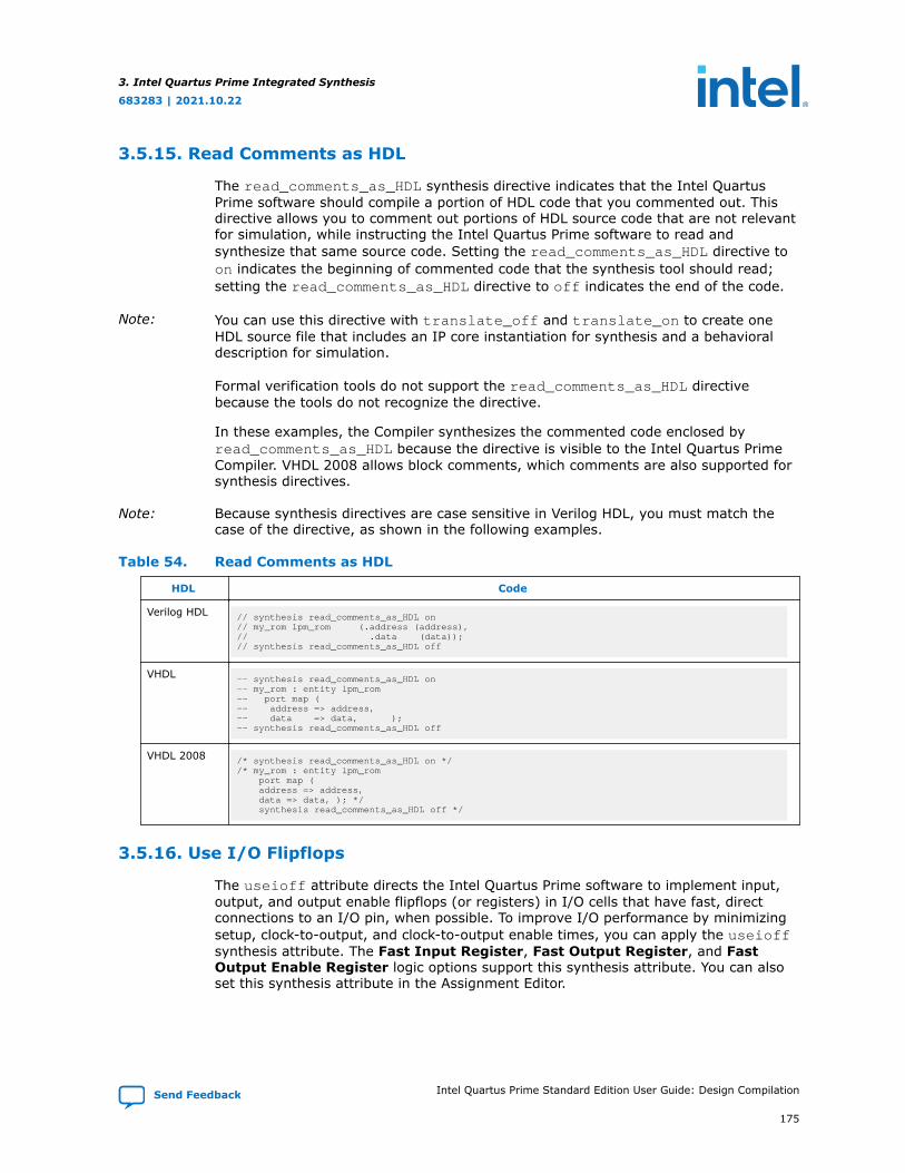
3.5.15. Read Comments as HDL
The read_comments_as_HDL synthesis directive indicates that the Intel QuartusPrime software should compile a portion of HDL code that you commented out. Thisdirective allows you to comment out portions of HDL source code that are not relevantfor simulation, while instructing the Intel Quartus Prime software to read andsynthesize that same source code. Setting the read_comments_as_HDL directive toon indicates the beginning of commented code that the synthesis tool should read;setting the read_comments_as_HDL directive to off indicates the end of the code.
Note: You can use this directive with translate_off and translate_on to create oneHDL source file that includes an IP core instantiation for synthesis and a behavioraldescription for simulation.
Formal verification tools do not support the read_comments_as_HDL directivebecause the tools do not recognize the directive.
In these examples, the Compiler synthesizes the commented code enclosed byread_comments_as_HDL because the directive is visible to the Intel Quartus PrimeCompiler. VHDL 2008 allows block comments, which comments are also supported forsynthesis directives.
Note: Because synthesis directives are case sensitive in Verilog HDL, you must match thecase of the directive, as shown in the following examples.
Table 54. Read Comments as HDL
HDL Code
Verilog HDL // synthesis read_comments_as_HDL on// my_rom lpm_rom (.address (address),// .data (data));// synthesis read_comments_as_HDL off
VHDL -- synthesis read_comments_as_HDL on-- my_rom : entity lpm_rom-- port map (-- address => address,-- data => data, );-- synthesis read_comments_as_HDL off
VHDL 2008 /* synthesis read_comments_as_HDL on *//* my_rom : entity lpm_rom port map ( address => address, data => data, ); */ synthesis read_comments_as_HDL off */
3.5.16. Use I/O Flipflops
The useioff attribute directs the Intel Quartus Prime software to implement input,output, and output enable flipflops (or registers) in I/O cells that have fast, directconnections to an I/O pin, when possible. To improve I/O performance by minimizingsetup, clock-to-output, and clock-to-output enable times, you can apply the useioffsynthesis attribute. The Fast Input Register, Fast Output Register, and FastOutput Enable Register logic options support this synthesis attribute. You can alsoset this synthesis attribute in the Assignment Editor.
3. Intel Quartus Prime Integrated Synthesis
683283 | 2021.10.22
Send Feedback Intel Quartus Prime Standard Edition User Guide: Design Compilation
175

The useioff synthesis attribute takes a boolean value. You can apply the value onlyto the port declarations of a top-level Verilog HDL module or VHDL entity (it is ignoredif applied elsewhere). Setting the value to 1 (Verilog HDL) or TRUE (VHDL) instructsthe Intel Quartus Prime software to pack registers into I/O cells. Setting the value to 0(Verilog HDL) or FALSE (VHDL) prevents register packing into I/O cells.
In Table 55 on page 176 and Table 56 on page 176, the useioff synthesis attributedirects the Intel Quartus Prime software to implement the a_reg, b_reg, and o_regregisters in the I/O cells corresponding to the a, b, and o ports, respectively.
Table 55. Verilog HDL Code: The useioff Attribute
HDL Code
Verilog HDL module top_level(clk, a, b, o); input clk; input [1:0] a, b /* synthesis useioff = 1 */; output [2:0] o /* synthesis useioff = 1 */; reg [1:0] a_reg, b_reg; reg [2:0] o_reg; always @ (posedge clk) begin a_reg <= a; b_reg <= b; o_reg <= a_reg + b_reg; end assign o = o_reg;endmodule
Table 56 on page 176 and Table 57 on page 176 show that the Verilog-2001 syntaxalso accepts the type of statements instead of the comment form in Table 55 on page176.
Table 56. Verilog-2001 Code: the useioff Attribute
HDL Code
Verilog-2001 (* useioff = 1 *) input [1:0] a, b;(* useioff = 1 *) output [2:0] o;
Table 57. VHDL Code: the useioff Attribute
HDL Code
VHDL library ieee;use ieee.std_logic_1164.all;use ieee.numeric_std.all;entity useioff_example is port ( clk : in std_logic; a, b : in unsigned(1 downto 0); o : out unsigned(1 downto 0)); attribute useioff : boolean; attribute useioff of a : signal is true; attribute useioff of b : signal is true; attribute useioff of o : signal is true;end useioff_example;architecture rtl of useioff_example is signal o_reg, a_reg, b_reg : unsigned(1 downto 0);begin process(clk) begin if (clk = '1' AND clk'event) then a_reg <= a; b_reg <= b; o_reg <= a_reg + b_reg; end if; end process;o <= o_reg;end rtl;
3. Intel Quartus Prime Integrated Synthesis
683283 | 2021.10.22
Intel Quartus Prime Standard Edition User Guide: Design Compilation Send Feedback
176

3.5.17. Specifying Pin Locations with chip_pin
The chip_pin attribute allows you to assign pin locations in your HDL source. Youcan use the attribute only on the ports of the top-level entity or module in yourdesign. You can assign pins only to single-bit or one-dimensional bus ports in yourdesign.
For single-bit ports, the value of the chip_pin attribute is the name of the pin on thetarget device, as specified by the pin table of the device.
Note: In addition to the chip_pin attribute, the Intel Quartus Prime software supports thealtera_chip_pin_lc attribute name for compatibility with other synthesis tools.When using this attribute in other synthesis tools, some older device families requirean “@” symbol in front of each pin assignment. In the Intel Quartus Prime software,the “@” is optional.
Table 58. Applying Chip Pin to a Single PinThese examples in this table show different ways of assigning my_pin1 to Pin C1 and my_pin2 to Pin 4 on adifferent target device.
HDL Code
Verilog-1995 input my_pin1 /* synthesis chip_pin = "C1" */;input my_pin2 /* synthesis altera_chip_pin_lc = "@4" */;
Verilog-2001(* chip_pin = "C1" *) input my_pin1;(* altera_chip_pin_lc = "@4" *) input my_pin2;
VHDL entity my_entity isport(my_pin1: in std_logic; my_pin2: in std_logic;…);end my_entity;attribute chip_pin : string;attribute altera_chip_pin_lc : string;attribute chip_pin of my_pin1 : signal is "C1";attribute altera_chip_pin_lc of my_pin2 : signal is "@4";
For bus I/O ports, the value of the chip pin attribute is a comma-delimited list of pinassignments. The order in which you declare the range of the port determines themapping of assignments to individual bits in the port. To leave a bit unassigned, leaveits corresponding pin assignment blank.
Table 59. Applying Chip Pin to a Bus of PinsThe example in this table assigns my_pin[2] to Pin_4, my_pin[1] to Pin_5, and my_pin[0] to Pin_6.
HDL Code
Verilog-1995 input [2:0] my_pin /* synthesis chip_pin = "4, 5, 6" */;
Table 60. Applying Chip Pin to Part of a BusThe example in this table reverses the order of the signals in the bus, assigning my_pin[0] to Pin_4 andmy_pin[2] to Pin_6 but leaves my_pin[1] unassigned.
HDL Code
Verilog-1995 input [0:2] my_pin /* synthesis chip_pin = "4, ,6" */;
3. Intel Quartus Prime Integrated Synthesis
683283 | 2021.10.22
Send Feedback Intel Quartus Prime Standard Edition User Guide: Design Compilation
177

Table 61. Applying Chip Pin to Part of a Bus of PinsThe example in this table assigns my_pin[2] to Pin 4 and my_pin[0] to Pin 6, but leaves my_pin[1]unassigned.
HDL Code
VHDL entity my_entity isport(my_pin: in std_logic_vector(2 downto 0);…);end my_entity;attribute chip_pin of my_pin: signal is "4, , 6";
Table 62. VHDL and Verilog-2001 Examples: Assigning Pin Location and I/O Standard
HDL Code
VHDL attribute altera_chip_pin_lc: string;attribute altera_attribute: string;attribute altera_chip_pin_lc of clk: signal is "B13";attribute altera_attribute of clk:signal is "-name IO_STANDARD ""3.3-V LVCMOS""";
Verilog-2001 (* altera_attribute = "-name IO_STANDARD \"3.3-V LVCMOS\"" *)(* chip_pin = "L5" *)input clk;(* altera_attribute = "-name IO_STANDARD LVDS" *)(* chip_pin = "L4" *)input sel;output [3:0] data_o, input [3:0] data_i);
3.5.18. Using altera_attribute to Set Intel Quartus Prime Logic Options
The altera_attribute attribute allows you to apply Intel Quartus Prime logicoptions and assignments to an object in your HDL source code. You can set thisattribute on an entity, architecture, instance, register, RAM block, or I/O pin. Youcannot set it on an arbitrary combinational node such as a net. Withaltera_attribute, you can control synthesis options from your HDL source evenwhen the options lack a specific HDL synthesis attribute. You can also use thisattribute to pass entity-level settings and assignments to phases of the Compiler flowthat follow Analysis & Synthesis, such as Fitting.
Assignments or settings made through the Intel Quartus Prime software, the .qsf, orthe Tcl interface take precedence over assignments or settings made with thealtera_attribute synthesis attribute in your HDL code.
The attribute value is a single string containing a list of .qsf variable assignmentsseparated by semicolons:
-name <variable_1> <value_1>;-name <variable_2> <value_2>[;…]
If the Intel Quartus Prime option or assignment includes a target, source, and sectiontag, you must use the syntax in this example for each .qsf variable assignment:
-name <variable> <value>-from <source> -to <target> -section_id <section>
This example shows the syntax for the full attribute value, including the optionaltarget, source, and section tags for two different .qsf assignments:
" -name <variable_1> <value_1> [-from <source_1>] [-to <target_1>] [-section_id \ <section_1>]; -name <variable_2> <value_2> [-from <source_2>] [-to <target_2>] \[-section_id <section_2>] "
3. Intel Quartus Prime Integrated Synthesis
683283 | 2021.10.22
Intel Quartus Prime Standard Edition User Guide: Design Compilation Send Feedback
178

Table 63. Example UsageIf the assigned value of a variable is a string of text, you must use escaped quotes around the value in VerilogHDL or double-quotes in VHDL:
HDL Code
Assigned Value of a Variable in Verilog HDL (WithNonexistent Variable and Value Terms)
"VARIABLE_NAME \"STRING_VALUE\""
Assigned Value of a Variable in VHDL (With NonexistentVariable and Value Terms)
"VARIABLE_NAME ""STRING_VALUE"""
To find the .qsf variable name or value corresponding to a specific Intel Quartus Primeoption or assignment, you can set the option setting or assignment in the IntelQuartus Prime software, and then make the changes in the .qsf.
Applying altera_attribute to an Instance
These examples use altera_attribute to set the power-up level of an inferredregister.
Table 64. Applying altera_attribute to an InstanceThese examples use altera_attribute to set the power-up level of an inferred register.
HDL Code
Verilog-1995 reg my_reg /* synthesis altera_attribute = "-name POWER_UP_LEVEL HIGH" */;
Verilog-2001 (* altera_attribute = "-name POWER_UP_LEVEL HIGH" *) reg my_reg;
VHDL signal my_reg : std_logic;attribute altera_attribute : string;attribute altera_attribute of my_reg: signal is "-name POWER_UP_LEVEL HIGH";
Note: For inferred instances, you cannot apply the attribute to the instance directly.Therefore, you must apply the attribute to one of the output nets of the instance. TheIntel Quartus Prime software automatically moves the attribute to the inferredinstance.
Applying altera_attribute to an Entity
These examples use the altera_attribute to disable the Auto Shift RegisterReplacement synthesis option for an entity. To apply the Altera Attribute to a VHDLentity, you must set the attribute on its architecture rather than on the entity itself.
Table 65. Applying altera_attribute to an Entity
HDL Code
Verilog-1995 module my_entity(…) /* synthesis altera_attribute = "-name AUTO_SHIFT_REGISTER_RECOGNITION OFF" */;
Verilog-2001 (* altera_attribute = "-name AUTO_SHIFT_REGISTER_RECOGNITION OFF" *) module my_entity(…) ;
VHDL entity my_entity is-- Declare generics and portsend my_entity;architecture rtl of my_entity isattribute altera_attribute : string;-- Attribute set on architecture, not entityattribute altera_attribute of rtl: architecture is "-name AUTO_SHIFT_REGISTER_RECOGNITION OFF";
continued...
3. Intel Quartus Prime Integrated Synthesis
683283 | 2021.10.22
Send Feedback Intel Quartus Prime Standard Edition User Guide: Design Compilation
179

HDL Code
begin-- The architecture bodyend rtl;
Applying altera_attribute with the -to Option
You can also use altera_attribute for more complex assignments that have morethan one instance. In Table 66 on page 180, the altera_attribute cuts all timingpaths from reg1 to reg2, equivalent to this Tcl or .qsf command, as shown in theexample below:
set_instance_assignment -name CUT ON -from reg1 -to reg2
Table 66. Applying altera_attribute with the -to Option
HDL Code
Verilog-1995 reg reg2;reg reg1 /* synthesis altera_attribute = "-name CUT ON -to reg2" */;
Verilog-2001andSystemVerilog
reg reg2;(* altera_attribute = "-name CUT ON -to reg2" *) reg reg1;
VHDL signal reg1, reg2 : std_logic;attribute altera_attribute: string;attribute altera_attribute of reg1 : signal is "-name CUT ON -to reg2";
You can specify either the -to option or the -from option in a singlealtera_attribute; Integrated Synthesis automatically sets the remaining option tothe target of the altera_attribute. You can also specify wildcards for eitheroption. For example, if you specify “*” for the -to option instead of reg2 in theseexamples, the Intel Quartus Prime software cuts all timing paths from reg1 to everyother register in this design entity.
You can use the altera_attribute only for entity-level settings, and theassignments (including wildcards) apply only to the current entity.
Related Information
• Synthesis Attributes on page 140
• Intel Quartus Prime Settings File ManualLists all variable names
3.6. Analyzing Synthesis Results
After performing synthesis, you can check your synthesis results in the Analysis &Synthesis section of the Compilation Report and the Project Navigator.
3. Intel Quartus Prime Integrated Synthesis
683283 | 2021.10.22
Intel Quartus Prime Standard Edition User Guide: Design Compilation Send Feedback
180

3.6.1. Analysis & Synthesis Section of the Compilation Report
The Compilation Report, which provides a summary of results for the project, appearsafter a successful compilation. After Analysis & Synthesis, the Summary section of theCompilation Report provides a summary of utilization based on synthesis data, beforeFitter optimizations have occurred. The Analysis & Synthesis section lists synthesis-specific information.
Analysis & Synthesis includes various report sections, including a list of the sourcefiles read for the project, the resource utilization by entity after synthesis, andinformation about state machines, latches, optimization results, and parametersettings.
Related Information
Analysis Synthesis Summary ReportsFor more information about each report section
3.6.2. Project Navigator
The Hierarchy tab of the Project Navigator provides a view of the project hierarchyand a summary of resource and device information about the current project. AfterAnalysis & Synthesis, before the Fitter begins, the Project Navigator provides asummary of utilization based on synthesis data, before Fitter optimizations haveoccurred.
If an entity in the Hierarchy tab contains parameter settings, a tooltip displays thesettings when you hold the pointer over the entity.
3.6.2.1. Upgrade IP Components Dialog Box
In the Intel Quartus Prime software version 12.1 SP1 and later, the Upgrade IPComponents dialog box allows you to upgrade all outdated IP in your project afteryou move to a newer version of the Intel Quartus Prime software.
Related Information
Upgrade IP Components dialog boxFor more information about the Upgrade IP Components dialog box
3.7. Analyzing and Controlling Synthesis Messages
You can analyze the generated messages during synthesis and control whichmessages appear during compilation.
3.7.1. Intel Quartus Prime Messages
The messages that appear during Analysis & Synthesis describe many of theoptimizations during the synthesis stage, and provide information about how thesoftware interprets your design. Altera recommends checking the messages to analyzeCritical Warnings and Warnings, because these messages can relate to importantdesign problems. Read the Info messages to get more information about how thesoftware processes your design.
The software groups the messages by following types: Info, Warning, CriticalWarning, and Error.
3. Intel Quartus Prime Integrated Synthesis
683283 | 2021.10.22
Send Feedback Intel Quartus Prime Standard Edition User Guide: Design Compilation
181

You can specify the type of Analysis & Synthesis messages that you want to view byselecting the Analysis & Synthesis Message Level option. To specify the displaylevel, click Assignments ➤ Settings ➤ Compiler Settings ➤ Advanced Settings(Synthesis)
Related Information
About the Messages WindowFor more information about the Messages window and message suppression
3.7.2. VHDL and Verilog HDL Messages
The Intel Quartus Prime software issues a variety of messages when it is analyzingand elaborating the Verilog HDL and VHDL files in your design. These HDL messagesare a subset of all Intel Quartus Prime messages that help you identify potentialproblems early in the design process.
HDL messages fall into the following categories:
• Info message—lists a property of your design.
• Warning message—indicates a potential problem in your design. Potentialproblems come from a variety of sources, including typos, inappropriate designpractices, or the functional limitations of your target device. Though HDL warningmessages do not always identify actual problems, Altera recommendsinvestigating code that generates an HDL warning. Otherwise, the synthesizedbehavior of your design might not match your original intent or its simulatedbehavior.
• Error message—indicates an actual problem with your design. Your HDL code canbe invalid due to a syntax or semantic error, or it might not be synthesizable aswritten.
In this example, the sensitivity list contains multiple copies of the variable i. Whilethe Verilog HDL language does not prohibit duplicate entries in a sensitivity list, it isclear that this design has a typing error: Variable j should be listed on the sensitivitylist to avoid a possible simulation or synthesis mismatch.
//dup.vmodule dup(input i, input j, output reg o);always @ (i or i) o = i & j;endmodule
When processing the HDL code, the Intel Quartus Prime software generates thefollowing warning message.
Warning: (10276) Verilog HDL sensitivity list warning at dup.v(2): sensitivity list contains multiple entries for "i".
In Verilog HDL, variable names are case sensitive, so the variables my_reg andMY_REG below are two different variables. However, declaring variables that havenames in different cases is confusing, especially if you use VHDL, in which variablesare not case sensitive.
// namecase.vmodule namecase (input i, output o); reg my_reg;
3. Intel Quartus Prime Integrated Synthesis
683283 | 2021.10.22
Intel Quartus Prime Standard Edition User Guide: Design Compilation Send Feedback
182

reg MY_REG; assign o = i;endmodule
When processing the HDL code, the Intel Quartus Prime software generates thefollowing informational message:
Info: (10281) Verilog HDL information at namecase.v(3): variable name "MY_REG" and variable name "my_reg" should not differ only in case.
In addition, the Intel Quartus Prime software generates additional HDL info messagesto inform you that this small design does not use neither my_reg nor MY_REG:
Info: (10035) Verilog HDL or VHDL information at namecase.v(3): object "my_reg" declared but not usedInfo: (10035) Verilog HDL or VHDL information at namecase.v(4): object "MY_REG" declared but not used
The Intel Quartus Prime software allows you to control how many HDL messages youcan view during the Analysis & Elaboration of your design files. You can set the HDLMessage Level to enable or disable groups of HDL messages, or you can enable ordisable specific messages.
Related Information
Synthesis Directives on page 142For more information about synthesis directives and their syntax
3.7.2.1. Setting the HDL Message Level
The HDL Message Level specifies the types of messages that the Intel Quartus Primesoftware displays when it is analyzing and elaborating your design files.
Table 67. HDL Info Message Level
Level Purpose Description
Level1 High-severity messages only If you want to view only the HDL messages that identify likelyproblems with your design, select Level1. When you select Level1, theIntel Quartus Prime software issues a message only if there is anactual problem with your design.
Level2 High-severity and medium-severity messages
If you want to view additional HDL messages that identify possibleproblems with your design, select Level2. Level2 is the default setting.
Level3 All messages, including low-severity messages
If you want to view all HDL info and warning messages, select Level3.This level includes extra “LINT” messages that suggest changes toimprove the style of your HDL code.
You must address all issues reported at the Level1 setting. The default HDL messagelevel is Level2.
To set the HDL Message Level in the Intel Quartus Prime software, follow these steps:
1. Click Assignments ➤ Settings ➤ Compiler Settings ➤ Advanced Settings(Synthesis)
2. Set the necessary message level from the pull-down menu in the HDL MessageLevel list, and then click OK.
You can override this default setting in a source file with the message_levelsynthesis directive, which takes the values level1, level2, and level3, asshown in the following table.
3. Intel Quartus Prime Integrated Synthesis
683283 | 2021.10.22
Send Feedback Intel Quartus Prime Standard Edition User Guide: Design Compilation
183

Table 68. HDL Examples of message_level Directive
HDL Code
Verilog HDL // altera message_level level1or/* altera message_level level3 */
VHDL -- altera message_level level2
A message_level synthesis directive remains effective until the end of a file oruntil the next message_level directive. In VHDL, you can use themessage_level synthesis directive to set the HDL Message Level for entities andarchitectures, but not for other design units. An HDL Message Level for an entityapplies to its architectures, unless overridden by another message_leveldirective. In Verilog HDL, you can use the message_level directive to set theHDL Message Level for a module.
3.7.2.2. Enabling or Disabling Specific HDL Messages by Module/Entity
Message ID is in parentheses at the beginning of the message. Use the Message ID toenable or disable a specific HDL info or warning message. Enabling or disabling aspecific message overrides its HDL Message Level. This method is different from themessage suppression in the Messages window because you can disable messages for aspecific module or a specific entity. This method applies only to the HDL messages,and if you disable a message with this method, the Intel Quartus Prime software liststhe message as a suppressed message.
To disable specific HDL messages in the Intel Quartus Prime software, follow thesesteps:
1. Click Assignments ➤ Settings ➤ Compiler Settings ➤ Advanced Settings(Synthesis).
2. In the Advanced Message Settings dialog box, add the Message IDs you wantto enable or disable.
To enable or disable specific HDL messages in your HDL, use the message_on andmessage_off synthesis directives. These directives require a space-separated listof Message IDs. You can enable or disable messages with these synthesisdirectives immediately before Verilog HDL modules, VHDL entities, or VHDLarchitectures. You cannot enable or disable a message during an HDL construct.
A message enabled or disabled via a message_on or message_off synthesisdirective overrides its HDL Message Level or any message_level synthesisdirective. The message remains disabled until the end of the source file or untilyou use another message_on or message_off directive to change the status ofthe message.
Table 69. HDL message_off Directive for Message with ID 10000
HDL Code
Verilog HDL // altera message_off 10000or/* altera message_off 10000 */
VHDL -- altera message_off 10000
3. Intel Quartus Prime Integrated Synthesis
683283 | 2021.10.22
Intel Quartus Prime Standard Edition User Guide: Design Compilation Send Feedback
184

3.8. Node-Naming Conventions in Intel Quartus Prime IntegratedSynthesis
Whenever possible, Intel Quartus Prime Integrated Synthesis uses wire or signalnames from your source code to name nodes such as LEs or ALMs. Some nodes, suchas registers, have predictable names that do not change when a design isresynthesized, although certain optimizations can affect register names. The names ofother nodes, particularly LEs or ALMs that contain only combinational logic, canchange due to logic optimizations that the software performs.
3.8.1. Hierarchical Node-Naming Conventions
To make each name in your design unique, the Intel Quartus Prime software adds thehierarchy path to the beginning of each name. The “|” separator indicates a level ofhierarchy. For each instance in the hierarchy, the software adds the entity name andthe instance name of that entity, with the “:” separator between each entity name andits instance name. For example, if a design defines entity A with the namemy_A_inst, the hierarchy path of that entity would be A:my_A_inst. You can obtainthe full name of any node by starting with the hierarchical instance path, followed by a“|”, and ending with the node name inside that entity.
This example shows you the convention:
<entity 0>:<instance_name 0>|<entity 1>:<instance_name 1>|...|<instance_name n>|<node_name>
For example, if entity A contains a register (DFF atom) called my_dff, its fullhierarchy name would be A:my_A_inst|my_dff.
To instruct the Compiler to generate node names that do not contain entity names, onthe Compilation Process Settings page of the Settings dialog box, click MoreSettings, and then turn off Display entity name for node name.
With this option turned off, the node names use the convention in shown in thisexample:
<instance_name 0>|<instance_name 1>|...|<instance_name n> |<node_name>
3.8.2. Node-Naming Conventions for Registers (DFF or D Flipflop Atoms)
In Verilog HDL and VHDL, inferred registers use the names of the reg or signalconnected to the output.
Table 70. HDL Example of a Register that Creates my_dff_out DFF Primitive
HDL Register Code
Verilog HDL wire dff_in, my_dff_out, clk;always @ (posedge clk)my_dff_out <= dff_in;
VHDL signal dff_in, my_dff_out, clk;process (clk)beginif (rising_edge(clk)) thenmy_dff_out <= dff_in;end if;end process;
3. Intel Quartus Prime Integrated Synthesis
683283 | 2021.10.22
Send Feedback Intel Quartus Prime Standard Edition User Guide: Design Compilation
185

AHDL designs explicitly declare DFF registers rather than infer, so the software usesthe user-declared name for the register.
For schematic designs using a .bdf, your design names all elements when youinstantiate the elements in your design, so the software uses the name you defined forthe register or DFF.
In the special case that a wire or signal (such as my_dff_out in the precedingexamples) is also an output pin of your top-level design, the Intel Quartus Primesoftware cannot use that name for the register (for example, cannot usemy_dff_out) because the software requires that all logic and I/O cells have uniquenames. Here, Intel Quartus Prime Integrated Synthesis appends ~reg0 to the registername.
Table 71. Verilog HDL Register Feeding Output PinFor example, the Verilog HDL code example in this table generates a register called q~reg0.
HDL Code
Verilog HDL module my_dff (input clk, input d, output q);always @ (posedge clk)q <= d;endmodule
This situation occurs only for registers driving top-level pins. If a register drives a portof a lower level of the hierarchy, the software removes the port during hierarchyflattening and the register retains its original name, in this case, q.
3.8.3. Register Changes During Synthesis
On some occasions, you might not find registers that you expect to view in thesynthesis netlist. Logic optimization might remove registers and synthesisoptimizations might change the names of the registers. Common optimizations includeinference of a state machine, counter, adder-subtractor, or shift register from registersand surrounding logic. Other common register changes occur when the software packsthese registers into dedicated hardware on the FPGA, such as a DSP block or a RAMblock.
The following factors can affect register names:
• Synthesis and Fitting Optimizations on page 186
• State Machines on page 187
• Inferred Adder-Subtractors, Shift Registers, Memory, and DSP Functions on page188
• Packed Input and Output Registers of RAM and DSP Blocks on page 188
3.8.3.1. Synthesis and Fitting Optimizations
Logic optimization during synthesis might remove registers if you do not connect theregisters to inputs or outputs in your design, or if you can simplify the logic due toconstant signal values. Synthesis optimizations might change register names, such aswhen the software merges duplicate registers to reduce resource utilization.
3. Intel Quartus Prime Integrated Synthesis
683283 | 2021.10.22
Intel Quartus Prime Standard Edition User Guide: Design Compilation Send Feedback
186

NOT-gate push back optimizations can affect registers that use preset signals. Thistype of optimization can impact your timing assignments when the software usesregisters as clock dividers. If this situation occurs in your design, change the clocksettings to work on the new register name.
Synthesis netlist optimizations often change node names because the software cancombine or duplicate registers to optimize your design.
The Intel Quartus Prime Compilation Report provides a list of registers that synthesisoptimizations remove, and a brief reason for the removal. To generate the IntelQuartus Prime Compilation Report, follow these steps:
1. In the Analysis & Synthesis folder, open Optimization Results.
2. Open Register Statistics, and then click the Registers Removed DuringSynthesis report.
3. Click Removed Registers Triggering Further Register Optimizations.
The second report contains a list of registers that causes synthesis optimizations toremove other registers from your design. The report provides a brief reason for theremoval, and a list of registers that synthesis optimizations remove due to theremoval of the initial register.
Intel Quartus Prime Integrated Synthesis creates synonyms for registers duplicatedwith the Maximum Fan-Out option (or maxfan attribute). Therefore, timingassignments applied to nodes that are duplicated with this option are applied to thenew nodes as well.
The Intel Quartus Prime Fitter can also change node names after synthesis (forexample, when the Fitter uses register packing to pack a register into an I/O element,or when physical synthesis modifies logic). The Fitter creates synonyms for duplicatedregisters so timing analysis can use the existing node name when applyingassignments.
You can instruct the Intel Quartus Prime software to preserve certain nodesthroughout compilation so you can use them for verification or making assignments.
3.8.3.2. State Machines
If your HDL code infers a state machine, the software maps the registers thatrepresent the states into a new set of registers that implement the state machine.Most commonly, the software converts the state machine into a one-hot form in whichone register represents each state. In this case, for Verilog HDL or VHDL designs, theregisters take the name of the state register and the states.
For example, consider a Verilog HDL state machine in which the states are parameterstate0 = 1, state1 = 2, state2 = 3, and in which the software declares thestate machine register as reg [1:0] my_fsm. In this example, the three one-hotstate registers are my_fsm.state0, my_fsm.state1, and my_fsm.state2.
An AHDL design explicitly specifies state machines with a state machine name. Yourdesign names state machine registers with synthesized names based on the statemachine name, but not the state names. For example, if a my_fsm state machine hasfour state bits, The software might synthesize these state bits with names such asmy_fsm~12, my_fsm~13, my_fsm~14, and my_fsm~15.
3. Intel Quartus Prime Integrated Synthesis
683283 | 2021.10.22
Send Feedback Intel Quartus Prime Standard Edition User Guide: Design Compilation
187

3.8.3.3. Inferred Adder-Subtractors, Shift Registers, Memory, and DSP Functions
The Intel Quartus Prime software infers IP cores from Verilog HDL and VHDL code forlogic that forms adder-subtractors, shift registers, RAM, ROM, and arithmetic functionsthat are placed in DSP blocks.
Because adder-subtractors are part of an IP core instead of generic logic, thecombinational logic exists in the design with different names. For shift registers,memory, and DSP functions, the software implements the registers and logic insidethe dedicated RAM or DSP blocks in the device. Thus, the registers are not visible asseparate LEs or ALMs.
3.8.3.4. Packed Input and Output Registers of RAM and DSP Blocks
The software packs registers into the input registers and output registers of RAM andDSP blocks, so that they are not visible as separate registers in LEs or ALMs.
3.8.4. Preserving Register Names
Altera recommends that you preserve certain register names for verification ordebugging, or to ensure that you applied timing assignments correctly. Intel QuartusPrime Integrated Synthesis preserves certain nodes automatically if the software usesthe nodes in a timing constraint.
Related Information
• Preserve Registers on page 154Use the preserve attribute to instruct the Compiler not to minimize or removea specified register during synthesis optimizations or register netlistoptimizations
• Noprune Synthesis Attribute/Preserve Fan-out Free Register Node on page 156Use the noprune attribute to preserve a fan-out-free register through theentire compilation flow
• Disable Register Merging/Don’t Merge Register on page 155Use the synthesis attribute syn_dont_merge to ensure that the Compiler doesnot merge registers with other registers
3.8.5. Node-Naming Conventions for Combinational Logic Cells
Whenever possible for Verilog HDL, VHDL, and AHDL code, the Intel Quartus Primesoftware uses wire names that are the targets of assignments, but can change thenode names due to synthesis optimizations.
For example, consider the Verilog HDL code in this example. Intel Quartus PrimeIntegrated Synthesis uses the names c, d, e, and f for the generated combinationallogic cells.
wire c;reg d, e, f;assign c = a | b;always @ (a or b)d = a & b;always @ (a or b) begin : my_labele = a ^ b;endalways @ (a or b)f = ~(a | b);
3. Intel Quartus Prime Integrated Synthesis
683283 | 2021.10.22
Intel Quartus Prime Standard Edition User Guide: Design Compilation Send Feedback
188

For schematic designs using a .bdf, your design names all elements when youinstantiate the elements in your design and the software uses the name you definedwhen possible.
If logic cells are packed with registers in device architectures such as the Stratix andCyclone device families, those names might not appear in the netlist after fitting. Inother devices, such as newer families in the Stratix and Cyclone series device families,the register and combinational nodes are kept separate throughout the compilation, sothese names are more often maintained through fitting.
When logic optimizations occur during synthesis, it is not always possible to retain theinitial names as described. Sometimes, synthesized names are used, which are thewire names with a tilde (~) and a number appended. For example, if a complexexpression is assigned to wire w and that expression generates several logic cells,those cells can have names such as w, w~1, and w~2. Sometimes the original wirename w is removed, and an arbitrary name such as rtl~123 is created. Intel QuartusPrime Integrated Synthesis attempts to retain user names whenever possible. Anynode name ending with ~<number> is a name created during synthesis, which canchange if the design is changed and re-synthesized. Knowing these namingconventions helps you understand your post-synthesis results, helping you to debugyour design or create assignments.
During synthesis, the software maintains combinational clock logic by not changingnodes that might be clocks. The software also maintains or protects multiplexers inclock trees, so that the Timing Analyzer has information about which paths are unate,to allow complete and correct analysis of combinational clocks. Multiplexers oftenoccur in clock trees when the software selects between different clocks. To help withthe analysis of clock trees, the software ensures that each multiplexer encountered ina clock tree is broken into 2:1 multiplexers, and each of those 2:1 multiplexers ismapped into one lookup table (independent of the device family). This optimizationmight result in a slight increase in area, and for some designs a decrease in timingperformance. To disable the option, click Assignments ➤ Settings ➤ CompilerSettings ➤ Advanced Settings (Synthesis) ➤ Clock MUX Protection.
Related Information
Clock MUX Protection logic optionFor more information about Clock MUX Protection logic option and a list ofsupported devices
3.8.6. Preserving Combinational Logic Names
You can preserve certain combinational logic node names for verification ordebugging, or to ensure that timing assignments are applied correctly.
Use the keep attribute to keep a wire name or combinational node name through logicsynthesis minimizations and netlist optimizations.
For any internal node in your design clock network, use keep to protect the name sothat you can apply correct clock settings. Also, set the attribute for combinational logicinvolved in cut and -through assignments.
Note: Setting the keep attribute for combinational logic can increase the area utilization andincrease the delay of the final mapped logic because the attribute requires theinsertion of extra combinational logic. Use the attribute only when necessary.
3. Intel Quartus Prime Integrated Synthesis
683283 | 2021.10.22
Send Feedback Intel Quartus Prime Standard Edition User Guide: Design Compilation
189

Related Information
Keep Combinational Node/Implement as Output of Logic Cell on page 157
3.9. Scripting Support
You can run procedures and make settings in a Tcl script. You can also run someprocedures at a command prompt. For detailed information about scripting commandoptions, refer to the Intel Quartus Prime Command-Line and Tcl API Help browser.
To run the Help browser, type the command at the command prompt shown in thisexample:
quartus_sh --qhelp
You can specify many of the options either on an instance, at the global level, or both.
To make a global assignment, use the Tcl command shown in this example:
set_global_assignment -name <QSF Variable Name> <Value>
To make an instance assignment, use the Tcl command shown in this example:
set_instance_assignment -name <QSF Variable Name> <Value>\ -to <Instance Name>
To set the Synthesis Effort option at the command line, use the --effort optionwith the quartus_map executable shown in this example:
quartus_map <Design name> --effort= "auto | fast"
Related Information
• Tcl ScriptingFor more information about Tcl scripting
• Intel Quartus Prime Settings File ManualFor more information about all settings and constraints in the Intel QuartusPrime software
• Command-Line ScriptingFor more information about command-line scripting
3.9.1. Adding an HDL File to a Project and Setting the HDL Version
To add an HDL or schematic entry design file to your project, use the Tcl assignmentsshown in this example:
set_global_assignment –name VERILOG_FILE <file name>.<v|sv>set_global_assignment –name SYSTEMVERILOG_FILE <file name>.svset_global_assignment –name VHDL_FILE <file name>.<vhd|vhdl>set_global_assignment -name AHDL_FILE <file name>.tdfset_global_assignment -name BDF_FILE <file name>.bdf
Note: You can use any file extension for design files, as long as you specify the correctlanguage when adding the design file. For example, you can use .h for Verilog HDLheader files.
3. Intel Quartus Prime Integrated Synthesis
683283 | 2021.10.22
Intel Quartus Prime Standard Edition User Guide: Design Compilation Send Feedback
190

To specify the Verilog HDL or VHDL version, use the option shown in this example, atthe end of the VERILOG_FILE or VHDL_FILE command:
- HDL_VERSION <language version>
The variable <language version> takes one of the following values:
• VERILOG_1995
• VERILOG_2001
• SYSTEMVERILOG_2005
• VHDL_1987
• VHDL_1993
• VHDL_2008
For example, to add a Verilog HDL file called my_file.v written in Verilog-1995, usethe command shown in this example:
set_global_assignment –name VERILOG_FILE my_file.v –HDL_VERSION \ VERILOG_1995
In this example, the syn_encoding attribute associates a binary encoding with thestates in the enumerated type count_state. In this example, the states are encodedwith the following values: zero = "11", one = "01", two = "10", three = "00".
ARCHITECTURE rtl OF my_fsm IS TYPE count_state is (zero, one, two, three); ATTRIBUTE syn_encoding : STRING; ATTRIBUTE syn_encoding OF count_state : TYPE IS "11 01 10 00"; SIGNAL present_state, next_state : count_state;BEGIN
You can also use the syn_encoding attribute in Verilog HDL to direct the synthesistool to use the encoding from your HDL code, instead of using the State MachineProcessing option.
The syn_encoding value "user" instructs the Intel Quartus Prime software toencode each state with its corresponding value from the Verilog HDL source code. Bychanging the values of your state constants, you can change the encoding of yourstate machine.
In Verilog-2001 and SystemVerilog Code: Specifying User-Encoded States with thesyn_encoding Attribute on page 191, the states are encoded as follows:
init = "00"last = "11"next = "01"later = "10"
Example 22. Verilog-2001 and SystemVerilog Code: Specifying User-Encoded States withthe syn_encoding Attribute
(* syn_encoding = "user" *) reg [1:0] state;parameter init = 0, last = 3, next = 1, later = 2;always @ (state) begincase (state)init:out = 2'b01;next:
3. Intel Quartus Prime Integrated Synthesis
683283 | 2021.10.22
Send Feedback Intel Quartus Prime Standard Edition User Guide: Design Compilation
191

out = 2'b10;later:out = 2'b11;last:out = 2'b00;endcaseend
Without the syn_encoding attribute, the Intel Quartus Prime software encodes thestate machine based on the current value of the State Machine Processing logicoption.
If you also specify a safe state machine (as described in Safe State Machine on page152), separate the encoding style value in the quotation marks from the safe valuewith a comma, as follows: “safe, one-hot” or “safe, gray”.
Related Information
• Safe State Machine on page 152
• Manually Specifying State Assignments Using the syn_encoding Attribute on page149
3.9.2. Assigning a Pin
To assign a signal to a pin or device location, use the Tcl command shown in thisexample:
set_location_assignment -to <signal name> <location>
Valid locations are pin location names. Some device families also support edge and I/Obank locations. Edge locations are EDGE_BOTTOM, EDGE_LEFT, EDGE_TOP, andEDGE_RIGHT. I/O bank locations include IOBANK_1 to IOBANK_n, where n is thenumber of I/O banks in a device.
3.9.3. Creating Design Partitions for Incremental Compilation
To create a partition, use the command shown in this example:
set_instance_assignment -name PARTITION_HIERARCHY \<file name> -to <destination> -section_id <partition name>
The <file name> variable is the name used for internally generated netlist files duringincremental compilation. If you create the partition in the Intel Quartus Primesoftware, netlist files are named automatically by the Intel Quartus Prime softwarebased on the instance name. If you use Tcl to create your partitions, you must assigna custom file name that is unique across all partitions. For the top-level partition, thespecified file name is ignored, and you can use any dummy value. To ensure thenames are safe and platform independent, file names should be unique, regardless ofcase. For example, if a partition uses the file name my_file, no other partition canuse the file name MY_FILE. To make file naming simple, Altera recommends that youbase each file name on the corresponding instance name for the partition.
The <destination> is the short hierarchy path of the entity. A short hierarchy path isthe full hierarchy path without the top-level name, for example: "ram:ram_unit|altsyncram:altsyncram_component" (with quotation marks). For the top-levelpartition, you can use the pipe (|) symbol to represent the top-level entity.
3. Intel Quartus Prime Integrated Synthesis
683283 | 2021.10.22
Intel Quartus Prime Standard Edition User Guide: Design Compilation Send Feedback
192

The <partition name> is the partition name you designate, which should be uniqueand less than 1024 characters long. The name may only consist of alphanumericcharacters, as well as pipe ( | ), colon ( : ), and underscore ( _ ) characters. Alterarecommends enclosing the name in double quotation marks (" ").
Related Information
Node-Naming Conventions in Intel Quartus Prime Integrated Synthesis on page 185For more information about hierarchical naming conventions
3.10. Document Revision History
Table 72. Document Revision History
Date Version Changes
2021.10.29 18.1.0 • Added "Intel Quartus Prime Support for VHDL-2008". The previous removal ofVHDL-2008 references was done in error. Intel Quartus Prime Standard Editionsupports a limited set of VHDL-2008 constructs.
2019.01.25 18.1.0 • Removed reference to Add Pass-Through Logic to Inferred RAMs GUI option. Thisoption can only be set in the Intel Quartus Prime Settings File (.qsf).
2018.09.24 18.1.0 • Added Factors Affecting Compilation Results topic.• Removed references to VHDL-2008 synthesis support. This support was listed in
error and VHDL-2008 is only supported in Intel Quartus Prime Pro Edition
2016.05.03 16.0.0 Corrected description of Fitter Intial Placement Seed option.
2015.11.02 15.1.0 Changed instances of Quartus II to Intel Quartus Prime.
2015.05.04 15.0.0 • Removed support for early timing estimate feature.• Removed the note on the assignment of the RAM style attributes as it is no
longer relevant.
2014.12.15 14.1.0 Updated location of Fitter Settings, Analysis & Synthesis Settings, and PhysicalOptimization Settings to Compiler Settings.
2014.06.30 14.0.0 Template update.
November 2013 13.1.0 • Added a note regarding ROM inference using the ram_init_file in “RAMInitialization File—for Inferred Memory” on page 16–61.
May 2013 13.0.0 • Added “Verilog HDL Configuration” on page 16–6.• Added “RAM Style Attribute—For Shift Registers Inference” on page 16–57.• Added “Upgrade IP Components Dialog Box” on page 16–75.
June 2012 12.0.0 • Updated “Design Flow” on page 16–2.
November 2011 11.1.0 • Updated “Language Support” on page 16–5, “Incremental Compilation” onpage 16–22, “Intel Quartus Prime Synthesis Options” on page 16–24.
May 2011 11.0.0 • Updated “Specifying Pin Locations with chip_pin” on page 14–65, and “ShiftRegisters” on page 14–48.
• Added a link to Intel Quartus Prime Help in “SystemVerilog Support” onpage 14–5.
• Added Example 14–106 and Example 14–107 on page 14–67.
December 2010 10.1.0 • Updated “Verilog HDL Support” on page 13–4 to include Verilog-2001 support.• Updated “VHDL-2008 Support” on page 13–9 to include the condition operator
(explicit and implicit) support.• Rewrote “Limiting Resource Usage in Partitions” on page 13–32.• Added “Creating LogicLock Regions” on page 13–32 and “Using Assignments to
Limit the Number of RAM and DSP Blocks” on page 13–33.
continued...
3. Intel Quartus Prime Integrated Synthesis
683283 | 2021.10.22
Send Feedback Intel Quartus Prime Standard Edition User Guide: Design Compilation
193

Date Version Changes
• Updated “Turning Off the Add Pass-Through Logic to Inferred RAMs no_rw_checkAttribute” on page 13–55.
• Updated “Auto Gated Clock Conversion” on page 13–28.• Added links to Intel Quartus Prime Help.
July 2010 10.0.0 • Removed Referenced Documents section.• Added “Synthesis Seed” on page 9–36 section.• Updated the following sections:
“SystemVerilog Support” on page 9–5“VHDL-2008 Support” on page 9–10“Using Parameters/Generics” on page 9–16“Parallel Synthesis” on page 9–21“Limiting Resource Usage in Partitions” on page 9–32“Synthesis Effort” on page 9–35“Synthesis Attributes” on page 9–25“Synthesis Directives” on page 9–27“Auto Gated Clock Conversion” on page 9–29“State Machine Processing” on page 9–36“Multiply-Accumulators and Multiply-Adders” on page 9–50“Resource Aware RAM, ROM, and Shift-Register Inference” on page 9–52“RAM Style and ROM Style—for Inferred Memory” on page 9–53“Turning Off the Add Pass-Through Logic to Inferred RAMs no_rw_checkAttribute” on page 9–55“Using altera_attribute to Set Intel Quartus Prime Logic Options” on page 9–68“Adding an HDL File to a Project and Setting the HDL Version” on page 9–83“Creating Design Partitions for Incremental Compilation” on page 9–85“Inferring Multiplier, DSP, and Memory Functions from HDL Code” on page 9–50
• Updated Table 9–9 on page 9–86.
December 2009 9.1.1 • Added information clarifying inheritance of Synthesis settings by lower-levelentities, including Altera and third-party IP
• Updated “Keep Combinational Node/Implement as Output of Logic Cell” onpage 9–46
November 2009 9.1.0 • Updated the following sections:“Initial Constructs and Memory System Tasks” on page 9–7“VHDL Support” on page 9–9“Parallel Synthesis” on page 9–21“Synthesis Directives” on page 9–27“Timing-Driven Synthesis” on page 9–31“Safe State Machines” on page 9–40“RAM Style and ROM Style—for Inferred Memory” on page 9–53“Translate Off and On / Synthesis Off and On” on page 9–62“Read Comments as HDL” on page 9–63“Adding an HDL File to a Project and Setting the HDL Version” on page 9–81
• Removed “Remove Redundant Logic Cells” section• Added “Resource Aware RAM, ROM, and Shift-Register Inference” section• Updated Table 9–9 on page 9–83
March 2009 9.0.0 • Updated Table 9–9.• Updated the following sections:
“Partitions for Preserving Hierarchical Boundaries” on page 9–20“Analysis & Synthesis Settings Page of the Settings Dialog Box” on page 9–24“Timing-Driven Synthesis” on page 9–30“Turning Off Add Pass-Through Logic to Inferred RAMs/ no_rw_check AttributeSetting” on page 9–54
• Added “Parallel Synthesis” on page 9–21• Chapter 9 was previously Chapter 8 in software version 8.1
3. Intel Quartus Prime Integrated Synthesis
683283 | 2021.10.22
Intel Quartus Prime Standard Edition User Guide: Design Compilation Send Feedback
194

Related Information
Documentation ArchiveFor previous versions of the Intel Quartus Prime Handbook, search thedocumentation archives.
3. Intel Quartus Prime Integrated Synthesis
683283 | 2021.10.22
Send Feedback Intel Quartus Prime Standard Edition User Guide: Design Compilation
195

4. Reducing Compilation TimeYou can employ various techniques to reduce to time required for synthesis and fittingin the Intel Quartus Prime Compiler.
4.1. Compilation Time Advisor
A Compilation Time Advisor is available in the Intel Quartus Prime GUI by clickingTools ➤ Advisors ➤ Compilation Time Advisor. This chapter describes all thecompilation time optimizing techniques available in the Compilation Time Advisor.
4.2. Strategies to Reduce the Overall Compilation Time
You can use the following strategies to reduce the overall time required to compileyour design:
• Parallel compilation (for systems with multiple processor cores)
• Incremental compilation reduces compilation time by only recompiling designpartitions that have not met design requirements.
• Rapid Recompile and Smart Compilation reuse results from a previous compilationto reduce overall compilation time
4.2.1. Running Rapid Recompile
During Rapid Recompile the Compiler reuses previous synthesis and fitting resultswhenever possible, and does not reprocess unchanged design blocks. Use RapidRecompile to reduce timing variations and the total recompilation time after makingsmall design changes.
Figure 36. Rapid Recompile
Regular Compile
A
BC
D
E
J Gx y z
Unchanged
Changed
RapidRecompile
683283 | 2021.10.22
Send Feedback
Intel Corporation. All rights reserved. Intel, the Intel logo, and other Intel marks are trademarks of IntelCorporation or its subsidiaries. Intel warrants performance of its FPGA and semiconductor products to currentspecifications in accordance with Intel's standard warranty, but reserves the right to make changes to anyproducts and services at any time without notice. Intel assumes no responsibility or liability arising out of theapplication or use of any information, product, or service described herein except as expressly agreed to inwriting by Intel. Intel customers are advised to obtain the latest version of device specifications before relyingon any published information and before placing orders for products or services.*Other names and brands may be claimed as the property of others.
ISO9001:2015Registered

To run Rapid Recompile, follow these steps:
1. To start Rapid Recompile following an initial compilation (or after running theRoute stage of the Fitter), click Processing ➤ Start ➤ Start Rapid Recompile.Rapid Recompile implements the following types of design changes without fullrecompilation:
• Changes to nodes tapped by the Signal Tap Logic Analyzer
• Changes to combinational logic functions
• Changes to state machine logic (for example, new states, state transitionchanges)
• Changes to signal or bus latency or addition of pipeline registers
• Changes to coefficients of an adder or multiplier
• Changes register packing behavior of DSP, RAM, or I/O
• Removal of unnecessary logic
• Changes to synthesis directives
The Incremental Compilation Preservation Summary report provides details aboutplacement and routing implementation.
2. Click the Rapid Recompile Preservation Summary report to view detailedinformation about the percentage of preserved compilation results.
Figure 37. Rapid Recompile Preservation Summary
4.2.2. Enabling Multi-Processor Compilation
The Compiler can detect and use multiple processors to reduce total compilation time.You specify the number of processors the Compiler uses. The Intel Quartus Primesoftware can use up to 16 processors to run algorithms in parallel. The Compiler usesparallel compilation by default. To reserve some processors for other tasks, specify amaximum number of processors that the software uses.
This technique reduces the compilation time by up to 10% on systems with twoprocessing cores, and by up to 20% on systems with four cores. When running timinganalysis independently, two processors reduce the timing analysis time by an averageof 10%. This reduction reaches an average of 15% when using four processors.
The Intel Quartus Prime software does not necessarily use all the processors that youspecify during a given compilation. Additionally, the software never uses more thanthe specified number of processors. This fact enables you to work on other taskswithout slowing down your computer. The use of multiple processors does not affectthe quality of the fit. For a given Fitter seed, and given Maximum processorsallowed setting on a specific design, the fit is exactly the same and deterministic.This remains true, regardless of the target machine, and the number of availableprocessors. Different Maximum processors allowed specifications produce differentresults of the same quality. The impact is similar to changing the Fitter seed setting.
4. Reducing Compilation Time
683283 | 2021.10.22
Send Feedback Intel Quartus Prime Standard Edition User Guide: Design Compilation
197

To enable multiprocessor compilation, follow these steps:
1. Open or create an Intel Quartus Prime project.
2. Click Assignments ➤ Settings ➤ Compilation Process Settings.
3. Under Parallel compilation, specify options for the number of processors theCompiler uses.
4. View detailed information about processor use in the Parallel Compilation reportfollowing compilation.
To specify the number of processors for compilation at the command line, use thefollowing Tcl command in your script:
set_global_assignment -name NUM_PARALLEL_PROCESSORS <value>
In this case, <value> is an integer from 1 to 16.
If you want the Intel Quartus Prime software to detect the number of processorsand use all the processors for the compilation, include the following Tcl commandin your script:
set_global_assignment -name NUM_PARALLEL_PROCESSORS ALL
The actual reduction in compilation time when using incremental compilationpartitions depends on your design and on the specific compilation settings. Forexample, compilations with multi-corner optimization enabled benefit more fromusing multiple processors than compilations without multi-corner optimization. TheFitter (quartus_fit) and the Intel Quartus Prime Timing Analyzer(quartus_sta) stages in the compilation can, in certain cases, benefit from theuse of multiple processors. The Flow Elapsed Time report shows the averagenumber of processors for these stages. The Parallel Compilation report shows amore detailed breakdown of processor usage. This report displays only if youenable parallel compilation.
For designs with partitions, once you partition your design and enable partialcompilation, the Intel Quartus Prime software can use different processors tocompile those partitions simultaneously during Analysis & Synthesis. This cancause higher peak memory usage during Analysis & Synthesis.
Note: The Compiler detects Intel Hyper-Threading® Technology (Intel® HTTechnology) as a single processor. If your system includes a single processorwith Intel HT Technology, set the number of processors to one. Do not usethe Intel HT Technology for Intel Quartus Prime compilations.
4.2.3. Using Incremental Compilation
The incremental compilation feature can accelerate design iteration time by up to 70%for small design changes, and helps you reach design timing closure more efficiently.
You can speed up design iterations by recompiling only a particular design partitionand merging results with previous compilation results from other partitions. You canalso use physical synthesis optimization techniques for specific design partitions whileleaving other parts of your design untouched to preserve performance.
If you are using a third-party synthesis tool, you can create separate atom netlist filesfor the parts of your design that you already have synthesized and optimized so thatyou update only the parts of your design that change.
4. Reducing Compilation Time
683283 | 2021.10.22
Intel Quartus Prime Standard Edition User Guide: Design Compilation Send Feedback
198

In the standard incremental compilation design flow, you can divide the top-leveldesign into partitions, which the software can compile and optimize in the top-levelIntel Quartus Prime project. You can preserve fitting results and performance forcompleted partitions while other parts of your design are changing. Incrementalcompilation reduces the compilation time for each design iteration because thesoftware does not recompile the unchanged partitions in your design.
The incremental compilation feature facilitates team-based design flows by enablingdesigners to create and optimize design blocks independently, when necessary, andsupports third-party IP integration.
4.2.4. Using Block-Based Compilation
During the design process, you can isolate functional blocks that meet placement andtiming requirements from others still undergoing change and optimization. By isolatingfunctional blocks into partitions, you can apply optimization techniques to selectedareas only compile those areas.
To create partitions dividing functional blocks:
1. In the Design Partition Planner, identify blocks of a size suitable for partitioning.
In general, a partition represents roughly 15 to 20 percent of the total design size.Use the information area below the bar at the top of each entity.
Figure 38. Entity representation in the Design Partition Planner
Percent of total design size
2. Extract and collapse entities as necessary to achieve stand-alone blocks
3. For each entity of the desired size containing related blocks of logic, right-click theentity and click Create Design Partition to place that entity in its own partition.
The goal is to achieve partitions containing related blocks of logic.
4.3. Reducing Synthesis Time and Synthesis Netlist OptimizationTime
You can reduce synthesis time without affecting the Fitter time by reducing your useof netlist optimizations. For tips on reducing synthesis time when using third-partyEDA synthesis tools, refer to your synthesis software’s documentation.
4.3.1. Settings to Reduce Synthesis Time and Synthesis NetlistOptimization Time
Synthesis netlist and physical synthesis optimization settings can significantly increasethe overall compilation time for large designs. Refer to Analysis and Synthesismessages to determine the length of optimization time.
4. Reducing Compilation Time
683283 | 2021.10.22
Send Feedback Intel Quartus Prime Standard Edition User Guide: Design Compilation
199

If your design already meets performance requirements without synthesis netlist orphysical synthesis optimizations, turn off these options to reduce compilation time. Ifyou require synthesis netlist optimizations to meet performance, optimize partitions ofyour design hierarchy separately to reduce the overall time spent in Analysis andSynthesis.
4.3.2. Use Appropriate Coding Style to Reduce Synthesis Time
Your HDL coding style can also affect the synthesis time. For example, if you want toinfer RAM blocks from your code, you must follow the guidelines for inferring RAMs. IfRAM blocks are not inferred properly, the software implements those blocks asregisters.
If you are trying to infer a large memory block, the software consumes moreresources in the FPGA. This can cause routing congestion and increasing compilationtime significantly. If you see high routing utilizations in certain blocks, it is a good ideato review the code for such blocks.
4.4. Reducing Placement Time
The time required to place a design depends on two factors: the number of ways thelogic in your design can be placed in the device, and the settings that control theamount of effort required to find a good placement.
You can reduce the placement time by changing the settings for the placementalgorithm, or by using incremental compilation to preserve the placement for theunchanged parts of your design.
Sometimes there is a trade-off between placement time and routing time. Routingtime can increase if the placer does not run long enough to find a good placement.When you reduce placement time, ensure that it does not increase routing time andnegate the overall time reduction.
4.4.1. Fitter Effort Setting
For designs with very tight timing requirements, both Auto Fit and Standard Fit usethe maximum effort during optimization.Intel recommends using Auto Fit forreducing compilation time.
The highest Fitter effort setting, Standard Fit, requires the most runtime, but doesnot always yield a better result than using the default Auto Fit. If you are certain thatyour design has only easy-to-meet timing constraints, you can select Fast Fit for aneven greater runtime savings.
4.4.2. Placement Effort Multiplier Settings
You can control the amount of time the Fitter spends in placement by reducing withthe Placement Effort Multiplier option.
Click Assignments ➤ Settings ➤ Compiler Settings ➤ Advanced Settings(Fitter) and specify a value for Placement Effort Multiplier. The default is 1.0. Legalvalues must be greater than 0 and can be non-integer values. Numbers between 0and 1 can reduce fitting time, but also can reduce placement quality and designperformance.
4. Reducing Compilation Time
683283 | 2021.10.22
Intel Quartus Prime Standard Edition User Guide: Design Compilation Send Feedback
200

4.4.3. Physical Synthesis Effort Settings
Physical synthesis options enable you to optimize the post-synthesis netlist andimprove timing performance. These options, which affect placement, can significantlyincrease compilation time.
If your design meets your performance requirements without physical synthesisoptions, turn them off to reduce compilation time. For example, if some or all thephysical synthesis algorithm information messages display an improvement of 0 ps,turning off physical synthesis can reduce compilation time.
You also can use the Physical synthesis effort setting on the Advanced FitterSettings dialog box to reduce the amount of extra compilation time used by theseoptimizations.
The Fast setting directs the Intel Quartus Prime software to use a lower level ofphysical synthesis optimization. Compared to the Normal physical synthesis effortlevel, using the Fast setting can cause a smaller increase in compilation time.However, the lower level of optimization can result in a smaller increase in designperformance.
4.4.4. Preserving Placement with Incremental Compilation
Preserving information about previous placements can make future placements faster.The incremental compilation feature provides an easy-to-use method for preservingplacement results.
4.5. Reducing Routing Time
The routing time is usually not a significant amount of the compilation time. The timerequired to route a design depends on three factors: the device architecture, theplacement of your design in the device, and the connectivity between different parts ofyour design.
If your design requires a long time to route, perform one or more of the followingactions:
• Check for routing congestion.
• Turn off Fitter Aggressive Routability Optimization.
• Use incremental compilation to preserve routing information for parts of yourdesign.
4.5.1. Identifying Routing Congestion with the Chip Planner
To identify areas of routing congestion in your design:
4. Reducing Compilation Time
683283 | 2021.10.22
Send Feedback Intel Quartus Prime Standard Edition User Guide: Design Compilation
201

1. Click Tools ➤ Chip Planner.
2. To view the routing congestion in the Chip Planner, double-click the ReportRouting Utilization command in the Tasks list.
3. Click Preview in the Report Routing Utilization dialog box to preview thedefault congestion display.
4. Change the Routing utilization type to display congestion for specific resources.The default display uses dark blue for 0% congestion and red for 100%.
5. Adjust the slider for Threshold percentage to change the congestion thresholdlevel.
The Intel Quartus Prime compilation messages contain information about average andpeak interconnect usage. Peak interconnect usage over 75%, or average interconnectusage over 60% indicate possible difficulties fitting your design. Similarly, peakinterconnect usage over 90%, or average interconnect usage over 75%, indicate ahigh chance of not getting a valid fit.
Related Information
Using Incremental Compilation on page 198
4.5.1.1. Areas with Routing Congestion
Even if average congestion is not high, the design may have areas where congestion ishigh in a specific type of routing. You can use the Chip Planner to identify areas ofhigh congestion for specific interconnect types.
• You can change the connections in your design to reduce routing congestion
• If the area with routing congestion is in a Logic Lock (Standard) region or betweenLogic Lock (Standard) regions, change or remove the Logic Lock (Standard)regions and recompile your design.
— If the routing time remains the same, the time is a characteristic of yourdesign and the placement
— If the routing time decreases, consider changing the size, location, or contentsof Logic Lock (Standard) regions to reduce congestion and decrease routingtime.
4.5.1.2. Congestion due to HDL Coding style
Sometimes, routing congestion may be a result of the HDL coding style used in yourdesign. After identifying congested areas using the Chip Planner, review the HDL codefor the blocks placed in those areas to determine whether you can reduce interconnectusage by code changes.
4.5.1.3. Preserving Routing with Incremental Compilation
Preserving the previous routing results for part of your design can reduce futurerouting time. Incremental compilation provides an easy-to-use methodology thatpreserves placement and routing results.
4. Reducing Compilation Time
683283 | 2021.10.22
Intel Quartus Prime Standard Edition User Guide: Design Compilation Send Feedback
202

4.6. Reducing Static Timing Analysis Time
If you are performing timing-driven synthesis, the Intel Quartus Prime software runsthe Timing Analyzer during Analysis and Synthesis.
The Intel Quartus Prime Fitter also runs the Timing Analyzer during placement androuting. If there are incorrect constraints in the Synopsys Design Constraints File(.sdc), the Intel Quartus Prime software may spend unnecessary time processingconstraints several times.
• If you do not specify false paths and multicycle paths in your design, the TimingAnalyzer may analyze paths that are not relevant to your design.
• If you redefine constraints in the .sdc files, the Timing Analyzer may spendadditional time processing them. To avoid this situation, look for indications thatSynopsis design constraints are being redefined in the compilation messages, andupdate the .sdc file.
• Ensure that you provide the correct timing constraints to your design, because thesoftware cannot assume design intent, such as which paths to consider as falsepaths or multicycle paths. When you specify these assignments correctly, theTiming Analyzer skips analysis for those paths, and the Fitter does not spendadditional time optimizing those paths.
4.7. Setting Process Priority
It might be necessary to reduce the computing resources allocated to the compilationat the expense of increased compilation time. It can be convenient to reduce theresource allocation to the compilation with single processor machines if you must runother tasks at the same time.
Related Information
Processing Page (Options Dialog Box)In Intel Quartus Prime Help.
4.8. Reducing Compilation Time Revision History
Date Version Changes
2016.05.02 16.0.0 • Corrected typo in Using Parallel Compilation with Multiple Processors.• Stated limitations about deprecated physical synthesis options.
2015.11.02 15.1.0 Changed instances of Quartus II to Intel Quartus Prime.
2014.12.15 14.1.0 • Updated location of Fitter Settings, Analysis & Synthesis Settings, and PhysicalSynthesis Optimizations to Compiler Settings.
• Added information about Rapid Recompile feature.
2014.08.18 14.0a10.0 Added restriction about smart compilation in Arria 10 devices.
June 2014 14.0.0 Updated format.
May 2013 13.0.0 Removed the “Limit to One Fitting Attempt”, “Using Early Timing Estimation”, “FinalPlacement Optimizations”, and “Using Rapid Recompile” sections.Updated “Placement Effort Multiplier Settings” section.Updated “Identifying Routing Congestion in the Chip Planner” section.General editorial changes throughout the chapter.
continued...
4. Reducing Compilation Time
683283 | 2021.10.22
Send Feedback Intel Quartus Prime Standard Edition User Guide: Design Compilation
203

Date Version Changes
June 2012 12.0.0 Removed survey link.
November 2011 11.0.1 Template update.
May 2011 11.0.0 • Updated “Using Parallel Compilation with Multiple Processors”.• Updated “Identifying Routing Congestion in the Chip Planner”.• General editorial changes throughout the chapter.
December 2010 10.1.0 • Template update.• Added details about peak and average interconnect usage.• Added new section “Reducing Static Timing Analysis Time”.• Minor changes throughout chapter.
July 2010 10.0.0 Initial release.
Related Information
Documentation ArchiveFor previous versions of the Intel Quartus Prime Handbook, search thedocumentation archives.
4. Reducing Compilation Time
683283 | 2021.10.22
Intel Quartus Prime Standard Edition User Guide: Design Compilation Send Feedback
204

A. Intel Quartus Prime Standard Edition User GuidesRefer to the following user guides for comprehensive information on all phases of theIntel Quartus Prime Standard Edition FPGA design flow.
Related Information
• Intel Quartus Prime Standard Edition User Guide: Getting StartedIntroduces the basic features, files, and design flow of the Intel Quartus PrimeStandard Edition software, including managing Intel Quartus Prime StandardEdition projects and IP, initial design planning considerations, and projectmigration from previous software versions.
• Intel Quartus Prime Standard Edition User Guide: Platform DesignerDescribes creating and optimizing systems using Platform Designer (Standard),a system integration tool that simplifies integrating customized IP cores in yourproject. Platform Designer (Standard) automatically generates interconnectlogic to connect intellectual property (IP) functions and subsystems.
• Intel Quartus Prime Standard Edition User Guide: Design RecommendationsDescribes best design practices for designing FPGAs with the Intel QuartusPrime Standard Edition software. HDL coding styles and synchronous designpractices can significantly impact design performance. Following recommendedHDL coding styles ensures that Intel Quartus Prime Standard Edition synthesisoptimally implements your design in hardware.
• Intel Quartus Prime Standard Edition User Guide: Design CompilationDescribes set up, running, and optimization for all stages of the Intel QuartusPrime Standard Edition Compiler. The Compiler synthesizes, places, and routesyour design before generating a device programming file.
• Intel Quartus Prime Standard Edition User Guide: Design OptimizationDescribes Intel Quartus Prime Standard Edition settings, tools, and techniquesthat you can use to achieve the highest design performance in Intel FPGAs.Techniques include optimizing the design netlist, addressing critical chains thatlimit retiming and timing closure, and optimization of device resource usage.
• Intel Quartus Prime Standard Edition User Guide: ProgrammerDescribes operation of the Intel Quartus Prime Standard Edition Programmer,which allows you to configure Intel FPGA devices, and program CPLD andconfiguration devices, via connection with an Intel FPGA download cable.
• Intel Quartus Prime Standard Edition User Guide: Partial ReconfigurationDescribes Partial Reconfiguration, an advanced design flow that allows you toreconfigure a portion of the FPGA dynamically, while the remaining FPGAdesign continues to function. Define multiple personas for a particular designregion, without impacting operation in other areas.
683283 | 2021.10.22
Send Feedback
Intel Corporation. All rights reserved. Intel, the Intel logo, and other Intel marks are trademarks of IntelCorporation or its subsidiaries. Intel warrants performance of its FPGA and semiconductor products to currentspecifications in accordance with Intel's standard warranty, but reserves the right to make changes to anyproducts and services at any time without notice. Intel assumes no responsibility or liability arising out of theapplication or use of any information, product, or service described herein except as expressly agreed to inwriting by Intel. Intel customers are advised to obtain the latest version of device specifications before relyingon any published information and before placing orders for products or services.*Other names and brands may be claimed as the property of others.
ISO9001:2015Registered

• Intel Quartus Prime Standard Edition User Guide: Third-party SimulationDescribes RTL- and gate-level design simulation support for third-partysimulation tools by Aldec*, Cadence*, Mentor Graphics, and Synopsys thatallow you to verify design behavior before device programming. Includessimulator support, simulation flows, and simulating Intel FPGA IP.
• Intel Quartus Prime Standard Edition User Guide: Third-party SynthesisDescribes support for optional synthesis of your design in third-party synthesistools by Mentor Graphics, and Synopsys. Includes design flow steps, generatedfile descriptions, and synthesis guidelines.
• Intel Quartus Prime Standard Edition User Guide: Debug ToolsDescribes a portfolio of Intel Quartus Prime Standard Edition in-system designdebugging tools for real-time verification of your design. These tools providevisibility by routing (or “tapping”) signals in your design to debugging logic.These tools include System Console, Signal Tap logic analyzer, TransceiverToolkit, In-System Memory Content Editor, and In-System Sources and ProbesEditor.
• Intel Quartus Prime Standard Edition User Guide: Timing AnalyzerExplains basic static timing analysis principals and use of the Intel QuartusPrime Standard Edition Timing Analyzer, a powerful ASIC-style timing analysistool that validates the timing performance of all logic in your design using anindustry-standard constraint, analysis, and reporting methodology.
• Intel Quartus Prime Standard Edition User Guide: Power Analysis and OptimizationDescribes the Intel Quartus Prime Standard Edition Power Analysis tools thatallow accurate estimation of device power consumption. Estimate the powerconsumption of a device to develop power budgets and design power supplies,voltage regulators, heat sink, and cooling systems.
• Intel Quartus Prime Standard Edition User Guide: Design ConstraintsDescribes timing and logic constraints that influence how the Compilerimplements your design, such as pin assignments, device options, logicoptions, and timing constraints. Use the Pin Planner to visualize, modify, andvalidate all I/O assignments in a graphical representation of the target device.
• Intel Quartus Prime Standard Edition User Guide: PCB Design ToolsDescribes support for optional third-party PCB design tools by Mentor Graphicsand Cadence*. Also includes information about signal integrity analysis andsimulations with HSPICE and IBIS Models.
• Intel Quartus Prime Standard Edition User Guide: ScriptingDescribes use of Tcl and command line scripts to control the Intel QuartusPrime Standard Edition software and to perform a wide range of functions,such as managing projects, specifying constraints, running compilation ortiming analysis, or generating reports.
A. Intel Quartus Prime Standard Edition User Guides
683283 | 2021.10.22
Intel Quartus Prime Standard Edition User Guide: Design Compilation Send Feedback
206