Integration of stretchable and washable electronic modules for smart textile applications
13
This article was downloaded by: [University of Gent] On: 08 March 2012, At: 07:35 Publisher: Taylor & Francis Informa Ltd Registered in England and Wales Registered Number: 1072954 Registered office: Mortimer House, 37-41 Mortimer Street, London W1T 3JH, UK Journal of the Textile Institute Publication details, including instructions for authors and subscription information: http://www.tandfonline.com/loi/tjti20 Integration of stretchable and washable electronic modules for smart textile applications Thomas Vervust a , Guy Buyle b , Frederick Bossuyt a & Jan Vanfleteren a a IMEC-UGent, Centre for Microsystems Technology (CMST), Ghent, Belgium b Centexbel-Ghent, Ghent, Belgium Available online: 05 Mar 2012 To cite this article: Thomas Vervust, Guy Buyle, Frederick Bossuyt & Jan Vanfleteren (2012): Integration of stretchable and washable electronic modules for smart textile applications, Journal of the Textile Institute, DOI:10.1080/00405000.2012.664866 To link to this article: http://dx.doi.org/10.1080/00405000.2012.664866 PLEASE SCROLL DOWN FOR ARTICLE Full terms and conditions of use: http://www.tandfonline.com/page/terms-and-conditions This article may be used for research, teaching, and private study purposes. Any substantial or systematic reproduction, redistribution, reselling, loan, sub-licensing, systematic supply, or distribution in any form to anyone is expressly forbidden. The publisher does not give any warranty express or implied or make any representation that the contents will be complete or accurate or up to date. The accuracy of any instructions, formulae, and drug doses should be independently verified with primary sources. The publisher shall not be liable for any loss, actions, claims, proceedings, demand, or costs or damages whatsoever or howsoever caused arising directly or indirectly in connection with or arising out of the use of this material.
Transcript of Integration of stretchable and washable electronic modules for smart textile applications
This article was downloaded by: [University of Gent]On: 08 March 2012, At: 07:35Publisher: Taylor & FrancisInforma Ltd Registered in England and Wales Registered Number: 1072954 Registered office: Mortimer House,37-41 Mortimer Street, London W1T 3JH, UK
Journal of the Textile InstitutePublication details, including instructions for authors and subscription information:http://www.tandfonline.com/loi/tjti20
Integration of stretchable and washable electronicmodules for smart textile applicationsThomas Vervust a , Guy Buyle b , Frederick Bossuyt a & Jan Vanfleteren aa IMEC-UGent, Centre for Microsystems Technology (CMST), Ghent, Belgiumb Centexbel-Ghent, Ghent, Belgium
Available online: 05 Mar 2012
To cite this article: Thomas Vervust, Guy Buyle, Frederick Bossuyt & Jan Vanfleteren (2012): Integration ofstretchable and washable electronic modules for smart textile applications, Journal of the Textile Institute,DOI:10.1080/00405000.2012.664866
To link to this article: http://dx.doi.org/10.1080/00405000.2012.664866
PLEASE SCROLL DOWN FOR ARTICLE
Full terms and conditions of use: http://www.tandfonline.com/page/terms-and-conditions
This article may be used for research, teaching, and private study purposes. Any substantial or systematicreproduction, redistribution, reselling, loan, sub-licensing, systematic supply, or distribution in any form toanyone is expressly forbidden.
The publisher does not give any warranty express or implied or make any representation that the contentswill be complete or accurate or up to date. The accuracy of any instructions, formulae, and drug doses shouldbe independently verified with primary sources. The publisher shall not be liable for any loss, actions, claims,proceedings, demand, or costs or damages whatsoever or howsoever caused arising directly or indirectly inconnection with or arising out of the use of this material.

Integration of stretchable and washable electronic modules for smart textile applications
Thomas Vervusta*, Guy Buyleb, Frederick Bossuyta and Jan Vanfleterena
aIMEC-UGent, Centre for Microsystems Technology (CMST), Ghent, Belgium; bCentexbel-Ghent, Ghent, Belgium
(Received 19 April 2011; final version received 3 February 2012)
Today electronics in “wearable systems” or “smart textiles” are mainly realised on traditional interconnection sub-strates, like rigid printed circuit boards or mechanically flexible substrates. The electronic modules are detachableto allow cleaning and washing of the textile. In order to achieve a higher degree of integration and user comfort,a technology for flexible and stretchable electronic circuits was developed. The electronic system is completelyembedded in an elastomer material like polydimethylsiloxane (PDMS, silicone), resulting in soft and stretchableelectronic modules. The technology uses standard packaged components (ICs) and meander-shaped copper tracks,so that stretchable systems with complex functionality can be achieved. This paper describes how these stretchablemodules can be integrated in textiles. Also the influence of the PDMS on the stretchability of the textile has beenexamined. A basic electronic module with blinking light emitting diodes (LEDs) was designed and produced toillustrate the textile integration and to perform initial washing tests.
Keywords: stretchable electronics; textile integration; smart textile; washability
Introduction
In the current era of “ambient intelligence”, peoplecarry more and more electronic systems while doingall kinds of activities in all kinds of places. The antici-pated applications are vast but unfortunately mostideas have only been developed as a concept and existonly in laboratories. A survey of several ideas/applica-tions covering the diverse fields of electronic textilesand wearable technologies is given in “TextileFutures” (Quinn, 2010). These electronic systemscould fulfil more and more complex functions. Thelimitation on user comfort and mobility of thisincreasing number of “portable” electronic systemsmust be kept to a minimum. Ideally these systems arequasi-invisible and non-noticeable to the user.
Regarding this, an important bottleneck is thecompatibility of the electronics with the textiles, i.e.the level of integration. In principle, electronic devicescan be made on a yarn or on a filament level, whichwould lead to an almost perfect integration level.Research in this direction is promising but practicalapplications are quite far off in the future. Therefore,current technologies rely on “hybrid” textile-electronicstructures, which show a much lower level of integra-tion. In practice, this means integrating standard rigidelectronic devices (e.g. portable phones, GPS devices,mp3 players, etc.) into textiles by putting them in
pouch-like structures and fastening them via (press)buttons, hook-and-loop fasteners or the like. Also thenecessary cabling is still far from elegantly integratedalthough progress is being made. As a result, currenttextile-electronics structures lose quite some of thetypical textile properties (stretchability and flexibility)and the electronic devices must be removed from thegarment during washing. A good overview of theseaspects is given in a recent overview by Suh (2010a,2010b).
The lack of technology for real integration of tex-tile-compatible electronics with high functionality isone of the factors which prevent a massive break-through of “intelligent textile” products at themoment. As soon as a certain degree of functionalityis required, one reverts to “traditional” electronics likerigid printed circuit boards (PCBs), which are thenbuilt into the garments. It is clear that this is not idealfor integration in textile because the circuit cannotmove with the textile. Also the garment cannot becleaned/washed in a conventional way without firstremoving the electronics. If one could fabricate elec-tronic circuits which move the same way the textilesdo (e.g. which are stretchable to some extent) and,moreover, which are washable, one has achieved avery high degree of integration, thus opening the wayto a large number of applications.
*Corresponding author. Email: [email protected]
The Journal of The Textile InstituteiFirst, 2012, 1–12
ISSN 0040-5000 print/ISSN 1754-2340 onlineCopyright � 2012 The Textile Institutehttp://dx.doi.org/10.1080/00405000.2012.664866http://www.tandfonline.com
Dow
nloa
ded
by [
Uni
vers
ity o
f G
ent]
at 0
7:35
08
Mar
ch 2
012
A possible solution for achieving this goal is theuse of flexible and stretchable electronics which inprinciple enables integration into textiles without lossof the typical wearability and comfort aspects. Amajor challenge remains nevertheless the washability.For this reason, electronics can be encapsulated in apolymer. Embedding stretchable electronics in a poly-mer opens the potential for washability because it actsas a conformal coating to protect the electronicsagainst moisture. Here, we investigated the use ofpolydimethylsiloxane (PDMS) as an encapsulant.
Regarding the testing of the washability of elec-tronics or conductive textiles, relatively little is foundin literature. A thorough washing of electro-textiles,i.e. metal foil-wrapped yarns, metal-coated yarns andcommercially available conductive fabrics, was exam-ined in depth by Slade et al. (2003). For the investi-gated yarns, they reported that the samples hadundergone 30 cleaning repetitions before a significantincrease in resistance was observed. For the conduc-tive fabric, the situation was far worse: for most sam-ples, already after 10 cycles the conductivity wasreduced by over 98%. It has been reported that poly-urethane-encapsulated transmission lines could with-stand 10 washing cycles (Cho, Moon, Jeong, & Cho,2007). Probably the device most investigated forwashability is the Radio Frequency Identification(RFID) tag. Washable flexible solutions are commer-cially available that guarantee washability up to 200cycles (Fujitsu, 2011). Washability of RFIDs that areencapsulated in an approach similar to the one pre-sented in this article, but using thermoplastic polyure-thane (TPU) instead of PDMS, also reached goodwashability: a failure rate of ca. 5% after 10 washingsand ca. 20% after 20 washes (Vieroth, Kallmayer,Aschenbrenner, & Reichl, 2009). Next to this, othercommercial products also claim washability. An inter-esting example is formed by the fire suits from Vik-ing: the sensors give the firemen a warning when thetemperature gets too high. They are integrated in thefire suit and are claimed to withstand 25 washingcycles (Viking TST’s Intelligent clothing, n.d.).
A lot of other research papers on “intelligent” tex-tile applications focus on the system development andthe possibilities that arise when textiles, sensors andelectronic circuitry are combined into a smart textile.However, in most cases little attention is given to thewashability of these smart textiles. Yang, Huang,Yang, Hsieh, and Liu (2008) described a textile sensorfor detecting breathing frequency. The sensor itselfhad a high degree of textile integration because it wasentirely fabricated out of textile. The control box withthe electronics, however, was a rigid box that limitsuser comfort and needs to be removed for washing.Also in the case of the integration of a Bluetooth-
based ECG system into clothing (Ottenbacher, Romer,Kunze, Grossmann, & Stork, 2004), removing therigid/flexible electronic circuitry was advised to washthe garment. Niazmand, Jehle, D’Angelo, and Lueth(2010) demonstrated a washable garment for falldetection. In their case, the electronics were encapsu-lated in a rigid washable box but little informationwas given on the washability itself.
In this article, we focus on the integration of veryflexible and stretchable electronics into textiles and ontheir washability. First, we consider the basic technol-ogies needed: stretchable and washable electronics andintegration technology (see “Integration in textile” sec-tion). Then, we discuss basic building blocks and theirintegration into textiles. Finally, we present resultsobtained on the washability and on a prototypestretchable structure integrated in a garment (i.e.T-shirt).
Background to the technology
Flexible, stretchable and washable electronics
In the past years, a growing interest in conformableelectronic circuits was observed. Different conceptsand technologies for fabricating stretchable substrateshave been published.
The first method to make non-stretchable conduct-ing materials stretchable is the use of out-of-planedesigns to accommodate the applied strains. Thismethod is used at Princeton University (Lacour, Jones,Wagner, Li, & Suo, 2005). In their work, very thinfilms of gold were evaporated on pre-stretched or 3D-structured PDMS membranes to obtain stretchableconductors. Work at the University of Illinois usesinorganic materials (e.g. single-crystal inorganic semi-conductor materials) to realise the stretchable out-of-plane structures. In this way a stretchable siliconphotodetector array was realised (Kim & Rogers,2008).
In the second method, the non-stretchable conduc-tors are structured in a planar horseshoe shape toaccommodate the applied strains. Initial results on thisapproach were published by Gray, Tien, and Chen(2004) and by Brosteaux, Axisa, Gonzalez, andVanfleteren (2007). Gold was lithographically pat-terned to form meander-shaped metal patterns. PDMSelastomer had been used to mechanically protect andelectrically insulate the interconnections. More recenttechnologies using the planar horseshoe shape weredeveloped within the framework of the projectSTELLA (Stella Project, n.d.). Technische UniversitätBerlin developed a technology using TPU to supportstretchable copper meanders (Loher, Seckel, & Ost-mann, 2010). Interuniversity Microelectronics Centre-Ghent University developed a technology where
2 T. Vervust et al.
Dow
nloa
ded
by [
Uni
vers
ity o
f G
ent]
at 0
7:35
08
Mar
ch 2
012
stretchable copper meanders and electronic compo-nents were completely embedded in PDMS (Bossuyt,Vervust, Axisa, & Vanfleteren, 2010). This technologyhas been used in the work presented in this article andwill be further referred to as stretchable moulded inter-connect (SMI).
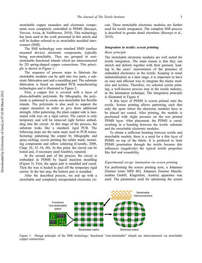
The SMI technology uses standard SMD (surfacemounted device) electronic components, typicallybeing non-stretchable. They are grouped in non-stretchable functional islands which are interconnectedby 2D spring-shaped copper connections. This princi-ple is shown in Figure 1.
The sequence of process steps to fabricate thestretchable modules can be split into two parts, a sub-strate fabrication part and a moulding part. The substratefabrication is based on standard PCB manufacturingtechnologies and is illustrated in Figure 2.
First, a copper foil is covered with a layer ofphoto-definable polyimide. By lithography, the poly-imide is patterned to create non-stretchable but flexibleislands. The polyimide is also used to support thecopper meanders in order to give them additionalstrength. After patterning, the plain copper side is lam-inated with wax on a rigid carrier. The carrier is onlytemporary and will be removed right before embed-ding into the circuit. At this stage of the process, thesubstrate looks like a standard, rigid PCB. Thefollowing steps are the same steps used in PCB manu-facturing: patterning the copper by lithography andspray-etching; screen printing the solder mask; mount-ing components and reflow soldering (Coombs, 2008,Chap. 26, 32–34, 40). At this point, the circuit can betested and, if necessary (and feasible), repaired.
In the second part of the process, the circuit isembedded in PDMS by liquid injection moulding(Figure 3). First, the upper part is moulded and cured.Then the wax is heated to peel off the temporary rigidcarrier. In the last step, the bottom part is moulded.
After the described process, we end up with astretchable and completely encapsulated electronic cir-
cuit. These stretchable electronic modules are furtherused for textile integration. The complete SMI processis described in greater detail elsewhere (Bossuyt et al.,2010).
Integration in textile: screen printing
Basic principle
The stretchable electronic modules are well suited fortextile integration. The main reason is that they canstretch and deform together with their garment, lead-ing to the users’ unawareness of the presence ofembedded electronics in the textile. Keeping in mindindustrialisation at a later stage, it is important to havean easy and efficient way to integrate the elastic mod-ules and textiles. Therefore, we selected screen print-ing, a well-known process step in the textile industry,as the lamination technique. The integration principleis illustrated in Figure 4.
A thin layer of PDMS is screen printed onto thetextile. Screen printing allows patterning such thatonly the spots where the electronic modules have tobe placed are coated. After printing, the module ispositioned with slight pressure on the wet printedPDMS layer. After placement, the PDMS is cured,resulting in a bonding between the textile substrateand the stretchable electronic modules.
To obtain a sufficient bonding between textile andstretchable module, there is a need for a thin layer ofPDMS on top of the fabric. It is preferred to limitPDMS penetration through the textile because thisinfluences (negatively) the typical textile propertieslike feel and wearability.
Experimental set-up: lamination via screen printing
For performing the screen printing tests, a JohannesZimmer (mini MDI 482, Johannes Zimmer Maschi-nenbau GmbH, Klagenfurt, Austria) apparatus wasused. The parameters used for optimising the screen
Figure 1. Design principle of the SMI technology: functional “non-stretchable” islands are interconnected via stretchablecopper connections.
The Journal of The Textile Institute 3
Dow
nloa
ded
by [
Uni
vers
ity o
f G
ent]
at 0
7:35
08
Mar
ch 2
012

printing process were: the mesh properties (thickness,opening size and density), bar type (thickness and sur-
face structure), magnetic force on the bar and velocityof the bar as it moves over the screen. After some ini-
Figure 2. Process flow (from top to bottom) for stretchable substrate fabrication in the SMI technology.
Figure 3. Encapsulating the electronics in PDMS by liquid injection moulding.
Figure 4. Textile bonding by screen printing PDMS.
4 T. Vervust et al.
Dow
nloa
ded
by [
Uni
vers
ity o
f G
ent]
at 0
7:35
08
Mar
ch 2
012

tial trials, it was chosen to use a mesh with 68 lines/cm and a furrowed bar of 18mm diameter as thisresulted in the most easy processing.
Different commercially available PDMS materialsfrom Dow Corning were selected for screen printing:Sylgard 184, Sylgard 186 and Textile Printing Inks9600 and 9601. Sylgard 184 and 186 were selectedbecause these materials are also used for encapsulatingthe stretchable modules. The 9600 and 9601 TextilePrinting Inks were selected because of their higherviscosity which was expected to result in less penetra-tion through the textile. To apply these products, onefirst adds to the basic PDMS material the suitablecross linker. The viscosities of the examined PDMSmaterials are listed in Table 1. More detailedinformation can be found on the suppliers’ website(Dow Corning, n.d.).
With respect to minimum impact of the laminatedstructure on the comfort and wearability, it is impor-tant that the PDMS does not penetrate too deep intothe fabric. Three main parameters influence thispenetration.
The key influence is of course the type of PDMS,i.e. its viscosity: the higher the viscosity, the lesser thepenetration. Further, the method of curing the PDMSlayer determines the time frame in which the layer hasto penetrate into the textile. This is illustrated in Fig-ure 5. When curing at room temperature, virtually allPDMS penetrate into the fabric structure (Figure 5(a)).Curing at an elevated temperature (10min at 100°C)clearly prevents this and a layer of PDMS is formedon top of the fabric (Figure 5(b)).
Finally, also the type of substrate has a stronginfluence on the penetration. As an example, Figure 6shows the screen-printed layer on a woven (Figure 6(a)) and knitted (Figure 6(b)) fabric. For the wovenfabric, the PDMS penetrates only in the top fibres ofthe yarns that have direct contact with the PDMS. For
the knitted fabric, the situation is clearly different:PDMS-coated yarns can be found practically all overthe cross section.
Examples: PDMS sheet laminated on textile substrates
By varying the type of PDMS and changing the mag-netic force and the speed of the bar, coating thick-nesses ranging from 30 to 140 μm could be obtainedon PET foil.
For the actual lamination tests further described inthis paper (unless otherwise mentioned), the magneticforce and bar velocity were set in order that a curedPDMS layer of around 50 μm was obtained on a PETfoil; the silicon type used was Textile Printing Inks9601 of Dow Corning; curing was done in an oven at100°C for 10min.
Cross-sections of actual laminations of PDMSsheets on textile substrates are shown in Figure 6. InFigure 6(a), the cross-section shows a woven fabric,the screen-printed layer and the PDMS sheet on top.The PDMS sheet has a thickness of ca. 200 μm, thethin lamination layer has an average thickness ofroughly 50 μm. Note the smoothness of this thin layeron the side that contacts the PDMS sheet. Figure 6(b)shows a knitted fabric. In this case, the PDMS sheeton top actually consists of two layers that togetherform the encapsulation of the electronics. The thinscreen-printed layer is hardly visible because it pene-
Table 1. Viscosity of different PDMS materials.
PDMS Viscosity (cP)
Dow Corning 9601 280,000Dow Corning 9600 490,000Dow Corning 184 4575Dow Corning 186 99,700
Figure 5. Cross-section of woven cotton fabric coated with PDMS (type Sylgard 186); (a) curing at room temperature and(b) curing in oven (10min at 100°C).
The Journal of The Textile Institute 5
Dow
nloa
ded
by [
Uni
vers
ity o
f G
ent]
at 0
7:35
08
Mar
ch 2
012
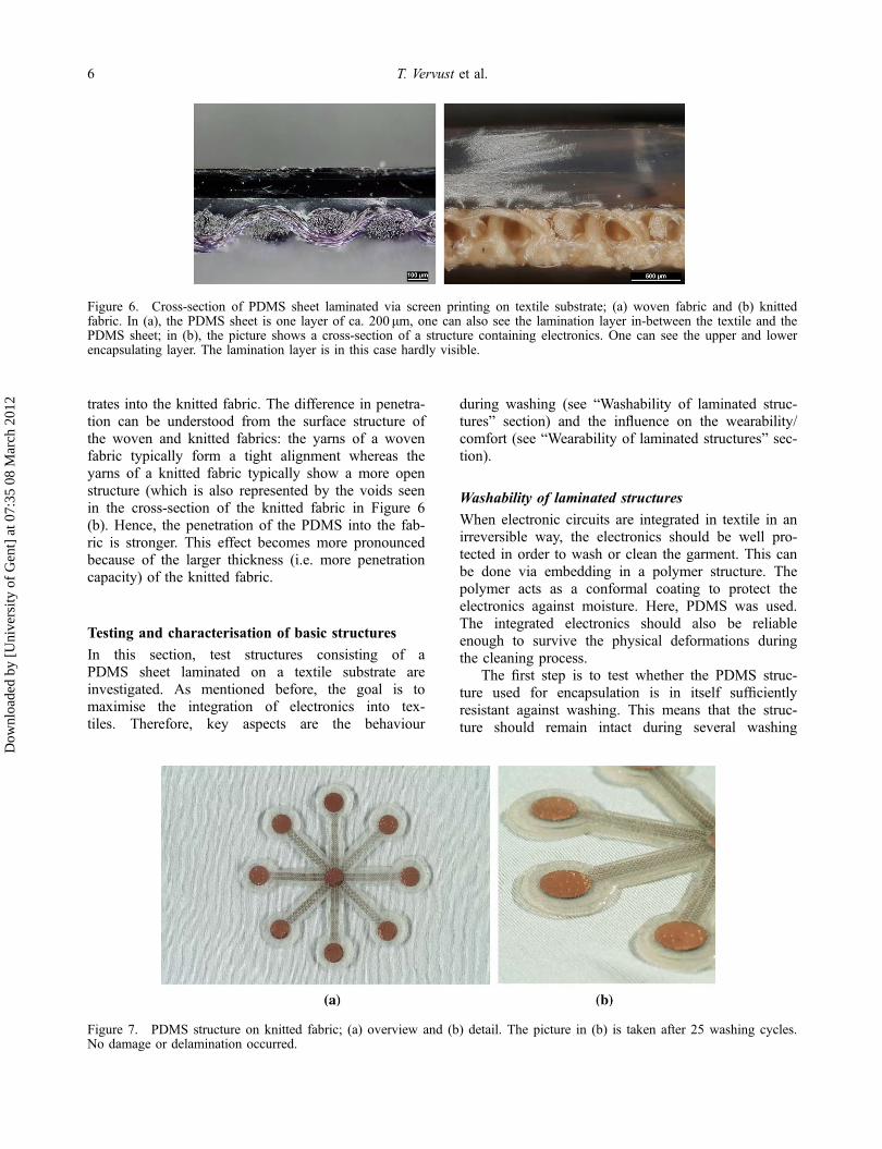
trates into the knitted fabric. The difference in penetra-tion can be understood from the surface structure ofthe woven and knitted fabrics: the yarns of a wovenfabric typically form a tight alignment whereas theyarns of a knitted fabric typically show a more openstructure (which is also represented by the voids seenin the cross-section of the knitted fabric in Figure 6(b). Hence, the penetration of the PDMS into the fab-ric is stronger. This effect becomes more pronouncedbecause of the larger thickness (i.e. more penetrationcapacity) of the knitted fabric.
Testing and characterisation of basic structures
In this section, test structures consisting of aPDMS sheet laminated on a textile substrate areinvestigated. As mentioned before, the goal is tomaximise the integration of electronics into tex-tiles. Therefore, key aspects are the behaviour
during washing (see “Washability of laminated struc-tures” section) and the influence on the wearability/comfort (see “Wearability of laminated structures” sec-tion).
Washability of laminated structures
When electronic circuits are integrated in textile in anirreversible way, the electronics should be well pro-tected in order to wash or clean the garment. This canbe done via embedding in a polymer structure. Thepolymer acts as a conformal coating to protect theelectronics against moisture. Here, PDMS was used.The integrated electronics should also be reliableenough to survive the physical deformations duringthe cleaning process.
The first step is to test whether the PDMS struc-ture used for encapsulation is in itself sufficientlyresistant against washing. This means that the struc-ture should remain intact during several washing
Figure 6. Cross-section of PDMS sheet laminated via screen printing on textile substrate; (a) woven fabric and (b) knittedfabric. In (a), the PDMS sheet is one layer of ca. 200 μm, one can also see the lamination layer in-between the textile and thePDMS sheet; in (b), the picture shows a cross-section of a structure containing electronics. One can see the upper and lowerencapsulating layer. The lamination layer is in this case hardly visible.
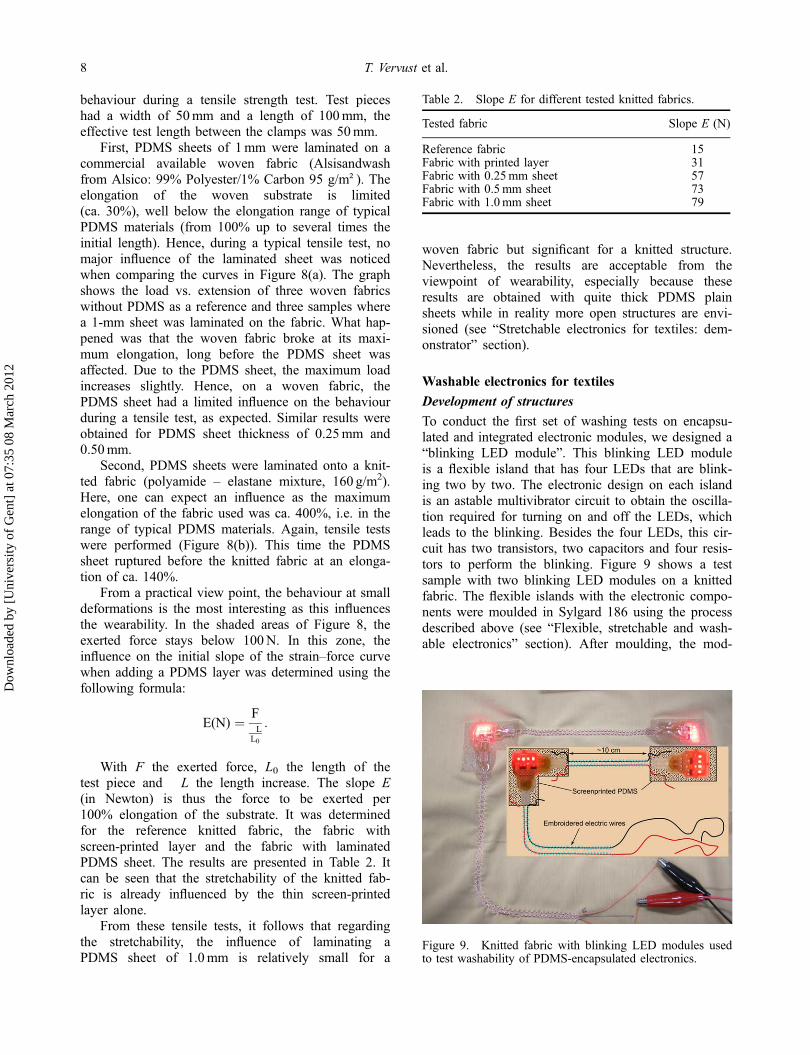
Figure 7. PDMS structure on knitted fabric; (a) overview and (b) detail. The picture in (b) is taken after 25 washing cycles.No damage or delamination occurred.
6 T. Vervust et al.
Dow
nloa
ded
by [
Uni
vers
ity o
f G
ent]
at 0
7:35
08
Mar
ch 2
012

cycles and that it should not delaminate. To test this, aPDMS structure made from Sylgard 186 has beenlaminated on a textile substrate (ca. 20 × 20cm2)according to the procedure described in “Integration intextile: screen printing” section. The PDMS encapsu-lates a copper conductive structure as shown inFigure 7(a).
To test the adhesion between the PDMS structureand the textile, a standard washing method was used:“Textiles – Domestic washing and drying proceduresfor textile testing (procedure 5A) – ISO 6330:2000”.This standard is representative of common domesticwashing conditions (in Europe). It means the use of afront-loading washing machine as this is most com-mon in Europe (90%) and a washing temperature of40°C. Standard detergents (Europäische Conventionfür Echtheitsprüfungen [ECE] soap) are used whichare slightly alkaline (pH � 10). The sample was putin a protective textile bag during washing. This wasdone to mimic the real-life situation where it wouldbe placed on the inner side of a garment. The samplewas dried in open air (no tumble drying).
The test structure shown in Figure 7(a) has beenwashed up to 50 times according to this procedure.No visual damage of the washing was observed ascan also be seen in Figure 7(b) (picture taken after 25cycles).
This test and similar ones (not shown) indicate thatthe PDMS used for encapsulation is very stable andthat it does not delaminate from the textile surface.Hence, it appears to be a good choice as an encapsu-lant of electronics. The testing of how an actual work-ing electronic circuit encapsulated in PDMS performsafter washing is reported in “Washable electronics fortextiles” section.
Wearability of laminated structures
In general, the wearability/comfort depends on severalaspects: breathability, stretchability, weight, flexibility,drapability, etc. A test for flexibility/stiffness is the“Hanging Heart Loop Test” (FED STD 191A-5200),which assesses the stiffness of the textile (Slade, Wil-son, Farrell, Teverovsky, & Thomson, 2003). Here,we did not consider all the aspects of wearability indetail. Instead, we focused on two aspects: simple ten-sile testing which was performed to check if there wasa significant influence of the PDMS sheet on thestretchability and an assessment of the extra weightadd-on.
Indeed, an important factor in wearability is thefabric thickness and its total weight (expressed in g/m2). The cross-sections shown in Figure 6 are makingclear that the attachment of the PDMS sheets has alarge influence on the textile/garment. We can see that
the total thickness easily doubles. But, when lookingat the weight, the relative impact is even stronger. Fora textile substrate, one can take typically a density of100–200 g/m2. For a PDMS sheet of 1.0mm thicknessand assuming a density of 2 g/cm3, we obtain a totalweight of 2000 g/m2. This means that the patcheswhere the electronics are attached will be ca. 10 timesas heavy as the textile itself. Hence, it should be clearthat such patches can only be added as relativelysmall areas and at strategic places (e.g. close to thewaist or at the end of sleeves). The weight is also thereason for focusing on open PDMS structures(see “Stretchable electronics for textiles: demonstrator”section).
Even though the weight will have a very stronginfluence on wearability, it is also interesting to lookat the stretchability. We evaluated the influence of aPDMS sheet laminated on a textile substrate on its
(a)
(b)
Figure 8. Load vs. extension curve recorded during tensiletests, the shaded zone (lower left corner) indicates roughlythe area of interest when considering wearability; (a) forwoven fabrics, one can see a slight increase in the total loadbefore rupture when a 1mm PDMS sheet is added, in thearea of interest no relevant influence is observed and (b) forknitted fabrics a shift is observed in the curves for thefabric with PDMS; in the area of interest there is also aclear effect of adding the PDMS: a larger force is needed toreach the same extension because the PDMS is lessstretchable than the knitted fabric.
The Journal of The Textile Institute 7
Dow
nloa
ded
by [
Uni
vers
ity o
f G
ent]
at 0
7:35
08
Mar
ch 2
012
behaviour during a tensile strength test. Test pieceshad a width of 50mm and a length of 100mm, theeffective test length between the clamps was 50mm.
First, PDMS sheets of 1mm were laminated on acommercial available woven fabric (Alsisandwashfrom Alsico: 99% Polyester/1% Carbon 95 g/m²). Theelongation of the woven substrate is limited(ca. 30%), well below the elongation range of typicalPDMS materials (from 100% up to several times theinitial length). Hence, during a typical tensile test, nomajor influence of the laminated sheet was noticedwhen comparing the curves in Figure 8(a). The graphshows the load vs. extension of three woven fabricswithout PDMS as a reference and three samples wherea 1-mm sheet was laminated on the fabric. What hap-pened was that the woven fabric broke at its maxi-mum elongation, long before the PDMS sheet wasaffected. Due to the PDMS sheet, the maximum loadincreases slightly. Hence, on a woven fabric, thePDMS sheet had a limited influence on the behaviourduring a tensile test, as expected. Similar results wereobtained for PDMS sheet thickness of 0.25mm and0.50mm.
Second, PDMS sheets were laminated onto a knit-ted fabric (polyamide – elastane mixture, 160 g/m2).Here, one can expect an influence as the maximumelongation of the fabric used was ca. 400%, i.e. in therange of typical PDMS materials. Again, tensile testswere performed (Figure 8(b)). This time the PDMSsheet ruptured before the knitted fabric at an elonga-tion of ca. 140%.
From a practical view point, the behaviour at smalldeformations is the most interesting as this influencesthe wearability. In the shaded areas of Figure 8, theexerted force stays below 100N. In this zone, theinfluence on the initial slope of the strain–force curvewhen adding a PDMS layer was determined using thefollowing formula:
E(N) ¼ F�LL0
:
With F the exerted force, L0 the length of thetest piece and �L the length increase. The slope E(in Newton) is thus the force to be exerted per100% elongation of the substrate. It was determinedfor the reference knitted fabric, the fabric withscreen-printed layer and the fabric with laminatedPDMS sheet. The results are presented in Table 2. Itcan be seen that the stretchability of the knitted fab-ric is already influenced by the thin screen-printedlayer alone.
From these tensile tests, it follows that regardingthe stretchability, the influence of laminating aPDMS sheet of 1.0mm is relatively small for a
woven fabric but significant for a knitted structure.Nevertheless, the results are acceptable from theviewpoint of wearability, especially because theseresults are obtained with quite thick PDMS plainsheets while in reality more open structures are envi-sioned (see “Stretchable electronics for textiles: dem-onstrator” section).
Washable electronics for textiles
Development of structures
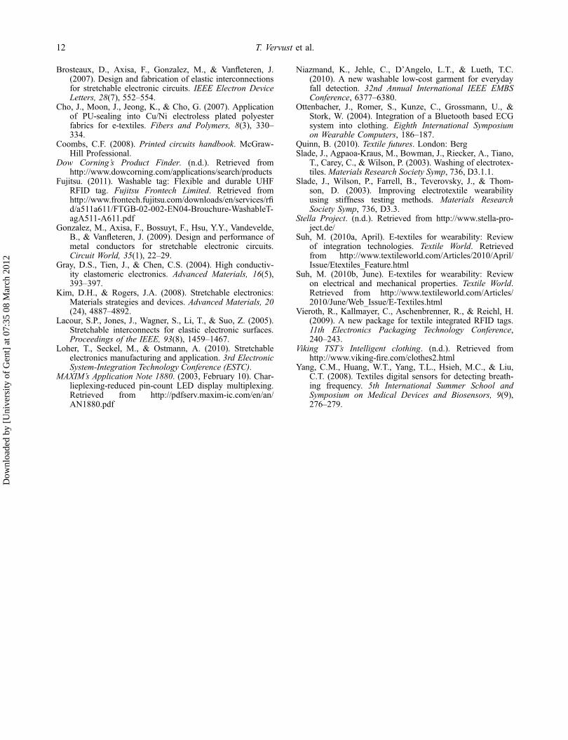
To conduct the first set of washing tests on encapsu-lated and integrated electronic modules, we designed a“blinking LED module”. This blinking LED moduleis a flexible island that has four LEDs that are blink-ing two by two. The electronic design on each islandis an astable multivibrator circuit to obtain the oscilla-tion required for turning on and off the LEDs, whichleads to the blinking. Besides the four LEDs, this cir-cuit has two transistors, two capacitors and four resis-tors to perform the blinking. Figure 9 shows a testsample with two blinking LED modules on a knittedfabric. The flexible islands with the electronic compo-nents were moulded in Sylgard 186 using the processdescribed above (see “Flexible, stretchable and wash-able electronics” section). After moulding, the mod-
Table 2. Slope E for different tested knitted fabrics.
Tested fabric Slope E (N)
Reference fabric 15Fabric with printed layer 31Fabric with 0.25mm sheet 57Fabric with 0.5mm sheet 73Fabric with 1.0mm sheet 79
Figure 9. Knitted fabric with blinking LED modules usedto test washability of PDMS-encapsulated electronics.
8 T. Vervust et al.
Dow
nloa
ded
by [
Uni
vers
ity o
f G
ent]
at 0
7:35
08
Mar
ch 2
012

ules were attached to the textile using the screen print-ing technique (see “Integration in textile: screen print-ing” section). For the next step, conductive andisolated copper wires were fixed to the textile bystitching. The interconnections were made by solder-ing the wires onto the contact pads of the LED mod-ules. The openings in the PDMS encapsulation toaccess the pads were created by proper mould design.
The module with the corner shape of Figure 9 hastwo places for interconnecting the power. At one side,the power arrives and at the other side the power isfurther transmitted to another module. Once the sol-dering was done and the interconnections werechecked, the openings were sealed with PDMS (3-4241 dielectric gel, Dow Corning) to protect the inter-connections.
Washing procedure
Three identical samples with encapsulated LEDs(“Development of structures” section) were made forperforming washing tests. They are referred to as L1,L2 and L3.
Immersion tests of encapsulated LEDs
Step 1: immersion in water. In the first step, two sam-ples (L1 and L2) were immersed in hard water at 60°C. The recipient with samples was horizontally shaken(ca. 25 cycles/min – amplitude of 2 cm). After 3 h, thesamples were removed from the liquid and dried over-night. When testing the dried samples, it appeared thatall LEDs on both samples were still working.
Step 2: immersion in water-soap mixture. Based onthe positive results of Step 1, the same procedure wasrepeated using again L1 and L2, but this time soapwas added to the water. The soap was of the typeused for standardised textile washing (so-called ECEsoap), the concentration was 2.5 g/l as this is also theconcentration used in the actual machine washing tests(see further). Again the samples were removed fromthe liquid after 3 h and subsequently dried overnight.When testing the dried samples, it appeared that allLEDs were still working.
Gyro washing tests of encapsulated LEDs
In the next step, samples L1 and L2 were subjected toa gyro washing instead of immersion. The term “gyrowashing” refers to a simplified washing method, usedfor evaluation of colour fastness of textile materials.The equipment consists of several separate vessels,per vessel only one sample was put in together withthe water-soap mixture (800ml hard water, 2 g ECE
soap). The sample was positioned around a plastictube that fitted into the vessel in order to limit themechanical action on the sample. The vessels werespun around and kept at a washing temperature of60 °C via the “au-bain-marie” method. The duration ofthe washing cycle was 30min. After this gyro wash-ing, the samples were dried overnight. Again all LEDson both L1 and L2 remained functional.
Standardised domestic washing of encapsulated LEDs
Given the encouraging results obtained with theimmersion and gyro washing, domestic washing wasperformed according to the standard ISO 6330 –method 5A. This means washing at 40°C, togetherwith other items. Two more parameters were varied:(i) the samples were added to the washing load withor without a protective bag and (ii) the drying methodwas varied: open air or tumble drying. During tumbledrying, the temperature goes up to maximum 50°C.
The results for the different tests:
• With a protective bag and with open air drying:sample L1 was washed and dried this way. It wasstill functional after repeating the washing anddrying procedure five times. Then, the test wasstopped and sample L1 was used for a differenttype of testing (see further).• Without protective bag and with open air drying:sample L2 was washed and dried this way. It wasstill functional after repeating the washing anddrying procedure five times. But after the sixthwashing and drying cycle, the sample was nolonger functioning.• With a protective bag and with tumble drying:sample L3 was tested in this way. After the firsttime, the sample was still fine but already afterthe second washing and drying cycle, the samplewas no longer functioning.
Standardised industrial washing on encapsulatedLEDs
Next to the domestic washing, the goal was also toperform industrial washing. This was performedaccording to the standard “Textiles – Industrial wash-ing and finishing procedures for testing of workwear”– ISO15797. The temperature during washing waseither 40 or 65°C. However, compared to the domesticwashing, the total load in the washing machine is lar-ger, implying that stronger mechanical forces areworking on the sample. In this case only tumble dry-ing was performed, with temperatures reaching up to80°C. To do the test, sample L1 was simply added toanother washing load.
The Journal of The Textile Institute 9
Dow
nloa
ded
by [
Uni
vers
ity o
f G
ent]
at 0
7:35
08
Mar
ch 2
012

The outcome of the tests was that for industrialwashing at 40°C both LED groups of L1 were stillfunctioning after repeating the washing and dryingcycles five times.
Given this good and somewhat unexpected result,a washing test was performed at 65°C. After the firstwashing, one group of LEDs did not function any-more. Between the second and fifth time of washing,also the other group of LEDs was affected: instead ofblinking, the LEDs of that group were now burningcontinuously. This indicates a serious defect in the cir-cuitry, so it was decided to stop the testing with sam-ple L1.
Conclusion from washing tests of encapsulated LEDs
These tests showed that a group of LEDs, encapsulatedin PDMS, can withstand up to a certain degree of stan-dard domestic or industrial textile washing: sample L2survived five washing cycles, sample L1, 10 washingcycles. Tumble, drying, on the other hand, seems, notsurprisingly, a harder process than the washing itself.Still, one sample (L1) managed to survive five cycles.
Analysis and evaluation of the samples after failure
After the LEDs were not burning anymore, the sam-ples were subjected to failure analysis. At first itwas tested if the interconnections to power the mod-ules were still conducting. This was done by puttingneedles through the PDMS to make contact with thepads. When powered up, all the LEDs were blinkingagain, indicating that the samples suffered damageonly at the interconnections. Optical and X-rayimages of a broken wire at the interconnection areshown in Figure 10.
This result teaches us that the electronic circuit isstill functional after washing and that the failure arisesat the interconnection. It is not the solder ball thatreleases from the copper pad, but the wire that breaks
at the solder ball. This means that the forces on thisweak spot should be lowered to prevent failure. Thiscan be done by using a PDMS with a higher hardnessas a sealant or by creating a stiffer zone at the transi-tion. Also a small SMD connector can be used tomake a more reliable connection.
Stretchable electronics for textiles: demonstrator
An important and interesting property of the SMItechnology is the stretchability of the electroniccircuitry. The intrinsic non-stretchable copper is madestretchable by using planar, horseshoe-shaped struc-tures in which bending at the corners can accommo-date the applied strains. PDMS has been used aselastomer to encapsulate these meandering copperconductors. Simulations and experiments on thestretchability of the horseshoe shapes are reported byGonzalez et al. (2009).
To show the possibilities of the SMI technology inthe field of textile applications, we designed an attrac-
Figure 10. Images of the broken contact; (a) problem at interconnection; (b) detail and (c) X-ray of the broken wire.
Figure 11. Stretchable 7� 8 LED-matrix before PDMSembedding.
10 T. Vervust et al.
Dow
nloa
ded
by [
Uni
vers
ity o
f G
ent]
at 0
7:35
08
Mar
ch 2
012

tive demonstrator. This technology demonstratorshows a 7� 8 single colour LED-matrix, which canbe used, for example, in wearable signage applica-tions. The LED-islands are interconnected with mean-der-shaped conductors to achieve stretchability. Theelectronic circuit is built up around a MSP430F123microcontroller from Texas Instruments (Texas Instru-ments, Texas, USA). The microcontroller is pro-grammed to show a scrolling text message on the 7� 8LED-matrix. The aim was to realise an electronic designfor driving the LEDs with the minimum of components.In order to reduce the number of interconnections, amore unusual multiplexing technique called “Charlie-plexing” was implemented (MAXIM, 2003).
In Figure 11, the production state before embed-ding is shown. The circuit can be divided in two mainparts: the part with the LEDs is arranged in a stretch-able matrix and the part with the microcontroller fordriving the LED matrix is placed on a flexible island.
This stage of the process allows programming ofthe microcontroller firmware and testing of the circuitfunctionality. If the system works properly, the circuitis moulded in PDMS, using liquid injection moulding.This demonstrator was moulded in Sylgard 186 andthe result is shown in Figure 12(a). The mould wasdesigned to create openings in the stretchable PDMSmodule on places without conducting meanders. Indoing so, the PDMS surface is minimised which aidsto a lighter and more flexible/stretchable device inorder to maximise user comfort.
After the moulding step, the stretchable electronicmodule is finished and ready to be embedded in tex-tile. Textile integration is done using the screen print-ing process described in the “Integration in textile:screen printing” section. A T-shirt with an integratedstretchable LED module is shown in Figure 12(b). Ithas to be noted that little attention was given to theinterconnection of the power wires in this technologydemonstrator. With the failure of the interconnectionsof the LED-blinking modules in mind, this technology
demonstrator was not used for washing experiments.Future work will rely on improving the overall robust-ness of the stretchable modules to increase the numberof washing cycles.
Conclusions
The developed SMI technology is well suited for textileintegration. It has a higher degree of integration com-pared to rigid and flexible circuit boards. A thin PDMSlayer was screen printed onto knitted and woven fabricsto laminate SMI modules. The adhesion between thefabric and the modules was sufficient to prevent delam-ination during washing. This was tested up to 50“domestic” washing cycles. Basic LED modules encap-sulated in PDMS, can withstand up to a certain degreeof domestic or industrial textile washing. The test sam-ples failed at the interconnection of the power wireswith the electronic circuit. A more complex LED dis-play was made to show the feasibility of the technologyand to improve the moulding techniques to create open-ings in the PDMS module. This results in a lighter andmore flexible/stretchable device in order to maximiseuser comfort. Future work will rely on improving theoverall robustness of the stretchable modules toincrease the number of washing cycles.
AcknowledgementsThis work was supported by European CommissionResearch programme STELLA (contract number 028026).The work was also supported by the Belgian Science Policy(Belspo) through the SWEET project (contract number P2/00/08). The authors wish to thank the project partners andthe respective funding organisations. Special thanks to DowCorning for PDMS materials support.
ReferencesBossuyt, F., Vervust, T., Axisa, F., & Vanfleteren, J. (2010).
Improved stretchable electronics technology for large areaapplications. MRS Proceedings, 1271, 1271-JJ08-03.
Figure 12. 7� 8 LED matrix technology demonstrator; (a) after PDMS moulding and (b) after textile integration.
The Journal of The Textile Institute 11
Dow
nloa
ded
by [
Uni
vers
ity o
f G
ent]
at 0
7:35
08
Mar
ch 2
012
Brosteaux, D., Axisa, F., Gonzalez, M., & Vanfleteren, J.(2007). Design and fabrication of elastic interconnectionsfor stretchable electronic circuits. IEEE Electron DeviceLetters, 28(7), 552–554.
Cho, J., Moon, J., Jeong, K., & Cho, G. (2007). Applicationof PU-sealing into Cu/Ni electroless plated polyesterfabrics for e-textiles. Fibers and Polymers, 8(3), 330–334.
Coombs, C.F. (2008). Printed circuits handbook. McGraw-Hill Professional.
Dow Corning’s Product Finder. (n.d.). Retrieved fromhttp://www.dowcorning.com/applications/search/products
Fujitsu. (2011). Washable tag: Flexible and durable UHFRFID tag. Fujitsu Frontech Limited. Retrieved fromhttp://www.frontech.fujitsu.com/downloads/en/services/rfid/a511a611/FTGB-02-002-EN04-Brouchure-WashableT-agA511-A611.pdf
Gonzalez, M., Axisa, F., Bossuyt, F., Hsu, Y.Y., Vandevelde,B., & Vanfleteren, J. (2009). Design and performance ofmetal conductors for stretchable electronic circuits.Circuit World, 35(1), 22–29.
Gray, D.S., Tien, J., & Chen, C.S. (2004). High conductiv-ity elastomeric electronics. Advanced Materials, 16(5),393–397.
Kim, D.H., & Rogers, J.A. (2008). Stretchable electronics:Materials strategies and devices. Advanced Materials, 20(24), 4887–4892.
Lacour, S.P., Jones, J., Wagner, S., Li, T., & Suo, Z. (2005).Stretchable interconnects for elastic electronic surfaces.Proceedings of the IEEE, 93(8), 1459–1467.
Loher, T., Seckel, M., & Ostmann, A. (2010). Stretchableelectronics manufacturing and application. 3rd ElectronicSystem-Integration Technology Conference (ESTC).
MAXIM’s Application Note 1880. (2003, February 10). Char-lieplexing-reduced pin-count LED display multiplexing.Retrieved from http://pdfserv.maxim-ic.com/en/an/AN1880.pdf
Niazmand, K., Jehle, C., D’Angelo, L.T., & Lueth, T.C.(2010). A new washable low-cost garment for everydayfall detection. 32nd Annual International IEEE EMBSConference, 6377–6380.
Ottenbacher, J., Romer, S., Kunze, C., Grossmann, U., &Stork, W. (2004). Integration of a Bluetooth based ECGsystem into clothing. Eighth International Symposiumon Wearable Computers, 186–187.
Quinn, B. (2010). Textile futures. London: BergSlade, J., Agpaoa-Kraus, M., Bowman, J., Riecker, A., Tiano,
T., Carey, C., & Wilson, P. (2003). Washing of electrotex-tiles. Materials Research Society Symp, 736, D3.1.1.
Slade, J., Wilson, P., Farrell, B., Teverovsky, J., & Thom-son, D. (2003). Improving electrotextile wearabilityusing stiffness testing methods. Materials ResearchSociety Symp, 736, D3.3.
Stella Project. (n.d.). Retrieved from http://www.stella-pro-ject.de/
Suh, M. (2010a, April). E-textiles for wearability: Reviewof integration technologies. Textile World. Retrievedfrom http://www.textileworld.com/Articles/2010/April/Issue/Etextiles_Feature.html
Suh, M. (2010b, June). E-textiles for wearability: Reviewon electrical and mechanical properties. Textile World.Retrieved from http://www.textileworld.com/Articles/2010/June/Web_Issue/E-Textiles.html
Vieroth, R., Kallmayer, C., Aschenbrenner, R., & Reichl, H.(2009). A new package for textile integrated RFID tags.11th Electronics Packaging Technology Conference,240–243.
Viking TST’s Intelligent clothing. (n.d.). Retrieved fromhttp://www.viking-fire.com/clothes2.html
Yang, C.M., Huang, W.T., Yang, T.L., Hsieh, M.C., & Liu,C.T. (2008). Textiles digital sensors for detecting breath-ing frequency. 5th International Summer School andSymposium on Medical Devices and Biosensors, 9(9),276–279.
12 T. Vervust et al.
Dow
nloa
ded
by [
Uni
vers
ity o
f G
ent]
at 0
7:35
08
Mar
ch 2
012