INTEGRATION OF EE IN BUILDINGS – PART 3 - meetMED
52
www.meetmed.org Mitigation Enabling Energy Transition in the MEDiterranean region INTEGRATION OF EE IN BUILDINGS – PART 3 HVAC systems Dr Miriam Benedetti, Researcher, ENEA Training course on Energy Efficiency and Renewable Energy Sources in buildings 26 February 2020 – Tunis, Tunisia
-
Upload
khangminh22 -
Category
Documents
-
view
0 -
download
0
Transcript of INTEGRATION OF EE IN BUILDINGS – PART 3 - meetMED
www.meetmed.org
Mitigation Enabling Energy Transition in the MEDiterranean region
INTEGRATION OF EE IN BUILDINGS –PART 3
HVAC systems Dr Miriam Benedetti, Researcher, ENEA
Training course on Energy Efficiency and Renewable Energy Sources in buildings
26 February 2020 – Tunis, Tunisia
Heating & Ventilation and Air
Conditioning (HVAC)
. 3
Brainstorming
• Have I ever felt uncomfortable (e.g. too hot or too cold) in a building/room?
• What do I know about HVAC systems?
• What do I expect to know about HVAC systems at the end of this course?
. 4
What is an HVAC system?
• Heating Ventilation and Air Conditioning (HVAC) systems regulate temperature, ventilation, and humidity level to ensure the physical comfort of the occupants in commercial and industrial buildings and/or the conditions required by industrial processes or equipment.
• HVAC systems adapt and function in response to:– External thermal loads (weather conditions and their effect on the
building);– Internal thermal loads (people, processes, equipment in the building).
• Many of the existing HVAC systems were not designed with energy efficiency as one of the design factors.

. 5
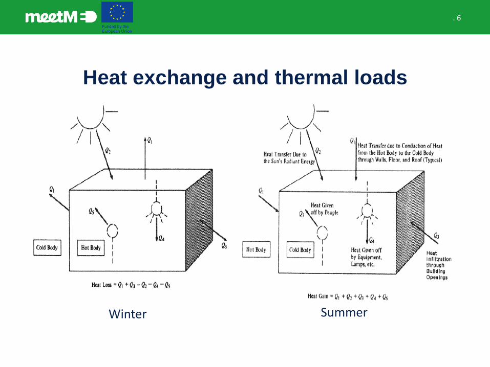
Heat exchange and thermal loads
. 6
Heat exchange and thermal loads
Winter Summer
. 7
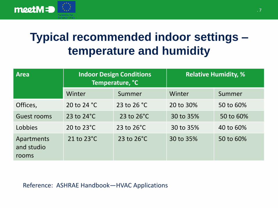
Typical recommended indoor settings –
temperature and humidity
Area Indoor Design Conditions Temperature, °C
Relative Humidity, %
Winter Summer Winter Summer
Offices, 20 to 24 °C 23 to 26 °C 20 to 30% 50 to 60%
Guest rooms 23 to 24°C 23 to 26°C 30 to 35% 50 to 60%
Lobbies 20 to 23°C 23 to 26°C 30 to 35% 40 to 60%
Apartments and studio rooms
21 to 23°C 23 to 26°C 30 to 35% 50 to 60%
Reference: ASHRAE Handbook—HVAC Applications
. 8
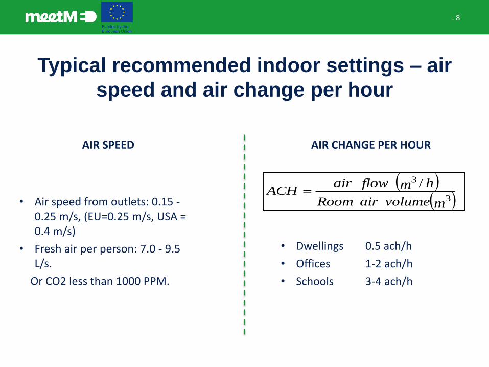
Typical recommended indoor settings – air
speed and air change per hour
• Air speed from outlets: 0.15 -0.25 m/s, (EU=0.25 m/s, USA = 0.4 m/s)
• Fresh air per person: 7.0 - 9.5 L/s.
Or CO2 less than 1000 PPM.
AIR SPEED AIR CHANGE PER HOUR
( )( )mvolumeairRoom
hmflowairACH
3
3 /=
• Dwellings 0.5 ach/h
• Offices 1-2 ach/h
• Schools 3-4 ach/h
. 9
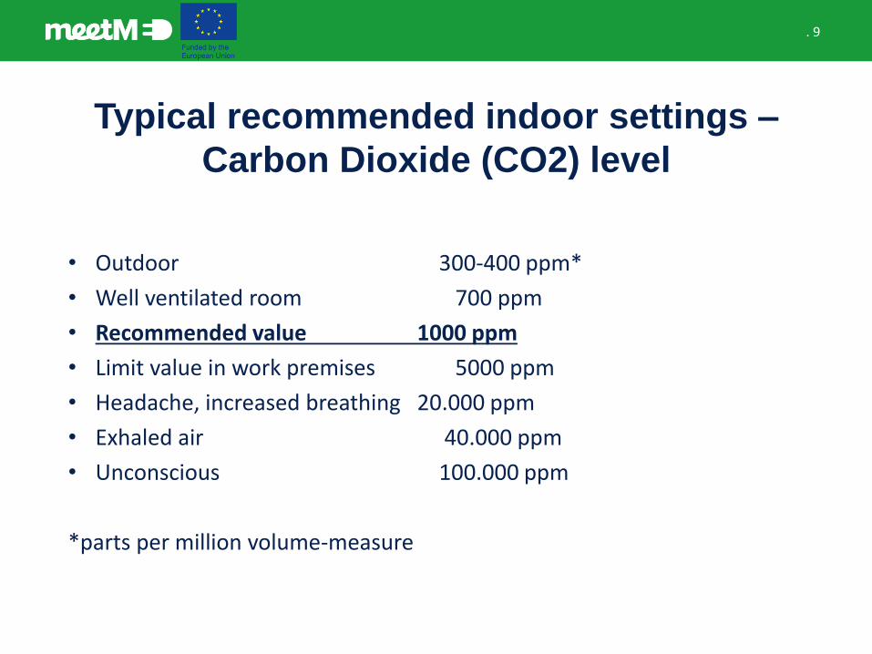
Typical recommended indoor settings –
Carbon Dioxide (CO2) level
• Outdoor 300-400 ppm*
• Well ventilated room 700 ppm
• Recommended value 1000 ppm
• Limit value in work premises 5000 ppm
• Headache, increased breathing 20.000 ppm
• Exhaled air 40.000 ppm
• Unconscious 100.000 ppm
*parts per million volume-measure
. 10
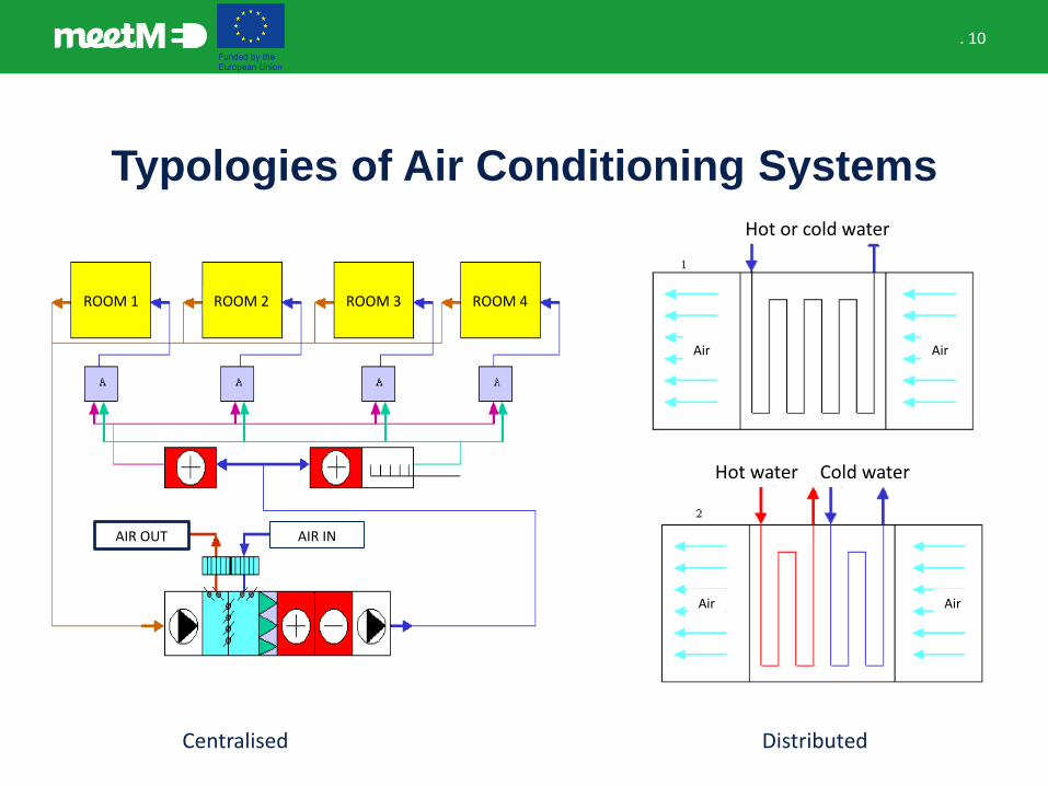
Typologies of Air Conditioning Systems
Centralised
ROOM 1 ROOM 2 ROOM 3 ROOM 4
AIR INAIR OUT
Distributed
Hot or cold water
Hot water Cold water
AirAir
AirAir
. 11
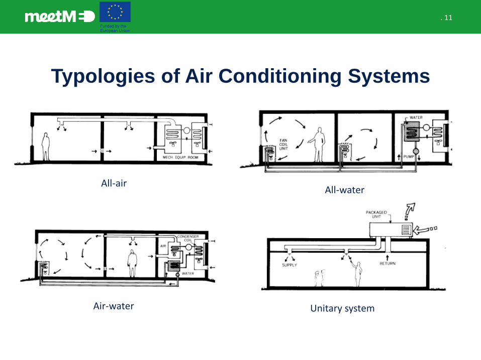
Typologies of Air Conditioning Systems
All-airAll-water
Air-water Unitary system
. 12
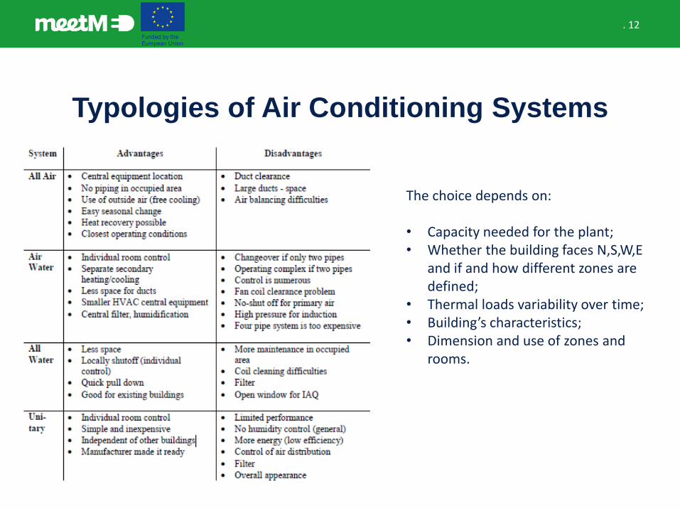
Typologies of Air Conditioning Systems
The choice depends on:
• Capacity needed for the plant;• Whether the building faces N,S,W,E
and if and how different zones are defined;
• Thermal loads variability over time;• Building’s characteristics;• Dimension and use of zones and
rooms.
. 13
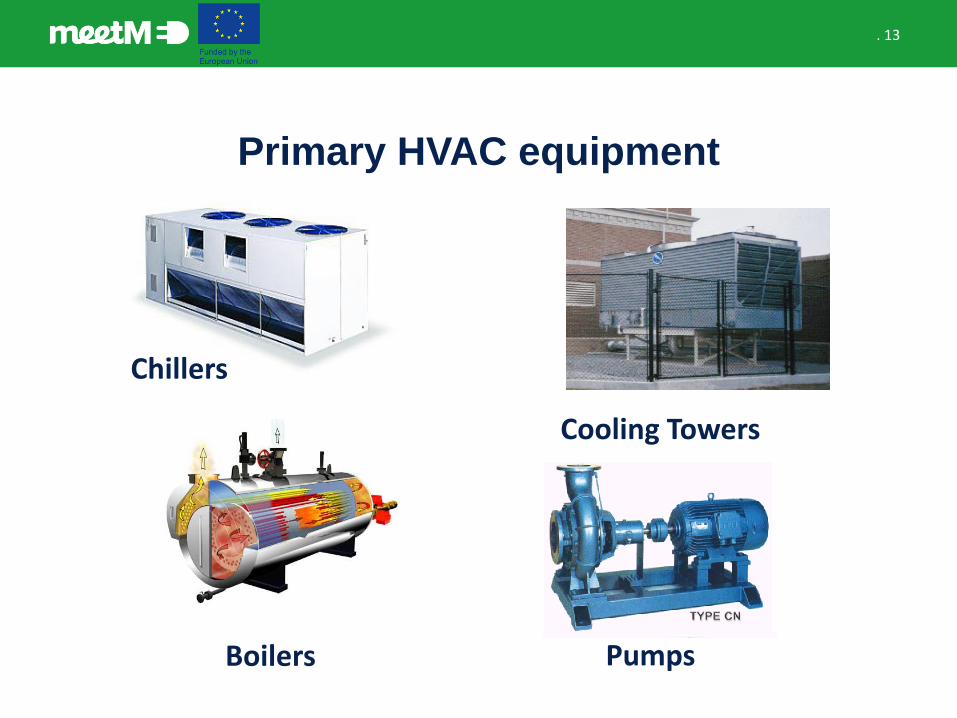
Primary HVAC equipment
Chillers
Cooling Towers
Boilers Pumps
. 14
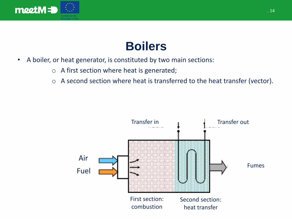
Boilers• A boiler, or heat generator, is constituted by two main sections:
o A first section where heat is generated;
o A second section where heat is transferred to the heat transfer (vector).
Air
Fuel
First section: combustion
Second section: heat transfer
Fumes
Transfer in Transfer out
. 15
Vapor refrigeration systems
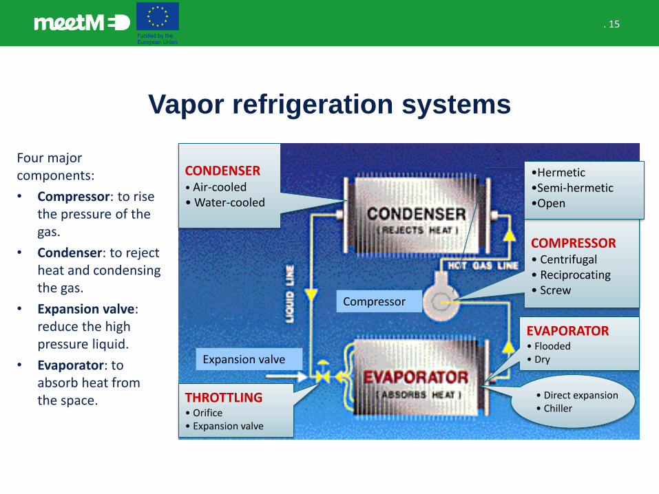
Four major components:
• Compressor: to rise the pressure of the gas.
• Condenser: to reject heat and condensing the gas.
• Expansion valve: reduce the high pressure liquid.
• Evaporator: to absorb heat from the space.
Expansion valve
Compressor
COMPRESSOR• Centrifugal • Reciprocating• Screw
EVAPORATOR• Flooded• Dry
CONDENSER• Air-cooled• Water-cooled
• Direct expansion• Chiller
THROTTLING• Orifice• Expansion valve
•Hermetic•Semi-hermetic•Open
. 16
Vapor refrigeration systems
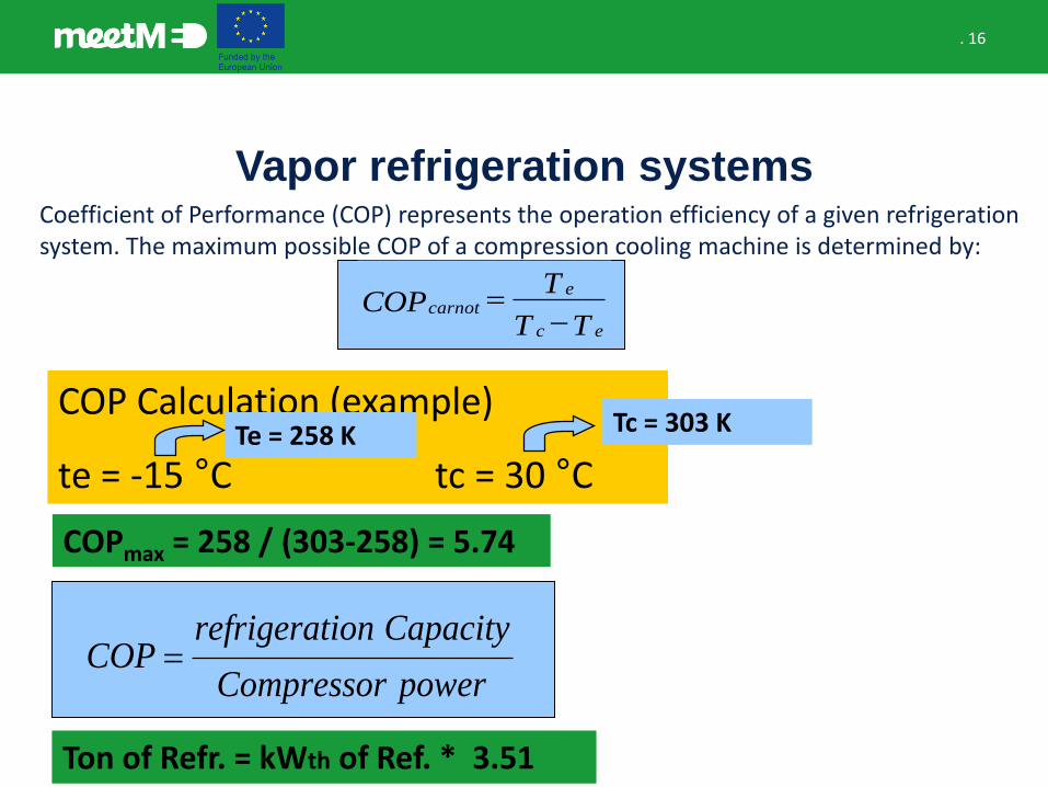
COPmax = 258 / (303-258) = 5.74
COP Calculation (example)
te = -15 °C tc = 30 °C
Tc = 303 KTe = 258 K
powerCompressor
CapacityionrefrigeratCOP =
TT
TCOP
ec
ecarnot
−=
Coefficient of Performance (COP) represents the operation efficiency of a given refrigeration system. The maximum possible COP of a compression cooling machine is determined by:
Ton of Refr. = kWth of Ref. * 3.51
. 17
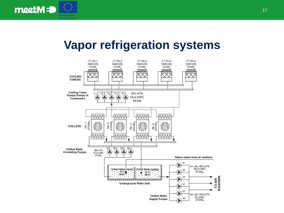
Vapor refrigeration systems
HVAC case study
. 19
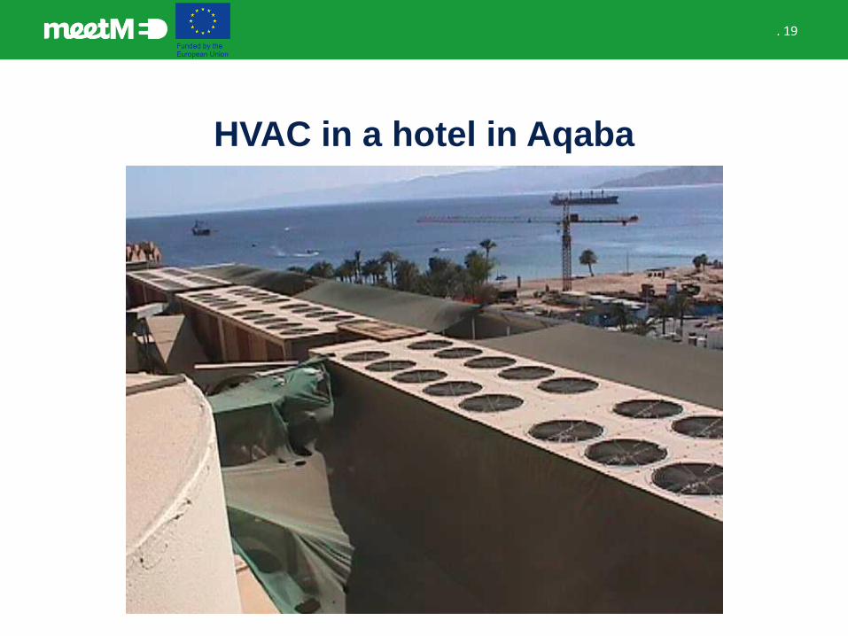
HVAC in a hotel in Aqaba
. 20
HVAC in a hotel in Aqaba
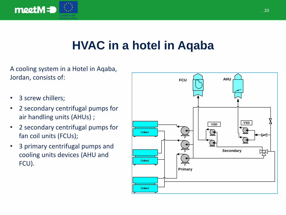
A cooling system in a Hotel in Aqaba, Jordan, consists of:
• 3 screw chillers;
• 2 secondary centrifugal pumps for air handling units (AHUs) ;
• 2 secondary centrifugal pumps for fan coil units (FCUs);
• 3 primary centrifugal pumps and cooling units devices (AHU and FCU).
Chiller1
P
Chiller2
Chiller2
P
P
VSDVSD
FCU AHU
Primary
Secondary
. 21
HVAC in a hotel in Aqaba
• The chillers are air-cooled type and each chiller has 4 compressors such that each two compressors work in one cycle.
• Moreover, each chiller has 20 fans over the condenser, where 10 fans are operating per cycle.
• Unfortunately, the hotel staff did not have information on chiller performance, such as cooling capacity, compressor power and coefficient of performance (COP).
• Thus, coefficients of performance (COPs) were estimated by measuring the primary water flow rate, chillers power consumption and chilled water temperature difference of supplied and returned water. The measurements were carried out and logged for every 1 minute for 48 hours.
. 22
HVAC in a hotel in Aqaba
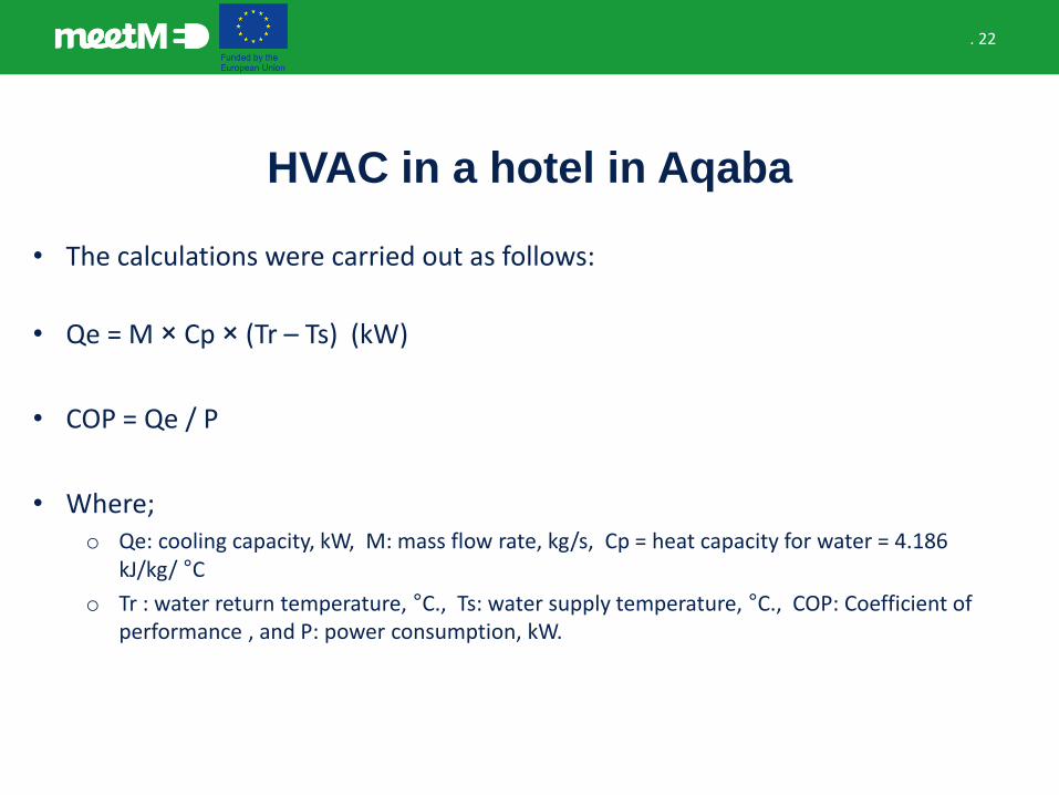
• The calculations were carried out as follows:
• Qe = M × Cp × (Tr – Ts) (kW)
• COP = Qe / P
• Where;o Qe: cooling capacity, kW, M: mass flow rate, kg/s, Cp = heat capacity for water = 4.186
kJ/kg/ °C
o Tr : water return temperature, °C., Ts: water supply temperature, °C., COP: Coefficient of performance , and P: power consumption, kW.
. 23
HVAC in a hotel in Aqaba

. 24
Brainstorming
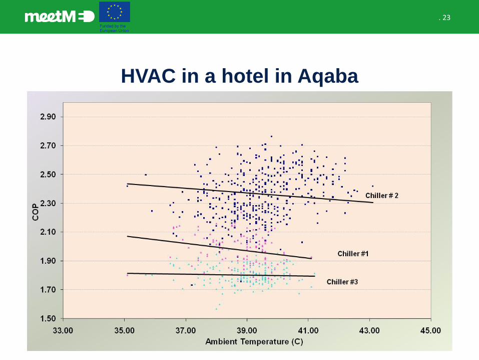
• What kind of information can you gather and what conclusion would youdraw from the previous graph?
. 25
HVAC in a hotel in Aqaba
• It was found that most of the times only two chillers are operated during the summer season. Therefore, it is recommended to run the highest efficiency chillers, namely; chiller #2 and/or chiller #1.
• Chiller #3 can be run only if one of these chillers is out of order.
• This energy efficiency measure has no initial cost and savings have been estimated in 130.000 kWh and 32.600 Euros per year.
. 26
HVAC in a pharmaceutical company
• Try to identify possible causes of system’s energy behavior illustrated in the following slides.
. 27
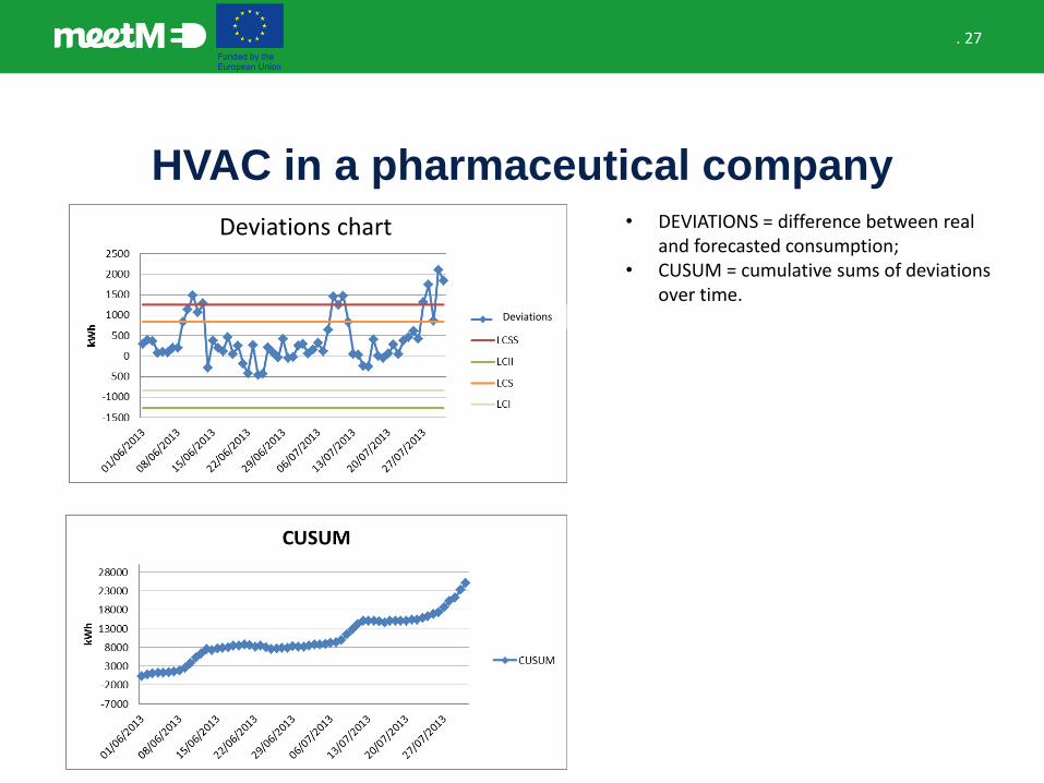
HVAC in a pharmaceutical company
Deviations chart
Deviations
• DEVIATIONS = difference between realand forecasted consumption;
• CUSUM = cumulative sums of deviationsover time.
. 28
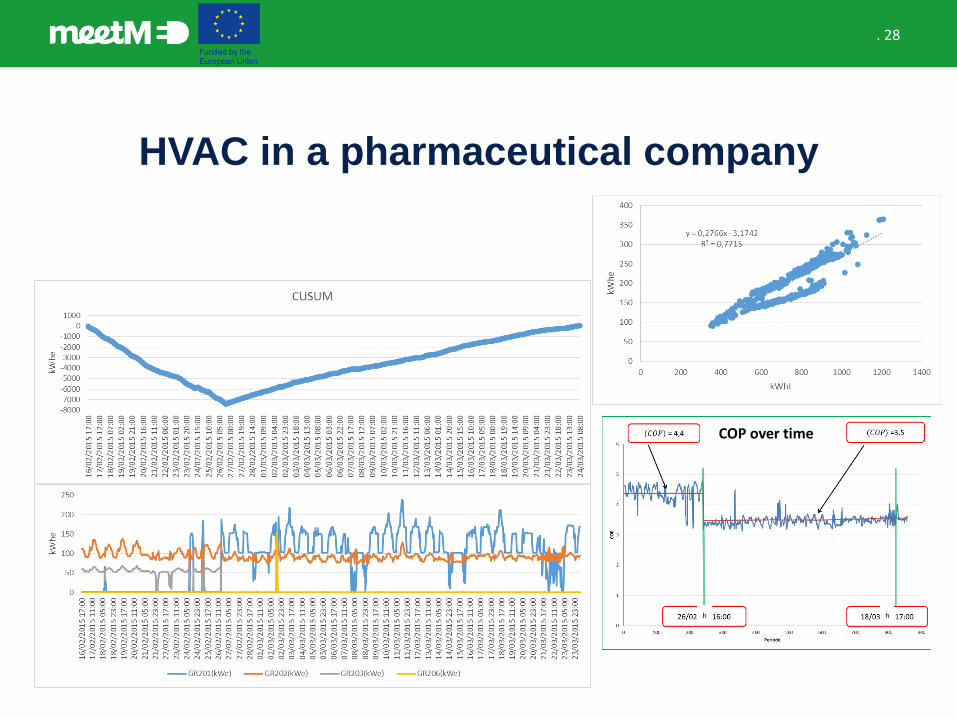
HVAC in a pharmaceutical company
COP over time
h h
. 29
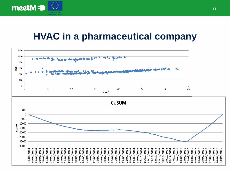
HVAC in a pharmaceutical company

Secondary HVAC equipment
. 31
Secondary HVAC equipment
• Air handling equipment (air handling units and fan coil units).
• Ducts and air outlets (diffusers, grilles, linear slot diffusers).
• Terminal units: are devices at the end of a duct that transfer heating or cooling.
• Controls: turn equipment on/off, adjust energy outputs (chillers, boilers), adjust flow rates (fans, pumps, coils), adjust temperatures (air, water, space).
. 32
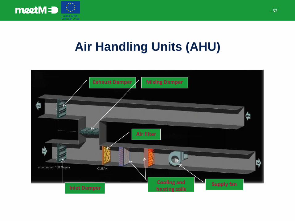
Air Handling Units (AHU)
Supply fanInlet Damper
Exhaust Damper Mixing Damper
Cooling and heating coils
Air filter

. 33
Air Handling Units (AHU) vs Fan Coil Units
(FCU)
• Large ductwork is needed.
• AHU consists of:o Filters.o Fans.o Coils
• Maximum air volume is 19.000 l/s.
• Configuration is complicated and needs large areas.
• Should be designed and manufacture for each single application.
AHU FCU
• Less pipework is needed.
• FCU consists of:o Filters.o Fans.o Coils
• Maximum air volume is 1.100 l/s (and can be quite noisy!).
• Configuration is simple and needs small areas.
• Easily available, always in stock.
. 34
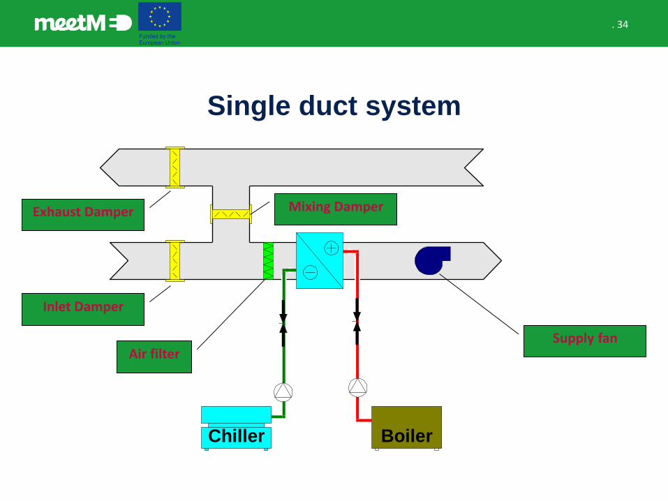
Single duct system
Chiller Boiler
Exhaust Damper
Inlet Damper
Mixing Damper
Air filterSupply fan
. 35
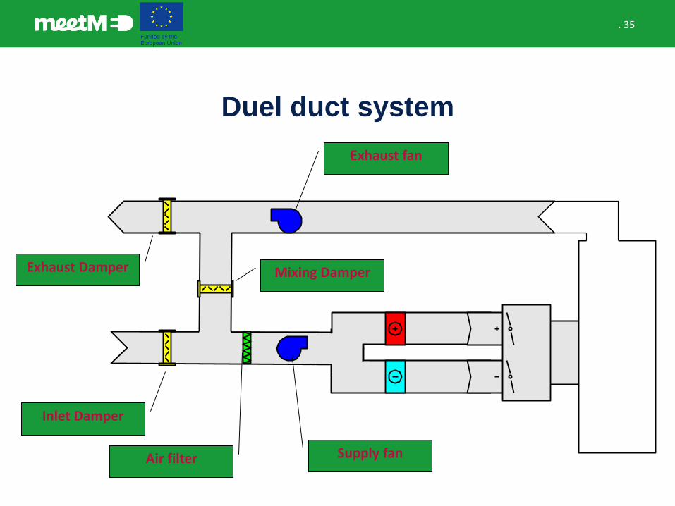
Duel duct system
Exhaust Damper
Inlet Damper
Mixing Damper
Air filter Supply fan
Exhaust fan
. 36
Humidity control
• Humidity: amount of water vapor in the air.
• Humidification – The air is too dry and water vapor must be added for comfort.
• Dehumidification – The air is too wet and water vapor must be removed for comfort.
• HVAC systems typically over-cool the air to remove water vapor, and then may have to heat the air back up – this called reheat, and requires additional energy.
. 37
Temperature control
• It is possible to vary the temperature of the supply air to the space while keeping the air flow rate constant. This is the constant volume, variable temperature approach.
• It is possible to vary the air flow rate while keeping the supply air temperature constant. This is the variable volume constant temperature approach.
• It is possible to vary the supply air temperature and the flow rate, as in variable volume reheat system.
. 38
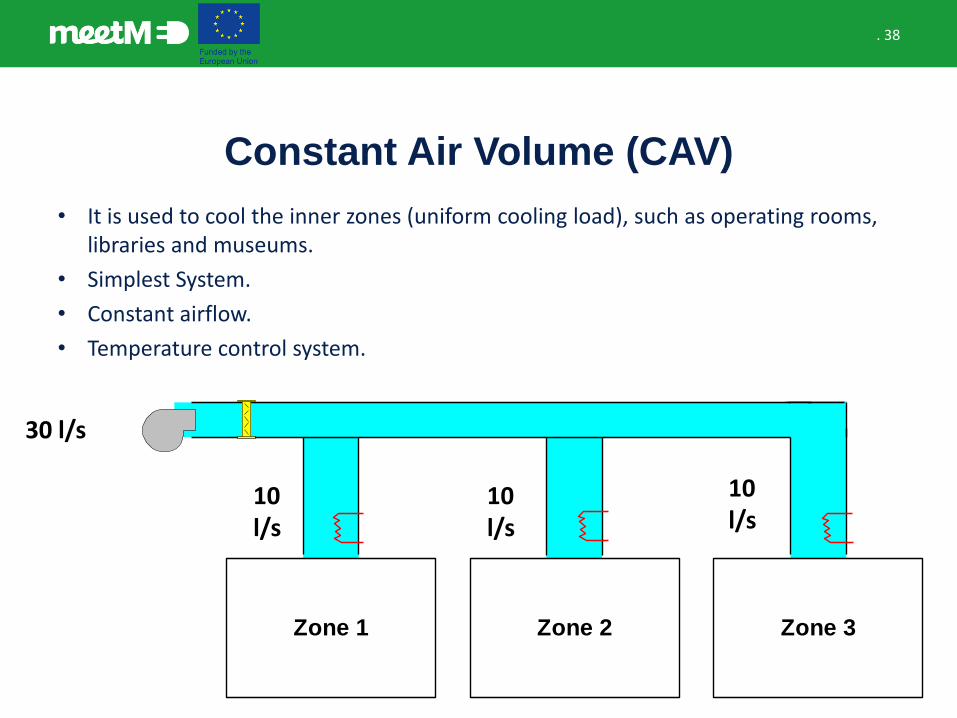
Constant Air Volume (CAV)
• It is used to cool the inner zones (uniform cooling load), such as operating rooms, libraries and museums.
• Simplest System.
• Constant airflow.
• Temperature control system.
30 l/s
Zone 1 Zone 2 Zone 3
10 l/s
10 l/s
10 l/s
. 39
Variable Air Volume (VAV)
• It is used to cool the perimeter areas which have variable cooling loads. For example, common areas in hotels and hospitals and theaters.
• Constant air :temperature (55oF/ 13o C).
• Modulate airflow to meet cooling loads.
• VAV types:
• By pass VAV box.
• Variable speed drive (VSD).
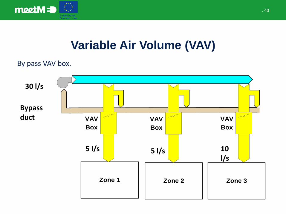
. 40
Variable Air Volume (VAV)
Zone 1 Zone 2 Zone 3
VAV
Box
VAV
Box
VAV
Box
Bypass duct
30 l/s
5 l/s 5 l/s 10 l/s
By pass VAV box.
. 41
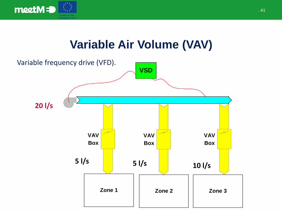
Variable Air Volume (VAV)
Variable frequency drive (VFD).
Zone 1 Zone 2 Zone 3
VAV
Box
VAV
Box
VAV
Box
VSD
20 l/s
5 l/s 5 l/s 10 l/s
. 42
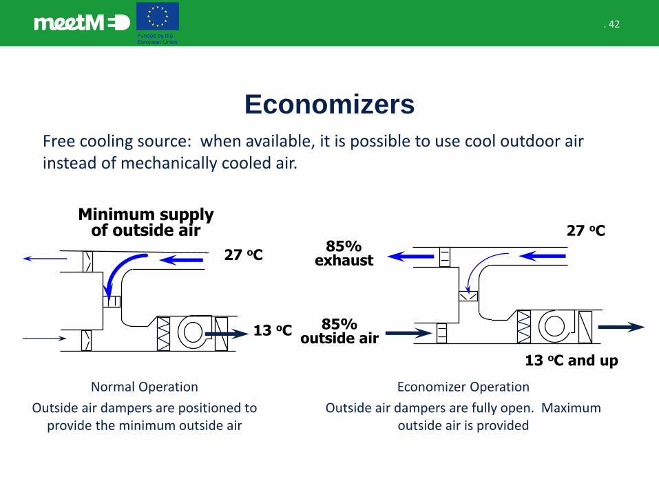
Economizers
Free cooling source: when available, it is possible to use cool outdoor air instead of mechanically cooled air.
Normal Operation
Outside air dampers are positioned to provide the minimum outside air
Economizer Operation
Outside air dampers are fully open. Maximum outside air is provided
13 oC
27 oC
Minimum supply of outside air 27 oC
13 oC and up
85%outside air
85%exhaust
Secondary HVAC equipment case study
. 44
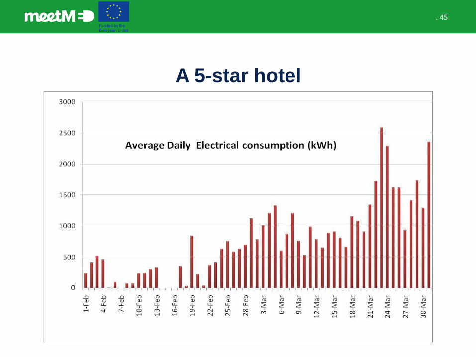
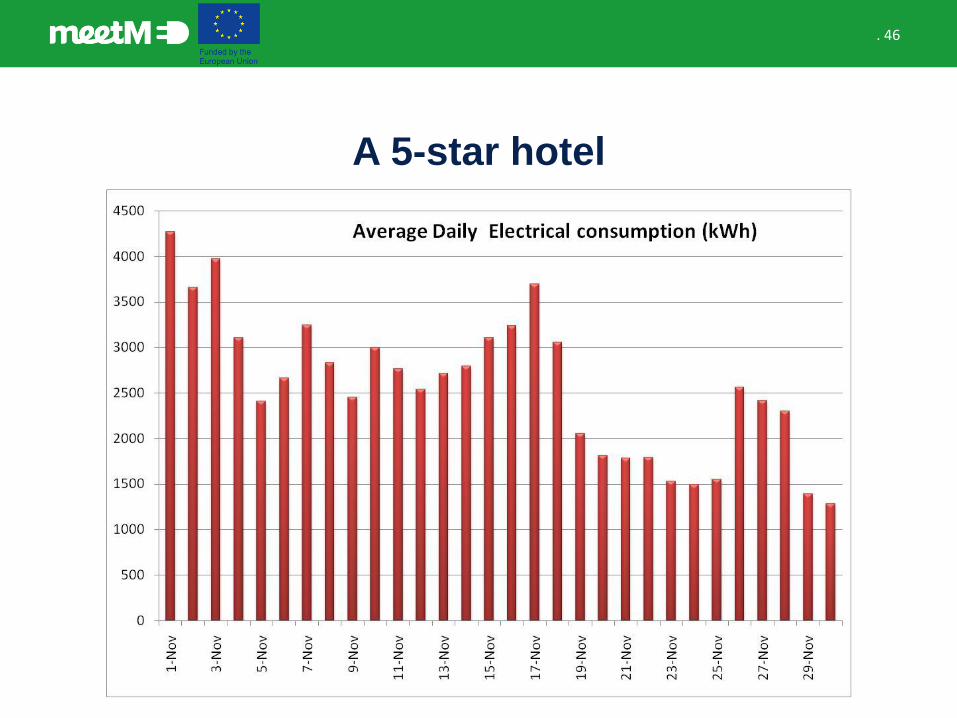
A 5-star hotel
• In a 5-star hotel it was demonstrated that some chillers were running during winter season (February, March and November).
• It is recommended during these period to introduce fresh outdoor air to cover the load.
. 45
A 5-star hotel
. 46
A 5-star hotel
. 47
A 5-star hotel
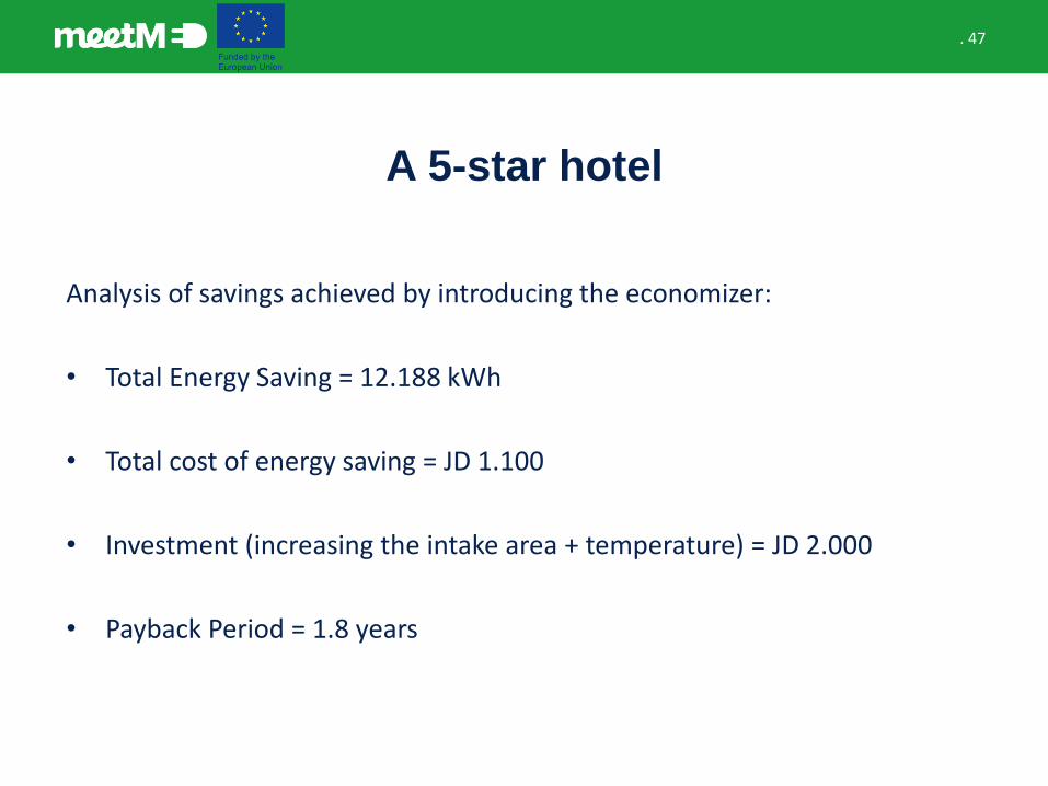
Analysis of savings achieved by introducing the economizer:
• Total Energy Saving = 12.188 kWh
• Total cost of energy saving = JD 1.100
• Investment (increasing the intake area + temperature) = JD 2.000
• Payback Period = 1.8 years

Main energy conservation measures
. 49
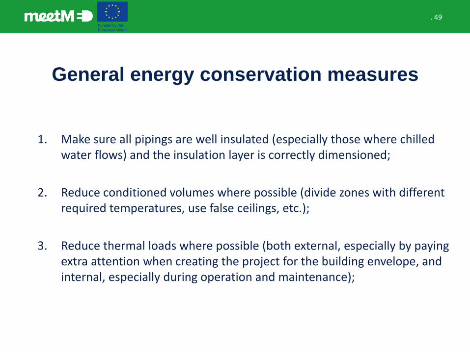
General energy conservation measures
1. Make sure all pipings are well insulated (especially those where chilled water flows) and the insulation layer is correctly dimensioned;
2. Reduce conditioned volumes where possible (divide zones with different required temperatures, use false ceilings, etc.);
3. Reduce thermal loads where possible (both external, especially by paying extra attention when creating the project for the building envelope, and internal, especially during operation and maintenance);
. 50
General energy conservation measures
4. Considering chillers:• Make sure all components are well maintained;
• Make sure to provide an adequate amount of chilled and cooling water;• Try to keep the load as uniform as possible;• Adequately set and keep under control the condenser and the
evaporator;• When possible use adsorption chillers (exploiting residual thermal
energy instead of electricity);
5. Keep coils clean;
. 51
General energy conservation measures
6. Use high efficiency motors;
7. Use VSDs with secondary chilled water pumps;
8. Use VAV and VSDs in common areas;
9. Night-flush with cool air;
10. Use outside air economizers where possible.

. 52
Contact us!
52
www.meetmed.orgmeetMED Project
@meetmed1