Instruction Book − Model LE389 - McCulloch
33
The owner must be certain that all the product information is included with the unit. This information includes the INSTRUCTION BOOKS, the REPLACEMENT PARTS and the WARRANTIES. This information must be included to make sure state laws and other laws are followed. PRODUCT INFORMATION Owner’s Manual 601 00 24 69 Reference No. F-031102C Instruction Book - Model LE389 Read and keep this book for future reference. This book contains important information on SAFETY, ASSEMBLY, OPERATION, AND MAINTENANCE. 16 1.2003
-
Upload
khangminh22 -
Category
Documents
-
view
3 -
download
0
Transcript of Instruction Book − Model LE389 - McCulloch

The owner must be certain that all the product information is included with the unit.This information includes the INSTRUCTION BOOKS, the REPLACEMENT PARTS and the WARRANTIES.This information must be included to make sure state laws and other laws are followed.
PRODUCT INFORMATION
Owner’s Manual 601 00 24 69Reference No. F-031102C
Instruction Book − Model LE389
Read and keep this book for future reference.This book contains important information onSAFETY, ASSEMBLY, OPERATION, AND MAINTENANCE.
16
1.2003

2F-031102C
WARRANTY STATEMENT
SECTION 1: LIMITED WARRANTYHusqvarna Forest & Garden Company (“Husqvarna”) warrants Husqvarna products to theoriginal purchaser to be free from defects in material and workmanship from the date of pur-chase for the “Warranty Period” of the product as set forth below:
Lifetime Warranty: All tiller tines, trimmer shafts, ignition coils and modules on hand heldproducts.
2 Year Warranty: Riding lawn mowers, yard and garden tractors, walk behind mowers, trim-mers, brushcutters, snow blowers, hand held blowers, hedge trimmers, and electrical prod-ucts for non-commercial, non-professional, non-institutional or non-income producing use,except as herin stated.
Emission control system components necessary to comply with CARB-95 and EPA regula-tions, except for those components which are part of engine systems manufactured by thirdparty engine manufacturers for which the purchaser has received a separate warranty withproduct information supplied at time of purchase.
1 Year Warranty: Chain saws, cultivators, clearing saws and backpack blowers for non-com-mercial, non-professional, non-institutional or non-income producing use. Trimmer models120, 125, 122, 132, 225, 232 and 235 used for commercial purposes.
90 Day Warranty: Any Husqvarna product used for rental, commercial, institutional, profes-sional or income producing use except as otherwise provided herin.
30 Day Warranty: Husqvarna bow guide and replacement parts.
SECTION 2: HUSQVARNA’S OBLIGATIONS UNDER THE WARRANTYHusqvarna will repair or replace defective components without charge for parts or labor if acomponent fails because of a defect in material or workmanship during the warranty period.
SECTION 3: ITEMS NOT COVERED BY THIS WARRANTYThe following items are not covered by this warranty:
1. Normal customer maintenance items which become worn through normal regular use, in-cluding, but not limited to, belts, blades, blade adapters, bulbs, filters, guide bars, lubri-cants, rewind springs, saw chain, spark plugs, starter ropes and tines.
2. Natural discoloration of material due to ultraviolet light.
3. Engine and drive systems not manufactured by Husqvarna; these items are covered bythe respective manufacturer’s warranty as provided in writing with the product informationsupplied at the time of purchase; all claims must be sent to the appropriate manufacturer.
4. Lawn and garden attachments are covered by a third party which gives a warranty, allclaims for warranty should be sent to the manufacturer.
5. Emission Control System components necessary to comply with CARB-95 and EPA regu-lations which are manufactured by third parts engine manufacturer.
SECTION 4: EXCEPTIONS AND LIMITATIONSThis warranty shall be inapplicable to defects resulting from the following:
1. Accident, abuse, misuse, negligence and neglect, including stale fuel, dirt, abrasives,moisture, rust, corrosion, or any adverse reaction due to incorrect storage or use habits.

3F-031102C
WARRANTY STATEMENT
2. Failure to operate or maintain the unit in accordance with the Owner/Operator’s manualor instruction sheet furnished by Husqvarna.
3. Alterations or modifications that change the intended use of the product or affects theproduct’s performance, operation, safety, or durability, or causes the product to fail to com-ply with any applicable laws.
4. Additional damage to parts or components due to continued use occurring after any of theabove.
REPAIR OR REPLACEMENT AS PROVIDED UNDER THIS WARRANTY IS THE EXCLU-SIVE REMEDY OF THE PURCHASER. HUSQVARNA SHALL NOT BE LIABLE FOR ANYINCIDENTAL OR CONSEQUENTIAL DAMAGES FOR BREACH OF ANY EXPRESS ORIMPLIED WARRANTY ON THESE PRODUCTS EXCEPT TO THE EXTENT PROHIBITEDBY APPLICABLE LAW. ANY IMPLIED WARRANTY OF MERCHANTABILITY OR FITNESSFOR A PARTICULAR HUSQVARNA RESERVES THE RIGHT TO CHANGE OR IMPROVETHE DESIGN OF THE PRODUCT WITHOUT NOTICE, AND DOES NOT ASSUME OB-LIGATION TO UPDATE PREVIOUSLY MANUFACTURED PRODUCTS.
Some states do not allow the exclusion of incidental or consequential damages, or limitationsor how long an implied warranty lasts, so the above limitations or exclusions may not applyto you. This warranty gives you specific legal rights, and you may also have other rights whichvary from state to state.
SECTION 5: CUSTOMER RESPONSIBILITIESThe product must exhibit reasonable care, maintenance, operation, storage and general up-keep as written in the maintenance section of the Owner’s/Operator’s manual. Should an op-erational problem or failure occur, the product should not be used, but delivered as is to anauthorized Husqvarna dealer for evaluation. Proof of purchase, as explained in section 6,rests solely with the customer.
SECTION 6: PROCEDURE TO OBTAIN WARRANTY CONSIDERATIONIt is the Owner’s and Dealer’s responsibility to make certain that the Warranty RegistrationCard is properly filled out and mailed to Husqvarna Forest & Garden Company. This cardshould be mailed within ten (10) days from the date of purchase in order to confirm the warran-ty and to facilitate post-sale service.
Proof of purchase must be presented to the authorized Husqvarna dealer in order to obtainwarranty service. This proof must include date purchased and model number.
To obtain the benefit of this warranty, the product believed to be defective must be deliveredto an authorized Husqvarna dealer in a timely manner, no later that thirty (30) days from dateof the operational problem or failure. The product must be delivered at the owner’s expense.Pick up and delivery charges are not covered by this warranty. An authorized Husqvarnadealer can be normally located through the “Yellow Pages” of the local telephone directoryor by calling 1-800-HUSKY62 for a dealer in your area.
HUSQVARNA FOREST & GARDEN COMPANY9006-J Perimeter Woods Drive
1Charlotte, NC 28216
SAFETY RULES
4F-031102C
This instruction book is written for a person with some mechanical ability. Like most service books,not all the steps are described. Steps on how to loosen or tighten fasteners are steps anyone canfollow with some mechanical ability. Read and follow these instructions before you use the unit.
Know your product: If you understand the unit and how the unit operates, you will get the bestperformance. As you read this manual, compare the illustrations to the unit. Learn the location andthe function of the controls. To help prevent an accident, follow the operating instructions and thesafety rules. Keep this manual for future reference.
IMPORTANT: Many units are not assembled and are sold in cartons. It is the responsibility of theowner to make sure the assembly instructions in this manual are exactly followed. Other units arepurchased in an assembled condition. On assembled units, it is the responsibility of the owner tomake sure the unit is correctly assembled. The owner must carefully check the unit according tothe instructions in this manual before it is first used.
RESPONSIBILITY OF THE OWNERThe responsibility of the owner is to follow the instructions below.
1. Carefully read and follow the rules for safe operation.
2. Follow all the assembly and preparation instructions.
3. Inspect the unit.
4. Make sure that the operator of the unit knows how to correctly use all standard and accessoryequipment.
5. Operate the unit only with guards, shields, and other safety items in place and working correctly.
6. Correctly adjust the unit.
7. Service the unit only with authorized or approved replacement parts.
8. Complete all maintenance on the unit.
Engine Exhaust, some of its constituents, andcertain vehicle components contain or emitchemicals known to the State of California tocause cancer and birth defects or other repro-ductive harm.Battery posts, terminals and related accesso-ries contain lead and lead compounds, chemi-cals known to the State of California to causecancer and birth defects or other reproductiveharm. WASH HANDS AFTER HANDLING.

SAFETY RULES
5F-031102C
Safe Operation Practices for Edger.
WARNING: Look for this symbol to point out important safety precautions.It means: “Attention! Become Alert! Your Safety Is Involved.”
WARNING: To prevent acciden-tal starting when setting-up,transporting, adjusting or mak-
ing repairs, always disconnect sparkplug wire and put wire where it cannotcontact the spark plug .
Before Use
� Read the owner’s manual carefully. Bethoroughly familiar with the controls andthe proper use of the Edger. Know how tostop the Edger and disengage the controlsquickly.
� Do not operate the Edger without wearingadequate outer garments. Wear footwearthat will improve footing on slippery sur-faces.
� Keep the area of operation clear of all per-sons, particularly small children and pets.
� Thoroughly inspect the area where theEdger is to be used and remove all foreignobjects.
Fuel Safety
� Handle fuel with care; it is highly flam-mable.
� Use an approved container.
� Check fuel supply before each use, allow-ing space for expansion as the heat of theengine and/or sun can cause fuel to ex-pand.
� Fill fuel tank outdoors with extreme care.Never fill fuel tank indoors. Replace fueltank cap securely and wipe up spilled fuel.
� Never remove the fuel tank cap or add fuelto a running or hot engine.
� Never store fuel or Edger with fuel in thetank inside a building where fumes mayreach an open flame.
Operating Safety
� Never allow children or young teenagers tooperate the Edger. Keep them away whileit is operating. Never allow adults to oper-ate the Edger without proper instruction.
� Do not operate this machine if you are tak-ing drugs or other medication which cancause drowsiness or affect your ability tooperate this machine.
� Do not use this machine if you are mentallyor physically unable to operate this ma-chine safely.
� Always wear safety glasses or eye shieldsduring operation or while performing anadjustment or repair to protect your eyesfrom foreign objects that may be thrownfrom the Edger.
� Do not put hands or feet near or under ro-tating parts.
� Exercise extreme caution when operatingon or crossing gravel drives, walks, orroads. Stay alert for hidden hazards ortraffic.
� Exercise caution to avoid slipping or falling.
� Never operate the Edger without properguards, plates, or other safety protectivedevices in place.
� Never operate the Edger at high transportspeeds on slippery surfaces. Look behindand use care when backing.
� Never allow bystanders near the Edger.
� Keep children and pets away whileoperating.
� Never operate the Edger without good visi-bility or light.
� Do not run the engine indoors. The ex-haust fumes are dangerous, containingCARBON MONOXIDE, an ODORLESSand DEADLY GAS.
� Take all possible precautions when leavingthe Edger unattended. Stop the engine.
� Do not overload the Edger capacity by at-tempting to till too deep at too fast a rate.

SAFETY RULES
6F-031102C
Safe Storage
� Always refer to the owner’s manual instruc-tions for important details if the Edger is tobe stored for an extended period.
� Never store the Edger with fuel in the fueltank inside a building where ignitionsources are present such as water andspace heaters, clothes dryers, and the like.Allow the engine to cool before storing inany enclosure.
� Keep the Edger in safe working condition.Check all fasteners at frequent intervals forproper tightness.
Repair / Adjustments Safety
� After striking a foreign object, stop the en-gine. Remove the wire from the spark plug,and keep the wire away from the plug toprevent accidental starting. Thoroughly in-
spect the Edger for any damage, and re-pair the damage before restarting andoperating it.
� If Edger should start to vibrate abnormally,stop engine and check immediately for thecause. Vibration is generally a warning oftrouble.
� Stop the engine whenever you leave theoperating position. Also, disconnect thespark plug wire before unclogging theblade and when making any repairs, ad-justments, or inspections.
� When cleaning, repairing, or inspecting,shut off the engine and make certain allmoving parts have stopped.
� Never attempt to make any adjustmentswhile the engine is running except whenspecifically recommended by the manufac-turer.

SAFETY RULES
7F-031102C
INTERNATIONAL SYMBOLSIMPORTANT: Many of the following symbols are located on your unit or on literature sup-plied with the product. Before you operate the unit, learn and understand the purpose foreach symbol.
Control And Operating Symbols
Slow Fast
WARNINGThrown Objects.
Keep Bystanders Away.
WARNINGRotating Parts. Stop Engine.
Disconnect Spark Wire BeforeMaking Adjustments.
IMPORTANTRead Owner’s Manual
Before Operating This Machine.
WARNING
STOPWARNINGWear Eye Protection
Safety Warning Symbols
Fuel Oil

ASSEMBLY
8F-031102C
ASSEMBLYRead and follow the assembly and adjust-ment instructions. All fasteners are in theparts bag. Do not discard any parts or mate-rial until the unit is assembled.
WARNING: Before doing anyassembly or maintenance to theunit, remove the wire from the
spark plug.
NOTE: Torque is measured in footpounds (metric N.m). This measurementdescribes how tight a nut or bolt must be.The torque is measured with a torquewrench.2 - Adjustable Wrenches1 - Utility Knife1 - Blade Type Screwdriver1 - Pliers
PARTS BAG - CONTENTSThe fasteners are shown at full size. The quantities are shown in brackets ( ).NOTE: Some models will not use every fastener shown on this page.
Locknut(1)
3/8-16
Shoulder Bolt (1)3/8-16 x 1.40
Cotter Pin (1)Locknut (8)
5/16-18
Bolt (1)5/16-18 x 4-1/2
Spacer (1)
Bolt (4)5/16-18 x 5/8
Spacer (2)
Handle Bolt (4)
Washer (4)11/32 x 11/16
Hair Pin (2)
Washer (1)1/2 x 3/4
Wide Flange Hex Nut (1)5/16-18

ASSEMBLY
9F-031102C
Parts Packed Separately In Carton1 - Owner’s Manual (not shown)1 - Upper Handle1 - Lower Handle1 - Handle Panel1 - Control Rod4 - Wheels
WARNING: Always wear safetyglasses or eye shields while as-sembling the Edger.
Figure 1 shows the Edger completely as-sembled.References to the right or left side of theEdger are from the viewpoint of the opera-tor’s position behind the unit.
REMOVE THE EDGER FROM THECARTON1. Remove the lower handle, upper handle,
control rod and packing material from thecarton.
2. Remove the wheels and parts bag fromthe carton.
3. Cut down all four corners of the carton.
4. Remove the packing material positionedaround the unit.
5. Lift the Edger out of the carton and placeon a hard level surface.
Figure 1

ASSEMBLY
10F-031102C
HOW TO ASSEMBLE THE HANDLE
For ease of assembly, attach the lower han-dle before mounting the wheels.1. Mount the lower handle to the inside of
the edger frame (see Figure 2). Fastenthe lower handle with the fastenersshown in the illustration. As you tightenthe fasteners, pull back on the lowerhandle.
2. Attach the right rear wheel to the wheelsupport rod with the fasteners shownin Figure 3.
3. Attach the left rear wheel to the edgerframe with the fasteners shown inFigure 4.
4. Attach the front wheels to the frontwheel arm with the fasteners shown inFigure 5.
Figure 2
Locknut5/16-18
Lower Handle
Bolt5/16-18 x 5/8
Edger Frame
Figure 3
Cotter Pin
Washer1/2x3/4
Wheel SupportRod
Right Rear Wheel
Locknut3/8-16
Spacer
Bolt3/8-16 x 1.40
Left Rear Wheel
Figure 4
Figure 5
Bolt5/16-18 x 4-1/2
Washer11/32 x 11/16
Spacer51887
Washer 11/32 x 11/16
Washer11/32 x 11/16
Wide FlangeHex Nut5/16-18
Front Wheel

ASSEMBLY
11F-031102C
5. Assemble the upper handle and thehandle panel to the lower handle withthe fasteners shown in Figure 7. Makesure the locknuts are on the inside ofthe lower handle.
6. Slide one end of the clutch rod from leftto right through the hole in the clutchlever. Secure with the hair pin shown inFigure 7.
7. Move the clutch lever to the first depthposition. Attach the other end of the con-trol rod to the quill support arm withthe hair pin as shown in Figure 7.
8. Move the clutch lever back to the “N”NEUTRAL position.
NOTE: If it is difficult to move the clutchlever to the “N” NEUTRAL position, loos-en the fasteners that hold the lower han-dle to the edger frame (see Figure 2).Raise the handle until the clutch lever willeasily move to the “N” NEUTRAL posi-tion. Tighten the fasteners.
9. When the clutch lever is in NEUTRALposition, the quill support arm must beclose to the screw as shown in Figure 6.
Figure 6
Quill Support Arm
Screw
Figure 7
Locknut5/16-18
ControlRod
Handle Bolt
HandlePanel
UpperHandle
LowerHandle
Hair Pin
Hair Pin
Clutch Lever
Quill SupportArm

ASSEMBLY
12F-031102C
HOW TO PREPARE THE ENGINE
ENGINE DOES NOT CONTAINOIL OR GASOLINE
See the engine manufacturer’s instructionsfor the type of gasoline and oil to use. Beforeyou use the unit, read the information onsafety, operation, maintenance, and storage.
To fill the crankcase, remove the oil fill cap/dipstick and add SAE30 motor oil. DO NOTOVERFILL.NOTE: The engine may contain a smallamount of oil. When adding oil, frequentlyinsert the oil fill cap/dipstick and checkthe amount of oil in the engine. DO NOTOVERFILL.
Oil Fill Cap/Dipstick
Figure 8
Fuel Tank
WARNING: Follow the enginemanufacturer’s instructions forthe type of gasoline and oil to
use. Always use a safety gasoline con-tainer. Do not smoke when adding gaso-line to the engine. When inside an en-closure, do not fill with gasoline. Beforeyou add gasoline, stop the engine. Letthe engine cool for several minutes.
IMPORTANT: This unit is equipped with aninternal combustion engine and must notbe used on or near any unimproved forest-covered, brush-covered or grass-coveredland unless the engine’s exhaust system isequipped with a spark arrester meeting ap-plicable local or state laws (if any). If aspark arrester is used, it must be main-tained in effective working order by the op-erator.
In the State of California the above is re-quired by law (Section 4442 of the Califor-nia Public Resources Code). Other statesmay have similar laws. Federal laws applyon federal lands. See an Authorized Ser-vice Center for a spark arrester for the muf-fler.
� CHECKLIST
For the best performance and satisfactionfrom this quality product, please review thefollowing checklist before you operate theEdger:
� All assembly instructions have beencompleted.
� Check carton. Make sure no looseparts remain in the carton.
� All fasteners have been properly tight-ened.
As you learn how to use the Edger, pay extraattention to the following important items:
�� Engine oil is at proper level.
�� Fuel tank is filled with a fresh, clean,regular Unleaded gasoline.
�� Become familiar and understand thefunction of all controls. Before yourstart the engine, operate all controls.

OPERATION
13F-031102C
KNOW YOUR EDGERREAD THE OWNER’S MANUAL AND ALL SAFETY RULES BEFORE YOU OPERATE theEdger. To familiarize yourself with the location of the controls, compare the illustrations withyour Edger. Save this manual for future reference.
Figure 9
Clutch Lever
Control Rod
OIl Fill Cap/Dipstick
Blade Guard
Adjustable Front WheelAdjustable Rear Wheel
ThrottleControl
StarterHandle
ENGINE
VIEW OF BLADE AREA
Primer Button
Blade
Index Lever
Throttle Control - Controls the enginespeed.
Primer Button - Injects fuel directly intothe carburetor for faster starts.
Clutch Lever - Use to start and stop theblade and control the depth of cut.
Adjustable Rear Wheel - Right rearwheel is adjustable to level the Edger whenedging along a curb (curb-hopping).
Adjustable Front Wheel - Front wheelis adjustable from side-to-side for balance.
The front wheel can also be adjusted downfor curb-hopping .
Recoil Starter Handle - The engine isequipped with an easy pull recoil starter.
Blade Guard - Use to prevent stones orother material from being thrown at the oper-ator.
Index Lever - Permits adjustment fromthe edging (vertical) position to the trimming(horizontal) position. To change position, pullthe index lever and rotate the quill assemblyto the desired angle or position.
EYE PROTECTIONAlways wear safety glasses. If you wear eyeglasses, put a Wide Vision Safety Mask overyour eye glasses.
WARNING: Debris thrown fromthe Edger can result in foreignobjects being thrown into the
eyes, which can cause severe eye dam-age. Always wear safety glasses or eyeshields when operating the Edger.

OPERATION
14F-031102C
HOW TO STOP THE EDGER1. Move the clutch lever back to the DIS-
ENGAGED position. Then, move thethrottle control to the STOP position.See Figure 10.
WARNING: Never leave theEDGER unattended while theengine is running. Always dis-
engage the cutting blade and stop theengine.
HOW TO USE THE THROTTLE CONTROL1. During normal use, run the engine at full
speed.
2. Move the throttle control up to increaseengine speed, or down to decrease en-gine speed (see Figure 10).
Figure 10
ClutchLever
ThrottleControl
HOW TO USE THE PRIMER BUTTONWhen starting a cold engine, push the prim-er button five times (see Figure 11). Waitapproximately two seconds between eachpush.
IMPORTANT: When starting a warm engine,do not use the primer button.
Primer ButtonFigure 11
HOW TO USE THE CLUTCH LEVER1. Start the engine.
2. To engage the cutting blade, move theclutch lever forward (see Figure 12).
3. Select the edging depth you need. Thereare five selections down to approximate-ly 2-3/4 inches deep.
NOTE: For deep edging, first cut at shallowdepths. Then, cut at greater depths untilthe desired depth is obtained.
Clutch Lever
Figure 12
OPERATION
15F-031102C
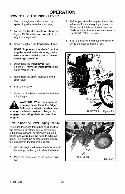
HOW TO USE THE INDEX LEVER
1. Stop the engine and disconnect thespark plug wire from the spark plug.
2. Loosen the front wheel knob shown inFigure 13. Slide the front wheel all theway to the right side.
3. Securely tighten the front wheel knob.
NOTE: To prevent the blade from hit-ting the wheel while trimming, makesure the front wheel is set in the ex-treme right position.
4. Disengage the index lever (seeFigure 14). Move the index lever to thenotch marked 90�.
5. Reconnect the spark plug wire to thespark plug.
6. Start the engine.
7. Move the clutch lever to the desired trim-ming height.
WARNING: While the engine isrunning, never leave the Edger.Before you adjust the wheels or
change the blade position, always dis-engage the cutting blade and stop theengine.
How To Use The Bevel Edging FeatureThe index lever has four other positions thatwill provide a beveled edge. A bevel edgecut along a sidewalk or driveway makes atrench and will reduce the need to edge asoften. The larger the degree of cut set withthe index lever, the larger the trench.
1. With the engine off, move the front wheelfar enough to the right to clear the blade.
2. Move the index lever to the desired posi-tion.
3. Before you start the engine, line up theedger as if you were going to bevel cut.Move the clutch lever down to test theblade location. Return the clutch lever tothe ”N’ NEUTRAL position.
4. Start the engine and move the clutch le-ver to the desired depth of cut.
Figure 13
Front WheelKnob
Front Wheel
Figure 14Index Lever

OPERATION
16F-031102C
HOW TO USE THE CURB-HOPPING FEATUREBecause the front wheel and the right rearwheel are adjustable, the Edger can be usedon uneven surfaces, such as the curb shownin Figure 15. Set the wheel positions as fol-lows.
1. Stop the engine.
2. Disconnect the spark plug wire from thespark plug.
3. Loosen the front wheel knob.
4. Slide the front wheel to the best posi-tion to clear the curb and balance theunit.
5. Securely tighten the front wheel knob.
6. Use the curb height adjust lever tolower the front wheel. Lower the front
wheel until the front wheel is level withthe left rear wheel and the unit is settingon the curb as shown in Figure 15.
7. Loosen the rear wheel knob.
8. Lower the right rear wheel until theEdger is level and the left rear wheel ison the curb.
9. Securely tighten the rear wheel knob.
10. Connect the spark plug wire to the sparkplug.
WARNING: Keep away from therotating blade. The blade cancause injury.
Figure 15
Blade Guard
Front Wheel
Front Wheel Knob
Curb HeightAdjust Lever
Support Rod
Rear Wheel Knob
Right Rear Wheel

OPERATION
17F-031102C
HOW TO STOP THE ENGINE
To stop the engine, move the clutch lever allthe way back to the DISENGAGED position.Then, push the throttle control lever down tothe STOP position.
If the engine will not stop, hold a screwdriveragainst the spark plug and against the enginecooling fins. The spark will go to ground andthe engine will stop.
HOW TO START THE ENGINEIMPORTANT: Before you start the engine,operate the controls several times. Makesure all controls move freely.
1. Check the oil.
2. Fill the fuel tank with regular unleadedgasoline. Make sure the gasoline isclean. Leaded gasoline will increase de-posits and shorten the life of the valves.
NOTE: Do not use gasohol or methanol. Donot use premium unleaded gasoline.
WARNING: Always use a safetygasoline container. Do notsmoke when adding gasoline to
the fuel tank. When inside an enclosure,do not add gasoline. Before you addgasoline, stop the engine and let the en-gine cool for several minutes.
3. Make sure the spark plug wire is con-nected to the spark plug.
4. Pull the clutch lever all the way back toraise and disengage the blade.
5. Move the throttle control lever to theFAST position.
6. Some models have a primer button onthe front or side of the engine (Figure 16).Every time you push the primer button,wait two seconds. For the number oftimes required to push the primer but-ton, see the engine manufacturer’s in-structions.
Primer Button
Figure 16
NOTE: Do not use the primer button to starta warm engine.
7. To start engine, hold the recoil starterhandle firmly with your right hand.
8. Hold the edger handle firmly with your lefthand.
9. Quickly pull the recoil starter handle. DONOT allow the starter rope to snap back.Let the starter rope slowly rewind. If en-gine fails to start after three pulls, pushprimer button two times and again pullthe recoil starter handle.
10.When the engine starts, move the throttlecontrol lever up (FAST position) to in-crease speed or down to decreasespeed. During normal use keep thethrottle in the FAST position.
11. If the engine does not start in 5 or 6 tries,See the “Trouble Shooting Instructions”.
NOTE: The cutting blade speed is con-trolled by the engine speed. To reduce thecutting blade speed, push down on thethrottle control lever. To increase the cut-ting blade speed, pull up on the throttlecontrol lever.
WARNING: Never run the engineindoors or in a poorly ventilatedarea. Engine exhaust contains
carbon monoxide, an odorless anddeadly gas. Keep hands, feet, hair andloose clothing away from any movingparts. Avoid the muffler and surround-ing areas. Temperatures can exceed 150degrees.

OPERATION
18F-031102C
EDGING TIPS
� Edging is best performed when conditionsare dry. If the soil is to wet, dirt becomespacked around the blade causing prema-ture belt wear and decreased perfor-mance.
� If dirt does become packed around theblade, stop the engine and remove thewire from the spark plug. Remove thepacked dirt and debris from the blade.
� For deep edging, first cut at shallowdepths. Then, cut at greater depths untilthe desired depth is obtained.
� For uniform edging, make sure the bladeguide rides on the surface.
� Edging can be customized by varying thenumber of passes and by the distance theblade is from the surface.
WARNING: Read the Owner’smanual. Know location andfunctions of all controls. Keep
all safety devices and shields in place.Never allow children or uninstructedadults to operate Edger. Shut off enginebefore unclogging blade or making re-pairs. Keep bystanders away from ma-chine. Keep away from the blade all ro-tating parts, which cause injury.

MAINTENANCE
19F-031102C
CUSTOMER RESPONSIBILITIES
SERVICERECORDS
Fill in dates as youcomplete regular
service.
AfterFirst
2Hours
BeforeEachUse Often
Every10
Hours
Every25
Hours
BeforeEach
SeasonBefore
StorageSERVICEDATES
Lubricate All PivotPoints √ √
Lubricate WheelAxles √ √
Check Engine OilLevel √
Check Spark Plug √ √
Check Drive Belt √
Tighten All Fasteners √ √
Check Blade ForWear Or Damage √
Lubricate Quill Rod/tube √ √ √
GENERAL RECOMMENDATIONS
The warranty on this Edger does not coveritems that have been subjected to operatorabuse or negligence. To receive full valuefrom the warranty, the operator must main-tain the Edger as instructed in this manual.
Some adjustments must be made periodical-ly to properly maintain your Edger.
All adjustments in the Service and Adjust-ments section of this manual must bechecked at least once each season.
ENGINE MAINTENANCEUse the following maintenance section tokeep your unit in good operating condition.All the maintenance information for the en-gine is in the “Engine Instruction Book”. Be-fore you start the engine, read this book.
LUBRICATION1. After each 25 hours, apply a small amount
of engine oil to all moving parts, particular-ly the wheels.
2. To lubricate the engine, refer to the “En-gine Instruction Book”.

SERVICE AND ADJUSTMENT
20F-031102C
HOW TO REMOVE THE BELTThe belt made of a special compound. If thebelt becomes worn or breaks, replace thebelt with an original equipment belt.
1. Disconnect the spark plug wire from thespark plug.
2. Pull the clutch lever back to release thetension from the belt.
3. Remove the two screws and spacersfrom the top of the engine pulley cover.Remove the engine pulley cover (seeFigure 17).
4. Loosen, do not remove, the screw thatholds the belt guide. Then, move thebelt guide away from the belt.
5. Remove the screws from the belt guard(see Figure 18).
6. Remove the old belt from the engineand quill assembly pulleys. Replace withan original equipment belt.
7. To install a new belt, reverse the abovesteps.
Figure 17
Spacer
EnginePulley
BeltGuide
Screw
EnginePulleyCover
Spacer
Screws
Figure 18
Screw
Screw
Belt Guard

SERVICE AND ADJUSTMENT
21F-031102C
HOW TO REPLACE THE BLADEThe blade is subject to wear and damage,such as nicks and dents. This will not gener-ally affect its function.
The blade is designed to not require sharp-ening. Do not attempt to sharpen the blade.The blade is also reversible. If nicks ordents are excessive, remove the blade andturn it around. This will provide a fresh cut-ting edge. Replace the blade if both sidesare worn or damaged.
WARNING: Do not sharpen theblade. Sharpening can damagethe blade and cause it to break,
which can cause injury to yourself or toothers.
To replace the blade, follow the steps below.
1. Disconnect the spark plug wire from thespark plug.
2. Remove the blade locknut that holdsthe blade to the drive shaft.
WARNING: To remove or tigh-ten the blade locknut, alwaysuse the method shown in
Figure 19. Always position the holdingwrench on the nut behind the blade.
3. Remove the blade.
4. Install a new blade and blade locknut.Tighten the blade locknut to a torque of40-45 foot pounds.
Figure 19
Blade Locknut
Turn WrenchTo Tighten Locknut
Hold Nut, Do Not Turn

SERVICE AND ADJUSTMENT
22F-031102C
STORAGE
WARNING: Never store theEdger indoors with fuel in thefuel tank. Never store in an en-
closed, poorly ventilated area wherefumes could reach an open flame, aspark or a pilot light as on a furnace, wa-ter heater or clothes dryer.
WARNING: Do not remove gas-oline while inside a building,near a fire, or while you smoke.
Gasoline fumes can cause an explosionor a fire.
When the Edger is put in storage for thirtydays or more, follow the steps below tomake sure the Edger is in good condition thefollowing season.
1. Drain the fuel tank.
2. Let the engine run until it is out of gaso-line.
3. Drain the oil from the warm engine. Fillthe engine crankcase with new oil.
4. Remove the spark plug from the cylin-der. Pour one ounce of oil into the cylin-
der. Slowly pull the recoil-start grip sothat the oil will protect the cylinder. Installa new spark plug in the cylinder.
5. Clean the dirt and debris from the cylin-der cooling fins and the engine housing.
6. Completely clean the Edger.
7. Check the Edger for worn or damagedparts. Tighten all loose hardware.
8. Apply a small amount of engine oil to allmoving parts, particularly the wheels.
9. Put the unit in a building that has goodventilation.
10. Cover the Edger with a suitable protec-tive cover that does not retain moisture.Do not use plastic.
IMPORTANT: Never cover the Edger whilethe engine and exhaust areas are stillwarm.
NOTE: A yearly checkup or tune-up byan Authorized Service Center is a goodway to make sure that your Edger willprovide maximum performance for thenext season.

TROUBLESHOOTING CHART
23F-031102C
TROUBLE CAUSE CORRECTION
Engine difficult to start Stale fuel Drain fuel tank. Fill with freshfuel.
or Clogged fuel filter Replace fuel filter
Engine runs erraticallyDirt in fuel tank or out of fuel Clean fuel tank.
Engine runs erratically
or
Carburetor out of adjustment See Carburetor Adjustmentsection.
or
Engine will not run at full
Fouled spark plug Clean and set spark pluggap.
Engine will not run at fullspeed Dirty air filter Replace air filter.
Engine smokesexcessively
Plugged air filter Replace air filter.
Debris interfering with blade Clean debris from blade.
Cutting blade will notrotate
Loose blade Tighten blade nut.rotate
Defective V-belt Replace V-belt.
Blade will not cut properlyDefective quill bearings Replace the quill assembly.
Blade will not cut properlyDamage or worn blade Reverse the blade or replace
the blade.
Excessive vibration Loose parts Stop engine immediately.Tighten all fasteners. Ifvibration continues, take theunit to an Authorized ServiceCenter.

MODEL LE389 FACTORY NO. 13051x37NA
24F-031102C
4344
40
45
41
222642
2024
2930
32
20
80
81
12
10
323095F
KEYNO. PART NO. DESCRIPTION
KEYNO. PART NO. DESCRIPTION
10 − − − − − Engine
12 601 00 08 35 Screw, 3/8−16x1.00
20 601 00 22 03 Pulley, Half
22 601 00 13 27 Screw, 5/16−24x1.00
24 601 00 00 23 Washer
26 601 00 05 47 Flatwasher
29 601 00 05 09 Belt, V4L 32.60LG
30 601 00 14 33 Screw and Washer Assy
32 601 00 05 80 Guide, Belt
40 601 00 22 04 Cover, Engine Pulley
41 601 00 00 80 Screw, 5/16−24x3.00
42 601 00 22 05 Spacer, Sleeve
43 601 00 22 06 Screw, 5/16−24x3.75
44 601 00 22 07 Spacer
45 601 00 22 05 Spacer, Sleeve
80 601 00 22 08 Frame, Assy. Edger
81 601 00 22 09 Strap
−− 601 00 24 69 Instruction Manual

MODEL LE389 FACTORY NO. 13051x37NA
25F-031102C
332244B
REF. LOWER HANDLE
REF. FRAME
667
654
651654
655
655
654
653654
650
670
680
669
668
KEYNO. PART NO. DESCRIPTION
KEYNO. PART NO. DESCRIPTION
650 601 00 22 49 Tire & Rim
651 601 00 08 67 Nut, 5/16−18
653 601 00 00 86 Screw, 5/16−18x4.50
654 601 00 00 19 Flatwasher
655 601 00 05 87 Spacer, Sleeve
667 601 00 22 50 Bolt, SHH 3/8−16
668 601 00 22 51 Spacer & Washer
669 601 00 05 42 Nut, 3/8−16
670 601 00 01 09 Flatwasher
680 601 00 00 25 Cotter Pin
MODEL LE389 FACTORY NO. 13051x37NA
26F-031102C
REF. FRAME ASSEMBLY
151
150
163
152
164
155
157
156
158
159
154
161
160
153
331765E
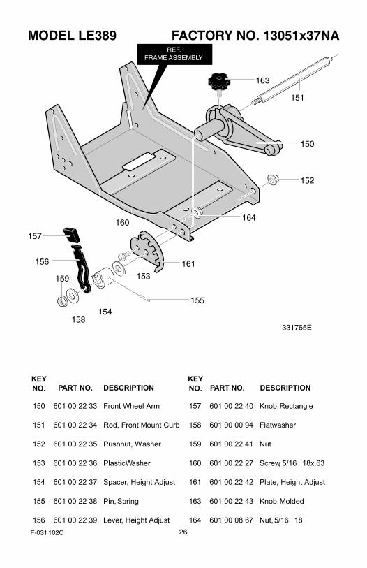
KEYNO. PART NO. DESCRIPTION
KEYNO. PART NO. DESCRIPTION
150 601 00 22 33 Front Wheel Arm
151 601 00 22 34 Rod, Front Mount Curb
152 601 00 22 35 Pushnut, Washer
153 601 00 22 36 Plastic Washer
154 601 00 22 37 Spacer, Height Adjust
155 601 00 22 38 Pin, Spring
156 601 00 22 39 Lever, Height Adjust
157 601 00 22 40 Knob, Rectangle
158 601 00 00 94 Flatwasher
159 601 00 22 41 Nut
160 601 00 22 27 Screw, 5/16�18x.63
161 601 00 22 42 Plate, Height Adjust
163 601 00 22 43 Knob, Molded
164 601 00 08 67 Nut, 5/16�18

MODEL LE389 FACTORY NO. 13051x37NA
27F-031102C
REF. FRAME
184182
171
183171
170
172
181
180
186
172
323179E
KEYNO. PART NO. DESCRIPTION
KEYNO. PART NO. DESCRIPTION
170 601 00 06 47 Bracket, Curb Hop Mnt
171 601 00 00 73 Screw, 5/16−18x.75
172 601 00 00 59 Nut, 5/16−18
180 601 00 19 70 Bolt, 5/16−18x2.00
181 601 00 06 55 Clevis
182 601 00 19 71 Spacer, Sleeve
183 601 00 00 19 Flatwasher
184 601 00 06 84 Knob, Wing 5/16−18
186 601 00 19 72 Rod, Wheel Support

MODEL LE389 FACTORY NO. 13051x37NA
28F-031102C
323129E
310
311
302
321
331
329
330322
323
320
301
325
312
305
300
REF. FRAME ASSY.
REF. SUPPORT BRKT.
KEYNO. PART NO. DESCRIPTION
KEYNO. PART NO. DESCRIPTION
300 601 00 00 21 Flatwasher
301 601 00 21 96 Quill Support
302 601 00 22 16 Bolt, 3/8−16
305 601 00 24 07 Nut, 3/8−16
310 601 00 22 17 Rubber Deflector
311 601 00 22 18 Screw, 10−16x1.50
312 601 00 22 13 Flatwasher
320 601 00 23 14 Spring, Compression
321 601 00 21 97 Quill Assembly
322 601 00 22 44 Lever, Index
323 601 00 22 45 Spring, Torsion
325 601 00 22 59 Nut, 5/16−18
329 601 00 00 94 Flatwasher
330 601 00 22 46 Blade, Edger
331 601 00 05 52 Nut, 1/2−20

MODEL LE389 FACTORY NO. 13051x37NA
29F-031102C
12
4
5
6
8
9REF.
QUILL ASSY.
332247D
KEYNO. PART NO. DESCRIPTION
1 601 00 22 10 Blade Guard
2 601 00 07 86 Bolt, Carriage 5/16−18x.63
4 601 00 08 67 Nut, 5/16−18
5 601 00 22 11 Guide, Belt Front
6 601 00 21 95 Screw, 1/4−20x.50
8 601 00 19 78 Cover, Quill Pulley
9 601 00 24 70 Screw, 10−16x.50

MODEL LE389 FACTORY NO. 13051x37NA
30F-031102C
741
737
743
745
738
732
731
739
740
725
735
323136F
KEYNO. PART NO. DESCRIPTION
KEYNO. PART NO. DESCRIPTION
725 601 00 21 98 Upper Handle & Foam
731 601 00 22 22 Selector Plate
732 601 00 00 69 Screw, 1/4−20x1.25
735 601 00 23 18 Nut, 1/4−20
737 601 00 22 23 Depth Adjust Handle
738 601 00 19 84 Screw, 5/16−18x1.25
739 601 00 01 01 Spring, Compression
740 601 00 00 59 Nut, 5/16−18
741 601 00 22 48 Grip, Hand
743 601 00 22 25 Stud
745 601 00 24 07 Nut, 3/8−16

MODEL LE389 FACTORY NO. 13051x37NA
31F-031102C
REF. BLADE ASSY.
REF. UPPERHANDLE
7
5
1
8
2
4
3
4
332237C
KEYNO. PART NO. DESCRIPTION
KEYNO. PART NO. DESCRIPTION
1 601 00 22 27 Screw, 5/16−18x.63
2 601 00 00 59 Nut, 5/16−18
3 601 00 12 94 Bolt, 5/16−18x1.63
4 601 00 05 23 Hair Pin
5 601 00 22 28 Lower Handle
7 601 00 22 47 Control Rod
8 601 00 00 59 Nut 5/16−18

MODEL LE389 FACTORY NO. 13051x37NA
32F-031102C
REF. LOWERHANDLE
REF. UPPERHANDLE
760
332228B
KEYNO. PART NO. DESCRIPTION
760 601 00 22 26 Panel, Handle

MODEL LE389 FACTORY NO. 13051x37NA
33F-031102C
825
829
830
823
821
824
826
820
822
KEYNO. PART NO. DESCRIPTION
820 601 00 22 00 Decal, Recoil Cover
821 601 00 18 77 Decal, Information Danger
822 Reference Only
823 601 00 22 52 Decal, Engine
824 601 00 22 29 Decal, Angle Indicator
825 601 00 22 30 Decal, Quadrant Selector
826 601 00 22 31 Decal, Blade Guard
829 601 00 20 96 Decal, Panel
830 601 00 22 53 Decal, Husqvarna LE389