INSTRUCTION BOOK - HappyJapan USA
376
Industrial Single-head Embroidery Machine INSTRUCTION BOOK Program Ver. C.3.00 ~ HCD3E DEV617-7
-
Upload
khangminh22 -
Category
Documents
-
view
1 -
download
0
Transcript of INSTRUCTION BOOK - HappyJapan USA

Industrial Single-head Embroidery Machine
INSTRUCTION BOOKProgram Ver. C.3.00 ~
HCD3E
DEV617-7


-DE -4
CONTENTSIMPORTANT SAFETY INSTRUCTIONS ... 1-1WARNING LABELS & THEIR LOCATIONS ..... 1-2SETTING UP THE MACHINE
Assemble machine unit ........................... 2-1How to carry machine ............................. 2-2Machine installation ................................ 2-3Assemble safety sensor (Option) ...................... 2-4Assemble Wide X-carriage (Option) ................ 2-4bAssemble table (Option) ......................... 2-5Assemble border frame (Option) ............ 2-5bAssemble Expand side table (Option) .... 2-5cAssemble bobbin thread guide (Option) 2-6Grounding instruction (for type of 120V) 2-7Disposal of a battery .............................. 2-7
MAIN PARTS ............................................. 3-1THE CONTROL BOX ................................ 3-3DRIVE MODE .................................. 3-4
Frame change ................................... 3-8aMENU ................................................... 3-AINSERTING A NEEDLE ............................. 4-1SELECT NEEDLES AND THREADS ....... 4-2BACKING MATERIALS ............................. 4-3BORDER FRAME CLIP ............................. 4-3aBOBBIN WINDING
Winding the bobbin (Option) ................... 4-4Removing the bobbin .............................. 4-5Inserting the bobbin ................................ 4-5Adjusting bobbin thread tension .............. 4-5Inserting the bobbin case ........................ 4-5
THREADING THE MACHINEHow to thread upper thread .................... 4-6
HOW TO READ THESE INSTRUCTIONS, SCROLLBAR ... 4-8DISPLAYING THE PATTERN IN SETTING MODE ... 4-9TURNING THE MACHINE ON
How to turn on the machine .................... 5-1How to turn off the machine .................... 5-1c Calendar and clock setting ...................... 5-2
MESSAGES .............................................. 5-3PREPARATION OF PATTERN DATA
Connecting to a PC ................................. 5-4Reading embroidery pattern data from the PC . 5-4bReading embroidery pattern data ........... 5-5
Selection of folders ................................. 5-9How to select patterns from memory ... 5-AErasing patterns from memory .............. 5-B
NEEDLE BAR SELECTION .................... 5--ESEWING WITH TUBULAR FRAMES
Installing and removing the frame base .. 6-1How to hoop ............................................ 6-2Mounting the hoop on the machine ......... 6-3Starting to embroider .............................. 6-4
CAP FRAME (option)Cap frame settings .................................. 7-1Installing and removing the cap drive frame ...7-2Normal cap frames .................................. 7-5Wide cap frames ..................................... 7-8Starting to embroider ........................... 7-B
ADJUSTING THE THREAD TENSION ..... 8-1ADJUSTING THE LASER POINTER (OPTION) .. 8-2BORER (Option) ........................................ 8-4SEWING
What to do if the thread breaks while sewing 9-1Stopping and resuming sewing ............... 9-1Loss of power while embroidering .......... 9-2Moving the hoop while embroidering and then returning to the correct location (Position) ............................. 9-3Moving back to the starting point (Origin) 9-3Going back to the beginning of the design (Top) ... 9-4Placing the design in the center of the selected embroidery frame (Center) ........................... 9-4Rotating and mirroring designs (Convert) ..... 9-5Starting in the middle of a design (Position) ...9-6
POSITION ALIGNMENT BY DEFINING 2 POINTS .. 9-8POSITION ................................................. 9-B
Piece number ..........................................9-CBobbin thread alarm ..............................9-Ca Work save .............................................9-Ce
REGISTER ................................................9-D
Entry ........................................................9-EReturn ..................................................... 9-F
READINGJoin ....................................................... 10-1Pattern read settings ............................. 10-3
0_1 TA01
0-1

-DE -5
CONTENTS
0_2 V601
0-2PATTERNS IN MEMORY
Locking pattern data ..............................11-1Trace type ..............................................11-2Export .....................................................11-3Renaming patterns .................................11-5Copying pattern data ..............................11-6Moving pattern data ...............................11-7Renaming folders ...................................11-9Sort ........................................................11-AThread break report .............................. 11-BRetrieve built-in data from machine ......11-CSearching pattern data ..........................11-D
NEEDLE BAR SELECTION .................... 12-1Auto setting ........................................... 12-2Thread color .......................................... 12-4Color change data registration .............. 12-6Color change data read ........................ 12-7Repetition of color group setting ........... 12-8
FRAME CONFIRMATION ....................... 13-1Frame selection ....................................... 13-2Adjusted for embroidery area ................ 13-4User-defined frames (1 ~ 5) .................. 13-7User-defined frames (6 ~ 20) .................13-AHow to change center point of frame (1 ~ 5, 6 ~ 20) ........13-HNon registered frame .............................13-J
PATTERN SETTINGS ............................. 14-1Scaling .................................................. 14-2Width adjustment .................................. 14-3Angle ..................................................... 14-4Repeat sewing ...................................... 14-5Auto origin ............................................. 14-7Offset .................................................... 14-8Frame out ...............................................14-D
MACHINE SETTINGS ............................. 15-1LOCK STITCHES .................................... 15-5OPTIONAL DEVICE SETTING ............... 15-6LETTER ................................................... 16-1QUEUE .................................................... 17-1
Alter and Execution ............................... 17-2Needle bar selection and Pattern settings ... 17-4
Registration of QUEUE setting ............. 17-6Read QUEUE setting ............................ 17-7
OTHER SETTINGSCreate network ...................................... 18-1Wire LAN connection setting .....................18-2bWireless LAN connection settings (Option) ...18-2eVersion information and software update .... 18-3Language .............................................. 18-5Calibrate ................................................ 18-6User maintenance mode ....................... 18-8
Report ...................................................... 19-1GUIDE .................................................. 20-1SCREEN SAVER ..................................... 21-1i-CUSTOM ............................................... 22-1
LAN connection .........................................22-2bTASK RESERVATION ............................... 22-2c
Reading ................................................. 22-2dNeedle bar selection ............................. 22-2eSetting ................................................... 22-2fSearch ................................................... 22-2gList ........................................................ 22-2hLetter ..................................................... 22-2iLayout ................................................... 22-2j
USER MANAGEMENTRegistration of administrator ................. 22-3Registration of user ............................... 22-6Selection of user (Login) ....................... 22-8Selection of user (Login) at power ON .. 22-9
LAYOUT ...................................................22-ATHREAD SET ...........................................22-KSPECIFICATIONS • MAINTENANCE
Specifications ........................................ 23-1Oiling ..................................................... 23-1Cleaning the rotary hookCleaning the thread cutting knife .......... 23-2
ERRORS AND WHAT TO DO ................. 24-1INITIALIZING OF MACHINE SETTINGS
Re-Initialization of machine system ......... 25-1 Initialize the PMS .................................. 25-1Initialize the Network ............................. 25-1Initializing of machine speed ................. 25-2
HELPFUL HINTS ..................................... 26-1EMBROIDERY TERMS ........................... 26-2BUILT-IN FONT LIST ............................... 26-3BUILT-IN PATTERNS LIST ...................... 26-4VARIOUS SPECIAL FRAMES (OPTIONS) .... 27-1

-CD -5
IMPORTANT SAFETY INSTRUCTIONS
1_1 F701
1-1When using an electrical appliance, basic safety precautions should always be followed, includ-ing the following.
Read all instructions before using this appliance.
DANGER - To reduce the risk of electric shock:1. An appliance should never be left unattended when plugged in. Always unplug this appliance
from the electric outlet immediately after using and before cleaning.
WARNING - To reduce the risk of burns, fire, electric shock, or injury to persons:1. Do not allow to be used as a toy. Close attention is necessary when this appliance is used
by or near children.2. Use this appliance only for its intended use as described in this manual. Use only
attachments recommended by the manufacturer as contained in this manual.3. Never operate this appliance if it has a damaged cord or plug, if it is not working properly, if it
has been dropped or damaged, or dropped into water. Return the appliance to the nearestauthorized dealer or service center for examination, repair, electrical or mechanicaladjustment.
4. Never operate the appliance with any air openings blocked. Keep ventilation openings of thesewing machine free from the accumulation of lint, dust, and loose cloth.
5. Never drop or insert any object into any opening.6. Do not use outdoors.7. Do not operate where aerosol (spray) products are being used or where oxygen is being
administered.8. To disconnect, turn all controls to the off (“0”) position, then remove plug from outlet.9. Do not unplug by pulling on cord. To unplug, grasp the plug, not the cord.10.Keep fingers away from all moving parts. Special care is required around the sewing
machine needle.11.Always use the proper needle plate. The wrong plate can cause the needle to break.12.Do not use bent needles.13.Do not pull or push fabric while stitching. It may deflect the needle causing it to break.14.Switch the sewing machine off (“0”) when making any adjustments in the needle area, such
as threading needle, changing needle, threading bobbin, or changing presser foot, etc.15.Always unplug sewing machine from the electrical outlet when removing covers, lubricating,
or when making any other user servicing adjustments mentioned in the instruction manual.
SAVE THESE INSTRUCTIONS

-D2 -5
WARNING LABELS & THEIR LOCATIONS
1_2 M101
1-2Safety Instruction Sticker for servicing, operating and
maintaining
Caution Sticker for hot surface( on all pulse motors, the motors may reach a certain temperature afterlong time running, which can reach up to 60°(C )
Trapping hazard( please see sketch for location )
Trapping hazard wherever this label is found
Injury risk warning for all needles
Shock hazard on all electrical components
Injury risk on moving head(s)
Injury risk on frame and carriage
Laser beam (Class 1)Do not stare into the beam.
ES-HMF-5113-0
WARNING
Shut the cover when starting themachine. Do not put hands inwhile the machine is running.
Fear of serious injury.
ES-HMF-5127-0
SAFETY INSTRUCTIONS1. Machine must be operated by well trained
person only.2. Machine must be used for original purpose
only, do not use for other purpose.3. Shut machine off to oil, adjust or service.4. Do not operate machine fill close and fix
cover.5. Do not leave running when unattende.
ES-HMF-5128-0
Do not touchhot surfaces.
CAUTION
ES-HMF-5112-1
Fear of serious injury.Keep fingers away fromthe needles whilethe machine is running.
WARNING
ES-HMF-5117-0
CAUTION
Keep hands away from themoving heads while themachine is running.
Possibility of injury.
ES-HMF-5114-0
CAUTION
Possibilityof injury.Keep hands awayfrom the driveframe whilethe machineis running. ES-HMF-5115-0
CAUTION
Possibilityof injury.Do not put fingersin holes or groovesof the table.
Laser beam (Class 1)CAUTION
Do not stare into the beam.

-DA -8
SETTING UP THE MACHINE
2_1 S328
2-1Assemble machine unit
1. Insert thread stand felt on the thread stand.
2. Turn the thread guide pillar clockwise with a 3 mm hexagonal driver until tight.
3. Install the thread guide bracket with supplied screws (pan head screw M4 X 8 2 pcs).
4. Loosen the screw with a offset driver and remove the red shipping collars that are equipped on the both side of the guide bar. (Keep the shipping collars. It is necessary when packing.)
5. Raise slowly the control box to the front then fix it with 2 screws (upper and lower).
6. Install the tubular frame arm for embroidery. Please refer to (page 6-1) “Installing and removing the tubular frame arm”. Or, Install the cap frame for the cap embroidery. Please refer to (page 7-1) “Installing and removing the cap drive frame”.
7. Insert built-in stylus into the holder (slot) of control box.
When taking the machine apart in case of packing, the process is opposite of assembling the machine. Please do exactly the opposite way of assembling.
When packing the machine up for transportation, be sure to select the eighth needle and fix it with shipping collars on the both side of the guide bar.
12
3
Thread stand felt
Thread guide pillar
Thread guide
5
Screw
4
Screw
Screws
Stylus
7

-D2M4 -92-2 LC01
2-2SETTING UP THE MACHINE for qualified personnel only
How to carry machineThe unpacked machine should be carried by 3
person with the hand position at markshown in photos.
2 Ocasionaladjusters
Adjusters
Rubber mount1
Right side
Left side
Rear side
Machine installation
Do not run the machine before setting itproperly.Make sure of taking the following steps toset the machine.
1. Pick up rubber mount (3 places) on thestand then mount machine on the stand.Then adjust machine level by adjuster onfoot and lock the each nut.
Be sure to use rubber mounts. Also be sureto use robust stand that enables to adjustlevel of the machine and endure machineweight and vibration.
2. Please two occasional adjuster light touchto stand and lock.

-DA -112-3 RC01
2-3SETTING UP THE MACHINE for qualified personnel only
3. Remove needle plates and bobbin cases from all the heads.
4. Lower the needle holder by pressing down with fingers on Fig. 4.
5. Turn main shaft by using the hexagonal driver in direction shown with arrow mark on Fig. 5 and set the angle of the adjustment disk as shown in fig. 6.
6. Check the needle depth on all needles. Pull white plastic f17 measuring gauge in and out of rotary hook in fig. 7. If height gauge brushes lightly against tip of needle, needle height is correct. If not, loosen needle bar block screw to adjust, then re-tighten after adjustment. (Remove the gauge when finished). Note: Height gauge is contained in tool box.
7. Turn main shaft slightly in direction shown by the arrow mark. Then set the angle of adjustment disc as shown in Fig. 8. Note the space or timing between needle and tip of rotary hook as shown Fig. 9, 10. If the space is too open or too close, loosen 3 screws of shuttle to adjust. Make sure to tighten 3 screws after adjusted the space. (The timing is set exactly at the factory. However, in some cases timing is inadvertently thrown off from handling during shipment.)
8. Turn main shaft in direction and set to C point. Place the bobbin and bobbin case in the hook and replace the needle plate and tighten.
9. Machine is now ready for sewing.
L+5°
L+23°
�
Fig. 10
Fig. 9
Fig. 8
Fig. 7
Fig. 6
Fig. 5
Fig. 4
針止めNeedle zholder
ScrewsNeedleTip of rotary hook
0.1~0.15mmHead bed
0.1 ~ 0.2mm
Rotary hookNeedle
φ17 Measuring gauge
Tip of rotary hookNeedle

-DA -112-4 Q701
2-4SETTING UP THE MACHINEAssemble safety sensor (Option)
Safety sensors are set at a provisional positionfor transportation. Please reset the safety sen-sors at normal positions for adjustment.
1. Unscrew set screws at lower points on the safety sensors on right and left sides. Loosen set screws slightly at upper points on the safety sensors.
2. Set the right and left safety sensors at the positions as shown in a photo by turning them to the front side. At this time, make sure the part on the sensors indicated by an arrow shall be set vertically, and set safety sensors both right and left at parallel positions each other with viewing them from the side. The set screw on the right safety sensor shall be tightened to the level that the positions of the safety sensors can be adjusted vertically.
3. Turnonthemachineandconfirmalampforreceiving ray (orange) is on when the way of sensor ray is not blocked.
4. Confirmifthelampforreceivingray(orange)is turned off by blocking the way of sensor ray by a hand or other. Tightenthesetscrewfirmly.
1
2
3
Set screw
Sensor left
Sensor right
Sensor rightSensor left
Ray receiver Ray projector
Power indicatorLamp for receiving ray
Power indicator
Way of sensor ray
4

-DE -142-4b V301
2-4bSETTING UP THE MACHINEAssemble Wide X-carriage
(Option)
Wide X-carriage is packed separately from ma-chine.When you set machine up, please install Wide X-carriage on machine.
1. Move stay at middle of Y-carriage.
2. Put wide X-carriage on stay and adjust screw hole position.
3. Fixcarriagebyflatheadscrew(M4x8)atholeposition[1]and[2](forthepurposeofpositioning).
4. [3][4]FixCarriagebyFixingscrew(CapM4x8,springwasher,plainwasher)atholeposition[3]and[4].
5. Unscrewflatheadscrewfrom[1]and[2]andfixbyfixingscrew(CapM4x8,springwasher,plainwasher).
6. Unscrew(panheadscrewM4x8,springwasher,plainwasher)andremovethecableclamp attached to the underside of the con-trol box bracket.
7. Inserttheconnector(male)ofthemotorcord of the wide X-carriage into the connec-tor(female)comeoutfromthebaseofthebracket.
8. FixX-motorcabletotheundersideofthebracket with a cable clamp. Atthistime,fixthegroundterminalofthemotorcabletogetherwiththefixingscrew.
9. Covertheconnector.
Please reverse procedure when remove the X-carriage.
Wide X-carriage
X-Motor cable
1 2
Cable clamp
Control box bracke
Stay (left) Stay (right)
Stay (left) Stay (right)
1 4
3 2
14
32
Connector
Cover
3 4 5
Front
6 7
8 9Ground terminal

-DA -132-5 OC10
2-5SETTING UP THE MACHINE
1. Insert Knob screw to right and left side of machine. And set table like right side picture. Please insert table bracket trench to the knob screw.
2. Tight 2 knob screw on under the table for fix table.
3. Tight 2 knob screw on side of the table.
Please reverse procedure when remove the table.
Knob screw
Knob screw
1
Assemble table (Option)Installing theTable or the Table (border).
2

-DA -142-5b OC10
2-5bSETTING UP THE MACHINE
1. Fix the border frame under the bracket of the X carriage and tighten the knob screw completely.
Clearance between X-carriage and Border Frame at right edge and left edge should be equal.
2. Select Frame Type “Border”. Please refer in this manual page “FRAME CONFIRMATION” for “Frame selection”.
13-2
Please reverse procedure when remove the border frame.
1
X carriage
Border frame
Assemble border frame (Option)
Bracket
Knob screw

-CD -152-5c J520
2-5cSETTING UP THE MACHINEAssemble Expand side table (Option)
1. Set Stay on Expand Side table.Put Expand Side Table under Border tableand set Stay by Wing Bolt.Adjust height of Adjuster by Wing bolt to thesame height as surface of border table.
Stay A
Border table1
2
Wing bolt
Stay B
Adjuster
Wing bolt
Expand side table
In case you need to set Expand Side Tableon same level of machine stand (or table), setAdjuster to Stay A directly.
Adjuster
2. Turn Expand Side Table and join tables withinserting Prop B into Prop A.
Border tableExpand side table (Left)
Expand side table(Right)
CAUTION: To prevent accidents.Table may be slanted.Tighten Wing bolt to fix height of stay.
Border table
Expand side table
Prop A
Prop B

-CD -16
3. Confirm that Middle support plate enters tothe space between table and Prop plate andthere is no opening between tables.Tighten Knob bolt of Prop A at Border tableand fix Lock nut.Then set Clamp.
4. Adjust height of Expand Side Table byAdjuster and fix by Lock nut.
Please reverse procedure when remove theExpand Side Table.
2-5d J520
2-5dSETTING UP THE MACHINELock nutKnob bolt
Clamp
Prop plate
Middle table supportplate
Border table Expand sidetable (R)
3
Lock nutFix by Lock nut
Higher Lower
4
CAUTION: To prevent accidents.Table may be slanted.Please do not load any objects on Expandside table.

-CD -122-6 FB01
2-6SETTING UP THE MACHINEAssemble bobbin thread guide
(Option)
1. Install the bobbin thread guide with suppliedscrews (pan head screw M4 X 6 2 pcs).( Showing following pictures, Please squareleft end of sticker with right end of threadstand)
Bobbin thread guideScrewsSticker
1

-CS -11
Grounding instruction (for type of 120V)
This product must be grounded. In the event of malfunction or breakdown, grounding provides apath of least resistance for electric current to reduce the risk of electric shock. This product isequipped with a cord having an equipment-grounding conductor and a grounding plug. The plugmust be plugged into an appropriate outlet that is properly installed and grounded in accordancewith all local codes and ordinances.
DANGER – Improper connection of the equipment-grounding conductor can result in arisk of electric shock. The conductor with insulation having an outer surface that is green with orwithout yellow stripes is the equipment-grounding conductor. If repair or replacement of the cordor plug is necessary, do not connect the equipment-grounding conductor to a live terminal.
Check with a qualified electrician or serviceman if the grounding instructions are not completelyunderstood, or if in doubt as to whether the product is properly grounded.
Do not modify the plug provided with the product – if it will not fit the outlet, have a proper outletinstalled by a qualified electrician.
This product is for use on a nominal 120 V circuit, and has a grounding plug that looks like theplug illustrated in sketch A in Figure. A temporary adaptor, which looks like the adaptor illus-trated in sketches B and C, may be used to connect this plug to a 2-pole receptacle as shown insketch B if a properly grounded outlet is not available. The temporary adaptor should be usedonly until a properly grounded outlet can be installed by a qualified electrician. The green col-ored rigid ear, lug, and the like, extending from the adaptor must be connected to a permanentground such as a properly grounded outlet box cover. Whenever the adaptor is used, it must beheld in place by the metal screw.
2_6 I916
2-7SETTING UP THE MACHINE
Disposal of a battery
A battery is had built-in to this embroidery machine.When you dispose of a battery, according to each country or a method determined in each area,please dispose appropriately.
Metal screw
Cover of groundedoutlet box
Grounding pin
Grounding means
Grounding methods
Adapter
A B
C

-DE -19
MAIN PARTS
1. Keeper cover2. Hook3. Bobbin case4. Needle plate5. Take-up lever6. Lower rectifier7. Thread tension8. Upper rectifier9. Guide tube10. Thread guide support11. Thread guide12. Thread check spring13. Thread stand pin14. Thread stand felt
15. Needle bar selection knob16. Control box17. LAN port18. USB port (Standard-A receptacle)19. Frame hold arm20. Carriage21. Fuse (6A)22. Terminal box
23. Power switch When turning off the machine, be sure to press (Power off) key on the control box to turn off the machine. 5-1c
24. USB port (Standard-B receptacle)
3_1 V601
3-1
1
23
4
5
7
8
9
10
11
12
13
14
15
16
1920
21
17
22
23
18
6
24
CAUTIONDo not charge your smartphone etc via the USB port (Standard-A receptacle).If you make a mistake, you can not operate the control box or can not read from the USB port.In this cace disconnect the USB cord and turn it back on once.

-DE -203_2 V601
3-2MAIN PARTSCONTROL BOX
28.糸巻き軸29.ボビン押さえ30.糸調子
4 5
1. Emergency stop button2. Display (L.C.D.)3. LAN port4. Thread cut button5. Start/Stop button
6
5
7
6
1
4
2
3
1. Thread guide2. Thread tension3. Spindle4. Lever5. Thread stand pin6. Plastic spring7. Thread stand felt
BOBBIN WINDING (Option)
3 7
1
2
16
8
6. USB port (Standard-A receptacle)7. USB port (Standard-B receptacle)8. Stylus
6

-S3 -15
1. Emergency stop buttonWhen pressed , the power is switched off and the machine stops immediately.The emergency button locks whenpressed.To unlock, turn the button to the right, or pull it up.Use this button only for emergency.
2. Display (Touch screen)Shows the embroidery design name, the number of the current needle and other machine generated messages. Menu and keys in the display can be operated with a finger or built-in stylus.
3. LAN portYou can connect PC with a LAN.
4. Thread trim buttonThe Machine will cut the upper and lower thread when this button is pressed.In case you press and keep (around 2 sec.), you can cut only bobbin thread.
THE CONTROL BOX
3_3 U701
3-3
5. Start/Stop buttonThis button starts the machine.When pressed, while the machine is running, the machine will stop.
Green .......... Machine ready to sew. Main menu also accessible by pressing MENU, which causes menu to display.
Blinking red .. Indicates the upper thread has bro-ken or the Bobbin thread has run out.
Red .............. Machine is running.Orange ........ Machine has detected an error.
An error number will be shown on the Display. 24-1
6. USB port (Standard-A receptacle) USB flash drive socket.
USB mouse socket.Menu and keys in the display can be operated with a commercial USB mouse.Press right mouse button to show a mouse pointer in the display.
7. USB port (Standard-B receptacle)Use this port to connect the machine with PC via USB.
8. StylusStylus can be used for pressing menu and keys in place of fingers.Most operation can be done by fingers. Stylus is required for some operation such as calibration for the touch panel LCD. 18-6 Insert a stylus into the holder (slot) of control box when not used to prevent loss of the stylus.
9. USB port (Standard-A receptacle)USB flash drive socket.
CAUTION: To prevent accidents.If you Press thread trim button, the needle will penetrate the fabric. Please keep your hands clear for your safety.
1
2
4 5 6
16
73
8
CAUTIONThe touch screen can be operated by finger, but in some cases sensitivity of the screen will be affected by condition of the finger.In such cases, please use the fingertip or built-in stylus to hit small touch targets.
9

-3A -293_9 V601
3-4DRIVE MODEDrive keyThe each key menu will be shown.
3 Forward and Back-ward
2 Needle bar selection
4 Needle change
6 Frame move
1 Speed control
3 Forward and Back-ward
2 Needle bar selection
4 Needle change
6 Frame move
1 Speed control
5 i-Custom (default display)
5 i-Custom (default display)
7 Quick menu
MenuDisplay menu mode. 3-A
STANDARD CONTROL BOX
10.4” CONTROL BOX (option)
Powe offTurn off the machine.
5-1c
MenuDisplay menu mode. 3-A
Powe offTurn off the machine.
5-1c

-3A -283_9b S201
3-5DRIVE MODE
4 Needle change
Change the needle bar directly to the indicated needle number on the button.
Change
Move the sewing head to the adjacent needle in the direction of the arrows.Although the needl bar setting has been done, needle bar setting is changed and pressed
, following dialogue will be displayed.
Needle bar setting will be changed and the display will return to Drive mode.
Needle bar setting will not be changed and the display will return to Drive mode.
Jump (Off)
The machine can embroider.
Jump (On)Machine becomes jump and the machine doesn’t embroider.
3 Frame forwardThis creates direct designations to the position and data to the designated sewing position.
Piece 9-CIf “Repeat” is set, this allows the frame to move to the beginning of any piece at will.
Change (Color position ) 9-7This moves the frame to the beginning of any Color change number at will beginning of color.
Stitch (Number of stitches ) 9-6This moves the frame to any stitch at will.
1 Drive speedControl embroidery speed.The speed can be controlled while embroidering.
Speed control
Press the + key to increase the machine sewingspeed and the - key to lower the machine speed.is displayed on the LCD display.
2 Needle bar selection 5-EFor each color change in a given pattern, the needle number loaded with the correct color thread is as-signed by the operator.
Low speed operation (OFF state) Press the button to turn “ON” state.
Low speed operation (ON state) The drive speed will be reduced to “200 rpm”. Press the button to turn “OFF” state.
Speed setting by needle (OFF state) 3-8 Press the button to turn “ON” state.
Speed setting by needle (ON state)Press the button to turn “OFF” state.
Color position forward
Move the frame to the beginning embroidery position of the previous or later color position number
Stitch number forward
Move the frame forward or backward by the stitch number displayed in each button.
Bobbin thread alarm 9-CbAlarm message will be displayed when the re-maining amount of bobbin thread becomes low.
Work save 9-CeSave the state of working design and selected frame.

-3A -303_9c SC01
3-6DRIVE MODE
Original point return
This returns the frame to *pattern origin point.After performing this action once, repeating thisagain will cause the frame to return to the previous position.
Origin registration
Register the current frame position as origin.
Trace
When pressed while at the beginning of design,the embroidery frame moves following the outeredge of the design. This allows you to comparethe design size and position against the framebefore sewing.
Register
Register will restore the position of the frame to the last point before a power failure even if thepoint of origin or the pattern itself were changed.
6 Frame move
Selection the way of frame movement and Move frame.
Frame change 3-8a
Change the frame to be used.
Design centering
Move design to the center of frame.
Center
Moves the embroidery frame to the center auto-matically.
Frame out
Move frame to the front position which was set on the Machine setting ( 15-1b) before.
Press (Position) to return the frame to the
original position before frame out position.It is convenience if hand work is required in the middle of embroider process.
Position
When sewing is interrupted in the middle of a design, this returns the frame to current sewingposition regardless of where frame may have been moved with the arrow keys after interrupt.target design.
5 i-Custom 22-1The following display and key icons are set as default. You can place other frequently used icons freely on the right side of Drive mode screen.
Calendar
Current year, month date is displayed.
Clock
Current time is displayed.
Stitch number forward
Move the frame forward or backward by the one In addition, “Key lock” function can be used by setting. 15-2
When the key is pressed continuously, the “Key lock” function is activated and the frame will move continuously even the finger is released from the key.When the key is pressed much longer, the step of “Stitch number forward” will be changed from one stitch to 10 stitches.
When you stop it, press (Start/Stop button).

-RA -26
Quick move
First press this key and then the arrow key to move the frame toward the edge of the max-imum embroidery area in the direction of the arrow.
Quick embroidery design data position move
First press this key and then the arrow key to move the frame where the design data can be embroidered at the edge in the direction of the arrow.
Frame move key
The frame moves toward direction of the arrow
3_9d RC01
3-7DRIVE MODE
Pointer (Option)Turn on and off the laser pointer.
Position alignment by defining 2 points 9-8machine automatically sets angle and embroidery only by defining 2 points.
X Direction frame move
YDirection frame moveThe frame can be moved with specified distance along X axis or Y axis. (Unit: mm) The function allows you to move the frame pre-cisely with a pitch of 0.1mm.
Select the number, and press .
The frame will move specified distance.
Changing is cancelled.
Numbers are deleted.
Fast move (OFF state)Press the button to turn “ON” state.
Fast move (ON state)Press this key one time to move the frame faster toward the direction of the arrow.Press the button to turn “OFF” state.
Fast move speed setting (High)
Fast move speed setting (Middle)
Fast move speed setting (Low)The speed of “Fast move” can be adjusted.
You can move the embroidery frame by pressing desired position on the screen.

-3A -333_9d V601
3-7aDRIVE MODE7 Quick menu (10.4ʼ CONTROL BOX)
Display menu icons at lower part of the screen.
You can choose menu icons ( top line of the menu screen ) directly without pressing .
Top line of the menu screen

-3A -323_A RA01
3-8DRIVE MODESpeed setting by needle (ON state)
Embroidery speed can be set by needle.If speed by needle exceeds the speed set at Drive speed setting, the value of speed turns gray and speed by the needle is applied to the speed set at Drive speed setting.You can be set up taking the following steps.
1. Press .
2. Press .
3. Change the setting on the needle number you would like to change with .
Press when returning the setting on all the needle numbers to maximum.
4. Press .
The screen returns to Drive mode.
Speed setting by needle Drive speed setting

-CU -273_A TA01
3-8aDRIVE MODE Frame change
Change the frame according to the pattern to embroider.This helps to confirm positioning between the embroidery area and the pattern.
1. Press .
2. Press .
3. Select the type or size of the frame. Tubular round frame
Tubular square frame, One touch frame
Cap and One-point frame
Square clamp frame, Border frame
Sock frame
User-defined frame 13-A
Special frame
Non registered 13-J
Embroidery area Pattern
Frame recommend func. 15-2
If the setting of “Frame recommend func.” on “OPTION” is set to “YES”, the frame display becomes gray when the embroidery area of frame is smaller than the pattern size.You can select the frame, but a warning may be displayed when you start embroidery.
3-8b

-SJ -183_A T124
3-8bDRIVE MODE4. Press .
At this time, a warning of A or B may be displayed.
A When placing the center of the pattern in the center of the embroidery area, it may not fit the embroidery area. B The pattern does not fit into the embroidery area.Return to step 2. and select a large frame. Press and the warning will disappear.
5. Press to return to Drive mode.
6. Press if you want to start embroidering
without tracing.
At this time, the following warning may be displayed.
The position of the current pattern does not fit into the embroidery range, or there is not much area.Please select a large frame or change the position of the pattern. 6-4, 7-B
Press and the warning will disappear.
Unable to start due to the design is oversized or positioned out of the embroidery area. OK
The design is larger than the embroidery area of the frame.
OK
Probably the design is larger than the embroidery area of the frame.Confirm the frame size.
OK
A
B
CAUTIONWarnings are not displayed when Sock frame, Special frame, User-defined frame is selected, or machine in QUEUE.

-DA -27
Memory # of selected pattern
Currently-selected nee-dle
Number of stitches sewn up to now
Name of selected pattern
When beginning an embroidery
Machine stopped during embroidering
Display example
Status
TopThis indicates that themachine is ready to startsewing from the “top” memo-ry position of the pattern.
Frame outThis indicates that aframe out is occuring.
3_B R801
3-9DRIVE MODE
Pointer
Current *Color change number
Stitches of pattern
Needle number and color
*Color change number
Pointer indicates the position of actual stitch point.
If a needle number is not assigned to a Col-or change number, the default color will be as-signed automatically.
Shift to left when color
Size of pattern and distance Heigh
t Width
Mark for color
Mark for frame out
Selected frame
Display if the ma-chine has no design in memory
Remaining embroidery time, Hour : Minute.When over 24 hours, Day(s).
Bar graph
Remaining amount of bobbin thread. 9-CbWhen "Bobbin thread alarm" is set, bar graph will be appeared.

-UP -303_C U901
3-AMENUThe diagram below describesthe layout functions accesedfrom the main menu.
The main menu is accessed
by pressing .
StandardD CONTROL BOX 10.4” CONTROL BOX (Option)
Setting 14-1
Scale 14-2Repeat sewing 14-5
Offset 14-8Frame out 14-D
Needle bar selection 12-1
Repetition of color group setting 12-8
Auto setting 12-2Thread color 12-4Color change data registration 12-6Color change data read 12-7
Frame confirmation 13-1
Screen saver 21-1 i-custom 21-1Guide 20-1
Explanation page
Report 19-1
Position alignment by defining 2 points 9-8
Change embroidery area 13-4, 13-7
Reading frame data 13-D
Deleting user frame 13-F
Changing center point 13-H
Queue 17-1Needle bar selection and Pattern settings 17-4Registration of QUEUE setting 17-6READ QUEUE setting
17-7
CalendarNetworkSystem
VersionMaintenanceLanguageCalibrate
Other settings
5-2 18-1 25-1
18-3 18-8 18-5 18-6
Machine settingsMachine 15-1
Reading 10-3Lock stitches 15-5
Optional dev. 15-6
Letter 16-1
Layout method 16-3
Space between letters 16-5Color change between letters 16-6
Reading 5-5
Memory pattern 5-A
Export 11-3
Moving 11-7
Renaming folders 11-9
Sort 11-A
Thread break report 11-B
Lock of pattern data 11-1
Erasing 5-B
Rename 11-5
Copy of pattern data 11-6
Standardd COntrOL BOX10.4” CONTROL BOX (Option)
User management 22-1 Layout 22-A
Power off 5-1c
Power off 5-1c
Press to change the page menu. (Standerd
control box)
Press or to
return to Drive mode.
Thread set 22-J
Settings 10-3
Read the all de-signs
5-7
Search 5-8

-CS -21
Select a needle of the right type. See the following “SELECT THREADS”.
1
2
4
3
A
4_1 D424
4-1
Needle clamp screw
INSERTING A NEEDLE
Front
T
S
CAUTION: To prevent accidents.Turn off the power before removing the needle.
1. Loosen the needle clamp screw slightly with the screw-driver.
2. Remove the needle.
3. Insert a new needle into the needle clamp with push it upas far as it will go keeping the slotted side of the needle infront.
4. Tighten the needle clamp screw with the screwdriver.
A. Do not use a bent or blunt needle.Place the needle on a flat surface and checkfor straightness.

-CS -22
SELECT NEEDLES AND THREADSAbout needlePlease select needles by type of material .Normally, We supply a DB X K5 needle as in the machine accessory kit.
4_2 D607
4-2
Relation of needle and upper threadPlease select type of needle and upper thread by flowing list.
eziS daerhtreppudnaeldeenfonoitaleR
nagrO namreG #nottoC kliS retseyloP noyaR
8# 06# 031~001 061~041 002~051 07~05
9 5608~07 021~001 051~031 001~07
01 07
11 5706~05 001~08 031~001 031~001
21 08
31 5804~63 07~06 001~08 051~031
41 09
51 59
61 001 63~03 06~05 08~06 061~051
71 501
81 011 03~42 05~04 06~05 032~081
Normal em-broidery field
Normal use embroidery needle and upper thread.
Upper thread : Rayon 120 d/2 (120 denier)Polyester 120 d/2 (120 denier)
Needle : #11 ( DB X K5 )
If the relationship of needle size and thread type is incorrect, it is possible to have any of thefollowing problems.
• Thread break• Skip stitch (Upper thread does not catch bobbin thread)• Other stitch quality problem
EPYT NOITACILPPA eziSeldeeN
32K-BD tinkroF 21~9
5KXBD yrediorbmelamronroF 81~9

-R3 -18
BACKING MATERIALSBackingGenerally, Backing is used for hooped embroidery fabric. Knit fabrics particularly require the useof embroidery backings.Embroidery backings will allow the hoop to move the fabric more accurately, creating a morebeautiful embroidery.
Select backing typeChoose the thickness and number of sheets by the type of material and embroidery condition.Generally, you should consider the following items.
•Embroidery stitch quality•Contraction or compression of fabric caused by sewing, etc.•Stiffness of fabric
In case, if you sew lace and leather, you may not need backing sheet.
Example of using a backing
4_3 P801
4-3
Embroidery frame (Inner frame)
Fabric
Backing sheet
Outer frame
Clip
Fabric
Backing sheet
Border frame

-DA -28
140
280
300
300 300
300
140
280300 x 8
280 x 2140 x 2
300
300
300
300
180 x 4170 x 2140 x 6
140
140
140
180
180
180
180
170
170
140
140
140
1501
X1501
BORDER FRAME CLIP 4-3aWhen using border frame(option), the clips should be set continuously without gaps in order to get good embroidery quality.Please refer the drawing below and set the clips to specified position.
Clip
Embroidery frame
4_3a RA01

-CD -27
1
2
34
BOBBIN WINDINGWinding the bobbin (OPTION)
4_4 H808
4-4
Thread the bobbin winder as shown below:
1. Thread guide
2. Thread tension – Be sure to thread throughthe small eye before going between the disks.
3. Bobbin (Place the bobbin on the bobbinwinder spindle.)
4. Press the limit lever as indicated by the arrowto start the winder. The lever stops the winderautomatically after the winding is complete.
Increase Decrease
TensionWhen adjusting bobbin winder tension:
• Ensure thread winds evenly on bobbin asshown.
Confirm that the bobbin is wound properly..
• Keep the tension constant while winding.
Tighten thread tension if thread winds too loosely.

-D3 -20
BA
4_5 RC01
4-5
A
B
BOBBIN WINDING
Removing the bobbin case
1. Open hook cover (A) to front.
2. Grasp bobbin case latch (B) and withdraw bobbin case from hook taking care not to damage the thread keeper.
Inserting the bobbin case1. After threading bobbin in case, open bob-
bin case latch (A), grasping it in fingers as shown. Slip bobbin and case on stud of rotary hook body, and press in securely. Release bobbin case latch. Press the bobbin case in to be sure it is fully seated.
2. Close hook cover.
Inserting the bobbin1. Hold the bobbin case in left hand. Hold the
bobbin in your right hand with thread on top leading from left to right.
2. Insert bobbin in case and draw thread up into slot in case.
3. Draw thread under tension spring (A) and wind into guide coil (B). The bobbin should turn clockwise in the case when the thread is pulled.
Adjusting bobbin thread tension1. Hold bobbin thread and jerk upward approx.
an inch. Thread should unspool further approx. the same amount.
2. The screw on the tension spring is for adjusting bobbin tension. This adjustment is very delicate. Please turn the screw only a small amount. Only 1/8 of a turn maximum.
CAUTION: To prevent accidents.Please watch out for the point of the rotary hook when you replace the bobbin.
Increase
Decrease
The attached bobbin case is available only for this machine. Thread may be caught in thread guide coil if other types are used.
CAUTION: To prevent accidents.Keep fingers away from rotary hook while the machine is running.
A
C
B
A

-3A -19
THREADING THE MACHINE
4_6 R119
4-6How to thread upper thread
Pass upper threads in order according to the figure.
1. Thread standPut felt on thread stand and set thread cone.
2. Thread guideThread through the thread guide above each thread cone.
3. Guide wirePut guide wire in thread guide tube and put ends of guide wire and thread together, then pull the guide wire to your side according to figure.
Continued next page
2
3
Guide wire
1

-DA -28
THREADING THE MACHINE
4_7 M201
4-7
4. Upper rectifier
5. Minor thread tension
6. Thread tensionWind upper threads one time around rotarytension disc clock-wise.
7. Thread guide
8. Guide pin
9. Lower rectifier
10.Thread adjusting spring
11.Take-up lever
12.Thread guide
13.Thread guide plate lower
14.Needle bar thread guide
15.NeedleThread from front side of needle.Pull upper threads slowly and see that the rotarytension disc moves smoothly by pulling the threaddownward as much as possible.
16.Pressure foot
When checking thread, pull upper threadsfrom needle and check if detecting rollermoves smoothly.
CAUTION: To prevent accidents.Please be careful of the sharp point of theneedles when threading upper threadsthrough the needle.
11
4
6
8
9
10
12
5
7
13
141516

-SA -17
HOW TO READ THESE INSTRUCTIONS and SCROLLBAR 4-8
3_3 O901
How to read these instructionThe instructions in this manual have been formatted as follows:Written instructions will be provided on the left side of the page while graphics depicting the nec-essary steps are provided on the right.Graphics on the far right will show the display after performing the steps indicated.
This indicates an additional explanation on an operation elsewhere in the manual for more detail.
AWords marked with a “*” are explained in “EMBROIDERY TERMS” at the end of this
CAUTION: To prevent accidents.This will appear for items related to your safety.
CAUTION: To avoid problems.This will appear for items related to potential problems.
Order of operation
Indicates supplementary ex-planation regarding a given operation or action.
1. When the machine is stopped, press .
2. Select “PATTERN”.
The display indicates the current pattern. The right side of display shows the number, name and details for the current pattern.
Number of stitches Number of Color change number Height Width
3. Select *pattern data.This pattern will be selected. 3-3
Selected pattern data
Operation key
Press to return to Menu mode.
Press to return to Drive mode.
Scrollbar
Display area
Scroll areaArrow keyScrollbar
If the data are too much to fit into display screen, you can use scrollbar.
Display area : It shows the area which is displayed. Arrow key : You can scroll the display area to arrow marked direction. Scroll area : It shows the whole area of the data. You can push arbitrary point of Scroll area to display the desired location.

-SA -47
4-9DISPLAYING THE PATTERN IN SETTING MODE
1. When the machine is stopped, press .
2. Select desired menu.Icon of will be shown in sub-menu.
3. Press .Illustration of the pattern selected will be dis-played.Right side of display shows the detail information of the current pattern data.
4. Press .The display returns to the view of Step 2.
10_1 NB01
When there is shows on the right side menu, the pattern data may be shown on the screen.
Press to return to Menu mode.
Press to return to Drive mode.

-DE -22
TURNING THE MACHINE ON
2. Connect the power plug to an electrical outlet.
3. Turn on the power switch.Indicates the select frame. Please confirm the emergency stop button has been released.Push the power switch firmly so it will remain on.
If the following icons are displayed during startup and the startup screen does not appear, turn off the power and then turn it on again. If the startup screen still does not appear, contact your distributor or dealer.
There is something wrong with the data on the built-in SD card.
The built-in SD card is damaged or unrecognizable.
It takes about 30 seconds until startup screen is appeared.
3_5 V601
5-1
Power switch
1. Connect the power cord to the inlet on the right side of the machine.
ON
OFF
How to turn on the machine
CAUTIONThe touch screen can be operated by finger, but in some cases sensitivity of the screen will be affected by condition of the finger.In such cases, please use the fingertip or built-in stylus to hit small touch targets.
Selected frame

-DE -23
TURNING THE MACHINE ON
3_6 V601
5-1b
DANGER: To reduce the risk of electric shock.Never leave the machine unattended when plugged in.Always unplug this machine from the electrical outlet immediately after use and before per-forming any maintenance on it.
WARNING: To reduce the risk of burns, fire, electric shock, or injury to persons.Do not unplug by pulling on cord. To unplug, grasp the plug, not the cord.
In case you want to change frame type, Press .
When turning off the machine, Press .
5-1c5. Select the desired frame with .
: Tubular round frame
: Tubular square frame, One touch frame
: Cap and One-point frame.
: Border frame, Square clamp frame
: Sock frame
: User-defined frame
: Special frame
: Non registered
6. Select desired type of frame and Press .
The display returns to the view of Step 3.
When turning off the power, follow the procedure in “How to turn off the machine
5-1c” and then remove the power plug from the outlet.
CAUTION: To prevent accidents.The embroidery frame and carriage will move. Please keep hands clear for your safety.
4. In case you do not need to change frame type, Press .
After the carriage and frame move slightly, the embroidery frame will return to the previous

-3A -25
TURNING THE MACHINE ON
3_5 V601
5-1cHow to turn off the machineCAUTION
When turning off the machine, be sure to press (Power off) key on the control box to turn
off the machine.If the power can not be turned off by pressing this key due to a problem with the machine, turn off the power with the power switch.
STANDARD CONTROL BOX
10.4” CONTROL BOX (Option)
Shutting down...
ON If the power can not be turned off automatically, turn off the OFF power with the power switch.
1. Press and hold .on the drive mode or
menu mode.
The power switch is automatically turned “OFF” and the machine is turned off.
ON
OFF

-DA -21
1. When the machine is stopped, press .
2. Press ”OTHER”.
3. Press .Current year, month date and time is displayed.
4. Select year/month or time. Press right /left of to select the
setting point, and press up/down of to
select the number.
To select the day, select the day of calendar directly.
5. Press .The date is fixed.
6. Press to return to Menu mode.
Calendar and clock settingSetting the calendar and clock lets the machine advise when oiling and other maintenance is scheduled to occur.
TURNING THE MACHINE ON 5-2
3_6 RA01
Set day
Current day

-DE -21
MESSAGES 5-3
3_4 V601
Below is a list of possible messages that may appear while operating the machine, along withan brief explanation and suggested actions to take as a result.The message with mark will be appeared with beep sound.Press the screen (any location is okay) or button, then message and buzzer will be stopped.
Start/Stop button
Message >>Stop Switch
CAUTION: To prevent accidents.The embroidery frame may move. Please keep hands clear for your safety.
MESSAGE EXPLANATION OPERATION PAGE
Place to oil
Designated letter on the display is due to be lubricated.
Push [Done] and lubricate indicated location with instruction in the reference page.Push [Leter], if you can not lubricate right away.The message will be disappeared temporary, but it will come up later.
23-1
Cleaning of rotary fook
Cleaning of thread cut knife
Clean the rotary hook and the thread cutting knife.
Clean with instruction in the reference page. 23-2
>>Stop Switch The machine is stoppedbecause the stop button was pressed while embroidering the design.
Press the start/stop button to resume sewing.
>>End The machine is stoppedbecause it has finished thedesign.
If you wish to sew design again, please newly hooped item on machine & press start/stop button.
>>Change Stop Machine stopped, because you used "Stop at color change point" function.
When you press the start/stop button,the machine will select the next colorand resume embroidering automatically.
>>Color ? Machine stopped, because you used "Stop at color change point" function.
Please select next needle number by needle selection button then press the start/stop button.
>>Thread BreakMachine stopped, because upper or bobbin thread is broken at displayed needle number.
Please thread upper thread or checkbobbin thread then press start/stopbutton to resume sewing.
>>Frame out The "Frame out" function has been executed.
Press the start/stop button if OK. 14-D
>>Sequin Empty Sequin is empty. Please set the new sequin then pressstart button to resume sewing.

-S3 -18
USB port
5-4PREPARATION OF PATTERN DATA
5_4 U701
Connecting to a PCThis embroidery machine will allow you to read design data from a connected PC.A USB cable or a LAN cable can be used for the connection.
Install the clampfilterIn order to avoid unexpected trouble caused by electric noise, install attached clamp filter on the embroidery machine side on USB cable or LAN cable.
1. Please set clampfilter on new cable as picture. Clampfilter should be located close to machine. Cable should be turned around clampfil-ter as picture.
2. Please confirm filter is closed completely. When the filter is removed, please press latch (2 positions) on clampfilter by thin rod. Clampfilter opens and it can be removed from cable..
Machine
USB connection (based on the USB 1.1, 2.0)Connect by USB cable between USB port (Standard-B receptacle) of the machine and USB port of the PC.
When you connect the USB cable, make sure that the machine is powered and set into drive mode, and that the PC is also turned on.After recognizing USB in your PC, start-up the “Happy Link”.Please refer to instruction book of “Happy Link” for more precise information.
USB

-UP -56
Reading embroidery pattern data from the PCDesigns can be transferred to the machine along with some functions by using the “Happy Link LAN” software.Please refer to the “Happy Link” or “Happy Link LAN” software manual for instructions.The maximum number of registrable pattern will be 3000.Please use following software version which supports the “max. registrable pattern” function. ” Happy Link Ver. Ver. 4.03 or later” ” Happy Link LAN Ver. A2.03 or later”
LAN connectionConnect the LAN cable between the LAN port of the machine and the network of the PC.
Multiple and different type of machines can be connected to a PC which has Happy Link LAN software installed. Please refer to instruction book of “Happy Link LAN” for more precise information.
Connect to the Switching HUB or the Wireless LAN device. Please refer to instruction book of “Happy Link LAN” for more precise information.
LAN port
PREPARATION OF PATTERN DATA 5-4b
5_4b UC01

-S3 -235_5 U701
5-5PREPARATION OF PATTERN DATARead embroidery pattern data
Read the pattern to be embroidered from the memory media.
These types of memory media can be used.This machine is able to read FAT or FAT32 format memory media, which are generally used.
•USB flash drive
If you initialize the memory media with your PC, please proceed with FAT or FAT32 format.
Handling note of memory media.Do not bend, drop, disassemble, charge or heat the memory media.Keep away from humidity or direct sunlight.
To insert a USB flash drive
1. InserttheUSBflashdriveallthewayintotheUSBflashdriveportofthemachine(frontor right side of control box).
2. Read embroidery design data according to following “Reading pattern data” in the next section.
To remove a USB flash drive
Press or to return to the menu
modeordrivemode,andthenslowlyre-movetheUSBflashdrivebyhand.
Removing note of USB flash drive
WhenremovingtheUSBflashdrive,besuretopress or to return to the menu
modeordrivemode.IfyouremovetheUSBflashdrivewhileviewing,reading,orwriting,thedataintheUSBflashdrivewillbedamaged.

-DA -40
Reading pattern dataThis reads pattern data and writes into memory.WhentheHAPPYformatpatterndatawith*variousfunctionsettingsarereadinmemory,vari-ous functions such as needle bar selection, pattern data adjustments and etc. will be set auto-matically.(Itisnecessarytoset“etc.funcread”. 10-3)Inadditiontomemorymedia,thismachinecanreadpatterndatasavedinthePCconnectedwith “Happy Link LAN”.Design folder settings on the “Happy Link LAN” is required before reading pattern data.Please refer to “Happy Link LAN” System INSTRUCTION MANUAL regarding the settings meth-od.The pattern data can be read through the designated folder and sub-folders by accessing from the machine.
IftheHappyorTajimapatterndatahasBarudanorZSK*data.(Tajimafile: DSB [Barudan] or DSZ [ZSK]) The machine can read HAPPY and Tajima pattern data normally when “Auto” is selected at SETTING RANGE of SETTING ITEM 7 data format of Pattern read settings on page 10-3. If the machine dose not read pattern data cannot at “Auto”, please try with other data format
5-6PREPARATION OF PATTERN DATA
5_6 S201
1. InserttheUSBflashdriveintothemachineasdescribedin“InsertingUSBflashdrive”.
2. When the machine is stopped, press .
3. Select “READ”.
4. Select (USBflashdrive)or (Pattern
data in the PC).Indicates pattern data.
TAP : HAPPY DST : Tajima DSB : Tajima (Barudan) DSZ : Tajima (ZSK)
Folder : Contents of folder will be displayed
when you select this icon.
The designs new ID number in the machines memory.Free memory
Folder
--- Serch pattern ---
Un-recognized device will be shown with gray color.

-S3 -25
5-7PREPARATION OF PATTERN DATA
5_7c U701
5. Select pattern data. 1 % of free memory is equivalent to about 1,000,000 stitches. If there are more stitches than remaining space, you may need to delete some designs to make room for the new patterns.
Once design is read.
13. Press .Enable to read other pattern data. If you wish to read another design, continue to read other pattern data.
If you press , the display will return to step 3.
Switch the source you would like to extract pattern data from.
When the screen displays pattern data in the folder, is displayed.
When is pressed, the screen moves off from the current folder.
--- Check pattern data ---
--- Reading ---
Press to return to Menu mode.
Press to return to Drive mode.
Read the all designs The icon allows you to read the all
designs at once which are located in the currently opened folder or directory.
Complete
OK
ThenameofUSBflashdrives(volumelabel)isdisplayedwhenmultipleUSBflashdrives are inserted. SelecttheUSBflashdrivetouse.

-S3 -26
5-8PREPARATION OF PATTERN DATA
5_7c U701
5-8 Search
Search pattern data or folders stored in the selected USB memory (or PC) by name.
1. Press .
In this keyboard for searching, all design names are checked beforehand and only candidate alphabets will be highlighted along respective digits.
2. Enter the whole or a part of the name.
To search a folder, press . and then enter.
Switches between pattern search and folda search.
All the letters and/or numbers are deleted.
The letter is deleted before the cursor position.
Cancelled.
The search will start.
3. Press .
Displayed a selection screen for the searched pattern or folder is displayed.
When multiple searches are performed, the fi rst selection screen searched from the top of the selection screen is displayed.
Search for pattern
Search folder
Cursor

-D2 -38
5-9PREPARATION OF PATTERN DATA
5_9 NB01
Selection of foldersThe pattern data memory is consist of 20 individual folders.Select desired folder to choose or input pattern data.
Selected folder
1. When the machine is stopped, press .
2. Select "PATTERN".
The pattern data of the selected folder willappear on the display.
3. Go on to step 4, if you want to select patternfrom displayed folder.
Press to select from whole folders.
4. Select desired folder.The selected folder has been switched.
You cannot switch to the folder without patterndata.
Selected folder
Press to return to Menu mode.
Press to return to Drive mode.

-D2 -39
5-APREPARATION OF PATTERN DATA
1. When the machine is stopped, press .
2. Select "PATTERN".
The display indicates the current pattern.The right side of display shows the number,name and details for the current pattern.
Number of stitches Number of Color change number Height Width
3. Select pattern data.This pattern will be selected.
5_A NB01
How to select patterns from memoryTo select an embroidery design previously stored into the machine memory.
Selected pattern data
Selected pattern data
Press to return to Menu mode.
Press to return to Drive mode.

-D2 -40
5-BPREPARATION OF PATTERN DATA
5_B NB01
1. When the machine is stopped, press .
2. Select "PATTERN".
3. Press from right submenu.
4. Select desired pattern.
Mark will appear left of the pattern.Make will be cleared by press it again.
Multiple pattern data can be selected.
: Select all the pattern data
: Cancel pattern data erasing
Erasing patterns from memoryThis is to erase an unnecessary design data from the machine memory.
Pattern data cannot be erased if the lock is set.
Mark

-RA -38
5-CPREPARATION OF PATTERN DATA
5_C O512
5. Press .
6. Push "OK" to delete.The item will be deleted.To delete other patterns, repeat steps 3 to 6.
Press “Cancel” to cancel the delete.The display will return to step 2.
Delete pattern? < 2>
Cancel OK
Showing number of delete design(s)
Press to return to Menu mode.
Press to return to Drive mode.
Erasing all patterns from memoryThis is to erase alldesign data from the machine memory.
Pattern data can be erased if the lock is set.
1. When the machine is stopped, press .
Please note that this function can not beactivated through "PATTERN" icon at"Quick menu".In this case, open normal ÅgMENUÅh by
pressing and follow the procedure
as below.
2. Select "PATTERN" while pressing the
and
3. Press .
The item will be deleted.

-RA -46
1. When the machine is stopped, press .
2. Select “NEEDLE”.The screen of color number 1 selection is dis-played. The current color number is showed in the pattern data display portion.
3. Select the needle number.After setting the needle number on color number, the following color number selection is displayed.You can also select color number directly. You can switch color change numbers with
if the color change number has more than 5.
4. Select the needle number on all the color change numbers. Press to return to Menu mode.
5-ENEEDLE BAR SELECTION
5_E NB01
For each color change in a given pattern, the needle number loaded with the correct color thread is assigned by the operator. When this is set, the machine automatically changes to the programmed needle when the design reaches that point in the course of sewing the design.
You can not setting “NEEDLE” for selected “LOCK” design. Please release “LOCK” from design. 11-1
Needle
Current color
Needle number
Color change number
Press to on the sub menu to check the setting.
Number of color

-3A -46
5-FNEEDLE BAR SELECTION
5_F N701
Color change stop markFrame out mark
Color change stop functionWhen a color change stop is set to a color change number, the machine will stop after it finishes sewing the marked needle number, then following message will be shown:
When you wish to start again, Press (Start/Stop button).
1. Select a color change number and press .The mark is displayed on the color change number.
2. Set it to the same on other color change number if necessary.
Selection of color change numberSet Color change number to execute frameout set at “PATTERN SETTINGS”.A frame out command can be added to a design. By setting frameout to a *Color change number in a design, you can move the frame to a desired position automatically and stop it after the machine finishes sewing of that color change number.When you resume operation, the frame has an automatic return to previous position and you can continue sewing. 14-D
1. Select a color change number and press .The mark is displayed on the color change number.
2. Set it to the same on other color change number if necessary.
When you turn frameout “On” without setting the movement distance of frameout at “PATTERN SETTINGS”, the frame will move automatically to the position which was set already with “20 Frameout position” at “MACHINE SETTINGS”. 5-1b.
No thread cut after color changeWhen “no thread cut after color change” is set on a color change number, thread cut is not done after color change at the specified color change number and the machine switches to the next color change number.
“No thread cut after color change” function can be set by combining color change stop or frame out function.
No thread cut mark

-SA -29
6-1SEWING WITH TUBULAR FRAMES
6_1 O901
1. When the machine is stopped, press .
2. Press .
3. Select or .
: Tubular round frame
: Tubular square frame
: User-defined frame
4. Select desired type of frame.
Installing and removing the frame basePlease attach the frame base to the carriage when you wish to use a tubular embroidering hoop.Please remove it in the reverse order ofinstallation.

-D2 -45
6-1bSEWING WITH TUBULAR FRAMES
6_1 M620
X carriage
Bracket
5. Press .
6. Move the carriage to the position shown by
press .
7. Fix the Tubular frame arm to the bracket ofthe X carriage and tighten completely.
Press to return to Drive mode.Tubular frame arm R
Tubular frame arm L
360
520500
Mount Tubularframe armMount tubular framearm in tubular framebracket per mount-ing dimension fortubular frames (360,500, and 520cm).Insert tubular framearm in the arrowdirection and mountthe arm in thebracket by tighteningset screws.When removing thearm, loosen setscrews. You do nothave to remove setscrews.
Set screw

-CS -51
6-2SEWING WITH TUBULAR FRAMES
6_2 D610
How to hoop
Inner frame
Cloth
Backing
Outer frame
Please stretch the embroidery cloth in thedirections of the arrow to smooth the cloth.
Do not stretch the elastic cloth too much.Please smooth the embroidery cloth while adjustingtightness of outer frame. i
LoosenTighten

-D3 -51
6-3SEWING WITH TUBULAR FRAMES
6_3 RC01
Mounting the hoop on the machine
1. Move the Tubular frame arm to the approximate center position before inserting the tubular embroidering frame.
2. Insert the embroidery frame.
Make sure that the holder pins are inserted into the positioning holes of the frame base on each side.
Holder Holder
Embroidering hoop
Positioning holePositioning pin
Positioning holePositioning pin
Tubular frame arm

-S2 -18
6-3bSEWING WITH TUBULAR FRAMES
6_3b M701
Use TAJIMA made tubular frameYou can use TAJIMA made tubular fame which has the same installation width (space be-tween left and right positioning pin) as HAPPY's frame by changing the position of both leftand right hold springs and left and right hold spring bases.Follow the procedure below after removing tubular frame.
1. Loosen screws (2 each at both left and right).2. Move both left and right hold spring bases deep into screws.3. Move both left and right hold springs forward until the spring touches screws and stops
moving.4. Tighten screws (2 each at both left and right).5. Install tubular frame and check if the tip of both left and right hold springs enters receiving
hole on tubular frame.If the tip dose not enter receiving hole, loosen screw, rotate hold springs left or right sothat the tip can enter the hole, and tighten screw.Please reverse the procedure above when returning to the position of something beforechange has been made.
HAPPY TAJIMA
Hold spring
Hold spring base
Screws
Positioning pin
1
2
3
4
5
5
Receiving hole

-DA -51
6-4SEWING WITH TUBULAR FRAMES
6_4 R801
Starting to embroider
1. Press and move the frame to the
original point with the .
2. Press .
Press , and the embroidering frame moves for the design trace. 14-5 Make sure that the pressure foot and needle do not touch the frame.Press , and trace is stopped.
Go on to step 4 if you want to start embroidering without tracing.
3. Press after the trace is completed.The embroidering frame has moved to the first stitch point of the pattern.
4. Press .The embroidery will start.
5. After embroidering your design is complete, show “>>End” and the machine will stop.
The embroidery frame returns to the original point automatically if the “Auto origin” function has been activated.
: Original point (Start point)
You can confirm outline trace and the position of the design.
>>End
Forward only when pressing
Frame move
Backward only when pressing

-DA -48
7-1CAP FRAME optionCap frame settings
2 types of cap frames, Normal and Wide, are available with this model. When you embroider byusing a cap frame, please ensure that a correct setting is selected according to each.
CAUTION: To avoid problems.The machine and/or cap frame may be dam-aged if the incorrect frame settings are used.
1. When the machine is stopped, press .
2. Press .
3. Select “Cap and One-point frame”.
4. Select desired type of frame.Then Cap frame will be set.
5. Press and .The embroidery frame will move to the center .
7-1 O901
CAUTION: To prevent accidents.The embroidery frame and carriage will move.Please keep hands clear for your safety.
Press to return to Drive mode.

-UP -75
7-2CAP FRAMEInstalling and removing the cap drive frame
The cap drive frame must be installed onto the carriage to embroider a cap.Please remove by reverse order of these step.
CAUTION: To prevent accidents.The frame moves quickly.Keep hands away from the frame.
7-2 U901
3. Press and Press .
The embroidery frame will move to the center .
1. Turn on the power switch.Push the power switch firmly so it will remain on.
Confirmthatthereare“Cap(Std.)”or“Cap(Wide)”inthedisplay.
If these icons are not in the display, please return to “How to turn on the machine” on previous page and change the cap frame.
2. Press .
The carriage and frame will move slightly and then the embroidery frame will return to the previous position automatically.
ON
OFF
CAUTION: To prevent accidents.The frame moves quickly.Keep hands away from the frame.
ON
OFF
4. Press and press and hold .
The power switch is automatically turned “OFF” and the machine is turned off.
Shutting down...
ON If the power can not be turn off automatically, turn off the power OFF With the power switch.

-D3 -58
7-3CAP FRAME option
7_3 S223
Removing Tubular frame arm
Make sure that both left and right arms are removed from connecting plate before installing cap drive frame. The arms can be removed by loosening screws shown by the arrows and pulling both arms.
X carriage
Connecting plateTubular frame arm R
Tubular frame arm L
Knob screwKnob screw Fixing bracket
5. With machine powered off, move the X carriage back and forth by hand and note the resistance before mounting the cap drive frame.
6. Mount the cap drive frame assembly on the bed.
Temporally fix both left and right fixing brackets with knob screws as indicated in the picture on the right.
When holding the cap drive frame assembly, be sure to also hold onto the rotary cylinder. If you hold the rail bracket, fingers may be caught between the rail bracket and rotary cylinder or the rail bracket may be knocked out of place.
Connecting plateRotary cylinderFixing bracket
Drive frame connecting bracket
X carriage base

-DA -56
7-4CAP FRAME option
7_4 N312
7. TemporallyfixbothleftandrightfixingDriveframe connecting bracket with knob screws. PushDriveframeconnectingbrackettothecarriageside(directionofthearrowinthepictureontheright.)sothatpositionpinsfitslots of connecting plate. Fixfirmlydriveframeconnectingbracketand connecting plate with the knob screws.
8. FixfirmlyXcarriagebasewithbothleftandright lower knob screws while pushing left andrightfixingbracketsinthedirectionofthe arrow.
9. Move the rail bracket completely right andlefttoconfirmthattherailsareinthegrooves of the rotary cylinder.
Grooves of rotary cylinder Rail
Rail bracketKnob screwFixing bracket
X carriage baseKnob screw
Positioning pin
Knob screw
Knob screw
Connecting plateDrive frame connecting bracket

-DA -57
7-4aCAP FRAME option
7_4a S223
10. Press and Press .
11. Press the to move frame to the
frontposition,confirmthatgapbetweenro-tary cylinder and needle plate comes to gap showninfig.(TheDriveframeissetexactlyat the factory. Normally you do not need to adjust.) Ifitisnotasshowninthefigure,adjustitinstep 12.
12.Loosen four screws slightly shown by the arrowmark,movetheRotarycylinderandadjust it so that it becomes the same gp as in step 11. Fixthefourscrewssecurelyafteradjust-ment.
13.ManuallymovetheXcarriagebackand forth to ensure that it moves freely throughout its range of movement without catching. There may be some additional resistance buttheframeshouldnotbedifficulttomove. Ifyouhaveaproblem,startoverfromthebeginning.
Rotary cylinder
Needle plate
Gap 0.5 ~ 1.0mm
Needle plate
Rotary cylinder

-D3 -57
7-5CAP FRAME (OPTION)
4_5 RC01
AdjustmentWhen you hoop a cap on the cap frame, please adjust in the following manner:
1. Adjust up and down position of the hook according to the thickness of the cap to adjust clamp tension. At this moment, the hook should open and close without feeling too tight. (For adjustment, proceed to procedure 5 below). Use the wing nuts for adjustment. (Fig. 1)
If the hook is extremely tight, it will damage the cap frame permanently.
2. Adjust the guide position to suit the height of the cap. Remove screws at left and right to adjust. (Fig. 2)
Wing nut
Hook Fig. 1
Normal cap frame
Cap drive Guide Screw
Fig. 2
High Low

-CS -60
Cap stretcherCap frame
Notchedportion
Clamp
Fig. 5
Sweatband
Flange
Clamp
Hooping caps
1. Place cap stretcher securelyon a sturdy work bench.
2. As shown in Fig. 5, hold capframe with both hands andplace on cap stretcher. Bypushing locking levers at 2places with fingers, place capframe so that center guide ofcap stretcher fits in concavearea of cap frame.
Confirm that the cap frame is securelyplaced on cap stretcher.
3. As shown in Fig. 6, open clamp andkeep open to the right.
4. Take the front half of the sweatband outof the cap and cover the cap stretcherwith the sweatband.Cover the cap stretcher with the sweat-band so that the edge of the sweatbandcontacts the flange of the cap frame.
Please place one or two sheets of non-woven fabric (backing) of standard thick-ness under unstructured caps.
5. As shown in Fig. 7, pull back part of capand hook it temporarily on the hook andsmooth out wrinkles on cap.At this time, align the center of the capto the center mark on the cap frame sothat notched portion of the clamp fitsinto the seam of the visor of the cap.
6. Latch the hook, taking care not tocause wrinkles in the cap.
If you can't get rid of wrinkles on the cap,adjust the cap frame again according to"Adjustment" of the previous page.
Center guideConcave
Hook
Seam
Fig. 7
Fig. 6
7-6CAP FRAME (OPTION)
7_6 E201
Nonwoven fabric
Locking levers

-DA -52
7-7CAP FRAME option
7-7 OC10
7. Remove the cap frame from the capstretcher.
8. As shown in Fig. 8, install the cap frame oncap in the drive frame.Rotate the cap frame as show in the Fig 8so that the brim of the cap cannot hit themachine.Then, push the holder lever in the 2 placesshown in the arrow in Fig. 8, and install thecap frame in the cap drive frame so that sothat the center guide of the drive frame fitsthe concave area of the cap frame.
Confirm that the cap frame is firmly installed onthe cap drive frame without any gap.If there is a gap between the cap frame and thecap frame drive or the holder lever does not fitthe hole of the cap frame, adjust loosen the setscrew on the hold lever to adjust the position.
Centerguide
Hold lever
Cap driveframe
Fig. 8

-D3 -59
7-8CAP FRAME (OPTION)
7_8 KC01
Adjusting Cap gripHook
Hook
Cap stretcher
Loosen(Thick fabric)
Tighten(Thin fabric)
Wide cap frame
AdjustmentWhen you fix cap to cap hold frame, please adjust in the following manner.
Make sure to do the adjustment of the cap hold frame. If it is not adjusted properly, it may cause the deformity, damage of the cap, damage of the cap hold frame and break of the cap grip. After adjusting the cap hold frame, make sure the cap to be set properly.
1. Adjust the length of the cap grip to suit the thickness of the fabric. At this moment, hook should open and close without feeling heavy. (For the adjustment follow the next page “Hooping caps” item 1 to 5.) The adjustment to be done by two adjusting screws. (Fig. 1)
If the cap grip is loose, even after hooked the cap is not fixed tightly and the cap is moving. (Fig. 2)
If the cap grip is too tight, you feel heavy when it is hooked and the grip bites into the cap too much. (Fig. 3)
If you feel hook extremely heavy in opening and closing, there is a case that cap hold frame will lose its shape or damaged.
2. Adjust the guide position to suit the height of the cap. Remove screws at left and right to adjust. (Fig. 4)
Fig. 4
Fig. 2
Fig. 3
Fig. 1
Cap drive Guide Screw
High Low

-CS -63
7-9CAP FRAME (OPTION)
7_9 KC10
Hold lever
Cap strecherCap hold frame
Hold lever
Hooping caps
1. Place cap stretcher securely onsturdy work bench.
2. As shown in Fig. 1, hold caphold frame with both hands andplace on cap stretcher. Bypushing hold lever at 3 placesin arrow marks with fingers,place cap hold frame so thatcenter guide of cap stretchergets in concave of upper caphold frame.
Confirm that cap holder frame issecurely placed on cap stretcherwithout gap.
3. As shown in Fig. 2, remove capgrip and keep open to the left.
4. Take the front half of thesweatband out of the cap andcover the cap stretcher with thesweatband.Cover the cap stretcher withthe sweatband so that the edgeof the sweatband contacts theflange of the cap frame.
Please place one or two sheets ofnonwoven fabric (backing) ofstandard thickness under unstruc-tured caps.The length of nonwoven fabricshould be the same as one ofround of cap.
5. Place hook of the cap grips.At this time, align the center ofthe cap to the center mark onthe cap frame so that notchedportion of the clamp fits into theseam of the visor.Close hook.
Center guideConcave
HookCap grip
SeamNotched portion
Sweatband
Cap grip
Flange
Fig. 2
Fig. 3
Fig. 1Nonwoven fabric

-DA -53
7-ACAP FRAME option
7-A M717
7. Remove the cap holder frame from the capstretcher.
8. As shown in Fig. 5, install the cap frame oncap in the drive frame.Rotate the cap frame as show in the Fig 5 sothat the brim of the cap cannot hit themachine. Then, push the holder lever in the3 places shown in the arrow in Fig. 5, andinstall the cap frame in the cap drive frameso that so that the center guide of the driveframe fits the concave area of the cap frame.
Confirm that the cap frame is firmly installed onthe cap drive frame without any gap.
Clip ClipLever for clip6. As shown in Fig. 4, tip the capstretcher forward.Clip the back of the cap andnonwoven fabric in two places.
Make the clip livers face each other.
Fig. 4
Fig. 5
Holdlever
Cap driveframe
Centerguide
If there is a gap between the cap frame and thecap frame drive or the holder lever does not fitthe hole of the cap frame, adjust loosen the setscrew on the hold lever to adjust the position.

-D3 -63
:Original point (Start point)
Embroidery area
Embroidery area (Max. *1)
180mm (Normal cap frame)360mm (Wide cap frame)
You can confirm the outline
70mm(Normal cap frame)95mm(Wide cap frame)
7-BCAP FRAME optionStarting to embroider
1. Press and move the frame to the
original point of pattern data by .
2. Press .
When you Press , the frame will start moving for the design trace. 14-5 Make sure that the pressure foot and needle does not touch the frame. When you Press , the machine will stop.
Go on to step 4 if you want to start embroidering without tracing first.
3. Press , the design trace fineished.
The cap frame will return to the original point.
7-B Q101
* The actual embroidery area will be restricted by the design and shape of a cap.
Forward only when pressing
Frame move
Backward only when pressing

-D2 -47
7-CCAP FRAME option
7_C M201
4. Press the .Embroidery will start.
5. After finishing your design, the display willshow ">>End" and the machine will stop.
The embroidery frame will return to the originalpoint automatically if the auto origin function hasbeen activated. 12-7
>>End
:Original point (Start point)

-RA -56
8-1ADJUSTING THE THREAD TENSIONS
8_1 N101
1. With the thread going through the hole ofthe pressure foot, pull it out slowly towardthe front.
2. Adjust the Minor thread tension by the firsttension knob and then the second Threadtension knob.
According to the type of upper thread and cloth.
Pressure foot
LoosenTighten
First tension
Second tension

-DA -62
8-2ADJUSTING THE LASER POINTER (OPTION)
8_2 O901
1. For switch ON laser pointer, Press
and Press on the submenu.
For switch OFF laser pointer, Press .
2. Press to return to Drive mode, and
press and set a position of moving
head to needle No. 1.
3. Set fabric on the frame, then put white paper to the position of needle and fix by Scotch tape.
4. Press and Press ”OTHER”.
5. Press .
6. Press to cancel “Jump”.
7. Press and keep until needle reachs to
the paper and make hole.
Laser pointer indicates the needle position.The beam of laser is coming from right upper side, thus the position of laser pointer can be changed depending on the height of surface of fabric.Please adjust the angle of laser pointer depending on thickness of fabric and type of frame.
CAUTION: To prevent accidents.The needle will penetrate the fabric. Please keep your hands clear for your safety.
CAUTION: Laser beam (Class 1)Do not stare into the beam.

-DA -58
8-3ADJUSTING THE LASER POINTER (OPTION)
8_3 O901
Fixing screw for X8. Unscrew a fixing screw for X directionslightly and change angle of support(X).
9. Unscrew a fixing screw for Y directionslightly and change angle of support(Y).
10. Fix the fixing screw for X and the fixingscrew for Y.
11.Check the hole position on paper and thepoint of laser beam, and take paper out.
12.Press .
13.Press .
Fixing screw for Y
Hole on paper Laser beam Source of laser
Support (Y)
Support (X)
X direction
Y direction
Press to return to Drive mode.
14.Press .
CAUTION: To prevent accidents.The needle will penetrate the fabric.Please keep your hands clear for your safety.
C point
OK

-RA -68
BORER (Option)
15_1 M717
8-4Important safety instructionsWhen using an appliance, basic safety precautions should always be followed, including the following.
WARNING - To reduce the risk of injury to persons:1. An appliance should never be left unattended when plugged in. Always unplug this appliance
from the electric outlet or switch main breaker OFF after using and before cleaning.2. Do not allow to be used as a toy. Close attention is necessary when this appliance is used by
or near children.3. Use this appliance only for its intended use as described in this manual. Use only
attachments recommended by the manufacturer as contained in this manual.4. Keep fingers away from all moving parts. Special care is required around the sewing
machine needle and borer blade.5. Switch the sewing machine off (“0”) when making any adjustments in the borer device area,
such as changing borer blade, etc.
SAVE THESE INSTRUCTIONS
ES-HMF-5112-1
Fear of serious injury.Keep fingers away fromthe needles whilethe machine is running.
WARNING
ES-HMF-5112-1
Fear of serious injury.Keep fingers away fromthe needles whilethe machine is running.
WARNING
For safe use of this device, we highly recommend to use “Safety Sensor” (option) together. “Safety Sensor” will stop machine, when your hand gets closer to needles or knife. Please contact your local distributor to get more detail information.
Borer
Borer blade

-RA -76
1. When the machine is stopped, press .
2. Select “NEEDLE”.
3. Press from right submenu.
4. Select 15th needle number. Display on right side of needle number. If you press again, cancel the BORER setting.
5. Forfixthesetting,press .
If you like to cancel this setting, press .
8-5BORER (Option)
15_2 NB01
(If your machine 12 needle ma-chine, select 12th)
Select needle number for Borer deviceSelect needle number which Borer device is installed.
Press to return to Menu mode.
Press to return to Drive mode.

-RA -77
1. When the machine is stopped, press .
2. Select “NEEDLE”.
The screen of color number 1 selection is dis-played. The current color number is showed in the pattern data display portion.
3. Select the color change number.
The current color number is showed in the pat-tern data display portion.
4. Select Needle number (15th needle).
The setting is completed. If you like to set borer to another color sequence too, you need to repeat step 3 and 4 again.
8-6BORER (Option)
15_3 NB01
Borer setting to color change sequenceWhen you use the borer, you can set the use of the borer blade to any color number of theselected pattern data.
You can not setting “NEEDLE” for selected “LOCK” design. Please release “LOCK” from design. 11-1
Borer mark
(If your machine 12 needle machine, select 12th)
Number of color change number
Needle number
Current color change number
Needle number
Color change number
Press to return to Menu mode.
Press to return to Drive mode.

-RA -71
8-7BORER (Option)
15_4 M717
1. Loosen the set screw and remove old borer blade from bracket.
2. Please set position of Top of borer blade 3 mm higher than surface of Bracket, and Cutting point of blade should be on front and back, right and left.
Exchange the borer blade (option)If the Borer blade become bunt or should chip, exchange the Blade in the following procedures.
CAUTION: To prevent accidents;Please do not push up Blade guard by finger.
CAUTION: To prevent accidents;Be sure power switch is “OFF”.
Bracket
Set screw
Borer blade
Top of Borer blade
3mm
Blade guard
Borer blade
Standard Borer blade position is that position of Top of borer blade is 3mm higher than surface of Bracket.Depending on cutting result this height can be adjusted between 0mm to 3mm.
Borer blade
RightLeft
Back
Front

-DE -72
9-1SEWING
9_1 U801
What to do if the thread breaks while sewingIf the thread breaks or runs out while sewing, the machine senses the break, stops, and moves back several stitches from the break point.(This prevents open sections in the design when sewing is resumed. See the thread break sec-tion. 5-1)
If the upper thread breaksThread the upper thread again.(Refer to 4-6)In case bobbin thread breaksThread lower thread again.(See bobbin winding 4-5)
CAUTION: To prevent accidents.When performing a thread trim, be careful of the needle which will pierce the fabric.
Example: An unsatisfactory gap between lines be-cause the machine stopped at a half point in embroi-
Stopping and resuming sewingEven if you need to turn off the machine in the middle of embroidering, you will be able to resume sewing from the stop point after turning on the machine back on.
If you leave the machine off for too long, the fabric may distort which will create gaps in the embroidery design.
To suspend sewing1. Stop the sewing by pressing the button.
2. Press button.The needle will go down and trim the thread.
3. Press and hold .The power switch is automatically turned “OFF” and the machine is turned off.
To resume sewing from the last sewn position:4. Turn on the power switch.
5. Press button.After the carriage and frame move slightly, the embroidery frame will return to the previous position automatically.
6. Press and back up several stitches
from the stop point by pressing the 3-4 times.
7. Press .
8. Start sewing again by pressing the .
ON
OFF
ON
OFF
>>Stop Switch
CAUTION: To prevent accidents.The frame moves quickly. Keep your hands and body clear of the ma-chine.

-DE -73
9-2SEWING
9_2 U901
Loss of power while embroideringIf you have a power failure while embroidering, follow these instructions and you can restore the position of the frame and the pattern data to its state before the failure.
1. Turn on the power switch.
2. Press .
3. Press .
4. Press .The main shaft will make one rotation and stop at the “C” point (proper stop position).
5. Press .The needle will go down and trim the thread.
6. Press .After the carriage and frame move slightly, the embroidery frame will return to the previous position automatically.
7. Press and back up several stitches
from the stop point by pressing the 3-4 times.
8. Press .
9. Start sewing again by pressing the .
ON
E-050 C point
OK
CAUTION: To prevent accidents.When performing a thread trim, be careful of the needle which will pierce the fabric.
CAUTION: To prevent accidents.The frame moves quickly. Keep your hands and body clear of the ma-chine.

-DA -65
9-3SEWING
9_3 R801
Moving the hoop while embroidering and then returning to the correct location
1. Stop the sewing by pressing the while embroidering.
2. Press and move frame with
.
3. Press .The frame will automatically return to the current sewing position.
縫縫縫縫縫縫縫縫
1. 矢印ボタン(上下左右)を押して刺繍枠を柄データの原点にあわせます。
2. 開始ボタンを押します。刺刺刺刺刺刺刺刺刺刺刺刺刺刺刺刺刺刺刺 5-2 刺刺刺刺刺刺刺刺刺刺刺刺刺刺刺刺刺刺刺刺刺刺刺刺刺刺刺刺刺刺刺刺刺刺刺刺刺刺刺刺刺刺刺刺刺刺刺刺刺刺刺刺刺刺刺刺刺刺刺刺刺刺刺刺刺
3. “>>Traceend”と表示して、刺繍枠が停止します。
刺刺刺刺刺刺刺刺刺刺刺刺刺刺刺刺刺刺
4. 開始ボタンを押します。刺刺刺刺刺刺刺刺刺刺
5. 刺繍が終了すると“>>End”と表示され機械が停止します。
Moving back to the starting point (Origin)The frame returns to the origin point (beginning position of design).
1. Press and press .The frame will move to the origin point and the pattern data will return to the start point.
(Top) will be shown on the display. If you would like the frame to be restored to the previous state of origin point (before
pressing ), press again.
(Top) will be cleared on the display.
2. Press .
>>Stop Switch
CAUTION: To prevent accidents.The frame moves quickly. Keep hands away from the frame.
CAUTION: To prevent accidents.The frame moves quickly. Keep hands away from the frame.
Pointer
4. Press .
Pointer

-DA -66
9-4SEWING
9_4 R801
Going back to the beginning of the design (Top)Stopping sewing in the middle of a design, changing the design’s location in the hoop, and then restarting from the beginning.If you use “Top”, you will return to the start point the frame position left where it is.
1. Press and Press .
2. Press .The pattern data will return to the start point.
(Top) will be shown on the display.
3. Press .
Placing the design in the center of the selected embroidery frame
1. Press and Press .
The embroidery frame will move to the center automatically. If you want to get back to the previous status
from “Center”. Do procedure of “Position”.
9-3
2. Press .
CAUTION: To prevent accidents.The frame moves quickly. Keep hands away from the frame.
Pointer
Pointer

-D2 -63
9-5SEWING
9_5 NB01
Rotating and mirroring designs (Convert)Convert selected pattern data.
1. When the machine is stopped, Press .
2. Press "SETTING".
3. Press .
4. Press to select conversion of positionrequired.
The setting is fixed.
Normal Mirror reverse
0° 90° 180° 270° 0° 90° 180° 270°
Normal angleNormal
Setting example
Mirror reverse + 90°With the start point of pattern as apivot, the machine changes theangle in 90 degree increments.
: Start point of pattern
Press to return to Menu mode.
Press to return to Drive mode.

-DA -68
9-6SEWING
9_6 R801
Starting in the middle of a design (POSITION)This function allows you to go directly to a stitch number or a color change and positions the hoop correctly.
CAUTION: To prevent accidents.The frame moves quickly. Keep hands away from the frame.
Stitch1. Press ”Frame forward”.
2. Press .
3. Input the stitich number and press .
The frame will move to the selected stitch number position.
Pointer shows you the current position of the frame.
: Beginning of any couloir num-ber
+ : Any stitches
+
Stitch (Number of stitches )This moves the frame to any stitch number desired.
Change (Color position )This moves the frame to the beginning of any Color change number.
Press to return to Drive mode.

-DA -69
9-7SEWING
9_7 R801
Change
1. Press ”Frame forward”.
2. Press .
3. Input the color change number and press .
The frame moves to the selected color position.
Pointer shows you the current position of the frame.
CAUTION: To prevent accidents.The frame moves quickly. Keep hands away from the frame.
Press to return to Drive mode.

-SA -60
9-8POSITION ALIGNMENT BY DEFINING 2 POINTS
15_1 N122
When embroidery position is aligned, machine automatically sets angle and embroidery only by defining 2 points (P1, P2).This function is easy to align the position for embroidery on the edge of pocket or over seam of shirt. *This function cannot be executed when repeat sewing “ is set. 14-5*This function is cleared when pattern with “Offset” is set. 14-8
Align pat-tern left of
Align pat-tern at the center of
Align patter right of
Align pattern with horizontal base line
Align pat-tern under base line
Align base line at the center of height of
Alight pattern on
Align pat-tern at right side of base
Align base line at the center of width of
Align pat-tern at left side of base
Align pattern with vertical base line
Align pat-tern top of
Align pat-tern at the center of
Align pat-tern bottom of base line
Alignment Example
Method : Align pattern on base line Align pattern at the center of base line
Offset of Y direction : noneOffset of X direction : none
Alignment Method
ABC
ABC
ABC
ABC
P1 P2
P1
P2
P1
P2 P1
P2
base line
Y dir.
X dir.
Y dir.
X dir.
Method : Align pattern at the center of base line Align base line at the center of width of pattern
Offset of Y direction : yesOffset of X direction : none
Method : Align pattern under base line Align pattern left of base line
Offset of Y direction : yesOffset of X direction : yes
Method : Align pattern bottom of base line Align pattern at right side of base line
Offset of Y direction : noneOffset of X direction : yes

-RA -73
9-9POSITION ALIGNMENT BY DEFINING 2 POINTS
15_2 R801
P1
P1 P2
Base line
1. Hoop a shirt on embroidery frame. (Diagonal position of pocket on frame is okay.) Set the frame on the machine.
2. Press .
Press and to turn the pointer on when laser pointer is installed.
3. Press .
4. Select alignment method
Select in this case.
5. Move frame with and align the
pointer or pressure foot on the left edge (P1) of pocket.
6. Press and move frame with
, and align the pointer or
pressure foot on the right edge (P2) of pocket.
Line connected between P1 and P2 is base line.
The procedure is explained as an example of embroidering pattern on pocket of shirt.

-RA -74
7. Press . Enter movement of arrow from base line (edge of pocket) to pattern.
Enter “15.0”(15mm) in this case.
8. Press . Enter movement of arrow from base line (edge of pocket) to pattern.
Leave “0.0” when pattern is aligned to the center of base line (width of pocket).
9. Press .
10.Press .
Angle and position of embroidery are automati-cally set.
9-APOSITION ALIGNMENT BY DEFINING 2 POINTS
15_3 R801
P1P2
Base line
P1P2
Complete
Movement
Movement

-D2 -114
9-BPOSITION
16_1 M717
This creates direct designations to the number of stitches and *color change number, as well assetting the frame and data to the designated sewing position.
PieceIf "Repeat" is set, this allows the frame to move to the beginning of any piece at will.
You can specify sewing position at specified pattern data number and specified number ofstitch or color change number by entering the specified information.
Change (Color position ) 9-7
This moves the frame to the beginning of any Color change number at will beginning of color.
Stitch (Number of stitches ) 9-6
This moves the frame to any stitch at will.
Piece Stitch(Number of stitches )
Change(Color position )
+ : Any stitches
+
: Beginning of any pieces
1
3
2
: Beginning of any couloir number
2
13

-D2 -114
9-CPOSITION
16_2 M717
Piece numberThe frame and pointer can be moved a specified piece number.
1. Press ”Frame forward”.
2. Press .
3. Input the number and press .
The frame and pointer will move to the specifiedpiece number.
CAUTION: To prevent accidents.The frame moves quickly.Keep hands away from the frame.
Press to return to Drive mode.
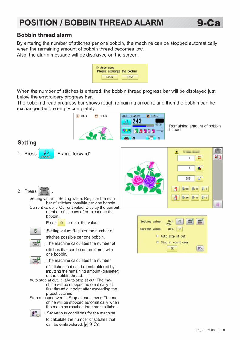
-DE -110
9-CaPOSITION / BOBBIN THREAD ALARM
16_2 U801
Bobbin thread alarmBy entering the number of stitches per one bobbin, the machine can be stopped automatically when the remaining amount of bobbin thread becomes low.Also, the alarm message will be displayed on the screen.
When the number of stitches is entered, the bobbin thread progress bar will be displayed just below the embroidery progress bar.The bobbin thread progress bar shows rough remaining amount, and then the bobbin can be exchanged before empty completely.
Setting
1. Press ”Frame forward”.
2. Press .Setting value : Setting value: Register the num-
ber of stitches possible per one bobbin.Current value : Current value: Display the current
number of stitches after exchange the bobbin. Press to reset the value.
: Setting value: Register the number of stitches possible per one bobbin.
: The machine calculates the number of stitches that can be embroidered with one bobbin.
: The machine calculates the number of stitches that can be embroidered by inputting the remaining amount (diameter) of the bobbin thread.
Auto stop at cut. : sAuto stop at cut: The ma-chine will be stopped automatically at first thread cut point after exceeding the preset stitches.
Stop at count over. : Stop at count over: The ma-chine will be stopped automatically when the machine reaches the preset stitches.
: Set various conditions for the machine to calculate the number of stitches that can be embroidered. 9-Cc
Remaining amount of bobbin thread

-DE -111
Auto stop option
Remaining bobbin thread length
Remaining diameter
9-CbPOSITION / BOBBIN THREAD ALARM
16_2 U801
3. Press to set the desired number of stitches..
Input the stitich number and press .The standard bobbin which is winded with #120 cotton thread will be used around 30000 stitches. But, the consumption of bobbin thread is varied depending on embroidery conditions such as stich type, stitch length and thread tension.It is recommended to enter the value to 30000 stitches as first setting.
Press to have the machine calculate the number of stitches.
The machine calculates and sets the number of stitches according to various conditions set in
. The machine calculates the number of stitches by the ratio of the sewing method such as satin or tatami in the currently selected pattern.
Press to have the machine calculate the number of stitches on the bobbin where the bobbin thread is not fully wound. Enter the remaining diameter of the bobbin thread and press .
The machine calculates and sets the number of stitches according to the bobbin remaining bobbin thread amount and various conditions set in
. The option of auto stop function can be selected ( ) from “Auto stop at cut.” and “Stop at count over.".
4. Press .
5. Press to return to Drive mode.
The number of stitches that can be embroi-dered with one bobbin varies depending on the proportion of the sewing method such as satin or tatami in the selected pattern. If you select another pattern, set the “Setting value” again so that the bobbin replacement alert will be displayed at the appropriate time.

-DE -112
9-CcPOSITION / BOBBIN CHANGE ALERT
16_2 U801
1. Press . During embroidery, the red progress bar which shows the remaining amount of bobbin thread will be extended until the preset stitches.
When the auto stop function is activated.
The machine stops automatically.
When the machine is stopped by manually.
2. Press when the bobbin is not required to exchange.
The setting value will not be reset and the stitch will be counted continuously.
Press when the bobbin is required to exchange.
The setting value will be reset to “zero” and the progress bar becomes blue.
Remaining amount of bobbin thread
Setting correctionCorrect the setting value to display the alarm message at proper timing.
Condition settingIn order for the machine to calculate the number of stitches that can be embroidered with one bobbin, set various conditions such as the size of the bobbin used and the diameter of the bobbin thread being wound.After setting the required items, press .
Diameter of wound bobbin thread
Core diameter of bobbin
Internal width of bobbin
Length of bobbin thread wound
As a margin, advance the timing to display the alert by the length of the set bobbin thread.
When satin sewing is performed, the ratio of the width of the bobbin thread to the swing width when viewed from the back side.
Standard values are preset for each item.

-DE -113
9-CdPOSITION / BOBBIN CHANGE ALERT
16_2 U801
3. Remove the bobbin and check the remaining amount. When the remaining amount is suitable, it is no need to correct the value. Please continue embroidery. The correction of setting value is required when the remaining amount is overage or shortage. Go on to step 4.
4. Press “Frame forward”.
5. Press .
6. Press .
7. Reduce the setting vale when the bobbin is almost empty.
Increase the setting vale when the remaining amount is too much.
The total stitch number which is calculated after the last bobbin exchange is displayed as “Current value”. Please refer the “Current value” to find suitable setting.
8. Press and .
9. Press to return to Drive mode. Please note that several corrections may be required to find suitable setting.

-DA -110
9-CePOSITION / WORK SAVE
16_2 S201
Work saveYou can save the state (before, during) of working design (the design displayed on the drive mode) and the selected frame type for the working design.This allows you to resume work by suspend sewing and returning to the state before the suspend of the driving design even after working other designs.
1. Press ”Frame forward”.
2. Press “Save”.
3. Press .The state of working design and selected frame type have been saved.
"Save” turn to "Read”.
Saving is cancelled.
4. Press to return to Drive mode.
Time to saveSelected frame
Number of stitches sewn up to now
Stitches of pattern
SaveSave the state of working design and selected frame type.
Working design to save

-DA -111
9-CfPOSITION / WORK SAVE, WORK READ
16_2 S201
1. Press ”Frame forward”.
2. Press "Load” .
3. Press .The saved working design's state and the selected frame type are loaded, and restore it to the state before suspend sewing.
"Read” return to "Save”.
Reading is cancelled and delete the
saved state of working design etc.. (The memory design will not be deleted.)
Reading is cancelled.
4. Press to return to Drive mode.
LoadLoads the saved working design's state and the selected frame type, and restore it to the state before suspend sewing.
Saved timeSelected frame
Number of stitches sewn up to now
Stitches of pattern
CAUTION: To prevent accidents.The frame moves quickly. Keep hands away from the frame.
Saved working design

-DA -102
9-DREGISTER
17_1 Q501
Register will restore the position of the frame to the last point before a power failure even if the point of origin or the pattern itself were changed.
If register is used with a cap drive frame, make sure that the machine recognizes it by showing “Cap” (Cap frame) or “OnePoint” (One Point frame) the appropriate frame or the machine could be damaged. If register is used with indication of frames that do not require cap drive frame, carriage moves and exceeds embroidery area of cap drive frame and damages the machine and cap drive frame.
When you use “REGISTER”, keep clear of the frame and table. It is dangerous as the frame could make sudden movements. Never use register with the needle bar and presser foot lowered, as they could hit the cap drive frame and break.
It is not always necessary to set “Entry”, but you can’t set “Return”. Once “Entry” is set, it is retained even if power is turned off. If you change the position of the original point, set it again.
Even if you set “Entry”, the frame may not return exactly to the original position in process of time. Reset this monthly.
EntryRegistering the start point in the selected pattern.
Return (Registered position)When position of the frame changes because of power loss, this will restore the frame to theregistered point.
Selected frame

-DA -111
1. Press .
2. Confirmthatthereisindicationof (Top) inthedisplayandgoontoprocedureno.3.
Press “Top”,ifthereisnotaindication.
Upper right indication of will be shown.
3. Movetheframetotheoriginalpointwiththe
.
Iftheframeislocatedattheoriginpoint,proceedtoStep4.
4. Press .
5. Press .
The origin point is registered.
9-EREGISTER
17_2 NB01
EntryThisregisterstheoriginalpointoftheselectedpattern.
Press toreturntoDrivemode.

-DA -112
1. Press .
2. Confirmthatthereisindicationof (Top) inthedisplayandgoontoprocedureno.3.
Press “Top”,ifthereisnotaindication.
Upper right indication of will be shown.
3. Press .
4. press.
The frame will return to the origin point you registered.
9-FREGISTER
17_3 Q101
ReturnIncaseofpowerfailureyoucanreturntotheoriginalpointyouregistered.
CAUTION: To prevent accidents.Theframemovesquickly. Keepyourhandsawayfromtheframe.
Press toreturntoDrivemode.

-DE -108
10-1READING
1. Insert the memory media into the machine as described in “Inserting memory media”.
5-5
2. When the machine is stopped, press .
3. Select “READ”.
4. Select (USB flash drive).
Indicates pattern data of the memory media.
TAP : HAPPY DST : Tajima DSB : Tajima (Barudan) DSZ : Tajima (ZSK)
Folder : Contents of folder will be displayed
when you select this icon. 1 % of free memory is equivalent to about 1,000,000 stitches. If there are more stitches than remaining space, you may need to delete some designs to make room for the new patterns.
14_1 UC01
JoinJoining 2 patterns into 1 pattern data to be read from a memory media.Function of joining patterns is not valid for pattern data in PC connected with LAN. 5-6
In case you would like to use “Join” function, please set “Join design data” to “YES” on “READING” setting in advance. 14-4
Holder
--- Serch pattern ---
Free memoryThe designs new ID number in

-DA -101
10-2READING
14_2 S201
--- Check pattern data ---
--- Reading ---5. Select the pattern.
Once design is read.
Enable to read other pattern data.
6. Press .
7. Press
Shift the Memory media if the pattern data you desire to Join is in the other Memory media.
8. Select the pattern data to be Joined.
9. Press .
10. Press .The pattern data selected to be joined is joined next to the pattern data previously read in the machine as one pattern data and the screen returns to Menu screen.Pattern name is registered as the name of the first pattern data read in the machine in pattern datum joined.
Press if you desire to join more patters.
Necessary pattern data can be read by performing step 6 to 10.
When the screen displays pattern data in the folder, is displayed.
When is pressed, the screen moves off from the current folder.
--- Reading ---
Disk set O.K.?
OK
Complete
OK

-CU -110
SETTING ITEM SETTING RANGE (Difult is underlined)
CONTENTS
1 Keep null (CHG.) Yes•No This function lets the machine read zero stitches as they are before color change when reading pattern data.
2 Skip null stitch Yes•No This lets you choose to ignore all null stitches when reading pattern data.3 Combine jump Yes•No Allows you to combine multiple, consecutive jump stitches when reading pattern
data, if desired. It combines them into jump stitches of the maximum 12.7mm and reads the pattern with the combined jumps.
4 Stitch sweeper Yes•No This function eliminates extremely short stitch for stitch width when reading pattern data.
5 Sweep length 0 ~ 0.4 ~ 0.8(mm)
This setting controls the length of the stitches eliminated by the Stitch sweeper. Stitches shorter than this setting will be eliminated.
6 DST name display Yes•No When patterns in Tajima format are read in, the display shows the fi le name.7 Data format
AutoHappyBrdZsk
Turn data format for reading patterns. Usually, set it to Automatic. → Automatic→ HAPPY, Tajima→ Barudan→ Zsk
8 Design information Yes•No This function reads various function setting which are set in pattern data together with pattern data (type TAP).
9 Trace type Lets you select the type of trace data that is created as a pattern is read in.→ Maximum embroidery area of pattern→ Out line
10 Join design data Yes•No It is appeared that other pattern data is joined to the data previously read in the machine.You can make one pattern data by joining multiple pattern data read in the machine.
11 Folder select Yes•No When reading pattern data, the list for selection of folders will be displayed.12 Completion msg. Yes•No Completion msg. will appear after reading pattern data.
10-3READING
10_3 V402
Pattern read settingsSettings related to pattern data reading.
Detailed explanation of machine setting
4 Stitch sweeperThis removes stitches that are extremely narrow when reading pattern data and writing tomachine memory. If thread breaks occur often at the same point in a pattern, this may bebecause of narrow stitches.
If the thread still breaks in the same place you can use this function again but repeated usage may distort the shape of the stitch.
1. Save the pattern to USB fl ash drive.
2. Conduct a stitch sweeping of the pattern and load it into the machine again.
End
7 Data formatThis enables you to select a diff erent format and read the pattern again if the machine did notread it correctly the fi rst time.

-D2 -99
8 Design information*Various settings are saved together with a pattern. If some settings are changed in thepattern and you wish to return to the originals, simply reload.
The data may only be HAPPY format (TAP).
9 Trace typeYou can compare the design size and design position to the embroidery frame before you startsewing.The embroidery frame will move around the actual design size.At this time you can choose which type of trace from the two types as seen in the followingfigure:
10-4READING
14_5 NB01
● Start point
Area Outline

-DA -102
10-5READING
14_6 NB01
1. When the machine is stopped, press .
2. Select “OPTION”.
3. Select .
4. Select desired setting item and change the setting.
You can move to next page by pressing .
Press , all settings are returned to the de-fault.
Press to return to Menu mode.
Press to return to Drive mode.

-D2 -66
11-1PATTERNS IN MEMORY
5_B NB01
1. When the machine is stopped, press .
2. Select "PATTERN".
3. Press from right submenu.
4. Select desired pattern.
Mark will appear right of the pattern.Make will be cleared by press it again.Multiple pattern data can be selected.
Locking pattern dataLocking pattern data stored in the machine memory will prevent deletion and changes in set-tings.
Mark

-D2 -67
11-1bPATTERNS IN MEMORY
5_B NB01
5. Press .
Repeat steps 3 and 5 to unlock.
Press to return to Menu mode.
Press to return to Drive mode.

-D2 -68
11-2PATTERNS IN MEMORY
11_2 NB01
Trace typeChanging the trace type of the pattern data in the machine memory. 10-4
1. When the machine is stopped, press .
2. Select "PATTERN".
3. Select desired pattern.
Maximum embroidery area of pattern
Outline of pattern
4. Press and select or .
Trace type is changed.
--- Calculating ---
Press to return to Menu mode.
Press to return to Drive mode.
Trace type

-DA -70
11-3PATTERNS IN MEMORY
11_3 Q701
ExportYou can write out of machine memory to a memory media.
1. When the machine is stopped, press .
2. Select “PATTERN”.
3. Select desired pattern.
4. Press from right submenu.
5. Press from right submenu.
The name of the pattern will be shown.

-DA -71
11-4PATTERNS IN MEMORY
11_4 Q701
7. Press if the pattern name is not to be changed.
The pattern data will be written.
Choose the column with . Then select each digit in the existing name.
Select word and press .The pattern data will be written.The maximum number of characters in a design name is eight letters or numbers.
All the letters and/or numbers are deleted.
Selected letter or number is deleted.
Changing name is cancelled.
The display returns to the view of Step 5.
Press to return to Menu mode.
Press to return to Drive mode.

-DA -72
11-5PATTERNS IN MEMORY
11_5 Q701
Renaming patternsRename pattern in memory.
1. When the machine is stopped, press .
2. Select “PATTERN”.
3. Select desired pattern.
4. Press from right submenu.
5. Choose the column with . Then select each digit in the existing name.
Select word.The maximum number of characters in a design name is eight letters or numbers.
All the letters and/or numbers are deleted.
Selected letter or number is deleted.
Renaming is cancelled.

-D2 -72
6. Press .
The pattern name will be changed.
11-5bPATTERNS IN MEMORY
11_5 NB01
Press to return to Menu mode.
Press to return to Drive mode.

-D2 -73
11-6PATTERNS IN MEMORY
11_6 NB01
Copying pattern dataCopying of the pattern data stored in the machine memory is available.
Copied pattern data
1. When the machine is stopped, press .
2. Select "PATTERN".
3. Select desired pattern.
4. Press from right submenu.
Copy of the selected pattern will be made.
Press to return to Menu mode.
Press to return to Drive mode.

-D2 -74
11-7PATTERNS IN MEMORYMoving pattern data
Export pattern data into the other folder.
1. When the machine is stopped, press .
2. Select "PATTERN".
3. Press from right submenu.
4. Press from right submenu.
11_8 NB01

-D2 -75
11-8PATTERNS IN MEMORY
11_8 NB01
Importing folder
4. Select desired pattern.
Mark will appear left of the pattern.Make will be cleared by press it again.
Multiple pattern data can be selected.
: Cancel pattern data moving
5. Press .
6. Select the importing folder.
The pattern data will be transferred.
Mark
Press to return to Menu mode.
Press to return to Drive mode.

-D2 -76
11-9PATTERNS IN MEMORY
11_9 NB01
Renaming foldersRename folder in memory.
1. When the machine is stopped, press .
2. Select "PATTERN".
3. Press from right submenu.
4. Press from right submenu.

-DA -78
11-9aPATTERNS IN MEMORY
11_9 Q701
5. Select desired folder.
6. Choose the column with . Then select each digit in the existing name.
Select word.The maximum number of characters in a design name is 12 letters or numbers.
Uppercase and lowercase letter are switched.
All the letters are deleted.
Selected letter or number is deleted.
Renaming is cancelled.
7. Press .
The folder name will be changed.
Renamed folder
Press to return to Menu mode.
Press to return to Drive mode.
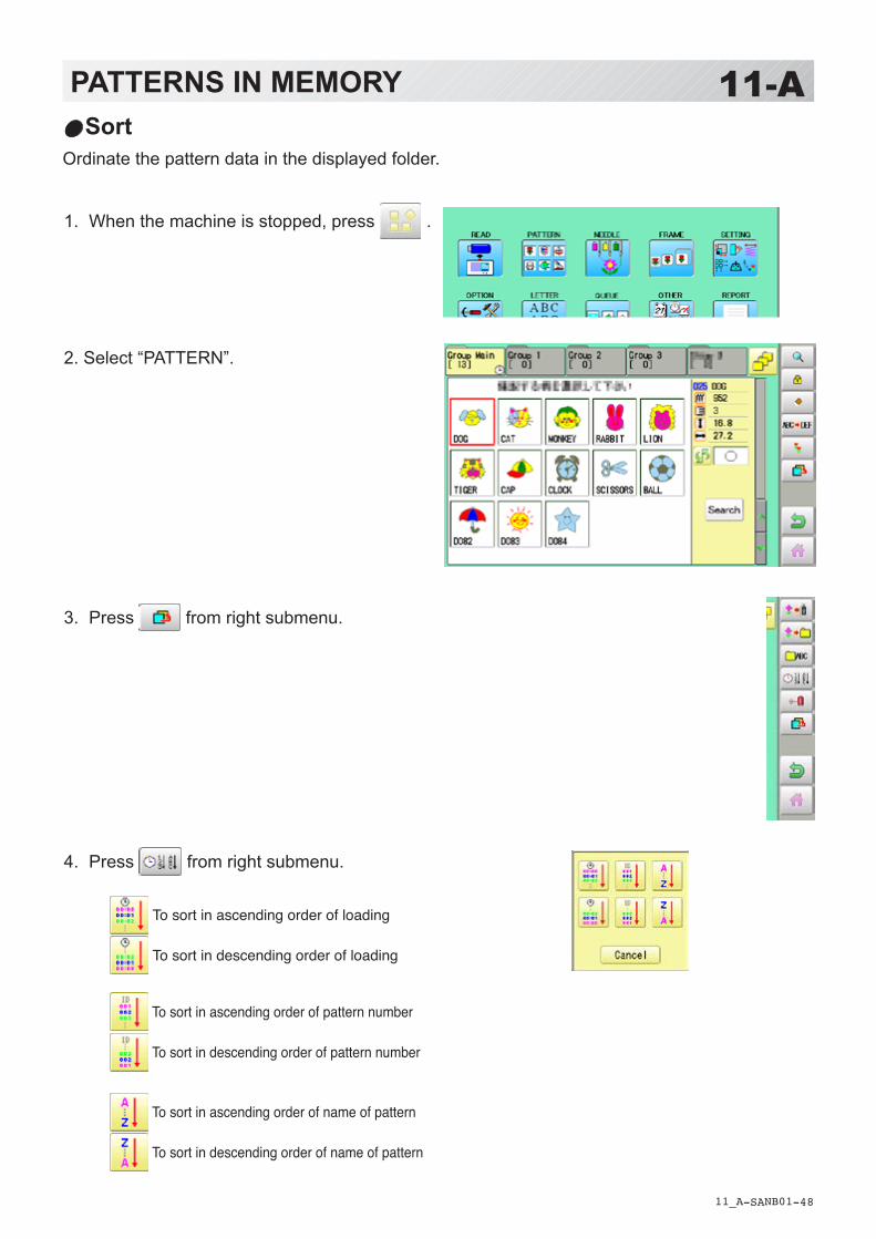
-SA -48
11-APATTERNS IN MEMORY
11_A NB01
SortOrdinate the pattern data in the displayed folder.
1. When the machine is stopped, press .
2. Select “PATTERN”.
3. Press from right submenu.
4. Press from right submenu.
To sort in ascending order of loading
To sort in descending order of loading
To sort in ascending order of pattern number
To sort in descending order of pattern number
To sort in ascending order of name of pattern
To sort in descending order of name of pattern

-SA -35
11-AbPATTERNS IN MEMORY
11_Ab NB01
5. Select sorting method.
Sort will be carry out.
Press to return to Menu mode.
Press to return to Drive mode.

-DA -82
11-BPATTERNS IN MEMORY
11_B NB01
Thread break reportThis function will show recorded thread break of pattern data. The machine detects break thread during operation and records by pattern the number of stitches at the stopped position. If thread break is happening at same number of stitches, please check construction of stitch de-sign.
1. When the machine is stopped, press .
2. Select “PATTERN”.
3. Select desired pattern.
4. Press from right submenu.
5. Press from right submenu.
Thread break report will appear in the window.The maximum memory is up to No. 30.If the record exceeds No. 30, the new records will be added to the latest 29 records.
To delete the record
6. Press . Exit the mode.
Pattern numberPuttern name
Number of stitches
Number of stitches at the stopped position by thread break
Press to return to Menu mode.
Press to return to Drive mode.

-SA -50
11-CPATTERNS IN MEMORY
11_C NB01
Retrieve built-in data from machine100 pattern data are built-in in machine and you need to retrieve built-in pattern data from ma-chine memory to design data folder. These pattern data are stored in the [Group 4] folder on the PATTERN screen. Empty the [Group 4] folder before built-in pattern data are retrieved from machine memory. Built-in pattern data cannot be retrieved if there is any pattern data in the [Group 4] folder.Built-in pattern data can be moved to other folder and/or deleted like monogramming data made on LETTER screen and other pattern data imported from outside of machine. 11-7, 5-BYou can retrieve the pattern data from machine memory again after deleting the built-in data.
1. When the machine is stopped press .
2. Select “PATTERN” .
3. Press from right submenu.
4. Press from right submenu.
5. Press from right sub-menu. Retrieving patter data is started.It takes several minutes to complete data retriev-ing.100 built-in data is shown on page 26-4.
Right side folder
Press to return to Menu mode.
Press to return to Drive mode.

-SA -51
11-DPATTERNS IN MEMORY
11_D Q701
Searching pattern dataSearching of the pattern data stored in the machine memory is available.
1. When the machine is stopped press .
2. Select “PATTERN” .
3. Press . All pattern data stored in the machine memory will be displayed.
Search from designated folder.
4. Press . In this keyboard for searching, all design names are checked beforehand and only candidate alphabets will be highlighted along respective digits.
Display the folder name to search
The folder name which the pattern is savedCursor
Stitches

-SA -50
Press to return to Menu mode.
Press to return to Drive mode.
PATTERNS IN MEMORY
11_C Q701
11-E5. Enter the whole or a part of the pattern
name.
The maximum number of characters in a design name is eight letters or numbers.
All the letters and/or numbers are deleted.
Selected letter or number is deleted.
Searching is cancelled.
6. Press . In this example, “CA” is entered as first 2 charac-ters of the design name.Then, all design name which start from “CA” is displayed.
7. Press displayed pattern icon to confirm your selection. Press to leave from searching menu.
Number of searched pattern data
Selected pattern data

-D2 -101
12-1NEEDLE BAR SELECTION
13_1 MA05
Needle number settings 5-E
A needle number can be assigned to a *color change number.When the needle number is assigned, the machine will embroider and automatically switch tothe programmed for each color change number.
Color change stop function 5-F
A *color change stop can be assigned to a color change number.When this is done, the machine embroiders the stitches for that color change number and thenstops, displaying the following message:
Auto settingChanges all designated needle numbers at once.
Thread colorThis sets the background color or color assigned to each needle bar to be shown in the display.
Color change data registration, Color change data readYou can use the color change data from a saved pattern, register it, and then export the regis-tered data to the selected pattern for use.
Repetition of color group settingIf your design has repetition of the group of the same color sequence, only set first sequenceand set other automatically by following steps.
>>Change Stop

-RA -65
1. When the machine is stopped, press .
2. Select “NEEDLE”.
3. Press from right submenu.
4. Select the current needle number you would like to change.
5. Select the needle number to be changed.
12-2NEEDLE BAR SELECTION
13_2 N701
Needle number to be changed
Auto settingThis changes all designated needle numbers at once.For example, if you want to change all needles numbered “3” to “5”, just select one of the color change numbers in which “5” is set, then all color change numbers can be changed into “3”.
Needle number to be changed after

-RA -65
12-3NEEDLE BAR SELECTION
13_2 B701
The needle number has been changed from 3 to5.
6. Press .
Setting is cancelled.
Preview screen is displayed.
7. Press .
The setting is fixed.
Press to return to Menu mode.
Press to return to Drive mode.

-RA -67
12-4NEEDLE BAR SELECTION
13_3 O512
Yellowish greenSet needle number : 3
Set needle number : 2
Set needle number : 1 Red
Color stteing 1 : Red 2 : Yellowish green 3 : Green
Green
Thread colorThis sets the background color or color assigned to each needle bar to be shown in the display.This is useful to help confirm the correct color setup of a pattern.
You will find difficulty to see the pattern if you set same color on both pattern and background.
1. When the machine is stopped, press .
2. Select “NEEDLE”.
3. Press from right submenu.
Cloth (back-ground color)

-RA -61
12-5NEEDLE BAR SELECTION
13_4 O512
4. Select the needle number or cloth (background color).
You chan change the color palette.
5. Select the color to be changed at the palette.
You can select the color with .
Current color will be shown.
6. Press .
7. Press .
The setting is fixed.
Preview screen is displayed.
current colorColor to be changed after
Press to return to Menu mode.
Press to return to Drive mode.
256 colors palette 70 colors palette

-RA -68
1. When the machine is stopped, press .
2. Select “NEEDLE”.
3. Press from right submenu.
4. Press .
The color change data will be saved into memo-ry.
12-6NEEDLE BAR SELECTION
13_5 B701
Color change data registrationYou can import and apply color change data from saved patterns (Including color change stops) to the current pattern. This function lets you apply the same color change data from other patterns.
The color change data is limited to one and the color change numbers are limited to 250.
Color change number
Press to return to Menu mode.
Press to return to Drive mode.

-RA -69
1. When the machine is stopped, press .
2. Select “NEEDLE”.
3. Press from right submenu.
4. Press .
The needle number set is subject to the color change data exported. Confirm the color shown in the preview display.
12-7NEEDLE BAR SELECTION
13_6 NB01
Color change data readYou can export the registered color change data to other patterns.
If the pattern receiving the imported color change data has more color changes than the imported data, the extra color changes will be set to “0” and will need to be set manually later.
Color change number
Press to return to Menu mode.
Press to return to Drive mode.

-RA -70
1. When the machine is stopped, press .
2. Select “NEEDLE”.
3. Set first color sequence group.
Please confirm that the next number of the group is “0”.
4. Press from right submenu.
Set other color change setting automatically.
If the number of total color change does not be-come the first number of group multiple number. Machine display warning.
12-8NEEDLE BAR SELECTION
13_7 NB01
Repetition of color group settingIf your design has repetition of the group of the same color sequence, only set first sequence and set other automatically by following steps.(If you have some function in the needle “Example: color change stop”, the function also will set)
Fig. 1
First sequence
● : Start point of pattern■ : End point of pattern
Check repeat setting. OK
First sequence
Press to return to Menu mode.
Press to return to Drive mode.

-D2 -125
13-1FRAME CONFIRMATION
20_1 M401
By default the machine checks if the pattern fits the embroidery area.This helps you to check whether or not the selected pattern fits in the desired hoop.This helps confirm positioningbetween the embroidery area and the pattern.If you change the frame position by the frame move key, the display will be changed and youcan check the position onscreen.
The "monitor display" checks whether or not the pattern fits the embroidery area of theframe you are going to use before starting the operation.This is not a safety device that will prevent crashes if pattern size is too large for the frame;it is intended for your reference only when judging the fit of a pattern to a given size frame.After using "monitor display", do not move the frame. If you do so the machine may bedamaged due to the needle or pressure foot hitting the frame.
Make sure to perform "Registration number selection" when changing hoop size. If notdone, the machine may be damaged from the needle or pressure foot hitting the frame.

-DA -121
13-2FRAME CONFIRMATION
20_2 PC01
1. When the machine is stopped, press .
2. Select “FRAME”. Tubular round frame
Tubular square frame, One touch frame
Cap and One-point frame
Border frame, Square clamp frame
Sock frame
User-defined frame
Special frame
Non registered
3. Select type of frame.
Change the type of frame.
Frame selectionSelecting a frame.The embroidery area for each registered frame is set to the inside of the frame edge to allow for pressure foot clearance. (Fig. 1)This allows confirmation of positioning between the embroidery area and the pattern.
Embroi-dery area
Fig. 1
Inner size (Length-
Embroi-dery area
Inner size (Sidewise)Inner size
Round frame Square frame

-DA -119
13-3FRAME CONFIRMATION
20_3 R801
4. Select desired size of frame and press .
The embroidery area appear in red.
5. Confirmthat (Top) appears in the display and go to step 7. If this does not appear, go to step 6.
6. Press “Top”.
Upper right indication of will be shown.
7. By position of design can be
moved.
8. Press .
The display returns to Drive mode.
Start sewing by pressing .

-DA -123
13-4FRAME CONFIRMATION
20_4 O901
Adjusted for embroidery area
Cap frameThe embroidery area of HAPPY semi-wide and wide cap frames is saved in the machine.The Y axis of the embroidery area can be ad-justed for a variety of caps. (Fig. 1)
Embroidery area
Embroidery area (Side wise) Fig. 1
Embroidery area (Lengthwise)
1. When the machine is stopped, press .
2. Select “FRAME”.
3. Select ”Cap and One-point frame”.
4. Select desired size of frame and press .
The embroidery area appear in red.
5. Press .

-DA -118
13-5FRAME CONFIRMATION
20_5 R201
6. Press .
7. Press .
8. Select the number .
Enter the width of the cap. Standard 40 ~ 70mm Width 40 ~ 95mm
9. Press .
10. Press .
The setting is fixed.
Settings are returned to the default.

-D2 -117
13-6FRAME CONFIRMATION
20_5 NB01
11.Press .
Press to return to Drive mode.

-DA -129
13-7FRAME CONFIRMATION
20_7 O901
1. When the machine is stopped, press .
2. Select “FRAME”.
3. Select “User-defined frames”.
4. Select desired size of frame and press .
The embroidery area appear in red.
User-defined frames (1 ~ 5)The embroidery area of each registered frame is set to the inside of the frame edge for pressurefoot clearance. (Fig. 1, 2)
The embroidery area of each registered frame is set to the inside of the frame edge for pressure foot clearance. (Fig. 1, 2) When you use square frame as shown in fig.3, pressure foot may hit the corner of frame. In this case you need to create frame as special shape under the frame No.6 - 20.
Fig. 1
Embroidery areaRound frameEmbroidery areaSquare frame
Fig. 3Fig. 2
Embroidery area
Inner size (Sidewise)Inner size
Inner size (lengthwise)

-DA -119
13-8FRAME CONFIRMATION
20_8 O901
5. Press .
6. Press .
7. Press to select the hoop (Class).
: Round frame: Square frame
8. Press .
Select or you wish to
change square frame size.
9. Select the number .
Input number for size of embroidery area.
10.Press .
Case for selectedround frame
Case for selectedsquare frame

-DA -120
13-9FRAME CONFIRMATION
20_9 O901
11.Press .
The date is fixed.
12.Press .
Case for selectedround frame
Case for selectedsquare frame
Press to return to Drive mode.

-CU -149
13-AFRAME CONFIRMATION
20_A T601
User-defined frames (6 ~ 60)You need to prepare for the data which entered the shape of the frame and entry the entered data.You can entry the data up to 55 different size of custom frames.You need to prepare custom frame size data for entry the size to your machine. 13-BThe embroidery area for each registered frame is set to the inside of the frame edge to allow for pressure foot clearance. (Fig. 1)
Embroidery area
Fig. 1
Embroidery area
Round frame Square frame

-CU -145
13-BFRAME CONFIRMATION
20_B T601
Frame data constitution
Type = [Type of data]Name = “[Name of frame]”Form = [L00],[L10],[L20],[L30],[L40],[L50],[L60],[L70],[L80],[L90] (Frame shape)
Type : Select type of data by following number. 1 : Frame size 2 : Possible embroidery size
Note: If select “1”, machine will memory reduced size for Presser food diameter automatically. If select “2”, machine will memory exactly same size as can embroider it on.
Name : Naming the your User-custom frame. Pick up to 10 letters up with a “mark.
Form : Refer the above figure. Please fill it out every 10 degrees of dimensions to the inside of the frame in a frame heartily. (20 to 500mm) Fill it out length from point from No. L00 till L90 total 10 points size using “, “ between the each size data. If your frame shape is Round, the every 10 points length frame size data should be same. If you select Type (Type of data) “2”, please put length data of L00 and L90 only.
END : Please fill out the line of the last of data. Please make entry of “END” by all means.
Please use half width character for the length data.
Please cut off the decimal of the length.Example: 102.3mm -> 102
How to make frame size data of your User-defined frames (6 ~ 60)We need to use text edit software of PC like “WordPad” and make frame size data with following constitution, then entry the data to your machine.
Fig. 1
Center of user-defined frame
Fig. 2
90°
0°
L90
L00
90°
0°
L10L20
L30
L40
L50L60L70L80L90
L00
Type = 1 (Type of data) Type = 2 (Type of data)
Center of user-defined frame

-CR -126
13-CFRAME CONFIRMATIONWhen you save the frame size data, please save as text document form and file name shouldbe less than 8 characters.Extension should be ".TXT"Example: ROUND250.TXT
Please save the frame size data to machine usable memory media and read the data byembroidery machine. 13-D
Example of making the frame size dataSample for each teaching method.
20_C N525
Ex. Round frame
Type = 1Name = "Round"Form = 125,125,125,125,125,125,125,125,125,125END
Ex. Square frame
Type = 1Name = "PS240"Form = 120,122,126,130,128,120,106,100,96,94END
Ex. Possible embroidery size
Type = 2Name = "T-SC-01"Form = 90,60END

-DA -131
13-DFRAME CONFIRMATION
20_D O901
Reading frame data
1. When the machine is stopped, press .
2. Select “FRAME”.
3. Select “User-defined frames”.
4. Press .
You can choose any frame options.
5. Press t .

-DA -125
6. Press .
7. Select the frame data “CCLAGOB.txt”.
The frame data has been read.
8. Press .
13-EFRAME CONFIRMATION
20_E O901
Press to return to Drive mode.

-CU -149
13-FFRAME CONFIRMATION
20_I T601
1. When the machine is stopped, press .
2. Select “FRAME”.
3. Select “User-defined frames”.
4. Press .
You can choose any frame options.
5. Press t .
How to delete the resisted user-defined frames (6 ~ 60)Delete resisted User-defined frame from memory.

-DA -127
13-GFRAME CONFIRMATION
20_I O901
6. Select desired User-defined frames.
7. Press .
The user-defined frames will be deleted.
8. Press .
Press to return to Drive mode.

-CU -151
13-HFRAME CONFIRMATION
20_J T601
How to change center point of frame (1 ~ 5, 6 ~ 60)You can change memorized frame center point.When you set your frame and use machine function of “Frame move” and “Center” ( 3-6), If your frame is not center, please practice following steps for center setting again.
1. When the machine is stopped, press .
2. Select “FRAME”.
3. Select “User-defined frames”.
4. Press .
You can choose any frame options.
5. Press t .

-DA -129
13-IFRAME CONFIRMATION
20_K O901
6. Select desired User-defined frames.
7. Press .
8. Press .
9. Move embroidery frame to frame center
point by .
10.Press .
Memorized frame center point coordinate to themachine.
11.Press .
Press to return to Drive mode.
CAUTION: To prevent accidents.The frame moves quickly.Keep hands away from the frame.

-DA -135
13-JFRAME CONFIRMATION
20_L R801
1. When the machine is stopped, press .
2. Select “FRAME”.
3. Select “Non registered” or “Special frame”.
4. Press .
Iindication of frame type disappears. It means that “Non Registered (Special frame) “ is selected.
When you need to change from Non Registered frame (Special frame) to other type of frame, please powor machine off and start again. Without re-starting machine, machine will move incorrectly.
Non registered, Special frameIn case Non Registered Frame is selected, carriage does not have movement for creating the coordinates of frame position at the time of turning machine on.Please select Non Registered Frame, when you need use special frame which can hit pressure foot or other machine parts by movement of carriage for creating the coordinates of frame posi-tion.The following functions is canceled by selecting Non Registered Frame;
* Frame confirmation* Restore the position at the time of power failure* Locate* Autostop function when movement exceeds the carriage limit.
Frame Iindication disappears
Except using special shape frame, please do not select Non Registered Frame.In case you have operation mistake, needle and/or pressure foot may hit frame and machine and/or frame can be damaged.

-D2 -83
14-1PATTERN SETTINGS
12_1 N525
Various settings such as the scaling, repeat sewing, offset and frame out can be applied to apattern.
AdjustThis menu contains settings such as scaling, width adjustment, angle and convert design.
Repeat sewingThe machine repeats the pattern a number of times in the X and Y directions as set by the user.
OffsetSets the start point of the frame in the selected pattern.
Frame outInserts a frame out command in the selected pattern.
Various settings are executed in assortment.
Adjust
ScalingThis adjusts the scale of the selected pattern.
Width adjustmentThis adjusts the width of the selected pattern.
AngleThis adjusts the angle of the selected pattern.
Convert design 9-5This sets the rotation of the selected pattern in increments of 90 degrees, normal or reversed.

-D2 -82
14-2PATTERN SETTINGS
12_2 NB01
ScalingThe pattern's scale can be increased or de-creased in 1% increments.
Setting example
1. When the machine is stopped, press .
2. Select "SETTING".
3. Select (Scaling X) or (Scaling Y).
4. Select the number.
Changing is cancelled.
Numbers are deleted.
5. Press .
The setting is fixed.
: Start point of pattern
Normal X 100 %, Y 150 %
Default : X,Y 100%
Adjust
The pattern data may be shown.
Setting is returned to the default.
To return to Menu mode.
to return to Drive mode.

-D2 -83
14-3PATTERN SETTINGS
12_3 NB01
Width adjustmentThis setting adjusts stitch width (L) in a patternin a range of -1.0 ~ +1.0mm in increments of0.1mm.
In case "Width" (Width adjustment) is setand embroidery is made, there is a casethat error occurs at end point. In such acase, please return setting figure of stitchwidth to "0.0".
Setting example
1. When the machine is stopped, press .
2. Select "SETTING".
3. Select (Width adjustment).
4. Select the number.
Changing is cancelled.
Numbers are deleted.
5. Press .
The setting is fixed.
LL + 0.4mm
0.4 mm
Default : 0 mm
Adjust
The pattern data may be shown.
Setting is returned to the default.
To return to Menu mode.
to return to Drive mode.

-D2 -84
14-4PATTERN SETTINGS
12_4 NB01
AngleWith the start point of the pattern as a pivot,the machine rotates the angle clockwise.
Setting example
1. When the machine is stopped, press .
2. Select "SETTING".
3. Select (Angle).
4. Select the number.
Changing is cancelled.
Numbers are deleted.
5. Press .
The setting is fixed.
30°Normal
: Start point of pattern
Default : 0°
Adjust
The pattern data may be shown.
Setting is returned to the default.
To return to Menu mode.
to return to Drive mode.

-CU -115
1
2
3
4
5
6
1
3
5
2
4
6
14-5PATTERN SETTINGS
14_5 V402
Repeat sewingThe machine embroiders a user-specifi ed number of copies in the X and Y directions.
Setting example
Space X
Space Y
Piece X 2Piece Y 3Space X -150.0Space Y 120.0Priority Y
This is the case that “Priority” in the left list is set to X
● : Start point of pattern■ : End point of pattern
SETTING ITEM SETTING RANGE DEFAULT CONTENTS
Piece X 1 ~ 30 1 This sets number of pieces side wise and length wise when you perform repeat.
Piece Y 1 ~ 30 1 The number of pieces to be embroidered is product obtained by multiplying numbers in X and Y.
Space X -999.9 ~ 999.9 (mm)
0 This sets side wise distance between start point of each pattern when you perform repeat. When plus number is input, the machine makes repeat toward right. In case of minus number, toward left.
Space Y -999.9 ~ 999.9 (mm)
0 This sets length wise distance between start point of each pattern when you perform repeat. When plus number is input, the machine makes repeat upward. In case of minus number, downward.
Priority X (Side)• Y (Length) X When you set more than 2 pieces for repeat length wise and side wise, this selects direction to embroider 2nd piece.

-CU -104
1. When the machine is stopped, press .
2. Select “SETTING” and select (Repeat).
Gap 14-6a No gap 14-6a Fill 14-6a
3. Select each setting item and select the num-ber.
Changing is cancelled.
Numbers are deleted.
4. Press .
The setting is fixed.
5. Set necessary item by performing procedure no. 3 to no.4.
Set all the necessary items.
6. Press .
14-6PATTERN SETTINGS
12_6 T601
The pattern data may be shown.
Setting is returned to the default.
To return to Menu mode.
Repeat
Pattern sizeOverall size

-CU -102
14-6aPATTERN SETTINGS
12_6 NB01
Setting item
GapSet the space X and space Y (pattern size + gaps) set in the setting items with only gaps, and relocation.
1. Press .
2. Enter X gaps and press .
X direction of repeat sewing
3. Enter Y gaps and press .
Y direction of repeat sewing
It will be relocated with the set gap. You can change each setting item even after relocation.
No gapThe number of X and Y numbers set in the setting items will be relocated without gaps.
1. Press .
It will be relocated without gaps. You can change each setting item even after relocation.
Setting item
FillRelocate the maximum number at the set space to the selected frame.
1. Press .
It will be relocated.
CAUTIONThe machine calculates the shape of the selected frame as a simple rectangle (square). Check if it is actually inside the frame, and set the number and space in the setting items as necessary.
Setting item

-D2 -87
14-7PATTERN SETTINGS
12_7 NB01
Auto originWhen a pattern has different start and end points, the frame returns to the start point.
Setting example
1. When the machine is stopped, press .
2. Select "SETTING" and select (Offset).
3. Press (Auto origin) and select (ON)or (OFF).
The setting is fixed.
● : Start point of pattern■ : End point of pattern
Offset
The pattern data may be shown.
Setting is returned to the default.
To return to Menu mode.
to return to Drive mode.

-D2 -86
14-8PATTERN SETTINGS
12_8 NB01
OffsetSetting the offset point designates a place for the frame to rest before moving to the start pointof the actual embroidery.When used together with the "Auto origin" ( 14-7) feature, the machine will return to the offsetwhen it is finished embroidering as well.This allows you to send the frame to a place where it will be easier to handle, when you willneed to change hoops for example.
Direct inputYou can move the offset point manually and save the position with "Teaching input".
PresetThere are 9 preset points that can be used for offsets around and in the center of the pattern.
Teaching inputYou can set the offset point manually.
When you Press (Original point return) or use "Auto origin" ( 14-7) with an offset, the
frame will return to the offset point.
❍ : Offaet point● : Start point of pattern■ : End point of pattern
Auto origin

-DA -91
Direct inputYou can move the offset manually and save the position with “teaching input”.
1. When the machine is stopped, press .
2. Select “SETTING” and select (Offset).
3. Select (X axis distance) or (Y axis distance) and select the number.
Changing is cancelled.
Numbers are deleted.
4. Press .
The setting is fixed.
14-9PATTERN SETTINGS
12_9 NB01
Offset point
Sidewise move distance
Length-wise move distance
❍ : Offaet point● : Start point of pattern
Offset
The pattern data may be shown.
Setting is returned to the default.
To return to Menu mode.
to return to Drive mode.

-D2 -90
1. When the machine is stopped, press .
2. Select "SETTING" and select (Offset).
3. Select .
4. Select the offset point and press .
The setting is fixed.
Setting is unset.
14-APATTERN SETTINGS
12_A NB01
PresetThere are 9 preset points that can be used for offsets around the or in the center of the pattern.
Offset
Offset point
The pattern data may be shown.
Setting is returned to the default.
To return to Menu mode.
to return to Drive mode.

-D2 -91
Teaching inputYou can set the offset position manually.
1. When the machine is stopped, press .
2. Select "SETTING" and select (Offset).
3. Select .
4. Press .
5. Move the frame to the pattern start point.
Setting is cancelled.
6. Press .
The setting is fixed.
14-BPATTERN SETTINGS
12_B NB01
Sidewise movedistance
Lengthwisemovedistance
❍ : Offaet point● : Start point of pattern
Offset
CAUTION: To prevent accidents.The frame moves quickly.Keep hands away from the frame.

-D2 -92
14-CPATTERN SETTINGS
12_C NB01
Complete
Offset point
7. Move the frame to the offset point.
8. Press .
The setting is fixed.
The pattern data may be shown.
Setting is returned to the default.
To return to Menu mode.
to return to Drive mode.

-D2 -97
14-DPATTERN SETTINGS
12_D M401
Frame outA frame out command can be added to a design. By setting frameout to a *Color change num-ber in a design, you can move the frame to a desired position automatically and stop it after themachine finishes sewing of that color change number.When you resume operation, the frame has an automatic return to previous position and youcan continue sewing. (Fig.1)This function will be convenient for trimming threads while embroidering or for sewing appliqueetc.
Selection of color change number 5-F
Set Color change number to execute frameout.
Teaching inputSet position of frame out and the distance of movement will be the frame out distance.Usually move distance to frame out point is input, with original point as pivot.(Fig.1)In case offset is set, the move distance is input with offset point as pivot.(Fig.2)
You can set number of stitches or Color change number to make frame out in plural, butframe out point is limited to one place. The point set finally becomes good for making frameout. The point set finally becomes good for making frame out.
Direct inputYou can set the position of frame out directly by inputting by the number keys. You can alsochange the position of a frame out set by "Teaching input".Normally, the distance to the frameout point is input with the original point as a pivot. (Fig. 1) Incase where an offset is set, the move distance to frameout position is input with offset point aspivot. (Fig.2)
Lengthwisemovedistance 1
5
: Frame out point● : Original point (Start point of pattern)■ : Last position of Color change number❍ : Offset point
Sidewise movedistance
Lengthwisemovedistance
Sidewisemovedistance
Fig.2Fig.1

-D2 -94
1. When the machine is stopped, press .
2. Select "SETTING" and select (Frame
out).
3. Select .
4. Move the frame to the frame out position.
Setting is cancelled.
5. Press .
The setting is fixed.
14-EPATTERN SETTINGS
12_F NB01
Teaching inputMove the frame and the position will be savedas the frame out.
: Frame out point● : Original point (Start point of pattern)
: Last position of Color change number
Lengthwisemovedistance 1
5
Sidewise movedistance
Frame out
The pattern data may be shown.
Setting is returned to the default.
To return to Menu mode.
to return to Drive mode.

-DA -98
Direct inputYou can change the position of your frame out by using this function. You can change the moving distance of the frame out and change the frame out position, which saved by “Teaching input”.
1. When the machine is stopped, press .
2. Select “SETTING” and select (Frame
out).
3. Select (X axis distance) or (Y axis distance) and select the number.
Changing is cancelled.
Numbers are deleted.
4. Press .
The setting is fixed.
14-FPATTERN SETTINGS
12_G P801
: Frame out point● : Original point (Start point of pattern)
: Last position of Color change number
Length-wise move distance 1
5
Sidewise move distance
Frame out
The pattern data may be shown.
Setting is returned to the default.
To return to Menu mode.
to return to Drive mode.

-SA -26
15-1MACHINE SETTINGS
5_1 R701
Before embroidering, check the basic settings of the machine.The rest of the settings can be left at default values (as indicated by underline or blue icon).
No. Display Settings(std : Underlined or Blue)
Contents
1 Fine mode
The machine emphasizes stitch quality by controlling embroidery speed.By default it is set to "NO".
2 Tightness level
- (Loos))□ (Normal)+ (Tight)
The machine adjusts thread tightness level by controlling the timing of frame move.By default it is set to "Normal".
3 TRD. break back
1- 50 (6)...0 .........
On thread breaks, this causes sewing position & frame to move backwards by several stitches before the detected break before stopping.
・The frame will be moved backward by the preset stitch numbers・ The frame will not be moved
5 Width data limit
1 - 13mm
(13=12.7)
When stitch length exceeds this length, the machine divides it by this jump length and creates multiple movements. Width data limit becomes 12.7mm only when setting value is set to 13.Please use a smaller number when you use thick and heavy material.
Stitch length
Jump JumpStitchStitch
StitchStitch
Jump length Jump length Jump length
6 Quick start mode If you set to "No", the machine will increase speed slowly. Please
select "No"when you have a problem with skipped stitches on the beginning stitch after thread trim.
YES : The machine sews up to 3 stitches slowly after thread cut.NO : The machine sews up to 5 stitches slowly after thread cut.
7 Auto thread cut This performs automatic thread cut after color change and stop.
8 Cut at jump data
1- 8 (3) .
When a set number of continuous jumps exists in pattern data, the machine cuts threads before jumping.• Machine trims the thread on setting number of constant jump.• Does not trim.
Jump Jump Jump
Auto thread cut
StitchStitch

-SJ -37
15-1aMACHINE SETTINGS
15_1a T901
No. Display Settings(std : Underlined or Blue)
Contents
9 Cut at null jump This sets thread cuts before null jumps (Jump without moving)
YES : Does trim on empty jump data.
Auto thread cut
Null jump StitchStitch
10 CHG. always cut Forces a trim at every color change.YES : Always thread trim before color change.
Jump Jump Jump
Color changeor Sop
Auto thread cut
NO : If data does not have trim function at color change point, machine does not trim.
Jump Jump Jump
Color changeor Sop
11 Length of TRD. cut
Min.ShortNormalLongMax.Needle........
The machine cuts upper threads to a longer length.
• The upper threads of each needle will be cut off by registered length. 15-3
13 Width data all
-1.0~1.0mm 0.0mm ....
This is to alter the widths of all satin stitches for all the designs in the memory.
• Adjust satin stitch width by selected amount.
LL + Xmm Sat in st i tch width by selected
Widths of satin stitches for the designs in the memory
14 TRD. break detect
Off ~ Slow 3~ Norma ~ Quick 3 ~
Needle........
Sensitivity selection of the thread break detect sensor.Select "Quick" to increase sensitivity.Select "Slow" to decrease sensitivity. By default it is set to "Normal".
• You can set sensitivity of thread break detection needle by needle. 15-4

-DE -37
15-1bMACHINE SETTINGS
5_1 V208
No. Display Settings(std : Underlined or Blue)
Contents
15 Convert cap When using cap frame, the vertical direction of the embroidery design should be turned 180 degrees because cap is set on the drive frame upside down.With this function, the vertical direction of the embroidery design will be turned 180 degrees automatically when cap frame is selected on the menu.
16 Revers ramemove
Frame will be moved in the opposite direction of the arrow key.
17 STR.Auto Position
When machine is stopped in the middle of design and frame is moved for treating thread, the frame should be returned to last stopped point with Position key.With this function, you just need to press Start button, then the frame will be returned to the last stopped point automatically and start embroidery without pressing Position key.
❍ : Moved point● : Last stopped point
18 Embroidery weight
This setting for heavy duty material depends by material weight.Normally, please select "middle" or "Heavy" for Border frame.Machine speed is decreased automatically, when you sellect "middle "or "heavy".
19 Expand cap limit
1 ~ 10mm0 .........
The direction of Y-axis of the embroidery area (standard) is extended in the direction of the brim of the cap.
If the embroidery area is extended too much, there is a possibility that a needle and pressure foot may hit a frame and may be damaged.Before start sewing, please check carefully the embroidery area by trace function etc..
• The embroidery area is extended with the set-up size.• The embroidery area is not extended.
Extended embroidery area
Embroidery area
20 Frameout position
0 ~ 100 ~ 330mm
Set movement of frameout in the Framemove. 3-6
❍ : Frameout position● : Stop position
Movement
21 Display inch N0 : Display the unit of dimensions by millimeters meter.YES : Display the unit of dimensions at an inch.
22 Trace speed
0 ~ 100 ~ 300
You can change the Tracing speed. "100" mean the normal speed.If you change the number bigger, the speed decrease.
23 Display off timer
0 ~ 1 ~ 240 (min.)
The machine turns off the display screen when the time without any operation exceeds the time entered in the parameter.Timer function is "off" when setting value is set to "0"

-UP -48
15-2MACHINE SETTINGS
15_2 V419
No. Display Settings(std : Underlined or Blue)
Contents
24 Design disp mode All : When drive mode, highlight all color change number on the LCD Display.Change: Highlight only current color change number. All Change number
26 Operation Sound Make beep sound when button or key of touch panel is pressed.
27 Notifi cation Sound Make beep sound when the machine is stopped.
28 FW/BW Lock Count (1st.)
0 ~ 100
In "Stitch number forward", when the key is pressed continuously, the "Key lock" function is activated and the frame will move by the one stitchcontinuously even the fi nger is released from the key.Set number of stitches until "Key lock" function is activated.The "Key lock" function will be disabled when the number of stitches is set to "0".
29 FW/BW Lock Count (10st.)
0 ~ 100
In "Stitch number forward", when the key is pressed continuously, the "Fast forward"(ten stitches) function is activated and the frame will move by ten stitches step continuously even the finger is released from the key.In "Stitch number forward ten", when the key is pressed continuously, the frame will move by ten stitches step continuously even the fi nger is released from the key.Set number of stitches (Stitch number forward) or steps (Stitch number forward ten) until "Key lock" function is activated.The "Key lock" function will be disabled when the number of stitches is set to "0".
30 Cross mark type Selection of the cross mark (pointer) type.
31 PC Keyboard Layout Selection of the keyboard layout.
YES : PC (QWERTY)NO : Alphabetical order
33 Frame recommend func.
When the embroidery frame is selected, the frame whose embroidery area is smaller than the size of the pattern is displayed in gray.You can select the frame, but needle and/or pressure foot may hit frame and machine and/or frame can be damaged. 3-8a
34 Embroidery area margin
1 ~ 3 ~ 10mm
Change the margin of embroidery area.If you increase the margin of the embroidery area, risk of damage the machine will be reduced by cauce of needle or ressure foot hit the frame. Setting example 3mm (Standard) 8mm

-DE -37
MACHINE SETTINGS 15-2a
5_2a UC01
1. When the machine is stopped, press .
2. Select “OPTION”.
3. Select .
4. Select desired setting item and change the setting.
You can move to next page by pressing .
Press to return to Menu mode.
Press to return to Drive mode.
No. Display Settings(std : Underlined or Blue)
Contents
35 Buzzer stop time
Repeat (Continue) 1 sec. ~ 5 min.
Change the time of the buzzer that sounds when the machine stops.

-R3 -33
15-3MACHINE SETTINGS
5_2b N722
Detailed explanation of machine settings
11 Length of TRD.cutIf you select “Needle” with this setting, the upper threads of each needle will be cut off by registered length.The length of each thread can be set up taking the following steps.
1. Follow the steps 1.- 3. on the previous page and the display shows machine setting page.
2. Press .
3. Change the setting on the needle number you would like to change with .
Press when returning the setting on all the needle numbers to default.
4. Press .
Needle number

-3A -44
15-3aMACHINE SETTINGS
5_2c SC01
13 Width data allThis function adds additional width to all satinstitches in a design.This is otherwise set in the “Settings” function( 14-3), in which case any changes made to the setting from this screen will have no effect.
You can also set detailed adjustment with using “Width data multi-step” function.Please note that the value of “Width data all” should be set “0.0mm” to activate above func-tion.The step of setting is as follows.
1. Follow the steps 1.- 3. on the previous page and the display shows machine setting page.
2. Press .
3. Change the setting on the each width you would like to change with .
You can select the “%” or “mm”. Press when the setting on all the each width.
Press when returning the setting on all the each width to “ 0% “ or “0.0mm”.
4. Press .
Width
Width data all
LL + Xmm
Setting : X mm
Width data multi-step
LL + L x X%
Setting : X%
LL + Xmm
Setting : X mm
“%” has selected
“mm” has selected

-R3 -34
15-4MACHINE SETTINGS
5_3 N701
Needle number
15 TRD. break detectIf you select “Needle” with this setting, you can set sensitivity of thread break detection needle by needle.You can be set up taking the following steps.
1. Follow the steps 1.- 3. on the page 15-2a and the display shows machine setting page.
2. Press .
3. Change the setting on the needle number you would like to change with .
Press when returning the setting on all the needle numbers to default.

-CU -51
LOCK STITCHES 15-5
15_5 V322
This machine adds lock stitches automatically as default setting at start and thread cut point.These lock stitches prevent upper thread from fraying and coming off from needle hole.The length and number of lock stitches (start / thread cut) can be adjusted with following setting items.
* At start of embroidery, if upper thread comes off often even default setting, it is recommendable to change setting of STR. Lock stitch from AUTO to ON and adjust STR. Lock Length longer.
Ex. STR. Lock stitch
Ex. Cut Lock stitchLock Length
Lock Length
SETTING ITEM SETTING(Default is underlined)
CONTENTS
1 Cut Lock stitchOFFONAUTO
Remove lock stitch when the machine cuts threads.Add lock stitch per SETTING ITEM 2 and 3 when the machine cuts threads.Add lock stitch when length of the stitch before thread cut is longer than length set at SETTING ITEM 2.
2 Cut Lock Length 0.4~0.7~1.2mm Set lock stitch length when “ON” or “AUTO” on SETTING ITEM 1 Cut Lock stitch is selected.
3 Cut Lock Count 1 ~ 2 ~ 3 Set number of lock stitch when “ON” on SETTING ITEM 1 Cut Lock stitch is selected.
4 STR. Lock stitchOFFONAUTO
Add Lock stitch when the machine starts sewing.Remove lock stitch when the machine starts.Add lock stitch per SETTING ITEM 5 and 6.Add lock stitch when length of the stitch before the machine starts sewing cut is longer than length set at SETTING ITEM 5.
5 STR. Lock Length 0.4~0.7~1.6mm Set length of lock stitch when “ON” or “AUTO” on SETTING ITEM 4 Cut Lock stitch is selected.
6 STR. Lock Count 1 ~ 2 Set number of lock stitch when “ON” on SETTING ITEM 4 Cut Lock stitch is selected.

-CU -52
LOCK STITCHES 15-5a
15_5a V322
1. When the machine is stopped, press .
2. Select “OPTION”.
3. Select .
4. Select desired setting item and change the setting.
Press when returning the setting to default.
Press to return to Menu mode.
Press to return to Drive mode.

-RA -36
OPTIONAL DEVICE SETTING 15-6
5_3c P801
1. When the machine is stopped, press .
2. Select “OPTION”.
3. Select .
4. Select setting item and change its setting.
Press to reset all the sequin settings to default.
When the optional device is mounted to the machine, setting at the embroidery machine is required.Concerning the details of setting, please refer the instruction manual of each device.In case the embroidery machine has no optional device, please skip this page.
Press to return to Menu mode.
Press to return to Drive mode.

-SJ -49
16-1Selecting letters using the built-in fonts.You can create monogramming data by using built-in alphabet, numbers and symbols.You can choose layout method of monogramming data from horizontal, arch, or circle layout.Save lettering embroidery data to design memory automatically.
ベースラインの右に寄せて配置
ベースラインの右に配置
Layout method
Base line
Horizontal
(straight line)
Base line is horizontally laidout.
Arch (upward)Increase or decrease by 5. Setby entering value.Baseline is formed a round arch inan upward direction.Change settings of baseline'swidth and height.
Press after setting is firmed.
Arch (downward)Cap line is formed a roundarch in a downward direction.Change settings of capline'swidth and depth.Press after setting is firmed.
Press after setting is firmed.
Circle (upward)Baseline is formed a circle inan upward direction.Change settings of baseline'sdiameter and angle.
Press after setting is firmed.
Circle (downward)Capline is formed a circle in andownward direction.Change settings of cap line'sdiameter and angle.
Press after setting is firmed.
Width
Increase or decreaseby 5(mm or degrees)
Height
Set by enteringvalue.
Diameter
Angle
Base line
Base line
Cap line
LETTER
18_1 N401
Cap line
Cap line
Width
Height
Diameter
Angle

-SJ -74
The display of Cyrillic script after pressing .
16-2LETTER
18_1b Q701
1. When the machine is stopped, press .
2. Select “LETTER”.
Letter selectionSelect letters. One data can contain up to 26 letters including space.
3. Select letter. The screen is switched to basic script or cyrillic script.
All the letters are deleted.
Basic script
Biacritic script
Cyrillic script
Symbol
The screen returns to menu.
Selected letter or number is deleted.
The cursor moves left and right.
Except for the space between letters, space is elimi-nated.
4. Press when you are finished with the letter selection.
Fix your setting and you can select fonts. For fonts, refer to [BUILT-IN FONT LIST]. 26-3
Font SelectionEnables you to select the preferred font. 26-3
5. Select the font.
Fix your setting and go to next step.
Cyrillic scriptBasic script (Diacritic)
Space or Delete

-SJ -79
16-3LETTER
18_2 U701
Letter Height selectionSelect the letter height.
6. Select .
7. Select desired height.
After the height setting is fixed and now line length can be selected.
Layout methodSelect layout method.
8. When you would like to change layout meth-od, select either layout method from the right submenu. 16-1 Initial layout method is horizontal (straight line).
Line LengthWhen layout method is “horizontal “, you can change line length.For other layout method than “horizontal”, line length is not used.
9. Select when “horizontal” in layout method is selected. Go to the procedure when other style than “horizontal” in layout method is selected.
Horizontal (straight line)
Arch (upward)
Arch (downward)
Circle (upward)
Circle (downward)
Space between letters
Insert color change between
Layout
Cyrillic scriptBasic script (Diacritic)

-SJ -76
16-4LETTER9. Select the number.
Setting is canceled.
10. Press .
Return to the Letter selection.
Return to the Font Selection.
Return to the Letter Height selection.
Return to the Line Length.
You can change start point of monogramming data.
: Start point is the center of mono-gramming data.
: Start point is the center of mono-gramming data. Start point is the center of baseline or capline for “arch” and “circle” layout.
CreateYou can create embroidery data from the letter settings.
11. Press .The new pattern data will be created. Then you will return to menu mode.
Press and go to Running Screen.
You can see letter created as embroidery data. The first 8 letters will be shown as the name of the pattern which you have made by letter selec-tion.
Start point
Start point
18_3 R801
Press to return to Menu mode.

-SJ -61
16-5
Space between lettersSpace can be added between letters.
1. Press on the letter setting screen.
2. Select on space between lettersyou would like to change.
3. Enter value.
4. Press .
When you would like to make the same valueon all the space at the same time select
and enter value of the space.
Press .All the space settings are firmed.
Letter setting screen
Changed space
LETTER
18_4 NB01

-SJ -62
16-6
1. Press on the letter setting screen.
2. Select on space between lettersyou would like to change.
Setting of space between letters is ON.
Setting of space between le is OFF.
Setting of space can switched by pressing
and .
Press .The settings are firmed.
Letter setting screen
Color change setting is made
Color change between lettersColor change can be made between letters.
When color change setting is made for the space between letters you can set needlenumber of the letters of both sides of the space whose color change setting is ON.
3-9, 5-E
LETTER
18_5 NB01

-D2 -119
17-1QUEUE
19_1 M401
This sets up a succession of patterns that can be embroidered in any desired sequence.The machine will proceed with the *various settings set to each pattern.
If you embroider a pattern like in Fig.1, you will need to set an offset as a pivot to eachpattern in advance. If the offset is set to the first pattern like in Fig. 2, you will need to set asetoff point to the first pattern with the offset of the other pattern as a pivot. 14-8
If automatic original point return is set, the machine will return to the original point whenfinished. If automatic original point return is not set, the embroider will finish at the end pointof the last pattern.
Setting example
Alter and ExecutionThis registers Queued patterns in order, and executes.
Needle bar selection and Pattern settingsNeedle bar selection and Pattern Settings for patterns selected to QUEUE operation can beapplied by the following steps.
Registration of QUEUE settingUp to 10 QUEUE settings can be registered.
Read QUEUE settingRead registered QUEUE setting.
Pat.#03
Pat.#02
Pat.#14
Sidewise offsetof pat.#02
Sidewise offsetof pat.#14 Fig.1
❍ : Original point● : Start point of pattern■ : Offset point
Lengthwiseoffset of pat.#02 Lengthwise
offset ofpat.#14
Pat.#03
Pat.#02
Pat.#14
Sidewise offset of pat.#14
Sidewiseoffset ofpat.#02
Sidewise offset of pat.#03
Lengthwiseoffset ofpat.#02
Lengthwiseoffset ofpat.#03
Lengthwiseoffset ofpat.#14
Fig.2
■
❍ : Original point● : Start point of pattern■ : Offset point

-DA -113
17-2QUEUE
1. When the machine is stopped, press .
2. Select “QUEUE”.
The left side shows the pattern data.
3. Select desired pattern and press .
The selected pattern is shown to the left. If you need to erase the design, press .
4. Select desired pattern and press .
The selected pattern is shown to the left.
If you select other memory pattern data continu-ously, repeat step 4.
19_2 NB01
Alter and ExecutionThis allows you to sew any combination of designs in sequence (up to 30 designs), and exe-cutes.Once “QUEUE” is set, the pattern data registered and set in the “QUEUE” is embroidered until pattern data in “READ” is selected.Therefore, you need to select other pattern data in “READ” to cancel QUEUE.

-DA -107
17-3QUEUE
19_3 Q101
5. Combined design can be seen on Screen. To show combined design, please press
.
Illustration of the pattern selected will be dis-played.
In case you do not need to check combined design, please go to step no.7.
6. Press .
7. Press .
8. Press .The machine will start a Queue embroidery withQueue operation in registered order.After finishing your last design, the display will show “>>End” and the machine will stop.
--- Check pattern data ---
>>End

-DA -115
17-4QUEUE
1. When the machine is stopped, press .
2. Select “QUEUE”.
The selected pattern is shown to the left.
3. Select desired pattern.
4. Press .
5. Select desired setting.
Please refer pages mentioned below for setting. “Needle bar selection” 5-E, “Pattern settings” 14-1
19_4 Q701
Needle bar selection and Pattern settingsNeedle bar selection and Pattern Settings for patterns selected to QUEUE operation can be ap-plied by the following steps.
Needle bar selection
Pattern settings
(Setting can be done without returning MENU screen.)You can do these setting also from MENU screen, and the last setting will be valid.

-DA -10919_4b NB01
6. After setting, press .
For setting of “Needle Bar Selection”[NEEDLE] and “Pattern Setting”[SETTING] to other design, please do steps no.3-6.
17-5QUEUE
Press to return to Menu mode.
Press to return to Drive mode.

-DA -110
17-6QUEUE
1. According to step 1-8 of “Alter”, select patterns.
2. Select .
3. Select registration No. and press .
When pattern data is not displayed on the left side on the screen, no pattern data is registered in the holder of the setting No.
Registration is deleted.
4. Press .
QUEUE setting is registered as setting No.2.
19_5 NB01
Registration of QUEUE settingUp to 10 QUEUE settings can be registered.Once you register QUEUE you can select registered QUEUE setting anytime.
In case you delete pattern from machine memory, QUEUE setting which has deleted pattern will be deleted too. (Erasing patterns from memory 5-B)
Press to return to Menu mode.
Press to return to Drive mode.

-DA -118
17-7QUEUE
19_6 NB01
Read QUEUE settingRead registered QUEUE setting.
1. When the machine is stopped, press .
2. Select “QUEUE”.
3. Select .
4. Select number and press .
QUEUE setting is selected.
Press to return to Menu mode.
Press to return to Drive mode.

-S3 -108
18-1OTHER SETTINGSCreate network
Network setting is required in order to connect the embroidery machine with PC’s network man-agement software (HAPPY link LAN) .You do not have to do this setting when you do not connect the machine with the network.There are two types of connecting method such as Wired and Wireless LAN connection.You need to have wireless LAN function, it is necessary to install the WiFi USB adapter (option) on the embroidery machine in advance.
You cannot use both Wired and Wireless LAN connection at the same time. Select either connection method.
Note: HAPPY link LAN is a software designed to be used at LAN (Local Area Network) connection between the software installed PC (server) and the software-enabled embroidery machine(s). If this network is connected with other network, you might not be able to communicate due to the overlapping of IP address and other code. If PC or machine that is connected with other network has to be inevitably connected with Happy link LAN, you might change network settings as specified in this manual. In this case, the settings are required by your network administrator or person(s) of network knowledge.
If communication does not work or the operation is unstable even if the network is set properly, perform “Initialize the Network” in “Re-Initialization of machine system” and try the settings again. 25-1
22_1 U901
Installing the WiFi USB adapter (option)In addition to the WiFi USB adapter we supply as an option, the following products can be used.The WiFi USB adapter must use the product certified by the radio wave in your country.Contact your distributor or retailer for more information.
Model ManufacturerDWA-131 (H/W Ver. E1) D-LinkEP-N8508GS EDUPLM007 LM TechnologiesTL-WN725N TP-Link TL-WN823N TP-Link
With the embroidery machine switched off, Insert the WiFi USB adapter all the way into the USB flash drive port of the machine (front or right side of control box).As soon as you turn on the power of the embroidery machine, you will be able to set up the wireless LAN connection. 18-2e
Be sure to turn off the machine when removing the WiFi USB adapter.
WiFi USB adapter

-S3 -109
18-2OTHER SETTINGS
22_2 M510
Wired LAN connectionWired LAN connection create network connection between the embroidery machine and PC with a LAN cable.There are 2 types of Wired LAN connection methods.
HUB connectionPC via switching HUB connects with the embroidery machine.You can connect PC with multiple embroidery machines.
Direct connectionYou can connect PC with a machine with crossover cable and without HUB if you connect PC with only one machine.However, a straight cable can be also used for this connection if your PC’s LAN port recognizes the type of cable.You cannot connect PC with multiple embroidery machines.
HUB connection
Direct connection ...
Embroidery machine
PC (HAPPY LinK LAN)
PC (HAPPY LinK LAN)
Switching HUB
LAN cable LAN cable
LAN cable (Cross cable)
1st embroi-dery machine
2nd embroi-dery machine
3rd embroi-dery machine

-S3 -110
Wireless LAN connectionWireless LAN connection creates network connection between the embroidery machine and PC with wireless LAN.You can connect PC with embroidery machines via Access point (Wireless LAN device).You can connect PC with multiple embroidery machines.
PC (HAPPY LinK LAN) Switching HUB
Access Point (Wireless LAN device)
LAN cable LAN cable wireless
18-2aOTHER SETTINGS
22_3 U901
...
1st embroi-dery machine
2nd embroi-dery machine
3rd embroi-dery machine

-S3 -111
1. When the machine is stopped, press .
2. Select “OTHER”.
3. Press .
If the LAN cable is not connected, the “Machine IP” and “Subnet mask” will be displayed in gray and cannot be set.
18-2bOTHER SETTINGSWire LAN connection setting
Set the value based on network management software (HAPPY link LAN).Boot the network management software (HAPPY link LAN) on the PC before setting the em-broidery machine.
22_4 U901

-S3 -112
18-2cOTHER SETTINGS
18-2b U901
4. When you set values on the embroidery machine as the 1st machine connected to network, check if each setting item shall be default settings.
Press and and move to
operation no 9 if there is no change of setting required. Default settings Port No. : 7891 Server IP : 192.168. 1. 1 Machine IP : 192.168. 1. 10 Subnet mask : 255.255.255. 0 Set values on the 2nd machine or later machine based on the following “Setup of Machine IP address”.
Press to change.
Press right /left of to select the setting point.
5. Press .
Setup of Machine IP addressExamples : 192.168. 1. XX
If you have 2 or more machines, add one to the number enclosed in boxes on the right cor-ner of Machine IP address like the examples shown below.Leave other values than Machine IP address as they are and do not make any changes of these values.Add one to default value [10] such as [11] for 2nd machine and [12] for 3rd machine.Machine IP address is a Decimal number.Machine IP address is shown by incrementing the number by one as follows.10, 11, 12, 13, 14, 15, 16, 17, 18, 19, 20, 21, 22, 23, 24, 25, 26, 27 ~

-S3 -113
6. Press .
7. Press .
The display returns to MENU.
9. Press or .
The machine will automatically connect with HAPPY link LAN booted on the PC.
LAN connection indicator is displayed. If LAN connection indicator is not displayed in the screen, refer to the following causes and countermeasures.
18-2dOTHER SETTINGS
18_2c U901
LAN connection indicator
Causes and countermeasures1 Is IP address overlapped on the machine with other machine that creates LAN
connection? If so, set IP address so that IP Address on each machine is not overlapped.
2 “HAPPY link LAN” is not booted. If not booted, boot “HAPPY link LAN” on the PC. LAN is not recognized before HAPPY link LAN is booted.
3 Is IP Address in “HAPPY link LAN” set correctly? Set up the IP Address correctly based on the “HAPPY Link LAN” manual.
4 Are PC network settings set correctly? Set up the PC network settings correctly based on the “HAPPY Link LAN” manual.

-S3 -114
18-2eOTHER SETTINGS
22_1 U901
Wireless LAN connection settings (Option)Boot network management software “HAPPY link LAN” on the PC before set up on the machine.Connect and enable a commercially available wireless network device on the PC.Follow the instruction manual for the wireless LAN device regarding its connection and settings.
Record the following information when you set up wireless LAN device or connect the machine with enabled wireless LAN device.The following information is required when settings of wireless LAN device on the embroidery machine are made.
SSID (Service Set Identifier)Identifier of wireless LAN device
Network keyNetwork keys are case sensitive (distinguish uppercase and lower case letter).You must enter exactly the same network keys including the number of letters you set up.

-S3 -115
18-2fOTHER SETTINGS
22_2 U901
1. When the machine is stopped, press .
2. Select “OTHER”.
3. Press .
4. Press .
5. Press . Connectable access point is displayed in the screen.
It shows that the WiFi USB adapter is plugged in. 18-1

-S3 -116
18-2gOTHER SETTINGS
22_3 U901
Network key
6. Select access point you would like to connect with the machine.
7. Press .
8. Enter Network key, and press .
Network keys are case sensitive (distinguish uppercase and lower case letter).You must enter exactly the same network keys you set up as well as the same number of letters.
The cursor moves left and right.
Uppercase and lowercase letter are switched.
All the letters are deleted.
Selected letter or number is deleted.
Renaming is cancelled.
9. Press .
The embroidery machine makes wireless LAN connection.
Press and restart operation no. 5 to cancel the settings.
The icon indicates connection is made.
Machine IP address for wireless

-S3 -117
18-2hOTHER SETTINGS
22_4 U901
10. .When you connect an embroidery machine with network as the 1st machine to connect, check if Machine IP address for wireless and Subnet mask on the machine shall be default settings. When change is not required, please jump to operation no.12. Default settings Machine IP : 192.168. 1. 30 Subnet mask : 255.255.255. 0 Set values on the 2nd machine or later machine based on the following “Setup of Machine IP address for wireless”. Press to change.
Press right /left of to select the
setting point.
11. Press .
Setup of Machine IP address for wirelessExamples : 192.168. 1. XXWhen you create wireless LAN connection, you need to set up Machine IP address and
Machine IP address for wireless.You need to avoid IP address overlaps between Machine IP address and Machine IP ad-dress for wireless.If you have 2 or more machines, add one to the number enclosed in boxes on the right cor-ner of Machine IP address like the examples shown below.Leave Subnet mask at default and do not make any changes.Add one to default value [30] such as [31] for 2nd machine and [32] for 3rd machine.Machine IP address is a Decimal number.Machine IP address is shown by incrementing the number by one as follows.30, 31, 32, 33, 34, 35, 36, 37, 38, 39, 40, 41, 42, 43, 44, 45, 46, 47 ~
12. Press .

-S3 -118
18-2iOTHER SETTINGS
22_5 U901
13. Press .
14. Press
15. Press or .
Wireless connection indicator is displayed if wireless connection is set up correctly. If wireless connection indicator is not displayed.Check wireless connection settings.
The machine is automatically connected with “HAPPY link LAN” booted on the PC.
Then, LAN c indicator is displayed. Refer to the following cause and counter measures if LAN connection indicator is not displayed.
Wireless LAN indicator
LAN connection indicator
Causes and countermeasures1 Is IP address overlapped on the machine with other machine that creates LAN connection?2 LAN cable is connected between the embroidery machine and the PC.
Remove LAN cable from the machine once and create wireless LAN connection settings.3 “HAPPY link LAN” is not booted.
If not booted, boot “HAPPY link LAN” on the PC. LAN is not recognized before HAPPY link LAN is booted.4 Is IP Address in “HAPPY link LAN” set correctly?
Set up the IP Address correctly based on the “HAPPY Link LAN” manual.5 Are PC network settings set correctly? Set up the PC network settings correctly based on the “HAPPY
Link LAN” manual.6 The wireless connection indicator will light up even if the wrong network key is used.
Check if correct net work key is entered.

-S3 -119
18-2jOTHER SETTINGS
22_6 U801
16. Press .
17. Press .
The machine will be rebooted and show Drive mode in the display.
18. Press .
Wireless LAN indicator is displayed if wireless LAN is set up correctly. Network communication is not made if wireless LAN indicator is not displayed.Check wireless LAN settings.
The machine is automatically connected with “HAPPY link LAN” booted on the PC.
Then, LAN connection indicator is displayed. Refer to the following cause and counter measures if LAN connection indicator is not displayed.
Wireless LAN indicator
LAN connection indicator
Causes and countermeasures1 Is IP address overlapped on the machine with other machine that creates LAN connection?2 LAN cable is connected between the embroidery machine and the PC.
Remove LAN cable from the machine once and create wireless LAN connection settings.3 “HAPPY link LAN” is not booted.
If not booted, boot “HAPPY link LAN” on the PC. LAN is not recognized before HAPPY link LAN is booted.4 Is IP Address in “HAPPY link LAN” set correctly?
Set up the IP Address correctly based on the “HAPPY Link LAN” manual.5 Are PC network settings set correctly? Set up the PC network settings correctly based on the “HAPPY
Link LAN” manual.6 When encryption method is WEP, wireless LAN indicator is displayed with incorrect network key.
Check if correct net work key is entered.
7 Press at step 13.

-S3 -99
18-3OTHER SETTINGSVersion information and software update
Software version installed in the machine is displayed.Software can be updated to the latest version.
1. When the machine is stopped, press .
2. Select “OTHER”.
3. Press .
The version of each program is displayed. 1. Main Program (Control Box) 2. Linux Kernel (OS) 3. Machine Control 4. Frame Drive Data
4. Confirmversionnumber. Press to return to MENU screen.
The display returns to MENU.
Whenupdating,insertUSBflashdriveincludingupdatefileintothecontrollerandpress .
22_3 U901
Preparation for update file
Contactyourdistributortoobtainthelatestupdatefile.Usetheappropriateupdatefileforyourmachine.PutupdatefileintherootdirectoryofUSBflashdrive.

-S3 -100
18-4OTHER SETTINGS
22_3a U901
5. Selectthefile“UPDATE***.IMG”.
When the version of each program and the versionintheupdatefilearedifferent,theversionnumber is displayed in red. Update even if the version mutch
(OFF) : Only different versions of the program will be updated.
(On):Allprogramswillberewrittenevenif the version number is the same.(Up to 16 minutes)
6. Press .
(Start/Stop button) lights in blue and
Update is started.Donotturnonpowerduringupdating.
IftheLinuxKernelisnotupdatedinstep5,thetouchpanelLCDisnotcalibrated. “REBOOTING...”willchangetotheappeared in step 8 and the update will be completed.
Itmaytakeuptoabout15minutesforthedisplayon the right to appear.
Prepare built-in stylus.
7. Press the center of displayed in screen in numerical order by a stylus.
will appear in numerical order.
8. Press the 5th by stylus.
The update is complete and the machine will restart.
REBOOTING...
TSLIB calibration utilityTouch crosshair to calibrate
1 2
34
5
Update is cancelled.

-DA -148
18-5OTHER SETTINGSLanguage
Change the language displayed on control box.
22_3b S401
1. When the machine is stopped, press .
2. Select “OTHER”.
3. Press .
4. Select the Language.
The language has been changed,and the display returns to Drive mode.

-S3 -101
18-6OTHER SETTINGSCalibrate
Calibration for the touch panel LCD.Touch panel is already adjusted and you do not need adjustment of the panel.If the screen does not recognize correct position of each icon and you cannot operate, please adjust the screen as follows:
22_3 U901
1. When the machine is stopped, press .
2. Select “OTHER”.
3. Press .
4. Press .
Prepare built-in stylus.
5. Press the center of ” displayed in screen in numerical order by a stylus.
will appear in numerical order.
TSLIB calibration utilityTouch crosshair to calibrate
1 2
34
5
REBOOTING...

-S3 -102
18-7OTHER SETTINGS
22_3 U901
6. Press the 5th by stylus.
Adjustment is complete and startup screen isappeared.
7. Press .
After the carriage and frame move slightly, theembroidery frame will return to the previousposition automatically.The display will return to Drive mode.
CAUTION: To prevent accidents.The embroidery frame and carriage will move. Please keep hands clear for your safety.

-3A -90
18-8OTHER SETTINGSUser maintenance mode
User maintenance mode has 8 items as below.Indicates point which sensors are active.
22_5 N101
ConditionsL point sensor The point that indicator becomes RED is L-point, when upper shaft is turned.C point sensor The point that indicator becomes RED is C-point, when upper shaft is turned.Needle sensor The point that indicator becomes RED is needle position, when moving head is
moved.Origin point of cutter The point that indicator becomes RED is origin point of cutter.Origin point of thread catcher The point that indicator becomes RED is origin point of thread catcher.
AngleIndicate angle of upper shaft.In addition, directly enter the angle when you press , the upper shaft can be turned to any angle.Please use dial when you need to know precision angle.
Key Machine movement
Change jumpsChange the needle bar’s movement.“JUMP” : Needle Jump, “DRIVE” : Needle Drive
Upper shaft turnsUpper shaft turns clockwise and counterclockwise. When release key, upper shaft stops.
Caution: please be careful that Needles for all head move at once.
Needle change Move the sewing head to the adjustment needle in the direction of the arrows.
Cutter Open/CloseWhen cutter is open position, cutter move to close position. When cutter is close position, cutter move to open position.
Caution: please be careful that cutter for all head move at once.
Cutter Open/CloseWhen catcher is open position, cutter move to close position. When catcher is close position, cutter move to open position.
Clip-type thread holder (option)When clip is open position, clip move to close position. When clip is close position, clip move to open position.
Keeper When keeper is open position, keeper move to close position. When keeper is close position, keeper move to open position.
Standby positionIn case, each equipment position without standby position, as example “Upper shaft is not at C point, Thread cut blade is not at stop position, Thread Catcher is open position”, this key work for back to standby position automatically.

-DA -138
18-9OTHER SETTINGS
22_6 O901
1. When the machine is stopped, press .
2. Press ”OTHER”.
3. Press .
4. Press one key and check machine movement.
CAUTION: To prevent accidents;The machine moves quickly.Keep hands away from the machine.
One equipment was not standby position, machine show following messagewhen you press key. C point : Upper shaft is not at C point. Cut blade : Thread cut blade is not at standby position. Thread Catcher : Thread Catcher is open position.
Please press for back to standby potion and repeat step 4 again.
**********
OK
Press to return to Menu mode.

-SA -91
Time of power off (1st raw is time of
Time of power onmonth/day/year/ Number
Time of deleting Current time (time of viewing the
Number of stitches after
1. When the machine is stopped, press .
2. Select “REPORT”.
3. Select .
4. In order to exit the mode, proceed to the step 5. If you want to delete the record, press
.
5. Press . The display returns to MENU.
19-1REPORT
22_4 O901
Indicating operation record of machine.
Production dataLast 10 records of following production data will be displayed.Time of power on/off, and number of operated stitches will be recorded in machine memory.If the machine is switched on without embroidery operation, it will not be recorded in memory.
[Power ON] he time when machine main switch is turned on[Power OFF] The time when machine main switch is turned off[Embroidery Stitches] The number of embroidered stiches while main switch is turned on
Press to return to Drive mode.
Save the reportYou can save the displayed records in CSV format.Insert the USB flash drive into the machine and press key then, new folder named “Production Report” will be made and the report data will be saved as file name “Stitch Re-port_*****”.

-SA -79
1. When the machine is stopped, press .
2. Select “REPORT”.
3. Select .
4. In order to exit the mode, proceed to thestep 5.
If you want to delete the record, press.
4. Press .
The display returns to MENU.
19-1bREPORT
22_4b O901
Detailed production dataYou can view following detailed production data for each user. (Max 4,096 data)
ITEMS [No.] Number : Sequence number of the records [User] *1 User ID : The ID number of embroidery machine operator
User Name : The name of embroidery machine operator [Design] Design ID : The ID number of embroidery design
Design Name : The name of embroidery design [Stitche] Stitches : The number of stitches of embroidery design [Pro.] Output : Quantities of production [TTL.] Total time (min.) : The total required time (minutes) to complete the embroidery design [RUN] Running time (min.) : The machine running time to embroider the design [PAUSE] Pause time (min.) : The pause time in the middle of embroidery [Run %] Operating rate (%) : Running time / Total time [Pro./H] Productivity : Quantity of the production per hour [BRK.] Number of thread breakage : The number of thread breakage within one production cycle
*1 :When machine main switch is operated (On/Off), "Power off <> on" will be displayed in "User Name" section.
Press to return to Drive mode.

-SA -93
19-1cREPORT
22_4c Q701
Save the reportYou can save the displayed records in CSV format.Insert the USB flash drive into the machine and press key then, new folder named “ProductionReport” and "RunningLog" will be made and the following files will be saved.
ProductionReport (Holder)“ProductionReport-Standard_*****” : This file contains the output data in each piece of embroidery produc-tion.“ProductionReport-Arranged_*****” : This file contains the output data which is totalized in user and design.“ProductionReport-Arranged2_*****” : This file contains the output data in each day of running ratio.
RunningLog (Holder)"RunLog_*****" :The monthly report of running time par hour of each day.
This report is remained after 13 months.
ITEMS [No.] : Sequence number of the records [User ID] : The ID number of embroidery machine operator [User Name]*1 : The name of embroidery machine operator [Machine Name] *2 : The embroidery machine name of embroidery design [Design ID] : The ID number of embroidery design [Design Name] : The name of embroidery design [Stitches] : The number of stitches of embroidery design [Output] : Quantities of production [Start of Design] *2 : The time embroidery is started [End of Design] *2 : The time embroidery is completed [Total time (min.)] : The total required time (minutes) to complete the embroidery design [Run (min.)] : The machine running time to embroider the design [Pause (min.)] : The pause time in the middle of embroidery [Power OFF] *2 : The time main switch is turned off [Power ON] *2 : he time main switch is turned on [Power OFF time] *2 : The elapsed time while main switch is turned off. [Run Ratio] : Running time / Total time [Pause Ratio] *2 : Pause time / Total time [Productivity/hour] : Quantity of the production per hour [Thread Break] : The number of thread breakage within one production cycle [Error] *2 : The number of error message within one production cycle [Interval (min.)] *2 : The time period from machine power on till start of embroidery or the time after completion of embroidery until it starts the next embroidery.
*1 :When machine main switch is operated (On/Off), “Power off <> on” will be displayed.*2 :These items will not be shown in the display.

-SA -94
1. When the machine is stopped, press .
2. Select “REPORT”.
3. Select .
4. In order to exit the mode, proceed to the step 5. If you want to delete the record, press
.
4. Press . The display returns to MENU.
19-1dREPORT
22_4d O901
Record of thread breakThis function will show thread break data of each needles.In case of Multi-head embroidery machine, data line for each head will be displayed.
Press to return to Drive mode.
Needle number
Total
Head number
Save the reportYou can save the displayed records in CSV format.Insert the USB flash drive into the machine and press key then, new folder named “Production Report” will be made and the report data will be saved as file name “BreakReport_*****”.

-SA -95
1. When the machine is stopped, press .
2. Select “REPORT”.
3. Select .
The screen is switched to date or number.
4. In order to exit the mode, proceed to the step 5. If you want to delete the record, press
.
5. Press . The display returns to MENU.
19-1eREPORT
22_4e O901
The date and time of error messageYou can view code and time of the error message and last 100 times of the data will be held.
The number of error messageYou can view the total number of each error messages which is occurred in the embroidery ma-chine.
Press to return to Drive mode.
Save the reportYou can save the displayed records in CSV format.Insert the USB flash drive into the machine, Insert the USB flash drive into the machine and press key then, new folder named “Production Report” will be made and the following files will be saved.

-DA -28
GUIDE
3_D O901
20-1
1. When the machine is stopped, press .
2. Select “GUIDE”.
3. Select desired item.
4. You can move to next page by pressing .
5. Press .
You will return to the guide menu.
The GUIDE offers tips and step-by-step help for embroidering with the machine.In each stage of embroidery operation there is an easy to follow guide available.
Press to return to Menu mode.

-DE -161
1. When the machine is stopped, press .
2. Select “SCREEN”.
3. Press .
4. Select the number. (Unit : minute)
Changing is cancelled.
Numbers are deleted.
5. Press .
6. Press . The setting is fixed and display returns to MENU.
21-1SCREEN SAVER
22_6 UA01
If screen saver is set, images saved in the machine are displayed on the screen in numerical order when the machine is stopped and is not in operation for a certain amount of time.Screen saver is cancelled when any place on the touch screen is touched.
If the setting time of “display off timer” on “OPTION” is shorter than one of screen saver, screen saver is not displayed. Make sure the setting time of “display off timer” is longer than one of screen saver when both screen saver and “display off timer” are used. 15-1b
Start-up timeSet the time to start screen saver
Press to return to Drive mode.

-DE -163
1. When an image is changed, insert the USB flash drive into the machine.
2. When the machine is stopped, press .
2. Select “SCREEN”.
4. Select the image to be unwanted or deleted saved on the screen.
3. Press .
Image is deleted.
Setting is cancelled.
4. SelectImagefile.Press the image file name you would like to add on the screen.
Ex: The new image is added in the 006.
5. Press . The setting is fixed and display returns to MENU.
21-2SCREEN SAVER
22_9 UA01
Change and delete image(s)This is done to change or delete screen saver image(s) 5 images are pre-installed in 001 thru 005.Maximum 12 images can be saved by adding images.
Press to return to Drive mode.

-DE -164
1. When the machine is stopped, press .
2. Select “SCREEN”.
3. Press .
4. Press .
Initialization is cancelled.
5. Press . The setting is fixed and display returns to MENU.
21-3SCREEN SAVER
22_A UA01
Initialization of registered images in the machineScreen saver images to set current status to initial status (factory setting).Original images in 001 to 005 are restored although they are deleted.All the images saved in 006 to 012 are deleted.
Press to return to Drive mode.

-DE -166
21-4SCREEN SAVER
22_B M412
How to make the screen saver imageYou can display any image(s) in addition to pre-installed images.Create image(s) to meet the following specifications by using your image editing software.Save the image(s) in USB flash memory.
800 pixels
480 pi xels
Pixelsof Image file
File formatBMP formatEx : “********.bmp”
Pixels800 x 480 is recommended.
1600 x 1200 can be displayed. However, capacity of the file is larger and the machine consumes the memory for pattern data.
The number of colorMaximum 24 bits color (full color)

-S3 -81
22-1i-CUSTOM
21_1 U901
You can place frequently used icons freely on the right side of Drive mode screen.
i-Custom
Ex. 1
Ex. 2
Ex. 3
Display icons to be placed Calendar
Current year, month date is displayed.
Clock Current time is displayed.
LAN connection This indicates the machine connects with LAN. By pressing this icon, you can retrieve embroi-dery design from connected PC and load the design to the machine. 22-2a
Wireless connection (Option) This indicates the machine recognizes wireless LAN device.
Function icons to be placed Stitch number forward
Move the frame forward or backward by the one stitch. 3-6
Design centering Move design to the center of frame.
Center Moves the embroidery frame to the center auto-matically.
Frame out 15-2 Move frame to the front position which was set before.
Original point return 3-6 This returns the frame to *pattern origin point.
Origin registration Register the current frame position as origin.
Trace When pressed while at the beginning of design, the embroidery frame moves following the outer edge of the design.
Register Register will restore the position of the frame to the last point before a power failure even if the point of origin or the pattern itself were changed.

-S3 -72
22-1bi-CUSTOM
21_1 U701
Pointer (Option) Turn on and off the laser pointer.
Jump
Turn on and off the Jump. 3-5
Low speed operation 3-5 Turn on and off the Low speed operation.
Position alignment by defining 2 points Embroidery position is aligned by defining 2 points. 9-8
Convert 9-5 Rotate and mirror invert selected pattern data.
Width adjustment This setting adjusts stitch width. 14-3
Preset (Offset) This select the Offset position. 14-A
Read USB Read embroidery data from USB flash drive.
Read PC Read embroidery data from PC.
Task reservation 22-2b It is possible to perform reading design and other operations even while machine is embroidering.
Bobbin thread alarm Alarm message will be displayed when the remaining amount of bobbin thread becomes low.
9-Cb
Work save Save working design or read working design.
9-Ce
Stitch number forward tenMove the frame forward or backward by ten stitch-es step In addition, “Key lock” function can be used by set-ting. 15-2When the key is pressed continuously, the “Key lock” function is activated and the frame will move continuously even the finger is released from the key.
When you stop it, press (Start/Stop button).
Searching pattern data Searching of the pattern data stored in the machine memory is available.
11-D

-S3 -83
1. When the machine is stopped, press .
2. Select “i-CUSTOM”.
3. Select a desired custom icon.
4. Select display or key icon(s) from the gray frame. When changing to other display or key icon(s),.
When you select the desired display or key, re-peat steps 3 and 4 .
To change the number of icons to display.
22-2a To change to the page of i-CUSTOM.
To delete delete a selected i-CUSTOM.
Setting is returned to the default.
5. Press .The setting is fixed and to return to Menu mode.
6. Press .
Custom icon change is made.
i-CUSTOM currently selected
The desired key change has been made.
22-2i-CUSTOM
21_2 U901

-S3 -84
22-2ai-CUSTOM
21_2 U901
1. Press .
The number of placement icon will increase. Return to the previous number of icons when press .
2. Press .
3. Press .
It increases the number of icons to be displayed on the Drive mode.
Change the number of iconsi-CUSTOM capacity will be expanded from 6 to 14 icons. It returns to capacity of 6 by pressing this selection key again.

-SA -66
22-2bi-CUSTOM
21_2 R201
1. Press .
2. Enter the pattern name.The maximum number of characters in a de-sign name is 24 letters or numbers. For correct retrieval, all characters need to match exactly. Normally, extension name is not required when the pattern name is displayed correctly.
The cursor moves left and right.
The screen is switched.
Enter the extension.
All the letters are deleted.
The letter is deleted before the cursor position.
The screen returns to drive mode.
Read retrieved pattern from PC.
3. Press .
Machine return to Drive mode.
Currently selected pattern name is displayed.
LAN connectionThis indicates the machine connects with LAN. Design folder settings on the “Happy Link LAN” is required before reading pattern data.Please refer to “Happy Link LAN” System INSTRUCTION MANUAL regarding the settings method.The pattern data can be read through the designated folder and sub-folders.
The retrieval function will not work when same pattern name is saved in selected folder and sub-folder.
Barcode readerBarcode reader from third parties which is connected to USB port of the control box (Standard-A receptacle) can also be used for retrieving design name.The barcode reader should be set to add code "CR+LF" at end of the data.Please refer to instruction manual of the barcode reader for setting and operation.

-3A -79
TASK RESERVATION
22_2b R821
22-2cThis function allows you to perform following operations even while machine is embroidering.After the task reservation, it is also possible to reserve the pattern to the embroidery sequence list. (max. 30 patterns)By this reserve function, the embroidery patterns can be changed sequentially in accordance with the list.The below confirmation message will be shown before changing the patterns.
Reading : This reads pattern data and writes into memory. 22-2d
Needle bar selection : A needle number can be assigned to a color change number of pattern
data. 22-2e
Setting : Settings such as the scaling, repeat sewing, offset and frame out can be
applied to a pattern data. 22-2f
Search : Search and read embroidery patterns which are saved in the PC connected
through LAN. 22-2g
List : Open the embroidery sequence list to access the patterns.
Also some editing functions are available such as delete, sort and copy. 22-2h
Please note that the Task reservation function is only available when the Task
reservation icon is placed on the drive mode screen with using i-CUSTOM beforehand. 22-1
Icon of "Task reservation"

-3A -74
TASK RESERVATION
22_2c S201
22-2d
1. Press “TASK RESERVATION”.
2. Press “READ”.
3. Select [USB] or [PC] from Source window.
4. Select pattern for reading pattern data.
5. Press .
6. Press or .
The pattern will be reserved in the em-broidery list.
The pattern will not be reserved. The display go to the view of Step 7.
7. Press .Enable to read other pattern data. If you wish to read another design, to read other design from Step 4.
8. Press (Sub-mnu). Machine return to Task reservation menu.
Source
Task reservation menu
Reading
This reads pattern data and writes into memory.There are some icons (displayed in gray) which can’t be used through the function.However, the basic operation is same as “reading” function from main menu. 5-6
Reserved pattern data
Selected or embroidering pattern
Sub-menu

-3A -74
1. Press “TASK RESERVATION”.
2. Press "NEEDLE".
3. Select pattern data, then press (Sub-mnu).
4. Press or .
The pattern will be reserved in the embroi-dery list.
The pattern will not be reserved. The display go to the view of Step 5.
5. Press .
6. Perform Needle bar selection, then press (Sub-mnu).
Machine return to Task reservation menu.
Design under embroidering
Sub-menu
TASK RESERVATION
22_2d R821
22-2e
Task reservation menu
Needle bar selection
A needle number can be assigned to a color change number of pattern data.There are some icons (displayed in gray) which can’t be used through the function.However, the basic operation is same as “reading” function from main menu. 5-E
Reserved patternd ata
Selected or embroidering pattern

-3A -75
Sub-menu
1. Press “TASK RESERVATION”.
2. Press "SETTING".
3. Select pattern data, then press (Sub-mnu).
4. Press or .
The pattern will be reserved in the em-broidery list.
The pattern will not be reserved. The display go to the view of Step 5.
5. Press .
6. Perform Pattern setting, then press (Sub-mnu).
Machine return to Task reservation menu.
TASK RESERVATION
22_2e R821
22-2f Setting
Settings such as the scaling, repeat sewing, offset and frame out can be applied to a pattern data.There are some icons (displayed in gray) which can’t be used through the function.However, the basic operation is same as “reading” function from main menu. 14-1
Task reservation menu
Reserved pattern data
Selected or embroidering pattern

-3A -76
1. Press “TASK RESERVATION”.
2. Press "SEEARCH".
3. Enter the pattern name.
4. Press .
5. Press or .
The pattern will be reserved in the embroi-dery list.
The pattern will not be reserved. Machine return to Task reservation menu.
6. Press .
Machine return to Task reservation menu.
TASK RESERVATION
22_2f R821
22-2g
Task reservation menu
Search
Design folder settings on the “Happy Link LAN” is required before reading pattern data.The basic operation is same as “LAN connection” function. 22-2b
Reserved pattern data
Selected or embroidering pattern

-3A -77
List
Open the embroidery sequence list to access the patterns.Also some editing functions are available such as delete, sort and copy.
TASK RESERVATION
22_2g R821
22-2h
Task reservation menu1. Press “TASK RESERVATION”.
2. Press "LIST". You can see embroidery list.
3. Edit the reservations when it is needed Display the selected pattern on the screen.
Delete the selected pattern reservation. By doing long press of the icon, all reservations will be deleted.
Move the selected reservation to desired position
icons will be displayed between the reservations. Press icon at desired position.
Make a copy of the selected pattern and insert it at next position of the original. This function can be used to make same embroidery once more
4. Press . Machine return to Task reservation menu.
Selected pattern
Selected or embroidering Preview of reserved pattern
Estimated embroidery time

-3A -86
TASK RESERVATION
22_2g U701
22-2i
1. Press “TASK RESERVATION”.
2. Press "Letter".
3. Select letter.
4. Press when you are fi nished with the letter selection.
5. Select the font.Set the various functions if necessary.
6. Press or .
The pattern data is saved and machine return to Task reservation menu.
The pattern data is saved and machine
return to Drive modeu.
The created pattern data is not reserved in the embroidery list.
Letter
You can create monogramming data by using built-in alphabet, numbers and symbols. 22-2iThe basic operation is same as “Letter” function from main menu. 16-1
Task reservation menu

-3A -87
TASK RESERVATION
22_2g U701
22-2j Layout
Combined pattern data can be made by putting pattern(s) and letter(s) anywhere you like on the layout window. The basic operation is same as “Leyout” function from main menu. 22-A
1. Press “TASK RESERVATION”.
2. Press .
3. Press “Pattern selection”and seelct the
pattern.
Press “Letter selection" and select the
letter.
Set the various functions if necessary.
4. Press or .
5. Press .Select start point of embroidery from 9 preset points which are located around or center of the pattern.
The start point of first selected pattern will be set as the start point of combined deign.
6. Press .Saving pattern name is displayed.
7. Press .The created pattern is saved and the display return to Drive mode. The created pattern data is not reserved in the embroidery list.
Task reservation menu

-SA -60
1. When the machine is stopped, press .
2. Select " USER".
3. Press .
When administratorÅfs password is set,enter password and press .
Cancelled.
Numbers are deleted.
USER MANAGEMENT
21_3 O901
22-3When machine operators have been registered as user, you can manage the right to operatethe embroidery machine and you can collect the production data of each user.
Registration of administratorRegistration and change of administratorÅfs name and password.Only registered administrator has the right to access the user management function.
The display when password is not set.
The display when password is set.

-SA -68
4. Press .
5. Press , in case you do not need to change the administratorÅfs name. When you prefer to change the administra-tor’s name, move cursor with then, enter new name from the keyboard and press .
The maximum number of characters is 16 letters.
Uppercase and lowercase letter are switched.
All the letters are deleted.
Selected number is deleted.
Cancelled.
6. Enter arbitrary 6 digits number as pass-word.
Enter “000000” if you do not want to use pass-word. Please keep your password safe.
Cancelled.
Numbers are deleted.
7. Press .
Password is fixed.
8. Push to activate the User manage-ment function.
The icon will be changed to .
Proceed to step 9, if you do not want to use the User management function.
USER MANAGEMENT
21_4 Q701
22-4
CAUTION If you lost the pass-word, you may not be able to access the User management function.Please contact your dealer, if you have forgotten or lost your password.

-SA -69
9. Press , when you want to change the machine name.
10. Enter new [Machine name] and press .
Please note that the [Machine name] will be re-corded as an item of the Production data.The maximum number of characters is 15 letters.
If the Machine name is not to be changed, proceed to Step 11.
11. Press .
The setting is fixed and to return to Menu mode.
USER MANAGEMENT
21_5 Q701
22-5

-SA -70
1. When the machine is stopped, press .
2. Select “ USER”.
3. Press .
4. Select desired ID number.
5. Enter user name from key board then, press .
The maximum number of characters is 16 letters.
Cursor are moved.
Uppercase and lowercase letter are switched.
All the letters are deleted.
Selected number is deleted.
Cancelled.
USER MANAGEMENT
21_6 Q701
22-6Registration of user
Registration and change of user name and password.The maximum 250 user can be registered.
User ID

-SA -64
6. Enter arbitrary 6 digits number as pass-word.
Enter "000000" if you do not want to use pass-word.
Cancelled.
Numbers are deleted.
7. Press .
The setting is fixed.
8. To continue registering other user, repeatthe procedure from step 4 to 7.
Proceed to step 9, if you do not want toregister user name.
9. Press .
The setting is fixed and to return to Menu mode.
USER MANAGEMENT
21_7 O901
22-7

-SA -65
1. When the machine is stopped, press .
2. Select " USER".
3. Press .
4. Select user or administrator
If password has not been set, the screen will bechanged as step 6.
5. Enter the password.
6. Press .
To return to Menu mode.
USER MANAGEMENT
21_8 O901
22-8Selection of user (Login)
You can select user name and login, whenUser management function has been activatedbeforehand.
Usermanage-ment
User Administrator

-S3 -95
1. Turn on the power switch.
2. Press .
After the carriage and frame move slightly, the embroidery frame will return to the previous position automatically.
3. Select user or administrator
If password has not been set, the screen will be changed as step 5.
4. Enter the password.
5. Press .
Machine becomes ready for operation.
USER MANAGEMENT
21_9 U801
22-9
User
Selection of user (Login) at power ON The user selection menu will be displayed, when User management function has been acti-vated beforehand.
Administrator
User man-agement
CAUTION: To prevent accidents.The embroidery frame and carriage will move. Please keep hands clear for your safety.

-RA -87
Combined pattern data can be made by putting pattern(s) and letter(s) anywhere you like on thelayout window.The pattern data can be saved to the machine for embroidering.
When “PATTERN SETTING” is set on the selected design, these setting will be taken over to the new design.
The number of color change function (Color change) for combined pattern data shall not exceed 250.
LAYOUT 22-A
21_A O901
Letter Others
Selection
Layout areaDisplay the area for pattern layout
With "Layout area" key, you can change
the area for pattern layout.
Letter
LettersChanging the Letter.
FontChanging the font.
HeightChanging the hightt.
Line lengthChanging the line length.
Space 16-5Changing the spacet.
Color change between letters 16-6Color change can be made between letters.
Layout metodh 16-1Changing the layout method of the letterst.
Layout
CenteringMove the pattern to center of the Layout area.
Pattern settings 14-2 ~ 14-4, 9-5Various pattern settings such as scaling, widthadjustment, rotate angle and convert design.
Repeat 14-5Copy the design as user-specified number in the Xand Y directions.Please note that the repeat function does not workat letter layout.
Multiple patterns movement 22-FSelect multiple patterns and move position to-gether.
Selection
Selecting the pattern.Display selected pattern number (sequencenumber of layout) and pattern name.
Layout
Moving keys
Layout area

-RA -88
LAYOUT 22-B
21_ B O901
Moving keys
Move selected pattern.You can also move the pattern bypressing desired position on the screen.
With pressing , you can change the steps
of movement to 1.0mm.
Others
Layout area 22-GChange display area for pattern layout.
Pattern selectionSelect desired pattern for layout
Letter selectionEnter desired letters for layout.
DeleteDelete selected pattern (letters)
Zoom 22-HZoom in and zoom out the pattern layout.The selected patterns can be moved with keepingdesired scale.
View allDisplay whole pattern image when the layoutarea is set more than 100mm.
Grid 22-IDisplay grid with desired scale.
This instruction is based on an example inthe right drawing.
1. When the machine is stopped, press .
2. Select "LAYOUT".
Pattern selection
3. Press .
All pattern data stored in the machine memorywill be displayed.
Searching the patterns. 11-D
Selecting the folder.
Display the folder name to searchThe folder name which the pattern is saved
Stitchesof pattern

-RA -94
LAYOUT 22-C
21_C U701
Space or Delete
4. Seelct the pattern
Letter selection
5. Press .
6. Select letter.Select letters. One data can contain up to 26 letters including space.
The screen is switched to basic script or cyrillic script.
All the letters are deleted.
Basic script
Diacritic script
Cyrillic script
Symbol
The screen returns to menu.
Selected letter or number is deleted.
The cursor moves left and right.
Except for the space between letters, space is elimi-nated.
7. Press when you are finished with the letter selection.
Fix your setting and you can select fonts. For fonts, refer to [BUILT-IN FONT LIST]. 26-3
Font Selection
8. Select the font.
Cyrillic scriptBasic script (Diacritic)
Cyrillic scriptBasic script (Diacritic)

-RA -90
LAYOUT 22-D
21_D O901
9. Select desired height.
10.Move letters with .
The selected letters (pattern) can be moved.
Layout method
11.Select .
Adjust width and height of arch if necessary. 16-1
You can move letters with .
12.Press .
13.Move letters with .
The selected letter (pattern) is displayed with rectangularframe.

-RA -91
LAYOUT 22-E
21_E O901
SavingSave the laid pattern data.
14.Press or .
15.Press .
Select start point of embroidery from 9 presetpoints which are located around or center of thepattern.
The start point of first selected pattern will be set as the start point of combined deign.
16.Press .
Saving pattern name is displayed.
17.Go on to next step, if the pattern name isnot to be changed.
When you would like to change the letters,select each digit in the existing name with
.Then select each digit in the existing name.Select word.
The maximum number of characters in a designname is eight letters or numbers.
All the letters and/or numbers are deleted.
Selected letter or number is deleted.
Renaming is cancelled.
18.Press .
The new design is saved and the display return toMenu mode or Drive mode.

-RA -92
LAYOUT 22-F
21_F O901
Multiple patterns selection
Select all or multiple patterns and move the position together.
Non-selected pattern (gray)
Selected pattern (black)
The selected pattern is displayed with rectangular frame.
An example when all patterns are selected.
1. Change pattern with , then press
.
The desired pattern is selected.Make sure that the selected pattern is displayedwith rectangular frame.
Switch status between selected and non-selected
Set all patterns as non-selected.
Set all patterns as selected.
2. Move selected pattern with .
3. Press .
Selected pattern will be moved.

-RA -93
LAYOUT 22-G
21_G O901
Layout area
Change the size of layout area.
1. Enter X axis distance.
2. Press .
3. Enter Y axis distance.
4. Press .
The size of layout area is changed.
X direction is displayed in red. (It is ready to enter figure)
選択されている柄に枠が表示されます。
Y direction is displayed in red.(It is ready to enter figure)

-RA -99
LAYOUT 22-H
21_G U701
1. Press .
2. Press .
3. Select type of frame and Press .
Selected frame will be displayed.
Frame display
Select and display the frame, in the area where the pattern is placed.
Embroidery area

-RA -100
LAYOUT 22-I
21_H O901
1. Change display scale with .
2. Press .
The pattern is displayed with desired scale.
Switch zoom function between on and off.
Move selected pattern.
3. Press . Exit from zoom function.
Zoom
Zoom in and zoom out the display of pattern.The selected patterns can be moved with keeping desired display scale.

-RA -101
LAYOUT 22-J
21_I O901
Grid
Display grid in the layout area with desired scale.The snap function will work when you move the pattern by finger or stylus.Then, the center of the pattern and cross line of the grid will match automatically.
1. Enter size of the grid.
2. Press .
The grid is displayed. Enter “0” if you do not use the grid.

-HP -95
22-KTHREAD SETThis function is used when the embroidery machine and Happy PMS (Production management system) are connected with network.It is not required to set when the Happy PMS is disconnected.Please refer to instruction book of “Happy PMS” for more precise information.
21_4 TB01
1. When the machine is stopped, press .
2. Press when the standerd contorol box.
The page of menu to changed.
3. Select “THREAD SET”.
Please refer the instruction manual of “Happy PMS".
4. Presss .
Fix your setting and the display returns to MENU.

-DE -167
23-1SPECIFICATIONS • MAINTENANCE
23_1 V617
Specifi cations
CAUTION: To prevent accidents.When performing maintenance, be sure to disconnect the power cord.
Oiling
*1 Actual embroidery area will be restricted in accordance with inner frame size.*2 Actual embroidery area will be restricted in accordance with shape of a cap.*3 Maximum machine speed may change by sewing condition, such as pattern, material and etc.
Specifi cations are subject to change without notice.
The machine will periodically prompt periodically for lubrication basedon the number of stitches sewn.When powered on, the machine will display an icon and letter to indi-cate that lubrication is necessary. 5-3
When oiling the head shaft, please move the head to the left and set it to needle No. 1.
Too much oil may stain fabrics and threads.
Please lubricate the specifi ed oil locations according to the instruc-tions below.Running the machine without proper oiling will damage the machine.Lint will gather in and around the rotary hook. Rotary hooks then wear which will cause the threads to break. Please clean lint with a brush and run the machine idly for 2 ~ 3 minutes.
kraM .oN liootecalP liodeificepS
A 1 koohyratoRdnahsurbllamsahtiwylthgilsliohtiwetacirbuL(rennidnaretuoehtneewteblioenihcamgniwes
).strapkoohyrator
gniweSlioenihcam
B 2 rabeldeeN
3 tfahsdaeH
4 revelknarC
Place to oilPlace to oil
1
3
4
2 3
Voltage 1 phase 100V ~ 115V -10% ~ +5% 1 phase 200V ~ 230V -10% ~ +10%
Electricity consumption 240 Wh 240 Wh
Frequency 50 / 60Hz
Short Circuit Rating 200A
Noise level Under 72dB(A) (at 0.5m away from needle point)
Environmental condition Temperature 0 ~ 40° CMoisture 45 ~ 85 %
Dimension(Width x Height x Depth)
845 mm x 871 mm x 778 mm, 33.3 x 34.3" x 30.6" (Standard)1,522 mm x 871 mm x 778 mm, 59.9" x 34.3" x 30.6" (Wide X-Carriage Option)
Weight 106 kg (Standard)109 kg (Wide X-Carriage Option)
Embroidery area (Y x X)Standard 400 mm x 520 mm, 15.7"" x 20.5"" Max.*1(Wide X-Carriage Option) 400 mm x1,200 mm, 15.7"" x 47.2"" Max.*1Standard cap frame (Option) 70 mm x 180 mm, 2.8"" x 7.1"" Max.*2Wide cap frame (Option) 95 mm x 360 mm, 3.7"" x 14.2"" Max.*2
Max speed 1,200 rpm *3 (Standard)1,000 rpm *3 (Wide X-Carriage Option)
Memory capacity About 100,000,000 stitches
Registered pattern 3,000 pat.
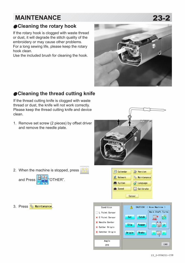
-D3 -158
23-2MAINTENANCE
23_2 RC01
Cleaning the rotary hookIf the rotary hook is clogged with waste thread or dust, it will degrade the stitch quality of the embroidery or may cause other problems.For a long sewing life, please keep the rotary hook clean.Use the included brush for cleaning the hook.
If the thread cutting knife is clogged with waste thread or dust, the knife will not work correctly.Please keep the thread cutting knife and deviceclean.
1. Remove set screw (2 pieces) by offset driver and remove the needle plate.
2. When the machine is stopped, press
and Press ”OTHER”.
3. Press .
Cleaning the thread cutting knife

-D3 -159
4. Press .In maintenance mode, pressing this button causes the moving knife to open and stop at max open position.
5. Remove any waste thread and dust from the knife assembly and surrounding area.
6. Press .Moving knife returns to the original position.
23-3MAINTENANCE
23_3 RC01
CAUTION: To prevent accidents.The thread cutting knife moves quickly. Keep your hands away from the machine.
Needle plate
Positioning pin
Press to return to Menu mode.
7. Put the needle plate on the bed.Please insert positioning pin to hole of the needle plate.
8. Tightsetscrews(2pieces)forfixtheneedleplate.

-D2 -110
24-1ERRORS AND WHAT TO DO
24_1 M201
.oN yalpsiD rorrE snoituloS egaP
100 draobtiucriC tiucriclortnocnidetcetedytilamronbAdraob
01retfa,dnaenihcamnwodrewoP.niaganorewop,sdnoces
200 ecruosrewoP egatlovlamronbaroeruliafrewoP
400 yromemmetsyS tluafyromemmetsyS
410 mralAnaF tluafnafgnilooC .relaeDruoytcatnoC
510 pirtretrevnI .elbuortdetaler-rotomgniweShtiwelbuort,tiucrictrohs,daolrevO
tinuevirdrotom
.dnahybtfahsniamnrutdnarewoptuC.niaganorewop,yllamronsnrutfI
2.giF610 tinuXmralA rotom-x.e.i,elbuortdetaler-rotom-X
htiwmelborp,tiucrictrohs,daolrevotinuevirdrotom
hpargotnaptset,enihcamfforewoPynarofkcehC.yllaunamtnemevomfoegnarlluftuohguorhtytilamronba
.noitomniaganorewop,dnuofenonfI
710 tinuYmralA rotom-x.e.i,elbuortdetaler-rotom-Yhtiwmelborp,tiucrictrohs,daolrevo
tinuevirdrotom810 tfahsniaM .nruttonlliwtfahsniaM lluf1tsaeltayllaunamtfahsniamnruT
gniraelc,yleerfsnruttitahterusne&nrutenihcamezilaitini-er,nehT.majyna
.deepsdnametsys
1-522-52
020 tcetedeldeeN #eldeentnerrucgnitcetedtonenihcaMsitinunoitcelesrabeldeenro,yltcerroc
htiwelbuorT.noitisoppotsstiffo.draobtiucricgnitceted-noitisop
dexifehtotrotcelesrabeldeennruTniwolebnwohsaeradekram(noitisop
.)1.giF
Turn the disk with3mm hexagonaldriver clockwise.
CAUTION: To prevent accidents.In case of "Automatic errors backup", the machine's sudden movement might be causedwithout showing errors or messages after its stoppage.
E-050 C point
OK
C
Fig. 1 Fig. 2
Situationalposition
Turn the needle barselection knob to themoving headsituational position.
The machine has an extensive error code list to aid in trouble-shooting when problems occur, as listed below. Upon error,press the to release the error and correct it accordingto the list below.When errors occur frequently, please contact your dealer.
Automatic errors backupThe machine recovers from some errors (E-050, E-190, E-193) automatically after detecting theerror(s) by it self. In cases where the machine does not recover from the error automatically,follow the “Soluions” below according to the indicated error number.

-D2 -155
24-2ERRORS AND WHAT TO DO
24_2 NC13
.oN yalpsiD rorrE snoituloS egaPp g021022
Needle move Motor for needle bar selection unit hasstopped partway through its path.No movement due to malfunction ofthread take-up lever or trouble ofposition-detecting circuit board
After fixing malfunction of needle andthread take-up lever, turn needle barselector shaft with wrench to have it setat center of fixed position (range withinwhich needle bar selector doesn't move)Fig. 1
024 Needle center Needle bar stop position is off-center;needle bar stop position is out of place.
Turn needle bar selector with 3mm hexwrench to have it set at center of fixedposition (scope within which needle barselector doesn't move).Fig. 1
025 Needle over Needle # out of range of actual needleson given machine.
026 Needle differ Needle # differs between
030 Slow mismatch Improper speed adjustment at lowspeed. Speed does not decrease below100rpm at low speed.
Re-initialize machine system and speed. 25-125-2
050 C point Main shaft is stopped in a position otherthan "C" point
See Fig. 2 below. 24-5
051 L sensor Timing detection board fault, or marredphoto-sensor. Malfunction of "Lowestneedle position" sensor [PH2] ondetection circuit board.Improper adjustment of slit plate.
Check to see if photo sensor is clean or ifthe slit plate contacts sensor.Re-initialize machine system and speed.
25-125-2
052 C sensor Timing board detection fault, or marredphoto-sensor. Malfunction of "Colorchange position" sensor [PH1] on timingdetection circuit board.Improper adjustment of slit plate.
060 X limit Frame/pantograph has moved beyondsewing area along X-axis.
Return frame within sewing area usingthe frame movement keys on the controlboxl.Check pattern size and center mark toensure that it is within size range ofselected hoop and also properlycentered.
061 Y limit Frame/pantograph has moved beyondsewing area along Y-axis.
063 Drive Setup During embroidery, preparation for framemovement did not complete withinpredetermined time.
Malfunction of "Lowest needle position"sensor on detection circuit board,Improper adjustment. Re-initializemachine speed. If this condition occursfrequently, contact your Dealer.
25-2
064 X Center sens. Trouble with X-Carriage sensor,Improper position adjustment, sensorrelay board fault, cable fault.
Contact your Dealer.
065 Y Center sens. Trouble with Y-Carriage sensor,Improper position adjustment, sensorrelay board fault, cable fault.
066 Frame drive During embroidery, frame movement didnot complete within predeterminedmoving time.
If this condition occurs frequently, contactyour Dealer.
Fig. 1
Situationalposition
Turn the needle barselection knob to themoving headsituational position.

-RA -91
24-3ERRORS AND WHAT TO DO
24_3 Q509
No. Display Error Solutions Page
001 Circuit board Abnormality was detected in controlcircuit board.
Turn off power source and turn it onagain.
002 Power source Power failure or lowered voltage
004 System memory System memory is out of order
014 Fan Alarm Contact your Dealer.
015 Inverter trip Sewing motor related troubleOver-load on sewing motor, short circuit,trouble of motor drive unit
Cut power and turn main shaft with hand.If no abnormality is found, turn on again.Fig. 2
016 Alarm X unit X axis motor related troubleOver-load on X carriage motor, shortcircuit, trouble of motor drive unit
Turn power off, move drive frame anddrive motor with a hand. If no abnormalityis found, turn power on again.
017 Alarm Y unit Y axis motor related troubleOver-load on Y carriage motor, shortcircuit, trouble of motor drive unit
018 Main shaft Main shaft doesn't turn Make sure if main shaft or drives arenormal.Initialize the machine system and themachine speed.
25-125-2
020 Needle detect Needle position is not detected. Needlebar selection unit is off its stop position.Trouble of position detecting circuitboard
Turn needle bar selection knob to thefixed position (Marked area).Fig. 1
021022
Needle move Motor for needle bar selection unitstopped halfway.No movement owing to malfunction ofthread take-up lever or trouble ofposition detecting circuit board.
After fixing malfunction of needle andthread take-up lever, turn needle barselection knob to the fixed position(Marked area).Fig. 1
024 Needle center Needle bar stop position is off center.Needle bar stop position is out of place.
Turn needle bar selection knob to thefixed position (Marked area).Fig. 1025 Needle over Needle number not existing in the
machine was specified.026 Needle differ Needle number at time of finish and start
of operation differs. It was changed tocorrect one.
030 Slow mismatch Improper speed adjustment at lowspeed. Speed doesn't decrease below100rpm at low speed.
Initialize the machine system and themachine speed.
25-125-2
050 C point Stop position of main shaft is out of itsplac
See Fig. 2 below. 10-6
051 L sensor Trouble of timing detecting board, dirtyphoto sensor [PH2](L.P.)Malfunction of "Lowest needle position"sensor on detecting circuit board.Improper adjustment of slit plate.
Photo sensor is dirty or the slit platecontacts sensor.Initialize the machine system and themachine speed.
25-125-2
052 C sensor Trouble of timing detecting board, stainof photo sensor [PH1](C.P.).Malfunction of "Color change position"sensor on timing detecting circuit board.
060 X limit Frame moved beyond sewing area side-ways.
Return frame within sewing area by useof the arrow button.Check pattern size and contents ofsettings.061 Y limit Frame moved beyond sewing area
length-wise.
066 Frame drive
If this condition occurs frequently, contactyour Dealer.
067 Position data Follow the instructions below.If this condition occurs frequently, contactyour Dealer.
24-8
068 Position set Check if position sensor is stained.Turn off power source once and turn it onagain.If not OK, contact your dealer.
069 Position Entry
070 Safety sensor Safety sensor activated by concerningdanger.
Be confirmed of nothing is put around thesafety sensor. Confirm the safety ofembroidery area.
090 Miss reception Error occurred during communication ofdata.
Read pattern data again from thebeginning.
5-4
091 No send Data did not sent in for over 10 seconds.
103 Data format The machine cannot automaticallydetermine the format of the pattern data.
Check data format of pattern data.Set data format properly.
14-5
104 Miss function Timing to read pattern data doesn'tconform.
Read pattern data again from thebeginning.
5-4
105 Dual function One stitch has more than 2 functions. Read pattern data again from thebeginning.
5-4
106 No function Distance between start point of readingand start point of pattern is too longwhen reading.
108 Improper read While reading pattern data, an erroroccurred.
Read pattern data again from thebeginning.
5-4
110 Memory full While reading a pattern, memoryexceeded its capacity.
Delete unnecessary patterns and readfrom the outset.
10-1
111 Change over While reading pattern data, thefrequency of color change (color No.)exceeded 250 times.
Reduce frequency of color change of onepattern to less than 250 times.
112 Data error Pattern data of pattern to beembroidered is damaged.
Delete pattern and read pattern dataagain.
5-8
114 Id over The number of patterns in memory hasreached maximum of 99.
Delete unnecessary patterns and readagain from the bebinning.
5-8
116 Not found Id Specified pattern doesn't exist. Check setting.
118 Trace data over Over 1024 stitches trace data werecreated during reading of pattern data.
Set maximum stitch length to Embroideryarea of pattern data within 2m(lengthwise) x 2m(side wise).
120 Memory error It became impossible to retain contentsof memory.
If this condition occurs frequently, CPUcircuit board is out of order.Contact your Dealer.
130 Card error Incapable of disposing of memory cardcontinuously.
Turn off power source once and turn it onagain.If not OK, contact your dealer.
131 Card no ready Memory card is not set. Check if memory card is properly set. 5-5
132 Write protect Disk write protect. Make write protect tab in data disk"Writing possible".
2-?
133 Bad card Memory card is not proper or broken. Memory card cannot be read or brokenmemory card or memory card notinitialized.Contact your Dealer.
5-5
134 Disk unit Trouble in disk drive unit. Turn off power source once and turn it onagain. If not recovered, it will be trouble indisk drive unit.
140 Entry over Capacity is full for registeringpatterns.(refer to page of""SPECIFICATIONS"")
Clear unnecessary patterns. Or useother data disk.
141 Not found name Designated pattern is not found. Memory card is not correct. 5-5
142 Disk full Capacity is full for storing. (refer to page of "SPECIFICATIONS")
Clear unnecessary patterns. Or useother data disk.
21-1
143 Multi name If there is multi name of data whenwriting.
Change name, write in another disk.(Over write)
190 Cut blade Thread cut knife is not at stop position. Follow the instructions below. 24-6
193 Catcher Thread catch hook is off its positionLimit switch to detect position is not"OFF".
Please follow the exsample below.1. Check if it does not cut thread.If thread is not cut, cut it and return thethread catch hook to its normal position.2. If threads are cut, check if thread catchhook on head has returned to its positioncompletely.
24-7
215 Frm. drive err If this condition occurs frequently, contactyour Dealer.
217 Frm.drive data
220 Calendar Stop
Contact your Dealer.
3-7
221 Battery Low
Contact your Dealer.222 Calendar Data
Contact your Dealer.
3-7
067 Position data Loss of embroidery frame coordinatedata.
If this condition occurs frequently, contactyour Dealer.
068 Position set Failure to read embroidery frame sensorsignal. (Return)
Check if position sensor is dirty.Turn off power source, then turn onagain.If problem still persists, contact yourDealer.
069 Position Entry Failure to read embroidery frame sensorsignal. (Entry)
070 Safety sensor Safety sensor has been tripped. Clear area around safety sensor. Ensurethat sewing area are clear.
090 Miss reception Error has occurred during data transfer(via cable) between machine and PC.
Try reading pattern data again. Verifythat transmission speed setting is correctat (1) transfer software; (2) devicemanager of PC and (3) RS-232C speedof machine.
5-4
091 No send Machine has not received data for > 10seconds during data transfer.
103 Data format Machine unable to determine format ofpattern data.
Verify format of pattern data and fix ifnecessary.
10-3
104 Miss function Timing to read pattern data does notconform.
Read pattern data again from the start. 5-4
105 Dual function Data has been detected in the patternthat has ambiguous/dual function.
Read pattern data again from the start. 5-4
106 No function Interval between start read time andtime of reception of actual pattern datais too grea.
Check quality of design data.
108 Improper read While reading pattern data, error hasoccurred in internal processing.
Read pattern data again from the start. 5-4
110 Memory full Memory has filled while reading in adesign.
Delete unnecessary patterns frommachine memory and try again.
5-B
111 Change over While reading pattern data, # of colorchanges (color No.) has exceeded 250.
Divide pattern data such that number ofcolor changes of each segment is lessthan 250.
112 Data error Pattern data of current design isdamaged.
Delete pattern and re-load. 5-B
114 Id over # of patterns in control panel memoryhas exceeded the maximum of 999.
Delete unnecessary patterns frommachine memory and try again.
5-B
116 Not found Id Specified pattern does not exist. Check setting.
118 Trace data over Over 1024 stitches trace data werecreated during reading of pattern data.
Set maximum stitch length to embroideryarea of pattern data within 2m(lengthwise) x 2m (sideways).
120 Memory error Fault in retaining contents of patternmemory.
If this occurs frequently, it is likely thatLCD-CE board is faulty.Contact your Dealer.
130 Disk error Unable to communicate continuouslywith memory media.
Power down machine and after a 10seconds, power on again.If error remains, contact your Dealer.
131 Device no ready Memory media is not set. Check if memory media is properly set. 5-5
133 Bad card Improper or faulty memory media. Memory media that media reading unitcan't read or faulty media or un-initializedmedia.
5-5
141 Not found name Designated pattern is not found. Memory card is not correct. 5-5
142 Disk full Memory media is full to capacity. Clear unnecessary patterns or use adifferent memory media.
143 Multi name Another pattern with same name hasbeen detected while attempting to writeto memory media.
Change name, use a different memorymedia, or overwrite existing pattern.
ssuzuki
長方形
ssuzuki
長方形
ssuzuki
タイプライターテキスト
3000

-RA -90
24-4ERRORS AND WHAT TO DO
24_4 O512
y190 Cut blade Thread cut knife is not at stop position. Follow the instructions below. 24-5
191 Cut Sensor Thread cut knife is not at stop position. Check if threads are jammed aroundthe thread cutting knife.Press the thread cutting button 2~3 times.If error remains, contact your Dealer.
23-223-4
193 Catcher Thread catch hook is off its position.Limit switch to detect position is not"OFF".
Please follow the example below:1. Check whether thread was actually cutby thread cutting knife. If not, cut threadand return catch hook to its normalposition.2. If thread is actually cut, check if threadcatch hook on head has returned to itsposition completely.
24-6
203 Install data Error has occurred during update ofprogram.
Check an update program.
215 Frm. drive err Frame movement did not completeduring normal movement. (Time over)
If this condition occurs frequently, contactyour Dealer.
217 Frm.drive data Frame movement data loose.
255 Default Error During embroidery, frame movement didnot complete until main shaft reach"Lowest needle position".
Re-initialize machine speed setting.Check adjustment of upper shaft timing.(C point / L point)If this condition occurs frequently, contactyour Dealer
25-2
.oN yalpsiD rorrE snoituloS egaP

-DA -154
24-5ERRORS AND WHAT TO DO
24_5 Q101
1. Press .
2. Select “Auto”.
The main shaft turns 2 to 3 times and returns to a stop position (“C” point ) automatically. The display returns to drive mode.
What to do when Stop position of main shaft is out of place (error
1. Press .
2. Select “Manual”.
The error status is released and the display shows “drive mode”.
3. Remove the cap over the small hole in the rear of the machine. Using a 3 mm hexagonal driver, Please turn the main shaft and adjust it to the “C” point.
CAUTION! <Main shaft turns>
C
When you cannot clear by the method above (Auto)
E-050 C point
OK
E-050 C point
OK

-DA -155
24-6ERRORS AND WHAT TO DO
24_6 Q101
1. Press .
2. Select “Auto”. The display returns to the drive mode.
What to do for “Thread cut knife is not at the stop position (error E-190)”
1. Press .
2. Select “Manual”.
The error status is released and the display shows “drive mode”.
3. Using a 3 mm hexagonal driver, Please turn the main shaft and adjust it to the “C” point. C
When you cannot clear by the method above (Auto)
E-190 Cut blade
OK
E-190 Cut blade
OK

-DA -157
24-7ERRORS AND WHAT TO DO
24_7 O901
4. When the machine is stopped, press
and Press ”OTHER”.
5. Press .
6. Press .You should hear the sound of moving knifeopening.
7. Press .You should hear the sound of moving knifereturning to the closed position.
Press to return to Menu mode.
Press once again to return to Drive
mode.

-DA -157
24-8ERRORS AND WHAT TO DO
24_8 Q101
1. Press .
2. Select “Auto”.
The thread catch hook returns to the original position. The display returns to drive mode.
What to do for “Thread catch hook is off its position (error E-193)”
1. Press .
2. Select “Manual”.
The Error status is cleared and the display shows “drive mode”.
3. Refer to the page in the section (ERRORS AND WHAT TO DO), and determine what may be preventing the hook from returning to the original position, and follow the steps outlined. 24-3
When you cannot clear by the method above (Auto)
E-193 Catcher
OK
E-193 Catcher
OK

-3A -102
25-1INITIALIZING OF MACHINE SETTINGS
25_1 U901
Re-Initialization of machine systemPerform this function only to fix problems with the machine.
Initialize the systemWhen performed, all settings in the “OPTION” menu are lost.Be sure to reset the “OPTION” menu after performing this function.
Initialize the PMSPlease activate this function when the embroidery machine has malfunction after the operation with Happy PMS (Production management system).Please refer to instruction book of “Happy PMS” for more precise information.
Initialize the NetworkWhen performed, all settings in the “Network” menu are lost.
System initialize OK?
Cancel OK
1. When the machine is stopped, press
and Press “OTHER”.
2. Press .
3. Press .Go on to step 5.
Press . Press .
Go on to step 5.
4. Press .
5. Press to carry out.Formatting of the machines systems are carried out. Indicate HAPPY logo in screen.
If you cancel, press the .The display returns to MENU.
PMS initialize OK ?
Cancel OK
Reboot ?
Cancel OK
Network initialize OK?
Cancel OK

-RA -95
1. When the machine is stopped, press
and Press “OTHER”.
2. Press .
3. Press to execute.
The machine will display a warning, then start turning the main shaft automatically. The speed will slowly increase from slowest speed to maximum and then stop automatically and return to Drive mode.
If you cancel, press the .
The display returns to MENU.
25-2INITIALIZING OF MACHINE SETTINGS
25_2 Q101
Initializing of machine speedIf you have E-18, E-30, E-51 or E-52 while sewing, Please try initializing the machine settings.
Speed setting OK? CAUTION! <Main shaft turns> Cancel OK
CAUTION! <Main shaft turns>

-DA -158
MELBORP ESUAC NOITCERROC EGAP
daerhtreppUskaerb
.dedaerhtylreporptonenihcaM.yltcerrocnidetresnieldeeN
.thgitootnoisnetdaerhT.ytilauqdaerhtrooP
koohyrDynitsuounitnocrosehctitsytpmE
.atadngisednisehctitsreppunanidelgnatsidaerhT
.enocdaerht
.enihcamdaerht-eR,rebmemer(.eldeentresni-eR
)!kcabdnatnorfaevahseldeen.noisnetdaerhttsujdaeR
.daerhtytilauqdooghtiwecalpeR.koohehtliO
neht,noitcnufpeewshctitsnonruT.niaganiatadngiseddaer
.daerhtelgnat-nU
6-41-4
1-8
1-324-41
rewoL)nibbob(
skaerbdaerht
.yltcerrocnidedaerhtnibboB.llufootroylnevenudnuownibboB
.thgitootnoisnetdaerhT.koohehtnotriD
koohyrD
.nibbobehtdaerht-eR.nibbobehtdniw-eR
.noisnetdaerhttsujdaeR.koohehtnaelC
.koohehtliO
5-44-45-42-321-32
kaerbdaerhTpusthgilpmaldaerhtetipsed
gniebtoneslaF(nekorb
)skaerbdaerht
gnissaptonsidaerhtreppU.rellorgnitcetedehtdnuora
.yltcerrocdaerhtreppudaerhT 7-4
spiksenihcaMsehctits
.yltcerrocnidetresnieldeeN.eldeentnulbrotneB
.eldeenfoezistcerrocnI
.eldeentresni-eR.eldeenwentresnI
rofeldeenezistcerrocesoohC.cirbaf
1-41-42-4
srekcupcirbaF .dedaerhtylreporptonenihcaM.yltcerrocnidedaerhtnibboB
.eldeentnulB.thgitootnoisnetdaerhT
.enihcamdaerht-eR.nibbobehtdaerht-eR
.eldeenwentresnI.noisnetdaerhttsujdaeR
6-45-41-41-8
enihcaMesoolsekam
rosehctitsspool
.yltcerrocnidedaerhtnibboB.dedaerhtylreporptonenihcaM
.ylreporpdetsujdatonnoisneT
.nibbobehtdaerht-eR.enihcamdaerht-eR
.noisnetdaerhttsujdaeR
5-46-41-8,5-4
noisnetrooPecnalab
.yltcerrocnidedaerhtnibboB.dedaerhtylreporptonenihcaM
koohyrD
.nibbobehtdaerht-eR.enihcamdaerht-eR
.koohyratorliO
5-46-41-32
ngisedrooPnoitartsiger
.yltcerrocdepoohtoncirbaFcitsalefoedamsitnemraG
.lairetamenihcamotnidellatsnitonpooH
.ylreporp
.yltcerrocgnippoohteSerusnednagnikcabtcerrocesU
.yalrednureporpsahngisedtaht.yltcerrocpoohteS
9-7,2-69-7,2-6
5-7,3-6
skaerbeldeeN .eldeentnulbrotneB.tcerrocnignitteseldeeN
.lairetamtsniagaeldeennihT.gnipoohrooP
.eldeenwentresnI.eldeentresni-eR
.eldeenrekcihtotegnahC.cirbafpooh-eR
1-41-42-4
snurenihcaMytluciffidhtiw
.ecarkoohehtnotriD .koohyratornaelC.koohyratorliO
2-321-32
lliwenihcaMnurton
lacirtceleotnideggulptondroC.teltuo
.nodenruttonsihctiwsrewoP
.nwolbsahesufecruosrewoP
.teltuootniyllufgulptresnI
.hctiwsehtnonruT.)A6(esufecruosrewopecalpeR
5-31-3
nonruttonlliw dekcolninottubpotsycnegremE.noitisop
nottubpotsycnegremeesaeleR.kcol
8-3
HELPFUL HINTS
26_1 M416
26-1

-DA -169
EMBROIDERY TERMS
26_2 RC01
26-2Thread break back
With this setting, drive frame backs up several stitches after a thread break before stopping.
Color change number The Needle number (thread color) to be sewn can be set to each Color change number. For example, if a pattern is divided by a color change function in 2 places, 3 color change numbers exist in the pattern. When the needle number is set to its respective color change number, the pattern is sewn in 3 colors.
Memory patternPatterns stored in memory.
Start point of the frameThis is the point where the frame begins to move before the machine starts sewing.
Various function settingsA general term for Needle bar selection, Convert, Pattern adjustment, Repeat sewing, Offset and frame out which are set in the pattern data.
Zero stitchThis is a stitch whose net movement in both the X- and Y- direction is zero, and the needle lands in the same position.
Original PointThe frame position where the machine embroiders the pattern from the beginning is automatically reg-istered as the original point.
StitchesThis is the minimum unit within the pattern data. There are different types of such “stitches”: “stitches” that command determine the sewing sequence; “functions” that dictate functions such as jumps, thread cut, etc; “sideways movement distance” and “lengthwise movement distance” that command the movement distance of the frame.
Auto originThis returns the frame automatically to the original point upon finishing the embroidery.
Tubular round frame, Tubular square frame
The frames made by HAPPY and used for cylin-der sewing, such as on T-shirts, bags, etc. These frames have brackets at both sides.
Memory mediaWhat saves design data by things, such as memo-ry card and a USB flash drive.
Data format This is the format that the pattern data is convert-ed into/
Color change stopWhen a color change stop is assigned to a color change number, the machine embroiders the set color change and stops.
ConversionThis is a user-adjustable design setting of a given pattern that allows rotation in increments of 90 degrees.
Pattern dataEmbroidery data that has been converted to the format such as TAP, DST, DSB, DSZ.

-RA -110
26-3BUILT-IN FONT LIST
26_3 P401
Basic script, Diacritic script

-RA -111
26-3aBUILT-IN FONT LIST
26_3a P401

-RA -112
26-3bBUILT-IN FONT LIST
26_3b P401
Those fonts are created by (www.i-cliqq.com)
Cyrillic script

-SJ -93
BUILT IN PATTERN includes clip art from [Master clip] created by H2soft (Fax:+81-422-28-5211E-mail:[email protected]).
26-4BUILT-IN PATTERN LIST
26_4 N602


-S3 -122
27-1VARIOUS SPECIAL FRAMES (OPTIONS)Special frames for various purposes are available as options.Use a special frame corresponding to the material and shape of the object to be embroidered.
26_4 U701
One-Point Embroidery Frame
Shoe Clamp Frame
Side Clamp Frame
Square Clamp Frame
One Touch Frame
Tubular Sock Frame Holder

FOTC12-8
HCH(Plus),HCS2,HCD2(HCD3E), HCD3,HCU,HCR2,HCR3
One-Point Embroidery Frame (small) / (large) Long One-Point Embroidery FrameINSTRUCTION MANUAL
IMPORTANT SAFETY INSTRUCTIONS
Use this Manual together with Instruction Manual of embroidery machine for mounting this appliance and for
operating.
Use this appliance only for its intended use as described in this manual. Use only attachments recommended
by the manufacturer as contained in this manual.
Keep fingers away from all moving parts. Special care is required around the sewing machine needle.
Do not pull or push fabric while stitching. It causes damage.
Do not modify this appliance.
SAVE THESE INSTRUCTIONS
0

-FO -2
INDEX
Basic information of One-point frame....................... 1-1
Frames
One-point frame .................................................... 1-2
Long One-point frame ........................................... 1-3
Preparation ............................................................... 2-1
One-point frame settings
HCH, HCS2 ........................................................... 3-1
HCD2, HCD3, HCU, HCR2, HCR3 ....................... 3-2
Adjustment of One-point frame ................................ 4-1
Hooping fabric
One-point frame .................................................... 4-2
Long One-point frame ........................................... 4-4
Starting to sew ......................................................... 5-1
Frame confirmation .................................................. 6-1
Installing and removing the guide ............................ 7-1
Exchanging setting plate .......................................... 8-1
etc.
Exchange Cushion ................................................ 9-1
0_1 Q203
0-1

-FO -3
1-1BASIC INFORMATION OF ONE-POINT FRAME
1_1 _ Q203
• Please read all instructions before using this appliance.
• The entrance width of item for the One-point Frame
Entrance widthOne-point Frame S : more than 105mmOne-point Frame L : more than 130mmLong One-point Frame : more than 170mm
Long One-point Frame cannot be used for HCH, HCS2, HCR2 machine.
Sizes will be changed by type of fabric and form of item. Please check before using thisframe.
Entrance width
Frame L
Entrance width
Frame S
Entrance width
Long Frame

-FO -4
One-point frame
FRAMES
FRA48010 One-point frame (small)EMB. area (YxX) : 60 x 40 mm 55 x 40 mm (HCH, HCS)
Accessories
1-2
1_2 _ N101
FRA48020 One-point frame (large)EMB. area (YxX) : 60 x 76 mm 55 x 76 mm (HCH, HCS)
Setting base
FRA48140 W-clip(packed with frame)
FRA48130 Cushion(packed with frame)
FRA48111 One-point frame setting base
You can modify setting base from cap stretcher byexchanging setting plate.
FRA48120 One-point frame setting plate

-FO -5
Long One-point frame
FRAMES
FRA48160EMB. area (YxX) : 200 x 55 mm Accessories
1-3
1_2 _ N101
Long One-point frame setting baseFRA48200Long one-point frame setting base
You can modifysetting basefrom capstretcher byexchangingsetting plate.
FRA48210Long one-point frame setting plate
FRA48130 Cushion(packed with frame)
FRA48140 W-clip(packed with frame)

-FO -6
2-1PREPARATION
2_1 N101
1. Prepare Drive Frame which Guide is not installed.
The following preparation steps are required forusing One-point Frame. 7-1
2. Install Drive Frame.
Please refer to "[CAP FRAME]-[Installing andremoving the cap drive frame]" in machineinstruction manual.
3. Prepare One-point frame setting base.
In case you have Cap Stretcher, you can modify
it by exchanging setting plate. 8-1
The following preparation steps are required for using One-point Frame.
Drive Frame without Guide
One-point frame setting plate Long one-point frame setting plateOne-point frame setting base (for S, L) Long One-point frame setting base

-FC -5
3-1ONE POINT FRAME SETTINGSOne Point Frame has 2 different size (S size and L size).When you use One Point Frame, please make machine setting according to frame size selected.
CAUTION: To avoid problems.The machine and / or One point frame may be damaged if the incorrect frame settings are used.
3_1 M501
ON
OFF Selected frame
HCH, HCS2
1. Turn on the power switch.
Indicates the selected frame.
2. In case required One-point frame is already selected, press the abd jump to operation no.4. In case selected frame type is not same as your re-
quirement, press .
3. Select “Cap and One-point frame”.
Change the type of frame.
OnePoint S : One-point frame (small)OnePoint L : One-point frame (large)
4. Select desired size of frame and press .
The embroidery area and outline of the pattern itself appear in red. All are displayed on the left together.

-FO -8
3-2ONE-POINT FRAME SETTINGS
3_2 Q203
CAUTION: To prevent accidents.The frame moves quickly.Keep hands away from the frame.
5. Press .
After the carriage and frame move slightly, theembroidery frame will return to the previousposition automatically.Machine becomes ready for operation.
One-point frame will be shown in the lower rightcorner of the screen.Then One-point frame will be set.
HCD2, HCD3, HCU, HCR2, HCR3
1. When the machine is stopped, press .
2. Select "FRAME".
3. Select "Cap and One-point frame".
Change the type of frame.
OnePoint S : One-point frame (small)OnePoint L : One-point frame (large)L.OnePoint : Long One-point frame (except
for HCR2)
4. Select desired size of frame and press .
The embroidery area and outline of the patternitself appear in red. All are displayed on the lefttogether.

-FO -9
3-3ONE-POINT FRAME SETTINGS
3_3 N101
CAUTION: To prevent accidents.The frame moves quickly.Keep hands away from the frame.
5. Press .
After the carriage and frame move slightly, theembroidery frame will return to the previousposition automatically.Machine becomes ready for operation.
One-point frame will be shown in the lower rightcorner of the screen.Then One-point frame will be set.

-FO -10
4-1ADJUSTMENT OF ONE-POINT FRAME
4_1 N101
1. Adjust the position of Hook according to the thick-ness of the fabric for keeping proper clamp tension.The hook has to be closed and opened without hightension. For adjustment of tension, use the wingnuts.In case you have no allowance to adjust tension forthick fabric, refer operation no.2 and adjust tension.
If the hook has extremely high tension, it willdamage frame itself.
2. In case position of upper and lower frame isnot matching because of thickness of fabric,adjust position of upper frame by wing nuts.
The upper frame should be parallel to the lowerframe.
If position is not parallel, fabric is not held firmlyand it may happen that frame hits pressure footand damages machine.
The following adjustment is required for setting fabric.
Wing nutHook
Lower framelUper frame
Wing nut

-FO -11
4-2HOOPING FABRIC
4_2 K101
Hold lever
1. Place Frame setting base securely on a sturdy workbench.
2. Hold One-point frame with both hands and place onFrame setting base.By pushing Hold levers at 2 places with fingers,place One-point frame so that center guide of Framesetting base fits in concave area of One-point frame.
Confirm that the Frame is securely placed onFrame setting base.
3. Open upper frame and keep open to the right.
4. Set pocket to frame with opening pocket.
Please place one or two sheets of nonwovenfabric (backing) of standard thickness underunstructured fabrics.
5. Pull back fabrics and hook it on the hook and smoothout creases on fabrics.
6. Latch the hook, taking care not to cause wrinkles inthe fabrics.
Hook
Uper frame
Center guideConcave
Framesettingbase
One-point frame
One-point frameAs example, pocket setting for dress shirts is introduced.

-FO -12
4-3HOOPING FABRIC
4_3 K101
7. Remove the One-point frame from the Framesetting base.
8. Set frame on Cap frame driver with opening pocket.Please confirm bed of machine is entered intopocket.Then, push the holder lever in the 2 places shown,and place the One-point frame on so that the centerguide of the Cap drive frame assembly fits into theOne-point frame notch.
Confirm that the Frame is firmly seated on thecap drive frame assembly without any gaps.If there is a gap between the Frame or the capdrive frame holding lever doesn't go into the holeof the Frame, loosen the set screw on the holdlever for adjustment.
Hold lever
Centerguide
Cap driveframe
W-clipW-clip is used when you make embroidery on stretchfabric or thin fabric.Especially large design or many filling stitches is re-quired, fabric may shrink.
One-pointframe
W-clip
CAUTION: To avoid problems.Do not power machine on, when frame is placed withfabric.Machine may move wider area than embroidery areaof frame and damage frame, machine and fabric

-FO -13
4-4HOOPING FABRIC
4_4 N101
Hold lever
1. Place Frame setting base securely on a sturdy workbench.
2. Hold One-point frame with both hands and place onFrame setting base.By pushing Hold levers at 2 places with fingers,place One-point frame so that center guide of Framesetting base fits in concave area of One-point frame.
Confirm that the Frame is securely placed onFrame setting base.
3. Open upper frame and keep open to the right.
4. Set pocket to frame with opening pocket.
Please place one or two sheets of nonwovenfabric (backing) of standard thickness underunstructured fabrics.
5. Pull back fabrics and hook it on the hook and smoothout creases on fabrics.
6. Latch the hook, taking care not to cause wrinkles inthe fabrics.
Hook
Uper frame
Center guideConcave
Framesettingbase
One-point frame
Long One-point frameAs example, sleeve setting for dress shirts is introduced.
Roll upfabricsprotrudedfrom frame.

-FO -14
4-5HOOPING FABRIC
4_5 N101
8. Remove the One-point frame from the Framesetting base.
9. Set frame on Cap frame driver with opening pocket.Please confirm bed of machine is entered intopocket.Then, push the holder lever in the 2 places shown,and place the One-point frame on so that the centerguide of the Cap drive frame assembly fits into theOne-point frame notch.
Confirm that the Frame is firmly seated on thecap drive frame assembly without any gaps.If there is a gap between the Frame or the capdrive frame holding lever doesn't go into the holeof the Frame, loosen the set screw on the holdlever for adjustment. Hold lever
Centerguide
Cap driveframe
One-pointframe
W-clip
CAUTION: To avoid problems.Do not power machine on, when frame is placed withfabric.Machine may move wider area than embroidery areaof frame and damage frame, machine and fabric
Thick fabricThin fabric Change the number W-clip
7. Fasten around frame with bundled W-clips.
Use more W-clips when you make embroi-dery on stretch fabric or thin fabric.Especially large design or many fillingstitches is required, fabric may shrink.

-FO -15
5-1STARTING TO SEW
Embroidery area (Max.)
5_1 N101
40mm (small), 76mm (large),55mm (long)
60mm (small) (large)(55mm HCH, HCS2)
200mm (long)
:Original point (Start point)
You can confirm the outlineand position of design.
Embroideryarea
1. Press the and move the frame to the original
point with the .
2. Press the .
Press , and the embroidering frame movesfor the design trace.Make sure that the pressure foot and needle donot touch the frame.
Press , and trace is stopped.
Go on to step 4 if you want to start embroideringwithout tracing.
3. Press after the trace is completed.
The embroidering frame has moved to the firststitch point of the pattern.
Pose
Backward only when pressingForward only when pressing

-FO -16
5-2STARTING TO SEW
5_2 M501
4. Press the .
The embroidery will start.
5. After finishing your design, the display will show">>End" and the machine will stop.
The embroidery frame returns to the originalpoint automatically if the auto origin function hasbeen activated.
>>End
:Original point (Start point)

-FO -17
6-1FRAME CONFIRMATION
6_1 Q203
The embroidery area of HAPPY One-point frame S and One-point frame L is saved in the machine.This allows confirmation of positioning between the embroidery area and the pattern.
Embroidery area(Sidewise)
Embroidery area(Lengthwise)
Embroidery area
1. When the machine is stopped, press .
2. Select "FRAME".
2. Select "Cap and One-point frame".
Change the type of frame.
OnePoint S : One-point frame (small)OnePoint L : One-point frame (large)L.OnePoint : Long One-point frame (except
for HCH, HCS2, HCR2)
4. Select desired frame and press .
The embroidery area and outline of the patternitself appear in red. All are displayed on the lefttogether.
5. Confirm that (Top) appears in the display andgo to step 7.
If this does not appear, go to step 6.

-FO -18
6-2FRAME CONFIRMATION
6_2 N101
6. Press "Top".
Upper left indication of will be shown.
7. By position of design can be
moved.
8. Press .
The display returns to MENU.
Start sewing by pressing .

-FO -19
7-1INSTALLING AND REMOVING THE GUIDE
7_1 N101
When One-point frame is used, Guide should be removed from Drive Frame.When Cap frame is used, Guide should be installed on Drive Frame.The following is process of installing and removing Guide.
When Long-One point frame is used, Guide should not be removed from Drive frame.
Installing1. Install Drive frame on machine.
Refer to "[CAP FRAME]-[Installing and removingthe cap drive frame]" in machine instructionmanual.
2. Put Guide (right) one needle plate and fix Guide by 2screws (M4x10).Then fix Guide (left) as well.
Please do not press Guide down too much anddo not have clearance between pressure footand tape under Guide.
3. After setting Guide, please confirm following points:Needle hole is located center position of right andleft Guide.Height is equal for right and left Guide.Clearance of tape and needle plate is equal for rightand left Guide.When frame is moved front and back, Guide is nothitting to needle plate.
Guide
Screws
Tape

-FO -20
4. Fix the Reinforcement plate (M4x6 2pcs).
Completed
7-2INSTALLING AND REMOVING THE GUIDE
7_2 K101
RemovingPlease remove by reverse order of these step.When you take Guide out, you do not need to use Drive Frame.
Reinforcement plateScrewScrew

-FO -21
8-1EXCHANGING SETTING PLATE
8_1 K101
1. Place cap stretcher securely on a sturdywork bench.
2. Loosen screws (M5x12, Spring washer, washer each2pcs).
3. Loosen screws (M5x20 2pcs).
Please be careful that Stretch plate ass'y, RBlock and Back plate will be taken out togetherfrom base .
These parts are taken from base as photo.
Cap Stretcher can be modified for One-point frame with exchanging setting plate.Contruction of One-point frame setting base is same as Cap stretcher except shape of setting plate.
Back plate
R block
Stretch plate ass'y

-FO -22
8-2EXCHANGING SETTING PLATE
8_2 N101
4. Loosen screw (M4x10 4pcs) and remove theStretch plate.
These parts are taken from Stretch plate ass'y asphoto.
5. Set One-point frame setting plate on Cylinder byscrews (M4x10 4pcs).
6. Set Setting plate ass'y, R block and Back plate byscrews (M5x20 2pcs).
Stretch plate (for cap frame) Cylinder
One-point frame setting platefor One-point frame for Long one-point frame

-FO -23
8-3EXCHANGING SETTING PLATE
8_3 N101
7. Set Back Plate on Hinge by screws (M5x12,Spring washer and washer each 2pcs).
As springs pull Cylinder down, cylinder should bepushed up for screwing.
Finish operation
Hinge
Same operation is required to modify from One-point frame setting base to Cap Stretcher.
Cylinder
for One-point frame
for Long one-point frame

-FO -24
9-1etc.
9_1 N101
Exchange CushionCushion is located under the upper frame to hold fabric firmly.When cushion is worn or damaged, please exchange cushion.Please cut cushion to required length and attach under upper frame.
Cushion
Upper frame
Cushion
Upper frameLong One-point frame
One-point frame

C
25
C
25
ONE POINT FRAME (HOLD FRAME) 19d-1CRK409
2021
22
14
1911
3
A
B
G
EE
30F
13
12
I
21 20
22F
23
EI
H
7H
D
27
2
2
2
6
6
5
5
8
2021
22
1415
1911
3
A
B
G
EE
30F
13
29
I
21 20
22F
23
EI
H
7H
D
27
2
2
2
6
6
5
5
8

ONE POINT FRAME ワンポイント枠 19d-1 組 指図 部品番号 部品名 CRK101 備考
Ass'y El't Parts No. Parts Names Note
1 FRA48010 One point frame S ワンポイント枠S2 FRA48091 Hold ruber under 下押さえゴム3 FRA44180 Cap marker センターステッカー4 FRA48030 Hold frame S 取り付け枠(小)セット5 FRA48101 Hold ruber upper 上押さえゴム6 FRA48130 Hold ruber cushion 上押さえクッション7 FRA48150 Spacer スペーサー8 FRA48140 W-clip ダブルクリップ
11 FRA44170 E-ring Eリング12 FRA48070 Upper frame S 上枠(小)13 FRA44160 Latch 小型パチン錠14 FRA48020 One point frame L ワンポイント枠L15 FRA48040 Hold frame L 取り付け枠(大)セット19 FRA46141 Spacer スペーサー20 FRA46610 Side holder ass'y サイド押えセット21 FRA46630 Side holder cushion サイド押えゴム22 FRA46182 Side holder サイド押え23 FRA46082 Bracket ブラケット25 FRA46520 Side support (right) サイド受け(右)27 FRA46530 Side support (left) サイド受け(左)29 FRA48080 Upper frame L 上枠(大)30 FRA46151 Latch bracket パチン錠ブラケットA SGAD03004 Flat head screw (phillips, M3x4) 十字穴付き皿小ねじ(M3x4)B SGAD03006 Flat head screw (phillips, M3x6) 十字穴付き皿小ねじ(M3x6)C SPDD04006 Pan head screw (phillips, M4x6) 十字穴付きなべ小ねじ(M4x6)D SCAD04045 Hex socket head cap screw (M4x45) 六角穴付きボルト(M4x45)E WSAD03000 Spring lock washer (M3) ばね座金(M3)F WPAD03000 Plain washer (M3) 平座金(M3)G NHCD03000 Hex nut (M3) 六角ナット(M3)H NHAD04000 Hex nut (M4) 六角ナット(M4)I NWBK03000 Wing nut (M3) ちょうナット(M3)

19e-1ONE POINT FRAME (SETTING BASE) FRL101
1JB
LM
4A5
3 B2
97
14K
B
KA
11
HB21
13
D15
22212324
25N
27
C16
1718
I
26
16
1718
E
20a
FG
EO 20
19
20b

ONE POINT FRAME (SETTING BASE) ワンポイント枠(段取台)19e-1 組 指図 部品番号 部品名 FRL101 備考Ass'y El't Parts No. Parts Names Note
1 FRA48111 Setting base (for One point frame) 段取台組(ワンポイント枠用)2 FRA44600 Base E ブロックE3 FRA44610 Stopper A ストッパーA4 FRA44581 Hinge 平蝶番5 FRA44590 Base D ブロックD7 FRA44620 Tension coil spring 保持ばね9 FRA44562 Base B ブロックB
11 FRA44571 Base C ブロックC13 FRA44630 Cushion クッションゴム14 FRA44531 Back plate バックプレート15 FRA44541 R block Rブロック16 FRA43591 Lever bracket (right) レバーブラケット(右)17 FRA43560 Hold lever ass'y (right) 保持レバー(右)組18 FRA43620 Torsion coil spring (right) ねじりコイルバネ(右)19 FRA43611 Support pin 段付きピン
20a FRA43602 Lock pin ロックピン20b FRA43603 Lock pin ロックピン20 FRAU43603 Lock pin set
This can be substituted for "20a".ロックピン(組)"20a" の代用可
21 FRA43550 Spring 板ばね22 FRA43542 Center guide センターガイド23 FRA43651 Lever bracket (left) レバーブラケット(左)24 FRA43630 Hold lever ass'y (left) 保持レバー(左)組25 FRA43660 Torsion coil spring (left) ねじりコイルバネ(左)26 FRA44511 Cylinder 保持リング27 FRA48120 Stretch plate (for One point frame) 布張り板(ワンポイント枠用)A SCAD05020 Hex socket head cap screw (M5x20) 六角穴付きボルト(M5x20)B SCAD05012 Hex socket head cap screw (M5x12) 六角穴付きボルト(M5x12)C SGAD03005 Flat head screw (phillips, M3x5) 十字穴付き皿小ねじ(M3x5)D SPAD03005 Pan head screw (phillips, M3x5) 十字穴付きなべ小ねじ(M3x5)E SPDD04008 Pan head screw (phillips, M4x8) 十字穴付きなべ小ねじ(M4x8)F NHCD04000 Hex nut (M4) 六角ナット(M4)G WSAD04000 Spring lock washer (M4) ばね座金(M4)H SWAK10020 Wing bolt (M10x20) ちょうボルト(M10x20)I SPDD04010 Pan head screw (phillips, M4x10) 十字穴付きなべ小ねじ(M4x10)J SCAD05035 Hex socket head cap screw (M5x35) 六角穴付きボルト(M5x35)K NHAD05000 Hex nut (M5) 六角ナット(M5)L WSAD05000 Spring lock washer (M5) ばね座金(M5)M WPAD05000 Plain washer (M5) 平座金(M5)N WPAD03000 Plain washer (M3) 平座金(M3)O SPDD04006 Pan head screw (phillips, M4x6) 十字穴付きなべ小ねじ(M4x6)

C
25
LONG ONE POINT FRAME (HOLD FRAME) 19f-1FRN201
2021
22
14
1911
3
A
B
G
EE
30F
13
12
I
21 20
22F
23
EI
H
7H
D
27
2
2
6
6
55
8
2
2
5
2

LONG ONE POINT FRAME ロングワンポイント枠(取付枠)19f-1 組 指図 部品番号 部品名 FRN201 備考
Ass'y El't Parts No. Parts Names Note
1 FRA48160 Long one point frame ロングワンポイント枠2 FRA48091 Hold ruber under 下押さえゴム3 FRA44180 Cap marker センターステッカー4 FRA48170 Long hold frame set ロング取付け枠セット5 FRA48101 Hold ruber upper 上押さえゴム6 FRA48130 Hold ruber cushion 上押さえクッション7 FRA48150 Spacer スペーサー8 FRA48140 W-clip ダブルクリップ
11 FRA44170 E-ring Eリング12 FRA48190 Long upper frame ロング上枠13 FRA44160 Latch 小型パチン錠19 FRA46141 Spacer スペーサー20 FRA46610 Side holder ass'y サイド押えセット21 FRA46630 Side holder cushion サイド押えゴム22 FRA46182 Side holder サイド押え23 FRA46082 Bracket ブラケット25 FRA46520 Side support (right) サイド受け(右)27 FRA46530 Side support (left) サイド受け(左)30 FRA46151 Latch bracket パチン錠ブラケットA SGAD03004 Flat head screw (phillips, M3x4) 十字穴付き皿小ねじ(M3x4)B SGAD03006 Flat head screw (phillips, M3x6) 十字穴付き皿小ねじ(M3x6)C SPDD04006 Pan head screw (phillips, M4x6) 十字穴付きなべ小ねじ(M4x6)D SCAD04045 Hex socket head cap screw (M4x45) 六角穴付きボルト(M4x45)E WSAD03000 Spring lock washer (M3) ばね座金(M3)F WPAD03000 Plain washer (M3) 平座金(M3)G NHCD03000 Hex nut (M3) 六角ナット(M3)H NHAD04000 Hex nut (M4) 六角ナット(M4)I NWBK03000 Wing nut (M3) ちょうナット(M3)

19g-1LONG ONE POINT FRAME (SETTING BASE) FRN201
1JB
LM
4A5
3 B2
97
14K
B
KA
11
HB21
13
D15
22212324
25N
27
C16
1718
I
26
16
1718
FG
EO
19
20

LONG ONE POINT FRAME (SETTING BASE) ロングワンポイント枠(段取台) 19g-1 組 指図 部品番号 部品名 FRN201 備考Ass'y El't Parts No. Parts Names Note
1 FRA48200 Setting base (for Long one point frame) ロングワンポイント用段取台組2 FRA44600 Base E ブロックE3 FRA44610 Stopper A ストッパーA4 FRA44581 Hinge 平蝶番5 FRA44590 Base D ブロックD7 FRA44620 Tension coil spring 保持ばね9 FRA44562 Base B ブロックB
11 FRA44571 Base C ブロックC13 FRA44630 Cushion クッションゴム14 FRA44531 Back plate バックプレート15 FRA44541 R block Rブロック16 FRA43591 Lever bracket (right) レバーブラケット(右)17 FRA43560 Hold lever ass'y (right) 保持レバー(右)組18 FRA43620 Torsion coil spring (right) ねじりコイルバネ(右)19 FRA43611 Support pin 段付きピン20 FRA43603 Lock pin ロックピン21 FRA43550 Spring 板ばね22 FRA43542 Center guide センターガイド23 FRA43651 Lever bracket (left) レバーブラケット(左)24 FRA43630 Hold lever ass'y (left) 保持レバー(左)組25 FRA43660 Torsion coil spring (left) ねじりコイルバネ(左)26 FRA44511 Cylinder 保持リング27 FRA48210 Stretch plate (for Long one point frame) ロング布張り板組A SCAD05020 Hex socket head cap screw (M5x20) 六角穴付きボルト(M5x20)B SCAD05012 Hex socket head cap screw (M5x12) 六角穴付きボルト(M5x12)C SGAD03005 Flat head screw (phillips, M3x5) 十字穴付き皿小ねじ(M3x5)D SPAD03005 Pan head screw (phillips, M3x5) 十字穴付きなべ小ねじ(M3x5)E SPDD04008 Pan head screw (phillips, M4x8) 十字穴付きなべ小ねじ(M4x8)F NHCD04000 Hex nut (M4) 六角ナット(M4)G WSAD04000 Spring lock washer (M4) ばね座金(M4)H SWAK10020 Wing bolt (M10x20) ちょうボルト(M10x20)I SPDD04010 Pan head screw (phillips, M4x10) 十字穴付きなべ小ねじ(M4x10)J SCAD05035 Hex socket head cap screw (M5x35) 六角穴付きボルト(M5x35)K NHAD05000 Hex nut (M5) 六角ナット(M5)L WSAD05000 Spring lock washer (M5) ばね座金(M5)M WPAD05000 Plain washer (M5) 平座金(M5)N WPAD03000 Plain washer (M3) 平座金(M3)O SPDD04006 Pan head screw (phillips, M4x6) 十字穴付きなべ小ねじ(M4x6)

FCTC12-5
HCH(Puls),HCS2,HCD2(HCD3E),HCD3,HCU
Shoe Clamp FrameINSTRUCTION MANUAL
Program Ver. *1.60 ~
IMPORTANT SAFETY INSTRUCTIONS
Use this Manual together with Instruction Manual of embroidery machine for mounting this appliance and for
operating.
Use this appliance only for its intended use as described in this manual. Use only attachments recommended
by the manufacturer as contained in this manual.
Keepfingersawayfromallmovingparts.Specialcareisrequiredaroundthesewingmachineneedle.
Do not pull or push fabric while stitching. It causes damage.
Do not modify this appliance.
SAVE THESE INSTRUCTIONS
0

-FC -2
INDEX
BASICINFORMATIONOFSHOESCLAMPFRAME .... 1-1
ACCESSORIES.............................................................. 1-2
ADJUSTMENTOFEMBROIDERYAREA ...................... 2-1
ADJUSTMENTOFUPPERARM ................................... 2-2
INSTALLINGTHEFRAME ............................................. 3-1
HOOPINGSHOES
Sideofshoes .................................................................. 4-1
Tongue ............................................................................ 4-3
STARTINGTOEMBROIDER ......................................... 5-1
ETC.
EXCHANGESPONGEANDSHEET ........................... 6-1
PARTSLIST ................................................................... 7-1
0_1 PB19
0-1

-FC -3
1-1BASIC INFORMATION OF SHOE CLAMP FRAME
FRA21D0Shoes clamp frame ass’y (for HCH, HCS2)
FRA21D1Shoes clamp frame ass’y (for HCD2, HCD3, HCU)
The types of shoe clamp frame are described below.Use correct type of shoe frame for your embroidery machine.
CAUTION: To avoid problems.To use shoe clamp frame, select “Special frame” from frame selection menu.Please note that the following functions will be canceled at “Special Frame” mode.* Frame confirmation (embroidery area of frame)* Auto stop function when frame movement exceeds the carriage limit.
1-2ACCESSORIES
FRA21161 Sponge (2 pcs) FRA21171 Sheet (2 pcs) (packed with frame)
1_1 TC12

-FC -4
2-1ADJUSTMENT OF EMBROIDERY AREA
Pleasenotethatbasicallytheupperarmandthelowerarmshouldbeparallelatlockingposi-tion.Incasethethicknessofthematerialisuneven,useadjustingsetscrewandeccentricpintochangeangleoftheupperarmtogiveholdingpressureevenly.
Lowerarm
Setscrew
Eccentricpin
Upper arm
Parallel
2-2ADJUSTMENT OF UPPER ARM
Adjustwidthoftheupperarmtomeetsizeoftongueandembroiderydesign. Widthofthearmshouldhaveenoughmarginsforembroideryarea. Loosenbothsideknobnutsforadjustmentofarm. Tightenallknobnutsafteradjustment.
0 ~ 100mm
60mm
Knob nut Knob nut
Arm Arm
2_1 PA13
Open
Close
Open
Close
RightLeft
Lever
5mm ~ 5mm ~

-FC
3-1INSTALLING THE FRAMEWhen you use Shoe clamp frame or Side clamp frame, please make machine setting according to frame type se-lected.
CAUTION: To avoid problems.The machine and / or frame may be damaged if the incorrect frame settings are used.
ON
OFF Selected frame
1. Turn on the power switch.
Indicates the selected frame.
2. In case required “Special frame” is already
selected, press the and jump to operation no.4. In case selected frame type is not “Special frame”,
press .
3. Select “Special frame”.
4. Press .
3_1

-FC -6
3-2INSTALLING THE FRAME5. Press .
Iindication of frame type disappears. It means that “Special frame” is selected.
When you need to change from Special frame to oth-er type of frame, please powor machine off and start again. Without re-starting machine, machine will move in-correctly.
6. Press and move the carriage to the position
shown by press .
Frame Iindication disappears
HCD2, HCD3
HCH, HCS2
3_2 TC12
Machine
Machine
Carriage
Carriage
HCU
Carriage
Machine

-FC -7
3-3INSTALLING THE FRAME7. Insertshoeclampframetobelowthefixing
base of carriage by sliding on bed. Fixknobscrewsashittingthebearingagainst the carriage while pressing the shoe clamp frame to the carriage.
HCD2, HCD3, HCU
HCH, HCS2
CarriageKnob screw
Fixingbase
Shoes clamp frame
CarriageKnob screwFixingbase
Shoes clamp frame
3_3 PA13
Pushing against
Positioning bolt
Pushing against
Bearing
Carriage

-FC -8
4-1HOOPING SHOESSide of shoes
Thefollowingisanexampletomakeembroideryonsideofsportsshoe.
Lever
1. Adjustwidthofthearmtomeetsizeofma-terial and embroidery design. Widthofthearmshouldhaveenoughmar-gins for embroidery area. Loosenbothsideknobnutsforadjustmentof arm. Tightenallknobnutsafteradjustment.
2. Turnrightandleftlevertoopentheupperarm.
3. Removeshoestring. Pull tongue toward outside.
Tongue
Upper arm
Knob nut Knob nutArm Arm
4_1 PA13
Open
Close
Open
Close
RightLeft
5mm~ 5mm~

-FC -9
4-2HOOPING SHOES4. Turnrightandleftlever,thentheshoewill
belocked. Pleasemakesurethatthematerialinsideofembroideryareaissetflat.
Pleasealsocheckthatnohardmateriallikeeyelet is located in the embroidery area. Shoessupportshouldbeinsertedintheshoe.
Shoessupport
Embroideryarea
Lever
4_2 PA13

-FC -10
4-3HOOPING SHOESTongue
Thefollowingisanexampletomakeembroideryontongueofsportsshoe.
Lever
Tongue
Upper arm
1. Adjustwidthoftheupperarmtomeetsizeof tongue and embroidery design. Widthofthearmshouldhaveenoughmar-gins for embroidery area. Loosenbothsideknobnutsforadjustmentof arm. Tightenallknobnutsafteradjustment.
2. Turnrightandleftlevertoopentheupperarm.
3. Removeshoestring. Pull tongue toward outside.
Knob nut Knob nutArm Arm
4_3 PA13
Open
Close
Open
Close
RightLeft
5mm~ 5mm~

-FC -11
4-4HOOPING SHOES4. Turnrightandleftlever,thentheshoewill
belocked. Pleasemakesurethatthematerialinsideofembroideryareaissetflat.
Pleasealsocheckthatnohardmateriallikeeyelet is located in the embroidery area. Shoessupportshouldbeinsertedintheshoe.
In case you cannot install shoes support due to shapeoftheshoe,holdthebodyoftheshoebyhandwhilemakingembroiderytopreventthetongue from coming off.
Shoessupport
Embroideryarea
Lever
4_4 PA13

-FC -12
5-1STARTING TO EMBROIDER
:Originalpoint(Startpoint)
Embroideryarea
1. Press andmovetheframetotheoriginal
point with the .
2. Press .
Press ,andtheembroideringframemovesfor the design trace. Youcanconfirmoutlinetraceandthepositionofthe design.Press ,andtraceisstopped.
Goontostep4ifyouwanttostartembroideringwithout tracing.
3. Press after the trace is completed.
Theembroideringframehasmovedtothefirststitch point of the pattern.
4. Press .
Theembroiderywillstart.
5. Afterembroideringyourdesigniscomplete,show“>>End”andthemachinewillstop.
Theembroideryframereturnstotheoriginalpointautomaticallyifthe“Autoorigin”functionhasbeenactivated.
:Originalpoint(Startpoint)
Forward only when pressingBackwardonlywhenpressing
Youcanconfirmtheoutlineand position of design.
>>End
Side of shoes Tongue
5_1 PA13
Pause button

-FC -136_1 PB19
6-1ETC.EXCHANGE SPONGE AND SHEET
Spongeandsheetarelocatedundertheupperarmandonthelowerarmtoholdfabricfirmly.Whenspongeorsheetarewornordamaged,pleaseexchangespongeorsheet.
1. Removethesetscrewanddisassembletheeccentric pin.
2. Removetheupperarm.
3. Removethespongeorsheetfromtheupper arm or the lower arm.
4. Attachthespongetofitwiththeedgeofthe upper arm as shown.
5. Attachthesheettofitwiththeedgesofthelower arm as shown.
Cuttofitaroundthecorner.
4. Inthereverseorderofdisassembling,fixtheupperarm,byscrew.
Afterfixtheupperframe,adjusttheupperframeinaccordancewith“ADJUSTMENTOFUPPERARM2-2”.
Rightside
Eccentricpin
Setscrew
Upper armSponge
Sheet Lowerarm
Sheet
Upper arm
Sponge
Lowerarm


HCH, HCS2 HCD2, HCD3, HCU
SHOES FRAME 7-1FCTC12
16
16
1015
13
12
7
10
4 5
26
C
11
B
6
151412
3
A
25
EE D
F
27
1
I
I
1719
22
2023K
21
K2320 I
2
18
24
J
24J
7
9
8

SHOES FRAME 靴枠 7-2指図 部品番号 部品名 FCPA15 備考
Ass'y El't Parts No. Parts Names Note1 FRA21D0 Shoes frame ass'y (for HCH, HCS2) 靴枠組(HCH, HCS2用)
2 FRA21D1 Shoes frame ass'y (for HCD2) 靴枠組(HCD2, HCD3用)
3 FRA21F00 Lower arm (right) ass'y 下アーム(R)組
4 FRA21F10 Lower arm (left) ass'y 下アーム(L)組
5 FRA21171 Sheet 滑り止めシート
6 FRA21F40 Fulcrum block (right) ass'y 支点ブロック(R)組
7 FRA21F50 Fulcrum block (left) ass'y 支点ブロック(L)組
8 FRA21F70 Upper arm (right) ass'y 上アーム(R)組
9 FRA21F80 Upper arm (left) ass'y 上アーム(L)組
10 FRA21161 Sponge 滑り止めスポンジ
11 FRA21F60 Eccentric pin ass'y 偏心ピン組
12 MPZ04730 Washer 金属ワッシャ
13 FRA21F20 Cam (right) ass'y 溝カム(R)組
14 FRA21F30 Cam (left) ass'y 溝カム(L)組
15 FRA21340 Shaft シャフト
16 FRA21102 Knob nut ノブナット
17 FRA21152 Connecting plate 靴枠連結板
18 FRA21B51 Connecting plate ass'y 靴枠連結板組
19 FRA21200 Scale sticker A (250mm) メモリテープA
20 HCB40041 Screw ベアリング止めネジ
21 HCB40121 Arm 連結アーム
22 HCB40132 Bracket 取付け板
23 MPB00250 Bearing (L1680ZZ) ミニチュアベアリング
24 HCD37092 Knob screw ノブネジA
25 FRA21082 Shoes support (right) 靴受け(R)
26 FRA21092 Shoes support (left) 靴受け(L)
27 MPZ04260 U-nut Uナット M4
A SGAK04010 Flat head screw (phillips, M4x10) 十字穴付き皿小ねじ (M4×10)
B SSAA03005 Hex socket screw (M3x5) 六角穴付き止めねじ (M3×5)
C SCAD04010 Hex socket head cap screw (M4x10) 六角穴付きボルト (M4×10)
D NHAD04000 Hex nut (M4) 六角ナット (M4)
E WPAD04000 Plain washer (M4) 平座金 (M4)
F WSAD04000 Spring lock washer (M4) ばね座金 (M4)
I SBAK04008 Bind head screw (phillips, M4x8) 十穴付きバインド小ねじ (M4×8)
J SCAD04006 Hex socket head cap screw (M4x6) 六角穴付きボルト (M4×6)
K WPAD05000 Plain washer (M5) 平座金 (M5)

FCTC12-6
HCH(Puls),HCS2,HCD2(HCD3E),HCD3,HCU
Side Clamp FrameINSTRUCTION MANUAL
Program Ver. *1.60 ~
IMPORTANT SAFETY INSTRUCTIONS
Use this Manual together with Instruction Manual of embroidery machine for mounting this appliance and for
operating.
Use this appliance only for its intended use as described in this manual. Use only attachments recommended
by the manufacturer as contained in this manual.
Keepfingersawayfromallmovingparts.Specialcareisrequiredaroundthesewingmachineneedle.
Do not pull or push fabric while stitching. It causes damage.
Do not modify this appliance.
SAVE THESE INSTRUCTIONS
0

-FC -2
INDEX
BASICINFORMATIONOFSIDECLAMPFRAME .. 1-1
ACCESSORIES........................................................ 1-2
ADJUSTMENTOFEMBROIDERYAREA ................ 2-1
ADJUSTMENTOFUPPERARM ............................. 2-2
INSTALLINGTHEFRAME ....................................... 3-1
HOOPINGMATERIAL .............................................. 4-1
STARTINGTOEMBROIDER ................................... 5-1
ETC.
EXCHANGESPONGEANDSHEET ..................... 6-1
PARTSLIST ............................................................. 7-1
0_1 PB19
0-1

-FC -31_1 TC12
BASIC INFORMATION OF SIDE CLAMP FRAME 1-1The types of side clamp frame are described below.Use correct type of side clamp frame for your embroidery machine.
FRA21G0Side Clamp Frame (for HCH, HCS2)
FRA21G1Side Clamp Frame (for HCD2, HCD3, HCU)
CAUTION: To avoid problems.To use side clamp frame , select “Special frame” from frame selection menu.Please note that the following functions will be canceled at “Special Frame” mode.* Frame confirmation (embroidery area of frame)* Auto stop function when frame movement exceeds the carriage limit.
1-2ACCESSORIES
FRA21181 Sponge (2 pcs)FRA21191 Sheet (2 pcs)(packed with frame)

-FC -4
ADJUSTMENT OF EMBROIDERY AREA 2-1Adjust width of the upper arm to meet size of material and embroidery design. Widthofthearmshouldhaveenoughmarginsforembroideryarea. Loosenbothsideknobnutsforadjustmentofarm. Tightenallknobnutsafteradjustment.
Knob nut
Arm
0 ~ 220mm
140mm
Knob nut
2_1 PA13
Pleasenotethatbasicallytheupperarmandthelowerarmshouldbeparallelatlockingposi-tion.Incasethethicknessofthematerialisuneven,useadjustingsetscrewandeccentricpintochangeangleoftheupperarmtogiveholdingpressureevenly.
Lowerarm
Setscrew
Eccentricpin
Upper arm
Parallel
2-2ADJUSTMENT OF UPPER ARM
Open
Close
Open
Close
RightLeft
Lever
Arm
5mm ~ 5mm ~

-FC
3-1INSTALLING THE FRAMEWhen you use side clamp frame, please make machine setting according to frame type selected.
CAUTION: To avoid problems.The machine and / or frame may be damaged if the incorrect frame settings are used.
ON
OFF Selected frame
1. Turn on the power switch.
Indicates the selected frame.
2. In case required “Special frame” is already
selected, press the and jump to operation no.4. In case selected frame type is not “Special frame”,
press .
3. Select “Special frame”.
4. Press .
3_1

-FC -6
3-2INSTALLING THE FRAME5. Press .
Iindication of frame type disappears. It means that “Special frame” is selected.
When you need to change from Special frame to oth-er type of frame, please powor machine off and start again. Without re-starting machine, machine will move in-correctly.
6. Press and move the carriage to the position
shown by press .
Frame Iindication disappears
HCD2, HCD3
HCH, HCS2
3_2 TC12
Machine
Carriage
Machine
Carriage
HCU
Carriage
Machine

-FC -7
3-3INSTALLING THE FRAME7. Insertshoeframetobelowthefixingbaseof
carriage by sliding on bed. Fixknobscrewsashittingthebearingagainst the carriage while pressing the side clamp frame to the carriage.
HCD2, HCD3, HCU
HCH, HCS2
CarriageKnob screw
Fixingbase
Side clamp frame
CarriageKnob screwFixingbase
Side clamp frame
3_3 PA13
Pushing against
Positioning bolt
Pushing against
Bearing
Carriage

-FC-8
4-2HOOPING MATERIAL
Lever
1. Adjust width of the arm to meet size of ma-terial and embroidery design. Widthofthearmshouldhaveenoughmar-gins for embroidery area. Loosenbothsideknobnutsforadjustmentof arm. Tightenallknobnutsafteradjustment.
2. Turnrightandleftlevertoopentheupperarm.
3. Takeoffallremovablepartslikeinsoletoreduce weight of the bag. Openallsidezipperstokeepthematerialflexible.
Upper arm
Knob nut Knob nut
Arm Arm
Thefollowingisanexampleforbagembroidery.
4_1 PA13
Open
Close
Open
Close
RightLeft
5mm ~ 5mm ~

-FC -9
4-2HOOPING MATERIAL4. Turnrightandleftlever,thenthebagwillbe
locked. Pleasemakesurethatthematerialinsideofembroideryareaissetflat.
Pleasealsocheckthatnohardmateriallikemetalhookislocatedintheembroideryarea.
Edgeofbagshouldbesetinthespacebe-low upper arm.
Ifthebagistooheavy,usesupporttabletopreventthearmfromslantingdown.
4_2 PA13
Embroideryarea
Spacebelowupperarm
Lever
Table (HCS2)

-FC -10
5-1STARTING TO EMBROIDER
:Originalpoint(Startpoint)
1. Press andmovetheframetotheoriginal
point with the .
2. Press .
Press ,andtheembroideringframemovesfor the design trace. Youcanconfirmoutlinetraceandthepositionofthe design.Press ,andtraceisstopped.
Goontostep4ifyouwanttostartembroideringwithout tracing.
3. Press after the trace is completed.
Theembroideringframehasmovedtothefirststitch point of the pattern.
4. Press .
Theembroiderywillstart. Handsupportisalsohelpfulwhenthearmisslanted down due to weigh of the bag.
5. Afterembroideringyourdesigniscomplete,show“>>End”andthemachinewillstop.
Theembroideryframereturnstotheoriginalpointautomaticallyifthe“Autoorigin”functionhasbeenactivated.
:Originalpoint(Startpoint)
Forward only when pressingBackwardonlywhenpressing
Youcanconfirmtheoutlineand position of design.
>>End
Embroideryarea
5_1 PA13
(HCS2)
Pause button

-FC -11
6-1ETC.EXCHANGE SPONGE AND SHEET
Spongeandsheetarelocatedundertheupperarmandonthelowerarmtoholdfabricfirmly.Whenspongeorsheetarewornordamaged,pleaseexchangespongeorsheet.
1. Removethesetscrewanddisassembletheeccentric pin.
2. Removetheupperarm.
3. Removethespongeorsheetfromtheupper arm or the lower arm.
4. Attachthespongetofitwiththeedgeofthe upper arm as shown.
5. Attachthesheettofitwiththeedgesofthelower arm as shown.
Cuttofitaroundthecorner.
4. Inthereverseorderofdisassembling,fixthe upper frame by screw.
Afterfixtheupperframe,adjusttheupperframeinaccordancewith“ADJUSTMENTOFUPPERARM2-2”.
Rightside Eccentricpin
Setscrew
Upper armSponge
Sheet Lowerarm
Sheet
Upper arm
Sponge
Lowerarm
6_1 PB19


I17
19
I
2023K
21
K2320 I
22
1
224
J
15
12
910
4
B
3
16
16
A
15
12
525
11
HCH, HCS2 HCD2, HCD3, HCU
SIDE CLAMP FRAME 7-1FCS725
7
18
24J
255
6
8
11
10
B
19
27
26
14
13

SIDE CLAMP FRAME サイドクランプ枠 7-2指図 部品番号 部品名 FCS725 備考
Ass'y El't Parts No. Parts Names Note1 FRA21G00 Side clamp frame ass'y (for HCH, HCS2) サイドクランプ枠組(HCH, HCS2用)
2 FRA21G10 Side clamp frame ass'y (for HCD2, HCD3) サイドクランプ組(HCD2, HCD3用)
3 FRA21I00 Lower arm long ass'y (right) 下アームロング(R)組
4 FRA21I10 Lower arm long ass'y (left) 下アームロング(L)組
5 FRA21191 Sheet long 滑り止めシートロング
6 FRA21F40 Fulcrum block ass'y (right) 支点ブロック(R)組
7 FRA21F50 Fulcrum block ass'y (left) 支点ブロック(L)組
8 FRA21I20 Upper arm long ass'y (right) 上アームロング(R)組
9 FRA21I30 Upper arm long ass'y (left) 上アームロング(L)組
10 FRA21181 Sponge long 滑り止めスポンジロング
11 FRA21F60 Eccentric pin ass'y 偏心ピン組
12 MPZ04730 Washer 金属ワッシャ
13 FRA21F20 Cam ass'y (right) 溝カム(R)組
14 FRA21F30 Cam ass'y (left) 溝カム(L)組
15 FRA21340 Shaft シャフト
16 FRA21102 Knob nut ノブナット
17 FRA21152 Connecting plate 靴枠連結板
18 FRA21B51 Connecting plate ass'y 靴枠連結板組
19 FRA21200 Scale sticker A (250mm) メモリテープA
20 HCB40041 Screw ベアリング止めネジ
21 HCB40121 Arm 連結アーム
22 HCB40132 Bracket 取付け板
23 MPB00250 Bearing (L1680ZZ) ミニチュアベアリング
24 HCD37092 Knob screw ノブネジA
25 FRA21210 Scale sticker B (140mm) メモリシールB
26 FRA21H00 SC frame clamp ass'y (right) SC枠クランプ枠(R)組
27 FRA21H10 SC frame clamp ass'y (left) SC枠クランプ枠(L)組
A SGAK04010 Flat head screw (phillips, M4x10) 十字穴付き皿小ねじ (M4×10)
B SSAA03005 Hex socket screw (M3x5) 六角穴付き止めねじ (M3×5)
I SBBK04008 Bind head screw (phillips, M4x8) 十穴付きバインド小ねじ (M4×8)
J SCAD04006 Hex socket head cap screw (M4x6) 六角穴付きボルト (M4×6)
K WPAD05000 Plain washer (M5) 平座金 (M5)

FCTC12-3
HCH(Puls),HCS2,HCD2(HCD3E),HCD3,HCU
Square Clamp FrameINSTRUCTION MANUAL
Program Ver. *1.60 ~
IMPORTANT SAFETY INSTRUCTIONS
Use this Manual together with Instruction Manual of embroidery machine for mounting this appliance and for
operating.
Use this appliance only for its intended use as described in this manual. Use only attachments recommended
by the manufacturer as contained in this manual.
Keepfingersawayfromallmovingparts.Specialcareisrequiredaroundthesewingmachineneedle.
Do not pull or push fabric while stitching. It causes damage.
Do not modify this appliance.
SAVE THESE INSTRUCTIONS
0

-FC -2
INDEX
BASICINFORMATIONOFSQUARECLAMPFRAME ................1-1
ACCESSORIES............................................................................1-2
EMBROIDERYAREA ...................................................................2-1
BACKINGMATERIALS ................................................................2-2
ADJUSTMENTOFARM ...............................................................2-3
INSTALLINGTHEFRAME ...........................................................3-1
W-clip .........................................................................................3-4
STARTINGTOEMBROIDER .......................................................4-1
ETC.
EXCHANGESPONGEANDSHEET .........................................5-1
PARTSLIST .................................................................................6-1
0_1 PB19
0-1

-FC -3
1-1BASIC INFORMATION OF SQUARE CLAMP FRAMEThe types of square clamp frame are described below.Use correct type of square clamp frame for your embroidery machine.
FRA22A2Square clamp frame (L) ass’y (for HCH, HCS2)
FRA22A3Square clamp frame (L) ass’y (for HCD2, HCD3, HCU)
FRA22A0Square clamp frame (S) ass’y (for HCH, HCS2)
FRA22A1Square clamp frame (S) ass’y (for HCD2, HCD3, HCU)
1-2ACCESSORIES
1_1 TC12
CAUTION: To avoid problems.To use square clamp frame, select “Border/Clamp frame” from frame selection menu.
FRA48140 W-clip (M) (L:3 pcs, S:2 pcs)MPZ05110 W-clip (S) (L:3 pcs, S:2 pcs)(packed with frame)
FRA22130 Sponge (L:6 pcs, S:4 pcs)FRA22140 Sheet (L:6 pcs, S:4 pcs)(packed with frame)

-FC -4
2-1EMBROIDERY AREA
2_1 TC12
Square clamp frame (L)
Square clamp frame (S)
HCH:290mmHCS2:290mmHCD2, HCD3, HCU:300mm
HCH:150mmHCS2:140mmHCD2, HCD3, HCU:142mm
HCH:150mmHCS2:150mmHCD2, HCD3, HCU:150mm
HCH:150mmHCS2:140mmHCD2, HCD3, HCU:142mm

-FC -5
2-2BACKING MATERIALSBackingGenerally,Backingisusedforhoopedembroideryfabric.Knitfabricsparticularlyrequiretheuseofembroiderybackings.Embroiderybackingswillallowthehooptomovethefabricmoreaccurately,creatingamorebeautiful embroidery.
Select backing typeChoosethethicknessandnumberofsheetsbythetypeofmaterialandembroiderycondition.Generally,youshouldconsiderthefollowingitems. •Embroiderystitchquality •Contractionorcompressionoffabriccausedbysewing,etc. •Stiffnessoffabric
Incase,ifyousewlaceandleather,youmaynotneedbackingsheet.
Example of using a backing
FabricBackingsheet
Upper frame
Lowerframe
2_2 PA14

-FC -6
Pleasenotethatbasicallytheupperframeandthelowerframeshouldbeparallelatlockingposition.Incasethethicknessofthematerialisuneven,useadjustingsetscrewandeccentricpintochangeangleofthearmtogiveholdingpressureevenly.
SetscrewEccentricpin
2-3ADJUSTMENT OF ARM
Parallel
Upper frame
Lowerframe
2_3 PA14
Open
Close
Open
Close
RightLeft
Lever
Arm

-FC
3-1INSTALLING THE FRAME
CAUTION: To avoid problems.The machine and / or frame may be damaged if the incorrect frame settings are used.
ON
OFF Selected frame
1. Turn on the power switch.
Indicates the selected frame.
2. In case required “Border/Clamp frame” is
already selected, press the and jump to operation no.4.
In case selected frame type is not “Border/Clamp
frame”, press .
3. Select “Border/Clamp frame”.
4. Select desired type of frame and Press .
3_1
HCS2 HCD2, HCD3, HCUHCH

-FC -8
3-2INSTALLING THE FRAME5. Press .
It means that “Clamp frame” is selected.
HCD2, HCD3, HCH, HCS2
3_2 TC12
(HCS2)Embroidery area
Square clamp frame (S)
HCHHCD2, HCD3, HCU
Machine
CarriageMachine
Carriage
HCU
Carriage
Machine

-FC -9
3-3INSTALLING THE FRAME7. Insertsquareclampframetobelowthefix-
ing base of carriage by sliding on bed.
Fixknobscrewsashittingthebearingagainst the carriage while pressing the square clamp frame to the carriage.
HCD2, HCD3, HCU
HCH, HCS2
CarriageKnob screw
Fixingbase
CarriageKnob screwFixingbase
Square clamp frame (S)
3_3 TC12
Square clamp frame (S)
Pushing against
Pushing against
Positioning bolt
Bearing
Carriage

-FC -10
3-4INSTALLING THE FRAME
3_4 PA14
Thefollowingisanexampletomakeembroideryonthefeltcloth.
Lever Upper arm1. Turnrightandleftlevertoopentheupperarm.
2. Turnrightandleftlever,thenthefeltclothwillbelocked. Pleasemakesurethatthematerialinsideofembroideryareaissetflat.
W-clipW-clipisusedwhenyoumakeembroideryonstretchfabricorthinfabric.Especiallylargedesignormanyfillingstitchesisrequired,fabricmayshrink.
W-clip(S)
W-clip(M)
W-clip(S)
W-clip(M)
Open
Close
Open
Close
RightLeft

-FC -11
4-1STARTING TO EMBROIDER
:Originalpoint(Startpoint)
1. Press andmovetheframetotheoriginal
point with the .
2. Press .
Press ,andtheembroideringframemovesfor the design trace. Youcanconfirmoutlinetraceandthepositionofthe design.Press ,andtraceisstopped.
Goontostep4ifyouwanttostartembroideringwithout tracing.
3. Press after the trace is completed.
Theembroideringframehasmovedtothefirststitch point of the pattern.
4. Press .
Theembroiderywillstart.
5. Afterembroideringyourdesigniscomplete,show“>>End”andthemachinewillstop.
Theembroideryframereturnstotheoriginalpointautomaticallyifthe“Autoorigin”functionhasbeenactivated.
:Originalpoint(Startpoint)
Forward only when pressingBackwardonlywhenpressing
Youcanconfirmtheoutlineand position of design.
>>End
4_1 PA14
(HCH)
Pause button

-FC -125_1 PB19
5-1ETC.EXCHANGE SPONGE AND SHEET
Spongeandsheetarelocatedundertheupperframeandonthelowerframetoholdfabricfirmly.Whenspongeorsheetarewornordamaged,pleaseexchangespongeorsheet.Pleasecutspongeorsheettorequiredlengthandattachtotheunderupperframeoronthelower frame.
ThefollowingisanexampletouseSquareclampframe(S).
1. Removethescrew(A,B)attherightandleftand disassemble the upper frame.
2. Removethespongeor sheet from the up-per frame or lower frame.
3. Attach the sponge or sheet tofitwiththeedges of the upper frame or lower frame.
4. Inthereverseorderofdisassembling,fixthe upper frame by screw.
Sponge
Lowerframe
Sheet
screw(B)Rightside
Washer
screw(A)
Upper frame
LowerframeUpper frame

16
16
1015
13
12
7
10
4 5
26
C
11
B
6
151412
3
A
25
EE D
F
27
I
I
1719
22
2023K
21
K2320 I
18
24
J
24J
7
9
8
2125
26
2
1H
H
F
2320
H
F
23
20
24
KK 24
18
1416E
13
GF19
17
18
A G
1819F
A
12
E1514
31
116
8
A
9
810 A
54
11
23
BD
BCD8
7BD
22
25
26
HCH, HCS2 HCD2, HCD3, HCU
SQUARE CLAMP FRAME (L) 6-1FCTC12

SQUARE CLAMP FRAME (L/S) 手動クランプ枠(大/小) 6-2指図 部品番号 部品名 FCPA15 備考
Ass'y El't Parts No. Parts Names Note1 FRA21A00 Square clamp frame (L) ass’y (for HCH, HCS2) 手動クランプ枠150300組(HCH/HCS2) (L)1 FRA22A0 Square clamp frame (S) ass’y (for HCH, HCS2) 手動クランプ枠□150組(HCH/HCS2) (S)2 FRA21A10 Square clamp frame (L) ass’y (for HCD2) 手動クランプ枠150300組(HCD2, HCD3) (L)2 FRA22A1 Square clamp frame (S) ass’y (for HCD2) 手動クランプ枠□150組(HCD2, HCD3) (S)1 FRA21F20 Cam (right) ass’y 溝カム(R)組
2 FRA21F30 Cam (left) ass’y 溝カム(L)組
3 FRA21340 Shaft シャフト
4 FRA22060 Connecting bracket (150300) 連結ブラケット(150300) (L), HCH, HCS24 FRA22000 Connecting bracket (□150) 連結ブラケット(□150) (S), HCH, HCS25 FRA22B30 Connecting bracket (150300) ass’y 連結ブラケット(150300)組 (L), HCD2, HCD35 FRA22B20 Connecting bracket (□150) ass’y 連結ブラケット(□150)組 (S), HCD2, HCD36 FRA22100 Lower frame ass’y (150300) 下枠溶接組(150300) (L)6 FRA22030 Lower frame ass’y (□150) 下枠溶接組(□150) (S)7 FRA22120 Clip bracket (150300) クリップブラケット(150300) (L)7 FRA22060 Clip bracket (□150) クリップブラケット(□150) (S)8 FRA22140 Sheet 滑り止めシート
9 FRA22160 Plate B 滑りプレートB (L)9 FRA22150 Plate A 滑りプレートA (S)
10 FRA22170 Plate C 滑りプレートC
11 MPZ04730 Washer 金属ワッシャ
12 FRA21F40 Fulcrum block (right) ass'y 支点ブロック(R)組
13 FRA21F50 Fulcrum block (left) ass'y 支点ブロック(L)組
14 FRA21F60 Eccentric pin ass'y 偏心ピン組
15 FRA22B00 Arm (right) ass'y アーム(R)組
16 FRA22B10 Arm (left) ass'y アーム(L)組
17 FRA22110 Upper frame (150300) 上枠(150300) (L)17 FRA22050 Upper frame (□150) 上枠(□150) (S)18 FRA22130 Sponge 滑り止めスポンジ
19 MPZ05090 Support screw 支点用段付きねじ
20 HCB40041 Screw ベアリング止めねじ
21 HCB40121 Arm 連結アーム
22 HCB40132 Bracket 取付け板
23 MPB00250 Bearing (L1680ZZ) ミニチュアベアリング
24 HCD37092 Knob screw ノブネジA
25 MPZ05110 W-clip (S) ダブルクリップ(小)
26 FRA48140 W-clip (M) ダブルクリップ(中)
A SGAK04010 Flat head screw (phillips, M4x10) 十字穴付き皿小ねじ (M4×10)
B WPAD04000 Plain washer (M4) 平座金 (M4)
C WSAD04000 Spring lock washer (M4) ばね座金 (M4)
D NDAD04000 Acorn nut (M4) 六角袋ナット (M4)
E SSAA03005 Hex socket screw (M3x5) 六角穴付き止めねじ (M3×5)
F WPAD05000 Plain washer (M5) 平座金 (M5)
G NDAD03000 Acorn nut (M3) 六角袋ナット (M3)
H SBAK04008 Bind head screw (phillips, M4x8) 十字穴付きバインド小ねじ (M4×8)
I SCAD04006 Hex socket head cap screw (M4x6) 六角穴付きボルト (M4×6)

FOTC12-2
HCH(Puls),HCS2,HCD2(HCD3E),HCD3,HCU
One Touch FrameINSTRUCTION MANUAL
Program Ver. *1.62 ~
IMPORTANT SAFETY INSTRUCTIONS 0 CAUTION
Make sure to observe the followings:
Before installing this appliance and starting the operation, read and understand both One Touch Frame
instruction manual(this book) and the instruction Manual of the embroidery machine to ensure safety. Do not use this appliance for any purpose other than those described in this manual. Use only the attachments
the manufacturer recommends in this manual. While the machine is operating, keep an eye on the needles and keep fingers away from all the moving parts.
Do not pull or push the frame while stitching. Otherwise, damage will be caused on the machine.
Do not modify this appliance.

-FO -2
BASIC INFORMATION OF ONE TOUCH FRAME ...................1-1
BASIC INFORMATION OF ONE TOUCH FRAME BASE ........2-1
EMBROIDERY AREA ...............................................................3-1
HOW TO HOOP .......................................................................4-1
INSTALLING THE FRAME .......................................................5-1
INSTALL THE FRAME BASE ................................................5-1
SELECT A FRAME ................................................................5-3
ATTACHING THE FRAME ....................................................5-4
REMOVING THE FRAME .....................................................5-4
STARTING TO EMBROIDER ...................................................6-1
PARTS LIST .............................................................................7-1
INDEX 0-1
0_1 01

-FO -3
1-1BASIC INFORMATION OF ONE TOUCH FRAME
FRA-23A2-0One touch frame (16X22)
FRA-23A0-0One touch frame base for HCH・HCS2
One touch frame has 3 variations as shown below:
NOTICE:Before installing one touch frame, select "Tubular square frame" and the frame to be installed, then confirm that the embroidery pattern falls within the frame's embroidery area.When changing type of one touch frame, the frame size on the machine must be changed together. Otherwise, the frame could hit the bed when moving and could fall apart.
FRA-23A3-0One touch frame (13X15)
FRA-23A4-0One touch frame (9X6)
FRA-23A1-0One touch frame base for HCD2, HCD3, HCU
2-1BASIC INFORMATION OF ONE TOUCH FRAME BASEWhen using one touch frame, install the frame base to embroidery machine.The types of frame base are described below;
NOTICE:Use appropriate frame base for your embroidery machine.
0_1 TC12

-FO -4
3-1EMBROIDERY AREA
One touch frame (16X22)
One touch frame (13X15)
One touch frame (9X6)
HCH:200mmHCS2:205mmHCD2, HCD3, HCU:205mm
HCH:145mmHCS2:135mmHCD2, HCD3, HCU:140mm
HCH:100mmHCS2:100mmHCD2, HCD3, HCU:108mm
HCH:120mmHCS2:130mmHCD2, HCD3, HCU:125mm
HCH:65mmHCS2:60mmHCD2, HCD3, HCU:63mm
HCH:40mmHCS2:42mmHCD2, HCD3, HCU:45mm
0_1 TC12

-FO -5
1. Loosen the adjustment screw on the outer frame and remove the inner frame.
2. Place the outer frame on flat table.
3. Set the fabric over the outer frame. Place the inner frame on the fabric and adjust the
position. The outer frame and the inner frame both have “I” mark on the surface. Align the “I” mark of each. Press the inner frame from upward until the frames are even height.
4. Tighten the adjusting screw slightly and pick up the slack from fabric by pulling the fabric edge. Tighten the screw securely. NOTE: This procedure for hooping stays the same for the
other type of frames.
4-1HOW TO HOOP
Inner frame
Outer frame
Adjustment screw
“I”
4_1 01

-FO -6
5-1INSTALLING THE FRAMEINSTALL THE FRAME BASE
ON
OFF
Selected frame1. Turn on the power switch and the frame type current-ly selected will be displayed in the screen.
2. If ”PTA-32320” of “Tubular square frame” is already selected, press .
Otherwise, press and select “PTA-32320” in “Tubular square frame”.
The image of the frame being selected will be displayed on the operation screen.
3. Press then utilize to move the
carriage to the position shown in the photos below.
In case the other frame and/or frame base is in-stalled, remove them in advance.
HCH, HCS2
CarriageMachine
HCD2, HCD3
Carriage
Machine
selected frame
NOTE: The procedure(1,2 and 3) is a preparation for the following frame base installation(4).It includes frame selection of PTA-32320 which moves the carriage to the closest position to the worker, but please note that it is tentative and just for positioning. For the frame actually installed, the frame selection needs to be done after base installation (5-3).
HCU
Carriage
Machine

-FO -7
5-2INSTALLING THE FRAME4. Insert the frame base under the mounting.
HCD2, HCD3, HCU
HCH, HCS2 Knob screwBase mounting
Frame base
CarriageKnob screwFixing base
Positioning bolt
Pushing against
Bearing
Press the frame base to the carriage and confirm that its bearings are fitted to the carriage surface then fix the frame base with the knob screws.
Carriage
Bearing
Frame base
Press the frame base to the carriage and confirm that the positioning bolts are proper-ly fitted into the recessed area of the car-riage then fix the frame base with the knob screws.
Pushing against
0_1 TC12

-FO -8
1. Press .
Press “Tubular square frame”.
2. Select the frame to be set and press .
3. Prerss .
Carriage will move to the center of the embroidery area.
Press to return to Drive mode.
5-3INSTALLING THE FRAMESELECT A FRAME
HCH HCD2, HCD3, HCUHCS2
NOTICE:The frame type selection must be consistent with the frame actually attached to the machine. Incorrect selection will cause damage on machine and frame.
WARNING:Keep your hands away from the embroidery frame and carriage while they are moving to ensure safety and prevent damage on the machine.
0_1 TC12

-FO -9
5-4INSTALLING THE FRAME
1. Turn the frame in the direction shown in the picture.
2. Insert the frame. Set the frame on the frame base: Push the frame to the direction shown as an arrow so that the frame base pins(2) are properly set in the holes on the frame.
ATTACHING THE FRAME
REMOVING THE FRAMEWhen removing the frame from the frame base, pull the frame back while pressing the lever.
Releasing lever
Frame base
Pin
Hole
5_4 01
Frame

-FO -10
1. Press and move the frame to the original
point with the .
2. Press .
Press and the embroidery frame will start tracing the embroidery pattern. Confirm that pres-sure foot and needle do not interfere with upper arm.Press and the tracing will stop.
3. Press after the trace is completed.
NOTE: The embroidery frame comes back to the original point(start point) of the pattern when tracing is completed.
4. Press and the embroidery will start.
5. When embroidery is completed, the message,“>>End” will be displayed and the machine will stop.
NOTE: If the “Auto origin” function has been activated in the pattern setting. the embroidery frame returns to the originalpoint automatically before the machine stops.
>>End
6-1STARTING TO EMBROIDER
: Original point (Start point)
Original point (Start point)
Forward only when pressingBackward only when pressing
You can confirm the position and the pattern of embroidery in advance. Pause button
6_1 01
NOTE:When stitching heavy cloth, place a support beneath the cloth to prevent the frame from tilting forward and maintain stitching quality.
CAUTION: Before start stitching, perform tracing and confirm that the embroidery frame does not interfere with pressure foot. This confirmation must be made especially when stitching thick cloth near the end of embroidery area.

HCH, HCS2 HCD2, HCD3, HCU
ONE TOUCH FRAME 7-1FOPC01
1
12 1314
2
63
B
11
C9
4 E
A3
4D
C
8
7
5
10

ONE TOUCH FRAME ワンタッチ枠 7-2指図 部品番号 部品名 FOPC01 備考
Ass'y El't Parts No. Parts Names Note1 FRA23A00 One touch frame base for HCH・HCS2 ワンタッチ枠保持ベース for HCH・HCS2
2 FRA23A10 One touch frame base for HCD2 ワンタッチ枠保持ベース for HCD2
3 FRA23010 Connecting bracket ワンタッチ枠連結ブラケット
4 36023 Y carrier ass'y Yキャリア組
5 HCB40041 Screw ベアリング止ネジ
6 HCD37092 Knob screw A ノブネジA
7 MPB00250 Bearing ミニチュアベアリング
8 MPA00940 Spacer スペーサー
9 MPA00950 Spacer スペーサー
10 MPZ05170 Nut カレイナット
11 MPZ04270 Nut カレイナット
12 FRA23A20 One touch frame (16X22) ワンタッチ枠(16X22)
13 FRA23A30 One touch frame (13X15) ワンタッチ枠(13X15)
14 FRA23A40 One touch frame (9X6) ワンタッチ枠(9X6)
A SCAA04008 Hex socket head cap screw (M4x8) 低頭六角穴付きボルトM4×8
B SCAD04006 Hex socket head cap screw (M4x6) 六角穴付きボルトM4×6
C NHAD04000 Hex nut (M4) 六角ナット M4
D SBAD03004 Binding head screw (M3x4) バインド小ねじM3×4
E SBAD03012 Binding head screw (M3x12) バインド小ねじM3×12

FSTC12-6
HCH(Plus), HCS2, HCD2(HCD3E), HCD3, HCU, HCR2, HCR3Tubular Sock Frame Holder
IMPORTANT SAFETY INSTRUCTIONS
Use this Manual together with Instruction Manual of embroidery machine for mounting this appliance and for operating.
Use this appliance only for its intended use as described in this manual. Use only attachments recommended by the manufacturer as contained in this manual.
Keepfingersawayfromallmovingparts.Specialcareisrequiredaroundthesewingmachineneedle.
Do not pull or push fabric while stitching. It causes damage.
Do not modify this appliance.
SAVE THESE INSTRUCTIONS
0

-FS -2
INDEX
MOUNTING
Tubular Sock Frame Holder and Option ............... 1-1
Assemble Frame Holder ....................................... 1-2
HOOPING SOCK .....................................................2-1
Preparation of PATTERN data .................................3-1
SOCK FRAME SETTINGS ...................................... 4-1
STARTING TO SEW................................................ 5-1
0_1 N218
0-1

-FS -3
Tubular Sock Frame Holder and Option
MOUNTING
FRA20A00Tubular Sock Frame Holder
Fit on arm of Tubular framebracket which has 360 mminterval.
2 pcs of Sock frame (adult)can be set in one time.
Option
FRA20010Sock Frame(Adult)
Inner diameter:78 x 57 (mm)
FRA20030Sock hooping board (Adult)
Use for setting sockon Sock frame.
1-1
1_1 K226

-FS -4
MOUNTING
1. Mount Tubular frame bracket on machine.To use border table is recommended. (Please referto Instruction manual of machine)
2. Set Tubular sock frame holder to arm of Tubularframe bracket.
Make sure that the holder pins are inserted into thepositioning holes of the Tubular Sock Frame Holderon each side.
Positioning holePositioning pin
Positioning holePositioning pin
1-2
Arm Arm
1_2 K226
Assemble Frame Holder

-FS -5
2-1
2_1 K226
Nonwoven fabric
1. Place Sock hooping board securely on sturdy workbench.
In case you can not use screws for work benchbecause of material type, please use clamp.
2. Put Nonwoven fabric on Lower frame and set toSock hooping board.
Please set edge of Nonwoven fabric betweenLower frame and Sock hooping board.
3. Open entrance of sock and set to Sock hoopingboard.
Please check position of Nonwoven fabric.
4. Set Upper frame from top and press.Sock should be binded by Upper and Lower framefirmly.
Upper frame
Lower frame
HOOPING SOCK

-FS -6
2-2HOOPING SOCK
2_2 K226
5. Pull entrance of sock to front and locate betweenUpper and Lower frame.
6. Take Sock frame out from Sock hooping board.
7. Set Sock frame to Tubular sock frame holder
Insert Sock frame up to the position of stopperon Holder.
Please confirm that Hold springs of Holder enterinto square holes of Sock frame.
Sock Frame
Hold spring

-FS -7
3-1PREPARATION OF PATTERN DATA
3_1 N913
Size of 1 pattern should be smaller than embroidery area of Sock frame. 5-2
In case you make 2 patterns in a file, distance should be 100mm and connect by Jump function.Origin point can be on right or left pattern.
Please prepare design data with the following conditions.
Connect by Jump function
1 pattern in a file
2 patterns in a file100mm
: Original point (Start point)

-FS -8
4-1SOCK FRAME SETTINGSWhen you use Frame, please make machine setting according to frame type selected.
CAUTION: To avoid problems.The machine and frame may be damaged if the incorrect frame settings are used.
4_1 N218
1. When the machine is stopped, press .
2. Select "FRAME".
3. Select "Sock frame".
Change the type of frame.
4. Select desired size of frame and press .
The embroidery area appear in red.

-FS -9
4-2SOCK FRAME SETTINGS
4_2 N218
5. Press .
Sock frame will be shown in the lower rightcorner of the screen.Then Sock frame will be set.

-FS -10
5-1STARTING TO SEW
5_1 TC12
Embroidery area is limited by model of machine.
CAUTION: To prevent accidents.The frame moves quickly.Keep hands away from the frame.
Embroidery
Embroidery
3520 15
8.5 13.5
10.5
46.5
2128
.518
Embroidery
3819 19
9.5 9.5
10.5
5413
.5
28.5
25.5
HCD2,HCD3,HCU,HCR2,HCR3 HCS2
Unit : mm
1. Press and Press .
The embroidery frame will move to the center of the embroidery area automatically.
For 1 pattern in a file, frame moves to the start point which is closer.
HCH (Plus)
3620 16
8.5 12.5
8.5
5910
.5
30.5
28.5
Embroidery

-FS -11
5-2STARTING TO SEW
5_2 N913
>>End
1 pattern in a file
2 patterns in a file
2. Press and move the frame to the original
point of pattern data by .
3. Press .
When you Press , the frame will start
moving for the design trace. Make sure that the pressure foot and needledoes not touch the frame.
When you Press , the machine will stop.
Go on to step 4 if you want to start embroideringwithout tracing first.
The embroidering frame will return to the firststitch point of the pattern.
4. Press , the design trace fineished.
The frame will return to the original point.
5. Press .
Embroidery will start.
6. After finishing your design, the display will show">>End" and the machine will stop.
For 1 pattern in a file, Machine will stop at theend of pattern.
When press button, frame moves another
side and start embroidery.


OA01E
HEAD OFFICE 3-3515, Tachiyagawa, Yamagata-city, 990-2251, JapanPhone: +81-23-686-2272 Fax: +81-23-686-2243
TOKYO OFFICE 2-9-5, Taito, Taito-Ku, Tokyo 110-0016, JapanPhone: +81-3-3834-0711 Fax: +81-3-3835-8917