Institutionen för datavetenskap - DiVA portal
75
Institutionen för datavetenskap Department of Computer and Information Science Master’s Thesis Secure key management in a trusted domain on mobile devices by Oskar Solsjö LIU-IDA/LITH-EX-A–15/015–SE 2015-05-25 Linköpings universitet SE-581 83 Linköping, Sweden Linköpings universitet 581 83 Linköping
-
Upload
khangminh22 -
Category
Documents
-
view
1 -
download
0
Transcript of Institutionen för datavetenskap - DiVA portal
Institutionen för datavetenskap Department of Computer and Information Science
Master’s Thesis
Secure key management in a trusted domain on mobile devices
by
Oskar Solsjö
LIU-IDA/LITH-EX-A–15/015–SE
2015-05-25
Linköpings universitet
SE-581 83 Linköping, Sweden Linköpings universitet
581 83 Linköping

Linköpings universitet Institutionen för datavetenskap
Master’s Thesis
Secure key management in a trusted domain on mobile devices
by
Oskar Solsjö
LIU-IDA/LITH-EX-A–15/015–SE
2015-05-25
Supervisors: Ola Leifler (IDA, Linköpings Universitet) Thomas Abrahamsson (Sectra Communications AB)
Examiner: Nahid Shahmehri (IDA, Linköpings Universitet)

Abstract
As mobile devices manage more and more sensitive information they havebecome a more targeted platform to exploit. To maintain system integritywhile providing a highly responsive product, platform developers have de-veloped hardware as well as software solutions to improve security. Untilrecently however, it was only possible to devise hardware solutions to achievethe security requirements of EU’s Restricted VoIP protocol. This thesis in-vestigates whether a software solution can provide the necessary levels ofassurance to protect EU Restricted Voice over Internet Protocol (VoIP)communications.
The thesis covers a literature study over possible approaches to protectsensitive information, which was used in the risk analysis to derive five teststo evaluate the trusted execution environment.
The tests show that the trusted execution environment does providegood protection but that the implementation and design greatly influencethe robustness and level of assurance that can be expected from the trustedexecution environment.
iii

Acknowledgements
There have been a number of people which have been of special value tome during this thesis. Firstly, I would like to thank my supervisor OlaLeifler for his guidance and support during this thesis. It has been mostgreatly appreciated. And also, my supervisor at Sectra CommunicationsAB, Thomas Abrahamsson, for his ideas, guidance and feedback. Further athanks goes to my examiner Nahid Shahmehri, it has been a privilege andI am grateful for having had the opportunity to have you as my examiner.
The thesis was carried out in the o�ce hallways at Sectra Communica-tion, again it has been a privilege to work among you all. No one mentionedand no one forgotten. But a special thanks goes to Fredrik Hansson for yourenergy, support and encouragement, I have cherished our many talks.
I would also like to acknowledge my classmates. You have always sup-ported me and I cherish you all.
Lastly I extend a special thanks to my family, for always believing inme. My wife, Ann-Louise Solsjo, for her never-failing support. My childrenfor being my inspiration. And, to the Lord, my God for being my strength,my fortress and salvation.
Anno Domini, 2015in anticipation of our Lord Jesus Christ’s return
Oskar Solsjo
v

Contents
1 Introduction 31.1 Thesis objectives . . . . . . . . . . . . . . . . . . . . . . . . . 4
2 Background 52.1 On security . . . . . . . . . . . . . . . . . . . . . . . . . . . . 5
2.1.1 Risk analysis . . . . . . . . . . . . . . . . . . . . . . . 52.1.2 Assets and their properties . . . . . . . . . . . . . . . 62.1.3 Threats . . . . . . . . . . . . . . . . . . . . . . . . . . 62.1.4 Assets on mobile devices . . . . . . . . . . . . . . . . . 7
2.2 On trust . . . . . . . . . . . . . . . . . . . . . . . . . . . . . . 82.2.1 A history of trust . . . . . . . . . . . . . . . . . . . . . 9
2.3 Evaluation . . . . . . . . . . . . . . . . . . . . . . . . . . . . . 112.3.1 A history of evaluation . . . . . . . . . . . . . . . . . . 122.3.2 Common Criteria . . . . . . . . . . . . . . . . . . . . . 122.3.3 Evaluation in EU . . . . . . . . . . . . . . . . . . . . . 13
3 Trust enforcing entities on mobile devices 143.1 The Secure Element . . . . . . . . . . . . . . . . . . . . . . . 14
3.1.1 Conclusion . . . . . . . . . . . . . . . . . . . . . . . . 153.2 The Trusted Platform Module . . . . . . . . . . . . . . . . . . 15
3.2.1 TPM keys . . . . . . . . . . . . . . . . . . . . . . . . . 163.2.2 Conclusion . . . . . . . . . . . . . . . . . . . . . . . . 17
3.3 Mobile Trusted Module . . . . . . . . . . . . . . . . . . . . . 173.3.1 MTM operation . . . . . . . . . . . . . . . . . . . . . 18
3.4 The Trusted Execution Environment . . . . . . . . . . . . . . 193.4.1 TrustZone . . . . . . . . . . . . . . . . . . . . . . . . . 193.4.2 Global platform TEE . . . . . . . . . . . . . . . . . . 21
4 Attacks on the TEE 274.0.1 Abuse and rollback attack . . . . . . . . . . . . . . . . 274.0.2 RAM bus probing . . . . . . . . . . . . . . . . . . . . 284.0.3 Attacks based on Electromagnetic emissions . . . . . . 284.0.4 Glitch attack . . . . . . . . . . . . . . . . . . . . . . . 284.0.5 RAM extraction by cold boot . . . . . . . . . . . . . . 29
vii
CONTENTS
4.0.6 Timing attacks . . . . . . . . . . . . . . . . . . . . . . 294.0.7 Eavesdropping on user input . . . . . . . . . . . . . . 29
5 Method 315.1 Feasibility study . . . . . . . . . . . . . . . . . . . . . . . . . 315.2 Implementation of tests . . . . . . . . . . . . . . . . . . . . . 33
5.2.1 Data-at-rest . . . . . . . . . . . . . . . . . . . . . . . . 335.2.2 Data-in-use . . . . . . . . . . . . . . . . . . . . . . . . 345.2.3 Trusted user input . . . . . . . . . . . . . . . . . . . . 38
6 Result of risk analysis and tests 396.1 Feasibility study . . . . . . . . . . . . . . . . . . . . . . . . . 39
6.1.1 Identify assets . . . . . . . . . . . . . . . . . . . . . . 396.1.2 Identify vulnerabilities . . . . . . . . . . . . . . . . . . 396.1.3 Identify upper bound on threats . . . . . . . . . . . . 416.1.4 Identify threats . . . . . . . . . . . . . . . . . . . . . . 416.1.5 Identify impact . . . . . . . . . . . . . . . . . . . . . . 436.1.6 Risk analysis results . . . . . . . . . . . . . . . . . . . 43
6.2 Implementation . . . . . . . . . . . . . . . . . . . . . . . . . . 456.2.1 Data-at-rest . . . . . . . . . . . . . . . . . . . . . . . . 456.2.2 Data-in-use . . . . . . . . . . . . . . . . . . . . . . . . 456.2.3 Trusted user input . . . . . . . . . . . . . . . . . . . . 48
7 Discussion 507.0.1 Result . . . . . . . . . . . . . . . . . . . . . . . . . . . 507.0.2 Review of method . . . . . . . . . . . . . . . . . . . . 52
8 Conclusions 558.1 TEE beneficial values and summary . . . . . . . . . . . . . . 568.2 Future work . . . . . . . . . . . . . . . . . . . . . . . . . . . . 57
viii
List of Tables
1 Test success set-up . . . . . . . . . . . . . . . . . . . . . . . . 33
2 Platform di↵erences between Smart Card and TEE . . . . . . 413 OMTP threat estimates . . . . . . . . . . . . . . . . . . . . . 424 TEE exploitation attack estimates . . . . . . . . . . . . . . . 425 TEE protection profile attack estimates . . . . . . . . . . . . 436 Impact estimates . . . . . . . . . . . . . . . . . . . . . . . . . 447 Test success rating . . . . . . . . . . . . . . . . . . . . . . . . 458 RAM extraction statistics . . . . . . . . . . . . . . . . . . . . 46
1
List of Figures
1 History of trust . . . . . . . . . . . . . . . . . . . . . . . . . . 122 History of Common Criteria . . . . . . . . . . . . . . . . . . . 12
3 Example Smart Card hardware layout . . . . . . . . . . . . . 154 The TrustZone CPU modes . . . . . . . . . . . . . . . . . . . 205 The TrustZone secure boot . . . . . . . . . . . . . . . . . . . 216 Example TrustZone multiprocessor software implementation . 227 TEE realizations . . . . . . . . . . . . . . . . . . . . . . . . . 238 SoC package . . . . . . . . . . . . . . . . . . . . . . . . . . . . 239 The TEE architecture . . . . . . . . . . . . . . . . . . . . . . 2510 Example communication with the TEE . . . . . . . . . . . . 26
11 Uncertainty of the TEE . . . . . . . . . . . . . . . . . . . . . 3212 Test of data-at-rest . . . . . . . . . . . . . . . . . . . . . . . . 3413 Test of data-in-use . . . . . . . . . . . . . . . . . . . . . . . . 3514 Possible RAM layout . . . . . . . . . . . . . . . . . . . . . . . 35
15 Distribution of execution times . . . . . . . . . . . . . . . . . 4716 Uniformity of execution times . . . . . . . . . . . . . . . . . . 4817 Accelerometer side-channel . . . . . . . . . . . . . . . . . . . 4818 Gyroscope side-channel . . . . . . . . . . . . . . . . . . . . . 49
2
Chapter 1
Introduction
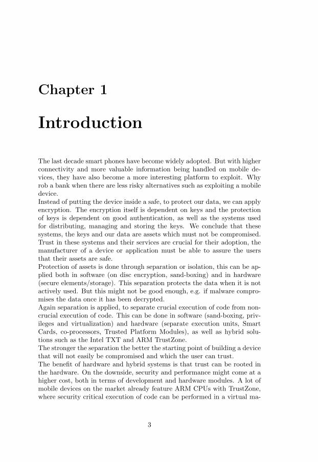
The last decade smart phones have become widely adopted. But with higherconnectivity and more valuable information being handled on mobile de-vices, they have also become a more interesting platform to exploit. Whyrob a bank when there are less risky alternatives such as exploiting a mobiledevice.Instead of putting the device inside a safe, to protect our data, we can applyencryption. The encryption itself is dependent on keys and the protectionof keys is dependent on good authentication, as well as the systems usedfor distributing, managing and storing the keys. We conclude that thesesystems, the keys and our data are assets which must not be compromised.Trust in these systems and their services are crucial for their adoption, themanufacturer of a device or application must be able to assure the usersthat their assets are safe.Protection of assets is done through separation or isolation, this can be ap-plied both in software (on disc encryption, sand-boxing) and in hardware(secure elements/storage). This separation protects the data when it is notactively used. But this might not be good enough, e.g. if malware compro-mises the data once it has been decrypted.Again separation is applied, to separate crucial execution of code from non-crucial execution of code. This can be done in software (sand-boxing, priv-ileges and virtualization) and hardware (separate execution units, SmartCards, co-processors, Trusted Platform Modules), as well as hybrid solu-tions such as the Intel TXT and ARM TrustZone.The stronger the separation the better the starting point of building a devicethat will not easily be compromised and which the user can trust.The benefit of hardware and hybrid systems is that trust can be rooted inthe hardware. On the downside, security and performance might come at ahigher cost, both in terms of development and hardware modules. A lot ofmobile devices on the market already feature ARM CPUs with TrustZone,where security critical execution of code can be performed in a virtual ma-
3
1.1. THESIS OBJECTIVES
chine commonly referred to as the Trusted Execution Environment (TEE).
1.1 Thesis objectives
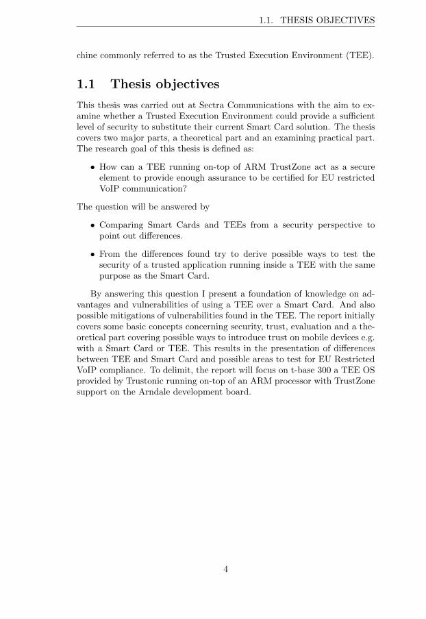
This thesis was carried out at Sectra Communications with the aim to ex-amine whether a Trusted Execution Environment could provide a su�cientlevel of security to substitute their current Smart Card solution. The thesiscovers two major parts, a theoretical part and an examining practical part.The research goal of this thesis is defined as:
• How can a TEE running on-top of ARM TrustZone act as a secureelement to provide enough assurance to be certified for EU restrictedVoIP communication?
The question will be answered by
• Comparing Smart Cards and TEEs from a security perspective topoint out di↵erences.
• From the di↵erences found try to derive possible ways to test thesecurity of a trusted application running inside a TEE with the samepurpose as the Smart Card.
By answering this question I present a foundation of knowledge on ad-vantages and vulnerabilities of using a TEE over a Smart Card. And alsopossible mitigations of vulnerabilities found in the TEE. The report initiallycovers some basic concepts concerning security, trust, evaluation and a the-oretical part covering possible ways to introduce trust on mobile devices e.g.with a Smart Card or TEE. This results in the presentation of di↵erencesbetween TEE and Smart Card and possible areas to test for EU RestrictedVoIP compliance. To delimit, the report will focus on t-base 300 a TEE OSprovided by Trustonic running on-top of an ARM processor with TrustZonesupport on the Arndale development board.
4
Chapter 2
Background
Certified information technology (IT) systems provide information assurancewhich is a measure of to which extent a system can be trusted. Trustin the system relies on the system security mechanisms and the securitymechanisms are deployed as result of a risk analysis in response to a threat.
2.1 On security
The need for security originates from the need of a stakeholder to protectassets of value from a threat. To properly protect the asset we need toidentify and quantify assets and threats, which is done though risk analysis.
2.1.1 Risk analysis
Risk analysis is typically the process of determining the likelihood of a threatbeing realized. The following steps are typically applied [1, 2]:Asset assessment - determine assets of valueThreat assessment - quantify threatsVulnerability assessment - identify weaknesses in design or implementa-
tion which might be exploited by a threatImpact assessment - quantify the impact of compromise of the assets for
a given threatRisk assessment - determine the likelihood of the threats being realized
for a given asset.Threats can be quantified by threat level, which is typically a product ofa threat actor’s capability and motivation. The risk of a threat is quanti-fied by risk level, which is typically a product of the impact of disclosure ofthe asset and the threat level. CESG (Communications-Electronics SecurityGroup a branch of the British GCHQ) categorizes impact as Business Im-pact Levels (BIL) ranging from 0-6, where BIL0 represents no impact andBIL6 represents extreme impact. UK Restricted information corresponds to
5
2.1. ON SECURITY
BIL3, as an example BIL3 in public finance would likely result in ”loss toHMG/Public sector of £millions” [1].
2.1.2 Assets and their properties
Security is essentially a measure to take in order to make sure an asset can-not be copied, modified or made unavailable. An asset is something of valuewhich has the following properties [3]:
Confidentiality - the asset is protected from disclosureIntegrity - the asset is protected from unauthorized modificationAvailability - the asset is available at the time of intended usage
The assets need of protection must be weighed against the cost of disclosingthe asset. If the cost outweighs the value of the asset then the purpose ofprotecting it have been defeated. So for each stakeholder in the system it isneeded to identify what the asset is and when the asset is identified, possiblethreats and threat actors against the asset must be identified. We can thenapply appropriate protection and countermeasures to mitigate these threats.
2.1.3 Threats
There is always a possibility that with enough time, e↵ort and funding theprotection of a system will be breached. The key to appropriately protectingan asset against an attack is to make the attack either too time consumingor too costly to perform to be justifiable [4]. For instance, an attack whichis time consuming and costly might be economically justifiable, if it has alarge impact on many stakeholders, assets or if it is easy to distribute.
Below follows two example properties of a threat, complexity and knowl-edge. Higher measures of complexity will likely lead to higher constraintson resources and time; and increased di�cult in repeatability.
Soft attack - Software attack, user with or without intent installs mal-ware.
Hard attack - Low budget hardware attack.Lab attack - Unlimited reverse engineering possibilities. These attacks are
hard to defend against, so instead of defending against lab attacks onecan try to minimize the damage, for instance by making informationonly valuable to one device or during a short period of time.
Higher requirements of knowledge for a threat will likely result in increaseddi�cult in manufacturing and distribution of a threat.
Device owner - has interest in accessing own content as she pleasesRemote attacker - distributes rogue software. No physical access to the
device
6
CHAPTER 2. BACKGROUND
Security specialist - experts, criminal gangs and users with exceptionalknowledge
2.1.4 Assets on mobile devices
A PC generally has one stakeholder the owner, but mobile systems di↵erfrom non-mobile systems. The most obvious di↵erence being that a mobilesystem has a RF module for the purpose of connecting to a global telecom-munication network [5, 6, 7, 8]. As such it operates under legislation fromregulatory bodies and so the concept of owner/stakeholder becomes diverse.Early mobile systems were single purpose and utilized only to make phonecalls. The stakeholders could be identified as:
• Regulatory bodies like the FCC who specifies the use of the radiofrequency spectrum.
• The mobile network operator which provide users access to its services.• The user which pays the mobile network operator to access the net-work.
Assets can be identified as:• Firmware associated with the baseband processor• International Mobile Subscriber Identity (IMSI), the unique identityof the SIM card and its keys are used to authenticate the user againstthe mobile network operator.
• SIMLock, the network service provider wants to make sure that thedevice is tied to itself since it have subsided the phone.
• International Mobile Equipment Identity (IMEI), uniquely identifiesthe device to the network. If the phone is stolen the IMEI can beblacklisted, which can render the device useless for making phone calls.
Over time, mobile systems evolved from single purpose communication end-points into mobile computers. A mobile devices now often o↵ers a full-fledged OS and the ability to download signed code (possibly arbitrary code,should the user chose to). These features enable users to consume multi-media material, carry out banking transactions and to facilitate their labor(such as accessing their corporate networks) [6, 5]. Stakeholders can now beextended with:
• the user/owner/corporation/government• service providers, such as DRM content providers, applications devel-opers or IT administration
• device manufacturer
With their own valuable assets:• private data• DRM content• firmware/software
7
2.2. ON TRUST
• services
The very mechanism enforcing the security of the system is called the trustedcomputing base (TCB); it is made up of all software, firmware and hardwarecritical for security of the system.Again, as mobile systems evolve there is a growing possibility of unintendeddesign faults and unnoticed bugs entering the TCB which can lead to com-promise of the device integrity. This is why the parts making up the TCBmust be thoroughly designed and tested.
2.2 On trust
Trust in an IT system is essential for the certification and procurement ofthe same. How do we define trust? Ross Anderson and Chris Mitchell [9, 10]define trust with the following relations:
Trusted system - ”a trusted system or component is defined as one whosefailure can break the security policy.”
Trustworthy system - ”a trustworthy system or component is defined asone that will not fail”
The Trusted Computing Group (TCG) instead defines a trusted system asTrusted system - ”a trusted system or component is one that behaves in
the expected manner for a particular purpose”
The stakeholders in a system must be able to trust that the system is secure.They do so by challenging the claim of the system being trustworthy. If thesystem can satisfactorily respond to this challenge the stakeholder can deter-mine the system to be a trusted system. Amit Vasudevan et al. [11] proposethat a trustworthy mobile system should exhibit the following the properties:
Isolated execution By providing isolated execution, a user can be confi-dent that a program cannot be tampered with and that the programcannot tamper with data other than its own.
Secure storage Which provides protection of data when it is currently notin use (commonly referred to as data-at-rest). By binding or sealingthe data to the platform, the data can be protected even though theOS compromised or the storage is removed.
Remote Attestation To allow a platform to attest to another platformthat it can be trusted. Combining this with isolated execution enforcesthe challenger’s confidence that the platform can be trusted as thereis less risk of run-time exploits.
Secure provisioning To securely migrate data or applications from onetrusted software module on one platform to another trusted software
8
CHAPTER 2. BACKGROUND
module on another platform, while maintaining the confidentiality andintegrity of the data.
Trusted path To provide a trusted path from a peripheral (touchscreen,memory etc.) to a software module. This is important as malwaremight try to eavesdrop on touchscreen input, provide a false but le-gitimate looking log-in screen or utilize device sensors to derive touchinput.
2.2.1 A history of trust
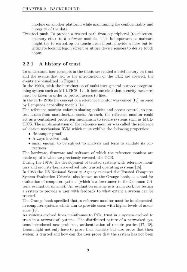
To understand how concepts in the thesis are related a brief history on trustand the events that led to the introduction of the TEE are covered, theevents are visualized in Figure 1.In the 1960s, with the introduction of multi-user general-purpose program-ming system such as MULTICS [12], it became clear that security measuresmust be taken in order to protect access to files.In the early 1970s the concept of a reference monitor was coined [13] inspiredby Lampsons capability models [14].The reference monitor enforces sharing policies and access control, to pro-tect assets from unauthorized users. As such, the reference monitor couldact as a centralized protection mechanism to secure systems such as MUL-TICS. The implementation of the reference monitor was called the referencevalidation mechanism RVM which must exhibit the following properties:
• Be tamper proof.• Always invoked and;• small enough to be subject to analysis and tests to validate its cor-rectness.
The hardware, firmware and software of which the reference monitor aremade up of is what we previously covered, the TCB.During the 1970s, the development of trusted systems with reference moni-tors and security kernels evolved into trusted operating systems [15].In 1983 the US National Security Agency released the Trusted ComputerSystem Evaluation Criteria, also known as the Orange book, as a tool forevaluation of computer systems (which is a forerunner to the Common Cri-teria evaluation scheme). An evaluation scheme is a framework for testinga system to provide a user with feedback to what extent a system can betrusted.The Orange book specified that, a reference monitor must be implemented,in computer systems which aim to provide users with higher levels of assur-ance [16].As systems evolved from mainframes to PCs, trust in a system evolved totrust in a network of systems. The distributed nature of a networked sys-tems introduced new problems, authentication of remote parties [17, 18].Users might not only have to prove their identity but also prove that theirsystem is trusted and how can the user prove that the system has not been
9
2.2. ON TRUST
tampered with?In 1986 Robert D. Sansom et. al [19] proposes capability based securityover a network. In 1987 the department of defense releases the Red bookon evaluation of connected systems.The Orange book and Red book later became part of what is commonlyreferred to as the rainbow series, the Department of defense computer secu-rity standards.To introduce assurance of integrity, the Trusted Computing Platform Al-liance (TCPA) was initiated in the late 1990s as a consortium of companiesto facilitate development of specifications on standards for trusted comput-ing and a trusted platform:
Balache↵ et al. [20] defines a platform as ”A Platform is any com-puting device —a PC, server, mobile phone, or any appliance capable ofcomputing and communicating electronically with other platforms”
and Chris Mitchell [10] describes a trusted platform as ”a computingplatform that has a trusted component, which is used to create a foundationof trust for software processes.”
While TCPA defines a trusted platform as ”a computing platformthat can be trusted to report its properties”.
TCPA later transitioned into the Trusted Computing Group (TCG) whichis the current instance issuing these specifications on trusted computing.TCGs solution for a trusted platform is called the Trusted Platform Mod-ule (TPM). The TPM is a tamper resistant integrated circuit, much like aSmart Card, intended to give the owner exclusive control over her data andplatform [21, 22].The TPM sports a number of facilities that allows it to, perform crypto-graphic operations, verify the boot process, encrypt user data and performremote attestation.In parallel, the GSM Association (GSMA) and later Open Mobile TerminalPlatform (OMTP) worked to standardize the mobile platform as it evolvedfrom a single purpose device for communication into a device for general-purpose computing.ARM, a CPU design licensor, develops its CPU extension TrustZone, whichadds an additional CPU mode to the CPU, the monitor mode. This enablesa single CPU to act as a hypervisor to host two virtual processors, a normalprocessor and a trusted processor.Later OMTP and GSMA publish the standard on the Advanced TrustedEnvironment referred to as Tr1 [23]. By following the standard the idea isthat handsets should be protected primarily against software attacks butalso against a subset of hardware attacks.Trusted Logic, later acquired by Gemalto (a Smart Card developer) develops
10
CHAPTER 2. BACKGROUND
the first OS compliant with the Tr1 standard, called Trusted Foundations.In conjunction with this, Global platform (GP) (an industry consortiumpublishes standards on secure elements such as Smart Cards), adopts theconcept of the Tr1 and publishes the standard on the TEE along with theTEE Protection Profile (PP). A protection profile is used in Common Cri-teria evaluations of IT systems.
GP defines an Execution Environment as ”a set of hardware and soft-ware components providing facilities necessary to support running of appli-cations” [24].
TCG on their hand releases the specification on TPMs for mobiledevices, the Mobile Trusted Module (MTM) due to the more complex con-cept of ownership associated with mobile devices. The enhanced security ofthe TEE can be leveraged by running the MTM on-top of it [5] instead ofadding an expensive dedicated hardware module (such as the TPM) to theplatform.Giesecke & Devrient (another Smart Card developer) develops the MobiCoreOS to leverage the TEE. To further push the adoption of the TEE and pro-vide a competitive product ARM, Gemalto and Giesecke & Devrient launchthe joint venture Trustonic and launches t-base, the first OS compliant withthe Global platform TEE protection profile.In response to the bring your own device (BYOD) trend and the informationleakage threats it poses to companies, the National institute of Standards(NIST) publishes guidelines on mobile device management in the govern-ment and enterprise sector. The guidelines outline the need for mobiledevices management, trusted boot, integrity checks, remote attestation, re-mote wipe, etc. [25, 26]. Recently, Samsung Inc. launched their Knoxservice, an android solution compliant with the U.S. Department of Defenserequirements for mobile handsets. Knox utilizes the TEE for its remoteattestation and integrity checks.
2.3 Evaluation
As mentioned in the Introduction, evaluation and the resulting assurancelevel of a product can be crucial for market adoption of a product. As anexample, a manufacturer of a product wants to sell the product but needsto know what is expected from it. The buyer wants to buy the productbut needs assurance that the system will behave as defined. In our case themanufacturer is interested in whether a TEE could provide enough assuranceto qualify for EU Restricted VoIP on a mobile device. The level of assurancethe TEE can provide is obtained through an evaluation.
11
2.3. EVALUATION
Trusted systems
TCG
Reference monitor
Remoteauthentication
1970 1980 1990 2000
required by
supported by
TPM MTMOMTP & GSMA
Tr1
ARM
Tr0GPGP TEE
Trusted LogicTrusted
Foundations
G&DMobiCore OS
GemaltoTrustZone
Trustonict-base OS
2010
Starting Point
Event
Orange book
Common Criteria
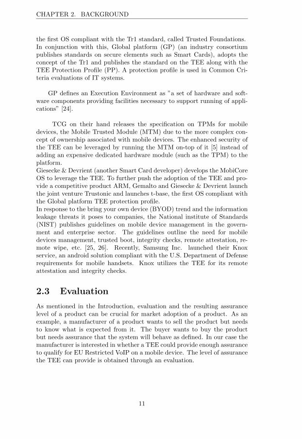
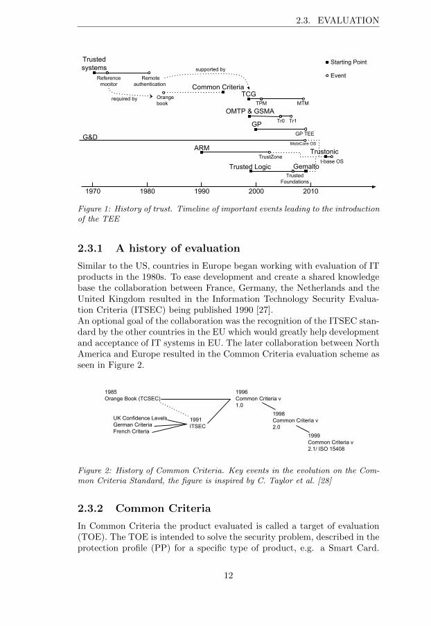
Figure 1: History of trust. Timeline of important events leading to the introductionof the TEE
2.3.1 A history of evaluation
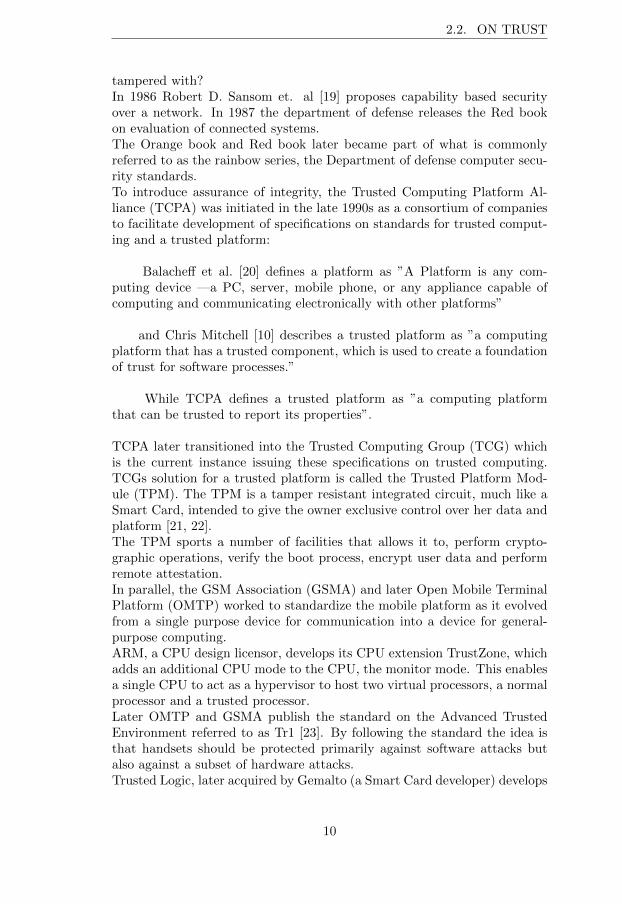
Similar to the US, countries in Europe began working with evaluation of ITproducts in the 1980s. To ease development and create a shared knowledgebase the collaboration between France, Germany, the Netherlands and theUnited Kingdom resulted in the Information Technology Security Evalua-tion Criteria (ITSEC) being published 1990 [27].An optional goal of the collaboration was the recognition of the ITSEC stan-dard by the other countries in the EU which would greatly help developmentand acceptance of IT systems in EU. The later collaboration between NorthAmerica and Europe resulted in the Common Criteria evaluation scheme asseen in Figure 2.
1985Orange Book (TCSEC)
UK Confidence LevelsGerman CriteriaFrench Criteria
1991ITSEC
1996Common Criteria v 1.0
1998Common Criteria v 2.0
1999Common Criteria v 2.1/ ISO 15408
Figure 2: History of Common Criteria. Key events in the evolution on the Com-mon Criteria Standard, the figure is inspired by C. Taylor et al. [28]
2.3.2 Common Criteria
In Common Criteria the product evaluated is called a target of evaluation(TOE). The TOE is intended to solve the security problem, described in theprotection profile (PP) for a specific type of product, e.g. a Smart Card.
12
CHAPTER 2. BACKGROUND
Typically, the developer defines a set of implementation dependent securityrequirements in the security target (ST) document, compliant with the PP,to which the TOE must conform. As a result the ST is specific to the prod-uct being evaluated.The evaluation process serves to validate the claims made about the TOEand establish the level of assurance which the TOE provides. The levelsrange from evaluation assurance level 1 to 7, EAL1 to EAL7. EAL1 islowest possible assurance where the product is functionally tested. EAL7is highest possible assurance where the design of the product is formallyverified and tested. However, a higher EAL does not mean a more secureproduct. Only that the claims about the product, by the developer, havebeen more extensively verified [29].In addition to evaluation of the security requirements the evaluator shouldalso perform a vulnerability assessment to determine if there exist flaws inthe TOE when used in its operational environment. PP/ST authors mayinclude information on attack potentials derived from their threat assess-ment; these are intended to provide the evaluator with guidance on whethera penetration test is in-scope during the vulnerability analysis.
2.3.3 Evaluation in EU
There exists a mutual recognition agreement between member countries ofCommon Criteria. The mutual recognition between member countries ex-tends to EAL4 [29]. This means that member countries should be able totrust the evaluation of a product performed by another member country upto EAL4.
For the deployment of communication and information systems dealingwith EU classified information, EU has a mutual recognition based on Ap-propriately Qualified Authorities (AQUA). There are six AQUA members inthe EU, France, Germany, Italy, the Netherlands, the United Kingdom andSweden. For an IT product to be approved to handle classified informationin the EU, the product must be evaluated by two members of the AQUAgroup [30]. In accordance with the AQUA agreement, national evaluationof a Swedish product may be performed by Sweden but the EU evaluationmust be conducted by another AQUA member e.g. the Netherlands.In order for a Swedish company to o↵er products for procurement in theEU, the company needs to be classified by the Swedish Defense Material Ad-ministration (FMV). The procurement is referred to as security protectedprocurement with security contract or in Swedish Sakerhetsskyddad Up-phandling med sakerhetsskyddsavtal (SUA). FMV then issues a securitycontract between itself and the company which places security requirementson the facilities and employees of the company which the company commitsto maintain. With the security contract approved, FMV vouches that thecompany is approved to handle classified information.
13
Chapter 3
Trust enforcing entities onmobile devices
There exist di↵erent approaches to providing higher levels of assurance ina mobile device. Possible approaches cover the use of secure elements (likeSIM cards, embedded NFC chips or embedded secure elements). In NokiaLumia phones a TPM is used to enforce the secure boot and in newer an-droid phones the TEE is used for hardware backed key management. Thedi↵erences among the entities can be used to derive tests for the TEE.
3.1 The Secure Element
The secure element is an integrated circuit card (ICC) or Smart Card, itgenerally consist of a microcontroller and memory. K. Markantonakis etal. [31] defines a Smart Card as an entity that:
1. Can participate in an automated electronic transaction.2. Is used primarily to add security and;3. is a tamper-resistant microprocessor chip (incorporating countermea-
sures against known attacks) and is di�cult to forge or copy. (Insupport of (2) and (3), two more definitions have been added.)
1. Can store data securely.2. Can host/run a range of security algorithms and functions.
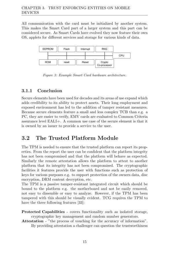
These properties provide the Smart Card with isolated execution of code andsecure storage of data, which is a good starting point to protect sensitivecode. Modern payment cards like Europay, Mastercard or VISA (EMV)often feature a Smart Card with a general purpose processor and a co-processor for heavy cryptographic operations [32] as seen in Figure 3 tospeed up operations.Smart Cards however do not feature any built-in power supply and no clock.
14
CHAPTER 3. TRUST ENFORCING ENTITIES ON MOBILEDEVICES
All communication with the card must be initialized by another system.This makes the Smart Card part of a larger system and this part can beconsidered secure. As Smart Cards have evolved they now feature their ownOS, applets for di↵erent services and storage for various kinds of data.
EEPROM
ROM
Flash
reset
Interrupt
Reset
RNG
CryptoCo-processor
CPU
Figure 3: Example Smart Card hardware architecture.
3.1.1 Conclusion
Secure elements have been used for decades and its areas of use expand whichadds credibility to its ability to protect assets. Their long employment andexposed environment has led to the addition of tamper resistant measures.Because secure elements feature a small and less complex TCB than e.g. aPC, they are easier to verify, EMV cards are evaluated to Common Criteriaassurance level EAL5+. A common use case of the secure element is that itis owned by an issuer to provide a service to the user.
3.2 The Trusted Platform Module
The TPM is needed to ensure that the trusted platform can report its prop-erties. From the report the user can be confident that the platform integrityhas not been compromised and that the platform will behave as expected.Similarly the remote attestation allows the platform to attest to anotherplatform that its integrity has not been compromised. The cryptographicfacilities it features provide the user with functions such as protection ofkeys for various purposes e.g. to support protection of the owners data, discencryption, DRM content decryption, etc.The TPM is a passive tamper-resistant integrated circuit which should bebound to the platform e.g. the motherboard and not be easily removed,not easy to dissemble or easy to analyze. However, if the TPM has beentampered with this should be visually evident. TCG requires the TPM tohave the three following features [33]:
Protected Capabilities - covers functionality such as isolated storage,cryptographic key management and random number generators.
Attestation - ”the process of vouching for the accuracy of information”.By providing attestation a challenger can question the trustworthiness
15
3.2. THE TRUSTED PLATFORM MODULE
of the platform and the TPM answers by returning data which can onlybe provided by a functional TPM on a trusted platform.
Integrity measurement, logging and reporting - The TPM can per-form and store measurements of the platform and also attest to themeasurements stored.
To provide these features we need three basic functions, the so-called roots-of-trust. A root-of-trust is a component which must be trusted and uponwhich all extended trust in platform is built.
Root-of-Trust for measurement (RTM) provides the measurement func-tionality.
Root-of-Trust for storage (RTS) provides storage of measurements, cryp-tographic keys and sensitive data.
Root-of-Trust for reporting (RTR) reports the measurements by sign-ing the measurements, using a stored key.
Of these three only RTS and RTR are required to exist inside the TPM, theRTM can be stored outside of the TPM but must reside in memory whichcannot be tampered with typically in the boot ROM or BIOS.At boot-up every step in the boot-chain measures the next step and storesthe measurement in the TPM. The RTM as first process to boot, measuresthe rest of BIOS and once BIOS is loaded, BIOS measures the OS loader.The OS loader in turn measures the OS which then can measure the appli-cations to be deployed. This forms an integrity chain known as the trustedboot, where each level verifies the next and takes appropriate actions shouldnot the measures correspond to the reference measurements.The measurements of the firmware or software are compared to the Refer-ence Integrity Metric (RIM) certificates that are embedded into the software.RIM certificates are used to ”describe an approved state of a platform and/ or approved integrity metrics” [5]. That is, a RIM certificate can be usedto verify platform, platform state and software. If a measurement is notconsistent with a RIM certificate or if the owner turns o↵ the TPM, theplatform should still be functional but might provide a degraded service.
3.2.1 TPM keys
The TPM maintains a key hierarchy to provide the owner with a range ofservices. These keys described below.
Attestation Identity Key (AIK) is used by the TPM when a challenger(could be a program, remote party or user) ask for attestation of theplatform. The AIK must never disclose the owner.
Endorsement key (EK) is a key permanently bound to the TPM usuallyby the TPM manufacturer. It is used for enrolling certificates for AIK
16
CHAPTER 3. TRUST ENFORCING ENTITIES ON MOBILEDEVICES
and decrypting owner specific data among other things.Storage root key (SRK) is used to protect/encrypt the other keys asso-
ciated with the TPM. The SRK is generated when an owner takesownership of the TPM.
Storage keys used for encrypting data stored externallyBinding keys allows for encrypting data so that it may only be decrypted
by the same TPM that encrypted it.Signing keys used for signing messages or application data.
3.2.2 Conclusion
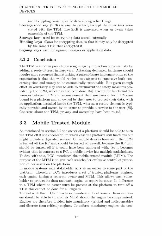
The TPM is a tool in providing strong integrity protection of owner data byadding a roots-of-trust in hardware. Attacking dedicated hardware shouldrequire more resources than attacking a pure software implementation so theexpectation is that this would render most attacks to expensive both con-cerning time and money to be economically sustainable. But given enoughe↵ort an adversary may still be able to circumvent the safety measures pro-vided by the TPM, which has also been done [34]. Except for functional dif-ferences between TPM and secure element their use cases di↵er. TPMs arebound to a platform and an owned by their user to protect their data, withno applications installed inside the TPM, whereas a secure element is typi-cally portable and owned by an issuer to provide a service to the user [35].Concerns about the TPM, privacy and ownership have been raised.
3.3 Mobile Trusted Module
As mentioned in section 3.2 the owner of a platform should be able to turnthe TPM o↵ if she chooses to, in which case the platform still functions butmight provide a degraded service. On mobile devices however if the TPMis turned o↵ the RF unit should be turned o↵ as-well, because the RF unitshould be turned o↵ if it could have been tampered with. So it becomesevident that in contrast to a PC, a mobile device has multiple stakeholders.To deal with this, TCG introduced the mobile trusted module (MTM). Thepurpose of the MTM is to give each stakeholder exclusive control of protec-tion of her assets on the platform.In mobile systems each stakeholder acts as an owner to some part of theplatform. Therefore, TCG introduces a set of trusted platforms, engines,each engine having a separate owner and MTM. This allows each stake-holder to protect its data and each engine to report its state. In di↵erenceto a TPM where an owner must be present at the platform to turn o↵ aTPM this cannot be done for all engines.To deal with this, TCG introduces remote and local owners. Remote own-ers should be able to turn o↵ its MTM should the engine be compromised.Engines are therefore divided into mandatory (critical and indispensable)and discrete (non-critical) engines. To enforce mandatory engines the con-
17
3.3. MOBILE TRUSTED MODULE
cept of secure boot is introduced. In di↵erence to trusted boot, if not allmandatory engines booted to a trusted state, the device will not boot at all.This provides stakeholders of mandatory engines with confidence that theservices functions as expected. Additionally the roots-of-trust are extendedwith root-of-trust-for-verification and the root-of-trust-for-enforcement.
Root-of-Trust for verification is required to be supported by all engineswith a remote owner. It checks measurements before storing them inthe RTS. The RTV can verify the measurements of the current stateof other engines.
Root-of-Trust for enforcement is responsible for building the roots-of-trust in its own engine.
TCG is short on implementation details of the MTM, allowing it to imple-mented either in software e.g. as a trusted application running on a TEEor in hardware, e.g. on a co-processor [5].
3.3.1 MTM operation
Since every stakeholder can have its own engine, the event of an engineending up in a failed mode does not have to mean that the device cannot beused. Only that device will have to work in a degraded mode not utilizingthe services of that engine.Since there is a possibility that an engine ends up in a failed state due toe.g. unforeseen errors in design or implementation. Mechanisms must beapplied to limit damage when sensitive information is compromised. Thereare two aspects, preventing transition out of a success state and reacting totransitioning out of success state to limiting damage. Preventative measurescover features such as memory separation, trusted boot, verification of codeat load-time, etc. Reactive measures to deal with run-time threats can beachieved by extending trusted boot with run-time integrity measurements.This way threats like program privilege escalation could be countered andreduced.To comply with TCG standards, at least the device manufacturer’s enginemust support run-time integrity checks. The entity responsible for run-timeintegrity measurements is called the Run-time Measurement VerificationAgent RMVA. The primary RMVA must perform at least one form of run-time measurement, event-driven or time-based. The RMVA can create achain of trust by continuously measure and trigger secondary RMVAs thatdo further measurements of the OS. If a RMVA has been tampered withthis should not go unnoticed for a long period of time. An example ofRMVA could be Samsung Knox TIMA, which conducts run-time integritymeasurements in Knox.
18
CHAPTER 3. TRUST ENFORCING ENTITIES ON MOBILEDEVICES
3.4 The Trusted Execution Environment
The TEE provides an area which is protected from the rest of the system it ispart of. Similar to a Smart Card with applications, the di↵erence lies in howthe TEE is implemented. In literature the TEE is often considered a trustedOS running on a virtual processor on-top of ARM TrustZone and a trustedhypervisor. That is also the configuration which is tested in this thesis.The use case of the TEE can be considered an environment to run securitysensitive application such as banking, integrity checking, identification, sub$10 dollar proximity payments and DRM decryption.
3.4.1 TrustZone
To deal with e.g. DRM protection, system security must be thought of interms of the whole system, rather than the individual components [4, 36, 37].For instance, the DRM content will still be compromised if its decryptionkeys are safe in a TPM, but the content is stolen once the DRM content isdecrypted.
TrustZone hardware architecture
TrustZone is a concept developed by ARM that provides a system wide secu-rity by allowing a single processor to swap between two worlds, the normalworld and the secure world. The idea is that the normal world never willhave insight to the secure world and so the secure world can act as a TEEwhere critical code can be executed. The separation enables the TEE tocontrol communication with peripherals and debug port on the SoC. Theswap is made possible with a hypervisor like entity running the two worldsas virtual processors, as seen in Figure 4.Typically in virtualization, a hypervisor sits in a privileged mode, while theguest OS sits in a less privileged mode. Virtualization can be achieved in anumber of ways; examples are pure virtualization and para-virtualization [38,39].Pure virtualization allows a guest to run as if it was running on the bare
machine without any modifications. The hypervisor can trap-and-emulate sensitive instruction calls by the guest. A trap-and-emulateoperation is issued on every sensitive instruction, which leads to per-formance impact. It does, however, provide the best isolation and isused in Green Hills Integrity OS.
Para-virtualization defines an API for hypercalls (instructions for com-municating directly with the hypervisor), which reduces both overheadof execution and complexity of the hypervisor. The drawback is thatthe guest must be modified to use the API. A hypervisor is often dedi-cated hypervisor software, but can with e�ciency be built with a microkernel such as the L4 [40, 41, 38].
19
3.4. THE TRUSTED EXECUTION ENVIRONMENT
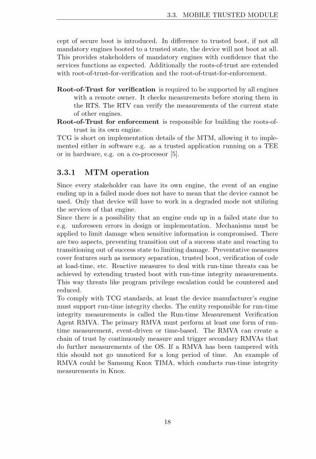
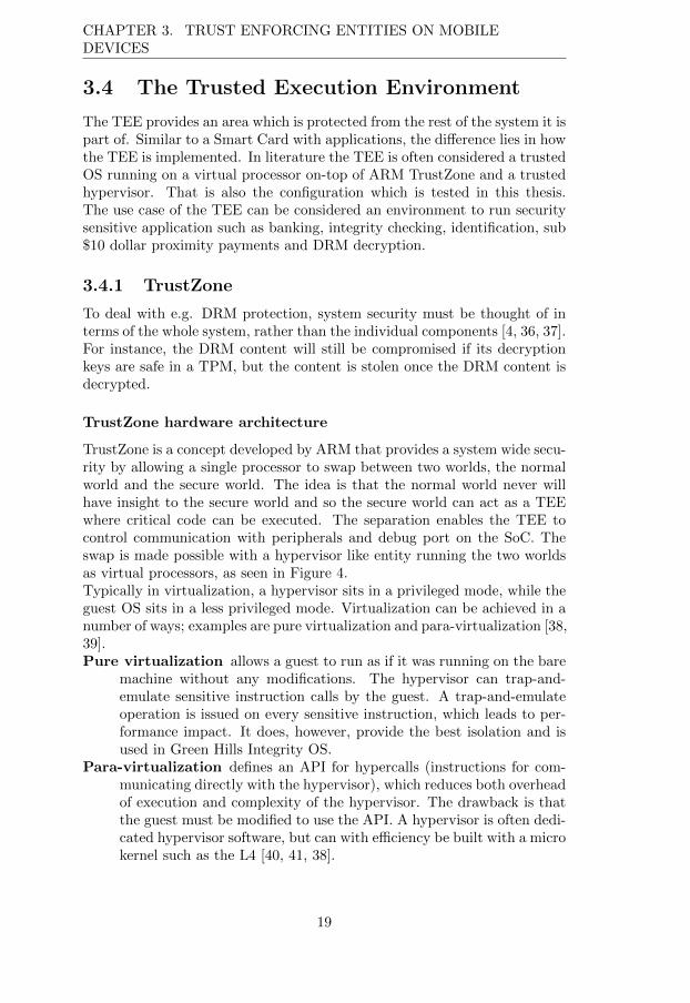
Para-virtualization is the solution usually employed with the Linux kernelin Android on mobile devices and which is likely employed in t-base.TrustZone achieves separation in transactions by introducing a 33rd addressbit, the non-secure NS-bit, separating addresses in a 32 bit address spacefor each world. When the NS-bit is high for a component of the systemit means its working with the normal world mode. The ARM processorarchitecture has a bus for communicating with the peripherals supportingthe NS-bit called AXI bus. To function in accordance with the intent ofTrustZone the NS-bit should be checked by all components connected to thebus. So that if a component with NS-bit high tries to perform a transactionwith another component with the NS-bit low the transaction should fail.This way peripherals (components) such as RAM and display bu↵er can besafely divided into secure world and normal world, without the normal worldhaving knowledge or access to secure world information.
User
Priv.
Monitor
Non secure world Secure world
User
Priv.
Figure 4: The TrustZone CPU modes, the extension of the monitor mode enablea trusted switch between non-secure world and secure world. The figure is inspiredby the ARM TrustZone whitepaper [4]
The swap between the secure and normal world is done through a so-called world switch, or more precisely a context switch. When a contextswitch is requested the data of the requester is cached until a new contextswitch is requested. The switch can be initiated in a number of ways, byhardware exceptions or by raising a software interrupt with the Secure Mon-itor Call (SMC) hypercall instruction. When the switch has been initiated,control is passed to the hypervisor running in monitor mode. The switchis indicated by the NS-bit in the secure configuration register SCR in thesystem control coprocessor (CP15). As seen in Figure 4 the monitor modeis always executing in secure world.During a context switch it is imperative that no information from the secureworld leaks to the normal world through the registers of the processor, the
20
CHAPTER 3. TRUST ENFORCING ENTITIES ON MOBILEDEVICES
peripherals or the instructions still in the pipeline. This is why the mod-ification of the NS-bit should only be performed in the monitor mode bytrusted code. This way, the risk that the normal performs a world switch inan erroneous way to leak secure world information is mitigated.
TrustZone software architecture, secure boot and multi-processors
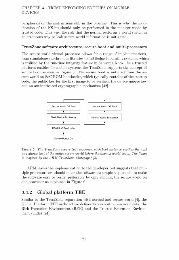
The secure world virtual processor allows for a range of implementations,from standalone synchronous libraries to full-fledged operating systems, whichis utilized by the run-time integrity feature in Samsung Knox. As a trustedplatform enabler for mobile systems the TrustZone supports the concept ofsecure boot as seen in Figure 5. The secure boot is initiated from the se-cure world on-SoC ROM bootloader, which typically contains of the startupcode, the public key for the first image to be verified, the device unique keyand an authenticated cryptographic mechanism [42].
Device Power On
ROM SoC Bootloader
Flash Device Bootloader
Secure World OS Boot
Normal World Bootloader
Normal World OS Boot
Figure 5: The TrustZone secure boot sequence, each boot instance verifies the nextand allows boot of the entire secure world before the normal world boots. The figureis inspired by the ARM TrustZone whitepaper [4]
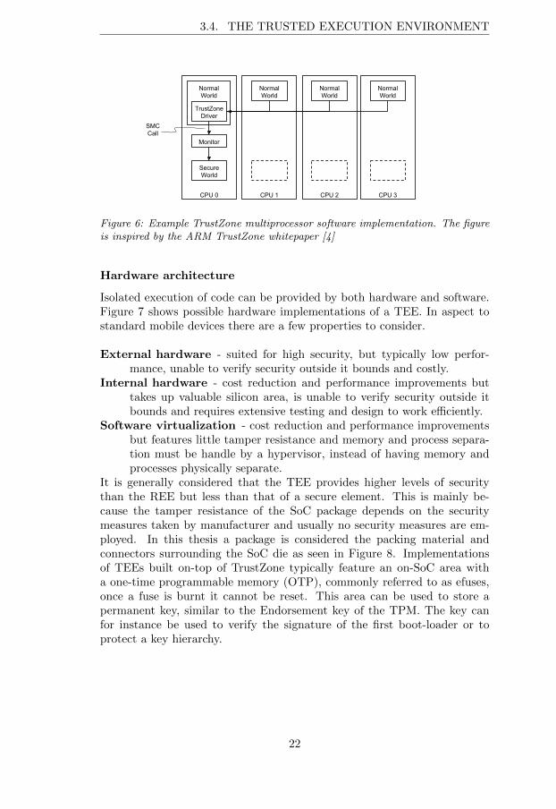
ARM leaves the implementation to the developer but suggests that mul-tiple processor core should make the software as simple as possible, to makethe software easy to verify, preferably by only running the secure world onone processor as explained in Figure 6.
3.4.2 Global platform TEE
Similar to the TrustZone separation with normal and secure world [4], theGlobal Platform TEE architecture defines two execution environments, theRich Execution Environment (REE) and the Trusted Execution Environ-ment (TEE) [24].
21
3.4. THE TRUSTED EXECUTION ENVIRONMENT
NormalWorld
Monitor
SecureWorld
SMC Call
NormalWorld
CPU 0 CPU 1
NormalWorld
CPU 2
NormalWorld
CPU 3
TrustZone Driver
Figure 6: Example TrustZone multiprocessor software implementation. The figureis inspired by the ARM TrustZone whitepaper [4]
Hardware architecture
Isolated execution of code can be provided by both hardware and software.Figure 7 shows possible hardware implementations of a TEE. In aspect tostandard mobile devices there are a few properties to consider.
External hardware - suited for high security, but typically low perfor-mance, unable to verify security outside it bounds and costly.
Internal hardware - cost reduction and performance improvements buttakes up valuable silicon area, is unable to verify security outside itbounds and requires extensive testing and design to work e�ciently.
Software virtualization - cost reduction and performance improvementsbut features little tamper resistance and memory and process separa-tion must be handle by a hypervisor, instead of having memory andprocesses physically separate.
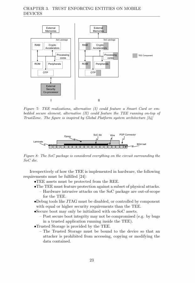
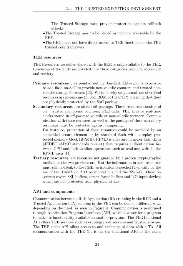
It is generally considered that the TEE provides higher levels of securitythan the REE but less than that of a secure element. This is mainly be-cause the tamper resistance of the SoC package depends on the securitymeasures taken by manufacturer and usually no security measures are em-ployed. In this thesis a package is considered the packing material andconnectors surrounding the SoC die as seen in Figure 8. Implementationsof TEEs built on-top of TrustZone typically feature an on-SoC area witha one-time programmable memory (OTP), commonly referred to as efuses,once a fuse is burnt it cannot be reset. This area can be used to store apermanent key, similar to the Endorsement key of the TPM. The key canfor instance be used to verify the signature of the first boot-loader or toprotect a key hierarchy.
22
CHAPTER 3. TRUST ENFORCING ENTITIES ON MOBILEDEVICES
RAM CryptoAccelerators
SoC package
Processing cores
ROM Peripherals
OTP
ExternalMemories
ExternalSecurity
Co-processor
RAM CryptoAccelerators
SoC package
Processing cores
ROM Peripherals
OTP
ExternalMemories
I II
TEE Component
Figure 7: TEE realizations, alternative (I) could feature a Smart Card or em-bedded secure element, alternative (II) could feature the TEE running on-top ofTrustZone. The figure is inspired by Global Platform system architecture [24]
SoC dieEpoxy
LaminateBGA ball
POP ConnectorWire
Figure 8: The SoC package is considered everything on the circuit surrounding theSoC die.
Irrespectively of how the TEE is implemented in hardware, the followingrequirements must be fulfilled [24]:
•TEE assets must be protected from the REE.•The TEE must feature protection against a subset of physical attacks.
– Hardware intrusive attacks on the SoC package are out-of-scopefor the TEE.
•Debug tools like JTAG must be disabled, or controlled by componentwith equal or higher security requirements than the TEE.
•Secure boot may only be initialized with on-SoC assets.– Post secure boot integrity may not be compromised (e.g. by bugsin a trusted application running inside the TEE).
•Trusted Storage is provided by the TEE.– The Trusted Storage must be bound to the device so that anattacker is prohibited from accessing, copying or modifying thedata contained.
23
3.4. THE TRUSTED EXECUTION ENVIRONMENT
– The Trusted Storage must provide protection against rollbackattacks.
•The Trusted Storage may to be placed in memory accessible by theREE.•The REE must not have direct access to TEE functions or the TEEtrusted core framework.
TEE resources
TEE Resources are either shared with the REE or only available to the TEE.Resources of the TEE are divided into three categories primary, secondaryand tertiary.
Primary resources , as pointed out by Jan-Erik Ekberg it is expensiveto add flash on-SoC to provide non-volatile counters and trusted non-volatile storage for assets [43]. Which is why only a small set of criticalresources are in-package (in SoC ROM or the OTP), meaning that theyare physically protected by the SoC package.
Secondary resources are stored o↵-package. These resources consists ofe.g. trusted monotonic counters, TEE data, TEE keys or real-timeclocks stored in o↵-package volatile or non-volatile memory. Commu-nication with these resources as-well as the package of these secondaryresources must be protected against tampering.For instance, protection of these resources could be provided by anembedded secure element or by standard flash with a replay pro-tected memory block (RPMB). RPMB is a feature in newer flash chips(JEDEC eMMC standards >v4.41) that requires authentication be-tween CPU and flash to allow operations such as read and write in theRPMB area [44].
Tertiary resources are resources not guarded by a proven cryptographicmethod as the two previous are. But the information in such resourcesmust still not leak to the REE, so isolation is needed (Typically by theuse of the TrustZone AXI peripheral bus and the NS-bit). These re-sources covers SSL bu↵ers, screen frame bu↵ers and I/O input deviceswhich are not protected from physical attack.
API and components
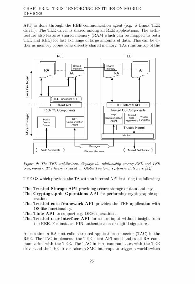
Communication between a Rich Application (RA) running in the REE and aTrusted Application (TA) running in the TEE can be done in di↵erent waysdepending on the need, as seen in Figure 9. Communication is performedthrough Application Program Interfaces (API) which is a way for a programto make its functionality available to another program. The TEE functionalAPI o↵ers TEE services such as cryptographic services and trusted storage.The TEE client API o↵ers access to and exchange of data with a TA. Allcommunication with the TEE (be it via the functional API or the client
24
CHAPTER 3. TRUST ENFORCING ENTITIES ON MOBILEDEVICES
API) is done through the REE communication agent (e.g. a Linux TEEdriver). The TEE driver is shared among all REE applications. The archi-tecture also features shared memory (RAM which can be mapped to bothTEE and REE) for fast exchange of large amounts of data. This can be ei-ther as memory copies or as directly shared memory. TAs runs on-top of the
RA
TEE Functional API
TEE Client API
TA
TEE Internal API
Shared memory
Shared memory
Rich OS Components Trusted OS Components
REE TEE
Trusted Kernel
Trusted Functions
Trusted Core
Framework
TEE Communication
AgentREE
Communication Agent
Platform Hardware
Public Device Drivers
RA RA
MessagesPublic Peripherals Trusted Peripherals
Less
Priv
ilege
dM
ore
Priv
ilege
d
Monitor
Figure 9: The TEE architecture, displays the relationship among REE and TEEcomponents. The figure is based on Global Platform system architecture [24]
TEE OS which provides the TA with an internal API featuring the following:
The Trusted Storage API providing secure storage of data and keysThe Cryptographic Operations API for performing cryptographic op-
erationsThe Trusted core framework API provides the TEE application with
OS like functionality.The Time API to support e.g. DRM operations.The Trusted user interface API for secure input without insight from
the REE. For instance PIN authentication or digital signatures.
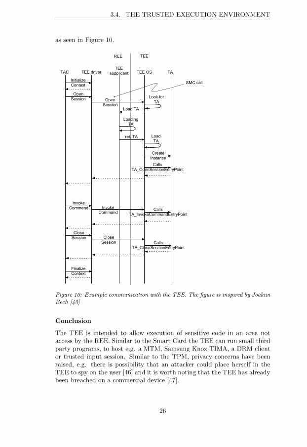
At run-time a RA first calls a trusted application connector (TAC) in theREE. The TAC implements the TEE client API and handles all RA com-munication with the TEE. The TAC in-turn communicates with the TEEdriver and the TEE driver raises a SMC interrupt to trigger a world switch
25
3.4. THE TRUSTED EXECUTION ENVIRONMENT
as seen in Figure 10.
TAC TEE driverTEE
supplicant TEE OS TA
OpenSession Open
Session
Look for TA
Load TA
Loading TA
ret. TA LoadTA
CreateInstance
CallsTA_OpenSessionEntryPoint
InitializeContext
Invoke Command Invoke
CommandCalls
TA_InvokeCommandEntryPoint
Close Session Close
Session CallsTA_CloseSessionEntryPoint
FinalizeContext
SMC call
REE TEE
Figure 10: Example communication with the TEE. The figure is inspired by JoakimBech [45]
Conclusion
The TEE is intended to allow execution of sensitive code in an area notaccess by the REE. Similar to the Smart Card the TEE can run small thirdparty programs, to host e.g. a MTM, Samsung Knox TIMA, a DRM clientor trusted input session. Similar to the TPM, privacy concerns have beenraised, e.g. there is possibility that an attacker could place herself in theTEE to spy on the user [46] and it is worth noting that the TEE has alreadybeen breached on a commercial device [47].
26
Chapter 4
Attacks on the TEE
Mobile devices provide services in a hostile environment. For instance, thedevice could easily be stolen and when in operation and neither user, userinput, networks or code should be trusted. Even though the TEE furtherhardens the mobile device security and integrity it should be noted thatthe TEE already have been compromised once. The compromise was donein software by fuzzing of the TEE client API with faulty memory rangesand analyzing the decompiled TEE binary [47]. Below follows some attacksof interest considering platform di↵erence between TEE and Smart Card.The attacks where identified during the risk analysis of the TEE, which isexplained in section 6.1.4.
4.0.1 Abuse and rollback attack
A rollback attack is conducted by replacing data, keys or program with anolder version which has known vulnerabilities. A data asset might containconfiguration data which exposes a vulnerability in a program. To protectthe asset one can apply encryption, but the asset may still be copied. Whena new patched asset replaces the old asset the attacker can delete the newasset and replace it with the old. If the program has no protected way ofchecking the assets state, such as version or age the program might use theold configuration which exposes the vulnerability again. Abuse of the assetscan be done by copying assets and letting another program utilize them, e.g.to fake a signature, this is shown in Tim Cooijmans master thesis [48]. Aminimal protection against rollback attacks is to store a monotonic counterwith the state of the asset, which itself must be protected from rollbackattacks. Another solution is the use of separate storage, like secure elementcould hinder the assets from being moved around.
27
4.0.2 RAM bus probing
On an ordinary stationary PC, RAM hardware modules are easily exchangedand the standard contacts connecting RAM to the motherboard is easy totap into. This allows for a multitude of attacks such as altering RAMcontents on the fly (with a mod-chip) or eaves-dropping on the RAM buswith a logic analyzer. On mobile devices RAM is often soldered with atechnique called package-on-package (POP) on-top of the SoC. To enablePOP the RAM chips connectors are typically exposed with a ball-grid array(BGA). This way of stacking chips makes the RAM bus harder to probe,because the chip would have to be removed, which requires precise heatcontrol to a specific area of the mobile device motherboard. Additionallythe attacker would have to reflow the BGA and create a socket to exposethe connections between CPU and RAM. When this is done, the attack canbe deployed in the same way as on a PC with a logic analyzer. Mitigationsagainst RAM bus probing cover encryption of RAM, use of on-SOC memory,and utilization of CPU registers [49, 50].
4.0.3 Attacks based on Electromagnetic emissions
These attacks are commonly referred to as Van Eck phreaking, which takesadvantage of that all electrical devices leak electromagnetic emissions frome.g. power supply, display or CPU. By analyzing these emissions with theright tools information about what is happening on the PC can be de-rived [51]. Van Eck phreaking usually cover attacks such as Simple andDi↵erential power analysis (SPA and DPA). Both of these attacks are basedon placing a probe over the CPU to collect the emissions. Because di↵erentoperations in the CPU require di↵erent amounts power key material andoperations in cryptographic operations can be spied up-on. Mitigation ofsuch attacks can be done by shielding the SoC package and by rewritingthe Cryptographic operations so that emissions look the same even withdi↵erent keys.
4.0.4 Glitch attack
A glitch attack is used to make a device misbehave by introducing powerglitches and power spikes in the device. This could result in the programcounter jumping past a crucial instruction, e.g. in comparing two hash sums.This in turn could lead to execution of unsigned code. Glitch attacks arenot considered in this thesis as it is the platform vulnerabilities in the TEEwhich should be tested and glitch attacks can be mounted on Smart Cardsas-well.
28
CHAPTER 4. ATTACKS ON THE TEE
4.0.5 RAM extraction by cold boot
RAM is non-volatile memory used by the CPU to store data which is cur-rently in use. Non-volatile implies the information will be lost once thepower is turned o↵. This is true, but the information disappears gradu-ally [52] as shown by Tilo Muller and disappears even slower if the RAM iscooled down [53], this is known as the reminiscence e↵ect. In a cold boot,the power supply to a device is turned o↵, when power is restored the de-vice performs a cold boot, in which case the device will have forgotten theRAM layout, and where data was stored, but the data may still remain frombefore the cold boot. On a PC freezing of RAM can be done by turning acompressed can or air upside down and spraying the RAM and then remov-ing it. The information can then remain for minutes with a low rate of bitdecay and can then be extracted by mounting the RAM onto another PC.On a mobile device the RAM is harder to remove and so the attack wouldhave to be mounted by cooling down the device and extracting RAM withsoftware (by installing tools in fastboot or as a privileged user during Linuxstart-up). Since the attack enables the attacker to get a snapshot of themobile device state. Any assets in use when the device was attacked willprobably be disclosed. Mitigations of the attack are possible by staticallydefining the RAM accessible by the REE or by using a secure element forsensitive operations in the TEE.
4.0.6 Timing attacks
Timing attacks are a type of side-channel (attacks which take advantageof the physical properties of a system). The timing attack exploits the factthat cryptographic operations have physical properties that leak informationabout time. This information about the time taken to perform a crypto-graphic operation can be used to derive the key [54, 55, 56, 57]. Attacksmay even be conducted over a network connection where round-trip timesand congestion a↵ects the timing measurements. Protection against timingattacks can be provided by introducing random elements in cryptographicoperations.
4.0.7 Eavesdropping on user input
There are a multitude of programs for PCs (spyware and keylogger) whichallow an attacker to log keystrokes and send the information like, passwordsor bank account information to the attacker’s server. On mobile devicesthis is harder because the applications are typically distributed via an on-line application market which performs controls of the applications. Further,applications are typically not allowed to access screen I/O when running inthe background. However there are other ways to derive input on a mobiledevice, because today, a mobile device typically features on-board sensors.The sensors can be used as a side-channel to derive the user input [58, 59].
29
Possible mitigations cover disabling of sensors and randomizing input layout.To defend against phishing the interface should display a secret only knownto the user.
30
Chapter 5
Method
The thesis covers two major parts the feasibility study and the implementa-tion. The feasibility study results in a risk analysis on the assets protectedby the TEE. The implementation covers tests of the vulnerabilities identifiedin the risk analysis.
5.1 Feasibility study
In lack of readily available test suites for the TEE such as the Global Plat-form test suits [60], a risk analysis of the TEE was performed. However,the risk analysis does not cover the entire TEE; the thesis would be too ex-tensive. Instead, in correspondence with the Common Criteria vulnerabilityassessment, vulnerabilities of the TEE were identified. But the vulnerabil-ities of interest are only those which are exposed by the TEE and not bythe Smart Card. These vulnerabilities created an uncertainty in the TEEspossible certification as visualized in Figure 11.
31
5.1. FEASIBILITY STUDY
Cla
ssifi
catio
n le
vel Confidential
Restricted
Unclassified
Attacks to protect
against
-Radiation attacks
-Software attacks-Subset of
hardware attacks
-Hardware attacks
EU classification
level
-Sophisticated
hardware attacks
TEE
Smar
t Car
d
Cost of attack
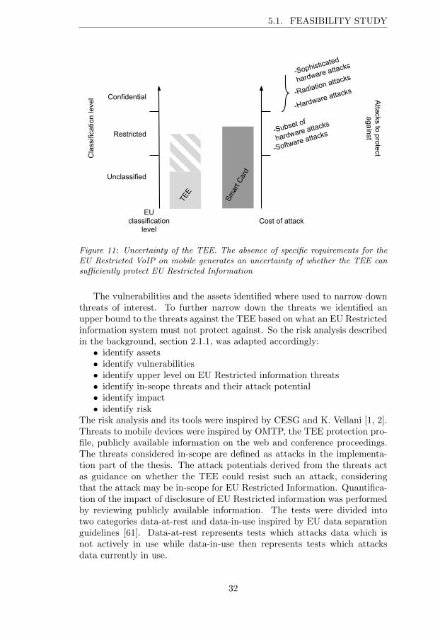
Figure 11: Uncertainty of the TEE. The absence of specific requirements for theEU Restricted VoIP on mobile generates an uncertainty of whether the TEE cansu�ciently protect EU Restricted Information
The vulnerabilities and the assets identified where used to narrow downthreats of interest. To further narrow down the threats we identified anupper bound to the threats against the TEE based on what an EU Restrictedinformation system must not protect against. So the risk analysis describedin the background, section 2.1.1, was adapted accordingly:
• identify assets• identify vulnerabilities• identify upper level on EU Restricted information threats• identify in-scope threats and their attack potential• identify impact• identify risk
The risk analysis and its tools were inspired by CESG and K. Vellani [1, 2].Threats to mobile devices were inspired by OMTP, the TEE protection pro-file, publicly available information on the web and conference proceedings.The threats considered in-scope are defined as attacks in the implementa-tion part of the thesis. The attack potentials derived from the threats actas guidance on whether the TEE could resist such an attack, consideringthat the attack may be in-scope for EU Restricted Information. Quantifica-tion of the impact of disclosure of EU Restricted information was performedby reviewing publicly available information. The tests were divided intotwo categories data-at-rest and data-in-use inspired by EU data separationguidelines [61]. Data-at-rest represents tests which attacks data which isnot actively in use while data-in-use then represents tests which attacksdata currently in use.
32
CHAPTER 5. METHOD
5.2 Implementation of tests
The tests were the result of the platform di↵erences of TEE and Smart Cardintersected with attacks derived from the risk analysis of the TEE. The testtarget was the Arndale development board from Trustonic, sporting a TEEenabled Samsung Exynos 5250 Cortex-A15 @ 1.7 GHz dual core subsystemwith 64/128 bit SIMD NEON CPU and 2 GB of RAM. The Kernel is Linuxversion 3.4.5-ga21b98b-dirty, it is available from Insignals git repository [62].The Android version is 4.2.1 (jellybean mr-1). The TEE OS is t-base 300.Because t-base 300 is proprietary its implementation details are unavail-able, which is why tests only cover use case based black-box testing andnon-functional requirements [63]. In the criterions listed below, a test T*
consists of a requirement R* and an attack A*. R* represents a requirementto be fulfilled for an asset, A* represents an attack trying to break thatrequirement. The outcome of a test results in 4 if the requirement holds,or 8 if the attack breaks the requirement, as exemplified in Table 1.
SuccessfulT* 4
Table 1: Test success set-up
A successful test 4 implies that the attack does not pose a risk, whereasa failed test 8 implies that an existing risk could be exploited. If all testsare successful this indicates that the TEE could be considered for EU Re-stricted VoIP. If all tests are not successful this indicates that the TEE hasvulnerabilities which will need to be considered.
5.2.1 Data-at-rest
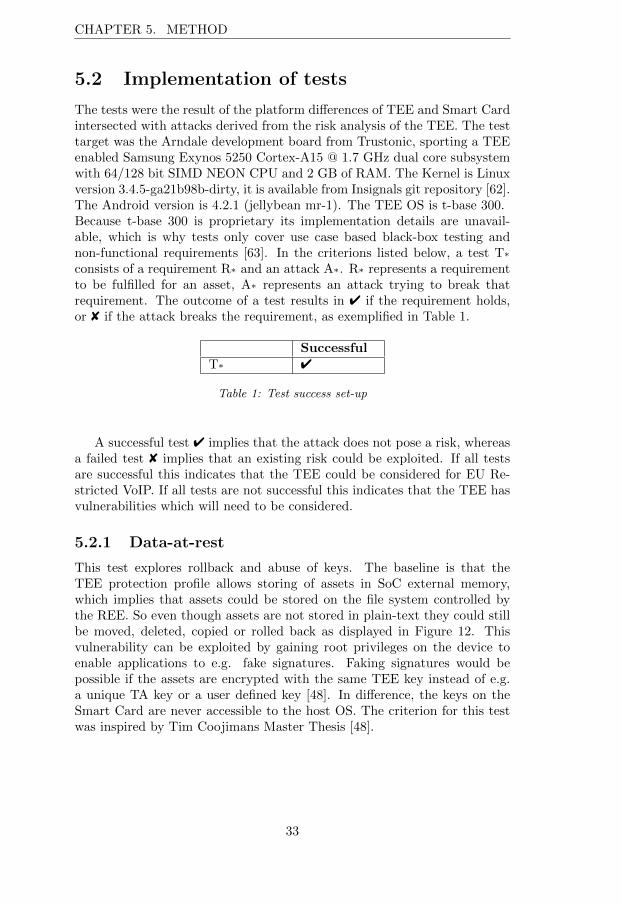
This test explores rollback and abuse of keys. The baseline is that theTEE protection profile allows storing of assets in SoC external memory,which implies that assets could be stored on the file system controlled bythe REE. So even though assets are not stored in plain-text they could stillbe moved, deleted, copied or rolled back as displayed in Figure 12. Thisvulnerability can be exploited by gaining root privileges on the device toenable applications to e.g. fake signatures. Faking signatures would bepossible if the assets are encrypted with the same TEE key instead of e.g.a unique TA key or a user defined key [48]. In di↵erence, the keys on theSmart Card are never accessible to the host OS. The criterion for this testwas inspired by Tim Coojimans Master Thesis [48].
33

5.2. IMPLEMENTATION OF TESTS
TATA
Asset
Device
Figure 12: Test of data-at-rest. Schematic figure of the attacker’s privileges andhow the asset can be misused
Use case: An attacker want exploit the TEE by abusing or rolling back anasset. Rational: The attacker wants to misuse assets such as cryptographickeys that can be used to eaves-drop on, or fake communication.
Criteria data-at-rest
Attacker profiles:A
Abuse
- attacker moves assetA
Rollback
- attacker rollbacks an asset
The Requirements tested to be fulfilled for data-at-rest were:R
no abuse
- assets cannot be abused by attackerR
no rollback
- assets cannot be rolled back
Steps to break requirements:AAbuse-Rno abuse:
1) move asseta of TAa to TAb
2) request TAb to open assetaARollback-Rno rollback:
1) replace asseta 2 of TAa with rolled back asseta 1 of TAa
2) request TAa to open asseta 1
5.2.2 Data-in-use
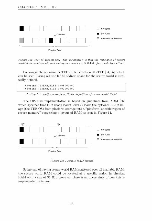
This test consists of two parts concerning leakage of information duringoperations with assets. The first part is similar to the previous test. TheTEE protection profile allows shared volatile storage and the separation ofmemory is handled by the TEE. In di↵erence, RAM on the Smart Card isnever accessible to the host OS. The shared memory could allow for a coldboot attack as seen in Figure 13. My initial starting point was that the TEEOS scattered the secure world RAM over all available RAM and in a coldboot the OS would have forgotten the location of the secure world RAM.
34
CHAPTER 5. METHOD
NW RAM
SW RAM
Remnants of SW RAM
Cold boot
Physical RAM
Figure 13: Test of data-in-use. The assumption is that the remnants of secureworld data could remain and end up in normal world RAM after a cold boot attack.
Looking at the open-source TEE implementation OP-TEE [64, 65], whichcan be seen Listing 5.1 the RAM address space for the secure world is stat-ically defined.
#define TZDRAM_BASE 0x06000000
#define TZDRAM_SIZE 0x02000000
Listing 5.1: platform config.h, Static definition of secure world RAM
The OP-TEE implementation is based on guidelines from ARM [66]which specifies that BL2 (boot-loader level 2) loads the optional BL3-2 im-age (the TEE OS) from platform storage into a ”platform- specific region ofsecure memory” suggesting a layout of RAM as seen in Figure 14.
NW RAM
SW RAM
Remnants of SW RAM
Cold boot
Physical RAM
SW NW
Figure 14: Possible RAM layout
So instead of having secure world RAM scattered over all available RAM,the secure world RAM could be located at a specific region in physicalRAM with a size of 32 Mib, however, there is an uncertainty of how this isimplemented in t-base.
35

5.2. IMPLEMENTATION OF TESTS
Cold boot attack
As mentioned in section 4.0.5, RAM gets corrupted at a slower rate at lowertemperature, to maintain the Arndale board at low temperature a climatetest chamber was used which allows precise control over temperature andhumidity. However a normal freezer would have been su�cient. Since elec-tronic components could be harmed or malfunction at too low temperatures(e.g. display crystals may be harmed) Tilo Muller only cools down the de-vice to around zero degrees Celsius. On the other hand J. Alex Haldermanet al. [53] cool down PC RAM to -50 degrees Celsius. As a compromisethe tests were conducted inside the test chamber at -12 degrees Celsius.The chamber features a service port to pull wiring such as power and USBcord. From this service port power can be turned on and o↵ to produce acold boot.
The test will be performed by writing reference values to the normaland secure world, if a reference value can be found after a cold boot thetest is considered failed. The reference value is an obfuscation of the string”RamTest”. In the secure world each char is incremented by one resulting inthe string ”SbnUftu” and in the normal world each char is incremented bytwo resulting in the string ”TcoVguv”. This is done to avoid false positives;if the reference value was hard-coded the reference would end up in NWRAM as the program was loaded into the TEE from the REE.
The RAM extraction attack will be carried out with an extraction toolcalled LiME (Linux memory extractor), which is a loadable kernel mod-ule. To tools to analyze the RAM dumps the Linux tools grep and wc wasused. To cope with bit losses corrupting the reference values two regex fileswere created. The file pattern T was used for normal world values and pat-tern S was used for secure world values, pattern T contains permutations of”TcoVguv” and pattern S contains permutations of ”SbnUftu”. A sampleof pattern S is provided in Listing 5.2. Both files contain permutations ofthe reference value with three wild card characters. That is, if at least 4characters (more than 50%) of the seven character reference value are foundit is considered a partial hit. And if all characters are found it is considereda full hit. Before performing the test, three reference tests were conducted:
Live memory extraction on normal world, this test was performed totest how much data can be written to RAM and if the extraction works.
Cold boot extraction of normal world, this test was performed to geta measure on how much information was lost in a cold boot.
RAM extraction of secure world after a Linux kernel crash, this testis performed to test how the TEE handles a crash of the REE (a coldboot might not even be required).
36
CHAPTER 5. METHOD
SbnU ...
.bnUf..
..nUft.
..n.ftu
S..U.tu
Sb..f.u
Listing 5.2: Sample of the wildcard permutations of ”SbnUftu” from the pattern Sregex file.
Timing attack
The Second part will test whether timing attacks are feasible by examiningwhether the execution of cryptographic operations in the TEE leak infor-mation about their time property.To get as precise observations as possible the timing attack will be performedby first measuring the time to make a function call without performing anyoperation and then by measuring time to perform an operation. This waythe time for making the call can be subtracted. The resource to test willbe a TA and its use of the TEE crypto API. Do note that the timing testdo not provide a way to retain the key, it only provides a way examine ifside-channel information is leaked, which could be used to mount a futureattack.Use case: An attacker want to exploit the run-time behavior of the TEE tofind sensitive assets. Rational: The attacker, possibly the owner intend tosell the assets to a criminal organization.
Criteria data-in-use
Attacker profiles:A
side channel timing
- Attacker requests cryptographic operations to per-form timing attacks
Acold boot
- Attacker dumps RAM after a cold boot to analyze its content
The Requirements tested to be fulfilled for data in use are:R
no leak time
- crypto-operation execution times are constant for di↵erentlengths of input. Or, crypto-operation execution times are random forthe same input
Rno leak reference
- no reference found in memory
Steps to break the requirements:Aside channel timing-Rno leak time:
1) conduct enough measurements to conclude the existence of patternsor random elementsAcold boot-Rno leak reference:
1) cool down the Arndale board
37
5.2. IMPLEMENTATION OF TESTS
2) generate a reference value3) write the value to memory4) turn o↵ and turn on power5) dump RAM6) find the value
5.2.3 Trusted user input
The TEE provides a trusted user input (TUI), a trusted path from screento TA which ensures that the REE cannot capture screen I/O. However, byusing side-channel information it might be possible to derive the input fromthe user [58, 59]. This test covers the possibility to register REE sensorevents during a TUI session. As a reference test a screenshot was taken.
Use case: An attacker want to access sensitive assets by bypassing the au-thentication mechanism, this is done by exploiting a side-channel. Rational:The attacker intends to misuse, disclose or sell confidential information.Attacker profile:A
side channel
- attacker uses available side-channels in the REE to eaves-drop on user input
The Requirement tested to be fulfilled for the TUI is:R
no leak
- no side-channel information was accessible
Steps to break requirements: Aside channel-Rno leak:1) execute a background process which listens to device sensors2) start TUI application3) analyze sensor input
38
Chapter 6
Result of risk analysis andtests
First a risk analysis of the TEE was conducted to derive which platformvulnerabilities are exposed by the TEE but not by the Smart Card. Secondlya suite of tests were created to test the TEE vulnerabilities found.
6.1 Feasibility study
The adapted risk analysis in section 5.1 resulted in the identification of fourtest concerning TEE vulnerabilities and one test concerning the trusted userinterface which is a feature a Smart Card cannot provide. The steps of therisk analysis follow below.
6.1.1 Identify assets
Assets we are interested in are assets protecting our classified information, aswell as assets bound to the Smart Card. These assets are keys, credentialsfor cryptographic operations, configuration files and blacklists. All theseassets should be protected by the TEE.
6.1.2 Identify vulnerabilities
The solution with the Smart Card is already certified for EU RestrictedVoIP which makes it the natural reference point. By identifying di↵erencesbetween Smart Card and TEE, vulnerabilities can be identified.
Smart Card
Smart Cards are a hardware separation between host and card and areintended for very sensitive data and often provide strong physical protection
39
6.1. FEASIBILITY STUDY
such as:• tamper evident seals• sophisticated tamper reactive responses such as deletion of keys onsuspected tampering
• wire obfuscation• tamper resistant enclosures
The TCB of a Smart Card is inherently minimalistic due to constraints onthe hardware. This makes the correctness of the TCB easier to verify. Itcan also feature software protection such as:
• modified algorithms to make simple and di↵erential power analysis(SPA and DPA) di�cult
• thoroughly designed, implemented and tested software components• sand-boxed applications
To provide key management functionality on a Smart Card the Smart CardOS often provides interfaces for applications to use. All cryptographic op-erations and key management can be performed inside the Smart Card.The clock frequency of a Smart Card is limited by the hardware with clockfrequencies in the MHz region.
TEE
The TEE can generally be considered more safe than a REE, but less safethan a Smart Card depending on how the TEE is implemented, consideringboth the physical protection but also the size of the TCB and the featuresit provide. In contrast to the Smart Card, our TEE does not employ anytamper protection capabilities other than the SoC package and both volatileand non-volatile memory and peripherals are shared with the REE and theTCB is larger.During execution of cryptographic operations the keys used must at somepoint leave the encrypted storage and be available in plain text, possibly ino↵-SoC RAM which could allow for extraction with e.g. cold boot attacksas mentioned in section 4.0.5. A mobile device often features debug portssuch as JTAG, which must be handled with care so no information is leaked.Compared to the Smart Card which operates in the MHz region a general-purpose mobile CPU operates in the GHz region, which could make eaves-dropping harder. The control of the peripherals allows the TEE to extendtrust to peripherals, providing the user with a trusted path to the TEE, liketrusted PIN input, something the Smart Card cannot provide.
Di↵erences between Smart Card and TEE
The di↵erences of interest were those areas which are exposed by the use ofa TEE but which are protected by default by the Smart Card. Di↵erencesin CPU and OS were deemed less important because attacks like bu↵eroverflows or API type-safety attacks can be executed on both Smart Cardand TEE. The di↵erences are presented in Table 2. All di↵erences marked
40
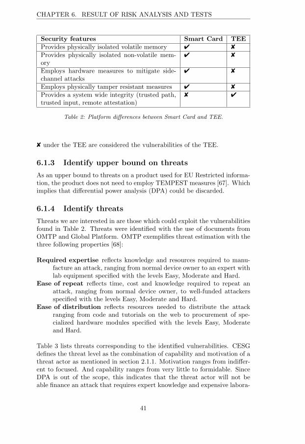
CHAPTER 6. RESULT OF RISK ANALYSIS AND TESTS
Security features Smart Card TEEProvides physically isolated volatile memory 4 8Provides physically isolated non-volatile mem-ory
4 8
Employs hardware measures to mitigate side-channel attacks
4 8
Employs physically tamper resistant measures 4 8Provides a system wide integrity (trusted path,trusted input, remote attestation)
8 4
Table 2: Platform di↵erences between Smart Card and TEE.
8 under the TEE are considered the vulnerabilities of the TEE.
6.1.3 Identify upper bound on threats
As an upper bound to threats on a product used for EU Restricted informa-tion, the product does not need to employ TEMPEST measures [67]. Whichimplies that di↵erential power analysis (DPA) could be discarded.
6.1.4 Identify threats
Threats we are interested in are those which could exploit the vulnerabilitiesfound in Table 2. Threats were identified with the use of documents fromOMTP and Global Platform. OMTP exemplifies threat estimation with thethree following properties [68]:
Required expertise reflects knowledge and resources required to manu-facture an attack, ranging from normal device owner to an expert withlab equipment specified with the levels Easy, Moderate and Hard.
Ease of repeat reflects time, cost and knowledge required to repeat anattack, ranging from normal device owner, to well-funded attackersspecified with the levels Easy, Moderate and Hard.
Ease of distribution reflects resources needed to distribute the attackranging from code and tutorials on the web to procurement of spe-cialized hardware modules specified with the levels Easy, Moderateand Hard.
Table 3 lists threats corresponding to the identified vulnerabilities. CESGdefines the threat level as the combination of capability and motivation of athreat actor as mentioned in section 2.1.1. Motivation ranges from indi↵er-ent to focused. And capability ranges from very little to formidable. SinceDPA is out of the scope, this indicates that the threat actor will not beable finance an attack that requires expert knowledge and expensive labora-
41
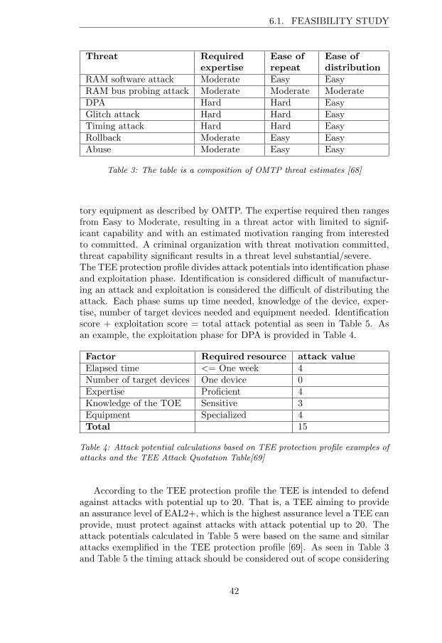
6.1. FEASIBILITY STUDY
Threat Requiredexpertise
Ease ofrepeat
Ease ofdistribution
RAM software attack Moderate Easy EasyRAM bus probing attack Moderate Moderate ModerateDPA Hard Hard EasyGlitch attack Hard Hard EasyTiming attack Hard Hard EasyRollback Moderate Easy EasyAbuse Moderate Easy Easy
Table 3: The table is a composition of OMTP threat estimates [68]
tory equipment as described by OMTP. The expertise required then rangesfrom Easy to Moderate, resulting in a threat actor with limited to signif-icant capability and with an estimated motivation ranging from interestedto committed. A criminal organization with threat motivation committed,threat capability significant results in a threat level substantial/severe.The TEE protection profile divides attack potentials into identification phaseand exploitation phase. Identification is considered di�cult of manufactur-ing an attack and exploitation is considered the di�cult of distributing theattack. Each phase sums up time needed, knowledge of the device, exper-tise, number of target devices needed and equipment needed. Identificationscore + exploitation score = total attack potential as seen in Table 5. Asan example, the exploitation phase for DPA is provided in Table 4.
Factor Required resource attack valueElapsed time <= One week 4Number of target devices One device 0Expertise Proficient 4Knowledge of the TOE Sensitive 3Equipment Specialized 4Total 15
Table 4: Attack potential calculations based on TEE protection profile examples ofattacks and the TEE Attack Quotation Table[69]
According to the TEE protection profile the TEE is intended to defendagainst attacks with potential up to 20. That is, a TEE aiming to providean assurance level of EAL2+, which is the highest assurance level a TEE canprovide, must protect against attacks with attack potential up to 20. Theattack potentials calculated in Table 5 were based on the same and similarattacks exemplified in the TEE protection profile [69]. As seen in Table 3and Table 5 the timing attack should be considered out of scope considering
42
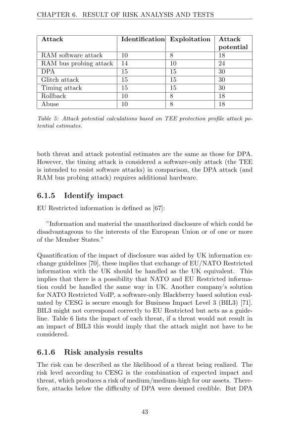
CHAPTER 6. RESULT OF RISK ANALYSIS AND TESTS
Attack Identification Exploitation Attackpotential
RAM software attack 10 8 18RAM bus probing attack 14 10 24DPA 15 15 30Glitch attack 15 15 30Timing attack 15 15 30Rollback 10 8 18Abuse 10 8 18
Table 5: Attack potential calculations based on TEE protection profile attack po-tential estimates.
both threat and attack potential estimates are the same as those for DPA.However, the timing attack is considered a software-only attack (the TEEis intended to resist software attacks) in comparison, the DPA attack (andRAM bus probing attack) requires additional hardware.
6.1.5 Identify impact
EU Restricted information is defined as [67]:
”Information and material the unauthorized disclosure of which could bedisadvantageous to the interests of the European Union or of one or moreof the Member States.”
Quantification of the impact of disclosure was aided by UK information ex-change guidelines [70], these implies that exchange of EU/NATO Restrictedinformation with the UK should be handled as the UK equivalent. Thisimplies that there is a possibility that NATO and EU Restricted informa-tion could be handled the same way in UK. Another company’s solutionfor NATO Restricted VoIP, a software-only Blackberry based solution eval-uated by CESG is secure enough for Business Impact Level 3 (BIL3) [71].BIL3 might not correspond correctly to EU Restricted but acts as a guide-line. Table 6 lists the impact of each threat, if a threat would not result inan impact of BIL3 this would imply that the attack might not have to beconsidered.
6.1.6 Risk analysis results
The risk can be described as the likelihood of a threat being realized. Therisk level according to CESG is the combination of expected impact andthreat, which produces a risk of medium/medium-high for our assets. There-fore, attacks below the di�culty of DPA were deemed credible. But DPA
43
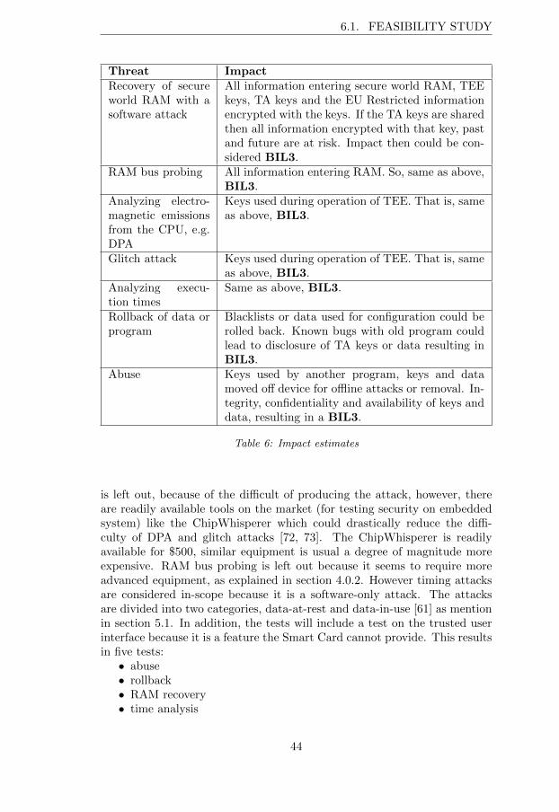
6.1. FEASIBILITY STUDY
Threat ImpactRecovery of secureworld RAM with asoftware attack
All information entering secure world RAM, TEEkeys, TA keys and the EU Restricted informationencrypted with the keys. If the TA keys are sharedthen all information encrypted with that key, pastand future are at risk. Impact then could be con-sidered BIL3.
RAM bus probing All information entering RAM. So, same as above,BIL3.
Analyzing electro-magnetic emissionsfrom the CPU, e.g.DPA
Keys used during operation of TEE. That is, sameas above, BIL3.
Glitch attack Keys used during operation of TEE. That is, sameas above, BIL3.
Analyzing execu-tion times
Same as above, BIL3.
Rollback of data orprogram
Blacklists or data used for configuration could berolled back. Known bugs with old program couldlead to disclosure of TA keys or data resulting inBIL3.
Abuse Keys used by another program, keys and datamoved o↵ device for o✏ine attacks or removal. In-tegrity, confidentiality and availability of keys anddata, resulting in a BIL3.
Table 6: Impact estimates
is left out, because of the di�cult of producing the attack, however, thereare readily available tools on the market (for testing security on embeddedsystem) like the ChipWhisperer which could drastically reduce the di�-culty of DPA and glitch attacks [72, 73]. The ChipWhisperer is readilyavailable for $500, similar equipment is usual a degree of magnitude moreexpensive. RAM bus probing is left out because it seems to require moreadvanced equipment, as explained in section 4.0.2. However timing attacksare considered in-scope because it is a software-only attack. The attacksare divided into two categories, data-at-rest and data-in-use [61] as mentionin section 5.1. In addition, the tests will include a test on the trusted userinterface because it is a feature the Smart Card cannot provide. This resultsin five tests:
• abuse• rollback• RAM recovery• time analysis
44
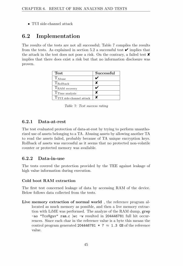
CHAPTER 6. RESULT OF RISK ANALYSIS AND TESTS
• TUI side-channel attack
6.2 Implementation
The results of the tests are not all successful; Table 7 compiles the resultsfrom the tests. As explained in section 5.2 a successful test 4 implies thatthe attack in the test does not pose a risk. On the contrary, a failed test 8implies that there does exist a risk but that no information disclosure wasproven.
Test SuccessfulTAbuse 4TRollback 8TRAM recovery 4TTime analysis 8TTUI side-channel attack 8
Table 7: Test success rating
6.2.1 Data-at-rest
The test evaluated protection of data-at-rest by trying to perform unautho-rized use of assets belonging to a TA. Abusing assets by allowing another TAto read the assets failed, probably because of TA unique encryption keys.Rollback of assets was successful as it seems that no protected non-volatilecounter or protected memory was available.
6.2.2 Data-in-use
The tests covered the protection provided by the TEE against leakage ofhigh value information during execution.
Cold boot RAM extraction
The first test concerned leakage of data by accessing RAM of the device.Below follows data collected from the tests.
Live memory extraction of normal world , the reference program al-located as much memory as possible, and then a live memory extrac-tion with LiME was performed. The analyze of the RAM dump, grep-ao "TcoVguv" ram c |wc -w resulted in 204446781 full hit occur-rences. Since each char in the reference value is a byte this means thecontrol program generated 204446781 * 7 ⇡ 1.3 GB of the referencevalue.
45
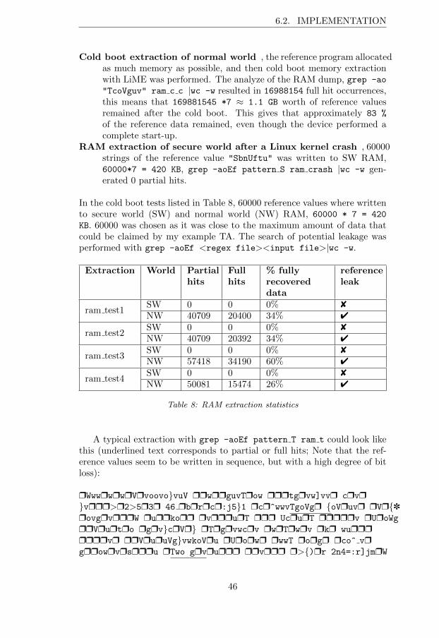
6.2. IMPLEMENTATION
Cold boot extraction of normal world , the reference program allocatedas much memory as possible, and then cold boot memory extractionwith LiME was performed. The analyze of the RAM dump, grep -ao
"TcoVguv" ram c c |wc -w resulted in 16988154 full hit occurrences,this means that 169881545 *7 ⇡ 1.1 GB worth of reference valuesremained after the cold boot. This gives that approximately 83 %
of the reference data remained, even though the device performed acomplete start-up.
RAM extraction of secure world after a Linux kernel crash , 60000strings of the reference value "SbnUftu" was written to SW RAM,60000*7 = 420 KB, grep -aoEf pattern S ram crash |wc -w gen-erated 0 partial hits.
In the cold boot tests listed in Table 8, 60000 reference values where writtento secure world (SW) and normal world (NW) RAM, 60000 * 7 = 420
KB. 60000 was chosen as it was close to the maximum amount of data thatcould be claimed by my example TA. The search of potential leakage wasperformed with grep -aoEf <regex file><input file>|wc -w.
Extraction World Partialhits
Fullhits
% fullyrecovereddata
referenceleak
ram test1SW 0 0 0% 8NW 40709 20400 34% 4
ram test2SW 0 0 0% 8NW 40709 20392 34% 4
ram test3SW 0 0 0% 8NW 57418 34190 60% 4
ram test4SW 0 0 0% 8NW 50081 15474 26% 4
Table 8: RAM extraction statistics
A typical extraction with grep -aoEf pattern T ram t could look likethis (underlined text corresponds to partial or full hits; Note that the ref-erence values seem to be written in sequence, but with a high degree of bitloss):
rWwwrwrwrVrvoovo}vuV rrwrrguvTrow rrrtgrvw]vvr crvr}vrrr>r2>5r3r 46 rbrrrcr:j5}1 rcr^wwvTgoVgr {oVruvr rVr{]rovgrvrrrW rurrkorr rvrrrurT rrr UcrurT rrrrrv rUroWg
rrVrurtro rgrv}crVr} rTrgrvwcrv rwrTrwrv rkr wurrrrrrrvr rrVruruVg}vwkoVru rUrorwr rwwT rorgr rco^ vrgrrowrvrsrrru rTwo grvrurrr rrvrrr r>{)rr 2n4=:r]jmrW
46
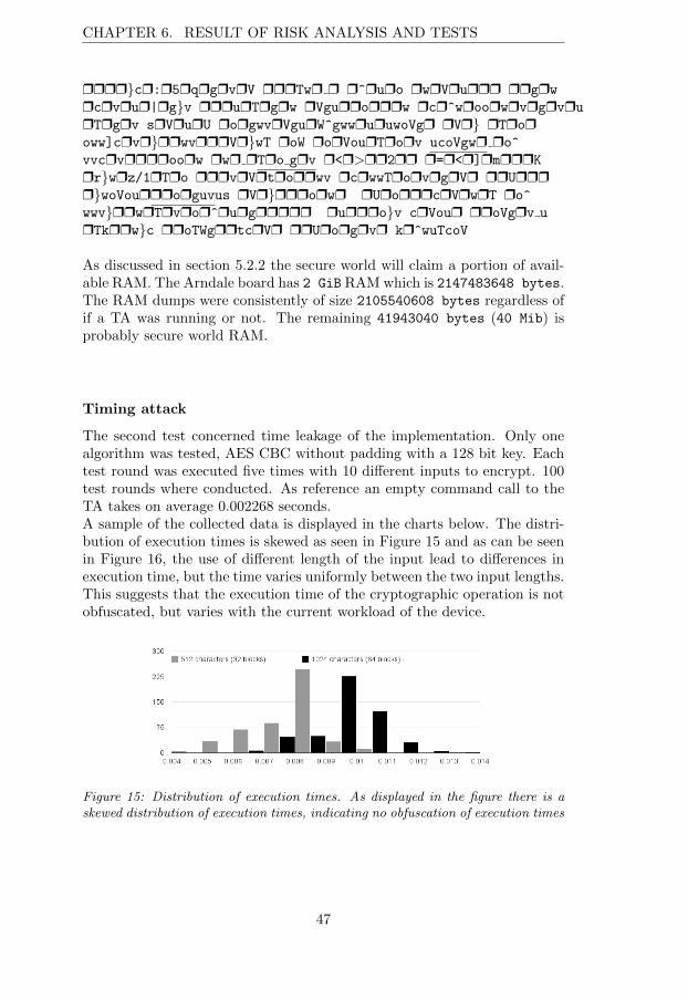
CHAPTER 6. RESULT OF RISK ANALYSIS AND TESTS
rrrr}cr:r5rqrgrvrV rrrTwr r r^ruro rwrVrurrr rrgrw
rcrvrur|rg}v rrrurTrgrw rVgurrorrrw rcr^wroorwrvrgrvru
rTrgrv srVrurU rorgwvrVgurW^gwwruruwoVgr rVr} rTroroww]crvr}rrwvrrrVr}wT roW rorVourTrorv ucoVgwr ro^
vvcrvrrrroorw rwr rTro grv r<r>rr2rr r=r<r]rmrrrK
rr}wrz/1rTro rrrvrVrtrorrwv rcrwwTrorvrgrVr rrUrrrr}woVourrrorguvus rVr}rrrorwr rUrorrrcrVrwrT ro^
wwv}rrwrTrvror^rurgrrrrr rurrro}v crVour rroVgrv u
rTkrrw}c rroTWgrrtcrVr rrUrorgrvr kr^wuTcoV
As discussed in section 5.2.2 the secure world will claim a portion of avail-able RAM. The Arndale board has 2 GiB RAMwhich is 2147483648 bytes.The RAM dumps were consistently of size 2105540608 bytes regardless ofif a TA was running or not. The remaining 41943040 bytes (40 Mib) isprobably secure world RAM.
Timing attack
The second test concerned time leakage of the implementation. Only onealgorithm was tested, AES CBC without padding with a 128 bit key. Eachtest round was executed five times with 10 di↵erent inputs to encrypt. 100test rounds where conducted. As reference an empty command call to theTA takes on average 0.002268 seconds.A sample of the collected data is displayed in the charts below. The distri-bution of execution times is skewed as seen in Figure 15 and as can be seenin Figure 16, the use of di↵erent length of the input lead to di↵erences inexecution time, but the time varies uniformly between the two input lengths.This suggests that the execution time of the cryptographic operation is notobfuscated, but varies with the current workload of the device.
Figure 15: Distribution of execution times. As displayed in the figure there is askewed distribution of execution times, indicating no obfuscation of execution times
47
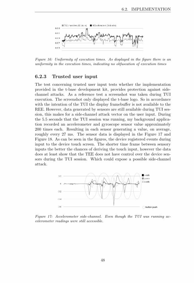
6.2. IMPLEMENTATION
Figure 16: Uniformity of execution times. As displayed in the figure there is anuniformity in the execution times, indicating no obfuscation of execution times
6.2.3 Trusted user input
The test concerning trusted user input tests whether the implementationprovided in the t-base development kit, provides protection against side-channel attacks. As a reference test a screenshot was taken during TUIexecution. The screenshot only displayed the t-base logo. So in accordancewith the intention of the TUI the display framebu↵er is not available to theREE. However, data generated by sensors are still available during TUI ses-sion, this makes for a side-channel attack vector on the user input. Duringthe 5.5 seconds that the TUI session was running, my background applica-tion recorded an accelerometer and gyroscope sensor value approximately200 times each. Resulting in each sensor generating a value, on average,roughly every 27 ms. The sensor data is displayed in the Figure 17 andFigure 18. As can be seen in the figures, the device registered events duringinput to the device touch screen. The shorter time frame between sensoryinputs the better the chances of deriving the touch input, however the datadoes at least show that the TEE does not have control over the device sen-sors during the TUI session. Which could expose a possible side-channelattack.
button push
Figure 17: Accelerometer side-channel. Even though the TUI was running ac-celerometer readings were still accessible.
48
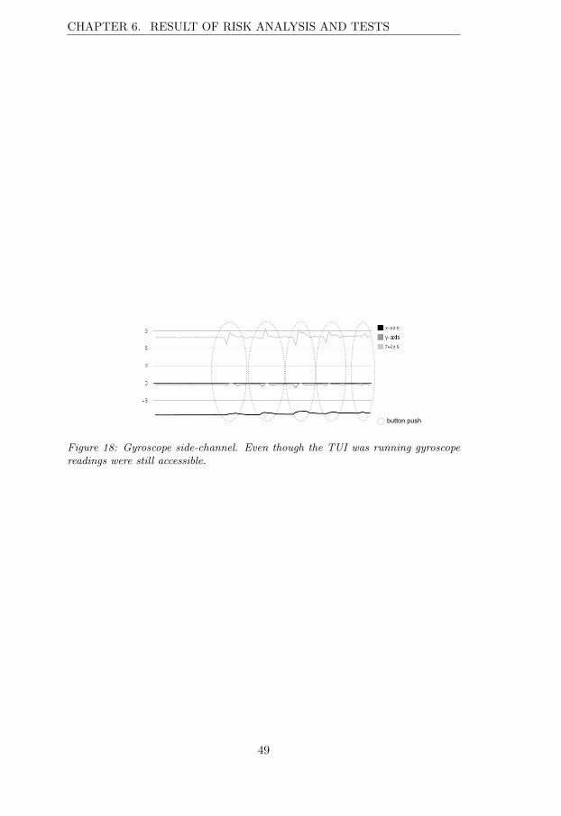
CHAPTER 6. RESULT OF RISK ANALYSIS AND TESTS
button push
Figure 18: Gyroscope side-channel. Even though the TUI was running gyroscopereadings were still accessible.
49
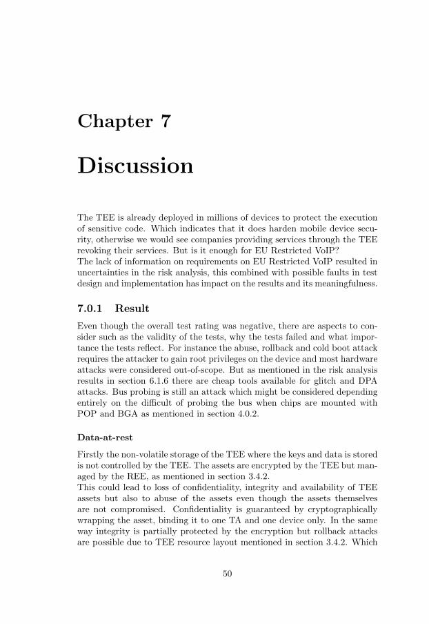
Chapter 7
Discussion
The TEE is already deployed in millions of devices to protect the executionof sensitive code. Which indicates that it does harden mobile device secu-rity, otherwise we would see companies providing services through the TEErevoking their services. But is it enough for EU Restricted VoIP?The lack of information on requirements on EU Restricted VoIP resulted inuncertainties in the risk analysis, this combined with possible faults in testdesign and implementation has impact on the results and its meaningfulness.
7.0.1 Result
Even though the overall test rating was negative, there are aspects to con-sider such as the validity of the tests, why the tests failed and what impor-tance the tests reflect. For instance the abuse, rollback and cold boot attackrequires the attacker to gain root privileges on the device and most hardwareattacks were considered out-of-scope. But as mentioned in the risk analysisresults in section 6.1.6 there are cheap tools available for glitch and DPAattacks. Bus probing is still an attack which might be considered dependingentirely on the di�cult of probing the bus when chips are mounted withPOP and BGA as mentioned in section 4.0.2.
Data-at-rest
Firstly the non-volatile storage of the TEE where the keys and data is storedis not controlled by the TEE. The assets are encrypted by the TEE but man-aged by the REE, as mentioned in section 3.4.2.This could lead to loss of confidentiality, integrity and availability of TEEassets but also to abuse of the assets even though the assets themselvesare not compromised. Confidentiality is guaranteed by cryptographicallywrapping the asset, binding it to one TA and one device only. In the sameway integrity is partially protected by the encryption but rollback attacksare possible due to TEE resource layout mentioned in section 3.4.2. Which
50
CHAPTER 7. DISCUSSION
allows an attacker to move, copy and delete files on the file system. Forthe same reason availability cannot be guaranteed. This implies that anattacker could force the user to use an unsecure communications channelfor his or her communication. However, the attacker will never be able toaccess the asset in plain-text.Reviewing the test results from a real world aspect there are a few other pa-rameters to consider, impact level and attacker profile. The attack would notrequire any expensive tools and not even a very educated attacker. Consid-ering that the assets in this case are cryptographic keys for communicationchannel establishment, rollback or deletion of the asset would result in de-nial of service. No asset has been compromised.However, even though the assets are cryptographically wrapped, they areavailable for o✏ine brute force attacks, which is not true for the SmartCard. As mentioned, Jan Ekberg explains that adding flash on-SoC to storea larger amount of assets is expensive [43]. Optional solutions then could beto build a file system separate from the REE file system on the same flashdisc which is not accessible by the REE, possible with the help of the Trust-Zone NS-bit. Or as the flash is not on-SoC it could sport an authenticationmechanism such as RPMB as mentioned in section 3.4.2, to make sure thatinvasive attacks are not allowed to easily modify data stored on the flash.This way, at least rollback and abuse attacks can be prevented. It shouldbe considered that even though the Arndale board does not sport RPMB itdoes not mean it is not in used on available devices on the market.
Data-in-use
The test was divided into two parts, RAM leakage and execution time leak-age. As displayed in the Table 8, no secure world data was recovered, despitegood conditions for the cold boot attack, which is shown in the referencetests. It is therefore probable that the secure world RAM is mapped to aspecific region as mentioned in section 5.2.2 which provides higher protec-tion of RAM from cold boot attacks.The timing test showed that at least one algorithm leaked time information,but no penetration was proven. Reviewing the results from a real worldaspect the assets of value in this kind of cold boot attack is the potential offinding secret key material.The potential attacker in this case could be the user herself, as the assetcan be sold to e.g. criminal gangs. The cold boot attack is mitigated butcryptographic operations should employ random execution times.
Trusted-user-input
The purpose of the TUI is that frame-bu↵er and touch input are not sup-posed to be accessible by the REE as mentioned in section 3.4.2 and sec-tion 2.2. As shown in the test, side-channel data is still available which hasbeen demonstrated to provide good-enough precision to figure out where on
51
the screen the finger tapped [58, 59]. Which is why the TEE and TUI shouldrequire control over and disable most sensory input as-well as camera duringTUI operation, as it is otherwise ine↵ective in protecting the user input. Asimple solution would be randomize the buttons for the pin input and toprevent phishing by other applications the TUI should display a secret onlyknown to the user which the REE cannot access.
7.0.2 Review of method
Many of the sources emphasized that the Smart Card is secure and the TEEless secure but more secure than the REE and discussed similar solutions tothe TEE and TrustZone and the di↵erent use cases of the alternatives. Butthe sources often did not go in-depth, did not have appropriate hardware totake the work further or did not present any proof-of-concept implementa-tions [40, 74, 35, 75, 11]. The focus in literature was on the TrustZone asan enabler for TEE, but more hardware elements are required to support aTEE, such as trusted storage area to support at least non-volatile counters.In aspect of evaluation another company successfully launched a Blackberrysolution for NATO Restricted VoIP without a separate secure element. Butthe requirements on NATO Restricted cannot be assumed to apply to EURestricted VoIP. In lack of readily available test suites for the TEE [60] andthe specific comparison between TEE and Smart Card a risk analysis basedon TEE vulnerabilities was conducted. The risk analysis resulted in twotests categories, data-at-rest and data-in-use inspired by EU data separa-tion guidelines [61]. The TUI was added as it provides the device with anextra dimension of security.The tests only cover software attacks as those were the only attacks consid-ered in-scope as mentioned in section 6.1.6. The tests themselves howevercould have been more complete.Abuse and rollback - The test requirements should have been more through.
For instance, only one development board was available making it im-possible to test if assets where device bound.
RAM extraction - Tilo Muller’s tool FROST [52], based on LiME wasfirst considered but was required to be built from scratch as no sourcecode was available. This included modifying the CyanogenMod kerneland ClockworkMod to support the Arndale board, as it had not yetbeen ported. FROST allows dumping of RAM from fastboot, beforeAndroid is started. The solution instead, was to run LiME immedi-ately after complete start-up. In my case, this was considered accept-able as the occurrence of even a single secure world RAM referencewould prove the attack successful.
Timing test - The test indicates that at least for the algorithm chosen timeobfuscation is not applied. However the tests should have covered morealgorithms.
TUI test - The test shows that side-channels can be used to figure out
52
CHAPTER 7. DISCUSSION
inputs on the device. But for more interesting results, contact couldhave been made with authors of [58, 59] to use their code and ap-proach. Also data was collected by printing to the terminal. Printingto the terminal is slow, a better approach would have been to storethe sensor data in an array and export the data after execution.
The overall intention of the tests was to derive whether the TEE could pro-vide enough assurance to be used it as a virtual Smart Card, where theassurance level should be high enough to protect EU Restricted informa-tion. The tests do provide some input, but more tests would be needed. Areasonable approach would have been to contact an evaluation lab to takepart of their test suites and have a discussion with them about a subset offeasible test. Further the tests could have been more thoroughly designedand defined [63].The tests can easily be executed again and would most likely generate thesame results; however there are some random elements in the tests. Forinstance, in the data-in-use cold boot tests, it is hard to know where bitinformation will be lost. So in theory, if t-base is implemented in anotherway then the test implies, another outcome could be possible.The same is true for the time test, it was concluded that there is not a ran-dom element in the algorithm implementation because a pattern and skewdistribution was evident in the data collected. Instead of visually inspect-ing the data, entropy calculation and more measurements could have beenperformed. Also, the tests are coarse-grained; the TUI test only reveals theside-channel not the PIN input. So in terms of validity, the tests show thatthere are potential security risks, but no penetration of the security hasbeen proven except for the rollback attack. There is also a possibility thatinformation in documents and resources could have been misunderstood orthat the Arndale board allows things not allowed on market deployed im-plementations, which would a↵ect both design and implementation of thetests.The rational for a TEE in a mobile device should be discussed as-well. Thesmartphone market is rough; to attract customers you must add value tothe device. For instance by enabling HD Netflix streaming, Netflix on theother hand will not stream HD quality unless the stream is secure. TheTEE push to the mobile market seems to be driven more from an economicperspective rather than a security perspective.It should also be considered that Tr1 is defined for handset whereas theGlobal Platform TEE is more general and can be applied in e.g. the auto-motive sector. The Global Platform standards for the TEE will help supportthe adoption of the TEE and ease development, as the code does not needto be rewritten for di↵erent platforms.Now, when many smart phones features an ARM TrustZone CPU and TEEthe obvious question is, what else can we do with it? Inherently, this poses asecurity threat, because more third-party code will likely result in a higher
53
probability of bugs. Similar to the criticism against the TPM, one couldargue that the TEE would make for a good place to spy on the user [46].Also, should the TEE be miss-implemented or breached [47] it could leadto compromise of all assets stored on the device. This in-turn creates op-portunities for adversaries to work unnoticed to eaves-drop on and spoofactions.
54
Chapter 8
Conclusions
The aim of this thesis was to provide input to Sectra on whether a TA couldact as a virtual Smart Card while providing enough assurance to handle EUrestricted VoIP communication. The input would be based on a feasibilitystudy and practical tests. As the Global Platform specification leaves a lotof freedom to implementers on how to design their TEE, it became obviousthat the TEE employed in mobile devices is not intended to handle assets ofhigh value. Rather it further hardens the security of the mobile device. Inaddition the TEE protection profile is still a work in progress but will onlybe defined up to EAL2+.The analysis of the employed TEE was hampered by the fact that no func-tional or non-functional requirements for EU restricted VoIP for mobiledevices were found. Looking at the research question, the final answer towhether the TEE could act as a substitute to a Smart Card, is that it isunclear.Replay attacks could be prohibited by the use of a RPMB enabled flashdisc, further, abuse and cold boot attacks was not possible. Timing attacksmight have to be considered when using the TEE and finally, the TUI doesharden protection of user input, but input could be derived if an attackercan install a malicious application on the device. Finally, three areas are ofinterest, RAM, Evaluation and Maturity.
RAM In the current Smart Card solution session keys for VoIP are trans-ferred to RAM during a VoIP call. But the private keys used for keynegotiation of the session keys never leave the Smart Card.In the TEE case, the private key will enter trusted RAM and this re-sult in an attack opportunity to probe the bus to the RAM.On e.g. the Samsung Galaxy S5, RAM is soldered on-top of the CPUwith BGA which introduces some higher di�culty to probe the bus.To mitigate that threat at least some parts of the trusted volatilememory could have been placed in an embedded secure element, TPM
55
8.1. TEE BENEFICIAL VALUES AND SUMMARY
or on-chip RAM like SRAM. Another approach would be to use CPUregister as live storage of unencrypted keys [49, 50] or if trusted o↵-chip RAM could be encrypted.Up until recently some mobile devices featured NFC chips with a se-cure element to store credit card credentials for proximity purchases(Google Wallet). The secure element on newer devices has unfortu-nately been removed and the payment method have been replaced byhost-based card emulation (HCE) which has become the standard forNFC proximity purchases mostly due to mobile network operators op-posing the NFC+secure element configuration.If that secure element had been kept it would have been a good can-didate for separate storage of keys and execution of key operations.
Evaluation The TEE protection profile is only defined up to EAL2+, dueto complexity of the EAL rules concerning the CPU. This means thatthere is a limit to the amount of assurance which can be gained fromthe TEE. Perhaps then, evaluation of the TEE could be split into TEEOS and TEE hardware to allow higher assurance levels of the TEE OS.Further, the mobile industry releases new models often which couldresult in each new model intended for use might have to be evaluatedbefore procurement to control if e.g. RPMB and other features areprovided.
Maturity The maturity of the technology and implementation is also ofinterest, such as su�cient testing of the TEE and TUI. The TEE isalready deployed in many devices worldwide. But as in the case withSmart Cards, the more extensively they are used and the higher valuesthey protect the higher the risk of attacks on them. As an examplethe breach of the TEE [47] only required software tools whereas theattack against the TPM [34] required a lot of time and lab equipment.
8.1 TEE beneficial values and summary
What value does the TEE bring? The TEE further hardens the mobile de-vice by providing a trusted boot and a trusted execution environment andeven if the attacker becomes root in the REE the secrets are still crypto-graphically protected. The CPU of the mobile device is faster than that ofa Smart Card and large shared memory bu↵ers makes it ideal for contentencryption/decryption.The Global Platform standardization means TA code will run on any GlobalPlatform compliant TEE and the process of provisioning an application toa TEE becomes simpler because provisioning might not dependent of theapproval of the carrier or manufacturer, as it probably would if inserted intoa SIM card.The TUI provides the user with a safer input mechanism, e.g. to enable 2-factor authentication, but has yet to be implemented in commercial devices.
56
CHAPTER 8. CONCLUSIONS
The addition of attestation allows for devices to attest that they are trustedwhich makes a good foundation for device management.Smart Card and TEE should not be considered opposites of each other;they could advantageously be used in combination to leverage each of theirstrengths.To summarize, for the TEE to protect against simpler hardware attacks,keys for cryptographic operations should either be handled on-SoC, in a se-cure element or with encrypted RAM. The TEE should control not only thescreen but also sensors and camera to mitigate attacks on the TUI. Assetsor monotonic counters tied to assets should be stored in RPMB and side-channel attacks like glitch attacks and DPA might have to be considered inthe future as tools become available for exploiting such vulnerabilities.
8.2 Future work
Even if the TEE is intended to primary protect against software attacks, itis still interesting to investigate if a low-cost hardware attacks can penetratethe TEE. The ChipWhisperer tool mentioned in section 6.1.6 would be aninteresting starting point.Would it be possible to use a glitch attacks to circumvent the memory rangechecks or boot loader signature-verification in the TEE to access TEE mem-ory from the REE.According to EU guidelines [67], only information classified as EU Confiden-tial and above needs protection against TEMPEST. However, since tools likeChipwisperer are now readily available at low-cost perhaps EU Restrictedshould include TEMPEST measures as-well.Would it be possible to use low-cost hardware to perform DPA attacks onTEE crypto-operations, to reveal keys and device secrets?Also to avoid disclosing key material into RAM would it be possible to useon-chip SRAM, CPU registers, or encrypt data on the memory bus, to mit-igate bus probing attacks.Another interesting aspect would be to look at secure provisioning. Wouldit be possible and considered safe enough for EU Restricted VoIP to provi-sion session keys to the device using only remote attestation and a one-timetoken (like an AIK), which could be used to identify a user? That is, canattestation be used to identify the device and user. This could then removethe need for a stored credential on the device.It would be interesting to push the research question further by co-operatingwith a test lab or Swedish authorities to understand what requirements areapply for EU restricted VoIP on mobile devices to build a reference imple-mentation of a virtual Smart Card and let a test-lab evaluate the solution.This approach however does not only take a lot of time but is also costly asevaluations are costly.
57
Bibliography
[1] CESG. HMG IA Standard No. 1 Technical Risk Assessment. CESGrecommendation, 2009.
[2] Karim Vellani. Strategic security management: a risk assessment guidefor decision makers. Butterworth-Heinemann, 2006.
[3] NIST. Standards for security categorization of federal information andinformation systems. NIST standard, 2004.
[4] ARM. Building a Secure System using TrustZone Technology. whitepa-per, 2009.
[5] TCG. TCG Mobile Reference Architecture. draft, spec-ification version 1.0 revision 1, 12 june 2007, TCG,2007. http://www.trustedcomputinggroup.org/files/
temp/644597BE-1D09-3519-AD5ADDAFA0B539D2/MPWG%
20tcg-mobile-reference-architecture-1.pdf, Accessed:2014-09-07.
[6] TCG. Mobile phone work group, selected use case analyses v 1.0.description, TCG, 2009. http://www.trustedcomputinggroup.
org/files/temp/6443B207-1D09-3519-AD3180491A6DF1F5/
MPWG%20Selected_Mobile_Phone_Use_Case_Analyses_v1.pdf,Accessed:2014-08-17.
[7] Kari Kostiainen, Elena Reshetova, Ahmad-Reza Sadeghi, Lucas Davi,Alexandra Dmitrienko, Stephan Heuser, and N. Asokan. Mobile Plat-form Security. Morgan & Claypool, 2014.
[8] Ben Smeets and Patrik Ekdahl. Evolution: new phones, new se-curity needs. http://www.ericsson.com/research-blog/security/evolution-new-phones-new-security-needs/, 2014. Accessed:2014-06-29.
[9] Ross Anderson. Security engineering. John Wiley & Sons, 2008.
[10] Chris Mitchell. Trusted Computing. Institution of Electrical Engineers,2005.
58
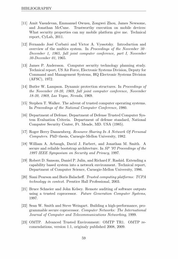
BIBLIOGRAPHY
[11] Amit Vasudevan, Emmanuel Owusu, Zongwei Zhou, James Newsome,and Jonathan McCune. Trustworthy execution on mobile devices:What security properties can my mobile platform give me. Technicalreport, CyLab, 2011.
[12] Fernando Jose Corbato and Victor A. Vyssotsky. Introduction andoverview of the multics system. In Proceedings of the November 30–December 1, 1965, fall joint computer conference, part I, November30-December 01, 1965.
[13] James P. Andersson. Computer security technology planning study.Technical report, US Air Force, Electronic Systems Division, Deputy forCommand and Management Systems, HQ Electronic Systems Division(AFSC), 1972.
[14] Butler W. Lampson. Dynamic protection structures. In Proceedings ofthe November 18-20, 1969, fall joint computer conference, November18-20, 1969, Las Vegas, Nevada, 1969.
[15] Stephen T. Walker. The advent of trusted computer operating systems.In Proceedings of the National Computer Conference, 1980.
[16] Department of Defense. Department of Defense Trusted Computer Sys-tem Evaluation Criteria. Department of defense standard, NationalComputer Security Center, Ft. Meade, MD. USA (1985).
[17] Roger Berry Dannenberg. Resource Sharing In A Network Of PersonalComputers. PhD thesis, Carnegie-Mellon University, 1982.
[18] William A. Arbaugh, David J. Farbert, and Jonathan M. Smith. Asecure and reliable bootstrap architecture. In SP ’97 Proceedings of the1997 IEEE Symposium on Security and Privacy, 1997.
[19] Robert D. Sansom, Daniel P. Julin, and Richard F. Rashid. Extending acapability based system into a network environment. Technical report,Department of Computer Science, Carnegie-Mellon University, 1986.
[20] Siani Pearson and Boris Balache↵. Trusted computing platforms: TCPAtechnology in context. Prentice Hall Professional, 2003.
[21] Bruce Schneier and John Kelsey. Remote auditing of software outputsusing a trusted coprocessor. Future Generation Computer Systems,1997.
[22] Sean W. Smith and Steve Weingart. Building a high-performance, pro-grammable secure coprocessor. Computer Networks: The InternationalJournal of Computer and Telecommunications Networking, 1999.
[23] OMTP. Advanced Trusted Environment: OMTP TR1. OMTP re-comendations, version 1.1, originaly published 2008, 2009.
59
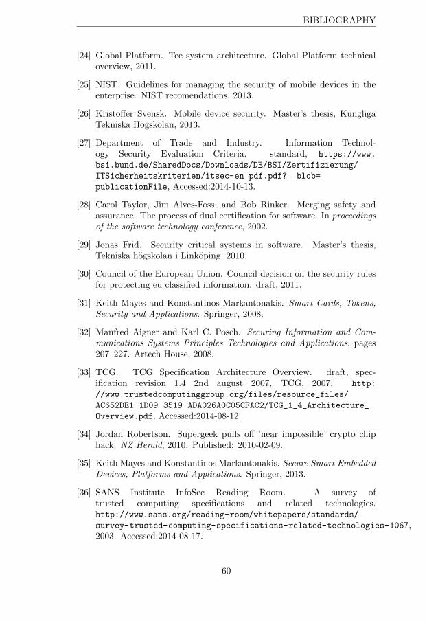
BIBLIOGRAPHY
[24] Global Platform. Tee system architecture. Global Platform technicaloverview, 2011.
[25] NIST. Guidelines for managing the security of mobile devices in theenterprise. NIST recomendations, 2013.
[26] Kristo↵er Svensk. Mobile device security. Master’s thesis, KungligaTekniska Hogskolan, 2013.
[27] Department of Trade and Industry. Information Technol-ogy Security Evaluation Criteria. standard, https://www.
bsi.bund.de/SharedDocs/Downloads/DE/BSI/Zertifizierung/
ITSicherheitskriterien/itsec-en_pdf.pdf?__blob=
publicationFile, Accessed:2014-10-13.
[28] Carol Taylor, Jim Alves-Foss, and Bob Rinker. Merging safety andassurance: The process of dual certification for software. In proceedingsof the software technology conference, 2002.
[29] Jonas Frid. Security critical systems in software. Master’s thesis,Tekniska hogskolan i Linkoping, 2010.
[30] Council of the European Union. Council decision on the security rulesfor protecting eu classified information. draft, 2011.
[31] Keith Mayes and Konstantinos Markantonakis. Smart Cards, Tokens,Security and Applications. Springer, 2008.
[32] Manfred Aigner and Karl C. Posch. Securing Information and Com-munications Systems Principles Technologies and Applications, pages207–227. Artech House, 2008.
[33] TCG. TCG Specification Architecture Overview. draft, spec-ification revision 1.4 2nd august 2007, TCG, 2007. http:
//www.trustedcomputinggroup.org/files/resource_files/
AC652DE1-1D09-3519-ADA026A0C05CFAC2/TCG_1_4_Architecture_
Overview.pdf, Accessed:2014-08-12.
[34] Jordan Robertson. Supergeek pulls o↵ ’near impossible’ crypto chiphack. NZ Herald, 2010. Published: 2010-02-09.
[35] Keith Mayes and Konstantinos Markantonakis. Secure Smart EmbeddedDevices, Platforms and Applications. Springer, 2013.
[36] SANS Institute InfoSec Reading Room. A survey oftrusted computing specifications and related technologies.http://www.sans.org/reading-room/whitepapers/standards/
survey-trusted-computing-specifications-related-technologies-1067,2003. Accessed:2014-08-17.
60
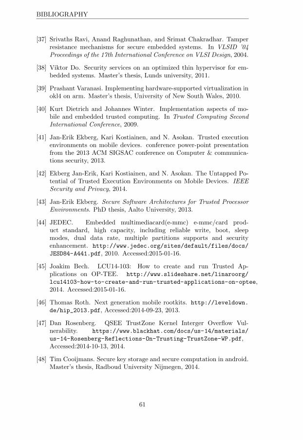
BIBLIOGRAPHY
[37] Srivaths Ravi, Anand Raghunathan, and Srimat Chakradhar. Tamperresistance mechanisms for secure embedded systems. In VLSID ’04Proceedings of the 17th International Conference on VLSI Design, 2004.
[38] Viktor Do. Security services on an optimized thin hypervisor for em-bedded systems. Master’s thesis, Lunds university, 2011.
[39] Prashant Varanasi. Implementing hardware-supported virtualization inokl4 on arm. Master’s thesis, University of New South Wales, 2010.
[40] Kurt Dietrich and Johannes Winter. Implementation aspects of mo-bile and embedded trusted computing. In Trusted Computing SecondInternational Conference, 2009.
[41] Jan-Erik Ekberg, Kari Kostiainen, and N. Asokan. Trusted executionenvironments on mobile devices. conference power-point presentationfrom the 2013 ACM SIGSAC conference on Computer & communica-tions security, 2013.
[42] Ekberg Jan-Erik, Kari Kostiainen, and N. Asokan. The Untapped Po-tential of Trusted Execution Environments on Mobile Devices. IEEESecurity and Privacy, 2014.
[43] Jan-Erik Ekberg. Secure Software Architectures for Trusted ProcessorEnvironments. PhD thesis, Aalto University, 2013.
[44] JEDEC. Embedded multimediacard(e-mmc) e-mmc/card prod-uct standard, high capacity, including reliable write, boot, sleepmodes, dual data rate, multiple partitions supports and securityenhancement. http://www.jedec.org/sites/default/files/docs/
JESD84-A441.pdf, 2010. Accessed:2015-01-16.
[45] Joakim Bech. LCU14-103: How to create and run Trusted Ap-plications on OP-TEE. http://www.slideshare.net/linaroorg/
lcu14103-how-to-create-and-run-trusted-applications-on-optee,2014. Accessed:2015-01-16.
[46] Thomas Roth. Next generation mobile rootkits. http://leveldown.
de/hip_2013.pdf, Accessed:2014-09-23, 2013.
[47] Dan Rosenberg. QSEE TrustZone Kernel Interger Overflow Vul-nerability. https://www.blackhat.com/docs/us-14/materials/
us-14-Rosenberg-Reflections-On-Trusting-TrustZone-WP.pdf,Accessed:2014-10-13, 2014.
[48] Tim Cooijmans. Secure key storage and secure computation in android.Master’s thesis, Radboud University Nijmegen, 2014.
61
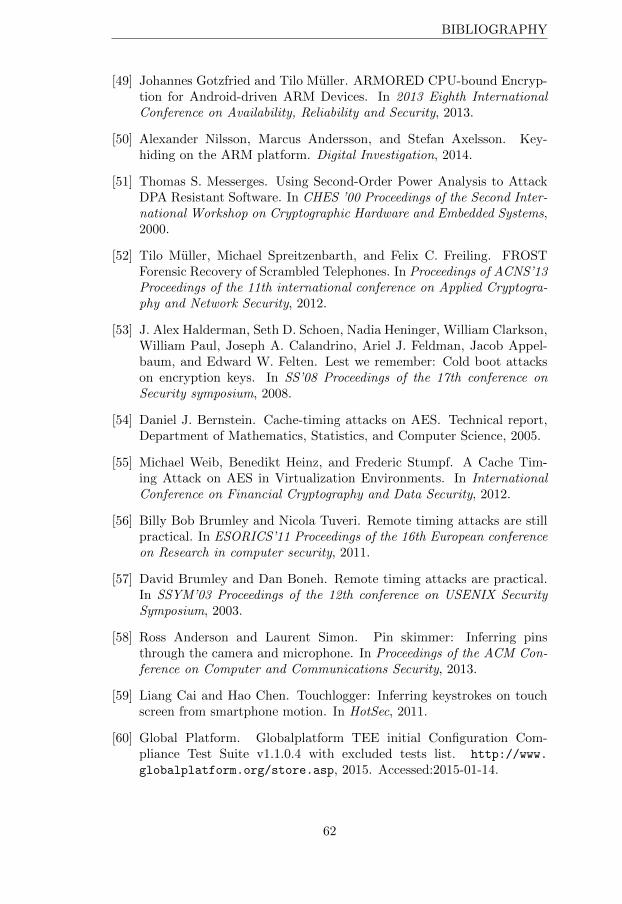
BIBLIOGRAPHY
[49] Johannes Gotzfried and Tilo Muller. ARMORED CPU-bound Encryp-tion for Android-driven ARM Devices. In 2013 Eighth InternationalConference on Availability, Reliability and Security, 2013.
[50] Alexander Nilsson, Marcus Andersson, and Stefan Axelsson. Key-hiding on the ARM platform. Digital Investigation, 2014.
[51] Thomas S. Messerges. Using Second-Order Power Analysis to AttackDPA Resistant Software. In CHES ’00 Proceedings of the Second Inter-national Workshop on Cryptographic Hardware and Embedded Systems,2000.
[52] Tilo Muller, Michael Spreitzenbarth, and Felix C. Freiling. FROSTForensic Recovery of Scrambled Telephones. In Proceedings of ACNS’13Proceedings of the 11th international conference on Applied Cryptogra-phy and Network Security, 2012.
[53] J. Alex Halderman, Seth D. Schoen, Nadia Heninger, William Clarkson,William Paul, Joseph A. Calandrino, Ariel J. Feldman, Jacob Appel-baum, and Edward W. Felten. Lest we remember: Cold boot attackson encryption keys. In SS’08 Proceedings of the 17th conference onSecurity symposium, 2008.
[54] Daniel J. Bernstein. Cache-timing attacks on AES. Technical report,Department of Mathematics, Statistics, and Computer Science, 2005.
[55] Michael Weib, Benedikt Heinz, and Frederic Stumpf. A Cache Tim-ing Attack on AES in Virtualization Environments. In InternationalConference on Financial Cryptography and Data Security, 2012.
[56] Billy Bob Brumley and Nicola Tuveri. Remote timing attacks are stillpractical. In ESORICS’11 Proceedings of the 16th European conferenceon Research in computer security, 2011.
[57] David Brumley and Dan Boneh. Remote timing attacks are practical.In SSYM’03 Proceedings of the 12th conference on USENIX SecuritySymposium, 2003.
[58] Ross Anderson and Laurent Simon. Pin skimmer: Inferring pinsthrough the camera and microphone. In Proceedings of the ACM Con-ference on Computer and Communications Security, 2013.
[59] Liang Cai and Hao Chen. Touchlogger: Inferring keystrokes on touchscreen from smartphone motion. In HotSec, 2011.
[60] Global Platform. Globalplatform TEE initial Configuration Com-pliance Test Suite v1.1.0.4 with excluded tests list. http://www.
globalplatform.org/store.asp, 2015. Accessed:2015-01-14.
62
BIBLIOGRAPHY
[61] Council of the European Union. Information assurance security guide-lines on data separation. guidelines, 2014.
[62] Insignal. http://git.insignal.co.kr/?p=about. Accessed:2015-01-14.
[63] Lee Copeland. A Practioner’s Guide to Software Test Design. ArtechHouse, 2004.
[64] STMicroelectronics. OP-TEE. https://github.com/OP-TEE.Accessed:2015-01-14.
[65] STMicroelectronics. OP-TEE. https://github.com/OP-TEE/optee_
os/blob/master/core/arch/arm32/plat-vexpress/platform_
config.h. Accessed:2015-01-14.
[66] ARM. ARM Trusted Firmware Design. https://
github.com/ARM-software/arm-trusted-firmware/blob/
5b36ab3e0bd273934e792593d9ac80c4183270bd/firmware-design.
md. Accessed:2015-01-14.
[67] Council of the European Union. Council decision of 23 september 2013on the security rules for protecting eu classified information. guidelines,2013.
[68] OMTP. Security threats on embedded consumer devices. OMTP re-comendations, version 1.1, 2009, 2009.
[69] Global Platform. Tee protection profile. Global Platform standard,2013.
[70] Cabinet O�ce. International classified exchanges. https:
//www.gov.uk/government/uploads/system/uploads/attachment_
data/file/337116/International_Classified_Exchanges.pdf,2014. Accessed:2014-11-18.
[71] Caps product results. www.cesg.gov.uk/finda/Pages/CAPSProduct.aspx?PID=186. Accessed:2014-09-15.
[72] Colin O’Flynn and Zhizhang Chen. Chipwhisperer: An open-source platform for hardware embedded security research.https://web.elastic.org/~fche/mirrors/www.jya.com/2014/
03/chip-whisperer.pdf, 2014. Accessed:2015-01-14.
[73] Colin O’Flynn. Chipwisperer: Security research. http:
//hackaday.io/project/956-chipwhisperer-security-research.Accessed:2015-01-14.
[74] Jan-Erik Ekberg, Kari Kostiainen, Anand Rajan, Carlos Rozas,Ahmad-Reza Sadeghi, Ste↵en Schulz, Christian Wachsmann, andN. Asokan. Mobile trusted computing.
63
BIBLIOGRAPHY
[75] Jan-Erik Ekberg, Kari Kostiainen, and N. Asokan. Trusted ExecutionEnvironments on Mobile Devices.
64
På svenska Detta dokument hålls tillgängligt på Internet – eller dess framtida ersättare – under en längre tid från publiceringsdatum under förutsättning att inga extra-ordinära omständigheter uppstår.
Tillgång till dokumentet innebär tillstånd för var och en att läsa, ladda ner, skriva ut enstaka kopior för enskilt bruk och att använda det oförändrat för ickekommersiell forskning och för undervisning. Överföring av upphovsrätten vid en senare tidpunkt kan inte upphäva detta tillstånd. All annan användning av dokumentet kräver upphovsmannens medgivande. För att garantera äktheten, säkerheten och tillgängligheten finns det lösningar av teknisk och administrativ art.
Upphovsmannens ideella rätt innefattar rätt att bli nämnd som upphovsman i den omfattning som god sed kräver vid användning av dokumentet på ovan beskrivna sätt samt skydd mot att dokumentet ändras eller presenteras i sådan form eller i sådant sammanhang som är kränkande för upphovsmannens litterära eller konstnärliga anseende eller egenart.
För ytterligare information om Linköping University Electronic Press se förlagets hemsida http://www.ep.liu.se/ In English The publishers will keep this document online on the Internet - or its possible replacement - for a considerable time from the date of publication barring exceptional circumstances.
The online availability of the document implies a permanent permission for anyone to read, to download, to print out single copies for your own use and to use it unchanged for any non-commercial research and educational purpose. Subsequent transfers of copyright cannot revoke this permission. All other uses of the document are conditional on the consent of the copyright owner. The publisher has taken technical and administrative measures to assure authenticity, security and accessibility.
According to intellectual property law the author has the right to be mentioned when his/her work is accessed as described above and to be protected against infringement.
For additional information about the Linköping University Electronic Press and its procedures for publication and for assurance of document integrity, please refer to its WWW home page: http://www.ep.liu.se/
© Oskar Solsjö