
Installation and Configuration Guide for Exadata Database ...
349
Oracle® Exadata Database Machine Installation and Configuration Guide for Exadata Database Machine 21.2 F29249-11 October 2021
-
Upload
khangminh22 -
Category
Documents
-
view
1 -
download
0
Transcript of Installation and Configuration Guide for Exadata Database ...

Oracle® Exadata Database MachineInstallation and Configuration Guide forExadata Database Machine
21.2F29249-11October 2021

Oracle Exadata Database Machine Installation and Configuration Guide for Exadata Database Machine, 21.2
F29249-11
Copyright © 2008, 2021, Oracle and/or its affiliates.
Primary Author: Peter Fusek
Contributing Authors: Craig Brown, Glenn Maxey, James Spiller
Contributors: Doug Archambault, Leo Agranonik, Andrew Babb, Nilesh Choudhury, Henry Chow, RavindraDani, Boris Erlikhman, Jaime Figueroa, Roger Hansen, Leslie Keller, Frank Kobylanski, René Kundersma,Holger Leister, Yang Liu, Juan Loaiza, Barb Lundhild, Catherine Luu, Philip Newlan, Dan Norris, MichaelNowak, Gavin Parish, Hector Pujol, Dmitry Potapov, Darryl Presley, Ashish Ray, Richard Scales, OliverSharwood, Jia Shi, Kesavan Srinivasan, Krishnadev Telikicherla, Cliff Thomas, Alex Tsukerman, KothandaUmamageswaran, Doug Utzig, Zheren Zhang, Alex Blyth, Gautam Bhatt
This software and related documentation are provided under a license agreement containing restrictions onuse and disclosure and are protected by intellectual property laws. Except as expressly permitted in yourlicense agreement or allowed by law, you may not use, copy, reproduce, translate, broadcast, modify, license,transmit, distribute, exhibit, perform, publish, or display any part, in any form, or by any means. Reverseengineering, disassembly, or decompilation of this software, unless required by law for interoperability, isprohibited.
The information contained herein is subject to change without notice and is not warranted to be error-free. Ifyou find any errors, please report them to us in writing.
If this is software or related documentation that is delivered to the U.S. Government or anyone licensing it onbehalf of the U.S. Government, then the following notice is applicable:
U.S. GOVERNMENT END USERS: Oracle programs (including any operating system, integrated software,any programs embedded, installed or activated on delivered hardware, and modifications of such programs)and Oracle computer documentation or other Oracle data delivered to or accessed by U.S. Government endusers are "commercial computer software" or "commercial computer software documentation" pursuant to theapplicable Federal Acquisition Regulation and agency-specific supplemental regulations. As such, the use,reproduction, duplication, release, display, disclosure, modification, preparation of derivative works, and/oradaptation of i) Oracle programs (including any operating system, integrated software, any programsembedded, installed or activated on delivered hardware, and modifications of such programs), ii) Oraclecomputer documentation and/or iii) other Oracle data, is subject to the rights and limitations specified in thelicense contained in the applicable contract. The terms governing the U.S. Government’s use of Oracle cloudservices are defined by the applicable contract for such services. No other rights are granted to the U.S.Government.
This software or hardware is developed for general use in a variety of information management applications.It is not developed or intended for use in any inherently dangerous applications, including applications thatmay create a risk of personal injury. If you use this software or hardware in dangerous applications, then youshall be responsible to take all appropriate fail-safe, backup, redundancy, and other measures to ensure itssafe use. Oracle Corporation and its affiliates disclaim any liability for any damages caused by use of thissoftware or hardware in dangerous applications.
Oracle, Java, and MySQL are registered trademarks of Oracle and/or its affiliates. Other names may betrademarks of their respective owners.
Intel and Intel Inside are trademarks or registered trademarks of Intel Corporation. All SPARC trademarks areused under license and are trademarks or registered trademarks of SPARC International, Inc. AMD, Epyc,and the AMD logo are trademarks or registered trademarks of Advanced Micro Devices. UNIX is a registeredtrademark of The Open Group.
This software or hardware and documentation may provide access to or information about content, products,and services from third parties. Oracle Corporation and its affiliates are not responsible for and expresslydisclaim all warranties of any kind with respect to third-party content, products, and services unless otherwiseset forth in an applicable agreement between you and Oracle. Oracle Corporation and its affiliates will not beresponsible for any loss, costs, or damages incurred due to your access to or use of third-party content,products, or services, except as set forth in an applicable agreement between you and Oracle.

Contents
Preface
Audience xii
Documentation Accessibility xii
Diversity and Inclusion xii
Related Documentation xiii
Conventions xiv
1 Site Requirements for Oracle Exadata Database Machine and OracleExadata Storage Expansion Rack
1.1 Ensuring That the Site is Ready 1-2
1.2 General Environmental Requirements 1-2
1.2.1 General Environmental Requirements for Oracle Exadata Rack X6 and Later 1-3
1.2.2 General Environmental Requirements for Oracle Exadata Database MachineX5-2 1-3
1.2.3 General Environmental Requirements for Oracle Exadata Database MachineX5-8 1-6
1.2.4 General Environmental Requirements for Oracle Exadata Database MachineX4-2 1-6
1.2.5 General Environmental Requirements for Oracle Exadata Database MachineX4-8 with Exadata Storage Server X5-2 Servers 1-9
1.2.6 General Environmental Requirements for Oracle Exadata Database MachineX4-8 Full Rack 1-10
1.2.7 General Environmental Requirements for Oracle Exadata Database MachineX3-2 1-11
1.2.8 General Environmental Requirements for Oracle Exadata Database MachineX3-8 Full Rack with Exadata Storage Server X4-2L Servers 1-14
1.2.9 General Environmental Requirements for Oracle Exadata Database MachineX3-8 Full Rack with Exadata Storage Server X3-2 Servers 1-15
1.2.10 General Environmental Requirements for Oracle Exadata Database MachineX2-2 1-17
1.2.11 General Environmental Requirements for Oracle Exadata Database MachineX2-8 Full Rack 1-18
1.2.12 General Environmental Requirements for Oracle Exadata Storage ExpansionRack X5-2 1-19
iii
1.2.13 General Environmental Requirements for Oracle Exadata Storage ExpansionRack X4-2 1-21
1.2.14 General Environmental Requirements for Oracle Exadata Storage ExpansionRack X3-2 1-23
1.2.15 General Environmental Requirements for Oracle Exadata Storage ExpansionRack with Exadata Storage Server with Sun Fire X4270 M2 Servers 1-24
1.2.16 General Environmental Requirements for Single Servers 1-25
1.3 Space Requirements 1-30
1.3.1 Space Requirements for Racks up to Oracle Exadata Database Machine X6 1-30
1.4 Receiving, Unpacking, and Access Route Requirements 1-31
1.4.1 Rack Weights for Oracle Exadata Database Machine 1-32
1.4.2 Rack Weights for Oracle Exadata Storage Expansion Rack 1-33
1.5 Maintenance Access Requirements 1-34
1.6 Flooring Requirements 1-35
1.7 Electrical Power Requirements 1-35
1.7.1 PDU Power Requirements 1-36
1.7.1.1 Low-voltage 15 kVA Single Phase PDUs for North America, SouthAmerica, Japan and Taiwan 1-37
1.7.1.2 Low-voltage 15 kVA Three Phase PDUs for North America, SouthAmerica, Japan and Taiwan 1-37
1.7.1.3 High-voltage 15 kVA Single Phase PDUs for Europe, the Middle Eastand Africa (EMEA), and Asia Pacific (APAC), except for Japan andTaiwan 1-38
1.7.1.4 High-voltage 15 kVA Three Phase for Europe, the Middle East and Africa(EMEA), and Asia Pacific (APAC), except for Japan and Taiwan 1-39
1.7.1.5 Low-voltage 22 kVA Single Phase PDUs for North America, SouthAmerica, Japan and Taiwan 1-40
1.7.1.6 High-voltage 22 kVA Single Phase PDUs for Europe, the Middle Eastand Africa (EMEA), and Asia Pacific (APAC), except for Japan andTaiwan 1-41
1.7.1.7 Low-voltage 24 kVA Three Phase PDUs for North America, SouthAmerica, Japan and Taiwan 1-42
1.7.1.8 High-voltage 24 kVA Three Phase PDUs for Europe, the Middle East andAfrica (EMEA), and Asia Pacific (APAC), except for Japan and Taiwan 1-43
1.7.2 Facility Power Requirements 1-43
1.7.3 Circuit Breaker Requirements 1-44
1.7.4 Electrical Grounding Guidelines 1-44
1.8 Temperature and Humidity Requirements 1-44
1.9 Ventilation and Cooling Requirements 1-45
1.10 Network Connection and IP Address Requirements for Oracle Exadata Rack 1-47
1.10.1 Network Connection Requirements for Oracle Exadata Rack 1-47
1.10.2 DNS Configuration for Oracle Exadata Rack 1-48
1.10.3 IP Address Requirements for Oracle Exadata Rack 1-49
iv

2 Understanding the Network Requirements for Oracle Exadata DatabaseMachine
2.1 Overview of Network Requirements 2-1
2.2 Network Channel Bonding Support 2-3
2.3 Network Partitioning on Oracle Exadata Database Machine 2-4
2.3.1 VLAN Support on Customer-Facing Networks 2-5
2.3.2 Access VLAN Support with RoCE Network Fabric 2-5
2.3.3 Using Exadata Secure RDMA Fabric Isolation 2-6
2.3.4 Using InfiniBand Partitioning for Network Isolation with InfiniBand NetworkFabric 2-9
2.4 Configuring a Separate Network for ILOM 2-9
2.5 Default IP Addresses 2-10
2.6 Port Assignments When Using a Firewall 2-11
3 Using Oracle Exadata Deployment Assistant
3.1 Overview of Oracle Exadata Deployment Assistant 3-1
3.1.1 Considerations and Requirement for Using OEDA 3-2
3.2 Getting Started with the OEDA Browser-based User Interface 3-4
3.3 Using the Browser-based Version of Oracle Exadata Deployment Assistant 3-7
4 OEDA Command Line Interface
4.1 About the OEDA Command Line Interface 4-1
4.2 Starting the OEDACLI Utility 4-3
4.2.1 Displaying Help Output for OEDACLI 4-4
4.2.2 Displaying Help Output for an OEDACLI Command 4-5
4.3 OEDACLI Command Reference 4-6
4.3.1 ACFSVOLUME 4-7
4.3.1.1 ADD ACFSVOLUME 4-8
4.3.1.2 ALTER ACFSVOLUME 4-8
4.3.1.3 DELETE ACFSVOLUME 4-9
4.3.1.4 LIST ACFSVOLUMES 4-10
4.3.2 ACTION 4-10
4.3.2.1 SAVE ACTION 4-10
4.3.2.2 MERGE ACTIONS 4-11
4.3.2.3 DEPLOY ACTIONS 4-11
4.3.3 ALERT 4-11
4.3.3.1 ALTER ALERT 4-12
4.3.3.2 DELETE ALERT 4-14
4.3.3.3 LIST ALERTS 4-14
v

4.3.4 CELL 4-14
4.3.4.1 CLONE CELL 4-15
4.3.4.2 CLONE NEWCELL 4-17
4.3.4.3 DELETE CELL 4-18
4.3.4.4 DELETE NEWCELL 4-18
4.3.4.5 LIST CELLS 4-19
4.3.5 CLUSTER 4-19
4.3.5.1 ALTER CLUSTER 4-20
4.3.5.2 CREATE CLUSTER 4-22
4.3.5.3 DESTROY CLUSTER 4-23
4.3.5.4 DOWNGRADE CLUSTER 4-24
4.3.5.5 LIST CLUSTER 4-25
4.3.5.6 LIST CLUSTERS 4-25
4.3.5.7 UPGRADE CLUSTER 4-26
4.3.6 COMPUTE 4-29
4.3.6.1 CLONE COMPUTE 4-29
4.3.6.2 DELETE COMPUTE 4-32
4.3.7 CURRENTACTION 4-33
4.3.7.1 CLEAR CURRENTACTION 4-34
4.3.7.2 LIST CURRENTACTION 4-34
4.3.8 DATABASE 4-34
4.3.8.1 ADD DATABASE 4-34
4.3.8.2 ALTER DATABASE 4-37
4.3.8.3 DELETE DATABASE 4-38
4.3.8.4 LIST DATABASES 4-40
4.3.9 DATABASEHOME 4-40
4.3.9.1 ADD DATABASEHOME 4-41
4.3.9.2 ALTER DATABASEHOME 4-43
4.3.9.3 DELETE DATABASEHOME 4-45
4.3.9.4 LIST DATABASEHOMES 4-46
4.3.10 DISKGROUP 4-46
4.3.10.1 ADD DISKGROUP 4-47
4.3.10.2 ALTER DISKGROUP 4-49
4.3.10.3 ALTER DISKGROUPS 4-52
4.3.10.4 DELETE DISKGROUP 4-53
4.3.10.5 LIST DISKGROUPS 4-54
4.3.11 DOM0 4-54
4.3.11.1 LIST DOM0S 4-54
4.3.12 DOMAIN 4-54
4.3.12.1 GET DOMAIN 4-55
4.3.13 ES 4-55
vi

4.3.13.1 ALTER ES 4-56
4.3.13.2 DISCOVER ES 4-56
4.3.13.3 VALIDATE ES 4-57
4.3.14 EXITONERROR 4-57
4.3.14.1 SET EXITONERROR 4-57
4.3.15 FILE 4-57
4.3.15.1 LOAD FILE 4-58
4.3.15.2 MERGE FILES 4-58
4.3.15.3 SAVE FILE 4-58
4.3.15.4 SAVE FILES 4-59
4.3.16 GUEST 4-59
4.3.16.1 CLONE GUEST 4-59
4.3.16.2 DELETE GUEST 4-62
4.3.17 ILOM 4-63
4.3.17.1 ALTER ILOM 4-63
4.3.17.2 LIST ILOMS 4-64
4.3.18 LOGIN 4-65
4.3.18.1 CHECK LOGIN 4-65
4.3.19 MACHINE 4-65
4.3.19.1 ALTER MACHINE 4-65
4.3.19.2 ALTER MACHINES 4-69
4.3.19.3 LIST MACHINES 4-70
4.3.20 NETWORK 4-70
4.3.20.1 ADD NETWORK 4-70
4.3.20.2 ALTER NETWORK 4-72
4.3.20.3 ALTER NETWORKS 4-74
4.3.20.4 DELETE NETWORK 4-75
4.3.20.5 LIST NETWORKS 4-75
4.3.21 PASSWORD 4-76
4.3.21.1 ALTER PASSWORD 4-76
4.3.22 PROPERTY 4-77
4.3.22.1 ALTER PROPERTY 4-77
4.3.22.2 LIST PROPERTIES 4-77
4.3.23 RACK 4-78
4.3.23.1 ADD RACK 4-78
4.3.23.2 ALTER RACK 4-79
4.3.23.3 LIST RACKS 4-80
4.3.23.4 LIST RACKDESCRIPTION 4-80
4.3.24 REQUIREDFILES 4-80
4.3.24.1 LIST REQUIREDFILES 4-80
4.3.25 REMOTE 4-81
vii

4.3.25.1 EXEC REMOTE 4-81
4.3.26 SCAN 4-81
4.3.26.1 ADD SCAN 4-82
4.3.26.2 ALTER SCAN 4-82
4.3.26.3 DELETE SCAN 4-83
4.3.26.4 LIST SCANS 4-83
4.3.27 SECURITY 4-84
4.3.27.1 SET SECURITY 4-84
4.3.28 SOFTWAREVERSIONS 4-85
4.3.28.1 LIST SOFTWAREVERSIONS 4-85
4.3.29 SSHKEYS 4-85
4.3.29.1 DEPLOY SSHKEYS 4-86
4.3.29.2 GENERATE SSHKEYS 4-86
4.3.29.3 SET SSHKEYS 4-87
4.3.30 STEPS 4-87
4.3.30.1 LIST STEPS 4-88
4.3.31 SWITCH 4-90
4.3.31.1 ADD SWITCH 4-90
4.3.31.2 ALTER SWITCH 4-91
4.3.31.3 LIST SWITCHES 4-91
4.3.32 SU 4-92
4.3.32.1 SET SU 4-92
4.3.33 ULOC 4-92
4.3.33.1 LIST ULOC 4-92
4.3.34 VIP 4-93
4.3.34.1 ADD VIP 4-93
4.3.34.2 ALTER VIP 4-94
4.3.34.3 DELETE VIP 4-94
4.3.34.4 LIST VIPS 4-95
4.3.35 VOLUME 4-95
4.3.35.1 ADD VOLUME 4-96
4.3.35.2 DELETE VOLUME 4-96
4.3.35.3 LIST VOLUMES 4-96
4.3.36 XMLACTION 4-97
4.3.36.1 ALTER XMLACTION 4-97
4.3.36.2 DELETE XMLACTION 4-97
4.3.36.3 LIST XMLACTION 4-98
4.3.36.4 LIST XMLACTIONS 4-98
viii

5 Installing Oracle Exadata Database Machine or Oracle Exadata StorageExpansion Rack at the Site
5.1 Reviewing Safety Guidelines 5-1
5.2 Unpacking Oracle Exadata Rack 5-3
5.2.1 Contents of the Shipping Kit for X7 and Later Racks 5-4
5.2.2 Contents of the Shipping Kit for X6 and Earlier Racks 5-4
5.2.3 Removing Oracle Exadata Rack from the Shipping Crate 5-5
5.3 Placing Oracle Exadata Rack in Its Allocated Space 5-6
5.3.1 Moving Oracle Exadata Rack 5-7
5.3.2 Stabilizing Oracle Exadata Rack 5-8
5.3.2.1 Stabilize Oracle Exadata Rack with Leveling Feet 5-8
5.3.2.2 Stabilize Oracle Exadata Rack X7 and Later with Leveling Feet 5-10
5.3.3 Attaching a Ground Cable (Optional) 5-12
5.4 Acclimating the Oracle Exadata Database Machine 5-13
5.5 Powering on the System the First Time 5-14
5.5.1 Inspecting the Machine After it is in Place 5-14
5.5.2 Connecting Power Cords 5-14
5.5.3 Powering on Oracle Exadata Rack 5-15
6 Configuring Oracle Exadata Database Machine
6.1 Verifying the Network Configuration Prior to Configuring the Rack 6-2
6.2 Configuring the RDMA Network Fabric Switch 6-3
6.2.1 Configuring Sun Datacenter InfiniBand Switch 36 Switch 6-3
6.2.2 Configuring the Cisco Nexus C9336C-FX2 Switch 6-6
6.2.3 Configuring the Cisco Nexus C9336C-FX2 Switches to Enable Exadata SecureRDMA Fabric Isolation 6-12
6.3 Setting the Subnet Manager Master on Oracle Exadata Database Machine Full Rackand Oracle Exadata Database Machine Half Rack 6-12
6.4 Configuring the Cisco Ethernet Switch 6-14
6.4.1 Configuring the Cisco Catalyst 4948 Ethernet Switch 6-14
6.4.2 Configuring the Cisco Nexus 93108-1G or 9348 Ethernet Switch 6-21
6.4.2.1 Performing the Initial Switch Configuration for the Cisco Nexus93108-1G or 9348 Ethernet Switch 6-22
6.4.2.2 Setting the Clock on the Cisco 93108-1G or 9348 Ethernet Switch 6-26
6.5 Configuring the Power Distribution Units 6-26
6.6 Configuring the Threshold Settings for the Power Distribution Units 6-28
6.6.1 PDU Thresholds for Oracle Exadata Database Machine X5-2 and Later 6-29
6.6.2 PDU Thresholds for Oracle Exadata Database Machine X4-2 6-30
6.6.2.1 PDU Thresholds for Oracle Exadata Database Machine X4-2 Full Rack 6-30
6.6.2.2 PDU Thresholds for Oracle Exadata Database Machine X4-2 Half Rack 6-32
ix

6.6.2.3 PDU Thresholds for Oracle Exadata Database Machine X4-2 QuarterRack 6-33
6.6.3 PDU Thresholds for Oracle Exadata Database Machine X3-2 6-35
6.6.3.1 PDU Thresholds for Oracle Exadata Database Machine X3-2 Full Rack 6-36
6.6.3.2 PDU Thresholds for Oracle Exadata Database Machine X3-2 Half Rack 6-37
6.6.3.3 PDU Thresholds for Oracle Exadata Database Machine X3-2 QuarterRack 6-39
6.6.4 PDU Thresholds for Oracle Exadata Database Machine X2-2 (with X4170 M2and X4270 M2 servers) 6-41
6.6.4.1 PDU Thresholds for Oracle Exadata Database Machine X2-2 (withX4170 M2 and X4270 M2 servers) Full Rack 6-42
6.6.4.2 PDU Thresholds for Oracle Exadata Database Machine X2-2 (withX4170 M2 and X4270 M2 servers) Half Rack 6-43
6.6.4.3 PDU Thresholds for Oracle Exadata Database Machine X2-2 (withX4170 M2 and X4270 M2 servers) Quarter Rack 6-45
6.6.5 PDU Thresholds for Oracle Exadata Database Machine X2-2 (with X4170 andX4275 servers) 6-47
6.6.5.1 PDU Thresholds for Oracle Exadata Database Machine X2-2 (withX4170 and X4275 servers) Full Rack 6-48
6.6.5.2 PDU Thresholds for Oracle Exadata Database Machine X2-2 (withX4170 and X4275 servers) Half Rack 6-49
6.6.5.3 PDU Thresholds for Oracle Exadata Database Machine X2-2 (withX4170 and X4275 servers) Quarter Rack 6-51
6.6.6 PDU Thresholds for Oracle Exadata Database Machine X4-8 and Later 6-53
6.6.7 PDU Thresholds for Oracle Exadata Database Machine X3-8 Full Rack 6-53
6.6.8 PDU Thresholds for Oracle Exadata Database Machine X2-8 Full Rack 6-56
6.6.9 PDU Thresholds for Oracle Exadata Storage Expansion Rack with ExadataStorage Server with Sun Fire X4270 M2 Servers 6-57
6.6.9.1 PDU Thresholds for Oracle Exadata Storage Expansion Full Rack withExadata Storage Server with Sun Fire X4270 M2 Servers 6-58
6.6.9.2 PDU Thresholds for Oracle Exadata Storage Expansion Half Rack withExadata Storage Server with Sun Fire X4270 M2 Servers 6-59
6.6.9.3 PDU Thresholds for Oracle Exadata Storage Expansion Quarter Rackwith Exadata Storage Server with Sun Fire X4270 M2 Servers 6-61
6.7 Checking Exadata Storage Servers 6-63
6.8 Checking Oracle Exadata Database Servers 6-67
6.9 Performing Additional Checks and Configuration 6-71
6.10 Verifying the RoCE Network Fabric Configuration 6-72
6.11 Verifying the InfiniBand Network Fabric Network 6-72
6.12 Imaging a New System 6-74
6.12.1 Using ISO Images to Image a New System 6-75
6.12.2 Using Elastic Configuration to Image a New System 6-78
6.12.3 Using ISO to Image a New System 6-80
6.12.4 Using PXE to Image a New System 6-86
6.12.4.1 Using PXE to Image a New System Using Release 12.1.2.2.0 or Later 6-86
x

6.12.4.2 Using PXE to Image a New System for Releases Earlier than 12.1.2.2.0 6-91
6.12.5 Using USB to Image a New System 6-95
6.12.6 Updates to Imaging Parameters 6-100
6.13 Performing Initial Elastic Configuration of Oracle Exadata Database Machine 6-101
6.14 Adding Additional Elastic Nodes to an Existing Rack 6-107
6.15 Using the OEDA setuprootssh Utility 6-108
6.16 Loading the Configuration Information and Installing the Software 6-109
6.16.1 Configuring Oracle Exadata Database Machine Using OEDA 6-110
6.16.2 Using Oracle Exadata Deployment Assistant in Conjunction with Key-BasedAuthentication 6-113
6.16.3 Using Oracle Exadata Deployment Assistant on Systems with Non-Defaultroot Passwords 6-113
6.16.4 Configuring Oracle Database and Oracle ASM Instances for Oracle ExadataDatabase Machine Manually 6-114
6.16.4.1 Configuring the Compatible Parameter for a Database Instance 6-116
6.16.4.2 Configuring Initialization Parameters for an Oracle ASM Instance 6-116
6.16.4.3 Using the Same DB_UNIQUE_NAME for Multiple Database Instances 6-117
6.17 Using the OEDA changePassword Utility 6-118
6.18 Installing Oracle Enterprise Manager Cloud Control 6-118
6.19 Adding a VM Cluster to Oracle Exadata Database Machine Using OEDA 6-119
A Site Checklists
A.1 System Components Checklist A-2
A.2 Data Center Room Checklist A-3
A.3 Data Center Environment Checklist A-4
A.4 Access Route Checklist A-6
A.5 Facility Power Checklist A-8
A.6 Safety Checklist A-10
A.7 Logistics Checklist A-11
A.8 Network Configuration Checklist A-14
A.9 Auto Service Request Checklist A-15
A.10 Re-racking Checklists A-16
A.11 PDU Checklist for Re-racking A-19
A.12 Recycling the Racks A-20
B Database High Availability Checklist
xi

Preface
This guide describes Oracle Exadata Database Machine for online transactionprocessing (OLTP) and enterprise data warehousing. It includes information about siteplanning and configuration, as well as physical, electrical, and environmentalspecifications.
• Audience
• Documentation Accessibility
• Diversity and Inclusion
• Related Documentation
• Conventions
AudienceThis guide is intended for Oracle Exadata Database Machine customers and thoseresponsible for data center site planning, configuration, and maintenance of OracleExadata Database Machine.
Documentation AccessibilityFor information about Oracle's commitment to accessibility, visit the OracleAccessibility Program website at http://www.oracle.com/pls/topic/lookup?ctx=acc&id=docacc.
Access to Oracle Support
Oracle customers that have purchased support have access to electronic supportthrough My Oracle Support. For information, visit http://www.oracle.com/pls/topic/lookup?ctx=acc&id=info or visit http://www.oracle.com/pls/topic/lookup?ctx=acc&id=trsif you are hearing impaired.
Diversity and InclusionOracle is fully committed to diversity and inclusion. Oracle respects and values havinga diverse workforce that increases thought leadership and innovation. As part of ourinitiative to build a more inclusive culture that positively impacts our employees,customers, and partners, we are working to remove insensitive terms from ourproducts and documentation. We are also mindful of the necessity to maintaincompatibility with our customers' existing technologies and the need to ensurecontinuity of service as Oracle's offerings and industry standards evolve. Because ofthese technical constraints, our effort to remove insensitive terms is ongoing and willtake time and external cooperation.
Preface
xii

Related DocumentationIn addition to the Oracle Exadata Database Machine documentation set, the following guidescontain hardware information for Oracle Exadata Database Machine:
• Oracle Exadata Database Machine System Overview
• Oracle Exadata Database Machine Security Guide
• Oracle Engineered System Safety and Compliance Guide, Compliance Model No.:ESY27
• Oracle Engineered Systems Extending and Multi-Rack Cabling Guide
• Oracle Exadata Database Machine Maintenance Guide
• Oracle Exadata System Software User's Guide
• Oracle Exadata X8-2 Database Server Service Manual at http://docs.oracle.com/cd/E93359_01/html/E93386/index.html
• Oracle Exadata Storage Server X8-2 EF,HC, and XT Service Manual at https://docs.oracle.com/cd/E93361_01/html/E93395/index.html
• Oracle Exadata Database Server X8-8 Service Manual at http://docs.oracle.com/cd/E93360_01/html/E96097/index.html
• Oracle Server X7-2 Service Manual at http://docs.oracle.com/cd/E72435_01/html/E72445/index.html
• Oracle Server X7-2L Service Manual at http://docs.oracle.com/cd/E72463_01/html/E72474/index.html
• Oracle Server X7-8 Service Manual at http://docs.oracle.com/cd/E71925_01/html/E71936/index.html
• Oracle Server X6-2 Service Manual at http://docs.oracle.com/cd/E62159_01/html/E62171/index.html
• Oracle Server X6-2L Service Manual at http://docs.oracle.com/cd/E62172_01/html/E62184/index.html
• Oracle Server X5-2 Service Manual at http://docs.oracle.com/cd/E41059_01/html/E48312/napsm.html
• Oracle Server X5-2L Service Manual at http://docs.oracle.com/cd/E41033_01/html/E48325/cnpsm.html#scrolltoc
• Sun Server X4-8 Service Manual at http://docs.oracle.com/cd/E40591_01/html/E40317/index.html
• Sun Server X4-2 Service Manual at http://docs.oracle.com/cd/E36975_01/html/E38045/gentextid-14757.html#scrolltoc
• Sun Server X4-2L Service Manual at http://docs.oracle.com/cd/E36974_01/html/E38145/gentextid-14728.html#scrolltoc
• Sun Server X3-2 (formerly Sun Fire X4170 M3) Service Manual at http://docs.oracle.com/cd/E22368_01/html/E27242/gentextid-14840.html#scrolltoc
• Sun Server X3-2L (formerly Sun Fire X4270 M3) Service Manual at http://docs.oracle.com/cd/E23393_01/html/E27229/gentextid-14804.html#scrolltoc
• Sun Server X2-8 (formerly Sun Fire X4800 M2) Service Manual at http://docs.oracle.com/cd/E20815_01/html/E20819/index.html
Preface
xiii

• Sun Fire X4800 Server Service Manual at http://docs.oracle.com/cd/E19140-01/html/821-0282/index.html
• Sun Fire X4270 M2 Server Service Manual at http://docs.oracle.com/cd/E19245-01/E21671/index.html
• Sun Fire X4170 M2 Server Service Manual at http://docs.oracle.com/cd/E19762-01/E22369-02/index.html
• Sun Fire X4170, X4270, and X4275 Servers Service Manual at http://docs.oracle.com/cd/E19477-01/820-5830-13/index.html
• Sun Datacenter InfiniBand Switch 36 Firmware Version 2.1 Documentation at http://docs.oracle.com/cd/E36265_01/index.html
• Sun Datacenter InfiniBand Switch 36 Firmware Version 2.2 Documentation at http://docs.oracle.com/cd/E76424_01/index.html
• Sun Flash Accelerator F20 PCIe Card User's Guide at http://docs.oracle.com/cd/E19682-01/E21358/index.html
• Sun Flash Accelerator F40 PCIe Card User's Guide at http://docs.oracle.com/cd/E29748_01/html/E29741/index.html
• Sun Flash Accelerator F80 PCIe Card User's Guide at http://docs.oracle.com/cd/E41278_01/html/E41251/index.html
• Oracle Flash Accelerator F160 PCIe Card User Guide at http://docs.oracle.com/cd/E54943_01/html/E54947/index.html
• Oracle Flash Accelerator F320 PCIe Card User Guide at http://docs.oracle.com/cd/E65386_01/html/E65387/index.html
• Oracle Flash Accelerator F640 PCIe Card User Guide at https://docs.oracle.com/cd/E87231_01/html/E87233/index.html
• Sun Storage 6 Gb SAS PCIe RAID HBA Documentation at http://docs.oracle.com/cd/E19221-01/
• Oracle Storage 12 Gb/s SAS PCIe RAID HBA, Internal Documentation Library at http://docs.oracle.com/cd/E52363_01/index.html
• Oracle Integrated Lights Out Manager (ILOM) Documentation at http://www.oracle.com/goto/ilom/docs
• "Cisco Catalyst 4948E and 4948E-F Ethernet Switches Data Sheet" at https://www.cisco.com/c/en/us/products/collateral/switches/catalyst-4948e-ethernet-switch/data_sheet_c78-598933.html
• "Cisco Nexus 9300-EX and 9300-FX Platform Switches Data Sheet at https://www.cisco.com/c/en/us/products/collateral/switches/nexus-9000-series-switches/datasheet-c78-736651.html"
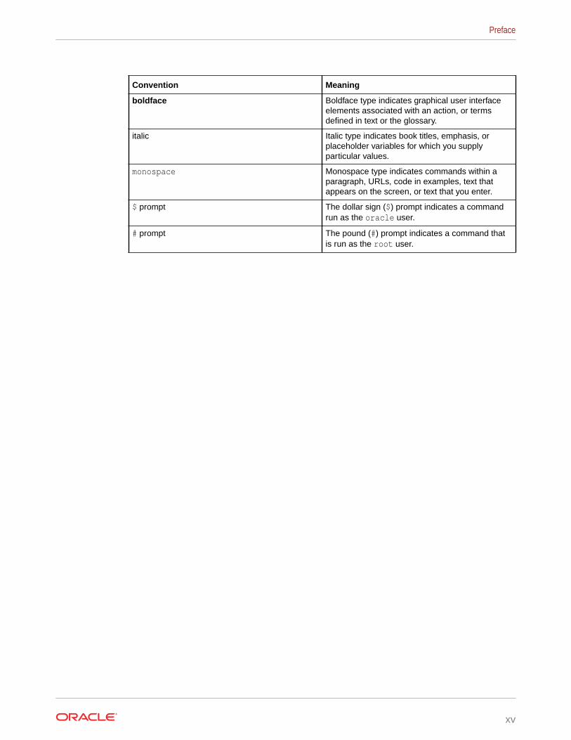
ConventionsThe following text conventions are used in this document:
Preface
xiv
Convention Meaning
boldface Boldface type indicates graphical user interfaceelements associated with an action, or termsdefined in text or the glossary.
italic Italic type indicates book titles, emphasis, orplaceholder variables for which you supplyparticular values.
monospace Monospace type indicates commands within aparagraph, URLs, code in examples, text thatappears on the screen, or text that you enter.
$ prompt The dollar sign ($) prompt indicates a commandrun as the oracle user.
# prompt The pound (#) prompt indicates a command thatis run as the root user.
Preface
xv

1Site Requirements for Oracle ExadataDatabase Machine and Oracle ExadataStorage Expansion Rack
This chapter describes the site requirements for Oracle Exadata Database Machine andOracle Exadata Storage Expansion Rack.
Note:
For ease of reading, the name "Oracle Exadata Rack" is used when informationrefers to both Oracle Exadata Database Machine and Oracle Exadata StorageExpansion Rack.
• Ensuring That the Site is Ready
• General Environmental Requirements
• Space Requirements
• Receiving, Unpacking, and Access Route RequirementsBefore your Oracle Exadata Rack arrives, ensure that the receiving area is large enoughfor the package.
• Maintenance Access RequirementsThe maintenance area must be large enough for Oracle Exadata Rack, and have therequired access space.
• Flooring RequirementsOracle Exadata Rack may be installed on raised floor or solid floor environments.
• Electrical Power RequirementsThe Oracle Exadata Rack can operate effectively over a wide range of voltages andfrequencies. However, each rack must have a reliable power source.
• Temperature and Humidity RequirementsExcessive internal temperatures may result in full or partial shut down of Oracle ExadataDatabase Machine.
• Ventilation and Cooling RequirementsAlways provide adequate space in front and behind the rack to allow for properventilation.
• Network Connection and IP Address Requirements for Oracle Exadata Rack
Related Topics
• Site Checklists
1-1
1.1 Ensuring That the Site is ReadyBefore Oracle Exadata Rack is delivered to the site, the following tasks must beperformed to ensure the site is ready:
Task 1 Review Site RequirementsReview the site requirements in this chapter and use the checklists in Site Checkliststo understand the requirements for Oracle Exadata Rack.
Task 2 Understand the Networking Requirements and OptionsReview Understanding the Network Requirements for Oracle Exadata DatabaseMachine to discern the networking requirements and configuration decisions that youmust make.
Task 3 Run Oracle Exadata Deployment Assistant (OEDA)Run OEDA to create the necessary configuration files.See Using Oracle Exadata Deployment Assistant.
Task 4 Configure the NetworkConfigure the network using the files from OEDA. This includes registering thenetworks in the Domain Name System (DNS), assigning IP addresses, andconfiguring data center switches and firewalls.
Task 5 Prepare the Site Based on RequirementsPrepare the site based on the requirements, such as, install the network cables andpower supplies, prior to the arrival of Oracle Exadata Rack.Review the procedures in Installing Oracle Exadata Database Machine or OracleExadata Storage Expansion Rack at the Site.
1.2 General Environmental RequirementsThe following sections describe the general environmental requirements for OracleExadata Racks.
• General Environmental Requirements for Oracle Exadata Rack X6 and Later
• General Environmental Requirements for Oracle Exadata Database Machine X5-2
• General Environmental Requirements for Oracle Exadata Database Machine X5-8
• General Environmental Requirements for Oracle Exadata Database Machine X4-2
• General Environmental Requirements for Oracle Exadata Database Machine X4-8with Exadata Storage Server X5-2 Servers
• General Environmental Requirements for Oracle Exadata Database Machine X4-8Full Rack
• General Environmental Requirements for Oracle Exadata Database Machine X3-2
• General Environmental Requirements for Oracle Exadata Database Machine X3-8Full Rack with Exadata Storage Server X4-2L Servers
• General Environmental Requirements for Oracle Exadata Database Machine X3-8Full Rack with Exadata Storage Server X3-2 Servers
• General Environmental Requirements for Oracle Exadata Database Machine X2-2
Chapter 1Ensuring That the Site is Ready
1-2

• General Environmental Requirements for Oracle Exadata Database Machine X2-8 FullRack
• General Environmental Requirements for Oracle Exadata Storage Expansion Rack X5-2
• General Environmental Requirements for Oracle Exadata Storage Expansion Rack X4-2
• General Environmental Requirements for Oracle Exadata Storage Expansion Rack X3-2
• General Environmental Requirements for Oracle Exadata Storage Expansion Rack withExadata Storage Server with Sun Fire X4270 M2 Servers
• General Environmental Requirements for Single Servers
1.2.1 General Environmental Requirements for Oracle Exadata Rack X6and Later
Starting with X6 models of Oracle Exadata Database Machine and Oracle Exadata StorageExpansion Rack, use Oracle Exadata Configuration Assistant (OECA) to determineenvironmental requirements, such as size, weight, acoustic level, power, cooling, and airflow.This includes all X6, X7, X8, X8M, X9M, and later models.
Related Topics
• Oracle Exadata Configuration Assistant (OECA) Downloads
1.2.2 General Environmental Requirements for Oracle Exadata DatabaseMachine X5-2
The environmental requirements for Oracle Exadata Database Machine X5-2 depend on thesize of the system. The following table shows the general environmental requirements forOracle Exadata Database Machine X5-2.
Table 1-1 Environmental Requirements for Oracle Exadata Database Machine X5-2
EnvironmentalComponent
Oracle ExadataDatabaseMachine X5-2Full Rack
Oracle ExadataDatabaseMachine X5-2Half Rack
Oracle ExadataDatabaseMachine X5-2Quarter Rack
Oracle ExadataDatabaseMachine X5-2Eighth Rack
Weight
See Also: FlooringRequirements
• Extreme Flashdrives: 804.9kg (1774 lbs)
• High capacitydrives: 874.8kg (1928 lbs))
• Extreme Flashdrives: 525.9kg (1160 lbs)
• High capacitydrives: 560.9kg (1236 lbs)
• Extreme Flashdrives: 366.3kg (808 lbs)
• High capacitydrives: 381.2kg (841 lbs)
• Extreme Flashdrives: 366.3kg (808 lbs)
• High capacitydrives: 381.2kg (841 lbs)
Acoustic levels 86 db(A) 85 db(A) 83 db(A) 83 db(A)
Chapter 1General Environmental Requirements
1-3

Table 1-1 (Cont.) Environmental Requirements for Oracle Exadata Database MachineX5-2
EnvironmentalComponent
Oracle ExadataDatabaseMachine X5-2Full Rack
Oracle ExadataDatabaseMachine X5-2Half Rack
Oracle ExadataDatabaseMachine X5-2Quarter Rack
Oracle ExadataDatabaseMachine X5-2Eighth Rack
Power
See Also: Electrical PowerRequirements
• Extreme Flashdrives
Maximum:15.7 kVA
Typical: 11.0kVA (variesbased onapplicationload)
• High capacitydrives
Maximum:15.6 kVA
Typical: 10.9kVA (variesbased onapplicationload)
• Extreme Flashdrives
Maximum: 8.5kVA
Typical: 5.9kVA (variesbased onapplicationload)
• High capacitydrives
Maximum: 8.4kVA
Typical: 5.9kVA (variesbased onapplicationload)
• Extreme Flashdrives
Maximum: 4.2kVA
Typical: 3.0kVA (variesbased onapplicationload)
• High capacitydrives
Maximum: 4.2kVA
Typical:2.9kVA (variesbased onapplicationload)
• Extreme Flashdrives
Maximum: 3.5kVA
Typical: 2.4kVA (variesbased onapplicationload)
• High capacitydrives
Maximum: 34kVA
Typical: 2.4kVA (variesbased onapplicationload)
Cooling
See Also: Temperature andHumidityRequirements, and Ventilation andCoolingRequirements
• Extreme Flashdrives
Maximum:52,578 BTU/hour (55,469kJ/hour)
Typical:36,804 BTU/hour (38,829kJ/hour)
• High capacitydrives
Maximum:52,052 BTU/hour (54,915kJ/hour)
Typical:36,437 BTU/hour (38,441kJ/hour)
• Extreme Flashdrives
Maximum:28,396 BTU/hour (29,958kJ/hour)
Typical:19,877 BTU/hour (20,970kJ/hour)
• High capacitydrives
Maximum:28,133 BTU/hour (29,680kJ/hour)
Typical:19,693 BTU/hour (20,776kJ/hour)
• Extreme Flashdrives
Maximum:14,195 BTU/hour (14,975kJ/hour)
Typical: 9,936BTU/hour(10,483 kJ/hour)
• High capacitydrives
Maximum:14,082 BTU/hour (14,856kJ/hour)
Typical: 9,857BTU/hour(10,399 kJ/hour)
• Extreme Flashdrives
Maximum:11,674 BTU/hour (12,317kJ/hour)
Typical: 8,172BTU/hour(8,622 kJ/hour)
• High capacitydrives
Maximum:11,530 BTU/hour (12,164kJ/hour)
Typical: 8,071BTU/hour(8,515 kJ/hour)
Chapter 1General Environmental Requirements
1-4

Table 1-1 (Cont.) Environmental Requirements for Oracle Exadata Database MachineX5-2
EnvironmentalComponent
Oracle ExadataDatabaseMachine X5-2Full Rack
Oracle ExadataDatabaseMachine X5-2Half Rack
Oracle ExadataDatabaseMachine X5-2Quarter Rack
Oracle ExadataDatabaseMachine X5-2Eighth Rack
Air flow front-to-back (subject toactual data centerenvironment)
See Also: Temperature andHumidityRequirements, and Ventilation andCoolingRequirements
• Extreme Flashdrives
Maximum:Approximately2,434 CFM
Typical:Approximately1,704 CFM
• High capacitydrives
Maximum:Approximately2,410 CFM
Typical:Approximately1,687 CFM
• Extreme Flashdrives
Maximum:Approximately1,315 CFM
Typical:Approximately920 CFM
• High capacitydrives
Maximum:Approximately1,302 CFM
Typical:Approximately912 CFM
• Extreme Flashdrives
Maximum:Approximately657 CFM
Typical:Approximately460 CFM
• High capacitydrives
Maximum:Approximately652 CFM
Typical:Approximately456 CFM
• Extreme Flashdrives
Maximum:Approximately540 CFM
Typical:Approximately378 CFM
• High capacitydrives
Maximum:Approximately534 CFM
Typical:Approximately374 CFM
IP Addresses
See Also:"NetworkConnection and IPAddressRequirements forOracle ExadataDatabaseMachine"
68 for Ethernetnetwork, assumingsingle cluster
Up to 36 for RDMANetwork Fabric
38 for Ethernetnetwork, assumingsingle cluster
Up to 18 for RDMANetwork Fabric
22 for Ethernetnetwork, assumingsingle cluster
Up to 8 for RDMANetwork Fabric
22 for Ethernetnetwork, assumingsingle cluster
Up to 8 for RDMANetwork Fabric
Network drops
See Also:"NetworkConnection and IPAddressRequirements forOracle ExadataDatabaseMachine"
Minimum of 11network drops
Minimum of 7network drops
Minimum of 5network drops
Minimum of 5network drops
Externalconnectivity
See Also:"NetworkConnection and IPAddressRequirements forOracle ExadataDatabaseMachine"
18 x 1 GbE/10GbE Ethernetports
16 x 10 GbEEthernet ports
At least 12 RDMANetwork Fabricports
12 x 1 GbE/10GbE Ethernetports
8 x 10 GbEEthernet ports
At least 12 RDMANetwork Fabricports
6 x 1 GbE/10 GbEEthernet ports
4 x 10 GbEEthernet ports
At least 12 RDMANetwork Fabricports
6 x 1 GbE/10 GbEEthernet ports
4 x 10 GbEEthernet ports
At least 12 RDMANetwork Fabricports
Chapter 1General Environmental Requirements
1-5

1.2.3 General Environmental Requirements for Oracle ExadataDatabase Machine X5-8
Table 1-2 shows the general environmental requirements for Oracle Exadata DatabaseMachine X5-8. Other sections in this chapter provide detailed information.
Table 1-2 Environmental Requirements for Oracle Exadata Database MachineX5-8
Environmental Component Oracle Exadata DatabaseMachine X5-8 Full Rack
Oracle Exadata DatabaseMachine X5-8 Half Rack
Weight
See Also: "FlooringRequirements"
Extreme Flash drives: 1826.5lbs (828.1 kg)
High capacity drives: 1980.5lbs (898.3 kg)
Extreme Flash drives: 1160.1lbs (526.2 kg)
High capacity drives: 1193.1lbs (541.2 kg)
Acoustic levels 8.68 8.58
Power
See Also: "Electrical PowerRequirements"
Extreme Flash drives:
• Max: 16.4 kW (16.7 kVA)• Typical: 11.5 kW (11.7
kVA)High capacity drives:
• Max: 16.2 kW (16.6 kVA)• Typical: 11.4 kW (11.6
kVA)
Extreme Flash drives:
• Max: 9.5 kW (9.7 kVA)• Typical: 6.7 kW (6.8 kVA)High capacity drives:
• Max: 9.5 kW (9.7 kVA)• Typical: 6.6 kW (6.8 kVA)
Cooling
See Also: "Temperature andHumidity Requirements", and"Ventilation and CoolingRequirements"
Extreme Flash drives:
• Max: 55,935 BTU/hour(59,012 kJ/hour)
• Typical: 39,155 BTU/hour(41,308 kJ/hour)
High capacity drives:
• Max: 55,410 BTU/hour(58,457 kJ/hour)
• Typical: 38,787 BTU/hour(40,920 kJ/hour)
Extreme Flash drives:
• Max: 32,436 BTU/hour(34,220 kJ/hour)
• Typical: 22,705 BTU/hour(23,954 kJ/hour)
High capacity drives:
• Max: 32,323 BTU/hour(34,101 kJ/hour)
• Typical: 22,626 BTU/hour(23,871 kJ/hour)
Air flow front-to-back (subjectto actual data centerenvironment)
See Also: "Temperature andHumidity Requirements", and"Ventilation and CoolingRequirements"
Extreme Flash drives:
• Max: 2590 CFM• Typical: 1813 CFMHigh capacity drives:
• Max: 2565 CFM• Typical: 1796 CFM
Extreme Flash drives:
• Max: 1502 CFM• Typical: 1051 CFMHigh capacity drives:
• Max: 1496 CFM• Typical: 1048 CFM
1.2.4 General Environmental Requirements for Oracle ExadataDatabase Machine X4-2
The environmental requirements for Oracle Exadata Database Machine X4-2 dependon the size of the system. Table 1-3 shows the general environmental requirements forOracle Exadata Database Machine X4-2. The other sections in this chapter providedetailed information.
Chapter 1General Environmental Requirements
1-6

Table 1-3 Environmental Requirements for Oracle Exadata Database Machine X4-2
EnvironmentalComponent
Oracle ExadataDatabaseMachine X4-2Full Rack
Oracle ExadataDatabaseMachine X4-2Half Rack
Oracle ExadataDatabaseMachine X4-2Quarter Rack
Oracle ExadataDatabaseMachine X4-2Eighth Rack
Weight
See Also:"FlooringRequirements"
852.8 kg (1880lbs)
525.3 kg (1158lbs)
365.6 kg (806 lbs) 365.6 kg (806 lbs)
Acoustic levels 93 db(A) 89 db(A) 85 db(A) 85 db(A)
Power
See Also:"Electrical PowerRequirements"
• Highperformancedrives
Maximum:12.4 kVA
Typical: 8.7kVA (variesbased onapplicationload)
• High capacitydrives
Maximum:11.4 kVA
Typical: 8.1kVA (variesbased onapplicationload)
• Highperformancedrives
Maximum: 6.8kVA
Typical: 4.8kVA (variesbased onapplicationload)
• High capacitydrives
Maximum: 6.3kVA
Typical: 4.4kVA (variesbased onapplicationload)
• Highperformancedrives
Maximum: 3.4kVA
Typical: 2.5kVA (variesbased onapplicationload)
• High capacitydrives
Maximum: 3.2kVA
Typical: 2.3kVA (variesbased onapplicationload)
• Highperformancedrives
Maximum: 3.1kVA
Typical: 2.2kVA (variesbased onapplicationload)
• High capacitydrives
Maximum: 2.9kVA
Typical: 2.1kVA (variesbased onapplicationload)
Cooling
See Also:"Temperature andHumidityRequirements",and "Ventilationand CoolingRequirements"
• Highperformancedrives
Maximum:41,300 BTU/hour (43,600kJ/hour)
Typical:29,000 BTU/hour (30,600kJ/hour)
• High capacitydrives
Maximum:38,300 BTU/hour (40,400kJ/hour)
Typical:27,000 BTU/hour (28,500kJ/hour)
• Highperformancedrives
Maximum:22,500 BTU/hour (23,750kJ/hour)
Typical:16,000 BTU/hour (16,900kJ/hour)
• High capacitydrives
Maximum:21,200 BTU/hour (22,400kJ/hour)
Typical:14,700 BTU/hour (15,500kJ/hour)
• Highperformancedrives
Maximum:11,300 BTU/hour (11,900kJ/hour)
Typical: 8,200BTU/hour(8,700 kJ/hour)
• High capacitydrives
Maximum:10,600 BTU/hour (11,200kJ/hour)
Typical: 7,500BTU/hour(7,900 kJ/hour)
• Highperformancedrives
Maximum:10,200 BTU/hour (10,700kJ/hour)
Typical: 7,100BTU/hour(7,500 kJ/hour)
• High capacitydrives
Maximum:9,500 BTU/hour (10,000kJ/hour)
Typical: 6,600BTU/hour(7,000 kJ/hour)
Chapter 1General Environmental Requirements
1-7
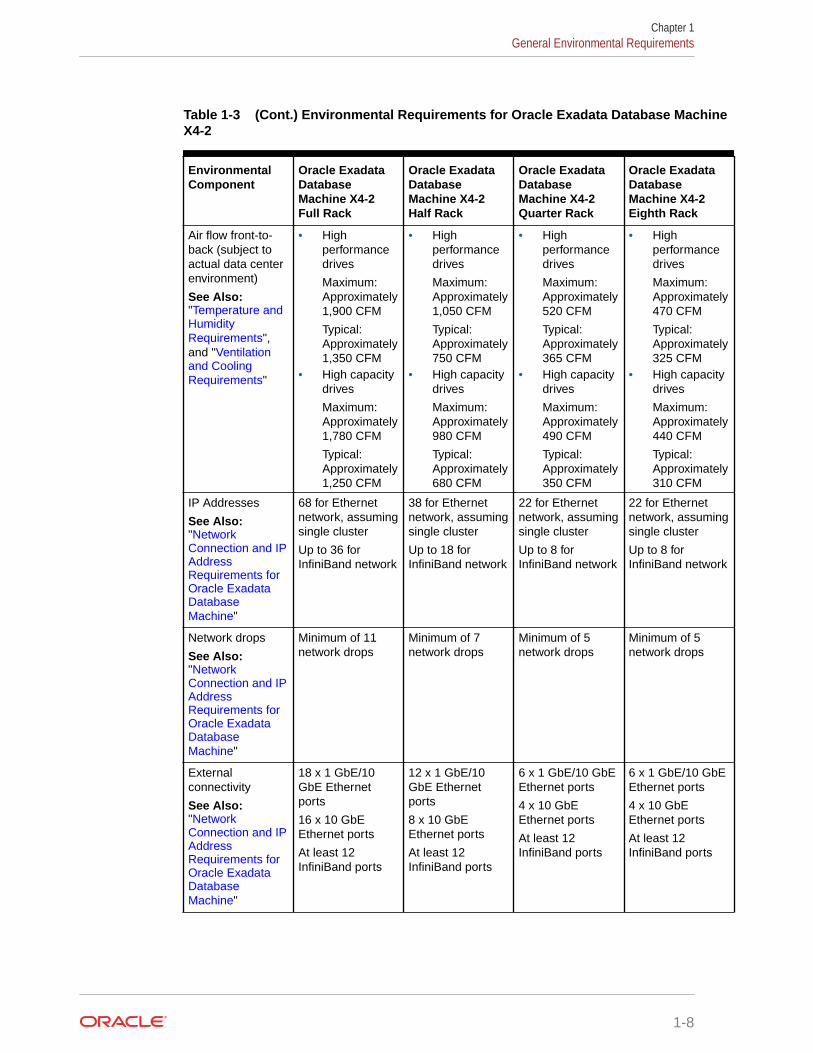
Table 1-3 (Cont.) Environmental Requirements for Oracle Exadata Database MachineX4-2
EnvironmentalComponent
Oracle ExadataDatabaseMachine X4-2Full Rack
Oracle ExadataDatabaseMachine X4-2Half Rack
Oracle ExadataDatabaseMachine X4-2Quarter Rack
Oracle ExadataDatabaseMachine X4-2Eighth Rack
Air flow front-to-back (subject toactual data centerenvironment)
See Also:"Temperature andHumidityRequirements",and "Ventilationand CoolingRequirements"
• Highperformancedrives
Maximum:Approximately1,900 CFM
Typical:Approximately1,350 CFM
• High capacitydrives
Maximum:Approximately1,780 CFM
Typical:Approximately1,250 CFM
• Highperformancedrives
Maximum:Approximately1,050 CFM
Typical:Approximately750 CFM
• High capacitydrives
Maximum:Approximately980 CFM
Typical:Approximately680 CFM
• Highperformancedrives
Maximum:Approximately520 CFM
Typical:Approximately365 CFM
• High capacitydrives
Maximum:Approximately490 CFM
Typical:Approximately350 CFM
• Highperformancedrives
Maximum:Approximately470 CFM
Typical:Approximately325 CFM
• High capacitydrives
Maximum:Approximately440 CFM
Typical:Approximately310 CFM
IP Addresses
See Also:"NetworkConnection and IPAddressRequirements forOracle ExadataDatabaseMachine"
68 for Ethernetnetwork, assumingsingle cluster
Up to 36 forInfiniBand network
38 for Ethernetnetwork, assumingsingle cluster
Up to 18 forInfiniBand network
22 for Ethernetnetwork, assumingsingle cluster
Up to 8 forInfiniBand network
22 for Ethernetnetwork, assumingsingle cluster
Up to 8 forInfiniBand network
Network drops
See Also:"NetworkConnection and IPAddressRequirements forOracle ExadataDatabaseMachine"
Minimum of 11network drops
Minimum of 7network drops
Minimum of 5network drops
Minimum of 5network drops
Externalconnectivity
See Also:"NetworkConnection and IPAddressRequirements forOracle ExadataDatabaseMachine"
18 x 1 GbE/10GbE Ethernetports
16 x 10 GbEEthernet ports
At least 12InfiniBand ports
12 x 1 GbE/10GbE Ethernetports
8 x 10 GbEEthernet ports
At least 12InfiniBand ports
6 x 1 GbE/10 GbEEthernet ports
4 x 10 GbEEthernet ports
At least 12InfiniBand ports
6 x 1 GbE/10 GbEEthernet ports
4 x 10 GbEEthernet ports
At least 12InfiniBand ports
Chapter 1General Environmental Requirements
1-8

1.2.5 General Environmental Requirements for Oracle Exadata DatabaseMachine X4-8 with Exadata Storage Server X5-2 Servers
Table 1-4 shows the general environmental requirements for Oracle Exadata DatabaseMachine X4-8 with Exadata Storage Server X5-2 Servers. The other sections in this chapterprovide detailed information.
Table 1-4 Environmental Requirements for Oracle Exadata Database Machine X4-8Racks with Exadata Storage Server X5-2 Servers
Environmental Component Oracle Exadata DatabaseMachine X4-8 Full Rack withExadata Storage Server X5-2Servers
Oracle Exadata DatabaseMachine X4-8 Half Rack withExadata Storage Server X5-2Servers
Weight
See Also: "FlooringRequirements"
• Extreme Flash drives: 828.1kg (1826 lbs)
• High capacity drives: 898.3kg (1980 lbs))
• Extreme Flash drives: 526.2kg (1160 lbs)
• High capacity drives: 541.2kg (1193 lbs)
Acoustic levels 86 db(A) 85 db(A)
Power
See Also: "Electrical PowerRequirements"
• Extreme Flash drives
Maximum: 17.1 kVA
Typical: 12.0 kVA (variesbased on application load)
• High capacity drives
Maximum: 17.0 kVA
Typical: 11.9 kVA (variesbased on application load)
• Extreme Flash drives
Maximum: 10.1 kVA
Typical: 7.1 kVA (variesbased on application load)
• High capacity drives
Maximum: 10.1 kVA
Typical: 7.0 kVA (variesbased on application load)
Cooling
See Also: "Temperature andHumidity Requirements", and"Ventilation and CoolingRequirements"
• Extreme Flash drives
Maximum: 57,300 BTU/hour(60,452 kJ/hour)
Typical: 40,110 BTU/hour(42,316 kJ/hour)
• High capacity drives
Maximum: 56,775 BTU/hour(59,897 kJ/hour)
Typical: 39,742 BTU/hour(41,928 kJ/hour)
• Extreme Flash drives
Maximum: 33,801 BTU/hour(35,660 kJ/hour)
Typical: 23,660 BTU/hour(24,962 kJ/hour)
• High capacity drives
Maximum: 33,688 BTU/hour(35,541 kJ/hour)
Typical: 23,582 BTU/hour(24,879 kJ/hour)
Air flow front-to-back (subject toactual data center environment)
See Also: "Temperature andHumidity Requirements", and"Ventilation and CoolingRequirements"
• Extreme Flash drives
Maximum: Approximately2,653 CFM
Typical: Approximately1,857 CFM
• High capacity drives
Maximum: Approximately2,628 CFM
Typical: Approximately1,840 CFM
• Extreme Flash drives
Maximum: Approximately1,565 CFM
Typical: Approximately1,095 CFM
• High capacity drives
Maximum: Approximately1,560 CFM
Typical: Approximately1,092 CFM
Chapter 1General Environmental Requirements
1-9

Table 1-4 (Cont.) Environmental Requirements for Oracle Exadata Database MachineX4-8 Racks with Exadata Storage Server X5-2 Servers
Environmental Component Oracle Exadata DatabaseMachine X4-8 Full Rack withExadata Storage Server X5-2Servers
Oracle Exadata DatabaseMachine X4-8 Half Rack withExadata Storage Server X5-2Servers
IP Addresses
See Also: "Network Connectionand IP Address Requirementsfor Oracle Exadata DatabaseMachine"
44 for Ethernet network,assuming single cluster
Up to 44 for InfiniBand network
22 for Ethernet network,assuming single cluster
Up to 22 for InfiniBand network
Network drops
See Also: "Network Connectionand IP Address Requirementsfor Oracle Exadata DatabaseMachine"
Minimum of 5 network drops Minimum of 5 network drops
External connectivity
See Also: "Network Connectionand IP Address Requirementsfor Oracle Exadata DatabaseMachine"
16 x 1 GbE Ethernet ports
16 x 10 GbE Ethernet SFP+ports
At least 12 InfiniBand ports
16 x 1 GbE Ethernet ports
16 x 10 GbE Ethernet SFP+ports
At least 12 InfiniBand ports
1.2.6 General Environmental Requirements for Oracle ExadataDatabase Machine X4-8 Full Rack
Table 1-5 shows the general environmental requirements for Oracle Exadata DatabaseMachine X4-8 Full Rack. The other sections in this chapter provide detailedinformation.
Table 1-5 Environmental Requirements for Oracle Exadata Database MachineX4-8 Full Rack
Environmental Component Oracle Exadata Database Machine X4-8Full Rack
Weight
See Also: "Flooring Requirements"
867.3 kg (1912 lbs)
Acoustic levels 93 db(A)
Power
See Also: "Electrical Power Requirements"
• High performance drives
Maximum: 15.3 kVA
Typical: 10.7 kVA (varies based onapplication load)
• High capacity drives
Maximum: 14.7 kVA
Typical: 10.3 kVA (varies based onapplication load)
Chapter 1General Environmental Requirements
1-10

Table 1-5 (Cont.) Environmental Requirements for Oracle Exadata DatabaseMachine X4-8 Full Rack
Environmental Component Oracle Exadata Database Machine X4-8Full Rack
Cooling
See Also: "Temperature and HumidityRequirements", and "Ventilation and CoolingRequirements"
• High performance drives
Maximum: 51,200 BTU/hour (54,000 kJ/hour)
Typical: 36,400 BTU/hour (38,400 kJ/hour)
• High capacity drives
Maximum: 49,110 BTU/hour (52,000 kJ/hour)
Typical: 34,400 BTU/hour (36,300 kJ/hour)
Air flow front-to-back (subject to actual datacenter environment)
See Also: "Temperature and HumidityRequirements", and "Ventilation and CoolingRequirements"
• High performance drives
Maximum: Approximately 2,410 CFM
Typical: Approximately 1,700 CFM• High capacity drives
Maximum: Approximately 2,280 CFM
Typical: Approximately 1,600 CFM
IP Addresses
See Also: "Network Connection and IPAddress Requirements for Oracle ExadataDatabase Machine"
44 for Ethernet network, assuming singlecluster
Up to 36 for InfiniBand network
Network drops
See Also: "Network Connection and IPAddress Requirements for Oracle ExadataDatabase Machine"
Minimum of 5 network drops
External connectivity
See Also: "Network Connection and IPAddress Requirements for Oracle ExadataDatabase Machine"
16 x 1 GbE Ethernet ports
16 x 10 GbE Ethernet SFP+ ports
12 InfiniBand ports
1.2.7 General Environmental Requirements for Oracle Exadata DatabaseMachine X3-2
The environmental requirements for Oracle Exadata Database Machine X3-2 depend on thesize of the system. Table 1-6 shows the general environmental requirements for OracleExadata Database Machine X3-2. The other sections in this chapter provide detailedinformation.
Chapter 1General Environmental Requirements
1-11

Table 1-6 Environmental Requirements for Oracle Exadata Database MachineX3-2
EnvironmentalComponent
Oracle ExadataDatabaseMachine X3-2Full Rack
Oracle ExadataDatabaseMachine X3-2Half Rack
Oracle ExadataDatabaseMachine X3-2Quarter Rack
Oracle ExadataDatabaseMachine EighthRack
Weight
See Also:"FlooringRequirements"
871.4 kg (1921lbs)
543.9 kg (1199lbs)
368.8 kg (813lbs)
368.8 kg (813lbs)
Acoustic levels 87 db(A) 84 db(A) 81 db(A) 81 db(A)
Power
See Also:"Electrical PowerRequirements"
• Highperformancedrives
Maximum:12.1 kVA
Typical: 8.6kVA (variesbased onapplicationload)
• Highcapacitydrives
Maximum:11.1 kVA
Typical: 7.8kVA (variesbased onapplicationload)
• Highperformancedrives
Maximum:6.6 kVA
Typical: 4.7kVA (variesbased onapplicationload)
• Highcapacitydrives
Maximum:6.1 kVA
Typical: 4.3kVA (variesbased onapplicationload)
• Highperformancedrives
Maximum:3.3 kVA
Typical: 2.4kVA (variesbased onapplicationload)
• Highcapacitydrives
Maximum:3.1 kVA
Typical: 2.2kVA (variesbased onapplicationload)
• Highperformancedrives
Maximum:3.0 kVA
Typical: 2.1kVA (variesbased onapplicationload)
• Highcapacitydrives
Maximum:2.8 kVA
Typical: 2.0kVA (variesbased onapplicationload)
Cooling
See Also:"Temperatureand HumidityRequirements",and "Ventilationand CoolingRequirements"
• Highperformancedrives
Maximum:40,600 BTU/hour (42,800kJ/hour)
Typical:28,700 BTU/hour (30,300kJ/hour)
• Highcapacitydrives
Maximum:37,200 BTU/hour (39,250kJ/hour)
Typical:26,000 BTU/hour (27,400kJ/hour)
• Highperformancedrives
Maximum:22,200 BTU/hour (23,400kJ/hour)
Typical:15,700 BTU/hour (16,600kJ/hour)
• Highcapacitydrives
Maximum:20,500 BTU/hour (21,600kJ/hour)
Typical:14,300 BTU/hour (15,100kJ/hour)
• Highperformancedrives
Maximum:10,900 BTU/hour (11,500kJ/hour)
Typical:7,850 BTU/hour (8,300kJ/hour)
• Highcapacitydrives
Maximum:10,200 BTU/hour (10,800kJ/hour)
Typical:7,200 BTU/hour (7,600kJ/hour)
• Highperformancedrives
Maximum:9,900 BTU/hour (10,500kJ/hour)
Typical:6,800 BTU/hour (7,200kJ/hour)
• Highcapacitydrives
Maximum:9,200 BTU/hour (9,700kJ/hour)
Typical:6,500 BTU/hour (6,850kJ/hour)
Chapter 1General Environmental Requirements
1-12

Table 1-6 (Cont.) Environmental Requirements for Oracle Exadata DatabaseMachine X3-2
EnvironmentalComponent
Oracle ExadataDatabaseMachine X3-2Full Rack
Oracle ExadataDatabaseMachine X3-2Half Rack
Oracle ExadataDatabaseMachine X3-2Quarter Rack
Oracle ExadataDatabaseMachine EighthRack
Air flow front-to-back (subject toactual datacenterenvironment)
See Also:"Temperatureand HumidityRequirements",and "Ventilationand CoolingRequirements"
• Highperformancedrives
Maximum:Approximately 1,900 CFM
Typical:Approximately 1,350 CFM
• Highcapacitydrives
Maximum:Approximately 1,700 CFM
Typical:Approximately 1,200 CFM
• Highperformancedrives
Maximum:Approximately 1,050 CFM
Typical:Approximately 750 CFM
• Highcapacitydrives
Maximum:Approximately 950 CFM
Typical:Approximately 670 CFM
• Highperformancedrives
Maximum:Approximately 500 CFM
Typical:Approximately 375 CFM
• Highcapacitydrives
Maximum:Approximately 470 CFM
Typical:Approximately 330 CFM
• Highperformancedrives
Maximum:Approximately 460 CFM
Typical:Approximately 325 CFM
• Highcapacitydrives
Maximum:Approximately 425 CFM
Typical:Approximately 300 CFM
IP Addresses
See Also:"NetworkConnection andIP AddressRequirements forOracle ExadataDatabaseMachine"
69 for Ethernetnetwork,assuming singlecluster
22 for InfiniBandnetwork
39 for Ethernetnetwork,assuming singlecluster (39 IPaddresses areneeded forOracle ExadataDatabaseMachine X2-2(with X4170 andX4275 servers))
11 for InfiniBandnetwork
22 for Ethernetnetwork,assuming singlecluster
5 for InfiniBandnetwork
22 for Ethernetnetwork,assuming singlecluster
5 for InfiniBandnetwork
Network drops
See Also:"NetworkConnection andIP AddressRequirements forOracle ExadataDatabaseMachine"
Minimum of 11network drops
Minimum of 7network drops
Minimum of 5network drops
Minimum of 5network drops
Chapter 1General Environmental Requirements
1-13

Table 1-6 (Cont.) Environmental Requirements for Oracle Exadata DatabaseMachine X3-2
EnvironmentalComponent
Oracle ExadataDatabaseMachine X3-2Full Rack
Oracle ExadataDatabaseMachine X3-2Half Rack
Oracle ExadataDatabaseMachine X3-2Quarter Rack
Oracle ExadataDatabaseMachine EighthRack
Externalconnectivity
See Also:"NetworkConnection andIP AddressRequirements forOracle ExadataDatabaseMachine"
24 x 1 GbE/10GbE Ethernetports
16 x 10 GbEEthernet ports
At least 12InfiniBand ports
12 x 1 GbE/10GbE Ethernetports
8 x 10 GbEEthernet ports
At least 12InfiniBand ports
6 x 1 GbE/10GbE Ethernetports
4 x 10 GbEEthernet ports
At least 12InfiniBand ports
6 x 1 GbE/10GbE Ethernetports
4 x 10 GbEEthernet ports
At least 12InfiniBand ports
1.2.8 General Environmental Requirements for Oracle ExadataDatabase Machine X3-8 Full Rack with Exadata Storage Server X4-2LServers
Table 1-7 shows the general environmental requirements for Oracle Exadata DatabaseMachine X3-8 Full Rack with Exadata Storage Server X4-2L Servers. The othersections in this chapter provide detailed information.
Table 1-7 Environmental Requirements for Oracle Exadata Database MachineX3-8 Full Rack with Exadata Storage Server X4-2L Servers
Environmental Component Oracle Exadata Database Machine X3-8Full Rack with Exadata Storage ServerX4-2L Servers
Weight
See Also: "Flooring Requirements"
911.27 kg (2009 lbs)
Acoustic levels 84 db(A)
Power
See Also: "Electrical Power Requirements"
• High performance drives
Maximum: 15.3 kVA
Typical: 10.7 kVA (varies based onapplication load)
• High capacity drives
Maximum: 14.5 kVA
Typical: 10.2 kVA (varies based onapplication load)
Chapter 1General Environmental Requirements
1-14

Table 1-7 (Cont.) Environmental Requirements for Oracle Exadata DatabaseMachine X3-8 Full Rack with Exadata Storage Server X4-2L Servers
Environmental Component Oracle Exadata Database Machine X3-8Full Rack with Exadata Storage ServerX4-2L Servers
Cooling
See Also: "Temperature and HumidityRequirements", and "Ventilation and CoolingRequirements"
• High performance drives
Maximum: 51,200 BTU/hour (54,000 kJ/hour)
Typical: 35,900 BTU/hour (37,900 kJ/hour)
• High capacity drives
Maximum: 48,500 BTU/hour (51,200 kJ/hour)
Typical: 34,200 BTU/hour (36,100 kJ/hour)
Air flow front-to-back (subject to actual datacenter environment)
See Also: "Temperature and HumidityRequirements", and "Ventilation and CoolingRequirements"
• High performance drives
Maximum: Approximately 2,400 CFM
Typical: Approximately 1,700 CFM• High capacity drives
Maximum: Approximately 2,250 CFM
Typical: Approximately 1,600 CFM
IP Addresses
See Also: "Network Connection and IPAddress Requirements for Oracle ExadataDatabase Machine"
45 for Ethernet network, assuming singlecluster
Up to 36 for InfiniBand network
Network drops
See Also: "Network Connection and IPAddress Requirements for Oracle ExadataDatabase Machine"
Minimum of 5 network drops
External connectivity
See Also: "Network Connection and IPAddress Requirements for Oracle ExadataDatabase Machine"
16 x 1 GbE Ethernet ports
16 x 10 GbE Ethernet SFP+ ports
12 InfiniBand ports
1.2.9 General Environmental Requirements for Oracle Exadata DatabaseMachine X3-8 Full Rack with Exadata Storage Server X3-2 Servers
Table 1-8 shows the general environmental requirements for Oracle Exadata DatabaseMachine X3-8 Full Rack with Exadata Storage Server X3-2 Servers. The other sections inthis chapter provide detailed information.
Chapter 1General Environmental Requirements
1-15

Table 1-8 Environmental Requirements for Oracle Exadata Database MachineX3-8 Full Rack with Exadata Storage Server X3-2 Servers
Environmental Component Oracle Exadata Database Machine X3-8Full Rack with Exadata Storage ServerX3-2 Servers
Weight
See Also: "Flooring Requirements"
929.9 kg (2050 lbs)
Acoustic levels 84 db(A)
Power
See Also: "Electrical Power Requirements"
• High performance drives
Maximum: 15.3 kVA
Typical: 10.7 kVA (varies based onapplication load)
• High capacity drives
Maximum: 14.3 kVA
Typical: 10.0 kVA (varies based onapplication load)
Cooling
See Also: "Temperature and HumidityRequirements", and "Ventilation and CoolingRequirements"
• High performance drives
Maximum: 51,200 BTU/hour (54,000 kJ/hour)
Typical: 35,900 BTU/hour (37,900 kJ/hour)
• High capacity drives
Maximum: 47,800 BTU/hour (50,400 kJ/hour)
Typical: 33,500 BTU/hour (35,300 kJ/hour)
Air flow front-to-back (subject to actual datacenter environment)
See Also: "Temperature and HumidityRequirements", and "Ventilation and CoolingRequirements"
• High performance drives
Maximum: Approximately 2,400 CFM
Typical: Approximately 1,700 CFM• High capacity drives
Maximum: Approximately 2,200 CFM
Typical: Approximately 1,550 CFM
IP Addresses
See Also: "Network Connection and IPAddress Requirements for Oracle ExadataDatabase Machine"
45 for Ethernet network, assuming singlecluster
22 for InfiniBand network
Network drops
See Also: "Network Connection and IPAddress Requirements for Oracle ExadataDatabase Machine"
Minimum of 5 network drops
External connectivity
See Also: "Network Connection and IPAddress Requirements for Oracle ExadataDatabase Machine"
16 x 1 GbE Ethernet ports
16 x 10 GbE Ethernet SFP+ ports
12 InfiniBand ports
Chapter 1General Environmental Requirements
1-16

1.2.10 General Environmental Requirements for Oracle Exadata DatabaseMachine X2-2
The environmental requirements for Oracle Exadata Database Machine X2-2 depend on thesize of the system. Table 1-9 shows the general environmental requirements for OracleExadata Database Machine X2-2. The other sections in this chapter provide detailedinformation.
Table 1-9 Environmental Requirements for Oracle Exadata Database Machine X2-2
EnvironmentalComponent
Oracle ExadataDatabase MachineX2-2 Full Rack
Oracle ExadataDatabase MachineX2-2 Half Rack
Oracle ExadataDatabase MachineX2-2 Quarter Rack
Weight
See Also: "FlooringRequirements"
966.6 kg (2131 lbs) 602.8 kg (1329 lbs) 409.1kg (902 lbs)
Acoustic levels 89 db(A) 86 db(A) 83 db(A)
Power
See Also: "ElectricalPower Requirements"
Maximum: 14.0 kW(14.3 kVA)
Typical: 9.8 kW (10.0kVA) (varies based onapplication load)
Maximum: 7.2 kW (7.3kVA)
Typical: 5.1 kW (5.2kVA) (varies based onapplication load)
Maximum: 3.6 kW (3.7kVA)
Typical: 2.7 kW(2.75kVA) (varies basedon application load)
Cooling
See Also: "Temperatureand HumidityRequirements", and"Ventilation and CoolingRequirements"
Maximum: 47,800 BTU/hour (50,400 kJ/hour)
Typical: 33,400 BTU/hour (35,300 kJ/hour)
Maximum: 26,400 BTU/hour (25,950 kJ/hour)
Typical: 17,400 BTU/hour (35,300 kJ/hour)
Maximum: 12,300 BTU/hour (13,000 kJ/hour)
Typical: 9,200 BTU/hour(9,700 kJ/hour)
Air flow front-to-back(subject to actual datacenter environment)
See Also: "Temperatureand HumidityRequirements", and"Ventilation and CoolingRequirements"
Maximum:Approximately 2,200CFM
Typical: Approximately1,560 CFM
Maximum:Approximately 1,130CFM
Typical: Approximately840 CFM
Maximum:Approximately 550 CFM
Typical: Approximately410 CFM
IP Addresses
See Also: "NetworkConnection and IPAddress Requirementsfor Oracle ExadataDatabase Machine"
70 for Ethernet network,assuming single cluster
22 for InfiniBandnetwork
40 for Ethernet network,assuming single cluster(39 IP addresses areneeded for OracleExadata DatabaseMachine X2-2 (withX4170 and X4275servers))
11 for InfiniBandnetwork
23 for Ethernet network,assuming single cluster
5 for InfiniBand network
Chapter 1General Environmental Requirements
1-17

Table 1-9 (Cont.) Environmental Requirements for Oracle Exadata Database MachineX2-2
EnvironmentalComponent
Oracle ExadataDatabase MachineX2-2 Full Rack
Oracle ExadataDatabase MachineX2-2 Half Rack
Oracle ExadataDatabase MachineX2-2 Quarter Rack
Network drops
See Also: "NetworkConnection and IPAddress Requirementsfor Oracle ExadataDatabase Machine"
Minimum of 12 networkdrops
Minimum of 8 networkdrops
Minimum of 6 networkdrops
External connectivity
See Also: "NetworkConnection and IPAddress Requirementsfor Oracle ExadataDatabase Machine"
24 x 1 GbE Ethernetports
16 x 10 GbE Ethernetports (valid for M2servers only)
At least 12 InfiniBandports
12 x 1 GbE Ethernetports
8 x 10 GbE Ethernetports (valid for M2servers only)
At least 12 InfiniBandports
6 x 1 GbE Ethernetports
4 x 10 GbE Ethernetports (valid for M2servers only)
At least 12 InfiniBandports
1.2.11 General Environmental Requirements for Oracle ExadataDatabase Machine X2-8 Full Rack
Table 1-10 shows the general environmental requirements for Oracle ExadataDatabase Machine X2-8 Full Rack. The other sections in this chapter provide detailedinformation.
Table 1-10 Environmental Requirements for Oracle Exadata Database MachineX2-8 Full Rack
Environmental Component Oracle Exadata DatabaseMachine X2-8 Full Rack(Sun Fire X4800 OracleDatabase Servers)
Oracle Exadata DatabaseMachine X2-8 Full Rack(Sun Server X2-8 OracleDatabase Servers)
Weight
See Also: "FlooringRequirements"
943.5 kg (2080 lbs) 980.7 kg (2162 lbs)
Acoustic levels 85 db(A) 85 db(A)
Power
See Also: "Electrical PowerRequirements"
Maximum: 17.0 kW (17.4 kVA)
Typical: 11.9 kW (12.2 kVA)(varies based on applicationload)
Maximum: 17.7 kW (18.1 kVA)
Typical: 12.4 kW (112.7 kVA)(varies based on applicationload)
Cooling
See Also: "Temperature andHumidity Requirements", and"Ventilation and CoolingRequirements"
Maximum: 58,050 BTU/hour(61,200 kJ/hour)
Typical: 40,630 BTU/hour(42,840 kJ/hour)
Maximum: 60,350 BTU/hour(63,630 kJ/hour)
Typical: 42,280 BTU/hour(44,580 kJ/hour)
Chapter 1General Environmental Requirements
1-18

Table 1-10 (Cont.) Environmental Requirements for Oracle Exadata DatabaseMachine X2-8 Full Rack
Environmental Component Oracle Exadata DatabaseMachine X2-8 Full Rack(Sun Fire X4800 OracleDatabase Servers)
Oracle Exadata DatabaseMachine X2-8 Full Rack(Sun Server X2-8 OracleDatabase Servers)
Air flow front-to-back (subjectto actual data centerenvironment)
See Also: "Temperature andHumidity Requirements", and"Ventilation and CoolingRequirements"
Maximum: Approximately2,690 CFM
Typical: Approximately 1,880CFM
Maximum: Approximately2,781CFM
Typical: Approximately 1,950CFM
IP Addresses
See Also: "NetworkConnection and IP AddressRequirements for OracleExadata Database Machine"
45 for Ethernet network,assuming single cluster
22 for InfiniBand network
45 for Ethernet network,assuming single cluster
22 for InfiniBand network
Network drops
See Also: "NetworkConnection and IP AddressRequirements for OracleExadata Database Machine"
Minimum of 5 network drops Minimum of 5 network drops
External connectivity
See Also: "NetworkConnection and IP AddressRequirements for OracleExadata Database Machine"
16 x 1 GbE Ethernet ports
16 x 10 GbE Ethernet SFP+ports
12 InfiniBand ports
16 x 1 GbE Ethernet ports
16 x 10 GbE Ethernet SFP+ports
12 InfiniBand ports
1.2.12 General Environmental Requirements for Oracle Exadata StorageExpansion Rack X5-2
The environmental requirements for Oracle Exadata Storage Expansion Rack X5-2 dependon the size of the system. Table 1-11 shows the general environmental requirements for eachtype of Oracle Exadata Storage Expansion Rack X5-2.
Table 1-11 Environmental Requirements for Oracle Exadata Storage Expansion RackX5-2
EnvironmentalComponent
Oracle ExadataStorage ExpansionX5-2 Full Rack
Oracle ExadataStorage ExpansionX5-2 Half Rack
Oracle ExadataStorage ExpansionX5-2 Quarter Rack
Weight • Extreme Flashdrives: 821 kg(1810 lbs)
• High capacitydrives: 915.8 kg(2019 lbs)
• Extreme Flashdrives: 546.6 kg(1205 lbs)
• High capacitydrives: 591.5 kg(1304 lbs)
• Extreme Flashdrives: 364.5 kg(804 lbs)
• High capacitydrives: 384.4 kg(848 lbs)
Acoustic levels 82 db(A) 79 db(A) 76 db(A)
Chapter 1General Environmental Requirements
1-19

Table 1-11 (Cont.) Environmental Requirements for Oracle Exadata StorageExpansion Rack X5-2
EnvironmentalComponent
Oracle ExadataStorage ExpansionX5-2 Full Rack
Oracle ExadataStorage ExpansionX5-2 Half Rack
Oracle ExadataStorage ExpansionX5-2 Quarter Rack
Power • Extreme Flashdrives
Maximum: 13.1kVA
Typical: 9.2 kVA(varies based onapplication load)
• High capacitydrives
Maximum: 12.8kVA
Typical: 8.9 kVA(varies based onapplication load)
• Extreme Flashdrives
Maximum: 5.9 kVA
Typical: 4.2 kVA(varies based onapplication load)
• High capacitydrives
Maximum: 6.9 kVA
Typical: 4.8 kVA(varies based onapplication load)
• Extreme Flashdrives
Maximum: 3.7 kVA
Typical: 2.6 kVA(varies based onapplication load)
• High capacitydrives
Maximum: 3.7 kVA
Typical: 2.6 kVA(varies based onapplication load)
Cooling • Extreme Flashdrives
Maximum: 43,765BTU/hour (46,170kJ/hour)
Typical: 30,635BTU/hour (32,320kJ/hour)
• High capacitydrives
Maximum: 42,670BTU/hour (45,020kJ/hour)
Typical: 29,870BTU/hour (31,515kJ/hour)
• Extreme Flashdrives
Maximum: 19,880BTU/hour (20,970kJ/hour)
Typical: 13,915BTU/hour (14,680kJ/hour)
• High capacitydrives
Maximum: 22,950BTU/hour (24,210kJ/hour)
Typical: 16,065BTU/hour (16,950kJ/hour
• Extreme Flashdrives
Maximum: 12,362BTU/hour (13,042kJ/hour)
Typical: 8,654 BTU/hour (9,129 kJ/hour)
• High capacitydrives
Maximum: 12,212BTU/hour (12,884kJ/hour)
Typical: 8,548 BTU/hour (9,019 kJ/hour)
Air flow front-to-back(subject to actual datacenter environment)
• Extreme Flashdrives
Maximum:Approximately2,030 CFM
Typical:Approximately1,420 CFM
• High capacitydrives
Maximum:Approximately1,975 CFM
Typical:Approximately1,385 CFM
• Extreme Flashdrives
Maximum:Approximately 920CFM
Typical:Approximately 645CFM
• High capacitydrives
Maximum:Approximately1,065 CFM
Typical:Approximately 745CFM
• Extreme Flashdrives
Maximum:Approximately 565CFM
Typical:Approximately 396CFM
• High capacitydrives
Maximum:Approximately 572CFM
Typical:Approximately 401CFM
Chapter 1General Environmental Requirements
1-20
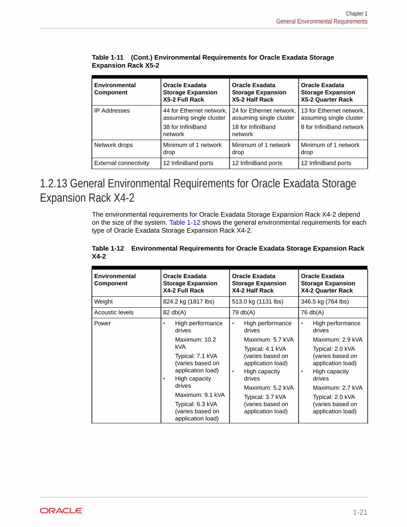
Table 1-11 (Cont.) Environmental Requirements for Oracle Exadata StorageExpansion Rack X5-2
EnvironmentalComponent
Oracle ExadataStorage ExpansionX5-2 Full Rack
Oracle ExadataStorage ExpansionX5-2 Half Rack
Oracle ExadataStorage ExpansionX5-2 Quarter Rack
IP Addresses 44 for Ethernet network,assuming single cluster
38 for InfiniBandnetwork
24 for Ethernet network,assuming single cluster
18 for InfiniBandnetwork
13 for Ethernet network,assuming single cluster
8 for InfiniBand network
Network drops Minimum of 1 networkdrop
Minimum of 1 networkdrop
Minimum of 1 networkdrop
External connectivity 12 InfiniBand ports 12 InfiniBand ports 12 InfiniBand ports
1.2.13 General Environmental Requirements for Oracle Exadata StorageExpansion Rack X4-2
The environmental requirements for Oracle Exadata Storage Expansion Rack X4-2 dependon the size of the system. Table 1-12 shows the general environmental requirements for eachtype of Oracle Exadata Storage Expansion Rack X4-2.
Table 1-12 Environmental Requirements for Oracle Exadata Storage Expansion RackX4-2
EnvironmentalComponent
Oracle ExadataStorage ExpansionX4-2 Full Rack
Oracle ExadataStorage ExpansionX4-2 Half Rack
Oracle ExadataStorage ExpansionX4-2 Quarter Rack
Weight 824.2 kg (1817 lbs) 513.0 kg (1131 lbs) 346.5 kg (764 lbs)
Acoustic levels 82 db(A) 79 db(A) 76 db(A)
Power • High performancedrives
Maximum: 10.2kVA
Typical: 7.1 kVA(varies based onapplication load)
• High capacitydrives
Maximum: 9.1 kVA
Typical: 6.3 kVA(varies based onapplication load)
• High performancedrives
Maximum: 5.7 kVA
Typical: 4.1 kVA(varies based onapplication load)
• High capacitydrives
Maximum: 5.2 kVA
Typical: 3.7 kVA(varies based onapplication load)
• High performancedrives
Maximum: 2.9 kVA
Typical: 2.0 kVA(varies based onapplication load)
• High capacitydrives
Maximum: 2.7 kVA
Typical: 2.0 kVA(varies based onapplication load)
Chapter 1General Environmental Requirements
1-21

Table 1-12 (Cont.) Environmental Requirements for Oracle Exadata StorageExpansion Rack X4-2
EnvironmentalComponent
Oracle ExadataStorage ExpansionX4-2 Full Rack
Oracle ExadataStorage ExpansionX4-2 Half Rack
Oracle ExadataStorage ExpansionX4-2 Quarter Rack
Cooling • High performancedrives
Maximum: 34,100BTU/hour (36,000kJ/hour)
Typical: 23,900BTU/hour (25,200kJ/hour)
• High capacitydrives
Maximum: 30,400BTU/hour (32,100kJ/hour)
Typical: 21,200BTU/hour (22,400kJ/hour)
• High performancedrives
Maximum: 19,100BTU/hour (20,150kJ/hour)
Typical: 13,650BTU/hour (14,400kJ/hour)
• High capacitydrives
Maximum: 17,400BTU/hour (18,400kJ/hour)
Typical: 12,300BTU/hour (13,000kJ/hour)
• High performancedrives
Maximum: 9,500BTU/hour (10,000kJ/hour)
Typical: 6,700 BTU/hour (7,000 kJ/hour)
• High capacitydrives
Maximum: 8,900BTU/hour (9,400kJ/hour)
Typical: 6,500 BTU/hour (6,900 kJ/hour)
Air flow front-to-back(subject to actual datacenter environment)
• High performancedrives
Maximum:Approximately1,600 CFM
Typical:Approximately1,100 CFM
• High capacitydrives
Maximum:Approximately1,410 CFM
Typical:Approximately 980CFM
• High performancedrives
Maximum:Approximately 900CFM
Typical:Approximately 650CFM
• High capacitydrives
Maximum:Approximately 810CFM
Typical:Approximately 570CFM
• High performancedrives
Maximum:Approximately 440CFM
Typical:Approximately 310CFM
• High capacitydrives
Maximum:Approximately 410CFM
Typical:Approximately 300CFM
IP Addresses 42 for Ethernet network,assuming single cluster
36 for InfiniBandnetwork
24 for Ethernet network,assuming single cluster
18 for InfiniBandnetwork
13 for Ethernet network,assuming single cluster
8 for InfiniBand network
Network drops Minimum of 1 networkdrop
Minimum of 1 networkdrop
Minimum of 1 networkdrop
External connectivity 12 InfiniBand ports 12 InfiniBand ports 12 InfiniBand ports
Chapter 1General Environmental Requirements
1-22

1.2.14 General Environmental Requirements for Oracle Exadata StorageExpansion Rack X3-2
The environmental requirements for Oracle Exadata Storage Expansion Rack X3-2 dependon the size of the system. Table 1-13 shows the general environmental requirements for eachtype of Oracle Exadata Storage Expansion Rack X3-2.
Table 1-13 Environmental Requirements for Oracle Exadata Storage Expansion RackX3-2
EnvironmentalComponent
Oracle ExadataStorage ExpansionX3-2 Full Rack
Oracle ExadataStorage ExpansionX3-2 Half Rack
Oracle ExadataStorage ExpansionX3-2 Quarter Rack
Weight 827.4 kg (1824 lbs) 516.2 kg (1138 lbs) 349.7 kg (771 lbs)
Acoustic levels 82 db(A) 79 db(A) 76 db(A)
Power • High performancedrives
Maximum: 10.2kVA
Typical: 7.1 kVA(varies based onapplication load)
• High capacitydrives
Maximum: 8.9 kVA
Typical: 6.2 kVA(varies based onapplication load)
• High performancedrives
Maximum: 5.7 kVA
Typical: 4.1 kVA(varies based onapplication load)
• High capacitydrives
Maximum: 5.1 kVA
Typical: 3.6 kVA(varies based onapplication load)
• High performancedrives
Maximum: 2.9 kVA
Typical: 2.0 kVA(varies based onapplication load)
• High capacitydrives
Maximum: 2.6 kVA
Typical: 1.9 kVA(varies based onapplication load)
Cooling • High performancedrives
Maximum: 34,100BTU/hour (36,000kJ/hour)
Typical: 23,900BTU/hour (25,200kJ/hour)
• High capacitydrives
Maximum: 29,700BTU/hour (31,300kJ/hour)
Typical: 20,800BTU/hour (21,950kJ/hour)
• High performancedrives
Maximum: 19,100BTU/hour (20,150kJ/hour)
Typical: 13,650BTU/hour (14,400kJ/hour)
• High capacitydrives
Maximum: 17,100BTU/hour (18,000kJ/hour)
Typical: 11,950BTU/hour (12,600kJ/hour)
• High performancedrives
Maximum: 9,500BTU/hour (10,000kJ/hour)
Typical: 6,700 BTU/hour (7,000 kJ/hour)
• High capacitydrives
Maximum: 8,500BTU/hour (9,000kJ/hour)
Typical: 6,150 BTU/hour (6,500 kJ/hour)
Chapter 1General Environmental Requirements
1-23
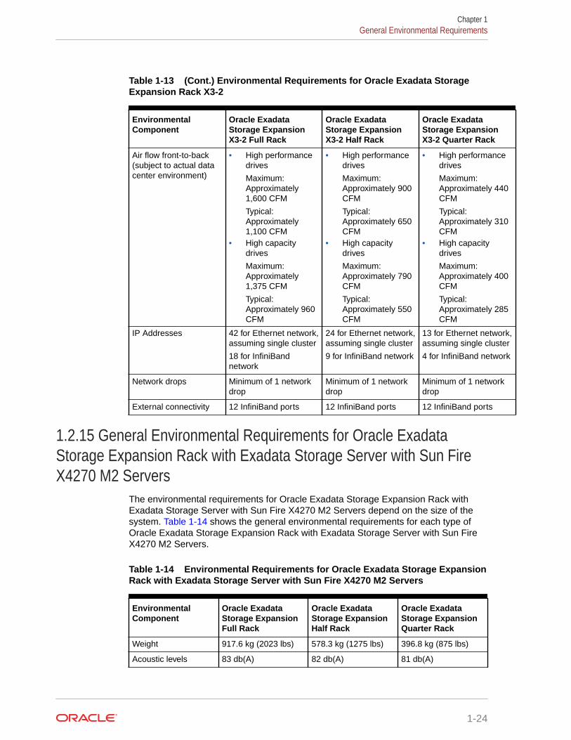
Table 1-13 (Cont.) Environmental Requirements for Oracle Exadata StorageExpansion Rack X3-2
EnvironmentalComponent
Oracle ExadataStorage ExpansionX3-2 Full Rack
Oracle ExadataStorage ExpansionX3-2 Half Rack
Oracle ExadataStorage ExpansionX3-2 Quarter Rack
Air flow front-to-back(subject to actual datacenter environment)
• High performancedrives
Maximum:Approximately1,600 CFM
Typical:Approximately1,100 CFM
• High capacitydrives
Maximum:Approximately1,375 CFM
Typical:Approximately 960CFM
• High performancedrives
Maximum:Approximately 900CFM
Typical:Approximately 650CFM
• High capacitydrives
Maximum:Approximately 790CFM
Typical:Approximately 550CFM
• High performancedrives
Maximum:Approximately 440CFM
Typical:Approximately 310CFM
• High capacitydrives
Maximum:Approximately 400CFM
Typical:Approximately 285CFM
IP Addresses 42 for Ethernet network,assuming single cluster
18 for InfiniBandnetwork
24 for Ethernet network,assuming single cluster
9 for InfiniBand network
13 for Ethernet network,assuming single cluster
4 for InfiniBand network
Network drops Minimum of 1 networkdrop
Minimum of 1 networkdrop
Minimum of 1 networkdrop
External connectivity 12 InfiniBand ports 12 InfiniBand ports 12 InfiniBand ports
1.2.15 General Environmental Requirements for Oracle ExadataStorage Expansion Rack with Exadata Storage Server with Sun FireX4270 M2 Servers
The environmental requirements for Oracle Exadata Storage Expansion Rack withExadata Storage Server with Sun Fire X4270 M2 Servers depend on the size of thesystem. Table 1-14 shows the general environmental requirements for each type ofOracle Exadata Storage Expansion Rack with Exadata Storage Server with Sun FireX4270 M2 Servers.
Table 1-14 Environmental Requirements for Oracle Exadata Storage ExpansionRack with Exadata Storage Server with Sun Fire X4270 M2 Servers
EnvironmentalComponent
Oracle ExadataStorage ExpansionFull Rack
Oracle ExadataStorage ExpansionHalf Rack
Oracle ExadataStorage ExpansionQuarter Rack
Weight 917.6 kg (2023 lbs) 578.3 kg (1275 lbs) 396.8 kg (875 lbs)
Acoustic levels 83 db(A) 82 db(A) 81 db(A)
Chapter 1General Environmental Requirements
1-24

Table 1-14 (Cont.) Environmental Requirements for Oracle Exadata StorageExpansion Rack with Exadata Storage Server with Sun Fire X4270 M2 Servers
EnvironmentalComponent
Oracle ExadataStorage ExpansionFull Rack
Oracle ExadataStorage ExpansionHalf Rack
Oracle ExadataStorage ExpansionQuarter Rack
Power Maximum: 12.6 kW(12.9 kVA)
Typical: 8.8 kW (9.0kVA) (varies based onapplication load)
Maximum: 6.9 kW (7.1kVA)
Typical: 4.8 kW (5.0kVA) (varies based onapplication load)
Maximum: 3.4 kW (3.5kVA)
Typical: 2.4 kW(2.5kVA) (variesbased on applicationload)
Cooling Maximum: 43,000BTU/hour (45,400 kJ/hour)
Typical: 30,100 BTU/hour (31,800 kJ/hour)
Maximum: 23,600BTU/hour (24,900 kJ/hour)
Typical: 16,500 BTU/hour (17,400 kJ/hour)
Maximum: 11,600BTU/hour (12,250 kJ/hour)
Typical: 8,100 BTU/hour (8,600 kJ/hour)
Air flow front-to-back(subject to actual datacenter environment)
Maximum:Approximately 1,980CFM
Typical: Approximately1,390 CFM
Maximum:Approximately 1,090CFM
Typical: Approximately760 CFM
Maximum:Approximately 530CFM
Typical: Approximately375 CFM
IP Addresses 43 for Ethernetnetwork, assumingsingle cluster
18 for InfiniBandnetwork
25 for Ethernetnetwork, assumingsingle cluster
9 for InfiniBandnetwork
14 for Ethernetnetwork, assumingsingle cluster
4 for InfiniBandnetwork
Network drops Minimum of 2 networkdrops
Minimum of 2 networkdrops
Minimum of 2 networkdrops
External connectivity 12 InfiniBand ports 12 InfiniBand ports 12 InfiniBand ports
1.2.16 General Environmental Requirements for Single ServersThe environmental requirements for single servers are shown in the following tables.
Table 1-15 Environmental Requirements for X9M-2 Single Servers
Environmental Component
DatabaseServer X9M-2
ExadataStorageServer X9M-2- HighCapacity
ExadataStorageServer X9M-2Eighth Rack -High Capacity
ExadataStorageServer X9M-2- ExtremeFlash
ExadataStorageServer X9M-2XT Server
Weight 20.7 kg (45.6lbs)
34.8 kg (76.7lbs)
30.6 kg (67.5lbs)
27.5 kg (60.6lbs)
30.2 kg (66.7lbs)
Acoustic levels 79 db 80 dB 80 dB 80 dB 80 dB
Chapter 1General Environmental Requirements
1-25

Table 1-15 (Cont.) Environmental Requirements for X9M-2 Single Servers
Environmental Component
DatabaseServer X9M-2
ExadataStorageServer X9M-2- HighCapacity
ExadataStorageServer X9M-2Eighth Rack -High Capacity
ExadataStorageServer X9M-2- ExtremeFlash
ExadataStorageServer X9M-2XT Server
Power Maximum: 0.9kW (0.9 kVA)
Typical: 0.7 kW(0.7 kVA)(varies basedon applicationload)
Maximum: 0.9kW (0.9 kVA)
Typical: 0.5 kW(0.6 kVA)(varies basedon applicationload)
Maximum: 0.6kW (0.6 kVA)
Typical: 0.4 kW(0.4 kVA)(varies basedon applicationload)
Maximum: 0.9kW (0.9 kVA)
Typical: 0.6 kW(0.6 kVA)(varies basedon applicationload)
Maximum: 0.5kW (0.5 kVA)
Typical: 0.4 kW(0.4 kVA)(varies basedon applicationload)
Cooling At max usage:3,153 BTU/hour (3,326 kJ/hour)
At typicalusage: 2,207BTU/hour(2,328 kJ/hour
At max usage:2,883 BTU/hour (3,042 kJ/hour)
At typicalusage: 2,018BTU/hour(2,129 kJ/hour)
At max usage:2,134 BTU/hour (2,251 kJ/hour)
At typicalusage: 1,494BTU/hour(1,576 kJ/hour)
At max usage:2,907 BTU/hour (3,067 kJ/hour)
At typicalusage: 2,035BTU/hour(2,147 kJ/hour)
At max usage:1,720 BTU/hour (1,814 kJ/hour)
At typicalusage: 1,204BTU/hour(1,270 kJ/hour)
Air flow front-to-back(subject toactual datacenterenvironment)
At max usage:Approximately146 CFM
At typicalusage:Approximately102 CFM
At max usage:Approximately133 CFM
At typicalusage:Approximately93 CFM
At max usage:Approximately99 CFM
At typicalusage:Approximately69 CFM
At max usage:Approximately135 CFM
At typicalusage:Approximately94 CFM
At max usage:Approximately80 CFM
At typicalusage:Approximately56 CFM
Table 1-16 Environmental Requirements for X8M-2 Single Servers
EnvironmentalComponent
DatabaseServerX8M-2
ExadataStorageServerX8M-2 - HighCapacity
ExadataStorageServerX8M-2 EighthRack - HighCapacity
ExadataStorageServerX8M-2 -ExtremeFlash
ExadataStorageServerX8M-2 XTServer
Weight 20.7 kg (45.6lbs)
34.8 kg (76.7lbs)
30.6 kg (67.5lbs)
27.5 kg (60.6lbs)
30.2 kg (66.7lbs)
Acousticlevels
77 db 82 dB 82 dB 82 dB 82 dB
Power Maximum: 0.7kW (0.7 kVA)
Typical: 0.5kW (0.5 kVA)(varies basedon applicationload)
Maximum: 0.8kW (0.8 kVA)
Typical: 0.5kW (0.6 kVA)(varies basedon applicationload)
Maximum: 0.6kW (0.6 kVA)
Typical: 0.4kW (0.4 kVA)(varies basedon applicationload)
Maximum: 0.8kW (0.8 kVA)
Typical: 0.6kW (0.6 kVA)(varies basedon applicationload)
Maximum: 0.5kW (0.5 kVA)
Typical: 0.3kW (0.3 kVA)(varies basedon applicationload)
Chapter 1General Environmental Requirements
1-26

Table 1-16 (Cont.) Environmental Requirements for X8M-2 Single Servers
EnvironmentalComponent
DatabaseServerX8M-2
ExadataStorageServerX8M-2 - HighCapacity
ExadataStorageServerX8M-2 EighthRack - HighCapacity
ExadataStorageServerX8M-2 -ExtremeFlash
ExadataStorageServerX8M-2 XTServer
Cooling At max usage:2,409 BTU/hour (2,541kJ/hour)
At typicalusage: 1,686BTU/hour(1,779 kJ/hour
At max usage:2,631 BTU/hour (2,775kJ/hour)
At typicalusage: 1,842BTU/hour(1,943 kJ/hour)
At max usage:1,947 BTU/hour (2,054kJ/hour)
At typicalusage: 1,363BTU/hour(1,438 kJ/hour)
At max usage:2,730 BTU/hour (2,880kJ/hour)
At typicalusage: 1,911BTU/hour(2,016 kJ/hour)
At max usage:1570 BTU/hour (1,656kJ/hour)
At typicalusage: 1,099BTU/hour(1,159 kJ/hour)
Air flow front-to-back(subject toactual datacenterenvironment)
At max usage:Approximately112 CFM
At typicalusage:Approximately78 CFM
At max usage:Approximately122 CFM
At typicalusage:Approximately85 CFM
At max usage:Approximately90 CFM
At typicalusage:Approximately63 CFM
At max usage:Approximately126 CFM
At typicalusage:Approximately88 CFM
At max usage:Approximately73 CFM
At typicalusage:Approximately51 CFM
Table 1-17 Environmental Requirements for X8-2 Single Servers
Environmental Component
DatabaseServer X8-2
ExadataStorageServer X8-2 -High Capacity
ExadataStorageServer X8-2Eighth Rack -High Capacity
ExadataStorageServer X8-2 -Extreme Flash
ExadataStorageServer X8-2XT Server
Weight 20.7 kg (45.6lbs)
34.8 kg (76.7lbs)
30.6 kg (67.5lbs)
27.5 kg (60.6lbs)
30.2 kg (66.7lbs)
Acoustic levels 77 db 82 dB 82 dB 82 dB 82 dB
Power Maximum: 0.7kW (0.7 kVA)
Typical: 0.5 kW(0.5 kVA)(varies basedon applicationload)
Maximum: 0.7kW (0.7 kVA)
Typical: 0.5 kW(0.5 kVA)(varies basedon applicationload)
Maximum: 0.5kW (0.5 kVA)
Typical: 0.4 kW(0.4 kVA)(varies basedon applicationload)
Maximum: 0.7kW (0.7 kVA)
Typical: 0.5 kW(0.5 kVA)(varies basedon applicationload)
Maximum: 0.5kW (0.5 kVA)
Typical: 0.3 kW(0.3 kVA)(varies basedon applicationload)
Cooling At max usage:2,409 BTU/hour (2,541 kJ/hour)
At typicalusage: 1,686BTU/hour(1,779 kJ/hour
At max usage:2,317 BTU/hour (2,444 kJ/hour)
At typicalusage: 1,622BTU/hour(1,711 kJ/hour)
At max usage:1,714 BTU/hour (1,809 kJ/hour)
At typicalusage: 1,200BTU/hour(1,266 kJ/hour)
At max usage:2,283 BTU/hour (2,408 kJ/hour)
At typicalusage: 1,598BTU/hour(1,686 kJ/hour)
At max usage:1570 BTU/hour(1,656 kJ/hour)
At typicalusage: 1,099BTU/hour(1,159 kJ/hour)
Chapter 1General Environmental Requirements
1-27

Table 1-17 (Cont.) Environmental Requirements for X8-2 Single Servers
Environmental Component
DatabaseServer X8-2
ExadataStorageServer X8-2 -High Capacity
ExadataStorageServer X8-2Eighth Rack -High Capacity
ExadataStorageServer X8-2 -Extreme Flash
ExadataStorageServer X8-2XT Server
Air flow front-to-back(subject toactual datacenterenvironment)
At max usage:Approximately112 CFM
At typicalusage:Approximately78 CFM
At max usage:Approximately107 CFM
At typicalusage:Approximately75 CFM
At max usage:Approximately79 CFM
At typicalusage:Approximately56 CFM
At max usage:Approximately106 CFM
At typicalusage:Approximately74 CFM
At max usage:Approximately73 CFM
At typicalusage:Approximately51 CFM
Table 1-18 Environmental Requirements for X7-2 Single Servers
EnvironmentalComponent
ExadataStorage ServerX7-2 - ExtremeFlash
ExadataStorage ServerX7-2 EighthRack - HighCapacity
ExadataStorage ServerX7-2 - HighCapacity
DatabaseServer X7-2
Weight 27.5 kg (61 lbs) 30.1 kg (66.3 lbs) 34.4 kg (76 lbs) 20.7 kg (46 lbs)
Acoustic levels 82 db(A) 79 db(A) 82 db(A) 77 db(A)
Power Maximum: 0.6kW (0.6 kVA)
Typical: 0.4 kW(0.5 kVA) (variesbased onapplication load)
Maximum: 0.5kW (0.5 kVA)
Typical: 0.3 kW(0.3 kVA) (variesbased onapplication load)
Maximum: 0.6kW (0.6 kVA)
Typical: 0.4 kW(0.4 kVA) (variesbased onapplication load)
Maximum: 0.8kW (0.8 kVA)
Typical: 0.5 kW(0.6 kVA) (variesbased onapplication load)
Cooling Maximum: 2,167BTU/hour (2,286kJ/hour)
Typical: 1,600BTU/hour (1,378kJ/hour)
Maximum: 1,588BTU/hour (1,676kJ/hour)
Typical: 1,112BTU/hour (1,173kJ/hour)
Maximum: 2,146BTU/hour (2,264kJ/hour)
Typical: 1,502BTU/hour (1,585kJ/hour)
Maximum: 2,631BTU/hour (2,775kJ/hour)
Typical: 1,842BTU/hour (1,943kJ/hour
Air flow front-to-back (subject toactual datacenterenvironment)
Maximum:Approximately100 CFM
Typical:Approximately 70CFM
Maximum:Approximately 74CFM
Typical:Approximately 51CFM
Maximum:Approximately 99CFM
Typical:Approximately 70CFM
Maximum:Approximately122 CFM
Typical:Approximately 85CFM
Table 1-19 Environmental Requirements for X6-2 Single Servers
EnvironmentalComponent
Exadata StorageServer X6-2 -Extreme Flash
Exadata StorageServer X6-2 - HighCapacity
Database ServerX6-2
Weight 28.1 kg (62 lbs) 33.1 kg (73 lbs) 20.4 kg (45 lbs)
Acoustic levels 78 db(A) 78 db(A) 78 db(A)
Chapter 1General Environmental Requirements
1-28

Table 1-19 (Cont.) Environmental Requirements for X6-2 Single Servers
EnvironmentalComponent
Exadata StorageServer X6-2 -Extreme Flash
Exadata StorageServer X6-2 - HighCapacity
Database ServerX6-2
Power Maximum: 0.6 kVA
Typical: 0.4 kVA(varies based onapplication load)
Maximum: 0.6 kVA
Typical: 0.4 kVA(varies based onapplication load)
Maximum: 0.665 kW(0.678 kVA)
Typical: 0.466 kW(0.475 kVA) (variesbased on applicationload)
Cooling Maximum: 1,866 BTU/hour (1,969 kJ/hour)
Typical: 1,307 BTU/hour (1,378 kJ/hour)
Maximum: 2,006 BTU/hour (2,117 kJ/hour)
Typical: 1,404 BTU/hour (1,482 kJ/hour)
Maximum: 2,269 BTU/hour (2,394 kJ/hour)
Typical: 1,588 BTU/hour (1,676 kJ/hour
Air flow front-to-back(subject to actual datacenter environment)
Maximum:Approximately 86CFM
Typical: Approximately60 CFM
Maximum:Approximately 93CFM
Typical: Approximately65 CFM
Maximum:Approximately 105CFM
Typical: Approximately74 CFM
Table 1-20 Environmental Requirements for X5-2 Single Servers
EnvironmentalComponent
Exadata StorageServer X5-2 - ExtremeFlash
Exadata StorageServer X5-2 - HighCapacity
Database Server X5-2
Weight 28.1 kg (62 lbs) 33.1 kg (73 lbs) 20.4 kg (45 lbs)
Acoustic levels 78 db(A) 78 db(A) 78 db(A)
Power Maximum: 0.6 kVA
Typical: 0.4 kVA (variesbased on applicationload)
Maximum: 0.6 kVA
Typical: 0.4 kVA (variesbased on applicationload)
Maximum: 0.7 kVA
Typical: 0.5 kVA (variesbased on applicationload)
Cooling Maximum: 2,037 BTU/hour (2,149 kJ/hour)
Typical: 1,426 BTU/hour(1,504 kJ/hour)
Maximum: 2,000 BTU/hour (2,109 kJ/hour)
Typical: 1,400 BTU/hour(1,477 kJ/hour)
Maximum: 2,481 BTU/hour (2,617 kJ/hour)
Typical: 1,736 BTU/hour(1,832 kJ/hour
Air flow front-to-back(subject to actual datacenter environment)
Maximum:Approximately 94 CFM
Typical: Approximately66 CFM
Maximum:Approximately 93 CFM
Typical: Approximately65 CFM
Maximum:Approximately 115 CFM
Typical: Approximately80 CFM
Table 1-21 Environmental Requirements for 8-Socket Servers, Model X4-8 and Later
EnvironmentalComponent
Database ServerX8M-8 and X9M-8
Database ServerX7-8 and X8-8
Database ServerX5-8 and X6-8
Database ServerX4-8
Weight 90.2 kg (198.8 lbs) 90.2 kg (198.8 lbs) 93.4 kg (206 lbs) 93.4 kg (206 lbs)
Acoustic levels 87 dB 87 dB 81 db(A) 81 db(A)
Chapter 1General Environmental Requirements
1-29
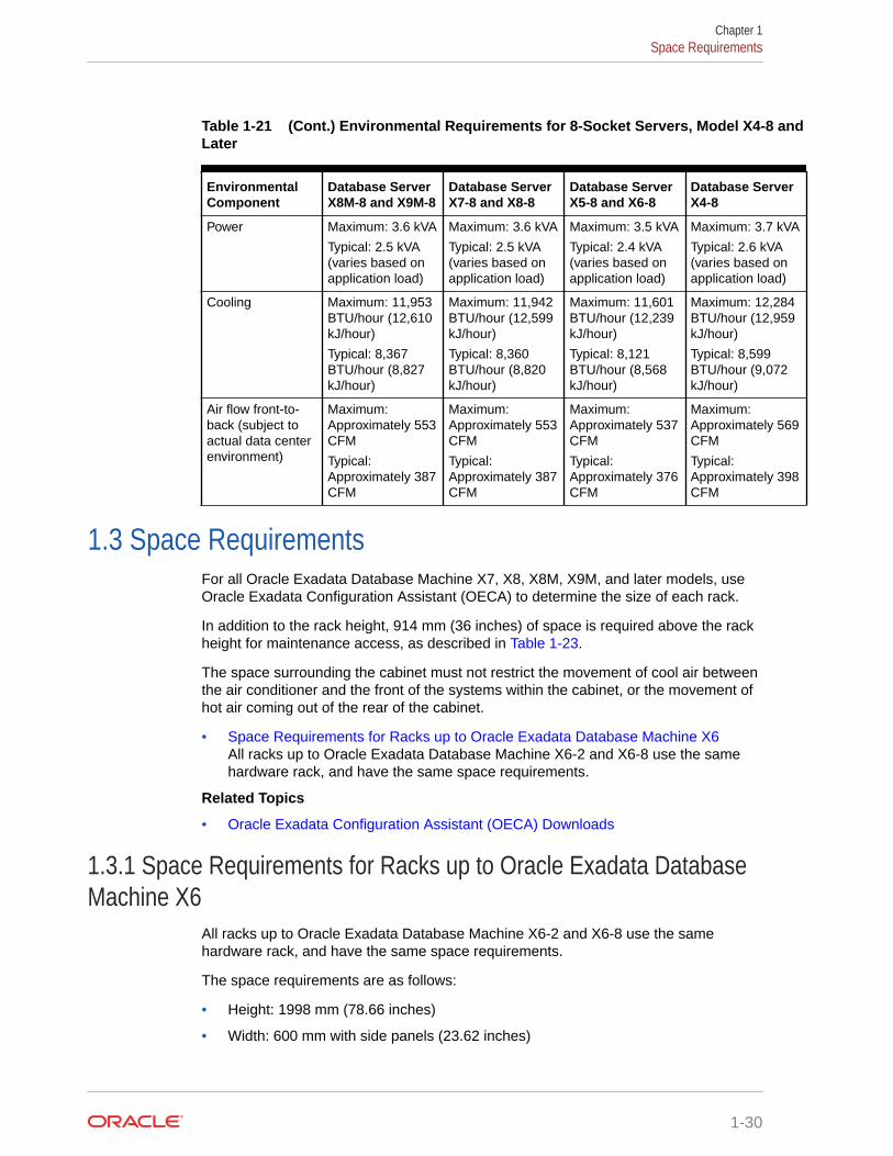
Table 1-21 (Cont.) Environmental Requirements for 8-Socket Servers, Model X4-8 andLater
EnvironmentalComponent
Database ServerX8M-8 and X9M-8
Database ServerX7-8 and X8-8
Database ServerX5-8 and X6-8
Database ServerX4-8
Power Maximum: 3.6 kVA
Typical: 2.5 kVA(varies based onapplication load)
Maximum: 3.6 kVA
Typical: 2.5 kVA(varies based onapplication load)
Maximum: 3.5 kVA
Typical: 2.4 kVA(varies based onapplication load)
Maximum: 3.7 kVA
Typical: 2.6 kVA(varies based onapplication load)
Cooling Maximum: 11,953BTU/hour (12,610kJ/hour)
Typical: 8,367BTU/hour (8,827kJ/hour)
Maximum: 11,942BTU/hour (12,599kJ/hour)
Typical: 8,360BTU/hour (8,820kJ/hour)
Maximum: 11,601BTU/hour (12,239kJ/hour)
Typical: 8,121BTU/hour (8,568kJ/hour)
Maximum: 12,284BTU/hour (12,959kJ/hour)
Typical: 8,599BTU/hour (9,072kJ/hour)
Air flow front-to-back (subject toactual data centerenvironment)
Maximum:Approximately 553CFM
Typical:Approximately 387CFM
Maximum:Approximately 553CFM
Typical:Approximately 387CFM
Maximum:Approximately 537CFM
Typical:Approximately 376CFM
Maximum:Approximately 569CFM
Typical:Approximately 398CFM
1.3 Space RequirementsFor all Oracle Exadata Database Machine X7, X8, X8M, X9M, and later models, useOracle Exadata Configuration Assistant (OECA) to determine the size of each rack.
In addition to the rack height, 914 mm (36 inches) of space is required above the rackheight for maintenance access, as described in Table 1-23.
The space surrounding the cabinet must not restrict the movement of cool air betweenthe air conditioner and the front of the systems within the cabinet, or the movement ofhot air coming out of the rear of the cabinet.
• Space Requirements for Racks up to Oracle Exadata Database Machine X6All racks up to Oracle Exadata Database Machine X6-2 and X6-8 use the samehardware rack, and have the same space requirements.
Related Topics
• Oracle Exadata Configuration Assistant (OECA) Downloads
1.3.1 Space Requirements for Racks up to Oracle Exadata DatabaseMachine X6
All racks up to Oracle Exadata Database Machine X6-2 and X6-8 use the samehardware rack, and have the same space requirements.
The space requirements are as follows:
• Height: 1998 mm (78.66 inches)
• Width: 600 mm with side panels (23.62 inches)
Chapter 1Space Requirements
1-30

• Depth: 1200 mm (47.24 inches)
The minimum ceiling height for the cabinet is 2912 mm (114.65 inches), measured from thetrue floor or raised floor, whichever is higher. This includes an additional 914 mm (36 inches)of space required above the rack height for maintenance access, as described in Table 1-23.The space surrounding the cabinet must not restrict the movement of cool air between the airconditioner and the front of the systems within the cabinet, or the movement of hot air comingout of the rear of the cabinet.
1.4 Receiving, Unpacking, and Access Route RequirementsBefore your Oracle Exadata Rack arrives, ensure that the receiving area is large enough forthe package.
Use the following package dimensions for Oracle Exadata Rack:
• Shipping height: 2159 mm (85 inches)
• Shipping width: 1219 mm (48 inches)
• Shipping depth: 1575 mm (62 inches)
If your loading dock meets the height and ramp requirements for a standard freight carriertruck, then you can use a pallet jack to unload the rack. If the loading dock does not meet therequirements, then you must provide a standard forklift or other means to unload the rack.You can also request that the rack be shipped in a truck with a lift gate.
When Oracle Exadata Rack arrives, leave the rack in its shipping packaging until it arrives atits installation site. Use a conditioned space to remove the packaging material to reduceparticles before entering the data center. The entire access route to the installation siteshould be free of raised-pattern flooring that can cause vibration.
Allow enough space for unpacking it from its shipping cartons. Ensure that there is enoughclearance and clear pathways for moving Oracle Exadata Rack from the unpacking locationto the installation location.
Caution:
Prior to moving the rack, always make sure that all four leveling and stabilizing feetare raised and out of the way.
Table 1-22 Access Route Requirements
Access Route Item With Shipping Pallet Without Shipping Pallet
Minimum door height 2184 mm (86 inches) 2040 mm (80.32 inches)
Minimum door width 1270 (50 inches) 640 mm (25.19 inches)
Minimum elevator depth 1625.6 mm (64 inches) 1240 mm (48.82 inches)
Maximum incline 6 degrees 6 degrees
Minimum elevator, pallet jack,and floor loading capacity
1134 kg (2500 lbs) 1134 kg (2500 lbs)
Chapter 1Receiving, Unpacking, and Access Route Requirements
1-31

• Rack Weights for Oracle Exadata Database MachineReview the weight of your Oracle Exadata Rack to ensure that it can be deliveredand located safely.
• Rack Weights for Oracle Exadata Storage Expansion Rack
1.4.1 Rack Weights for Oracle Exadata Database MachineReview the weight of your Oracle Exadata Rack to ensure that it can be delivered andlocated safely.
For all Oracle Exadata Database Machine X6, X7, X8, X8M, X9M, and later models,use Oracle Exadata Configuration Assistant (OECA) to determine the net rack weight.In addition to the net rack weight, allow approximately 180 kg (400 lbs) for packagingmaterials.
For earlier models, use the following table to determine the rack weight:
Type of Rack Shipping Weight Net Weight
Oracle Exadata DatabaseMachine X5-2 Full Rack
984.8 kg (2171 lbs) 901.3 kg (1987 lbs)
Oracle Exadata DatabaseMachine X5-2 Half Rack
639.6 kg (1410 lbs) 587.4 kg (1295 lbs)
Oracle Exadata DatabaseMachine X5-2 Quarter Rack
453.1 kg (999 lbs) 418.2 kg (922 lbs)
Oracle Exadata DatabaseMachine X5-2 Eighth Rack
453.1 kg (999 lbs) 418.2 kg (922 lbs)
Oracle Exadata DatabaseMachine X5-8 Full Rack
Extreme Flash drives: 894.7kg (1972.5 lbs)
High capacity drives: 964.6 kg(2126.5 lbs)
Extreme Flash drives: 828.5kg (1826.5 lbs)
High capacity drives: 898.3 kg(1980.5 lbs)
Oracle Exadata DatabaseMachine X5-8 Half Rack
Extreme Flash drives: 592.4kg (1306.1 lbs)
High capacity drives: 607.4 kg(1339.1 lbs)
Extreme Flash drives: 526.2kg (1160.1 lbs)
High capacity drives: 541.2 kg(1193.1 lbs)
Oracle Exadata DatabaseMachine X4-2 Full Rack
936 kg (2064 lbs) 852.8 kg (1880 lbs)
Oracle Exadata DatabaseMachine X4-2 Half Rack
577 kg (1273 lbs) 525.3 kg (1158 lbs)
Oracle Exadata DatabaseMachine X4-2 Quarter Rack
401 kg (883 lbs) 365.6 kg (806 lbs)
Oracle Exadata DatabaseMachine X4-2 Eighth Rack
401 kg (883 lbs) 365.6 kg (806 lbs)
Oracle Exadata DatabaseMachine X4-8 Full Rack
High performance drives: 951kg (2097 lbs)
High capacity drives: 1019 kg(2247 lbs)
High performance drives: 867kg (1912 lbs)
High capacity drives: 936 kg(2063 lbs)
Oracle Exadata DatabaseMachine X3-2 Full Rack
954.8 kg (2105 lbs) 871.4 kg (1921 lbs)
Oracle Exadata DatabaseMachine X3-2 Half Rack
596.0 kg (1314 lbs) 543.9 kg (1199 lbs)
Chapter 1Receiving, Unpacking, and Access Route Requirements
1-32

Type of Rack Shipping Weight Net Weight
Oracle Exadata DatabaseMachine X3-2 Quarter Rack
403.7 kg (890 lbs) 368.8 kg (813 lbs)
Oracle Exadata DatabaseMachine X3-2 Eighth Rack
403.7 kg (890 lbs) 368.8 kg (813 lbs)
Oracle Exadata DatabaseMachine X3-8 Full Racks withExadata Storage ServerX4-2L Servers
994.7 kg (2193 lbs) 911.3 kg (2009 lbs)
Oracle Exadata DatabaseMachine X3-8 Full Racks
1013.3 kg (2234 lbs) 929.9 kg (2050 lbs)
Oracle Exadata DatabaseMachine X2-2 Full Rack
1050.1 kg (2315 lbs) 966.61 kg (2131 lbs)
Oracle Exadata DatabaseMachine X2-2 Half Rack
684.1 kg (1508 lbs) 602.8 kg (1329 lbs)
Oracle Exadata DatabaseMachine X2-2 Quarter Rack
487.6 kg (1075 lbs) 409.1 kg (902 lbs)
Oracle Exadata DatabaseMachine X2-8 Full Rack withSun Fire X4800 OracleDatabase Servers
1026.9 kg (2264 lbs) 943.8 kg (2080 lbs)
Oracle Exadata DatabaseMachine X2-8 Full Rack withSun Server X2-8 OracleDatabase Servers
1036.0 kg (2284 lbs) 980.7 kg (2162 lbs)
Related Topics
• Oracle Exadata Configuration Assistant (OECA) Downloads
1.4.2 Rack Weights for Oracle Exadata Storage Expansion RackFor all Oracle Exadata Storage Expansion Rack X6-2, X7-2, X8-2, X8M-2, and later models,use Oracle Exadata Configuration Assistant (OECA) to determine the net rack weight. Inaddition to the net rack weight, allow approximately 180 kg (400 lbs) for packaging materials.
For earlier models, use the following table to determine the rack weight:
Type of Rack Shipping Weight Net Weight
Oracle Exadata StorageExpansion Rack X5-2 Full Rack
994.7 kg (2193 lbs) 915.8 kg (2019 lbs)
Oracle Exadata StorageExpansion Rack X5-2 Half Rack
640.9 kg (1413 lbs) 591.5 kg (1304 lbs)
Oracle Exadata StorageExpansion Rack X5-2 QuarterRack
444.5 kg (980 lbs) 411 kg (906.1 lbs)
Oracle Exadata StorageExpansion Rack X4-2 Full Rack
903.1 kg (1991 lbs) 824.2 kg (1817.1 lbs)
Oracle Exadata StorageExpansion Rack X4-2 Half Rack
562.4 kg (1239.9 lbs) 513.0 kg (1131 lbs)
Chapter 1Receiving, Unpacking, and Access Route Requirements
1-33

Type of Rack Shipping Weight Net Weight
Oracle Exadata StorageExpansion Rack X4-2 QuarterRack
380.1 kg (838 lbs) 346.5 kg (764 lbs)
Oracle Exadata StorageExpansion Rack X3-2 Full Rack
906.3 kg (1998 lbs) 827.4 kg (1824.1 lbs)
Oracle Exadata StorageExpansion Rack X3-2 Half Rack
565.6 kg (1247 lbs) 516.2 kg (1138 lbs)
Oracle Exadata StorageExpansion Rack X3-2 QuarterRack
383.3 kg (845 lbs) 349.7 kg (771 lbs)
Oracle Exadata StorageExpansion Rack Full Rack withExadata Storage Server withSun Fire X4270 M2 Servers
1001.1 kg (2207 lbs) 917.6 kg (2023 lbs)
Oracle Exadata StorageExpansion Rack Half Rack withExadata Storage Server withSun Fire X4270 M2 Servers
659.6 kg (1454.2 lbs) 578.3 kg (1275 lbs)
Oracle Exadata StorageExpansion Rack Quarter Rackwith Exadata Storage Serverwith Sun Fire X4270 M2 Servers
475.3 kg (1047.9 lbs) 396.8 kg (874.8 lbs)
Related Topics
• Oracle Exadata Configuration Assistant (OECA) Downloads
1.5 Maintenance Access RequirementsThe maintenance area must be large enough for Oracle Exadata Rack, and have therequired access space.
The required space to remove the side panels is 675.64 mm (26.6 inches). Side panelaccess is not required for normal maintenance.
Front access space requirement is typically the length of the longest chassissupported in the rack, plus the distance the rails need to travel out to install andremove equipment from the front.
Rear access space requirement is the space needed for a person working behind theOracle Exadata Rack.
Top access space requirement is for a person standing on a ladder to be able servicecomponents installed in the top of the rack.
Table 1-23 Maintenance Access Requirements for Oracle Exadata Rack (AllModels)
Location Maintenance Access Requirement
Rear maintenance 914 mm (36 inches)
Front maintenance 1232 (48.5 inches)
Chapter 1Maintenance Access Requirements
1-34

Table 1-23 (Cont.) Maintenance Access Requirements for Oracle Exadata Rack(All Models)
Location Maintenance Access Requirement
Top maintenance 914 mm (36 inches)
Note:
• In raised floor data centers, an adjacent tile at the rear of the rack must be ableto be opened to access any cabling going under the floor.
• Oracle Exadata Racks can be placed side-by-side when interconnecting theracks.
1.6 Flooring RequirementsOracle Exadata Rack may be installed on raised floor or solid floor environments.
The site floor or the raised flooring must be able to support the total weight of Oracle ExadataRack.
Table 1-24 Floor Load Requirements for Oracle Exadata Rack
Description Requirement
Maximum allowable weight of installed rackequipment
952.5 kg (2100 lbs)
Maximum allowable weight of installed powerdistribution units
52.16 kg (115 lbs)
Maximum dynamic load (maximum allowableweight of installed equipment including PDUs)
1004.66 kg (2215 lbs)
Note:
For raised floors, a floor tile with a cutout at the rear of the Exadata rack is neededfor routing power and network cables into the rack from under the raised floor. Thecutout is located between the two rear leveling feet. See Figure 5-3 and Figure 5-5.
1.7 Electrical Power RequirementsThe Oracle Exadata Rack can operate effectively over a wide range of voltages andfrequencies. However, each rack must have a reliable power source.
Damage may occur if the ranges are exceeded. Electrical disturbances such as the followingmay damage Oracle Exadata Rack:
Chapter 1Flooring Requirements
1-35

• Fluctuations caused by brownouts
• Wide and rapid variations in input voltage levels or in input power frequency
• Electrical storms
• Faults in the distribution system, such as defective wiring
To protect Oracle Exadata Rack from such disturbances, you should have a dedicatedpower distribution system, power-conditioning equipment, as well as lightning arrestersor power cables to protect from electrical storms.
• PDU Power RequirementsEach rack has two pre-installed power distribution units (PDUs). The PDUs acceptdifferent power sources. You must specify the type of PDU that is correct for yourOracle Exadata Rack and data center.
• Facility Power RequirementsTo prevent catastrophic failures, design the input power sources to ensureadequate power is provided to the PDUs.
• Circuit Breaker RequirementsIf computer equipment is subjected to repeated power interruptions andfluctuations, then it is susceptible to a higher rate of component failure.
• Electrical Grounding GuidelinesThe cabinets for Oracle Exadata Rack are shipped with grounding-type powercords.
1.7.1 PDU Power RequirementsEach rack has two pre-installed power distribution units (PDUs). The PDUs acceptdifferent power sources. You must specify the type of PDU that is correct for yourOracle Exadata Rack and data center.
The following are the PDUs that Oracle Exadata Database Machine currently supportsor has supported in the past:
• Low-voltage 15 kVA Single Phase PDUs for North America, South America, Japanand Taiwan
• Low-voltage 15 kVA Three Phase PDUs for North America, South America, Japanand Taiwan
• High-voltage 15 kVA Single Phase PDUs for Europe, the Middle East and Africa(EMEA), and Asia Pacific (APAC), except for Japan and Taiwan
• High-voltage 15 kVA Three Phase for Europe, the Middle East and Africa (EMEA),and Asia Pacific (APAC), except for Japan and Taiwan
• Low-voltage 22 kVA Single Phase PDUs for North America, South America, Japanand Taiwan
• High-voltage 22 kVA Single Phase PDUs for Europe, the Middle East and Africa(EMEA), and Asia Pacific (APAC), except for Japan and Taiwan
• Low-voltage 24 kVA Three Phase PDUs for North America, South America, Japanand Taiwan
• High-voltage 24 kVA Three Phase PDUs for Europe, the Middle East and Africa(EMEA), and Asia Pacific (APAC), except for Japan and Taiwan
Chapter 1Electrical Power Requirements
1-36
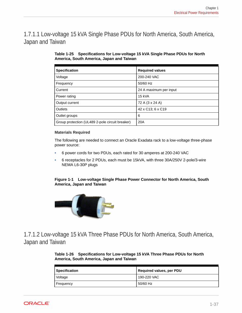
1.7.1.1 Low-voltage 15 kVA Single Phase PDUs for North America, South America,Japan and Taiwan
Table 1-25 Specifications for Low-voltage 15 kVA Single Phase PDUs for NorthAmerica, South America, Japan and Taiwan
Specification Required values
Voltage 200-240 VAC
Frequency 50/60 Hz
Current 24 A maximum per input
Power rating 15 kVA
Output current 72 A (3 x 24 A)
Outlets 42 x C13; 6 x C19
Outlet groups 6
Group protection (UL489 2-pole circuit breaker) 20A
Materials Required
The following are needed to connect an Oracle Exadata rack to a low-voltage three-phasepower source:
• 6 power cords for two PDUs, each rated for 30 amperes at 200-240 VAC
• 6 receptacles for 2 PDUs, each must be 15kVA, with three 30A/250V 2-pole/3-wireNEMA L6-30P plugs
Figure 1-1 Low-voltage Single Phase Power Connector for North America, SouthAmerica, Japan and Taiwan
1.7.1.2 Low-voltage 15 kVA Three Phase PDUs for North America, South America,Japan and Taiwan
Table 1-26 Specifications for Low-voltage 15 kVA Three Phase PDUs for NorthAmerica, South America, Japan and Taiwan
Specification Required values, per PDU
Voltage 190-220 VAC
Frequency 50/60 Hz
Chapter 1Electrical Power Requirements
1-37

Table 1-26 (Cont.) Specifications for Low-voltage 15 kVA Three Phase PDUs for NorthAmerica, South America, Japan and Taiwan
Specification Required values, per PDU
Current 40 A maximum per phase
Power rating 14.4 kVA
Output current 69.3 A (3 x 23.1A)
Outlets 42 x C13; 6 x C19
Outlet groups 6
Group protection (UL489 2-pole circuit breaker) 20A
Data center receptacle IEC309-3P4W-IP67 60A 250VAC 3ph (Hubbellequivalent is HBL460R9W)
Materials Required
The following are needed to connect an Oracle Exadata system to a low-voltage three-phase power source:
• 2 power cords for two PDUs, 60 amperes at 190-220 VAC three-phase
• 2 receptacles to connect the PDUs to 2 IEC 60309 60A 4-pin 250VAC 3ph IP67data center receptacles
Figure 1-2 Low-voltage Three Phase Power Connector for North America,South America, Japan and Taiwan
1.7.1.3 High-voltage 15 kVA Single Phase PDUs for Europe, the Middle Eastand Africa (EMEA), and Asia Pacific (APAC), except for Japan and Taiwan
Table 1-27 Specifications for High-voltage 15 kVA Single Phase PDUs forEurope, the Middle East and Africa (EMEA), and Asia Pacific (APAC), except forJapan and Taiwan
Specification Required values, per PDU
Voltage 220-240 VAC
Frequency 50/60 Hz
Current 24 A maximum per input
Power rating 15 kVA
Output current 72 A (3 x 24 A)
Chapter 1Electrical Power Requirements
1-38

Table 1-27 (Cont.) Specifications for High-voltage 15 kVA Single Phase PDUsfor Europe, the Middle East and Africa (EMEA), and Asia Pacific (APAC), exceptfor Japan and Taiwan
Specification Required values, per PDU
Outlets 42 x C13; 6 x C19
Outlet groups 6
Group protection (UL489 2-pole circuitbreaker)
20A
Data center receptacle 15kVA, IEC309-2P3W-IP44 32A 250VAC(Hubbell equivalent is HBL332R6W
Note:
The high-voltage 15kVA single phase PDU is no longer available. The high-voltage22kVA is a compatible replacement with the same receptacle and breakerrequirements
Figure 1-3 High-voltage Single Phase Power Connector
1.7.1.4 High-voltage 15 kVA Three Phase for Europe, the Middle East and Africa(EMEA), and Asia Pacific (APAC), except for Japan and Taiwan
Table 1-28 Specifications for High-voltage 15 kVA Three Phase for Europe, the MiddleEast and Africa (EMEA), and Asia Pacific (APAC), except for Japan and Taiwan
Specification Required values, per PDU
Voltage 220/380-240/415 VAC 3-phase
Frequency 50/60 Hz
Current 25 A maximum per phase
Power rating 14.4 kVA
Output current 62.7 A (3 x 20.9 A)
Outlets 42 x C13; 6 x C19
Outlet groups 6
Group protection (UL489 1-pole circuit breaker) 20A
Chapter 1Electrical Power Requirements
1-39

Table 1-28 (Cont.) Specifications for High-voltage 15 kVA Three Phase for Europe, theMiddle East and Africa (EMEA), and Asia Pacific (APAC), except for Japan and Taiwan
Specification Required values, per PDU
Data center receptacle 15kVA, three phase, 5-pin, IEC 60309 32A, 5-pin230/400V, three phase IP44
Materials Required
The following are needed to connect an Oracle Exadata system to a high-voltagethree-phase power source:
• 2 power cords for two PDUs, 25 amperes at 220/380-240/415 VAC three-phase
• 2 receptacles to connect the PDUs to 2 IEC 60309 32A 5-pin 230/400VAC 3phIP44 data center receptacles
Figure 1-4 High-voltage Three Phase Power Connector
1.7.1.5 Low-voltage 22 kVA Single Phase PDUs for North America, SouthAmerica, Japan and Taiwan
Table 1-29 Specifications for Low-voltage 22 kVA Single Phase PDUs for NorthAmerica, South America, Japan and Taiwan
Specifications Required values, per PDU
Voltage 200-240 VAC
Frequency 50/60 Hz
Current 36.8 A maximum per input / 110.4 A Maximumper PDU
Power rating 22 kVA
Output current 110.4A (3x 36.8)
Outlets 42 x C13; 6 x C19
Outlet groups 6
Group protection (UL489 2-pole circuitbreaker)
20A
Data center receptacle Hubbell CS8269 or CS8264
Chapter 1Electrical Power Requirements
1-40

Materials Required
The following are needed to connect an Oracle Exadata system to a low-voltage single-phasepower source:
• 3 power cords for two PDUs
• 6 receptacles to connect the PDUs
The following image shows the low-voltage, 22 kVA single phase PDU power connector forNorth America, South America, Japan and Taiwan. This power connector is different from thepower connector for the low-voltage 15 kVA single phase PDU.
Figure 1-5 Low-voltage 22 kVA Single Phase Power Connector
1.7.1.6 High-voltage 22 kVA Single Phase PDUs for Europe, the Middle East andAfrica (EMEA), and Asia Pacific (APAC), except for Japan and Taiwan
Table 1-30 Specifications for High-voltage 22 kVA Single Phase PDUs for Europe, theMiddle East and Africa (EMEA), and Asia Pacific (APAC), except for Japan and Taiwan
Specifications Required values, per PDU
Voltage 220-240 VAC
Frequency 50/60 Hz
Current 32 A maximum per input
Power rating 22 kVA
Output current 96 A (3 x 32 A)
Outlets 42 x C13; 6 x C19
Outlet groups 6
Group protection (UL489 1-pole circuit breaker) 20A
Data center receptacle IEC309-2P3W-IP44 32A 250VAC (Hubbellequivalent is HBL332R6W)
Materials Required
Note:
The high-voltage 15kVA single phase PDU is no longer available. The high-voltage22kVA is a compatible replacement with the same receptacle and breakerrequirements
Chapter 1Electrical Power Requirements
1-41

The following are needed to connect an Oracle Exadata system to a high-voltage one-phase power source:
• 6 power cords for two PDUs, each rated for 25 amperes at 220/380-240/415 VAC1-phase voltage
• 6 receptacles to connect the PDUs
Figure 1-6 High-voltage Single Phase Power Connector
1.7.1.7 Low-voltage 24 kVA Three Phase PDUs for North America, SouthAmerica, Japan and Taiwan
Table 1-31 Specifications for Low-voltage 24 kVA Three Phase PDUs for NorthAmerica, South America, Japan and Taiwan
Specifications Required values, per PDU
Voltage 200-208 VAC 3-phase
Frequency 50/60 Hz
Current 34.6 A maximum per phase
Power rating 25 kVA
Output current 120 A (6 x 20 A)
Outlets 42 x C13; 6 x C19
Outlet groups 6
Group protection (UL489 2-pole circuitbreaker)
20A
Data center receptacle IEC309-3P4W-IP67 60A 250VAC 3ph (Hubbellequivalent is HBL460R9W)
Materials Required
The following are needed to connect an Oracle Exadata system to a low-voltage three-phase power source:
• 4 power cords for two PDUs
• 4 receptacles to connect the PDUs
Chapter 1Electrical Power Requirements
1-42

1.7.1.8 High-voltage 24 kVA Three Phase PDUs for Europe, the Middle East andAfrica (EMEA), and Asia Pacific (APAC), except for Japan and Taiwan
Table 1-32 Specifications for High-voltage 24 kVA Three Phase PDUs for Europe, theMiddle East and Africa (EMEA), and Asia Pacific (APAC), except for Japan and Taiwan
Specifications Required values, per PDU
Voltage 220/380-240/415 VAC 3-phase
Frequency 50/60 Hz
Current 18.1 A maximum per phase
Power rating 25 kVA
Output current 108.6A (6 x 18.1 A)
Outlets 42 x C13; 6 x C19
Outlet groups 6
Group protection (UL489 1-pole circuit breaker) 20A
Data center receptacle IEC309-4P5W-IP44 32A 400VAC 3ph (Hubbellequivalent is HBL532R6W)
Materials Required
The following are needed to connect an Oracle Exadata system to a high-voltage three-phase power source:
• 4 power cords for two PDUs
• 4 receptacles to connect the PDUs
1.7.2 Facility Power RequirementsTo prevent catastrophic failures, design the input power sources to ensure adequate power isprovided to the PDUs.
Use dedicated AC breaker panels for all power circuits that supply power to the PDU. Whenplanning for power distribution requirements, balance the power load between available ACsupply branch circuits. In the United States of America and Canada, ensure that the overallsystem AC input current load does not exceed 80 percent of the branch circuit AC currentrating.
Note:
Electrical work and installations must comply with applicable local, state, or nationalelectrical codes. Contact your facilities manager or qualified electrician to determinewhat type of power is supplied to the building.
PDU power cords are 4 meters (13.12 feet) long, and 1 to 1.5 meters (3.3 to 4.9 feet) of thecord is routed within the rack cabinet. The installation site AC power receptacle must bewithin 2 meters (6.6 feet) of the rack.
Chapter 1Electrical Power Requirements
1-43

1.7.3 Circuit Breaker RequirementsIf computer equipment is subjected to repeated power interruptions and fluctuations,then it is susceptible to a higher rate of component failure.
You are responsible for supplying the circuit breakers. One circuit breaker is requiredfor each power cord. In addition to circuit breakers, provide a stable power source,such as an uninterruptible power supply (UPS) to reduce the possibility of componentfailures.
Use dedicated AC breaker panels for all power circuits that supply power to the server.Servers require electrical circuits be grounded to the Earth.
Note:
Electrical work and installations must comply with applicable local, state, ornational electrical codes.
1.7.4 Electrical Grounding GuidelinesThe cabinets for Oracle Exadata Rack are shipped with grounding-type power cords.
• Always connect the cords to grounded power outlets.
• Check the grounding type, because different grounding methods are useddepending on your location.
• Refer to documentation such as IEC documents for the correct grounding method.
• Ensure that the facility administrator or qualified electrical engineer verifies thegrounding method for the building, and performs the grounding work.
1.8 Temperature and Humidity RequirementsExcessive internal temperatures may result in full or partial shut down of OracleExadata Database Machine.
Airflow through Oracle Exadata Rack is from front to back. Refer to GeneralEnvironmental Requirements for information on cooling and airflow.
Note:
Studies have shown that temperature increases of 10 degrees Celsius (15degrees Fahrenheit) above 20 degrees Celsius (70 degrees Fahrenheit)reduce long-term electronics reliability by 50 percent.
The following table lists the temperature, humidity and altitude requirements foroperating and non-operating machines.
Chapter 1Temperature and Humidity Requirements
1-44
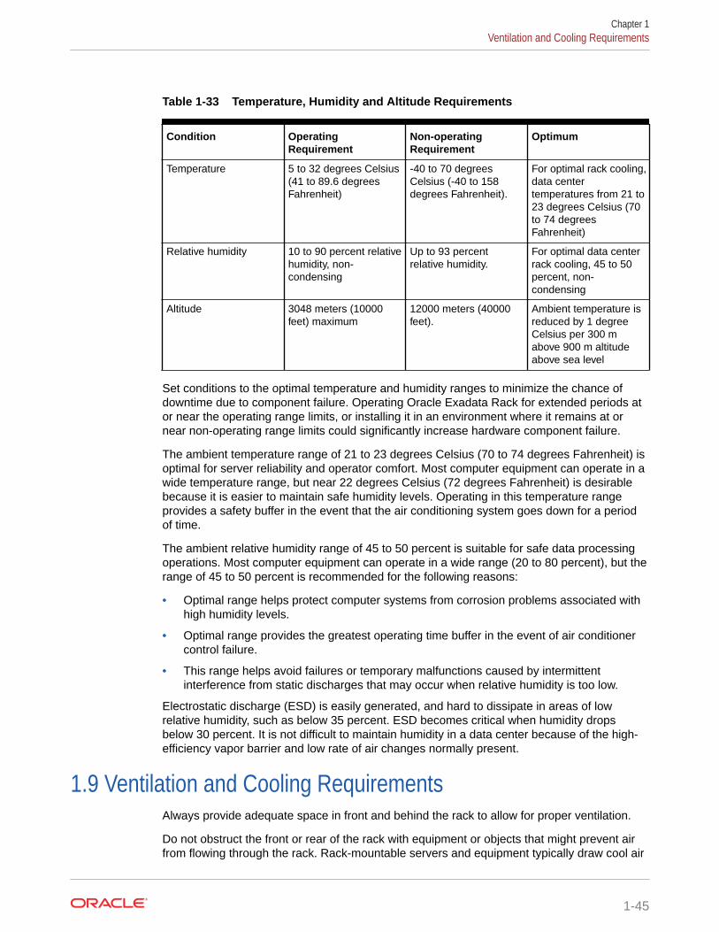
Table 1-33 Temperature, Humidity and Altitude Requirements
Condition OperatingRequirement
Non-operatingRequirement
Optimum
Temperature 5 to 32 degrees Celsius(41 to 89.6 degreesFahrenheit)
-40 to 70 degreesCelsius (-40 to 158degrees Fahrenheit).
For optimal rack cooling,data centertemperatures from 21 to23 degrees Celsius (70to 74 degreesFahrenheit)
Relative humidity 10 to 90 percent relativehumidity, non-condensing
Up to 93 percentrelative humidity.
For optimal data centerrack cooling, 45 to 50percent, non-condensing
Altitude 3048 meters (10000feet) maximum
12000 meters (40000feet).
Ambient temperature isreduced by 1 degreeCelsius per 300 mabove 900 m altitudeabove sea level
Set conditions to the optimal temperature and humidity ranges to minimize the chance ofdowntime due to component failure. Operating Oracle Exadata Rack for extended periods ator near the operating range limits, or installing it in an environment where it remains at ornear non-operating range limits could significantly increase hardware component failure.
The ambient temperature range of 21 to 23 degrees Celsius (70 to 74 degrees Fahrenheit) isoptimal for server reliability and operator comfort. Most computer equipment can operate in awide temperature range, but near 22 degrees Celsius (72 degrees Fahrenheit) is desirablebecause it is easier to maintain safe humidity levels. Operating in this temperature rangeprovides a safety buffer in the event that the air conditioning system goes down for a periodof time.
The ambient relative humidity range of 45 to 50 percent is suitable for safe data processingoperations. Most computer equipment can operate in a wide range (20 to 80 percent), but therange of 45 to 50 percent is recommended for the following reasons:
• Optimal range helps protect computer systems from corrosion problems associated withhigh humidity levels.
• Optimal range provides the greatest operating time buffer in the event of air conditionercontrol failure.
• This range helps avoid failures or temporary malfunctions caused by intermittentinterference from static discharges that may occur when relative humidity is too low.
Electrostatic discharge (ESD) is easily generated, and hard to dissipate in areas of lowrelative humidity, such as below 35 percent. ESD becomes critical when humidity dropsbelow 30 percent. It is not difficult to maintain humidity in a data center because of the high-efficiency vapor barrier and low rate of air changes normally present.
1.9 Ventilation and Cooling RequirementsAlways provide adequate space in front and behind the rack to allow for proper ventilation.
Do not obstruct the front or rear of the rack with equipment or objects that might prevent airfrom flowing through the rack. Rack-mountable servers and equipment typically draw cool air
Chapter 1Ventilation and Cooling Requirements
1-45

in through the front of the rack and let out warm air out the rear of the rack. There is noair flow requirement for the left and right sides due to front-to-back cooling.
If the rack is not completely filled with components, then cover the empty sections withfiller panels. Gaps between components can adversely affect air flow and coolingwithin the rack.
Relative humidity is the percentage of the total water vapor that can exist in the airwithout condensing, and is inversely proportional to air temperature. Humidity goesdown when the temperature rises, and goes up when the temperature drops. Forexample, air with a relative humidity of 45 percent at a temperature of 24 degreesCelsius (75 degrees Fahrenheit) has a relative humidity of 65 percent at a temperatureof 18 degrees Celsius (64 degrees Fahrenheit). As the temperature drops, the relativehumidity rises to more than 65 percent, and water droplets are formed.
Air conditioning facilities usually do not precisely monitor or control temperature andhumidity throughout an entire computer room. Generally, monitoring is done atindividual points corresponding to multiple exhaust vents in the main unit, and otherunits in the room. Special consideration should be paid to humidity when usingunderfloor ventilation. When underfloor ventilation is used, monitoring is done at eachpoint close to an exhaust vent. Distribution of the temperature and humidity across theentire room is uneven.
Oracle Exadata Racks have been designed to function while mounted in a naturalconvection air flow. The following requirements must be followed to meet theenvironmental specification:
• Ensure there is adequate air flow through the server.
• Ensure the server has front-to-back cooling. The air inlet is at the front of theserver, and the air is let out the rear.
• Allow a minimum clearance of 1219.2 mm (48 inches) at the front of the server,and 914 mm (36 inches) at the rear of the server for ventilation.
Use perforated tiles, approximately 400 CFM/tile, in front of the rack for cold air intake.The tiles can be arranged in any order in front of the rack, as long as cold air from thetiles can flow into the rack. Inadequate cold air flow could result in a higher inlettemperature in the servers due to exhaust air recirculation. The following tabledescribes the recommended number of floor tiles:
Type of Oracle Exadata Database Machineor Oracle Exadata Storage Expansion Rack
Recommended Number of Floor Tiles
Oracle Exadata full rack systems 4
Oracle Exadata half rack systems 3
Oracle Exadata quarter and eighth racksystems
1
Figure 1-7 shows a typical installation of the floor tiles for Oracle Exadata DatabaseMachine Full Rack in a typical data center.
Chapter 1Ventilation and Cooling Requirements
1-46

Figure 1-7 Typical Data Center Configuration for Perforated Floor Tiles
1.10 Network Connection and IP Address Requirements forOracle Exadata Rack
This section describes the requirements to connect Oracle Exadata Database Machine orOracle Exadata Storage Expansion Rack to your existing network infrastructure.
• Network Connection Requirements for Oracle Exadata Rack
• DNS Configuration for Oracle Exadata Rack
• IP Address Requirements for Oracle Exadata Rack
1.10.1 Network Connection Requirements for Oracle Exadata RackPrior to installation, network cables must be run from your existing network infrastructure tothe installation site. The requirements to connect Oracle Exadata Database Machine to yourexisting network infrastructure are as follows:
Chapter 1Network Connection and IP Address Requirements for Oracle Exadata Rack
1-47
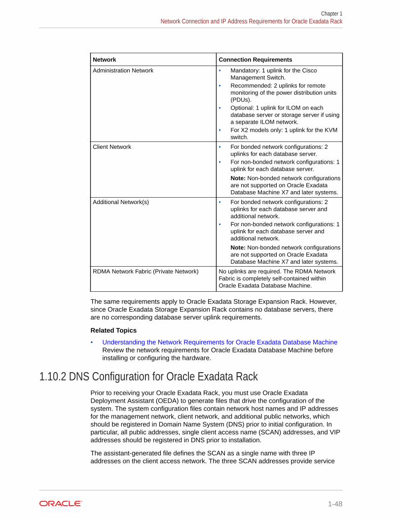
Network Connection Requirements
Administration Network • Mandatory: 1 uplink for the CiscoManagement Switch.
• Recommended: 2 uplinks for remotemonitoring of the power distribution units(PDUs).
• Optional: 1 uplink for ILOM on eachdatabase server or storage server if usinga separate ILOM network.
• For X2 models only: 1 uplink for the KVMswitch.
Client Network • For bonded network configurations: 2uplinks for each database server.
• For non-bonded network configurations: 1uplink for each database server.
Note: Non-bonded network configurationsare not supported on Oracle ExadataDatabase Machine X7 and later systems.
Additional Network(s) • For bonded network configurations: 2uplinks for each database server andadditional network.
• For non-bonded network configurations: 1uplink for each database server andadditional network.
Note: Non-bonded network configurationsare not supported on Oracle ExadataDatabase Machine X7 and later systems.
RDMA Network Fabric (Private Network) No uplinks are required. The RDMA NetworkFabric is completely self-contained withinOracle Exadata Database Machine.
The same requirements apply to Oracle Exadata Storage Expansion Rack. However,since Oracle Exadata Storage Expansion Rack contains no database servers, thereare no corresponding database server uplink requirements.
Related Topics
• Understanding the Network Requirements for Oracle Exadata Database MachineReview the network requirements for Oracle Exadata Database Machine beforeinstalling or configuring the hardware.
1.10.2 DNS Configuration for Oracle Exadata RackPrior to receiving your Oracle Exadata Rack, you must use Oracle ExadataDeployment Assistant (OEDA) to generate files that drive the configuration of thesystem. The system configuration files contain network host names and IP addressesfor the management network, client network, and additional public networks, whichshould be registered in Domain Name System (DNS) prior to initial configuration. Inparticular, all public addresses, single client access name (SCAN) addresses, and VIPaddresses should be registered in DNS prior to installation.
The assistant-generated file defines the SCAN as a single name with three IPaddresses on the client access network. The three SCAN addresses provide service
Chapter 1Network Connection and IP Address Requirements for Oracle Exadata Rack
1-48

access for clients to Oracle Exadata Database Machine. Configure DNS for round robinresolution for the SCAN name to these three SCAN addresses.
All addresses registered in DNS must be configured for both forward resolution and reverseresolution. Reverse resolution must be forward confirmed (forward-confirmed reverse DNS)such that both the forward and reverse DNS entries match each other.
Note:
During configuration using OEDA, Grid Naming Service (GNS) is not configured onOracle Exadata Database Machine.
See Also:
• "Using Oracle Exadata Deployment Assistant"
• Oracle Grid Infrastructure Installation and Upgrade Guide for Linux foradditional information about SCAN addresses
• Your DNS vendor documentation for additional information about configuringround robin name resolution
1.10.3 IP Address Requirements for Oracle Exadata RackOracle Exadata Database Machine and Oracle Exadata Storage Expansion Rack require adedicated allocation of host names and IP addresses. The number of required IP addressesprimarily depends on the size of the system and whether it is configured to use virtualmachines (VMs).
The detailed network configuration, including host names and IP addresses, is generatedfrom information supplied to Oracle Exadata Deployment Assistant (OEDA).
You should configure the IP addresses in your existing networks after you run OEDA. All IPaddresses in the configuration file must be unassigned at the time of initial configuration. Inaddition, all IP addresses must be statically-assigned IP addresses, not dynamically-assigned(DHCP) addresses.
All RDMA Network Fabric IP addresses must be in the same subnet, with a minimum subnetmask of 255.255.240.0 (or /20). The subnet mask chosen should be wide enough toaccommodate possible future expansion of the Oracle Exadata Database Machine and theinternal network.
You can use the information in the following sections to calculate the IP address requirementfor Oracle Exadata Database Machine. However, ensure that you use the configurationinformation generated in OEDA as your authoritative guide.
Rack-Level IP Address Requirements
The following table outlines the rack-level IP address requirements for Oracle ExadataDatabase Machine. These addresses are required regardless of the configuration options
Chapter 1Network Connection and IP Address Requirements for Oracle Exadata Rack
1-49

that are selected for the system. For Oracle Exadata Storage Expansion Rack, nofurther IP addresses are required beyond these rack-level IP addresses.
Network IP Address Requirements
Administration Network • 1 IP address for the administrationnetwork interface on each databaseserver or storage server.
• 1 IP address for the ILOM networkinterface on each database server orstorage server.
Note: By default, the database server andstorage server ILOM interfaces reside inthe administration network. However,starting with Oracle Exadata SystemSoftware release 19.1.0, the ILOMinterfaces can reside in a separatemanagement network. Either way, thenumber of required IP addresses remainsthe same.
• 1 IP address for the managementinterface on each RDMA Network Fabricswitch.
• 1 IP address for the managementinterface on the Cisco ManagementSwitch switch.
• 1 IP address for the managementinterface in each power distribution unit(PDU).
• For X2 models only: 1 IP address for theKVM switch.
RDMA Network Fabric (Private Network) 2 IP addresses for each database server orstorage server.
Note: Older configurations (typically X3 andprior) may be configured with Linux Ethernetbonding, which uses 1 IP address for eachdatabase server or storage server.
Bare-Metal IP Address Requirements
When Oracle Exadata Database Machine is configured without VMs (otherwise knownas a bare-metal configuration), one additional set of cluster-level IP addresses isrequired in addition to the rack-level addresses outlined in the previous table. Use thefollowing table to determine the additional IP addresses required for a bare-metalconfiguration.
Network IP Address Requirements
Client Network • 1 IP address for the client networkinterface on each database server.
• 1 IP address for the virtual (VIP) networkinterface on each database server.
• 3 IP addresses for SCAN networkservices.
Additional Network(s) 1 IP address for each additional networkinterface on each database server.
Chapter 1Network Connection and IP Address Requirements for Oracle Exadata Rack
1-50

VM Cluster IP Address Requirements
When Oracle Exadata Database Machine is configured with virtual machines (VMs), each VMcluster requires a separate set of IP addresses, which are in addition to the system-leveladdresses outlined previously. Use the following table to determine the additional IPaddresses required for each VM cluster.
Network IP Address Requirements
Administration Network 1 IP address for the administration networkinterface on each database server VM.
Client Network • 1 IP address for the client network interfaceon each database server VM.
• 1 IP address for the virtual (VIP) networkinterface on each database server VM.
• 3 IP addresses for SCAN network services.
Additional Network(s) 1 IP address for each additional network interfaceon each database server VM.
RDMA Network Fabric (Private Network) 2 IP addresses for each database server VM.
Related Topics
• Single Client Access Name (SCAN)
• Using Oracle Exadata Deployment Assistant
Chapter 1Network Connection and IP Address Requirements for Oracle Exadata Rack
1-51

2Understanding the Network Requirements forOracle Exadata Database Machine
Review the network requirements for Oracle Exadata Database Machine before installing orconfiguring the hardware.
Note:
For ease of reading, the name "Oracle Exadata Rack" is used when informationrefers to both Oracle Exadata Database Machine and Oracle Exadata StorageExpansion Rack.
• Overview of Network RequirementsIn addition to the database and storage servers, Oracle Exadata Database Machineincludes equipment to connect the system to your network. The network connectionsallow clients to connect to the database servers and also enables remote systemadministration.
• Network Channel Bonding Support
• Network Partitioning on Oracle Exadata Database Machine
• Configuring a Separate Network for ILOMWhen configuring or re-imaging an Oracle Exadata Rack, you can use Oracle ExadataDeployment Assistant (OEDA) to configure a separate network for Integrated Lights OutManager (ILOM).
• Default IP AddressesStarting with Oracle Exadata System Software release 12.1.2.1.0, the defaultadministration network IP addresses are assigned dynamically by the elasticconfiguration procedure during the first start of the system.
• Port Assignments When Using a Firewall
2.1 Overview of Network RequirementsIn addition to the database and storage servers, Oracle Exadata Database Machine includesequipment to connect the system to your network. The network connections allow clients toconnect to the database servers and also enables remote system administration.
Use the information in this section in conjunction with Oracle Exadata Deployment Assistant(OEDA) to configure your Oracle Exadata Database Machine environment.
To deploy Oracle Exadata Database Machine ensure that you meet the minimum networkrequirements. Oracle Exadata Database Machine requires a minimum of three networks, andthere are interfaces available for additional networks. Each network must be on a separateand distinct subnet. The network descriptions are as follows:
2-1
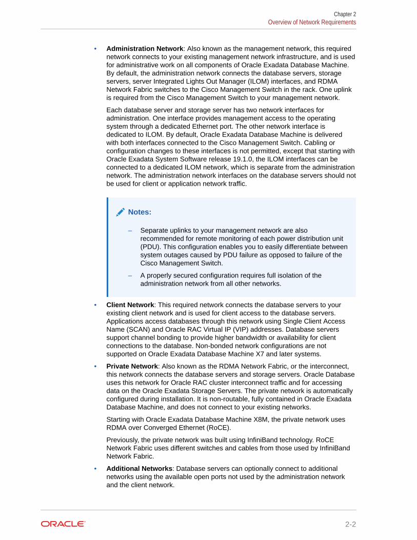
• Administration Network: Also known as the management network, this requirednetwork connects to your existing management network infrastructure, and is usedfor administrative work on all components of Oracle Exadata Database Machine.By default, the administration network connects the database servers, storageservers, server Integrated Lights Out Manager (ILOM) interfaces, and RDMANetwork Fabric switches to the Cisco Management Switch in the rack. One uplinkis required from the Cisco Management Switch to your management network.
Each database server and storage server has two network interfaces foradministration. One interface provides management access to the operatingsystem through a dedicated Ethernet port. The other network interface isdedicated to ILOM. By default, Oracle Exadata Database Machine is deliveredwith both interfaces connected to the Cisco Management Switch. Cabling orconfiguration changes to these interfaces is not permitted, except that starting withOracle Exadata System Software release 19.1.0, the ILOM interfaces can beconnected to a dedicated ILOM network, which is separate from the administrationnetwork. The administration network interfaces on the database servers should notbe used for client or application network traffic.
Notes:
– Separate uplinks to your management network are alsorecommended for remote monitoring of each power distribution unit(PDU). This configuration enables you to easily differentiate betweensystem outages caused by PDU failure as opposed to failure of theCisco Management Switch.
– A properly secured configuration requires full isolation of theadministration network from all other networks.
• Client Network: This required network connects the database servers to yourexisting client network and is used for client access to the database servers.Applications access databases through this network using Single Client AccessName (SCAN) and Oracle RAC Virtual IP (VIP) addresses. Database serverssupport channel bonding to provide higher bandwidth or availability for clientconnections to the database. Non-bonded network configurations are notsupported on Oracle Exadata Database Machine X7 and later systems.
• Private Network: Also known as the RDMA Network Fabric, or the interconnect,this network connects the database servers and storage servers. Oracle Databaseuses this network for Oracle RAC cluster interconnect traffic and for accessingdata on the Oracle Exadata Storage Servers. The private network is automaticallyconfigured during installation. It is non-routable, fully contained in Oracle ExadataDatabase Machine, and does not connect to your existing networks.
Starting with Oracle Exadata Database Machine X8M, the private network usesRDMA over Converged Ethernet (RoCE).
Previously, the private network was built using InfiniBand technology. RoCENetwork Fabric uses different switches and cables from those used by InfiniBandNetwork Fabric.
• Additional Networks: Database servers can optionally connect to additionalnetworks using the available open ports not used by the administration networkand the client network.
Chapter 2Overview of Network Requirements
2-2

By using the OEDA Web user interface, you can create up to two additional networks. InOEDA, the first additional network is known as the Backup Network, and the secondadditional network is known as the Other Network. You can create more additionalnetworks by using the OEDA command-line interface (OEDACLI).
Like the client network, the additional networks support channel bonding to maximizebandwidth and availability. Non-bonded network configurations are not supported onOracle Exadata Database Machine X7 and later systems.
The following diagram displays how the various Oracle Exadata Database Machinecomponents connect to the different networks.
PDU PDU
Exadata Storage ServerExadata Database Server
RDMA NetworkFabric Switch
RDMA NetworkFabric Switch
Ethernet Switch
Admin ILOMClient Network
(BONDETH0)
Additional Network
(BONDETHn)
Admin ILOM
Client Network
Administration Network
Additional Network(s)
Related Topics
• Using Oracle Exadata Deployment Assistant
• Hardware Components of Oracle Exadata Database Machine
2.2 Network Channel Bonding SupportA pair of database server network ports can be bonded to provide higher network availabilityor bandwidth for the client network and additional networks.
Non-bonded network configurations are not supported on Oracle Exadata Database MachineX7 and later systems.
In a bonded network configuration:
• Use Oracle Exadata Deployment Assistant (OEDA) to specify the physical networkinterfaces that you want to bond for the client network and the additional networks, if
Chapter 2Network Channel Bonding Support
2-3

configured. OEDA generates bonded network interfaces that amalgamate twophysical network interfaces.
• Manual changes to the OEDA-generated bonding configuration are allowed butare discouraged. Oracle will not support questions or issues associated with non-standard bonding configurations. In any event, bonding configurations havingfewer than two networking interfaces are not permitted.
• The bonded client network interface name is bondeth0. The bonded interfacename for the first additional network, also known in OEDA as the Backup Network,is bondeth1. The bonded interface name for the second additional network, alsoknown in OEDA as the Other Network, is bondeth2, and so on.
• The XML configuration file generated by OEDA includes detailed information thatmaps the bonded network interfaces to the underlying Ethernet ports.
• During the initial configuration using OEDA, the Linux bonding module isconfigured to use active-backup mode (mode=active-backup) by default. If LinkAggregation Control Protocol (LACP) is enabled, then mode=802.3ad. Additionalconfiguration of other bonding parameters is allowed but is outside the scope ofinstallation services and must be performed by customer network engineers.Reconfiguration to enable a different bonding policy is permitted but isdiscouraged.
For further details, refer to the "Linux Ethernet Bonding Driver HOWTO" at https://www.kernel.org/doc/Documentation/networking/bonding.txt.
• You must provide network infrastructure (switches) capable of supporting thechosen bonding mode. For example, if LACP is enabled (mode=802.3ad), then youmust supply and configure the network switches accordingly.
Requirements for specific bonding policies are documented in the "Linux EthernetBonding Driver HOWTO" at https://www.kernel.org/doc/Documentation/networking/bonding.txt
2.3 Network Partitioning on Oracle Exadata DatabaseMachine
Oracle Exadata Database Machine supports network partitioning using a variety ofmechanisms.
• VLAN Support on Customer-Facing NetworksOracle Exadata Database Machine can use VLANs to implement networkpartitioning in conjunction with the client, backup, administration, and ILOMnetworks.
• Access VLAN Support with RoCE Network FabricOracle Exadata Database Machine can use Access VLAN settings to implementserver-level isolation across the RoCE Network Fabric.
• Using Exadata Secure RDMA Fabric IsolationStarting with Oracle Exadata System Software release 20.1.0, you can configurethe RoCE Network Fabric to enable Exadata Secure RDMA Fabric Isolation.
• Using InfiniBand Partitioning for Network Isolation with InfiniBand Network FabricAn InfiniBand partition defines a group of InfiniBand nodes or members that areallowed to communicate with one another.
Chapter 2Network Partitioning on Oracle Exadata Database Machine
2-4

2.3.1 VLAN Support on Customer-Facing NetworksOracle Exadata Database Machine can use VLANs to implement network partitioning inconjunction with the client, backup, administration, and ILOM networks.
By default, the network switches are minimally configured, without VLAN tagging. If VLANtagging is to be used, then it can be configured by the customer during the initial deployment.Customers can also configure VLAN tagging after the initial deployment. This applies to bothphysical and virtual machine (VM) deployments.
Notes:
• Oracle Exadata Deployment Assistant (OEDA) supports VLAN tagging for bothphysical and VM deployments.
• Network VLAN tagging is supported for Oracle Real Application Clusters(Oracle RAC) on the public network.
• Client and backup VLAN networks must be bonded. The administration networkis never bonded.
• If the backup network is on a tagged VLAN network, the client network mustalso be on a separate tagged VLAN network.
• The backup and client networks can share the same network cables.
• VLAN tagging on the client and backup networks is supported with IPv4 andIPv6 on all hardware models. For IPv6 support on Oracle Database version12.1.0.2, and later, patch 22289350 is also required.
• VM deployments do not support IPv6 VLANs.
• VLAN tagging on the administration network is only supported with IPv4addresses on X3-2 and above for two-socket servers, and X4-8 and above foreight-socket servers.
• If the client network uses VLAN tagging and your system uses more than 10Oracle Clusterware virtual IP (VIP) addresses, then you must use 3-digit VLANIDs. Do not use 4-digit VLAN IDs because the VLAN name can exceed theoperating system interface name limit, which is the 15 characters.
Related Topics
• Implementing InfiniBand Partitioning across Oracle VM Oracle RAC Clusters on OracleExadata
• Enabling 802.1Q VLAN Tagging in Exadata Database Machine over client networks (MyOracle Support Doc ID 1423676.1)
• Implementing Tagged VLAN Interfaces in Oracle VM Environments on Exadata (MyOracle Support Doc ID 2018550.1)
2.3.2 Access VLAN Support with RoCE Network FabricOracle Exadata Database Machine can use Access VLAN settings to implement server-levelisolation across the RoCE Network Fabric.
Chapter 2Network Partitioning on Oracle Exadata Database Machine
2-5

By default, Oracle Exadata Database Machine uses Access VLAN ID 3888 for allRoCE Network Fabric private network traffic, on the server re0 and re1 interfaces.This setting enables all database servers and storage servers to communicate freelywith each other, and is suitable for many system configurations. However, you canchange the Access VLAN ID to a non-default value to implement server-level isolation.
You can use this capability to create isolated groups of servers in an Oracle ExadataDatabase Machine X8M system. For example, in a Half Rack X8M-2 system you mightwant to create two isolated server groups:
• Database servers 1 and 2, and storage servers 1, 2, and 3 using VLAN ID 3888
• Database servers 3 and 4, and storage servers 4, 5, 6, and 7 using VLAN ID 3889
VLAN ID 3889VLAN ID 3888
Switch
StorageServer 1
StorageServer 2
StorageServer 3
DB Server 1 DB Server 2 DB Server 3 DB Server 4
StorageServer 4
StorageServer 5
StorageServer 6
StorageServer 7
With this configuration:
• Database servers 1 and 2 can only access storage servers 1, 2, and 3. But, theycannot access storage servers 4, 5, 6 or 7.
• Database servers 3 and 4 can only access storage servers 4, 5, 6 and 7. But, theycannot access storage servers 1, 2, and 3.
• Oracle Linux KVM guests on database servers 1 and 2 can communicate witheach other, but cannot communicate with guests on database servers 3 and 4.
• Oracle Linux KVM guests on database servers 3 and 4 can communicate witheach other, but cannot communicate with guests on database servers 1 and 2.
Related Topics
• Using Access VLANs with RoCE Network Fabric
2.3.3 Using Exadata Secure RDMA Fabric IsolationStarting with Oracle Exadata System Software release 20.1.0, you can configure theRoCE Network Fabric to enable Exadata Secure RDMA Fabric Isolation.
Exadata Secure RDMA Fabric Isolation enables strict network isolation for Oracle RealApplication Clusters (Oracle RAC) clusters on Oracle Exadata Database Machinesystems that use RDMA over Converged Ethernet (RoCE).
Chapter 2Network Partitioning on Oracle Exadata Database Machine
2-6

Secure Fabric provides critical infrastructure for secure consolidation of multiple tenants onOracle Exadata Database Machine, where each tenant resides in a dedicated virtual machine(VM) cluster. Using this feature ensures that:
• Database servers in separate clusters cannot communicate with each other. They arecompletely isolated from each other on the network.
• Database servers in multiple clusters can share all of the storage server resources.However, even though the different clusters share the same storage network, no cross-cluster network traffic is possible.
Exadata Secure RDMA Fabric Isolation uses RoCE VLANs to ensure that a VM clustercannot see network packets from another VM cluster. Secure Fabric uses a double VLANtagging system, where one tag identifies the network partition and the other tag specifies themembership level of the server in the partition. Within each network partition, a partitionmember with full membership can communicate with all other partition members, includingother full and limited members. Partition members with limited membership cannotcommunicate with other limited membership partition members. However, a partition memberwith limited membership can communicate with other full membership partition members.
With Secure Fabric, each database cluster uses a dedicated network partition and VLAN IDfor cluster networking between the database servers, which supports Oracle RAC inter-nodemessaging. In this partition, all of the database servers are full members. They cancommunicate freely within the partition but cannot communicate with database servers inother partitions.
Another partition, with a separate VLAN ID, supports the storage network partition. Thestorage servers are full members in the storage network partition, and every database serverVM is also a limited member. By using the storage network partition:
• Each database server can communicate with all of the storage servers.
• Each storage server can communicate with all of the database servers that they support.
• Storage servers can communicate directly with each other to perform cell-to-celloperations.
Chapter 2Network Partitioning on Oracle Exadata Database Machine
2-7

Figure 2-1 Secure Fabric Network Partitions
To support the cluster network partition and the storage network partition, eachdatabase server VM is plumbed with 4 virtual interfaces:
• clre0 and clre1 support the cluster network partition.
• stre0 and stre1 support the storage network partition.
Corresponding stre0 and stre1 interfaces are also plumbed on each storageserver.
On each server, the RoCE network interface card acts like a switch on the hypervisor,which performs VLAN tag enforcement. Since this is done at the KVM host level,cluster isolation cannot be bypassed by any software exploits or misconfiguration onthe database server VMs.
In this release, you can only enable Secure Fabric as part of the initial systemdeployment using Oracle Exadata Deployment Assistant (OEDA). You cannot enableSecure Fabric on an existing system without wiping the system and re-deploying itusing OEDA. When enabled, Secure Fabric applies to all servers and clusters thatshare the same RoCE Network Fabric.
To use Secure Fabric you must:
1. Configure the RoCE Network Fabric switch hardware to enable Secure Fabric.After you complete the switch configuration, the leaf switch ports become trunkports, which can carry network traffic with multiple VLAN IDs.
The switch configuration must occur before initial system deployment using OEDA.See Configuring the Cisco Nexus C9336C-FX2 Switches to Enable ExadataSecure RDMA Fabric Isolation.
2. As part of initial system deployment using OEDA, select the option to enableSecure Fabric and specify VLAN IDs for all of the network partitions. This option isone of the advanced options located in the Cluster Networks page of the OEDA
Chapter 2Network Partitioning on Oracle Exadata Database Machine
2-8

Web user interface. See Using the Browser-based Version of Oracle ExadataDeployment Assistant.
2.3.4 Using InfiniBand Partitioning for Network Isolation with InfiniBandNetwork Fabric
An InfiniBand partition defines a group of InfiniBand nodes or members that are allowed tocommunicate with one another.
InfiniBand partitioning enables network separation between different clusters on systems withInfiniBand Network Fabric.
InfiniBand partitions are created and managed by the master subnet manager. Each partitionis identified by a unique partition key, and partition members use the key for communicationwithin the partition. Members within a partition can only communicate among themselves.
With Oracle Exadata Database Machine, each database cluster uses a dedicated networkpartition for cluster networking between the database servers. All of the database servers cancommunicate freely within the partition, other but cannot communicate with database serversin other partitions. Another partition enables communication between each database clusterand the storage servers. By using this partition, database servers can communicate with all ofthe storage servers, storage servers can communicate with all of the database servers thatthey support, and storage servers can communicate directly with each other to perform cell-to-cell operations.
You can use InfiniBand partitioning on physical or virtual machine (VM) deployments.
For details see Configuring InfiniBand Partitioning.
2.4 Configuring a Separate Network for ILOMWhen configuring or re-imaging an Oracle Exadata Rack, you can use Oracle ExadataDeployment Assistant (OEDA) to configure a separate network for Integrated Lights OutManager (ILOM).
Before Oracle Exadata System Software release 19.1.0, the Exadata servers and ILOMinterfaces must have network access to each other for certain features, such as alertnotification. Starting with Oracle Exadata System Software release 19.1.0, this networkdependency is removed while maintaining all of the previously supported features. Now, youcan configure ILOM interfaces on a completely separate network.
1. Use the OEDA Web Configurator to configure the settings for your Oracle Exadata Rack.
2. On the Rack Networks page, check the box Separate ILOM Network to configure aseparate network for ILOM.
Chapter 2Configuring a Separate Network for ILOM
2-9

A new section appears on the page, with the heading of ILOM. In this area youspecify the information required to configure the ILOM network.
3. Provide the required values for the ILOM network:
• Gateway
• Start IP Address
• Subnet Mask
• Domain Name
4. Optional: If you do not want to use the default names and values for the ILOMnetwork, click the Modify Masks button and customize the network settings.
2.5 Default IP AddressesStarting with Oracle Exadata System Software release 12.1.2.1.0, the defaultadministration network IP addresses are assigned dynamically by the elasticconfiguration procedure during the first start of the system.
The default administration network IP addresses are in the 172.16.2.1 to 172.16.7.254range. In earlier releases, Oracle Exadata Database Machine had default IPaddresses set at the factory, and the range of IP addresses was 192.168.1.1 to192.168.1.203.
Chapter 2Default IP Addresses
2-10

Note:
Prior to connecting Oracle Exadata Database Machine to the network, ensure theseIP addresses do not conflict with other addresses on the network. Use thecheckip.sh script generated by Oracle Exadata Deployment Assistant (OEDA) tocheck for conflicts. You run the checkip.sh script on the network after the DNSentries for the Oracle Exadata Database Machine have been created, but beforethe Oracle Exadata Database Machine is configured or connected to the network.Oracle recommends running the script to avoid configuration delays, even if a checkwas performed as part of planning process before the machine was delivered. See Verifying the Network Configuration Prior to Configuring the Rack.
If you run OEDA on a Microsoft Windows system, then the generated script ischeckip.bat.
2.6 Port Assignments When Using a FirewallThe following table lists the ports used by services on Oracle Exadata Database Machine.When network communication requires access through a firewall, review the list and open thenecessary ports. All ports are on the administration network, except for port 1521 which is onthe client network.
Table 2-1 Open Ports for Firewall
Source Target Protocol Port Network Application
Any Databaseservers,storage cells,and ILOMs fordatabaseservers,ExadataStorageServers, andRDMA NetworkFabric switches
SSH over TCP 22 Administration SSH
Any KVM SSH over TCP 22 Administration SSH for serialsessions toMPUIQ-SRLmodule
ExadataStorageServers
SMTP e-mailserver
SMTP 25 Administration SMTP (SimpleMail TransferProtocol)
Any ILOMs fordatabaseservers,ExadataStorageServers, andRDMA NetworkFabric switches
HTTP 80 Administration Web (userconfigurable)
Chapter 2Port Assignments When Using a Firewall
2-11

Table 2-1 (Cont.) Open Ports for Firewall
Source Target Protocol Port Network Application
Any PDU HTTP 80 Administration Browserinterface
Any KVM HTTP 80 Administration Avocent videoviewerdownload forJava applet
Any rpcbind TCP 111 Administration rpcbind
Databasemanagement
NTP servers NTP over UDP 123 Client OutgoingNetwork TimeProtocol (NTP)
Databaseservers,ExadataStorageServers,ILOMs, RDMANetwork Fabricswitches, andCisco switch
NTP servers NTP over UDP 123 Administration Outgoing NTP
Any ILOMs fordatabaseservers,ExadataStorageServers, andRDMA NetworkFabric switches
SNMP overUDP
161 Administration SNMP (SimpleNetworkManagementProtocol) (userconfigurable)
Any PDU SNMP overUDP
161 Administration SNMP (userconfigurable)
Any KVM SNMP overUDP
161 Administration SNMP (userconfigurable)
ExadataStorageServers
SNMPsubscribersuch as OracleEnterpriseManager CloudControl or anSNMPmanager
SNMP 162 Administration SNMP version1 (SNMPv1)outgoing traps(user-configurable)
Chapter 2Port Assignments When Using a Firewall
2-12
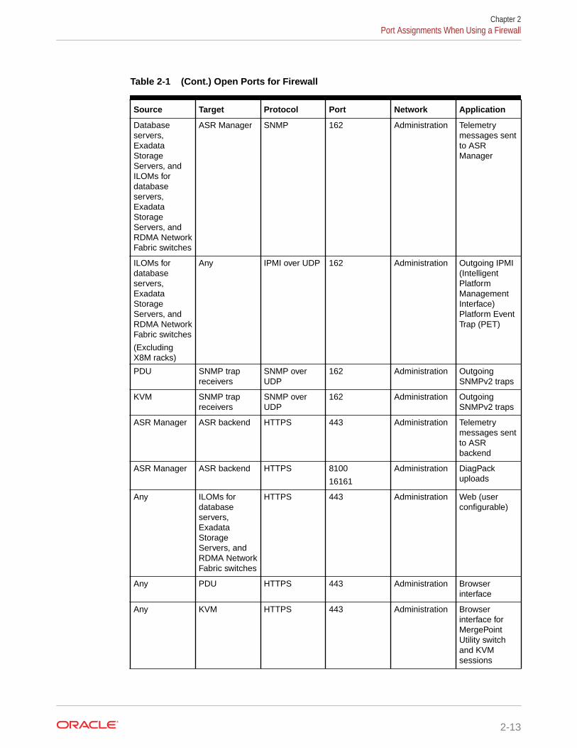
Table 2-1 (Cont.) Open Ports for Firewall
Source Target Protocol Port Network Application
Databaseservers,ExadataStorageServers, andILOMs fordatabaseservers,ExadataStorageServers, andRDMA NetworkFabric switches
ASR Manager SNMP 162 Administration Telemetrymessages sentto ASRManager
ILOMs fordatabaseservers,ExadataStorageServers, andRDMA NetworkFabric switches
(ExcludingX8M racks)
Any IPMI over UDP 162 Administration Outgoing IPMI(IntelligentPlatformManagementInterface)Platform EventTrap (PET)
PDU SNMP trapreceivers
SNMP overUDP
162 Administration OutgoingSNMPv2 traps
KVM SNMP trapreceivers
SNMP overUDP
162 Administration OutgoingSNMPv2 traps
ASR Manager ASR backend HTTPS 443 Administration Telemetrymessages sentto ASRbackend
ASR Manager ASR backend HTTPS 8100
16161
Administration DiagPackuploads
Any ILOMs fordatabaseservers,ExadataStorageServers, andRDMA NetworkFabric switches
HTTPS 443 Administration Web (userconfigurable)
Any PDU HTTPS 443 Administration Browserinterface
Any KVM HTTPS 443 Administration Browserinterface forMergePointUtility switchand KVMsessions
Chapter 2Port Assignments When Using a Firewall
2-13

Table 2-1 (Cont.) Open Ports for Firewall
Source Target Protocol Port Network Application
ExadataStorageServers
SMTPS client SMTPS 465 Administration Simple MailTransferProtocol,Secure (ifconfigured)
Databaseservers,ExadataStorageServers, andILOMs fordatabaseservers,ExadataStorageServers, andRDMA NetworkFabric switches
Syslog server Syslog overUDP
514 Administration OutgoingSyslog
PDU Syslog server Syslog overUDP
514 Administration OutgoingSyslog
KVM Syslog server Syslog overUDP
514 Administration OutgoingSyslog
Any ILOMs fordatabaseservers,ExadataStorageServers, andRDMA NetworkFabric switches(not applicableto X8Mservers)
IPMI over UDP 623 Administration IPMI
Any plathwsvcd TCP 723 Administration
Any evnd TCP 791 Administration
Any partitiond TCP 867 Administration
Any Databaseservers
TCP 1521 Client Databaselistener
Any KVM TCP 2068 Administration KVM sessiondata forkeyboard andmousetransmission,or for videotransmission
Any tgtd TCP 3260 Administration SCSI targetdaemon
Any TCP 3872 Administration Java EM agent
Chapter 2Port Assignments When Using a Firewall
2-14

Table 2-1 (Cont.) Open Ports for Firewall
Source Target Protocol Port Network Application
StorageServers
Fast nodedeath detection(FNDD) onRDMA overConvergedEthernet(RoCE)systems
TCP 5053 Administration
Any Cisco SmartInstall
TCP 4786 Administration Cisco SmartInstall
Any ILOMs fordatabaseservers, andExadataStorageServers
TCP 5120 Administration ILOM remoteconsole: CD
Any ILOMs fordatabaseservers, andExadataStorageServers
TCP 5121 Administration ILOM remoteconsole:keyboard andmouse
Any ILOMs fordatabaseservers, andExadataStorageServers
TCP 5123 Administration ILOM remoteconsole:diskette
Any ILOMs fordatabaseservers, andExadataStorageServers
TCP 5555 Administration ILOM remoteconsole:encryption
Any ILOMs fordatabaseservers, andExadataStorageServers
TCP 5556 Administration ILOM remoteconsole:authentication
Any OracleNotificationService
TCP 6200 Administration OracleNotificationService
ASR Manager ILOMs fordatabaseservers, andExadataStorageServers
HTTP 6481 Administration Service taglistener forasset activation
Chapter 2Port Assignments When Using a Firewall
2-15

Table 2-1 (Cont.) Open Ports for Firewall
Source Target Protocol Port Network Application
Any ILOMs fordatabaseservers, andExadataStorageServers
TCP 6481 Administration ILOM remoteconsole:Servicetagdaemon
Any ILOMs fordatabaseservers, andExadataStorageServers
TCP 7578 Administration ILOM remoteconsole: video
Any ILOMs fordatabaseservers, andExadataStorageServers
TCP 7579 Administration ILOM remoteconsole: serial
Any Databaseservers andExadataStorageServers
TCP 7777 Both OracleEnterpriseManager GridControl HTTPconsole port
Any Databaseservers andExadataStorageServers
TCP 7799 Both OracleEnterpriseManager GridControl HTTPSconsole port
Any OracleWebLogic
TCP 7878
8888
Administration ManagementServer (MS)
Note: Appliesonly to OracleExadataSystemSoftwarebefore release20.1.0.
Diagpackuploads
Databaseservers andExadataStorageServers
8100
16161
Any rpc.statd TCP 21408
40801
41460
47431
Administration rpc.statd
Any gpnpd.bin TCP 19193 (IPv6)
25194
Administration gpnpd.bin
Chapter 2Port Assignments When Using a Firewall
2-16

See Also:
Appendix E, "Managing Oracle Database Port Numbers", in the Oracle RealApplication Clusters Installation Guide for Linux and UNIX.
Chapter 2Port Assignments When Using a Firewall
2-17

3Using Oracle Exadata Deployment Assistant
• Overview of Oracle Exadata Deployment AssistantUse Oracle Exadata Deployment Assistant (OEDA) to specify the system configurationdetails and drive the system configuration processes.
• Getting Started with the OEDA Browser-based User InterfaceThe OEDA application server is available for Linux, OSX and Windows.
• Using the Browser-based Version of Oracle Exadata Deployment Assistant
Related Topics
• OEDA Command Line InterfaceWhen you run the oedacli program, it starts the OEDA command line interface.
3.1 Overview of Oracle Exadata Deployment AssistantUse Oracle Exadata Deployment Assistant (OEDA) to specify the system configurationdetails and drive the system configuration processes.
OEDA provides a graphical user interface to gather your configuration details and create theOracle Exadata Rack configuration file. The configuration file drives the automatedinstallation and configuration processes for Oracle Exadata Rack.
Note:
For ease of reading, Oracle Exadata Rack is used when information refers to bothOracle Exadata Database Machine and Oracle Exadata Storage Expansion Rack.
You can also use the OEDA command-line interface (OEDACLI) to perform Oracle ExadataRack life-cycle management tasks.
You can download the latest version of OEDA from Exadata Database Machine and ExadataStorage Server Supported Versions (Doc ID 888828.1). OEDA is also available on OracleTechnology Network.
In addition to Oracle Exadata Rack, OEDA is also used for Oracle Zero Data Loss RecoveryAppliance and Oracle SuperCluster.
Oracle Exadata System Software release 19.1.0 introduced the Web-based interface forOEDA, which replaces the previous Java-based user interface as the graphical user interfacefor configuring Oracle Exadata Rack.
The following outlines how OEDA is used during the implementation of Oracle Exadata Rack:
• Before your engineered system arrives, do the following:
1. Work with your network and database administrators to evaluate the current networksettings, such as current IP address use and network configuration.
2. Define the settings for the rack, such as network configuration and backup method.
3-1

3. Download the latest version of OEDA from Oracle Technology Network.
4. Unzip and run the configuration script on a supported platform, and select thetype of system to configure.
5. Go through every page in OEDA and supply values for all required fields. Youcannot advance to the next page if you do not supply all of the requiredvalues. You must provide naming details and DNS, NTP, and networkingdetails.
6. At the end of the dialogue with OEDA, configuration files are generated on theclient. The files are also listed at the bottom of theInstallationTemplate.html file that is generated by OEDA. Depending onyour engineered system and configuration, OEDA generates all or some of thefollowing files:
– databasemachine.xml
– CustomerName-rackname.xml
– CustomerName-rackname-preconf_GUID.csv
– CustomerName-rackname-InstallationTemplate.html
– CustomerName-rackname-platinum.csv
– CustomerName-rackname-checkip.sh
– CustomerName-rackname.zip
– pkey_GUID.csv and pkey_racknamehostname_GUID.csv — if you enabledInfiniBand partitioning for your virtual environments
The CustomerName-hostname.zip file contains all the generated files.
7. Review the InstallationTemplate.html file to check the entireconfiguration and verify all information was entered correctly.
• Shortly before your engineered system arrives, or is scheduled to be configured,validate the network configuration, as directed by Oracle. See Verifying theNetwork Configuration Prior to Configuring the Rack.
• After your engineered system arrives, the configuration files are copied to adatabase server, and the validation and installation is completed. See ConfiguringOracle Exadata Database Machine Using OEDA.
• Considerations and Requirement for Using OEDAReview this information before using Oracle Exadata Deployment Assistant(OEDA).
3.1.1 Considerations and Requirement for Using OEDAReview this information before using Oracle Exadata Deployment Assistant (OEDA).
• Oracle Exadata Database Machine ships with the Oracle Linux operating systeminstalled on the servers.
• The rack prefix is used to generate host names for all components. For example, ifyou specify dbm0 for the rack prefix:
– The database server host names are like dbm0db01
– The storage server host names are like dbm0cel01
Chapter 3Overview of Oracle Exadata Deployment Assistant
3-2

– The InfiniBand Network Fabric switch names are like dbm0sw-iba1
– The RoCE Network Fabric switch names are like dbm0sw-rocea1
Note:
The rack prefix can contain a maximum of 20 letters and numbers. Spaces andsymbols are not permitted; for example, exclamation (!), hyphen (-), and so on.
In you have multiple racks, then, each rack prefix should be a unique value that identifiesthe rack. Oracle recommends using dbm01 for the first rack, dbm02 for the second, dbm03for the third, and so on.
• The backup method and redundancy protection levels you use determine how to size theOracle Automatic Storage Management (Oracle ASM) disk groups that are createdduring installation.
– If you configure internal backups, then the database backups are created on disk inthe Fast Recovery Area in the RECO disk group for the database. The Fast RecoveryArea also contains Archived Redo Logs and Flashback Log Files. The division of diskspace between the DATA disk group and the RECO disk group is 40% and 60%,respectively.
– If you configure external backups, then database backups are created on disk or tapemedia that is external to currently deployed Oracle Exadata Database Machine. TheFast Recovery Area contains only objects such as Archived Redo Logs andFlashback Log Files.
Because you do not need to reserve additional space in the RECO disk group forbackups, the division of disk space between the DATA disk group and the RECO diskgroup is now 80% and 20%, respectively.
• Oracle recommends the use of high redundancy disk groups for mission criticalapplications. Use the following guidelines to assist in sizing the disk groups based on theredundancy levels for the disk groups:
Table 3-1 Protection Levels and Disk Group Contents
Oracle ASMRedundancy Levelfor DATA Disk Group
Oracle ASMRedundancy Levelfor RECO Disk Group
DATA GroupContents
RECO GroupContents
High High Data files
Temporary files
Online redo logs
Control file
Archive logs
Flashback log files
High Normal Data files
Online redo logs
Control file.
Archive logs
Temporary files
Flashback log files
Normal High Data files
Temporary files
Online redo logs
Control file
Archive logs
Flashback log files
Chapter 3Overview of Oracle Exadata Deployment Assistant
3-3
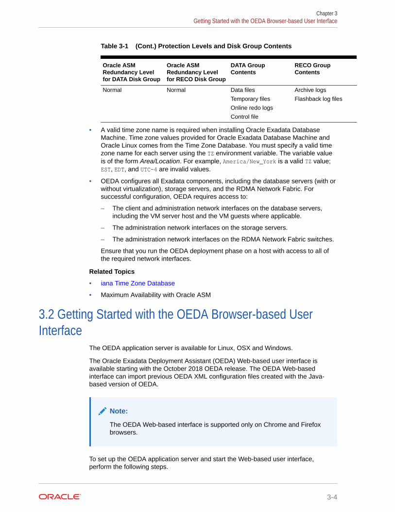
Table 3-1 (Cont.) Protection Levels and Disk Group Contents
Oracle ASMRedundancy Levelfor DATA Disk Group
Oracle ASMRedundancy Levelfor RECO Disk Group
DATA GroupContents
RECO GroupContents
Normal Normal Data files
Temporary files
Online redo logs
Control file
Archive logs
Flashback log files
• A valid time zone name is required when installing Oracle Exadata DatabaseMachine. Time zone values provided for Oracle Exadata Database Machine andOracle Linux comes from the Time Zone Database. You must specify a valid timezone name for each server using the TZ environment variable. The variable valueis of the form Area/Location. For example, America/New_York is a valid TZ value;EST, EDT, and UTC-4 are invalid values.
• OEDA configures all Exadata components, including the database servers (with orwithout virtualization), storage servers, and the RDMA Network Fabric. Forsuccessful configuration, OEDA requires access to:
– The client and administration network interfaces on the database servers,including the VM server host and the VM guests where applicable.
– The administration network interfaces on the storage servers.
– The administration network interfaces on the RDMA Network Fabric switches.
Ensure that you run the OEDA deployment phase on a host with access to all ofthe required network interfaces.
Related Topics
• iana Time Zone Database
• Maximum Availability with Oracle ASM
3.2 Getting Started with the OEDA Browser-based UserInterface
The OEDA application server is available for Linux, OSX and Windows.
The Oracle Exadata Deployment Assistant (OEDA) Web-based user interface isavailable starting with the October 2018 OEDA release. The OEDA Web-basedinterface can import previous OEDA XML configuration files created with the Java-based version of OEDA.
Note:
The OEDA Web-based interface is supported only on Chrome and Firefoxbrowsers.
To set up the OEDA application server and start the Web-based user interface,perform the following steps.
Chapter 3Getting Started with the OEDA Browser-based User Interface
3-4
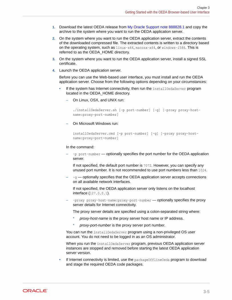
1. Download the latest OEDA release from My Oracle Support note 888828.1 and copy thearchive to the system where you want to run the OEDA application server.
2. On the system where you want to run the OEDA application server, extract the contentsof the downloaded compressed file. The extracted contents is written to a directory basedon the operating system, such as linux-x64, macosx-x64, or windows-i586. This isreferred to as the OEDA_HOME directory.
3. On the system where you want to run the OEDA application server, install a signed SSLcertificate.
4. Launch the OEDA application server.
Before you can use the Web-based user interface, you must install and run the OEDAapplication server. Choose from the following options depending on your circumstances:
• If the system has Internet connectivity, then run the installOedaServer programlocated in the OEDA_HOME directory.
– On Linux, OSX, and UNIX run:
./installOedaServer.sh [-p port-number] [-g] [-proxy proxy-host-name:proxy-port-number]
– On Microsoft Windows run:
installOedaServer.cmd [-p port-number] [-g] [-proxy proxy-host-name:proxy-port-number]
In the command:
– -p port-number — optionally specifies the port number for the OEDA applicationserver.
If not specified, the default port number is 7072. However, you can specify anyunused port number. It is not recommended to use port numbers less than 1024.
– -g — optionally specifies that the OEDA application server accepts connectionson all available network interfaces.
If not specified, the OEDA application server only listens on the localhostinterface (127.0.0.1).
– -proxy proxy-host-name:proxy-port-number — optionally specifies the proxyserver details for Internet connectivity.
The proxy server details are specified using a colon-separated string where:
* proxy-host-name is the proxy server host name or IP address.
* proxy-port-number is the proxy server port number.
You can run the installOedaServer program using a non-privileged OS useraccount. You do not need to be logged in as an OS administrator.
When you run the installOedaServer program, previous OEDA application serverinstances are stopped and removed before starting the latest OEDA applicationserver version.
• If Internet connectivity is limited, use the packageOfflineOeda program to downloadand stage the required OEDA code packages.
Chapter 3Getting Started with the OEDA Browser-based User Interface
3-5
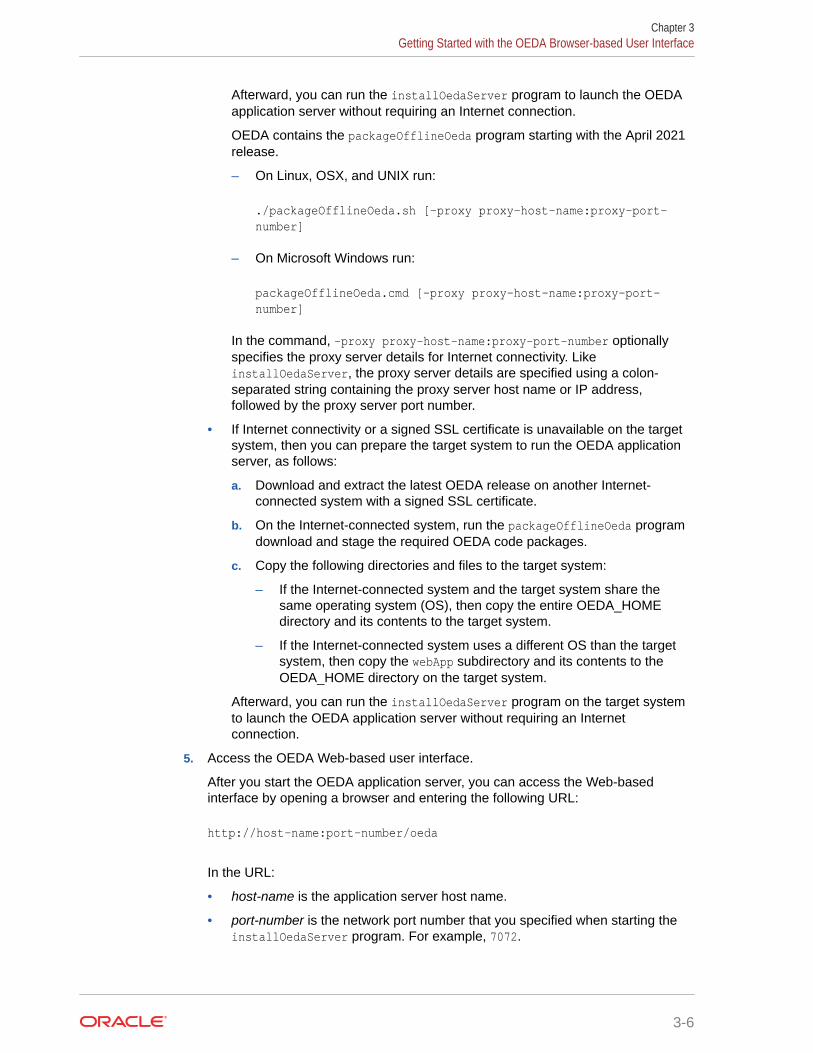
Afterward, you can run the installOedaServer program to launch the OEDAapplication server without requiring an Internet connection.
OEDA contains the packageOfflineOeda program starting with the April 2021release.
– On Linux, OSX, and UNIX run:
./packageOfflineOeda.sh [-proxy proxy-host-name:proxy-port-number]
– On Microsoft Windows run:
packageOfflineOeda.cmd [-proxy proxy-host-name:proxy-port-number]
In the command, -proxy proxy-host-name:proxy-port-number optionallyspecifies the proxy server details for Internet connectivity. LikeinstallOedaServer, the proxy server details are specified using a colon-separated string containing the proxy server host name or IP address,followed by the proxy server port number.
• If Internet connectivity or a signed SSL certificate is unavailable on the targetsystem, then you can prepare the target system to run the OEDA applicationserver, as follows:
a. Download and extract the latest OEDA release on another Internet-connected system with a signed SSL certificate.
b. On the Internet-connected system, run the packageOfflineOeda programdownload and stage the required OEDA code packages.
c. Copy the following directories and files to the target system:
– If the Internet-connected system and the target system share thesame operating system (OS), then copy the entire OEDA_HOMEdirectory and its contents to the target system.
– If the Internet-connected system uses a different OS than the targetsystem, then copy the webApp subdirectory and its contents to theOEDA_HOME directory on the target system.
Afterward, you can run the installOedaServer program on the target systemto launch the OEDA application server without requiring an Internetconnection.
5. Access the OEDA Web-based user interface.
After you start the OEDA application server, you can access the Web-basedinterface by opening a browser and entering the following URL:
http://host-name:port-number/oeda
In the URL:
• host-name is the application server host name.
• port-number is the network port number that you specified when starting theinstallOedaServer program. For example, 7072.
Chapter 3Getting Started with the OEDA Browser-based User Interface
3-6

If you did not specify the -g option when starting the OEDA application server, then youmust run the browser on the same host as the OEDA application server and specifylocalhost as the application server host name.
3.3 Using the Browser-based Version of Oracle ExadataDeployment Assistant
Use the deployment assistant for initial configuration, and when adding to an existingdeployment. You can import an existing configuration when adding new racks or components.
Have the following available before running the deployment assistant:
• IP addresses
• Machine names
• DNS information
• NTP information for the rack
The following options are available from the OEDA drop-down Menu:
• About: View version information for OEDA.
• New: Start a new configuration.
• Import: Import an existing configuration file. The file format is XML.
• Command Console: Opens a command console for the OEDA command-line interface(OEDACLI).
• Save: Save the current configuration to an XML file.
• Diagnostics: Creates a ZIP file that can be used to troubleshoot and diagnose issueswith the OEDA Web interface.
• Preferences: Specify your preferences for how the Web interface behaves.
• Validate: Check the current configuration for completeness and correctness.
• CheckIp: Checks the IP addresses.
• Installation Template: Generates the Installation Template report, which summarizes thecurrent configuration.
• Help: Describes the options and controls provided in the OEDA Web interface.
The following list describes the configuration flow in the OEDA Web interface. Use the Helpmenu option to display details about the options and controls provided in the OEDA Webinterface.
1. Select the hardware for the deployment on the Select Hardware page. Also providecustomer information on this page.
2. Use the Choose Operating System page to choose whether to configure virtualizationon the database servers.
Note:
Creating more than 8 VMs on Exadata database servers is not supported.
Chapter 3Using the Browser-based Version of Oracle Exadata Deployment Assistant
3-7

3. Enter the management network and private network information on the RackNetworks page.
4. Specify the user and group configuration on the Users page. You can choosebetween Default, Role Separated, or a Custom configuration.
5. Define the clusters on the Clusters page for each cluster.
6. Define the disk group layout on the Diskgroups page.
7. Specify the Oracle Database home information for each Oracle home on theCreate Database Home page.
8. Specify databases and their attributes on the Create Database page.
9. Enter the client and backup network information on the Cluster Networks page.
10. Configure the email alerts, SNMP alerts, Auto Service Request, Oracle ConfigManager, and Enterprise Manager alerting on the Alerting page.
11. Answer the configuration questionnaire and provide additional information aboutthe deployment in the text field on the Comments page. Information entered inthis field appears at the bottom of the InstallationTemplate.html file.
12. Click Save and Download to create the configuration files. You are prompted tochoose a location in which to save a ZIP file to your local computer.
13. Copy the ZIP file to a directory on the first database server in Oracle ExadataRack. Use a subdirectory of /u01, such as the /u01/oeda directory. These filesare used by the field engineer to configure the Oracle Exadata Rack.
Chapter 3Using the Browser-based Version of Oracle Exadata Deployment Assistant
3-8

4OEDA Command Line Interface
When you run the oedacli program, it starts the OEDA command line interface.
• About the OEDA Command Line InterfaceYou can use the OEDA command-line interface (OEDACLI) to perform Exadata life cyclemanagement tasks.
• Starting the OEDACLI Utility
• OEDACLI Command ReferenceThese OEDACLI commands are arranged by the object they act upon.
4.1 About the OEDA Command Line InterfaceYou can use the OEDA command-line interface (OEDACLI) to perform Exadata life cyclemanagement tasks.
Supported tasks include:
• Add nodes to and remove nodes from a VM cluster
• Add or remove Oracle Database home directories
• Add or remove storage cells
• Resize Oracle ASM disk groups
• Add or remove additional databases
OEDACLI supports life cycle management tasks for Oracle Exadata systems only. OEDACLIdoes not support life cycle management operations on Oracle SuperCluster and Oracle ZeroData Loss Recovery Appliance (ZDLRA).
OEDACLI allows you to update an existing Exadata configuration file (es.xml). The updatesare called Actions. An Action is a single atomic task.
An Action can have many sub commands, however most actions are single commands.Examples of multi-command steps are - CLONE GUEST and CLONE CELL
OEDACLI has two operating modes:
• Edit mode:
– Used against an es.xml file before you run the install.sh command steps
– Used to edit an XML file, for example to add a second Database Home, then savethe XML file
– Can be used as a logical XML editor for the es model prior to deployment
• Deploy mode:
– Used to edit an es.xml file after you have run the install.sh command steps
– Can be used to Clone Oracle VM Guests or grow or shrink Oracle ASM Disk groups
– Has a smaller list of supported changes than Edit mode
4-1

– Can be used as a logical XML editor and deployment tool after the initialdeployment
Edit Mode Workflow
1. When the command line interface starts, it has no target es.xml file to work on,so you first load an es.xml file.
LOAD FILE name=es.xml
2. Modify an in-memory version of the es.xml. Specify the additional actions toperform during deployment. For example, to clone an Oracle VM guest to a newguest:
clone guest srcname=asdset privnet name1='test08adm01-priv1',ip1='192.168.216.102',name2='testadm01-priv2',ip2='192.168.216.103'set parent name='test08adm01a'set adminnet name='test08adm01vm02',ip='10.128.218.70'set clientnet name='test08client01vm02',ip='10.128.196.63'set vipnet name='test08client01vm02-vip',ip='10.128.196.71'
3. After you have provided all the commands for an action, save the action to a list ofactions to be processed within the command line interface. At this point, the datain the es.xml file is not yet updated.
SAVE ACTION
4. Merge the actions into the main body of the in-memory copy of the es.xml usingthe FORCE keyword.
MERGE ACTIONS FORCE
5. Save the memory copy of the es.xml, overwriting the input file or writing to a newfile that you specify.
SAVE FILE [name=new_es.xml]
Deploy Mode Workflow
1. When the command line interface starts, it has no target es.xml file to work on,so you first load an es.xml file.
LOAD FILE name=es.xml
2. Modify an in-memory version of the es.xml. Specify the actions to perform.
3. After you have provided all the commands for an action, save the action to a list ofactions to be processed within the command line interface. At this point, the datain the es.xml file is not yet updated.
SAVE ACTION
Chapter 4About the OEDA Command Line Interface
4-2

4. Merge the actions into the main body of the in-memory copy of the es.xml.
MERGE ACTIONS
5. Deploy the actions into the main body of the es.xml file. This step will perform thespecified actions such as creating the new Oracle VM guest.
DEPLOY ACTIONS
6. Save the memory copy of the es.xml, overwriting the input file or writing to a new filethat you specify.
SAVE FILE [name=new_es.xml]
4.2 Starting the OEDACLI UtilityStarting with August 2017 Release of Oracle Exadata Deployment Assistant (OEDA), acommand-line utility — oedacli — can be used for various routine tasks on Exadata.
Prerequisites
To use oedacli, you must meet the following requirements:
• Download the August 2017 release or later of OEDA. The August 2017 release of OEDAis only supported on Oracle Linux.
• Have the original OEDA configuration XML file used for deployment
• Use the default password on the nodes in the cluster (for the root, oracle and gridusers)
Note:
If your environment does not use the default passwords for the specified users, thenrefer to My Oracle Support Doc ID 2163751.1.
File Path
The directory that contains the unzipped files from the OEDA download. Forexample /u01/joc/linux-x64.
Syntax
./oedacli
Usage Notes
To display the help output, use one of the following:
• HELP
• HELP command name
Chapter 4Starting the OEDACLI Utility
4-3
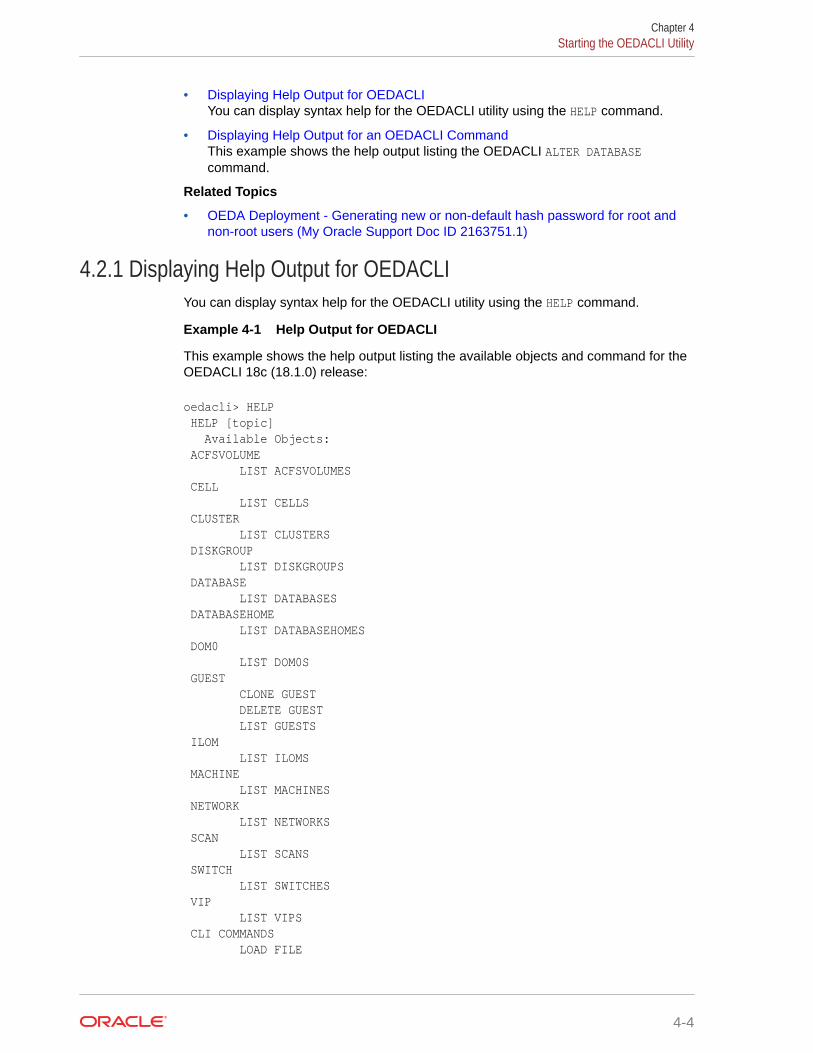
• Displaying Help Output for OEDACLIYou can display syntax help for the OEDACLI utility using the HELP command.
• Displaying Help Output for an OEDACLI CommandThis example shows the help output listing the OEDACLI ALTER DATABASEcommand.
Related Topics
• OEDA Deployment - Generating new or non-default hash password for root andnon-root users (My Oracle Support Doc ID 2163751.1)
4.2.1 Displaying Help Output for OEDACLIYou can display syntax help for the OEDACLI utility using the HELP command.
Example 4-1 Help Output for OEDACLI
This example shows the help output listing the available objects and command for theOEDACLI 18c (18.1.0) release:
oedacli> HELP HELP [topic] Available Objects: ACFSVOLUME LIST ACFSVOLUMES CELL LIST CELLS CLUSTER LIST CLUSTERS DISKGROUP LIST DISKGROUPS DATABASE LIST DATABASES DATABASEHOME LIST DATABASEHOMES DOM0 LIST DOM0S GUEST CLONE GUEST DELETE GUEST LIST GUESTS ILOM LIST ILOMS MACHINE LIST MACHINES NETWORK LIST NETWORKS SCAN LIST SCANS SWITCH LIST SWITCHES VIP LIST VIPS CLI COMMANDS LOAD FILE
Chapter 4Starting the OEDACLI Utility
4-4

SAVE FILE SAVE FILES LIST XMLACTIONS SAVE ACTION MERGE ACTIONS DEPLOY ACTIONS
4.2.2 Displaying Help Output for an OEDACLI CommandThis example shows the help output listing the OEDACLI ALTER DATABASE command.
Example 4-2 Help Output for the OEDACLI ALTER DATABASE command
This example shows how to display the syntax for the ALTER DATABASE command ofOEDACLI. The help output is shown for the 18c (18.1.0) release.
oedacli> HELP ALTER DATABASE Usage: ALTER DATABASE BLOCKSIZE = <blocksize> | CHARSET = <characterset> | DATADG = <datadg> | DBLANG = <dblang> | DBNAME = <dbname> | DBTEMPLATE = <dbtemplate> | DBTYPE = <dbtype> | HOSTNAMES = <hostnames> | RECODG = <recodg> WHERE ID = <databaseid> | CLUSTERNUMBER = <clusternumber> DATABASENAME = <databasename> | CLUSTERNAME = <clustername> DATABASENAME = <databasename> | CLUSTERID = <clusterid> DATABASENAME = <databasename> Purpose: Alters an existing database Arguments: <blocksize> : Default: 8192, not required for PDB <characterset> : Default: AL32UTF8, not required for PDB <datadg> : *The DATA diskgroup, not required for PDB <dblang> : Default: all_langs, not required for PDB <dbname> : *Database name <dbtemplate> : Default: ADMIN, otherwise ADMIN or DW, not required for PDB <dbtype> : Default: normal DB, otherwise CDB or PDB <hostnames> : Default: list of nodes from db home <recodg> : *The RECO diskgroup, not required for PDB Where: <databaseid> : The es xml id of the database <clusternumber> : The cluster number in the es xml, starting at 1 <clustername> : The name of the cluster <clusterid> : The es xml id of the cluster <databasename> : The name of the database in the cluster
Chapter 4Starting the OEDACLI Utility
4-5
4.3 OEDACLI Command ReferenceThese OEDACLI commands are arranged by the object they act upon.
• ACFSVOLUMEYou can add, alter, delete, or list Oracle ACFS volumes.
• ACTIONYou can save, merge, and deploy OEDACLI actions.
• ALERTYou can create, alter, delete, or list Oracle alerts.
• CELLYou can clone, delete, or list Oracle Exadata storage cells.
• CLUSTERYou can alter or list the Oracle RAC Clusters on the Oracle Exadata DatabaseMachine.
• COMPUTEUse these commands to add or delete a physical compute node as a clustermember.
• CURRENTACTIONYou can clear or list the current action in OEDACLI.
• DATABASEYou can add, alter, delete, or list the Oracle databases.
• DATABASEHOMEYou can add, alter, delete, or list the Oracle Database homes.
• DISKGROUPYou can add, alter, delete, or list the Oracle ASM disk groups.
• DOM0You can list Oracle VM management domains (dom0s).
• DOMAINYou can get live information from a domain.
• ESYou can discover an engineered system or alter a limited number of attributes ofan engineered system.
• EXITONERRORYou can set the exit status for OEDACLI.
• FILEYou can manage the Engineered System XML file (es.xml).
• GUESTYou can clone or delete an Oracle VM guest.
• ILOMYou can alter or list the ILOMS in the loaded es.xml file.
• LOGINYou can check remote login to a machine or cluster.
Chapter 4OEDACLI Command Reference
4-6

• MACHINEYou can alter or list the machines in the es.xml file.
• NETWORKYou can add, alter, delete, or list the networks defined in the XML configuration file.
• PASSWORDYou can specify the default passwords.
• PROPERTYYou can set OEDA properties.
• RACKYou can manage an Engineered System rack.
• REQUIREDFILESYou can display information about required files.
• REMOTEYou can run a command on a remote host.
• SCANYou can add, alter, delete, or list the SCANs for a cluster.
• SECURITYYou can manage security settings.
• SOFTWAREVERSIONSYou can check supported software versions.
• SSHKEYSYou can generate and deploy SSH keys for root user authentication on Oracle ExadataRack.
• STEPSYou can display the steps for a virtual CREATE CLUSTER deployment.
• SWITCHYou can display and manage the switches.
• SUControls use of the su command.
• ULOCYou can display the location of rack items.
• VIPYou can add, alter, delete, or list the Oracle Clusterware VIPs.
• VOLUMEYou can display and manage storage volumes.
• XMLACTIONYou can manage actions relating to the Engineered System XML file.
4.3.1 ACFSVOLUMEYou can add, alter, delete, or list Oracle ACFS volumes.
• ADD ACFSVOLUME
• ALTER ACFSVOLUME
• DELETE ACFSVOLUME
Chapter 4OEDACLI Command Reference
4-7

• LIST ACFSVOLUMES
4.3.1.1 ADD ACFSVOLUMEThis command adds Oracle ASM Cluster File System (Oracle ACFS) volumes.
Syntax
ADD ACFSVOLUME VOLUMENAME=volume_name VOLUMESIZE=volume_size MOUNTPATH=mount_path WHERE { DISKGROUPID=diskgroup_id | CLUSTERNUMBER=cluster_number DISKGROUPNAME=diskgroup_name | CLUSTERNAME=cluster_name DISKGROUPNAME=diskgroup_name | CLUSTERID=cluster_id DISKGROUPNAME=diskgroup_name }
Arguments
Specify the following attributes for the new Oracle ACFS volume:
• VOLUMENAME : Specifies a unique name for the new volume
• VOLUMESIZE : A number that specifies the size of the new volume in GB
• MOUNTPATH : Specifies the file system mount path for the new volume
The following arguments are available in the WHERE clause:
• DISKGROUPID : Specifies the es.xml ID for the container disk group
• CLUSTERNUMBER : Specifies the cluster number in the es.xml, starting at 1
• CLUSTERNAME : Specifies the name of the cluster
• CLUSTERID : Specifies the es.xml ID of the cluster
• DISKGROUPNAME : Specifies the name of the container disk group
4.3.1.2 ALTER ACFSVOLUMEThis command alters an existing Oracle ASM Cluster File System (Oracle ACFS)volume.
Syntax
ALTER ACFSVOLUME { VOLUMENAME=volume_name | VOLUMESIZE=volume_size | MOUNTPATH=mountpath } ...WHERE { ID=acfs_volume_id | DISKGROUPID=diskgroup_id VOLUMENAME=volume_name | CLUSTERNUMBER=cluster_number DISKGROUPNAME=diskgroup_name VOLUMENAME=volume_name | CLUSTERNAME=cluster_name DISKGROUPNAME diskgroup_name VOLUMENAME=volume_name |
Chapter 4OEDACLI Command Reference
4-8

CLUSTERID=cluster_id DISKGROUPNAME=diskgroup_name VOLUMENAME=volume_name }
Arguments
You can modify the following attributes of the Oracle ACFS volume:
• VOLUMENAME : Specifies a new, unique volume name
• VOLUMESIZE : A number that specifies the new size of the volume in GB
• MOUNTPATH : Specifies the new file system mount path for the volume
The following arguments are available in the WHERE clause:
• ID : Specifies the es.xml ID for an existing Oracle ACFS volume
• DISKGROUPID : Specifies the es.xml ID for the container disk group
• CLUSTERNUMBER : Specifies the cluster number in the es.xml, starting at 1
• CLUSTERNAME : Specifies the name of the cluster
• CLUSTERID : Specifies the es.xml ID of the cluster
• DISKGROUPNAME : Specifies the name of the container disk group
• VOLUMENAME : Specifies the name of the existing Oracle ACFS volume
4.3.1.3 DELETE ACFSVOLUMEThis command deletes an existing Oracle ASM Cluster File System (Oracle ACFS) volume.
Syntax
DELETE ACFSVOLUMEWHERE { ID=acfs_volume_id | DISKGROUPID=diskgroup_id VOLUMENAME=volume_name | CLUSTERNUMBER=cluster_number DISKGROUPNAME=diskgroup_name VOLUMENAME=volume_name | CLUSTERNAME=cluster_name DISKGROUPNAME=diskgroup_name VOLUMENAME=volume_name | CLUSTERID=cluster_id DISKGROUPNAME=diskgroup_name VOLUMENAME=volume_name }
Arguments
The following arguments are available in the WHERE clause:
• ID : Specifies the es.xml ID for the Oracle ACFS volume
• DISKGROUPID : Specifies the es.xml ID for the container disk group
• CLUSTERNUMBER : Specifies the cluster number in the es.xml, starting at 1
• CLUSTERNAME : Specifies the name of the cluster
• CLUSTERID : Specifies the es.xml ID of the cluster
• DISKGROUPNAME : Specifies the name of the container disk group
Chapter 4OEDACLI Command Reference
4-9

• VOLUMENAME : Specifies the name of the existing Oracle ACFS volume
4.3.1.4 LIST ACFSVOLUMESThis command lists the Oracle ASM Cluster File System (Oracle ACFS) volumes.
Syntax
LIST ACFSVOLUMES[ WHERE { ID=acfs_volume_id | DISKGROUPID=diskgroup_id | CLUSTERNUMBER=cluster_number [ DISKGROUPNAME=diskgroup_name ] | CLUSTERNAME=cluster_name [ DISKGROUPNAME=diskgroup_name ] | CLUSTERID=cluster_id [ DISKGROUPNAME=diskgroup_name ] }
Arguments
The following arguments are available in the WHERE clause:
• ID : Specifies the es.xml ID for the Oracle ACFS volume
• DISKGROUPID : Specifies the es.xml ID for the container disk group
• CLUSTERNUMBER : Specifies the cluster number in the es.xml, starting at 1
• CLUSTERNAME : Specifies the name of the cluster
• CLUSTERID : Specifies the es.xml ID of the cluster
• DISKGROUPNAME : Specifies the name of the container disk group
4.3.2 ACTIONYou can save, merge, and deploy OEDACLI actions.
• SAVE ACTION
• MERGE ACTIONS
• DEPLOY ACTIONS
4.3.2.1 SAVE ACTIONUse this command to save the current action to in-memory copy of the EngineeredSystem XML configuration.
Syntax
SAVE ACTION [FORCE]
Arguments
Specify FORCE to auto-merged the action into the Engineered System model.
Chapter 4OEDACLI Command Reference
4-10
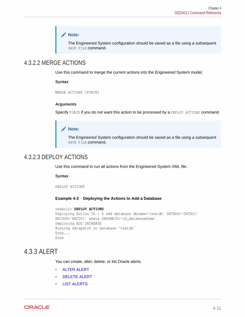
Note:
The Engineered System configuration should be saved as a file using a subsequentSAVE FILE command.
4.3.2.2 MERGE ACTIONSUse this command to merge the current actions into the Engineered System model.
Syntax
MERGE ACTIONS [FORCE]
Arguments
Specify FORCE if you do not want this action to be processed by a DEPLOY ACTIONS command.
Note:
The Engineered System configuration should be saved as a file using a subsequentSAVE FILE command.
4.3.2.3 DEPLOY ACTIONSUse this command to run all actions from the Engineered System XML file.
Syntax
DEPLOY ACTIONS
Example 4-3 Deploying the Actions to Add a Database
oedacli> DEPLOY ACTIONS Deploying Action ID : 4 add database dbname='testdb' DATADG='DATAC1' RECODG='RECOC1' where DBHOMEID='c0_databaseHome' Deploying ADD DATABASE Running datapatch on database 'testdb' Done... Done
4.3.3 ALERTYou can create, alter, delete, or list Oracle alerts.
• ALTER ALERT
• DELETE ALERT
• LIST ALERTS
Chapter 4OEDACLI Command Reference
4-11

4.3.3.1 ALTER ALERTThis command creates or alters an Oracle alert.
Syntax
ALTER ALERT { RECIPIENTS='recipients' FROMNAME='from_name' FROMEMAIL=from_email SMTPHOST=smtp_host [ SSL=uses_ssl ] [ PORT=smtp_port ] | SNMPHOST=snmp_host [ PORT=snmp_port ] [ COMMUNITY=snmp_community ] | ASRHOST=asr_host CONTACT=asr_contact EMAIL=asr_email MOSACCOUNT=asr_mos_account [ PROXYHOST=asr_proxy_host ] [ PROXYPORT=asr_proxy_port ] [ PROXYUSER=asr_proxy_user ] | [ EMAIL=ocm_email ] [ HUBHOST=ocm_hub_host ] [ HUBUSER=ocm_hub_user ] [ PROXYHOST=ocm_proxy_host ] [ PROXYPORT=ocm_proxy_port ] [ PROXYUSER=ocm_proxy_user ] | EMBASE=em_base [ OMSHOST=oms_host ] PORT=oms_port }WHERE { ID=alert_id | TYPE=alert_type | HOSTNAME=host_name TYPE=alert_type | CLUSTERNUMBER=cluster_number TYPE=alert_type | CLUSTERNAME=cluster_name TYPE=alert_type | CLUSTERID=cluster_id TYPE=alert_type }
Arguments
You can specify various attributes according to the alert type.
• For SMTP alerts:
– RECIPIENTS : Specifies a list of email addresses. The list entries are separatedby a space or a comma and the list is surrounded by single quotation marks
– FROMNAME : Specifies the name of the email sending user, surrounded by singlequotation marks
– FROMEMAIL : Specifies the email address of the email sending user
– SMTPHOST : Specifies the hostname of the SMTP email server
Chapter 4OEDACLI Command Reference
4-12

– SSL : Optionally, set to true to use SSL. Default value is false.
– PORT : Optionally, specifies the SMTP email server port. Default value is 25.
• For SNMP alerts:
– SNMPHOST : Specifies the hostname of the SNMP server
– PORT : Optionally, specifies the SNMP server port. Default value is 162.
– COMMUNITY : Optionally, specifies the SNMP community value. Default value ispublic.
• For Oracle Auto Service Request (ASR) alerts:
– ASRHOST : Specifies the hostname of the ASR server
– CONTACT : Specifies the ASR contact name
– EMAIL : Specifies the ASR email address
– MOSACCOUNT : Specifies the ASR My Oracle Support (MOS) email address
– PROXYHOST : Optionally, specifies the proxy hostname for connectivity to the ASRserver
– PROXYPORT : Optionally, specifies the proxy port for connectivity to the ASR server
– PROXYUSER : Optionally, specifies the proxy username for connectivity to the ASRserver
• For Oracle Configuration Manager (OCM) alerts:
– EMAIL : Specifies the OCM email address
– HUBHOST : Specifies the hostname of the OCM hub
– HUBUSER : Specifies the OCM hub user name
– PROXYHOST : Optionally, specifies the proxy hostname for connectivity to the OCM hub
– PROXYPORT : Optionally, specifies the proxy port for connectivity to the OCM hub
– PROXYUSER : Optionally, specifies the proxy username for connectivity to the OCM hub
• For Oracle Enterprise Manager (EM) alerts:
– EMBASE : Optionally, specifies the EM base directory. Default value is /u01/app/oracle/product/EMbase.
– OMSHOST : Specifies the hostname of the Oracle Management Server (OMS)
– PORT : Optionally, specifies the OMS server port. Default value is 4900.
The following arguments are available in the WHERE clause:
• ID : Specifies the es.xml ID for an existing alert
• TYPE : Specifies the alert type: SNMP, SMTP, ASR, OCM, or EM
• HOSTNAME : Specifies the target server hostname
• CLUSTERNUMBER : Specifies the cluster number in the es.xml, starting at 1
• CLUSTERNAME : Specifies the name of the cluster
• CLUSTERID : Specifies the es.xml ID of the cluster
Chapter 4OEDACLI Command Reference
4-13

4.3.3.2 DELETE ALERTThis command deletes a specific alert.
Syntax
DELETE ALERTWHERE { ID=alert_id | HOSTNAME=host_name [ TYPE=alert_type ] | CLUSTERNUMBER=cluster_number [ TYPE=alert_type ] | CLUSTERNAME=cluster_name [ TYPE=alert_type ] | CLUSTERID=cluster_id [ TYPE=alert_type ] }
Arguments
The following arguments are available in the WHERE clause:
• ID : Specifies the es.xml ID for an existing alert
• HOSTNAME : Specifies the target server hostname
• TYPE : Specifies the alert type: SNMP, SMTP, ASR, OCM, or EM
• CLUSTERNUMBER : Specifies the cluster number in the es.xml, starting at 1
• CLUSTERNAME : Specifies the name of the cluster
• CLUSTERID : Specifies the es.xml ID of the cluster
4.3.3.3 LIST ALERTSThis command lists alerts.
Syntax
LIST ALERTS[ WHERE { ID=alert_id | TYPE=alert_type | HOSTNAME=host_name [ TYPE=alert_type ] } ]
Arguments
The following arguments are available in the WHERE clause:
• ID : Specifies the es.xml ID for an existing alert
• TYPE : Specifies the alert type: SNMP, SMTP, ASR, OCM, or EM
• HOSTNAME : Specifies the target server hostname
4.3.4 CELLYou can clone, delete, or list Oracle Exadata storage cells.
• CLONE CELL
Chapter 4OEDACLI Command Reference
4-14

• CLONE NEWCELL
• DELETE CELL
• DELETE NEWCELL
• LIST CELLS
4.3.4.1 CLONE CELLThis command clones an existing storage cell.
Note:
This command is deprecated and replaced by CLONE NEWCELL.
Syntax
CLONE CELL SRCNAME=source_cell [ TGTNAME=new_cell_name ] [ WAIT=wait ] [ POWER=power ][ WHERE STEPNAME=step ]
SET ADMINNET NAME=admin_name IP=admin_ip [ NETMASK=netmask ] [ GATEWAY=gatewayip ]SET PRIVNET NAME1=priv_name_1 IP1=priv_ip1 NAME2=priv_name_2 IP2=priv_ip2SET ILOMNET NAME=ilom_name IP=ilom_ip [ NETMASK=netmask ] [ GATEWAY=gatewayip ]SET RACK NUM=rack_number ULOC=ulocation
Arguments
• SRCNAME: Specifies the name of an existing cell from which the new cell is derived.
• TGTNAME: Specifies the name of the new cell being added.
• WAIT: Default is true, in which case the command waits for completion of the ASMrebalance operation prior to completion. Optionally, set to false to return control withoutwaiting for the ASM rebalance operation.
• POWER : Optionally, specifies the ASM rebalance power limit. Default value is 4. Range ofvalid values is 1 - 1024.
• STEPNAME: Specifies the deployment step to perform, which is one of the following:
– CONFIG_CELL
– CREATE_GRIDDISKS
– ADD_DISKS_TO_ASM
– REBALANCE
You can set the following options for a cloned cell:
Chapter 4OEDACLI Command Reference
4-15

• ADMINNET : Specifies the DNS name and IP address to use for the administrationnetwork. The DNS name may optionally include the domain name. You can alsooptionally specify the netmask and gateway for the administration network.
• PRIVNET : Specifies the names and IP addresses to use for the first and secondprivate networks. The names may optionally include the domain name.
• ILOMNET : Specifies the DNS name and IP address to use for the ILOM network.The DNS name may optionally include the domain name. You can also optionallyspecify the netmask and gateway for the ILOM network.
• RACK : Specifies the rack number in a multi-rack configuration, where 1 is the firstrack, and the physical location (slot number) of the cell in the rack.
The following example shows the command sequence for adding cell dbm01celadm14by cloning dbm01celadm09.
# CloneCLONE CELL SRCNAME=dbm01celadm09 TGTNAME=dbm01celadm14 where STEPNAME=CONFIG_CELLSET ADMINNET NAME=dbm01celadm14 IP=203.0.161.160SET PRIVNET NAME1=dbm01celadm14-priv1 IP1=192.168.160.19 NAME2=dbm01celadm14-priv2 IP2=192.168.160.20SET ILOMNET NAME=dbm01celadm14-ilom IP=203.0.161.182SET RACK NUM=1, ULOC=12
SAVE ACTIONMERGE ACTIONSDEPLOY ACTIONS
# Create GriddisksCLONE CELL SRCNAME=dbm01celadm09 TGTNAME=dbm01celadm14 where STEPNAME=CREATE_GRIDDISKS
SAVE ACTIONMERGE ACTIONSDEPLOY ACTIONS
# Add Griddisks to ASM DiskgroupsCLONE CELL SRCNAME=dbm01celadm09 TGTNAME=dbm01celadm14 where STEPNAME=ADD_DISKS_TO_ASM
SAVE ACTIONMERGE ACTIONSDEPLOY ACTIONS
# Rebalance ASM DiskgroupsCLONE CELL SRCNAME=dbm01celadm09 TGTNAME=dbm01celadm14 where STEPNAME=REBALANCE
SAVE ACTIONMERGE ACTIONSDEPLOY ACTIONS
Chapter 4OEDACLI Command Reference
4-16
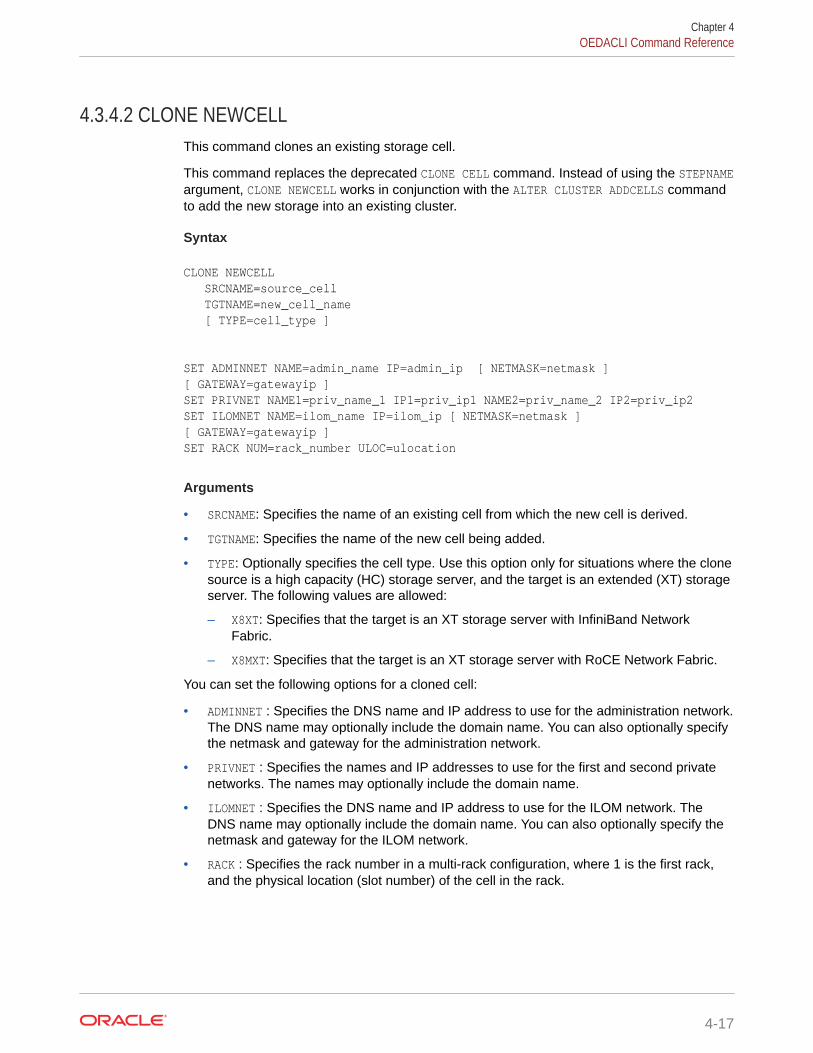
4.3.4.2 CLONE NEWCELLThis command clones an existing storage cell.
This command replaces the deprecated CLONE CELL command. Instead of using the STEPNAMEargument, CLONE NEWCELL works in conjunction with the ALTER CLUSTER ADDCELLS commandto add the new storage into an existing cluster.
Syntax
CLONE NEWCELL SRCNAME=source_cell TGTNAME=new_cell_name [ TYPE=cell_type ]
SET ADMINNET NAME=admin_name IP=admin_ip [ NETMASK=netmask ] [ GATEWAY=gatewayip ]SET PRIVNET NAME1=priv_name_1 IP1=priv_ip1 NAME2=priv_name_2 IP2=priv_ip2SET ILOMNET NAME=ilom_name IP=ilom_ip [ NETMASK=netmask ] [ GATEWAY=gatewayip ]SET RACK NUM=rack_number ULOC=ulocation
Arguments
• SRCNAME: Specifies the name of an existing cell from which the new cell is derived.
• TGTNAME: Specifies the name of the new cell being added.
• TYPE: Optionally specifies the cell type. Use this option only for situations where the clonesource is a high capacity (HC) storage server, and the target is an extended (XT) storageserver. The following values are allowed:
– X8XT: Specifies that the target is an XT storage server with InfiniBand NetworkFabric.
– X8MXT: Specifies that the target is an XT storage server with RoCE Network Fabric.
You can set the following options for a cloned cell:
• ADMINNET : Specifies the DNS name and IP address to use for the administration network.The DNS name may optionally include the domain name. You can also optionally specifythe netmask and gateway for the administration network.
• PRIVNET : Specifies the names and IP addresses to use for the first and second privatenetworks. The names may optionally include the domain name.
• ILOMNET : Specifies the DNS name and IP address to use for the ILOM network. TheDNS name may optionally include the domain name. You can also optionally specify thenetmask and gateway for the ILOM network.
• RACK : Specifies the rack number in a multi-rack configuration, where 1 is the first rack,and the physical location (slot number) of the cell in the rack.
Chapter 4OEDACLI Command Reference
4-17
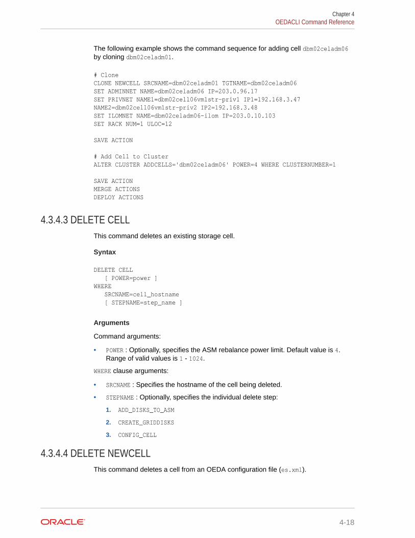
The following example shows the command sequence for adding cell dbm02celadm06by cloning dbm02celadm01.
# CloneCLONE NEWCELL SRCNAME=dbm02celadm01 TGTNAME=dbm02celadm06SET ADMINNET NAME=dbm02celadm06 IP=203.0.96.17SET PRIVNET NAME1=dbm02cell06vm1str-priv1 IP1=192.168.3.47 NAME2=dbm02cell06vm1str-priv2 IP2=192.168.3.48SET ILOMNET NAME=dbm02celadm06-ilom IP=203.0.10.103SET RACK NUM=1 ULOC=12
SAVE ACTION
# Add Cell to ClusterALTER CLUSTER ADDCELLS='dbm02celadm06' POWER=4 WHERE CLUSTERNUMBER=1
SAVE ACTIONMERGE ACTIONSDEPLOY ACTIONS
4.3.4.3 DELETE CELLThis command deletes an existing storage cell.
Syntax
DELETE CELL [ POWER=power ]WHERE SRCNAME=cell_hostname [ STEPNAME=step_name ]
Arguments
Command arguments:
• POWER : Optionally, specifies the ASM rebalance power limit. Default value is 4.Range of valid values is 1 - 1024.
WHERE clause arguments:
• SRCNAME : Specifies the hostname of the cell being deleted.
• STEPNAME : Optionally, specifies the individual delete step:
1. ADD_DISKS_TO_ASM
2. CREATE_GRIDDISKS
3. CONFIG_CELL
4.3.4.4 DELETE NEWCELLThis command deletes a cell from an OEDA configuration file (es.xml).
Chapter 4OEDACLI Command Reference
4-18

Syntax
DELETE NEWCELLWHERE { SRCNAME=cell_host_name | SRCNAMES=cell_host_names }
Arguments
WHERE clause arguments:
• SRCNAME : Specifies the host name of the cell being deleted from es.xml.
• SRCNAMES : Specifies a comma-separated list of host names for the cells being deletedfrom es.xml.
Usage Notes
Use SAVE ACTION FORCE to save changes only to es.xml. No deployment actions areperformed.
4.3.4.5 LIST CELLSThis command lists the storage cells.
Syntax
LIST CELLS
Usage Notes
This command is deprecated. Instead, use:
LIST MACHINES WHERE TYPE=CELL
4.3.5 CLUSTERYou can alter or list the Oracle RAC Clusters on the Oracle Exadata Database Machine.
• ALTER CLUSTER
• CREATE CLUSTERUse this command to create virtual guests for a virtual machine (VM) cluster, includingthe steps to configure and deploy an Oracle RAC database.
• DESTROY CLUSTERThis command is used to cleanly remove a running virtual machine (VM) cluster in oneoperation.
• DOWNGRADE CLUSTERUse this command downgrade a previously upgraded cluster.
• LIST CLUSTERThis command lists a specific Exadata cluster.
Chapter 4OEDACLI Command Reference
4-19

• LIST CLUSTERSThis command lists the existing Exadata clusters.
• UPGRADE CLUSTERUse this command upgrade an Oracle Grid Infrastructure cluster.
4.3.5.1 ALTER CLUSTERThis command alters cluster attributes.
Syntax
ALTER CLUSTER { CLUSTERNAME=cluster_name | GIVERSION=grid_version | GIHOMELOC=grid_home_location | INVLOC=inventory_location | BASEDIR=oracle_base_dir | PATCHLIST=patch_list | VCPU=vcpu | VMEM=vmem | ASMSCOPEDSECURITY=asm_scoped_security | ADDCELLS='add_cells' ] | DROPCELLS='drop_cells' ] | DISKGROUPS='asm_diskgroups' ] | POWER=power ] | WAIT=wait ] | HOMESIZE=home_size | INSTALLTYPE={ CLONE | ZIP } } ...WHERE { CLUSTERNUMBER=cluster_number | CLUSTERNAME=cluster_name | ID=cluster_id }
Arguments
You can modify the following attributes of the Oracle RAC Cluster:
• CLUSTERNAME : Specifies a new, unique name for the cluster
• GIVERSION : Specifies the clusterware version, including the release update (RU).For example: 12.1.0.2.170418
• GIHOMELOC : Specifies a new path for the Grid home location
• INVLOC : Specifies a new path for the software inventory
• BASEDIR : Specifies a new path for the Oracle base directory
• PATCHLIST : Optionally, specifies a comma-separated list of patches. The list mustbe enclosed in single quotes. By default, the patch list is derived from the RUincluded in the GIVERSION.
• VCPU : Specifies the number of virtual CPUs for each virtual machine (VM) in a VMcluster. This option only applies to a cluster in a VM deployment.
• VMEM : Specifies the amount of memory (in GB) for each virtual machine (VM) in aVM cluster. This option only applies to a cluster in a VM deployment.
Chapter 4OEDACLI Command Reference
4-20

• ASMSCOPEDSECURITY : Optionally, specify true to enable ASM scoped security. The defaultvalue is false.
• ADDCELLS : Optionally, specifies a comma-separated list of cells to add to the disk groups.The list must be enclosed in single quotes.
• DROPCELLS : Optionally, specifies a comma-separated list of cells to drop from the diskgroups. The list must be enclosed in single quotes.
• DISKGROUPS : Optionally, specifies a comma-separated list of disk groups from which youwant to add or remove cells specified in ADDCELLS or DROPCELLS. The list must beenclosed in single quotes. If not specified, then the specified cells are added to orremoved from all of the disk groups.
• POWER : Optionally, specifies the ASM rebalance power limit. Default value is 4. Range ofvalid values is 1 - 1024.
• WAIT : Optionally, specify false so that the command returns without waiting for the ASMrebalance operation to complete. The default value is true.
• HOMESIZE : Specifies the cluster home size (in GB).
• INSTALLTYPE: Specifies the software installation method to use. The options are:
– CLONE: Uses image files to clone a software installation. The image files include thebase software release, and may also include additional patches and updates. Byincluding updates in the image files, this method reduces deployment time andimproves deployment consistency.
The CLONE software installation method is the only supported method for a cluster in avirtual machine (VM) deployment. This option is also available for clusters in aphysical (bare metal) deployment.
– ZIP: Performs a fresh software installation by using compressed (zip) files thatcontain the software release. This method does not include additional patches orupdates.
The ZIP software installation method is the default method for clusters in a physical(bare metal) deployment. This option is not available for clusters in a virtual machine(VM) deployment.
The following arguments are available in the WHERE clause:
• CLUSTERNUMBER : Specifies the cluster number in the es.xml, starting at 1
• CLUSTERNAME : Specifies the name of the cluster
• ID : Specifies the es.xml ID of the cluster
Example 4-4 Deploying a Cluster Change
The following example shows an OEDACLI session that uses the ALTER CLUSTER commandalong with typical output at each step.
oedacli> alter cluster clustername=cluster-c1 where id=Cluster-c6e838fe4-e317-ee1a-dd89-53f0b49a689b_idoedacli> save actionoedacli> merge actions processMerge processMergeActions Merging Action : alter cluster clustername=cluster-c1 where id=Cluster-c6e838fe4-e317-ee1a-dd89-53f0b49a689b_id
Chapter 4OEDACLI Command Reference
4-21

Merging ALTER CLUSTER Action Validated and Merged OKoedacli> deploy actions Deploying Action ID : 1 alter cluster clustername=cluster-c1 where id=Cluster-c6e838fe4-e317-ee1a-dd89-53f0b49a689b_id Deploying ALTER CLUSTER Done... Done
4.3.5.2 CREATE CLUSTERUse this command to create virtual guests for a virtual machine (VM) cluster, includingthe steps to configure and deploy an Oracle RAC database.
Syntax
CREATE CLUSTER [ STEPS='step_short_names' [ DELETEDB={ true | false } ] | SKIPSTEPS='step_short_names' [ DELETEDB={ true | false } ] | DELETEDB={ true | false } ][ WHERE { CLUSTERNAME=cluster_name | CLUSTERNUMBER=cluster_number | ID=cluster_id } ]
Arguments
• STEPS : Optionally, specifies the steps to run.
The list consists of space-separated step short names and the entire list isenclosed in single quotes.
Use the LIST STEPS command to view the available steps.
• SKIPSTEPS : Optionally, specifies steps to skip.
The list consists of space-separated step short names and the entire list isenclosed in single quotes.
Use the LIST STEPS command to view the available steps.
• DELETEDB : Optionally, specify true to delete the default Oracle RAC databaseafter cluster creation. The default value is false.
The following arguments are available in the WHERE clause:
• CLUSTERNUMBER: Specifies the cluster number in the es.xml, starting at 1
• CLUSTERNAME: Specifies the name of the cluster
• CLUSTERID: Specifies the es.xml ID of the cluster
Usage Notes
• The command can only create a cluster in a VM deployment. You cannot use thiscommand to create the cluster in a physical (bare-metal) deployment.
Chapter 4OEDACLI Command Reference
4-22

• The simplest form of this command does not require any arguments. However, if the XMLconfiguration file (es.xml) contains more than one cluster, then the WHERE clause ismandatory.
Example 4-5 Using the STEPS Parameter with CREATE CLUSTER
Use the following command to only create the guest domains for the Cluster-c1 cluster:
CREATE CLUSTER STEPS='CREATEVM' WHERE CLUSTERNAME=Cluster-c1
Example 4-6 Using the SKIPSTEPS and DELETEDB Parameters with CREATECLUSTER
Use the following command to create the Cluster-c1 cluster, skipping the specifiedSKIPSTEPS and deleting the default database.
CREATE CLUSTER SKIPSTEPS='VALIDATE CALIBRATE RESECURE' DELETEDB=true WHERE CLUSTERNAME=Cluster-c1
4.3.5.3 DESTROY CLUSTERThis command is used to cleanly remove a running virtual machine (VM) cluster in oneoperation.
Syntax
DESTROY CLUSTER [ WHERE { CLUSTERNUMBER=cluster_number | CLUSTERNAME=cluster_name | CLUSTERID=cluster_id } ]
Arguments
The following arguments are available in the WHERE clause:
• CLUSTERNUMBER: Specifies the cluster number in the es.xml, starting at 1
• CLUSTERNAME: Specifies the name of the cluster
• CLUSTERID: Specifies the es.xml ID of the cluster
Usage Notes
• No WHERE clause is required if the XML file contains one cluster only.
• The MERGE step indicates the machines that will be destroyed and the affected cells.
Example 4-7 Using the DESTROY CLUSTER Command
The following example shows the simplest case, where there is only a single cluster in theXML file.
oedacli> DESTROY CLUSTERoedacli> SAVE ACTION
Chapter 4OEDACLI Command Reference
4-23

oedacli> MERGE ACTIONSoedacli> DEPLOY ACTIONS
4.3.5.4 DOWNGRADE CLUSTERUse this command downgrade a previously upgraded cluster.
Syntax
DOWNGRADE CLUSTERWHERE { CLUSTERNAME=cluster_name [ STEPNAME=step_name ] | CLUSTERNUMBER=cluster_number [ STEPNAME=step_name ] | ID=cluster_id [ STEPNAME=step_name ] }
Arguments
The following arguments are available in the WHERE clause:
• CLUSTERNUMBER: Specifies the cluster number in the es.xml, starting at 1
• CLUSTERNAME: Specifies the name of the cluster
• ID: Specifies the es.xml ID of the cluster
• STEPNAME : Optionally, specifies the individual downgrade step:
1. RUN_ROOTSCRIPT
2. CONFIG_HOME
3. ADD_HOME
Usage Notes
• To use the command, you must use the es.xml that contains the upgraded cluster.
• The command can only downgrade a cluster in a VM deployment. You cannot usethis command to downgrade the cluster in a physical (bare-metal) deployment.
• The command can only run if the DELETE_OLDHOME step has not been run on theupgraded cluster.
Example 4-8 Cluster Downgrade
The following example shows an OEDACLI session that uses the DOWNGRADE CLUSTERcommand along with typical output at each step.
oedacli> downgrade cluster where clusternumber=1oedacli> save actionoedacli> merge actions processMerge processMergeActions Merging Action : downgrade cluster where clusternumber=1 Merging DOWNGRADE CLUSTER Action Validated and Merged OKoedacli> deploy actions Deploying Action ID : 4 downgrade cluster where clusternumber=1 Deploying DOWNGRADE CLUSTER
Chapter 4OEDACLI Command Reference
4-24

Downgrading Cluster Validating Target cluster version 12.2.0.1 Validating Target Clusterware Home.. /u01/app/12.2.0.1/grid Checking Cluster status... Checking status of cluster... Checking clustereware file system /u01/app/12.2.0.1/grid Validating active cluster version. Active cluster version found on cluster ovmClus8 is 18.0.0.0 Validating Inventory... Clusterware Home /u01/app/12.2.0.1/grid validation completed successfully Downgrading clusterware to 12.2.0.1 Running rootcrs.sh on node dbm01adm01vm08.example.com Running rootcrs.sh on node dbm01adm02vm08.example.com Deregistering Clustereware Home /u01/app/18.13.0.0/grid from oracle inventory Registering Clusterware Home /u01/app/12.2.0.1/grid with oracle inventory Starting Clusterware stack using software home /u01/app/12.2.0.1/grid Removing /u01/app/18.13.0.0/grid from Oracle inventory... Updating inventory on dbm01adm01vm08.example.com Updating inventory on dbm01adm02vm08.example.com Unmounting file systems..... Unmounting file system /u01/app/18.13.0.0/grid on dbm01adm01vm08.example.com Unmounting file system /u01/app/18.13.0.0/grid on dbm01adm02vm08.example.com Updating /etc/fstab entries... Active cluster version after downgraded 12.2.0.1.0 Clusterware successfully downgraded to 12.2.0.1.190115
4.3.5.5 LIST CLUSTERThis command lists a specific Exadata cluster.
Syntax
LIST CLUSTERWHERE { NAME=cluster_name | ID=cluster_id }
Arguments
The following arguments are available in the WHERE clause:
• NAME: Specifies the name of the cluster
• ID: Specifies the es.xml ID of the cluster
4.3.5.6 LIST CLUSTERSThis command lists the existing Exadata clusters.
Syntax
LIST CLUSTERS[ WHERE
Chapter 4OEDACLI Command Reference
4-25
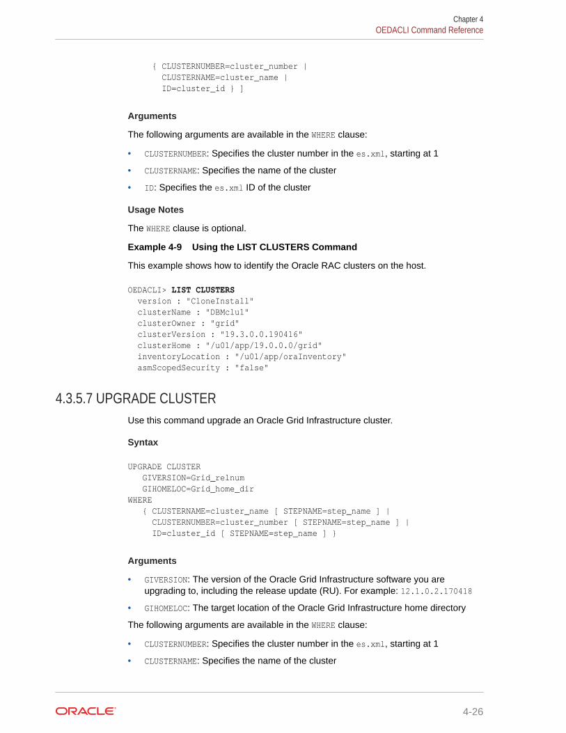
{ CLUSTERNUMBER=cluster_number | CLUSTERNAME=cluster_name | ID=cluster_id } ]
Arguments
The following arguments are available in the WHERE clause:
• CLUSTERNUMBER: Specifies the cluster number in the es.xml, starting at 1
• CLUSTERNAME: Specifies the name of the cluster
• ID: Specifies the es.xml ID of the cluster
Usage Notes
The WHERE clause is optional.
Example 4-9 Using the LIST CLUSTERS Command
This example shows how to identify the Oracle RAC clusters on the host.
OEDACLI> LIST CLUSTERS version : "CloneInstall" clusterName : "DBMclu1" clusterOwner : "grid" clusterVersion : "19.3.0.0.190416" clusterHome : "/u01/app/19.0.0.0/grid" inventoryLocation : "/u01/app/oraInventory" asmScopedSecurity : "false"
4.3.5.7 UPGRADE CLUSTERUse this command upgrade an Oracle Grid Infrastructure cluster.
Syntax
UPGRADE CLUSTER GIVERSION=Grid_relnum GIHOMELOC=Grid_home_dirWHERE { CLUSTERNAME=cluster_name [ STEPNAME=step_name ] | CLUSTERNUMBER=cluster_number [ STEPNAME=step_name ] | ID=cluster_id [ STEPNAME=step_name ] }
Arguments
• GIVERSION: The version of the Oracle Grid Infrastructure software you areupgrading to, including the release update (RU). For example: 12.1.0.2.170418
• GIHOMELOC: The target location of the Oracle Grid Infrastructure home directory
The following arguments are available in the WHERE clause:
• CLUSTERNUMBER: Specifies the cluster number in the es.xml, starting at 1
• CLUSTERNAME: Specifies the name of the cluster
Chapter 4OEDACLI Command Reference
4-26
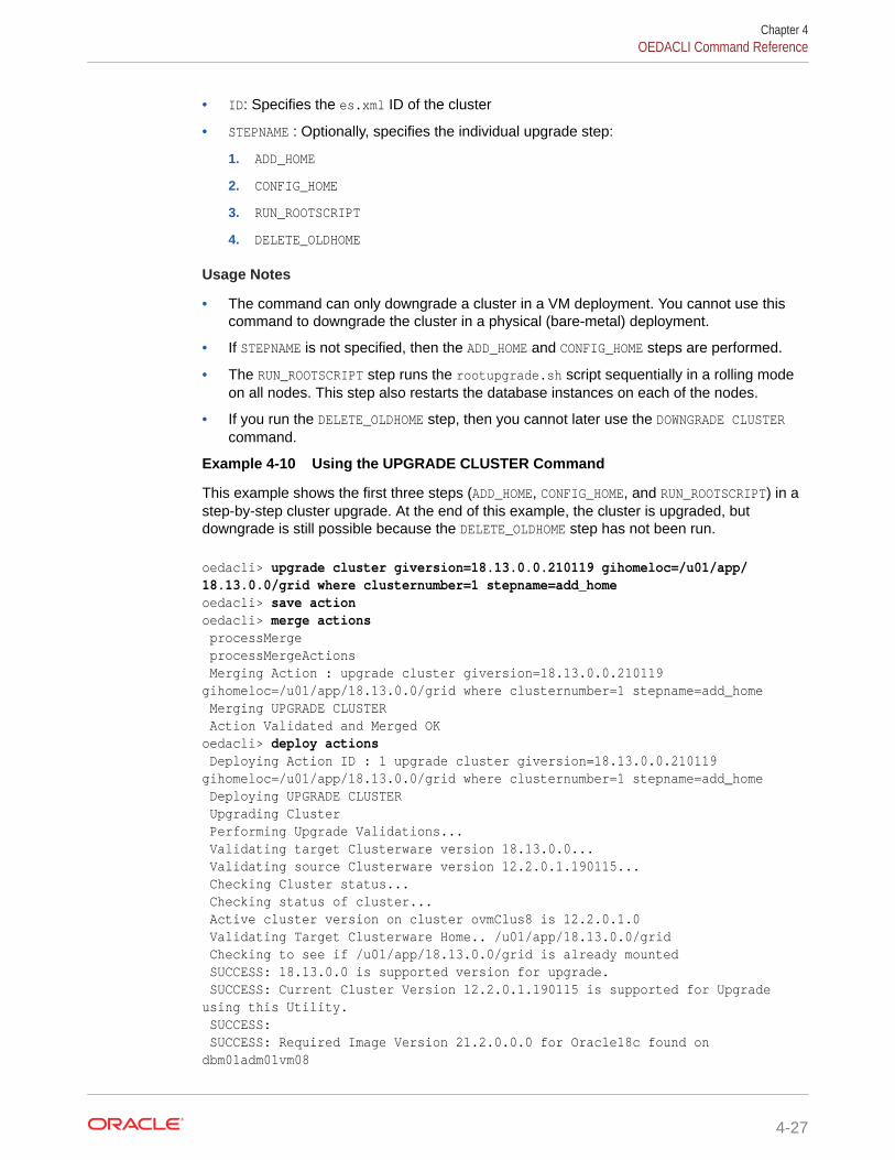
• ID: Specifies the es.xml ID of the cluster
• STEPNAME : Optionally, specifies the individual upgrade step:
1. ADD_HOME
2. CONFIG_HOME
3. RUN_ROOTSCRIPT
4. DELETE_OLDHOME
Usage Notes
• The command can only downgrade a cluster in a VM deployment. You cannot use thiscommand to downgrade the cluster in a physical (bare-metal) deployment.
• If STEPNAME is not specified, then the ADD_HOME and CONFIG_HOME steps are performed.
• The RUN_ROOTSCRIPT step runs the rootupgrade.sh script sequentially in a rolling modeon all nodes. This step also restarts the database instances on each of the nodes.
• If you run the DELETE_OLDHOME step, then you cannot later use the DOWNGRADE CLUSTERcommand.
Example 4-10 Using the UPGRADE CLUSTER Command
This example shows the first three steps (ADD_HOME, CONFIG_HOME, and RUN_ROOTSCRIPT) in astep-by-step cluster upgrade. At the end of this example, the cluster is upgraded, butdowngrade is still possible because the DELETE_OLDHOME step has not been run.
oedacli> upgrade cluster giversion=18.13.0.0.210119 gihomeloc=/u01/app/18.13.0.0/grid where clusternumber=1 stepname=add_homeoedacli> save actionoedacli> merge actions processMerge processMergeActions Merging Action : upgrade cluster giversion=18.13.0.0.210119 gihomeloc=/u01/app/18.13.0.0/grid where clusternumber=1 stepname=add_home Merging UPGRADE CLUSTER Action Validated and Merged OKoedacli> deploy actions Deploying Action ID : 1 upgrade cluster giversion=18.13.0.0.210119 gihomeloc=/u01/app/18.13.0.0/grid where clusternumber=1 stepname=add_home Deploying UPGRADE CLUSTER Upgrading Cluster Performing Upgrade Validations... Validating target Clusterware version 18.13.0.0... Validating source Clusterware version 12.2.0.1.190115... Checking Cluster status... Checking status of cluster... Active cluster version on cluster ovmClus8 is 12.2.0.1.0 Validating Target Clusterware Home.. /u01/app/18.13.0.0/grid Checking to see if /u01/app/18.13.0.0/grid is already mounted SUCCESS: 18.13.0.0 is supported version for upgrade. SUCCESS: Current Cluster Version 12.2.0.1.190115 is supported for Upgrade using this Utility. SUCCESS: SUCCESS: Required Image Version 21.2.0.0.0 for Oracle18c found on dbm01adm01vm08
Chapter 4OEDACLI Command Reference
4-27

SUCCESS: Required Image Version 21.2.0.0.0 for Oracle18c found on dbm01adm02vm08 SUCCESS: Cluster verification completed successfully SUCCESS: Find the valid upgrading version from 12.2.0.1 to 18.13.0.0 SUCCESS: Target Cluster Version is valid.. SUCCESS: Target Clusterware Home /u01/app/18.13.0.0/grid is not already mounted. SUCCESS: Found valid target clusterware version. SUCCESS: Valid Bundle Patch / RU Version found. Validating required files... Extracting files.. Copying files... Creating new disk image file.. Attaching disk image to Virtual Machine dbm01adm01vm08.example.com Attaching disk image to Virtual Machine dbm01adm02vm08.example.com Completed adding new Clusterware home /u01/app/18.13.0.0/grid on Cluster ovmClus8 Done... Doneoedacli> upgrade cluster giversion=18.13.0.0.210119 gihomeloc=/u01/app/18.13.0.0/grid where clusternumber=1 stepname=config_homeoedacli> save actionoedacli> merge actions processMerge processMergeActions Merging Action : upgrade cluster giversion=18.13.0.0.210119 gihomeloc=/u01/app/18.13.0.0/grid where clusternumber=1 stepname=config_home Merging UPGRADE CLUSTER Action Validated and Merged OKoedacli> deploy actions Deploying Action ID : 2 upgrade cluster giversion=18.13.0.0.210119 gihomeloc=/u01/app/18.13.0.0/grid where clusternumber=1 stepname=config_home Deploying UPGRADE CLUSTER Upgrading Cluster Configuring new clusterware home at /u01/app/18.13.0.0/grid Running Cluster Verification Utility for upgrade readiness.. Pre-upgrade Validation completed successfully. Setting up new clusterware home... Relinking binaries with RDS /u01/app/18.13.0.0/grid Upgrading software.. Completed configuring new Clusterware home /u01/app/18.13.0.0/grid Done... Doneoedacli> upgrade cluster giversion=18.13.0.0.210119 gihomeloc=/u01/app/18.13.0.0/grid where clusternumber=1 stepname=RUN_ROOTSCRIPToedacli> save actionoedacli> merge actions processMerge processMergeActions Merging Action : upgrade cluster giversion=18.13.0.0.210119 gihomeloc=/u01/app/18.13.0.0/grid where clusternumber=1 stepname=RUN_ROOTSCRIPT Merging UPGRADE CLUSTER
Chapter 4OEDACLI Command Reference
4-28

Action Validated and Merged OKoedacli> deploy actions Deploying Action ID : 3 upgrade cluster giversion=18.13.0.0.210119 gihomeloc=/u01/app/18.13.0.0/grid where clusternumber=1 stepname=RUN_ROOTSCRIPT Deploying UPGRADE CLUSTER Upgrading Cluster Running Cluster Verification Utility for upgrade readiness.. Pre-upgrade Validation completed successfully. Running rootupgrade.sh on node dbm01adm01vm08.example.com Checking file root_dbm01adm01vm08.example.com_2021-05-07_16-35-47-279774287.log on node dbm01adm01vm08.example.com Checking status of cluster on dbm01adm01vm08.example.com Running rootupgrade.sh on node dbm01adm02vm08.example.com Checking file root_dbm01adm02vm08.example.com_2021-05-07_16-55-09-777507261.log on node dbm01adm02vm08.example.com Checking status of cluster on dbm01adm02vm08.example.com Running Configuration Assistants on dbm01adm01vm08.example.com Active cluster version after upgrade 18.0.0.0.0 Clusterware successfully upgraded to 18.13.0.0.210119 Applying Security Fixes... Done... Done
4.3.6 COMPUTEUse these commands to add or delete a physical compute node as a cluster member.
• CLONE COMPUTEUse this command to clone an existing physical compute cluster node.
• DELETE COMPUTEThis command deletes an existing compute node, removes the instance, home andclusterware from the cluster.
4.3.6.1 CLONE COMPUTEUse this command to clone an existing physical compute cluster node.
Syntax
CLONE COMPUTE { SRCNAME=source_compute_node TGTNAME=target_compute_node | TGTNAMES=target_compute_nodes }[ WHERE STEPNAME=stepname ]
SET ADMINNET NAME=admin_name IP=admin_ipSET PRIVNET NAME1=priv_name_1 IP1=priv_ip1 [ NAME2=priv_name_2 IP2=priv_ip2 ][ SET INTERCONNECT NAME1=priv_name_1 IP1=priv_ip1 [ NAME2=priv_name_2 IP2=priv_ip2 ] ]
Chapter 4OEDACLI Command Reference
4-29

[ SET CLIENTNET NAME=client_name IP=client_ip ][ SET VIPNET NAME=vip_name IP=vip_ip ][ SET BACKUP NAME=backup_name IP=backup_ip ]SET ILOMNET NAME=ilom_name IP=ilom_ipSET RACK NUM=rack_number ULOC=ulocation
Arguments
• SRCNAME: Specifies the name of an existing compute server from which thecompute server is derived.
• TGTNAME: Specifies the name of the new compute server to add.
• TGTNAMES: Specifies a comma-separated list of new compute servers to add.
• STEPNAME: Optionally specifies the deployment step to perform, which is one of thefollowing:
– CREATE_USERS
– CELL_CONNECTIVITY
– ADD_NODE
– EXTEND_DBHOME
– ADD_INSTANCE
If STEPNAME is not specified, then all steps are performed.
You can set the following options for a cloned compute node:
• ADMINNET : Specifies the DNS name and IP address to use for the administrationnetwork. The DNS name may optionally include the domain name.
• PRIVNET : Specifies the names and IP addresses to use for the first and secondprivate networks. The names may optionally include the domain name.
• INTERCONNECT: Only required if the compute nodes are configured with ExadataSecure RDMA Fabric Isolation or InfiniBand security (PKEYS). Specifies thenames and IP addresses to use for the first and second private networks. Thenames may optionally include the domain name.
• CLIENTNET : Specifies the DNS name and IP address to use for the client network.The DNS name may optionally include the domain name. Not required on virtualmachine (VM) hosts (Oracle Linux KVM or Oracle VM).
• VIPNET : Specifies the DNS name and IP address to use for the virtual IP (VIP)network. The DNS name may optionally include the domain name. Not required onvirtual machine (VM) hosts (Oracle Linux KVM or Oracle VM).
• BACKUP : Specifies the DNS name and IP address to use for the backup network.The DNS name may optionally include the domain name. Not required on serverswithout a backup network.
• ILOMNET: Specifies the DNS name and IP address to use for the ILOM network.The DNS name may optionally include the domain name.
• RACK : Specifies the rack number in a multi-rack configuration, where 1 is the firstrack, and the physical location (slot number) of the server in the rack.
Chapter 4OEDACLI Command Reference
4-30

Usage Notes
• For configurations with Exadata Secure RDMA Fabric Isolation or InfiniBand security(PKEYS), INTERCONNECT defines the private network that connects the database nodesand PRIVNET defines the private storage network.
• Use TGTNAMES to clone multiple compute servers simultaneously in the DEPLOY ACTIONS.Use TGTNAMES without additional SET statements. Use SAVE ACTION FORCE prior to usingthis argument. See the example below.
Example 4-11 Cloning a Compute Node
This example clones the dbadm13 compute server to a new server, dbadm14.
CLONE COMPUTE srcname=dbadm13 tgtname=dbadm14SET ADMINNET name=dbadm04 ip=10.128.161.192SET PRIVNET name1=dbadm04-priv1 ip1=192.168.161.195 name2=dbadm04-priv2 ip2=192.168.161.196SET CLIENTNET name=dbadm04-client ip=198.51.100.112SET VIPNET name=dbadm04-vip ip=10.128.177.116SET ILOMNET name=dbadm04-ilom ip=10.128.161.203SET RACK num=1 uloc=17
SAVE ACTIONMERGE ACTIONSDEPLOY ACTIONS
Example 4-12 Cloning Multiple Compute Nodes Using TGTNAMES
This example clones dbadm23 and creates the new compute servers dbadm24 and dbadm25.By using the TGTNAMES argument, both new nodes are deployed at the same time in the finalDEPLOY ACTIONS.
CLONE COMPUTE SRCNAME='dbadm23' TGTNAME='dbadm24'SET ADMINNET name=dbadm24 ip=10.128.161.192SET PRIVNET name1=dbadm24-priv1 ip1=192.168.161.195 name2=dbadm24-priv2 ip2=192.168.161.196...SAVE ACTION FORCE
CLONE COMPUTE SRCNAME='dbadm23' TGTNAME='dbadm25'SET ADMINNET name=dbadm25 ip=10.128.161.193...SAVE ACTION FORCE
CLONE COMPUTE TGTNAMES='dbadm24,dbadm25'
SAVE ACTIONMERGE ACTIONSDEPLOY ACTIONS
Chapter 4OEDACLI Command Reference
4-31

Example 4-13 Cloning a Compute Node Using Steps
This example clones the dbadm33 compute server to a new server, dbadm34, runningindividual steps. The example shows only the first three steps and does not show allthe steps involved in cloning the compute node.
CLONE COMPUTE srcname=dbadm33 tgtname=dbadm34 WHERE STEPNAME=CREATE_USERSSET ADMINNET name=dbadm04 ip=10.128.161.192SET PRIVNET name1=dbadm04-priv1 ip1=192.168.161.195 name2=dbadm04-priv2 ip2=192.168.161.196SET CLIENTNET name=dbadm04-client ip=198.51.100.112SET VIPNET name=dbadm04-vip ip=10.128.177.116SET ILOMNET name=dbadm04-ilom ip=10.128.161.203SET RACK num=1 uloc=17
SAVE ACTIONMERGE ACTIONSDEPLOY ACTIONS
CLONE COMPUTE compute srcname=dbadm33 tgtname=dbadm34 WHERE STEPNAME=CELL_CONNECTIVITY
SAVE ACTIONMERGE ACTIONSDEPLOY ACTIONS
CLONE COMPUTE srcname=dbadm33 tgtname=dbadm34 WHERE STEPNAME=ADD_NODE
SAVE ACTIONMERGE ACTIONSDEPLOY ACTIONS
...
4.3.6.2 DELETE COMPUTEThis command deletes an existing compute node, removes the instance, home andclusterware from the cluster.
Syntax
DELETE COMPUTE WHERE { SRCNAME=host_name [ STEPNAME=step_name ] | SRCNAMES=host_names [ STEPNAME=step_name ] }
Arguments
SRCNAME specifies the host name of the guest that you want to remove.
SRCNAMES specifies a comma-separated list host names of the guests that you want toremove.
Chapter 4OEDACLI Command Reference
4-32

STEPNAME is used to clean up steps from a failed CREATE COMPUTE command. Specify thename of the individual creation step to be reverted. The values for step_name are:
• ADD_INSTANCE
• EXTEND_DBHOME
• ADD_NODE
• CELL_CONNECTIVITY
• CREATE_USERS
Example 4-14 Deleting a Compute Node - Simple Case
This example removes the dbadm04 compute node from the cluster.
LOAD FILE NAME=4-4compute.xmlDELETE COMPUTE where srcname=dbadm04SAVE ACTIONMERGE ACTIONSDEPLOY ACTIONSSAVE FILE name=3-4compute.xml
Example 4-15 Deleting a Compute Node with Individual Steps
This example removes the dbadm04 compute node from the cluster, running each stepindividually. This example does not show all the steps involved in removing the computenode.
LOAD FILE NAME=4-4compute.xmlDELETE COMPUTE where srcname=dbadm04 stepname=ADD_INSTANCESAVE ACTIONMERGE ACTIONSDEPLOY ACTIONS
DELETE COMPUTE where srcname=dbadm04 stepname=EXTEND_DBHOMESAVE ACTIONMERGE ACTIONSDEPLOY ACTIONS
DELETE COMPUTE where srcname=dbadm04 stepname=ADD_NODESAVE ACTIONMERGE ACTIONSDEPLOY ACTIONS...
4.3.7 CURRENTACTIONYou can clear or list the current action in OEDACLI.
• CLEAR CURRENTACTION
• LIST CURRENTACTION
Chapter 4OEDACLI Command Reference
4-33

4.3.7.1 CLEAR CURRENTACTIONClears the current action in OEDACLI.
Syntax
CLEAR CURRENTACTION
4.3.7.2 LIST CURRENTACTIONLists the current action in OEDACLI.
Syntax
LIST CURRENTACTION
4.3.8 DATABASEYou can add, alter, delete, or list the Oracle databases.
• ADD DATABASE
• ALTER DATABASE
• DELETE DATABASE
• LIST DATABASES
4.3.8.1 ADD DATABASEThis command adds an Oracle database; either a non-container database (non-CDB),container database (CDB), or pluggable database (PDB) to an existing CDB.
Syntax
ADD DATABASE [ BLOCKSIZE=blocksize ] [ CHARSET=database_character_set DATADG=data_diskgroup [ DBLANG=database_language ] DBNAME=database_name [ UNIQUENAME=database_unique_name ] [ DBTEMPLATE=database_template ] [ DBTYPE=database_type ] [ HOSTNAMES='host_names' ] RECODG=reco_diskgroupWHERE { DBHOMEID=database_home_id | CLUSTERNUMBER=cluster_number DBHOMELOC=database_home_location | CLUSTERNAME=cluster_name DBHOMELOC=database_home_location | CLUSTERID=cluster_id DBHOMELOC=database_home_location | CLUSTERNUMBER=cluster_number CDBNAME=container_database_name |
Chapter 4OEDACLI Command Reference
4-34
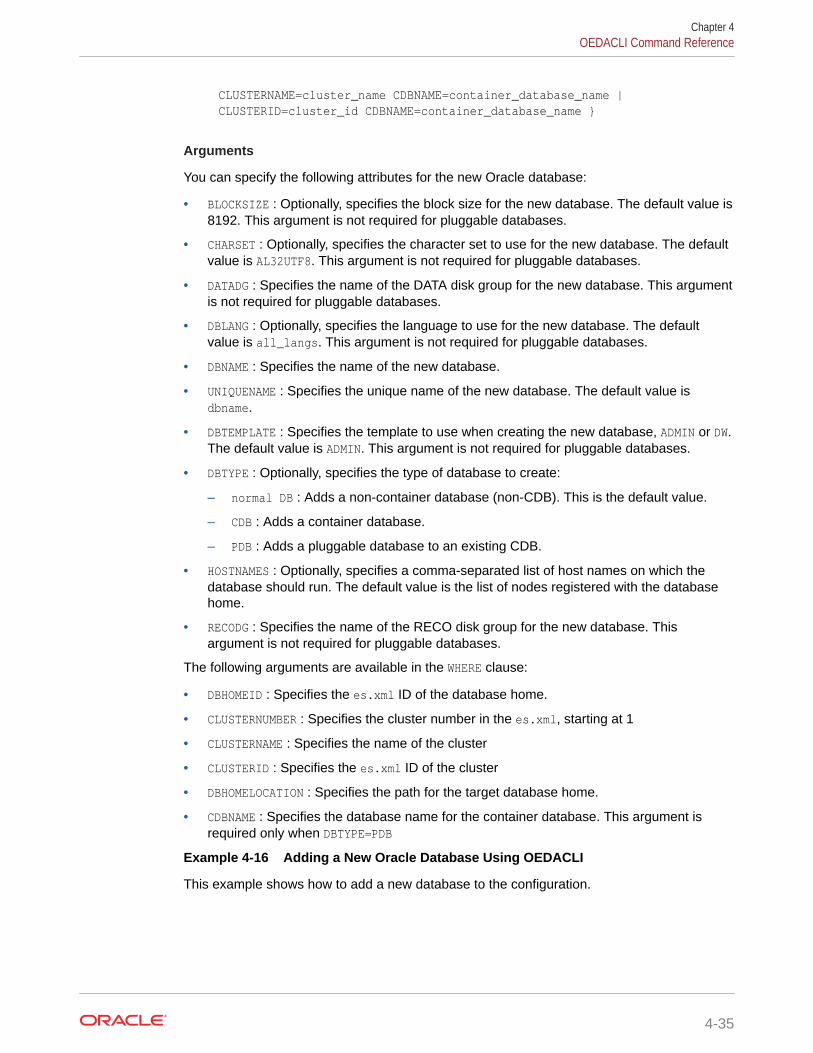
CLUSTERNAME=cluster_name CDBNAME=container_database_name | CLUSTERID=cluster_id CDBNAME=container_database_name }
Arguments
You can specify the following attributes for the new Oracle database:
• BLOCKSIZE : Optionally, specifies the block size for the new database. The default value is8192. This argument is not required for pluggable databases.
• CHARSET : Optionally, specifies the character set to use for the new database. The defaultvalue is AL32UTF8. This argument is not required for pluggable databases.
• DATADG : Specifies the name of the DATA disk group for the new database. This argumentis not required for pluggable databases.
• DBLANG : Optionally, specifies the language to use for the new database. The defaultvalue is all_langs. This argument is not required for pluggable databases.
• DBNAME : Specifies the name of the new database.
• UNIQUENAME : Specifies the unique name of the new database. The default value isdbname.
• DBTEMPLATE : Specifies the template to use when creating the new database, ADMIN or DW.The default value is ADMIN. This argument is not required for pluggable databases.
• DBTYPE : Optionally, specifies the type of database to create:
– normal DB : Adds a non-container database (non-CDB). This is the default value.
– CDB : Adds a container database.
– PDB : Adds a pluggable database to an existing CDB.
• HOSTNAMES : Optionally, specifies a comma-separated list of host names on which thedatabase should run. The default value is the list of nodes registered with the databasehome.
• RECODG : Specifies the name of the RECO disk group for the new database. Thisargument is not required for pluggable databases.
The following arguments are available in the WHERE clause:
• DBHOMEID : Specifies the es.xml ID of the database home.
• CLUSTERNUMBER : Specifies the cluster number in the es.xml, starting at 1
• CLUSTERNAME : Specifies the name of the cluster
• CLUSTERID : Specifies the es.xml ID of the cluster
• DBHOMELOCATION : Specifies the path for the target database home.
• CDBNAME : Specifies the database name for the container database. This argument isrequired only when DBTYPE=PDB
Example 4-16 Adding a New Oracle Database Using OEDACLI
This example shows how to add a new database to the configuration.
Chapter 4OEDACLI Command Reference
4-35
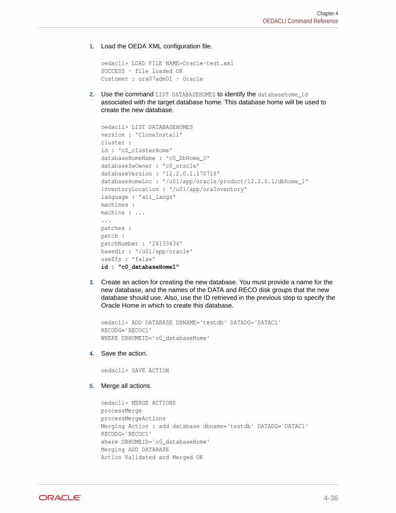
1. Load the OEDA XML configuration file.
oedacli> LOAD FILE NAME=Oracle-test.xml SUCCESS - file loaded OK Customer : ora07adm01 - Oracle
2. Use the command LIST DATABASEHOMES to identify the databasehome_idassociated with the target database home. This database home will be used tocreate the new database.
oedacli> LIST DATABASEHOMESversion : "CloneInstall" cluster : id : "c0_clusterHome" databaseHomeName : "c0_DbHome_0" databaseSwOwner : "c0_oracle" databaseVersion : "12.2.0.1.170718" databaseHomeLoc : "/u01/app/oracle/product/12.2.0.1/dbhome_1" inventoryLocation : "/u01/app/oraInventory" language : "all_langs" machines : machine : ... ... patches : patch : patchNumber : "26133434" basedir : "/u01/app/oracle" useZfs : "false" id : "c0_databaseHome1"
3. Create an action for creating the new database. You must provide a name for thenew database, and the names of the DATA and RECO disk groups that the newdatabase should use. Also, use the ID retrieved in the previous step to specify theOracle Home in which to create this database.
oedacli> ADD DATABASE DBNAME='testdb' DATADG='DATAC1' RECODG='RECOC1' WHERE DBHOMEID='c0_databaseHome'
4. Save the action.
oedacli> SAVE ACTION
5. Merge all actions.
oedacli> MERGE ACTIONSprocessMerge processMergeActions Merging Action : add database dbname='testdb' DATADG='DATAC1' RECODG='RECOC1' where DBHOMEID='c0_databaseHome' Merging ADD DATABASE Action Validated and Merged OK
Chapter 4OEDACLI Command Reference
4-36
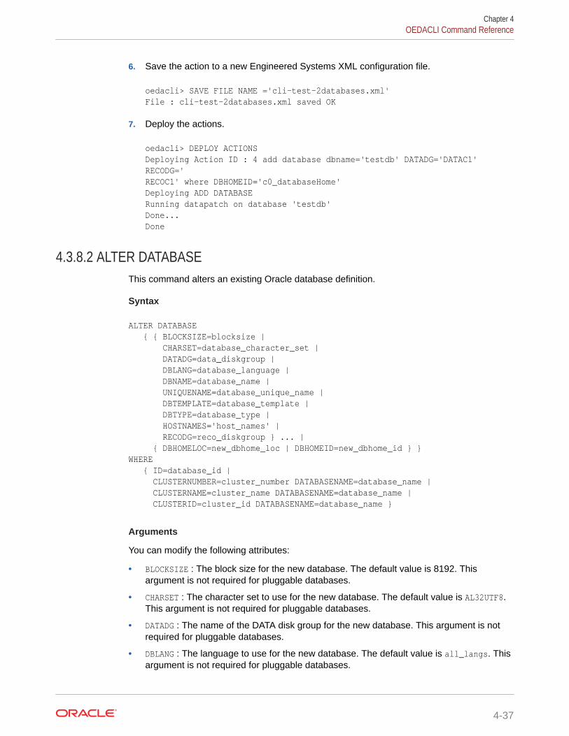
6. Save the action to a new Engineered Systems XML configuration file.
oedacli> SAVE FILE NAME ='cli-test-2databases.xml' File : cli-test-2databases.xml saved OK
7. Deploy the actions.
oedacli> DEPLOY ACTIONS Deploying Action ID : 4 add database dbname='testdb' DATADG='DATAC1' RECODG='RECOC1' where DBHOMEID='c0_databaseHome' Deploying ADD DATABASE Running datapatch on database 'testdb' Done... Done
4.3.8.2 ALTER DATABASEThis command alters an existing Oracle database definition.
Syntax
ALTER DATABASE { { BLOCKSIZE=blocksize | CHARSET=database_character_set | DATADG=data_diskgroup | DBLANG=database_language | DBNAME=database_name | UNIQUENAME=database_unique_name | DBTEMPLATE=database_template | DBTYPE=database_type | HOSTNAMES='host_names' | RECODG=reco_diskgroup } ... | { DBHOMELOC=new_dbhome_loc | DBHOMEID=new_dbhome_id } }WHERE { ID=database_id | CLUSTERNUMBER=cluster_number DATABASENAME=database_name | CLUSTERNAME=cluster_name DATABASENAME=database_name | CLUSTERID=cluster_id DATABASENAME=database_name }
Arguments
You can modify the following attributes:
• BLOCKSIZE : The block size for the new database. The default value is 8192. Thisargument is not required for pluggable databases.
• CHARSET : The character set to use for the new database. The default value is AL32UTF8.This argument is not required for pluggable databases.
• DATADG : The name of the DATA disk group for the new database. This argument is notrequired for pluggable databases.
• DBLANG : The language to use for the new database. The default value is all_langs. Thisargument is not required for pluggable databases.
Chapter 4OEDACLI Command Reference
4-37

• DBNAME : The name of the new database.
• UNIQUENAME : The unique name of the new database. The default value is dbname.
• DBTEMPLATE : The template to use when creating the new database, ADMIN or DW.The default value is ADMIN. This argument is not required for pluggable databases.
• DBTYPE : The type of database to create:
– normal DB : Specifies a non-container database (non-CDB). This is the defaultvalue.
– CDB : Specifies a container database.
– PDB : Specifies a pluggable database to an existing CDB.
• HOSTNAMES : A comma-separated list of host names on which the database shouldrun. The default value is the list of nodes registered with the database home.
• RECODG : The name of the RECO disk group for the new database. This argumentis not required for pluggable databases.
• DBHOMELOC : The location of the database home that you want to move thedatabase to. This argument is not required for pluggable databases.
• DBHOMEID : The es.xml ID of the database home that you want to move thedatabase to. This argument is not required for pluggable databases.
The following arguments are available in the WHERE clause:
• ID : Specifies the es.xml ID of the database
• CLUSTERNUMBER : Specifies the cluster number in the es.xml, starting at 1
• CLUSTERNAME : Specifies the name of the cluster
• CLUSTERID : Specifies the es.xml ID of the cluster
• DATABASENAME : Specifies the name of the database in the cluster
Usage Notes
For moving the database to use a different database home, specify only the new homelocation (DBHOMELOC) or the ID of the new database home (DBHOMEID).
4.3.8.3 DELETE DATABASEThis command deletes an existing Oracle database.
Syntax
DELETE DATABASE WHERE { ID=database_id | CLUSTERNUMBER=cluster_number DATABASENAME=database_name | CLUSTERNAME=cluster_name DATABASENAME=database_name | CLUSTERID=cluster_id DATABASENAME=database_name }
Arguments
The following arguments are available in the WHERE clause:
Chapter 4OEDACLI Command Reference
4-38

• ID : Specifies the es.xml ID of the database
• CLUSTERNUMBER : Specifies the cluster number in the es.xml, starting at 1
• CLUSTERNAME : Specifies the name of the cluster
• CLUSTERID : Specifies the es.xml ID of the cluster
• DATABASENAME : Specifies the name of the database in the cluster
Example 4-17 Deleting an Oracle Database Using OEDACLI
This example shows how to delete an existing database from the configuration.
1. Load the OEDA XML configuration file.
oedacli> LOAD FILE NAME=Oracle-test.xml SUCCESS - file loaded OK Customer : ora07adm01 - Oracle
2. List the databases contained in the XML configuration file, so that you can identify thedatabase ID associated with the database you want to delete.
oedacli> LIST DATABASESversion : "2" databaseOwner : "c0_oracle" databaseSid : "dbm01" databaseBlockSize : "8192" characterset : "AL32UTF8" databaseHome : id : "c0_databaseHome" machines : machine : ..... ..... diskGroups : diskGroup : id : "c0_datadg" id : "c0_recodg" id : "c0_dbm01" ..... ..... databaseHome : id : "c0_databaseHome3" machines : machine : .... .... databaseTemplate : "OLTP" databaseStyle : "ADMIN" language : "all_langs" diskGroups : diskGroup : id : "c0_datadg" id : "c0_recodg" id : "c0_testdb01"
Chapter 4OEDACLI Command Reference
4-39

3. Create an action to delete the target database. Use the database id identified inthe previous step
oedacli> delete database where id='c0_testdb01'
4. Save the action.
oedacli> SAVE ACTION
5. Merge all actions.
oedacli> MERGE ACTIONS processMerge processMergeActions Merging Action : delete database where id='c0_testdb01' Merging DELETE DATABASE Action Validated and Merged OK
6. Deploy the actions into the current configuration.
oedacli> DEPLOY ACTIONS Deploying Action ID : 1 delete database where id='c0_testdb01' Deploying DELETE DATABASE Deleting database testdb Done... Done
4.3.8.4 LIST DATABASESThis command lists the existing Oracle databases.
Syntax
LIST DATABASES [ WHERE { ID=database_id | CLUSTERNUMBER=cluster_number | CLUSTERNAME=cluster_name | CLUSTERID=cluster_id } ]
Arguments
The following arguments are available in the WHERE clause:
• ID : Specifies the es.xml ID of the database
• CLUSTERNUMBER : Specifies the cluster number in the es.xml, starting at 1
• CLUSTERNAME : Specifies the name of the cluster
• CLUSTERID : Specifies the es.xml ID of the cluster
4.3.9 DATABASEHOMEYou can add, alter, delete, or list the Oracle Database homes.
Chapter 4OEDACLI Command Reference
4-40
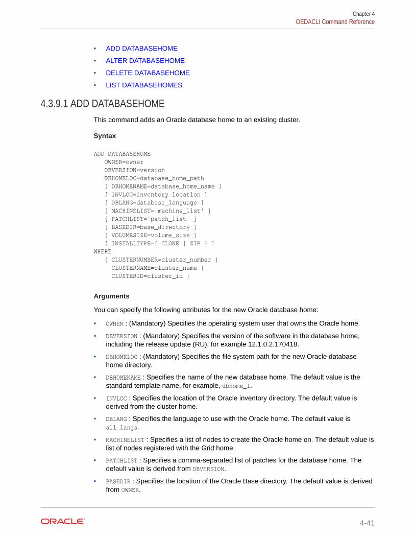
• ADD DATABASEHOME
• ALTER DATABASEHOME
• DELETE DATABASEHOME
• LIST DATABASEHOMES
4.3.9.1 ADD DATABASEHOMEThis command adds an Oracle database home to an existing cluster.
Syntax
ADD DATABASEHOME OWNER=owner DBVERSION=version DBHOMELOC=database_home_path [ DBHOMENAME=database_home_name ] [ INVLOC=inventory_location ] [ DBLANG=database_language ] [ MACHINELIST='machine_list' ] [ PATCHLIST='patch_list' ] [ BASEDIR=base_directory ] [ VOLUMESIZE=volume_size ] [ INSTALLTYPE={ CLONE | ZIP } ]WHERE { CLUSTERNUMBER=cluster_number | CLUSTERNAME=cluster_name | CLUSTERID=cluster_id }
Arguments
You can specify the following attributes for the new Oracle database home:
• OWNER : (Mandatory) Specifies the operating system user that owns the Oracle home.
• DBVERSION : (Mandatory) Specifies the version of the software in the database home,including the release update (RU), for example 12.1.0.2.170418.
• DBHOMELOC : (Mandatory) Specifies the file system path for the new Oracle databasehome directory.
• DBHOMENAME : Specifies the name of the new database home. The default value is thestandard template name, for example, dbhome_1.
• INVLOC : Specifies the location of the Oracle inventory directory. The default value isderived from the cluster home.
• DBLANG : Specifies the language to use with the Oracle home. The default value isall_langs.
• MACHINELIST : Specifies a list of nodes to create the Oracle home on. The default value islist of nodes registered with the Grid home.
• PATCHLIST : Specifies a comma-separated list of patches for the database home. Thedefault value is derived from DBVERSION.
• BASEDIR : Specifies the location of the Oracle Base directory. The default value is derivedfrom OWNER.
Chapter 4OEDACLI Command Reference
4-41

• VOLUMESIZE : Specifies the size of the home directory volume. The default value is50 GB. This argument is applicable only for database homes for Oracle VMclusters.
• INSTALLTYPE: Specifies the software installation method to use. The options are:
– CLONE: Uses image files to clone a software installation. The image filesinclude the base software release, and may also include additional patchesand updates. By including updates in the image files, this method reducesdeployment time and improves deployment consistency.
The CLONE software installation method is the only supported method fordatabase homes in a virtual machine (VM) deployment. This option is alsoavailable for database homes in a physical (bare metal) deployment.
– ZIP: Performs a fresh software installation by using compressed (zip) files thatcontain the software release. This method does not include additional patchesor updates.
This option is not available for database homes in a virtual machine (VM)deployment.
If you do not specify the INSTALLTYPE setting, then the default setting matches theINSTALLTYPE setting in the containing cluster.
The following arguments are available in the WHERE clause:
• CLUSTERNUMBER : Specifies the cluster number in the es.xml, starting at 1
• CLUSTERNAME : Specifies the name of the cluster
• CLUSTERID : Specifies the es.xml ID of the cluster
Example 4-18 Adding a Database Home to a Deployment using OEDACLI
This example shows how to add a new Oracle home. dbversion should specify boththe base version and the target release update (RU). In this example, we are settingup a new Oracle database home with 12.1.0.2.170418. The software will be installedunder /u01/app/oracle/product/12.1.0.2/dbhome_2.
./oedacli
oedacli> LOAD FILE NAME=Oracle-test12.xmlSUCCESS - file loaded OK Customer : ora07adm01 - Oracle
oedacli> ADD DATABASEHOME OWNER='oracle' DBVERSION='12.1.0.2.170418' DBHOMELOC='/u01/app/oracle/product/12.1.0.2/dbhome_2' WHERE CLUSTERNUMBER=1
oedacli> SAVE ACTION
oedacli> MERGE ACTIONSprocessMerge processMergeActions Merging Action : add databasehome owner='oracle' dbversion='12.1.0.2.170418' dbhomeloc='/u01/app/oracle/product/12.1.0.2/dbhome_2' where clusternumber=1 Merging ADD DATABASEHOME
Chapter 4OEDACLI Command Reference
4-42

Action Validated and Merged OK
oedacli> DEPLOY ACTIONSDeploying Action ID : 1 add databasehome owner='oracle' dbversion='12.1.0.2.170418' dbhomeloc='/u01/app/oracle/product/12.1.0.2/dbhome_2' where clusternumber=1 Deploying ADD DATABASEHOME Checking local files.. Required files are: SUCCESS: Required file /scratch/cpabba/Oeda/main/linux-x64/WorkDir/p26022196_121020_Linux-x86-64.zip exists... SUCCESS: Required file /scratch/cpabba/Oeda/main/linux-x64/WorkDir/p26027162_121020_Linux-x86-64.zip exists... SUCCESS: Required file /scratch/cpabba/Oeda/main/linux-x64/WorkDir/p6880880_122010_Linux-x86-64.zip exists... SUCCESS: Required file /scratch/cpabba/Oeda/main/linux-x64/WorkDir/linuxamd64_12102_database_2of2.zip exists... SUCCESS: Required file /scratch/cpabba/Oeda/main/linux-x64/WorkDir/linuxamd64_12102_database_1of2.zip exists... Copying required files... Checking status of remote files... Checking status of existing files on remote nodes... Getting status of local files... Copying file: linuxamd64_12102_database_1of2.zip to node node1adm01.example.com Copying file: linuxamd64_12102_database_2of2.zip to node node1adm01.example.com Copying file: p26022196_121020_Linux-x86-64.zip to node node1adm01.example.com Copying file: p26027162_121020_Linux-x86-64.zip to node node1adm01.example.com Copying file: p26022196_121020_Linux-x86-64.zip to node node1adm02.example.com Copying file: p26027162_121020_Linux-x86-64.zip to node node1adm02.example.com Completed copying files... Extracting files... Completed extracting files... Validating nodes for database readiness... Installing database software ... Running database installer on node node1adm01.example.com ... Please wait... After running database installer... Patching... Done... Done
4.3.9.2 ALTER DATABASEHOMEThis command alters an existing Oracle database home.
Chapter 4OEDACLI Command Reference
4-43
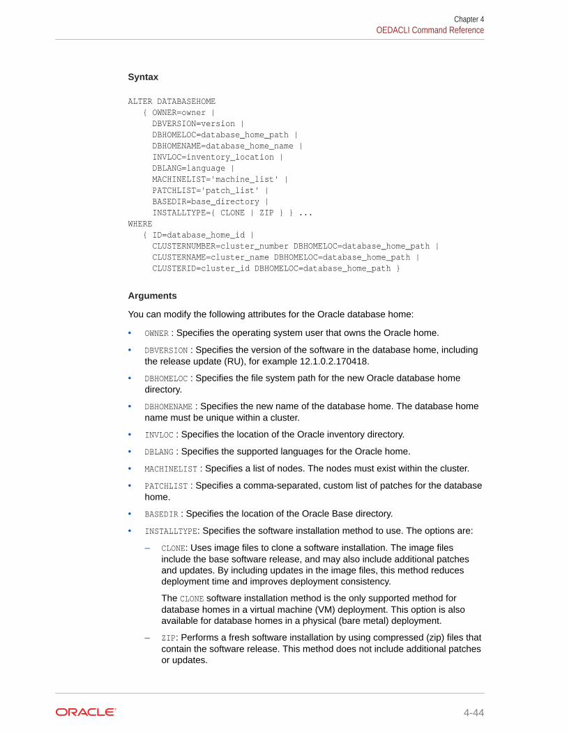
Syntax
ALTER DATABASEHOME { OWNER=owner | DBVERSION=version | DBHOMELOC=database_home_path | DBHOMENAME=database_home_name | INVLOC=inventory_location | DBLANG=language | MACHINELIST='machine_list' | PATCHLIST='patch_list' | BASEDIR=base_directory | INSTALLTYPE={ CLONE | ZIP } } ...WHERE { ID=database_home_id | CLUSTERNUMBER=cluster_number DBHOMELOC=database_home_path | CLUSTERNAME=cluster_name DBHOMELOC=database_home_path | CLUSTERID=cluster_id DBHOMELOC=database_home_path }
Arguments
You can modify the following attributes for the Oracle database home:
• OWNER : Specifies the operating system user that owns the Oracle home.
• DBVERSION : Specifies the version of the software in the database home, includingthe release update (RU), for example 12.1.0.2.170418.
• DBHOMELOC : Specifies the file system path for the new Oracle database homedirectory.
• DBHOMENAME : Specifies the new name of the database home. The database homename must be unique within a cluster.
• INVLOC : Specifies the location of the Oracle inventory directory.
• DBLANG : Specifies the supported languages for the Oracle home.
• MACHINELIST : Specifies a list of nodes. The nodes must exist within the cluster.
• PATCHLIST : Specifies a comma-separated, custom list of patches for the databasehome.
• BASEDIR : Specifies the location of the Oracle Base directory.
• INSTALLTYPE: Specifies the software installation method to use. The options are:
– CLONE: Uses image files to clone a software installation. The image filesinclude the base software release, and may also include additional patchesand updates. By including updates in the image files, this method reducesdeployment time and improves deployment consistency.
The CLONE software installation method is the only supported method fordatabase homes in a virtual machine (VM) deployment. This option is alsoavailable for database homes in a physical (bare metal) deployment.
– ZIP: Performs a fresh software installation by using compressed (zip) files thatcontain the software release. This method does not include additional patchesor updates.
Chapter 4OEDACLI Command Reference
4-44

This option is not available for database homes in a virtual machine (VM)deployment.
The following arguments are available in the WHERE clause:
• ID : Specifies the es.xml ID for the database home
• CLUSTERNUMBER : Specifies the cluster number in the es.xml, starting at 1
• CLUSTERNAME : Specifies the name of the cluster
• CLUSTERID : Specifies the es.xml ID of the cluster
• DBHOMELOC : Specifies the path for the database home directory.
4.3.9.3 DELETE DATABASEHOMEThis command removes an existing Oracle database home.
Syntax
DELETE DATABASEHOME WHERE { ID=database_home_id | CLUSTERNUMBER=cluster_number DBHOMELOC=database_home_path | CLUSTERNAME=cluster_name DBHOMELOC=database_home_path | CLUSTERID=cluster_id DBHOMELOC=database_home_path }
Arguments
The following arguments are available in the WHERE clause:
• ID : Specifies the es.xml ID for the database home
• CLUSTERNUMBER : Specifies the cluster number in the es.xml, starting at 1
• CLUSTERNAME : Specifies the name of the cluster
• CLUSTERID : Specifies the es.xml ID of the cluster
• DBHOMELOC : Specifies the path for the database home directory.
Usage Notes
The database home you are deleting must not contain any dependent databases.
Example 4-19 Removing an Existing Oracle Database Home
This example shows how to delete an existing Oracle Database home directory.
oedacli> LOAD FILE NAME=Oracle-test12.xml SUCCESS - file loaded OK Customer : ora07adm01 - Oracle
oedacli> DELETE DATABASEHOME WHERE id='c0_databaseHome1'
oedacli> SAVE ACTION
oedacli> MERGE ACTIONS processMerge
Chapter 4OEDACLI Command Reference
4-45
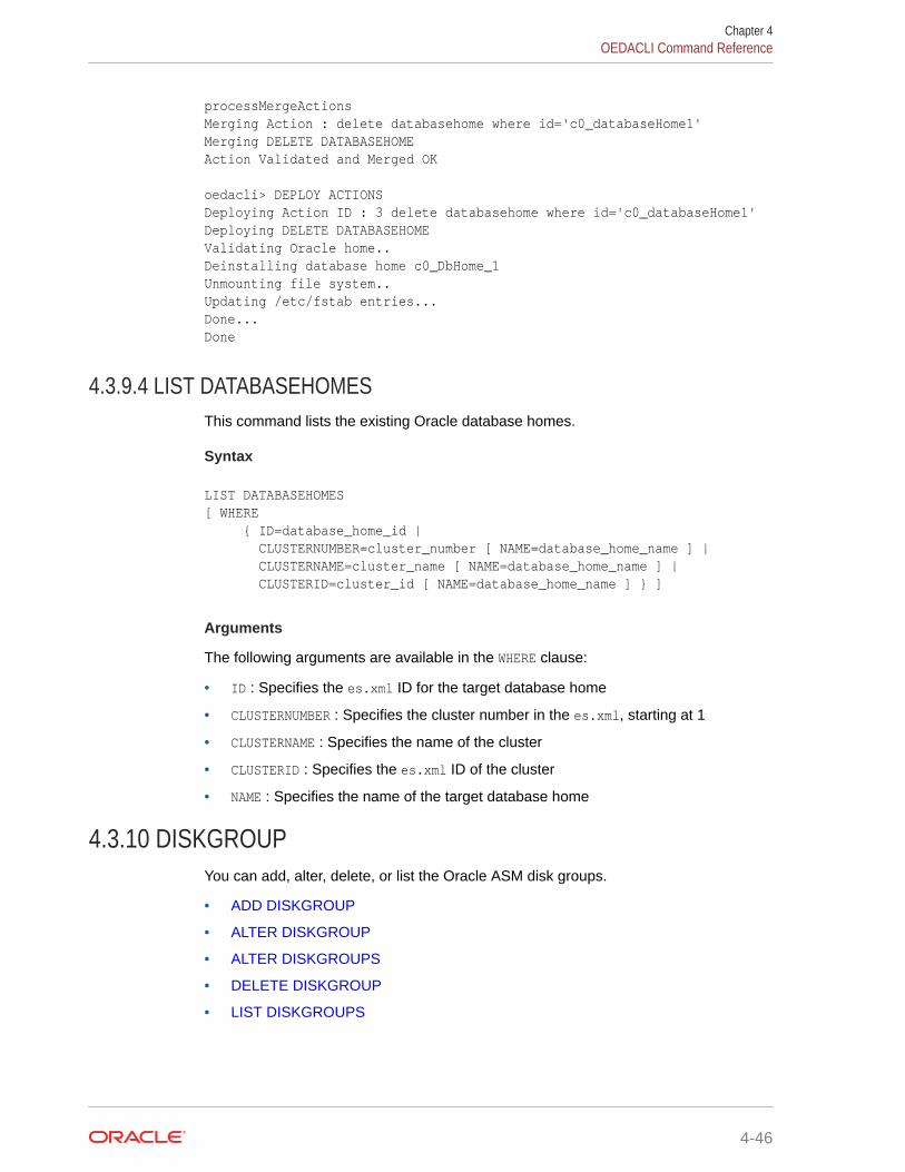
processMergeActions Merging Action : delete databasehome where id='c0_databaseHome1' Merging DELETE DATABASEHOME Action Validated and Merged OK
oedacli> DEPLOY ACTIONS Deploying Action ID : 3 delete databasehome where id='c0_databaseHome1' Deploying DELETE DATABASEHOME Validating Oracle home.. Deinstalling database home c0_DbHome_1 Unmounting file system.. Updating /etc/fstab entries... Done... Done
4.3.9.4 LIST DATABASEHOMESThis command lists the existing Oracle database homes.
Syntax
LIST DATABASEHOMES[ WHERE { ID=database_home_id | CLUSTERNUMBER=cluster_number [ NAME=database_home_name ] | CLUSTERNAME=cluster_name [ NAME=database_home_name ] | CLUSTERID=cluster_id [ NAME=database_home_name ] } ]
Arguments
The following arguments are available in the WHERE clause:
• ID : Specifies the es.xml ID for the target database home
• CLUSTERNUMBER : Specifies the cluster number in the es.xml, starting at 1
• CLUSTERNAME : Specifies the name of the cluster
• CLUSTERID : Specifies the es.xml ID of the cluster
• NAME : Specifies the name of the target database home
4.3.10 DISKGROUPYou can add, alter, delete, or list the Oracle ASM disk groups.
• ADD DISKGROUP
• ALTER DISKGROUP
• ALTER DISKGROUPS
• DELETE DISKGROUP
• LIST DISKGROUPS
Chapter 4OEDACLI Command Reference
4-46

4.3.10.1 ADD DISKGROUPThis command adds an Oracle ASM disk group.
Syntax
ADD DISKGROUP [ ACFSNAME=acfs_name ] [ ACFSPATH=acfs_path ] [ ACFSSIZE=acfs_size ] [ CELLLIST='cell_list' ] DISKGROUPNAME=diskgroup_name [ DISKGROUPLOCATION=diskgroup_location ] DISKGROUPSIZE=diskgroup_size [ OCRVOTE=ocr_voting_disks_included ] [ QUORUMDISK=quorum_disks_included ] REDUNDANCY=redundancy_level SLICESIZE=slice_size [ SPARSE=sparse ] [ TYPE=diskgroup_type [ DATABASENAME=database_name ]]WHERE { CLUSTERNUMBER=cluster_number | CLUSTERNAME=cluster_name | CLUSTERID=cluster_id }
Arguments
You can specify the following attributes for the new Oracle ASM disk group:
• ACFSNAME : Specifies the name for the Oracle ACFS volume on this disk group
• ACFSPATH : Specifies the path for the Oracle ACFS file system
• ACFSSIZE : Specifies the size for the Oracle ACFS volume on this diskgroup
• CELLLIST : A comma separated list of cells for this disk group, enclosed in single quotes
• DISKGROUPNAME : (Mandatory) Specifies the name of the disk group
• DISKGROUPLOCATION : Specifies the media type where the disk group is located. The validvalues are FLASHDISK or HARDDISK. The default value is HARDDISK.
The same disk group location is recommended for all non-RECO disk groups across allclusters in the Exadata configuration file (es.xml). If the RECO disk group location isFLASHDISK, then FLASHDISK is the recommended location for all disk groups.
• DISKGROUPSIZE : (Mandatory) Specifies the size of the disk group
• OCRVOTE : A boolean variable, where TRUE indicates the disk group should store the OCRand voting disks for the cluster.
• QUORUMDISK : A boolean variable, where TRUE indicates the disk group requires a quorum
• REDUNDANCY : (Mandatory) Specifies the redundancy level for the disk group. The validvalues are NORMAL or HIGH.
• SLICESIZE : (Mandatory) Specifies the slice size on disk for each grid disk for this diskgroup.
Chapter 4OEDACLI Command Reference
4-47

• SPARSE : A boolean variable, where TRUE indicates this should be sparse diskgroup.
• TYPE : Specifies the disk group type, which can be DATA, RECO, DBFS or OTHER. Thedefault value is OTHER. If you want the database to use this disk group, then thetype must be set to DATA or RECO.
• DATABASENAME : Specifies the name of the target database for disk groups of typeDATA or RECO.
The following arguments are available in the WHERE clause:
• CLUSTERNUMBER : Specifies the cluster number in the es.xml, starting at 1
• CLUSTERNAME : Specifies the name of the cluster
• CLUSTERID : Specifies the es.xml ID of the cluster
Example 4-20 Adding a Disk Group
The following example shows an OEDACLI session that uses the ADD DISKGROUPcommand along with typical output at each step.
oedacli> add diskgroup diskgroupname=OTHER7 diskgroupsize=1TB redundancy=HIGH celllist='dbm01celadm07.example.com,dbm01celadm08.example.com,dbm01celadm09.example.com' where clustername=Cluster-c1oedacli> save actionoedacli> merge actions processMerge processMergeActions Merging Action : add diskgroup diskgroupname=OTHER7 diskgroupsize=1TB redundancy=HIGH celllist='dbm01celadm07.example.com,dbm01celadm08.example.com,dbm01celadm09.example.com' where clustername=Cluster-c1 Merging ADD DISKGROUP Action Validated and Merged OKoedacli> deploy actions Deploying Action ID : 3 add diskgroup diskgroupname=OTHER7 diskgroupsize=1TB redundancy=HIGH celllist='dbm01celadm07.example.com,dbm01celadm08.example.com,dbm01celadm09.example.com' where clustername=Cluster-c1 Deploying ADD DISKGROUP Diskgroup OTHER7 will be created on Storage Servers [dbm01celadm07.example.com, dbm01celadm08.example.com, dbm01celadm09.example.com] Validating free space.... Creating Grid Disks for ASM Disk Group OTHER7 Creating ASM Disk Group OTHER7 Updating ASM Diskstring... Checking ASM Disk Group status...Completed creation of ASM Disk Group OTHER7Done...Done
Chapter 4OEDACLI Command Reference
4-48
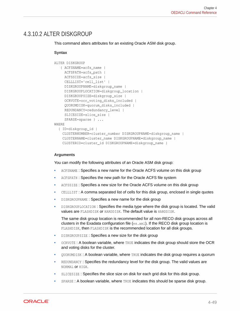
4.3.10.2 ALTER DISKGROUPThis command alters attributes for an existing Oracle ASM disk group.
Syntax
ALTER DISKGROUP { ACFSNAME=acfs_name | ACFSPATH=acfs_path | ACFSSIZE=acfs_size | CELLLIST='cell_list' | DISKGROUPNAME=diskgroup_name | DISKGROUPLOCATION=diskgroup_location | DISKGROUPSIZE=diskgroup_size | OCRVOTE=ocr_voting_disks_included | QUORUMDISK=quorum_disks_included | REDUNDANCY=redundancy_level | SLICESIZE=slice_size | SPARSE=sparse } ...WHERE { ID=diskgroup_id | CLUSTERNUMBER=cluster_number DISKGROUPNAME=diskgroup_name | CLUSTERNAME=cluster_name DISKGROUPNAME=diskgroup_name | CLUSTERID=cluster_id DISKGROUPNAME=diskgroup_name }
Arguments
You can modify the following attributes of an Oracle ASM disk group:
• ACFSNAME : Specifies a new name for the Oracle ACFS volume on this disk group
• ACFSPATH : Specifies the new path for the Oracle ACFS file system
• ACFSSIZE : Specifies a new size for the Oracle ACFS volume on this disk group
• CELLLIST : A comma separated list of cells for this disk group, enclosed in single quotes
• DISKGROUPNAME : Specifies a new name for the disk group
• DISKGROUPLOCATION : Specifies the media type where the disk group is located. The validvalues are FLASHDISK or HARDDISK. The default value is HARDDISK.
The same disk group location is recommended for all non-RECO disk groups across allclusters in the Exadata configuration file (es.xml). If the RECO disk group location isFLASHDISK, then FLASHDISK is the recommended location for all disk groups.
• DISKGROUPSIZE : Specifies a new size for the disk group
• OCRVOTE : A boolean variable, where TRUE indicates the disk group should store the OCRand voting disks for the cluster.
• QUORUMDISK : A boolean variable, where TRUE indicates the disk group requires a quorum
• REDUNDANCY : Specifies the redundancy level for the disk group. The valid values areNORMAL or HIGH.
• SLICESIZE : Specifies the slice size on disk for each grid disk for this disk group.
• SPARSE : A boolean variable, where TRUE indicates this should be sparse disk group.
Chapter 4OEDACLI Command Reference
4-49

The following arguments are available in the WHERE clause:
• ID : Specifies the es.xml ID for the disk group
• CLUSTERNUMBER : Specifies the cluster number in the es.xml, starting at 1
• CLUSTERNAME : Specifies the name of the cluster
• CLUSTERID : Specifies the es.xml ID of the cluster
• DISKGROUPNAME : Specifies the name of the disk group
Usage Notes
• With the ALTER DISKGROUP command, you may alter the size of an existing diskgroup using OEDACLI in deploy mode. All other disk group alterations are onlypermitted using OEDACLI in edit mode.
• If you modify the redundancy, the volume size will be maintained, however theslice size will be recalculated.
Example 4-21 Resizing an Oracle ASM Disk Group Using OEDACLI
This example shows how to resize an existing Oracle ASM disk group usingOEDACLI.
1. Load the OEDA XML configuration file.
oedacli> LOAD FILE NAME=Oracle-test.xml SUCCESS - file loaded OK Customer : ora07adm01 - Oracle
2. Use the command LIST DISKGROUPS to view the disk group details.
oedacli> LIST DISKGROUPSversion : "PhysicalLayoutLegacy" diskGroupName : "DBFS_DG" redundancy : "NORMAL" sliceSize : "default" machines : machine : ... ... cellDisks : "ALL" diskGroupSize : "436G" ocrVote : "true" quorumDisk : "false" id : "c0_dbfsdg" version : "PhysicalLayoutLegacy" diskGroupName : "DATAC1" redundancy : "NORMAL" sliceSize : "2953G" machines : .. .. cellDisks : "ALL" diskGroupSize : "53154G" ocrVote : "false" quorumDisk : "false"
Chapter 4OEDACLI Command Reference
4-50

id : "c0_datadg" version : "PhysicalLayoutLegacy" diskGroupName : "RECOC1" redundancy : "NORMAL" sliceSize : "ALL" machines : .. .. cellDisks : "ALL" diskGroupSize : "13284G" ocrVote : "false" quorumDisk : "false" id : "c0_recodg"
3. Create an action for resizing the disk group.
oedacli> ALTER DISKGROUP DISKGROUPSIZE='2500G' WHERE CLUSTERNUMBER=1 DISKGROUPNAME='DATAC1'
4. Save the action.
oedacli> SAVE ACTION
5. Merge all actions.
oedacli> MERGE ACTIONSprocessMerge processMergeActions Merging Action : alter diskgroup diskgroupsize='2500G' where diskgroupname='DATAC1' clusternumber=1 Merging ALTER DISKGROUPAction Validated and Merged OK
6. Deploy the actions.
oedacli> DEPLOY ACTIONS Deploying Action ID : 3 alter diskgroup diskgroupsize='2500G' where diskgroupname='DATAC1' Deploying ALTER DISKGROUP Deploying Action ID : 4 alter diskgroup diskgroupsize='2500G' where diskgroupname='DATAC1' clusternumber=1 Deploying ALTER DISKGROUP Validating ASM Disk status.. Disks in ASM Disk Group DATAC1 have valid status Shrinking Disk Group size to 2500 GB Resizing ASM Disk Group.. Checking Reblance operations in disk group DATAC1 Rebalance operations completed in disk group DATAC1 Original Grid Disk Size 2953 GB, new size 138 GB on node1celadm02.example.com
Chapter 4OEDACLI Command Reference
4-51

Original Grid Disk Size 2953 GB, new size 138 GB on node1celadm03.example.com Original Grid Disk Size 2953 GB, new size 138 GB on node1celadm01.example.com Updated/New Disk Group size 2484 GB, original size 53154 GB. Done... Done
4.3.10.3 ALTER DISKGROUPSThis command alters disk group sizing attributes for existing Oracle ASM disk groups.
Syntax
ALTER DISKGROUPS DATASPLIT=data_split_percent RECOSPLIT=reco_split_percent DATAREDUNDANCY=data_redundancy_level RECOREDUNDANCY=reco_redundancy_level SPLITDISK=percent_of_cell_diskWHERE DATADG=data_diskgroup RECODG=reco_diskgroup { CLUSTERNAME=cluster_name | CLUSTERNUMBER=cluster_number | CLUSTERID=cluster_id }
Arguments
You can modify the following sizing attributes of the DATA and RECO Oracle ASM diskgroups:
• DATASPLIT : Specifies a percentage of the Oracle ASM volume allocated to theDATA disk group. The sum of DATASPLIT and RECOSPLIT cannot exceed 100.
• RECOSPLIT : Specifies a percentage of the Oracle ASM volume allocated to theRECO disk group. The sum of DATASPLIT and RECOSPLIT cannot exceed 100.
• DATAREDUNDANCY : Specifies the redundancy level for the DATA disk group. Theaccepted values are NORMAL or HIGH.
• RECOREDUNDANCY : Specifies the redundancy level for the RECO disk group. Theaccepted values are NORMAL or HIGH.
• SPLITDISK : Specifies the percentage of the cell disk to allocate to the DATA andRECO disk groups. The specified value must be an integer between 1 and 100.
The following arguments are available in the WHERE clause:
• DATADG : Specifies the name of the DATA disk group in the cluster
• RECODG : Specifies the name of the RECO disk group in the cluster
• CLUSTERNUMBER : Specifies the cluster number in the es.xml, starting at 1
• CLUSTERNAME : Specifies the name of the cluster
• CLUSTERID : Specifies the es.xml ID of the cluster
Chapter 4OEDACLI Command Reference
4-52

4.3.10.4 DELETE DISKGROUPThis command deletes an existing Oracle ASM disk group.
Syntax
DELETE DISKGROUP WHERE { ID=diskgroup_id | CLUSTERNUMBER=cluster_number DISKGROUPNAME=diskgroup_name | CLUSTERNAME=cluster_name DISKGROUPNAME=diskgroup_name | CLUSTERID=cluster_id DISKGROUPNAME=diskgroup_name }
Arguments
The following arguments are available in the WHERE clause:
• ID : Specifies the es.xml ID for the disk group
• CLUSTERNUMBER : Specifies the cluster number in the es.xml, starting at 1
• CLUSTERNAME : Specifies the name of the cluster
• CLUSTERID : Specifies the es.xml ID of the cluster
• DISKGROUPNAME : Specifies the name of the disk group
Example 4-22 Deleting a Disk Group
The following example shows an OEDACLI session that uses the DELETE DISKGROUPcommand along with typical output at each step.
oedacli> delete diskgroup where id=10dff870-b824-cdb7-0542-8a03a88e9653oedacli> save actionoedacli> merge actions processMerge processMergeActions Merging Action : delete diskgroup where id=10dff870-b824-cdb7-0542-8a03a88e9653 Merging DELETE DISKGROUP Action Validated and Merged OKoedacli> deploy actions Deploying Action ID : 4 delete diskgroup where id=10dff870-b824-cdb7-0542-8a03a88e9653 Deploying DELETE DISKGROUP Dropping ASM Disk Group DATAC1 ASM Disk Group DATAC1 does not exist.. Grid Disks for Disk Group DATAC1 exist on cells dbm01celadm07.example.com Grid Disks for Disk Group DATAC1 exist on cells dbm01celadm08.example.com Grid Disks for Disk Group DATAC1 exist on cells dbm01celadm09.example.com Dropping Grid Disks on [dbm01celadm07.example.com, dbm01celadm08.example.com, dbm01celadm09.example.com] Deleting quorum devices... Completed dropping ASM Disk Group DATAC1 Done... Done
Chapter 4OEDACLI Command Reference
4-53

4.3.10.5 LIST DISKGROUPSThis command lists the existing Oracle ASM disk groups.
Syntax
LIST DISKGROUPS [ WHERE { ID=diskgroup_id | CLUSTERNUMBER=cluster_number | CLUSTERNAME=cluster_name | CLUSTERID=cluster_id } ]
Arguments
The following arguments are available in the WHERE clause:
• ID : Specifies the es.xml ID for the disk group
• CLUSTERNUMBER : Specifies the cluster number in the es.xml, starting at 1
• CLUSTERNAME : Specifies the name of the cluster
• CLUSTERID : Specifies the es.xml ID of the cluster
• DISKGROUPNAME : Specifies the name of the disk group
4.3.11 DOM0You can list Oracle VM management domains (dom0s).
• LIST DOM0S
4.3.11.1 LIST DOM0SThis command lists Oracle VM management domains (dom0s).
Syntax
LIST DOM0S
Usage Notes
This command is deprecated. Instead, use:
LIST MACHINES WHERE TYPE=DOM0
4.3.12 DOMAINYou can get live information from a domain.
• GET DOMAIN
Chapter 4OEDACLI Command Reference
4-54

4.3.12.1 GET DOMAINThis command displays live domain information from a running system.
Syntax
GET DOMAIN ACTION=actionWHERE { ID=id | HOSTNAME=hostname | CLUSTERNUMBER=cluster_number { COMPUTENUMBER=compute_number | STORAGENUMBER=storage_number } | CLUSTERNAME=cluster_name { COMPUTENUMBER=compute_number | STORAGENUMBER=storage_number } | CLUSTERID=cluster_id { COMPUTENUMBER=compute_number | STORAGENUMBER=storage_number } }
Arguments
ACTION : Specifies the information that the command returns.
If the action is applied to a guest, then the command displays specific information for theguest.
If the action is applied to the host, then the command displays information for the hypervisor.
• LISTIMAGES: Displays image file details.
• LISTDOMAIN: Displays domain details.
• LISTMEMORY: Displays memory details.
• LISTVCPU: Displays CPU details.
The following arguments are available in the WHERE clause:
• ID : Specifies the es.xml ID for the target machine
• HOSTNAME : Specifies the current hostname of the target machine
• CLUSTERNUMBER : Specifies the cluster number in the es.xml, starting at 1
• CLUSTERNAME : Specifies the name of the cluster
• CLUSTERID : Specifies the es.xml ID of the cluster
• COMPUTENUMBER : Specifies the es.xml compute node number in the cluster, starting at 1
• STORAGENUMBER : Specifies the es.xml storage server number in the cluster, starting at 1
4.3.13 ESYou can discover an engineered system or alter a limited number of attributes of anengineered system.
• ALTER ESThis command alters the attributes of an engineered system.
Chapter 4OEDACLI Command Reference
4-55

• DISCOVER ESThis command discovers an existing configuration of an engineered system.
• VALIDATE ES
4.3.13.1 ALTER ESThis command alters the attributes of an engineered system.
Syntax
ALTER ES PAAS = 'pass_mode' | CUSTOMERNAME = customer_name | CUSTOMERDEPT = customer_dept
Arguments
You can modify the following attributes for the engineered system:
• PAAS : A boolean value, TRUE or FALSE, which specifies whether to enable PaaSmode.
• CUSTOMERNAME : Specifies the customer name.
• CUSTOMERDEPT : Specifies the customer department.
4.3.13.2 DISCOVER ESThis command discovers an existing configuration of an engineered system.
Syntax
DISCOVER ES HOSTNAMES = host_names LOCATION = directory_name
Arguments
You can use the following arguments when discovering an engineered systemconfiguration:
• HOSTNAMES: Specifies the list of nodes to be discovered, with each host nameseparated by a ',' or a space. The list must be enclosed in quotation marks, forexample, 'node1,node2' or 'node1 node2'. For virtual environments with userdomains, you need to provide a list of only management domain (dom0) hostnames and storage servers.
• LOCATION: Specifies the target directory for file creation.
Usage Notes
The following are requirements and limitations of the DISCOVER ES command:
• Supported only on Exadata. ZDLRA is not supported.
• All hosts must have the same root password.
Chapter 4OEDACLI Command Reference
4-56

• Discover will not work with custom Operating System profiles and customized SQL*Plusprompts.
• Only RAC databases are discovered. Single instance databases and SIHA databases arenot discovered.
• Oracle Clusterware must be running.
• Only online databases are discovered.
• If DISCOVER ES cannot log into databases as SYSDBA using Operating Systemauthentication databases are skipped.
• Only database resources registered with Oracle Clusterware are discovered.
• Virtual machines that are not running are not discovered.
4.3.13.3 VALIDATE ESValidates certain aspects of an OEDA XML configuration file (es.xml).
Syntax
VALIDATE ES
4.3.14 EXITONERRORYou can set the exit status for OEDACLI.
• SET EXITONERRORThis command controls the exit status for OEDACLI when an error in encountered.
4.3.14.1 SET EXITONERRORThis command controls the exit status for OEDACLI when an error in encountered.
Syntax
SET EXITONERROR ENABLE={ true | false }
Arguments
• ENABLE: When ENABLE=true, a run-time error causes OEDACLI to terminate with exitcode 1. This option may be useful when OEDACLI is used inside a script.
4.3.15 FILEYou can manage the Engineered System XML file (es.xml).
• LOAD FILE
• MERGE FILES
• SAVE FILE
• SAVE FILES
Chapter 4OEDACLI Command Reference
4-57

4.3.15.1 LOAD FILEUse this command to load an Engineered System XML file (es.xml) into OEDACLImemory for further use.
Syntax
LOAD FILE NAME=file_name
Arguments
• NAME : Specifies the name of an existing Engineered System XML file
Example 4-23 Loading a File into OEDACLI for Editing
oedacli> LOAD FILE NAME=Oracle-test12.xml SUCCESS - file loaded OK Customer : testadm01 - Oracle
4.3.15.2 MERGE FILESUse this command to merge multiple Engineered System XML files into a new file.
Syntax
MERGE FILES INPUT='input_files' OUTPUT=output_file
Arguments
• INPUT: Specifies a space-separated list of Engineered System XML files to merge.The list of input files is surrounded by single quotes (').
• OUTPUT: Specifies the new target Engineered System XML file. The file isoverwritten if it already exists.
4.3.15.3 SAVE FILEUse this command to save a current set of actions to an Engineered System XML file.
Syntax
SAVE FILE [ NAME=file_name ] [ MAC={ true | false } ]
Arguments
• NAME: Optionally specifies the name of a new Engineered System XML file. If youdo not specify the NAME argument, then the command overwrites the source file.
Chapter 4OEDACLI Command Reference
4-58

• MAC: When MAC=true, OEDACLI updates the Engineered System XML file with MACaddresses for the system components. The ILOM interfaces must be available for thisoperation.
4.3.15.4 SAVE FILESUse this command to generate a full set of OEDA configuration files.
Syntax
SAVE FILES LOCATION=dir_name [ MAC={ true | false } ]
Arguments
• LOCATION: Specifies the name of a target directory for file creation.
• MAC: When MAC=true, OEDACLI updates the Engineered System XML file with MACaddresses for the system components. The ILOM interfaces must be available for thisoperation.
Usage Notes
The specified LOCATION directory is created if it does not already exist.
4.3.16 GUESTYou can clone or delete an Oracle VM guest.
• CLONE GUESTThis command clones an existing VM guest and creates a new fully functional guest withstorage, users, and Oracle RAC instances.
• DELETE GUESTThis command deletes an existing Oracle VM guest, and removes all of its configuration:instances, software installations, storage, and users from the cluster.
4.3.16.1 CLONE GUESTThis command clones an existing VM guest and creates a new fully functional guest withstorage, users, and Oracle RAC instances.
Prerequisites
Before you can clone an virtual machine (VM) guest, you must download the appropriatesoftware images from My Oracle Support and extract the files. Place the extracted "klone.zip"files for Oracle Grid Infrastructure and Oracle Database in the /EXAVMIMAGES/onecommand/<platform>/WorkDir directory in the management domain (dom0) wherethe new guest clone will be created.
Syntax
CLONE GUEST { SRCNAME=source_guest TGTNAME=target_guest |
Chapter 4OEDACLI Command Reference
4-59

TGTNAMES=target_guests }[ WHERE STEPNAME=stepname ]
SET PARENT NAME=parent_name [ SET ADMINNET NAME=admin_name IP=admin_ip [ GATEWAY=gateway NETMASK=netmask ] ][ SET BACKUPNET NAME=backup_name IP=backup_ip ]SET PRIVNET NAME1=priv_name_1 IP1=priv_ip1 NAME2=priv_name_2 IP2=priv_ip2 [ SET INTERCONNECT NAME1=priv_name_1 IP1=priv_ip1 NAME2=priv_name_2 IP2=priv_ip2 ]SET CLIENTNET NAME=client_name IP=client_ip [ NATHOSTNAME=nat_host_name NATIP=nat_ip NATDOMAINNAME=nat_domain_name, NATNETMASK=nat_netmask ]SET VIPNET NAME=vip_name,IP=vip_ip[ SET VCPU COUNT=guest_cpu ][ SET VMEM SIZE=guest_memory ]
Arguments
• SRCNAME: Specifies the name of an existing guest VM from which the new guestVM is derived.
• TGTNAME: Specifies the host name of the new guest VM that you are creating withthe clone operation.
• TGTNAMES: Specifies a comma-separated list of new guest VMs to add.
• STEPNAME: Specifies the deployment step to perform, which is one of the following:
– CREATE_GUEST
– CREATE_USERS
– CELL_CONNECTIVITY
– ADD_NODE
– EXTEND_DBHOME
– ADD_INSTANCE
You can specify the following additional settings when specifying CLONE GUEST with theWHERE STEPNAME=CREATE_GUEST clause or when specifying CLONE GUEST without usingany WHERE STEPNAME clause:
• PARENT: Specifies the name of the virtual machine (VM) host (Oracle Linux KVM orOracle VM) that hosts the new guest.
• ADMINNET : Specifies the DNS name and IP address to use for the administrationnetwork. Also, optionally specifies the gateway and netmask for the administrationnetwork.
• BACKUPNET : Specifies the DNS name and IP address to use for the backupnetwork. The DNS name may optionally include the domain name. Not required onguests without a backup network.
• PRIVNET : Specifies the names and IP addresses to use for the first and secondprivate networks.
Chapter 4OEDACLI Command Reference
4-60

• INTERCONNECT: Only required if the compute nodes are configured with Exadata SecureRDMA Fabric Isolation or InfiniBand security (PKEYS). Specifies the names and IPaddresses to use for the first and second private networks.
• CLIENTNET : Specifies the DNS name and IP address to use for the client network. Mayoptionally include host name, IP address, domain name, and netmask details to supportNetwork Address Translation (NAT).
• VIPNET : Specifies the DNS name and IP address to use for the virtual IP (VIP) network.
Usage Notes
• For configurations with Exadata Secure RDMA Fabric Isolation or InfiniBand security(PKEYS), INTERCONNECT defines the private network that connects the database nodesand PRIVNET defines the private storage network.
• When you load the XML configuration file to use when cloning a guest domain, the XMLfile should have the management domain (dom0) node of the source VM defined but notallocated to the cluster that is being extended into the guest domain.
• You should save the modified XML file after the actions are merged so that you have anew XML file that reflects the addition of the new guest domain.
Example 4-24 Cloning a Guest VM
This example shows how to clone a new guest from an existing node in the cluster. In thisexample, the source node name is exa01adm01vm01.example.com and the new node isexa01adm03vm01.example.com. A series of SET commands are used to specify theconfiguration for the new guest VM.
The XML file loaded at the beginning of this example has the dom0 node(host01adm01.example.com) defined but not allocated to the cluster that is being extendedinto the guest.
oedacli> LOAD FILE NAME=exa01-pre-cloning-node3.xmloedacli> CLONE GUEST SRCNAME='exa01adm01vm01.example.com' TGTNAME='exa01adm03vm01.example.com'oedacli> SET PARENT NAME='exa01adm03.example.com'oedacli> SET ADMINNET NAME='exa01adm03vm01.example.com' IP='10.xxx.xx.x'oedacli> SET CLIENTNET NAME='exa01client03vm01.example.com' IP='10.xxx.xx.x'oedacli> SET PRIVNET NAME1='exa01adm03vm01-priv' IP1='192.168.16.8' NAME2='exa01adm01vm03-priv2' IP2='192.168.16.9'oedacli> SET VIPNET NAME='exa01client03m01-vip.example.com' IP='10.xxx.xx.x'oedacli> SAVE ACTIONoedacli> MERGE ACTIONSoedacli> SAVE FILE NAME='exa01-cloned-node3-rac.xml'oedacli> DEPLOY ACTIONS
Example 4-25 Cloning Multiple Guests Using TGTNAMES
This example clones dbguest23 and creates the new guests dbguest24 and dbguest25. Byusing the TGTNAMES argument, both new guests are deployed at the same time in the finalDEPLOY ACTIONS.
CLONE GUEST SRCNAME='dbguest23' TGTNAME='dbguest24'SET ADMINNET name='dbguest24' ip='10.128.161.202'...SAVE ACTION FORCE
Chapter 4OEDACLI Command Reference
4-61
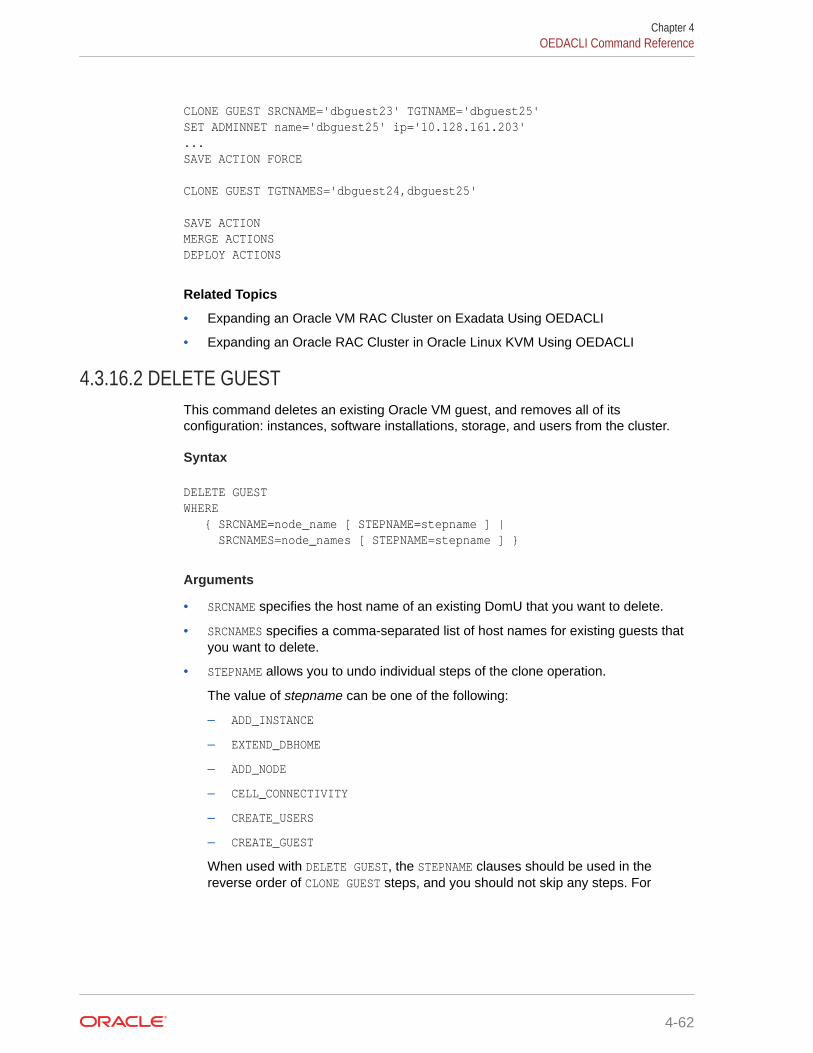
CLONE GUEST SRCNAME='dbguest23' TGTNAME='dbguest25'SET ADMINNET name='dbguest25' ip='10.128.161.203'...SAVE ACTION FORCE
CLONE GUEST TGTNAMES='dbguest24,dbguest25'
SAVE ACTIONMERGE ACTIONSDEPLOY ACTIONS
Related Topics
• Expanding an Oracle VM RAC Cluster on Exadata Using OEDACLI
• Expanding an Oracle RAC Cluster in Oracle Linux KVM Using OEDACLI
4.3.16.2 DELETE GUESTThis command deletes an existing Oracle VM guest, and removes all of itsconfiguration: instances, software installations, storage, and users from the cluster.
Syntax
DELETE GUEST WHERE { SRCNAME=node_name [ STEPNAME=stepname ] | SRCNAMES=node_names [ STEPNAME=stepname ] }
Arguments
• SRCNAME specifies the host name of an existing DomU that you want to delete.
• SRCNAMES specifies a comma-separated list of host names for existing guests thatyou want to delete.
• STEPNAME allows you to undo individual steps of the clone operation.
The value of stepname can be one of the following:
– ADD_INSTANCE
– EXTEND_DBHOME
– ADD_NODE
– CELL_CONNECTIVITY
– CREATE_USERS
– CREATE_GUEST
When used with DELETE GUEST, the STEPNAME clauses should be used in thereverse order of CLONE GUEST steps, and you should not skip any steps. For
Chapter 4OEDACLI Command Reference
4-62

example, if you want to undo the ADD_NODE and ADD_INSTANCE steps, you would use thefollowing commands:
DELETE GUEST WHERE SRCNAME=node_name STEPNAME=ADD_INSTANCEDELETE GUEST WHERE SRCNAME=node_name STEPNAME=EXTEND_DBHOMEDELETE GUEST WHERE SRCNAME=node_name STEPNAME=ADD_NODE
Example 4-26 Deleting a Guest
The following example shows an OEDACLI session that uses the DELETE GUEST commandalong with typical output at each step.
oedacli> delete guest where srcname='dbm01vm103.example.com'oedacli> save actionoedacli> merge actions processMerge processMergeActions Merging Action : delete guest where srcname='dbm01vm103.example.com' Merging DELETE GUEST Action Validated and Merged OKoedacli> deploy actions Deploying Action ID : 1 delete guest where srcname='dbm01vm103.example.com' Deploying DELETE GUEST Delete Guest Removing Cell Connectivity... Deleting cellip.ora and cellinit.ora on node dbm01vm103.example.com Done deleting cellip.ora and cellinit.ora on dbm01vm103.example.com Successfully completed removing cell connectivity [elapsed Time [Elapsed = 5018 mS [0.0 minutes] Wed May 05 10:29:51 PDT 2021]] Deleting users on dbm01vm103.example.com ... Deleting cluster users on node dbm01vm103.example.com Deleting cluster users... Deleting groups... Done deleting users and groups on node dbm01vm103.example.com Successfully completed deleting users on node(s) dbm01vm103.example.com[elapsed Time [Elapsed = 6043 mS [0.0 minutes] Wed May 05 10:29:57 PDT 2021]] Deleting KVM Guest dbm01vm103.example.com from dom0 dbm01adm03.example.com KVM Guest dbm01vm103.example.com deleted successfully. Done... Done
4.3.17 ILOMYou can alter or list the ILOMS in the loaded es.xml file.
• ALTER ILOM
• LIST ILOMS
4.3.17.1 ALTER ILOMThis command alters attributes of an ILOM.
Chapter 4OEDACLI Command Reference
4-63

Syntax
ALTER ILOM { DNSSERVERS='dns_servers' | NTPSERVERS='ntp_servers' | TIMEZONE=timezone } ...WHERE { ID=ilom_id | HOSTNAME=host_name | ILOMNAME=ilom_host_name }
Arguments
You can specify the following attributes for the ILOM:
• DNSSERVERS : Specifies a comma-separated list of DNS servers that is enclosed insingle quotes.
• NTPSERVERS : Specifies a comma-separated list of NTP servers that is enclosed insingle quotes.
• TIMEZONE : Specifies a valid time zone for the ILOM.
The following arguments are available in the WHERE clause:
• ID : Specifies the es.xml ID for the target ILOM
• HOSTNAME : Specifies the current host name of the target machine
• ILOMNAME : Specifies the current host name of the ILOM
4.3.17.2 LIST ILOMSThis command lists the ILOMs in the es.xml file.
Syntax
LIST ILOMS [ WHERE { ID = ilom_id | HOSTNAME = hostname | ILOMNAME = ilom_hostname } ]
Arguments
The following arguments are available in the WHERE clause:
• ID : Specifies the es.xml ID for the target ILOM
• HOSTNAME : Specifies the current host name of the target machine
• ILOMNAME : Specifies the current host name of the ILOM
Usage Notes
If you do not specify a WHERE clause, then this command lists all the ILOMs in thees.xml file.
Chapter 4OEDACLI Command Reference
4-64

4.3.18 LOGINYou can check remote login to a machine or cluster.
• CHECK LOGIN
4.3.18.1 CHECK LOGINThis command checks remote login to a machine or cluster.
Syntax
CHECK LOGIN WHERE { CLUSTERNUMBER=cluster_number | CLUSTERNAME=cluster_name | CLUSTERID=cluster_id | HOSTNAME=host_name }
Arguments
The following arguments are available in the WHERE clause:
• CLUSTERNUMBER : Specifies the cluster number in the es.xml, starting at 1
• CLUSTERNAME : Specifies the name of the cluster
• CLUSTERID : Specifies the es.xml ID of the cluster
• HOSTNAME : Specifies the name of an individual host
4.3.19 MACHINEYou can alter or list the machines in the es.xml file.
• ALTER MACHINE
• ALTER MACHINES
• LIST MACHINES
4.3.19.1 ALTER MACHINEThis command modifies attributes of an Engineered System machine, which is a physicalserver or virtual machine (VM) guest.
Syntax
ALTER MACHINE { { DNSSERVERS='dnsservers' | GATEWAYADAPTER=gatewayadapter | HOSTNAMEADAPTER=hostnameadapter | NTPSERVERS='ntpservers' | TIMEZONE=timezone | VSWITCH={ true | false } |
Chapter 4OEDACLI Command Reference
4-65

TYPE=newmachinetype | ORADISKSIZE=oradisksize | ORADISKPATH=oradiskpath }... | ACTION={ START [ WAIT={ true | false } ] | STOP [ WAIT={ true | false } ] | RESTART [ WAIT={ true | false } ] | CREATEIMAGE IMAGEFILE=imagefile SIZE=size [ FILESYSTEM=filesystem ] [ ZIPFILE=zipfile ] | ATTACHDISK IMAGEFILE=imagefile MOUNTPATH=mountpath [ FILESYSTEM=filesystem ] | DETACHDISK IMAGEFILE=imagefile [ DELETE=delete ] | SETVCPU [ VCPU=vcpu ] [ MAXVCPU=maxvcpu ] [ REBOOT={ true | false } ] | SETVMEM VMEM=vmem [ REBOOT={ true | false } ] } } WHERE { ID=id | HOSTNAME=hostname | CLUSTERNUMBER=clusternumber { COMPUTENUMBER=computenumber | STORAGENUMBER=storagenumber } | CLUSTERNAME=clustername { COMPUTENUMBER=computenumber | STORAGENUMBER=storagenumber } | CLUSTERID=clusterid { COMPUTENUMBER=computenumber | STORAGENUMBER=storagenumber } }
Arguments
You can specify the following arguments for the machine:
• DNSSERVERS: Comma-separated list of DNS servers for the machine. Enclose thelist in single quotes (').
• GATEWAYADAPTER: Network adapter to use for the machine gateway: ADMIN orCLIENT
• HOSTNAMEADAPTER: Network adapter to use for the machine hostname: ADMIN orCLIENT
• NTPSERVERS: Comma-separated list of NTP servers for the machine. Enclose thelist in single quotes (').
• TIMEZONE: Timezone specification for the machine
• VSWITCH: Specifies if the machine is connected to a vswitch. Default is false.
• TYPE: Sets a machine as new type. For example: X8XT
• ORADISKSIZE: Size (in GB) of the Oracle software volume (typically /u01). Defaultis 20, minimum is 10.
• ORADISKPATH: Mount point of the Oracle software volume. Default is /u01. For non-default values, take great care to ensure other paths are compatible with thesetting.
• ACTION: Action to perform against the specified VM guest machine. One of thefollowing:
– START: Starts the specified guest. The action completes when the machine isready for SSH connections. There is no error if the machine is already started.
Chapter 4OEDACLI Command Reference
4-66

– STOP: Stops the specified guest. The action completes when the machine is shutdown. There is no error if the machine is already stopped.
– RESTART: Stops and then starts the specified guest. The action completes when themachine is ready for SSH connections. There is no error if the machine is alreadystopped.
– CREATEIMAGE: Creates a disk image in the hypervisor for subsequent ATTACHDISKcommands.
– ATTACHDISK: Attaches a disk image from the hypervisor to a running guest andmounts the file system in the guest. FILESYSTEM must be specified if the default (xfs)is not used.
– DETACHDISK: Unmount the file system and detach a disk image from a guest, andoptionally delete the disk image.
– SETVCPU: Changes the CPU resource allocation for a guest. The action allowsallocation increases and reductions within the limit specified by the maxcpu value inthe vm.cfg file. The action can operate on a running guest. A reboot is not required toenable changes.
– SETVMEM: Changes the RAM resource allocation for a guest. A reboot is required toenable a change.
The following ACTION arguments are available:
– WAIT: Optionally specifies whether to wait for the associated action to complete.Default is true. With WAIT=false, the action starts asynchronously, and thecommand returns immediately with no indication or guarantee of success.
– IMAGEFILE: Name of the disk image file
– SIZE: Size (in GB) of the disk image file
– FILESYSTEM: File system type used in the disk image. Default is xfs. Alternative isext4.
– ZIPFILE: Zip file used to optionally populate a new disk image
– MOUNTPATH: Guest directory used to mount the disk image
– DELETE: Optionally specifies whether to delete the disk image. Default is false.
– VCPU: Number of Virtual CPUs allocated to the guest machine
– MAXVCPU: Maximum number of Virtual CPUs allocated to the guest machine
– VMEM: Amount of RAM (in GB) allocated to the guest machine
– REBOOT: Optionally specifies whether to automatically reboot the guest. Default isfalse.
The following arguments are available in the WHERE clause:
• ID: Specifies the identifier for the target machine in the OEDA XML file (es.xml)
• HOSTNAME: Specifies the current host name of the target machine
• CLUSTERNUMBER: Cluster number associated with target machine in the OEDA XML file(es.xml), starting at 1
• CLUSTERNAME: Name of the cluster associated with target machine in the OEDA XML file(es.xml)
Chapter 4OEDACLI Command Reference
4-67
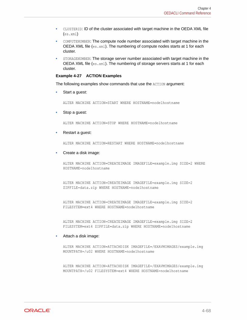
• CLUSTERID: ID of the cluster associated with target machine in the OEDA XML file(es.xml)
• COMPUTENUMBER: The compute node number associated with target machine in theOEDA XML file (es.xml). The numbering of compute nodes starts at 1 for eachcluster.
• STORAGENUMBER: The storage server number associated with target machine in theOEDA XML file (es.xml). The numbering of storage servers starts at 1 for eachcluster.
Example 4-27 ACTION Examples
The following examples show commands that use the ACTION argument:
• Start a guest:
ALTER MACHINE ACTION=START WHERE HOSTNAME=node1hostname
• Stop a guest:
ALTER MACHINE ACTION=STOP WHERE HOSTNAME=node1hostname
• Restart a guest:
ALTER MACHINE ACTION=RESTART WHERE HOSTNAME=node1hostname
• Create a disk image:
ALTER MACHINE ACTION=CREATEIMAGE IMAGEFILE=example.img SIZE=2 WHERE HOSTNAME=node1hostname
ALTER MACHINE ACTION=CREATEIMAGE IMAGEFILE=example.img SIZE=2 ZIPFILE=data.zip WHERE HOSTNAME=node1hostname
ALTER MACHINE ACTION=CREATEIMAGE IMAGEFILE=example.img SIZE=2 FILESYTEM=ext4 WHERE HOSTNAME=node1hostname
ALTER MACHINE ACTION=CREATEIMAGE IMAGEFILE=example.img SIZE=2 FILESYTEM=ext4 ZIPFILE=data.zip WHERE HOSTNAME=node1hostname
• Attach a disk image:
ALTER MACHINE ACTION=ATTACHDISK IMAGEFILE=/EXAVMIMAGES/example.img MOUNTPATH=/u02 WHERE HOSTNAME=node1hostname
ALTER MACHINE ACTION=ATTACHDISK IMAGEFILE=/EXAVMIMAGES/example.img MOUNTPATH=/u02 FILESYSTEM=ext4 WHERE HOSTNAME=node1hostname
Chapter 4OEDACLI Command Reference
4-68

• Detach a disk image:
ALTER MACHINE ACTION=DETACHDISK IMAGEFILE=example.img WHERE HOSTNAME=node1hostname
ALTER MACHINE ACTION=DETACHDISK IMAGEFILE=example.img DELETE=true WHERE HOSTNAME=node1hostname
• Change the CPU resource allocation:
ALTER MACHINE ACTION=SETVCPU MAXVCPU=12 VCPU=12 WHERE HOSTNAME=node1hostname
• Change the RAM resource allocation:
ALTER MACHINE ACTION=SETVMEM VMEM=9 WHERE HOSTNAME=node1hostname
4.3.19.2 ALTER MACHINESThis command modifies attributes of a collection of Engineered System machines.
Syntax
ALTER MACHINES { ORADISKSIZE=oradisksize | ORADISKPATH=oradiskpath | IMAGEVERSION=imageversion }...WHERE { CLUSTERNUMBER=clusternumber | CLUSTERNAME=clustername | CLUSTERID=clusterid | TYPE=GUESTS }
Arguments
You can specify the following arguments for the machine:
• ORADISKSIZE: Size (in GB) of the Oracle software volume (typically /u01). Default is 20,minimum is 10.
• ORADISKPATH: Mount point of the Oracle software volume. Default is /u01. For non-defaultvalues, take great care to ensure other paths are compatible with the setting.
• IMAGEVERSION: The version of the image to deploy on guest machines. This argument isonly applicable to guest machines (WHERE TYPE=GUEST).
The following arguments are available in the WHERE clause:
• CLUSTERNUMBER: Cluster number associated with target machine in the OEDA XML file(es.xml), starting at 1
• CLUSTERNAME: Name of the cluster associated with target machine in the OEDA XML file(es.xml)
Chapter 4OEDACLI Command Reference
4-69

• CLUSTERID: ID of the cluster associated with target machine in the OEDA XML file(es.xml)
• TYPE=GUEST: Applies the change to all guest machines. This option is onlyapplicable when setting the IMAGEVERSION.
4.3.19.3 LIST MACHINESThis command lists the machine available in the es.xml file for an engineered system.
Syntax
LIST MACHINES [ WHERE { TYPE=type | ID=machine_id | CLUSTERNUMBER=cluster_number [ TYPE=type ] | CLUSTERNAME=cluster_name [ TYPE=type ] | CLUSTERID=cluster_id [ TYPE=type ] } ]
Arguments
The following arguments are available in the WHERE clause:
• TYPE : Specifies the machine type. The valid values are COMPUTE, CELL, STORAGE,DOM0, GUEST, DOMU, KVM, or KVMGUEST.
• ID : Specifies the es.xml ID for an individual machine
• CLUSTERNUMBER : Specifies the cluster number in the es.xml, starting at 1
• CLUSTERNAME : Specifies the name of the cluster
• CLUSTERID : Specifies the es.xml ID of the cluster
Usage Notes
If you do not specify a WHERE clause, then this command lists all the machines definedin the es.xml file.
4.3.20 NETWORKYou can add, alter, delete, or list the networks defined in the XML configuration file.
• ADD NETWORK
• ALTER NETWORK
• ALTER NETWORKS
• DELETE NETWORK
• LIST NETWORKS
4.3.20.1 ADD NETWORKThis command adds a network record to a machine in the existing configuration.
Chapter 4OEDACLI Command Reference
4-70

Syntax
ADD NETWORK NETWORKTYPE=network_type HOSTNAME=hostname IP=ip_addr NETMASK=netmask DOMAINNAME=domain_name MASTER=master [ MTU=mtu ] [ GATEWAY=gateway ] [ SSHENABLED={ true | false } ] [ MAC=mac_addr ] [ LINKSPEED=nic_speed ] [ SLAVE='slave' ] [ PKEY=pkey ] [ PKEYNAME=pkey_name ] [ STATUS = status ] [ LACP={ true | false } ] [ VLANID=vlan_id ] [ INTERFACENAME=interface_name ] [ DESCRIPTION='network_description' ] [ VSWITCHNETWORKPARAMS='vswitchnetwork_parameters' ] [ NATHOSTNAME=nat_host_name ] [ NATIP=nat_ip_addr ] [ NATDOMAINNAME=nat_domain_name ] [ NATNETMASK=nat_mask ] WHERE { HOSTNAME=hostname | CLUSTERNAME=cluster_name { COMPUTENUMBER=compute_number | STORAGENUMBER=storage_number } | CLUSTERNUMBER=cluster_name { COMPUTENUMBER=compute_number | STORAGENUMBER=storage_number } }
Arguments
You can specify the following attributes when adding a network:
• NETWORKTYPE: Specifies the type of network, which can be ADMIN, CLIENT, BACKUP,PRIVATE, OTHER, INGESTVIP, REPLICATIONVIP, or ILOM.
• HOSTNAME: Specifies the short host name for the network
• IP: Specifies the IP address of the network
• NETMASK: Specifies the network netmask
• DOMAINNAME: Specifies the domain name of the network
• MASTER: Specifies the primary adapter name
• MTU: Specifies the network MTU (maximum transmission unit). Not applicable for PRIVATEor ILOM networks.
• GATEWAY: Specifies the network subnet gateway
• SSHENABLED: TRUE indicates that SSH should be enabled for this adapter
Chapter 4OEDACLI Command Reference
4-71

• MAC: Specifies the MAC address
• LINKSPEED: Either 10000 or 25000. Only for X7-2 or later 2-socket compute nodes.
• SLAVE: Specifies a space-separated list of secondary devices for a bondednetwork, enclosed in single quotes
• PKEY: Specifies the pkey, for PRIVATE networks only
• PKEYNAME: Specifies the pkey name, for PRIVATE networks only
• STATUS: Specifies the status of the network
• LACP: TRUE indicates that LACP should be enabled
• VLANID: Specifies the VLAN identifier. Applicable if the network is a non-privateVLAN network, or a VLAN network on a KVM guest.
• INTERFACENAME: The name for the private network on the VLAN for a KVM guestand cell, clre[0-1] or stre[0-1].
• DESCRIPTION: The text description for this network, surrounded by single quotes.
• VSWITCHNETWORKPARAMS: Parameters required for vswitches, surrounded by singlequotes.
• NATHOSTNAME: Specifies the NAT host name
• NATIP: Specifies the NAT IP address
• NATDOMAINNAME: Specifies the NAT domain name
• NATNETMASK: Specifies the NAT netmask
The following arguments are available in the WHERE clause:
• HOSTNAME: Specifies the host name for an existing compute node
• CLUSTERNUMBER: Specifies the cluster number in the es.xml, starting at 1
• CLUSTERNAME: Specifies the name of an existing cluster
• COMPUTENUMBER: Specifies the number of an existing compute node in the cluster,starting at 1
• STORAGENUMBER: Specifies the umber of an existing storage cell in the cluster,starting at 1
4.3.20.2 ALTER NETWORKThis command modifies a network record for a machine in the existing configuration.
Syntax
ALTER NETWORK { HOSTNAME=hostname | IP=ip_addr | NETMASK=netmask | DOMAINNAME=domain_name | MASTER=master | GATEWAY=gateway | SSHENABLED={ true | false } | MAC=mac_addr | MTU=mtu |
Chapter 4OEDACLI Command Reference
4-72

LINKSPEED=nic_speed | SLAVE='slave' | PKEY=pkey | PKEYNAME=pkey_name | STATUS=status | LACP={ true | false } | VLANID=vlan_id | INTERFACENAME=interface_name | DESCRIPTION='network_description' | VSWITCHNETWORKPARAMS='vswitchnetwork_parameters' | NATHOSTNAME=nat_host_name | NATIP=nat_ip_addr | NATDOMAINNAME=nat_domain_name | NATNETMASK=nat_mask } ... WHERE { ID=network_id | NETWORKHOSTNAME=network_hostname | NATHOSTNAME=nat_hostname | HOSTNAME=hostname NETWORKTYPE=network_type [ PRIVATEID=private_id ] | CLUSTERNAME=cluster_name { COMPUTENUMBER=compute_number | STORAGENUMBER=storage_number } NETWORKTYPE=network_type [ PRIVATEID=private_id ] | CLUSTERNUMBER=cluster_number { COMPUTENUMBER=compute_number | STORAGENUMBER=storage_number } NETWORKTYPE=network_type [ PRIVATEID=private_id ] }
Arguments
You can specify the following attributes when altering a network:
• HOSTNAME: Specifies the short host name for the network
• IP: Specifies the IP address of the network
• NETMASK: Specifies the netmask of the network
• DOMAINNAME: Specifies the domain name of the network
• MASTER: Specifies the master adapter name
• GATEWAY: Specifies the network subnet gateway
• SSHENABLED: TRUE indicates that SSH should be enabled for this adapter
• MAC: Specifies the MAC address
• MTU: Specifies the network MTU (maximum transmission unit). Not applicable for PRIVATEor ILOM networks.
• LINKSPEED: Either 10000 or 25000. Only for X7-2 or later 2-socket compute nodes.
• SLAVE: Specifies a space-separated list of secondary devices for a bonded network,enclosed in single quotes
• PKEY: Specifies the pkey, for PRIVATE networks only
• PKEYNAME: Specifies the pkey name, for PRIVATE networks only
• STATUS: Specifies the status of the network
• LACP: TRUE indicates that LACP should be enabled
Chapter 4OEDACLI Command Reference
4-73

• VLANID: Specifies the VLAN identifier. Applicable if the network is a non-privateVLAN network, or a VLAN network on a KVM guest.
• INTERFACENAME: The name for the private network on the VLAN for a KVM guestand cell, clre[0-1] or stre[0-1].
• DESCRIPTION: The text description for this network, surrounded by single quotes.
• VSWITCHNETWORKPARAMS: Parameters required for vswitches, surrounded by singlequotes.
• NATHOSTNAME: Specifies the NAT host name
• NATIP: Specifies the NAT IP address
• NATDOMAINNAME: Specifies the NAT domain name
• NATNETMASK: Specifies the NAT netmask
The following arguments are available in the WHERE clause:
• ID: Specifies the ID for the target network in the XML configuration file.
• NETWORKHOSTNAME: Specifies the host name for an network object, not the machinehost name
• NATHOSTNAME: Specifies the NAT host name for an existing compute node
• HOSTNAME: Specifies the host name for an existing compute node
• NETWORKTYPE: Specifies the type of network, which can be ADMIN, CLIENT, BACKUP,PRIVATE, OTHER, INGESTVIP, REPLICATIONVIP, or ILOM.
• PRIVATEID: Specifies the ID of the private network
• CLUSTERNUMBER: Specifies the cluster number in the XML configuration file, startingat 1
• CLUSTERNAME: Specifies the name of an existing cluster
• COMPUTENUMBER: Specifies the number of an existing compute node in the cluster,starting at 1
• STORAGENUMBER: Specifies the number of an existing storage cell in the cluster,starting at 1
4.3.20.3 ALTER NETWORKSThis command modifies the VLAN number for the specified machines.
Syntax
ALTER NETWORKS VLANID=vlan_idWHERE HOSTNAMES=hostnames NETWORKTYPE=network_type
Arguments
• VLANID: Specifies the VLAN identifier.
• HOSTNAMES: Specifies a comma-separated list of host names
Chapter 4OEDACLI Command Reference
4-74
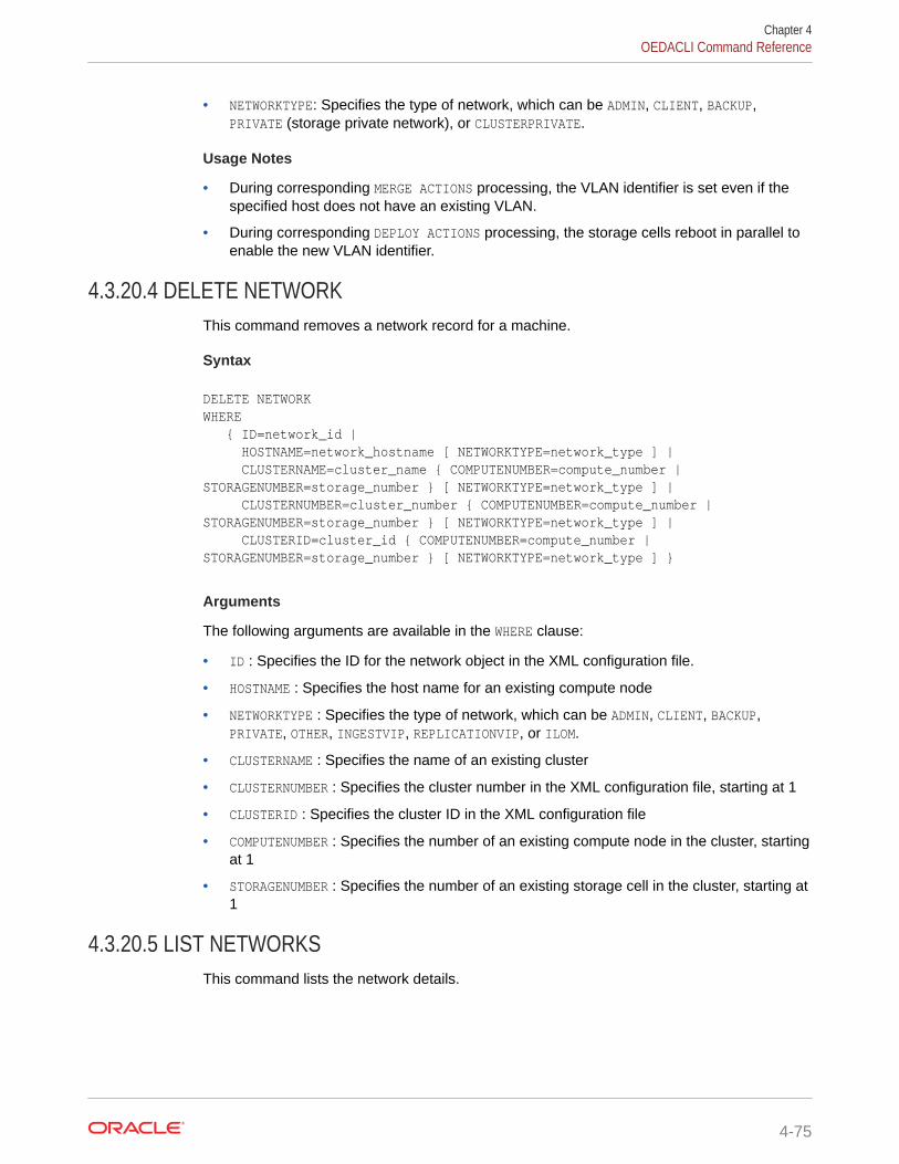
• NETWORKTYPE: Specifies the type of network, which can be ADMIN, CLIENT, BACKUP,PRIVATE (storage private network), or CLUSTERPRIVATE.
Usage Notes
• During corresponding MERGE ACTIONS processing, the VLAN identifier is set even if thespecified host does not have an existing VLAN.
• During corresponding DEPLOY ACTIONS processing, the storage cells reboot in parallel toenable the new VLAN identifier.
4.3.20.4 DELETE NETWORKThis command removes a network record for a machine.
Syntax
DELETE NETWORK WHERE { ID=network_id | HOSTNAME=network_hostname [ NETWORKTYPE=network_type ] | CLUSTERNAME=cluster_name { COMPUTENUMBER=compute_number | STORAGENUMBER=storage_number } [ NETWORKTYPE=network_type ] | CLUSTERNUMBER=cluster_number { COMPUTENUMBER=compute_number | STORAGENUMBER=storage_number } [ NETWORKTYPE=network_type ] | CLUSTERID=cluster_id { COMPUTENUMBER=compute_number | STORAGENUMBER=storage_number } [ NETWORKTYPE=network_type ] }
Arguments
The following arguments are available in the WHERE clause:
• ID : Specifies the ID for the network object in the XML configuration file.
• HOSTNAME : Specifies the host name for an existing compute node
• NETWORKTYPE : Specifies the type of network, which can be ADMIN, CLIENT, BACKUP,PRIVATE, OTHER, INGESTVIP, REPLICATIONVIP, or ILOM.
• CLUSTERNAME : Specifies the name of an existing cluster
• CLUSTERNUMBER : Specifies the cluster number in the XML configuration file, starting at 1
• CLUSTERID : Specifies the cluster ID in the XML configuration file
• COMPUTENUMBER : Specifies the number of an existing compute node in the cluster, startingat 1
• STORAGENUMBER : Specifies the number of an existing storage cell in the cluster, starting at1
4.3.20.5 LIST NETWORKSThis command lists the network details.
Chapter 4OEDACLI Command Reference
4-75

Syntax
LIST NETWORKS [ WHERE { ID=network_id | HOSTNAMES=ALL [ NETWORKTYPE=network_type ] | HOSTID=host_id [ NETWORKTYPE=network_type ] | HOSTNAME=network_hostname [ NETWORKTYPE=network_type ] | CLUSTERNAME=cluster_name { COMPUTENUMBER=compute_number | STORAGENUMBER=storage_number } [ NETWORKTYPE=network_type ] | CLUSTERNUMBER=cluster_number { COMPUTENUMBER=compute_number | STORAGENUMBER=storage_number } [ NETWORKTYPE=network_type ] } ]
Arguments
The following arguments are available in the WHERE clause:
• ID : Specifies the ID for the network object in the XML configuration file
• HOSTNAMES=ALL : Specifies all hosts
• NETWORKTYPE : Specifies the type of network, which can be ADMIN, CLIENT, BACKUP,PRIVATE, or ILOM.
• HOSTID : Specifies the host ID in the XML configuration file
• HOSTNAME : Specifies the host name for an existing compute node
• CLUSTERNAME : Specifies the name of an existing cluster
• CLUSTERNUMBER : Specifies the cluster number in the XML configuration file,starting at 1
• CLUSTERID : Specifies the cluster ID in the XML configuration file
• COMPUTENUMBER : Specifies the number of an existing compute node in the cluster,starting at 1
• STORAGENUMBER : Specifies the number of an existing storage cell in the cluster,starting at 1
4.3.21 PASSWORDYou can specify the default passwords.
• ALTER PASSWORDModifies the OEDA properties that specifies the default passwords.
4.3.21.1 ALTER PASSWORDModifies the OEDA properties that specifies the default passwords.
Syntax
ALTER PASSWORD [ PASSWORD=new_password ]
Chapter 4OEDACLI Command Reference
4-76

WHERE USER={ ROOT | NONROOT }
Arguments
• PASSWORD: Specifies the new password.
• USER: Specifies the user type; either ROOT or NONROOT.
Usage Notes
If the PASSWORD argument is not specified, then the user is prompted to specify and verify thepassword interactively.
4.3.22 PROPERTYYou can set OEDA properties.
• ALTER PROPERTYModifies an OEDA properties parameter.
• LIST PROPERTIESDisplays information about OEDA properties.
4.3.22.1 ALTER PROPERTYModifies an OEDA properties parameter.
Syntax
ALTER PROPERTY NAME=property_name VALUE=valueWHERE [ OS=os_name ]
Arguments
• NAME: Specifies the name of the property to alter. See LIST PROPERTIES to display theavailable properties.
• VALUE: Specifies the new property value
• OS: Optionally specifies the operating system that is associated with the property.Permitted values are: LINUX, SPARC, WINDOWS, MAC, OVM, or WEB.
Usage Notes
If the OS argument is not specified, then the property is updated in the main es.propertiesfile is updated.
4.3.22.2 LIST PROPERTIESDisplays information about OEDA properties.
Chapter 4OEDACLI Command Reference
4-77
Syntax
LIST PROPERTIES[ WHERE OS=os_name ]
Arguments
• OS: Optionally specifies the operating system that is associated with the properties.Permitted values are: LINUX, SPARC, WINDOWS, MAC, OVM, or WEB.
Usage Notes
If the OS argument is not specified, then the properties in the main es.properties aredisplayed.
4.3.23 RACKYou can manage an Engineered System rack.
• ADD RACKAdd a new rack to the Engineered System XML file.
• ALTER RACKModify a rack in the Engineered System XML file.
• LIST RACKSDisplays information about racks in the Engineered System XML file.
• LIST RACKDESCRIPTIONDisplays information about rack types supported by OEDA.
4.3.23.1 ADD RACKAdd a new rack to the Engineered System XML file.
Syntax
ADD RACK TYPE=ELASTIC MODEL={ X7 | X8 | X8M } SRCRACK=srcrack
SET ADMIN NAME=admin_name IP=admin_ipSET LEAF1 NAME=leaf1_name IP=leaf1_ipSET LEAF2 NAME=leaf2_name IP=leaf2_ip[ SET SPINE NAME=spine_name IP=spine_ip ][ SET PDU1 NAME=pdu1_name IP=pdu1_ip ][ SET PDU2 NAME=pdu2_name IP=pdu2_ip ]
Arguments
• TYPE: Specifies the ELASTIC rack type.
Chapter 4OEDACLI Command Reference
4-78

• MODEL: Specifies the rack model. Permitted values are: X7, X8, or X8M.
• SRCRACK: Specifies the es.xml identifier of the existing rack, which is used as thetemplate for the new rack.
You can set the following options for the new rack:
• ADMIN : Specifies the DNS name and IP address to use for the administration networkswitch. The DNS name may optionally include the domain name.
• LEAF1 : Specifies the DNS name and IP address to use for the first leaf switch. The DNSname may optionally include the domain name.
• LEAF2 : Specifies the DNS name and IP address to use for the second leaf switch. TheDNS name may optionally include the domain name.
• SPINE : Optionally specifies the DNS name and IP address to use for the spine switch.The DNS name may optionally include the domain name.
• PDU1 : Optionally specifies the DNS name and IP address to use for the first PDU. TheDNS name may optionally include the domain name.
• PDU2 : Optionally specifies the DNS name and IP address to use for the second PDU.The DNS name may optionally include the domain name.
4.3.23.2 ALTER RACKModify a rack in the Engineered System XML file.
Syntax
ALTER RACK ULOC={ ulocation | 0 | GENERATE }WHERE RACKNUMBER=rack_number [ HOSTNAME=host_name ]
ALTER RACK { DESCRIPTION=description | RACKID=rack_type } ...WHERE RACKNUMBER=rack_number
Arguments
You can modify the following attributes:
• ULOC: Sets the rack location (uloc) as follows:
– ULOC=ulocation: Specifies a rack location for a specific host or switch
– ULOC=0: Sets the rack location to 0 (zero) for all hosts and switches in the specifiedrack.
– ULOC=GENERATE: Assigns valid rack locations to all hosts and switches in the specifiedrack.
• DESCRIPTION: Sets the rack description
• RACKID: Sets the rack type
Chapter 4OEDACLI Command Reference
4-79

The following arguments are available in the WHERE clause:
• RACKNUMBER: Specifies the number of the rack in the Engineered System XML file,starting at 1
• HOSTNAME: Specifies the host name for a specific host or switch
Usage Notes
If you use the ULOC argument and supply a specific rack location (ULOC=ulocation),then you must specify HOSTNAME=host_name in the WHERE clause.
4.3.23.3 LIST RACKSDisplays information about racks in the Engineered System XML file.
Syntax
LIST RACKS
4.3.23.4 LIST RACKDESCRIPTIONDisplays information about rack types supported by OEDA.
Syntax
LIST RACKDESCRIPTION[ WHERE TYPE=rack ]
Arguments
TYPE: Optionally specifies the rack model that you want to use to limit the commandoutput.
Usage Notes
If the WHERE clause is omitted, all rack types are displayed.
4.3.24 REQUIREDFILESYou can display information about required files.
• LIST REQUIREDFILESDisplays information about required installation files for Oracle Grid Infrastructureor Oracle Database.
4.3.24.1 LIST REQUIREDFILESDisplays information about required installation files for Oracle Grid Infrastructure orOracle Database.
Chapter 4OEDACLI Command Reference
4-80

Syntax
LIST REQUIREDFILES { GRID | DATABASE | GIVERSION='<giversion>' | DBVERSION='<dbversion>' }
Arguments
• GRID: Displays information about required files for Oracle Grid Infrastructure
• DATABASE: Displays information about required files for Oracle Database
• GIVERSION: Specifies the Oracle Grid Infrastructure version including the release update(RU). For example: 12.1.0.2.170418.
• DBVERSION: Specifies the Oracle Database version including the release update (RU). Forexample: 12.1.0.2.170418.
Usage Notes
• Use GIVERSION or DBVERSION when no es.xml file is loaded.
• Use LIST SOFTWAREVERSIONS { GRID | DATABASE } to display information aboutsoftware versions.
4.3.25 REMOTEYou can run a command on a remote host.
• EXEC REMOTERuns a command on remote hosts.
4.3.25.1 EXEC REMOTERuns a command on remote hosts.
Syntax
EXEC REMOTE COMMAND='command'WHERE HOSTNAMES='host_names'
Section Title
• COMMAND: Specifies the command to run on the specified hosts.
• HOSTNAMES: Specifies the comma-separated list of remote hosts.
4.3.26 SCANYou can add, alter, delete, or list the SCANs for a cluster.
Chapter 4OEDACLI Command Reference
4-81

• ADD SCAN
• ALTER SCAN
• DELETE SCAN
• LIST SCANS
4.3.26.1 ADD SCANThis command adds a SCAN to the an Oracle Grid Infrastructure cluster.
Syntax
ADD SCAN SCANNAME=scan_name [ SCANPORT=scan_port ] SCANIPS='scan_ip_addrs'WHERE { CLUSTERNAME=cluster_name | CLUSTERNUMBER=cluster_number | CLUSTERID=cluster_id }
Arguments
You can specify the following attributes for the new SCAN:
• SCANNAME : Specifies the DNS name for the SCAN
• SCANPORT : Optionally specifies the port for the SCAN. The default value is 1521.
• SCANIPS : A comma-separated list of IP addresses for the SCAN, enclosed insingle quotes
The following arguments are available in the WHERE clause:
• CLUSTERNAME : Specifies the name of the cluster
• CLUSTERNUMBER : Specifies the cluster number in the XML configuration file,starting at 1
• CLUSTERID : Specifies the ID of the cluster in the XML configuration file
4.3.26.2 ALTER SCANThis command modifies the attributes of a SCAN for an Oracle Grid Infrastructurecluster.
Syntax
ALTER SCAN { SCANNAME=scan_name | SCANPORT=scan_port | SCANIPS='scan_ip_addrs' } ...WHERE { CLUSTERNAME=cluster_name | CLUSTERNUMBER=cluster_number | CLUSTERID=cluster_id }
Chapter 4OEDACLI Command Reference
4-82

Arguments
You can modify the following attributes for the SCAN:
• SCANNAME : Specifies the DNS name for the SCAN
• SCANPORT : Specifies the port for the SCAN
• SCANIPS : A comma-separated list of IP addresses for the SCAN, enclosed in singlequotes
The following arguments are available in the WHERE clause:
• CLUSTERNAME : Specifies the name of the cluster
• CLUSTERNUMBER : Specifies the cluster number in the XML configuration file, starting at 1
• CLUSTERID : Specifies the ID of the cluster in the XML configuration file
4.3.26.3 DELETE SCANThis command removes the SCAN for an Oracle Grid Infrastructure cluster.
Syntax
DELETE SCAN WHERE { CLUSTERNAME=cluster_name | CLUSTERNUMBER=cluster_number | CLUSTERID=cluster_id }
Arguments
The following arguments are available in the WHERE clause:
• CLUSTERNAME : Specifies the name of the cluster
• CLUSTERNUMBER : Specifies the cluster number in the XML configuration file, starting at 1
• CLUSTERID : Specifies the ID of the cluster in the XML configuration file
4.3.26.4 LIST SCANSThis command lists the SCAN details for all Oracle Grid Infrastructure clusters or for anindividual cluster.
Syntax
LIST SCANS [ WHERE { ID=scan_id | CLUSTERNAME=cluster_name | CLUSTERNUMBER=cluster_number | CLUSTERID=cluster_id } ]
Chapter 4OEDACLI Command Reference
4-83

Arguments
The following arguments are available in the WHERE clause:
• ID : Specifies the ID of the SCAN object in the XML configuration file
• CLUSTERNAME : Specifies the name of the cluster
• CLUSTERNUMBER : Specifies the cluster number in the XML configuration file,starting at 1
• CLUSTERID : Specifies the ID of the cluster in the XML configuration file
Usage Notes
If you do not specify a WHERE clause, then this command lists details about all theSCANS for all the clusters in the XML configuration file.
4.3.27 SECURITYYou can manage security settings.
• SET SECURITYThis command performs security-related actions, like setting the non-default rootpassword for the OEDACLI session or controlling password-based authentication.
4.3.27.1 SET SECURITYThis command performs security-related actions, like setting the non-default rootpassword for the OEDACLI session or controlling password-based authentication.
Prerequisites
Before you can use this command with the ENABLEPASSWORDLOGIN option, you mustconfigure SSH key-based authentication on the target system. See DEPLOYSSHKEYS.
Syntax
SET SECURITY PASSWORD=root_password
SET SECURITY ENABLEPASSWORDLOGIN={ true | false } [ HOSTNAMES="host1[,host2[,host3 ...]]" ]
Arguments
• PASSWORD: Specifies the non-default root password for the OEDACLI session
• ENABLEPASSWORDLOGIN: Specifies whether to enable or disable password-basedauthentication for the root user
• HOSTNAMES: Optionally specifies the list of host names on which to act
Chapter 4OEDACLI Command Reference
4-84

Usage Notes
If the HOSTNAMES argument is not specified, then the command acts on the currently loadedEngineered System XML file.
4.3.28 SOFTWAREVERSIONSYou can check supported software versions.
• LIST SOFTWAREVERSIONSDisplays information about supported versions of Oracle Grid Infrastructure and OracleDatabase.
4.3.28.1 LIST SOFTWAREVERSIONSDisplays information about supported versions of Oracle Grid Infrastructure and OracleDatabase.
Syntax
LIST SOFTWAREVERSIONS [ GRID | DATABASE ]
Arguments
• GRID: Displays information about supported versions of Oracle Grid Infrastructure
• DATABASE: Displays information about supported versions of Oracle Database
Usage Notes
• If neither argument (GRID or DATABASE) is specified, then LIST SOFTWAREVERSIONSdisplays information about supported software versions for Oracle Grid Infrastructure andOracle Database.
4.3.29 SSHKEYSYou can generate and deploy SSH keys for root user authentication on Oracle ExadataRack.
• DEPLOY SSHKEYSThis command configures SSH key-based authentication on all hosts in the EngineeredSystem XML file (es.xml), or the host names specified in the command.
• GENERATE SSHKEYSThis command generates SSH key pairs for all hosts in the Engineered System XML file(es.xml), or the host names specified in the command. The keys are saved in the OEDAWorkDir .
• SET SSHKEYSThis command enables and disables SSH key-based authentication for remotecommands run by OEDACLI.
Chapter 4OEDACLI Command Reference
4-85
4.3.29.1 DEPLOY SSHKEYSThis command configures SSH key-based authentication on all hosts in theEngineered System XML file (es.xml), or the host names specified in the command.
Syntax
DEPLOY SSHKEYS [ PASSWORD=root_password ] [ ENABLEPASSWORDLOGIN={ true | false } ] [ HOSTNAMES="host1[,host2[,host3 ...]]" ]
Arguments
• PASSWORD: Optionally specifies the non-default root password for connecting to thehosts to set up SSH key access
• ENABLEPASSWORDLOGIN: Optionally specifies whether to enable or disablepassword-based authentication for the root user after SSH key access is set up
• HOSTNAMES: Optionally specifies the list of host names on which to deploy SSHkeys
Usage Notes
• If the SSH key pairs are not located in the OEDA WorkDir, then the command alsogenerates them.
• If the HOSTNAMES argument is not specified, then the command acts on thecurrently loaded Engineered System XML file.
Example 4-28 Deploy SSH keys for all hosts of an XML file
oedacli> LOAD FILE NAME=es.xmlSUCCESS - file loadededacli> DEPLOY SSHKEYS ENABLEPASSWORDLOGIN=false
Example 4-29 Deploy SSH keys for specified hosts
oedacli> DEPLOY SSHKEYS ENABLEPASSWORDLOGIN=false PASSWORD="password" HOSTNAMES="dbm01adm05.example.com,dbm01adm06.example.com"
4.3.29.2 GENERATE SSHKEYSThis command generates SSH key pairs for all hosts in the Engineered System XMLfile (es.xml), or the host names specified in the command. The keys are saved in theOEDA WorkDir .
Syntax
GENERATE SSHKEYS [ HOSTNAMES="host1[,host2[,host3 ...]]" ]
Chapter 4OEDACLI Command Reference
4-86
Arguments
• HOSTNAMES optionally specifies the list of host names for which to generate SSH keys.
Usage Notes
• If the HOSTNAMES argument is not specified, then the command acts on the currentlyloaded Engineered System XML file.
Example 4-30 Generate SSH keys for all hosts of an XML file
oedacli> LOAD FILE NAME=es.xmlSUCCESS - file loadededacli> GENERATE SSHKEYSCreating SSH Key Pairs for hosts [dbm01adm01.example.com, dbm01adm02.example.com, ...]... Generated SSH Keys for [dbm01adm01.example.com, dbm01adm02.example.com, ...]
Example 4-31 Generate SSH keys for specified hosts
oedacli> GENERATE SSHKEYS HOSTNAMES="dbm02adm05.example.com,dbm02adm06.example.com"Creating SSH Key Pairs for hosts [dbm02adm06.example.com, dbm02adm05.example.com]... Generated SSH Keys for [dbm02adm06.example.com, dbm02adm05.example.com]
4.3.29.3 SET SSHKEYSThis command enables and disables SSH key-based authentication for remote commandsrun by OEDACLI.
Prerequisites
Before you can use this command, you must configure SSH key-based authentication on thetarget system. See DEPLOY SSHKEYS.
Syntax
SET SSHKEYS ENABLE={ true | false }
Arguments
• ENABLE specifies whether or not to enable SSH key-based authentication for remotecommands run by OEDACLI.
4.3.30 STEPSYou can display the steps for a virtual CREATE CLUSTER deployment.
• LIST STEPSThis command lists the steps for a virtual CREATE CLUSTER deployment.
Chapter 4OEDACLI Command Reference
4-87

4.3.30.1 LIST STEPSThis command lists the steps for a virtual CREATE CLUSTER deployment.
Each step is named, for example Create Virtual Machine. Each step also has a oneword identifier, for example, CREATEVM. The short name identifier is used whenspecifying STEPS or SKIPSTEPS in other commands, such as the CREATE CLUSTERcommand.
The list of valid steps for a cluster depends on the features selected for the cluster.The steps listed are valid for the identified cluster. If the XML file contains only 1cluster, then there is no need to identify the cluster explicitly.
The step numbers listed may change depending on features implemented for thecluster, but the short name identifier is always the same for a given step.
Syntax
LIST STEPS[ WHERE { CLUSTERNUMBER=cluster_number | CLUSTERNAME=cluster_name | ID=cluster_id } ]
Arguments
The following arguments are available in the WHERE clause:
• CLUSTERNUMBER : Specifies the cluster number in the es.xml, starting at 1
• CLUSTERNAME : Specifies the name of the cluster
• ID : Specifies the es.xml ID of the cluster
Example 4-32 Listing the Steps for a Specific Cluster
oedacli> LIST STEPS WHERE CLUSTERNAME = Cluster-c1 { "step" : [ { "stepName" : "Validate Configuration File", "shortName" : "VALIDATE", "id" : "1" }, { "stepName" : "Create Virtual Machine", "shortName" : "CREATEVM", "id" : "2" }, { "stepName" : "Create Users", "shortName" : "USERS", "id" : "3" }, { "stepName" : "Setup Cell Connectivity", "shortName" : "CELLCONN", "id" : "4" }, { "stepName" : "Calibrate Cells",
Chapter 4OEDACLI Command Reference
4-88

"shortName" : "CALIBRATE", "id" : "5" }, { "stepName" : "Create Cell Disks", "shortName" : "CELLDISKS", "id" : "6" }, { "stepName" : "Create Grid Disks", "shortName" : "GRIDDISKS", "id" : "7" }, { "stepName" : "Install Cluster Software", "shortName" : "INSTALLGI", "id" : "8" }, { "stepName" : "Initialize Cluster Software", "shortName" : "INITGI", "id" : "9" }, { "stepName" : "Install Database Software", "shortName" : "INSTALLDB", "id" : "10" }, { "stepName" : "Relink Database with RDS", "shortName" : "RELINK", "id" : "11" }, { "stepName" : "Create ASM Diskgroups", "shortName" : "ASMDG", "id" : "12" }, { "stepName" : "Create Databases", "shortName" : "DATABASE", "id" : "13" }, { "stepName" : "Apply Security Fixes", "shortName" : "APPLYFIXES", "id" : "14" }, { "stepName" : "Install Exachk", "shortName" : "EXACHK", "id" : "15" }, { "stepName" : "Create Installation Summary", "shortName" : "INSTALLSUMMARY", "id" : "16" }, { "stepName" : "Resecure Machine", "shortName" : "RESECURE", "id" : "17" } ]}
Chapter 4OEDACLI Command Reference
4-89

4.3.31 SWITCHYou can display and manage the switches.
• ADD SWITCHAdd a new switch to a rack in the Engineered System XML file.
• ALTER SWITCH
• LIST SWITCHES
4.3.31.1 ADD SWITCHAdd a new switch to a rack in the Engineered System XML file.
Syntax
ADD SWITCHWHERE { RACKID=rack_id | RACKNUMBER=rack_number }
SET ADMINNET NAME=admin_name, IP=admin_ip [ , GATEWAY=gateway, NETMASK=netmask ]SET DESCRIPTION VALUE=description[ SET IBPARTITIONMEMBERSHIP VALUE=pkey_membership ][ SET ULOC VALUE=ulocation ][ SET TIMEZONE VALUE=timezone ][ SET DNSSERVERS IP1=dns_ip1, IP2=dns_ip2, IP3=dns_ip3 ][ SET NTPSERVERS IP1=ntp_ip1, IP2=ntp_ip2, IP3=ntp_ip3 ]
Arguments
The following arguments are available in the WHERE clause:
• RACKID: Specifies the rack identifier in the XML configuration file
• RACKNUMBER: Specifies the rack number in the XML configuration file
You can set the following options for the new rack:
• ADMINNET: Specifies the details for the administration network.
• DESCRIPTION: Specifies a description for the switch
• IBPARTITIONMEMBERSHIP: Specifies the switch pkey membership
• ULOC: Specifies physical rack location for the switch
• TIMEZONE: Specifies a valid time zone for the switch
• DNSSERVERS: Specifies the DNS servers to set in the switch configuration
• NTPSERVERS: Specifies the NTP servers to set in the switch configuration
Chapter 4OEDACLI Command Reference
4-90
4.3.31.2 ALTER SWITCHThis command alters attributes of an individual switch.
Syntax
ALTER SWITCH { DNSSERVERS='dns_servers' | NTPSERVERS='ntp_servers' | TIMEZONE=time_zone | DESCRIPTION=description | ULOC=ulocation | IBPARTITIONMEMBERSHIP=pkey_membership } ... WHERE { ID=switch_id | HOSTNAME=switch_name }
Arguments
You can modify the following attributes for a switch:
• DNSSERVERS: Specifies a comma-separated list of DNS servers that is enclosed in singlequotes
• NTPSERVERS: Specifies a comma-separated list of NTP servers that is enclosed in singlequotes
• TIMEZONE: Specifies a valid time zone for the switch
• DESCRIPTION: Specifies a description for the switch
• ULOC: Specifies physical rack location for the switch
• IBPARTITIONMEMBERSHIP: Specifies the switch pkey membership
The following arguments are available in the WHERE clause:
• ID: Specifies the switch identifier in the XML configuration file
• HOSTNAME: Specifies the host name of the switch
4.3.31.3 LIST SWITCHESThis command displays details for all switches or for an individual switch.
Syntax
LIST SWITCHES [ WHERE { ID=switch_id | HOSTNAME=switch_name } ]
Arguments
The following arguments are available in the WHERE clause:
• ID : Specifies the switch identifier in the XML configuration file
Chapter 4OEDACLI Command Reference
4-91

• HOSTNAME : Specifies the host name of the switch
Usage Notes
If you do not specify a WHERE clause, then the command displays the details for allswitches.
4.3.32 SUControls use of the su command.
• SET SUThis command enables and disables using su from the root user to run remotenon-root commands from OEDACLI.
4.3.32.1 SET SUThis command enables and disables using su from the root user to run remote non-root commands from OEDACLI.
Syntax
SET SU ENABLE={ true | false }
Arguments
• ENABLE: Specifies whether or not OEDACLI uses su from the root user to runremote non-root commands.
4.3.33 ULOCYou can display the location of rack items.
• LIST ULOC
4.3.33.1 LIST ULOCThis command displays the location of defined rack items and new rack items.
Syntax
LIST ULOC [ NEWCOMPUTES={ new_computes_count | 'new_computes_list' } ] [ NEWCELLS={ new_cells_count | 'new_cells_list' } ][ WHERE RACKUMBER=rack_number ]
Arguments
• NEWCOMPUTES: Optionally specifies the number of new compute nodes to be added,or a comma-separated list of new compute node host names. Default is 0.
• NEWCELLS: Optionally specifies the number of new storage cells to be added, or acomma-separated list of new storage cell host names. Default is 0.
Chapter 4OEDACLI Command Reference
4-92
The following arguments are available in the WHERE clause:
• RACKNUMBER: Specifies the rack number in the XML configuration file
Usage Notes
If you do not specify a WHERE clause, then the command displays the details for rack number1.
4.3.34 VIPYou can add, alter, delete, or list the Oracle Clusterware VIPs.
• ADD VIP
• ALTER VIP
• DELETE VIP
• LIST VIPS
4.3.34.1 ADD VIPThis command adds a VIP for an individual node in a cluster.
Purpose
This command does not add additional VIPs. You should only use this command afterpreviously issuing a DELETE VIP command.
Syntax
ADD VIP NAME=vip_name DOMAINNAME=domain_name IP=vip_ip_addr WHERE { HOSTNAME=host_name | CLUSTERNAME=cluster_name COMPUTENUMBER=compute_number | CLUSTERNUMBER=cluster_number COMPUTENUMBER=compute_number | CLUSTERID=cluster_id COMPUTENUMBER=compute_number }
Arguments
You must specify the following attributes when adding a VIP:
• NAME: Specifies the short DNS name for the VIP
• DOMAINNAME: Specifies the domain name for the VIP
• IP: Specifies the IP address for the VIP
The following arguments are available in the WHERE clause:
• HOSTNAME: Specifies the host name for the compute node in the cluster
• CLUSTERNUMBER: Specifies the cluster number in the es.xml, starting at 1
• CLUSTERNAME: Specifies the name of the cluster
Chapter 4OEDACLI Command Reference
4-93

• CLUSTERID: Specifies the es.xml ID of the cluster
• COMPUTENUMBER: Specifies the compute node number in the cluster, starting at 1
Usage Notes
When adding a VIP to a compute node, the node must not already have a VIP defined.
4.3.34.2 ALTER VIPThis command alters the attributes of a VIP for an individual node in a cluster.
Syntax
ALTER VIP { NAME=vip_name | DOMAINNAME=domain_name | IP=vip_ip_addr } ...WHERE { HOSTNAME=host_name | CLUSTERNAME=cluster_name COMPUTENUMBER=compute_number | CLUSTERNUMBER=cluster_number COMPUTENUMBER=compute_number | CLUSTERID=cluster_id COMPUTENUMBER=compute_number }
Arguments
You can modify the following attributes for the VIP:
• NAME: Specifies the short DNS name for the VIP
• DOMAINNAME: Specifies the domain name for the VIP
• IP: Specifies the IP address for the VIP
The following arguments are available in the WHERE clause:
• HOSTNAME: Specifies the host name for the compute node in the cluster
• CLUSTERNUMBER: Specifies the cluster number in the es.xml, starting at 1
• CLUSTERNAME: Specifies the name of the cluster
• CLUSTERID: Specifies the es.xml ID of the cluster
• COMPUTENUMBER: Specifies the compute node number in the cluster, starting at 1
4.3.34.3 DELETE VIPThis command removes a VIP from an individual node in a cluster.
Syntax
DELETE VIP WHERE { ID=vip_id | HOSTNAME=host_name | CLUSTERNAME=cluster_name COMPUTENUMBER=compute_number |
Chapter 4OEDACLI Command Reference
4-94
CLUSTERNUMBER=cluster_number COMPUTENUMBER=compute_number | CLUSTERID=cluster_id COMPUTENUMBER=compute_number }
Arguments
The following arguments are available in the WHERE clause:
• ID: Specifies the ID for the VIP in the XML configuration file
• HOSTNAME: Specifies the host name for the compute node in the cluster
• CLUSTERNUMBER: Specifies the cluster number in the XML configuration file, starting at 1
• CLUSTERNAME: Specifies the name of the cluster
• CLUSTERID: Specifies the ID of the cluster in the XML configuration file
• COMPUTENUMBER: Specifies the compute node number in the cluster, starting at 1
4.3.34.4 LIST VIPSThis command lists the VIPs for all clusters or for an individual node in a cluster.
Syntax
LIST VIPS [ WHERE { HOSTNAME=host_name | CLUSTERNAME=cluster_name [ COMPUTENUMBER=compute_number ] | CLUSTERNUMBER=cluster_number [ COMPUTENUMBER=compute_number ] | CLUSTERID=cluster_id [ COMPUTENUMBER=compute_number ] }
Arguments
The following arguments are available in the WHERE clause:
• ID: Specifies the ID for the VIP in the XML configuration file
• HOSTNAME: Specifies the host name for the compute node in the cluster
• CLUSTERNUMBER: Specifies the cluster number in the XML configuration file, starting at 1
• CLUSTERNAME: Specifies the name of the cluster
• CLUSTERID: Specifies the ID of the cluster in the XML configuration file
• COMPUTENUMBER: Specifies the compute node number in the cluster, starting at 1
Usage Notes
If you do not specify a WHERE clause, then this command lists the VIPs for all clusters.
4.3.35 VOLUMEYou can display and manage storage volumes.
• ADD VOLUME
• DELETE VOLUME
• LIST VOLUMES
Chapter 4OEDACLI Command Reference
4-95
4.3.35.1 ADD VOLUMEThis command adds a storage volume to a KVM guest.
Syntax
ADD VOLUME MOUNTPATH=mount_path SIZE=sizeWHERE HOSTNAME=host_name
Arguments
You must specify the following attributes when adding a volume:
• MOUNTPATH: Specifies the mount point directory for the volume
• SIZE: Specifies the volume size in GB. Must be an integer value.
The following arguments are available in the WHERE clause:
• HOSTNAME: Specifies the host name for the KVM guest
Usage Notes
You can use this command to add a custom sized volume for the /u01 filesystem.
4.3.35.2 DELETE VOLUMEThis command deletes a storage volume from a KVM guest.
Syntax
DELETE VOLUME WHERE HOSTNAME=host_name MOUNTPATH=mount_path
Arguments
The following arguments are required in the WHERE clause:
• HOSTNAME: Specifies the host name for the KVM guest
• MOUNTPATH: Specifies the mount point directory for the volume
4.3.35.3 LIST VOLUMESThis command lists the volumes defined for an individual KVM guest.
Chapter 4OEDACLI Command Reference
4-96
Syntax
LIST VOLUMES WHERE HOSTNAME=host_name
Arguments
The following arguments are required in the WHERE clause:
• HOSTNAME: Specifies the host name for the KVM guest
4.3.36 XMLACTIONYou can manage actions relating to the Engineered System XML file.
• ALTER XMLACTION
• DELETE XMLACTION
• LIST XMLACTION
• LIST XMLACTIONS
4.3.36.1 ALTER XMLACTIONThis command alters a specific OEDACLI action.
Syntax
ALTER XMLACTION ID=action_identifer CMDID=command_identifer CMD=command
Arguments
• ID: Specifies the action identifier. See output from LIST XMLACTIONS.
• CMDID: Specifies the command identifier. See output from LIST XMLACTIONS.
• CMD: Specifies the command for the action.
4.3.36.2 DELETE XMLACTIONThis command removes a specific OEDACLI action.
Syntax
DELETE XMLACTION ID=action_identifer
Arguments
ID: Specifies the action identifier. See output from LIST XMLACTIONS.
Chapter 4OEDACLI Command Reference
4-97

4.3.36.3 LIST XMLACTIONThis command lists a specific OEDACLI action.
Syntax
LIST XMLACTION ID=action_identifer
Arguments
ID: Specifies the action identifier. See output from LIST XMLACTIONS.
4.3.36.4 LIST XMLACTIONSThis command lists the current actions created by OEDACLI.
Syntax
LIST XMLACTIONS
Chapter 4OEDACLI Command Reference
4-98

5Installing Oracle Exadata Database Machineor Oracle Exadata Storage Expansion Rack atthe Site
This chapter describes how to move, install and configure the hardware through to poweringon the system.
Note:
For ease of reading, the name "Oracle Exadata Rack" is used when informationrefers to both Oracle Exadata Database Machine and Oracle Exadata StorageExpansion Rack.
• Reviewing Safety GuidelinesBefore Oracle Exadata Rack arrives, the following safety precautions should be reviewedto ensure the site is safe, as well as ready for delivery.
• Unpacking Oracle Exadata Rack
• Placing Oracle Exadata Rack in Its Allocated Space
• Acclimating the Oracle Exadata Database MachineOracle recommends an acclimation period of 24 hours for the Oracle Exadata DatabaseMachine.
• Powering on the System the First Time
5.1 Reviewing Safety GuidelinesBefore Oracle Exadata Rack arrives, the following safety precautions should be reviewed toensure the site is safe, as well as ready for delivery.
Failing to observe these precautions can result in injury, equipment damage, or malfunction.
• Do not block ventilation openings.
• Do not install Oracle Exadata Rack in a location that is exposed to direct sunlight or neara device that may become hot.
• Do not install Oracle Exadata Rack in a location that is exposed to excessive dust,corrosive gases, or air with high salt concentrations.
• Do not install Oracle Exadata Rack in a location that is exposed to frequent vibrations.Install Oracle Exadata Rack on a flat, level surface.
• Use a power outlet that uses proper grounding. When using shared grounding, thegrounding resistance must not be greater than 10 ohms. Ensure that your facilityadministrator or a qualified electrical engineer verifies the grounding method for thebuilding, and performs the grounding work.
5-1

• Be sure that each grounding wire used for Oracle Exadata Rack is usedexclusively for Oracle Exadata Rack. Also be sure to observe the precautions,warnings, and notes about handling that appear on labels on the equipment.
• Do not place cables under the equipment or stretch the cables too tightly.
• Do not disconnect power cords from the equipment while its power is on.
• If you cannot reach the connector lock when disconnecting LAN cables, then pressthe connector lock with a flathead screwdriver to disconnect the cable. You coulddamage the system board if you force your fingers into the gap rather than using aflathead screwdriver.
• Do not place anything on top of Oracle Exadata Rack or perform any work directlyabove the rack.
• Do not let the room temperature rise sharply, especially in winter. Suddentemperature changes can cause condensation to form inside Oracle ExadataRack. Allow for a sufficient warm-up period prior to server operation.
• Do not install Oracle Exadata Rack near a photocopy machine, air conditioner,welding machine, or any other equipment that generates loud, electronic noises.
• Avoid static electricity at the installation location. Static electricity transferred toOracle Exadata Rack can cause malfunctions. Static electricity is often generatedon carpets.
• Confirm the supply voltage and frequency match the electrical ratings indicated forOracle Exadata Rack.
• Do not insert anything into any Oracle Exadata Rack opening, unless doing so ispart of a documented procedure. Oracle Exadata Rack contains high-voltageparts. If a metal object or other electrically-conductive object enters an opening inOracle Exadata Rack, then it could cause a short circuit. This could result inpersonal injury, fire, electric shock, and equipment damage.
• When using single phase power distribution units (PDUs), note the following:
– PDU A input 0 and PDU B input 2 must be on the same phase.
– PDU A input 1 and PDU B input 1 must be on the same phase.
– PDU A input 2 and PDU B input 0 must be on the same phase.
The inputs are labeled where they come out of the PDU. Connecting cables asdescribed ensures the phases are balanced on both sides, A and B, in case of afailover.
See Also:
• Important Safety Information for Sun Hardware Systems (816-7190)included with the rack
• Oracle Engineered System Safety and Compliance Guide, ComplianceModel No.: ESY27
Chapter 5Reviewing Safety Guidelines
5-2

5.2 Unpacking Oracle Exadata RackThe unpacking location should be determined during the site planning process. The followingimage shows the Oracle Exadata Rack shipping crate.
Figure 5-1 Oracle Exadata Rack in Shipping Crate
85.0 in
(2159 mm)
62.0 in
(1575 mm)
43.0 in
(1092 mm)
48.0 in
(1219 mm)
15ft (4451 mm)
Minimum Required for Roll-off
• Contents of the Shipping Kit for X7 and Later Racks
• Contents of the Shipping Kit for X6 and Earlier Racks
• Removing Oracle Exadata Rack from the Shipping CrateUse these steps to unpack Oracle Exadata Rack and prepare it for moving to theinstallation site.
Chapter 5Unpacking Oracle Exadata Rack
5-3
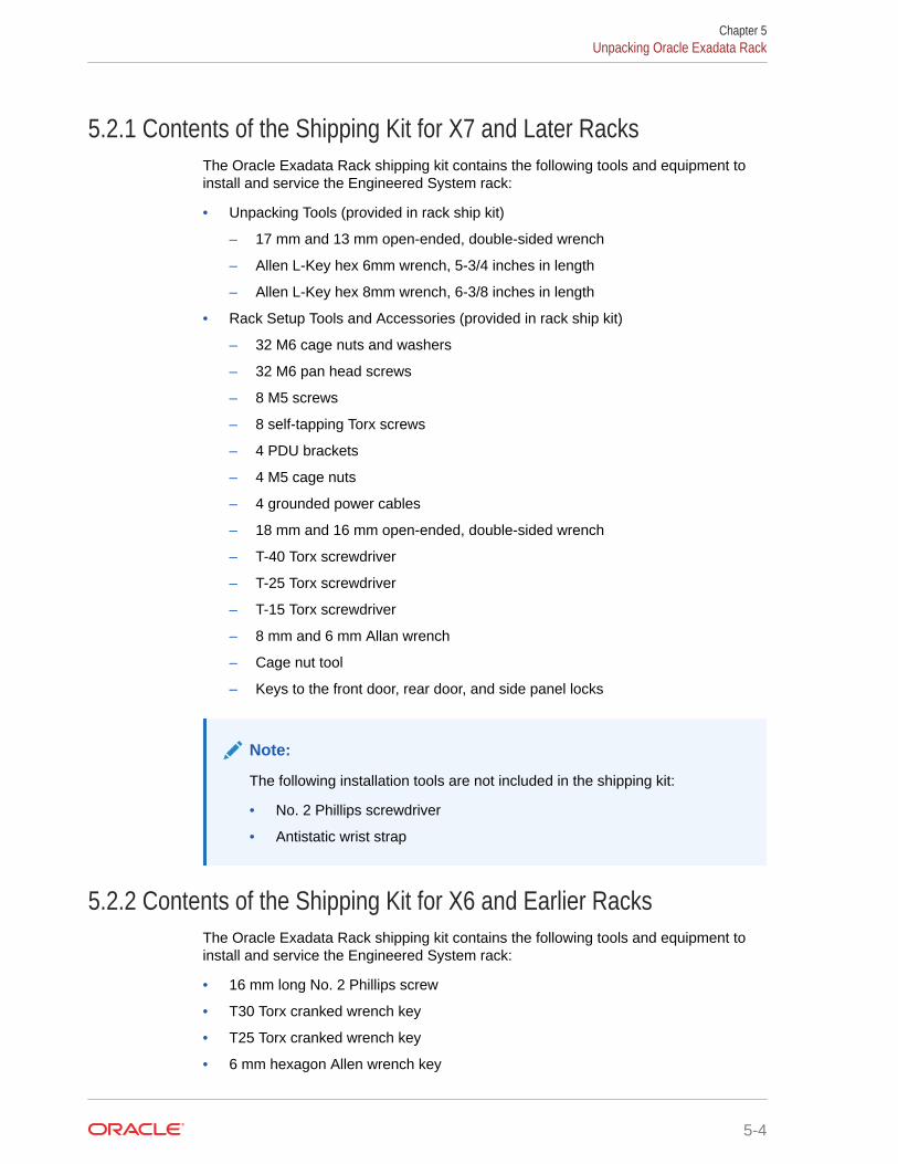
5.2.1 Contents of the Shipping Kit for X7 and Later RacksThe Oracle Exadata Rack shipping kit contains the following tools and equipment toinstall and service the Engineered System rack:
• Unpacking Tools (provided in rack ship kit)
– 17 mm and 13 mm open-ended, double-sided wrench
– Allen L-Key hex 6mm wrench, 5-3/4 inches in length
– Allen L-Key hex 8mm wrench, 6-3/8 inches in length
• Rack Setup Tools and Accessories (provided in rack ship kit)
– 32 M6 cage nuts and washers
– 32 M6 pan head screws
– 8 M5 screws
– 8 self-tapping Torx screws
– 4 PDU brackets
– 4 M5 cage nuts
– 4 grounded power cables
– 18 mm and 16 mm open-ended, double-sided wrench
– T-40 Torx screwdriver
– T-25 Torx screwdriver
– T-15 Torx screwdriver
– 8 mm and 6 mm Allan wrench
– Cage nut tool
– Keys to the front door, rear door, and side panel locks
Note:
The following installation tools are not included in the shipping kit:
• No. 2 Phillips screwdriver
• Antistatic wrist strap
5.2.2 Contents of the Shipping Kit for X6 and Earlier RacksThe Oracle Exadata Rack shipping kit contains the following tools and equipment toinstall and service the Engineered System rack:
• 16 mm long No. 2 Phillips screw
• T30 Torx cranked wrench key
• T25 Torx cranked wrench key
• 6 mm hexagon Allen wrench key
Chapter 5Unpacking Oracle Exadata Rack
5-4

• SW 12 mm single-headed wrench
• 2 square jumper brackets with 4 M5 Torx screws
• 2 cable management hooks with 4 spring nuts
• Side panel removal tool
• Keys to the front door, rear door, and side panel locks
• 32 M6 cage nuts
• 32 M6 screws
• Cage nut mounting tool
• SW 17 mm single-headed wrench is included on the shipping pallet
Note:
The following items are not included in the shipping kit:
• No. 2 Phillips screwdriver
• Antistatic wrist strap
5.2.3 Removing Oracle Exadata Rack from the Shipping CrateUse these steps to unpack Oracle Exadata Rack and prepare it for moving to the installationsite.
WARNING:
Oracle strongly recommends that you use professional movers when unpackingand installing Oracle Exadata Rack. Rocking or tilting the rack can cause it to fallover and cause serious personal injury or death.
1. Unpack Oracle Exadata Rack carefully from the packaging and shipping pallet as follows:
Note:
Before unpacking the rack from the shipping carton, refer to the labels on thecarton and to the instructions that they provide.
a. Remove the shipping carton bands.
b. Remove the carton top.
c. Remove the carton sides and inner top.
2. Remove the shipping kit.
3. Attach the ramps to the shipping pallet as follows:
a. Remove the ramps from the pallet sides.
Chapter 5Unpacking Oracle Exadata Rack
5-5

b. Obtain the parts bag from inside the cabinet.
c. Adjust the leveling bolts on the ramps and connect the ramps to the palletwheel track.
d. Verify that leveling feet are up before moving rack.
4. Carefully roll Oracle Exadata Rack off the shipping pallet as follows:
a. Unfasten the exterior shipping brackets from the pallet.
b. Unfasten the interior shipping brackets from the pallet.
Note:
Use care when removing the shipping brackets from underneathOracle Exadata Rack. Access to the inside shipping brackets mightbe limited.
c. Roll the cabinet down the ramps to the level floor. Oracle recommends havingthree people available to move the rack down the ramp: two people on bothsides to help guide the rack and one person in back.
The rack's front casters are fixed, so you must steer using the rear casters.You can maneuver the rack safely by pushing it from behind.
5. Save the shipping brackets used to secure the rack to the shipping pallet. Do notdispose of these brackets, because you cannot order replacement brackets.
6. Recycle the packaging properly. Follow local laws and guidelines to dispose of thematerial.
See Also:
• Sun Rack II User's Guide at https://docs.oracle.com/cd/E19657-01/html/E29153/index.html
• Oracle Rack Cabinet 1242 User's Guide at http://docs.oracle.com/cd/E85660_01/html/E87280/index.html for X7 orlater systems
5.3 Placing Oracle Exadata Rack in Its Allocated SpaceThis section describes how to position, stabilize, and ground Oracle Exadata Rack.
• Moving Oracle Exadata Rack
• Stabilizing Oracle Exadata RackAfter moving Oracle Exadata Rack to the installation site, stabilize the rack toensure that it does not move or tip over.
• Attaching a Ground Cable (Optional)
Chapter 5Placing Oracle Exadata Rack in Its Allocated Space
5-6

5.3.1 Moving Oracle Exadata RackThe following procedure describes how to move Oracle Exadata Rack:
1. Ensure the doors are closed and secured.
2. Ensure the leveling and stabilizing feet on the rack are raised and out of the way.
3. Push Oracle Exadata Rack from behind to the installation site.
When moving Oracle Exadata Rack to the installation site, the front casters do not turn;you must steer the unit by moving the rear casters. You can safely maneuver OracleExadata Rack by carefully pushing it. Figure 5-2 shows the correct way to push the rack.
Figure 5-2 Carefully Push Oracle Exadata Rack from Behind
Oracle recommends having two people to move the rack: one person in front and oneperson in back to help guide the rack. When transporting configured racks from onelocation to another, take care to move them slowly, 0.65 meters per second (2.13 feet persecond) or slower.
Carefully examine the transportation path. Avoid obstacles such as doorways or elevatorthresholds that can cause abrupt stops or shocks. Go around obstacles by using rampsor lifts to enable smooth transport.
WARNING:
• Never attempt to move Oracle Exadata Rack by pushing on the side panels.Pushing on the side panels can tip the rack over. This can cause seriouspersonal injury or death as well as damage to the equipment.
• Never tip or rock Oracle Exadata Rack because the rack can fall over.
Chapter 5Placing Oracle Exadata Rack in Its Allocated Space
5-7

5.3.2 Stabilizing Oracle Exadata RackAfter moving Oracle Exadata Rack to the installation site, stabilize the rack to ensurethat it does not move or tip over.
Oracle does not recommend using the shipping brackets to permanently mount therack to the floor.
Caution:
Shipping brackets are not for use for bracing or anchoring the rack duringseismic events.
You can stabilize the rack by extending the rack leveling feet.
• Stabilize Oracle Exadata Rack with Leveling Feet
• Stabilize Oracle Exadata Rack X7 and Later with Leveling FeetThe rack contains four leveling feet that can be lowered to stabilize the rack.
5.3.2.1 Stabilize Oracle Exadata Rack with Leveling FeetThe Oracle Exadata Rack contains four leveling feet that can be lowered to stabilizethe rack. The leveling feet can be used even when the rack is permanently secured tothe floor. The four leveling feet should share the rack load with at least one othersupport. The following is an acceptable method to share the rack load:
• Casters and leveling feet
To adjust the leveling feet, do the following:
1. Locate the four leveling feet located at the bottom corners of the Oracle ExadataRack. Figure 5-3 shows the location of the leveling feet on the bottom of the rack.
Chapter 5Placing Oracle Exadata Rack in Its Allocated Space
5-8

Figure 5-3 Location of Leveling Feet on Oracle Exadata Rack
• 1: Distance from the edge of the mounting feet to the side of the rack is 33.75 mm(1.33 inches)
• 2: Width from the outside edges of the leveling feet is 532.5 mm (20.96 inches)
• 3: Width from the inside edges of the leveling feet is 429 mm (16.89 inches)
• 4: Distance from the edge of the feet to the front rack surface is 73.75 m (2.90inches)
• 5: Depth of the outside edges of the leveling feet is 1058.5 mm (41.67 inches)
• 6: Distance from the edge of the leveling feet to the rear rack surface is 32.5 mm(1.28 inches)
• 7: Distance from the center of front casters to the side of the rack is 86.7 mm (3.41inches)
• 8: Width between the center of the front casters is 426.6 mm (16.80 inches)
• 9: Distance from the center of the rear casters to the rear of the rack is 173.7 mm(6.83 inches)
• 10: Depth between the front and rear casters is 828.6 mm (32.62 inches)
• 11: Distance between the rear casters and the rear of the rack is 162.4 mm (6.39inches)
• 12: Distance from the center of rear casters to the side of the rack is 96.4 mm (3.80inches)
• 13: Width between the center of the rear casters is 407.2 mm (16.03 inches)
2. Lower the leveling feet to the floor to share the load with the casters, as shown in Figure 5-4 using the SW 12 mm wrench.
Chapter 5Placing Oracle Exadata Rack in Its Allocated Space
5-9

Figure 5-4 Securing Oracle Exadata Rack Using the Leveling Feet
5.3.2.2 Stabilize Oracle Exadata Rack X7 and Later with Leveling FeetThe rack contains four leveling feet that can be lowered to stabilize the rack.
The leveling feet can be used even when the rack is permanently secured to the floor.The four leveling feet share the load with the casters. This increases the footprint ofthe rack which improves stability and helps prevent rack movement.
To adjust the leveling feet, do the following:
1. Locate the four leveling feet located at the bottom corners of Oracle ExadataRack. The following figure shows the location of the leveling feet on the bottom ofOracle Exadata Rack. The image dimensions include the doors attached to therack.
Chapter 5Placing Oracle Exadata Rack in Its Allocated Space
5-10

Figure 5-5 Location of Leveling Feet on Oracle Exadata Rack X7 or later
• 1: Distance from the edge of the feet to the Front door surface is 58 mm (2.3 inches)
• 2: Depth of the outside edges of the leveling feet is 1113 mm (43.8 inches)
• 3: Distance from the edge of the leveling feet to the rear door surface is 26 mm (1.0inches)
• 4: Distance from the center of rear casters to the side of the rack is 96.5 mm (3.8inches)
• 5: Width between the center of the rear casters is 407 mm (16.0 inches)
• 6: Distance from the center of the rear casters to the rear door surface is 142 mm(5.6 inches)
• 7: Depth between the front and rear casters is 889 mm (35.0 inches)
• 8: Distance between the center of the front casters and the Front door surface is 166mm (6.5 inches)
• 9: Width from the outside edges of the leveling feet is 583 mm (23.0 inches)
• 10: Width from the inside edges of the leveling feet is 513 mm (20.2 inches)
• 11: Distance from the edge of the mounting feet to the side of the rack is 8.5 mm (0.3inches)
• 12: Width between the center of the front casters is 410 mm (16.1 inches)
• 13: Distance from the center of front casters to the side of the rack is 95 mm (3.7inches)
2. Stabilize the rack by lowering the four leveling feet to the floor, using a 6-mm hex wrenchor your fingers, as shown in the following image.
Chapter 5Placing Oracle Exadata Rack in Its Allocated Space
5-11

Figure 5-6 Securing Oracle Exadata Rack Using the Leveling Feet
See Also:
Oracle Rack Cabinet 1242 User's Guide at http://docs.oracle.com/cd/E85660_01/html/E87280/index.html for the rack specifications
5.3.3 Attaching a Ground Cable (Optional)The Oracle Exadata Rack power distribution units (PDUs) achieve earth groundthrough their power cords. Final chassis ground is achieved by way of the groundprong when you connect the power cord to a socket. For additional grounding, attach achassis earth ground cable to Oracle Exadata Rack. The additional ground pointenables electrical current leakage to dissipate more efficiently.
WARNING:
The PDU power input lead cords and the ground cable must reference acommon earth ground. If they do not, then a difference in ground potentialcan be introduced. If you are unsure of your facility's PDU receptaclegrounding, then do not install a ground cable until you confirm that there is aproper PDU receptacle grounding. If a difference in ground potential isapparent, then you must take corrective action.
Chapter 5Placing Oracle Exadata Rack in Its Allocated Space
5-12

Note:
A grounding cable is not shipped with the system.
1. Ensure the installation site has properly grounded the power source in the data center.The facility PDU must have earth ground.
2. Ensure all grounding points, such as raised floors and power receptacles, reference thefacility ground.
3. Ensure that direct, metal-to-metal contact is made for this installation. Duringmanufacturing, the ground cable attachment area might have been painted or coated.
4. Attach the ground cable to one of the attachment points located at the bottom rear of thesystem frame as shown in Figure 5-7. The attachment point is an adjustable bolt that isinside the rear of the Oracle Exadata Rack cabinet on the right side.
Figure 5-7 Earth Ground Attachment Bolt Location
See Also:
Oracle Exadata Database Machine Extending and Multi-Rack Cabling Guide ifOracle Exadata Rack will be connected to another Oracle Exadata Rack.
5.4 Acclimating the Oracle Exadata Database MachineOracle recommends an acclimation period of 24 hours for the Oracle Exadata DatabaseMachine.
This applies to all hardware, including racks and cables. Acclimation to the surroundingenvironment prevents damage as a result of condensation.
Chapter 5Acclimating the Oracle Exadata Database Machine
5-13

5.5 Powering on the System the First TimeBefore powering on the system for the first time, it is necessary to inspect themachine, and connect the power cords.
• Inspecting the Machine After it is in PlaceThis procedure describes how to visually examine the Oracle Exadata Rackphysical system after it is in place, but before power is supplied.
• Connecting Power Cords
• Powering on Oracle Exadata RackThis procedure describes how to power on Oracle Exadata Rack.
5.5.1 Inspecting the Machine After it is in PlaceThis procedure describes how to visually examine the Oracle Exadata Rack physicalsystem after it is in place, but before power is supplied.
1. Check the rack for damage.
2. Check the rack for loose or missing screws.
3. Check Oracle Exadata Rack for the ordered configuration. Refer to the CustomerInformation Sheet (CIS) on the side of the packaging.
4. Check that all cable connections are secure and firmly in place as follows:
a. Check the power cables. Ensure that the correct connectors have beensupplied for the data center facility power source.
b. Check the network data cables.
5. Check the site location tile arrangement for cable access and airflow.
6. Check the data center airflow that leads in to the front of Oracle Exadata Rack.
Related Topics
• Ventilation and Cooling RequirementsAlways provide adequate space in front and behind the rack to allow for properventilation.
5.5.2 Connecting Power CordsThe following procedure describes how to connect power cords to Oracle ExadataRack:
1. Open the rear cabinet door.
2. Ensure that the correct power connectors have been supplied.
3. Unfasten the power cord cable ties. The ties are for shipping only and are nolonger needed.
4. Route the power cords to the facility receptacles as shown in Figure 5-8.
5. Secure the power cords in bundles as shown in Figure 5-8.
6. Plug the PDU power cord connectors into the facility receptacles. Ensure thebreaker switches are in the OFF position before connecting the power cables.
Chapter 5Powering on the System the First Time
5-14

Figure 5-8 Power Cord Routing Example
5.5.3 Powering on Oracle Exadata RackThis procedure describes how to power on Oracle Exadata Rack.
Note:
Oracle Exadata Database Machine X2-8 Full Rack database servers may take up to15 minutes to start through the normal BIOS POST tests.
1. Switch on the PDU B circuit breakers, one at a time. PDU B is on the right side of therack when viewed from the rear. The circuit breakers are on the rear of the OracleExadata Rack cabinet as shown in the following figure. Press the ON (|) side of the toggleswitch. When the breaker is in the ON position, the breakers are flush with the side of thePDU.
Chapter 5Powering on the System the First Time
5-15
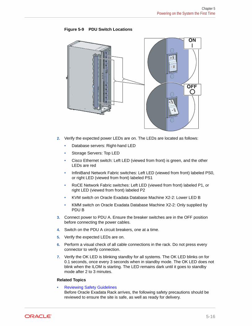
Figure 5-9 PDU Switch Locations
2. Verify the expected power LEDs are on. The LEDs are located as follows:
• Database servers: Right-hand LED
• Storage Servers: Top LED
• Cisco Ethernet switch: Left LED (viewed from front) is green, and the otherLEDs are red
• InfiniBand Network Fabric switches: Left LED (viewed from front) labeled PS0,or right LED (viewed from front) labeled PS1
• RoCE Network Fabric switches: Left LED (viewed from front) labeled P1, orright LED (viewed from front) labeled P2
• KVM switch on Oracle Exadata Database Machine X2-2: Lower LED B
• KMM switch on Oracle Exadata Database Machine X2-2: Only supplied byPDU B
3. Connect power to PDU A. Ensure the breaker switches are in the OFF positionbefore connecting the power cables.
4. Switch on the PDU A circuit breakers, one at a time.
5. Verify the expected LEDs are on.
6. Perform a visual check of all cable connections in the rack. Do not press everyconnector to verify connection.
7. Verify the OK LED is blinking standby for all systems. The OK LED blinks on for0.1 seconds, once every 3 seconds when in standby mode. The OK LED does notblink when the ILOM is starting. The LED remains dark until it goes to standbymode after 2 to 3 minutes.
Related Topics
• Reviewing Safety GuidelinesBefore Oracle Exadata Rack arrives, the following safety precautions should bereviewed to ensure the site is safe, as well as ready for delivery.
Chapter 5Powering on the System the First Time
5-16

6Configuring Oracle Exadata DatabaseMachine
This chapter describes how to configure the system, accounts, and software for OracleExadata Database Machine.
Note:
• For ease of reading, the name "Oracle Exadata Rack" is used when informationrefers to both Oracle Exadata Database Machine and Oracle Exadata StorageExpansion Rack.
• The procedures in this chapter are applicable to Oracle Exadata StorageExpansion Rack as well as Oracle Exadata Database Machine.
• The procedures in this chapter use the information from Oracle ExadataDatabase Machine Deployment Assistant (OEDA). Be sure to run OEDA beforestarting the procedures in this chapter.
• Verifying the Network Configuration Prior to Configuring the RackUse the checkip.sh script to ensure there are no IP address conflicts between theexisting network and your new Oracle Exadata Rack.
• Configuring the RDMA Network Fabric SwitchYou must perform an initial configuration of the RDMA Network Fabric switch.
• Setting the Subnet Manager Master on Oracle Exadata Database Machine Full Rack andOracle Exadata Database Machine Half Rack
• Configuring the Cisco Ethernet SwitchYou must perform an initial configuration of the Cisco Ethernet switch.
• Configuring the Power Distribution UnitsThe power distribution units (PDUs) are configured with a static IP address to connect tothe network for monitoring.
• Configuring the Threshold Settings for the Power Distribution Units
• Checking Exadata Storage ServersAfter powering up the rack, check the Oracle Exadata Storage Servers.
• Checking Oracle Exadata Database ServersBefore installing the software, check the configuration of the Oracle Exadata DatabaseServers.
• Performing Additional Checks and ConfigurationPerform these additional checks and steps to verify the configuration of your OracleExadata Rack.
• Verifying the RoCE Network Fabric ConfigurationThis procedure describes how to verify the RoCE Network Fabric configuration.
6-1
• Verifying the InfiniBand Network Fabric NetworkThis procedure describes how to verify the InfiniBand Network Fabric network.
• Imaging a New SystemYou have different options for preparing an Oracle Exadata system fordeployment.
• Performing Initial Elastic Configuration of Oracle Exadata Database MachineThis topic provides background information on elastic configuration and describeshow to perform the initial configuration of Oracle Exadata Database Machine.
• Adding Additional Elastic Nodes to an Existing RackYou can add nodes to an existing rack using elastic configuration.
• Using the OEDA setuprootssh UtilityYou can set up key-based authentication for the root user by using thesetuprootssh.sh utility included with OEDA.
• Loading the Configuration Information and Installing the SoftwareYou can use Oracle Exadata Deployment Assistant to configure your rack, or youcan do it manually.
• Using the OEDA changePassword UtilityYou can change the password of the grid and oracle users across all clusters byusing the changePassword.sh utility included with OEDA.
• Installing Oracle Enterprise Manager Cloud Control
• Adding a VM Cluster to Oracle Exadata Database Machine Using OEDAYou can use Oracle Exadata Deployment Assistant (OEDA) to add a virtualmachine (VM) cluster to an existing Oracle Exadata Database Machinedeployment.
Related Topics
• Oracle Sun Database Machine Setup/Configuration Best Practices (My OracleSupport Doc ID 1274318.1)
6.1 Verifying the Network Configuration Prior to Configuringthe Rack
Use the checkip.sh script to ensure there are no IP address conflicts between theexisting network and your new Oracle Exadata Rack.
The checkip.sh script performs a pre-installation check to verify that the IP addressesand host names that you specified in Oracle Exadata Deployment Assistant (OEDA)are defined in the DNS, that the NTP servers and gateways are available, and thatprivate addresses are not pingable. Running this script before the hardware arriveshelp to avoid additional delays that would be caused by misconfigured networkservices, such as Domain Name System (DNS) and NTP.
The checkip.sh script is created in a format that matches the operating system of theclient on which you ran OEDA. Because this script is run before the engineeredsystem rack has arrived, you typically do not run this script on an engineered systemserver, but on a client. The client must have access to the same network where theengineered system will be deployed. The script is also available in the ZIP filegenerated by OEDA.
Chapter 6Verifying the Network Configuration Prior to Configuring the Rack
6-2

1. On the client where OEDA was run, copy the checkip.sh script generated by OEDA andthe XML file CustomerName_hostname.xml to the same directory (one directory level up)as the OEDA config.sh script.
2. Run the checkip.sh script on the client machine or existing server.
Use a command similar to the following, where configuration_file is the name of theconfiguration generated by the Oracle Exadata Deployment Assistant for the rack beinginstalled.
# ./checkip.sh -cf configuration_file
If the command is run from a Microsoft Windows machine, then the command ischeckip.cmd.If this engineered system rack is an addition for an existing installation, then run thecheckip.sh script from an existing engineered system server. This enables the script toidentify in-use IP addresses in the fabric. Not identifying existing IP addresses may causeIP collisions after installation of the new engineered system rack. To create a checkip.shthat can run on an existing server, you must run OEDA on a server or client that uses thesame operating system as the existing engineered system server.
The output from the script is a file that contains status messages such as GOOD or ERROR.
If there are conflicts that you are unable to resolve, then work with your assigned Oraclerepresentative to correct the problems.
6.2 Configuring the RDMA Network Fabric SwitchYou must perform an initial configuration of the RDMA Network Fabric switch.
• Configuring Sun Datacenter InfiniBand Switch 36 Switch
• Configuring the Cisco Nexus C9336C-FX2 SwitchThe RoCE Network Fabric switch supplied with the engineered system rack is minimallyconfigured during installation.
• Configuring the Cisco Nexus C9336C-FX2 Switches to Enable Exadata Secure RDMAFabric IsolationYou can configure your RoCE Network Fabric switches to enable Exadata Secure RDMAFabric Isolation.
6.2.1 Configuring Sun Datacenter InfiniBand Switch 36 SwitchThe following procedure describes how to configure the Sun Datacenter InfiniBand Switch 36switches.
1. Log in to the first database server as the root user. The first database server is thelowest database server in the rack, which is rack position U16.
Note:
If you do not have the password for the root user, then contact Oracle SupportServices.
Chapter 6Configuring the RDMA Network Fabric Switch
6-3

2. Use SSH to log in to the Sun Datacenter InfiniBand Switch 36 switch as the ilom-admin user. Find the default IP address for the Sun Datacenter InfiniBand Switch36 switch for your system in "Default IP Addresses". The following is an exampleof the command:
3. Use spsh to open the Integrated Lights Out Manager (ILOM) command lineinterface.
4. Configure the network interface using the following commands:
set /SP/network pendingipdiscovery=static pendingipaddress=pending_ip \pendingipgateway=pending_gw pendingipnetmask=pending_nm
set /SP/network commitpending=true
In the preceding commands, pending_ip, pending_gw, and pending_nm are IPaddresses defined by the network administrator.
5. Use the exit command to exit the interface.
6. Edit the /etc/hosts file to set the IP address and host name using an editorsuch as vi. The following is an example of the updated file:
#Do not remove the following link, or various programs#that require network functionality will fail.127.0.0.1 localhost.localdomain localhost10.7.7.32 dm01sw-ib1-ib2.example.com trnasw-ib2
It is required that the second line has both fully-qualified and non-fully-qualifiednames.
7. Use the ILOM interface to configure the IP address, host name, NTP servers, andDNS servers.
8. Restart the switch.
9. Examine the firmware version using the following command:
# version
Refer to My Oracle Support Note 888828.1 for the current firmware version.
10. Check the health of the switch using the following command:
# showunhealthy
OK - No unhealthy sensors
11. Run the environment test using the following command:
# env_test
NM2 Environment test started:
Chapter 6Configuring the RDMA Network Fabric Switch
6-4

Starting Voltage test:Voltage ECB OKMeasured 3.3V Main = 3.28 VMeasured 3.3V Standby = 3.42 VMeasured 12V =12.06 VMeasured 5V =5.03 VMeasured VBAT =3.06 VMeasured 2.5V =2.53 VMeasured 1.8V =1.79 VMeasured I4 1.2V =1.22 VVoltage test returned OKStarting PSU test:PSU 0 presentPSU 1 presentPSU test returned OKStarting Temperature test:Back temperature 30.50Front temperature 33.88ComEx temperature 34.12I4 temperature 56,maxtemperature 57Temperature test returned OKStarting FAN test:Fan 0 not presentFan 1 running at rpm 12946Fan 2 running at rpm 12684Fan 3 running at rpm 12558Fan 4 not presentFAN test returned OKStarting Connector test:Connector test returned OKStarting I4 test:I4 OKAll I4s OKI4 test returned OKNM2 Environment test PASSED
12. Enable the InfiniBand Subnet Manager using the following command:
# enablesm
Note:
If you get an error indicating the InfiniBand Subnet Manager is already running,then restart it as follows:
# disablesm
# enablesm
Chapter 6Configuring the RDMA Network Fabric Switch
6-5

13. Verify the IP address is correct using the following command:
# ifconfig eth0
eth0 Link encap:Ethernet HWaddr 00:E0:4B:2A:07:2B inet addr:172.16.10.32 Bcast:172.16.10.255Mask:255.255.255.0 inet6 addr:fe80::2e0:3a00:fe2a:61e/64 Scope:Link UP BROADCAST RUNNING MULTICAST MTU:1500 Metric:1 RX packets:11927 errors:0 dropped:0 overruns:0 frame:0 TX packets:89 errors:0 dropped:0 overruns:0 carrier:0 collisions:0 txqueuelen:1000 RX bytes:720262 (703.3 KiB)TX bytes:11402 (11.1 KiB)
14. Verify the host name is correct using the following command:
# hostname
dm01sw-ib2.example.com
15. Set the Subnet Manager Master as described in "Setting the Subnet ManagerMaster on Oracle Exadata Database Machine Full Rack and Oracle ExadataDatabase Machine Half Rack". This step is needed for Oracle Exadata DatabaseMachine Half Rack and Oracle Exadata Database Machine Full Rack.
16. Log out from the InfiniBand switch using the following command:
# exit
Note:
If the network settings did not appear after restart, then power cycle theswitch by removing both power cords for one minute.
Related Topics
• Exadata Database Machine and Exadata Storage Server Supported Versions (MyOracle Support Doc ID 888828.1)
6.2.2 Configuring the Cisco Nexus C9336C-FX2 SwitchThe RoCE Network Fabric switch supplied with the engineered system rack isminimally configured during installation.
During initial system configuration, you can reset and configure the switch.
1. Connect from the RoCE Network Fabric switch serial console to a laptop or similardevice using the available RJ45 cable.
2. Ensure the terminal session is recorded on the laptop by logging the output.
The output can be used as a reference that the switch has been configuredcorrectly.
Chapter 6Configuring the RDMA Network Fabric Switch
6-6

3. Power on the switch.
4. Log in as the admin user.
User Access Verificationdbm0sw-rocea0 login: adminPassword: ********
Note:
If you do not have the password for the admin user, then contact Oracle SupportServices.
5. Erase the existing configuration.
dbm0sw-rocea0# write erase
Warning: This command will erase the startup-configuration.
Do you wish to proceed anyway? (y/n) [n] y
6. Restart the system so you can perform the automated setup.
dbm0sw-rocea0# reload
This command will reboot the system. (y/n)? [n] y
2017 Aug 31 01:09:00 dbm0sw-rocea0 %$ VDC-1 %$ %PLATFORM-2-PFM_SYSTEM_RESET: Manual system restart from Command Line Interface
CISCO SWITCH Ver7.59Device detected on 0:1:2 after 0 msecs ...
7. Switch to normal setup and, when asked if you want to enforce secure passwordstandard, enter no, then enter a new password for the admin user.
Running S93thirdparty-script...
Populating conf files for hybrid sysmgr ...Starting hybrid sysmgr ...inserting /isan/lib/modules/klm_cisco_nb.o ... done
Abort Auto Provisioning and continue with normal setup ? (yes/no) [n]: yes
---- System Admin Account Setup ----
Do you want to enforce secure password standard (yes/no) [y]: no
Enter the password for "admin": Confirm the password for "admin":
Chapter 6Configuring the RDMA Network Fabric Switch
6-7

8. When the Basic System Configuration Dialog appears, choose to enter the basicconfiguration dialog.
---- Basic System Configuration Dialog VDC: 1 ----
This setup utility will guide you through the basic configuration ofthe system. Setup configures only enough connectivity for managementof the system.
Please register Cisco Nexus9000 Family devices promptly with yoursupplier. Failure to register may affect response times for initialservice calls. Nexus9000 devices must be registered to receive entitled support services.
Press Enter at anytime to skip a dialog. Use ctrl-c at anytimeto skip the remaining dialogs.
Would you like to enter the basic configuration dialog (yes/no): yes
9. In the basic configuration, you can use the default inputs until asked to enter theswitch name.
In this example, the switch has a name of test123sw-rocea0.
Create another login account (yes/no) [n]: Configure read-only SNMP community string (yes/no) [n]: Configure read-write SNMP community string (yes/no) [n]: Enter the switch name : test123sw-rocea0
10. Respond yes when asked to configure Out-of-band management configuration,and specify appropriate network addresses when prompted.
Continue with Out-of-band (mgmt0) management configuration? (yes/no) [y]: yes Mgmt0 IPv4 address : 100.104.10.21 Mgmt0 IPv4 netmask : 255.255.248.0 Configure the default gateway? (yes/no) [y]: IPv4 address of the default gateway : 100.104.10.1
11. Respond yes when asked to configure advanced IP options.
Configure advanced IP options? (yes/no) [n]: yes
12. Respond yes when asked to configure static route (this can be changed later).
Configure static route? (yes/no) [n]: yes
13. Enter the destination prefix and mask, and other values as prompted.
Destination prefix : 10.100.100.0
Destination prefix mask : 255.255.255.0
Chapter 6Configuring the RDMA Network Fabric Switch
6-8

Next hop IPv4 address : 10.100.100.1
14. Configure the DNS IPv4 addresses.
Configure the DNS IPv4 address? (yes/no) [n]: yes DNS IP address: 10.100.100.2
15. Skip configuring the default domain name (this will be configured later).
Configure the default domain name? (yes/no) [n]: no
16. Accept the default responses until asked to configure SSH and the NTP server.
Enable the telnet service? (yes/no) [n]: noEnable the ssh service? (yes/no) [y]: yes Type of ssh key you would like to generate (dsa/rsa) [rsa]: rsa Number of rsa key bits <1024-2048> [1024]: 1024 Configure the NTP server? (yes/no) [n]: yes NTP server IPv4 address : 10.100.100.3
17. Accept the default responses until asked to specify the CoPP system profile. Enterstrict.
Configure default interface layer (L3/L2) [L2]: Configure default switchport interface state (shut/noshut) [noshut]: Configure CoPP system profile (strict/moderate/lenient/dense) [strict]: strict
18. After reviewing the configuration, save the configuration.
The following configuration will be applied: no password strength-check switchname test123sw-rocea0 ip route 100.104.8.0 255.255.248.0 100.104.10.1 vrf context management ip route 0.0.0.0/0 100.104.10.1 exit no feature telnet ssh key rsa 1024 force feature ssh ntp server 100.104.10.1 system default switchport no system default switchport shutdown copp profile strict interface mgmt0 ip address 100.104.10.21 255.255.248.0 no shutdown
Would you like to edit the configuration? (yes/no) [n]:
Use this configuration and save it? (yes/no) [y]: yes
Chapter 6Configuring the RDMA Network Fabric Switch
6-9

[########################################] 100%Copy complete.
19. Enable the scp server feature on the switch.
test123sw-rocea0# feature scp-server
20. Save the running configuration to flash.
test123sw-rocea0# copy running-config startup-config[########################################] 100%Copy complete.
21. Apply the golden configuration on the switch.
• Starting with Oracle Exadata System Software release 20.1.0, use theprocedure described in Applying Golden Configuration Settings on RoCENetwork Fabric Switches, in Oracle Exadata Database Machine MaintenanceGuide.
• Otherwise, use the following procedure to apply the golden configuration onthe switch:
a. Delete the configuration file on the switch for the target configuration.
Note:
If you do not remove the file you are replacing, then when youattempt to overwrite the file you will get a 'permission denied' error.
Log in to the switch, enter configuration mode, then run a command similar tothe following:
test123sw-rocea0# delete bootflash:roce_leaf_switch.cfgDo you want to delete "/roce_leaf_switch.cfg" ? (yes/no/abort) [y] ytest123sw-rocea0#
b. Log in to a server that has SSH access to the switch, and contains the latestRDMA Network Fabric patch ZIP file.
To find the available RDMA Network Fabric patches, search for 'RDMAnetwork switch' in My Oracle Support document 888828.1. Download anduse the latest patch for your Oracle Exadata System Software release.
c. Unzip the RDMA Network Fabric patch ZIP file and change directories to thelocation of the patchmgr utility.
d. Locate the golden configuration files in the RDMA Network Fabric patchbundle.
The files are located within the roce_switch_templates directory.
The golden configuration files are as follows:
• Single rack leaf: roce_leaf_switch.cfg
Chapter 6Configuring the RDMA Network Fabric Switch
6-10

• Multi-rack leaf: roce_leaf_switch_multi.cfg
• Multi-rack spine: roce_spine_switch_multi.cfg
• Single rack leaf with Secure Fabric support: roce_sf_leaf_switch.cfg
• Multi-rack leaf with Secure Fabric support: roce_sf_leaf_switch_multi.cfg
• Single rack leaf configured with 23 host ports: roce_leaf_switch_23hosts.cfg
• Multi-rack leaf configured with 23 host ports:roce_leaf_switch_23hosts_multi.cfg
• Multi-rack leaf configured with 14 inter-switch links:roce_leaf_switch_14uplinks_multi.cfg
• Multi-rack leaf configured with 14 inter-switch links and with Secure Fabricsupport: roce_sf_leaf_switch_14uplinks_multi.cfg
• Multi-rack leaf configured with 23 host ports and 14 inter-switch links:roce_leaf_switch_23hosts_13uplinks_multi.cfg
e. Copy the golden configuration file to the switch.
In the following example, 100.104.10.21 represents the IP address of the switch youare configuring.
# scp roce_leaf_switch.cfg [email protected]:/User Access VerificationPassword:roce_leaf_switch.cfg 100% 23KB 23.5KB/s 00:00
f. Apply the golden configuration file on the switch.
Use the run-script command while connected directly to the switch.
test123sw-rocea0# run-script bootflash:roce_leaf_switch.cfg | grep 'none'
Note:
This command may take up to 1-2 minutes on a single-rack switch and upto 3-4 minutes on a multi-rack switch.
g. Verify the switch configuration.
Use the patchmgr utility on the server that has SSH access to the switch, andcontains the latest RDMA Network Fabric patch bundle.
In the following command, roceswitch.lst is a file that contains the switch hostname or IP address.
# ./patchmgr --roceswitches roceswitch.lst --verify-config
22. Backup up the switch configuration.
Follow the steps in Backing Up Settings on the ROCE Switch, in Oracle ExadataDatabase Machine Maintenance Guide.
Chapter 6Configuring the RDMA Network Fabric Switch
6-11

23. Optional: Set the clock, using the same procedure as in Setting the Clock on theCisco 93108-1G or 9348 Ethernet Switch.
Related Topics
• Exadata Database Machine and Exadata Storage Server Supported Versions (MyOracle Support Doc ID 888828.1)
6.2.3 Configuring the Cisco Nexus C9336C-FX2 Switches to EnableExadata Secure RDMA Fabric Isolation
You can configure your RoCE Network Fabric switches to enable Exadata SecureRDMA Fabric Isolation.
Secure Fabric enables network separation between different clusters on systems withRoCE Network Fabric. This capability is conceptually similar to InfiniBand NetworkFabric partitioning. Secure Fabric support is available starting with Oracle ExadataSystem Software release 20.1.0.
To use Secure Fabric, you must enable Secure Fabric support in the RoCE NetworkFabric switch hardware before initial system deployment using Oracle ExadataDeployment Assistant (OEDA):
For each RoCE Network Fabric leaf switch, perform the basic configuration stepsoutlined in Configuring the Cisco Nexus C9336C-FX2 Switch.
Then, on each RoCE Network Fabric leaf switch, you must apply a specific goldenconfiguration to enable Secure Fabric support. Use the procedure described in Applying Golden Configuration Settings on RoCE Network Fabric Switches, in OracleExadata Database Machine Maintenance Guide. However, when you specify theconfiguration type for each leaf switch, ensure that you specify the configuration typethat enables Secure Fabric support.
After you complete the switch configuration, the leaf switch ports become trunk ports,which can carry network traffic with multiple VLAN IDs.
6.3 Setting the Subnet Manager Master on Oracle ExadataDatabase Machine Full Rack and Oracle Exadata DatabaseMachine Half Rack
Oracle Exadata Database Machine X3-2 systems and Oracle Exadata DatabaseMachine X2-2 systems have three Sun Datacenter InfiniBand Switch 36 switches.Starting with Oracle Exadata Database Machine X4-2, Oracle Exadata DatabaseMachine Systems have two Sun Datacenter InfiniBand Switch 36 switches.
Note:
This procedure does not apply to Oracle Exadata Database Machine X8Mracks with RoCE Network Fabric.
Chapter 6Setting the Subnet Manager Master on Oracle Exadata Database Machine Full Rack and Oracle Exadata Database Machine
Half Rack
6-12

The switch located in rack unit 1 (U1) is referred to as the spine switch. The other twoswitches are referred to as the leaf switches. The location of the leaf switches is as follows:
• Oracle Exadata Database Machine Two-Socket Systems (X3-2 and later): rack unit 20(U20) and rack unit 22 (U22)
• Oracle Exadata Database Machine X2-2 racks: rack unit 20 (U20) and rack unit 24 (U24)
• Oracle Exadata Database Machine Eight-Socket Systems (X2-8 and later) Full Racks:Rack unit 21 (U21) and rack unit 23 (U23)
The spine switch is the Subnet Manager Master for the InfiniBand Network Fabric subnet.The Subnet Manager Master has priority 8, and can be verified using the following procedure:
1. Log in to the spine switch as the root user.
2. Run the setsmpriority list command.
The command should show that smpriority has a value of 8. If smpriority has adifferent value, then do the following:
a. Use the disablesm command to stop the Subnet Manager.
b. Use the setsmpriority 8 command to set the priority to 8.
c. Use the enablesm command to restart the Subnet Manager.
The leaf switches are the Standby Subnet Managers with a priority of 5. This can be verifiedusing the preceding procedure, substituting a value of 5 in the setsmpriority commandabove.
Note:
Oracle Exadata Database Machine Half Rack with Sun Fire X4170 OracleDatabase Servers include two Sun Datacenter InfiniBand Switch 36 switches, whichare set to priority 5.
To determine the Subnet Manager Master, log in as the root user on any InfiniBand NetworkFabric switch, and run the getmaster command. The location of the Subnet Manager Masteris displayed. The following is an example of the output from the getmaster command:
# getmaster20100701 11:46:38 OpenSM Master on Switch : 0x0021283a8516a0a0 ports 36 Sun DCS 36QDR switch dm01sw-ib1.example.com enhanced port 0 lid 1 lmc 0
The preceding output shows the proper configuration. The Subnet Master Manager is runningon spine switch dm01sw-ib1.example.com.
If the spine switch is not the Subnet Manager Master, then do the following procedure to setthe Subnet Manager Master:
1. Use the getmaster command to identify the current location of the Subnet ManagerMaster.
2. Log in as the root user on the leaf switch that is the Subnet Manager Master.
3. Disable Subnet Manager on the switch. The Subnet Manager Master relocates to anotherswitch.
Chapter 6Setting the Subnet Manager Master on Oracle Exadata Database Machine Full Rack and Oracle Exadata Database Machine Half Rack
6-13

4. Use the getmaster command to identify the current location of the SubnetManager Master. If the spine switch is not Subnet Manager Master, then repeatsteps 2 and 3 until the spine switch is the Subnet Manager Master.
5. Enable Subnet Manager on the leaf switches that were disabled during thisprocedure.
Note:
• If the InfiniBand Network Fabric network consists of four or more rackscabled together, then only the spine switches should run SubnetManager. The leaf switches should have Subnet Manager disabled onthem.
• Oracle Exadata Database Machine Half Racks with Sun Fire X4170Oracle Database Servers, and Oracle Exadata Database MachineQuarter Racks have two Sun Datacenter InfiniBand Switch 36 switches,and both are set to priority 5. The master is the one with the lowestGUID.
See Also:
• "Enable the Subnet Manager" in Sun Datacenter InfiniBand Switch 36User's Guide
• "Disable the Subnet Manager" in Sun Datacenter InfiniBand Switch 36User's Guide
• Oracle Exadata Database Machine System Overview for hardwarecomponent information
• Cabling tables in Oracle Exadata Database Machine System Overview
6.4 Configuring the Cisco Ethernet SwitchYou must perform an initial configuration of the Cisco Ethernet switch.
• Configuring the Cisco Catalyst 4948 Ethernet SwitchThe Cisco Catalyst 4948 Ethernet switch supplied with Oracle Exadata Rack isminimally configured during installation.
• Configuring the Cisco Nexus 93108-1G or 9348 Ethernet SwitchThe Cisco Nexus 93108-1G or 9348 Ethernet switch supplied with Oracle ExadataRack is minimally configured during installation.
6.4.1 Configuring the Cisco Catalyst 4948 Ethernet SwitchThe Cisco Catalyst 4948 Ethernet switch supplied with Oracle Exadata Rack isminimally configured during installation.
Chapter 6Configuring the Cisco Ethernet Switch
6-14

The minimal configuration disables IP routing, and sets the following:
• Host name
• IP address setup
• Subnet mask
• Default gateway
• Domain name
• Name server
• NTP server
• Time
• Time zone
Before configuring the switch, note the following:
• The Cisco Ethernet switch should not be connected until the running configuration hasbeen verified, and any necessary changes have been made by the network administrator.
• The Cisco Ethernet switch should not be connected to the customer network until the IPaddresses on all components have been configured in Oracle Exadata Rack. This is toprevent any duplicate IP address conflicts which are possible due to the defaultaddresses set in the components when shipped.
Note that the Cisco 4948E-F switch supports multiple uplinks to the customer network byutilizing ports 49 - 52. This is a more complicated switch setup due to the redundantconnectivity, and should be performed by the customer's network administrator.
The following procedure describes how to configure the Cisco Ethernet switch. Configurationshould be done with the network administrator.
1. Connect a serial cable from the Cisco switch console to a laptop or similar device. AnOracle supplied rollover cable is pre-installed on the Cisco serial console port. Obtain theappropriate adapter and connect it at the end of the rollover cable. An Oracle P/N530-3100 RJ45-DB9 adapter as used on ILOM ports will also work, connected at the endof the network cable.
2. Ensure the terminal session is recorded on the laptop by logging the output. The outputcan be used as a reference that the switch has been configured correctly. The defaultserial port speed is 9600 baud, 8 bits, no parity, 1 stop bit, and no handshake.
Switch con0 is now availablePress RETURN to get started.
3. Change to the enable mode.
Switch> enablePassword: ******Switch#
Note:
If you do not have the password, then contact Oracle Support Services.
Chapter 6Configuring the Cisco Ethernet Switch
6-15
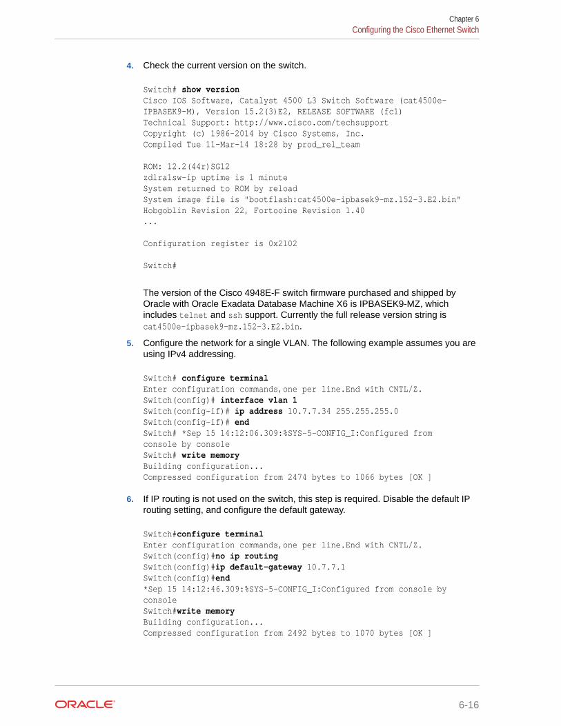
4. Check the current version on the switch.
Switch# show version Cisco IOS Software, Catalyst 4500 L3 Switch Software (cat4500e-IPBASEK9-M), Version 15.2(3)E2, RELEASE SOFTWARE (fc1)Technical Support: http://www.cisco.com/techsupportCopyright (c) 1986-2014 by Cisco Systems, Inc.Compiled Tue 11-Mar-14 18:28 by prod_rel_team
ROM: 12.2(44r)SG12zdlra1sw-ip uptime is 1 minuteSystem returned to ROM by reloadSystem image file is "bootflash:cat4500e-ipbasek9-mz.152-3.E2.bin"Hobgoblin Revision 22, Fortooine Revision 1.40...
Configuration register is 0x2102
Switch#
The version of the Cisco 4948E-F switch firmware purchased and shipped byOracle with Oracle Exadata Database Machine X6 is IPBASEK9-MZ, whichincludes telnet and ssh support. Currently the full release version string iscat4500e-ipbasek9-mz.152-3.E2.bin.
5. Configure the network for a single VLAN. The following example assumes you areusing IPv4 addressing.
Switch# configure terminalEnter configuration commands,one per line.End with CNTL/Z.Switch(config)# interface vlan 1Switch(config-if)# ip address 10.7.7.34 255.255.255.0Switch(config-if)# endSwitch# *Sep 15 14:12:06.309:%SYS-5-CONFIG_I:Configured from console by consoleSwitch# write memoryBuilding configuration...Compressed configuration from 2474 bytes to 1066 bytes [OK ]
6. If IP routing is not used on the switch, this step is required. Disable the default IProuting setting, and configure the default gateway.
Switch#configure terminalEnter configuration commands,one per line.End with CNTL/Z.Switch(config)#no ip routingSwitch(config)#ip default-gateway 10.7.7.1Switch(config)#end *Sep 15 14:12:46.309:%SYS-5-CONFIG_I:Configured from console by consoleSwitch#write memoryBuilding configuration...Compressed configuration from 2492 bytes to 1070 bytes [OK ]
Chapter 6Configuring the Cisco Ethernet Switch
6-16

7. If IP routing is required on the switch, then leave the IP routing setting as the default, andconfigure the default gateway. Replace 10.7.7.1 with the IP address of the gateway forthe installation:
Switch#configure terminalEnter configuration commands,one per line.End with CNTL/Z.Switch(config)#ip route 0.0.0.0 0.0.0.0 10.7.7.1Switch(config)#end*Sep 15 14:13:26.013:%SYS-5-CONFIG_I:Configured from console by consoleSwitch#write memoryBuilding configuration...Compressed configuration from 2502 bytes to 1085 bytes [OK ]
8. Set the host name of the switch.
This example sets the name to exa1sw-ip:
Switch#configure terminalEnter configuration commands,one per line.End with CNTL/Z.Switch(config)#hostname exa1sw-ipexa1sw-ip(config)#endexa1sw-ip#write memoryBuilding configuration...Compressed configuration from 3789 bytes to 1469 bytes [OK ]
The system host name is used as the prompt name.
9. Configure up to three DNS servers. Replace the domain name and IP addresses used inthis example with the values for the installation:
exa1sw-ip#configure terminalEnter configuration commands,one per line.End with CNTL/Z.exa1sw-ip(config)#ip domain-name example.comexa1sw-ip(config)#ip name-server 10.7.7.3exa1sw-ip(config)#ip name-server 198.51.100.5 exa1sw-ip(config)#ip name-server 10.8.160.1exa1sw-ip(config)#end *Sep 15 14:26:37.045:%SYS-5-CONFIG_I:Configured from console by consoleexa1sw-ip#write memoryBuilding configuration...Compressed configuration from 2603 bytes to 1158 bytes [OK ]
If you do not have DNS service available, you must still set the domain-name so that youcan configure the SSH keys.
10. (Optional) Set the password.
exa1sw-ip# configure terminalEnter configuration commands,one per line. End with CNTL/Z.exa1sw-ip(config)# enable password passwordexa1sw-ip(config)# enable secret password exa1sw-ip(config)# endexa1sw-ip# write memory *Sep 15 14:25:05.893:%SYS-5-CONFIG_I:Configured from console by console
Chapter 6Configuring the Cisco Ethernet Switch
6-17

Building configuration...Compressed configuration from 2502 bytes to 1085 bytes [OK ]
11. Verify telnet access is disabled. Telnet is not secure, and should not be enabledunless there is a compelling reason. To enable telnet, set a password. To disableit, remove the password.
exa1sw-ip#configure terminalEnter configuration commands,one per line. End with CNTL/Z.exa1sw-ip(config)#line vty 0 15exa1sw-ip(config)#login% Login disabled on line 1, until 'password' is set% Login disabled on line 2, until 'password' is set ...% Login disabled on line 16, until 'password' is setexa1sw-ip(config)#end
If the login command returns output as shown above, then telnet access has beendisabled. If instead you get a prompt, then telnet access is not yet disabled soshould be disabled now.
exa1sw-ip(config-line)#no passwordexa1sw-ip(config-line)#endexa1sw-ip#write memory Building configuration...Compressed configuration from 3786 bytes to 1468 bytes [OK ]
12. To configure a secure shell (SSH) on the Ethernet switch:
exa1sw-ip# configure terminalEnter configuration commands, one per line. End with CNTL/Z.exa1sw-ip(config)# crypto key generate rsa% You already have RSA keys defined named exa1sw-ip.example.com.% Do you really want to replace them? [yes/no]: yesChoose the size of the key modulus in the range of 360 to 2048 foryour General Purpose Keys. Choosing a key modulus greater than 512may take a few minutes.How many bits in the modulus [512]: 768
% Generating 768 bit RSA keys, keys will be non-exportable...[OK]exa1sw-ip(config)# username admin password 0 welcome1exa1sw-ip(config)# line vty 0 15exa1sw-ip(config-line)# transport input sshexa1sw-ip(config-line)# exitexa1sw-ip(config)# aaa new-model
exa1sw-ip(config)# ip ssh time-out 60exa1sw-ip(config)# ip ssh authentication-retries 3exa1sw-ip(config)# ip ssh version 2exa1sw-ip(config)# end*Sep 15 14:26:37.045: %SYS-5-CONFIG_I: Configured from console by consoleexa1sw-ip# write memory
Chapter 6Configuring the Cisco Ethernet Switch
6-18

Building configuration...Compressed configuration from 2603 bytes to 1158 bytes[OK]
13. Set the clock and time zone. The switch keeps internal time in Coordinated UniversalTime (UTC) format.
• To use UTC, use the following command:
no clock timezone global configuration
• To use a time zone, use the following command:
clock timezone zone hours-offset [minutes-offset]
In the preceding command, zone is the time zone to display when standard time ineffect, hours-offset is the hours offset from UTC, and minutes-offset is the minutesoffset from UTC.
• Daylight savings time (or summer time) is disabled by default. To set summer timehours, use the following command:
clock summer-time zone recurring [week day monthhh:mm week day month \hh:mm[offset]]
In the preceding command, zone is the time zone to be displayed when summer timeis in effect (EDT, for example), week is the week of the month (1 to 5 or last), day isthe day of the week (Sunday, Monday, ...), month is the month (January,February, ...), hh:mm is the hours and minutes in 24-hour format, and offset is thenumber of minutes to add during summer time. The default offset is 60 minutes.
• To manually set the clock to any time use the following command, where the timespecified is relative to the configured time zone:
clock set hh:mm:ss month day year
In the preceding command, hh:mm:ss is the time in 24-hour format, day is the day bydate in the month, month is the name of the month, and year is the 4-digit year.
The ordering of commands is important when setting the local time and time zone. Forexample, to set the local time to US Eastern time:
exa1sw-ip# configure terminalEnter configuration commands,one per line. End with CNTL/Z.exa1sw-ip(config)# clock timezone EST -5 exa1sw-ip(config)# clock summer-time EDT recurringexa1sw-ip(config)# endexa1sw-ip# clock set 21:00:00 August 09 2018exa1sw-ip# write memoryBuilding configuration...Compressed configuration from 3784 bytes to 1465 bytes [OK ]exa1sw-ip# show clock21:00:06.643 EST Mon Aug 9 2018
Chapter 6Configuring the Cisco Ethernet Switch
6-19

14. After setting the local time zone, you can configure up to two NTP servers.Replace the IP addresses used in this example with the values for the installation:
exa1sw-ip# configure terminalEnter configuration commands,one per line. End with CNTL/Z.exa1sw-ip(config)# ntp server 10.7.7.32 preferexa1sw-ip(config)# ntp server 198.51.100.19exa1sw-ip(config)# end*Sep 15 14:51:08.665:%SYS-5-CONFIG_I:Configured from console by consoleexa1sw-ip# write memoryBuilding configuration...Compressed configuration from 2654 bytes to 1163 bytes [OK ]exa1sw-ip# show ntp status<output will vary per network> .exa1sw-ip# show clock21:00:23.175 EST Mon Aug 9 2018
The NTP server is synchronized to local time when you connect the Cisco switchto the network and it has access to NTP.
Symbols that precede the show clock display indicate that the time is thefollowing:
• * Not authoritative
• . Authoritative, but NTP is not synchronized.
• Authoritative (blank space).
15. Verify the Ethernet configuration using the following command:
exa1sw-ip# show running-configBuilding configuration...Current configuration : 3923 bytes!version 15.2no service padservice timestamps debug datetime msecservice timestamps log datetime msecno service password-encryptionservice compress-config . . .
Chapter 6Configuring the Cisco Ethernet Switch
6-20

Note:
If any setting is incorrect, then repeat the appropriate step. To erase a setting,enter no in front of the same command. For example, to erase the defaultgateway, use the following commands:
exa1sw-ip#configure terminalEnter configuration commands, one per line. End with CNTL/Z.exa1sw-ip(config)# no ip default-gateway 10.7.7.1exa1sw-ip(config)# endexa1sw-ip#*Sep 15 14:13:26.013: %SYS-5-CONFIG_I: Configured from console by consoleexa1sw-ip(config)# write memoryBuilding configuration...Compressed configuration from 2502 bytes to 1085 bytes[OK]
16. Save the current configuration.
exa1sw-ip#copy running-config startup-configDestination filename [startup-config]?Building configuration...Compressed configuration from 2654 bytes to 1189 bytes[OK]
17. Exit from the session using the following command:
exa1sw-ip# exit
exa1sw-ip con0 is now available
Press RETURN to get started.
18. Disconnect the cable from the Cisco console.
The Cisco switch must not be connected to the management network at this stage. Theswitch will be connected later after Oracle has configured the systems with the necessaryIP addresses and you have worked with the field service engineer to make any additionalchanges necessary for connecting to the network.
19. To check the Cisco switch, attach a laptop computer to port 48, and ping the IP addressof the internal management network to check the configuration.
Related Topics
• Network Connection and IP Address Requirements for Oracle Exadata Rack
• Network Configuration ChecklistUse this checklist to ensure that the network configuration requirements have beenaddressed.
6.4.2 Configuring the Cisco Nexus 93108-1G or 9348 Ethernet SwitchThe Cisco Nexus 93108-1G or 9348 Ethernet switch supplied with Oracle Exadata Rack isminimally configured during installation.
Chapter 6Configuring the Cisco Ethernet Switch
6-21

Note that the Cisco Nexus 93108-1G or 9348 switch supports multiple uplinks to thecustomer network by utilizing the QSFP+ ports. This is a more complicated switchsetup due to the redundant connectivity, and should be performed by the customer'snetwork administrator.
Whether you are configuring the switch for the first time, or configuring a replacementswitch, use the following procedures:
• Performing the Initial Switch Configuration for the Cisco Nexus 93108-1G or 9348Ethernet SwitchDuring the initial configuration, you reset the switch and use the Basic SystemConfiguration Dialog to configure the switch.
• Setting the Clock on the Cisco 93108-1G or 9348 Ethernet SwitchAfter you have performed the initial configuration, you can adjust the time used bythe switch.
6.4.2.1 Performing the Initial Switch Configuration for the Cisco Nexus93108-1G or 9348 Ethernet Switch
During the initial configuration, you reset the switch and use the Basic SystemConfiguration Dialog to configure the switch.
Before configuring the switch, note the following:
• The Cisco Ethernet switch should not be connected until the running configurationhas been verified, and any necessary changes have been made by the networkadministrator.
• The Cisco Ethernet switch should not be connected to the customer network untilthe IP addresses on all components have been configured in Oracle ExadataRack. This is to prevent any duplicate IP address conflicts which are possible dueto the default addresses set in the components when shipped.
Configuration should be done with the network administrator.
1. Connect from the Cisco switch serial console to a laptop or similar device usingthe available RJ45 cable.
2. Ensure the terminal session is recorded on the laptop by logging the output.
The output can be used as a reference that the switch has been configuredcorrectly. The default serial port speed is 9600 baud, 8 bits, no parity, 1 stop bit,and no handshake.
3. Power on the switch.
4. Log in as the admin user.
User Access Verificationexadatax7-adm0 login: adminPassword: ********
Note:
If you do not have the password for the admin user, then contact OracleSupport Services.
Chapter 6Configuring the Cisco Ethernet Switch
6-22

5. Erase the existing configuration.
exadatax7-adm0# write erase
Warning: This command will erase the startup-configuration.
Do you wish to proceed anyway? (y/n) [n] y
6. Restart the system so you can perform the automated setup.
exadatax7-adm0# reload
This command will reboot the system. (y/n)? [n] y
2017 Aug 31 01:09:00 exadatax7-adm0 %$ VDC-1 %$ %PLATFORM-2-PFM_SYSTEM_RESET: Manual system restart from Command Line Interface
CISCO SWITCH Ver7.59Device detected on 0:1:2 after 0 msecs ...
7. Switch to normal setup and, when asked if you want to enforce secure passwordstandard, enter no, then enter a new password for the admin user.
Running S93thirdparty-script...
Populating conf files for hybrid sysmgr ...Starting hybrid sysmgr ...inserting /isan/lib/modules/klm_cisco_nb.o ... done
Abort Auto Provisioning and continue with normal setup ? (yes/no) [n]: yes
---- System Admin Account Setup ----
Do you want to enforce secure password standard (yes/no) [y]: no
Enter the password for "admin": Confirm the password for "admin":
8. When the Basic System Configuration Dialog appears, choose to enter the basicconfiguration dialog.
---- Basic System Configuration Dialog VDC: 1 ----
This setup utility will guide you through the basic configuration ofthe system. Setup configures only enough connectivity for managementof the system.
Please register Cisco Nexus9000 Family devices promptly with yoursupplier. Failure to register may affect response times for initialservice calls. Nexus9000 devices must be registered to receive entitled support services.
Chapter 6Configuring the Cisco Ethernet Switch
6-23

Press Enter at anytime to skip a dialog. Use ctrl-c at anytimeto skip the remaining dialogs.
Would you like to enter the basic configuration dialog (yes/no): yes
9. In the basic configuration, you can use the default inputs until asked to enter theswitch name.
In this example, the switch has a name of test123sw-adm0.
Create another login account (yes/no) [n]: Configure read-only SNMP community string (yes/no) [n]: Configure read-write SNMP community string (yes/no) [n]: Enter the switch name : test123sw-adm0
10. Respond no when asked to configure Out-of-band management configuration.
Continue with Out-of-band (mgmt0) management configuration? (yes/no) [y]: no
11. Respond yes when asked to configure advanced IP options.
Configure advanced IP options? (yes/no) [n]: yes
12. Respond no when asked to configure static route (this will be configured later).
Configure static route? (yes/no) [n]: no
13. Enter the destination prefix and mask, and other values as prompted.
Destination prefix : 10.100.100.0
Destination prefix mask : 255.255.255.0
Next hop IPv4 address : 10.100.100.1
14. Skip configuring the DNS IPv4 addresses (this will be configured later).
Configure the DNS IPv4 address? (yes/no) [n]: no
15. Skip configuring the default domain name (this will be configured later).
Configure the default domain name? (yes/no) [n]: no
16. Accept the default responses until asked to configure SSH and the NTP server.
Enable the telnet service? (yes/no) [n]: noEnable the ssh service? (yes/no) [y]: yes Type of ssh key you would like to generate (dsa/rsa) [rsa]: rsa Number of rsa key bits <1024-2048> [1024]: 1024 Configure the ntp server? (yes/no) [n]: yes NTP server IPv4 address : 10.100.100.3
Chapter 6Configuring the Cisco Ethernet Switch
6-24

17. Accept the default responses until asked to specify the CoPP system profile. Enterlenient.
Configure default interface layer (L3/L2) [L2]: Configure default switchport interface state (shut/noshut) [noshut]: Configure CoPP system profile (strict/moderate/lenient/dense) [strict]: lenient
18. After reviewing the configuration, save the configuration.
The following configuration will be applied: no password strength-check switchname test123sw-adm0 ...
Would you like to edit the configuration? (yes/no) [n]:
Use this configuration and save it? (yes/no) [y]: yes
[########################################] 100%Copy complete.
19. Add the VLAN 1 IP address.
test123sw-adm0(config)# feature interface-vlantest123sw-adm0(config)# interface vlan 1test123sw-adm0(config-if)# ip address 10.100.100.110/24test123sw-adm0(config-if)# no shutdowntest123sw-adm0(config-if)# exit
20. Set the spanning tree port type for ports 1-47.
test123sw-adm0(config)# interface E1/1-47test123sw-adm0(config-if)# spanning-tree port type edgetest123sw-adm0(config-if)# exit
21. Set switchport on all 48 ports and set port 48 to a network port (instead of a host port).
test123sw-adm0(config)# interface E1/1-48test123sw-adm0(config-if)# switchporttest123sw-adm0(config-if)# exittest123sw-adm0(config)# interface E1/48test123sw-adm0(config-if)# spanning-tree port type networktest123sw-adm0(config-if)# ip route 0.0.0.0/0 10.100.100.1
22. Configure the DNS information.
test123sw-adm0(config)# ip domain-name example.comtest123sw-adm0(config)# ip name-server 10.100.100.2test123sw-adm0(config)# exit
Chapter 6Configuring the Cisco Ethernet Switch
6-25

23. Save the current configuration.
test123sw-adm0# copy running-config startup-config[########################################] 100%Copy complete.
24. Optional: Set the clock, as described in the next topic.
6.4.2.2 Setting the Clock on the Cisco 93108-1G or 9348 Ethernet SwitchAfter you have performed the initial configuration, you can adjust the time used by theswitch.
1. Log in as the admin user.
2. View the current time.
test123sw-adm0(config)# show clock20:44:52.986 UTC Thu Aug 31 2017Time source is NTP
3. Set the timezone appropriately.
test123sw-adm0(config)# clock timezone PST -8 0
4. View the modified time.
test123sw-adm0(config)# show clock12:46:22.692 PST Thu Aug 31 2017Time source is NTP
5. Save the configuration.
test123sw-adm0# copy running-config startup-config [########################################] 100%Copy complete.
6.5 Configuring the Power Distribution UnitsThe power distribution units (PDUs) are configured with a static IP address to connectto the network for monitoring.
Ensure you have the following before connecting the PDU to the network:
• Static IP address
• Subnet mask
• Default gateway
• Ethernet cables
• Laptop computer with either Oracle Solaris or Microsoft Windows
For systems less than full racks, the PDU Ethernet connections may use availableports in the Cisco Management Switch. Note that for full rack systems, you cannot
Chapter 6Configuring the Power Distribution Units
6-26

connect PDUs to the Cisco Management Switch because all the ports on the switch arealready reserved for other components.
The following procedure describes how to configure and connect the PDU to the network:
1. Power off the PDU.
2. Disconnect the power leads from the power source.
3. Select an unused LAN network connection from the available network connections on thelaptop as follows:
• For Oracle Solaris:
a. Log in as a super user.
b. Use the dladm show-link command to find an unused Ethernet interface.
c. Use the ifconfig -a command to determine which interface is being used.
d. Use the following command to plumb the unused interface:
# ifconfig interface plumb up
In the preceding command, interface is the network interface determined in step 3.c.
e. Using the following command to assign an IPv4 address and netmask to theinterface:
# ifconfig interface IPv4_address netmask + netmask \ broadcast broadcast up
In the preceding command, interface is the network interface, IPv4_address isthe IP address, netmask is the netmask address, and broadcast is the broadcastaddress.
Note:
The network interfaces configured with the ifconfig command do notpersist across system restarts.
• For Microsoft Windows:
a. Select Settings from the Start menu.
b. Select Network Connections from the Settings menu.
c. Select an unused local area connection from the Network Connections menu.
d. Double-click Internet Protocol (TCP/IP) in the Local Area Connection Propertieswindow. The Internet Protocol (TCP/IP) window appears.
e. Select Use the following IP address.
f. Enter the IP address in the IP address field. Do not use 192.168.0.1 because thatis the default PDU metering unit address.
g. Enter the IP address in the Subnet mask field.
h. Leave the Default gateway field blank.
Chapter 6Configuring the Power Distribution Units
6-27

i. Click OK.
4. Connect the PDU and the laptop to two ports on the Cisco Management Switch.The equipment currently using the Cisco Management Switch must bedisconnected temporarily.
5. Connect the PDU power input lead to the power source. Only one PDU powerinput lead needs to be connected, as follows:
• On PDUs with one power input lead, connect the one lead to the powersource.
• On PDUs with two power leads, connect the first power lead to the powersource. The first power lead is labeled 0.
• On PDUs with three power input leads, connect the middle power lead to thepower source. The middle power lead is labeled 1.
6. Use a Web browser to access the PDU metering unit by entering the factorydefault IP address for the unit, 192.168.0.1, in the address line of the browser.The Current Measurement page should appear.
7. Click Network Configuration in the upper left of the page.
8. Log in as the admin user on the PDU metering unit. Change the password afterconfiguring the network.
9. Confirm the DHCP Enable check box is not selected.
10. Enter the following network settings for the PDU metering unit:
• IP address
• Subnet mask address
• Default gateway
11. Click Submit to set the network settings, and reset the PDU metering unit.
12. Disconnect the PDU and laptop from the Cisco Management Switch.
13. Reconnect the two cables that were originally connected to the CiscoManagement Switch.
14. Connect an Ethernet cable to the PDU metering unit RJ-45 Ethernet port and tothe network.
15. Log in to the PDU metering unit using a Web browser. Use the PDU meteringunit's static IP address in the browser's address line. If the configuration wassuccessful, then the Current Measurement page is displayed.
16. Connect the remaining PDU power input leads to the power source.
6.6 Configuring the Threshold Settings for the PowerDistribution Units
The PDU current can be monitored directly or with Oracle Enterprise Manager GridControl. Configure the threshold settings to monitor the PDUs. The threshold settingsdepend on the size of Oracle Exadata Rack and type PDU. The configurable thresholdvalues for each metering unit module and phase are Info low, Pre Warning, andAlarm.
Chapter 6Configuring the Threshold Settings for the Power Distribution Units
6-28

Note:
The thresholds must be set in the Param Configuration section of the PDU meteringunit. Setting threshold values using the Oracle Enterprise Manager Grid Controlplug-in has no effect.
• PDU Thresholds for Oracle Exadata Database Machine X5-2 and Later
• PDU Thresholds for Oracle Exadata Database Machine X4-2
• PDU Thresholds for Oracle Exadata Database Machine X3-2
• PDU Thresholds for Oracle Exadata Database Machine X2-2 (with X4170 M2 and X4270M2 servers)
• PDU Thresholds for Oracle Exadata Database Machine X2-2 (with X4170 and X4275servers)
• PDU Thresholds for Oracle Exadata Database Machine X4-8 and LaterThis section contains the PDU thresholds for Oracle Exadata Database Machine Eight-Socket systems for X4-8 and later.
• PDU Thresholds for Oracle Exadata Database Machine X3-8 Full Rack
• PDU Thresholds for Oracle Exadata Database Machine X2-8 Full Rack
• PDU Thresholds for Oracle Exadata Storage Expansion Rack with Exadata StorageServer with Sun Fire X4270 M2 Servers
See Also:
• Oracle Enterprise Manager Exadata Management Getting Started Guide forinformation about using Oracle Enterprise Manager Grid Control to collect PDUmetrics and events
• Sun Rack II Power Distribution Units User's Guide at https://docs.oracle.com/cd/E19657-01/html/E23956/index.html for informationabout configuring and monitoring PDUs
• Oracle Rack Cabinet 1242 Power Distribution Units User's Guide at http://docs.oracle.com/cd/E85660_01/html/E87281/index.html for X7 and latersystems
• Oracle Exadata Database Machine Maintenance Guide for information aboutmonitoring components
6.6.1 PDU Thresholds for Oracle Exadata Database Machine X5-2 andLater
Starting with Oracle Exadata Database Machine X5-2, Oracle Exadata ConfigurationAssistant (OECA) is the only source for PDU thresholds. OECA is available on OracleTechnology Network at http://www.oracle.com/technetwork/database/exadata/oeca-download-2817713.html
Chapter 6Configuring the Threshold Settings for the Power Distribution Units
6-29

If for some reason you are unable to utilize OECA, contact Oracle Support.
6.6.2 PDU Thresholds for Oracle Exadata Database Machine X4-2This section contains the PDU thresholds for Oracle Exadata Database Machine X4-2.
Note:
The values listed here are reliable for use on systems in the configurationreceived upon deployment and delivery from the Oracle Factory. Anychanges to this configuration should be modeled in Oracle ExadataConfiguration Assistant (OECA), and the PDU thresholds listed in OECAshould then be used. OECA is available on Oracle Technology Network.
• PDU Thresholds for Oracle Exadata Database Machine X4-2 Full Rack
• PDU Thresholds for Oracle Exadata Database Machine X4-2 Half Rack
• PDU Thresholds for Oracle Exadata Database Machine X4-2 Quarter Rack
6.6.2.1 PDU Thresholds for Oracle Exadata Database Machine X4-2 Full RackThe following tables list the threshold values for Oracle Exadata Database MachineX4-2 Full Rack:
• Table 6-1 Threshold Values for Oracle Exadata Database Machine X4-2 Full Rackwith Single-phase, Low-voltage PDU
• Table 6-2 Threshold Values for Oracle Exadata Database Machine X4-2 Full Rackwith Three-phase, Low-voltage PDU
• Table 6-3 Threshold Values for Oracle Exadata Database Machine X4-2 Full Rackwith Single-phase, High-voltage PDU
• Table 6-4 Threshold Values for Oracle Exadata Database Machine X4-2 Full Rackwith Three-phase, High-voltage PDU
Table 6-1 lists the threshold values for Oracle Exadata Database Machine X4-2 FullRack using a single-phase, low-voltage PDU.
Table 6-1 Threshold Values for Oracle Exadata Database Machine X4-2 FullRack with Single-phase, Low-voltage PDU
PDU Module/Phase Info LowThreshold
Pre WarningThreshold
AlarmThreshold
A Module 1, phase1
0 20 24
A Module 1, phase2
0 17 22
A Module 1, phase3
0 19 24
B Module 1, phase1
0 19 24
Chapter 6Configuring the Threshold Settings for the Power Distribution Units
6-30

Table 6-1 (Cont.) Threshold Values for Oracle Exadata Database Machine X4-2Full Rack with Single-phase, Low-voltage PDU
PDU Module/Phase Info LowThreshold
Pre WarningThreshold
AlarmThreshold
B Module 1, phase2
0 17 22
B Module 1, phase3
0 20 24
Table 6-2 lists the threshold values for Oracle Exadata Database Machine X4-2 Full Rackusing a three-phase, low-voltage PDU.
Table 6-2 Threshold Values for Oracle Exadata Database Machine X4-2 Full Rack withThree-phase, Low-voltage PDU
PDU Module/Phase Info LowThreshold
Pre WarningThreshold
Alarm Threshold
A and B Module 1, phase 1 0 32 40
A and B Module 1, phase 2 0 34 42
A and B Module 1, phase 3 0 32 40
Table 6-3 lists the threshold values for Oracle Exadata Database Machine X4-2 Full Rackusing a single-phase, high-voltage PDU.
Table 6-3 Threshold Values for Oracle Exadata Database Machine X4-2 Full Rack withSingle-phase, High-voltage PDU
PDU Module/Phase Info LowThreshold
Pre WarningThreshold
Alarm Threshold
A Module 1, phase 1 0 18 23
A Module 1, phase 2 0 16 20
A Module 1, phase 3 0 18 23
B Module 1, phase 1 0 18 23
B Module 1, phase 2 0 16 20
B Module 1, phase 3 0 18 23
Table 6-4 lists the threshold values for Oracle Exadata Database Machine X4-2 Full Rackusing a three-phase, high-voltage PDU.
Table 6-4 Threshold Values for Oracle Exadata Database Machine X4-2 Full Rack withThree-phase, High-voltage PDU
PDU Module/Phase Info LowThreshold
Pre WarningThreshold
Alarm Threshold
A and B Module 1, phase 1 0 18 21
A and B Module 1, phase 2 0 18 21
Chapter 6Configuring the Threshold Settings for the Power Distribution Units
6-31

Table 6-4 (Cont.) Threshold Values for Oracle Exadata Database Machine X4-2 FullRack with Three-phase, High-voltage PDU
PDU Module/Phase Info LowThreshold
Pre WarningThreshold
Alarm Threshold
A and B Module 1, phase 3 0 16 21
6.6.2.2 PDU Thresholds for Oracle Exadata Database Machine X4-2 Half RackThe following tables list the threshold values for Oracle Exadata Database MachineX4-2 Half Rack:
• Table 6-5 Threshold Values for Oracle Exadata Database Machine X4-2 Half Rackwith Single-phase, Low-voltage PDU
• Table 6-6 Threshold Values for Oracle Exadata Database Machine X4-2 Half Rackwith Three-phase, Low-voltage PDU
• Table 6-7 Threshold Values for Oracle Exadata Database Machine X4-2 Half Rackwith Single-phase, High-voltage PDU
• Table 6-8 Threshold Values for Oracle Exadata Database Machine X4-2 Half Rackwith Three-phase, High-voltage PDU
Table 6-5 lists the threshold values for Oracle Exadata Database Machine X4-2 HalfRack using a single-phase, low-voltage PDU.
Table 6-5 Threshold Values for Oracle Exadata Database Machine X4-2 HalfRack with Single-phase, Low-voltage PDU
PDU Module/Phase Info LowThreshold
Pre WarningThreshold
AlarmThreshold
A Module 1, phase1
0 20 24
A Module 1, phase2
0 10 13
A Module 1, phase3
0 0.1 0.2
B Module 1, phase1
0 0.1 0.2
B Module 1, phase2
0 10 13
B Module 1, phase3
0 20 24
Table 6-6 lists the threshold values for Oracle Exadata Database Machine X4-2 HalfRack using a three-phase, low-voltage PDU.
Chapter 6Configuring the Threshold Settings for the Power Distribution Units
6-32

Table 6-6 Threshold Values for Oracle Exadata Database Machine X4-2 Half Rack withThree-phase, Low-voltage PDU
PDU Module/Phase Info LowThreshold
Pre WarningThreshold
Alarm Threshold
A and B Module 1, phase 1 0 17 22
A and B Module 1, phase 2 0 19 24
A and B Module 1, phase 3 0 15 20
Table 6-7 lists the threshold values for Oracle Exadata Database Machine X4-2 Half Rackusing a single-phase, high-voltage PDU.
Table 6-7 Threshold Values for Oracle Exadata Database Machine X4-2 Half Rack withSingle-phase, High-voltage PDU
PDU Module/Phase Info LowThreshold
Pre WarningThreshold
Alarm Threshold
A Module 1, phase 1 0 18 23
A Module 1, phase 2 0 9 12
A Module 1, phase 3 0 0.1 0.2
B Module 1, phase 1 0 0.1 0.2
B Module 1, phase 2 0 9 12
B Module 1, phase 3 0 18 23
Table 6-8 lists the threshold values for Oracle Exadata Database Machine X4-2 Half Rackusing a three-phase, high-voltage PDU.
Table 6-8 Threshold Values for Oracle Exadata Database Machine X4-2 Half Rack withThree-phase, High-voltage PDU
PDU Module/Phase Info LowThreshold
Pre WarningThreshold
Alarm Threshold
A and B Module 1, phase 1 0 11 15
A and B Module 1, phase 2 0 9 12
A and B Module 1, phase 3 0 7 10
6.6.2.3 PDU Thresholds for Oracle Exadata Database Machine X4-2 Quarter RackThe following tables list the threshold values for Oracle Exadata Database Machine X4-2Quarter Rack:
• Table 6-9 Threshold Values for Oracle Exadata Database Machine X4-2 Quarter Rackwith Single-phase, Low-voltage PDU
• Table 6-10 Threshold Values for Oracle Exadata Database Machine X4-2 Quarter Rackwith Three-phase, Low-voltage PDU
• Table 6-11 Threshold Values for Oracle Exadata Database Machine X4-2 Quarter Rackwith Single-phase, High-voltage PDU
Chapter 6Configuring the Threshold Settings for the Power Distribution Units
6-33

• Table 6-12 Threshold Values for Oracle Exadata Database Machine X4-2 QuarterRack with Three-phase, High-voltage PDU
Table 6-9 lists the threshold values for Oracle Exadata Database Machine X4-2Quarter Rack using a single-phase, low-voltage PDU.
Table 6-9 Threshold Values for Oracle Exadata Database Machine X4-2 QuarterRack with Single-phase, Low-voltage PDU
PDU Module/Phase Info LowThreshold
Pre WarningThreshold
AlarmThreshold
A Module 1, phase1
0 10 13
A Module 1, phase2
0 5 7
A Module 1, phase3
0 0.1 0.2
B Module 1, phase1
0 0.1 0.2
B Module 1, phase2
0 5 7
B Module 1, phase3
0 10 13
Table 6-10 lists the threshold values for Oracle Exadata Database Machine X4-2Quarter Rack using a three-phase, low-voltage PDU.
Table 6-10 Threshold Values for Oracle Exadata Database Machine X4-2Quarter Rack with Three-phase, Low-voltage PDU
PDU Module/Phase Info LowThreshold
Pre WarningThreshold
AlarmThreshold
A and B Module 1, phase1
0 11 14
A and B Module 1, phase2
0 10 13
A and B Module 1, phase3
0 5 7
Table 6-11 lists the threshold values for Oracle Exadata Database Machine X4-2Quarter Rack using a single-phase, high-voltage PDU.
Table 6-11 Threshold Values for Oracle Exadata Database Machine X4-2Quarter Rack with Single-phase, High-voltage PDU
PDU Module/Phase Info LowThreshold
Pre WarningThreshold
AlarmThreshold
A Module 1, phase1
0 9 12
Chapter 6Configuring the Threshold Settings for the Power Distribution Units
6-34
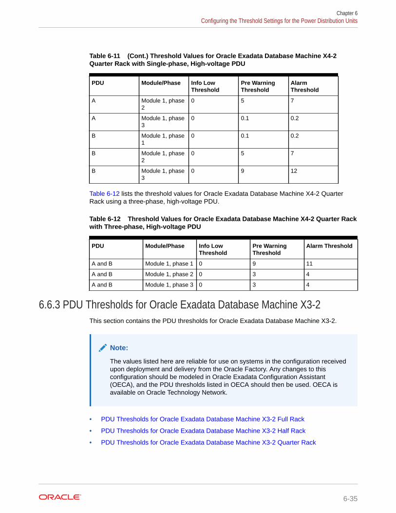
Table 6-11 (Cont.) Threshold Values for Oracle Exadata Database Machine X4-2Quarter Rack with Single-phase, High-voltage PDU
PDU Module/Phase Info LowThreshold
Pre WarningThreshold
AlarmThreshold
A Module 1, phase2
0 5 7
A Module 1, phase3
0 0.1 0.2
B Module 1, phase1
0 0.1 0.2
B Module 1, phase2
0 5 7
B Module 1, phase3
0 9 12
Table 6-12 lists the threshold values for Oracle Exadata Database Machine X4-2 QuarterRack using a three-phase, high-voltage PDU.
Table 6-12 Threshold Values for Oracle Exadata Database Machine X4-2 Quarter Rackwith Three-phase, High-voltage PDU
PDU Module/Phase Info LowThreshold
Pre WarningThreshold
Alarm Threshold
A and B Module 1, phase 1 0 9 11
A and B Module 1, phase 2 0 3 4
A and B Module 1, phase 3 0 3 4
6.6.3 PDU Thresholds for Oracle Exadata Database Machine X3-2This section contains the PDU thresholds for Oracle Exadata Database Machine X3-2.
Note:
The values listed here are reliable for use on systems in the configuration receivedupon deployment and delivery from the Oracle Factory. Any changes to thisconfiguration should be modeled in Oracle Exadata Configuration Assistant(OECA), and the PDU thresholds listed in OECA should then be used. OECA isavailable on Oracle Technology Network.
• PDU Thresholds for Oracle Exadata Database Machine X3-2 Full Rack
• PDU Thresholds for Oracle Exadata Database Machine X3-2 Half Rack
• PDU Thresholds for Oracle Exadata Database Machine X3-2 Quarter Rack
Chapter 6Configuring the Threshold Settings for the Power Distribution Units
6-35

6.6.3.1 PDU Thresholds for Oracle Exadata Database Machine X3-2 Full RackThe following tables list the threshold values for Oracle Exadata Database MachineX3-2 Full Rack:
• Table 6-13 Threshold Values for Oracle Exadata Database Machine X3-2 FullRack with Single-phase, Low-voltage PDU
• Table 6-14 Threshold Values for Oracle Exadata Database Machine X3-2 FullRack with Three-phase, Low-voltage PDU
• Table 6-15 Threshold Values for Oracle Exadata Database Machine X3-2 FullRack with Single-phase, High-voltage PDU
• Table 6-16
Threshold Values for Oracle Exadata Database Machine X3-2 Full Rack withThree-phase, High-voltage PDU
Table 6-13 lists the threshold values for Oracle Exadata Database Machine X3-2 FullRack using a single-phase, low-voltage PDU.
Table 6-13 Threshold Values for Oracle Exadata Database Machine X3-2 FullRack with Single-phase, Low-voltage PDU
PDU Module/Phase Info LowThreshold
Pre WarningThreshold
AlarmThreshold
A Module 1, phase1
0 20 24
A Module 1, phase2
0 14 18
A Module 1, phase3
0 19 24
B Module 1, phase1
0 19 24
B Module 1, phase2
0 14 18
B Module 1, phase3
0 20 24
Table 6-14 lists the threshold values for Oracle Exadata Database Machine X3-2 FullRack using a three-phase, low-voltage PDU.
Table 6-14 Threshold Values for Oracle Exadata Database Machine X3-2 FullRack with Three-phase, Low-voltage PDU
PDU Module/Phase Info LowThreshold
Pre WarningThreshold
AlarmThreshold
A and B Module 1, phase1
0 30 38
A and B Module 1, phase2
0 32 40
Chapter 6Configuring the Threshold Settings for the Power Distribution Units
6-36

Table 6-14 (Cont.) Threshold Values for Oracle Exadata Database Machine X3-2Full Rack with Three-phase, Low-voltage PDU
PDU Module/Phase Info LowThreshold
Pre WarningThreshold
AlarmThreshold
A and B Module 1, phase3
0 30 38
Table 6-15 lists the threshold values for Oracle Exadata Database Machine X3-2 Full Rackusing a single-phase, high-voltage PDU.
Table 6-15 Threshold Values for Oracle Exadata Database Machine X3-2 Full Rackwith Single-phase, High-voltage PDU
PDU Module/Phase Info LowThreshold
Pre WarningThreshold
Alarm Threshold
A Module 1, phase 1 0 18 23
A Module 1, phase 2 0 13 17
A Module 1, phase 3 0 18 22
B Module 1, phase 1 0 18 22
B Module 1, phase 2 0 13 17
B Module 1, phase 3 0 18 23
Table 6-16 lists the threshold values for Oracle Exadata Database Machine X3-2 Full Rackusing a three-phase, high-voltage PDU.
Table 6-16 Threshold Values for Oracle Exadata Database Machine X3-2 Full Rackwith Three-phase, High-voltage PDU
PDU Module/Phase Info LowThreshold
Pre WarningThreshold
Alarm Threshold
A and B Module 1, phase 1 0 17 21
A and B Module 1, phase 2 0 17 21
A and B Module 1, phase 3 0 15 19
6.6.3.2 PDU Thresholds for Oracle Exadata Database Machine X3-2 Half RackThe following tables list the threshold values for Oracle Exadata Database Machine X3-2 HalfRack:
• Table 6-17 Threshold Values for Oracle Exadata Database Machine X3-2 Half Rack withSingle-phase, Low-voltage PDU
• Table 6-18 Threshold Values for Oracle Exadata Database Machine X3-2 Half Rack withThree-phase, Low-voltage PDU
• Table 6-19 Threshold Values for Oracle Exadata Database Machine X3-2 Half Rack withSingle-phase, High-voltage PDU
Chapter 6Configuring the Threshold Settings for the Power Distribution Units
6-37

• Table 6-20 Threshold Values for Oracle Exadata Database Machine X3-2 HalfRack with Three-phase, High-voltage PDU
Table 6-17 lists the threshold values for Oracle Exadata Database Machine X3-2 HalfRack using a single-phase, low-voltage PDU.
Table 6-17 Threshold Values for Oracle Exadata Database Machine X3-2 HalfRack with Single-phase, Low-voltage PDU
PDU Module/Phase Info LowThreshold
Pre WarningThreshold
AlarmThreshold
A Module 1, phase1
0 20 24
A Module 1, phase2
0 9 11
A Module 1, phase3
0 0 0
B Module 1, phase1
0 0 0
B Module 1, phase2
0 9 11
B Module 1, phase3
0 20 24
Table 6-18 lists the threshold values for Oracle Exadata Database Machine X3-2 HalfRack using a three-phase, low-voltage PDU.
Table 6-18 Threshold Values for Oracle Exadata Database Machine X3-2 HalfRack with Three-phase, Low-voltage PDU
PDU Module/Phase Info LowThreshold
Pre WarningThreshold
AlarmThreshold
A and B Module 1, phase1
0 16 21
A and B Module 1, phase2
0 19 24
A and B Module 1, phase3
0 14 18
Table 6-19 lists the threshold values for Oracle Exadata Database Machine X3-2 HalfRack using a single-phase, high-voltage PDU.
Table 6-19 Threshold Values for Oracle Exadata Database Machine X3-2 HalfRack with Single-phase, High-voltage PDU
PDU Module/Phase Info LowThreshold
Pre WarningThreshold
AlarmThreshold
A Module 1, phase1
0 18 23
Chapter 6Configuring the Threshold Settings for the Power Distribution Units
6-38

Table 6-19 (Cont.) Threshold Values for Oracle Exadata Database Machine X3-2Half Rack with Single-phase, High-voltage PDU
PDU Module/Phase Info LowThreshold
Pre WarningThreshold
AlarmThreshold
A Module 1, phase2
0 8 10
A Module 1, phase3
0 0 0
B Module 1, phase1
0 0 0
B Module 1, phase2
0 8 10
B Module 1, phase3
0 18 23
Table 6-20 lists the threshold values for Oracle Exadata Database Machine X3-2 Half Rackusing a three-phase, high-voltage PDU.
Table 6-20 Threshold Values for Oracle Exadata Database Machine X3-2 Half Rackwith Three-phase, High-voltage PDU
PDU Module/Phase Info LowThreshold
Pre WarningThreshold
Alarm Threshold
A and B Module 1, phase 1 0 11 15
A and B Module 1, phase 2 0 9 11
A and B Module 1, phase 3 0 6 8
6.6.3.3 PDU Thresholds for Oracle Exadata Database Machine X3-2 Quarter RackThe following tables list the threshold values for Oracle Exadata Database Machine X3-2Quarter Rack:
• Table 6-21 Threshold Values for Oracle Exadata Database Machine X3-2 Quarter Rackwith Single-phase, Low-voltage PDU
• Table 6-22 Threshold Values for Oracle Exadata Database Machine X3-2 Quarter Rackwith Three-phase, Low-voltage PDU
• Table 6-23 Threshold Values for Oracle Exadata Database Machine X3-2 Quarter Rackwith Single-phase, High-voltage PDU
• Table 6-24 Threshold Values for Oracle Exadata Database Machine X3-2 Quarter Rackwith Three-phase, High-voltage PDU
Table 6-21 lists the threshold values for Oracle Exadata Database Machine X3-2 QuarterRack using a single-phase, low-voltage PDU.
Chapter 6Configuring the Threshold Settings for the Power Distribution Units
6-39

Table 6-21 Threshold Values for Oracle Exadata Database Machine X3-2Quarter Rack with Single-phase, Low-voltage PDU
PDU Module/Phase Info LowThreshold
Pre WarningThreshold
AlarmThreshold
A Module 1, phase1
0 10 13
A Module 1, phase2
0 5 6
A Module 1, phase3
0 0 0
B Module 1, phase1
0 0 0
B Module 1, phase2
0 5 6
B Module 1, phase3
0 10 13
Table 6-22 lists the threshold values for Oracle Exadata Database Machine X3-2Quarter Rack using a three-phase, low-voltage PDU.
Table 6-22 Threshold Values for Oracle Exadata Database Machine X3-2Quarter Rack with Three-phase, Low-voltage PDU
PDU Module/Phase Info LowThreshold
Pre WarningThreshold
AlarmThreshold
A and B Module 1, phase1
0 11 14
A and B Module 1, phase2
0 10 13
A and B Module 1, phase3
0 4 6
Table 6-23 lists the threshold values for Oracle Exadata Database Machine X3-2Quarter Rack using a single-phase, high-voltage PDU.
Table 6-23 Threshold Values for Oracle Exadata Database Machine X3-2Quarter Rack with Single-phase, High-voltage PDU
PDU Module/Phase Info LowThreshold
Pre WarningThreshold
AlarmThreshold
A Module 1, phase1
0 9 11
A Module 1, phase2
0 4 6
A Module 1, phase3
0 0 0
Chapter 6Configuring the Threshold Settings for the Power Distribution Units
6-40

Table 6-23 (Cont.) Threshold Values for Oracle Exadata Database Machine X3-2Quarter Rack with Single-phase, High-voltage PDU
PDU Module/Phase Info LowThreshold
Pre WarningThreshold
AlarmThreshold
B Module 1, phase1
0 0 0
B Module 1, phase2
0 4 6
B Module 1, phase3
0 9 11
Table 6-24 lists the threshold values for Oracle Exadata Database Machine X3-2 QuarterRack using a three-phase, high-voltage PDU.
Table 6-24 Threshold Values for Oracle Exadata Database Machine X3-2 Quarter Rackwith Three-phase, High-voltage PDU
PDU Module/Phase Info LowThreshold
Pre WarningThreshold
Alarm Threshold
A and B Module 1, phase 1 0 9 12
A and B Module 1, phase 2 0 2 3
A and B Module 1, phase 3 0 3 4
6.6.4 PDU Thresholds for Oracle Exadata Database Machine X2-2 (withX4170 M2 and X4270 M2 servers)
This section contains the PDU thresholds for Oracle Exadata Database Machine X2-2 (withX4170 M2 and X4270 M2 servers).
Note:
The values listed here are reliable for use on systems in the configuration receivedupon deployment and delivery from the Oracle Factory. Any changes to thisconfiguration should be modeled in Oracle Exadata Configuration Assistant(OECA), and the PDU thresholds listed in OECA should then be used. OECA isavailable on Oracle Technology Network.
• PDU Thresholds for Oracle Exadata Database Machine X2-2 (with X4170 M2 and X4270M2 servers) Full Rack
• PDU Thresholds for Oracle Exadata Database Machine X2-2 (with X4170 M2 and X4270M2 servers) Half Rack
• PDU Thresholds for Oracle Exadata Database Machine X2-2 (with X4170 M2 and X4270M2 servers) Quarter Rack
Chapter 6Configuring the Threshold Settings for the Power Distribution Units
6-41

6.6.4.1 PDU Thresholds for Oracle Exadata Database Machine X2-2 (withX4170 M2 and X4270 M2 servers) Full Rack
The following tables list the threshold values for Oracle Exadata Database MachineX2-2 (with X4170 and X4275 servers) Full Rack:
• Table 6-25 Threshold Values for Oracle Exadata Database Machine X2-2 (withX4170 M2 and X4270 M2 servers) Full Rack with Single-phase, Low-voltage PDU
• Table 6-26 Threshold Values for Oracle Exadata Database Machine X2-2 (withX4170 M2 and X4270 M2 servers) Full Rack with Three-phase, Low-voltage PDU
• Table 6-27 Threshold Values for Oracle Exadata Database Machine X2-2 (withX4170 M2 and X4270 M2 servers) Full Rack with Single-phase, High-voltage PDU
• Table 6-28 Threshold Values for Oracle Exadata Database Machine X2-2 (withX4170 M2 and X4270 M2 servers) Full Rack with Three-phase, High-voltage PDU
Table 6-25 lists the threshold values for Oracle Exadata Database Machine Full Rackusing a single-phase, low-voltage PDU.
Table 6-25 Threshold Values for Oracle Exadata Database Machine X2-2 (withX4170 M2 and X4270 M2 servers) Full Rack with Single-phase, Low-voltage PDU
PDU Module/Phase Info LowThreshold
Pre WarningThreshold
AlarmThreshold
A Module 1, phase1
0 18 23
A Module 1, phase2
0 22 24
A Module 1, phase3
0 18 23
B Module 1, phase1
0 18 23
B Module 1, phase2
0 22 24
B Module 1, phase3
0 18 23
Table 6-26 lists the threshold values for Oracle Exadata Database Machine Full Rackusing a three-phase, low-voltage PDU.
Table 6-26 Threshold Values for Oracle Exadata Database Machine X2-2 (withX4170 M2 and X4270 M2 servers) Full Rack with Three-phase, Low-voltage PDU
PDU Module/Phase Info LowThreshold
Pre WarningThreshold
AlarmThreshold
A and B Module 1, phase1
0 32 40
A and B Module 1, phase2
0 34 43
Chapter 6Configuring the Threshold Settings for the Power Distribution Units
6-42

Table 6-26 (Cont.) Threshold Values for Oracle Exadata Database Machine X2-2(with X4170 M2 and X4270 M2 servers) Full Rack with Three-phase, Low-voltagePDU
PDU Module/Phase Info LowThreshold
Pre WarningThreshold
AlarmThreshold
A and B Module 1, phase3
0 33 42
Table 6-27 lists the threshold values for Oracle Exadata Database Machine Full Rack using asingle-phase, high-voltage PDU.
Table 6-27 Threshold Values for Oracle Exadata Database Machine X2-2 (with X4170M2 and X4270 M2 servers) Full Rack with Single-phase, High-voltage PDU
PDU Module/Phase Info LowThreshold
Pre WarningThreshold
Alarm Threshold
A Module 1, phase 1 0 16 20
A Module 1, phase 2 0 20 21
A Module 1, phase 3 0 16 20
B Module 1, phase 1 0 16 20
B Module 1, phase 2 0 20 21
B Module 1, phase 3 0 16 20
Table 6-28 lists the threshold values for Oracle Exadata Database Machine Full Rack using athree-phase, high-voltage PDU.
Table 6-28 Threshold Values for Oracle Exadata Database Machine X2-2 (with X4170M2 and X4270 M2 servers) Full Rack with Three-phase, High-voltage PDU
PDU Module/Phase Info LowThreshold
Pre WarningThreshold
Alarm Threshold
A and B Module 1, phase 1 0 18 21
A and B Module 1, phase 2 0 18 21
A and B Module 1, phase 3 0 17 21
6.6.4.2 PDU Thresholds for Oracle Exadata Database Machine X2-2 (with X4170M2 and X4270 M2 servers) Half Rack
The following tables list the threshold values for Oracle Exadata Database Machine HalfRack:
• Table 6-29 Threshold Values for Oracle Exadata Database Machine X2-2 (with X4170 M2and X4270 M2 servers) Half Rack with Single-phase, Low-voltage PDU
• Table 6-30 Threshold Values for Oracle Exadata Database Machine X2-2 (with X4170 M2and X4270 M2 servers) Half Rack with Three-phase, Low-voltage PDU
Chapter 6Configuring the Threshold Settings for the Power Distribution Units
6-43

• Table 6-31 Threshold Values for Oracle Exadata Database Machine X2-2 (withX4170 M2 and X4270 M2 servers) Half Rack with Single-phase, High-voltage PDU
• Table 6-32 Threshold Values for Oracle Exadata Database Machine X2-2 (withX4170 M2 and X4270 M2 servers) Half Rack with Three-phase, High-voltage PDU
Table 6-29 lists the threshold values for Oracle Exadata Database Machine Half Rackusing a single-phase, low-voltage PDU.
Table 6-29 Threshold Values for Oracle Exadata Database Machine X2-2 (withX4170 M2 and X4270 M2 servers) Half Rack with Single-phase, Low-voltage PDU
PDU Module/Phase Info LowThreshold
Pre WarningThreshold
AlarmThreshold
A Module 1, phase1
0 18 23
A Module 1, phase2
0 13 17
A Module 1, phase3
0 0 0
B Module 1, phase1
0 0 0
B Module 1, phase2
0 13 17
B Module 1, phase3
0 18 23
Table 6-30 lists the threshold values for Oracle Exadata Database Machine Half Rackusing a three-phase, low-voltage PDU.
Table 6-30 Threshold Values for Oracle Exadata Database Machine X2-2 (withX4170 M2 and X4270 M2 servers) Half Rack with Three-phase, Low-voltage PDU
PDU Module/Phase Info LowThreshold
Pre WarningThreshold
AlarmThreshold
A and B Module 1, phase1
0 18 23
A and B Module 1, phase2
0 17 22
A and B Module 1, phase3
0 18 23
Table 6-31 lists the threshold values for Oracle Exadata Database Machine Half Rackusing a single-phase, high-voltage PDU.
Chapter 6Configuring the Threshold Settings for the Power Distribution Units
6-44

Table 6-31 Threshold Values for Oracle Exadata Database Machine X2-2 (with X4170M2 and X4270 M2 servers) Half Rack with Single-phase, High-voltage PDU
PDU Module/Phase Info LowThreshold
Pre WarningThreshold
Alarm Threshold
A Module 1, phase 1 0 16 20
A Module 1, phase 2 0 12 15
A Module 1, phase 3 0 0 0
B Module 1, phase 1 0 0 0
B Module 1, phase 2 0 12 15
B Module 1, phase 3 0 16 20
Table 6-32 lists the threshold values for Oracle Exadata Database Machine Half Rack using athree-phase, high-voltage PDU.
Table 6-32 Threshold Values for Oracle Exadata Database Machine X2-2 (with X4170M2 and X4270 M2 servers) Half Rack with Three-phase, High-voltage PDU
PDU Module/Phase Info LowThreshold
Pre WarningThreshold
Alarm Threshold
A and B Module 1, phase 1 0 9 12
A and B Module 1, phase 2 0 9 12
A and B Module 1, phase 3 0 10 13
6.6.4.3 PDU Thresholds for Oracle Exadata Database Machine X2-2 (with X4170M2 and X4270 M2 servers) Quarter Rack
The following tables list the threshold values for Oracle Exadata Database Machine QuarterRack:
• Table 6-33 Threshold Values for Oracle Exadata Database Machine X2-2 (with X4170 M2and X4270 M2 servers) Quarter Rack with Single-phase, Low-voltage PDU
• Table 6-34 Threshold Values for Oracle Exadata Database Machine X2-2 (with X4170 M2and X4270 M2 servers) Quarter Rack with Three-phase, Low-voltage PDU
• Table 6-35 Threshold Values for Oracle Exadata Database Machine X2-2 (with X4170 M2and X4270 M2 servers) Quarter Rack with Single-phase, High-voltage PDU
• Table 6-36 Threshold Values for Oracle Exadata Database Machine X2-2 (with X4170 M2and X4270 M2 servers) Quarter Rack with Three-phase, High-voltage PDU
Table 6-33 lists the threshold values for Oracle Exadata Database Machine Quarter Rackusing a single-phase, low-voltage PDU.
Chapter 6Configuring the Threshold Settings for the Power Distribution Units
6-45

Table 6-33 Threshold Values for Oracle Exadata Database Machine X2-2 (withX4170 M2 and X4270 M2 servers) Quarter Rack with Single-phase, Low-voltagePDU
PDU Module/Phase Info LowThreshold
Pre WarningThreshold
AlarmThreshold
A Module 1, phase1
0 10 13
A Module 1, phase2
0 6 8
A Module 1, phase3
0 0 0
B Module 1, phase1
0 0 0
B Module 1, phase2
0 6 8
B Module 1, phase3
0 10 13
Table 6-34 lists the threshold values for Oracle Exadata Database Machine QuarterRack using a three-phase, low-voltage PDU.
Table 6-34 Threshold Values for Oracle Exadata Database Machine X2-2 (withX4170 M2 and X4270 M2 servers) Quarter Rack with Three-phase, Low-voltagePDU
PDU Module/Phase Info LowThreshold
Pre WarningThreshold
AlarmThreshold
A and B Module 1, phase1
0 12 15
A and B Module 1, phase2
0 11 14
A and B Module 1, phase3
0 5 7
Table 6-35 lists the threshold values for Oracle Exadata Database Machine QuarterRack using a single-phase, high-voltage PDU.
Table 6-35 Threshold Values for Oracle Exadata Database Machine X2-2 (withX4170 M2 and X4270 M2 servers) Quarter Rack with Single-phase, High-voltagePDU
PDU Module/Phase Info LowThreshold
Pre WarningThreshold
AlarmThreshold
A Module 1, phase1
0 9 12
A Module 1, phase2
0 5 7
Chapter 6Configuring the Threshold Settings for the Power Distribution Units
6-46
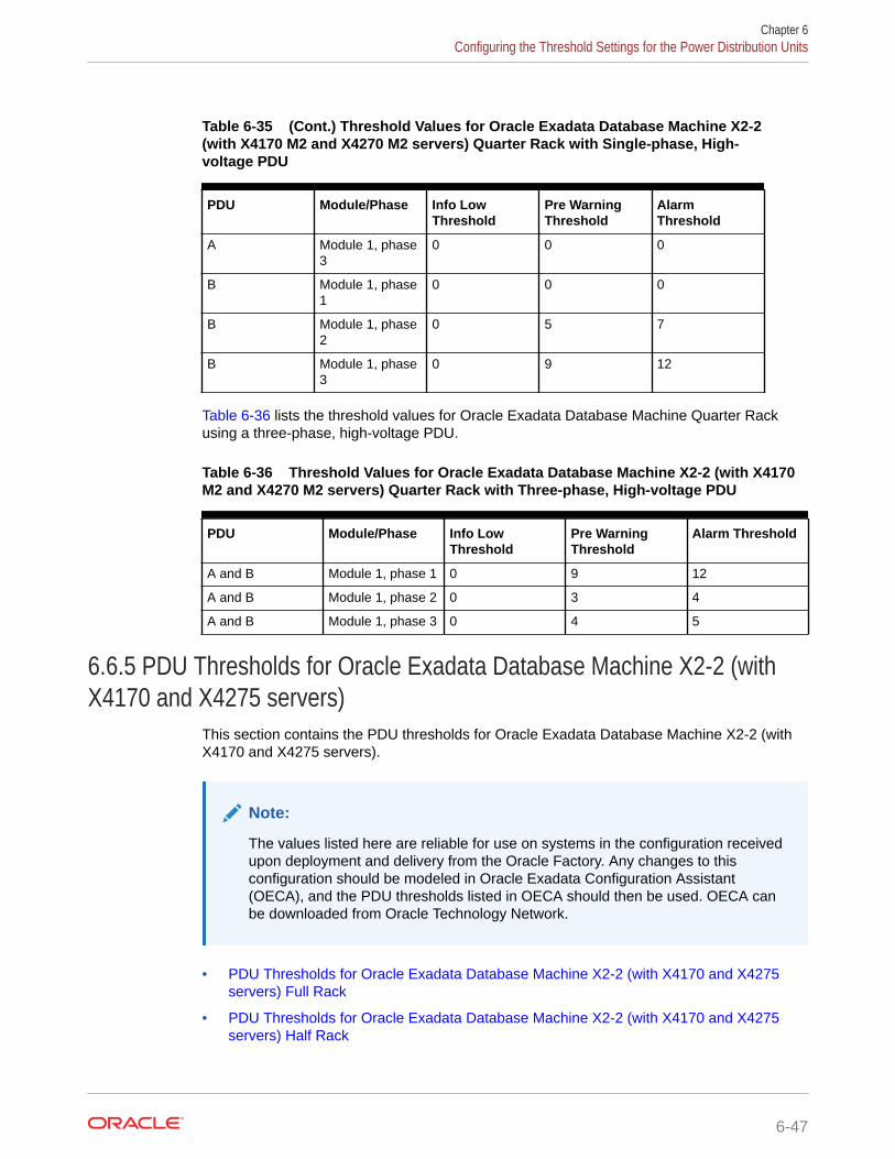
Table 6-35 (Cont.) Threshold Values for Oracle Exadata Database Machine X2-2(with X4170 M2 and X4270 M2 servers) Quarter Rack with Single-phase, High-voltage PDU
PDU Module/Phase Info LowThreshold
Pre WarningThreshold
AlarmThreshold
A Module 1, phase3
0 0 0
B Module 1, phase1
0 0 0
B Module 1, phase2
0 5 7
B Module 1, phase3
0 9 12
Table 6-36 lists the threshold values for Oracle Exadata Database Machine Quarter Rackusing a three-phase, high-voltage PDU.
Table 6-36 Threshold Values for Oracle Exadata Database Machine X2-2 (with X4170M2 and X4270 M2 servers) Quarter Rack with Three-phase, High-voltage PDU
PDU Module/Phase Info LowThreshold
Pre WarningThreshold
Alarm Threshold
A and B Module 1, phase 1 0 9 12
A and B Module 1, phase 2 0 3 4
A and B Module 1, phase 3 0 4 5
6.6.5 PDU Thresholds for Oracle Exadata Database Machine X2-2 (withX4170 and X4275 servers)
This section contains the PDU thresholds for Oracle Exadata Database Machine X2-2 (withX4170 and X4275 servers).
Note:
The values listed here are reliable for use on systems in the configuration receivedupon deployment and delivery from the Oracle Factory. Any changes to thisconfiguration should be modeled in Oracle Exadata Configuration Assistant(OECA), and the PDU thresholds listed in OECA should then be used. OECA canbe downloaded from Oracle Technology Network.
• PDU Thresholds for Oracle Exadata Database Machine X2-2 (with X4170 and X4275servers) Full Rack
• PDU Thresholds for Oracle Exadata Database Machine X2-2 (with X4170 and X4275servers) Half Rack
Chapter 6Configuring the Threshold Settings for the Power Distribution Units
6-47

• PDU Thresholds for Oracle Exadata Database Machine X2-2 (with X4170 andX4275 servers) Quarter Rack
6.6.5.1 PDU Thresholds for Oracle Exadata Database Machine X2-2 (withX4170 and X4275 servers) Full Rack
The following tables list the threshold values for Oracle Exadata Database MachineX2-2 (with X4170 and X4275 servers) Full Rack:
• Table 6-37 Threshold Values for Oracle Exadata Database Machine X2-2 (withX4170 and X4275 servers) Full Rack with Single-phase, Low-voltage PDU
• Table 6-38 Threshold Values for Oracle Exadata Database Machine X2-2 (withX4170 and X4275 servers) Full Rack with Three-phase, Low-voltage PDU
• Table 6-39 Threshold Values for Oracle Exadata Database Machine X2-2 (withX4170 and X4275 servers) Full Rack with Single-phase, High-voltage PDU
• Table 6-40 Threshold Values for Oracle Exadata Database Machine X2-2 (withX4170 and X4275 servers) Full Rack with Three-phase, High-voltage PDU
Table 6-37 lists the threshold values for Oracle Exadata Database Machine Full Rackusing a single-phase, low-voltage PDU.
Table 6-37 Threshold Values for Oracle Exadata Database Machine X2-2 (withX4170 and X4275 servers) Full Rack with Single-phase, Low-voltage PDU
PDU Module/Phase Info LowThreshold
Pre WarningThreshold
AlarmThreshold
A Module 1, phase1
0 22 24
A Module 1, phase2
0 22 24
A Module 1, phase3
0 21 24
B Module 1, phase1
0 21 24
B Module 1, phase2
0 22 24
B Module 1, phase3
0 22 24
Table 6-38 lists the threshold values for Oracle Exadata Database Machine Full Rackusing a three-phase, low-voltage PDU.
Table 6-38 Threshold Values for Oracle Exadata Database Machine X2-2 (withX4170 and X4275 servers) Full Rack with Three-phase, Low-voltage PDU
PDU Module/Phase Info LowThreshold
Pre WarningThreshold
AlarmThreshold
A and B Module 1, phase1
0 36 45
Chapter 6Configuring the Threshold Settings for the Power Distribution Units
6-48

Table 6-38 (Cont.) Threshold Values for Oracle Exadata Database Machine X2-2(with X4170 and X4275 servers) Full Rack with Three-phase, Low-voltage PDU
PDU Module/Phase Info LowThreshold
Pre WarningThreshold
AlarmThreshold
A and B Module 1, phase2
0 39 44
A and B Module 1, phase3
0 38 45
Table 6-39 lists the threshold values for Oracle Exadata Database Machine Full Rack using asingle-phase, high-voltage PDU.
Table 6-39 Threshold Values for Oracle Exadata Database Machine X2-2 (with X4170and X4275 servers) Full Rack with Single-phase, High-voltage PDU
PDU Module/Phase Info LowThreshold
Pre WarningThreshold
Alarm Threshold
A Module 1, phase 1 0 20 21
A Module 1, phase 2 0 20 21
A Module 1, phase 3 0 19 21
B Module 1, phase 1 0 19 21
B Module 1, phase 2 0 20 21
B Module 1, phase 3 0 20 21
Table 6-40 lists the threshold values for Oracle Exadata Database Machine Full Rack using athree-phase, high-voltage PDU.
Table 6-40 Threshold Values for Oracle Exadata Database Machine X2-2 (with X4170and X4275 servers) Full Rack with Three-phase, High-voltage PDU
PDU Module/Phase Info LowThreshold
Pre WarningThreshold
Alarm Threshold
A and B Module 1, phase 1 0 20 21
A and B Module 1, phase 2 0 21 21
A and B Module 1, phase 3 0 18 21
6.6.5.2 PDU Thresholds for Oracle Exadata Database Machine X2-2 (with X4170and X4275 servers) Half Rack
The following tables list the threshold values for Oracle Exadata Database Machine HalfRack:
• Table 6-41 Threshold Values for Oracle Exadata Database Machine X2-2 (with X4170and X4275 servers) Half Rack with Single-phase, Low-voltage PDU
• Table 6-42 Threshold Values for Oracle Exadata Database Machine X2-2 (with X4170and X4275 servers) Half Rack with Three-phase, Low-voltage PDU
Chapter 6Configuring the Threshold Settings for the Power Distribution Units
6-49

• Table 6-43 Threshold Values for Oracle Exadata Database Machine X2-2 (withX4170 and X4275 servers) Half Rack with Single-phase, High-voltage PDU
• Table 6-44 Threshold Values for Oracle Exadata Database Machine X2-2 (withX4170 and X4275 servers) Half Rack with Three-phase, High-voltage PDU
Table 6-41 lists the threshold values for Oracle Exadata Database Machine Half Rackusing a single-phase, low-voltage PDU.
Table 6-41 Threshold Values for Oracle Exadata Database Machine X2-2 (withX4170 and X4275 servers) Half Rack with Single-phase, Low-voltage PDU
PDU Module/Phase Info LowThreshold
Pre WarningThreshold
AlarmThreshold
A Module 1, phase1
0 21 24
A Module 1, phase2
0 13 17
A Module 1, phase3
0 0 0
B Module 1, phase1
0 0 0
B Module 1, phase2
0 13 17
B Module 1, phase3
0 21 24
Table 6-42 lists the threshold values for Oracle Exadata Database Machine Half Rackusing a three-phase, low-voltage PDU.
Table 6-42 Threshold Values for Oracle Exadata Database Machine X2-2 (withX4170 and X4275 servers) Half Rack with Three-phase, Low-voltage PDU
PDU Module/Phase Info LowThreshold
Pre WarningThreshold
AlarmThreshold
A and B Module 1, phase1
0 19 24
A and B Module 1, phase2
0 20 25
A and B Module 1, phase3
0 19 24
Table 6-43 lists the threshold values for Oracle Exadata Database Machine Half Rackusing a single-phase, high-voltage PDU.
Chapter 6Configuring the Threshold Settings for the Power Distribution Units
6-50
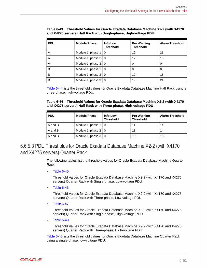
Table 6-43 Threshold Values for Oracle Exadata Database Machine X2-2 (with X4170and X4275 servers) Half Rack with Single-phase, High-voltage PDU
PDU Module/Phase Info LowThreshold
Pre WarningThreshold
Alarm Threshold
A Module 1, phase 1 0 19 21
A Module 1, phase 2 0 12 15
A Module 1, phase 3 0 0 0
B Module 1, phase 1 0 0 0
B Module 1, phase 2 0 12 15
B Module 1, phase 3 0 19 21
Table 6-44 lists the threshold values for Oracle Exadata Database Machine Half Rack using athree-phase, high-voltage PDU.
Table 6-44 Threshold Values for Oracle Exadata Database Machine X2-2 (with X4170and X4275 servers) Half Rack with Three-phase, High-voltage PDU
PDU Module/Phase Info LowThreshold
Pre WarningThreshold
Alarm Threshold
A and B Module 1, phase 1 0 11 14
A and B Module 1, phase 2 0 11 14
A and B Module 1, phase 3 0 10 13
6.6.5.3 PDU Thresholds for Oracle Exadata Database Machine X2-2 (with X4170and X4275 servers) Quarter Rack
The following tables list the threshold values for Oracle Exadata Database Machine QuarterRack:
• Table 6-45
Threshold Values for Oracle Exadata Database Machine X2-2 (with X4170 and X4275servers) Quarter Rack with Single-phase, Low-voltage PDU
• Table 6-46
Threshold Values for Oracle Exadata Database Machine X2-2 (with X4170 and X4275servers) Quarter Rack with Three-phase, Low-voltage PDU
• Table 6-47
Threshold Values for Oracle Exadata Database Machine X2-2 (with X4170 and X4275servers) Quarter Rack with Single-phase, High-voltage PDU
• Table 6-48
Threshold Values for Oracle Exadata Database Machine X2-2 (with X4170 and X4275servers) Quarter Rack with Three-phase, High-voltage PDU
Table 6-45 lists the threshold values for Oracle Exadata Database Machine Quarter Rackusing a single-phase, low-voltage PDU.
Chapter 6Configuring the Threshold Settings for the Power Distribution Units
6-51

Table 6-45 Threshold Values for Oracle Exadata Database Machine X2-2 (withX4170 and X4275 servers) Quarter Rack with Single-phase, Low-voltage PDU
PDU Module/Phase Info LowThreshold
Pre WarningThreshold
AlarmThreshold
A Module 1, phase1
0 12 15
A Module 1, phase2
0 6 8
A Module 1, phase3
0 0 0
B Module 1, phase1
0 0 0
B Module 1, phase2
0 6 8
B Module 1, phase3
0 12 15
Table 6-46 lists the threshold values for Oracle Exadata Database Machine QuarterRack using a three-phase, low-voltage PDU.
Table 6-46 Threshold Values for Oracle Exadata Database Machine X2-2 (withX4170 and X4275 servers) Quarter Rack with Three-phase, Low-voltage PDU
PDU Module/Phase Info LowThreshold
Pre WarningThreshold
AlarmThreshold
A and B Module 1, phase1
0 13 17
A and B Module 1, phase2
0 12 15
A and B Module 1, phase3
0 5 7
Table 6-47 lists the threshold values for Oracle Exadata Database Machine QuarterRack using a single-phase, high-voltage PDU.
Table 6-47 Threshold Values for Oracle Exadata Database Machine X2-2 (withX4170 and X4275 servers) Quarter Rack with Single-phase, High-voltage PDU
PDU Module/Phase Info LowThreshold
Pre WarningThreshold
AlarmThreshold
A Module 1, phase1
0 11 14
A Module 1, phase2
0 5 7
A Module 1, phase3
0 0 0
Chapter 6Configuring the Threshold Settings for the Power Distribution Units
6-52

Table 6-47 (Cont.) Threshold Values for Oracle Exadata Database Machine X2-2(with X4170 and X4275 servers) Quarter Rack with Single-phase, High-voltagePDU
PDU Module/Phase Info LowThreshold
Pre WarningThreshold
AlarmThreshold
B Module 1, phase1
0 0 0
B Module 1, phase2
0 5 7
B Module 1, phase3
0 11 14
Table 6-48 lists the threshold values for Oracle Exadata Database Machine Quarter Rackusing a three-phase, high-voltage PDU.
Table 6-48 Threshold Values for Oracle Exadata Database Machine X2-2 (with X4170and X4275 servers) Quarter Rack with Three-phase, High-voltage PDU
PDU Module/Phase Info LowThreshold
Pre WarningThreshold
Alarm Threshold
A and B Module 1, phase 1 0 11 14
A and B Module 1, phase 2 0 2 3
A and B Module 1, phase 3 0 3 4
6.6.6 PDU Thresholds for Oracle Exadata Database Machine X4-8 andLater
This section contains the PDU thresholds for Oracle Exadata Database Machine Eight-Socket systems for X4-8 and later.
Oracle Exadata Configuration Assistant (OECA) is the only source for PDU thresholds forOracle Exadata Database Machine X4-8 and later systems. OECA is available on OracleTechnology Network at http://www.oracle.com/technetwork/database/exadata/oeca-download-2817713.html
If for some reason you are unable to utilize OECA, contact Oracle Support.
6.6.7 PDU Thresholds for Oracle Exadata Database Machine X3-8 FullRack
This section contains the PDU thresholds for Oracle Exadata Database Machine X3-8 FullRack.
• Table 6-49 Threshold Values for Oracle Exadata Database Machine X3-8 Full Rack withSingle-phase, Low-voltage 22 kVA PDU
• Table 6-50 Threshold Values for Oracle Exadata Database Machine X3-8 Full Rack withThree-phase, Low-voltage 24 kVA PDU
Chapter 6Configuring the Threshold Settings for the Power Distribution Units
6-53

• Table 6-51 Threshold Values for Oracle Exadata Database Machine X3-8 FullRack with Single-phase, High-voltage 22 kVA PDU
• Table 6-52 Threshold Values for Oracle Exadata Database Machine X3-8 FullRack with Three-phase, High-voltage 24 kVA PDU
Table 6-49 lists the threshold values for Oracle Exadata Database Machine X3-8 FullRack using a single-phase, low-voltage 22 kVA PDU.
Table 6-49 Threshold Values for Oracle Exadata Database Machine X3-8 FullRack with Single-phase, Low-voltage 22 kVA PDU
PDU Module/Phase Info LowThreshold
Pre WarningThreshold
AlarmThreshold
A Module 1, phase1
0 25 31
A Module 1, phase2
0 26 33
A Module 1, phase3
0 24 30
B Module 1, phase1
0 24 30
B Module 1, phase2
0 26 33
B Module 1, phase3
0 25 31
Table 6-50 lists the threshold values for Oracle Exadata Database Machine X3-8 FullRack using a three-phase, low-voltage 24 kVA PDU.
Table 6-50 Threshold Values for Oracle Exadata Database Machine X3-8 FullRack with Three-phase, Low-voltage 24 kVA PDU
PDU Module/Phase Info LowThreshold
Pre WarningThreshold
AlarmThreshold
A Module 1, phase1
0 21 27
A Module 1, phase2
0 23 30
A Module 1, phase3
0 22 28
A Module 2, phase1
0 20 25
A Module 2, phase2
0 21 27
A Module 2, phase3
0 23 29
B Module 1, phase1
0 20 25
B Module 1, phase2
0 21 27
Chapter 6Configuring the Threshold Settings for the Power Distribution Units
6-54

Table 6-50 (Cont.) Threshold Values for Oracle Exadata Database Machine X3-8Full Rack with Three-phase, Low-voltage 24 kVA PDU
PDU Module/Phase Info LowThreshold
Pre WarningThreshold
AlarmThreshold
B Module 1, phase3
0 23 29
B Module 2, phase1
0 21 27
B Module 2, phase2
0 23 30
B Module 2, phase3
0 22 28
Table 6-51 lists the threshold values for Oracle Exadata Database Machine X3-8 Full Rackusing a single-phase, high-voltage 22 kVA PDU.
Table 6-51 Threshold Values for Oracle Exadata Database Machine X3-8 Full Rackwith Single-phase, High-voltage 22 kVA PDU
PDU Module/Phase Info LowThreshold
Pre WarningThreshold
Alarm Threshold
A and B Module 1, phase 1 0 22 28
A and B Module 1, phase 2 0 24 30
A and B Module 1, phase 3 0 22 28
Table 6-52 lists the threshold values for Oracle Exadata Database Machine X3-8 Full Rackusing a three-phase, high-voltage 24 kVA PDU.
Table 6-52 Threshold Values for Oracle Exadata Database Machine X3-8 Full Rackwith Three-phase, High-voltage 24 kVA PDU
PDU Module/Phase Info LowThreshold
Pre WarningThreshold
Alarm Threshold
A Module 1, phase 1 0 12 16
A Module 1, phase 2 0 13 17
A Module 1, phase 3 0 10 13
A Module 2, phase 1 0 10 13
A Module 2, phase 2 0 13 17
A Module 2, phase 3 0 11 15
B Module 1, phase 1 0 10 13
B Module 1, phase 2 0 13 17
B Module 1, phase 3 0 11 15
B Module 2, phase 1 0 12 16
B Module 2, phase 2 0 13 17
Chapter 6Configuring the Threshold Settings for the Power Distribution Units
6-55

Table 6-52 (Cont.) Threshold Values for Oracle Exadata Database Machine X3-8 FullRack with Three-phase, High-voltage 24 kVA PDU
PDU Module/Phase Info LowThreshold
Pre WarningThreshold
Alarm Threshold
B Module 2, phase 3 0 10 13
6.6.8 PDU Thresholds for Oracle Exadata Database Machine X2-8Full Rack
This section contains the PDU thresholds for Oracle Exadata Database Machine X2-8Full Rack.
• Table 6-53 Threshold Values for Oracle Exadata Database Machine X2-8 FullRack with Single-phase, Low-voltage 22 kVA PDU
• Table 6-54 Threshold Values for Oracle Exadata Database Machine X2-8 FullRack with Three-phase, Low-voltage 24 kVA PDU
• Table 6-55 Threshold Values for Oracle Exadata Database Machine X2-8 FullRack with Single-phase, High-voltage 22 kVA PDU
• Table 6-56 Threshold Values for Oracle Exadata Database Machine X2-8 FullRack with Three-phase, High-voltage 24 kVA PDU
Table 6-53 lists the threshold values for Oracle Exadata Database Machine X2-8 FullRack using a single-phase, low-voltage 22 kVA PDU.
Table 6-53 Threshold Values for Oracle Exadata Database Machine X2-8 FullRack with Single-phase, Low-voltage 22 kVA PDU
PDU Module/Phase Info LowThreshold
Pre WarningThreshold
AlarmThreshold
A Module 1, phase1
0 36 37
A Module 1, phase2
0 35 37
A Module 1, phase3
0 35 37
B Module 1, phase1
0 35 37
B Module 1, phase2
0 35 37
B Module 1, phase3
0 36 37
Table 6-54 lists the threshold values for Oracle Exadata Database Machine X2-8 FullRack using a three-phase, low-voltage 24 kVA PDU.
Chapter 6Configuring the Threshold Settings for the Power Distribution Units
6-56
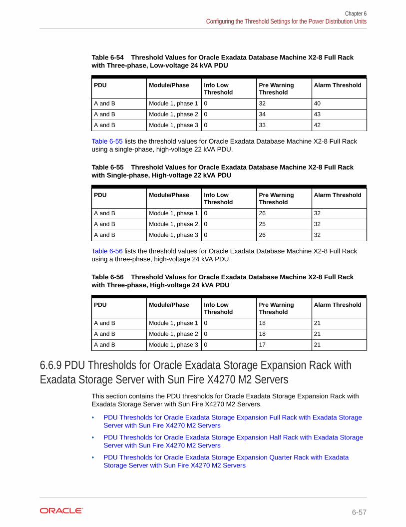
Table 6-54 Threshold Values for Oracle Exadata Database Machine X2-8 Full Rackwith Three-phase, Low-voltage 24 kVA PDU
PDU Module/Phase Info LowThreshold
Pre WarningThreshold
Alarm Threshold
A and B Module 1, phase 1 0 32 40
A and B Module 1, phase 2 0 34 43
A and B Module 1, phase 3 0 33 42
Table 6-55 lists the threshold values for Oracle Exadata Database Machine X2-8 Full Rackusing a single-phase, high-voltage 22 kVA PDU.
Table 6-55 Threshold Values for Oracle Exadata Database Machine X2-8 Full Rackwith Single-phase, High-voltage 22 kVA PDU
PDU Module/Phase Info LowThreshold
Pre WarningThreshold
Alarm Threshold
A and B Module 1, phase 1 0 26 32
A and B Module 1, phase 2 0 25 32
A and B Module 1, phase 3 0 26 32
Table 6-56 lists the threshold values for Oracle Exadata Database Machine X2-8 Full Rackusing a three-phase, high-voltage 24 kVA PDU.
Table 6-56 Threshold Values for Oracle Exadata Database Machine X2-8 Full Rackwith Three-phase, High-voltage 24 kVA PDU
PDU Module/Phase Info LowThreshold
Pre WarningThreshold
Alarm Threshold
A and B Module 1, phase 1 0 18 21
A and B Module 1, phase 2 0 18 21
A and B Module 1, phase 3 0 17 21
6.6.9 PDU Thresholds for Oracle Exadata Storage Expansion Rack withExadata Storage Server with Sun Fire X4270 M2 Servers
This section contains the PDU thresholds for Oracle Exadata Storage Expansion Rack withExadata Storage Server with Sun Fire X4270 M2 Servers.
• PDU Thresholds for Oracle Exadata Storage Expansion Full Rack with Exadata StorageServer with Sun Fire X4270 M2 Servers
• PDU Thresholds for Oracle Exadata Storage Expansion Half Rack with Exadata StorageServer with Sun Fire X4270 M2 Servers
• PDU Thresholds for Oracle Exadata Storage Expansion Quarter Rack with ExadataStorage Server with Sun Fire X4270 M2 Servers
Chapter 6Configuring the Threshold Settings for the Power Distribution Units
6-57

6.6.9.1 PDU Thresholds for Oracle Exadata Storage Expansion Full Rack withExadata Storage Server with Sun Fire X4270 M2 Servers
The following tables list the threshold values for Oracle Exadata Storage ExpansionFull Rack with Exadata Storage Server with Sun Fire X4270 M2 Servers Full Rack:
• Table 6-57 Threshold Values for Oracle Exadata Storage Expansion Full Rack withExadata Storage Server with Sun Fire X4270 M2 Servers with Single-phase, Low-voltage PDU
• Table 6-58 Threshold Values for Oracle Exadata Storage Expansion Full Rack withExadata Storage Server with Sun Fire X4270 M2 Servers with Three-phase, Low-voltage PDU
• Table 6-59 Threshold Values for Oracle Exadata Storage Expansion Full Rack withExadata Storage Server with Sun Fire X4270 M2 Servers with Single-phase, High-voltage PDU
• Table 6-60 Threshold Values for Oracle Exadata Storage Expansion Full Rack withExadata Storage Server with Sun Fire X4270 M2 Servers with Three-phase, High-voltage PDU
Table 6-57 lists the threshold values for Oracle Exadata Storage Expansion Full Rackwith Exadata Storage Server with Sun Fire X4270 M2 Servers using a single-phase,low-voltage PDU.
Table 6-57 Threshold Values for Oracle Exadata Storage Expansion Full Rackwith Exadata Storage Server with Sun Fire X4270 M2 Servers with Single-phase,Low-voltage PDU
PDU Module/Phase Info LowThreshold
Pre WarningThreshold
AlarmThreshold
A Module 1, phase1
0 18 23
A Module 1, phase2
0 22 24
A Module 1, phase3
0 18 23
B Module 1, phase1
0 18 23
B Module 1, phase2
0 22 24
B Module 1, phase3
0 18 23
Table 6-58 lists the threshold values for Oracle Exadata Storage Expansion Full Rackwith Exadata Storage Server with Sun Fire X4270 M2 Servers using a three-phase,low-voltage PDU.
Chapter 6Configuring the Threshold Settings for the Power Distribution Units
6-58

Table 6-58 Threshold Values for Oracle Exadata Storage Expansion Full Rack withExadata Storage Server with Sun Fire X4270 M2 Servers with Three-phase, Low-voltage PDU
PDU Module/Phase Info LowThreshold
Pre WarningThreshold
Alarm Threshold
A and B Module 1, phase 1 0 32 40
A and B Module 1, phase 2 0 34 43
A and B Module 1, phase 3 0 33 42
Table 6-59 lists the threshold values for Oracle Exadata Storage Expansion Full Rack withExadata Storage Server with Sun Fire X4270 M2 Servers using a single-phase, high-voltagePDU.
Table 6-59 Threshold Values for Oracle Exadata Storage Expansion Full Rack withExadata Storage Server with Sun Fire X4270 M2 Servers with Single-phase, High-voltage PDU
PDU Module/Phase Info LowThreshold
Pre WarningThreshold
Alarm Threshold
A Module 1, phase 1 0 16 20
A Module 1, phase 2 0 20 21
A Module 1, phase 3 0 16 20
B Module 1, phase 1 0 16 20
B Module 1, phase 2 0 20 21
B Module 1, phase 3 0 16 20
Table 6-60 lists the threshold values for Oracle Exadata Storage Expansion Full Rack withExadata Storage Server with Sun Fire X4270 M2 Servers using a three-phase, high-voltagePDU.
Table 6-60 Threshold Values for Oracle Exadata Storage Expansion Full Rack withExadata Storage Server with Sun Fire X4270 M2 Servers with Three-phase, High-voltage PDU
PDU Module/Phase Info LowThreshold
Pre WarningThreshold
Alarm Threshold
A and B Module 1, phase 1 0 18 21
A and B Module 1, phase 2 0 18 21
A and B Module 1, phase 3 0 17 21
6.6.9.2 PDU Thresholds for Oracle Exadata Storage Expansion Half Rack withExadata Storage Server with Sun Fire X4270 M2 Servers
The following tables list the threshold values for Oracle Exadata Storage Expansion HalfRack with Exadata Storage Server with Sun Fire X4270 M2 Servers:
Chapter 6Configuring the Threshold Settings for the Power Distribution Units
6-59

• Table 6-61 Threshold Values for Oracle Exadata Storage Expansion Half Rackwith Exadata Storage Server with Sun Fire X4270 M2 Servers with Single-phase,Low-voltage PDU
• Table 6-62 Threshold Values for Oracle Exadata Storage Expansion Half Rackwith Exadata Storage Server with Sun Fire X4270 M2 Servers with Three-phase,Low-voltage PDU
• Table 6-63 Threshold Values for Oracle Exadata Storage Expansion Half Rackwith Exadata Storage Server with Sun Fire X4270 M2 Servers with Single-phase,High-voltage PDU
• Table 6-64 Threshold Values for Oracle Exadata Storage Expansion Half Rackwith Exadata Storage Server with Sun Fire X4270 M2 Servers with Three-phase,High-voltage PDU
Table 6-61 lists the threshold values for Oracle Exadata Storage Expansion Half Rackwith Exadata Storage Server with Sun Fire X4270 M2 Servers using a single-phase,low-voltage PDU.
Table 6-61 Threshold Values for Oracle Exadata Storage Expansion Half Rackwith Exadata Storage Server with Sun Fire X4270 M2 Servers with Single-phase,Low-voltage PDU
PDU Module/Phase Info LowThreshold
Pre WarningThreshold
AlarmThreshold
A Module 1, phase1
0 18 23
A Module 1, phase2
0 13 17
A Module 1, phase3
0 0 0
B Module 1, phase1
0 0 0
B Module 1, phase2
0 13 17
B Module 1, phase3
0 18 23
Table 6-62 lists the threshold values for Oracle Exadata Storage Expansion Half Rackwith Exadata Storage Server with Sun Fire X4270 M2 Servers using a three-phase,low-voltage PDU.
Table 6-62 Threshold Values for Oracle Exadata Storage Expansion Half Rackwith Exadata Storage Server with Sun Fire X4270 M2 Servers with Three-phase,Low-voltage PDU
PDU Module/Phase Info LowThreshold
Pre WarningThreshold
AlarmThreshold
A and B Module 1, phase1
0 18 23
A and B Module 1, phase2
0 17 22
Chapter 6Configuring the Threshold Settings for the Power Distribution Units
6-60

Table 6-62 (Cont.) Threshold Values for Oracle Exadata Storage Expansion HalfRack with Exadata Storage Server with Sun Fire X4270 M2 Servers with Three-phase, Low-voltage PDU
PDU Module/Phase Info LowThreshold
Pre WarningThreshold
AlarmThreshold
A and B Module 1, phase3
0 18 23
Table 6-63 lists the threshold values for Oracle Exadata Storage Expansion Half Rack withExadata Storage Server with Sun Fire X4270 M2 Servers using a single-phase, high-voltagePDU.
Table 6-63 Threshold Values for Oracle Exadata Storage Expansion Half Rack withExadata Storage Server with Sun Fire X4270 M2 Servers with Single-phase, High-voltage PDU
PDU Module/Phase Info LowThreshold
Pre WarningThreshold
Alarm Threshold
A Module 1, phase 1 0 16 20
A Module 1, phase 2 0 12 15
A Module 1, phase 3 0 0 0
B Module 1, phase 1 0 0 0
B Module 1, phase 2 0 12 15
B Module 1, phase 3 0 16 20
Table 6-64 lists the threshold values for Oracle Exadata Storage Expansion Half Rack withExadata Storage Server with Sun Fire X4270 M2 Servers using a three-phase, high-voltagePDU.
Table 6-64 Threshold Values for Oracle Exadata Storage Expansion Half Rack withExadata Storage Server with Sun Fire X4270 M2 Servers with Three-phase, High-voltage PDU
PDU Module/Phase Info LowThreshold
Pre WarningThreshold
Alarm Threshold
A and B Module 1, phase 1 0 9 12
A and B Module 1, phase 2 0 9 12
A and B Module 1, phase 3 0 10 13
6.6.9.3 PDU Thresholds for Oracle Exadata Storage Expansion Quarter Rack withExadata Storage Server with Sun Fire X4270 M2 Servers
The following tables list the threshold values for Oracle Exadata Storage Expansion QuarterRack with Exadata Storage Server with Sun Fire X4270 M2 Servers:
Chapter 6Configuring the Threshold Settings for the Power Distribution Units
6-61

• Table 6-65 Threshold Values for Oracle Exadata Storage Expansion Quarter Rackwith Exadata Storage Server with Sun Fire X4270 M2 Servers with Single-phase,Low-voltage PDU
• Table 6-66 Threshold Values for Oracle Exadata Storage Expansion Quarter Rackwith Exadata Storage Server with Sun Fire X4270 M2 Servers with Three-phase,Low-voltage PDU
• Table 6-67 Threshold Values for Oracle Exadata Storage Expansion Quarter Rackwith Exadata Storage Server with Sun Fire X4270 M2 Servers with Single-phase,High-voltage PDU
• Table 6-68 Threshold Values for Oracle Exadata Storage Expansion Quarter Rackwith Exadata Storage Server with Sun Fire X4270 M2 Servers with Three-phase,High-voltage PDU
Table 6-65 lists the threshold values for Oracle Exadata Storage Expansion QuarterRack with Exadata Storage Server with Sun Fire X4270 M2 Servers using a single-phase, low-voltage PDU.
Table 6-65 Threshold Values for Oracle Exadata Storage Expansion QuarterRack with Exadata Storage Server with Sun Fire X4270 M2 Servers with Single-phase, Low-voltage PDU
PDU Module/Phase Info LowThreshold
Pre WarningThreshold
AlarmThreshold
A Module 1, phase1
0 10 13
A Module 1, phase2
0 6 8
A Module 1, phase3
0 0 0
B Module 1, phase1
0 0 0
B Module 1, phase2
0 6 8
B Module 1, phase3
0 10 13
Table 6-66 lists the threshold values for Oracle Exadata Storage Expansion QuarterRack with Exadata Storage Server with Sun Fire X4270 M2 Servers using a three-phase, low-voltage PDU.
Table 6-66 Threshold Values for Oracle Exadata Storage Expansion QuarterRack with Exadata Storage Server with Sun Fire X4270 M2 Servers with Three-phase, Low-voltage PDU
PDU Module/Phase Info LowThreshold
Pre WarningThreshold
AlarmThreshold
A and B Module 1, phase1
0 12 15
A and B Module 1, phase2
0 11 14
Chapter 6Configuring the Threshold Settings for the Power Distribution Units
6-62

Table 6-66 (Cont.) Threshold Values for Oracle Exadata Storage ExpansionQuarter Rack with Exadata Storage Server with Sun Fire X4270 M2 Servers withThree-phase, Low-voltage PDU
PDU Module/Phase Info LowThreshold
Pre WarningThreshold
AlarmThreshold
A and B Module 1, phase3
0 5 7
Table 6-67 lists the threshold values for Oracle Exadata Storage Expansion Quarter Rackwith Exadata Storage Server with Sun Fire X4270 M2 Servers using a single-phase, high-voltage PDU.
Table 6-67 Threshold Values for Oracle Exadata Storage Expansion Quarter Rackwith Exadata Storage Server with Sun Fire X4270 M2 Servers with Single-phase, High-voltage PDU
PDU Module/Phase Info LowThreshold
Pre WarningThreshold
Alarm Threshold
A Module 1, phase 1 0 9 12
A Module 1, phase 2 0 5 7
A Module 1, phase 3 0 0 0
B Module 1, phase 1 0 0 0
B Module 1, phase 2 0 5 7
B Module 1, phase 3 0 9 12
Table 6-68 lists the threshold values for Oracle Exadata Storage Expansion Quarter Rackwith Exadata Storage Server with Sun Fire X4270 M2 Servers using a three-phase, high-voltage PDU.
Table 6-68 Threshold Values for Oracle Exadata Storage Expansion Quarter Rackwith Exadata Storage Server with Sun Fire X4270 M2 Servers with Three-phase, High-voltage PDU
PDU Module/Phase Info LowThreshold
Pre WarningThreshold
Alarm Threshold
A and B Module 1, phase 1 0 9 12
A and B Module 1, phase 2 0 3 4
A and B Module 1, phase 3 0 4 5
6.7 Checking Exadata Storage ServersAfter powering up the rack, check the Oracle Exadata Storage Servers.
Perform the following checks on each Exadata Storage Server:
1. Connect to the storage server console.
Use one of the following connection options:
Chapter 6Checking Exadata Storage Servers
6-63
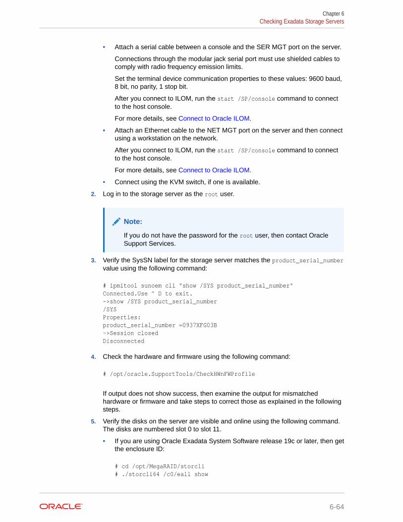
• Attach a serial cable between a console and the SER MGT port on the server.
Connections through the modular jack serial port must use shielded cables tocomply with radio frequency emission limits.
Set the terminal device communication properties to these values: 9600 baud,8 bit, no parity, 1 stop bit.
After you connect to ILOM, run the start /SP/console command to connectto the host console.
For more details, see Connect to Oracle ILOM.
• Attach an Ethernet cable to the NET MGT port on the server and then connectusing a workstation on the network.
After you connect to ILOM, run the start /SP/console command to connectto the host console.
For more details, see Connect to Oracle ILOM.
• Connect using the KVM switch, if one is available.
2. Log in to the storage server as the root user.
Note:
If you do not have the password for the root user, then contact OracleSupport Services.
3. Verify the SysSN label for the storage server matches the product_serial_numbervalue using the following command:
# ipmitool sunoem cli "show /SYS product_serial_number"Connected.Use ^ D to exit.->show /SYS product_serial_number/SYSProperties:product_serial_number =0937XFG03B->Session closedDisconnected
4. Check the hardware and firmware using the following command:
# /opt/oracle.SupportTools/CheckHWnFWProfile
If output does not show success, then examine the output for mismatchedhardware or firmware and take steps to correct those as explained in the followingsteps.
5. Verify the disks on the server are visible and online using the following command.The disks are numbered slot 0 to slot 11.
• If you are using Oracle Exadata System Software release 19c or later, then getthe enclosure ID:
# cd /opt/MegaRAID/storcli# ./storcli64 /c0/eall show
Chapter 6Checking Exadata Storage Servers
6-64

Controller = 0Status = SuccessDescription = None
Properties :==========
-----------------------------------------------------------------------------------------EID State Slots PD PS Fans TSs Alms SIM Port# ProdID VendorSpecific----------------------------------------------------------------------------------------- 8 OK 14 12 0 0 0 0 0 Port 0 - 3 & Port 4 - 7 x8 X5-2L SPMS v`252 OK 8 0 0 0 0 0 1 Internal SGPIO -----------------------------------------------------------------------------------------
EID-Enclosure Device ID |PD-Physical drive count |PS-Power Supply count|TSs-Temperature sensor count |Alms-Alarm count |SIM-SIM Count
Then show the state of the physical devices in that enclosure:
# cd /opt/MegaRAID/storcli# ./storcli64 /c0/e8/sall show all | grep "8:"8:0 16 Onln 0 7.151 TB SAS HDD N N 512B H7280A520SUN8.0T U8:1 17 Onln 1 7.151 TB SAS HDD N N 512B H7280A520SUN8.0T U8:2 20 Onln 2 7.151 TB SAS HDD N N 512B H7280A520SUN8.0T U8:3 15 Onln 3 7.151 TB SAS HDD N N 512B H7280A520SUN8.0T U8:4 12 Onln 4 7.151 TB SAS HDD N N 512B H7280A520SUN8.0T U8:5 18 Onln 5 7.151 TB SAS HDD N N 512B H7280A520SUN8.0T U8:6 11 Onln 6 7.151 TB SAS HDD N N 512B H7280A520SUN8.0T U8:7 9 Onln 7 7.151 TB SAS HDD N N 512B H7280A520SUN8.0T U8:8 14 Onln 8 7.151 TB SAS HDD N N 512B H7280A520SUN8.0T U8:9 21 Onln 11 7.151 TB SAS HDD N N 512B H7280B520SUN8.0T U8:10 13 Onln 9 7.151 TB SAS HDD N N 512B H7280A520SUN8.0T U8:11 10 Onln 10 7.151 TB SAS HDD N N 512B H7280A520SUN8.0T U
The rows displayed are from a table that displays the following information:
EID:Slt DID State DG Size Intf Med SED PI SeSz Model Sp-----------------------------------------------------------------------...EID-Enclosure Device ID|Slt-Slot No.|DID-Device ID|DG-DriveGroupDHS-Dedicated Hot Spare|UGood-Unconfigured Good|GHS-Global HotspareUBad-Unconfigured Bad|Onln-Online|Offln-Offline|Intf-InterfaceMed-Media Type|SED-Self Encryptive Drive|PI-Protection InfoSeSz-Sector Size|Sp-Spun|U-Up|D-Down|T-Transition|F-ForeignUGUnsp-Unsupported|UGShld-UnConfigured shielded|HSPShld-Hotspare
Chapter 6Checking Exadata Storage Servers
6-65
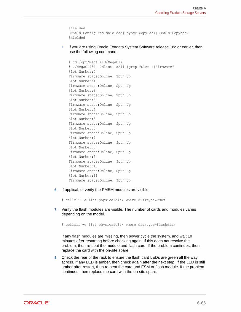
shieldedCFShld-Configured shielded|Cpybck-CopyBack|CBShld-Copyback Shielded
• If you are using Oracle Exadata System Software release 18c or earlier, thenuse the following command:
# cd /opt/MegaRAID/MegaCli# ./MegaCli64 -Pdlist -aAll |grep "Slot \|Firmware"Slot Number:0Firmware state:Online, Spun UpSlot Number:1Firmware state:Online, Spun UpSlot Number:2Firmware state:Online, Spun UpSlot Number:3Firmware state:Online, Spun UpSlot Number:4Firmware state:Online, Spun UpSlot Number:5Firmware state:Online, Spun UpSlot Number:6Firmware state:Online, Spun UpSlot Number:7Firmware state:Online, Spun UpSlot Number:8Firmware state:Online, Spun UpSlot Number:9Firmware state:Online, Spun UpSlot Number:10Firmware state:Online, Spun UpSlot Number:11Firmware state:Online, Spun Up
6. If applicable, verify the PMEM modules are visible.
# cellcli -e list physicaldisk where disktype=PMEM
7. Verify the flash modules are visible. The number of cards and modules variesdepending on the model.
# cellcli -e list physicaldisk where disktype=flashdisk
If any flash modules are missing, then power cycle the system, and wait 10minutes after restarting before checking again. If this does not resolve theproblem, then re-seat the module and flash card. If the problem continues, thenreplace the card with the on-site spare.
8. Check the rear of the rack to ensure the flash card LEDs are green all the wayacross. If any LED is amber, then check again after the next step. If the LED is stillamber after restart, then re-seat the card and ESM or flash module. If the problemcontinues, then replace the card with the on-site spare.
Chapter 6Checking Exadata Storage Servers
6-66

Note:
This step can be done when all systems are on. It does not have to be done ona per-server basis.
9. Log out of the system using the following command:
# logout
6.8 Checking Oracle Exadata Database ServersBefore installing the software, check the configuration of the Oracle Exadata DatabaseServers.
Perform the following checks on each Exadata database server:
1. Connect to the database server console.
Use one of the following connection options:
• Attach a serial cable between a console and the SER MGT port on the server.
Connections through the modular jack serial port must use shielded cables to complywith radio frequency emission limits.
Set the terminal device communication properties to these values: 9600 baud, 8 bit,no parity, 1 stop bit.
After you connect to ILOM, run the start /SP/console command to connect to thehost console.
For more details, see Connect to Oracle ILOM.
• Attach an Ethernet cable to the NET MGT port on the server and then connect usinga workstation on the network.
After you connect to ILOM, run the start /SP/console command to connect to thehost console.
For more details, see Connect to Oracle ILOM.
• Connect using the KVM switch, if one is available.
2. Log in as the root user to the database server.
Note:
If you do not have the password for the root user, then contact Oracle SupportServices.
3. Verify the SysSN label for the server matches the product_serial_number value usingthe following command:
# ipmitool sunoem cli "show /SYS product_serial_number"Connected.Use ^ D to exit.->show /SYS product_serial_number
Chapter 6Checking Oracle Exadata Database Servers
6-67

/SYS Properties: product_serial_number =093ABCD5001
->Session closedDisconnected
4. Change to the /opt/oracle.SupportTools/firstconf directory.
cd /opt/oracle.SupportTools/firstconf
5. Create a group file with the list of server IP addresses to use in the dcli utilitycommands, if required.
If you are configuring Oracle Exadata Rack X8M, then you must manually create afile and add the IP addresses.
On racks that use InfiniBand Network Fabric, you can use the following commandto identify the servers and copy the results into a text file.
# ibhosts | awk '/elastic/ {print $8}' | cut -c1-14 > group_file
In the preceding command, group_file is name of the file to create with the serverIP addresses.
6. Verify the hardware profile is correct using the following command. The commandchecks CPU type and count, component firmware, and so on.
# dcli -l root -g group_file "/opt/oracle.SupportTools/CheckHWnFWProfile \-c strict" > /tmp/checkhwfw.out
# more /tmp/checkhwfw.out
The following is an example of a check that failed:
172.108.1.6:[WARNING ]The hardware and firmware are not supported.See details below[DiskControllerPCIeSlotWidth ]Requires:x8Found:x4[WARNING ]The hardware and firmware are not supported. See details above
If a profile check fails and the firmware needs to be refreshed, then run thefollowing command from the system with the problem.
# /opt/oracle.SupportTools/CheckHWnFWProfile -U /opt/oracle.cellos/iso/cellbitsNow updating the ILOM and the BIOS …
Chapter 6Checking Oracle Exadata Database Servers
6-68

The command must be entered on a single line. After running the command, power offthe system, reset the Integrated Lights Out Manager (ILOM), and wait 10 minutes beforepowering on the system.
7. Verify the disks on the server are visible and online.
• If you are using Oracle Exadata System Software release 19c or later, then use thefollowing command:
# cd /opt/MegaRAID/storcli# ./storcli64 /call show | grep "Physical Drives" -A 25Physical Drives = 8
PD LIST :=======
------------------------------------------------------------------------------EID:Slt DID State DG Size Intf Med SED PI SeSz Model Sp Type------------------------------------------------------------------------------39:0 31 Onln 0 278.464 GB SAS HDD N N 512B ST930003SSUN300G U -39:1 35 Onln 0 278.464 GB SAS HDD N N 512B ST930003SSUN300G U -39:2 41 Onln 0 278.464 GB SAS HDD N N 512B H103030SCSUN300G U -39:3 37 Onln 0 278.464 GB SAS HDD N N 512B ST930003SSUN300G U -39:4 38 Onln 0 278.464 GB SAS HDD N N 512B ST930003SSUN300G U -39:5 44 Onln 0 278.464 GB SAS HDD N N 512B H109030SESUN300G U -39:6 33 Onln 0 278.464 GB SAS HDD N N 512B ST930003SSUN300G U -39:7 43 Onln 0 278.464 GB SAS HDD N N 512B ST930003SSUN300G U -------------------------------------------------------------------------------
EID-Enclosure Device ID|Slt-Slot No.|DID-Device ID|DG-DriveGroupDHS-Dedicated Hot Spare|UGood-Unconfigured Good|GHS-Global HotspareUBad-Unconfigured Bad|Onln-Online|Offln-Offline|Intf-InterfaceMed-Media Type|SED-Self Encryptive Drive|PI-Protection InfoSeSz-Sector Size|Sp-Spun|U-Up|D-Down|T-Transition|F-ForeignUGUnsp-Unsupported|UGShld-UnConfigured shielded|HSPShld-Hotspare shieldedCFShld-Configured shielded|Cpybck-CopyBack|CBShld-Copyback Shielded
• If you are using Oracle Exadata System Software release 18c or earlier, then use thefollowing command:
# cd /opt/MegaRAID/MegaCli# ./MegaCli64 -Pdlist -aAll |grep "Slot \|Firmware"
Chapter 6Checking Oracle Exadata Database Servers
6-69

Slot Number:0Firmware state:Online, Spun UpSlot Number:1Firmware state:Online, Spun UpSlot Number:2Firmware state:Online, Spun UpSlot Number:3Firmware state:Online, Spun UpSlot Number:4Firmware state:Online, Spun UpSlot Number:5Firmware state:Online, Spun UpSlot Number:6Firmware state:Online, Spun UpSlot Number:7Firmware state:Online, Spun UpSlot Number:8Firmware state:Online, Spun UpSlot Number:9Firmware state:Online, Spun UpSlot Number:10Firmware state:Online, Spun UpSlot Number:11Firmware state:Online, Spun Up
8. Examine the output of the following command:
• If you are using Oracle Exadata System Software release 19c or later, thenuse the following command:
/opt/MegaRAID/storcli/storcli64 -LdInfo -LAll -aAll
• If you are using Oracle Exadata System Software release 18c or earlier, thenyou can use the following command:
/opt/MegaRAID/MegaCli/MegaCli64 -LdInfo -LAll -aAll
9. (Oracle Exadata Database Machine based on Sun Fire X4170 Oracle DatabaseServers only) Check that the ILOM is configured for the proper fan cooling on eachdatabase server using the following command:
# ipmitool sunoem cli "show /SP/policy"
• If the policy is present and enabled, then no additional steps are needed.
• If the policy is present and disabled, then enable the policy using the followingcommand:
# ipmitool sunoem cli "set /SP/policy FLASH_ACCELERATOR_CARD_ \INSTALLED=enabled"
The command must be entered as a single line.
Chapter 6Checking Oracle Exadata Database Servers
6-70

10. Verify that NTP servers are configured the same for all servers using the followingcommand. The command is run on each database server individually.
# ntpq -p
11. Log out of the system using the following command:
# logout
6.9 Performing Additional Checks and ConfigurationPerform these additional checks and steps to verify the configuration of your Oracle ExadataRack.
1. (Oracle Exadata Database Machine only) Log in to the first database server as the rootuser.
2. Change to the firstconf directory using the following command:
# cd /opt/oracle.SupportTools/firstconf
3. Create a group file with the list of IP addresses to use in the dcli utility commands, if youwant to query multiple racks.
4. Verify the rack master serial number is set correctly using the following command:
# dcli -l root -g group_file_name "ipmitool sunoem cli 'show \/SP system_identifier'" | grep "system_identifier =" > /tmp/show-rack-msn.out
# more /tmp/show-rack-msn.out
If none of the serial numbers are set, then contact Oracle Support Services. If one serialnumber is not set correctly, then run the following command to correct it, where rack_typeis the rack designation, such as X8-8 and the string serial_number represents the serialnumber:
# ipmitool sunoem cli 'set /SP system_identifier= \"Exadata Database Machine rack_type serial_number"'
5. If you are running an Oracle Exadata System Software release earlier than 18.1, thenensure disk cache policy is set to Disabled using the following command as the rootuser on the first database server in the cluster:
# dcli -g /opt/oracle.SupportTools/onecommand/all_group -l root \/opt/MegaRAID/MegaCli/MegaCli64 -LdPdInfo -aALL | grep -i 'Disk Cache Policy'
The following is an example of the output from the command:
dm01db01: Disk Cache Policy : Disableddm01db02: Disk Cache Policy : Disableddm01db03: Disk Cache Policy : Disabled
Chapter 6Performing Additional Checks and Configuration
6-71

...dm01cel01: Disk Cache Policy : Disableddm01cel02: Disk Cache Policy : Disabled...
If any server shows different output, then identify the LUN and use the followingcommand to reset the policy to Disabled, where LUNn is the LUN number, suchas L2:
# MegaCli64 -LDSetProp -DisDskCache -LUNn -a0
6.10 Verifying the RoCE Network Fabric ConfigurationThis procedure describes how to verify the RoCE Network Fabric configuration.
1. Verify the proper oracle-rdma-release software versions are being used on thedatabase servers.
[root@dbm01adm08 ~]# rpm -qa |grep oracle-rdma-releaseoracle-rdma-release-0.11.0-1.el7ora.x86_64
The oracle-rdma-release software and adapter firmware versions areautomatically maintained on the Oracle Exadata Database Machine storageservers.
2. Check the adapter firmware versions on the database servers.
Use the CheckHWnFWProfile script to check firmware versions for the RDMANetwork Fabric adapters.
# /opt/oracle.SupportTools/CheckHWnFWProfile -action list
3. Visually check all the RDMA Network Fabric cable connections within the rack.
The port lights should be on, and the LEDs should be on. Do not press eachconnector to verify connectivity.
4. Complete the steps described in My Oracle Support Doc ID 2587717.1
Related Topics
• Verify RoCE Cabling on Oracle Exadata Database Machine X8M-2 and X8M-8Servers (My Oracle Support Doc ID 2587717.1)
6.11 Verifying the InfiniBand Network Fabric NetworkThis procedure describes how to verify the InfiniBand Network Fabric network.
1. Visually check all the RDMA Network Fabric cable connections within the rack.The port lights should be on, and the LEDs should be on. Do not press eachconnector to verify connectivity.
2. Log in as the root user on any component in the rack.
Chapter 6Verifying the RoCE Network Fabric Configuration
6-72

3. Verify the InfiniBand Network Fabric topology using the following commands:
# cd /opt/oracle.SupportTools/ibdiagtools# ./verify-topology [-t rack_size]
The following example shows the output when the network components are correct.
[DB Machine Infiniband Cabling Topology Verification Tool ]Is every external switch connected to every internal switch......[SUCCESS ]Are any external switches connected to each other................[SUCCESS ]Are any hosts connected to spine switch..........................[SUCCESS ]Check if all hosts have 2 CAs to different switches..............[SUCCESS ]Leaf switch check:cardinality and even distribution..............[SUCCESS ]Check if each rack has an valid internal ring....................[SUCCESS ]
In the preceding command, rack_size is the size of the rack. The -t rack_size option isneeded if the rack is Oracle Exadata Database Machine Half Rack or Oracle ExadataDatabase Machine Quarter Rack. Use the value halfrack or quarterrack, if needed.
The following example shows the output when there is a bad RDMA Network Fabricswitch to cable connection:
#./verify-topology[DB Machine Infiniband Cabling Topology Verification Tool ]Is every external switch connected to every internal switch......[SUCCESS ]Are any external switches connected to each other................[SUCCESS ]Are any hosts connected to spine switch..........................[SUCCESS ]Check if all hosts have 2 CAs to different switches..............[SUCCESS ]Leaf switch check:cardinality and even distribution..............[SUCCESS ]Check if each rack has an valid internal ring....................[ERROR ]
Switches 0x21283a87cba0a0 0x21283a87b8a0a0 have 6 connections between them.They should have at least 7 links between them
The following example shows the output when there is a bad RDMA Network Fabriccable on a database server:
#./verify-topology[DB Machine Infiniband Cabling Topology Verification Tool ]Is every external switch connected to every internal switch......[SUCCESS ]
Chapter 6Verifying the InfiniBand Network Fabric Network
6-73

Are any external switches connected to each other................[SUCCESS ]Are any hosts connected to spine switch..........................[SUCCESS ]Check if all hosts have 2 CAs to different switches..............[ERROR ]Node db01 has 1 endpoints.(Should be 2)Port 2 of this node is not connected to any switch--------fattree End Point Cabling verification failed-----Leaf switch check:cardinality and even distribution..............[ERROR ]Internal QDR Switch 0x21283a87b8a0a0 has fewer than 4 compute nodesIt has only 3 links belonging to compute nodes [SUCCESS ]Check if each rack has an valid internal ring...................[SUCCESS ]
The following example shows the output when there is a bad connection on theswitch and the system:
#./verify-topology[DB Machine Infiniband Cabling Topology Verification Tool ]Is every external switch connected to every internal switch......[SUCCESS ]Are any external switches connected to each other................[SUCCESS ]Are any hosts connected to spine switch..........................[SUCCESS ]Check if all hosts have 2 CAs to different switches..............[ERROR ]
Node burxdb01 has 1 endpoints.(Should be 2) Port 2 of this node is not connected to any switch--------fattree End Point Cabling verifation failed-----Leaf switch check:cardinality and even distribution..............[ERROR ]Internal QDR Switch 0x21283a87b8a0a0 has fewer than 4 compute nodes It has only 3 links belonging to compute nodes...................[SUCCESS ]Check if each rack has an valid internal ring....................[ERROR ]
Switches 0x21283a87cba0a0 0x21283a87b8a0a0 have 6 connections between themThey should have at least 7 links between them
6.12 Imaging a New SystemYou have different options for preparing an Oracle Exadata system for deployment.
Using a preconf.csv file with the PXE, USB and ISO options enables an unattendedfirst boot configuration and greatly simplifies the installation but is not mandatory. It is
Chapter 6Imaging a New System
6-74

possible to boot from the installation media and follow the prompts to configure the system.
Starting with Oracle Exadata System Software release 19.1.0, Secure Eraser is automaticallystarted during re-imaging if the hardware supports Secure Eraser. This significantly simplifiesthe re-imaging procedure while maintaining performance. Now, when re-purposing a rack,you only have to image the rack and the secure data erasure is taken care of transparently aspart of the process.
In release 12.1.2.2.0 and above, the installation media has been simplified, and it is no longernecessary to build files using the ImageMaker process.
• Using ISO Images to Image a New SystemYou can download ISO images to use when upgrading your Oracle Exadata DatabaseMachine.
• Using Elastic Configuration to Image a New SystemElastic configuration is now the standard methodology for all new deployments, andapplies to Oracle Exadata Database Machine X4-8 and later servers.
• Using ISO to Image a New SystemYou can use ISO to prepare a new Exadata system for deployment.
• Using PXE to Image a New SystemYou can use PXE to prepare a new Exadata system for deployment.
• Using USB to Image a New SystemYou can use USB to prepare a new Exadata system for deployment.
• Updates to Imaging ParametersSome of the command line options for imaging have changed with 12.1.2.1.0 and above.
6.12.1 Using ISO Images to Image a New SystemYou can download ISO images to use when upgrading your Oracle Exadata DatabaseMachine.
In versions prior to 12.1.2.2.0, ISO images are available as patches that you can downloadfor bare metal imaging an Exadata system. This is now the default method in 12.1.2.2.0 andabove. You are no longer required to build the ISO files using imagemaker. Patches areavailable for both database nodes and cells. You can use the ISO images to boot the serverusing a virtual media device on the ILOM (from the Devices menu of the ILOM console). Forexample, the two ISO images available for 12.1.2.1.1 are listed in the following table.
Table 6-69 ISO Images for 12.1.2.1.1
Version Type Edelivery Part /Notes
ARU Bug #/ULNChannel
Description
12.1.2.1.1 Cell ISO image andmd5sum:90305b9e2c7e050d7588b8a7d5c731e7cell_12.1.2.1.1_LINUX.X64_150316.2-1.x86_64.iso
Refer to 12.1.2.1.1Readme (Doc ID1959143.1) as wellas the readmeprovided with thedownload.
20757971 Oracle DatabaseMachine ExadataStorage Cell (X5-2L,X4-2L, X4270M3,X4270M2, X4275)Image 12c Release 1(12.1.2.1.1) for Linuxx86_64
Chapter 6Imaging a New System
6-75

Table 6-69 (Cont.) ISO Images for 12.1.2.1.1
Version Type Edelivery Part /Notes
ARU Bug #/ULNChannel
Description
12.1.2.1.1 DB ISO image andmd5sum:39f12722cb338b2d4de5acba90adf8fecompute_12.1.2.1.1_LINUX.X64_150316.2-1.x86_64.iso
Refer to 12.1.2.1.1Readme (Doc ID1959143.1) as wellas the readmeprovided with thedownload.
20757974 Oracle DatabaseMachine DatabaseHost (X4-8,X4800M2, X4800,X5-2, X4-2,X4170M3, X4170M2,X4170) Image 12cRelease 1(12.1.2.1.1) for Linuxx86_64
To prepare a new Exadata system for deployment using ISO images, perform thefollowing steps:
1. Obtain the latest Oracle Exadata Deployment Assistant (OEDA).
2. Run the OEDA configuration tool to generate the configuration files. You will needthe configuration files when you run applyElasticConfig.sh later.
3. Power on all the servers.
a. Database nodes and cells will automatically assign to themselves unused IPaddresses on eth0 in the 172.16 range.
b. Host names of the nodes will be of the format nodeN, where N is a number.
4. After booting from the ISO, follow the prompts and imaging will start automatically.You will be prompted to enter IP addresses.
You can use a preconf.csv by following the steps in Using ISO to Image a NewSystem to mount the image on an NFS repository. You need to place thepreconf.csv file in the same NFS directory.
5. If you are using virtualization on the database servers (Oracle VM Server orOracle Linux KVM), then run switch_to_ovm.sh on each database server. Thedatabase servers will reboot if you are using Oracle VM Server.
For example:
# /opt/oracle.SupportTools/switch_to_ovm.sh2014-12-07 11:58:36 -0800 [INFO] Switch to DOM0 system partition /dev/VGExaDb/LVDbSys3 (/dev/mapper/VGExaDb-LVDbSys3)2014-12-07 11:58:36 -0800 [INFO] Active system device: /dev/mapper/VGExaDb-LVDbSys12014-12-07 11:58:36 -0800 [INFO] Active system device in boot area: /dev/mapper/VGExaDb-LVDbSys12014-12-07 11:58:36 -0800 [INFO] Set active systen device to /dev/VGExaDb/LVDbSys3 in /boot/I_am_hd_boot2014-12-07 11:58:36 -0800 [INFO] Reboot has been initiated to switch to the DOM0 system partition
6. On systems with InfiniBand Network Fabric only, run /opt/oracle.SupportTools/reclaimdisks.sh -free -reclaim on each database server before installing anysoftware.
Chapter 6Imaging a New System
6-76

The command reclaims disk space reserved for the deployment type not selected, whichis not required on RoCE-based Exadata database servers.
The command typically takes less than 5 minutes.
Caution:
Do not skip this step. Skipping this step results in unused space that can nolonger be reclaimed by reclaimdisks.sh.
# /opt/oracle.SupportTools/reclaimdisks.sh -free -reclaimModel is ORACLE SERVER X5-2Number of LSI controllers: 1Physical disks found: 4 (252:0 252:1 252:2 252:3)Logical drives found: 1...[INFO ] Copying /usr/share/grub/x86_64-redhat/* to /boot/grub ...[INFO ] Create filesystem on device /dev/sda1[INFO ] Tune filesystem on device /dev/sda1
GNU GRUB version 0.97 (640K lower / 3072K upper memory)
[ Minimal BASH-like line editing is supported. For the first word, TABlists possible command completions. Anywhere else TAB lists the possiblecompletions of a device/filename.]grub> root (hd0,0) Filesystem type is ext2fs, partition type 0x83grub> setup (hd0) Checking if "/boot/grub/stage1" exists... no Checking if "/grub/stage1" exists... yes Checking if "/grub/stage2" exists... yes Checking if "/grub/e2fs_stage1_5" exists... yes Running "embed /grub/e2fs_stage1_5 (hd0)"... failed (this is not fatal) Running "embed /grub/e2fs_stage1_5 (hd0,0)"... failed (this is not fatal) Running "install /grub/stage1 (hd0) /grub/stage2 p /grub/grub.conf "... succeededDone.grub> quit
7. If you have an Oracle Exadata Rack X8 or earlier, then run ibhosts and verify that allnodes show the correct IP addresses and host names. There should be no nodes withelasticNode in the description.
8. Run the OEDA tool to deploy.
[root] # ./install.sh -cf ../MAA-dm01.xml -l1. Validate Configuration File2. Setup Capacity-on-Demand3. Create Virtual Machine 4. Create Users 5. Setup Cell Connectivity 6. Create Cell Disks 7. Create Grid Disks
Chapter 6Imaging a New System
6-77

8. Configure Alerting 9. Install Cluster Software 10. Initialize Cluster Software 11. Install Database Software 12. Relink Database with RDS 13. Create ASM Diskgroups 14. Create Databases 15. Apply Security Fixes 16. Install Exachk 17. Setup ASR Alerting 18. Create Installation Summary 19. Resecure Machine
Related Topics
• Exadata 12.1.2.1.1 release and patch (20240049) (My Oracle Support Doc ID1959143.1)
6.12.2 Using Elastic Configuration to Image a New SystemElastic configuration is now the standard methodology for all new deployments, andapplies to Oracle Exadata Database Machine X4-8 and later servers.
You can also use elastic configuration to add additional database servers or cells to anexisting configuration. The process allows initial IP addresses to be assigned todatabase servers and cells, regardless of the exact customer configuration ordered.
Elastic configuration is only applicable to machines shipped from the factory (or tomachines imaged exactly to mimic that) and only for X4-8 or later systems. You canrun elastic configuration at the first time of deployment, and when adding new factory-built components to a rack. You cannot use elastic configuration to configure orreconfigure systems. It is recommended that you use elastic configuration only withmachines shipped from the factory for first-time deployment.
To prepare a new Exadata system for deployment using the elastic configurationmethod, perform the following steps:
1. Download the latest version of Oracle Exadata Deployment Assistant (OEDA).
2. Run the OEDA configuration tool to generate the configuration files.
3. Power on all the servers.
a. Database nodes and cells will automatically assign to themselves unused IPaddresses on eth0 in the 172.16.* range.
b. Host names of the nodes will be of the format nodeN, where N is a number.
4. If you are using Oracle VM, then, before you run the OEDA installation tool, runswitch_to_ovm.sh on each database server. The database servers will reboot. Ifyou are using physical deployment and not virtualized deployment, then you canskip this step.
For example:
# /opt/oracle.SupportTools/switch_to_ovm.sh2014-12-07 11:58:36 -0800 [INFO] Switch to DOM0 system partition /dev/VGExaDb/LVDbSys3 (/dev/mapper/VGExaDb-LVDbSys3)2014-12-07 11:58:36 -0800 [INFO] Active system device: /dev/mapper/
Chapter 6Imaging a New System
6-78
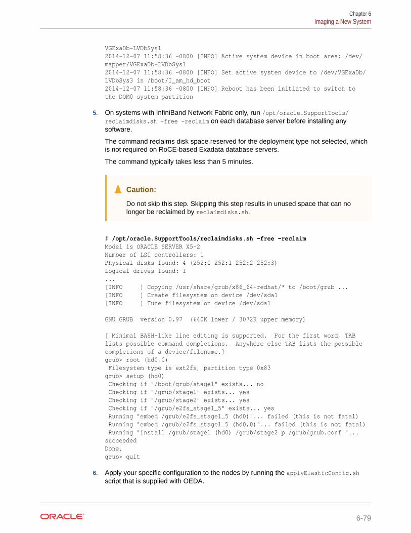
VGExaDb-LVDbSys12014-12-07 11:58:36 -0800 [INFO] Active system device in boot area: /dev/mapper/VGExaDb-LVDbSys12014-12-07 11:58:36 -0800 [INFO] Set active systen device to /dev/VGExaDb/LVDbSys3 in /boot/I_am_hd_boot2014-12-07 11:58:36 -0800 [INFO] Reboot has been initiated to switch to the DOM0 system partition
5. On systems with InfiniBand Network Fabric only, run /opt/oracle.SupportTools/reclaimdisks.sh -free -reclaim on each database server before installing anysoftware.
The command reclaims disk space reserved for the deployment type not selected, whichis not required on RoCE-based Exadata database servers.
The command typically takes less than 5 minutes.
Caution:
Do not skip this step. Skipping this step results in unused space that can nolonger be reclaimed by reclaimdisks.sh.
# /opt/oracle.SupportTools/reclaimdisks.sh -free -reclaimModel is ORACLE SERVER X5-2Number of LSI controllers: 1Physical disks found: 4 (252:0 252:1 252:2 252:3)Logical drives found: 1...[INFO ] Copying /usr/share/grub/x86_64-redhat/* to /boot/grub ...[INFO ] Create filesystem on device /dev/sda1[INFO ] Tune filesystem on device /dev/sda1
GNU GRUB version 0.97 (640K lower / 3072K upper memory)
[ Minimal BASH-like line editing is supported. For the first word, TABlists possible command completions. Anywhere else TAB lists the possiblecompletions of a device/filename.]grub> root (hd0,0) Filesystem type is ext2fs, partition type 0x83grub> setup (hd0) Checking if "/boot/grub/stage1" exists... no Checking if "/grub/stage1" exists... yes Checking if "/grub/stage2" exists... yes Checking if "/grub/e2fs_stage1_5" exists... yes Running "embed /grub/e2fs_stage1_5 (hd0)"... failed (this is not fatal) Running "embed /grub/e2fs_stage1_5 (hd0,0)"... failed (this is not fatal) Running "install /grub/stage1 (hd0) /grub/stage2 p /grub/grub.conf "... succeededDone.grub> quit
6. Apply your specific configuration to the nodes by running the applyElasticConfig.shscript that is supplied with OEDA.
Chapter 6Imaging a New System
6-79

7. Run ibhosts and verify that all nodes show the correct IP addresses and hostnames. There should be no nodes with elasticNode in the description.
8. Run the OEDA tool to deploy, supplying the name of the configuration filegenerated by OEDA.
For example, if your rack is named exadm01, then you would use the followingcommand:
[root] # ./install.sh -cf ../exadm01.xml -l1. Validate Configuration File2. Setup Capacity-on-Demand3. Create Virtual Machine 4. Create Users 5. Setup Cell Connectivity 6. Create Cell Disks 7. Create Grid Disks 8. Configure Alerting 9. Install Cluster Software 10. Initialize Cluster Software 11. Install Database Software 12. Relink Database with RDS 13. Create ASM Diskgroups 14. Create Databases 15. Apply Security Fixes 16. Install Exachk 17. Setup ASR Alerting 18. Create Installation Summary 19. Resecure Machine
6.12.3 Using ISO to Image a New SystemYou can use ISO to prepare a new Exadata system for deployment.
1. Obtain the latest Oracle Exadata Deployment Assistant (OEDA).
2. Run the OEDA configuration tool to generate the configuration files.
3. Power on all the servers.
a. Database nodes and cells will automatically assign to themselves unused IPaddresses on eth0 in the 172.16 range.
b. Host names of the nodes will be of the format nodeN, where N is a number.
4. Run OEDA to generate the preconf.csv file that can be used to image thesystem.
5. Connect to the first database node.
Use one of the following connection options:
• Attach a serial cable between a console and the SER MGT port on the server.
Connections through the modular jack serial port must use shielded cables tocomply with radio frequency emission limits.
Set the terminal device communication properties to these values: 9600 baud,8 bit, no parity, 1 stop bit.
For more details, see Connect to Oracle ILOM.
Chapter 6Imaging a New System
6-80

• Attach an Ethernet cable to the NET MGT port on the server and then connect usinga workstation on the network.
For more details, see Connect to Oracle ILOM.
6. Obtain the eth0 MAC address for each database node. This is the fru_macaddress fieldfrom /SYS/MB/NET0 in the ILOM (or through ip addr if logged into the console).
a. Connect to the other database nodes using ssh from the console.
b. Run ibhosts to get a list of node names and IP addresses.
7. Insert the MAC addresses using uppercase characters in the seventh field of thepreconf.csv file for each node. This field should be empty, that is, you should see twoconsecutive comma characters (,,). For example:
orhb42-b08-01,example.com,db,eth0,eth0,Management,00:10:E0:69:34:52,10.196.3.106,255.255.224.0,10.196.31.250,orhb42-b08-01-priv,Private:active-bond-ib,192.168.10.15,255.255.255.0,,,America/Los_Angeles
8. Run ipconf to verify the generated preconf.csv file. This can be done on any Exadataserver, and although not required, it is useful to ensure the preconf.csv is valid beforeproceeding.
# ipconf -verify -preconf /tmp/preconf.csv[Info]: ipconf command line: /opt/oracle.cellos/ipconf.pl -verify -preconf /tmp/preconf -nocodes[Done]: Pre config verification OK
9. Prepare and locate the files required for system imaging. The procedure variesdepending on the Oracle Exadata System Software version being used.
• If you are using version 12.1.2.2.0 or later, it is no longer necessary to useimagemaker to create the image files. The relevant PXE, ISO, and USB image filesare already in the patch archive.
Use Exadata Database Machine and Exadata Storage Server Supported Versions(My Oracle Support Doc ID 888828.1) to locate the relevant patch archive. Then,unzip the patch archive and follow the steps in the patch README.txt to copy the ISOfile and optional preconf.csv file into place.
Chapter 6Imaging a New System
6-81

Note:
– Using ISO with the preconf.csv file is supported only if theISO image is mounted on an NFS repository in ILOM and thepreconf.csv file is located in the same NFS directory.
All other methods of mounting the ISO image in ILOM (SAMBAURI and Java Remote Console) and burning ISO image to DVDwill not work with the preconf.csv file. For instructions on howto mount the ISO image from a NFS central repository, see"Configure a Host Storage Device Redirection Session" in theOracle X5 Series Servers Administration Guide
– If a newly imaged system does not have access to DHCP, thenthe imaging procedure will not be able to access thepreconf.csv file. In this case, the imaging procedure willattempt to locate the preconf.csv inside a dedicated ISOimage located in the same directory and named preconf.iso.
To use this method, you can create the preconf.iso file byusing the following command:
# mkisofs -l -input-charset ascii -o preconf.iso preconf.csv
– When a preconf.csv file is not being used, the ISO image canbe made available as virtual media on the ILOM of the nodebeing re-imaged.
– Because of possible late echos of text to the console, be awarethat the boot process will be waiting for input to complete theinteractive ipconf by prompting for Nameserver:
– Due to a bug, ipconf will prompt you twice to enter the networksettings.
• If you are using versions prior to 12.1.2.2.0, use ImageMaker to create theimage files as follows:
a. Download the imagemaker kit to prepare and create the files for the USBdrive.
This kit is available publicly on the Oracle Software Delivery Cloud(edelivery.oracle.com) site under “Oracle Database Products -> Linuxx86-64”. There are separate ImageMaker files for database nodes andcells.
b. After download, unzip the first file, called something similar toV75080-01.zip, and then unzip the subsequent file as well. Perform theunzips as the root user. Then untar the file.
# unzip V75080-01.zip
# unzip cellImageMaker_12.1.2.1.1_LINUX.X64_150316.2-1.x86_64.zip
Chapter 6Imaging a New System
6-82

# tar -pxvf cellImageMaker_12.1.2.1.1_LINUX.X64_150316.2-1.x86_64.tar
View the README_FOR_FACTORY.txt file in the resulting directory for additionaldetails.
c. Run makeImageMedia.sh to build the ISO file for imaging.
For building images for 12.1.2.1.0 and above, the recommendedmakeImageMedia.sh options for building ISO images are:
i. (12.1.2.1.0 up to 12.2.1.1.0) Change directory to the dl180 or dl360directory.
ii. (12.2.1.1.0 and above) Change directory to the cell or compute directory.
iii. Make the ISO file.
./makeImageMedia.sh -factory -stit -reboot-on-success -nodisktests [-preconf preconf_file] filename.iso
For ISO imaging, note that you must run makeImageMedia.sh from an OracleExadata database server if you are using the -preconf option.
For example:
# ./makeImageMedia.sh -factory -stit -reboot-on-success -nodisktests -preconf preconf.csv computenode.iso[Info]: ipconf command line: /root/imagemaker/compute/initrd/opt/oracle.cellos/ipconf.pl -preconf preconf.csv -verify -nocodes[Done]: Pre config verification OKPlease wait. Calculating md5 checksums for cellbits ...Calculating md5 checksum for exaos.tbz ...Calculating md5 checksum for dbboot.tbz ...Calculating md5 checksum for dbfw.tbz ...Calculating md5 checksum for kernel.tbz ...Calculating md5 checksum for ofed.tbz ...Calculating md5 checksum for sunutils.tbz ...Calculating md5 checksum for commonos.tbz ...Calculating md5 checksum for debugos.tbz ...Calculating md5 checksum for dbrpms.tbz ...Calculating md5 checksum for exaosovs.tbz ...Calculating md5 checksum for dbovsboot.tbz ...Calculating md5 checksum for kernelovs.tbz ...Calculating md5 checksum for ofedovs.tbz ...Calculating md5 checksum for commonovsos.tbz ...Calculating md5 checksum for debugosovs.tbz ...Calculating md5 checksum for dbovsrpms.tbz ...Calculating md5 checksum for sunovsutils.tbz ...Calculating md5 checksum for dbvmboot.tbz ...Calculating md5 checksum for ofedvm.tbz ...Calculating md5 checksum for sunvmutils.tbz ...Please wait. Making initrd ...395864 blocks
Chapter 6Imaging a New System
6-83

Please wait. Calculating md5 checksums for boot ...Size of boot image is 4 sectors -> No emulation0.30% done, estimate finish Wed Nov 29 10:47:27 20160.60% done, estimate finish Wed Nov 29 10:47:27 20160.90% done, estimate finish Wed Nov 29 10:47:27 20161.21% done, estimate finish Wed Nov 29 10:47:27 20161.51% done, estimate finish Wed Nov 29 10:47:27 20161.81% done, estimate finish Wed Nov 29 10:47:27 20162.11% done, estimate finish Wed Nov 29 10:47:27 20162.41% done, estimate finish Wed Nov 29 10:47:27 20162.71% done, estimate finish Wed Nov 29 10:47:27 20163.02% done, estimate finish Wed Nov 29 10:47:27 20163.32% done, estimate finish Wed Nov 29 10:47:27 20163.62% done, estimate finish Wed Nov 29 10:47:27 20163.92% done, estimate finish Wed Nov 29 10:47:27 20164.22% done, estimate finish Wed Nov 29 10:47:27 20164.52% done, estimate finish Wed Nov 29 10:47:27 20164.83% done, estimate finish Wed Nov 29 10:47:27 20165.13% done, estimate finish Wed Nov 29 10:47:27 20165.43% done, estimate finish Wed Nov 29 10:47:27 20165.73% done, estimate finish Wed Nov 29 10:47:27 2016<output truncated>97.72% done, estimate finish Wed Nov 29 10:47:30 201698.02% done, estimate finish Wed Nov 29 10:47:30 201698.32% done, estimate finish Wed Nov 29 10:47:30 201698.62% done, estimate finish Wed Nov 29 10:47:30 201698.92% done, estimate finish Wed Nov 29 10:47:30 201699.22% done, estimate finish Wed Nov 29 10:47:30 201699.52% done, estimate finish Wed Nov 29 10:47:30 201699.83% done, estimate finish Wed Nov 29 10:47:30 2016Total translation table size: 2048Total rockridge attributes bytes: 0Total directory bytes: 2048Path table size(bytes): 26Max brk space used 01657890 extents written (3238 MB)Done creation of installation ISO for compute node
d. Attach the ISO as virtual media to the ILOM of the database server to bere-imaged, and select CDROM as the next boot device.
10. Reboot the database node or cell to start the imaging process from the ISO.
11. If you are using Oracle VM, run switch_to_ovm.sh on each database server. Thedatabase servers will reboot.
For example:
# /opt/oracle.SupportTools/switch_to_ovm.sh2014-12-07 11:58:36 -0800 [INFO] Switch to DOM0 system partition /dev/VGExaDb/LVDbSys3 (/dev/mapper/VGExaDb-LVDbSys3)2014-12-07 11:58:36 -0800 [INFO] Active system device: /dev/mapper/VGExaDb-LVDbSys12014-12-07 11:58:36 -0800 [INFO] Active system device in boot
Chapter 6Imaging a New System
6-84

area: /dev/mapper/VGExaDb-LVDbSys12014-12-07 11:58:36 -0800 [INFO] Set active systen device to /dev/VGExaDb/LVDbSys3 in /boot/I_am_hd_boot2014-12-07 11:58:36 -0800 [INFO] Reboot has been initiated to switch to the DOM0 system partition
12. On systems with InfiniBand Network Fabric only, run /opt/oracle.SupportTools/reclaimdisks.sh -free -reclaim on each database server before installing anysoftware.
The command reclaims disk space reserved for the deployment type not selected, whichis not required on RoCE-based Exadata database servers.
The command typically takes less than 5 minutes.
Caution:
Do not skip this step. Skipping this step results in unused space that can nolonger be reclaimed by reclaimdisks.sh.
# /opt/oracle.SupportTools/reclaimdisks.sh -free -reclaimModel is ORACLE SERVER X5-2Number of LSI controllers: 1Physical disks found: 4 (252:0 252:1 252:2 252:3)Logical drives found: 1...[INFO ] Copying /usr/share/grub/x86_64-redhat/* to /boot/grub ...[INFO ] Create filesystem on device /dev/sda1[INFO ] Tune filesystem on device /dev/sda1
GNU GRUB version 0.97 (640K lower / 3072K upper memory)
[ Minimal BASH-like line editing is supported. For the first word, TABlists possible command completions. Anywhere else TAB lists the possiblecompletions of a device/filename.]grub> root (hd0,0) Filesystem type is ext2fs, partition type 0x83grub> setup (hd0) Checking if "/boot/grub/stage1" exists... no Checking if "/grub/stage1" exists... yes Checking if "/grub/stage2" exists... yes Checking if "/grub/e2fs_stage1_5" exists... yes Running "embed /grub/e2fs_stage1_5 (hd0)"... failed (this is not fatal) Running "embed /grub/e2fs_stage1_5 (hd0,0)"... failed (this is not fatal) Running "install /grub/stage1 (hd0) /grub/stage2 p /grub/grub.conf "... succeededDone.grub> quit
Chapter 6Imaging a New System
6-85

13. Run ibhosts and verify that all nodes show the correct IP addresses and hostnames. There should be no nodes with elasticNode in the description.
14. Run the OEDA tool to deploy.
[root] # ./install.sh -cf ../MAA-dm01.xml -l1. Validate Configuration File2. Setup Capacity-on-Demand3. Create Virtual Machine 4. Create Users 5. Setup Cell Connectivity 6. Create Cell Disks 7. Create Grid Disks 8. Configure Alerting 9. Install Cluster Software 10. Initialize Cluster Software 11. Install Database Software 12. Relink Database with RDS 13. Create ASM Diskgroups 14. Create Databases 15. Apply Security Fixes 16. Install Exachk 17. Setup ASR Alerting 18. Create Installation Summary 19. Resecure Machine
Related Topics
• Oracle Software Delivery Cloud
• Exadata Database Machine and Exadata Storage Server Supported Versions (MyOracle Support Doc ID 888828.1)
6.12.4 Using PXE to Image a New SystemYou can use PXE to prepare a new Exadata system for deployment.
• Using PXE to Image a New System Using Release 12.1.2.2.0 or LaterYou can use PXE to prepare a new Exadata system running Oracle ExadataSystem Software release 12.1.2.2.0 or later for deployment using a simplifiedmethod.
• Using PXE to Image a New System for Releases Earlier than 12.1.2.2.0You can use PXE to prepare a new Exadata system running an Oracle ExadataSystem Software release earlier than 12.1.2.2.0 for deployment.
6.12.4.1 Using PXE to Image a New System Using Release 12.1.2.2.0 or LaterYou can use PXE to prepare a new Exadata system running Oracle Exadata SystemSoftware release 12.1.2.2.0 or later for deployment using a simplified method.
1. Obtain the latest Oracle Exadata Deployment Assistant (OEDA) from http://www.oracle.com/technetwork/database/exadata/oeda-download-2076737.html.
2. Run the OEDA configuration tool to generate the configuration files.
3. Power on all the servers.
Chapter 6Imaging a New System
6-86

When the system is first started, the following conditions exist:
a. Database nodes and cells will automatically assign to themselves unused IPaddresses on eth0 in the 172.16 range.
b. Host names of the nodes will be of the format nodeN, where N is a number.
4. Run OEDA to generate the preconf.csv file that you will use to image the system.
5. Connect to the first database node.
Use one of the following connection options:
• Attach a serial cable between a console and the SER MGT port on the server.
Connections through the modular jack serial port must use shielded cables to complywith radio frequency emission limits.
Set the terminal device communication properties to these values: 9600 baud, 8 bit,no parity, 1 stop bit.
For more details, see Connect to Oracle ILOM.
• Attach an Ethernet cable to the NET MGT port on the server and then connect usinga workstation on the network.
For more details, see Connect to Oracle ILOM.
6. Obtain the eth0 MAC address for each database node.
The eth0 MAC address is the fru_macaddress field from /SYS/MB/NET0 in the ILOM (orfrom ip addr if logged into the console).
a. Connect to the each database node through SSH from the console.
b. Run ibhosts to get a list of node names and IP addresses.
7. Insert the MAC addresses using uppercase characters in the seventh field of thepreconf.csv file for each node.
This field should be empty, that is, you should see two consecutive comma characters(,,).
For example:
orhb42-b08-01,example.com,db,eth0,eth0,Management,00:10:E0:69:34:52,10.196.3.106,255.255.224.0,10.196.31.250,orhb42-b08-01-priv,Private:active-bond-ib,192.168.10.15,255.255.255.0,,,America/Los_Angeles
8. Create a PXE configuration file for each node.
The file name is hostname.xx-xx-xx-xx-xx-xx in the pxelinux.cfg directory. Below arethe recommended options for PXE imaging of versions 12.1.2.1.0 and above. The linestarting with append should be entered as a single line with no line breaks.
kernel vmlinux-iso-file-nameappend initrd=img_file pxe factory stit reboot-on-success notests=diskgroup dhcp preconf=n.n.n.n:/directory/preconf.csv iso-uri=http://web_server/x86_64/iso/image_name.iso console=ttyS0,115200n8
Chapter 6Imaging a New System
6-87

9. Optionally, configure key-based authentication for the root OS user.
Starting with Oracle Exadata System Software release 20.1.0, you can configurekey-based authentication for the root OS user as part of the PXE imagingprocess.
If you want to use this option, then perform the following for each node:
a. Create an RSA public and private key pair using a utility such as ssh-keygen.
For example:
# ssh-keygen -t rsa -b 4096
b. Rename the public key file so that the file name conforms to the followingformat:
id_rsa.short_hostname.root.pub
In the public key file name, short_hostname is the node host name as definedin the first field of the corresponding node entry in the preconf.csv file.
c. Copy the renamed public key file to the directory that contains thepreconf.csv file.
This is the same directory that you previously specified in the PXEconfiguration file preconf parameter, which defines the path to thepreconf.csv file.
If you configure key-based authentication, then password-based authentication isdisabled after the imaging process. Consequently, root access to the node is onlypossible using the matching private key. ILOM access using the root password isalso disabled.
By default, if the public key file is not named or located correctly, then password-based authentication is enabled for the node. You can also make key-basedauthentication mandatory by specifying root-ssh-key=yes as a boot option in thePXE configuration file. In this case, the imaging process fails if the public key is notin the correct location.
Regardless of any public keys, you can disable the configuration of key-basedauthentication by specifying root-ssh-key=no as a boot option in the PXEconfiguration file.
10. Create the image files, if necessary.
If you are using version 12.1.2.2.0 or later, it is no longer necessary to useImageMaker to create the image files. The relevant PXE, ISO, and USB imagefiles have already been created in the patches themselves. Simply download thepatch containing the pre-built PXE image files from Oracle Software DeliveryCloud and place them into the appropriate directories on the PXE server. For allreleases, see My Oracle Support note 888828.1 for the patch numbers. There areseparate PXE image patches for database servers and storage servers.
Note: For image version 12.1.2.2.0 the format of the downloadable imagefiles has changed.
The downloaded zip file contains four image files:
Chapter 6Imaging a New System
6-88

• For 12.1.2.2.0 up to 12.2.1.1.0:
kernel: vmlinux-version-ImageName-{DL180|DL360}initrd: initrd-version-ImageName-{DL180|DL360}.imgimage: nfsimg-version-ImageName-{DL180|DL360}.tarimage: nfsimg-version-ImageName-{DL180|DL360}.tar.md5
• For 12.2.1.1.0 and above:
kernel: vmlinux-iso-ImageName-{cell|compute}initrd: initrd-iso-ImageName-{cell|compute}.imgimage: vmlinux-iso-ImageName-{cell|compute}.tar
11. Change the boot order using the ILOM to boot from PXE and then restart the server tostart the imaging process.
For example, from the Oracle Linux prompt on the host:
# ipmitool chassis bootdev pxe
# shutdown -r now
12. If you are using Oracle VM, run switch_to_ovm.sh on all Oracle VM database serversbefore running the OEDA installation tool.
When you run this command, the database servers will reboot.
# /opt/oracle.SupportTools/switch_to_ovm.sh2014-12-07 11:58:36 -0800 [INFO] Switch to DOM0 system partition /dev/VGExaDb/LVDbSys3 (/dev/mapper/VGExaDb-LVDbSys3)2014-12-07 11:58:36 -0800 [INFO] Active system device: /dev/mapper/VGExaDb-LVDbSys12014-12-07 11:58:36 -0800 [INFO] Active system device in boot area: /dev/mapper/VGExaDb-LVDbSys12014-12-07 11:58:36 -0800 [INFO] Set active systen device to /dev/VGExaDb/LVDbSys3 in /boot/I_am_hd_boot2014-12-07 11:58:36 -0800 [INFO] Reboot has been initiated to switch to the DOM0 system partition
13. On systems with InfiniBand Network Fabric only, run /opt/oracle.SupportTools/reclaimdisks.sh -free -reclaim on each database server before installing anysoftware.
The command reclaims disk space reserved for the deployment type not selected, whichis not required on RoCE-based Exadata database servers.
The command typically takes less than 5 minutes.
Chapter 6Imaging a New System
6-89

Caution:
Do not skip this step. Skipping this step results in unused space that canno longer be reclaimed by reclaimdisks.sh.
# /opt/oracle.SupportTools/reclaimdisks.sh -free -reclaimModel is ORACLE SERVER X5-2Number of LSI controllers: 1Physical disks found: 4 (252:0 252:1 252:2 252:3)Logical drives found: 1...[INFO ] Copying /usr/share/grub/x86_64-redhat/* to /boot/grub ...[INFO ] Create filesystem on device /dev/sda1[INFO ] Tune filesystem on device /dev/sda1
GNU GRUB version 0.97 (640K lower / 3072K upper memory)
[ Minimal BASH-like line editing is supported. For the first word, TABlists possible command completions. Anywhere else TAB lists the possiblecompletions of a device/filename.]grub> root (hd0,0) Filesystem type is ext2fs, partition type 0x83grub> setup (hd0) Checking if "/boot/grub/stage1" exists... no Checking if "/grub/stage1" exists... yes Checking if "/grub/stage2" exists... yes Checking if "/grub/e2fs_stage1_5" exists... yes Running "embed /grub/e2fs_stage1_5 (hd0)"... failed (this is not fatal) Running "embed /grub/e2fs_stage1_5 (hd0,0)"... failed (this is not fatal) Running "install /grub/stage1 (hd0) /grub/stage2 p /grub/grub.conf "... succeededDone.grub> quit
14. Run ibhosts and verify that all nodes show the correct IP addresses and hostnames.
There should be no nodes with elasticNode in the description.
15. Run the OEDA tool to deploy.
Chapter 6Imaging a New System
6-90

Note:
If you configured key-based authentication for the root OS user, then you mustfirst copy the node private keys into the OEDA WorkDir.
[root] # ./install.sh -cf ../machine_config_file.xml -l1. Validate Configuration File2. Setup Capacity-on-Demand3. Create Virtual Machine 4. Create Users 5. Setup Cell Connectivity 6. Create Cell Disks 7. Create Grid Disks 8. Configure Alerting 9. Install Cluster Software 10. Initialize Cluster Software 11. Install Database Software 12. Relink Database with RDS 13. Create ASM Diskgroups 14. Create Databases 15. Apply Security Fixes 16. Install Exachk 17. Setup ASR Alerting 18. Create Installation Summary 19. Resecure Machine
Related Topics
• Exadata Database Machine and Exadata Storage Server Supported Versions (My OracleSupport Doc ID 888828.1)
6.12.4.2 Using PXE to Image a New System for Releases Earlier than 12.1.2.2.0You can use PXE to prepare a new Exadata system running an Oracle Exadata SystemSoftware release earlier than 12.1.2.2.0 for deployment.
1. Obtain the latest Oracle Exadata Deployment Assistant (OEDA) from http://www.oracle.com/technetwork/database/exadata/oeda-download-2076737.html.
2. Run the OEDA configuration tool to generate the configuration files.
3. Power on all the servers.
When the system is first started, the following conditions exist:
a. Database nodes and cells will automatically assign to themselves unused IPaddresses on eth0 in the 172.16 range.
b. Host names of the nodes will be of the format nodeN, where N is a number.
4. Run OEDA to generate the preconf.csv file that you will use to image the system.
5. Connect to the first database node.
Use one of the following connection options:
• Attach a serial cable between a console and the SER MGT port on the server.
Chapter 6Imaging a New System
6-91

Connections through the modular jack serial port must use shielded cables tocomply with radio frequency emission limits.
Set the terminal device communication properties to these values: 9600 baud,8 bit, no parity, 1 stop bit.
For more details, see Connect to Oracle ILOM.
• Attach an Ethernet cable to the NET MGT port on the server and then connectusing a workstation on the network.
For more details, see Connect to Oracle ILOM.
6. Obtain the eth0 MAC address for each database node.
The eth0 MAC address is the fru_macaddress field from /SYS/MB/NET0 in theILOM (or from ip addr if logged into the console).
a. Connect to the each database node through SSH from the console.
b. Run ibhosts to get a list of node names and IP addresses.
7. Insert the MAC addresses using uppercase characters in the seventh field of thepreconf.csv file for each node.
This field should be empty, that is, you should see two consecutive commacharacters (,,).
For example:
orhb42-b08-01,example.com,db,eth0,eth0,Management,00:10:E0:69:34:52,10.196.3.106,255.255.224.0,10.196.31.250,orhb42-b08-01-priv,Private:active-bond-ib,192.168.10.15,255.255.255.0,,,America/Los_Angeles
8. Create a PXE configuration file for each node.
Below are the recommended options for PXE imaging of versions prior to release12.1.2.2.0. The line starting with append should be entered as a single line with noline breaks.
append initrd=img_file pxe factory stit reboot-on-success notests=diskgroup dhcp preconf=n.n.n.n:/directory/preconf.csv sk=n.n.n.n:/directory console=ttyS0,115200n8
9. Download the ImageMaker kit to prepare and create the files for the PXE server.
The kit is available publicly on the Oracle Software Delivery Cloud (edelivery) siteunder “Oracle Database Products -> Linux x86-64”. There are separateImageMaker files for database nodes and cells.
10. After downloading the kit, as the root user, unzip the first file that has a namesimilar to V75080-01.zip, and then unzip the subsequent ZIP file. Finally, untar thefile.
# unzip V75080-01.zip
Chapter 6Imaging a New System
6-92

# unzip cellImageMaker_12.1.2.1.1_LINUX.X64_150316.2-1.x86_64.zip
# tar -pxvf cellImageMaker_12.1.2.1.1_LINUX.X64_150316.2-1.x86_64.tar
View the README_FOR_FACTORY.txt file in the resulting directory for additional details.
11. Run makeImageMedia.sh to build the kernel, initrd, and image files, if necessary.
Place the image files in the relevant directories on the PXE server. These files will besent at boot time to the node being imaged.
• Change directory to the dl180 or dl360 directory and make the PXE build using:
./makeImageMedia.sh -pxe -pxeout ImageName
If the dl180 or dl360 directory are not available, then change directory to the cell orcompute directory.
The makeImageMedia.sh command creates four files in the ./PXE subdirectory:
kernel: vmlinux-version-ImageName-{DL180|DL360}initrd: initrd-version-ImageName-{DL180|DL360}.imgimage: nfsimg-version-ImageName-{DL180|DL360}.tarimage: nfsimg-version-ImageName-{DL180|DL360}.tar.md5
12. Change the boot order using the ILOM to boot from PXE and then restart the server tostart the imaging process.
For example, from the Oracle Linux prompt on the host:
# ipmitool chassis bootdev pxe
# shutdown -r now
13. If you are using Oracle VM run switch_to_ovm.sh on all Oracle VM database serversbefore running the OEDA installation tool.
When you run this command, the database servers will reboot.
# /opt/oracle.SupportTools/switch_to_ovm.sh2014-12-07 11:58:36 -0800 [INFO] Switch to DOM0 system partition /dev/VGExaDb/LVDbSys3 (/dev/mapper/VGExaDb-LVDbSys3)2014-12-07 11:58:36 -0800 [INFO] Active system device: /dev/mapper/VGExaDb-LVDbSys12014-12-07 11:58:36 -0800 [INFO] Active system device in boot area: /dev/mapper/VGExaDb-LVDbSys12014-12-07 11:58:36 -0800 [INFO] Set active systen device to /dev/VGExaDb/LVDbSys3 in /boot/I_am_hd_boot2014-12-07 11:58:36 -0800 [INFO] Reboot has been initiated to switch to the DOM0 system partition
Chapter 6Imaging a New System
6-93

14. On systems with InfiniBand Network Fabric only, run /opt/oracle.SupportTools/reclaimdisks.sh -free -reclaim on each database server before installing anysoftware.
The command reclaims disk space reserved for the deployment type not selected,which is not required on RoCE-based Exadata database servers.
The command typically takes less than 5 minutes.
Caution:
Do not skip this step. Skipping this step results in unused space that canno longer be reclaimed by reclaimdisks.sh.
# /opt/oracle.SupportTools/reclaimdisks.sh -free -reclaimModel is ORACLE SERVER X5-2Number of LSI controllers: 1Physical disks found: 4 (252:0 252:1 252:2 252:3)Logical drives found: 1...[INFO ] Copying /usr/share/grub/x86_64-redhat/* to /boot/grub ...[INFO ] Create filesystem on device /dev/sda1[INFO ] Tune filesystem on device /dev/sda1
GNU GRUB version 0.97 (640K lower / 3072K upper memory)
[ Minimal BASH-like line editing is supported. For the first word, TABlists possible command completions. Anywhere else TAB lists the possiblecompletions of a device/filename.]grub> root (hd0,0) Filesystem type is ext2fs, partition type 0x83grub> setup (hd0) Checking if "/boot/grub/stage1" exists... no Checking if "/grub/stage1" exists... yes Checking if "/grub/stage2" exists... yes Checking if "/grub/e2fs_stage1_5" exists... yes Running "embed /grub/e2fs_stage1_5 (hd0)"... failed (this is not fatal) Running "embed /grub/e2fs_stage1_5 (hd0,0)"... failed (this is not fatal) Running "install /grub/stage1 (hd0) /grub/stage2 p /grub/grub.conf "... succeededDone.grub> quit
15. Run ibhosts and verify that all nodes show the correct IP addresses and hostnames.
There should be no nodes with elasticNode in the description.
Chapter 6Imaging a New System
6-94

16. Run the OEDA tool to deploy.
[root] # ./install.sh -cf ../machine_config_file.xml -l1. Validate Configuration File2. Setup Capacity-on-Demand3. Create Virtual Machine 4. Create Users 5. Setup Cell Connectivity 6. Create Cell Disks 7. Create Grid Disks 8. Configure Alerting 9. Install Cluster Software 10. Initialize Cluster Software 11. Install Database Software 12. Relink Database with RDS 13. Create ASM Diskgroups 14. Create Databases 15. Apply Security Fixes 16. Install Exachk 17. Setup ASR Alerting 18. Create Installation Summary 19. Resecure Machine
Related Topics
• Oracle Software Delivery Cloud
6.12.5 Using USB to Image a New SystemYou can use USB to prepare a new Exadata system for deployment.
1. Obtain the latest Oracle Exadata Deployment Assistant (OEDA).
2. Run OEDA to generate the preconf.csv file that you can use to image the system.
3. Power on all the servers.
a. Database nodes and cells will automatically assign to themselves unused IPaddresses on eth0 in the 172.16 range.
b. Host names of the nodes will be of the format nodeN, where N is a number.
4. Connect to the first database node.
Use one of the following connection options:
• Attach a serial cable between a console and the SER MGT port on the server.
Connections through the modular jack serial port must use shielded cables to complywith radio frequency emission limits.
Set the terminal device communication properties to these values: 9600 baud, 8 bit,no parity, 1 stop bit.
For more details, see Connect to Oracle ILOM.
• Attach an Ethernet cable to the NET MGT port on the server and then connect usinga workstation on the network.
For more details, see Connect to Oracle ILOM.
Chapter 6Imaging a New System
6-95
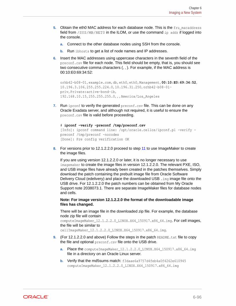
5. Obtain the eth0 MAC address for each database node. This is the fru_macaddressfield from /SYS/MB/NET0 in the ILOM, or use the command ip addr if logged intothe console.
a. Connect to the other database nodes using SSH from the console.
b. Run ibhosts to get a list of node names and IP addresses.
6. Insert the MAC addresses using uppercase characters in the seventh field of thepreconf.csv file for each node. This field should be empty, that is, you should seetwo consecutive comma characters (,,). For example, if the MAC address is00:10:E0:69:34:52:
orhb42-b08-01,example.com,db,eth0,eth0,Management,00:10:E0:69:34:52,10.196.3.106,255.255.224.0,10.196.31.250,orhb42-b08-01-priv,Private:active-bond-ib,192.168.10.15,255.255.255.0,,,America/Los_Angeles
7. Run ipconf to verify the generated preconf.csv file. This can be done on anyOracle Exadata server, and although not required, it is useful to ensure thepreconf.csv file is valid before proceeding.
# ipconf -verify -preconf /tmp/preconf.csv[Info]: ipconf command line: /opt/oracle.cellos/ipconf.pl -verify -preconf /tmp/preconf -nocodes[Done]: Pre config verification OK
8. For versions prior to 12.1.2.2.0 proceed to step 11 to use ImageMaker to createthe image files.
If you are using version 12.1.2.2.0 or later, it is no longer necessary to useimagemaker to create the image files in version 12.1.2.2.0. The relevant PXE, ISO,and USB image files have already been created in the patches themselves. Simplydownload the patch containing the prebuilt image file from Oracle SoftwareDelivery Cloud (edelivery) and place the downloaded USB .img image file onto theUSB drive. For 12.1.2.2.0 the patch numbers can be obtained from My OracleSupport note 2038073.1. There are separate ImageMaker files for database nodesand cells.
Note: For image version 12.1.2.2.0 the format of the downloadable imagefiles has changed.
There will be an image file in the downloaded zip file. For example, the databasenode zip file will containcomputeImageMaker_12.1.2.2.0_LINUX.X64_150917.x86_64.img. For cell images,the file will be similar tocellImageMaker_12.1.2.2.0_LINUX.X64_150917.x86_64.img.
9. (For 12.1.2.2.0 and above) Follow the steps in the patch README.txt file to copythe file and optional preconf.csv file onto the USB drive.
a. Place the computeImageMaker_12.1.2.2.0_LINUX.X64_150917.x86_64.imgfile in a directory on an Oracle Linux server.
b. Verify that the md5sums match: f3daae6a9757d4feb4a0f4262e610945computeImageMaker_12.1.2.2.0_LINUX.X64_150917.x86_64.img
Chapter 6Imaging a New System
6-96

c. Prepare the USB drive using a command similar to the following, where /dev/sdd isthe name of the inserted USB drive:
# dd if=/dev/zero of=/dev/sdd bs=1M count=100 oflag=direct
You can determine the exact name of the USB drive by looking in /var/log/messages after inserting the USB drive.
d. Write the .img file to the USB drive. This may take 15 minutes or more and no outputis shown during the operation.
# dd if=filename.img of=/dev/sdd bs=1M oflag=direct
e. Rescan the partition table on Oracle Linux to recognize the new partition:
# partprobe
f. Verify that the USB is mountable as long as the system supports ext4 file system.This must be an Oracle Linux 6 system for this step even if the previous dd commandwas run on an Oracle Linux 5 system.
mount /dev/sdd1 /mnt
g. (Optional) Prepare and place the preconf.csv file on the USB drive. The file namemust be preconf.csv on the USB drive. The preconf.csv file must contain MACaddresses for each node in the order to be used during the image. If no preconf.csvfile is used during imaging, the node will prompt for its network configuration the firsttime it boots up.
# cp /path/preconf.csv /mnt/preconf.csv
# umount /mnt
The umount command above ensures that the file system is synchronized.
h. Proceed to step 15. Steps 11 to 14, which create the image files, can be skipped.
10. Download the ImageMaker kit to prepare and create the files for the USB drive. This kit isavailable publicly on the Oracle Software Delivery Cloud (edelivery) site under “OracleDatabase Products -> Linux x86-64”. There are separate ImageMaker files for databasenodes and cells.
11. After downloading ImageMaker, unzip the first file, which is named similar toV75080-01.zip, and then also unzip the subsequent file. Perform the unzip as the rootuser. Then untar the file.
# unzip V75080-01.zip
# unzip cellImageMaker_12.1.2.1.1_LINUX.X64_150316.2-1.x86_64.zip
# tar -pxvf cellImageMaker_12.1.2.1.1_LINUX.X64_150316.2-1.x86_64.tar
View the README_FOR_FACTORY.txt file in the resulting directory for additional details
12. Insert a blank USB device in the slot of the server where ImageMaker was unpacked.
Chapter 6Imaging a New System
6-97

13. Run makeImageMedia.sh to build the kernel, initrd, and image files for the USBdevice. makeImageMedia.sh will prompt to confirm creation of the image on theUSB device. For building 12.1.2.1.0 and above images, the recommendedmakeImageMedia.sh options for building USB bootable media are:
a. (For 12.1.2.1.0 up to 12.2.1.1.0) Change directory to the dl180 or dl360directory.
b. (For 12.2.1.1.0 and above) Change directory to the cell or compute directory.
c. Make files for the USB.
./makeImageMedia.sh -factory -stit -reboot-on-success -nodisktests [-preconf path_to_preconf_file]
For USB imaging, note the following:
• makeImageMedia.sh must be run from an Oracle Exadata database server ifusing the -preconf option.
• Storage servers and database servers can hang during boot when attemptinga reimage using a bootable USB created with the makeImageMedia.sh scriptprovided with storage server and database server host images available onthe Oracle Software Delivery Cloud (edelivery). To work around the issue, seeMy Oracle Support note 1919001.1
14. After the USB drive has been prepared, place it into the slot of the server to beimaged. Ensure the image type matches the server type (database node or cell).
15. Reboot the database node or cell to start the imaging process from USB.
16. If you are using Oracle VM, run switch_to_ovm.sh on each database server. Thedatabase servers will reboot.
For example:
# /opt/oracle.SupportTools/switch_to_ovm.sh2014-12-07 11:58:36 -0800 [INFO] Switch to DOM0 system partition /dev/VGExaDb/LVDbSys3 (/dev/mapper/VGExaDb-LVDbSys3)2014-12-07 11:58:36 -0800 [INFO] Active system device: /dev/mapper/VGExaDb-LVDbSys12014-12-07 11:58:36 -0800 [INFO] Active system device in boot area: /dev/mapper/VGExaDb-LVDbSys12014-12-07 11:58:36 -0800 [INFO] Set active systen device to /dev/VGExaDb/LVDbSys3 in /boot/I_am_hd_boot2014-12-07 11:58:36 -0800 [INFO] Reboot has been initiated to switch to the DOM0 system partition
17. On systems with InfiniBand Network Fabric only, run /opt/oracle.SupportTools/reclaimdisks.sh -free -reclaim on each database server before installing anysoftware.
The command reclaims disk space reserved for the deployment type not selected,which is not required on RoCE-based Exadata database servers.
The command typically takes less than 5 minutes.
Chapter 6Imaging a New System
6-98

Caution:
Do not skip this step. Skipping this step results in unused space that can nolonger be reclaimed by reclaimdisks.sh.
# /opt/oracle.SupportTools/reclaimdisks.sh -free -reclaimModel is ORACLE SERVER X5-2Number of LSI controllers: 1Physical disks found: 4 (252:0 252:1 252:2 252:3)Logical drives found: 1...[INFO ] Copying /usr/share/grub/x86_64-redhat/* to /boot/grub ...[INFO ] Create filesystem on device /dev/sda1[INFO ] Tune filesystem on device /dev/sda1
GNU GRUB version 0.97 (640K lower / 3072K upper memory)
[ Minimal BASH-like line editing is supported. For the first word, TABlists possible command completions. Anywhere else TAB lists the possiblecompletions of a device/filename.]grub> root (hd0,0) Filesystem type is ext2fs, partition type 0x83grub> setup (hd0) Checking if "/boot/grub/stage1" exists... no Checking if "/grub/stage1" exists... yes Checking if "/grub/stage2" exists... yes Checking if "/grub/e2fs_stage1_5" exists... yes Running "embed /grub/e2fs_stage1_5 (hd0)"... failed (this is not fatal) Running "embed /grub/e2fs_stage1_5 (hd0,0)"... failed (this is not fatal) Running "install /grub/stage1 (hd0) /grub/stage2 p /grub/grub.conf "... succeededDone.grub> quit
18. Run ibhosts and verify that all nodes show the correct IP addresses and host names.There should be no nodes with "elasticNode" in the description.
19. Run the OEDA tool to deploy.
[root] # ./install.sh -cf ../MAA-dm01.xml -l1. Validate Configuration File2. Setup Capacity-on-Demand3. Create Virtual Machine 4. Create Users 5. Setup Cell Connectivity 6. Create Cell Disks 7. Create Grid Disks 8. Configure Alerting 9. Install Cluster Software 10. Initialize Cluster Software 11. Install Database Software 12. Relink Database with RDS 13. Create ASM Diskgroups
Chapter 6Imaging a New System
6-99

14. Create Databases 15. Apply Security Fixes 16. Install Exachk 17. Setup ASR Alerting 18. Create Installation Summary 19. Resecure Machine
Related Topics
• Oracle Software Delivery Cloud
• Exadata 12.1.2.2.0 release and patch (20131726) (My Oracle Support Doc ID2038073.1)
• Exadata reimaging using USB fails to boot USB (My Oracle Support Doc ID1919001.1)
• Exadata Database Machine and Exadata Storage Server Supported Versions (MyOracle Support Doc ID 888828.1)
6.12.6 Updates to Imaging ParametersSome of the command line options for imaging have changed with 12.1.2.1.0 andabove.
The changes are:
• updfrm
Do NOT use the updfrm option in any form. It will be removed from the imagingoptions in the future. Allow the firmware to be updated automatically upon initialboot instead.
• dualboot
dualboot is no longer required with 12.1.2.1.0 as there is no support for Solaris. Ithas no meaning in releases 12.1.2.1.0 and above.
• factory
The meaning of the factory keyword has changed as of 12.1.2.1.0. The use of"factory" now enforces additional options such as "ovs=yes". This should be usedfor all imaging, regardless of the ultimate system configuration (Oracle VM,Physical etc.)
• OVS=yes|no
This option defaults to "no". However it is not recommended to use this at allbecause it may change in the future. In its place, use the "factory" option which willoverride some default options.
There are some additional command line options which may be useful:
• To create a hot spare on dbnodes, use the enable_hot_spare option.
– makeImageMedia.sh option: -enable_hot_spare
– PXE option: enable_hot_spare
• To force active bond or no active bond for InfiniBand interfaces (mainly forexpansion rack cases), use the active-bond-ib option.
– makeImageMedia.sh option: -active-bond-ib <yes|no>
Chapter 6Imaging a New System
6-100
– PXE option: active-bond-ib=<yes|no>
The README_FOR_FACTORY.txt file shipped with the imagemaker software explains eachoption in more detail.
Related Topics
• Exadata 12.1.2.2.0 release and patch (20131726) (My Oracle Support Doc ID2038073.1)
• Reimaging Exadata Cell Node Guidance (My Oracle Support Doc ID 2151671.1)
6.13 Performing Initial Elastic Configuration of Oracle ExadataDatabase Machine
This topic provides background information on elastic configuration and describes how toperform the initial configuration of Oracle Exadata Database Machine.
You need the configuration file generated by Oracle Exadata Deployment Assistant (OEDA).
Elastic configuration is new in Oracle Exadata System Software release 12.1.2.1.0. It appliesto all rack configurations, such as the following:
• Racks ordered with a standard number of database nodes and cells, for example, quarteror half racks
• Rack configurations that feature additional database nodes and cells
• Oracle Exadata Database Machine Two-Socket X5 generation and later storage servers
• Oracle Exadata Racks that use an InfiniBand Network Layer or a RoCE Network Layer.
Starting with the Oracle Exadata Database Machine Two-Socket X5 generation of storageservers, the same process can also be used to add additional database servers or storageservers to an existing configuration.
The process allows initial IP addresses to be assigned to database servers and storageservers, regardless of the exact configuration you ordered. Your specific configuration canthen be applied to the nodes. The procedure can be run from any database node (usually thefirst node,) and also from a storage server in cases where expansion involves adding onlystorage servers.
Every Oracle Exadata Database Machine has a predefined method for the cabling of nodesto the RDMA Network Fabric switch ports. Therefore, there is a fixed mapping from eachnode's location in the rack to the ports of the RDMA Network Fabric switches. Assuming therack is always populated following this map, a node's rack unit location can be identified byquerying the RDMA Network Fabric to determine the RDMA Network Fabric switch port thenode is connected to. Once found, that information is used to determine the rack unit locationof the node. With this information, nodes can be allocated initial IP addresses based on theirrack unit location, with nodes lower in the rack getting lower IP addresses.
Chapter 6Performing Initial Elastic Configuration of Oracle Exadata Database Machine
6-101
Note:
• Disk space for unused system partitions must be reclaimed beforeinstalling software on all database servers with InfiniBand NetworkFabric. Use the following command to reclaim the disk space: /opt/oracle.SupportTools/reclaimdisks.sh -free -reclaim. Thiscommand is not required on RoCE-based Exadata database servers.
• If a RAID rebuild/reconstruction (that is, a disk replacement orexpansion) is in progress, wait until it is finished before performing thesteps in this section. The reason is that the reclaimdisks.sh script isblocked from running until the RAID rebuild/reconstruction is complete.
1. Open a console session to the first database server. The first database server isthe lowest database server in the rack, which is rack position U16. In the case ofan expansion involving only cells, the procedure should be run from a storageserver instead of a database node.
Note:
The network connection and configuration for Oracle Exadata DatabaseMachine has not occurred yet.
2. Log in as the root user on the first database server.
Note:
If you do not have the password for the root user, then contact OracleSupport Services.
3. On systems with InfiniBand Network Fabric only, verify all servers are configuredwith the 172.16.* IP address for the eth0 interface using the following command:
# ibhosts
Ca : 0x0010e00001486fb8 ports 2 "node10 elasticNode 172.16.2.46,172.16.2.46 ETH0"Ca : 0x0010e00001491228 ports 2 "node9 elasticNode 172.16.2.45,172.16.2.45 ETH0"Ca : 0x0010e000014844f8 ports 2 "node8 elasticNode 172.16.2.44,172.16.2.44 ETH0"Ca : 0x0010e00001488218 ports 2 "node4 elasticNode 172.16.2.40,172.16.2.40 ETH0"Ca : 0x0010e000014908b8 ports 2 "node2 elasticNode 172.16.2.38,172.16.2.38 ETH0"Ca : 0x0010e0000148ca68 ports 2 "node1 elasticNode 172.16.2.37,172.16.2.37 ETH0"
Chapter 6Performing Initial Elastic Configuration of Oracle Exadata Database Machine
6-102

Ca : 0x0010e00001485fd8 ports 2 "node3 elasticNode 172.16.2.39,172.16.2.39 ETH0"
Each server description should be hostname elasticNode. ipaddress ETH0.
4. If using virtualization on the rack, configure each database server as follows:
Note:
Starting with Oracle Exadata Database Machine X8M-2, Oracle Linux KVM isthe virtualization technology for systems that use RoCE Network Fabric.Otherwise, Oracle VM Server (OVM) is a Xen-based virtualization technology,which is used across Oracle Exadata Database Machine systems that useInfiniBand Network Fabric.
This step applies to both virtualization technologies.
# /opt/oracle.SupportTools/switch_to_ovm.sh
The database servers will reboot during this step.
Note:
It is not possible or supported to switch between physical and virtualizedconfigurations.
5. On systems with InfiniBand Network Fabric only, reclaim the unused disk space on thedatabase servers.
Disk space for unused system partitions must be reclaimed before installing software onall database servers with InfiniBand Network Fabric. Use the following command toreclaim the disk space: /opt/oracle.SupportTools/reclaimdisks.sh -free -reclaim.This command is not required on RoCE-based Exadata database servers.
reclaimdisks.sh performs partition reconfiguration and a few other necessaryconfiguration changes that take typically less than a minute to complete.
6. On systems with InfiniBand Network Fabric only, verify the disk configuration on thedatabase servers.
# /opt/oracle.SupportTools/reclaimdisks.sh -check
If the system is a physical (bare metal) deployment, the last line of output will be thefollowing:
Valid. Booted: Linux. Layout: Linux.
If the system is an Oracle VM deployment, the last line of output will be the following:
Valid. Booted: DOM0. Layout: DOM0.
Chapter 6Performing Initial Elastic Configuration of Oracle Exadata Database Machine
6-103

7. Copy the OEDA configuration files to the database server using one of thefollowing methods. If adding only storage servers, the steps can be run from astorage server.
• Using a USB flash drive:
a. Copy the configuration file to a USB flash drive.
b. Connect the USB drive to the database server or storage server.
c. Locate the USB drive using the following command:
for x in `ls -1 /sys/block`; do udevadm info --attribute-walk --path=/sys/block/$x | grep \-iq 'DRIVERS=="usb-storage"'; if [ $? -eq 0 ] ; then echo /dev/${x}1; \fi ; done
The expected output is similar to:
/dev/sdb1
Note:
If an Oracle Exadata Storage Server X6 or X5 Extreme Flash(EF) is used, the command will also return the two internal USBdrives, usually /dev/sda1 and /dev/sdb1. The newly insertedUSB drive will be the additional device, usually /dev/sdc1.
The expected output is similar to:
/dev/sda1/dev/sdb1/dev/sdc1
The internal USBs can be identified by viewing mdstat:
# grep md4 /proc/mdstat | awk '{print $5,$6;}'
d. Create a directory on the database server or storage server using thefollowing command:
# mkdir /mnt/usb
e. Create a directory for the installation using the following command:
# mkdir /opt/oracle.SupportTools/onecommand
If the directory already exists, then rename the existing one toonecommand.old, and then re-create the empty directory.
Chapter 6Performing Initial Elastic Configuration of Oracle Exadata Database Machine
6-104

Note:
Do not use a directory under /u01 or /EXAVMIMAGES becausereclaimdidsks.sh will fail if there is content in those directories.
f. Mount the device. Use the device name given in step 7.c. The following is anexample of the command.
# mount -t vfat /dev/sdb1 /mnt/usb
g. Copy OEDA and the configuration files from the USB flash drive to theonecommand directory on the database server or storage server using thefollowing command:
# cp /mnt/usb/path_to_file/*.* /opt/oracle.SupportTools/onecommand
In the preceding command, path_to_file is the directory path to the configurationfile on the USB flash drive.
h. Unmount the USB flash drive using the following command:
# umount /mnt/usb
i. Remove the USB flash drive from the database server or storage server.
• Using a temporary network connection:
This option is only needed if there were IP address conflicts, and Oracle ExadataDatabase Machine is not already connected to the network.
a. Connect a network cable to the Ethernet port labeled NET0 on the back of thefirst database server.
b. Bring up the eth0:1 interface as follows:
# ifconfig eth0:1 real_ip netmask real_netmask up
In the preceding command, real_ip is the IP address to assign to the databaseserver, and real_netmask is the subnet mask to assign to the database server.
c. Add the default route as follows:
# route add -net 0.0.0.0 netmask 0.0.0.0 gw real_gateway
In the preceding command, real_gateway is the default gateway to use for thedatabase server.
d. Copy the configuration files to the /opt/oracle.SupportTools/onecommand directory on the database server or storage server using a filetransfer utility such as scp.
e. Disconnect the network cable from Ethernet port NET0.
Chapter 6Performing Initial Elastic Configuration of Oracle Exadata Database Machine
6-105

Note:
It is not necessary to reconfigure the network because thenetwork is reconfigured automatically during the restart step.
8. Download and unzip the OEDA archive to a host on the same network as theservers in the rack (172.16.*).
The applyElasticConfig.sh script is not configured by default on the servers inthe rack.
9. Run the applyElasticConfig.sh script.
For example, if you unzipped the OEDA ZIP file into the /opt/oracle.SupportTools/onecommand/linux-x64 directory, then use the followingcommands:
# cd /opt/oracle.SupportTools/onecommand/linux-x64
# ./applyElasticConfig.sh -cf customer_name-configFile.xml
The applyElasticConfig.sh script performs network configuration for alldatabase servers and storage servers. All servers restart at the end of theprocess.
10. Connect the corporate network cable for the management network to the CiscoManagement Switch.
11. Connect the corporate network cables for the client access network to thedatabase servers.
12. Restart all database servers and storage servers.
13. Log in to the first database server (or storage server, if only storage servers wereadded for expansion) to verify network connectivity using the following commands:
# cd /opt/oracle.SupportTools/onecommand/linux-x64
#./checkip.sh -cf configuration_file
In the preceding command, configuration_file is the name of the configuration filefrom OEDA, and includes the full path.
Note:
• The checkip.sh script can be run on a server outside of OracleExadata Database Machine to verify network connectivity to OracleExadata Database Machine. Copy the checkip.sh file to the externalsystem, and run the command as shown in this step.
• If the command is run from a Microsoft Windows machine, then thecommand is checkip.cmd.
• Download the version of OEDA for the relevant platform.
Chapter 6Performing Initial Elastic Configuration of Oracle Exadata Database Machine
6-106

14. Use OEDA to install and configure the software for Oracle Exadata Database Machine.
Related Topics
• Cabling Information for Oracle Exadata Database Machine
• Powering On and Off Oracle Exadata Rack
• Adding Additional Elastic Nodes to an Existing RackYou can add nodes to an existing rack using elastic configuration.
6.14 Adding Additional Elastic Nodes to an Existing RackYou can add nodes to an existing rack using elastic configuration.
The elastic configuration procedure described in Performing Initial Elastic Configuration ofOracle Exadata Database Machine can also be used to add new servers to an existing rack.The new servers and existing servers must be at least X5. The procedure assigns IPaddresses to the new database servers and cells, in preparation for adding them into existingsetups. The addition of X5 or later model servers into previous generation racks using thismethodology is not supported.
The XML configuration file generated by the Oracle Exadata Deployment Assistant (OEDA)must contain the existing nodes, plus the new nodes to be added.
If you are adding only storage servers, then you can run the applyElasticConfig.sh scriptfrom a storage server rather than a database server.
The overall process for adding a new server to an existing rack is:
1. Use Oracle Exadata Deployment Assistant (OEDA) to add the new server to the rackconfiguration and generate the configuration files.
2. Download and unzip the OEDA archive to an existing server in the rack where you areadding the new server.
3. Install the new server into the rack.
4. Review the OEDAconfiguration file for the rack to determine the location within the rack(the ulocation) for the new server. For example:
<uLocation>16</uLocation>
5. Log in to the ILOM on the new server using the local serial management connection(SER MGT port), and review the system location in the SP.
For example:
-> show /sp/ system_location
/SP Properties: system_location = ru_06
->
6. If the location in the ILOM SP is different from the OEDA location, then modify thelocation in the ILOM SP to match the value from OEDAILOM.
Chapter 6Adding Additional Elastic Nodes to an Existing Rack
6-107
Note:
Ensure that there are no duplicate locations in the OEDA rackconfiguration XML file.
Set the system location in the ILOM SP with the following command:
-> set /SP/ system_location=RU16
7. For a database server with InfiniBand Network Fabric only, log in to the server andreclaim the unused disk space.
Disk space for unused system partitions must be reclaimed before installingsoftware on all database servers with InfiniBand Network Fabric. Use the followingcommand to reclaim the disk space: /opt/oracle.SupportTools/reclaimdisks.sh -free -reclaim. This command is not required on RoCE-based Exadata database servers.
reclaimdisks.sh performs partition reconfiguration and a few other necessaryconfiguration changes that take typically less than a minute to complete.
8. Log in to the server where you unzipped the OEDA configuration files and run theapplyElasticConfig.sh script.
For example, if you unzipped the OEDA ZIP file into the /opt/oracle.SupportTools/onecommand/linux-x64 directory, then use the followingcommands:
# cd /opt/oracle.SupportTools/onecommand/linux-x64
# ./applyElasticConfig.sh -cf customer_name-configFile.xml
The applyElasticConfig.sh script performs network configuration for the newservers. The new servers are restarted at the end of the process.
6.15 Using the OEDA setuprootssh UtilityYou can set up key-based authentication for the root user by using thesetuprootssh.sh utility included with OEDA.
Starting with the April 2020 release of Oracle Exadata Deployment Assistant (OEDA),the setuprootssh.sh utility is located in the same directory as the install and configscripts.
• To set up the required keys for SSH key-based authentication, run thesetuprootssh.sh utility.
./setuprootssh.sh -cf config.xml
For config.xml, specify the full path name to the deployment file created by OEDA.
For each physical and virtual machine (VM) host in the deployment file, thesetuprootssh.sh utility creates an SSH key pair. The keys are saved in the OEDAWorkDir using the following file naming conventions:
Chapter 6Using the OEDA setuprootssh Utility
6-108

– Private key: id_rsa.short_hostname.root
– Public key: id_rsa.short_hostname.root.pub
In the key file names, short_hostname is the corresponding server host name without anydomain name qualification.
Where possible, the utility also installs the public key on the host and disables password-based authentication for the root user.
If the utility cannot install the public key on the host, then the key file remains ready forlater use in the OEDA WorkDir. For example, this occurs to keys for VM hosts if you runthe utility before you create the VMs.
• If your system has a non-default root password, you must specify it by using the -proot_password option.
• Use the -h option to display the usage information.
6.16 Loading the Configuration Information and Installing theSoftware
You can use Oracle Exadata Deployment Assistant to configure your rack, or you can do itmanually.
Oracle Exadata Deployment Assistant (OEDA) loads the network settings, creates the useraccounts, installs Oracle Database software, and secures the system based on theinformation the configuration files.
• Configuring Oracle Exadata Database Machine Using OEDAUse Oracle Exadata Deployment Assistant (OEDA) to configure your engineered system.
• Using Oracle Exadata Deployment Assistant in Conjunction with Key-BasedAuthenticationYou can use the -sshkeys option to use SSH key-based authentication in conjunctionwith OEDA.
• Using Oracle Exadata Deployment Assistant on Systems with Non-Default rootPasswordsYou can use the -p option to prompt for a password instead of resetting the rootpassword to the expected default value.
• Configuring Oracle Database and Oracle ASM Instances for Oracle Exadata DatabaseMachine Manually
See Also:
Using Oracle Exadata Deployment Assistant for descriptions of the configurationfiles generated by OEDA.
Chapter 6Loading the Configuration Information and Installing the Software
6-109

6.16.1 Configuring Oracle Exadata Database Machine Using OEDAUse Oracle Exadata Deployment Assistant (OEDA) to configure your engineeredsystem.
The deployment phase of OEDA can be performed on one of the database servers ofyour new Oracle Exadata Database Machine or any other host that is connected to thesame network as the new engineered system rack. Do not run install.sh from astorage server. If you plan to run OEDA on a host outside of the new rack, then createthe OEDA home directory and Workdir, as described below, on the host machineinstead.
Note:
OEDA configures all Exadata components, including the database servers(with or without virtualization), storage servers, and the RDMA NetworkFabric. For successful configuration, OEDA requires access to:
• The client and administration network interfaces on the databaseservers, including the VM server host and the VM guests whereapplicable.
• The administration network interfaces on the storage servers.
• The administration network interfaces on the RDMA Network Fabricswitches.
Ensure that you run the OEDA deployment phase on a host with access toall of the required network interfaces.
Note:
Running OEDA from a client machine outside of the rack means the softwareimage files are transferred over the network, causing the process to beslower.
Note:
For this procedure, Oracle VM refers to OVM and KVM. Starting with OracleExadata Database Machine X8M-2, Oracle Linux KVM is the virtualizationtechnology for systems that use RoCE Network Fabric. Otherwise, OracleVM is a Xen-based virtualization technology, which is used across OracleExadata Database Machine systems that use InfiniBand Network Fabric.
You must have completed the other tasks described in Overview of Oracle ExadataDeployment Assistant before starting this task.
1. If you are installing Oracle VMs on the database servers, then run /opt/oracle.SupportTools/switch_to_ovm.sh on each database server.
Chapter 6Loading the Configuration Information and Installing the Software
6-110

2. Disk space for unused system partitions must be reclaimed before installing software onall database servers with InfiniBand Network Fabric. Use the following command toreclaim the disk space: /opt/oracle.SupportTools/reclaimdisks.sh -free -reclaim.This command is not required on RoCE-based Exadata database servers.
3. Create a directory for the extracted OEDA files on the host where you will runinstall.sh.
OEDA will not run if staged on the root file system (/)of any database server. Create adirectory to store the latest version of OEDA and all required files on a file system thathas at least 30 GB of available free space.
• For bare-metal database servers, create a directory on the /u01 file system, forexample /u01/onecommand or /u01/oeda.
• For Oracle VM servers, create a directory on the /EXAVMIMAGES file system.
4. Download the latest version of OEDA for the operating system of the client or serverwhere you will run install.sh.
Unzip the downloaded file into the OEDA home directory you created. This will create adirectory like /u01/onecommand/linux-x64. This directory is referred to as the OEDAhome directory.
5. Download the required image files for the Oracle software.
OEDA requires patches available from My Oracle Support or Oracle Software DeliveryCloud ( https://edelivery.oracle.com). Review the README file for OEDA to determinethe file name or patch number, which is based on the version of Oracle software beinginstalled. Place the files in the WorkDir sub-directory in the OEDA home directory.
• If you are installing on a bare-metal database server, then download the patches, asspecified in Section 2 of the OEDA README file. After downloading the patch ZIPfile, extract the contents into the WorkDir sub-directory.
• If you are configuring Oracle VM on the database servers, then download the goldimage files as indicated in the topic "Oracle Exadata Deployment Assistant Supportfor Oracle Virtual Machines" in the OEDA README file. After downloading the goldimage ZIP files, extract the contents into the WorkDir sub-directory.
A gold image is a copy of a software-only, installed Oracle home. It is used to copyan image of an Oracle home to a new host on a new file system to serve as anactive, usable Oracle home.
6. Copy the required OEDA configuration files to the WorkDir sub-directory on thedatabase server or Oracle VM.
When you used OEDA to specify the configuration details for your new engineeredsystem, it created several configuration files and a ZIP file that contains all the generatedfiles. The required files are also listed at the bottom of the InstallationTemplate.htmlfile that was generated by OEDA. You can copy the ZIP file and extract it into theWorkDir sub-directory, or copy the required files directly into the WorkDir sub-directory.
7. Log in to the database server or Oracle VM and go to the OEDA home directory.
8. Run the install.sh script to install and deploy the software on your new engineeredsystem.
Chapter 6Loading the Configuration Information and Installing the Software
6-111

In the following command syntax, configuration_file is the full path name for themaster configuration file, CustomerName-rackname.xml
# ./install.sh -cf configuration_file [-s step_number | \ -r step_numberA stepnumberB]
You can use the following options with the install.sh script:
• -cf file: Configuration file name
• -h: Help output for the script
• -l: List the steps of OEDA
• -r {n-N | n }: Run steps n through N of OEDA, or run the specified step.
• -s n: Run step n of OEDA.
• -u {n-N | n }: Undo steps n through N, or one step.
Note:
Always use the latest OEDA patch listed in My Oracle Support note888828.1. Refer to the README in the patch for the latest steps.
The following steps are performed by the OEDA deployment script. However, theactual steps for a specific deployment may differ depending on the deployment optionschosen. For example, the "Update Nodes for Eighth Rack" step is performed only ifyou are deploying an Eighth Rack configuration.
1. Validate Configuration File2. Update Nodes for Eighth Rack3. Create Virtual Machine4. Create Users5. Setup Cell Connectivity6. Create Cell Disks7. Create Grid Disks8. Configure Alerting9. Install Cluster Software10. Initialize Cluster Software11. Install Database Software12. Relink Database with RDS13. Create ASM Diskgroups14. Create Databases15. Apply Security Fixes16. Install Exachk17. Setup ASR Alerting18. Create Installation Summary19. Resecure Machine
Related Topics
• Oracle Exadata Deployment Assistant Downloads
Chapter 6Loading the Configuration Information and Installing the Software
6-112
• Exadata Database Machine and Exadata Storage Server Supported Versions (My OracleSupport Doc ID 888828.1)
6.16.2 Using Oracle Exadata Deployment Assistant in Conjunction withKey-Based Authentication
You can use the -sshkeys option to use SSH key-based authentication in conjunction withOEDA.
Starting with the April 2020 release of Oracle Exadata Deployment Assistant (OEDA), youcan use SSH keys for root user authentication on Oracle Exadata Racks.
To use this feature, you must first set up the required SSH keys. The easiest way to do this isto use the setuprootssh.sh utility included with OEDA. For example:
./setuprootssh.sh -cf config.xml
For more information about the setuprootssh.sh utility, see Using the OEDA setuprootsshUtility.
After you set up the required SSH keys, add the -sshkeys option to the regular command-lineoptions when you start up OEDA. For example:
./install.sh -cf config.xml -s 1 -sshkeys -usesu
When you specify the -sshkeys option, OEDA uses SSH key-based authentication. Inconjunction with this option, the OEDA WorkDir must contain the SSH private key for eachhost in the deployment file (config.xml). The private keys must conform to the following filenaming convention:
id_rsa.short_hostname.root
In the key file names, short_hostname is the corresponding server host name without anydomain name qualification.
As shown in the previous example, when you specify the -sshkeys option, you must alsospecify the -usesu option to instruct OEDA to run non-root commands from the root userusing su.
When you first log in to a host following the Resecure Machine deployment step, you areprompted to reset the root password. This still occurs even when SSH key-basedauthentication is enabled, and password-based authentication is disabled.
6.16.3 Using Oracle Exadata Deployment Assistant on Systems with Non-Default root Passwords
You can use the -p option to prompt for a password instead of resetting the root password tothe expected default value.
Starting with the November 2016 release, Oracle Exadata Deployment Assistant (OEDA)supports deployment on Oracle Exadata Racks that already have non-default rootpasswords. You can perform the deployment without having to change the root password
Chapter 6Loading the Configuration Information and Installing the Software
6-113
back to the default. In earlier releases, OEDA expected the root password to be thedefault on all the servers in an Oracle Exadata Rack.
With the new non-default password feature, root passwords can have different valueson each node in a rack. If non-default passwords are already set, add the -p option tothe existing command line options when you run OEDA. For example:
./install.sh -cf <config.xml> -s 1 -p
The -p option causes OEDA to prompt for the root password. Make sure you enterthe correct password because an incorrect password disables root access for 10minutes, and after 5 failed login attempts, the server is locked down.
Related Topics
• Default Security Settings Enacted by OEDA
6.16.4 Configuring Oracle Database and Oracle ASM Instances forOracle Exadata Database Machine Manually
Oracle Database and Oracle Automatic Storage Management (Oracle ASM) 11gRelease 2 (11.2) or later must be installed on the database server. Follow theinstructions for installing Oracle Database and Oracle ASM provided in the appropriateversion of the Oracle Database Installation Guide for your platform.
Note:
To fully utilize the Hardware Assisted Resilient Data (HARD) features, ensurethe DB_BLOCK_CHECKSUM initialization parameter is set to TYPICAL (default) orFULL.
When installing Oracle Database, you must select the Oracle ASM storage option. Ifyou are installing Oracle Real Application Clusters (Oracle RAC), then refer to theplatform-specific Oracle Clusterware and Oracle RAC installation guides, such asOracle Grid Infrastructure Installation and Upgrade Guide and Oracle Real ApplicationClusters Installation Guide.
If you are consolidating databases and need to have more than one database with thesame DB_UNIQUE_NAME on the Oracle Exadata Database Machine, then you mustconfigure Oracle ASM clusters on the storage cells and configure ASM-scopedsecurity.
Note:
For Oracle RAC, you must shut down the entire cluster, and then restart thecluster after the database and cell software have been installed, and the cellconfiguration files are in place.
Chapter 6Loading the Configuration Information and Installing the Software
6-114

The recommended procedure is to install the latest version of the Oracle software on OracleExadata Database Machine using Oracle Exadata Deployment Assistant (OEDA). If youchoose to install the software manually, then do the following:
Note:
Disk space for unused system partitions must be reclaimed before installingsoftware on all database servers with InfiniBand Network Fabric. Use the followingcommand to reclaim the disk space: /opt/oracle.SupportTools/reclaimdisks.sh-free -reclaim. This command is not required on RoCE-based Exadata databaseservers.
If a RAID rebuild or reconstruction (that is, a disk replacement or expansion) is inprogress, wait until it is finished before running the reclaimdisks.sh script. Thereason is that the reclaimdisks.sh script is blocked from running until the RAIDrebuild or reconstruction is complete.
1. Install Oracle Grid Infrastructure for a cluster software as described in Oracle GridInfrastructure Installation and Upgrade Guide for Linux.
2. Install Oracle Database software as described in Oracle Real Application ClustersInstallation Guide for Linux and UNIX.
3. Apply the latest patches for Oracle Database software and Oracle Exadata SystemSoftware.
After the cells are configured as described in Oracle Exadata System Software User's Guide,and the database and Oracle ASM instances are created, the instances must be configuredto use the cells as part of an Oracle ASM disk group. The required configuration involvesupdating the initialization parameter file of both the database and Oracle ASM instances.Additionally, Oracle ASM disk groups must be created to access storage cells.
You can update the initialization parameter file of the Oracle ASM or the database instancewhile the instance is running, but the instance must be restarted if you manually update theinitialization parameter file. If you update an initialization parameter dynamically using theSQL ALTER SYSTEM or ALTER SESSION commands, then there is no need to restart theinstance.
In addition, for the database, you can configure a new Oracle Database Resource Managerplan, rather than using the default plans.
• Configuring the Compatible Parameter for a Database InstanceOracle recommends using the best practices for Oracle Exadata System Softwareavailable at My Oracle Support.
• Configuring Initialization Parameters for an Oracle ASM Instance
• Using the Same DB_UNIQUE_NAME for Multiple Database InstancesYou can create database instances that use the same DB_UNIQUE_NAME value if thedatabases are associated with separate Oracle ASM clusters.
Related Topics
• Setting Up Oracle ASM-Scoped Security on Oracle Exadata Storage Servers
• Setting Up Configuration Files for a Database Server Host
• Managing I/O Resources
Chapter 6Loading the Configuration Information and Installing the Software
6-115
• Administering Oracle ASM Instances
• Configuring DBFS on Oracle Exadata Database Machine (My Oracle Support DocID 1054431.1)
• Oracle Exadata Best Practices (My Oracle Support Doc ID 757552.1)
6.16.4.1 Configuring the Compatible Parameter for a Database InstanceOracle recommends using the best practices for Oracle Exadata System Softwareavailable at My Oracle Support.
To configure a database instance to access cell storage, ensure that the COMPATIBLEparameter is set to 11.2.0.2 or later in the database initialization file.
You can view the initialization parameter file from the operating system or use theSQL*Plus administration command SHOW PARAMETER if the database is running. Forexample:
SQL> SHOW PARAMETERSQL> SHOW PARAMETER compatible
If necessary, set the COMPATIBLE initialization parameter in the initialization parameterfile to 11.2.0.2 or later. For example:
COMPATIBLE='18.0.0'
The COMPATIBLE parameter cannot be changed dynamically. If you change the value inthe initialization parameter file, then the database must be shut down and restarted forthe change to take effect.
Related Topics
• COMPATIBLE
6.16.4.2 Configuring Initialization Parameters for an Oracle ASM InstanceTo enable an Oracle ASM instance to discover and access Exadata Storage Servergrid disks, you must configure the ASM_DISKSTRING initialization parameter asfollows:
• Set the ASM_DISKSTRING initialization parameter to the empty string ('') todiscover all grid disks on the cells listed in the cellip.ora file. This causes OracleASM discovery for /dev/raw/* and any ASMLIB disks on any non-ExadataStorage Servers.
• Set the ASM_DISKSTRING initialization parameter to restrict the discovery byOracle ASM to only specific sets of disks, as shown in the examples.
– To discover only a subset of cells, use a pattern for the ASM_DISKSTRINGvalue such as the following:
o/cell-connect-info-pattern/griddisk-name-pattern.
For example:
ASM_DISKSTRING = 'o/*/data*'
Chapter 6Loading the Configuration Information and Installing the Software
6-116
– To discover non-Exadata Storage Server disks and all grid disks on all the cellsspecified in the cellip.ora file, use a wildcard pattern for Exadata Storage Servergrid disks. For example:
ASM_DISKSTRING = '/dev/rdsk/disk*', 'o/*/*'
You can change the ASM_DISKSTRING initialization parameter when the Oracle ASMinstance is running with the SQL ALTER SYSTEM command. If you edit the ASM_DISKSTRINGinitialization parameter in the initialization parameter file when the Oracle ASM instance isrunning, then the Oracle ASM instance must be shut down and restarted for the change totake effect.
See Also:
• Oracle Automatic Storage Management Administrator's Guide for additionalinformation about the following:
– Oracle ASM discovery strings
– starting up and connecting to an Oracle ASM instance
• Oracle Database Reference for additional information about theASM_DISKSTRING initialization parameter
• Oracle Database SQL Language Reference for additional information about theALTER SYSTEM command
6.16.4.3 Using the Same DB_UNIQUE_NAME for Multiple Database InstancesYou can create database instances that use the same DB_UNIQUE_NAME value if the databasesare associated with separate Oracle ASM clusters.
Starting with Oracle Exadata System Software release 19.1.0, Oracle Multitenant databaseclusters sharing the same storage can contain database instances that use the sameDB_UNIQUE_NAME.
WARNING:
If you configure databases to have the same DB_UNIQUE_NAME, then thosedatabases cannot be backed up to Oracle Zero Data Loss Recovery Appliance.
1. Create Oracle ASM clusters for the database clusters that use identical DB_UNIQUE_NAMEvalues for the database instances.
Each database instance that uses the same DB_UNIQUE_NAME must be in a separateOracle ASM cluster. The Oracle ASM cluster name is used to qualify the DB_UNIQUE_NAMEin I/O Resource Management (IORM), Exadata Smart Flash Cache, and Exadata SmartScan Offload operations.
2. Configure ASM-scoped security for each cluster database.
When configuring ASM-scoped security, the Oracle ASM client must be configured as anASMCLUSTER client.
Chapter 6Loading the Configuration Information and Installing the Software
6-117

If you already have ASM-scoped security configured, but the Oracle ASM client isnot configured as an ASMCLUSTER client, then you can use the ASSIGN KEYcommand upgrade the key to an ASMCLUSTER key.
3. Create the databases in each cluster using the same DB_UNIQUE_NAME.
Related Topics
• Setting Up Oracle ASM-Scoped Security on Oracle Exadata Storage Servers
• Upgrading ASM-Scoped Security Key for ASMCLUSTER
6.17 Using the OEDA changePassword UtilityYou can change the password of the grid and oracle users across all clusters byusing the changePassword.sh utility included with OEDA.
The utility is located in the same directory as the install and config scripts.
You cannot use this utility if the servers are locked down.
• To change the password of both oracle and grid users on all database serversand clusters, run the changePassword command.
./changePassword.sh -cf config.xml -userName root
For config.xml, specify the full path name to the deployment file created by OEDA.
The utility prompts for the current root password and allows you to change thepassword of any users in the rack.
• To change the password for a specific user, such as oracle or grid, use the -userName user_name option with the command.
• To change the password for all users within a specific cluster, use the -clusterName cluster_name option with the command.
• Use the -h option with the command to display the usage information.
6.18 Installing Oracle Enterprise Manager Cloud ControlOracle Exadata Database Machine should be monitored using Oracle EnterpriseManager Cloud Control. Ensure that the Enterprise Manager environment isconfigured for high availability and disaster recovery to ensure sufficient monitoring ofthe Exadata environments.
Related Topics
• Oracle Enterprise Manager Cloud Control Basic Installation Guide
• Installation and Deployment in Oracle Enterprise Manager Exadata ManagementGetting Started Guide
• Configuring Enterprise Manager for High Availability in Oracle Enterprise ManagerCloud Control Advanced Installation and Configuration Guide
• Oracle Enterprise Manager Cloud Control Advanced Installation and ConfigurationGuide
• Discovery in Oracle Enterprise Manager Cloud Control Administrator's Guide
Chapter 6Using the OEDA changePassword Utility
6-118

• How to Configure Oracle Configuration Manager for Oracle Exadata Database Machine(My Oracle Support Doc ID 1319476.1)
• MAA Best Practices website
6.19 Adding a VM Cluster to Oracle Exadata Database MachineUsing OEDA
You can use Oracle Exadata Deployment Assistant (OEDA) to add a virtual machine (VM)cluster to an existing Oracle Exadata Database Machine deployment.
The procedure has the following prerequisites:
• The system must support an existing VM deployment.
• You must have free space on your system to accommodate the new VM cluster.Specifically:
– You must not have the maximum number of VM clusters already deployed.
– You must have available CPU, memory, and local storage resources on the databaseservers.
– You must have available storage space on the storage servers.
• You require a current copy of the OEDA XML system configuration file.
To add a VM cluster to an existing Oracle Exadata Database Machine deployment:
1. Start the OEDA Web-based configuration tool.
See Getting Started with the OEDA Browser-based User Interface.
2. Import the existing XML system configuration file.
Use the Import option located in the drop-down menu at the top of the page.
3. Click Clusters in the navigation menu on the left of the page.
The Define Clusters section displays the configuration information for the existingclusters.
4. Click the Add Clusters button.
The Add Clusters button contains the plus symbol (+) and is adjacent to the existingcluster tabs.
Clicking the Add Clusters button adds a tab in the Define Clusters section to containthe configuration details for the new cluster.
5. In the new cluster tab, specify the configuration details for the new cluster. Then, clickApply.
OEDA now displays the Diskgroups section.
6. In the Diskgroups section, click the tab for the storage that is associated with the newlydefined cluster.
7. Specify the configuration details for the storage that is associated with the new cluster.Then, click Apply.
OEDA now displays the Create Database Home section.
8. Click the Add Database Home button, which contains the plus symbol (+) and isadjacent to the existing tabs.
Chapter 6Adding a VM Cluster to Oracle Exadata Database Machine Using OEDA
6-119

A new tab appears in the Create Database Home section to contain theconfiguration details for a new database home.
9. In the new tab, specify the configuration details for the new database home. Then,click Apply.
Ensure that you select the newly defined cluster as the location to contain the newdatabase home.
Afterward, OEDA displays the Create Database section.
10. Click the Add Database button, which contains the plus symbol (+) and isadjacent to the existing tabs.
A new tab appears in the Create Database section to contain the configurationdetails for a new database.
11. In the new tab, specify the configuration details for the new database. Then, clickApply.
Ensure that you select the newly defined database home to support the newdatabase.
Afterward, OEDA displays the Cluster Networks section.
12. For each network in the Cluster Networks section, select the tab that isassociated with the new cluster and specify the network settings. Then, clickApply.
As you step through the network settings, ensure that you specify valid IP addresssettings that are compatible with the existing system configuration.
Afterward, OEDA displays the Alerting section.
13. Click Comments in the navigation menu. Then, click Apply and Download tosave the updated system configuration information.
14. Unzip the zip file located in the directory containing the newly saved systemconfiguration information.
The directory containing the newly saved system configuration informationcontains multiple files, including the updated XML system configuration file andHTML installation template. However, the zip file contains additional cluster-specific XML configuration files.
15. Locate the cluster-specific XML configuration file for the new cluster.
The new cluster-specific XML configuration file is located in the unzipped directorythat you created in the previous step. The names of the cluster-specific XMLconfiguration files contain a numeric sequence that reflects the order of clustercreation, with the newest cluster having the highest number.
16. Use the cluster-specific XML configuration file to deploy the new cluster.
Use the OEDA deployment utility (install.sh) in conjunction with the cluster-specific XML configuration file for the new cluster.
Perform all of the deployment steps except for the following, which do not apply.Ensure that you do not perform the following deployment steps as they mayimpact system performance and availability:
• Update Nodes for Eighth Rack (For Eighth Rack systems only)
• Calibrate Cells
• Create Cell Disks
Chapter 6Adding a VM Cluster to Oracle Exadata Database Machine Using OEDA
6-120

• Resecure Machine
Also, when you perform the Create Installation Summary step, ensure that you use the-nocalibratecell option to ensure that cell calibration is not performed during that step.For example, if the step number for the Create Installation Summary step is 18:
$ ./install.sh -cf cluster4.xml -s 18 -nocalibratecell
To view a complete list of the deployment steps and the corresponding step numbers,use install.sh with the -l option. For example:
$ ./install.sh -cf cluster4.xml -l
1. Validate Configuration File2. Setup Required Files3. Create Users4. Setup Cell Connectivity5. Verify Infiniband6. Calibrate Cells7. Create Cell Disks8. Create Grid Disks9. Configure Cell Alerting10. Install Cluster Software11. Initialize Cluster Software12. Install Database Software13. Relink Database with RDS14. Create ASM Diskgroups15. Create Databases16. Apply Security Fixes17. Setup ASR Alerting18. Create Installation Summary19. Resecure Machine
To run an individual step, use install.sh with the -s option and specify the step number.For example, to run step 1:
$ ./install.sh -cf cluster4.xml -s 1
To run a range of steps, use install.sh with the -r option and specify the step range.For example, to run steps 12-16:
$ ./install.sh -cf cluster4.xml -r 12-16
Related Topics
• Configuring Oracle Exadata Database Machine Using OEDAUse Oracle Exadata Deployment Assistant (OEDA) to configure your engineered system.
Chapter 6Adding a VM Cluster to Oracle Exadata Database Machine Using OEDA
6-121

ASite Checklists
Complete the checklists in this appendix to ensure the site is prepared for your new OracleEngineered System.
Note:
For ease of reading, the Oracle Engineered System is sometimes referred to simplyas "the rack", which indicates the entire system, not just the cabinet.
• System Components ChecklistUse this checklist to ensure that the system component considerations have beenaddressed.
• Data Center Room ChecklistUse this checklist to ensure that the data center room requirements have beenaddressed.
• Data Center Environment ChecklistUse this checklist to ensure that the data center environment requirements have beenaddressed.
• Access Route ChecklistUse this checklist to ensure that the access route requirements are addressed.
• Facility Power ChecklistUse this checklist to ensure that the facility power requirements have been addressed.
• Safety ChecklistUse this checklist to ensure that the safety requirements have been addressed.
• Logistics ChecklistUse this checklist to ensure that the logistics requirements have been addressed.
• Network Configuration ChecklistUse this checklist to ensure that the network configuration requirements have beenaddressed.
• Auto Service Request ChecklistUse this checklist if you are planning to use Auto Service Request with the OracleExadata Database Machine.
• Re-racking ChecklistsUse these checklists prior to re-racking configurations approved for re-rack by OracleExadata Configuration Assistant (OECA) or your Oracle contact.
• PDU Checklist for Re-rackingUse this checklist to verify the power distribution unit (PDU) requirements when using there-racking service.
• Recycling the RacksUse this checklist when recycling the rack.
A-1

A.1 System Components ChecklistUse this checklist to ensure that the system component considerations have beenaddressed.
The cells in the second column of the following table are intentionally left blank so thatthe site survey team can fill in the requested information.
Table A-1 System Components Checklist
System Components Checklist Items Yes
No N/A
Comment
What type of engineered system rack are you installing?(Exadata Database Machine, Big Data Appliance,Oracle Cloud Machine, Exadata Storage Expansion,Zero Data Loss Recovery Appliance, etc.)
Is the rack installation an extension to an existingsystem, rather than a new installation?
If it is an extension to an existing system, refer to themulti-rack cabling information for your EngineeredSystem.
How many racks will be installed?
Have you ordered the multi-rack cabling service?
Are all Engineered System racks adjacent to eachother?
If the connecting racks are not within the specifiedproximity, or you are connecting more than 3 rackstogether, then have you completed the following tasks?
• Purchased longer InfiniBand cables from anapproved third-party provider?
• Asked Oracle Support Services to provide andschedule the custom multi-rack cabling service withthe installation?
If you are connecting the new rack to other Oracleracks, then does each rack (excluding Eighth Rackconfigurations) have a spine switch?
If any of the racks you plan to interconnect using theInfiniBand network are missing a spine switch, thenhave you ordered the InfiniBand switch and cables?
If your data center does not have a 10 GbE networkinfrastructure, then have you ordered an external switchthat supports both 1 GbE and 10 GbE (or 40 GbE)?
Have you purchased the cables and transceivers toconnect the InfiniBand Gateway switches to your 10GbE network infrastructure?
If the Ethernet switch be replaced, then have youarranged for the replacement switch installation?
Appendix ASystem Components Checklist
A-2

Table A-1 (Cont.) System Components Checklist
System Components Checklist Items Yes
No N/A
Comment
Will additional equipment be attached to or installed inthe rack?
If yes, then:
• Describe the additions• Have you verified that the additional equipment falls
within Oracle guidelines?• Is sufficient power and cooling available for the
additional equipment?
A.2 Data Center Room ChecklistUse this checklist to ensure that the data center room requirements have been addressed.
Data CenterRoom ChecklistItems
Yes No N/A Comment
Has the racklocation beenallocated and isvacant?
Does the floorlayout meet theequipmentmaintenanceaccessrequirements?
Will the rack bepositioned so thatthe exhaust air ofone rack does notenter the air inletof another rack?
Have cabinetstabilizationmeasures beenconsidered?
Appendix AData Center Room Checklist
A-3
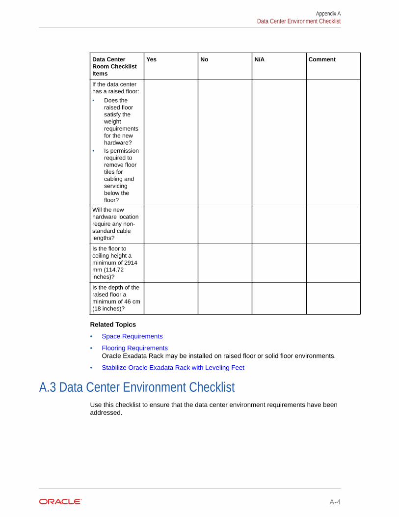
Data CenterRoom ChecklistItems
Yes No N/A Comment
If the data centerhas a raised floor:
• Does theraised floorsatisfy theweightrequirementsfor the newhardware?
• Is permissionrequired toremove floortiles forcabling andservicingbelow thefloor?
Will the newhardware locationrequire any non-standard cablelengths?
Is the floor toceiling height aminimum of 2914mm (114.72inches)?
Is the depth of theraised floor aminimum of 46 cm(18 inches)?
Related Topics
• Space Requirements
• Flooring RequirementsOracle Exadata Rack may be installed on raised floor or solid floor environments.
• Stabilize Oracle Exadata Rack with Leveling Feet
A.3 Data Center Environment ChecklistUse this checklist to ensure that the data center environment requirements have beenaddressed.
Appendix AData Center Environment Checklist
A-4
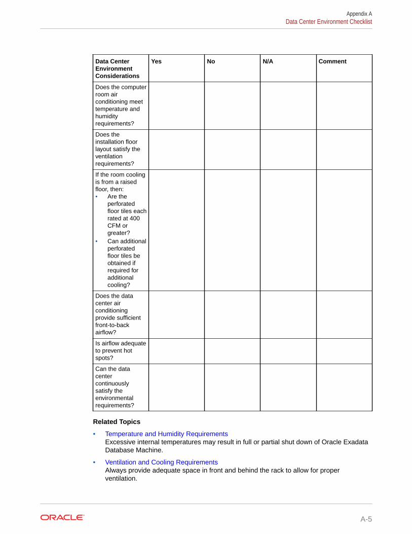
Data CenterEnvironmentConsiderations
Yes No N/A Comment
Does the computerroom airconditioning meettemperature andhumidityrequirements?
Does theinstallation floorlayout satisfy theventilationrequirements?
If the room coolingis from a raisedfloor, then:• Are the
perforatedfloor tiles eachrated at 400CFM orgreater?
• Can additionalperforatedfloor tiles beobtained ifrequired foradditionalcooling?
Does the datacenter airconditioningprovide sufficientfront-to-backairflow?
Is airflow adequateto prevent hotspots?
Can the datacentercontinuouslysatisfy theenvironmentalrequirements?
Related Topics
• Temperature and Humidity RequirementsExcessive internal temperatures may result in full or partial shut down of Oracle ExadataDatabase Machine.
• Ventilation and Cooling RequirementsAlways provide adequate space in front and behind the rack to allow for properventilation.
Appendix AData Center Environment Checklist
A-5

• General Environmental Requirements
A.4 Access Route ChecklistUse this checklist to ensure that the access route requirements are addressed.
Access RouteConsiderations
Yes No N/A Comment
Has the accessroute beenchecked forclearances of therack, in particular,the minimumwidth and heightrequirements forall doors on theroute?
Dimensions ofthe packagedrack:
• Height: 2159mm (85inches)
• Width: 1219mm (48inches)
• Depth: 1575mm (62inches)
Dimensions ofthe unpackagedrack:
• Height: 1998mm (78.66inches)
• Width: 600mm with sidepanels(23.62inches)
• Depth 1200mm (47.24inches)
Are there anystairs, ramps, orthresholds thatare of concern? Ifyes, then providedetails.
Are all accessroute inclineangles within thepermitted range(6 degrees)?
Appendix AAccess Route Checklist
A-6

Access RouteConsiderations
Yes No N/A Comment
Is the accessroute free of anyobstacles thatwould expose theequipment toshock?
Are all thesurfacesacceptable forrolling the newunpacked andpackedequipment?
If a pallet jack isto be used:
• Can thepallet jacksupport theweight of therack?
• Are thepallet jacktinescompatiblewith theshippingpallet?
If there are stairs,is a loadingelevator availablefor theequipment?
Appendix AAccess Route Checklist
A-7
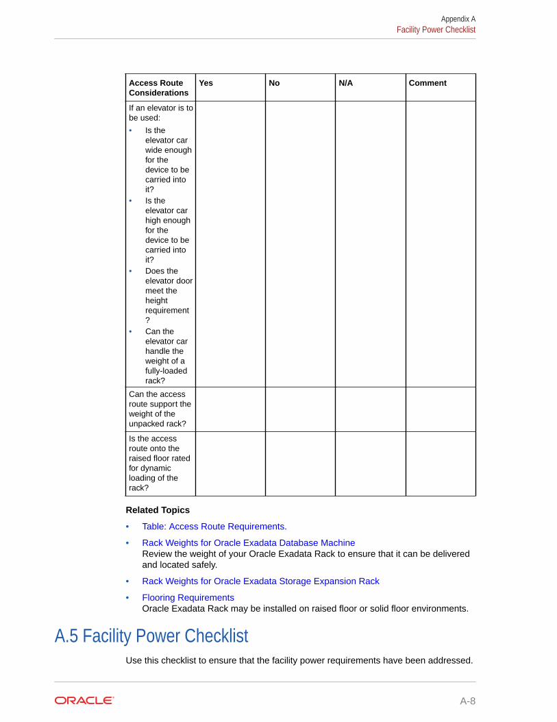
Access RouteConsiderations
Yes No N/A Comment
If an elevator is tobe used:
• Is theelevator carwide enoughfor thedevice to becarried intoit?
• Is theelevator carhigh enoughfor thedevice to becarried intoit?
• Does theelevator doormeet theheightrequirement?
• Can theelevator carhandle theweight of afully-loadedrack?
Can the accessroute support theweight of theunpacked rack?
Is the accessroute onto theraised floor ratedfor dynamicloading of therack?
Related Topics
• Table: Access Route Requirements.
• Rack Weights for Oracle Exadata Database MachineReview the weight of your Oracle Exadata Rack to ensure that it can be deliveredand located safely.
• Rack Weights for Oracle Exadata Storage Expansion Rack
• Flooring RequirementsOracle Exadata Rack may be installed on raised floor or solid floor environments.
A.5 Facility Power ChecklistUse this checklist to ensure that the facility power requirements have been addressed.
Appendix AFacility Power Checklist
A-8

Facility PowerConsiderations
Yes No N/A Comment
Have the operatingvoltage andelectric currentrequirements beenreviewed?
Powerrequirements listedin "ElectricalPowerRequirements".
Will single-phase(low-voltage orhigh-voltage) or 3-phase (low-voltageor high-voltage)power be used?
Are enough poweroutlets providedwithin 2 meters foreach rack?
Do the poweroutlets haveappropriate socketreceptacles for thePDU optionordered? Optionsare low voltage orhigh voltage,single-phase or 3-phase.
Will optionalground cables beattached to therack?
Are the circuitbreakers for theequipment suitablein terms of voltageand current-carryingcapacities?
Does the powerfrequency meetthe equipmentspecifications?
Are power outletsavailable for thenew equipment atthe designatedlocation?
Appendix AFacility Power Checklist
A-9

Facility PowerConsiderations
Yes No N/A Comment
Will system powerbe delivered fromtwo separategrids?
Is there a UPS topower theequipment?
Are the minimumrequired powersources availableto support thepower load for thenew hardware?Use kilowatt (kW) /kilovolt (kVA) toexpress powerload.
A.6 Safety ChecklistUse this checklist to ensure that the safety requirements have been addressed.
Safety ChecklistConsiderations
Yes No N/A Comment
Is there anemergencypower shut off?
Is there a fireprotection systemin the data centerroom?
Is the computerroom adequatelyequipped toextinguish a fire?
Is antistaticflooring installed?
Is the area belowthe raised floorfree of obstaclesand blockages?
Related Topics
• Temperature and Humidity RequirementsExcessive internal temperatures may result in full or partial shut down of OracleExadata Database Machine.
Appendix ASafety Checklist
A-10

See Also:
"Powering On and Off Oracle Exadata Rack" in the Oracle Exadata DatabaseMachine Maintenance Guide
A.7 Logistics ChecklistUse this checklist to ensure that the logistics requirements have been addressed.
LogisticsChecklistConsiderations
Yes No N/A Comment
Is contactinformation for thedata centerpersonnelavailable?
Is there security oraccess control forthe data center?
Are there anysecuritybackgroundchecks or securityclearancesrequired for Oraclepersonnel toaccess the datacenter? If yes, thenprovide theprocess for Oracleto follow.
How many days inadvance mustbackgroundchecks becompleted?
Are there anyadditional securityaccess issues?
Is computer roomaccess availablefor installationpersonnel?
Are laptopsallowed in the datacenter?
Are cell phonesallowed in the datacenter?
Appendix ALogistics Checklist
A-11

LogisticsChecklistConsiderations
Yes No N/A Comment
Are camerasallowed in the datacenter?
Does the buildinghave a deliverydock?
Is there a delivery/unpacking/stagingarea?
Is inside deliveryplanned (direct tothe final racklocation in the datacenter room)?
If the delivery isnot inside, then isthe site preparedfor uncrating?
Is the delivery/unpacking/stagingarea protectedfrom theelements?
Does the buildinghave adequatereceiving space?
Is the unpackingarea air-conditioned toavoid thermalshock for varioushardwarecomponents?
Will sufficientmoving personnelbe available totransport the rack?
(If applicable toyour country) Isunion laborrequired for anypart of the deliveryor installation?
Appendix ALogistics Checklist
A-12

LogisticsChecklistConsiderations
Yes No N/A Comment
Is the siteprepared foruncrating andpackagingremoval? Packageremoval shouldtake place outsidethe data centerroom.
Is uncrating ofcabinet andcabinet packagingremoval required?
Are there anyrestrictions ondelivery trucklength, width orheight?
Is there storagespace (cabinet) forthe ride alongspares? If not,does the customerallow cardboardboxes and otherpacking material inthe computerroom, since thespares are packedin cardboardboxes?
Is there a timeconstraint on dockaccess? If yes,please providetime constraints.
Is a tail or side liftrequired on thedelivery carrier tounload theequipment at thedelivery dock?
Appendix ALogistics Checklist
A-13

LogisticsChecklistConsiderations
Yes No N/A Comment
Will any specialequipment berequired to placethe rack in the datacenter room?Examples:
• Stair walkers• Lifters• Ramps• Steel plates• Floor covers
Does the deliverycarrier require anyspecial equipment,such as non-floordamaging rollers,transport dollies,pallet jacks or forklifts?
Related Topics
• Space Requirements
A.8 Network Configuration ChecklistUse this checklist to ensure that the network configuration requirements have beenaddressed.
NetworkConfigurationConsiderations
Yes No N/A Comment
Were anyconflicts foundwhile running thecheckip.shscript beforeconnecting thenetwork?
See "Default IPAddresses" forinformation onthe script.
Will the requirednetwork cablesbe laid from thenetworkequipment to thelocation wherethe Oracle Rackwill be installed?
Appendix ANetwork Configuration Checklist
A-14

NetworkConfigurationConsiderations
Yes No N/A Comment
Will the networkcables that willconnect to theOracle Rack belabeled?
Will the 10 GbEor 25 GbEinterfaces beused for the clientaccess network?
Have the optional10 GbE or 25GbE SFP+transceivers andappropriate fibercables beenordered?
Will the CiscoEthernet switchhave IP routingdisabled(recommended)?
Related Topics
• Understanding the Network Requirements for Oracle Exadata Database MachineReview the network requirements for Oracle Exadata Database Machine before installingor configuring the hardware.
A.9 Auto Service Request ChecklistUse this checklist if you are planning to use Auto Service Request with the Oracle ExadataDatabase Machine.
Auto ServiceRequestConsiderations
Yes No N/A Comment
Does the customerhave a My OracleSupport account toregister AutoService Request?
Is the OracleSupport CustomerSupport Identifier(CSI) numberavailable?
Appendix AAuto Service Request Checklist
A-15

Auto ServiceRequestConsiderations
Yes No N/A Comment
Are the host nameand IP address forthe server whereASR Manager willbe installedavailable?
Will the systemneed a proxyserver? If so, whatis the host nameand IP address forthe proxy server?
Is the CustomerTechnical Contactinformation forAuto ServiceRequest available?This informationshould include thefirst name, lastname, and e-mailaddress of thecontact.
See Also:
"Understanding Auto Service Request" in the Oracle Exadata DatabaseMachine Maintenance Guide
A.10 Re-racking ChecklistsUse these checklists prior to re-racking configurations approved for re-rack by OracleExadata Configuration Assistant (OECA) or your Oracle contact.
Note:
• Customer must purchase both the Oracle Re-racking Service and OracleInstallation Service.
• Oracle does not provide support for customer-supplied equipment.
Appendix ARe-racking Checklists
A-16

Re-rackingConsiderations
Yes No N/A Comment
Has the customerpurchased theOracle Re-rackingService?
Is there a cartcapable of carryingthe weight of theservers to movethe componentsand associatedcabling from thesupplied rack tothe customersupplied rack?
Is the target rackempty?
Do the target rackdimensions meetthe followingrequirements?
• Height: 42 RU• Width: 600
mm (23.62inches)
• Depth: 1112mm (43.78inches)without frontand rear doors
If the rack is lessthan 42 RU, thenthe customer mustprovide compatiblePDUs to install inthe target rack.
Is the distancebetween the frontand rear mountingplanes betweenthe minimum of610 mm and themaximum 915 mm(24 inches to 36inches)?
Is the clearancedepth in the frontof the frontmounting plane(distance to thefront cabinet door)at least 25.4 mm(1 inch)?
Appendix ARe-racking Checklists
A-17

Re-rackingConsiderations
Yes No N/A Comment
Does the targetrack meet thefollowing minimumload capacity?
• 19 kg (41.89lb) / RU
Is the rack a four-post rack(mounting at bothfront and rear)?
Note: Two-postracks are notcompatible.
Does the targetrack's horizontalopening and unitvertical pitchconform toANSI/EIA 310-D-1992 or IEC60297 standards?
Does the targetrack have RETMArail support?
Note: OracleEngineeredSystem racksrequire 19 inches(483 mm) forRETMA railspacing width. Theminimum rackwidth of 600 mm(23.63 inches) isrecommended toaccommodate thePDU and cableharnesses on theside. If the rack isless than 600 mmwide, then it musthave additionaldepth toaccommodatemounting behindthe server CMAs.
Does the targetrack supportOracle cablemanagement arms(CMAs)?
Appendix ARe-racking Checklists
A-18

Re-rackingConsiderations
Yes No N/A Comment
Does the targetrack supportinstallation ofOracle vented andsolid filler panels?
Can the target rackprovide tie-downsalong the left rearside of the rack tosupport the RDMANetwork Fabriccables? The sideis left rear sidewhen viewed fromthe front of therack.
Can the target rackprovide tie-downsfor the Ethernetwiring harness?
Is there sufficientspace for the cableharnesses and thePDUs in the targetrack?
Can a label withthe OracleEngineeredSystem Rackserial number beprinted andattached to thetarget rack?
A.11 PDU Checklist for Re-rackingUse this checklist to verify the power distribution unit (PDU) requirements when using the re-racking service.
PDU Re-rackingConsiderations
Yes No N/A Comment
Does the targetrack supportinstallation ofstandard OraclePDUs?
If not, thencomplete thischecklist.
Appendix APDU Checklist for Re-racking
A-19

PDU Re-rackingConsiderations
Yes No N/A Comment
Can the customerprovide anequivalent pair ofPDUs?
Can the customerprovide two PDUswith capacity of 10kVA per PDU?
Can the customerprovide at least 17x 10A C13 plugsper PDU?
Can the customerprovide a singlePDU and itscircuits to supportthe OracleEngineeredSystem Rackpowerrequirements incase one PDUfails?
Can the customerensure powerloads are evenlydistributed acrossall circuits of asingle PDU?
Can the customerprovideappropriate powerdrops for thePDUs?
A.12 Recycling the RacksUse this checklist when recycling the rack.
RecyclingConsiderations
Yes No N/A Comment
Does thecustomer wantOracle to takeback and recyclethe empty rack?
If yes, then theOracle serviceengineer canpack the emptyrack for recycling.
Appendix ARecycling the Racks
A-20

RecyclingConsiderations
Yes No N/A Comment
If Oracle isrecycling therack, then hasthe customercompleted theappropriateapplication at theOracle HardwareTake BackProgramwebsite?
Related Topics
• Product Take Back and Recycling website
Appendix ARecycling the Racks
A-21

BDatabase High Availability Checklist
Use this checklist to ensure the requirements for high availability are met for Oracle ExadataDatabase Machine.
Database HighAvailabilityConsiderations
Yes No N/A Comment
Have highredundancy diskgroups beenconfigured for bestprotection againstdifferent storagefailures andcorruptions?
Do you have abonded networkfor client access?
Will the pre-optimized andconfigureddatabase be usedafter deployment?
Have you reviewedthe OracleExadata SystemSoftware patchingoverview andpatch testingguidelines in MyOracle Supportnote 1262380.1?
Have you reviewedthe OracleExadata SystemSoftware MaximumAvailabilityArchitecture (MAA)Web site for post-deployment stepsto achieve MAA?
B-1

Database HighAvailabilityConsiderations
Yes No N/A Comment
Will you useOracle ExadataDatabase Machinehealth check afterdeployment? Thehealth check isavailable from MyOracle Supportnote 1070954.1.
Will you followOracle ExadataDatabase Machinemonitoring bestpractices availablein My OracleSupport note1920255.1?
Have you reviewedthe recommendedsoftware for OracleExadata DatabaseMachine in MyOracle Supportnote 888828.1?
Have you reviewedOracle ExadataDatabase Machinebest practices inMy Oracle Supportnote 757552.1?
Related Topics
• Oracle Database High Availability Overview and Best Practices
• Exadata Patching Overview and Patch Testing Guidelines (My Oracle Support DocID 1262380.1)
• Oracle Maximum Availability Architecture website
• Oracle Exadata Database Machine exachk or HealthCheck (My Oracle SupportDoc ID 1070954.1)
• Exadata Health and Resource Usage Monitoring Technical Paper (My OracleSupport Doc ID 1920255.1)
• Exadata Database Machine and Exadata Storage Server Supported Versions (MyOracle Support Doc ID 888828.1)
• Oracle Exadata Best Practices (My Oracle Support Doc ID 757552.1)
Appendix B
B-2