Descripción de la Implementación de los Círculos De Calidad en el Instituto Tecnológico-ITEC
Upload
khangminh22Category
view
0download
0
Information Security (ITEC 3300) ALG Proposal:546
Umar M. Khokhar Ph.D. Binh Tran Ph.D. GEORGIA GWINNETT COLLEGE,

Table of Contents
CHAPTER 1 .........................................................................................................................................................4
INTRODUCTION TO INFORMATION SECURITY ...................................................................................................................4 1.1 INFORMATION SECURITY ..............................................................................................................................5 1.2 RECENT SECURITY BREACHES.........................................................................................................................6 1.3 SECURITY TERMINOLOGIES ...........................................................................................................................6
1.3.1 Basic Parameters of the Security ........................................................................................................7 1.3.2 How to ensure Confidentiality ............................................................................................................7 1.3.3 How to ensure Integrity ......................................................................................................................8 1.3.4 How to ensure Availability ..................................................................................................................8
1.4 COMPONENTS OF INFORMATION SYSTEM ........................................................................................................9 1.4.1 Domains of IT Organization ................................................................................................................9
1.5 ANOTHER LAYER OF PROTECTION ................................................................................................................. 10 1.5.1 The Process of Cyber attack .............................................................................................................. 11
CHAPTER 2 ....................................................................................................................................................... 13
NETWORKING FUNDAMENTALS ................................................................................................................................. 13 2.1 INTRODUCTION ........................................................................................................................................ 14
2.1.1 Networking Basics ............................................................................................................................ 14 2.2 OSI AND TCP/IP MODELS ......................................................................................................................... 16
2.2.1 Open Systems Interconnect Model.................................................................................................... 16 2.3 TRANSMISSION CONTROL PROTOCOL/INTERNET PROTOCOL MODEL .................................................................... 18 2.4 NETWORKING SECURITY CONCEPTS .............................................................................................................. 20
2.4.1 Network Security Hardware.............................................................................................................. 20 2.4.2 Network Protocols ............................................................................................................................ 23
CHAPTER 3 ....................................................................................................................................................... 27
MALWARE AND SECURITY ATTACKS ........................................................................................................................... 27 3.1 MALICIOUS ATTACKS ................................................................................................................................. 28 3.2 WHAT WE ARE TRYING TO PROTECT? ............................................................................................................ 28
3.2.1 What is a Security Breach? ............................................................................................................... 28 3.2.2 Activities that cause Security breaches ............................................................................................. 28 3.2.3 Additional Security challenges .......................................................................................................... 30
3.3 TYPES OF ACTIVE THREATS ......................................................................................................................... 30 3.3.1 Password Cracking attacks: .............................................................................................................. 31 3.3.2 Malicious Software .......................................................................................................................... 31 3.3.3 Social Engineering attacks ................................................................................................................ 33
3.4 WIRELESS NETWORKS AND WEB APPLICATION ATTACKS ................................................................................... 34 3.4.1 Wireless Network Attacks................................................................................................................. 34 3.4.2 Web Application Attacks .................................................................................................................. 34
3.5 RECOMMENDATIONS FOR AVOIDANCE ........................................................................................................... 35 3.5.1 Multi-Factor Authentication (MFA) ................................................................................................... 35 3.5.2 Security Analysis/Penetration testing ............................................................................................... 35 3.5.3 Educate Users .................................................................................................................................. 35 3.5.4 Anti-malware ................................................................................................................................... 35 3.5.5 Firewall and Network Security Devices .............................................................................................. 36
CHAPTER 4 ....................................................................................................................................................... 37
AUTHENTICATION .................................................................................................................................................. 37 4.1 ELEMENTS OF AUTHENTICATION .................................................................................................................. 38
4.1.1 Authentication Factors ..................................................................................................................... 38 4.2 KNOWLEDGE BASED AUTHENTICATION .......................................................................................................... 38
4.2.1 Password Weaknesses ..................................................................................................................... 39 4.2.2 Attacks on passwords ....................................................................................................................... 39 4.2.3 Password Defenses: ......................................................................................................................... 42
4.3 TOKEN BASED AUTHENTICATION .................................................................................................................. 43 4.3.1 Challenge Response Authentication: ................................................................................................. 44
4.4 BIOMETRICS BASED AUTHENTICATION........................................................................................................... 45 4.4.1 Fingerprint Scanner: ......................................................................................................................... 46 4.4.2 Eye Scanner: .................................................................................................................................... 46 4.4.3 Speaker Recognition: ........................................................................................................................ 46 4.4.4 Face Recognition: ............................................................................................................................. 47
4.5 LOCATION BASED AUTHENTICATION ............................................................................................................. 47 4.6 ACTION BASED AUTHENTICATION ................................................................................................................ 47 4.7 FORMAL AUTHENTICATION PROTOCOLS......................................................................................................... 48
4.7.1 RADIUS ............................................................................................................................................ 48 4.7.2 TACACS+ .......................................................................................................................................... 49 4.7.3 SAML ............................................................................................................................................... 50 4.7.4 LDAP ................................................................................................................................................ 50 4.7.5 Kerberos .......................................................................................................................................... 50 4.7.6 OAuth 2.0 ........................................................................................................................................ 52
CHAPTER 5 ....................................................................................................................................................... 53
ACCESS CONTROL FUNDAMENTALS ............................................................................................................................ 53 5.1 ACCESS CONTROL SYSTEMS ........................................................................................................................ 54
5.1.1 Definition of Access Control Systems ................................................................................................. 54 5.1.2 Parts of Access Control Systems ........................................................................................................ 54 5.1.3 Security Kernel ................................................................................................................................. 54
5.2 FORMAL MODELS OF ACCESS CONTROL SYSTEMS ............................................................................................ 55 5.2.1 Discretionary Access Control (DAC) ................................................................................................... 55 5.2.2 Mandatory Access Control (MAC) ..................................................................................................... 55 5.2.3 Role Based Access Control (RBAC) ..................................................................................................... 57 5.2.4 Attribute Based Access Control (ABAC) ............................................................................................. 58
5.3 TECHNOLOGIES TO IMPLEMENT ACCESS CONTROL ............................................................................................ 58 5.3.1 Access Control Lists (ACLs) ................................................................................................................ 58 5.3.2 Blockchain Access Control ................................................................................................................ 60 5.3.3 Account Policies ............................................................................................................................... 60
CHAPTER 6 ....................................................................................................................................................... 61
SYMMETRIC ENCRYPTION ........................................................................................................................................ 61 6.1 FUNDAMENTALS OF CRYPTOGRAPHY ............................................................................................................. 62
6.1.1 Why do we need Cryptography? ....................................................................................................... 63 6.1.2 Classical Encryption Schemes............................................................................................................ 64 6.1.2.1 Substitution Cipher....................................................................................................................... 64 6.1.2.2 Transposition Cipher .................................................................................................................... 65 6.1.3 Digital Encryption ............................................................................................................................. 66
6.2 TYPES OF CRYPTOGRAPHY .......................................................................................................................... 67

6.3 SYMMETRIC ENCRYPTION ALGORITHMS ......................................................................................................... 68 6.3.1 Data Encryption Standard (DES) ....................................................................................................... 68 6.3.2 Triple Data Encryption Standard (3DES) ............................................................................................ 69 6.3.3 Advanced Encryption Standard (AES) ................................................................................................ 70 6.3.4 International Data Encryption Algorithm (IDEA) ................................................................................ 70
6.4 KEYSTREAM GENERATION ALGORITHMS ........................................................................................................ 71 6.4.1 Key Generation using feedback Hash Values ..................................................................................... 72 Figure 6.8: Key Generation using feedback Hash Values ................................................................................ 72 6.4.2 Key Generation using Pseudo-Random Number Generators (PRNGs)................................................. 72
CHAPTER 7 ....................................................................................................................................................... 75
ASYMMETRIC ENCRYPTION ...................................................................................................................................... 75 7.1 FUNDAMENTALS OF ASYMMETRIC ENCRYPTION............................................................................................... 76
7.1.1 Digital Signatures ............................................................................................................................. 76 7.2 CHALLENGES OF CRYPTO-KEY MANAGEMENT ................................................................................................. 78
7.2.1 Key Distribution................................................................................................................................ 78 7.2.2 Re-Keying ......................................................................................................................................... 78
7.3 PUBLIC KEY ENCRYPTION ALGORITHMS ......................................................................................................... 81 7.3.1 RSA .................................................................................................................................................. 82 7.3.2 Diffie-Hellman Secret Key Exchange Algorithm ................................................................................. 83
7.4 PUBLIC KEY CERTIFICATES ........................................................................................................................... 84
CHAPTER 8 ....................................................................................................................................................... 87
WEB APPLICATION AND WIRELESS NETWORK ATTACKS................................................................................................... 87 8.1 WEB APPLICATION ATTACKS ....................................................................................................................... 88
8.1.1 Web Applications Vulnerabilities ...................................................................................................... 88 8.2 WIRELESS NETWORKS ATTACKS ................................................................................................................... 94
8.2.1 Bluetooth ......................................................................................................................................... 94 8.2.2 Wireless Local Area Network (WLAN) attacks ................................................................................... 95
Chapter 1 Introduction to Information Security
Agenda Items of the Chapters:
n Definition of the Security and why do we need security n Some Recent Security Breaches n Parameters of Security that need to be satisfied n Domains of IT infrastructure n Types of Attackers

1.1 Information Security
The word Information is the processed data or we can say the data in an organized form. The term that we use in industry or in the corporate sector is Information System which is the collection of the people, procedures, policies, hardware and software that all work together for smooth functioning of the organization or the system.
Now a day, we live in cyber era, where the computer is the foundational block of the Information System. Typically, a computer is used for the processing and storing of the information, however the technical advancement of the computational systems and specially the integration of the Artificial Intelligence (AI) have taken the applications of the computer at next level. The cloud computing, Enterprise Resource Planning (ERP), Supply Chain Management (SCM), Block Chaining (BC) and IoTs (Internet of Things) are some of the most prominent emerging technologies. The backbone of the all of these modernized digital systems is the Internet, where the Internet is the network of interconnected computer networks. To better understand the definition of the internet, let us consider the following scenario:
The network of two or more computers using Ethernet or IEEE-802.11 (WiFi) over a small geographical area (network within organization) is called Intranet. The connectivity of two or more Intranet using public network is called Extranet and finally the connectivity of all Extranets across the globe make Internet.
Fig. 1.1: Intranet Example
Fig. 1.2: Extranet Example
The Internet is a physical network, where all the computational resources are located and to access these resources we use World Wide Web (www) (logical interface). Now, consider if we have a website (e.g. www.xyz.com) which is running on a webserver and accessible from anywhere across the globe. When anyone visits our webpage then he is logically moving around our server’s directory and if we do not have good security infrastructure then the visitors can access those directories (files) which they are not allowed to access. Therefore, it is extremely important to deploy an efficient and optimized security infrastructure, which can protect the computational systems from the unauthorized access and avoid possible security attacks.
1.2 Recent Security Breaches
The dilemma of the information security field is the continuous surveillance and upgradation of the security infrastructure. We cannot stop anyone from planning or launching attacks against our computational systems, however we can design such system, which can at least avoid those pitfalls through which those attacks can be realized. The cyber-attacks are becoming very common now a days, nothing is cent percent safe. If anyone thinks his/her systems are 100% safe then it means those systems are more prone to viruses since they might be ignoring the zero-day attacks1. Most of the victims of the cyber-attacks do not publicize these attacks since it can affect their businesses and stock prices etc. Some of the recent security breaches are as follows:
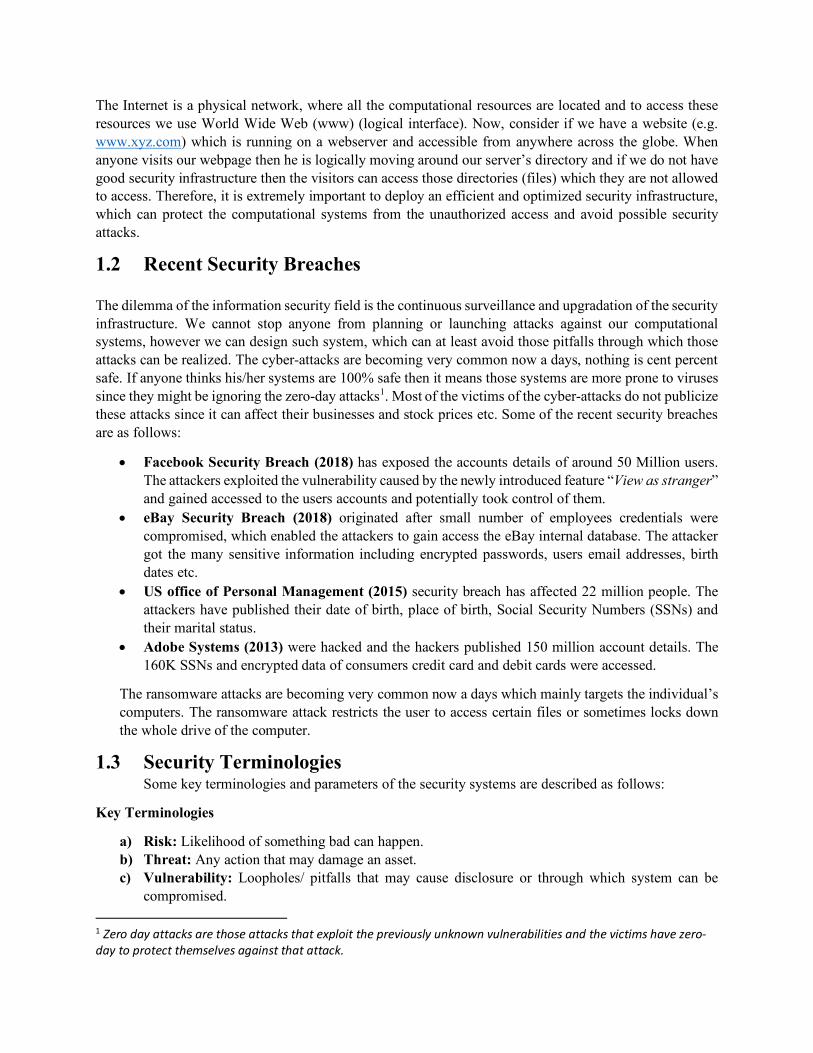
• Facebook Security Breach (2018) has exposed the accounts details of around 50 Million users. The attackers exploited the vulnerability caused by the newly introduced feature “View as stranger” and gained accessed to the users accounts and potentially took control of them.
• eBay Security Breach (2018) originated after small number of employees credentials were compromised, which enabled the attackers to gain access the eBay internal database. The attacker got the many sensitive information including encrypted passwords, users email addresses, birth dates etc.
• US office of Personal Management (2015) security breach has affected 22 million people. The attackers have published their date of birth, place of birth, Social Security Numbers (SSNs) and their marital status.
• Adobe Systems (2013) were hacked and the hackers published 150 million account details. The 160K SSNs and encrypted data of consumers credit card and debit cards were accessed.
The ransomware attacks are becoming very common now a days which mainly targets the individual’s computers. The ransomware attack restricts the user to access certain files or sometimes locks down the whole drive of the computer.
1.3 Security Terminologies Some key terminologies and parameters of the security systems are described as follows:
Key Terminologies
a) Risk: Likelihood of something bad can happen. b) Threat: Any action that may damage an asset. c) Vulnerability: Loopholes/ pitfalls that may cause disclosure or through which system can be
compromised. 1 Zero day attacks are those attacks that exploit the previously unknown vulnerabilities and the victims have zero-day to protect themselves against that attack.
d) Information System: The hardware, software, policies and people that work together for smooth functioning of the organization.
e) Information System Security: The activities/actions that ensure the security of the information system and data.
1.3.1 Basic Parameters of the Security
There are mainly three parameters through which the security of the computational systems can be evaluated:
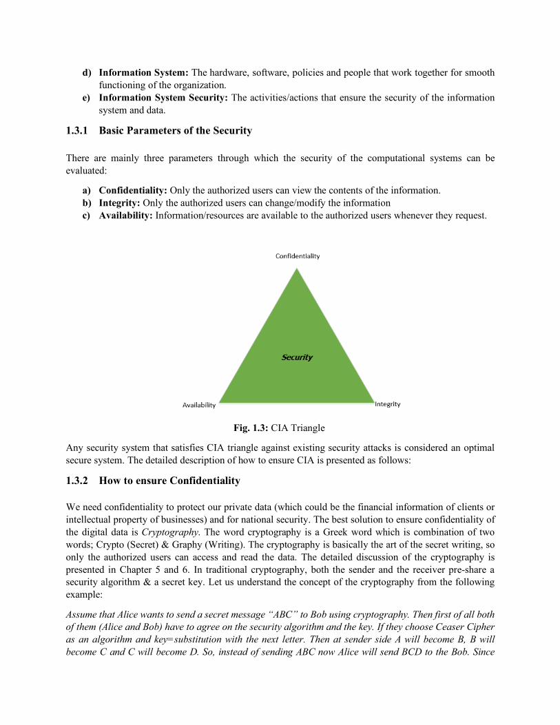
a) Confidentiality: Only the authorized users can view the contents of the information. b) Integrity: Only the authorized users can change/modify the information c) Availability: Information/resources are available to the authorized users whenever they request.
Fig. 1.3: CIA Triangle
Any security system that satisfies CIA triangle against existing security attacks is considered an optimal secure system. The detailed description of how to ensure CIA is presented as follows:
1.3.2 How to ensure Confidentiality
We need confidentiality to protect our private data (which could be the financial information of clients or intellectual property of businesses) and for national security. The best solution to ensure confidentiality of the digital data is Cryptography. The word cryptography is a Greek word which is combination of two words; Crypto (Secret) & Graphy (Writing). The cryptography is basically the art of the secret writing, so only the authorized users can access and read the data. The detailed discussion of the cryptography is presented in Chapter 5 and 6. In traditional cryptography, both the sender and the receiver pre-share a security algorithm & a secret key. Let us understand the concept of the cryptography from the following example:
Assume that Alice wants to send a secret message “ABC” to Bob using cryptography. Then first of all both of them (Alice and Bob) have to agree on the security algorithm and the key. If they choose Ceaser Cipher as an algorithm and key=substitution with the next letter. Then at sender side A will become B, B will become C and C will become D. So, instead of sending ABC now Alice will send BCD to the Bob. Since

Bob already knows the algorithm and the key, he will take the letters back to one position to retrieve the original message.
Some commonly used terms in cryptography are defined in the following table.
Table 1.1: Common Terms used in Cryptography
Term Definition Encryption Process of transforming data from plain text to
cipher text. Plain Text Original message to be encrypted Cipher text Encrypted message Decryption Processing of retrieving plain text from cipher text
1.3.3 How to ensure Integrity
The integrity ensures that the data has not altered/corrupted during the transmission and only the authorized people can update the contents of the data. Mostly, we use Hash functions to ensure integrity of the digital data. The detailed discussion of how to use security algorithms to ensure integrity is presented in Chapter 6. For basic understanding of the integrity, let us consider the following example:
Assume that Alice wants to send a message “Hello” to Bob with integrity protection. The Alice will firstly compute the Hash of the message and then concatenate the Hashed value with the original message. Finally, she sends the complete chunk (message + hash value) to Bob. At receiving end, firstly Bob extracts the original message and then passes the message from same Hash algorithm (which Alice has used) and computes the hash value. Further, Bob makes a comparison between the received hash and the calculated hash, if both hash value coincide then it means message has not altered during communication.
Hello aaf4c61ddcc5e
Integrity verified aaf4c61ddcc5e Hello
aaf4c61ddcc5e
Fig. 1.4: Integrity Assurance
1.3.4 How to ensure Availability
The availability is the amount of time a user can use a system or the amount of time the system is available to legitimate users. Usually, the attackers launch Denial of Service (DoS) attacks by sending excessive
Hash Function Concatenation
||
Hello||aaf4c61ddcc5e
Chunk with hash value
Hello||aaf4c61ddcc5e Hash Function ?
queries to the target server in order to make it unavailable to legitimate users. These excessive can become fatal when these are coming from the botnet. The DoS attacks can be avoided by blocking the Ping commands and using updated Firewalls.
1.4 Components of Information System
Before planning any security for the digital systems, let us have a complete overview of the typical information systems infrastructure, their connectivity and associated devices. The figure 1.5 shows the architecture of IT infrastructure.
1.4.1 Domains of IT Organization
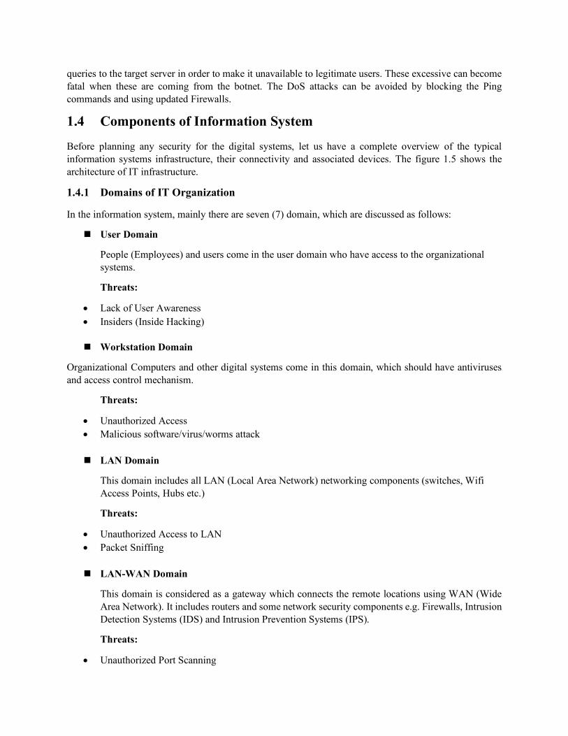
In the information system, mainly there are seven (7) domain, which are discussed as follows:
n User Domain
People (Employees) and users come in the user domain who have access to the organizational systems.
Threats:
• Lack of User Awareness • Insiders (Inside Hacking)
n Workstation Domain
Organizational Computers and other digital systems come in this domain, which should have antiviruses and access control mechanism.
Threats:
• Unauthorized Access • Malicious software/virus/worms attack
n LAN Domain
This domain includes all LAN (Local Area Network) networking components (switches, Wifi Access Points, Hubs etc.)
Threats:
• Unauthorized Access to LAN • Packet Sniffing
n LAN-WAN Domain
This domain is considered as a gateway which connects the remote locations using WAN (Wide Area Network). It includes routers and some network security components e.g. Firewalls, Intrusion Detection Systems (IDS) and Intrusion Prevention Systems (IPS).
Threats:
• Unauthorized Port Scanning

• Router/Firewall Vulnerabilities • Unauthorized User Access
n WAN Domain
WAN domain refers to internet which includes the physical and logical components e.g. Optical Fibers, Cloud etc. Since Internet is a public network which is open and accessible for all types of adversaries, therefore the biggest threat to this domain is Eavesdropping. In order to avoid the interception and eavesdropping, most of the corporate sectors use Virtual Private Network (VPN) which establishes a secure tunnel over the WAN and all the data goes in an secure form.
n Remote Access Domain
This domain encompasses the mobile users (outside LAN) or the users who access the organizational resources from outside of LAN using their own broadband. For the remote access of the organizational assets, the users are authenticated first and then using VPN they are given access to the resources which they are authorized to access. The device and credentials security are the most common threats of this domain, if a hacker gets them then he/she can access the organizational resources.
n System/Application Domain
This domain contains the organizational assets e.g. Web and Application Servers, Databases and Mainframes etc. which require a continuous security and monitoring.
Threats:
• Unauthorized Access • Downtime • Losing of the data
Now, we have a good understanding of a typical IT infrastructure and all associated threats. By keeping in view of all of these threats, we can better plan security for each domain.
1.5 Another layer of Protection
Besides the CIA, three (3) more security parameters; Authentication, Authorization and Accounting (AAA) have been added for Security analysis of information Systems to ensure optimal security and privacy. The definition of these parameters are as follows:
• Authentication: Ensures whether the individual is who he/she claims to be not an imposter e.g. Username, Password or Biometric based authentication.
• Authorization: After successful authentication, the users will be given access to the specified resources which she is authorized to access (level of privilege).
• Accounting: Makes logs of user’s activities (Tracks the user’s activities).
Any system which ensures CIA and provides AAA is considered to be secure. The main objective of the attacker is to launch attacks on these security parameters. If an attack discloses the secret information of the organization the Confidentiality is breached and if an attacker tampers the data (during communication or stored) without being noticed then this attack compromises integrity. The Denial of Service (DoS) attacks

that overwhelm the computational systems/Servers, prevent the legitimate users from accessing the resources and hence attack on availability. Depending upon the motivation of hacking, the hackers can be classified into following seven (7) types:
• Black Hat Hackers/Cyber Criminals: The hackers who perform illegal activities by breaking into the systems to steal or tamper the data. In other words, the hackers who find the vulnerabilities of the computational systems and exploit them for monetary gains.
• White Hat Hackers/Ethical Hackers: The hackers who have permissions from the owners of the system to break into their system to find vulnerabilities in their systems. The Ethical hackers find the vulnerabilities and report to concerns.
• Script Kiddies: The amateur hackers having less expertise of hacking and programming knowledge usually use the scripts written by professional hackers to hack the people.
• Cyber Terrorists: The target the national website/servers and utilities the hacking to bring politically and economic instability in the region. Now a day, the cyber warfare (hacking to level the battle field between two fighting countries) also comes under cyber terrorism.
• Hacktivist: The hacking for activism, they do the hacking to bring political change or sometime to expose injustice and corruption.
• State-sponsored: The hackers who work for the state or government and they spy the citizen and foreign governments.
• Insiders: They are also known as grey hat hackers. They pretend to be white hat hacker but have some hostile intentions. Since, they are usually the employees of the organizations therefore it is easy for them to find pitfalls.
1.5.1 The Process of Cyber attack
A typical Cyber-attack involves mainly eight (8) steps:
• Reconnaissance: Collection of information about the target e.g. IP addresses, Operating Systems, Open Ports, location of the servers etc.
o Tools: Whois, IDserve, Fping and NMAP etc. • Vulnerability Assessment: Identifying the vulnerabilities (Existing or new) through which system
can be compromised. o Tools: Zed Proxy Attack, OpenVAS, Nessus etc.
• Weaponization: After identifying the pitfalls, the attacker creates a exploit (malware). o Tools: Metasploit, Visual Basic Scripting, BeEF etc.
• Delivery: Get the malware delivered at the victim’s site (using social engineering) via email or pop up message.
• Trigger: The malware requires a human intervention to get it triggered. The malware can be triggered by clicking or opening the contaminated file.
• Installation: After the malware gets triggered, it installs itself on victim’s computer. • Command and Control: After successful installation, the attacker can remotely give commands
this agent and it can further control the victim’s computer. • Traces Removal: After completion of the attack objectives, most of the malware include rootkits
that remove the traces of the malware to avoid the back tracking.

Fig. 1.6: Process of Cyber Attack
Reconnaissance Vulnerability Assessment Weaponization
Delivery Trigger Installation
Command and Control Traces Removal

Chapter 2 Networking Fundamentals
Agenda Items for the Chapter:
n Networking Basics n OSI and TCP/IP Models n Networking Security Concepts
2.1 Introduction
Network security and Information security used to be used interchangeably because it is the network that is at the core of most computer information. Recently information security has evolved beyond the network; however, it is still essentially the computer networks that enable information sharing especially in organizations. Therefore, a comprehensive understanding of computer networks will allow both novice and experienced personnel to have the tools necessary in the defense and protection of valuable assets.
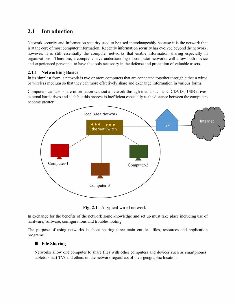
2.1.1 Networking Basics In its simplest form, a network is two or more computers that are connected together through either a wired or wireless medium so that they can more effectively share and exchange information in various forms.
Computers can also share information without a network through media such as CD/DVDs, USB drives, external hard drives and such but this process is inefficient especially as the distance between the computers become greater.
Fig. 2.1: A typical wired network
In exchange for the benefits of the network some knowledge and set up must take place including use of hardware, software, configurations and troubleshooting.
The purpose of using networks is about sharing three main entities: files, resources and application programs.
n File Sharing
Networks allow one computer to share files with other computers and devices such as smartphones, tablets, smart TVs and others on the network regardless of their geographic location.
Internet
Computer-1
Computer-2
Computer-3
Ethernet Switch ISP
Local Area Network
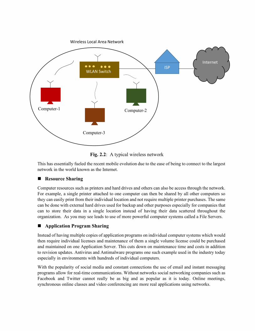
Fig. 2.2: A typical wireless network
This has essentially fueled the recent mobile evolution due to the ease of being to connect to the largest network in the world known as the Internet.
n Resource Sharing
Computer resources such as printers and hard drives and others can also be access through the network. For example, a single printer attached to one computer can then be shared by all other computers so they can easily print from their individual location and not require multiple printer purchases. The same can be done with external hard drives used for backup and other purposes especially for companies that can to store their data in a single location instead of having their data scattered throughout the organization. As you may see leads to use of more powerful computer systems called a File Servers.
n Application Program Sharing
Instead of having multiple copies of application programs on individual computer systems which would then require individual licenses and maintenance of them a single volume license could be purchased and maintained on one Application Server. This cuts down on maintenance time and costs in addition to revision updates. Antivirus and Antimalware programs one such example used in the industry today especially in environments with hundreds of individual computers.
With the popularity of social media and constant connections the use of email and instant messaging programs allow for real-time communications. Without networks social networking companies such as Facebook and Twitter cannot really be as big and as popular as it is today. Online meetings, synchronous online classes and video conferencing are more real applications using networks.
Computer-1
Computer-2
Computer-3
WLAN Switch ISP
Internet
Wireless Local Area Network

All one needs to connect to the network is a computer device that has a network interface card either wired or wireless that follows the rules of network functionality leading us into the next topic of the OSI and TCP/IP Models.
2.2 OSI and TCP/IP Models 2.2.1 Open Systems Interconnect Model
The Open System Interconnection (OSI) reference model was proposed by the International Organization for Standardization (ISO), a nonprofit organization that develops and publishes standards including information technology. It is headquartered in Geneva, Switzerland and comprised of 162-member countries.
The OSI model for networking explains how networks function in an orderly and structured, seven-layered approach. The OSI model is a theoretical concept that is used for teaching and learning in the field of computer networking; and, serves as a general conceptual framework on how networked systems should operate to be able to work together.
Fig. 2.3: OSI Model
Let us look at this example of why the reference model is needed and how the layered approach is so valuable using this non-networking example: Mary who lives in Atlanta, Georgia would like to send some information to Bob who lives in Los Angeles, California via the United States Postal Service or snail mail like many IT folks like to call it. Here is the breakdown of what has to happen:
1. Mary, who lives in Atlanta has some information she would like to send to Bob, who lives in Los Angeles. She writes a letter and puts the information with the letter to get to Bob and decides to use the postal service.
2. Mary folds the letter with the information and puts it in an envelope which is the standard “protocol” for sending letters in the United States ready to be sent but now has to address the envelope.
3. Mary addresses the envelope with Bob’s name, street address, city and state information in the middle and put her return address on the top left which is the standard “protocol” for sending letters.
Application
Presentation
Session
Transport
Network
Data Link
Physical

4. Mary must then purchase and put a stamp on the top right of the envelope per the stamp location standard “protocol”.
5. Mary then goes to the post office to drop it off or she can enable the flag at her home mailbox both of which are standard “protocols”.
6. The mail carrier obtains the envelope and brings it to the main sorting center in Atlanta and then it is sorted for the destination zip code which is in Los Angeles. The envelope is then placed on a plane to travel to Los Angeles main sorting center.
7. Upon arrival the letter then needs to be sorted according to Bob’s zip code and location for local delivery by the mail carrier.
8. The mail carrier then uses the street address to be sure to deliver it to Bob’s mailbox. 9. Bob then receives the envelope, open it up, discard the envelope and retrieves the letter and
information that Mary wanted to send to him.
As you can see there are a number of structured, orderly tasks that has to happen at each “layer” and one must be completed before the next layer take over. This layered approach may seem complex and in reality it is but it allows for each task to be handled separately thus allowing for more simplified troubleshooting. This “divide and conquer” strategy allows for solving big problems by breaking them down into smaller components and a change to one of the steps would not affect the entire process very much if at all.
Back to our networking concepts for example if we decided to use new fiber optic cables instead of older coaxial cables the delivery step the other steps in the entire process are not impacted.
The OSI model divides network communications into seven layers as shown in the figure in order from the top: 7 – Application 6 – Presentation 5 – Session 4 – Transport 3 – Network 2 – Data Link 1 – Physical
We will briefly discuss each layer to give you a high-level understanding of what happens at each layer without getting into too much detail.
n Application Layer
The Application layer (Layer 7) provides an interface for applications to access network services such as file sharing, message handling, database access and more. Protocols such as HTTP, HTTPS, FTP, DHCP, DNS, SMTP and many more operate here. Please keep in mind that the Application layer is not the application itself such as Microsoft Word or Adobe Photoshop but its connection to the network services. However, some user applications such as web browsers and email clients have integrated network functions with the application layer.
n Presentation Layer
The Presentation layer (Layer 6) handles data formatting and translation. The Data from the Application layer is “presented” by protocol conversion, data encryption and decryption, data compression and decompression and data representation. For example, a web browser that
connects to a secure Web server may need to encrypt and decrypt the data before it is transferred to the Web server.
n Session Layer
The Session layer (Layer 5) sets up and holds ongoing communications called a “session” across the network so that applications on both sides can exchange data for as long as the session lasts. Synchronization and check pointing occur here as well as in the example of an audio or video stream used by a web-conferencing application.
n Transport Layer
The Transport layer (Layer 4) manages the data transfer from one application across the network. One of the processes that happen here is the segmenting of the data streams in to small units called “segments” for travel over the network. The two primary protocols that operate at this layer is TCP and UDP. TCP is the connection-based, higher overhead protocol that uses hand-shaking thus is more reliable. UDP is the connection-less, less overhead and less reliable protocol.
n Network Layer The Network layer (Layer 3) handles logical network addressing such as translating Internet Protocol (IP) addresses into physical addresses (Media Access Control, MAC) addresses. It is responsible for performing the best route calculations to reach a certain destination and is the workhorse of the all networking. IP, ICMP, ARP, IPSec among other known protocols operate here. The data unit at this layer is called a “packet”.
n Data Link Layer The Data Link layer (Layer 2) works with “frames” as its data unit and it acts as a conduit between the Network layer and the Physical layer. Media Access Control (MAC) addresses can be found here as well as communication methods such as CSMA/CD and token passing. Network cards also operate here since they are programmed with MAC addresses as well as include the physical interface to the network.
n Physical Layer
The Physical layer (Layer 1) is where the conversion of data into bit signals of 0 or 1 to be transferred over the medium. The type of signals can be pulses of light as in the case of fiber optic cabling, electrical pulses in the case of twisted-pair cable or radio waves in the case of wireless communications.
Summary
In summary the OSI model is an organized and helpful way to separate networking activities and associate them with protocols and functionality. It helps explain how data is formatted as it moves through the layers and aids in understanding the hardware, software and protocols at each step of the overall communication process.
2.3 Transmission Control Protocol/Internet Protocol Model
The OSI model presents a great high-level overview of network communications but as mentioned earlier it is very theoretical and in many cases networking in the industry does not follow the OSI model.
However, the Transmission Control Protocol, Internet Protocol (TCP/IP) model or more commonly referred to as the TCP/IP Protocol Suite is used. Many experts describe the OSI model and theoretical whereas the TCP/IP model as practical.
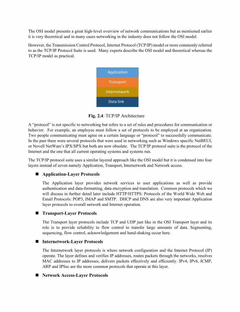
Fig. 2.4: TCP/IP Architecture
A “protocol” is not specific to networking but refers to a set of rules and procedures for communication or behavior. For example, an employee must follow a set of protocols to be employed at an organization. Two people communicating must agree on a certain language or “protocol” to successfully communicate. In the past there were several protocols that were used in networking such as Windows specific NetBEUI, or Novell NetWare’s IPX/SPX but both are now obsolete. The TCP/IP protocol suite is the protocol of the Internet and the one that all current operating systems and systems run.
The TCP/IP protocol suite uses a similar layered approach like the OSI model but it is condensed into four layers instead of seven namely Application, Transport, Internetwork and Network access.
n Application-Layer Protocols
The Application layer provides network services to user applications as well as provide authentication and data-formatting, data encryption and translation. Common protocols which we will discuss in further detail later include HTTP/HTTPS: Protocols of the World Wide Web and Email Protocols: POP3, IMAP and SMTP. DHCP and DNS are also very important Application layer protocols to overall network and Internet operation.
n Transport-Layer Protocols
The Transport layer protocols include TCP and UDP just like in the OSI Transport layer and its role is to provide reliability to flow control to transfer large amounts of data. Segmenting, sequencing, flow control, acknowledgement and hand-shaking occur here.
n Internetwork-Layer Protocols
The Internetwork layer protocols is where network configuration and the Internet Protocol (IP) operate. The layer defines and verifies IP addresses, routes packets through the networks, resolves MAC addresses to IP addresses, delivers packets effectively and efficiently. IPv4, IPv6, ICMP, ARP and IPSec are the more common protocols that operate at this layer.
n Network Access-Layer Protocols
Application
Transport
Internetwork
Data link
The Network Access layer technically does not include any protocols but rather technologies such as Ethernet. The layer is responsible for MAC address confirmation, defining of media access rules, de-encapsulation of frame, checking for errors and converting the signals to bits whether it is electrical, light pulses or radio waves.
As you can already see the TCP/IP suite more accurately aligns its protocols and functionality with real network services thus it is the more practical model used today.
2.4 Networking Security Concepts
There are many aspects to network security and this chapter will directly address many of these concepts. However, the rest of the book may address security aspects that may be outside the realm of network security. At its core network security can be divided into two main areas of study and that being network hardware and network software or protocols. Network hardware includes the physical devices and their inherent software that allows them to function on the network. Network software or protocols include the standard methods of communication that the network hardware uses to transfer and share data across networks.
2.4.1 Network Security Hardware
The most fundamental level of security can and should be done through the use of security features that are found with certain network hardware devices. Since many devices operate at different levels of the OSI or TCP/IP models a layered security approach allows for greater defense and protection. In turn this would entail an attacker to compromise multiple network devices significantly decreasing their chances for success before the attack is discovered. We will continue with an overview of some of the more popular devices and their capabilities.
n Switches
As of the last few years switches have replaced the obsolete hub device as the standard network device for connecting computers, printers, Voice over IP (VoIP) and other end devices. Hubs operated at Layer 1 – Physical Layer of the OSI model which meant that it just repeated all frames to all attached network devices. This not only increases unnecessary traffic but from a security standpoint allows for attackers to install software such as a protocol analyzer and capture packets that are sent through the network.
Switches as do hubs also connect multiple devices but once the network becomes stable meaning computers and end devices are plugged into certain switch ports the switch learns through a switching table or mac address table where each device is connected. Switches operate at Layer 2 – Data Link Layer of the OSI so used Media Access Control (MAC) addresses to only forward frames to the end device through the specific port that device is connected to. Network monitoring is still necessary but this helps minimize data floating around the network that can be vulnerable to attackers.
Advanced switches also support Virtual Local Area Network (VLANs) which offer additional network with physical port security. With the proper type of switch and configuration these devices offer the first line of defense with respect to security leading up to the next network device.
n Routers
Routers operate at Layer 3 – Network Layer of the OSI model and its purpose is to “route” packets across different computer networks. Routers view destination information in the packets it receives then consults with the routing table to send the packet to the next network towards the final destination. In doing so, routers have a built-in security function to filter specific types of network traffic going to specific networks.
Routers are very complex devices with many configuration features and in many small type networks is the main security appliance for the entire organization. Routers come in various sizes and robustness depending on how much bandwidth and traffic they are designed to handle as well as the ability to configure Access Control Lists (ACLs) to determine rules for packet propagation through the network. Misconfiguration of ACLs could block certain network traffic and, in some cases, can cause the entire network to come to a screeching halt.
Routers typically have their own operating system with a powerful central processing unit, random access memory as well as storage capabilities. Traditionally routers were wired devices but with the recent rapid mobile evolution wireless routers are now the dominant device used for households and small businesses. Router administrator passwords and security patches must be properly configured and maintained for them to be effective and protected again attackers.
n Firewalls
Network Firewalls are devices designed to protect an entire network by inspecting packets and either allow or deny their entry. Hardware firewalls are usually located outside the internal network and is the first line of defense from the outside. The packets are filtered by the firewall in one of two ways. The first is the “stateless packet filtering” method which looks at incoming packets and permits or denies it based on conditions that have been pre-defined by the network or security administrator. “Stateful packet filtering” is the second method which keeps a record of the connection between an internal computer and an external device and decides based on the connection as well as certain specific conditions.
The firewall has four different options it can “allow” the packet by letting it pass and continue on the network or it can “drop” the packet to prevent and not send any response to the sender. The firewall can “reject” the packet which prevents and also informs the sender and finally it can “ask” for user intervention the next course of action. There are also traditional rule-based firewalls as well more modern application-based firewalls also known as “next-generation firewalls” (NGFW) since they have more “intelligent” capabilities.
n Intrusion Detection Systems
An intrusion detection system (IDS) is a device that can detect an attack as it occurs. IDS systems can use various different methods for monitoring and detection of attacks but it essentially involves real-time monitoring and examination of network traffic, activity, behaviors and transactions in order to detect any security related anomalies. The IDS device can be installed either on a local host or on the network and they use one of the four following methods:
o Anomaly-based monitoring o Signature-based monitoring o Behavior-based monitoring o Heuristic monitoring
• Anomaly-based monitoring is designed for detecting statistical anomalies. Normally a baseline is established over a certain amount of time so whenever there is a significant deviation from this baseline an alarm or flag course be raised. This method is very fast but can lead to false positives if there are real non-security related spikes in the network activity. Additionally, anomaly-based monitoring requires high processing on the system so adequate hardware resources needs to be dedicated.
• Signature-based monitoring looks at the network traffic and activities for well-known patterns such as antivirus scanning. One of the weaknesses of signature-based monitoring is that the signatures needs to be constantly updated leading to heavy network usage. If the signatures are too specific they may miss certain intrusions; whereas, if they are too general they will cause many false positives.
• Behavior-based monitoring is a compromise of anomaly-based and signature-based monitoring by being adaptive and proactive instead of reactive. It analyzes the behavior of processes and programs on a system and alerts the user of any abnormal activity. One of the advantages is that is can help detect new attacks rather quickly even if there no new signature or definition exists.
• Heuristic monitoring is the last method which uses a totally different approach. Instead of comparing actions as is done with anomaly-based and signature based or comparing behaviors as is done by behavior-based it use experience-based techniques. The question it attempts to answer is “if this action can be harmful to the system.” It them monitors for events such as port scanning and protocol captures which are potentially dangerous and alerts them accordingly.
n Intrusion Prevention Systems
An Instruction Prevention System (IDS) as it implies not only monitors and alerts for malicious activities as does the IDS but it also can attempt to stop the attack. IDS systems are usually connected directly to certain network hardware devices or hosts where they can more quickly respond by blocking ports or packets deemed as dangerous in addition to reporting it back to the central monitoring system. Most IPS systems employ certain levels of intelligence so that they can provide a higher degree of accuracy regarding and speed in response to potential attacks.
n Unified Threat Management Security Appliance (UTM)
Since there are many different types of network security hardware devices such as firewalls, Internet content filters, web security gateways, IDS and IPS devices managing them all can be very complex. A Unified Threat Management (UTM) security device combines several security functions and can offer an array of security functions including:
o Antivirus and Antispyware o Antispam and Anti-Phishing o Bandwidth optimization o Content filtering o Encryption o Firewall o Intrusion Detection and Prevention o Web filtering

The Unified Threat Management device has also been referred to as the All-in-One Network Security Appliance.
2.4.2 Network Protocols
We already introduced the network security hardware devices so this section will continue address the network software or protocols with respect to security concepts. A network protocol is a set of standardized rules for proper communication between network devices and as mentioned earlier the most common protocol used today is the Transmission Control Protocol/Internet Protocol (TCP/IP).
TCP/IP is not a single protocol but consists of many protocols but the two most important protocols that make up its name are: TCP and IP. TCP is one of the main Transport Layer protocols in Layer 4 of the OSI model; whereas IP is one of the primary protocols that operate at the Network Layer, Layer 3 of the OSI model. There protocols work together because IP is responsible for network addressing and getting the packet on the right path or route to the destination; while TCP is responsible for transmissions control and reliable delivery of the packet.
n Transmission Control Protocol (TCP)
If an application requires reliable data transfer, it uses TCP as the Transport-layer protocol. TCP provides reliability with the following features:
• Establishing a connection • Segmenting large chunks of data • Ensuring flow control with acknowledgements
Each feature is dependent on the fact that TCP is a connection-based protocol. TCP establishes a connection with the destination, the data is transferred, and the connection is released. A real-world example would be a cellphone call where a user dials a number, a connection is established with a slight delay and if the recipient answers a connection is established and held during the entity of the conversation.
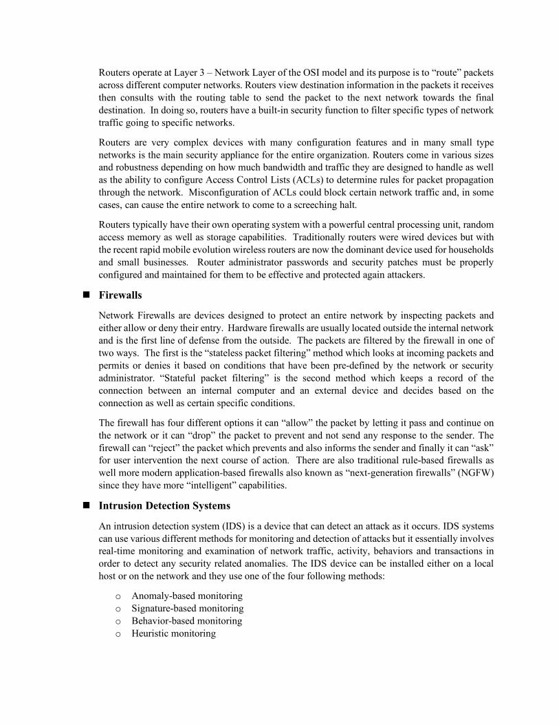
We will not get into the technical details of the TCP header in this chapter but TCP establishes the connection via the TCP Handshaking mechanism which is a three-step process. Each session is assigned a port number to keep track of the numerous numbers of network connections for the applications. Running the network command “netstat” will display the port numbers used and whether or not they are using TCP or UDP as well as private and public IP addresses.
n User Datagram Protocol (UDP)
The other Transport Layer (Layer 4) protocol is UDP. UDP is an alternative protocol that is primarily used for establishing low-latency or loss-tolerating connections between applications on the Internet. UDP enables process-to-process communication by sending “datagrams” and used a “best-effort” delivery method. UDP does not need to establish a connection and thus does not provide flow and error control; therefore, is often referred to as connection-less whereas, TCP is connected-based.
UDP also used port numbers to help distinguish different user requests and optionally offers a checksum to verify that data does arrive intact. A big difference between UDP and TCP is that packets may take different paths between the sender and receiver so some packets may be lost or may be received out of order.
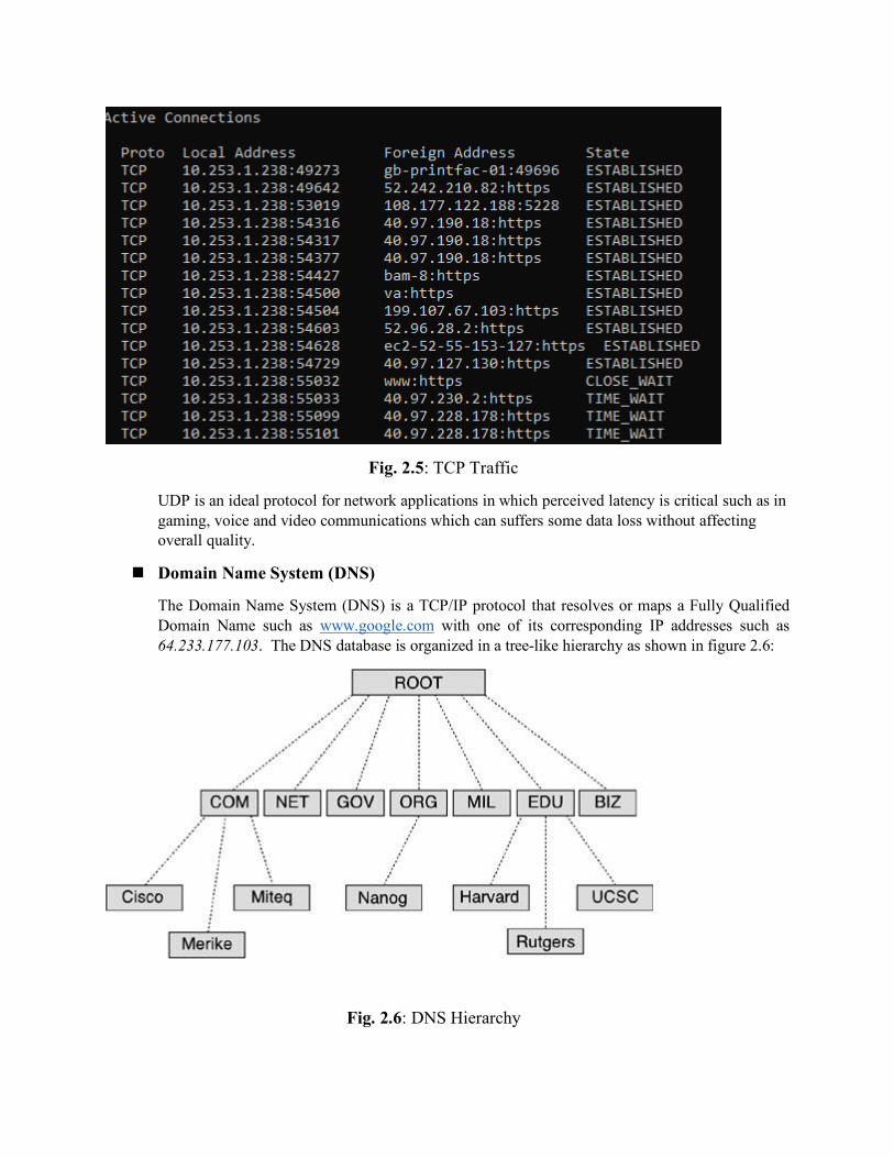
Fig. 2.5: TCP Traffic
UDP is an ideal protocol for network applications in which perceived latency is critical such as in gaming, voice and video communications which can suffers some data loss without affecting overall quality.
n Domain Name System (DNS)
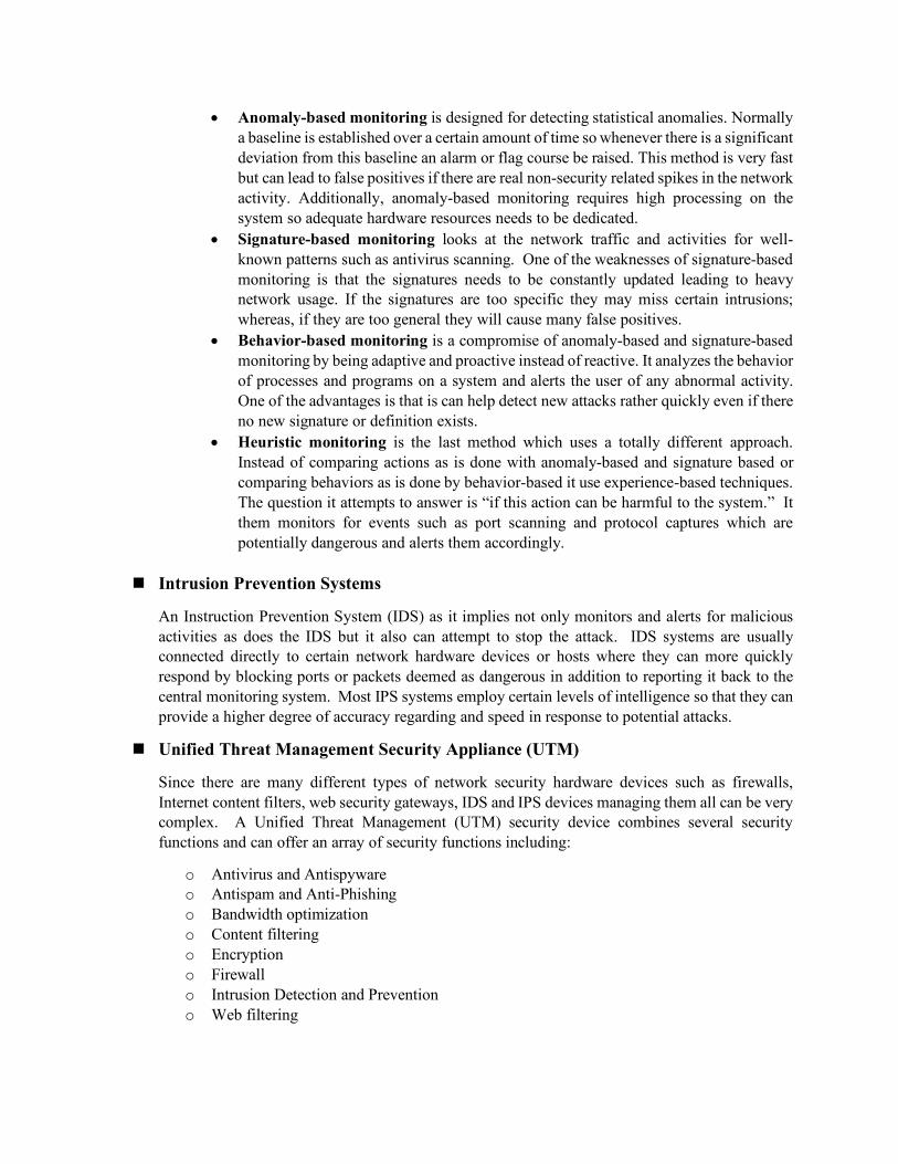
The Domain Name System (DNS) is a TCP/IP protocol that resolves or maps a Fully Qualified Domain Name such as www.google.com with one of its corresponding IP addresses such as 64.233.177.103. The DNS database is organized in a tree-like hierarchy as shown in figure 2.6:
Fig. 2.6: DNS Hierarchy

The top-level domains (TLDs) are organized into categories such as commercial (.com), nonprofit organizations (.org), government (.gov), education (.edu) or country of origin represented by a two-letter code such as Canada (.ca). The second-level domains are usually the names the companies or institutions. The host level represents individual computers or servers such as www which hosts all the web files or mail which maintains all the mailboxes.
Local DNS servers can be configured to the local organization websites for example www.company.com but they are also configured to know where the “root” servers are around the world in case they need to resolve addresses that are not in their local database. To help speed up this process some servers and clients make use of the DNS cache which stores the domain names and IP address pairs resolved recently in their local memory.
Because of its importance DNS is often the focus of security attacks. DNS poisoning results in substitute addresses so that the computer is redirected to another device and this can be done by the attacker at either the local host table, or the external DNS server. A variation of DNS poisoning involves replacing a MX (mail exchange) record resulting in all email being sent to the attacker instead of the proper MX server.
Finally, a DNS transfer attack tricks the server into giving information that the attacker could then use to map out the entire internal network of an organization that is linked to the DNS server. This can then be used in many ways to determine weaknesses in the network for other types of attacks.
n Internet Protocol (IP) The Internet Protocol (IP) is the heart of the TCP/IP protocol suite. IP addresses are defined at the Network Layer (Layer 3) of the OSI model and the Internetwork Layer of the TCP/IP. This is where network routing takes place and without routing the Internet and World Wide Web as a whole would not exist. The Internetwork layer is responsible for several main functions:
• Defines and verifies IP addresses • Routes packets through an internetwork • Resolves MAC addresses to IP addresses • Delivers packets efficiently
An IP address is assigned to every computer and network device that uses TCP/IP protocols for communications. The purpose of the IP address is to identify the device at the Internetwork or Network layer and also to identify which network it resides on because there would be many networks or subnetworks in an organization. IP addresses work similar to the 10-digit phone number used in the U.S. where the first three represent the area code and the last seven represent the individual number. Each IP address can be broken down into the Network ID and the Host ID.
The next task is to determine the best path to get the packets from the sender to the receiver navigating all the networks in between them. Similar to the Interstates in the U.S. many large networks have many paths that can be taken to get from one location to another. This “routing” task is shared with all the routers in the world network which must communicate with each other to determine the best path at any particular time.
The network packet that sent or received includes both the physical (MAC) and logical (IP) source and destination addresses so when it gets to the final destination it will know which unique device defined by MAC address needs to get the end information. This task is assisted by another protocol called Address Resolution Protocol (ARP) which maintains a table of MAC addresses and their respective IP addresses.

The IP protocol primary focus is to delivery packets efficiently so relies on Transport and Application Layer protocols to deal with flow control, delivery confirmation, message reassembly and other overhead. There are two main Internet Protocol versions IPv4 and IPv6. IPv4 is defined by 32-bits and uses the dotted decimal notation such as 172.31.149.10. All values must be from 0 to 255 resulting in a maximum of approximately 4 billion addresses which have been all used up for many years.
IPv6 developed and adopted in the late 1990s uses 128-bits for its addressing space and uses hexadecimal numbers resulting in 340 trillion possible addresses. (34 followed by 37 0s, IPv6 addresses will not be running out any time soon).
n Address Resolution Protocol (ARP)
Address Resolution Protocol (ARP) is used to resolve a logical IP address to a physical MAC address. The IP protocol’s purpose to get the packet to the correct network and once in that particular network it can query the ARP cache or table to find the physical address to populate into the Data Link (Layer 2) frame for proper delivery.
Fig 2.7: ARP Cache of the local computer
The process can be very complex and we will not go into its details in this chapter but one of the potential targets for attack is the ARP cache. In an attack called ARP poisoning or spoofing the attacker sends falsified ARP messages over the local area network, and by doing so the results allow the attacker to link their MAC address with the IP address of a victim server or computer on the network.

Chapter 3 Malware and Security Attacks
Agenda Items of the Chapters:
n Activities that can cause the security breaches n Types of Security Threats & Malware n Types of Wireless Network & Web application attacks n Counter Measures and suggestions for avoidance of Security attacks

3.1 Malicious attacks
The cyber-attacks are becoming very common now a days and nothing (Digital Systems) is 100% safe. The main reason of this dilemma is the presence of the juvenile hackers and script kiddies. In 2016, US law enforcement authorities sent a college student to prison for 20 years for hacking the US Vice presidential candidate’s email account. There are many other similar hacking and data breaches examples. Although, these attacks grabbed the attention of news, media and public however, because of brand image & stocks most of the victims of these attacks don’t publicize these attacks at all.
In 2013, Bloomsburg identified the top hacking countries, from where most of the security attacks are coming. In Bloomsburg’s ranking, China was at the top with 41%, US ranked at 2nd with 10%, Turkey and Russian were placed at 3rd & 4th positions with 4.7% & 4.3% respectively. However, it doesn’t mean that these countries have more hackers or security attackers but could have more proxy servers*.
3.2 What we are trying to Protect? Mainly, we are trying to protect the following items from being compromised:
• Customer data: It includes the customer related specific information e.g. Name, SSN (Social Security Number), Phone number, address etc.
• IT Assets and Network Infrastructure: Unauthorized access of hardware (Computers, Scanner, Printers etc.) and Software applications.
• Financial data: Clients Bank accounts, Credit and debit card information etc. • Service availability and Productivity: Continuous access of the resources to the legitimate users • Reputation and Brand Image: The company reputation and brand image by avoiding the security
breaches.
3.2.1 What is a Security Breach?
Any event that results in violation or that compromises the CIA of the system is called security breach. Some security breaches are accidental and some are intentional. Let us talk about the activities that cause the security breaches.
3.2.2 Activities that cause Security breaches
There are six (6) main activities through which CIA can be compromised or breached. The details of those activities are described as follows:
3.2.2.1 Denial of Service (DoS)
The DoS attack violates the Availability parameter of CIA. In DoS attack, the attacker overwhelms the system with excessive queries and prevent the legitimate users from gaining access of the resources. The DoS attack can be launched using techniques; Logic attack and Flooding. In the logic attack, the attacker use the software flaw to crash or hinder the performance while in the flooding attack, the attacker engages
* A computer that sits between the attacker and the victim’s computer, can be accessed remotely.

the system with unnecessary queries which makes it unavailable for legitimate users. The flooding attack can be classified into further two types: SYN Flood and Smurf attack.
• SYN Flood: In the SYN flood attack, the attackers exploit the vulnerability of the SYN protocol (TCP/IP) where after receiving the SYN request the server waits for the user’s SYN ACK message. To better understand the SYN flood, firstly, lets understand the SYN protocol: As we know (discussed in Chapter 2) the TCP is a connection-oriented protocol, where the sender makes connection first before sending any packet. Assume that Alice wants to access a webserver (Á). So, Alice’s computer will send a SYN Request to the Á and now if Á is up then it responds back with SYN ACK and opens a channel and waits for SYN ACK from Alice’s computer. The SYN ACK makes sure that Alice’s computer has received server’s acknowledgment. After receiving SNY ACK from webserver, the Alice’s computer responds back with SYN ACK and then the bi-directional communication starts. The figure 3.1 shows the working of SYN protocol. To launch SYN flood attack, the attacker firstly creates a Botnet (network of computers controlled by the hacker) and use the Botnet to initiate the SYN protocol. After receiving SNY request from the Botnet, the webserver responds back with SYN ACK and then waits for SYN ACK. The Botnet doesn’t respond the server back but instead initiate a new SYN protocol and again after receiving SYN ACK, none of them respond the server back. The attacker repeats this process again and again unless the server runs out of resources and becomes unavailable for legitimate users. The figure 3.2 describes the overall SYN flood attack model.
Figure 3.1: Three Way handshake (SYN Protocol)
Figure 3.2: SYN Flood
PC Webserver
SYN Req
SYN ACK
ACK
SYN ACK SYN ACK ………… SYN ACK
Webserver
SYN ACK
SYN ACK
SYN ACK
SYN ACK
…..
…..
SYN ACK
SYN Req
SYN Req
SYN Req
SYN Req
…..
…..
SYN ACK
Adversary
Botnet

• Smurf attack: In smurf attack model, the attacker first joins the network with which the target is connected. The attacker then impersonates as target’s computer and broadcast a ping packet to all connected nodes. When this ping packet arrives to the nodes, then they will start responding back to the target’s computer (even though it did not request for it). The attacker repeats this process unless the victim’s computer overwhelms.
3.2.2.2 Distributed Denial of Service (DDoS) The Denial of Service attack which is launched through multiple points (nodes) is called Distributed Denial of Service (DDOS). In the DDOS attack model, the attacker uses Zombies and Botnet. The Zombie is a computer which is controlled by hacker remotely while the Botnet is the network of Zombies.
3.2.2.3 Unacceptable Web Browsing The unacceptable web surfing can also cause security breaches. The following actions come under unacceptable web browsing:
• Violation of organization Acceptable Use Policy (AUP) • Visiting Prohibited Websites • Trying to access files/directories that you are not supposed to access.
3.2.2.4 Wiretapping The attackers can tap the telephone lines and data communication lines both actively and passively (Sniffing) . The active wiretapping can be further classified into two types:
• Between the lines: Active wiretapping, the attacker adds additional information and doesn’t modify the original message.
• Piggyback: The attacker completely modifies the message contents.
The most widely used tools for sniffing are Wireshark and Dsniff (discussed in detail in Lab 3).
3.2.2.5 Backdoors Software that includes hidden access methods are called backdoors. For example, Rootkits are the malicious software that opens the backdoor of the target computer to let the back traffic in or can turn off firewall/antivirus.
3.2.3 Additional Security challenges
There are some other security challenges that can also cause security breach:
• Spam: Unwanted emails and mostly the carrier of malware. • Spim: Unwanted Instant Messages • Hoax: is some act intended to deceive or trick the receiver. • Cookies: is a small text file that contains user preferences, user related specific information e.g.
User name, password, address, credit card number etc. The web browsers allow the webservers to store a cookie on user’s hard drive.
3.3 Types of Active Threats
The following are the types of different active threats that can exploit the vulnerabilities of the computational systems which eventually compromise the security.
3.3.1 Password Cracking attacks:
Most of the password cracking attacks are offline, where the attacker steals the hash file of the password and use cracking tools to guess the password. Some of the following methods are widely used in cracking tools:
• Birthday attack: The birthday attack is a type of cryptographic attack that exploits the mathematics behind the birthday problem of the probability. The birthday problem concerns the probability in a set of ‘n’ people having same birthday. The birthday attack model uses the probability of ‘n’ people having the same password to guess the password.
• Dictionary attacks: Instead of launching brute force (all possible combinations), in this attack model, the attacker does three tasks; create a dictionary of the relevant passwords, calculate the hashes of dictionary and then make a comparison of all computed hashes with stolen hash to guess the password.
• Session Hijacking: The attacker intercepts the communication of server and victim’s computer and steals the session token. After having the session token, the attacker takes the control of session and can inject malicious traffic to both the server and the victim’s computer.
• Social Engineering attack: The attacker tricks the users to get the confidential information by creating a con, sending phishing email or pharming (Section 3.3.3 discusses the Social Engineering attacks are discussed in detail).
3.3.2 Malicious Software
The short form of Malicious Software is Malware where ‘Mal’ is take from Malicious and ‘ware’ is taken from software. Any software which does the following four functions is known as malware;
• Causes the damages • Bypass the security framework • Disclose the confidential data • Modify or delete data
There are many types of malware, some of the common malware types are as follows:
3.3.2.1 Virus
The term computer virus is inspired from its biological counterpart. A biological virus firstly infects one cell then it turns the infected cell into factory of virus and start infecting other cells. Similarly, after entering the computer, the virus attaches itself with a file and starts infecting that file. Then the infected file starts infecting other files and eventually creates obstruction in the normal operation of the computer.
A computer virus can be formally defined as “A small piece of code that migrates through networks and can attach itself with different program files”. The virus cannot replicate itself and it requires a human intervention for transportation. The following are the three main virus infection methods:
• Appender Infection: In this infection method, the virus appends itself at the end of the program file and inserts a jump instruction at the beginning of the program code. Whenever the user opens the
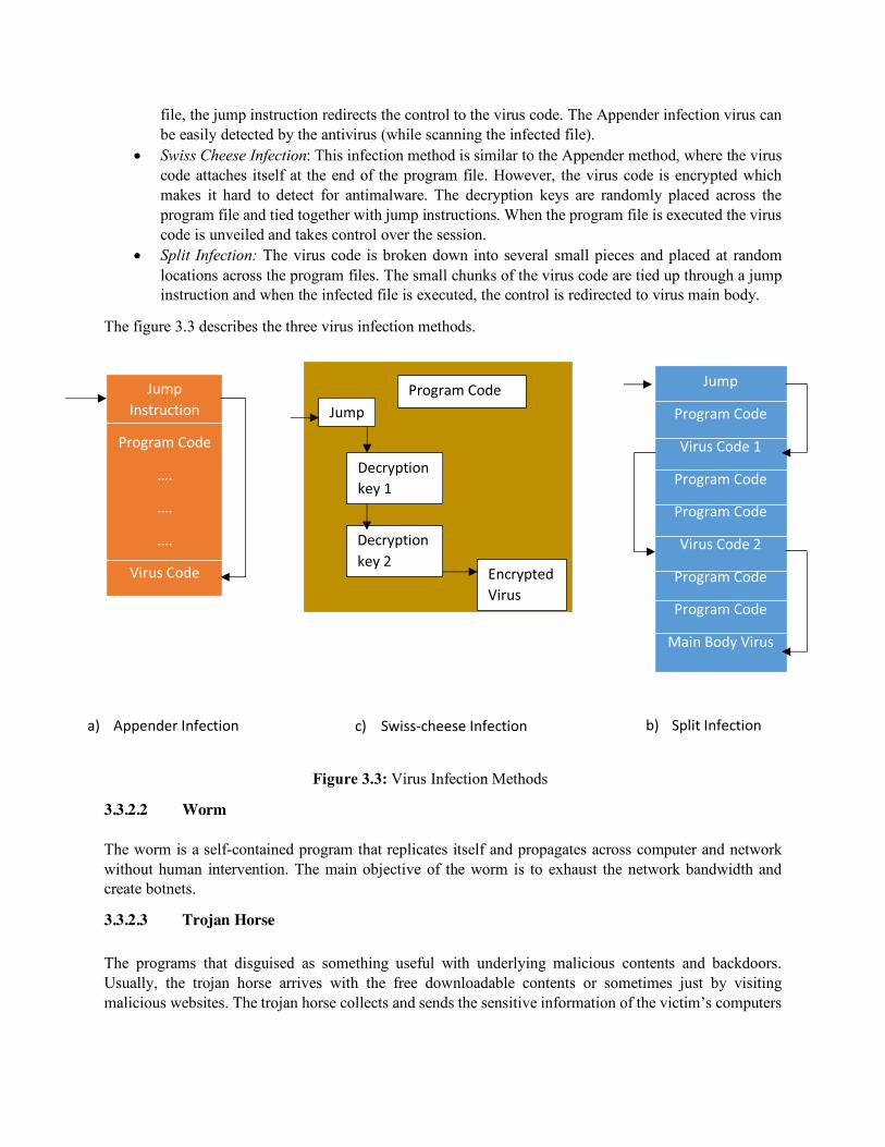
file, the jump instruction redirects the control to the virus code. The Appender infection virus can be easily detected by the antivirus (while scanning the infected file).
• Swiss Cheese Infection: This infection method is similar to the Appender method, where the virus code attaches itself at the end of the program file. However, the virus code is encrypted which makes it hard to detect for antimalware. The decryption keys are randomly placed across the program file and tied together with jump instructions. When the program file is executed the virus code is unveiled and takes control over the session.
• Split Infection: The virus code is broken down into several small pieces and placed at random locations across the program files. The small chunks of the virus code are tied up through a jump instruction and when the infected file is executed, the control is redirected to virus main body.
The figure 3.3 describes the three virus infection methods.
Figure 3.3: Virus Infection Methods
3.3.2.2 Worm
The worm is a self-contained program that replicates itself and propagates across computer and network without human intervention. The main objective of the worm is to exhaust the network bandwidth and create botnets.
3.3.2.3 Trojan Horse
The programs that disguised as something useful with underlying malicious contents and backdoors. Usually, the trojan horse arrives with the free downloadable contents or sometimes just by visiting malicious websites. The trojan horse collects and sends the sensitive information of the victim’s computers
Jump Instruction
Program Code
….
….
….
Virus Code
a) Appender Infection
Jump
Decryption key 1
Program Code
Decryption key 2
Encrypted Virus code
c) Swiss-cheese Infection
Jump
Program Code
Virus Code 1
Program Code
Program Code
Virus Code 2
Program Code
Program Code
Main Body Virus
b) Split Infection
(which includes web browser history and cookies etc.) to the attackers. Also, trojans open the backdoors (open ports, turn off AVS etc.) to let the bad traffic in, on the victim’s computer.
3.3.2.4 Rootkits
The rootkits hide themselves in Operating System files and get triggered each time whenever the victim restarts (reboot) the computer. The rootkit allows the remote user (attacker) to install the rogue files, delete the files, create backdoor and also rootkits hide the existing malware from being detected as well.
3.3.2.5 Adware
The Advertisement Software (Adware) usually designed using JavaScript and are embedded on the malicious websites. When, the victim visits the malicious website the script automatically runs and installs itself on the victim’s computer. The adware collects the web browser history and then create an unsolicited targeted advertisement and popup messages. The adware can also pull the session and persistent cookies which are serious threat to privacy and security of the individual.
3.3.2.6 Spyware
The spyware collects and forwards the victim’s activities and classified information which includes keystrokes, passwords, web browser history and cookies to the attacker. The keystroke logger is one of the most common type of spyware which records all the keystrokes of the users and sends the recorded data to the attacker.
3.3.3 Social Engineering attacks
The Social Engineering is a process that utilizes the knowledge of the human nature to get information from people which can be further used for destructive purposes. The Social Engineering techniques involves some kind of deception and trick the innocent users to get their classified information (such as passwords, Social security numbers or Financial details). The main idea of the Social Engineering is “Rather than cracking the password why not ask them their password”. The following are some types of the Social Engineering techniques:
Authority: Use of power/position to get classified information of the subordinates.
Dumpster Diving: Collection of information from Un-shredded papers.
Hoax: Creating a con that involves some kind of deception to get the confidential information of people.
Phishing: Tricking the people over email (Malware can also be attached with emails).
Vishing: Tricking the people over phone (Impersonation).
Whaling: Targeting the top-level managers (Executives) of an organization.
Pharming: The attackers craft a real looking fake website and then try to redirects the users to the fraudulent website to get their confidential information.

3.4 Wireless Networks and Web Application attacks
In this section, an overview of wireless networks and web application attacks has been presented. The detailed description of these attacks is discussed in Chapter 8.
3.4.1 Wireless Network Attacks
Some of the wireless network attacks are described as follows:
Bluesnarfing: allows the attackers to establish a connection with the victim’s Bluetooth enabled device and provides an unauthorized access to its internal data. The attacker can copy the contacts, emails, messages and even call logs without the owner’s consent.
Rogue Access Point: An unauthorized Access Point (AP) installed within the legitimate LAN and without proper security configurations is called Rogue Access Point. The Rogue Access Point allows the attackers to bypass the security framework/authentication of the LAN.
Evil Twin: An AP installed by an attacker (outside the legitimate LAN) which uses the same SSID (Service Set Identifier) as of legitimate one is called Evil Twin.
Packet Sniffing: The attackers use IP Packet capturing software such as Wireshark and Dnsiff etc. and can sniff the on-going communication (Packets) of the LAN.
Replay Attacks: The attacker captures the packets/messages of a genuine session and then replays them in a later session with the legitimate parties to gain unauthorize access or desynchronize the legitimate parties.
War Driving: The attacker uses the software such as Vistumbler, Arachni etc. and then drives down the street to look for the free/open Access points. The searching for the open access point is called War Driving.
War Chalking: After War Driving, the attackers publish the information of the open Access Points with Geolocation map (Coverage area) on blogging sites which is called War Chalking.
3.4.2 Web Application Attacks
Since, the tradition network security devices (Firewalls, IPS and IDS) ignore the HTTP contents, so to ensure security of web applications is much more difficult and different as compare to securing a typical network. The detailed description of the web application security concepts is discussed in Chapter 8. The following are some of the web application attacks.
Buffer Overflow Attack: In the Buffer overflow attack, the attackers find the bugs/mistakes in the coding of an application and then exploit it to gain unauthorize access to the system. The attackers push more data beyond the capacity of the buffer and make the application to store the additional data to adjacent memory buffer. It can crash the system and also create a backdoor which lets the bad traffic in.
Cross site scripting: In the Cross-Site Scripting (XSS) attacks, the attackers injects malicious scripts on the vulnerable websites and usually target the clients of the websites. When the users visits the contaminated website then these scripts automatically run and can steal the cookies and web browser history of the victim’s computer.
SQL injection attack: In the SQL injection attack, the attacker first finds whether the webserver is vulnerable to SQL injection attack or not. If the webserver is vulnerable to SQL injection attack, then the
attacker injects the SQL commands and obtain the secret information (stored on Database) of the individuals.
XML injection attack: In XML injection attack, the attackers manipulate the XML logic of the application and inserts the malicious contents into the resulting outputs. In XML injection attack, the attackers can login as Administrators and can have full control over the server and databases.
3.5 Recommendations for avoidance
These cyberattacks are becoming very common and inevitable in this modern era where digitization encompasses almost all the aspects of the life. However, many of these attacks can be avoided if the companies/individuals follow the following recommendations:
3.5.1 Multi-Factor Authentication (MFA)
The authentication is a process which ensures whether the individual is who he/she claims to be not an imposter. The typical way to perform authentication is knowledge-based authentication where the legitimate individuals are provided with the username and password and they will be authenticated using the provided credentials if they want to access resources. However, with the integration of Artificial Intelligence (AI), the password cracking tools have become much more powerful than before and also new sophisticated phishing attack models can lead to disclosure of the credentials. So, beside using Knowledge-based authentication, some other factors such as biometrics, IP address, tokens/security codes or actions can also be assimilated with the existing single factor authentication to avoid password cracking attacks.
3.5.2 Security Analysis/Penetration testing
The penetration testing is an authorized (legal) cyberattack to test the organization’s computer networks/systems robustness against real-world cyberattacks. While doing the Penetration Testing, the security analyst first finds the vulnerabilities (pitfalls) of the networks and web applications then creates an exploit (venom) to demonstrate how these vulnerabilities can compromise the organization’s assets. Finally, most of the security analysts provides recommendations as well to avoid the highlighted attacks. The security audit and Penetration testing can avoid many of the forthcoming threats to the organization.
3.5.3 Educate Users
The Users/people are the weakest link of any organization. The organizations should offer basic security trainings to educate their employee about the recent developments in security fields and familiarize them regarding Social Engineering techniques. The security trainings should involve following topics:
• Phishing and Pharming • Ransomware attacks • Basic Ethics of using Computational systems • Password Management Software • Organizational Security Policies and AUPs
3.5.4 Anti-malware
As discussed in section 3.3.2, there are different types of malware and some of them can arrive at victim’s computer only by visiting the malicious website or just by downloading applications (with underlying malware). The surfing over internet without having an updated anti-malware could be dangerous and can turn your computer into a Zombie computer. Therefore, an updated anti-malware must be installed on individual’s computer and organizational systems to avoid most of the pre-existing malware.
3.5.5 Firewall and Network Security Devices
The firewall inspects all incoming and outgoing traffic and then allows/denies packets based on the defined rules. In addition to anti-malware, the firewall also plays an important role to prevent the adversaries from gaining unauthorized access and stealing data from the individual(s) and organizational computers. The firewall can be software (e.g. the one which comes with windows computer) or it can be hardware (e.g. Palo Alto and Cisco NGFW etc.). To ensure the optimal security, an organization should include some other network security devices/software e.g. Intrusion Detection Systems (IDS) and Intrusion Prevention Systems (IPS) in their security fleet. Beside the runtime security, these network security systems provide enormous data for security analysis which is eventually helpful to combat against zero day attacks.
Chapter 4 Authentication
Agenda Items of the Chapters:
n Authentication Factors n Password Evolution Defenses and attacks n OAuth 2.0 and formal authentication models
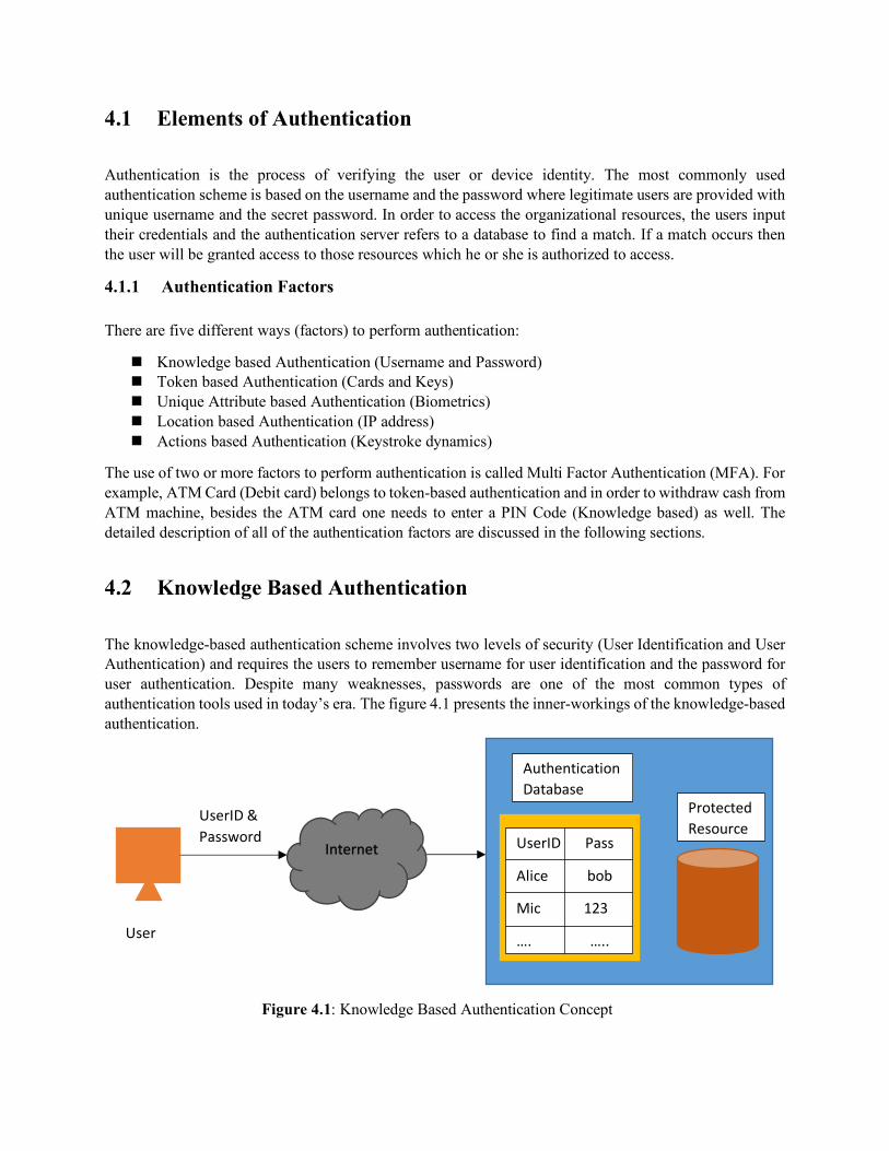
4.1 Elements of Authentication
Authentication is the process of verifying the user or device identity. The most commonly used authentication scheme is based on the username and the password where legitimate users are provided with unique username and the secret password. In order to access the organizational resources, the users input their credentials and the authentication server refers to a database to find a match. If a match occurs then the user will be granted access to those resources which he or she is authorized to access.
4.1.1 Authentication Factors
There are five different ways (factors) to perform authentication:
n Knowledge based Authentication (Username and Password) n Token based Authentication (Cards and Keys) n Unique Attribute based Authentication (Biometrics) n Location based Authentication (IP address) n Actions based Authentication (Keystroke dynamics)
The use of two or more factors to perform authentication is called Multi Factor Authentication (MFA). For example, ATM Card (Debit card) belongs to token-based authentication and in order to withdraw cash from ATM machine, besides the ATM card one needs to enter a PIN Code (Knowledge based) as well. The detailed description of all of the authentication factors are discussed in the following sections.
4.2 Knowledge Based Authentication
The knowledge-based authentication scheme involves two levels of security (User Identification and User Authentication) and requires the users to remember username for user identification and the password for user authentication. Despite many weaknesses, passwords are one of the most common types of authentication tools used in today’s era. The figure 4.1 presents the inner-workings of the knowledge-based authentication.
Figure 4.1: Knowledge Based Authentication Concept
Authentication Database
Protected Resource
UserID Pass
Alice bob
Mic 123
…. …..
Internet
UserID & Password
User
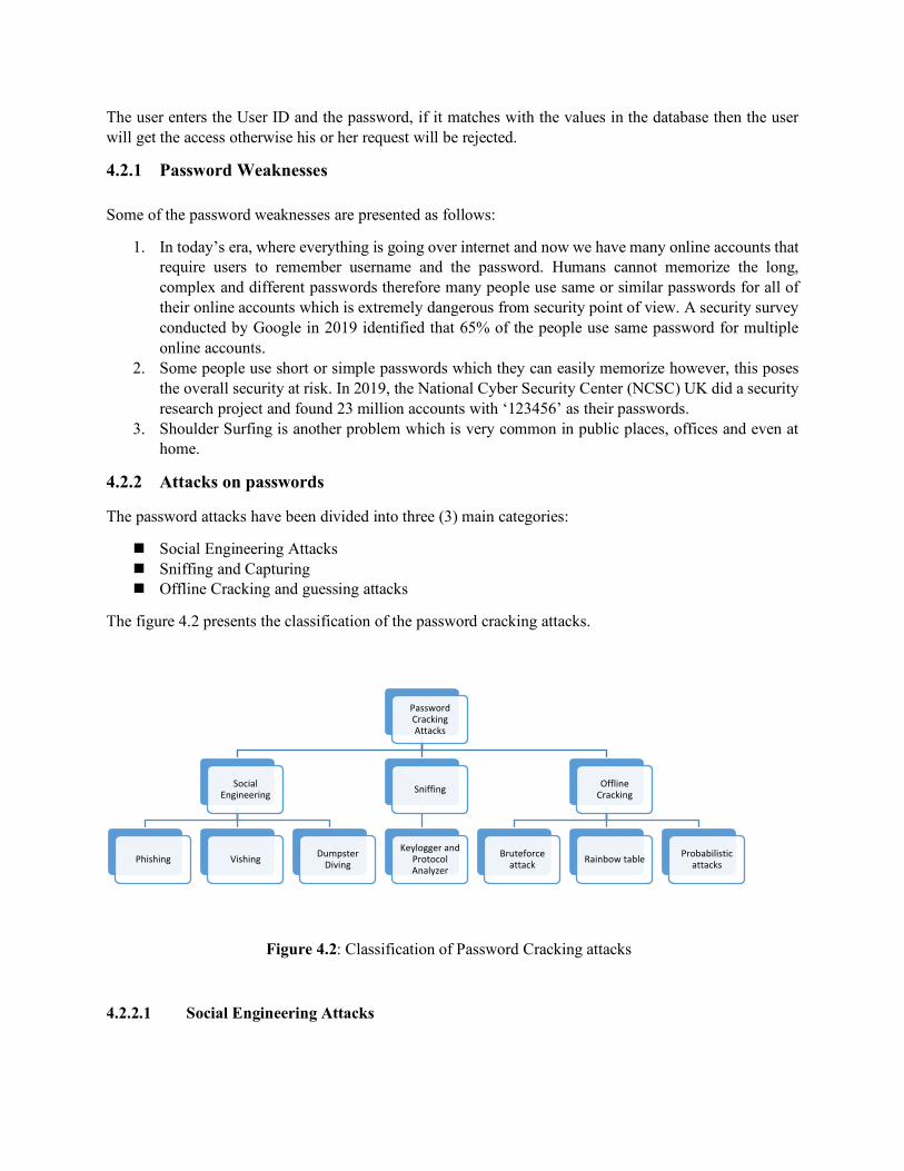
The user enters the User ID and the password, if it matches with the values in the database then the user will get the access otherwise his or her request will be rejected.
4.2.1 Password Weaknesses
Some of the password weaknesses are presented as follows:
1. In today’s era, where everything is going over internet and now we have many online accounts that require users to remember username and the password. Humans cannot memorize the long, complex and different passwords therefore many people use same or similar passwords for all of their online accounts which is extremely dangerous from security point of view. A security survey conducted by Google in 2019 identified that 65% of the people use same password for multiple online accounts.
2. Some people use short or simple passwords which they can easily memorize however, this poses the overall security at risk. In 2019, the National Cyber Security Center (NCSC) UK did a security research project and found 23 million accounts with ‘123456’ as their passwords.
3. Shoulder Surfing is another problem which is very common in public places, offices and even at home.
4.2.2 Attacks on passwords
The password attacks have been divided into three (3) main categories:
n Social Engineering Attacks n Sniffing and Capturing n Offline Cracking and guessing attacks
The figure 4.2 presents the classification of the password cracking attacks.
Figure 4.2: Classification of Password Cracking attacks
4.2.2.1 Social Engineering Attacks
Password Cracking Attacks
Social Engineering
Phishing Vishing Dumpster Diving
Sniffing
Keylogger and Protocol Analyzer
Offline Cracking
Bruteforce attack Rainbow table Probabilistic
attacks
The attackers use different Social Engineering (SE) techniques (Phishing, Dumpster Diving, Vishing etc.) to trick the people and get their confidential information (e.g. Password, Social Security Number and other financial details). The Social Engineering attacks are usually non-technical in nature where the attacker thinks “Rather than Cracking someone’s password why don’t I just ask them”. Now a days, these Social Engineering attacks are combined with the cyber-attacking techniques which empowers numerous insidious attacks.
4.2.2.2 Capturing
Another simple method to steal passwords and other confidential data is through the Keystroke loggers and the Protocol analyzers (packet sniffers). The keystroke logger can be hardware or software which capture the keystrokes of the victim’s computer and forwards the captured data to the attacker. Protocol analyzers are specialized hardware/software that monitor the packets transmitted over the network. The attackers use protocol analyzers such as Wireshark & Dsniff and steal the confidential data from the packets being transmitted.
4.2.2.3 Offline Cracking
To ensure the security of the passwords, the passwords are typically stored in Hash form on the user’s hard drive. The hash functions are unidirectional and always gives fixed size output. Most of the offline cracking attacks mainly involve two steps: firstly, the attackers steal the password file (Hash file) from the victim’s computer and then guess the password using a dictionary of the passwords or rainbow tables (discussed in the following sections). Some of the offline cracking attacks techniques are described as follows:
a) Brute Force attack: In this password cracking model, the attacker tries all possible combinations of letters (upper and lower cases), numbers, characters and their combination with special characters. Although, the success rate of Brute Force attack model is 100% however, due to its cumbersome nature it may require impractical time framework.
b) Dictionary Attack: In this attack model, firstly the attacker creates a dictionary of the passwords then calculates the hashes of all dictionary words. Finally, the attacker compares all the calculated hashes with the stolen hash and if it matches with any of the pre-calculated hashes then the password is successfully guessed. This scheme can be improved if they create a biased dictionary of the passwords (passwords associated with a user whose password needs to be cracked). The biased dictionary scheme reduces the search space (Number of possible passwords in dictionary) and also improves the success probability. The Figure 4.3 presents the conceptual flow of the possible dictionary attacks.
c) Birthday Attack: The birthday attack model uses the mathematics behind the birthday problem of the probability which concerns the probability that in a randomly chosen “n” people, some of the people might have the same birthdate. In the birthday attack model, the attacker uses this complex mathematical model and tries to guess the password by finding the word having the same digest (hash).
d) Rainbow tables: These rainbow tables are the database of pre-computed hashes which make them faster as compare to brute force attack models, where firstly we have to compute hashes of the dictionary words and them compare with all the computed hashes. The rainbow tables mainly involve two steps: Creating tables and Cracking password.

Figure 4.3: Dictionary attack for Password Cracking
i) Create Table: Firstly, the hash of the string is calculated, then a truncation/Reduction function is applied on the computed hash and calculate its hash again to get another string. Again, apply the reduction function, calculate its hash and repeat this process to form a chain. The Reduction function simply maps the hash value into a plaintext of the same length as that of the original password. For example, the plaintext is “bob” and its hash is “A8975Yu78” then the output of the simplest reduction function will be “u78” (the last three characters of the hash”. We create numerous chains (based on the same principle) and then store them in a table. To better understand this concept, let us create the rainbow table for the password “hello123”: 1) Firstly, we will compute the hash value of the password “hello123” using any hash
function:
𝐻𝑎𝑠ℎ(ℎ𝑒𝑙𝑙𝑜123) = 𝑓30𝑎𝑎7
2) Apply the Reduction function2 on the Calculated Hash value which turns it into a plaintext again
𝑅𝑒𝑑𝑢𝑐𝑡𝑖𝑜𝑛(𝑓30𝑎𝑎7) = 𝑎𝑙𝑖𝑐𝑒𝑝𝑡𝑖 3) Calculate the hash of the reduced string:
𝐻𝑎𝑠ℎ(𝑎𝑙𝑖𝑐𝑒𝑝𝑡𝑖) = 2𝑏1296
4) Repeat the step 2 and 3 until you have enough values in a chain.
2 The Reduction function maps the hashed value into a valid plaintext value (having the same length).
abc
alice
bob
xyz123
12345678
….
….
….
Hash Function
(e.g. MD5)
900150983cd24fb0d6963f7d28e17f72
6384e2b2184bcbf58eccf10ca7a6563c
9f9d51bc70ef21ca5c14f307980a29d8
613d3b9c91e9445abaeca02f2342e5a6
25d55ad283aa400af464c76d713c07ad
….
….
….
25d55ad283aa400af464c76d713c07ad
?
Matched
(Yes/No) Dictionary of the passwords
Hashes of the passwords
Hash to be cracked/Guessed

This forms one chain and in order to create more chains, we use another plain text and repeat the steps 1 through 4 to populate the chain. After obtaining enough chains, these chains are stored in the table. The equation 4.1 presents the chain 1 discussed in above example.
ℎ𝑒𝑙𝑙𝑜123 → 𝑓30𝑎𝑎7 → 𝑎𝑙𝑖𝑐𝑒𝑝𝑡𝑖 → 2𝑏1296 → 𝑐𝑎𝑡𝑖90𝑒(4.1)
ii) Password Cracking: To crack the password, the we first calculate the Reduction function of the hash value “whose password needs to be cracked” to find its chain and then take the corresponding starting point and follow its chain unless we get to the matching hash value. To better understand, consider the following example: Assume that we have a hash “2b1296” to be cracked/guessed. Firstly, we apply Reduction Function to find its chain:
2𝑏1296 → 𝑐𝑎𝑡𝑖90𝑒 Since, “cati90e” is one of the endpoints of our table (Chain 1), so we will pick Chain 1 of the table and traverse it until we get “2b1296”. In our example, the password will be “alicepti” or different password having the same hash value.
4.2.2.4 Probabilistic Attack Models:
The probabilistic attack models use the probabilistic assumptions that eventually reduces the search space of the passwords. The probabilistic models not only speed up the Password cracking process but also increase the success probability of the password guessing. The equation 4.2 presents an optimal probabilistic model (entropy based) that decreases the search space and improves the success probability:
𝑁 = AB×D
(4.2)
𝑁 = Number of Trials required for 50% success rate
𝑆 = Dictionary (Search Space)
𝐷 = Probability that the user picks the passwords from the Dictionary
For example, we need to guess the two-digit (2) pin code of a lock then a regular brute force attack requires 100 different combinations. However, if we assume that 60% of the people picks a specific day as a pin code (so they can memorize it) then we only need 25 trials to be more than 50% sure that pin code will be from the search space.
4.2.3 Password Defenses:
There are four main techniques which make it harder for the existing password cracking tools to guess or crack the passwords.
n Password Complexity n Credential Management n Password Hashing Algorithm n Salts (Random Nonce)
A detailed description of the password defenses techniques is presented as follows:

a) Password Complexity: As discussed in section 4.2.2, most of the password cracking tools guess the password using the pre-computed hashes of the common passwords. It is difficult for most of the password cracking tools to guess (crack) a long password (more than 14 characters) having a combination of upper-case letters, lower case letters, special characters and number. Moreover, it is highly recommended, not to use your first and last name plus your family member’s names in your passwords. The hackers get this personal information about the victims through Social Networking sites and sometimes from information sellers. Then they use collected information to create a person specific dictionary for password cracking. Usually, the password cracking tools work as follows:
n Test one thousand (1K) common passwords (such as 12345678, nopass etc.) and the phone numbers of the person whose password needs to be cracked. If fails to find a combination then move to the next step.
n Combine the 1K common passwords with dictionary words, common suffixes, victim’s family members & friends names, home addresses and other person specific information (varying upper-case and lower-case letters).
b) Credential Management: In order to avoid the password cracking attacks, the credential management also plays a pivotal role. The detailed description of the credential management is discussed as follows:
n Physical Security of the computer is extremely important to avoid unauthorized installation of the Keyloggers or spyware and stealing of Password Hash.
n Choose Difficult and Different passwords for all of the online accounts. n Periodically Change the passwords and do not use the old password. n Rather than using paper (sticky notes etc.) to remember the passwords, always use
Password Management Tools such as Keepass, Keeper and LastPass etc. to store the passwords.
n Do not allow every website to create cookies on the computer. n Do not enter passwords when using Public WiFi.
c) Password Hashing Algorithms: Computers do not store the passwords in plaintext form but in fact
store the passwords in Hash form. As discussed in Chapter 1, the hash functions are theoretically impossible to reverse and therefore if the hash value of the password gets compromised even then it is not an easy job for the hacker to extract the password out of it (if the password is complex and long). The Microsoft windows use LM (uses 3DES to calculate hash) and NTLM (Uses MD5) hash algorithms to calculate the hashes of the user (s) passwords.
d) Hashing with Random Nonce: The introduction of the salt (Random nonce) in hashes make the password cracking almost impossible. It increases the computational complexity for the cracker since, with the addition of salt, the cracker might have multiple hashes for the same password to be cracked. The figure 4.4 describes the hashing using salt.
4.3 Token Based Authentication
Token-based authentication mainly involves cards and the small devices (which can be affixed in keychain) to gain access to an electronically restricted resource. The small devices shown in figure 4.5 have
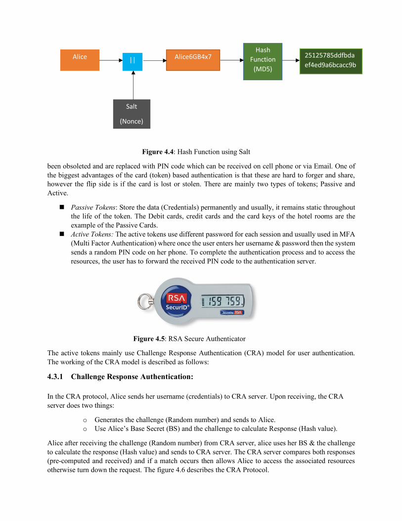
Figure 4.4: Hash Function using Salt
been obsoleted and are replaced with PIN code which can be received on cell phone or via Email. One of the biggest advantages of the card (token) based authentication is that these are hard to forger and share, however the flip side is if the card is lost or stolen. There are mainly two types of tokens; Passive and Active.
n Passive Tokens: Store the data (Credentials) permanently and usually, it remains static throughout the life of the token. The Debit cards, credit cards and the card keys of the hotel rooms are the example of the Passive Cards.
n Active Tokens: The active tokens use different password for each session and usually used in MFA (Multi Factor Authentication) where once the user enters her username & password then the system sends a random PIN code on her phone. To complete the authentication process and to access the resources, the user has to forward the received PIN code to the authentication server.
Figure 4.5: RSA Secure Authenticator
The active tokens mainly use Challenge Response Authentication (CRA) model for user authentication. The working of the CRA model is described as follows:
4.3.1 Challenge Response Authentication:
In the CRA protocol, Alice sends her username (credentials) to CRA server. Upon receiving, the CRA server does two things:
o Generates the challenge (Random number) and sends to Alice. o Use Alice’s Base Secret (BS) and the challenge to calculate Response (Hash value).
Alice after receiving the challenge (Random number) from CRA server, alice uses her BS & the challenge to calculate the response (Hash value) and sends to CRA server. The CRA server compares both responses (pre-computed and received) and if a match occurs then allows Alice to access the associated resources otherwise turn down the request. The figure 4.6 describes the CRA Protocol.
Alice ||
Salt
(Nonce)
Alice6GB4x7 Hash
Function (MD5)
25125785ddfbdaef4ed9a6bcacc9b356
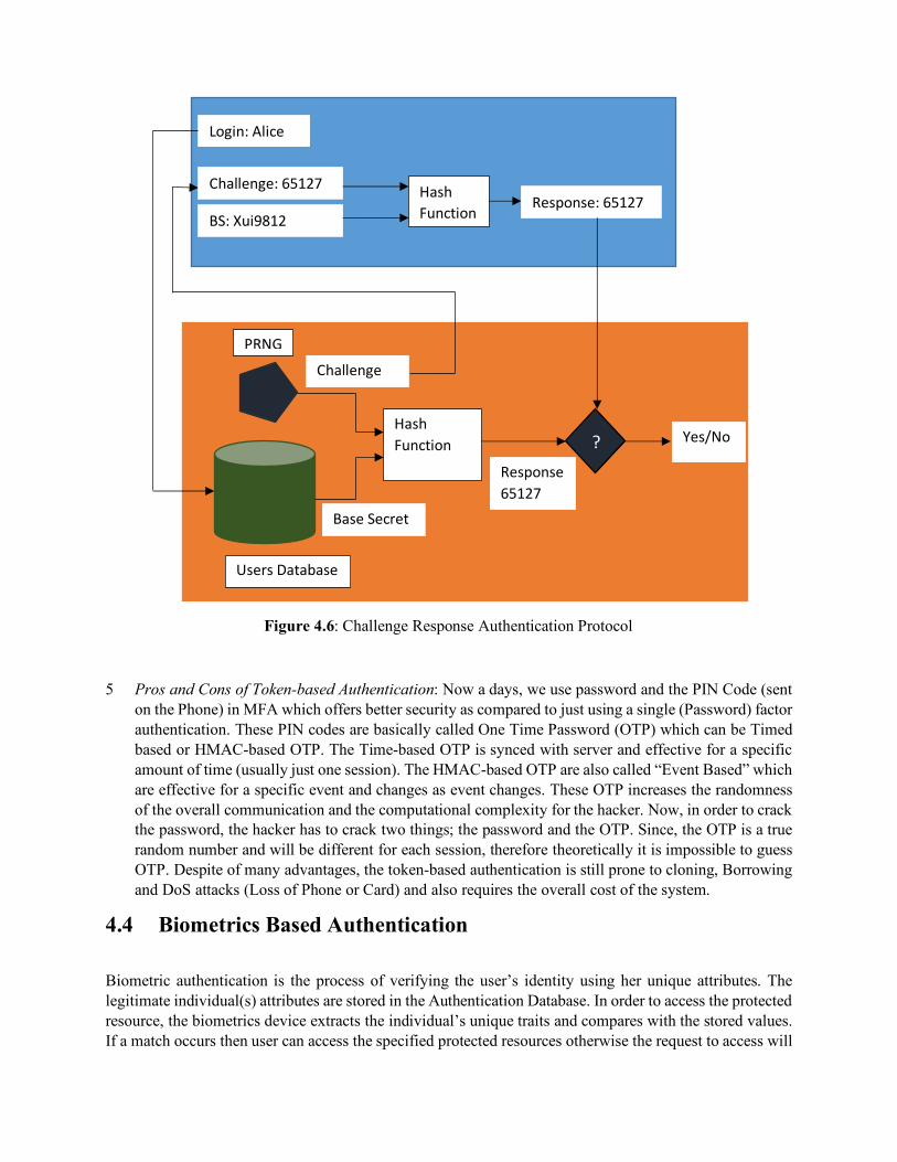
Figure 4.6: Challenge Response Authentication Protocol
5 Pros and Cons of Token-based Authentication: Now a days, we use password and the PIN Code (sent on the Phone) in MFA which offers better security as compared to just using a single (Password) factor authentication. These PIN codes are basically called One Time Password (OTP) which can be Timed based or HMAC-based OTP. The Time-based OTP is synced with server and effective for a specific amount of time (usually just one session). The HMAC-based OTP are also called “Event Based” which are effective for a specific event and changes as event changes. These OTP increases the randomness of the overall communication and the computational complexity for the hacker. Now, in order to crack the password, the hacker has to crack two things; the password and the OTP. Since, the OTP is a true random number and will be different for each session, therefore theoretically it is impossible to guess OTP. Despite of many advantages, the token-based authentication is still prone to cloning, Borrowing and DoS attacks (Loss of Phone or Card) and also requires the overall cost of the system.
4.4 Biometrics Based Authentication
Biometric authentication is the process of verifying the user’s identity using her unique attributes. The legitimate individual(s) attributes are stored in the Authentication Database. In order to access the protected resource, the biometrics device extracts the individual’s unique traits and compares with the stored values. If a match occurs then user can access the specified protected resources otherwise the request to access will
Login: Alice
Challenge: 65127 Response: 65127
BS: Xui9812
Hash Function
Hash Function
Base Secret
Challenge
? Response 65127
Yes/No
Users Database
PRNG
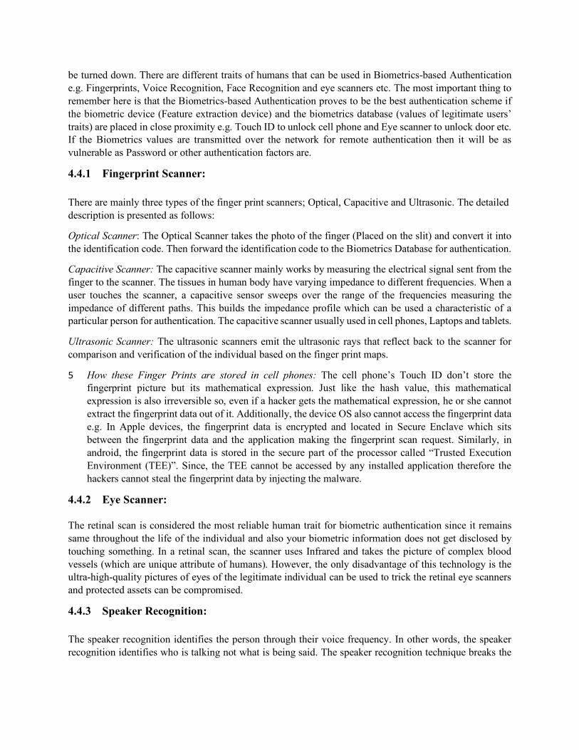
be turned down. There are different traits of humans that can be used in Biometrics-based Authentication e.g. Fingerprints, Voice Recognition, Face Recognition and eye scanners etc. The most important thing to remember here is that the Biometrics-based Authentication proves to be the best authentication scheme if the biometric device (Feature extraction device) and the biometrics database (values of legitimate users’ traits) are placed in close proximity e.g. Touch ID to unlock cell phone and Eye scanner to unlock door etc. If the Biometrics values are transmitted over the network for remote authentication then it will be as vulnerable as Password or other authentication factors are.
4.4.1 Fingerprint Scanner:
There are mainly three types of the finger print scanners; Optical, Capacitive and Ultrasonic. The detailed description is presented as follows:
Optical Scanner: The Optical Scanner takes the photo of the finger (Placed on the slit) and convert it into the identification code. Then forward the identification code to the Biometrics Database for authentication.
Capacitive Scanner: The capacitive scanner mainly works by measuring the electrical signal sent from the finger to the scanner. The tissues in human body have varying impedance to different frequencies. When a user touches the scanner, a capacitive sensor sweeps over the range of the frequencies measuring the impedance of different paths. This builds the impedance profile which can be used a characteristic of a particular person for authentication. The capacitive scanner usually used in cell phones, Laptops and tablets.
Ultrasonic Scanner: The ultrasonic scanners emit the ultrasonic rays that reflect back to the scanner for comparison and verification of the individual based on the finger print maps.
5 How these Finger Prints are stored in cell phones: The cell phone’s Touch ID don’t store the fingerprint picture but its mathematical expression. Just like the hash value, this mathematical expression is also irreversible so, even if a hacker gets the mathematical expression, he or she cannot extract the fingerprint data out of it. Additionally, the device OS also cannot access the fingerprint data e.g. In Apple devices, the fingerprint data is encrypted and located in Secure Enclave which sits between the fingerprint data and the application making the fingerprint scan request. Similarly, in android, the fingerprint data is stored in the secure part of the processor called “Trusted Execution Environment (TEE)”. Since, the TEE cannot be accessed by any installed application therefore the hackers cannot steal the fingerprint data by injecting the malware.
4.4.2 Eye Scanner:
The retinal scan is considered the most reliable human trait for biometric authentication since it remains same throughout the life of the individual and also your biometric information does not get disclosed by touching something. In a retinal scan, the scanner uses Infrared and takes the picture of complex blood vessels (which are unique attribute of humans). However, the only disadvantage of this technology is the ultra-high-quality pictures of eyes of the legitimate individual can be used to trick the retinal eye scanners and protected assets can be compromised.
4.4.3 Speaker Recognition:
The speaker recognition identifies the person through their voice frequency. In other words, the speaker recognition identifies who is talking not what is being said. The speaker recognition technique breaks the

speaker’s words into packets of frequencies which contains the user’s central frequency (Pitch). The users can be differentiated based on their central frequencies.
4.4.4 Face Recognition:
Like other Biometrics authentication techniques, face recognition involves two steps for user authentication; Extraction of the features and the Comparison with the stored values. The face recognition systems use face features such as skin texture, wrinkles, beauty marks, distance between nose and eyes etc., convert it into mathematical expression and use that mathematical expression for user authentication. The iPhone face ID technology uses 30K infrared dot and creates a 3D map of face (features) of the individual. This 3D face map is forwarded to Secure Enclave of the processor to be compared with the already stored 3D face map and unlocks the phone by just looking at it. However, the face recognition scheme can be tricked with makeups, masks and 3D face objects etc. and gives the access to unauthorized people. The face recognition scheme can be improved with the integration of Thermal imaging.
4.5 Location Based Authentication
The Location based authentication factor uses the user’s IP address (Geolocation) to authenticate the user and typically integrated with knowledge-based authentication factor. There are two main working models of the location-based authentication scheme:
a) Model-1: In this model, the authentication server stores the IP addresses (Home and Work etc.) of the user which she typically uses to access the specified webserver and resources. Now, even though the user enters the correct credentials, if the query comes from a different IP address (unknown to authentication server) then either the authentication server sends an alert notification to the user (request for actions) or ask the user security questions/PIN Code for authentication.
b) Model-2: This model is specifically designed for those laptops, tablets and smart phones which are equipped with Global Positioning System (GPS) chip. The GPS module provides almost the exact location of the users (difference within meters) and also many of the Social Networking sites e.g. Facebook, Snapchat, Instagram and even Google maps also use the device (built-in) GPS to track the user’s locations. In this model, after entering the correct username and password, the authentication server first checks the Geolocation of the user device (which usually she uses to logon) and then compares it with the Geolocation of the device from where the query is coming from. If a match occurs then user gets the access to the resources otherwise the user will be asked security questions or server will send a PIN code on user’s device for further authentication.
4.6 Action Based Authentication
Action-based authentication is quite new and innovative way to passively authenticate the user. The authentication server authenticates the user based on their keyboard typing pattern (Keystroke Dynamics). There are different parameters of the keystrokes through which one individual can be differentiated with others e.g. The time between pressing of two keys, one press and other release etc. The authentication server stores the threshold of the different keystroke dynamics (Parameters) for each legitimate user and in order to get access to the resources, besides the username & the password, the users also have to match their typing speed (pattern). There are few exceptional scenarios when the legitimate user couldn’t match her own speed then the authentication server uses other passive or active authentication factors (IP address, PIN code or Security questions) to authenticate the users. The figure 4.7 presents some screenshot of the

GreyC-keystroke software to demonstrate the action-based authentication. The red lines represents the samples and threshold of the legitimate keystroke patterns and the blue lines represents the keystrokes of the hacker who knows the password but couldn’t match the keystroke pattern. We can observe from the figure (blue line), even though the hacker cracked the original password but if she doesn’t match the legitimate typing speed, she cannot access the resources.
Figure 4.7: Gray Keystroke Dynamics (Action Based Authentication)
4.7 Formal Authentication Protocols
There are many formal authentication protocols which provide Authentication, Authorization and Accounting (AAA).
Authentication: Who are you?
Authorization: What can you do?
Accounting: What did you do?
Some of the traditional and modern authentication standardized protocols are discussed as follows:
4.7.1 RADIUS

The Remote Authentication Dial-In User Service (RADIUS) is a networking protocol that provides centralized AAA to all of the connected users. There are two main components of the RADIUS Authentication protocol; RADIUS Client (RC) and RADIUS Server (RS).
RADIUS Client: is a network device e.g. Router, Switch or Access Point, that connects the user with internet and intranet.
RADIUS Server: Maintains the user profiles and performs authentication of the users.
The working of the protocol is presented in Figure 4.8 and discussed as follows:
1. The user requests to access RC and forwards its Username and the Password. 2. The RC forwards the credentials to the RS (Password in encrypted form). 3. The RS looks for a match into its database and if a match occurs then authenticates the user and
sends authorization instructions to RC. 4. The RS also start maintaining the logs of the user in Accounting database.
Figure 4.8: RADIUS Authentication
4.7.2 TACACS+
Terminal Access Controller Access Control System Plus is the advanced version of TACACS and it is the Cisco propriety. The RADIUS was mainly designed to authenticate the remote users while TACACS+ provides the administrator access to the network devices (Routers and Switches). Unlike RADIUS and TACACS, the TACACS+ uses TCP for transportation thus requires secure connection to be established before the communication occurs. All the communication between the clients (Routers and Switches) and the TACACS+ goes in an encrypted form which uses a robust encryption algorithm that makes interception theoretically impossible. The working of TACACS+ involves following four steps:
1. The user initiates the protocol and send her username and password to TACACS+ client. 2. The TACACS+ client encrypts and sends the packet to TACACS+ server. 3. The TACACS+ server checks the database and responds with authentication result.
Internet
User
1.Username & Password 2. Forward Credentials
RADIUS Client
RADIUS Server
Accounting
3. Forward Credentials
4. Response
5. Monitor Logs
6. Response

4. The TACACS+ server also forwards the instructions of the authorization to TACACS+ client.
4.7.3 SAML
SAML stands for Security Assertion Markup Language which is XML-based open standard for transferring the identity of the users between Identity Provider and Service Provider. Let us take an example to better understand the SAML concept.
Alice joined a new company named “Modern Ethical Hacker Pro” and got her official email address and password to access the organizational digital platform. The company also provides external services (e.g. AWS, Adobe Suite and Office 365 etc.) to their employees. After logging in to company’s digital platform, she clicks office 365 and then a magic happens. She gets the access to Office 365 without entering her credentials. You are right, the magic was actually SAML.
Identity Provider: Performs authentication of the users, then forwards the identity (token) and authorization level to the Service Provider.
Service Provider: Fully trusts the Identity Providers and allows access to the requested services to the legitimate users.
In the above example, the identity provider is the AAA server (e.g. Auth0) of “Modern Ethical Hacker Pro” company while the Service Provider is Microsoft. Alice signs into the digital platform of the company with Auth0. Then Alice clicks the office 365 icon and office 365 recognizes that Alice wants to login with SAML. The Microsoft sends Alice to Auth0 with SAML for authentication, since Alice was already authenticated by Auth0, therefore Auth0 verifies the session with authorization response to Microsoft. The Microsoft checks the response and allows alice to access the authorized applications of office 365.
4.7.4 LDAP
The Lightweight Directory Authentication Protocol (LDAP) is an open and cross platform protocol which is used for directory services authentication. The LDAP is mainly used to communicate with the directory services which includes Windows Active Directory, Red hat directory services and Apache Directory server etc. For example, If Alice wants to access a specific file (data) located in a protected server, then she enters her username & password which goes through LDAP to active directory and check whether the user exist or not. If the user exists then she can further get the access otherwise the request will be turned down. So, the Active directory is directory service that performs authentication of the users while the LDAP is the protocol through which the users communicate with active directory.
4.7.5 Kerberos
The Kerberos is a client/server-based authentication protocol which provides security and authentication. The Kerberos protocol mainly avoids the eavesdropping of the passwords (specially in insecure networks) and also controls the access of the organizational resources (users’ authentication). In Kerberos, if the clients (Users) want to access the organizational resources the they have to be verified by a trusted third party, they cannot directly access the organizational systems. There are three main components in Kerberos; Client, Key Distribution Center and organizational system.
Client: is the user who requests to gain access to the organizational resources.
Key Distribution Center (KDC): The trusted third party which knows the passwords of all clients and has two servers: Authentication Server (AS) and Ticket Granting Center (TGC).
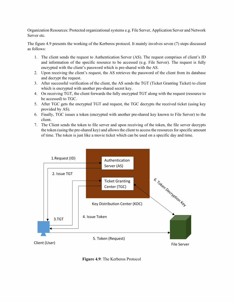
Organization Resources: Protected organizational systems e.g. File Server, Application Server and Network Server etc.
The figure 4.9 presents the working of the Kerberos protocol. It mainly involves seven (7) steps discussed as follows:
1. The client sends the request to Authentication Server (AS). The request comprises of client’s ID and information of the specific resource to be accessed (e.g. File Server). The request is fully encrypted with the client’s password which is pre-shared with the AS.
2. Upon receiving the client’s request, the AS retrieves the password of the client from its database and decrypt the request.
3. After successful verification of the client, the AS sends the TGT (Ticket Granting Ticket) to client which is encrypted with another pre-shared secret key.
4. On receiving TGT, the client forwards the fully encrypted TGT along with the request (resource to be accessed) to TGC.
5. After TGC gets the encrypted TGT and request, the TGC decrypts the received ticket (using key provided by AS).
6. Finally, TGC issues a token (encrypted with another pre-shared key known to File Server) to the client.
7. The Client sends the token to file server and upon receiving of the token, the file server decrypts the token (using the pre-shared key) and allows the client to access the resources for specific amount of time. The token is just like a movie ticket which can be used on a specific day and time.
Figure 4.9: The Kerberos Protocol
Authentication Server (AS)
Ticket Granting Center (TGC)
File Server
Key Distribution Center (KDC)
Client (User)
1.Request (ID)
2. Issue TGT
3.TGT 4. Issue Token
5. Token (Request)
6. Token Decryption Key
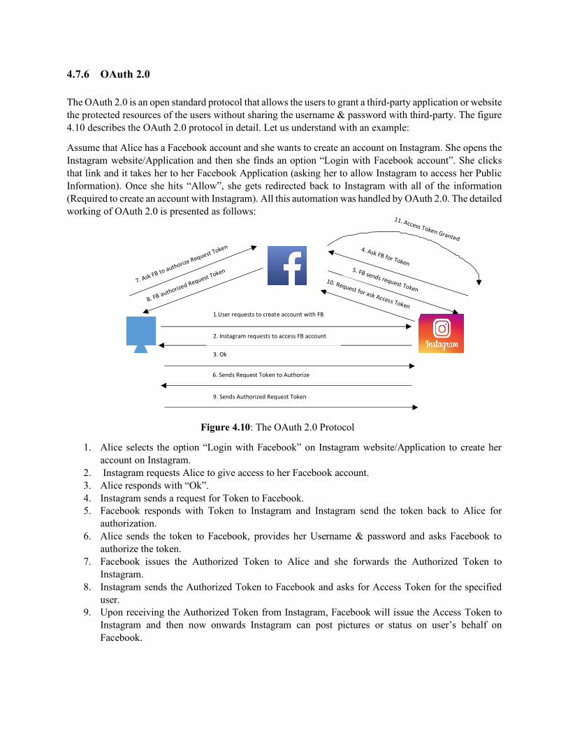
4.7.6 OAuth 2.0
The OAuth 2.0 is an open standard protocol that allows the users to grant a third-party application or website the protected resources of the users without sharing the username & password with third-party. The figure 4.10 describes the OAuth 2.0 protocol in detail. Let us understand with an example:
Assume that Alice has a Facebook account and she wants to create an account on Instagram. She opens the Instagram website/Application and then she finds an option “Login with Facebook account”. She clicks that link and it takes her to her Facebook Application (asking her to allow Instagram to access her Public Information). Once she hits “Allow”, she gets redirected back to Instagram with all of the information (Required to create an account with Instagram). All this automation was handled by OAuth 2.0. The detailed working of OAuth 2.0 is presented as follows:
Figure 4.10: The OAuth 2.0 Protocol
1. Alice selects the option “Login with Facebook” on Instagram website/Application to create her account on Instagram.
2. Instagram requests Alice to give access to her Facebook account. 3. Alice responds with “Ok”. 4. Instagram sends a request for Token to Facebook. 5. Facebook responds with Token to Instagram and Instagram send the token back to Alice for
authorization. 6. Alice sends the token to Facebook, provides her Username & password and asks Facebook to
authorize the token. 7. Facebook issues the Authorized Token to Alice and she forwards the Authorized Token to
Instagram. 8. Instagram sends the Authorized Token to Facebook and asks for Access Token for the specified
user. 9. Upon receiving the Authorized Token from Instagram, Facebook will issue the Access Token to
Instagram and then now onwards Instagram can post pictures or status on user’s behalf on Facebook.
1.User requests to create account with FB
2. Instagram requests to access FB account
3. Ok
4. Ask FB for Token 5. FB sends request Token
6. Sends Request Token to Authorize
7. Ask FB to authorize Request Token
8. FB authorized Request Token
9. Sends Authorized Request Token
10. Request for ask Access Token
11. Access Token Granted
Chapter 5 Access Control Fundamentals
Agenda Items of the Chapters:
n Definition of Access Control Systems n Formal Methods of Access Control Systems n Technologies to Implement Access Control Systems

5.1 Access Control Systems
5.1.1 Definition of Access Control Systems
The access control systems grants/denies permissions to use specific equipment/resources and mainly it can be of two types:
Physical Access Control: Uses the tangible systems (e.g. Security Guards, fencing and door locks) to control the access of buildings, parking lots or specific areas of the building.
Logical Access Control: Uses technological restrictions (e.g. Username, password etc.) to control access to computers and networks.
5.1.2 Parts of Access Control Systems
The access control system has mainly four components:
a) Identification: In logical access control, usually the users can be identified using their Username and Passwords while in physical access control, the physical cards/badges can be used to identify the users.
b) Authentication: In authentication phase, the verification process of the credentials is performed. c) Authorization: After successful verification, the authorization component allows access to
especially those resources which he/she are authorized to access (How much one can access). d) Accounting: Once the user got the access to the specified resources, the accounting system starts
making the logs of the user.
5.1.3 Security Kernel
The Security Kernel is a security software that enforces the access control on all computational devices and users. If a user wants to access any organizational resource then he/she has to request to Security Kernel and the Security Kernel allows/denies access based on the defined rules. The working of the security kernel is described as follows:
1. The subject requests access to an object which is intercepted by the Security Kernel. 2. The Security Kernel refers to its database to determine the access rights (whether the user is authorized
to access what is asking for). 3. The Security Kernel allows/denies the access based on the defined rules and starts monitoring logs.
The figure 5.1 shows the working of the Access control system.
Technical terms Description Subject Users Object Resources Actions Activities subjects can do with objects Relationships Conditions between subjects and Objects e.g.
Read, write and Execute
Table 5.1: Technical Terms used in Access Control systems

Figure 5.1: Security Kernel Access Control Concept
5.2 Formal Models of Access Control Systems
To implement access control, there are four formal access control models which are:
a) Discretionary Access Control (DAC) b) Mandatory Access Control (MAC) c) Non-Discretionary Access Control/Role Based Access Control (RBAC) d) Rule based/Attribute Based Access Control (ABAC)
The detailed description of these models is presented as follows.
5.2.1 Discretionary Access Control (DAC)
The DAC model is the least restrictive model among all, where each object has an owner and the owner decides, how the resource will be shared and who can access the resource. The owner can set the permissions and choose which user can read, write or execute. The DAC model is widely used in Microsoft Windows (All versions) and UNIX. Apparently, this scheme offers full control to the owner of the system however there is an information flow problem (You cannot control if someone you share the information with will not further share a file/data) which makes this model infeasible for larger networks. The figure 5.2 shows the Microsoft windows-based DAC relationships between the user and the data/file.
5.2.2 Mandatory Access Control (MAC)
User Security Kernel Resources
ACL
Database
Logs
Request

The MAC model is the most restrictive model which typically used in Military and Law enforcement institutes. The MAC model categorizes the organizational data into several tiers and data is labeled accordingly which defines its sensitivity. In order to access any specific data, the users should have the required security clearance which eventually escalate the access rights of the users. The data label comprises of the two things: Sensitivity Level and the compartment (the category of the data).
𝐿𝑎𝑏𝑙𝑒 = {𝑆𝑒𝑛𝑠𝑡𝑖𝑣𝑖𝑡𝑦𝐿𝑒𝑣𝑒𝑙, 𝐶𝑜𝑚𝑝𝑎𝑟𝑡𝑚𝑒𝑛𝑡}
𝐿𝑎𝑏𝑒𝑙 = P𝑇𝑆, {𝐶ℎ𝑒𝑚𝑖𝑐𝑎𝑙, 𝑁𝑢𝑐𝑙𝑒𝑎𝑟}R
The figure 5.3 describes the various categories of the data used in MAC model.
Figure 5.3: Data Classification of MAC Model
There are two major applications/implementation methods of the MAC model: Bell-LaPadula and Biba Integrity model, which are described as follows:
5.2.2.1 Bell- LaPadula Model
The Bell LaPadula Model is designed to protect confidentiality of the information and avoids the Information Flow problem (discussed in DAC) by using the concepts of “No Read up” and “No write down”. This model describes the acceptable connections between the subjects and the objects & ensures that the subjects are properly authenticated before accessing the objects. For example, a subject (Š) has Security clearance to access “Secret” data, so according to “No Read up” rule Š is not allowed to read anything one tier above (that is Top Secret). Similarly, “No write down” rule doesn’t allow the Š to write anything to documents located on one step
Unclassified/Public
Restricted
Confidential
Secret
Top Secret (TS)
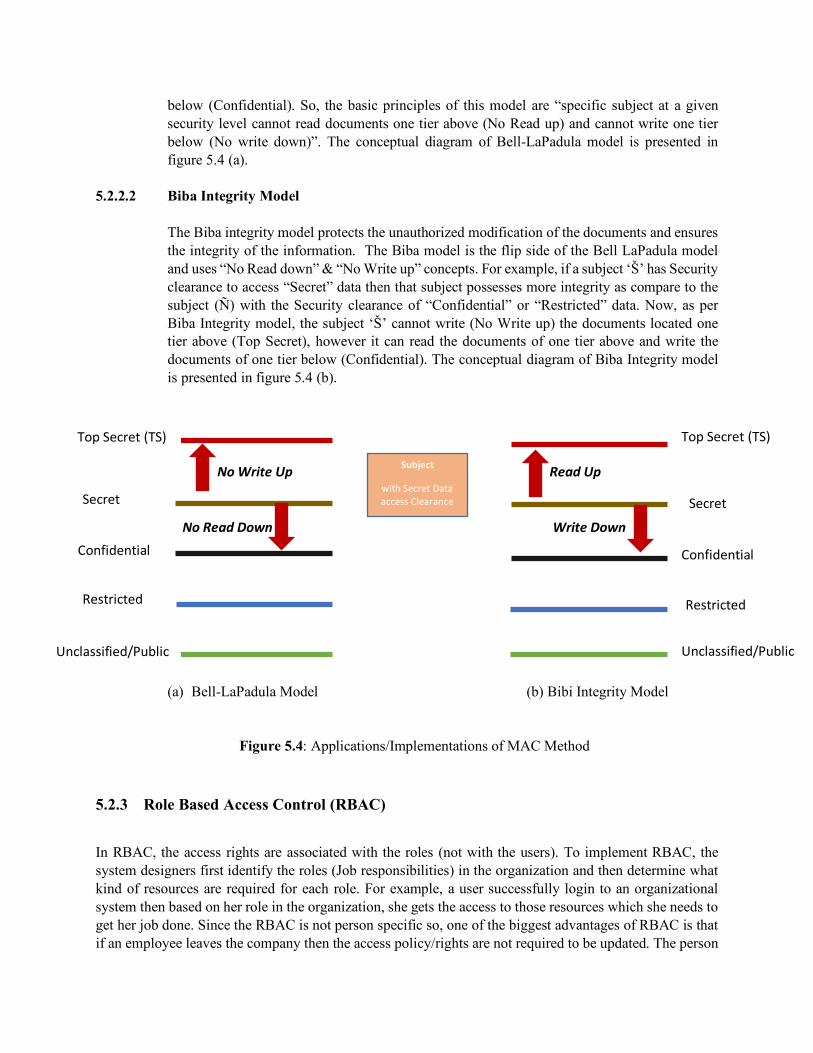
below (Confidential). So, the basic principles of this model are “specific subject at a given security level cannot read documents one tier above (No Read up) and cannot write one tier below (No write down)”. The conceptual diagram of Bell-LaPadula model is presented in figure 5.4 (a).
5.2.2.2 Biba Integrity Model The Biba integrity model protects the unauthorized modification of the documents and ensures the integrity of the information. The Biba model is the flip side of the Bell LaPadula model and uses “No Read down” & “No Write up” concepts. For example, if a subject ‘Š’ has Security clearance to access “Secret” data then that subject possesses more integrity as compare to the subject (Ñ) with the Security clearance of “Confidential” or “Restricted” data. Now, as per Biba Integrity model, the subject ‘Š’ cannot write (No Write up) the documents located one tier above (Top Secret), however it can read the documents of one tier above and write the documents of one tier below (Confidential). The conceptual diagram of Biba Integrity model is presented in figure 5.4 (b).
No Write Up Read Up No Read Down Write Down (a) Bell-LaPadula Model (b) Bibi Integrity Model Figure 5.4: Applications/Implementations of MAC Method
5.2.3 Role Based Access Control (RBAC)
In RBAC, the access rights are associated with the roles (not with the users). To implement RBAC, the system designers first identify the roles (Job responsibilities) in the organization and then determine what kind of resources are required for each role. For example, a user successfully login to an organizational system then based on her role in the organization, she gets the access to those resources which she needs to get her job done. Since the RBAC is not person specific so, one of the biggest advantages of RBAC is that if an employee leaves the company then the access policy/rights are not required to be updated. The person
Top Secret (TS)
Secret
Confidential
Restricted
Unclassified/Public
Subject
with Secret Data access Clearance
Top Secret (TS)
Secret
Confidential
Restricted
Unclassified/Public

who replaces that employee will take over the role and will get the associated access rights. The figure 5.5 describes the working of RBAC.
Users Roles Resources
Figure 5.5: Role Based Access Control
5.2.4 Attribute Based Access Control (ABAC)
Unlike the other access control systems, the ABAC involves four elements; Subjects, Objects, action and environment. The first three elements are the same as that of other access control models (defined in Table 5.1), however the environment is a unique element used in ABAC which defines the time, location or circumstances. For example, Mike (Subject) is an auditor who needs to access (action) sales record (object) however he can access the sales records only at the end of the Quarter (Environment). By using ABAC model, the rules are assigned to the objects which specifies under what conditions the subjects can access the different objects depending upon the project need.
5.3 Technologies to Implement Access Control
There are many traditional and modern techniques to implement access control. Some of these techniques are: Access Control Lists (ACLs), Blockchain Access Control and Account Policies. The detailed description of each technique is presented as follows:
5.3.1 Access Control Lists (ACLs)
The ACLs use a predefined set of rules to allow or block the incoming and outgoing packets coming from the different users. The ACLs work as a stateless firewall which permits or denies the packets travelling from source to destination. Usually, these ACLs come with routers and firewalls, however ACLs can be configured with other network devices (e.g. Servers, switches etc.) as well. The figure 5.6 describes the working of the ACLs (configured on Router).
As shown in Figure 5.6, the ACL list is configured on Router, which blocks the IT department’s computer from accessing the Accounts Database, however permits the Auditor’s computer to access the Accounts Database. With the ACL, one can permit some of the IT department computers to access the Accounts Database by adding their MAC/IP addresses in ACL. Another possible scenario is where we want to allow the IT department folks to access only the website (HTTP content) of the accounts department then we can enable Port 80 for them and disable everything else.
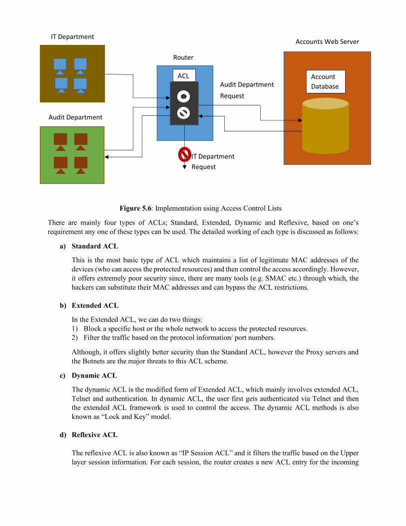
Figure 5.6: Implementation using Access Control Lists
There are mainly four types of ACLs; Standard, Extended, Dynamic and Reflexive, based on one’s requirement any one of these types can be used. The detailed working of each type is discussed as follows:
a) Standard ACL
This is the most basic type of ACL which maintains a list of legitimate MAC addresses of the devices (who can access the protected resources) and then control the access accordingly. However, it offers extremely poor security since, there are many tools (e.g. SMAC etc.) through which, the hackers can substitute their MAC addresses and can bypass the ACL restrictions.
b) Extended ACL
In the Extended ACL, we can do two things: 1) Block a specific host or the whole network to access the protected resources. 2) Filter the traffic based on the protocol information/ port numbers.
Although, it offers slightly better security than the Standard ACL, however the Proxy servers and the Botnets are the major threats to this ACL scheme.
c) Dynamic ACL
The dynamic ACL is the modified form of Extended ACL, which mainly involves extended ACL, Telnet and authentication. In dynamic ACL, the user first gets authenticated via Telnet and then the extended ACL framework is used to control the access. The dynamic ACL methods is also known as “Lock and Key” model.
d) Reflexive ACL The reflexive ACL is also known as “IP Session ACL” and it filters the traffic based on the Upper layer session information. For each session, the router creates a new ACL entry for the incoming
IT Department
Audit Department
Router
Account Database
Accounts Web Server
ACL Audit Department
Request
IT Department Request
traffic (based on the pre-known outgoing ACL). For each new session, the router creates a fresh ACL entry and removes the previous one.
5.3.2 Blockchain Access Control
The Blockchain is one of the most promising technologies which provides highly secure and transparent environment for many computational applications. The Blockchain mainly uses decentralized (distributed) model and hence avoids the risks of human errors and many cyber-attacks. In a typical access control system, all the organizational information is stored on a centralized server. If we outsource the security of the organization then we have to put a lot of trust on that company. Now, it raises two important questions:
1) If we want to change our Access control Operator (Third Party security) then what will happen to the data they possess?
2) How we can detect the data tampering and modifications?
By using Blockchain access control, one can avoid these threats. Since, the information is not stored on a centralized system and distributed over the network devices, therefore each device validates the integrity of the data. Moreover, the blockchain access control methods is much cheaper as compare to the traditional centralized server-based access control.
5.3.3 Account Policies
Another way to implement access control is through the account policies. Usually, this feature comes with the Microsoft windows and can be defined as “The set of the rules for a domain or specific group of users that determines the restrictions and enforces the defined rules on the users”. The account policies settings include; Password Policies, Account lockout policies and Kerberos Policies. In the password policies, one can define and enforce the size, expiration time and hardness (requirement) of the password, while the account lockout policy defines how to reactivate the account if you forget your password. The Kerberos policy is stored in active directory and act as a subset of the domain’s security policy.
For each domain, we can define one account policy which can be enforced through the domain controllers. If we want to give privileges to specific group of users then a separate domain needs to be created and it requires separate account policy. There are two more features of the account policies:
a) Account Restrictions: By using this feature, the users can access the system for the specified days and times. For example, your RFID based office access card works throughout the week but might not work on weekends.
b) Account Expiration: There are two types of accounts (that exist in any organization) which need to be terminated or monitored: 1) Orphaned Account: The account that remains active even after an employee left the
organization. 2) Dormant Account: The account which has not been accessed for long time.

Chapter 6 Symmetric Encryption
Agenda Items of the Chapters:
n Fundamentals of Cryptography n Traditional Cryptographic functions vs Digital Encryption operators n Symmetric Encryption algorithms
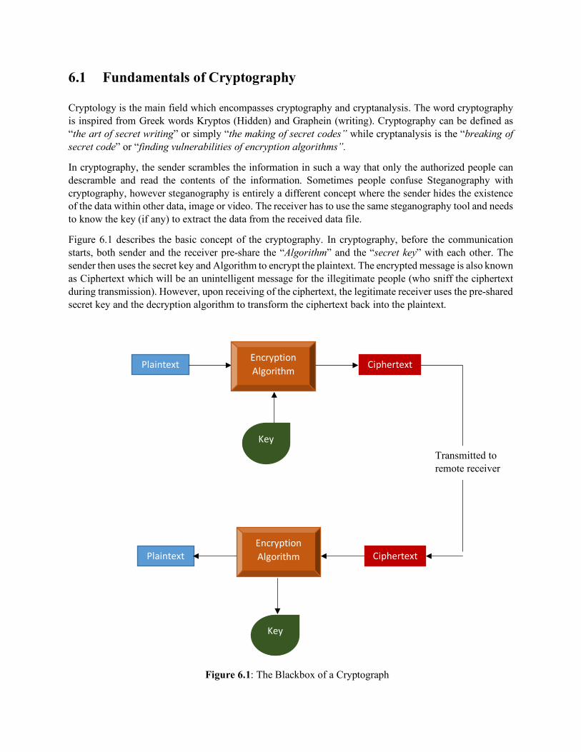
6.1 Fundamentals of Cryptography
Cryptology is the main field which encompasses cryptography and cryptanalysis. The word cryptography is inspired from Greek words Kryptos (Hidden) and Graphein (writing). Cryptography can be defined as “the art of secret writing” or simply “the making of secret codes” while cryptanalysis is the “breaking of secret code” or “finding vulnerabilities of encryption algorithms”.
In cryptography, the sender scrambles the information in such a way that only the authorized people can descramble and read the contents of the information. Sometimes people confuse Steganography with cryptography, however steganography is entirely a different concept where the sender hides the existence of the data within other data, image or video. The receiver has to use the same steganography tool and needs to know the key (if any) to extract the data from the received data file.
Figure 6.1 describes the basic concept of the cryptography. In cryptography, before the communication starts, both sender and the receiver pre-share the “Algorithm” and the “secret key” with each other. The sender then uses the secret key and Algorithm to encrypt the plaintext. The encrypted message is also known as Ciphertext which will be an unintelligent message for the illegitimate people (who sniff the ciphertext during transmission). However, upon receiving of the ciphertext, the legitimate receiver uses the pre-shared secret key and the decryption algorithm to transform the ciphertext back into the plaintext.
Figure 6.1: The Blackbox of a Cryptograph
Plaintext Encryption Algorithm
Key
Ciphertext
Ciphertext Encryption Algorithm
Key
Plaintext
Transmitted to remote receiver
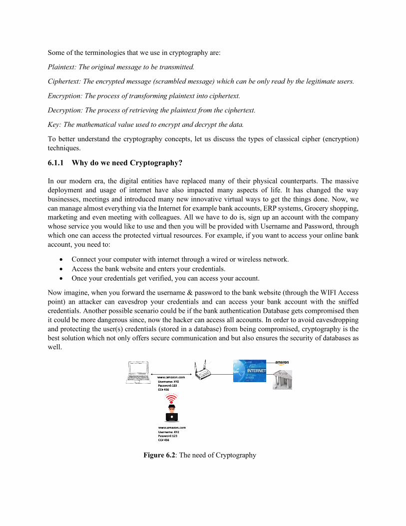
Some of the terminologies that we use in cryptography are:
Plaintext: The original message to be transmitted.
Ciphertext: The encrypted message (scrambled message) which can be only read by the legitimate users.
Encryption: The process of transforming plaintext into ciphertext.
Decryption: The process of retrieving the plaintext from the ciphertext.
Key: The mathematical value used to encrypt and decrypt the data.
To better understand the cryptography concepts, let us discuss the types of classical cipher (encryption) techniques.
6.1.1 Why do we need Cryptography?
In our modern era, the digital entities have replaced many of their physical counterparts. The massive deployment and usage of internet have also impacted many aspects of life. It has changed the way businesses, meetings and introduced many new innovative virtual ways to get the things done. Now, we can manage almost everything via the Internet for example bank accounts, ERP systems, Grocery shopping, marketing and even meeting with colleagues. All we have to do is, sign up an account with the company whose service you would like to use and then you will be provided with Username and Password, through which one can access the protected virtual resources. For example, if you want to access your online bank account, you need to:
• Connect your computer with internet through a wired or wireless network. • Access the bank website and enters your credentials. • Once your credentials get verified, you can access your account.
Now imagine, when you forward the username & password to the bank website (through the WIFI Access point) an attacker can eavesdrop your credentials and can access your bank account with the sniffed credentials. Another possible scenario could be if the bank authentication Database gets compromised then it could be more dangerous since, now the hacker can access all accounts. In order to avoid eavesdropping and protecting the user(s) credentials (stored in a database) from being compromised, cryptography is the best solution which not only offers secure communication and but also ensures the security of databases as well.
Figure 6.2: The need of Cryptography

6.1.2 Classical Encryption Schemes
There are mainly two types of classical encryption (Cipher) schemes; Substitution Cipher and Transposition Cipher. Detailed descriptions and further classification of these schemes are discussed as follows:
In substitution cipher, the data (Alphabets) is substituted with other data while in Transposition cipher, the data is scrambled or transposed based on the pre-shared key.
6.1.2.1 Substitution Cipher In substitution cipher, the unit of data or information is replaced with Ciphertext according to the pre-shared key. The following are some variants of the substitution cipher.
n Caesar Cipher: In simple substitution of the Caesar cipher, each letter of the plaintext is replaced with the next letter down the alphabets e.g. if the Plaintext is ‘ABC’ then after passing it through the simple substitution cipher the letter ‘A’ of the plaintext will become ‘B’, the letter ‘B’ of the plaintext will become ‘C’ and ‘C’ of the plaintext will become ‘D’. The ciphertext for the plaintext ‘ABC’ will be ‘BCD’. If we change the substitution key to 3, then each letter of the plaintext will be replaced with the third letter down the Alphabets. The plaintext “ABC” will become “DEF” and these variations can be rotated. In order to decrypt the substituted message, both the sender and receiver need to pre-share the substitution key.
n Vigenère Cipher: The Vigenère cipher is named after 16th century cryptographer Blaise de Vigenère. Figure 6.2 shows different stages of encryption of plaintext using Vigenère wheel. In Vigenère Cipher, the key can be a word which rotates the plaintext letters using the following steps:
o The Vigenère wheel has two disks: Inner and Outer. The outer disk is fixed (cannot be rotated) and the inner disk can be rotated according to the key.
o Rotate the inner disk in such a way that key (letter) should come next to the starting point (A) of the outer disk.
o Find the Plaintext (Letter) on the outer disk.
Figure 6.3: The Vigenère Wheel Cipher

o The ciphertext (Letter) will be the letter on the inner disk (right in front of the letter of outer disk).
o Repeat the steps unless all the plaintext gets encrypted.
Example of the Vigenère Cipher:
Plaintext: UMAR
Key : BINH
Ciphertext: VUNY
6.1.2.2 Transposition Cipher
Transposition is the process of encryption in which the plaintext is shifted/rotated based on the pre-shared key. The ciphertext is the permuted (interleaved) version of the plaintext which can be de-permuted with the pre-shared key. The following are some of the types of transposition cipher:
n Rail Fence Cipher: In the Rail Fence cipher, the plaintext is written downwards on specified spots (called rails) and when hits the bottom then moves up. To create the ciphertext, we will write down the letter row by row. So, the ciphertext for the plaintext “WE NEED SECURITY” will be “WECT EEDEUIY NSR”. Example of Rail Fence Cipher:
W E C T
E E D E U I Y
N S R
n Route Cipher: The Route Cipher mainly involves two steps: o Write the Plaintext in grid manner (column wise) of given dimension. o To create the Ciphertext, we will start writing the letters using pre-shared route (clockwise
or counter clock wise). (See the example for more detail).
The ciphertext for the plaintext “WE NEED SECURITY” will be “TYXIC DNEWE SUREE” using the clockwise route.
Example of Route Cipher:
W E S U T
E E E R Y
N D C I X
n Columnar Transposition:

The Columnar Transposition involves two steps to generate ciphertext: o The plaintext is written in rows (of fixed length) o Then a pre-shared random sequence is used to pick columns to form ciphertext.
To better understand the columnar transposition, let us see the following example:
Plaintext: WE NEED SECURITY
Permutation Sequence: 5 1 3 2 4
5 1 3 2 4
W E N E E
D S E C U
R I T Y
Ciphertext: ESI ECY NET EU WDR
6.1.3 Digital Encryption
Computers understand only Machine language (Binary) and therefore whenever we communicate with computers, an input device converts the human language into Machine Language and an output device is used to convert the Machine language back into what humans can understand. In the practical world, we use computers to access resources located on internet which involve different cryptographic algorithms to encrypt and decrypt the binary data. The modern cryptographic algorithms use Boolean functions, bitwise logical operators (XOR, OR, AND etc.), Rotations, Permutations and substitution boxes etc. to scramble the binary data. To better understand the concept of digital cryptography, let us see the following example shown in figure 6.4. We use Exclusive OR (XOR) operator for encryption and decryption. The table 6.1 presents the truth table of XOR operator:
A B 𝑨⨁𝐁 0 1 1 1 0 1 0 0 0 1 1 0
Table 6.1: Exclusive OR Truth Table
Figure 6.4 summarizes the digital encryption scheme using XOR with 8-bit binary example. The XOR based encryption scheme involves four steps:
1) The sender and the receiver pre-shares a secret key which will be used for encryption and decryption.
2) The sender encrypts the plaintext by taking XOR of the plaintext with the pre-shared key. 3) The sender forwards the ciphertext to the receiver. 4) Upon receiving of the ciphertext, the receiver decrypts it by taking XOR with the pre-shared key.
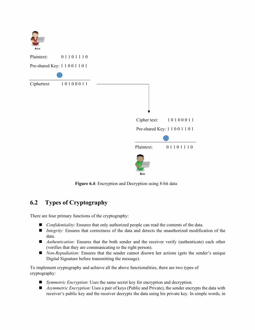
Plaintext: 0 1 1 0 1 1 1 0
Pre-shared Key: 1 1 0 0 1 1 0 1
Ciphertext 1 0 1 0 0 0 1 1
Cipher text: 1 0 1 0 0 0 1 1
Pre-shared Key: 1 1 0 0 1 1 0 1
Plaintext: 0 1 1 0 1 1 1 0
Figure 6.4: Encryption and Decryption using 8-bit data
6.2 Types of Cryptography
There are four primary functions of the cryptography:
n Confidentiality: Ensures that only authorized people can read the contents of the data. n Integrity: Ensures that correctness of the data and detects the unauthorized modification of the
data. n Authentication: Ensures that the both sender and the receiver verify (authenticate) each other
(verifies that they are communicating to the right person). n Non-Repudiation: Ensures that the sender cannot disown her actions (gets the sender’s unique
Digital Signature before transmitting the message).
To implement cryptography and achieve all the above functionalities, there are two types of cryptography:
n Symmetric Encryption: Uses the same secret key for encryption and decryption. n Asymmetric Encryption: Uses a pair of keys (Public and Private), the sender encrypts the data with
receiver’s public key and the receiver decrypts the data using his private key. In simple words, in

asymmetric encryption, we use different keys for encryption and decryption. Figure 6.5 summarizes the asymmetric encryption. In this chapter, we will discuss only the symmetric encryption algorithms while the asymmetric encryption algorithms will be discussed in Chapter 7.
Figure 6.5: Asymmetric Encryption
6.3 Symmetric Encryption Algorithms
The traditional (old) encryption algorithms were symmetric which use the single secret key to encrypt and decrypt the documents. These symmetric encryption algorithms are also known as Private Key Cryptography, since the secret key is kept private between the sender and the receiver. The symmetric encryption algorithms mainly ensure Confidentiality, Integrity & Availability (CIA), however it does not provide authentication and Non-repudiation. These two functionalities can be obtained through Digital Signatures and hashes which are extensively used in asymmetric encryption algorithms. Some of the commonly used symmetric encryption algorithms are:
n Data Encryption Standard (DES) n Triple Data Encryption Standard (3DES) n Advanced Encryption Standard (AES) n International Data Encryption Algorithm (IDEA)
The basic properties of these symmetric encryption algorithms are discussed as follows:
6.3.1 Data Encryption Standard (DES)
The DES algorithm was the joint venture of IBM and US Department of Defense and originally designed in 1970s. The DES algorithm is the simplified form of IBM’s Lucifer encryption Algorithm and it was
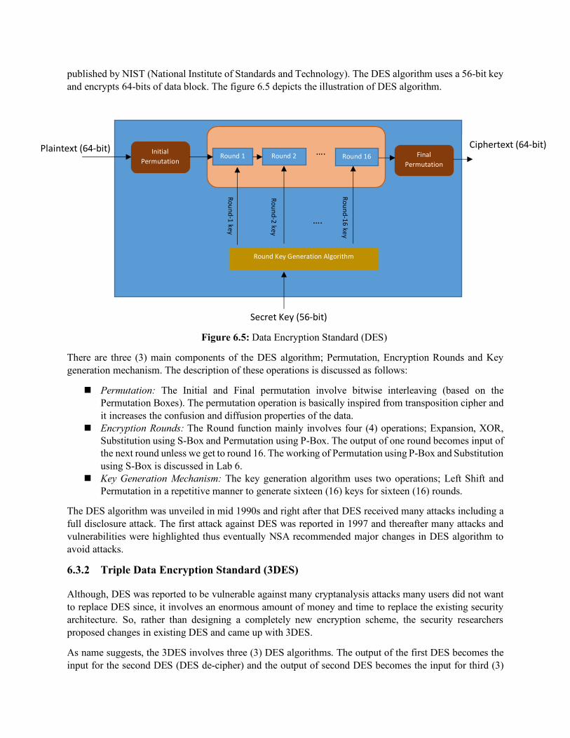
published by NIST (National Institute of Standards and Technology). The DES algorithm uses a 56-bit key and encrypts 64-bits of data block. The figure 6.5 depicts the illustration of DES algorithm.
Figure 6.5: Data Encryption Standard (DES)
There are three (3) main components of the DES algorithm; Permutation, Encryption Rounds and Key generation mechanism. The description of these operations is discussed as follows:
n Permutation: The Initial and Final permutation involve bitwise interleaving (based on the Permutation Boxes). The permutation operation is basically inspired from transposition cipher and it increases the confusion and diffusion properties of the data.
n Encryption Rounds: The Round function mainly involves four (4) operations; Expansion, XOR, Substitution using S-Box and Permutation using P-Box. The output of one round becomes input of the next round unless we get to round 16. The working of Permutation using P-Box and Substitution using S-Box is discussed in Lab 6.
n Key Generation Mechanism: The key generation algorithm uses two operations; Left Shift and Permutation in a repetitive manner to generate sixteen (16) keys for sixteen (16) rounds.
The DES algorithm was unveiled in mid 1990s and right after that DES received many attacks including a full disclosure attack. The first attack against DES was reported in 1997 and thereafter many attacks and vulnerabilities were highlighted thus eventually NSA recommended major changes in DES algorithm to avoid attacks.
6.3.2 Triple Data Encryption Standard (3DES)
Although, DES was reported to be vulnerable against many cryptanalysis attacks many users did not want to replace DES since, it involves an enormous amount of money and time to replace the existing security architecture. So, rather than designing a completely new encryption scheme, the security researchers proposed changes in existing DES and came up with 3DES.
As name suggests, the 3DES involves three (3) DES algorithms. The output of the first DES becomes the input for the second DES (DES de-cipher) and the output of second DES becomes the input for third (3)
Plaintext (64-bit) Initial Permutation
1 Round 1 Round 2 …. Round 16 Final Permutation
Ciphertext (64-bit)
Secret Key (56-bit)
Round Key Generation Algorithm
Round-1 key
Round-2 key
…. Round-16 key
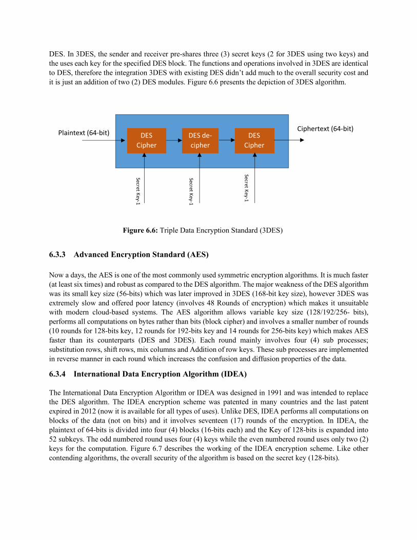
DES. In 3DES, the sender and receiver pre-shares three (3) secret keys (2 for 3DES using two keys) and the uses each key for the specified DES block. The functions and operations involved in 3DES are identical to DES, therefore the integration 3DES with existing DES didn’t add much to the overall security cost and it is just an addition of two (2) DES modules. Figure 6.6 presents the depiction of 3DES algorithm.
Figure 6.6: Triple Data Encryption Standard (3DES)
6.3.3 Advanced Encryption Standard (AES)
Now a days, the AES is one of the most commonly used symmetric encryption algorithms. It is much faster (at least six times) and robust as compared to the DES algorithm. The major weakness of the DES algorithm was its small key size (56-bits) which was later improved in 3DES (168-bit key size), however 3DES was extremely slow and offered poor latency (involves 48 Rounds of encryption) which makes it unsuitable with modern cloud-based systems. The AES algorithm allows variable key size (128/192/256- bits), performs all computations on bytes rather than bits (block cipher) and involves a smaller number of rounds (10 rounds for 128-bits key, 12 rounds for 192-bits key and 14 rounds for 256-bits key) which makes AES faster than its counterparts (DES and 3DES). Each round mainly involves four (4) sub processes; substitution rows, shift rows, mix columns and Addition of row keys. These sub processes are implemented in reverse manner in each round which increases the confusion and diffusion properties of the data.
6.3.4 International Data Encryption Algorithm (IDEA)
The International Data Encryption Algorithm or IDEA was designed in 1991 and was intended to replace the DES algorithm. The IDEA encryption scheme was patented in many countries and the last patent expired in 2012 (now it is available for all types of uses). Unlike DES, IDEA performs all computations on blocks of the data (not on bits) and it involves seventeen (17) rounds of the encryption. In IDEA, the plaintext of 64-bits is divided into four (4) blocks (16-bits each) and the Key of 128-bits is expanded into 52 subkeys. The odd numbered round uses four (4) keys while the even numbered round uses only two (2) keys for the computation. Figure 6.7 describes the working of the IDEA encryption scheme. Like other contending algorithms, the overall security of the algorithm is based on the secret key (128-bits).
Plaintext (64-bit) DES Cipher
DES de-cipher
DES Cipher
Ciphertext (64-bit)
Secret Key-1
Secret Key-1
Secret Key-1
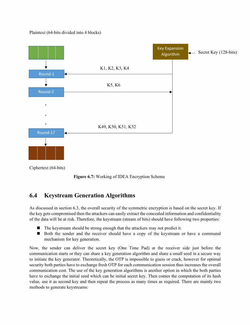
Plaintext (64-bits divided into 4 blocks)
Ciphertext (64-bits)
Figure 6.7: Working of IDEA Encryption Scheme
6.4 Keystream Generation Algorithms
As discussed in section 6.3, the overall security of the symmetric encryption is based on the secret key. If the key gets compromised then the attackers can easily extract the concealed information and confidentiality of the data will be at risk. Therefore, the keystream (stream of bits) should have following two properties:
n The keystream should be strong enough that the attackers may not predict it. n Both the sender and the receiver should have a copy of the keystream or have a communal
mechanism for key generation.
Now, the sender can deliver the secret key (One Time Pad) at the receiver side just before the communication starts or they can share a key generation algorithm and share a small seed in a secure way to initiate the key generator. Theoretically, the OTP is impossible to guess or crack, however for optimal security both parties have to exchange fresh OTP for each communication session thus increases the overall communication cost. The use of the key generation algorithms is another option in which the both parties have to exchange the initial seed which can be initial secret key. Then comes the computation of its hash value, use it as second key and then repeat the process as many times as required. There are mainly two methods to generate keystreams:
Key Expansion Algorithm
Round-1
Round-2
.
.
.
.
Round-17
K1, K2, K3, K4
K5, K6
K49, K50, K51, K52
Secret Key (128-bits)
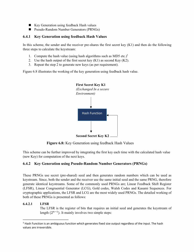
n Key Generation using feedback Hash values n Pseudo-Random Number Generators (PRNGs)
6.4.1 Key Generation using feedback Hash Values
In this scheme, the sender and the receiver pre-shares the first secret key (K1) and then do the following three steps to calculate the keystream:
1. Compute the hash value (using hash algorithms such as MD5 etc.)3 2. Use the hash output of the first secret key (K1) as second Key (K2). 3. Repeat the step 2 to generate new keys (as per requirement).
Figure 6.8 illustrates the working of the key generation using feedback hash value.
Figure 6.8: Key Generation using feedback Hash Values
This scheme can be further improved by integrating the first key each time with the calculated hash value (new Key) for computation of the next keys.
6.4.2 Key Generation using Pseudo-Random Number Generators (PRNGs)
These PRNGs use secret (pre-shared) seed and then generates random numbers which can be used as keystream. Since, both the sender and the receiver use the same initial seed and the same PRNG, therefore generate identical keystreams. Some of the commonly used PRNGs are; Linear Feedback Shift Register (LFSR), Linear Congruential Generator (LCG), Gold codes, Walsh Codes and Kasami Sequences. For cryptographic applications, the LFSR and LCG are the most widely used PRNGs. The detailed working of both of these PRNGs is presented as follows:
6.4.2.1 LFSR The LFSR is the register of bits that requires an initial seed and generates the keystream of length (2VWX). It mainly involves two simple steps:
3 Hash Function is an ambiguous function which generates fixed size output regardless of the input. The hash values are irreversible.
First Secret Key K1 (Exchanged In a secure Environment)
Hash Function
Second Secret Key K2
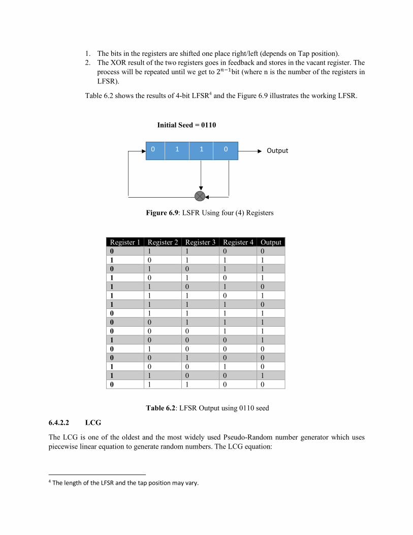
1. The bits in the registers are shifted one place right/left (depends on Tap position). 2. The XOR result of the two registers goes in feedback and stores in the vacant register. The
process will be repeated until we get to 2VWXbit (where n is the number of the registers in LFSR).
Table 6.2 shows the results of 4-bit LFSR4 and the Figure 6.9 illustrates the working LFSR.
Initial Seed = 0110
Figure 6.9: LSFR Using four (4) Registers
Register 1 Register 2 Register 3 Register 4 Output 0 1 1 0 0 1 0 1 1 1 0 1 0 1 1 1 0 1 0 1 1 1 0 1 0 1 1 1 0 1 1 1 1 1 0 0 1 1 1 1 0 0 1 1 1 0 0 0 1 1 1 0 0 0 1 0 1 0 0 0 0 0 1 0 0 1 0 0 1 0 1 1 0 0 1 0 1 1 0 0
Table 6.2: LFSR Output using 0110 seed
6.4.2.2 LCG
The LCG is one of the oldest and the most widely used Pseudo-Random number generator which uses piecewise linear equation to generate random numbers. The LCG equation:
4 The length of the LFSR and the tap position may vary.
0 1 1 0 Output
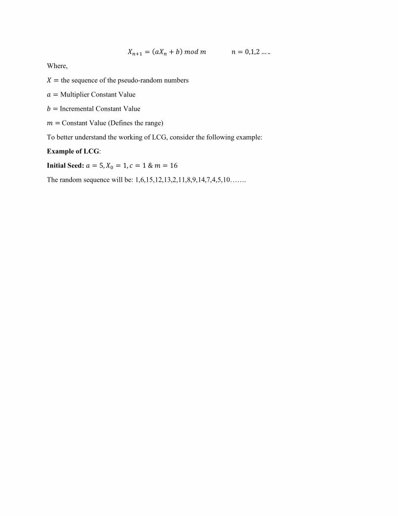
𝑋VZX = (𝑎𝑋V + 𝑏)𝑚𝑜𝑑𝑚𝑛 = 0,1,2… ..
Where,
𝑋 = the sequence of the pseudo-random numbers
𝑎 = Multiplier Constant Value
𝑏 =Incremental Constant Value
𝑚 =Constant Value (Defines the range)
To better understand the working of LCG, consider the following example:
Example of LCG:
Initial Seed: 𝑎 = 5, 𝑋^ = 1, 𝑐 = 1&𝑚 = 16
The random sequence will be: 1,6,15,12,13,2,11,8,9,14,7,4,5,10…….
Chapter 7 Asymmetric Encryption
Agenda Items of the Chapters:
n Fundamentals of Asymmetric Encryption n Challenges of Crypto-key Management n Nonce and Key Wrapping n Public Key Encryption Algorithms

7.1 Fundamentals of Asymmetric Encryption
As discussed in chapter 6, cryptography is the art of secret writing which can be performed with symmetric or asymmetric encryption methods. In symmetric encryption, both the sender and the receiver use the same key for encryption and decryption. Symmetric encryption algorithms are mainly used in low cost computing devices for secure communication and also widely used to protect databases. Since, symmetric encryption does not provide non-repudiation it is less common in bidirectional communication systems specially on IP based communication models. Asymmetric encryption uses a pair of keys (Public and Private) for encryption and decryption. All the entities who want to communicate will have one public key (which is assessable to the public) and one Private key (known to owner only). There is an interdependency between the pair of the keys which means if you encrypt anything using someone’s public key then it can be only decrypted using that entity’s private key. So, the sender uses the receiver’s public key to encrypt the message and that message can be decrypted using the receiver’s private key. To understand the concept of the asymmetric encryption, let us consider the following example:
Assume that Alice and Bob both have a pair of the keys (Public and Private). Alice wants to send a message “Hello” to Bob using asymmetric encryption method. She will use Bob’s public key, encrypt the message and sends it to Bob. Upon receiving this encrypted message, Bob will use his private key (known to Bob only) to decrypts the message. Figure 7.1 describes the asymmetric cryptography concept.
Fig 7.1: The Concept of Asymmetric Cryptography
7.1.1 Digital Signatures
“Hello”
Asymmetric Encryption Algorithm
APPublic key
ASPrivate key
BPPublic key
WXI6%O09*sWq Plaintext
(Ciphertext) BPPublic key
BSPrivate key
Asymmetric decryption Algorithm
WXI6%O09*sWq
“Hello” (Plaintext)
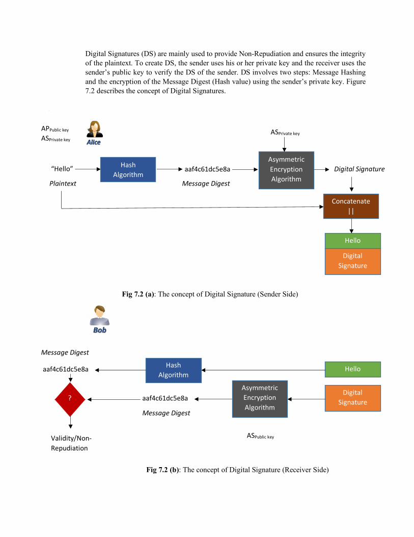
Digital Signatures (DS) are mainly used to provide Non-Repudiation and ensures the integrity of the plaintext. To create DS, the sender uses his or her private key and the receiver uses the sender’s public key to verify the DS of the sender. DS involves two steps: Message Hashing and the encryption of the Message Digest (Hash value) using the sender’s private key. Figure 7.2 describes the concept of Digital Signatures.
{{
Fig 7.2 (a): The concept of Digital Signature (Sender Side)
Fig 7.2 (b): The concept of Digital Signature (Receiver Side)
APPublic key
ASPrivate key
“Hello”
Plaintext
Hash Algorithm
aaf4c61dc5e8a
Message Digest
Asymmetric Encryption Algorithm
ASPrivate key
Digital Signature
Concatenate ||
Hello
Digital Signature
Hello
Digital Signature
Hash Algorithm
aaf4c61dc5e8a
Message Digest
Asymmetric Encryption Algorithm
aaf4c61dc5e8a
Message Digest
ASPublic key
?
Validity/Non-Repudiation
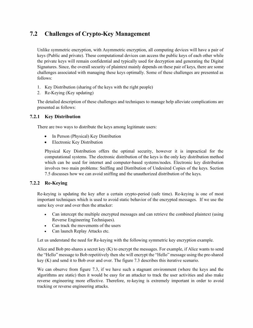
7.2 Challenges of Crypto-Key Management
Unlike symmetric encryption, with Asymmetric encryption, all computing devices will have a pair of keys (Public and private). These computational devices can access the public keys of each other while the private keys will remain confidential and typically used for decryption and generating the Digital Signatures. Since, the overall security of plaintext mainly depends on these pair of keys, there are some challenges associated with managing these keys optimally. Some of these challenges are presented as follows:
1. Key Distribution (sharing of the keys with the right people) 2. Re-Keying (Key updating)
The detailed description of these challenges and techniques to manage help alleviate complications are presented as follows:
7.2.1 Key Distribution
There are two ways to distribute the keys among legitimate users:
• In Person (Physical) Key Distribution • Electronic Key Distribution
Physical Key Distribution offers the optimal security, however it is impractical for the computational systems. The electronic distribution of the keys is the only key distribution method which can be used for internet and computer-based systems/nodes. Electronic key distribution involves two main problems: Sniffing and Distribution of Undesired Copies of the keys. Section 7.5 discusses how we can avoid sniffing and the unauthorized distribution of the keys.
7.2.2 Re-Keying
Re-keying is updating the key after a certain crypto-period (safe time). Re-keying is one of most important techniques which is used to avoid static behavior of the encrypted messages. If we use the same key over and over then the attacker:
• Can intercept the multiple encrypted messages and can retrieve the combined plaintext (using Reverse Engineering Techniques).
• Can track the movements of the users • Can launch Replay Attacks etc.
Let us understand the need for Re-keying with the following symmetric key encryption example.
Alice and Bob pre-shares a secret key (K) to encrypt the messages. For example, if Alice wants to send the “Hello” message to Bob repetitively then she will encrypt the “Hello” message using the pre-shared key (K) and send it to Bob over and over. The figure 7.3 describes this iterative scenario.
We can observe from figure 7.3, if we have such a stagnant environment (where the keys and the algorithms are static) then it would be easy for an attacker to track the user activities and also make reverse engineering more effective. Therefore, re-keying is extremely important in order to avoid tracking or reverse engineering attacks.
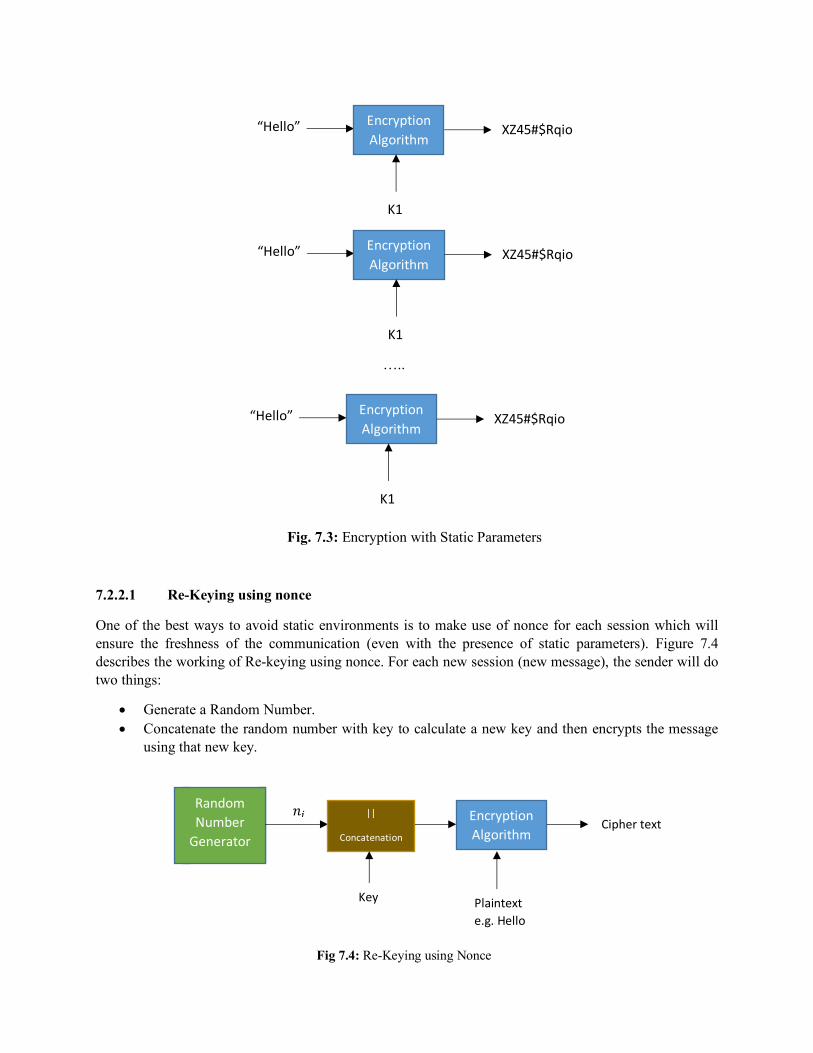
…..
Fig. 7.3: Encryption with Static Parameters
7.2.2.1 Re-Keying using nonce
One of the best ways to avoid static environments is to make use of nonce for each session which will ensure the freshness of the communication (even with the presence of static parameters). Figure 7.4 describes the working of Re-keying using nonce. For each new session (new message), the sender will do two things:
• Generate a Random Number. • Concatenate the random number with key to calculate a new key and then encrypts the message
using that new key.
“Hello” Encryption Algorithm
K1
XZ45#$Rqio
“Hello” Encryption Algorithm
K1
XZ45#$Rqio
“Hello” Encryption Algorithm
K1
XZ45#$Rqio
Random Number
Generator
||
Concatenation
𝑛`
Key
Encryption Algorithm
Plaintext e.g. Hello
Cipher text
Fig 7.4: Re-Keying using Nonce
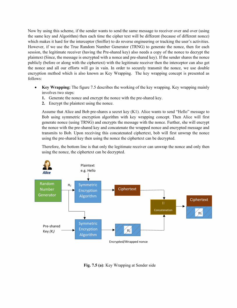
Now by using this scheme, if the sender wants to send the same message to receiver over and over (using the same key and Algorithm) then each time the cipher text will be different (because of different nonce) which makes it hard for the interceptor (Sniffer) to do reverse engineering or tracking the user’s activities. However, if we use the True Random Number Generator (TRNG) to generate the nonce, then for each session, the legitimate receiver (having the Pre-shared key) also needs a copy of the nonce to decrypt the plaintext (Since, the message is encrypted with a nonce and pre-shared key). If the sender shares the nonce publicly (before or along with the ciphertext) with the legitimate receiver then the interceptor can also get the nonce and all our efforts will go in vain. In order to securely transmit the nonce, we use double encryption method which is also known as Key Wrapping. The key wrapping concept is presented as follows:
• Key Wrapping: The figure 7.5 describes the working of the key wrapping. Key wrapping mainly involves two steps: 1. Generate the nonce and encrypt the nonce with the pre-shared key. 2. Encrypt the plaintext using the nonce.
Assume that Alice and Bob pre-shares a secret key (K1). Alice wants to send “Hello” message to Bob using symmetric encryption algorithm with key wrapping concept. Then Alice will first generate nonce (using TRNG) and encrypts the message with the nonce. Further, she will encrypt the nonce with the pre-shared key and concatenate the wrapped nonce and encrypted message and transmits to Bob. Upon receiving this concatenated ciphertext, bob will first unwrap the nonce using the pre-shared key then using the nonce the ciphertext can be decrypted.
Therefore, the bottom line is that only the legitimate receiver can unwrap the nonce and only then using the nonce, the ciphertext can be decrypted.
Fig. 7.5 (a): Key Wrapping at Sender side
Random Number
Generator
𝑛` Symmetric Encryption Algorithm
Plaintext e.g. Hello
Ciphertext
Symmetric Encryption Algorithm
Pre-shared Key (Ki)
𝑛`
Encrypted/Wrapped nonce
||
Concatenation
Ciphertext
𝑛`
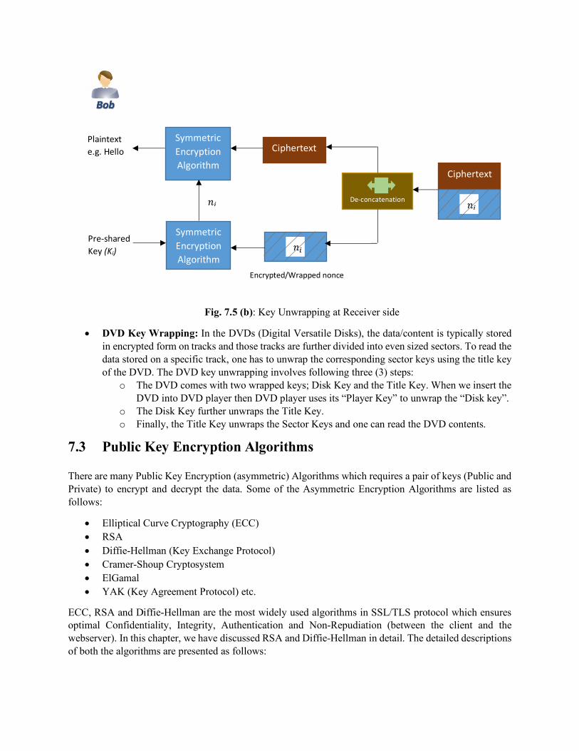
Fig. 7.5 (b): Key Unwrapping at Receiver side
• DVD Key Wrapping: In the DVDs (Digital Versatile Disks), the data/content is typically stored in encrypted form on tracks and those tracks are further divided into even sized sectors. To read the data stored on a specific track, one has to unwrap the corresponding sector keys using the title key of the DVD. The DVD key unwrapping involves following three (3) steps:
o The DVD comes with two wrapped keys; Disk Key and the Title Key. When we insert the DVD into DVD player then DVD player uses its “Player Key” to unwrap the “Disk key”.
o The Disk Key further unwraps the Title Key. o Finally, the Title Key unwraps the Sector Keys and one can read the DVD contents.
7.3 Public Key Encryption Algorithms
There are many Public Key Encryption (asymmetric) Algorithms which requires a pair of keys (Public and Private) to encrypt and decrypt the data. Some of the Asymmetric Encryption Algorithms are listed as follows:
• Elliptical Curve Cryptography (ECC) • RSA • Diffie-Hellman (Key Exchange Protocol) • Cramer-Shoup Cryptosystem • ElGamal • YAK (Key Agreement Protocol) etc.
ECC, RSA and Diffie-Hellman are the most widely used algorithms in SSL/TLS protocol which ensures optimal Confidentiality, Integrity, Authentication and Non-Repudiation (between the client and the webserver). In this chapter, we have discussed RSA and Diffie-Hellman in detail. The detailed descriptions of both the algorithms are presented as follows:
Encrypted/Wrapped nonce
Symmetric Encryption Algorithm
Plaintext e.g. Hello
Ciphertext
Symmetric Encryption Algorithm
Pre-shared Key (Ki)
𝑛`
De-concatenation
Ciphertext
𝑛` 𝑛`
7.3.1 RSA
RSA (Rivest-Shamir-Adleman) is a one of the oldest and widely used Public key encryption algorithm. The acronym RSA comes from the surnames of its inventors; Ron Rivest, Adi Shamir and Leonard Adleman. The algorithm was published in 1977 and mainly uses prime numbers to calculate the pair of keys (Public and Private). The encryption key is a public key which the sender uses to encrypt the message and then the receiver uses the decryption key (private key) to decrypt the message. Anyone can encrypt messages but only the legitimate people who knows the private keys or prime numbers can decrypt the messages.
To encrypt the messages, the sender uses the following equation 7.1.and for decryption the receiver uses the equation 7.2:
𝐶 = 𝑀b𝑚𝑜𝑑𝑛(7.1)
𝑀 = 𝐶c𝑚𝑜𝑑𝑛(7.1)
Where,
𝐶 = Ciphertext
𝑀 = Plaintext
𝑒 = Encryption Key (Public)
𝑑 = Decryption Key (Private)
𝑛 = Product of Prime Numbers
In RSA algorithm, the most important step is the computation of interdependent pair of keys (public and private keys). To calculate the public and private keys in RSA, there are five main steps which are described as follows:
1. Choose two prime numbers (𝑝, 𝑞). 2. Calculate the Product of those prime numbers (𝑛 = 𝑝 × 𝑞). 3. Calculate a Transition value ∅(𝑛),which mainly involves two steps:
a. Subtraction of prime number [(𝑝 − 1) and (𝑞 − 1)] b. ∅(𝑛) = (𝑝 − 1)(𝑞 − 1)
4. Choose large public key (𝑑) (should be a prime number and relative prime to transition value). 5. Computation of the private key (𝑒) (should be a prime number and relative prime to the transition
value) requires the satisfaction of the relation: 𝑒 × 𝑑𝑚𝑜𝑑i∅(𝑛)j = 1
Let us consider the following example to better understand the RSA key computation concept:
1. 𝑃 = 11&𝑞 = 17 (Prime numbers) 2. 𝑛 = 𝑝 × 𝑞
= 11 × 17 = 187 3. ∅(𝑛) = (𝑝 − 1)(𝑞 − 1)
= (11 − 1)(17 − 1) = (10)(16) = 160 4. Assume Public key, 𝑑 = 23 (Prime number and relative prime with ∅(𝑛)) 5. Calculate Private key, 𝑒 (Prime number and relative prime with ∅(𝑛))
𝑒 × 23𝑚𝑜𝑑(160) = 1(7.3)
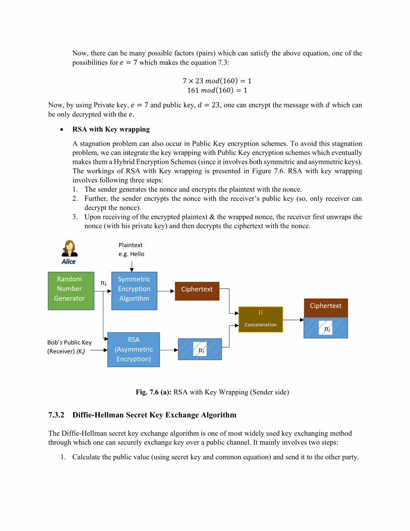
Now, there can be many possible factors (pairs) which can satisfy the above equation, one of the possibilities for 𝑒 = 7 which makes the equation 7.3:
7 × 23𝑚𝑜𝑑(160) = 1 161𝑚𝑜𝑑(160) = 1
Now, by using Private key, 𝑒 = 7 and public key, 𝑑 = 23, one can encrypt the message with 𝑑 which can be only decrypted with the 𝑒.
• RSA with Key wrapping
A stagnation problem can also occur in Public Key encryption schemes. To avoid this stagnation problem, we can integrate the key wrapping with Public Key encryption schemes which eventually makes them a Hybrid Encryption Schemes (since it involves both symmetric and asymmetric keys). The workings of RSA with Key wrapping is presented in Figure 7.6. RSA with key wrapping involves following three steps: 1. The sender generates the nonce and encrypts the plaintext with the nonce. 2. Further, the sender encrypts the nonce with the receiver’s public key (so, only receiver can
decrypt the nonce). 3. Upon receiving of the encrypted plaintext & the wrapped nonce, the receiver first unwraps the
nonce (with his private key) and then decrypts the ciphertext with the nonce.
Fig. 7.6 (a): RSA with Key Wrapping (Sender side)
7.3.2 Diffie-Hellman Secret Key Exchange Algorithm
The Diffie-Hellman secret key exchange algorithm is one of most widely used key exchanging method through which one can securely exchange key over a public channel. It mainly involves two steps:
1. Calculate the public value (using secret key and common equation) and send it to the other party.
Random Number
Generator
𝑛` Symmetric Encryption Algorithm
Plaintext e.g. Hello
Ciphertext
RSA (Asymmetric Encryption)
Bob’s Public Key (Receiver) (Ki)
𝑛`
||
Concatenation
Ciphertext
𝑛`

Fig. 7.6 (b): RSA with Key Wrapping (Receiver side)
2. Use the public value (sent by other party) and secret key to calculate the shared secret.
The Figure 7.7 describes the Diffie-Hellman algorithm:
Fig. 7.7: Diffie-Hellman Secret Key Exchange Algorithm Example
7.4 Public Key Certificates
Alice’s Private Key = 5
Bob’s Private Key = 4Pre-shared: 6
mod 13
Pre-shared: 6 mod 13
9 2
7776 mod 13 = 2
1296 mod 13 = 9
5904 mod 13 = 3
16 mod 13 = 3
Symmetric Encryption Algorithm
Plaintext e.g. Hello
Ciphertext
RSA (Asymmetric Encryption)
Bob’s Private Key (Receiver) (Kp)
𝑛`
Ciphertext
𝑛`
De-concatenation 𝑛`
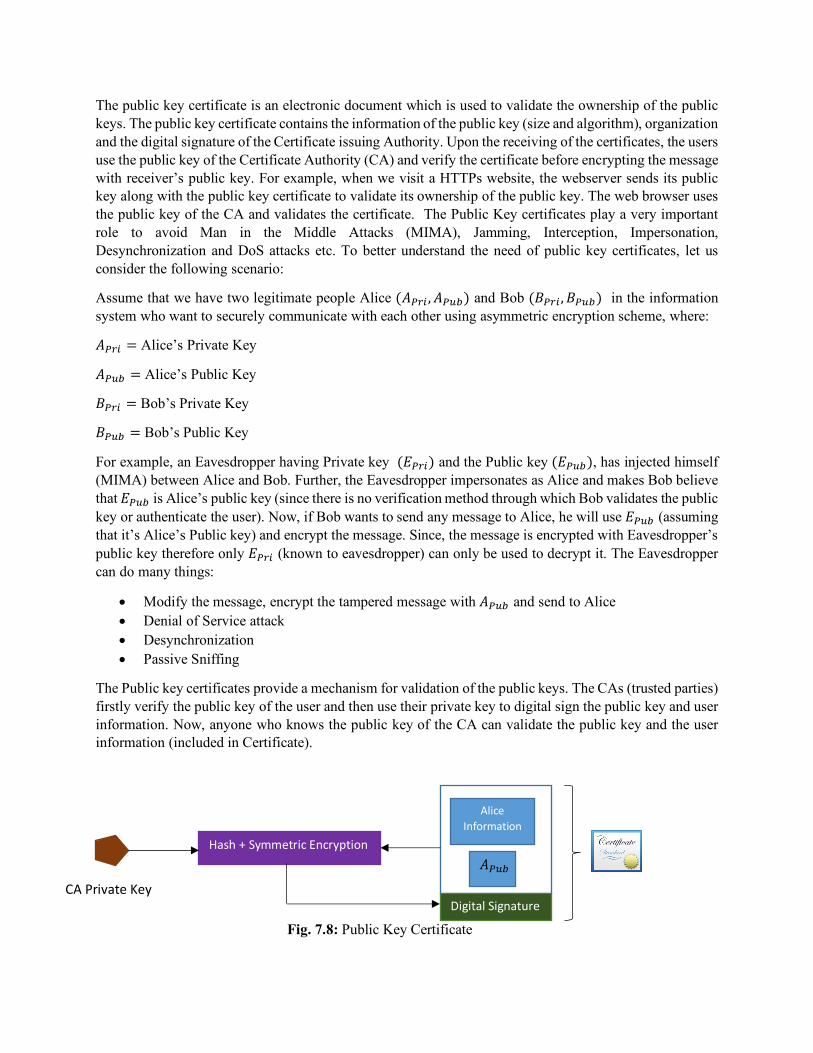
The public key certificate is an electronic document which is used to validate the ownership of the public keys. The public key certificate contains the information of the public key (size and algorithm), organization and the digital signature of the Certificate issuing Authority. Upon the receiving of the certificates, the users use the public key of the Certificate Authority (CA) and verify the certificate before encrypting the message with receiver’s public key. For example, when we visit a HTTPs website, the webserver sends its public key along with the public key certificate to validate its ownership of the public key. The web browser uses the public key of the CA and validates the certificate. The Public Key certificates play a very important role to avoid Man in the Middle Attacks (MIMA), Jamming, Interception, Impersonation, Desynchronization and DoS attacks etc. To better understand the need of public key certificates, let us consider the following scenario:
Assume that we have two legitimate people Alice (𝐴no`, 𝐴npq) and Bob (𝐵no`, 𝐵npq) in the information system who want to securely communicate with each other using asymmetric encryption scheme, where:
𝐴no` = Alice’s Private Key
𝐴npq = Alice’s Public Key
𝐵no` = Bob’s Private Key
𝐵npq = Bob’s Public Key
For example, an Eavesdropper having Private key (𝐸no`) and the Public key (𝐸npq), has injected himself (MIMA) between Alice and Bob. Further, the Eavesdropper impersonates as Alice and makes Bob believe that 𝐸npq is Alice’s public key (since there is no verification method through which Bob validates the public key or authenticate the user). Now, if Bob wants to send any message to Alice, he will use 𝐸npq (assuming that it’s Alice’s Public key) and encrypt the message. Since, the message is encrypted with Eavesdropper’s public key therefore only 𝐸no` (known to eavesdropper) can only be used to decrypt it. The Eavesdropper can do many things:
• Modify the message, encrypt the tampered message with 𝐴npq and send to Alice • Denial of Service attack • Desynchronization • Passive Sniffing
The Public key certificates provide a mechanism for validation of the public keys. The CAs (trusted parties) firstly verify the public key of the user and then use their private key to digital sign the public key and user information. Now, anyone who knows the public key of the CA can validate the public key and the user information (included in Certificate).
Fig. 7.8: Public Key Certificate
Alice Information
𝐴npq
CA Private Key
Hash + Symmetric Encryption
Digital Signature

Similarly, software updates are also digitally signed by the vendor. When the user receives the software updates from the vendors, firstly the user device verifies the update (using vendor’s public key) and then after successful verification the device lets the user to install the software updates.
Chapter 8 Web Application and Wireless Network Attacks
Agenda Items of the Chapter:
n Web Application Attacks n Wireless Network Attacks n Recommendations to avoid the security attacks
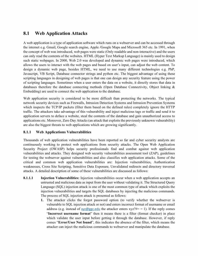
8.1 Web Application Attacks
A web application is a type of application software which runs on a webserver and can be accessed through the internet e.g. Gmail, Google search engine, Apple /Google Maps and Microsoft 365 etc. In 1991, when the concept of web was introduced, web pages were static (Only readable and non-interactive) and the users can only read the contents of the websites. HTML (Hyper Text Markup Language) is mainly used to design such static webpages. In 2000, Web 2.0 was developed and dynamic web pages were introduced, which allows the users to interact with the web pages and based on user’s input, can adjust the web content. To design a dynamic web page, besides HTML, we need to use many different technologies e.g. PhP, Javascript, VB Script, Database connector strings and python etc. The biggest advantage of using these scripting languages in designing of web pages is that one can design any security feature using the power of scripting languages. Sometimes when a user enters the data on a website, it directly stores that data in databases therefore the database connecting methods (Open Database Connectivity, Object linking & Embedding) are used to connect the web application to the database.
Web application security is considered to be more difficult than protecting the networks. The typical network security devices such as Firewalls, Intrusion Detection Systems and Intrusion Prevention Systems which inspects the TCP/IP packets (filter them based on the defined rules) completely ignore the HTTP traffic. The attackers take advantage of this vulnerability and inject malicious tags or traffic and send it to application servers to deface a website, steal the contents of the database and gain unauthorized access to applications etc. Moreover, Zero Day Attacks (an attack that exploits the previously unknown vulnerability) are also the biggest threats to web applications which are growing significantly.
8.1.1 Web Applications Vulnerabilities
Thousands of web application vulnerabilities have been reported so far and cyber security analysts are continuously working to protect web applications from security attacks. The Open Web Application Security Project (OWASP) helps security professionals find and combat against web application vulnerabilities and attacks. They designed web security vulnerabilities assessment tool (ZAP), guidelines for testing the webserver against vulnerabilities and also classifies web application attacks. Some of the critical and common web application vulnerabilities are: Injection vulnerabilities, Authentication weaknesses, Cross Site Scripting, Sensitive Data Exposure, Unvalidated redirects and directory traversal attacks. A detailed description of some of these vulnerabilities are discussed as follows:
8.1.1.1 Injection Vulnerabilities: Injection vulnerabilities occur when a web application accepts an untrusted and malicious data as input from the user without validating it. The Structured Query Language (SQL) injection attack is one of the most common type of attack which exploits the injection vulnerabilities and targets the SQL databases by injecting the malicious commands. The process of SQL injection attack is presented as follows: 1. The attacker clicks the forgot password option (to verify whether the webserver is
vulnerable to SQL injection attack or not) and enters incorrect format of username or email address (e.g. instead of [email protected] the attacker enters xyz?#= = 1). If the reply comes “Incorrect username format” then it means there is a filter (format checker) in place which validate the user input before getting it through the database. However, if reply comes “Error/User Not found”, this indicates the absence of the filter, which means the attacker can inject the malicious commands to webserver and manipulate the database.
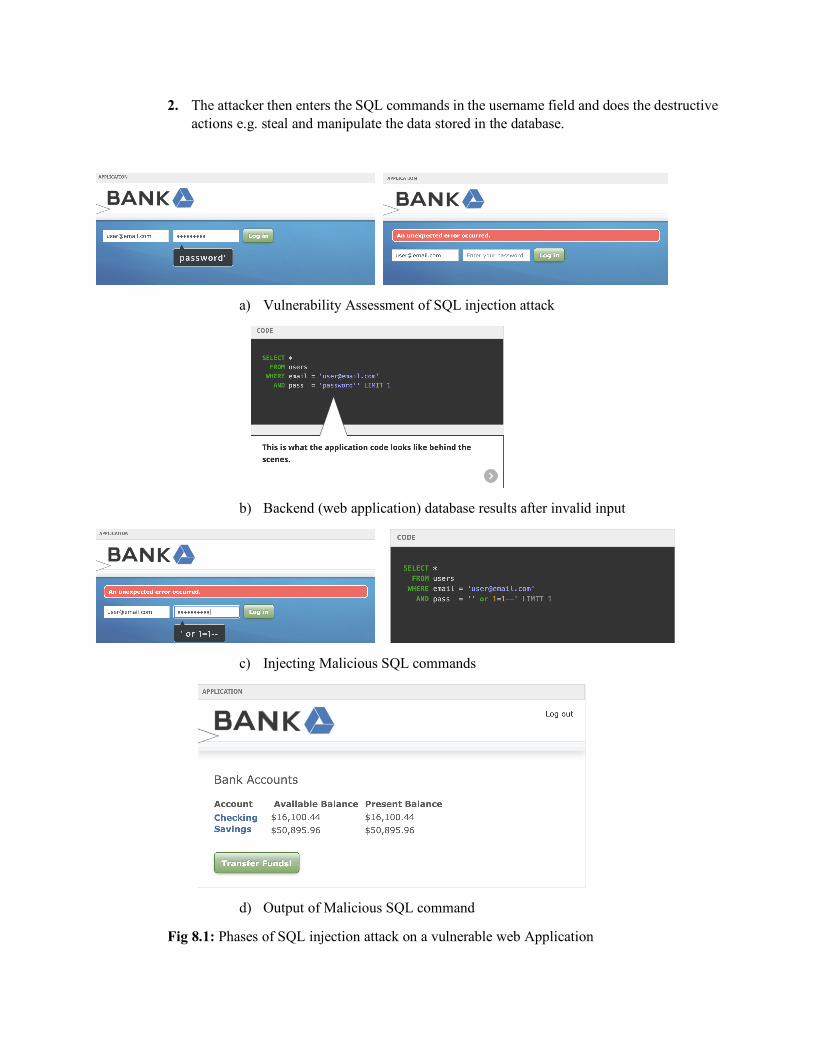
2. The attacker then enters the SQL commands in the username field and does the destructive actions e.g. steal and manipulate the data stored in the database.
a) Vulnerability Assessment of SQL injection attack
b) Backend (web application) database results after invalid input
c) Injecting Malicious SQL commands
d) Output of Malicious SQL command
Fig 8.1: Phases of SQL injection attack on a vulnerable web Application

The Sqlmap is the one of the most widely used tools for SQL injection attacks which automates the process of vulnerability assessment and injection of the SQL commands. The attacker just has to enter few commands and follow a simple four (4) steps process:
1) Identification of the databases 2) Choose a specific database and identify tables of that databases 3) Choose a specific table and identify the columns 4) Dump the columns
Figure 8.2 presents the results of a SQL injection attack using Sqlmap.
a) Identification of Databases
b) Available Databases on target webserver
c) Identification of Tables on the specified database
d) Available tables on specified database
e) Identification of Columns on the specified table
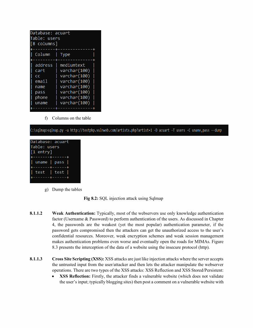
f) Columns on the table
g) Dump the tables
Fig 8.2: SQL injection attack using Sqlmap
8.1.1.2 Weak Authentication: Typically, most of the webservers use only knowledge authentication
factor (Username & Password) to perform authentication of the users. As discussed in Chapter 4, the passwords are the weakest (yet the most popular) authentication parameter, if the password gets compromised then the attackers can get the unauthorized access to the user’s confidential resources. Moreover, weak encryption schemes and weak session management makes authentication problems even worse and eventually open the roads for MIMAs. Figure 8.3 presents the interception of the data of a website using the insecure protocol (http).
8.1.1.3 Cross Site Scripting (XSS): XSS attacks are just like injection attacks where the server accepts the untrusted input from the user/attacker and then lets the attacker manipulate the webserver operations. There are two types of the XSS attacks: XSS Reflection and XSS Stored/Persistent: • XSS Reflection: Firstly, the attacker finds a vulnerable website (which does not validate
the user’s input; typically blogging sites) then post a comment on a vulnerable website with

Fig 8.3: Interception using Wireshark underlying malicious script. When any user clicks the comment to respond then it can result in many malicious outcomes e.g.
o Steals the user browser’s history or cookies o Redirects the users to a crafted/fraudulent website o Install a malicious software or Add-ons
• XSS Stored/Persistent: The XSS stored is more dangerous as compared to XSS reflection. In a XSS stored attack, the attacker injects the malicious scripts that are stored on vulnerable servers. Then, whoever visits that containment webserver, becomes the victim of the attack e.g. The attacker can store a cookies stealing script on the webserver and then anyone who visits the website, the malicious script forwards a copy of the session cookie to attacker. Figure 8.1 shows the session key stealing script.
8.1.1.4 Sensitive Data Exposure: Another common vulnerability of many of the web applications is sensitive data exposure which occurs because of information being cached on a local computer. For example, a client uses a public computer (Library or Internet café) to access his or her school’s email or bank account then some of the sensitive information related to the user’s account gets cached on the local memory. When the legitimate user logs off the system, an the attacker logs into the system and can access the user’s account with the cached account information.

Fig. 8.4: XSS attack session key stealing cookie
8.1.1.5 Invalidated URLs/redirects: Many blogging and social media websites, allow the users to post (embed) the URLs without any proper validation (whether the URLs are listed in the blacklists or not). This vulnerability leads to many social engineering and forgery attacks where the attackers redirect the users to his or her crafted site from a legitimate web application. Figure 8.5 presents an example of the malicious URL set up by the attacker.
Fig 8.5: Malicious website crafted by the attacker

8.1.1.6 Directory Traversal Attack: In a directory traversal attack, the attacker accesses those directories and files which they are not authorized to access. The directory traversal attack typically exploits poor access control mechanisms of web applications. Figure 8.6 presents a directory traversal attack resulting from a vulnerable web application.
Fig 8.6: Directory Traversal (Command Injection) Attack
8.2 Wireless Networks Attacks
Wireless Communication Technologies (WCTs) e.g. Wireless Local Area Network (WLAN), Bluetooth and NFC etc. have started quickly replacing the wired networks. These WCTs have changed the way we use the Internet and manage digital resources. Besides, many of the benefits of WCTs, attackers have identified many pitfalls in protocols and structural vulnerabilities of WCTs especially Wifi (Wireless Fidelity) and Bluetooth. In this chapter, we will discuss some security attacks on Bluetooth and WLAN technologies. The details are presented as follows:
8.2.1 Bluetooth
Bluetooth is a WCT that uses short range radio signals and allows the exchange of information between a fixed and mobile device. The network which is established using Bluetooth technology is called Personal Area Network (PAN). When two (2) Bluetooth enables devices (one could be fixed and other mobile) come within the range of each other then one of the devices becomes “Master” and the other becomes “Slave”. The Master controls the overall communication and gives the instructions to the slave. The slave executes the instructions and returns the output. In the Bluetooth enabled car audio system, the cell phone acts as master while the car speakers act as slave. There are three (3) common Bluetooth security attacks; Bluejacking, Bluejacking and Bluebugging. The detailed description of these attacks is presented as follows:
• Bluejacking: Bluejacking is more of an annoying attack (rather than a harmful), in bluejacking, the attacker sends the unsolicited messages to the nearby Bluetooth-enabled devices. The bluejacking attack just displays a message on the victim’s device screen and does not make any connection with the remote device (Bluetooth device).
• Bluesnarfing: Bluesnarfing is a harmful attack in which, the attacker establishes a connection with the nearby Bluetooth-enabled device without the victim’s knowledge and accesses the internal data of the device. The attacker can copy the phone contacts, recent call logs, messages, emails and even the pictures stored on the device.
• Bluebugging: The most harmful attack as compared to other Bluetooth attacks is Bluebugging, in a bluebugging attack, the attacker first establishes a silent connection (without owner’s knowledge) with the victim’s device (e.g. Social Engineering techniques). After successful connection, the attacker installs a backdoor (malware) to bypass the authentication schemes and finally takes full control of the device. After having the full control over the device, the attacker can make phone calls from the victim’s device, activate call forwarding, change passwords or patterns and make copy the pictures or videos etc.
8.2.2 Wireless Local Area Network (WLAN) attacks
In 1997, IEEE (Institute of Electrical and Electronics Engineers) introduced the concept of WLAN under the project 802.11 and the term Wi-Fi was adapted in August 1999. This newly introduced way of connecting devices with Internet got a lot of attention and appreciation. Since, Wi-Fi involves wireless channels for communication information security was the only concern at that time, which IEEE tried to resolve with the integration of WEP (Wired Equivalent Privacy) security protocol with IEEE 802.11 standard. In 2003, several security analysts and researchers highlighted many vulnerabilities of the WEP protocol and raised the need of new security protocol. In 2003, IEEE proposed a new security protocol named; Wi-Fi Protected Access (WPA). In addition to encryption, WPA also introduced the key (password) based access control of the Wi-Fi routers which avoided the piggy backers to access the bandwidth. The WPA uses Temporal Key Integrity Protocol (TKIP) and validates the integrity of the exchanged messages which was better as compared to a CRC (Cyclic Redundancy Check) used in WEP. However, within six (6) months of its introduction, security analysts reported many pitfalls of the encryption scheme used in WPA which makes it even worse than WEP. Then in 2004, WPA2 was introduced which involves key-based router accessing mechanism and AES based encryption mode. In 2018, WPA3 was introduced as a replacement of WPA2. WPA3 mainly involves Simultaneous Authentication of Equals, offers forward secrecy and also ensures the protection of management frames. One of the inherent vulnerabilities of WLAN is the “undefined boundary” of the wireless network which allows the attackers to do multiple malicious activities e.g.
• Unauthorized scanning of the networks • Interception • Desynchronization attacks
To avoid most of the WLAN security threats, following two (2) recommendations are suggested:
• Disable broadcasting of SSID, once all legitimate devices are connected with WLAN. • Use WPA2 or WPA3 to configure the WLAN.
In this chapter, we have discuss six main (6) security attacks of WLAN:
1. Rogue Access Points 2. Evil Twins 3. Intercepting the wireless data 4. Replay attacks
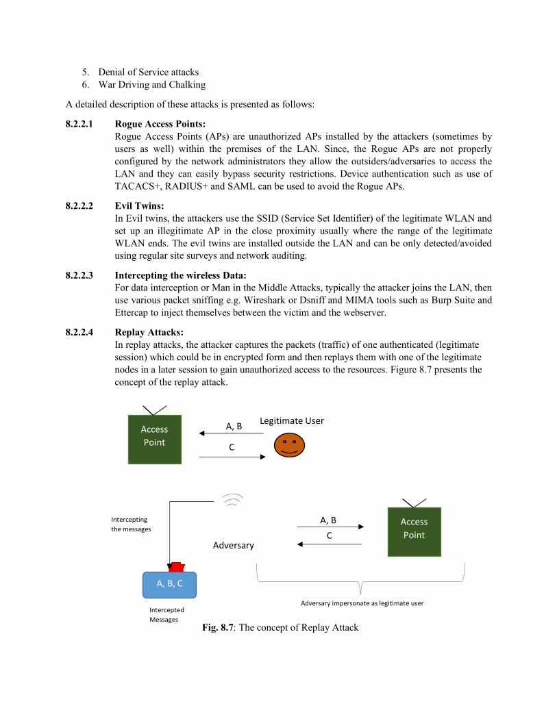
5. Denial of Service attacks 6. War Driving and Chalking
A detailed description of these attacks is presented as follows:
8.2.2.1 Rogue Access Points: Rogue Access Points (APs) are unauthorized APs installed by the attackers (sometimes by users as well) within the premises of the LAN. Since, the Rogue APs are not properly configured by the network administrators they allow the outsiders/adversaries to access the LAN and they can easily bypass security restrictions. Device authentication such as use of TACACS+, RADIUS+ and SAML can be used to avoid the Rogue APs.
8.2.2.2 Evil Twins: In Evil twins, the attackers use the SSID (Service Set Identifier) of the legitimate WLAN and set up an illegitimate AP in the close proximity usually where the range of the legitimate WLAN ends. The evil twins are installed outside the LAN and can be only detected/avoided using regular site surveys and network auditing.
8.2.2.3 Intercepting the wireless Data: For data interception or Man in the Middle Attacks, typically the attacker joins the LAN, then use various packet sniffing e.g. Wireshark or Dsniff and MIMA tools such as Burp Suite and Ettercap to inject themselves between the victim and the webserver.
8.2.2.4 Replay Attacks: In replay attacks, the attacker captures the packets (traffic) of one authenticated (legitimate session) which could be in encrypted form and then replays them with one of the legitimate nodes in a later session to gain unauthorized access to the resources. Figure 8.7 presents the concept of the replay attack.
Fig. 8.7: The concept of Replay Attack
Access Point
Legitimate User A, B
C Adversary
Intercepting the messages
A, B, C
Intercepted Messages
Access Point
A, B
C
Adversary impersonate as legitimate user
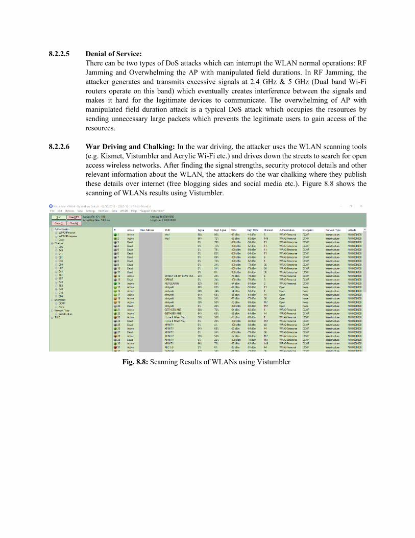
8.2.2.5 Denial of Service: There can be two types of DoS attacks which can interrupt the WLAN normal operations: RF Jamming and Overwhelming the AP with manipulated field durations. In RF Jamming, the attacker generates and transmits excessive signals at 2.4 GHz & 5 GHz (Dual band Wi-Fi routers operate on this band) which eventually creates interference between the signals and makes it hard for the legitimate devices to communicate. The overwhelming of AP with manipulated field duration attack is a typical DoS attack which occupies the resources by sending unnecessary large packets which prevents the legitimate users to gain access of the resources.
8.2.2.6 War Driving and Chalking: In the war driving, the attacker uses the WLAN scanning tools (e.g. Kismet, Vistumbler and Acrylic Wi-Fi etc.) and drives down the streets to search for open access wireless networks. After finding the signal strengths, security protocol details and other relevant information about the WLAN, the attackers do the war chalking where they publish these details over internet (free blogging sides and social media etc.). Figure 8.8 shows the scanning of WLANs results using Vistumbler.
Fig. 8.8: Scanning Results of WLANs using Vistumbler
Copyright © 2022 FDOKUMEN