Information Bulletin 102
104
Information Bulletin 102 High-Voltage Product and Service Solutions TABLE OF CONTENTS
-
Upload
khangminh22 -
Category
Documents
-
view
1 -
download
0
Transcript of Information Bulletin 102

Information Bulletin 102
High-Voltage Product and Service Solutions
TABLE OF CONTENTS
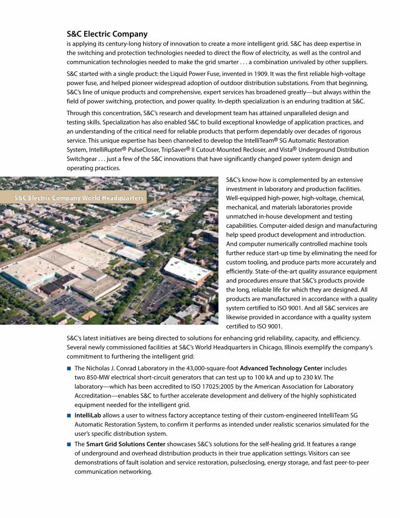
S&C Electric Company World Headquarters
S&C Electric Company is applying its century-long history of innovation to create a more intelligent grid. S&C has deep expertise in the switching and protection technologies needed to direct the flow of electricity, as well as the control and communication technologies needed to make the grid smarter . . . a combination unrivaled by other suppliers.
S&C started with a single product: the Liquid Power Fuse, invented in 1909. It was the first reliable high-voltage power fuse, and helped pioneer widespread adoption of outdoor distribution substations. From that beginning, S&C’s line of unique products and comprehensive, expert services has broadened greatly—but always within the field of power switching, protection, and power quality. In-depth specialization is an enduring tradition at S&C.
Through this concentration, S&C’s research and development team has attained unparalleled design and testing skills. Specialization has also enabled S&C to build exceptional knowledge of application practices, and an understanding of the critical need for reliable products that perform dependably over decades of rigorous service. This unique expertise has been channeled to develop the IntelliTeam® SG Automatic Restoration System, IntelliRupter® PulseCloser, TripSaver® II Cutout-Mounted Recloser, and Vista® Underground Distribution Switchgear . . . just a few of the S&C innovations that have significantly changed power system design and operating practices.
S&C’s know-how is complemented by an extensive investment in laboratory and production facilities. Well-equipped high-power, high-voltage, chemical, mechanical, and materials laboratories provide unmatched in-house development and testing capabilities. Computer-aided design and manufacturing help speed product development and introduction. And computer numerically controlled machine tools further reduce start-up time by eliminating the need for custom tooling, and produce parts more accurately and efficiently. State-of-the-art quality assurance equipment and procedures ensure that S&C’s products provide the long, reliable life for which they are designed. All products are manufactured in accordance with a quality system certified to ISO 9001. And all S&C services are likewise provided in accordance with a quality system certified to ISO 9001.
S&C’s latest initiatives are being directed to solutions for enhancing grid reliability, capacity, and efficiency. Several newly commissioned facilities at S&C’s World Headquarters in Chicago, Illinois exemplify the company’s commitment to furthering the intelligent grid:
■ The Nicholas J. Conrad Laboratory in the 43,000-square-foot Advanced Technology Center includes two 850-MW electrical short-circuit generators that can test up to 100 kA and up to 230 kV. The laboratory—which has been accredited to ISO 17025:2005 by the American Association for Laboratory Accreditation—enables S&C to further accelerate development and delivery of the highly sophisticated equipment needed for the intelligent grid.
■ IntelliLab allows a user to witness factory acceptance testing of their custom-engineered IntelliTeam SG Automatic Restoration System, to confirm it performs as intended under realistic scenarios simulated for the user’s specific distribution system.
■ The Smart Grid Solutions Center showcases S&C’s solutions for the self-healing grid. It features a range of underground and overhead distribution products in their true application settings. Visitors can see demonstrations of fault isolation and service restoration, pulseclosing, energy storage, and fast peer-to-peer communication networking.
CONTENTS
SOLUTIONS FOR ENHANCING GRID RELIABILITY, CAPACITY, AND EFFICIENCY 4 Introduction
8 IntelliTeam® SG Automatic Restoration System and IntelliNode™ Interface Module
12 IntelliRupter® PulseCloser
16 Scada-Mate® Switching System
20 Scada-Mate CX™ Switching System
22 TripSaver® II Cutout-Mounted Recloser
24 Remote Supervisory and Source-Transfer PMH and PME Pad-Mounted Gear
26 Remote Supervisory and Source-Transfer Vista® Underground Distribution Switchgear
28 High-Speed Fault-Clearing System
30 PureWave® UPS System and PureWave® UPS XT System
32 IntelliTeam® VV Volt-Var Optimization System, IntelliCap® 2000 and IntelliCap® Automatic Capacitor Controls, and BankGuard Plus® Controls
34 PureWave® DSTATCOM Distributed Static Compensator, Vista® Underground Distribution Switchgear, and System VI™ Switchgear
36 PureWave® Storage Management System and PureWave® Community Energy Storage System
38 SpeedNet™ Radios, IntelliCom® Mesh Radios, IntelliTeam® CNMS Communication Network Management System, and IntelliCom® View Pro Network Management Software
40 Services for Enhancing Grid Reliability, Capacity, and Efficiency
GENERAL SWITCHING AND PROTECTION SOLUTIONS 44 Introduction 46 Fault Tamer ® Fuse Limiter 48 Type XS Fuse Cutouts 50 Positrol® Fuse Links 52 SMD-20 Power Fuses and SMD-40 Power Fuses 56 Loadbuster Disconnects®
58 Loadbuster ®—The S&C Loadbreak Tool 60 Omni-Rupter ® Switches and Alduti-Rupter® Switches 68 Regulator Bypass Switches and Recloser Bypass Disconnects 70 PMH and PME Pad-Mounted Gear 78 Vista® Underground Distribution Switchgear 82 Vista® SD Underground Distribution Switchgear 86 Custom Metal-Enclosed Switchgear 90 PMX™ Modular Metal-Enclosed Switchgear 92 System VI™ Switchgear 94 SMD-1A, -2B, -2C, -3, and -50 Power Fuses 96 Trans-Rupter II® Transformer Protectors 98 Circuit-Switchers and Circuit-Isolator II™ Disconnects100 General Switching and Protection Services
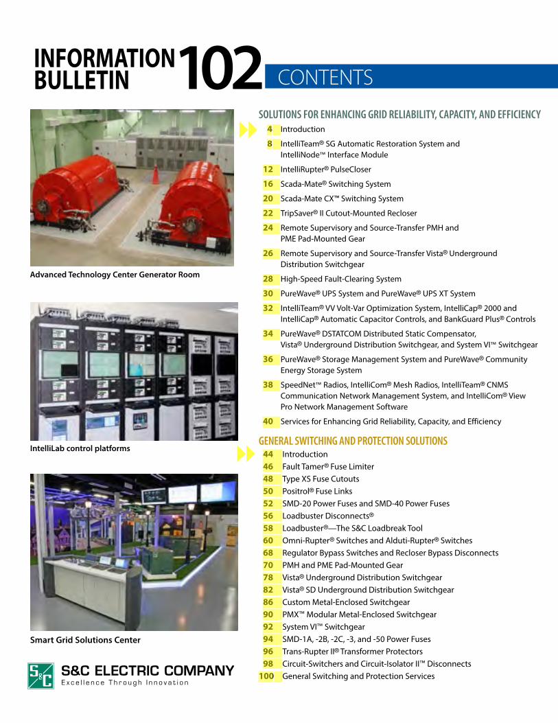
INFORMATIONBULLETIN 102
Advanced Technology Center Generator Room
IntelliLab control platforms
Smart Grid Solutions Center
aleknam
Highlight
aleknam
Highlight
aleknam
Highlight
aleknam
Highlight
aleknam
Highlight
aleknam
Highlight
aleknam
Highlight
aleknam
Highlight
aleknam
Highlight
aleknam
Highlight
aleknam
Highlight
aleknam
Highlight
aleknam
Highlight
aleknam
Highlight
aleknam
Highlight
aleknam
Highlight
aleknam
Highlight
aleknam
Highlight
aleknam
Highlight
aleknam
Highlight
aleknam
Highlight
aleknam
Highlight
aleknam
Highlight
aleknam
Highlight
aleknam
Highlight
aleknam
Highlight
aleknam
Highlight
aleknam
Highlight
aleknam
Highlight
aleknam
Highlight
aleknam
Highlight
aleknam
Highlight
aleknam
Highlight
aleknam
Highlight

4 TABLE OF CONTENTS
S&C is the industry leader in switching, protection, control, and communication technologies for enhancing grid reliability, capacity, and efficiency.
IntelliTeam® SG Automatic Restoration System is the cornerstone of S&C’s offerings. This scalable system is the latest refinement to award-winning IntelliTeam®. IntelliTeam SG enables a network of switching devices to be “self-aware” of the distribution system and quickly make decisions for optimizing the system—such as reconfiguring it after a fault to restore service to the maximum number of customers . . . often in less than five seconds.
IntelliTeam SG runs on S&C’s revolutionary IntelliRupter® PulseCloser, as well as 6800 Series Automatic Switch Controls applied with Scada-Mate® Switches, Scada-Mate CX™ Switches, Remote Supervisory PMH Pad-Mounted Gear, Remote Supervisory PME Pad-Mounted Gear, and Remote Supervisory Vista® Underground Distribution Switchgear.
IntelliTeam SG is a truly universal solution. It also runs on the IntelliNode™ Interface Module, which works with the microprocessor relay of a non-S&C-manufactured substation breaker, recloser, or other intelligent electronic device to provide full team member logic and communication capabilities to the device. It allows the device to operate as needed to minimize the impact of a fault or loss of source.
TripSaver® II Cutout-Mounted Recloser is ideal for overhead lateral circuits that frequently experience
momentary faults. This self-powered, electronically controlled, single-phase fault interrupter eliminates the permanent outages which can result when a lateral fuse operates in response to a momentary fault, and can be installed in a new or existing current-production S&C or MacLean Power Systems Type XS Fuse Cutout Mounting.
For certain industrial, commercial, and campus power users, no power interruptions are acceptable. The High-Speed Fault-Clearing System, featuring specially configured Remote Supervisory Vista® Underground Distribution Switchgear, can provide a no-interruption system for underground applications.
For critical loads such as hospitals, airports, pumping stations, and commercial office buildings, service continuity can often be improved through the use of multiple power sources and automatic source-transfer equipment. S&C’s microprocessor-based Micro-AT® Source-Transfer Controls and 6802 Automatic Switch Controls are ideally suited for these applications and can provide transfer in as little a 10 cycles in Source-Transfer PMH Pad-Mounted Gear.
The PureWave® UPS System enhances continuity for facilities in which voltage sags, surges, transients, momentary disruptions, and complete outages are of concern. It offers 60 seconds of protection at 100% load, protecting sensitive loads from 99% of all power quality problems. The PureWave® UPS XT System can protect sensitive loads for any specified length of time: one minute, five minutes, 15 minutes, or beyond.
Solutions for Enhancing Grid Reliability, Capacity, and Efficiency
Scada-Mate® Switching System—pages 16 -19.IntelliRupter® PulseCloser—pages 12 -15.
aleknam
Highlight
aleknam
Highlight

5TABLE OF CONTENTS
Remote Supervisory Vista® Underground Distribution Switchgear—pages 26 - 27.
PureWave® UPS System—pages 30 - 31.
Remote Supervisory PME Pad-Mounted Gear—pages 24 - 25.
TripSaver® II Cutout-Mounted Recloser—pages 22 - 23.
Scada-Mate CX™ Switching System—pages 20 -21.
SOLU
TION
S FOR EN
HA
NCIN
G G
RID RELIA
BILITY, CAPACITY, A
ND
EFFICIENCY
aleknam
Highlight
aleknam
Highlight
aleknam
Highlight
aleknam
Highlight
aleknam
Highlight

6 TABLE OF CONTENTS
PureWave® Community Energy Storage System— pages 36 - 37.
IntelliTeam® VV Volt -Var Optimization System— pages 32 - 33.
Solutions for Enhancing Grid Reliability, Capacity, and Efficiency
IntelliTeam® VV Volt-Var Optimization System provides a cost-effective means for optimizing distribution system voltage, power factor, and other grid operating characteristics based on real-time conditions. It works with a wide range of load-tap changers, voltage regulators, and capacitor bank controls including IntelliCap® 2000 Automatic Capacitor Controls.
S&C also offers non-communicating IntelliCap® Automatic Capacitor Controls for distribution capacitor bank applications, along with BankGuard Plus® Controls for substation capacitor bank applications.
To address the VAR compensation requirements of renewable energy plants and permit them to conform to interconnection requirements, S&C offers the PureWave® DSTATCOM Distributed Static Compensator. This fast-compensating reactive power source has been applied at installations worldwide.
S&C offers the broadest range of energy storage solutions in the industry, including systems that increase the utilization of renewable energy from a wind or solar plant, or provide supplemental power to a group of residential customers.
PureWave® Storage Management System allows better utilization of renewable energy. Applied at the wind or solar plant collector substation, it offers megawatt-hours of energy storage, permitting this power to be dispatched when it’s needed.
PureWave® Community Energy Storage System provides distributed energy storage close to residential customers. It has the capacity to supply supplemental power to a group of customers for up to three hours . . . more than sufficient for the duration of most outages.
PureWave® Storage Management System—pages 36 - 37.
aleknam
Highlight
aleknam
Highlight
aleknam
Highlight

7TABLE OF CONTENTS
PureWave® DSTATCOM Distributed Static Compensator—pages 34 -35.
Series 2000 Circuit-Switcher—pages 98 -99.
SOLU
TION
S FOR EN
HA
NCIN
G G
RID RELIA
BILITY, CAPACITY, A
ND
EFFICIENCY
Renewable energy plants require a collector system to deliver the energy to the collector substation, and on to the transmission grid. S&C’s proven switchgear solutions for collector system applications deliver superior performance in the most challenging environments. Compact Vista® Switchgear provide switching and protection for the turbines that produce gigawatts of power around the world. System VI™ Switchgear is a cost-effective alternative to a traditional solar farm collection point substation and can be commissioned in far less time. Both feature switches with a clearly visible open gap and integral grounding capability for a higher level of safety for your operating personnel.
Renewable energy plants also require an interconnection substation to deliver the energy collected from the plant to the grid. S&C’s industry-leading
switchgear is ideal for this application as well. And Circuit-Switcher offers proven transmission-voltage switching and protection performance. It’s been applied at thousands of substations.
S&C’s solutions for enhancing grid reliability, capacity, and efficiency include a broad range of associated engineering and design services, construction and implementation services, post-sales support and remote monitoring services, and inspection and maintenance services. S&C also offers comprehensive services related to the integration of renewable energy plants and energy storage into the intelligent grid.
These services, detailed on pages 40 through 43, can be furnished individually or on an EPC basis with the equipment.
aleknam
Highlight
aleknam
Highlight
aleknam
Highlight
aleknam
Highlight

8 TABLE OF CONTENTS
IntelliTeam® SG Automatic Restoration System and IntelliNode™ Interface Module
Introduced in 1997, IntelliTeam® was the first product of its kind. It uses peer-to-peer communication with distributed intelligence to track system conditions and quickly initiate service restoration. It was way ahead of its time.
In 2003, S&C brought out IntelliTeam® II . . . an order of magnitude more powerful than the original. Fully scalable, it supports complex systems of virtually any size and tie points from multiple sources. It can handle as many teams of switches as line loading will allow. And each team can have up to eight switches, arranged in radial or looped circuits, or a combination of both.
Now, S&C has advanced IntelliTeam technology with IntelliTeam SG. It’s even more robust and easier to use, and offers such important features as:
IntelliTeam SG Designer. Simplifies system configuration. Just draw a single-line diagram of your distribution system. Your diagram automatically populates IntelliTeam SG settings. IntelliTeam SG Designer propagates the settings to all team members.
IntelliTeam SG Designer workspace.
Rapid Self-Healing. Isolates faulted section and restores service to non-faulted sections in seconds. An example is shown on page 11.
Communication Enhanced Coordination. Improves feeder segmentation and reduces momentary interruptions. In a system where IntelliRupter® PulseClosers share the same protection curve, only the IntelliRupter closest to a fault will open.
Post-Restoration Load Management. Protects reconfigured system from loading exceeding the capabilities of the system.
Closed-Loop Operation. Eliminates the need for a normally open switching point in applications where the loop is served from two substations. Permits any number of two-sub sections. Ideal for subtransmission applications.
Site Automation Testing. Lets you emulate events using actual site parameters and peer-to-peer communication and—optionally—operate switches.
“New Normal.” Lets you accept the present circuit configuration as the permanent normal configuration.
In-Field Instant Replay. Aids analysis of events. IntelliTeam Designer collects event logs from affected devices and compiles them in a single record. Play it back on the single-line diagram used to configure IntelliTeam SG.
A Truly Universal SolutionIntelliTeam SG is an open platform offering unmatched interoperability. It can automate new or existing circuits. It works with S&C IntelliRupter® PulseClosers, Scada-Mate® and Scada-Mate CX™ Switches, Remote Supervisory PMH and PME Pad-Mounted Gear, and Remote Supervisory Vista® Underground Distribution Switchgear.
IntelliRupter® PulseCloser.
aleknam
Highlight

9TABLE OF CONTENTS
Remote Supervisory Vista® Underground Distribution Switchgear.
And—with S&C’s IntelliNode™ Interface Module—IntelliTeam SG works with a wide array of new and existing DNP 3.0-compatible intelligent electronic devices from other manufacturers, including Cooper, Nu-Lec, SEL, and ABB protection relays and recloser controls.
IntelliNode™ Interface Module.
Improves Service ReliabilityIntelliTeam SG improves service reliability for critical areas of your distribution system, and can be expanded to serve entire regions of the system. No central monitoring or SCADA control is needed . . . though SCADA is fully supported.
With IntelliTeam SG, restoration proceeds without the delays inherent in a dispatcher-operated or centrally controlled system. IntelliTeam SG monitors real-time current and voltage throughout the system and uses this information to make smart switching decisions. It acts locally before breakers or reclosers lock out.
Unlike time-coordinated restoration systems that must be carefully pre-programmed, IntelliTeam SG’s sophisticated operating logic can automatically restore service under multiple event contingencies. During storms or major outages, it quickly returns service to as many customers as possible, freeing your personnel to deal with system repairs. IntelliTeam SG minimizes “Customer Minutes of Interruption,” improving your reliability ratings.
Easily ImplementedIntelliTeam SG provides out-of-the-box automatic restoration functions. No custom programming is required.
IntelliTeam SG is the easiest, most cost-effective way to improve service reliability.
Maximizes Efficiency of Your SystemRestoration capacity is based on real-time loading and actual feeder capacity, not often-outdated historical loading data. Circuits can be routinely loaded higher . . . IntelliTeam SG prevents overloading during restoration. The excess capacity of adjacent sources is used to restore service to unfaulted segments, helping defer the need for system upgrades and allowing you to tie circuits that traditional planning criteria wouldn’t permit.
SOLU
TION
S FOR EN
HA
NCIN
G G
RID RELIA
BILITY, CAPACITY, A
ND
EFFICIENCY
10 TABLE OF CONTENTS
IntelliTeam® SG Automatic Restoration System and IntelliNode™ Interface Module
You’re in ControlIntelliTeam SG gives you the flexibility to select restoration strategies. You’re assured that system planning criteria are observed and that critical users get the highest priority.
IntelliTeam SG can be set to limit the number of segments involved in the restoration process. The process is automatically stopped if it is not completed in a timely manner. IntelliTeam SG utilizes multiple blocking points to prevent automatic operation when your crews are working on the line.
S&C will fully train your operating personnel on this and all other features of IntelliTeam SG, with simple demonstrations utilizing actual controls.
IntelliTeam SG Operating Principles Are Simple Each team maintains power on its line segment,
using the normal power source if possible.
Each team communicates with neighboring teams through controls they share in common. The excess capacity of a neighboring team is a possible restoration source that’s available at the shared switch.
If the normal source power is lost, the team evaluates the excess capacity of all alternate sources and transfers the load to the first available source with sufficient capacity. The alternate source can be more than one team away; inter-team data exchange ensures sharing of excess capacity and coordination of all restoration decisions. If desired, you can prioritize the order in which alternate sources are specified.
Protect the reconfigured system from overloading. After the system has been reconfigured, overloading can potentially occur. If desired, post-restoration load shedding and reconfiguration can be utilized to protect the system from overloading—shifting or dropping load based on prioritization rules you’ve set.
When normal power is restored or the fault corrected, the system returns to its normal configuration: manually, automatically, or via SCADA control.
If another event takes place after the team has transferred to an alternate source, the team will seek another alternate source to keep its line segment energized. The ability to respond to multiple contingencies makes IntelliTeam SG a much more effective tool than other systems. Each team maintains excess-capacity statistics on adjacent teams that it can use to dynamically prioritize the restoration strategy.

11TABLE OF CONTENTS
If there isn’t sufficient capacity in a single source, IntelliTeam SG will instead use Expert Self-Healing to restore service to as many outaged sections as possible using all available sources.
For more information on IntelliTeam SG, see S&C publication 1044-34. For more information on the IntelliNode Interface Module, see S&C publications 1043-30 and 1043-31. These publications are available on our website www.sandc.com. Go to www.sandc.com/it2a for interactive demonstrations of IntelliTeam SG derived from real test scenarios, using actual switch controls and communication devices.
Here’s an example of IntelliTeam SG’s Rapid Self-Healing feature. This feature, when enabled, can significantly decrease the self-healing response time by minimizing the number of switching operations.
If a fault occurs and there’s sufficient capacity in a single source, IntelliTeam SG will use Rapid Self-Healing, opening all switches surrounding the faulted team, then closing one switch to restore service to as many outaged sections as possible using that source.
Rapid Self-HealingLoss of SRC3, IntelliTeam SG
Rapid Self-HealingLoss of SRC3, IntelliTeam SG
Rapid Self-HealingLoss of SRC3, IntelliTeam SG
2
3
1
SOLU
TION
S FOR EN
HA
NCIN
G G
RID RELIA
BILITY, CAPACITY, A
ND
EFFICIENCY

12 TABLE OF CONTENTS
IntelliRupter PulseCloser is a breakthrough in overhead and underground distribution system protection. It features revolutionary PulseClosing Technology™— a unique means for verifying that the line is clear of faults before initiating a closing operation. Pulseclosing is superior to conventional reclosing. It greatly reduces stress on system components, as well as voltage sags experienced by customers upstream of the fault.
IntelliRupter Handles All Your Application NeedsIntelliRupter offers outstanding protection for systems through 38 kV. It features a generous continuous-current capability of up to 800 amperes and a fault interrupting rating of up to 16,000 amperes symmetrical. Models are available with or without an integrated, interlocked disconnect for visible air-gap isolation. All switching is performed internally, for reliable all-weather operation.
In standalone fault interrupter applications, PulseClosing Technology enhances power quality by minimizing momentary interruptions. For example, on a radial circuit, IntelliRupters can be configured so that after one IntelliRupter opens to isolate a fault, those downstream of it open on loss of power and send SCADA exception reports indicating status and the reason for opening. When power returns, each IntelliRupter pulsecloses to verify that its line segment is unfaulted, then recloses to restore service . . . it will never close into a fault. Cold-load inrush is mitigated because only one line segment is energized with each closing. No communication system is required to take advantage of inrush mitigation.
Fully Compatible with IntelliTeam SGIntelliRupter can be readily integrated into an S&C IntelliTeam® SG Automatic Restoration System. After IntelliRupter has isolated a fault, IntelliTeam SG makes full use of multiple sources to restore unfaulted line segments. IntelliTeam SG minimizes the number of customers experiencing an extended power interruption, tremendously improving your System Average Interruption Duration Index. IntelliTeam SG can handle multiple contingencies too.
IntelliRupter is fully compatible with IntelliTeam SG- equipped S&C Scada-Mate® Switches, Scada-Mate CX™ Switches, Remote Supervisory PMH and PME Pad-Mounted Gear, and Remote Supervisory Vista® Underground Distribution Switchgear.
Easy Up–Easy OnIntelliRupter is totally self-contained. All major components—including current and voltage sensors, control group, surge arresters, control power, and disconnect, if furnished—go up in one easy lift. The embedded sensors eliminate the cost, clutter, and complexity of separately mounted sensors. There’s no control enclosure or control cable to install either.
For more information on IntelliRupter PulseCloser, see S&C publications 766-30, 766-31, and 766A-31, available on our website www.sandc.com.
PulseClosing Technology drastically reduces over-
current stress on your system, as shown here
for a phase-wire to grounded-neutral fault.
IntelliRupter® PulseCloser
PULSECLOSING
CONVENTIONAL RECLOSING

13TABLE OF CONTENTS
Integrated voltage sensors on both sides of IntelliRupter provide ±0.5% sensing accuracy across entire temperature range. Integrated current sensors provide extremely flat response, from low-level load currents through fault current levels, with ±0.5% sensing accuracy—ensuring reliable measurements critical for system analysis
Integrated pole-mounting bracket is designed for easy installation. Prevents tilting
Ground-trip blocking lever for temporarily blocking ground overcurrent protection elements when bypassing IntelliRupter
Interrupter open/close/ready lever for manually opening and closing interrupters
Integral power module fed from one side of IntelliRupter or, optionally, two integral power modules fed from a different phase on each side
Hot-line tag lever for setting and releasing tags for energized line work
Integrated disconnect with optional wildlife protection provides visible air gap isolation for dead-line work and facilitates operational testing. Mechanically interlocked with interrupters
Control group features hookstick-removable protection and control module and communication module. Multi-function status light indicates control group is operating normally. Hot-line tag light indicates “set” tag
Optional factory- installed and wired surge arresters
Interrupter open/close indicator on each phase is large and uses reflective materials for easy viewing, day or night. It’s attached directly to the operating rod—no complicated linkages to break
INTELLIRUPTER PULSECLOSER
60-Hz Ratings—50-Hz Ratings in Parentheses
kV Amperes, RMS
Min Max BIL Cont.① Interrupting
11.43(9)
15.5(15.5)
110(110)
630(630)
16 000(16 000)
18.81(20)
27(24)
125(125)
630(630)
12 500(12 500)
23.8(29.7)
38(38)
170(170)
630(630)
12 500(12 500)
① 800 amperes with a minimum wind velocity of two feet per second.
Disconnect open and close lever
15.5 - kV Disconnect Style IntelliRupter PulseCloser in Upright-Crossarm Mounting Configuration.
Stainless-steel base provides outstanding corrosion resistance, even in the harshest environments
SOLU
TION
S FOR EN
HA
NCIN
G G
RID RELIA
BILITY, CAPACITY, A
ND
EFFICIENCY
14 TABLE OF CONTENTS
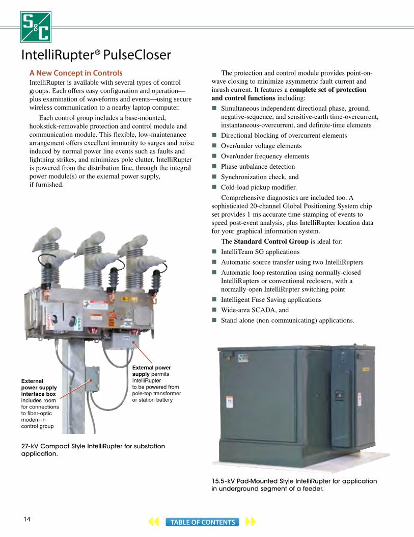
IntelliRupter® PulseCloser A New Concept in Controls IntelliRupter is available with several types of control groups. Each offers easy configuration and operation—plus examination of waveforms and events—using secure wireless communication to a nearby laptop computer.
Each control group includes a base-mounted, hookstick-removable protection and control module and communication module. This flexible, low-maintenance arrangement offers excellent immunity to surges and noise induced by normal power line events such as faults and lightning strikes, and minimizes pole clutter. IntelliRupter is powered from the distribution line, through the integral power module(s) or the external power supply, if furnished.
External power supply permits IntelliRupter to be powered from pole-top transformer or station battery
External power supply interface box includes room for connections to fiber-optic modem in control group
The protection and control module provides point-on-wave closing to minimize asymmetric fault current and inrush current. It features a complete set of protection and control functions including:
Simultaneous independent directional phase, ground, negative-sequence, and sensitive-earth time-overcurrent, instantaneous-overcurrent, and definite-time elements
Directional blocking of overcurrent elements
Over/under voltage elements
Over/under frequency elements
Phase unbalance detection
Synchronization check, and
Cold-load pickup modifier.
Comprehensive diagnostics are included too. A sophisticated 20-channel Global Positioning System chip set provides 1-ms accurate time-stamping of events to speed post-event analysis, plus IntelliRupter location data for your graphical information system.
The Standard Control Group is ideal for:
IntelliTeam SG applications
Automatic source transfer using two IntelliRupters
Automatic loop restoration using normally-closed IntelliRupters or conventional reclosers, with a normally-open IntelliRupter switching point
Intelligent Fuse Saving applications
Wide-area SCADA, and
Stand-alone (non-communicating) applications.
15.5 - kV Pad-Mounted Style IntelliRupter for application in underground segment of a feeder.
27- kV Compact Style IntelliRupter for substation application.
15TABLE OF CONTENTS
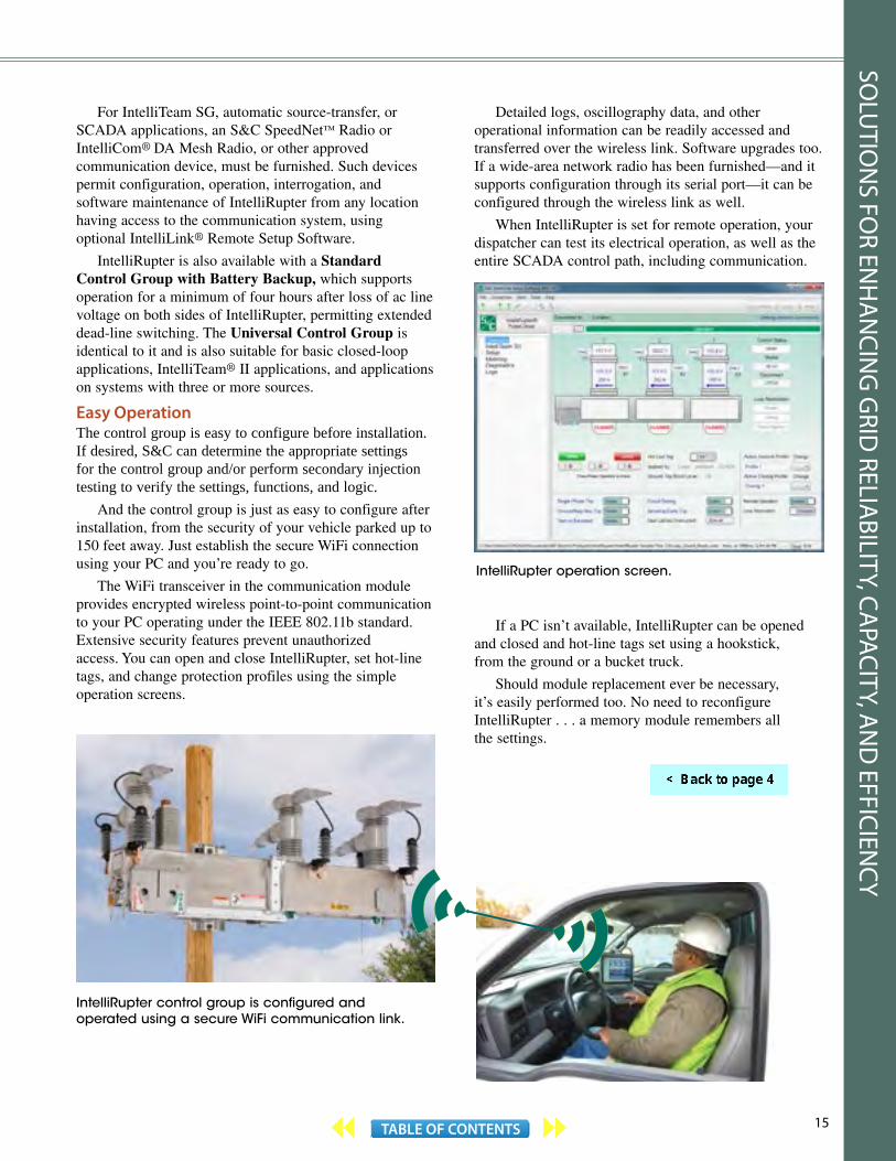
For IntelliTeam SG, automatic source-transfer, or SCADA applications, an S&C SpeedNet™ Radio or IntelliCom® DA Mesh Radio, or other approved communication device, must be furnished. Such devices permit configuration, operation, interrogation, and software maintenance of IntelliRupter from any location having access to the communication system, using optional IntelliLink® Remote Setup Software.
IntelliRupter is also available with a Standard Control Group with Battery Backup, which supports operation for a minimum of four hours after loss of ac line voltage on both sides of IntelliRupter, permitting extended dead-line switching. The Universal Control Group is identical to it and is also suitable for basic closed-loop applications, IntelliTeam® II applications, and applications on systems with three or more sources.
Easy OperationThe control group is easy to configure before installation. If desired, S&C can determine the appropriate settings for the control group and/or perform secondary injection testing to verify the settings, functions, and logic.
And the control group is just as easy to configure after installation, from the security of your vehicle parked up to 150 feet away. Just establish the secure WiFi connection using your PC and you’re ready to go.
The WiFi transceiver in the communication module provides encrypted wireless point-to-point communication to your PC operating under the IEEE 802.11b standard. Extensive security features prevent unauthorized access. You can open and close IntelliRupter, set hot-line tags, and change protection profiles using the simple operation screens.
IntelliRupter control group is configured and operated using a secure WiFi communication link.
Detailed logs, oscillography data, and other operational information can be readily accessed and transferred over the wireless link. Software upgrades too. If a wide-area network radio has been furnished—and it supports configuration through its serial port—it can be configured through the wireless link as well.
When IntelliRupter is set for remote operation, your dispatcher can test its electrical operation, as well as the entire SCADA control path, including communication.
IntelliRupter operation screen.
If a PC isn’t available, IntelliRupter can be opened and closed and hot-line tags set using a hookstick, from the ground or a bucket truck.
Should module replacement ever be necessary, it’s easily performed too. No need to reconfigure IntelliRupter . . . a memory module remembers all the settings.
SOLU
TION
S FOR EN
HA
NCIN
G G
RID RELIA
BILITY, CAPACITY, A
ND
EFFICIENCY
16 TABLE OF CONTENTS
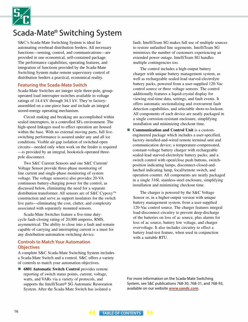
Scada-Mate® Switching SystemS&C’s Scada-Mate Switching System is ideal for automating overhead distribution feeders. All necessary functions—sensing, control, and communications—are provided in one economical, self-contained package. The performance capabilities, operating features, and integration of functions provided by the Scada-Mate Switching System make remote supervisory control of distribution feeders a practical, economical reality.
Featuring the Scada-Mate SwitchScada-Mate Switches are integer style three-pole, group- operated load interrupter switches available in voltage ratings of 14.4 kV through 34.5 kV. They’re factory-assembled on a one-piece base and include an integral stored-energy operating mechanism.
Circuit making and breaking are accomplished within sealed interrupters, in a controlled SF6 environment. The high-speed linkages used to effect operation are housed within the base. With no external moving parts, full live-switching performance is assured under any and all ice conditions. Visible air-gap isolation of switched-open circuits—needed only when work on the feeder is required —is provided by an integral, hookstick-operated three-pole disconnect.
Two S&C Current Sensors and one S&C Current/Voltage Sensor provide three-phase monitoring of line current and single-phase monitoring of system voltage. The voltage sensor(s) also provides 20-VA continuous battery-charging power for the control, as discussed below, eliminating the need for a separate distribution transformer. All sensors are of S&C Cypoxy™ construction and serve as support insulators for the switch live parts—eliminating the cost, clutter, and complexity associated with separately mounted sensors.
Scada-Mate Switches feature a five-time duty-cycle fault-closing rating of 20,000 amperes, RMS, asymmetrical. The ability to close into a fault and remain capable of carrying and interrupting current is a must for any distribution-automation switching device.
Controls to Match Your Automation ObjectivesA complete S&C Scada-Mate Switching System includes a Scada-Mate Switch and a control. S&C offers a variety of controls to match your automation objectives. 6801 Automatic Switch Control provides remote
reporting of switch status points, current, voltage, watts, and VARs via a variety of protocols, and supports the IntelliTeam® SG Automatic Restoration System. After the Scada-Mate Switch has isolated a
fault, IntelliTeam SG makes full use of multiple sources to restore unfaulted line segements. IntelliTeam SG minimizes the number of customers experiencing an extended power outage. IntelliTeam SG handles multiple contingencies too.
The control includes a high-output battery charger with unique battery management system, as well as rechargeable sealed-lead starved-electrolyte battery packs, powered from a user-supplied 120-Vac control source or three voltage sensors. The control additionally features a liquid-crystal display for viewing real-time data, settings, and fault events. It offers automatic sectionalizing and overcurrent fault detection capabilities, and selectable shots-to-lockout. All components of each device are neatly packaged in a single corrosion-resistant enclosure, simplifying installation and minimizing checkout time.
Communication and Control Unit is a custom- engineered package which includes a user-specified, factory-installed-and-wired remote terminal unit and communication device; a temperature-compensated, constant-voltage battery charger with rechargeable sealed-lead starved-electrolyte battery packs; and a switch control with open/close push buttons, switch-position indicating lamps, disconnect-closed-and- latched indicating lamp, local/remote switch, and operation counter. All components are neatly packaged in a single 316L stainless-steel enclosure, simplifying installation and minimizing checkout time.
The charger is powered by the S&C Voltage Sensor or, in a higher-output version with unique battery management system, from a user-supplied 120-Vac control source. The charger features integral load-disconnect circuitry to prevent deep-discharge of the batteries on loss of ac source, plus alarms for loss of ac source, battery low voltage, and charger overvoltage. It also includes circuitry to effect a battery load-test feature, when used in conjunction with a suitable RTU.
For more information on the Scada-Mate Switching System, see S&C publications 768-30, 768-31, and 768-93, available on our website www.sandc.com.

17TABLE OF CONTENTS
Sealed SF6 interrupters—circuit making and circuit breaking are accomplished internally with no exposed moving parts
Two S&C Current Sensors and one S&C Current/Voltage Sensor provide three-phase monitoring of line current and single-phase monitoring of system voltage. Three-phase voltage sensing (shown) is optionally available. Voltage sensors can be provided on both sides of the switch for designated normally open points on the system
Model 6801 Automatic Switch Control. See page 18 for details
Dead-ending provisions allow convenient attachment of conductors
Interrupter open/closed indicator
Shielded control cable for low-voltage connection of switch to control
A variety of options are available—wildlife protection, extension-link assemblies, and others
Disconnect operating lever for hookstick opening and closing of integral disconnect. Disconnect may be locked or tagged in the open position
Integral stored-energy operating mechanism with manual opening and closing capabilities
Enclosed one-piece base houses drive linkages for interrupters
25 - kV Scada-Mate Switch in the Upright Mounting Configuration.
SCADA-MATE SWITCHES
60-Hz Ratings—50-Hz Ratings in Parentheses
kV① Amperes, RMS Five-Time Duty-Cycle Fault Closing,
Amperes, RMS, Asym.Nom. Max BIL Cont. and Interr.②
Mom., Asym.
14.4 (10)«
17.0(15)
110(110)
600(630)
25 000(25 000)
20 000(20 000)
25 (20)«
29(24)
150(150)
600(630)
25 000(25 000)
20 000(20 000)
34.5 38 200 600 25 000 20 000
① System voltage restrictions apply when the control is powered by S&C Current/Voltage Sensors.
② Up to 900 amperes continuous in ambient temperatures to 40°C with a minimum wind velocity of two feet per second.
« Minimum voltage rating.
SOLU
TION
S FOR EN
HA
NCIN
G G
RID RELIA
BILITY, CAPACITY, A
ND
EFFICIENCY
18 TABLE OF CONTENTS
Scada-Mate® Switching System
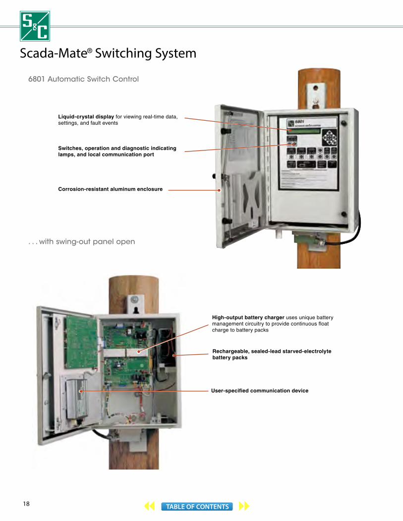
6801 Automatic Switch Control
High-output battery charger uses unique battery management circuitry to provide continuous float charge to battery packs
Rechargeable, sealed-lead starved-electrolyte battery packs
User-specified communication device
Liquid-crystal display for viewing real-time data, settings, and fault events
Switches, operation and diagnostic indicating lamps, and local communication port
Corrosion-resistant aluminum enclosure
. . . with swing- out panel open

19TABLE OF CONTENTS
Scada-Mate Switch Mounting Configurations
Vertical
Tiered-outboard
Upright
Pole-Top
SOLU
TION
S FOR EN
HA
NCIN
G G
RID RELIA
BILITY, CAPACITY, A
ND
EFFICIENCY

20 TABLE OF CONTENTS
Scada-Mate CX™ Switching SystemAutomation needs change and grow with increased load, capacity, and demands for more reliable service. Scada-Mate CX Switches meet these changing needs, economically. These three-pole, group-operated interrupter switches are specifically designed for automating overhead distribution systems. They feature a five-time duty-cycle fault-closing rating of 20,000 amperes, RMS, asymmetrical, plus full live-switching performance under any and all ice conditions—circuit making and circuit breaking are accomplished internally, within sealed interrupters, in a controlled sulfur hexafluoride (SF6) environment.
Scada-Mate CX Switches are factory-assembled on a one-piece base and include an integral stored-energy operating mechanism. In addition to electrically operating the interrupters, the operating mechanism provides non-electrical mechanical opening and closing of the interrupters by means of a manual-operation pull ring. The switch can be locked open to prevent electrical or manual closing.
Scada-Mate CX Switches are also available in a hookstick-operated version. On these switches, the stored-energy operating mechanism is replaced by a factory-adjusted, spring-wound hookstick operating mechanism.
Sealed interrupters, fully enclosed base. Scada-Mate CX Switches feature the same hermetically sealed, low-gas-volume interrupters, open/close indicator, and operating mechanism as Scada-Mates. They’re ideal for installation in areas prone to icing, polluted and coastal environments, and remote locales.
Compact. Scada-Mate CX Switches are 40% smaller than Scada-Mates. And they can be furnished without the disconnect to save additional space.
Upgradable. With Scada-Mate CX Switches, you can purchase the features you need today . . . and easily upgrade tomorrow. Switches can be furnished with factory-installed S&C Current Sensors or S&C Current/Voltage Sensors. Or, alternately, S&C sensors or sensors of other manufacture can be added later. And an S&C control unit or control of other manufacture can be added at any time.
Hookstick-operated switches can be upgraded too, with a motor operator. It permits remote operation in sectionalizing applications that don’t require sensing and intelligent controls.
Visible-break disconnect. If your system practices require it, Scada-Mate CX Switches can be furnished with an integral disconnect comprised of three single-phase hookstick-operated blades, based on S&C’s proven Loadbuster Disconnect® design. The disconnect is interlocked to prevent opening when the interrupters are closed, and closing of the interrupters when the disconnect is open.
Controls that meet your requirements. Scada-Mate CX Switches are available with a wide range of controls to match your automation objectives.
For remote supervisory control applications, the 6801 Automatic Switch Control combines sophisticated automatic control schemes with RTU functionality, data logging, and advanced communication capabilities in a single package. It can manage switches and automatically sectionalize a feeder based on factors such as overcurrent, loss of voltage, and phase unbalance. Multiple controls can be programmed to communicate with each other using the optional IntelliTeam® SG Automatic Restoration System.
Scada-Mate CX Switches can also be furnished with a custom-engineered communication and control unit that provides the interface between the switch and the master-station computer. It can accommodate a remote terminal device of any manufacture, and can be powered by either a customer-supplied source or S&C Current/Voltage Sensors on the Scada-Mate CX Switch.
For source-transfer applications utilizing two Scada-Mate CX Switches, a Micro-AT® Source-Transfer Control or 6802 Automatic Switch Control can be furnished. Both controls provide transfer in as little as 70 cycles.
Simple installation. Scada-Mate CX Switches are easy to install. Lifting means are provided for convenient rigging and hoisting. With their integral sensors and disconnect— and no vertical operating pipe—Scada-Mate CX Switches present a clean uncluttered look.
For more information on the Scada-Mate CX Switching System, see S&C publications 768-34, 768-711, and 768-712, available on our website www.sandc.com.

21TABLE OF CONTENTS
Manual-operation pull ring
Enclosed one-piece base houses drive linkages for interrupters
Integral stored-energy operating mechanism with manual opening and closing capabilities
Sealed SF6 interrupters—circuit making and circuit breaking are accomplished internally with no exposed moving parts
Optional three-phase S&C Current/Voltage Sensors
Interrupter open/closed indicator
14.4-kV Scada-Mate CX Switch in the Upright Mounting Configuration. Also available in Upright—Extra Mounting-Pole Clearance, Upright—Compact, and Tiered-Outboard Mounting Configurations.
SCADA-MATE CX SWITCHES
60-Hz Ratings—50-Hz Ratings in Parentheses
kV① Amperes, RMS Five-Time Duty-Cycle Fault Closing,
Amperes, RMS, Asym.Nom. Max BIL Cont. and Interr.②
Mom., Asym.
14.4 (10)★
17.0(15)
110(110)
900(900)
25 000(25 000)
20 000(20 000)
25 (20)★
29(24)
150(150)
900(900)
25 000(25 000)
20 000(20 000)
① System voltage restrictions apply when the control is powered by S&C Current/Voltage Sensors.
② Switches furnished with optional visible-break disconnect can carry up to 900 amperes continuous in ambient temperatures to 40°C with a minimum wind velocity of 2 feet per second. Maximum allowable conductor temperature is 90°C. Without minimum wind velocity of 2 feet per second, these switches can carry up to 630 amperes continuous.
★ Minimum voltage rating.
14.4-kV Hookstick-Operated Scada-Mate CX Switch, shown with optional visible-break disconnect.
Optional visible-break disconnect
Spring-wound hookstick operating mechanism
SOLU
TION
S FOR EN
HA
NCIN
G G
RID RELIA
BILITY, CAPACITY, A
ND
EFFICIENCY

22 TABLE OF CONTENTS
TripSaver® II Cutout-Mounted RecloserLateral Protection Used to Require ConcessionsOver 90% of temporary faults on overhead distribution circuits occur on laterals. Over the years, utilities have dealt with lateral protection a couple of ways . . .
Some employ a “fuse blowing” philosophy: The lateral fuse clears any downstream fault within its rating. But this means that service to customers on the lateral is permanently interrupted—even for a temporary fault. And the utility must deal with the high cost of service calls to replace lateral fuses.
Others utilities employ a “fuse saving” philosophy: The first trip of the substation feeder breaker is intentionally miscoordinated so the breaker operates faster than the lateral fuse. But all customers on the feeder experience a momentary interruption for all faults.
A Better Solution for Overhead Lateral ProtectionS&C’s TripSaver II Cutout-Mounted Recloser, offered in system class voltage ratings of 15 kV and 25 kV, is ideally suited for lateral circuits that frequently experience momentary faults.
TripSaver II eliminates the permanent outages which can result when lateral fuses operate in response to these momentary faults. It also eliminates the
momentary interruptions on feeders in instances where the substation breaker is tripped to save the lateral fuse during a momentary fault. This self-powered, electronically controlled, single-phase vacuum fault interrupter is available for installation in new or existing current-production (“R10” or “R11”) S&C or MacLean Power Systems Type XS Fuse Cutout Mountings. A two-insulator branch-feeder style mounting is also available.
TripSaver II can provide up to four tripping operations, with a wide variety of available time-current characteristic curves. The vacuum interrupter resets two seconds after TripSaver II drops open. The operator can then reclose TripSaver II into the mounting.
Using a personal computer, you can configure TripSaver II operating parameters, check functionality, and view historical data at any suitable indoor location.
OVERHEAD POLE-TOP STYLE TRIPSAVER II
50/60-Hz Ratings Leakage Distanceto Ground,
Minimum, Inches (mm)kV Amperes, RMS①
System Class
Nom. Max BIL Cont.Interr., Sym.
With Porcelain Insulator
With Polymer Insulator
15 15 15.5 110 1004000 8½ (216) 14⅞ (378)
6300 8½ (216) 14⅞ (378)
25 25 29
125 1004000 11 (279) —
6300 11 (279) —
150 1004000 17 (432) 19 (483)
6300 17 (432) 19 (483)
BRANCH-FEEDER STYLE TRIPSAVER II
50/60-Hz Ratings Leakage Distanceto Ground,
Minimum, Inches (mm)kV Amperes, RMS①
System Class
Nom. Max BIL Cont.Interr., Sym.
With Porcelain Insulators
With Cypoxy™ Insulators
15 15 15.5 150 1004000 24 (610) 24¼ (616)
6300 24 (610) 24¼ (616)
25 25 29 150 1004000 24 (610) 24¼ (616)
6300 24 (610) 24¼ (616)
① Minimum trip current is 5 amperes.
Applicable for protection of single-phase-to-neutral circuits only in solidly- grounded-neutral (multi-grounded-neutral) 34.5-kV systems where leakage distance to ground meets user’s requirement. Uses 25-kV 150-kV BIL mounting.
23TABLE OF CONTENTS
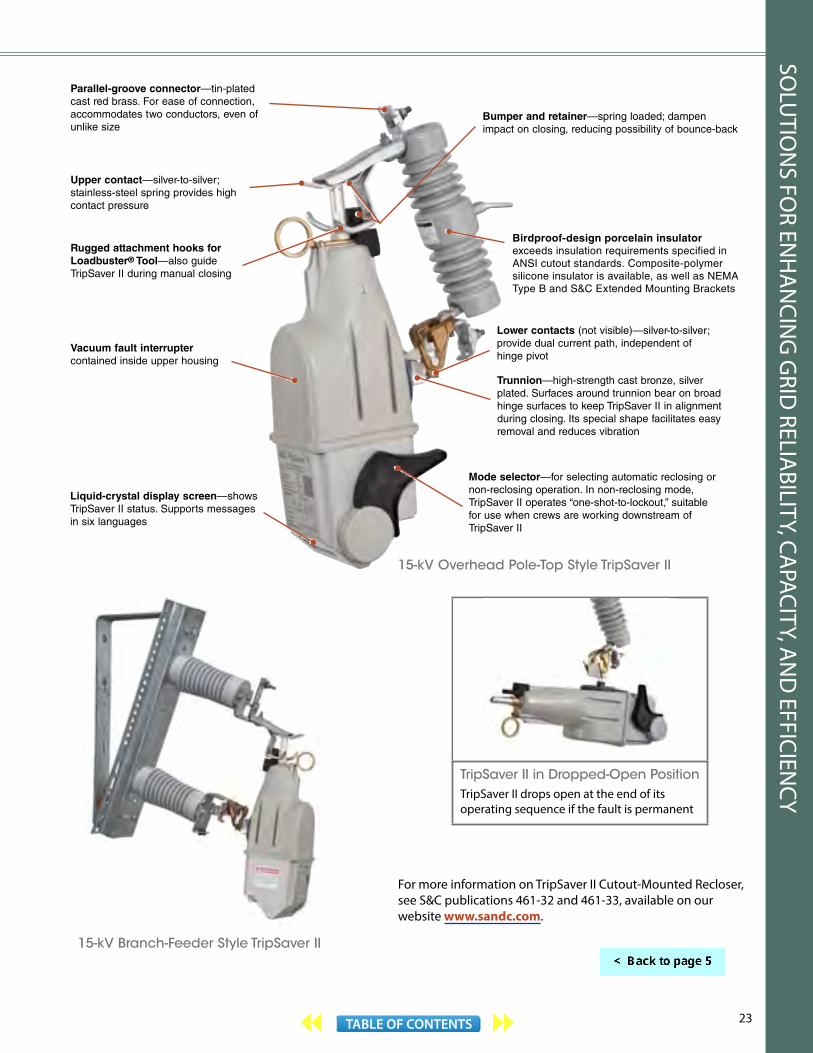
Birdproof-design porcelain insulator exceeds insulation requirements specified in ANSI cutout standards. Composite-polymer silicone insulator is available, as well as NEMA Type B and S&C Extended Mounting Brackets
Parallel-groove connector—tin-plated cast red brass. For ease of connection, accommodates two conductors, even of unlike size
Upper contact—silver-to-silver; stainless-steel spring provides high contact pressure
Vacuum fault interruptercontained inside upper housing
Trunnion—high-strength cast bronze, silver plated. Surfaces around trunnion bear on broad hinge surfaces to keep TripSaver II in alignment during closing. Its special shape facilitates easy removal and reduces vibration
Mode selector—for selecting automatic reclosing or non-reclosing operation. In non-reclosing mode, TripSaver II operates “one-shot-to-lockout,” suitable for use when crews are working downstream of TripSaver II
Lower contacts (not visible)—silver-to-silver; provide dual current path, independent of hinge pivot
Rugged attachment hooks for Loadbuster® Tool—also guide TripSaver II during manual closing
For more information on TripSaver II Cutout-Mounted Recloser, see S&C publications 461-32 and 461-33, available on our website www.sandc.com.
15-kV Overhead Pole-Top Style TripSaver II
15-kV Branch-Feeder Style TripSaver II
TripSaver II in Dropped-Open Position
TripSaver II drops open at the end of its operating sequence if the fault is permanent
Liquid-crystal display screen—shows TripSaver II status. Supports messages in six languages
Bumper and retainer—spring loaded; dampen impact on closing, reducing possibility of bounce-back
SOLU
TION
S FOR EN
HA
NCIN
G G
RID RELIA
BILITY, CAPACITY, A
ND
EFFICIENCY
24 TABLE OF CONTENTS
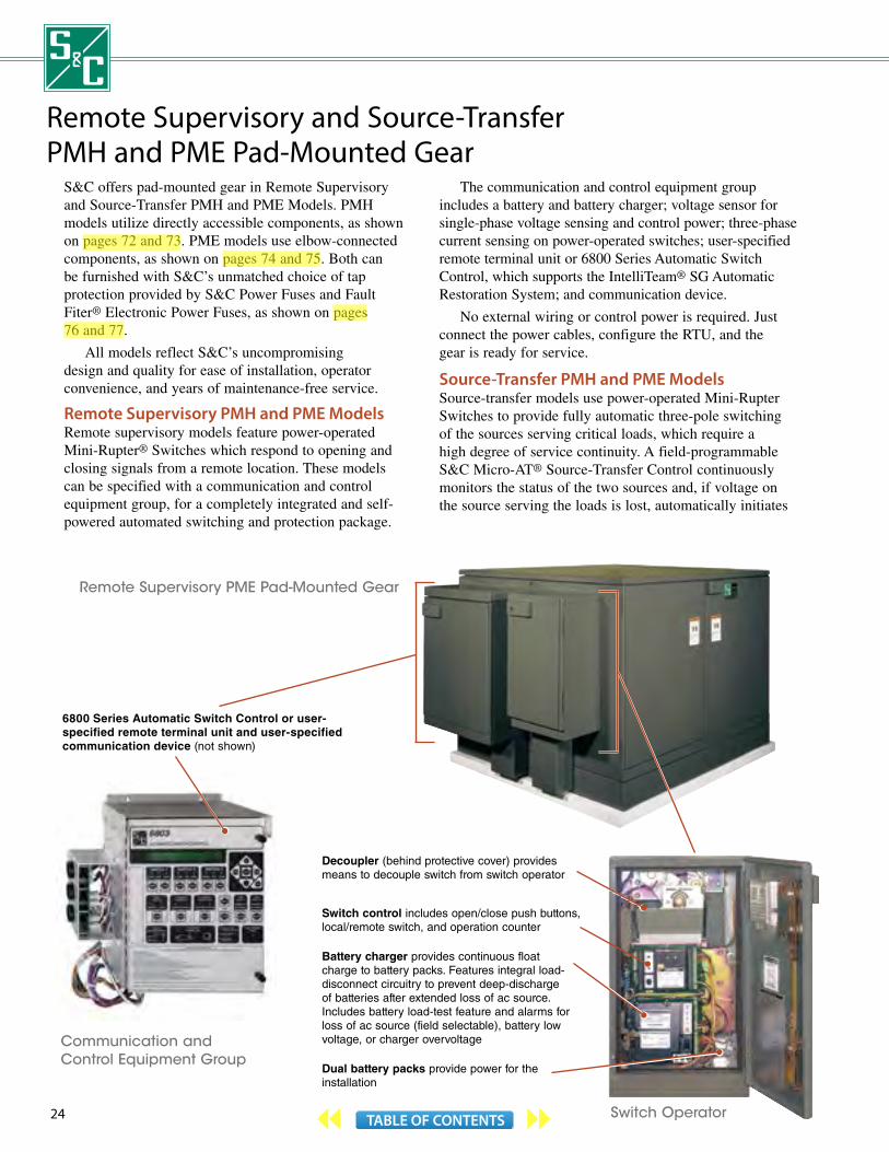
Remote Supervisory and Source-Transfer PMH and PME Pad-Mounted Gear
S&C offers pad-mounted gear in Remote Supervisory and Source-Transfer PMH and PME Models. PMH models utilize directly accessible components, as shown on pages 72 and 73. PME models use elbow-connected components, as shown on pages 74 and 75. Both can be furnished with S&C’s unmatched choice of tap protection provided by S&C Power Fuses and Fault Fiter® Electronic Power Fuses, as shown on pages 76 and 77.
All models reflect S&C’s uncompromising design and quality for ease of installation, operator convenience, and years of maintenance-free service.
Remote Supervisory PMH and PME Models Remote supervisory models feature power-operated Mini-Rupter® Switches which respond to opening and closing signals from a remote location. These models can be specified with a communication and control equipment group, for a completely integrated and self-powered automated switching and protection package.
The communication and control equipment group includes a battery and battery charger; voltage sensor for single-phase voltage sensing and control power; three-phase current sensing on power-operated switches; user-specified remote terminal unit or 6800 Series Automatic Switch Control, which supports the IntelliTeam® SG Automatic Restoration System; and communication device.
No external wiring or control power is required. Just connect the power cables, configure the RTU, and the gear is ready for service.
Source-Transfer PMH and PME ModelsSource-transfer models use power-operated Mini-Rupter Switches to provide fully automatic three-pole switching of the sources serving critical loads, which require a high degree of service continuity. A field-programmable S&C Micro-AT® Source-Transfer Control continuously monitors the status of the two sources and, if voltage on the source serving the loads is lost, automatically initiates
Remote Supervisory PME Pad-Mounted Gear
Decoupler (behind protective cover) provides means to decouple switch from switch operator
Switch control includes open/close push buttons, local/remote switch, and operation counter
Battery charger provides continuous float charge to battery packs. Features integral load-disconnect circuitry to prevent deep-discharge of batteries after extended loss of ac source. Includes battery load-test feature and alarms for loss of ac source (field selectable), battery low voltage, or charger overvoltage
Dual battery packs provide power for the installation
6800 Series Automatic Switch Control or user-specified remote terminal unit and user-specified communication device (not shown)
Communication and Control Equipment Group
Switch Operator
aleknam
Highlight
aleknam
Highlight
aleknam
Highlight

25TABLE OF CONTENTS
switching to transfer to the alternate source, thus restoring power to the loads.
Source-transfer models are totally self-contained switching and protection packages. Each is completely factory-assembled and ready for installation. No external wiring or control power is required.
REMOTE SUPERVISORY AND SOURCE-TRANSFER PMH PAD-MOUNTED GEAR
60-Hz Ratings①
kV Mini-Rupter Switch, Amperes Fuse
Short-Circuit,
Amperes, RMS, Sym.Nom. Max BIL Cont. Load
Dropping Type
Amperes
Max
Load Dropping
with Uni-Rupter
14.4 17.0 95 600 600
SML-20 200E 200 14 000
SML-4Z 200E 200 12 500
Fault Fiter 200 200 14 000
25 27 125 600 600
SML-20 200E 200 12 500
SML-4Z 200E 200 12 500
Fault Fiter 200 200 12 500
For more information on Remote Supervisory PMH Models, see S&C publication 664-31. For Source-Transfer PMH Models, see S&C publications 663A-30 and 663A-31. For Remote Supervisory PME Models, see S&C publication 666-31. All are available on our website www.sandc.com.
REMOTE SUPERVISORY AND SOURCE-TRANSFER PME PAD-MOUNTED GEAR
60-Hz Ratings①
kV Mini-Rupter Switch, Amperes Fuse Short-
Circuit, Amperes, RMS, Sym.Nom. Max BIL Cont. Load
Dropping Type AmperesMax
14.4 17.0 95 600 600
SME-20 200E 14 000
SME-4Z 200E 12 500
Fault Fiter 200 14 000
25 27 125 600 600
SME-20 200E 12 500
SME-4Z 200E 12 500
Fault Fiter 200 12 500
① Consult the nearest S&C Sales Office for 50-hertz ratings. 25-kV models equipped with Fault Fiter® Electronic Power Fuses are rated 29 kV max. SMU-20 Fuse Units are available in ratings through 200K amperes as well as 200E amperes. Applicable to solidly-grounded-neutral systems only, with fuses connected by single-conductor, concentric-neutral-type cable to a transformer or trans-formers. Rating is 9,400 amperes, RMS, symmetrical for all other applications.
Open/close push buttons permit local electrical operation
Operator targets show switch operator status (charged or discharged) and position (open or closed)
Charging shaft for manual charging in the event power is lost
Switch-position target indicates whether Mini-Rupter® Switch is open or closed
Decoupler indicator shows whether switch operator is coupled to Mini-Rupter Switch
Decoupler handle permits convenient decoupling of switch from switch operator for functional testing of source-transfer schemes and exercising of switch operator, without disturbing power circuit
Bolted covers provide access to input connectors and receptacles, and terminal blocks
Dual-purpose manual handle for charging and tripping switch operators when control power is not available
Optional remote-control receptacle for attaching remote-control station. Permits open-close operation from adjacent area
S&C Micro-AT® Source-Transfer Control—microprocessor-based, field programmable
Source-Transfer PMH Pad-Mounted Gear
SOLU
TION
S FOR EN
HA
NCIN
G G
RID RELIA
BILITY, CAPACITY, A
ND
EFFICIENCY

26 TABLE OF CONTENTS
Communication and Control Equipment Group includes user-specified remote terminal unit and communication device, battery charger(s), battery packs, switch controls, and surge protector
Remote Supervisory Vista UDS
Position-indicating lamps
Motor operators provide power operation of load-interrupter switches and three-phase-tripping fault interrupters
Operation push buttons
Push-to-test lamps
Connector for portable motor operator control
Operation counter
Switch Controls
Remote Supervisory and Source-Transfer Vista® Underground Distribution Switchgear
Vista Underground Distribution Switchgear is available in Remote Supervisory and Source-Transfer Models. Each offers the same features and benefits of manual Vista gear, discussed in detail on pages 78 through 81.
Remote Supervisory Vista UDSRemote Supervisory Vista UDS provides automated switching and fault protection, and can also perform auto-sectionalizing without tripping the main breaker.
Up to six load-interrupter switches or fault interrupters can be motor operated in a single unit of Vista UDS. The motor operators may be battery powered or, optionally, self-powered using internal voltage transformers. The low-voltage compartment can be furnished with a user-furnished remote terminal unit or 6800 Series Automatic Switch Control which supports the IntelliTeam® SG Automatic Restoration System, and communication device.
The vacuum bottles of any three-phase fault interrupter way can be remotely tripped using external, user-specified relays. This capability permits advanced applications like sensitive earth-ground fault detection, as well as protective relay schemes using high-speed communication for closed-loop and open-loop systems.
Source-Transfer Vista UDSSource-Transfer Vista UDS provides fully automatic primary-selective service for one, two, or three critical loads. It includes an S&C Micro-AT® Source-Transfer Control, three-phase voltage sensing on source ways, and internal power provided by voltage transformers. It is available in common-bus and split-bus configurations.

27TABLE OF CONTENTS
REMOTE SUPERVISORY AND SOURCE-TRANSFER VISTA UDS
50/60-Hz ANSI Ratings—IEC Ratings in Parentheses
kV Amperes, RMS
SystemClass
Max BILMain Bus
Cont. Current①
Short-Circuit,Sym.
Fault InterrupterLoad-Interrupter
Switch
Cont. and
Load Drop-ping①
Ten-Time Duty-Cycle
Fault- Interr., Sym.
Cont. and
Load Drop-ping①
Mom. and One-Second,
Sym.
15.5(12)
15.5(15.5)
95(95)
600(630)
12 500(12 500)
200(200)
12 500(12 500)
600(630)
12 500(12 500)
25 000(25 000)
600(630)
25 000(25 000)
600(630)
25 000(25 000)
27(24)
29(29)
125(125)
600(630)
12 500(12 500)
200(200)
12 500(12 500)
600(630)
12 500(12 500)
25 000(25 000)
600(630)
25 000(25 000)
600(630)
25 000(25 000)
38(36)
38(38)
150(150)
600(630)
12 500(12 500)
200(200)
12 500(12 500)
600(630)
12 500(12 500)
25 000(25 000)
600(630)
25 000(25 000)
600(630)
25 000(25 000)
① Higher ratings are possible. Consult the nearest S&C Sales Office.
Manual/automatic operation selector switch
Menu keys—voltage, current, time, event, configure, test, and examine
Last and next item keys
Test keys for simulating over-current and loss of voltage on source
Source-voltage indicating lamp
Automatic-transfer “ready” indicating lamp
Overcurrent-lockout indicating lamp and reset key (included with optional overcurrent-lockout feature)
Two-line × 24-character liquid-crystal display
Keypad for input of programming parameters
Low-voltage compartment of Remote Supervisory Vista UDS featuring 6800 Series Automatic Switch Control.
Low-voltage compartment of Source-Transfer Vista UDS featuring Micro-AT Source-Transfer Control. Micro-AT® Source-Transfer Control
For more information on Remote Supervisory and Source-Transfer Vista Underground Distribution Switchgear, see S&C publications 680-30, 682-31, and 683-31. All are available on our website www.sandc.com.
SOLU
TION
S FOR EN
HA
NCIN
G G
RID RELIA
BILITY, CAPACITY, A
ND
EFFICIENCY
28 TABLE OF CONTENTS
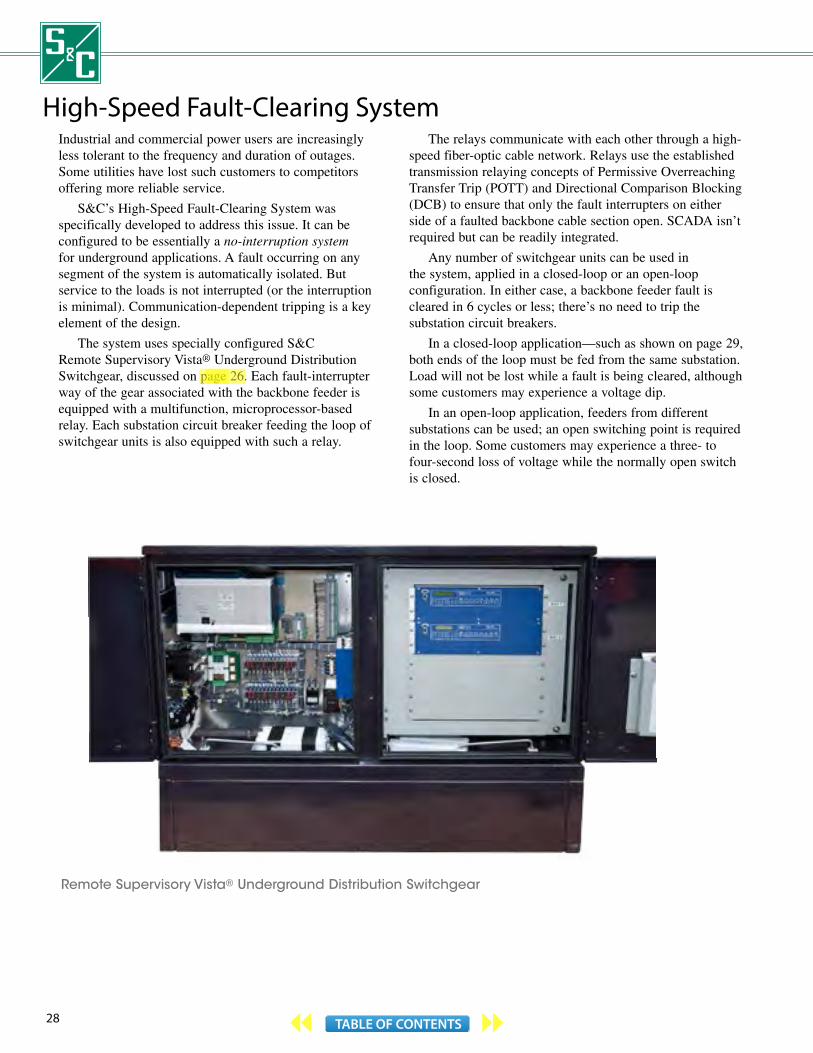
Remote Supervisory Vista® Underground Distribution Switchgear
High-Speed Fault-Clearing SystemIndustrial and commercial power users are increasingly less tolerant to the frequency and duration of outages. Some utilities have lost such customers to competitors offering more reliable service.
S&C’s High-Speed Fault-Clearing System was specifically developed to address this issue. It can be configured to be essentially a no-interruption system for underground applications. A fault occurring on any segment of the system is automatically isolated. But service to the loads is not interrupted (or the interruption is minimal). Communication-dependent tripping is a key element of the design.
The system uses specially configured S&C Remote Supervisory Vista® Underground Distribution Switchgear, discussed on page 26. Each fault-interrupter way of the gear associated with the backbone feeder is equipped with a multifunction, microprocessor-based relay. Each substation circuit breaker feeding the loop of switchgear units is also equipped with such a relay.
The relays communicate with each other through a high-speed fiber-optic cable network. Relays use the established transmission relaying concepts of Permissive Overreaching Transfer Trip (POTT) and Directional Comparison Blocking (DCB) to ensure that only the fault interrupters on either side of a faulted backbone cable section open. SCADA isn’t required but can be readily integrated.
Any number of switchgear units can be used in the system, applied in a closed-loop or an open-loop configuration. In either case, a backbone feeder fault is cleared in 6 cycles or less; there’s no need to trip the substation circuit breakers.
In a closed-loop application—such as shown on page 29, both ends of the loop must be fed from the same substation. Load will not be lost while a fault is being cleared, although some customers may experience a voltage dip.
In an open-loop application, feeders from different substations can be used; an open switching point is required in the loop. Some customers may experience a three- to four-second loss of voltage while the normally open switch is closed.
aleknam
Highlight
aleknam
Highlight

29TABLE OF CONTENTS
Typical operation of High-Speed Fault-Clearing System in closed-loop application.
Normal configuration
1
Relay 5 detects fault current flowing in the direction of its respective arrow, as does Relay 6. Each relay sends a “forward fault detected” signal to the other relay
3
If a fault occurs, current will flow to it through both substation circuit breakers
2
Relays 5 and 6 each recognize that other has sensed fault current flowing in the direction of its respective arrow and trips its respective fault interrupter. The faulted cable section is de-energized but service to the loads served by Vista Units B and C is uninterrupted
4
For more information on the High-Speed Fault-Clearing System, see S&C publication 682-60, available on our website www.sandc.com.
SOLU
TION
S FOR EN
HA
NCIN
G G
RID RELIA
BILITY, CAPACITY, A
ND
EFFICIENCY

30 TABLE OF CONTENTS
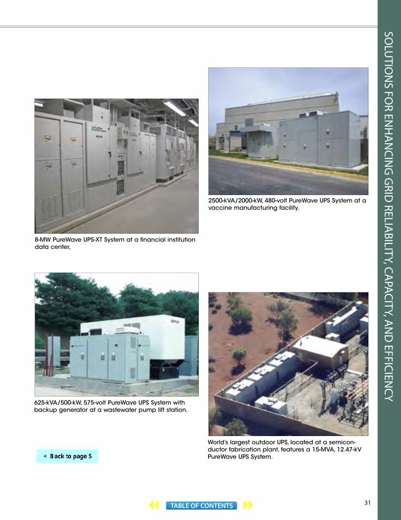
PureWave® UPS System and PureWave® UPS XT SystemPureWave® UPS System provides enhanced service continuity to facilities where voltage sags, surges, transients, momentary disruptions, and complete outages are of concern. Models rated 208 to 600 volts support loads up to 2500 kVA and models rated 4.16 to 25 kV support loads up to 20 MVA.
PureWave UPS System offers 60 seconds of power protection at 100% load and up to three minutes of power protection for partial loads—handling more than 99% of all power quality problems. For mission-critical medium-voltage applications, a PureWave® UPS XT System can be furnished. It can support critical loads for 15 minutes or more. All models can be applied with a backup generator too, assuring seamless service through extended outages.
PureWave UPS System is the only facility-wide UPS designed for manufacturing plants and data centers. It’s readily expandable and can be installed outdoors . . . no costly, air-conditioned indoor space is required.
PureWave UPS System is the most energy-efficient UPS in the industry. It needs far less upkeep. Conventional UPS systems require ongoing battery maintenance. And flywheel systems need routine vacuum pump maintenance along with periodic bearing changes. PureWave UPS System needs NO battery maintenance.
In the PureWave UPS System, batteries aren’t exposed to the harmful effect of dc ripple, like in conventional battery-based UPS systems. The batteries are maintained in a true open-circuit state, prolonging their operating life.
PureWave UPS System includes an unsurpassed five-year non-prorated warranty on the battery string. All 60-Hertz models rated 208 to 600 volts, 313 to 2500 kVA are listed per UL 1778, “Uninterruptible Power Supply Equipment, 2nd Edition.”
For more information on the PureWave UPS System, see S&C publications 653-30 and 653-32, available on our website www.sandc.com.
938-kVA/750-kW, 480-volt PureWave UPS System at a semiconductor fabrication plant.
31TABLE OF CONTENTS
World’s largest outdoor UPS, located at a semicon-ductor fabrication plant, features a 15-MVA, 12.47-kV PureWave UPS System.
8-MW PureWave UPS-XT System at a financial institution data center,
2500-kVA/2000-kW, 480-volt PureWave UPS System at a vaccine manufacturing facility.
625-kVA/500-kW, 575-volt PureWave UPS System with backup generator at a wastewater pump lift station.
SOLU
TION
S FOR EN
HA
NCIN
G G
RID RELIA
BILITY, CAPACITY, A
ND
EFFICIENCY

32 TABLE OF CONTENTS
IntelliTeam VV Volt-Var Optimization SystemIntelliTeam VV provides a cost-effective means for optimizing distribution system voltage, power factor, and other grid operating characteristics based on real-time conditions. It can be readily integrated with existing utility software applications, distribution devices, and sensors to enable significant efficiencies and demand reduction. IntelliTeam VV requires no consumer involvement. It allows a utility to reduce losses to meet a regulatory mandate, as well as lower their total energy purchases and associated greenhouse gas emissions. Volt-Var Control Module is the basic building block
of IntelliTeam VV. It dynamically regulates distribution system voltages and reactive power by controlling distribution capacitor banks, thus reducing demand and increasing capacity of the system. The module maintains two-way communication with the capacitor bank controls and initiates switching based on real-time data analysis. It eliminates independent switching decisions at each capacitor bank, which can work against each other . . . overall system power factor is optimized, not just the power factor at the feeder.
Dynamic Voltage Optimization Module can be applied in conjunction with the Volt-Var Control Module to reduce system-level consumption through Conservation Voltage Reduction. It maintains two-way communication with substation load tap changers and voltage regulators, and distribution voltage regulators. It monitors the real-time outputs of remotely located voltage sensors and regulates end-of-line voltages through control of substation voltage regulation devices and distribution voltage regulators. It eliminates uncoordinated capacitor bank switching decisions and load tap changer and voltage regulator operations, which can sometimes work against each other.
Dynamic Measurement and Verification Module calculates the real-time energy savings achieved by the Volt-Var Control Module and Dynamic Voltage Optimization Module. Unlike traditional measurement and verification methods—which rely on long-term data sampling and off-line statistical analysis to quantify savings—the Dynamic Measurement and Verification Module calculates load reduction benefits through power flow analysis of real-time
IntelliTeam® VV Volt-Var Optimization System, IntelliCap® 2000 and IntelliCap® Automatic Capacitor Controls, and BankGuard Plus® Controls
measurements. It continuously measures actual demand against a simulated base-case demand to verify demand reduction . . . as frequently as every five minutes.
IntelliTeam VV dashboard view.
IntelliCap 2000 Automatic Capacitor ControlsIntelliCap 2000 Controls are two-way communicating controls that are ideally suited for distribution capacitor bank application with IntelliTeam VV. They can be furnished with a variety of factory-installed communication devices, including SpeedNet™ and IntelliCom® DA Mesh Radios, discussed on pages 38 and 39.
IntelliCap 2000 Controls offer a wide range of software-selectable functions, including voltage, time, temperature, time-biased voltage, and time-biased temperature control strategies. VAR and current control strategies are optionally available. Voltage/temperature and SCADA override strategies are provided too; when enabled, a control returns to its regular control strategy after receiving a SCADA command.
IntelliCap 2000 Controls automatically calculate voltage change (and kVAR change, if applicable) due to capacitor bank switching, and offer automatic adjustment for daylight savings time and holidays, daily limit on automatic switching operations, undervoltage and overvoltage protection.
Neutral input sensing is optionally available and can lock out the capacitor bank if blown fuses or stuck switch poles are detected.
aleknam
Highlight

33TABLE OF CONTENTS
IntelliCap 2000 Automatic Capacitor Control.
IntelliCap Automatic Capacitor ControlsFor distribution capacitor switching applications that do not require an interface with IntelliTeam VV or SCADA, IntelliCap Automatic Capacitor Controls offer an ideal solution. They provide local control switching strategies based on time, temperature, voltage, and—optionally—VARs and current.
IntelliCap Automatic Capacitor Control.
BankGuard Plus ControlsBankGuard Plus Controls protect substation capacitor banks from overvoltage stress. They also protect shunt reactors from turn-to-turn faults. BankGuard Plus Controls have the sensitivity to detect and alarm on the loss of individual capacitor units or developing winding faults.
BankGuard Plus Controls can detect—and compensate for—system voltage and capacitor-bank or reactor unbalance resulting from manufacturing-tolerance variations among individual capacitor units and reactor phase windings. In large-size banks, such unbalance voltages can introduce significant errors in, or even overpower, the voltage signal created by the loss of individual capacitor units.
BankGuard Plus Control.
For more information on IntelliTeam VV Volt-Var Optimization System, see S&C publications 1046 -30 and 1046 -31. For more information on IntelliCap 2000 Automatic Capacitor Controls, see S&C publications 1024-30 and 1024-31. For more information on IntelliCap Automatic Capacitor Controls, see S&C publications 1022-30 and 1022-31. For more information on Bankguard Plus Controls, see S&C publications 1011-30 and 1011-31. All are available on our website www.sandc.com.
SOLU
TION
S FOR EN
HA
NCIN
G G
RID RELIA
BILITY, CAPACITY, A
ND
EFFICIENCY
34 TABLE OF CONTENTS
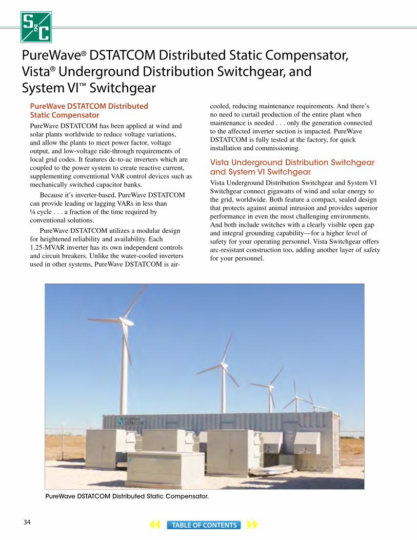
PureWave® DSTATCOM Distributed Static Compensator, Vista® Underground Distribution Switchgear, and System VI™ Switchgear
PureWave DSTATCOM Distributed Static CompensatorPureWave DSTATCOM has been applied at wind and solar plants worldwide to reduce voltage variations, and allow the plants to meet power factor, voltage output, and low-voltage ride-through requirements of local grid codes. It features dc-to-ac inverters which are coupled to the power system to create reactive current, supplementing conventional VAR control devices such as mechanically switched capacitor banks.
Because it’s inverter-based, PureWave DSTATCOM can provide leading or lagging VARs in less than ¼ cycle . . . a fraction of the time required by conventional solutions.
PureWave DSTATCOM utilizes a modular design for heightened reliability and availability. Each 1.25-MVAR inverter has its own independent controls and circuit breakers. Unlike the water-cooled inverters used in other systems, PureWave DSTATCOM is air-
cooled, reducing maintenance requirements. And there’sno need to curtail production of the entire plant when maintenance is needed . . . only the generation connected to the affected inverter section is impacted. PureWave DSTATCOM is fully tested at the factory, for quick installation and commissioning.
Vista Underground Distribution Switchgear and System VI SwitchgearVista Underground Distribution Switchgear and System VI Switchgear connect gigawatts of wind and solar energy to the grid, worldwide. Both feature a compact, sealed design that protects against animal intrusion and provides superior performance in even the most challenging environments. And both include switches with a clearly visible open gap and integral grounding capability—for a higher level of safety for your operating personnel. Vista Switchgear offers arc-resistant construction too, adding another layer of safety for your personnel.
PureWave DSTATCOM Distributed Static Compensator.
35TABLE OF CONTENTS
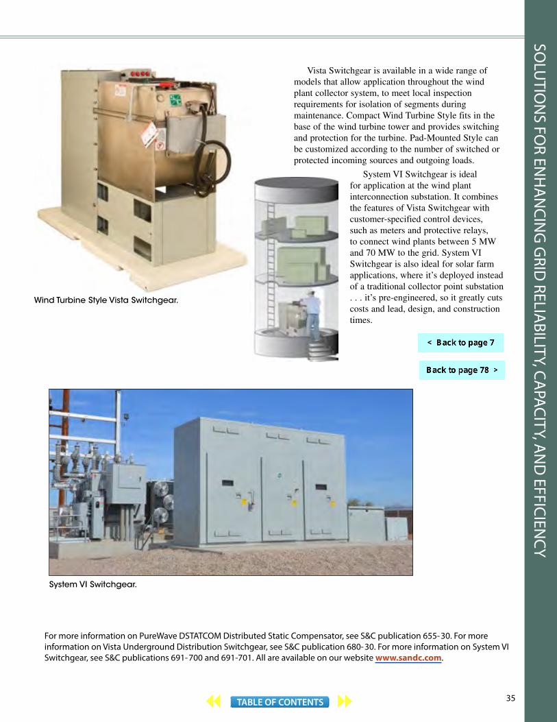
Vista Switchgear is available in a wide range of models that allow application throughout the wind plant collector system, to meet local inspection requirements for isolation of segments during maintenance. Compact Wind Turbine Style fits in the base of the wind turbine tower and provides switching and protection for the turbine. Pad-Mounted Style can be customized according to the number of switched or protected incoming sources and outgoing loads.
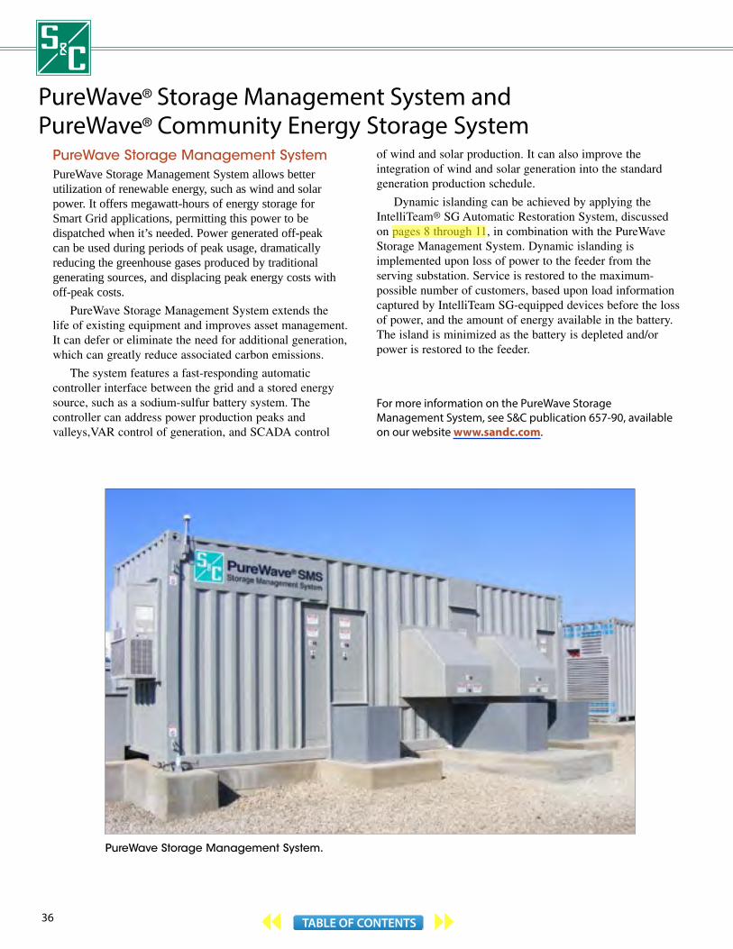
System VI Switchgear is ideal for application at the wind plant interconnection substation. It combines the features of Vista Switchgear with customer-specified control devices, such as meters and protective relays, to connect wind plants between 5 MW and 70 MW to the grid. System VI Switchgear is also ideal for solar farm applications, where it’s deployed instead of a traditional collector point substation . . . it’s pre-engineered, so it greatly cuts costs and lead, design, and construction times.
Wind Turbine Style Vista Switchgear.
For more information on PureWave DSTATCOM Distributed Static Compensator, see S&C publication 655-30. For more information on Vista Underground Distribution Switchgear, see S&C publication 680-30. For more information on System VI Switchgear, see S&C publications 691-700 and 691-701. All are available on our website www.sandc.com.
System VI Switchgear.
SOLU
TION
S FOR EN
HA
NCIN
G G
RID RELIA
BILITY, CAPACITY, A
ND
EFFICIENCY
36 TABLE OF CONTENTS
PureWave Storage Management System.
PureWave® Storage Management System andPureWave® Community Energy Storage System
PureWave Storage Management SystemPureWave Storage Management System allows better utilization of renewable energy, such as wind and solar power. It offers megawatt-hours of energy storage for Smart Grid applications, permitting this power to be dispatched when it’s needed. Power generated off-peak can be used during periods of peak usage, dramatically reducing the greenhouse gases produced by traditional generating sources, and displacing peak energy costs with off-peak costs.
PureWave Storage Management System extends the life of existing equipment and improves asset management. It can defer or eliminate the need for additional generation, which can greatly reduce associated carbon emissions.
The system features a fast-responding automatic controller interface between the grid and a stored energy source, such as a sodium-sulfur battery system. The controller can address power production peaks and valleys,VAR control of generation, and SCADA control
of wind and solar production. It can also improve the integration of wind and solar generation into the standard generation production schedule.
Dynamic islanding can be achieved by applying the IntelliTeam® SG Automatic Restoration System, discussed on pages 8 through 11, in combination with the PureWave Storage Management System. Dynamic islanding is implemented upon loss of power to the feeder from the serving substation. Service is restored to the maximum-possible number of customers, based upon load information captured by IntelliTeam SG-equipped devices before the loss of power, and the amount of energy available in the battery. The island is minimized as the battery is depleted and/or power is restored to the feeder.
For more information on the PureWave Storage Management System, see S&C publication 657-90, available on our website www.sandc.com.
aleknam
Highlight

37TABLE OF CONTENTS
PureWave Community Energy Storage SystemPureWave Community Energy Storage System offers extensive benefits for the Smart Grid.
The system provides distributed electric energy storage, for reliable, local backup power for consumers. The close proximity of this energy storage to consumers helps ensure supplemental service in case of outages.
The system also provides distributed voltage control, reducing losses and thus improving distribution feeder efficiencies. The multiplicity of energy storage units—integrated and controlled by the IntelliTeam® DEM Distributed Energy Management System—offers higher aggregated availability . . . keeping the grid functioning for more consumers. The system additionally integrates the community’s renewable power resources into the grid. These resources can be dispatched when they’re needed.
-+
-+
-+
-+
IntelliTeamDEM ControllerCES Unit Pad-Mounted
Transformer
Radio communication (typically)
PureWave Community Energy Storage System.
And because the energy storage units respond rapidly to local as well as distant system disturbances, large energy storage unit deployments can enhance grid stability. For example, when grid power frequency drops, demand can be managed by connecting regional load to the distributed energy storage units.
The PureWave Community Energy Storage System supports plug-in hybrid vehicle deployment too. The IntelliTeam DEM Distributed Energy Management System determines when battery charging can be performed most economically.
For more information on the PureWave Community Energy Storage System, see S&C publication 658-30. For more information on the IntelliTeam DEM Distributed Energy Management System, see S&C publication 1047-30. Both are available on our website www.sandc.com.
IntelliTeam DEM Controller
PureWave Community Energy Storage Unit.
SOLU
TION
S FOR EN
HA
NCIN
G G
RID RELIA
BILITY, CAPACITY, A
ND
EFFICIENCY
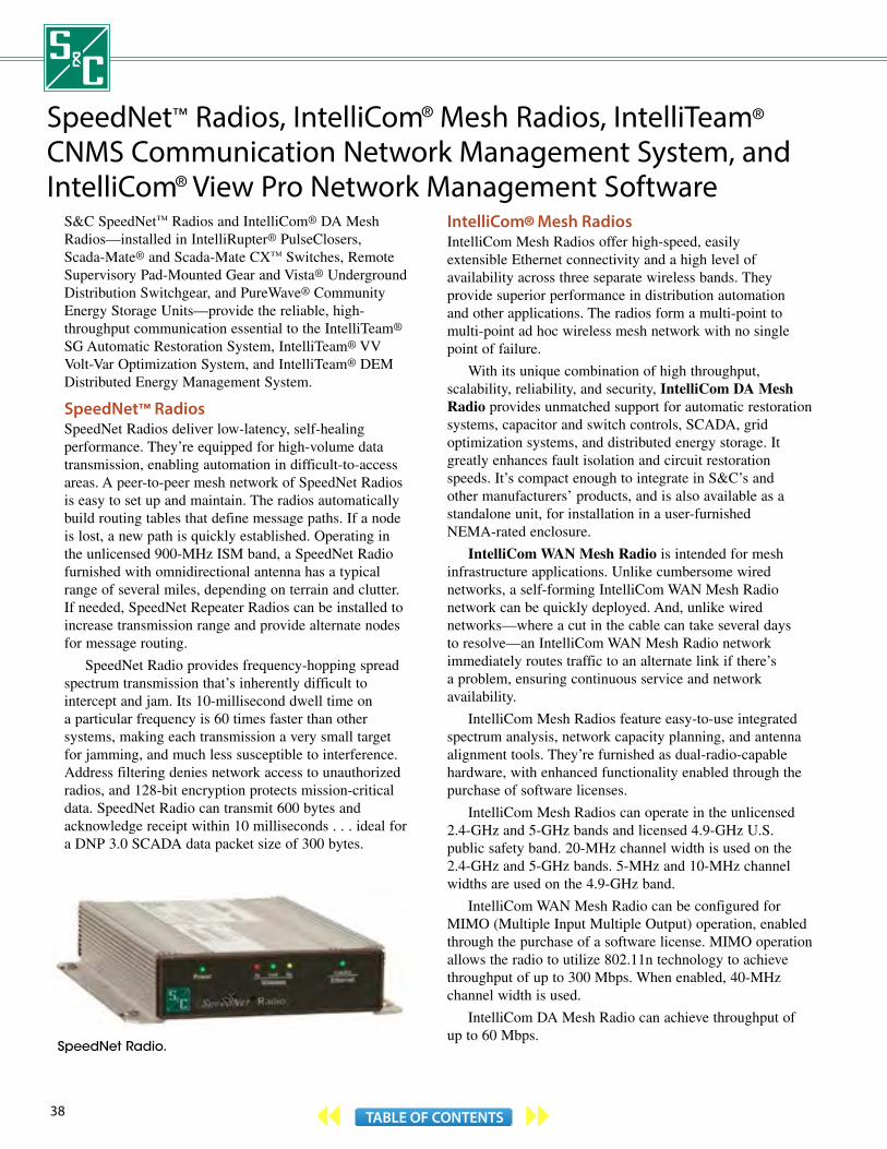
38 TABLE OF CONTENTS
SpeedNet™ Radios, IntelliCom® Mesh Radios, IntelliTeam® CNMS Communication Network Management System, and IntelliCom® View Pro Network Management Software
S&C SpeedNet™ Radios and IntelliCom® DA Mesh Radios—installed in IntelliRupter® PulseClosers, Scada-Mate® and Scada-Mate CX™ Switches, Remote Supervisory Pad-Mounted Gear and Vista® Underground Distribution Switchgear, and PureWave® Community Energy Storage Units—provide the reliable, high-throughput communication essential to the IntelliTeam® SG Automatic Restoration System, IntelliTeam® VV Volt-Var Optimization System, and IntelliTeam® DEM Distributed Energy Management System.
SpeedNet™ RadiosSpeedNet Radios deliver low-latency, self-healing performance. They’re equipped for high-volume data transmission, enabling automation in difficult-to-access areas. A peer-to-peer mesh network of SpeedNet Radios is easy to set up and maintain. The radios automatically build routing tables that define message paths. If a node is lost, a new path is quickly established. Operating in the unlicensed 900-MHz ISM band, a SpeedNet Radio furnished with omnidirectional antenna has a typical range of several miles, depending on terrain and clutter. If needed, SpeedNet Repeater Radios can be installed to increase transmission range and provide alternate nodes for message routing.
SpeedNet Radio provides frequency-hopping spread spectrum transmission that’s inherently difficult to intercept and jam. Its 10-millisecond dwell time on a particular frequency is 60 times faster than other systems, making each transmission a very small target for jamming, and much less susceptible to interference. Address filtering denies network access to unauthorized radios, and 128-bit encryption protects mission-critical data. SpeedNet Radio can transmit 600 bytes and acknowledge receipt within 10 milliseconds . . . ideal for a DNP 3.0 SCADA data packet size of 300 bytes.
SpeedNet Radio.
IntelliCom® Mesh RadiosIntelliCom Mesh Radios offer high-speed, easily extensible Ethernet connectivity and a high level of availability across three separate wireless bands. They provide superior performance in distribution automation and other applications. The radios form a multi-point to multi-point ad hoc wireless mesh network with no single point of failure.
With its unique combination of high throughput, scalability, reliability, and security, IntelliCom DA Mesh Radio provides unmatched support for automatic restoration systems, capacitor and switch controls, SCADA, grid optimization systems, and distributed energy storage. It greatly enhances fault isolation and circuit restoration speeds. It’s compact enough to integrate in S&C’s and other manufacturers’ products, and is also available as a standalone unit, for installation in a user-furnished NEMA-rated enclosure.
IntelliCom WAN Mesh Radio is intended for mesh infrastructure applications. Unlike cumbersome wired networks, a self-forming IntelliCom WAN Mesh Radio network can be quickly deployed. And, unlike wired networks—where a cut in the cable can take several days to resolve—an IntelliCom WAN Mesh Radio network immediately routes traffic to an alternate link if there’s a problem, ensuring continuous service and network availability.
IntelliCom Mesh Radios feature easy-to-use integrated spectrum analysis, network capacity planning, and antenna alignment tools. They’re furnished as dual-radio-capable hardware, with enhanced functionality enabled through the purchase of software licenses.
IntelliCom Mesh Radios can operate in the unlicensed 2.4-GHz and 5-GHz bands and licensed 4.9-GHz U.S. public safety band. 20-MHz channel width is used on the 2.4-GHz and 5-GHz bands. 5-MHz and 10-MHz channel widths are used on the 4.9-GHz band.
IntelliCom WAN Mesh Radio can be configured for MIMO (Multiple Input Multiple Output) operation, enabled through the purchase of a software license. MIMO operation allows the radio to utilize 802.11n technology to achieve throughput of up to 300 Mbps. When enabled, 40-MHz channel width is used.
IntelliCom DA Mesh Radio can achieve throughput of up to 60 Mbps.
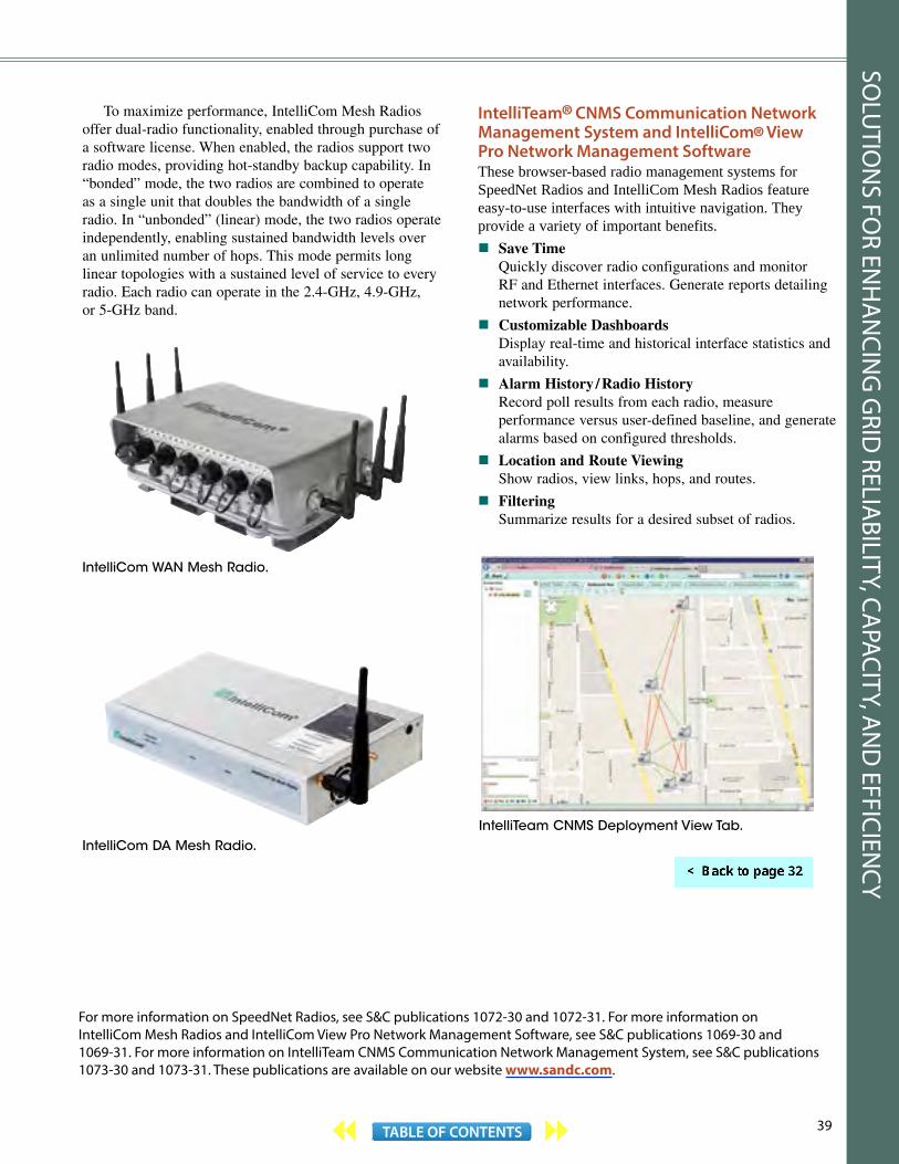
39TABLE OF CONTENTS
For more information on SpeedNet Radios, see S&C publications 1072-30 and 1072-31. For more information on IntelliCom Mesh Radios and IntelliCom View Pro Network Management Software, see S&C publications 1069-30 and 1069-31. For more information on IntelliTeam CNMS Communication Network Management System, see S&C publications 1073-30 and 1073-31. These publications are available on our website www.sandc.com.
To maximize performance, IntelliCom Mesh Radios offer dual-radio functionality, enabled through purchase of a software license. When enabled, the radios support two radio modes, providing hot-standby backup capability. In “bonded” mode, the two radios are combined to operate as a single unit that doubles the bandwidth of a single radio. In “unbonded” (linear) mode, the two radios operate independently, enabling sustained bandwidth levels over an unlimited number of hops. This mode permits long linear topologies with a sustained level of service to every radio. Each radio can operate in the 2.4-GHz, 4.9-GHz, or 5-GHz band.
IntelliCom WAN Mesh Radio.
IntelliCom DA Mesh Radio.
IntelliTeam® CNMS Communication Network Management System and IntelliCom® View Pro Network Management SoftwareThese browser-based radio management systems for SpeedNet Radios and IntelliCom Mesh Radios feature easy-to-use interfaces with intuitive navigation. They provide a variety of important benefits. Save Time Quickly discover radio configurations and monitor
RF and Ethernet interfaces. Generate reports detailing network performance.
Customizable Dashboards Display real-time and historical interface statistics and
availability.
Alarm History / Radio History Record poll results from each radio, measure
performance versus user-defined baseline, and generate alarms based on configured thresholds.
Location and Route Viewing Show radios, view links, hops, and routes.
Filtering Summarize results for a desired subset of radios.
IntelliTeam CNMS Deployment View Tab.
SOLU
TION
S FOR EN
HA
NCIN
G G
RID RELIA
BILITY, CAPACITY, A
ND
EFFICIENCY

40 TABLE OF CONTENTS
S&C’s Power Systems Solutions team of automation, system planning, and engineering experts have vast expertise in the real-world application of technology for improved grid reliability. They’re well suited to perform the studies, engineering and design, project management, procurement, and field services needed to deliver a complete Smart Grid solution for you. These services can be furnished individually or on an Engineering, Procurement, and Construction (EPC) basis with the equipment.
Examples of the services which S&C can provide include:
Engineering and Design Engineering analysis to determine the ideal
automation strategy. S&C can perform an analysis to determine the best automation approach for your system: distributed intelligence and control utilizing the IntelliTeam® SG Automatic Restoration System, a new or optimized existing SCADA system, or S&C’s patented High-Speed Fault-Clearing System.
SCADA integration. S&C can specify, install, configure, and optimize SCADA and communication equipment, working closely with the SCADA supplier throughout the entire process.
Factory acceptance testing. S&C engineers can test your distribution automation system in our unique IntelliLab in Chicago, to confirm it will perform as intended under realistic scenarios using software running on the actual control platforms, with a live communication network.
Construction and Implementation Project management. S&C’s experts can work with
your contractor to make certain your equipment is installed properly. Or, if desired, S&C can provide equipment procurement and installation.
Training. S&C can provide in-depth training on the hardware and software for your engineers, operations personnel, and technicians.
Commissioning. S&C engineers can provide on-site commissioning of the hardware and software, ensuring project start-up goes smoothly.
Site acceptance testing. S&C can develop a comprehensive test plan and provide the necessary on-site support.
Services for Enhancing Grid Reliability, Capacity, and Efficiency
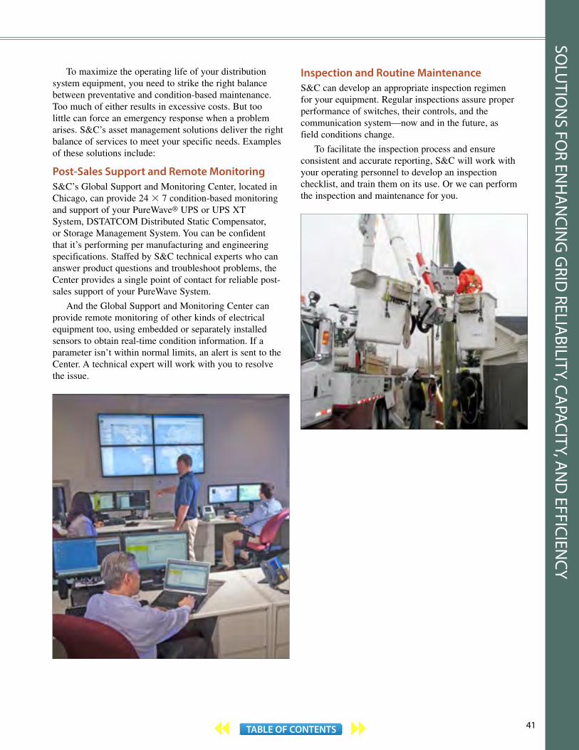
41TABLE OF CONTENTS
To maximize the operating life of your distribution system equipment, you need to strike the right balance between preventative and condition-based maintenance. Too much of either results in excessive costs. But too little can force an emergency response when a problem arises. S&C’s asset management solutions deliver the right balance of services to meet your specific needs. Examples of these solutions include:
Post-Sales Support and Remote MonitoringS&C’s Global Support and Monitoring Center, located in Chicago, can provide 24 × 7 condition-based monitoring and support of your PureWave® UPS or UPS XT System, DSTATCOM Distributed Static Compensator, or Storage Management System. You can be confident that it’s performing per manufacturing and engineering specifications. Staffed by S&C technical experts who can answer product questions and troubleshoot problems, the Center provides a single point of contact for reliable post-sales support of your PureWave System.
And the Global Support and Monitoring Center can provide remote monitoring of other kinds of electrical equipment too, using embedded or separately installed sensors to obtain real-time condition information. If a parameter isn’t within normal limits, an alert is sent to the Center. A technical expert will work with you to resolve the issue.
Inspection and Routine Maintenance S&C can develop an appropriate inspection regimen for your equipment. Regular inspections assure proper performance of switches, their controls, and the communication system—now and in the future, as field conditions change.
To facilitate the inspection process and ensure consistent and accurate reporting, S&C will work with your operating personnel to develop an inspection checklist, and train them on its use. Or we can perform the inspection and maintenance for you.
SOLU
TION
S FOR EN
HA
NCIN
G G
RID RELIA
BILITY, CAPACITY, A
ND
EFFICIENCY
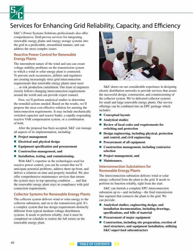
42 TABLE OF CONTENTS
Services for Enhancing Grid Reliability, Capacity, and Efficiency S&C’s Power Systems Solutions professionals also offer comprehensive, field-proven services for integrating renewable energy plants and energy storage systems into the grid in a predictable, streamlined manner, and can address the most complex issues.
Reactive Power Control for Renewable Energy PlantsThe intermittent nature of the wind and sun can create voltage stability problems on the transmission system to which a wind or solar energy plant is connected. To prevent such occurrences, utilities and regulators are creating increasingly strict grid interconnection requirements that renewable energy plants must meet . . . or risk production curtailment. Our team of engineers closely follows changing interconnection requirements around the world and can provide expert counsel.
First, we’ll perform analytical studies to determine the remedial actions needed. Based on the results, we’ll propose the most cost-effective solution for meeting the interconnection requirements. It may include mechanically switched capacitor and reactor banks, a rapidly responding reactive VAR compensation system, or a combination of both.
After the proposal has been accepted, S&C can manage all aspects of its implementation, including:
Project management
Electrical and physical design
Equipment specification and procurement
Construction management, and
Installation, testing, and commissioning.
With S&C’s expertise in the technologies used for reactive power control, you can be certain that we’ll anticipate potential problems, address them up-front, and deliver a solution on time and properly installed. We also offer comprehensive maintenance services that ensure the system stays in top operating condition . . . and that the renewable energy plant stays in compliance with grid connection requirements.
Collector Systems for Renewable Energy PlantsThe collector system delivers wind or solar energy to the collector substation, and on to the transmission grid. It’s a complex system that has design requirements distinctly different from typical medium-voltage distribution systems. It needs to perform reliably. And it must be completed on schedule to realize the full return on the renewable energy plant.
S&C draws on our considerable experience in designing electric distribution networks to provide services that assure the successful design, construction, and commissioning of the collector system. We’ve delivered collector systems for small and large renewable energy plants. Our service offerings can be combined into an EPC package which includes:
Conceptual layouts
Analytical studies
Review of local codes and requirements for switching and protection
Design engineering, including physical, protection and control, and civil engineering
Procurement of all equipment
Construction management, including contractor selection
Project management, and
Maintenance.
Interconnection Substations for Renewable Energy PlantsThe interconnection substation delivers wind or solar energy collected from the plant to the grid. It needs to perform its function reliably, right from the start.
S&C can furnish a complete EPC interconnection substation up to—and including—the final transmission line segment that connects the plant to the grid. We can provide:
Analytical studies; engineering design; and installation documentation, including drawings, specifications, and bills of material
Procurement of major equipment
Construction, including site preparation, erection of steel structures, and equipment installation, utilizing S&C-supervised subcontractors

43TABLE OF CONTENTS
Acceptance and in-service testing of all equipment, and
Commissioning.
By selecting S&C to provide the interconnection substation on an EPC basis, you can dedicate more time to other critical tasks needed to complete your renewable energy plant. Your total investment cost is reduced as well, as S&C’s experienced team will streamline the design and approval processes and effectively manage construction and commissioning.
Energy Storage SystemsEnergy storage system requirements vary tremendously, depending on the application . . .
A storage management system for a wind or solar energy plant needs to provide megawatt-hours of energy storage, to allow the power collected to be sold when demand is high.
A community energy storage system has a different set of requirements. It needs to provide sufficient energy storage for a group of residential consumers, to ensure supplemental service is available to them in the event of an outage lasting a couple of hours. And it must be capable of integrating the community’s renewable energy resources into the grid.
Few companies have as much experience in deploying energy storage systems as S&C. We’re a leader at integrating energy storage into the grid and can draw on our real-world expertise to make certain your energy storage project is a success—from the earliest stages of project evaluation and design, to system commissioning and life-cycle maintenance.
We’ve successfully implemented large-scale and residential-level projects around the globe. Our experts will work with you to design and deploy a system that meets your needs.
First, we'll perform analytical studies to determine the right energy storage solution. Then we’ll provide the planning and procurement services necessary to ensure timely project completion. We can engineer, construct, commission, and maintain the entire solution too.
For more information on these services, see S&C publication 180-36 and 180-460 through 180-464, available on our website www.sandc.com.
SOLU
TION
S FOR EN
HA
NCIN
G G
RID RELIA
BILITY, CAPACITY, A
ND
EFFICIENCY

44 TABLE OF CONTENTS
S&C developed the first reliable high-voltage fuse: the S&C Liquid Fuse. It expanded the scope of high-voltage protection and brought about the widespread adoption of outdoor distribution substations. It was the forerunner of S&C’s broad range of overhead distribution and substation switching and protection products.
S&C’s switching and protection products are renowned for their long-term reliability and exceptional value. They’re carefully designed and proven through rigorous testing. They perform dependably over decades of service in the most demanding environments, and reduce users’ operating costs.
S&C also introduced metal-enclosed switchgear and pad-mounted gear to the industry. These products led the way to the extensive adoption of underground distribution systems. Today, S&C offers the most comprehensive selection of medium-voltage metal-enclosed gear available from any manufacturer. There’s a version to suit almost every application and economic requirement: Indoor or outdoor . . . live front or dead front . . . manual, source-transfer, or remote supervisory . . . with conventional power fuses or sophisticated microprocessor-controlled fault interrupters. UL-listed gear, CSA-listed gear, and arc-resistant gear are available too.
Coordinaide™—The S&C Protection and Coordination Assistant—is available at no charge on our website www.sandc.com. This powerful tool lets you quickly and easily select the optimal S&C Fuse, TripSaver® II Cutout-Mounted Recloser, IntelliRupter® PulseCloser, or Vista® Underground Distribution Switchgear time-current characteristic curve for your specific application.
S&C offers a comprehensive range of substation and distribution system switching and protection services. These services, detailed on pages 100 and 101, can be provided individually or on an Engineering, Procurement, and Construction (EPC) basis with the equipment.
PMX™ Modular Metal -Enclosed Switchgear—pages 90 -91.
Custom Metal -Enclosed Switchgear—pages 86 -89.
Vista® Underground Distribution
Switchgear— pages 78 -81.
System VI™ Switchgear—pages 92 -93.
General Switching and Protection Solutions
aleknam
Highlight
aleknam
Highlight
aleknam
Highlight
aleknam
Highlight
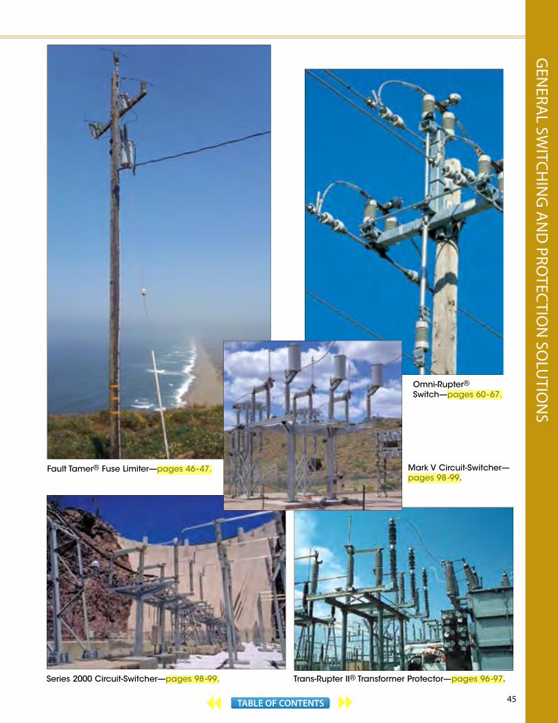
45TABLE OF CONTENTS
Fault Tamer® Fuse Limiter—pages 46 - 47. Mark V Circuit-Switcher—pages 98 -99.
Omni-Rupter® Switch—pages 60 - 67.
Series 2000 Circuit-Switcher—pages 98 -99. Trans-Rupter II® Transformer Protector—pages 96 -97.
GEN
ERAL SW
ITCHIN
G A
ND
PROTEC
TION
SOLU
TION
S
aleknam
Highlight
aleknam
Highlight
aleknam
Highlight
aleknam
Highlight
aleknam
Highlight
46 TABLE OF CONTENTS
Fault Tamer ® Fuse Limiter The New Generation of Protection for Pole-Top TransformersS&C’s Fault Tamer Fuse Limiter combines a series fuse and backup limiter in one powerful package which can be easily incorporated in new or existing installations of 14.4-kV, 25-kV, and 34.5-kV overhead pole-top transformers. Fault Tamer provides short-circuit protection to the system, limits let-through current to a level which will minimize catastrophic transformer failures due to high-magnitude internal faults, and also minimizes damage from high-magnitude external faults such as bushing flashovers. Fault Tamer offers major benefits over conventional fuse cutouts, including cutouts appendaged with bolt-on backup current-limiting fuses.
Improved Service ContinuityConventional fuse cutouts have limitations that can compromise service continuity. For example, close to substations—where fault currents can be high—complete coordination frequently is not possible between the fuse link protecting a pole-top transformer and the upstream lateral fuse link. As a result, a large-magnitude fault, such as a wildlife-induced flashover of a transformer bushing, can not only cause the transformer fuse link to operate but the lateral fuse link as well . . . exposing all customers on the lateral to an extended outage. Fault Tamer eliminates this problem because it coordinates with lateral fuse links over the full range of fault currents.
And, unlike conventional cutouts, Fault Tamer’s current-limiting action provides clearing characteristics which coordinate with the instantaneous setting of the substation circuit breaker, thus eliminating unnecessary momentary interruptions for transformer faults exceeding the breaker’s instantaneous setting.
Enhanced Power QualityHigh-magnitude faults near a substation can suppress the voltage on the substation bus, as well as on feeders emanating from the substation. Fault Tamer’s current-limiting action clears high-magnitude transformer faults before voltage dips can damage or shut down sensitive electronic equipment served by adjacent feeders.
Maximum Surge ProtectionVoltage surges are a major cause of overhead transformer failure. Maximum protection from overvoltages can be achieved by mounting the surge arrester on the transformer tank, thus shortening the lead from the arrester to the transformer winding and to ground. But with the surge arrester connected to the load side of a conventional cutout, the fuse link is more susceptible to nuisance operation from lightning strikes. Fault Tamer’s
high inrush withstand capability eliminates this problem . . . arresters can be tank-mounted without concern for nuisance fuse operations.
Impossible to Mismatch Series Fuse and LimiterIn cutouts with bolt-on backup current-limiting fuses, it’s possible to inadvertently apply the wrong size fuse link— thus jeopardizing the integrity of your coordination plan. But the clearing characteristics of Fault Tamer’s fuse cartridge are matched to that of the backup limiter so coordination is assured.
Simpler HandlingRe-fusing a bolted-in backup current-limiting fuse means climbing the pole, or using a bucket truck, to remove the fuse with a wrench—a time-consuming procedure that requires wearing gloves and other safety garb.
But re-fusing Fault Tamer is quick and easy. Since Fault Tamer’s combination fuse tube and backup limiter drops open after a fault-clearing operation, it can be removed from the mounting from the ground using an extendostick. The process is made even easier by use of S&C’s Talon™ Fuse Handling Fitting.
Retrofit Existing InstallationsFault Tamer is designed to fit into all vintages of S&C and MacLean Power Systems Type XS Fuse Cutout Mountings. You can upgrade to Fault Tamer’s superior current-limiting protection at minimal cost.
Heightened SafetyFault Tamer’s backup limiter features internal exhaust control which prevents fuse cartridge parts from being expelled during a fault-clearing operation. In contrast, conventional fuse cutouts—even fuse cutouts with bolted-on backup current-limiting fuses—can violently expel fuse link parts during operation . . . a potential exhaust hazard to operating personnel.
And Fault Tamer provides an extremely significant reduction in fire hazard as compared to conventional fuse cutouts. Fault Tamer complies with Spark Production Class A in Australian Standard AS 1033.1-1990, which requires that no sparks may be produced during a fault-clearing operation.
Mates Perfectly with Loadbuster® ToolUsing S&C’s portable loadbreak tool, live switching can be done at the point that minimizes the length of planned outages and the number of customers affected.
For more information on Fault Tamer Fuse Limiter, see S&C publications 451-30 and 451-31, available on our website www.sandc.com.

47TABLE OF CONTENTS
FAULT TAMER FUSE LIMITER
50/60-Hz Ratings
Voltage, kV Amperes, RMS
System Class, ANSI (IEC)
System Maximum
BIL Cont.Interr.,Sym.
60 Hz 50 Hz
Three-Phase①
Phase-to-Neutral
Three-Phase①
Phase-to-Neutral
15 (12) 15 8.7 15 8.7 110 20 12 000
15 (12) 15 8.7 15 8.7 125 20 12 000
25 (24) 29 16.8 26 15.1 125 20 12 000
25 (24) 29 16.8 26 15.1 150 20 12 000
25 (24) 29 16.8 26 15.1 150 20 12 000
22/38(20.8/36) — 22 — 20.8 150 20 12 000
38 (36) 38 22 36 20.8 150 20 12 000
① Also applies to phase-to-phase applications. Applications involving single-phase transformers connected phase-to-phase, as well as three-phase applications, require the use of a Fault Tamer in each lead.
Mounting with porcelain insulator meets 170-kV BIL rating requirement of IEC Publication 282-2.
Dropout mechanism provides dropout indication of operation
Fuse-tube cap
Attachment hooks for Loadbuster® Tool guide tube during closing
Birdproof-design porcelain insulator exceeds insulation requirements specified in ANSI cutout and IEC high-voltage fuse standards
Trunnion
Backup limiter—replaced after a high-magnitude fault-clearing operation
Parallel-groove connector— other styles available
Fuse cartridge—replaced after a fault-clearing operation
Spring-and-cable assembly— stainless-steel spring provides high-speed elongation of arc when fuse cartridge operates. Copper cable inside spring carries load (and fault) current
3
Tim
e in
Sec
on
ds
5 7 10 15 20
Fault Tamer TCC Curves
Current in Amperes
Also available with composite-polymer silicone insulator. It’s lighter and more rugged and provides better dielectric performance in hostile environments
Optional features include NEMA Type B and extended mounting brackets, and stainless-steel inserts and hardware
GEN
ERAL SW
ITCHIN
G A
ND
PROTEC
TION
SOLU
TION
S

48 TABLE OF CONTENTS
Type XS Fuse Cutouts An Unexcelled CutoutType XS Fuse Cutouts, when fused with S&C Positrol® Fuse Links, provide full-fault-spectrum protection for overhead distribution systems rated 4.16 kV through 25 kV, whether applied to overhead transformers, capacitors, cables, or lines. This performance also extends to solidly grounded systems rated 26.4 kV through 34.5 kV, for protection of single-phase-to-neutral lines and transformers and grounded-wye connected capacitor banks. “Full-fault-spectrum protection” means that Type XS Fuse Cutouts interrupt all faults . . . from the lowest current that will melt the fuse link to the maximum rated interrupting current—under all realistic transient-recovery-voltage conditions.
Single Venting–Down and AwayAll Type XS Fuse Cutouts employ an S&C-developed innovation: single venting . . . down and away only . . . an especially important feature where exhaust must be kept out of other phases in overbuilt circuits. There are no costly-to-replace expendable fuse-tube caps.
Voltage RatingsType XS Fuse Cutouts are assigned single-value nominal voltage ratings and can be applied without restriction on all three-phase systems having system maximum operating voltage (line-to-line) less than or equal to the cutout maximum voltage. In highly contaminated environments, a cutout with a higher voltage rating may be used to provide extra leakage distance.
RuggednessThe mechanical construction of the Type XS Fuse Cutout is rugged and strong: it is designed to withstand the interruption forces of heavy fault currents and the typically forceful closing-in by operating personnel.
The upper contact and the hinge are attached to husky steel supports by means of ½-inch galvanized steel carriage bolts and are further secured by a key-and-slot construction designed to resist torsional forces during closing operations.
Superb Current TransferUpper and lower contacts feature heavily silver-clad, spring-loaded, embossed surfaces for built-in wiping action—resulting in minimum electrical resistance.
Superior Mechanical Performance Features Simple fuse-link installation even with gloved hands.
The carefully proportioned flipper can be readily held in place while the large, easy-to-grasp cable clamping nut is being tightened.
Easy fuse-tube insertion and removal. Careful steering or manipulation is not required to hang the tube in the cutout, or to remove it. The fuse-tube lower ferrule can be hookstick-engaged either by its large, accessible lifting ring or its equally accessible hookstick keyhole.
Superb alignment when closing from the front or side and from the pole, the ground, or a bucket truck. In the first stage of closing, the fuse tube is restrained from tilting left or right by broad guiding surfaces at the hinge. When the tube is slammed into the upper contact, it is further controlled by the Loadbuster® attachment hooks. At the end of the closing stroke, the fuse-tube cap wipes in and seats squarely in the detent-type latch . . . which won’t rebound and release like so-called “positive” latches.
No fuse-link breakage. The high reduction ratio of the Type XS Fuse Cutout flipper lever system allows the high impact forces on closing to be absorbed before they reach the fuse link.
Completely reliable dropout action regardless of fault-current level. As the high-speed spring-loaded flipper rapidly withdraws the fuse-link cable, the hinge toggle is released, permitting the upper-contact spring to drive the fuse tube down and away into the open position.
Every Type XS Fuse Cutout Is a Load-Switching PointWhen used with Loadbuster®—the S&C portable loadbreak tool, the cutout becomes a switching device for no-external-arc live switching of transformers, capacitors, lines, or cables. There’s no need for complex dead-switching procedures. You can minimize the length of planned outages and the number of customers involved.
The XS Fuse Cutout’s Loadbuster attachment hooks keep the portable tool positively anchored throughout its entire opening stroke, yet allow for easy removal of Loadbuster. Attaching Loadbuster to the XS Fuse Cutout cannot cause the fuse tube to drop open prematurely.
For more information on Type XS Fuse Cutouts, see S&C publications 351-30, 351-31, and 351-705, available on our website www.sandc.com.
Single-shot Overhead—Pole-Top Style Type XS Fuse Cutouts are sold in the United States and Canada by MacLean Power Systems, www.macleanpower.com.
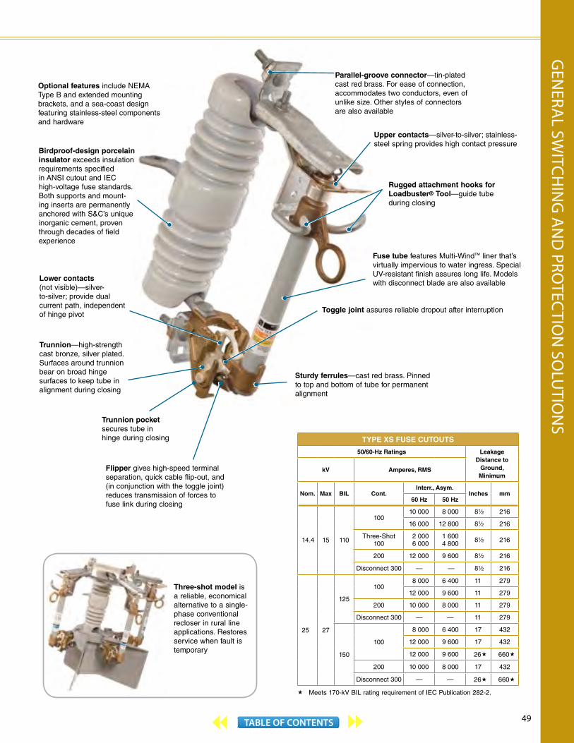
49TABLE OF CONTENTS
TYPE XS FUSE CUTOUTS
50/60-Hz Ratings Leakage Distance to
Ground, Minimum
kV Amperes, RMS
Nom. Max BIL Cont.Interr., Asym.
Inches mm60 Hz 50 Hz
14.4 15 110
10010 000 8 000 8½ 216
16 000 12 800 8½ 216
Three-Shot100
2 0006 000
1 600 4 800 8½ 216
200 12 000 9 600 8½ 216
Disconnect 300 — — 8½ 216
25 27
125
1008 000 6 400 11 279
12 000 9 600 11 279
200 10 000 8 000 11 279
Disconnect 300 — — 11 279
150
100
8 000 6 400 17 432
12 000 9 600 17 432
12 000 9 600 26« 660«
200 10 000 8 000 17 432
Disconnect 300 — — 26« 660«
« Meets 170-kV BIL rating requirement of IEC Publication 282-2.
Birdproof-design porcelain insulator exceeds insulation requirements specified in ANSI cutout and IEC high-voltage fuse standards. Both supports and mount-ing inserts are permanently anchored with S&C’s unique inorganic cement, proven through decades of field experience
Lower contacts (not visible)—silver-to-silver; provide dual current path, independent of hinge pivot
Trunnion pocket secures tube in hinge during closing
Flipper gives high-speed terminal separation, quick cable flip-out, and (in conjunction with the toggle joint) reduces transmission of forces to fuse link during closing
Parallel-groove connector—tin-plated cast red brass. For ease of connection, accommodates two conductors, even of unlike size. Other styles of connectors are also available
Upper contacts—silver-to-silver; stainless-steel spring provides high contact pressure
Rugged attachment hooks for Loadbuster® Tool—guide tube during closing
Fuse tube features Multi-Wind™ liner that’s virtually impervious to water ingress. Special UV-resistant finish assures long life. Models with disconnect blade are also available
Trunnion—high-strength cast bronze, silver plated. Surfaces around trunnion bear on broad hinge surfaces to keep tube in alignment during closing
Toggle joint assures reliable dropout after interruption
Sturdy ferrules—cast red brass. Pinned to top and bottom of tube for permanent alignment
Optional features include NEMA Type B and extended mounting brackets, and a sea-coast design featuring stainless-steel components and hardware
Three-shot model is a reliable, economical alternative to a single-phase conventional recloser in rural line applications. Restores service when fault is temporary
GEN
ERAL SW
ITCHIN
G A
ND
PROTEC
TION
SOLU
TION
S
50 TABLE OF CONTENTS
Positrol ® Fuse Links Positrol Fuse Links, with their precise TCCs, nondamageable fusible elements, and superior fault-interrupting ability, give you the ultimate in fuse-link performance. They eliminate “sneakouts” (uncoordinated blowings due to TCC shifts), and the need to call on upstream protective devices to do the fuse link’s work—thereby saving operating dollars and improving service reliability . . . two factors that are crucial in today’s competitive environment. The exceptional features of Positrol Fuse Links make all of these benefits possible.
Nondamageable and Permanently AccuratePositrol Fuse Links aren’t affected by aging, vibration, or surges that heat the element nearly to the severing point. They’re nondamageable, so they operate only when they should—not when they shouldn’t. They won’t sneak out. To a utility, the savings are significant . . . Positrol Fuse Links eliminate those costly excursions to find and replace needlessly blown fuse links.
And because Positrol Fuse Links are nondamageable, there’s no need for “safety zones” or “setback allowances.” Close fusing is achievable without fear that changes in time-current characteristics will occur—causing troublesome departures from your carefully orchestrated protection and coordination plans. The enduring permanency of Positrol TCCs has been repeatedly demonstrated by exhaustive full-scale laboratory testing.
Tight TolerancesPositrol Fuse Links have exceptionally tight tolerances . . . typically half those of other fuse links . . . which means they can be counted on to clear faults faster. Tight tolerances and nondamageability combine to allow you to choose a minimum-size link for each application, ensuring maximum protection and enhanced coordination. With Positrol Fuse Links you can even coordinate adjacent ampere ratings.
These superb performance characteristics of Positrol Fuse Links are the result of uncompromising design, plus diligent attention to manufacturing details. The fusible elements of silver, silver-copper eutectic, and nickel-chrome (depending on rating) are inherently nondamageable. Wire materials of carefully checked purity and conductivity are drawn through precision dies to exact cross sections confirmed by laser micrometer. And painstaking assembly ensures no nicks, no kinks,
no necking down that might compromise TCC accuracy. Elements are swaged to their terminals for permanent, nondamageable connections.
Superior Fault-Interrupting PerformanceThe fuse link—not the cutout fuse tube—determines the ability of a cutout to interrupt low-magnitude fault currents, particularly transformer secondary-side faults with their severe transient recovery voltages (TRVs). Extensive testing through the full spectrum of secondary faults . . . with realistically severe TRVs . . . has proved the matchless performance of Positrol Fuse Links, whether applied in single-vented or double-vented cutouts. These links, with their controlled-burst-strength extruded thermoplastic sheaths, reliably interrupt all levels of secondary-fault currents on systems through 27 kV, and in single-phase- to-neutral applications on systems through 38 kV.
Broad Selection of SpeedsPositrol Fuse Links are available in six speeds: T, K, QR (interchangeable with “QA” speed offerings), N, Standard, and Coordinating.
All these speeds, plus a selection of ampere ratings from 1 through 200 amperes, make optimal coordination and maximum protection a practical reality at every sectionalizing point, riser pole, distribution transformer, and capacitor bank.
Easy to ApplyEasy-to-use application information, developed with the same attention to detail as the Positrol Fuse Links themselves, is available to facilitate selection of S&C Fuse Links. Request S&C Data Bulletin 350-110 for transformer protection, S&C Data Bulletin 350-130 for capacitor protection, or S&C Data Bulletin 350-170 for series coordination. These comprehensive application guides take the work out of selecting the fuse link best suited to each protection requirement.
For more information on Positrol Fuse Links, see S&C publications 352-30 and 352-31, available on our website www.sandc.com.
Positrol Fuse Links are Rural Utilities Service accepted.
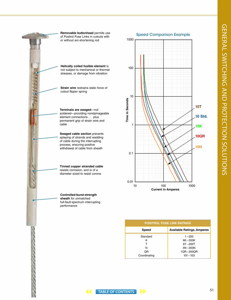
51TABLE OF CONTENTS
POSITROL FUSE LINK RATINGS
Speed Available Ratings, Amperes
StandardKTN
QRCoordinating
1 – 2006K – 200K6T – 200T5N – 200N
1QR – 200QR101 – 103
Speed Comparison Example
10T
10 Std.
10K
10QR
10N
0.01
0.1
1
10
100
1000
10 100 1000Current in Amperes
Tim
e in
Sec
on
ds
Terminals are swaged—not soldered—providing nondamageable element connections . . . pluspermanent grip of strain wire and cable
Swaged cable section prevents splaying of strands and wadding of cable during the interrupting process, ensuring positive withdrawal of cable from sheath
Removable buttonhead permits use of Positrol Fuse Links in cutouts with or without arc-shortening rod
Strain wire restrains static force of cutout flipper spring
Helically coiled fusible element is not subject to mechanical or thermal stresses, or damage from vibration
Tinned copper stranded cable resists corrosion, and is of a diameter sized to resist corona
Controlled-burst-strength sheath for unmatched full-fault-spectrum interrupting performance
GEN
ERAL SW
ITCHIN
G A
ND
PROTEC
TION
SOLU
TION
S
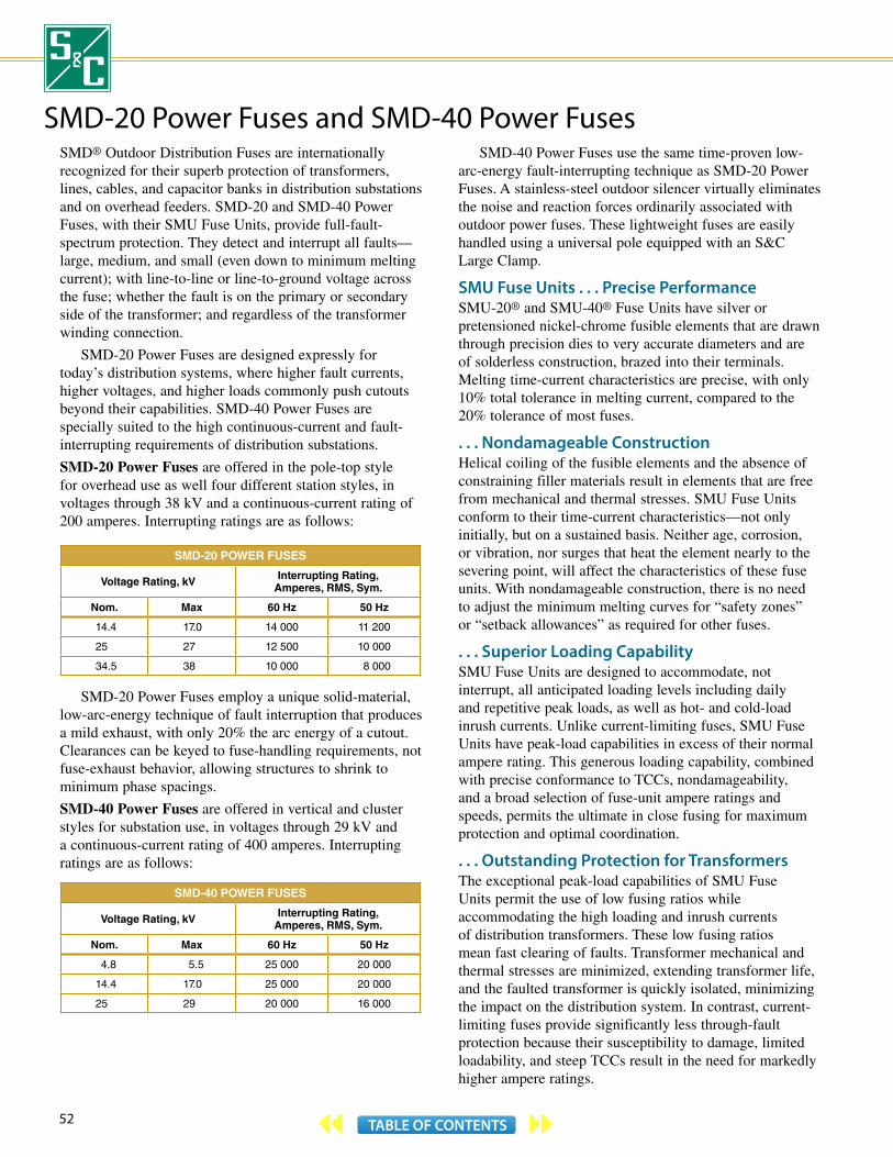
52 TABLE OF CONTENTS
SMD® Outdoor Distribution Fuses are internationally recognized for their superb protection of transformers, lines, cables, and capacitor banks in distribution substations and on overhead feeders. SMD-20 and SMD-40 Power Fuses, with their SMU Fuse Units, provide full-fault-spectrum protection. They detect and interrupt all faults—large, medium, and small (even down to minimum melting current); with line-to-line or line-to-ground voltage across the fuse; whether the fault is on the primary or secondary side of the transformer; and regardless of the transformer winding connection.
SMD-20 Power Fuses are designed expressly for today’s distribution systems, where higher fault currents, higher voltages, and higher loads commonly push cutouts beyond their capabilities. SMD-40 Power Fuses are specially suited to the high continuous-current and fault-interrupting requirements of distribution substations.
SMD-20 Power Fuses are offered in the pole-top style for overhead use as well four different station styles, in voltages through 38 kV and a continuous-current rating of 200 amperes. Interrupting ratings are as follows:
SMD-20 POWER FUSES
Voltage Rating, kV Interrupting Rating,Amperes, RMS, Sym.
Nom. Max 60 Hz 50 Hz
14.4 17.0 14 000 11 200
25 27 12 500 10 000
34.5 38 10 000 8 000
SMD-20 Power Fuses employ a unique solid-material, low-arc-energy technique of fault interruption that produces a mild exhaust, with only 20% the arc energy of a cutout. Clearances can be keyed to fuse-handling requirements, not fuse-exhaust behavior, allowing structures to shrink to minimum phase spacings.
SMD-40 Power Fuses are offered in vertical and cluster styles for substation use, in voltages through 29 kV and a continuous-current rating of 400 amperes. Interrupting ratings are as follows:
SMD-40 POWER FUSES
Voltage Rating, kV Interrupting Rating,Amperes, RMS, Sym.
Nom. Max 60 Hz 50 Hz
4.8 5.5 25 000 20 000
14.4 17.0 25 000 20 000
25 29 20 000 16 000
SMD-40 Power Fuses use the same time-proven low-arc-energy fault-interrupting technique as SMD-20 Power Fuses. A stainless-steel outdoor silencer virtually eliminates the noise and reaction forces ordinarily associated with outdoor power fuses. These lightweight fuses are easily handled using a universal pole equipped with an S&C Large Clamp.
SMU Fuse Units . . . Precise PerformanceSMU-20® and SMU-40® Fuse Units have silver or pretensioned nickel-chrome fusible elements that are drawn through precision dies to very accurate diameters and are of solderless construction, brazed into their terminals. Melting time-current characteristics are precise, with only 10% total tolerance in melting current, compared to the 20% tolerance of most fuses.
. . . Nondamageable ConstructionHelical coiling of the fusible elements and the absence of constraining filler materials result in elements that are free from mechanical and thermal stresses. SMU Fuse Units conform to their time-current characteristics—not only initially, but on a sustained basis. Neither age, corrosion, or vibration, nor surges that heat the element nearly to the severing point, will affect the characteristics of these fuse units. With nondamageable construction, there is no need to adjust the minimum melting curves for “safety zones” or “setback allowances” as required for other fuses.
. . . Superior Loading CapabilitySMU Fuse Units are designed to accommodate, not interrupt, all anticipated loading levels including daily and repetitive peak loads, as well as hot- and cold-load inrush currents. Unlike current-limiting fuses, SMU Fuse Units have peak-load capabilities in excess of their normal ampere rating. This generous loading capability, combined with precise conformance to TCCs, nondamageability, and a broad selection of fuse-unit ampere ratings and speeds, permits the ultimate in close fusing for maximum protection and optimal coordination.
. . . Outstanding Protection for TransformersThe exceptional peak-load capabilities of SMU Fuse Units permit the use of low fusing ratios while accommodating the high loading and inrush currents of distribution transformers. These low fusing ratios mean fast clearing of faults. Transformer mechanical and thermal stresses are minimized, extending transformer life, and the faulted transformer is quickly isolated, minimizing the impact on the distribution system. In contrast, current-limiting fuses provide significantly less through-fault protection because their susceptibility to damage, limited loadability, and steep TCCs result in the need for markedly higher ampere ratings.
SMD-20 Power Fuses and SMD-40 Power Fuses

53TABLE OF CONTENTS
SMU-20 Fuse Unit (SMU-40 Fuse Unit is similar)
SMD-20 and SMD-40 Power Fuses are Rural Utilities Service accepted.
Upper seal—prevents water ingress
Tin-plated copper conducting tube—expanded into glass-epoxy outer tube for a positive water seal
Latch-actuating pin initiates drop-open action for easy identification of blown fuses
Drive spring
Tulip contact—spring-loaded
Solid-material arc-extinguishing medium
Arcing rod—silver-clad copper
Filament-wound glass-epoxy tube—with exceptionally durable, ultraviolet-resistant finish
Silver fusible element—helically coiled to absorb mechanical vibration and thermal shock
Tin-plated red brass exhaust ferrule—magneformed onto glass-epoxy tube
. . . For Capacitor BanksIn protecting pole-top and small station capacitor banks, the high peak-load capabilities again allow exceptionally close fusing—so that even evolving faults within individual capacitor units can be detected and cleared.
. . . And for Sectionalizing PointsWhen installed at sectionalizing points and cable risers, these fuses protect against permanent faults and coordinate easily with reclosers. The low fusing ratios possible with SMU-20 and SMU- 40 Fuse Units permit upstream protective devices to be set for faster operation . . . reducing system short-circuit stresses. And, SMU Fuse Units’ TCC curve shapes facilitate complete coordination with downstream protective devices.
Every SMD-20 and SMD-40 Power Fuse is a Load-Switching DeviceWhen used with Loadbuster®, S&C’s portable loadbreak tool, SMD-20 and SMD-40 Power Fuses become switching devices for no-external-arc live switching of transformers, lines, cables, and capacitors. There’s no need for complex system switching procedures—you can minimize the length of planned outages and the number of customers involved.
SMU FUSE UNIT RATINGS
SpeedAvailable Ratings, Amperes
SMU-20Fuse Units
SMU-40Fuse Units
S&C K 3K—200K —
S&C Standard 1—200E 1— 400E
S&C Slow 15E—200E 15E— 400E
S&C Very Slow 50E—200E —
S&C DR 3DR—20DR —
For more information on SMD-20 and SMD-40 Power Fuses, see S&C publications 242-31, 242-32, 242-700, and 242-704, available on our website www.sandc.com.
GEN
ERAL SW
ITCHIN
G A
ND
PROTEC
TION
SOLU
TION
S

54 TABLE OF CONTENTS
Overhead—Pole-Top Style SMD-20 Mountings
Station Style SMD-20 MountingsAvailable with Cypoxy™ or porcelain station post insulators
Latch-and-upper-contact assembly prevents fuse unit from dropping open due to vibration or shock, or when hot-washed. Assures positive latch release for dropout when fuse unit operates
Birdproof-design porcelain insulator provides insulationcharacteristics higher than ANSIdistribution-cutout standards andequal in most cases to ANSI switch and bus standards. Mounting bracket and hardware are included
Attachment hooks for Loadbuster® Tool also provide self-guiding action for fuse unit during closing
Silver-clad contacts throughout— backed by prestressed loading springs, feature built-in wiping action
Pull ring—carefully contoured for reliable operation from pole or bucket, with Loadbuster or hookstick
SMU-20 Fuse Unit
Hinge-and-lower-contact assembly guides fuse unit during closing for on-center approach, even when operated from an adverse angle
Wide variety of connector options available
Models through 25 kV available with composite-polymer silicone insulator. It’s lighter and morerugged, and provides better dielectric performance in hostile environments
Available with stainless-steel inserts and hardware
SMD-20 Power Fuses and SMD-40 Power Fuses
Inverted
Right-Angle
Vertical-Offset
OVERHEAD—POLE-TOP STYLE SMD-20 MOUNTINGS
50/60-Hz Ratings Leakage Distanceto Ground, MinimumkV Amperes, RMS
Nom. Max BIL MaxInterr., Sym.
Polymer Insulator
PorcelainInsulator
60 Hz 50 Hz Inches mm Inches mm
14.4 17.0
125 200E or 200K 14 000 11 200 — — 11 279
150 200E or 200K 14 000 11 200 19 480 17 432
25 27 150 200E or 200K 12 500 10 000
— — 17 432
35½ 900 26 660
34.5 38 200 200E or 200K 10 000 8 000 — — 25½ 648
STATION STYLE SMD-20 MOUNTINGS
50/60-Hz Ratings LeakageDistance
to Ground, Minimum
kV Amperes, RMS
Nom. Max BIL MaxInterr., Sym.
Inches mm60 Hz 50 Hz
14.4 17.0 110 200E or 200K 14 000 11 200 15½ 394
25 27 150 200E or 200K 12 500 10 000 24 610
34.5 38 200 200E or 200K 10 000 8 000 37 940Cluster-Offset
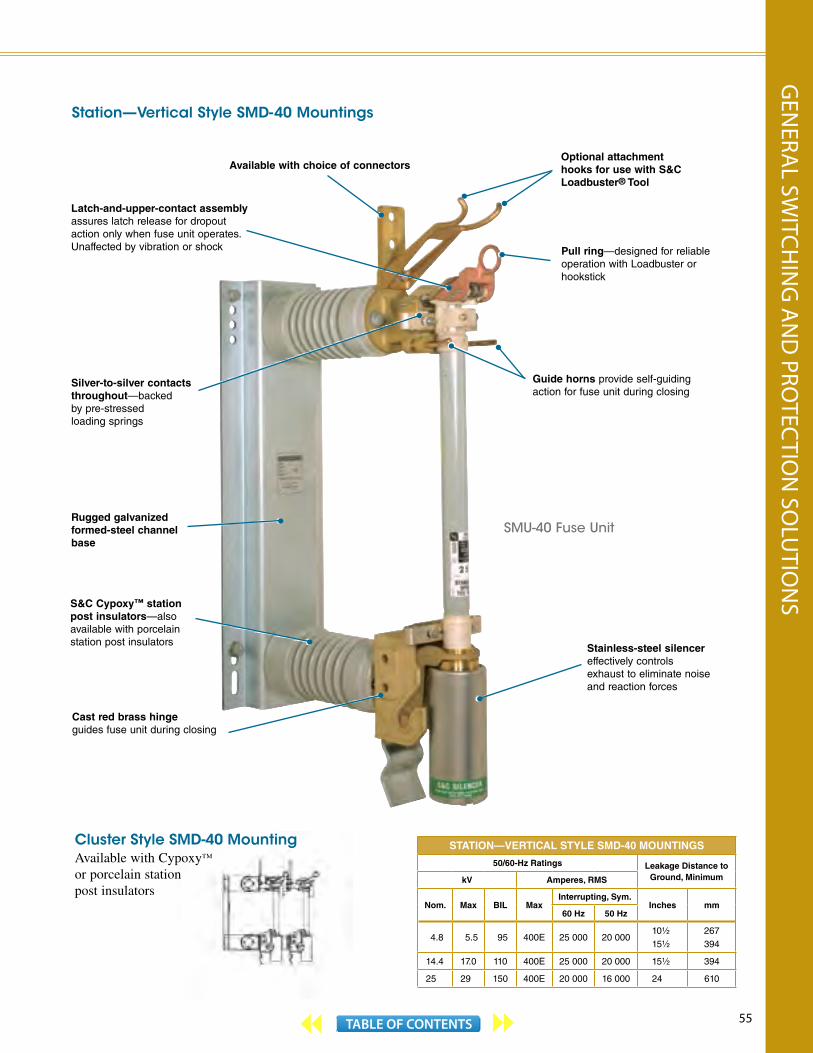
55TABLE OF CONTENTS
STATION—VERTICAL STYLE SMD-40 MOUNTINGS
50/60-Hz Ratings Leakage Distance to Ground, MinimumkV Amperes, RMS
Nom. Max BIL MaxInterrupting, Sym.
Inches mm60 Hz 50 Hz
4.8 5.5 95 400E 25 000 20 00010½
15½
267394
14.4 17.0 110 400E 25 000 20 000 15½ 394
25 29 150 400E 20 000 16 000 24 610
Latch-and-upper-contact assembly assures latch release for dropout action only when fuse unit operates. Unaffected by vibration or shock
Available with choice of connectors
Guide horns provide self-guiding action for fuse unit during closing
Silver-to-silver contacts throughout—backed by pre-stressed loading springs
Rugged galvanized formed-steel channel base
S&C Cypoxy™ station post insulators—also available with porcelain station post insulators
Cast red brass hinge guides fuse unit during closing
Station—Vertical Style SMD-40 Mountings
SMU-40 Fuse Unit
Pull ring—designed for reliable operation with Loadbuster or hookstick
Optional attachment hooks for use with S&C Loadbuster® Tool
Stainless-steel silencer effectively controls exhaust to eliminate noise and reaction forces
Cluster Style SMD-40 MountingAvailable with Cypoxy™
or porcelain station post insulators
GEN
ERAL SW
ITCHIN
G A
ND
PROTEC
TION
SOLU
TION
S
56 TABLE OF CONTENTS
Loadbuster Disconnects®
Loadbuster Disconnects are double-duty devices. They’re unexcelled as straight disconnects and, when used with Loadbuster®, S&C’s portable loadbreak tool, are the ultimate devices for low-cost, universal live switching. Loadbuster Disconnects are available in voltage ratings from 14.4 through 34.5 kV, with continuous current ratings of 600 and 900 amperes, and a momentary rating of 40,000 amperes. All models, except those in the Overhead Pole-Top Style, are available with a choice of Cypoxy™ or porcelain insulators. Overhead Pole-Top Style models are available with a porcelain or polymer insulator.
As a Straight DisconnectLoadbuster Disconnects, in Branch Feeder, Main Feeder, and Crossarm Styles, are specifically designed to meet the high-performance requirements of today’s outdoor distribution systems. With their rugged station-type reliability, they accommodate the prevailing heavier loads and higher fault currents. Through excellence of concept and construction, Loadbuster Disconnects have stepped up the standard for hookstick-operated distribution-type disconnects.
The high momentary ratings of Loadbuster Disconnects are made possible by the silver-to-silver contacts at the attachment-hook end. Contacts won’t weld, burn, or pit on overcurrents. Loadbuster Disconnects will carry rated load, opening and closing without difficulty, even after long exposure of contacts to atmospheric contamination.
Loadbuster Disconnects feature double-member, hard-drawn, round-edged copper blades, formed for extra rigidity to ensure positive engagement with the stationary tongue contact when closing, even when closed from the side.
As a Low-Cost Load Switching DeviceLoadbuster Disconnects, when used with S&C’s Loadbuster, provide the ultimate in distribution live-switching versatility, economy, and universality. Loadbuster Disconnects give you the operating flexibility of a system with multipoint interrupter switches, but without the cost associated with having an interrupting unit built into every switch.
Together, Loadbuster Disconnects and Loadbuster not only switch load currents through 900 amperes at distribution voltages through 34.5 kV . . . they break associated transformer-magnetizing currents, line-charging currents, and cable-charging currents. And they switch single capacitor banks typically found on distribution systems.
Loadbuster switching helps keep service interruptions to a minimum. There’s no need for complex dead-switching procedures. Loadbuster makes every disconnect a sectionalizing point, minimizing the length of planned outages and the number of customers involved. And Loadbuster operation is simple, positive—there’s no external arc, no contact burning.
For more information on Loadbuster Disconnects, see S&C publications 821-30 and 821-31, available on our website www.sandc.com.
LOADBUSTER DISCONNECTS—Branch Feeder, Main Feeder, Crossarm, and Station Styles
50/60-Hz Ratings DisconnectGapkV Amperes, RMS
Nom. Max BIL Cont. Mom.,Asym. Inches mm
14.4 15.5 110
600 40 000
8 203
10⅞ 276
10 254
900 40 0007½ 191
10 254
25 27 125600 40 000 10⅞ 276
900 40 000 10½ 267
25/34.5 38 150600 40 000 10 254
900 40 000 14 356
34.5 38150 900 40 000 14 356
200 900 40 000 14 356
LOADBUSTER DISCONNECTS—Overhead Pole -Top Style
50/60-Hz Ratings DisconnectGapkV Amperes, RMS
Nom. Max BIL Cont. Mom.,Asym. Inches mm
14.4 15.5 110 900 36 000 8 203
25 27 150 900 36 000 11 279
34.5 38 170 900 36 000 11 279
S&C’s tested value for disconnect with porcelain insulator. Rating per ANSI: 150 kV.
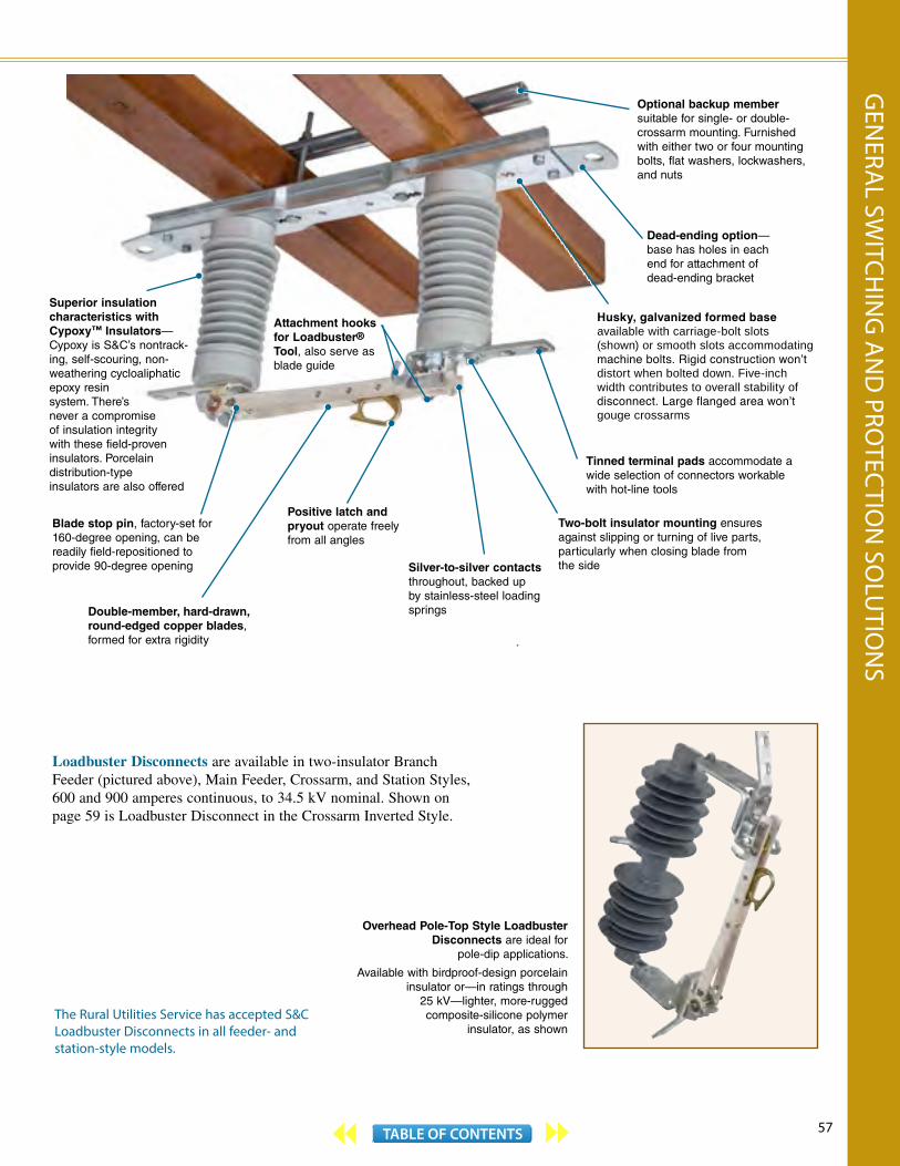
57TABLE OF CONTENTS
Overhead Pole-Top Style Loadbuster Disconnects are ideal for
pole-dip applications.
Available with birdproof-design porcelain insulator or—in ratings through
25 kV—lighter, more-rugged composite-silicone polymer
insulator, as shown
Loadbuster Disconnects are available in two-insulator Branch Feeder (pictured above), Main Feeder, Crossarm, and Station Styles, 600 and 900 amperes continuous, to 34.5 kV nominal. Shown on page 59 is Loadbuster Disconnect in the Crossarm Inverted Style.
Silver-to-silver contacts throughout, backed up by stainless-steel loading springs
Positive latch andpryout operate freely from all angles
Double-member, hard-drawn, round-edged copper blades, formed for extra rigidity
Husky, galvanized formed base available with carriage-bolt slots (shown) or smooth slots accommodating machine bolts. Rigid construction won’t distort when bolted down. Five-inch width contributes to overall stability of disconnect. Large flanged area won’t gouge crossarms
Attachment hooks for Loadbuster®
Tool, also serve as blade guide
Superior insulation characteristics with Cypoxy™ Insulators— Cypoxy is S&C’s nontrack-ing, self-scouring, non-weathering cycloaliphatic epoxy resin system. There’s never a compromise of insulation integrity with these field-proven insulators. Porcelain distribution-type insulators are also offered
Blade stop pin, factory-set for 160-degree opening, can bereadily field-repositioned toprovide 90-degree opening
Dead-ending option—base has holes in each end for attachment of dead-ending bracket
Two-bolt insulator mounting ensures against slipping or turning of live parts, particularly when closing blade fromthe side
Optional backup member suitable for single- or double-crossarm mounting. Furnished with either two or four mounting bolts, flat washers, lockwashers, and nuts
Tinned terminal pads accommodate a wide selection of connectors workable with hot-line tools
The Rural Utilities Service has accepted S&C Loadbuster Disconnects in all feeder- and station-style models.
GEN
ERAL SW
ITCHIN
G A
ND
PROTEC
TION
SOLU
TION
S

58 TABLE OF CONTENTS
Optional carrying case—double-wall, high-density polyethylene construction provides extraordinary protection for Loadbuster
Operation counter lets you make informed decisions regarding inspection and maintenance
Loadbuster ®—The S&C Loadbreak ToolA Better Way of SwitchingS&C’s Loadbuster is the original light-weight, easy-to-use loadbreak tool for use with disconnects, cutouts, and power fuses. It brings load switching capability through 34.5 kV and 600 amperes nominal, 900 amperes maximum to a wide variety of devices on your distribution system.
Greater Flexibility at Lower CostHaving an arc-interrupting device built into every disconnect, cutout, and power fuse on your distribution system is needlessly expensive. Loadbuster, S&C’s portable loadbreak tool, brings the interrupter to the disconnect, cutout, or power fuse whenever load-switching capability is needed . . . but only when needed. Costs are limited to one Loadbuster tool for each line truck. An acceptable minimal cost is spread across your entire system.
Power Consumers BenefitLoadbuster switching helps keep service interruptions to a minimum. There’s no need for complex switching procedures involving opening and reclosing of line and feeder breakers to permit dead switching. There’s no need for one or more line crews to travel and retravel miles of system. Every disconnect, cutout, and power fuse becomes a sectionalizing point. Live switching can be done at the point that minimizes the length of the planned outage and affects the fewest consumers.
Foolproof OperationOperation is simple, positive. Loadbuster’s anchor is simply hung on the attachment hook of the disconnect, cutout, or power fuse; then the pull ring is engaged with Loadbuster’s pull-ring hook, held fast by the pull-ring latch. A firm, steady downward pull opens the switching device and trips
Loadbuster, interrupting the circuit—there’s no external arc, no contact burning. Loadbuster can be instantly reset for the next operation.
There are no “booby trap” arc chutes and auxiliary blades on Loadbuster-operable switching devices to concern operating personnel, nor “gingerbread” mechanisms to challenge them.
Loadbuster can handle 1500 to 2000 operations between inspections. Just a minimum of attention keeps it in top-notch condition. And with Loadbuster’s operation counter, monitoring usage is easy.
UniversalityNot only can Loadbuster switch load currents up through 600 amperes nominal, 900 amperes maximum at distribution system voltages up through 34.5 kV . . . it can break the associated transformer-magnetizing, line- charging, and cable-charging currents. And it can switch single capacitor banks typically found on distribution systems within its voltage rating.
For more information on Loadbuster, see S&C publications 811-30 and 811-31, available on our website www.sandc.com.
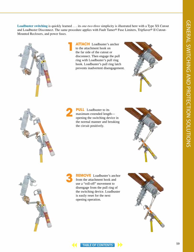
59TABLE OF CONTENTS
PULL Loadbuster to its maximum extended length—opening the switching device in the normal manner and breaking the circuit positively.
Loadbuster switching is quickly learned . . . its one-two-three simplicity is illustrated here with a Type XS Cutout and Loadbuster Disconnect. The same procedure applies with Fault Tamer® Fuse Limiters, TripSaver® II Cutout-Mounted Reclosers, and power fuses.
1
2
3
ATTACH Loadbuster’s anchor to the attachment hook on the far side of the cutout or disconnect. Then engage the pull ring with Loadbuster’s pull ring hook. Loadbuster’s pull ring latch prevents inadvertent disengagement.
REMOVE Loadbuster’s anchor from the attachment hook and use a “roll-off” movement to disengage from the pull ring of the switching device. Loadbuster is easily reset for the next opening operation.
GEN
ERAL SW
ITCHIN
G A
ND
PROTEC
TION
SOLU
TION
S

60 TABLE OF CONTENTS
Omni-Rupter ® Switches and Alduti-Rupter
® SwitchesS&C Omni-Rupter Switches and Alduti-Rupter Switches provide no-external-arc circuit interruption for overhead distribution feeders and outdoor distribution substations. They’re specially designed for these live-switching duties:
Line switching—load splitting (parallel or loop switching), load dropping . . . and associated charging currents.
Transformer switching—load currents . . . and associated magnetizing currents.
Cable switching—load splitting (parallel or loop switching), load dropping . . . and associated charging currents.
Overhead Distribution FeedersIncreasingly greater load densities have resulted in more load per mile of line, and more interconnections, laterals, and branches. To simplify switching procedures, curtail the scope of outages, and facilitate post-outage cold-load pickup, more and more sectionalizing points are being used. Since switching duties have far outgrown the capabilities of ordinary disconnects, interrupter switches have become the choice for most applications.
Omni-Rupter Switches are especially suited for overhead-line switching through 29 kV. These 900-ampere switches are offered in the integer style, with all three switch poles preassembled on a one-piece steel or insulated base, factory-assembled and adjusted . . . all necessary clearances are built in. A variety of mounting configurations are available, tailored to the most popular overhead-distribution line designs.
Omni-Rupter Switches bring unsurpassed live-switching performance to overhead distribution feeders. They offer a two-time duty-cycle fault-closing capability of 42,000 amperes, peak, and a ten-time duty-cycle fault-closing capability of 21,000 amperes, peak—plus ice-breaking capability on opening and closing, and substantial emergency overload capabilities. Omni-Rupter Switches are shipped as a single package. They are easy to hoist using the single-point lifting bracket, and mount quickly and easily using two through-bolts and one or two pole bands. With the simple addition of the vertical operating mechanism and handle, installation is complete. Hookstick-operated models are available too, in upright, vertical, and tiered-outboard mounting configurations, providing the ultimate solution for simple, quick, and cost-effective installation.
Integer style Alduti-Rupter Switches are also available for switching overhead distribution feeders at system voltages through 46 kV and 1200 amperes continuous. They can be power operated through the addition of an S&C Type AS-1A, AS-10, LS-2, or M Series® Switch Operator, as appropriate.
M Series Switch Operator
M Series Switch Operators are fully integrated, micro-processor-based operators that combine electromechanical components, RTU, control circuitry, and communications in a single package—for enhanced installation flexibility and reliability, and reduced cost. M Series Switch Operators monitor the entire switching cycle and can automatically take corrective action in the event of a problem.
S&C’s switches provide the utmost flexibility in distribution system switching. Lines may be readily extended and additional load accommodated since Omni-Rupter and Alduti-Rupter Switches can handle heavier-duty loads—typically up through the emergency overload rating of the line conductor. S&C switches can drop or split the entire connected load without complicated breaker-and-switch sequencing. There’s no need to drop individual loads as a preliminary operation.
Outdoor Distribution SubstationsThe economics of power distribution have forced heavier loading of substation transformers, through the addition of new feeders and increased loading of existing ones. S&C’s Alduti-Rupter is the ideal switching device for these heavier duties—it can split load, and drop lines or cables or even the entire load. Its no-external-arc interrupting performance is essential in substations, where close phase spacings rule out the use of arc-producing disconnects.
S&C Alduti-Rupter Switches are available in voltage ratings through 69 kV, in six rugged three-pole group-operated styles. They’re offered in ratings of 600 amperes and 1200 amperes, continuous and interrupting. For applications where simultaneous three-phase switching isn’t needed, single-pole Alduti-Rupter Switches are an excellent alternative; they’re conveniently operated with a conventional hookstick.

61TABLE OF CONTENTS
The Rural Utilities Service has accepted a wide variety of Omni-Rupter Switch and Alduti-Rupter Switch styles and configurations.
No-External-Arc InterruptionEvery S&C Alduti-Rupter and Omni-Rupter Switch incorporates built-in interrupters . . . there’s no need to rig S&C switches with “add-ons.” Operation is simple and straightforward. Interrupter contacts separate at high speed. The contacts and blade are synchronized to coordinate dynamic internal dielectric strength with the interrupter’s external striking distance, eliminating any chance of flashover. Arc-extinguishing deionizing gases are quietly vented through a labyrinthine muffler. There’s no oil, no vacuum . . . no maintenance.
Exhaustively Tested, Utility ProvenEvery S&C switch rating is based on full-scale testing: load splitting, load dropping, line and cable switching—all at maximum voltages and rated currents . . . and with test circuits tuned to duplicate the most severe transient recovery voltages likely to be encountered in service. Rated performance is assured for all live-switching duties. The validity of S&C’s testing has been confirmed by over 60 years of reliable operation of S&C switches on utility systems worldwide.
For more information on Omni-Rupter Switches, see S&C publications 765-30, 765-31, and 765-80. For more information on Alduti-Rupter Switches, see S&C publications 761-30, 761-31, and 761-80. For more information on M Series Switch Operators, see S&C publication 1051-30. All of these publications are available on our website www.sandc.com.
GEN
ERAL SW
ITCHIN
G A
ND
PROTEC
TION
SOLU
TION
S
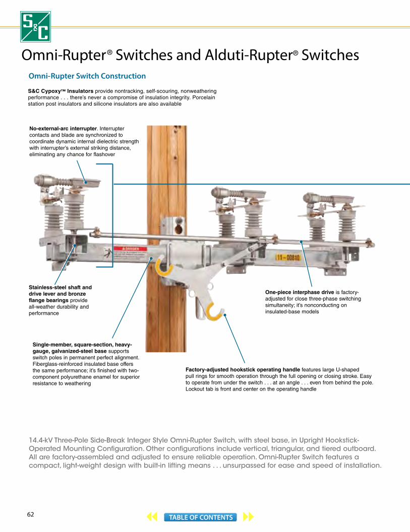
62 TABLE OF CONTENTS
Omni- Rupter Switch Construction
14.4-kV Three-Pole Side-Break Integer Style Omni-Rupter Switch, with steel base, in Upright Hookstick-Operated Mounting Configuration. Other configurations include vertical, triangular, and tiered outboard. All are factory-assembled and adjusted to ensure reliable operation. Omni-Rupter Switch features a compact, light-weight design with built-in lifting means . . . unsurpassed for ease and speed of installation.
One-piece interphase drive is factory-adjusted for close three-phase switching simultaneity; it’s nonconducting on insulated-base models
Single-member, square-section, heavy-gauge, galvanized-steel base supports switch poles in permanent perfect alignment. Fiberglass-reinforced insulated base offers the same performance; it’s finished with two-component polyurethane enamel for superior resistance to weathering
No-external-arc interrupter. Interrupter contacts and blade are synchronized to coordinate dynamic internal dielectric strength with interrupter’s external striking distance, eliminating any chance for flashover
S&C Cypoxy™ Insulators provide nontracking, self-scouring, nonweathering performance . . . there’s never a compromise of insulation integrity. Porcelain station post insulators and silicone insulators are also available
Omni-Rupter ® Switches and Alduti-Rupter ® Switches
Factory-adjusted hookstick operating handle features large U-shaped pull rings for smooth operation through the full opening or closing stroke. Easy to operate from under the switch . . . at an angle . . . even from behind the pole. Lockout tab is front and center on the operating handle
Stainless-steel shaft and drive lever and bronze flange bearings provide all-weather durability and performance
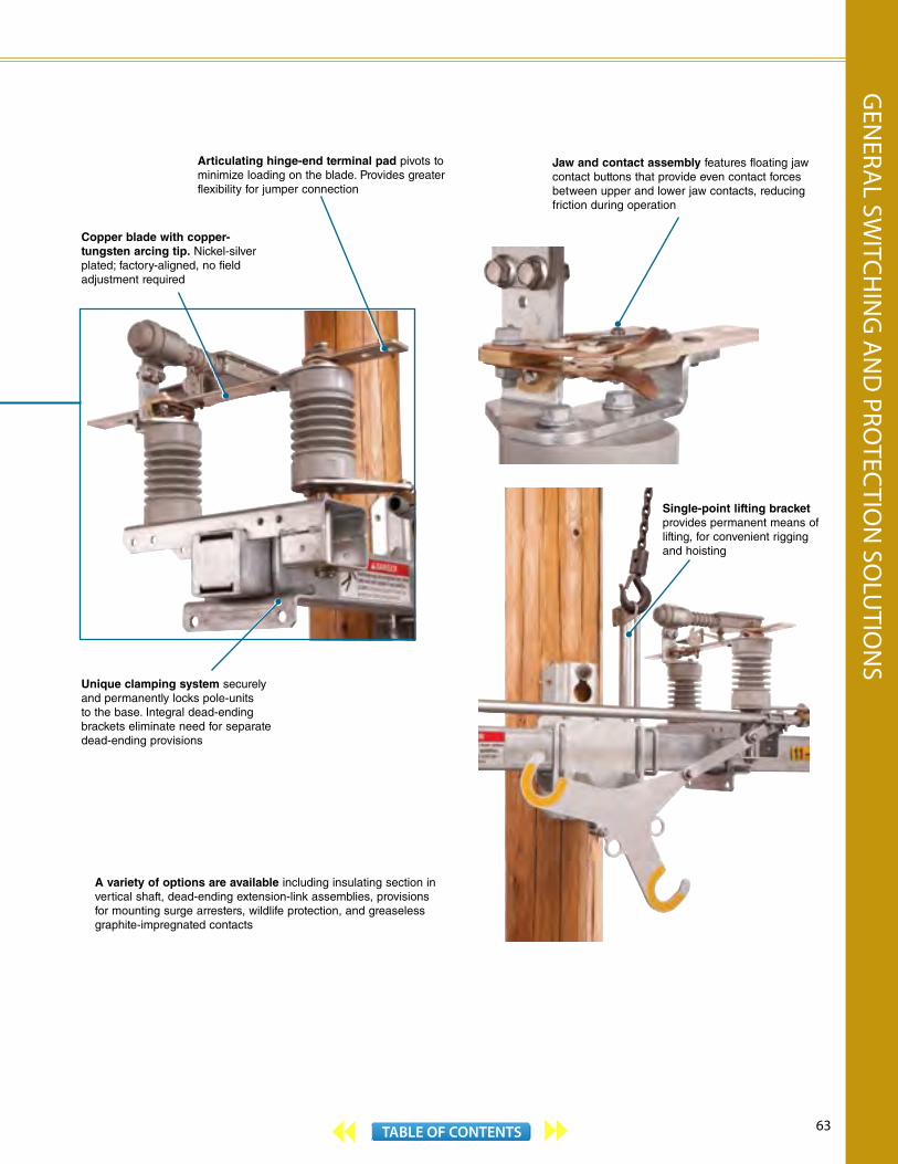
63TABLE OF CONTENTS
Omni-Rupter ® Switches and Alduti-Rupter ® Switches
A variety of options are available including insulating section in vertical shaft, dead-ending extension-link assemblies, provisions for mounting surge arresters, wildlife protection, and greaseless graphite-impregnated contacts
Single-point lifting bracket provides permanent means of lifting, for convenient rigging and hoisting
Unique clamping system securely and permanently locks pole-units to the base. Integral dead-ending brackets eliminate need for separate dead-ending provisions
Jaw and contact assembly features floating jaw contact buttons that provide even contact forces between upper and lower jaw contacts, reducing friction during operation
Articulating hinge-end terminal pad pivots to minimize loading on the blade. Provides greater flexibility for jumper connection
Copper blade with copper- tungsten arcing tip. Nickel-silver plated; factory-aligned, no field adjustment required
GEN
ERAL SW
ITCHIN
G A
ND
PROTEC
TION
SOLU
TION
S
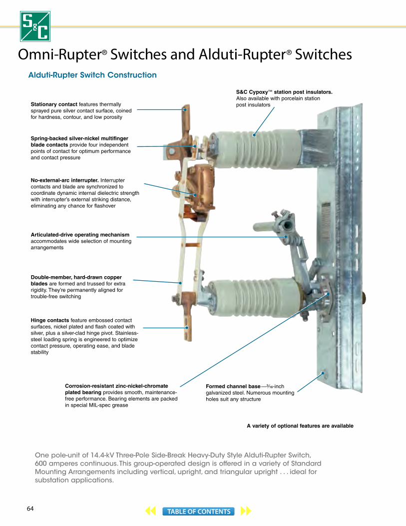
64 TABLE OF CONTENTS
Alduti-Rupter Switch Construction
Stationary contact features thermally sprayed pure silver contact surface, coined for hardness, contour, and low porosity
Spring-backed silver-nickel multifinger blade contacts provide four independent points of contact for optimum performance and contact pressure
S&C Cypoxy™ station post insulators. Also available with porcelain station post insulators
Double-member, hard-drawn copper blades are formed and trussed for extra rigidity. They’re permanently aligned for trouble-free switching
No-external-arc interrupter. Interrupter contacts and blade are synchronized to coordinate dynamic internal dielectric strength with interrupter’s external striking distance, eliminating any chance for flashover
Hinge contacts feature embossed contactsurfaces, nickel plated and flash coated withsilver, plus a silver-clad hinge pivot. Stainless-steel loading spring is engineered to optimize contact pressure, operating ease, and blade stability
Corrosion-resistant zinc-nickel-chromate plated bearing provides smooth, maintenance-free performance. Bearing elements are packed in special MIL-spec grease
Articulated-drive operating mechanism accommodates wide selection of mounting arrangements
Formed channel base —3⁄16-inch galvanized steel. Numerous mounting holes suit any structure
One pole-unit of 14.4-kV Three-Pole Side-Break Heavy-Duty Style Alduti-Rupter Switch, 600 amperes continuous. This group-operated design is offered in a variety of Standard Mounting Arrangements including vertical, upright, and triangular upright . . . ideal for substation applications.
A variety of optional features are available
Omni-Rupter ® Switches and Alduti-Rupter ® Switches

65TABLE OF CONTENTS
Omni-Rupter ® Switches and Alduti-Rupter ® Switches
One pole-unit of 34.5-kV Three-Pole Vertical-Break Style Alduti-Rupter Switch, 1200 amperes continuous. Group-operated vertical-break style switches are available in voltage ratings of 14.4 kV through 34.5 kV, and continuous current ratings of 600 amperes and 1200 amperes. They’re offered in vertical and upright Standard Mounting Arrangements.
Double-member, hard-drawn copper blades are formed and trussed for extra rigidity. They’re permanently aligned for trouble-free switching
Hex-crimped, galvanized-steel-pipe operating shaft
Rectangular-section, heavy- gauge, galvanized steel base
Four silver-nickel contact rivets on switch blade, plus silver-clad blade support ensure efficient current transfer and velvet-smooth action at the blade hinge. Hinge loading springs, truss members, spacer, and equalizer bar—all of stainless steel—are engineered for optimal contact pressure, operating ease, and blade stability
Circuit interruption takes place within S&C’s Cypoxylated™ molded interrupter, without external arc or flame. Interrupter contacts and blade are synchronized to coordinate dynamic internal dielectric strength with interrupter’s external striking distance, eliminating any chance for flashover
Fault-closing contacts feature copper-tungsten disks silver-brazed to copper blade-tongue, and carbon-block (600-A switch) or copper-tungsten-block (1200-A switch) jaw. Current-carrying contacts consist of four silver-nickel contact rivets on copper blade-tongue; and self-aligning, four-finger, spring-loaded, silver-clad copper jaw
Low-inertia Cypoxy™ operating rod permits high-speed operation; there are no heavy rotating or rocking insulators to accelerate or decelerate. Operating rod is designed to withstand all dynamic tensile and compressive forces. Advanced skirt configuration provides generous leakage distance . . . more than enough for contaminated environments
S&C Cypoxy station post insulators. Also available with porcelain station post insulators
Corrosion-resistant brass guide bearing provides smooth, maintenance-free performance
A variety of optional features are available
GEN
ERAL SW
ITCHIN
G A
ND
PROTEC
TION
SOLU
TION
S
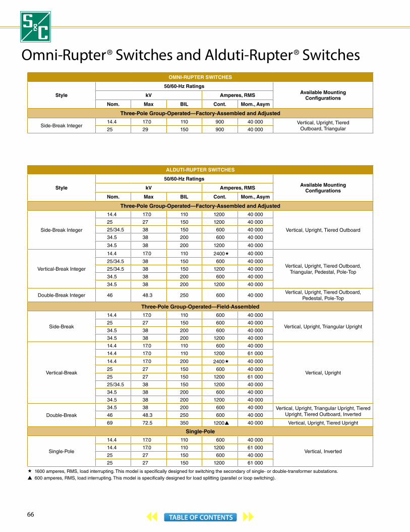
66 TABLE OF CONTENTS
Omni-Rupter ® Switches and Alduti-Rupter
® SwitchesOMNI-RUPTER SWITCHES
Style
50/60-Hz RatingsAvailable Mounting
ConfigurationskV Amperes, RMS
Nom. Max BIL Cont. Mom., Asym
Three-Pole Group-Operated—Factory-Assembled and Adjusted
Side-Break Integer14.4 17.0 110 900 40 000 Vertical, Upright, Tiered
Outboard, Triangular25 29 150 900 40 000
ALDUTI-RUPTER SWITCHES
Style
50/60-Hz RatingsAvailable Mounting
ConfigurationskV Amperes, RMS
Nom. Max BIL Cont. Mom., Asym
Three-Pole Group-Operated—Factory-Assembled and Adjusted
Side-Break Integer
14.4 17.0 110 1200 40 000
Vertical, Upright, Tiered Outboard
25 27 150 1200 40 000
25 /34.5 38 150 600 40 000
34.5 38 200 600 40 000
34.5 38 200 1200 40 000
Vertical-Break Integer
14.4 17.0 110 2400« 40 000
Vertical, Upright, Tiered Outboard,Triangular, Pedestal, Pole-Top
25 /34.5 38 150 600 40 000
25 /34.5 38 150 1200 40 000
34.5 38 200 600 40 000
34.5 38 200 1200 40 000
Double-Break Integer 46 48.3 250 600 40 000Vertical, Upright, Tiered Outboard,
Pedestal, Pole-Top
Three-Pole Group-Operated—Field-Assembled
Side-Break
14.4 17.0 110 600 40 000
Vertical, Upright, Triangular Upright25 27 150 600 40 000
34.5 38 200 600 40 000
34.5 38 200 1200 40 000
Vertical-Break
14.4 17.0 110 600 40 000
Vertical, Upright
14.4 17.0 110 1200 61 000
14.4 17.0 200 2400« 40 000
25 27 150 600 40 000
25 27 150 1200 61 000
25 /34.5 38 150 1200 40 000
34.5 38 200 600 40 000
34.5 38 200 1200 40 000
Double-Break
34.5 38 200 600 40 000 Vertical, Upright, Triangular Upright, Tiered Upright, Tiered Outboard, Inverted46 48.3 250 600 40 000
69 72.5 350 1200 40 000 Vertical, Upright, Tiered Upright
Single-Pole
Single-Pole
14.4 17.0 110 600 40 000
Vertical, Inverted 14.4 17.0 110 1200 61 000
25 27 150 600 40 000
25 27 150 1200 61 000
« 1600 amperes, RMS, load interrupting. This model is specifically designed for switching the secondary of single- or double-transformer substations. 600 amperes, RMS, load interrupting. This model is specifically designed for load splitting (parallel or loop switching).

67TABLE OF CONTENTS
Omni-Rupter ® Switches and Alduti-Rupter
® Switches
Vertical-Break Integer Alduti-Rupter Switch, Pedestal Mounting
Double-Break Integer Alduti-Rupter Switch,Pole-Top Mounting
Side-Break IntegerAlduti-Rupter Switch,
Tiered Outboard Mounting
Side-Break Alduti-Rupter Switch,Upright Mounting
Vertical-Break Alduti-Rupter Switch, Vertical Mounting
Single-Pole Alduti-Rupter Switch,Vertical Mounting
Double-Break Alduti-Rupter Switch, Vertical Mounting
Side-Break Integer Omni-Rupter Switch,Upright MountingSide-Break Integer Omni-Rupter Switch,
Vertical Mounting
GEN
ERAL SW
ITCHIN
G A
ND
PROTEC
TION
SOLU
TION
S

68 TABLE OF CONTENTS
Regulator Bypass Switches and Recloser Bypass DisconnectsRegulator Bypass Switches are used to bypass and isolate voltage regulators for maintenance. Recloser Bypass Disconnects are used in combination with separately mounted Loadbuster Disconnects® to bypass and isolate automatic circuit reclosers for maintenance. Both station-type devices are suitable for other applications, such as bypassing and isolating current transformers.
Regulator Bypass Switches and Recloser Bypass Disconnects offer the exceptionally sturdy construction features needed to assure years of reliable, easy operation:
All blades are of double-member, hard-drawn copper construction.
Silver-to-silver contacts are utilized at all current- transfer points. The surface structure of the stationary contacts differs from that of the blade contacts—preventing sticking, galling, or seizing. Contacts won’t weld, burn, or pit on overcurrents.
Stainless-steel or beryllium-copper loading springs behind the contact areas of the blades keep the contacts under constant pressure, and provide smooth, positive wiping action during opening and closing. This feature is especially important for regulator bypass switches, since the bypass blade is normally in the open position . . . the bypass blade must carry full load current after the contacts have endured long periods of exposure to the elements.
Regulator Bypass Switches and Recloser Bypass Disconnects are offered with a choice of Cypoxy™ or porcelain station post insulators. Cypoxy station post insulators are nontracking, self-scouring, nonweathering, and meet or exceed the electrical and mechanical-strength requirements established in ANSI Standard C29.9 (1983) for porcelain station post insulators.
Type XL Regulator Bypass Switches, rated 600 amperes, provide built-in mechanical interlocking, sequencing, and synchronization. Only a single pull of a hookstick is required to isolate the regulator. The bypass blade closes first, bypassing the regulator to prevent interruption of service. Then the disconnect blade opens the regulator series-winding circuit. Finally, the interrupter blade opens; interruption of shunt-winding magnetizing current takes place within the no-external-arc interrupter, and the regulator is isolated from the line. This switching sequence is reversed automatically during the closing stroke, putting the voltage regulator back into operation without interrupting service.
Special attention has been given to the operation and alignment of the disconnect blade through the use of stainless-steel hardware and rigid anchoring of the disconnect blade to the interrupter blade. Ease of operation is assured by floating contact alignment and a carefully positioned and proportioned pull ring.
Type NL Regulator Bypass Switches perform the same functions as Type XL Switches but sequence of operation is done by the operator. Type NL Switches are used in applications where a 1200-ampere rating is needed or where it is desired to bypass the voltage regulator with its shunt winding energized (bypass blade closed, disconnect blade open) so that mechanical and electrical testing can be carried out.
To isolate the regulator, the operator first closes the bypass blade to prevent interruption of service. Then the disconnect blade is opened, to open the regulator series-winding circuit. Finally, the interrupter blade is opened; shunt-winding magnetizing current is interrupted within the interrupter, and the regulator is isolated from the line. The procedure is reversed to place the regulator back into service.
Recloser Bypass Disconnects, rated up through 900 amperes, consist of a fuse—a Type SMD-20, Type SMD-40, or Type SM-5® Power Fuse, or a Type XS Fuse Cutout (depending on the available fault and continuous current levels of the application)—in series with an integral Loadbuster Disconnect. The fuse is inserted into the device to protect the circuit while the recloser is out of service. The readily accessible trunnion pocket of the rugged cast bronze hinge makes inserting the fuse easy. Guiding surfaces on the inner surface of the hinge ensure “on-center” approach of the fuse to the upper live parts during closing. And a carefully positioned and proportioned brass pull ring makes opening with a conventional hookstick a simple operation.
Recloser Bypass Disconnects are alternately available with a second Loadbuster Disconnect (in place of the fuse) for applications where devices other than protective equipment are being bypassed for maintenance or inspection.
For more information on Regulator Bypass Switches, see S&C publications 841-30 and 841-31. For more information on Recloser Bypass Disconnects, see S&C publications 842-30, 842-31, and 842-700. All are available on our website www.sandc.com.

69TABLE OF CONTENTS
REGULATOR BYPASS SWITCHES
50/60-Hz Ratings
kV Amperes, RMS
Nom. Max BIL Cont. Mom., Asym.
14.4 17.0 110 « 30 000
25 27 150 « 30 000
« 600 amperes for Type XL, 1200 amperes for Type NL.
RECLOSER BYPASS DISCONNECTS
50/60-Hz Ratings
Fuse TypekV
Amperes, RMS
Switch Fuse
Nom. Max BIL Cont. Mom.,Asym. Max
Interr., Sym.
60 Hz 50 Hz
14.4
15 110 600 40 000100 7 100 5 680 XS Fuse Cutout
200 7 100 5 680 XS Fuse Cutout
15.5 110600 40 000
200E or 200K 14 000 11 200 SMD-20
400E 25 000 20 000 SMD-40
400E 34 000 27 200 SM-5
— — —
900 40 000• — — —
25 27
125« 900 40 000• — — —
150 600 40 000
100 5 300 4 240 XS Fuse Cutout
200 5 300 4 240 XS Fuse Cutout
200E or 200K 12 500 10 000 SMD-20
300E 20 000 16 000 SM-5
400E 20 000 16 000 SMD-40
— — —
34.5 38 200 900 40 000 200E or 200K 10 000 8 000 SMD-20
« When furnished with Cypoxy™ Insulators, meets requirements for 150-kV BIL ratings.• Three-second rating is 25,000 amperes, RMS, symmetrical. Furnished with a second S&C Loadbuster Disconnect in place of the fuse.
Type XL Regulator Bypass Switches and Recloser Bypass Disconnects are Rural Utilities Service accepted.
Recloser Bypass Disconnect with Type SMD-20 Power Fuse
Source terminal
Type NL Regulator Bypass Switch
Recloser Bypass Disconnect—Type RA
Load terminalBypass
Recloser terminals
Type XL Regulator Bypass Switch
Interrupter blade
Interrupter
Voltage-regulator terminal
Disconnect blade
Bypass blade
Load terminal
Source terminal
Load terminal
Bypassblade
Disconnect blade
Voltage-regulator terminals
Interrupter
Interrupter blade
Source terminal
Load terminal
Disconnect blade
Recloser terminal
SMU-20 Fuse Unit
Fuse hinge
Source terminal
GEN
ERAL SW
ITCHIN
G A
ND
PROTEC
TION
SOLU
TION
S
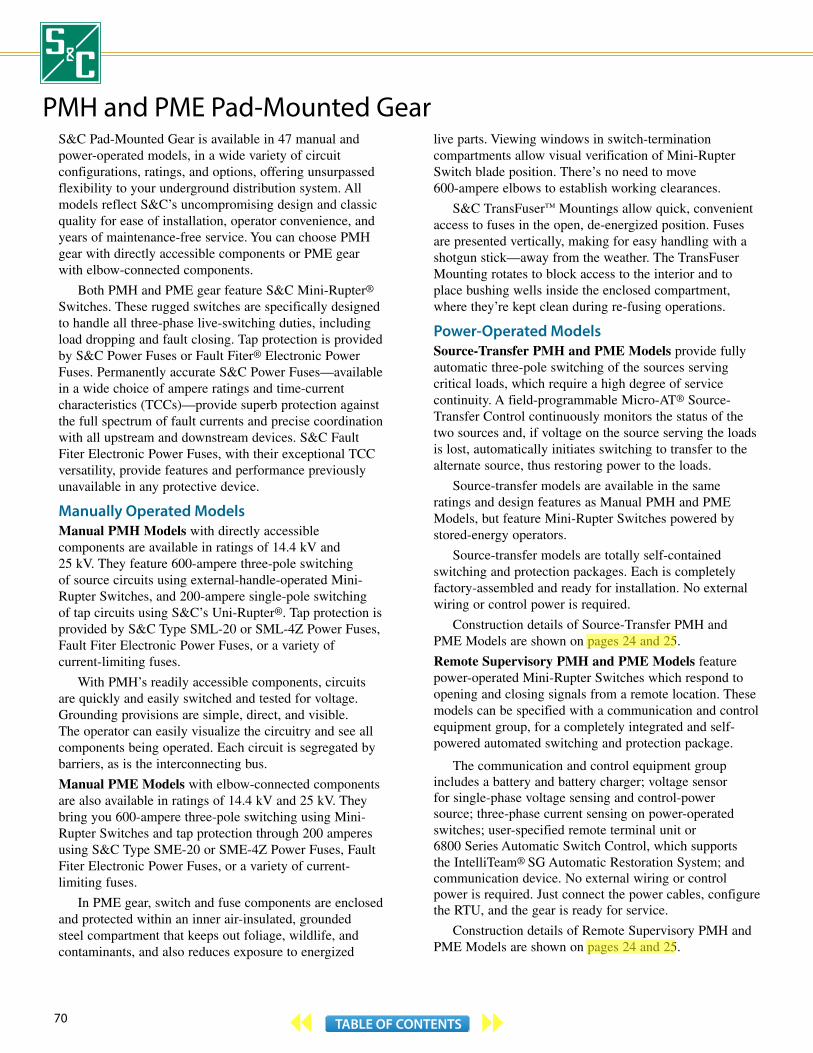
70 TABLE OF CONTENTS
PMH and PME Pad-Mounted GearS&C Pad-Mounted Gear is available in 47 manual and power-operated models, in a wide variety of circuit configurations, ratings, and options, offering unsurpassed flexibility to your underground distribution system. All models reflect S&C’s uncompromising design and classic quality for ease of installation, operator convenience, and years of maintenance-free service. You can choose PMH gear with directly accessible components or PME gear with elbow-connected components.
Both PMH and PME gear feature S&C Mini-Rupter® Switches. These rugged switches are specifically designed to handle all three-phase live-switching duties, including load dropping and fault closing. Tap protection is provided by S&C Power Fuses or Fault Fiter® Electronic Power Fuses. Permanently accurate S&C Power Fuses—available in a wide choice of ampere ratings and time-current characteristics (TCCs)—provide superb protection against the full spectrum of fault currents and precise coordination with all upstream and downstream devices. S&C Fault Fiter Electronic Power Fuses, with their exceptional TCC versatility, provide features and performance previously unavailable in any protective device.
Manually Operated Models Manual PMH Models with directly accessible components are available in ratings of 14.4 kV and 25 kV. They feature 600-ampere three-pole switching of source circuits using external-handle-operated Mini-Rupter Switches, and 200-ampere single-pole switching of tap circuits using S&C’s Uni-Rupter®. Tap protection is provided by S&C Type SML-20 or SML-4Z Power Fuses, Fault Fiter Electronic Power Fuses, or a variety of current-limiting fuses.
With PMH’s readily accessible components, circuits are quickly and easily switched and tested for voltage. Grounding provisions are simple, direct, and visible. The operator can easily visualize the circuitry and see all components being operated. Each circuit is segregated by barriers, as is the interconnecting bus.
Manual PME Models with elbow-connected components are also available in ratings of 14.4 kV and 25 kV. They bring you 600-ampere three-pole switching using Mini-Rupter Switches and tap protection through 200 amperes using S&C Type SME-20 or SME-4Z Power Fuses, Fault Fiter Electronic Power Fuses, or a variety of current-limiting fuses.
In PME gear, switch and fuse components are enclosed and protected within an inner air-insulated, grounded steel compartment that keeps out foliage, wildlife, and contaminants, and also reduces exposure to energized
live parts. Viewing windows in switch-termination compartments allow visual verification of Mini-Rupter Switch blade position. There’s no need to move 600-ampere elbows to establish working clearances.
S&C TransFuser™ Mountings allow quick, convenient access to fuses in the open, de-energized position. Fuses are presented vertically, making for easy handling with a shotgun stick—away from the weather. The TransFuser Mounting rotates to block access to the interior and to place bushing wells inside the enclosed compartment, where they’re kept clean during re-fusing operations.
Power-Operated Models Source-Transfer PMH and PME Models provide fully automatic three-pole switching of the sources serving critical loads, which require a high degree of service continuity. A field-programmable Micro-AT® Source-Transfer Control continuously monitors the status of the two sources and, if voltage on the source serving the loads is lost, automatically initiates switching to transfer to the alternate source, thus restoring power to the loads.
Source-transfer models are available in the same ratings and design features as Manual PMH and PME Models, but feature Mini-Rupter Switches powered by stored-energy operators.
Source-transfer models are totally self-contained switching and protection packages. Each is completely factory-assembled and ready for installation. No external wiring or control power is required.
Construction details of Source-Transfer PMH and PME Models are shown on pages 24 and 25.
Remote Supervisory PMH and PME Models feature power-operated Mini-Rupter Switches which respond to opening and closing signals from a remote location. These models can be specified with a communication and control equipment group, for a completely integrated and self- powered automated switching and protection package.
The communication and control equipment group includes a battery and battery charger; voltage sensor for single-phase voltage sensing and control-power source; three-phase current sensing on power-operated switches; user-specified remote terminal unit or 6800 Series Automatic Switch Control, which supports the IntelliTeam® SG Automatic Restoration System; and communication device. No external wiring or control power is required. Just connect the power cables, configure the RTU, and the gear is ready for service.
Construction details of Remote Supervisory PMH and PME Models are shown on pages 24 and 25.
aleknam
Highlight
aleknam
Highlight
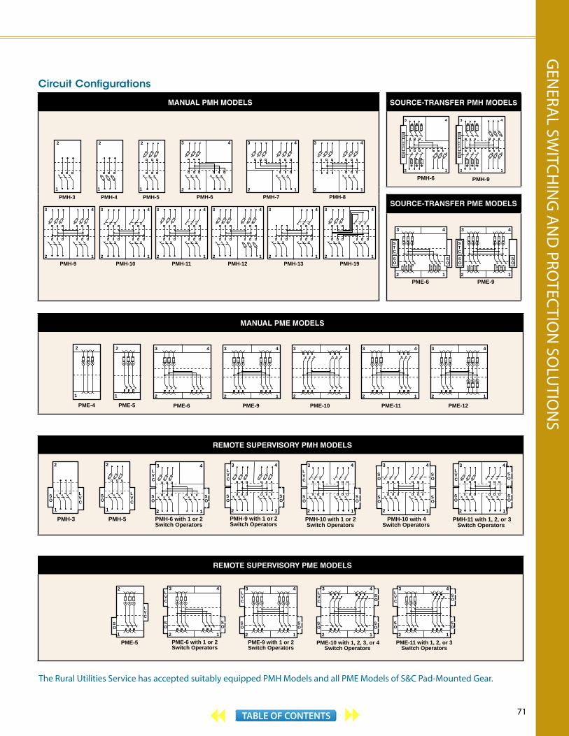
71TABLE OF CONTENTS
The Rural Utilities Service has accepted suitably equipped PMH Models and all PME Models of S&C Pad-Mounted Gear.
Circuit Configurations
MANUAL PMH MODELS SOURCE-TRANSFER PMH MODELS
2
1
PMH-3
2
1
PMH-4
2
1
PMH-5
3
2PMH-6
4
1
3
2PMH-7
4
1
3
2PMH-8
4
1
3
2PMH-19
4
1
3
2PMH-13
4
1
3
2PMH-12
4
1
3
2PMH-11
4
1
3
2PMH-10
4
1
3
2PMH-9
4
1
PMH-9
3
2
4
1
VS
VS
VS
SO
STC
SO
VS
VS
VS
PMH-6
3
2
4
1
VS
VS
VS
SO
STC
SO
VS
VS
VS
SOURCE-TRANSFER PME MODELS
PME-6 PME-9
3
2 1
4
SO
STC
SO
3
2 1
4
SO
STC
SO
MANUAL PME MODELS
PME-11
3
2
4
1
PME-9
3
2
4
1
3
2
4
1
PME-6
2
1
PME-4
2
1
PME-5 PME-12
3
2
4
1
PME-10
3
2
4
1
REMOTE SUPERVISORY PMH MODELS
1
LVC
SO
SO
4
1
3
2
LVC
SO
PMH-3 PMH-5
4
1 PMH-10 with 4Switch Operators
SO
3
2
SO
SO
SO
PMH-10 with 1 or 2 Switch Operators
4
1
LVC
SO
3
2
SO
PMH-9 with 1 or 2Switch Operators
SO
4
1
3
2
LVC
SO
PMH-6 with 1 or 2Switch Operators
2
1
LVC
SO
2
PMH-11 with 1, 2, or 3 Switch Operators
SO
SO
4
1
3
2
LVC
SO
SO
REMOTE SUPERVISORY PME MODELS
PME-11 with 1, 2, or 3 Switch Operators
3
2
SO
LVC
1
4
SO
3
2
SO
LVC
1
4
SO
PME-10 with 1, 2, 3, or 4 Switch Operators
PME-9 with 1 or 2Switch Operators
3
2
SO
LVC
1
4
SO
PME-6 with 1 or 2Switch Operators
3
2
SO
LVC
1
4
SO
PME-5
LVC
2
1
SO
SO
SO
GEN
ERAL SW
ITCHIN
G A
ND
PROTEC
TION
SOLU
TION
S

72 TABLE OF CONTENTS
PMH Models—Fuse« and Switch Compartments
S&C’s Uni-Rupter® provides the ultimate in single-pole live switching . . . just a firm opening pull on the fuse interrupts the circuit with a quick-break action. Uni-Rupter self-resets for the next opening operation. Separate current-carrying and fault-closing contacts are provided
Corrosion-resistant non-ferrous door hinges and hinge pins
Insulated roof—“no-drip” compound on underside of roof guards against formation of condensation that could drip onto energized parts
Dual-purpose front barriers of GPO3-grade fiberglass-reinforced polyester guard against inadvertent contact with live parts when in the normal vertical position. Inserted into the open gap of a switch or fuse, barrier provides isolation from bus and upper contacts
Grappler™ takes the work out of fuse handling . . . provides sure grip, perfect balance, and ready control that operators appreciate
Segregated circuits—full-length steel barriers separate side-by-side compartments; GPO3-grade fiberglass-reinforced polyester barriers separate front compartments from rear compartments and isolate the tie bus
Optional cable guides assist in cable training and provide protection against damage from
excessive cable or foundation movement
Ground studs for fuse terminals, switch terminals, and the ground pad in each compartment
Optional base spacer increases elevation of the gear up to 24 inches, to provide additional cable training space or additional distance above the ground
Also available: • Optional stainless-steel enclosure
• Optional key-interlock schemes
• Optional inner barrier panel—meets Rural Utilities Service “dead-front” requirements
• Optional Canadian Standards Association Listing
• Optional UL Listing
Cypoxy™—S&C’s cycloaliphatic epoxy resin system . . . insulates all live parts from ground
S&C’s Ultradur™ Finishing System provides superb corrosion resistance
« Fuse compartments illustrate non-standard combination of Fault Fiter® Electronic Power Fuses (on left) and SML-20 Power Fuses (on right) for comparison only.
PMH and PME Pad-Mounted Gear

73TABLE OF CONTENTS
PMH PAD-MOUNTED GEAR60-Hz Ratings①
kV Mini-Rupter Switch, Amperes Fuse
Short-Circuit, Amperes, RMS, Sym.Nom. Max BIL Cont. Load
Dropping TypeAmperes
Max Load Droppingwith Uni-Rupter
14.4 17.0 95 600 600
SML-20 200E 200 14 000
SML-4Z 200E 200 12 500
Fault Fiter 200 200 14 000
25 27u 125 600 600
SML-20 200E 200 12 500
SML-4Z 200E 200 12 500
Fault Fiter 200 200 12 500
① Consult the nearest S&C Sales Office for 50-hertz ratings.u 25-kV models equipped with Fault Fiter® Electronic Power Fuses are rated 29 kV max. SMU-20 Fuse Units are available in ratings through 200K amperes as well as 200E amperes. Applicable to solidly-grounded-neutral systems only, with fuses connected by single-conductor, concentric-neutral-type cable to a transformer or transformers. Rating is 9,400 amperes, RMS, symmetrical for all other applications.
For more information on Manual PMH Models, see S&C publications 662-30 and 662A-31. These publications are available on our website www.sandc.com.
Penta-Latch® Mechanism provides vandal-resistant, automatic, three-point door latching for S&C Pad-Mounted Gear and is fully coordinated with provision for padlocking
Aluminum bus connections— wire-brushed and protected by an oxide-inhibiting abrasive compound— are bolted at a uniform torque of 50 ft-lb; two spring-washers per bolt maintain contact pressure
Viewing window for visible verification of switch position is easily removed for voltage testing or phasing
Optional mounting provisions for fault indicator with viewing window in door accommodates one three-phase indicator with single-phase sensors (fault indicator shown for illustrative purposes only)
Optional distribution-class surge arresters are available in 9-kV through 18-kV ratings for application at source-side switch terminals
S&C Mini-Rupter® Switch—the field-tested and proven 600-A three-pole group- operated interrupter switch
Interphase and end barriers of GPO3-grade fiberglass-reinforced polyester for superior arc and track resistance. Switch barriers are easily removed to facilitate terminating cables
Optional fuse-storage feature accommo-dates up to three spare SML fuse assemblies, one spare Fault Fiter Holder, or two spare Fault Fiter Interrupting Modules
Optional terminal adapters can be added at all switch and bus terminals to accommodate two connectors per terminal
GEN
ERAL SW
ITCHIN
G A
ND
PROTEC
TION
SOLU
TION
S

74 TABLE OF CONTENTS
PME Models—Fuse« and Switch Compartments
Generous spacing of bushing wells and parking stands accommodates a full spectrum of elbows, portable feed-thrus, and accessories
200-A Cypoxy™ bushing wells have interfaces in accordance with ANSI/IEEE Standard 386
Viewing windows allow easy checking of blown-fuse indicators
Storage racks hold spare Fault Fiter Interrupting Modules, SMU-20 Fuse Units, or SM-4 Refill Units—operators can restore service without delay
Ground rings are readily accessible in up-front location. Enclosure doors may be closed with grounding clamps in place
Up-front access to fuses takes the hassle out of fuse changeout. With an almost effortless pull, TransFuser™ Mounting unlatches and pivots to its open position, making the de-energized and isolated fuse accessible for easy replacement
« Fuse compartments illustrate non-standard combination of Fault Fiter® Electronic Power Fuses (on left) and SME-20 Power Fuses (on right) for comparison only.
PMH and PME Pad-Mounted Gear
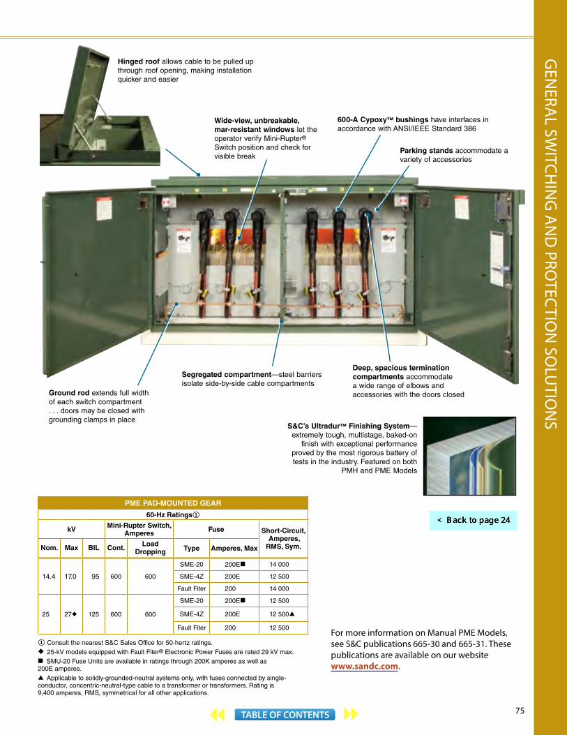
75TABLE OF CONTENTS
PME PAD-MOUNTED GEAR
60-Hz Ratings①
kV Mini-Rupter Switch, Amperes Fuse Short-Circuit,
Amperes, RMS, Sym.Nom. Max BIL Cont. Load
Dropping Type Amperes, Max
14.4 17.0 95 600 600
SME-20 200E 14 000
SME-4Z 200E 12 500
Fault Fiter 200 14 000
25 27u 125 600 600
SME-20 200E 12 500
SME-4Z 200E 12 500
Fault Fiter 200 12 500
① Consult the nearest S&C Sales Office for 50-hertz ratings.u 25-kV models equipped with Fault Fiter® Electronic Power Fuses are rated 29 kV max. SMU-20 Fuse Units are available in ratings through 200K amperes as well as 200E amperes. Applicable to solidly-grounded-neutral systems only, with fuses connected by single- conductor, concentric-neutral-type cable to a transformer or transformers. Rating is 9,400 amperes, RMS, symmetrical for all other applications.
600-A Cypoxy™ bushings have interfaces in accordance with ANSI/IEEE Standard 386
Ground rod extends full width of each switch compartment . . . doors may be closed with grounding clamps in place
Deep, spacious termination compartments accommodate a wide range of elbows and accessories with the doors closed
Wide-view, unbreakable, mar-resistant windows let the operator verify Mini-Rupter® Switch position and check for visible break
Parking stands accommodate a variety of accessories
S&C’s Ultradur™ Finishing System— extremely tough, multistage, baked-on
finish with exceptional performance proved by the most rigorous battery of tests in the industry. Featured on both
PMH and PME Models
Hinged roof allows cable to be pulled up through roof opening, making installation quicker and easier
Segregated compartment—steel barriers isolate side-by-side cable compartments
For more information on Manual PME Models, see S&C publications 665-30 and 665-31. These publications are available on our website www.sandc.com.
GEN
ERAL SW
ITCHIN
G A
ND
PROTEC
TION
SOLU
TION
S

76 TABLE OF CONTENTS
PMH and PME Pad-Mounted Gear FusesS&C Pad-Mounted Gear offers a wide variety of S&C Power Fuses for protection of your distribution system.
With SML and SME Power Fuses, you can select from a range of ampere ratings and time-current characteristics to achieve close fusing, for maximum protection and optimum coordination. TCCs are precise, with only 10% total
tolerance in melting current, compared to the 20% tolerance of many fuses. The design and construction features of the fusible elements ensure that SML and SME Power Fuses conform to their TCCs not only initially, but on a sustained basis. They’re nondamageable . . . TCCs are unaffected by age, corrosion, vibration, or surges that heat the element nearly to the severing point. SML and SME Power Fuses provide superior protection against the full spectrum of
S&C Power Fuses with Uni-Rupter™ feature single-pole live switching of single-phase or three-phase load circuits. TransFuser™ Mountings are furnished with 200-ampere bushing wells for loadbreak or non-loadbreak elbow connections to cable.
Fault Fiter® Electronic Power Fuse (shown in fuse holder for mountings with Uni-Rupter) is rated 400 and 200 A max continuous at 14.4 kV and 25 kV, respectively, in PMH Models. In PME Models, the max continuous rating is 200 A at both 14.4 kV and 25 kV. 60-hertz interrupting ratings are 14,000 A RMS symmetrical at 14.4 kV, 12,500 A RMS symmetrical at 25 kV
SML-4Z and SME-4Z (shown) Power Fuses use S&C’s SM-4 Refill Unit and are rated 200E A max continuous; 60-hertz interrupting rating is 12,500 A RMS symmetrical at both 14.4 kV and 25 kV
SML-20 (shown) and SME-20 Power Fuses are rated 200E or 200K A max continuous; 60-hertz interrupting ratings are 14,000 A RMS symmetrical at 14.4 kV, 12,500 A RMS symmetrical at 25 kV. These power fuses feature S&C’s SMU-20 Fuse Unit, designed for universal use on both your underground and overhead distribution systems
Brilliant blaze-orange blown-fuse target appears at top of interrupting module after Fault Fiter operates. It’s lucent by daylight or flashlight
Lustrous-red blown-fuse target projects from top of upper end fitting when fuse unit has operated . . . automatically resets when blown fuse unit is replaced. Fuse condition is easily checked with fuse in the closed position
Fluorescent fire-red blown-fuse target moves to “BLOWN” indicator window in translucent holder when fuse operates . . . permits positive visual check of fuse condition without removing fuse from the mounting. Target fluoresces at night when illuminated with a flashlight
Replaceableinterruptingmodule
Electroniccontrolmodule

77TABLE OF CONTENTS
fault currents; they detect and interrupt all faults—large, medium, and small (even down to the minimum melting current).
Fault Fiter Electronic Power Fuses combine an innovative high-tech electronic control module with a unique interrupting module, to solve difficult protection and coordination applications. The control module incorporates a current transformer and circuitry to provide current sensing and the TCC, as well as energy to initiate interruption. Fault Fiter’s unprecedented variety of unique electronically derived TCCs provide superior protection and precise coordination for a wide range of applications. Since the TCC isn’t determined by a fusible element, Fault Fiter is not susceptible to the protection vagaries of traditional current-limiting fuses.
SMU-20® FUSE UNIT AND SM-4® REFILL UNIT RATINGS
SpeedAvailable Ratings, Amperes
SMU-20 Fuse Units SM-4 Refill Units
S&C “K” 3K—200K —
S&C Standard 1—200E 1—200E
S&C Slow 15E—200E 15E—200E
S&C Very Slow 50E—200E —
S&C Coordinating — 210«
« Available in 14.4-kV PMH and PME Models only.
FAULT FITER ® ELECTRONIC POWER FUSE RATINGS①
Curve Type
Available Ratings, Amperes
Max Continuous Current
MinimumPickup, RMS
High-Current or Instantaneous Pickup,
RMS
Inverse 600 400 —1500 —
Type-DelayedCompound
600 400 —1100 3000, 6000
UndergroundSubloop 600 400, 500 3000
① For selection and application information or for other curve types, refer to the nearest S&C Sales Office or your S&C Authorized Distributor.
CURRENT-LIMITING FUSES ACCOMMODATED IN FAULT FITER MOUNTINGS
Current-Limiting FuseFor Use in
S&C Pad-Mounted GearRated, kVManufacturer Type
Rating
Maximum Voltage, kV Maximum Current, Amperes
Cooper
Kearney B 8.3 30 — 112 14.4
15.522
30 — 10025 — 65
25
Kearney Q 8.315.5
6 — 100 14.4
15.5 6 — 100 25
McGraw - Edison NX®
8.315.5
1.5C —100C 14.4
15.523
1.5C —100C6C — 40C
25
RTE® ELX
8.315.5
3 —50 14.4
15.523
3 —503 —40
25
Combined TechnologiesX Limiter™
8.315.5
12 —14012 —100
14.4
15.523
12 —10012 — 40
25
Eaton
Cutler Hammer CX
8.315.5
3.5C — 40C4C — 40C
14.4
15.5 4C — 40C 25
Cutler Hammer CXN
8.315.5
60C — 200C45C — 100C
14.4«
15.5 45C — 100C 25
« Available in PME models only.
GEN
ERAL SW
ITCHIN
G A
ND
PROTEC
TION
SOLU
TION
S
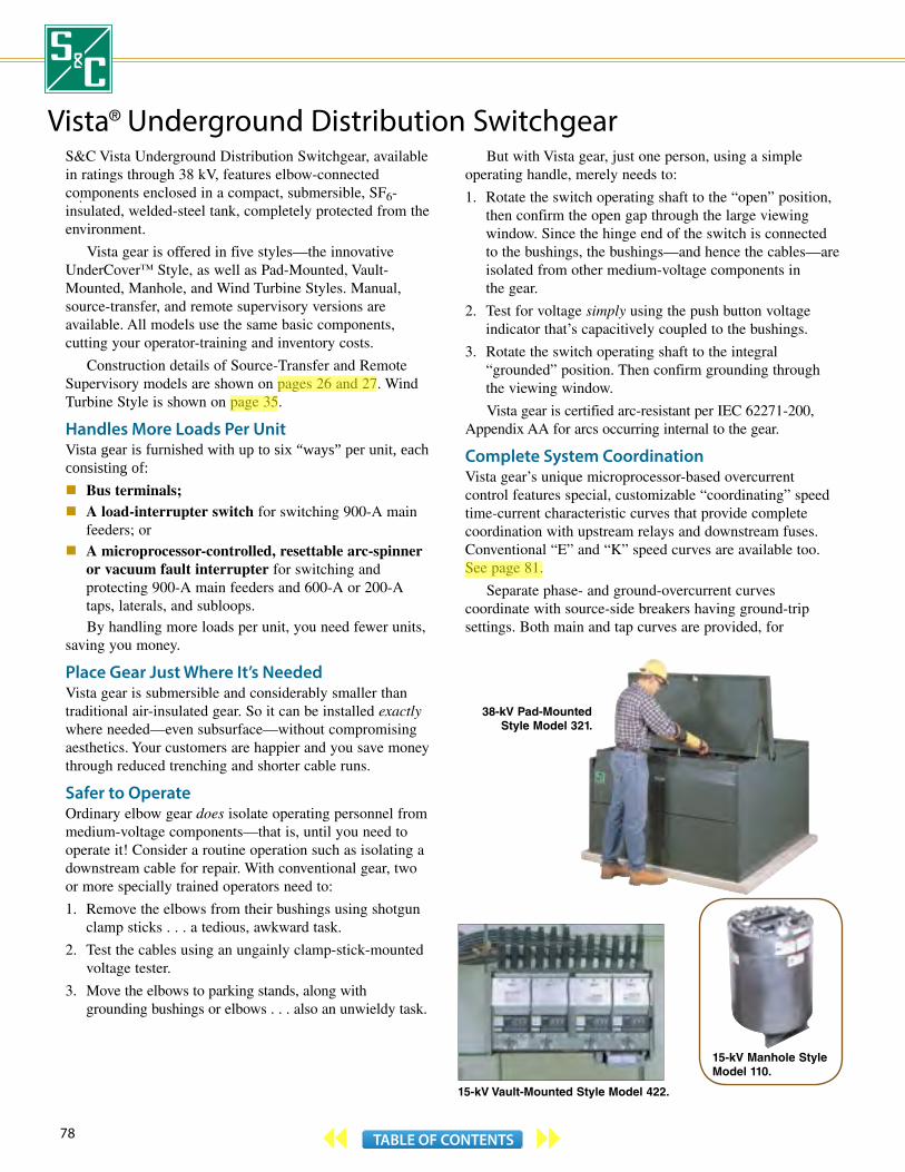
78 TABLE OF CONTENTS
Vista® Underground Distribution SwitchgearS&C Vista Underground Distribution Switchgear, available in ratings through 38 kV, features elbow-connected components enclosed in a compact, submersible, SF6-insulated, welded-steel tank, completely protected from the environment.
Vista gear is offered in five styles—the innovative UnderCover™ Style, as well as Pad-Mounted, Vault-Mounted, Manhole, and Wind Turbine Styles. Manual, source-transfer, and remote supervisory versions are available. All models use the same basic components, cutting your operator-training and inventory costs.
Construction details of Source-Transfer and Remote Supervisory models are shown on pages 26 and 27. Wind Turbine Style is shown on page 35.
Handles More Loads Per UnitVista gear is furnished with up to six “ways” per unit, each consisting of: Bus terminals; A load-interrupter switch for switching 900-A main
feeders; or A microprocessor-controlled, resettable arc-spinner
or vacuum fault interrupter for switching and protecting 900-A main feeders and 600-A or 200-A taps, laterals, and subloops.By handling more loads per unit, you need fewer units,
saving you money.
Place Gear Just Where It’s NeededVista gear is submersible and considerably smaller than traditional air-insulated gear. So it can be installed exactly where needed—even subsurface—without compromising aesthetics. Your customers are happier and you save money through reduced trenching and shorter cable runs.
Safer to OperateOrdinary elbow gear does isolate operating personnel from medium-voltage components—that is, until you need to operate it! Consider a routine operation such as isolating a downstream cable for repair. With conventional gear, two or more specially trained operators need to:
1. Remove the elbows from their bushings using shotgun clamp sticks . . . a tedious, awkward task.
2. Test the cables using an ungainly clamp-stick-mounted voltage tester.
3. Move the elbows to parking stands, along with grounding bushings or elbows . . . also an unwieldy task.
But with Vista gear, just one person, using a simple operating handle, merely needs to:
1. Rotate the switch operating shaft to the “open” position, then confirm the open gap through the large viewing window. Since the hinge end of the switch is connected to the bushings, the bushings—and hence the cables—are isolated from other medium-voltage components in the gear.
2. Test for voltage simply using the push button voltage indicator that’s capacitively coupled to the bushings.
3. Rotate the switch operating shaft to the integral “grounded” position. Then confirm grounding through the viewing window.
Vista gear is certified arc-resistant per IEC 62271-200, Appendix AA for arcs occurring internal to the gear.
Complete System CoordinationVista gear’s unique microprocessor-based overcurrent control features special, customizable “coordinating” speed time-current characteristic curves that provide complete coordination with upstream relays and downstream fuses. Conventional “E” and “K” speed curves are available too. See page 81.
Separate phase- and ground-overcurrent curves coordinate with source-side breakers having ground-trip settings. Both main and tap curves are provided, for
38-kV Pad-MountedStyle Model 321.
15-kV Manhole StyleModel 110.
15-kV Vault-Mounted Style Model 422.
aleknam
Highlight
aleknam
Highlight
aleknam
Highlight

79TABLE OF CONTENTS
Operating panel is located near grade level so UnderCover Style gear is easily operated from a standing position—away from medium-voltage cables
Switch terminals—equipped with 600-A bushings or 200-A bushing wells
Bushings and bushing wells are located on one side of the gear, reducing operating space required for elbows and cables
Optional voltage indicator with liquid-crystal display.
See detail on page 81. You can check the integrity of the
voltage indicator by shining a flashlight on the photocell-
powered test circuit, while placing a gloved finger over the test button. No flashlight
needed in daylight
Optional portable motor operator (not shown) lets you operate any load-interrupter switch or fault interrupter from a remote location
Fault interrupter terminals—equipped with 600 -A bushingsor 200 -A bushing wells
Overcurrent control—readily programmedwith your PC
Large viewing windows let you see open gap and grounded positions on
load-interrupter switches and fault interrupters. Trip indicators are easily
checked too
complete coordination between fault interrupters applied on main feeders and those applied on subloop taps.
The overcurrent control is programmed with a PC, in the shop or in the field . . . no knobs or dials to compromise security. It features a handy event recorder that captures information on the last twelve operations of each fault interrupter.
Fault interrupters can also be tripped remotely by external relays.
For more information on Manual Vista gear, see S&C publications 680-30, 681-31, and 681-700 through 681-708. All are available on our website www.sandc.com.
VISTA UNDERGROUND DISTRIBUTION SWITCHGEAR
50/60-Hz ANSI Ratings—IEC Ratings in Parentheses
kV Amperes, RMS
SystemClass
Max BILMain Bus
Cont. Current①
Short-Circuit,Sym.
Fault Interrupter Load-Interrupter Switch
Cont. and
Load Dropping①
Ten-Time Duty-Cycle
Fault- Interr., Sym.
Cont. and
Load Dropping①
Mom. and One- Second,
Sym.
15.5(12)
15.5(15.5)
95(95)
600(630)
12 500(12 500)
200(200)
12 500(12 500)
600(630)
12 500(12 500)
25 000(25 000)
600(630)
25 000(25 000)
600(630)
25 000(25 000)
27(24)
29(29)
125(125)
600(630)
12 500(12 500)
200(200)
12 500(12 500)
600(630)
12 500(12 500)
25 000(25 000)
600(630)
25 000(25 000)
600(630)
25 000(25 000)
38(36)
38(38)
150(150)
600(630)
12 500(12 500)
200(200)
12 500(12 500)
600(630)
12 500(12 500)
25 000(25 000)
600(630)
25 000(25 000)
600(630)
25 000(25 000)
① Main bus rating up to 1200 amperes, and fault interrupter and load-interrupter switch rating up to 900 amperes are possible. Consult the nearest S&C Sales Office.
15-kV UnderCover Style Model 422.
GEN
ERAL SW
ITCHIN
G A
ND
PROTEC
TION
SOLU
TION
S

80 TABLE OF CONTENTS
Vista® Underground Distribution Switchgear
Circuit Configurations①
MANUAL AND REMOTE SUPERVISORY MODELS MANUAL STYLE MODELS
201 210 211 320 321 330
413 422 431 440
514 523 624 633
110
101
SOURCE-TRANSFER STYLE MODELS
VT VT
523
431 422
550
330321 440
VT VT VT VTVT VT
532 550
VT VT VT VT VT VT
VT VT
VT VT
Common-Bus Configurations Split-Bus Configurations
① Model number indicates the total number of ways, as well as the number of load-interrupter switch ways and fault-interrupter ways. For example, Model 431 has “4” ways—“3” load-interrupter switch ways and “1” fault-interrupter way. Other configurations are available; consult the nearest S&C Sales Office.

81TABLE OF CONTENTS
Select the TCCs You NeedVista’s overcurrent control lets you choose these time-current characteristic curves: “E” speed—from 25E through 200E amperes.
“K” speed—from 25K through 200K amperes.
Coordinating speed tap—with minimum pickup settings from 50 through 400 amperes. Perfect for fault interrupters feeding subloop taps. Optimizes coordination with load-side weak link/backup current-limiting fuse combinations and source-side relays with low time-dial settings.
Coordinating speed main—with minimum pickup settings from 100 through 800 amperes. Ideal for fault interrupters on main feeders. Curves have longer minimum response times and different shapes to coordinate with tap-interrupter curves.
ANSI/U. S. and IEC—conform with IEEE C37.112-1996, “IEEE Standard Inverse-Time Characteristic Equations for Overcurrent Relays.” Enhance coordination with upstream relays utilizing CO9, CO11, and IAC curves . . . microprocessor relays too.
Coordinating-speed TCCs can be customized into hundreds of different curves using a variety of instantaneous (1- through 8-kA) and definite-time delay (32- through 96-ms) settings. Minimum total clearing time is only 40 milliseconds (2.5 cycles), allowing proper coordination with typical upstream circuit-breaker relays.
Compact welded-steel tank protects switching and protection components from the environment. Stainless-steel construction standard in UnderCover™ Style
Optional voltage indicator with liquid-crystal display. Includes test feature. See page 79
Operating panel of Vista gear. Viewing windows, for confirming open gap and grounded position on load-interrupter switches and fault interrupters, are located under hinged covers of voltage indicators.
Pressure gauge (located under window)—temperature- and altitude-compensated
Operating mechanisms for switches and fault interrupters—padlockable in any position
Microprocessor-based overcurrent control housed in watertight enclosure. CTs (not visible) provide power andsignal inputs
Operation selector prevents inadvertent operation from “closed” position directly to “grounded”position and vice versa
Gas-fill port
GEN
ERAL SW
ITCHIN
G A
ND
PROTEC
TION
SOLU
TION
S

82 TABLE OF CONTENTS
Vista® SD Underground Distribution SwitchgearS&C now offers you another choice in metal-enclosed gear. Economical new Vista SD Underground Distribution Switchgear features:
Visi-Gap™ Switches. These vacuum load-interrupter switches provide three-pole live switching of 600-ampere main feeders.
Visi-Gap™ Fault Interrupters. These micro-processor-controlled vacuum fault interrupters provide three-pole live switching and protection of 600-ampere main feeders and 200- or 600-ampere taps, laterals, and sub-loops.
The elbow-connected switches and fault interrupters are encapsulated in an environmentally friendly solid-dielectric insulating material.
Each load-interrupter switch and fault interrupter includes a manually operated, two-position isolating disconnect. Easy-to-follow mimic bus and indicators on the front of the switchgear convey the position of each switch and fault interrupter and its isolating disconnect—and whether a fault interrupter has tripped in response to a fault.
Vista SD Switchgear can be furnished with up to six “ways” (load-interrupter switches and/or fault interrupters), in ratings through 29 kV and 16 kA symmetrical interrupting. By handling more loads per unit, fewer units of Vista SD Switchgear are required.
Each way includes an easy-to-operate manual operating mechanism. Operating mechanisms for fault-interrupter ways are “trip-free” . . . the opening spring is charged when the closing spring is charged, and will open the fault interrupter—based on the TCC curve in the overcurrent control—if the fault interrupter is closed into a fault. Factory-installed and wired motor operators, to facilitate remote power operation, are optionally available. The operators can be decoupled to permit testing of the motor and controls.
Vista SD Switchgear is completely submersible and suitable for application in subsurface vaults subject to flooding. It is also available for above-grade application in pad-mounted style enclosures. Enclosures with isolated cable compartments are available.
Vista SD Switchgear is considerably smaller than traditional air-insulated gear. So it can be installed exactly where it’s needed without compromising aesthetics. Consumers are happier and you save money through reduced trenching and shorter cable runs.
Simple to OperateWith Vista SD Underground Distribution Switchgear, routine operation, such as isolating a downstream cable for repair, is easy. Just one person, using either the manual handle or a suitable user-furnished universal pole equipped with a standard fitting, merely needs to:
1. Place the load-interrupter switch operating mechanism in the “open” position, then confirm the open gap of the isolating disconnect through the large viewing window.
2. Test for voltage using the optional potential indication feature.
Vista SD Switchgear is furnished with a ground connection pad on each load-interrupter switch and fault interrupter, for attaching an elbow ground cable. Continuous ground bus for the entire switchgear assembly is optionally available.
Complete System CoordinationVista SD Underground Distribution Switchgear is furnished with the same microprocessor-based overcurrent control used in S&C Vista® Underground Distribution Switchgear. This proven, reliable device offers special, customizable “coordinating” speed time-current characteristic curves that provide complete coordination with upstream relays and downstream fuses. Conventional “E” and “K” speed curves are available too. See page 85.
Separate phase- and ground-overcurrent curves coordinate with source-side circuit breakers having ground-trip settings. Both main and tap curves are included, for complete coordination between fault interrupters applied on main feeders and those applied on subloop taps.
The overcurrent control is programmed with a PC, in the shop or in the field. There are no knobs or dials to compromise security. The control features an event recorder that captures information on the last twelve operations of each fault interrupter.
External trip provisions are optionally available, permitting the fault interrupters to be tripped remotely by external controls or relays.
NEW
aleknam
Highlight

83TABLE OF CONTENTS
VISTA SD UNDERGROUND DISTRIBUTION SWITCHGEAR
50/60-Hz ANSI Ratings—IEC Ratings in Parentheses
kV Amperes, RMS
SystemClass Max BIL
Main Bus Continuous
Current
Short-Circuit, RMS, Sym.
Load-Interrupter Switch Fault Interrupter
Continuous, Load Dropping,
and Load Splitting①
Momentary and Three-
Second, Sym.
Three-Time Duty-Cycle
Fault Closing, Sym.②
Continuous, Load Dropping,
and Load Splitting①
Short-Circuit Interrupting
15 (12)
17.5 (12)
95 (75)
600 (630) 16 000 600
(630) 16 000 16 000 600 (630)u 16 000�
27 (24)
29 (24)
125 (125)
600 (630)
12 500 (16 000)
600 (630) 16 000 16 000 600
(630)u12 500
(16 000)�
① Parallel or loop switching. Load-interrupter switches and fault interrupters can switch the magnetizing current of transformers associated with this rating. Unloaded cable switching capability: 10 amperes at 17.5 kV, 20 amperes at 29 kV. Load-interrupter switches and fault interrupters can also switch single capacitor banks through 1800 kVAR.
② Applicable to fault closing into closed position.
u 200 amperes if fault interrupters are furnished with optional 200-ampere bushing wells.
� 12 500 amperes if fault interrupters are furnished with optional 200-ampere bushing wells.
Vault-Mounted Style
All terminals are equipped with 600-A bushings with threaded studs. Bushings without studs are optional. Fault interrupters can be optionally furnished with 200-A bushing wells. Interfaces conform to ANSI/IEEE 386 and accept all standard insulated connectors and inserts
Vista SD Underground Distribution Switchgear.
Pad-Mounted Style
Pad-mounted enclosure meets IEEE C57.12.28 and C57.12.29. Available in mild steel or stainless steel
GEN
ERAL SW
ITCHIN
G A
ND
PROTEC
TION
SOLU
TION
S
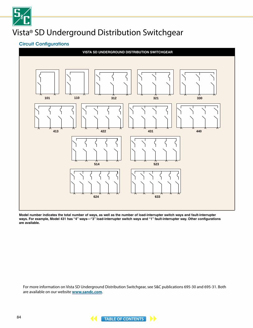
84 TABLE OF CONTENTS
Circuit Configurations
VISTA SD UNDERGROUND DISTRIBUTION SWITCHGEAR
312 321 330
413 422 431 440
514 523
624 633
110101
Model number indicates the total number of ways, as well as the number of load-interrupter switch ways and fault-interrupter ways. For example, Model 431 has “4” ways—“3” load-interrupter switch ways and “1” fault-interrupter way. Other configurations are available.
For more information on Vista SD Underground Distribution Switchgear, see S&C publications 695-30 and 695-31. Both are available on our website www.sandc.com.
Vista® SD Underground Distribution Switchgear

85TABLE OF CONTENTS
Select the TCCs You NeedThe Vista SD Underground Distribution Switchgear overcurrent control lets you choose these time-current characteristic curves:
“E” speed—from 25E through 200E amperes.
“K” speed—from 25K through 200K amperes.
Coordinating speed tap—with minimum pickup settings from 50 through 400 amperes. Perfect for fault interrupters feeding subloop taps. Optimizes coordination with load-side weak link/backup current-limiting fuse combinations and source-side relays with low time-dial settings.
Coordinating speed main—with minimum pickup settings from 100 through 800 amperes. Ideal for fault interrupters on main feeders. Curves have longer minimum response times and different shapes to coordinate with tap-interrupter curves.
ANSI/U. S. and IEC—conform to IEEE C37.112-1996, “IEEE Standard Inverse-Time Characteristic Equations for Overcurrent Relays.” Enhance coordination with upstream relays utilizing CO9, CO11, and IAC curves . . . microprocessor relays too.
Coordinating-speed TCCs can be customized into hundreds of different curves using a variety of instantaneous (1- through 8-kA) and definite-time delay (32- through 96-ms) settings. Minimum total clearing time is only 40 milliseconds (2.5 cycles), allowing proper coordination with typical upstream circuit breaker relays.
Operating mechanism with mimic bus and semaphore status indicators that show positions of load-interrupter switch or fault indicator and isolating disconnect
Optional potential indication feature permits routine switching to be performed by just one person, without cable handling or exposure to medium voltage. Includes provisions for low-voltage phasing
Cable testing can be performed through the back of a user-supplied elbow or feed-thru bushing
Optional motor operator facilitates remote operation of load-interrupter switch or fault interrupter. Can be decoupled from operating mechanism to permit testing without changing switch or fault interrupter position
Coupled Decoupled
Viewing window lets you readily confirm position of isolating disconnect
Motor operator includes receptacles for wired portable remote control pendant, plus auxiliary switch that tracks position of isolating disconnect
Remote Control Pendant Accessory includes “Open/Reset,” “Close,” and “Enable” push buttons, motor operator and isolating disconnect position-indicating lamps, and “Lamp Test” push button. Pendant is fully submersible and is furnished standard with 25-foot control cable
Closed Open
Optional parking stands
GEN
ERAL SW
ITCHIN
G A
ND
PROTEC
TION
SOLU
TION
S

86 TABLE OF CONTENTS
Custom Metal-Enclosed SwitchgearCustom Metal-Enclosed Switchgear, rated 4.16 kV through 34.5 kV, features reliable, time-tested fuses and manual or power-operated interrupter switches in rugged 11-gauge steel enclosures. These enclosures are configured into integrated packages that provide application flexibility, operating simplicity, and superior dependability in switching and protecting medium-voltage power circuits in commercial, institutional, industrial, and high-rise installations. S&C’s expertise in this field has been established through nearly 70 years of metal-enclosed switchgear design and manufacture, and is complemented by UL® listing of all S&C Custom Metal-Enclosed Switchgear rated 4.16 kV through 13.8 kV with 600-ampere or 1200-ampere main bus.
Power-System-Matched Switching and ProtectionFull-load switching, plus S&C’s unique one-time and two-time duty-cycle fault closing. S&C interrupter switches carry and interrupt rated load currents, even after being inadvertently closed into available fault currents corresponding to their fault-closing ratings. You can restore power quickly without first having to repair the switches.
One-cycle total clearing with S&C SM Power Fuses. Compare this to the 5 cycles or more required by circuit breakers . . . simplifies upstream coordination, minimizes short-circuit stresses on the system.
Choice of unique response curves with maintenance-free S&C Electronic Power Fuses. They provide protection unavailable with any other device—even circuit breakers, with their relays and batteries.
Three-phase protection for three-phase loads. S&C open-phase detectors and overcurrent relays isolate three-phase loads from single-phasing and other open-phase conditions.
Single-phase protection for single-phase loads. Fuses—unlike circuit breakers—selectively isolate only faulted phases of feeders serving single-phase loads.
Threefold EconomyLow purchase cost—economies inherent in the interrupter switch and fuse protection concept translate into significant first-cost savings.
Low installation cost—metal-enclosed switchgear, light in weight in comparison with breaker gear, is easy to handle and needs no foundation, no support channels . . . only a level floor or pad. Multibay lineups assemble with a minimum of interbay bolting, and inter-unit bus connections need no taping. Simple field assembly—with no relays to set and test—means less time, equipment, and manpower. Future additions are readily accommodated as your system expands.
Low maintenance cost—S&C fuses are nondamageable and do not require any maintenance or calibration to perpetuate the accuracy of their time-current characteristics. S&C interrupter switches are maintenance-free . . . requiring only an occasional exercising. S&C gear just needs a check of the insulators and, if necessary, a simple cleaning.

87TABLE OF CONTENTS
MAXIMUM 60-HZ SHORT-CIRCUIT RATINGS AND THREE-PHASE LOAD CAPABILITY①
Switchgear Ratings
Voltage, kV
Nominal 4.16 4.8 13.8 25 34.5
Maximum 4.8 5.5 17.0 29 38
BIL 60 60 95 125 or 150
150 or 200
Main Bus, Continuous, Amperes 600, 1200, or 2000
Short-Circuit, and Duty-Cycle Fault-Closing
Amperes, RMS, Symmetrical 37,500 40,000 25,000 40,000 25,000 40,000 25,000 17,500
MVA, Three-Phase Symmetrical at Nominal Voltage 270 290 210 330 600 960 1080 1050
Maximum Three-Phase Load per
Fused Feeder (at nominal voltage)
Continuous Load, kVA 5200 4300 6000 5000 17,200 14,300 25,900 17,900
Permissible Peak Load, kVA 5700 5800 6600 6700 18,900 19,100 34,500 22,400
① Consult the nearest S&C Sales Office for 50-hertz ratings.
Simplified Power-System PlanningSimple, reliable, economical—Custom Metal-Enclosed Switchgear is readily configured into basic circuit arrangements that make power-system planning and design easy . . . implementation is logical and straightforward. The basic arrangements shown here are often combined to handle even the most complex distribution system needs . . . assuring maximum service continuity for extremely critical loads.
For more information on Custom Metal-Enclosed Switchgear, contact the nearest S&C Sales Office or your S&C Authorized Distributor. S&C publications 620-55, 620-700, and 621-30 provide descriptive information and comprehensive application guidelines on S&C Custom Metal-Enclosed Switchgear. All of these publications are available on our website www.sandc.com.
EF
UTILITYSOURCE
ENTRANCEBAY FEEDER BAYS
SERVICE-ENTRANCESWITCHING CENTER
METERING BAY
A radial system is the simplest system and is economical, permitting extensive use of dedicated radial circuits. The direct circuitry facilitates quick location and repair of faulted circuits. Segmentation of a distribution system with multiple radial circuits limits the extent of service interruption due to faults. In this example, the service-entrance bay of the S&C Custom Metal-Enclosed Switchgear is provided with electronic power fuses to achieve full coordination with the upstream protective device.
SPLIT-BUSPRIMARY-SELECTIVESERVICE-ENTRANCESWITCHING CENTER
METERING BAY
UTILITY SOURCE 1
BUS-TIESWITCH
EF
EF
STC
SO N.O.
VS
SO
SO
VS
UTILITY SOURCE 2
Split-bus primary-selective S&C Custom Metal-Enclosed Switchgear allows large in-plant systems to be supplied power through one switching center since both util-ity sources are fully utilized under normal operation, with the two source interrupter switches closed and the bus-tie switch open. Each source, in effect, is the preferred source for its bus section and the alternate source for the other bus section
COMMON-BUSPRIMARY-SELECTIVESERVICE-ENTRANCESWITCHING CENTER
UTILITY SOURCE 1UTILITY SOURCE 2
VS
VS Z
SD
SO
STC
SO
SO
N.O.
Common-bus primary-selective S&C Custom Metal-Enclosed Switchgear assures a higher level of service continuity. Two utility sources—one source preferred, the other alternate—supply power to the metal-enclosed switchgear. A power-operated inter-rupter switch for each source plus a source-transfer control effect automatic two-way transfer in primary-selective switchgear. Interrupter switches with power fuses switch and protect the load circuits; in this example, two are manually operated while the third is power operated, with an electronic overcurrent relay and switch operator providing automatic three-phase isolation when a fuse operates.
GEN
ERAL SW
ITCHIN
G A
ND
PROTEC
TION
SOLU
TION
S
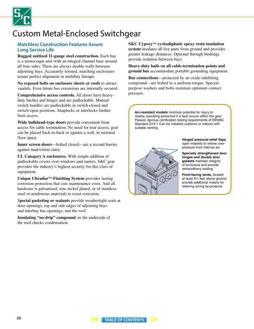
88 TABLE OF CONTENTS
Matchless Construction Features Assure Long Service LifeRugged unitized 11-gauge steel construction. Each bay is a monocoque unit with an integral channel base around all four sides. There are always double walls between adjoining bays. Accurately formed, matching enclosures assure perfect alignment in multibay lineups.
No exposed bolts on enclosure sheets or roofs to attract vandals. Even future bus extensions are internally secured.
Comprehensive access controls. All doors have heavy-duty latches and hinges and are padlockable. Manual switch handles are padlockable in switch-closed and switch-open positions. Snaplocks or interlocks further limit access.
Wide bulkhead-type doors provide convenient front access for cable termination. No need for rear access; gear can be placed back-to-back or against a wall, in minimal floor space.
Inner screen doors—bolted closed—are a second barrier against inadvertent entry.
UL Category A enclosures. With simple addition of padlockable covers over windows and meters, S&C gear provides the industry’s highest security for this class of equipment.
Unique Ultradur™ Finishing System provides lasting corrosion protection that cuts maintenance costs. And all hardware is galvanized, zinc-nickel plated, or of stainless-steel or nonferrous materials to resist corrosion.
Special gasketing or sealants provide weathertight seals at door openings, top and side edges of adjoining bays and interbay bus openings, and the roof.
Insulating “no-drip” compound on the underside of the roof checks condensation.
S&C Cypoxy™ cycloaliphatic epoxy resin insulation system insulates all live parts from ground and provides greater leakage distances. Optional through bushings provide isolation between bays.
Heavy-duty bails on all cable-termination points and ground bus accommodate portable grounding equipment.
Bus connections—protected by an oxide-inhibiting compound—are bolted to a uniform torque. Special-purpose washers and bolts maintain optimum contact pressure.
Arc-resistant models minimize potential for injury to nearby operating personnel if a fault occurs within the gear. Passes rigorous certification testing requirements of EEMAC Standard G14.1. Can be installed outdoors or indoors with suitable venting
Hinged pressure-relief flaps open instantly to relieve over-pressure from internal arc
Specially strengthened door hinges and double door gaskets maintain integrity of enclosure and provide extraordinary sealing
Front-facing vents, located at least 6½ feet above ground, provide additional means for relieving arcing by-products
Custom Metal-Enclosed Switchgear

89TABLE OF CONTENTS
A wide choice of S&C components—exhaustively tested, field-proven, of unequaled performance and operational dependability—all expressly designed to solve your power distribution problems . . .
Interrupter Switches handle all live-switching duties and feature duty-cycle fault-closing ratings—a requisite for automatic control schemes
Mini-Rupter® Switch (pictured) is rated through 600 amperes continuous and interrupting. Alduti-Rupter® Switches rated through 1200 amperes continuous and interrupting are also available
Type MS Switch Operators provide high-speed automatic trip-open operation of Mini-Rupter Switches . . . interrupting time is 4 cycles. These operators are available in a choice of manual or automatic trip-closed operation
Type MS-2 Switch Operator (pictured) is ideal for use with the Micro-AT Source-Transfer Control
SM Power Fuses are offered in a wide variety of ampere ratings and time-current characteristics, permitting close fusing ratios for optimal coordination and maximum protection. Their time-current characteristics are precise and permanently accurate
Type SM-40 Power Fuse (pictured) is rated 400 amperes max continuous. Other Type SM Power Fuses are available in ratings from 200 through 720 amperes max continuous
Micro-AT® Source-Transfer Controls minimize interruptions resulting from loss of one source . . . transfer is achieved in as little as 20-25 cycles
Micro-AT Source-Transfer Control is available with a wide choice of options
Fault Fiter® Electronic Power Fuses, with their exceptional TCC versatility and higher continuous current ratings, provide features and performance previously unavailable in any protective device
Fault Fiter (pictured) is rated 600 amperes max continuous. Paralleled Fault Fiters provide 1200-ampere protection
Electronic Relays, applied on individual load feeders, protect three-phase loads from single-phasing resulting from blown fuses and other open-phase conditions
Type ZSD Overcurrent Relay (pictured) is superior to ordinary overcurrent relays . . . it can distinguish between fault current and transformer inrush current
GEN
ERAL SW
ITCHIN
G A
ND
PROTEC
TION
SOLU
TION
S

90 TABLE OF CONTENTS
Single-line diagram
PMX Modular Metal-Enclosed Switchgear lineup.
PMX™ Modular Metal-Enclosed SwitchgearA Unique Alternative to Conventional SwitchgearPMX Modular Metal-Enclosed Switchgear, available in ratings of 13.8 and 25 kV, combines the top-notch features of S&C Custom Metal-Enclosed Switchgear with the size and economic benefits of S&C Pad-Mounted Gear. It’s available with S&C’s Mini-Rupter® Switches and the full range of S&C Power Fuses.
PMX Switchgear features individual modules that are electrically connected with bus through-bushings. Any number of modules can be combined, along with metering or cable entrance modules, to create a lineup that’s right for your application. With this economical construction technique, PMX Switchgear provides significant savings over conventional metal-enclosed switchgear.
Models to Suit Your NeedsPMX Modular Metal-Enclosed Switchgear is offered in manual, remote supervisory, and source-transfer versions.
In source-transfer applications, the entrance modules are provided with power-operated switches and a Micro-AT® Source-Transfer Control.
In remote supervisory applications, the entrance modules are provided with power-operated switches and a 6802 Automatic Switch Control, which provides sophisticated RTU functionality and supports a variety of
of user-specified communication devices. Alternately, a user-specified RTU can be furnished.
Entrance and feeder modules can be furnished with Type SM-20, SM-4Z, SM-40, or SM-5S Power Fuses or Fault Fiter® Electronic Power Fuses. These modules can be provided with an enhanced fuse handling option featuring S&C’s patented TransFuser™ Mountings. Each mounting effortlessly unlatches and pivots to the open position, making the de-energized and isolated power fuse accessible for replacement. All modules can be furnished with optional barriers that separate the cable termination sections from the main bus and switching sections.
Most 13.8-kV PMX Switchgear lineups include UL® Listing. UL Listing is not available on 25-kV switchgear assemblies.
For more information on PMX Modular Metal-Enclosed Switchgear, contact the nearest S&C Sales Office or your S&C Authorized Distributor. S&C publications 627-30, 627-50, and 627-700 provide descriptive information and comprehensive application guidelines on PMX Modular Metal-Enclosed Switchgear, and show the complete range of modules and options available. All of these publications are available on our website www.sandc.com.

91TABLE OF CONTENTS
Typical feeder modules with Type SM-20 Power Fuses.
Typical feeder module with enhanced fuse handling, featuring Type SME-20 Power Fuses in TransFuser Mountings.
PMX MODULAR METAL-ENCLOSED SWITCHGEAR
60-Hz Ratings①
kV Mini-Rupter Switch, Amperes Fuse Short-Circuit,Amperes,
RMS, Sym.Nom. Max BIL Cont. Load Dropping Type Amperes Max
13.8 17.0 95 600 600
SM-20, SME-20 200E 14 000
SM-4Z, SME-4Z 200E 12 500
SM-40, SME-40 400E 25 000
SM-5S 400E 25 000
Fault Fiter 600 25 000
25 27u 125 600 400
SM-20, SME-20 200E 12 500
SM-4Z, SME-4Z 200E 9 400q
SM-40, SME-40 400E 20 000
SM-5S 300E 20 000
Fault Fiter 600 25 000
① Consult the nearest S&C Sales Office for 50-hertz ratings.
u 25-kV models equipped with SM-40 or SME-40 Power Fuses or Fault Fiter Electronic Power Fuses are rated 29 kV max.
SMU-20 Fuse Units are available in ratings through 200K as well as 200E amperes.
q 12,500 amperes, RMS, symmetrical when applied on solidly grounded neutral systems, with fuses connected by single-conductor, concentric-neutral type cable (or directly coupled) to transformer(s).
GEN
ERAL SW
ITCHIN
G A
ND
PROTEC
TION
SOLU
TION
S
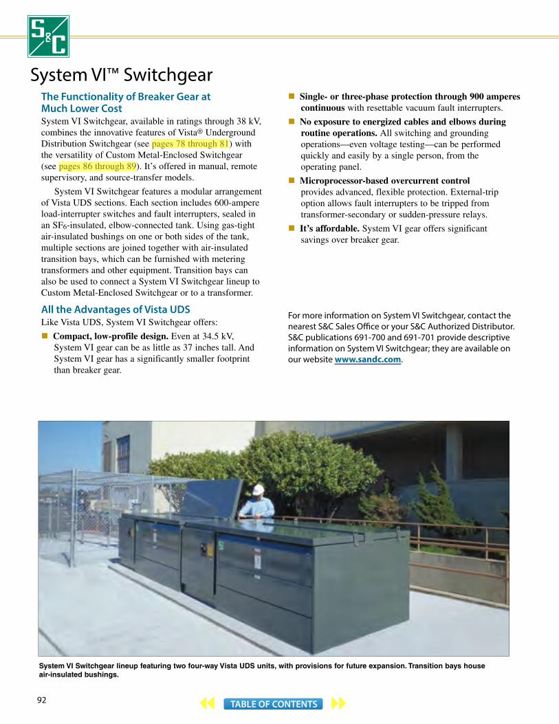
92 TABLE OF CONTENTS
System VI Switchgear lineup featuring two four-way Vista UDS units, with provisions for future expansion. Transition bays house air-insulated bushings.
System VI™ SwitchgearThe Functionality of Breaker Gear at Much Lower CostSystem VI Switchgear, available in ratings through 38 kV, combines the innovative features of Vista® Underground Distribution Switchgear (see pages 78 through 81) with the versatility of Custom Metal-Enclosed Switchgear (see pages 86 through 89). It’s offered in manual, remote supervisory, and source-transfer models.
System VI Switchgear features a modular arrangement of Vista UDS sections. Each section includes 600-ampere load-interrupter switches and fault interrupters, sealed in an SF6-insulated, elbow-connected tank. Using gas-tight air-insulated bushings on one or both sides of the tank, multiple sections are joined together with air-insulated transition bays, which can be furnished with metering transformers and other equipment. Transition bays can also be used to connect a System VI Switchgear lineup to Custom Metal-Enclosed Switchgear or to a transformer.
All the Advantages of Vista UDSLike Vista UDS, System VI Switchgear offers:
Compact, low-profile design. Even at 34.5 kV, System VI gear can be as little as 37 inches tall. And System VI gear has a significantly smaller footprint than breaker gear.
Single- or three-phase protection through 900 amperes continuous with resettable vacuum fault interrupters.
No exposure to energized cables and elbows during routine operations. All switching and grounding operations—even voltage testing—can be performed quickly and easily by a single person, from the operating panel.
Microprocessor-based overcurrent control provides advanced, flexible protection. External-trip option allows fault interrupters to be tripped from transformer-secondary or sudden-pressure relays.
It’s affordable. System VI gear offers significant savings over breaker gear.
For more information on System VI Switchgear, contact the nearest S&C Sales Office or your S&C Authorized Distributor. S&C publications 691-700 and 691-701 provide descriptive information on System VI Switchgear; they are available on our website www.sandc.com.
aleknam
Highlight
aleknam
Highlight

93TABLE OF CONTENTS
System VI Switchgear with Vista UDS incoming and outgoing sections and air-insulated metering bay.
Voltage indicators lift up to reveal large viewing windows
Incoming section. Any combination of load-interrupter switches and fault interrupters can be furnished, for a total of six ways. Unit shown has two load-interrupter switches
Outgoing section. Unit shown has four ways, each with single-pole fault interrupters. Three-pole fault interrupters are also available
Metering bay includes voltage and current transformers (door removed to show internal components)
Termination compartment accommodates cables, elbows, surge arresters, and feedthru inserts
S&C’s Ultradur ™ Finishing System—the industry’s best finish—protects enclosure from corrosion
Padlockable lift-up covers are hinged for convenient access to operating and termination compartments
Operating panel with operating mechanisms, viewing windows, voltage indicators, and low-voltage phasing provisions—all isolated from medium-voltage cables
Single-line diagram
SYSTEM VI SWITCHGEAR
50/60-Hz ANSI Ratings—IEC Ratings in Parentheses
kV Amperes, RMS
SystemClass
Max BILMain Bus Cont.
Current①Short-Circuit,
Sym.
Fault Interrupter Load-Interrupter Switch
Cont. andLoad Dropping①
Ten-Time Duty-Cycle Fault-Interr., Sym.
Cont. andLoad Dropping①
Mom. and One-Second, Sym.
15.5(12)
15.5(15.5)
95(95)
600(630)
12 500(12 500)
200(200)
12 500(12 500)
600(630)
12 500(12 500)
25 000(25 000)
600(630)
25 000(25 000)
600(630)
25 000(25 000)
27(24)
29(29)
125(125)
600(630)
12 500(12 500)
200(200)
12 500(12 500)
600(630)
12 500(12 500)
25 000(25 000)
600(630)
25 000(25 000)
600(630)
25 000(25 000)
38(36)
38(38)
150(150)
600(630)
12 500(12 500)
200(200)
12 500(12 500)
600(630)
12 500(12 500)
25 000(25 000)
600(630)
25 000(25 000)
600(630)
25 000(25 000)
① Higher ratings are possible. Consult the nearest S&C Sales Office.
GEN
ERAL SW
ITCHIN
G A
ND
PROTEC
TION
SOLU
TION
S
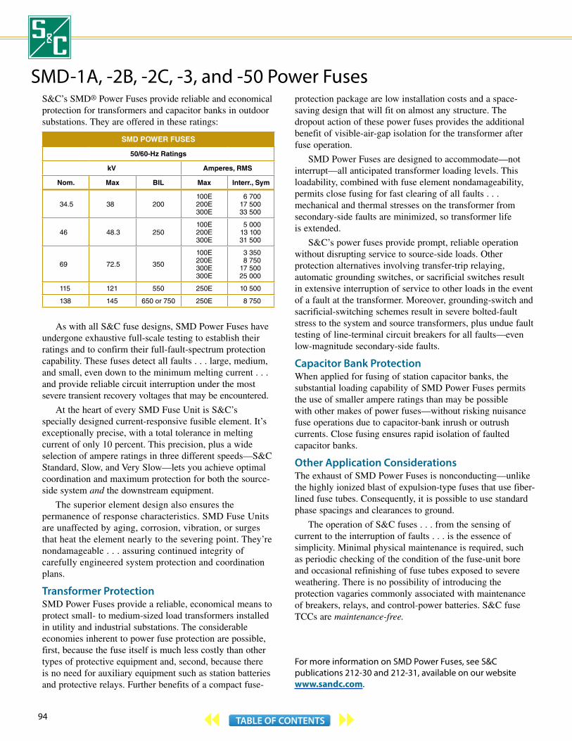
94 TABLE OF CONTENTS
SMD -1A, -2B, -2C, -3, and -50 Power FusesS&C’s SMD® Power Fuses provide reliable and economical protection for transformers and capacitor banks in outdoor substations. They are offered in these ratings:
SMD POWER FUSES
50/60-Hz Ratings
kV Amperes, RMS
Nom. Max BIL Max Interr., Sym
34.5 38 200100E200E300E
6 70017 50033 500
46 48.3 250100E200E300E
5 00013 10031 500
69 72.5 350
100E200E300E300E
3 3508 750
17 50025 000
115 121 550 250E 10 500
138 145 650 or 750 250E 8 750
As with all S&C fuse designs, SMD Power Fuses have undergone exhaustive full-scale testing to establish their ratings and to confirm their full-fault-spectrum protection capability. These fuses detect all faults . . . large, medium, and small, even down to the minimum melting current . . . and provide reliable circuit interruption under the most severe transient recovery voltages that may be encountered.
At the heart of every SMD Fuse Unit is S&C’s specially designed current-responsive fusible element. It’s exceptionally precise, with a total tolerance in melting current of only 10 percent. This precision, plus a wide selection of ampere ratings in three different speeds—S&C Standard, Slow, and Very Slow—lets you achieve optimal coordination and maximum protection for both the source-side system and the downstream equipment.
The superior element design also ensures the permanence of response characteristics. SMD Fuse Units are unaffected by aging, corrosion, vibration, or surges that heat the element nearly to the severing point. They’re nondamageable . . . assuring continued integrity of carefully engineered system protection and coordination plans.
Transformer ProtectionSMD Power Fuses provide a reliable, economical means to protect small- to medium-sized load transformers installed in utility and industrial substations. The considerable economies inherent to power fuse protection are possible, first, because the fuse itself is much less costly than other types of protective equipment and, second, because there is no need for auxiliary equipment such as station batteries and protective relays. Further benefits of a compact fuse-
protection package are low installation costs and a space-saving design that will fit on almost any structure. The dropout action of these power fuses provides the additional benefit of visible-air-gap isolation for the transformer after fuse operation.
SMD Power Fuses are designed to accommodate—not interrupt—all anticipated transformer loading levels. This loadability, combined with fuse element nondamageability, permits close fusing for fast clearing of all faults . . . mechanical and thermal stresses on the transformer from secondary-side faults are minimized, so transformer life is extended.
S&C’s power fuses provide prompt, reliable operation without disrupting service to source-side loads. Other protection alternatives involving transfer-trip relaying, automatic grounding switches, or sacrificial switches result in extensive interruption of service to other loads in the event of a fault at the transformer. Moreover, grounding-switch and sacrificial-switching schemes result in severe bolted-fault stress to the system and source transformers, plus undue fault testing of line-terminal circuit breakers for all faults—even low-magnitude secondary-side faults.
Capacitor Bank ProtectionWhen applied for fusing of station capacitor banks, the substantial loading capability of SMD Power Fuses permits the use of smaller ampere ratings than may be possible with other makes of power fuses—without risking nuisance fuse operations due to capacitor-bank inrush or outrush currents. Close fusing ensures rapid isolation of faulted capacitor banks.
Other Application ConsiderationsThe exhaust of SMD Power Fuses is nonconducting—unlike the highly ionized blast of expulsion-type fuses that use fiber-lined fuse tubes. Consequently, it is possible to use standard phase spacings and clearances to ground.
The operation of S&C fuses . . . from the sensing of current to the interruption of faults . . . is the essence of simplicity. Minimal physical maintenance is required, such as periodic checking of the condition of the fuse-unit bore and occasional refinishing of fuse tubes exposed to severe weathering. There is no possibility of introducing the protection vagaries commonly associated with maintenance of breakers, relays, and control-power batteries. S&C fuse TCCs are maintenance-free.
For more information on SMD Power Fuses, see S&C publications 212-30 and 212-31, available on our website www.sandc.com.

95TABLE OF CONTENTS
Fault is quickly and positively interrupted by high-speed elongation of the arc . . . and by efficient deionizing and cooling of the arc path with turbulent nonconducting gases released by the solid arc-extinguishing materials
Single arcing rod of SMD Fuse Unit: high-fault currents are inter-rupted in lower large-diameter bore section A that relieves pressure buildup, resulting in a milder exhaust . . . low-to- moderate fault currents are interrupted in upper small- diameter bore section B where deionizing gases are effectively concentrated for arc extinction
Fusible element senses an overcurrent condition and melts. Strain wire then severs, initiating an arc and releasing the spring-loaded arcing rod to effect fault interruption—arc is extinguished as it is drawn upward through solid materials
Other Available Mounting Styles
Vertical-Offset Right-Angle Upright
How It Works . . .
Compression-loaded silver-clad contacts provide superb current transfer
Latch-and-upper-contact assembly features “floating” roller latch mechanism that prevents accidental fuse dropout, yet releases without resistance when operated intentionally
Fuse unit
Hinge-and-lower-contact assembly also features compression-loaded silver-clad contacts
Release tube—weather- sealed
Standard station post insulators. Also availablewith silicone-housed composite insulators orCypoxy™ insulators
Rugged, galvanized steel base
Vertical Style Mounting
B
A
SMD FUSE UNIT RATINGS
Speed
Available Ratings, Amperes for Fuse Unit Types
SMD-1ASMD-2B,SMD-2C,SMD-3
SMD-50
S&CStandard 1–200E 1–300E 5E–100E
S&C Slow 15E–200E 15E–300E 15E–100E
S&CVery Slow 50E–200E 50E–300E —
SMD Power Fuses are Rural Utilities Service accepted.
GEN
ERAL SW
ITCHIN
G A
ND
PROTEC
TION
SOLU
TION
S

96 TABLE OF CONTENTS
Trans-Rupter II® Transformer ProtectorsTrans-Rupter II is designed exclusively for primary-side application on distribution substation transformers. This revolutionary device combines the three-phase tripping, high interrupting ratings, and sophisticated protection capabilities of higher-cost circuit-switchers and circuit breakers . . . with the simple installation procedures and minimal maintenance requirements of lower-cost power fuses.
Choose the Version That Fits Your NeedsModel EX is tripped by an external signal provided by a user-furnished differential, sudden-pressure, or overcurrent relay. Model EX is perfect for new installations, and for retrofitting outdated circuit-switcher, circuit breaker, and high-speed grounding switch installations where protective relays and control power are already in place. It’s available with optional motor operators that provide remote-resetting capability.
Model SE features a self-powered overcurrent protection system activated by current transformers on the primary bushings of the transformer. Digital overcurrent relays provide complete time-overcurrent and instantaneous-overcurrent protection; they’re field-settable and include user-selectable time-current characteristics.
With Model SE there’s no need for external relays, substation batteries, or a control house . . . you can save tens of thousands of dollars over the installed cost of a circuit-switcher or circuit breaker. Model SE is ideal for new installations, as well as for retrofitting overdutied power fuse installations.
No-Maintenance Interrupters, No-Maintenance Operating MechanismTrans-Rupter II interrupters are factory-filled and hermetically sealed, eliminating the hassle and expense of field-filling with SF6. These electrically tripped, resettable interrupters provide 31.5-kA, 3-cycle fault-interrupting performance. There’s no mechanical linkage to adjust or maintain. Trans-Rupter II’s operating mechanisms are likewise sealed for life, protected from the environment.
Shatterproof Composite-Polymer Silicone InsulationTrans-Rupter II’s interrupter and insulating support column insulation stands up to the most severe environment. The unique patented skirt arrangement on 115-kV and 138-kV pole-units provides enhanced dielectric performance.
Space-Saving, Lightweight Design with Superior Mounting FlexibilityTrans-Rupter II installs on nearly any structure—even on the transformer or source-side disconnect switch. It’s ideal for retrofit of older equipment and for mobile-transformer applications.
A user-furnished, three-pole, group-operated disconnect switch is required to provide visible air-gap isolation during maintenance, and to pick up transformer magnetizing inrush current. Alternately, Trans-Rupter II can be furnished with a space-saving integral vertical-break style disconnect.
S&C Mounting Pedestals are available too, in a variety of heights and phase spacings.
For more information on Trans-Rupter II, see S&C publications 731-30, 731-31, and 731-700 through 731-705, available on our website www.sandc.com.
Pole-units are fully assembled and factory-tested . . . just hoist them into position. Installation is quick and easy.
Interrupter and insulating support column featureshatterproof composite-polymer silicone insulation. Pole-unit is light weight and easy to mount on nearly any structure
Stored-energy operating mechanism is sealed for life. No heater needed

97TABLE OF CONTENTS
TRANS-RUPTER II TRANSFORMER PROTECTORS
50/60-Hz Ratings
kV Fault-InterruptingAmperes, RMS
Suitable forTransformers Rated, MVANom. Max BIL
69115138
72.5123145
350550650
31 50031 50031 500
30/40/5037.5/50/62.5★50/66.5/83★
★ Based on 8% impedance. Larger-size transformers can be accommodated at higher impedance levels.
138-kV Trans-Rupter II Model EX, shown on S&C Mounting Pedestals. Low-voltage connection enclosure provides connections for user- furnished relays and control power.
Easy-to-use charging tool is included for closing and charging pole-units, to restore service. Optional motor operators provide three-phase remote-resetting capability.
Closed-and-charged indicator Operating shaft
for charging tool
Temperature-compensated gas-pressure gauge indicates gas density, provides two alarm levels
Control cabinet of Model SE.
Optionalmotoroperator
GEN
ERAL SW
ITCHIN
G A
ND
PROTEC
TION
SOLU
TION
S
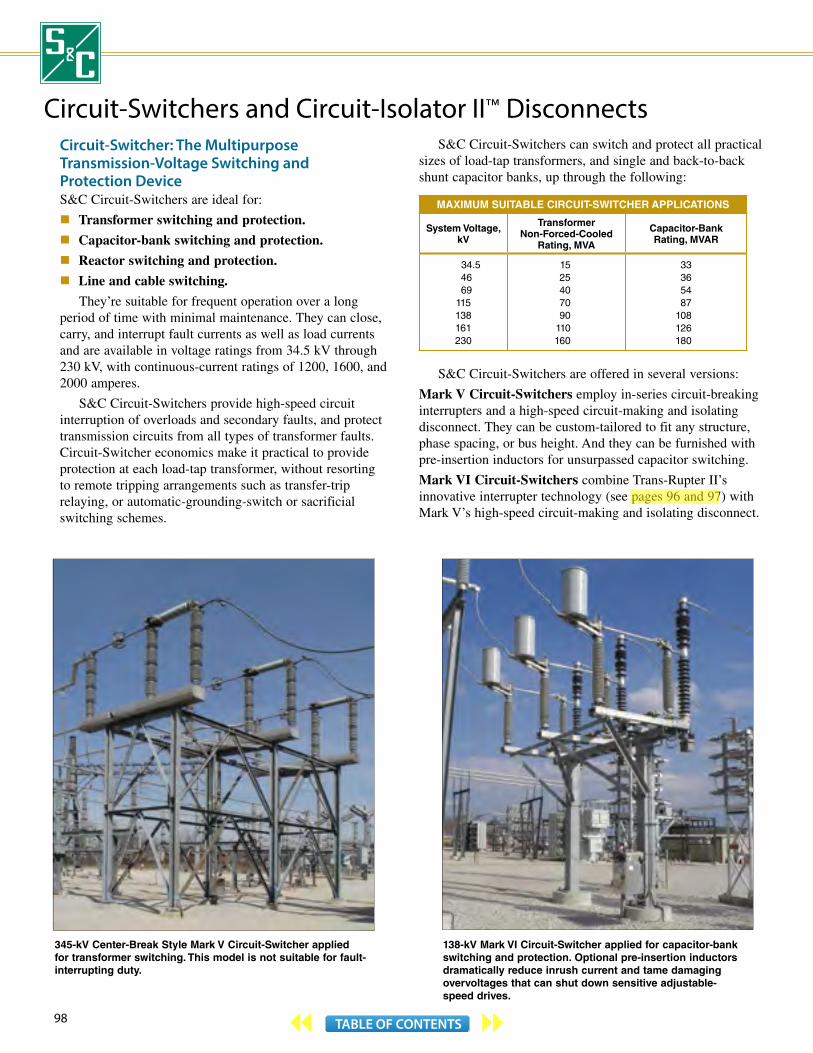
98 TABLE OF CONTENTS
138-kV Mark VI Circuit-Switcher applied for capacitor-bank switching and protection. Optional pre-insertion inductors dramatically reduce inrush current and tame damaging overvoltages that can shut down sensitive adjustable- speed drives.
345-kV Center-Break Style Mark V Circuit-Switcher applied for transformer switching. This model is not suitable for fault-interrupting duty.
Circuit-Switchers and Circuit-Isolator II™ DisconnectsCircuit-Switcher: The Multipurpose Transmission-Voltage Switching and Protection DeviceS&C Circuit-Switchers are ideal for:
Transformer switching and protection.
Capacitor-bank switching and protection.
Reactor switching and protection.
Line and cable switching.
They’re suitable for frequent operation over a long period of time with minimal maintenance. They can close, carry, and interrupt fault currents as well as load currents and are available in voltage ratings from 34.5 kV through 230 kV, with continuous-current ratings of 1200, 1600, and 2000 amperes.
S&C Circuit-Switchers provide high-speed circuit interruption of overloads and secondary faults, and protect transmission circuits from all types of transformer faults. Circuit-Switcher economics make it practical to provide protection at each load-tap transformer, without resorting to remote tripping arrangements such as transfer-trip relaying, or automatic-grounding-switch or sacrificial switching schemes.
S&C Circuit-Switchers can switch and protect all practical sizes of load-tap transformers, and single and back-to-back shunt capacitor banks, up through the following:
MAXIMUM SUITABLE CIRCUIT-SWITCHER APPLICATIONS
System Voltage, kV
Transformer Non-Forced-Cooled
Rating, MVA
Capacitor-Bank Rating, MVAR
34.5 46 69115138161230
1525407090
110160
33365487
108126180
S&C Circuit-Switchers are offered in several versions:
Mark V Circuit-Switchers employ in-series circuit-breaking interrupters and a high-speed circuit-making and isolating disconnect. They can be custom-tailored to fit any structure, phase spacing, or bus height. And they can be furnished with pre-insertion inductors for unsurpassed capacitor switching.
Mark VI Circuit-Switchers combine Trans-Rupter II’s innovative interrupter technology (see pages 96 and 97) with Mark V’s high-speed circuit-making and isolating disconnect.
aleknam
Highlight

99TABLE OF CONTENTS
138-kV Series 2000 Circuit-Switcher Model 2020—With Vertical Interrupters and Side-Break Power-Operated Disconnect, applied for transformer switching and protection.
69-kV Trans-Rupter II Transformer Protector Model EX with Circuit-Isolator II Disconnect and Type DS-1 Switch Operator.
Mark VI Circuit-Switchers can also be furnished with pre-insertion inductors . . . the industry standard for reducing inrush current and transient overvoltages when switching capacitor banks.
Series 2000 Circuit-Switchers feature interrupters designed to close the circuit, interrupt the circuit, and maintain rated dielectric strength when open. They’re available in mounting configurations suiting the broad spectrum of substation layouts and profiles, with or without an integral power-operated disconnect.
All Circuit-Switcher interrupters use no-maintenance single-pressure SF6 puffer technology for restrike-free, non-current-chopping, minimum-voltage surge performance. They’re field-proven through 50 years of superior service. Isolating disconnect blades feature current-carrying contacts with built-in wiping action, assuring a clean, low-resistance path. Operators are designed to assure the full inherent mechanical and electrical performance characteristics of Circuit-Switchers.
Circuit-Isolator II DisconnectS&C’s Circuit-Isolator II Disconnects provide three-pole, group-operated, visible-air-gap isolation in distribution substations. They can interrupt low-level charging currents associated with substation buswork and circuit breaker bushings, and are ideally suited for use with S&C Trans-Rupter II® Transformer Protector and Type SMD® Power Fuses.
Circuit-Isolator II Disconnects are available in voltage ratings from 69 kV through 138 kV, with continuous-current ratings of 1200, 1600, and 2000 amperes. Side-break, vertical-break, center-break, and double-break styles can be furnished, to suit almost any substation layout.
For more information on S&C Circuit-Switchers and Circuit-Isolator II Disconnects, contact the nearest S&C Sales Office. Or visit our website www.sandc.com.
GEN
ERAL SW
ITCHIN
G A
ND
PROTEC
TION
SOLU
TION
S

100 TABLE OF CONTENTS
General Switching and Protection ServicesS&C’s highly trained Power-Systems Solutions staff can assist you with a variety of substation and distribution system switching and protection services. These services can be furnished individually or on an Engineering, Procurement, and Construction (EPC) basis with the equipment.
Engineering and Design Coordination studies are used to select appropriately
rated protective devices and their settings. The objective is to minimize the impact of short-circuits by isolating faults as quickly as possible, while maintaining power to the rest of the system. We’ll develop time-current characteristic curves for all protective devices on each feeder.
Studies for industrial and commercial facilities are performed in accordance with accepted industry practices and procedures, consistent with ANSI/IEEE Standard 242-2001. Studies for electric utilities are based on their specific fusing and reclosing practices.
Short-circuit studies determine currents flowing in a power system under fault conditions. Since system growth often results in increased available short-circuit current, the momentary and interrupting ratings of all equipment are checked to ensure the equipment can withstand the short-circuit energy.
We’ll calculate three-phase, line-to-line, and line-to-ground fault currents at relevant locations on the system, in accordance with ANSI Standards C37.010, C37.5, and C37.13. An ANSI closing-and-latching duty analysis can be performed to calculate the maximum currents following fault inception.
Arc-flash studies evaluate the incident energy and arc-flash boundary of energized electrical equipment, calculated in accordance with IEEE 1584 and NFPA-70E standards. Such analyses are essential to select
the appropriate level of Personal Protective Equipment for working on or near the equipment. Boundaries for limited, restricted, and prohibited approaches are defined for each device.
Power quality studies include site surveys and measurements to evaluate the impact of voltage sags, interruptions, motor starting, or flicker on end-user equipment. Such studies frequently result in the recommendation of a mitigation device appropriate for the power quality issue.
Load-flow studies determine if system voltages remain within specified limits under various contingency conditions, and whether transformers and conductors are overloaded. They are often used to identify the need for additional generation or VAR support, or the placement of capacitors or reactors to maintain system voltages within specified limits.
Reliability studies maximize the reliability, efficiency, and safety of a power system. S&C engineers will perform a site visit and then prepare a comprehensive report discussing the findings and suggestions to improve reliability. The assessment is based on reliability indices such as SAIDI, SAIFI, and CAIDI.
Switching transient studies analyze the transients associated with the switching of utility or industrial capacitor banks or shunt reactors, or the performance of transient mitigation devices during transmission line energization.
S&C can provide physical design engineering for substation projects, and custom installations and retrofit projects on distribution systems. We’ll gather geotechnical information, legal and topographical surveys, and soil samples. Then we’ll use your CAD standards, as applicable, to develop a physical design conforming to NESC, ANSI, and NEMA requirements. We’ll perform calculations to properly specify the substation transformer and grounding grid, and provide a thorough structural analysis.
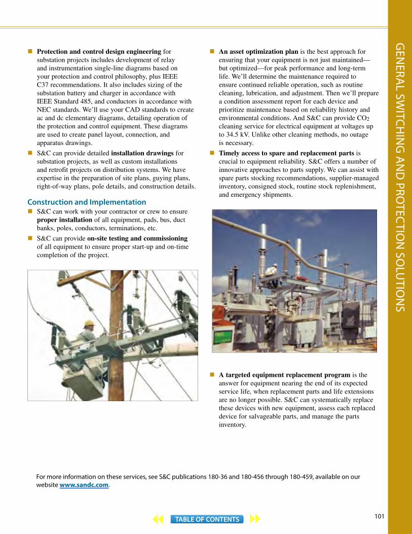
101TABLE OF CONTENTS
For more information on these services, see S&C publications 180-36 and 180-456 through 180-459, available on our website www.sandc.com.
Protection and control design engineering for substation projects includes development of relay and instrumentation single-line diagrams based on your protection and control philosophy, plus IEEE C37 recommendations. It also includes sizing of the substation battery and charger in accordance with IEEE Standard 485, and conductors in accordance with NEC standards. We’ll use your CAD standards to create ac and dc elementary diagrams, detailing operation of the protection and control equipment. These diagrams are used to create panel layout, connection, and apparatus drawings.
S&C can provide detailed installation drawings for substation projects, as well as custom installations and retrofit projects on distribution systems. We have expertise in the preparation of site plans, guying plans, right-of-way plans, pole details, and construction details.
Construction and Implementation S&C can work with your contractor or crew to ensure
proper installation of all equipment, pads, bus, duct banks, poles, conductors, terminations, etc.
S&C can provide on-site testing and commissioning of all equipment to ensure proper start-up and on-time completion of the project.
An asset optimization plan is the best approach for ensuring that your equipment is not just maintained—but optimized—for peak performance and long-term life. We’ll determine the maintenance required to ensure continued reliable operation, such as routine cleaning, lubrication, and adjustment. Then we’ll prepare a condition assessment report for each device and prioritize maintenance based on reliability history and environmental conditions. And S&C can provide CO2 cleaning service for electrical equipment at voltages up to 34.5 kV. Unlike other cleaning methods, no outage is necessary.
Timely access to spare and replacement parts is crucial to equipment reliability. S&C offers a number of innovative approaches to parts supply. We can assist with spare parts stocking recommendations, supplier-managed inventory, consigned stock, routine stock replenishment, and emergency shipments.
A targeted equipment replacement program is the answer for equipment nearing the end of its expected service life, when replacement parts and life extensions are no longer possible. S&C can systematically replace these devices with new equipment, assess each replaced device for salvageable parts, and manage the parts inventory.
GEN
ERAL SW
ITCHIN
G A
ND
PROTEC
TION
SOLU
TION
S


Aguascalientes, Mexico
Suzhou, China Alameda, California
S&C Electric Company World HeadquartersChicago, USA
Swansea, Wales
Toronto, Canada
Curitiba, Brazil
Milwaukee, Wisconsin
Orlando, Florida
S&C Worldwide

2014© Printed in the U.S.A.
S&C ELECTRIC COMPANY6601 North Ridge BoulevardChicago, Illinois 60626-3997sandc.com