admission information brochure undergraduate classes - GM ...
Upload
independentCategory
view
1download
0
Information brochure (en)
Accessories, equipment and tools
7Accessories_a_en

2 / 28 Festo 7Accessories_a_en
Imprint
Version: 7Accessories_a_en (03.2013)
Copyright: ©Festo AG & Co. KG P.O. Box D-73726 Esslingen
Editorial team: SC-S
Tel.: ++49 (0) 711 / 347-0
E-mail: [email protected]
Internet: http://www.festo.com
The reproduction, distribution and utilisation of this document as well as the communication of its contents to others without explicit authorisation is prohibited. Offenders will be liable for damages. All rights reserved, in particular the right to file patent, utility model or registered design applications.
All product designations and brand names used are the property of the owners and not explicitly identified as such.
All technical data are subject to change according to technical up-dates.

3 / 28Festo 7Accessories_a_en
Preface
This information brochure describes the accessories, equipment and tools required to assemble, maintain and repair Festo products.
This information brochure has been prepared with care.
Festo AG & Co. KG does not, however, accept liability for any errors in this in-formation brochure or their consequences. Likewise no liability is accepted for direct or consequential damage resulting from improper use of the accessories, equipment and tools mentioned in this information brochure.
More detailed information on this can be found in chapter 13 “Liability”.
To find out which accessories, equipment and tools to use for which product and for which assembly, maintenance and repair steps, please refer to the spare parts documentation, operating instructions and repair instructions for the product.
The relevant regulations on occupational safety, safety engineering, environ-mental protection and interference suppression as well as the stipulations contained in this information brochure must be observed when using the acces-sories, equipment and tools.
This information brochure is valid to the exclusion of any liability claims.

4 / 28 Festo 7Accessories_a_en
Table of contents
1 Important information 6
1.1 About this information brochure 6
1.2 Pictograms used in this information brochure 6
1.3 General safety information 7
2 Lubricating greases and grease gun 7
2.1 Lubricating greases 7
2.2 Grease gun 9
2.2.1 One-hand grease gun LUB-1 9
2.2.2 Accessories for one-hand grease gun LUB-1 9
3 Screw locking agent 11
4 Special oils and oil guns 12
4.1 Special oils 12
4.1.1 Special oil OFSW-32 12
4.1.2 Special oil OFSB-1 12
4.2 Oil guns 13
5 Socket spanners for slotted nuts 14
6 Slotted screwdriver 15
7 Mounting sleeve for solenoid valves 16
8 Mounting sleeve for piston rods 16
9 Mounting sleeve and pressure piece for inserting the piston rod seal into the sealing seat of the round cylinder CRDSNU 17
9.1 Mounting sleeve and pressure piece for inserting the piston rod seal into the sealing seat of the round cylinders CRDSNU-12/16/20/25 17
9.1.1 Schematic diagram of the mounting sleeve for inserting the piston rod seal into the sealing seat of the round cylinders CRDSNU-12/16/20/25 18
9.1.2 Schematic diagram of the pressure piece for inserting the piston rod seal into the sealing seat of the round cylinders CRDSNU-12/16/20/25 18
9.2 Mounting sleeve and pressure piece for inserting the piston rod seal into the sealing seat of the round cylinders CRDSNU-32/40/50/63 19
9.2.1 Schematic diagram of the mounting sleeve for inserting the piston rod seal into the sealing seat of the round cylinders CRDSNU-32/40/50/63 19
9.2.2 Schematic diagram of the pressure piece for inserting the piston rod seal into the sealing seat of the round cylinders CRDSNU-32/40/50/63 19
10 Centring tool and box spanner for mounting the cushioning bosses on cylinders of the type ADN-…-PPS and ADNGF-…-PPS 21
10.1 Centring tool for the cushioning bosses on cylinders of the type ADN-…-PPS and ADNGF-…-PPS 21
10.2 Box spanner for dismounting and mounting the cushioning bosses on cylinders of the type ADN-…-PPS and ADNGF-…-PPS 22
5 / 28Festo 7Accessories_a_en
11 Devices for checking the toothed belt tension 23
11.1 Fully equipped Systainer for checking the toothed belt tension 23
11.2 Basic device for checking the toothed belt tension 23
11.2.1 Mounting kit for toothed belt axis ELGA-TB 24
11.3 Device for checking the toothed belt tension 24
11.4 Acoustic belt tension meter (frequency meter) 25
11.4.1 Spare O-ring 10x1 26
11.5 Empty Systainer with foam insert 26
12 Cleaning and greasing 27
12.1 Cleaning 27
12.2 Greasing 27
12.2.1 Extremely thin grease film 27
12.2.2 Thin grease film 27
12.2.3 Grease reservoir 27
13 Liability 27

6 / 28 Festo 7Accessories_a_en
1 Important information
1.1 About this information brochure
This document contains important information about the correct way of using the accessories, equipment and tools required to assemble, operate, maintain and repair Festo products. Before using the respective accessories, equipment and tools you should read the relevant chapter in this information brochure.
To find out which accessories, equipment and tools to use for which product and for which assembly, maintenance and repair steps, please refer to the spare parts documentation and operating instructions for the product and, if available, the repair instructions. There you will also find precise indications for e.g. relubrication intervals, greasing instructions, application, etc.
1.2 Pictograms used in this information brochure
Danger categoriesThis description includes instructions on the possible dangers which can occur if the product is used incorrectly. These instructions are marked with a signal word (Warning, Caution, etc.), printed on a shaded background and marked additionally with a pictogram. A distinction is made between the following danger warnings:
Warning... means that serious injury to people and damage to property can occur if this warning is not heeded.
Caution... means that injury to people and damage to property can occur if this warning is not heeded.
Note... means that damage to property can occur if this warning is not heeded.
Marking special informationThe following pictograms mark passages in the text which contain special information.
Information:
Recommendations, tips and references to other sources of information.
Environment:
Information on the environmentally-friendly use of Festo products.

7 / 28Festo 7Accessories_a_en
1.3 General safety information
WarningThe accessories, equipment and tools must only be used by authorised and trained staff in accordance with the speci-fications in this information brochure and the respective product documentation such as spare parts documentation, operating instructions and repair instructions.
Use of the accessories, equipment and tools by unauthorised and untrained staff is dangerous and therefore not permitted.
The current safety data sheets for the lubricating greases, screw locking agents and special oils can be viewed at www.festo.com/en/msds.
When using lubricating grease, oil, screw locking agent, cleaning agents and other chemicals, the locally applicable environmental protection regulations must be followed.
All environmental information about the lubricating greases, screw locking agents and special oils can be found in the current safety data sheets (http://www.festo.com/en/msds).
2 Lubricating greases and grease gun
2.1 Lubricating greases
WarningThe possible dangers of the product (in this case lubricating greases) to people and how to protect against these dangers as well as information on first-aid measures can be found in the current safety data sheets for the lubricating greases.
The safety data sheets according to the Regulation (EC) No. 1907/2006 can be viewed at www.festo.com/en/msds.
When using lubricating greases, the locally applicable environmental protection regulations must be followed.
All environmental information about lubricating greases can be found in the current safety data sheets.
The safety data sheets according to the Regulation (EC) No. 1907/2006 can be viewed at www.festo.com/en/msds.
Lubricating greases with different characteristics are used for assembly, repair and maintenance.
To find out which lubricating grease to use for which product and for the assembly, maintenance and repair steps in question, please refer to the spare parts documentation and operating instructions for the product and, if available, the repair instructions. There you will also find precise indications for e.g. relubrication intervals, application, etc.
The lubrication instructions for pneumatic cylinders can be found in chapter 12 “Cleaning and greasing”.
8 / 28 Festo 7Accessories_a_en
Type Designation Characteristic Quantity Order no.
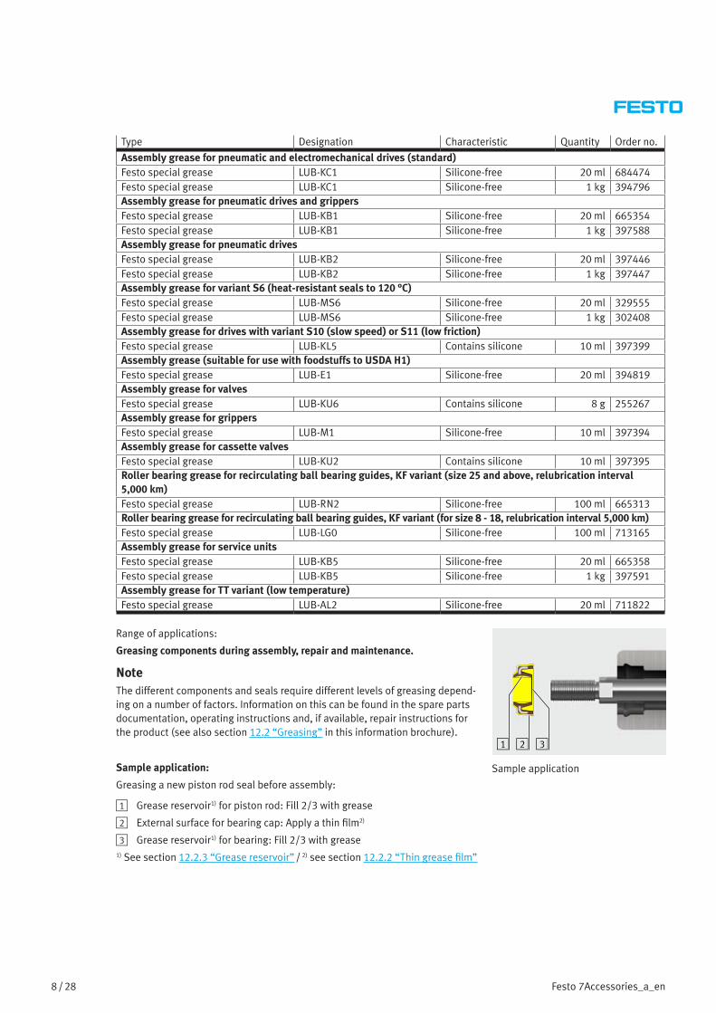
Assembly grease for pneumatic and electromechanical drives (standard) Festo special grease LUB-KC1 Silicone-free 20 ml 684474Festo special grease LUB-KC1 Silicone-free 1 kg 394796Assembly grease for pneumatic drives and grippersFesto special grease LUB-KB1 Silicone-free 20 ml 665354Festo special grease LUB-KB1 Silicone-free 1 kg 397588Assembly grease for pneumatic drivesFesto special grease LUB-KB2 Silicone-free 20 ml 397446Festo special grease LUB-KB2 Silicone-free 1 kg 397447Assembly grease for variant S6 (heat-resistant seals to 120 °C)Festo special grease LUB-MS6 Silicone-free 20 ml 329555Festo special grease LUB-MS6 Silicone-free 1 kg 302408Assembly grease for drives with variant S10 (slow speed) or S11 (low friction)Festo special grease LUB-KL5 Contains silicone 10 ml 397399Assembly grease (suitable for use with foodstuffs to USDA H1)Festo special grease LUB-E1 Silicone-free 20 ml 394819Assembly grease for valvesFesto special grease LUB-KU6 Contains silicone 8 g 255267Assembly grease for grippersFesto special grease LUB-M1 Silicone-free 10 ml 397394Assembly grease for cassette valvesFesto special grease LUB-KU2 Contains silicone 10 ml 397395Roller bearing grease for recirculating ball bearing guides, KF variant (size 25 and above, relubrication interval 5,000 km)Festo special grease LUB-RN2 Silicone-free 100 ml 665313Roller bearing grease for recirculating ball bearing guides, KF variant (for size 8 - 18, relubrication interval 5,000 km)Festo special grease LUB-LG0 Silicone-free 100 ml 713165Assembly grease for service unitsFesto special grease LUB-KB5 Silicone-free 20 ml 665358Festo special grease LUB-KB5 Silicone-free 1 kg 397591Assembly grease for TT variant (low temperature)Festo special grease LUB-AL2 Silicone-free 20 ml 711822
Range of applications:
Greasing components during assembly, repair and maintenance.
NoteThe different components and seals require different levels of greasing depend-ing on a number of factors. Information on this can be found in the spare parts documentation, operating instructions and, if available, repair instructions for the product (see also section 12.2 “Greasing” in this information brochure).
Sample application:
Greasing a new piston rod seal before assembly:
1 Grease reservoir1) for piston rod: Fill 2/3 with grease
2 External surface for bearing cap: Apply a thin film2)
3 Grease reservoir1) for bearing: Fill 2/3 with grease1) See section 12.2.3 “Grease reservoir” / 2) see section 12.2.2 “Thin grease film”
1 2 3
Sample application

9 / 28Festo 7Accessories_a_en
2.2 Grease gun
2.2.1 One-hand grease gun LUB-1
Sturdy and ergonomic design for manual lubrication. Used for lubricating greases and mineral oils.
Technical specifications Values
Capacity 120 cm³Delivery rate 0.5 cm³/strokeOperating pressure 400 barEmpty weight 660 gLength without nozzle pipe 230 mmContainer diameter x length 40x140 mmNozzle connecting thread M10x1Nozzle pipe connecting thread G1/8"
Handling:
• Filling is done manually or using the filler neck with a filling device.
• Venting is done through the air vent.
Type Quantity Order no.
One-hand high-pressure grease gun LUB-1 with pinpoint nozzle LUB-1-TR 1 piece 647958
Range of applications:
• The pinpoint nozzle LUB-1-TR is suitable for funnel-shaped lubrication nipples to DIN 3405, miniature funnel-shaped lubrication nipples and also lubricating holes, e.g. for lubricating recirculating ball bearing guides and lead screws on the following products:
– DGE
– DGEA
– DGC
– EGC
– SLG
– EGSP/K, etc.
• The pinpoint nozzle LUB-1-TR must be used for the electric slide EGSK-15.
2.2.2 Accessories for one-hand grease gun LUB-1
2.2.2.1 Lubrication adapter LUB-1-KU
The lubrication adapter LUB-1-KU can be fitted on the one-hand grease gun LUB-1 instead of the pinpoint nozzle LUB-1-TR (see section 2.2.1 “One-hand grease gun LUB-1”).
Type Quantity Order no.
Lubrication adapter LUB-1-KU (female thread M10x1) for the electric slide EGSK-20/-26/-33 1 piece 744166
Range of applications:
• The lubrication adapter LUB-1-KU is suitable for ball-type lubricating nipples similar to those specified in DIN 3402.
• The ball-type lubricating nipple similar to those specified in DIN 3402 is used with the electric slide EGSK-20/-26/-33.

10 / 28 Festo 7Accessories_a_en
2.2.2.2 Lubrication adapter LUB-1-KE
The lubrication adapter LUB-1-KE can be fitted on the one-hand grease gun LUB-1 instead of the pinpoint nozzle LUB-1-TR (see section 2.2.1 “One-hand grease gun LUB-1”).
Type Quantity Order no.
Lubrication adapter LUB-1-KE (female thread M10x1) for the electric slide EGSK-46 1 piece 744167
Range of applications:
• The lubrication adapter LUB-1-KE is suitable for ball-type lubricating nipples similar to those specified in DIN 71412.
• The ball-type lubricating nipple similar to those specified in DIN 71412 is used with the electric slide EGSK-46.
2.2.2.3 Lubrication adapter LUB-1-TR-I
The nozzle pipe LUB-1-TR-I can be screwed onto the one-hand grease gun LUB-1 instead of the pinpoint nozzle LUB-1-TR (see section 2.2.1 “One-hand grease gun LUB-1”) and is ideal for lubricating components in locations that are very difficult to access.
Type Quantity Order no.
Lubrication adapter LUB-1-TR-I (nozzle pipe Ø 6x200 axial) 1 piece 647959
Range of applications:
The lubrication adapter LUB-1-TR-I is ideal for lubricating components in locations that are very difficult to access.
2.2.2.4 Lubrication adapter LUB-1-TR-L
The nozzle pipe LUB-1-TR-L can be screwed onto the one-hand grease gun LUB-1 instead of the pinpoint nozzle LUB-1-TR (see section 2.2.1 “One-hand grease gun LUB-1”).
Type Quantity Order no.
Lubrication adapter LUB-1-TR-L (nozzle pipe Ø 6x200 lateral) 1 piece 647960
Range of applications:
The lubrication adapter LUB-1-TR-L is ideal for lubricating components in locations that are very difficult to access.

11 / 28Festo 7Accessories_a_en
3 Screw locking agent
WarningThe possible dangers of the product (in this case screw locking agent) to people and how to protect against these dangers as well as information on first-aid measures can be found in the current safety data sheets for the screw lock-ing agents.
The safety data sheets according to the Regulation (EC) No. 1907/2006 can be viewed at www.festo.com/en/msds.
When using the screw locking agents, the locally applicable environmental protection regulations must be followed.
All environmental information about the screw locking agents can be found in the current safety data sheets.
The safety data sheets according to the Regulation (EC) No. 1907/2006 can be viewed at www.festo.com/en/msds.
Loctite screw locking agents are single-component adhesives in liquid and semi-solid form. They cure to a stable duroplast at room temperature and can be used to join steel, aluminium, brass and most other metals.
Loctite screw locking agents are suitable for a variety of applications.
To find out which screw locking agent to use for which product and for which assembly, maintenance and repair work, please refer to the spare parts documentation and operating instructions for the prod-uct and, if available, the repair instructions.
Type Designation Characteristic Quantity Order no.
Screw locking agent Loctite 222 Low strength 1 ml 395251Screw locking agent Loctite 243 Medium strength 1 ml 247891Screw locking agent Loctite 243 Medium strength 10 ml 384267Screw locking agent Loctite 2701 High strength 10 ml 701774
Range of applications:
Securing screws and threaded connections.
The Loctite screw locking agent stops screws and threaded connections loosen-ing as a result of vibration and shock loads.
Sample application
12 / 28 Festo 7Accessories_a_en
4 Special oils and oil guns
4.1 Special oils
When using and disposing of the special oils, the locally applicable environmental protection regulations must be followed.
All environmental information about the special oils can be found in the current safety data sheets.
The safety data sheets according to the Regulation (EC) No. 1907/2006 can be viewed at www.festo.com/en/msds.
To find out which special oil to use for which product and for which application, please refer to the spare parts docu-mentation for the product and the operating instructions.
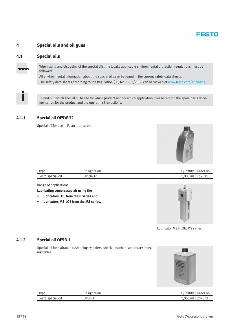
4.1.1 Special oil OFSW-32
Special oil for use in Festo lubricators.
Type Designation Quantity Order no.
Festo special oil OFSW-32 1,000 ml 152811
Range of applications:
Lubricating compressed air using the
• lubricators LOE from the D series and
• lubricators MS-LOE from the MS series.
Lubricator MS9-LOE, MS series
4.1.2 Special oil OFSB-1
Special oil for hydraulic cushioning cylinders, shock absorbers and rotary index-ing tables.
Type Designation Quantity Order no.
Festo special oil OFSB-1 1,000 ml 207873

13 / 28Festo 7Accessories_a_en
Range of applications:
Special oil for
• hydraulic cushioning cylinders type YZL-… and
• hydraulic cushioning cylinders type YD-…
Hydraulic cushioning cylinder
4.2 Oil guns
Oil guns for cushioning components.
Oil gun YD
Oil gun YSR-OEP
Type Quantity Order no.
Oil gun YD 1 piece 2212Oil gun YSR-OEP 1 piece 11698
Range of applications:
• Hydraulic cushioning cylinders type YZL-… and
• hydraulic cushioning cylinders type YD-…

14 / 28 Festo 7Accessories_a_en
5 Socket spanners for slotted nuts
Socket spanners for loosening and tightening slotted nuts.
The socket spanners for the slotted nuts must be produced by the customer.
The exact dimensions can be found in the schematic diagrams below.
Socket spanner for slotted nuts DPZ-10-…Schematic diagram:
Socket spanner for slotted nuts DPZ-16/20/25-…Schematic diagram:
Socket spanner for slotted nuts DPZ-32-…

15 / 28Festo 7Accessories_a_en
Schematic diagram:
Range of applications:
Twin-piston cylinder DPZ/DPZJ
The socket spanner is required to fasten the yoke/end plate 2 to the piston rod 3 using the slotted nut 1.
1 Socket spanner for slotted nuts
2 Slotted nut
3 Yoke/end plate
4 Twin-piston cylinder DPZ/DPZJ1 2 3 4
Sample application
6 Slotted screwdriver
Slotted screwdriver for loosening and tightening slotted nuts.
Type Area of application Quantity Order no.
M3, slotted screwdriver (DIN 546) ADVUL-12/16 1 piece 384353M4, slotted screwdriver (DIN 546) ADVUL-20 – 40, ADNGF-32 – 40 1 piece 384354M5, slotted screwdriver (DIN 546) ADVUL-50 – 100, ADNGF-50 – 100 1 piece 384355
Range of applications:
Compact cylinder ADVUL-…
The slotted screwdriver is required to bolt the yoke/end plate of the moment compensator 2 to the guide rod 4 using the slotted nut 1.
1 Slotted nut
2 Yoke plate/moment compensator
3 Shim
4 Guide rod1 2 3 4
Sample application

16 / 28 Festo 7Accessories_a_en
7 Mounting sleeve for solenoid valves
Mounting sleeve for fitting sealing rings.
Type Area of application Quantity Order no.
1/8" mounting sleeve Solenoid valve VL-5-1/8 and MFH-5-1/8 1 piece 2283891/4" mounting sleeve Solenoid valve VL-5-1/4 and MFH-5-1/4 1 piece 229363
Range of applications:
Solenoid valves of the type:
• VL-5-1/8
• VL-5-1/4
• MFH-5-1/8
• MFH-5-1/4
The mounting sleeve is used to fit sealing rings on the hand lever valve/stem on the above mentioned solenoid valves.
Solenoid valve MFH
8 Mounting sleeve for piston rods
Mounting sleeve for piston rods for protecting the piston rod seal and the bear-ing in the bearing cap or sealing seat during repairs.
The mounting sleeve for piston rods must be produced by the customer.
The exact dimensions can be found in the schematic diagram below.
The dimensions “C”, “D” and “E” (see schematic diagram: “Mounting sleeve for piston rods”) must be adjusted accord-ingly when using an extended piston rod thread or a piston rod with female thread.
Schematic diagram:
B A
C
D
E
3°
R 1

17 / 28Festo 7Accessories_a_en
A (= piston rod diameter) B C D E
6 Ø 6.6 26 27 558 Ø 8.6 23.5 25 6510 Ø 10.6 27 28 7512 Ø 12.6 34 35 8516 Ø 16.6 35 40 9020 Ø 20.6 45 50 10025 Ø 25.6 55 60 10032 Ø 32.6 65 80 11040 Ø 40.6 100 110 16050 Ø 50.6 110 120 20063 Ø 63.6 130 150 230
All dimensions in millimetres [mm]
Range of applications:
Repairing cylinders with piston rod
The appropriate mounting sleeve for piston rods 2 protects the bearing and the new piston rod seal from damage caused by the piston rod thread 3 when pushing the piston rod through the bearing cap/sealing seat 1.
1 Bearing cap
2 Mounting sleeve for piston rods
3 Piston rod thread
4 Cylinder barrel
1 42 3
Sample application
The exact procedure for exchanging the piston rod seal in the bearing cap or sealing seat of cylinders with piston rod can be found in the respective repair instructions.
9 Mounting sleeve and pressure piece for inserting the piston rod seal into the sealing seat of the round cylinder CRDSNU
The mounting sleeve and matching pressure piece prevent damage to the piston rod seal when inserting it into the sealing seat of the round cylinder CRDSNU.
A sample application of these tools can be found at the end of section 9.2.2 “Schematic diagram of the pressure piece for inserting the piston rod seal into the sealing seat of the round cylinders CRDSNU-32/40/50/63”.
9.1 Mounting sleeve and pressure piece for inserting the piston rod seal into the sealing seat of the round cylinders CRDSNU-12/16/20/25
The mounting sleeve and matching pressure piece for insert-ing the piston rod seal into the sealing seat of the round cylinder CRDSNU must be produced by the customer.
The exact dimensions can be found in the schematic diagrams below.

18 / 28 Festo 7Accessories_a_en
9.1.1 Schematic diagram of the mounting sleeve for inserting the piston rod seal into the sealing seat of the round cylinders CRDSNU-12/16/20/25
The mounting sleeve should only ever be used with the match-ing pressure piece, see section 9.1.2 “Schematic diagram of the pressure piece for inserting the piston rod seal into the sealing seat of the round cylinders CRDSNU-12/16/20/25”.
A B C D E
1x45°
0,5x45°F
J I
H
K
G
polished
Round cylinder CRDSNU A B C D E F G H I J K
CRDSNU-12 Ø 18 12° Ø 11 Ø 11.5 Ø 14 R 0.4 – 8.2 9.6 6 22.6CRDSNU-16 Ø 18 12° Ø 11 Ø 11.5 Ø 14 R 0.4 – 8.2 9.6 6 22.6CRDSNU-20 Ø 24 12° Ø 14.2 Ø 16.2 Ø 17.5 R 0.4 R 1 9 12 8 24CRDSNU-25 Ø 24 12° Ø 16 Ø 16.4 Ø 17.5 – R 1 10.3 13.3 8 26
All dimensions in millimetres [mm] unless otherwise specified
9.1.2 Schematic diagram of the pressure piece for inserting the piston rod seal into the sealing seat of the round cylinders CRDSNU-12/16/20/25
B
DC
A
0.5x45°
R 0.5
Round cylinder CRDSNU A B C D
CRDSNU-12 Ø 30 Ø 10.9 40 60CRDSNU-16 Ø 30 Ø 10.9 40 60CRDSNU-20 Ø 30 Ø 14.1 40 60CRDSNU-25 Ø 30 Ø 15.9 40 60
All dimensions in millimetres [mm]

19 / 28Festo 7Accessories_a_en
9.2 Mounting sleeve and pressure piece for inserting the piston rod seal into the sealing seat of the round cylinders CRDSNU-32/40/50/63
The mounting sleeve and matching pressure piece for insert-ing the piston rod seal into the sealing seat of the round cylinder CRDSNU must be produced by the customer.
The exact dimensions can be found in the schematic diagrams below.
9.2.1 Schematic diagram of the mounting sleeve for inserting the piston rod seal into the sealing seat of the round cylinders CRDSNU-32/40/50/63
The mounting sleeve should only ever be used with the match-ing pressure piece, see section 9.2.2 “Schematic diagram of the pressure piece for inserting the piston rod seal into the sealing seat of the round cylinders CRDSNU-32/40/50/63”.
BA D
EF
R 0,
5
R 15
C G
H
polished
Round cylinder CRDSNU A B C D E F G H
CRDSNU-32 Ø 29.5 30° Ø 25.3 Ø 22 3.1 16 Ø 30 13.1CRDSNU-40 Ø 35.5 30° Ø 29.2 Ø 26 3.6 16.5 Ø 36 18.1CRDSNU-50 Ø 42.5 30° Ø 33.2 Ø 30 3.9 16.5 Ø 43 22.1CRDSNU-63 Ø 42.5 30° Ø 33.2 Ø 30 3.9 16.5 Ø 43 22.1
All dimensions in millimetres [mm] unless otherwise specified
9.2.2 Schematic diagram of the pressure piece for inserting the piston rod seal into the sealing seat of the round cylinders CRDSNU-32/40/50/63
B
DC
A
0.5x45°
R 0.5

20 / 28 Festo 7Accessories_a_en
Round cylinder CRDSNU A B C D
CRDSNU-32 Ø 40 Ø 21.9 40 60CRDSNU-40 Ø 40 Ø 25.9 40 60CRDSNU-50 Ø 40 Ø 29.9 40 60CRDSNU-63 Ø 40 Ø 29.9 40 60
All dimensions in millimetres [mm]
Range of applications:
Inserting the piston rod seal into the sealing seat of the round cylinder CRDSNU
Place the appropriate mounting sleeve 3 on the sealing seat 4 to insert the piston rod seal 2 without damaging it into the sealing seat 4 using the matching pressure piece 1.
1 Pressure piece for piston rod seals
2 Piston rod seal
3 Mounting sleeve for the piston rod seal
4 Sealing seat CRDSNU
1 2 3 4
Sample application
The exact procedure for inserting the piston rod seal into the sealing seat of the round cylinder CRDSNU can be found in the respective repair instructions.
21 / 28Festo 7Accessories_a_en
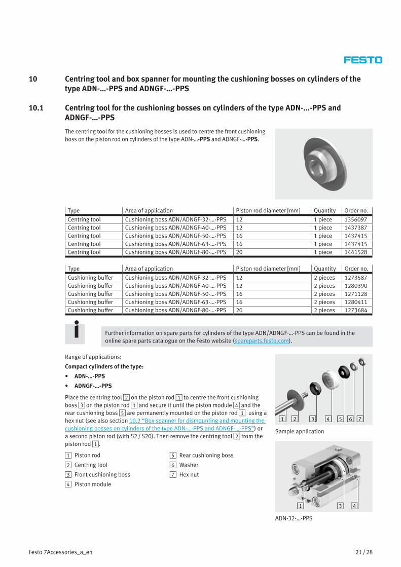
10 Centring tool and box spanner for mounting the cushioning bosses on cylinders of the type ADN-…-PPS and ADNGF-…-PPS
10.1 Centring tool for the cushioning bosses on cylinders of the type ADN-…-PPS and ADNGF-…-PPS
The centring tool for the cushioning bosses is used to centre the front cushioning boss on the piston rod on cylinders of the type ADN-…-PPS and ADNGF-…-PPS.
Type Area of application Piston rod diameter [mm] Quantity Order no.
Centring tool Cushioning boss ADN/ADNGF-32-…-PPS 12 1 piece 1356097Centring tool Cushioning boss ADN/ADNGF-40-…-PPS 12 1 piece 1437387Centring tool Cushioning boss ADN/ADNGF-50-…-PPS 16 1 piece 1437415Centring tool Cushioning boss ADN/ADNGF-63-…-PPS 16 1 piece 1437415Centring tool Cushioning boss ADN/ADNGF-80-…-PPS 20 1 piece 1441528
Type Area of application Piston rod diameter [mm] Quantity Order no.
Cushioning buffer Cushioning boss ADN/ADNGF-32-…-PPS 12 2 pieces 1273587Cushioning buffer Cushioning boss ADN/ADNGF-40-…-PPS 12 2 pieces 1280390Cushioning buffer Cushioning boss ADN/ADNGF-50-…-PPS 16 2 pieces 1271128Cushioning buffer Cushioning boss ADN/ADNGF-63-…-PPS 16 2 pieces 1280411Cushioning buffer Cushioning boss ADN/ADNGF-80-…-PPS 20 2 pieces 1273684
Further information on spare parts for cylinders of the type ADN/ADNGF-…-PPS can be found in the online spare parts catalogue on the Festo website (spareparts.festo.com).
Range of applications:
Compact cylinders of the type:
• ADN-…-PPS
• ADNGF-…-PPS
Place the centring tool 2 on the piston rod 1 to centre the front cushioning boss 3 on the piston rod 1 and secure it until the piston module 4 and the rear cushioning boss 5 are permanently mounted on the piston rod 1 using a hex nut (see also section 10.2 “Box spanner for dismounting and mounting the cushioning bosses on cylinders of the type ADN-…-PPS and ADNGF-…-PPS”) or a second piston rod (with S2 / S20). Then remove the centring tool 2 from the piston rod 1.
1 Piston rod
2 Centring tool
3 Front cushioning boss
4 Piston module
5 Rear cushioning boss
6 Washer
7 Hex nut
321 4 5 6 7
Sample application
1 3 4
ADN-32-…-PPS

22 / 28 Festo 7Accessories_a_en
10.2 Box spanner for dismounting and mounting the cushioning bosses on cylinders of the type ADN-…-PPS and ADNGF-…-PPS
Box spanner for loosening and tightening the hex nuts on the piston rod on cylinders of the type ADN/ADNGF-…-PPS. This box spanner protects the cushioning boss against damage.
Type Area of application Quantity Order no.*
Box spanner, A/F 13 ADN/ADNGF-32-…-PPS 1 piece 200/08Box spanner, A/F 17 ADN/ADNGF-40-…-PPS 1 piece 200/17Box spanner, A/F 19 ADN/ADNGF-50-…-PPS 1 piece 200/20Box spanner, A/F 19 ADN/ADNGF-63-…-PPS 1 piece 200/20Box spanner, A/F 22 ADN/ADNGF-80-…-PPS 1 piece 200/22
* The box spanners listed here can be ordered from Bauer & Böcker GmbH & Co. KG (http://www.boecker-qualitaet.de) using the specified order numbers.
The wall thickness of the box spanner used together with the width across flats is an important factor in preventing damage when mounting the cushioning boss. Use the order numbers listed above to be sure of obtaining the appropriate box spanners for the respective cylinders from Bauer & Böcker GmbH & Co. KG.
Range of applications:
Exchanging the cushioning bosses on compact cylinders of the type:
• ADN-…-PPS
• ADNGF-…-PPS
Use the box spanner 8 to loosen or tighten the hex nut 7 on the piston rod 1 without damaging the rear cushioning boss 5.
1 Piston rod
2 Centring tool
3 Front cushioning boss (covered)
4 Piston module
5 Rear cushioning boss
6 Washer
7 Hex nut
8 Box spanner
321 4 5 6 87
Sample application
The exact procedure for exchanging the cushioning bosses can be found in the respective repair instructions.

23 / 28Festo 7Accessories_a_en
11 Devices for checking the toothed belt tension
11.1 Fully equipped Systainer for checking the toothed belt tension
The fully equipped Systainer (with foam insert) contains:
• Basic test device TB-TE-EQ2 (see section 11.2 “Basic device for checking the toothed belt tension”)
• Mounting kit for toothed belt axis (ELGA-TB) TB-TE-EQ4 (see section 11.2.1 “Mounting kit for toothed belt axis ELGA-TB”)
• Device TB-TE-EQ5 (see section 11.3 “Device for checking the toothed belt tension”) and
• Acoustic belt tension meter (frequency meter) TB-TE-EQ3 (see section 11.4 “Acoustic belt tension meter (frequency meter)”).
Type Designation
Fully equipped Systainer for checking the toothed belt tension TB-TE-EQ1 On request
The exact procedure for checking the toothed belt tension can be found in the operating instructions “Test equipment for checking the tension of toothed belts” (7Tension01_TBb_en and 7Tension02_TBb_en).
11.2 Basic device for checking the toothed belt tension
The basic device TB-TE-EQ2 has a holder for the test probe of the acoustic fre-quency meter of the type TB-TE-EQ3 and enables the toothed belt to be excited by means of a plunger.
The basic device is supplied in the Systainer with foam insert.
The acoustic belt tension meter TB-TE-EQ3 must be ordered separately, see section 11.4 “Acoustic belt tension meter (frequency meter)”.
Type Designation
Basic device for checking the toothed belt tension TB-TE-EQ2 On request
Range of applications:
Checking the toothed belt tension for toothed belt axes of the type:
• DGE-25/40/63-ZR-(KF)
• DGE-25/40/63-ZR-RF
• EGC-TB-KF
• ELGA-TB-G-70 / 80 / 120 (the mounting kit TB-TE-EQ4 must be used for checking the toothed belt tension, see section 11.2.1 “Mounting kit for toothed belt axis ELGA-TB”)
The toothed belt tension of the above mentioned toothed belt axes can be checked using the acoustic belt tension meter TB-TE-EQ3 connected to the basic device TB-TE-EQ2.
Sample application
The exact procedure for checking the toothed belt tension can be found in the operating instructions “Test equipment for checking the tension of toothed belts” (7Tension01_TBb_en).

24 / 28 Festo 7Accessories_a_en
11.2.1 Mounting kit for toothed belt axis ELGA-TB
The mounting kit TB-TE-EQ4 can only be used in combination with the basic device TB-TE-EQ2 (see section 11.2 “Basic device for checking the toothed belt tension”) for checking the toothed belt tension on toothed belt axes of the type ELGA-TB-G-70/80/120.
The basic device TB-TE-EQ2 and the acoustic belt tension meter TB-TE-EQ3 must be ordered separately, see section 11.2 “Basic device for checking the toothed belt tension” and section 11.4 “Acoustic belt tension meter (frequency meter)”.
Contents of the mounting kit TB-TE-EQ4:
1 Position stop bolt
2 Left-hand position stop
3 Right-hand position stop
4 Distance piece for ELGA-TB-G-120
5 Distance piece for ELGA-TB-G-80
6 Distance piece for ELGA-TB-G-70
7 Transport holder for distance pieces7
1 32
6 5 4
Type Designation
Mounting kit for toothed belt axis ELGA-TB TB-TE-EQ4 On request
Range of applications:
Checking the toothed belt tension for toothed belt axes ELGA-TB-G-70/80/120 only
The toothed belt tension of the toothed belt axes of the type ELGA-TB-G-70/80/120 can be checked using the acoustic belt tension meter TB-TE-EQ3 connected to the basic device TB-TE-EQ2 and using the mounting kit TB-TE-EQ4.
Sample application
The exact procedure for checking the toothed belt tension on the toothed belt axis ELGA-TB-G-70/80/ 120 using the mounting kit can be found in the operating instructions “Test equipment for checking the tension of toothed belts” (7Tension01_TBb_en).
11.3 Device for checking the toothed belt tension
The basic device TB-TE-EQ5 has a holder for the test probe of the acoustic frequency meter of the type TB-TE-EQ3 and enables the toothed belt to be excited by means of a plunger.
The acoustic belt tension meter TB-TE-EQ3 must be ordered separately, see section 11.4 “Acoustic belt tension meter (frequency meter)”.
Type Designation
Test equipment for checking the toothed belt tension TB-TE-EQ5 On request
25 / 28Festo 7Accessories_a_en
Range of applications:
Checking the toothed belt tension for drives of the type:
• ERMB
• EHMB
The toothed belt tension on the above mentioned drives can be checked using the acoustic belt tension meter TB-TE-EQ3 connected to the device TB-TE-EQ5.
Sample application
The exact procedure for checking the toothed belt tension can be found in the operating instructions “Test equipment for checking the tension of toothed belts” (7Tension02_TBb_en).
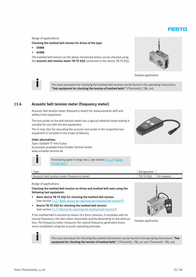
11.4 Acoustic belt tension meter (frequency meter)
Acoustic belt tension meter (frequency meter) for measurements with and without test equipment.
The test probe on the belt tension meter has a special adhesive bond making it suitable for use with the test equipment.
The O-ring 10x1 for mounting the acoustic test probe in the respective test equipment is included in the scope of delivery.
Order alternatives:Type: Optibelt TT mini S plusExclusively available from Schäfer Technik GmbHwww.schaefer-technik.de
Purchasing spare O-rings 10x1, see section 11.4.1 “Spare O-ring 10x1”.
Type Designation
Acoustic belt tension meter (frequency meter) TB-TE-EQ3 On request
Range of applications:
Checking the toothed belt tension on drives and toothed belt axes using the following test equipment:
• Basic device TB-TE-EQ2 for checking the toothed belt tension (see section 11.2 “Basic device for checking the toothed belt tension”)
• Device TB-TE-EQ5 for checking the toothed belt tension (see section 11.3 “Device for checking the toothed belt tension”)
If the toothed belt is excited by means of a force stimulus, it oscillates with its natural frequency; this dies down reasonably quickly depending on the attenua-tion. The frequency meter measures the natural frequency generated (trans-verse oscillation) using the acoustic operating principle.
Sample application
The exact procedure for checking the toothed belt tension can be found in the operating instructions “Test equipment for checking the tension of toothed belts” (7Tension01_TBb_en and 7Tension02_TBb_en).

26 / 28 Festo 7Accessories_a_en
11.4.1 Spare O-ring 10x1
For mounting the acoustic test probe of the frequency meter TB-TE-EQ3 in the test equipment by means of clamping friction.
The O-ring 10x1 is included in the scope of delivery of the frequency meter TB-TE-EQ3 (see section 11.4 “Acoustic belt tension meter (frequency meter)”).
Type Quantity Order no.
O-ring 10x1 1 piece 200926
11.5 Empty Systainer with foam insert
Empty Systainer with foam insert
Type Designation
Empty Systainer with foam insert TB-TE-EQ0 On request
Range of applications:
The Systainer with foam insert offers space for
• Basic test device TB-TE-EQ2 (see section 11.2 “Basic device for checking the toothed belt tension”)
• Mounting kit for toothed belt axis (ELGA-TB) TB-TE-EQ4 (see section 11.2.1 “Mounting kit for toothed belt axis ELGA-TB”)
• Device TB-TE-EQ5 (see section 11.3 “Device for checking the toothed belt tension”) and
• Acoustic belt tension meter (frequency meter) TB-TE-EQ3 (see section 11.4 “Acoustic belt tension meter (frequency meter)”).
Systainer fully equipped

27 / 28Festo 7Accessories_a_en
12 Cleaning and greasing
12.1 Cleaning
The components must be thoroughly cleaned of all foreign particles, machining residues and old lubricants before they are greased.
CautionFesto recommends Loctite 7063 and Loctite 7070 for cleaning.
When using other cleaning agents, make sure that they do not corrode the seals of the cylinder with piston rod. In case of doubt, check the resistance of the seals using the data on the Festo website (www.festo.com).
12.2 Greasing
The different components require different levels of greasing depending on a number of factors.
12.2.1 Extremely thin grease film
A barely continuous film of grease covers the bearing surface. The grease can give a sheen to the surface; however, the colour of the grease must not darken it.
Recommendation:
Apply the grease using a cloth or similar dipped in the grease.
Remove the excess grease from the seal system components (e.g. by drawing the assembled piston with the piston rod once fully through the greased cylinder barrel) and then remove the excess from the seal components by wiping it off.
12.2.2 Thin grease film
A film of grease covers the bearing surface so that the grease colour darkens the surface slightly.
Recommendation:
Apply the grease with a soft brush or similar.
12.2.3 Grease reservoir
There is a certain amount of oil enclosed between two sealing rims or in enclosed ring volumes.
DocumentsTo find out which lubricating grease to use for which product and for instructions on greasing the individual compo-nents, please refer to the spare parts documentation and operating instructions and, if available, the repair instruc-tions for the product. There you will also find precise indications for e.g. relubrication intervals, application, etc.
The lubrication instructions for pneumatic cylinders can be found in chapter 12 “Cleaning and greasing”.
13 Liability
The General Terms and Conditions of Sale of Festo AG & Co. KG, which can be viewed on the Festo website (www.festo.com), apply.

28 / 28 Festo 7Accessories_a_en
Conditions of use for “electronic documentation”
I. Protection rights and scope of use
The file of your choice is subject to protec-tion provisions. Festo or third parties have protection rights concerning this electronic documentation which Festo makes available on portable data storage devices (floppy disks, CD-ROM, removable disks) as well as on the Internet and/or Intranet, hereinafter referred to as electronic documentation. Provided third parties are entitled to partial or full rights concerning this electronic docu-mentation, Festo shall have the correspond-ing rights of use. Festo permits the user to use the electronic documentation under the following conditions:
1. Scope of use
a) The user of the electronic documenta-tion is allowed to use this documentation for his own, exclusively company-internal purposes on any number of machines within his business premises (location). This right of use includes exclusively the right to save the electronic documentation on the central processors (machines) used at the location.
b) The electronic documentation may be printed out on a printer at the location of the user as often as desired, providing this printout is printed with or kept in a safe place together with these conditions of use and other user instructions.
c) With the exception of the Festo logo, the user has the right to use pictures and texts from the electronic documentation for creat-ing his own machine and system documen-tation. The use of the Festo logo requires written consent from Festo. The user himself is responsible for ensuring that the pictures and texts used match the machine/system or the relevant product.
d) Further uses are permitted within the fol-lowing framework:
Copying exclusively for use within the frame-work of machine and system documentation from electronic documents of all documented supplier components. Demonstrating to third parties exclusively under guarantee that no data material is stored wholly or partly in other networks or other data storage devices or can be reproduced there.
Passing on printouts to third parties not covered by the provision stated in item 3, as well as any processing or other use, is not permitted.
2. Copyright note
Every “electronic document” receives a copyright note. This note must be included on every copy and every printout.
Example: E 2003, Festo AG & Co. KG, D-73726 Esslingen
3. Transferring the authorisation of use
The user can transfer the authorisation of use in the scope of and with the limitations of the conditions in accordance with items 1 and 2 completely to a third party. The third party must be made explicitly aware of these conditions of use.
II. Exporting the electronic documentation
When exporting the electronic documenta-tion, the licence holder must observe the export regulations of the exporting country and those of the purchasing country.
III. Warranty
1. Festo products are being continuously developed with regard to hardware and soft-ware. The hardware status and, where appli-cable, the software status of the product can be found on the name plate of the product. If the electronic documentation, in whatever form, is not supplied with the product, i. e. is not supplied on a portable data storage device (floppy disk, CD-ROM, removable disk), Festo does not guarantee that the elec-tronic documentation corresponds to every hardware and software status of the product. In this case, the printed documentation from Festo accompanying the product alone is decisive for ensuring that the hardware and software status of the product matches that of the electronic documentation.
2. The information contained in this electronic documentation can be amended by Festo without prior notice and does not commit Festo in any way.
IV. Liability/Limitations of liability
1. Festo supplies this electronic documenta-tion in order to assist the user in creating his machine and system documentation. In the case of electronic documentation that does not directly accompany a product in the form of portable data storage devices (floppy disk, CD-ROM, removable disk), i. e. that is not automatically supplied together with that product, Festo does not guarantee that the electronic documentation available/supplied separately matches the product actually used by the user.
The latter applies particularly to extracts of the documents for the user’s own documenta-tion. The guarantee and liability for separately available/supplied data storage devices, i. e. except for the electronic documentation available via the Internet/Intranet, is limited exclusively to proper duplication of the software, whereby Festo guarantees that in each case the data storage device or software contains the latest update of the documenta-tion. Concerning electronic documentation available on the Internet/Intranet, there is no guarantee that it will have the same version status as the last printed edition.
2. Furthermore, Festo cannot be held liable for the lack of economic success or for dam-age or claims by third parties resulting from the use of the documentation by the user, with the exception of claims arising from infringement of the protection rights of third parties concerning the use of the electronic documentation.
3. The limitations of liability as per para-graphs 1 and 2 do not apply if, in cases of intent or gross negligence or the lack of warranted quality, liability is compulsory. In such a case, Festo’s liability is limited to the damage discernable by Festo when the defini-tive circumstances are made known.
V. Safety guidelines/documentation
Warranty and liability claims in conformity with the aforementioned regulations (items III and IV) may be raised only if the user has observed the safety guidelines of the docu-mentation in conjunction with the use of the machine and its safety guidelines. The user himself is responsible for ensuring that the electronic documentation, when not supplied with the product, matches the product actu-ally used by the user.
Copyright © 2022 FDOKUMEN