Influence of toe load on the fatigue resistance of elastic rail clips
10
Original Article Influence of toe load on the fatigue resistance of elastic rail clips Anat Hasap 1 , Phanasindh Paitekul 1 , Nitikorn Noraphaiphipaksa 2 and Chaosuan Kanchanomai 2 Abstract As a critical component of the fastening system, the elastic rail clip maintains the rail in the vertical, lateral, and longitudinal positions using its specified toe load. In this study, the influence of toe load on the deformation and fatigue resistance of the clip was studied. Finite element analysis, static load experiments, and fatigue experiments were performed to evaluate the deformation and fatigue resistance of the clip. With the contribution of the lateral wheel load, the deformation range of the outer clip was higher than that of the inner clip. Therefore, the cyclic deformation of the outer clip was used for the fatigue experiment. The toe load had no influence on the fatigue resistance of the clip under normal wheel load, i.e. the clips under high, normal, and low toe loads were run-out at 5 10 6 cycles. However, with the contribution of impact on the wheel load, the fatigue lives were reduced to 5468 cycles and 16,839 cycles for the clips under high and normal toe loads, respectively. In the case of low toe load, the clip under the contribution of impact could withstand more than 5 10 6 cycles. Accordingly, the reduction of toe load may enhance the fatigue resistance of the clip under impact. Keywords Elastic rail clip, toe load, wheel load, fatigue, fastening system Date received: 23 November 2016; accepted: 2 April 2017 Introduction In the modern railway track system, various com- ponents – e.g. rail, pad, insulator, clip, and base plate – form a complex fastening system. 1,2 One crit- ical component of the fastening system is the clip, which properly maintains the rail in vertical, lateral, and longitudinal positions. An important criterion to ensure the proper functioning of the clip is the speci- fied toe load during the installation. In order to ensure a proper toe load, the load transducer has been invented and successfully employed in the load meas- urement. It was found that some clips have toe loads that differ from the specification. Moreover, clips in service are subjected to the combination between the toe load (static load) and the repeated wheel load (cyclic load), which can cause fatigue failure. 3 Because the high static load can accelerate the fatigue failure of engineering components, 3 it is therefore necessary to systematically investigate the influence of the toe load on the fatigue failure of the clip. Mohammadzadeh et al. 4 proposed a method for the analysis of fatigue reliability of the fasten- ing spring clip under operating conditions. The displacement–time history was applied to the finite element analysis (FEA) of the fastening spring clip. The crack nucleation life was numerically estimated using the rain-flow method and Palmgren–Miner linear damage rule. Unfortunately, the in-service fati- gue lives were not compared with their results to verify the predictions. Tamagawa et al. 5 developed a fatigue limit diagram for the ‘‘wire-shaped’’ clip, i.e. the relationship between the mean strain and the strain amplitude. Their fatigue life predictions using a fatigue limit diagram were in good agreement with those of fatigue tests. Sadeghi et al. 6 experimentally evaluated the influence of the rail loading conditions on the fatigue phenomena of Vossloh and Pandrol flexible clips under various train speeds and axle loads. The increase of axle loads caused substantial increases in the plastic deformations of the clips, while the train speeds had less influence on the deflection. 1 Railway Transportation System Testing Center, Institute of Scientific and Technological Research, Pathumthani, Thailand 2 Faculty of Engineering, Department of Mechanical Engineering, Center of Materials Engineering and Performance, Thammasat University, Pathumthani, Thailand Corresponding author: Chaosuan Kanchanomai, Department of Mechanical Engineering, Faculty of Engineering, Thammasat University, Pathumthani 12120, Thailand. Email: [email protected] Proc IMechE Part F: J Rail and Rapid Transit 2018, Vol. 232(4) 1078–1087 ! IMechE 2017 Reprints and permissions: sagepub.co.uk/journalsPermissions.nav DOI: 10.1177/0954409717707834 journals.sagepub.com/home/pif
-
Upload
khangminh22 -
Category
Documents
-
view
5 -
download
0
Transcript of Influence of toe load on the fatigue resistance of elastic rail clips
Original Article
Influence of toe load on the fatigueresistance of elastic rail clips
Anat Hasap1, Phanasindh Paitekul1,Nitikorn Noraphaiphipaksa2 and Chaosuan Kanchanomai2
Abstract
As a critical component of the fastening system, the elastic rail clip maintains the rail in the vertical, lateral, and longitudinal
positions using its specified toe load. In this study, the influence of toe load on the deformation and fatigue resistance of the
clip was studied. Finite element analysis, static load experiments, and fatigue experiments were performed to evaluate the
deformation and fatigue resistance of the clip. With the contribution of the lateral wheel load, the deformation range of the
outer clip was higher than that of the inner clip. Therefore, the cyclic deformation of the outer clip was used for the fatigue
experiment. The toe load had no influence on the fatigue resistance of the clip under normal wheel load, i.e. the clips under
high, normal, and low toe loads were run-out at 5� 106 cycles. However, with the contribution of impact on the wheel
load, the fatigue lives were reduced to 5468 cycles and 16,839 cycles for the clips under high and normal toe loads,
respectively. In the case of low toe load, the clip under the contribution of impact could withstand more than 5� 106
cycles. Accordingly, the reduction of toe load may enhance the fatigue resistance of the clip under impact.
Keywords
Elastic rail clip, toe load, wheel load, fatigue, fastening system
Date received: 23 November 2016; accepted: 2 April 2017
Introduction
In the modern railway track system, various com-ponents – e.g. rail, pad, insulator, clip, and baseplate – form a complex fastening system.1,2 One crit-ical component of the fastening system is the clip,which properly maintains the rail in vertical, lateral,and longitudinal positions. An important criterion toensure the proper functioning of the clip is the speci-fied toe load during the installation. In order to ensurea proper toe load, the load transducer has beeninvented and successfully employed in the load meas-urement. It was found that some clips have toe loadsthat differ from the specification. Moreover, clips inservice are subjected to the combination between thetoe load (static load) and the repeated wheel load(cyclic load), which can cause fatigue failure.3
Because the high static load can accelerate the fatiguefailure of engineering components,3 it is thereforenecessary to systematically investigate the influenceof the toe load on the fatigue failure of the clip.
Mohammadzadeh et al.4 proposed a methodfor the analysis of fatigue reliability of the fasten-ing spring clip under operating conditions. Thedisplacement–time history was applied to the finiteelement analysis (FEA) of the fastening spring clip.The crack nucleation life was numerically estimated
using the rain-flow method and Palmgren–Minerlinear damage rule. Unfortunately, the in-service fati-gue lives were not compared with their results toverify the predictions. Tamagawa et al.5 developed afatigue limit diagram for the ‘‘wire-shaped’’ clip, i.e.the relationship between the mean strain and thestrain amplitude. Their fatigue life predictions usinga fatigue limit diagram were in good agreement withthose of fatigue tests. Sadeghi et al.6 experimentallyevaluated the influence of the rail loading conditionson the fatigue phenomena of Vossloh and Pandrolflexible clips under various train speeds and axleloads. The increase of axle loads caused substantialincreases in the plastic deformations of the clips, whilethe train speeds had less influence on the deflection.
1Railway Transportation System Testing Center, Institute of Scientific
and Technological Research, Pathumthani, Thailand2Faculty of Engineering, Department of Mechanical Engineering, Center
of Materials Engineering and Performance, Thammasat University,
Pathumthani, Thailand
Corresponding author:
Chaosuan Kanchanomai, Department of Mechanical Engineering,
Faculty of Engineering, Thammasat University, Pathumthani 12120,
Thailand.
Email: [email protected]
Proc IMechE Part F:
J Rail and Rapid Transit
2018, Vol. 232(4) 1078–1087
! IMechE 2017
Reprints and permissions:
sagepub.co.uk/journalsPermissions.nav
DOI: 10.1177/0954409717707834
journals.sagepub.com/home/pif

A comparison of the results obtained for the twotypes of clips (Vossloh and Pandrol) indicated thatboth the railway flexible clips had the similar fatiguebehavior. Shang et al.7 numerically evaluated theeffect of the vertical displacement of the clip’sfinger on the clamping force and stress. The verticaldisplacement of the clip’s finger had a marginal effecton the clamping force, but a large effect on the max-imum equivalent stress in the clip. The fatigue crackmight easily nucleate and propagate in the clip’sstress concentration area after repeated passages oftrains. Although there are literature works that focuson the reliability of clips, the effect of toe load on thereliability of the clip has not been clearlyunderstood.
In this study, the influence of toe load on thedeformation and fatigue resistance of elastic railclips was studied. FEA, static load experiments, andfatigue experiments were performed to evaluate thedeformations and fatigue resistances of clips. Thefindings can be used as a guideline for the installation
and maintenance to ensure the structural integrity of arailway track system.
Railway track system
An elastic rail clip (e-clip), which is a standard type ofelastic rail fastening, was used in this study. The clipapplies the toe load between the rail and the sleeper toprohibit the relative movement (Figure 1). Its chem-ical composition was evaluated using an emissionspectrometer (Spectrolab: M10), i.e. 0.532wt% C,1.80wt% Si, 0.841wt% Mn, 0.244wt% Cr, and96.1wt% Fe. The composition corresponds to thatof the SUP10 spring steel (JIS G48018). On theother hand, the rail was an UIC60 rail (BS EN136749).
Procedure of the research
FEA, static load experiments, and fatigue experimentswere performed to evaluate the deformations and
Figure 1. The railway track system (dimension in mm).
Hasap et al. 1079
fatigue resistances of clips. The study was divided intofour steps as follows:
(i) Deformation of the railway track system. Thestresses and deformations of a railway tracksystem with five base plates under the combin-ation of toe load and wheel load were experimen-tally and numerically evaluated. FEA results werethen compared with those of experiments to val-idate the FEA.
(ii) Influence of the number of base plates on thedeformation of rails. The deformations of railswith various lengths and number of base platesunder wheel load were numerically calculated.The length and number of base plates, that prop-erly represent the deformation of rail, wereselected for the evaluation of clip deformation.
(iii) Deformation of clips. The deformations of therailway track system under the combination oftoe load and wheel load were numerically calcu-lated using FEA. The maximum deformationrange of clip was determined and used as acyclic deformation for the fatigue experiment ofthe clip.
(iv) Fatigue of clips. The fatigue experiments of clipswere performed to evaluate the fatigue resistanceof clips.
Deformation of the railway track system
Static loading experiment
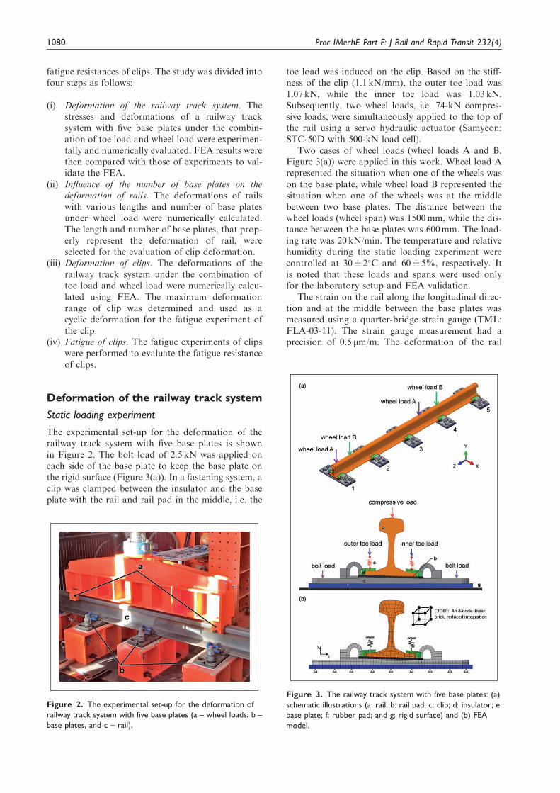
The experimental set-up for the deformation of therailway track system with five base plates is shownin Figure 2. The bolt load of 2.5 kN was applied oneach side of the base plate to keep the base plate onthe rigid surface (Figure 3(a)). In a fastening system, aclip was clamped between the insulator and the baseplate with the rail and rail pad in the middle, i.e. the
toe load was induced on the clip. Based on the stiff-ness of the clip (1.1 kN/mm), the outer toe load was1.07 kN, while the inner toe load was 1.03 kN.Subsequently, two wheel loads, i.e. 74-kN compres-sive loads, were simultaneously applied to the top ofthe rail using a servo hydraulic actuator (Samyeon:STC-50D with 500-kN load cell).
Two cases of wheel loads (wheel loads A and B,Figure 3(a)) were applied in this work. Wheel load Arepresented the situation when one of the wheels wason the base plate, while wheel load B represented thesituation when one of the wheels was at the middlebetween two base plates. The distance between thewheel loads (wheel span) was 1500mm, while the dis-tance between the base plates was 600mm. The load-ing rate was 20 kN/min. The temperature and relativehumidity during the static loading experiment werecontrolled at 30� 2�C and 60� 5%, respectively. Itis noted that these loads and spans were used onlyfor the laboratory setup and FEA validation.
The strain on the rail along the longitudinal direc-tion and at the middle between the base plates wasmeasured using a quarter-bridge strain gauge (TML:FLA-03-11). The strain gauge measurement had aprecision of 0.5 mm/m. The deformation of the rail
Figure 3. The railway track system with five base plates: (a)
schematic illustrations (a: rail; b: rail pad; c: clip; d: insulator; e:
base plate; f: rubber pad; and g: rigid surface) and (b) FEA
model.
Figure 2. The experimental set-up for the deformation of
railway track system with five base plates (a – wheel loads, b –
base plates, and c – rail).
1080 Proc IMechE Part F: J Rail and Rapid Transit 232(4)
in the vertical direction and at the middle between thebase plates was measured using a dial gauge with aprecision of 10 mm. It is noted that the deformationmeasured by the dial gauge was a combination of the
deformations of the rail and the rail pad. The strainwas converted to stress using Hook’s law. Both stres-ses and deformations obtained from the experimentswere used to validate the FEA.
Finite element analysis
The stresses and deformations of a railway tracksystem with five base plates under the combinationof toe load and wheel load were numerically calcu-lated using 3D linear-elastic FEA, i.e. ABAQUS.10
Bolt loads applied for FEA were similar to those ofthe static loading experiment. To simplify the FEAmodel, the clips were replaced by linear springswith the same stiffness of 1.1 kN/mm, as shown inFigure 3(b). The material properties of each compo-nent are shown in Table 1. It is assumed that thePoisson’s ratios (n) of steel components were 0.3,while those of polymer components were 0.45. Thedeformation and compressive load of linear springswere adjusted to be the same as those of clips afterinstallation, i.e. the outer toe load of 1.07 kN, and theinner toe load of 1.03 kN. Two cases of wheel loads(wheel loads A and B) were applied for FEA.
Frictional-contact elements (eight-node linearbrick, C3D8R), master-slave algorithm, and penaltymethod were applied to all the contact interfaces.They are the contacts between rail vs. rail pad, railvs. insulator, rail pad vs. base plate, base plate vs.rubber pad, and rubber pad vs. rigid surface.
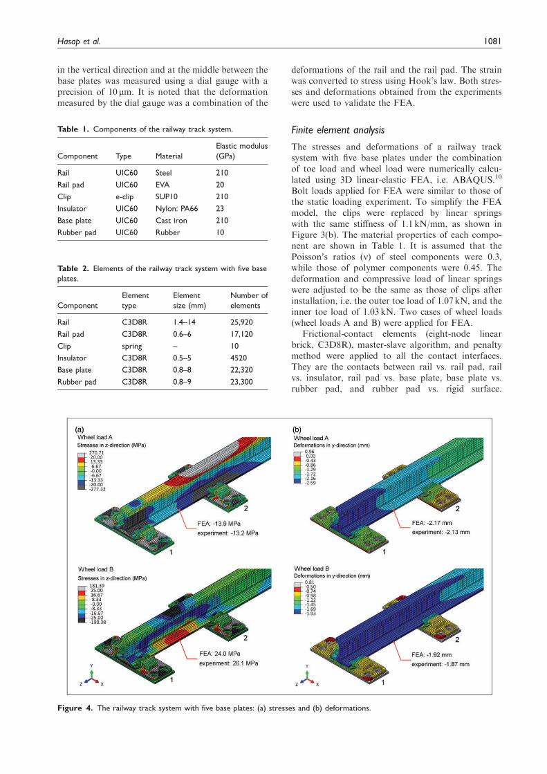
Figure 4. The railway track system with five base plates: (a) stresses and (b) deformations.
Table 2. Elements of the railway track system with five base
plates.
Component
Element
type
Element
size (mm)
Number of
elements
Rail C3D8R 1.4–14 25,920
Rail pad C3D8R 0.6–6 17,120
Clip spring – 10
Insulator C3D8R 0.5–5 4520
Base plate C3D8R 0.8–8 22,320
Rubber pad C3D8R 0.8–9 23,300
Table 1. Components of the railway track system.
Component Type Material
Elastic modulus
(GPa)
Rail UIC60 Steel 210
Rail pad UIC60 EVA 20
Clip e-clip SUP10 210
Insulator UIC60 Nylon: PA66 23
Base plate UIC60 Cast iron 210
Rubber pad UIC60 Rubber 10
Hasap et al. 1081

The slip of the contact interface was assumed to occurwhen the shear stress is greater than the critical shearstress (�c), i.e.
�5�c ¼ ��n ð1Þ
where �n and � are the normal stress and the frictioncoefficient, respectively. The friction coefficient of 0.3
was assumed for all contacts. The boundary condi-tions were applied at the contact between the rubberpad and the rigid surface. The displacement in the ydirection and the rotations around all axes were con-strained. Each wheel load was gradually increasedwith intervals of 20 steps from 0 to the maximum of74 kN. To minimize the influence of element size, thesize of elements was adjusted until the variation of the
Figure 5. Rail and rigid supports at the locations of base plates: (a) schematic illustrations and (b) deformations in the vertical
direction (y-axis) of the rail.
1082 Proc IMechE Part F: J Rail and Rapid Transit 232(4)
Von Mises stress around the critical points of eachcomponent was below 5%. The sizes of the elementand the number of elements of each component aresummarized in Table 2.
The stresses and deformations of a railway tracksystem with five base plates obtained from experi-ments and FEA are shown in Figure 4(a) and (b),respectively. The stresses and deformations calculatedusing FEA were in good agreement with those ofexperiments. Thus, the validation of the presentFEA was confirmed.
Influence of the number of base plateson the deformation of rails
Because the length of the rail and the number of baseplates could influence the deformations of rail andclips under wheel load, the deformations of railswith various lengths and number of base plates (upto 14 base plates) were numerically calculated. Thelength of the rail and the number of base plates thatclearly represent the deformation of rail should be
used for the numerical evaluation of deformationsof clips.
It is known that the flexibility of the fasteningsystem has influence on the stress and deformationof rail. Thus, the deformations of rails with variouslengths and number of base plates should be evalu-ated using the model with fastening system.Unfortunately, models with various lengths andnumber of base plates have too many assemblies ofcomplex parts and require long run time. To simplifythe FEA model, only rail and rigid supports at thelocations of base plates were used for the FEA(Figure 5(a)). Although this simplification cannot pro-vide the actual stress and deformation of rails, it isbelieved that the results of FEA can be used for theselection of the length of the rail and the number ofbase plates to be used for the numerical evaluation ofdeformations of clips.
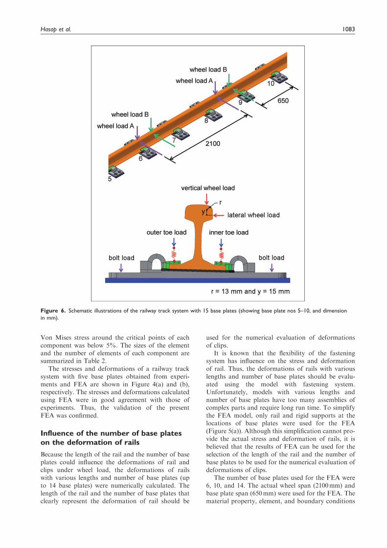
The number of base plates used for the FEA were6, 10, and 14. The actual wheel span (2100mm) andbase plate span (650mm) were used for the FEA. Thematerial property, element, and boundary conditions
Figure 6. Schematic illustrations of the railway track system with 15 base plates (showing base plate nos 5–10, and dimension
in mm).
Hasap et al. 1083
were similar to the previous FEA (section ‘‘Finiteelement analysis’’). Wheel load A, which representedthe situation when one of the wheels was on the baseplate, was used for the FEA.
Deformations in the vertical direction of the rail(y-axis) are shown in Figure 5(b). Because the leftwheel load was applied on the base plate, the deform-ation of rail was limited. On the other hand, the rightwheel load was applied between base plates; thus, thehighest deformation of the rail could be observed.FEA model with 14 base plates clearly representedthe deformations of rail under two wheel loads; thusan FEA model with 14 base plates or more should beused for the numerical evaluation of clipdeformations.
Deformation of clips
Stresses and strains of the railway track systemunder the combination of toe load and wheel loadwere numerically calculated. The maximum deform-ation range of the clip was determined and used ascyclic deformation for the fatigue experiment of theclip. A railway track system with 15 base plates was
selected for the FEA, as shown in Figure 6.Geometries, material properties, elements, boltload, outer toe load, inner toe load, and boundaryconditions were similar to the previous FEA (section‘‘Finite element analysis’’). However, the distancebetween wheels was 2100mm, while the distancebetween base plates was 650mm. These wheel spanand base plate span were selected to represent theactual geometries of the railway track system. Tosimulate the curve rail, where most of the clip failurewas observed,1 a lateral wheel load of 39 kN and avertical wheel load of 74 kN were used for the FEA.These loads were suggested by AS 1085.1911 for thecurve rail in the mainline of a 20-ton axle load vehi-cle at a speed of 100 km/h, which is similar to thoserecommended by BS EN 13481.12
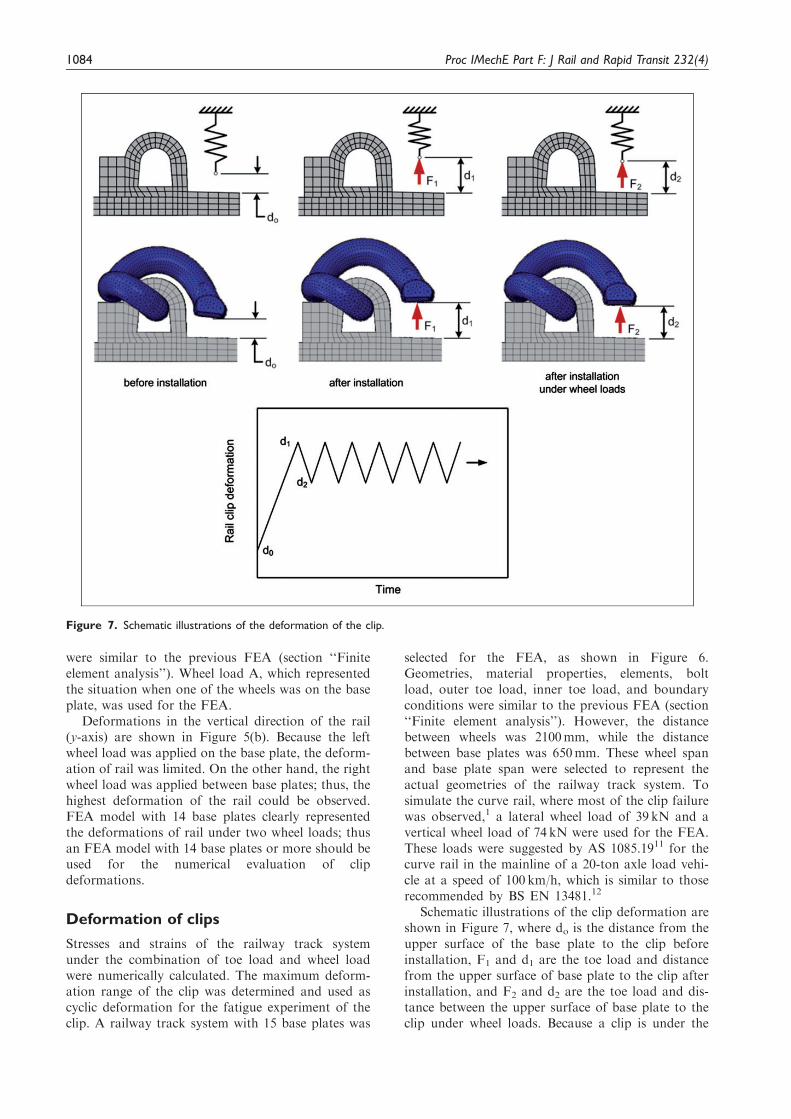
Schematic illustrations of the clip deformation areshown in Figure 7, where do is the distance from theupper surface of the base plate to the clip beforeinstallation, F1 and d1 are the toe load and distancefrom the upper surface of base plate to the clip afterinstallation, and F2 and d2 are the toe load and dis-tance between the upper surface of base plate to theclip under wheel loads. Because a clip is under the
Figure 7. Schematic illustrations of the deformation of the clip.
1084 Proc IMechE Part F: J Rail and Rapid Transit 232(4)
repeated wheel loads during actual operation, thecyclic deformation from d1 to d2 is likely to occur,as schematically shown in Figure 7. If the magnitudeof deformation and number of cycles are high enough,the fatigue failure of clip is possible.
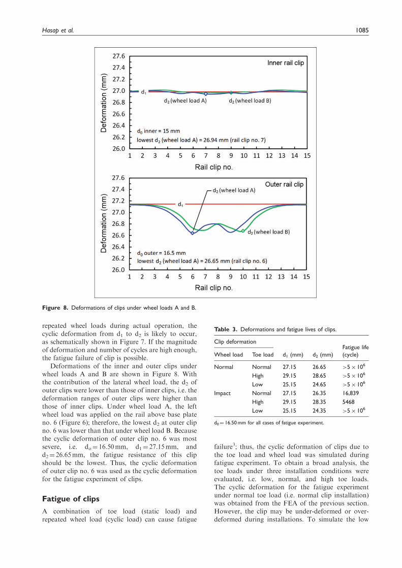
Deformations of the inner and outer clips underwheel loads A and B are shown in Figure 8. Withthe contribution of the lateral wheel load, the d2 ofouter clips were lower than those of inner clips, i.e. thedeformation ranges of outer clips were higher thanthose of inner clips. Under wheel load A, the leftwheel load was applied on the rail above base plateno. 6 (Figure 6); therefore, the lowest d2 at outer clipno. 6 was lower than that under wheel load B. Becausethe cyclic deformation of outer clip no. 6 was mostsevere, i.e. do¼ 16.50mm, d1¼ 27.15mm, andd2¼ 26.65mm, the fatigue resistance of this clipshould be the lowest. Thus, the cyclic deformationof outer clip no. 6 was used as the cyclic deformationfor the fatigue experiment of clips.
Fatigue of clips
A combination of toe load (static load) andrepeated wheel load (cyclic load) can cause fatigue
failure3; thus, the cyclic deformation of clips due tothe toe load and wheel load was simulated duringfatigue experiment. To obtain a broad analysis, thetoe loads under three installation conditions wereevaluated, i.e. low, normal, and high toe loads.The cyclic deformation for the fatigue experimentunder normal toe load (i.e. normal clip installation)was obtained from the FEA of the previous section.However, the clip may be under-deformed or over-deformed during installations. To simulate the low
Figure 8. Deformations of clips under wheel loads A and B.
Table 3. Deformations and fatigue lives of clips.
Clip deformation
d1 (mm) d2 (mm)
Fatigue life
(cycle)Wheel load Toe load
Normal Normal 27.15 26.65 >5� 106
High 29.15 28.65 >5� 106
Low 25.15 24.65 >5� 106
Impact Normal 27.15 26.35 16,839
High 29.15 28.35 5468
Low 25.15 24.35 >5� 106
d0¼ 16.50 mm for all cases of fatigue experiment.
Hasap et al. 1085

toe load (i.e. under-deformed clip installation) thedeformation of 2mm was subtracted from thedeformations of the clip under normal installation(d1 and d2), while the deformation of 2mm wasadded to the deformations of the clip undernormal installation (d1 and d2) to simulate thehigh toe load (i.e. over-deformed clip installation).The deformations of clips under the influence of toeloads are summarized in Table 3.
In the actual operation of a railway track system,the impact caused by irregularities of rails and wheels,e.g. weldment, wear, corrugated rail, can add up to60% of the wheel load.4,13 Ling et al.13 found that theVon Mises stress increased with the corrugationdepth. For severe corrugation, the Von Mises stressin the clip exceeded the ultimate strength of the clipdue to the impact load. To simulate the influence of
impact on cyclic deformation, 60% of deformationwas added to the cyclic deformation range (d1–d2),while the deformation under toe load (d1) was unal-tered. The deformations of clips under the influence ofimpact are summarized in Table 3.
The experimental set-up for the fatigue of the clip isshown in Figure 9(a). Two clips were clampedbetween the insulators and the base plate with therail and rail pad in the middle. Sinusoidal cyclicdeformation with 5Hz frequency was applied to theclips through a rail by a servo hydraulic actuator(MTS: 244.22 with 100 kN load cell). A linear-variabledifferential transformer with 0.05-mm precision wasused to control the required deformation of the clip.The temperature and relative humidity during the fati-gue experiment were controlled at 30� 2�C and60� 5%, respectively. The fatigue life is defined asthe number of cycles that occur before a completefracture. However, if a clip does not fail after5� 106 cycles, it is considered as a run-out. Withthree cases of toe loads and two cases of wheelloads (Table 3), the fatigue experiments were per-formed under six conditions. The fatigue experimentswere repeated twice for each condition, and the aver-age fatigue lives were determined. The difference infatigue lives between repeated fatigue experimentswas lower than 10%. However, this difference anduncertain factors during fatigue experiments may beminimized by increasing the number of repeatedexperiments.
The experimental results are summarized inTable 3. Under normal wheel load, the toe load hadno influence on the fatigue resistance of the clip, i.e.the clips under high, normal, and low toe loads wererun-out. However, with the contribution of an impact,the fatigue lives were significantly reduced to 5468cycles and 16,839 cycles for the clips under high andnormal toe loads, respectively. In both cases, the frac-tures of clips occurred at the same location, i.e. fatiguecrack started from the inner curvature and propa-gated to the outer curvature (Figure 9(b)). Underlow toe load with impact, the clip could withstandmore than 5� 106 cycles. Based on these findings, itis recommended that the proper maintenance of arailway track system is crucial to keep the impact aslow as possible. If all maintenances are appropriatelycarried out but the fatigue is still prevalent, a possiblesolution is to reduce the toe load, as it showed thepositive effect on the fatigue resistance of the clipunder impact. However, the reducing of toe loadhas disadvantages, and should be carefully con-sidered. If the toe load of the clip is reduced toomuch, the clip may not be able to properly maintainthe rail in vertical, lateral, and longitudinal positions,i.e. the fastening system becomes loose. Under thissituation, the slips and vibrations may developamong the components of the fastening system,which may enhance the deterioration of eachcomponent.
Figure 9. (a) The experimental set-up for the fatigue of clip
(a: clips; b: rail; and c: actuator) and (b) location of fracture.
1086 Proc IMechE Part F: J Rail and Rapid Transit 232(4)
Conclusion
FEA, static load experiments, and fatigue experimentswere performed to evaluate the influence of toe loadon the deformation and fatigue resistance of clips. Thefindings are summarized as follows:
1. Stresses and deformations calculated using FEAwere in good agreement with those of experiments.The FEA model with 14 base plates or moreclearly represented the deformations of railunder wheel loads; thus, the FEA models with15 base plates were used for the numerical evalu-ation of clip deformations.
2. With the contribution of the lateral wheel load,the deformation ranges of outer clips were higherthan those of inner clips. Therefore, the cyclicdeformation of the outer clip was used as cyclicdeformation for the fatigue experiment.
3. The toe load had no influence on the fatigue resist-ance of the clip under normal wheel load, i.e. theclips under high, normal, and low toe load wererun-out after 5� 106 cycles. However, with thecontribution of impact, the fatigue lives were sig-nificantly reduced to 5468 cycles and 16,839 cyclesfor the clips under high and normal toe loads,respectively. Under low toe load with impact, theclip could withstand more than 5� 106 cycles.
Acknowledgements
The authors would like to acknowledge the discussion and
support from Dr Anchalee Manonukul (National Metaland Materials Technology Center, Thailand).
Declaration of Conflicting Interests
The author(s) declared no potential conflicts of interest with
respect to the research, authorship, and/or publication ofthis article.
Funding
The author(s) disclosed receipt of the following financial
support for the research, authorship, and/or publicationof this article: The authors would like to acknowledgethe supports from the Thammasat Research Fund, the
Thailand Commission on Higher Education of Thailand
(the National Research University Project), the RoyalGolden Jubilee Ph.D. Program (RGJ), the ThailandResearch Fund (TRF), and the National Research
Council of Thailand (NRCT).
References
1. Esveld C. Modern railway track. Zaltbommel, TheNetherlands: MRT-Productions, 2001, p.189.
2. Esveld C. Recent developments in slab track. EurRailway Rev 2003; 2: 81–85.
3. Suresh S. Fatigue of materials. 2nd edn. Cambridge:
Cambridge University Press, 1998.4. Mohammadzadeh S, Ahadi S and Nouri M. Stress-
based fatigue reliability analysis of the rail fastening
spring clip under traffic loads. Latin Am J SolidsStruct 2014; 11: 993–1011.
5. Tamagawa S, Kataoka H and Deshimaru T. A fatiguelimit diagram for plastic rail clips. WIT Trans Built
Environ 2014; 135: 839–848.6. Sadeghi J, Fesharaki M and Khajehdezfuly A.
Influences of train speed and axle loads on life cycle
of rail fastening clips. Trans Can Soc Mech Eng 2015;39: 1–11.
7. Shang HX, Wen ZF, Wu L, et al. Finite element ana-
lysis of type III rail fastening clip failure in metro lines.Gongcheng Lixue/Eng Mech 2015; 32: 210–215.
8. JIS G 4801. Spring steels. Tokyo, Japan: The Japan
Iron and Steel Federation, 2011.9. BS EN 13674-1. Railway applications – track – Vignole
railway rails 46 kg/m and above. In: British-AdoptedEuropean Standard. Brussels, Belgium: European
Committee for Standardization, 2002.10. ABAQUS user’s manual. Providence, Rhode Island,
USA: Dassault Systemes Simulia Corp., 2014.
11. AS1085.19. Railway track material. In: The Australianstandard. Sydney, Australia: Standards AustraliaInternational Ltd, 2003.
12. BS EN 13481-2. Railway applications – track – per-formance requirements for fastening systems.Fastening systems for concrete sleepers. In: British-Adopted European Standard. Brussels, Belgium:
European Committee for Standardization, 2012.13. Ling L, Li W, Shang H, et al. Experimental and numer-
ical investigation of the effect of rail corrugation on the
behaviour of rail fastenings. Vehicle Syst Dyn 2014; 52:1211–1231.
Hasap et al. 1087