
INET Framework for OMNeT++ Manual
157
INET Framework for OMNeT++ Manual Generated on June 21, 2012
-
Upload
groupeesam -
Category
Documents
-
view
3 -
download
0
Transcript of INET Framework for OMNeT++ Manual
INET Framework for OMNeT++Manual
Generated on June 21, 2012

OMNeT++ Manual –
Contents
Contents iii
1 Introduction 1
1.1 What is INET Framework . . . . . . . . . . . . . . . . . . . . . . . . . . . . . . . . . 1
1.2 About the documentation . . . . . . . . . . . . . . . . . . . . . . . . . . . . . . . . . 1
1.3 Contents of this Manual . . . . . . . . . . . . . . . . . . . . . . . . . . . . . . . . . 1
2 Using the INET Framework 3
2.1 Installation . . . . . . . . . . . . . . . . . . . . . . . . . . . . . . . . . . . . . . . . . 3
2.2 INET as an OMNeT++-based simulation framework . . . . . . . . . . . . . . . . . . 3
2.3 Creating and Running Simulations . . . . . . . . . . . . . . . . . . . . . . . . . . . 4
2.4 Result Collection and Analysis . . . . . . . . . . . . . . . . . . . . . . . . . . . . . . 5
2.5 Setting up wired network simulations . . . . . . . . . . . . . . . . . . . . . . . . . 5
2.5.1 Modeling Link and Node Failures . . . . . . . . . . . . . . . . . . . . . . . . 6
2.5.2 Specifying IP (IPv6) addresses in module parameters . . . . . . . . . . . . . 6
2.6 Setting up wireless network simulations . . . . . . . . . . . . . . . . . . . . . . . . 6
2.7 Setting up ad-hoc network simulations . . . . . . . . . . . . . . . . . . . . . . . . . 6
2.8 Emulation . . . . . . . . . . . . . . . . . . . . . . . . . . . . . . . . . . . . . . . . . . 6
2.9 Packet traces . . . . . . . . . . . . . . . . . . . . . . . . . . . . . . . . . . . . . . . . 6
2.10Developing New Protocols . . . . . . . . . . . . . . . . . . . . . . . . . . . . . . . . . 7
3 Node Architecture 9
3.1 Overview . . . . . . . . . . . . . . . . . . . . . . . . . . . . . . . . . . . . . . . . . . 9
3.2 Addresses . . . . . . . . . . . . . . . . . . . . . . . . . . . . . . . . . . . . . . . . . . 11
3.3 The Notification Board . . . . . . . . . . . . . . . . . . . . . . . . . . . . . . . . . . 11
3.4 The Interface Table . . . . . . . . . . . . . . . . . . . . . . . . . . . . . . . . . . . . 12
3.4.1 Accessing the Interface Table . . . . . . . . . . . . . . . . . . . . . . . . . . . 12
3.4.2 Interface Entries . . . . . . . . . . . . . . . . . . . . . . . . . . . . . . . . . . 13
3.4.3 Interface Registration . . . . . . . . . . . . . . . . . . . . . . . . . . . . . . . 14
3.4.4 Interface Change Notifications . . . . . . . . . . . . . . . . . . . . . . . . . . 15
iii
3.5 Initialization Stages . . . . . . . . . . . . . . . . . . . . . . . . . . . . . . . . . . . . 15
3.6 Communication between protocol layers . . . . . . . . . . . . . . . . . . . . . . . . 16
3.7 Publish-Subscribe Communication within Nodes . . . . . . . . . . . . . . . . . . . 16
3.8 Network interfaces . . . . . . . . . . . . . . . . . . . . . . . . . . . . . . . . . . . . . 16
3.9 The wireless infrastructure . . . . . . . . . . . . . . . . . . . . . . . . . . . . . . . . 16
3.10NED Conventions . . . . . . . . . . . . . . . . . . . . . . . . . . . . . . . . . . . . . 17
3.10.1The @node Property . . . . . . . . . . . . . . . . . . . . . . . . . . . . . . . . 17
3.10.2The @labels Module Property . . . . . . . . . . . . . . . . . . . . . . . . . . . 17
3.10.3The @labels Gate Property . . . . . . . . . . . . . . . . . . . . . . . . . . . . 17
4 Point-to-Point Links 19
4.1 Overview . . . . . . . . . . . . . . . . . . . . . . . . . . . . . . . . . . . . . . . . . . 19
4.2 PPP frames . . . . . . . . . . . . . . . . . . . . . . . . . . . . . . . . . . . . . . . . . 19
4.3 PPP module . . . . . . . . . . . . . . . . . . . . . . . . . . . . . . . . . . . . . . . . . 20
4.4 PPPInterface module . . . . . . . . . . . . . . . . . . . . . . . . . . . . . . . . . . . . 21
5 The Ethernet Model 23
5.1 Overview . . . . . . . . . . . . . . . . . . . . . . . . . . . . . . . . . . . . . . . . . . 23
5.1.1 Implemented Standards . . . . . . . . . . . . . . . . . . . . . . . . . . . . . . 23
5.2 Physical layer . . . . . . . . . . . . . . . . . . . . . . . . . . . . . . . . . . . . . . . . 24
5.2.1 EtherBus . . . . . . . . . . . . . . . . . . . . . . . . . . . . . . . . . . . . . . 24
5.2.2 EtherHub . . . . . . . . . . . . . . . . . . . . . . . . . . . . . . . . . . . . . . 24
5.3 MAC layer . . . . . . . . . . . . . . . . . . . . . . . . . . . . . . . . . . . . . . . . . . 25
5.3.1 EtherMACFullDuplex . . . . . . . . . . . . . . . . . . . . . . . . . . . . . . . 27
5.3.2 EtherMAC . . . . . . . . . . . . . . . . . . . . . . . . . . . . . . . . . . . . . . 28
5.4 Switches . . . . . . . . . . . . . . . . . . . . . . . . . . . . . . . . . . . . . . . . . . . 29
5.4.1 MAC relay units . . . . . . . . . . . . . . . . . . . . . . . . . . . . . . . . . . 30
5.4.2 EtherSwitch . . . . . . . . . . . . . . . . . . . . . . . . . . . . . . . . . . . . . 31
5.5 Link Layer Control . . . . . . . . . . . . . . . . . . . . . . . . . . . . . . . . . . . . . 31
5.5.1 Frame types . . . . . . . . . . . . . . . . . . . . . . . . . . . . . . . . . . . . . 31
5.5.2 EtherEncap . . . . . . . . . . . . . . . . . . . . . . . . . . . . . . . . . . . . . 32
5.5.3 EtherLLC . . . . . . . . . . . . . . . . . . . . . . . . . . . . . . . . . . . . . . 32
5.5.4 EthernetInterface module . . . . . . . . . . . . . . . . . . . . . . . . . . . . . 34
5.6 Ethernet applications . . . . . . . . . . . . . . . . . . . . . . . . . . . . . . . . . . . 34
5.7 Ethernet networks . . . . . . . . . . . . . . . . . . . . . . . . . . . . . . . . . . . . . 34
5.7.1 LargeNet model . . . . . . . . . . . . . . . . . . . . . . . . . . . . . . . . . . 34
6 The Radio Infrastructure 37
6.1 Overview . . . . . . . . . . . . . . . . . . . . . . . . . . . . . . . . . . . . . . . . . . 37
7 The 802.11 Model 39
7.1 Overview . . . . . . . . . . . . . . . . . . . . . . . . . . . . . . . . . . . . . . . . . . 39
7.1.1 Limitations . . . . . . . . . . . . . . . . . . . . . . . . . . . . . . . . . . . . . 40
8 Node Mobility 41
8.1 Overview . . . . . . . . . . . . . . . . . . . . . . . . . . . . . . . . . . . . . . . . . . 41
8.2 Mobility in INET . . . . . . . . . . . . . . . . . . . . . . . . . . . . . . . . . . . . . . 42
8.2.1 MobilityBase class . . . . . . . . . . . . . . . . . . . . . . . . . . . . . . . . . 42
8.2.2 MovingMobilityBase . . . . . . . . . . . . . . . . . . . . . . . . . . . . . . . . 43
8.2.3 LineSegmentsMobilityBase . . . . . . . . . . . . . . . . . . . . . . . . . . . . 43
8.3 Implemented models . . . . . . . . . . . . . . . . . . . . . . . . . . . . . . . . . . . 43
8.3.1 Deterministic movements . . . . . . . . . . . . . . . . . . . . . . . . . . . . . 43
8.3.2 Random movements . . . . . . . . . . . . . . . . . . . . . . . . . . . . . . . . 44
8.3.3 Replaying trace files . . . . . . . . . . . . . . . . . . . . . . . . . . . . . . . . 46
8.4 Mobility scripts . . . . . . . . . . . . . . . . . . . . . . . . . . . . . . . . . . . . . . . 47
9 IPv4 51
9.1 Overview . . . . . . . . . . . . . . . . . . . . . . . . . . . . . . . . . . . . . . . . . . 51
9.1.1 INET modules . . . . . . . . . . . . . . . . . . . . . . . . . . . . . . . . . . . . 51
9.2 The IPv4 Module . . . . . . . . . . . . . . . . . . . . . . . . . . . . . . . . . . . . . . 52
9.2.1 IP packets . . . . . . . . . . . . . . . . . . . . . . . . . . . . . . . . . . . . . . 52
9.2.2 Interface with higher layer . . . . . . . . . . . . . . . . . . . . . . . . . . . . 54
9.2.3 Routing, and interfacing with lower layers . . . . . . . . . . . . . . . . . . . 56
9.2.4 Parameters . . . . . . . . . . . . . . . . . . . . . . . . . . . . . . . . . . . . . 58
9.2.5 Statistics . . . . . . . . . . . . . . . . . . . . . . . . . . . . . . . . . . . . . . 58
9.3 The RoutingTable module . . . . . . . . . . . . . . . . . . . . . . . . . . . . . . . . . 58
9.4 The ICMP module . . . . . . . . . . . . . . . . . . . . . . . . . . . . . . . . . . . . . 60
9.5 The ARP module . . . . . . . . . . . . . . . . . . . . . . . . . . . . . . . . . . . . . . 61
9.6 The IGMP module . . . . . . . . . . . . . . . . . . . . . . . . . . . . . . . . . . . . . 63
9.6.1 Host behaviour . . . . . . . . . . . . . . . . . . . . . . . . . . . . . . . . . . . 64
9.6.2 Router behaviour . . . . . . . . . . . . . . . . . . . . . . . . . . . . . . . . . . 64
9.6.3 Disabling IGMP . . . . . . . . . . . . . . . . . . . . . . . . . . . . . . . . . . . 65
9.6.4 Parameters . . . . . . . . . . . . . . . . . . . . . . . . . . . . . . . . . . . . . 65
9.7 The NetworkLayer module . . . . . . . . . . . . . . . . . . . . . . . . . . . . . . . . 66
9.8 The NetworkInfo module . . . . . . . . . . . . . . . . . . . . . . . . . . . . . . . . . 66
9.9 Configuring IPv4 networks . . . . . . . . . . . . . . . . . . . . . . . . . . . . . . . . 66
9.9.1 IPv4NetworkConfigurator . . . . . . . . . . . . . . . . . . . . . . . . . . . . . 67
9.9.2 FlatNetworkConfigurator . . . . . . . . . . . . . . . . . . . . . . . . . . . . . 72
9.9.3 Old routing files . . . . . . . . . . . . . . . . . . . . . . . . . . . . . . . . . . 72
9.10Applications . . . . . . . . . . . . . . . . . . . . . . . . . . . . . . . . . . . . . . . . 74
9.10.1IP traffic generators . . . . . . . . . . . . . . . . . . . . . . . . . . . . . . . . 74
9.10.2The PingApp application . . . . . . . . . . . . . . . . . . . . . . . . . . . . . 75
10 IPv6 and Mobile IPv6 77
10.1Overview . . . . . . . . . . . . . . . . . . . . . . . . . . . . . . . . . . . . . . . . . . 77
11 The UDP Model 79
11.1Overview . . . . . . . . . . . . . . . . . . . . . . . . . . . . . . . . . . . . . . . . . . 79
11.2The UDP module . . . . . . . . . . . . . . . . . . . . . . . . . . . . . . . . . . . . . . 79
11.2.1Sending UDP datagrams . . . . . . . . . . . . . . . . . . . . . . . . . . . . . 80
11.2.2Receiving UDP datagrams . . . . . . . . . . . . . . . . . . . . . . . . . . . . . 81
11.2.3Signals . . . . . . . . . . . . . . . . . . . . . . . . . . . . . . . . . . . . . . . . 81
11.3UDP sockets . . . . . . . . . . . . . . . . . . . . . . . . . . . . . . . . . . . . . . . . 82
11.4UDP applications . . . . . . . . . . . . . . . . . . . . . . . . . . . . . . . . . . . . . . 82
11.4.1UDPBasicApp . . . . . . . . . . . . . . . . . . . . . . . . . . . . . . . . . . . . 83
11.4.2UDPSink . . . . . . . . . . . . . . . . . . . . . . . . . . . . . . . . . . . . . . . 83
11.4.3UDPEchoApp . . . . . . . . . . . . . . . . . . . . . . . . . . . . . . . . . . . . 83
11.4.4UDPVideoStreamCli . . . . . . . . . . . . . . . . . . . . . . . . . . . . . . . . 83
11.4.5UDPVideoStreamSvr . . . . . . . . . . . . . . . . . . . . . . . . . . . . . . . . 83
11.4.6UDPBasicBurst . . . . . . . . . . . . . . . . . . . . . . . . . . . . . . . . . . . 84
12 The TCP Models 87
12.1Overview . . . . . . . . . . . . . . . . . . . . . . . . . . . . . . . . . . . . . . . . . . 87
12.1.1TCP segments . . . . . . . . . . . . . . . . . . . . . . . . . . . . . . . . . . . . 87
12.1.2TCP connections . . . . . . . . . . . . . . . . . . . . . . . . . . . . . . . . . . 89
12.1.3Flow control . . . . . . . . . . . . . . . . . . . . . . . . . . . . . . . . . . . . . 89
12.1.4Transmission policies . . . . . . . . . . . . . . . . . . . . . . . . . . . . . . . 91
12.1.5Congestion control . . . . . . . . . . . . . . . . . . . . . . . . . . . . . . . . . 93
12.2TCP module . . . . . . . . . . . . . . . . . . . . . . . . . . . . . . . . . . . . . . . . . 96
12.2.1TCP packets . . . . . . . . . . . . . . . . . . . . . . . . . . . . . . . . . . . . . 96
12.2.2TCP commands . . . . . . . . . . . . . . . . . . . . . . . . . . . . . . . . . . . 97
12.2.3TCP parameters . . . . . . . . . . . . . . . . . . . . . . . . . . . . . . . . . . 98
12.2.4Statistics . . . . . . . . . . . . . . . . . . . . . . . . . . . . . . . . . . . . . . 98
12.3TCP connections . . . . . . . . . . . . . . . . . . . . . . . . . . . . . . . . . . . . . . 99
12.3.1Data transfer modes . . . . . . . . . . . . . . . . . . . . . . . . . . . . . . . . 99
12.3.2Opening connections . . . . . . . . . . . . . . . . . . . . . . . . . . . . . . . 100
12.3.3Sending Data . . . . . . . . . . . . . . . . . . . . . . . . . . . . . . . . . . . . 101
12.3.4Receiving Data . . . . . . . . . . . . . . . . . . . . . . . . . . . . . . . . . . . 101
12.3.5RESET handling . . . . . . . . . . . . . . . . . . . . . . . . . . . . . . . . . . 101
12.3.6Closing connections . . . . . . . . . . . . . . . . . . . . . . . . . . . . . . . . 102
12.3.7Aborting connections . . . . . . . . . . . . . . . . . . . . . . . . . . . . . . . 102
12.3.8Status Requests . . . . . . . . . . . . . . . . . . . . . . . . . . . . . . . . . . 102
12.4TCP algorithms . . . . . . . . . . . . . . . . . . . . . . . . . . . . . . . . . . . . . . . 102
12.4.1DumbTCP . . . . . . . . . . . . . . . . . . . . . . . . . . . . . . . . . . . . . . 103
12.4.2TCPBaseAlg . . . . . . . . . . . . . . . . . . . . . . . . . . . . . . . . . . . . . 103
12.4.3TCPNoCongestion . . . . . . . . . . . . . . . . . . . . . . . . . . . . . . . . . 104
12.4.4TCPTahoe . . . . . . . . . . . . . . . . . . . . . . . . . . . . . . . . . . . . . . 104
12.4.5TCPReno . . . . . . . . . . . . . . . . . . . . . . . . . . . . . . . . . . . . . . . 105
12.4.6TCPNewReno . . . . . . . . . . . . . . . . . . . . . . . . . . . . . . . . . . . . 105
12.5TCP socket . . . . . . . . . . . . . . . . . . . . . . . . . . . . . . . . . . . . . . . . . 105
12.6Other TCP implementations . . . . . . . . . . . . . . . . . . . . . . . . . . . . . . . 107
12.6.1TCP LWIP . . . . . . . . . . . . . . . . . . . . . . . . . . . . . . . . . . . . . . 107
12.6.2TCP NSC . . . . . . . . . . . . . . . . . . . . . . . . . . . . . . . . . . . . . . . 108
12.7TCP applications . . . . . . . . . . . . . . . . . . . . . . . . . . . . . . . . . . . . . . 109
12.7.1TCPBasicClientApp . . . . . . . . . . . . . . . . . . . . . . . . . . . . . . . . 109
12.7.2TCPSinkApp . . . . . . . . . . . . . . . . . . . . . . . . . . . . . . . . . . . . 110
12.7.3TCPGenericSrvApp . . . . . . . . . . . . . . . . . . . . . . . . . . . . . . . . . 110
12.7.4TCPEchoApp . . . . . . . . . . . . . . . . . . . . . . . . . . . . . . . . . . . . 110
12.7.5TCPSessionApp . . . . . . . . . . . . . . . . . . . . . . . . . . . . . . . . . . . 111
12.7.6TelnetApp . . . . . . . . . . . . . . . . . . . . . . . . . . . . . . . . . . . . . . 111
12.7.7TCPSrvHostApp . . . . . . . . . . . . . . . . . . . . . . . . . . . . . . . . . . 112
13 The SCTP Model 113
13.1Overview . . . . . . . . . . . . . . . . . . . . . . . . . . . . . . . . . . . . . . . . . . 113
14 Internet Routing 115
14.1Overview . . . . . . . . . . . . . . . . . . . . . . . . . . . . . . . . . . . . . . . . . . 115
15 Differentiated Services 117
15.1Overview . . . . . . . . . . . . . . . . . . . . . . . . . . . . . . . . . . . . . . . . . . 117
15.1.1Implemented Standards . . . . . . . . . . . . . . . . . . . . . . . . . . . . . . 118
15.2Architecture of NICs . . . . . . . . . . . . . . . . . . . . . . . . . . . . . . . . . . . . 118
15.2.1Traffic Conditioners . . . . . . . . . . . . . . . . . . . . . . . . . . . . . . . . 118
15.2.2Output Queues . . . . . . . . . . . . . . . . . . . . . . . . . . . . . . . . . . . 119
15.3Simple modules . . . . . . . . . . . . . . . . . . . . . . . . . . . . . . . . . . . . . . 119
15.3.1Queues . . . . . . . . . . . . . . . . . . . . . . . . . . . . . . . . . . . . . . . 119
15.3.2Droppers . . . . . . . . . . . . . . . . . . . . . . . . . . . . . . . . . . . . . . 120
15.3.3Schedulers . . . . . . . . . . . . . . . . . . . . . . . . . . . . . . . . . . . . . 121
15.3.4Classifiers . . . . . . . . . . . . . . . . . . . . . . . . . . . . . . . . . . . . . . 122
15.3.5Meters . . . . . . . . . . . . . . . . . . . . . . . . . . . . . . . . . . . . . . . . 123
15.3.6Markers . . . . . . . . . . . . . . . . . . . . . . . . . . . . . . . . . . . . . . . 124
15.4Compound modules . . . . . . . . . . . . . . . . . . . . . . . . . . . . . . . . . . . . 124
15.4.1AFxyQueue . . . . . . . . . . . . . . . . . . . . . . . . . . . . . . . . . . . . . 124
15.4.2DiffservQeueue . . . . . . . . . . . . . . . . . . . . . . . . . . . . . . . . . . . 125
15.5Examples . . . . . . . . . . . . . . . . . . . . . . . . . . . . . . . . . . . . . . . . . . 126
15.5.1Simple domain example . . . . . . . . . . . . . . . . . . . . . . . . . . . . . . 126
15.5.2One domain example . . . . . . . . . . . . . . . . . . . . . . . . . . . . . . . 126
16 The MPLS Models 131
16.1Overview . . . . . . . . . . . . . . . . . . . . . . . . . . . . . . . . . . . . . . . . . . 131
16.2MPLS/RSVP/LDP Model - Implemented Standards . . . . . . . . . . . . . . . . . . 131
16.3MPLS Operation . . . . . . . . . . . . . . . . . . . . . . . . . . . . . . . . . . . . . . 131
16.4LDP Message Processing . . . . . . . . . . . . . . . . . . . . . . . . . . . . . . . . . 133
16.4.1Label Request Message processing . . . . . . . . . . . . . . . . . . . . . . . 133
16.4.2Label Mapping Message processing . . . . . . . . . . . . . . . . . . . . . . . 134
16.5LIB Table File Format . . . . . . . . . . . . . . . . . . . . . . . . . . . . . . . . . . . 134
16.6The CSPF Algorithm . . . . . . . . . . . . . . . . . . . . . . . . . . . . . . . . . . . . 134
16.7The traffic.xml file . . . . . . . . . . . . . . . . . . . . . . . . . . . . . . . . . . . . . 135
17 Applications 139
17.1Overview . . . . . . . . . . . . . . . . . . . . . . . . . . . . . . . . . . . . . . . . . . 139
18 History 141
18.1IPSuite to INET Framework (2000-2006) . . . . . . . . . . . . . . . . . . . . . . . . 141
References 143
Index 144
OMNeT++ Manual – Introduction
Chapter 1
Introduction
1.1 What is INET Framework
INET Framework contains IPv4, IPv6, TCP, SCTP, UDP protocol implementations, and severalapplication models. The framework also includes an MPLS model with RSVP-TE and LDPsignalling. Link-layer models are PPP, Ethernet and 802.11. Static routing can be set upusing network autoconfigurators, or one can use routing protocol implementations.
The INET Framework supports wireless and mobile simulations as well. Support for mobilityand wireless communication has been derived from the Mobility Framework.
1.2 About the documentation
This manual is acompanied by a Reference generated from NED and MSG files using OM-NeT++’s documentation generator, and the documentation of the underlying C++ classes,generated from the source files using Doxygen.
The C++ doc is generated in a way that it contains the full C++ source code as HTML pages.It is syntax highlighted, and variable and class names are hyperlinked and cross-referenced,which makes it convenient for exploring the code.
1.3 Contents of this Manual
todo...
1

OMNeT++ Manual – Introduction
2
OMNeT++ Manual – Using the INET Framework
Chapter 2
Using the INET Framework
2.1 Installation
To install the INET Framework, download the most recent INET Framework source releasefrom the download link on the http://inet.omnetpp.org web site, unpack it, and follow theinstructions in the INSTALL file in the root directory of the archive.
If you plan to simulate ad-hoc networks or you need more wireless link layer protocols thanprovided in INET, download and install the INETMANET source archive instead. (INETMANETaready contains a copy of the INET Framework.)
If you plan to make use of other INET extensions (e.g. HttpTools, VoipTools or TraCI), followthe installation instructions provided with them. If there are no install instructions, check ifthe archive contains a .project file. If it does, then the project can be imported into the IDE(use File > Import > General > Existing Project into workspace); make sure that the project isrecognized as an OMNeT++ project (the Project Properties dialog contains an OMNeT++ page)and it lists the INET or INETMANET project as dependency (check the Project References pagein the Project Properties dialog).
If the extension project contains no .project file, create an empty OMNeT++ project usingthe New OMNeT++ Project wizard in File > New, add the INET or INETMANET project asdependency using the Project References page in the Project Properties dialog, and copy thesource files into the project.
After installation, run the example simulations to make sure everything works correctly. TheINSTALL file also describes how to do that.
2.2 INET as an OMNeT++-based simulation framework
TODO what is documented where in the OMNeT++ manual (chapter, section title)
The INET Framework builds upon OMNeT++, and uses the same concept: modules that com-municate by message passing. Hosts, routers, switches and other network devices are rep-resented by OMNeT++ compound modules. These compound modules are assembled fromsimple modules that represent protocols, applications, and other functional units. A networkis again an OMNeT++ compound module that contains host, router and other modules. Theexternal interfaces of modules are described in NED files. NED files describe the parametersand gates (i.e. ports or connectors) of modules, and also the submodules and connections (i.e.
3
OMNeT++ Manual – Using the INET Framework
netlist) of compound modules.
Modules are organized into hierarchical packages that directly map to a folder tree, verymuch like Java packages. Packages in INET are organized roughly according to OSI layers;the top packages include inet.applications, inet.transport, inet.networklayer, andinet.linklayer. Other packages are inet.base, inet.util, inet.world, inet.mobilityand inet.nodes. These packages correspond to the src/applications/, src/transport/,etc. directories in the INET source tree. (The src/ directory corresponds to the inet package,as defined by the src/package.ned file.) Subdirectories within the top packages usuallycorrespond to concrete protocols or protocol families. The implementations of simple modulesare C++ classes with the same name, with the source files placed in the same directory as theNED file.
The inet.nodes package contains various pre-assembled host, router, switch, access point,and other modules, for example StandardHost, Router and EtherSwitch and WirelessAP.These compound modules contain some customization options via parametric submoduletypes, but they are not meant to be universal: it is expected that you will create your ownnode models for your particular simulation scenarios.
Network interfaces (Ethernet, IEEE 802.11, etc) are usually compound modules themselves,and are being composed of a queue, a MAC, and possibly other simple modules. See Ether-netInterface as an example.
Not all modules implement protocols. There are modules which hold data (for example Rout-ingTable), facilitate communication of modules (NotificationBoard), perform autoconfig-uration of a network (FlatNetworkConfigurator), move a mobile node around (for exampleConstSpeedMobility), and perform housekeeping associated with radio channels in wirelesssimulations (ChannelControl).
Protocol headers and packet formats are described in message definition files (msg files),which are translated into C++ classes by OMNeT++’s opp_msgc tool. The generated messageclasses subclass from OMNeT++’s cPacket or cMessage classes.
The internal structure of compound modules such as host and router models can be cus-tomized in several ways. The first way is the use of gate vectors and submodule vectors. Thesizes of vectors may come from parameters or derived by the number of external connectionsto the module. For example, one can have an Ethernet switch model that has as many portsas needed, i.e. equal to the number of Ethernet devices connected to it.
The second way of customization is parametric types, that is, the type of a submodule (ora channel) may be specified as a string parameter. For example, the relay unit inside anEthernet switch has several alternative implementations, each one being a distinct moduletype. The switch model contains a parameter which allows the user to select the appropriaterelay unit implementation.
A third way of customizing modules is inheritance: a derived module may add new parameters,gates, submodules or connections, and may set inherited unassigned parameters to specificvalues.
2.3 Creating and Running Simulations
To create a simulation, you would write a NED file that contains the network, i.e. routers,hosts and other network devices connected together. You can use a text editor or the IDE’sgraphical editor to create the network.
Modules in the network contain a lot of unassigned parameters, which need to be assigned
4
OMNeT++ Manual – Using the INET Framework
before the simulation can be run.1 The name of the network to be simulated, parameter valuesand other configuration option need to be specified in the omnetpp.ini file.2
omnetpp.ini contains parameter assignments as key=value lines, where each key is a wild-card pattern. The simulator matches these wildcard patterns against full path of the pa-rameter in the module tree (something like ThruputTest.host[2].tcp.nagleEnabled), andvalue from the first match will be assigned for the parameter. If no matching line is found, thedefault value in the NED file will be used. (If there is no default value either, the value will beinteractively prompted for, or, in case of a batch run, an error will be raised.)
There are two kinds of wildcards: a single asterisk * matches at most one component namein the path string, while double asterisk ** may match multiple components. Technically: *never matches a dot or a square bracket (., [, ]), while ** can match any of them. Patternsare also capable of expressing index ranges (**.host[1..3,5,8].tcp.nagleEnabled) andranges of numbers embedded in names (**.switch{2..3}.relayUnitType).
OMNeT++ allows several configurations to be put into the omnetpp.ini file under [Con-fig <name>] section headers, and the right configuration can be selected via command-line options when the simulation is run. Configurations can also build on each other: ex-tends=<name> lines can be used to set up an inheritance tree among them. This featureallows minimizing clutter in ini files by letting you factor out common parts. (Another ways offactoring out common parts are ini file inclusion and specifying multiple ini files to a simula-tion.) Settings in the [General] section apply to all configurations, i.e. [General] is the rootof the section inheritance tree.
Parameter studies can be defined by specifying multiple values for a parameter, with the${10,50,100..500 step 100, 1000} syntax; a repeat count can also be specified.
how to run;
C++ -> dll (opp_run) or exe
2.4 Result Collection and Analysis
how to anaylize results
how to configure result collection
2.5 Setting up wired network simulations
For an introduction, in this section we show you how to set up simulations of wired networksusing PPP or Ethernet links with autoconfigured static IP routing. (If your simulation involvesmore, such as manually configured routing tables, dynamic routing, MPLS, or IPv6 or otherfeatures and protocols, you’ll find info about them in later chapters.)
Such a network can be assembled using the predefined StandardHost and Router modules.For automatic IP address assignment and static IP routing we can use the FlatNetworkCon-figurator utility module.
ethg, pppg; automatically expand (++)
todo which modules are needed into it, what they do, etc.
how to add apps, etc
1The simulator can interactively ask for parameter values, but this is not very convenient for repeated runs.2This is the default file name; using other is also possible.
5
OMNeT++ Manual – Using the INET Framework
2.5.1 Modeling Link and Node Failures
todo
Some modules have only one instance, at global network level:
FlatNetworkConfigurator assigns IP addresses to hosts and routers, and sets up staticrouting.
ScenarioManager makes simulations scriptable. Modules can be made to support scriptingby implementing the IScriptable C++ interface.
ChannelControl is required for wireless simulations. It keeps track of which nodes are withininterference distance of other nodes.
2.5.2 Specifying IP (IPv6) addresses in module parameters
In INET, TCP, UDP and all application layer modules work with both IPv4 and IPv6. Internallythey use the IPvXAddress C++ class, which can represent both IPv4 and IPv6 addresses.
Most modules use the IPAddressResolver C++ class to resolve addresses specified in moduleparameters in omnetpp.ini. IPAddressResolver accepts the following syntax:
• literal IPv4 address: "186.54.66.2"
• literal IPv6 address: "3011:7cd6:750b:5fd6:aba3:c231:e9f9:6a43"
• module name: "server", "subnet.server[3]"
• interface of a host or router: "server/eth0", "subnet.server[3]/eth0"
• IPv4 or IPv6 address of a host or router: "server(ipv4)", "subnet.server[3](ipv6)"
• IPv4 or IPv6 address of an interface of a host or router: "server/eth0(ipv4)", "sub-net.server[3]/eth0(ipv6)"
2.6 Setting up wireless network simulations
todo which modules are needed into it, what they do, etc.
2.7 Setting up ad-hoc network simulations
todo which modules are needed into it, what they do, etc.
2.8 Emulation
2.9 Packet traces
Recording packet traces
Traffic generation using packet traces
6
OMNeT++ Manual – Using the INET Framework
2.10 Developing New Protocols
where to put the source files: you can copy and modify the INET framework (fork it) in thehope that you’ll contribute back the changes; or you can develop in a separate project (createnew project in the IDE; mark INET as referenced project)
NED and source files in the same folder; examples under examples/; etc.
for details, read the OMNeT++ manual and the following chapters of this manual
todo...
7

OMNeT++ Manual – Using the INET Framework
8
OMNeT++ Manual – Node Architecture
Chapter 3
Node Architecture
3.1 Overview
This chapter describes the architecture of INET host and router models.
Hosts and routers in the INET Framework are OMNeT++ compound modules that are com-posed of the following ingredients:
• Interface Table (InterfaceTable). This module contains the table of network interfaces(eth0, wlan0, etc) in the host. Interfaces are registered dynamically during the initial-ization phase by modules that represent network interface cards (NICs). Other modulesaccess interface information via a C++ class interface.
• Routing Table (RoutingTable). This module contains the IPv4 routing table. It is alsoaccessed from other via a C++ interface. The interface contains member functions foradding, removing, enumerating and looking up routes, and finding the best matchingroute for a given destination IP address. The IP module calls uses the latter function forrouting packets, and routing protocols such as OSPF or BGP call the route manipulationmethods to add and manage discovered routes. For IPv6 simulations, RoutingTable isreplaced (or co-exists) with a RoutingTable6 module; and for Mobile IPv6 simulations(xMIPv6 project [TODO]), possibly with a BindingCache module as well.
• Notification Board (NotificationBoard). This module makes it possible for severalmodules to communicate in a publish-subscribe manner. Notifications include changenotifications (“routing table changed”) and state changes (“radio became idle”).
• Mobility module. In simulations involving node mobility, this module is responsible formoving around the node in the simulated “playground.” A mobility module is also neededfor wireless simulations even if the node is stationery, because the mobility module storesthe node’s location, needed to compute wireless transmissions. Different mobility models(Random Walk, etc.) are supported via different module types, and many host modelsdefine their mobility submodules with parametric type so that the mobility model can bechanged in the configuration ("mobility: <mobilityType> like IMobility").
• NICs. Network interfaces are usually compound modules themselves, composed of aqueue and a MAC module (and in the case of wireless NICs, a radio module or mod-ules). Examples are PPPInterface, EthernetInterface, and WLAN interfaces such asIeee80211NicSTA. The queue submodule stores packets waiting for transmission, and
9
OMNeT++ Manual – Node Architecture
it is usually defined as having parametric type as it has multiple implementations toaccomodate different needs (DropTailQueue, REDQueue, DropTailQoSQueue, etc.) MostMACs also have an internal queue to allow operation without an external queue module,the advantage being smaller overhead. The NIC’s entry in the host’s InterfaceTable isusually registered by the MAC module at the beginning of the simulation.
• Network layer. Modules that represent protocols of the network layer are usuallygrouped into a compound module: NetworkLayer for IP, and NetworkLayer6 for IPv6.NetworkLayer contains the modules IP, ARP, ICMP and ErrorHandling. The IP mod-ule performs IP encapsulation/decapsulation and routing of datagrams; for the latter itaccesses the C++ function call interface of the RoutingTable. Packet forwarding can beturned on/off via a module parameter. The ARP module is put into the path of packetsleaving the network layer towards the NICs, and performs address resolution for inter-faces that need it (e.g. Ethernet). ICMP deals with sending and receiving ICMP packets.The ErrorHandling module receives and logs ICMP error replies. The IPv6 networklayer, NetworkLayer6 contains the modules IPv6, ICMPv6, IPv6NeighbourDiscoveryand IPv6ErrorHandling. For Mobile IPv6 simulations (xMIPv6 project [TODO]), Net-workLayer6 is extended with further modules.
• Transport layer protocols. Transport protocols are represented by modules connectedto the network layer; currently TCP, UDP and SCTP are supported. TCP has severalimplementations: TCP is the OMNeT++ native implementation; the TCP_lwip modulewraps the lwIP TCP stack [TODO]; and the TCP_NSC module wraps the Network Sim-ulation Cradle library [TODO]. For this reason, the tcp submodule is usually definedwith a parametric submodule type ("tcp: <tcpType> like ITCP"). UDP and SCTPare implemented by the UDP and SCTP modules, respectively.
• Applications. Application modules typically connect to TCP and/or UDP, and model theuser behavior as well as the application program (e.g. browser) and application layerprotocol (e.g. HTTP). For convenience, StandardHost supports any number of UDP, TCPand SCTP applications, their types being parametric ("tcpApp[numTcpApps]: <tc-pAppType> like TCPApp; udpApp[numUdpApps]: <udpAppType> like UDPApp;..."). This way the user can configure applications entirely from omnetpp.ini, anddoes not need to write a new NED file every time different applications are needed in ahost model. Application modules are typically not present in router models.
• Routing protocols. Router models typically contain modules that implement routingprotocols such as OSPF or BGP. These modules are connected to the TCP and/or theUDP module, and manipulate routes in the RoutingTable module via C++ functioncalls.
• MPLS modules. Additional modules are needed for MPLS simulations. The MPLS moduleis placed between the network layer and NICs, and implements label switching. MPLSrequires a LIB module (Label Information Base) to be present in the router which itaccesses via C++ function calls. MPLS control protocol implementations (e.g. the RSVPmodule) manage the information in LIB via C++ calls.
• Relay unit. Ethernet (and possibly other) switch models may contain a relay unit, whichswitches frames among Ethernet (and other IEEE 802) NICs. Concrete relay unit typesinclude MACRelayUnitPP and MACRelayUnitNP, which differ in their performance mod-els.
• Battery module. INET extensions uses for wireless sensor networks (WSNs) may adda battery module to the node model. The battery module would keep track of energyconsumption. A battery module is provided e.g. by the INETMANET project.
10
OMNeT++ Manual – Node Architecture
The StandardHost and Router predefined NED types are only one possible example of host/routermodels, and they do not contain all the above components; for specific simulations it is a per-fectly valid approach to create custom node models.
Most modules are optional, i.e. can be left out of hosts or other node models when not neededin the given scenario. For example, switch models do not need a network layer, a routing tableor interface table; it may need a notification board though. Some NICs (e.g. EtherMAC) can beused without and interface table and queue models as well.
The notification board (NotificationBoard) and the interface table (InterfaceTable) willbe described later in this chapter. Other modules are covered in later chapters, i.e. Rout-ingTable in the IPv4 chapter.
3.2 Addresses
The INET Framework uses a number of C++ classes to represent various addresses in thenetwork. These classes support initialization and assignment from binary and string rep-resentation of the address, and accessing the address in both forms. (Storage is in binaryform). They also support the "unspecified" special value (and the isUnspecified() method)that corresponds to the all-zeros address.
• MACAddress represents a 48-bit IEEE 802 MAC address. The textual notation it under-stands and produces is hex string.
• IPAddress represents a 32-bit IPv4 address. It can parse and produce textual represen-tations in the "dotted decimal" syntax.
• IPv6Address represents a 128-bit IPv6 address. It can parse and produce addressstrings in the canonical (RFC 3513) syntax.
• IPvXAddress is conceptually a union of a IPAddress and IPv6Address: an instancestores either an IPv4 address or an IPv6 address. IPvXAddress is mainly used in thetransport layer and above to abstract away network addresses. It can be assigned fromboth IPAddress and IPv6Address, and can also parse string representations of both.The isIPv6(), get4() and get6() methods can be used to access the value.
TODO: Resolving addresses with IPAddressResolver
3.3 The Notification Board
The NotificationBoard module allows publish-subscribe communication among moduleswithin a host. Using NotificationBoard, modules can notify each other about eventssuch as routing table changes, interface status changes (up/down), interface configurationchanges, wireless handovers, changes in the state of the wireless channel, mobile node posi-tion changes, etc. NotificationBoard acts as a intermediary between the module where theevents occur and modules which are interested in learning about those events.
NotificationBoard has exactly one instance within a host or router model, and it is accessedvia direct C++ method calls (not message exchange). Modules can subscribe to categories ofchanges (e.g. “routing table changed” or “radio channel became empty”). When such a changeoccurs, the corresponding module (e.g. the RoutingTable or the physical layer module) will
11
OMNeT++ Manual – Node Architecture
let NotificationBoard know, and it will disseminate this information to all interested mod-ules.
Notification events are grouped into categories. Examples of categories are:NF_HOSTPOSITION_UPDATED, NF_RADIOSTATE_CHANGED, NF_PP_TX_BEGIN, NF_PP_TX_END,NF_IPv4_ROUTE_ADDED, NF_BEACON_LOST, NF_NODE_FAILURE, NF_NODE_RECOVERY, etc. Eachcategory is identified by an integer (right now it’s assigned in the source code via an enum, inthe future we’ll convert to dynamic category registration).
To trigger a notification, the client must obtain a pointer to the NotificationBoard of thegiven host or router (explained later), and call its fireChangeNotification() method. Thenotification will be delivered to all subscribed clients immediately, inside the fireChangeNo-tification() call.
Clients that wish to receive notifications should implement (subclass from) the INotifiableinterface, obtain a pointer to the NotificationBoard, and subscribe to the categories theyare interested in by calling the subscribe() method of the NotificationBoard. Notificationswill be delivered to the receiveChangeNotification() method of the client (redefined fromINotifiable).
In cases when the category itself (an int) does not carry enough information about the no-tification event, one can pass additional information in a data class. There is no restrictionon what the data class may contain, except that it has to be subclassed from cObject, andof course producers and consumers of notifications should agree on its contents. If no extrainfo is needed, one can pass a NULL pointer in the fireChangeNotification() method.
A module which implements INotifiable looks like this:
class Foo : public cSimpleModule, public INotifiable {...virtual void receiveChangeNotification(int category, const cObject *details) {..}...
};
Note: cObject was called cPolymorphic in earlier versions of OMNeT++. You may occasion-ally still see the latter name in source code; it is an alias (typedef) to cObject.
Obtaining a pointer to the NotificationBoard module of that host/router:
NotificationBoard *nb; // this is best made a module class membernb = NotificationBoardAccess().get(); // best done in initialize()
TODO how to fire a notification
3.4 The Interface Table
The InterfaceTable module holds one of the key data structures in the INET Framework:information about the network interfaces in the host. The interface table module does notsend or receive messages; other modules access it using standard C++ member function calls.
3.4.1 Accessing the Interface Table
If a module wants to work with the interface table, first it needs to obtain a pointer to it. Thiscan be done with the help of the InterfaceTableAccess utility class:
IInterfaceTable *ift = InterfaceTableAccess().get();
12
OMNeT++ Manual – Node Architecture
InterfaceTableAccess requires the interface table module to be a direct child of the hostand be called "interfaceTable" in order to be able to find it. The get() method neverreturns NULL: if it cannot find the interface table module or cannot cast it to the appropriateC++ type (IInterfaceTable), it throws an exception and stop the simulation with an errormessage.
For completeness, InterfaceTableAccess also has a getIfExists() method which can beused if the code does not require the presence of the interface table. This method returnsNULL if the interface table cannot be found.
Note that the returned C++ type is IInterfaceTable; the initial "I" stands for "interface".IInterfaceTable is an abstract class interface that InterfaceTable implements. Usingthe abstract class interface allows one to transparently replace the interface table with an-other implementation, without the need for any change or even recompilation of the INETFramework.
3.4.2 Interface Entries
Interfaces in the interface table are represented with the InterfaceEntry class. IInter-faceTable provides member functions for adding, removing, enumerating and looking upinterfaces.
Interfaces have unique names and interface IDs; either can be used to look up an interface(IDs are naturally more efficient). Interface IDs are invariant to the addition and removal ofother interfaces.
Data stored by an interface entry include:
• name and interface ID (as described above)
• MTU : Maximum Transmission Unit, e.g. 1500 on Ethernet
• several flags:
– down: current state (up or down)
– broadcast: whether the interface supports broadcast
– multicast whether the interface supports multicast
– pointToPoint: whether the interface is point-to-point link
– loopback: whether the interface is a loopback interface
• datarate in bit/s
• link-layer address (for now, only IEEE 802 MAC addresses are supported)
• network-layer gate index: which gate of the network layer within the host the NIC isconnected to
• host gate IDs: the IDs of the input and output gate of the host the NIC is connected to
Extensibility. You have probably noticed that the above list does not contain data such asthe IP or IPv6 address of the interface. Such information is not part of InterfaceEntrybecause we do not want InterfaceTable to depend on either the IPv4 or the IPv6 protocolimplementation; we want both to be optional, and we want InterfaceTable to be able tosupport possibly other network protocols as well.
13
OMNeT++ Manual – Node Architecture
Thus, extra data items are added to InterfaceEntry via extension. Two kinds of extensionsare envisioned: extension by the link layer (i.e. the NIC), and extension by the network layerprotocol:
• NICs can extend interface entries via C++ class inheritance, that is, by simply subclass-ing InterfaceEntry and adding extra data and functions. This is possible because NICscreate and register entries in InterfaceTable, so in their code one can just write newMyExtendedInterfaceEntry() instead of new InterfaceEntry().
• Network layer protocols cannot add data via subclassing, so composition has tobe used. InterfaceEntry contains pointers to network-layer specific data struc-tures. Currently there are four pointers: one for IPv4 specific data, one for IPv6specific data, and two additional ones that are unassigned. The four data objectscan be accessed with the following InterfaceEntry member functions: ipv4Data(),ipv6Data(), protocol3Data(), and protocol4Data(). They return pointers of thetypes IPv4InterfaceData, IPv6InterfaceData and InterfaceProtocolData (2x), re-spectively. For illustration, IPv4InterfaceData is installed onto the interface entries bythe RoutingTable module, and it contains data such as the IP address of the interface,the netmask, link metric for routing, and IP multicast addresses associated with the in-terface. A protocol data pointer will be NULL if the corresponding network protocol is notused in the simulation; for example, in IPv4 simulations only ipv4Data() will return anon-NULL value.
3.4.3 Interface Registration
Interfaces are registered dynamically in the initialization phase by modules that representnetwork interface cards (NICs). The INET Framework makes use of the multi-stage initializa-tion feature of OMNeT++, and interface registration takes place in the first stage (i.e. stage0).
Example code that performs interface registration:
void PPP::initialize(int stage){
if (stage==0) {...interfaceEntry = registerInterface(datarate);
...}
InterfaceEntry *PPP::registerInterface(double datarate){
InterfaceEntry *e = new InterfaceEntry();
// interface name: NIC module’s name without special characters ([])e->setName(OPP_Global::stripnonalnum(getParentModule()->getFullName()).c_str());
// data ratee->setDatarate(datarate);
// generate a link-layer address to be used as interface token for IPv6InterfaceToken token(0, simulation.getUniqueNumber(), 64);e->setInterfaceToken(token);
14
OMNeT++ Manual – Node Architecture
// set MTU from module parameter of similar namee->setMtu(par("mtu"));
// capabilitiese->setMulticast(true);e->setPointToPoint(true);
// addIInterfaceTable *ift = InterfaceTableAccess().get();ift->addInterface(e, this);
return e;}
3.4.4 Interface Change Notifications
InterfaceTable has a change notification mechanism built in, with the granularity of inter-face entries.
Clients that wish to be notified when something changes in InterfaceTable can subscribeto the following notification categories in the host’s NotificationBoard:
• NF_INTERFACE_CREATED: an interface entry has been created and added to the interfacetable
• NF_INTERFACE_DELETED: an interface entry is going to be removed from the interfacetable. This is a pre-delete notification so that clients have access to interface data thatare possibly needed to react to the change
• NF_INTERFACE_CONFIG_CHANGED: a configuration setting in an interface entry haschanged (e.g. MTU or IP address)
• NF_INTERFACE_STATE_CHANGED: a state variable in an interface entry has changed (e.g.the up/down flag)
In all those notifications, the data field is a pointer to the corresponding InterfaceEntry ob-ject. This is even true for NF_INTERFACE_DELETED (which is actually a pre-delete notification).
3.5 Initialization Stages
Node architecture makes it necessary to use multi-stage initialization. What happens in eachstage is this:
In stage 0, interfaces register themselves in InterfaceTable modules
In stage 1, routing files are read.
In stage 2, network configurators (e.g. FlatNetworkConfiguration) assign addresses andset up routing tables.
In stage 3, TODO...
In stage 4, TODO...
15
OMNeT++ Manual – Node Architecture
...
The multi-stage initialization process itself is described in the OMNeT++ Manual.
3.6 Communication between protocol layers
In the INET Framework, when an upper-layer protocol wants to send a data packet overa lower-layer protocol, the upper-layer module just sends the message object representingthe packet to the lower-layer module, which will in turn encapsulate it and send it. Thereverse process takes place when a lower layer protocol receives a packet and sends it upafter decapsulation.
It is often necessary to convey extra information with the packet. For example, when anapplication-layer module wants to send data over TCP, some connection identifier needs tobe specified for TCP. When TCP sends a segment over IP, IP will need a destination addressand possibly other parameters like TTL. When IP sends a datagram to an Ethernet interfacefor transmission, a destination MAC address must be specified. This extra information isattached to the message object to as control info.
Control info are small value objects, which are attached to packets (message objects) withits setControlInfo() member function. Control info only holds auxiliary information forthe next protocol layer, and is not supposed to be sent over the network to other hosts androuters.
3.7 Publish-Subscribe Communication within Nodes
The NotificationBoard module makes it possible for several modules to communicate in apublish-subscribe manner. For example, the radio module (Ieee80211Radio) fires a "radiostate changed" notification when the state of the radio channel changes (from TRANSMIT toIDLE, for example), and it will be delivered to other modules that have previously subscribed tothat notification category. The notification mechanism uses C++ functions calls, no messagesending is involved.
The notification board submodule within the host (router) must be called notificationBoardfor other modules to find it.
3.8 Network interfaces
todo...
3.9 The wireless infrastructure
todo...
16
OMNeT++ Manual – Node Architecture
3.10 NED Conventions
3.10.1 The @node Property
By convention, compound modules that implement network devices (hosts, routers, switches,access points, base stations, etc.) are marked with the @node NED property. As node modelsmay themselves be hierarchical, the @node property is used by protocol implementations andother simple modules to determine which ancestor compound module represents the physicalnetwork node they live in.
3.10.2 The @labels Module Property
The @labels property can be added to modules and gates, and it allows the OMNeT++ graphi-cal editor to provide better editing experience. First we look at @labels as a module property.
@labels(node) has been added to all NED module types that may occur on network level.When editing a network, the graphical editor will NED types with @labels(node) to the topof the component palette, allowing the user to find them easier.
Other labels can also be specified in the @labels(...) property. This has the effect that ifone module with a particular label has already been added to the compound module beingedited, other module types with the same label are also brought to the top of the palette. Forexample, EtherSwitch is annotated with @labels(node,ethernet-node). When you dropan EtherSwitch into a compound module, that will bring EtherHost (which is also taggedwith the ethernet-node label) to the top of the palette, making it easier to find.
module EtherSwitch{
parameters:@node();@labels(node,ethernet-node);@display("i=device/switch");
...}
Module types that are already present in the compound module also appear in the top part ofthe palette. The reason is that if you already added a StandardHost, for example, then youare likely to add more of the same kind. Gate labels (see next section) also affect palette order:modules which can be connected to modules already added to the compound module will alsobe listed at the top of the palette. The final ordering is the result of a scoring algorithm.
3.10.3 The @labels Gate Property
Gates can also be labelled with @labels(); the purpose is to make it easier to connect mod-ules in the editor. If you connect two modules in the editor, the gate selection menu will listgate pairs that have a label in common.
TODO screenshot
For example, when connecting hosts and routers, the editor will offer connecting Ethernetgates with Ethernet gates, and PPP gates with PPP gates. This is the result of gate labellinglike this:
module StandardHost
17
OMNeT++ Manual – Node Architecture
{...gates:
inout pppg[] @labels(PPPFrame-conn);inout ethg[] @labels(EtherFrame-conn);
...}
Guidelines for choosing gate label names: For gates of modules that implement protocols, usethe C++ class name of the packet or acompanying control info (see later) associated with thegate, whichever applies; append /up or /down to the name of the control info class. For gatesof network nodes, use the class names of packets (frames) that travel on the correspondinglink, with the -conn suffix. The suffix prevents protocol-level modules to be promoted in thegraphical editor palette when a network is edited.
Examples:
simple TCP like ITCP{
...gates:
input appIn[] @labels(TCPCommand/down);output appOut[] @labels(TCPCommand/up);input ipIn @labels(TCPSegment,IPControlInfo/up);output ipOut @labels(TCPSegment,IPControlInfo/down);input ipv6In @labels(TCPSegment,IPv6ControlInfo/up);output ipv6Out @labels(TCPSegment,IPv6ControlInfo/down);
}
simple PPP{
...gates:
input netwIn;output netwOut;inout phys @labels(PPPFrame);
}
18
OMNeT++ Manual – Point-to-Point Links
Chapter 4
Point-to-Point Links
4.1 Overview
The INET Framework contains an implementation of the Point-to-Point Protocol as describedin RFC1661 with the following limitations:
• There are no LCP messages for link configuration, link termination and link mainte-nance. The link can be configured by setting module parameters.
• PFC and ACFC are not supported, the PPP frame always contains the 1-byte Addressand Control fields and a 2-byte Protocol field.
• PPP authentication is not supported
• Link quality monitoring protocols are not supported.
• There are no NCP messages, the network layer protocols are configured by other means.
The modules of the PPP model can be found in the inet.linklayer.ppp package:
PPP This simple module performs encapsulation of network datagrams into PPP frames anddecapsulation of the incoming PPP frames. It can be connected to the network layerdirectly or can be configured to get the outgoing messages from an output queue. Themodule collects statistics about the transmitted and dropped packages.
PPPInterface is a compound module complementing the PPP module with an output queue.It implements the IWiredNic interface. Input and output hooks can be configured forfurther processing of the network messages.
4.2 PPP frames
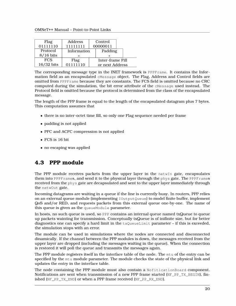
According to RFC1662 the PPP frames contain the following fields:
19
OMNeT++ Manual – Point-to-Point Links
Flag01111110
Address11111111
Control00000011
Protocol8/16 bits
Information∗
Padding∗
FCS16/32 bits
Flag01111110
Inter-frame Fillor next Address
The corresponding message type in the INET framework is PPPFrame. It contains the Infor-mation field as an encapsulated cMessage object. The Flag, Address and Control fields areomitted from PPPFrame because they are constants. The FCS field is omitted because no CRCcomputed during the simulation, the bit error attribute of the cMessage used instead. TheProtocol field is omitted because the protocol is determined from the class of the encapsulatedmessage.
The length of the PPP frame is equal to the length of the encapsulated datagram plus 7 bytes.This computation assumes that
• there is no inter-octet time fill, so only one Flag sequence needed per frame
• padding is not applied
• PFC and ACFC compression is not applied
• FCS is 16 bit
• no escaping was applied
4.3 PPP module
The PPP module receives packets from the upper layer in the netwIn gate, encapsulatesthem into PPPFrames, and send it to the physical layer through the phys gate. The PPPFramesreceived from the phys gate are decapsulated and sent to the upper layer immediately throughthe netwOut gate.
Incoming datagrams are waiting in a queue if the line is currently busy. In routers, PPP relieson an external queue module (implementing IOutputQueue) to model finite buffer, implementQoS and/or RED, and requests packets from this external queue one-by-one. The name ofthis queue is given as the queueModule parameter.
In hosts, no such queue is used, so PPP contains an internal queue named txQueue to queueup packets wainting for transmission. Conceptually txQueue is of inifinite size, but for betterdiagnostics one can specify a hard limit in the txQueueLimit parameter – if this is exceeded,the simulation stops with an error.
The module can be used in simulations where the nodes are connected and disconnecteddinamically. If the channel between the PPP modules is down, the messages received from theupper layer are dropped (including the messages waiting in the queue). When the connectionis restored it will poll the queue and transmits the messages again.
The PPP module registers itself in the interface table of the node. The mtu of the entry can bespecified by the mtu module parameter. The module checks the state of the physical link andupdates the entry in the interface table.
The node containing the PPP module must also contain a NofiticationBoard component.Notifications are sent when transmission of a new PPP frame started (NF_PP_TX_BEGIN), fin-ished (NF_PP_TX_END) or when a PPP frame received (NF_PP_RX_END).
20
OMNeT++ Manual – Point-to-Point Links
The PPP component is the source of the following signals:
• txState state of the link (0=idle,1=busy)
• txPkBytes number of bytes transmitted
• rxPkBytesOk number of bytes received successfully
• droppedPkBytesBitError number of bytes received in erronous frames
• droppedPkBytesIfaceDown number of bytes dropped because the link is down
• rcvdPkBytesFromHL number of bytes received from the the upper layer
• passedUpPkBytes number of bytes sent to the the upper layer
These signals are recorded as statistics (sum, count and vector), so they can be analyzed afterthe simulation.
When the simulation is executed with the graphical user interface the module displays usefulstatistics. If the link is operating, the datarate and number of received, sent and droppedmessages show in the tooltip. When the link is broken, the number of dropped messagesis displayed. The state of the module is indicated by the color of the module icon and theconnection (yellow=transmitting).
4.4 PPPInterface module
The PPPInterface is a compound module implementing the IWiredNic interface. It containsa PPP module and a passive queue for the messages received from the network layer.
The queue type is specified by the queueType parameter. It can be set to NoQueue or to amodule type implementing the IOutputQueue interface. There are implementations with QoSand RED support.
In typical use of the PPP module it is augmented with other nodes that monitor the trafficor simulate package loss and duplication. The PPPInterface module abstract that usage byadding IHook components to the network input and output of the PPP component. Any num-ber of hook can be added by specifying the numOutputHooks and numInputHooks parametersand the types of the outputHook and inputHook components. The hooks are chained in theirnumeric order.
21

OMNeT++ Manual – Point-to-Point Links
22
OMNeT++ Manual – The Ethernet Model
Chapter 5
The Ethernet Model
5.1 Overview
Variations: 10Mb/s ethernet, fast ethernet, Gigabit Ethernet, Fast Gigabit Ethernet, full du-plex
The Ethernet model contains a MAC model (EtherMAC), LLC model (EtherLLC) as well as abus (EtherBus, for modelling coaxial cable) and a hub (EtherHub) model. A switch model(EtherSwitch) is also provided.
• EtherHost is a sample node with an Ethernet NIC;
• EtherSwitch, EtherBus, EtherHub model switching hub, repeating hub and the oldcoxial cable;
• basic compnents of the model: EtherMAC, EtherLLC/EtherEncap module types, MACRe-layUnit (MACRelayUnitNP and MACRelayUnitPP), EtherFrame message type, MACAd-dress class
Sample simulations:
• the MixedLAN model contains hosts, switch, hub and bus
• the LargeNet model contains hundreds of computers, switches and hubs (numbers de-pend on model configuration in largenet.ini) and mixes all kinds of Ethernet technologies
5.1.1 Implemented Standards
The Ethernet model operates according to the following standards:
• Ethernet: IEEE 802.3-1998
• Fast Ethernet: IEEE 802.3u-1995
• Full-Duplex Ethernet with Flow Control: IEEE 802.3x-1997
• Gigabit Ethernet: IEEE 802.3z-1998
23
OMNeT++ Manual – The Ethernet Model
5.2 Physical layer
The nodes of the Ethernet networks are connected by coaxial, twisted pair or fibre cables.There are several cable types specified in the standard.
In the INET framework, the cables are represented by connections. The connections used inEthernet LANs must be derived from DatarateConnection and should have their delay anddatarate parameters set. The delay parameter can be used to model the distance betweenthe nodes. The datarate parameter can have four values:
• 10Mbps classic Ethernet
• 100Mbps Fast Ethernet
• 1Gbps Gigabit Ethernet
• 10Gbps Fast Gigabit Ethernet
5.2.1 EtherBus
The EtherBus component can model a common coaxial cable found in earlier Ethernet LANs.The nodes are attached at specific positions of the cable. If a node sends a packet, it istransmitted in both direction by a given propagation speed.
The gates of the EtherBus represent taps. The positions of the taps are given by the posi-tions parameter as a space separated list of distances in metres. If there are more gates thenpositions given, the last distance is repeated. The bus component send the incoming messagein one direction and a copy of the message to the other direction (except at the ends). Thepropagation delays are computed from the distances of the taps and the propagationSpeedparameter.
Messages are not interpreted by the bus model in any way, thus the bus model is not specificto Ethernet in any way. Messages may represent anything, from the beginning of a frametransmission to end (or abortion) of transmission.
5.2.2 EtherHub
Ethernet hubs are a simple broadcast devices. Messages arriving on a port are regeneratedand broadcast to every other port.
The connections connected to the hub must have the same data rate. Cable lengths shouldbe reflected in the delays of the connections.
Messages are not interpreted by the EtherType hub model in any way, thus the hub modelis not specific to Ethernet. Messages may represent anything, from the beginning of a frametransmission to end (or abortion) of transmission.
The hub module collects the following statistics:
• pkBytes handled packets length (vector)
• messages/sec number of packets per seconds (scalar)
24
OMNeT++ Manual – The Ethernet Model
5.3 MAC layer
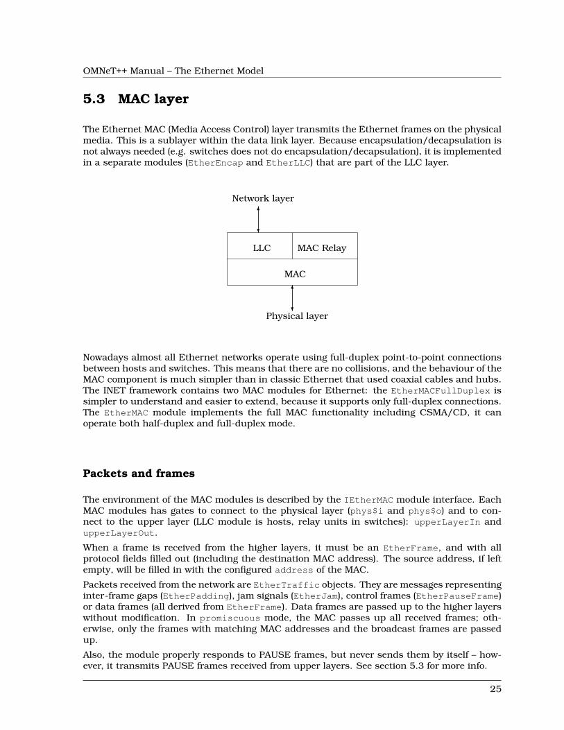
The Ethernet MAC (Media Access Control) layer transmits the Ethernet frames on the physicalmedia. This is a sublayer within the data link layer. Because encapsulation/decapsulation isnot always needed (e.g. switches does not do encapsulation/decapsulation), it is implementedin a separate modules (EtherEncap and EtherLLC) that are part of the LLC layer.
Network layer
6
?
LLC MAC Relay
MAC
6
?Physical layer
Nowadays almost all Ethernet networks operate using full-duplex point-to-point connectionsbetween hosts and switches. This means that there are no collisions, and the behaviour of theMAC component is much simpler than in classic Ethernet that used coaxial cables and hubs.The INET framework contains two MAC modules for Ethernet: the EtherMACFullDuplex issimpler to understand and easier to extend, because it supports only full-duplex connections.The EtherMAC module implements the full MAC functionality including CSMA/CD, it canoperate both half-duplex and full-duplex mode.
Packets and frames
The environment of the MAC modules is described by the IEtherMAC module interface. EachMAC modules has gates to connect to the physical layer (phys$i and phys$o) and to con-nect to the upper layer (LLC module is hosts, relay units in switches): upperLayerIn andupperLayerOut.
When a frame is received from the higher layers, it must be an EtherFrame, and with allprotocol fields filled out (including the destination MAC address). The source address, if leftempty, will be filled in with the configured address of the MAC.
Packets received from the network are EtherTraffic objects. They are messages representinginter-frame gaps (EtherPadding), jam signals (EtherJam), control frames (EtherPauseFrame)or data frames (all derived from EtherFrame). Data frames are passed up to the higher layerswithout modification. In promiscuous mode, the MAC passes up all received frames; oth-erwise, only the frames with matching MAC addresses and the broadcast frames are passedup.
Also, the module properly responds to PAUSE frames, but never sends them by itself – how-ever, it transmits PAUSE frames received from upper layers. See section 5.3 for more info.
25
OMNeT++ Manual – The Ethernet Model
Queueing
When the transmission line is busy, messages received from the upper layer needs to bequeued.
In routers, MAC relies on an external queue module (see OutputQueue), and requests packetsfrom this external queue one-by-one. The name of the external queue must be given as thequeueModule parameer. There are implementations of OutputQueue to model finite buffer,QoS and/or RED.
In hosts, no such queue is used, so MAC contains an internal queue named txQueue to queueup packets waiting for transmission. Conceptually, txQueue is of infinite size, but for betterdiagnostics one can specify a hard limit in the txQueueLimit parameter – if this is exceeded,the simulation stops with an error.
PAUSE handling
The 802.3x standard supports PAUSE frames as a means of flow control. The frame containsa timer value, expressed as a multiple of 512 bit-times, that specifies how long the transmittershould remain quiet. If the receiver becomes uncongested before the transmitter’s pause timerexpires, the receiver may elect to send another PAUSE frame to the transmitter with a timervalue of zero, allowing the transmitter to resume immediately.
EtherMAC will properly respond to PAUSE frames it receives (EtherPauseFrame class), how-ever it will never send a PAUSE frame by itself. (For one thing, it doesn’t have an input bufferthat can overflow.)
EtherMAC, however, transmits PAUSE frames received by higher layers, and EtherLLC can beinstructed by a command to send a PAUSE frame to MAC.
Error handling
If the MAC is not connected to the network ("cable unplugged"), it will start up in "disabled"mode. A disabled MAC simply discards any messages it receives. It is currently not supportedto dynamically connect/disconnect a MAC.
CRC checks are modeled by the bitError flag of the packets. Erronous packets are droppedby the MAC.
Signals and statistics
Both MAC modules emits the following signals:
• txPk after successful data frame transmission, the data frame
• rxPkOk after successful data frame reception, the data frame
• txPausePkUnits after PAUSE frame sent, the pause time
• rxPausePkUnits after PAUSE frame received, the pause time
• rxPkFromHL when a data frame received from higher layer, the data frame
• dropPkNotForUs when a data frame received not addressed to the MAC, the data frame
26
OMNeT++ Manual – The Ethernet Model
• dropPkBitError when a frame received with bit error, the frame
• dropPkIfaceDown when a message received and the MAC is not connected, the droppedmessage
• packetSentToLower before starting to send a packet on phys$o gate, the packet
• packetReceivedFromLower after a packet received on phys$i gate, the packet (excludingPAUSE and JAM messages and dropped data frames)
• packetSentToUpper before sending a packet on upperLayerOut, the packet
• packetReceivedFromUpper after a packet received on upperLayerIn, the packet
Apart from statistics can be generated from the signals, the modules collects the followingscalars:
• simulated time total simulation time
• full duplex boolean value, indicating whether the module operated in full-duplex mode
• frames/sec sent data frames sent (not including PAUSE frames) per second
• frames/sec rcvd data frames received (not including PAUSE frames) per second
• bits/sec sent
• bits/sec rcvd
Note that four of these scalars could be recorded as the count and value of the txPkBytesSig-nal and rxPkBytesSignal signals resp.
Visual effects
In the graphical environment, some animation effects help to follow the simulation. The colorof the transmission channel is changed to yellow during transmission, and turns to red whencollision detected. The icon of disconnected MAC modules are grayed out.
The icon of the Ethernet NICs are also colored according to the state of MAC module: yellowif transmitting, blue if receiving, red if collision detected, white in backoff and gray in pausedstate.
5.3.1 EtherMACFullDuplex
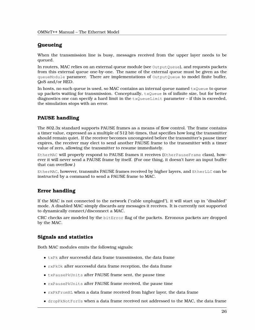
From the two MAC implementation EtherMACFullDuplex is the simpler one, it operates onlyin full-duplex mode (its duplexEnabled parameter fixed to true in its NED definition). Thismodule does not need to implement CSMA/CD, so there is no collision detection, retransmis-sion with exponential backoff, carrier extension and frame bursting. Flow control works asdescribed in section 5.3.
In the EtherMACFullDuplex module, packets arrived at the phys$i gate are handled whentheir last bit received.
Outgoing packets are transmitted according to the following state diagram:
27
OMNeT++ Manual – The Ethernet Model
TX_IDLE
PAUSE
PAUSE frame rcvd
WAIT_IFG
frame rcvd from upper layer
pause time elapsed
PAUSE frame rcvd
pause time elapsedqueued msgs
TRANSMITTING
96 bittime elapsed
tx finishedno queued msgs
tx finishedPAUSE frame rcvd
tx finishedqueued msgs, no PAUSE
The EtherMACFullDuplex module records two scalars in addition to the ones mentionedearlier:
• rx channel idle (%): reception channel idle time as a percentage of the total simula-tion time
• rx channel utilization (%): total reception time as a percentage of the total simu-lation time
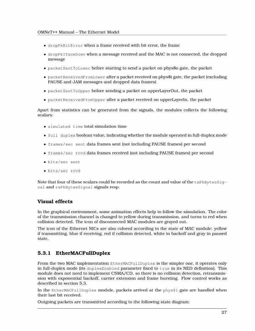
5.3.2 EtherMAC
Ethernet MAC layer implementing CSMA/CD. It supports both half-duplex and full-duplexoperations; in full-duplex mode it behaves as EtherMACFullDuplex. In half-duplex modeit detects collisions, sends jam messages and retransmit frames upon collisions using theexponential backoff algorithm. In Gigabit Ethernet networks it supports carrier extensionand frame bursting. Carrier extension can be turned off by setting the carrierExtensionparameter to false.
Unlike EtherMACFullDuplex, this MAC module processes the incoming packets when theirfirst bit is received. The end of the reception is calculated by the MAC and detected byscheduling a self message.
When frames collide the transmission is aborted – in this case the transmitting station trans-mits a jam signal. Jam signals are represented by a EtherJam message. The jam messagecontains the tree identifier of the frame whose transmission is aborted. When the EtherMACreceives a jam signal, it knows that the corresponding transmission ended in jamming andhave been aborted. Thus when it receives as many jams as collided frames, it can be sure thatthe channel is free again. (Receiving a jam message marks the beginning of the jam signal, soactually has to wait for the duration of the jamming.)
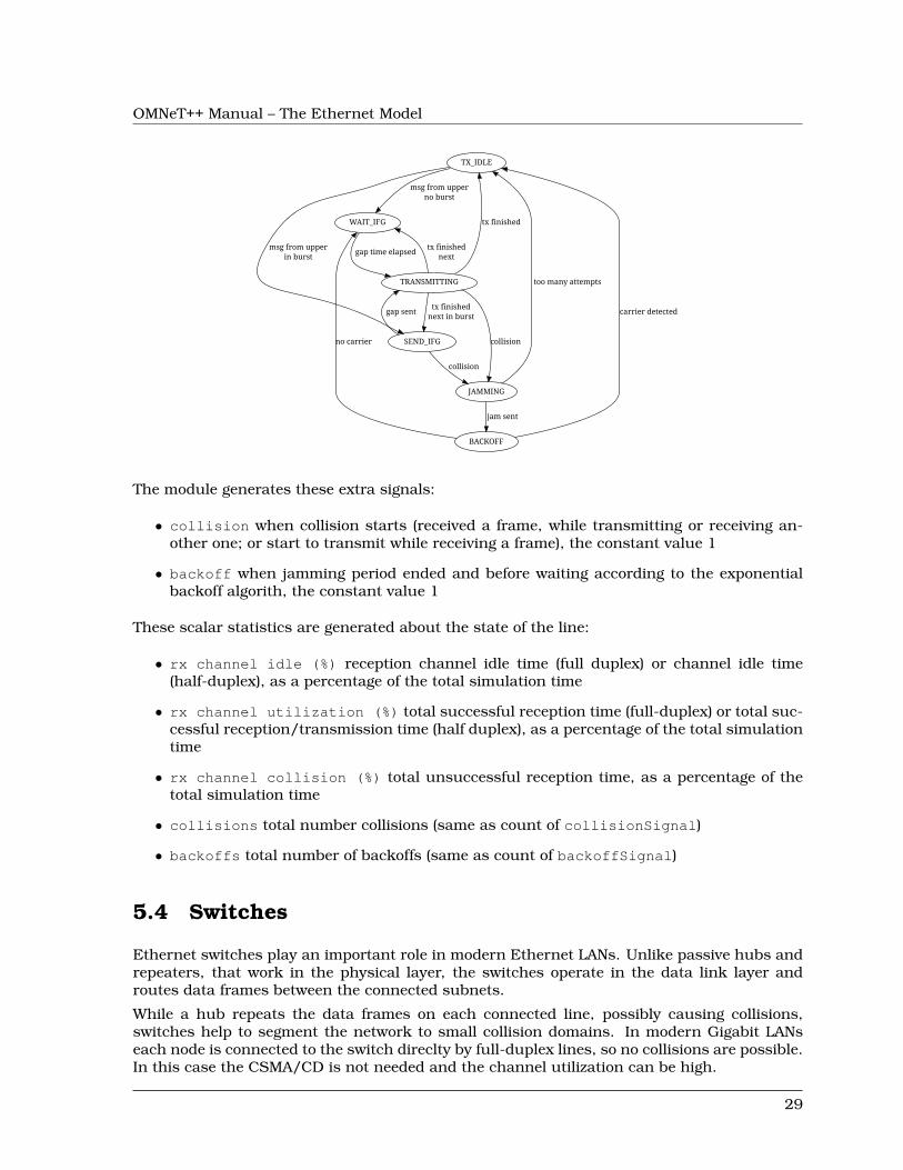
The operation of the MAC module can be schematized by the following state chart:
28
OMNeT++ Manual – The Ethernet Model
TX_IDLE
WAIT_IFG
msg from upperno burst
SEND_IFG
msg from upperin burst
TRANSMITTING
gap time elapsed
gap sent
JAMMING
collision
tx finished
tx finishednext
tx finishednext in burst
collision
too many attempts
BACKOFF
jam sent
carrier detected
no carrier
The module generates these extra signals:
• collision when collision starts (received a frame, while transmitting or receiving an-other one; or start to transmit while receiving a frame), the constant value 1
• backoff when jamming period ended and before waiting according to the exponentialbackoff algorith, the constant value 1
These scalar statistics are generated about the state of the line:
• rx channel idle (%) reception channel idle time (full duplex) or channel idle time(half-duplex), as a percentage of the total simulation time
• rx channel utilization (%) total successful reception time (full-duplex) or total suc-cessful reception/transmission time (half duplex), as a percentage of the total simulationtime
• rx channel collision (%) total unsuccessful reception time, as a percentage of thetotal simulation time
• collisions total number collisions (same as count of collisionSignal)
• backoffs total number of backoffs (same as count of backoffSignal)
5.4 Switches
Ethernet switches play an important role in modern Ethernet LANs. Unlike passive hubs andrepeaters, that work in the physical layer, the switches operate in the data link layer androutes data frames between the connected subnets.
While a hub repeats the data frames on each connected line, possibly causing collisions,switches help to segment the network to small collision domains. In modern Gigabit LANseach node is connected to the switch direclty by full-duplex lines, so no collisions are possible.In this case the CSMA/CD is not needed and the channel utilization can be high.
29
OMNeT++ Manual – The Ethernet Model
5.4.1 MAC relay units
INET framework ethernet switches are built from IMACRelayUnit components. Each relayunit has N input and output gates for sending/receiving Ethernet frames. They should beconnected to IEtherMAC modules.
Internally the relay unit holds a table for the destination address -> output port mapping.When it receives a data frame it updates the table with the source address->input port. Thetable can also be pre-loaded from a text file while initializing the relay unit. The file namegiven as the addressTableFile parameter. Each line of the file contains a hexadecimal MACaddress and a decimal port number separated by tabs. Comment lines beginning with ’#’ arealso allowed:
01 ff ff ff ff 000-ff-ff-ee-d1 10A:AA:BC:DE:FF 2
The size of the lookup table is restricted by the addressTableSize parameter. When the tableis full, the oldest address is deleted. Entries are also deleted if their age exceeds the durationgiven as the agingTime parameter.
If the destination address is not found in the table, the frame is broadcasted. The frame is notsent to the same subnet it was received from, because the target already received the originalframe. The only exception if the frame arrived through a radio channel, in this case thetarget can be out of range. The port range 0..numWirelessPorts-1 are reserved for wirelessconnections.
The IMACRelayUnit module is not a concrete implementation, it just defines gates and pa-rameters an IMACRelayUnit should have. Concrete inplementations add capacity and per-formance aspects to the model (number of frames processed per second, amount of memoryavailable in the switch, etc.) C++ implementations can subclass from the class MACRelayU-nitBase.
There are two versions of IMACRelayUnit:
MACRelayUnitNP models one or more CPUs with shared memory, working from a singleshared queue.
MACRelayUnitPP models one CPU assigned to each incoming port, working with shared mem-ory but separate queues.
In both models input messages are queued. CPUs poll messages from the queue and pro-cess them in processingTime. If the memory usage exceeds bufferSize, the frame will bedropped.
A simple scheme for sending PAUSE frames is built in (although users will probably changeit). When the buffer level goes above a high watermark, PAUSE frames are sent on all ports.The watermark and the pause time is configurable; use zero values to disable the PAUSEfeature.
The relay units collects the following statistics:
usedBufferBytes memory usage as function of time
processedBytes count and length of processed frames
droppedBytes count and length of frames dropped caused by out of memory
30
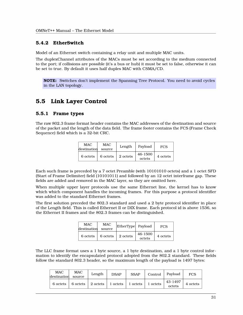
OMNeT++ Manual – The Ethernet Model
5.4.2 EtherSwitch
Model of an Ethernet switch containing a relay unit and multiple MAC units.
The duplexChannel attributes of the MACs must be set according to the medium connectedto the port; if collisions are possible (it’s a bus or hub) it must be set to false, otherwise it canbe set to true. By default it uses half duples MAC with CSMA/CD.
NOTE: Switches don’t implement the Spanning Tree Protocol. You need to avoid cyclesin the LAN topology.
5.5 Link Layer Control
5.5.1 Frame types
The raw 802.3 frame format header contains the MAC addresses of the destination and sourceof the packet and the length of the data field. The frame footer contains the FCS (Frame CheckSequence) field which is a 32-bit CRC.
MACdestination
MACsource
Length Payload FCS
6 octets 6 octets 2 octets46-1500octets
4 octets
Each such frame is preceded by a 7 octet Preamble (with 10101010 octets) and a 1 octet SFD(Start of Frame Delimiter) field (10101011) and followed by an 12 octet interframe gap. Thesefields are added and removed in the MAC layer, so they are omitted here.
When multiple upper layer protocols use the same Ethernet line, the kernel has to knowwhich which component handles the incoming frames. For this purpose a protocol identifierwas added to the standard Ethernet frames.
The first solution preceded the 802.3 standard and used a 2 byte protocol identifier in placeof the Length field. This is called Ethernet II or DIX frame. Each protocol id is above 1536, sothe Ethernet II frames and the 802.3 frames can be distinguished.
MACdestination
MACsource
EtherType Payload FCS
6 octets 6 octets 2 octets46-1500octets
4 octets
The LLC frame format uses a 1 byte source, a 1 byte destination, and a 1 byte control infor-mation to identify the encapsulated protocol adopted from the 802.2 standard. These fieldsfollow the standard 802.3 header, so the maximum length of the payload is 1497 bytes:
MACdestination
MACsource
Length DSAP SSAP Control Payload FCS
6 octets 6 octets 2 octets 1 octets 1 octets 1 octets43-1497octets
4 octets
31
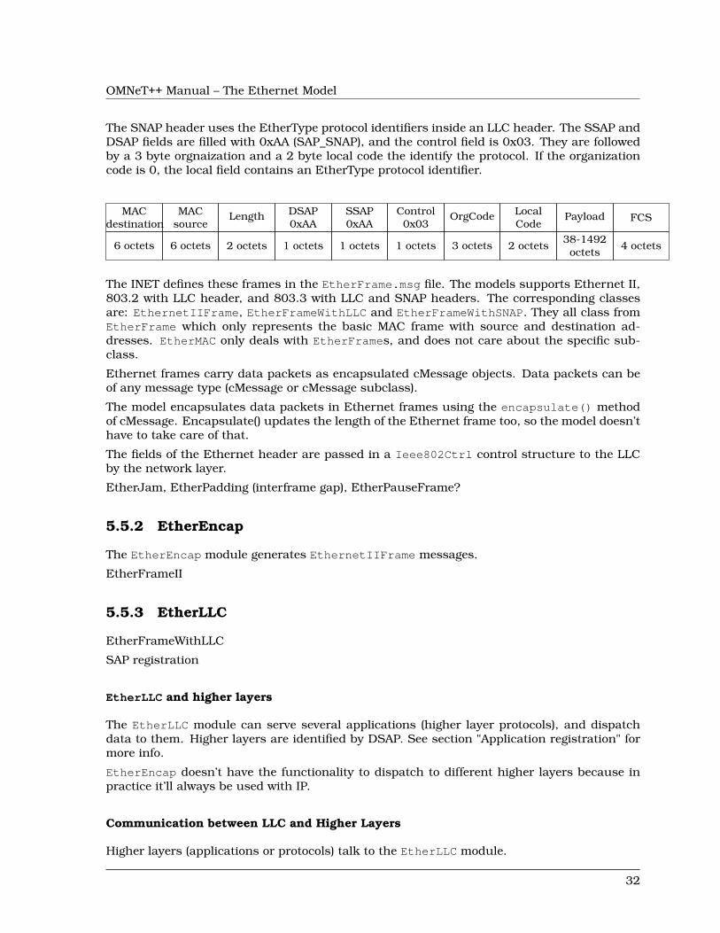
OMNeT++ Manual – The Ethernet Model
The SNAP header uses the EtherType protocol identifiers inside an LLC header. The SSAP andDSAP fields are filled with 0xAA (SAP_SNAP), and the control field is 0x03. They are followedby a 3 byte orgnaization and a 2 byte local code the identify the protocol. If the organizationcode is 0, the local field contains an EtherType protocol identifier.
MACdestination
MACsource
Length DSAP0xAA
SSAP0xAA
Control0x03
OrgCode LocalCode
Payload FCS
6 octets 6 octets 2 octets 1 octets 1 octets 1 octets 3 octets 2 octets38-1492octets
4 octets
The INET defines these frames in the EtherFrame.msg file. The models supports Ethernet II,803.2 with LLC header, and 803.3 with LLC and SNAP headers. The corresponding classesare: EthernetIIFrame, EtherFrameWithLLC and EtherFrameWithSNAP. They all class fromEtherFrame which only represents the basic MAC frame with source and destination ad-dresses. EtherMAC only deals with EtherFrames, and does not care about the specific sub-class.
Ethernet frames carry data packets as encapsulated cMessage objects. Data packets can beof any message type (cMessage or cMessage subclass).
The model encapsulates data packets in Ethernet frames using the encapsulate() methodof cMessage. Encapsulate() updates the length of the Ethernet frame too, so the model doesn’thave to take care of that.
The fields of the Ethernet header are passed in a Ieee802Ctrl control structure to the LLCby the network layer.
EtherJam, EtherPadding (interframe gap), EtherPauseFrame?
5.5.2 EtherEncap
The EtherEncap module generates EthernetIIFrame messages.
EtherFrameII
5.5.3 EtherLLC
EtherFrameWithLLC
SAP registration
EtherLLC and higher layers
The EtherLLC module can serve several applications (higher layer protocols), and dispatchdata to them. Higher layers are identified by DSAP. See section "Application registration" formore info.
EtherEncap doesn’t have the functionality to dispatch to different higher layers because inpractice it’ll always be used with IP.
Communication between LLC and Higher Layers
Higher layers (applications or protocols) talk to the EtherLLC module.
32
OMNeT++ Manual – The Ethernet Model
When a higher layer wants to send a packet via Ethernet, it just passes the datapacket (a cMessage or any subclass) to EtherLLC. The message kind has to be set toIEEE802CTRL_DATA.
In general, if EtherLLC receives a packet from the higher layers, it interprets the mes-sage kind as a command. The commands include IEEE802CTRL_DATA (send a frame),IEEE802CTRL_REGISTER_DSAP (register highher layer) IEEE802CTRL_DEREGISTER_DSAP(deregister higher layer) and IEEE802CTRL_SENDPAUSE (send PAUSE frame) – see EtherLLCfor a more complete list.
The arguments to the command are NOT inside the data packet but in a "control info" datastructure of class Ieee802Ctrl, attached to the packet. See controlInfo() method of cMessage(OMNeT++ 3.0).
For example, to send a packet to a given MAC address and protocol identifier, the applicationsets the data packet’s message kind to ETH_DATA ("please send this data packet" command),fills in the Ieee802Ctrl structure with the destination MAC address and the protocol identi-fier, adds the control info to the message, then sends the packet to EtherLLC.
When the command doesn’t involve a data packet (e.g. IEEE802CTRL_(DE)REGISTER_DSAP,IEEE802CTRL_SENDPAUSE), a dummy packet (empty cMessage) is used.
Rationale
The alternative of the above communications would be:
• adding the parameters such as destination address into the data packet. This would bea poor solution since it would make the higher layers specific to the Ethernet model.
• encapsulating a data packet into an interface packet which contains the destinationaddress and other parameters. The disadvantages of this approach is the overheadassociated with creating and destroying the interface packets.
Using a control structure is more efficient than the interface packet approach, because thecontrol structure can be created once inside the higher layer and be reused for every packet.
It may also appear to be more intuitive in Tkenv because one can observe data packets trav-elling between the higher layer and Ethernet modules – as opposed to "interface" packets.
EtherLLC: SAP Registration
The Ethernet model supports multiple applications or higher layer protocols.
So that data arriving from the network can be dispatched to the correct applications (higherlayer protocols), applications have to register themselves in EtherLLC. The registration is donewith the IEEE802CTRL_REGISTER_DSAP command (see section "Communication betweenLLC and higher layers") which associates a SAP with the LLC port. Different applications haveto connect to different ports of EtherLLC.
The ETHERCTRL_REGISTER_DSAP/IEEE802CTRL_DEREGISTER_DSAP commands use onlythe dsap field in the Ieee802Ctrl structure.
33
OMNeT++ Manual – The Ethernet Model
5.5.4 EthernetInterface module
The EthernetInterface compound module implements the IWiredNic interface. Comple-ments EtherMAC and EtherEncap with an output queue for QoS and RED support. It alsohas configurable input/output filters as IHook components similarly to the PPPInterfacemodule.
5.6 Ethernet applications
The inet.applications.ethernet package contains modules for a simple client-server ap-plication. The EtherAppCli is a simple traffic generator that peridically sends EtherAppReqmessages whose length can be configured. destAddress, startTime,waitType, reqLength, re-spLength
The server component of the model (EtherAppSrv) responds with a EtherAppResp message ofthe requested length. If the response does not fit into one ethernet frame, the client receivesthe data in multiple chunks.
Both applications have a registerSAP boolean parameter. This parameter should be set totrue if the application is connected to the EtherLLC module which requires registration ofthe SAP before sending frames.
Both applications collects the following statistics: sentPkBytes, rcvdPkBytes, endToEndDelay.
The client and server application works with any model that accepts Ieee802Ctrl control infoon the packets (e.g. the 802.11 model). The applications should be connected directly to theEtherLLC or an EthernetInterface NIC module.
The model also contains a host component that groups the applications and the LLC andMAC components together (EtherHost). This node does not contain higher layer protocols,it generates Ethernet traffic directly. By default it is configured to use half duplex MAC(CSMA/CD).
5.7 Ethernet networks
5.7.1 LargeNet model
The LargeNet model demonstrates how one can put together models of large LANs with littleeffort, making use of MAC auto-configuration.
LargeNet models a large Ethernet campus backbone. As configured in the default om-netpp.ini, it contains altogether about 8000 computers and 900 switches and hubs. Thisresults in about 165MB process size on my (32-bit) linux box when I run the simulation. Themodel mixes all kinds of Ethernet technology: Gigabit Ethernet, 100Mb full duplex, 100Mbhalf duplex, 10Mb UTP, 10Mb bus ("thin Ethernet"), switched hubs, repeating hubs.
The topology is in LargeNet.ned, and it looks like this: there’s chain of n=15 large "backbone"switches (switchBB[]) as well as four more large switches (switchA, switchB, switchC, switchD)connected to somewhere the middle of the backbone (switchBB[4]). These 15+4 switches makeup the backbone; the n=15 number is configurable in omnetpp.ini.
Then there’re several smaller LANs hanging off each backbone switch. There’re three typesof LANs: small, medium and large (represented by compound module types SmallLAN, Medi-umLAN, LargeLAN). A small LAN consists of a few computers on a hub (100Mb half duplex);
34
OMNeT++ Manual – The Ethernet Model
a medium LAN consists of a smaller switch with a hub on one of its port (and computers onboth); the large one also has a switch and a hub, plus an Ethernet bus hanging of one port ofthe hub (there’s still hubs around with one BNC connector besides the UTP ones). By defaultthere’re 5..15 LANs of each type hanging off each backbone switch. (These numbers are alsoomnetpp.ini parameters like the length of the backbone.)
The application model which generates load on the simulated LAN is simple yet powerful. Itcan be used as a rough model for any request-response based protocol such as SMB/CIFS(the Windows file sharing protocol), HTTP, or a database client-server protocol.
Every computer runs a client application (EtherAppCli) which connects to one of the servers.There’s one server attached to switches A, B, C and D each: serverA, serverB, serverC andserverD – server selection is configured in omnetpp.ini). The servers run EtherAppSrv.Clients periodically send a request to the server, and the request packet contains how manybytes the client wants the server to send back (this can mean one or more Ethernet frames,depending on the byte count). Currently the request and reply lengths are configured inomnetpp.ini as intuniform(50,1400) and truncnormal(5000,5000).
The volume of the traffic can most easily be controlled with the time period between sendingrequests; this is currently set in omnetpp.ini to exponential(0.50) (that is, average 2 requestsper second). This already causes frames to be dropped in some of the backbone switches, sothe network is a bit overloaded with the current settings.
The model generates extensive statistics. All MACs (and most other modules too) write statis-tics into omnetpp.sca at the end of the simulation: number of frames sent, received, dropped,etc. These are only basic statistics, however it still makes the scalar file to be several tenmegabytes in size. You can use the analysis tools provided with OMNeT++ to visualized thedata in this file. (If the file size is too big, writing statistics can be disabled, by putting**.record-scalar=false in the ini file.) The model can also record output vectors, but this iscurrently disabled in omnetpp.ini because the generated file can easily reach gigabyte sizes.
35

OMNeT++ Manual – The Ethernet Model
36
OMNeT++ Manual – The Radio Infrastructure
Chapter 6
The Radio Infrastructure
6.1 Overview
Blah blah blah
37

OMNeT++ Manual – The Radio Infrastructure
38
OMNeT++ Manual – The 802.11 Model
Chapter 7
The 802.11 Model
7.1 Overview
This chapter provides an overview of the IEEE 802.11 model for the INET Framework.
An IEEE 802.11 interface (NIC) comes in several flavours, differring in their role (ad-hocstation, infrastructure mode station, or access point) and their level of detail:
1. Ieee80211Nic: a generic (configurable) NIC
2. Ieee80211NicAdhoc: for ad-hoc mode
3. Ieee80211NicAP, Ieee80211NicAPSimplified: for use in an access point
4. Ieee80211NicSTA, Ieee80211NicSTASimplified: for use in an infrastructure-modestation
NICs consist of four layers, which are the following (in top-down order):
1. agent
2. management
3. MAC
4. physical layer (radio)
The physical layer modules (Ieee80211Radio; with some limitations, SnrEval80211, De-cider80211 can also be used) deal with modelling transmission and reception of frames.They model the characteristics of the radio channel, and determine if a frame was receivedcorrectly (that is, it did not suffer bit errors due to low signal power or interference in theradio channel). Frames received correctly are passed up to the MAC. The implementation ofthese modules is based on the Mobility Framework.
The MAC layer (Ieee80211Mac) performs transmission of frames according to the CSMA/CAprotocol. It receives data and management frames from the upper layers, and transmits them.
The management layer performs encapsulation and decapsulation of data packets for theMAC, and exchanges management frames via the MAC with its peer management entities
39
OMNeT++ Manual – The 802.11 Model
in other STAs and APs. Beacon, Probe Request/Response, Authentication, Association Re-quest/Response etc frames are generated and interpreted by management entities, and trans-mitted/received via the MAC layer. During scanning, it is the management entity that periodi-cally switches channels, and collects information from received beacons and probe responses.
The management layer has several implementations which differ in their role (STA/AP/ad-hoc)and level of detail: Ieee80211MgmtAdhoc, Ieee80211MgmtAP, Ieee80211MgmtAPSimplified,Ieee80211MgmtSTA, Ieee80211MgmtSTASimplified. The ..Simplified ones differ from theothers in that they do not model the scan-authenticate-associate process, so they cannot beused in experiments involving handover.
The agent is what instructs the management layer to perform scanning, authentication andassociation. The management layer itself just carries out these commands by performingthe scanning, authentication and association procedures, and reports back the results to theagent.
The agent layer is currenly only present in the Ieee80211NicSTA NIC module, as anIeee80211AgentSTA module. The managament entities in other NIC variants do not haveas much freedom as to need an agent to control them.
By modifying or replacing the agent, one can alter the dynamic behaviour of STAs in thenetwork, for example implement different handover strategies.
7.1.1 Limitations
See the documentation of Ieee80211Mac for features unsupported by this model.
TODO further details about the implementation: what is modelled and what is not (beacons,auth, ...), communication between modules, frame formats, ...
40
OMNeT++ Manual – Node Mobility
Chapter 8
Node Mobility
8.1 Overview
In order to accurately evaluate a protocol for an ad-hoc network, it is important to use a re-alistic model for the motion of mobile hosts. Signal strengths, radio interference and channeloccupancy depends on the distances between nodes. The choice of the mobility model cansignificantly influence the results of a simulation (e.g. data packet delivery ratio, end-to-enddelay, average hop count) as shown in [CBD02].
There are two methods for incorporating mobility into simulations: using traces and syntheticmodels. Traces contains recorded motion of the mobile hosts, as observed in real life system.Synthetic models use mathematical models for describing the behaviour of the mobile hosts.
There are mobility models that represent mobile nodes whose movements are independent ofeach other (entity models) and mobility models that represent mobile nodes whose movementsare dependent on each other (group models). Some of the most frequently used entity modelsare the Random Walk Mobility Model, Random Waypoint Mobility Model, Random DirectionMobility Model, Gauss-Markov Mobility Model, City Section Mobility Model. The group modelsinclude the Column Mobility Model, Nomadic Community Mobility Model, Pursue MobilityModel, Reference Point Group Mobility Model.
The INET framework has components for the following trace files:
• Bonn Motion native file format of the BonnMotion scenario generation tool.
• Ns2 trace file generated by the CMU’s scenario generator that used in Ns2.
• ANSim XML trace file of the ANSim (Ad-Hoc Network Simulation) tool.
It is easy to integrate new entity mobility models into the INET framework, but group mobilityis not supported yet. Therefore all the models shipped with INET are implementations ofentitiy models:
• Deterministic Motions for fixed position nodes and nodes moving on a linear, circular,rectangular paths.
• Random Waypoint model includes pause times between changes in destination andspeed.
41
OMNeT++ Manual – Node Mobility
• Gauss-Markov model uses one tuning parameter to vary the degree of randomness inmobility pattern.
• Mass Mobility models a mass point with inertia and momentum.
• Chiang Mobility uses a probabilistic transition matrix to change the state of motion ofthe node.
8.2 Mobility in INET
In INET mobile nodes have to contain a module implementing the IMobility marker inter-face. This module stores the current coordinates of the node and is responsible for updatingthe position periodically and emitting the mobilityStateChanged signal when the positionchanged.
The p[0] and p[1] fields of the display string of the node is also updated, so if the simulationrun is animated, the node is actually moving on the screen. The current position of the nodecan be obtained from the display string.
The radio simulations has a ChannelControl module that takes case of establishing commu-nication channels between nodes that are within communication distance and tearing downthe connections when they move out of range. The ChannelControl module uses to mobili-tyStateChanged signal to determine when the connection status needs to be updated.
There are two possibilities to implement a new mobility model. The simpler but limited one isto use TurtleMobility as the mobility component and to write a script similar to the turtlegraphics of LOGO. The second is to implement a simple module in C++. In this case theC++ class of the mobility module should be derived from IMobility and its NED type shouldimplement the IMobility interface.
8.2.1 MobilityBase class
The abstract MobilityBase class is the base of the mobility modules defined in the INETframework. This class allows to define a cubic volume that the node can not leave. Thevolume is configured by setting the constraintAreaX, constraintAreaY, constraintAreaZ,constraintAreaWidth, constraintAreaHeight and constraintAreaDepth parameters.
When the module is initialized it sets the initial position of the node by calling the initial-izePosition() method. The default implementation of this method sets the position from thedisplay string if the initFromDisplayString parameter is true. Otherwise the position canbe given as the initialX, initialY and initialZ parameters. If neither of these parametersare given, a random initial position is choosen within the contraint area.
The module is responsible for periodically updating the position. For this purpose it shouldsend timer messages to itself. These messages are processed in the handleSelfMessagemethod. In derived classes, handleSelfMessage should compute the new position and up-date the display string and publish the new position by calling the positionUpdated method.
When the node reaches the boundary of the constraint area, the mobility component has toprevent the node to exit. It can call the handleIfOutside method, that offers the followingpolicies:
• reflect of the wall
• reappear at the opposite edge (torus area)
42

OMNeT++ Manual – Node Mobility
• placed at a randomly chosen position of the area
• stop the simulation with an error
8.2.2 MovingMobilityBase
The abstract MovingMobilityBase class can be used to model mobilities when the nodemoves on a continous trajectory and updates its position periodically. Subclasses only needto implement the move method that is responsible to update the current position and speedof the node.
The abstract move method is called autmotically in every updateInterval steps. The methodis also called when a client requested the current position or speed or when the move methodrequested an update at a future moment by setting the nextChange field. This can be usedwhen the state of the motion changes at a specific time that is not a multiple of updateIn-terval. The method can set the stationary field to true to indicate that the node reachedits final position and no more position update is needed.
8.2.3 LineSegmentsMobilityBase
The path of a mobile node often consist of linear movements of constant speed. The nodemoves with some speed for some time, then with another speed for another duration and soon. If a mobility model fits this description, it might be suitable to derive the implementingC++ class from LineSegmentsMobilityBase.
The module first choose a target position and a target time by calling the setTargetPositionmethod. If the target position differs from the current position, it starts to move toward thetarget and updates the position in the configured updateInterval intervals. When the targetposition reached, it chooses a new target.
8.3 Implemented models
8.3.1 Deterministic movements
StationaryMobility This mobility module does nothing; it can be used for stationary nodes.
StaticGridMobility Places all nodes in a rectangular grid.
LinearMobility This is a linear mobility model with speed, angle and acceleration parameters.Angle only changes when the mobile node hits a wall: then it reflects off the wall at thesame angle.
z coordinate is constant movement is always parallel with X-Y plane
CircleMobility Moves the node around a circle parallel to the X-Y plane with constant speed.The node bounces from the bounds of the constraint area. The circle is given by the cx,cy and r parameters, The initial position determined by the startAngle parameter. Theposition of the node is refreshed in updateInterval steps.
RectangleMobility Moves the node around the constraint area. configuration: speed, start-Pos, updateInterval
43
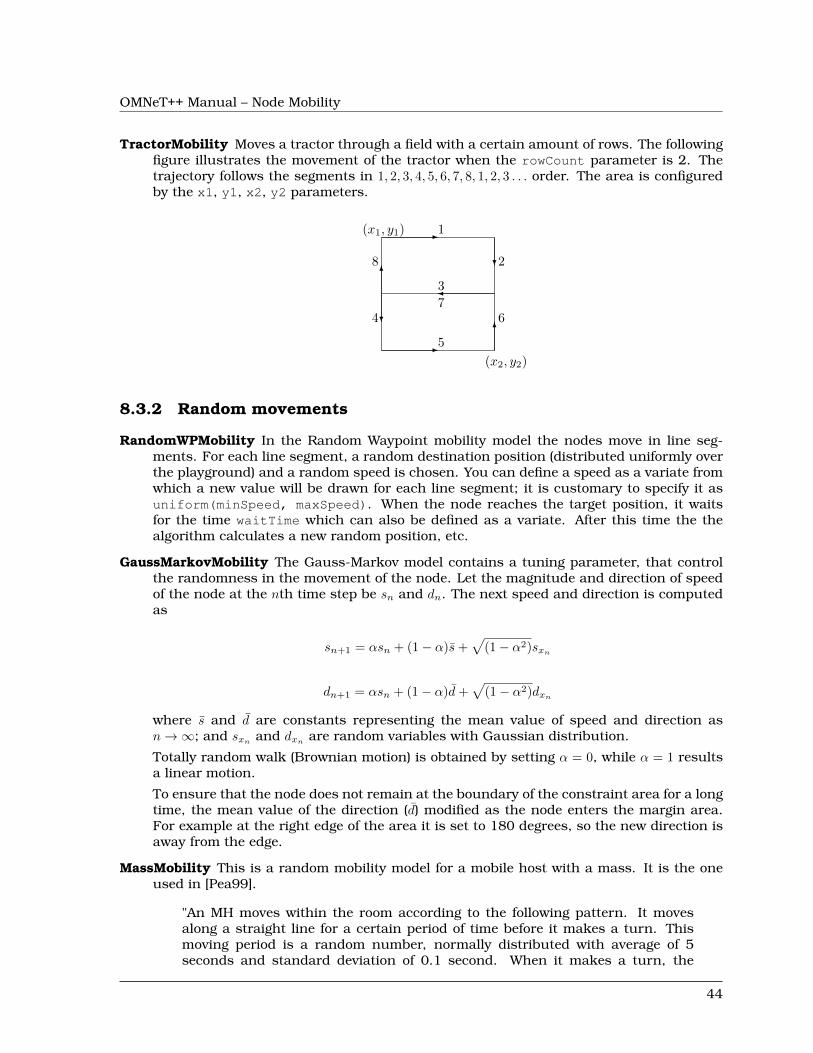
OMNeT++ Manual – Node Mobility
TractorMobility Moves a tractor through a field with a certain amount of rows. The followingfigure illustrates the movement of the tractor when the rowCount parameter is 2. Thetrajectory follows the segments in 1, 2, 3, 4, 5, 6, 7, 8, 1, 2, 3 . . . order. The area is configuredby the x1, y1, x2, y2 parameters.
1-
2?
3�
4?
5-
66
7
86
(x1, y1)
(x2, y2)
8.3.2 Random movements
RandomWPMobility In the Random Waypoint mobility model the nodes move in line seg-ments. For each line segment, a random destination position (distributed uniformly overthe playground) and a random speed is chosen. You can define a speed as a variate fromwhich a new value will be drawn for each line segment; it is customary to specify it asuniform(minSpeed, maxSpeed). When the node reaches the target position, it waitsfor the time waitTime which can also be defined as a variate. After this time the thealgorithm calculates a new random position, etc.
GaussMarkovMobility The Gauss-Markov model contains a tuning parameter, that controlthe randomness in the movement of the node. Let the magnitude and direction of speedof the node at the nth time step be sn and dn. The next speed and direction is computedas
sn+1 = αsn + (1− α)s̄+√
(1− α2)sxn
dn+1 = αsn + (1− α)d̄+√
(1− α2)dxn
where s̄ and d̄ are constants representing the mean value of speed and direction asn→∞; and sxn
and dxnare random variables with Gaussian distribution.
Totally random walk (Brownian motion) is obtained by setting α = 0, while α = 1 resultsa linear motion.
To ensure that the node does not remain at the boundary of the constraint area for a longtime, the mean value of the direction (d̄) modified as the node enters the margin area.For example at the right edge of the area it is set to 180 degrees, so the new direction isaway from the edge.
MassMobility This is a random mobility model for a mobile host with a mass. It is the oneused in [Pea99].
"An MH moves within the room according to the following pattern. It movesalong a straight line for a certain period of time before it makes a turn. Thismoving period is a random number, normally distributed with average of 5seconds and standard deviation of 0.1 second. When it makes a turn, the
44

OMNeT++ Manual – Node Mobility
new direction (angle) in which it will move is a normally distributed randomnumber with average equal to the previous direction and standard deviation of30 degrees. Its speed is also a normally distributed random number, with acontrolled average, ranging from 0.1 to 0.45 (unit/sec), and standard deviationof 0.01 (unit/sec). A new such random number is picked as its speed when itmakes a turn. This pattern of mobility is intended to model node movementduring which the nodes have momentum, and thus do not start, stop, or turnabruptly. When it hits a wall, it reflects off the wall at the same angle; in oursimulated world, there is little other choice."
This implementation can be parameterized a bit more, via the changeInterval,changeAngleBy and changeSpeedBy parameters. The parameters described above cor-respond to the following settings:
changeInterval = normal(5, 0.1)changeAngleBy = normal(0, 30)speed = normal(avgSpeed, 0.01)
ChiangMobility Chiang’s random walk movement model ([Chi98]).
In this model, the state of the mobile node in each direction (x and y) can be:
• 0: the node stays in its current position
• 1: the node moves forward
• 2: the node moves backward
The (i, j) element of the state transition matrix determines the probability that the statechanges from i to j:
0 0.5 0.50.3 0.7 00.3 0 0.7
The ChiangMobility module supports the following parameters:
• updateInterval position update interval
• stateTransitionInterval state update interval
• speed: the speed of the node
ConstSpeedMobility ConstSpeedMobility does not use one of the standard mobility ap-proaches. The user can define a velocity for each Host and an update interval. If thevelocity is greater than zero (i.e. the Host is not stationary) the ConstSpeedMobilitymodule calculates a random target position for the Host. Depending to the update in-terval and the velocity it calculates the number of steps to reach the destination and thestep-size. Every update interval ConstSpeedMobility calculates the new position on itsway to the target position and updates the display. Once the target position is reachedConstSpeedMobility calculates a new target position.
This component has been taken over from Mobility Framework 1.0a5.
45
OMNeT++ Manual – Node Mobility
8.3.3 Replaying trace files
BonnMotionMobility Uses the native file format of BonnMotion.
The file is a plain text file, where every line describes the motion of one host. A lineconsists of one or more (t, x, y) triplets of real numbers, like:
t1 x1 y1 t2 x2 y2 t3 x3 y3 t4 x4 y4 ...
The meaning is that the given node gets to (xk, yk) at tk. There’s no separate notation forwait, so x and y coordinates will be repeated there.
Ns2Mobility Nodes are moving according to the trace files used in NS2. The trace file hasthis format:
# ’#’ starts a comment, ends at the end of line$node_(<id>) set X_ <x> # sets x coordinate of the node identified by <id>$node_(<id>) set Y_ <y> # sets y coordinate of the node identified by <id>$node_(<id>) set Z_ <z> # sets z coordinate (ignored)$ns at $time "$node_(<id>) setdest <x> <y> <speed>" # at $time start movingtowards <x>,<y> with <speed>
The Ns2MotionMobility module has the following parameters:
• traceFile the Ns2 trace file
• nodeId node identifier in the trace file; -1 gets substituted by parent module’s index
• scrollX,scrollY user specified translation of the coordinates
ANSimMobility reads trace files of the ANSim Tool.
The nodes are moving along linear segments described by an XML trace file conformingto this DTD:
<!ELEMENT mobility (position_change*)><!ELEMENT position_change (node_id, start_time, end_time, destination)><!ELEMENT node_id (#PCDATA)><!ELEMENT start_time (#PCDATA)><!ELEMENT end_time (#PCDATA)><!ELEMENT destination (xpos, ypos)><!ELEMENT xpos (#PCDATA)><!ELEMENT ypos (#PCDATA)>
Parameters of the module:
• ansimTrace the trace file
• nodeId the node_id of this node, -1 gets substituted to parent module’s index
NOTE: The ANSimMobility module process only the position_change elements and itignores the start_time attribute. It starts the move on the next segment immediately.
46
OMNeT++ Manual – Node Mobility
8.4 Mobility scripts
The TurtleMobility module can be parametrized by a script file containing LOGO-stylemovement commands in XML format.
The module has these parameters:
• updateInterval time interval to update the hosts position
• constraintAreaX, constraintAreaY, constraintAreaWidth, constraintArea-Height: constraint area that the node can not leave
• turtleScript XML file describing the movements
The content of the XML file should conform to the following DTD (can be found as TurtleMo-bility.dtd in the source tree):
<!ELEMENT movements (movement)*>
<!ELEMENT movement (repeat|set|forward|turn|wait|moveto|moveby)*><!ATTLIST movement id NMTOKEN #IMPLIED>
<!ELEMENT repeat (repeat|set|forward|turn|wait|moveto|moveby)*><!ATTLIST repeat n CDATA #IMPLIED>
<!ELEMENT set EMPTY><!ATTLIST set x CDATA #IMPLIED
y CDATA #IMPLIEDspeed CDATA #IMPLIEDangle CDATA #IMPLIEDborderPolicy (reflect|wrap|placerandomly|error) #IMPLIED>
<!ELEMENT forward EMPTY><!ATTLIST forward d CDATA #IMPLIED
t CDATA #IMPLIED>
<!ELEMENT turn EMPTY><!ATTLIST turn angle CDATA #REQUIRED>
<!ELEMENT wait EMPTY><!ATTLIST wait t CDATA #REQUIRED>
<!ELEMENT moveto EMPTY><!ATTLIST moveto x CDATA #IMPLIED
y CDATA #IMPLIEDt CDATA #IMPLIED>
<!ELEMENT moveby EMPTY><!ATTLIST moveby x CDATA #IMPLIED
y CDATA #IMPLIEDt CDATA #IMPLIED>
The file contains movement elements, each describing a trajectory. The id attribute of themovement element can be used to refer the movement from the ini file using the syntax:
47
OMNeT++ Manual – Node Mobility
**.mobility.turtleScript = xmldoc("turtle.xml", "movements//movement[@id=’1’]")
The motion of the node is composed of uniform linear segments. The state of motion isdescribed by the following variables:
• position: (x, y) coordinate of the current location of the node
• speed, angle: magnitude and direction of the node’s velocity
• targetPos: target position of the current line segment. If given the speed and angle isnot used
• targetTime the end time of the current linear motion
• borderPolicy: one of
– reflect the node reflects at the boundary,
– wrap the node appears at the other side of the area,
– placerandomly the node placed at a random position of the area,
– error signals an error when the node reaches the boundary
The movement elements may contain the the following commands:
• repeat(n) repeats its content n times, or indefinetly if the n attribute is omitted.
• set(x,y,speed,angle,borderPolicy) modifies the state of the node.
• forward(d,t) moves the node for t time or to the d distance with the current speed. Ifboth d and t is given, then the current speed is ignored.
• turn(angle) increase the angle of the node by angle degrees.
• moveto(x,y,t) moves to point (x, y) in the given time. If t is not specified, it is computedfrom the current speed.
• moveby(x,y,t) moves by offset (x, y) in the given time. If t is not specified, it is computedfrom the current speed.
• wait(t) waits for the specified amount of time.
Attribute values must be given without physical units, distances are assumed to be given asmeters, time intervals in seconds and speeds in meter per seconds. Attibutes can contain ex-pressions that are evaluated each time the command is executed. The limits of the constraintarea can be referenced as $MINX, $MAXX, $MINY, and $MAXY. Random number distibutionsgenerate a new random number when evaluated, so the script can describe random as well asdeterministic scenarios.
To illustrate the usage of the module, we show how some mobility models can be implementedas scripts:
• RectangleMobility:
48
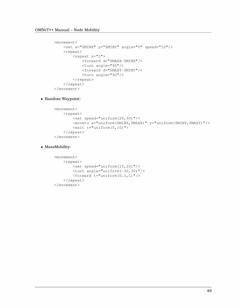
OMNeT++ Manual – Node Mobility
<movement><set x="$MINX" y="$MINY" angle="0" speed="10"/><repeat>
<repeat n="2"><forward d="$MAXX-$MINX"/><turn angle="90"/><forward d="$MAXY-$MINY"/><turn angle="90"/>
</repeat></repeat>
</movement>
• Random Waypoint:
<movement><repeat>
<set speed="uniform(20,60)"/><moveto x="uniform($MINX,$MAXX)" y="uniform($MINY,$MAXY)"/><wait t="uniform(5,10)">
</repeat></movement>
• MassMobility:
<movement><repeat>
<set speed="uniform(10,20)"/><turn angle="uniform(-30,30)"/><forward t="uniform(0.1,1)"/>
</repeat></movement>
49

OMNeT++ Manual – Node Mobility
50
OMNeT++ Manual – IPv4
Chapter 9
IPv4
9.1 Overview
The IP protocol is the workhorse protocol of the TCP/IP protocol suite. All UDP, TCP, ICMPpackets are encapsulated into IP datagrams and transported by the IP layer. While higherlayer protocols transfer data among two communication end-point, the IP layer provides anhop-by-hop, unreliable and connectionless delivery service. IP does not maintain any stateinformation about the individual datagrams, each datagram handled independently.
The nodes that are connected to the Internet can be either a host or a router. The hostscan send and recieve IP datagrams, and their operating system implements the full TCP/IPstack including the transport layer. On the other hand, routers have more than one interfacecards and perform packet routing between the connected networks. Routers does not needthe transport layer, they work on the IP level only. The division between routers and hosts isnot strict, because if a host have several interfaces, they can usually be configured to operateas a router too.
Each node on the Internet has a unique IP address. IP datagrams contain the IP address of thedestination. The task of the routers is to find out the IP address of the next hop on the localnetwork, and forward the packet to it. Sometimes the datagram is larger, than the maximumdatagram that can be sent on the link (e.g. Ethernet has an 1500 bytes limit.). In this casethe datagram is split into fragments and each fragment is transmitted independently. Thedestination host must collect all fragments, and assemble the datagram, before sending upthe data to the transport layer.
9.1.1 INET modules
The INET framework contains several modules to build the IPv4 network layer of hosts androuters:
• IPv4 is the main module that implements RFC791. This module performs IP encapsu-lation/decapsulation, fragmentation and assembly, and routing of IP datagrams.
• The RoutingTable is a helper module that manages the routing table of the node. Itis queried by the IPv4 module for best routes, and updated by the routing daemonsimplementing RIP, OSPF, Manet, etc. protocols.
51

OMNeT++ Manual – IPv4
• The ICMP module can be used to generate ICMP error packets. It also supports ICMPecho applications.
• The ARP module performs the dynamic translation of IP addresses to MAC addresses.
• The IGMPv2 module to generate and process multicast group membership reports.
These modules are assembled into a complete network layer module called NetworkLayer.This module has dedicated gates for TCP, UDP, SCTP, RSVP, OSPF, Manet, and Ping higherlayer protocols. It can be connected to several network interface cards: Ethernet, PPP, Wlan,or external interfaces. The NetworkLayer module is used to build IPv4 hosts (StandardHost)and routers (Router).
The implementation of these modules are based on the following RFCs:
• RFC791: Internet Protocol
• RFC792: Internet Control Message Protocol
• RFC826: Address Resolution Protocol
• RFC1122: Requirements for Internet Hosts - Communication Layers
• RFC2236: Internet Group Management Protocol, Version 2
The subsequent sections describe the IPv4 modules in detail.
9.2 The IPv4 Module
The IPv4 module implements the IPv4 protocol.
For connecting the upper layer protocols the IPv4 module has transportIn[] and transportOut[]gate vectors.
The IP packets are sent to the ARP module through the queueOut gate. The incoming IPpackets are received directly from the network interface cards through the queueIn[] gates.Each interface card knows its own network layer gate index.
The C++ class of the IPv4 module is derived from QueueBase. There is a processing time asso-ciated with each incoming packet. This processing time is specified by the procDelay moduleparameter. If a packet arrives, when the processing of a previous has not been finished, it isplaced in a FIFO queue.
The current performance model assumes that each datagram is processed within the sametime, and there is no priority between the datagrams. If you need a more sophisticated per-formance model, you may change the module implementation (the IP class), and:
1. override the startService() method which determines processing time for a packet, or
2. use a different base class.
9.2.1 IP packets
IP datagrams start with a variable length IP header. The minimum length of the header is20 bytes, and it can contain at most 40 bytes for options, so the maximum length of the IPheader is 60 bytes.
52
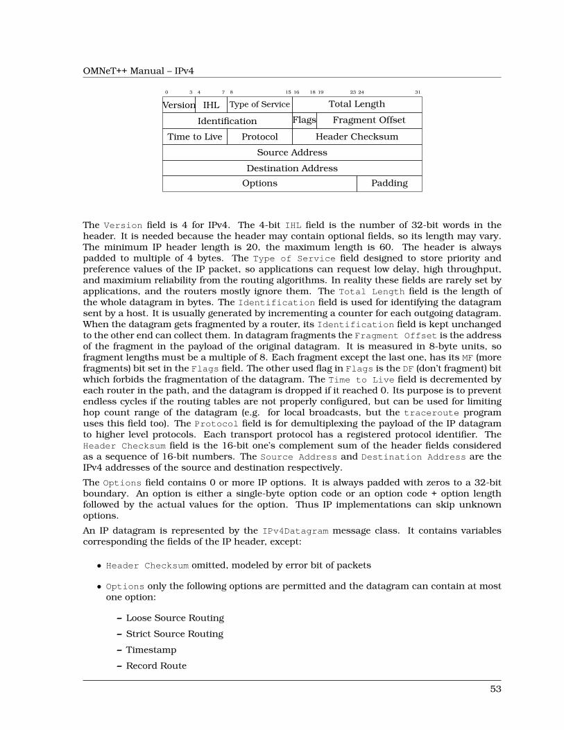
OMNeT++ Manual – IPv4
0 3 4 7 8 15 16 18 19 23 24 31
Version IHL Type of Service Total Length
Identification Flags Fragment Offset
Time to Live Protocol Header Checksum
Source Address
Destination Address
Options Padding
The Version field is 4 for IPv4. The 4-bit IHL field is the number of 32-bit words in theheader. It is needed because the header may contain optional fields, so its length may vary.The minimum IP header length is 20, the maximum length is 60. The header is alwayspadded to multiple of 4 bytes. The Type of Service field designed to store priority andpreference values of the IP packet, so applications can request low delay, high throughput,and maximium reliability from the routing algorithms. In reality these fields are rarely set byapplications, and the routers mostly ignore them. The Total Length field is the length ofthe whole datagram in bytes. The Identification field is used for identifying the datagramsent by a host. It is usually generated by incrementing a counter for each outgoing datagram.When the datagram gets fragmented by a router, its Identification field is kept unchangedto the other end can collect them. In datagram fragments the Fragment Offset is the addressof the fragment in the payload of the original datagram. It is measured in 8-byte units, sofragment lengths must be a multiple of 8. Each fragment except the last one, has its MF (morefragments) bit set in the Flags field. The other used flag in Flags is the DF (don’t fragment) bitwhich forbids the fragmentation of the datagram. The Time to Live field is decremented byeach router in the path, and the datagram is dropped if it reached 0. Its purpose is to preventendless cycles if the routing tables are not properly configured, but can be used for limitinghop count range of the datagram (e.g. for local broadcasts, but the traceroute programuses this field too). The Protocol field is for demultiplexing the payload of the IP datagramto higher level protocols. Each transport protocol has a registered protocol identifier. TheHeader Checksum field is the 16-bit one’s complement sum of the header fields consideredas a sequence of 16-bit numbers. The Source Address and Destination Address are theIPv4 addresses of the source and destination respectively.
The Options field contains 0 or more IP options. It is always padded with zeros to a 32-bitboundary. An option is either a single-byte option code or an option code + option lengthfollowed by the actual values for the option. Thus IP implementations can skip unknownoptions.
An IP datagram is represented by the IPv4Datagram message class. It contains variablescorresponding the fields of the IP header, except:
• Header Checksum omitted, modeled by error bit of packets
• Options only the following options are permitted and the datagram can contain at mostone option:
– Loose Source Routing
– Strict Source Routing
– Timestamp
– Record Route
53
OMNeT++ Manual – IPv4
The Type of Service field is called diffServCodePoint in IPv4Datagram.
Before sending the IPv4Datagram through the network, the IPv4 module attaches aIPv4RoutingDecision control info. The control info contains the IP address of the nexthop, and the identifier of the interface it should be sent. The ARP module translate the IPaddress to the hardware address on the local net of the specified interface and forwards thedatagram to the interface card.
9.2.2 Interface with higher layer
Higher layer protocols should be connected to the transportIn/transportOut gates of theIPv4 module.
Sending packets
Higher layer protocols can send a packet by attaching a IPv4ControlInfo object to theirpacket and sending it to the IPv4 module.
The following fields must be set in the control info:
• procotol: the Protocol field of the IP datagram. Valid values are defined in the IPPro-tocolId enumeration.
• destAddr: the Destination Address of the IP datagram.
Optionally the following fields can be set too:
• scrAddr: Source Address of the IP datagram. If given it must match with the addressof one of the interfaces of the node, but the datagram is not necessarily routed throughthat interface. If left unspecified, then the address of the outgoing interface will be used.
• timeToLive: TTL of the IP datagram or -1 (unspecified). If unspecified then the TTL ofthe datagram will be 1 for destination addresses in the 224.0.0.0 – 224.0.0.255 range.(Datagrams with these special multicast addresses do not need to go further that onehop, routers does not forward these datagrams.) Otherwise the TTL field is determinedby the defaultTimeToLive or defaultMCTimeToLive module parameters dependingwhether the destination address is a multicast address or not.
• dontFragment: the Don’t Fragment flag of the outgoing datagram (default is false)
• diffServCodePoint: the Type of Service field of the outgoing datagram. (ToS iscalled diffServCodePoint in IPv4Datagram too.)
• multicastLoop: if true, then a copy of the multicast datagrams are sent to the loopbackinterface, so applications on the same host can receive it.
• interfaceId: id of outgoing interface (can be used to limit broadcast or restrict routing).
• nextHopAddr: explicit routing info, used by Manet DSR routing. If specified, then in-terfaceId must also be specified. Ignored in Manet routing is disabled.
The IP module encapsulates the transport layer datagram into an IPv4Datagram and fills inthe header fields according to the control info. The Identification field is generated byincrementing a counter.
54
OMNeT++ Manual – IPv4
The generated IP datagram is passed to the routing algorithm. The routing decides if the data-gram should be delivered locally, or passed to one of the network interfaces with a specifiednext hop address, or broadcasted on one or all of the network interfaces. The details of therouting is described in the next subsection (9.2.3) in detail.
Before sending the datagram on a specific interface, the IPv4 module checks if the packetlength is smaller than the MTU of the interface. If not, then the datagram is fragmented. Whenthe Don’t Fragment flag forbids fragmentation, an Destination Unreachable ICMP erroris generated with the Fragmentation Error (5) error code.
NOTE: Each fragment will encapsulate the whole higher layer datagram, although thelength of the IP datagram corresponds to the fragment length.
The fragments are sent to the ARP module through the queueOut gate. The ARP moduleforwards the datagram immediately to point-to-point interface cards. If the outgoing interfaceis a 802.x card, then before forwarding the datagram it performs address resolution to obtainthe MAC address of the destination.
Receiving packets
The IPv4 module of hosts processes the datagrams received from the network in three steps:
1. Reassemble fragments
2. Decapsulate the transport layer datagram
3. Dispatch the datagram to the appropriate transport protocol
When a fragment received, it is added to the fragment buffer of the IP. If the fragment wasthe last fragment of a datagram, the processing of the datagram continues with step 2. Thefragment buffer stores the reception time of each fragment. Fragments older than fragment-Timeout are purged from the buffer. The default value of the timeout is 60s. The timeout isonly checked when a fragment is received, and at least 10s elapsed since the last check.
An IPv4ControlInfo attached to the decapsulated transport layer packet. The control infocontains fields copied from the IP header (source and destination address, protocol, TTL, ToS)as well as the interface id through it was received. The control info also stores the original IPdatagram, because the transport layer might signal an ICMP error, and the ICMP packet mustencapsulate the erronous IP datagram.
NOTE: IP datagrams containing a DSR packet are not decapsulated, the unchanged IPdatagram is passed to the DSR module instead.
After decapsulation, the transport layer packet will be passed to the appropriate transportprotocol. It must be connected to one of the transportOut[] gate. The IPv4 module findsthe gate using the protocol id→ gate index mapping given in the protocolMapping stringparameter. The value must be a comma separated list of ”<protocol_id>:<gate_index>” items.For example the following line in the ini file maps TCP (6) to gate 0, UDP (17) to gate 1, ICMP(1) to gate 2, IGMP (2) to gate 3, and RVSP (46) to gate 4.
**.ip.protocolMapping="6:0,17:1,1:2,2:3,46:4"
If the protocol of the received IP datagram is not mapped, or the gate is not connected, thedatagram will be silently dropped.
Some protocols are handled differently:
55
OMNeT++ Manual – IPv4
• ICMP: ICMP errors are delivered to the protocol whose packet triggered the error. OnlyICMP query requests and responses are sent to the ICMP module.
• IP: sent through preRoutingOut gate. (bug!)
• DSR: ??? (subsection about Manet routing?)
9.2.3 Routing, and interfacing with lower layers
The output of the network interfaces are connected to the queueIn gates of the IPv4 mod-ule. The incoming packets are either IP datagrams or ARP responses. The IP datagrams areprocessed by the IPv4 module, the ARP responses are forwarded to the ARP.
The IPv4 module first checks the error bit of the incoming IP datagrams. There is aheaderlength/packetlength probability that the IP header contains the error (assuming 1 biterror). With this probability an ICMP Parameter Problem generated, and the datagram isdropped.
When the datagram does not contain error in the IP header, a routing decision is made. As aresult of the routing the datagram is either delivered locally, or sent out one or more outputinterface. When it is sent out, the routing algorithm must compute the next hop of its route.The details are differ, depending on that the destination address is multicast address or not.
When the datagram is decided to be sent up, it is processed as described in the previoussubsection (Receiving packets). If it is decided to be sent out through some interface, itis actually sent to the ARP module through the queueOut gate. An IPv4RoutingDecisioncontrol info is attached to the outgoing packet, containing the outgoing interface id, and theIP address of the next hop. The ARP module resolve the IP address to a hardware address ifneeded, and forwards the datagram to next hop.
Unicast/broadcast routing
When the higher layer generated the datagram, it will be processed in these steps:
1. If the destination is the address of a local interface, then the datagram is locally delivered.
2. If the destination is the limited broadcast address, or a local broadcast address, thenit will be broadcasted on one or more interface. If the higher layer specified am out-going interface (interfaceId in the control info), then it will be broadcasted on thatinterface only. Otherwise if the forceBroadcast module parameter is true, then it willbroadcasted on all interfaces including the loopback interface. The default value of theforceBroadcast is false.
3. If the higher layer provided the routing decision (Manet routing), then the datagram willbe sent through the specified interface to the specified next hop.
4. Otherwise IP finds the outgoing interface and the address of the next hop by consultingthe routing table, and sends the datagram to the next hop. If no route found, then aDestination Unreachable ICMP error is generated.
Incoming datagrams having unicast or broadcast destination addresses are routed in thefollowing steps:
56
OMNeT++ Manual – IPv4
1. Deliver datagram locally. If the destination address is a local address, the limited broad-cast address (255.255.255.255), or a local broadcast address, then it will be sent to thetransport layer.
2. Drop packets received from the network when IP forwarding is disabled.
3. Forward the datagram to the next hop. The next hop is determined by looking up thebest route to the destination from the routing table. If the gateway is set in the route,then the datagram will be forwarded to the gateway, otherwise it is sent directly to thedestination. If no route is found, then a Destination Unreachable ICMP error is sentto the source of the datagram.
Multicast routing
Outgoing multicast datagrams are handled as follows:
1. If the higher layer set the multicastLoop variable to true, the IP will send up a copy ofthe datagram through the loopback interface.
2. Determine the outgoing interface for the multicast datagram, and send out the datagramthrough that interface. The outgoing interface is determined by the following rules:
(a) if the HL specified the outgoing interface in the control info, the it will be used(b) otherwise use the interface of the route configured in the routing table for the desti-
nation address(c) if no route found, then use the interface whose address matches the source address
of the datagram(d) if the HL did not specify the source address, then use the first multicast capable
interface(e) if no such interface found, then the datagram is unroutable and droppped
Incoming multicast datagrams are forwarded according to their source address (Reverse PathForwarding), i.e. datagrams are sent away from their sources instead towards their destina-tions. The multicast routing table maintains a spanning tree for each source network andmulticast group. The source network is the root of the tree, and there is a path to each LANthat has members of the multicast group. Each node expects the multicast datagram to arrivefrom their parent and forwards them towards their children. Multicast forwarding loops areavoided by dropping the datagrams not arrived on the parent interface.
More specifically, the routing routine for multicast datagrams performs these steps:
1. Deliver a copy of the datagram locally. If the interface on which the datagram arrivedbelongs to the multicast group specified by the destination address, it is sent up to thetransport layer.
2. Discard incoming packets that can not be delivered locally and can not be forwarded. Anon-local packet can not be forwarded if multicast forwarding is disabled, the destinationis a link local multicast address (224.0.0.x), or the TTL field reached 0.
3. Discard the packet if no multicast route found, or if it did not arrive on the parentinterface of the route (to avoid multicast loops). If the parent is not set in the route, thenthe shortest path interface to the source is assumed.
4. Forward the multicast datagram. A copy of the datagram is sent on each child interfacedescribed by multicast routes (except the incoming interface). Interfaces may have a
57
OMNeT++ Manual – IPv4
ttlThreshold parameter, that limits the scope of the multicast: only datagrams withhigher TTL are forwarded.
9.2.4 Parameters
The IPv4 module has the following parameters:
• procDelay processing time of each incoming datagram.
• timeToLive default TTL of unicast datagrams.
• multicastTimeToLive default TTL of multicast datagrams.
• protocolMapping string value containing the protocol id → gate index mapping,e.g. “6:0,17:1,1:2,2:3,46:4”.
• fragmentTimeout the maximum duration until fragments are kept in the fragmentbuffer.
• forceBroadcast if true, then link-local broadcast datagrams are sent out through eachinterface, if the higher layer did not specify the outgoing interface.
9.2.5 Statistics
The IPv4 module does not write any statistics into files, but it has some statistical informationthat can be watched during the simulation in the gui environment.
• numForwarded: number of forwarded datagrams, i.e. sent to one of the interfaces (notbroadcast), counted before fragmentation.
• numLocalDeliver: number of datagrams locally delivered. (Each fragment counted sep-arately.)
• numMulticast: number of routed multicast datagrams.
• numDropped number of dropped packets. Either because there is no any interface, theinterface is not specified and no forceBroadcast, or received from the network but IPforwarding disabled.
• numUnroutable: number of unroutable datagrams, i.e. there is no route to the destina-tion. (But if outgoing interface is specified it is routed!)
In the graphical interface the bubble of the IPv4 module also displays these counters.
9.3 The RoutingTable module
The RoutingTable module represents the routing table. IP hosts and routers contain oneinstance of this class. It has methods to manage the routing table and the interface table, soone can achieve functionality similar to the route and ifconfig commands.
This is a simple module without gates, it requires function calls to it (message handling doesnothing). Methods are provided for reading and updating the interface table and the routetable, as well as for unicast and multicast routing.
58
OMNeT++ Manual – IPv4
Interfaces are dynamically registered: at the start of the simulation, every L2 module adds itsown interface entry to the table.
The route table is read from a file; the file can also fill in or overwrite interface settings. Theroute table can also be read and modified during simulation, typically by routing protocolimplementations (e.g. OSPF).
Entries in the route table are represented by IPv4Route objects. IPv4Route objects can bepolymorphic: if a routing protocol needs to store additional data, it can simply subclass fromIPv4Route, and add the derived object to the table. The IPv4Route object has the followingfields:
• host is the IP address of the target of the route (can be a host or network). When anentry searched for a given destination address, the destination address is compared withthis host address using the netmask below, and the longest match wins.
• netmask used when comparing host with the detination address. It is 0.0.0.0 for thedefault route, 255.255.255.255 for host routes (exact match), or the network or subnetmask for network routes.
• gateway is the IP address of the gateway for indirect routes, or 0.0.0.0 for direct routes.Note that 0.0.0.0 can be used even if the destination is not directly connected to thisnode, but can be found using proxy ARP.
• interface the outgoing interface to be used with this route.
• type DIRECT or REMOTE. For direct routes, the next hop address is the destination ad-dress, for remote routes it is the gateway address.
• source MANUAL, IFACENETMASK, RIP, OSPF, BGP, ZEBRA, MANET, or MANET2. MANUALmeans that the route was added by a routing file, or a network configurator. IFACENET-MASK routes are added for each interface of the node. Other values means that the routeis managed by the specific routing daemon.
• metric the “cost” of the route. Currently not used when choosing the best route.
In multicast routers the routing table contains multicast routes too. A multicast route isrepresented by an instance of the IPv4MulticastRoute class. The IPv4MulticastRouteinstance stores the following fields:
• origin IP address of the network of the source of the datagram
• originNetmask netmask of the source network
• group the multicast group to be matched the destination of the datagram. If unspecified,then the route matches with
• parent interface towards the parent link in the multicast tree. Only those datagramsare forwarded that arrived on the parent interface.
• children the interfaces on which the multicast datagram to be forwarded. Each entrycontains a flag indicating if this interface is a leaf in the multicast tree. The datagram isforwarded to leaf interfaces only if there are known members of the group in the attachedLAN.
• source enumerated value identifying the creator of the entry. MANUAL for static routes,DVRMP for the DVMRP routers, PIM_SM for PIM SM routers.
59
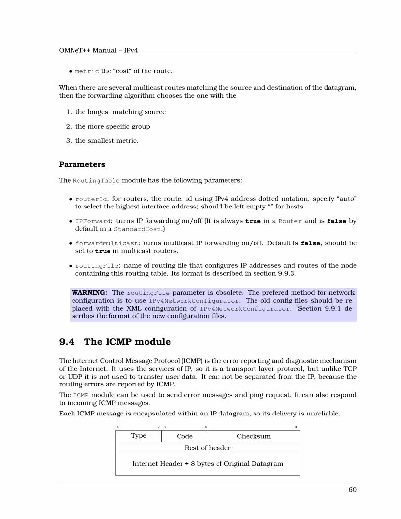
OMNeT++ Manual – IPv4
• metric the “cost“ of the route.
When there are several multicast routes matching the source and destination of the datagram,then the forwarding algorithm chooses the one with the
1. the longest matching source
2. the more specific group
3. the smallest metric.
Parameters
The RoutingTable module has the following parameters:
• routerId: for routers, the router id using IPv4 address dotted notation; specify “auto”to select the highest interface address; should be left empty “” for hosts
• IPForward: turns IP forwarding on/off (It is always true in a Router and is false bydefault in a StandardHost.)
• forwardMulticast: turns multicast IP forwarding on/off. Default is false, should beset to true in multicast routers.
• routingFile: name of routing file that configures IP addresses and routes of the nodecontaining this routing table. Its format is described in section 9.9.3.
WARNING: The routingFile parameter is obsolete. The prefered method for networkconfiguration is to use IPv4NetworkConfigurator. The old config files should be re-placed with the XML configuration of IPv4NetworkConfigurator. Section 9.9.1 de-scribes the format of the new configuration files.
9.4 The ICMP module
The Internet Control Message Protocol (ICMP) is the error reporting and diagnostic mechanismof the Internet. It uses the services of IP, so it is a transport layer protocol, but unlike TCPor UDP it is not used to transfer user data. It can not be separated from the IP, because therouting errors are reported by ICMP.
The ICMP module can be used to send error messages and ping request. It can also respondto incoming ICMP messages.
Each ICMP message is encapsulated within an IP datagram, so its delivery is unreliable.
0 7 8 15 31
Type Code Checksum
Rest of header
Internet Header + 8 bytes of Original Datagram
60

OMNeT++ Manual – IPv4
The corresponding message class (ICMPMessage) contains only the Type and Code fields. Themessage encapsulates the IP packet that triggered the error, or the data of the ping request/re-ply.
The ICMP module has two methods which can be used by other modules to send ICMP errormessages:
• sendErrorMessage(IPv4Datagram*, ICMPType, ICMPCode) used by the networklayer to report erronous IPv4 datagrams. The ICMP header fields are set to the giventype and code, and the ICMP message will encapsulate the given datagram.
• sendErrorMessage(cPacket*, IPv4ControlInfo*, ICMPType, ICMPCode) used bythe transport layer components to report erronous packets. The transport packet willbe encapsulated into an IP datagram before wrapping it into the ICMP message.
The ICMP module can be accessed from other modules of the node by calling ICMPAc-cess::get().
When an incoming ICMP error message is received, the ICMP module sends it out on the er-rorOut gate unchanged. It is assumed that an external module is connected to errOut thatcan process the error packet. There is a simple module (ErrorHandling) that simply logs theerror and drops the message. Note that the IPv4 module does not send REDIRECT, DES-TINATION_UNREACHABLE, TIME_EXCEEDED and PARAMETER_PROBLEM messages to theICMP module, it will send them to the transport layer module that sent the bogus packetencapsulated in the ICMP message.
NOTE: ICMP protocol encapsulates only the IP header + 8 byte following the IP headerfrom the bogus IP packet. The ICMP packet length computed from this truncated packet,despite it encapsulates the whole IP message object. As a consequence, calling decap-sulate() on the ICMP message will cause an “packet length became negative” error. Toavoid this, use getEncapsulatedMsg() to access the IP packet that caused the ICMPerror.
The ICMP module receives ping commands on the pingIn gate from the application. The pingcommand can be any packet having an IPv4ControlInfo control info. The packet will beencapsulated with an ICMPMessage and handed over to the IP.
If ICMP receives an echo request from IP, the original message object will be returned asthe echo reply. Of course, before sending back the object to IP, the source and destinationaddresses are swapped and the message type changed to ICMP_ECHO_REPLY.
When an ICMP echo reply received, the application message decapsulated from it and passedto the application through the pingOut gate. The IPv4ControlInfo also copied from theICMPMessage to the application message.
9.5 The ARP module
The ARP module implements the Address Resolution Protocol (RFC826). The ARP protocol isdesigned to translate a local protocol address to a hardware address. Altough the ARP protocolcan be used with several network protocol and hardware addressing schemes, in practice theyare almost always IPv4 and 802.3 addresses. The INET implementation of the ARP protocol(the ARP module) supports only IP address → MAC address translation.
If a node wants to send an IP packet to a node whose MAC address is unknown, it broadcastsan ARP frame on the Ethernet network. In the request its publish its own IP and MAC
61
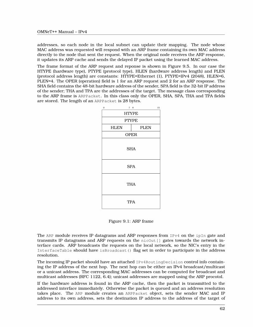
OMNeT++ Manual – IPv4
addresses, so each node in the local subnet can update their mapping. The node whoseMAC address was requested will respond with an ARP frame containing its own MAC addressdirectly to the node that sent the request. When the original node receives the ARP response,it updates its ARP cache and sends the delayed IP packet using the learned MAC address.
The frame format of the ARP request and reponse is shown in Figure 9.5. In our case theHTYPE (hardware type), PTYPE (protocol type), HLEN (hardware address length) and PLEN(protocol address length) are constants: HTYPE=Ethernet (1), PTYPE=IPv4 (2048), HLEN=6,PLEN=4. The OPER (operation) field is 1 for an ARP request and 2 for an ARP response. TheSHA field contains the 48-bit hardware address of the sender, SPA field is the 32-bit IP addressof the sender; THA and TPA are the addresses of the target. The message class correspondingto the ARP frame is ARPPacket. In this class only the OPER, SHA, SPA, THA and TPA fieldsare stored. The length of an ARPPacket is 28 bytes.
0 7 8 15
HTYPE
PTYPE
HLEN PLEN
OPER
SHA
SPA
THA
TPA
Figure 9.1: ARP frame
The ARP module receives IP datagrams and ARP responses from IPv4 on the ipIn gate andtransmits IP datagrams and ARP requests on the nicOut[] gates towards the network in-terface cards. ARP broadcasts the requests on the local network, so the NIC’s entry in theInterfaceTable should have isBroadcast() flag set in order to participate in the addressresolution.
The incoming IP packet should have an attached IPv4RoutingDecision control info contain-ing the IP address of the next hop. The next hop can be either an IPv4 broadcast/multicastor a unicast address. The corresponding MAC addresses can be computed for broadcast andmulticast addresses (RFC 1122, 6.4); unicast addresses are mapped using the ARP procotol.
If the hardware address is found in the ARP cache, then the packet is transmitted to theaddressed interface immediately. Otherwise the packet is queued and an address resolutiontakes place. The ARP module creates an ARPPacket object, sets the sender MAC and IPaddress to its own address, sets the destination IP address to the address of the target of
62
OMNeT++ Manual – IPv4
the IP datagram, leave the destination MAC address blank and broadcasts the packet on eachnetwork interface with broadcast capability. Before sending the ARP packet, it retransmissiona timer. If the timer expires, it will retransmit the ARP request, until the maximum retry countis reached. If there is no response to the ARP request, then the address resolution fails, andthe IP packet is dropped from the queue. Otherwise the MAC address of the destination islearned and the IP packet can be transmitted on the corresponding interface.
When an ARP packet is received on the ipIn gate, and the sender’s IP is already in theARP cache, it is updated with the information in the ARP frame. Then it is checked that thedestination IP of the packet matches with our address. In this case a new entry is created withthe sender addresses in the ARP cache, and if the packet is a request a response is createdand sent directly to the originator. If proxy ARP is enabled, the request can be responded withour MAC address if we can route IP packets to the destination.
Usually each ARP module maintains a local ARP cache. However it is possible to use a globalcache. The global cache is filled in with entries of the IP and MAC addresses of the knowninterfaces when the ARP modules are initiated (at simulation time 0). ARP modules that areusing the global ARP cache never initiate an address resolution; if an IP address not foundin the global cache, the simulation stops with an error. However they will respond to ARPrequest, so the simulation can be configured so that some ARPs use local, while others theglobal cache.
When an entry is inserted or updated in the local ARP cache, the simulation time saved in theentry. The mapping in the entry is not used after the configured cacheTimeout elapsed. Thisparameter does not affect the entries of the global cache however.
The module parameters of ARP are:
• retryTimeout: number of seconds ARP waits between retries to resolve an IPv4 address(default is 1s)
• retryCount: number of times ARP will attempt to resolve an IPv4 address (default is 3)
• cacheTimeout: number of seconds unused entries in the cache will time out (default is120s)
• proxyARP: enables proxy ARP mode (default is true)
• globalARP: use global ARP cache (default is false)
The ARP module emits four signals:
• sentReq: emits 1 each time an ARP request is sent
• sentReplies: emits 1 each time an ARP response is sent
• initiatedResolution: emits 1 each time an ARP resolution is initiated
• failedResolution: emits 1 each time an ARP resolution is failed
These signals are recorded as vectors and their counts as scalars.
9.6 The IGMP module
The IGMP module is responsible for distributing the information of multicast group member-ships from hosts to routers. When an interface of a host joins to a multicast group, it will
63
OMNeT++ Manual – IPv4
send an IGMP report on that interface to routers. It can also send reports when the interfaceleaves the multicast group, so it does not want to receive those multicast datagrams. TheIGMP module of multicast routers processes these IGMP reports: it updates the list of groups,that has members on the link of the incoming message.
The IIGMP module interface defines the connections of IGMP modules. IGMP reportsare transmitted by IP, so the module contains gates to be connected to the IP module(ipIn/ipOut). The IP module delivers packets with protocol number 2 to the IGMP module.However some multicast routing protocols (like DVMRP) also exchange routing information bysending IGMP messages, so they should be connected to the routerIn/routerOut gates ofthe IGMP module. The IGMP module delivers the IGMP messages not processed by itself tothe connected routing module.
The IGMPv2 module implements version 2 of the IGMP protocol (RFC 2236). Next we describeits behaviour in host and routers in details. Note that multicast routers behaves as hosts too,i.e. they are sending reports to other routers when joining or leaving a multicast group.
9.6.1 Host behaviour
When an interface joins to a multicast group, the host will send a Membership Report imme-diately to the group address. This report is repeated after unsolicetedReportInterval tocover the possibility of the first report being lost.
When a host’s interface leaves a multicast group, and it was the last host that sent a Mem-bership Report for that group, it will send a Leave Group message to the all-routers multicastgroup (224.0.0.2).
This module also responds to IGMP Queries. When the host receives a Group-Specific Queryon an interface that belongs to that group, then it will set a timer to a random value between 0and Max Response Time of the Query. If the timer expires before the host observe a Member-ship Report sent by other hosts, then the host sends an IGMPv2 Membership Report. Whenthe host receives a General Query on an interface, a timer is initialized and a report is sentfor each group membership of the interface.
9.6.2 Router behaviour
Multicast routers maintains a list for each interface containing the multicast groups that havelisteners on that interface. This list is updated when IGMP Membership Reports and LeaveGroup messages arrive, or when a timer expires since the last Query.
When multiple routers are connected to the same link, the one with the smallest IP addresswill be the Querier. When other routers observe that they are Non-Queriers (by receivingan IGMP Query with a lower source address), they stop sending IGMP Queries until other-QuerierPresentInterval elapsed since the last received query.
Routers periodically (queryInterval) send a General Query on each attached network forwhich this router is a Querier. On startup the router sends startupQueryCount queriesseparated by startupQueryInterval. A General Query has unspecified Group Address field,a Max Response Time field set to queryResponseInterval, and is sent to the all-systemsmulticast address (224.0.0.1).
When a router receives a Membership Report, it will add the reported group to the list ofmulticast group memberships. At the same time it will set a timer for the membership togroupMembershipInterval. Repeated reports restart the timer. If the timer expires, the
64
OMNeT++ Manual – IPv4
router assumes that the group has no local members, and multicast traffic is no more for-warded to that interface.
When a Querier receives a Leave Group message for a group, it sends a Group-Specific Queryto the group being left. It repeats the Query lastMemberQueryCount times in separated bylastMemberQueryInterval until a Membership Report is received. If no Report received,then the router assumes that the group has no local members.
9.6.3 Disabling IGMP
The IPv4 NetworkLayer contains an instance of the IGMP module. IGMP can be turned off bysetting the enabled parameter to false. When disabled, then no IGMP message is generated,and incoming IGMP messages are ignored.
9.6.4 Parameters
The following parameters has effects in both hosts and routers:
• enabled if false then the IGMP module is silent. Default is true.
These parameters are only used in hosts:
• unsolicitedReportInterval the time between repetitions of a host’s initial report ofmembership in a group. Default is 10s.
Router timeouts are configured by these parameters:
• robustnessVariable the IGMP is robust to robustnessVariable-1 packet losses. De-fault is 2.
• queryInterval the interval between General Queries sent by a Querier. Default is 125s.
• queryResponseInterval the Max Response Time inserted into General Queries
• groupMembershipInterval the amount of time that must pass before a multicast routerdecides there are no more members of a group on a network. Fixed to robustnessVari-able * queryInterval + queryResponseInterval.
• otherQuerierPresentInterval the length of time that must pass before a multicastrouter decides that there is no longer another multicast router which should be thequerier. Fixed to robustnessVariable * queryInterval + queryResponseInterval /2.
• startupQueryInterval the interval between General Queries sent by a Querier onstartup. Default is queryInterval / 4.
• startupQueryCount the number of Queries sent out on startup, separated by the star-tupQueryInterval. Default is robustnessVariable.
• lastMemberQueryInterval the Max Response Time inserted into Group-SpecificQueries sent in response to Leave Group messages, and is also the amount of timebetween Group-Specific Query messages. Default is 1s.
• lastMemberQueryCount the number of Group-Specific Queries sent before the routerassumes there are no local members. Default is robustnessVariable.
65
OMNeT++ Manual – IPv4
9.7 The NetworkLayer module
The NetworkLayer module packs the IP, ICMP, ARP, and IGMP modules into one compoundmodule. The compound module defines gates for connecting UDP, TCP, SCTP, RSVP and OSPFtransport protocols. The pingIn and pingOut gates of the ICMP module are also available,while its errorOut gate is connected to an inner ErrorHandling component that writes theICMP errors to the log.
The component can be used in hosts and routers to support IPv4.
9.8 The NetworkInfo module
The NetworkInfo module can be used to dump detailed information about the network layer.This module does not send or received messages, it is invoked by the ScenarioManagerinstead. For example the following ScenarioManager script dump the routing table of theLSR2 module at simulation time t = 2 into LSR2_002.txt:
<scenario><at t="2">
<routing module="NetworkInfo" target="LSR2" file="LSR2_002.txt"/></at>
</scenario>
The module currently support only the routing command which dumps the routing table.The command has four parameters given as XML attributes:
• target the name of the node that owns the routing table to be dumped
• filename the name of the file the output is directed to
• mode if set to “a”, the output is appended to the file, otherwise the target is truncated ifthe file existed
• compat if set to “linux”, then the output is generated in the format of the route -ncommand of Linux. The output is sorted only if compat is true.
9.9 Configuring IPv4 networks
An IPv4 network is composed of several nodes like hosts, routers, switches, hubs, Ethernetbuses, or wireless access points. The nodes having a IPv4 network layer (hosts and routers)should be configured at the beginning of the simulation. The configuration assigns IP ad-dresses to the nodes, and fills their routing tables. If multicast forwarding is simulated, thenthe multicast routing tables also must be filled in.
The configuration can be manual (each address and route is fully specified by the user), orautomatic (addresses and routes are generated by a configurator module at startup).
Before version 1.99.4 INET offered FlatNetworkConfigurator for automatic and routingfiles for manual configuration. Both had serious limitations, so a new configurator has beenadded in version 1.99.4: IPv4NetworkConfigurator. This configurator supports both fullymanual and fully automatic configuration. It can also be used with partially specified manualconfigurations, the configurator fills in the gaps automatically.
66
OMNeT++ Manual – IPv4
The next section describes the usage of IPv4NetworkConfigurator, FlatNetworkConfigu-rator and old routing files are described in the following sections.
9.9.1 IPv4NetworkConfigurator
The IPv4NetworkConfigurator assigns IP addresses and sets up static routing for an IPv4network.
It assigns per-interface IP addresses, strives to take subnets into account, and can also opti-mize the generated routing tables by merging routing entries.
Hierarchical routing can be set up by using only a fraction of configuration entries comparedto the number of nodes. The configurator also does routing table optimization that signifi-cantly decreases the size of routing tables in large networks.
The configuration is performed in stage 2 of the initialization. At this point interface modules(e.g. PPP) has already registered their interface in the interface table. If an interface is named“ppp[0]”, then the corresponding interface entry is named “ppp0”. This name can be used inthe config file to refer to the interface.
The configurator goes through the following steps:
1. Builds a graph representing the network topology.
2. Assigns IP addresses to all interfaces of all nodes.
3. Configure multicast group membership of the interfaces.
4. Adds the manual routes that are specified in the configuration file.
5. Adds the multicast routes that are specified in the configuration file.
6. Adds static routes to all routing tables in the network.
7. Optimizes the routing tables for size. This step could take much time, so it can be turnedoff.
8. Optionally prints the results of the configuration process (network topology, addresses,routing tables).
The module can dump the result of the configuration in the XML format which it can read.This is useful to save the result of a time consuming configuration (large network with opti-mized routes), and use it as the config file of subsequent runs.
Network topology graph
The network topology graph is constructed from the nodes of the network. The node is amodule having a @node property (this includes hosts, routers, and L2 devices like switches,access points, Ethernet hubs, etc.). An IP node is a node that contains an InterfaceTableand a RoutingTable. A router is an IP node that has multiple network interfaces, and IPforwarding is enabled in its routing table module. In multicast routers the forwardMulticastparameter is also set to true.
A link is a set of interfaces that can send datagrams to each other without intervening routers.Each interface belongs to exactly one link. For example two interface connected by a point-to-point connection forms a link. Ethernet interfaces connected via buses, hubs or switches.
67
OMNeT++ Manual – IPv4
The configurator identifies links by discovering the connections between the IP nodes, buses,hubs, and switches.
Wireless links are identified by the ssid or accessPointAddress parameter of the 802.11management module. Wireless interfaces whose node does not contain a management moduleare supposed to be on the same wireless link. Wireless links can also be configured in theconfiguration file of IPv4NetworkConfigurator:
<wireless hosts="area1.*" interface="wlan*">
puts wlan interfaces of the specified hosts into the same wireless link.
If a link contains only one router, it is marked as the gateway of the link. Each datagramwhose destination is outside the link must go through the gateway.
Address assignment
Addresses can be set up manually by giving the address and netmask for each IP node. If somepart of the address or netmask is unspecified, then the configurator can fill them automati-cally. Unspecified fields are given as an “x” character in the dotted notation of the address.For example, if the address is specified as 192.168.1.1 and the netmask is 255.255.255.0,then the node address will be 192.168.1.1 and its subnet is 192.168.1.0. If it is given as192.168.x.x and 255.255.x.x, then the configurator chooses a subnet address in the range of192.168.0.0 - 192.168.255.252, and an IP address within the chosen subnet. (The maximumsubnet mask is 255.255.255.252 allows 2 nodes in the subnet.)
The following configuration generates network addresses below the 10.0.0.0 address for eachlink, and assign unique IP addresses to each host:
<config><interface hosts=’*’ address=’10.x.x.x’ netmask=’255.x.x.x’/>
</config>
The configurator tries to put nodes on the same link into the same subnet, so its enough toconfigure the address of only one node on each link.
The following example configures a hierarchical network in a way that keeps routing tablessmall.
<config><interface hosts="area11.lan1.*" address="10.11.1.x" netmask="255.255.255.x"/><interface hosts="area11.lan2.*" address="10.11.2.x" netmask="255.255.255.x"/><interface hosts="area12.lan1.*" address="10.12.1.x" netmask="255.255.255.x"/><interface hosts="area12.lan2.*" address="10.12.2.x" netmask="255.255.255.x"/><interface hosts="area*.router*" address="10.x.x.x" netmask="x.x.x.x"/><interface hosts="*" address="10.x.x.x" netmask="255.x.x.0"/>
</config>
The <interface> element may contain the following attributes:
• @hosts specifies a list of host name patterns (e.g. "subnet.client*" or "host* router[0..3]"or "area*.*.host[0]"). Only interfaces in the specified hosts are affected. The default valueis "*" that matches all hosts.
• @names specifies a list of interface name patterns (e.g. "eth* ppp0" or "*"). Only interfaceswith the specified names are affected. The default value is "*" that matches all interfaces.
68
OMNeT++ Manual – IPv4
• @towards specifies a list of host name patterns (e.g. "ap" or "server" or "client*"). Onlyinterfaces connected towards the specified hosts are affected. This works even if there’sa switch between the configured host and the one specified here. For wired networks itmight be easier to specify this parameter instead of specifying the interface names. Thedefault value is "*".
• @address IP address of the interface (e.g. "192.168.1.1" or "10.0.x.x"). Unspecified parts("x" characters in the address) will be filled automatically by the configurator. The defaultvalue "" means that the address will not be configured.
• @netmask netmask of the subnet of the interface (e.g. "255.255.255.0" or "255.255.x.x"or "255.255.x.0"). Unspecified part ("x" characters in the address) is filled automaticallyby the configurator.
• @mtu the MTU of the interface. When unspecified the interface parameter is left un-changed.
Multicast groups
Multicast groups can be configured by adding <multicast-group> elements to the configu-ration file. Interfaces belongs to a multicast group will join to the group automatically.
For example
<config><multicast-group hosts="router*" interfaces="eth*" address="224.0.0.5"/></config>
adds all Ethernet interfaces of nodes whose name starts with “router” to the 224.0.0.5 multi-cast group.
The <multicast-group> element has the following attributes:
• @hosts specifies a list of host name patterns. Only interfaces in the specified hosts areaffected. The default value is "*" that matches all hosts.
• @interfaces specifies a list of interface name patterns. Only interfaces with the speci-fied names are affected. The default value is "*" that matches all interfaces.
• @address: one or more multicast address, that are added to the multicast groups of theselected interfaces. E.g. "224.0.0.1 224.0.1.33".
Manual route configuration
The IPv4NetworkConfigurator module allows the user to fully specify the routing tables ofIP nodes at the beginning of the simulation.
The <route> elements of the configuration add a route to the routing tables of selected nodes.The element has the following attributes:
• @hosts specifies a list of host name patterns. Only routing tables in the specified hostsare affected. The default value "*" means all hosts will be affected.
• @destination specifies the destination address of the route. Its value can be a dottedIP address ("192.168.1.1"), the name of the destination node ("subnet.client[3]") or "*"(meaning any destination, used with "/0" netmask). The default value is "*".
• @netmask specifies the netmask in the route. It can be given as dotted decimal notation("255.255.255.0"), as prefix length ("/29") or as "*" (for default route). The default valueis "*".
69
OMNeT++ Manual – IPv4
• @gateway specifies the gateway (next-hop) address in the route. Its value can be an IPaddress, a hostname ("subnet.router") or "*". When unspecified the interface parametermust be specified. The default value is "*".
• @interface specifies the output interface name in the route (e.g. "eth0"). When unspec-ified the gateway parameter must be specified.
@metric specifies the metric in the route. The default value is 0.
Multicast routing tables can similarly be configured by adding <multicast-route> elementsto the configuration.
• @hosts specifies a list of host name patterns. Only routing tables in the specified hostsare affected.
• @source specifies the address of the source network. The default value is "*" thatmatches all sources.
• @netmask specifies the netmask of the source network. The default value is "*" thatmatches all sources.
• @groups list of IPv4 multicast addresses specifying the groups this entry applies to (e.g."225.0.0.1 225.0.1.2"). The default value is "*" that matches all multicast groups.
• @metric specifies the metric in the route.• @parent specifies the name of the parent (incoming) interface. Only multicast datagrams
that arrived on the parent interface are forwarded. If unspecified, then the interface onthe shortest path towards the source of the datagram will be the parent interface of theroute.
• @children specifies the child (outgoing) interfaces as a list of interface name patterns:– a name pattern (e.g. "ppp*") matches the name of the interface– a towards pattern (starting with ">", e.g. ">router*") matches the interface by naming
one of the neighbour nodes on its link.Multicast datagrams are forwarded to each child interface except the one they arrived in.
The following example adds an entry to the multicast routing table of router1, that intsructsthe routing algorithm to forward multicast datagrams whose source is in the 10.0.1.0 net-work and whose destinatation address is 225.0.0.1 to send on the eth1 and eth2 interfacesassuming it arrived on the eth0 interface:
<multicast-route hosts="router1" source="10.0.1.0" netmask="255.255.255.0"groups="225.0.0.1" metric="10"parent="eth0" children="eth1 eth2"/>
Automatic route configuration
If the addStaticRoutes parameter is true, then the configurator add static routes to allrouting tables.
The configurator uses Dijkstra’s weighted shortest path algorithm to find the desired routesbetween all possible node pairs. The resulting routing tables will have one entry for all desti-nation interfaces in the network.
The configurator can be safely instructed to add default routes where applicable, significantlyreducing the size of the host routing tables. It can also add subnet routes instead of interfaceroutes further reducing the size of routing tables. Turning on this option requires carefuldesign to avoid having IP addresses from the same subnet on different links.
70
OMNeT++ Manual – IPv4
CAUTION: Using manual routes and static route generation together may have un-wanted side effects, because route generation ignores manual routes. Therefore if theconfiguration file contains manual routes, then the addStaticRoutes parameter shouldbe set to false.
Route optimization
If the optimizeRoutes parameter is true then the configurator tries to optimize the routingtable for size. This optimization allows configuring larger networks with smaller memoryfootprint and makes the routing table lookup faster.
The optimization is performed by merging routes whose gateway and outgoing interface isthe same by finding a common prefix that matches only those routes. The resulting routingtable might be different in that it will route packets that the original routing table did not.Nevertheless the following invariant holds: any packet routed by the original routing table(has matching route) will still be routed the same way by the optimized routing table.
Parameters
This list summarize the parameters of the IPv4NetorkConfigurator:
• config: XML configuration parameters for IP address assignment and adding manualroutes.
• assignAddresses: assign IP addresses to all interfaces in the network
• assignDisjunctSubnetAddresses: avoid using the same address prefix and netmaskon different links when assigning IP addresses to interfaces
• addStaticRoutes: add static routes to the routing tables of all nodes to route to alldestination interfaces (only where applicable; turn off when config file contains manualroutes)
• addDefaultRoutes: add default routes if all routes from a source node go through thesame gateway (used only if addStaticRoutes is true)
• addSubnetRoutes: add subnet routes instead of destination interface routes (only whereapplicable; used only if addStaticRoutes is true)
• optimizeRoutes: optimize routing tables by merging routes, the resulting routing tablemight route more packets than the original (used only if addStaticRoutes is true)
• dumpTopology: if true, then the module prints extracted network topology
• dumpAddresses: if true, then the module prints assigned IP addresses for all interfaces
• dumpRoutes: if true, then the module prints configured and optimized routing tables forall nodes to the module output
• dumpConfig: name of the file, write configuration into the given config file that can befed back to speed up subsequent runs (network configurations)
71
OMNeT++ Manual – IPv4
9.9.2 FlatNetworkConfigurator
The FlatNetworkConfigurator module configures IP addresses and routes of IP nodes of anetwork. All assigned addresses share a common subnet prefix, the network topology willbe ignored. Shortest path routes are also generated from any node to any other node of thenetwork. The Gateway (next hop) field of the routes is not filled in by these configurator, so itrelies on proxy ARP if the network spans several LANs.
The FlatNetworkConfigurator module configures the network when it is initialized. Theconfiguration is performed in stage 2, after interface tables are filled in. Do not use a Flat-NetworkConfigurator module together with static routing files, because they can iterferewith the configurator.
The FlatNetworkConfigurator searches each IP nodes of the network. (IP nodes are thosemodules that have the @node NED property and has a RoutingTable submodule named“routingTable”). The configurator then assigns IP addresses to the IP nodes, controlled by thefollowing module parameters:
• netmask common netmask of the addresses (default is 255.255.0.0)
• networkAddress higher bits are the network part of the addresses, lower bits should be0. (default is 192.168.0.0)
With the default parameters the assigned addresses are in the range 192.168.0.1 -192.168.255.254, so there can be maximum 65534 nodes in the network. The same IP ad-dress will be assigned to each interface of the node, except the loopback interface whichalways has address 127.0.0.1 (with 255.0.0.0 mask).
After assigning the IP addresses, the configurator fills in the routing tables. There are twokind of routes:
• default routes: for nodes that has only one non-loopback interface a route is added thatmatches with any destination address (the entry has 0.0.0.0 host and netmask fields).These are remote routes, but the gateway address is left unspecified. The delivery of thedatagrams rely on the proxy ARP feature of the routers.
• direct routes following the shortest paths: for nodes that has more than one non-loopback interface a separate route is added to each IP node of the network. The outgoinginterface is chosen by the shortest path to the target node. These routes are added asdirect routes, even if there is no direct link with the destination. In this case proxy ARPis needed to deliver the datagrams.
NOTE: This configurator does not try to optimize the routing tables. If the networkcontains n nodes, the size of all routing tables will be proportional to n2, and the time ofthe lookup of the best matching route will be proportional to n.
9.9.3 Old routing files
Routing files are files with .irt or .mrt extension, and their names are passed in the rout-ingFile parameter to RoutingTable modules.
Routing files may contain network interface configuration and static routes. Both are optional.Network interface entries in the file configure existing interfaces; static routes are added tothe route table.
72
OMNeT++ Manual – IPv4
Interfaces themselves are represented in the simulation by modules (such as the PPP module).Modules automatically register themselves with appropriate defaults in the RoutingTable, andentries in the routing file refine (overwrite) these settings. Interfaces are identified by names(e.g. ppp0, ppp1, eth0) which are normally derived from the module’s name: a module called"ppp[2]" in the NED file registers itself as interface ppp2.
An example routing file (copied here from one of the example simulations):
ifconfig:
# ethernet card 0 to routername: eth0 inet_addr: 172.0.0.3 MTU: 1500 Metric: 1 BROADCAST MULTICASTGroups: 225.0.0.1:225.0.1.2:225.0.2.1
# Point to Point link 1 to Host 1name: ppp0 inet_addr: 172.0.0.4 MTU: 576 Metric: 1
ifconfigend.
route:172.0.0.2 * 255.255.255.255 H 0 ppp0172.0.0.4 * 255.255.255.255 H 0 ppp0default: 10.0.0.13 0.0.0.0 G 0 eth0
225.0.0.1 * 255.255.255.255 H 0 ppp0225.0.1.2 * 255.255.255.255 H 0 ppp0225.0.2.1 * 255.255.255.255 H 0 ppp0
225.0.0.0 10.0.0.13 255.0.0.0 G 0 eth0
routeend.
The ifconfig...ifconfigend. part configures interfaces, and route..routeend. partcontains static routes. The format of these sections roughly corresponds to the output of theifconfig and netstat -rn Unix commands.
An interface entry begins with a name: field, and lasts until the next name: (or untilifconfigend.). It may be broken into several lines.
Accepted interface fields are:
• name: - arbitrary interface name (e.g. eth0, ppp0)
• inet_addr: - IP address
• Mask: - netmask
• Groups: Multicast groups. 224.0.0.1 is added automatically, and 224.0.0.2 also if thenode is a router (IPForward==true).
• MTU: - MTU on the link (e.g. Ethernet: 1500)
• Metric: - integer route metric
• flags: BROADCAST, MULTICAST, POINTTOPOINT
73
OMNeT++ Manual – IPv4
The following fields are parsed but ignored: Bcast,encap, HWaddr.
Interface modules set a good default for MTU, Metric (as 2 ∗ 109/bitrate) and flags, but leaveinet_addr and Mask empty. inet_addr and mask should be set either from the routing fileor by a dynamic network configuration module.
The route fields are:
Destination Gateway Netmask Flags Metric Interface
Destination, Gateway and Netmask have the usual meaning. The Destination field shouldeither be an IP address or “default” (to designate the default route). For Gateway, * is alsoaccepted with the meaning 0.0.0.0.
Flags denotes route type:
• H “host”: direct route (directly attached to the router), and
• G “gateway”: remote route (reached through another router)
Interface is the interface name, e.g. eth0.
IMPORTANT: The meaning of the routes where the destination is a multicast addresshas been changed in version 1.99.4. Earlier these entries was used both to select theoutgoing interfaces of multicast datagrams sent by the higher layer (if multicast interfacewas otherwise unspecified) and to select the outgoing interfaces of datagrams that arereceived from the network and forwarded by the node.From version 1.99.4 multicast routing applies reverse path forwarding. This requiresa separate routing table, that can not be populated from the old routing table entries.Therefore simulations that use multicast forwarding can not use the old configurationfiles, they should be migrated to use an IPv4NetworkConfigurator instead.Some change is needed in models that use link-local multicast too. Earlier if the IPmodule received a datagram from the higher layer and multiple routes was given for themulticast group, then IP sent a copy of the datagram on each interface of that routes.From version 1.99.4, only the first matching interface is used (considering longest match).If the application wants to send the multicast datagram on each interface, then it mustexplicitly loop and specify the multicast interface.
9.10 Applications
The applications described in this section uses the services of the network layer only, they donot need transport layer protocols. They can be used with both IPv4 and IPv6.
9.10.1 IP traffic generators
Traffic generators that connect directly to IP (without using TCP or UDP): IIPvXTraffixGen-erator (prototype). IPvXTrafGen,
Sends IP or IPv6 datagrams to the given address at the given sendInterval. The sendIn-terval parameter can be a constant or a random value (e.g. exponential(1)). If the destAd-dresses parameter contains more than one address, one of them is randomly for each packet.An address may be given in the dotted decimal notation (or, for IPv6, in the usual notation
74
OMNeT++ Manual – IPv4
with colons), or with the module name. (The IPvXAddressResolver class is used to resolvethe address.) To disable the model, set destAddresses to "".
The IPvXTrafGen sends messages with length packetLength. The sent packet is emitted inthe sentPk signal. The length of the sent packets can be recorded as scalars and vectors.
The IPvXTrafSink can be used as a receiver of the packets generated by the traffic generator.This module emits the packet in the rcvdPacket signal and drops it. The rcvdPkBytes andendToEndDelay statistics are generated from this signal.
The IPvXTrafGen can also be the peer of the traffic generators; it handles the received packetsexactly like IPvXTrafSink.
You can see an example usage of these applications in examples/inet/routerperf/om-netpp.ini simulaton.
9.10.2 The PingApp application
The PingApp application generates ping requests and calculates the packet loss and roundtrip parameters of the replies.
Start/stop time, sendInterval etc. can be specified via parameters. An address may be givenin the dotted decimal notation (or, for IPv6, in the usual notation with colons), or with themodule name. (The IPvXAddressResolver class is used to resolve the address.) To disablesend, specify empty destAddr.
Every ping request is sent out with a sequence number, and replies are expected to arrivein the same order. Whenever there’s a jump in the in the received ping responses’ sequencenumber (e.g. 1, 2, 3, 5), then the missing pings (number 4 in this example) is counted as lost.Then if it still arrives later (that is, a reply with a sequence number smaller than the largestone received so far) it will be counted as out-of-sequence arrival, and at the same time thenumber of losses is decremented. (It is assumed that the packet arrived was counted earlieras a loss, which is true if there are no duplicate packets.)
Uses PingPayload as payload for the ICMP(v6) Echo Request/Reply packets.
Parameters
• destAddr: destination address
• srcAddr: source address (useful with multi-homing)
• packetSize: of ping payload, in bytes (default is 56)
• sendInterval: time to wait between pings (can be random, default is 1s)
• hopLimit: TTL or hopLimit for IP packets (default is 32)
• count: stop after count ping request, 0 means continuously
• startTime: send first ping request at startTime
• stopTime: time of finish sending, 0 means forever
• printPing: dump on stdout (default is false)
75
OMNeT++ Manual – IPv4
Signals and Statistics
• rtt value of the round trip time
• numLost number of lost packets
• outOfOrderArrivals number of packets arrived out-of-order
• pingTxSeq sequence number of the sent ping request
• pingRxSeq sequence number of the received ping response
76
OMNeT++ Manual – IPv6 and Mobile IPv6
Chapter 10
IPv6 and Mobile IPv6
10.1 Overview
IPv6 support is implemented by several cooperating modules. The IPv6 module implementsIPv6 datagram handling (sending, forwarding etc). It relies on RoutingTable6 to get ac-cess to the routes. RoutingTable6 also contains the neighbour discovery data structures(destination cache, neighbour cache, prefix list – the latter effectively merged into the routetable). Interface configuration (address, state, timeouts etc) is held in the InterfaceTable,in IPv6InterfaceData objects attached to InterfaceEntry as its ipv6() member.
The module IPv6NeighbourDiscovery implements all tasks associated with neighbour dis-covery and stateless address autoconfiguration. The data structures themselves (destinationcache, neighbour cache, prefix list) are kept in RoutingTable6, and are accessed via publicC++ methods. Neighbour discovery packets are only sent and processed by this module –when IPv6 receives one, it forwards the packet to IPv6NeighbourDiscovery.
The rest of ICMPv6 (ICMP errors, echo request/reply etc) is implemented in the moduleICMPv6, just like with IPv4. ICMP errors are sent into IPv6ErrorHandling, which the usercan extend or replace to get errors handled in any way they like.
77

OMNeT++ Manual – IPv6 and Mobile IPv6
78
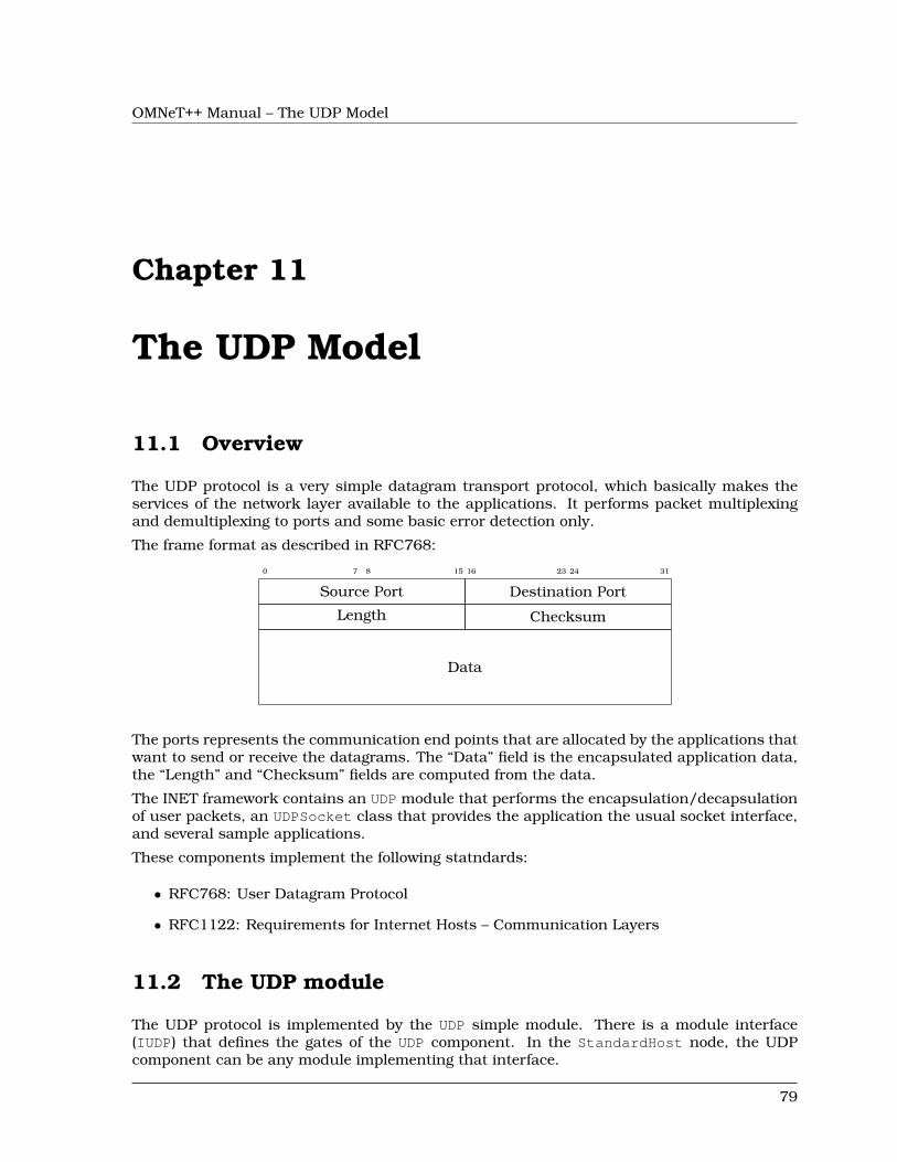
OMNeT++ Manual – The UDP Model
Chapter 11
The UDP Model
11.1 Overview
The UDP protocol is a very simple datagram transport protocol, which basically makes theservices of the network layer available to the applications. It performs packet multiplexingand demultiplexing to ports and some basic error detection only.
The frame format as described in RFC768:
0 7 8 15 16 23 24 31
Source Port Destination Port
Length Checksum
Data
The ports represents the communication end points that are allocated by the applications thatwant to send or receive the datagrams. The “Data” field is the encapsulated application data,the “Length” and “Checksum” fields are computed from the data.
The INET framework contains an UDP module that performs the encapsulation/decapsulationof user packets, an UDPSocket class that provides the application the usual socket interface,and several sample applications.
These components implement the following statndards:
• RFC768: User Datagram Protocol
• RFC1122: Requirements for Internet Hosts – Communication Layers
11.2 The UDP module
The UDP protocol is implemented by the UDP simple module. There is a module interface(IUDP) that defines the gates of the UDP component. In the StandardHost node, the UDPcomponent can be any module implementing that interface.
79
OMNeT++ Manual – The UDP Model
Each UDP module has gates to connect to the IPv4 and IPv6 network layer (ipIn/ipOut andipv6In/ipv6Out), and a gate array to connect to the applications (appIn/appOut).
The UDP module can be connected to several applications, and each application can useseveral sockets to send and receive UDP datagrams. The state of the sockets are stored withinthe UDP module and the application can configure the socket by sending command messagesto the UDP module. These command messages are distinguished by their kind and the typeof their control info. The control info identifies the socket and holds the parameters of thecommand.
Applications don’t have to send messages directly to the UDP module, as they can use theUDPSocket utility class, which encapsulates the messaging and provides a socket like inter-face to applications.
11.2.1 Sending UDP datagrams
If the application want to send datagrams, it optionally can connect to the destination. Itdoes this be sending a message with UDP_C_CONNECT kind and UDPConnectCommand controlinfo containing the remote address and port of the connection. The UDP protocol is in factconnectionless, so it does not send any packets as a result of the connect call. When the UDPmodule receives the connect request, it simply remembers the destination address and portand use it as default destination for later sends. The application can send several connectcommands to the same socket.
For sending an UDP packet, the application should attach an UDPSendCommand control info tothe packet, and send it to UDP. The control info may contain the destination address and port.If the destination address or port is unspecified in the control info then the packet is sent tothe connected target.
The UDP module encapsulates the application’s packet into an UDPPacket, creates an appro-priate IP control info and send it over ipOut or ipv6Out depending on the destination address.
The destination address can be the IPv4 local broadcast address (255.255.255.255) or a mul-ticast address. Before sending broadcast messages, the socket must be configured for broad-casting. This is done by sending an message to the UDP module. The message kind isUDP_C_SETOPTION and its control info (an UDPSetBroadcastCommand) tells if the broadcastis enabled. You can limit the multicast to the local network by setting the TTL of the IP pack-ets to 1. The TTL can be configured per socket, by sending a message to the UDP with anUDPSetTimeToLive control info containing the value. If the node has multiple interfaces, theapplication can choose which is used for multicast messages. This is also a socket option, theid of the interface (as registered in the interface table) can be given in an UDPSetMulticas-tInterfaceCommand control info.
NOTE: The UDP module supports only local broadcasts (using the special255.255.255.255 address). Packages that are broadcasted to a remote subnet are han-dled as undeliverable messages.
If the UDP packet cannot be delivered because nobody listens on the destination port, theapplication will receive a notification about the failure. The notification is a message withUDP_I_ERROR kind having attached an UDPErrorIndication control info. The control infocontains the local and destination address/port, but not the original packet.
After the application finished using a socket, it should close it by sending a messageUDP_C_CLOSE kind and UDPCloseCommand control info. The control info contains only the
80
OMNeT++ Manual – The UDP Model
socket identifier. This command frees the resources associated with the given socket, forexample its socket identifier or bound address/port.
11.2.2 Receiving UDP datagrams
Before receiving UDP datagrams applications should first “bind” to the given UDP port. Thiscan be done by sending a message with message kind UDP_C_BIND attached with an UDP-BindCommand control info. The control info contains the socket identifier and the local addressand port the application want to receive UDP packets. Both the address and port is optional.If the address is unspecified, than the UDP packets with any destination address is passed tothe application. If the port is -1, then an unused port is selected automatically by the UDPmodule. The localAddress/localPort combination must be unique.
When a packet arrives from the network, first its error bit is checked. Erronous messagesare dropped by the UDP component. Otherwise the application bound to the destination portis looked up, and the decapsulated packet passed to it. If no application is bound to thedestination port, an ICMP error is sent to the source of the packet. If the socket is connected,then only those packets are delivered to the application, that received from the connectedremote address and port.
The control info of the decapsulated packet is an UDPDataIndication and contains informa-tion about the source and destination address/port, the TTL, and the identifier of the interfacecard on which the packet was received.
The applications are bound to the unspecified local address, then they receive any packets tar-geted to their port. UDP also supports multicast and broadcast addresses; if they are used asdestination address, all nodes in the multicast group or subnet receives the packet. The socketreceives the broadcast packets only if it is configured for broadcast. To receive multicast mes-sages, the socket must join to the group of the multicast address. This is done be sending theUDP module an UDP_C_SETOPTION message with UDPJoinMulticastGroupsCommand con-trol info. The control info specifies the multicast addresses and the interface identifiers. Ifthe interface identifier is given only those multicast packets are received that arrived at thatinterface. The socket can stop receiving multicast messages if it leaves the multicast group.For this purpose the application should send the UDP another UDP_C_SETOPTION messagein their control info (UDPLeaveMulticastGroupsCommand) specifying the multicast addressesof the groups.
11.2.3 Signals
The UDP module emits the following signals:
• sentPk when an UDP packet sent to the IP, the packet
• rcvdPk when an UDP packet received from the IP, the packet
• passedUpPk when a packet passed up to the application, the packet
• droppedPkWrongPort when an undeliverable UDP packet received, the packet
• droppedPkBadChecksum when an erronous UDP packet received, the packet
81
OMNeT++ Manual – The UDP Model
11.3 UDP sockets
UDPSocket is a convenience class, to make it easier to send and receive UDP packets fromyour application models. You’d have one (or more) UDPSocket object(s) in your applicationsimple module class, and call its member functions (bind(), connect(), sendTo(), etc.) to createand configure a socket, and to send datagrams.
UDPSocket chooses and remembers the sockId for you, assembles and sends command pack-ets such as UDP_C_BIND to UDP, and can also help you deal with packets and notificationmessages arriving from UDP.
Here is a code fragment that creates an UDP socket and sends a 1K packet over it (the codecan be placed in your handleMessage() or activity()):
UDPSocket socket;socket.setOutputGate(gate("udpOut"));socket.connect(IPvXAddress("10.0.0.2"), 2000);
cPacket *pk = new cPacket("dgram");pk->setByteLength(1024);socket.send(pk);
socket.close();
Processing messages sent up by the UDP module is relatively straightforward. You onlyneed to distinguish between data packets and error notifications, by checking the messagekind (should be either UDP_I_DATA or UDP_I_ERROR), and casting the control info to UDP-DataIndication or UDPErrorIndication. USPSocket provides some help for this with the be-longsToSocket() and belongsToAnyUDPSocket() methods.
void MyApp::handleMessage(cMessage *msg){
if (msg->getKind() == UDP_I_DATA){
if (socket.belongsToSocket())processUDPPacket(PK(msg));
}else if (msg->getKind() == UDP_I_ERROR){
processUDPError(msg);}else{
error("Unrecognized message (%s)", msg->getClassName());}
}
11.4 UDP applications
All UDP applications should be derived from the IUDPApp module interface, so that the appli-cation of StandardHost could be configured without changing its NED file.
The following applications are implemented in INET:
82
OMNeT++ Manual – The UDP Model
• UDPBasicApp sends UDP packets to a given IP address at a given interval
• UDPBasicBurst sends UDP packets to the given IP address(es) in bursts, or acts as apacket sink.
• UDPEchoApp similar to UDPBasicApp, but it sends back the packet after reception
• UDPSink consumes and prints packets received from the UDP module
• UDPVideoStreamCli,UDPVideoStreamSvr simulates UDP streaming
The next sections describe these applications in details.
11.4.1 UDPBasicApp
The UDPBasicApp sends UDP packets to a the IP addresses given in the destAddressesparameter. The application sends a message to one of the targets in each sendIntervalinterval. The interval between message and the message length can be given as a randomvariable. Before the packet is sent, it is emitted in the sentPk signal.
The application simply prints the received UDP datagrams. The rcvdPk signal can be used todetect the received packets.
The number of sent and received messages are saved as scalars at the end of the simulation.
11.4.2 UDPSink
This module binds an UDP socket to a given local port, and prints the source and destinationand the length of each received packet.
11.4.3 UDPEchoApp
Similar to UDPBasicApp, but it sends back the packet after reception. It accepts only packetswith UDPEchoAppMsg type, i.e. packets that are generated by another UDPEchoApp.
When an echo response received, it emits an roundTripTime signal.
11.4.4 UDPVideoStreamCli
This module is a video streaming client. It send one “video streaming request” to the server attime startTime and receives stream from UDPVideoStreamSvr.
The received packets are emitted by the rcvdPk signal.
11.4.5 UDPVideoStreamSvr
This is the video stream server to be used with UDPVideoStreamCli.
The server will wait for incoming "video streaming requests". When a request arrives, it drawsa random video stream size using the videoSize parameter, and starts streaming to theclient. During streaming, it will send UDP packets of size packetLen at every sendInterval,until videoSize is reached. The parameters packetLen and sendInterval can be set to
83
OMNeT++ Manual – The UDP Model
constant values to create CBR traffic, or to random values (e.g. sendInterval=uniform(1e-6,1.01e-6)) to accomodate jitter.
The server can serve several clients, and several streams per client.
11.4.6 UDPBasicBurst
Sends UDP packets to the given IP address(es) in bursts, or acts as a packet sink. Compatiblewith both IPv4 and IPv6.
Addressing
The destAddresses parameter can contain zero, one or more destination addresses, sep-arated by spaces. If there is no destination address given, the module will act as packetsink. If there are more than one addresses, one of them is randomly chosen, either for thewhole simulation run, or for each burst, or for each packet, depending on the value of thechooseDestAddrMode parameter. The destAddrRNG parameter controls which (local) RNG isused for randomized address selection. The own addresses will be ignored.
An address may be given in the dotted decimal notation, or with the module name. (TheIPvXAddressResolver class is used to resolve the address.) You can use the "Broadcast"string as address for sending broadcast messages.
INET also defines several NED functions that can be useful:
- moduleListByPath("pattern",...):Returns a space-separated list of the modulenames. All modules whole getFullPath()matches one of the pattern parameters will get included. The patterns may containwilcards in the same syntax as in ini files. See cTopology::extractByModulePath() func-tion example: destaddresses = moduleListByPath("**.host[*]", "**.fixhost[*]")
- moduleListByNedType("fully.qualified.ned.type",...):Returns a space-separated list of the modulenames with the given NED type(s). Allmodules whose getNedTypeName() is listed in the given parameters will get included.The NED type name is fully qualified. See cTopology::extractByNedTypeName() functionexample: destaddresses = moduleListByNedType("inet.nodes.inet.StandardHost")
The peer can be UDPSink or another UDPBasicBurst.
Bursts
The first burst starts at startTime. Bursts start by immediately sending a packet; sub-sequent packets are sent at sendInterval intervals. The sendInterval parameter can be arandom value, e.g. exponential(10ms). A constant interval with jitter can be specified as1s+uniform(-0.01s,0.01s) or uniform(0.99s,1.01s). The length of the burst is controlled bythe burstDuration parameter. (Note that if sendInterval is greater than burstDuration,the burst will consist of one packet only.) The time between burst is the sleepDuration pa-rameter; this can be zero (zero is not allowed for sendInterval.) The zero burstDuration isinterpreted as infinity.
84
OMNeT++ Manual – The UDP Model
Packets
Packet length is controlled by the messageLength parameter.
The module adds two parameters to packets before sending:
- sourceID: source module ID
- msgId: incremented by 1 after send any packet.
When received packet has this parameters, the module checks the order of received packets.
Operation as sink
When destAddresses parameter is empty, the module receives packets and makes statisticsonly.
Statistics
Statistics are collected on outgoing packets:
- sentPk: packet object
Statistics are collected on incoming packets:
- outOfOrderPk: statistics of out of order packets. The packet is out of order, when hasmsgId and sourceId parameters and module received bigger msgId from same sourceID.
- dropPk: statistics of dropped packets. The packet is dropped when not out-of-orderpacket and delay time is larger than delayLimit parameter. The delayLimit=0 is infinity.
- rcvdPk: statistics of not dropped, not out-of-order packets.
- endToEndDelay: end to end delay statistics of not dropped, not out-of-order packets.
85

OMNeT++ Manual – The UDP Model
86
OMNeT++ Manual – The TCP Models
Chapter 12
The TCP Models
12.1 Overview
TCP protocol is the most widely used protocol of the Internet. It provides reliable, ordereddelivery of stream of bytes from one application on one computer to another application onanother computer. It is used by such applications as World Wide Web, email, file transferamongst others.
The baseline TCP protocol is described in RFC793, but other tens of RFCs contains modifi-cations and extensions to the TCP. These proposals enhance the efficiency and safety of theTCP protocol and they are widely implemented in the real TCP modules. As a result, TCP isa complex protocol and sometimes it is hard to see how the different requirements interactswith each other.
The TCP modules of the INET framework implements the following RFCs:
RFC 793 Transmission Control ProtocolRFC 896 Congestion Control in IP/TCP InternetworksRFC 1122 Requirements for Internet Hosts – Communication LayersRFC 1323 TCP Extensions for High PerformanceRFC 2018 TCP Selective Acknowledgment OptionsRFC 2581 TCP Congestion ControlRFC 2883 An Extension to the Selective Acknowledgement (SACK) Option for TCPRFC 3042 Enhancing TCP’s Loss Recovery Using Limited TransmitRFC 3390 Increasing TCP’s Initial WindowRFC 3517 A Conservative Selective Acknowledgment (SACK)-based Loss RecoveryAlgorithm for TCPRFC 3782 The NewReno Modification to TCP’s Fast Recovery Algorithm
In this section we describe the features of the TCP protocol specified by these RFCs, thefollowing sections deal with the implementation of the TCP in the INET framework.
12.1.1 TCP segments
The TCP module transmits a stream of the data over the unreliable, datagram service thatthe IP layer provides. When the application writes a chunk of data into the socket, the TCPmodule breaks it down to packets and hands it over the IP. On the receiver side, it collectsthe recieved packets, order them, and acknowledges the reception. The packets that are notacknowledged in time are retransmitted by the sender.
87
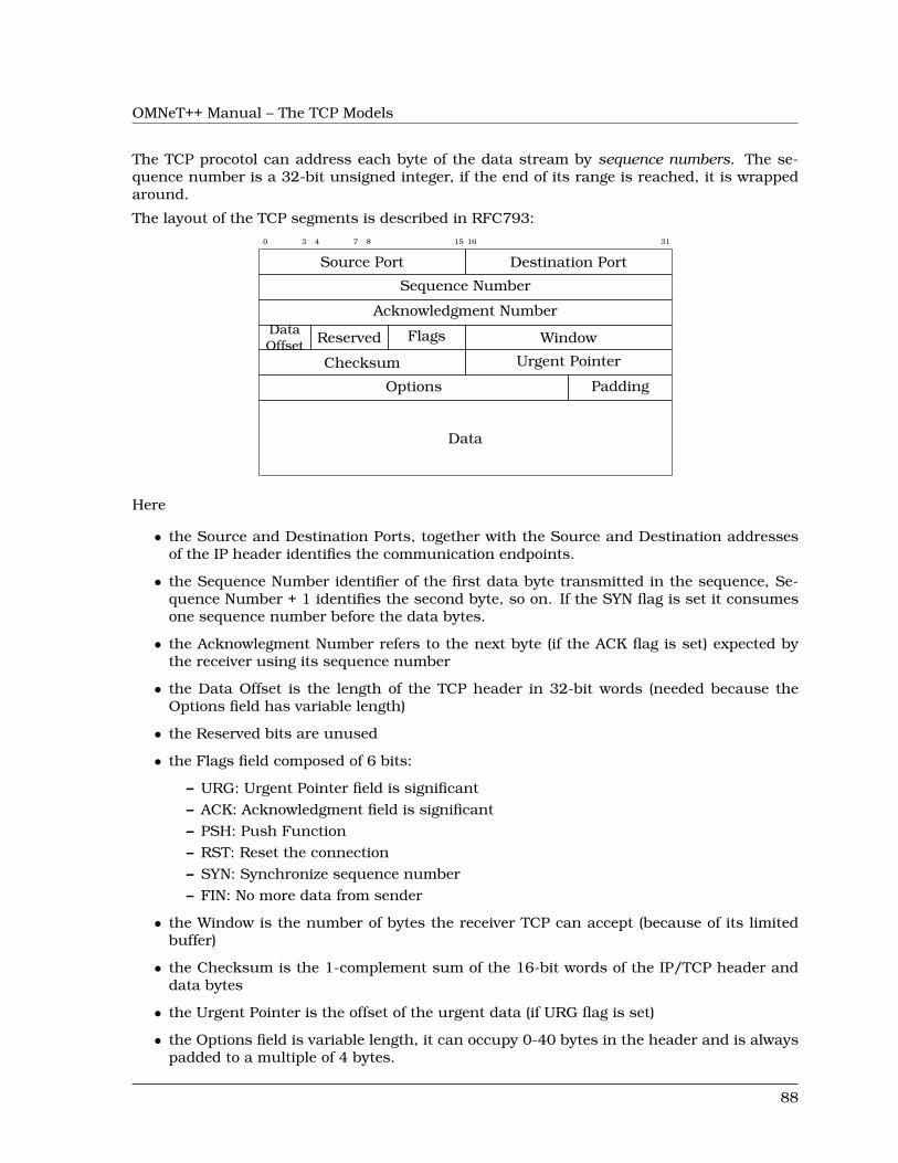
OMNeT++ Manual – The TCP Models
The TCP procotol can address each byte of the data stream by sequence numbers. The se-quence number is a 32-bit unsigned integer, if the end of its range is reached, it is wrappedaround.
The layout of the TCP segments is described in RFC793:0 3 4 7 8 15 16 31
Source Port Destination Port
Sequence Number
Acknowledgment NumberDataOffset Reserved Flags Window
Checksum Urgent Pointer
Options Padding
Data
Here
• the Source and Destination Ports, together with the Source and Destination addressesof the IP header identifies the communication endpoints.
• the Sequence Number identifier of the first data byte transmitted in the sequence, Se-quence Number + 1 identifies the second byte, so on. If the SYN flag is set it consumesone sequence number before the data bytes.
• the Acknowlegment Number refers to the next byte (if the ACK flag is set) expected bythe receiver using its sequence number
• the Data Offset is the length of the TCP header in 32-bit words (needed because theOptions field has variable length)
• the Reserved bits are unused
• the Flags field composed of 6 bits:
– URG: Urgent Pointer field is significant– ACK: Acknowledgment field is significant– PSH: Push Function– RST: Reset the connection– SYN: Synchronize sequence number– FIN: No more data from sender
• the Window is the number of bytes the receiver TCP can accept (because of its limitedbuffer)
• the Checksum is the 1-complement sum of the 16-bit words of the IP/TCP header anddata bytes
• the Urgent Pointer is the offset of the urgent data (if URG flag is set)
• the Options field is variable length, it can occupy 0-40 bytes in the header and is alwayspadded to a multiple of 4 bytes.
88
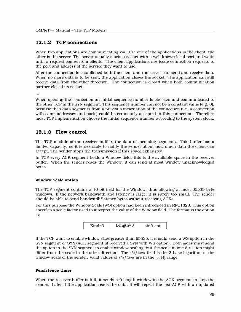
OMNeT++ Manual – The TCP Models
12.1.2 TCP connections
When two applications are communicating via TCP, one of the applications is the client, theother is the server. The server usually starts a socket with a well known local port and waitsuntil a request comes from clients. The client applications are issue connection requests tothe port and address of the service they want to use.
After the connection is established both the client and the server can send and receive data.When no more data is to be sent, the application closes the socket. The application can stillreceive data from the other direction. The connection is closed when both communicationpartner closed its socket.
...
When opening the connection an initial sequence number is choosen and communicated tothe other TCP in the SYN segment. This sequence number can not be a constant value (e.g. 0),because then data segments from a previous incarnation of the connection (i.e. a connectionwith same addresses and ports) could be erronously accepted in this connection. Thereforemost TCP implementation choose the initial sequence number according to the system clock.
12.1.3 Flow control
The TCP module of the receiver buffers the data of incoming segments. This buffer has alimited capacity, so it is desirable to notify the sender about how much data the client canaccept. The sender stops the transmission if this space exhausted.
In TCP every ACK segment holds a Window field; this is the available space in the receiverbuffer. When the sender reads the Window, it can send at most Window unacknowledgedbytes.
Window Scale option
The TCP segment contains a 16-bit field for the Window, thus allowing at most 65535 bytewindows. If the network bandwidth and latency is large, it is surely too small. The sendershould be able to send bandwitdh*latency bytes without receiving ACKs.
For this purpose the Window Scale (WS) option had been introduced in RFC1323. This optionspecifies a scale factor used to interpret the value of the Window field. The format is the optionis:
Kind=3 Length=3 shift.cnt
If the TCP want to enable window sizes greater than 65535, it should send a WS option in theSYN segment or SYN/ACK segment (if received a SYN with WS option). Both sides must sendthe option in the SYN segment to enable window scaling, but the scale in one direction mightdiffer from the scale in the other direction. The shift.cnt field is the 2-base logarithm of thewindow scale of the sender. Valid values of shift.cnt are in the [0, 14] range.
Persistence timer
When the reciever buffer is full, it sends a 0 length window in the ACK segment to stop thesender. Later if the application reads the data, it will repeat the last ACK with an updated
89
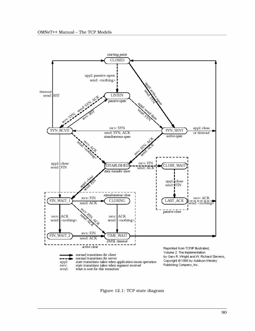
OMNeT++ Manual – The TCP Models
Figure 12.1: TCP state diagram
90
OMNeT++ Manual – The TCP Models
window to resume data sending. If this ACK segment is lost, then the sender is not notified,so a deadlock happens.
To avoid this situation the sender starts a Persistence Timer when it received a 0 size window.If the timer expires before the window is increased it send a probe segment with 1 byte ofdata. It will receive the current window of the receiver in the response to this segment.
Keepalive timer
TCP keepalive timer is used to detect dead connections.
12.1.4 Transmission policies
Retransmissions
When the sender TCP sends a TCP segment it starts a retransmission timer. If the ACK arrivesbefore the timer expires it is stopped, otherwise it triggers a retransmission of the segment.
If the retransmission timeout (RTO) is too high, then lost segments causes high delays, if it istoo low, then the receiver gets too many useless duplicated segments. For optimal behaviour,the timeout must be dynamically determined.
Jacobson suggested to measure the RTT mean and deviation and apply the timeout:
RTO = RTT + 4 ∗D
Here RTT and D are the measured smoothed roundtrip time and its smoothed mean deviation.They are initialized to 0 and updated each time an ACK segment received according to thefollowing formulas:
RTT = α ∗RTT + (1− α) ∗M
D = α ∗D + (1− α) ∗ |RTT −M |
where M is the time between the segments send and the acknowledgment arrival. Here the αsmoothing factor is typically 7/8.
One problem may occur when computing the round trip: if the retransmission timer timed outand the segment is sent again, then it is unclear that the received ACK is a response to the firsttransmission or to the second one. To avoid confusing the RTT calculation, the segments thathave been retransmitted do not update the RTT. This is known as Karn’s modification. He alsosuggested to double the RTO on each failure until the segments gets through (“exponentialbackoff”).
Delayed ACK algorithm
A host that is receiving a stream of TCP data segments can increase efficiency in both theInternet and the hosts by sending fewer than one ACK (acknowledgment) segment per datasegment received; this is known as a "delayed ACK" [TCP:5].
Delay is max. 500ms.
91
OMNeT++ Manual – The TCP Models
A delayed ACK gives the application an opportunity to update the window and perhaps to sendan immediate response. In particular, in the case of character-mode remote login, a delayedACK can reduce the number of segments sent by the server by a factor of 3 (ACK, windowupdate, and echo character all combined in one segment).
In addition, on some large multi-user hosts, a delayed ACK can substantially reduce pro-tocol processing overhead by reducing the total number of packets to be processed [TCP:5].However, excessive delays on ACK’s can disturb the round-trip timing and packet "clocking"algorithms [TCP:7].
a TCP receiver SHOULD send an immediate ACK when the incoming segment fills in all orpart of a gap in the sequence space.
Nagle’s algorithm
RFC896 describes the “small packet problem": when the application sends single-byte mes-sages to the TCP, and it transmitted immediatly in a 41 byte TCP/IP packet (20 bytes IPheader, 20 bytes TCP header, 1 byte payload), the result is a 4000% overhead that can causecongestion in the network.
The solution to this problem is to delay the transmission until enough data received fromthe application and send all collected data in one packet. Nagle proposed that when a TCPconnection has outstanding data that has not yet been acknowledged, small segments shouldnot be sent until the outstanding data is acknowledged.
Silly window avoidance
The Silly Window Syndrome (SWS) is described in RFC813. It occurs when a TCP receiveradvertises a small window and the TCP sender immediately sends data to fill the window. Let’stake the example when the sender process writes a file into the TCP stream in big chunks,while the receiver process reads the bytes one by one. The first few bytes are transmitted aswhole segments until the receiver buffer becomes full. Then the application reads one byte,and a window size 1 is offered to the sender. The sender sends a segment with 1 byte payloadimmediately, the receiver buffer becomes full, and after reading 1 byte, the offered window is1 byte again. Thus almost the whole file is transmitted in very small segments.
In order to avoid SWS, both sender and receiver must try to avoid this situation. The receivermust not advertise small windows and the sender must not send small segments when onlya small window is advertised.
In RFC813 it is offered that
1. the receiver should not advertise windows that is smaller than the maximum segmentsize of the connection
2. the sender should wait until the window is large enough for a maximum sized segment.
Timestamp option
Efficient retransmissions depends on precious RTT measurements. Packet losses can reducethe precision of these measurements radically. When a segment lost, the ACKs received inthat window can not be used; thus reducing the sample rate to one RTT data per window.This is unacceptable if the window is large.
92
OMNeT++ Manual – The TCP Models
The proposed solution to the problem is to use a separate timestamp field to connect therequest and the response on the sender side. The timestamp is transmitted as a TCP option.The option contains two 32-bit timestamps:
Kind=5 Length=10 TS Value TS Echo Reply
Here the TS Value (TSVal) field is the current value of the timestamp clock of the TCP sendingthe option, TS Echo Reply (TSecr) field is 0 or echoes the timestamp value of that was sent bythe remote TCP. The TSscr field is valid only in ACK segments that acknowledges new data.Both parties should send the TS option in their SYN segment in order to allow the TS optionin data segments.
The timestamp option can also be used for PAWS (protection against wrapped sequence num-bers).
12.1.5 Congestion control
Flow control allows the sender to slow down the transmission when the receiver can not acceptthem because of memory limitations. However there are other situations when a slow down isdesirable. If the sender transmits a lot of data into the network it can overload the processingcapacities of the network nodes, so packets are lost in the network layer.
For this purpose another window is maintained at the sender side, the congestion win-dow (CWND). The congestion window is a sender-side limit on the amount of data thesender can transmit into the network before receiving ACK. More precisely, the sender cansend at most max(CWND, WND) bytes above SND.UNA, therefore SND.NXT < SND.UNA +max(CWND,WND) is guaranteed.
The size of the congestion window is dinamically determined by monitoring the state of thenetwork.
Slow Start and Congestion Avoidance
There are two algorithm that updates the congestion window, “Slow Start” and “CongestionAvoidance”. They are specified in RFC2581.
cwnd← 2 ∗ SMSSssthresh← upper bound of the window (e.g. 65536)whenever ACK received
if cwnd < ssthreshcwnd← cwnd+ SMSS
otherwisecwnd← cwnd+ SMSS ∗ SMSS/cwnd
whenever packet loss detectedcwnd← SMSSssthresh← max(FlightSize/2, 2 ∗ SMSS)
Slow Start means that when the connection opened the sender initially sends the data witha low rate. This means that the initial window (IW) is at most 2 MSS, but no more than 2segments. If there was no packet loss, then the congestion window is increased rapidly, it isdoubled in each flight. When a packet loss is detected, the congestion window is reset to 1MSS (loss window, LW) and the “Slow Start” is applied again.
93

OMNeT++ Manual – The TCP Models
NOTE: RFC3390 increased the IW to roughly 4K bytes: min(4∗MSS,max(2∗MSS, 4380)).
When the congestion window reaches a certain limit (slow start threshold), the “CongestionAvoidance” algorithm is applied. During “Congestion Avoidance” the window is incrementedby 1 MSS per round-trip-time (RTT). This is usually implemented by updating the windowaccording to the cwnd+ = SMSS ∗ SMSS/cwnd formula on every non-duplicate ACK.
The Slow Start Threshold is updated when a packet loss is detected. It is set tomax(FlightSize/2, 2 ∗ SMSS).
How the sender estimates the flight size? The data sent, but not yet acknowledged.
How the sender detect packet loss? Retransmission timer expired.
Fast Retransmit and Fast Recovery
RFC2581 specifies two additional methods to increase the efficiency of congestion control:“Fast Retransmit” and “Fast Recovery”.
“Fast Retransmit” requires that the receiver signal the event, when an out-of-order segmentarrives. It is achieved by sending an immediate duplicate ACK. The receiver also sends animmediate ACK when the incoming segment fills in a gap or part of a gap.
When the sender receives the duplicated ACK it knows that some segment after that sequencenumber is received out-of-order or that the network duplicated the ACK. If 3 duplicated ACKreceived then it is more likely that a segment was dropped or delayed. In this case the senderstarts to retransmit the segments immediately.
“Fast Recovery” means that “Slow Start” is not applied when the loss is detected as 3 duplicateACKs. The arrival of the duplicate ACKs indicates that the network is not fully congested,segments after the lost segment arrived, as well the ACKs.
Loss Recovery Using Limited Transmit
If there is not enough data to be send after a lost segment, then the Fast Retransmit algorithmis not activated, but the costly retranmission timeout used.
RFC3042 suggests that the sender TCP should send a new data segment in response to eachof the first two duplicate acknowledgement. Transmitting these segments increases the prob-ability that TCP can recover from a single lost segment using the fast retransmit algorithm,rather than using a costly retransmission timeout.
Selective Acknowledgments
With selective acknowledgments (SACK), the data receiver can inform the sender about allsegments that have arrived successfully, so the sender need retransmit only the segmentsthat have actually been lost.
With the help of this information the sender can detect
• replication by the network
• false retransmit due to reordering
• retransmit timeout due to ACK loss
94
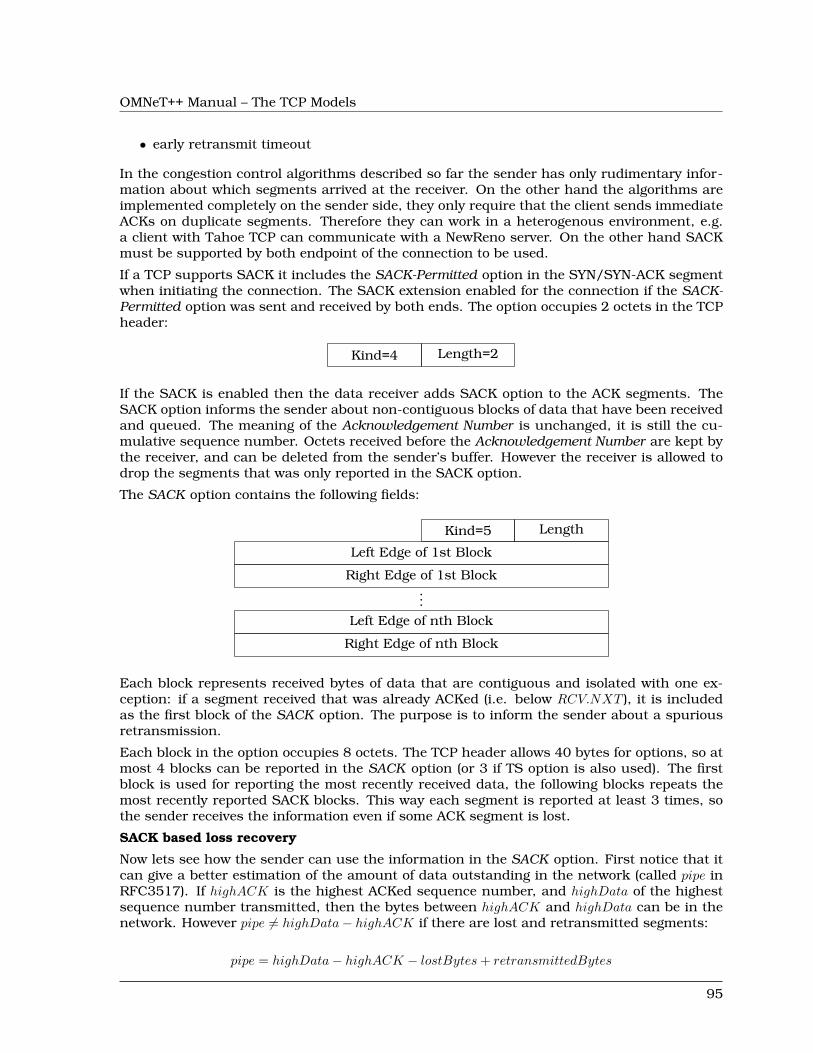
OMNeT++ Manual – The TCP Models
• early retransmit timeout
In the congestion control algorithms described so far the sender has only rudimentary infor-mation about which segments arrived at the receiver. On the other hand the algorithms areimplemented completely on the sender side, they only require that the client sends immediateACKs on duplicate segments. Therefore they can work in a heterogenous environment, e.g.a client with Tahoe TCP can communicate with a NewReno server. On the other hand SACKmust be supported by both endpoint of the connection to be used.
If a TCP supports SACK it includes the SACK-Permitted option in the SYN/SYN-ACK segmentwhen initiating the connection. The SACK extension enabled for the connection if the SACK-Permitted option was sent and received by both ends. The option occupies 2 octets in the TCPheader:
Kind=4 Length=2
If the SACK is enabled then the data receiver adds SACK option to the ACK segments. TheSACK option informs the sender about non-contiguous blocks of data that have been receivedand queued. The meaning of the Acknowledgement Number is unchanged, it is still the cu-mulative sequence number. Octets received before the Acknowledgement Number are kept bythe receiver, and can be deleted from the sender’s buffer. However the receiver is allowed todrop the segments that was only reported in the SACK option.
The SACK option contains the following fields:
Kind=5 Length
Left Edge of 1st Block
Right Edge of 1st Block...
Left Edge of nth Block
Right Edge of nth Block
Each block represents received bytes of data that are contiguous and isolated with one ex-ception: if a segment received that was already ACKed (i.e. below RCV.NXT ), it is includedas the first block of the SACK option. The purpose is to inform the sender about a spuriousretransmission.
Each block in the option occupies 8 octets. The TCP header allows 40 bytes for options, so atmost 4 blocks can be reported in the SACK option (or 3 if TS option is also used). The firstblock is used for reporting the most recently received data, the following blocks repeats themost recently reported SACK blocks. This way each segment is reported at least 3 times, sothe sender receives the information even if some ACK segment is lost.
SACK based loss recovery
Now lets see how the sender can use the information in the SACK option. First notice that itcan give a better estimation of the amount of data outstanding in the network (called pipe inRFC3517). If highACK is the highest ACKed sequence number, and highData of the highestsequence number transmitted, then the bytes between highACK and highData can be in thenetwork. However pipe 6= highData− highACK if there are lost and retransmitted segments:
pipe = highData− highACK − lostBytes+ retransmittedBytes
95
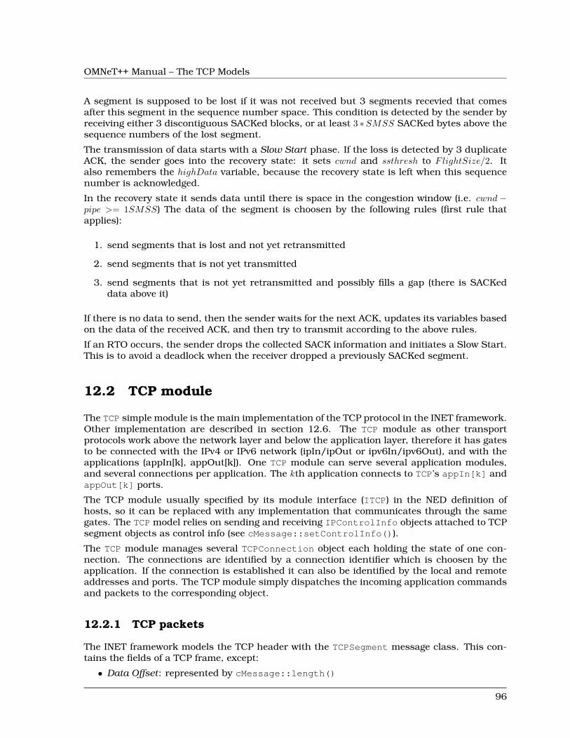
OMNeT++ Manual – The TCP Models
A segment is supposed to be lost if it was not received but 3 segments recevied that comesafter this segment in the sequence number space. This condition is detected by the sender byreceiving either 3 discontiguous SACKed blocks, or at least 3 ∗SMSS SACKed bytes above thesequence numbers of the lost segment.
The transmission of data starts with a Slow Start phase. If the loss is detected by 3 duplicateACK, the sender goes into the recovery state: it sets cwnd and ssthresh to FlightSize/2. Italso remembers the highData variable, because the recovery state is left when this sequencenumber is acknowledged.
In the recovery state it sends data until there is space in the congestion window (i.e. cwnd −pipe >= 1SMSS) The data of the segment is choosen by the following rules (first rule thatapplies):
1. send segments that is lost and not yet retransmitted
2. send segments that is not yet transmitted
3. send segments that is not yet retransmitted and possibly fills a gap (there is SACKeddata above it)
If there is no data to send, then the sender waits for the next ACK, updates its variables basedon the data of the received ACK, and then try to transmit according to the above rules.
If an RTO occurs, the sender drops the collected SACK information and initiates a Slow Start.This is to avoid a deadlock when the receiver dropped a previously SACKed segment.
12.2 TCP module
The TCP simple module is the main implementation of the TCP protocol in the INET framework.Other implementation are described in section 12.6. The TCP module as other transportprotocols work above the network layer and below the application layer, therefore it has gatesto be connected with the IPv4 or IPv6 network (ipIn/ipOut or ipv6In/ipv6Out), and with theapplications (appIn[k], appOut[k]). One TCP module can serve several application modules,and several connections per application. The kth application connects to TCP’s appIn[k] andappOut[k] ports.
The TCP module usually specified by its module interface (ITCP) in the NED definition ofhosts, so it can be replaced with any implementation that communicates through the samegates. The TCP model relies on sending and receiving IPControlInfo objects attached to TCPsegment objects as control info (see cMessage::setControlInfo()).
The TCP module manages several TCPConnection object each holding the state of one con-nection. The connections are identified by a connection identifier which is choosen by theapplication. If the connection is established it can also be identified by the local and remoteaddresses and ports. The TCP module simply dispatches the incoming application commandsand packets to the corresponding object.
12.2.1 TCP packets
The INET framework models the TCP header with the TCPSegment message class. This con-tains the fields of a TCP frame, except:
• Data Offset: represented by cMessage::length()
96
OMNeT++ Manual – The TCP Models
• Reserved• Checksum: modelled by cMessage::hasBitError()• Options: only EOL, NOP, MSS, WS, SACK_PERMITTED, SACK and TS are possible• Padding
The Data field can either be represented by (see TCPDataTransferMode):
• encapsulated C++ packet objects,• raw bytes as a ByteArray instance,• its byte count only,
corresponding to transfer modes OBJECT, BYTESTREAM, BYTECOUNT resp.
12.2.2 TCP commands
The application and the TCP module communicates with each other by sending cMessageobjects. These messages are specified in the TCPCommand.msg file.
The TCPCommandCode enumeration defines the message kinds that are sent by the applicationto the TCP:
• TCP_C_OPEN_ACTIVE: active open
• TCP_C_OPEN_PASSIVE: passive open
• TCP_C_SEND: send data
• TCP_C_CLOSE: no more data to send
• TCP_C_ABORT: abort connection
• TCP_C_STATUS: request status info from TCP
Each command message should have an attached control info of type TCPCommand. Somecommands (TCP_C_OPEN_xxx, TCP_C_SEND) use subclasses. The TCPCommand object hasa connId field that identifies the connection locally within the application. connId is to bechosen by the application in the open command.
When the application receives a message from the TCP, the message kind is set to one of theTCPStatusInd values:
• TCP_I_ESTABLISHED: connection established
• TCP_I_CONNECTION_REFUSED: connection refused
• TCP_I_CONNECTION_RESET: connection reset
• TCP_I_TIME_OUT: connection establish timer went off, or max retransmission countreached
• TCP_I_DATA: data packet
• TCP_I_URGENT_DATA: urgent data packet
• TCP_I_PEER_CLOSED: FIN received from remote TCP
• TCP_I_CLOSED: connection closed normally
• TCP_I_STATUS: status info
These messages also have an attached control info with TCPCommand or derived type (TCPCon-nectInfo, TCPStatusInfo, TCPErrorInfo).
97
OMNeT++ Manual – The TCP Models
12.2.3 TCP parameters
The TCP module has the following parameters:
• advertisedWindow in bytes, corresponds with the maximal receiver buffer capacity(Note: normally, NIC queues should be at least this size, default is 14*mss)
• delayedAcksEnabled delayed ACK algorithm (RFC 1122) enabled/disabled
• nagleEnabled Nagle’s algorithm (RFC 896) enabled/disabled
• limitedTransmitEnabled Limited Transmit algorithm (RFC 3042) enabled/disabled(can be used for TCPReno/TCPTahoe/TCPNewReno/TCPNoCongestionControl)
• increasedIWEnabled Increased Initial Window (RFC 3390) enabled/disabled
• sackSupport Selective Acknowledgment (RFC 2018, 2883, 3517) support (header option)(SACK will be enabled for a connection if both endpoints support it)
• windowScalingSupport Window Scale (RFC 1323) support (header option) (WS will beenabled for a connection if both endpoints support it)
• timestampSupport Timestamps (RFC 1323) support (header option) (TS will be enabledfor a connection if both endpoints support it)
• mss Maximum Segment Size (RFC 793) (header option, default is 536)
• tcpAlgorithmClass the name of TCP flavour
Possible values are “TCPReno” (default), “TCPNewReno”, “TCPTahoe”, “TCPNoConges-tionControl” and “DumpTCP”. In the future, other classes can be written which imple-ment Vegas, LinuxTCP or other variants. See section 12.4 for detailed description ofimplemented flavours.
Note that TCPOpenCommand allows tcpAlgorithmClass to be chosen per-connection.
• recordStats if set to false it disables writing excessive amount of output vectors
12.2.4 Statistics
The TCP module collects the following vectors:
98
OMNeT++ Manual – The TCP Models
send window SND.WNDreceive window RCV.WND, after SWS avoidance appliedadvertised window RCV.NXT +RCV.WNDsent seq Sequence Number of the sent segmentsent ack Acknowledgement Number of the sent segmentrcvd seq Sequence Number of the received segmentrcvd ack Acknowledgement Number of the received segmentunacked bytes number of sent and unacknowledged bytes
(maxofSND.NXT − SND.UNA)rcvd dupAcks number of duplicate acknowledgements, reset to 0 when
SND.UNA advancespipe the value of the SACK pipe variable (estimated number of
bytes outstanding in the network)sent sacks number of SACK blocks sentrcvd sacks number of SACK blocks receivedrcvd oooseg number of received out-of-order segmentsrcvd naseg number of received unacceptable segments (outside the re-
ceive window)rcvd sackedBytes total amount of SACKed bytes in the buffer of the sendertcpRcvQueueBytes number of bytes in the receiver’s buffertcpRcvQueueDrops number of bytes dropped by the receiver (not enough
buffer)cwnd congestion windowssthresh slow start thresholdmeasured RTT measured round trip timesmoothed RTT smoothed round trip timeRTTVAR measured smoothed variance of round trip timeRTO retransmission timeoutnumRTOs number of retransmission timeouts occured
If the recordStats parameter is set to false, then none of these output vectors are generated.
12.3 TCP connections
Most part of the TCP specification is implemented in the TCPConnection class: takes care ofthe state machine, stores the state variables (TCB), sends/receives SYN, FIN, RST, ACKs, etc.TCPConnection itself implements the basic TCP “machinery”, the details of congestion controlare factored out to TCPAlgorithm classes.
There are two additional objects the TCPConnection relies on internally: instances ofTCPSendQueue and TCPReceiveQueue. These polymorph classes manage the actual datastream, so TCPConnection itself only works with sequence number variables. This makesit possible to easily accomodate need for various types of simulated data transfer: real bytestream, "virtual" bytes (byte counts only), and sequence of cMessage objects (where everymessage object is mapped to a TCP sequence number range).
12.3.1 Data transfer modes
Different applications have different needs how to represent the messages they communicatewith. Sometimes it is enough to simulate the amount of data transmitted (“200 MB”), contentsdoes not matter. In other scenarios contents matters a lot. The messages can be represented
99
OMNeT++ Manual – The TCP Models
as a stream of bytes, but sometimes it is easier for the applications to pass message objectsto each other (e.g. HTTP request represented by a HTTPRequest message class).
The TCP modules in the INET framework support 3 data transfer modes:
• TCP_TRANSFER_BYTECOUNT: only byte counts are represented, no actual payload inTCPSegments. The TCP sends as many TCP segments as needed
• TCP_TRANSFER_BYTESTREAM: the application can pass byte arrays to the TCP. The send-ing TCP breaks down the bytes into MSS sized chunks and transmits them as the payloadof the TCP segments. The receiving application can read the chunks of the data.
• TCP_TRANSFER_OBJECT: the application pass a cMessage object to the TCP. The sendingTCP sends as many TCP segments as needed according to the message length. The cMes-sage object is also passed as the payload of the first segment. The receiving applicationreceives the object only when its last byte is received.
These values are defined in TCPCommand.msg as the TCPDataTransferMode enumeration. Theapplication can set the data transfer mode per connection when the connection is opened. Theclient and the server application must specify the same data transfer mode.
12.3.2 Opening connections
Applications can open a local port for incoming connections by sending the TCP aTCP_C_PASSIVE_OPEN message. The attached control info (an TCPOpenCommand) containsthe local address and port. The application can specify that it wants to handle only one con-nection at a time, or multiple simultanous connections. If the fork field is true, it emulatesthe Unix accept(2) semantics: a new connection structure is created for the connection (witha new connId), and the connection with the old connection id remains listening. If fork isfalse, then the first connection is accepted (with the original connId), and further incomingconnections will be refused by the TCP by sending an RST segment. The dataTransferModefield in TCPOpenCommand specifies whether the application data is transmitted as C++ objects,real bytes or byte counts only. The congestion control algorithm can also be specified on a perconnection basis by setting tcpAlgorithmClass field to the name of the algorithm.
The application opens a connection to a remote server by sending the TCP aTCP_C_OPEN_ACTIVE command. The TCP creates a TCPConnection object an sends a SYNsegment. The initial sequence number selected according to the simulation time: 0 at time 0,and increased by 1 in each 4µs. If there is no response to the SYN segment, it retry after 3s,9s, 21s and 45s. After 75s a connection establishment timeout (TCP_I_TIMEOUT) reported tothe application and the connection is closed.
When the connection gets established, TCP sends a TCP_I_ESTABLISHED notification to theapplication. The attached control info (a TCPConnectInfo instance) will contain the local andremote addresses and ports of the connection. If the connection is refused by the remote peer(e.g. the port is not open), then the application receives a TCP_I_CONNECTION_REFUSEDmessage.
NOTE: If you do active OPEN, then send data and close before the connection hasreached ESTABLISHED, the connection will go from SYN_SENT to CLOSED without ac-tually sending the buffered data. This is consistent with RFC 793 but may not be whatyou would expect.
100
OMNeT++ Manual – The TCP Models
NOTE: Handling segments with SYN+FIN bits set (esp. with data too) is inconsistentacross TCPs, so check this one if it is of importance.
12.3.3 Sending Data
The application can write data into the connection by sending a message with TCP_C_SENDkind to the TCP. The attached control info must be of type TCPSendCommand.
The TCP will add the message to the send queue. There are three type of send queues corre-sponding to the three data transfer mode. If the payload is transmitted as a message object,then TCPMsgBasedSendQueue; if the payload is a byte array then TCPDataStreamSendQueue;if only the message lengths are represented then TCPVirtualDataSendQueue are the classesof send queues. The appropriate queue is created based on the value of the dataTransfer-Mode parameter of the Open command, no further configuration is needed.
The message is handed over to the IP when there is enough room in the windows. If Nagle’salgorithm is enabled, the TCP will collect 1 SMSS data and sends them toghether.
NOTE: There is no way to set the PUSH and URGENT flags, when sending data.
12.3.4 Receiving Data
The TCP connection stores the incoming segments in the receive queue. The receive queuealso has three flavours: TCPMsgBasedRcvQueue, TCPDataStreamRcvQueue and TCPVirtu-alDataRcvQueue. The queue is created when the connection is opened according to thedataTransferMode of the connection.
Finite receive buffer size is modeled by the advertisedWindow parameter. If receive bufferis exhausted (by out-of-order segments) and the payload length of a new received segmentis higher than the free receiver buffer, the new segment will be dropped. Such drops arerecorded in tcpRcvQueueDrops vector.
If the Sequence Number of the received segment is the next expected one, then the data ispassed to the application immediately. The recv() call of Unix is not modeled.
The data of the segment, which can be either a cMessage object, a ByteArray object, or asimply byte count, is passed to the application in a message that has TCP_I_DATA kind.
NOTE: The TCP module does not handle the segments with PUSH or URGENT flagsspecially. The data of the segment passed to the application as soon as possible, but theapplication can not find out if that data is urgent or pushed.
12.3.5 RESET handling
When an error occures at the TCP level, an RST segment is sent to the communication partnerand the connection is aborted. Such error can be:
• arrival of a segment in CLOSED state• an incoming segment acknowledges something not yet sent.
The receiver of the RST it will abort the connection. If the connection is not yet established,then the passive end will go back to the LISTEN state and waits for another incoming connec-tion instead of aborting.
101
OMNeT++ Manual – The TCP Models
12.3.6 Closing connections
When the application does not have more data to send, it closes the connection by sending aTCP_C_CLOSE command to the TCP. The TCP will transmit all data from its buffer and in thelast segment sets the FIN flag. If the FIN is not acknowledged in time it will be retransmittedwith exponential backoff.
The TCP receiving a FIN segment will notify the application that there is no more data fromthe communication partner. It sends a TCP_I_PEER_CLOSED message to the applicationcontaining the connection identifier in the control info.
When both parties have closed the connection, the applications receive a TCP_I_CLOSEDmessage and the connection object is deleted. (Actually one of the TCPs waits for 2MSL beforedeleting the connection, so it is not possible to reconnect with the same addresses and portnumbers immediately.)
12.3.7 Aborting connections
The application can also abort the connection. This means that it does not wait for incom-ing data, but drops the data associated with the connection immediately. For this purposethe application sends a TCP_C_ABORT message specifying the connection identifier in theattached control info. The TCP will send a RST to the communication partner and deletesthe connection object. The application should not reconnect with the same local and remoteaddresses and ports within MSL (maximum segment lifetime), because segments from the oldconnection might be accepted in the new one.
12.3.8 Status Requests
Applications can get detailed status information about an existing connection. For this pur-pose they send the TCP module a TCP_C_STATUS message attaching an TCPCommand info withthe identifier of the connection. The TCP will respond with a TCP_I_STATUS message with aTCPStatusInfo attachement. This control info contains the current state, local and remoteaddresses and ports, the initial sequence numbers, windows of the receiver and sender, etc.
12.4 TCP algorithms
The TCPAlgorithm object controls retransmissions, congestion control and ACK sending: de-layed acks, slow start, fast retransmit, etc. They are all extends the TCPAlgorithm class. Thissimplifies the design of TCPConnection and makes it a lot easier to implement TCP variationssuch as Tahoe, NewReno, Vegas or LinuxTCP.
Currently implemented algorithm classes are TCPReno, TCPTahoe, TCPNewReno, TCPNoCon-gestionControl and DumbTCP. It is also possible to add new TCP variations by implementingTCPAlgorithm.
102
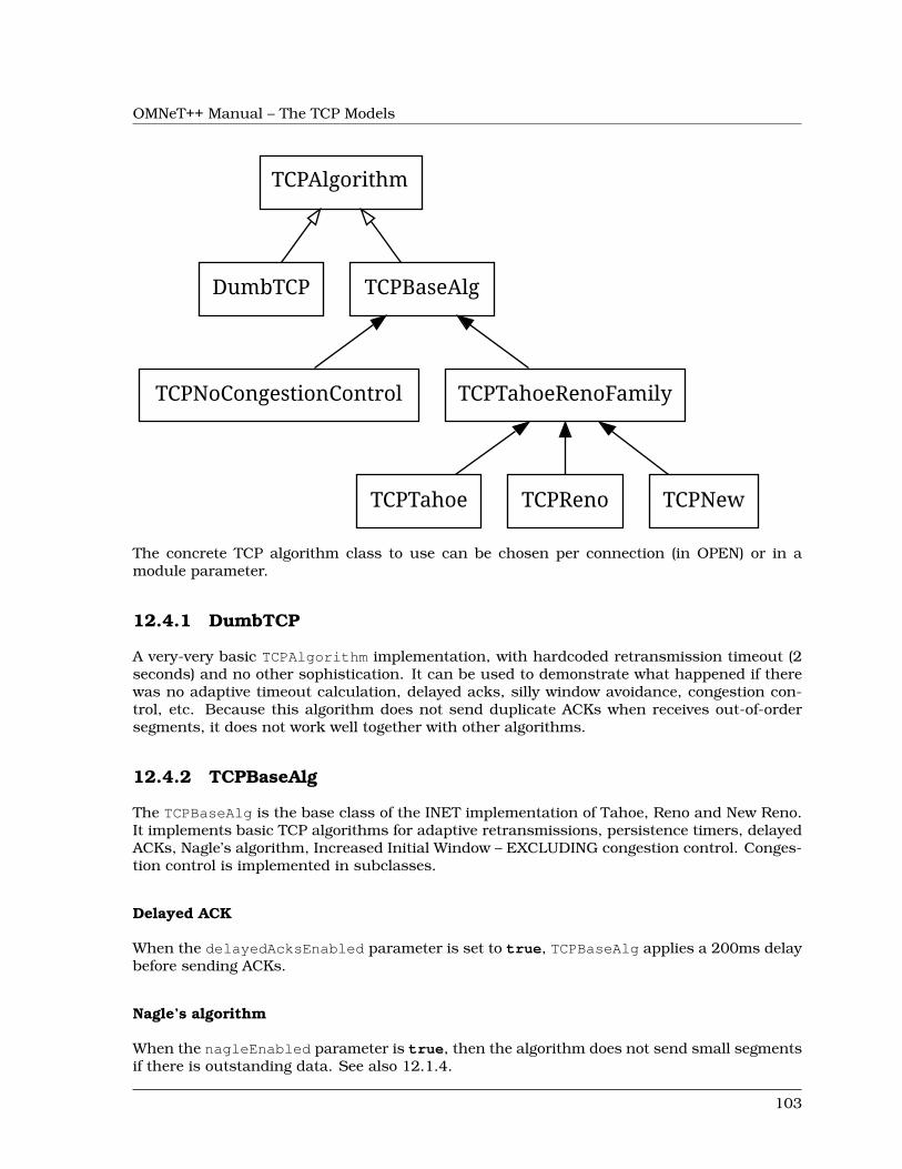
OMNeT++ Manual – The TCP Models
TCPAlgorithm
DumbTCP TCPBaseAlg
TCPNoCongestionControl TCPTahoeRenoFamily
TCPTahoe TCPReno TCPNew
The concrete TCP algorithm class to use can be chosen per connection (in OPEN) or in amodule parameter.
12.4.1 DumbTCP
A very-very basic TCPAlgorithm implementation, with hardcoded retransmission timeout (2seconds) and no other sophistication. It can be used to demonstrate what happened if therewas no adaptive timeout calculation, delayed acks, silly window avoidance, congestion con-trol, etc. Because this algorithm does not send duplicate ACKs when receives out-of-ordersegments, it does not work well together with other algorithms.
12.4.2 TCPBaseAlg
The TCPBaseAlg is the base class of the INET implementation of Tahoe, Reno and New Reno.It implements basic TCP algorithms for adaptive retransmissions, persistence timers, delayedACKs, Nagle’s algorithm, Increased Initial Window – EXCLUDING congestion control. Conges-tion control is implemented in subclasses.
Delayed ACK
When the delayedAcksEnabled parameter is set to true, TCPBaseAlg applies a 200ms delaybefore sending ACKs.
Nagle’s algorithm
When the nagleEnabled parameter is true, then the algorithm does not send small segmentsif there is outstanding data. See also 12.1.4.
103
OMNeT++ Manual – The TCP Models
Persistence Timer
The algorithm implements Persistence Timer (see 12.1.3). When a zero-sized window is re-ceived it starts the timer with 5s timeout. If the timer expires before the window is increased,a 1-byte probe is sent. Further probes are sent after 5, 6, 12, 24, 48, 60, 60, 60, ... secondsuntil the window becomes positive.
Initial Congestion Window
Congestion window is set to 1 SMSS when the connection is established. If the increasedI-WEnabled parameter is true, then the initial window is increased to 4380 bytes, but at least2 SMSS and at most 4 SMSS. The congestion window is not updated afterwards; subclassescan add congestion control by redefining virtual methods of the TCPBaseAlg class.
Duplicate ACKs
The algorithm sends a duplicate ACK when an out-of-order segment is received or when theincoming segment fills in all or part of a gap in the sequence space.
RTO calculation
Retransmission timeout (RTO) is calculated according to Jacobson algorithm (with α = 7/8),and Karn’s modification is also applied. The initial value of the RTO is 3s, its minimum is 1s,maximum is 240s (2 MSL).
12.4.3 TCPNoCongestion
TCP with no congestion control (i.e. congestion window kept very large). Can be used todemonstrate effect of lack of congestion control.
12.4.4 TCPTahoe
The TCPTahoe algorithm class extends TCPBaseAlg with Slow Start, Congestion Avoidance andFast Retransmit congestion control algorithms. This algorithm initiates a Slow Start when apacket loss is detected.
Slow Start
The congestion window is initially set to 1 SMSS or in case of increasedIWEnabled is trueto 4380 bytes (but no less than 2 SMSS and no more than 4 SMSS). The window is increasedon each incoming ACK by 1 SMSS, so it is approximately doubled in each RTT.
Congestion Avoidance
When the congestion window exceeded ssthresh, the window is increased by SMSS2/cwnd oneach incoming ACK event, so it is approximately increased by 1 SMSS per RTT.
104
OMNeT++ Manual – The TCP Models
Fast Retransmit
When the 3rd duplicate ACK received, a packet loss is detected and the packet is retransmittedimmediately. Simultanously the ssthresh variable is set to half of the cwnd (but at least 2 SMSS)and cwnd is set to 1 SMSS, so it enters slow start again.
Retransmission timeouts are handled the same way: ssthresh will be cwnd/2, cwnd will be 1SMSS.
12.4.5 TCPReno
The TCPReno algorithm extends the behaviour TCPTahoe with Fast Recovery. This algorithmcan also use the information transmitted in SACK options, which enables a much more accu-rate congestion control.
Fast Recovery
When a packet loss is detected by receiveing 3 duplicate ACKs, ssthresh set to half of thecurrent window as in Tahoe. However cwnd is set to ssthresh + 3 ∗ SMSS so it remains incongestion avoidance mode. Then it will send one new segment for each incoming duplicateACK trying to keep the pipe full of data. This requires the congestion window to be inflated oneach incoming duplicate ACK; it will be deflated to ssthresh when new data gets acknowledged.
However a hard packet loss (i.e. RTO events) cause a slow start by setting cwnd to 1 SMSS.
SACK congestion control
This algorithm can be used with the SACK extension. Set the sackSupport parameter to trueto enable sending and receiving SACK options.
12.4.6 TCPNewReno
This class implements the TCP variant known as New Reno. New Reno recovers more effi-ciently from multiple packet losses within one RTT than Reno does.
It does not exit fast-recovery phase until all data which was out-standing at the time it enteredfast-recovery is acknowledged. Thus avoids reducing the cwnd multiple times.
12.5 TCP socket
TCPSocket is a convenience class, to make it easier to manage TCP connections from yourapplication models. You’d have one (or more) TCPSocket object(s) in your application simplemodule class, and call its member functions (bind(), listen(), connect(), etc.) to open, close orabort a TCP connection.
TCPSocket chooses and remembers the connId for you, assembles and sends command pack-ets (such as OPEN_ACTIVE, OPEN_PASSIVE, CLOSE, ABORT, etc.) to TCP, and can also helpyou deal with packets and notification messages arriving from TCP.
105
OMNeT++ Manual – The TCP Models
A session which opens a connection from local port 1000 to 10.0.0.2:2000, sends 16K ofdata and closes the connection may be as simple as this (the code can be placed in yourhandleMessage() or activity()):
TCPSocket socket;socket.connect(IPvXAddress("10.0.0.2"), 2000);
msg = new cMessage("data1");msg->setByteLength(16*1024); 16Ksocket.send(msg);
socket.close();
Dealing with packets and notification messages coming from TCP is somewhat more cum-bersome. Basically you have two choices: you either process those messages yourself, orlet TCPSocket do part of the job. For the latter, you give TCPSocket a callback objecton which it’ll invoke the appropriate member functions: socketEstablished(), socket-DataArrived(), socketFailure(), socketPeerClosed(), etc (these are methods of TCP-Socket::CallbackInterface)., The callback object can be your simple module class too.
This code skeleton example shows how to set up a TCPSocket to use the module itself ascallback object:
class MyModule : public cSimpleModule, public TCPSocket::CallbackInterface{
TCPSocket socket;virtual void socketDataArrived(int connId, void *yourPtr,
cPacket *msg, bool urgent);virtual void socketFailure(int connId, void *yourPtr, int code);...
};
void MyModule::initialize() {socket.setCallbackObject(this,NULL);
}
void MyModule::handleMessage(cMessage *msg) {if (socket.belongsToSocket(msg))
socket.processMessage(msg); dispatch to socketXXXX() methodselse
...}
void MyModule::socketDataArrived(int, void *, cPacket *msg, bool) {ev << "Received TCP data, " << msg->getByteLength() << " bytes\\n";delete msg;
}
void MyModule::socketFailure(int, void *, int code) {if (code==TCP_I_CONNECTION_RESET)
ev << "Connection reset!\\n";else if (code==TCP_I_CONNECTION_REFUSED)
ev << "Connection refused!\\n";else if (code==TCP_I_TIMEOUT)
106
OMNeT++ Manual – The TCP Models
ev << "Connection timed out!\\n";}
If you need to manage a large number of sockets (e.g. in a server application which handlesmultiple incoming connections), the TCPSocketMap class may be useful. The following codefragment to handle incoming connections is from the LDP module:
TCPSocket *socket = socketMap.findSocketFor(msg);if (!socket){
not yet in socketMap, must be new incoming connection: add to socketMapsocket = new TCPSocket(msg);socket->setOutputGate(gate("tcpOut"));socket->setCallbackObject(this, NULL);socketMap.addSocket(socket);
}dispatch to socketEstablished(), socketDataArrived(), socketPeerClosed()or socketFailure()socket->processMessage(msg);
12.6 Other TCP implementations
INET contains two other implementation of the TCP protocol: TCP_lwIP and TCP_NSC. AllTCP modules implements the ITCP interface and communicate with the application and theIP layer through the same interface. Therefore they can be interchanged and can operatewith each other. See examples/inet/tcpclientserver/omnetpp.ini how to parametrizeStandardHosts to use the different implementations.
12.6.1 TCP LWIP
lwIP is a light-weight implementation of the TCP/IP protocol suite that was originally writtenby Adam Dunkels of the Swedish Institute of Computer Science. The current developmenthomepage is http://savannah.nongnu.org/projects/lwip/.
The implementation targets embedded devices: it has very limited resource usage (it works“with tens of kilobytes of RAM and around 40 kilobytes of ROM”) and does not require anunderlying OS.
The TCP_lwIP simple module is based on the 1.3.2 version of the lwIP sources.
Features:
• delayed ACK• Nagle’s algorithm• round trip time estimation• adaptive retransmission timeout• SWS avoidance• slow start threshold• fast retransmit• fast recovery• persist timer• keep-alive timer
107
OMNeT++ Manual – The TCP Models
Limitations
• only MSS and TS TCP options are supported. The TS option is turned off by default, butcan be enabled by defining LWIP_TCP_TIMESTAMPS to 1 in lwipopts.h.
• fork must be true in the passive open command
• The status request command (TCP_C_STATUS) only reports the local and remoteaddresses/ports of the connection and the MSS, SND.NXT, SND.WND, SND.WL1,SND.WL2, RCV.NXT, RCV.WND variables.
Statistics
The TCP_lwIP module generates the following vector files:
• send window: value of the SND.WND variable
• sent seq: Sequence Number of the sent segment
• sent ack: Acknowledgment Number of the sent segment
• receive window: value of the RCV.WND variable
• rcvd seq: Sequence Number of the received segment
• rcvd acq: Acknowledgment Number of the received segment
The creation of these vectors can be disabled by setting the recordStats parameter to false.
12.6.2 TCP NSC
Network Simulation Cradle (NSC) is a tool that allow real-world TCP/IP network stacks tobe used in simulated networks. The NSC project is created by Sam Jansen and avail-able on http://research.wand.net.nz/software/nsc.php. NSC currently contains Linux,FreeBSD, OpenBSD and lwIP network stacks, altough on 64-bit systems only Linux imple-mentations can be built.
To use the TCP_NSC module you should download the nsc-0.5.2.tar.bz2 package and followthe instructions in the <inet_root>/3rdparty/README file to build it.
WARNING: Before generating the INET module, check that the opp_makemake call in themake file (<inet_root>/Makefile) includes the -DWITH_TCP_NSC argument. Withoutthis option the TCP_NSC module is not built. If you build the INET library from the IDE,it is enough to enable the TCP (NSC) project feature.
Parameters
The TCP_NSC module has the following parameters:
• stackName: the name of the TCP implementation to be used. Possible values are:liblinux2.6.10.so, liblinux2.6.18.so, liblinux2.6.26.so, libopenbsd3.5.so,libfreebsd5.3.so and liblwip.so. (On the 64 bit systems, the liblinux2.6.26.soand liblinux2.6.16.so are available only).
108
OMNeT++ Manual – The TCP Models
• stackBufferSize: the size of the receive and send buffer of one connection for selectedTCP implementation. The NSC sets the wmem_max, rmem_max, tcp_rmem, tcp_wmem pa-rameters to this value on linux TCP implementations. For details, you can see the NSCdocumentation.
Statistics
The TCP_NSC module collects the following vectors:
• sent seq Sequence Number of the sent TCP segment
• sent ack Acknowledgment Number of the sent TCP segment
• rcvd seq Sequence Number of the received TCP segment
• rcvd ack Acknowledgement Number of the received TCP segment
Limitations
• Because the kernel code is not reentrant, NSC creates a record containing the globalvariables of the stack implementation. By default there is room for 50 instance in thistable, so you can not create more then 50 instance of TCP_NSC. You can increase theNUM_STACKS constant in num_stacks.h and recompile NSC to overcome this limitation.
• The TCP_NSC module does not supprt TCP_TRANSFER_OBJECT data transfer mode.
• The MTU of the network stack fixed to 1500, therefore MSS is 1460.
• TCP_C_STATUS command reports only local/remote addresses/ports and current win-dow of the connection.
12.7 TCP applications
This sections describes the applications using the TCP protocol. Each application must im-plement the ITCPApp module interface to ease configuring the StandardHost module.
The applications described here are all contained by the inet.applications.tcpapp pack-age. These applications use GenericAppMsg objects to represent the data sent between theclient and server. The client message contains the expected reply length, the processing de-lay, and a flag indicating that the connection should be closed after sending the reply. Thisway intelligence (behaviour specific to the modelled application, e.g. HTTP, SMB, databaseprotocol) needs only to be present in the client, and the server model can be kept simple anddumb.
12.7.1 TCPBasicClientApp
Client for a generic request-response style protocol over TCP. May be used as a rough modelof HTTP or FTP users.
The model communicates with the server in sessions. During a session, the client opens asingle TCP connection to the server, sends several requests (always waiting for the completereply to arrive before sending a new request), and closes the connection.
109
OMNeT++ Manual – The TCP Models
The server app should be TCPGenericSrvApp; the model sends GenericAppMsg messages.
Example settings:
FTP
numRequestsPerSession = exponential(3)requestLength = truncnormal(20,5)replyLength = exponential(1000000)
HTTP
numRequestsPerSession = 1 # HTTP 1.0numRequestsPerSession = exponential(5) # HTTP 1.1, with keepaliverequestLength = truncnormal(350,20)replyLength = exponential(2000)
Note that since most web pages contain images and may contain frames, applets etc, possiblyfrom various servers, and browsers usually download these items in parallel to the main HTMLdocument, this module cannot serve as a realistic web client.
Also, with HTTP 1.0 it is the server that closes the connection after sending the response,while in this model it is the client.
12.7.2 TCPSinkApp
Accepts any number of incoming TCP connections, and discards whatever arrives on them.
The module parameter dataTransferMode should be set the transfer mode in TCP layer. Itspossible values (“bytecount”, “object”, “bytestream”) are described in ...
12.7.3 TCPGenericSrvApp
Generic server application for modelling TCP-based request-reply style protocols or applica-tions.
Requires message object preserving sendQueue/receiveQueue classes to be usedwith TCP (that is, TCPMsgBasedSendQueue and TCPMsgBasedRcvQueue; TCPVirtual-BytesSendQueue/RcvQueue are not good).
The module accepts any number of incoming TCP connections, and expects to receive mes-sages of class GenericAppMsg on them. A message should contain how large the reply shouldbe (number of bytes). TCPGenericSrvApp will just change the length of the received messageaccordingly, and send back the same message object. The reply can be delayed by a constanttime (replyDelay parameter).
12.7.4 TCPEchoApp
The TCPEchoApp application accepts any number of incoming TCP connections, and sendsback the messages that arrive on them, The lengths of the messages are multiplied byechoFactor before sending them back (echoFactor=1 will result in sending back the same
110
OMNeT++ Manual – The TCP Models
message unmodified.) The reply can also be delayed by a constant time (echoDelay parame-ter).
When TCPEchoApp receives data packets from TCP (and such, when they can be echoed)depends on the dataTransferMode setting. With "bytecount" and "bytestream", TCP passesup data to us as soon as a segment arrives, so it can be echoed immediately. With "object"mode, our local TCP reproduces the same messages that the sender app passed down to itsTCP – so if the sender app sent a single 100 MB message, it will be echoed only when all 100megabytes have arrived.
12.7.5 TCPSessionApp
Single-connection TCP application: it opens a connection, sends the given number of bytes,and closes. Sending may be one-off, or may be controlled by a "script" which is a series of(time, number of bytes) pairs. May act either as client or as server, and works with TCPVirtu-alBytesSendQueue/RcvQueue as sendQueue/receiveQueue setting for TCP. Compatible withboth IPv4 ( IPv4) and IPv6.
Opening the connection
Regarding the type of opening the connection, the application may be either a client or aserver. When active=false, the application will listen on the given local localPort, and wait foran incoming connection. When active=true, the application will bind to given local localAd-dress:localPort, and connect to the connectAddress:connectPort. To use an ephemeral port aslocal port, set the localPort parameter to -1.
Even when in server mode (active=false), the application will only serve one incoming connec-tion. Further connect attempts will be refused by TCP (it will send RST) for lack of LISTENingconnections.
The time of opening the connection is in the tOpen parameter.
Sending data
Regardless of the type of OPEN, the application can be made to send data. One way ofspecifying sending is via the tSend, sendBytes parameters, the other way is sendScript. Withthe former, sendBytes bytes will be sent at tSend. With sendScript, the format is "<time><numBytes>;<time> <numBytes>;..."
Closing the connection
The application will issue a TCP CLOSE at time tClose. If tClose=-1, no CLOSE will be issued.
12.7.6 TelnetApp
Models Telnet sessions with a specific user behaviour. The server app should be TCPGener-icSrvApp.
In this model the client repeats the following activity between startTime and stopTime:
1. opens a telnet connection
111
OMNeT++ Manual – The TCP Models
2. sends numCommands commands. The command is commandLength bytes long. The com-mand is transmitted as entered by the user character by character, there is keyPress-Delay time between the characters. The server echoes each character. When the lastcharacter of the command is sent (new line), the server responds with a commandOutput-Length bytes long message. The user waits thinkTime interval between the commands.
3. closes the connection and waits idleInterval seconds
4. if the connection is broken it is noticed after reconnectInterval and the connection isreopened
Each parameter in the above description is “volatile”, so you can use distributions to emulaterandom behaviour.
Additional parameters: addresses,ports dataTransferMode
NOTE: This module emulates a very specific user behaviour, and as such, it shouldbe viewed as an example rather than a generic Telnet model. If you want to modelrealistic Telnet traffic, you are encouraged to gather statistics from packet traces on areal network, and write your model accordingly.
12.7.7 TCPSrvHostApp
This module hosts TCP-based server applications. It dynamically creates and launches a new"thread" object for each incoming connection.
Server threads should be subclassed from the TCPServerThreadBase C++ class, registeredin the C++ code using the Register_Class() macro, and the class name should be specified inthe serverThreadClass parameter of TCPSrvHostApp. The thread object will receive events viaa callback interface (methods like established(), dataArrived(), peerClosed(), timerExpired()),and can send packets via TCPSocket’s send() method.
Example server thread class: TCPGenericSrvThread.
IMPORTANT: Before you try to use this module, make sure you actually need it! In mostcases, TCPGenericSrvApp and GenericAppMsg will be completely enough, and they area lot easier to handle. You’ll want to subclass your client from TCPGenericCliAppBasethen; check TelnetApp and TCPBasicClientApp for examples.
112
OMNeT++ Manual – The SCTP Model
Chapter 13
The SCTP Model
13.1 Overview
Blah blah blah
113

OMNeT++ Manual – The SCTP Model
114
OMNeT++ Manual – Internet Routing
Chapter 14
Internet Routing
14.1 Overview
Blah blah blah
115

OMNeT++ Manual – Internet Routing
116
OMNeT++ Manual – Differentiated Services
Chapter 15
Differentiated Services
15.1 Overview
In the early days of the Internet, only best effort service was defined. The Internet deliversindividually each packet, and delivery time is not guaranteed, moreover packets may even bedropped due to congestion at the routers of the network. It was assumed that transport proto-cols, and applications can overcome these deficiencies. This worked until FTP and email wasthe main applications of the Internet, but the newer applications such as Internet telephonyand video conferencing cannot tolerate delay jitter and loss of data.
The first attempt to add QoS capabilities to the IP routing was Integrated Services. Integratedservices provide resource assurance through resource reservation for individual applicationflows. An application flow is identified by the source and destination addresses and ports andthe protocol id. Before data packets are sent the necessary resources must be allocated alongthe path from the source to the destination. At the hops from the source to the destinationeach router must examine the packets, and decide if it belongs to a reserved applicationflow. This could cause a memory and processing demand in the routers. Other drawback isthat the reservation must be periodically refreshed, so there is an overhead during the datatransmission too.
Differentiated Services is a more scalable approach to offer a better than best-effort service.Differentiated Services do not require resource reservation setup. Instead of making per-flow reservations, Differentiated Services divides the traffic into a small number of forwardingclasses. The forwarding class is directly encoded into the packet header. After packets aremarked with their forwarding classes at the edge of the network, the interior nodes of thenetwork can use this information to differentiate the treatment of packets. The forwardingclasses may indicate drop priority and resource priority. For example, when a link is con-gested, the network will drop packets with the highest drop priority first.
In the Differentiated Service architecture, the network is partitioned into DiffServ domains.Within each domain the resources of the domain are allocated to forwarding classes, takinginto account the available resources and the traffic flows. There are service level agggreements(SLA) between the users and service providers, and between the domains that describe themapping of packets to forwarding classes and the allowed traffic profile for each class. Therouters at the edge of the network are responsible for marking the packets and protect thedomain from misbehaving traffic sources. Nonconforming traffic may be dropped, delayed, ormarked with a different forwarding class.
117
OMNeT++ Manual – Differentiated Services
15.1.1 Implemented Standards
The implementation follows these RFCs below:
• RFC 2474: Definition of the Differentiated Services Field (DS Field) in the IPv4 and IPv6Headers
• RFC 2475: An Architecture for Differentiated Services
• RFC 2597: Assured Forwarding PHB Group
• RFC 2697: A Single Rate Three Color Marker
• RFC 2698: A Two Rate Three Color Marker
• RFC 3246: An Expedited Forwarding PHB (Per-Hop Behavior)
• RFC 3290: An Informal Management Model for Diffserv Routers
15.2 Architecture of NICs
Network Interface Card (NIC) modules, such as PPPInterface and EthernetInterface, maycontain traffic conditioners in their input and output data path. Traffic conditioners haveone input and one output gate as defined in the ITrafficConditioner interface. They cantransform the incoming traffic by dropping or delaying packets. They can also set the DSCPfield of the packet, or mark them other way, for differentiated handling in the queues.
The NICs may also contain an external queue component. If the queueType parameter is set,it must contain a module type implementing the IOutputQueue module interface. If it is notspecified, then PPP and EtherMAC use an internal drop tail queue to buffer the packets untilthe line is busy.
15.2.1 Traffic Conditioners
Traffic conditioners have one input and one output gate as defined in the ITrafficCondi-tioner interface. They can transform the incoming traffic by dropping or delaying packets.They can also set the DSCP field of the packet, or mark them other way, for differentiatedhandling in the queues.
Traffic conditioners perform the following actions:
• classify the incoming packets
• meter the traffic in each class
• marks/drops packets depending on the result of metering
• shape the traffic by delaying packets to conform to the desired traffic profile
INET provides classifier, meter, and marker modules, that can be composed to build a trafficconditioner as a compound module.
118

OMNeT++ Manual – Differentiated Services
15.2.2 Output Queues
The queue component also has one input and one output gate. These components mustimplement a passive queue behaviour: they only deliver a packet, when the module connectedto its output explicitly asks them. In terms of C++ it means, that the simple module owning theout gate, or which is connected to the out gate of the compound module, must implement theIPassiveQueue interface. The next module asks a packet by calling the requestPacket()method of this interface.
15.3 Simple modules
This section describes the primitive elements from which traffic conditioners and outputqueues can be built. The next sections shows some examples, how these queues, schedulers,droppers, classifiers, meters, markers can be combined.
The type of the components are:
• queue: container of packets, accessed as FIFO
• dropper: attached to one or more queue, it can limit the queue length below somethreshold by selectively dropping packets
• scheduler: decide which packet is transmitted first, when more packets are availableon their inputs
• classifier: classify the received packets according to their content (e.g. source/desti-nation, address and port, protocol, dscp field of IP datagrams) and forward them to thecorresponding output gate.
• meter: classify the received packets according to the temporal characteristic of theirtraffic stream
• marker: marks packets by setting their fields to control their further processing
15.3.1 Queues
When packets arrive at higher rate, than the interface can trasmit, they are getting queued.
Queue elements store packets until they can be transmitted. They have one input and oneoutput gate. Queues may have one or more thresholds associated with them.
Received packets are enqueued and stored until the module connected to their output asks apacket by calling the requestPacket() method.
They should be able to notify the module connected to its output about the arrival of newpackets.
FIFO Queue
The FIFOQueue module implements a passive FIFO queue with unlimited buffer space. It canbe combined with algorithmic droppers and schedulers to form an IOutputQueue compoundmodule.
The C++ class implements the IQueueAccess and IPassiveQueue interfaces.
119
OMNeT++ Manual – Differentiated Services
DropTailQueue
The other primitive queue module is DropTailQueue. Its capacity can be specified by theframeCapacity parameter. When the number of stored packet reached the capacity of thequeue, further packets are dropped. Because this module contains a built-in dropping strat-egy, it cannot be combined with algorithmic droppers as FIFOQueue can be. However itsoutput can be connected to schedulers.
This module implements the IOutputQueue interface, so it can be used as the queue compo-nent of interface card per se.
15.3.2 Droppers
Algorithmic droppers selectively drop received packets based on some condition. The condi-tion can be either deterministic (e.g. to bound the queue length), or probabilistic (e.g. REDqueues).
Other kind of droppers are absolute droppers; they drop each received packet. They can beused to discard excess traffic, i.e. packets whose arrival rate exceeds the allowed maximum.In INET the Sink module can be used as an absolute dropper.
The algorithmic droppers in INET are ThresholdDropper and REDDropper. These moduleshas multiple input and multiple output gates. Packets that arrive on gate in[i] are forwardedto gate out[i] (unless they are dropped). However the queues attached to the output gatesare viewed as a whole, i.e. the queue length parameter of the dropping algorithm is the sumof the individual queue lengths. This way we can emulate shared buffers of the queues. Note,that it is also possible to connect each output to the same queue module.
Threshold Dropper
The ThresholdDropper module selectively drops packets, based on the available buffer spaceof the queues attached to its output. The buffer space can be specified as the count of packets,or as the size in bytes.
The module sums the buffer lengths of its outputs and if enqueuing a packet would exceedthe configured capacities, then the packet will be dropped instead.
By attaching a ThresholdDropper to the input of a FIFO queue, you can compose a drop tailqueue. Shared buffer space can be modeled by attaching more FIFO queues to the output.
RED Dropper
The REDDropper module implements Random Early Detection ([FJ93]).
It has n input and n output gates (specified by the numGates parameter). Packets that arriveat the ith input gate are forwarded to the ith output gate, or dropped. The output gatesmust be connected to simple modules implementing the IQueueAccess C++ interface (e.g.FIFOQueue).
The module sums the used buffer space of the queues attached to the output gates. If it isbelow a minimum threshold, the packet won’t be dropped, if above a maximum threshold, itwill be dropped, if it is between the minimum and maximum threshold, it will be dropped bya given probability. This probability determined by a linear function which is 0 at the minthand maxp at maxth.
120
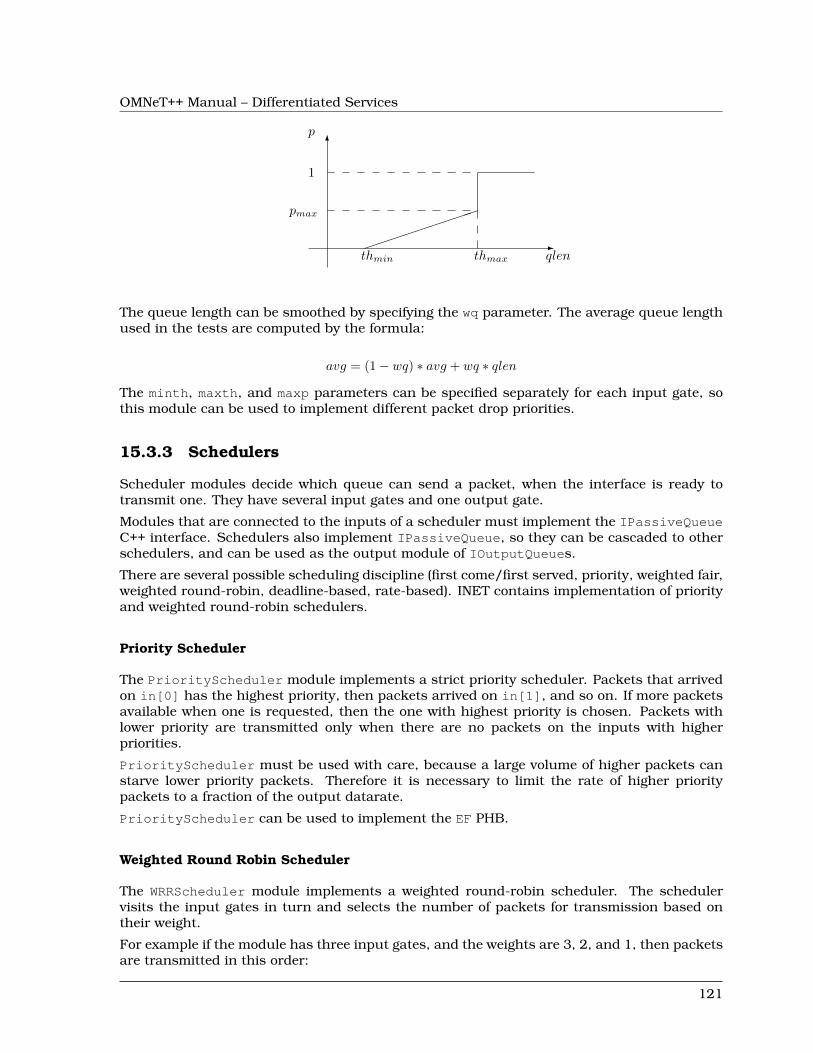
OMNeT++ Manual – Differentiated Services
-
6
qlen
p
����
�����
1
pmax
thmin thmax
The queue length can be smoothed by specifying the wq parameter. The average queue lengthused in the tests are computed by the formula:
avg = (1− wq) ∗ avg + wq ∗ qlen
The minth, maxth, and maxp parameters can be specified separately for each input gate, sothis module can be used to implement different packet drop priorities.
15.3.3 Schedulers
Scheduler modules decide which queue can send a packet, when the interface is ready totransmit one. They have several input gates and one output gate.
Modules that are connected to the inputs of a scheduler must implement the IPassiveQueueC++ interface. Schedulers also implement IPassiveQueue, so they can be cascaded to otherschedulers, and can be used as the output module of IOutputQueues.
There are several possible scheduling discipline (first come/first served, priority, weighted fair,weighted round-robin, deadline-based, rate-based). INET contains implementation of priorityand weighted round-robin schedulers.
Priority Scheduler
The PriorityScheduler module implements a strict priority scheduler. Packets that arrivedon in[0] has the highest priority, then packets arrived on in[1], and so on. If more packetsavailable when one is requested, then the one with highest priority is chosen. Packets withlower priority are transmitted only when there are no packets on the inputs with higherpriorities.
PriorityScheduler must be used with care, because a large volume of higher packets canstarve lower priority packets. Therefore it is necessary to limit the rate of higher prioritypackets to a fraction of the output datarate.
PriorityScheduler can be used to implement the EF PHB.
Weighted Round Robin Scheduler
The WRRScheduler module implements a weighted round-robin scheduler. The schedulervisits the input gates in turn and selects the number of packets for transmission based ontheir weight.
For example if the module has three input gates, and the weights are 3, 2, and 1, then packetsare transmitted in this order:
121
OMNeT++ Manual – Differentiated Services
A, A, A, B, B, C, A, A, A, B, B, C, ...
where A packets arrived on in[0], B packets on in[1], and C packets on in[2]. If there areno packets in the current one when a packet is requested, then the next one is chosen thathas enough tokens.
If the size of the packets are equal, then WRRScheduler divides the available bandwith ac-cording to the weights. In each case, it allocates the bandwith fairly. Each flow receives aguaranteed minimum bandwith, which is ensured even if other flows exceed their share (flowisolation). It is also efficiently uses the channel, because if some traffic is smaller than itsshare of bandwidth, then the rest is allocated to the other flows.
WRRScheduler can be used to implement the AFxy PHBs.
15.3.4 Classifiers
Classifier modules have one input and many output gates. They examine the received packets,and forward them to the appropriate output gate based on the content of some portion of thepacket header. You can read more about classifiers in RFC 2475 2.3.1 and RFC 3290 4.
The inet.networklayer.diffserv package contains two classifiers: MultiFieldClassi-fier to classify the packets at the edge routers of the DiffServ domain, and BehaviorAggre-gateClassifier to classify the packets at the core routers.
Multi-field Classifier
The MultiFieldClassifier module can be used to identify micro-flows in the incomingtraffic. The flow is identified by the source and destination addresses, the protocol id, and thesource and destination ports of the IP packet.
The classifier can be configured by specifying a list of filters. Each filter can specify asource/destination address mask, protocol, source/destination port range, and bits of Type-OfService/TrafficClass field to be matched. They also specify the index of the output gatematching packet should be forwarded to. The first matching filter determines the output gate,if there are no matching filters, then defaultOut is chosen.
The configuration of the module is given as an XML document. The document element mustcontain a list of <filter> elements. The filter element has a mandatory @gate attribute thatgives the index of the gate for packets matching the filter. Other attributes are optional andspecify the condition of matching:
• @srcAddress, @srcPrefixLength: to match the source address of the IP• @destAddress, @destPrefixLength:• @protocol: matches the protocol field of the IP packet. Its value can be a name (e.g.
“udp”, “tcp”), or the numeric code of the protocol.• @tos,@tosMask: matches bits of the TypeOfService/TrafficClass field of the IP packet.• @srcPort: matches the source port of the TCP or UDP packet.• @srcPortMin, @srcPortMax: matches a range of source ports.• @destPort: matches the destination port of the TCP or UDP packet.• @destPortMin, @destPortMax: matches a range of destination ports.
The following example configuration specifies
• to transmit packets received from the 192.168.1.x subnet on gate 0,• to transmit packets addressed to port 5060 on gate 1,• to transmit packets having CS7 in their DSCP field on gate 2,
122
OMNeT++ Manual – Differentiated Services
• to transmit other packets on defaultGate.
<filters><filter srcAddress="192.168.1.0" srcPrefixLength="24" gate="0"/><filter protocol="udp" destPort="5060" gate="1"/><filter tos="0b00111000" tosMask="0x3f" gate="2"/>
</filters>
Behavior Aggregate Classifier
The BehaviorAggregateClassifier module can be used to read the DSCP field from the IPdatagram, and direct the packet to the corresponding output gate. The DSCP value is thelower six bits of the TypeOfService/TrafficClass field. Core routers usually use this classifierto guide the packet to the appropriate queue.
DSCP values are enumerated in the dscps parameter. The first value is for gate out[0], thesecond for out[1], so on. If the received packet has a DSCP value not enumerated in thedscps parameter, it will be forwarded to the defaultOut gate.
15.3.5 Meters
Meters classify the packets based on the temporal characteristics of their arrival. The arrivalrate of packets is compared to an allowed traffic profile, and packets are decided to be green(in-profile) or red (out-of-profile). Some meters apply more than two conformance level, e.g. inthree color meters the partially conforming packets are classified as yellow.
The allowed traffic profile is usually specified by a token bucket. In this model, a bucket isfilled in with tokens with a specified rate, until it reaches its maximum capacity. When apacket arrives, the bucket is examined. If it contains at least as many tokens as the length ofthe packet, then that tokens are removed, and the packet marked as conforming to the trafficprofile. If the bucket contains less tokens than needed, it left unchanged, but the packetmarked as non-conforming.
Meters has two modes: color-blind and color-aware. In color-blind mode, the color assignedby a previous meter does not affect the classification of the packet in subsequent meters. Incolor-aware mode, the color of the packet can not be changed to a less conforming color: if apacket is classified as non-conforming by a meter, it also handled as non-conforming in latermeters in the data path.
IMPORTANT: Meters take into account the length of the IP packet only, L2 headers areomitted from the length calculation. If they receive a packet which is not an IP datagramand does not encapsulate an IP datagram, an error occurs.
TokenBucketMeter
The TokenBucketMeter module implements a simple token bucket meter. The module hastwo output, one for green packets, and one for red packets. When a packet arrives, the gainedtokens are added to the bucket, and the number of tokens equal to the size of the packet aresubtracted.
Packets are classified according to two parameters, Committed Information Rate (cir), Com-mitted Burst Size (cbs), to be either green, or red.
123
OMNeT++ Manual – Differentiated Services
Green traffic is guaranteed to be under cir ∗ (t1 − t0) + 8 ∗ cbs in every [t0, t1] interval.
SingleRateThreeColorMeter
The SingleRateThreeColorMeter module implements a Single Rate Three Color Meter (RFC2697). The module has three output for green, yellow, and red packets.
Packets are classified according to three parameters, Committed Information Rate (cir), Com-mitted Burst Size (cbs), and Excess Burst Size (ebs), to be either green, yellow or red. The greentraffic is guaranteed to be under cir∗ (t1− t0)+8∗cbs, while the green+yellow traffic to be undercir ∗ (t1 − t0) + 8 ∗ (cbs+ ebs) in every [t0, t1] interval.
TwoRateThreeColorMeter
The TwoRateThreeColorMeter module implements a Two Rate Three Color Meter (RFC 2698).The module has three output gates for the green, yellow, and red packets.
It classifies the packets based on two rates, Peak Information Rate (pir) and Committed Infor-mation Rate (cir), and their associated burst sizes (pbs and cbs) to be either green, yellow orred. The green traffic is under pir ∗ (t1 − t0) + 8 ∗ pbs and cir ∗ (t1 − t0) + 8 ∗ cbs, the yellow trafficis under pir ∗ (t1 − t0) + 8 ∗ pbs in every [t0, t1] interval.
15.3.6 Markers
DSCP markers sets the codepoint of the crossing packets. The codepoint determines thefurther processing of the packet in the router or in the core of the DiffServ domain.
The DSCPMarker module sets the DSCP field (lower six bit of TypeOfService/TrafficClass) ofIP datagrams to the value specified by the dscps parameter. The dscps parameter is a spaceseparated list of codepoints. You can specify a different value for each input gate; packetsarrived at the ith input gate are marked with the ith value. If there are fewer values, thangates, then the last one is used for extra gates.
The DSCP values are enumerated in the DSCP.msg file. You can use both names and integervalues in the dscps parameter.
For example the following lines are equivalent:
**.dscps = "EF 0x0a 0b00001000"
**.dscps = "46 AF11 8"
15.4 Compound modules
15.4.1 AFxyQueue
The AFxyQueue module is an example queue, that implements one class of the Assured For-warding PHB group (RFC 2597).
Packets with the same AFx class, but different drop priorities arrive at the afx1In, afx2In,and afx3In gates. The received packets are stored in the same queue. Before the packetis enqueued, a RED dropping algorithm may decide to selectively drop them, based on theaverage length of the queue and the RED parameters of the drop priority of the packet.
124
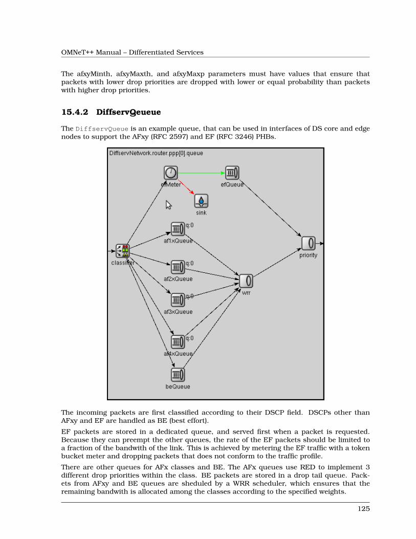
OMNeT++ Manual – Differentiated Services
The afxyMinth, afxyMaxth, and afxyMaxp parameters must have values that ensure thatpackets with lower drop priorities are dropped with lower or equal probability than packetswith higher drop priorities.
15.4.2 DiffservQeueue
The DiffservQueue is an example queue, that can be used in interfaces of DS core and edgenodes to support the AFxy (RFC 2597) and EF (RFC 3246) PHBs.
The incoming packets are first classified according to their DSCP field. DSCPs other thanAFxy and EF are handled as BE (best effort).
EF packets are stored in a dedicated queue, and served first when a packet is requested.Because they can preempt the other queues, the rate of the EF packets should be limited toa fraction of the bandwith of the link. This is achieved by metering the EF traffic with a tokenbucket meter and dropping packets that does not conform to the traffic profile.
There are other queues for AFx classes and BE. The AFx queues use RED to implement 3different drop priorities within the class. BE packets are stored in a drop tail queue. Pack-ets from AFxy and BE queues are sheduled by a WRR scheduler, which ensures that theremaining bandwith is allocated among the classes according to the specified weights.
125
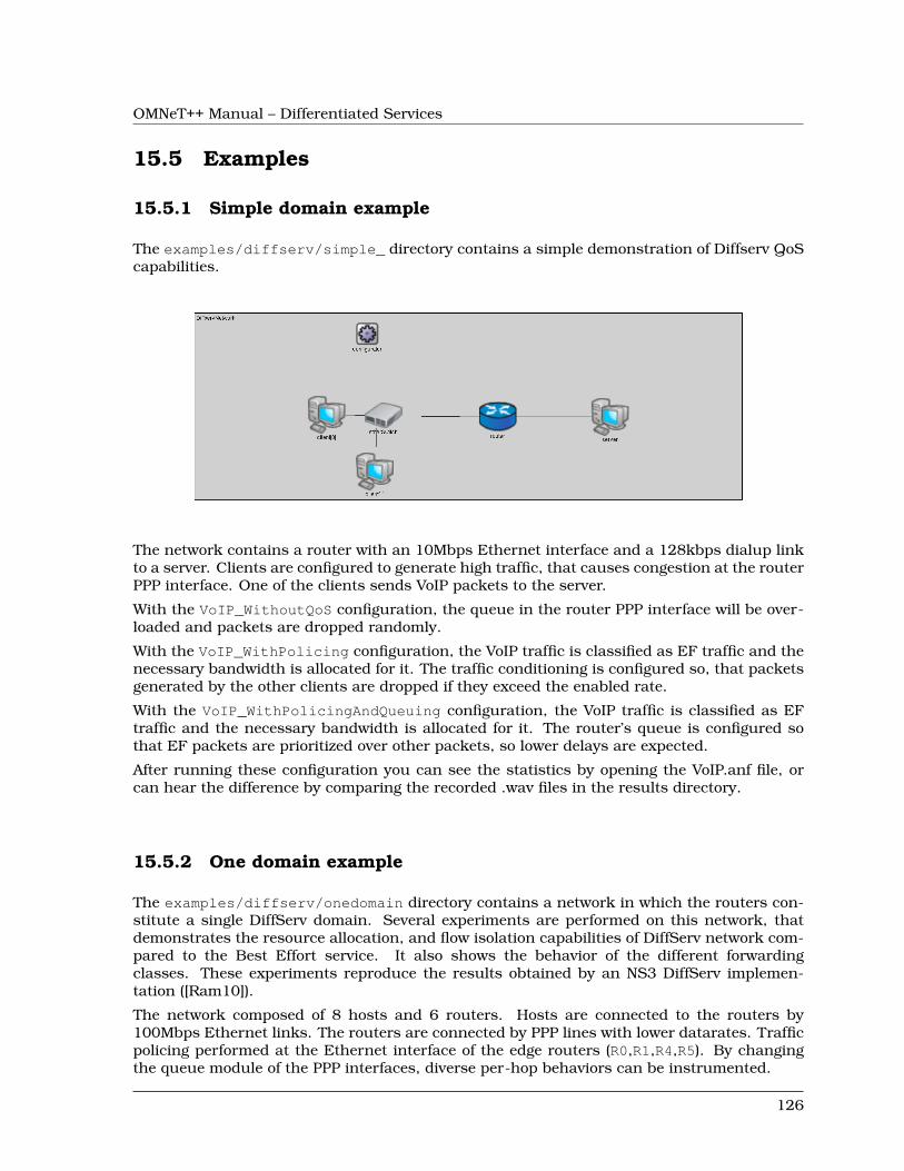
OMNeT++ Manual – Differentiated Services
15.5 Examples
15.5.1 Simple domain example
The examples/diffserv/simple_ directory contains a simple demonstration of Diffserv QoScapabilities.
The network contains a router with an 10Mbps Ethernet interface and a 128kbps dialup linkto a server. Clients are configured to generate high traffic, that causes congestion at the routerPPP interface. One of the clients sends VoIP packets to the server.
With the VoIP_WithoutQoS configuration, the queue in the router PPP interface will be over-loaded and packets are dropped randomly.
With the VoIP_WithPolicing configuration, the VoIP traffic is classified as EF traffic and thenecessary bandwidth is allocated for it. The traffic conditioning is configured so, that packetsgenerated by the other clients are dropped if they exceed the enabled rate.
With the VoIP_WithPolicingAndQueuing configuration, the VoIP traffic is classified as EFtraffic and the necessary bandwidth is allocated for it. The router’s queue is configured sothat EF packets are prioritized over other packets, so lower delays are expected.
After running these configuration you can see the statistics by opening the VoIP.anf file, orcan hear the difference by comparing the recorded .wav files in the results directory.
15.5.2 One domain example
The examples/diffserv/onedomain directory contains a network in which the routers con-stitute a single DiffServ domain. Several experiments are performed on this network, thatdemonstrates the resource allocation, and flow isolation capabilities of DiffServ network com-pared to the Best Effort service. It also shows the behavior of the different forwardingclasses. These experiments reproduce the results obtained by an NS3 DiffServ implemen-tation ([Ram10]).
The network composed of 8 hosts and 6 routers. Hosts are connected to the routers by100Mbps Ethernet links. The routers are connected by PPP lines with lower datarates. Trafficpolicing performed at the Ethernet interface of the edge routers (R0,R1,R4,R5). By changingthe queue module of the PPP interfaces, diverse per-hop behaviors can be instrumented.
126
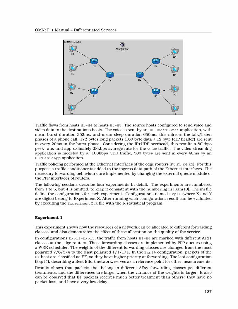
OMNeT++ Manual – Differentiated Services
Traffic flows from hosts H1-H4 to hosts H5-H8. The source hosts configured to send voice andvideo data to the destinations hosts. The voice is sent by an UDPBacisBurst application, withmean burst duration 352ms, and mean sleep duration 650ms; this mirrors the talk/listenphases of a phone call. 172 bytes long packets (160 byte data + 12 byte RTP header) are sentin every 20ms in the burst phase. Considering the IP+UDP overhead, this results a 80kbpspeek rate, and approximately 28kbps avarege rate for the voice traffic. The video streamingapplication is modeled by a 100kbps CBR traffic, 500 bytes are sent in every 40ms by anUDPBasicApp application.
Traffic policing performed at the Ethernet interfaces of the edge routers (R0,R1,R4,R5). For thispurpose a traffic conditioner is added to the ingress data path of the Ethernet interfaces. Thenecessary forwarding behaviours are implemented by changing the external queue module ofthe PPP interfaces of routers.
The following sections describe four experiments in detail. The experiments are numberedfrom 1 to 5, but 4 is omitted, to keep it consistent with the numbering in [Ram10]. The ini filedefine the configurations for each experiment. Configurations named ExpXY (where X and Yare digits) belong to Experiment X. After running each configuration, result can be evaluatedby executing the ExperimentX.R file with the R statistical program.
Experiment 1
This experiment shows how the resources of a network can be allocated to different forwardingclasses, and also demontrates the effect of these allocation on the quality of the service.
In configurations Exp11-Exp15, the traffic from hosts H1-H4 are marked with different AFx1classes at the edge routers. These forwarding classes are implemented by PPP queues usinga WRR scheduler. The weights of the different forwarding classes are changed from the mostpolarized 7/6/5/4 to the least polarized 1/1/1/1. In the Exp16 configuration, packets of theH4 host are classified as EF, so they have higher priority at forwarding. The last configuration(Exp17), describing a Best Effort network, serves as a reference point for other measurements.
Results shows that packets that belong to different AFxy forwarding classes get differenttreatments, and the differences are larger when the variance of the weights is larger. It alsocan be observed that EF packets receives much better treatment than others: they have nopacket loss, and have a very low delay.
127
OMNeT++ Manual – Differentiated Services
Experiment 2
This experiment shows how the different drop precedencies of the AFxy forwarding classescan be implemented by RED queueing. In configurations Exp21-Exp24, hosts H1-H3 sendsthe normal voice and video traffic, while H4 sends only CBR traffic whose rate changes from10kbps to 100kpbs in 10kpbs (so there is 10 measurement for each configuration). Packetsfrom H1-H3 are marked with increasing drop priority (i.e. H1 traffic is forwarded as AF11, H2as AF12, and H3 as AF13). The forwarding treatment of H4 traffic is changing in the differentconfigurations: AF11 in Exp21, AF12 in Exp22, and AF13 in Exp23. The Exp24 configurationshows the behavior of a Best Effort network under the same traffic.
The plots shows that in the DiffServ network, there is no loss of AF11 traffic, and AF12 trafficloss is very low. The average queue length is lower in Exp23, because the red packets aredropped more likely.
Experiment 3
This experiment tests bandwidth utilization and flow isolation. Only hosts H1 and H2 generatetraffic. H1 has an extra UDPBasicApp application, that generates a CBR traffic in addition tothe voice and video streams. The rate of this extra traffic varies from 10kbps to 50kbps in10kpbs steps in different measurements. Because the PPP links have only 300kbps datarate,the link between R2 and R3 is congested when the extra traffic is high enough.
With the first configuration (Exp31), both traffic policing and DiffServ queues are used. Trafficis metered at the egde routers by a token bucket meter. Packets whose rate is below 150kbpsmarked as AF11, the excess traffic is marked as AF12. RED queues in the network areconfigured so, that AF12 packets are dropped more aggressively than AF11 packets.
With the second configuration (Exp32), only traffic policing is used. Packets whose rate ex-ceeding the allowed 150kbps limit are dropped at the boundary of the domain. There is nodifferentiated forwarding treatment of packets inside the domain. Each packet goes to thesame queue in the PPP interfaces of routers. They are simple drop tail queues with 200frames capacity.
The third configuration describes a Best Effort network. There is not traffic policing, and thePPP interfaces contain drop tail queues having buffer space for 200 frames.
As it is expected, the bandwith utilization is high in the first and third case, but lower inthe second case. On the other hand, the Best Effort network does not provide the same flowisolation as the DiffServ network. In the third case the well-behaving H3 node suffers from theextra traffic generated by H1.
Experiment 5
This experiment compares a DiffServ network and a Best Effort network. In the DiffServ net-work, all voice traffic is marked with EF class at the edge routers. The video traffic originatingfrom H1 and H3 are marked with AF11, while video traffic from H2 and H4 are marked withAF21. Routers contain DiffServQueue that implements the EF and AFxy forwarding classeswith priority queueing, and weighted round-robin queueing. The weight of AF11 is a bit larger,than the weight of AF21, so hosts H1 and H3 gets better services. The queues contain a 100frame buffer capacity for each forwarding class.
In the Best Effort network each PPP queue is a DropTailQueue. The queue capacities are 200frames, to keep the buffer space equal to the DiffServ case.
128
OMNeT++ Manual – Differentiated Services
In the DiffServ network, there is no loss of voice packets. Losses of video packets are smallerfor H1 and H3 hosts, and higher for H2 and H4 than in a Best Effort network. This is expected,because DiffServ cannot increase the available resources, it only distributes them differently.It can also be observed, that the delay of voice packets are much smaller in the DiffServnetwork, so it can provide the necessary services for VoIP applications, while a Best Effortnetwork can not.
Multiple domains example
This example describes a real-world scenario, and shows how the SLAs can be implementedwith the components offered by INET.
129

OMNeT++ Manual – Differentiated Services
130
OMNeT++ Manual – The MPLS Models
Chapter 16
The MPLS Models
16.1 Overview
Blah blah blah
16.2 MPLS/RSVP/LDP Model - Implemented Standards
The implementation follows those RFCs below:
• RFC 2702: Requirements for Traffic Engineering Over MPLS
• RFC 2205: Resource ReSerVation Protocol
• RFC 3031: Multiprotocol Label Switching Architecture
• RFC 3036: LDP Specification
• RFC 3209: RSVP-TE Extension to RSVP for LSP tunnels
• RFC 2205: RSVP Version 1 - Functional Specification
• RFC 2209: RSVP Message processing Version 1
16.3 MPLS Operation
The following algorithm is carried out by the MPLS module:
Step 1: - Check which layer the packet is coming fromAlternative 1: From layer 3
Step 1: Find and check the next hop of this packetAlternative 1: Next hop belongs to this MPLS cloud
Step 1: Encapsulate the packet in an MPLS packet withIP_NATIVE_LABEL labelStep 2: Send to the next hopStep 3: Return
131
OMNeT++ Manual – The MPLS Models
Alternative 2: Next hop does not belong to this MPLS cloudStep 1: Send the packet to the next hop
Alternative 2: From layer 2Step 1: Record the packet incoming interfaceStep 2: - Check if the packet is for this LSRAlternative 1: Yes
Step 1: Check if the packet has labelAlternative 1: Yes
Step 1: Strip off all labels and send the packet to L3Step 2: Return
Alternative 2: NoStep 1: Send the packet to L3Step 2: Return
Alternative 2: NoStep 1: Continue to the next step
Step 3: Check the packet typeAlternative 1: The packet is native IP
Step 1: Check the LSR typeAlternative 1: The LSR is an Ingress Router
Step 1: Look up LIB for outgoing labelAlternative 1: Label cannot be found
Step 1: Check if the label for this FEC is being requestedAlternative 1: Yes
Step 1: ReturnAlternative 2: No
Step 1: Store the packet with FEC idStep 2: Do request the signalling componentStep 3: Return
Alternative 2: Label foundStep 1: Carry out the label operation on the packetStep 2: Forward the packet to the outgoing interface foundStep 3: Return
Alternative 2: The LSR is not an Ingress RouterStep 1: Print out the errorStep 2: Delete the packet and return
Alternative 2: The packet is MPLSStep 1: Check the LSR typeAlternative 1: The LSR is an Egress Router
Step 1: POP the top labelStep 2: Forward the packet to the outgoing interface foundStep 3: Return
Alternative 2: The LSR is not an Egress RouterStep 1: Look up LIB for outgoing labelAlternative 1: Label cannot be found
Step 1: Check if the label for this FEC is being requestedAlternative 1: Yes
Step 1: ReturnAlternative 2: No
Step 1: Store the packet with FEC idStep 2: Do request the signalling componentStep 3: Return
Alternative 2: Label found
132
OMNeT++ Manual – The MPLS Models
Step 1: Carry out the label operation on the packetStep 2: Forward the packet to the outgoing interface foundStep 3: Return
Step 2: Return
16.4 LDP Message Processing
The simulation follows message processing rules specified in RFC3036 (LDP Specification). Asummary of the algorithm used in the RFC is presented below.
16.4.1 Label Request Message processing
An LSR may transmit a Request message under any of the conditions below:
• The LSR recognizes a new FEC via the forwarding tale, and the next hop is its LDP peer.The LIB of this LSR does not have a mapping from the next hop for the given FEC.
• Network topology changes, the next hop to the FEC is no longer valid and new mappingis not available.
• The LSR receives a Label Request for a FEC from an upstream LDP and it does not havelabel binding information for this FEC. The FEC next hop is an LDP peer.
Upon receiving a Label Request message, the following procedures will be performed:
Step 1: Extract the FEC from the message and locate the incoming interfaceof the message.
Step 2: Check whether the FEC is an outstanding FEC.Alternative 1: This FEC is outstanding
Step 1: ReturnAlternative 2: This FEC is not outstanding
Step 1: ContinueStep 3: Check if there is an exact match of the FEC in the routing table.
Alternative 1: There is an exact matchStep 1: Continue
Alternative 2: There is no matchStep 1: Construct a Notification message of No route and
send this message back to the sender.Step 4: Make query to local LIB to find out the corresponding label.
Alternative 1: The label foundStep 1: Construct a Label Mapping message and send over
the incoming interface.Alternative 2: The label cannot be found for this FEC
Step 1: Construct a new Label Request message and sendthe message out using L3 routing.
Step 2: Construct a Notification message indicating that thelabel cannot be found.
133
OMNeT++ Manual – The MPLS Models
16.4.2 Label Mapping Message processing
Upon receiving a Label Mapping message, the following procedures will be performed:
Step 1: Extract the FEC and the label from the message.Step 2: Check whether this is an outstanding FEC
Alternative 1: This FEC is outstandingStep 1: Continue
Alternative 2: This FEC is not outstandingStep 1: Send back the server an Notification of Error message.
Step 3: Install the new label to the local LIB using the extracted label,FEC and the message incoming interface.
16.5 LIB Table File Format
The format of a LIB table file is:
The beginning of the file should begin with comments. Lines that begin with # are treatedas comments. An empty line is required after the comments. The "LIB TABLE" syntax mustcome next with an empty line. The column headers follow. This header must be strictly "In-lblIn-intf Out-lbl Out-intf". Column values are after that with space or tab for field separation.The following is a sample of lib table file.
#lib table for MPLS network simulation test#lib1.table for LSR1 - this is an edge router#no incoming label for traffic from in-intf 0 &1 - LSR1 is ingress router for those traffic#no outgoing label for traffic from in_intf 2 &3 - LSR 1 is egress router for those traffic
LIB TABLE:
In-lbl In-intf Out-lbl Out-intf1 193.233.7.90 1 193.231.7.212 193.243.2.1 0 193.243.2.3
16.6 The CSPF Algorithm
CSPF stands for Constraint Shortest Path First. This constraint-based routing is executed on-line by Ingress Router. The CSPF calculates an optimum explicit route (ER), based on specificconstraints. CSPF relies on a Traffic Engineering Database (TED) to do those calculations.The resulting route is then used by RSVP-TE.
The CSPF in particular and any constraint based routing process requires following inputs:
• Attributes of the traffic trunks, e.g., bandwidth, link affinities
• Attributes of the links of the network, e.g. bandwidth, delay
• Attributes of the LSRs, e.g. types of signaling protocols supported
• Other topology state information.
134
OMNeT++ Manual – The MPLS Models
There has been no standard for CSPF so far. The implementation of CSPF in the simulationis based on the concept of "induced graph" introduced in RFC 2702. An induced graph isanalogous to a virtual topology in an overlay model. It is logically mapped onto the physicalnetwork through the selection of LSPs for traffic trunks. CSPF is similar to a normal SPF,except during link examination, it rejects links without capacity or links that do not matchcolor constraints or configured policy. The CSPF algorithm used in the simulation has twophases. In the first phase, all the links that do not satisfy the constraints of bandwidth areexcluded from the network topology. The link affinity is also examined in this phase. In thesecond phase, Dijkstra algorithm is performed.
Dijkstra Algorithm:
Dijkstra(G, w, s):Initialize-single-source(G,s);S = empty set;Q = V[G];While Q is not empty {
u = Extract-Min(Q);S = S union {u};for each vertex v in Adj[u] {
relax(u, v, w);}
}
In which:
• G: the graph, represented in some way (e.g. adjacency list)
• w: the distance (weight) for each edge (u,v)
• s (small s): the starting vertex (source)
• S (big S): a set of vertices whose final shortest path from s have already been determined
• Q: set of remaining vertices, Q union S = V
16.7 The traffic.xml file
The traffic.xml file is read by the RSVP-TE module (RSVP). The file must be in the same folderas the executable network simulation file.
The XML elements used in the "traffic.xml" file:
• <Traffic></Traffic> is the root element. It may contain one or more <Conn> elements.
• <Conn></Conn> specifies an RSVP session. It may contain the following elements:
– <src></src> specifies sender IP address
– <dest></dest> specifies receiver IP address
– <setupPri></setupPri> specifies LSP setup priority
– <holdingPri></holdingPri> specifies LSP holding priority
– <bandwidth></bandwidth> specifies the requested BW.
135
OMNeT++ Manual – The MPLS Models
– <delay></delay> specifies the requested delay.
– <route></route> specifies the explicit route. This is a comma-separated list of IP-address, hop-type pairs (also separated by comma). A hop type has a value of 1 ifthe hop is a loose hop and 0 otherwise.
The following presents an example file:
<?xml version="1.0"?><!-- Example of traffic control file --><traffic>
<conn><src>10.0.0.1</src><dest>10.0.1.2</dest><setupPri>7</setupPri><holdingPri>7</holdingPri><bandwidth>400</bandwidth><delay>5</delay>
</conn><conn>
<src>11.0.0.1</src><dest>11.0.1.2</dest><setupPri>7</setupPri><holdingPri>7</holdingPri><bandwidth>100</bandwidth><delay>5</delay>
</conn></traffic>
An example of using RSVP-TE as signaling protocol can be found in ExplicitRouting folderdistributed with the simulation. In this example, a network similar to the network in LDP-MPLS example is setup. Instead of using LDP, "signaling" parameter is set to 2 (value ofRSVP-TE handler). The following xml file is used for traffic control. Note the explicit routesspecified in the second connection. It indicates that the route is a strict one since the valuesof every hop types are 0. The route defined is 10.0.0.1 -> 1.0.0.1 -> 10.0.0.3 -> 1.0.0.4 ->10.0.0.5 -> 10.0.1.2.
<?xml version="1.0"?><!-- Example of traffic control file --><traffic>
<conn><src>10.0.0.1</src><dest>10.0.1.2</dest><setupPri>7</setupPri><holdingPri>7</holdingPri><bandwidth>0</bandwidth><delay>0</delay><ER>false</ER>
</conn><conn>
<src>11.0.0.1</src><dest>11.0.1.2</dest>
136

OMNeT++ Manual – The MPLS Models
<setupPri>7</setupPri><holdingPri>7</holdingPri><bandwidth>0</bandwidth><delay>0</delay><ER>true</ER><route>1.0.0.1,0,1.0.0.3,0,1.0.0.4,0,1.0.0.5,0,10.0.1.2,0</route>
</conn></traffic>
137

OMNeT++ Manual – The MPLS Models
138

OMNeT++ Manual – Applications
Chapter 17
Applications
17.1 Overview
This chapter describes application models and traffic generators.
Blah blah blah
139

OMNeT++ Manual – Applications
140
OMNeT++ Manual – History
Chapter 18
History
18.1 IPSuite to INET Framework (2000-2006)
The predecessor of the INET framework was written by Klaus Wehrle, Jochen Reber, DirkHolzhausen, Volker Boehm, Verena Kahmann, Ulrich Kaage and others at the University ofKarlsruhe during 2000-2001, under the name IPSuite.
The MPLS, LDP and RSVP-TE models were built as an add-on to IPSuite during 2003 by XuanThang Nguyen ([email protected]) and other students at the University of Technol-ogy, Sydney under supervision of Dr Robin Brown. The package consisted of around 10,000LOCs, and was published at http://charlie.it.uts.edu.au/ tkaphan/xtn/capstone (now un-available).
After a period of IPSuite being unmaintained, Andras Varga took over the development in July2003. Through a series of snapshot releases in 2003-2004, modules got completely reorga-nized, documented, and many of them rewritten from scratch. The MPLS models (includingRSVP-TE, LDP, etc) also got refactored and merged into the codebase.
During 2004, Andras added a new, modular and extensible TCP implementation, applicationmodels, Ethernet implementation and an all-in-one IP model to replace the earlier, modular-ized one.
The package was renamed INET Framework in October 2004.
Support for wireless and mobile networks got added during summer 2005 by using code fromthe Mobility Framework.
The MPLS models (including LDP and RSVP-TE) got revised and mostly rewritten from scratchby Vojta Janota in the first half of 2005 for his diploma thesis. After further refinements byVojta, the new code got merged into the INET CVS in fall 2005, and got eventually released inthe March 2006 INET snapshot.
The OSPFv2 model was created by Andras Babos during 2004 for his diploma thesis whichwas submitted early 2005. This work was sponsored by Andras Varga, using revenues fromcommercial OMNEST licenses. After several refinements and fixes, the code got merged intothe INET Framework in 2005, and became part of the March 2006 INET snapshot.
The Quagga routing daemon was ported into the INET Framework also by Vojta Janota. Thiswork was also sponsored by Andras Varga. During fall 2005 and the months after, ripd andospfd were ported, and the methodology of porting was refined. Further Quagga daemons stillremain to be ported.
141
OMNeT++ Manual – History
Based on experience from the IPv6Suite (from Ahmet Sekercioglu’s group at CTIE, MonashUniversity, Melbourne) and IPv6SuiteWithINET (Andras’s effort to refactor IPv6Suite andmerge it with INET early 2005), Wei Yang Ng (Monash Uni) implemented a new IPv6 modelfrom scratch for the INET Framework in 2005 for his diploma thesis, under guidance fromAndras who was visiting Monash between February and June 2005. This IPv6 model got firstincluded in the July 2005 INET snapshot, and gradually refined afterwards.
The SCTP implementation was contributed by Michael Tuexen, Irene Ruengeler and ThomasDreibholz
Support for Sam Jensen’s Network Simulation Cradle, which makes real-world TCP stacksavailable in simulations was added by Zoltan Bojthe in 2010.
TCP SACK and New Reno implementation was contributed by Thomas Reschka.
Several other people have contributed to the INET Framework by providing feedback, reportingbugs, suggesting features and contributing patches; I’d like to acknowledge their help here aswell.
142
OMNeT++ Manual – REFERENCES
References
[CBD02] Tracy Camp, Jeff Boleng, and Vanessa Davies. A survey of mobility models forad hoc network research. WIRELESS COMMUNICATIONS & MOBILE COMPUTING(WCMC): SPECIAL ISSUE ON MOBILE AD HOC NETWORKING: RESEARCH, TRENDSAND APPLICATIONS, 2:483–502, 2002.
[Chi98] Ching-Chuan Chiang. Wireless network multicasting, 1998.
[FJ93] Sally Floyd and Van Jacobson. Random early detection gateways for congestionavoidance, 1993.
[Pea99] Charles E. Perkins and et al. Optimized smooth handoffs in mobile ip. In IN PRO-CEEDINGS OF ISCC, pages 340–346, 1999.
[Ram10] Sanjay Ramroop. Performance evaluation of diffserv networks using the ns-3 simu-lator, 2010.
143

OMNeT++ Manual – INDEX
Index
<inet_root>/3rdparty/README, 108<inet_root>/Makefile, 108
accessPointAddress, 68activity(), 106addDefaultRoutes, 71address, 25addressTableFile, 30addressTableSize, 30addStaticRoutes, 70, 71addSubnetRoutes, 71advertisedWindow, 98, 101AFxyQueue, 124agingTime, 30ANSimMobility, 46ansimTrace, 46ARP, 10, 52, 55, 56, 61–63, 66ARPPacket, 62assignAddresses, 71assignDisjunctSubnetAddresses, 71
backoff, 29backoffSignal, 29BehaviorAggregateClassifier, 122, 123belongsToAnyUDPSocket(), 82belongsToSocket(), 82BindingCache, 9bitError, 26bufferSize, 30burstDuration, 84ByteArray, 97, 101
cacheTimeout, 63carrierExtension, 28changeAngleBy, 45changeInterval, 45changeSpeedBy, 45ChannelControl, 4, 6, 42ChiangMobility, 45children, 59chooseDestAddrMode, 84cMessage, 20, 97, 99–101
cMessage::hasBitError(), 97cMessage::length(), 96cMessage::setControlInfo(), 96cObject, 12collision, 29collisionSignal, 29commandLength, 112commandOutputLength, 112config, 71connId, 97, 100constraintAreaDepth, 42constraintAreaHeight, 42constraintAreaWidth, 42constraintAreaX, 42constraintAreaY, 42constraintAreaZ, 42ConstSpeedMobility, 4, 45count, 75cPolymorphic, 12cx, 43cy, 43
datarate, 24DatarateConnection, 24dataTransferMode, 100, 101, 110decapsulate(), 61Decider80211, 39defaultMCTimeToLive, 54defaultOut, 123defaultTimeToLive, 54delay, 24delayedAcksEnabled, 98, 103destAddr, 54, 75destAddresses, 74, 83–85destAddrRNG, 84Destination, 74diffServCodePoint, 54DiffservQueue, 125dontFragment, 54droppedPkBadChecksum, 81droppedPkWrongPort, 81dropPkBitError, 27
144
OMNeT++ Manual – INDEX
dropPkIfaceDown, 27dropPkNotForUs, 26DropTailQoSQueue, 10DropTailQueue, 10, 120, 128DSCP.msg, 124DSCPMarker, 124dscps, 123, 124DumbTCP, 102dumpAddresses, 71dumpConfig, 71dumpRoutes, 71dumpTopology, 71duplexEnabled, 27
echoDelay, 111echoFactor, 110enabled, 65ErrorHandling, 10, 61, 66EtherAppCli, 34, 35EtherAppReq, 34EtherAppResp, 34EtherAppSrv, 34, 35EtherBus, 23, 24EtherEncap, 23, 25, 32, 34EtherFrame, 23, 25, 32EtherFrame.msg, 32EtherFrameWithLLC, 32EtherFrameWithSNAP, 32EtherHost, 17, 23, 34EtherHub, 23EtherJam, 25, 28EtherLLC, 23, 25, 26, 32–34EtherMAC, 11, 23, 25, 26, 28, 32, 34, 118EtherMACFullDuplex, 25, 27, 28EthernetIIFrame, 32EthernetInterface, 4, 9, 34, 118EtherPadding, 25EtherPauseFrame, 25, 26EtherSwitch, 4, 17, 23EtherTraffic, 25EtherType, 24examples/diffserv/onedomain, 126examples/diffserv/simple_, 126examples/inet/routerperf/omnetpp.ini, 75examples/inet/tcpclientserver/omnetpp.ini,
107ExperimentX.R, 127
false, 54, 56, 60, 63, 65, 71, 75, 99, 108FIFOQueue, 119, 120fireChangeNotification(), 12Flags, 74
FlatNetworkConfiguration, 15FlatNetworkConfigurator, 4–6, 66, 67, 72forceBroadcast, 56, 58fork, 100, 108forwardMulticast, 60, 67fragmentTimeout, 55, 58frameCapacity, 120
Gateway, 74GenericAppMsg, 109, 110, 112get(), 13get4(), 11get6(), 11getEncapsulatedMsg(), 61getIfExists(), 13globalARP, 63group, 59groupMembershipInterval, 64, 65
handleIfOutside, 42handleMessage(), 106handleSelfMessage, 42Header Checksum, 53hopLimit, 75HTTPRequest, 100
ICMP, 10, 52, 56, 60, 61, 66ICMPAccess::get(), 61ICMPMessage, 61ICMPv6, 10, 77idleInterval, 112Ieee80211AgentSTA, 40Ieee80211Mac, 39, 40Ieee80211MgmtAdhoc, 40Ieee80211MgmtAP, 40Ieee80211MgmtAPSimplified, 40Ieee80211MgmtSTA, 40Ieee80211MgmtSTASimplified, 40Ieee80211Nic, 39Ieee80211NicAdhoc, 39Ieee80211NicAP, 39Ieee80211NicAPSimplified, 39Ieee80211NicSTA, 9, 39, 40Ieee80211NicSTASimplified, 39Ieee80211Radio, 16, 39Ieee802Ctrl, 32, 33IEtherMAC, 25, 30ifconfig, 58IGMP, 66IGMPv2, 52, 64IHook, 21, 34IIGMP, 64IInterfaceTable, 13
145
OMNeT++ Manual – INDEX
IIPvXTraffixGenerator, 74IMACRelayUnit, 30IMobility, 42increasedIWEnabled, 98, 104inet.applications.ethernet, 34inet.applications.tcpapp, 109inet.linklayer.ppp, 19inet.networklayer.diffserv, 122inet_addr, 74initFromDisplayString, 42initializePosition(), 42initialX, 42initialY, 42initialZ, 42INotifiable, 12inputHook, 21Interface, 74InterfaceEntry, 13–15, 77interfaceId, 54, 56InterfaceProtocolData, 14InterfaceTable, 9–15, 62, 67, 77InterfaceTableAccess, 12, 13IOutputQueue, 20, 21, 118, 120, 121IP, 10, 66IPAddress, 11IPAddressResolver, 6IPassiveQueue, 119, 121IPControlInfo, 96IPForward, 60IPv4, 51, 52, 54–56, 58, 61, 62IPv4ControlInfo, 54, 55, 61ipv4Data(), 14IPv4Datagram, 53, 54IPv4InterfaceData, 14IPv4MulticastRoute, 59IPv4NetorkConfigurator, 71IPv4NetworkConfigurator, 60, 66–69, 74IPv4Route, 59IPv4RoutingDecision, 54, 56, 62IPv6, 10IPv6Address, 11ipv6Data(), 14IPv6ErrorHandling, 10, 77IPv6InterfaceData, 14, 77IPv6NeighbourDiscovery, 10, 77IPvXAddress, 6, 11IPvXAddressResolver, 75, 84IPvXTrafGen, 74, 75IPvXTrafSink, 75IQueueAccess, 119, 120isBroadcast(), 62IScriptable, 6
isIPv6(), 11isUnspecified(), 11ITCP, 96, 107ITCPApp, 109ITrafficConditioner, 118IUDP, 79IUDPApp, 82IWiredNic, 19, 21, 34
keyPressDelay, 112
LargeLAN, 34LargeNet, 23, 34lastMemberQueryCount, 65lastMemberQueryInterval, 65LIB, 10limitedTransmitEnabled, 98LineSegmentsMobilityBase, 43LSR2_002.txt, 66lwipopts.h, 108
MACAddress, 11, 23MACRelayUnit, 23MACRelayUnitBase, 30MACRelayUnitNP, 10, 23, 30MACRelayUnitPP, 10, 23, 30Mask, 74mask, 74maxp, 121maxth, 121MediumLAN, 34messageLength, 85metric, 60minth, 121MixedLAN, 23MobilityBase, 42move, 43MovingMobilityBase, 43MPLS, 10mss, 98mtu, 20multicastLoop, 54, 57multicastTimeToLive, 58MultiFieldClassifier, 122
nagleEnabled, 98, 103Netmask, 74netmask, 72netwIn, 20networkAddress, 72NetworkInfo, 66NetworkLayer, 10, 52, 65, 66NetworkLayer6, 10
146
OMNeT++ Manual – INDEX
netwOut, 20nextChange, 43nextHopAddr, 54nodeId, 46NofiticationBoard, 20NoQueue, 21NotificationBoard, 4, 9, 11, 12, 15, 16Ns2MotionMobility, 46nsc-0.5.2.tar.bz2, 108NUM_STACKS, 109num_stacks.h, 109numCommands, 112numGates, 120numInputHooks, 21numLost, 76numOutputHooks, 21numWirelessPorts, 30
optimizeRoutes, 71Options, 53origin, 59originNetmask, 59otherQuerierPresentInterval, 64, 65outOfOrderArrivals, 76outputHook, 21OutputQueue, 26
packetLen, 83packetLength, 75packetReceivedFromLower, 27packetReceivedFromUpper, 27packetSentToLower, 27packetSentToUpper, 27packetSize, 75parent, 59passedUpPk, 81phys, 20PingApp, 75PingPayload, 75pingRxSeq, 76pingTxSeq, 76positions, 24positionUpdated, 42PPP, 19–21, 118PPPFrame, 20PPPInterface, 9, 19, 21, 34, 118printPing, 75PriorityScheduler, 121procDelay, 52, 58processingTime, 30procotol, 54promiscuous, 25
propagationSpeed, 24protocol3Data(), 14protocol4Data(), 14protocolMapping, 55, 58proxyARP, 63
queryInterval, 64, 65queryResponseInterval, 64, 65QueueBase, 52queueModule, 20, 26queueType, 21, 118
r, 43rcvdPacket, 75rcvdPk, 81, 83receiveChangeNotification(), 12reconnectInterval, 112recordStats, 98, 99, 108recv(), 101REDDropper, 120REDQueue, 10registerSAP, 34requestPacket(), 119retryCount, 63retryTimeout, 63rmem_max, 109robustnessVariable, 65roundTripTime, 83route, 58Router, 4, 5, 11, 52, 60routerId, 60routingFile, 60, 72RoutingTable, 4, 9–11, 14, 51, 58, 60, 67, 72RoutingTable6, 9, 77rowCount, 44RSVP, 10rtt, 76rxPausePkUnits, 26rxPkBytesSignal, 27rxPkFromHL, 26rxPkOk, 26
sackSupport, 98, 105ScenarioManager, 6, 66scrAddr, 54scrollX, 46scrollY, 46SCTP, 10sendErrorMessage, 61sendInterval, 74, 75, 83, 84sentPk, 75, 81, 83setTargetPosition, 43SingleRateThreeColorMeter, 124
147
OMNeT++ Manual – INDEX
Sink, 120sleepDuration, 84SmallLAN, 34SnrEval80211, 39socketDataArrived(), 106socketEstablished(), 106socketFailure(), 106socketPeerClosed(), 106source, 59speed, 45srcAddr, 75ssid, 68stackBufferSize, 109stackName, 108StandardHost, 4, 5, 10, 11, 17, 52, 60, 79,
82, 107, 109startAngle, 43startService(), 52startTime, 75, 83, 84, 111startupQueryCount, 64, 65startupQueryInterval, 64, 65stateTransitionInterval, 45stationary, 43stopTime, 75, 111subscribe(), 12
TCP, 10, 96, 98, 110TCP_lwIP, 107, 108TCP_lwip, 10TCP_NSC, 10, 107–109tcp_rmem, 109tcp_wmem, 109TCPAlgorithm, 99, 102, 103tcpAlgorithmClass, 98, 100TCPBaseAlg, 103, 104TCPBasicClientApp, 112TCPCommand, 97, 102TCPCommand.msg, 97, 100TCPCommandCode, 97TCPConnectInfo, 100TCPConnection, 96, 99, 100, 102TCPDataStreamRcvQueue, 101TCPDataStreamSendQueue, 101TCPDataTransferMode, 97, 100TCPEchoApp, 110, 111TCPGenericCliAppBase, 112TCPGenericSrvApp, 110–112TCPGenericSrvThread, 112TCPMsgBasedRcvQueue, 101TCPMsgBasedSendQueue, 101TCPNewReno, 102TCPNoCongestionControl, 102
TCPOpenCommand, 100TCPReceiveQueue, 99TCPReno, 102, 105TCPSegment, 96, 100TCPSendCommand, 101TCPSendQueue, 99TCPServerThreadBase, 112TCPSocket, 105TCPSocket::CallbackInterface, 106TCPSocketMap, 107TCPSrvHostApp, 112TCPStatusInd, 97TCPStatusInfo, 102TCPTahoe, 102, 104, 105TCPVirtualDataRcvQueue, 101TCPVirtualDataSendQueue, 101TelnetApp, 112thinkTime, 112ThresholdDropper, 120timestampSupport, 98timeToLive, 54, 58TokenBucketMeter, 123traceFile, 46traceroute, 53true, 54, 56–58, 60, 63, 65–67, 71, 103–105,
108ttlThreshold, 58TurtleMobility, 42, 47TurtleMobility.dtd, 47TwoRateThreeColorMeter, 124txPausePkUnits, 26txPk, 26txPkBytesSignal, 27txQueue, 26txQueueLimit, 20, 26Type of Service, 54
UDP, 10, 79–81, 83UDPBacisBurst, 127UDPBasicApp, 83, 127, 128UDPBasicBurst, 83UDPBindCommand, 81UDPCloseCommand, 80UDPConnectCommand, 80UDPDataIndication, 81UDPEchoApp, 83UDPEchoAppMsg, 83UDPErrorIndication, 80UDPJoinMulticastGroupsCommand, 81UDPLeaveMulticastGroupsCommand, 81UDPPacket, 80UDPSendCommand, 80
148
OMNeT++ Manual – INDEX
UDPSetBroadcastCommand, 80UDPSetMulticastInterfaceCommand, 80UDPSetTimeToLive, 80UDPSink, 83UDPSocket, 79, 80UDPVideoStreamCli, 83UDPVideoStreamSvr, 83unsolicetedReportInterval, 64unsolicitedReportInterval, 65updateInterval, 43, 45
videoSize, 83
waitTime, 44windowScalingSupport, 98WirelessAP, 4wmem_max, 109wq, 121WRRScheduler, 121, 122
x1, 44x2, 44
y1, 44y2, 44
149