Increasing deterministic behavior of mobile robots by adding a ...
88
Increasing deterministic behavior of mobile robots by adding a safety layer M.N. (Mark) Bruijn MSc Report Committee: Prof.dr.ir. G.J.M. Krijnen K.J. Russcher, MSc Dr.ir. D. Dresscher Dr.ir. D.M. Ziener February 2019 008RAM2019 Robotics and Mechatronics EE-Math-CS University of Twente P.O. Box 217 7500 AE Enschede The Netherlands Version 1.1
-
Upload
khangminh22 -
Category
Documents
-
view
0 -
download
0
Transcript of Increasing deterministic behavior of mobile robots by adding a ...

Increasing deterministic behavior of mobile robots by adding a safety layer
M.N. (Mark) Bruijn
MSc Report
Committee: Prof.dr.ir. G.J.M. Krijnen
K.J. Russcher, MSc Dr.ir. D. Dresscher Dr.ir. D.M. Ziener
February 2019
008RAM2019 Robotics and Mechatronics
EE-Math-CS University of Twente
P.O. Box 217 7500 AE Enschede
The Netherlands
Version 1.1


Abstract
Tele-operated mobile robots have a potentially high value for emergency services. Mobile robots can aidin observations and act in place of humans in dealing with unsafe situations. However, mobile robots cancurrently show non-deterministic behavior after onboard failures, resulting in mission failure or unsafe sit-uations. Non-deterministic behavior of a mobile robot implies that the robot expresses random behaviorthat does not match the operator’s expected response. Operators require the mobile robots to behave de-terministically at all times, even after onboard failures. If this requirement is met, overall support for usingmobile robots will increase, fewer emergency operations will fail and dangerous consequences will be prevented.
In this thesis, I will research how to increase deterministic behavior of mobile robots by implementing a safetylayer. The safety layer is modeled analogous to safety layers used in critical chemical processes, in whicha safety layer is added that shuts down the process after detecting failures. This gives the operator time toeliminate dangerous behavior and mitigate failures. Inspired by this principle, the safety layer detects onboard-computer failures using a watchdog onboard the mobile robot. Once the failures are detected, the safety layeris responsible for taking over the robot’s controls, stopping all movement, and eliminating non-deterministicbehavior using its GPS sensor and compass. Emergency services utilize different types of mobile robots.Therefore, the safety layer is designed to be generic so that it can be implemented on any mobile robot. Afterimplementing and testing the functionalities, the effect of the safety layer on a mobile robot is determined.This is done by estimating the probabilities of negative consequences and yields the safety layer’s effect on thedeterministic behavior of the mobile robot.
By implementing a safety layer, the deterministic behavior of a mobile robot is increased. The safety layermitigates onboard failures. This includes onboard-computer failures, to which protection is currently complex.The safety layer is tested for 25 continuous hours, in which a failure was introduced every 30 minutes. Thesafety layer caught all failures and resolved them without false positive or false negatives. The estimation showsthat the safety layer increases the deterministic behavior by 23.6% for the mobile robot at the University ofTwente.


Glossary
Onboard failure
An onboard failure is any failure onboard the mobile robot. A failure terminates
the mobile robot’s ability to perform its tasks. Motor controller failures and
onboard-computer failures are examples of onboard failures.
Onboard-computer
failure
An onboard-computer failure is a failure of the onboard computer of a mobile
robot. The onboard computer processes incoming control commands, processes
sensor data and produces control signals for the motors.
ErrorA human action that produces an incorrect result [1]. An error may result in a
fault. An example error is shown in figure 1.
FaultA manifestation of an error in software [1]. A fault may result in a failure. An
example fault is shown in figure 1.
FailureObservable incorrect behavior [1]. A failure is always caused by a fault. An
example failure is shown in figure 1.
Failure mitigation Keeping the consequences of a failure to a minimum.
Error Fault Failure
Typo incontrol code
Invalid controlsignal
Motor controllerfailure
Fig. 1 Example of an error, a fault and a failure.


Abbreviations
AED Automatic External Defibrillator
AR Augmented Reality (drone name)
CPU Central Processing Unit
EEPROM Electrically Erasable Programmable Read-Only Memory
EMC Electromagnetic Compatibility
FPGA Field-Programmable Gate Array
GPGGA Global Positioning System Fix Data
GPS Global Positioning System
I2C Inter-Integrated Circuit
LED Light Emitting Diode
LOPA Layers Of Protection Analysis
MCU Microcontroller Unit
MUX Multiplexer
NOP Normal Operations
PCB Printed Circuit Board
PPM Pulse Position Modulation
PWM Pulse Width Modulation
RaM Robotics and Mechatronics
RAM Random Access Memory
UART Universal Asynchronous Receiver-Transmitter
VHDL Very high speed integrated circuit Hardware Description Language
WLAN Wireless Local Area Network


Acknowledgement
First of all, I would like to thank my supervisors Klaas Jan Russcher, Douwe Dresscher, Gijs Krijnen andDaniel Ziener for their professional support and input to this research. Many meetings and brainstorm sessionshave provided me with useful insights.
I would like to thank Lianne Straetemans for unlimited access to her office space and unlimited supply of coffeein times of need. Also, I would like to thank all those who gave me feedback on my thesis.
Finally, I would like to thank the Robotics and Mechatronics group at the University of Twente for hosting meduring this research and providing me with the necessary hardware.


Table of contents
Abstract i
Glossary iii
Abbreviations v
Acknowledgement vii
1 Introduction 11.1 Problem description . . . . . . . . . . . . . . . . . . . . . . . . . . . . . . . . . . . . . . . . 11.2 Deterministic behavior . . . . . . . . . . . . . . . . . . . . . . . . . . . . . . . . . . . . . . 11.3 Relevance . . . . . . . . . . . . . . . . . . . . . . . . . . . . . . . . . . . . . . . . . . . . . 21.4 Context . . . . . . . . . . . . . . . . . . . . . . . . . . . . . . . . . . . . . . . . . . . . . . 31.5 Goal . . . . . . . . . . . . . . . . . . . . . . . . . . . . . . . . . . . . . . . . . . . . . . . . 41.6 Scope . . . . . . . . . . . . . . . . . . . . . . . . . . . . . . . . . . . . . . . . . . . . . . . 41.7 Report outline . . . . . . . . . . . . . . . . . . . . . . . . . . . . . . . . . . . . . . . . . . . 4
2 Background 52.1 Mobile robots . . . . . . . . . . . . . . . . . . . . . . . . . . . . . . . . . . . . . . . . . . . 52.2 Real-time systems . . . . . . . . . . . . . . . . . . . . . . . . . . . . . . . . . . . . . . . . . 62.3 Pulse width modulation . . . . . . . . . . . . . . . . . . . . . . . . . . . . . . . . . . . . . . 72.4 Pulse position modulation . . . . . . . . . . . . . . . . . . . . . . . . . . . . . . . . . . . . . 72.5 Fork bomb . . . . . . . . . . . . . . . . . . . . . . . . . . . . . . . . . . . . . . . . . . . . . 8
3 Analysis 93.1 What are common threats to deterministic behavior? . . . . . . . . . . . . . . . . . . . . . . 93.2 How can threats best be detected? . . . . . . . . . . . . . . . . . . . . . . . . . . . . . . . . 133.3 What is the appropriate response to failures? . . . . . . . . . . . . . . . . . . . . . . . . . . . 253.4 How can the responses best be effectuated? . . . . . . . . . . . . . . . . . . . . . . . . . . . 26
4 Design & implementation 354.1 Overview . . . . . . . . . . . . . . . . . . . . . . . . . . . . . . . . . . . . . . . . . . . . . 354.2 Detection block . . . . . . . . . . . . . . . . . . . . . . . . . . . . . . . . . . . . . . . . . . 364.3 Response block . . . . . . . . . . . . . . . . . . . . . . . . . . . . . . . . . . . . . . . . . . 394.4 Control block . . . . . . . . . . . . . . . . . . . . . . . . . . . . . . . . . . . . . . . . . . . 42

x Table of contents
4.5 Multiplexer . . . . . . . . . . . . . . . . . . . . . . . . . . . . . . . . . . . . . . . . . . . . 444.6 Safety layer . . . . . . . . . . . . . . . . . . . . . . . . . . . . . . . . . . . . . . . . . . . . 45
5 Testing 495.1 Component testing . . . . . . . . . . . . . . . . . . . . . . . . . . . . . . . . . . . . . . . . 495.2 Endurance test . . . . . . . . . . . . . . . . . . . . . . . . . . . . . . . . . . . . . . . . . . . 52
6 Results 556.1 Consequence probabilities . . . . . . . . . . . . . . . . . . . . . . . . . . . . . . . . . . . . 556.2 Impact on deterministic behavior . . . . . . . . . . . . . . . . . . . . . . . . . . . . . . . . . 62
7 Discussion 65
8 Conclusion 67
9 Future work 69
References 71
Appendix A Safety layer PCB schematic 73
Appendix B Consequence probabilities 75

1 | Introduction
In 2012, a criminal group was producing the toxic sarin gas, allegedly for use in a terrorist attack. Afterarrests were made, the national police deployed two mobile robots to investigate the improvised laboratoryin a basement. The mobile robots were deployed to take samples in the basement and transport them to adecontamination team. During the operation, the pair of mobile robots failed multiple times. The telemetrythat was used to steer one robot was jamming the other robot, which made sensors provide false information.Additionally, the telemetry interference caused an unsafe situation in which control over both mobile robotswas lost [2].
1.1 Problem description
In operations by emergency services, unexpected mobile robot responses are unacceptable. Emergency servicesmust at all times be able to rely on responsive and deterministic mobile robots. However, mobile robots still donot always behave responsive and deterministic, especially after onboard failures, when undefined behavioroccurs. A software fault resulting in an onboard-computer failure will cause a mobile robot to be unresponsiveand mission data may be lost. These failures have various causes and are not always fixable during an operation.In case of an onboard-computer failure, the mobile robot’s behavior is undefined and the mobile robot mightcontinue its path in the last known heading, which can cause a dangerous situation.
Mobile robots should always be reliable and show deterministic behavior. If this requirement cannot be met,emergency operations can fail, mobile robots can harm their environment, and overall support for the usage ofmobile robots can decrease.
1.2 Deterministic behavior
In deterministic behavior, no randomness is involved in determining the next state of the system. A mobilerobot that behaves deterministically will at all times have the same response to events such as control signalsor onboard failures. In other words, the mobile robot always behaves as expected. Deterministic behavior isnot necessarily behavior without errors. This is illustrated using two examples of a mobile robot on wheelsdeployed during a bomb disposal mission.
A mobile robot is deployed for a bomb disposal mission. The mobile robot collects the bomb in order to bringit to a safe location. All control signals result in the operator’s expected response. Suddenly one of the motorcontrollers fails and initiates full throttle, even though a stop is expected by the operator. This results in the

2 Introduction
mobile robot driving off a bridge and detonating the bomb on impact. In this unwanted and dangerous situation,the operator does not have control over the mobile robot and cannot rely on it. The mobile robot only showsdeterministic behavior before the motor controller failure. Without deterministic behavior at all times, themobile robots are not fit for usage by emergency services.
In an identical mission as described above, a more sophisticated mobile robot is deployed. The mobile robot isdeployed to bring the bomb to a safe location. All control signals result in the operator’s expected response.Suddenly, one of the motor controllers fails. The mobile robot automatically halts operations and rearmsthe motor controller. Two seconds later, the mobile robot is ready to continue its operations with all motorcontrollers working properly. This mobile robot shows deterministic behavior at all times, even after onboardfailures. The operator knows exactly what the response of the mobile robot is to control signals and onboardfailures such as the motor controller failure.
1.3 Relevance
In 2016, the United States had seen a 750% increase in drone usage by emergency services in the last two years.The majority of the deployments are done by sheriff and police, followed by fire brigades [3]. In the Netherlands(and in the rest of Europe) there is also a growing interest in the usage of mobile robots by emergency services.Emergency services such as fire brigades are experimenting with the use of mobile robots. The Dutch nationalpolice are already using mobile robots on a small scale.
If mobile robots do not show deterministic behavior during emergency operations, unacceptable dangerousconsequences can occur. When emergency services deploy a mobile robot, there is likely a dangerous situationor environment. The consequences of non-deterministic behavior depend on the type of operation and theoperation’s environment. There are two types of operations for emergency services:
• Covert operations are operations by emergency services that are hidden to the public and usually used forgathering intelligence. It is essential that control over mobile robots is not lost during these operations asthis can expose the mission.
• Overt operations are public operations by emergency services. During these operations, there is often alarge number of spectators. Monitoring fires or crowded events are examples of overt operations. Duringthese operations, losing control over mobile robots must be prevented as it can cause injuries and damage.
During any operation, non-deterministic behavior can damage the mobile robots, damage their surroundings,cause injuries and undermine trust in mobile robots. In case of covert operations, non-deterministic behaviorcan additionally result in losing cover. An onboard failure can cause the mobile robot to continue in thelast known heading. This can result in damage, injuries or mission failures. If the operators can rely on thedeterministic behavior of their mobile robots, the mobile robots can be deployed in many applications. Therefore,ensuring deterministic behavior of mobile robots is essential and the probability of negative consequences ofnon-deterministic behavior must be minimized.

1.4 Context 3
1.4 Context
Emergency services are not the only organizations using mobile robots. Many mobile robots are alreadyin use at chemical plants, manufacturing sites, and other locations. Their purpose is usually inspection ortransportation; for example a pipe inspection robot on a chemical plant. The negative consequences of failuresduring inspection or transportation are less severe than the negative consequences of failures during operationsby emergency services. In the latter, a cover can be lost or injuries can be done. This results in more strictrequirements for mobile robots used by emergency services. Additionally, mobile robots used in operations byemergency services cannot always be approached or reset during operations.
Most mobile robots are teleoperated. This means visual feedback is given to the operators which they use forcontrolling the mobile robot. Mobile robots such as drones and rovers can be deployed by emergency servicesfor a wide variety of scenarios. Some useful scenarios are:
• Covert observation of suspects. It is very valuable for police to be able to observe a suspect without thesuspect knowing it is being observed.
• Getting an overview of an active fire. Drones can be equipped with thermal imaging sensors to provide avaluable overview to fire brigades.
• Searching for missing persons. Drones are especially useful to find missing persons when equipped witha thermal imaging sensor [4].
• Bomb disposals. Emergency services prevent putting human lives in danger by using mobile robots withmechanical arms and grippers to dispose of bombs.
Every mobile robot can have a different implementation of software, hardware, signal formats, et cetera.This diversity can complexify designing universal safety logic. With many different mobile robots owned byemergency services, a universal control system is beneficial. This system is being developed by the Roboticsand Mechatronics (RaM) group at the University of Twente. It enables multiple mobile robots to be controlledby multiple user interfaces. In this system, local and remote controllers can request control over the mobilerobot of their choice. This allows for a more flexible deployment of mobile robots as any operator can controlany mobile robot.

4 Introduction
1.5 Goal
The goal is to research how to design a safety layer that increases the deterministic behavior of mobile robots.The safety layer must be fit for implementation on any mobile robot, so the safety layer must be generic. Amobile robot designed by RaM at the University of Twente with the safety layer implemented will serve as aproof of concept and will test the impact of the safety layer.
How to increase deterministic behavior of mobile robots by adding a safety layer? To address this problem I tryto answer to following research questions:
• What are common threats to deterministic behavior?
• How can threats best be detected?
• What is the appropriate response to failures?
• How can the responses best be effectuated?
1.6 Scope
The research is about increasing the deterministic behavior of mobile robots by adding a safety layer. A mis-match between the operator’s expected response and the mobile robot response is the cause of non-deterministicbehavior. The mismatch can be caused by events such as incoming control commands and onboard failures.This research focuses on non-deterministic behavior as a result of failures on the mobile robot. The researchscope is limited to failures that require an onboard solution on the mobile robot. This means all failures thatcan be solved onboard will be considered in this research.
There are two exceptions. Device hijacking is out of the scope of this research. Protection against hijackingshould be done by experts in the field of cybersecurity. Hardware failures are also outside of the scope of thisresearch as they are the responsibility of mobile robot suppliers.
1.7 Report outline
In chapter 2, relevant background information about different types of mobile robots, real-time systems andcontrol signal structures is found. In chapter 3 the analysis is done. Common threats to deterministic behaviorare discussed first, and onboard failures are identified and analyzed. Then, the detection of these threats isdiscussed and the safety layer is introduced. Finally, determining an appropriate response and effectuatinga response are discussed. The conclusions of this chapter describe the design and the implementation of thesafety layer in chapter 4. In chapter 5, the results of testing the safety layer are discussed and evaluated. Theresults of the research are stated in chapter 6. Chapters 7, 8, and 9 describe the discussion, conclusion, andfuture work of the research.
2 | Background
This chapter contains relevant background information. Several different types of mobile robots are shown insection 2.1. The concept real-time systems is relevant for describing the timing requirements that real-timesystems can have. This is described in section 2.2. The different types of control signals, such as pulse positionmodulation (PPM) and pulse width modulation (PWM), for motor controllers are discussed in sections 2.3 and2.4. Finally, the concept of a fork bomb is described.
2.1 Mobile robots
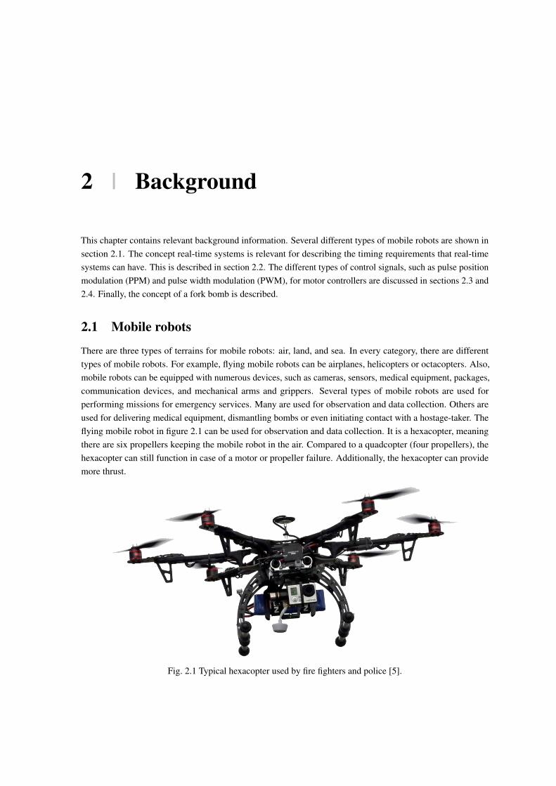
There are three types of terrains for mobile robots: air, land, and sea. In every category, there are differenttypes of mobile robots. For example, flying mobile robots can be airplanes, helicopters or octacopters. Also,mobile robots can be equipped with numerous devices, such as cameras, sensors, medical equipment, packages,communication devices, and mechanical arms and grippers. Several types of mobile robots are used forperforming missions for emergency services. Many are used for observation and data collection. Others areused for delivering medical equipment, dismantling bombs or even initiating contact with a hostage-taker. Theflying mobile robot in figure 2.1 can be used for observation and data collection. It is a hexacopter, meaningthere are six propellers keeping the mobile robot in the air. Compared to a quadcopter (four propellers), thehexacopter can still function in case of a motor or propeller failure. Additionally, the hexacopter can providemore thrust.
Fig. 2.1 Typical hexacopter used by fire fighters and police [5].
6 Background
Flying mobile robots are also useful for emergency medical assistance. A flying mobile robot can deliver anautomated external defibrillator (AED). People that experience a cardiac arrest can be given and AED by airmuch quicker than by ambulance. Bystanders can apply the defibrillator and follow instructions provided.
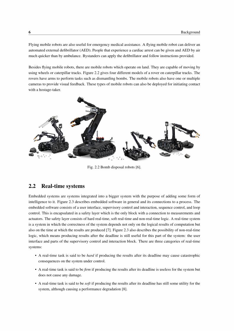
Besides flying mobile robots, there are mobile robots which operate on land. They are capable of moving byusing wheels or caterpillar tracks. Figure 2.2 gives four different models of a rover on caterpillar tracks. Therovers have arms to perform tasks such as dismantling bombs. The mobile robots also have one or multiplecameras to provide visual feedback. These types of mobile robots can also be deployed for initiating contactwith a hostage-taker.
Fig. 2.2 Bomb disposal robots [6].
2.2 Real-time systems
Embedded systems are systems integrated into a bigger system with the purpose of adding some form ofintelligence to it. Figure 2.3 describes embedded software in general and its connections to a process. Theembedded software consists of a user interface, supervisory control and interaction, sequence control, and loopcontrol. This is encapsulated in a safety layer which is the only block with a connection to measurements andactuators. The safety layer consists of hard real-time, soft real-time and non-real-time logic. A real-time systemis a system in which the correctness of the system depends not only on the logical results of computation butalso on the time at which the results are produced [7]. Figure 2.3 also describes the possibility of non-real-timelogic, which means producing results after the deadline is still useful for this part of the system: the userinterface and parts of the supervisory control and interaction block. There are three categories of real-timesystems:
• A real-time task is said to be hard if producing the results after its deadline may cause catastrophicconsequences on the system under control.
• A real-time task is said to be firm if producing the results after its deadline is useless for the system butdoes not cause any damage.
• A real-time task is said to be soft if producing the results after its deadline has still some utility for thesystem, although causing a performance degradation [8].

2.3 Pulse width modulation 7
Fig. 2.3 Embedded system layout [9].
2.3 Pulse width modulation
A pulse width modulated signal is a common control signal structure. Figure 2.4 shows how an analog signal isencoded in a PWM signal. Most motor controllers accept this digital signal as input. Every motor controllerneeds its own PWM signal. This means the safety layer will use one output pin for every motor on the mobilerobot. PWM signals have a constant amplitude and a variable duty cycle. The width represents the data; inthis application a throttle between 0% and 100%. The period (equal to the sample time) of PWM signals isusually 20 ms. This means a refresh rate of 50 Hz for the motor controllers. This is generally sufficient but canbe altered when necessary.
PWMsignal
Analogsignal
Sampling times
t
t
Fig. 2.4 Analog to PWM signal [10].
2.4 Pulse position modulation
A pulse position modulated signal is another common control signal structure. PPM signals have a constantamplitude and pulse width. The position of the pulse, relative to the period represents the data, in this applicationa throttle between 0% and 100%. Figure 2.5 shows how to encode an analog signal in a PPM signal. One PPMsignal can contain multiple channels. With a default period of 20 ms, and assigning 2 ms to every channel, up

8 Background
to 10 channels can be encoded. This means the safety layer will only need one output pin for all motors on themobile robot, provided it has no more than 10 motors. The period (equal to the sample time) of PWM signalsis usually 20 ms. This corresponds with a refresh rate of 50 Hz for the motor controllers. This is generallysufficient but can be altered when necessary.
PPMsignal
Analogsignal
Sampling times
t
t
Fig. 2.5 Analog to PPM signal [10].
2.5 Fork bomb
A fork bomb is an attack to a system in which a process is continuously forked. Forking a process means theprocess replicates itself. This leads to an exponential increase in fork bomb processes, as shown in figure 2.6.This results in slowing down and eventually crashing the system due to saturation of the operating system’sprocess table. Fork bombs are used to trigger onboard-computer failures.
Fig. 2.6 Fork bomb principle [11].

3 | Analysis
This chapter analyzes the design considerations of a safety layer increasing deterministic behavior of mobilerobots. Common threats to deterministic behavior are discussed. To tackle those threats, a safety layer isintroduced. The chapter tries to answer the research questions: What are common threats to deterministicbehavior? How can threats best be detected? What is the appropriate response to failures? How can theresponses best be effectuated?
3.1 What are common threats to deterministic behavior?
Mobile robots are currently not reliable enough because there is still too much non-deterministic behavior.Non-deterministic behavior occurs when the operator’s expected response does not match the mobile robot’sresponse, as seen in equation 3.1. This mismatch in response can occur after events such as incoming controlcommands or onboard failures.
i f operator’s expected response ̸= mobile robot response =⇒ non-deterministic behavior (3.1)
As mentioned in the research scope, this research focuses on non-deterministic behavior as a result of failureson the mobile robot. Hence, failures have to be analyzed. To visualize the causes and consequences of failures,a bow-tie figure is used. Bow-tie figures are often used for analyzing critical chemical processes. They visualizethe faults possibly resulting in a failure and the consequences of the failure. This gives insight into the safetybarriers necessary to prevent failures or mitigate failures. Bow-tie figures are a useful tool during this research.A simplified bow-tie figure for typical mobile robots is seen in figure 3.1.

10 Analysis
Fig. 3.1 Simplified bow-tie figure for most mobile robots.
Faults causing a failure (such as network interference causing a network connection error) are given on theleft-hand side. Safety barriers try to prevent the failure from happening. These barriers can be as simple asvoltage stabilizers or operators checking weather conditions. Not all faults have safety barriers preventing thefailure. There likely are faults or failures that have not yet been discovered, and therefore do not have a safetybarrier. In case these undiscovered faults occur, the failure and its consequences are imminent. As soon asany failure occurs, one of the consequences will follow, as there is no barrier to prevent this. For example, anunstable voltage source is a fault resulting in an onboard-computer failure (the failure). The correspondingsafety barrier preventing the failure could be a voltage stabilizer. Once the voltage stabilizer fails to stabilizethe voltage, the onboard computer fails. This immediately results in one of the consequences. For example, aflying mobile robot crashes in water and is lost.
3.1.1 Identifying onboard failures
What are common onboard failures? Some failures are identified because they happened before. Others becausethey were identified during discussions. Multiple controllers connected to one mobile robot can only cause afailure in a multi-robot environment. Currently, the identified onboard failures are:
• Onboard-computer failures
• Motor controller failures
• Network connection errors
• Battery failures
• Multiple controllers
• Incorrect output
The research scope restricted the failures to those that can be solved onboard. Also, hardware failures andhijacking are excluded by the research scope.

3.1 What are common threats to deterministic behavior? 11
3.1.2 Analyzing onboard failures
Every onboard failure is analyzed and given a score for likeliness and consequence. The likeliness score goesfrom very unlikely to very likely in four steps. The likeliness is relative to one deployment of a mobile robot.The score for consequence goes from negligible to severe in four steps, describing the consequence to materials,environment, and humans. Many barriers are already implemented that lower the likeliness and consequence ofonboard failures. These existing barriers (such as operators checking weather conditions) are included in thefailure analysis.
Onboard-computer failures
When an onboard-computer failure occurs on the mobile robot, the operator experiences unexpected behavior.The mobile robot may do unexpected moves or come to a complete stop. In both cases, the mobile robot maycause damage, injuries or mission failures. There are many causes of onboard-computer failures. Electricalinterference, bad programming, and hardware failures are some examples. With modern computers andprogrammers, onboard-computer failures are unlikely. Also, especially for operations by emergency services,extensive testing has been done to identify and resolve errors.⇒ Likeliness: unlikely⇒ Consequence: severe
Multiple controllers
In a multi-robot environment with multiple controllers, a mobile robot can potentially be linked to multiplecontrollers. This could lead to incorrect control signals and unexpected behavior. However, the combination ofthe control signals is not completely random and not necessarily problematic. The universal control system,developed at the University of Twente, gives exclusive ownership. This means – provided the multi-robot logicworks properly – it is very unlikely that multiple controllers will be linked to one mobile robot.⇒ Likeliness: very unlikely⇒ Consequence: moderate
Network connection errors
Protection against network connection errors is especially required when a mobile robot is operating in a hostileenvironment. Mobile robots can often experience network connection errors. This can have multiple causes,depending on the communication protocol. Mostly, network connection errors occur because of a weak signalin certain locations. This results in the mobile robot showing unexpected behavior. It depends on the softwarewhat a mobile robot will do when the network connection is lost. Some are implemented in a way that themobile robot will stop moving. Others will continue in the last known heading for a long period of time.Since operators are trained, they will take the range of a mobile robot in account when performing maneuvers.However, even then the mobile robot may lose signal due to obstructions or communicational noise. This givesa medium likeliness: possible. As mentioned, the consequences are significant.⇒ Likeliness: possible⇒ Consequence: significant

12 Analysis
Incorrect onboard computer output
An incorrect output by the onboard computer is an onboard failure that may lead to unexpected behavior. Thereare several causes that can lead to an incorrect output by the onboard computer. The most likely one is badprogramming. Since mobile robots are extensively tested, the likeliness of incorrect onboard computer outputis low. The consequences are high since arbitrary control signals or status parameters are produced. In turn, thismay result in damage, injuries or mission failures.⇒ Likeliness: very unlikely⇒ Consequence: severe
Motor controller failures
Another onboard failure is a motor controller failure. This too can lead to unexpected behavior and uncontrolledmobile robots. In case the mobile robot is a flying mobile robot, it will crash unless the mobile robot is amulti-copter with more than four propellers. For the rover, the consequences are less severe than for a flyingmobile robot. In case the mobile robot is a rover, the mobile robot will either come to a complete stop or startmaking turns in an arbitrary direction. Most motor controllers can handle faulty input values. However, themotor controllers may still fail due to noise or unstable voltage supplies. This makes the likeliness low. Sincethe consequences for flying mobile robots are severe, the consequence is considered significant.⇒ Likeliness: unlikely⇒ Consequence: significant
Battery failure
When the battery has failed, the mobile robot becomes dysfunctional. Communication is not possible and allmotors will stop. For flying mobile robots this means falling to the ground. For mobile robots, this meanscoming to a complete stop, unless the mobile robot is positioned on a slope. Ideally, an operator knows thehealth of the battery. This can prevent battery failure. Nevertheless, humans make mistakes and battery failuremay occur. The likeliness is low, but the consequence is high as all flying mobile robots will crash in case ofbattery failures.⇒ Likeliness: very unlikely⇒ Consequence: significant
A common safety analysis technique used in critical chemical processes is setting up a risk matrix. In this matrix,the likeliness of every failure is plotted against the consequence of that failure. Multiplying the consequencewith the likeliness gives the risk:
risk = consequence ∗ likeliness (3.2)
This means that an onboard failure that is placed in the top-right corner of the matrix must be solved to preventconstant problems, while onboard failures in the bottom-left corner have a lower priority. To visualize the riskof the onboard failures mentioned earlier, the corresponding risk matrix is given in figure 3.2.

3.2 How can threats best be detected? 13
Onboard-computerfailures
Motorcontrollerfailures
Networkconnectionerrors
Batteryfailures
Multiplecontrollers
Incorrectoutput
1
2
3
4
5
1 2 3 4 5
Likeliness
Consequence
likely
possible
unlikely
very unlikely
very likely
Fig. 3.2 Risk matrix.
From this graph, we can conclude that three failures (network connection errors, motor controller failures, andonboard-computer failures) pose the highest risk for normal operation of a mobile robot. Multiple controllerslinked to one mobile robot is the least problematic failure. Every failure’s risk is determined to define animplementation priority. Barriers for all failures should be added to the safety layer.
3.2 How can threats best be detected?
This chapter describes the differences between fault detection and failure detection. Also, the detection logiclocation, the detection method, and the safety layer are described.
3.2.1 Fault detection
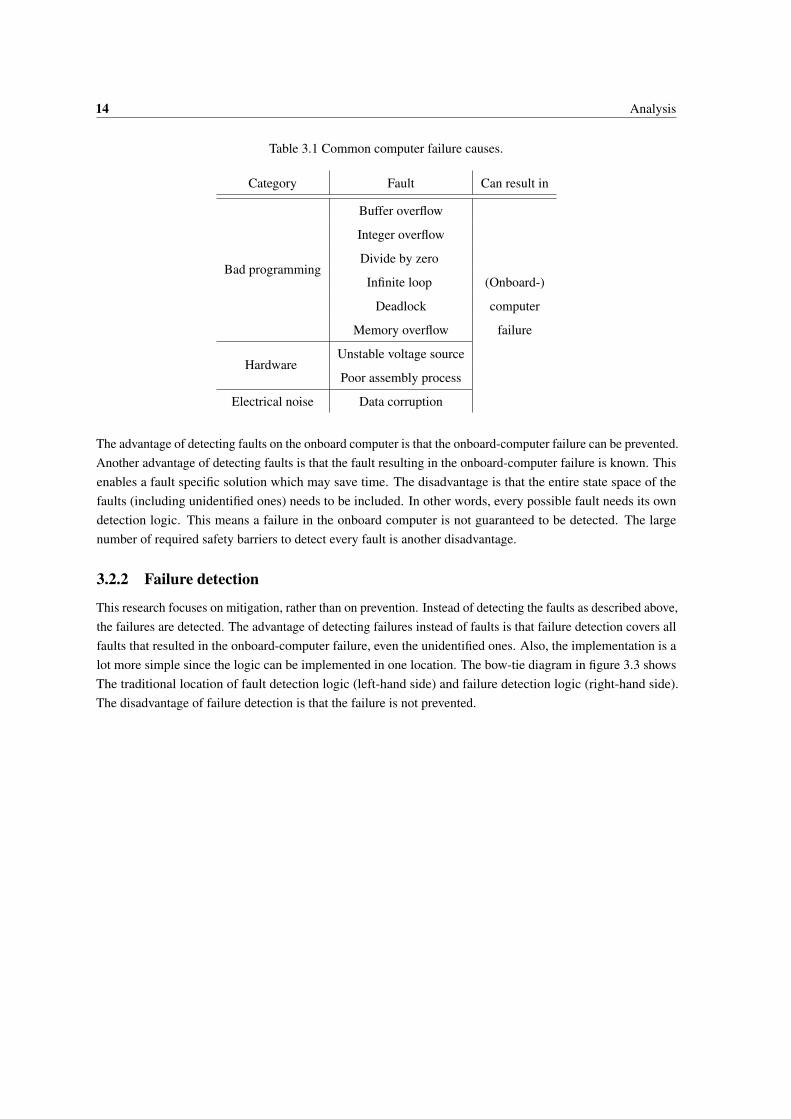
Traditionally, onboard-computer failures are prevented by detecting faults on the onboard computer. The mostcommon faults are buffer overflow, integer overflow, uninitialized data, null dereference, divide by zero, infiniteloop, deadlock and memory overflow [12]. Also, electrical noise corrupting data, an unstable voltage source ora poor assembly process [13] may cause system failures. Table 3.1 gives an overview of these most commonfaults. All faults can result in an onboard-computer failure.
14 Analysis
Table 3.1 Common computer failure causes.
Category Fault Can result in
Bad programming
Buffer overflow
(Onboard-)
computer
failure
Integer overflow
Divide by zero
Infinite loop
Deadlock
Memory overflow
HardwareUnstable voltage source
Poor assembly process
Electrical noise Data corruption
The advantage of detecting faults on the onboard computer is that the onboard-computer failure can be prevented.Another advantage of detecting faults is that the fault resulting in the onboard-computer failure is known. Thisenables a fault specific solution which may save time. The disadvantage is that the entire state space of thefaults (including unidentified ones) needs to be included. In other words, every possible fault needs its owndetection logic. This means a failure in the onboard computer is not guaranteed to be detected. The largenumber of required safety barriers to detect every fault is another disadvantage.
3.2.2 Failure detection
This research focuses on mitigation, rather than on prevention. Instead of detecting the faults as described above,the failures are detected. The advantage of detecting failures instead of faults is that failure detection covers allfaults that resulted in the onboard-computer failure, even the unidentified ones. Also, the implementation is alot more simple since the logic can be implemented in one location. The bow-tie diagram in figure 3.3 showsThe traditional location of fault detection logic (left-hand side) and failure detection logic (right-hand side).The disadvantage of failure detection is that the failure is not prevented.

3.2 How can threats best be detected? 15
Fig. 3.3 Bow-tie figure showing fault detection (left-hand side) and failure detection (right-hand side).
Concluding, it costs a lot of effort and logic to detect faults resulting in a failure. Even when a fault is detectable,not all failures are detected due to undiscovered faults. Therefore, failure detection is much more fit forimplementation.
3.2.3 Detection logic location
There are several locations for implementing detection logic. Traditionally, detection is done on the onboardcomputer, as it has access to all sensors and actuators. There are currently three locations where logic can beimplemented that detects onboard failures. Detection logic can be implemented on the:
• Onboard computer
• Network
• Controller (and operator)
Unfortunately, failures of the onboard computer cannot be solved by any of the three mentioned locations. Thisis because the onboard computer itself is dysfunctional and both the network and controller cannot access themobile robot because there is no network connection with the mobile robot. To increase deterministic behaviorof the mobile robots, onboard failures have to be included, especially considering its risk.
Independent safety layer
Inspired by systems used in critical chemical processes, a fourth location is added: an independent safety layer.Ronald J. Willey describes the independent safety layer in his layer of protection analysis (LOPA) tool, whichis a risk management technique commonly used in the chemical process industry [14]. The independent safetylayer is usually an emergency shutdown system that does not depend upon any operator interaction. A commonexample is seen in burners for boiler systems. In case there is no more flame, light sensors automaticallyshut down the gas flow. This prevents leakage of combustible gas into the furnace. Independent safety layersare added to improve safety. The safety layer reacts after a failure has occurred. It prevents catastrophic

16 Analysis
consequences – often by shutting down the process – and informs operators, who can trigger a reset of theprocess. The safety layer is independent of the control process, such that a failure in the latter does not affectthe safety layer. It is important to note that this strategy mitigates failures, meaning it keeps the consequences toa minimum, instead of preventing the failures. In the mobile robot industry, this concept can be a good solutionfor minimizing the consequences of onboard-computer failures. The independent safety layer can communicatewith the onboard computer.
To make sure all onboard failures are mitigated, an independent safety layer must be added to the list ofimplementation locations. The safety layer is not integrated with existing logic, to ensure independence. Thestructure of the safety layer will be further described in 3.2.5. With this fourth location added, all onboardfailures mentioned in 3.1.1 can be categorized.
Concluding, the onboard computer is capable of mitigating all onboard failures, except for one: onboard-computer failures. This must be done by the independent safety layer. The other onboard failures can best beimplemented on the onboard computer. It already has access to all sensors and actuators. The network andcontroller both cover less onboard failures than the onboard computer. The overview of onboard failures andthe corresponding location of the safety barrier is summarized in table 3.2.
Table 3.2 Onboard failures and their location for the safety barrier mitigating the failures.
Onboard failure Safety barrier location
Onboard-computer failures Independent safety layer
Motor controller failures Onboard computer
Network connection errors Onboard computer
Battery failures Onboard computer
Multiple controllers Onboard computer
Incorrect output Onboard computer
With the proposed safety layer, a new bow-tie figure is set up in figure 3.4. This time the safety layer formsadditional safety barriers that mitigate the failures on the right-hand side of the figure. In this situation, evenonboard-computer failures can be mitigated, which was previously complex. Additionally, unidentified faultscan encounter a safety barrier before consequences occur. The barriers that try to prevent the onboard failuresare still implemented on the left-hand side of the figure.

3.2 How can threats best be detected? 17
Fig. 3.4 Simplified bow-tie figure with the mitigating safety layer added.
3.2.4 Detection method
The best detection method must be determined. There are several methods for detecting onboard-computerfailures. The control signals of the onboard computer can be monitored, the computer’s crash dump can beanalyzed, a heartbeat signal can be added to processes or a watchdog timer can be used to monitor the system.The independent safety layer is responsible for detecting onboard-computer failures as it is the only entitycapable of detecting them. The detection of all other onboard failures is done on the onboard computer.
Monitoring control signals
Every onboard computer used in a mobile robot outputs control signals. Using these control signals to detectonboard-computer failures leads to a universal safety layer. An onboard-computer failure can disrupt the controlsignals, which can be detected by the safety layer.
A test is done, to check if control signals can be used for detecting onboard-computer failures. A RaspberryPi functions as the onboard computer outputting a PWM signal. The signals will represent a fixed value. Afork bomb will be performed on the Raspberry Pi, simulating an onboard-computer failure. At that point, astopwatch is started. The safety layer is used to detect the absence of control signals. It reads the PWM signaland indicates a failure using light emitting diodes (LEDs) when the signal is different than expected. When thesafety layer has detected the disruption, the stopwatch is stopped.
From the test results, I concluded that the Raspberry Pi successfully produces control signals until it is out ofmemory. Up to that point, the allocated memory for toggling the PWM output guarantees there are controlsignals on the output. Until there is an absence of the control signals, the control signals cannot be used fordetecting onboard-computer failures. Figure 3.5 shows that it can take up to 120 seconds until there is anabsence of control signals. Up to that point, valid control signals are produced. This means the mobile robotcan continue in its last known heading for the same amount of time. The results are summarized in table 3.3.

18 Analysis
0
1
2
3
4
5
0 10 20 30 40 50 60 70 80 90 100 110 120 More
Co
un
t
Detection delay [s]
Fig. 3.5 Histogram of detection delay when using control signals as heartbeat.
One could argue that a change in control signals indicates the onboard computer is still active. However, thiswould mean that a mobile robot in normal operations has to keep altering its control signals. This is also not afeasible option since many operations require movements that have the same control signals for a long periodof time. Therefore, a specific control signal for a long period of time cannot be interpreted as a failure in theonboard computer. Setting up a statistically acceptable set of rules for this would disrupt the functioning ofeither the safety layer or the mobile robot. Monitoring the control signals is not a suitable detection method forthis safety layer.
Crash dump analysis
Many operating systems have a crash dump. After a failure, the system will write the cause of the failure to thecrash dump log. Analyzing it is the most straightforward way of detecting a system failure and its cause. Anadvantage is that it is much easier to use this built-in logic, compared to manual monitoring of crash causes.The dump is usually flash memory or a local register to which the system writes failure information in case of asystem crash. The safety layer can be given access to this memory and can therefore determine the cause of thecomputer failure, and indicate the failure. A disadvantage is that it is a slow detection method. Only after thesystem has failed, the crash dump has been produced and the crash dump is read, the failure will be detected bythe safety layer.
The crash dump is only produced after the failure of the onboard computer. This means the crash dump is alsoproduced after there is an absence of control signals. Considering the test results for monitoring the controlsignals as a detection method, the crash dump is not fast enough. The crash dump is a slower detection methodthan monitoring the control signals, which makes crash dump analysis infeasible as a detection method. Themethod will not be tested.
3.2 How can threats best be detected? 19
Heartbeat signal
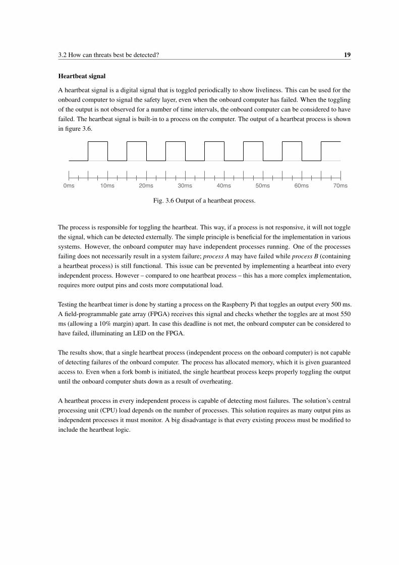
A heartbeat signal is a digital signal that is toggled periodically to show liveliness. This can be used for theonboard computer to signal the safety layer, even when the onboard computer has failed. When the togglingof the output is not observed for a number of time intervals, the onboard computer can be considered to havefailed. The heartbeat signal is built-in to a process on the computer. The output of a heartbeat process is shownin figure 3.6.
10ms0ms 20ms 30ms 40ms 50ms 60ms 70ms
Fig. 3.6 Output of a heartbeat process.
The process is responsible for toggling the heartbeat. This way, if a process is not responsive, it will not togglethe signal, which can be detected externally. The simple principle is beneficial for the implementation in varioussystems. However, the onboard computer may have independent processes running. One of the processesfailing does not necessarily result in a system failure; process A may have failed while process B (containinga heartbeat process) is still functional. This issue can be prevented by implementing a heartbeat into everyindependent process. However – compared to one heartbeat process – this has a more complex implementation,requires more output pins and costs more computational load.
Testing the heartbeat timer is done by starting a process on the Raspberry Pi that toggles an output every 500 ms.A field-programmable gate array (FPGA) receives this signal and checks whether the toggles are at most 550ms (allowing a 10% margin) apart. In case this deadline is not met, the onboard computer can be considered tohave failed, illuminating an LED on the FPGA.
The results show, that a single heartbeat process (independent process on the onboard computer) is not capableof detecting failures of the onboard computer. The process has allocated memory, which it is given guaranteedaccess to. Even when a fork bomb is initiated, the single heartbeat process keeps properly toggling the outputuntil the onboard computer shuts down as a result of overheating.
A heartbeat process in every independent process is capable of detecting most failures. The solution’s centralprocessing unit (CPU) load depends on the number of processes. This solution requires as many output pins asindependent processes it must monitor. A big disadvantage is that every existing process must be modified toinclude the heartbeat logic.
20 Analysis
Watchdog timer
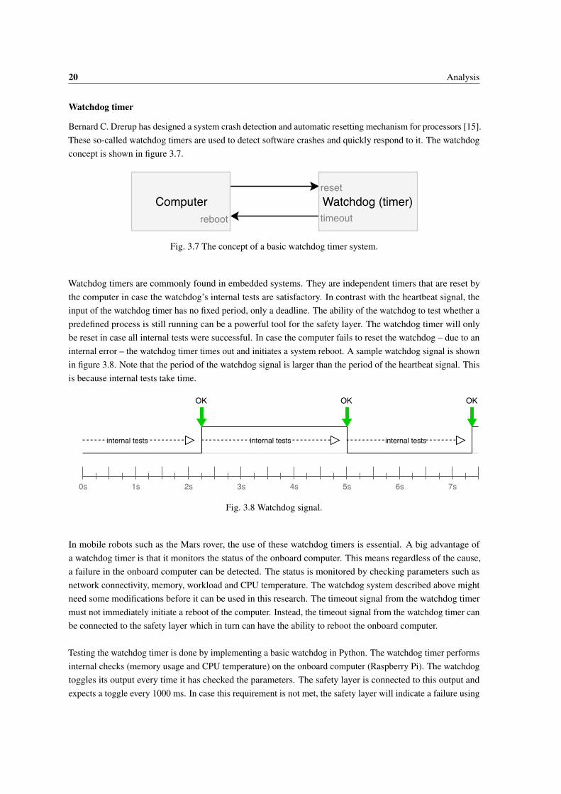
Bernard C. Drerup has designed a system crash detection and automatic resetting mechanism for processors [15].These so-called watchdog timers are used to detect software crashes and quickly respond to it. The watchdogconcept is shown in figure 3.7.
Computer Watchdog (timer)timeout
reset
reboot
Fig. 3.7 The concept of a basic watchdog timer system.
Watchdog timers are commonly found in embedded systems. They are independent timers that are reset bythe computer in case the watchdog’s internal tests are satisfactory. In contrast with the heartbeat signal, theinput of the watchdog timer has no fixed period, only a deadline. The ability of the watchdog to test whether apredefined process is still running can be a powerful tool for the safety layer. The watchdog timer will onlybe reset in case all internal tests were successful. In case the computer fails to reset the watchdog – due to aninternal error – the watchdog timer times out and initiates a system reboot. A sample watchdog signal is shownin figure 3.8. Note that the period of the watchdog signal is larger than the period of the heartbeat signal. Thisis because internal tests take time.
1s0s 2s 3s 4s 5s 6s 7s
internal tests
OKOK OK
internal tests internal tests
Fig. 3.8 Watchdog signal.
In mobile robots such as the Mars rover, the use of these watchdog timers is essential. A big advantage ofa watchdog timer is that it monitors the status of the onboard computer. This means regardless of the cause,a failure in the onboard computer can be detected. The status is monitored by checking parameters such asnetwork connectivity, memory, workload and CPU temperature. The watchdog system described above mightneed some modifications before it can be used in this research. The timeout signal from the watchdog timermust not immediately initiate a reboot of the computer. Instead, the timeout signal from the watchdog timer canbe connected to the safety layer which in turn can have the ability to reboot the onboard computer.
Testing the watchdog timer is done by implementing a basic watchdog in Python. The watchdog timer performsinternal checks (memory usage and CPU temperature) on the onboard computer (Raspberry Pi). The watchdogtoggles its output every time it has checked the parameters. The safety layer is connected to this output andexpects a toggle every 1000 ms. In case this requirement is not met, the safety layer will indicate a failure using

3.2 How can threats best be detected? 21
an LED. A fork bomb is used to simulate an onboard-computer failure. Discontinuing the watchdog processmust result in the safety layer detecting a failure.
From the results, I conclude that the watchdog timer is a reliable method for detecting onboard-computerfailures, when the internal tests are carefully chosen. The timeout value (currently 1000 ms) also needs to bedetermined before implementation. It takes up to two seconds to detect an onboard-computer failure using awatchdog, as shown in figure 3.9. This means the onboard computer is still functional for at most one secondafter the fork bomb is initiated. The solution requires only one output pin and has a low CPU load. The resultsare summarized in table 3.3.
0
1
2
3
4
5
6
0 0.2 0.4 0.6 0.8 1 1.2 1.4 1.6 1.8 2 2.2 2.4 More
Co
un
t
Detection delay [s]
Fig. 3.9 Histogram of detection delay when using a watchdog.
To test the performance of the detection methods, all faults listed in section 3.2.1 are triggered in the test. Theability of every detection method to detect a failure after every fault is described in table 3.3. A Yes indicates afailures was detected, a No indicates no failure was detected. Notes provide additional information. The CPUload and pin count are shown in the bottom two rows. In the test, a Raspberry Pi 3, model B (v1.2) representsthe onboard computer. Raspbian 9 is running Python scripts on the onboard computer. The safety layer isrepresented by very high speed integrated circuit hardware description language (VHDL) logic on a DE0-Nano(Cyclone IV chip) FPGA.

22 Analysis
Table 3.3 Results of testing failure detection methods.
Single
heartbeat process
Heartbeat process
in every
independent
process (P)
Standard
watchdog timer
Monitoring
control signals
Buffer overflow No Yes Yes No(1)
Integer overflow No(2) No(2) No(2) No(1)(2)
Divide by zero No Yes Yes No(1)
Infinite loop No Yes Yes No(1)
Deadlock No Yes Yes No(1)
Memory overflow No Yes Yes No(1)
Data corruption Not tested(4) Not tested(4) Not tested(4) Not tested(4)
Unstable voltage source No(3) No(3) No(3) No(1)(3)
Poor assembly process Not tested(4) Not tested(4) Not tested(4) Not tested(4)
High load (overheat) No Yes Yes No(1)
CPU load ~0% ~0*P% ~0% 0%
Pin count 1 P 1 0
(1) Until absence of control signals.(2) Integer overflow is impossible in Python, provided there is enough memory.(3) Until voltage source unacceptably low.(4) Data corruption and poor assembly process are complex to reproduce.
Using the test results in the table, I have concluded that the watchdog and the multiple heartbeat processes areboth satisfactory detection methods. The watchdog uses fewer communication pins and is therefore the bettermethod. The control signals and the crash dump cannot be used for quick detection. Using the control signalsresults in similar detection issues as using a single heartbeat process. An unstable voltage source is not detectedby any solution until the voltage source is unacceptably low such that the onboard computer powers off. Integeroverflow is not detected by any detection method. In Python, integers have arbitrary precision and can thereforerepresent an arbitrarily large range of integers. The integer range is only limited by available memory. TheCPU load of all detection methods is almost zero.
3.2 How can threats best be detected? 23
3.2.5 Safety layer structure
The safety layer can only be independent if it is stand-alone. This means it will not be integrated with existinglogic, such as the onboard computer. A stand-alone solution can be implemented locally (on the mobile robot)or remotely. Kristen Anderson’s research [16] shows a proof-of-concept for a crash avoidance system on a toycar. A remote safety layer functions using sensor data transmitted from the car. The remote solution works asa safety layer in the proof-of-concept. However, when a loss of connection to the sensors occurs, the crashavoiding safety layer cannot function. A remote solution is not feasible, because a network connection with themobile robot at all times cannot be guaranteed. Hence, a local stand-alone solution is required.
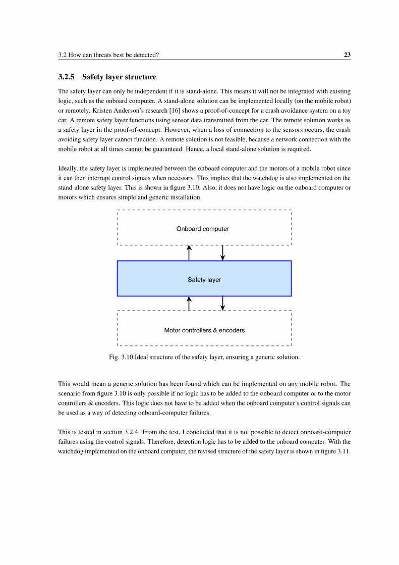
Ideally, the safety layer is implemented between the onboard computer and the motors of a mobile robot sinceit can then interrupt control signals when necessary. This implies that the watchdog is also implemented on thestand-alone safety layer. This is shown in figure 3.10. Also, it does not have logic on the onboard computer ormotors which ensures simple and generic installation.
Safety layer
Motor controllers & encoders
Onboard computer
Fig. 3.10 Ideal structure of the safety layer, ensuring a generic solution.
This would mean a generic solution has been found which can be implemented on any mobile robot. Thescenario from figure 3.10 is only possible if no logic has to be added to the onboard computer or to the motorcontrollers & encoders. This logic does not have to be added when the onboard computer’s control signals canbe used as a way of detecting onboard-computer failures.
This is tested in section 3.2.4. From the test, I concluded that it is not possible to detect onboard-computerfailures using the control signals. Therefore, detection logic has to be added to the onboard computer. With thewatchdog implemented on the onboard computer, the revised structure of the safety layer is shown in figure 3.11.

24 Analysis
Safety layer
Motor controllers & encoders
Onboard computer
Fig. 3.11 Revised structure of the safety layer.
The external logic has the advantage of being independent of the mobile robot’s main logic. This means amalfunction in the main logic does not interrupt the performance of the safety logic. The combination ofinternal and external enjoys the advantage of flexibility. The internal logic has access to all sensors, parametersand other logic on the mobile robot. This internal logic can communicate with the external logic which onits turn is independent of the main logic. A disadvantage is that the internal logic is unresponsive in caseof onboard-computer failures. Another disadvantage is extra financial and physical space costs for external logic.
Access to the onboard computer of the mobile robot is necessary for the watchdog to function. This is impossiblewithout integrating the detection logic on the mobile robot. Hence, the safety layer must contain logic integratedon the onboard computer. The safety layer must be able to function stand-alone in case the onboard computershows severe failures. In that case, the detection logic will be unresponsive. This conclusion means sacrificingsome physical space on the mobile robot. Altogether, the safety layer will be a stand-alone onboard solution. Ithas a watchdog on the onboard computer and all other logic on the external safety layer.
Concluding, the best method for detecting onboard-computer failures is using a watchdog. The watchdogmust be implemented on the onboard computer to ensure access to system data. The remaining parts of thesafety layer must be stand-alone to ensure independence from the onboard computer. This allows effectuating aresponse at all times.

3.3 What is the appropriate response to failures? 25
3.3 What is the appropriate response to failures?
The safety layer is responsible for responding to onboard-computer failures. In case of any other onboardfailure (general failures), the safety layer’s only response is to keep the mobile robot in its current location.These failures are given further response by the onboard computer. A response that matches the operator’sexpected response should be determined to increase deterministic behavior. What should the safety layer’sresponse to onboard-computer failures be?
3.3.1 Proposed response
The initial response by the safety layer must be to keep the mobile robot in its current location. Maintaininglocation includes altitude in case of a flying mobile robot. If critical processes (such as the control processor the video process) are not responding, these processes must be restarted. In case the network connectionhas failed, a restart of the network interface must be performed. If these actions are not successful, a rebootof the onboard computer must be performed. A reboot (soft reset) must always be attempted before a hardreset is performed. Mission data can be lost when rebooting the onboard computer. Hence, backing-up andrecovering mission data must be considered. Mission data can be stored in arbitrary locations, with any datasize and structure. Making a back-up or recovering these files can be complex. If a hard reset is not successful,there is no other option then to return to launch using the safety layer. If the onboard-computer failure is solved,and the control has been recovered, the mobile robot can continue operations.
3.3.2 Resetting the onboard computer
Resetting the onboard computer is an essential function of the safety layer. There are two options for resettingthe safety layer: a reboot and a hard reset. A reboot gives the onboard computer the reboot signal. This is thesafe way of rebooting a system. It initiates a sequence of commands that prevents system corruption. Thesystem is given time to save important data to memory, unmount external drives and eventually perform areboot. A hard reset is the last measure against unresponsive systems. Data corruption may occur, and importantdata may be lost. A hard reset cuts the power to the system and reboots it.
3.3.3 Configuring the response
To increase deterministic behavior of mobile robots, the operator’s expected response must match the mobilerobot response. The operator’s expected response may differ per operator and mission. Therefore, the operatormust be given the ability to configure the safety layer’s response. Parameters such as the timeout value for themobile robot to return to base instead of solving the failure must be configurable.
Concluding, backing up or recovering mission data is not included in the safety layer as it is very dependent onthe mobile robot. Mission data may be stored in arbitrary locations and have arbitrary data sizes and structures.It is also likely that mission data is stored on the operator side instead of on the mobile robot. A reboot mustalways be performed before the hard reset is performed. However, the response may differ per operator andmission. To ensure deterministic behavior, the response should match the expectations of the operator. Itis important that the operator knows all responses and can change them accordingly. This feature is a bigadvantage because it allows more deterministic behavior on the mobile robot.
26 Analysis
3.4 How can the responses best be effectuated?
With the responses determined, effectuating the responses can be analyzed. The safety layer should be able tokeep the mobile robot in the current location, reset the onboard computer and guide the mobile robot back tothe launch location.
3.4.1 Timing requirements
What are the timing requirements for the safety layer? Immediate detection of onboard-computer failures isvaluable. However, false positives must be prevented. A quick response by the safety layer will be beneficialfor the system performance. Computational deadlines for producing the control signals must be met to ensuresmooth control over the mobile robot.
Detection
Instantly detecting abnormal behavior using the watchdog is valuable. However, the safety layer must alwaysbe sure that abnormal behavior is actually occurring, when it indicates a failure. Falsely activating the safetylayer costs time and can impact emergency operations. The effects of these false positives can be as big as notactivating the safety layer after actual failures. On the other hand, faster detection of failures is beneficial for theoverall performance of the safety layer. The outcome of several internal checks determines whether the onboardcomputer is in normal operations or if there is an onboard-computer failure. The internal checks can be:
• Is there enough free memory?
• Is the average CPU load acceptable?
• Is the video process still running?
• Is the control process still running?
• Do network interfaces receive traffic?
• Is the CPU temperature acceptable?
By observing these parameters before and during onboard-computer failures, a selection is chosen for thedesign. The free memory is a good parameter to check. Under normal operations, an onboard computer uses nomore than 80% of its memory. This is an observation and depends on the hardware. The workload is not areliable parameter to monitor. A peak in user requests can trigger a CPU load of 100% which does not representa failure. Monitoring the video process and the control process are valuable internal tests for the watchdog. Afailure in one of these processes represents a failure. Network connectivity is currently not a good parameterto check. The Raspberry Pi has a weak wireless local area network (WLAN) adapter, occasionally causingnetwork interruptions. This can lead to false positives. The CPU temperature is a suitable parameter to monitor.From observation, I concluded that the CPU temperature does not exceed 85 °C under normal circumstances.Only in case of failures, the CPU temperature is higher.
A test has been done to determine the optimal watchdog timeout. The timeout is defined as the deadline for theonboard computer to signal the result of the internal checks. A large timeout ensures sufficient time for theCPU to perform the internal tests, minimizing the number of false positives. A small timeout results in quicker

3.4 How can the responses best be effectuated? 27
detection of failures. A Raspberry Pi is used as an onboard computer. The amount of false positives depends onthe timeout and the CPU load. CPU loads of 30%, 50%, 70%, and 90% are tested for timeouts between 100 msand 2000 ms. The load is kept constant at the desired level by dummy processes that rapidly perform complexcalculations. The safety layer keeps count of the number of onboard-computer failures it has detected. Theresults are shown in figure 3.12.
0
100
200
300
400
500
600
0.1 0.2 0.3 0.4 0.5 0.6 0.7 0.8 0.9 1.0 1.1 1.2 1.3 1.4 1.5 1.6 1.7 1.8 1.9 2.0
Fals
e p
osi
tive
s [m
in-1
]
Watchdog timeout [s]
90% load
70% load
50% load
30% load
Fig. 3.12 Results of the watchdog timeout test.
False positives are unacceptable. Therefore any timeout lower than 1100 ms cannot be used. Even though itcomes at the cost of a larger detection delay, I assume a timeout of 1500 ms is an acceptable compromise. Thismeans it takes up to 1.5 seconds to detect an onboard-computer failure.
Response
After an onboard failure has been detected, the safety layer needs to produce appropriate control signals asfast as possible. Producing computational results such as control signals too late will negatively impact theperformance of the safety layer. The safety layer can always produce control signals that try to keep the mobilerobot in its current location. Up to the point where an onboard-computer failure is detected, these controlsignals will be ignored. This yields a quick response.
Concluding, the detection is done by a watchdog timer with a timeout value of 1500 ms, this ensures a lowprobability of false positives and a quick detection of failures. The responses must be produced immediatelyafter an onboard-computer failure is detected. This is done by continuously producing control signals that tryto keep the mobile robot in its current location. They are not propagated until an onboard-computer failure isdetected.
Safety layer
The response must be produced by the safety layer as fast as possible. The safety layer can have three differenttiming requirements: soft real-time, firm real-time or hard real-time.
In soft real-time systems, repeatedly producing computational results after the deadline still has some valuefor the overall system, decreasing over time. An advantage of using a soft real-time environment is the

28 Analysis
simple implementation because of the widely available reference material. Basic (high level) code and a basicmicrocontroller unit (MCU) can satisfy soft real-time requirements. A disadvantage is that the quality of theproduced signals is low. A PWM signal produced in a soft real-time environment will show deviating valuesover time as deadlines are missed repeatedly. This is because the design focus is not on timing.
In firm real-time systems, incidentally missing a deadline is acceptable, though its computational results areuseless. Producing results after the deadline therefore only degrades system performance. This means thesystem is designed to perform all calculations within the given deadlines. The advantage of such an environmentis its implementation. Most MCUs running standard quality code can satisfy the firm real-time requirements.The disadvantage is that not all computations are guaranteed to be performed within their given deadline.
In hard real-time systems, missing a computational deadline has catastrophic consequences. A hard real-timeenvironment guarantees that all computational deadlines will be met. This comes at the cost of complexity.This disadvantage means only the most powerful devices and expert coding skills can be used to satisfy hardreal-time requirements. Designing hard real-time systems requires a complex timing and system analysis.
Concluding, the safety layer is a real-time system as the correctness of the system depends not only on thelogical results of the computation, but also on the computational time. The safety layer should be a firmreal-time system. Missing some deadlines can be afforded, although it degrades system performance. Thedesign focus must be on meeting computational deadlines. Soft real-time systems are not quick enough, asdeadlines are missed repeatedly. Hard real-time systems have excessively high timing requirements.
3.4.2 Logic implementation
There are three options for implementing the firm real-time safety layer. First, it could be implemented insoftware which sequentially executes code. Second, the safety layer logic can be implemented in hardware on aprinted circuit board (PCB). A third option is using an FPGA, in which logic gates can be programmed to forma hardware circuit.
Implementing the firm real-time safety layer can be done using software. There are many different processorsavailable that can run safety layer software. The advantage is a simple implementation which can easily bemodified when necessary. Complex functionalities such as using a global positioning system (GPS) or analyzingsystem data can be implemented in software using widely available reference material. A disadvantage is thatin software, all executions happen sequentially. This means it might take many clock cycles before the desiredactions are performed. A powerful MCU must be used to satisfy the firm real-time timing requirements.
The firm real-time safety layer can also be implemented on a hardware circuit; a PCB with logic elementsresulting in the desired behavior. The advantage of a safety layer implemented in hardware is that it is fasterthan its equivalent in software since executions can be performed in parallel. A firm real-time environmentis feasible. Not all actions can be performed in parallel. For instance when using a GPS sensor. A majordisadvantage is that the behavior of the circuit cannot be changed unless a new PCB is made. This means thereis little to no flexibility when using a PCB.

3.4 How can the responses best be effectuated? 29
A third option is to use an FPGA, in which hardware can be programmed to show desired behavior. Theprogrammable hardware circuit allows a lot more flexibility compared to a hardware implementation on aPCB. FPGAs translate VHDL code to a hardware circuit. This implies a parallel execution of desired behavior.FPGAs can also execute statements sequentially using processes. In a process, sequential statements such asconditional logic can be used. This simplifies the implementation of for instance a GPS sensor. Justin Youngresearched the benefits of controlling a quadcopter using an FPGA instead of an MCU [17]. He concludes thatit is feasible to make a light-weight controller for quadcopters. When using an FPGA, more room is left-overfor advanced features because the processor is free of data gathering activities thanks to the parallel nature ofFPGA design.
Concluding, functionalities implemented using hardware provide a faster solution, satisfying firm real-timerequirements. As some functionalities such as GPS or reading sensors require sequentiality, a hardware-onlysolution is infeasible. An FPGA allows reprogramming and sequential processes; this offers flexibility andsimplicity, while still satisfying firm real-time requirements. A software solution provides the necessaryflexibility and simplicity but does not always satisfy firm real-time requirements. An implementation using anFPGA is a more lightweight solution, satisfying firm real-time requirements. Therefore, an FPGA will be used.The watchdog is implemented on the onboard computer, as concluded in section 3.2.5. Its timing environmentis constrained by the onboard computer.
3.4.3 Power supply
A safety layer must be active when the mobile robot is active. This is to ensure that the safety layer can performits tasks. Providing power to the safety layer can be done by connecting it to the main battery, by giving it aseparate battery or by implementing a resettable fuse to the onboard computer.
The safety layer can be powered by the mobile robot’s main battery. The advantage is no additional financialand physical space costs. The solution provides power to the safety layer when the mobile robot is functional.A disadvantage is that power must be shared with the onboard computer, which might be problematic. Anonboard malfunction could result in a short circuit or high load at the onboard computer. This can leave toolittle power for the safety layer to function. Until the malfunction of the onboard computer is fixed by the safetylayer, there will be no power left for the safety layer.
The safety layer can also be powered by a separate battery. This ensures the safety layer is always active. Adisadvantage is that the separate battery must always have sufficient charge. This can be realized by chargingthe separate battery with the main battery. This means additional logic has to be added. Another disadvantageis the additional physical space and financial cost of the battery.
A resettable fuse between the safety layer and the onboard computer can also be implemented. The fuse cancut the power when the onboard computer’s power consumption is too high. This means when there is poweravailable on the mobile robot, the safety layer has guaranteed access to it. An advantage is the low financial andphysical space cost compared to adding a backup battery. Most MCUs and onboard computers already have afuse and will shut down or reboot in case of abnormalities in power consumption.

30 Analysis
Concluding, a mobile robot will not be able to perform any actions requested by the safety layer when themobile robot’s battery is dead. In that case, it is useless to have an active safety layer. Hence, there is no needfor an additional power supply for the safety layer. A resettable fuse to the onboard computer will guaranteeaccess to the main battery for the safety layer. The resettable fuse cuts off power to the onboard computer whenits load is too high. However, since all certified onboard computers have a fuse already, the onboard computerwill already switch off or reboot when the power consumption is abnormally high. Therefore, the safety layerwill be powered by the mobile robot’s main battery. This will guarantee an active safety layer when the mobilerobot is active.
3.4.4 Access to sensor data
Mobile robots need to be able to return to launch and need to be able to stay in the current location. In case of arover, staying in the current location means compensating for unwanted movement due to slopes. In case of aflying mobile robot such as a multi-copter, this means compensating for wind and natural drift in all six degreesof freedom. The only data necessary for maintaining location is relative location data. Returning to launchrequires either absolute location data or relative location data and recording the traveled path. For recording thetraveled path, an accelerometer or optical flow sensor are possible. The disadvantage of an accelerometer is thatit may fail to detect a velocity offset as it only senses acceleration. The disadvantage of using an optical flowsensor is that it has to be mounted on the mobile robot, such that it can determine flow. For most mobile robotsthat would be facing the ground. Another disadvantage of the optical flow sensor is that it cannot measurealtitude. A GPS can be used to find the absolute location. Then, there is no need for recording the traveledpath. The disadvantage of GPS is that it does not always work indoors. Abdulqadir Alaqeeli researched theimplementation of a fast GPS position tracking system on an FPGA [18]. The results were satisfactory: thenumber of operations was reduced, the hardware implementation was simplified and the acquisition time wasdecreased. Access to sensor data can be given by sharing sensors with the onboard computer or by giving thesafety layer private sensors.
The safety layer can use the mobile robot’s onboard sensors to control the mobile robot. To ensure functionalityeven when the onboard computer is dysfunctional, the sensors will require rerouting and data sharing. This is adisadvantage when implementing a safety layer and is in some cases even impossible, for instance when theGPS is embedded on the onboard computer. An advantage of sharing sensor data is that it does not have anyextra financial or physical space costs. The safety layer can also be given its own sensors. This would allow auniversal safety layer for all mobile robots. The disadvantage, however, is that it will introduce extra financialand physical space costs. The advantage is always functional sensors for the safety layer.
3.4.5 Control signals
Producing control signals is an essential part of the safety layer. The control signals on the input are of thesame format as the control signals on the output. They also use the same number of communication pins. Notall mobile robots expect the same type of control signals. This means the mobile robot must be able to produceall common types of control signals, such that it makes the solution as generic as possible. The disadvantage ofusing PWM is that every motor controller requires one data pin. For a hexacopter, this means six pins. Thedisadvantage of using PPM is that not all motor controllers support it.
3.4 How can the responses best be effectuated? 31
The safety layer must be able to switch between control signal sources. The two sources are the onboardcomputer and the safety layer. There will be a phase difference between the control signals of the onboardcomputer and the control signals of the external safety layer because they have a separate clock. To ensure boththe onboard computer and the safety layer can provide control signals, they need to be in phase. Otherwiseswitching between control signal sources can cause motor controller failures. The multiplexer reads theincoming control signals and reproduces them in phase with the safety layer’s control signals. This ensuressmooth transitions between control signal sources. Note that this introduces a permanent delay between thecontrol command and control action. The maximum delay dmax, as seen in equation 3.3, is the multiplicativeinverse of fc; the control signal frequency. As this frequency is generally 50 Hz, dmax is generally 20 ms.
dmax =1fc
(3.3)
3.4.6 Autonomously maintaining location
Lachlan K. Scott researched autonomously hovering drones by means of vision-based flight control [19]. Thismethod used the device’s camera to anchor the drone to a location. The research successfully created a systemthat eliminated natural drift of a drone. This has been tested outdoors in light winds and indoor on a treadmill.One problem encountered in the research is the next: "However with the low frame rates and resolution availableusing the AR Drone, it was unable to achieve autonomous hover when there was a lack of well-defined featuressuch as over-well-kept lawn or during low light conditions" [19]. In that case a gust of wind will cause thedrone to lose its anchor. Overall, the research for autonomous hovering was successful. One remark is thatthe researchers used a camera. Optical flow sensors outputting a velocity vector were not considered. Thissensor may be cheaper and more sophisticated than using a general purpose camera. However, autonomouslymaintaining the current location can be done using different techniques too. What are the options?
Accelerometer
An accelerometer can measure acceleration in the three-dimensional space. By integration, the velocity anddistance can be calculated. With the accelerometer, the acceleration ak(t) in direction k ∈ [x,y,z] can bedetermined. As seen in equation 3.4, integrating this can yield the velocity. However, the initial velocity v0,k isunknown. This causes a constant velocity offset.
vk(t) = v0,k +∫ t
0ak(t) dt (3.4)
When trying to keep a mobile robot in its location, the velocity is not enough. The displacement has to becalculated. This is done by integrating the velocity in direction k, as shown in equation 3.5. Note that thevelocity offset is integrated too. An additional offset is added: initial position x0,k. When trying to keep amobile robot in its current location, this can be set to zero as a relative location is sufficient.
xk(t) = x0,k +∫ t
0[v0,k +
∫ t
0ak(t) dt] dt (3.5)

32 Analysis
It could be that the offset is negligible. When the acceleration is in the form ak(t) = b+ ct +dt2, the relativelocation of the mobile robot to an anchor location can be described. Equation 3.6 describes this relative location.The terms b, c, and d are measured by the accelerometer. However, v0,k is unknown. When integrated, the driftv0,k(t) is introduced, growing over time. This means the offset is not negligible.
xrel,k(t) = v0,kt +bt2
2+ c
t3
6+d
t4
12(3.6)
The disadvantage of using an accelerometer for keeping a mobile robot in its location is the velocity offset,which causes a displacement drift. The advantage of using an accelerometer is its low complexity, low physicalspace cost and low financial cost of implementation.
Optical flow sensor
An optical flow sensor is a camera with the sole purpose of outputting a two-dimensional velocity vector. Thecamera finds points that it recognizes and checks the location of those points in every frame. The displacementof the points determines the velocity magnitude and direction. This can be used to anchor a mobile robot to alocation. The advantage is that – provided the surface is satisfactory – the technique works accurately, withoutan offset, also indoors. There are some disadvantages to this technique. First, when the camera has little tono points to recognize, the sensor fails to output a velocity vector. This may be a problem in some terrainsor poor lighting conditions. Second, the optical flow sensor needs to be mounted on the outside of a mobilerobot, facing the surface it moves along. This may not always be feasible. Finally, the optical flow sensor istwo-dimensional. It does not take altitude into account. This is a problem for flying mobile robots. The opticalflow sensor can be implemented alongside a barometer measuring altitude. Even then, some of the mentioneddisadvantages persist.
GPS
A GPS receiver uses trilateration to find its absolute location. This is done using satellites orbiting earth asreferences. Finding the location is a relatively complex computation. However, since it is a very popularconcept, reference material is available. The advantage of using a GPS is the absolute location it yields. Thismeans no offsets or drifts. The disadvantage is that the receiver should have access to satellite data. This is notalways the case indoors.
Compass
The mobile robot needs to know its orientation in order to be able to go to any predefined location. This is arequirement for the maintain current location command. An electronic compass can provide this information tothe safety layer.
Concluding, the relative location of the mobile robot and a record of its traveled path are sufficient. Recordingthe traveled path will likely result in errors, especially after onboard failures. Two sensors can be used to findthe relative location of the mobile robot: an accelerometer and an optical flow sensor. The velocity offset ofan accelerometer makes a reliable solution infeasible. The optical flow sensor is complex to implement as itmust face the surface along which the mobile robot moves. The optical flow sensor must also recognize distinctpoints, which may be a problem in poorly lighted areas or areas without distinct points. Additionally, the opticalflow sensor only works two-dimensional. This means no altitude data is known. Alternatively, the absolute

3.4 How can the responses best be effectuated? 33
location of the mobile robot is provided. The absolute location provided by a GPS sensor is more reliable andtherefore the better choice. Absolute location data eliminates drift of the mobile robot. A GPS sensor does notalways work indoors.
3.4.7 Return to launch
Accelerometer
Returning to launch can be done using an accelerometer when the traveled path is recorded. The accelerometer iscapable of capturing the mobile robot’s displacement information. However, the earlier discussed displacementdrift is a major disadvantage. It will make safely returning to launch using an accelerometer unlikely. Additionalsensors are needed to find the altitude of the mobile robot.
Optical flow sensor
Returning to launch can also be done using an optical flow sensor when the traveled path is recorded. Theoptical flow sensor is capable of capturing the mobile robot’s displacement information too. However, it is notcapable of capturing the mobile robot’s altitude data. A lack of well-defined features on the ground may causeerrors in the mobile robot’s path to launch. The optical flow sensor must be mounted in an appropriate location,which introduces an additional disadvantage.
GPS
The mobile robot can return to launch using a GPS sensor. Finding the absolute location minimizes errors, ascorrections are constantly performed. Waypoints to the location of the launch can be used to guide the mobilerobot back to launch. A disadvantage is that the GPS may lack access to satellite data indoors.
Compass
The mobile robot needs to know its orientation in order to be able to go to any predefined location. This isa requirement for the return to launch command. An electronic compass can provide this information to thesafety layer.
Concluding, returning to launch requires location services. This can be realized with an accelerometer, with anoptical flow sensor or with a GPS. The stacking of the drift over time will make it unlikely to safely return tothe launch location using an accelerometer. The error will be too large. The optical flow sensor cannot accessaltitude data and is very dependent on the ground surface. The GPS sensor has the ability to reliably bring themobile robot back to launch. The only disadvantage is that the GPS signal is weak indoors. A GPS sensor isthe best option for guiding a mobile robot back to the launch location. In addition to the GPS, a compass has tobe used to provide the mobile robot with orientation information. Only then, the mobile robot can navigate to aset of coordinates.


4 | Design & implementation
How can the safety layer be implemented most effectively? This chapter describes the design of the safetylayer, based on the conclusions of chapter 3. Of every component the design is discussed, followed by itsimplementation. The overview of the system components is described first.
4.1 Overview
As described in the analysis chapter, the functionalities of the safety layer are to detect failures, respond tofailures and to conditionally take over control of the mobile robot. Additionally, the safety layer needs to beable to switch between control signals. Therefore I propose a safety layer consisting of four components: adetection block, a response block, a control block, and a multiplexer. The blocks are shown in figure 4.1. Thecontrol block requires sensors. Details about the functionalities, connections, and implementations of everyblock are described next.
control signals
takeover
hard resetreboot
encoder data
Controlreset
maintain location
return to launch
Response
onboard com-puter status
Detection Onboard computer
Motors & encoders
External FPGA
general failure mode request
control signals
control signals
Multiplexer
GPS Compass
Motor controllers
Fig. 4.1 Overview of the safety layer (detection block, response block, control block, multiplexer and sensors).
36 Design & implementation
4.2 Detection block
The first component of the safety layer is the detection block, which is responsible for detecting failures on themobile robot. The detection block is implemented using software on the onboard computer. The detection blockdetects onboard-computer failures and requests for the general failure mode. The general failure mode can berequested by any process on the onboard computer in case of any onboard failure other than onboard-computerfailures.
4.2.1 Design
The detection block uses the principle of a watchdog to report the status of the onboard computer to the safetylayer. The watchdog timer performs several internal checks to determine the status of the onboard computer.The internal checks consist of monitoring the memory usage (80% maximum), the CPU temperature (85°C maximum), and the liveliness of the control process and video process. When the onboard computer is innormal operations, the watchdog timer toggles the detection block’s output after performing the internal tests.If one or multiple of the internal tests are not satisfactory, the detection block does not toggle the output. Theadvantage of this approach is that when the detection block (or the onboard computer) is unresponsive, it willstop toggling the output signal and, therefore, this failure is also detected by the response block. The binaryoutput signal Sdet as seen in equation 4.1 is output by the detection block.
Sdet =
not(Sdet), i f all internal tests ok
Sdet , otherwise(4.1)
The output signal Sdet is toggled every TS2 seconds, equal to the duration of the internal tests. When there is
no failure detected, the result is a periodic output signal with period TS. Using the test results described insection 3.4.1, I have concluded that the duration of the internal tests also depends on the CPU load. At 90%CPU load, the tests take at most 1100 ms. Using these results, I concluded that TS,max = 2∗1500 ms is a goodcompromise between a low detection delay and a low number of false positives. Therefore, TS will alwayssatisfy the condition in equation 4.2.
TS
2≤ 1500 ms (4.2)
In the worst case scenario, an onboard-computer failure is detected just after the output signal has been toggled.It then takes up to 1500 ms for the detection block to signal the failure to the response block on the externalFPGA. In case of a failure, the output signal will not be toggled. A sample output signal of the detection blockis shown in figure 4.2, in which the internal tests are not satisfactory at tF . This is not observed by the responseblock until tO.

4.2 Detection block 37
Sdet
tF
3s0s 6s 9s 12s 15s 18s 21s
tOTSmaxTS
Fig. 4.2 Sample detection block output signal.
A general failure mode can be requested by other processes on the onboard computer. This makes the requestan input of the detection block. The request for the general failure mode is signaled to the safety layer untilthe request is canceled by the process. Therefore, detection is done by waiting for a request. Currently, thegeneral onboard failures are motor controller failures, network connection errors, battery failures, multiplecontrollers, and incorrect output. Onboard-computer failures are not included, as they are impossible to solveby the onboard computer itself. The request for the general failure mode uses the second output of the detectionblock. It is a simple binary signal that is true in case of a request for the general failure mode. False indicatesno request for the general failure mode. Adding a liveliness indicator signal is not necessary as an unresponsivedetection block is already detectable by the response block.
It is important that the detection block can communicate with the response block. The detection block willbe implemented on an onboard computer, while the response block will be implemented on an FPGA. Theimplementation on different platforms can cause a problem upon startup. To make sure both blocks are readyfor start-up, an initialization procedure (a handshake) is performed. The detection block will signal the responseblock that initialization is requested. The response block can acknowledge this, after which both blocks areactive. This ensures both blocks are ready before the safety layer is activated. Additionally, a disturbance inone of the connections will cause the safety layer to fail activation. To check all connections, all inputs andoutputs are used for the handshake procedure. The hard reset signal is not used in the handshake since it cannotbe read by the onboard computer. The safety layer is only active after the initialization request by the detectionblock is acknowledged by the response block. The procedure is shown in figure 4.3.

38 Design & implementation
01 11 10 00general
failure mode
request
onboardcomputer
status
reboot
Initialization request Acknowledge
40ms0ms 80ms 120ms 160ms 200ms 240ms 280ms
.....
Fig. 4.3 Initialization procedure of the safety layer.
The detection block with its inputs and outputs is shown in figure 4.4. The detection block has system data suchas memory usage as input. This is because it is input for the internal checks of the watchdog. The second inputis the request for the general failure mode. Any process can request it. The two outputs are the status of theonboard computer, and the request for the general failure mode. Both are binary outputs.
general failure mode request
onboard computer statussystem data
general failure mode request
Detection
Fig. 4.4 Detection block.
4.2.2 Implementation
The detection block is implemented in Python on the onboard computer; a Raspberry Pi. The detection blockis capable of detecting onboard-computer failures by using a watchdog. The watchdog monitors CPU load,memory load, CPU temperature, network connectivity, and checks if the control process and video process arestill running. This is implemented by searching the process table for a process with the specified name. TheCPU load and network status are not used for determining the status of the onboard computer. The CPU loadand the network status are for reference only, as mentioned in section 3.4.1. The maximum memory usage isset at 80%. The maximum CPU temperature is set to 85 °C. The control process, video process and the networkall have to be responsive. If one or more of these conditions are violated, the detection block will not change itsoutput to the onboard-computer failure. The detection block signals any general failure mode request to the

4.3 Response block 39
external safety layer using a binary output. Onboard-computer failures are signaled using the watchdog, ofwhich the output signal is described in figure 4.2. A running detection block is shown in figure 4.5.
Fig. 4.5 Detection block showing watchdog parameters.
4.3 Response block
The second component of the safety layer is the response block, which is responsible for finding a response toonboard-computer failures and general failure mode requests. It is also responsible for acknowledging a requestfor initialization from the detection block.
4.3.1 Design
The response block is responsible for acknowledging a request for initialization by the detection block. After amaster reset, the response block is continuously listening for the initialization sequence. When this is observed,acknowledging is done by toggling the reboot pin ten times. This can also be any other sequence. The responseblock is also responsible for interpreting the onboard-computer failure status signal. This is done by resettinga timer every time the signal is toggled. In case the timer exceeds 1500 ms, an onboard-computer failureis assumed. The onboard computer is in normal operations (NOP) if NOP = True. If no toggle has beenobserved for more than 1500 ms, the onboard computer has failed (NOP = False) or its status is unknown(NOP =Unknown). The latter means either the onboard computer has failed or the safety layer has failed. Bothare interpreted as onboard-computer failure. With NOP ∈ [True, False, Unknown], the status of the onboardcomputer is determined by checking TS as stated in equation 4.3.
NOP =
True, i f TS2 ≤ 1500 ms
False | Unknown, i f TS2 > 1500 ms
(4.3)

40 Design & implementation
In case of a failure, the response block informs the control block to remain in the current location, return tolaunch or reset the onboard computer. Before every deployment, the response block can be configured with theoperator’s desired responses. The configurable responses are:
• Return to launch timer. If this timer times out, the response block will inform the control block to returnto launch.
• Hard reset timer. If this timer times out, the safety layer will perform a hard reset instead of a reboot.
The state diagram in figure 4.6 is used to explain the response of the response block to onboard failures. Duringnormal operations, the mobile robot is in the normal operation state. In case an onboard-computer failureoccurs, the mobile robot is in the onboard-computer failure state. While in the failure state, the safety layerkeeps the mobile robot in its current location. At the same time, the state initiates a reboot of the onboardcomputer. If this is successful, the failure state will be left, and normal operations can continue. In case thereboot failed, a hard reset will be attempted. If this also fails to tackle the onboard-computer failure, the mobilerobot will be in the return to launch state. This will guide the mobile robot back to the launch location. Incase a general failure mode request is signaled, the mobile robot maintains its current location. The onboardcomputer then has time to solve the failure. When the onboard computer is done, it clears the general failuremode request and normal operations will continue.
onboard-computer failure
general failure mode request
operation completeNormaloperation
Return to launch
failedfailed
success
Reboot
success
Hard reset
Maintain current location
Onboard-computer failure state
no general failure mode request
Onboard-computer handler
Maintain current location
General failure mode request state
Fig. 4.6 Response block state diagram.

4.3 Response block 41
The inputs for the response block are binary; the onboard computer status and the request for the general failuremode. The binary outputs trigger events at the control block: return to launch, reset onboard computer andmaintain location. Figure 4.7 shows the response block and its inputs and outputs.
general failure mode request
onboard computer status
return to launch
maintain location
reset onboard computerResponse
Fig. 4.7 Response block.
4.3.2 Implementation
The response block is implemented on the external FPGA. VHDL logic describes the behavior of the statediagram in figure 4.6. Listening for an initialization request is implemented as follows. The response blockconcatenates the two inputs from the detection block, forming a 2-bit number. Every change of this numbertriggers a state change. When the sequence "01","11","10","00" is observed, a counter is incremented. This canalso be any other sequence. When this counter reaches five, the initialization is complete and the acknowledgecan be given. The state diagram for listening is shown in figure 4.8.
"01"
Start
"11"others
Step 1
"10"
others
Step 2
"00"others
Step 3
"01"
others
Step 4counter++
counter = 0
Fig. 4.8 State diagram for listening to the initialization request.
When the response block detects the initialization sequence, it acknowledges the start-up procedure by togglingthe reboot pin ten times. After a short delay, the response block starts a timer which is reset every time theonboard-computer failure signal is toggled. In case this timer exceeds 1500 ms, an onboard-computer failure isidentified. The response block can be configured via universal asynchronous receiver-transmitter (UART) usingthe programmer connector. This allows adjusting parameter values such as the return to launch timer and thehard reset timer.

42 Design & implementation
4.4 Control block
The third component of the safety layer is the control block. This is the component that translates an instructionby the response block to an appropriate sequence of control actions. This can be a large set of control actions,involving a continuous stream of sensor data on the input (return to launch or maintain location). Alternatively,it can be a single toggle of an output (reset onboard computer). The control block is responsible for producinginstructions for the next actions: return to launch, reset onboard computer and remain in current location.
4.4.1 Design
The safety layer can produce PWM and PPM control signals. Depending on the configuration, one of thesewill be produced. The location of a mobile robot is required for maintaining the current location or returningto launch. This is done using a GPS sensor and a compass. The GPS sensor first captures the location tomaintain. Then, the sensor monitors its current location. The safety layer constantly determines the directionand distance to the captured location. The compass measures the current heading of the mobile robot. Withthese sensor values, the safety layer determines which control signals are needed to move to the desiredlocation. Rovers use encoder data from their motors to maintain their location. By reading encoder datawhen the mobile robot must maintain its current location, any unwanted movement due to slopes is detected.This unwanted movement can be directly compensated by producing control signals. When a reset of theonboard computer is requested, the control layer will first attempt a reboot. If this is unsuccessful after thehard_reset_timer has timed out, a hard reset will be attempted. The procedure for resetting the onboardcomputer is mobile robot type independent. The safety layer records the mobile robot’s path by capturingand storing waypoints (location data) every five seconds. These waypoints are used when the control layerreceives the command to return to launch. Then, the path home must be calculated. The stored waypoints willbe reversely inserted and will lead the mobile robot back to the launch location. When the mobile robot is aflying mobile robot, the altitude should be included. When the flying mobile robot is home, it can descent andpower off. For rovers, the altitude does not have to be considered. Before deploying a mobile robot, the opera-tor can configure parameters such as the hard_reset_timer value. Configuring is done within the response block.
The control block with its inputs and outputs is shown in figure 4.9. Most inputs are binary: return to launch,reset onboard computer and maintain location. The remaining inputs are the GPS sensor data, compass sensordata, and encoder data. The outputs of the control block are the control signals and the binary takeover, rebootand hard reset signals.

4.4 Control block 43
reset onboard computer
return to launch
maintain location
control signals
takeover
GPS sensor data
reboot hard reset
compass sensor data
encodersensor data
Control
Fig. 4.9 Control block.
4.4.2 Implementation
The control block is implemented in VHDL on the external FPGA. It has inputs from the response block andthe sensors and encoders. The outputs go to the onboard computer and the multiplexer block. The control blockproduces control signals (PWM or PPM) depending on the instructions from the response block and sensordata. The control block reads the compass using an inter-integrated circuit (I2C) bus and the GPS using UART.With the sensor information and the desired response, the control signals are produced. The GPS sensor haselectrically erasable programmable read-only memory (EEPROM) memory to allow quick start-up. This lowersthe initialization time from 60 seconds to one second, provided that the power supply is not interrupted. TheVHDL implementation of the control block instantiates a GPS entity, a compass entity, a PWM entity and aPPM entity. These entities are described in separate VHDL files. In the GPS entity, raw data from the GPSsensor is decoded. A raw data sample is shown in figure 4.10. VHDL logic checks the sentence type and theterm count, identified by separators. The entity extracts the safety layer’s latitude from the global positioningsystem fix data (GPGGA) sentence, term two and the longitude from sentence GPGGA, term four. Other datasuch as altitude and satellite count are also extracted.
Fig. 4.10 Raw UART data from the GPS sensor, to be decoded by the control block.

44 Design & implementation
The implementation is not complete; the compass and PPM entities are currently not implemented. Theimplementation of these entities is not necessary for a feasibility research. The return to launch command isnot implemented and is considered as interesting for future work. The reboot command must be triggeredon the onboard computer when the control block requests a reboot. This is currently implemented within thedetection block. A thread is implemented which monitors the reboot output and triggers the reboot command,os.system(’reboot’), when requested. This is the safe method to reboot the onboard computer. The hard reset isdone by pulling the run pin down (set to 0; ground) on the Raspberry Pi for one second. When the pin is pulledback up to 3.3V, the hard reset is performed.
4.5 Multiplexer
The final component of the safety layer is the multiplexer. The multiplexer receives two streams of controlsignals: one from the onboard computer and one from the control block. Once the safety layer has detectedany onboard failure, the multiplexer will propagate the safety layer’s control signals instead of the onboardcomputer’s control signals.
4.5.1 Design
When the takeover is 0, the multiplexer will propagate the onboard computer control signals. When the controlblock’s takeover is 1, the multiplexer will propagate the safety layer control signals instead. To tackle thephase difference between the two streams of control signals, the multiplexer reads the control signals from theonboard computer. Subsequently, it reproduces them in phase with the control signals from the safety layer.This introduces a delay of at most 20 ms when the control signal frequency is 50 Hz.
The multiplexer block with its three inputs and one output is shown in figure 4.11. The block has two controlsignals inputs; one from the safety layer and one from the onboard computer. The third input is the binarytakeover from the control block. The only output is the control signals output.
safety layer control signals
onboard computer control signals
control signals
takeover
MUX
1
0
Fig. 4.11 Multiplexer.
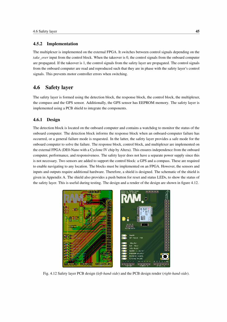
4.6 Safety layer 45
4.5.2 Implementation
The multiplexer is implemented on the external FPGA. It switches between control signals depending on thetake_over input from the control block. When the takeover is 0, the control signals from the onboard computerare propagated. If the takeover is 1, the control signals from the safety layer are propagated. The control signalsfrom the onboard computer are read and reproduced such that they are in phase with the safety layer’s controlsignals. This prevents motor controller errors when switching.
4.6 Safety layer
The safety layer is formed using the detection block, the response block, the control block, the multiplexer,the compass and the GPS sensor. Additionally, the GPS sensor has EEPROM memory. The safety layer isimplemented using a PCB shield to integrate the components.
4.6.1 Design
The detection block is located on the onboard computer and contains a watchdog to monitor the status of theonboard computer. The detection block informs the response block when an onboard-computer failure hasoccurred, or a general failure mode is requested. In the latter, the safety layer provides a safe mode for theonboard computer to solve the failure. The response block, control block, and multiplexer are implemented onthe external FPGA (DE0-Nano with a Cyclone IV chip by Altera). This ensures independence from the onboardcomputer, performance, and responsiveness. The safety layer does not have a separate power supply since thisis not necessary. Two sensors are added to support the control block: a GPS and a compass. These are requiredto enable navigating to any location. The blocks must be implemented on an FPGA. However, the sensors andinputs and outputs require additional hardware. Therefore, a shield is designed. The schematic of the shield isgiven in Appendix A. The shield also provides a push button for reset and status LEDs, to show the status ofthe safety layer. This is useful during testing. The design and a render of the design are shown in figure 4.12.
Fig. 4.12 Safety layer PCB design (left-hand-side) and the PCB design render (right-hand-side).

46 Design & implementation
The green power LED indicates whether the safety layer is on (LED continuously on), off (LED off) or waitingfor initialization (LED blinking). The red GPS signal lost LED indicates the absence of a GPS fix. Theremaining LEDs are blue. Takeover indicates that the safety layer produces control signals instead of theonboard computer. Soft reset and hard reset indicate the reset method. return to launch indicates that the safetylayer is trying to return to the launch location. maintain location indicates that the safety layer tries to keep themobile robot at its current location. Onboard failure and general failure indicate an onboard-computer failureand a request for the general failure mode, respectively. The programmer connector is used to program thetimer values for the response block. The onboard connector must be connected to the onboard computer. Thepins include the general failure mode request and onboard computer status inputs, as well as the reboot and hardreset outputs. The control in and control out connectors can be used to connect up to four motor controllers oninput and output. The push button is designed to be used for reset and setting the launch location.
4.6.2 Implementation
The safety layer components are implemented. The NEO6M GPS module is a plug-and-play GPS system. Itcalculates the position information of the system and transmits the results using UART. The control block readsand decodes this raw data using a UART receiver. The MAG3110 is a plug-and-play compass, communicatingover I2C. The control block also reads and decodes this data. The programmer connection is a UART interface.It is used to configure the response of the safety layer. In the top of the safety layer, there is an optionalconnector for the MAG3110 breakout board. The breakout board provides a soldered solution, which makessoldering much easier, as the pins are much larger. The implemented safety layer is shown in figure 4.13.
Fig. 4.13 Implementation of the safety layer PCB.
The safety layer is positioned between the onboard computer and the motor controllers and encoders. Thedetection block – also part of the safety layer – is implemented on the onboard computer. The location of thesafety layer in a mobile robot is seen in figure 4.14. This is also the implementation that will be used for testingthe safety layer. The lightweight Raspberry Pi is suitable for this. When the testing is complete, the safety layercan be implemented on any mobile robot using any onboard computer.

4.6 Safety layer 47
Control
ResponseDetection
Multiplexer
GPS
CompassMotors & encoders
Onboard-computer
Sensors Interfaces
Raspberry Pi
External FPGA
Motor controllers
Fig. 4.14 Implementation overview. Non-dashed boxes represent safety layer components.
The safety layer was meant to be implemented on a mobile robot at RaM at the University of Twente. Thismobile robot was unfortunately delivered late, so this was not done. However, the mobile robot can still beincluded for the remainder of the research. The mobile robot is a rover with a maximum speed of 7 km/h. Thismeans the mobile robot can travel at most 2.9 meters during the detection delay (1.5 seconds). The rover’sencoders are used as input data for the safety layer. Inside the body of the rover, the electronics are located. AJetson TX2 developed by Nvidia is implemented as the onboard computer. The safety layer is implemented onthe left-hand side of the body. The detection block can be implemented on the Jetson TX2. The mobile robot,the implemented safety layer and the onboard computer are shown in figure 4.15.

48 Design & implementation
Fig. 4.15 Mobile robot at University of Twente with implemented safety layer.
By implementing the possibility to request a general failure mode on the safety layer, a framework has effectivelybeen designed. The framework includes protection against onboard-computer failures by default. Logic tosolve other onboard failures can be added to the onboard computer, utilizing the ability to request a generalfailure mode to the safety layer.

5 | Testing
In the test setup, a Raspberry Pi is used as onboard computer. A motor controller and a motor are used to testthe output signals of the safety layer. For a feasibility test, implementing the safety layer on a mobile robot isnot necessary. The mobile robot at the University of Twente was not delivered in time to be used for testing.
5.1 Component testing
Every block is tested to verify whether it functions as expected. The control block’s advanced functionalities(producing control signals using sensor data) are recommended future work. For this feasibility research thesefunctionalities were not implemented.
5.1.1 Detection block
The detection block is tested using the safety layer and the Raspberry Pi. A functional detection block canperform the handshake, detect onboard-computer failures, and can request the general failure mode. Thehandshake procedure with the external FPGA is tested first. The watchdog must not be activated before anacknowledge of the response block on the external FPGA. This ensures that both blocks are ready and the wiresare properly connected. The response block will only acknowledge the initialization after reset. With the safetylayer ready, the detection block is started by running the Python script. The response block acknowledges thestartup request and the watchdog is started. Next, the test is repeated for a response block that has already beeninitialized. This is done by manipulating the response block’s state. This is repeated for a response block that isturned off. Both situations lead – as expected – to a detection block that keeps waiting for the acknowledgeand does not activate its watchdog. This confirms that the safety layer only activates when the connectionsand the blocks are functional. The next tests are all performed on an initialized safety layer. The watchdogis tested to verify it’s detection capabilities. The watchdog monitors memory load, CPU temperature, andinternal processes. Any unsatisfactory check must result in the identification of an onboard-computer failure.The control process is stopped first. The safety layer detects this and takes over control. This is repeated forthe video process. The watchdog is successful in detecting these faults. To simulate an unresponsive detectionblock or onboard computer, the detection block is stopped. This too must be detected by the safety layer. Thesafety layer successfully identifies the failure, which confirms that an unresponsive detection block or onboardcomputer is detected. To simulate any failure that makes the onboard computer fail, a fork bomb is triggered.As expected, this is detected by the safety layer due to the internal checks. At any time, the safety layer mustnot introduce false positives as they impact normal behavior of the mobile robot. This is tested by triggering ahigh load on the onboard computer. In reality this could be high definition image processing or another peak incomputational load. This peak is triggered in the test by requesting 20 instances of Chromium; a web browser

50 Testing
for Raspbian. Any other peak in computational load would also suffice for this test. Disconnecting the outputsof the detection block must be detected as onboard-computer failure by the response block. This ensures that thesafety layer detects the disconnection and does not allow normal operations when onboard-computer failurescannot be detected. In the tests, the cables are disconnected which results in the response block identifying anonboard-computer failure. The general failure mode request is tested to ensure that any process can successfullyrequest it when required. The request is tested using a dummy process that toggles the output dependingon keyboard input. The test results are positive for both requesting the mode and cancelling the request. Asummary of the detection block’s test results is given in table 5.1.
Table 5.1 Detection block testing.
Test action Expected response Satisfactory?
Start the detection block,
safety layer readyDetection block and safety layer online Yes
Start the detection block,
safety layer not readyDetection block and safety layer offline Yes
Stop the control process Onboard-computer failure identified Yes
Stop the video process Onboard-computer failure identified Yes
Stop the detection block Onboard-computer failure identified Yes
Insert a fork bomb Onboard-computer failure identified Yes
Open 20 instances of Chromium No onboard-computer failure identified Yes
Disconnect the outputs Onboard-computer failure identified Yes
Request general failure mode General failure mode request identified Yes
Cancel general failure mode request No general failure mode request identified Yes
5.1.2 Response block
The response block is tested using the safety layer and a Raspberry Pi. The acknowledge function of theresponse block is already tested in the previous section. The responses of the response block are tested usingthe safety layer’s LEDs as output. On the input, the detection block triggers failures. During normal operations,no response must be produced. This is tested to ensure that the safety layer does not interfere with the mobilerobot during normal operations. Next, a general failure mode is requested by the detection block. A dummyprocess triggers the request. Cancelling the request must lead to the general failure mode to be canceled. Thisis tested to ensure that the mobile robot can continue normal operations after an onboard failure has occurred.The block’s response to onboard-computer failures is compared to the expected response as shown in the statediagram from figure 4.6. Using a stopwatch, the timer values for attempting a hard reset and returning to launchare tested. The response matches the expected response. A summary of the response block’s test results is givenin table 5.2.

5.1 Component testing 51
Table 5.2 Response block testing.
Test action Expected response Satisfactory?
No failures No blue LEDs on Yes
Simulate general failure
mode request
Takeover + maintain location + general failure mode
until general failure mode request canceled.Yes
Simulate onboard-
computer failure
Takeover + maintain location + soft reset +
onboard failure until hard reset timer,
Takeover + maintain location + hard reset +
onboard failure until return to launch timer,
Takeover + return to launch + onboard failure
Yes
5.1.3 Control block
The implemented functionalities of the control block are tested using the safety layer and a Raspberry Pi. Inthe tests, the response block triggers responses to which the control block must react. An instruction by theresponse block to reset the onboard computer must result in an attempt to perform a reboot. This is essential forbringing the mobile robot back to normal operations after failures. The reboot is received by the detection blockthat runs a thread which listens to the reboot pin. The test concludes that this principle works. When the rebootis unsuccessful, a hard reset must be attempted. The reboot command is disabled for this test. The hard resetsuccessfully resets the onboard computer. The test is done to ensure that a reset is eventually performed, even ifa reboot is not successful. The additional tests for the control block include advanced functionalities. These arenot tested as they were not implemented. A summary of the control block’s test results is given in table 5.3.
Table 5.3 Control block testing.
Test action Expected response Satisfactory?
Normal operationsUse GPS + compass + encoders to produce control
signals to maintain location, no takeover.Not tested
Maintain locationUse GPS + compass + encoders to produce control
signals to maintain location, takeover.Not tested
Reset onboard computer Reboot, wait for hard reset timer, hard reset Yes
Return to launchInsert waypoints to return to launch, takeover,
use GPS + compass + encoders to go to waypointsNot tested
Some additional components of the control block were implemented and tested. The production of PWMcontrol signals is tested successfully. This is done by producing a sine wave connected to an LED that showsthe sine wave in brightness. The same is repeated for a servo motor and a motor with a motor controller. Thesefunctionalities are necessary for actuating responses such as the maintain location command. Reading the GPSsensor is implemented but not tested.

52 Testing
5.1.4 Multiplexer
The multiplexer is tested using the implemented safety layer, an electric motor, a motor controller and aRaspberry Pi. The Raspberry Pi functions as onboard computer and produces a PWM signal with a duty cycleof 75%. This signal will be propagated when the takeover is false. The control block will be modified toproduce a PWM signal with a duty cycle of 25%. This is the control signal that will be propagated whenthe safety layer has taken over control. For this test, the control block toggles the takeover output every fiveseconds, simulating an onboard-computer failure every five seconds, as shown in figure 5.1.
25% duty cycle PWM75% duty cycle PWM
5s 5.04s 5.08s 5.12s
takeover
controlsignals
4,96s4,92s4,88s4.84s
Fig. 5.1 Control signal output for multiplexer testing.
To ensure no motor controller failures are introduced, the toggle frequency is high; one toggle every five seconds.A motor controller for the electric motor is connected to the control signals output of the multiplexer. The resultmust be a motor spinning at 25% and 75% throttle every five seconds. A summary of the multiplexer’s testresults is given in table 5.4.
Table 5.4 Multiplexer testing.
Test action Expected response Satisfactory?
No takeover Propagate onboard computer control signals (75% duty cycle) Yes
Takeover Propagate safety layer control signals (25% duty cycle) Yes
5.2 Endurance test
The two most important performance indicators of the safety layer are the number of false positives and falsenegatives per unit time. False positives and false negatives decrease deterministic behavior. A test is set upthat determines the number of false positives and false negatives per unit time. Over a period of 25 hours, 50onboard-computer failures are triggered using a scheduler. This results in two onboard-computer failures everyhour. The safety layer is slightly modified to show the amount of detected onboard-computer failures on itsLEDs. In case it counts less than 50 failures, false negatives are introduced. In case the safety layer detectsmore than 50 failures, false positives are introduced. The onboard-computer failures are triggered using a forkbomb.

5.2 Endurance test 53
Crontab is a script execution scheduler, shown in figure 5.2. In this test, Crontab schedules the execution ofa dummy control process, a dummy video process and a detection block upon startup of the system. Sincea system reboot takes about 40 seconds, roughly 29 minutes after startup, the fork bomb must be triggered.The crash_process.py script is responsible for this and starts with a delay of 29 minutes and 20 seconds suchthat it can be executed directly after startup. Crontab also allows script scheduling based on the system time,which can simplify the scheduling. However, the Raspberry Pi used in the tests does not maintain systemtime after a hard reset. Since the system time is inaccurate after a hard reset, only the @reboot command is used.
Fig. 5.2 Screenshot of the Crontab script scheduler.
The results of the endurance test are positive. In 25 hours, 50 onboard-computer failures were identified bythe safety layer. This means no false positives and no false negatives are introduced for at least 25 hours ofoperations. This also ratifies the watchdog timeout of 1.5 seconds as no false positives were introduced during25 hours of operations. In these 25 hours, all internal test cycles (roughly 58,000) are performed in time.


6 | Results
The safety layer has been tested for its basic functionalities. The results are satisfactory: quick detection (atmost 1.5 seconds), and no false positives nor false negatives in 25 continuous hours of testing. The safety layeris capable of resetting the onboard computer using two methods. No reset has been unsuccessful during the 50failures of the endurance test. The safety layer is successful in taking over control of the onboard computerwithout causing motor controller failures. This chapter describes the estimated increase in deterministicbehavior of mobile robots after adding the safety layer.
6.1 Consequence probabilities
State diagrams are used to describe the probabilities. A sample state diagram is shown in figure 6.1, in whichevery fault has a probability of occurrence per deployment: P. A failure can be caused by several faults. Barrierscan prevent the fault from causing a failure. The barriers can consist of input signal validation, operatorschecking weather conditions, et cetera. Barriers are given a blocking factor Π. A high blocking factor, forexample Π(A → B) = 0.8, means that in 80% of the occurrences, A is blocked from transitioning to B. Abarrier with Π(C → D) = 0.0 means there is no barrier to block the state transition. When the barrier blocksa transition, normal operations continue. Once a failure occurred, the safety layer forms the last barrier (Πs)before consequences can occur. The distribution of the consequences is shown on the transition line. Their summust be one.
Consequence ACause A
Cause B
1/4
3/4
Failure A
Π = 0.8
Π = 0.0
Πs = 0.7
P=1/500
P=1/2
Consequence B
Deterministic Non-deterministic
Fig. 6.1 Sample state diagram.
Every failure is mapped into a state diagram with its barriers. Using estimations, the state diagrams are providedwith P, Π, Πs, and the consequence distribution, which allows quantifying the impact of the safety layer todeterministic behavior of mobile robots.

56 Results
6.1.1 Onboard-computer failures
The state diagram in figure 6.2 describes the probability of negative consequences due to onboard-computerfailures. Onboard-computer failures can be caused by programming errors, electrical interference or hardwarefailures. On average code contains 15 to 50 bugs per 1000 lines of code [20]. I assume that control softwarecontains roughly 5000 lines of code, which results in roughly 75 to 250 bugs per mobile robot. I assume0.5% of the bugs can cause an onboard-computer failure. This results in an 80% probability (P = 4/5) ofprogramming errors to cause an onboard-computer failure per deployment. I assume that once every 100deployments, the electrical interference is problematically high. This could be missions close to power lines,transformers or other high voltage equipment. Deployment of a mobile robot close to this such equipmentis possible, though unlikely. Hardware failures are unlikely as suppliers of hardware perform tests subject tostandards and certificates. Therefore, I estimate that hardware failures have a probability of one every 1000deployments. I estimate the probability of unknown faults causing an onboard-computer failure at one failureevery 500 deployments. A programming error is likely to be blocked because of testing for emergency robots.Therefore, the blocking factor is estimated at Π = 0.95. Hardware failures are blocked with Π = 0.1 as barelyany hardware has duplicates or backup logic. Protection against electrical interference is estimated at Π = 0.8since all equipment has to pass strict tests for electromagnetic compatibility (EMC). The structural body of amobile robot also helps to prevent electrical interference. Unknown causes can by definition not have safetybarriers. Hence, Π = 0.0. The consequences of onboard-computer failures are severe, damage to the robotor its environment is a likely consequence. During covert operations, exposing the mission is also a likelyconsequence. Therefore, both consequences are estimated at 3/8. Injuries to people is estimated at 1/8 becausethe maximum speed of the mobile robot is 7 km/h, which gives people time to react to the rover failure. In theremaining 1/8, the consequences are limited to undermined trust by emergency services. In the endurance test,100% of the onboard-computer failures were intercepted from causing consequences. I pessimistically estimatethe blocking factor of the safety layer at 30% lower, Πs = 0.7.
Expose missionDamage to robot orenvironment
Injuries to peopleUndermined trustProgramming
errors
Electricalinterference
Hardwarefailures Unknown
1/8 1/8
3/83/8
Onboardcomputerfailure
Π = 0.8 Π = 0.95
Π = 0.1
P=1/1000
P=4/5
P=1/500
P=1/100
Πs = 0.7
Fig. 6.2 State diagram for onboard-computer failures.

6.1 Consequence probabilities 57
6.1.2 Motor controller failures
The state diagram in figure 6.3 describes the probability of negative consequences due to motor controller fail-ures. Motor controller failures can be caused by component failures, vibration or incorrect inputs. Componentfailures are unlikely, the production of components is subject to testing with standards and certificates thatensure the quality of the components. However, components wear down and might therefore fail. I estimatethe probability of a component failure at one occurrence every 1000 deployments. Vibration can disconnectcomponents or make unwanted connections, this probability is estimated at one occurrence every 1000 de-ployments too. An incorrect input to the motor controller is more likely and is estimated at one occurrenceevery 100 deployments. I estimate the probability of unknown faults causing motor controller failures at onefailure every 100 deployments. Component failure and vibration failure do not have barriers as protection isgenerally not implemented. Hence, Π = 0.0 for both. A wrong input for the motor controller is usually caughtby the producer side (onboard computer) or by the receiver side (the motor controller). Hence, an estimationof Π = 0.9 seems reasonable. Unknown causes can by definition not have safety barriers. Hence, Π = 0.0. Iestimated that a motor controller failure is unlikely to result in damage to the robot or its environment. A motorcontroller failure will likely stop the mobile robot. If not, this mobile robot’s maximum speed is 7 km/h whichis unlikely to do any damage. Injuries to people is very unlikely, regarding the effect of a motor controllerfailure and the maximum speed of the mobile robot. Hence, both are unlikely but possible: 1/8. I estimatedthat in 3 out of 8 consequences, the mission is exposed due to random movement of the robot. In the remaining3/8, the consequences are limited to undermined trust by emergency services. If implemented, the onboardcomputer handler can use the general failure mode to solve the motor controller failure. Flying mobile robotswith less than five propellers will not be fixable. With these factors taken into account, I pessimistically estimatethe blocking factor of the safety layer at Πs = 0.2.
Incorrectinput
Componentfailure
Unknown
Motorcontrollerfailure
Π = 0.9
Vibration
Π = 0.0
P=1/1000
P=1/100
P=1/1000
P=1/100
Π = 0.0
Expose missionDamage to robot orenvironment
Injuries to peopleUndermined trust
3/8 1/8
3/81/8
Πs = 0.2
Fig. 6.3 State diagram for motor controller failures.

58 Results
6.1.3 Incorrect output
The state diagram in figure 6.4 describes the probability of negative consequences due to incorrect output. Anincorrect output by the onboard computer can be caused by a bug in the onboard computer or by an incorrectinput to the onboard computer. As calculated in section 6.1.1, the onboard computer encounters 75 to 250 bugsper deployment. I assume 0.5% of the bugs can cause an incorrect output. This results in an 80% probability(P = 4/5) of an incorrect output due to a bug in the onboard computer for one deployment. I assume that theprobability of a bug in the controller software, leading to an incorrect input, is equal to the probability of a bugin the onboard computer. With the same estimations this results in P = 4/5 too. I estimate the probability ofunknown faults causing an incorrect output at one failure every 500 deployments. Assuming extensive testingof control software, the blocking factor after bugs can be estimated at Π = 0.8. An incorrect input to the mobilerobot is likely to be blocked because of sophisticated checks in both the transmitter and the receiver. Therefore,the blocking factor is estimated at Π = 0.95. Unknown causes can by definition not have safety barriers. Hence,Π = 0.0. The consequences of an incorrect output are moderate, damage to the robot or its environment canoccur after arbitrary control signals. However, the maximum speed is only 7 km/h which is unlikely to doserious damage. Hence, P = 1/8. During covert operations, exposing the mission is a likely consequence asrandom movement can expose the mission. Therefore, the consequence is estimated at 3/8. Injuries to peopleis estimated at 1/8 because the maximum speed of the mobile robot is 7 km/h, which gives people time to reactto the rover’s random behavior. In the remaining 3/8, the consequences are limited to undermined trust byemergency services. Implementing the safety barrier is complex because of the necessary output validation onthe onboard computer. Once implemented, output validation has to be done, which is not always successful.Therefore, I pessimistically estimate the blocking factor of the safety layer at Πs = 0.1.
Bug inonboardcomputer
Incorrectinput
Unknown
Incorrectoutput
Π = 0.95
Π = 0.8
P=1/500
P=4/5
P=4/5
Expose missionDamage to robot orenvironment
Injuries to peopleUndermined trust
3/8 1/8
3/81/8
Πs = 0.1
Fig. 6.4 State diagram for incorrect output.

6.1 Consequence probabilities 59
6.1.4 Network connection errors
The state diagram in figure 6.5 describes the probability of negative consequences due to network connectionerrors. Network connection errors can be caused by the mobile robot to be out of range, experience interferenceor experience a blocked signal. A mobile robot is easily out of range. I estimate this to occur once everytwo deployments when no barriers are added. Naturally, the operator will be a strong barrier for preventingthis. Interference or noise can cause network connection errors. I estimate this at one occurrence every 50deployments. By estimation, 10% of the deployments will be indoors. Since the Netherlands has little roughterrain, I assume that no interference will occur because of the terrain. Combined, I estimate that once every 10deployments, the signal is blocked. I estimate the probability of unknown faults causing an network connectionerrors at one failure every 100 deployments. Interference on the network can be filtered or minimized. However,this is complex and not always implemented. Therefore, a careful estimation of Π = 0.1 seems reasonable.Operators are trained to maneuver mobile robots indoors. The impact of this on the network connection is notalways clear. However, operators will take this into account. The operator’s experience is also a factor in thisprobability. Altogether, the blocking factor is estimated at Π = 0.6. An operator will almost always prevent amobile robot from being out of range, since the operator known the range and applies a safety margin. It is asafe assumption that 90% of the operators will prevent this from happening. Unknown causes can by definitionnot have safety barriers. Hence, Π = 0.0. The consequences of a network connection error are moderate.During covert operations, exposing the mission due to random movement is a likely consequence. Therefore, itis estimated at 3/8. Injuries to people and damage to the robot or its surroundings are both estimated at 1/8because the maximum speed of the mobile robot is 7 km/h, which restricts the damage and gives people time toreact to the rover’s random behavior. In the remaining 3/8, the consequences are limited to undermined trustby emergency services. Solving network connection errors is commonly implemented due to the availablereference material. I assume it will be implemented on the rover with the general failure mode request. I assumethat 30% of the network connection errors will not be detected and solved. Therefore, Πs = 0.7.
Out ofrange
Interference/noise
Signalblocked Unknown
Networkconnectionerror
Π = 0.1
Π = 0.9
Π = 0.6
P=1/2
P=1/50
P=1/10P=1/100
Expose missionDamage to robot orenvironment
Injuries to peopleUndermined trust
3/8 1/8
3/81/8
Πs = 0.7
Fig. 6.5 State diagram for network connection errors.

60 Results
6.1.5 Battery failures
The state diagram in figure 6.6 describes the probability of negative consequences due to battery failures.Battery failures can be caused by an expired lifetime of the battery, extreme heat or damage. A Li-ion batteryis used. Typically, these batteries have 300 to 500 charge cycles [21]. One mission generally requires onecharge cycle. Hence, I assumed one battery failure every 400 deployments due to aging. Overheating thebattery is another fault. The maximum temperature of a battery is 60 °C [21]. I estimate that roughly onein three missions are for firefighter operations (the largest risk operations), and that once every 15 firefighterdeployments the maximum temperature is exceeded. This results in P = 1/3∗1/15 = 1/45 for the probabilityof overheating. Damage to a battery is estimated at one occurrence every 20 deployments. This number isrelatively high because deployments also include usage by firefighters. I estimate the probability of unknownfaults causing battery failures at one failure every 1000 deployments. Technicians sometimes keep track ofthe number of charge cycles of a battery. Visual inspections can be performed too. I estimate that this blocks90% of the battery failures due to aging. The housing of mobile robots forms a safety barrier for preventing thebattery to be overheated. I estimate that in 50% of the cases, this protection is sufficient. The same housing willprevent damage to be done to the battery. Preventing damage is less complex than preventing overheat. Hence,the blocking factor is higher: Π = 0.8. Unknown causes can by definition not have safety barriers. Hence,Π = 0.0. A failure of the battery means the mobile robot will stop moving. This means damage to the robot orits environment are excluded as consequence. They are both 0/8. I estimate that a rover that cannot move willexpose covert missions in half of the deployments: 4/8. In the remaining 4/8, the consequences are limited toundermined trust by emergency services. In the current setup, a battery failure disables the mobile robot andthe safety layer. Therefore, the consequences cannot be prevented and the blocking factor Πs is set to 0.0.
Cycles/age
Overheat
Damage
Unknown
Batteryfailure
Π = 0.5 Π = 0.9
Π = 0.8
P=1/400P=1/45
P=1/20
P=1/1000Blow missionDamage to robot or
environment
Injuries to peopleUndermined trust
4/8 0/8
4/80/8
Expose missionDamage to robot orenvironment
Injuries to peopleUndermined trust
4/8 0/8
4/80/8
Πs = 0.0
Fig. 6.6 State diagram for battery failures.

6.1 Consequence probabilities 61
6.1.6 Multiple controllers
The state diagram in figure 6.7 describes the probability of negative consequences due to multiple controllerscontrolling the same mobile robot. Multiple controllers controlling the same mobile robot can be caused by abug in the multi-robot system or a bug in the onboard computer. As calculated in section 6.1.1, the onboardcomputer encounters 75 to 250 bugs per deployment. I assume 0.1% of the bugs can cause multiple controllersto be controlling the same mobile robot. This results in a 16% probability per deployment (P = 1/6) of a bugin the multi-robot system causing multiple controllers on one mobile robot, which seems a bit high. However,a careful estimation is recommended. It is estimated that the probability of a bug in the multi-robot systemis equal to the probability of a bug on the onboard computer. This results in P = 1/6 too. I estimate theprobability of unknown faults causing multiple controllers to be linked to the same mobile robot at one failureevery 500 deployments. Bugs can occur in control software. Assuming extensive testing, the blocking factorcan be estimated at Π = 0.8. For the multi-robot system, this is estimated at Π = 0.5 since it is not as widelyused as control software. Unknown causes can by definition not have safety barriers. Hence, Π = 0.0. Theconsequences of multiple controllers linked to the rover are moderate. During covert operations, exposing themission is a likely consequence. Therefore, it is estimated at 3/8. Injuries to people and damage to the robot orits surroundings are both estimated at 1/8 because the maximum speed of the mobile robot is 7 km/h, whichrestricts the damage and gives people time to react to the rover’s random behavior. In the remaining 3/8, theconsequences are limited to undermined trust by emergency services. Since not many mobile robots operatein a multi-robot environment, reference material is scarce. Therefore, I estimate that detecting the failure iscomplex. I estimate the blocking factor at Πs = 0.4.
Bug in onboardcomputer
Bug inmultirobotsystem
Unknown
Multiplecontrollers
Π = 0.8
Π = 0.5
P=1/6
P=1/6
P=1/500Expose missionDamage to robot or
environment
Injuries to peopleUndermined trust
3/8 1/8
3/81/8
Πs = 0.4
Fig. 6.7 State diagram for multiple controllers.

62 Results
6.2 Impact on deterministic behavior
With these estimations, the probabilities for negative consequences can be calculated. To find the probability ofconsequence k occurring, all paths leading to the consequence must be considered. The consequence probabilityp(k) is calculated by multiplying the probability of failure h leading to the consequence k; P(h → k), withthe failure probability. The failure probability is found by multiplying the probability of fault g; P(g), withthe probability of reaching the failure, for every fault. The probability of reaching the failure depends on theblocking factor Π, which has a probability of 1−Π of reaching the next state. The summation of all paths thatlead to this consequence yields the consequence probability, as show in equation 6.1.
p(k) =H−1
∑h=0
P(h → k)∗G−1
∑g=0
P(g)∗ (1−Π(g → h)) (6.1)
With a safety layer added to the mobile robot, an extra barrier Πs is introduced. The effect on p(k) is a factor1−Πs(h → k). The consequence probability is then recalculated using equation 6.2.
p(k) =H−1
∑h=0
P(h → k)∗ (1−Πs(h → k))∗G−1
∑g=0
P(g)∗ (1−Π(g → h)) (6.2)
For every consequence, this calculation is done. The calculations are shown in Appendix B and the results areshown in table 6.1. Without a safety layer implemented to the mobile robot, the total probability of negativeconsequences is 43.2%, as calculated in equation 6.3.
p(consequences) = [1− (1−0.186)∗ (1−0.073)∗ (1−0.197)∗ (1−0.062)]≈ 0.432 (6.3)
When the safety layer is implemented, the total probability of negative consequences occurring is reduced to29.8% as shown in equation 6.4.
p(consequences) = [1− (1−0.125)∗ (1−0.042)∗ (1−0.128)∗ (1−0.039)]≈ 0.298 (6.4)
These two numbers are added to table 6.1 in the bottom row, indicated by the probability of any negativeconsequence occurring; p(k1|k2|k3|k4).
Table 6.1 Probabilities of negative consequences with and without implementing a safety layer.
Without
safety layer
With
safety layer
Undermined trust 18.6% 12.5%
Damage to mobile robot
or environment7.3% 4.2%
Expose mission 19.7% 12.8%
Injuries to people 6.2% 3.9%
p(k1|k2|k3|k4) 43.2% 29.8%

6.2 Impact on deterministic behavior 63
Next, the improvement must be calculated for every consequence k. This is done by dividing the differenceover the initial probability and yields the relative improvement. The probability of undermined trust is reducedwith 32.9%.
12.5%−18.6%18.6%
≈−32.9% (6.5)
The probability of damage to the mobile robot or its environment is reduced with 42.4%.
4.2%−7.3%7.3%
≈−42.4% (6.6)
The probability of exposing the mission is decreased by 35.0%.
12.8%−19.7%19.7%
≈−35.0% (6.7)
The probability of injuries to people is reduced with 37.1%.
3.9%−6.2%6.2%
≈−37.1% (6.8)
The effect on the deterministic behavior of this reduction of negative consequences is now determined. It isassumed that in all states before the safety barrier, deterministic behavior is shown. Once the safety layerdid not block the transition to a consequence state, non-deterministic behavior occurs. This means that theprobability negative consequences is equal to the probability of non-deterministic behavior. Deterministicbehavior is the inverse of non-deterministic behavior. Therefore, the probability of deterministic behavior isincreased from 100% - 43.2% = 56.8% to 100% - 29.8% = 70.2%, as shown in figure 6.8. The improvement is23.6%, as calculated in equation 6.9.
70.2%−56.8%56.8%
≈ 23.6% (6.9)
Without safety layer
Non-deterministic behavior
Deterministic behaviorWith safety layer
56.8% 70.2%
Fig. 6.8 Effect of implementing a safety layer on the probability of deterministic behavior per deployment.


7 | Discussion
We wanted to research how a safety layer can increase deterministic behavior of mobile robots. A safety layeris designed that mitigates onboard failures, instead of trying to prevent them. The effect of the safety layer onthe deterministic behavior of the mobile robot is determined by estimations. The results, shown in table 6.1, arediscussed next.
Regardless of the safety layer, the probabilities of injuries to people and damage to the mobile robot or itsenvironment are significantly smaller than the remaining probabilities. This can be explained by the mobilerobot type. It is a rover operating on land, with a maximum speed of 7 km/h. This is less likely to do damage orcause injuries. The biggest reduction in probabilities of negative consequences is the probability of damage tothe mobile robot or its environment (42.4% reduction). Next are the probabilities of injuries to people (37.1%reduction) and the probability of exposing the mission (35.0% reduction). The probability of undermined trust(32.9% reduction) is the smallest reduction. There does not seem to be a trend in which negative consequenceprobability is most decreased. This can be explained by the fact that the safety layer adds an additional barrier,effectively multiplying the probabilities with a certain factor. The impact of this reduction on deterministicbehavior is determined. In this process I assumed that all states up to the barrier of the safety layer showdeterministic behavior, as either the onboard computer or the safety layer has control over the mobile robot. Allstates after this point are assumed to show non-deterministic behavior, as no entity controls the mobile robot.This simplification could make the calculation inaccurate. A state can behave deterministically even though itis a negative consequence state, and vice versa.
Without implementing a safety layer, the mobile robot has a 56.8% probability of deterministic behavior perdeployment. When the safety layer is implemented, the probability of deterministic behavior per deployment isimproved to 70.2%. This is an improvement of 23.6%, which means an increase in deterministic behavior ofthe mobile robot is realized.


8 | Conclusion
Currently, many safety barriers are already implemented on mobile robots that try to prevent non-deterministicbehavior. The safety barriers are mostly aimed towards preventing onboard failures. Examples are voltagestabilizers, input signal validation and exception handlers for programming errors. However, not all failures canbe prevented by safety barriers. In this thesis I will research how to design a safety layer that mitigates failureson mobile robots and how this can improve the mobile robot’s deterministic behavior. Hence, the researchquestion: How to increase deterministic behavior of mobile robots by adding a safety layer?
What are common threats to deterministic behavior? Common threats to deterministic behavior are onboardfailures, such as onboard-computer failures, motor controller failures, network connection errors, batteryfailures, multiple controllers liked to a mobile robot and an incorrect output, triggering non-deterministicbehavior. How can threats best be detected? Detection of failures can best be done using a watchdog, requiringonly one implementation location and one output pin. Setting the watchdog timeout to 1.5 seconds leadsto quick detection without introducing false positives. A heartbeat process can only be used for detectingonboard-computer failures when it is implemented in every independent process on the onboard computer.Other detection methods were unsatisfactory. What is the appropriate response to failures? An appropriateresponse to onboard-computer failures is to initially keep the mobile robot in its current location. Then, a rebootof the onboard computer must be attempted. If unsuccessful, a hard reset must be attempted. If this too isunsuccessful, returning to the launch location must be attempted. When the general failure mode is requestedby the onboard computer, the safety layer must keep the mobile robot in its current location until the requestis canceled. How can the responses best be effectuated? Effectuating the responses can best be done by astand-alone safety layer, ensuring independence from the onboard computer. Independence from the onboardcomputer is necessary for guaranteeing a deterministic response of the mobile robot during failures. Themain part of the safety layer is implemented on an external FPGA which ensures performance, responsivenessand independence from the onboard computer. The watchdog used for detection is located on the onboardcomputer to ensure detecting onboard-computer failures timely and effectively. A request for the general failuremode allows the onboard computer to solve the remaining onboard failures, while the safety layer ensuresdeterministic behavior for the duration of the request. With this general failure mode, the safety layer forms aframework for all barriers preventing or mitigating failures.
An increase in deterministic behavior is realized by implementing a stand-alone safety layer with a watchdogdetecting onboard failures. The estimation shows that the safety layer increases the deterministic behavior by23.6% for the mobile robot at the University of Twente. The safety layer is tested for 25 continuous hours, inwhich a failure was introduced every 30 minutes. The safety layer caught all failures and resolved them withoutfalse positives or false negatives.


9 | Future work
During the research, some recommendations for future work emerged. Most are not done in this research due totime limitations.
• The estimations in the results are not verified. I recommend to verify the outcome of this research asfuture work.
• A mismatch between the operator’s expected response and the mobile robot’s response implies non-deterministic behavior. This behavior occurs after onboard failures but can also occur after other events,such as control commands. This research only considers non-deterministic behavior after onboardfailures. I recommend to research which other events lead to non-deterministic behavior.
• The advanced functionalities (return to launch and maintain location) of the control block are notimplemented and are considered future work before the safety layer can be implemented on any mobilerobot.
• The safety layer reads and reproduces control signals from the onboard computer. This introduces latency(generally 20 ms) between control commands and control signals, which can negatively impact themaneuverability of the mobile robot. The impact of this delay must be researched and alternatives mustbe found in case the impact is unacceptable.
• Only four negative consequences were identified in this research. There likely are more negativeconsequences. This can impact the results of this research. As future work I recommend identifyingmore negative consequences and recalculating the effect of the safety layer on mobile robots.


References
[1] IEEE. Standard classification for software anomalies. Software and Systems Engineering StandardsCommittee, 2:5, 2010.
[2] EU. European robotic squad proposal for h2020-ict-2014-1: case 2. Available on request, 1:16–17, 2014.
[3] Dan Gettinger. Public safety drones. Drones at home, pages 1–12, 2017.
[4] Ann Cavoukian. Privacy and drones: Unmanned aerial vehicles. page 7, 2012.
[5] Emergency Services Ireland. Police trial drone technology in south west. 2016.
[6] ICOR Technology. Homepage website. https://icortechnology.com/, 2018.
[7] Professor John A Stankovic. Real-Time Computing. Department of Computer Science, University ofMassachusetts, Amherst MA, 1992.
[8] Giorgio C. Buttazzo. Hard real-time computing systems, volume 3 of Third edition. Springer, SpringerScience and Business Media, 233 Spring Street, New York, USA, 2011.
[9] Marcel Groothuis Jan Broenink, Yunyun Ni. On model-driven design of robot software using co-simulation. International Conference on simulation, modeling and programming for autonomous robots,pages 659–668, 2010.
[10] Oscar Liang. PWM and PPM: difference and conversion (modified). 2013.
[11] B. Dake. Fork bomb The concept behind a fork bomb. 2017.
[12] Yandong Mao Haogang Chen. Linux kernel vulnerabilities: state-of-the-art defenses and open problems.APSys ’11, pages 1–5, 2011.
[13] Altium. Microcontroller Failure Modes: Why They Happen and How to Prevent Them. 2017.
[14] Ronald J. Willey. Layer of protection analysis. 2014 International Symposium on Safety Science andTechnology, 84:12–22, 2014.
[15] Bernard C. Drerup. System crash detect and automatic reset mechanism for processor cards. page 5, 1991.
[16] Kat Kononov Kristen Anderson. Autonomous Crash Avoidance System. 2011.
[17] Andrew Ross Price Justin Young. FPGA Based UAV Flight Controller. 2005.
[18] Frank van Graas Abdulqadir Alaqeeli, Janusz Starzyk. Real-time acquisition and tracking for gps receivers.pages 500–503, 2003.
[19] Lachlan K. Scott. Autonomous Hover through Vision Based Flight Control using the Parrot AR DroneQuadrotor. 2012.
[20] Dan Mayer. Bug to code ratios. https://www.mayerdan.com/ruby/2012/11/11/bugs-per-line-of-code-ratio,2012.
[21] Lithium-ion battery maintenance guidelines. https://www.newark.com/pdfs/techarticles/tektronix/LIBMG.pdf,March 2016.


74 Safety layer PCB schematic
A | Safety layer PCB schematic

B | Consequence probabilities
The calculations provide data to table 6.1. Consequence k∈ [UT,D,EM, I] failure h∈ [OCF,MCF, IO,NCE,BF,MC],fault g. For the consequences, UT = undermined trust, D = damage, EM = expose mission, I = injuries. Forthe failures, OCF = onboard-computer failure, MCF = motor controller failure, IO = incorrect output, NCE =network connection error, BF = battery failure, MC = multiple controllers.
P(k) without safety layer
p(k) =H−1
∑h=0
p(h)∗ p(h → k)
p(UT ) = 1/8∗ p(OCF)+3/8∗ p(MCF)+3/8∗ p(IO)+3/8∗ p(NCE)+4/8∗ p(BF)+3/8∗ p(MC)
p(I) = 1/8∗ p(OCF)+1/8∗ p(MCF)+1/8∗ p(IO)+1/8∗ p(NCE)+0/8∗ p(BF)+1/8∗ p(MC)
p(D) = 3/8∗ p(OCF)+1/8∗ p(MCF)+1/8∗ p(IO)+1/8∗ p(NCE)+0/8∗ p(BF)+1/8∗ p(MC)
p(EM) = 3/8∗ p(OCF)+3/8∗ p(MCF)+3/8∗ p(IO)+3/8∗ p(NCE)+4/8∗ p(BF)+3/8∗ p(MC)
P(k) with safety layer
p(k) =H−1
∑h=0
p(h)∗ p(h → k)∗ (1−Πs(h → k))
p(UT ) = 1/8∗ (1−0.7)∗ p(OCF)+3/8∗ (1−0.2)∗ p(MCF)+3/8∗ (1−0.1)∗ p(IO)+3/8∗ (1−0.7)∗p(NCE)+4/8∗ (1−0)∗ p(BF)+3/8∗ (1−0.4)∗ p(MC)
p(I) = 1/8∗ (1−0.7)∗ p(OCF)+1/8∗ (1−0.2)∗ p(MCF)+1/8∗ (1−0.1)∗ p(IO)+1/8∗ (1−0.7)∗p(NCE)+0/8∗ (1−0)∗ p(BF)+1/8∗ (1−0.4)∗ p(MC)
p(D) = 3/8∗ (1−0.7)∗ p(OCF)+1/8∗ (1−0.2)∗ p(MCF)+1/8∗ (1−0.1)∗ p(IO)+1/8∗ (1−0.7)∗p(NCE)+0/8∗ (1−0)∗ p(BF)+1/8∗ (1−0.4)∗ p(MC)
p(EM) = 3/8∗ (1−0.7)∗ p(OCF)+3/8∗ (1−0.2)∗ p(MCF)+3/8∗ (1−0.1)∗ p(IO)+3/8∗ (1−0.7)∗p(NCE)+4/8∗ (1−0)∗ p(BF)+3/8∗ (1−0.4)∗ p(MC)

76 Consequence probabilities
P(h)
p(h) =G−1
∑g=0
p(g)∗ (1−Π(g → h))
p(OCF) = 4/5∗ (1−0.95)+1/100∗ (1−0.8)+1/1000∗ (1−0.1)+1/500∗ (1−0)≈ 0.0449p(MCF) = 1/1000∗ (1−0)+1/1000∗ (1−0)+1/100∗ (1−0.9)+1/100∗ (1−0) = 0.0130p(IO) = 4/5∗ (1−0.95)+4/5∗ (1−0.8)+1/500∗ (1−0) = 0.2020p(NCE) = 1/2∗ (1−0.9)+1/10∗ (1−0.6)+1/50∗ (1−0.1)+1/100∗ (1−0) = 0.1180p(BF) = 1/400∗ (1−0.9)+1/20∗ (1−0.8)+1/45∗ (1−0.5)+1/1000∗ (1−0)≈ 0.0224p(MC) = 1/6∗ (1−0.5)+1/6∗ (1−0.8)+1/500∗ (1−0)≈ 0.1187
P(k) without safety layer
p(UT ) = 1/8∗0.0449+3/8∗0.0130+3/8∗0.2020+3/8∗0.1180+4/8∗0.0224+3/8∗0.1187 ≈ 0.186p(I) = 1/8∗0.0449+1/8∗0.0130+1/8∗0.2020+1/8∗0.1180+0/8∗0.0224+1/8∗0.1187 ≈ 0.062p(D) = 3/8∗0.0449+1/8∗0.0130+1/8∗0.2020+1/8∗0.1180+0/8∗0.0224+1/8∗0.1187 ≈ 0.073p(EM) = 3/8∗0.0449+3/8∗0.0130+3/8∗0.2020+3/8∗0.1180+4/8∗0.0224+3/8∗0.1187 ≈ 0.197
P(k) with safety layer
p(UT ) = 1/8∗ (1−0.7)∗0.0449+3/8∗ (1−0.2)∗0.0130+3/8∗ (1−0.1)∗0.2020+3/8∗ (1−0.7)∗0.1180+4/8∗ (1−0)∗0.0224+3/8∗ (1−0.4)∗0.1187 ≈ 0.125
p(I) = 1/8∗ (1−0.7)∗0.0449+1/8∗ (1−0.2)∗0.0130+1/8∗ (1−0.1)∗0.2020+1/8∗ (1−0.7)∗0.1180+0/8∗ (1−0)∗0.0224+1/8∗ (1−0.4)∗0.1187 ≈ 0.039
p(D) = 3/8∗ (1−0.7)∗0.0449+1/8∗ (1−0.2)∗0.0130+1/8∗ (1−0.1)∗0.2020+1/8∗ (1−0.7)∗0.1180+0/8∗ (1−0)∗0.0224+1/8∗ (1−0.4)∗0.1187 ≈ 0.042
p(EM) = 3/8∗ (1−0.7)∗0.0449+3/8∗ (1−0.2)∗0.0130+3/8∗ (1−0.1)∗0.2020+3/8∗ (1−0.7)∗0.1180+4/8∗ (1−0)∗0.0224+3/8∗ (1−0.4)∗0.1187 ≈ 0.128