Strengthening Micromechanisms in Cold-Chamber High-Pressure Die-Cast Mg-Al Alloys

In situ observation of collective grain-scale mechanics in Mgand Mg–rare earth alloys
F. Wang 1, S. Sandlobes ⇑, M. Diehl, L. Sharma, F. Roters, D. Raabe
Max-Planck-Institut fur Eisenforschung, Department for Microstructure Physics and Alloy Design, Max-Planck-Str. 1, Dusseldorf, Germany
Received 13 May 2014; received in revised form 18 July 2014; accepted 22 July 2014
Abstract
The microstructure evolution of pure Mg and two Mg–rare-earth alloys (Mg–3 wt.% Dy and Mg–3 wt.% Er) was studied during insitu compression tests by electron backscatter diffraction and electron channelling contrast imaging. Strain localization and the forma-tion of an early stage shear band (“pre-shear band”) were observed in pure Mg during compressive deformation below 5% engineeringstrain. In the experiments percolative grain clusters with prevalent basal slip as a precursor for shear band formation was observed. Thiscollective grain-cluster shear behaviour was analysed in more detail using crystal plasticity simulations, revealing a percolation of intensebasal slip activity across grain boundaries as the mechanism for shear band initiation. Plane trace analysis, Schmid factor calculation anddeformation transfer analysis at the grain boundaries were performed for the activated twins. It appears that many activated tensiontwins exhibit pronounced non-Schmid behaviour. Twinning appears to be a process of accommodating local strain rather than aresponse to macroscopic strain.� 2014 Acta Materialia Inc. Published by Elsevier Ltd. All rights reserved.
Keywords: Magnesium; Shear banding; Deformation twinning; Electron channelling contrast imaging; Crystal plasticity modelling
1. Introduction
Magnesium has a low mass density of 1.74 g cm�3 and isthe lightest structural metal [1]. Magnesium and its alloyshave received great attention for potential use in automo-tive applications [2]. However, the application of wroughtmagnesium alloys is restricted by its poor formability atambient temperatures caused by its strong basal-type tex-ture developed during processing and the lack of availabledeformation mechanisms [3].
The primary deformation modes at room temperature inmagnesium and magnesium alloys are basal slip andf10�12g tension twinning. Both are easy to activate and
have critical resolved shear stress (CRSS) values of a fewMPa according to single crystal experiments [4]. The prev-alence of basal dislocation slip produces a fiber texturewhere the basal planes are closely aligned with the primarymaterial flow direction, limiting the contribution of thebasal slip system to further deformation [5,6].
Besides non-basal dislocation slip, twinning can accom-modate strain along the crystal c-axis, providing additionaldegrees of freedom matching the requirement for five inde-pendent shear systems in the classical Taylor–Bishop–Hillsense [7,8]. However, it was earlier observed via a jointexperimental-simulation grain scale micromechanical anal-ysis [9] that if the Taylor–Bishop–Hill criterion is not ful-filled everywhere at the grain scale, collective deformationof grain clusters can in certain cases provide a sufficientnumber of shear degrees of freedom for compatible poly-crystalline deformation [10]. Due to the limitation of avail-able deformation systems, plastic heterogeneities and strain
http://dx.doi.org/10.1016/j.actamat.2014.07.048
1359-6454/� 2014 Acta Materialia Inc. Published by Elsevier Ltd. All rights reserved.
⇑ Corresponding author.E-mail address: [email protected] (S. Sandlobes).
1 Current address: University of Virginia, Materials Science andEngineering, Charlottesville, VA, USA.
www.elsevier.com/locate/actamat
Available online at www.sciencedirect.com
ScienceDirect
Acta Materialia 80 (2014) 77–93

localization in the form of shear bands [11] occur duringroom temperature deformation of Mg [12–18]. The mecha-nisms associated with such shear band formation in Mgalloys are not well understood [12–18]; some studies sug-gest 10�11 compression twinning [12,14], double-twinning[14,18], tension twinning [13] or rotational recrystallization[17] as possible mechanisms of shear band formation.Shear banding in Mg is a mesoscopic “grain-cluster” defor-mation process where the grains inside the shear band arereported to subsequently re-orient in the macroscopic sheardirection, i.e. “soften” the sheared region with respect tofurther basal dislocation slip during continuing deforma-tion [15,17,18].
Similarly, it is well known that twins appear also ingrains not suitably oriented for twinning. This anomaloustwinning or, more specifically, non-Schmid behaviour oftwinning was observed in rolled sheets and extruded Mgalloys, e.g. Refs. [19–23]. With the non-Schmid behaviourof twin variant selection we refer to the fact that the micro-mechanical i.e. the local stress state may profoundlydeviate from the macroscopic loading state. It should benoted though that the term non-Schmid behavioursometimes also refers to the effect of hydrostatic tensorcomponents on plastic flow: this definition is not used here.Apparently, the local microstructure plays an importantrole in twin activation and topology, besides thedependence on crystallographic orientation or grain size,on which many studies have focused before, e.g. Refs.[23,24]. Grain boundaries are important sites for twinnucleation given that they provide defect sources and stresspeaks. The interaction between twinning and grain bound-aries was investigated in polycrystalline hexagonal closepacked (hcp) Mg and hcp Ti [12,25,26]. It is found thattwin nucleation is not solely controlled by Schmid’s law,i.e. a twin variant with a lower Schmid factor might nucle-ate instead of the expected high Schmid factor twin variant,e.g. Refs. [19–23].
Jonas et al. [22] and Mu et al. [27] suggested that strainaccommodation required by the neighbouring grains mightinfluence the variant selection during twinning. The forma-tion of twins involves shearing in the matrix. When a twinnucleates from the grain boundary (GB), the neighbouringgrain is also being sheared to accommodate the shapechange at the GB [22]. The amount and type of deforma-tion required for strain accommodation in the neighbour-ing grains then affect which variant is required. Jonaset al. and Mu et al. identified the prismatic hai slip as thecritical geometrically necessary deformation system influ-encing the variant selection of twinning. Capolungo et al.conducted a statistical study of twinning in hcp Zr andshowed a strong correlation between twin nucleation andgrain boundaries [28]. Grain boundaries are important sitesfor twin nucleation since they can provide both, crystaldefect sources and places of stress concentration [28]. Theinteraction between primary twins and grain boundarieswas described by Christian and Mahajan [29]. They consid-ered that the stress concentration in the vicinity of a
GB–twin intersection can be relaxed either by slip or by slipand twinning in the adjoining grain. El Kadiri et al. [30]found that low angle grain boundaries with misorientationsbetween 13� and 15� are more preferential for tension twinnucleation in Mg than high angle grain boundaries, whichactually is another factor influencing non-Schmid twin var-iant selection.
Barnett et al. [24] ascribed the anomalous formation ofnon-Schmid oriented secondary twins to a local unloadingoccurring due to the relative ease of basal hai slip in sec-ondary twins. Additionally, the minimization of compati-bility strain of non-Schmid secondary twins to the closesttwinning plane of the primary compression twins [24] wasassumed to be substantial for variant selection and, partic-ularly, non-Schmid behaviour of secondary twinning [24].Other authors ascribed the non-Schmid behaviour to thedifference between the local and the global stress state[31,32], particularly, strain incompatibility at grain bound-aries [31,32].
Twinning stimulated by slip was reported by Wang et al.[26] in pure titanium. They reported strain transfer of pris-matic dislocation slip, the primary slip system in hcp Ti,into neighbouring grains as a criterion for the nucleationof tension twins at grain boundaries. Twin pairs at grainboundaries were also observed by Beyerlein et al. [21]and Wang et al. [25]. Their formation was proposed asone twin impacting a GB stimulating the nucleation ofanother twin in the neighbouring grain, or alternatively,that both twins nucleate mutually at the same location atthe GB and grow into their respective parent grains.
Here we focus on studying the activation of plasticheterogeneities such as shear bands and the effects ofnon-Schmid deformation on tension twinning with specificregard to grain-to-grain interactions and collective grainmechanisms. We performed in situ compression tests onpure Mg and two Mg–rare-earth (Mg–RE) alloys (Mg–3 wt.%Dy and Mg–3 wt.%Er) using electron backscatterdiffraction (EBSD) and electron channelling contrast imag-ing (ECCI) to determine the microstructure evolution andactive deformation carriers (dislocations, twins) duringdeformation. The two Mg–RE alloys were selected due tothe texture weakening effects associated with the RE alloy-ing compared to the sharp basal textures in pure Mg [31–36] and to investigate possible effects of RE addition ontwinning in Mg alloys [18,37]. Due to high local strainsinside and next to shear bands, microstructure character-ization using electron microscopy is challenging. Therefore,we applied combined in situ EBSD and ECCI observationson deformed sample surfaces to determine active slip andtwinning systems via orientation mapping and slip traceanalysis. Additionally we performed crystal plasticity sim-ulations and compatibility analyses of grain-to-grain straintransfer for obtaining insights on the true local microme-chanical loading situation and mechanisms associated withthe experimentally observed collective grain deformationphenomena. Specifically, we applied crystal plasticity simu-lations to study the mechanisms leading to the formation of
78 F. Wang et al. / Acta Materialia 80 (2014) 77–93

macroscopic shear bands in pure Mg. As dynamic localphenomena such as dislocation pile-ups at grain bound-aries are not included in the crystal plasticity frameworkemployed here we used the Luster–Morris parameter (geo-metric compatibility factor) to analyse the match in grain-to-grain strain transfer.
2. Experimental methods
The alloys were melted and solidified in an inductionfurnace under Ar pressure (15 bar) in a steel crucible.homogenisation annealing of the as-cast materials was per-formed for 24 h at 450 �C under Ar atmosphere followedby water quenching. The alloys were hot rolled at 500 �Cto a total engineering thickness reduction of 50%, imposing8–10% reduction per pass. Subsequent recrystallizationannealing was carried out at 350 �C under Ar atmospherefor 30 min, again followed by water quenching. Mg–3Erand Mg–3Dy are single hcp phase solid solution alloys.Neither second phases nor severe segregation wereobserved using electron dispersed X-ray (EDX) analysis.
The in situ specimens were cut via spark erosion todimensions 5 � 2 � 3 mm3 (longitudinal direction(LD) � compression direction (CD) � transverse direction(TD)). The observation planes (CD) were mechanicallyground followed by electropolishing using the commercialelectrolyte AC2 (Struers). The sample surfaces were pre-served during the experiment, which allowed the observa-tion of active deformation systems. Prior to compressionthe grain orientations were measured by EBSD. In situcompression experiments were carried out in a steel com-pression stage with displacement control (�0.002 mm dis-placement per compression step, corresponding to 1%strain). Fig. 1 shows a schematic sketch of the compressionstage, the sample geometry and the sample coordinate sys-tem nomenclature. The samples were kept under load inthe compression stage throughout the measurements, and
hence, microstructure relaxation was minimized. Compres-sion was continued until a total strain of �5%; increasedsurface roughness produced by slip traces and twins afterhigher deformation inhibits clear ECCI of the microstruc-tures and interferes with Kikuchi pattern indexing. EBSDand ECCI observations were performed on a 1540XBCrossbeam focused ion beam scanning electron microscopeat an acceleration voltage of 15 kV [38–40].
3. Deformation analysis methodology
Identification of active deformation systems was con-ducted by trace analysis in the ECC images combined withorientation data from EBSD, as described in other studies[38–42].
The Schmid factors of the primary deformation systemswere calculated under the assumption that the global stressstate is uniaxial compression. Twinning differs from slip byits unidirectional nature; i.e. twin shear only proceeds inone direction, which requires the resolved shear stress onthe twinning plane to be directed towards the same direc-tion as the shear direction.
3.1. Deformation transfer across the GB
A geometric compatibility factor m0, first defined byLuster and Morris [43], was employed. The group of Bielerand coworkers [25,26,44] successfully applied m0 to slip–twin interaction in pure Ti. In the present study, m0 was cal-culated as
m0 ¼ cosu � cos jThe angles u and j are schematically illustrated in Fig. 2.Since this geometric compatibility is considered for bothslip and twinning, the shear direction indicated by “b”
refers either to the slip direction in the case of dislocationsor to shear direction in the case of twinning.
Fig. 1. Schematic sketch of the compression stage, the sample geometryand the sample coordinate system nomenclature. The dashed rectanglesillustrate the observation area during in situ compression.
Fig. 2. Geometric alignment of two deformation systems in two neigh-bouring grains A and B described by angles u and j. The two grains arelinked by the misorientation matrix Dg. u is the angle between two planenormals nA and nB, and j the angle between two slip or shear directions bAand bB. The figure is reproduced from Ref. [43].
F. Wang et al. / Acta Materialia 80 (2014) 77–93 79

Based on this definition, m0 falls in the range [0,1]. Avalue of m0 = 1 indicates complete compatibility of therespective deformation systems and a value of m0 = 0 indi-cates incompatible deformation across the GB.
Basal slip and tension twinning are considered as pri-mary deformation modes. Non-basal slip systems areassumed improbable to be observed in these experimentsfor the following reasons:
(1) Non-basal dislocations cross-slip and cause interac-tion and network formation inside the microstructureand hence produce only weak wavy slip traces. Theassociated surface steps are therefore notpronounced.
(2) The observations were made in large areas at a widefield of view for better statistical relevance but, conse-quently, with magnifications not high enough to mapslip traces of non-basal slip systems.
4. Crystal plasticity modelling
In order to gain more quantitative insights into strainpartitioning, local micromechanical stress states and theassociated slip system activity, and the mechanisms leadingto shear band formation during deformation, crystal plas-ticity (CP) simulations [45] using a spectral solver [46,47]are conducted. The used CP formulation is a modificationof the phenomenological model by Hutchinson [48] forhexagonal crystals incorporated in the DAMASK frame-work [45,49–51]. The applicability of a similar constitutivemodel to Mg has been demonstrated by Prakash et al. [52].In the current formulation, the microstructure is parame-terized in terms of a slip resistance sa (a = 1,2, . . ., 18) oneach considered slip system. The following slip systemsare incorporated: three basal ({0001}h2�1�10i), threefirst-order prismatic hai ({01�10}h2�1�10i) six first-order pyramidal hai ({01�11}h2�1�10i) and six sec-ond-order pyramidal hc + ai ({2112}h2�1�13i) systems.These resistances increase asymptotically towards sa1 withshears cb (b = 1,2, . . ., 18) according to the relationship
_sa ¼X18b¼1
_cbh0 1� sb
sa1
��������w
sgn 1� sb
sa1
� �hab
with the dislocation interaction matrix (hab) and the strainhardening fitting parameters (w,h0). Given a set of currentslip resistances, shear on each system evolves at a rate of
_ca ¼ _c0sa
sa
��������n
sgnðsaÞ
where sa ¼ S � ðba � naÞ with S being the external stress ten-sor and ba and na being the unit vectors along the slip direc-tions and slip plane normals, respectively; _c0 is thereference shear rate and n is the stress exponent. The super-position of shear on all slip systems determines the plasticvelocity gradient Lp:
Lp ¼X18b¼1
_caðba � naÞ
Twinning is introduced in a similar way for the six first-order tension twins (T1) following the concept outlined inRef. [53].
The constitutive equations are integrated via a full-fieldspectral CP simulation method [46,47]. This spectralapproach is in the current case superior compared to thecommonly used finite element method solvers, since itenables one to capture high spatial gradients, cope withpronounced grain-to-grain or in-grain micromechanicalcontrast and directly use the EBSD measurement pointsas grid points [46].
The orientation information obtained from the EBSDmeasurements of the undeformed Mg specimen, shown inFig. 4, was thus taken as the initial grain-scale patchconfiguration for the CP simulation. Following Tromans[54] and Agnew et al. [55] the parameters used to modelthe constitutive response are given in Table 1. As in theexperiments, a quasi-static compression loading, namely10�3 s�1, was applied to the microstructural patch until afinal average strain of �5% in the compression directionwas reached.
The spectral method employs trigonometric polynomi-als for the approximation of the posed boundary valueproblem. Hence, the microstructure is assumed to be peri-odic. In order to minimize any micromechanical effectsstemming from the use of periodic boundary conditionsin the model compared to the non-periodic experiments,the simulated microstructure regions are kept larger thanthose that are being tracked experimentally.
The exact boundary condition tensors used are detailedin Section 6.
5. Experimental results
The deformation microstructures observed during insitu compression are consistent with microstructuresobserved during bulk ex situ compression. Therefore, weclaim that the observed in situ deformation microstructuresare representative.
Fig. 3 shows the textures of the initial, recrystallizedspecimens. The pure Mg specimen exhibits a basal-typetexture with a weak texture component which is slightly(a few degrees) tilted towards TD. The Mg–Er andMg–Dy alloys possess significantly lower basal textureintensities and more scattered texture peaks around(0001). In the case of the Mg–3Er alloy texture compo-nents with a sixfold symmetry at �30� from (0001) arepresent.
5.1. Pure Mg
Fig. 4a–f presents the microstructures observed byECCI after different compression steps. Additionally, the
80 F. Wang et al. / Acta Materialia 80 (2014) 77–93

corresponding inverse pole figure (IPF) map (Fig. 4g), ker-nel average misorientation (KAM) map (Fig. 4h) andimage quality (IQ) map with highlighted grain boundariesand twin boundaries (Fig. 4i) after the fifth compressionstep are shown. After the first and second step (Fig. 4band c), slip traces appear firstly in the upper part of theobserved area. With increasing strain, the slip tracesbecome more distinct and denser, leading to strain localiza-tion in the upper part of the region of interest (ROI). Twinsare observed after the third compression step, and most ofthem are of thin lenticular shape. Up to the fifth compres-sion step, all indexed twins in the ROI are tension twins,Fig. 4i. Strain localization and accumulated basal slipactivity in the upper half of the ROI are evident from theKAM map and the ECC images.
5.2. Mg–RE alloys
Fig. 5a–e shows the microstructures of the Mg–3Dysample observed by ECCI after different compressionsteps, Fig. 5f shows the corresponding IPF map andFig. 5g the IQ map with highlighted grain boundariesand twin boundaries. After the first step (Fig. 5b), sliptraces are homogeneously distributed in many grains inthe ROI. Most grains contribute to the overall strainaccommodation. With increasing strain, twins are activein many grains and twin propagation is observed. Twinmultiplication and activation of different variants are pres-ent in some grains (Fig. 5f and g).
The grain-cluster microstructures of the Mg–3Er speci-men during compression are shown in Fig. 6. The micro-structure development follows a similar trend as observed
for the Mg–3Dy alloy. After the first step (Fig. 6b) onlyfaint slip traces are observed in the ECC image. After thesecond step (Fig. 6c), slip traces are present in most grainswith a similar intensity, respectively. From the third stepon, twins were gradually activated in many grains; thesetwins were indexed as tension twins (Fig. 6h).
In both types of Mg–RE samples, deformation is morehomogeneously distributed in the ROIs inspected com-pared to the pure Mg sample. There is no apparent prefer-ence of specific regions or grain orientations where tensiontwins are activated, while in pure Mg most tension twinsare activated inside or adjacent to the strain localizationin the upper half of the ROI (Fig. 4).
Compression and secondary twins were observed in theMg–RE alloys only at higher strains.
5.3. Activation of tension twinning
The observed twins are categorised into four groups: (i)slip stimulated twinning; (ii) twinning stimulated twinning;(iii) twinning originating from triple junctions; and (iv)twinning activated in sample regions below the interactionvolume of the sample with the electron beam. We concen-trated on categories (i) and (ii) twins in this study due todifficulties in evaluating twin nucleation of categories (iii)and (iv). Twinning as a result of deformation transfer isassessed by employing the Luster–Morris parameter [43],which evaluates the geometric alignment of the deforma-tion modes among abutting grains [44].
Slip stimulated mechanical twinning is determined bythe microstructural feature that the “thick end” of a twinat a GB is accompanied by slip traces in the adjacent area
Fig. 3. Initial bulk recrystallization textures of the pure Mg (left), Mg–3Er (middle) and Mg–3Dy (right) samples.
F. Wang et al. / Acta Materialia 80 (2014) 77–93 81

in the neighbouring grain. Twinning stimulated twinning isdetermined by two twins meeting at a GB, of which onetwin formed first and its impingement on the GB stimu-lated the nucleation of the other twin. When two twinsnucleated during the same compression step at a GB, itcannot be determined if one twin stimulated the nucleationof the other twin or if both twins nucleated simultaneously.
Here, the term “adjoining twin pair” (ATP) [21,56] isadopted to describe this kind of twin.
5.3.1. Pure Mg
In pure Mg twins are commonly formed at and con-nected with grain boundaries or triple junctions. Fig. 7shows one region containing such a typical microstructure.
Fig. 4. ECC images of the microstructure development of pure Mg during compression. (a) Microstructure at the initial state without deformation, (b–f)microstructure after the first to the fifth compression step; (g) IPF map, (h) KAM map, (i) IQ map with highlighted grain and twin boundaries of pure Mgafter the fifth compression step. Each compression step corresponds to �1% engineering strain.
Table 1Material parameters used to model the constitutive response, based on Refs. [54,55].
Property Value Unit Property Value Unit Property Value Unit
C11 59.3 � 109 Pa s0,basal 10 � 106 Pa s0,T1 40 � 106 PaC33 61.5 � 109 Pa s1,basal 40 � 106 Pa h0,twintwin 50 � 106 PaC44 16.4 � 109 Pa s0,prism 55 � 106 Pa h0,twinslip 150 � 106 PaC12 25.7 � 109 Pa s1,prism 135 � 106 PaC13 21.4 � 109 Pa s0,pyr(a) 60 � 106 Pac/a 1.6235 – s1, pyr(a) 150 � 106 Pa
s0,pyr(c+a) 60 � 106 Pas1,pyr(c+a) 150 � 106 Pah0,slipslip 500 � 106 Pa
82 F. Wang et al. / Acta Materialia 80 (2014) 77–93

The twin in grain 7 originated from the triple junction thatis formed with grains 6 and 8, as suggested by the thick endat the triple junction and tapering of the twin towards thecentre of grain 7. In grain 8, a very fine twin emerged fromthe GB with grain 5 during the third compression step, anda new twin with the same plane trace inclination (indicatedby a white arrow in Fig. 7) emerged from the GB duringthe fifth compression step. Both twins are accompaniedby basal slip traces in grain 5 at the boundary.
Geometric alignment of the basal slip system(0001)[�1�120] in grain 5 and the active twinning system(1�102)[�1101] in grain 8 was analysed, Table 2. All sixpossible twin variants are of negative Schmid factors mS
with high absolute values. This is not surprising consider-ing the basal texture: grain 8 has its c-axis approximatelyparallel to the compression direction. The alignment ofthe observed variant with basal slip in grain 5 is low, assuggested by the very low m0 value of 0.084, Table 2. Thisvalue suggests that twin formation by strain transfer is veryunlikely to occur. As shown in Fig. 7, the observed twin ingrain 8 remains thin from the third to the fifth compressionstep, and no prominent surface steps were formed. Thismorphology also suggests that operation of this variant isnot favoured though it is activated. As a result of the
inability to accommodate strain at the GB via strain trans-fer, the GB between grains 5 and 8 is of stronger roughnesscompared to others in the region, i.e. a ledge was producedat the GB. Therefore, the active variant in grain 8 isassumed to have nucleated from this GB as a response tohigh locally concentrated stress. The twins in the upperpart of grain 5 and in grain 6 have one end connected tothe triple junction and the other end to the GB. Moreover,both twins are adjoined by a twin in the neighbouring grainat the GB. Each twin of the twin pairs in grains 3 and 5 aswell as grains 5 and 6, respectively, emerges during thesame compression step (twins in grains 3 and 5 appear afterthe second step and twins in grains 5 and 6 after the thirdstep), making it difficult to differentiate their sequence ofactivation. For these adjoining twin pairs, m0 values werecalculated to assess the geometric alignment between thetwo systems, Table 3. All twins have negative mS and highm0 values, indicating again the activation of tension twinsin pure Mg as a response to the locally concentrated stress.
5.3.2. Mg–RE alloys
Significantly more tension twins are activated in theMg–RE alloys than in pure Mg; moreover, they are morehomogeneously distributed in the microstructure.
Fig. 5. ECC images of the microstructure development during compression of Mg–3Dy. (a) Microstructure at the initial state without deformation; (b–e)microstructure after the first to the fourth compression steps; (f) IPF map; (g) IQ map with highlighted grain and twin boundaries of Mg–3Dy after thefourth compression step. Each compression step corresponds to �1% engineering strain.
F. Wang et al. / Acta Materialia 80 (2014) 77–93 83

Fig. 8 shows slip-induced twinning and twinning-induced twinning in Mg–3Dy. During the second step(Fig. 8b), a very fine twin emerged in grain 2 from theGB with grain 1, as indicated by the arrow. Since the twinis accompanied by slip activity in grain 1 at the GB, itsnucleation is attributed to slip stimulation across the GB.
Its highest Schmid factor (0.395) and second highest m0
value (0.563) among all six variants confirm the preferenceof activation, Table 4. During the third step (Fig. 8c), anew twin parallel to the existing one in grain 2 is formed.Additionally, two twins formed in grain 1 with their thickends meeting the two twins in grain 2 at the GB. Based
Fig. 6. ECC images of the microstructure development during compression of Mg–3Er: (a) microstructure at the initial state without deformation; (b–f)microstructure from the first to the fifth compression steps; (g) IPF map; (h) IQ map with highlighted grain and twin boundaries of Mg–3Er after the fifthcompression step. Each compression step corresponds to �1% engineering strain.
Fig. 7. ECCI of one region in the ROI of the pure Mg sample containing grains 5–8. The left-hand side patch is mapped after the third compression stepand the right-hand side patch after the fifth compression step. The hexagonal unit cell in grain 8 illustrates its orientation. Each compression stepcorresponds to �1% engineering strain.
84 F. Wang et al. / Acta Materialia 80 (2014) 77–93

on the activation sequence, nucleation of the twins in grain1 is assumed to be stimulated by the twins in grain 2. Thehighest mS (0.275) and m0 (0.714) values among the six vari-ants further support this assumption (Table 4). In the fol-lowing compression steps, twin propagation in length andextension in width are obvious, Fig. 8d.
In addition to basal slip lines covering the whole grainarea of grain 1, a set of slip lines with a different inclinationis present (Fig. 8e). The new set of plane traces was
identified using EBSD-assisted trace analysis and belongsto the first order pyramidal plane (�1101).
While the active twins in the above-mentioned grainspossess the highest Schmid factor and highest Luster–Morris parameter values among all six tension twinvariants, it was found that in other grains the observedtwins do not always have the highest Schmid factor value.Slip- or twin-induced twins with negative mS values werefrequently observed in both Mg–RE alloys and are,exemplarily, shown in Fig. 9. The twin shown in Fig. 9 isassociated with slip in a neighbouring grain with a soft ori-entation (grains 5 and 9) for basal slip. In grain 4 the activetwin variant has a negative mS and the highest m0 value(Table 5a). The last variant in Table 5a has a relatively highSchmid factor, yet it was not activated. In grain 10, whileall six twin variants have negative mS values, suggestingthat twin activation is unfavourable with respect to theexternal compression strain, the one with the highest m0
value is observed, Fig. 9 and Table 5b. The Schmid factors
Table 2Geometric analysis of slip and twinning systems in grains 5 and 8 after the third compression step shown in Fig 7. Schmid factor: mS; Luster–Morrisparameter: m0; u is the angle between two plane normals nA and nB, and j the angle between two slip or shear directions bA and bB (see Fig. 2); all anglesare specified in degrees.
Grain Euler angles (u1, /, u2) Slip/twinning systems mS u j m0
Slip systems in grains 5 and 8
5 343.2, 63.7, 35.6 ð0001Þ½�1�120�a 0.3868 175.9, 82.8, 164.8 ð0001Þ½�1�120�a 0.138
Slip-induced twin in grain 8
5 343.2, 63.7, 35.6 ð0001Þ½�1�120�a 0.3868 175.9, 82.8, 164.8 ð�1012Þ½10�11� �0.477 15.0 8.0 0.957
ð01�12Þ½0�111� �0.488 87.3 65.1 0.020ð0�112Þ½01�11� �0.470 35.6 40.2 0.621ð10�12Þ½�1011� �0.490 78.5 78.8 0.039ð�1102Þ½1�101� �0.490 57.6 35.0 0.439ð1�102Þ½�1101�a �0.486 76.7 68.5 0.084
a Activated system.
Table 3Twin pairs in grains 3, 5 and grains 5, 6 in Fig. 7. Schmid factor: mS;Luster–Morris parameter: m0.
Grain mS m0
Adjoining twin pairs
5 �0.313 0.9513 �0.4105 �0.302 0.7576 �0.447
Fig. 8. ECC images showing the microstructure development in one region in the ROI of the Mg–3Dy sample containing grains 1–3. (a–d) are from thefirst to the fourth compression step. Additional slip lines in grain 1 are illustrated in (e) imaged after the fourth step. Each compression step corresponds to�1% engineering strain.
F. Wang et al. / Acta Materialia 80 (2014) 77–93 85

Table 4Deformation transfer at the GB between grains 1 and 2 in Fig. 8. Schmid factor: mS; Luster–Morris parameter: m0; u is the angle between two planenormals nA and nB, and j the angle between two slip or shear directions bA and bB (see Fig. 2); all angles are specified in degrees.
Grain Euler angles (u1, /, u2) Slip/twinning systems mS u j m0
Slip systems in grains 1 and 2
1 45.1, 44.2, 292.9 ð000�1Þ½2�1�10�a 0.3892 82.0, 55.5, 308.2 ð0001Þ½2�1�10�a 0.084
Slip-induced twin in grain 2
1 45.1, 44.2, 292.9 ð0001Þ½2�1�10�a 0.3892 82.0, 55.5, 308.2 ð�1012Þ½10�11� 0.341 30.0 42.3 0.641
ð01�12Þ½0�111� �0.004 83.0 30.9 0.105ð0�112Þ½01�11� �0.005 63.5 66.1 0.180ð10�12Þ½�1011� �0.328 57.1 58.5 0.284ð�1102Þ½1�101�a 0.395 54.4 14.7 0.563ð1�102Þ½�1101� �0.382 75.0 72.8 0.077
Twinning-induced twin in grain 1
2 82.0, 55.5, 308.2 ð�1102Þ½1�101�a 0.3951 45.1, 44.2, 292.9 ð�1012Þ½10�11� 0.078 75.7 36.9 0.197
ð01�12Þ½0�111� �0.074 43.7 38.3 0.567ð0�112Þ½01�11� �0.090 65.9 51.2 0.256ð10�12Þ½�1011� �0.041 86.1 52.3 0.042ð�1102Þ½1�101�a 0.275 35.7 28.5 0.714ð1�102Þ½�1101� �0.222 60.2 57.8 0.265
a Activated system.
Fig. 9. ECC images showing microstructure development in one region in the ROI of the Mg–3Dy sample containing grains 4–10; (a–d) are from the firstto the fourth compression step. The arrow in (c) indicates the twin emerging from the GB. Each compression step corresponds to �1% engineering strain.
86 F. Wang et al. / Acta Materialia 80 (2014) 77–93

and the Luster–Morris parameters of the observed tensiontwins in pure Mg, Mg–3Dy and Mg–3Er which are notexplicitly shown above are presented in Tables 6–8. Foradjoining twin pairs, the Schmid factors of both twins arelisted with their common Luster–Morris parameter.
6. Discussion
6.1. Strain distribution and shear banding in pure Mg
Pure Mg exhibits a basal-type recrystallization texture(Fig. 3), i.e. most grains adopt a hard orientation withrespect to plane strain boundary conditions, renderingbasal slip and tension twinning unfavourable. The mostconspicuous observation in pure Mg is the accumulationof intense basal slip activity and strain localization duringin situ compression, Fig. 4. This strain localization phe-nomenon is proposed to be the pre-stage of a shear bandand is hereafter referred to as “pre-shear band”.
Experimentally, the formation of this pre-shear bandwas observed to start in conjunction with massive basal sliptraces. After the third deformation step tension twinsare formed. No compression or secondary twins wereobserved. Therefore, the concentrated basal slip activityand strain localization seem to be connected to the forma-tion of shear bands. The crystal orientations of the grainsinside the shear band and in the non-shear-banded areasin pure Mg were investigated and compared, Fig. 10. Thegrains away from the pre-shear band have basal orienta-tions while the grains in the region where the shear bandformed have their basal poles about 5–10� deviated fromthe compression direction, creating a slightly more favour-able orientation for basal slip.
However, the experimental observations impose severalquestions: (i) Is the observed intense basal slip activity thesource for or a result of (pre-) shear band formation? (ii)What is the impact of the observed slightly off-basal orien-tation for the formation of shear bands, both before andafter the deformation? (iii) Why does continuous softening
occur as a consequence of localised intense basal slip andnot, instead, gradual strain hardening?
In order to answer these questions a series of crystalplasticity simulations with a set of different local boundaryconditions for the patch considered is conducted. Theimposed local tensorial boundary conditions (final defor-mation gradient tensor (F)) are as follows:
0 0
0 0:95 0
0 0 1:0
0B@
1CA
CP1
0
0 0:95 0
0 0 1:0
0B@
1CA
CP2
0 0
0 0:95 0
0 0
0B@
1CA
CP3
0 0:95 0 0
0B@
1CA
CP4
The symbol * indicates that this specific deformation com-ponent is not prescribed but an unconstrained boundarycondition is applied for the respective component. Here,it should be noticed again that these are the average bound-ary conditions for the complete ROI owing to the periodicboundary conditions. The rationale behind using these dif-ferent local boundary conditions, as discussed below inmore detail for the four cases, lies in identifying possibleeffects associated with local constraint relaxations for thegrain cluster under inspection. The justification for thisprocedure is given by the experience that in the field ofgrain mechanics the local deformation state inside a sampleof macroscopic dimensions can profoundly differ from themacroscopic boundary conditions [9,10,44,45].
In these CP simulations the initial recrystallized micro-structure of the Mg specimen, as measured by EBSD,was used as the starting configuration. In a first crystalplasticity simulation run (CP1) pure plane strain compres-sion without allowing in-plane and out-of-plane shear wasapplied. These simulation conditions are macroscopicallycomparable to the deformation state in the sheet centre lay-ers of industrially rolled material or – when translated intolaboratory scale – channel die compression conditions. Thesimulated basal slip activity is shown in Fig. 11a. It isclearly visible that no strain localization occurs, but insteadhigh strain gradients at the grain boundaries are formedunder these conditions. To confirm the CP simulationresult, channel die experiments were performed and,
Table 5aDeformation transfer at the GB between grains 4 and 5 in Fig. 9. Schmid factor: mS; Luster–Morris parameter: m0; u is the angle between two planenormals nA and nB, and j the angle between two slip or shear directions bA and bB (see Fig. 2); all angles are specified in degrees.
Grain Euler angles (u1, /, u2) Slip/twinning systems mS u j m0
Slip systems in grains 4 and 5
4 222.8, 84.3, 162.3 ð0001Þ½�12�10�a 0.3305 292.7, 86.0, 89.6 ð0001Þ½�12�10�a 0.465
Slip-induced twin in grain 4
5 222.8, 84.3, 162.3 ð0001Þ½�12�10�a 0.4654 292.7, 86.0, 89.6 ð�1012Þ½10�11� �0.013 61.1 57.8 0.258
ð01�12Þ½0�111� �0.029 19.6 52.1 0.579ð0�112Þ½01�11� 0.052 74.7 83.9 0.028ð10�12Þ½�1011� 0.035 43.8 88.6 0.018ð�1102Þ½1�101�a �0.328 34.6 26.7 0.735ð1�102Þ½�1101� 0.374 67.5 67.3 0.148
a Activated system.
F. Wang et al. / Acta Materialia 80 (2014) 77–93 87

indeed, no shear banding but instead early fracture of thematerial along the grain boundaries was observed,Fig. 11b. In a second CP simulation (CP2) plane strain
compression allowing in-plane shear in the image plane(F12 free) was applied. The results show slightly lowerstrain gradients at the grain boundaries than under pureplane strain compression conditions but also no strain
Table 5bDeformation transfer at the GB between grains 9 and 10 in Fig. 9. Schmid factor: mS; Luster–Morris parameter: m0; u is the angle between two planenormals nA and nB, and j the angle between two slip or shear directions bA and bB (see Fig. 2); all angles are specified in degrees.
Grain Euler angles (u1, /, u2) Slip/twinning systems mS u j m0
Slip systems in grains 9 and 10
9 208.7, 84.8, 165.9 ð0001Þ½�12�10�a 0.39010 165.3, 80.9, 200.4 ð0001Þ½�12�10�a 0.465
Twinning induced by slip in grain 10
9 208.7, 84.8, 165.9 ð0001Þ½�12�10�a 0.46510 165.3, 80.9, 200.4 ð�1012Þ½10�11� �0.457 78.0 75.7 0.051
ð01�12Þ½0�111� �0.443 79.1 69.4 0.067ð0�112Þ½01�11� �0.414 42.1 44.7 0.527ð10�12Þ½�1011� �0.452 43.7 35.2 0.591ð�1102Þ½1�101� �0.434 86.0 86.1 0.005ð1�102Þ½�1101�a �0.400 0.9 5.1 0.996
a Activated system.
Table 6Summary of active twins on the observed plane in pure Mg. Schmidfactor: mS; Luster–Morris parameter: m0.
Grain mS m0
Adjoining twin pairs
5 �0.313 0.9513 �0.4105 �0.302 0.7576 �0.4479 �0.480 0.96710 �0.42714 �0.463 0.87615 �0.47515 �0.475 0.92216 �0.484Grain mS
Twins nucleated from triple junction
5 �0.3136 �0.4477 �0.475
Table 7Summary of active twins on the observed plane in Mg–3Dy. Schmidfactor: mS; Luster–Morris parameter: m0.
Grain mS m0
Slip-induced twins
2 0.395 0.5634 �0.328 0.7355 �0.208 0.31310 �0.400 0.99620 0.463 0.93522 0.447 0.81528 0.398 0.82634 �0.210 0.28534’ �0.193 0.608Adjoining twin pairs
1 0.275 0.7142 0.39521 0.061 0.76622 0.447
Table 8Summary of active twins on the observed plane in Mg–3Er. Schmid factor:mS; Luster–Morris parameter: m0.
Grain mS
Twins nucleated from triple junction
5-1 �0.2835-2, 3, 4 �0.2568 �0.3389 �0.05834 �0.17536 �0.11639 �0.08040 �0.31241 �0.32642 �0.36144 �0.412
Grain mS m0
Adjoining twin pairs
15 �0.279 0.61816 �0.40118 �0.236 0.94019 �0.389180 �0.273 0.940190 �0.40820 �0.258 0.44121 �0.42130 �0.284 0.49232 �0.00144 �0.412 0.89745 �0.421
Slip-induced twins
2 �0.287 0.76118 �0.107 0.95821 �0.421 0.87422 �0.327 0.86724 �0.395 0.626240 �0.351 0.54325 �0.408 0.95837 �0.356 0.71145 �0.414 0.878
88 F. Wang et al. / Acta Materialia 80 (2014) 77–93

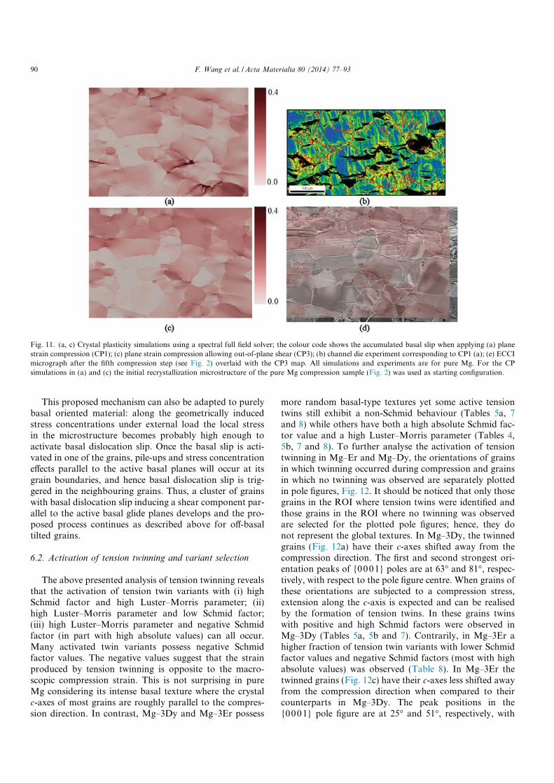
localization occurs. The results indicate that such in-planeshear relaxation is not promoting shear banding and thatinstead out-of-plane deformation components seem to berequired for the formation of shear bands during compres-sion of Mg polycrystals. Therefore, a third CP simulation(CP3) was performed, applying plane strain compressionand allowing out-of-plane deformation normal to theimage plane (F33 free), Fig. 11c. The modelling results showa percolation of high basal slip activity in the upper regionof the ROI, Fig. 11c, in agreement with the experimentallyobserved localised basal activity and shear band formation,Fig 4f. For a better visualisation the experimental ECCImicrograph (Fig. 4f) and the CP3 basal slip intensity mapare superimposed, Fig. 11d. The results imply the subse-quent development of a considerable out-of-plane shearstress component during compression. In order to furtheranalyse the impact of this shear stress component, a fourthcrystal plasticity simulation was performed, imposing com-pression loading and allowing additional out-of-planeshear (F12, F13, F23, F33 free). The simulation results donot show a significant difference to CP3. These findingsimply that the out-of-plane shear stress component whichis activated through the percolation of intense basal
dislocation slip in slightly off-basal oriented grains is caus-ing a dynamic facilitating local softening and leading to theformation of shear bands in polycrystalline Mg with pro-nounced basal texture.
Based on the above presented and discussed experimen-tal and computational results we propose the followingmechanisms for shear band formation in basal-texturedMg. A cluster of slightly off-basal oriented grains (wherethe slightly inclined near-basal texture components mightbe retained from a preceding inhomogeneous hot workingand/or rotation recrystallization step [57–59]) exhibit aslightly more favourable orientation for basal slip thanexactly basal oriented grains. In these grains, intensivebasal slip is locally activated during the on-set of plasticdeformation, leading to a micromechanical strain percola-tion effect in the form of a collective grain cluster deforma-tion mechanism. This cumulated basal slip extendingacross multiple neighboured grains creates a pronouncedshear component parallel to the active basal glide planes(out-of-plane) in the percolation area and, consequently,basal slip becomes more favourable in this area. Via thisdynamical process strain localization is facilitated andresults in shear band formation.
Fig. 10. ECC images and {0001}, {10�10} pole figures of the ROI at (a, c, d) the initial state and (b, e, f) after the fifth compression step. The dashed linedivides the ROI into the shear banded region and non-shear-banded region whose respective pole figures are presented in (c–f): (c) non-shear-bandedregion in the initial state, (d) shear banded region in the initial state, (e) non-shear-banded region after the fifth compression step and (f) shear bandedregion after the fifth compression step. The fifth deformation step corresponds to �5% macroscopic strain.
F. Wang et al. / Acta Materialia 80 (2014) 77–93 89
This proposed mechanism can also be adapted to purelybasal oriented material: along the geometrically inducedstress concentrations under external load the local stressin the microstructure becomes probably high enough toactivate basal dislocation slip. Once the basal slip is acti-vated in one of the grains, pile-ups and stress concentrationeffects parallel to the active basal planes will occur at itsgrain boundaries, and hence basal dislocation slip is trig-gered in the neighbouring grains. Thus, a cluster of grainswith basal dislocation slip inducing a shear component par-allel to the active basal glide planes develops and the pro-posed process continues as described above for off-basaltilted grains.
6.2. Activation of tension twinning and variant selection
The above presented analysis of tension twinning revealsthat the activation of tension twin variants with (i) highSchmid factor and high Luster–Morris parameter; (ii)high Luster–Morris parameter and low Schmid factor;(iii) high Luster–Morris parameter and negative Schmidfactor (in part with high absolute values) can all occur.Many activated twin variants possess negative Schmidfactor values. The negative values suggest that the strainproduced by tension twinning is opposite to the macro-scopic compression strain. This is not surprising in pureMg considering its intense basal texture where the crystalc-axes of most grains are roughly parallel to the compres-sion direction. In contrast, Mg–3Dy and Mg–3Er possess
more random basal-type textures yet some active tensiontwins still exhibit a non-Schmid behaviour (Tables 5a, 7and 8) while others have both a high absolute Schmid fac-tor value and a high Luster–Morris parameter (Tables 4,5b, 7 and 8). To further analyse the activation of tensiontwinning in Mg–Er and Mg–Dy, the orientations of grainsin which twinning occurred during compression and grainsin which no twinning was observed are separately plottedin pole figures, Fig. 12. It should be noticed that only thosegrains in the ROI where tension twins were identified andthose grains in the ROI where no twinning was observedare selected for the plotted pole figures; hence, they donot represent the global textures. In Mg–3Dy, the twinnedgrains (Fig. 12a) have their c-axes shifted away from thecompression direction. The first and second strongest ori-entation peaks of {0001} poles are at 63� and 81�, respec-tively, with respect to the pole figure centre. When grains ofthese orientations are subjected to a compression stress,extension along the c-axis is expected and can be realisedby the formation of tension twins. In these grains twinswith positive and high Schmid factors were observed inMg–3Dy (Tables 5a, 5b and 7). Contrarily, in Mg–3Er ahigher fraction of tension twin variants with lower Schmidfactor values and negative Schmid factors (most with highabsolute values) was observed (Table 8). In Mg–3Er thetwinned grains (Fig. 12c) have their c-axes less shifted awayfrom the compression direction when compared to theircounterparts in Mg–3Dy. The peak positions in the{0001} pole figure are at 25� and 51�, respectively, with
Fig. 11. (a, c) Crystal plasticity simulations using a spectral full field solver; the colour code shows the accumulated basal slip when applying (a) planestrain compression (CP1); (c) plane strain compression allowing out-of-plane shear (CP3); (b) channel die experiment corresponding to CP1 (a); (e) ECCImicrograph after the fifth compression step (see Fig. 2) overlaid with the CP3 map. All simulations and experiments are for pure Mg. For the CPsimulations in (a) and (c) the initial recrystallization microstructure of the pure Mg compression sample (Fig. 2) was used as starting configuration.
90 F. Wang et al. / Acta Materialia 80 (2014) 77–93

respect to the pole figure centre. The effect of the globalcompression strain on these grains is contraction alongthe c-axis.
The orientations of the grains in the ROI demonstratethat tension twinning occurs preferentially in the grainswith larger deviations of the basal poles from the compres-sion direction although the orientation may still be unfa-vourable for the activation of tension twinning due totheir negative Schmid factors.
In pure Mg, twinning occurs in hard oriented grainsinside the pre-shear band after intense basal slip activity.Due to strain localization it is very likely that the localstress state is different from the global stress state, in both,magnitude and directionality. Regardless of the Schmidfactor value, adjoining twin pairs possess quite high valuesof the Luster–Morris parameter (Table 6).
In Mg–3Dy there are variants activated with both thehighest Schmid factor and Luster–Morris values amongsix variants, e.g. in grains 1, 21, 22, but also variants withlow and/or negative Schmid factors but the highest Lus-ter–Morris values, e.g. in grains 4 and 10 (see Table 7). InMg–3Er all observed twin variants have negative Schmidfactors, several of them with high absolute values and highLuster–Morris parameters. Depending on the deformationmodes in the adjacent grain, different variants are activatedfrom the GB to fulfil the respective geometric compatibility.
For twinning-induced tension twins the analysis showsthat the tension twin which was first activated generallyis characterised by a high Schmid factor value while thesecond activated twin, i.e. the twin-stimulated twin, pos-sesses always a high Luster–Morris parameter, but in mostcases not the highest Schmid factor value. This indicates
again that lower Schmid factor tension twins are activatedin unfavourably oriented grains to accommodate the localstrain and maintain strain compatibility.
Since the tension twin variants with a high Luster–Morris parameter and a high absolute Schmid factor valueprevail in general, it is concluded from the present observa-tion that besides the Schmid factor the strain transfer com-patibility plays an important role in twin nucleation. Thecases where Schmid’s law of tension twinning was not ful-filled are probably resulting from the unfavourable orienta-tion of grains rather than a reflection of the nature of twinactivation. In fact, if the material is strained in a favourableorientation, e.g. compression along the RD and tensionalong the ND in rolled material [60], or compression alongthe extrusion direction and tension along the tangentialdirection in extruded material [61], good agreement withSchmid’s law is observed.
Direct comparison between pure Mg and the Mg–REalloys shows that in pure Mg localised and higher basal slipactivity and a lower tension twin activity than in Mg–Erand Mg–Dy was observed. In both Mg–RE alloys no local-ised deformation was observed; the activation of tensiontwins occurred slightly later and twin propagation wasfound to be slightly faster than in pure Mg. The distribu-tion of tension twins was homogeneous in Mg–Er andMg–Dy, whereas in pure Mg tension twins were observedto nucleate in the area of localised strain. Compressionand secondary twins were observed in both Mg–RE alloysonly at higher strains in ex situ experiments. The observeddifferences in tension twinning between pure Mg andMg–RE are assumed to result from texture effects. In thepresent work, the pure Mg sample possesses a stronger
Fig. 12. Pole figures based on orientation data of grains in which twins develop in subsequent compression (a, c) and grains in which no twin is observedduring the test (b, d) in the ROI of Mg–3Dy after the first compression step (a, b) and of Mg–3Er after the second compression step (c, d). Eachcompression step corresponds to �1% engineering strain.
F. Wang et al. / Acta Materialia 80 (2014) 77–93 91
and the two Mg–RE alloys weaker basal-type textures;therefore it can be assumed that the Schmid and non-Schmid behaviour of tension twins is firstly affected bythe texture. During the early stages of compressive defor-mation no “RE-effect” other than RE-induced textureweakening on the activation of tension twinning wasobserved.
In summary, the formation of tension twinning isrationalised in the following way. For grains with an orien-tation where the compressive stress component is parallelto the basal plane or the tensile stress component alongthe crystal c-axis, tension twinning is favoured. Here, thetwin variant which is geometrically well aligned with thedeformation mode in the adjacent grain is preferentiallyactivated. For grains with orientations that render tensiontwinning unfavourable, due to their hard orientation fortwinning, the global strain cannot be effectively accommo-dated and stress concentrates at grain boundaries. Whenthe concentrated stress is high enough to activate twinning,and if there is a geometrically well-aligned deformationmode in the adjacent grain, it is activated. Otherwise,strong strain gradients form in the vicinity of the GB, asis manifested by local orientation variations or even ledgesat the GB, such as observed in pure Mg (Fig. 4). Besidesthe Schmid factor several other factors seem to contributeto the twin variant selection in Mg alloys: (i) strain accom-modation required by the neighbouring grains [22], GBcharacter and misorientation [30], (iii) minimization ofcompatibility strain in the case of secondary twinning [24]and (iv) strain compatibility across grain boundaries asanalysed in the present study.
7. Conclusions
We analysed by in situ deformation the microstructuredevelopment of pure Mg and two Mg–RE alloys(Mg–3%Dy and Mg–3%Er) at the grain scale. The mainobservations and conclusions are as follows:
(1) Below an engineering strain of 5%, pure Mg exhibitslocalised slip activity, causing the formation of a pre-shear band and twinning exclusively in this pre-shearband. In contrast, the two Mg–RE alloys exhibithomogeneous deformation and a larger contributionof activated tension twins. The basal texture and theassociated grain clusters of similar basal orientationin the recrystallized pure Mg are an important factorresponsible for strain localization.
(2) During the early stages of compressive deformationno “RE-effect” other than RE-induced texture weak-ening on the activation of tension twinning wasobserved.
(3) Combined in situ deformation experiments and crys-tal plasticity simulations indicate that strain localiza-tion and pre-shear band formation in pure Mg is aresult of percolated basal slip activity in slightly off-basal orientated grains. As a result of this locally
cumulated intense basal slip a shear stress componentparallel to the active basal glide planes develops andsubsequently eases the basal slip, leading to the for-mation of a pre-shear band.
(4) Non-Schmid behaviour of tension twinning wasobserved in both pure Mg and the two Mg–REalloys. However, it appears in the two Mg–RE alloysthat activation of tension twinning preferentiallyoccurs in grains showing a larger deviation betweenthe crystal c-axis and the compression direction. Inpure Mg, tension twins are activated in areas withhigh local stresses, i.e. inside shear bands.
(5) The Luster–Morris parameter describes the geometriccompatibility and is an effective criterion in variantselection for twin activation. The activation of ten-sion twinning can be understood in combination withthe local stress tensor only. Analysis of the Luster–Morris parameter and the (global) Schmid factor ofactivated tension twins revealed that twinning followsSchmid’s law in orientations favourable for twinning,while in orientations where twinning is not favouredby the macroscopic stress state twinning is more aprocess of accommodating local strain and therebymaintaining strain compatibility at grain boundariesthan a response to macroscopically imposed strainin Mg and Mg alloys at low strain levels.
Acknowledgments
Parts of this research (CP simulations) were carried outunder project number M 41.2.10410 in the framework ofthe research program of the Materials innovation instituteM2i (www.m2i.nl).
References
[1] ASM Handbook. Properties and selections: nonferrous alloys andspecial purpose materials, vol. 2. Materials Park, OH: ASM; 1991.
[2] Schumann S, Friedrich H. Mater Sci Forum 2003;419–422:51–6.[3] Yoo M. Metall Trans A 1981;12:409–18.[4] Akhtar A, Teghtsoonian E. Acta Metall 1969;17:1339–49.[5] Hatherly M, Humphreys FJ. Recrystallization and related annealing
phenomena. Oxford: Elsevier; 1996.[6] Gottstein G, Al Samman T. Mater Sci Forum 2005;495–497:623–32.[7] Agnew S, Yoo M, Tome C. Acta Mater 2001;49(20):4277–89.[8] Bishop JFW, Hill R. Philos Mag 1951;42:414–27.[9] Raabe D, Sachtleber M, Zhao Z, Roters F, Zaefferer S. Acta Mater
2001;49:3433–41.[10] Zhao Z, Ramesh M, Raabe D, Cuitino A, Radovitzky R. Int J Plast
2008;24:2278–97.[11] Jia N, Roters F, Eisenlohr P, Kords C, Raabe D. Acta Mater
2012;60:1099–115.[12] Scott J, Miles M, Fullwood D, Adams B, Khosravani A, Mishra RK.
Metall Mater Trans A 2013;44:512–6.[13] Hazeli K, Cuadra J, Vanniamparambil PA, Kontsos A. Scripta Mater
2013;68:83–6.[14] Kim HL, Lee J-H, Lee CS, Bang W, Ahn SH, Chang YW. Mater Sci
Eng A 2012;558:431–8.[15] Chun YB, Davies CHJ. Mater Sci Eng A 2012;556:253–9.
92 F. Wang et al. / Acta Materialia 80 (2014) 77–93

[16] Zhang Z, Wang M-P, Jiang N, Zhu S. J Alloys Compd2012;512:73–8.
[17] Ion S, Humphreys F, White S. Acta Metall 1982;30:1909–19.[18] Barnett M, Nave M, Bettles C. Mater Sci Eng A 2004;386:205–11.[19] Koike J, Sato Y, Ando D. Mater Trans 2008;49:2792–800.[20] Jiang J, Godfrey A, Liu W, Liu Q. Scripta Mater 2008;58:122–5.[21] Beyerlein IJ, Capolungo L, Marshall PE, McCabe RJ, Tome C.
Philos Mag 2010;90:2161–90.[22] Jonas JJ, Mu S, Al-Samman T, Gottstein G, Jiang L, Martin E. Acta
Mater 2011;59:2046–56.[23] Agnew S, Tome C, Brown D, Holden T, Vogel S. Scripta Mater
2003;48:1003–8.[24] Barnett M, Keshavarz Z, Beer A, Atwell D. Acta Mater
2004;52:5093–103.[25] Wang L, Eisenlohr P, Yang Y, Bieler T, Crimp M. Scripta Mater
2010;63:827–30. 87 Bibliography 88.[26] Wang L, Yang Y, Eisenlohr P, Bieler T, Crimp M, Mason D. Metall
Mater Trans A 2010;41:421–30.[27] Mu S, Jonas JJ, Gottstein G. Acta Mater 2012;60:2043–53.[28] Capolungo L, Marshall P, McCabe R, Beyerlein I, Tome C. Acta
Mater 2009;57:6047–56.[29] Christian J, Mahajan S. Prog Mater Sci 1995;39:1–157.[30] El Kadiri H, Baird JC, Kapil J, Oppedal AL, Cherkaoui M, Vogel
SC. Int J Plast 2013;44:111–20.[31] Mishra RK, Gupta AK, Rao PR, Sachdev AK, Kumar AM, Luo
AA. Scripta Mater 2008;59:562–5.[32] Stanford N. Mater Sci Eng A 2010;527:2669–77.[33] Bohlen J, Nurnberg MR, Senn JW, Letzig D, Agnew SR. Acta Mater
2007;55:2101–12.[34] Stanford N, Atwell D, Beer A, Davies CHJ, Barnett MR. Scripta
Mater 2008;59:772–5.[35] Bohlen J, Yi S, Letzig D, Kainer KU. Mater Sci Eng A
2010;527:7092–8.[36] Al-Samman T, Li X. Mater Sci Eng A 2011;528:3809–22.[37] Sandlobes S, Zaefferer S, Schestakow I, Yi S, Gonzalez-Martinez R.
Acta Mater 2011;59:429–39.[38] Zaefferer S, Elhami NN. Acta Mater 2014;75:20–50.[39] Gutierrez-Urrutia I, Zaefferer S, Raabe D. Scripta Mater
2009;61:737–40.
[40] Gutierrez-Urrutia I, Zaefferer S, Raabe D. JOM 2013;65:1229–36.[41] Bridier F, Villechaise P, Mendez J. Acta Mater 2005;53:555–67.[42] Simkin B, Ng B, Bieler T, Crimp M, Mason D. Intermetallics
2003;11:215–23.[43] Luster J, Morris M. Metall Mater Trans A 1995;26:1745–56.[44] Bieler T, Eisenlohr P, Roters F, Kumar D, Mason D, Crimp M, et al.
Int J Plast 2009;25:1655–83.[45] Roters F, Eisenlohr P, Hantcherli L, Tjahjanto DD, Bieler TR, Raabe
D. Acta Mater 2010;58:1152–211.[46] Eisenlohr P, Diehl M, Lebensohn RA, Roters F. Int J Plast
2013;46:37–53.[47] Shanthraj P, Eisenlohr P, Diehl M, Roters F. Int J Plast; in press,
http://dx.doi.org/10.1016/j.ijplas.2014.02.006.[48] Hutchinson JW. Proc R Soc Lond A 1976;348:101–27.[49] Roters F. Advanced material models for the crystal plasticity finite
element method – development of a general CPFEM framework.RWTH Aachen, Aachen; 2011. URL: <http://darwin.bth.rwth-aachen.de/opus3/volltexte/2011/3874/>.
[50] Roters F, Eisenlohr P, Kords C, Tjahjanto DD, Diehl M, Raabe D.Procedia IUTAM 2012;3:3–10.
[51] DAMASK, Dusseldorf Advanced Material Simulation Kit, <http://damask.mpie.de/>.
[52] Prakash A, Weygand SM, Riedel H. Comput Mater Sci2009;45:744–50.
[53] Kalidindi SR. J Mech Phys Solids 1998;48:267–90.[54] Tromans D. Int J Res Rev Appl Sci 2011;6(4):462–83.[55] Agnew S, Brown D, Tome CN. Acta Mater 2006;54(18):4841–52.[56] Beyerlein I, McCabe R, Tome C. J Mech Phys Solids
2011;59:988–1003.[57] Ion SE, Humphreys FJ, White SH. Acta Metall 1982;30:1909–19.[58] Cottam R, Robson J, Lorimer G, Davis B. Mater Sci Eng A
2008;485:375–82.[59] Yi SB, Zaefferer S, Brokmeier H-G. Mater Sci Eng A
2006;424:275–81.[60] Park SH, Hong S-G, Lee CS. Scripta Mater 2010;62:202–5.[61] Godet S, Jiang L, Luo A, Jonas J. Scripta Mater 2006;55:1055–8.
F. Wang et al. / Acta Materialia 80 (2014) 77–93 93
Copyright © 2022 FDOKUMEN