
Improving Cloud Middlebox Infrastructure for Online Services
151
Purdue University Purdue e-Pubs Open Access Dissertations eses and Dissertations 8-2016 Improving Cloud Middlebox Infrastructure for Online Services Rohan S. Gandhi Purdue University Follow this and additional works at: hps://docs.lib.purdue.edu/open_access_dissertations Part of the Computer Sciences Commons is document has been made available through Purdue e-Pubs, a service of the Purdue University Libraries. Please contact [email protected] for additional information. Recommended Citation Gandhi, Rohan S., "Improving Cloud Middlebox Infrastructure for Online Services" (2016). Open Access Dissertations. 758. hps://docs.lib.purdue.edu/open_access_dissertations/758
-
Upload
khangminh22 -
Category
Documents
-
view
3 -
download
0
Transcript of Improving Cloud Middlebox Infrastructure for Online Services

Purdue UniversityPurdue e-Pubs
Open Access Dissertations Theses and Dissertations
8-2016
Improving Cloud Middlebox Infrastructure forOnline ServicesRohan S. GandhiPurdue University
Follow this and additional works at: https://docs.lib.purdue.edu/open_access_dissertations
Part of the Computer Sciences Commons
This document has been made available through Purdue e-Pubs, a service of the Purdue University Libraries. Please contact [email protected] foradditional information.
Recommended CitationGandhi, Rohan S., "Improving Cloud Middlebox Infrastructure for Online Services" (2016). Open Access Dissertations. 758.https://docs.lib.purdue.edu/open_access_dissertations/758


IMPROVING CLOUD MIDDLEBOX INFRASTRUCTURE FOR ONLINE
SERVICES
A Dissertation
Submitted to the Faculty
of
Purdue University
by
Rohan S. Gandhi
In Partial Fulfillment of the
Requirements for the Degree
of
Doctor of Philosophy
August 2016
Purdue University
West Lafayette, Indiana

ii
I want to dedicate this thesis to my family for their continuous support,
encouragement, patience and love.

iii
ACKNOWLEDGMENTS
I cannot thank my advisor Prof. Y. Charlie Hu enough for his continuous and
unmatched efforts in transforming my research approaches and skills. I want to
thank him to make me think “out of the box” and guide me on the right path from
conception to completion of research projects. His excitement and energy for the new
ideas and rigor in getting them through are contagious. Him constantly encouraging
me to improve upon the research ideas and designs eventually lead to many successful
chapters in this thesis. I specially want to thank him for pin-pointing the shortcomings
in my thinking and approaches towards research but also transforming those research
genes in the healthiest way. I will forever be in-debted to him for this transformation.
I also want to sincerely thank Ming Zhang from Microsoft Research who was more
than a co-advisor while I was in and out of Microsoft. I want to express my gratitude
for having rich discussions that go far beyond research, and also for relentlessly(!)
driving me to challenge and outperform myself and work towards perfection. I will
always remember his dedication when he drove to the office at 4AM to help me on
the Duet paper. Lastly, I want to thank him and Victor Bahl for offering me the
internships at MSR and striving to make me always focus on the bigger picture.
I want to thank my thesis committee members Prof. Sonia Fahmy, Prof. Sanjay
Rao, and Prof. Chih-Chun Wang for their useful discussions and help in completing
this thesis. I also want to thank my collaborators for their immense help and efforts
without which the thesis would not have completed. I want to thank (in alphabetical
order) Wendy Belluomini, Mary L. Comer, Andreas Haeberlen, Aayush Gupta, Ak-
shay Jajoo, Xin Jin, Tim Kaldewey, Srikanth Kandula, Cheng-Kok Koh, Dimitrios
Koutsonikolas, Hongqiang Liu, Guohan Lu, Ratul Mahajan, Amr Mohamed, Edet
Nposong, Jitu Padhye, Anna Povzner, Jennifer Rexford, Amit Sabne, Chih-Chun
Wang, Roger Wattenhofer, Yang Wu, Di Xie, Meilin Yang, Iona Yuan, Lihua Yuan.

iv
Additionally, I want to offer sincere gratitude towards members from Microsoft
Research, IBM Research and Microsoft Azure team for the discussions (including the
“TCP-undo” discussions with Monia!), experiences and sharing the data from produc-
tion systems that helped validate the research propositions, designs and evaluation. I
also want to thank all faculty members and teaching staff at Purdue for offering and
undertaking the academic courses, which helped me build a strong knowledge base
and sharpen my research skills. I also want to thank NSF and other agencies that
funded my research.
I want to thank my current and former lab-mates at the Distributed Systems and
Networks Lab (again in alphabetical order), Rohit Bhatia, Ali Butt, Xiaomeng Chen,
Ning Ding, Fawaz Hasan, Aashish Jain, Vaibhav Jain, Akshay Jajoo, Abhilash Jindal,
Dimitrios Koutsonikolas, Abhinav Pathak, Himabindu Pucha, Ashiwan Sivakumar
and Di Xie. I want to thank Pathak for many rich discussions in the first few years
of my PhD that helped me dream big. I cannot thank enough my house-mates
Neeraj Gadgil, Sai kumar Reddy and Amit Sabne, and other co-students, co-interns,
members from DoSM (sponsorship club at BITS Pilani), Panchsheel (my home!) and
my friends around the globe for being incredibly awesome! They made the PhD
journey a lot easier, and perhaps a lot more enjoyable. I cannot count the amazing
moments before and during the PhD journey. I will always cherish these happy
moments. They made the six years fly by in a flash.
I also want to thank all the members of the Purdue ECE department, graduate
students, international students office, business and shipping office for their help in
smoothly handling the academic and related problems.
Lastly, I want to thank my parents, sister and brother-in-law, and my friends Rahul
Parsani and Sohini Manna for helping me in hanging-in there and constantly support-
ing me through the many ups-and-downs during this roller coaster ride. Phew!

v
TABLE OF CONTENTS
Page
LIST OF TABLES . . . . . . . . . . . . . . . . . . . . . . . . . . . . . . . . ix
LIST OF FIGURES . . . . . . . . . . . . . . . . . . . . . . . . . . . . . . . x
ABSTRACT . . . . . . . . . . . . . . . . . . . . . . . . . . . . . . . . . . . xiii
1 CLOUD MIDDLEBOX INFRASTRUCTURE . . . . . . . . . . . . . . . 1
1.1 Requirements . . . . . . . . . . . . . . . . . . . . . . . . . . . . . . 1
1.2 Specialized hardware middleboxes and limitations . . . . . . . . . . 4
1.3 Software middleboxes and limitations . . . . . . . . . . . . . . . . . 4
1.3.1 High Cost . . . . . . . . . . . . . . . . . . . . . . . . . . . . 5
1.3.2 High latency inflation . . . . . . . . . . . . . . . . . . . . . . 5
1.3.3 High network bandwidth overhead . . . . . . . . . . . . . . 5
1.3.4 Poor availability . . . . . . . . . . . . . . . . . . . . . . . . . 6
1.3.5 Costly and limited cloud offerings . . . . . . . . . . . . . . . 7
1.4 Thesis Overview . . . . . . . . . . . . . . . . . . . . . . . . . . . . . 7
1.4.1 Load balancers using hardware and software . . . . . . . . . 8
1.4.2 Reducing network overhead by exploiting locality and end-pointflexibility . . . . . . . . . . . . . . . . . . . . . . . . . . . . 9
1.4.3 High Availability through decoupling TCP State . . . . . . . 11
1.5 Thesis contributions . . . . . . . . . . . . . . . . . . . . . . . . . . 13
2 DUET: CLOUD SCALE LOAD BALANCING WITH HARDWARE ANDSOFTWARE . . . . . . . . . . . . . . . . . . . . . . . . . . . . . . . . . 16
2.1 Background and Motivation . . . . . . . . . . . . . . . . . . . . . . 16
2.1.1 Ananta Software Load Balancer . . . . . . . . . . . . . . . . 17
2.1.2 Limitations of Software Load Balancer . . . . . . . . . . . . 18
2.2 Duet: Core ideas . . . . . . . . . . . . . . . . . . . . . . . . . . . . 19

vi
Page
2.2.1 HMux . . . . . . . . . . . . . . . . . . . . . . . . . . . . . . 20
2.2.2 Partitioning . . . . . . . . . . . . . . . . . . . . . . . . . . . 22
2.2.3 DUET: HMux + SMux . . . . . . . . . . . . . . . . . . . . . 23
2.3 VIP Assignment Algorithm . . . . . . . . . . . . . . . . . . . . . . 25
2.3.1 VIP Assignment . . . . . . . . . . . . . . . . . . . . . . . . . 27
2.3.2 VIP Migration . . . . . . . . . . . . . . . . . . . . . . . . . 28
2.4 Practical Issues . . . . . . . . . . . . . . . . . . . . . . . . . . . . . 31
2.4.1 Failure Recovery . . . . . . . . . . . . . . . . . . . . . . . . 31
2.4.2 Other Functionalities . . . . . . . . . . . . . . . . . . . . . . 32
2.5 Implementation . . . . . . . . . . . . . . . . . . . . . . . . . . . . . 35
2.6 Testbed Experiments . . . . . . . . . . . . . . . . . . . . . . . . . . 37
2.6.1 HMux Capacity . . . . . . . . . . . . . . . . . . . . . . . . . 38
2.6.2 HMux Failure Mitigation . . . . . . . . . . . . . . . . . . . . 39
2.6.3 VIP Migration . . . . . . . . . . . . . . . . . . . . . . . . . 40
2.7 Evaluation . . . . . . . . . . . . . . . . . . . . . . . . . . . . . . . . 42
2.7.1 Simulation Setup . . . . . . . . . . . . . . . . . . . . . . . . 42
2.7.2 SMux Reduction . . . . . . . . . . . . . . . . . . . . . . . . 43
2.7.3 Latency vs. SMuxes . . . . . . . . . . . . . . . . . . . . . . 45
2.7.4 Duet vs. Random . . . . . . . . . . . . . . . . . . . . . . . . 46
2.7.5 Impact of Failure . . . . . . . . . . . . . . . . . . . . . . . . 47
2.7.6 VIP Migration . . . . . . . . . . . . . . . . . . . . . . . . . 48
2.8 Discussion . . . . . . . . . . . . . . . . . . . . . . . . . . . . . . . . 50
2.9 Related Work . . . . . . . . . . . . . . . . . . . . . . . . . . . . . . 51
2.10 Summary . . . . . . . . . . . . . . . . . . . . . . . . . . . . . . . . 53
3 RUBIK: UNLOCKING THE POWER OF LOCALITY AND END-POINTFLEXIBILITY IN CLOUD SCALE LOAD BALANCING . . . . . . . . 54
3.1 Introduction . . . . . . . . . . . . . . . . . . . . . . . . . . . . . . . 54
3.2 Background . . . . . . . . . . . . . . . . . . . . . . . . . . . . . . . 55

vii
Page
3.2.1 VIP traffic . . . . . . . . . . . . . . . . . . . . . . . . . . . . 55
3.2.2 Workload Characteristics . . . . . . . . . . . . . . . . . . . . 55
3.3 Motivation . . . . . . . . . . . . . . . . . . . . . . . . . . . . . . . . 57
3.4 Rubik Overview . . . . . . . . . . . . . . . . . . . . . . . . . . . . 61
3.5 Rubik Architecture . . . . . . . . . . . . . . . . . . . . . . . . . . . 62
3.6 Joint VIP and DIP Assignment . . . . . . . . . . . . . . . . . . . . 64
3.6.1 DIP and Local Mapping Placement . . . . . . . . . . . . . . 66
3.6.2 Residual Mapping Placement . . . . . . . . . . . . . . . . . 68
3.7 Failure Recovery . . . . . . . . . . . . . . . . . . . . . . . . . . . . 69
3.8 Implementation . . . . . . . . . . . . . . . . . . . . . . . . . . . . . 70
3.9 Testbed . . . . . . . . . . . . . . . . . . . . . . . . . . . . . . . . . 71
3.9.1 Reduction in Congestion . . . . . . . . . . . . . . . . . . . . 72
3.9.2 Failure Mitigation . . . . . . . . . . . . . . . . . . . . . . . . 73
3.10 Simulation . . . . . . . . . . . . . . . . . . . . . . . . . . . . . . . . 76
3.10.1 MLU Reduction . . . . . . . . . . . . . . . . . . . . . . . . . 76
3.10.2 Traffic Localized . . . . . . . . . . . . . . . . . . . . . . . . 78
3.10.3 Traffic Reduction . . . . . . . . . . . . . . . . . . . . . . . . 79
3.10.4 DIP Load Balance . . . . . . . . . . . . . . . . . . . . . . . 80
3.10.5 Impact of Limiting Machine Moves . . . . . . . . . . . . . . 80
3.11 Related work . . . . . . . . . . . . . . . . . . . . . . . . . . . . . . 81
3.12 Summary . . . . . . . . . . . . . . . . . . . . . . . . . . . . . . . . 82
4 YODA: HIGHLY AVAILABLE LAYER-7 LOAD BALANCER . . . . . . 83
4.1 Background and Motivation . . . . . . . . . . . . . . . . . . . . . . 83
4.1.1 L7 load balancer . . . . . . . . . . . . . . . . . . . . . . . . 83
4.1.2 Existing L7 LB . . . . . . . . . . . . . . . . . . . . . . . . . 85
4.1.3 Limitations of Existing L7 LB . . . . . . . . . . . . . . . . . 85
4.2 Yoda Key Ideas . . . . . . . . . . . . . . . . . . . . . . . . . . . . . 87
4.3 Yoda Design . . . . . . . . . . . . . . . . . . . . . . . . . . . . . . . 89

viii
Page
4.3.1 Basic operations . . . . . . . . . . . . . . . . . . . . . . . . 89
4.3.2 Handling Yoda instance failure . . . . . . . . . . . . . . . . 92
4.3.3 Yoda TCPStore architecture . . . . . . . . . . . . . . . . . 94
4.3.4 VIP assignment . . . . . . . . . . . . . . . . . . . . . . . . . 95
4.3.5 Updating VIP assignment . . . . . . . . . . . . . . . . . . . 99
4.4 L7 LB Features . . . . . . . . . . . . . . . . . . . . . . . . . . . . . 100
4.4.1 Interface . . . . . . . . . . . . . . . . . . . . . . . . . . . . . 100
4.4.2 Practical issues . . . . . . . . . . . . . . . . . . . . . . . . . 101
4.5 Implementation . . . . . . . . . . . . . . . . . . . . . . . . . . . . . 103
4.6 Evaluation . . . . . . . . . . . . . . . . . . . . . . . . . . . . . . . . 105
4.6.1 Feasibility of decoupling flow state . . . . . . . . . . . . . . 106
4.6.2 Failure recovery . . . . . . . . . . . . . . . . . . . . . . . . . 109
4.6.3 Scalability . . . . . . . . . . . . . . . . . . . . . . . . . . . . 112
4.6.4 Safe policy update . . . . . . . . . . . . . . . . . . . . . . . 113
4.7 Simulation . . . . . . . . . . . . . . . . . . . . . . . . . . . . . . . . 113
4.7.1 Cost reduction . . . . . . . . . . . . . . . . . . . . . . . . . 114
4.7.2 Impact of updates . . . . . . . . . . . . . . . . . . . . . . . . 115
4.8 Questions and Answers . . . . . . . . . . . . . . . . . . . . . . . . . 116
4.9 Related Work . . . . . . . . . . . . . . . . . . . . . . . . . . . . . . 117
4.10 Summary . . . . . . . . . . . . . . . . . . . . . . . . . . . . . . . . 119
5 CONCLUSION . . . . . . . . . . . . . . . . . . . . . . . . . . . . . . . . 121
6 FUTURE WORK . . . . . . . . . . . . . . . . . . . . . . . . . . . . . . . 123
6.1 Middleboxes with RDMA . . . . . . . . . . . . . . . . . . . . . . . 123
6.2 What made specialized hardware middleboxes obsolete . . . . . . . 124
6.3 New Datacenter Hardware . . . . . . . . . . . . . . . . . . . . . . . 124
6.4 The only constant is change . . . . . . . . . . . . . . . . . . . . . . 125
REFERENCES . . . . . . . . . . . . . . . . . . . . . . . . . . . . . . . . . . 127
VITA . . . . . . . . . . . . . . . . . . . . . . . . . . . . . . . . . . . . . . . 132

ix
LIST OF TABLES
Table Page
1.1 Thesis contributions, new DC middlebox princoples and outcomes . . . 13
2.1 Notations used in VIP assignment algorithm. . . . . . . . . . . . . . . 26
3.1 Path length for different LB designs. . . . . . . . . . . . . . . . . . . . 58
3.2 Notations used in the algorithm. . . . . . . . . . . . . . . . . . . . . . 66
4.1 Impact of proxy failure on different websites. . . . . . . . . . . . . . . . 85
4.2 Notations used in the algorithm. . . . . . . . . . . . . . . . . . . . . . 97
4.3 Yoda Interface. . . . . . . . . . . . . . . . . . . . . . . . . . . . . . . . 100

x
LIST OF FIGURES
Figure Page
1.1 Typical middlebox deployment. The red boxes denote the software mid-dleboxes, whereas the blue symbols denote the specialized hardware mid-dleboxes. The arrows show the traffic flow when the client is within thesame DC. . . . . . . . . . . . . . . . . . . . . . . . . . . . . . . . . . . 2
2.1 Performance of software Mux. . . . . . . . . . . . . . . . . . . . . . . . 17
2.2 Storing VIP-DIP mapping on a switch. . . . . . . . . . . . . . . . . . . 20
2.3 Duet architecture: VIPs are partitioned across different HMuxes —VIP1 and VIP2 are assigned to HMux C2 and A6. Additionally, SMuxesact as backstop for all the VIPs. Every server (apart from SMuxes) runshost-agent that decapsulates the packets and forwards to the DIP. Linksmarked with solid lines carry VIP traffic, and links with dotted lines carryDIP traffic. . . . . . . . . . . . . . . . . . . . . . . . . . . . . . . . . . 23
2.4 Memory deadlock problem during VIP migration. VIPs V1 and V2 bothoccupy 60% of switch memory each. The goal of migration is to migratethe VIPs from assignment in (a) to (b); Duet eliminates this problem bymigrating VIPs through SMuxes, as shown in (c). . . . . . . . . . . . . 29
2.5 When the VIP assignment changes from ToR T2 to T3, only the linksinside container-2 are affected. As a result, we can first select best ToRin a container based on the links within container, and then scan over allcontainers and remaining Core and Agg switches. . . . . . . . . . . . . 30
2.6 Load balancing in virtualized clusters. . . . . . . . . . . . . . . . . . . 31
2.7 Large fanout support. . . . . . . . . . . . . . . . . . . . . . . . . . . . 33
2.8 Port-based load balancing. . . . . . . . . . . . . . . . . . . . . . . . . . 35
2.9 Components in Duet implementation. . . . . . . . . . . . . . . . . . . 36
2.10 Our testbed. FatTree with two containers of two Agg and two ToRSwitches each, connected by two Core switches. . . . . . . . . . . . . . 37
2.11 HMux has higher capacity. . . . . . . . . . . . . . . . . . . . . . . . . . 38
2.12 VIP availability during failure. . . . . . . . . . . . . . . . . . . . . . . . 39
2.13 VIP availability during migration. . . . . . . . . . . . . . . . . . . . . . 41
xi
Figure Page
2.14 Latency breakdown. . . . . . . . . . . . . . . . . . . . . . . . . . . . . 42
2.15 Traffic and DIP distribution. . . . . . . . . . . . . . . . . . . . . . . . . 43
2.16 Number of SMuxes used in Duet and Ananta. . . . . . . . . . . . . . . 44
2.17 Latency (microseconds) vs. number of SMuxes in Ananta and Duet. . 45
2.18 Number of SMuxes used by Duet and Random. . . . . . . . . . . . . . 46
2.19 Impact of failures on max. link utilization. . . . . . . . . . . . . . . . . 47
2.20 Effectiveness of different migration algorithms. . . . . . . . . . . . . . . 49
3.1 Distribution of the number of ToRs where the sources and DIPs are lo-cated. . . . . . . . . . . . . . . . . . . . . . . . . . . . . . . . . . . . . 56
3.2 Ratio of 99th percentile to average traffic volume for each VIP across allsources. . . . . . . . . . . . . . . . . . . . . . . . . . . . . . . . . . . . 56
3.3 MLU and total traffic under various LB schemes. Total traffic is measuredacross all the DC network links. . . . . . . . . . . . . . . . . . . . . . . 58
3.4 Duet architecture. Links marked with solid and dotted lines carry VIPand DIP traffic, respectively. . . . . . . . . . . . . . . . . . . . . . . . . 59
3.5 Rubik Architecture. DIPs for VIP1 are split in local (HMux-L) and resid-ual mappings (HMux-R). . . . . . . . . . . . . . . . . . . . . . . . . . . 63
3.6 Rubik implementation. . . . . . . . . . . . . . . . . . . . . . . . . . . 70
3.7 Our testbed. FatTree with 4 containers connected to 4 Core switches. . 72
3.8 Rubik reduces congestion. . . . . . . . . . . . . . . . . . . . . . . . . . 72
3.9 VIP availability when residual mapping fails. . . . . . . . . . . . . . . . 73
3.10 VIP availability during local mapping failure. . . . . . . . . . . . . . . 74
3.11 VIP availability during DIP failure. . . . . . . . . . . . . . . . . . . . . 75
3.12 Total traffic variation over 24 hours. . . . . . . . . . . . . . . . . . . . 77
3.13 Traffic handled by HMuxes vs. MLU. . . . . . . . . . . . . . . . . . . . 77
3.14 Traffic handled using local mappings. . . . . . . . . . . . . . . . . . . . 78
3.15 Total traffic in core and container. . . . . . . . . . . . . . . . . . . . . 79
3.16 DIP utilization distribution across VIPs. . . . . . . . . . . . . . . . . . 80
3.17 Impact of machine moves. . . . . . . . . . . . . . . . . . . . . . . . . . 81
4.1 Typical L7 LB deployment. . . . . . . . . . . . . . . . . . . . . . . . . 84

xii
Figure Page
4.2 Yoda architecture. Red lines denote L7LB-servers traffic. Blue linesdenote L7LB-clients traffic. . . . . . . . . . . . . . . . . . . . . . . . . 89
4.3 Connection establishment in Yoda. The sequence numbers used whileestablishing the connections are shown over the arrows. The times whenYoda instances store flow state are marked in Blue. . . . . . . . . . . 90
4.4 Front-and-back indirection: Yoda leverages the L4 LB to establish TCPconnections with both the client and the server: both the client and serversee the VIP as the other endpoint of their connections. . . . . . . . . . 91
4.5 Yoda Failure recovery. . . . . . . . . . . . . . . . . . . . . . . . . . . . 93
4.6 Look-up latency in HAProxy. . . . . . . . . . . . . . . . . . . . . . . . 96
4.7 ILP formulation of VIP assignment. . . . . . . . . . . . . . . . . . . . . 98
4.8 Components in Yoda implementation (shown in colored boxes). . . . . 103
4.9 Yoda latency breakdown. . . . . . . . . . . . . . . . . . . . . . . . . . 106
4.10 Yoda TCPStore latency. . . . . . . . . . . . . . . . . . . . . . . . . . 107
4.11 Yoda TCPStore CPU utilization. . . . . . . . . . . . . . . . . . . . . . 108
4.12 Yoda Failure recovery. . . . . . . . . . . . . . . . . . . . . . . . . . . . 110
4.13 Yoda scalability. . . . . . . . . . . . . . . . . . . . . . . . . . . . . . . 111
4.14 Yoda user policy update. . . . . . . . . . . . . . . . . . . . . . . . . . 112
4.15 Max-to-average traffic ratio for all VIPs. VIPs are sorted in decreasingorder of the traffic. . . . . . . . . . . . . . . . . . . . . . . . . . . . . . 114
4.16 Yoda update. . . . . . . . . . . . . . . . . . . . . . . . . . . . . . . . . 120
xiii
ABSTRACT
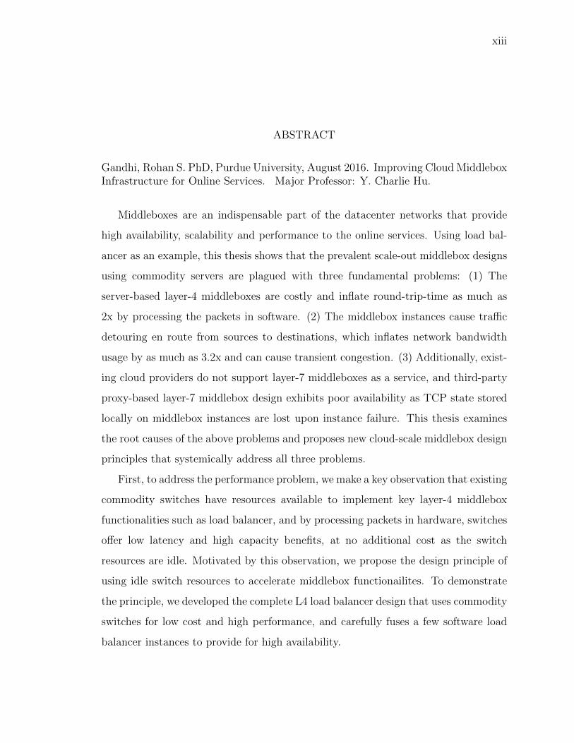
Gandhi, Rohan S. PhD, Purdue University, August 2016. Improving Cloud MiddleboxInfrastructure for Online Services. Major Professor: Y. Charlie Hu.
Middleboxes are an indispensable part of the datacenter networks that provide
high availability, scalability and performance to the online services. Using load bal-
ancer as an example, this thesis shows that the prevalent scale-out middlebox designs
using commodity servers are plagued with three fundamental problems: (1) The
server-based layer-4 middleboxes are costly and inflate round-trip-time as much as
2x by processing the packets in software. (2) The middlebox instances cause traffic
detouring en route from sources to destinations, which inflates network bandwidth
usage by as much as 3.2x and can cause transient congestion. (3) Additionally, exist-
ing cloud providers do not support layer-7 middleboxes as a service, and third-party
proxy-based layer-7 middlebox design exhibits poor availability as TCP state stored
locally on middlebox instances are lost upon instance failure. This thesis examines
the root causes of the above problems and proposes new cloud-scale middlebox design
principles that systemically address all three problems.
First, to address the performance problem, we make a key observation that existing
commodity switches have resources available to implement key layer-4 middlebox
functionalities such as load balancer, and by processing packets in hardware, switches
offer low latency and high capacity benefits, at no additional cost as the switch
resources are idle. Motivated by this observation, we propose the design principle of
using idle switch resources to accelerate middlebox functionailites. To demonstrate
the principle, we developed the complete L4 load balancer design that uses commodity
switches for low cost and high performance, and carefully fuses a few software load
balancer instances to provide for high availability.

xiv
Second, to address the high network overhead problem from traffic detouring
through middlebox instances, we propose to exploit the principles of locality and
flexibility in placing the middlebox instances and servers to handle the traffic closer
to the sources and reduce the overall traffic and link utilization in the network.
Third, to provide high availability in a layer 7 middleboxes, we propose a novel
middlebox design principle of decoupling the TCP state from middlebox instances and
storing it in persistent key-value store so that any middlebox instance can seamlessly
take over any TCP connection when middlebox instances fail. We demonstrate the
effectiveness of the above cloud-scale middlebox design principles using load balancers
as an example. Specifically, we have prototyped the three design principles in three
cloud-scale load balancers: Duet, Rubik, and Yoda, respectively. Our evaluation
using a datacenter testbed and large scale simulations show that Duet lowers the
costs by 12x and latency overhead by 1000x, Rubik further lowers the datacenter
network traffic overhead by 3x, and Yoda L7 Load balancer-as-a-service is practical;
decoupling TCP state from load balancer instances has a negligible (<1%) overhead.

1
1. CLOUD MIDDLEBOX INFRASTRUCTURE
Cloud computing has become an integral part of our lives. The online services that
provide important services such as email, news, banking, maps, search and music are
now residing in the cloud. The success of such cloud online services is incomplete
without middleboxes on which online services heavily rely for several network op-
erations including distributing load (load balancer, proxy), access control (firewall),
remote access (VPN). For example, without load balancers, the online services cannot
easily scale out to thousands of servers and support millions of user requests per sec-
ond. Additionally, without firewalls the online services are easily exposed to several
attacks and malicious activities that threaten to steal user confidential information.
Together, middleboxes simplify deployment, monitoring, security and management of
the online services making them an indispensable component of the online services.
Given these important benefits, the middlebox market is expected to cross $10B by
2016 [1], and become comparable to the router market.
1.1 Requirements
All user traffic coming to the online services first goes through the middleboxes
that perform the network operations before sending the traffic to the servers assigned
to the online services (Figure 1.1). For example, load balancer (LB) in Figure 1.1
splits and forwards the requests among hundreds of web front ends, or the firewall
inspects the incoming traffic for malicious activities.
In addition to handling the traffic coming from Internet, the middleboxes also
handle a large fraction of the total traffic within the datacenter (DC) because many
services inside the DC also take advantage of several benefits provided by the middle-
boxes. For example, middleboxes such as a load balancer provide a virtual IP (VIP)

2
DC Network
Client NAT
VIP1
DIP2
DIP1
Firewall
LB
Fig. 1.1.: Typical middlebox deployment. The red boxes denote the software middle-
boxes, whereas the blue symbols denote the specialized hardware middleboxes. The
arrows show the traffic flow when the client is within the same DC.
abstraction, where an online service receives traffic on one or a small number of VIPs,
and the load balancer splits the VIP traffic across servers assigned to the online ser-
vices. This indirection through the VIP provides many advantages, foremost is the
isolation, where it masks the dynamics such as server failure, migration and mainte-
nance within the online services from the users and other dependent online services.
To take advantage of such benefits, all the traffic between online services within the
same datacenter goes through the load balancer. It is reported that 44% of the total
datacenter traffic is VIP traffic.
Supporting such a high traffic volume adds significant strain on the middlebox
data-plane. Additionally, as the user traffic directly flows through the middleboxes,
middleboxes face stringent requirements on the availability and performance. Pre-
cisely, the middleboxes face the following requirements:
• High scalability: The middleboxes are expected to provide high capacity and
scalability to support large and highly dynamic nature of the user traffic. For
example, a load balancer is expected to handle traffic as high as 44 Tbps in a

3
mid-size datacenter with 40K servers [2], and this number is expected to grow
rapidly as new online services are being added and as the traffic to existing online
services grows. The middleboxes are also expected to provide high capacity to
individual tenants, e.g., handle 100+ Gbps traffic or 1+ million simultaneous
connections. Additionally, the online traffic is highly volatile, where the max.
to min. traffic ratio in a single day on average is 6x [3]. In such settings,
the middleboxes should be able to dynamically scale up/down to adapt to the
dynamic traffic volume.
• High availability: The middleboxes are required to provide high availability
as any downtime in the middleboxes can result in user traffic being dropped or
loss of connectivity of the online services, either of which directly reduces online
service availability and affects their revenue.
• Low latency: The online services have strict latency deadlines in responding
to the user requests, which also translates into middleboxes minimizing latency
inflation in processing the packets as any time lost in the middlebox processing
can otherwise be used by the online services to improve the response quality.
• Low cost: The middleboxes are expected to be low cost, as the money spent
on the middleboxes can otherwise be used to improve the online services in-
frastructure. Prior work estimates that the cost of the middleboxes should not
exceed 1% of the total server costs [2].
• Low network bandwidth overhead: Typically, the middleboxes run sepa-
rately from the servers and the clients, and the traffic from clients first need to
detour to the middleboxes en route to the destinations. The network operators
want to reduce such traffic detour as: (1) The middleboxes handle a huge traffic
volume, such detour can unnecessarily inflate the total traffic in the network,
which may require network operators to increase network capacity which is
costly; (2) The high traffic detour may also trigger transient congestion, which
can damage the performance of the latency-sensitive applications.
4
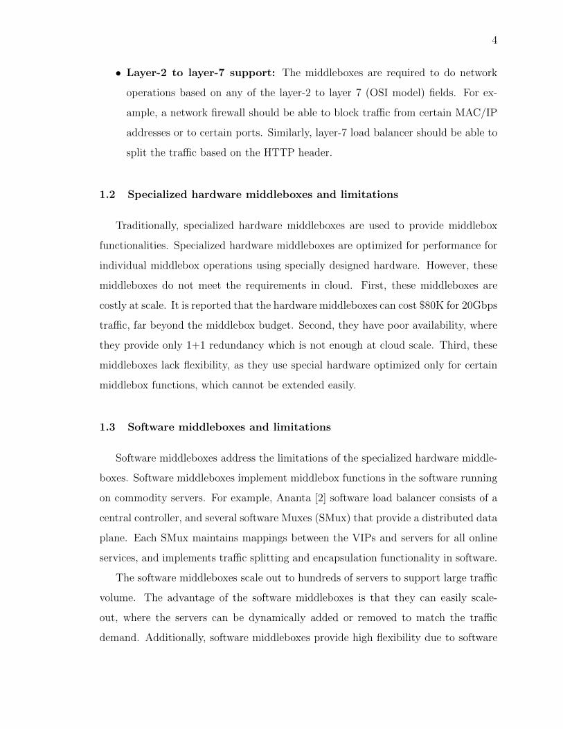
• Layer-2 to layer-7 support: The middleboxes are required to do network
operations based on any of the layer-2 to layer 7 (OSI model) fields. For ex-
ample, a network firewall should be able to block traffic from certain MAC/IP
addresses or to certain ports. Similarly, layer-7 load balancer should be able to
split the traffic based on the HTTP header.
1.2 Specialized hardware middleboxes and limitations
Traditionally, specialized hardware middleboxes are used to provide middlebox
functionalities. Specialized hardware middleboxes are optimized for performance for
individual middlebox operations using specially designed hardware. However, these
middleboxes do not meet the requirements in cloud. First, these middleboxes are
costly at scale. It is reported that the hardware middleboxes can cost $80K for 20Gbps
traffic, far beyond the middlebox budget. Second, they have poor availability, where
they provide only 1+1 redundancy which is not enough at cloud scale. Third, these
middleboxes lack flexibility, as they use special hardware optimized only for certain
middlebox functions, which cannot be extended easily.
1.3 Software middleboxes and limitations
Software middleboxes address the limitations of the specialized hardware middle-
boxes. Software middleboxes implement middlebox functions in the software running
on commodity servers. For example, Ananta [2] software load balancer consists of a
central controller, and several software Muxes (SMux) that provide a distributed data
plane. Each SMux maintains mappings between the VIPs and servers for all online
services, and implements traffic splitting and encapsulation functionality in software.
The software middleboxes scale out to hundreds of servers to support large traffic
volume. The advantage of the software middleboxes is that they can easily scale-
out, where the servers can be dynamically added or removed to match the traffic
demand. Additionally, software middleboxes provide high flexibility due to software

5
implementation, and provides n+1 redundancy as there are n instances active when
one instance fails.
Despite these benefits, software middleboxes suffer from numerous limitations,
which we enumerate below:
1.3.1 High Cost
First, software middleboxes are costly due to poor capacity at individual servers.
This limitation stems from processing the packets in the software. In case of a load
balancer, we observed that the individual servers can only handle 300K packets/sec
as the CPU saturates at this rate. This limited capacity translates into requiring 4K
servers to handle 15Tbps of the traffic only for load balancing, which is typical in a
midsize 40K datacenter [2, 4], which far exceeds the middlebox budget.
1.3.2 High latency inflation
Second, the software middleboxes incurs high and highly variable latency again
by processing the packets in software. Again, in case of a load balancer, we observed
latency inflation anywhere between 200-1000 µsec when processing packets at rate
as low as 100K packets per sec, which is significant as the typical datacenter RTTs
are around 330µsec. This results in high end-to-end latency and low throughput as
every packet coming to the online service suffers from this high latency. Applications
such as algorithmic stock trading and high performance distributed memory caches
demand ultra-low (a few microseconds) latency within the data center. For such
applications, the latency inflation by the software middleboxes is not acceptable.
1.3.3 High network bandwidth overhead
In addition to the limitations in cost and latency, software middleboxes also in-
flate the network bandwidth usage and maximum link utilization (MLU) indicating

6
congestion due to large traffic volume. The middleboxes are placed oblivious to the
location of the sources and destinations. Thus, even if the sources and destination are
in the same rack, the traffic first has to traverse many hops to reach the middleboxes.
Second, the middleboxes typically choose the destination end-point independent of its
location (using hash calculated over IP 5-tuples). Thus, even if the destinations are
in the same rack as the middleboxes, the middleboxes send the traffic to destinations
many hops away. Lastly, existing designs do not take advantage of the flexibility
in placing the end-points. End-points can be placed closer to the middleboxes and
sources to shorten the path.
Our analysis using real traffic traces showed that indeed all the traffic hits the
datacenter network core even if most of it can be contained in individual racks. This
detour to/from the middleboxes increase the number of hops and inflates traffic on
the individual links and max. link utilization beyond 90% indicating congestion. Such
high bandwidth usage not only requires the datacenter (DC) operator to provision
high network bandwidth which is costly, but also makes the network more prone to
transient congestion which affect latency-sensitive services.
1.3.4 Poor availability
The previous discussion was focused on a general class of middleboxes called layer-
4 middleboxes that process packets based on the up to layer-4 fields such as TCP/IP
fields. A special class of middleboxes called layer-7 middleboxes that process pack-
ets based on the up to layer 7 fields such as HTTP or FTP suffer from an additional
problem of poor availability, where the client and server connections break when indi-
vidual instances fail. The root-causes for this undesired problem are deeply embedded
into a proxy design heavily used by the layer-7 middleboxes especially load balancer,
where for an incoming client request, each load balancer instance first establishes a
TCP connection with the client to get the HTTP request, then selects the server
and starts a new connection with the server. However, the proxy instance stores the

7
client and server TCP connection state locally only, and is lost on failure. Even if the
packets get rerouted to another instance, it cannot recover the TCP state required to
maintain the connection. As a result, the client and server connections break, which
results in poor user experience and affects the revenue of online services.
1.3.5 Costly and limited cloud offerings
Major cloud providers do not provide layer-7 middleboxes as a service, which
prompts the tenants to either build and maintain their own service or use third party
designs (such as HAProxy). In either alternatives, the tenants have to manage scal-
ability of their middleboxes on their own. However, we observe that the tenants
cannot scale down the middlebox instances easily as removing instances could break
the existing connections as explained previously. Thus, the middlebox would remain
provisioned for the peak traffic even when the average traffic is small, which unnec-
essarily incurs high operating costs.
In summary, existing specialized hardware and software based middleboxes fail
to effectively meet all the requirements at the cloud scale, which calls for a new class
of middlebox designs.
1.4 Thesis Overview
Using load balancer as an example, this thesis presents a new class of middleboxes
that address all the limitations of their predecessors. As a first step, we design a new
layer-4 load balancer that offers high capacity at ultra low latency while substantially
reducing the load balancer cost. These improvements stem from a unique observation
that the existing commodity switches in the datacenters have idle resources to imple-
ment load balancer and other major layer-4 middleboxes functionalities. We further
improve the network bandwidth overhead using the principles of: (1) locality, i.e.,
placing the load balancer instances closer to the sources and destinations to mini-

8
mize the traffic detour, (2) end-point flexibility, i.e., flexibility to place the end-point
servers closer to the sources to further amplify the locality.
We show that the design choices that provided high availability in the layer-4 load
balancers cannot be extended to the layer-7 load balancers. Thus, we build a new
highly available layer-7 load balancer using a principle of decoupling the TCP state
from middlebox instances and storing it persistently.
Below we briefly overview the journey in building such new class of the load
balancers.
1.4.1 Load balancers using hardware and software
This thesis first proposes a new class of load balancer design, Duet, as a first
step to address the poor performance and high cost limitations of the existing layer-
4 load balancers. Duet is based on a key observation that existing commodity
switches which are in abundance in today’s datacenters have resources that can be
re-purposed to implement key layer-4 middlebox functionalities including load bal-
ancer and firewall. Specifically, we show that using these resources we can build Hard-
ware Multiplexer (HMux) on the switch that is functionally the same as the Software
Multiplexer (SMux) that runs on commodity servers in software load balancing [2].
Moreover, these resources are idle, i.e., not used by the existing applications in the
datacenter. Thus, using these resources incurs no cost to the cloud provider. More-
over, by processing the packets in the hardware, switches offer low latency and high
capacity benefits, where even a single switch can handle traffic in the order of 100
Gbps with latency inflation in the order of 10µsec.
While switches offer high capacity, low latency and low cost, the architecture is
less flexible than software load balancers. Specifically, handling certain cases of switch
failures is challenging (§2.4.1). Thus, our second idea is to integrate the switch-based
load balancer with a small deployment of software load balancer instances, to achieve
the best of both worlds. We make the integration seamless using simple routing

9
mechanisms. In the combined design, most of the traffic is handled by the switch-
based hardware load balancer, while software load balancer acts as a backstop, to
ensure high availability and provide flexibility.
Compared to dedicated hardware load balancers, or pure software load balancers
(Ananta), Duet is highly cost effective. It load-balances most of the traffic using
existing switches, and needs only a small deployment of software load balancer as a
backstop. Because most of the traffic is handled by the HMuxes, Duet has signifi-
cantly lower latency than software load balancers. At the same time, use of software
load balancer enables Duet to inherit high availability and flexibility of the software
load balancer.
To design Duet, we addressed two main challenges. First, individual switches
in the data center do not have enough memory to hold the load balancer mapping
database for all online services. Thus, we need to partition the mappings among
the switches. We devise a simple greedy algorithm to partition the mappings that
attempts to minimize the “leftover” traffic (which is perforce handled by the software
load balancer), while taking into account constraints on switch memory and demands
of various traffic flows.
The second challenge is that this mapping must be regularly updated to adapt
to the variety of datacenter conditions. For example, VIPs or DIPs are added or
removed by customers, switches and links fail and recover. We devise a migration
scheme that avoids memory deadlocks and minimizes unnecessary VIP movement.
Together, using these techniques Duet provides an organically scalable, high
performance and highly available layer-4 load balancer.
1.4.2 Reducing network overhead by exploiting locality and end-point
flexibility
Despite the benefits in Duet, it continues to suffer from high network bandwidth
overhead problem (§1.3.3). In fact, it suffers from an additional problem that the

10
traffic detouring through core links breaks the full-bisection bandwidth guarantees
originally provided by full-provisioned networks such as Clos and FatTree [31].
We propose Rubik, a new LB that significantly reduces the high bandwidth usage
by LB. Like Duet, Rubik uses a hybrid LB design consisting of the HMuxes and
SMuxes, and aims to maximize the VIP traffic handled by HMuxes to reduce the LB
costs. While doing that, Rubik reduces the bandwidth usage using two synergistic
design principles. First, Rubik exploits the locality, i.e., it tries to load balance VIP
traffic generated within individual ToRs across the DIPs residing in the same ToRs.
This reduces the total traffic entering the core network. Second, Rubik exploits end-
point flexibility, i.e., it tries to place the DIPs for a VIP in the same ToRs as the
sources generating the VIP traffic.
To exploit locality, Rubik uses a novel architecture that splits the VIP-to-DIP
mapping for a VIP into multiple “local” and a single “residual” mappings stored in
different HMuxes. The local mapping stored at a ToR handles the traffic generated
in the ToR across the DIPs in the same ToR. The residual mapping assigned to an
HMux handles the traffic not handled by local mappings and maximizes the total
VIP traffic handled by HMuxes.
To exploit locality and end-point flexibility, Rubik faces numerous challenges.
First, there are limited resources – individual switches have limited memory (where
VIP-to-DIP mappings are stored) and individual ToRs have limited servers (where
DIPs can be assigned). Also, individual DIPs (servers) have limited capacities. Ex-
ploiting end-point flexibility further compounds the challenge as there are dependen-
cies across services. The dependencies arise because many large services are multi-
tiered; when a subservice at tier i receives a request, it spawns multiple requests to
the subservices at tier (i+1). Because of such dependencies, traffic sources at a lower
tier are not known until DIPs in the higher tier are placed. Furthermore, Rubik
needs to ensure that it assigns DIPs that satisfy SLAs.
We develop a practical two-step solution to address the above challenges. In the
first step, we design an algorithm to jointly calculate the DIP placement and mappings

11
to maximize the traffic contained in ToRs while satisfying various constraints using
an LP solver. In the second step, we use a heuristic assignment to maximize the total
traffic handled by HMuxes to reduce the costs.
Lastly, to adapt to the cloud dynamics such as changes in the VIP traffic, failures,
etc., Rubik regularly updates its local, residual mappings and DIP placement while
limiting the number of servers migrated.
Using all these techniques, Rubik substantially reduces the network bandwidth
overhead while maintaining all the benefits of Duet.
1.4.3 High Availability through decoupling TCP State
Although Duet and Rubik provide highly available layer-4 load balancer, the
design choices that enabled the high availability cannot be extended to provide high
availability in the layer-7 load balancer. This is because layer-4 software middleboxes
naturally offer high availability as all instances select the same back-end server using
the hash calculated on the IP 5-tuples.
However, layer-7 middleboxes do not have such flexibility because the HTTP
header is carried only in the first few packets of a given connection. When one
middlebox instance fails after receiving the HTTP header, and packets get rerouted
to another instance, the later instance cannot determine the the server assigned to
that connection because it does not have the HTTP header required to select the
back-end server.
We propose Yoda, which enables L7 load balancing as a service to the tenants
in public clouds. Yoda is based on a scale-out design and uses existing VMs in
the cloud to address the above drawbacks of current per-tenant, proxy-based L7 LB
solutions. Yoda addresses the availability challenge using two ideas. We observe
that in current L7 LB solutions, the key reason a client flow handled by a failed L7
LB instance could not migrate to another instance is that the failed instance had
end-to-end connections with the server/client, and hence the TCP states for the two

12
connections stored locally at the L7 LB instance would be lost upon the instance
failure. The first key idea of Yoda is to have the L7 LB instances use the VIP
in connections with the server and the client so that neither connection is tied to
the instance’s IP. This is a prerequisite for migrating the client flow to another LB
instance in a way that is transparent to the client and the server. Our insight is that
LB instances can easily use the VIP by leveraging existing L4 LB service in the cloud.
The above mechanism allows the LB instance to receive and forward packets
between the client and the server using the VIP, but the flow state, consisting of the
two TCP states and the selected server, are still stored locally on the LB instance
and hence can be lost upon the instance failure. Our second idea is to decouple
such flow state from the specific LB instance handling the connection and store it in
a high performance persistent datastore, called TCPStore, that we built on top of
Memcached [5]. As a result, when an LB instance fails, the flow state of the traffic it
was handling can be retrieved from TCPStore by any of the remaining LB instances.
Together with the first idea of using VIP, the new LB instance can seamlessly take
over the flows. Using VIP and decoupling and sharing the flow state among LB
instances this way also simplify providing LB scalability, since the flows can easily
migrate to go through other LB instances as LB instances are added or removed.
The second goal in Yoda is on how to provide Yoda as a shared cloud service
to reduce the operational costs as well as absorb the management overhead. Yoda
provides an effective rule-based interface to the online service operators to specify the
policies on how to split the traffic. This rule-based interface can result in millions of
rules for individual online services as there are numerous combinations possible on
layer-3 to layer-7 fields, which triggers a new challenge of how to assign the rules to
the Yoda instances.
Assigning rules for all tenants to all LB instances provides high robustness, where
upon one LB instance failure, any of the remaining LB instances can handle its traffic.
However, this choice also increases the number of rules on individual LB instances
which significantly inflates latency. To address this challenge, we develop a many-to-
13
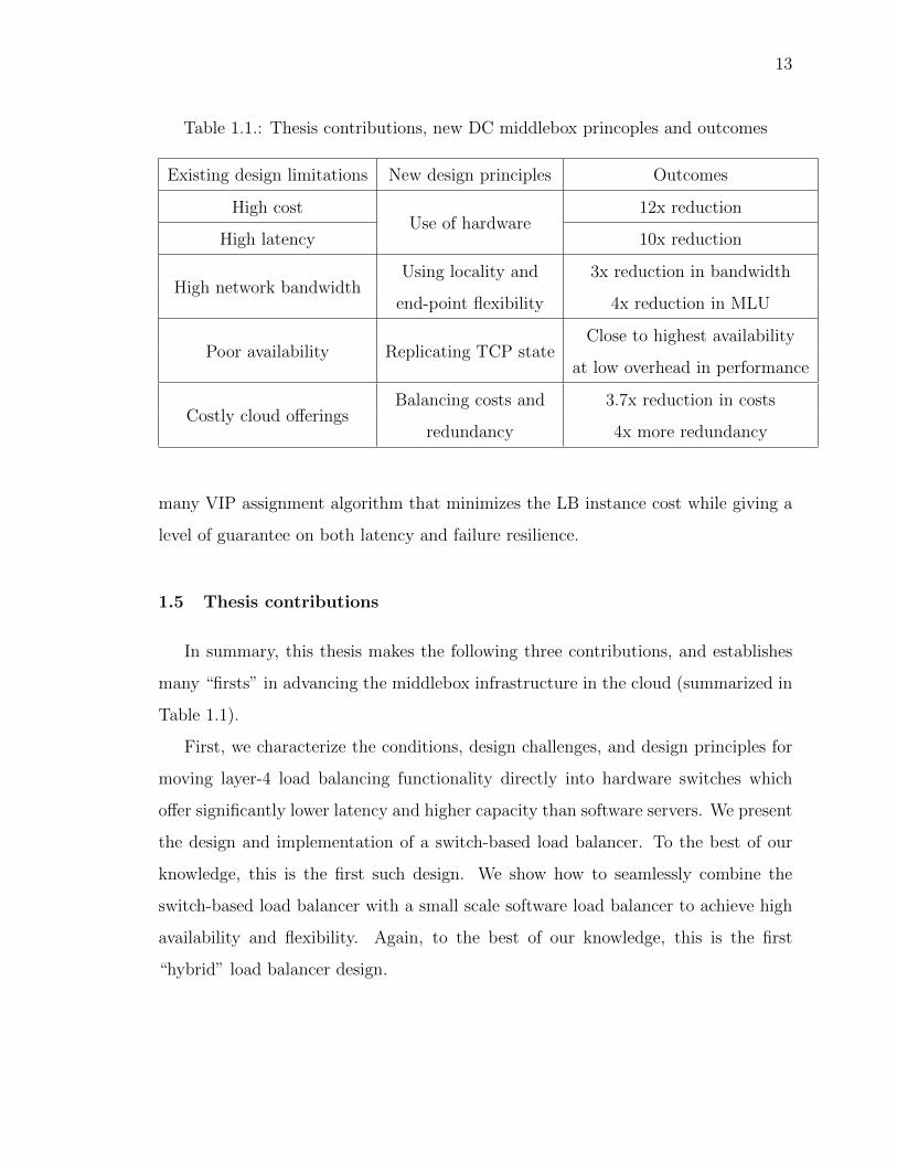
Table 1.1.: Thesis contributions, new DC middlebox princoples and outcomes
Existing design limitations New design principles Outcomes
High costUse of hardware
12x reduction
High latency 10x reduction
High network bandwidthUsing locality and 3x reduction in bandwidth
end-point flexibility 4x reduction in MLU
Poor availability Replicating TCP stateClose to highest availability
at low overhead in performance
Costly cloud offeringsBalancing costs and 3.7x reduction in costs
redundancy 4x more redundancy
many VIP assignment algorithm that minimizes the LB instance cost while giving a
level of guarantee on both latency and failure resilience.
1.5 Thesis contributions
In summary, this thesis makes the following three contributions, and establishes
many “firsts” in advancing the middlebox infrastructure in the cloud (summarized in
Table 1.1).
First, we characterize the conditions, design challenges, and design principles for
moving layer-4 load balancing functionality directly into hardware switches which
offer significantly lower latency and higher capacity than software servers. We present
the design and implementation of a switch-based load balancer. To the best of our
knowledge, this is the first such design. We show how to seamlessly combine the
switch-based load balancer with a small scale software load balancer to achieve high
availability and flexibility. Again, to the best of our knowledge, this is the first
“hybrid” load balancer design.

14
Second, through careful analysis of the LB workload from one of our production
DCs, we show that the existing LB incur high network bandwidth overhead. We
present the design and implementation of Rubik that overcomes these inefficiencies
by exploiting traffic locality and end-point flexibility. To the best of our knowledge,
this is the first LB design that exploits these principles.
Third, we present the design and implementation of a highly available and scalable
L7 load balancer as-a-service for public clouds. We present two key ideas for achieving
high availability of a L7 LB: the design principle of decoupling the flow state from the
LB instances and storing it in a persistent storage, and leveraging the L4 LB service
to enable each L7 LB instance to use the VIP in interacting with both the client
and the server. We present an effective algorithm for calculating VIP-LB instance
assignment to minimize the cost while guaranteeing a given level of LB robustness
and performance.
We believe the design choices and principles proposed in the context of the load
balancer can be easily applied to the broader categories of layer-4 and layer-7 mid-
dleboxes.
Outcomes: We evaluate Duet using a testbed implementation as well as extensive,
large-scale simulations. Our results show that Duet provides 12x more capacity
than the pure software load balancer, at a fraction of the software load balancer cost,
while also reducing the latency inflation by 10x or more. Additionally, we show that
Duet quickly adapts to the network dynamics in the data center including failures.
Through testbed experiments and extensive simulations, we show that Rubik reduces
the DC network bandwidth usage by 3x and the MLU (max. link utilization) by over
4x while providing a high performance and highly available LB.
We evaluate Yoda using a prototype deployed on a 60-VM testbed in Windows
Azure, and large scale simulations. Our results show that the flow state can be
captured, and used on different VMs to maintain the flows, transparently to the
servers and clients, and the overhead of decoupling TCP state is very small (<1
msec). Our simulation results using a one-day trace from production services show

15
that Yoda-as-a-service reduces L7 LB instance cost for the tenants by 3.7x while
providing 4x more redundancy.

16
2. DUET: CLOUD SCALE LOAD BALANCING WITH
HARDWARE AND SOFTWARE
2.1 Background and Motivation
In this chapter, we present a brief background on load balancing functional-
ity in datacenters (DCs), briefly describe a software-only load balancer architecture
(Ananta), and point out its shortcomings.
A DC typically hosts multiple services. Each service is a set of servers that work
together as a single entity. Each server in the set has a unique direct IP (DIP) address.
Each service exposes one or more virtual IP (VIP) outside the service boundary. The
load balancer forwards the traffic destined to a VIP to one of DIPs for that VIP. Even
services within the same DC use VIPs to communicate with each other, since the
indirection provided by VIPs offers several benefits. For example, individual servers
can be maintained or upgraded without affecting dependent services. Management
of firewall rules and ACLs is simplified by expressing them only in terms of VIPs,
instead of DIPs, which are far more numerous and are subject to churn.
The key to the efficient functioning of the indirection architecture is the load
balancer. A typical DC supports thousands of services [2, 6], each of which has at
least one VIP and many DIPs associated with it. All incoming Internet traffic to
these services and most inter-service traffic go through the load balancer. As in [2],
we observe that almost 70% of the total VIP traffic is generated within DC, and the
rest is from the Internet. The load balancer design must not only scale to handle this
workload but also minimize the processing latency. This is because to fulfill a single
user request, multiple back-end services often need to communicate with each other
— traversing the load balancer multiple times. Any extra delay imposed by the load
balancer could have a negative impact on end-to-end user experience. Besides that,
17
0
0.2
0.4
0.6
0.8
1
0.1 1 10C
DF
Latency (msec)
Switch No-load
200k300k
400k450k
(a) End-to-end latency
0
20
40
60
80
100
No-load 200k 300k 400k 450k
CP
U U
tiliz
atio
n(%
)
Traffic (Packets/sec)
(b) CPU Utilization
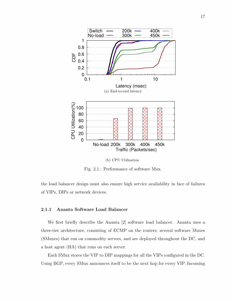
Fig. 2.1.: Performance of software Mux.
the load balancer design must also ensure high service availability in face of failures
of VIPs, DIPs or network devices.
2.1.1 Ananta Software Load Balancer
We first briefly describe the Ananta [2] software load balancer. Ananta uses a
three-tier architecture, consisting of ECMP on the routers, several software Muxes
(SMuxes) that run on commodity servers, and are deployed throughout the DC, and
a host agent (HA) that runs on each server.
Each SMux stores the VIP to DIP mappings for all the VIPs configured in the DC.
Using BGP, every SMux announces itself to be the next hop for every VIP. Incoming

18
packets for a VIP are directed to one of the SMuxes using ECMP. The SMux selects
a DIP for the VIP, and encapsulates the packet, setting the destination address of the
outer IP header to the chosen DIP. At the DIP, the HA decapsulates the incoming
packet, rewrites the destination address and port, and sends it to server. The HA
also intercepts outgoing packets, and rewrites their IP source addresses from the DIP
to the VIP, and forwards the direct server return (DSR).
Ananta can support essentially an unlimited number of VIPs and DIPs, because it
stores this mapping in the large main memory on commodity servers. While a single
SMux in Ananta has limited capacity (due to software processing), Ananta can still
scale to handle large volumes of traffic. First, Ananta deploys numerous SMuxs, and
relies on ECMP to split the incoming traffic among them. Second, DSR ensures that
only the incoming or the VIP traffic goes through the load balancer. Ananta also
includes a mechanism called fast path to enhance scalability. Fast path allows all
inter-service traffic to directly use DIPs, instead of using VIPs. However, this negates
the benefits of the VIP indirection. For example, if fast path is enabled, service ACLs
have to be expressed in terms of DIPs.
In summary, implementing parts of load balancing functionality in software allows
Ananta to be highly scalable and flexible. However, processing packets in software is
also the Achilles heel for Ananta, because it adds latency, and limits the throughput,
as we discuss next.
2.1.2 Limitations of Software Load Balancer
Figure 2.1(a) shows the CDF of the RTTs for the VIP traffic load-balanced by a
production Ananta SMux as traffic to the VIP varies between 0 and 450K packets/sec.
Even at zero load the SMux adds a median latency of 196µsec. The latency variance
is also significant, with the 90th percentile being 1ms. The median RTT (without load
balancer) in our production DCs is 381µsec, so the inflation in latency is significant
for the intra-DC traffic, which accounts for 70% of the total VIP traffic. (For the

19
remaining traffic from the Internet, it is a lesser problem due to larger WAN latencies).
The high latency inflation and high latency variability result from processing the
packets in software. We also see that the added latency and the variance get much
worse at higher load.
The results also illustrate that an individual SMux instance has low capacity. Be-
yond 300K packets/sec, the CPU utilization reaches 100% (Figure 2.1(b)). Thus, for
the hardware SKU used in our DCs, each SMux can handle only up to 300K pack-
ets/sec, which translates to 3.6 Gbps for 1,500-byte packets. At this rate, supporting
15 Tbps VIP traffic for a mid-sized (40K servers) DC would require over 4K SMuxes,
or 10% of the DC size; which is unacceptable1.
2.2 Duet: Core ideas
In the previous section, we saw that while software load balancers are flexible and
scalable, they suffer from low throughput and high latency. In this thesis, we propose
a new design called Duet that offers scalability, high throughput and low latency, at
a small fraction of the software load balancer’s cost.
Duet is based on two novel ideas. First, we leverage idle resources of modern,
commodity data center switches to construct a hardware load balancer. We call this
design Hardware Mux (HMux). HMux offers microsecond latency, and high capacity,
without the need for any additional hardware. However, the HMux design suffers
from certain shortcomings. Thus, our second idea is to combine the HMux with
Ananta-like software Mux (SMux). The combined system is called Duet in which
the SMux acts as a backstop for the HMux.
We now describe the design of HMux. To simplify the description, we will assume
that the DC is not virtualized, i.e., one DIP corresponds to one server. The changes
required to support VMs are described in §2.4.2.
1Newer technologies such as direct-packet IO and RDMA may help match packet processing capacityof the SMux to that of the NIC (10 Gbps), but they may not match packet processing capacity ofthe switch (600 Gbps+) as we explain in § 2.2.1.

20
Forwarding Table Tunneling Table
Index
0
1
2
3
ECMP Table
Encap IP
100.0.0.1
100.0.0.2
110.0.0.1
110.0.0.2
Destination IP
10.0.0.0/32
11.0.0.0/32
HMUX
Data 10.0.0.0 100.0.0.2
VIP DIP
Data 10.0.0.0
VIP
Fig. 2.2.: Storing VIP-DIP mapping on a switch.
2.2.1 HMux
Ananta’s SMux implements two key functions to load balance traffic: (1) for each
VIP, split traffic equally among its DIPs, and (2) use IP-in-IP encapsulation to route
the VIP traffic to the corresponding DIPs. Both of these functions have long been
available on commodity switches, i.e., traffic splitting is supported using ECMP and
IP-in-IP encapsulation is supported using tunneling. However, major switch vendors
have only recently started to provide the APIs for fine-grained control over ECMP
and tunneling functionality.
Our key insight is that by carefully programming the ECMP and tunneling tables
using these new APIs, we can make a commodity switch act as a hardware Mux
(HMux), in addition to its normal functionality. In fact, this can be easily done on
most of the switches used in our DCs today.
Figure 2.2 shows the HMux design. A packet arriving at a switch goes through
a processing pipeline. We focus on three tables used in the pipeline. The packet
matches one entry in the host forwarding table which then points to multiple ECMP
table entries. These ECMP table entries correspond to multiple next hops for the

21
packet2. The actual next hop for the packet is selected by using the hash of the
IP 5-tuple to index into the ECMP table. The tunneling table enables IP-in-IP
encapsulation by storing the information needed to prepare the outer IP header for
a given packet.
To construct HMux, we link the ECMP and tunneling functionalities. Consider
a packet destined for VIP 10.0.0.0 that arrives at the HMux. There are two DIPs
(100.0.0.1 and 100.0.0.2) for this VIP. The host forwarding table indicates that the
first two entries in the ECMP table pertain to this VIP. The ECMP entries indicate
that packets should be encapsulated, and point to appropriate entries in the tunneling
table. The switch encapsulates the packet using IP-in-IP encapsulation, and the
destination address in the outer IP header is set to the DIP address specified in the
tunneling table entry. The packet is then forwarded to the appropriate interface.
Thus, at the expense of some entries in the host forwarding, ECMP and tunneling
tables, we can build a load balancer using commodity switches. In fact, if all the
VIP-to-DIP mappings are stored on every top-of-rack (ToR) switch as well as every
access switch, this HMux design can provide load balancing functionality to all intra-
DC and inter-DC traffic. However, the amount of space available in the three tables
is limited, raising two distinct issues.
Number of VIPs: The first problem is the size of the host forwarding table.
The switches in our DC have 16K entries in the host table. The host table is mostly
empty, because it is used only for routing within a rack. But even the 16K entries
may not be enough to hold all VIPs in a large DC. One way to address this problem
is by using longest prefix match (LPM) forwarding table. However, LPM table is
heavily used for routing within and across DCs, and is not available to be used for
load balancing. We support higher number of VIPs using SMuxes as explained in
§2.2.3.
2The information is split between ECMP group table and ECMP table; we omit such details due tolack of space.
22
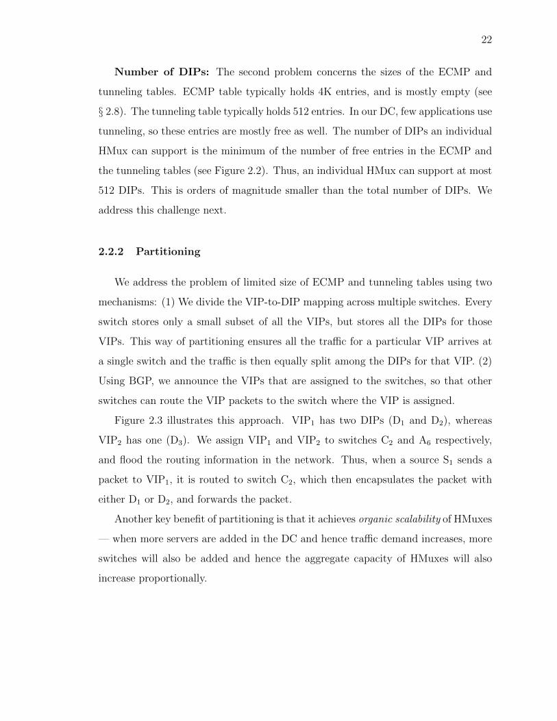
Number of DIPs: The second problem concerns the sizes of the ECMP and
tunneling tables. ECMP table typically holds 4K entries, and is mostly empty (see
§ 2.8). The tunneling table typically holds 512 entries. In our DC, few applications use
tunneling, so these entries are mostly free as well. The number of DIPs an individual
HMux can support is the minimum of the number of free entries in the ECMP and
the tunneling tables (see Figure 2.2). Thus, an individual HMux can support at most
512 DIPs. This is orders of magnitude smaller than the total number of DIPs. We
address this challenge next.
2.2.2 Partitioning
We address the problem of limited size of ECMP and tunneling tables using two
mechanisms: (1) We divide the VIP-to-DIP mapping across multiple switches. Every
switch stores only a small subset of all the VIPs, but stores all the DIPs for those
VIPs. This way of partitioning ensures all the traffic for a particular VIP arrives at
a single switch and the traffic is then equally split among the DIPs for that VIP. (2)
Using BGP, we announce the VIPs that are assigned to the switches, so that other
switches can route the VIP packets to the switch where the VIP is assigned.
Figure 2.3 illustrates this approach. VIP1 has two DIPs (D1 and D2), whereas
VIP2 has one (D3). We assign VIP1 and VIP2 to switches C2 and A6 respectively,
and flood the routing information in the network. Thus, when a source S1 sends a
packet to VIP1, it is routed to switch C2, which then encapsulates the packet with
either D1 or D2, and forwards the packet.
Another key benefit of partitioning is that it achieves organic scalability of HMuxes
— when more servers are added in the DC and hence traffic demand increases, more
switches will also be added and hence the aggregate capacity of HMuxes will also
increase proportionally.

23
C1 C2 C3
A1 A2
C4
A3 A4 A5 A6
Core
Agg
ToR T1 T2 T3 T4 T5 T6
Servers
HMux: VIP1 assigned
S1 D1 S2 D2 D3 SMux
Host Agent
DIP
HMux: VIP2 assigned
SMux: All VIPs assigned
Fig. 2.3.: Duet architecture: VIPs are partitioned across different HMuxes — VIP1
and VIP2 are assigned to HMux C2 and A6. Additionally, SMuxes act as backstop
for all the VIPs. Every server (apart from SMuxes) runs host-agent that decapsulates
the packets and forwards to the DIP. Links marked with solid lines carry VIP traffic,
and links with dotted lines carry DIP traffic.
2.2.3 DUET: HMux + SMux
While partitioning helps increase the number of DIPs HMux can support, that
number still remains limited. The HMux design also lacks the flexibility of SMux,
because VIPs are partitioned and “pinned” to specific HMuxes. This makes it chal-
lenging to achieve high VIP availability during network failures. Although replicating
VIP across a few switches may help improve failure resilience, it is still hard to achieve
the high availability of Ananta because Ananta stores the complete VIP-DIP map-
pings on a large number of SMuxes.
This motivates us to architect Duet— a new load balancer design to fuse the
flexibility of SMux and the high capacity and low latency of HMux.

24
Design
Duet’s goal is to maximize VIP traffic handled using HMux, while using SMux
as a backstop. Thus, besides an HMux on each switch, Duet also deploys a small
number of SMuxes on commodity servers (figure 2.3). The VIPs are partitioned
among HMuxes as described earlier. In addition, each SMux announces all the VIPs.
The routing protocol preferentially routes VIP traffic to HMux, ensuring that VIP
traffic is primarily handled by HMux – thereby providing high capacity and low
latency. In case of HMux failure, traffic is automatically diverted to SMux, thereby
achieving high availability. To ensure that existing connections do not break as a VIP
migrates from HMux to SMux or between HMuxes, all HMuxes and SMuxes use the
same hash function to select DIPs for a given VIP.
The preferential routing to HMux can be achieved in several ways. In our cur-
rent implementation, SMux announces the VIPs in aggregate prefixes, while HMux
announces /32 routes to individual VIPs. Longest prefix matching (LPM) prefers
/32 routes over aggregate prefix routes, and thus directs incoming VIP traffic to
appropriate HMux, unless that HMux is unavailable.
The number of SMuxes needed depends on several factors including the VIP traffic
that cannot be assigned to HMux due to switch memory or link bandwidth limits
(§2.3), the VIP traffic that failovers to SMux due to HMux failure (§2.4.1), and the
VIP traffic that is temporarily assigned to SMux during VIP migration (§2.3.2). We
estimate it based on historical traffic and failure data in DC.
Benefits
The key benefits of Duet are summarized below.
Low cost: Duet does not require any additional hardware – it uses idle resources
on existing switches to provide load balancing functionality. Duet also requires far
fewer SMuxes than Ananta, since SMuxes are used only as a backstop for HMuxes,
and hence carry far less traffic.

25
High capacity and low latency: this is because VIP traffic is primarily handled
by HMux on switch.
High availability: by using SMux as a backstop during failures, Duet enjoys
the same high availability as Ananta.
High limit on number of VIPs: If the number of VIPs exceeds the capacity of
the host forwarding table (16K), the additional VIPs can be hosted on SMux. Traffic
data (Figure 2.15) in our production DCs shows that VIP traffic distribution is highly
skewed – most of the traffic is destined for a small number of “elephant” VIPs which
can be handled by HMux. The remaining traffic to “mice” VIPs can be handled by
SMux.
These benefits can only be realized through careful VIP-switch assignment. The
assignment must take into account both memory and bandwidth constraints on in-
dividual switches, as well as different traffic load of different VIPs. The assignment
must dynamically adapt to changes in traffic patterns and network failures. In the
next two sections, we describe how Duet solves these problems, as well as provides
other load balancing functions.
2.3 VIP Assignment Algorithm
We formalize the VIP-switch assignment problem using the notations listed in
Table 2.1.
Input: The input to the algorithm includes the list of VIPs (V ), the DIPs for
each individual VIP v (dv), and the traffic volume for each VIP. The latter is obtained
from network monitoring. The input also includes the network topology, consisting of
a set of switches (S) and a set of links (E). The switches and links constitute the two
types of resources (R) in the assignment. Each resource instance has a fixed capacity
Ci, i.e., the link bandwidth for a link, and memory capacity that includes residual
ECMP and tunneling table capacity available for Duet on a switch. To absorb the

26
Table 2.1.: Notations used in VIP assignment algorithm.
Notation Explanation
V Set of VIPs
dv Set of DIPs for the v-th VIP
S,E Set of switches and links respectively
R Set of resources (switches and links)
Ci Capacity of i-th resource
ti,s,v v-th VIP’s traffic on i-th link, when it is
assigned to s-th switch
Li,s,v load (additional utilization) on i-th resource
if v-th VIP is assigned to s-th switch
Ui,s,v Cumulative utilization of i-th resource
if v-th VIP is assigned to s-th switch
Ui,v Cumulative utilization of i-th resource
after v VIPs have been assigned
MRUs,v Max. Resource Utilization (MRU)
after v-th VIP is assigned to s-th switch

27
potential transient congestion during VIP migration and network failures, we set the
capacity of a link to be 80% of its bandwidth.
Objective: Find the VIP-switch assignment that maximizes the VIP traffic han-
dled by HMux. As explained earlier, this will improve latency and reduce cost by
cutting the number of SMux needed. We do not attempt to minimize the extra net-
work propagation delay due to indirection because the propagation delay contributes
only less than 30µsec of the 381µsec RTT in our DC.
Constraints: Any VIP-switch assignment should not exceed the capacity of any
of the resources.
The VIP assignment problem is a variant of multi-dimensional bin-packing prob-
lem [7], where the resources are the bins, and the VIPs are the objects. Multi-
dimensional bin-packing problems are NP-hard [7]. Duet approximates it with a
greedy algorithm, which works quite well in our simulations based on real topology
and traffic load of a large production network.
2.3.1 VIP Assignment
We define the notion of maximum resource utilization (MRU). We have two types
of resource – switches and links. MRU represents the maximum utilization across all
switches and links.
Algorithm sketch: We sort a given set of VIPs in decreasing traffic volume, and
attempt to assign them one by one (i.e., VIPs with most traffic are assigned first).
To assign a given VIP, we consider all switches as possible candidates to host the
VIP. Typically, assigning a VIP to different switches will result in different MRU.
We pick the assignment that results in the smallest MRU, breaking ties at random.
If the smallest MRU exceeds 100%, i.e., no assignment can accommodate the load
of the VIP, the algorithm terminates. The remaining VIPs are not assigned to any
switch – their traffic will be handled by the SMuxes. We now describe the process of
calculating MRU.

28
Calculating MRU: We calculate the additional utilization (load) on every re-
source for each potential assignment. If the v-th VIP is assigned to the s-th switch,
the extra utilization on the i-th link is Li,s,v =ti,s,vCi
where traffic ti,s,v is calculated
based on the topology and routing information as the source/DIP locations and traf-
fic load are known for every VIP. Similarly, the extra switch memory utilization is
calculated as Ls,s,v = |dv |Cs
, i.e., the number of DIPs for that VIP over the switch
memory capacity.
The cumulative resource utilization when the v-th VIP is assigned to the s-th
switch is simply the sum of the resource utilization from previously assigned (v-1)
VIPs and the additional utilization due to the v-th VIP:
Ui,s,v = Ui,v−1 + Li,s,v (2.1)
The MRU is calculated as:
MRUs,v = max(Ui,s,v),∀i ∈ R (2.2)
2.3.2 VIP Migration
Due to traffic dynamics, network failures, as well as VIP addition and removal,
a VIP assignment calculated before may become out-of-date. From time to time,
Duet needs to re-calculate the VIP assignment to see if it can handle more VIP
traffic through HMux and/or reduce the MRU. If so, it will migrate VIPs from the
old assignment to the new one.
There are two challenges here: (1) how to calculate the new assignment that
can quickly adapt to network and traffic dynamics without causing too much VIP
reshuffling, which may lead to transient congestion and latency inflation. (2) how to
migrate from the current assignment to new one.
A simple approach would be to calculate the new assignment from scratch using
new inputs (i.e., new traffic, new VIPs etc.), and then migrate the VIPs whose
assignment has changed between the current assignment and the new one. To prevent

29
S2 (60%)
SMux SMux
VIP Traffic
V1 V2 S3
(60%)
S1 (60%)
(a) Initial
S2 (60%)
SMux SMux
VIP Traffic
V1 V2 S3
(60%)
S1 (60%)
(b) Final
S2
SMux SMux
VIP Traffic
V1,V2
S3
V1,V2
S1 (60%)
(c) Through SMux
Fig. 2.4.: Memory deadlock problem during VIP migration. VIPs V1 and V2 both
occupy 60% of switch memory each. The goal of migration is to migrate the VIPs
from assignment in (a) to (b); Duet eliminates this problem by migrating VIPs
through SMuxes, as shown in (c).
routing black holes during VIP migration, we would use make-before-break — i.e.,
a VIP would be announced from the new switch before it is withdrawn from the old
switch. This simple approach is called Non-sticky.
The Non-sticky approach suffers from two problems. First, it may lead to transi-
tional memory deadlock. Figure 2.4 shows a simple example where initially VIP V1
and VIP V2 are assigned to switches S2 and S3, respectively, but swap positions in
the new assignment. Further, either VIP takes 60% of the switch memory. Because of
limited free memory, there is no way to swap the VIPs under the make-before-break
approach. When there are a large number of VIPs to migrate, finding a feasible mi-
gration plan becomes very challenging. Second, even if there was no such deadlock,
calculating a new assignment from scratch may result in a lot of VIP reshuffling, for
potentially small gains.
Duet circumvents transitional memory deadlocks by using SMux as a stepping
stone. We first withdraw the VIPs that need to be moved from their currently as-

30
C1
C2
ToR Agg Core ToR Agg
T1
A1
A2
Container-1
T3
T2 A3
A4
Container-2
Fig. 2.5.: When the VIP assignment changes from ToR T2 to T3, only the links inside
container-2 are affected. As a result, we can first select best ToR in a container based
on the links within container, and then scan over all containers and remaining Core
and Agg switches.
signed switches and let their traffic hit the SMux3. We then announce the VIPs from
their newly assigned switches, and let the traffic move to the new switches. This is
illustrated in Figure 2.4(c) where both VIP’s (V1 and V2) traffic is handled by SMux
during migration.
Because SMux is used as a stepping stone, we want to avoid unnecessary VIP
reshuffling to limit the amount of VIP traffic that is handled by SMux during migra-
tion. Hence, we devise a Sticky version of the greedy VIP assignment algorithm that
takes the current assignment into account. A VIP is moved only if doing so results
in significant reduction in MRU. Let us say that VIP v was assigned to switch sc in
the current assignment, and the MRU would be the lowest if it is assigned to switch
sn in the new assignment. We assign v to sn only if (MRUsc,v −MRUsn,v) is greater
than a threshold. Else we leave v at sc.
Complexity: It is important for Duet to calculate the new assignment quickly
in order to promptly adapt to network dynamics. Since all Li,s,v can be pre-computed,
the complexity to find the minimum MRU (Equation 2.2) for VIP-switch assignment
is O(|V | · |S| · |E|).3Recall that SMux announces all VIPs to serve as a backstop (§2.2.3)
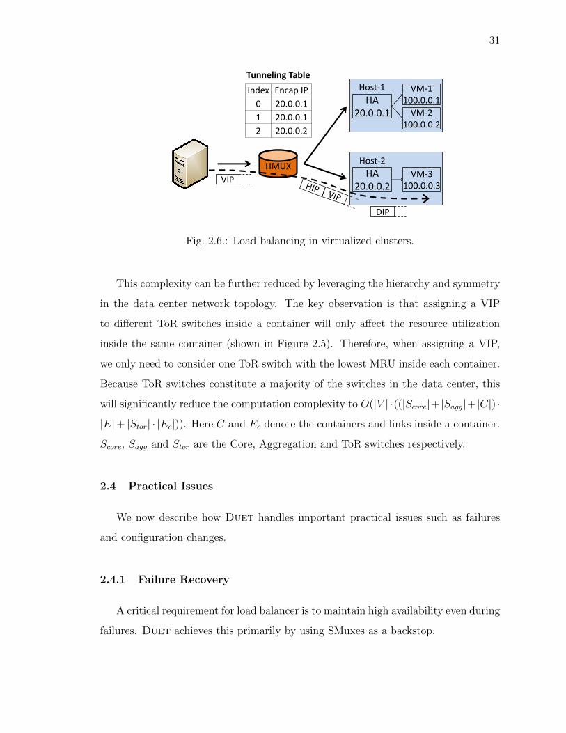
31
VM-1 100.0.0.1
VM-2 100.0.0.2
HA 20.0.0.1
Tunneling Table
Index Encap IP
0 20.0.0.1
1 20.0.0.1
2 20.0.0.2
VM-3 100.0.0.3
HA 20.0.0.2
Host-2
Host-1
VIP
DIP
HMUX
Fig. 2.6.: Load balancing in virtualized clusters.
This complexity can be further reduced by leveraging the hierarchy and symmetry
in the data center network topology. The key observation is that assigning a VIP
to different ToR switches inside a container will only affect the resource utilization
inside the same container (shown in Figure 2.5). Therefore, when assigning a VIP,
we only need to consider one ToR switch with the lowest MRU inside each container.
Because ToR switches constitute a majority of the switches in the data center, this
will significantly reduce the computation complexity to O(|V | ·((|Score|+ |Sagg|+ |C|) ·
|E|+ |Stor| · |Ec|)). Here C and Ec denote the containers and links inside a container.
Score, Sagg and Stor are the Core, Aggregation and ToR switches respectively.
2.4 Practical Issues
We now describe how Duet handles important practical issues such as failures
and configuration changes.
2.4.1 Failure Recovery
A critical requirement for load balancer is to maintain high availability even during
failures. Duet achieves this primarily by using SMuxes as a backstop.

32
HMux (switch) failure: The failure of an HMux is detected by neighboring
switches. The routing entries for the VIPs assigned to the failed HMux are removed
from all other switches via BGP withdraw messages. After routing convergence,
packets for these VIPs are forwarded to SMuxes, since SMuxes announce all VIPs.
All HMux and SMux use the same hash function to select DIPs for a given VIP,
so existing connections are not broken, although they may suffer some packet drops
and/or reorderings during convergence time (<40ms, see §2.6.2). Because in our
production DCs we rarely encounter failures that are more severe than three switch
failures or single container failures at a time, we provision sufficient number of SMuxes
to handle the failover VIP traffic from HMuxes due to those failures.
SMux failure: SMux failure has no impact on VIPs assigned to HMux, and
has only a small impact on VIPs that are assigned only to SMuxes. Switches detect
SMux failure through BGP, and use ECMP to direct traffic to other SMuxes. Existing
connections are not broken, although they may suffer packet drops and/or reorderings
during convergence.
Link failure: If a link failure isolates a switch, it is handled as a switch failure.
Otherwise, it has no impact on availability, although it may cause VIP traffic to
re-route.
DIP failure: The Duet controller monitors DIP health and removes failed DIP
from the set of DIPs for the corresponding VIP. Existing connections to the failed DIP
are necessarily terminated. Existing connections to other DIPs for the corresponding
VIP are still maintained using resilient hashing [8].
2.4.2 Other Functionalities
VIP addition: A new VIP is first added to SMuxes, and then the migration
algorithm decides the right destination.
VIP removal: When a VIP assigned to an HMux is to be withdrawn, the con-
troller removes it both from that HMux and from all SMuxes. VIPs assigned to only

33
HMUX-1
Tunneling Table
Index Encap IP
0 20.0.0.1
1 20.0.0.2
Tunneling Table
Tunneling Table
Index Encap IP
0 DIP-512
. ..
511 DIP-1023
VIP
VIP DIP
HMUX-2
HMUX-3
Index Encap IP
0 DIP-0
. ..
511 DIP-511
20.0.0.1
20.0.0.2
Fig. 2.7.: Large fanout support.
SMuxes need to be removed only from SMuxes. BGP withdraw messages remove the
corresponding routing entries from all switches.
DIP addition: The key issue is to ensure that existing connections are not
remapped if DIPs are added to a VIP. For VIPs assigned to SMuxes, this is easily
achieved, since SMuxes maintain detailed connection state to ensure that existing
connections continue to go to the right DIPs. However, HMuxes can only use a hash
function to map VIPs to DIPs (Figure 2.2). Resilient hashing only ensures correct
mapping in case of DIP removal – not DIP addition. Thus, to add a DIP to a VIP that
is assigned to an HMux, we first remove the VIP from the HMux, causing SMuxes
to take it over, as described earlier. We then add the new DIP, and eventually move
the VIP back to an appropriate HMux.
DIP removal: DIP removal is handled in a manner similar to DIP failure.
Virtualized clusters: In virtualized clusters, the HMux would have to encap-
sulate the packet twice – outer header carries the IP of the host (native) machine,
while inner header carries IP of the VM hosting the DIP. However, today’s switches
cannot encapsulate a single packet twice. So, we use HA in tandem with HMux, as
shown in Figure 2.6. The HMux encapsulates the packet with the IP of the host

34
machine (HIP) that is hosting the DIP. The HA on the DIP decapsulates the packet
and forwards it to the right DIP based on the VIP. If a host has multiple DIPs, the
ECMP and tunneling table on the HMux holds multiple entries for that HIP (HIP
20.0.0.1 in Figure 2.6) to ensure equal splitting. At the host, the HA selects the DIP
by hashing the 5-tuple.
Heterogeneity among servers: When the DIPs for a given VIP have different
processing power, we can proportionally split the traffic using WCMP (Weighted
Cost Multi-Path) where faster DIPs are assigned larger weights. WCMP can be
easily implemented on commodity switches.
VIPs with large fanout: Typically the capacity of the tunneling table on a
single-chip switch is 512. To support a VIP that has more than 512 DIPs, we use
indirection, as shown in Figure 2.7. We divide the DIPs into multiple partitions, each
with at most 512 entries. We assign a single transient IP (TIP) for each partition.
As a VIP, a TIP is a routable IP, and is assigned to a switch. When assigning a
VIP to an HMux, we store the TIPs (as opposed to DIPs) in the tunneling table
(Figure 2.7). When a packet for such a VIP is received at the HMux, the HMux
encapsulates the packet with one of the TIPs and forwards it to the switch to which
the TIP is assigned. That switch decapsulates the TIP header and re-encapsulates
the packet with one of the DIPs, and forwards it. The latency inflation is negligible,
as commodity switches are capable of decapsulating and re-encapsulating a packet at
line rate. This allows us to support up to 512 ∗ 512 = 262, 144 DIPs for a single VIP,
albeit with small extra propagation delay4.
Port-based load balancing: A VIP can have one set of DIPs for the HTTP
port and another for the FTP port. Duet supports this using the tunneling table and
ACL rules. ACL (Access Control) Rules are similar to OpenFlow rules, but currently
support a wider range of fields. We store the DIPs for different destination ports at
different indices in the tunneling table (Figure 2.8). The ACL rules, match on the IP
4The VIP assignment algorithm also needs some changes to handle TIPs. We omit details due tolack of space.

35
ACL Table Tunneling Table Index
0
1
2
3
ECMP Table Encap IP
100.0.0.1
100.0.0.2
110.0.0.1
110.0.0.2
Destination IP Port 10.0.0.0/32 HTTP 10.0.0.0/32 FTP
Fig. 2.8.: Port-based load balancing.
destination and destination port fields, and the action is forwarding the packet to the
corresponding tunneling table entry. Typically the number of ACL rules supported
is larger than the tunneling table size, so it is not a bottleneck.
SNAT: Source NAT (SNAT) support is needed for DIPs to establish outgoing
connections5. Ananta supports SNAT by maintaining state on SMuxes [2]. However,
as discussed earlier, switches cannot maintain such connection state. Instead, Duet
supports SNAT by sharing the hash function used by HMux with the host agent (HA).
Like Ananta, Duet assigns disjoint port ranges to the DIPs, but unlike Ananta, the
HA on the DIP does not randomly choose an unused port number. Instead, it selects
a port such that the hash of the 5-tuple would correctly match the ECMP table entry
on HMux. The HA can do this easily since it knows the hash function used by HMux.
Note that the HA needs to do this only during establishment (i.e., first packet) of
outgoing connections. If an HA runs out of available ports, it receives another set
from the Duet controller.
2.5 Implementation
In this section, we briefly discuss the implementation of the key components in
Duet: (1) Duet Controller, (2) Host Agent, and (3) Switch Agent, and (4) SMux,
as shown in Figure 2.9.
5Outgoing packets on established connections use DSR.

36
Duet Engine
Assignment Updater
Datacenter Monitoring
VIP Settings
VIP-switch assignment
Duet Controller
Operator
Host Agent Decapsulation Traffic metering
SMux Encapsulation VIP-DIP reconfiguration Route announcement
Switch Agent Encap + Decap VIP-DIP reconfiguration Route announcement
VIP-DIP Mapping DIP health Traffic
Topology
Fig. 2.9.: Components in Duet implementation.
Duet Controller: The controller is the heart of Duet. It performs three key
functions: (1) Datacenter monitoring: It gathers the topology and traffic information
from the underlying network. Additionally, it receives the VIP health status period-
ically from the host agents. (2) Duet Engine: It receives the VIP-to-DIP mapping
from the network operator and the topology and traffic information from the DC-
monitoring module, and performs the VIP-switch assignment as described in § 2.3.
(3) Assignment Updater: It takes the VIP-switch assignment from the Duet engine
and translates it into rules based on the switch agent interface. All these modules
communicate with each other using RESTful APIs.
Switch Agent: The switch agent runs on every switch. It uses vendor-specific
APIs to program the ECMP and tunneling tables, and provides RESTful APIs which
are used by the assignment updater to add/remove VIP-DIP mapping. On every VIP
change, the switch agent fires touting updates over BGP.
Host Agent and SMux: The host agent and SMux implementation are the
same as in Ananta. The host agent primarily performs packet decapsulation, SNAT
and DIP health monitoring. Additionally, the host agents perform traffic metering
and report the statistics to the Duet controller.
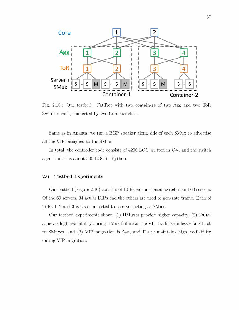
37
Agg
ToR
Server + SMux
2 1 Core
Container-1
2
2
1
S M S …
1
S M S …
4
4
3
S S …
3
S M S …
Container-2
Fig. 2.10.: Our testbed. FatTree with two containers of two Agg and two ToR
Switches each, connected by two Core switches.
Same as in Ananta, we run a BGP speaker along side of each SMux to advertise
all the VIPs assigned to the SMux.
In total, the controller code consists of 4200 LOC written in C#, and the switch
agent code has about 300 LOC in Python.
2.6 Testbed Experiments
Our testbed (Figure 2.10) consists of 10 Broadcom-based switches and 60 servers.
Of the 60 servers, 34 act as DIPs and the others are used to generate traffic. Each of
ToRs 1, 2 and 3 is also connected to a server acting as SMux.
Our testbed experiments show: (1) HMuxes provide higher capacity, (2) Duet
achieves high availability during HMux failure as the VIP traffic seamlessly falls back
to SMuxes, and (3) VIP migration is fast, and Duet maintains high availability
during VIP migration.

38
0
10
20
30
0 100 200 300
La
ten
cy (
mse
c)
Time (sec)
SMux (600k) SMux (1.2M) HMux (1.2M)
Fig. 2.11.: HMux has higher capacity.
2.6.1 HMux Capacity
If the load balancer instances have low capacity, packet queues will start building
up, and traffic will experience high latency. This experiment illustrates that individual
HMuxes instances (i.e., a switch) have significantly higher capacity than individual
SMux instances.
The experiment uses 11 VIPs, each with 2 DIPs. We send UDP traffic to 10 of
the VIPs, leaving the 11th VIP unloaded.
The experiment has three steps. (1) All 11 VIPs are assigned to the SMuxes, and
we generate a total traffic of 600K packets per second to the 10 VIPs (60K per VIP).
Since each VIP is announced from every SMux, the traffic is split evenly between all
SMuxes, and each SMux is handling 200K packets per second. (2) At time 100 sec,
we increase the traffic to 1.2M packets per second, so each SMux is handling 400K
packets per second. (3) Finally, at time 200 sec, we switch all VIPs to a single HMux
hosted on ToR 1.
The metric of interest is the latency to the unloaded VIP, measured using pings
sent every 3ms. We measure the latency to the unloaded VIP so that the latency
only reflects the delay suffered at the SMux or HMux – the VIP or the DIP itself is
not the bottleneck. The results shown in Figure 2.11.

39
0
1
0 50 100 150 200
Time (msec)
VIP1
0
1L
ate
ncy (
mse
c)
VIP2
0
1Tfail TrecoverVIP3
VIP on HMux VIP on SMux
Fig. 2.12.: VIP availability during failure.
We see that until time 100 sec, the latency is mostly below 1ms, with a few
outliers. This is because each SMux is handling only 200K packets per second, which
is well within its capacity (300K packets per second – see §2.1), and thus there is no
significant queue buildup. At time 100, the latency jumps up – now each SMux is
handling 400K packets per second, which is well beyond its ability. Finally, at time
200 sec, when all VIPs are on a single HMux, the latency goes down to 1ms again.
This shows that a single HMux instance has higher capacity than at least 3 SMux
instances.
In fact, since HMux processes all packets in the data plane of the switch, it can
handle packets at line rate, and no queue buildup will occur till we exceed the link
capacity (10Gbps in this experiment).
2.6.2 HMux Failure Mitigation
One of the most important benefits of using the SMux as a backstop is automatic
failure mitigation, as described in §2.4. In this experiment, we investigate the delay

40
involved in failing over from an HMux to an SMux. This delay is important because
during failover, traffic to the VIP gets disrupted.
We assign 7 VIPs across HMuxes and the remaining 3 to the SMuxes. We fail one
switch at 100 msec. We measure the impact of HMux failure on VIP availability by
monitoring the ping latency to all 10 VIPs every 3ms.
Figure 2.12 shows the ping latency for three VIPs: (1) One on the failed HMux
(VIP3), (2) One on a healthy HMux (VIP2), and (3) One on an SMux (VIP1), re-
spectively.
We make three observations: (1) The traffic to VIP3 falls over to SMux within
38 msec after HMux failure. The delay reflects the time it takes for other switches
to detect the failure, and for the routing to converge. The VIP was not available
during this period, i.e., there is no response to pings. (2) After 38 msec, pings to
VIP3 are successful again. (3) The VIPs assigned to other HMuxes and SMuxes are
not affected; their latency is unchanged during HMux failure. These observations
demonstrate the effectiveness of using SMux as a backstop in the Duet design.
2.6.3 VIP Migration
Recall that we also use SMux as a backstop during VIP migration. We now
investigate the delays involved in this process. This delay is important because it
places a lower bound on how quickly Duet can react to network conditions.
In this experiment, we assign 7 VIPs to the HMuxes and the remaining 3 VIPs
to the SMuxes. We migrate a VIP from HMux-to-SMux (VIP1), SMux-to-HMux
(VIP2), and HMux-to-HMux through SMux (VIP3) at different times. We measure
the VIP availability by monitoring the ping latency (every 3ms) to these VIPs, and
we also measure the migration delay.
Figure 2.13 shows the ping latency. At time T1, the controller starts the first
wave of migration by sending the migrate command (migrate to SMuxes) to the cor-
responding switch agents for VIP1 and VIP3. It takes about 450ms for the migration
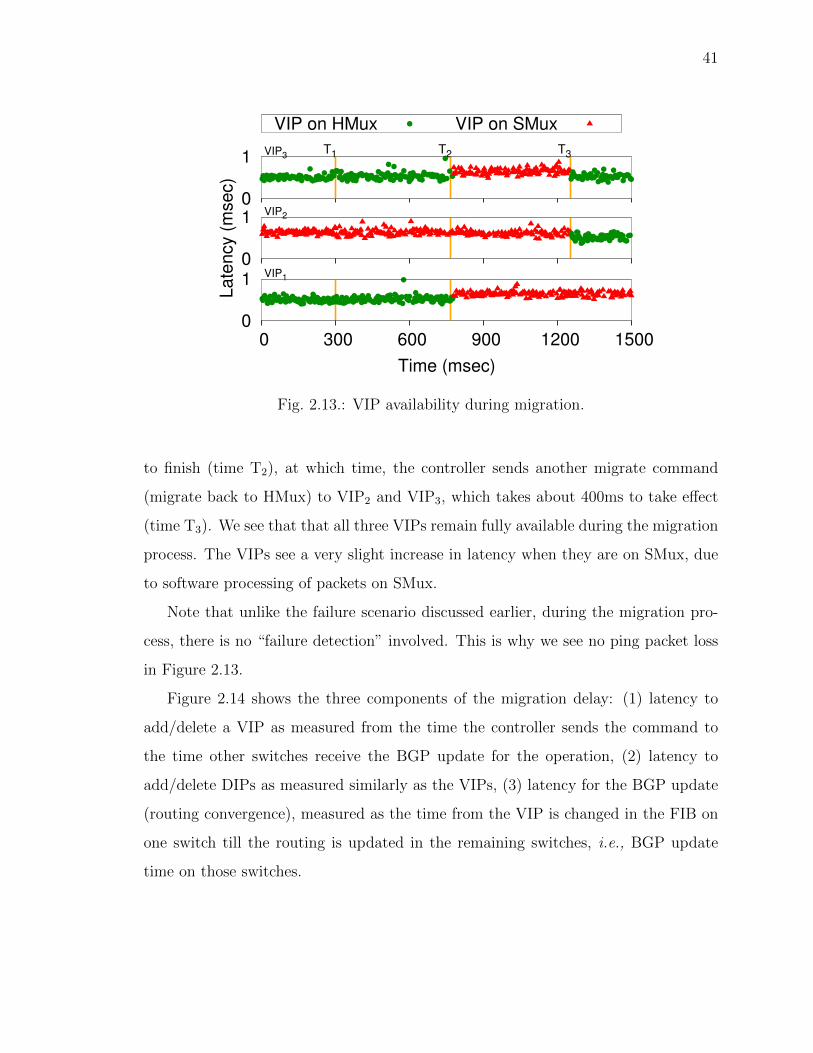
41
0
1
0 300 600 900 1200 1500
Time (msec)
VIP1
0
1L
ate
ncy (
mse
c)
VIP2
0
1T1 T2VIP3
T3
VIP on HMux VIP on SMux
Fig. 2.13.: VIP availability during migration.
to finish (time T2), at which time, the controller sends another migrate command
(migrate back to HMux) to VIP2 and VIP3, which takes about 400ms to take effect
(time T3). We see that that all three VIPs remain fully available during the migration
process. The VIPs see a very slight increase in latency when they are on SMux, due
to software processing of packets on SMux.
Note that unlike the failure scenario discussed earlier, during the migration pro-
cess, there is no “failure detection” involved. This is why we see no ping packet loss
in Figure 2.13.
Figure 2.14 shows the three components of the migration delay: (1) latency to
add/delete a VIP as measured from the time the controller sends the command to
the time other switches receive the BGP update for the operation, (2) latency to
add/delete DIPs as measured similarly as the VIPs, (3) latency for the BGP update
(routing convergence), measured as the time from the VIP is changed in the FIB on
one switch till the routing is updated in the remaining switches, i.e., BGP update
time on those switches.

42
0
100
200
300
400
500
600
Late
ncy (
msec)
Add-DIPsAdd-VIP
VIP-Announce
(a) Add
0
100
200
300
400
500
600
Late
ncy (
msec)
Delete-DIPsDelete-VIP
VIP-Withdraw
(b) Delete
Fig. 2.14.: Latency breakdown.
Almost all (80-90%) of the migration delay is due to the latency of
adding/removing the VIP to/from the FIB. This is because our implementation of
the switch agent is not fully optimized – improving it is part of our future work.
2.7 Evaluation
In this section, we use large-scale simulations to show that: (1) Duet needs
far fewer SMuxes than Ananta to load balance the same amount of VIP traffic; (2)
Despite using fewer SMuxes (and hence being cheaper), Duet incurs low latency
on load balanced traffic; (3) The VIP assignment algorithm is effective; (4) Network
component failures do not cause significant congestion, even though Duet’s VIP
assignment algorithm is oblivious to network component failures; (5) The migration
algorithm is effective.
2.7.1 Simulation Setup
Network: Our simulated network closely resembles that of a production datacen-
ter, with a FatTree topology connecting 50k servers connected to 1600 ToRs located
in 40 containers. Each container has 40 ToRs and 4 Agg switches, and the 40 contain-

43
0
0.2
0.4
0.6
0.8
1
0 0.2 0.4 0.6 0.8 1
CD
F
Fraction of Total VIPs
BytesPackets
DIPs
Fig. 2.15.: Traffic and DIP distribution.
ers are connected with 40 Core switches. The link and switch memory capacity were
set with values observed in production datacenters: routing table and tunneling table
sizes set to 16k and 512, respectively, and the link capacity set to 10Gbps between
ToR and Agg switches, and 40 Gbps between Agg and Core switches.
Workload: We run the simulations using the traffic trace collected from one of
our production datacenters. The trace consists of 30K VIPs, and the number of DIPs
and the traffic distribution across the VIPs are shown in Figure 2.15. We divide
the 3-hour trace into 10-minute intervals, and calculate the VIP assignment in each
interval, based on the traffic demand matrix (the number of bytes sent and received
between all sources and destinations), the topology and the forwarding tables.
2.7.2 SMux Reduction
We first compare the number of SMuxes needed in Duet and Ananta to load-
balance same amount of traffic in the datacenter.
We calculate the number of SMuxes needed by Ananta such that no SMux receives
traffic exceeding its capacity. We consider two SMux capacities: 3.6Gbps, as observed
on the production SMuxes (§2.1), and 10Gbps, assuming the CPU will not be a
bottleneck.

44
1
10
100
1000
10000
1.25 2.5 5 10Nu
mb
er
of
SM
uxe
s
Traffic (Tbps)
Duet(10G)Duet
Ananta(10G)Ananta
Fig. 2.16.: Number of SMuxes used in Duet and Ananta.
The number of SMuxes needed for Duet depends on the capacity of SMux, the
traffic generated by VIPs that could not be assigned to HMuxes, and specifics of
failure model, and migration probabilities (§2.2.3). In this experiment, we assign the
VIPs to HMuxes using the algorithm described in §2.3, which tries to assign as many
VIPs to HMuxes as it can, subject to switch memory and link bandwidth constraints.
We have specified the memory and bandwidth details earlier.
Based on failure scenarios in [9,10], we provision the number of SMuxes to handle
the maximum traffic under either (1) entire container failure, or (2) three random
switch failures. For example, if an entire container fails, the total traffic T to all the
VIPs assigned to the switches inside need to fail over to SMuxes. Thus the number
of SMuxes needed is TCsmux
where Csmux is SMux capacity.
We ignore migration – it is covered in §2.7.6.
Figure 2.16 shows that Duet requires far fewer SMuxes compared to Ananta at all
traffic rates. Note the log scale on Y axis. For all the traffic rates, Duet was able to
assign 16k VIPs to the HMuxes (routing table limit). Overall, compared to Ananta,
Duet requires 12-24x times fewer SMuxes when the SMux capacity is 3.6 Gbps and
8-12x times fewer SMuxes when the SMux capacity is 10Gbps, across different traffic
loads.
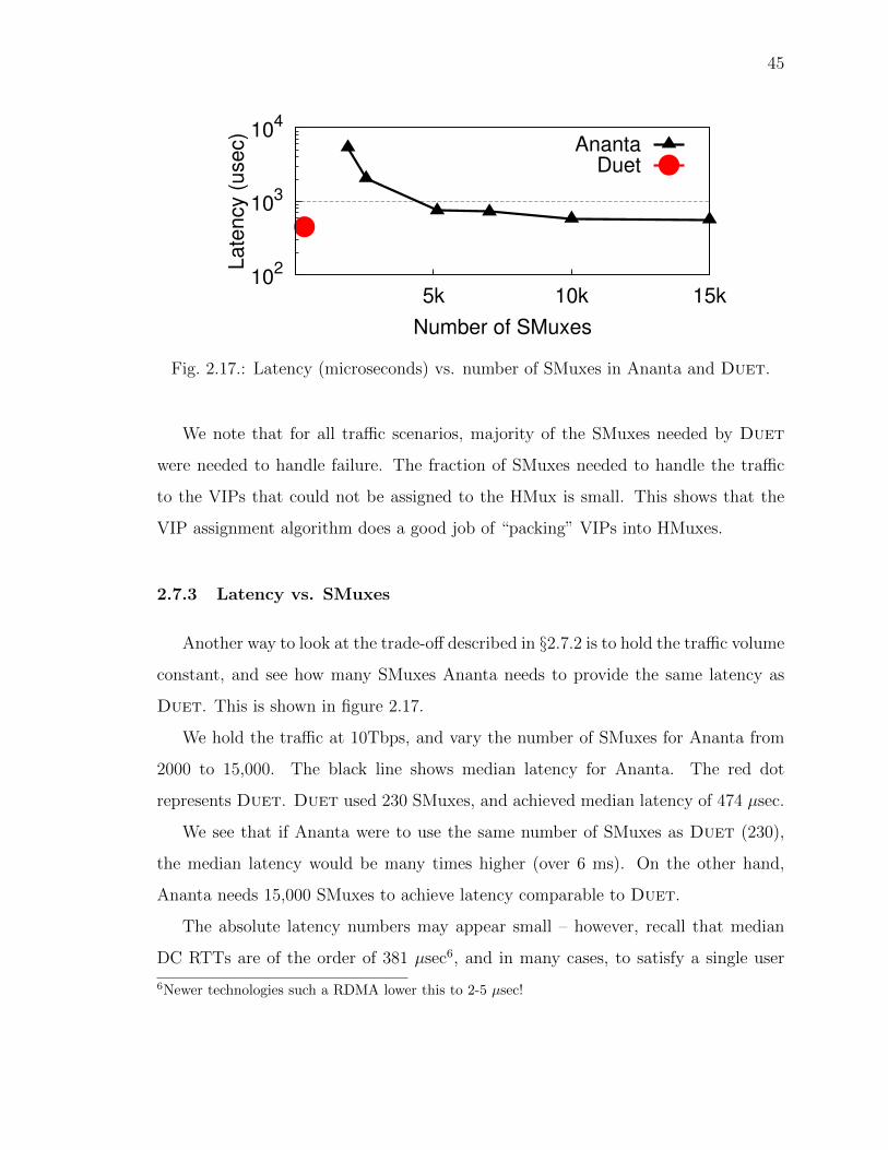
45
102
103
104
5k 10k 15k
La
ten
cy (
use
c)
Number of SMuxes
AnantaDuet
Fig. 2.17.: Latency (microseconds) vs. number of SMuxes in Ananta and Duet.
We note that for all traffic scenarios, majority of the SMuxes needed by Duet
were needed to handle failure. The fraction of SMuxes needed to handle the traffic
to the VIPs that could not be assigned to the HMux is small. This shows that the
VIP assignment algorithm does a good job of “packing” VIPs into HMuxes.
2.7.3 Latency vs. SMuxes
Another way to look at the trade-off described in §2.7.2 is to hold the traffic volume
constant, and see how many SMuxes Ananta needs to provide the same latency as
Duet. This is shown in figure 2.17.
We hold the traffic at 10Tbps, and vary the number of SMuxes for Ananta from
2000 to 15,000. The black line shows median latency for Ananta. The red dot
represents Duet. Duet used 230 SMuxes, and achieved median latency of 474 µsec.
We see that if Ananta were to use the same number of SMuxes as Duet (230),
the median latency would be many times higher (over 6 ms). On the other hand,
Ananta needs 15,000 SMuxes to achieve latency comparable to Duet.
The absolute latency numbers may appear small – however, recall that median
DC RTTs are of the order of 381 µsec6, and in many cases, to satisfy a single user
6Newer technologies such a RDMA lower this to 2-5 µsec!
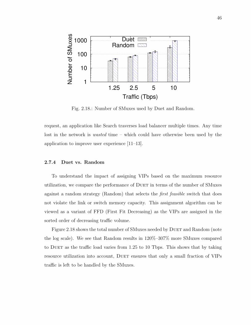
46
1
10
100
1000
1.25 2.5 5 10
Nu
mb
er
of
SM
uxe
s
Traffic (Tbps)
DuetRandom
Fig. 2.18.: Number of SMuxes used by Duet and Random.
request, an application like Search traverses load balancer multiple times. Any time
lost in the network is wasted time – which could have otherwise been used by the
application to improve user experience [11–13].
2.7.4 Duet vs. Random
To understand the impact of assigning VIPs based on the maximum resource
utilization, we compare the performance of Duet in terms of the number of SMuxes
against a random strategy (Random) that selects the first feasible switch that does
not violate the link or switch memory capacity. This assignment algorithm can be
viewed as a variant of FFD (First Fit Decreasing) as the VIPs are assigned in the
sorted order of decreasing traffic volume.
Figure 2.18 shows the total number of SMuxes needed by Duet and Random (note
the log scale). We see that Random results in 120%–307% more SMuxes compared
to Duet as the traffic load varies from 1.25 to 10 Tbps. This shows that by taking
resource utilization into account, Duet ensures that only a small fraction of VIPs
traffic is left to be handled by the SMuxes.

47
0
0.2
0.4
0.6
0.8
1
1.2
1.25 2.5 5 10
Ma
x.
Lin
k U
tiliz
atio
n
Traffic (Tbps)
NormalSwitch-fail
Container-fail
Fig. 2.19.: Impact of failures on max. link utilization.
2.7.5 Impact of Failure
Microbenchmark results in §2.6.2 showed that Duet can handle HMux failures
well – the VIPs fall back to SMux, and the disruption to the VIP traffic is minimal.
In §2.7.2, we considered the number of SMuxes Duet needs to cope with failures.
We now consider the bigger picture – what impact does failures of several switches,
or even a container have on overall traffic?
We consider the same failure model as was used in §2.7.2 – a container or up to 3
switches can fail simultaneously. We evaluate failure resilience of Duet by measuring
the maximum link utilization under these two scenarios: failure of a randomly selected
container, or 3 randomly selected switches.
A random switch failure affects link traffic load in two ways. It causes the traffic
of the VIPs assigned to the failed switch to be shifted to the backstop SMuxes, and
other through traffic to be shifted to the alternative path. A container failure affects
the traffic in more complicated ways: it not only causes all the switches inside to
be disconnected, but also makes all the traffic with sources and destinations (DIPs)
inside to disappear.
Figure 2.19 shows the measured maximum link utilization during the two failure
scenarios in the 10 experiments. We see that as expected, link failures can result

48
in transient congestion. However, the utilization increase of any link in the network
is no more than 16%, and hence is comfortably absorbed by the 20% bandwidth
reservation made in the VIP assignment algorithm. Interestingly, the single container
failure (with 44 switches inside) often results in less congestion than 3-switch failure.
This can be explained by two reasons: (1) any traffic with source and sinks (DIPs)
inside the container has disappeared, and (2) all the rest traffic which have sources
or sinks outside the container are not shifted to other paths as their paths do not go
through any switch inside the container.
2.7.6 VIP Migration
In this section, we evaluate the effectiveness of Duet’s VIP migration algorithm,
Sticky (§2.3.2). We set the threshold to be δ = 0.05, i.e., a VIP will migrate to a new
assignment only if doing so reduces the MRU by 5%.
We compare Sticky with Non-sticky, which calculates the new assignment from
scratch based on current traffic matrix (§2.3.1), but migrates all the VIPs at the same
time through SMuxes to avoid the memory deadlock problem. We evaluate these two
schemes by re-running the 3-hour traffic trace, where we reassign and migrate the VIPs
for Sticky and Non-sticky every 10 minutes. The total VIP traffic varies between 6.2
to 7.1 Tbps in this trace.
Effectiveness: We first compare the portion of total traffic that are handled
by the HMuxes under the two assignment schemes – the larger the portion, the
more effective the assignment algorithm. Here, we also compare Sticky and Non-
sticky against One-time algorithm, which assigns the VIPs at time 0 sec, and never
change it. Figure 2.20(a) shows the results over the duration of the trace. First, as
expected, while the portion of traffic handled by HMuxes started out the same, the
initial assignment which is used by One-time throughout the trace, gradually loses its
effectiveness, and results in only 60-89% (average 75.2%) of the total being handled
by HMuxes. In contrast, Sticky and Non-sticky handle 86-99.9% (average 95.3%) of

49
0
50
100
0 30 60 90 120 150 180
% T
raffic
on H
Mux
Time (min)
Duet One-time
(a) Traffic load-balanced by HMux
0
50
100
0 30 60 90 120 150 180
% m
igra
ted tra
ffic
Time (min)
Non-sticky Sticky
(b) Traffic shuffled during migration
1
10
100
1000
10000
1.25 2.5 5 10
Num
ber
of S
Muxes
Traffic (Tbps)
No-migrationSticky
Non-stickyAnanta
(c) Number of SMux
Fig. 2.20.: Effectiveness of different migration algorithms.
50
the traffic in HMuxes, from continuously adapting to the traffic dynamics. Second,
even though Sticky only migrates VIPs that reduce the MRU by at least 5%, it is as
effective as Non-sticky in maximizing the traffic assigned to HMuxes. In particular,
it handles 86-99.7% traffic (average 95.1%) in HMuxes, which is almost identical to
the 87-99.9% traffic (average 95.67%) handled by HMuxes under Non-sticky.
Traffic shuffled: Next, we compare the fraction of the total VIP traffic migrated
under Sticky and Non-sticky– the less traffic are migrated, the fewer SMuxes need to
be reserved as stepping stone. Figure 2.20(b) shows that migration using Non-sticky
results in reshuffling almost 25-46% (average 37.4%) of the total VIP traffic each
time throughout the trace duration, compared to only 0.7-4.4% (average 3.5%) under
Sticky. Such a drastic reduction in the traffic shuffled under Sticky is attributed to
its simple filtering scheme: a VIP is only migrated if it improves the MRU by 5%.
Number of SMuxes: Figure 2.20(c) shows the number of SMuxes needed by
Sticky and Non-sticky. Additionally, we also calculate the SMuxes needed without
migration (marked as No-migration) as well as number of SMuxes needed in Ananta
considering the SMux capacity to 3.6Gbps. The number of SMuxes needed in Sticky
and Non-sticky is calculated as maximum of SMuxes needed for VIP traffic, failure
and transition traffic. It can be seen that, Non-sticky always requires more SMuxes
compared to No-migration and Sticky, showing that Sticky does not increase the
number of SMuxes to handle the traffic during migration.
2.8 Discussion
Why are there empty entries in switch tables? Duet uses empty entries
in the host table, ECMP table, and tunneling table in switches to implement HMux.
Several reasons contribute to the abundance of such free resources in our production
datacenter. The host table of ToR switches has only a few dozen entries for the hosts
within each rack, and that of the rest of the switches is mostly empty. The ECMP
table of switches is mostly empty because of the hierarchical DC network topology,
51
where each switch has a small number of outgoing links among which all outgoing
traffic is split via ECMP. The tunneling table is mostly free since few online services
use encapsulation other than load balancing itself. We acknowledge that other DCs
may have a different setup, but we believe that our design will be applicable in
common cases.
VIP assignment: While the greedy VIP assignment algorithm described in §2.3
works well in our scenarios, we believe that it can be improved. The VIP assignment
problem resembles bin packing problem, which has many sophisticated solutions. We
plan to study them in future. Also, while we consider VIPs in order of traffic, other
orderings are possible (e.g., consider VIPs with latency sensitive traffic first).
Failover and Migration: Duet relies on SMuxes to simplify failover and mi-
gration. As hinted in §2.2.3, it may be possible to handle failover and migration by
replicating VIP entries in multiple HMuxes. We continue to investigate this approach,
although our initial exploration shows that the resulting design is far more complex
than our current design.
2.9 Related Work
To the best of our knowledge, Duet is a novel approach to building a performant,
low-cost, organically scalable load balancer. We are not aware of any load balancing
architecture that fuses switch-based load balancer with the software load balancers.
However, there has been much work on load balancers, and we briefly review it here.
Load balancer: Traditional hardware load balancers [14, 15] are expensive and
typically only provide 1+1 availability. Duet is much more cost effective, and pro-
vides enhanced availability by using SMuxes as a backstop. Importantly, compared to
traditional load balancers, Duet gives us control over very important vantage point
in our cloud infrastructure.
We have already discussed Ananta [2] software load balancer extensively. Other
software-based load balancers [16–18] are also available, but they lack the scalability

52
and availability of Ananta, as shown in [2]. Embrane [19] promises scalability, but
suffers from the same fundamental limitations of the software load balancer.
OpenFlow based load balancer: Two recent proposals focus on using Open-
Flow switches for load balancing. In [20], authors present a preliminary design for
a load balancing architecture using OpenFlow switches. They focus on minimizing
the number of wildcard rules. The paper, perhaps because it is a preliminary design,
ignores many key issues such as handling switch failures. Plug-n-Serve [21] is another
preliminary design that uses OpenFlow switches to load balance web servers deployed
in unstructured, enterprise networks. Duet is very different from these approaches.
Duet uses a combined hardware and software approach. Duet does not rely on
OpenFlow support. Duet is designed for data center networks, and pays careful at-
tention to handling numerous practical issues including various types of failures and
VIP migration to adapt to network dynamics.
Partitioning OpenFlow rules: Researchers have also proposed using OpenFlow
switches for a variety of other purposes. For example, DIFANE [22] uses some switches
in the data center to cache rules, and act as authoritative switches. While a load
balancing architecture can be built on top of DIFANE, the focus of the paper is very
different from Duet. In vCRIB [23] authors propose to offload some of the traffic
management rules from host agent to ToR switches, as well as to other host agents.
Their goal is to ensure resource-aware and traffic-aware placement of rules. While
vCRIB also faces problems such as managing network dynamics (e.g., VM migration),
their main focus is quite different than Duet.
SDN architecture and middleboxes: Similar to Duet, researchers have lever-
aged SDN architecture in the context of middleboxes to achieve policy enforcement
and verification [24,25], which is again a different goal than Duet.
Improving single server performance: Researchers have substantially im-
proved packet processing capabilities on commodity servers [26, 27], which could po-
tentially improve SMux performance. But, these improvements are unlikely to bridge

53
the differences in packet processing capabilities between HMux and SMux for the load
balancer workload.
Lastly, several algorithms for calculating flow hashes (e.g., resilient hashing [8],
cuckoo-hashing [26]) offer a wide variety of trade-offs. We do not review them here,
although Duet can leverage any advances in this field.
2.10 Summary
Duet is a new distributed hybrid load balancer designed to provide high capacity,
low latency, high availability, and high flexibility at low cost. The Duet design was
motivated by two key observations: (1) software load balancers offer high availability
and high flexibility but suffer high latency and low capacity per load balancer, and (2)
commodity switches have ample spare resources and now also support programma-
bility needed to implement load balancing functionality. The Duet architecture
seamlessly integrates the switch-based load balancer design with a small deployment
of software load balancer. We evaluate Duet using a prototype implementation and
extensive simulations using traces from our production DC. Our evaluation shows
that Duet provides 10x more capacity than a software load balancer, at a fraction
of its cost, while reducing the latency by over 10x, and can quickly adapt to network
dynamics including failures.

54
3. RUBIK: UNLOCKING THE POWER OF LOCALITY
AND END-POINT FLEXIBILITY IN CLOUD SCALE
LOAD BALANCING
3.1 Introduction
Despite the high capacity and low cost benefits in Duet, Duet and other load
balancer designs incur high bandwidth usage of the DC network because of the in-
trinsic nature of traffic redirection. First, even if the traffic source and the DIPs that
handle the traffic are under the same ToR, the traffic first has to be routed to the
Muxes, which may be faraway and elongate the path traveled by the traffic. Second,
in both Ananta and Duet, the Muxes select DIPs for a VIP by hashing the five-tuple
of IP headers, and hence are oblivious to DIP locations. As a result, even if the Mux
and some DIPs are located nearby the source, the traffic can be routed to faraway
DIPs in the DC, again traversing longer paths. Lastly, these designs do not leverage
the server location flexibility in placing the DIPs closer to the sources to shorten
the path. The second problem with the Duet LB design is that the traffic detouring
through core links breaks the full-bisection bandwidth guarantees originally provided
by full-provisioned networks such as Clos and FatTree.
Our evaluation of traffic paths in a production DC network shows that such traf-
fic detour significantly inflates the bandwidth usage of the DC network. This high
bandwidth usage not only requires the DC operator to provision high network band-
width which is costly, but also makes the network prone to transient congestion which
affects latency-sensitive services.
In this chapter, we first quantify the network bandwidth overhead in Duet and
other prior load balancer designs. We propose Rubik, a new LB that significantly
reduces the high bandwidth usage by LB. Like Duet, Rubik uses a hybrid LB design

55
consisting of the HMuxes and SMuxes, and aims to maximize the VIP traffic handled
by HMuxes to reduce the LB costs. While doing that, Rubik reduces the bandwidth
usage using two synergistic design principles. First, Rubik exploits the locality, i.e.,
it tries to load balance VIP traffic generated within individual ToRs across the DIPs
residing in the same ToRs. This reduces the total traffic entering the core network.
Second, Rubik exploits end-point flexibility, i.e., it tries to place the DIPs for a VIP
in the same ToRs as the sources generating the VIP traffic.
3.2 Background
In this section, we briefly explain LB workloads and quantify their impact on the
network bandwidth usage.
3.2.1 VIP traffic
In the Azure DC, 18-59% (average 44%) of the total traffic is VIP traffic which
requires load balancing [2]. This is because services within the same DC use VIPs to
communicate with each other to use the benefits provided by the VIP indirection. As
a result, all incoming Internet traffic to these services (close to 30% of the total VIP
traffic in our DC) as well as a large amount of inter-service traffic (accounting for 70%
of the total VIP traffic) go through the LB. For a DC with 40k servers, LB is expected
to handle 44 Tbps of traffic at full network utilization [2]. Such indirection of large
traffic volume requires a scalable, high performance (low latency, high capacity) and
highly available LB.
3.2.2 Workload Characteristics
We make the following observations about the VIP traffic being load balanced in
our production DC, by analyzing a 24-hour traffic trace, for 30K VIPs.

56
0
0.2
0.4
0.6
0.8
1
0 0.2 0.4 0.6 0.8 1
CD
F
Number of ToRs(Normalized to total number of ToRs)
SourcesDIPs
Fig. 3.1.: Distribution of the number of ToRs where the sources and DIPs are located.
0
0.2
0.4
0.6
0.8
1
0 20 40 60 80 100
CD
F
Ratio
AllTop-90
Fig. 3.2.: Ratio of 99th percentile to average traffic volume for each VIP across all
sources.
The traffic sources and DIPs for individual VIPs are scattered over
many ToRs. Fig. 3.1 shows the number of ToRs where the traffic sources and DIPs
for the top 10% VIPs which generate 90% of the total VIP traffic are located. We see
that traffic sources are widely scattered – the number of ToRs generating traffic for
each VIP varies between 0-44.5% of the total ToRs. Also, the number of ToRs where
the DIPs for a VIP are located varies between 0-58% of the total ToRs in the DC.

57
The traffic volume of sources per VIP are highly skewed. We measure
the traffic from all the ToRs for each VIP. Figure 3.2 shows the CDF of the ratio of
the 99th percentile to the median per-ToR traffic volume for each VIP. We see that
the source traffic volume for each VIP is highly skewed – the ratio varies between
1-35 (median 18) for the top VIPs generating 90% of the total traffic. The large
skew happens for multiple reasons, including different numbers of servers, skew in the
popularity of the objects that are served, and locality [28,29].
VIP dependencies: Many large-scale web services are composed of multi-tier
services, each with its own set of VIPs. When the top-level service receives a request,
it spawns multiple requests to the services at the second tier, which in turn send
requests to services at lower tiers. As a result, the VIP traffic exhibit hierarchical
dependencies – the DIPs serving the VIPs at tier i become the traffic sources for the
VIPs at tier (i + 1). We observe that 31.1% VIPs receive traffic from other VIPs.
These VIPs employ 25.1% of the total DIPs and contribute to 27.6% of the total VIP
traffic. The remaining 72.4% VIP traffic comes from the Internet, other DCs, and
other servers in the same DC that are not assigned to any VIPs.
The dependency among the VIPs can be represented in a DAG. The depth of the
DAG observed is similar to the depths reported by Facebook and Amazon [30].
3.3 Motivation
We next assess the impact of the VIP traffic characteristics (§3.2.2) on the DC
network bandwidth usage under the Duet LB. We simulate how Duet handles the VIP
traffic using a 24-hour traffic trace from our production DC on a network topology
that closely resembles our production DC. The topology, workload, and results are
detailed in §3.10. Duet maximizes the total traffic handled by HMuxes, on average
97% in the 24-hour period.

58
0
0.2
0.4
0.6
0.8
1
Duet Direct Closest
Max L
ink
Utiliz
ation (
MLU
)
Tota
l tr
affic
(T
bps)
MLUTraffic
Fig. 3.3.: MLU and total traffic under various LB schemes. Total traffic is measured
across all the DC network links.
Table 3.1.: Path length for different LB designs.
Duet Direct Closest
5.47 3.94 1.78
High link utilization Figure 3.3 shows the MLU and total traffic in the DC net-
work1. While Duet is able to handle 97% of the total VIP traffic by leveraging
HMuxes, it also inflates the MLU to 0.98 (or 98%). This high MLU can be explained
by two design decisions of Duet.
First, Duet assigns a VIP only to a single HMux. But the traffic sources and
DIPs for individual VIPs are spread in a large number of ToRs (Figure 3.1). The
diverse location of traffic sources and DIPs per VIP suggests no matter where the
single Mux for a VIP is positioned in the network, it will be far away from most of
the traffic sources and DIPs for that VIP, and hence most VIP traffic will traverse
through the network to reach the HMuxes and then the DIPs, which inflates the path
length between the sources and DIPs.
Table 3.1 shows that the average number of hops between the sources and the DIPs
across all individual VIPs is 5.47 in Duet. Notice that the traffic between two hosts
1Absolute values for “total traffic” are omitted for confidentiality.

59
C1 C2 C3 C4 Core
Agg
ToR
Servers (S) & DIPs(D)
A1 A2
T1
S1
Container 1
S2
T2
A3 A4
T3
S3
Container 2
S4
T4
A5 A6
T5
D1
Container 3
S7
T6
S8 D2 SMux S5 S6
HMux: VIP1 assigned
HMux: VIP2 assigned
Fig. 3.4.: Duet architecture. Links marked with solid and dotted lines carry VIP and
DIP traffic, respectively.
that does not go through the LB would have a maximum of 4 hops (ToR-Agg, Agg-
Core, Core-Agg, Agg-ToR). Thus the average path length of 5.47 in Duet indicates
that most traffic goes through the core links and further experiences some detour in
the DC network. Figure 3.4 shows an example where the VIP-1 traffic originated at
S1 has to travel 6 hops to reach DIP D1 – 3 hops to reach the HMux at switch A3,
and 3 more hops to reach D1.
To dissect the impact of the redirection, we measure the MLU and total traffic
in the DC network in a hypothetical case where the HMuxes are located on a direct
path between the sources and DIPs, labeled as “Direct”. Figure 3.3 shows that in
this case the MLU is reduced to 0.46 (from 0.98 in Duet), and the bandwidth used
is lowered by 1.36x, compared to Duet. Also, the average path length in “Direct”
is lowered to 3.94 (1.38x improvement). This means the redirection design in Duet
inflates the MLU by 2.13x and bandwidth used by 1.36x.
The second cause for the high link utilization is location-oblivious DIP selection in
Duet. The HMux splits the VIP’s traffic by hashing on the 5-tuples in the IP header,
and chooses the DIP based on the hash. Thus, even if there is a DIP located under
the same ToR as the HMux and has the capacity to handle all the local traffic for

60
the VIP, the HMux will spread the local traffic among all DIPs, many of which can
be far away in the DC.
To measure the impact of location-oblivious DIP selection, we measure the MLU
and bandwidth used in a hypothetical case, where the traffic from the individual
sources is routed to the closest DIP and assuming the HMuxes lie on the path. This
mechanism is labeled as “Closest”. Figure 3.3 shows that the MLU is reduced to just
0.08, and the bandwidth used reduces by 3.19x compared to Duet. Also, the average
path length is lowered to just 1.78 hops.
Effective full bisection bandwidth reduced at core Many DC networks have
adopted topologies like FatTree and Clos [31] to achieve full-bisection bandwidth.
Such networks guarantee that there is enough aggregate capacity between Core and
Agg switches as between Agg and ToR switches, and hence the core links will never
become a bottleneck for any traffic between the hosts.
However, traffic indirection can break this assumption, if the HMuxes reside in
Agg or ToR switches. This happens to Duet, as Duet considers all the switches while
assigning VIP-to-DIP mappings. This is illustrated in Figure 3.4. When VIP1 is
assigned to an Agg switch (A3), the traffic from source S1 travels the core links twice
en-route to DIP D1 – first to get to HMux A3, and then to D1. In contrast, direct host-
to-host traffic only has to traverse core links at most once. As a result, the effective
bandwidth in the core links is reduced – in Figure 3.4, the available bandwidth to
container-2 (servers S3-S6) is reduced due to the LB traffic among other containers.
Our evaluation in §3.10.3 shows the traffic overhead in Duet, i.e., the ratio of the
additional traffic due to redirection to the total traffic without redirection is 44% in
core links and 16% in containers. This means the remaining bisection bandwidth
of the Agg-Core links is lower than the remaining bisection bandwidth in the ToR-
Agg links. This breaks the full-bisection guarantee provided by the FatTree or Clos,
which jeopardizes other applications that co-exist in the DC and assume full-bisection
bandwidth is available (e.g., [32, 33]).
61
3.4 Rubik Overview
In the previous section, we saw that the traffic indirection in Duet incurs substan-
tial overhead in the DC network bandwidth usage. In this thesis, we propose a new
LB design, Rubik, that significantly reduces the bandwidth usage in the DC network
while providing low cost, high performance and high availability benefits.
Rubik is based on two key ideas motivated by the observations in the last section.
First, it exploits locality, i.e., it tries to load balance traffic generated in individual
ToRs across the DIPs present in the same ToRs. In this way, a substantial fraction
of the load balanced traffic will not enter the links beyond ToRs which reduces the
DC network bandwidth usage and MLU.
The second key idea of Rubik is to exploit DIP placement flexibility to place
DIPs closer to the sources. In Rubik online services specify the number of DIPs
for individual VIPs, and Rubik decides the location of the servers to be assigned to
individual VIPs. This idea is synergistic with the first idea, as it facilitates exploiting
locality in load balancing within ToRs.
Realizing the two ideas is challenging, because (1) there are a limited number of
servers in each ToR where DIPs can be assigned, (2) switches have limited memory
for storing VIP-to-DIP mappings, (3) a VIP may have traffic sources in more ToRs
than the total number of DIPs for that VIP. In such a case, a DIP cannot be assigned
in every ToR that has traffic sources, (4) dependencies between the VIPs make it
even harder, as the sources to some of the VIPs are not known until DIPs for other
VIPs are placed.
Rubik addresses the above capacity limitations (switch memory and DIPs in
a ToR) using two complimentary ideas. First, Rubik uses a new LB architecture
that splits the VIP-to-DIP mapping for a VIP across multiple HMuxes to enable
efficient use of switch memory while containing local traffic. Second, it employs a
novel algorithm that calculates the most efficient use of switch memory for containing
the most local traffic.

62
3.5 Rubik Architecture
Rubik uses a new LB design that splits the VIP-to-DIP mapping for each VIP
into multiple local and a single residual VIP-to-DIP mappings. This idea is inspired
by the observation that the traffic for individual VIPs is skewed (§3.2.2) – some ToRs
generate more traffic than other ToRs for a given VIP. In Rubik, we assign local
mappings to the ToRs generating large fractions of the traffic and also assign enough
DIPs to handle those traffic. The local mapping for a VIP load balances traffic for that
VIP across the DIPs present under the same ToR (called local DIPs). We then assign
a single residual mapping for that VIP to handle the traffic from all the remaining
ToRs, where no local mapping is assigned.
Effectively, the VIP-to-DIP mapping for a VIP is split across the local and residual
mappings such that a single DIP appears in only one mapping. Assigning a DIP only
once makes the most efficient use of the limited tunneling table space of HMuxes so
the total VIP traffic handled by the HMuxes can be maximized. The assignment
module (§3.6) then calculates the actual assignment that maximizes the VIP traffic
handled locally.
We now explain the Rubik architecture in detail.
Local mapping If some of the sources and DIPs for a VIP already reside in the same
ToR, Rubik exploits this locality by load balancing the source traffic across those local
DIPs. To ensure that the traffic does not flow outside the ToR in detouring through
the HMux, Rubik stores a subset of the VIP-to-DIP mapping, i.e., containing only
the local DIPs, at the ToR itself (e.g., HMux T2 in Fig. 3.5). We denote such a
mapping containing the subset of local DIPs as a local mapping.
Residual mapping For an individual VIP, we assign a single residual mapping
to handle the remaining traffic not handled by the local mappings (called residual
traffic). We pool all the remaining DIPs for a VIP together in a single DIP-set,
called the residual mapping for that VIP (e.g., HMux on C1 and A5 in Fig. 3.5).
The residual mapping for each VIP announces the VIP using BGP so that other
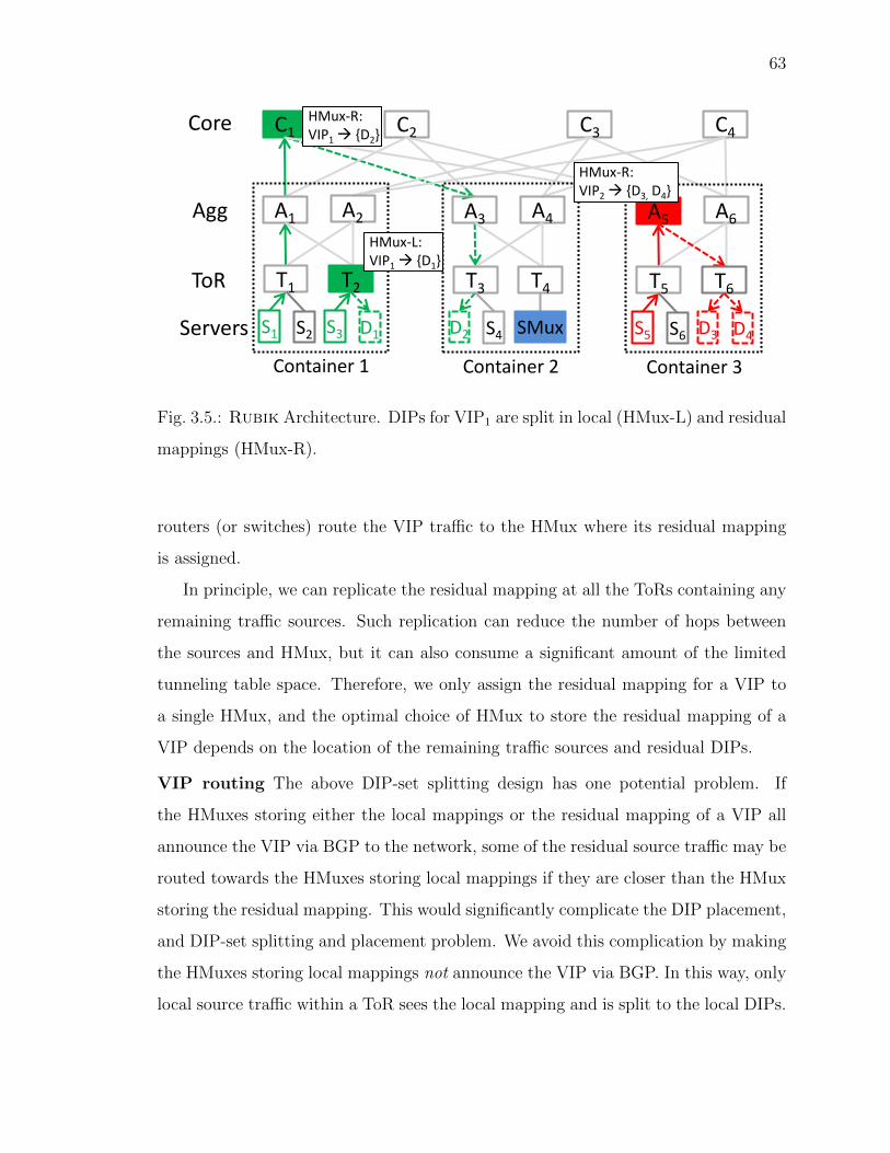
63
C1 C2 C3 C4 Core
Agg
ToR
Servers
A1 A2
T1
S1
Container 1
S2
T2
S3 D1
A3 A4
T3
D2
Container 2
S4
T4
SMux
A5 A6
T5
S5
Container 3
S6
T6
D3 D4
HMux-R: VIP1 {D2}
HMux-L: VIP1 {D1}
HMux-R: VIP2 {D3, D4}
Fig. 3.5.: Rubik Architecture. DIPs for VIP1 are split in local (HMux-L) and residual
mappings (HMux-R).
routers (or switches) route the VIP traffic to the HMux where its residual mapping
is assigned.
In principle, we can replicate the residual mapping at all the ToRs containing any
remaining traffic sources. Such replication can reduce the number of hops between
the sources and HMux, but it can also consume a significant amount of the limited
tunneling table space. Therefore, we only assign the residual mapping for a VIP to
a single HMux, and the optimal choice of HMux to store the residual mapping of a
VIP depends on the location of the remaining traffic sources and residual DIPs.
VIP routing The above DIP-set splitting design has one potential problem. If
the HMuxes storing either the local mappings or the residual mapping of a VIP all
announce the VIP via BGP to the network, some of the residual source traffic may be
routed towards the HMuxes storing local mappings if they are closer than the HMux
storing the residual mapping. This would significantly complicate the DIP placement,
and DIP-set splitting and placement problem. We avoid this complication by making
the HMuxes storing local mappings not announce the VIP via BGP. In this way, only
local source traffic within a ToR sees the local mapping and is split to the local DIPs.

64
SMuxes Because of the limited switch memory, the numbers of VIPs and DIPs
supported by HMuxes remain limited. Current HMuxes can support up to 16K
VIPs [4], and our DC has 30K+ VIPs. Also, it remains challenging to provide high
availability during HMux failures. We address both problems by deploying a small
number of SMuxes as a backstop, to handle the VIP traffic that could not be handled
using HMuxes. We also announce all the VIPs from all SMuxes. We use Longest
prefix matching (LPM) to: (1) preferentially route the VIP traffic to the HMuxes for
the VIPs assigned to both HMuxes and SMuxes, (2) route the traffic to the remaining
VIPs not assigned to HMuxes to the SMuxes.
The use of SMuxes in this way also provides high availability during residual
mapping failure. §3.7 gives details on how Rubik recovers from a variety of failures.
Summary The benefits of this architecture can only be realized by carefully calculat-
ing the DIP placement, and local and residual mappings for individual VIPs subject
to a variety of constraints, which we describe next.
3.6 Joint VIP and DIP Assignment
Rubik’s objective is to maximize the traffic handled by the HMuxes, while maxi-
mizing the traffic handled locally within ToRs. The assignment algorithm determines
for each VIP, (1) the location of its DIPs; (2) the number of DIPs in each ToR in the
local VIP-to-DIP mapping; and (3) the number of DIPs in the residual mapping, and
the HMux assigned to store the mapping.
Rubik needs to calculate this assignment such that the capacity of all resources
(switch tables, links, and servers per ToR) is not be exceeded. Also, Rubik needs
to ensure that it assigns DIPs in the failure domains (i.e., ToRs) specified by the
online services. The placement calculated at a given time may lose effectiveness over
time as the VIP traffic changes, and VIPs and DIPs are added and removed. To
adapt to such cloud dynamics, Rubik reruns the placement algorithm from time to

65
Input: V,M,Nv, fv, S, L, bt,v, Ct,v
Output: xDt,v, xMt,v
topological sort(V in DAG)
for l = 1, depth of DAG do
local mapping and dip placement(VIPs in DAG level(l))
end
residual mapping placement()Algorithm 1: Rubik Assignment Algorithm
time. While calculating a new assignment, Rubik has to ensure that the number of
machines migrated from the old assignment is under the limit.
The assignment problem is a variant of the bin-packing problem (NP-hard [7]),
where the resources are the bins, and the VIPs are the objects. It is further com-
pounded because the VIP traffic exhibits hierarchical dependencies (§3.2.2).
To reduce the complexity, Rubik decomposes the joint assignment problem into
two independent modules, (1) DIP and local mapping placement, (2) residual mapping
placement, as shown in Algorithm 1. The first module places the DIPs and local
mappings for all the VIPs to maximize the total traffic load-balanced locally on
individual ToRs. We calculate DIP and local mapping simultaneously, because the
problem of DIP and local mapping placement are intertwined, as the traffic for a VIP
is contained within a ToR only if the ToR has (1) enough DIPs to handle the traffic,
and (2) enough memory to store the corresponding VIP-to-DIP mapping.
Since the VIP traffic exhibits hierarchical dependencies (§3.2.2), we create a DAG
that captures the traffic flow and hence the dependency between the VIPs, and then
perform a topological sort on the DAG to divide the VIPs into different levels. We
then place the DIPs and local mappings for the VIPs level-by-level (lines 3:6 in Algo.
1). As we place DIPs for VIPs in one level, the sources in the next level become
known.
The second module places the residual mappings of all the VIPs to maximize
the total traffic handled by HMuxes. The residual mapping placement subproblem

66
Table 3.2.: Notations used in the algorithm.
Notation Explanation
Input
S,L, V Sets of switches, links, and VIPs
Mt # servers under t-th ToR
Ts Table capacity of s-th switch
Le Link traffic capacity of link e
Nv, fv #DIPs and failure-domain for v-th VIP
bt,v Traffic sent to v-th VIP from t-th ToR
Ct,v Traffic capacity of server in t-th ToR when
assigned to v-th VIP
Variables
xDt,v Number of servers (DIPs) in t-th ToR
assigned to v-th VIP
xMt,v Number of table entries in t-th ToR
assigned to v-th VIP
remains NP-hard. But, the residual VIP traffic is typically only a small portion of
the total traffic and hence we can apply heuristics to solve it without significantly
affecting the quality of the overall solution (line 7).
3.6.1 DIP and Local Mapping Placement
The first module places the DIPs and the local mappings of all the VIPs for which
the sources are known such that the total VIP traffic load balanced within the ToRs
is maximized. We formulate the joint DIP and local mapping placement problem as
ILP using notations shown in Table 3.2 as follows.
Input: The input includes (1) the network topology and resource information (ca-
pacity of switch tables, links, and servers in the ToRs), (2) for every VIP in current

67
level, the number of DIPs and number of failure domain and traffic, and (3) max.
number of DIPs to migrate (δ).
Output/Variables: The output includes the local VIP-to-DIP mappings on indi-
vidual ToRs, and placement of all the DIPs (including residual DIPs), for all VIPs.
Let xDt,v denote the number of machines in the t-th ToR assigned as the DIPs
for the v-th VIP, and xMt,v denote the number of machines out of these xDt,v machines
that are used in the local mapping for the VIP, i.e., they will appear in the local
VIP-to-DIP mapping of the t-th ToR.
Objective:
maximize Locality L =∑v∈V
∑t∈T
yMt,v · bt,v
where yDt,v is set if there are any DIPs in the t-th ToR assigned to the v-th VIP, and
yMt,v is set if the t-th ToR switch (HMux) contains local VIP-to-DIP mapping for the
v-th VIP. This way, yMt,v · bt,v denotes if traffic for v-th VIP in t-th ToR is handled
locally, and we maximize traffic handled locally across all VIPs and ToRs.
yMt,v =
1 xMt,v ≥ 1
0 OtherwiseyDt,v =
1 xDt,v ≥ 1
0 Otherwise
Constraints:
(1,2) Switch table size and number of servers not exceeded on every ToR
∀t ∈ T,∑v∈V
xMt,v ≤ Tt,∑v∈V
xDt,v ≤Mt
(3,4) Specified number of DIPs assigned for every VIP; failure domain
constraints
∀v ∈ V,∑t∈T
xDt,v = Nv,∑t∈T
yDt,v ≥ fv
(5a, 5b) DIPs are not overloaded (no hot-spots)
∀t ∈ T,∀v ∈ V, yMt,v · bt,v ≤ xMt,v · Ct,v
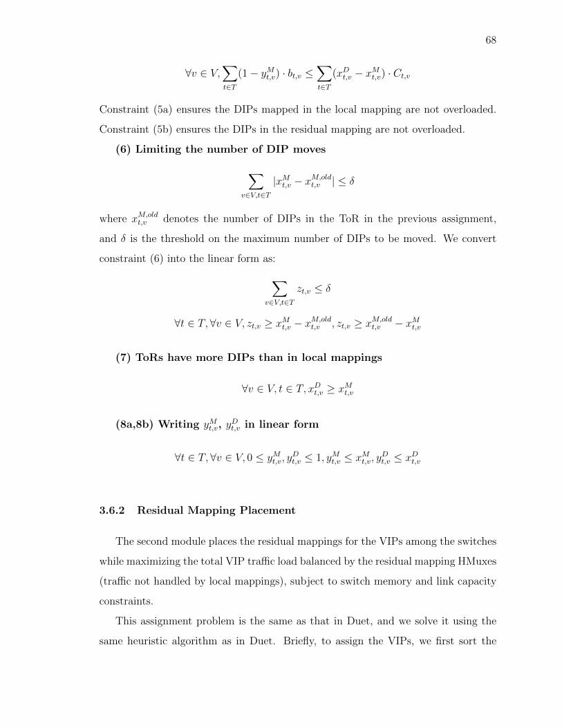
68
∀v ∈ V,∑t∈T
(1− yMt,v) · bt,v ≤∑t∈T
(xDt,v − xMt,v) · Ct,v
Constraint (5a) ensures the DIPs mapped in the local mapping are not overloaded.
Constraint (5b) ensures the DIPs in the residual mapping are not overloaded.
(6) Limiting the number of DIP moves
∑v∈V,t∈T
|xMt,v − xM,oldt,v | ≤ δ
where xM,oldt,v denotes the number of DIPs in the ToR in the previous assignment,
and δ is the threshold on the maximum number of DIPs to be moved. We convert
constraint (6) into the linear form as:∑v∈V,t∈T
zt,v ≤ δ
∀t ∈ T,∀v ∈ V, zt,v ≥ xMt,v − xM,oldt,v , zt,v ≥ xM,old
t,v − xMt,v
(7) ToRs have more DIPs than in local mappings
∀v ∈ V, t ∈ T, xDt,v ≥ xMt,v
(8a,8b) Writing yMt,v, yDt,v in linear form
∀t ∈ T,∀v ∈ V, 0 ≤ yMt,v, yDt,v ≤ 1, yMt,v ≤ xMt,v, y
Dt,v ≤ xDt,v
3.6.2 Residual Mapping Placement
The second module places the residual mappings for the VIPs among the switches
while maximizing the total VIP traffic load balanced by the residual mapping HMuxes
(traffic not handled by local mappings), subject to switch memory and link capacity
constraints.
This assignment problem is the same as that in Duet, and we solve it using the
same heuristic algorithm as in Duet. Briefly, to assign the VIPs, we first sort the

69
VIPs in decreasing traffic volume, and attempt to assign them one by one. We define
the notion of maximum resource utilization (MRU). MRU represents the maximum
utilization across all resources – switches and links. To assign a given VIP, we consider
all switches as candidates. We calculate the MRU for each assignment, and pick
the one that results in the smallest MRU, breaking ties at random. If the smallest
MRU exceeds 100%, i.e., no assignment can accommodate the traffic of the VIP, the
algorithm terminates. The remaining VIPs are not assigned to any switch – their
traffic will be handled by the SMuxes.
3.7 Failure Recovery
A key requirement of the LB design is to maintain high availability during failure:
(1) the traffic to any VIP should not be dropped, (2) existing connections should
not be broken. As in Duet, Rubik relies on SMuxes to load balance the traffic
during various failures. In addition to storing VIP-to-DIP mapping for all the VIPs,
we use the ample memory on individual SMuxes to provide connection affinity by
maintaining per-connection state.
Residual mapping HMux failure: Failure of the HMux storing the residual
mapping of a VIP only affects the traffic going to that HMux; the traffic handled
by other local and residual mappings is unaffected. The routing entries for the VIPs
assigned to the failed HMux are removed from all other switches via BGP withdraw
messages. After routing convergence, traffic to these VIPs is routed to the SMuxes,
which announce all VIPs. Since each SMux stores the same residual DIPs and uses
the same hash function as the residual mapping HMux to select a DIP, existing
connections are not broken.
Local mapping failure: When a ToR switch fails, all the sources and DIPs for
a VIP under it are also disconnected. As a result, the traffic the local mapping was
handling also disappears. Further, the rest of the traffic for that VIP continues to be
routed to the residual mapping or other local mappings, and are not affected.

70
Assignment Engine
Network Driver Datacenter Monitoring
VIP and DIP Settings
VIP-switch assignment
Rubik Controller
Operator
HMux SMux
POX Status
Rules Traffic
Fig. 3.6.: Rubik implementation.
SMux failure: On an SMux failure, traffic going to that SMux is rerouted to the
remaining SMuxes using ECMP. The connections are not broken as all the SMuxes
use the same hash function.
DIP failure: Existing connections to the failed DIP would necessarily be termi-
nated. For VIPs whose mapping are assigned to SMuxes, connection to the remaining
DIPs are maintained as SMuxes use consistent hashing in DIP selection [2]. For VIPs
assigned to HMuxes, the connections are maintained using smart hashing [8].
3.8 Implementation
We briefly describe the implementation of the three building blocks of Rubik, (1)
Rubik controller, (2) network driver, (3) HMux and SMux, as shown in Figure 3.6.
Rubik controller: The controller orchestrates all control activities in Rubik. It
consists of three key modules: (1) DC monitor, (2) Assignment engine, (3) Network
driver. The DC monitor periodically captures the traffic and DIP health information
from the DC network and sends it to the assignment engine. The assignment engine
calculates the DIP placement, local and residual VIP-to-DIP mappings for all the

71
VIPs, and pushes these new assignment to the network driver. We use CPLEX [34]
to solve the LP (§3.6.1).
Network driver: This module is responsible for maintaining VIP and DIP traffic
routing in the LB. Specifically, when the VIP-to-DIP assignment changes, the network
driver announces or withdraws routes for the changed VIPs according to BGP.
HMux and SMux: We implement HMuxes and SMuxes using Open vSwitches
that split the VIP traffic among its DIPs using ECMP based on the source ad-
dresses [35]. We implement smart hashing [8] using OpenFlow rules. The replies
from the DIPs directly go to the sources using DSR [2].
Lastly, we use POX to push the rules and poll the traffic statistics. We developed
a separate module to monitor the DIP health. The code for all the modules consists
of 3.4K LOC in C++ and Python.
3.9 Testbed
Setup: We evaluate Rubik prototype using Open vSwitches and Mininet. Our
testbed (Fig. 3.7) consists of 20 switches (HMuxes) in 4 containers connected in a
FatTree topology. Each ToR contains an SMux (marked “M”) and 2 hosts that can
be set as DIPs (marked “S”).
Services: We evaluate the performance of Rubik using two services that require
load balancing: (1) HTTP web service, (2) Bulk data transfer service. The web service
serves static web pages of size 1KB and generates a large number of short-lived TCP
flows. The Bulk data transfer service receives a large amount of data using a small
number of long-lived TCP flows. All the servers and clients for these services reside
in the same DC.
Experiments: Our testbed evaluation shows: (1) Rubik lowers congestion in
the network; (2) Rubik achieves high availability during a variety of failures – local
mapping, residual mapping, and DIP failure.

72
Agg
ToR
Server + SMux
4 1 Core
Container-1
2
2
1
S M S
1
S M S
8
8
7
7
S M S
Container-4
S M S
…
2 3
Fig. 3.7.: Our testbed. FatTree with 4 containers connected to 4 Core switches.
0
20
40
60
80
100
0 10 20 30
Th
rou
gh
pu
t(M
bp
s)
Time (sec)
Duet
BackgroundVIP-1
VIP-5
0 10 20 30
Time (sec)
Rubik
Fig. 3.8.: Rubik reduces congestion.
3.9.1 Reduction in Congestion
First we show that Rubik reduces congestion in the DC network by using local
mappings. In this experiment, initially 4 VIPs (each with 1 source and 1 DIP) are
assigned to 4 different HMuxes. Additionally, there is background traffic between 2
hosts. Figure 3.8 shows the per-second throughput measured across 2 flows. “VIP-1”
denotes the throughput for one of the 4 VIPs added initially. “Background” denotes
the throughput for the background flow (not going through the LB). Initially, there is
no congestion in the network and as a result all flows experience high throughput. At

73
0
2
0 200 400 600 800 1000
Time (msec)
VIP1
0
2L
ate
ncy (
mse
c)
VIP3 - Local
0
2Tfail Trecover
VIP3 - Residual
VIP on HMux VIP on SMux
Fig. 3.9.: VIP availability when residual mapping fails.
time 15 sec, we add a new VIP (VIP-5) that has 2 DIPs and 2 sources sending equal
volume of traffic, and assign it using Duet. However, assigning the new VIP causes
congestion as the new flows compete with the old flows. As a result, the throughput
for all the flows drop by almost 5-6x.
We repeat the same experiment with Rubik. At time 15 sec, we assign the VIP-
5 using Rubik. Rubik assigns local mappings to handle the VIP-5 traffic. As a
result, adding VIP-5 does not cause congestion (no drop in throughput), as shown
in Figure 3.8. This experiment shows that by exploiting locality, Rubik reduces the
congestion and improves the throughput by 5-6x.
3.9.2 Failure Mitigation
Next we show how Rubik maintains high availability during various failures.
Residual mapping failure: Fig. 3.9 shows the availability of the VIP, measured
using ping latency, when its residual mapping fails. In this experiment, we have 3
VIPs (VIP-1, 2, 3) assigned to the data-transfer service. VIP-1 and VIP-2 have one

74
0
2
0 200 400 600 800 1000
Time (msec)
Client-1
0
2Tfail
Client-2
La
ten
cy (
mse
c)
Local Residual
Fig. 3.10.: VIP availability during local mapping failure.
source and one DIP each in different ToRs, and their traffic is handled by residual
mappings (no local mapping). VIP-3 has two sources and two DIPs. One source and
one DIP are in the same ToR – the local mapping on that ToR handles their traffic.
The remaining source and DIP are in two different ToRs, and their traffic is handled
by the residual mapping.
At 400 msec, we fail the HMux storing the residual mapping for VIP-3. We make
four observations: (1) On HMux failure, VIP-3 traffic handled by it is lost for 114
msec. (2) After 114 msec, VIP-3 is 100% available, i.e., all of the pings are successful
again. During this time, the routing converges, and the traffic that used to go to
the HMux is rerouted to the SMuxes. (3) The traffic for VIP-3 handled by the local
mapping (shown as VIP-3-Local) is not affected – no ping message is dropped. (4)
Other VIPs (only VIP-1 is shown) are not affected – their ping messages are not
dropped.
This shows that Rubik provides high availability during residual mapping failure.
Local mapping failure: Figure 3.10 shows the impact of local mapping failure on
the availability of the VIPs. We use the same setup as before, and fail the HMux where
VIP-3’s local mapping was assigned. We measure the ping message latency from 2
sources for VIP-3 (denoted as Client-1, 2). The traffic from Client-2 is handled locally,
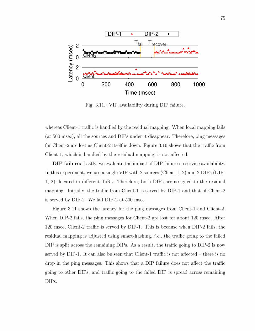
75
0
2
0 200 400 600 800 1000
Time (msec)
Client1
0
2Tfail Trecover
Client2
La
ten
cy (
mse
c)
DIP-1 DIP-2
Fig. 3.11.: VIP availability during DIP failure.
whereas Client-1 traffic is handled by the residual mapping. When local mapping fails
(at 500 msec), all the sources and DIPs under it disappear. Therefore, ping messages
for Client-2 are lost as Client-2 itself is down. Figure 3.10 shows that the traffic from
Client-1, which is handled by the residual mapping, is not affected.
DIP failure: Lastly, we evaluate the impact of DIP failure on service availability.
In this experiment, we use a single VIP with 2 sources (Client-1, 2) and 2 DIPs (DIP-
1, 2), located in different ToRs. Therefore, both DIPs are assigned to the residual
mapping. Initially, the traffic from Client-1 is served by DIP-1 and that of Client-2
is served by DIP-2. We fail DIP-2 at 500 msec.
Figure 3.11 shows the latency for the ping messages from Client-1 and Client-2.
When DIP-2 fails, the ping messages for Client-2 are lost for about 120 msec. After
120 msec, Client-2 traffic is served by DIP-1. This is because when DIP-2 fails, the
residual mapping is adjusted using smart-hashing, i.e., the traffic going to the failed
DIP is split across the remaining DIPs. As a result, the traffic going to DIP-2 is now
served by DIP-1. It can also be seen that Client-1 traffic is not affected – there is no
drop in the ping messages. This shows that a DIP failure does not affect the traffic
going to other DIPs, and traffic going to the failed DIP is spread across remaining
DIPs.

76
3.10 Simulation
In this section, we use large-scale simulations of Rubik and Duet to show: (1)
Rubik handles a large percentage of traffic in HMuxes as in Duet but incurs signif-
icantly lower maximum link utilization (MLU); (2) Rubik reduces the traffic in the
core by 3.68x and in the container by 3.47x; (3) Rubik contains 63% of VIP traffic
within ToRs; (4) Rubik does not create hotspots.
Network: Our simulated network closely resembles that of a production DC,
with a FatTree topology connecting 500K VMs under 1600 ToRs in 40 containers.
Each container has 40 ToRs and 4 Agg switches, and the 40 containers are connected
with 40 Core switches. The link and switch memory capacity were set with values
observed in the production DC.
Workload: We run the experiments using traffic trace collected from the pro-
duction DC over a 24-hour duration. The trace consists of the number of bytes
sent between all sources and all VIPs. Figure 3.12 shows the total traffic per hour
fluctuates over the 24-hour period2.
Comparison: We compare the performance of Duet, Rubik-LO and Rubik.
Duet exploits neither locality nor DIP placement. Rubik-LO is a version of Rubik
that only exploits locality without moving the DIPs; it assumes DIP placement is
fixed and given, and only calculates the local and residual mappings. Rubik exploits
both locality and flexibility in moving the DIPs. Rubik performs stage-by-stage
VIP-to-DIP mapping assignment following the VIP dependency.
3.10.1 MLU Reduction
We first compare the trade-off between the MLU and fraction of the traffic handled
by the HMuxes under the three schemes. Note that all three schemes try to maximize
the total traffic handled by HMuxes. The traffic not handled by HMuxes is handled
by SMuxes.
2Absolute values are omitted for confidentiality.

77
0 5 10 15 20
Tota
l tr
affic
(Tbps)
Time (hour)
Fig. 3.12.: Total traffic variation over 24 hours.
0 20 40 60 80
100
0 20 40 60 80 100% tra
ffic
offlo
aded
to H
Muxes
Maximum link utilization (%)
RubikRubik-LO
Duet
Fig. 3.13.: Traffic handled by HMuxes vs. MLU.
Figure 3.13 shows the fraction of traffic handled by HMuxes under the three
schemes. The MLU shown is the total MLU which resulted from load balancing all
VIP traffic, handled by HMuxes and by SMuxes. We see that Duet can handle 97%
traffic using HMuxes, but incurs a high MLU of 98%. But when MLU is restricted
to 47%, Duet can only handle 4% traffic using HMuxes.
In contrast, Rubik-LO handles 97% VIP traffic using HMuxes at MLU of 51%.
It handles 52% of VIP traffic using HMuxes at MLU of 35%. This improvement over
Duet comes purely from exploiting locality.

78
0
20
40
60
80
100
0 5 10 15 20
% tra
ffic
handle
dlo
cally
Time (hour)
Rubik Rubik-LO
Fig. 3.14.: Traffic handled using local mappings.
Lastly, Rubik significantly outperforms both Duet and Rubik-LO. It handles
97% traffic with a low MLU of 22.9%, a 4.3x reduction from Duet. Also, at a MLU
of 12%, Rubik handles 94% traffic using HMuxes.
3.10.2 Traffic Localized
Rubik significantly reduces the MLU by containing significant amount of traffic
within individual ToRs. Figure 3.14 shows the fraction of the total traffic contained
within ToRs in Rubik and Rubik-LO over the 24-hour period, where these mecha-
nisms calculate new assignment every hour. In Rubik, we limit the machine moves
to 1% based on the trade-off detailed in §3.10.5.
We see that Rubik-LO localizes 25.5-43.4% (average 34.8%) of the total traffic
within ToRs, and Rubik localizes 46-71.8% (average 63%) of the total traffic within
ToRs. Additionally, for the VIPs generating 90% of the total VIP traffic, we find
that, the local mappings handle traffic from 37.8-48.6% (average 41.8%) sources, and
50.2-57.7% (average 53%) of the total DIPs are assigned to their local mappings.

79
Duet Rubik-LO Rubik Duet Rubik-LO Rubik
Tota
l T
raffic
(T
bps)
Core Container
BaselineOverhead
Fig. 3.15.: Total traffic in core and container.
3.10.3 Traffic Reduction
Figure 3.15 shows the total bandwidth usage across all the links caused by the
VIP traffic under the three mechanisms. We separately show the total traffic on the
core links (between Core and Agg switches) and containers links (between ToR and
Agg switches). The total traffic shown is the average over 24 hours. Furthermore,
we break down the total traffic into baseline and overhead due to redirection. The
baseline traffic shows the amount of traffic generated if the HMuxes were on the direct
path between source and DIPs, which would cause no redirection. The remaining
traffic is the extra traffic due to the redirection to route traffic to and from HMuxes.
Rubik and Rubik-LO significantly reduce the total traffic in the core network
and containers. Compared to Duet, on average Rubik-LO reduces the total traffic
by 1.94x and 1.88x, respectively. Rubik reduces the total traffic by 3.68x and 3.47x,
respectively.
Secondly, Rubik-LO and Rubik reduce the traffic overhead due to traffic redirec-
tion by 2.1x and 10.9x compared to Duet. It should be noted that both Rubik and
Rubik-LO cannot eliminate the traffic overhead, because they cannot localize 100%
of the VIP traffic. As a result, the traffic not localized is handled by the HMuxes
storing residual mappings, which causes traffic detour.

80
0
0.2
0.4
0.6
0.8
1
0 0.2 0.4 0.6 0.8 1
CD
F
DIP Utilization (DIP traffic/capacity)
Rubik-MaxRubik-MedianRubik-LO-Max
Rubik-LO-Median
Fig. 3.16.: DIP utilization distribution across VIPs.
3.10.4 DIP Load Balance
To exploit locality, Rubik partitions the DIPs for a VIP into local and residual
DIP-sets, which can potentially overload some of the DIPs (hotspots). We calculate
the average and peak DIP utilization (DIP traffic/capacity) across all DIPs for every
VIP. Figure 3.16 shows the CDF across all VIPs in Rubik and Rubik-LO. It shows
that both schemes ensure that the peak utilization for all the DIPs is well under 80%,
which is the constraint given to the assignment algorithm. Furthermore, for 80%
VIPs, the peak utilization is under 40%. This shows Rubik does not create hotspots.
3.10.5 Impact of Limiting Machine Moves
Lastly, we evaluate the impact of limiting machine moves in Rubik’s assignment
LP formulation (§3.6.1) on the fraction of traffic localized and MLU. Figure 3.17
shows the two metrics as we reduce the percentage machine moves allowed. Without
any restriction, Rubik assignment results in moving 13.7% of the DIPs. When the
percentage machine moves is 1%, the fraction of traffic localized decreases by 8.7%
whereas the MLU increases by 6.6%, and the execution time to find the solution
increases by 2.3x compared to unrestricted machine moves. This shows that most

81
0
20
40
60
80
100
13.7 5 3 1 0
0.2
0.4
0.6
0.8
1
% t
raff
ic h
an
dle
dlo
ca
lly
ML
U
% Machines moved
Traffic MLU
Fig. 3.17.: Impact of machine moves.
of the benefits of Rubik are maintained after restricting the machine moves to just
1%. We therefore used this threshold in all the previous simulations and testbed
experiments.
3.11 Related work
To our best knowledge, Rubik is the first LB design that exploits locality and end-
point flexibility. Below we review work related to DC LB design which has received
much attention in recent years.
LB: Traditional hardware load balancers [14, 15] are expensive and typically only
provide 1+1 availability. We have already discussed Duet [4] and Ananta [2] load
balancers extensively. Other software-based load balancers [16–19] have also been
proposed, but they lack the scalability and availability of Ananta [2]. In contrast
to these previous designs, Rubik substantially reduces the DC network bandwidth
usage due to traffic indirection while providing low cost, high performance benefits.
OpenFlow based LB: Several recent proposals focus on using OpenFlow switches
for load balancing. In [20], the authors present a preliminary LB design using Open-
Flow switches. They focus on minimizing the number of wildcard rules. In [36],
the authors propose a hybrid hardware-software design and propose algorithms to

82
calculate the weights for splitting the VIP traffic. Plug-n-Serve [37] is another pre-
liminary design that uses OpenFlow switches to load balance web servers deployed in
unstructured, enterprise networks. In contrast, Rubik is designed for DC networks
and efficiently load balances the traffic by exploiting locality and end-point flexibility.
SDN architecture and middleboxes: Researchers have leveraged the SDN designs
in the context of middleboxes for policy enforcement and verification [24, 25], which
has a different goal from Rubik. Researchers have also proposed using OpenFlow
switches for a variety of other purposes. e.g., DIFANE [22] and vCRIB [23] use
switches to cache rules and act as authoritative switches. Again their main focus is
quite different from Rubik.
3.12 Summary
Rubik is a new load balancer design that drastically reduces the bandwidth usage
while providing low cost, high performance and reliability benefits. Rubik achieves
this by exploiting two design principles: (1) locality: it load balances traffic generated
in individual ToRs across DIPs present in the same ToRs, (2) end-point flexibility: it
places the DIPs closer to the traffic sources. We evaluate Rubik using a prototype
implementation and extensive simulations using traces from our production DC. Our
evaluation shows together these two principles reduce the bandwidth usage by the
load balanced traffic by over 3x compared to the prior art Duet.

83
4. YODA: HIGHLY AVAILABLE LAYER-7 LOAD
BALANCER
In the previous chapters, we saw how Duet and Rubik provide high scalability, low
cost, low network bandwidth overhead and more importantly high availability to the
L4 load balancers. As we show in this chapter, the principles that enabled high
availability in the L4 load balancers cannot be extended to the L7 load balancers.
We present Yoda that provides high availability to such L7 load balancers.
4.1 Background and Motivation
We start with a brief background on L7 load balancing in the cloud, describe the
current L7 LB solution HAProxy, and point out its limitations.
4.1.1 L7 load balancer
L4 load balancing is a basic load balancing mechanism [2, 20, 36]. Cloud-scale L4
LBs such as Ananta [2] and Duet [4] select the server by calculating the hash over the
L4 fields (the 5-tuple consisting of IP type, source and destination IP addresses and
port numbers), and use IP-in-IP encapsulation to forward the traffic to the selected
server.
As online services grow complex, they raise the need for partitioning website logic
and data across different sets of servers or even different DCs. For example, an online
service can have one set of servers to handle PHP content and a different set of servers
to handle CSS content.
L7 load balancing enables such fine-grained partitioning of traffic handled by the
online service. In contrast to an L4 LB, an L7 LB provides content-based switching,

84
DC-1
DC-2DC-3
L7 LB
L7 LB
Server-pool 1
Requests
Requests
Server-pool 2
Server-pool n
. .
HTTP language=en-GB
mysite.com/newsmysite.com
Fig. 4.1.: Typical L7 LB deployment.
where the LB inspects L7 header (HTTP) content in the incoming requests to select
the server where the requests are forwarded.
Figure 4.1 shows the typical usage of an L7 LB by online services as well as CDNs.
First, at the edge, the L7 LB is used to select the DC when not all the DCs store
all the data and applications (e.g., the requests for mysite.com/news is served only
through DC2). Additionally, within a single DC, an L7 LB is used to load balance the
traffic across different server pools (e.g., the requests with language en-GB is served
only through serverpool-1 in Figure 4.1).
Key requirements: As an L7 LB touches every packet received by online ser-
vices, its performance and robustness directly affects the performance and user ex-
perience of the online services. For this reason, the LB faces stringent robustness
and performance requirements. (1) Availability: The LB needs to be online, and
maintain connections during failures, (2) Scalability: The LB needs to adapt to the
dynamic traffic load; (3) Low latency: The LB should incur minimal extra delay
while load balancing the traffic. (4) Flexible and expressive interface so online
service operators can easily express policies.

85
Table 4.1.: Impact of proxy failure on different websites.
website nytimes reddit stanford
impact page timed-out page timed-out page timed-out
website vimeo soundcloud email service
impact service stopped service stopped email failed
4.1.2 Existing L7 LB
Today, major cloud service provides offer highly available and scalable L4 LB
services but not an L7 LB service. As a result, tenants are forced to build their own
L7 LB or to use third-party L7 solutions [16, 38] in cloud.
Current solutions in public cloud such as HAProxy [16] enable L7 load balancing
using a proxy-like mechanism. First, each proxy LB instance establishes a TCP
connection with the client and receives the HTTP content. Next, it inspects the
HTTP content and selects a server based on the user policies. Once the server is
selected, it establishes a TCP connection with the server and simply copies the data
between these two connections. To handle higher traffic load, multiple proxy instances
are used, and traffic is split among the multiple proxy instances using DNS or the L4
LB service.
4.1.3 Limitations of Existing L7 LB
Problem 1 – Low reliability: The current proxy-based L7 LB mechanism
faces a key limitation: Each L7 LB instance becomes a single point of failure.
Since the proxy operates at L4 and establishes TCP connections with both the client
and server, when the LB instance fails, the TCP connection state of the connections
with the server and client is lost, the packets from the server and client are dropped.
Eventually the two connections are terminated after HTTP timeout, which can be
several seconds or even minutes. Prior work has also emphasized that low reliability

86
of middleboxes (e.g., LBs) poses a significant challenge to middlebox vendors and
network operators. For example, FTMB [39] notes that many middlebox vendors
have argued against resetting the existing connections when failures happen because of
the potential for user-visible disruption to applications.
Failures are common: [40] shows the hardware middlebox (common in private
cloud) failures have low reliability – cumulatively hardware middleboxes (including
LBs, Firewalls) account for 43% of all the network device failures. When the mid-
dleboxes fail, all the existing connections on those middleboxes fail, and the traffic is
lost. [40] shows that 100’s of GB of traffic is lost during LB failures.
Similarly, when the L7 LBs are implemented in the software, e.g., HAProxy (com-
mon in public cloud), the connections break when the server crashes. The server
crashes occur for a variety of reasons including software bugs, hardware failures,
maintenance operations, power failures etc., which are common.
To understand the impact such failures can have on user experience, we emulate
a proxy failure that breaks a single established connection, and measure its impact
on 10 popular websites in terms of page-load time and session reset. Table 4.1 sum-
marizes the results1. We see that breaking a single established connection due to the
proxy failure either elongates the page-load time by 5 min (default Mozilla Firefox
browser HTTP timeout) for popular websites such as nytimes.com or reddit.com, or
breaks ongoing sessions for websites like vimeo.com or soundcloud.com. Such high
latency and session resets can significantly affect the online service user experience
and revenue especially for mobile and/or latency sensitive applications [12,13,41].
The low reliability of current L7 LBs leave the websites vulnerable when the LBs
crash.
Problem 2 – Management overhead: Using current proxy-based L7 LB solu-
tions (HAProxy), online services have to manage their own LB instances, i.e., tenants
have to somehow ensure scalability and availability on their own. Online services
1Due to page limit, we show the results for 6 websites.

87
cannot elastically add/remove LB instances as removing LB instances may break the
connections.
4.2 Yoda Key Ideas
In the previous section, we saw that the current proxy-based L7 LBs suffers a
fundamental limitation: client sessions are broken in case of LB instance failure. In
this thesis, we propose a new multi-tenant cloud L7 LB service called Yoda. Like
HAProxy, Yoda comprises of multiple instances running on VMs, does not require
administrative access to cloud infrastructure (e.g., switches), and hence can be easily
deployed by a third- party. But unlike HAProxy, Yoda provides high availability and
scalability, based on two key observations: (1) Each LB instance should not use its
actual IP for connecting with the client or server, since upon failure its IP becomes
unreachable2. (2) Each LB instance should not store the flow state for the connections
to the client/server locally, which will be lost upon failure.
These observations motivate the following design principles in Yoda:
Using VIP for client/server connections: In Yoda, each Yoda instance
always uses the VIP while making connections to clients and servers. In other words,
the clients and the servers always see the other endpoint of their connections as
the VIP. This “front-and-back” indirection masks the Yoda instance failures from
the clients and servers, and allows for transparent failover of client flows from being
handled by one Yoda instance to another. Yoda uses existing L4 LB service in
the cloud to redirect VIP traffic to/from the Yoda instances. Specifically, Yoda
requires L4 LB to split incoming requests across Yoda instances, and SNAT outgoing
responses with the VIP. These requirements are easily met by existing L4 LBs [2, 4].
This decoupling of the L4 and L7 LBs provides modularity and enables the design of
both LBs to evolve independently.
2Assigning its IP to another Yoda instance potentially in a different part of the DC network canincur a significant delay due to route convergence.

88
Storing flow state in persistent datastore: Running Yoda instances behind
VIP is not enough. When one Yoda instance fails, the subsequent packets for a flow
handled by the failed instance will be rerouted (by the underlying L4 LB) to another
Yoda instance. For the flow to be maintained, the subsequent packets between the
client and the server should be correctly translated, i.e., the sequence numbers, ports,
IP addresses should be consistent with before. To do this, the flow state consisting
of the client-VIP and VIP-server connections must survive the Yoda instance failure
and be accessible and reusable by other Yoda instances. To achieve this, Yoda
decouples the flow state from each instance and stores it in a persistent in-memory
datastore, called TCPStore, which can be retrieved by any other L7 Yoda instances.
The above ideas for achieving availability effectively allows for transparent client
flow migration between Yoda instances, and thus naturally provides high scalability,
where Yoda instances can be dynamically added or removed to match the traffic
load without affecting existing flows.
Tunneling at L3 for efficiency: A third idea of Yoda design is to minimize
TCP stack processing and storage operations by tunneling packets. We observe the
Yoda instance just needs to maintain a TCP connection with the client until it
receives the HTTP header, then opens a TCP connection to the selected server and
forwards the HTTP request. Since the header has only a few packets, TCP congestion
control has not kicked in this phase. After the server receives the HTTP request, the
LB instance can simply tunnel the traffic between the server and the client at L3, by
properly adjusting the TCP/IP header. Thus in either phase, the LB instance can
avoid performing TCP congestion control and leave congestion control to the client
and server.

89
mysite1.com VIP1mysite2.com VIP2
DNS
VIP1: L7LB-1,2VIP2: L7LB-2,3Cloud
mysite2.com
mysite1.com
Internet
L7LB-1 L7LB-3L7LB-2Yoda L7 LB
Yoda Controller
L4 LB
TCPStore
Fig. 4.2.: Yoda architecture. Red lines denote L7LB-servers traffic. Blue lines denote
L7LB-clients traffic.
4.3 Yoda Design
We now describe the Yoda design. To simplify the description, we consider
HTTP 1.0, where there is one request/response on one TCP connection. The changes
required to support HTTP 1.1 are described in §4.4.2.
4.3.1 Basic operations
Receiving VIP traffic: Figure 4.2 shows the Yoda architecture. Each online
service (mysite1, 2) is assigned a VIP in its DNS mapping, which clients use to send
requests. The requests are first received by the L4 LB in cloud. The L4 LB uses
the mapping between the VIP and Yoda instances (calculated and set by the Yoda
controller) to split the incoming VIP traffic among the Yoda instances (e.g., VIP1
traffic is split between L7LB1, 2).
Yoda instance: In a nut shell, an Yoda instance performs three functions: (1)
receiving the HTTP header from the client to select the server; (2) forwarding the
HTTP request to the server; (3) forwarding the data between the client and the server.
Yoda instances operate in two phases for every flow: (1) connection phase, where
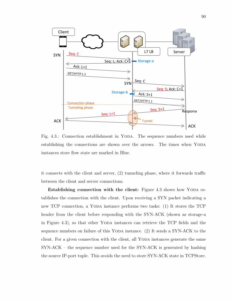
90
SYNL7 LB Server
Client
Seq: L; Ack: C+1
SYNSeq: S; Ack: C+1
Tunneling phaseConnection phase
ACKACK Tunnel
Response
Storage-a
Storage-b
Fig. 4.3.: Connection establishment in Yoda. The sequence numbers used while
establishing the connections are shown over the arrows. The times when Yoda
instances store flow state are marked in Blue.
it connects with the client and server, (2) tunneling phase, where it forwards traffic
between the client and server connections.
Establishing connection with the client: Figure 4.3 shows how Yoda es-
tablishes the connection with the client. Upon receiving a SYN packet indicating a
new TCP connection, a Yoda instance performs two tasks: (1) It stores the TCP
header from the client before responding with the SYN-ACK (shown as storage-a
in Figure 4.3), so that other Yoda instances can retrieve the TCP fields and the
sequence numbers on failure of this Yoda instance. (2) It sends a SYN-ACK to the
client. For a given connection with the client, all Yoda instances generate the same
SYN-ACK – the sequence number used for the SYN-ACK is generated by hashing
the source IP-port tuple. This avoids the need to store SYN-ACK state in TCPStore.
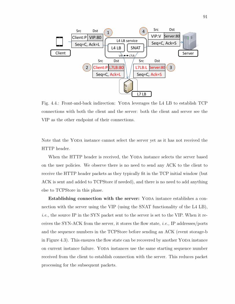
91
L4 LB SNATServerClient
L4 LB service
1
2 3
4
Client:P VIP:80
Src Dst
Seq=C, Ack=L
Client:P L7LB:80
Src Dst
Seq=C, Ack=L
L7LB:L Server:80
Src Dst
Seq=C, Ack=S
VIP:V Server:80
Src Dst
Seq=C, Ack=S
L7 LB
VIP L7LB
Fig. 4.4.: Front-and-back indirection: Yoda leverages the L4 LB to establish TCP
connections with both the client and the server: both the client and server see the
VIP as the other endpoint of their connections.
Note that the Yoda instance cannot select the server yet as it has not received the
HTTP header.
When the HTTP header is received, the Yoda instance selects the server based
on the user policies. We observe there is no need to send any ACK to the client to
receive the HTTP header packets as they typically fit in the TCP initial window (but
ACK is sent and added to TCPStore if needed), and there is no need to add anything
else to TCPStore in this phase.
Establishing connection with the server: Yoda instance establishes a con-
nection with the server using the VIP (using the SNAT functionality of the L4 LB),
i.e., the source IP in the SYN packet sent to the server is set to the VIP. When it re-
ceives the SYN-ACK from the server, it stores the flow state, i.e., IP addresses/ports
and the sequence numbers in the TCPStore before sending an ACK (event storage-b
in Figure 4.3). This ensures the flow state can be recovered by another Yoda instance
on current instance failure. Yoda instances use the same starting sequence number
received from the client to establish connection with the server. This reduces packet
processing for the subsequent packets.

92
Tunneling subsequent packets: Since subsequent packets do not need to be
inspected, the Yoda instance tunnels all subsequent packets between the client and
the server on the two connections at L3 as shown in Fig 4.3. However, the sequence
number received in the packet from the server will not match the sequence number
used by the Yoda instance in its connection with the client, and would require
translation to maintain the connection. To do this, the instance keeps the following
state locally and also in TCPStore: (1) the starting sequence numbers from the client
and the servers C and S, (2) the assigned server.
Figure 4.4 shows how the source/destination addresses and the sequence numbers
in the packets from the client and server are translated, during both the connection
phase and the tunneling phase, so that both the client and server will only see VIP
as the other endpoint of their connections.
Terminating connection: The flow state stored at the Yoda instance and
TCPStore is removed when the instance receives FIN-ACK.
4.3.2 Handling Yoda instance failure
The guiding principle to maintain flows during Yoda instance failure is that each
instance stores all the packets it ACKes (e.g., SYN from client and SYN-ACK from
server) in the connection phase in TCPStore, as shown in Figure 4.3, so that no state
is lost on failures. After failure, other Yoda instances can retrieve the flow state
from the retransmitted packets and from TCPStore. We now detail on how we use
this principle to maintain connections.
Recall the servers and clients do not see the individual Yoda instance failure, as
Yoda instances use the VIP on the connections with the servers and clients. When
a Yoda instance fails, the Yoda controller detects the failure and removes the failed
instance from all the mappings at L4 LB. As a result, the underlying L4 LB forwards
subsequent packets from the server and the client to one of the remaining instances.
We consider failure during the connection phase and tunneling phase separately.
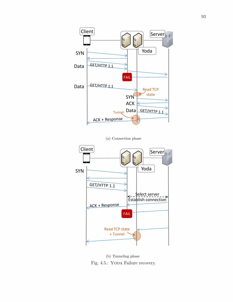
93
SYN
Data
ServerClient
Yoda
FAIL
Data
SYNACK
DataTunnel
Read TCP state
(a) Connection phase
SYN
ServerClient
Yoda
Select server Establish connection
Read TCP state+ Tunnel
FAIL
(b) Tunneling phase
Fig. 4.5.: Yoda Failure recovery.
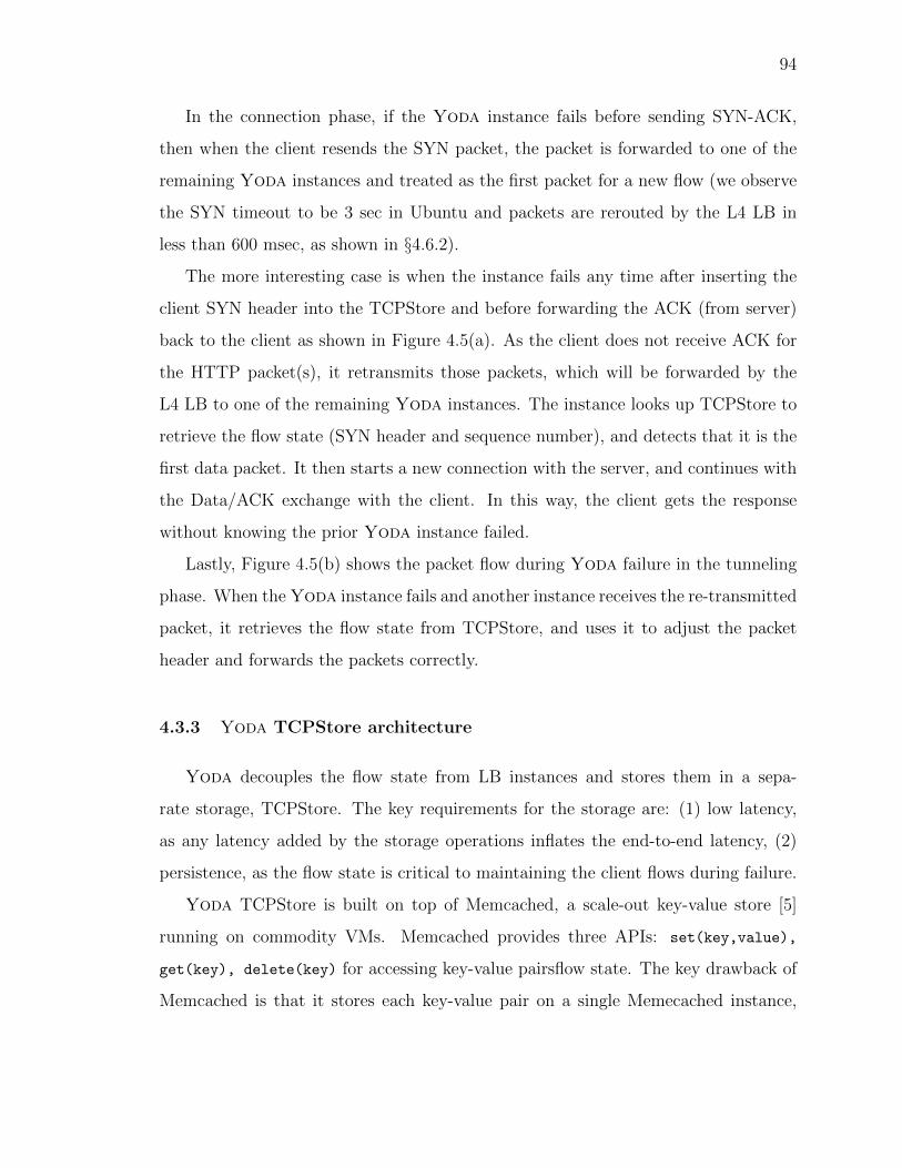
94
In the connection phase, if the Yoda instance fails before sending SYN-ACK,
then when the client resends the SYN packet, the packet is forwarded to one of the
remaining Yoda instances and treated as the first packet for a new flow (we observe
the SYN timeout to be 3 sec in Ubuntu and packets are rerouted by the L4 LB in
less than 600 msec, as shown in §4.6.2).
The more interesting case is when the instance fails any time after inserting the
client SYN header into the TCPStore and before forwarding the ACK (from server)
back to the client as shown in Figure 4.5(a). As the client does not receive ACK for
the HTTP packet(s), it retransmits those packets, which will be forwarded by the
L4 LB to one of the remaining Yoda instances. The instance looks up TCPStore to
retrieve the flow state (SYN header and sequence number), and detects that it is the
first data packet. It then starts a new connection with the server, and continues with
the Data/ACK exchange with the client. In this way, the client gets the response
without knowing the prior Yoda instance failed.
Lastly, Figure 4.5(b) shows the packet flow during Yoda failure in the tunneling
phase. When the Yoda instance fails and another instance receives the re-transmitted
packet, it retrieves the flow state from TCPStore, and uses it to adjust the packet
header and forwards the packets correctly.
4.3.3 Yoda TCPStore architecture
Yoda decouples the flow state from LB instances and stores them in a sepa-
rate storage, TCPStore. The key requirements for the storage are: (1) low latency,
as any latency added by the storage operations inflates the end-to-end latency, (2)
persistence, as the flow state is critical to maintaining the client flows during failure.
Yoda TCPStore is built on top of Memcached, a scale-out key-value store [5]
running on commodity VMs. Memcached provides three APIs: set(key,value),
get(key), delete(key) for accessing key-value pairsflow state. The key drawback of
Memcached is that it stores each key-value pair on a single Memecached instance,

95
and does not provide persistence when a Memcached instance fails. We address
this limitation by storing each key-value pair on multiple Memcached instances by
modifying the Memcached client library which runs on every Yoda instance and
handles all Memcached operations. §4.5 gives more details on the implementation of
TCPStore.
The Yoda TCPStore minimizes the latency of the storage operations through a
series of optimizations including (1) decentralized server selection, (2) concurrently
issuing operations to all replica servers, and (3) using long-lived TCP connections
between the Memcached clients and servers. We omit the details here due to page
limit.
4.3.4 VIP assignment
So far we have discussed how Yoda achieves high availability and scalability –
two primary goals of Yoda. We now detail the remaining design component on: (1)
how Yoda selects the server based on the rules, (2) how to assign L7 LB rules for
all online services (i.e., VIPs) to the Yoda instances to optimize cost, latency, and
failure resilience.
Server selection: Yoda provides an interface that lets online service operators
express their policies as OpenFlow-like rules (§4.4.1) that consist of match, action
and priority fields. The Yoda instances match the HTTP headers in incoming new
connections against these rules in order to select the server for each client flow.
Since designing a new classification algorithm is not the focus of Yoda, it uses
existing algorithm from HAProxy with an extension to support priority. HAProxy
maintains a single table with all the rules chained, and scans all the rules linearly
to select the backend server for every incoming new connection. In Yoda, we add a
new priority field to the rules, and arrange the rules in the decreasing order of the
priority. Priority enables Yoda to support rich set of policies easily as detailed in
§4.4.1.

96
0
3
6
9
12
1 2 3 4 5 6 7 8 9 10
Lookup late
ncy
(msec)
Number of rules (x1000)
Fig. 4.6.: Look-up latency in HAProxy.
Additionally, Yoda maintains a hash table that stores the mapping between the
connection (identified using TCP/IP 5-tuple) and the assigned backend server. Yoda
uses this mapping to forward the subsequent packets on the individual connections.
Next, we detail on how Yoda assigns the rules to the Yoda instance.
Rule assignment: One simple approach is to assign all the VIPs, and thus all
their rules to all Yoda instances. We call this scheme all-to-all. Such an approach
provides high robustness since any remaining instance can handle traffic for any VIP
when some Yoda instances fail.
However, it can incur high latency from scanning too many rules for every new
flow. We first assess the impact of the number of rules on latency in HAProxy.
Figure 4.6 shows that the (P90) latency increases about linearly with the number of
rules. The latency for scanning 10K rules is roughly 3x than for 1K rules, which is a
significant increase especially for latency sensitive applications.
To address these limitations, Yoda uses a many-to-many model for VIP assign-
ment, where a VIP (and its rules) is assigned only to a subset of Yoda instances.
This model significantly reduces the number of rules on each Yoda instance which
reduces server selection latency.

97
Table 4.2.: Notations used in the algorithm.
Notation Explanation
Input
Y, V Sets of Yoda instances and VIPs
tv, rv Total traffic and rules for v-th VIP
ov Over-subscription for v-th VIP
Ty, Ry Total traffic and rule capacity of y-th Yoda instance
nv # Yoda instances assigned to v-th VIP
fv # Yoda failures for v-th VIP to be tolerated
Output Variable (binary)
xv,y set if v-th VIP is assigned to y-th Yoda instance
The Yoda controller: (1) calculates the VIP assignment (i.e., which VIPs are
assigned to which Yoda instances), as the underlying L4 LB splits and forwards
traffic at the VIP granularity, all the rules for the individual VIPs are to be installed
at the Yoda instances where the VIP is assigned. (2) installs the L7 LB rules at
the corresponding Yoda instances, (3) installs the VIP-to-Yoda-instance mapping
in the L4 LB, so that VIP traffic is forwarded to the Yoda instances that store the
L7 rules for those VIPs.
We formulate the VIP assignment problem in Yoda as an ILP to minimize the
Yoda instances for a given latency constraint and level of robustness, as shown in
Figure 4.7.
Input: The input to the ILP includes the (1) set of VIPs (V) and Yoda instances
(Y), (2) total traffic and rules to each individual VIP (tv, rv), (3) traffic and rule
capacity for individual Yoda instances (Ty, Ry), (4) Number of replicas for individual
VIPs (nv), (5) over-subscription ratio ov for each VIP (ov and nv are specified by online
services).
We calculate fv = nv · ov, i.e., the number of Yoda instances assigned to v-th
VIP whose failure will not overload other Yoda instances.

98
ILP Variable: xv,y
Objective: Minimize∑y∈Y
yy, yy = 1 if∑v∈V
xv,y ≥ 1, else 0
Constraints:
Traffic capacity: ∀y ∈ Y,∑v∈V
xv,y ·tv
nv − fv≤ Ty (1)
Rule capacity: ∀y ∈ Y,∑v∈V
xv,y · rv ≤ Ry (2)
Number of replica: ∀v ∈ V,∑y∈Y
xv,y = nv (3)
Transient traffic: ∀y ∈ Y,∑v∈V
zv,y · tv ≤ Ty (4)
where zv,y = max(xv,y
nv,xoldv,y
noldv
) (5)
Connections migrated:∑
v∈V,y∈Ymv,y · Cold
v,y ≤ δ (6)
where mv,y = max(xprevv,y − xv,y, 0) (7)
Expressing yy: ∀y ∈ Y, 1 ≥ yy ≥
∑v∈V
xv,y
N (8)
Expressing zv,y: zv,y ≥ xv,y
nvand zv,y ≥
xoldv,y
noldv
(9)
Expressing mv,y: mv,y ≥ 0;mv,y ≥ xprevv,y − xv,y (10)
Fig. 4.7.: ILP formulation of VIP assignment.
Output: Yoda instances assigned to each individual VIP – xv,y is set if v-th VIP
is assigned to y-th Yoda instance.
Objective: Minimize the total number of Yoda instances, which lowers the
Yoda operating cost.
Constraints:
• Traffic capacity: Each Yoda instance has enough capacity to handle traffic
even after fv failures (Eq. 1 in Figure 4.7) for all the VIPs assigned to it. tvnv−fv
denotes the traffic for v-th VIP after fv failures.
• Rule capacity: Each server has enough memory to store the rules for VIPs
assigned to it (Eq. 2).
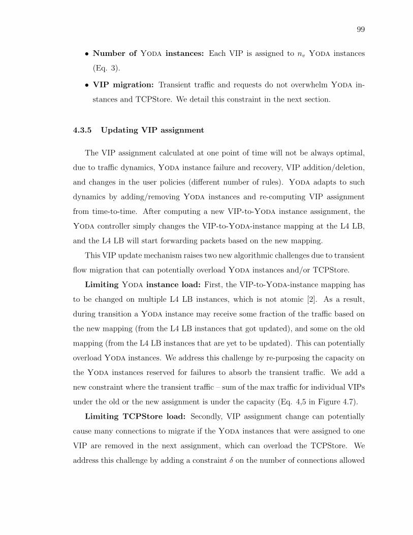
99
• Number of Yoda instances: Each VIP is assigned to nv Yoda instances
(Eq. 3).
• VIP migration: Transient traffic and requests do not overwhelm Yoda in-
stances and TCPStore. We detail this constraint in the next section.
4.3.5 Updating VIP assignment
The VIP assignment calculated at one point of time will not be always optimal,
due to traffic dynamics, Yoda instance failure and recovery, VIP addition/deletion,
and changes in the user policies (different number of rules). Yoda adapts to such
dynamics by adding/removing Yoda instances and re-computing VIP assignment
from time-to-time. After computing a new VIP-to-Yoda instance assignment, the
Yoda controller simply changes the VIP-to-Yoda-instance mapping at the L4 LB,
and the L4 LB will start forwarding packets based on the new mapping.
This VIP update mechanism raises two new algorithmic challenges due to transient
flow migration that can potentially overload Yoda instances and/or TCPStore.
Limiting Yoda instance load: First, the VIP-to-Yoda-instance mapping has
to be changed on multiple L4 LB instances, which is not atomic [2]. As a result,
during transition a Yoda instance may receive some fraction of the traffic based on
the new mapping (from the L4 LB instances that got updated), and some on the old
mapping (from the L4 LB instances that are yet to be updated). This can potentially
overload Yoda instances. We address this challenge by re-purposing the capacity on
the Yoda instances reserved for failures to absorb the transient traffic. We add a
new constraint where the transient traffic – sum of the max traffic for individual VIPs
under the old or the new assignment is under the capacity (Eq. 4,5 in Figure 4.7).
Limiting TCPStore load: Secondly, VIP assignment change can potentially
cause many connections to migrate if the Yoda instances that were assigned to one
VIP are removed in the next assignment, which can overload the TCPStore. We
address this challenge by adding a constraint δ on the number of connections allowed
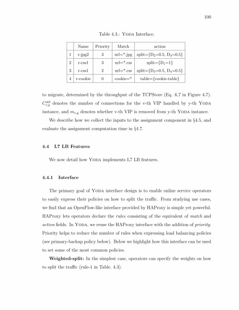
100
Table 4.3.: Yoda Interface.
Name Priority Match action
1 r-jpg2 3 url=*.jpg split={D2=0.5, D3=0.5}
2 r-css1 3 url=*.css split={D1=1}
3 r-css1 2 url=*.css split={D3=0.5, D4=0.5}
4 r-cookie 0 cookie=* table={cookie-table}
to migrate, determined by the throughput of the TCPStore (Eq. 6,7 in Figure 4.7).
Coldv,y denotes the number of connections for the v-th VIP handled by y-th Yoda
instance, and mv,y denotes whether v-th VIP is removed from y-th Yoda instance.
We describe how we collect the inputs to the assignment component in §4.5, and
evaluate the assignment computation time in §4.7.
4.4 L7 LB Features
We now detail how Yoda implements L7 LB features.
4.4.1 Interface
The primary goal of Yoda interface design is to enable online service operators
to easily express their policies on how to split the traffic. From studying use cases,
we find that an OpenFlow-like interface provided by HAProxy is simple yet powerful.
HAProxy lets operators declare the rules consisting of the equivalent of match and
action fields. In Yoda, we reuse the HAProxy interface with the addition of priority.
Priority helps to reduce the number of rules when expressing load balancing policies
(see primary-backup policy below). Below we highlight how this interface can be used
to set some of the most common policies.
Weighted-split: In the simplest case, operators can specify the weights on how
to split the traffic (rule-1 in Table. 4.3).

101
Primary-backup: In many cases, operators deploy services in a primary-backup
model, and want to prioritize traffic to a primary server until it fails/overloads. This
can be easily achieved using priority functionality in Yoda. Operators can specify
the same match condition with two actions with different priorities – a higher priority
action specifies weights for primary server(s), and a lower priority rule specifies weights
for the remaining servers (rule-2,3).
Sticky-sessions: Operators may want traffic from the same user/session to go
to the same server handling that session, by matching on HTTP cookies (rule-4).
Least loaded server: In another common case, operators simply want to forward
requests to the least loaded server. This can be done by setting the weights to (-1)
for all servers.
4.4.2 Practical issues
We now describe how Yoda handles important practical L7 LB issues including
configuration changes.
Adapting to user policy change: Online services can change user policies
(rules) dynamically during upgrades, new web design, or to add/remove backend
servers. Yoda’s periodic VIP assignment calculation accounts for the number of
rules. Yoda then simply updates the new rules on the Yoda instances where the
VIP is assigned. This change does not break existing connections, as Yoda instances
only apply new policies to new connections. Packets on existing connections continue
to be forwarded to their prior assigned server even during soft server removal so that
the connections do not break. If the operator removes the server immediately, then
it is treated as failure detailed next.
Backend server failure: The Yoda monitoring component periodically pings
the servers. When a server fails, its connections with Yoda instances are terminated3.
3Although not implemented currently, Yoda instances can initiate connections with the new serverand relay the same request to the new server, transparently to the client.

102
VIP addition and removal: When new services, i.e., VIPs, are added, Yoda
first runs the VIP assignment algorithm described in §4.3.4 to calculate the set of
Yoda instances assigned to the VIP. Next, we add the rules corresponding to the
new VIP to the Yoda instances where it is assigned. Lastly, we assign the mapping
between the VIP and the Yoda instances to the L4 LB. The sequence of VIP removal
is in reverse of VIP addition.
HTTP 1.1 and HTTP 2.0: In HTTP/1.1, a single TCP connection can be
reused for multiple requests, which may match different rules and hence need to be
forwarded to different backend servers. Yoda supports this by having Yoda in-
stances inspect the packets from the clients for the HTTP content. If the server
selected for the new request is different than the current one, it closes the old connec-
tion and initiates a connection with the new server, and also changes the mapping in
TCPStore.
Pipelining requests in HTTP/1.1 poses an additional challenge that Yoda in-
stances have to ensure that the responses are sent in-order, i.e., in the same order as
the received requests, even during Yoda failures. Yoda achieves this by storing the
order in which the requests were received in TCPStore, so that after failure, another
instance can gather and forward the responses.
In addition to pipelining requests in HTTP/1.1, HTTP/2.0 and SPDY propose
out-of-order delivery of responses to avoid head-of-line blocking [42]. Yoda can
easily support out-of-order responses from a server by correctly translating the TCP
sequence numbers.
SSL support [43]: Yoda supports SSL by sending the security certificates (set
by the operators) to the clients. On failure during certificate transfer, another Yoda
instance resends the entire certificate (TCP buffer at the client will remove duplicate
packets). The rest of the function remains the same as detailed in §4.2, except the
Yoda instance uses the security certificate for SSL termination to decrypt the request
to get HTTP content and select the server.

103
User Interface Assignment Engine
Assignment Updater
L7 rules
mysite1.comoperator
mysite.comoperator…
Policies
Health
Yoda Controller
MCD serverStore TCP state
Web Servers L4 LBLB-InstancePacket driverMemcached client
Monitoring
VIP-Yoda LB mapping
L7 rulesHealth +traffic
VIP-Yoda LB mapping
Yoda InstancePacket driverMemcached client
MCD serverStore TCP state
Web Servers
Fig. 4.8.: Components in Yoda implementation (shown in colored boxes).
Sending the same request to multiple servers: Many websites send the
same client request to multiple backend servers to reduce latency and handle server
failures, and send the first server response back to the client. Although it is not
currently supported, Yoda can easily support this by establishing connections with
multiple servers, and tunneling the first response it receives from the servers. It makes
a mark to drop packets of later responses from other servers.
4.5 Implementation
We have implemented Yoda on Linux completely at the user-level, i.e., it requires
no changes to the existing kernel, and therefore it can be deployed in the public cloud
as a service by a third party. We now describe the key components of Yoda: (1)
Yoda instances, (2) TCPStore, and (3) Yoda controller, as shown in Figure 4.8. All
components are written in C or python with the total 5k+ lines of code.
Yoda instances: Each Yoda instance runs in a VM and intercepts the packets
forwarded from the L4 LB using nfqueue and iptables [44]. Each instance runs

104
packet driver and Memcached client. The packet driver performs key functions of the
Yoda instance. It (1) establishes connections with clients/servers by sending and
receiving raw packets, (2) tunnels the packets on existing connections by changing the
TCP fields using nfqueue, (3) stores and retrieves the flow state in/from TCPStore
whenever necessary. The packet driver runs in user-space.
Inside a Yoda instance, the packet driver creates K queues, one for each of the
K cores of the VM, and starts a multi-threaded module to listen on each queue. The
packets are forwarded to nfqueue using iptables such that the packets on the same
TCP connection are forwarded to the same queue. This mechanism ensures that the
traffic is evenly spread across all the CPU cores, and packets on the same connection
are handled in the same order they arrive. We did not use kernel-space SNAT/DNAT
options as they do not provide fine-grained control over the TCP fields.
Lastly, each Yoda instance keeps track of the traffic for individual VIPs that
Yoda controller reads periodically.
TCPStore: We run unmodified Memcached on multiple VMs that store the flow
state. We modified the Memcached client library to store the same key-value pair on
multiple (K) Memcached servers for persistence. For any TCPStore operation, the
Memcached client first determines the K servers among the total N servers using K
different hash functions, and consistent hashing.
When a Memcached server fails, we do not replicate its key-value pairs mainly
because flows finish quicker than the replication latency.
Controller: The controller is at the heart of Yoda architecture. It has four
components: (1) User interface: It converts the user policies expressed using the
Yoda interface into the rules and sends them to the Yoda instances. (2) Assignment
engine: It calculates the assignment between the VIP and Yoda instances using the
ILP detailed in §4.3.4 implemented using CPlex [34], (3) Assignment updater: It
takes the VIP assignment from the assignment engine and changes the mapping at
the L4 LB. (4) Monitor: It gathers health information by pinging the Yoda instances,
Memcached servers, and backend servers every 600ms, and hence detects failure with

105
at most 600ms delay. It also gets traffic statistics from the Yoda instances. All
components communicate with each other using RESTful APIs.
4.6 Evaluation
Our testbed experiments evaluate the key ideas and objectives of Yoda design
and show that: (1) Decoupling flow state from the L7 LB (or middleboxes in general)
and maintaining them in a persistent storage is feasible – it incurs insignificant latency
to the flows being balanced and the cost of running the persistent storage is low; (2)
Yoda provides high availability and scalability – it does not break flows during LB
failures, addition, removal, and user policy updates.
Setup: Our testbed consists of 60 VMs in Windows Azure: 10 act as Yoda
instances, 10 as Memcached servers, 30 act as the backend servers, and 10 run a
version of Ananta L4 LB that forwards packets to remaining Yoda instances upon a
Yoda instance failure. The clients (generating requests) are located on a university
campus.
The backend servers are split across 4 online services – each online service emulates
a university website storing faculty and student webpages and embedded objects,
which are collected from an actual university website. In total we collected 10K+
objects with sizes 1K-442KB (median 46KB). Each web-request fetches an HTML
page and its embedded objects4.
Each Yoda and TCPStore instance runs on a separate VM with 8-core CPU
and 14GB RAM, and the backend servers run on dual-core VMs with 3.5GB RAM,
running the Apache/2.2.3 HTTP server. Each client generates the request workload
using either a Python client that emulates web-browser or the Apache benchmark
tool. All Yoda instances, TCPStore servers, backend servers, and clients run Ubuntu
12.04.
4We modified the webpages to change the URL for the embedded objects accordingly.

106
0
100
200
300
400
Late
ncy (
msec)
Yoda HAProxy
151133
8.2 10.40.89
144133
5.2 8
TotalBaseline
LBConnection
Storage
Fig. 4.9.: Yoda latency breakdown.
4.6.1 Feasibility of decoupling flow state
We first evaluate the feasibility of decoupling flow state from the Yoda instances
by measuring its latency overhead to the flows, CPU overhead to the Yoda instances,
and the scalability of TCPStore.
Latency overhead: To measure the latency overhead, we configure clients to
send requests at 50K req/sec for small objects (responses are of size 10KB). Using
smaller objects stresses the mechanisms for decoupling flow state since they incur
higher load on connection establishment and more frequent operations to TCPStore
than larger objects.
To put the latency overhead in perspective, we break down the end-to-end latency
(request completion time) into: (1) Baseline: the end-to-end latency when not using
any load balancer, which includes the latency incurred by the Internet and backend
server processing, (2) Connection: the time an LB instance takes to establish the
TCP connection with the backend. (3) Storage: the latency incurred while inserting
the flow information into TCPStore, unique to Yoda. (4) LB: The remaining latency
incurred by the LB instances while processing the packets.
Figure 4.9 shows the breakdown of median latency for Yoda and HAProxy, of
all flows in the experiment. We make the following observations. (1) The end-to-

107
0
1
2
3
4
Late
ncy (
msec)
4k 20k 40k
Client requests/sec/server
GET-MCD
GET-Yoda
SET-MCD
SET-Yoda
Fig. 4.10.: Yoda TCPStore latency.
end latency in Yoda and HAProxy are 151 msec and 144 msec, respectively, out of
which the baseline latency is 133 msec. (2) The extra latency to store flow states in
TCPStore in Yoda is only 0.89 msec. (3) Yoda takes slightly longer to establish
connections – 10.4 msec compared to 8 msec in HAProxy, and to process packets
– 8.2 msec compared to 5.23 msec in HAProxy. This is because currently Yoda is
written in Python and also as it copies packets between user and kernel space while
HAProxy performs TCP splicing in the kernel; an in-kernel implementation of Yoda
will achieve the same latency as HAProxy.
CPU overhead: Next, we measure the CPU utilization on the LB instances.
In Yoda, the CPU saturates (100% utilization) for 12K client req/sec for small
requests5, and hits 80% for 90K packets/sec request rate for larger requests (flow size
2MB). Under HAProxy, the CPU utilization is 46% and 34% for the two cases. The
close to 2x higher CPU utilization in Yoda is again due to copying packets between
the kernel and user space; we isolated the Memcached client calls and found them to
consume negligible CPU load. We fully expect an in-kernel implementation of Yoda
to reduce the CPU utilization to be similar to that of HAProxy.
TCPStore performance: We first measure the latency overhead of supporting
persistence in TCPStore. We measure the latency of get, set and delete opera-
tions while issuing 40K, 200K, and 400K ops/sec across 10 Memcached servers for
5 [16] noted higher throughput due to high-end physical server.

108
0
20
40
60
80
100
CP
U u
tiliz
atio
n (
%)
4k 20k 40kClient requests/sec/server
GET-MCD
GET-Yoda
SET-MCD
SET-Yoda
Fig. 4.11.: Yoda TCPStore CPU utilization.
60 seconds. Figure 4.10 compares the latency for the default Memcached which does
not store replicas and the Memcached changed in Yoda to provide 2 replicas for
persistence. Note the x-axis denotes the number of client requests per Memcached
server. Recall for a single client request, a Yoda instance issues two set operations
to store the flow state (§4.2). We make two observations: (1) even at 40K client
req/sec/server, the median operation latency under the default Memcached is only
0.75 msec, which is rather insignificant compared to the median end-to-end latency of
151 msec. (2) The overhead of adding persistence to the default Memcached is very
small: for 40K req/sec/sever, the overhead for the three operations is less than 24%
(0.18 msec). The low latency overhead benefited from sending the operation to two
replica servers in parallel.
Figure 4.11 shows the CPU utilization of Memcached (default and in Yoda). As
expected, the persistence feature of TCPStore, which issues each operation to two
servers, doubles the average CPU utilization.
Our evaluation shows that a single Memcached server can handle 80K client
req/sec (at 90% CPU utilization), while each Yoda instance can handle 12K client
req/sec. This suggests decoupling flow state to support high availability in a scale-out
L7 LB design is practical: we just need 1 TCPStore instance deployed for every 6.6
Yoda instances.

109
4.6.2 Failure recovery
One of the most important benefits of Yoda is it maintains client flows during
Yoda instance failures. In this experiment, we start with 10 Yoda instances and
fail 2 of them simultaneously. Without failure, a webpage and all its objects are
downloaded in 840 msec (median case). The clients emulate browser behavior with
HTTP timeout set to 30 seconds, which is the least among the popular web browsers
we tested (e.g., Android Chrome has 60 sec, and C# HttpWebRequest library has
100 sec [45,46]).
The clients send requests using 20 processes each. Each process waits for the
completion/timeout of the previous request before issuing a new one. We repeat this
experiment in four scenarios: (1) HAProxy without browser retry (HAProxy-noretry),
(2) HAProxy with browser retry=1 (HAProxy-retry), (3) Yoda without browser retry
(denoted as Yoda-noretry), (4) Yoda with browser retry=1 (not shown as there was
never any retry made).
Figure 4.12 shows the CDF of the end-to-end latency for requests. We make
three observations: (1) HAProxy-noretry broke 24% of the flows on failure, whereas
Yoda and HAProxy-retry did not break any flow, (2) Yoda increased the end-to-end
latency by 0.6 to 3 seconds, and (3) HAProxy-retry increased the latency beyond 30
sec.
To understand how Yoda maintained the flow during failure, we plot in Fig-
ure 4.12(b) the tcpdump output collected at the backend server for a flow that expe-
rienced the Yoda instance failure. Upon the failure, (1) the packets from the server
and client going through the failed instance are dropped during failover (point a in
Figure 4.12(b)). (2) The server retransmits the packet first at 300 msec (point b),
which the L4 LB sends to the failed LB, as the mapping at the L4 LB is yet to be
updated. (4) The server retransmits the packet at 600 msec (point c). At this time,
since the Yoda monitor has detected the instance failure and updated the mapping
at the L4 LB, the packet is sent to one of the online Yoda instances. (5) That in-

110
0
0.2
0.4
0.6
0.8
1
100 1000 10000
CD
F
Latency (msec)
No-failureHAProxy-retry
HAProxy-noretryYoda
(a) Latency
0
35000
70000
105000
140000
0 0.5 1 1.5 2
Se
qu
en
ce
nu
mb
er
Time (sec)
(a) Lost packets
(b) Retransmit lost
(c) Retransmit success
Sequence ACK
(b) Sequence number for a connection under Yoda.
Fig. 4.12.: Yoda Failure recovery.

111
0
25
50
75
100
0 5 10 15 20 25 30
CP
U U
til. (
%)
Time (sec)
0
4
8
12
req
/se
c (
x1
00
0)
Instance addedTraffic x2
Yoda-1 Yoda-2 Yoda-3
Fig. 4.13.: Yoda scalability.
stance retrieves the flow state from TCPStore and forwards the packet to the client,
which sustains the connection with the new Yoda instance, and subsequent packets
are forwarded normally. Note that the client did not timeout, and no HTTP request
was resent.
In contrast, when an HAProxy instance fails, all the packets from the servers and
ACKs from the clients going through the failed instance are dropped, breaking the
connections with the server and the client. After the HTTP timeout of 30 sec, if the
client resends the HTTP request (HAProxy-retry), the request is forwarded to one of
the live HAProxy instances as the L4 LB is updated; those objects are successfully
retrieved but with a delay of 30 seconds.

112
0
0.2
0.4
0.6
0 10 20 30 40Fra
ctio
n o
f P
acke
ts
Time (sec)
Srv-4 add Srv-1 remove Weights change
Srv-1 Srv-2 Srv-3 Srv-4
Fig. 4.14.: Yoda user policy update.
4.6.3 Scalability
In this experiment, we show that Yoda scales as the traffic coming to the load
balancer increases without breaking existing connections. Figure 4.13 shows the re-
quest rate (req/sec) and CPU utilization during a 30-second long experiment, where
we send requests using the Apache benchmark tool to fetch individual objects. In this
experiment, we initially have 6 Yoda instances. At time = 10 sec, we increase the
traffic for each Yoda instance from 5K req/sec to 10K req/sec, which increased the
CPU utilization on the Yoda instances from 40% to 80%. As a result, the Yoda con-
troller adds 3 more instances to reduce the CPU utilization which reduced the traffic
on each Yoda instance to 6.7K req/sec, and CPU utilization to 60%. Importantly,
all client flows were maintained throughout the experiment.
Lastly, we also measure the latency throughout the experiment. Surprisingly, we
do not see any significant variation in latency during the dynamics. The latency
during the 10-15 second interval under higher traffic load is not inflated because the
queues on the Yoda instances will not build up until the CPU saturates. The same
was observed with the software Mux in Ananta [2].

113
4.6.4 Safe policy update
In this experiment, we show that Yoda can safely update user policies without
breaking existing flows. We also show that the weights set to split the traffic in user
policies are correctly implemented by the distributed Yoda instances.
In this experiment, initially the user policy specifies equal weights among the 3
backend servers running on identical VMs. The operator wants to replace one of the
VMs with a VM that has 2x CPU cores. To do this, the operator uses make-before-
break, where at 10 sec, the operator adds the new VM (Srv-4), and at 20 sec, the
operator removes one of the existing VMs (Srv-1). Lastly, at 30 sec, the operator
changes the weights among the servers (Srv-2,3,4) to 1:1:2.
Figure 4.14 shows the dynamics during the 40-second interval. We see that the
fraction of traffic and CPU utilization (not shown) change according to the policy
changes. Between 0-10 sec, server -1 to -3 receive equal traffic. As the new VM is
added at 10 sec, the traffic is now split equally across the 4 servers. At 20 sec, as
Srv-1 is removed, the traffic is split equally among the 3 servers. Finally, at 30 sec,
the traffic is split following the 1:1:2 ratio. Again, none of the client flows were broken
as Yoda adapts to the user policy changes (§4.4.2).
4.7 Simulation
In this section, we evaluate Yoda’s VIP assignment algorithm (§4.3.4) using a
traffic trace production cloud. We show that: (1) Yoda reduces the L7 LB cost by
3.7x on average when all online services share the LB. (2) Yoda update algorithm is
effective in limiting the transient traffic overload and flows migrated;
Setup: The traffic trace collected from our production cloud consists of all flows
received by the Internet-facing services in a 24-hour period (during a weekday). The
trace consists of 100+ VIPs and 50K+ L7 rules. We calculate the assignment between
the VIP and the Yoda-instances every 10 mins. The VIP assignment algorithm
finishes in 1.5-21.5 sec (median 3.92 sec) using the CPLEX ILP solver.

114
1
10
100
0 0.2 0.4 0.6 0.8 1
Max/a
vera
ge
Ratio
VIP ID
Fig. 4.15.: Max-to-average traffic ratio for all VIPs. VIPs are sorted in decreasing
order of the traffic.
4.7.1 Cost reduction
We estimate the cost reduction based on the ratio of the max. to average traffic for
the individual VIPs, as the max-to-average ratio indicates the cost savings possible
by using the elasticity of Yoda-as-a-Service. This is because in using HAProxy, each
individual online service would need to provision LB based on its peak traffic demand,
as dynamically removing/adding HAProxy instances could break the connections,
whereas in using Yoda-as-a-service, an online service can easily scale up/down its
share of LB instances without breaking connections, and just has to pay for its share
of Yoda instance usage, and over time, its average LB instance usage is proportional
to its average traffic load. Note we are ignoring discretization effect in both cases,
which makes the saving conservative.
We calculate the ratio of the max-to-average traffic for individual VIPs in every
10-min interval throughout 24 hours. Figure 4.15 shows the max-to-average ratio for
all the VIPs. The VIPs are sorted in decreasing order based on their traffic volume.
By using Yoda, these online services can save L7 LB cost by 1.07x to 50.3x. (average
= 3.7x across all VIPs).

115
Next, we show that Yoda can provide these cost benefits by frequently calculating
(every 10 mins) the VIP to Yoda instance mapping (§4.3.4), and updating it through
congestion-free update (§4.3.5).
4.7.2 Impact of updates
We evaluate the effectiveness of Yoda’s assignment algorithm in terms of (1) the
number of Yoda instances required, (2) fraction of the Yoda instances overloaded
during transition, (3) number of flows migrated. The smaller these values, the more
effective the assignment algorithm.
We set the target latency due to YODA to 5 msec, which translates into 2K rules
on each YODA instance (Ry=2K) based on Figure 6. We set the limit on the number
of flows to be migrated to 10%. Lastly, we set nv = 4 · tvTy
, i.e., each VIP gets 4x more
replicas by using Yoda as a shared service than using Yoda individually.
We compared two versions of the algorithm: (1) Yoda-no-limit where there is
no limit on the transient traffic or number of flows migrated, (2) Yoda-limit, which
provides congestion-free transition, and may require more instances.
Numbers of rules: Figure 4.16(b) shows the median number of rules across the
LB instances that Yoda-no-limit and Yoda-limit generate normalized to that by
the all-to-all scheme. We see that Yoda instances store 0.5-3.7% (median 1%) of
the rules compared to Ananta, which reduces the number of rules in Yoda by 100x
compared to Ananta. But this also comes at a cost of increasing number of instances.
Number of instances: Figure 4.16(c) shows the number of Yoda instances
for Yoda-limit and Yoda-no-limit. As a reference, we also show the result for a
base-line all-to-all assignment, which requires least number of instances i.e., the total
traffic divided by traffic capacity of each instance.
We make two observations: (1) Yoda-no-limit (and -limit) requires 4.6-73% (av-
erage = 27%) more instances than the all-to-all. This is the overhead of reducing the
number of rules. (2) Importantly, Yoda-limit only requires up to (-8) – 11.7% more

116
instances compared to Yoda-no-limit (median 1.3%). In some cases Yoda-limit re-
quired lesser instances because optimality gap in CPLEX was set to 10%. This shows
that Yoda assignment algorithm is effective in packing VIPs under the constraints
and the overhead of providing congestion-free transition is very small.
Transient overload: Next, Figure 4.16(d) shows over the 24-hour period, Yoda-
no-limit results in 0-20.4% (median 5.3%) of the Yoda instances overloaded during
transition, which is significantly reduced in Yoda-limit. The instances that were
overloaded in Yoda-limit were already overloaded before starting the new round.
This also emphasize the need to frequently update the VIP assignment.
These result confirm that Yoda-no-limit results in significant number of Yoda
instances overloaded during transition compared to Yoda-limit.
Number of flows migrated: We observe that under Yoda-no-limit 2.7-95%
(median 44.9%) flows migrated from one Yoda instance to other, but under Yoda-
limit the number is significantly lower at 0-29.8% (median 8.3%) (not shown). We
set the limit on the number of flow migration to 10%, but the LP gave infeasible
assignment at two points. In such cases, we increased the limit by increments of 10%,
and the LP gave a feasible assignment when the limit was 30%.Yoda-limit was
4.8 Questions and Answers
We discuss a few questions that are frequently asked.
Q: Is it necessary to separate L4 and L7 LB?
A: We propose a separate L7 LB service for two reasons: (1) A large fraction of the
traffic in datacenters do not need to go through L7 LB but need L4 LB. (2) Building
the L7 LB service on top of L4 LB follows the module design principle.
Q: Why are there thousands of rules per tenant?
A: The rules are specified on the HTTP, TCP and IP fields. There could be a large

117
number of rules, as there are billions of URLs and cookies.
Q: Does Yoda instance access TCPStore for every packet?
A: No. TCPStore is accessed while establishing connection and after Yoda instance
failures.
Q: Does an L4 instance failure affect Yoda’s reliability?
A: No. L4 LB has built-in resilience to instance failures [2].
Q: Can the L4 LB failure resiliency mechanism used in L7?
A: No. L4 LB selects the server by hashing TCP/IP tuples, which are carried by
every packet of a flow. In L7 LB, the HTTP header used for server selection is not
embedded in every packet.
4.9 Related Work
To our knowledge, Yoda provides the first highly available cloud-scale L7 LB
design. In the following, we review related work on other middlebox functions in the
cloud and network state management and migration.
Middleboxes in cloud: Several startups provide middlebox functions in the
cloud. (e.g., Aryaka [47], Barracuda [38] Qualys [48]). APLOMP [49] helps on-
line operators split middlebox functionality between the cloud and enterprise, which
motivates the need for 3rd party offered middlebox functionalities in the cloud. Addi-
tionally, FTMB [39] and [40] show the evidence of middlebox failures in cloud which
facilitates the need for highly available middleboxes.
Layer-4 LB: There are several designs proposed for scalable layer-4 LB in cloud.
Ananta [2] uses software instances, whereas Duet [4] and Rubik [50] use hardware
switches and software instances for load balancing. The principles used by layer-4 LB
designs in providing availability cannot be used in layer-7 LB. Specifically, the layer-4
LBs use IP 5-tuple to select the server, and all the packets on a given connection

118
carry the same IP tuple. Therefore, even if the packets on the same connection reach
different LB instances, the LB instances select the same backend server. On the other
hand, the HTTP header is only in the first few packets, which necessitates the need
to store the selected backend persistently.
State management: OpenNF [51] helps to scale middleboxes safely by moving
the flows and state from one middlebox to another. However, its focus is on providing
elasticity and not failure resiliency, and thus it does not explicitly decouple flow state
and store them in a persistent storage for transparent flow recovery in case of failure.
FTMB [39] has high cost of maintaining the state. SSM [52] maintains user sessions,
which Yoda can leverage to maintain user sessions in addition to connections. Prior
work has looked at seamless migration of the BGP sessions and router failures [53,54],
which is different goal that Yoda.
Request redirection and CDN: DONAR [55] and Oasis [56] focus on request
redirection across multiple DCs and enterprises through DNS. Centrifuge [57] fo-
cuses on lease management of accesses to data that are partitioned across in-memory
servers. It does not recover state lost in failure and assumes applications will recreate
the lost state.
TCP splicing, handoff and migration: Application layer proxies typically use
TCP splicing [58, 59] to bind the sockets sockets connected to the server and client.
But these designs break the flows when proxies fail. Work on TCP handoff [60, 61]
focus on bypassing the LB instance (front-end) on the reverse path and do not address
LB instance failure. TCP Migration also tries to maintain connections when servers
fail or in the presence of IP mobility. But they require changes at the clients transport
layer [62, 63] or socket API [64] or assigning the same IP to all servers [65, 66] which
cannot work in the cloud.
Rule assignment and packet processing: Although rule management is not
a main focus, Yoda can benefit from the recent work on rule management and fault-
resilient updates [22, 23, 67–70]. Additionally, Yoda can leverage recent works to
improve its packet processing performance within individual instances [26,71].

119
4.10 Summary
Yoda is a distributed L7-LB-as-a-service designed to meet the availability, scale
and operational requirements of multi-tenant clouds. The high availability in Yoda
is attributed to three design choices: (1) decoupling the TCP state from individual
instances and storing it in a persistent in-memory storage (called TCPStore). (2) A
novel mechanism that enables one instance to re-use TCP state created on different
instance. (3) Using virtual IP to establish connections with the clients and servers
so that the connections are shielded from the failure and other dynamics within the
Yoda instances (fron-tand-back indirection). Our evaluation of Yoda using a proto-
type implementation and simulations using a production traces shows that Yoda can
transparently restore flows with low latency overhead in decoupling the state (0.89
msec) while meeting high availability and scalability requirements. Additionally, com-
pared to individual tenants using the load balancer service in isolation, Yoda as a
shared service can reduce the L7 load balancing cost by 3.7x.

120
0 3 6 9 12 15 18 21 24
Tota
l T
raffic
Time (hour)
(a) Total VIP traffic
0
0.01
0.02
0.03
0.04
0 3 6 9 12 15 18 21 24
Num
ber
of ru
les
rela
tive to a
ll-to
-all
Time (hour)
(b) Number of rules
Yoda-Limit Yoda-Nolimit
0
150
300
450
600
0 3 6 9 12 15 18 21 24
# Y
od
a in
sta
nce
s
Time (hour)
(c) Number of Yoda instancesAll-to-all Yoda-Nolimit Yoda-limit
0
5
10
15
20
25
0 3 6 9 12 15 18 21 24
% in
sta
nce
so
ve
rlo
ad
ed
Time (hour)
(d) Number of Yoda instances overloaded
Yoda-Limit Yoda-Nolimit
Fig. 4.16.: Yoda update.

121
5. CONCLUSION
In this thesis, using load balancer as an example, we revisit existing cloud scale mid-
dlebox designs to identify their fundamental shortcomings. Then we propose a new
class of distributed hybrid middleboxes designed to provide high capacity, low la-
tency, high availability, and high flexibility at low cost. The Duet load balancer
design was motivated by two key observations: (1) software load balancers offer high
availability and high flexibility but suffer high latency and low capacity per load bal-
ancer, and (2) commodity switches have ample spare resources and now also support
programmability needed to implement load balancing and other major layer-4 mid-
dlebox functionalities. The Duet architecture seamlessly integrates the switch-based
load balancer design with a small deployment of software load balancer. We evaluate
Duet using a prototype implementation and extensive simulations using traces from
the production DC.
While Duet achieves significant improvements in terms of performance and scal-
ability, it continues to suffer from the network bandwidth overhead problem. This
thesis proposes Rubik to drastically reduce the bandwidth usage while providing
low cost, high performance and reliability benefits of Duet. Rubik achieves this by
exploiting two design principles: (1) locality : it load balances traffic generated in
individual ToRs across DIPs present in the same ToRs, (2) end-point flexibility : it
places the DIPs closer to the traffic sources. We evaluate Rubik using a prototype
implementation and extensive simulations using traces from the production DC.
Lastly, current layer-7 middleboxes suffer from poor availability, and the design
choices that enabled high availability in the layer-4 middleboxes cannot be extended
to the layer-7 middleboxes. Additionally, the lack of offerings from the major cloud
providers force the tenants to design and maintain their middleboxes on their own.
This thesis proposes Yoda – a distributed L7-LB-as-a-service designed to meet the

122
availability, scale and operational requirements of multi-tenant clouds. The high
availability in Yoda is attributed to three design choices: (1) decoupling the TCP
state from individual instances and storing it in a persistent in-memory storage (called
TCPStore). (2) A novel mechanism that enables one instance to re-use TCP state
created on different instance. (3) Using virtual IP to establish connections with the
clients and servers so that the connections are shielded from the failure and other
dynamics within the Yoda instances (front-and-back indirection).
Our evaluation shows that Duet provides 10x more capacity than a software load
balancer, at a fraction of its cost, while reducing the latency by over 10x, and can
quickly adapt to network dynamics including failures. Further, compared to Duet,
Rubik can reduce the bandwidth usage by the load balanced traffic by over 3x. The
evaluation of Yoda using a prototype implementation and simulations using a pro-
duction traces shows that Yoda can transparently restore flows with low latency
inflation (< 1msec) while meeting high availability and scalability requirements. Ad-
ditionally, compared to individual tenants using the load balancer service in isolation,
Yoda as a shared service can reduce the L7 load balancing cost by 3.7x.

123
6. FUTURE WORK
We believe further improving middlebox infrastructure in cloud is an exciting and
rich space of research. Some of the problems in middlebox infrastructure that we
want to explore in the future are outlined below.
6.1 Middleboxes with RDMA
RDMA over Ethernet (specifically RoCEv2 [72]) is replacing the current TCP/IP
based network transport at a fast pace [73,74]. The key driving force for this transi-
tion is the low latency and high throughput benefits in RDMA as it bypasses OS and
reduces the data copy overhead when transferring the data between servers. The exist-
ing literature has focused on integrating RDMA with storage systems [74–76]. These
works overlook designing middleboxes for RDMA since storage systems do not heavily
use middleboxes. However, since the web applications heavily use middleboxes, and
as RDMA makes powerful strides in integrating with the web applications, there is a
strong need for revisiting middlebox design for RDMA.
Designing high performance and highly available middleboxes with RDMA raises
many new challenges in both layer-4 and layer-7 middleboxes. The key challenges
stem from: (1) Existing TCP/IP based software middleboxes [2, 77] use network
functionalities such as encapsulation/decapsulation and direct-server-return (DSR)
to easily enable routing to/from middleboxes. Such network functionalities are very
useful to provide high scalability and availability and to easily handle failures. How-
ever, these functionalities are not available in RDMA as packets bypass the OS stack,
which makes providing high scalability and availability an onerous task; (2) The chal-
lenges are further amplified due to various dynamics such as failure, migration and
congestion; (3) As an alternative, the packets could go through the OS to implement

124
network functions. However, such design can inflate the latency, and could diminish
or even eliminate the benefits promised by RDMA; (4) Providing high availability
to layer-7 middleboxes is even harder. Designs such as Yoda that decoupled and
stored TCP state are not feasible in RDMA settings due to their roughly 40x latency
overhead in such settings. Alternatively, hardware middleboxes cannot implement all
middlebox functionalities due to limited resources.
6.2 What made specialized hardware middleboxes obsolete
The key reason for the fast penetration of NFV is because traditional specialized
hardware middleboxes are too costly, and have poor scalability and availability in
cloud settings. However, specialized hardware middleboxes still offer better perfor-
mance by using FPGAs and ASICs tailored specifically for the middlebox functions.
I want to take a step back and have a closer look at the specialized hardware middle-
boxes to determine the key root causes for their downfall. In the next step, I want
to design new genes of specialized hardware middleboxes that offer the same benefits
such as better cost, scalability, availability and programmability as NFVs but deliver
higher performance. Secondly, I also want to take a look at middleboxes in WAN.
Many cloud operators have reported that the DDoS-type traffic should be blocked
before hitting the servers (or NFVs) within data-center, as such traffic strangles the
precious access bandwidth. I want to design middleboxes that handle such malicious
traffic in WAN itself to protect other resources.
6.3 New Datacenter Hardware
Datacenter is a fertile playground to induct new hardware and technologies to
continually improve the performance of online services. In one such case, new NICs
are designed with FPGA to offload custom network functions ranging from simple
tasks like computing check-sums to more complicated ones such as SSL offload. The

125
FPGA on the NIC can be leveraged to offload middlebox functions that can lower
the latency overhead and relieve CPU load related to the middlebox functions.
New hardware such as FPGA powered NICs provide new opportunities and chal-
lenges in designing middleboxes. Prior middlebox designs assumed two classes of
resources – switches (hardware) and servers (software). The FPGA powered NICs
add another class to this list, as they have capacity and speed different than those of
the switches and servers. It is unclear how to architect middleboxes around different
classes of resources with varying performance. I view this problem as similar to de-
signing distributed applications when the available storage resources (DRAM, SSDs
and disks) have varying performance, and application performance depends on how
applications leverage underlying storage resources.
Lastly, the datacenters are adopting optical and wireless networking which enables
dynamic topologies, where the path between two end-points changes dynamically.
Such topologies have implications on maintaining a coherent state of flows across
middleboxes. As the path changes dynamically, it makes the traffic pass through
more than one middlebox instance, which needs fast state synchronization across
instances. I want to study implications of the dynamic topologies on middleboxes in
the cloud.
6.4 The only constant is change
Apart from middleboxes, I also view network management as a rich space for re-
search. Specifically, I want to investigate and build better schedulers for: (1) network
updates that can induce a certain degree of sub-optimality in exchange for higher
update speeds; (2) CoFlow abstraction to improve the job completion time of the
analytic jobs by observing that current schedulers completely miss out on the spatial
dimension (ports where flows of CoFlows arrive), which results in poor performance.
Next, I want to carefully fuse the spatial dimension to improve CoFlow and job com-
pletion times at scale.

126
Lastly, today many of the datacenter workloads are dominated by search and big-
data applications. Many different applications including deep neural network and bio-
informatics are on the horizon and have very distinct requirements in terms of storage,
low-latency processing, privacy and security. I believe that as these applications
become mainstream, they hold the potential to shake the design principles used to
build today’s cloud infrastructure, and would require revisiting many of the decisions
made in designing today’s cloud infrastructure.

REFERENCES

127
REFERENCES
[1] “Middlebox market capitalization,” http : //www.businesswire . com/news/home/20110110006441/en/Enterprise-Network-Data-Security-Spending-Shows-Remarkable.
[2] P. Patel et al., “Ananta: Cloud scale load balancing,” in Proc. of ACM SIG-COMM, 2013.
[3] Y. Chen, R. Mahajan, B. Sridharan, and Z.-L. Zhang, “A provider-side view ofweb search response time,” in Proc. of SIGCOMM, 2013.
[4] R. Gandhi, H. Liu, Y. C. Hu, G. Lu, J. Padhye, L. Yuan, and M. Zhang, “Duet:Cloud scale load balancing with hardware and software,” in Proc. of ACM SIG-COMM, 2014.
[5] “Memcached key-value store,” memcached.org.
[6] P. Bodık, I. Menache, M. Chowdhury, P. Mani, D. A. Maltz, and I. Stoica, “Sur-viving failures in bandwidth-constrained datacenters,” in Proc. of ACM SIG-COMM, 2012.
[7] C. Chekuri and S. Khanna, “On multi-dimensional packing problems,” in Proc.of ACM SODA, 1999.
[8] “Broadcom smart hashing,” http://http://www.broadcom.com/collateral/wp/StrataXGS SmartSwitch-WP200-R.pdf.
[9] P. Gill, N. Jain, and N. Nagappan, “Understanding network failures in datacenters: measurement, analysis, and implications,” in Proc. of ACM SIGCOMMCCR, 2011.
[10] X. Wu, D. Turner, C.-C. Chen, D. A. Maltz, X. Yang, L. Yuan, and M. Zhang,“Netpilot: automating datacenter network failure mitigation,” Proc. of ACMSIGCOMM CCR, 2012.
[11] M. Alizadeh, A. Greenberg, D. A. Maltz, J. Padhye, P. Patel, B. Prabhakar,S. Sengupta, and M. Sridharan, “Data center TCP (DCTCP),” in Proc. of ACMSIGCOMM, 2010.
[12] J. Hamilton, “The cost of latency,” http://perspectives.mvdirona.com/2009/10/31/TheCostOfLatency.aspx.
[13] L. Ravindranath, J. Padhye, R. Mahajan, and H. Balakrishnan, “Timecard: Con-trolling User-Perceieved Delays in Server-based Mobile Applications,” in Proc.of ACM SOSP, 2013.
[14] “F5 load balancer,” http://www.f5.com.

128
[15] “A10 networks ax series,” http://www.a10networks.com.
[16] “Ha proxy load balancer,” http://haproxy.1wt.eu.
[17] “Loadbalancer.org virtual appliance,” http://www.load-balancer.org.
[18] “Netscalar vpx virtual appliance,” http://www.citrix.com.
[19] “Embrane,” http://www.embrane.com.
[20] R. Wang, D. Butnariu, and J. Rexford, “Openflow-based server load balancinggone wild,” in Proc. of USENIX HotICE, 2011.
[21] N. Handigol, S. Seetharaman, M. Flajslik, N. McKeown, and R. Johari, “Plug-n-serve: Load-balancing web traffic using openflow,” ACM SIGCOMM Demo,2009.
[22] M. Yu, J. Rexford, M. J. Freedman, and J. Wang, “Scalable flow-based network-ing with difane,” in Proc. of ACM SIGCOMM, 2010.
[23] M. Moshref, M. Yu, A. Sharma, and R. Govindan, “Scalable rule managementfor data centers,” in Proc. of USENIX NSDI, 2013.
[24] Z. A. Qazi, C.-C. Tu, L. Chiang, R. Miao, V. Sekar, and M. Yu, “Simple-fyingmiddlebox policy enforcement using sdn,” in SIGCOMM, 2013.
[25] S. Fayazbakhsh, V. Sekar, M. Yu, and J. Mogul, “Flowtags: Enforcing network-wide policies in the presence of dynamic middlebox actions,” Proc. of ACMHotSDN, 2013.
[26] D. Zhou, B. Fan, H. Lim, M. Kaminsky, and D. G. Andersen, “Scalable, highperformance ethernet forwarding with cuckooswitch,” in Proc. of ACM CoNext,2013.
[27] M. Dobrescu, N. Egi, K. Argyraki, B.-G. Chun, K. Fall, G. Iannaccone, A. Knies,M. Manesh, and S. Ratnasamy, “Routebricks: Exploiting parallelism to scalesoftware routers,” in Proc. of ACM SOSP, 2009.
[28] V. Jalaparti, P. Bodik, S. Kandula, I. Menache, M. Rybalkin, and C. Yan,“Speeding up distributed request-response workflows,” Proc. of ACM SIG-COMM, 2013.
[29] G. Ananthanarayanan, S. Agarwal, S. Kandula, A. Greenberg, I. Stoica, D. Har-lan, and E. Harris, “Scarlett: coping with skewed content popularity in mapre-duce clusters,” in Proc. of ACM EuroSys, 2011.
[30] J. Ousterhout, P. Agrawal, D. Erickson, C. Kozyrakis, J. Leverich, D. Mazieres,S. Mitra, A. Narayanan, D. Ongaro, G. Parulkar et al., “The case for ramcloud,”Proc. of Communications of the ACM, 2011.
[31] A. Greenberg, J. R. Hamilton, N. Jain, S. Kandula, C. Kim, P. Lahiri, D. A.Maltz, P. Patel, and S. Sengupta, “Vl2: a scalable and flexible data centernetwork,” in Proc. of ACM SIGCOMM, 2009.
[32] M. Chowdhury, S. Kandula, and I. Stoica, “Leveraging endpoint flexibility indata-intensive clusters,” in Proc. of ACM SIGCOMM, 2013.

129
[33] D. Shue, M. J. Freedman, and A. Shaikh, “Performance isolation and fairnessfor multi-tenant cloud storage,” in Proc. of USENIX OSDI, 2012.
[34] “Ibm cplex lp solver,” http : / / www - 01 . ibm . com / software / commerce /optimization/cplex-optimizer/.
[35] “Fattree routing using openflow,” https://github.com/brandonheller/ripl.
[36] N. Kang, M. Ghobadi, J. Reumann, A. Shraer, and J. Rexford, “Niagara: Scal-able load balancing on commodity switches,” in Technical Report (TR-973-14),Princeton, 2014.
[37] N. Handigol, S. Seetharaman, M. Flajslik, N. McKeown, and R. Johari, “Plug-n-serve: Load-balancing web traffic using openflow,” ACM SIGCOMM Demo,2009.
[38] “Barracuda lb,” https://techlib.barracuda.com/display/blbv42/3539006.
[39] J. Sherry, P. X. Gao, S. Basu, A. Panda, A. Krishnamurthy, C. Maciocco,M. Manesh, J. Martins, S. Ratnasamy, L. Rizzo et al., “Rollback-recovery formiddleboxes,” in Proc. of ACM SIGCOMM, 2015.
[40] R. Potharaju and N. Jain, “Demystifying the dark side of the middle: A fieldstudy of middlebox failures in datacenters,” in Proc. of ACM IMC, 2013.
[41] H. Lu, J. Yang, Z. Liu, N. D. Lane, T. Choudhury, and A. T. Campbell, “Thejigsaw continuous sensing engine for mobile phone applications,” in Proc. of the8th ACM Conference on Embedded Networked Sensor Systems, 2010.
[42] “Http 2.0,” http://https://tools.ietf.org/html/draft-ietf-httpbis-http2-04.
[43] “Ssl,” http://en.wikipedia.org/wiki/Transport Layer Security.
[44] “Linux iptables and nfqueue,” http://www.iptables.info/en/iptables-targets-and-jumps.html.
[45] “Httpwebrequest timeout,” http://msdn.microsoft.com/en-us/library/system.net.httpwebrequest.timeout.
[46] “Firefox http timeout,” https://support.mozilla.org/en-US/questions/998088.
[47] “Aryaka networks,” https://http://www.aryaka.com/.
[48] “Qualys inc,” https://www.qualys.com.
[49] J. Sherry, S. Hasan, C. Scott, A. Krishnamurthy, S. Ratnasamy, and V. Sekar,“Making middleboxes someone else’s problem: Network processing as a cloudservice,” in Proc. of ACM SIGCOMM, 2012.
[50] R. Gandhi, H. H. Liu, Y. C. Hu, C.-K. Koh, and M. Zhang, “Rubik: unlockingthe power of locality and end-point flexibility in cloud scale load balancing,” inProc. of USENIX ATC, 2015.
[51] A. Gember-Jacobson, R. Viswanathan, C. Prakash, R. Grandl, J. Khalid, S. Das,and A. Akella, “Opennf: Enabling innovation in network function control,” inProc. of ACM SIGCOMM, 2014.

130
[52] B. C. Ling, E. Kiciman, and A. Fox, “Session state: Beyond soft state.” in Proc.of USENIX NSDI, 2004.
[53] E. Keller, M. Yu, M. Caesar, and J. Rexford, “Virtually eliminating router bugs,”in Proc. of ACM CoNEXT, 2009.
[54] E. Keller, J. Rexford, and J. Van Der Merwe, “Seamless bgp migration withrouter grafting,” in Proc. of USENIX NSDI, 2010.
[55] P. Wendell, J. W. Jiang, M. J. Freedman, and J. Rexford, “Donar: Decentralizedserver selection for cloud services,” in Proc. of ACM SIGCOMM, 2010.
[56] M. J. Freedman, K. Lakshminarayanan, and D. Mazieres, “Oasis: Anycast forany service.” in Proc. of USENIX NSDI, 2006.
[57] A. Adya, J. Dunagan, and A. Wolman, “Centrifuge: Integrated lease manage-ment and partitioning for cloud services,” in Proc. of USENIX NSDI, 2010.
[58] D. A. Maltz and P. Bhagwat, “Tcp splice application layer proxy performance,”Proc. of J. High Speed Netw., 2000.
[59] O. Spatscheck, J. S. Hansen, J. H. Hartman, and L. L. Peterson, “Optimizingtcp forwarder performance,” Proc. of IEEE/ACM Trans. Netw., 2000.
[60] V. S. Pai, M. Aron, G. Banga, M. Svendsen, P. Druschel, W. Zwaenepoel,and E. Nahum, “Locality-aware request distribution in cluster-based networkservers,” in Proc. of ACM ASPLOS, 1998.
[61] M. Aron, P. Druschel, and W. Zwaenepoel, “Efficient support for p-http incluster-based web servers.” in Proc. of USENIX ATC, 1999.
[62] A. C. Snoeren, D. Anderson, and H. Balakrishnan, “Fine-grained failover usingconnection migration,” in Proc. of Usenix Symposium on Internet Technologiesand Systems, 2001.
[63] A. C. Snoeren and H. Balakrishnan, “An end-to-end approach to host mobility,”in Proc. of ACM Mobicom, 2000.
[64] D. Maltz and P. Bhagwat, “Msocks: An architecture for transport layer mobil-ity,” in Proc. of IEEE INFOCOM, 1998.
[65] F. Sultan, K. Srinivasan, D. Iyer, and L. Iftode, “Migratory tcp: Highly availableinternet services using connection migration,” in Proc. of ICDCS, 2002.
[66] M. Marwah, S. Mishra, and C. Fetzer, “Fault-tolerant and scalable tcp spliceand web server architecture,” in Proc. of IEEE SRDS, 2006.
[67] A. Ghodsi, V. Sekar, M. Zaharia, and I. Stoica, “Multi-resource fair queueing forpacket processing,” in Proc. of ACM SIGCOMM, 2012.
[68] H. H. Liu, X. Wu, M. Zhang, L. Yuan, R. Wattenhofer, and D. Maltz, “zupdate:Updating data center networks with zero loss,” in Proc. of ACM SIGCOMM,2013.
[69] H. H. Liu, S. Kandula, R. Mahajan, M. Zhang, and D. Gelernter, “Traffic engi-neering with forward fault correction,” in Proc. of ACM SIGCOMM, 2014.

131
[70] N. Kang, M. Ghobadi, J. Reumann, A. Shraer, and J. Rexford, “Efficient trafficsplitting on commodity switches,” in Proc. of ACM CoNEXT, 2015.
[71] B. Pfaff, J. Pettit, T. Koponen, E. J. Jackson, A. Zhou, J. Rajahalme, J. Gross,A. Wang, J. Stringer, P. Shelar, K. Amidon, and M. Casado, “The design andimplementation of open vswitch,” in Proc. of USENIX NSDI, 2015.
[72] “Http 2.0,” https://en.wikipedia.org/wiki/RDMA over Converged Ethernet.
[73] Y. Zhu, H. Eran, D. Firestone, C. Guo, M. Lipshteyn, Y. Liron, J. Padhye,S. Raindel, M. H. Yahia, and M. Zhang, “Congestion control for large-scalerdma deployments,” in Proc. of SIGCOMM, 2015.
[74] A. Dragojevic, D. Narayanan, M. Castro, and O. Hodson, “Farm: Fast remotememory,” in Proc. of NSDI, 2014.
[75] C. Mitchell, Y. Geng, and J. Li, “Using one-sided rdma reads to build a fast,cpu-efficient key-value store.” in Proc. of USENIX ATC, 2013.
[76] A. Kalia, M. Kaminsky, and D. G. Andersen, “Using rdma efficiently for key-value services,” in Proc. of SIGCOMM, 2014.
[77] D. E. Eisenbud, C. Yi, C. Contavalli, C. Smith, R. Kononov, E. Mann-Hielscher,A. Cilingiroglu, B. Cheyney, W. Shang, and J. D. Hosein, “Maglev: A fast andreliable software network load balancer,” in Proc. of USENIX NSDI, 2016.

VITA

132
VITA
Rohan Gandhi is a PhD candidate at Purdue university advised by Prof. Y.
Charlie Hu. He completed his bachelors (B.E.) from BITS Pilani, India. His research
interests lie broadly in computer systems and networking with a focus on middleboxes
and datacenter networking. Before joining Purdue, he spent some exciting time at
Cypress Semiconductor working on Powerline Communications.