
IMPORTANT NOTICE – PLEASE READ CAREFULLY!! - CiteSeerX
226
COBB COUNTY PURCHASING DEPARTMENT 1772 County Services Parkway Marietta, Georgia 30008-4012 (770) 528-8400 /FAX (770) 528-1154 Email: purchasing @cobbcounty.org www.purchasing.cobbcountyga.gov IMPORTANT NOTICE – PLEASE READ CAREFULLY!! ALL bids MUST be received at the Cobb County Purchasing Department. BIDS MUST BE RECEIVED BEFORE 12:00 (NOON) ON BID OPENING DAY Any bid received later than 12:00 (noon) will not be accepted. The County accepts no responsibility for delays in the mail. Bids are to be mailed or delivered to: COBB COUNTY PURCHASING DEPARTMENT 1772 COUNTY SERVICES PARKWAY MARIETTA, GA 30008-4012 PLEASE CHECK bid specifications and advertisement for document requirements. Documents/Forms listed below MUST be submitted when required. Omission of these documents /forms will cause your bid/proposal to be declared NON-RESPONSIVE. BID SUBMITTAL FORM ► Official Signature is required on this form guaranteeing the quotation. CONTRACTOR AFFIDAVIT and AGREEMENT – Exhibit A ► Affidavit MUST be signed, notarized and submitted with any bid requiring the performance of physical services. If the affidavit is not submitted at the time of the bid, bid will be determined non-responsive and will be disqualified. . BID BOND All vendors are required to submit the ORIGINAL AND AT LEAST one (1) duplicated copy of any bid submitted to Cobb County. Please refer to your bid specifications to determine if more than one (1) copy is required. Non-submission of a duplicate copy may disqualify your bid/proposal. A “SEALED BID LABEL” has been enclosed to affix to your bid. This label MUST be affixed to the outside of the envelope or package, even if it is a “NO BID” response. Failure to attach the label may result in your bid being opened in error or not routed to the proper location for consideration. No bid will be accepted after the date and time specified. Thank you in advance for your cooperation.
-
Upload
khangminh22 -
Category
Documents
-
view
1 -
download
0
Transcript of IMPORTANT NOTICE – PLEASE READ CAREFULLY!! - CiteSeerX

COBB COUNTY PURCHASING DEPARTMENT 1772 County Services Parkway Marietta, Georgia 30008-4012 (770) 528-8400 /FAX (770) 528-1154 Email: purchasing @cobbcounty.org www.purchasing.cobbcountyga.gov
IMPORTANT NOTICE – PLEASE READ CAREFULLY!!
ALL bids MUST be received at the Cobb County Purchasing Department.
BIDS MUST BE RECEIVED BEFORE 12:00 (NOON) ON BID OPENING DAY
Any bid received later than 12:00 (noon) will not be accepted. The County accepts no responsibility for delays in the mail. Bids are to be mailed or delivered to:
COBB COUNTY PURCHASING DEPARTMENT 1772 COUNTY SERVICES PARKWAY
MARIETTA, GA 30008-4012
PLEASE CHECK bid specifications and advertisement for document requirements.
Documents/Forms listed below MUST be submitted when required.
Omission of these documents /forms will cause your bid/proposal to be declared NON-RESPONSIVE.
BID SUBMITTAL FORM ► Official Signature is required on this form guaranteeing the quotation.
CONTRACTOR AFFIDAVIT and AGREEMENT – Exhibit A ► Affidavit MUST be signed, notarized and submitted with any bid requiring the performance of physical services. If the affidavit is not submitted at the time of the bid, bid will be determined non-responsive and
will be disqualified. .
BID BOND
All vendors are required to submit the ORIGINAL AND AT LEAST one (1) duplicated copy of any bid submitted to Cobb County. Please refer to your bid specifications to determine if more than one (1) copy is required. Non-submission of a duplicate copy may disqualify your bid/proposal. A “SEALED BID LABEL” has been enclosed to affix to your bid. This label MUST be affixed to the outside of the envelope or package, even if it is a “NO BID” response. Failure to attach the label may result in your bid being opened in error or not routed to the proper location for consideration. No bid will be accepted after the date and time specified. Thank you in advance for your cooperation.

BID SUBMITTAL FORM
SUBMIT BID/PROPOSAL TO: COBB COUNTY PURCHASING DEPARTMENT
1772 COUNTY SERVICES PARKWAY MARIETTA, GA 30008-4012
BID/PROJECT NUMBER: 11-5540
ANNUAL CONTRACT PURCHASE OF TRAFFIC SIGNAL EQUIPMENT
COBB COUNTY DEPARTMENT OF TRANSPORTATION
DELIVERY DEADLINE: NOVEMBER 18, 2010 BEFORE 12:00 (NOON) EST (NO BIDS/PROPOSALS WILL BE ACCEPTED AFTER THIS DEADLINE).
BID OPENING DATE: NOVEMBER 18, 2010 @ 2:00 P.M. IN THE PURCHASING DEPARTMENT BID ROOM. BUSINESS NAME AND ADDRESS INFORMATION: Company name: _______________________________________________________________________ Contact name: _________________________________________________________________________ Company address: _____________________________________________________________________ E-mail address: ________________________________________________________________________ Phone number: _____________________________ Fax number: ______________________________
_____________________________________________ NAME AND OFFICIAL TITLE OF OFFICER GUARANTEEING THIS QUOTATION: ________________________________________ _____________________________ (PLEASE PRINT/TYPE) NAME TITLE SIGNATURE OF OFFICER ABOVE: ___ (SIGNATURE)
_____________________________________________________________
TELEPHONE: __________________________________ FAX: _________________________________________ BIDDER WILL INDICATE TIME PAYMENT DISCOUNT: ________________________________________________ BIDDER SHALL INDICATE MAXIMUM DELIVERY DATE: _______________________________________________ Bids received after the date and time indicated will not be considered. Cobb County reserves the right to reject any and all bids, to waive informalities, to reject portions of the bid, to waive technicalities and to award contracts in a manner consistent with the county and the laws governing the state of Georgia. The enclosed (or attached) bid is in response to Bid Number 11-5540; is a firm offer, as defined by section O.C.G.A. (s) 11-2-205 of the code of Georgia (Georgia laws 1962 pages 156-178), by the undersigned bidder. This offer shall remain open for acceptance for a period of 60 days calendar days from the bid opening date, as set forth in this invitation to bid unless otherwise specified in the bid documents.
NOTICE TO BIDDERS - - BID QUOTES MUST INCLUDE INSIDE DELIVERY CHARGES
Advertise Dates: OCTOBER 29, 2010 NOVEMBER 5, 12, 2010

SEALED BID LABEL
SEALED BID ENCLOSED DELIVER TO:
COBB COUNTY PURCHASING 1772 County Services Parkway
Marietta, GA 30008-4012 ________________________________________
SEALED BID # 11-5540 DATE: November 18, 2010
BIDS MUST BE RECEIVED BEFORE 12:00 NOON
DESCRIPTION: Annual Contract Purchase of Traffic Signal Equipment
PLEASE ATTACH LABEL TO OUTSIDE OF BID PACKAGE

"STATEMENT OF NO BID”
COBB COUNTY PURCHASING DEPARTMENT 1772 COUNTY SERVICES PARKWAY
MARIETTA, GA 30008
TO ALL PROSPECTIVE BIDDERS: Because of the many requests to be placed on our vendors' list, we are continuously updating the list. While we want to include all bona fide vendors, we do not want to mail bids to those vendors who may no longer be interested in participating in our bidding process. If you do not choose to respond to the attached Invitation to Bid/Request for Proposal, please fill out the form below indicating whether or not you want to be retained on our current vendor list. Vendors who do not respond in any way (by either submitting a bid or by returning this form) over a period of one year may be removed from the current vendor list. Vendors who do not wish to bid often return the entire bid package, sometimes at considerable postage expense. Returning the entire bid package is not necessary. Simply return this form. Thank you for your cooperation. Cobb County Purchasing Department ______________________________________________________________________
"STATEMENT OF NO BID”
SEALED BID NUMBER 11-5540 ANNUAL CONTRACT
PURCHASE OF TRAFFIC SIGNAL EQUIPMENT
If you do not wish to respond to the attached Invitation to Bid/Request for Proposal, please complete this form and mail/fax to: Cobb County Purchasing Department, Attention: Sealed Bid Department, 1772 County Services Parkway, Marietta, GA. Fax # 770-528-1154 I do not wish to submit a bid/proposal on this solicitation. I wish to be retained on the vendor list for this commodity or service: Yes_____ No ____ Please PRINT the following: ________________________________ Company Representative You are invited to list reasons for your decision not to bid:

INVITATION TO BID
SEALED BID # 11-5540 ANNUAL CONTRACT
PURCHASE OF TRAFFIC SIGNAL EQUIPMENT COBB COUNTY DEPARTMENT OF TRANSPORTATION
BID OPENING DATE: NOVEMBER 18, 2010
BIDS ARE RECEIVED IN THE
COBB COUNTY PURCHASING DEPARTMENT 1772 COUNTY SERVICES PARKWAY
MARIETTA, GEORGIA 30008 BEFORE 12:00 (NOON) BY THE BID OPENING DATE
BIDS WILL BE OPENED IN THE COBB COUNTY PURCHASING DEPARTMENT BID/MEETING ROOM AT 2:00 P.M.
VENDORS ARE REQUIRED TO SUBMIT THE ORIGINAL AND 1 COPY OF BID
(UNLESS OTHERWISE SPECIFIED IN BID SPECIFICATIONS)
N.I.G.P. COMMODITY CODE: 55085, 55088, 55089 NAME: ADDRESS: REPRESENTATIVE: PHONE: FAX: E-MAIL___________________________________________________________________
NOTE: The Cobb County Purchasing Department will not be responsible for the accuracy or completeness of the content of any Cobb County Invitation to Bid or Request for Proposal or subsequent addenda thereto
received from a source other than the Cobb County Purchasing Department.

COBB COUNTY DEPARTMENT OF TRANSPORTATION
ANNUAL CONTRACT PURCHASE OF TRAFFIC SIGNAL EQUIPMENT

Table of Contents General Provisions
Group 1------ 2070 Controller/Master Group 1: Bid Form - Page 86 2070 Equipment 332A Cabinet Flasher Cabinet Uninterruptible Power System School Flashers with Pagers
Solar Powered School Flasher with Pagers Group 2------ Vehicle Detectors Group 2: Bid Form - Page 93 Group 3------ Signal Heads Group 3: Bid Form – Page 142 Video Detection LED Signals LED Countdown Pedestrian Signal Heads CCTV Camera Equipment Microwave Vehicle Motion Detector Group 4------ Steel Poles Group 4: Bid Form – Page 150 Mast Arm Poles Anchor Bolts Luminaire Arms Group 5------ Loop Sealant Group 5: Bid Form – Page 161 Group 6------ Traffic Signal Hardware Group 6: Bid Form – Page 169 Span Wire Pedestrian Push Buttons NEMA Cabinet Base Pull Boxes Astro-Brac Pedestrian Clamshell Pedestrian Pole/Base Fiber-Optic Closures Strand-Vises Strand-Links Eyebolts Group 7------ Spade Terminals Group 7: Bid Form – Page 177
Butt Connectors Inverted Construction Marking Paint Group 8------ Power Cable Group 8: Bid Form – Page 183 Loop Cable Signal Cable Ground Cable Fiber-Optic Cable Video Coaxial Cable Group 9------ Internal Modems Group 9: Bid Form – Page 208 External Modems Transmitter/Transceiver
External Faxmodem Wireless Modems Ethernet Switches Video Encoders

Invitation to Bid Annual Contact – Purchase of Traffic Signal Equipment
Cobb County Department of Transportation Sealed Bid #11-5540
GENERAL PROVISIONS FOR SUPPLYING TRAFFIC CONTROL EQUIPMENT
1.1 PURPOSE – The purpose of this specification is to set forth the requirements and terms for
supplying Cobb County, Georgia the traffic control equipment described in the following sections. All equipment and signal installations shall conform to the Georgia Department of Transportation specifications unless otherwise noted in these specifications. Where differences occur, this specification shall take precedence. NOTE: All general provisions contained within these specifications shall apply to all groups and sections. Bids are due to the Cobb County Purchasing Department located at 1772 County Services Parkway, Marietta, GA, 30008 before 12:00 noon on November 18, 2010. Late bids will not be accepted.
Please submit an original and one (1) copy to: Cobb County Purchasing Department 1772 County Services Parkway Marietta, GA 30008
1.2 DESCRIPTION – These specifications define the minimum acceptable design and
operational standards for traffic control equipment. All traffic signal controllers and masters shall be fully capable of running SEPAC software with full monitoring from the central computer running ACTRA Software. All 2070 controllers shall conform to the Georgia Department of Transportation and CALTRANS Specifications (Caltrans November 19, 1999 or latest Transportation Electrical Equipment Specifications). Where differences occur, the Georgia Department of Transportations specifications shall prevail. The Conflict Monitor shall be fully capable of being monitored by the ACTRA software so that the software from the central computer can be run through the controller connection in the field to the conflict monitor.
1.3 Related References
A. Georgia Department of Transportation Standard Specifications Section 105—Control of Work Section 106—Control of Materials Section 107—Legal Regulations and Responsibility to the Public Section 108—Prosecution and Progress Section 500—Concrete Structures Section 501—Steel Structures Section 535—Painting Structures Section 615—Jacking or Boring Pipe Section 631—Changeable Message Signs

Section 636—Highway Signs Section 639—Strain Poles for Overhead Sign and Signal Assemblies Section 645—Repair of Galvanized Coatings Section 680—Highway Lighting Section 681—Lighting Standards and Luminaries Section 682—Electrical Wire, Cable, and Conduit Section 700—Grassing Section 755—Electrical Work Section 800—Coarse Aggregate Section 801—Fine Aggregate Section 832—Curing Agents Section 833—Joint Fillers and Sealers Section 850—Aluminum Alloy Materials Section 852—Miscellaneous Steel Materials Section 853—Reinforcement and Tensioning Steel Section 854—Castings and Forgings Section 861—Piling and Round Timber Section 870—Paint Section 886—Epoxy Resin Adhesives Section 910—Sign Fabrication Section 911—Steel Sign Posts Section 912—Sign Blanks and Panels Section 913—Reflectorizing Materials Section 915—Mast Arm Assemblies Section 922—Electrical Wire and Cable Section 923—Electrical Conduit Section 924—Miscellaneous Electrical Materials Section 925—Traffic Signal Equipment Section 935—Fiber Optic System Section 936—CCTV System Section 937—Video Detection System Section 938—Radar Detection System Section 939—Communications & Electronic Equipment Section 940—Navigator Integration
1.4 DOCUMENTATION - Documentation packages shall be delivered and available to be
downloaded from the Internet at the same time as the equipment to which it pertains. Also, there shall be one complete documentation package furnished with each traffic control equipment package ordered.
1.4.1 Parts Identifications – The documentation package shall contain a method of parts identification that shows the location of every individual component. This includes integrated circuits, transistors, resistors, capacitors, and inductors as well as test points, switches and indicators. Parts identification shall be imprinted, stamped or etched on circuit boards in addition to providing a pictorial layout. Such markings shall not be obscured from normal viewing as a result of parts mounting and shall be referenced to the schematic.

1.4.2 Parts Replacement/Repair – The documentation package shall contain a part replacement guide so that any component needing replacement can be identified. It shall be possible to use the parts replacement guide for information to either find an industry standard replacement part or order a needed component from the manufacturer. All components that are not standard components readily available from commercial electronics supply outlets shall be identified in the documentation package. The documentation package shall contain a repair price list.
1.4.3 Schematics – The documentation packages shall include a schematic of each component and printed circuit board to include identification of all parts and terminals. Data on all internal circuitry of at least a schematic symbol, a truth table, and identification of pin settings and their functions.
1.4.4 Installation Procedures – The documentation packages shall include complete electrical and mechanical installation procedures for each type of unit. Procedures shall be precise and easy to understand.
1.4.5 Maintenance Procedures – Maintenance and trouble-shooting procedures shall be included and referenced to the schematics so block checks can be made to locate any defective components. Point to point voltages shall be included that are pertinent to proper servicing. Test points must be easy to locate and contact with test instrument probes.
1.4.6 Equipment Descriptions – A complete physical description of each unit shall be provided to include dimensions, weight, temperature rating, voltage requirements, power requirements, material composition, and complete performance specifications.
1.4.7 Operation Guides and Users Manuals – One complete set of user manuals shall be provided with each piece of equipment ordered. These documents shall include all setup configurations and programming procedures for the equipment.
1.4.8 Cables and Connectors – All cables, connectors, and special cables shall be provided with each piece of equipment and peripheral equipment.
1.5 BID REQUIREMENTS
1.5.1 Statement of Qualifications – A documentation package shall accompany the equipment submitted for acceptance testing. The prospective bidder shall attach a letter of compliance to their documentation package stating that their equipment meets all requirements of these specifications. Cobb County reserves the right to disqualify any equipment containing exceptions to specifications contained herein. The manufacturer shall retain copies of all drawings to be reproduced upon request of the County. The County may require equipment demonstrations at Cobb County, the manufacturer’s factory, or actual installation locations. All bidders must submit a specification sheet for each item submitted. 1.5.2 Bid Rejections – Cobb County reserves the right to reject bids on an individual model without affecting the bid on other models.

1.5.3 Bid Evaluation – After all bids have been received, they will be reviewed for conformance to the specifications. Cobb County may request delivery of any bid item for inspection prior to award of contract. An evaluation will be made to determine what, if any components, printed circuit boards, or other replacement parts, are interchangeable with similar components of the solid state controllers currently owned by the County. When equipment is to be purchased for an intersection that is within a current traffic control system, the ability of the proposed equipment to communicate with the existing system will be considered in the award decision. Cobb County reserves the right to purchase any equipment from another vendor to maintain equipment and software compatibility within signal systems or for any other reason the County deems necessary.
1.5.4 Award of Contract – Cobb County reserves the right to award a contract to more than one bidder, and may purchase from whichever bidder meets the County’s need for a particular project. Award of contract will supersede any previous contracts for same equipment previously held by Cobb County, exclusive of warranty requirements.
1.5.5 Contract Duration – Bid prices shall be good for a period of one year from award of contract. Cobb County shall have the right to increase or decrease the number of each bid item without changing the unit bid price within the one-year period. The contract shall be renewable on a yearly basis, not to exceed (3) years (basic year and two (2) one (1) year options, if mutually agreed upon in writing between Cobb County and the vendor.
Prices shall remain firm for the duration of the initial Contract period. Reasonable price changes based on market conditions and price/cost analysis may be made after the initial Contract period. The Contractor shall supply documentation satisfactory to Cobb County, such as: documented changes to Producers Price Indexes; Consumer Price Indexes; or a manufacturer’s published notification of price change(s). Cobb County will evaluate this information to determine if revising the pricing is considered fair and reasonable to the satisfaction of Cobb County. Requests for any such change must be received in writing by the Cobb County Purchasing Department thirty (30) days prior to the expiration of the original contract term. The County may cancel the contract if the price increase request is not approved. All price reductions at the manufacturers’ or distributors’ level shall be reflected in a reduction of the contract price(s) to Cobb County retroactive to the effective date of the price reduction(s).
1.5.6 Termination of Contract – Cobb County reserves the right to cancel portions of this contract upon a 30 day written notice at any time during the contract if any equipment furnished under these specifications is found to be in violation of any requirements of this specification, including inadequate servicing of equipment and software. Cobb County also reserves the right to cancel portions of this contract and purchase from the next lowest bidder in the event of excessive equipment problems or malfunctions, excessive software problems, and failure to respond to requests for technical

information and assistance within 24 hours (excluding holidays and week ends). It will be at Cobb County’s sole discretion to determine the quantity of equipment and software problems that are deemed to be excessive.
1.5.7 Contact Person – Bidder must provide the name and phone number(s) of a person to act as a single point-of-contact for all equipment and software problems. See section 1.9 for further details.
1.5.8 Changes to Specifications – Cobb County may make changes to these specifications that would improve the specifications by reducing cost or provide a better product. Changes to the specifications would require full consent of the successful bidder.
1.6 WARRANTY
1.6.1 Warranty Requirements - The warranty shall include only failures, which occur as a result of normal operation of the equipment. The warranty shall not include damage due to lightning, fire, and high winds, moving objects, acts of vandalism or sabotage or acts of God. The bidder shall bear all costs of repair or replacement in addition to return shipment of any unit, portion of a unit, or component associated with the equipment, which may fail because of normally occurring electrical or mechanical problems. 1.6.2 Duration – Warranty shall be effective for an operation period, minimum of one year (12 months) unless a longer warranty is specified in other parts of this specification. If bidder is furnishing equipment that carries a manufacturer’s warranty greater than one year, the manufacturer’s warranty shall supersede Cobb County’s warranty requirement. Units, which have been found to be defective by Cobb County, will be removed from service and returned to the bidder at no charge to Cobb County. The bidder shall have 30 days after receipt of defective equipment to either repair or replace it, upon which date the equipment shall be returned to Cobb County. A minimum of 120 operation hours shall be required on each repaired or replaced item before it is returned. The bidder shall notify Cobb County as soon as the repair item is return shipped. Should the bidder elect to repair or replace any equipment on site in Cobb County, he shall have 30 days after receipt of notification to completely restore equipment to proper operation. The warranty period shall commence at the date of delivery and extend for one year (12 months) in an operating environment.
1.6.3 Documentation – All warranty documentation shall be submitted with equipment at time of delivery.
1.7 DELIVERY AND ACCEPTANCE
1.7.1 Delivery Requirements – All equipment shall be delivered prepaid, with shipping and handling charges included in the bid price, to Cobb County Department of Transportation, Signal Shop, 1890 County Services Parkway, Building 11, Marietta, Georgia 30008. All packages and materials shall be identified with the Cobb County purchase order number. Sealed packing lists must be affixed with each showing its content.

1.7.2 Acceptance Requirements – Upon arrival, the equipment shall be inspected. If said equipment is found to be in compliance with these specifications, final acceptance will be granted. If damaged equipment or areas of non-compliance are found, final acceptance will be withheld, payment will not be authorized, and the manufacturer shall have two (2) weeks (exclusive of shipping time) from the date of receipt of notification to repair or replace all equipment in order to secure compliance with these specifications. Upon acceptance by Cobb County, the supplier may invoice Cobb County for the equipment delivered with the invoice prices of each unit.
1.7.3 Delivery Time – The supplier shall deliver all cabinet and controller items ordered by Cobb County within 90 days of receipt of purchase order.
1.7.4 Late Penalty – Cobb County may enforce a late delivery penalty for delinquent equipment shipments in an amount of one percent (1%) per day of the bid price.
1.8 DEVIATIONS FROM SPECIFICATION REQUIREMENTS
1.8.1 Bid Exceptions – It is the intent of Cobb County that all traffic signal equipment and material shall conform to the requirements of these specifications. Cobb County may grant infrequent exceptions of the specifications in order to take advantage of “State-of-the-Art” equipment advances or other circumstances that are found to be in the public interest. All exceptions must be listed at the time of bid. Exceptions to these bid requirements not listed at bid opening time will result in disqualification of the bid. Cobb County reserves the right to reject any exceptions and conform to the equipment specifications defined herein.
1.9 CUSTOMER SERVICE
1.9.1 Contact Person – The bidder must furnish the name and phone number(s) of a customer service representative that will serve as a liaison for Cobb County to address all equipment and software problems. It is the responsibility of this person to provide answers to all questions pertaining to the equipment being provided. If the contact person cannot answer a particular question, it is their responsibility to obtain an answer from an appropriate source. If equipment needs to be repaired or replaced, the contact person is responsible for making arrangements for returns and deliveries. All correspondence shall be through the contact person, unless otherwise agreed upon by Cobb County. 1.9.2 Response Time – The contact person must respond within one working day of being contacted by Cobb County personnel. At this time, Cobb County must be notified of how the problem will be addressed and how long Cobb County should expect to wait for an answer.
1.9.3 Alternate Contact – When the primary contact person will be unavailable for more than 24 hours (vacations, illness, etc.), Cobb County must be furnished with the name and phone number of an alternate contact given all responsibilities of the primary contact.

All signal materials shall conform to the current Georgia Department of Transportation Specifications Edition and the Cobb County Master Contract Section 3 except as specified below. NOTE: Modem strings should be provided and guaranteed to work.

GROUP 1
SECTION 1
332 and 332A CABINET, 2070 CONTROLLER, AND FLASHER CABINET SPECIFICATIONS
925.2 Materials
A. Requirements Ensure that the traffic signal equipment and materials meet the Plans and Specifications.
All equipment furnished shall be new and meet the requirements of the following:
Underwriter’s Laboratory Incorporated (UL)
Electronic Industries Association (EIA)
National Electric Code (NEC)
American Society of Testing and Materials (ASTM)
American National Standards Institute (ANSI)
International Municipal Signal Association (IMSA)
National Electrical Manufacturers Association (NEMA)
Applicable Standards, Specifications, and Regulations of the:
Georgia Department of Transportation
Traffic Signal Electrical Facility & NaviGAtor Support (TSEF) 935 E. Confederate Avenue, Building 5 Atlanta, GA 30316
B. Fabrication General Provisions 101 through 150.
C. Acceptance General Provisions 101 through 150.
D. Materials Warranty
Provide all manufacturers’ warranties and guarantees for all signal equipment items listed in this document as well as any signal equipment listed in the plans, except for state supplied equipment.
Ensure that warranties and guarantees are consistent with those provided as customary trade practices; or as otherwise specified in the plans, Standard Specifications, Supplemental Specifications or Special Provisions.
Ensure that manufacturer’s and supplier’s warranties and guarantees are transferable to the agency or user that is responsible for traffic signal maintenance, are continuous throughout their duration and state that they are subject to such transfer.
Ensure equipment provided under this specification shall be warranted by the manufacturer to be free from defects in materials and workmanship for a period of two years from date of receipt or one year from date of acceptance of installation.
Ensure the manufacturer will repair any faulty equipment during this period at no charge to the Department for parts, labor or shipping to and from the factory.
925.2.01 Type 2070 Controller Assemblies
A. Requirements
For 2070 controller cabinet assemblies, use 2070 controller units that meet the requirements of the following or are previously approved by TSEF:
� Traffic Electrical Equipment Specifications (TEES) published by the State of California Business, Transportation, and Housing Agency; Department of Transportation, current edition and current addenda
� CALTRANS Qualified Products List (QPL)
Ensure the unit supplied is compatible with current GDOT licensed firmware.
Ensure each 2070 controller is shipped with the current GDOT license intersection software installed and operational.
Ensure each 2070 controller is shipped with one 5-volt 2 MB data key.
Ensure each 2070 controller is capable of running the SCATS (Adaptive Signal Timing) software.
The following specifications augment the CALTRANS specifications and take precedence over conflicting CALTRANS Specifications.
1. Input/output (I/O) and Configuration:
The 2070 Controller shall be supplied in one of the following configurations, as specified in the Plans (all modules are specified in TEES, but these configurations supersede the defined configurations in TEES):
2070L: Provide Chassis, 2070-1B Single-Board CPU, 2070-2A Field I/O Module, 2070-3B Front Panel (8x40 display), 2070-4B 3.5-amp Power Supply, and a 2070-7A Module. This unit shall provide the default input and output configuration as shown in Tables 925 -6, 925-8 and 925-9 for ITS cabinets.
2070 LCN: Provide Chassis, 2070-1B Single-Board CPU, 2070-2B Field I/O Module, 2070-3B Front Panel (8x40 display), 2070-4NB 3.5-amp Power Supply, 2070-8 NEMA Interface Module, and a 2070-7A Module.
2. Power Supply Modules:
Either the 2070-4A, 2070-4B, 2070-4NA or 2070-4NB module shall be provided as required in the configuration requirements in the preceding Item. In addition to all requirements of the TEES, the power supplies shall be clearly marked as a “2070-4A”, “2070-4B”,”2070-4NA”, or “2070-4NB”. . The Vendor may supply a 2070-4A or 4NA

power supply module in lieu of a 2070-4B or 4NB, as long as it is so marked and adds no additional cost to GDOT and/or Cobb DOT.
3. Documentation:
Include with each controller, manuals that document the programming, operation, and maintenance of the unit. Include schematic drawings and pin assignment charts in the manuals for maintenance. Documentation shall include all components, including communications modules.
4. Testing:
Provide for complete testing of unit before it is shipped. If unit is shipped with applications software installed. It must be tested with the application (e.g. Traffic Signal Control). If random samples of greater than 10 percent of the units tested are rejected then the total shipment shall be rejected and vendor will be responsible for all costs to test and repair all units provided.
B. Fabrication
General Provisions 101 through 150.
C. Acceptance
(See Subsection 925.2.01 for compliance with CALTRANS QPL also see 4. Testing in Section A above.).
D. Materials Warranty:
(See Subsection 925.2.D for Materials Warranties).
925.2.02 Type 2070 Controller Subassemblies
A. Requirements
For 2070 controller subassemblies, use 2070 controller subassembly units that meet the requirements of the following or are previously approved by TSEF:
� Traffic Electrical Equipment Specifications (TEES) published by the State of California Business, Transportation, and Housing Agency; Department of Transportation, current edition and current addenda
� CALTRANS Qualified Products List (QPL)
The following specifications augment the CALTRANS specifications and take precedence over conflicting CALTRANS Specifications.
1. 2070 1B Module:
The 2070 1B module may be supplied as a separate item to be used in all versions of the 2070 controller. The 2070 1B module shall be supplied complete with the operating software. Ensure it contains the required files to be compatible with the current GDOT applications software.
2. 2070 2A Field I/O Module
The 2070 2A Field I/O module may be supplied as a separate item. The 2070 2A Field I/O module shall consist of the Field Controller Unit; Parallel Input/Output Ports; other

Module Circuit Functions (includes muzzle jumper); Serial Communication Circuitry; Module Connectors C1S, C11S and C12S mounted on the module front plate; VDC Power Supply (+12VDC to + 5VDC) and required software. Ensure it contains any configuration jumpers to be compatible with current GDOT Applications software. Ensure the 2070 2A field I/O Module functions with a Model 2070 L or 2070LB Controller Assembly and is compatible with current GDOT applications software.
3. 2070 2B Field I/O Module:
The 2070 2B Field I/O module may be supplied as a separate item and consist of the Serial Communication Circuitry, DC power Supply, and Module Connector 12S mounted on the module front plate only. Ensure it contains any configuration jumpers to be compatible with current GDOT Applications software. Ensure the 2070 2B field I/O Module functions with a Model 2070 LC or 2070LCN1 Controller Assembly and is compatible with current GDOT applications software.
4. 2070 3B Front Panel Display Module:
The 2070 3B Display Module may be supplied as a separate item and provides a Front Panel Assembly controller, two keyboards, AUX switch alarm bell and an 8 line by 40 character display. This assembly shall also include a panel with latch assembly and two TSD #1 hinge attaching devices, assembly PCB, external serial port connectors, CPU active LED indicator, contrast adjustment knob, and Front Panel Harness. Ensure it contains any configuration jumpers to be compatible with current GDOT Applications software. Ensure the 2070 3B Front Panel Assembly Module functions with Models 2070 L, 2070 LC, 2070 LCN1 and 2070 LCN2 Controller Assemblies and is compatible with current GDOT applications software. Ensure the hardware hinge attaching devices mate with existing 2070 assemblies. Ensure the Front Panel Harness is connected to the front panel via a removable connector. Ensure the front panel connector supports the aux switch.
5. 2070 4B Power Supply Module:
The 2070 4B Power Supply Module may be supplied as a separate item and is an independent, self contained module. Ensure that it is vented and cooled by convection only. Provide module that slides into power supply compartment from the back of the chassis and is attached to the Backplane mounting surface by its four TSD #3 Devices. Ensure the module supplies at least 3.5 amperes of +5VDC. Ensure the 2070 4B Power Supply Module is compatible with Models 2070 L, 2070 LB, and 2070 LC Controller Assemblies and is compatible with current GDOT applications software. Ensure the connection harness PS 2 on existing units can be mated with the 4B module supplied. A 2070 4A Power Supply Module may be provided in place of a 4B module as long as it is labeled as such and there is no additional cost to GDOT. Ensure the module supplied is appropriately marked as a 4B or 4A module.

6. 2070 4NB Power Supply Module:
The 2070 4NB Power Supply Module may be supplied as a separate item and is an independent self contained module. Ensure that it is vented and cooled by convection only. Provide module that slides into power supply compartment from the back of the chassis and is attached to the Backplane mounting surface by its four TSD #3 Devices. Ensure the module supplies at least 3.5 amperes of +5VDC. Ensure the 2070 4B Power Supply Module is compatible with Models 2070 LCN1 and 2070 LCN2 Controller Assemblies and is compatible with current GDOT applications software. Ensure the connection harness PS 2 on existing units can be mated with the 4B module supplied. Ensure the 4NB power supply module supports the NEMA TS1 and TS2 Standards. A 2070 4A Power Supply Module may be provided in place of a 4B module as long as it is labeled as such and there is no additional cost to GDOT. Ensure the module supplied is appropriately marked as a 4NA or 4NB module.
7. 2070 7A Communications Module:
The 2070 7A Communications Module may be supplied as a separate item. The 7A communications module is a dual async serial communications module. Ensure the module supports serial communications on both ports. Ensure it contains any configuration jumpers to be compatible with current GDOT Applications software.
8. 2070 8 Field I/O Module:
The 2070 8 Field I/O Module may be supplied as a separate item. The 8 Field I/O Module consists of the module chassis, module power supply, Field Control Unit Controller, parallel input/output ports, serial communications circuits and module connectors. Ensure the EX1 connector is provided with appropriate mating connections to interface with either 6B or 7A communications modules. Ensure the 2070 8 Field I/O module is provided with the appropriate mating connector to mate with the C12S connector on the 2070 2B Field I/O module. Ensure the 2070 8 Field I/O module functions as part of a Model 2070 LCN1 controller.
B. Fabrication
General Provisions 101 through 150.
C. Acceptance
(See Subsection 925.2.01 for compliance with CALTRANS QPL).
D. Materials Warranty:
(See Subsection 925.2.D for Materials Warranties).

925.2.03 Type 170E Cabinet Assemblies
A. Requirements
Ensure that the cabinet assembly meets the requirements of the CALTRANS Specifications as described in this document.
In addition to the CALTRANS Specifications, ensure that the cabinet assembly conforms to the requirements listed below, which take precedence over conflicting CALTRANS Specifications.
1. Cabinet configuration:
Supply cabinets in accordance with these specifications. Equip the cabinets with auxiliary equipment as follows:
a. Model 332 and 332A Cabinet:
Lower input field termination panel
1 – Model GDI 242 DC Isolator in Slot 14 of Upper Input File
4 – Flash Transfer Relays
2 – Model 204 Flashers
1– Auxiliary Cabinet Shelf to support Communication Devices
1– 4 Position Power Strip
Note: Include above components in cabinet at time of delivery.
Other auxiliary cabinet components such as controllers, monitors, load switches, etc. will be ordered as separate items.
2. Finish
Use cabinets that have a bare aluminum finish and the internal racks shall have a galvanized finish to prevent rusting (see Subsection 925.2.06.A.1 for controller-cabinet minimum fabrication specifications).
3. Locks
Equip the main cabinet door with locks that accept No. 2 Corbin keys. Provide two sets of keys with each cabinet. One set of keys is defined as one – No. 2 key and one - police panel key.
4. Power
Equip the cabinet assemblies with a power distribution assembly to generate AC and DC power for the electronic components, except the DC power for the controller units. Provide the Model 332 and 332A cabinets with a GDI 242 DC isolator for stop time/flash sense, located in slot 14 of the input file.
5. Unused Phase Monitoring
Provide odd-phase reds with ballast resistor dummy loads. Do not wire the cabinet to monitor pedestrian yellow indications.

Neatly lace and bundle the wiring from the signal monitor for pedestrian yellow monitoring on the back panel.
6. Red Monitoring Provide a connector and terminal assembly designated as P20 (Magnum P/N 722120 or equivalent) for monitoring the absence of red as an integral part of the output file.
Terminate the connector and ensure compatible with the cable and C connector of a Type 2010 conflict monitor unit capable of monitoring the absence of red.
Provide the pin assignments of the P20 connector and terminal assemble with the cabinet plans.
Ensure that the P20 connector is physically alike to the cable and connector of a Type 2010 conflict monitor unit to prevent the absence of red cable connector from being inserted into the P20 connector 180 degrees out of alignment.
Submit details for programming of the unused red channels for approval.
7. Cabinet Light
Include in each cabinet one fluorescent lighting fixture mounted inside the top front portion of the cabinet.
The fixture includes a cool white lamp, covered, and operated by a normal power factor, UL listed ballast.
Install a door-actuated switch to turn on the cabinet light when either door is opened.
8. Cabinet Interlock
Do not install the interlock circuit, as detailed in the CALTRANS Specifications.
9. Cabinet Drawer
Equip each Model 332, 332A, and 336 cabinet with an aluminum storage compartment mounted in the rack assembly with the approximate following dimensions: 16 inches (400 mm) wide, 14 inches (350 mm) long, and 1.75 inches (44 mm) deep.
Mount this compartment directly under the Type 2070 controller. Provide a drawer with telescoping drawer guides to allow full extension from the rack assembly.
When extended, the storage compartment opens to provide storage space for cabinet documentation and other miscellaneous items.
Ensure that the storage compartment be of adequate construction to support a weight of 25 pounds (12 kg) when extended.
Provide a top for the storage compartment that has a non-slip plastic laminate attached, which covers a minimum of 90% of the surface area of the top.
10. Auxiliary Equipment Shelf
Provide a “shelf” in each cabinet that provides a location to mount Fiber modem, dialup modem and/or Field hardened switch. Provide shelf in location that allows easy access to AC power outlets and communications links (telephone, interconnect). Locate shelf so as not block access to other equipment or modules including Battery Backup System.

11. Power Strip
Equip each cabinet with a power strip (minimum of 4 outlets) to support AC power for external communications devices in cabinet. Ensure that power strip may be used by block power supplies such that the block power supply does not block other outlets. Attach power strip to a permanent location that is easily accessible to devices in the rear of the cabinet. Do not plug power strip into GFI outlet.
12. Surge Protection
Equip each cabinet with EDCO surge protectors to protect the control equipment from surges and over voltages.
Design the surge protector panels to allow for adequate space for a wire connection and surge protector replacement without the removal of terminal blocks or panels. Provide EDCO surge protectors for the input sections as detailed below and as shown in the Input Terminal and Surge Arrestor Detail.
Supply EDCO surge protectors that meet the following specifications.
a. AC SERVICE INPUT Each cabinet shall include a plug-able surge protection unit on the AC service input that meets or exceeds the following requirement: (EDCO SHA-1250 or equivalent utilizing 16 pin Beau connectors). The surge arrestor shall be a multi stage series hybrid type power line surge device. The surge arrestor shall be installed between the applied line voltage and earth ground. The unit shall have 2 LED indicators for operational display status. The surge arrestor shall be capable of reducing the effect of lightning transient voltages applied to the AC line and provide filtering that conforms to 50 kHz with a minimum insertion loss of 50db. The arrestor shall conform to the following:
Peak surge current for an 8 X 20 microsecond waveform; 20,000 A for 20
occurrences. Clamp voltage at 20,000 A; 280 V max. Maximum continuous operating current at 120 V/60 Hz: 15 A Series Inductance: AC Line/AC Neutral 200 microhenries. Response time: (< a nanosecond) Voltage never exceeds 280V during
surge. Temperature range: -40 to +85 degrees Celsius Spike suppression for +/- 700V spike: +/- 40 V deviations from sine wave
all phase angles between 0 and 180 degrees. The arrestor shall have the following terminals:
Main Line (AC line first stage terminal) Main Neutral (AC neutral input terminal) Equipment Line In (AC line second stage input terminal, 10A) Equipment Line Out (AC line second stage output terminal, 10A) Equipment neutral out (neutral terminal to protected equipment) Ground (GND) (earth connection).

The arrestor shall be encapsulated in a flame-retardant material. The equipment line out shall provide power to the Type 2070 controller and to the 24 V power supply.
The unit shall be a two-stage device that will allow the connection of the radio interference filter in the circuit between the stages. EDCO # SHA-1250 or equivalent
b. INTERCONNECT CABLE INPUTS Use a surge protection device to protect each interconnect line as it enters the cabinet with a surge protection device that meets or exceeds the following requirements: Peak Surge Trip Point: 600 V/microsecond impulse <890 volts 3000 V/microsecond impulse <950 volts Response Time <200 ns at 10k/s
Temperature: -40° F to +185° F (-40º C to 85º C) Peak Current (8 x 20 s impulse) 20,000 Amp per circuit Estimated occurrences: 25 @ 10kA Insulation Resistance under 200 V @ 1000 A Max Operating Line Current 1 ampere
EDCO # SPA-60B or equivalent
c. INDUCTIVE LOOP DETECTOR INPUTS This article sets forth the specifications for two types of loop detector surge protectors: one, which mounts directly on terminal blocks and one, which mounts on a self-contained stud.
General Requirements:
All loop detector surge protectors shall conform to the following requirements. Number of 100-ampere surge current occurrences of a 10 x 700-microsecond waveform: Common mode: at least 25 Differential mode; at least 25 Clamp characteristics (common and differential modes): Maximum break-over voltage: 170 volts Maximum on-state clamping voltage: 3 volts Response time: less than 5 nanoseconds Off-state leakage current: less than 10 microamperes
Capacitance (common and differential modes): less than 220 picofarads

Temperature range: -40 to +85 degrees Celsius Maximum dimensions: 2”x2”x1.25” The surge protection shall operate properly with the loop type vehicle detectors
specified in Section 5.
Type TB Loop Detector Surge Protectors – EDCO # SRA6LCA-916, SRA6LCA-716 or equivalent
Type TB loop detector surge protectors shall conform to all of the requirements of paragraph 6.2.1. The Type TB surge protector shall have three integral spade lugs that shall enable the unit to be mounted and connected directly to a terminal block. The Type TB surge protector shall be furnished for either 7/16-inch or 9/16-inch terminal spacing as required by the bid list or as required to match the terminal blocks to which it is to be connected in each instance. Type SC Loop Detector Surge Protectors – EDCO # SRA-6LC or equivalent
Type SC loop detector surge protectors shall conform to all of the requirements of paragraph 6.2.1. The Type SC surge protector shall have in integral 3/8-inch (minimum) long NO. 10-32 mounting and grounding stud.
d. OUTPUT FILE SIGNAL SWITCH PACKS PROTECTORS
The output of the switch pack in the output file shall be protected by metal oxide arrestors (MOV), which are tied from the AC positive field terminal to chassis ground to protect switch packs from surges occurring on the AC output lines. Surge suppression for the field wiring shall be installed on the back of the output file. Each protector will have three leads and a ground stud and meet the following general requirements. Peak Surge Current…………………10kA (8x20s) Occurrences…………………….>100 @ 200 Amps Voltage Clamp………………………….…… 475 V EDCO # SPA-303 or equivalent
e. COMMUNICATION INPUTS
This article sets forth the specifications for a communications surge protector.
General Requirements: All communications surge protectors shall conform to the following requirements. Surge current occurrences at: 2000 amperes, 8x20 microsecond waveform: at least 80 400 amperes, 10x700-microsecond waveform: at least 80 Peak surge current for: 10,000 amperes

8x20 microsecond waveform: (2,500 amperes/line) 100x 700-microsecond waveform: 500 amperes/line Response time: < 1 nanosecond Series resistance: 15 ohms, maximum Capacity, average: 1500 picofarads Temperature range: -40 oF (-40 oC) to +185 oF (85 oC)
Clamp Voltage: 8V line to line
This unit shall be a hybrid device with the first stage formed by a 3-element gas tube that will withstand a peak surge current (8x20 microsecond waveform) of 5000 amperes per side. The second stage shall dissipate at least 1.5 kilowatts.
No tools shall be required for the insertion and removal of the surge protector.
Type SC Communications Surge Protectors – EDCO # PC642C-008 or equivalent Type SC communications surge protectors shall conform to all of the above requirements and shall service up to two communications circuit pairs. The Type SC surge protector shall have a printed circuit board card-edge connector that will mate with a Buchannan PN PCB 1B-10A connector. The contact strips shall be gold-plated. The Type SC surge protector shall be furnished with a mating socket. The maximum size of the Type SC surge protector with its socket shall be 2”x2.75”x 1.25”.
f. Low Voltage DC Inputs
Provide an external surge protection device for each low voltage DC input channel which meets or exceeds these requirements:
Surge current occurrences at: 2000 amperes, 8x20 microsecond waveform: at least 80 400 amperes, 10x700-microsecond waveform: at least 80 Peak surge current for: 10,000 amperes
8x20 microsecond waveform: (2,500 amperes/line) 100x 700-microsecond waveform: 500 amperes/line Response time: < 1 nanosecond Series resistance: 15 ohms, maximum Capacity, average: 1500 picofarads Temperature range: -40 oF (-40 oC) to +185 oF (85 oC)
Clamp Voltage: 30V line to line
This unit shall be a hybrid device with the first stage formed by a 3-element gas tube that will withstand a peak surge current (8x20 microsecond waveform) of 5000 amperes per side. The second stage shall dissipate at least 1.5 kilowatts.
No tools shall be required for the insertion and removal of the surge protector.

Type SC Communications Surge Protectors – EDCO # PC642C-030 or equivalent Type SC communications surge protectors shall conform to all of the above requirements and shall service up to two communications circuit pairs. The Type SC surge protector shall have a printed circuit board card-edge connector that will mate with a Buchannan PN PCB 1B-10A connector. The contact strips shall be gold-plated. The Type SC surge protector shall be furnished with a mating socket. The maximum size of the Type SC surge protector with its socket shall be 2”x2.75”x 1.25”.
g. COAXIAL VIDEO CABLES
This unit shall be a hybrid device, with the first stage formed by a gas tube that will withstand a peak surge current (8x20 microsecond waveform) of 5000 amperes. The second stage shall dissipate at least 1.5 kilowatts. EDCO # CX06-M and CX06-MI or equivalent
Peak Surge Current 8x20us………………………………10K (2500A per line)
10x700us……………………………...……500A per line Technology…………………………...Hybrid, Solid State Attenuation……………………………...0.1db @ 10 MHz Response Time……………………..……<1 nanosecond Protection………………………………..Signal to ground Clamp Voltage…………………………...………….6 volts Connectors………………………………….BNC, F, UHF Impedance…………………………………50 or 75 ohms Temperature…………………………………-40 to 85+ C Humidity…………………………0-95% non-condensing
h. HIGH FREQUENCY COAX PROTECTOR
The surge protector shall protect sensitive electronic equipment from damage due to excessive voltage or currents generated by lighting or static build-up. There shall be a replaceable protection cartridge and a low signal loss at frequencies up to 3 gigahertz. It should accommodate both bulkhead mount and stud mount. The Input and Output connections shall be interchangeable. General Requirements
Frequency: 0 to 4000 MHz Max Insertion Loss: 0.3 dB Max VSWR: 1.2 Characteristic Impedance: 50 Ohms DC Blocking: None Connectors: Female N-Type

Breakdown Voltage: 350 V Surge Current: 5000 Amps Cartridge Life: >600 Times @ 500 Amp pulse Size: 1 x 1.25 x .875 (W x H x L) Mounting Stud: ¼ x 20
EDCO # CX-HFN or equivalent
I. MEDIUM DUTY 120V AC (Parallel) SURGE SUPPRESSOR
The surge suppressor should protect AC distribution panel circuits or 120V power supplies feeding sensitive electronic equipment. It should be designed to be installed in parallel on standard single-phase 120V AC (L, N, and G) circuits. The installation should be able to be close-nipple up to a distribution panel/circuit or hardwired in parallel up to power supply input terminal screws. General Requirements
Peak Surge Current (8x20us): 6500 A Response Time: <5 nanoseconds Voltage Clamp 8x20us (100A): 325V Power Dissipation: 180 Joules Operating Temp: -40 C to +85 C Size: 3” x 1.5” x 2.5” (L x W x H) Leads: (3) 12”, 14 AWG
EDCO # FAS-120AC or equivalent
j. SURGE PROTECTION FOR COMPUTERS OR PERIPHERALS
The surge protector should utilize silicon avalanche clamp devices. It should be able plug in series with the data cable at or near the equipment to be protected. General Requirements
Max Operating Voltage (10 x 1000us): + 20V Leakage Current (typical): 5uA Max Data Rate: 150 kb Operating Temperature: 0 C to +85 C Max Surge Current (10 x 1000us): 43A Max Clamp Voltage: 35V Clamp Response Time: <1ns
EDCO # SRS-232 Series or equivalent k. INTERNAL MOUNT 120VAC SURGE PROTECTION
The unit shall be an advanced 3 stage hybrid, solid state power line protector, The unit shall have features such as noise filtering, common mode and normal mode
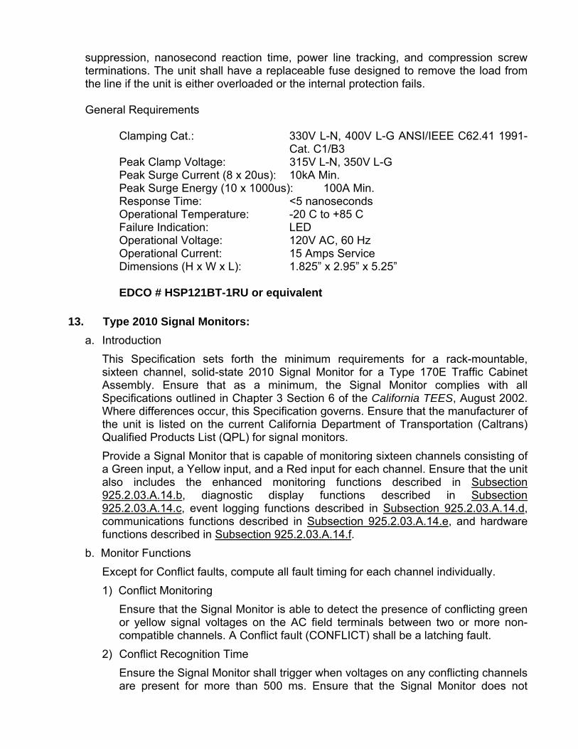
suppression, nanosecond reaction time, power line tracking, and compression screw terminations. The unit shall have a replaceable fuse designed to remove the load from the line if the unit is either overloaded or the internal protection fails.
General Requirements
Clamping Cat.: 330V L-N, 400V L-G ANSI/IEEE C62.41 1991-Cat. C1/B3
Peak Clamp Voltage: 315V L-N, 350V L-G Peak Surge Current (8 x 20us): 10kA Min. Peak Surge Energy (10 x 1000us): 100A Min. Response Time: <5 nanoseconds Operational Temperature: -20 C to +85 C Failure Indication: LED Operational Voltage: 120V AC, 60 Hz Operational Current: 15 Amps Service Dimensions (H x W x L): 1.825” x 2.95” x 5.25” EDCO # HSP121BT-1RU or equivalent
13. Type 2010 Signal Monitors:
a. Introduction
This Specification sets forth the minimum requirements for a rack-mountable, sixteen channel, solid-state 2010 Signal Monitor for a Type 170E Traffic Cabinet Assembly. Ensure that as a minimum, the Signal Monitor complies with all Specifications outlined in Chapter 3 Section 6 of the California TEES, August 2002. Where differences occur, this Specification governs. Ensure that the manufacturer of the unit is listed on the current California Department of Transportation (Caltrans) Qualified Products List (QPL) for signal monitors.
Provide a Signal Monitor that is capable of monitoring sixteen channels consisting of a Green input, a Yellow input, and a Red input for each channel. Ensure that the unit also includes the enhanced monitoring functions described in Subsection 925.2.03.A.14.b, diagnostic display functions described in Subsection 925.2.03.A.14.c, event logging functions described in Subsection 925.2.03.A.14.d, communications functions described in Subsection 925.2.03.A.14.e, and hardware functions described in Subsection 925.2.03.A.14.f.
b. Monitor Functions
Except for Conflict faults, compute all fault timing for each channel individually.
1) Conflict Monitoring
Ensure that the Signal Monitor is able to detect the presence of conflicting green or yellow signal voltages on the AC field terminals between two or more non-compatible channels. A Conflict fault (CONFLICT) shall be a latching fault.
2) Conflict Recognition Time
Ensure the Signal Monitor shall trigger when voltages on any conflicting channels are present for more than 500 ms. Ensure that the Signal Monitor does not

trigger when voltages on any conflicting channels are present for less than 200 ms. Conflicting signals sensed for more than 200 ms and less than 500 ms may or may not trigger the unit.
3) 24VDC Monitoring VDC
Ensure that the Signal Monitor is able to detect that the cabinet +24 Vdc supply has fallen below 18 Vdc. A 24VDC failure (VDC FAIL) shall be a latching fault.
4) 24VDC Recognition Time
Ensure that the Signal Monitor shall trigger when the voltage on the +24V input is below 18 Vdc for more than 500 ms. Ensure that the Signal Monitor does not trigger when the voltage on the +24V input is below 18 Vdc for less than 200 ms. A voltage level of +22 Vdc will be required to prevent the unit from triggering.
5) Controller Watchdog Monitoring
Ensure that the Signal Monitor triggers when the Watchdog input does not toggle within the programmed time period (WDT ERROR). Ensure that the unit remains latched in the fault state until reset by the Reset button, an External Reset input command, or AC Line voltage restoring from a AC Line Brownout event (see 2.4). Ensure that a reset resulting from an AC Line Brownout event does not clear the WDT ERROR LED.
6) Controller Watchdog Latch Option
Ensure a programming option sets the Watchdog monitoring function to a latching mode and that only a reset from the Reset button or External Reset input can clear a Watchdog fault. An AC Line brownout condition will not reset the fault.
7) Controller Watchdog Recognition Time
Ensure a programming option sets the maximum Watchdog recognition time to: 1000 + or - 100 ms; or 1500 + or - 100 ms.
8) Controller Watchdog Enable Switch
Provide an internal switch to disable the Watchdog monitoring function. Mount the switch on the PCB and be clearly label "WD ENABLE - ON...OFF". Ensure that placement of the switch in the OFF position causes monitoring of the Watchdog to be inhibited.
9) WDT ERROR LED Control
Ensure that the WDT ERROR LED illuminates when the unit has been triggered by a Watchdog fault. Ensure that it can only be cleared by a reset command from the front panel Reset switch or External Reset input. If the Watchdog monitoring function is inhibited due to the Watchdog Enable switch, the WDT ERROR LED shall flash at a 0.5 Hz rate.
10) AC Line Monitoring
a) AC Line Brownout Recognition

Ensure that the Signal Monitor is able to detect that the AC Line has fallen below 98 + or - 2 Vac for greater than 400 + or - 50 ms. This shall force the output Relay to the de-energized "fault" state, enable the Stop-Time output, and cause the AC POWER LED to flash at a 2 Hz rate. Ensure that the unit maintains this state until the AC Line voltage rises above 103 + or - 2 Vac for greater than 400 50 ms. Provide a jumper option which will change the AC Brownout dropout level to 92 + or - 2 Vac and the restore level to 98 + or - 2 Vac.
b) AC Line Power-up and Brownout Delay Time
When the AC Line is greater than 103 + or - 2 volts after power-up or Brownout restore, ensure that the Signal Monitor holds the Output Relay in the de-energized "fault" state and enable the Stop-Time output, for a period of not less than 6.0 + or - 0.5 seconds and not greater than 10.0 + or - 0.5 seconds. Ensure that this flash interval is terminated after at least 6.0 + or - 0.5 seconds if the Signal Monitor has detected at least five transitions of the Watchdog input. If the Signal Monitor does not detect five transitions of the Watchdog input before 10.0 + or - 0.5 seconds, ensure that the Signal Monitor goes to the fault state. During this interval, ensure that the AC POWER LED flashes at a 4 Hz rate.
c) Red Fail Monitoring
Ensure that the Signal Monitor is able to detect the absence of an active voltage on the green and yellow and red field signal inputs of a channel. Red Fail fault (RED FAIL) shall be a latching fault. Ensure that the Red Fail monitoring function is enabled for all channels except when the Red Enable input is not active, or pin #EE is active, or Special Function #1 input is active, or Special Function #2 input is active.
d) Red Fail Recognition Time
Ensure the Signal Monitor triggers when an active voltage on one of the three inputs of a channel are absent for more than 1500 ms. Ensure that the Signal Monitor does not trigger when an active voltage on one of the three inputs of a channel are absent for less than 1200 ms. Channels without proper voltages sensed for more than 1200 ms and less than 1500 ms may or may not trigger the unit. Provide an option switch (RF 2010) which will change the fault recognition time to between 700 ms and 1000 ms.
e) Red Interface Cable Fault
Ensure a programming option is provided such that operating without the Red Interface cable installed shall cause the Signal Monitor to enter the fault mode causing the Output relay contacts to close and enabling the Stop-Time output to the controller. To indicate this fault mode, ensure that the Red Fail indicator is illuminated with all fault channel indicators Off.
Ensure that any Red Fail preemption control to the monitor uses the Special Function inputs #1 or #2.

f) Dual Indication Monitoring
Ensure that the Signal Monitor is able to detect the presence of active voltage on the green and yellow, green and red, or yellow and red field signal inputs of a channel. GYR Dual Indication fault (DUAL IND) shall be a latching fault. Ensure this function is enabled on a per channel basis using dip switches mounted on the PCB labeled "CH1" through "CH16". Ensure that the GYR Dual Indication monitoring function is enabled for all selected channels except when the Red Enable input is not active or pin #EE is active.
g) GY Dual Indication Monitoring
Ensure that the Signal Monitor is able to detect the presence of active voltage on the green and yellow field signal inputs of a channel. GY Dual Indication fault (DUAL IND) shall be a latching fault. Enable this function with a dip switch on the PCB labeled "GY ENABLE". When the switch is in the ON position, monitor all channels for simultaneous active green and yellow inputs on a channel. When selected by the GY ENABLE switch, ensure that the GY Dual Indication monitoring function is disabled when pin #EE is active.
h) Dual Indication Recognition Time
Ensure that the Signal Monitor triggers when multiple inputs are active on a channel for more than 500 ms. Ensure that the Signal Monitor does not trigger when multiple inputs are active on a channel for less than 250 ms. Channels with multiple voltages active for more than 250 ms and less than 500 ms may or may not trigger the unit.
i) Sequence (Short or Absent Yellow) Monitoring
Ensure that the Signal Monitor is able to detect that a channel has not provided an adequate Yellow Clearance interval during a green to yellow to red sequence. A Sequence failure (SEQUENCE) shall be a latching fault. Ensure that this function is enabled on a per channel basis using dip switches mounted on the PCB labeled "CH1" through "CH16". Ensure that the Sequence monitoring function is enabled for all selected channels except when the Red Enable input is not active or pin #EE is active.
j) Sequence Recognition Time
The minimum Yellow Clearance interval may be modified by switches mounted on the PCB labeled "YEL TIME 1", "YEL TIME 2", and "YEL TIME 3". Ensure that the Yellow Clearance interval is 2.7 seconds plus 0.2 seconds times the binary sum of the three switches. The minimum Yellow Clearance interval shall therefore have a range of 2.7 seconds to 4.1 seconds, 0.1 seconds.
k) Recurrent Pulse Detection (RP Detect)
Ensure that the Signal Monitor detects Conflict, Red Fail, and Dual Indication faults that result from intermittent or flickering field signal inputs. These recurring pulses shall result in a latching fault with the RP DETECT indicator illuminated along with the resulting Conflict, Red Fail, or Dual Indication indicator. Provide an option switch to disable the RP detect function.

l) Configuration Change Monitoring
On power-up, reset, and periodically during operation, ensure that the Signal Monitor compares the current configuration settings with the previously stored value and if the settings have changed, the Signal Monitor automatically logs the new setting. Ensure that these settings include the permissive diode matrix, all switches, all jumpers, and the Watchdog Enable switch.
Provide a programming option such that any change in the configuration parameters will cause the Signal Monitor to enter the fault mode causing the Output relay contacts to close and enabling the Stop-Time output to the controller. To indicate this fault mode ensure that the PCA indicator will flash at a 4 Hz rate. Depressing the Reset button for 5 full seconds is required to clear this fault and log the new configuration parameters.
If the programming option is not selected, ensure that the unit does not set the fault mode but will still log the configuration change.
m) Program Card Ajar
Ensure that when the Programming Card is removed or not seated properly, the Signal Monitor forces the Output Relay to the de-energized "fault" state, enable the Stop-Time output, and illuminate the PCA LED. A reset command from the front panel Reset switch or External Reset input is required once the Program Card is in place.
n) Exit Flash
When the Signal Monitor exits the flash state (Output relay de-energized) as a result of a Reset command or AC Line brownout restore, ensure that the Stop Time output goes to the inactive state 250 + OR - 50 ms before the Output relay transfers to the energized state. This transition will provide an early indication to the Controller Unit that the cabinet will transfer from flash to signal operation.
11. Display Functions
Ensure that it is possible to view the active channels for each individual color (GYR) during operation and when latched in a fault state. When the Signal Monitor is latched in a fault state ensure that it is also be possible to view the active channels for each individual color and fault status for each channel for the current fault and the two previous faults.
1) Previous Fault GYR Display
When the Signal Monitor has been triggered by a fault the channel status display will alternate between the channels which were involved in the fault (fault status) for 2 seconds, and the field signals active at the time of the fault for 6 seconds. The channels involved in the fault will flash their respective Green, Yellow, and Red indicators simultaneously at a 4 Hz rate for the 2 second interval.
The two previous faults may also be displayed individually. This status is not reset by an AC Line power interruption. To enter this display mode remove the Program Card. The sequence is as follows:
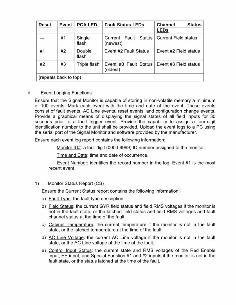
Reset Event PCA LED Fault Status LEDs Channel Status LEDs
--- #1 Single flash
Current Fault Status (newest)
Current Field status
#1 #2 Double flash
Event #2 Fault Status Event #2 Field status
#2 #3 Triple flash Event #3 Fault Status (oldest)
Event #3 Field status
(repeats back to top)
d. Event Logging Functions
Ensure that the Signal Monitor is capable of storing in non-volatile memory a minimum of 100 events. Mark each event with the time and date of the event. These events consist of fault events, AC Line events, reset events, and configuration change events. Provide a graphical means of displaying the signal states of all field inputs for 30 seconds prior to a fault trigger event. Provide the capability to assign a four-digit identification number to the unit shall be provided. Upload the event logs to a PC using the serial port of the Signal Monitor and software provided by the manufacturer.
Ensure each event log report contains the following information:
� Monitor ID#: a four digit (0000-9999) ID number assigned to the monitor.
� Time and Date: time and date of occurrence.
� Event Number: identifies the record number in the log. Event #1 is the most recent event.
1) Monitor Status Report (CS)
Ensure the Current Status report contains the following information:
a) Fault Type: the fault type description.
b) Field Status: the current GYR field status and field RMS voltages if the monitor is not in the fault state, or the latched field status and field RMS voltages and fault channel status at the time of the fault.
c) Cabinet Temperature: the current temperature if the monitor is not in the fault state, or the latched temperature at the time of the fault.
d) AC Line Voltage: the current AC Line voltage if the monitor is not in the fault state, or the AC Line voltage at the time of the fault.
e) Control Input Status: the current state and RMS voltages of the Red Enable input, EE input, and Special Function #1 and #2 inputs if the monitor is not in the fault state, or the status latched at the time of the fault.

2) Previous Fault Log (PF)
Ensure the Previous Fault log contains the following information:
a) Fault Type: the fault type description.
b) Field Status: the latched field status with RMS voltages, and fault channel status at the time of the fault.
c) Cabinet Temperature: the latched temperature at the time of the fault.
d) AC Line Voltage: the AC Line voltage at the time of the fault.
e) Control Input Status: the latched state of the Red Enable input, EE input, and Special Function #1 and #2 inputs at the time of the fault.
3) AC Line Event Log (AC)
The AC Line log shall contain the following information:
a) Event Type: describes the type of AC Line event that occurred.
Power-up—AC on, monitor performed a cold start
Interrupt—AC Line < Brownout level
Restore—AC restored from brown-out or interruption (AC Off), no cold start
b) AC Line Voltage: the AC Line voltage at the time of the event.
4) Monitor Reset Log (MR)
Ensure the Monitor Reset log contains the following information:
a) The monitor was reset from a fault by the front panel Reset button or External Reset input.
5) Configuration Change Log (CF)
Ensure the Configuration Change log contains the following information:
a) Program Card Matrix: the permissive programming for each channel.
b) Yellow Disable Jumpers: the Yellow Disable programming for each channel.
c) Dual/Sequence Switches: the switch programming for each channel.
d) Option Switches: RF 2010, RP Disable, GY Enable, SF1 Polarity, Sequence Timing, Minimum Flash Enable, Configuration Fault Enable, Red Cable Fault enable, AC Brownout timing.
e) Watchdog Programming: Watchdog Enable, Watchdog Latch, and Watchdog timing.
f) Configuration CRC: A unique CRC value which is based on the configuration of items #a though #e above.
Indicate on the log, which items have been changed since the last log entry.

6) Signal Sequence Log
Provide a log that graphically displays all field signal states for up to 30 seconds prior to the current fault trigger event. Ensure that the resolution of the display is at least 50 milliseconds.
e. Communications Functions
1) Controller Unit Communications
Ensure that the Signal Monitor is compatible with the Command/Response protocol of BI Tran Systems Inc. Model 233 Software. Ensure the unit supports command types 02 and 07.
2) Personal Computer Communications
Have the manufacturer provide software to access the Signal Monitor status and event logs described in Subsection 925.2.01.A.14.d. Ensure this software operates with Microsoft Windows 2000TM or Windows XPTM
f. Hardware
1) Red Monitoring
a) Red Field Inputs
Ensure that the Signal Monitor is capable of monitoring sixteen Red field signals. Ensure that a Red input is sensed active when the input voltage exceeds 70 Vrms. Ensure that a Red input is sensed not active when the input voltage is less than 50 Vrms. A Red input may or may not be sensed active when the input voltage is between 50 Vrms and 70 Vrms.
b) Red Enable Input
Ensure that the Red Enable input provides an AC input to the unit which enables Red Monitoring, Dual Indication Monitoring, and Sequence monitoring when the input is sensed active.
Ensure that the Red Enable input is sensed active when the input voltage exceeds 70 Vrms. Ensure that the Red Enable input is sensed not active when the input voltage is less than 50 Vrms. The Red Enable input may or may not be sensed active when the input voltage is between 50 Vrms and 70 Vrms.
c) Special Function Preemption Inputs
Ensure that the Special Function Preemption inputs #1 and #2 provide an AC input to the unit which disables only Red Fail Monitoring (Lack of Output) when either input is sensed active.
Ensure that a Special Function input is sensed active when the input voltage exceeds 70 Vrms. Ensure that a Special Function input is sensed not active when the input voltage is less than 50 Vrms. A Special Function input may or may not be sensed active when the input voltage is between 50 Vrms and 70 Vrms.
Use a PCB mounted switch to provide the option to invert the active status of the Special Function #1 input. When the switch is in the ON position, ensure that the

Special Function #1 input is sensed not active when the input voltage exceeds 70 Vrms. Ensure that the Special Function #1 input is sensed active when the input voltage is less than 50 Vrms. The Special Function #1 input may or may not be sensed active when the input voltage is between 50 Vrms and 70 Vrms.
d) Red Interface Connector
This connector provides the required inputs for the unit to monitor the Red field signal outputs. Ensure the connector is a 3M #3428-5302 type or equivalent and be polarized to insure proper mating with the cable. Ensure Ejector latches are included to facilitate removal and prevent the cable from inadvertently disconnecting. Ensure the unit shall function as a standard 210 Signal Monitor when the cable is disconnected. Use the pin assignments shown in Table 1.
Table 1
Pin Function Pin Function
1 Channel 15 Red 11 Channel 9 Red
2 Channel 16 Red 12 Channel 8 Red
3 Channel14 Red 13 Channel 7 Red
4 Chassis Ground* 14 Channel 6 Red
5 Channel 13 Red 15 Channel 5 Red
6 Special Function #2 16 Channel 4 Red
7 Channel 12 Red 17 Channel 3 Red
8 Special Function #1 18 Channel 2 Red
9 Channel 10 Red 19 Channel 1 Red
10 Channel 11 Red 20 Red Enable
*A jumper option shall be provided to allow the connection of Pin #4 to be made with Chassis Ground.
2) Front Panel
Ensure the front panel is constructed of sheet aluminum with a minimum thickness of 0.090 in. (2.286 mm), and finished with an anodized coating. Ensure the model information shall be permanently displayed on the front surface.
a) Indicators
Ensure that all display indicators are mounted on the front panel of the Signal Monitor and are water clear, T-1 package, Super Bright type LEDs. Ensure that all fault LEDs are red except the AC POWER indicator which is green. Provide a separate Red, Yellow, and Green indicator for each channel. Label the indicators and provide the information as follows:
(1) AC POWER
Ensure the AC Power indicator flashes at a rate of 2 Hz when the unit has detected a low voltage condition as described in Subsection 925.2.03.A.14.b.10).a. Ensure the AC POWER indicator flashes at a rate of 4 Hz during the minimum flash interval as described in Subsection 925.2.03.A.14.b.10).b. Ensure that the indicator illuminates when the AC Line voltage level is restored above the brownout level. Ensure the indicator extinguishes when the AC Line voltage is less than 80 Vac.
(2) VDC FAILED
Ensure the VDC FAILED indicator illuminates when a 24VDC fault condition is detected. This indicator remains extinguished if the monitor has not been triggered by a 24VDC fault.
(3) WDT ERROR
Ensure the WDT ERROR indicator illuminates when a controller Watchdog fault is detected. Ensure the WDT Error indicator flashes ON once every 2 seconds if the WD Enable switch on the monitor is placed in the OFF position to disable Watchdog monitoring, or the AC Line voltage is below the Watchdog disable level.
(4) CONFLICT
Ensure that the CONFLICT indicator illuminates when a conflicting signal fault is detected.
(5) DIAGNOSTIC
Ensure the DIAGNOSTIC indicator illuminates when one of the following faults are detected: Internal Watchdog fault, Memory Test fault, or Internal power supply fault. This indicator is intended to inform the service technician of a monitor hardware or firmware failure.
(6) RED FAIL
Ensure the RED FAIL indicator illuminates when an absence of signal is detected on a channel(s). Ensure the RED FAIL indicator flashes ON once every two seconds if the RED ENABLE input is not active, or a Special Function input is active, or the EE input is active
(7) DUAL IND.
Ensure the Dual IND. indicator illuminates when a GY-Dual or GYR-Dual Indication fault is detected on a channel(s).
(8) SEQUENCE
Ensure the Sequence indicator illuminates when the minimum Yellow Clearance time has not been met on a channel(s).
(9) PCA
Ensure the PCA indicator illuminates if the Program Card is absent or not properly seated.

If the unit is in the Diagnostic Display mode, ensure the PCA indicator flashes ON (once, twice, or three times) to indicate the fault event number being displayed. See Subsection 925.2.03.A.14.c.
(10) RP DETECT
Ensure the RP DETECT indicator illuminates when the unit has detected a Conflict, Red Fail, or Dual Indication fault as a result of recurring pulse field inputs.
(11) CHANNEL STATUS
Ensure that during normal operation the 48 Channel Status indicators displays all active signals (Red, Green, and Yellow).
In the fault mode, ensure that the Channel Status indicators display all signals active at the time of the fault for six seconds and then indicate the channels involved in the fault for 2 seconds.
b) Front Panel Control
(1) RESET Button
Provide a momentary SPST Control switch labeled RESET on the unit front panel to reset the monitor circuitry to a non-failed state. Position the switch on the front panel such that the switch can be operated while gripping the front panel handle. Ensure that a reset command issued from either the front panel button or External Reset input is a one-time reset input to prevent the unit from constant reset due to a switch failure or constant external input, and causes all LED indicators to illuminate for 300 ms.
The Reset button also provides control of the Diagnostic Display mode. For a complete description of Diagnostic Display operation, see Subsection 925.2.03.A.14.c.
c) Serial Communications Connector Use this connector to provide EIA-232 serial communications. Ensure that
it is an AMP 9721A or equivalent 9 pin metal shell D subminiature type with female contacts. Refer to Table 2 for Pin assignments.

Table 2
Pin Function
1 DCD*
2 TX DATA
3 RX DATA
4 DTR (Data Terminal Ready)
5 SIGNAL GROUND
6 DSR
7 DSR*
8 CTS*
9 NC
* Provide Jumper options to allow the connection of Pin #4 to be made with Pin #7, and the connection of Pin #8 to be made with Pin #1.
3) Electronics
a) RMS Voltage Sampling
Use high speed sampling techniques to determine the true RMS value of the AC field inputs. Sample each AC input at least 32 times per cycle. Ensure that the RMS voltage measurement is insensitive to phase, frequency, and waveform distortion.
b) Internal MPU Watchdog
Use a microprocessor for all timing and control functions. Verify continuing operation of the microprocessor by an independent monitor circuit, that forces the Output Relay to the de-energized "fault" state, enable the Stop-Time output, and illuminate the DIAGNOSTIC indicator if a pulse is not received from the microprocessor within 300 ms.
If the microprocessor should resume operation, ensure the Signal Monitor continues to operate. Ensure that this monitoring circuit is also configurable to latch in the fault state. Ensure the unit requires a power-up cycle to reset the circuit once it is triggered.
c) Sockets
In the interest of reliability, ensure that only the PROM memory device for the microprocessor firmware is socket mounted. Ensure that the PROM memory socket is a precision screw machine type socket with a gold contact finish providing a reliable gas tight seal. Low insertion force sockets or sockets with "wiper" type contacts are not acceptable.
d) Internal Power Supply
Use a built-in, high-efficiency switching power supply to generate all required internal voltages. Ensure that all supply voltages regulated. Failure of the

internal power supply to provide proper operating voltages shall force the output Relay to the de-energized "fault" state, enable the Stop-Time output, and illuminate the DIAGNOSTIC indicator. Provide a user replaceable slow blow fuse for the AC Line input. Ensure the unit is operational over the AC Line voltage range of 75 Vac to 135 Vac.
e) EIA-232 Interface
Ensure the EIA-232 port interface electronics is electrically isolated from all monitor electronics except chassis ground.
f) Configuration Parameters
Select user-programmed configuration settings using PCB mounted switches or jumpers. Designs requiring a Personal Computer (PC) to program or verify the configuration parameters are not acceptable. Ensure that user-programmed configuration settings that are transferred to memory are stored in a programmable read-only memory (PROM or EEPROM). Designs using a battery to maintain configuration data are not acceptable.
g) Field Terminal Inputs
Ensure that all 120 Vac field terminal inputs provide an input impedance of 150K 50K ohms and be terminated with a discrete resistor having a power dissipation rating of 0.5 Watts or greater and a voltage rating exceeding 350 volts.
h) Component Specifications
Ensure that all electrical components used in the Signal Monitor are rated by the component manufacturer to operate beyond the full unit operating temperature range of –29 oF to 165 oF(-34 oC to +74 oC).
i) Printed Circuit Boards
Ensure that all printed circuit boards meet the requirements of the California Traffic Signal Control Equipment Specifications, January 1989, plus the following requirements to enhance reliability:
(1) All plated-through holes and exposed circuit traces are plated with solder.
(2) Both sides of the printed circuit board are covered with a solder mask material.
(3) The circuit reference designation for all components and the polarity of all capacitors and diodes are clearly marked adjacent to the component. Ensure that Pin #1 for all integrated circuit packages is designated on both sides of all printed circuit boards.
(4) All electrical mating surfaces are gold plated.
(5) All printed circuit board assemblies are coated on both sides with a clear moisture-proof and fungus-proof sealant.
(6) All components and wire harnesses are mounted to the PCB using plated holes. "Piggy back" connections or jumper wires are not acceptable.

14. Model GDI 242 DC Isolator
Provide Model GDI 242 DC Isolators that are in accordance with the latest version of CALTRANS Specifications as referenced earlier in this section. Ensure that the GDI 242 isolator input signal polarity may easily be inverted without the use of tools. Provide isolators that:
Output is OFF for input voltages greater than 12 volts;
Output is ON for voltages of less than 8 volts that have a duration of at least 5 to 25 ms (optional 2-7 ms);
Minimum output pulse width is 100 ms with a valid input (can be disabled);
Output is optically isolated open collector NPN transistor;
Capable of sinking 50 ma when on;
Can register a new input within 25 ms of the old signal going away; and
Output clamped on power up and down
Compatible with 2070 controllers and latest version of Caltrans TEES including errata
15. Model 200 Switchpack
Provide Model 200 Switchpacks that are in accordance with the latest version of CALTRANS Specifications as referenced earlier in this section.
16. Model 204 Flasher Unit
Provide Model 204 Flasher Units that are in accordance with the latest version of CALTRANS Specifications as referenced earlier in this section.
17. Flash Transfer Relay
Provide Flash Transfer Relays that are in accordance with the latest version of CALTRANS Specifications as referenced earlier in this section.
18. Cabinet Model 332
Provide Cabinet Model 332 that meets the CALTRANS Specification with the addition of surge protection as detailed in Table 925-1 Model 332 Default Input Files Assignment Detail and Table 925-2 Required Surge Arrestors for Model 332 Cabinet.
Supply Model 332 (lower input panel) cabinets, with housing Type 1B, and all components as described in these specifications.
Supply cabinets having two input files which conform to the CALTRANS Specifications and configured to accept two 2070 controllers in the top portion of the cabinet.
Configure the cabinet for dial up communications. Mount a two (2) circuit Buchanan connector on the right side panel (from rear door).
Mount a phone jack with a RJ11 connector above or to the right of the Buchanan terminal block.
Wire the phone jack to the Buchanan and to the Terminal Block (TB0) in accordance with Figure 925-1.

A manual jack shall be installed on the police panel. The jack shall inter-mate with a three circuit 1/4 inch (6.35 mm) diameter phone plug. The tip and ring (middle) circuits of the jack shall-be connected to the logic ground and the interval advance inputs of controller unit. When the manual hand cord is plugged into the jack and the pushbutton is pressed, logic ground shall be connected to the interval advance input of the controller unit. A manual pushbutton with cord shall be provided. The cord shall have a minimum length of 3 feet (0.9 m). It shall have a 1/4 inch (6.35 mm) diameter, three circuit plug connected to one end and a manual pushbutton enclosed in a hand held enclosure at the other end. A complete cycle (push-release) of the manual pushbutton shall terminate the controller unit interval which is active except the vehicular yellow and all red clearance intervals. Cycling the push-button during the vehicular yellow or all red clearance intervals shall not terminate the timing of those intervals. Supply cabinets with a 12” x 16” x 1” Air Filter
19. Cabinet Model 332A with Auxiliary Output File
Ensure that this unit meets the requirements of Subsection 925.2.03.A.18 above, except that the cabinet is configured with an Auxiliary Output File. Additionally, the field wiring terminals may be mounted on the rear of the input file.
B. Fabrication
Refer to Subsection 925.2.06.A.1 for controller cabinet minimum fabrication specifications.
C. Acceptance
Refer to Subsection 925.2.01.A for compliance with CALTRANS QPL.
D. Materials Warranty
Refer Subsection 925.2.D for Materials Warranties.


Table 925 – 1 Model 332 Default Input Files Assignment Detail
Slot 1 2 3 4 5 6 7 8 9 10 11 12 13 14 Type Det Det Det Det Det Det Det Det Det DC DC DC
Channel 1
C1 Pin 56 39 63 47 58 41 65 49 60 80 67 68 81
Function �1 �2 �2 �2 CALL
�3 �4 �4 �4 CALL
�1 INTERVAL ADVANCE
�2 PED
�6 PED
FLASH
Field Term
TB-2 1,2
TB-2 5,6
TB-2 9,10
TB-4 1,2
TB-4 5,6
TB-4 9,10
TB-6 1,2
TB-6 5,6
TB- 6 9,10
NC TB- 8
4,6
TB- 8
7,9
NC
Channel 2
C1 Pin 56 43 76 47 58 45 78 49 62 53 69 70 82
Function �1 �2 �2 �2 CALL
�3 �4 �4 �4 CALL
�3 MCE �4 PED
�8 PED
STOP TIME
Upper Input File ( I
)
Field Term
TB-2 3,4
TB-2 7,8
TB-2 11,12
TB-4 3,4
TB-4 7,8
TB-4 11,12
TB-6 3,4
TB-6 7,8
TB-6 11,12
NC TB-8
5,6
TB-8
8,9
NC
Slot 1 2 3 4 5 6 7 8 9 10 11 12 13 14 Type Det Det Det Det Det Det Det Det Det TBA TBA DC
Channel 1
C1 Pin 55 40 64 48 57 42 66 50 59 54 71 72 51
Function �5 �6 �6 �6 CALL
�7 �8 �8 �8 CALL
�5 EVA EVB R/R
Field Term
TB-3 1,2
TB-3 5,6
TB-3 9,10
TB-5 1,2
TB-5 5,6
TB-5 9,10
TB-7 1,2
TB-7 5,6
TB- 7 9,10
TB- 9
4,6
TB- 9
7,9
TB- 9 10,12
Channel 2
C1 Pin 55 44 77 48 57 46 79 50 61 75 73 74 52
Function �5 �6 �6 �6 CALL
�7 �8 �8 �8 CALL
�7 EVC EVD
Lower Input File (
J )
Field Term
TB-3 3,4
TB-3 7,8
TB-3 11,12
TB-5 3,4
TB-5 7,8
TB-5 11,12
TB-7 3,4
TB-7 7,8
TB-7 11,12
TB-9
5,6
TB-9
8,9
TB- 9 11,12

Table 925-2 Required Surge Arrestors for Model 332 Cabinet Field Terminal Block Terminals Required Arrestor
TB-8 1-12 EDCO PC642C-030 plug in arrestors in PCB1B Terminal Block TB-9 10-12 EDCO PC642C-030 plug in arrestors in PCB1B Terminal Block TB-9 4-9 EDCO PCB1B Terminal Block only TB-2, TB-3, TB-4, TB-5, TB-6, TB-7
1-12 EDCO SRA-6LB
Figure 925-1—Wiring Diagram for Dial-up Communications
Note: For a typical signal installation, the Model 332 cabinet is the design standard.
YellowRed
6 8
BUCHANAN TERMINAL BLOCK
10
9 5 3 1
4
Green
2
7
Black
TERMINAL BLOCK TB0

925.2.04 Flashing Beacon Assembly
A. Requirements
This specification is for a flashing signal cabinet, which consists of an aluminum cabinet containing a flasher assembly, Field connection terminal block, surge arrestor and circuit breaker wired in a manner to operate flashing beacons. Refer to Figure 925-12.
SPA 100
TB
NEMA FLASHER
AC BRKR
Note: Front view of cabinet Door Assembly not shown No scale
Figure 925-12—Typical Flashing Signal Cabinet Layout
1. Cabinet
Supply a NEMA Type 3R cabinet assembly, manufactured of aluminum with a minimum thickness of 0.125 inches (3 mm).
Ensure that the cabinet exterior has a smooth, uniform “bare” aluminum finish with all joints between adjoining cabinet components (sides and bottom) continuously welded on the outside to prevent the intrusion of moisture and dust.

42
Ensure that all welds are free of cracks, blow holes and other irregularities.
Supply a cabinet with the following exterior dimensions:
Minimum Maximum
Height 14 inches (350 mm) 18 inches (450 mm)
Width 10 inches (250 mm) 14 inches (350 mm)
Depth 10 inches (250 mm) 10 inches (250 mm)
Use a cabinet door that is double flanged on all four sides to prevent the entry of dirt and liquids when the door is open.
Install a one-piece gasket formed around the door opening to insure a weather tight seal when the door is secured.
Attach the door to the cabinet housing by a continuous tamper proof hinge.
Equip each cabinet with a Corbin #2 lock and one key. Police panel type locks are not acceptable.
Install an aluminum back panel in the cabinet, mounted on standoffs, to facilitate mounting of internal components.
Install exterior aluminum mounting brackets, which extend a minimum of 1.75 inches (44 mm) and a maximum of 2.5 inches (63 mm) from the top and bottom of the cabinet.
Use brackets that extend across the full width of the cabinet back on the top and bottom.
Provide these brackets with holes for mounting to a flat surface with screws and vertical slots for banding to steel, concrete or wooden signal poles.
2. Flasher Unit
Supply a standard plug in two circuits NEMA flasher.
Ensure that the flasher is of all solid state construction, meets the requirements of the NEMA standards and is rated at a minimum of 10 A per circuit.
Ensure that the flasher utilizes zero voltage turn-on and turn-off current and is capable of dimming outputs.
3. Surge Arrestor
Supply a flasher cabinet that incorporates an AC surge arrestor (EDCO SPA-100 or equivalent) to protect the internal components from lighting and over voltages on the AC service input.
The requirements for the surge arrestor are:
Peak Surge Current 15000 A
Peak Surge Voltage @ 10KA 680 V
Energy Handling 220 J
Power Dissipation Rate 1.5 W maximum
Continuous AC Voltage 130 V AC RMS
Initial Breakdown (1mA) 212 V

43
Typical Capacitance 4000 pF
Operating Temp. -40 ºF to 185 ºF (-40 ºC to 85 ºC)
4. Circuit Breaker
Include a 15 A circuit breaker in the cabinet. (Square D QOU 115 Series or equivalent).
5. Terminal Block
Include a four position terminal block in the cabinet for making field connections. Properly label all field terminal connections.
6. Construction
Assemble the flasher assembly, terminal block, surge arrestor and circuit breaker in the cabinet as shown on the attached drawing.
Wire all components together as a working unit, thus requiring only field connections to and from the AC power and flashing beacons.
B. Fabrication
Refer to Subsection 925.2.05.A.1 for controller cabinet minimum fabrication specifications.
C. Acceptance
General Provisions 101 through 150.
D. Materials Warranty
Refer to Subsection 925.2.D for Materials Warranties.
925.2.05 Flashing Signal Cabinet with Pager A. Requirements
This specification is for a flashing signal cabinet with pager which consists of an aluminum cabinet containing a flasher assembly, pager, field connection terminal block, surge arrestor and circuit breaker wired in a manner to operate school flashing beacons. Refer to Figure 925-13.
1. Cabinet
Supply a NEMA Type 3R cabinet assembly that is manufactured of aluminum with a minimum thickness of 0.125 inches (3 mm).
Ensure that the cabinet exterior has a smooth, uniform natural aluminum finish, and that all joints between adjoining cabinet components (sides and bottom) are continuously welded on the outside to prevent the intrusion of moisture and dust.
Ensure that all welds are free of cracks, blow holes and other irregularities.
The exterior dimensions of the cabinet are as follows:
Minimum Maximum
Height 14 inches (350 mm) 18 inches (450 mm)
Width 10 inches (250 mm) 14 inches (350 mm)
Depth 10 inches (250 mm) 10 inches (250 mm)

Supply a cabinet door that is double flanged on all four sides to prevent the entry of dirt and liquids when the door is open.
Use a one-piece gasket that is formed around the door opening to insure a weather tight seal when the door is secured.
Attach the door to the cabinet housing with a continuous tamper proof hinge.
Provide each cabinet with a Corbin #2 lock and one key. Police panel type locks are not acceptable.
Supply each cabinet with an aluminum back panel mounted on standoffs to facilitate mounting of internal components.
Supply cabinets with exterior aluminum mounting brackets, which extend a minimum of 1.75 inches (44 mm) and a maximum of 2.5 inches (63 mm) from the top and bottom of the cabinet.
Use brackets that extend across the full width of the cabinet back on the top and bottom.
Provide these brackets with holes for mounting to a flat surface with screws and vertical slots for banding to steel, concrete or wooden signal poles.
PAGER
NEMA FLASHER
TB
SPA 100
AC BRKR
Note: Front view of cabinet Door Assembly not shown
No scale
Figure 925-13—Typical Flashing Cabinet with Pager Cabinet Layout
44

45
2. Flasher Unit
Supply a standard plug in, two circuits NEMA flasher.
Ensure that the flasher is of all solid state construction, meets the requirements of the NEMA standards and is rated at a minimum of 10 A per circuit.
Ensure that the flasher utilizes zero voltage turn-on and turn-off current and be capable of dimming outputs.
3. Time Switch
Supply a time switch that meets the requirements as outlined in Section 925.2.06 below in this specification.
4. Surge Arrestor
Supply flasher cabinets that incorporate an AC surge arrestor (EDCO SPA-100 or equivalent) to protect the internal components from lighting and over voltages on the AC service input.
The requirements of the surge arrestor are as follows:
Peak Surge Current 15000 A
Peak Surge Voltage @ 10KA 680 V
Energy Handling 220 J
Power Dissipation Rate 1.5 W maximum
Continuous AC Voltage 130 V AC RMS
Initial Breakdown (1mA) 212 V
Typical Capacitance 4000 pF
Operating Temp. -40 ºF to 185 ºF (-40 ºC to 85 ºC)
5. Circuit Breaker
Include a 15 A circuit breaker in each cabinet. (Square D QOU 115 Series or equivalent).
6. Terminal Block
Include a four position terminal block in each cabinet for making field connections. Properly label all field terminal connections.
7. Construction
Assemble the flasher assembly, terminal block, surge arrestor and circuit breaker in the cabinet as shown on the attached drawing.
Wire all components together as a working unit, thus requiring only field connections of the AC power and flashing beacons.
B. Fabrication
Refer to Subsection 925.2.06.A.1 for controller cabinet minimum fabrication specifications.

46
C. Acceptance
General Provisions 101 through 150.
D. Materials Warranty
Refer to Subsection 925.2.D for Materials Warranties.
925.2.06 Pager Programmable Time Switch with GPS Time Reference This specification sets the minimum acceptable requirements, materials, and workmanship for a solid state time switch that is programmable using existing pager technology. The time switch shall also have the capability of setting the day-of-week and time-of-day from GPS satellite technology.
A. Requirements The time switch unit shall have a wireless pager module able to receive programs and commands generated by a time switch-programming device through a local pager service. The pager module shall be compatible with commercial 900 MHz frequency range alphanumeric paging services using FLEX protocol. The pager module shall work as a radio modem for the time switch. When the pager module receives a message it will pass the message to the time switch for decoding. All addressing (except CAPCODE), timing and on/off command decisions shall be made by the time switch and not by the pager module. The time switch shall be capable of receiving and running the following programs via the paging network: Default Week Plan – the default week plan is a seven-day program with up to 24 program steps for controlling the output relay of the time switch. The time switch stores the default week plan and automatically runs this plan when it is received over the paging network or when an alternate week or override plan expires. If the time switch receives a new default week plan over the paging network it will replace the old plan with the new plan and immediately start running the new plan. Alternate Week Plan – an alternate week plan is a seven-day program with up to 24 program steps for controlling the output relay of the time switch. An alternate week plan runs instead of the default week plan until the alternate week plan expires. The time switch shall immediately start running the alternate week plan when it is downloaded over the paging network. Override Plan – an override plan is a one-day program with up to 24 program steps for controlling the output relay of the time switch. An override plan runs instead of the default or alternate week plan until the override plan expires. The time switch shall immediately start running the override plan when it is received over the paging network. The time switch shall revert back to either the default or alternate week plan (whichever was running at the time the override plan was received) at midnight of the same day or if a page is downloaded that cancels the override plan. Time Set – the day-of-week, hour and minute of the time switch shall be set and reset over the paging network. When a time set page is received, the time switch shall immediate adjust its internal clock accordingly.

47
Setup Time Switch – the time switch shall accept a single page that will download all of the operating parameters to include addressing, day-of-week and time-of-day, default week plan and alternate week plan programming.
If a time switch is being programmed for the first time using on-air addressing, the system shall download the new group and location address, the day and time-of-day, the default week plan for the group and an alternate week plan for the group with a single page.
If a time switch is being moved from one group address to another group address, the system shall download the address change, the day and time-of-day, the default week plan for the new group and an alternate week plan for the new group with a single page.
If programming a time switch without changing its preset address, the operating parameters downloaded will include day and time-of-day, the default week plan for the group and an alternate week plan for the group.
Enclosure The time switch shall be housed in an aluminum enclosure with a means for mounting to a suitable back plane. Mounting holes that provide clearance for at least a #10 screw is required. The mounting hole pattern of the enclosure shall be the same as existing time switches used by the agency to facilitate easy installation. The time switch shall not exceed 3.7”w x 7.5”h x 1.55”d. Interface to the power line and/or to the flasher cabinet shall be provided by means of a terminal block capable of terminating wires sizes up to #14 AWG. The AC power inputs, if any, shall be protected with a fuse and MOV, DC power with a fuse only. A separate terminal point shall be provided for each pole of the relay, AC line, AC neutral, Ground, +12VDC and -12V Common.
Electrical The time switch shall be capable of operating on either 12VDC +/-2VDC or an AC power source between 95 and 135VAC. The AC & DC power supply must be an integral part of the time switch circuit board due to the fact that many flasher cabinets do not have AC power outlets. A separate power supply module, similar to those used for calculators and battery chargers, is not acceptable.
Power Back-up System A means shall be provided to maintain timekeeping and all programming when the line power source (120VAC or 12VDC) is lost. This back-up system shall maintain timekeeping and all programming for not less than 60 days at 25C when fully charged, and shall go on line automatically upon failure of the power source. Upon resumption of power source, the unit shall automatically resume normal operation with the relay output either energized or de-energized based on the last program being run.

48
When the time switch is operating on the back-up system, the indicators and relay output shall be off to conserve back-up power.
Manual Operation The time switch shall be equipped with a push button switch that will allow a technician to manually activate and/or deactivate the relay output. The relay shall remain in the manual condition until the next program step of the default, week plan or override plan, whichever is running.
Indicators The time switch shall have a minimum of four (4) LED indicators to display the following:
When the time switch has power applied and is operating, When the time switch is in the process of receiving a page, When the time switch has failed to receive a page after midnight Saturday, When the output relay is energized or de-energized, When a switch setting error has been made using switch addressing, The group and location number when using DIP switch or on-air addressing, When the time switch is running an empty default week plan, a default week plan with programming, an alternate week plan or an override plan.
Time Switch Addressing
The group and location address in each time switch shall be programmable by DIP switches and on-air over the paging network. It shall be possible to program a unique address on each time switch board by setting two DIP switches. One DIP switch shall be used to set the group address (01-99) and another DIP switch shall be used to set the location address (01-99). This unique address will allow the operator at the computer to program any time switch individually or as part of a complete group. An LED indicator shall continuously display the group and location number once the DIP address has been set. It shall be possible to set and reset the group (01-99) and location (01-99) address on-air via the paging network. An LED indicator shall continuously display the group and location number once the on-air address has been set. The operator shall have the ability to convert from using switch addressing to on-air addressing and back at any time. When converting from on-air to switch addressing, the time switch will retain the on-air address number. Group and/or individual addressing programmed in the pager module is not acceptable.
Program Search Back When the time switch is downloaded with a new default week plan, alternate week plan, day-of-week and time-of-day, or override plan, it shall initiate a search back routine to determine if the relay output should be on or off at the time the download is complete.

49
Pager Receiver Reset In order to insure proper operation of the pager module, the time switch shall reset the pager module at least once per day.
Output Relay
The time switch shall have a SPDT relay output rated at 15 amps resistive at 120VAC.
Antenna Each time switch shall be supplied with an external antenna. The antenna shall be housed in PVC pipe with a Meyers hub for mounting. The antenna shall have a minimum of fifteen feet of coax cable to accommodate mounting the antenna at the top of the pole assembly. A BNC (or equal) connector shall be installed on the coax cable for connection to the time switch.
Program Upload and Download Each time switch shall be supplied with a DB9 connector mounted on the front of the time switch. This connector shall be used to upload and download time switch programming as follows: Upload and download from a central computer: Current time-of-day and day-of-week Default Plan programming Week Plan programming Override Plan programming Actual relay status (ON or OFF) Upload and download from a Palm Pilot: Current time-of-day and day-of-week Default Plan programming Week Plan programming Override Plan programming Upload and download from a hand-held display: Current time-of-day and day-of-week Default Plan programming Week Plan programming Override Plan programming
Download (only) from a computer:
Current time-of-day and day-of-week Default Plan programming Week Plan programming On-Air addressing (new address and change address)

50
Hand-held Display
The maximum dimensions of the hand-held display shall be 8 ½” h x 4 ½” w x 1 ½” d. The and-held display shall have a 6’ cable with a DB9 connector to plug into the DB9 on the time switch. The hand-held display shall have a 2 line, 16 characters per line, LCD display and three push buttons. The hand-held display shall have a built in power supply that will allow the operator to review the previously uploaded program and/or clear the program without being plugged into a time switch. The LCD display and push buttons shall be used to: Clear the programming in the hand-held display, Upload the programming from a time switch, Download the programming to a time switch, Scroll through the default plan program, Scroll through the week plan program, Scroll through the override plan program. The LCD display shall have a back light that automatically illuminates upon connection to a time switch or pressing any of the push buttons. The hand-held display shall automatically turn off the LCD back light and revert the LCD display to the time-of-day and day-of-week after 10 seconds of push button inactivity. It shall be possible to clear all of the programming in the hand-held display. Upon clearing the programming in the hand-held display, the day and time shall revert to Sunday, 12:00 a.m. and shall remain fixed on that day and time until a program has been uploaded from a time switch. The hand-held display shall be capable of uploading the following programming from a time switch: Current time-of-day and day-of-week, Default Plan programming, Week Plan programming, Override Plan programming. It shall be possible to upload the time-of-day, day-of-week and all programming from one time switch to a hand-held display and then download that information to another time switch from the hand-held display. A means shall be provided to maintain timekeeping and all programming in the hand-held display when the unit is not plugged into a time switch. This back-up system shall maintain timekeeping and all programming for not less than 60 days at 25C when fully charged. The number of hand-held displays required by the agency will be specified on the bid document as a separate line item.

51
Palm Pilot Operation The time switch shall have the capability of sending and receiving all programming from a Palm Pilot. The Palm Pilot shall plug into the DB9 located on the front of the time switch. The Palm Pilot shall be capable of uploading and downloading the following programming: Current time-of-day and day-of-week, Default Plan programming, Week Plan programming, Override Plan programming. When the Palm Pilot is synced with the computer running the CPR III System Software, all programming for all Groups shall be loaded into the Palm Pilot.
Audible and Visual Alarm
The audible and visual alarm shall be compact in size and shall plug into the DB9 located on the front of the time switch. The visual alarm shall consist of two (2) LED indicators each flashing at the same rate as the operating LED mounted on the time switch circuit board. The audible alarm shall be a piezo device that shall beep repeatedly when the time switch receives a page that matches the group and location address set on the time switch.
Connector
Each time switch shall be equipped with a circular CPC type connector. This connector shall be identical in style and pin assignment to the connector currently in use by the agency. This requirement will facilitate the direct replacement of time switches currently in use by the agency with the pager programmable time switch. It shall be the responsibility of each bidder to determine the connector style and pin assignment necessary to meet this requirement.
Verify Unit If specified on the bid documents, the bidder shall supply a time switch configured as a verify unit. The verify unit shall be a time switch that complies with the above specification and configured to work with the computer running the pager programmable time switch system software. The verify unit shall receive all pages transmitted by the pager carrier and send the character string received to the computer through a com port on the computer.
This process shall verify that the message sent to the pager carrier from the computer was broadcast over the pager network successfully. The software shall have a screen that will list at least 500 pages that were verified by the system. This list shall include the time, date, actual page message received and a description of the message.
CRC Error Checking To eliminate the possibility of receiving a corrupted page, the time switch firmware shall include an algorithm that generates a “Cyclic Redundancy Check” (CRC) error-checking character set for each page received. If the time switch CRC character set does not match the CRC character set received over the paging network, the time switch shall ignore the page and continue running its

52
program. The bidder will be required to demonstrate the CRC error checking capability to the agency as specified in the Test and Acceptance section of this specification. The Check Sum method of error checking shall not be accepted.
GPS Time Reference Option The time switch shall have the capability of automatically setting the day-of-week and time-of-day using GPS technology. The optional GPS receiver shall plug into the DB-9 connector located on the front of the time switch. If a GPS receiver is used, the time switch shall reset to GPS day and time at least once per day. List of Reference Accounts All bidders shall supply, with their bid, a list of 20 governmental agencies that have operated the proposed pager programmable time switch system for at least one (1) year and currently have at least 20 pager units operating school zone flashers. The list shall include the agency name, contact name and title, and contact phone number. Failure to supply this list with the bid will immediately render the bid non-responsive. B. Warranty The time switch shall be warranted to be free from defects in material and workmanship for a period of two years from the date of shipment. Any warranty service required shall be promptly performed at the manufacturer’s facility or the manufacturer’s authorized service agency. The purchaser will pay transportation costs to such service point, and the manufacturer will pay those costs to return the unit by normal surface transportation means. Service information shall be available to the purchaser consisting of at least schematics, parts locators and parts lists. C. Test and Acceptance The apparent low bidder shall be required to supply a complete working system to the agency for testing and evaluation. This working system shall include a computer preloaded with the software, a verification time switch unit, six-field time switch units, a hand-held display and any other equipment or supplies necessary for the agency to adequately test and evaluate the system. The bidder shall setup the computer, the verification time switch unit and the six field time switch units at a location identified by the agency. The bidder will successfully demonstrate the CRC error-checking feature to the agency personnel by simulating a time switch receiving normal pages and corrupted pages. The bidder will train agency personnel on how to program and operate the pager programmable time switch system. The agency will supply a phone line for the test. The bidder will make all necessary arrangements with a local pager carrier and be responsible for the cost of the pager carrier service for the duration of the test and evaluation. The test and evaluation will take up to 60 days at which time the equipment may be picked up by the bidder or shipped to the bidder freight collect. Upon telephone or written notification, the bidder must deliver this equipment to the agency within 14 calendar days. Failure to comply with the above requirement will render the bid non-responsive.

53
SECTION 2
SOLAR POWERED SCHOOL ZONE ASSEMBLY
1. FLASHER CABINET ASSEMBLY
Scope The intent of this specification is to outline the minimum acceptable design requirements for a flasher cabinet assembly wired for a time switch, confirmation light and two (2) flashing beacons. Each flasher cabinet assembly will be used to operate a school zone or a 24 hour flasher. Power for the flasher cabinet assembly shall be supplied by a 12 volt battery that is charged from the sun's energy. Flasher and Interface Circuit Board The flasher cabinet assembly shall include a flasher and interface board. A two (2) circuit 12VDC flasher shall be integral to the flasher and interface board. The flasher shall be of all solid state construction and shall be rated at a minimum of 6.0 Amps per circuit. The flasher shall utilize zero-voltage turn-on and turn-off of current thus eliminating electromagnetic interference. The flasher and interface board shall have two terminal blocks for connecting the wiring of the cabinet. Barrier type terminal blocks shall be used to terminate all wires. The terminal blocks shall terminate the following functions: 1. Solar Panel + 1. Time switch relay common 2. Solar Panel - 2. Time Switch relay normally open 3. Battery + 3. DC + power to time switch 4. Battery - 4. DC – to time switch 5. Confirmation light + 6. Confirmation light - 7. Load-1 from the flasher 8. Load-2 from the flasher 9. DC common from flasher 10. DC common from flasher The above functions shall be clearly silk screened on the circuit board adjacent to the appropriate terminal. The flasher and interface board shall be pre-wired for connection to a solar regulator. The wires connecting the flasher and interface board to the solar regulator shall be a minimum of 16AWG and shall be permanently soldered to the flasher and interface board. The flasher and interface board shall be pre-wired with a 16-position, CPC type, quick disconnect connector to accommodate a time switch. The time switch connector shall be wired as follows:

54
Pin 4: Relay common Pin 10: Relay normally open Pin 13: DC common Pin 15: DC + The flasher and interface board shall include 3 separate fuses to protect the solar array, the battery and the load. The fuses shall be easily replaceable from the front of the board with the use of a standard fuse removal tool. It shall be possible to configure the flasher and interface board to operate as a 24 hour flasher with the use of standard tools. Solar Regulator The flasher cabinet shall include a solar regulator. The solar regulator shall be 100% solid state and be designed for use as a battery charge regulator in photo voltaic (solar) energy systems. The solar regulator will allow maximum solar panel current to flow into the battery until the battery voltage reaches the charge termination set point. When the battery voltage drops to the charge resumption set point, the solar regulator will allow charging to resume. The solar regulator shall have terminals to accept the wires from the flasher and interface board. The solar regulator shall have two LED indicators. One LED indicator shall be on when the solar array is charging the battery and off when the solar array is not charging the battery. The second LED shall be off during normal operation and on when the solar regulator has disconnected the load due to a low voltage battery of 11.5 volts (low voltage disconnect). The solar regulator shall automatically reconnect the load if the battery voltage level reaches 12.6 volts. The solar regulator shall be configurable to work with both sealed and flooded batteries. It shall be possible to switch between sealed and flooded with the use of simple tools. Cabinet The cabinet shall have a hinged panel for mounting the time switch, the flasher and interface board and the solar regulator. The cabinet shall be designed to mount a time switch with dimensions of 10 3/8"h x 4 7/8"w x 4"d with the CPC connector. The cabinet shall be fabricated of .125 inch sheet aluminum. The cabinet shall be weatherproof using a neoprene gasket and shall be supplied with a standard #2 Corbin lock and key. The cabinet shall be of sufficient size to house one (1) 100-amp hour battery. The outside dimensions of the cabinet shall be a minimum of 17"h x 18.5"w x 14.75"d. The outside of the cabinet shall be the natural aluminum finish. The cabinet shall have a rain flap designed to cover the top of the cabinet door. The rain flap shall extend the width of the cabinet and shall be 1.75” deep. The rain flap shall have a slight down angle and extend past the door of the cabinet when the door is closed to allow rain water to drip past the opening of the cabinet door.

55
In order to allow battery gasses to escape, the cabinet shall be equipped with vents on the left and right side of the cabinet. The vents shall be covered on the inside of the cabinet with a screen to prevent insects and other debris from entering the cabinet. The flasher cabinet shall be supplied with appropriate hardware for mounting to a 4 1/2" o. d. pedestal pole. Warranty Each flasher cabinet assembly shall be warranted to be free from defects in material and workmanship for a period of one year from installation or fifteen (15) months from the date of shipment from the factory, whichever occurs first. Any warranty service required shall be promptly performed at the manufacturer's facility or the manufacturer's authorized service agency. The purchaser will pay transportation costs to such service point, and the manufacturer will pay those costs to return the unit by normal surface transportation means.
2. SOLAR PANEL ARRAY (40 watt panel)
The solar panel array shall consist of one or more 40 watt solar panels. Each solar panel shall be ultra-high efficient type made of superior quality encapsulation materials. Each individual solar panel shall generate a nominal 40 watts of power in direct sunlight at a typical operating voltage of 16.7 volts with an optimum current rating of 2.40 amps. The front surface of the solar panel shall be manufactured with an impact resistant glass front for strength and maximum light transmission. Each solar panel shall be framed with a rugged anodized aluminum frame and a tough, multi-layered polymer back sheet. A weather resistant junction box shall be provided for connection of the wires to the cabinet assembly. The junction box shall be located such that easy access can be achieved. The overall dimensions of each 40 Watt solar panel shall not exceed 38.38"W x 17.13” W and each panel shall weigh less than 13 pounds. The solar panel array shall be equipped with a mounting bracket for affixing the solar panels to the top of a 4 1/2 inch OD pole. The mounting bracket shall be of a slip fitter type design to slip over the top of the pole.
BATTERY
Each battery shall be sealed gell cell, with a nominal voltage of 12 volts at 100 amp hour. Each battery shall conform to the following:

56
Weight: 66 lbs. wet Max discharge current: 900 amps Operating temperature range: Discharge -40 degrees to +160 degrees F Charge -10 degrees F to 140 degrees F Case: Polypropylene Vents: Pressure relief vents permanently attached Grid Material: Lead Calcium Sealed Construction: Will not leak or spill Flag terminals: Hold clearance for 1/4" bolt Maximum Size: 9.5"H x 13.5"W x 7"D The battery shall be low self-discharging, leak proof, gelled electrolyte and maintenance free intended for photo voltaic service. The battery shall carry a prorated warranty for a minimum of two years by the battery manufacturer.
3. Pager Programmable Time Switch with GPS Time Reference Refer to the description and requirements outlined above under the “Flashing Signal Cabinet with Pager”. 4. Mounting The single battery flasher cabinet, 40 watt solar array, school speed limit sign and two 12 VDC Amber LED Signal Display shall mount on one fifteen foot spun aluminum pole. All items described below shall be PELCO Products. NO EXCEPTIONS shall be allowed.
(1) PB-5100-15 Pole (1) PB-5335 Base (1) PB-5306 Anchor Bolt Set of four (1) PB-5325 Pole Base Collar Assembly (2) SE-0567-ALO Hub Assembly (1) SH-0206 U-Bolt Sign Clamp for 4” OD Pole
5. Signals Two Signals shall be supplied with the system. The signals shall have LED Amber inserts. The signals shall be Siemens SIG101B1111YYY Poly Signals and shall contain (2) GELcore DR6-YTFB-23B 12vdc Amber LED lens. No EXCEPTIONS to brand and model shall be allowed.
Or

57
Radio/WiFi Programmable Time Switch with GPS Capability
Hardware Specification
This specification sets the minimum acceptable requirements, materials, and workmanship for a solid state time switch that is programmable using two way radio/WiFi technology. The time switch shall operate from a 900MHz radio and a WiFi network that is part of a wireless RS-232 network. The time switch shall have the capability of automatically resetting its time-of-day from a GPS receiver. The time switch shall also be programmable from a laptop computer or a Palm PDA using a serial cable and a BLUETOOTH wireless adaptor. Radio/WiFi Programmable Time Switch The time switch unit shall have a radio or WiFi transceiver that is able to receive programs and commands generated by a time switch-programming device and transmit its programming data back to the time switch-programming device upon demand. The radio/WiFi transceiver shall work as a wireless RS-232 connection for the time switch. When the radio/WiFi transceiver receives a message it will pass the message to the time switch for decoding. All addressing, timing and on/off command decisions shall be made by the time switch and not by the radio/WiFi transceiver. The time switch shall be capable of receiving and running the following programs via the radio/WiFi network: Default Week Plan – the default week plan is a seven-day program with up to 24 program steps for controlling the output relay of the time switch. The time switch stores the default week plan and automatically runs this plan when it is received over the radio/WiFi network or when an alternate week or override plan expires. If the time switch receives a new default week plan over the radio/WiFi network it will replace the old plan with the new plan and immediately start running the new plan. Alternate Week Plan – an alternate week plan is a seven-day program with up to 24 program steps for controlling the output relay of the time switch. An alternate week plan runs instead of the default week plan until the alternate week plan expires. The time switch shall immediately start running the alternate week plan when it is downloaded over the radio/WiFi network. Override Plan – an override plan is a one-day program with up to 24 program steps for controlling the output relay of the time switch. An override plan runs instead of the default or alternate week plan until the override plan expires. The time switch shall immediately start running the override plan when it is received over the radio/WiFi network. The time switch shall revert back to either the default or alternate week plan (whichever was running at the time the override plan was received) at midnight of the same day or if a command is downloaded that cancels the override plan. Time Set – the day-of-week, hour and minute of the time switch shall be set and reset over the radio/WiFi network. When a time set command is received, the time switch shall immediate adjust its internal clock accordingly.

58
Setup Time Switch – the time switch shall accept a single radio/WiFi transmission that will download all of the operating parameters to include day-of-week and time-of-day, default week plan and alternate week plan programming. Enclosure The time switch shall be housed in an aluminum enclosure with a means for mounting to a suitable back plane. Mounting holes that provide clearance for at least a #10 screw is required. The mounting hole pattern of the enclosure shall be the same as existing time switches used by the agency to facilitate easy installation. The time switch shall not exceed 3.7”w x 7.5”h x 1.55”d. Interface to the power line and/or to the flasher cabinet shall be provided by means of a terminal block capable of terminating wires sizes up to #14 AWG. The AC power inputs, if any, shall be protected with a fuse and MOV, DC power with a fuse only. A separate terminal point shall be provided for each pole of the relay, AC line, AC neutral, Ground, +12VDC and -12V Common. Electrical The time switch shall be capable of operating on either 12VDC +/-2VDC or an AC power source between 95 and 135VAC. The AC & DC power supply must be an integral part of the time switch circuit board due to the fact that many flasher cabinets do not have AC power outlets. A separate power supply module, similar to those used for calculators and battery chargers, is not acceptable. Power Back-up System A means shall be provided to maintain timekeeping and all programming when the line power source (120VAC or 12VDC) is lost. This back-up system shall maintain timekeeping and all programming for not less than 60 days at 25C when fully charged, and shall go on line automatically upon failure of the power source. Upon resumption of power source, the unit shall automatically resume normal operation with the relay output either energized or de-energized based on the last program being run. When the time switch is operating on the back-up system, the indicators and relay output shall be off to conserve back-up power. Manual Operation The time switch shall be equipped with a push button switch that will allow a technician to manually activate and/or deactivate the relay output. The relay shall remain in the manual condition until the next program step of the default, week plan or override plan, whichever is running. Indicators The time switch shall have a minimum of four (4) LED indicators to display the following:

59
When the time switch has power applied and is operating, When the time switch is in the process of receiving a radio/WiFi signal, When the time switch has failed to receive a radio/WiFi signal after midnight Saturday, When the output relay is energized or de-energized, When a switch setting error has been made using switch addressing, The group and location number when using DIP switch or on-air addressing, When the time switch is running an empty default week plan, a default week plan with programming, an alternate week plan or an override plan.
Time Switch Addressing The group and location address in each time switch shall be programmable by DIP switches mounted on the printed circuit board. It shall be possible to program a unique address on each time switch board by setting two DIP switches. One DIP switch shall be used to set the group address (01-99) and another DIP switch shall be used to set the location address (01-99). This unique address will allow the operator at the computer to program any time switch individually or as part of a complete group. An LED indicator shall continuously display the group and location number once the DIP address has been set. Group and/or individual addressing programmed in the radio/WiFi transceiver is not acceptable. Program Search Back When the time switch is downloaded with a new default week plan, alternate week plan, day-of-week and time-of-day, or override plan, it shall initiate a search back routine to determine if the relay output should be on or off at the time the download is complete. Radio Transceiver Each time switch shall be equipped with a radio transceiver. The radio transceiver shall be frequency-hopping spread spectrum designed for license-free operation in the 900MHz ISM band. The radio shall be equipped with an RS-232 serial port and shall have a power output of 1000mW. The radio shall receive its power directly from the time switch and shall not consume more than 400ma at 12VDC. A separate power supply module, similar to those used for calculators and battery chargers, is not acceptable. The radio shall not exceed 4.4” x 2.7” x 1.4” and shall be designed to operate from -40 to +80 degrees C.
GPS Receiver (option) The time switch shall have the option of receiving Global Positioning Satellites (GPS) signals from a receiver designed for this function. The GPS receiver shall reset the time-of-day in the time switch once each day and shall automatically adjust for time zones and daylight savings time.

60
The GPS receiver shall not exceed 1.2”h x 3.5”w when mounted on the top or side of a flasher cabinet. The GPS receiver shall connect to the time switch inside the flasher cabinet using a 48” wiring harness. The GPS Receiver shall be purchased separately from the time switch.
Output Relay The time switch shall have a SPDT relay output rated at 15 amps resistive at 120VAC. Antenna Each time switch shall be supplied with an external yaggi antenna. The yaggi antenna shall have a minimum of 7 elements and have a minimum gain of 7dbd. A mounting bracket shall be supplied with each antenna that bands to any size pole and has the ability to swing the antenna 180 degrees about the pole. The antenna shall have a minimum of twenty feet of LMR400 coax cable to accommodate mounting the antenna at the top of the pole assembly. A connector shall be installed on each end the coax cable for connection from the yaggi antenna to the radio transceiver. Program Upload and Download Each time switch shall be supplied with a DB9 connector mounted on the front of the time switch. This connector shall be used to upload and download time switch programming as follows: Upload and download from a central computer: Current time-of-day and day-of-week Default Plan programming Week Plan programming Override Plan programming Actual relay status (ON or OFF) Upload and download from a PalmPilot with a serial cable and/or BLUETOOTH Wireless: Current time-of-day and day-of-week Default Plan programming Week Plan programming Override Plan programming Upload and download from a hand-held display: Current time-of-day and day-of-week Default Plan programming Week Plan programming Override Plan programming
Download (only) from a computer:
Current time-of-day and day-of-week

61
Default Plan programming Week Plan programming On-Air addressing (new address and change address) Hand-held Display The maximum dimensions of the hand-held display shall be 8 ½” h x 4 ½” w x 1 ½” d. The hand-held display shall have a 6’ cable with a DB9 connector to plug into the DB9 on the time switch. The hand-held display shall have a 2 line, 16 characters per line, LCD display and three push buttons. The hand-held display shall have a built in power supply that will allow the operator to review the previously uploaded program and/or clear the program without being plugged into a time switch. The LCD display and push buttons shall be used to: Clear the programming in the hand-held display, Upload the programming from a time switch, Download the programming to a time switch, Scroll through the default plan program, Scroll through the week plan program, Scroll through the override plan program. The LCD display shall have a back light that automatically illuminates upon connection to a time switch or pressing any of the push buttons. The hand-held display shall automatically turn off the LCD back light and revert the LCD display to the time-of-day and day-of-week after 10 seconds of push button inactivity. It shall be possible to clear all of the programming in the hand-held display. Upon clearing the programming in the hand-held display, the day and time shall revert to Sunday, 12:00 a.m. and shall remain fixed on that day and time until a program has been uploaded from a time switch. The hand-held display shall be capable of uploading the following programming from a time switch: Current time-of-day and day-of-week, Default Plan programming, Week Plan programming, Override Plan programming. It shall be possible to upload the time-of-day, day-of-week and all programming from one time switch to a hand-held display and then download that information to another time switch from the hand-held display. A means shall be provided to maintain timekeeping and all programming in the hand-held display when the unit is not plugged into a time switch. This back-up system shall maintain timekeeping and all programming for not less than 60 days at 25C when fully charged.

62
The number of hand-held displays required by the agency will be specified on the bid document as a separate line item. Audible and Visual Alarm The audible and visual alarm shall be compact in size and shall plug into the DB9 located on the front of the time switch. The visual alarm shall consist of two (2) LED indicators each flashing at the same rate as the operating LED mounted on the time switch circuit board. The audible alarm shall be a piezo device that shall beep repeatedly when the time switch receives a radio/WiFi message that matches the group and location address set on the time switch.
Connector Each time switch shall be equipped with a circular CPC type connector. This connector shall be identical in style and pin assignment to the connector currently in use by the agency. This requirement will facilitate the direct replacement of time switches currently in use by the agency with the radio/WiFi programmable time switch. It shall be the responsibility of each bidder to determine the connector style and pin assignment necessary to meet this requirement. CRC Error Checking To eliminate the possibility of receiving a corrupted radio/WiFi message, the time switch firmware shall include an algorithm that generates a “Cyclic Redundancy Check” (CRC) error-checking character set for each radio/WiFi message received. If the time switch CRC character set does not match the CRC character set received over the radio/WiFi network, the time switch shall ignore the message and continue running its program. The bidder will be required to demonstrate the CRC error checking capability to the agency as specified in the Test and Acceptance section of this specification. The Check Sum method of error checking shall not be accepted. Warranty The time switch shall be warranted to be free from defects in material and workmanship for a period of two years from the date of shipment. Any warranty service required shall be promptly performed at the manufacturer’s facility or the manufacturer’s authorized service agency. The purchaser will pay transportation costs to such service point, and the manufacturer will pay those costs to return the unit by normal surface transportation means. Service information shall be available to the purchaser consisting of at least schematics, parts locators and parts lists. Test and Acceptance The apparent low bidder shall be required to supply a complete working system to the agency for testing and evaluation. This working system shall include a computer preloaded with the software, a radio/WiFi transceiver for the computer, six-field time switch units, a hand-held display and any other equipment or supplies necessary for the agency to adequately test and evaluate the system.

63
The bidder shall setup the computer and the six field time switch units at a location identified by the agency. The bidder will successfully demonstrate the CRC error-checking feature to the agency personnel by simulating a time switch receiving a normal message and a corrupted message. The bidder will train agency personnel on how to program and operate the radio/WiFi programmable time switch system. The test and evaluation will take up to 60 days at which time the equipment may be picked up by the bidder or shipped to the bidder freight collect. Upon telephone or written notification, the bidder must deliver this equipment to the agency within 14 calendar days. Failure to comply with the above requirement will render the bid non-responsive.
Radio/WiFi Programmable Time Switch System with Master Groups
System Software
This specification sets the minimum acceptable requirements, materials, and workmanship for a Radio/WiFi Programmable Time Switch System that is activated using two-way Radio/WiFi technology. Software and Computer Configuration The Radio/WiFi Programmable Time Switch System software shall be capable of operation on a central office computer running Windows™ 98, 2000, ME, NT or XT. The software shall be user friendly and intuitive in format and shall employ a “Windows” style interface and shall include suitable prompts and verifications as well as help screens. The computer used for the Radio/WiFi Programmable Time Switch System shall be configured as follows:
PC running Windows™ 98, 2000, ME, NT or XT. 3.5” Floppy Drive. 4MB RAM. 10MB hard drive space. Modem (not X2) connected to a phone line. Monitor (1024 x 768) or better. Mouse and Printer. COM port for use by the radio transceiver. COM port for downloading programs directly to time switches (optional). UPS power supply (optional).
If a computer is to be delivered as part of the bid, it will be specified in the request for bid. The Radio Programmable Time Switch System shall operate from 900MHz spread spectrum radios forming a wireless RS-232 network. The wireless RS-232 network shall have the capability of communicating with an individual time switch, all of the time switches for a particular school and all time switches throughout the network.

64
Master Group Programming The software shall be capable of programming up to 10 Master Groups. Each Master Group shall be comprised of 99 Sub Groups. Each Sub Group shall be programmable to accommodate the daily, weekly and annual schedule of the flashing beacons around one school or school zone. The system shall be capable of programming a total of 990 individual schools or school zones. The Master Group number shall appear at the top of each program screen that is Master Group specific. Sub Group Programming The software shall be capable of programming up to 10 Master Groups each with up to 99 Sub Groups. A sub group will be comprised of time switch locations that share common daily, weekly and annual programs, typically for controlling flashing beacons around one school or school zone. Each Sub Group shall be capable of accommodating up to 99 different time switch location addresses. The programming of each Sub Group shall include an alphanumeric name and group number that is selected by the user from a list of available Sub Group numbers. One button shall be provided for adding a Sub Group to a master group and a separate button shall be provided for editing a Sub Group. The add feature shall allow the operator to enter a new Sub Group name and select a Sub Group number from a list of available Sub Group numbers. The edit feature shall allow the operator to change an existing Sub Group name, change a Sub Group number, and delete a Sub Group. If a Sub Group is deleted, or if the number of a Sub Group has been changed, the deleted and changed numbers shall be added back to the list of available Sub Group numbers. This feature will eliminate the possibility of inadvertently making a program change. The software shall allow the operator to list the Sub Groups by name, and list the Sub Groups by number. Print capability shall be provided when listing the Sub Groups by name or number. Location Programming Each Sub Group (see above) shall be capable of accommodating up to 99 different time switch location addresses. The programming of each location shall include the location name, location type, sub group number and a unique location ID number. The software shall allow the operator to assign a unique location ID number. Each new location type shall be automatically added to a pull down list, eliminating the need to reenter the same location type more than once. One button shall be provided for adding a location and a separate button shall be provided for editing a location. The add feature shall allow the operator to enter a new location name, location type and select a location number from a list of available location numbers. The edit feature shall allow the operator to change an existing location name, location type, change a location number, and delete a location. If a location is deleted, or if the number of a location has been changed, the deleted and changed numbers shall be added back to the list of available location numbers. This feature will eliminate the possibility of inadvertently making a program change. The software shall allow the operator to list the locations by name, by type and by sub group. Print capability shall be provided when listing the locations by name, type or sub group.

65
Day Plan Programming Each sub group described above shall have up to twenty (20) day plans with 24 program steps per plan. Each day plan program step shall include the following: Time of day: Hours, Minutes, AM or PM ON / OFF Commands: ON OFF A list of the program steps shall be displayed on the screen as the day plan program is being entered. The operator shall be able to access any of the program steps that are displayed for editing. One of the day plans shall be reserved for programming a normal school day. The operator shall have the option of entering a name for each of the other day plans such as Early Out, Football, Summer School, etc. This feature immediately identifies each day plan’s function. The operator shall have the ability to edit or delete any day plan name. Each new day plan name shall be automatically added to a list, eliminating the need to enter the same name more than once. Provisions shall be made to edit or delete any day plan step. It shall also be possible to copy the program from any day plan to any other day plan, and copy from any sub group to any other sub group. Print capability shall be provided for any sub group and day plan combination including the day plan name. Over the Radio/WiFi network, it shall be possible to manually send default week plans to any or all sub groups of time switches. It shall also be possible, over the Radio/WiFi network, to manually re-send any alternate week plans that are currently running. The day plan program screen shall include an “Error Check” button. When clicked, this button shall search all of the day plans for errors in the program. An error is defined as one of the following conditions:
ON command followed by an ON command, OFF command followed by an OFF command, A sub group having more than one day plan with the same name.
The error check display will tell the operator the sub group name, the day plan number, a description of the error found and the step numbers where the error occurs. Default Week Plan Programming Each Sub Group shall have a Default Week Plan. The Default Week Plan is the normal Monday through Friday school program for a Sub Group.
The system shall automatically program Saturday and Sunday to no Day Plan, and Monday through Friday to the Normal Day Plan. The operator shall have the ability to change any day from the Normal Day Plan to any other Day Plan programmed for that Sub Group.

66
Annual Plan Programming The software shall be capable of executing an unlimited number of holiday plans, day plans and vacation plans. A holiday plan shall be used for single days where the time switch/s are not to operate (i.e.: school holiday). A day plan shall be used for days where the time switch/s are to operate according to a day plan other than the Normal Day Plan (i.e.: early out). A vacation plan shall be used for multiple days where the time switch/s are not to operate (i.e.: summer vacation, winter vacation, spring break, etc.). The software shall display a 15-month calendar on the screen without having to scroll. The calendar shall start with the current month set in Windows™. Each holiday plan and day plan shall be programmed by selecting a day from the calendar. Each vacation plan shall be programmed by selecting individual start and end days from the calendar. In addition to the calendar display, the annual programming screen shall provide a list of all of the master groups and the sub groups for each master group programmed into the system. When the operator selects a sub group, the screen shall display the following information specific to that sub group:
Holiday Plan,
Vacation Plan, All day plans with their assigned names. It shall not be possible to select a day prior to the date set on the computer or program more than one holiday plan and/or day plan for the same day. When a day on the calendar is programmed for a holiday plan, that day shall be highlighted with the letter H displayed. When a day on the calendar is programmed for a day plan, that day shall be highlighted with the day plan number displayed. The operator shall select the start and end days of a vacation plan from the calendar displayed on the screen. When the start and end days of a vacation plan are programmed on the calendar, the individual days shall be highlighted with the letter V displayed. A provision shall be provided that will allow the operator to view only the highlighted days on the calendar that are programmed for a holiday plan, vacation plan or a day plan. A button shall be provided that will allow the operator to view all highlighted days simultaneously. It shall be possible for day plans to be programmed during the days programmed for a vacation plan. This feature will allow the flashing beacons to operate during summer school or other school functions that may occur during the school vacation. Over the Radio/WiFi network, the holiday plan, day plan and vacation plan programs shall cause the software to automatically download the appropriate programming to all affected time switches. The software shall automatically delete all holiday plans, day plans and vacation plans whose date has passed.

67
It shall be possible for the operator to copy all programming to include locations, day plans, holiday plans and vacation plans from one sub group to any of the other sub groups in the system. The software shall allow the operator to add and delete any holiday plan, day plan or vacation plan and to show all of the holiday plans, day plans and vacation plans on the computer screen. Print capability shall be provided for the holiday plans, day plans and vacation plans. Display Today’s Plan The display today’s plan screen shall show the month, day, year, all sub groups by name, day plan, vacation plan or override plan in effect for each sub group and the daily program. It shall be possible for the operator to view the daily program for any day in the future by selecting the month, day and year from a calendar displayed on the screen. It shall be possible for the operator to sort the daily program display by time of day and by sub group name. The operator shall have the capability of re-sending Week Plan and Vacation Plan commands. Print capability shall be provided for any plan displayed on this screen. Override Program The main menu shall include a program override button that when clicked will allow the operator to create a special program and download that program to selected sub group/s or location/s of Radio/WiFi programmable time switch/s in the field via the paging network. The Radio/WiFi programmable time switch/s will run the override program until midnight of the same day and then revert to the program previously running. This feature will allow the agency to download a special program to account for daily operational changes due to inclement weather, special holidays, or other unforeseen events. Over the Radio/WiFi network, the system shall be capable of downloading an override program to
1) a single location within a sub group of time switches, 2) each individual sub group of time switches, 3) any number of selected sub groups of time switches, or 4) all sub groups of time switches.
Once the operator has sent an override command, the system shall provide a means for selecting any sub group running an override program, review that override program, and re-send or cancel the override command. When a Radio/WiFi programmable time switch receives a cancel override command, it will revert to the program that was running prior to receiving the override command. Manual Control Over the Radio/WiFi network, it shall be possible to manually control any set of location time switch/s, or an entire sub group of time switches, or all sub groups of time switches from the computer. The operator shall have the ability to build a manual control list of up to six sub group/location/ON or OFF commands. Once this manual control list is complete, the operator shall click a button to download all manual commands over the Radio/WiFi network. In order for the operator to confirm that the manual command has been successfully transmitted, the manual control screen shall display all commands received by the time switch/es.

68
The time switches affected by this operation shall remain in the manual state until the next program step of the default, week plan or override plan, whichever is running. Automatic and Manual Data Archive At midnight each day the software shall determine if any changes were made to the program that day. If program changes were made, the software shall create an archive file to back up the data. The software shall have an archive screen that shows a list of all of the previously archived files. A button shall be provided that will allow the operator to manually create an archive file to back up the data currently in the system. The operator shall be able to click on any previous archive file and load that program data into the system. The name of each archive file shall include the month, day, year, hour, and minute that the archive file was made. Time/Day Update and Week Plan Commands With one Radio/WiFi transmission, the software shall have the capability of downloading the current day-of-week and time-of-day to all time switches over the Radio/WiFi network. This time/day update shall be initiated automatically and shall be broadcast 3 times at 2 minute intervals every Sunday. The operator shall set the hour and minute on Sunday morning to automatically broadcast the 3 time updates. Additionally, the operator shall have the option of manually transmitting the time/day update to all time switches at any time. After the 3 time/day updates are sent on Sunday, the system will automatically download any alternate week plan programs to the time switch/s over the Radio/WiFi network. Validation of Time Switch Programming To insure that each time switch is running the correct program, the software shall automatically poll each time switch for errors (see Error Detection). An error shall be either 1) the Radio/WiFi connection with the time switch failed or 2) the Radio/WiFi connection passed but the program in the time switch did not match the program in the computer. When errors are detected, the software will automatically retry to download the correct program and re-validate each time switch listed as having an error. The retry process will repeat every 30 minutes throughout Sunday in an effort to automatically clear all errors in all time switches. Error Detection The system software shall have the ability to detect errors with any Radio/WiFi time switch in the field. The error shall be either 1) the Radio/WiFi connection with the time switch failed or 2) the Radio/WiFi connection passed but the program in the time switch did not match the program in the computer. An error button shall appear on the main menu of the software when one or more errors are detected. Clicking this button shall display a screen with all errors listed. Each error listed on this screen shall include the following information:

69
Type of Error Detected Location Name and Number, Group Name and Number Time, day and date the error was detected Computer program for the location to include:
Default week plan, alternate week plan and override plan From the error screen the operator shall have the ability to re-validate any error, reprogram any time switch listed, erase any individual error and erase all errors. Error Notification System If the software detects an error from any Radio/WiFi time switch in the field, a coded signal shall be transmitted automatically over the radio network that will activate an Error Notification System. The error notification system shall be comprised of one or more locations with a radio time switch that is configured as an error notification unit. When the error notification system is activated, all of the error notification units shall energize their output relays to turn on a light. The purpose of the light is to alert all technicians that an error has been detected that requires attention. When all errors have been cleared by the technician, the software shall automatically transmit a coded signal to deactivate the error notification system. The error notification system shall operate independent from All Group and/or All Location manual control commands to activate or deactivate the school beacons. Log Files The software shall create a log file for different functions. The log files are as follows: Error Log – logs every error detected by the system. Transmit Log – logs the data for every transmission from the computer. System Log – log the time and date each time the software is launched and shut down. Validate Log – logs the results each time the software tries to validate a time switch program. These logs shall be easily assessable by the operator. The operator shall be able to select one or more log to be displayed on the screen. The operator shall be able to list the logs files recorded from any of the following time durations: Last 24 Hours; Last 2 Days; Last 7 Days; Last 14 Days; Last 30 Days;
Last 3 Months; Last 6 Months; Last 9 Months Validate Time Switch Programming To insure that each time switch is running the correct program, the operator shall be able to manually activate a routine from a validate screen that will poll each time switch to validate the program. The validate screen shall list all time switches in the system by location name and number, and group name and number. When the validate process starts, the software will poll each time switch for errors (see Error Detection). An error shall be either 1) the Radio/WiFi connection with the time switch failed or 2) the Radio/WiFi connection passed but the program in the time switch did not match the program in the computer.

70
The validate screen shall allow the operator to disable any time switch from the validate process and to start and stop the validate process. Exiting the Program The operator shall have to execute at least three (3) buttons in order for the program to be shut down. At the last screen in this process, the computer shall display a distinct warning that the system will not operate if the program is exited. The operator shall have the option of completing the shut down procedure or returning to the program. Password for Exiting the Program The operator shall have the option of activating and deactivating a password feature. When activated, the password will be necessary to exit out of the program. The operator shall be able to change the password at any time. Communications Set-up The communications set-up of the software shall allow the operator to select the comm port for the radio transceiver from a pull down menu. View Time Switch Program The operator shall have the option of selecting any time switch from a list. The operator shall have the ability to read the data from any time switch in the field. The software shall have a screen listing all of the Groups and Locations. The operator shall highlight any time switch Location and click to read the data programmed in that time switch. The data shall be as follows: Actual day-of-week and time-of-day snapshot Default week plan Alternate week plan (if running) Override plan (if running) Actual status of relay (ON or OFF) This data shall be purged from the computer each day at midnight. This screen shall also display the program stored in the software for all Groups and Locations. The operator shall be able to show the computer program and the actual time switch program on the screen at the same time for comparison. The software shall indicate automatically if the program in the time switch does not match the program in the computer. Set-up Time Switch The system shall have the capability of programming any time switch over the Radio/WiFi network. The setup time switch program will compile the commands necessary to program any time switch with the following:

71
Current day-of-week and time-of-day Default week plan for the sub group selected Alternate week plan currently running for sub group (if selected) Special Week Plan to run the remainder of the week. If a Special Week Plan is to be downloaded, the operator shall build this plan from the day plans programmed into the sub group selected.
The operator shall have the option of sending the setup program to the time switch over the Radio/WiFi network or downloading the setup program directly to a time switch through a COM port on the computer. If downloading directly to a time switch, the operator shall select the computer COM port to be used for the download from a list of available COM ports.
CRC Error Checking To eliminate the possibility of a time switch in the field receiving a corrupted transmission, the software shall include an algorithm that generates a four character, “Cyclic Redundancy Check” (CRC) error-checking character set. If a transmission contains programming for multiple time switches, a unique CRC shall be generated for each time switch program sent. The bidder will be required to demonstrate the CRC error checking capability to the agency as specified in the Test and Acceptance section of this specification. The Check Sum method of error checking shall not be accepted.
Print Setup The system shall have the capability of printing all programmed data. The operator shall be able to switch between a word format and a spreadsheet format for the printout. Help Screens The software shall include help screens that will assist the operator in the set-up and operation of the system software. A separate help button shall be displayed on each appropriate screen. Warranty The time switch programming device software and hardware, and the time switch units shall be warranted to be free from defects in material and workmanship for a period of two years from the date of shipment. Any warranty service required shall be promptly performed at the manufacturer’s facility or the manufacturer’s authorized service agency. The purchaser will pay transportation costs to such service point, and the manufacturer will pay those costs to return the unit by normal surface transportation means. Service information shall be available to the purchaser consisting of at least schematics, parts locators and parts lists. Test and Acceptance The apparent low bidder shall be required to supply a complete working system to the agency for testing and evaluation. This working system shall include a computer preloaded with the software, a

72
verification time switch unit, six field time switch units and any other equipment or supplies necessary for the agency to adequately test and evaluate the system. The bidder shall set up the computer, the computer transceiver and the six field time switch units at a location identified by the agency. The bidder will successfully demonstrate the CRC error-checking feature to the agency personnel by simulating a time switch receiving normal commands and corrupted commands. The bidder will train agency personnel on how to program and operate the Radio/WiFi programmable time switch system. The agency will supply a phone line for the test. The test and evaluation will take up to 60 days, at which time the equipment may be picked up by the bidder or shipped to the bidder freight collect. Upon telephone or written notification, the bidder must deliver this equipment to the agency within 14 calendar days. Failure to comply with the above requirement will render the bid non-responsive.
CPR RADIO MASTER The intent of this specification is to outline the minimum acceptable design requirements for a radio master transceiver. The radio master shall have a power output of 1.0 Watt maximum with a range of at least 20 miles line-of-sight. Frequency Hopping Range The radio master shall be capable of range hopping up to 128 frequencies within 902 to 928 MHz, configurable in 3.2 MHz zones. Frequency Stability The radio master shall maintain a frequency stability of +/- 1.5ppm. Half-Duplex Operation The radio master shall operate at half-duplex within +/- 1.6 MHz TX/RX split. Network Addressing The radio master shall be programmable to a maximum of 65,000 possible addresses. The network address shall be programmable using a laptop or PC. Environmental The radio master shall have an operation temperature range of -40 degrees C to +70 degrees C and humidity range <95% at +40degrees C, non-condensing. Power Requirements The radio master shall operate within 6 VDC to 18 VDC range. The maximum current draw during transmit operation shall be 510ma at 13.8 VDC. The maximum current draw during receiving

73
operation shall be 115ma at 13.8 VDC. The maximum current draw during sleep mode shall be 8ma at 13.8 VDC. Physical Dimension The radio master shall not exceed 1.81”W x 3.45”L x 0.63”H and shall have a serial port programmable from 1200 baud to 115200 bps asynchronous. Power Supply and Antenna The radio master shall be supplied with the necessary power supply, antenna and coax cable for proper operation. Warranty Each radio master shall be warranted to be free from defects in material and workmanship for a period of one year from installation or fifteen (15) months from the date of shipment from the factory, whichever occurs first. Any warranty service required shall be promptly performed at the manufacturer's facility or the manufacturer's authorized service agency. The purchaser will pay transportation costs to such service point, and the manufacturer will pay those costs to return the unit by normal surface transportation means.
CPR RADIO REPEATER
SOLAR POWERED CABINET ASSEMBLY
The intent of this specification is to outline the minimum acceptable design requirements for a radio repeater cabinet assembly. Each cabinet assembly will be used to operate a radio transceiver 24 hours a day. Power for the repeater cabinet assembly shall be supplied by a 12 volt battery that is charged from the sun's energy. Interface Circuit Board The cabinet assembly shall include an interface board. The interface board shall have two terminal blocks for connecting the wiring of the cabinet. Barrier type terminal blocks shall be used to terminate all wires. The terminal blocks shall terminate the following functions: 1. Solar Panel + 1. Time switch relay common (if used) 2. Solar Panel - 2. Time Switch relay normally open (if used) 3. Battery + 3. DC + power to time switch (is used) 4. Battery - 4. DC – to time switch (if used) 5. Not used this application 6. Not used this application 7. Not used this application 8. Not used this application
74
9. Not used this application 10. Not used this application The above functions shall be clearly silk screened on the circuit board adjacent to the appropriate terminal. The interface board shall be pre-wired for connection to a solar regulator. The wires connecting interface board to the solar regulator shall be a minimum of 16AWG and shall be permanently soldered to the interface board. The interface board shall be pre-wired with a 16-position, CPC type, quick disconnect connector to accommodate a CPR 2102 Time Switch and the radio repeater. The time switch connector shall be wired as follows: Pin 4: Relay common Pin 10: Relay normally open Pin 13: DC common Pin 15: DC + The interface board shall include 3 separate fuses to protect the solar array, the battery and the load. The fuses shall be easily replaceable from the front of the board with the use of a standard fuse removal tool. Solar Regulator The repeater cabinet shall include a solar regulator. The solar regulator shall be 100% solid state and be designed for use as a battery charge regulator in photo voltaic (solar) energy systems. The solar regulator will allow maximum solar panel current to flow into the battery until the battery voltage reaches the charge termination set point. When the battery voltage drops to the charge resumption set point, the solar regulator will allow charging to resume. The solar regulator shall have terminals to accept the wires from the interface board. The solar regulator shall have two LED indicators. One LED indicator shall be on when the solar array is charging the battery and off when the solar array is not charging the battery. The second LED shall be off during normal operation and on when the solar regulator has disconnected the load due to a low voltage battery of 11.5 volts (low voltage disconnect). The solar regulator shall automatically reconnect the load if the battery voltage level reaches 12.6 volts. The solar regulator shall be configurable to work with both sealed and flooded batteries. It shall be possible to switch between sealed and flooded with the use of simple tools. Solar Array Module The solar array shall be rated at 20 watts at 16.5 Vmp and with a 1.22 Imp. The array shall contain 36 solar cells connected in series. The glass surface is to be impact resistant and allow maximum light transmission. The frame shall be made of anodized aluminum and shall mount to the top of the cabinet. A weather resistant junction box shall accommodate all wiring methods including moisture-

75
tight strain relief and electrical conduit. The module shall have a 20-year, 80% power output manufacturer’s warranty. Cabinet The cabinet shall have a hinged panel for mounting the repeater radio, the time switch, the interface board and the solar regulator. The cabinet shall be designed to mount a time switch with dimensions of 10 3/8"h x 4 7/8"w x 4"d with the CPC connector. The cabinet shall be fabricated of .125 inch sheet aluminum. The cabinet shall be weatherproof using a neoprene gasket and shall be supplied with a standard #2 corbin lock and key. The cabinet shall be of sufficient size to house one (1) 100-amp hour battery. The outside dimensions of the cabinet shall be a minimum of 17"h x 18.5"w x 14.75"d. The outside of the cabinet shall be the natural aluminum finish. The cabinet shall have a rain flap designed to cover the top of the cabinet door. The rain flap shall extend the width of the cabinet and shall be 1.75” deep. The rain flap shall have a slight down angle and extend past the door of the cabinet when the door is closed to allow rain water to drip past the opening of the cabinet door. In order to allow battery gasses to escape, the cabinet shall be equipped with vents on the left and right side of the cabinet. The vents shall be covered on the inside of the cabinet with a screen to prevent insects and other debris from entering the cabinet. Radio Repeater with Time Switch The repeater assembly shall have a radio transceiver that is able to receive and transmit its programming to and from a master radio or another repeater radio. The radio repeater shall connect to a time switch that provides addressing for the repeater assembly and power to the radio repeater. Radio Repeater Each repeater assembly shall have a radio transceiver. The radio transceiver shall be frequency-hopping spread spectrum designed for license-free operation in the 900MHz ISM band. The radio shall be equipped with an RS-232 serial port and shall have a power output of 1000mW. The radio shall receive its power directly from the time switch and shall not consume more than 400ma at 12VDC. A separate power supply module, similar to those used for calculators and battery chargers, is not acceptable. The radio shall not exceed 4.4” x 2.7” x 1.4” and shall be designed to operate from -40 to +80 degrees C. Antenna with Mounting Hardware Each repeater assembly shall be supplied with an external antenna. The antenna shall have a minimum gain of 6dbd, shall be omni directional and shall be supplied with hardware for side-of-pole mounting. The antenna shall have a minimum of twenty feet of LMR400 coax cable to

76
accommodate mounting the antenna at the top of the pole assembly. Connectors shall be installed on the coax cable for connection from the antenna to the radio transceiver. Connector Each time switch shall be equipped with a circular CPC type connector appropriately wired for installation in the repeater assembly cabinet. CRC Error Checking To eliminate the possibility of receiving a corrupted radio message, the time switch firmware shall include an algorithm that generates a “Cyclic Redundancy Check” (CRC) error-checking character set for each radio message received. If the time switch CRC character set does not match the CRC character set received over the radio network, the time switch shall ignore the message. Radio Repeater Time Switch Addressing It shall be possible to program a unique address on each radio repeater time switch board by setting two DIP switches. One DIP switch shall be used to set the group address (01-99) and another DIP switch shall be used to set the location address (01-99). This unique address will allow the operator to identify each radio repeater to confirm that all radio repeaters are operating properly. An LED indicator shall continuously display the group and location number once the DIP address has been set. Indicators The radio repeater time switch shall have a minimum of four (4) LED indicators to display the following: When the radio repeater time switch has power applied and is operating, When the radio repeater time switch is in the process of receiving a radio signal, When the radio repeater time switch has failed to receive a radio signal after midnight Saturday, When the output relay is energized or de-energized, When an address DIP switch setting error has been made, Enclosure The radio repeater time switch shall be housed in an aluminum enclosure with a means for mounting to a suitable back plane. Mounting holes that provide clearance for at least a #10 screw is required. The mounting hole pattern of the enclosure shall be the same as existing time switches used by the agency to facilitate easy installation. The time switch shall not exceed 3.7”w x 7.5”h x 1.55”d. Interface to the repeater cabinet shall be provided by means of a terminal block capable of terminating wires sizes up to #14 AWG. The DC power input to the time switch shall be protected with a fuse.

77
Warranty Each repeater cabinet assembly shall be warranted to be free from defects in material and workmanship for a period of one year from installation or fifteen (15) months from the date of shipment from the factory, whichever occurs first. Any warranty service required shall be promptly performed at the manufacturer's facility or the manufacturer's authorized service agency. The purchaser will pay transportation costs to such service point, and the manufacturer will pay those costs to return the unit by normal surface transportation means.
SECTION 3
Uninterruptible Power System for Traffic Signal Applications This specification shall be for a true-on-line, power conditioner and uninterruptible power system (UPS) with battery backup capability designed for transportation and traffic applications. The UPS shall be a totally microprocessor controlled and software driven power system. The inverter shall be in operation at all times supplying clean regulated power (both voltage and frequency) to all loads, at all times. The UPS system must be fully power factor corrected and fully functional with any type of auxiliary power generator. The UPS system shall be furnished and installed in conformance with the following specification. System Example: Clary SP1000SN+ – Uninterruptible Power System PIM30G – Power Interface Module OPB100 – Battery Cable OP72C – Battery Set Provide either a 336 Type (base mounted) or External Cabinet to mount to side of a 332 cabinet with circuit breaker, generator connection, suppression, and led indication. (As needed) The external cabinet shall be a NEMA 3R rated cabinet with the following dimensions – 13 inches deep, 56 inches high, and 26 inches wide. 1.0 Operation
A. The UPS shall be capable of producing – simultaneously – fully regenerated and regulated, conditioned and true sinewave power with continuous and hot standby AC output capability.
B. The UPS’s inverter shall be on at all times to produce continuous, clean, regulated power to all loads. The inverter shall have a minimum operating efficiency of 92%. The continuous power output shall be provided for signals, controllers and modems, etc.; standby output can also be provided for signals if so required. Up to the maximum load rating, the UPS shall be capable of supplying power to any combination of signal heads, whether Incandescent, LED or Neon, by any manufacturer, regardless of power factor, without overdriving the LED heads which may cause early degradation, low luminosity or

78
early signal failure. Also, a programmable digital delay timer is included for short-term battery run under full cycling operation.
C. Upon loss of utility power the UPS shall utilize battery power in support of the system via a supplied Power Interface Module (PIM). In the normal operation, the UPS shall be operated in the real-time true on-line mode with the inverter supplying power to all cabinet loads, at all times. In addition, the UPS can be operated in hot standby mode with power transfer being accomplished in 100 msec. or less, if required. In the event of UPS failure and/or battery depletion, the PIM will ensure that the UPS will drop out and, upon return of utility power; the traffic control system will default to normal operating mode.
D. The Power Interface Module shall enable removal and replacement of the UPS without shutting down the traffic control system (i.e. “hot swap” capability). Connectors shall be equipped with a “safety interlock” feature.
E. For 170 type cabinets, upon loss of power the UPS shall actuate the existing Flash Transfer Relays (FTRs) and Mercury Contractor (MC) to force the traffic control system into Flash Mode operation.
F. Existing Flasher Modules and Flash Transfer Relays shall be utilized. G. To facilitate emergency crews and police activities, the UPS shall be fully compatible with
police panel functions (i.e. “Signals OFF” switch must kill power to the field wiring even when on UPS/Battery power).
H. The UPS shall not duplicate or take over flash operation or flash transfer relay functions. I. The Traffic UPS shall be capable of providing continuous, fully conditioned, regulated,
pure sinusoidal (AC) power to all connected devices such as signal controllers, modems, communications hubs, NTCIP adapters and video equipment at all times.
J. The UPS shall be NTCIP capable with optional standard adapter. K. The UPS shall contain two external serial ports located on the front panel (rear panel for
170 applications) of the UPS. The Signal serial port shall provide the user the option to select alarm output functions. These functions shall be open collector type contact closures that the user can assign as signal utility interrupt, low battery and inverter active conditions or utility fail indicate. These signals shall be capable of being interfaced to any manufacturer’s controller auxiliary alarm inputs or the Power Interface Module (PIM). The RS232 Signal port provides an intelligent interface for connection to optional software systems for monitoring and control, including internet connections.
L. The UPS shall be fully power factor corrected under all operating conditions. M. Each UPS shall be provided with a CD ROM containing Windows based configuration
software.
2.0 Description The UPS shall consist of three major components, the Electronics Module with a detachable Power Interface Module, and the Battery System.
2.1 The Electronics Module shall consist of the following: A. True on line, double conversion, pure sinewave, high frequency inverter utilizing
IGBT technology B. 3-stage, temperature compensated, battery charger C. Digital microprocessor based timer for programmable flash command requirements D. For connection from the Electronics Module to the Power Interface Module and
Battery System, dedicated harnesses shall be provided with quick-release, keyed, circular connectors and braided nylon sleeving over all conductors,

79
E. Local individual LED indicators for AC input, inverter, summary alarm, UPS output, battery status, load levels, with LCD panels for battery run time, and event counters.
F. Local and remote communications capabilities, G. A detachable Power Interface Module for inserting power safety and reliably, H. And be capable of accepting an NTCIP-ready adapter or a Spread Spectrum Radio
modem. I. Two separate DB9F connectors for remote signal alarms and true RS232
monitoring and remote communications. 2.2 Mounting/Configuration -Shall be of Universal Design. 2.2.1 NEMA Style: mounting method shall be shelf-mount or wall-mount. 2.2.2 170 Style: mounting method shall be 19” rack-mount. 2.3 Power Interface Module (PIM) 2.4 A PIM shall be required to safely insert utility power into the UPS system 2.5 The PIM shall contain a terminal strip for input and output power connections in addition to
neutral and ground connections. In addition, the terminal strip shall also include open collector (relay type) connections for: on battery, low battery and digital flash timer. .
2.5.1 The PIM shall include two serial ports with connection to the digital timer. When the serial port on the UPS is connected to the signal serial port on the PIM, loss of utility power shall activate the digital timer. The digital timer shall switch the signal operation from full colors to flash based on flash trigger values
2.5.2 The signal serial port on the PIM can be used to send open collector type contact closures that the user can assign as signal utility interrupt, low battery and inverter active conditions to the signal controller auxiliary alarm inputs.
2.5.3 Optional PIM models shall be available for connection to auxiliary power generators and to provide a GFI outlet.
2.6 Battery System 2.6.1 The battery shall be comprised of extreme temperature, deep cycle, AGM/VRLA (Absorbed
Glass Mat/Valve Regulated Lead Acid) batteries that have been field proven and tested by the U.S. military.
2.6.2 The battery system shall consist of a single string of 6 (1250VA) or 8 (2000VA) batteries of extreme temperature, deep cycle, AGM/VRLA type (Absorbed Glass Mat/Valve Regulated Lead Acid) batteries.
2.6.3 Batteries shall be certified to operate at extreme temperatures (from -40C to +74C) and shall not require aid of any external devices to cool or heat the batteries.
2.6.4 The batteries shall be provided with keyed interconnect wiring harness. This harness shall connect the battery pack to the UPS module. The harness shall be a minimum of 5 feet in length.
2.6.5 The interconnect cable shall be protected with abrasion-resistant nylon sheathing. 2.6.6 The interconnect cable shall connect to the base module via a quick-release circular connector. 2.6.7 For purposes of safety and proper operation, the circular battery connector shall have
interlocking pins to prevent turn-on if batteries are not connected, and to shut off the UPS should the batteries be disconnected.
2.6.8 Battery construction shall include heavy-duty, inter-cell connections for low-impedance between cells, and heavy-duty plates to withstand shock and vibration.

80
2.6.9 The top cover shall use tongue and groove construction and shall be epoxied to the battery case for maximum strength and durability.
2.6.10 The external cabinet shall be a 336 170 style cabinet with EIA rack, light, fan, and vents with front and back door.
3.0 Electrical Specifications 3.1 Input Voltage
Nominal Input Voltage 120 VAC, Single Phase DC Battery Buss 72VDC-1250VA or 96VDC-2000VA Input Voltage Range 85 VAC to 140 VAC Input Frequency 50 or 60 Hz (+/-5%) Input Configuration 3 Wire (Hot, Neutral & Ground) Input Current (Max. draw) 7.2 amps, PFC-1250VA or 14.6 amps, PFC-2000VA Input Protection Input Fuse (20 amps) 3.1 Output Specification Nominal Output Voltage 120 VAC, Single Phase Power Rating 1250VA/825W with (10 sec) 2000VA/1400W. Output Voltage Regulation +/-2% for 100% step load change and from High battery to
Low battery condition Output Frequency 50 or 60 Hz (+/-5%) Output Configuration Keyed, circular connectors and duplex receptacle Output Wave Form True Sinewave Overload capability 110% for 10 minutes 200% for ½ second Fault clearing Current limit and automatic shutdown Short circuit protection Current limit and automatic shutdown Efficiency 92% at full load Load Power Factor .7 lagging through unity to .7 leading
4.0 Physical Specifications
UPS Electronics Module shall be no greater than: Rack-mount: Width = 19”, Depth = 13”, Height = 3.5” (2U) Shelf-mount: Width = 19”, Depth = 13”, Height = 3.5” Wall-mount: Width = 19”, Depth – 13”, Height = 3.5” Detachable Power-Interface Module = Width = 6”, Depth = 2.8”, Height = 9” Weight: UPS: 20 lbs. or less, Shipping weight: 25 lbs. or less
5.0 Environmental Specification
5.1 The UPS system, including batteries, shall meet or exceed NEMA temperature standards from -40 C to +74 C.
5.2 The UPS system, including batteries, shall be certified and field proven to meet or exceed NEMA temperature standards. A certificate of compliance, from a independent testing facility, shall be made available upon request.
6.0 Battery Specifications
6.1 The battery system shall be certified and field proven to meet or exceed NEMA temperature standards from –40 C to +74 C.
6.2 Batteries shall be the 41 Ampere-Hour rating type.

81
6.3 Batteries shall meet MIL SPEC B-8565J for hydrogen gas emissions. 7.0 Communication, Controls and Diagnostics
7.1 Alarm function monitoring through the UPS shall be through a standard DB-9F connector with open collectors (40V@20mA) indicating: a) Loss of utility power b) Inverter failure c) Low battery
7.2 An RS232 interface shall be provided via a DB-9F connector to allow full interactive remote computer monitoring and control of the UPS functions.
7.3 Front panel controls shall consist of no less than: Power On, Cold (DC) Start, Alarm Silence, Battery Test, Bypass Breaker, and DC/Battery Breaker.
8.0 Reliability
8.1 Calculated MTBF is 100,000 hours based on component ratings. 8.2 When Bypass and Power Interface Module are included, system MTBF increases to
150,000 hours. 9.0 Options 9.1 UPS-Link, Internally mounted STMP/NTCIP adapter
9.2 Extended run times via additional batteries 9.3 Battery tray for 170 type cabinets, to hold a maximum of 4 batteries and mounts on
RETMA rails. 9.4 Swing-out battery box, capable of being mounted on right inside rail behind back door
of 170 type cabinets. Box to hold a maximum of 6 batteries. 9.5 Service pedestal or cabinet mount. 9.6 High rate battery charger for accelerated charging capacity for multiple battery strings.
10.0 External UPS Cabinet
Either an industry standard 336 cabinet shell or 332 side mounted cabinet shall be allowed. The 336 cabinet shell shall have the same electrical connections as outlined in the below specifications. The External UPS Cabinet shall be a NEMA 3R rated cabinet mounted to the side of the Model 332 Cabinet (see Figure 925- 8 for details). This external UPS cabinet shall conform to TEES, August 16, 2002 Chapter 7, Section 2-Housings for the construction and finish of the cabinet. The specific finish of the external UPS cabinet shall be anodic as per TEES 7.2.2.3.1. Anti-Graffiti paint shall not be used. The cabinet shall have the minimum dimensions shown in the drawings below and shall not exceed a maximum of one inch in any cabinet dimension.

Figure 925- 8 External UPS Cabinet
82
10.1 The external cabinet shall mount to the Model 332 Cabinet with a minimum of eight
bolts. Figure 925- 8 shows the typical mounting location of the external cabinet. 10.2 The specific dimensions and details of the external UPS cabinet shall be as shown in
Figure 925 – 9 through 925 – 11. 10.3 Four shelves shall be provided. There shall be a minimum of 304.8mm (12”) clearance
between shelves. Each shelf shall be a minimum of 263.65mm (10.38”) X 635.0mm (25”), and capable of supporting a minimum of 57kg (125 lbs.). Shelf edges shall be turned down on all four sides for support and to provide a flat top surface. Shelves shall be predrilled with EIA rail mounting holes.
10.4 The bottom shelf shall be removable. 10.5 The external UPS cabinet shall be ventilated through the use of louvered vents, filter,
and one thermostatically controlled fan as per TEES Chapter 7 Section 2-Housings. 10.6 External UPS cabinet fan shall be AC operated from the same line output of the
Manual Bypass Switch that supplies power to the 332 Cabinet. A 2-position terminal block shall be provided on the fan panel, along with 3 meters of connected hookup wire.
10.7 The door shall be attached to the cabinet through the use of either a continuous stainless steel piano hinge or four, two-bolts per leaf, hinges as per TEES Chapter 7
Police Panel
External Battery Cabinet
26.00 in. (660.4 mm)
56.00 in. (1422.4 mm)
12.00 in. (304.8 mm)
Top View
External Battery Cabinet
Model 332A Cabinet
Side View
External UPS Cabinet

Section 2. The door shall use a padlock clasp or latch and lock mechanisms as described in the TEES, in order to lock the door.
10.8 The external UPS cabinet shall come provided with all bolts, washers, nuts and cabinet-cabinet coupler fittings provided, necessary for mounting the external UPS cabinet to the 332A Cabinet.
Figure 925 – 9 External UPS Cabinet Details
10.9 Fasteners shall meet the following requirements: (Total of 8 bolts per cabinet with 2 flat washers per bolt and 1 K-lock nut per
bolt) Cabinet mounting bolts shall be: 18-8 Stainless Steel Hex Head (Fully Threaded) 3/8” – 16 X 1” Washers shall be: Designed for 3/8” bolt 18-8 Stainless Steel 1” OD round flat type K-lock washer shall be: 18-8 Stainless Steel, Hex Nut Assembled with Free-Spinning Tooth Washer 3/8” – 16 Screw size
10.10 External UPS Cabinet to 332A Cabinet couplings shall provide a conduit for power connections between the 332A Cabinet and External UPS Cabinet. The couplings shall consist of three parts and meet the following requirements:
2” Nylon Insulated, Steel Chase Nipple, T & B 1947 or equivalent 2” Sealing, Steel Locknut, T & B 146SL or equivalent
83

2” Nylon Insulated, Steel Bushing, T & B 1227 or equivalent 10.11 Two EIA angle rails, per Detail C, Figure 925 – 10, along with all necessary mounting
hardware (4 sets of 10-32 bolts and nuts with captive washers) shall be provided with the external cabinet (not installed). Rails shall be symmetric to allow for installation on either right or left sides of the cabinet. Mounting holes and bracket shall allow for EIA rail installation at any location in the external cabinet. The EIA mounting angle nominal thickness shall be either 0.1345 inch (3.4163mm) plated steel or 0.105 inch (2.667mm) stainless steel.
Figure 925 – 10 EIA Rail for Mounting Inverter or PTR inside External UPS Cabinet
10.12 EIA rail mounting bracket shall be of continuous, one-piece design bolted into the cabinet to provide adequate support for rail-mounted equipment. See Figure 925 – 11.
10.13 Pressed in, flush-head threaded screw posts shall be inserted into the front face of the
cabinet enclosure top sill. These threaded posts shall be used to mount both the fan panel and the EIA rail-mounting bracket. The screw posts shall be #10-32 thread size PEM Stud, part number FHA-032-10 or equivalent. Refer to Figure 925 – 9, front views for mounting detail.
84

Figure 925 – 11 EIA Rail Mounting Bracket for Mounting EIA Rails inside External UPS Cabinet
11.0 Serviceability & Maintainability
11.1 MTTR (Mean-Time-To-Replace or Repair) 11.1.1 Electronics: 15 minutes or less 11.1.2 Battery System: 15 minutes or less
12.0 Warranty
Standard warranty terms cover entire UPS including battery. Terms are two-year parts and labor F.O.B. factory.
85

86
BID FORM – GROUP 1
PURCHASE OF TRAFFIC SIGNAL EQUIPMENT SEALED BID #11-5540
DESCRIPTION
ESTIMATED QUANTITY
DELIVERY DATE
UNIT PRICE
1. 2070 L Controller w/display & software 15
2. 2070 Master Controller w/display & software 1
3. 2070 LCN Controller w/display & software 1
4. 2010 Conflict Monitor 22
5. 2070-1B (8 MB CPU w/software) 20
6. 2070-2A Field I/O Module 20
7. 2070-4B 3.5 amp Power Supply 20
8. Model GDI 242 DC Isolator 1
9. Flashing Signal Cabinet Assembly (Flasher Cabinet)
1
10. Flashing Signal Cabinet Assembly (Flasher Cabinet) w/Pager
1
11. Model 200 Switch Pack 1
12. Model 204 Flasher Unit 1
13. Pager Programmable Time Switch with GPS Time Reference
20
14. Surge Protector, AC Service 1
15. Surge Protector, Loop Detector 1
16. Surge Protector, Communications Inputs 1
17. Surge Protector, DC Inputs 1
18. Flash Transfer Relay 1
19. 206L Power Supply 10
20. Power Distribution Assembly 2 (PDA 2) 1
21. Modem Shelves 1
22. 332 Cabinet 10
23. 332A Cabinet w/Auxiliary Output File 3
24. EDCO Suppressor SHA-1250 1

87
DESCRIPTION
ESTIMATED QUANTITY
DELIVERY DATE
UNIT PRICE
25. EDCO Suppressor SPA-60B 1
26. EDCO Suppressor SRA6LCA-916 1
27. EDCO Suppressor SRA6LCA-716 1
28. EDCO Suppressor PC642C-008 1
29. EDCO Suppressor SRA-6LC 1
30. EDCO Suppressor PC642C-030 1
31. EDCO Suppressor CX06-M 100
32. EDCO Suppressor CX06-MI 100
33. EDCO Suppressor SPA-303 1
34. EDCO Suppressor CX-HFN 1
35. EDCO Suppressor FAS-120AC 1
36. EDCO Suppressor SRS-232-Series 1
37. EDCO Suppressor HSP121BT-1RU 100
38. Complete UPS System (850 Watt) Side Mounted Cabinet
1
39. Complete UPS System (850 Watt) Stand Alone Cabinet
1
40. Complete UPS System (1250 Watt) Side Mounted Cabinet
2
41. Complete UPS System (1250 Watt) Stand Alone Cabinet
1
42. Solar Powered School Zone Flasher Assembly Complete
1
43. CPR Radio Flasher Cabinet 1
44. CPR Radio with Antenna 1
45. CPR Radio only (for spares) 1
46. CPR Repeater Cabinet 1
47. CPR Master Radio 1

88
DESCRIPTION ESTIMATED QUANTITY
DELIVERY DATE
UNIT PRICE
48. CPR Master Software 1
49. CPR Audio/Visual Alarm 1
50. CPR Blue Tooth Adapter 1
END OF BID FORM – GROUP 1
Vendor name: ______________________________________________________________

89
GROUP 2
Vehicle Detection, Measurement and Data Acquisition System
A. Requirements
This specification sets forth the minimum acceptable design, operational and functional performance requirements for multi-channel, inductive loop vehicle detection systems.
1. General Requirements
a. Mounting
Ensure that the unit is configured for rack mount insertion into a NEMA (TS l or TS 2) card rack and/or CALTRANS Type 2070 cabinet input file.
b. Environmental
Ensure that the unit is in full compliance with the environmental tests, transient tests and size requirements of NEMA standard TS-l Section 15, TS-2 Section 6.5 and the California Type 2070 specifications.
Provide documentation from an independent laboratory, which certifies that the unit is in compliance with the above specifications.
c. LED Indicator
Ensure that each channel includes two high visibility LED indicators; one for the detect state and the second to indicate the status of the fault monitor.
d. Phase Indicator
Ensure that each channel has an erasable write-on pad to aid in identification of the associated phase or function.
2. Operational Requirements
a. Tuning
Supply units that are fully digital and self-tuning.
Ensure that each channel of the unit can automatically tune to any loop and lead in combination within two (2) seconds of application of power or when a reset signal is received.
Ensure that the tuning circuit is designed so that drift, caused by environmental changes or changes in applied power, does not cause false actuations.
b. Scanning
Supply units that sequentially scan each channel (only one channel energized at any given time) to eliminate crosstalk from multiple loops in adjacent lanes and/or allow overlapped loops for directional control and/or allow use of multi-conductor homerun cable when connected to the same detector unit.

90
c. Sensitivity Setting
Ensure that each channel is equipped with front panel selectable sensitivity settings in presence and pulse modes.
d. Frequency
Supply units that have a minimum of three switch selectable operating frequencies.
e. Inductance Range
Ensure that each channel can tune to an inductive load from 50 to 2000 microhenries with a Q factor > 5.
f. Grounded Loops
Ensure that each channel can continue to operate with poor quality loop systems (Q>2) including those that have a single point short to ground.
g. Fault Monitoring
Supply units that constantly monitor the operation of each channel.
Ensure that the unit detects shorted loops, open circuit loops or sudden changes in inductance (>25% of nominal).
Ensure that each type of fault is indicated on a fault LED by a unique sequence of flashes until the fault is rectified.
Ensure that while the channel is in the fault condition, the channel output remains in the detect state.
When the fault is rectified, the fault LED continues to emit the sequence signifying the last fault detected, but the detect LED and output returns to normal operation.
h. Failsafe Output
Ensure that each channel output generates a continuous solid state output to the controller when power to the detector is removed.
i. Operational Modes
Supply units with each channel selectable for either pulse or presence modes and that meet the following requirements:
� Pulse Mode
This setting provides a single output pulse (125 ms +/- 25) in response to a vehicle entering the loop.
If a vehicle remains in the sensing zone in excess of two (2) seconds, the unit "tunes out" said vehicle.
The channel is then capable of detecting another vehicle entering the same detection zone.
� Presence Mode
The presence hold time is a minimum of four (4) minutes for small vehicles (motorcycles) and a minimum of sixty (60) minutes for automobiles.

91
Ensure that the unit tunes out of continuous peak hour traffic over long or multiple small loops as long as there is vehicle motion in the sensing zone every ten (10) minutes.
j. Resets
Ensure that the channels are manually resettable by removing the power momentarily.
Ensure that the channels reset remotely when the voltage on Pin C falls below 8 V DC for a period > l5s, and that the unit resumes normal operation within four (4) seconds after the application of power or after a reset signal of l5s.
k. Field Tuning
Ensure that field adjustments to the operation of the detector do not require the use of a meter, circuit changes, special software or any substitutions, modifications or additions to the unit.
3. Performance Requirements
If testing should be required, provide the Department with a test unit and/or software within ten (10) calendar days of the request.
Should the unit fail to meet the design and/or performance requirements of this specification, the unit will be rejected.
Ensure that the units meet the following requirements:
a. Capable of detecting passage, holding presence and accurately counting all types of licensed motor vehicles when connected in various loop configurations and lead-in combinations without detecting vehicles in adjacent lanes.
Typical Loop Configurations with Lead-in of 5 feet (1.5 m) to 1,500 feet (1000 m) are:
6 feet x 6 feet (1.8 m x 1.8 m)
6 feet x 15 feet (1.8 m x 4.5 m)
6 feet x 50 feet [(1.8 m x 15 m) standard or quadrupole]
b. Capable of responding to an inductance change of 0.02% and sense vehicles at speeds of up to 80 mph (130 km/h).
c. Not detect vehicles, moving or stopped, at distances greater than three feet for any loop perimeter.
d. Detect all vehicles over multiple turn and/or multiple loops that may he connected in series, parallel or series/parallel with homerun lengths from <5 feet (1.5 m) to > 1,500 feet (1,000 m).
4. Optional Features
In addition to the requirements listed in the previous sections, the units may be requested with any combination of the following optional features:
a. Option 1- Timing Features - Delay & Extension
When this option is specified, ensure that the unit incorporates the following features:
Delay Timing

92
Minimum selectable delay time of 1 to 30 seconds in minimum 1-second increments for each channel.
Extension Timing
Minimum selectable extension time of 0.5 to 10 seconds in minimum 0.5-second increments for each channel.
b. Option 2 - Advanced Features
When the option for advanced features is specified, supply units that incorporate the following advanced features:
Serial Port Interface
When the serial port interface is specified, equip the detector with a front and rear panel RS 232 port for the transmission of data. Provide Windows 98 or newer compatible software for interfacing with the detector.
PC Interface
Ensure that PC software, when connected directly to the unit through the front panel RS 232 port, provides a screen to display the following loop system operating characteristics, on a per channel basis, for system setup, data collection and diagnostics.
* Loop Status
* Loop Inductance (H)
* Loop Frequency (kHz)
* Inductance Change (nH)
* Last Fault: Open, Shorted, >25% �L
* Fault Occurrence: Date & Time
* Vehicle Count
� Speed, Volume & Occupancy
The software, when connected directly to the unit, is capable of collecting and storing speed, volume and occupancy data from each detector channel.
The software allows assignment of loop-to-loop distances to enable accurate speed and vehicle length measurements.
The speed volume and occupancy information is uploaded and stored in the vendor-supplied software.
Upon request, supply the necessary information/protocols to allow the Department to write custom software to retrieve speed, volume and occupancy data.
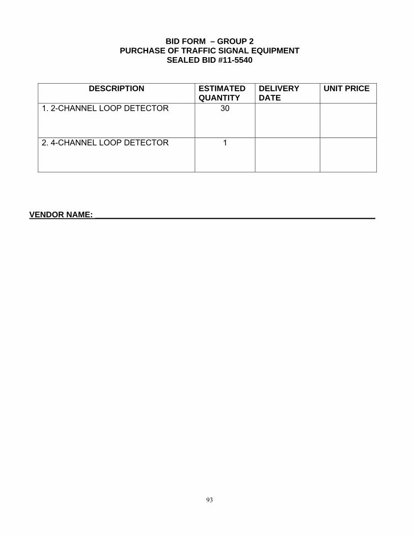
93
BID FORM – GROUP 2 PURCHASE OF TRAFFIC SIGNAL EQUIPMENT
SEALED BID #11-5540
DESCRIPTION ESTIMATED QUANTITY
DELIVERY DATE
UNIT PRICE
1. 2-CHANNEL LOOP DETECTOR 30
2. 4-CHANNEL LOOP DETECTOR 1
VENDOR NAME: ______________________________________________________________

94
GROUP 3
The purpose of Group 3 is to set forth specification requirements for CCTV Camera’s, Video Detection, Microwave Vehicle Motion Detector, LED Signals, Signal Heads, and Pedestrian Signal Heads. All design qualification testing shall be completed, documented and submitted with the equipment quotation.
SECTION 1
TRAFFIC SIGNAL HEADS
Traffic signal heads shall be 12 inches (300 mm) in diameter for traffic control applications and be modular type constructed primarily on non-metallic components that can be arranged in different combinations with each other to provide vehicle signal displays in accordance with the Manual on Uniform Traffic Control Devices. The performance of the traffic signal shall conform to the Standard for Adjustable Face Vehicular Traffic Control Signal Head, Technical Report Number one (1) of the Institute of Traffic Engineers. Each traffic signal shall consist of one or more signal face. Each signal face shall consist on one or more signal section of such design and construction as to fit rigidly and securely together, to prevent the entrance of dirt or moisture and prevent the rotation or misalignment of the individual sections with each other. It shall be possible to arrange a signal face in either a vertical or a horizontal alignment. The major components of the signal head, including but not limited to the housing and door, shall be ultra-violet stabilized polycarbonate resin. The housing of each signal section shall be of one-piece polycarbonate resin die molded complete with integral top, bottom and sides having a minimum thickness of 5/32 inches. Mount one steel reinforcing support plate in the top of the red section of each three, four, or five-section signal head for the installation of mounting hardware. Install a support plate between each section of all signal heads. Place these plates such that there is a plate in the bottom of and/or top of any sections where sections adjoin to another section. Cluster hardware shall be included with all five-section signal heads. The signal head housing color shall be available in either all yellow or all black.
SECTION 2
VIDEO DETECTION
Wide-Area Video Vehicle Detection System – Option 1
1. Video Detection—General This specification sets the minimum requirements for a wide-area vehicle detection system that processes video images for vehicle presence, count, speed, and other typical traffic parameters. The detection of vehicles passing through the field of view of an image sensor shall be available to a large variety of end user applications as encoded traffic data, simple contact closure outputs, and optional NEMA TS2 messages for a traffic controller. This reflects the current real time detector, alarm states (on/off), or summary traffic statistics that are reported locally or remotely. The contact

95
closure outputs to a traffic signal controller shall comply to the NEMA (National Electrical Manufacturers Association) type C or D detector rack or a Type 170 input file rack standards. The system architecture shall fully support networking of system components through a variety of industry standard and commercially available infrastructure that are used in the traffic industry. The serial data communications shall support direct connect, modem, and multi-drop interconnects. Simple twisted pair wiring shall be supported to minimize overall system cost, improve reliability, utilize existing infrastructure and for ease of system installation and maintenance. Both video communications and serial data communications shall optionally be interconnected over long distances through repeat and daisy chain configurations. A single serial data communications multi-drop link on twisted pair shall extend up to 2 miles and include up to 24 units on a drop before the signal(s) must be repeated. On the software application side of the network, the system shall be integrated through a modern client-server architecture. A communications server shall manage the data communications interface between as few as one to as many as hundreds of machine vision processors (MVP) and a number of client applications. The client applications shall either be hosted on the same PC as the communications server or may be distributed over a local area network of PC’s using the industry standard TCP/IP network protocol. Multiple client applications shall execute simultaneously on the same host or multiple hosts, depending on the network configuration. 1.1. System Hardware The machine vision system hardware shall typically consist of four components: 1) a color, 22x zoom lens camera, 2) Machine Vision Processor (MVP) 3) a surge protection interface panel; and 4) a “JBox” that is a NEMA 4 rated box measuring 10” x 10” x 4” with EDCO HSP121BT-1RU for AC+, AC-, Chassis Ground and EDCO CX06-MI for Coax Suppression. The PC shall host the communication server and client applications to setup, program and monitor detection performance. The real-time performance shall be observed by viewing the video output with overlaid flashing detectors to indicate the current detection state (on/off). The MVP shall optionally store cumulative traffic statistics internally in non-volatile memory, for later retrieval and analysis. The MVP shall communicate with the various PC applications using the industry-standard TCP/IP network protocol. Additionally, one or more PCs shall communicate directly or remotely to a MVP network where each MVP has a unique Internet Protocol (IP) address. The MVP network shall support communications over a mix of media, including PSTN, CDPD, CDMA, dedicated twisted-pair, fiber, and various wireless technologies. The traffic controller interface from the MVP shall comply with the form factor and electrical characteristics of a NEMA type C or D detector rack or a 170 input file detector rack card. For a contact closure interface to a traffic controller or other device, each MVP shall accept four (4) contact closure inputs (usually red and green control signals), and provide eight (8) contact closure outputs to a traffic signal controller. The surge suppression interface panel in the cabinet shall provide the mechanical support and electrical termination of heavy, external cables for video, data and power to the video sensor. It shall provide transient protection on the incoming video signal to electrically protect equipment in the cabinet. The interface panel shall be available in two models: a four-sensor model or a six-sensor model. Connection from video sensor(s) to the interface panel shall be with manufacturers

96
recommended coax cable and power cable. This will allow for a quick and easy installation and will allow the user to splice the cable if a single length run is not used. 1.2. System Software The MVP sensor’s embedded firmware shall automatically perform a variety of diagnostic, installation, fault tolerant, and vehicle detection operations. Vehicle detection shall be reliable, consistent, and perform under all weather, lighting and traffic congestion conditions. All software applications described below, including data collection and alarms shall be from manufacturers supplied single software package and will not require additional hardware or software modules. A software suite of client applications shall reside on the host client / server PC. The software suite shall support Microsoft Windows 98 second edition, ME, XP, NT, 2000 and later operating systems. Client applications shall include, but not be limited to:
Network Browser: Learn a network of connected MVPs and then show the topology in a logical hierarchical relationship.
Detector Editor: Create and modify detector configurations to be executed on the MVP sensor.
Configuration Wizard: Quickly create detector configurations for stop line intersection applications.
Operation Log: Extract the MVP run-time operation log of special events that have occurred. Software Installer: Reconfigure one or more MVPs with a newer release of embedded
system software Video Player: Play streaming color video from any or all video sensors connected to
network. Video player shall also have the ability for a video wall option, which will divide the PC screen in as many sensors that are opened giving the user optimal viewing. The video player shall also be able to record and play back any or all sensors being viewed.
Video Controller: Set the zoom, pan & tilt (optional) of the video sensor. Multiple sensors shall be able to be viewed or controlled at the same time. If multiple sensors are being viewed simultaneously, the video controller application shall allow the user to enlarge the screen to a video wall option, which will split up the whole screen with the number of sensors being viewed.
An optional software developer’s kit shall facilitate creation of custom client applications. 2. Functional Capabilities 2.1. Video Image Sensor The video image sensor shall be an integrated imaging color CCD array with optics, and a special purpose processor bundled into a sealed enclosure. The CCD array shall be directly controlled by the processor, thus providing high video quality for detection that has virtually no noise to degrade detection performance. It shall be possible for the user to zoom the lens, as required for operation. The image sensor shall provide automatic iris and shutter speed control. The image sensor shall be equipped with an integrated auto zoom/auto focus lens that can be changed using computer software. The lens shall remain in focus as the zoom varies.

97
The MVP shall provide software JPEG video compression and an optional video compression co-processor so as not to interfere with detection performance while streaming video. Real-time detector performance shall be observed by viewing the video output from the MVP with overlaid flashing detectors to indicate the current detection state (on/off). Real-time speeds and classifications shall also be visible through streaming video via the video player and from full motion video. 2.1.1. Power The video sensor shall operate on 120 VAC, 50/60Hz at a maximum of 10 watts, including a faceplate heater. 2.1.2. Video Outputs The video sensor shall provide color or B&W video output for real-time NTSC or PAL display on a monitor or PC over standard coax cable. 2.1.3. Detection Types The MVP shall be programmable with a variety of detector types that perform specific functions. The general functions performed by the detectors shall:
Include presence/passage detection of moving and stopped vehicles. Enable detection based on the direction of travel or based on when a moving vehicle
stops. Measuring vehicle speed and length and provide five (5) classes of vehicles based on
length. Determine counts, either lane-by-lane or cumulative. Speed alarm detectors:
1. Output alarm on each fast vehicle, ignoring vehicles of length of less than the user defines.
2. Output alarm based on the average number of vehicles the user enters and the upper and lower speed thresholds that the user defines.
3. Output alarm based on the average speed over a user defined time frame. 4. Output alarm based on a user defined percent increase or decrease over a
speed limit.
2.1.4. Detection Zone Programming Placement of detection zones shall be by means of a supervisor computer (PC) operating in the Windows 98 second edition, 2000 or Windows NT graphical environments, a keyboard, and a mouse. The VGA monitor or a video monitor shall both be able to show the detection zones superimposed on images of traffic scenes.

98
The detection zones shall be created by using a mouse to draw detection zones on the supervisor computer's VGA monitor. Using a mouse and the keyboard, it shall be possible to place, size, and orient detection zones to provide optimal road coverage for vehicle detection. It shall be possible to download detector configurations from the supervisor computer to the MVP, to retrieve the detector configuration that is currently running in the MVP, and to back up detector configurations by saving them to the supervisor computer’s removable or fixed disks. The supervisor computer's mouse and keyboard shall be used to edit previously defined detector configurations to permit adjustment of the detection zone size and placement, to add detectors for additional traffic applications, or to reprogram the sensor for different traffic applications or changes in installation site geometry or traffic rerouting.
2.1.5. Optimal Detection The video detection system shall detect vehicle passage and presence when the video sensor is mounted 20 feet (6m) or higher above the roadway, when the image sensor is adjacent to the desired coverage area, and when the distance to the farthest detection zone locations are not greater than ten (10) times the mounting height of the sensor. The video detection system shall optimally detect vehicle passage and presence when the MVP sensor is mounted 40 feet (13m) or higher above the roadway, when the image sensor is adjacent to the desired coverage area, and when the distance to the farthest detection zone locations are not greater than ten (10) times the mounting height of the MVP. The recommended deployment geometry for optimal detection also requires that there be an unobstructed view of each traveled lane where detection is required. Although optimal detection may be obtained when the MVP is mounted directly above the traveled lanes, the MVP shall not be required to be directly over the roadway. The MVP shall be able to view either approaching or receding traffic or both in the same field of view. The preferred image sensor orientation shall be to view approaching traffic since there are more high contrast features on vehicles as viewed from the front rather than the rear. The MVP sensor placed at a mounting height that minimizes vehicle image occlusion shall be able to monitor a maximum of six (6) to eight (8) traffic lanes simultaneously. 2.1.6. Traffic Data Collection The MVP shall optionally store cumulative traffic statistics, internally in non-volatile memory, for later retrieval and analysis. Data shall also be able to be polled in real time. MVP shall have at least 5 megabytes of memory for data storage. Data collection shall not require additional modules or extra software. The following data types are available to be stored in time increments from a cycle to one-hour increments:
Average Flow Rate Total Volume Count Arithmetic Mean Speed Vehicle Class Count Average Time Headway Average Time Occupancy Level of Service Space Mean Speed
99
Space Density Density
The above data types shall also be available to be viewed real-time through a standard web browser via an optional data collection and management service (DCMS). This DCMS shall have the capability of polling any and all video detector sensors via a number of communication interfaces, including and not limited to PSTN, CDPD, CDMA, dedicated twisted-pair, fiber, and various wireless technologies, and displaying the data real-time on a custom website provided by the manufacturer. In addition to displaying real-time data and color snapshots from the image sensor, the manufacturer shall archive all data for the agency to create custom data reports in Excel or HTML by simply accessing the website and filtering the dates and reporting parameters. All hardware necessary to facilitate the DCMS shall be owned and maintained by the manufacturer with the agency only needing a web browser to view and operate the DCMS.
3. System Installation & Training The supplier of the video detection system shall supervise the installation and testing of the video detection system and computer equipment. A factory certified representative from the supplier shall be on-site during installation. An eight-hour session of training shall be provided to personnel of the contracting agency in the operation, setup and maintenance of the video detection system. Instruction and materials shall be provided for a maximum of 10 persons and shall be conducted at a location selected by the contracting agency. The MVP and its support hardware/software is a sophisticated leading-edge technology system. Proper instruction from certified instructors is required to ensure that the end-user has complete competency in system operation. The User's Guide is not an adequate substitute for practical classroom training and formal certification by an approved agency. 4. Warranty, Service and Support Its supplier for a minimum of two (2) years from date of installation shall warrant the video detection system. Beginning of warranty shall not exceed 12 months past date of shipment. Ongoing software support by the supplier shall include software updates of the MVP and supervisor computer applications. These updates shall be provided free of charge during the warranty period. The supplier shall maintain a program for technical support and software updates following expiration of the warranty period. This program shall be available to the contracting agency in the form of a separate agreement for continuing support.
Or
Wide-Area Video Vehicle Detection System – Option 2

100
1. Video Detection - General This specification sets forth the minimum requirements for a system that monitors vehicles on a roadway via processing of video images. The detection of vehicles passing through the field-of-view of an image sensor shall be made available to a large variety of end user applications as simple contact closure outputs that reflect the current real-time detector or alarm states (on/off) or as summary traffic statistics that are reported locally or remotely. The contact closure outputs shall be provided to a traffic signal controller and comply with the National Electrical Manufacturers Association (NEMA) type C or D detector rack or 170 input file rack standards. The system architecture shall fully support Ethernet networking of system components through a variety of industry standard and commercially available infrastructures that are used in the traffic industry. The data communications shall support direct connect, [modem,] and multi-drop interconnects. Simple, standard Ethernet wiring shall be supported to minimize overall system cost and improve reliability, utilizing existing infrastructure and ease of system installation and maintenance. Both streaming video and data communications shall optionally be interconnected over long distances through fiber optic, microwave, or other commonly used digital communications transport configurations. On the software application side of the network, the system shall be integrated through a client-server relationship. A communications server application shall provide the data communications interface between as few as one to as many as hundreds of Machine Vision Processor (MVP) sensors and a number of client applications. The client applications shall either be hosted on the same PC as the communications server or may be distributed over a local area network of PC’s using the industry standard TCP/IP network protocol. Multiple client applications shall execute simultaneously on the same host or multiple hosts, depending on the network configuration. Additionally, a web-browser interface shall allow use of industry standard Internet web browsers to connect to MVP sensors for setup, maintenance, and playing digital streaming video. 1.1 System Hardware The machine vision system hardware shall consist of four components: 1) a color, 22x zoom, MVP sensor 2) a modular cabinet interface unit 3) a communication interface panel 4) a “J-Box” that is a NEMA 4 rated box measuring 10” x 10” x 4” with EDCO HSP121BT-1RU for AC+, AC-, Chassis Ground and EDCO CX06-MI for Coax Suppression. Additionally, an optional personal computer (PC) shall host the server and client applications that are used to program and monitor the system components. The real-time performance shall be observed by viewing the video output from the sensor with overlaid flashing detectors to indicate the current detection state (on/off). The MVP sensor shall optionally store cumulative traffic statistics internally in non-volatile memory for later retrieval and analysis. The MVP shall communicate to the modular cabinet interface unit via the communications interface panel and the software applications using the industry standard TCP/IP network protocol. The MVP shall have a built-in, Ethernet-ready, Internet Protocol (IP) address and shall be addressable with no plug in devices or converters required. The MVP shall provide standard MPEG-4 streaming digital video. Achievable frame rates shall vary from 5 to 30 frames/sec as a function of video quality and available bandwidth. The modular cabinet interface unit shall communicate directly with up to eight (8) MVP sensors and shall comply with the form factor and electrical characteristics to plug directly into a NEMA type C or

101
D detector rack providing up to thirty-two (32) inputs and sixty-four (64) outputs or a 170 input file rack providing up to sixteen (16) contact closure inputs and twenty-four (24) contact closure outputs to a traffic signal controller. The communication interface panel shall provide four (4) sets of three (3) electrical terminations for three-wire power cables for up to eight (8) MVP sensors that may be mounted on a pole or mast arm with a traffic signal cabinet or junction box. The communication interface panel shall provide high-energy transient protection to electrically protect the modular cabinet interface unit and connected MVP sensors. The communications interface panel shall provide single-point Ethernet connectivity via RJ45 connector for communication to and between the modular cabinet interface module and the MVP sensors. 1.2 System Software The MVP sensor embedded software shall incorporate multiple applications that perform a variety of diagnostic, installation, fault tolerant operations, data communications, digital video streaming, and vehicle detection processing. The detection shall be reliable, consistent, and perform under all weather, lighting, and traffic congestion levels. An embedded web server shall permit standard internet browsers to connect and perform basic configuration, maintenance, and video streaming services. There shall be a suite of client applications that reside on the host client / server PC. The applications shall execute under Microsoft Windows XP or Vista. Available client applications shall include:
Master network browser: Learn a network of connected modular cabinet interface units and MVP sensors, display basic information, and launch applications software to perform operations within that system of sensors.
Configuration setup: Create and modify detector configurations to be executed on the MVP sensor and the modular cabinet interface unit.
Operation log: Retrieve, display, and save field hardware run-time operation logs of special events that have occurred.
Software install: Reconfigure one or more MVP sensors with a newer release of embedded system software.
Streaming video player: Play and record streaming video with flashing detector overlay.
Data retrieval: Fetch once or poll for traffic data and alarms and store on PC storage media.
Communications server: Provide fault-tolerant, real-time TCP/IP communications to / from all devices and client applications with full logging capability for systems integration.
2. Functional Capabilities 2.1 MVP Sensor The MVP sensor shall be an integrated imaging color CCD array with zoom lens optics, high-speed, dual-core image processing hardware bundled into a sealed enclosure. The CCD array shall be directly controlled by the dual-core processor, thus providing high-quality video for detection that has virtually no noise to degrade detection performance. It shall be possible to zoom the lens as required for setup and operation. It shall provide JPEG video compression as well as standard

102
MPEG-4 digital streaming video with flashing detector overlay. The MVP shall provide direct real-time iris and shutter speed control. The MVP image sensor shall be equipped with an integrated 22x zoom lens that can be changed using either configuration computer software. The digital streaming video output and all data communications shall be transmitted over the three-wire power cable. 2.1.2 Power The MVP sensor shall operate on 110/220 VAC, 50/60Hz at a maximum of 25 watts. The camera and processor electronics shall consume a maximum of 10 watts and the remaining 15 watts shall support an enclosure heater. 2.1.3 Detection Zone Programming Placement of detection zones shall be by means of a PC with a Windows XP or Vista operating system, a keyboard, and a mouse. The PC monitor shall be able to show the detection zones superimposed on images of traffic scenes. The detection zones shall be created by using a mouse to draw detection zones on the PC monitor. Using the mouse and keyboard it shall be possible to place, size, and orient detection zones to provide optimal road coverage for vehicle detection. It shall be possible to download detector configurations from the PC to the MVP sensor and cabinet interface module, to retrieve the detector configuration that is currently running in the MVP sensor, and to back up detector configurations by saving them to the PC fixed disks or other removable storage media. The supervisor computer's mouse and keyboard shall be used to edit previously defined detector configurations to permit adjustment of the detection zone size and placement, to add detectors for additional traffic applications, or to reprogram the MVP sensor for different traffic applications or changes in installation site geometry or traffic rerouting.
2.1.4 Optimal Detection The video detection system shall optimally detect vehicle passage and presence when the MVP sensor is mounted 30 feet (10 m) or higher above the roadway, when the image sensor is adjacent to the desired coverage area, and when the distance to the farthest detection zone locations are not greater than ten (10) times the mounting height of the MVP. The recommended deployment geometry for optimal detection also requires that there be an unobstructed view of each traveled lane where detection is required. Although optimal detection may be obtained when the MVP is mounted directly above the traveled lanes, the MVP shall not be required to be directly over the roadway. The MVP shall be able to view either approaching or receding traffic or both in the same field of view. The preferred MVP sensor orientation shall be to view approaching traffic since there are more high contrast features on vehicles as viewed from the front rather than the rear. The MVP sensor placed at a mounting height that minimizes vehicle image occlusion shall be able to simultaneously monitor a maximum of six (6) traffic lanes when mounted at the road-side or up to eight (8) traffic lanes when mounted in the center with four lanes on each side.

103
2.2 Modular Cabinet Interface Unit The modular cabinet interface unit shall provide the hardware and software means for up to eight (8) MVP sensors to communicate real-time detection states and alarms to a local traffic signal controller. It shall comply with the electrical and protocol specifications of the detector rack standards. The card shall have 1500 Vrms isolation between rack logic ground and street wiring. The modular cabinet interface unit shall be a simple interface card that plugs directly into a 170 input file rack or a NEMA type C or D detector rack. The modular cabinet interface unit shall occupy only 2 slots of the detector rack. The modular cabinet interface unit shall accept up to sixteen (16) phase inputs and shall provide up to twenty-four (24) detector outputs.
2.3 Communications Interface Panel The communications interface panel shall support up to eight MVPs. The communications interface panel shall accept 110/220 VAC, 50/60 Hz power and provide predefined wire termination blocks for MVP power connections, a Broadband-over-Power-Line (BPL) transceiver to support up to 10MB/s interdevice communications, electrical surge protectors to isolate the modular cabinet interface unit and MVP sensors, and an interface connector to cable directly to the modular cabinet interface unit. The interface panel shall provide power for up to eight (8) MVP sensors, taking local line voltage 110/220 VAC, 50/60 Hz and producing 110/220 VAC, 50/60 Hz, at about 30 watts to each MVP sensor. Two ½-amp SLO-BLO fuses shall protect the communications interface panel. 3. System Installation & Training The supplier of the video detection system may supervise the installation and testing of the video detection system and computer equipment as required by the contracting agency. Training is available to personnel of the contracting agency in the operation, set up, and maintenance of the video detection system. The MVP sensor and its support hardware / software is a sophisticated leading-edge technology system. Proper instruction from certified instructors is recommended to ensure that the end user has complete competency in system operation. The User's Guide is not an adequate substitute for practical classroom training and formal certification by an approved agency. 4. Warranty, Service, & Support For a minimum of two (2) years, the supplier shall warrant the video detection system. An option for additional year(s) warranty for up to 5 years shall be available. Ongoing software support by the supplier shall include software updates of the MVP sensor, modular cabinet interface unit, and supervisor computer applications. These updates shall be provided free of charge during the warranty period. The supplier shall maintain a program for technical support and software updates following expiration of the warranty period. This program shall be available to the contracting agency in the form of a separate agreement for continuing support.

104
SECTION 3
LED SPECIFICATIONS
LIGHT EMITTING DIODE (LED) TRAFFIC SIGNAL 12” SPECIFICATION
FOR SPAN WIRE AND MAST ARM MOUNTED SIGNALS 1. Purpose
The purpose of this specification is to provide the minimum performance requirements for 300 mm (12 in) LED traffic signal modules. An LED signal module shall be capable of replacing the optical unit of an existing vehicle traffic signal section.
2. Physical and Mechanical
Installation of a retrofit replacement LED signal module into an existing signal housing shall only require the removal of the existing optical unit components, i.e., lens, lamp module, and gaskets. The LED retrofit replacement shall not require the removal of the reflector and socket; shall be weather tight and fit securely into existing traffic signal housings built to the VTCSH “Vehicle Traffic Control Signal Heads” standard without modification to the housing.
3. Construction
The LED retrofit replacement shall not require the removal of the reflector and socket; shall be weather tight and fit securely in the housing. The power supply must be designed to fit and mount inside the traffic signal module. The external lens shall be smooth on the outside to prevent excessive dirt/dust buildup. The assembly and manufacturing process for the LED signal assembly shall be designed to assure all internal LED and electronic components are adequately supported to withstand mechanical shock and vibration from high winds and other sources as per ITE requirements.
4. Environmental Requirements
The LED signal module shall be rated for use in the ambient operating temperature range of -40ºC (-40ºF) to + 74ºC (+165ºF). The LED signal module shall be protected against dust and moisture intrusion per the requirements of NEMA Standard 250-1991, for Type 4 enclosures to protect all internal LED, electronic, and electrical components. The LED signal module lens shall be UV stabilized.
5. LED Signal Module Lens
Each module shall comprise of a smooth surfaced UV stabilized polycarbonate outer shell. Red and Green LED indications shall meet the minimum luminous intensity values per the attached Table 1; Specifications for Span wire Mounted Signals for a minimum period of 60 months. Intensity values shall be measured as per the ITE VTCSH (June 2005 version) specifications. The values in Table 1 equal or exceed the ITE VTCSH (June 2005 version) minimum luminous intensity values for every grid points.

105
Yellow LED indications shall meet the minimum luminous intensity values per the attached Table 1; Specifications for Span wire Mounted Signals for a minimum period of 60 months. Photometric, luminous intensity and color measurements for yellow LED signal modules shall be taken immediately after the modules are energized and at 25oC. Initial intensity of the LED ball indications shall meet or exceed 120% of the values in Table 1; Specifications for Span wire Mounted Signals. This increased intensity shall be demonstrated on the independent lab reports. No optical lens shall be used in order to meet these visibility requirements. The measured chromaticity coordinates of LED signal modules shall conform to the chromaticity requirements of Section 8.04 and Figure 1 of the ITE VTCSH standard (1998 version). 6. Materials
The multiple LED light source should be the latest technology available on the market. Materials used for the lens and signal module construction shall conform to ASTM specifications for the materials where applicable. Enclosures containing either the power supply or electronic components of the signal module shall be made of UL94VO flame retardant materials.
7. Chromaticity
The measured chromaticity coordinates of LED signal modules shall conform to the chromaticity requirements of Section 8.04 and Figure 1 of the VTCSH standard.
8. Electrical
All wiring and terminal blocks shall meet the requirements of Section 13.02 of the VTCSH standard. Two secured, color-coded, 914 mm (36 in) long 600 V, 20 AWG minimum, jacketed wires, conforming to the National Electrical Code, rated for service at +105ºC, are to be provided for electrical connection. The module shall operate on a 60 Hz AC line voltage ranging from 80 volts rms to 135 volts rms with less than 10% light intensity variation. Nominal rated voltage for all measurements shall be 120 ± 3 volts rms. The circuitry shall prevent flickering over this voltage range. The module shall be ETL certified to meet applicable ITE standards (red and green).
9. LED Drive Circuitry (Power Supply)
The individual LED light sources shall be wired so that a catastrophic failure of one LED light source will result in the loss of only that one LED light source, and the loss of no more than 1% of the total LED’s within the LED signal module. The power supply must current regulated. Independent third party laboratory reports shall be supplied to verify modules meet the above requirements.
10. Electronic Noise
The LED signal and associated on-board circuitry must meet Federal Communications Commission (FCC) Title 47, Sub-Part B, Section 15 regulations concerning the emission of electronic noise.

106
11. Power Factor (PF)
The LED signal module shall provide a power factor of 0.90 or greater at 25ºC and at the nominal operating voltage.
12. AC Harmonics
Total harmonic distortion (THD), (current and voltage); induced into an ac power line by a signal module shall not exceed 20 percent, over the operating voltage range specified in Section 14 and within the ambient temperature range specified in Section 4.
13. Transient Voltage Protection
The signal module on-board circuitry shall include voltage surge protection to withstand high-repetition noise transients and low-repetition high-energy transients as stated in Section 2.1.6, NEMA Standard TS-2, 1992.
14. Voltage Range
The LED signal module shall operate from a 60 ± 3 HZ ac line power over a voltage range from 80 Vac rms to 135 Vac rms. The current draw shall be sufficient to ensure compatibility and proper triggering and operation of load current switches and conflict monitors in signal controller units the procuring traffic authority customer has in use.
15. Signal Module Burn-in
All LED signal modules shall be energized for a minimum of 24 hours, at 100 percent on-time duty cycle, in an ambient temperature of 60ºC (+140ºF).
16. Design Qualification Testing
Independent lab test results showing the LED indications satisfy ITE Chapter 2a, VTCHS Part 2: Light Emitting Diode (LED) Vehicle Signal Modules (1998 version) sections 3, 4 and 5 (with the exception of 4.1), and attached Table 1, Specifications for Span wire Mounted Signals must be supplied. Design Qualification testing shall be performed on new LED signal module designs, and when a major design change has been implemented on an existing design. Testing shall be performed once every 5 years or when the module design or LED technology has been changed. Test data shall be retained by the manufacturer for a minimum period of 5 years.
17. Quality Assurance
LED signal modules shall be manufactured in accordance with a vendor quality assurance (QA) program. The QA program shall include two types of quality assurance: (1) design quality assurance and (2) production quality assurance. The production quality assurance includes statistically controlled routine tests to ensure minimum performance levels of LED signal modules built to meet this specification. QA process and test results documentation shall be kept on file for a minimum period of seven years.

107
18. Certificate of Compliance
Manufacturers shall provide a Certificate of Compliance to this specification for each shipment of LED signal modules to an end user. Each LED signal module shall be identified with a serial number. The manufacturer shall also participate in the ETL traffic control equipment certification program.
19. Warranty
Manufacturer will provide the following warranty provisions: (1) Replacement or repair of an LED signal module that fails to function as intended due to workmanship or material defects within the first 60 months from the date of delivery. (2) Replacement or repair of LED signal modules that exhibit luminous intensity of less than the minimum values specified in ITE specification VTCSH- June 27, 2005, within the first 60 months from the date of delivery.
Table 1 Specifications for Span Wire Mounted LED Signals
MINIMUM LIGHT INTENSITY GRID SPECIFICATION FOR 12IN RED
Angle 27.5 22.5 17.5 12.5 7.5 2.5 -2.5 -7.5 -12.5 -17.5 -22.5 -27.5 22.5U 15 19 36 36 36 36 36 36 36 36 19 15 17.5U 15 19 42 42 42 42 42 42 42 42 19 15 12.5U 15 21 64 83 91 94 94 91 83 64 21 15 7.5U 15 36 84 137 190 213 213 190 137 84 36 15 2.5U 15 36 73 133 236 319 319 236 133 73 36 15 2.5D 33 62 117 201 295 399 399 295 201 117 62 33 7.5D 26 47 105 171 238 281 281 238 171 105 47 26
12.5D 19 26 80 104 114 118 118 114 104 80 26 19 17.5D 19 24 52 52 52 52 52 52 52 52 24 19 22.5D 19 24 46 46 46 46 46 46 46 46 24 19 27.5D 19 24 39 39 39 39 39 39 39 39 24 19 32.5D 19 24 33 33 33 33 33 33 33 33 24 19 37.5D 19 24 26 26 26 26 26 26 26 26 24 19
MINIMUM LIGHT INTENSITY GRID SPECIFICATION FOR 12IN GREEN
Angle 27.5 22.5 17.5 12.5 7.5 2.5 -2.5 -7.5 -12.5 -17.5 -22.5 -27.5 22.5U 26 30 33 38 43 47 47 43 38 33 30 26 17.5U 29 35 47 70 112 132 132 112 70 47 35 29 12.5U 32 44 83 188 237 276 276 237 188 83 44 32 7.5U 35 62 168 286 348 420 420 348 286 168 62 35

108
2.5U 38 78 192 330 470 491 491 470 330 192 78 38 2.5D 43 81 193 341 527 590 590 527 341 193 81 43 7.5D 37 72 186 317 474 594 594 474 317 186 72 37
12.5D 35 59 151 270 360 443 443 360 270 151 59 35 17.5D 34 47 90 179 254 289 289 254 179 90 47 34 22.5D 33 38 50 78 110 137 137 110 78 50 38 33 27.5D 30 32 35 39 43 47 47 43 39 35 32 30 32.5D 27 27 28 29 29 29 29 29 29 28 27 27 37.5D 22 23 24 24 24 24 24 24 24 24 23 22
MINIMUM LIGHT INTENSITY GRID SPECIFICATION FOR 12IN YELLOW
(Measured Immediately After Modules are Energized)
Angle 27.5 22.5 17.5 12.5 7.5 2.5 -2.5 -7.5 -12.5 -17.5 -22.5 -27.5 22.5U 57 64 72 76 77 80 80 77 76 72 64 57 17.5U 62 73 86 103 116 129 129 116 103 86 73 62 12.5U 68 82 109 149 195 231 231 195 149 109 82 68 7.5U 71 94 142 227 364 432 432 364 227 142 94 71 2.5U 74 105 175 333 502 649 649 502 333 175 105 74 2.5D 82 155 291 501 728 892 892 728 501 291 155 82 7.5D 77 118 228 391 582 701 701 582 391 228 118 77
12.5D 75 101 157 264 415 461 461 415 264 157 101 75 17.5D 71 90 123 171 230 288 288 230 171 123 90 71 22.5D 64 78 95 117 140 158 158 140 117 95 78 64 27.5D 59 67 75 84 92 98 98 92 84 75 67 59 32.5D 52 58 63 67 69 70 70 69 67 63 58 52 37.5D 44 50 52 56 57 57 57 57 56 52 50 44
SECTION 4
12” LED Vehicle Arrow Traffic Signal Modules 1.0 PURPOSE The purpose of this specification is to provide the minimum performance requirements for 12 in. LED vehicle arrow traffic signal modules. This specification refers to definitions and practices described in ''Vehicle Traffic Control Signal Heads'' published in the Equipment and Materials Standards of the Institute of Transportation Engineers, referred to in this document as ''VTCSH''. 2.0 PHYSICAL AND MECHANICAL REQUIREMENTS

2.1 General
LED vehicle arrow traffic signal modules (The Arrow) designed as retrofit replacements for existing signal lamps shall not require special tools for installation. Retrofit replacement LED arrow shall fit into existing traffic signal housings built to the VTCSH Standard without modification to the housing. Installation of a retrofit replacement LED arrow into an existing signal housing shall only require the removal of the existing optical unit components, i.e., lens, lamp module and gaskets. The installation of the LED arrow shall not require removal of the reflector. It shall be weather tight, fit securely in the housing and shall connect directly to existing electrical wiring. 2.2 LED Vehicle Arrow Traffic Signal Module
2.2.1 The retrofit LED arrow shall be capable of replacing the optical unit. 2.2.2 Tinting (Optional) -The lens shall be tinted or shall use transparent film or materials with similar characteristics. 2.2.3 The LED arrow lens shall be a replaceable part without the need to replace the complete LED arrow. 2.2.4 The configuration of the arrow icon is illustrated in Figure 1. FIGURE 1
11.81'' / 300mm
0.85'' / 21.5mm
6.75'' / 171.5mm
0.93'' / 23.5mm
0.93'' / 23.5mm
1'' / 25.5mm
5'' / 127mm
90°Section A:
Section C:
Section B:
2.3 Environmental Requirements
109

110
2.3.1 The LED arrow shall be rated for use in the ambient operating temperature range, of -40°C (-40°F) to +74°C (+165°F). 2.3.2 The LED arrow shall be protected against dust and moisture intrusion per NEMA Standard 250-1991 requirements, for Type 4 enclosures to protect all internal LED, electronic, and electrical components. 2.3.3 The LED arrow lens shall be UV stabilized.
2.4 Construction
2.4.1 The LED arrow shall be a single, self-contained device, not requiring on-site assembly for installation into an existing traffic signal housing. The power supply must be designed to fit and mount inside the LED arrow. 2.4.2 The assembly and manufacturing process for the LED arrow assembly shall be designed to assure all internal LED and electronic components are adequately supported to withstand mechanical shock and vibration from high winds and other sources.
2.5 Materials
2.5.1 Materials used for the module construction shall conform to ASTM specifications for the materials where applicable. 2.5.2 Enclosures containing the power supply and electronic components of the arrow shall be made of UL94VO flame retardant materials. The lens of the arrow is excluded from this requirement.
2.6 Module Identification
2.6.1 Each LED arrow shall be identified on the backside with the manufacturer's name and serial number. 2.6.2 The following operating characteristics shall be identified: nominal operating voltage, power consumption, and Volt-Ampere. 2.6.3 Arrows shall have a prominent and permanent vertical indexing indicator, i.e., UP ARROW or the word UP or TOP, for correct indexing and orientation inside a signal housing.
3.0 PHOTOMETRIC REQUIREMENTS
3.1 Luminous Intensity & Distribution
3.1.1 The maintained minimum luminous intensity values for LED arrows throughout the warranty period, under the operating conditions defined in Sections 2.3.1, and 4.2.1, and at the end of the warranty period, shall not be less than the values shown in Table 1.

111
3.1.2 The uniformity of the icon illumination shall meet a ratio of not more than 1 to 5 between the minimum and maximum illuminance measurements (in Cd/m2). A spot size of 12mm shall be used with at least three measurements taken in each of the three sections (A, B & C) shown in figure 1. 3.1.3 The optical lens shall reflect a light distribution look with the individual LED’s being visible.
3.2 Chromaticity The measured chromaticity coordinates of LED arrows shall be between 500 nm and 650 nm, conforming to the chromaticity requirements of Section 8.04 and Figure 1 of the VTCSH standard.
Table 1. Maintained Minimum Luminous Intensity for the LED Vehicle Arrow Traffic Signal Modules.
Candlepower Values (candelas (cd))
12-inch Signal Vertical Down
Horiz.
+/- Red Yellow Green
2.5o 60 150 90 7.5 o 44 110 66
12.5 o 25 62 38
2.5o
17.5 o 14 35 21 2.5 o 40 100 60 7.5 o 36 90 54
12.5 o 26 65 39 17.5 o 16 40 24 22.5 o 7 17 11
7.5 o
27.5 o 3 7 4 2.5 o 9 23 14 7.5 o 9 22 14
12.5 o 8 20 12 17.5 o 6 15 9 22.5 o 4 10 6
12.5 o
27.5 o 3 7 4 2.5 o 4 10 6 7.5 o 4 10 6
12.5 o 4 10 6 17.5 o 4 9 6 22.5 o 4 8 5
17.5 o
27.5 o 3 7 4

112
The LED arrow wattage shall meet the following requirements:
Retrofit Wattage 12” Red Arrow 5 or less 12” Yellow Arrow 10 or less 12” Green Arrow 5 or less
4.0 ELECTRICAL
4.1 General All wiring and terminal blocks shall meet the requirements of Section 13.02 of the VTCSH standard. Two secured, color coded, 914 mm (36 in) long 600 V, 20 AWG minimum, jacketed wires, conforming to the National Electrical Code, rated for service at +105°C, are to be provided for electrical connection. 4.2 Voltage Range
4.2.1 LED arrows shall operate from a 60 + 3 cycle ac line power over a voltage range from 80 Vac rms to 135Vac rms. The current draw shall be sufficient to ensure compatibility and proper triggering and operation of load current switches and conflict monitors in signal controller units the procuring traffic authority customer has in use. 4.2.2 Nominal operating voltage for all measurements shall be 120 + 3 volts rms. 4.2.3 Fluctuations in line voltage over the range of 80Vac to 135Vac shall not affect luminous intensity by more than + 10 percent. 4.2.4 The LED circuitry shall prevent flicker at less than 100 Hz over the voltage range specified in Section 4.2.1. 4.2.5 Low Voltage Turn Off There shall be no illumination from the arrow when the applied voltage is less than 45 volts AC. To test for this condition the unit must first be fully illuminated at the nominal operating voltage. The applied voltage is then reduced to the point that there is no illumination. This point must be greater than 45 volts AC. The same requirement should apply in rising voltage from 0 to 45 with no visible illumination. 4.2.6 Turn-On and Turn-Off Time: The modules shall reach 90% of their full illumination (turn-on) within 100 msec after the application of the nominal operating voltage. The arrows shall not be illuminated (turn-off) within 100 msec after the removal of the nominal operating voltage.

113
4.3 Transient Voltage Protection
4.3.1 The arrow on-board circuitry shall include voltage surge protection to withstand high-repetition noise transients and low-repetition, high-energy transients as stated in Section 2.1.6, NEMA Standard TS-2, 1992.
4.4 LED Drive Circuitry
4.4.1 The individual LED light sources shall be wired so that the catastrophic failure of one LED will result in the loss of the light from only that one LED.
4.5 Electronic Noise The LED arrow and associated on-board circuitry must meet Federal Communications Commission (FCC) Title 47, SubPart B, Section 15 regulations concerning the emission of electronic noise. 4.6 Power Factor (PF) and AC Harmonics
4.6.1 LED arrows shall provide a power factor of 0.90 or greater when operated at nominal operating voltage, and 25°C (77°F). 4.6.2 Total harmonic distortion induced into an ac power line by an LED arrow, at 25°C (77°F) shall not exceed 20 percent.
5.0 QUALITY ASSURANCE
5.1 General
5.1.1 Quality Assurance Program LED arrows shall be manufactured in accordance with a vendor quality assurance (QA) program. The QA program shall include two types of quality assurance: (1) design quality assurance, and (2) production quality assurance. The production quality assurance shall include statistically controlled routine tests to ensure minimum performance levels of LED arrows built to meet this specification. 5.1.2 Record Keeping QA process and test results documentation shall be kept on file for a minimum period of seven years. 5.1.3 Conformance LED arrows designs not satisfying design qualification testing and the production quality assurance testing performance requirements in Sections 5.3 and 5.4 shall not be labeled, advertised, or sold as conforming to this specification.

114
5.2 Manufacturers Serial Numbers Each LED arrow shall be identified by a manufacturer's serial number for warranty purposes. 5.3 Production Quality Assurance (QA) Testing All new LED arrows shall undergo the following Production Quality Assurance testing prior to shipment. Failure of any LED arrow to meet requirements of these QA tests shall be cause for rejection. QA test results shall be maintained per the requirement of Section 5.1.2.
5.3.1 Production Luminous Intensity Test All arrows shall be tested for maintained minimum luminous intensity. A single point measurement with a correlation to the intensity requirements of Table 1 in Section 3.0 may be used. 5.3.2 Power Factor All LED arrows shall be tested for power factor after burn-in per the requirements of Section 4.6.1. A commercially available power factor meter may be used to perform this measurement. 5.3.3 Current All LED arrows shall be measured for the amount of current consumption. The measured current values shall be compared against current values resulting from design qualification measurements in Section 5.4.4.1. Measured current values in excess of 120 percent of the design qualification current values shall be cause for rejection. 5.3.4 Visual Inspection All LED arrows shall be visually inspected for any exterior physical damage or assembly anomalies. 5.4.2 Maintained Minimum Luminous Intensity 5.4.2.1 For independent lab testing, the LED arrow modules shall be tested for maintained minimum luminous intensity at each of the points indicated in Table 1, Section 3.0. These measurements shall be recorded at an ambient temperature of 25°C after the signal has been operated for 60 min. The yellow arrow shall be measured at initial energization.
6.0 WARRANTY
6.1 LED arrows shall be replaced or repaired if it fails to function as intended due to workmanship or material defects within the first 60 months from the date of delivery.

115
6.2 LED arrows which exhibit luminous intensities less than the minimum values specified in Table 1 Section 3.0 within the first 60 months of the date of delivery shall be replaced or repaired.
7.0 DOCUMENTATION
7.1 Independent Lab reports from (Intertek Testing Services, ETL Semko), or LightMetrics, shall be supplied to verify modules meet the photometric requirements in table 1, per the guidelines in section 5.4.2.1, and power factor and AC harmonics requirements in section 4.6.
SECTION 5
PEDESTRIAN SIGNALS
GENERAL Pedestrian signal shall be designed to fit the same mounting brackets employed by California type A, B, C, and G pedestrian signals. Construction design shall be compatible with clamshell mounting hardware.
5.1 LED PEDESTRIAN AND COUNTDOWN SIGNAL MODULE (16" X 18" Type – Overlapping Fully Populated hand and man + countdown)
5.1.1 PRODUCTS
GENERAL
Pedestrian and countdown LED traffic signal modules shall be designed as a retrofit replacement for the message bearing surface of a nominal 16” 18” pedestrian and countdown traffic signal housing built to the PTCSI Standard. The message-bearing surface of the module shall be supplied with a fully populated “HAND” and “MAN” symbol, overlapping, with the individual LED’s being visible, that comply with PTCSI standard for these symbols for a message-bearing surface of the size specified. The numbers 00 to 99 on the numerical display shall have 2 rows of LED’s that are side by side, not offset or staggered, with 14 segments and a minimum height of 9 inches. The 2-row countdown digit portion shall have no less than 180 LED’s, to ensure even illumination and visibility. The Man symbol shall have no less than 72 LED’s to ensure even illumination and visibility. The Hand symbol shall have no less than 120 LED’s to ensure even illumination and visibility.
. INSTALLATION a. LED pedestrian and countdown signal modules shall be designed as retrofit
replacements for the existing pedestrian signals.

b. LED pedestrian and countdown signal modules shall not require special tools for installation.
c. LED pedestrian and countdown signal modules shall fit into the existing traffic housings built to the VTCSH Standard without any modification to the housing.
d. LED pedestrian and countdown signal modules shall be weather tight, fit securely in the housing and shall connect directly to existing electrical wiring.
e. Installation of a replacement LED module into the existing pedestrian housing shall only require the removal of the existing optical unit components, i.e., lens, lamp, gaskets, and reflector.
5.1.2 LED PEDESTRIAN AND COUNTDOWN SIGNAL MODULE CONSTRUCTION
a. The LED pedestrian and countdown signal module shall be a single, self-contained
device, not requiring on-site assembly for installation into the existing traffic signal housing and include an installed gasket.
b. All Portland Orange LEDs shall be “AlInGaP” technology or equal, and rated for 100,000 hours or more at 25ºC and 20 mA. White LEDs must be InGaN technology.
c. All internal LED and electronic components shall be adequately supported to withstand mechanical shock and vibration from high winds and other sources.
d. The signal module shall be made of UL94VO flame-retardant materials. The lens is excluded from this requirement.
e. The lens of the LED pedestrian and countdown signal modules shall be polycarbonate UV stabilized.
f. The exterior of the lens of the LED pedestrian and countdown signal module shall be uniform and frosted to reduce sun phantom effect.
g. Each individual LED traffic module shall be identified for warranty purposes with the manufacturer’s trade name, serial number and operating characteristics, i.e., rated voltage, power consumption, and volt-ampere.
h. The walking person and hand icons shall be full (not outlines). The countdown digits shall be 9 inches in height and have a minimum of two aligned (non-staggered) rows of LED’s. The configurations of the walking person icon and hand icon are illustrated in Figure 1 and Figure 2 respectively.
116

117
Figure 1. Figure 2.
Dimensions for Figure 1 and Figure 2
For each nominal message bearing surface (module) size, use the corresponding H (height) and W (width):
Bearing Surface
Module Size Icon Height
Icon Width
Countdown Height
Countdown Width
A 406 x 457 mm
297 mm 178 mm 178 mm 165 mm
(16 x 18 in) or 11 in or 7 in or 9 in or 6.5 in 5.1.3 ENVIRONMENTAL REQUIREMENTS
a. The LED pedestrian and countdown signal modules shall be rated for use in the
ambient operating temperature range of -40ºC to +60ºC (-40ºF to +140ºF). b. The LED pedestrian and countdown signal modules, when properly installed with
gasket, shall be protected against dust and moisture intrusion per requirements of NEMA Standard 250-1991, sections 4.7.2.1 and 4.7.3.2, for type 4 enclosures to protect all internal LED, electronic, and electrical components.
5.1.4 PHOTOMETRIC REQUIREMENTS
a. Luminance, Uniformity & Distribution
For a minimum period of 60 months, the maintained minimum luminance values for the modules under the operating conditions defined in Sections 2.3.1 and 4.2.1, shall not be less than the values shown Reference 1 and Reference 2 for the walking person and hand icons respectively, when measured perpendicular to the surface of the module at nine (nine) separate points on the icon. These values may decrease up to 50% of these table values beyond 15o from the perpendicular in either to the left or right on a horizontal plane. Reference 1. Maintained Minimum Luminance value for the Walking Person icon of the Module (candelas/meter square): 5300 cd/m2 Reference 2. Maintained Minimum Luminance value for the Hand icon of the Module (candelas/meter square): 3750 cd/m2
b. Uniformity The uniformity of the walking person and hand icons’ illumination shall meet a ratio of not more than 1 to 5 between the minimum and maximum luminance measurements (in Cd/m2).
c. Chromaticity The standard colors for the LED Pedestrian Signal Module shall be White for the walking person and Portland Orange for the hand icon and countdown digits. The colors for these icons shall conform to the CIE chromaticity diagram x, y coordinates as follows. The white area is defined by the sum of these two areas that are contiguous, and are defined by the following lines:

118
First area: Yellow boundary: x = 0.400 Blue boundary: x = 0.280 Green boundary: y = 0.7917x + 0.0883 Purple boundary: y = 0.4600x + 0.1810 Second area: Yellow boundary: x = 0.450 Blue boundary: x = 0.400 Green boundary: y = 0.7917x + 0.0483 Purple boundary: y = 0.4600x + 0.2210 The Portland Orange area is defined as Red boundary: y = 0.331 Yellow boundary: y = 0.390 White boundary: y = 0.997 – x
5.1.5 ELECTRICAL
a. Maximum of 3ea secured, color coded, 914 mm (36 in) long, 600V, 16 AWG minimum,
jacketed wires, conforming to the National Electrical Code, rated for service at +105ºC, are to be provided for electrical connection.
b. The LED pedestrian and countdown signal module shall operate from a 60 ±3 Hz AC line over a voltage range of 80 VAC to 135 VAC. Rated voltage for all measurements shall be 120 ±3 volts rms.
c. The LED circuitry shall prevent perceptible flicker over the voltage range specified above.
d. The LED pedestrian and countdown signal module circuitry shall include voltage surge protection against high-repetition noise transients and low-repetition noise transients as stated in Section 2.1.6, NEMA Standard TS-2, 1992.
e. Catastrophic failure of one LED light source in Man & Hand Symbol shall not result in the loss of more than the light from that one LED.
f. The individual LED light sources for the countdown numbers indication shall be wired so that a catastrophic failure of one LED light source shall not result in the loss of illumination of more than one display LED segment.
g. The LED pedestrian and countdown module shall be operationally compatible with the currently used controller assemblies. The LED pedestrian and countdown module shall be operationally compatible with conflict monitors.
h. The LED pedestrian and countdown module including its circuitry must meet Federal Communications Commission (FCC) Title 47, Subpart B, Section 15 regulations concerning the emission of noise.
i. The LED pedestrian and countdown module shall provide a power factor of .90 or greater over the operating voltage range and temperature range specified above for modules with 6 watts or more.
j. Total harmonic distortion (current and voltage) induced into an AC power line by an LED pedestrian and countdown module shall not exceed 20% over the operating voltage range and temperature range specified above.
119
5.1.6 MODULE FUNCTIONS
a. Basic operation The control and regulation module shall be of the “smart” type in order for the countdown displays to be automatically adjusted with the programmed intervals of the traffic controller. The module shall operate in one mode only: Clearance Cycle Countdown Mode. The module will start counting when the flashing clearance signal turns on and will countdown to “0” and turn off when the steady “Don’t Walk” signal turns on. b. Learning Cycle At power on, the module enters a single automatic learning cycle. During the automatic learning cycle, the countdown display shall remain dark. c. Cycle Modification The unit re-programs itself if it detects any increase or decrease of Pedestrian Timing. The counting unit will go blank once a change is detected and then take one complete pedestrian cycle (with no counter during this cycle) to adjust its buffer timer. d. Recycling The module shall allow for consecutive cycles without displaying the steady Hand icon (“Don’t Walk”). e. Preemption The module shall recognize preemption events and temporarily modify the crossing cycle accordingly. If the controller preempts during the walking man, the countdown will follow the controller's directions and will adjust from walking man to flashing hand. It will start to count down during the flashing hand. If the controller preempts during the flashing hand, the countdown will continue to count down without interruption. The next cycle, following the preemption event, shall use the correct, initially programmed values. f. “Don’t Walk” Steady If the controller output displays Don’t Walk steady condition and the unit has not arrived to zero or if both the hand and man are dark for some reason, the unit suspends any timing and the digits will go dark. g. Power Outage The equipment must maintain a consistent countdown during short power failures (<1 second). A longer failure or an absence of signal superior to one (1) second must turn off display and trigger a restart system remembering the last sequence, as it is done for the NEMA traffic controller.
h. Operating Modes The module shall operate in one mode only: Clearance Cycle Countdown Mode – The module will start counting when the flashing clearance signal turns on and will countdown to “0” and turn off when the steady “Don’t Walk” signal turns on. Note: The units shall not have any external attachments, dip switches, toggle switches or options that will allow the mode to be changed from counting the clearance cycle, to the full walk/don’t walk cycle or any other modification to the icons or digits.

120
5.1.7 QUALITY ASSURANCE
a. LED pedestrian and countdown modules shall be manufactured in accordance with a Vendor quality assurance (QA) program including both design and production quality assurance. All QA process and test result documentation shall be kept on file for a minimum of seven years.
b. Samples: Submit within 7 business days of request, signal module sample. The samples will be inspected, tested, and evaluated for conformity to the specifications. Samples must be actual production unit modules and not a proto0type or test unit. If Bidder fails to submit a sample for evaluation, or if the sample does not confimr to the specification, the Bid will be rejected. Each module submitted shall be accompanied with a complete circuit schematic for the unit, one standard catalog cut and one manufacturers technical specification sheet for the unit, and specification describing individual LED light sources used in the unit.
5.1.8 WARRANTY
a. The unit shall be repaired or replaced by the contractor if it exhibits a failure due to workmanship or material defect within the first 60 months of delivery.
Requirements Checklist to be filled out by Manufacturer to demonstrate compliance Requirement Comply
Fully populated Hand and Man with LED’s fully visible
Countdown digits – 2 rows of LED’s side by side, not offset, not staggered, 9” high with 14 segments
Countdown digits – minimum 180 LED’s
Man Symbol – minimum 72 LED’s
Hand Symbol – minimum 120 LED’s
Catastrophic failure of one LED light source in Man & Hand Symbol shall not result in the loss of more than the light from that one LED.
Catastrophic failure of one LED light source in the digits shall not result in the loss of the entire segment. A maximum of 1 row of LEDs per segment is allowed to go out.
Module operates in Clearance mode only
The units shall not have any external attachments, dip switches, or options that will allow the mode to be changed from counting the clearance cycle, to the full walk/don’t walk cycle.
Provide Model Number

121
5.2 PEDESTRIAN SIGNAL HOUSING – Pedestrian signal housing shall be designed to fit the same mounting brackets employed by California type A, B, C, and G pedestrian signals. Construction design shall be compatible with clamshell mounting hardware. The construction of the housing shall include a single piece cast aluminum housing with two integrally hinge lugs, screw slots and openings at each end. The construction of the door shall include a single piece cast aluminum swing down door frame with two hinge lugs cast on top of the door and two latch points cast on the bottom. Ensure that the door is provided with a neoprene gasket capable of making a weather resistant, dustproof seal when closed. Provide each unit with hinge pins of stainless steel to attach the door to the housing, two eye bolts and wing nuts on the other side of the door and a blank-out Z-crate sun visor. The maximum overall dimension of the signal shall be 18.5”W x 18.75”H x 9”D, including the Z-crate sun visor and hinges. The housing color shall be available in either yellow or black.
SECTION 6
CLOSED CIRCUIT TELEVISION (CCTV) Section 936 - Closed Circuit Television (CCTV) The text included herein is written in the imperative mood (sentences often begin with commands). All commands and references in, or in connection with, the text in this document are written to imply Contractor responsibility for action unless otherwise specified. 936.1 General Description This work includes furnishing closed circuit television (CCTV) system, any specified type, which is a CCTV video surveillance field installation, including but not limited to color CCTV cameras, lens, housing, pan/tilt drive, camera system assembly, cabling, mounting hardware, interface panel, camera control receiver, and cabinet wiring. This CCTV system provides operator control and video imaging to the Georgia Department’s NaviGAtor Advanced Transportation Management System (ATMS). 936.1.01 Definitions CCTV System, Type A – Previously called CCTV System. Not applicable on this project. CCTV System, Type B – The Type B CCTV System uses a self-contained camera system assembly with an analog NTSC video output and RS-232 serial data control interface. Type A Cabinet – As specified in Section 939, the Type A cabinet housing is a standard Model 336 stretch (336S) housing with approximate exterior dimensions of 46 in (H) by 24 in (W) by 23 in (D). Type B Cabinet – As specified in Section 939, the Type B cabinet housing is a standard Model 337 housing with approximate exterior dimensions of 35 in (H) x 20 in (W) x 17 in (D). Type C Cabinet – As specified in Section 939, the Type C cabinet housing is a standard Model 332 housing with approximate exterior dimensions of 64 in (H) by 24 in (W) by 30 in (D). Type D Cabinet – As specified in Section 939, the Type D cabinet housing is a standard Model 336 stretch (336S) housing with approximate exterior dimensions of 46 in (H) by 24 in (W) by 23 in (D).

122
936.1.02 Related References
A. Georgia Specifications Section 639 - Strain Poles for Overhead Sign and Signal Assemblies Section 680 - Highway Lighting Section 682 - Electrical Wire, Cable and Conduit Section 922 - Electrical Wire and Cable Section 923 - Electrical Conduit Section 925 - Traffic Signal Equipment Section 939 - Communications and Electronic Equipment B. Referenced Documents American National Standards Institute (ANSI) American Society of Testing and Materials (ASTM) Electronic Industries Association (EIA) FCC Rules Part 15, Sub-part J Insulated Cable Engineers Association (ICEA) International Municipal Signal Association (IMSA) MIL-STD-454 MIL-STD-810E Method 509 Procedure 1 – exterior salt atmospheres National Electric Code (NEC) National Electrical Manufacturers Association (NEMA) NEMA-4 Underwriter’s Laboratory Incorporated (UL) 936.2 Materials 936.2.01 CCTV System, Type B Ensure that the individual components and assemblies of the CCTV System, Type B, conform to the requirements specified in the following sections. A. Camera System Assembly Follow these minimum requirements for a dome-enclosed camera system assembly including the camera, lens, pan/tilt drive, and control electronics. Provide a downward-looking circular dome-shaped enclosure assembly. The enclosure shall have a maximum diameter of 14 in (356 mm) at its widest point and a maximum height of 22 in (559 mm) from the top of the housing assembly to the bottom point of the dome. The upper housing shall be constructed of a non-metallic UV-stabilized material of a light tan, gray, or white color, or constructed of an aluminum material with a heat-cured paint coating of an equivalent color. The lower housing shall be constructed of a UV-stabilized optically-correct acrylic material. The maximum weight of the complete and fully functional camera system assembly, including the camera, lens, pan/tilt drive, control electronics, environmental control components, housing assembly, and hub adapter shall be 25 lbs (11.4 kg).

123
Use an enclosure assembly that secures to the mounting bracket arm with a 1-1/2 in (37.5 mm) threaded pipe nipple. Hub adapters for the threaded pipe nipple on either the enclosure or the mounting arm, or both, are permitted. All fastening and mounting hardware on or within the enclosure assembly shall be stainless steel. Use a pressurized enclosure assembly that uses extra dry grade nitrogen. Provide a pressure relief valve and a Schrader valve for filling and evacuating the enclosure. An additional pressure relief screw is allowed. All mounting and wiring connections shall be pressure-tight. Electrical power for the complete camera system assembly shall be per the manufacturer’s recommendations and between 12V to 120V DC or single-phase AC utilizing a two-wire (not counting ground) supply from the cabinet interface assembly in the equipment cabinet. Do not use a dual-voltage power supply. Maximum electrical load with all subsystems operational, including the heater, shall be no more than 130 VA. Use an enclosure assembly with a heater and a circulating blower fan for environmental (temperature and defogging) control. Maximum electrical load for the heater shall be no more than 80 VA. Use a camera unit with an integrated camera sensor and zoom lens assembly and an analog NTSC-compliant composite video output with a signal-to-noise ratio of 45dB or greater. The camera shall use a ¼-inch interline transfer CCD image sensor, with a minimum of 768 horizontal by 492 vertical active picture elements. All elements shall remain operational. The camera shall have a minimum resolution of 460 horizontal TV lines by 350 vertical TV lines. The camera shall include on/off selectable automatic gain control and manual/automatic selectable white balance. The camera shall include an electronic shutter mode with user-selectable speeds of a minimum range from 1/60 second to 1/10,000 second. The camera unit shall provide an on/off selectable day/night function where the image sensing and output automatically switch between color and black-and-white imaging; fixed color or black-and-white imaging shall be user-controllable. The camera sensitivity shall be no less than 3.0 lux in color mode (1/60 second) and 0.5 lux in black-and-white mode (1/60 second, IR cut removed). Provide a camera unit with an integrated zoom lens of a minimum of 22X optical zoom and a minimum of 4X digital zoom. The camera shall not employ any digital zoom functionality unless the lens is at the full limit of optical zoom and the zoom command continues to be applied, in which case the camera unit shall automatically switch from optical to digital zoom. The optical focal length shall be approximately 4 mm to 80 mm. The camera unit shall include on/off selectable automatic focus and manual/automatic selectable iris control. Use a pan/tilt drive for the camera unit that is fully-contained within the enclosure assembly. The drive shall be capable of 360 degree panning and at least 0 degree horizontal to 90 degree vertical looking downward tilting. The camera unit and pan/tilt drive shall provide automatic 180-degree image output flip at the bottom of the tilt travel. The camera unit and pan/tilt drive shall provide a minimum of eight privacy blackout zones, each zone being individually programmable to be on/off by the user. The panning speed, when a pan-left or pan-right command is applied by the user, shall

124
be between 10 and 18 degrees per second. The tilting speed, when a tilt-up or tilt-down command is applied by the user, shall be between 4 and 10 degrees per second. Provide a system control interface to the camera system assembly that physically and logically supplies the user commands to and monitoring from the camera system assembly, including but not limited to pan, tilt, zoom, focus, position reporting, and configuration. The system control interface shall physically connect the camera system assembly to the cabinet interface assembly through cables C1 and C3 as specified below. Do not use a system control interface through cable C2. Provide a system control interface as serial data communications of any messaging format that is in compliance with all of the physical and operational requirements specified for a CCTV System, Type B. Provide the capability to set the communications address used by the Standard Protocol (subsection 936.2.01.C) through the system control interface or through the user control interface in the cabinet; do not require the opening/disassembly of the camera system enclosure to set the communications address. Store all user configurable settings in non-volatile memory that is retained indefinitely upon loss of power. B. Camera System Assembly Mount Provide a camera system assembly mount that includes a mounting bracket arm, camera enclosure mount and disconnect, mounting straps, and incidental fastening hardware. All fastening and mounting hardware shall be stainless steel. The mounting bracket arm shall be suitable for pole-mounted applications using mounting straps or bolts. The bracket shall be fabricated to exactly mate with the camera enclosure mount/disconnect/pipe nipple and any needed pole-mount adapter with no drilling or welding required. The bracket shall be fabricated from aluminum alloy with an exterior polyurethane coating, stainless steel, or mild steel with a heat-cured paint coating. All bracket coatings shall be beige, tan, gray or off-white in color and corrosion resistant in accordance with MIL-STD-810E Method 509 Procedure 1 for exterior salt atmospheres. Use a mounting bracket arm that locates the vertical centerline of the camera enclosure from 14 in (356 mm) to 24 in (610 mm) from the exterior surface of the support pole. The mounting bracket arm shall provide for cable entrance through the base of the bracket directly from the support pole and from the exterior through a rain tight opening on the underside of the bracket and adjacent to the support pole. Provide non-metallic cable protection grommets for both cable entrances. Use a mounting bracket arm that fully encloses the cable connectors J1 and J2 and the manufacturer’s connector on the camera enclosure for cable C3. Provide a rain tight access opening to cable connectors J1 and J2 on the underside of the bracket, and provide a rain tight access to the camera enclosure connector for cable C3 in accordance with the manufacturer’s recommendations. Include a camera enclosure mount and disconnect on the mounting bracket arm that secures to the camera enclosure with a 1-1/2 in (37.5 mm) threaded pipe nipple. Hub adapters for the threaded pipe nipple on either the enclosure or the mounting arm, or both, are permitted. When installed and fastened, the completed mounting mechanism assembly shall rigidly connect the camera enclosure to the mounting bracket arm with no movement relative between the enclosure and the arm. Provide a disconnect means for dismounting and remounting the camera enclosure from the mounting bracket arm with the use of threaded fasteners or locking pinned/slotted/keyed attachment mechanism and without the need to unthread the 1-1/2 in (37.5 mm) pipe nipple. The disconnecting means shall be compatible with the camera system manufacturer cable C3 and connector.

125
Unless otherwise shown in the Plans, mount the bracket arm to the support pole using a minimum of two 1/ 2 in (12.5 mm) or greater stainless steel mounting straps. C. Cabinet Interface Assembly Use a cabinet interface assembly that provides electrical service for the camera system assembly and provides the user control interface connection to the NaviGAtor system and/or user personnel. Install the cabinet interface assembly in the equipment cabinet. All fastening and mounting hardware shall be stainless steel. The cabinet interface panel assembly includes the following:
• CCTV Interface Enclosure EDCO and/or approved equivalent surge suppression for data control lines EDCO and/or approved equivalent surge suppression for Video SS15 4 AMP 120VAC fuse for male power inlet in rear panel LED rocker switch for 120VAC power inlet in rear panel Male reset 120VAC power outlet rear panel Video in/out rear panel via BNC Video front panel BNC inline with rear BNC and SS15 surge suppression device Toggle switch in front panel to allow control to switch BNC and DB9 RS232 male in rear
panel (control interface to the NaviGAtor system) to BNC and DB9 RS232 female in front panel to provide local viewing and control from rear panel to front panel without disconnecting any cables
• Camera System Assembly Power Supply with surge suppression LED rocker switch in front panel for camera power 4 AMP fuse for camera power front panel Internal data conversion to allow control of the camera RS485 to RS232 from either the
local front panel DB9 or the rear remote panel DB9 Phoenix connector rear panel to translator out to both DB9 front panel and DB9 rear panel External ground lug connecting all internal grounds with #16AWG ground cable
Use the CCTV Interface Enclosure to hold the Camera System Assembly Power Supply and the user control interface unit for the camera electrical service and system control interface data path as shown in detail drawing 936.1a and 936.1b. The CCTV Interface Enclosure shall be rack mountable on a standard 19” rack and located in cabinet rack as shown in detail drawing 936.2a and 936.2b. The CCTV Interface Enclosure height shall not exceed 3 Rack Units, and it shall not exceed a depth of 15 inches. The CCTV Interface Enclosure shall provide the connector rear connector ports as defined below; unless otherwise specified, all connector ports shall be pluggable polarity-keyed terminal blocks with touch-safe design (Phoenix Contact Combicon blocks or approved equivalent) and rated for the voltage and current of the application. All connector ports shall be labeled as specified here and shall be located on the rear panel of the CCTV Interface Enclosure. The CCTV Interface Enclosure shall be labeled with the manufacturer model and part number of the camera system assembly with which the enclosure is supplied. Provide a Camera System Assembly Power Supply in the CCTV Interface Enclosure that supports all electrical service needs for all components and subsystems of the camera system assembly and CCTV Interface Enclosure. Connect the line and neutral inputs of the CCTV Interface Enclosure power connector port labeled “CP Power” to the equipment cabinet’s 120VAC electrical supply on

126
terminal block TB2 as shown in the CCTV system detail drawings, and use standard conductor insulation colors for 120VAC electrical service (black, white, and green). Provide a copper or copper alloy grounding lug on the CCTV Interface Enclosure and bond all internal components to the grounding lug to the cabinet ground busbar. Connect the power supply output of the CCTV Interface Enclosure, labeled “CP1” to the camera system assembly directly to the terminals of TB18, connecting to cable C1. Use only stranded copper wiring, with a minimum #12 AWG for the line and neutral conductors of the 120VAC circuit to TB2, and a minimum wire size recommended by the CCTV system manufacturer for the power supply circuit to TB18 but not less than #18 AWG. Ground the input and output sections of the power supply in accordance with the CCTV system manufacturer’s recommendations. The power supply shall not have any fusing for any circuit except for socket/holder mounted fusing. The power supply shall include a switch on the rear of the CCTV Interface Enclosure to disconnect power from the camera system assembly. The power supply and user control interface unit shall be sized so that they can fit inside of the CCTV Interface Enclosure. Provide a transient voltage surge suppressor for the power conductors to the camera system assembly. Use a surge suppressor that is independent of and external to the Camera System Assembly Power Supply. Use a surge suppressor rated for the voltage, current and polarity of the Camera System Assembly with MOV/diode/thermal fusing technology and a -40C to +75C operating temperature. Provide terminal block TB18 for the termination of cable C1 from the camera system assembly and the termination of wiring from the power supply and the user control interface unit. Mount TB18 on the equipment cabinet side panel as shown in the CCTV system detail drawings, not in the CCTV Interface Enclosure. Use a 14-position dual-screen barrier type terminal block with 7/16 in (11.11 mm) spacing using nickel-plated brass 6-32 philslot screw (Cinch 141 or approved equivalent) and quick-clamp type wire terminals (Cinch QC-1 or approved equivalent). Use a terminal block with voltage and current ratings greater than the voltage and current ratings of the wires, which are terminated on the block. Provide an EMI/RFI shield over the terminal block if recommended by the CCTV system manufacturer. Do not use compression-type, tubular clamp, or spade lug terminals. Provide a connector port on the CCTV Interface Enclosure for connection to TB18; label this port “CP2”. Provide surge suppressor SS15 for the protection and termination of the coaxial video cables C2 and C4. Mount SS15 in the CCTV Interface Enclosure. Use a shielded gas-tube and diode hybrid technology or equivalent with 6-volt line-to-ground clamping, 20kA peak surge current,-40C to +75C operating temperature, and BNC coaxial connectors (EDCO CX06-BNCY or approved equivalent). The maximum dimensions of SS15 are 4 in L x 2 in H x 1.5 in W (102mm L x 51mm H x 38mm W.) Use a minimum #16 AWG stranded copper insulated green wire to ground SS15 directly to the CCTV Interface Assembly and then to cabinet ground bussbar. Provide a user control interface on the front of the CCTV Interface Enclosure to provide for control and monitoring communications between the camera system assembly and the NaviGAtor system user. The user control interface unit port shall be a DB9 connector labeled “CP4” that matches the RS232 cable provided with the CCTV Embedded Protocol control software required below. The user control interface unit shall fully support control and monitoring communications from the NaviGAtor Standard CCTV Control Protocol and from the CCTV system manufacturer’s own embedded protocol; simultaneous operation of these two protocols is not required. The user control interface unit shall be a protocol switching or translation, port-sharing or port-coupling, or similar device that controls and monitors the camera system assembly through its system control interface.

127
The NaviGAtor Standard CCTV Control Protocol (hereinafter called the “CCTV Standard Protocol”) is specified below and shall connect to the user control interface unit through an RS-232 serial data interface directly from the NaviGAtor system. Connect the user control interface inside the CCTV Interface Enclosure to the CCTV Standard Protocol with cable C5 through the connector port labeled “CP3”. Provide the CCTV system manufacturer’s proprietary embedded protocol (hereinafter called the “CCTV Embedded Protocol”) as a Microsoft Windows-based PC software application with user interface. Provide the CCTV Embedded Protocol and control software application on CD-ROM with printed user documentation. The CCTV Embedded Protocol control software shall be capable of fully operating the camera system assembly and user control interface unit, including but not limited to control, monitoring, and configuration. Operate the control software through a cable connection between the user control interface unit and an RS-232 serial data interface on a Windows-based PC. Provide the control software with a properly configured RS-232 cable (minimum length 6 ft) with a female DB-9 connector on the cable end attached to the computer and a pre-configured connector or termination on the end attached to the user control interface unit. Provide the control software with an unrestricted, non-cancelable user license for the Department’s use with any NaviGAtor equipment at any location. Furnish three copies each of the software, license, appropriate RS-232 cable, and user documentation per project. Changeover between CCTV Standard Protocol and CCTV Embedded Protocol control and monitoring communications with the camera system assembly shall occur only through the user control interface unit. There shall be no requirement to physically access the camera system assembly or to reconfigure any wiring between the cabinet interface assembly and the camera system assembly. Use of different interface ports or use of the same port, on the user control interface unit for the two protocols is permitted provided that the CCTV Embedded Protocol port is connectorized. Configuration changes to the user control interface unit to switch operation between the two protocols is not permitted, including but not limited to dipswitch or jumper settings. Connect the user control interface unit, using cable C6, to TB18 for connection through C1 to the camera system assembly. Use a single one, two or three pair multi-pair cable of stranded copper wiring, minimum #18 AWG, twisted and/or shielded as recommended by the CCTV system manufacturer, and label this cable C6 (Belden 9369 or approved equivalent). Ground or bond any C6 cable or pair shielding and any unused conductors in accordance with the CCTV system manufacturer’s recommendations. Do not connect unused conductors of C1 to the user control interface unit unless recommended by the CCTV system manufacturer. Connect C6 directly to the terminating port on the user control interface unit; do not use any port adapters, gender changers, couplers, or similar components. Provide automatically-resetting surge suppression for each connected ungrounded conductor between the user control interface unit and TB18. Use a surge suppressor with low capacitance gas-tube and diode hybrid technology or equivalent with 10kA peak surge current (8X20 waveform) and -40C to +75C operating temperature. Connect the user control interface unit to the Video Encoder port with cable C5. Use a single multi-conductor or multi-pair cable with minimum stranded copper #18 AWG, with twisted pairs and/or shielded/bonded as recommended by the CCTV system manufacturer, and label this cable C5 (9369 Belden or approved equivalent). Ground or bond any C5 cable or pair shielding and any unused conductors in accordance with the CCTV system manufacturer’s recommendations. Cable C5 shall be pre-connectorized on one or both ends as required for the user control interface and the Video Encoder port configurations and as required by the CCTV system manufacturer. Connect C5

directly to the terminating ports on either end; do not use any port adapters, gender changers, couplers, or similar components. D. CCTV Standard Protocol 1. General Use the NaviGAtor Standard CCTV Control Protocol (hereinafter called the “CCTV standard protocol” or “standard protocol”) for CCTV system control communications between the user control interface unit and the NaviGAtor central system. Implement the standard protocol as specified in this subsection for all CCTV equipment installed on this project. The CCTV standard protocol governs all control communications between the NaviGAtor central system (hereinafter called the “host”) and the CCTV system specified in this Subsection 936.2.01 (hereinafter called the “remote”). Do not implement any other control communications except as required and specified in this Subsection 936.2.01.C. 2. Interface The remote shall communicate using the CCTV standard protocol over an RS-232 serial interface. Data is transmitted using 1 start bit, 8 data bits, and 1 stop bit (no parity) at a baud rate of 9600. Each remote shall be identified by a unique integer address between 1 and 233. This address is set during installation and shall not be altered using the standard protocol. The address is included in messages to identify the intended recipient of commands from the host and responses from the remote. 3. Message Sequence All communication between the host and the remote is initiated by the host. The remote shall not transmit except in response to a properly formatted message from the host addressed to the remote’s assigned address. The remote shall respond to such messages with an ACK (a single ASCII character 0x06) within 500 milliseconds (“ACK timeout”). The remote shall be ready to receive and process another command in as little as 150 milliseconds after the ACK is transmitted (“Inter-command spacing”). Figure 1 below depicts this sequence.
128
Some messages from the host require a subsequent response message from the remote. In this case, the remote’s ACK shall be followed immediately by a response message. When the host

receives the properly formatted response, it will transmit an ACK back to the remote. This sequence is depicted below in Figure 2. The timing constraints presented above apply. Additionally, the host will wait a maximum of 500 milliseconds for each byte in the response message (“Inter-byte timeout”).
Command and response messages shall be formatted as shown below in Table 1.
Messages start with a single-byte header followed by a single-byte address. Two or more message data bytes follow the address. The message is terminated with a single-byte checksum. Checksum Calculations The message checksum byte is defined as the least significant nibble of the exclusive-or of all previous bytes in the message (excluding the 0xF8 header) added to 0x80. The resulting byte will be between 0x80 and 0x8F inclusive. Checksum Example: • The bytes of a “Pan Left” command addressed to controller 1 would be: 0xF8 0x01 0x50 0x4C 0x?? • The bitwise exclusive-or of the bytes between the 0xF8 header and the checksum comes out to 0x1D. 0x01 ^ 0x50 ^ 0x4C = 0x1D • Adding the least significant nibble to 0x80, we get 0x8D for the checksum byte. 0x80 | (0x0F & 0x1D) = 0x8D • The resulting 5-byte command would be 0xF8 0x01 0x50 0x4C 0x8D
129

5. Command Messages The tables below present the message data contained within command messages sent by the host to the remote. In most cases (exceptions will be noted), the “Data” column contains the ASCII characters of the message data to be sent. For example, the Pan Left command data is “PL”, an ASCII ‘P’ (0x50) followed by an ASCII ‘L’ (0x4C). An “ACK” in the “Response” column indicates no response message is expected from the remote beyond the ACK itself as shown above in Figure 1. An “ACK + * Response” indicates the ACK from the remote is to be followed by the specified response message as shown above in Figure 2.
130

Position Encoding The message data for the “Pan/Tilt Goto Command” above begins with an ASCII ‘p’ followed by the azimuth (A2A1A0) and elevation (E2E1E0) positions. The positions are 12-bit values encoded four-bits each in to the least significant nibbles of the three bytes whose most significant nibbles are always 0x30. The subscript-2 indicates the byte containing the most significant bytes of the position and subscript-0 indicates the least significant. Position Encoding Example: Encoding an azimuth position value of decimal 2748 or 0xABC, we break it up into three nibbles and add 0x30 to each so A2 = 0x3A, A1 = 0x3B, and A0 = 0x3C. The same encoding scheme is used for the zoom and focus positions in the “Zoom/Focus Goto Command”. 6. Response Messages The table below presents the message data contained within response messages sent by the remote to the host.
131

While the remote is going to a position as a result of a “Pan/Tilt Goto”, “Zoom/Focus Goto”, or “Preset Goto” command, “Preset Responses” will return ‘A’ in the D0 byte. If the remote is unable to get to the position in the “Goto” command (i.e. the pan/tilt assembly reaches the mechanical stops), the “Latch Response” will return ‘E’ in the D0 byte. E. Cabling and Connectors Provide cabling and connectors between the camera system assembly and the cabinet interface assembly as shown in the CCTV system detail drawings and in the Plans. Provide coaxial video signal cables C2 and C4, with labels attached at both ends of each cable. Video signal cable C2 shall be double-shielded with tinned copper braid, #20 AWG solid copper center conductor, and polyethylene outer jacket approved for outdoor use (Belden 8281 or approved
132

133
equivalent.) Video signal cable C4 shall be high-flexibility double-shielded with tinned copper braid, #22 AWG stranded copper center conductor, and PVC outer jacket (Belden 8281F or approved equivalent.) Use BNC connectors with gold-plated center pins on the video signal cables; use only connectors recommended by the cable manufacturer. Provide control cable C1 with labels attached at both ends of the cable. Control cable C1 shall be a UL-listed six twisted-pair power limited tray cable with #18 AWG 19-strand tinned copper conductors with individual foil or braid shield on each pair and UV-resistant PVC or polyethylene outer jacket rated for 300 V, -30C to +105C operating range (Belden 9389 or approved equivalent). Terminate cable C1 in the equipment cabinet on TB18 as shown in the CCTV system detail drawings and as recommended by the CCTV system manufacturer. Ground or bond any pair shielding and any unused conductors in accordance with the CCTV system manufacturer’s recommendations. Provide camera system assembly connector cable C3 to connect cables C1 and C2, through connectors J1 and J2 respectively, with the camera system assembly connector as provided by the CCTV system manufacturer. Cable C3 shall be manufactured and configured to mate with connectors J1 and J2 in accordance with the conductor assignments shown in the CCTV system detail drawings and the CCTV system manufacturer’s recommendations. Use stranded copper conductors, or a solid copper conductor for a coaxial cable, with minimum 75 degree C individual conductor and outer jacket insulation ratings on all materials. Cable C3 shall be configured with the minimum length necessary for connection within the mounting bracket arm to J1, J2 and the camera system assembly connector, while providing sufficient slack for a technician to disconnect and reconnect the cable at the camera system assembly connector. Cable C3 shall mate to the camera system assembly connector with a positive locking mechanism to prevent vibration from loosening the connection. The camera system assembly connector shall use gold-plated pins and sockets. Connector J1 on cable C3 shall be configured with male conductor pins. Connector J2 on cable C3 shall be a coaxial cable BNC connector as specified for cables C2 and C4 above. All connectors on cable C3 shall be strain-relieved. Label the cable as C3 and with the camera system manufacturer’s name and model number. Terminate the aerial end of cable C1 with connector J1, which shall connect to mating connector J1 on C3. For J1 use a strain-relieved CPC 17-14 free-hanging plug and receptacle connector set (AMP 206043 / 206044 or compatible and approved equivalent) with gold-over-nickel spring-detent two-piece pins and sockets, with female conductor sockets terminated on cable C1. Do not use one-piece “formed” pins and sockets. Terminate the aerial end of cable C2 as connector J2 with a BNC connector as specified for cables C2 and C4 above. Connect cable C2 to cable C3 through a BNC coupler with gold-plated center socket.

134

135
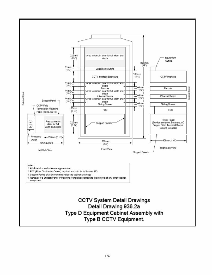
136

137

138

139

140

141
SECTION 7
MICROWAVE VEHICLE MOTION DETECTOR
The Microwave Vehicle Motion Detector shall be a microprocessor controlled vehicle detector with a selectable range (long or short). It shall be designed to trigger the operation of a traffic controller. The detector shall only respond to motion in one direction (approach or depart only----selectable). The detector shall be able to be mounted in an overhead position or from a side-fire position. The detector shall have an external adjustable panel and indicator LED’s. The detector shall have a minimum 18 month warranty. The specifications for the Microwave Vehicle Motion Detector are as follows: Operating Frequency 10.525 GHz (X-band) Detection Method Microprocessor analyzed Doppler-microwave Detection Pattern (maximum) 200’ long x 50’ wide (cars) 350’ long x 75’ wide (trucks) Detection Mode Directional motion Detection Hold-Time Continuous with motion Response Time 0.250 seconds Time Delay Adjustable 0.250 – 5.0 seconds Power Requirements 12 to 24 V AC or DC Current Draw 75mA max. @ 24V DC Power Consumption 1.8 Watts max. @ 24V DC Relay Output Form C, rated at 3 Amps @ 24V DC Wiring Harness 18 gauge 5 conductor cable (standard) 18 gauge 5 conductor quick release cable (optional) Mounting Bracket Predrilled & slotted (band or lag-bolt mount) Enclosure/Finish Gray powder coated aluminum Operating Temperature -35 degrees F to 165 degrees F (-37 degrees C to 75 degrees C) Weight Approx. 5 pounds Physical Dimensions 9.25 inches length x 5.5 inches width x 5.5 inches height 23.5 cm length x 14.0 cm width x 14.0 cm height

142
BID FORM – GROUP 3 PURCHASE OF TRAFFIC SIGNAL EQUIPMENT
SEALED BID #11-5540
DESCRIPTION
ESTIMATED QUANTITY
DELIVERY DATE
UNIT PRICE
1. Autoscope Color Sensor and Bracket 20
2. Rackvision Module 20
3. 30’ Coax and Power Pigtail for Rackvision 20
4. Rackvision Interface Panel (2 cameras) 1
5. Rackvision Interface Panel (4 cameras) 1
6. Rackvision Installation Kit 20
7. Rackvision Stand Alone Housing and Power Supply
1
8. Solo Terra Camera/Processor Unit 20
9. Solo Terra Interface Panel (TIP) 5
10. Solo Terra Access Point (TAP) 5
11. Solo Terra Installation Kit 20
12. LED lamp module 12” RED 1
13. LED lamp module 12” YELLOW 1
14. LED lamp module 12” GREEN 1
15. LED lamp module 12” arrow RED 1
16. LED lamp module 12” arrow YELLOW 1
17. LED lamp module 12” arrow GREEN 1
18. LED Count Down Module 200
19. LED Count Down Signal Side or Top of Pole Mounting
20
20. LED Count Down Signal w/Clamshell Mounting LEFT
1
21. LED Count Down Signal w/Clamshell Mounting RIGHT
1
22. Signal head 3-section 12” (Yellow) 40
23. Signal head 3-section 12” (Black) 40
24. Signal head 4-section 12” (Yellow) 1

143
DESCRIPTION
ESTIMATED QUANTITY
DELIVERY DATE
UNIT PRICE
25. Signal head 4-section 12” (Black) 1
26. Signal head 5-section cluster 12” (Yellow) 20
27. Signal head 5-section cluster 12” (Black) 20
28. APS-10 Audible Pedestrian Signal (Yellow) 4
29. APS-10 Audible Pedestrian Signal (Black) 4
30. CCTV Camera System Assembly, Type B 15
31. CCTV Camera System Assembly Mount, Type B 15
32. CCTV Cabinet Interface Assembly, Type B 15
33. CCTV Camera Cabling and Connectors, Type B 15
34. Microwave Vehicle Motion Detector 15
35. Pedestrian Signal Housing (Yellow)
25
36. Pedestrian Signal Housing (Black)
25
END OF BID FORM – GROUP 3 VENDOR NAME: ________________________________________________________________

144
GROUP 4
SECTION 1
STEEL STRAIN POLES 4.1 PURPOSE – The purpose of this Group 4 of this specification is to set forth the minimum
requirements for Steel Poles, Mast Arms, Anchor Bolts and Luminaire Arms. All design qualification testing shall be completed, documented and submitted with the equipment quotation.
4.2 LUMINAIRE ARM
Steel: ASTM A36 MOD 45KSI YIELD, Round Tapered Steel Tube, 11 gauge, 0.14” taper/foot, 2.375” tip O.D., Clamp-On type with a 3 foot rise, ranging from 12 feet to 30 feet in length.
Aluminum: Aluminum Alloy 6063-T6, Round Tapered Aluminum Tube, 0.125 wall, 0.14” taper/foot, 2.375” tip O.D., Clamp-On type with a 3 foot rise, ranging from 12 feet to 30 feet in length.
4.3 STEEL STRAIN POLE – The steel strain pole shall be manufactured of hi-strength steel,
formed into a tubular shape and welded with one automatic seam weld. The poles shall have an integral base plate, hexagonal in shape, constructed of 1-3/4” thick A36 steel plate. The shaft shall telescope into the base, with fillet welds inside and out. The steel strain pole shall be of size, 3 ga., 13” x 8.52” x 32’. The base shall have a six-bolt hole plate with an 18” bolt circle. The pole shall be provided with six 1-1/2” x 60” anchor bolts cut threads, round, full dimension bar stock conforming to AASHTO M314, Gr.55 The threaded end shall be galvanized, complete with each bolt – two (2) heavy hex nuts, two (2) F436 hardened flat washers, one (1) lock washer. All galvanizing to shall meet or exceed ASTM A153. The pole shall include a 4” x 8” hand-hole with ½”-13 tapped grounding lug, three (3) 2” BHC couplings for wire entrance 30” down from the top, one (1) removable pole top complete, six (6) individual bolt covers for the anchor bolts complete, one (1) hand-hole cover complete, one (1) U-Bolt span wire clamp #9 in size. The following shall be the material specifications:
Tube Steel - Min. 55,000 psi Base Plate - ASTM A36 Anchor Bolts - Min. 55,000 psi Misc. Hardware - Stainless Steel Pole Top - Steel or Aluminum (pressed or cast) Galv. Finish - ASTM A123 The design shall meet or exceed the Ga. DOT specifications. With each shipment, one
additional anchor bolt complete, shall be provided at no charge for possible Ga. DOT testing.
4.4 MAST ARM POLE – Steel mast arms and poles shall be manufactured from 1015-1020
basic oxygen hot-rolled sheet, which shall be formed and welded (single seam weld) into a round, tapered, conical shape. This tube shall then be cold-rolled in accordance with

145
ASTM A595, Gr.B to produce a high strength structural tube with a minimum yield strength of 60,000 pounds per square inch. The weld seam shall be rolled flat into the tube, which shall make the seam un-noticeable. The resulting structural tube shall remain its full weld-ability, and shall be available in thicknesses of .1196”, .179”, .250”, and .3125”. A base plate of proper size and shall accommodate four (4) anchor bolts and telescope onto the shaft and be fully welded inside and out. The mast arm pole shall be provided with the appropriate number of anchor bolts cut threads, round, full dimension bar stock conforming to AASHTO M314, Gr.55 The threaded end shall be galvanized, complete with each bolt – two (2) heavy hex nuts, two (2) F436 hardened flat washers, one (1) lock washer. A wiring hand-hole shall be provided approximately 12 inches above the base plate and shall be fabricated by welding a reinforcement frame in the shaft, complete with tapped grounding lug. A removable cover shall be provided. Mast arm poles type IV tubes shall be welded onto a flange plate in the same manner as the base plate described above. The pole shaft shall have a reinforced box mast arm attachment, which matches the arm flange plate.
A
Mast arms shall be attached to the pole with high strength A325 connecting hardware.
The design shall be such that an appropriate slope is provided to eliminate sagging. All flange and base plates shall conform to ASTM A36, and all galvanizing shall conform to ASTM A123. All miscellaneous hardware shall be AISI series 300 passivated stainless steel and be provided with each mast arm and pole. Mast arm anchor bolts shall have cut threads, and be manufactured of round, full dimension bar stock conforming AASHTO M314, Gr.55. The threaded ends shall be galvanized. With each bolt there shall be supplied two (2) heavy hex nuts, two (2) F436 hardened flat washers, one (1) lock washer. With each mast arm pole there shall be provided one (1) pole top. With each arm there shall be provided the appropriate size and cap with arm mounting hardware. All other misc. hardware shall be provided to complete the mast arm manufactured. The following chart lists the standard pole/arm length, bending moment, bolt circle, bolt size.
ARM LENGTH SINGLE
BENDING MOMENT
BOLT CIRCLE
BOLT SIZE
15 ft.
36,500 ft. lbs.
12.5 in.
1 ¼ in. x 48 in.
20 ft.
40,750 ft. lbs.
13.0 in.
1 ¼ in. x 48 in.
25 ft.
60,000 ft. lbs.
13.0 in.
1 ½ in. x 60 in.
30 ft.
66,700 ft. lbs.
13.5 in.
1 ½ in. x 60 in.
35 ft.
81,800 ft. lbs.
15.0 in.
1 ½ in. x 60 in.
40 ft.
89,900 ft. lbs.
15.5 in.
1 ½ in. x 60 in.
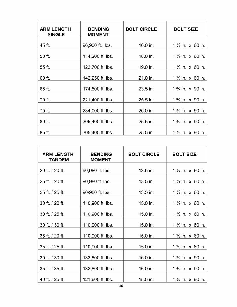
146
ARM LENGTH SINGLE
BENDING MOMENT
BOLT CIRCLE
BOLT SIZE
45 ft.
96,900 ft. lbs.
16.0 in.
1 ½ in. x 60 in.
50 ft.
114,200 ft. lbs.
18.0 in.
1 ½ in. x 60 in.
55 ft.
122,700 ft. lbs.
19.0 in.
1 ½ in. x 60 in.
60 ft.
142,250 ft. lbs.
21.0 in.
1 ½ in. x 60 in.
65 ft.
174,500 ft. lbs.
23.5 in.
1 ¾ in. x 90 in.
70 ft.
221,400 ft. lbs.
25.5 in.
1 ¾ in. x 90 in.
75 ft.
234,000 ft. lbs.
26.0 in.
1 ¾ in. x 90 in.
80 ft.
305,400 ft. lbs.
25.5 in.
1 ¾ in. x 90 in.
85 ft.
305,400 ft. lbs.
25.5 in.
1 ¾ in. x 90 in.
ARM LENGTH TANDEM
BENDING MOMENT
BOLT CIRCLE
BOLT SIZE
20 ft. / 20 ft.
90,980 ft. lbs.
13.5 in.
1 ½ in. x 60 in.
25 ft. / 20 ft.
90,980 ft. lbs.
13.5 in.
1 ½ in. x 60 in.
25 ft. / 25 ft.
90/980 ft. lbs.
13.5 in.
1 ½ in. x 60 in.
30 ft. / 20 ft.
110,900 ft. lbs.
15.0 in.
1 ½ in. x 60 in.
30 ft. / 25 ft.
110,900 ft. lbs.
15.0 in.
1 ½ in. x 60 in.
30 ft. / 30 ft.
110,900 ft. lbs.
15.0 in.
1 ½ in. x 60 in.
35 ft. / 20 ft.
110,900 ft. lbs.
15.0 in.
1 ½ in. x 60 in.
35 ft. / 25 ft.
110,900 ft. lbs.
15.0 in.
1 ½ in. x 60 in.
35 ft. / 30 ft.
132,800 ft. lbs.
16.0 in.
1 ¾ in. x 90 in.
35 ft. / 35 ft.
132,800 ft. lbs.
16.0 in.
1 ¾ in. x 90 in.
40 ft. / 25 ft.
121,600 ft. lbs.
15.5 in.
1 ¾ in. x 90 in.

147
ARM LENGTH TANDEM
BENDING MOMENT
BOLT CIRCLE
BOLT SIZE
40 ft. / 30 ft.
132,800 ft. lbs.
16.0 in.
1 ¾ in. x 90 in.
40 ft. / 35 ft.
132,800 ft. lbs.
16.0 in.
1 ¾ in. x 90 in.
40 ft. / 40 ft.
132,800 ft. lbs.
16.0 in.
1 ¾ in. x 90 in.
45 ft. / 25 ft.
132,800 ft. lbs.
16.0 in.
1 ¾ in. x 90 in.
45 ft. / 30 ft.
132,800 ft. lbs.
16.0 in.
1 ¾ in. x 90 in.
45 ft. / 35 ft.
132,800 ft. lbs.
16.0 in.
1 ¾ in. x 90 in.
45 ft. / 40 ft.
156,000 ft. lbs.
18.0 in.
1 ¾ in. x 90 in.
45 ft. / 45 ft.
156,000 ft. lbs.
18.0 in.
1 ¾ in. x 90 in.
50 ft. / 25 ft.
156,000 ft. lbs.
18.0 in.
1 ¾ in. x 90 in.
50 ft. / 30 ft.
156,000 ft. lbs.
18.0 in.
1 ¾ in. x 90 in.
50 ft. / 35 ft.
156,000 ft. lbs.
18.0 in.
1 ¾ in. x 90 in.
50 ft. / 40 ft.
174,500 ft. lbs.
23.5 in.
1 ¾ in. x 90 in.
50 ft. / 45 ft.
174,500 ft. lbs.
23.5 in.
1 ¾ in. x 90 in.
50 ft. / 50 ft.
174,500 ft. lbs.
23.5 in.
1 ¾ in. x 90 in.
55 ft. / 25 ft.
174,500 ft. lbs.
23.5 in.
1 ¾ in. x 90 in.
55 ft. / 30 ft.
174,000 ft. lbs.
23.5 in.
1 ¾ in. x 90 in.
55 ft. / 35 ft.
182,400 ft. lbs.
20.0 in.
1 ¾ in. x 90 in.
55 ft. / 40 ft.
182,400 ft. lbs.
20.0 in.
1 ¾ in. x 90 in.
55 ft. / 45 ft.
210,000 ft. lbs.
22.0 in.
1 ¾ in. x 90 in.
55 ft. / 50 ft.
210,000 ft. lbs.
22.0 in.
1 ¾ in. x 90 in.
55 ft. / 55 ft.
210,000 ft, lbs.
22.0 in.
1 ¾ in. x 90 in.
60 ft. / 25 ft.
174,500 ft. lbs.
23.5 in.
1 ¾ in. x 90 in.

148
ARM LENGTH TAMDEM
BENDING MOMENT
BOLT CIRCLE
BOLT SIZE
60 ft. / 30 ft.
174,500 ft. lbs.
23.5 in.
1 ¾ in. x 90 in.
60 ft. / 35 ft.
210,000 ft. lbs.
22.0 in.
1 ¾ in. x 90 in.
60 ft. / 40 ft.
210,000 ft. lbs.
22.0 in.
1 ¾ in. x 90 in.
60 ft. / 45 ft.
210,000 ft. lbs.
22.0 in.
1 ¾ in. x 90 in.
60 ft. / 50 ft.
210,000 ft. lbs.
22.0 in.
1 ¾ in. x 90 in.
60 ft. / 55 ft.
239,800 ft. lbs.
23.5 in.
1 ¾ in. x 90 in.
60 ft. / 60 ft.
239,800 ft. lbs.
23.5 in.
1 ¾ in. x 90 in.
65 ft. / 30 ft.
210,000 ft. lbs.
22.0 in.
1 ¾ in. x 90 in.
65 ft. / 35 ft.
210,000 ft. lbs.
22.0 in.
1 ¾ in. x 90 in.
65 ft. / 40 ft.
210,000 ft. lbs.
22.0 in.
1 ¾ in. x 90 in.
65 ft. / 45 ft.
239,800 ft. lbs.
23.5 in.
1 ¾ in. x 90 in.
65 ft. / 50 ft.
239,800 ft. lbs.
23.5 in.
1 ¾ in. x 90 in.
65 ft. / 55 ft.
239,800 ft. lbs.
23.5 in.
1 ¾ in. x 90 in.
65 ft. / 60 ft.
239,800 ft. lbs.
23.5 in.
1 ¾ in. x 90 in.
65 ft. / 65 ft.
239,800 ft. lbs.
23.5 in.
1 ¾ in. x 90 in.
70 ft. / 35 ft.
239,800 ft. lbs.
23.5 in.
1 ¾ in. x 90 in.
70 ft. / 40 ft.
239,800 ft. lbs.
23.5 in.
1 ¾ in. x 90 in.
70 ft. / 45 ft.
271,500 ft. lbs.
24.0 in.
1 ¾ in. x 90 in.
70 ft. / 50 ft.
305,400 ft. lbs.
25.5 in.
1 ¾ in. x 90 in.
70 ft. / 55 ft.
305,400 ft. lbs.
25.5 in.
1 ¾ in. x 90 in.
70 ft. / 60 ft.
336,000 ft. lbs.
28.0 in.
2 in. x 90 in.
70 ft. / 65 ft.
336,000 ft. lbs.
28.0 in.
2 in. x 90 in.

149
ARM LENGTH TAMDEM
BENDING MOMENT
BOLT CIRCLE
BOLT SIZE
70 ft. / 70 ft.
336/000 ft. lbs.
28.0 in.
2 in. x 90 in.
75 ft. / 35 ft.
271,500 ft. lbs.
24.0 in.
1 ¾ in. x 90 in.
75 ft. / 40 ft.
271,500 ft. lbs.
24.0 in.
1 ¾ in. x 90 in.
75 ft. / 45 ft.
271,500 ft. lbs.
24.0 in.
1 ¾ in. x 90 in.
75 ft. / 50 ft.
305,400 ft. lbs.
25.5 in.
1 ¾ in. x 90 in.
75 ft. / 55 ft.
305,400 ft. lbs.
25.5 in.
1 ¾ in. x 90 in.
75 ft. / 60 ft.
336,000 ft. lbs.
28.0 in.
2 in. x 90 in.
75 ft. / 65 ft.
336,000 ft. lbs.
28.0 in.
2 in. x 90 in.
75 ft. / 70 ft.
336,000 ft. lbs.
28.0 in.
2 in. x 90 in.
75 ft. / 75 ft.
336,000 ft. lbs.
28.0 in.
2 in. x 90 in.

150
BID FORM – GROUP 4 PURCHASE OF TRAFFIC SIGNAL EQUIPMENT
SEALED BID #11-5540 DESCRIPTION
ESTIMATED QUANTITY
DELIVERY DATE
UNIT PRICE
1. Steel Strain Pole 3 gauge 13” x 32’
As needed
2. Anchor bolt ¾ “ x 30”
As needed
3. Anchor bolt 1 ¼” x 48”
As needed
4. Anchor bolt 1 ½” x 60”
As needed
5. Anchor bolt 1 ¾” x 90”
As needed
6. Anchor bolt 2” x 90”
As needed
7. U-bolt span wire clamp # 9
As needed
MAST ARM SINGLE
-----------------------
---------------------
8. 15 ft.
As needed
9. 20 ft.
As needed
10. 25 ft.
As needed
11. 30 ft.
As needed
12. 35 ft.
As needed
13. 40 ft.
As needed
14. 45 ft.
As needed
15. 50 ft.
As needed
16. 55 ft.
As needed
17. 60 ft.
As needed
18. 65 ft.
As needed
19. 70 ft.
As needed
20. 75 ft.
As needed
21. 80 ft.
As needed

151
DESCRIPTION ESTIMATED
QUANTITY DELIVERY DATE
UNIT PRICE
MAST ARM TANDEM
----------------------
---------------------
23. 20 ft. / 20 ft.
As needed
24. 25 ft. / 20 ft.
As needed
25. 25 ft. / 25 ft.
As needed
26. 30 ft. / 20 ft.
As needed
27. 30 ft. / 25 ft.
As needed
28. 30 ft. / 30 ft.
As needed
29. 35 ft. / 20 ft.
As needed
30. 35 ft. / 25 ft.
As needed
31. 35 ft. / 30 ft.
As needed
32. 35 ft. / 35 ft.
As needed
33. 40 ft. / 25 ft.
As needed
34. 40 ft. / 30 ft.
As needed
35. 40 ft. / 35 ft.
As needed
36. 40 ft. / 40 ft.
As needed
37. 45 ft. / 25 ft.
As needed
38. 45 ft. / 30 ft.
As needed
39. 45 ft. / 35 ft.
As needed

152
DESCRIPTION ESTIMATED
QUANTITY DELIVERY DATE
UNIT PRICE
MAST ARM TANDEM
-----------------------
---------------------
40. 45 ft. / 40 ft. As needed
41. 45 ft. / 45 ft. As needed
42. 50 ft. / 25 ft. As needed
43. 50 ft. / 30 ft. As needed
44. 50 ft. / 35 ft. As needed
45. 50 ft. / 40 ft.
As needed
46. 50 ft. / 45 ft.
As needed
47. 50 ft. / 50 ft.
As needed
48. 55 ft. / 25 ft.
As needed
49. 55 ft. / 30 ft.
As needed
50. 55 ft. / 35 ft.
As needed
51. 55 ft. / 40 ft.
As needed
52. 55 ft. / 45 ft.
As needed
53. 55 ft. / 50 ft.
As needed
54. 55 ft. / 55 ft.
As needed
55. 60 ft. / 25 ft.
As needed
56. 60 ft. / 30 ft.
As needed
57. 60 ft. / 35 ft.
As needed
58. 60 ft. / 40 ft.
As needed
59. 60 ft. / 45 ft.
As needed
60. 60 ft. / 50 ft.
As needed
61. 60 ft. / 55 ft.
As needed

153
DESCRIPTION
ESTIMATED QUANTITY
DELIVERY DATE
UNIT PRICE
MAST ARM TANDEM
-----------------------
---------------------
62. 60 ft. / 60 ft.
As needed
63. 65 ft. / 30 ft.
As needed
64. 65 ft. / 35 ft.
As needed
65. 65 ft. / 40 ft.
As needed
66. 65 ft. / 45 ft.
As needed
67. 65 ft. / 50 ft.
As needed
68. 65 ft. / 55 ft.
As needed
69. 65 ft. / 60 ft.
As needed
70. 65 ft. / 65 ft.
As needed
71. 70 ft. / 35 ft.
As needed
72. 70 ft. / 40 ft.
As needed
73. 70 ft. / 45 ft.
As needed
74. 70 ft. / 50 ft.
As needed
75. 70 ft. / 55 ft.
As needed
76. 70 ft. / 60 ft.
As needed
77. 70 ft. / 65 ft.
As needed
78. 70 ft. / 70 ft.
As needed
79. 75 ft. / 35 ft.
As needed
80. 75 ft. / 40 ft.
As needed
81. 75 ft. / 45 ft.
As needed
82. 75 ft. / 50 ft.
As needed

154
DESCRIPTION ESTIMATED QUANTITY
DELIVERY DATE
UNIT PRICE
MAST ARM TANDEM
-----------------------
---------------------
83. 75 ft. / 55 ft.
As needed
84. 75 ft. / 60 ft.
As needed
85. 75 ft. / 65 ft.
As needed
86. 75 ft. / 70 ft.
As needed
87. 75 ft. / 75 ft.
As needed
LUMINAIRE ARM
----------------------- ---------------------
88. 12 ft Aluminum Luminaire Arm As needed
89. 15 ft Aluminum Luminaire Arm
As needed
90. 20 ft Aluminum Luminaire Arm
As needed
91. 25 ft Aluminum Luminaire Arm
As needed
92. 30 ft Aluminum Luminaire Arm
As needed
93. 12 ft Steel Luminaire Arm As needed
94. 15 ft Steel Luminaire Arm As needed
95. 20 ft Steel Luminaire Arm As needed
96. 25 ft Steel Luminaire Arm As needed
97. 30 ft Steel Luminaire Arm As needed
END OF BID FORM – GROUP 4 VENDOR NAME: ___________________________________________________________

155
GROUP 5
LOOP SEALANT PROPOSED SPECIFICATION
High Performance Detector Loop Sealant
I. Scope
The sealant is intended to provide environmental protection to the wires of a detector loop traffic detection system. The material shall provide compressive yield strength to withstand normal vehicular traffic as well as sufficient flexibility to withstand normal movement in asphalt and concrete road pavements, while protecting the loop wire from moisture, penetration, fracture, and shear forces.
II. General
A. The sealant shall be a one-part elastomeric compound requiring no mixing, measuring
or application of heat prior to or during its installation.
B. The sealant shall, within its stated shelf life and original undamaged packaging, cure only in the presence of moisture. The rate of cure will depend on temperature and relative humidity at the time of installation (cool, dry weather will slow curing while warm, humid weather will accelerate it).
C. The sealant shall have flow characteristics, which insure complete encapsulation of
the wires. D. The sealant shall not run out of the detector saw-cut in sloped roadbed areas during or
after application. E. The uncured sealant shall be designed to permit cleanup with a cleaner that will not
threaten harm to workers or the environment. F. The sealant shall be designed to enable vehicular traffic to pass over the properly filled
1/4 inch to 3/8 inch (63.5mm 95.3mm) wide saw-cut immediately after installation without danger of the sealant pulling out of the saw-cut during cure.
G. The sealant shall exhibit minimal shrinkage during cure so as not to require any
additional material after cure. H. The sealant shall be designed for roadway installation when surface temperature is
40°F to 100°F (4C to 38C).

156
I. The sealant shall be classified “not regulated for surface transportation” according to U.S. DOT regulation.
J. The cured sealant shall be landfill disposable.
III. Physical Requirements A. The sealant shall have physical properties, which enable the product to meet the
General Description (See Table 1) requirements.
B. The sealant shall not contain solvents incompatible with asphalt (Toluene, Mineral Spirits, other similar hydrocarbons).
IV. Environmental Aspects A. Properly installed and cured sealant shall exhibit resistance to effects of weather,
vehicular abrasion, motor oils, gasoline, antifreeze solution, brake fluid, deicing chemicals and salt normally encountered in such a manner that the performance of the vehicle detector loop wire is not adversely effected.
B. The cured sealant shall be temperature stable and exhibit no degradation in performance throughout the ambient temperature ranges experienced within the continental United States, Alaska, Hawaii and Puerto Rico.
V. Dispensing
A. The sealant shall be available in metric sized, pliable packaging for dispensing from a
commercially available 66 cm air assisted applicator gun and generate less than 65 cc of solid waste per liter of sealant.
B. The sealant shall be dispensable from bulk containers (five gallon pails or 55 gallon drums) with a commercially available pumping system.
VI. Life/Reliability A. The sealant shall have the following shelf life in undamaged containers
when stored below 80F (27C). 1. Liter ply packs: Nine months after receipt.
2. Five-gallon pails (containing 4.5 U.S. gallons): Twelve months
after receipt. 3. Gallon drums (containing 50 U.S. gallons):
Twelve months after receipt.

157
TABLE I
Physical Properties of the Uncured (wet) Sealant:
Property
Requirement
Test Procedure ASTM
Reference 10.0 - 10.6 lb./gal A. Density 1.20-1.27g/cc A. Weight/Gallon D-1875 B. Total Solids by Weight
75% minimum B. Determination of non-volatile content
D-2834
C. Viscosity 5,000-85,000 cps C. Viscosity D-1048B D. Drying Time Touch: 24 hr. D. Tack-Free Time D-1640 E. Non-Flow 70% min. E. Retention Test 1 ---
Physical Properties of the Cured Encapsulant
Property
Requirement
Test Procedure
ASTM Reference
A. Hardness (Indentation)
60-85 A. Rex Hardness D-22403
800 psi min B. Tensile Strength
.0.563Kg/mm2 B. Tensile and Elongation
D-412A2
C. Elongation at break
400-700% C. Tensile and Elongation
D-412A2
1. See attached testing procedure. 2. Jaw speed: Ten-inch(25.4cm)/minute 3. Maintain measuring pressure for ten seconds and record initial and final value. Final value shall be within five units of the original value.
Retention Test for Detector Loop Sealant

158
I. TITLE: Percent by Weight Retention Test II. SCOPE: To measure the non-flow properties of a one-component sealant. III. EQUIPMENT AND MATERIALS: 1. Balance 2. Tongue depressor 3. Two ounce ointment cans or equivalent 4. One inch (2.54cm) wide masking tape 5. Percent retention test fixture (this is an aluminum fixture--see attached figure) 6. B-D 10 cc. syringe 7. Sample of sealant to be tested IV. PROCEDURE: 1. Put a strip of masking tape on both ends of the test fixture completely covering the
slot. 2. Weigh the fixture with masking tape (a). 3. Sample of sealant should be tested at 75-79°F (24-26C) and stirred for one minute
prior to testing. 4. Fill the syringe with the sample and inject the sample into the slot in the test fixture. 5. Using a tongue depressor, scrape off any excess sealant from the top of the test
fixture so that the sealant fills the test fixture slot and is level with the top of the fixture. 6. Re-weigh the fixture with the sample material filling the slot (b). 7. Put the fixture on top of the two-ounce ointment cans and remove the masking tape
from the sides. 8. Wipe off and discard any sealant on the pieces of masking tape. Do not discard the
pieces of masking tape. 9. The test period is for five minutes, starting when the two strips of masking tape are
removed from the ends of the test fixture. During the test period the sealant may flow out of the slot onto and down the sides of the test fixture.
10. After the five minute test period, using a tongue depressor, wipe off and discard any
sealant that has run out of the slot onto the sides of the test fixture, so that the only remaining sealant is in the slot of the fixture.
11. Replace the same pieces of masking tape that were removed at the beginning of the
test, back onto the fixture.

159
12. Re-weigh the test fixture with the residual amount of sealant (c). Final weight of sample x 100 = % Retention Original weight of sample Final weight of sample = (After test) (c) Weight of fixture and residual sample - (a) weight of fixture with masking tape Original weight of sample = (Before test) (b) Weight of fixture and original sample - (a) weight of fixture with masking tape 3M LOOP SEALANT OR EQUIVALENT

160

161
BID FORM – GROUP 5
PURCHASE OF TRAFFIC SIGNAL EQUIPMENT SEALED BID #11-5540
DESCRIPTION ESTIMATED
QUANTITY DELIVERY DATE
BID PRICE
1. Loop Sealant - 12-1 liter ply Pack per case (per case)
96
VENDOR NAME:_______________________________________________________________

162
GROUP 6
The purpose of Group 6 is to set forth specification requirements for Traffic Signal hardware, cabinet bases, span wire, span wire clamp and assembly, pull boxes, Astro-Brac, pedestal pole, pedestal base, pedestrian pushbutton, pedestrian clamshell, fiber-optic closures, strand-vise, strand-link, and eyebolt. All design qualification testing shall be completed, documented and submitted with the equipment quotation.
Section 1
Universal Span Wire Clamp Description Universal Span Wire Clamp, Aluminum with J-Bolts and ¾ “ Slot Universal Span Wire Clamp Body, Aluminum Cable Bar J-Bolt, ½” – 13NC x 3” x 49/64” x 1 – 1/8” x 2 1/4” Lock-washer, split, ½” Nut, Hex., 1/2” – 13, heavy grade 2 Clevis Pin, 5/8” x 2 ¼” Cotter Pin, 5/32” x 1 ½”
Section 2
Momentary (Non-Latching) Pedestrian Push Button
Momentary Pedestrian Push Button 1. Button shall be highly vandal resistant and pressure activated with essentially no moving
parts. Button shall be able to withstand an impact from a baseball bat or hammer. 2. Button housing shall be cast aluminum powder coated. 3. Button cap shall be made of 316 stainless steel. 4. Switch shall be solid state Piezo electronic switch rated for 100 million cycles with no moving
plunger or moving electrical contacts. 5. Button shall have LED that flashes approximately 0.025 seconds each time the button is
pressed. 6. Button shall give a two toned beep indication of button being pushed (one tone for push, one
tone for release). 7. Button shall have built in surge protection. 8. Button shall be able to hold the call for a minimum of 5 seconds. 9. Button shall operate immediately after being completely immersed in water for 5 minutes. 10. Button shall not be able to allow ice to form such that it would impede function of button or
button cap 11. All switch electronics shall be sealed within the cast aluminum housing. Total depth of button, from face of button cap to back of button terminal, shall be less than 1.75 inches. 11. Button shall have raised ridges to protect the button from side impacts.

163
Button Adapter
1. An adapter shall be provided when requested that allows the latching button to be installed on an existing push button housing manufactured by PELCO, Inc. or TEECO.
2. The adapter shall attach to the existing PELCO or TEECO housing utilizing two screws and shall allow for the latching button to be attached utilizing four screws.
3. The adapter shall be a polycarbonate material and shall be available in yellow, black, green, or silver to accommodate existing bases.
Aluminum Button Cup
1. The aluminum button cup shall be supplied when requested for new product installations. The aluminum button cup shall install on the pole and the latching button shall attach to it with four screws.
2. The aluminum button cup shall utilize stainless steel nuts installed in the cup for the latching button to be attached to. This shall eliminate screw holes from being stripped out.
Pedestrian Push Button The Pedestrian push button shall be of substantial tamper proof construction. They shall consist of a 2 in. direct push type button and single momentary contact switch in a cast metal housing. Operating voltage for pedestrian push buttons shall not exceed 24 volts. Pedestrian push buttons shall meet the current ADA specifications. The assembly shall be weatherproof and so constructed that it will be impossible to receive an electrical shock under any weather conditions.
Section 3
Prefabricated Controller Cabinet Base
The cabinet base shall be of heavy-duty fiberglass construction using fire-retardant resin with gelcoated exterior for superior weather ability to fit the 332 controller cabinet. This base shall be of one (1) piece and protection from ultraviolet light. The opening on the top of the base shall be 24” by 18”.
Section 4
Messenger and Guy Strand
All span wire shall be Grade A / EHS 7 Wire Strand galvanized steel, Class A Galvanized Coating, left lay, preformed, to neutralize internal stresses and prevent the strand from flaring apart when cut. All span wire shall conform to ASTM A 475 Siemens-Martin or better with class A coating.

164
Breaking Strengths in Pounds
Strand Diameter
Inches
Utilities Grade
High Strength
Extra High
Strength
Siemens- Martin Grade
Approx. Wt. Lbs.
Per 1000 Ft
¼ ----------------- ----------------- 6,650 ----------------- 121
5/16 ----------------- ----------------- 11,200 ----------------- 205
3/8 ----------------- ----------------- 15,400 ----------------- 273
Section 5
Span Wire Signal Assembly
The assembly shall be of cast from aluminum alloy 713 or equivalent, free of voids, pits, dents, molding sand and excessive foundry grinding marks. The fabrication shall be from aluminum ingot with minimum requirements as follows: Aluminum alloy 713 --- Yield strength, KSI 25 --- Tensile strength, KSI 35 --- Brinell hardness 75 --- Elongation (% in 2”) 3.
Section 6
“PG” Style (Stackable) Service Box
Box shall be of polymer concrete, reinforced with fiberglass for exceptional strength. Box shall be design load 15,000# over a 10” square with a minimum test load of 22,568#. The minimum measurements for the different types of pullboxes are listed below. The Type IV box shall consist of three pieces: Bottom portion with a solid bottom and drain hole, Top portion with an open bottom, and Cover. Type II and III shall consist of two pieces: Bottom portion and Cover. The Cover shall bolt to box with the logo “TRAFFIC SIGNAL”.
Pullbox Length Width Depth Type II 25” 15” 12” Type III 33” 20” 12” Type IV 38” 26” 36” Type V 50” 32” 36”
Section 7
Astro-Brac
The Astro-Brac shall be designed to facilitate the mounting of any size or combination of signals to any size and shape of mast arm or pole. This design shall be of Pelco mounts.

165
Section 8
Pedestrian Clamshell Mount
The clamshell shall be entirely of cast aluminum with integral terminal strip, stainless steel hinges, and a ½” conduit entrance.
Section 9
Pedestrian Sign
The pedestrian sign shall be 9” x 15”. The sign shall display the meaning of the pedestrian indication. (SF-1017-08 and SF-1018-08 or equivalent; SF-1051-08 and SF-1052-08 or equivalent)
Section 10
Aluminum Post Top Signal Mount
The top post mount one (1) way shall be complete with SE-3002, SE-3054, SE-0443, SE-0354, and SE-0360. The top post mount two (2) way shall be complete with SE-3005, SE-0443, SE-0354, SE-0457, SE-0325, SE-0436-06, and SE-0326-48.
Section 11
Pedestal Pole/Base
The pedestal pole shall be made ten (10) feet in height above grade. The shaft shall be manufactured of aluminum alloy 6061 heat tempered to T6, of four (4) inch schedule 40-pipe size. One end shall be threaded, and shall screw into the top of a cast aluminum base. The base shall be square in shape, 14-1/4” in height, and shall be made of aluminum 356 with a T6 temper. A removable, locking access door shall be provided. Four (4) anchor bolts size ¾” x 20” with hex nuts and flat washers (galvanized) shall also be provided. The entire assembly when carrying signals shall be capable of withstanding one hundred (100) mph wind loads without failure. PB-5100-10 and PB-5335 or equivalent.
Section 12
Fiber-Optic Closure
The closure shall be constructed of a chemically resistant material suited for aerial and buried applications. The case shall be rigid non-filled and resist severe conditions of moisture, vibration and impact, cable stress and flexing, and temperature extremes. The case shall be expandable using a kit to handle up to four cables in a butt configuration or eight cables in-line. Double stacking the kit shall increase the capacity to six cables in a butt configuration or twelve cables in-line.

166
Dome Splice Closure – Buried or Underground 1. Use
The closure shall be designed for use under the most severe conditions such as moisture, vibration, impact, cable stress and flex temperature extremes. Splice closures shall pass the factory test procedures and minimum specifications listed below.
2. Physical Requirements a. The closure shall handle up to eight cables in a butt configuration. b. Ensure that the closure prevents the intrusion of water without the use of encapsulate. c. Provide a closure that is capable of accommodating splice organizer trays that accept
mechanical, fusion, or multi-fiber array splices. Use a splice closure that has provisions for storing fiber splices in an orderly manner, mountings for splice organizer assemblies, and space for excess or non-spliced fiber. Use splice organizers that are re-enterable and resealable. Splice cases shall hold a minimum of 2 splice trays to a maximum of 4 splice trays with each tray housing from 12 to 216 splices depending on splice type.
d. Use only UL rated splice cases. e. Verify that closure re-entry and subsequent reassemble does not require specialized tools
or equipment. Further, these operations cannot require the use of additional parts. f. Provide a splice closure that is convertible to a closure shell for in-line applications or
provide additional drop capacity. g. Provide enclosures that measure 6.5” x 17” and 6.5” x 22”.
3. Quality Assurance Requirements
Install only underground splice closures that pass the following factory testing: a. Compression Test Provide a closure that does not deform more than 10% in its largest
cross-sectional dimension when subjected to a uniformly distributed load of 300 lbf (1334 N )at a temperature of 0 °F and 100 °F (-18 oC to 38 oC). Perform the test after stabilizing at the required temperature for a minimum of two hours. Place an assembled closure between two flat paralleled surfaces, with the longest closure dimension parallel to the surfaces. Place the weight on the upper surface for a minimum of 15 minutes. Take the measurement with weight in place.
b. Impact Test Provide an assembled closure capable of withstanding an impact of 21 ft-lb
(28.5 N·m) at temperatures of 10 °F and 100 °F (-12 oC and 38 oC). Perform the test after stabilizing the closure at the required temperature for a minimum of 2 hours. The test fixture shall consist of 20 lb (9 kg) cylindrical steel impacting head with a 2 in (50 mm) spherical radius at the point where it contacts the closure. Drop it from a height of 12 in (300 mm). Ensure that the closure does not exhibit any cracks or fractures to the housing that would preclude it from passing the water immersion test. There shall be no

167
permanent deformation to the original diameter or characteristic vertical dimension by more than 5%.
c. Cable Gripping and Sealing Testing The cable gripping and sealing hardware shall not
use an increase in fiber attenuation in excess of 0.05 dB/fiber at 1550 nm when attached to the cables and the closure assembly. Test by measuring six fibers, one from each buffer tube or channel, or randomly selected in the case of a single fiber bundle. Take measurements from the test fibers, before and after assembly to determine the effects of the cable gripping and sealing hardware on the optical transmission of the fibers.
d. Vibration Test Provide splice organizers that securely hold the fiber splices and store the
excess fiber. Use fiber splice organizers and splice retaining hardware tested per EIA Standard FOP-II, Test Condition I. The individual fibers shall not show an increase in attenuation in excess of 0.1 dB/fiber.
e. Water Immersion Test Provide a closure capable of preventing a 10 foot (3 m) water
head from intruding into the splice compartment for a period of 7 days. Ensure that testing of the splice closure has been accomplished by the placing of the closure into a pressure vessel and filling the vessel with tap water to cover the closure. Apply continuous pressure to the vessel to maintain a hydrostatic head equivalent to 10 feet (3 m) on the closure and cable. Continue this process for 7 days. Remove the closure and open to check for the presence of water. Any intrusion of water in the compartment containing the splices constitutes a failure.
Dome Splice Closure - Aerial 1. Use
Design the closure for use in aerial applications and to conform to the requirements below.
2. Physical Requirements
a. Ensure that the closure has the capacity to accommodate up to 648 splices using three
216 splice count capacity trays. b. Provide a splice closure that is convertible to a closure shell for in-line applications or
provide additional drop capacity. c. Design the closure to allow each cable entrance to be accessed without disruption to the
surrounding cables. d. Provide a closure with fully assembled weather tight closure design. e. The closure shall have flexible thermoplastic rubber end seals with pre-template cable
ports. f. Ensure that the closure has a high density polyethylene body. g. The closure shall have corrosion resistant aluminum or stainless steel hardware. Design
the aerial closure in such a way as to allow complete splice access after closure

168
placement, without removal of the closure or electrical bonds from the cable. The closure shall be suitable for straight, butt or branch splices. Include provisions for strain relief, both around the cable jacket and to internal cable strength members. The aerial closure design shall eliminate the need for drip collars and sealing collars.
h. Provide enclosures that measure 6.5” x 17” and 6.5” x 22”.
3. Optical Fiber Organizer
The fiber organizer is a system that holds splice or organizer trays in such a way as to protect and support cable splices within an environmentally protected area. Provide organizer trays that will accommodate heat shrink or mechanical splice protectors. All trays shall be completely re-enterable. Provide only trays able to accept both multi-mode or single mode fibers. The organizer itself shall accept a minimum of four trays, and offer bonding and grounding hardware. The organizer shall offer a simple one-piece cable strapping system.
Section 13
Strand-Vise and Strand-link
Strand-Vises shall meet the following specifications:
Reliable Number 5101 for 5/16 inch / 6M Galvanized Steel Strand. Minimum Holding Strength shall be 7,200 pounds or 3.6 tons. Reliable Number 5102 for 3/8 inch / 10M Galvanized Steel Strand. Minimum Holding Strength shall be 10,350 pounds or 5.175 tons.
Strand-links shall meet the following specifications and rated the same as the Strand-Vises for like sizes: Reliable Number 5001 for 5/16 inch. Reliable Number 5002 for 3/8 inch.
Section 14
Forged Oval Eyebolts and Machine Bolts
The Oval Eyebolts and Machine Bolts of the same grade shall meet the following specification: 5/8 inch x 6-20 inches – Minimum Tensile Strength shall be 13,550 pounds or 6.775 tons. ¾ inch x 8-18 inches – Minimum Tensile Strength shall be 20,050 pounds or 10.025 tons. These bolts shall meet one or more of the following: AAR, ANSI, ASTM, CA BELL, IEEE, NEMA, CSA, REA, USTA, AND WU.
Section 15
Miscellaneous Hardware Items Streetcom Transhub Multi-port RS 232 Serial Hub or equivalent.
Streetcom Easy Cables (matched connector cables) or equivalent. Bull Rings that are self colored weldless steel 0.63, 0.88, and 1.00 inch diameter.

169
BID FORM – GROUP 6
PURCHASE OF TRAFFIC SIGNAL EQUIPMENT SEALED BID #11-5540
DESCRIPTION ESTIMATED QUANTITY
DELIVERY DATE
UNIT PRICE
1. Prefabricated Controller 332 Cabinet Base
1
2. Quazite Work Pad (2458AA)
20
3. Messenger guy strand ¼ inch-7 wire stranded galvanized Steel/Class “A” coating
2000 ft
4. Messenger guy strand 5/16 inch-7 wire stranded galvanized Steel/Class “A” coating
1000 ft
5. Messenger guy strand 3/8 inch-7 wire stranded galvanized Steel/Class “A” coating
2000 ft
6. Universal Span Wire Clamp w/J Bolts (SE-3217)
40
7. Span Wire Signal Assembly (SE-3049)
1
8. Span Wire Signal Closure Kit (SE-3054)
1
9. Strand-Vise 5/16 inch 1
10. Strand-Vise 3/8 inch 100
11. Strand-Link 5/16 inch 1
12. Strand-Link 3/8 inch 100
13. Eyebolt 5/8 inch x 6 inches 1
14. Eyebolt 5/8 inch x 8 inches 1
15. Eyebolt 5/8 inch x 9 inches 1
16. Eyebolt 5/8 inch x 10 inches 1
17. Eyebolt 5/8 inch x 12 inches 50
18. Eyebolt 5/8 inch x 14 inches 50
19. Eyebolt 5/8 inch x 16 inches 50
20. Eyebolt 5/8 inch x 18 inches 50

170
DESCRIPTION
ESTIMATED QUANTITY
DELIVERY DATE
UNIT PRICE
21. Eyebolt 5/8 inch x 20 inches 1
22. Eyebolt ¾ inch x 8 inches 1
23. Eyebolt ¾ inch x 10 inches 1
24. Eyebolt ¾ inch x 12 inches 1
25. Eyebolt ¾ inch x 14 inches 1
26. Eyebolt ¾ inch x 16 inches 1
27. Eyebolt ¾ inch x 18 inches 1
28. “PG” Style service box w/lid Type II
10
29. “PG” Style service box w/lid Type III
25
30. “PG” Style service box w/lid Type IV
30
31. Astro-Brac cable clamp kit (AB-3009-62)
10
32. Astro-Brac cable clamp kit (AB-3009-84)
10
33. Astro-Brac cable clamp kit (AB-3009-96)
10
34. Astro-Brac band clamp kit (AB-3004-36)
1
35. Astro-Brac 3-sec. 12” assy (AB-0125-3-36)
30
36. Astro-Brac 5-sec. 12” assy (AB-0138-2-36)
15
37. Astro-Brac Arm Kit (AB-4000)
1
38. Astro-Brac Arm Kit (AB-5001)
1
39. Astro-Brac Tube (AB-2003-37)
1
40. Astro-Brac Tube (AB-2003-46)
1
41. Astro-Brac Tube (AB-2003-58) 1
42. Astro-Brac Tube (AB-2003-74) 1
43. Pedestrian Clamshell Mount 24
44. Pedestrian Push-Button (Yellow) 60

171
DESCRIPTION
ESTIMATED QUANTITY
DELIVERY DATE
UNIT PRICE
45. Pedestrian Push-Button (Black) 16
46. Pedestrian Sign 50
47. Countdown Pedestrian Sign 100
48. Aluminum Post Top Signal Mount (1-way)
10
49. Aluminum Post Top Signal Mount (2-way)
10
50. Pedestal Pole (PB-5100-10) 20
51. Pedestal Base (PB-5335)
20
52. Fiber splice organizer tray small (3M-2522 or equivalent)
1
53. Fiber-Optic splice case small (3M-2178-S or equivalent)
1
54. Dome Fiber Closure (6.5” x 17”) 1
55. Dome Fiber Closure (6.5” x 22”) 1
56. Fiber splice tray 12 count (6.5” x 17”)
1
57. Fiber splice tray 12 count (6.5” x 22”)
1
58 Fiber splice tray 36 count (6.5” x 22”)
1
59. Aerial Hanger Bracket (for 6.5” x 17” fiber closure)
1
60. Aerial Hanger Bracket (for 6.5” x 22” fiber closure)
1
61. Moisture Block Sealant (per case) 1
62. Fiber Closure Grommet (1-entry .42”-.60” (10.7-15.2mm))
1
63. Fiber Closure Grommet (1-entry .60”-.85” (15.2-21.6mm))
1
64. Fiber Closure Grommet (1-entry .85”-1.0” (21.6-25.4mm))
1
65. Fiber Closure Grommet (1-entry 1.0”-1.25” (25.4-31.6mm))
1
66. Fiber Closure Grommet (2-entry .42”-.85” (10.7-21.6mm))
1
67. Fiber Closure Grommet (2-entry .42”-.60” (10.7-15.2mm))
1

172
DESCRIPTION
ESTIMATED QUANTITY
DELIVERY DATE
UNIT PRICE
68. Fiber Closure Grommet (4-entry .03”-.43” (7.6-10.9mm))
1
69. Cable addition kit for 2178-LS series (3M-2181-LS)
1
70. 3M Scotch Super 33+ vinyl electrical tape (box of 10)
30
71. Streetcom Transhub Multi-port RS 232 Serial Hub
1
72. Streetcom Easy Cables
1
73. Momentary (Non-Latching) Button Complete (Button & Button Cup)(Yellow)
50
74. Momentary (Non-Latching) Button Complete (Button & Button Cup)(Black)
16
75. Aluminum Button Cup (Yellow) 1
76. Aluminum Button Cup (Black) 1
77. Momentary (Non-Latching) Button Only (For Replacements) (Yellow)
50
78. Momentary (Non-Latching) Button Only (For Replacements) (Black)
50
79. Button Cup Adapter for PELCO and TEECO Cups (Yellow)
1
80. Button Cup Adapter for PELCO and TEECO Cups (Black)
1
END OF BID FORM – GROUP 6 VENDOR NAME: _______________________________________________________________

GROUP 7
MISCELLANEOUS MATERIALS
The purpose of Group 7 is to set forth specification requirements for Spade Terminals (Split Lug), Butt Connectors, and Inverted Construction Marking Paint for use in Traffic Signal Installations. All design qualification testing shall be completed, documented and submitted with the equipment quotation. 2. Red Spade Terminal (Fig. 1) 2. Blue Spade Terminal (Fig. 1) Description: Copper Material, Description: Copper Material, Nylon Insulation, Max 600 V, Nylon Insulation, Max 600 V, Temperature 75 C Temperature 75 C Wire Range 22-18 Gauge Wire Gauge 16-14 Gauge Stock - .030” Stock - .030” Stud size 8 Stud size 10 A - 1.030” B - .318” A - .866” B - .366” C - .174” D - .326” C - .209” D - .256” E - .161” F - .536” E - .177” F - .433” G - .069” G - .091” DC-661085 or equivalent DC-862105 or equivalent
173
A
C B
D
E
F
G
Figure 1. RED AND BLUE SPADE TERMINAL (Split Lug)

3. Yellow Funnel Entry Spade Terminal (Fig. 2) Description: Copper Material, Vinyl Insulation, Max 600 V, Temperature 75 C Wire Range 12-10 Gauge Stock - .040” Stud size 10 DC-563105 or equivalent
174
301"
375"250"
1 103"
550"
128"
Figure 2. YELLOW FUNNEL ENTRY SPADE TERMINAL

4. Blue Nylon Butt Connector (Fig. 3) Description: Copper Material, Clear Nylon Insulation, Maximum 600 V, 27 Amps, Temperature 105 C Wire Range 16-14 Gauge
DC-822005 or equivalent
Figure 3. BLUE NYLON BUTT CONNECTOR
5. Red Nylon Butt Connector (Fig. 4) Description: Copper Material, Nylon Insulation, Maximum 600 V Wire Range 22-18 Gauge
DC-821005 or equivalent
175
059"
1 035"
.13
675"
Figure 4. RED NYLON BUTT CONNECTOR

6. Yellow Nylon Butt Connector (Fig. 5)
Description: Copper Material, Sleeve Material-Tin Plated Brass, Nylon Insulation, Maximum 600 V Wire Range 12-10 Gauge
Stock - .040” DC-523005 or equivalent
176
Centrally Located
.138"
1.610"
.230" .300"
Figure 5. YELLOW BUTT CONNECTOR
7. Inverted Construction Marking Paint The construction grade marking paint shall provide quality visibility and color durability up to three months. The paint shall come in a inverted 17 to 20 ounce can and packaged 12 to a case. The paint color shall be Fluorescent Orange, Fluorescent Red, and White.

177
BID FORM – GROUP 7 PURCHASE OF TRAFFIC SIGNAL EQUIPMENT
SEALED BID #11-5540
DESCRIPTION ESTIMATED QUANTITY
DELIVERY DATE
UNIT PRICE
1. Spade Terminal, 22 – 18 AWG, Stud size 8 (Bag of 100)
25
3. Spade Terminal, 16 – 14 AWG, Stud size 10 (Bag of 100)
25
4. Spade Terminal, 12 – 10 AWG, Stud size 10 (Bag of 100)
10
5. Butt Connector 22 – 18 AWG (Bag of 100)
25
6. Butt Connector 16 – 14 AWG (Bag of 100)
25
7. Butt Connector 12 – 10 AWG (Bag of 100)
10
8. Inverted Construction Marking Paint Fluorescent Orange (per case)
10
9. Inverted Construction Marking Paint Fluorescent Red (per case)
10
10. Inverted Construction Marking Paint White (per case)
10
VENDOR NAME: __________________________________________________________

178
GROUP 8
CABLES AND WIRE
8.1 PURPOSE – The purpose of this Group 8 of this specification is to set forth the requirements for Power cable, Loop cable, Signal cable, Ground cable, Fiber-Optic cable. All design qualification testing shall be completed, documented, and submitted with the equipment quotation. Note: All spools for the cable and wire shall be either wood or metal.
8.2 POWER CABLE Duplex Power Cable (UG and Overhead) The power cable shall be duplex. For overhead the cable shall meet or exceed the
following ASTM specifications. B-230 aluminum wire, 1350-H19 for electrical purposes. B-231 aluminum conductors, concentric-lay-stranded. B-232 aluminum conductors, concentric-lay-stranded coated steel, reinforced (ACSR). B-399 concentric-lay-stranded 6201-T81 aluminum alloy conductors. Shall meet or exceed all applicable requirements of ICEA S-61-402 for polyethylene insulated conductors and ICEA S-66-524 for cross-linked polyethylene. Conductors are concentrically stranded, compressed 1350-H19 aluminum, insulated with either polyethylene or VIP (vulcanized interlinked polyethylene). Neutral messengers shall be concentrically stranded bare 6201, AAC or ACSR. Phase conductor size #6 AWG stranding 7, insulation thick (mils) 45. Bare neutral messenger size #6 AWG stranding 6/1, rated strength lbs. 1190. Weight per 1000 ft. (lbs) VIP 78.3, poly 74.6. Ampacity (amps) VIP 70, poly 70. For UG duplex 600 volts shall meet or exceed the following ASTM specifications. B-230 aluminum wire, 1350-H19 for electrical purposes. B-231 aluminum conductors, concentric-lay-stranded duplex shall meet or exceed all applicable requirements of ICEA S-66-524 for cross-linked polyethylene insulated conductors. Conductors are concentrically stranded, compressed 1350-H19 aluminum, unipass insulated with VIP (vulcanized interlinked polyethylene, cross-linked polyethylene). Neutrals are triple yellow extruded stripe. Phase conductors; size (AWG or KCM) 6-stranding 7, insulation thick (mils) 60. Dimensions single phase cond. 299, complete cable 598. Weight per 1000 ft. (lbs.) 104. Ampacity (amps), direct burial 95 in ducts 70.
6 AWG Stranded Copper The conductor shall be 7 strand count annealed coated copper per UL Standard 854 and
44. The insulation shall be a crosslinked polyethylene complying with the physical and electrical requirements of UL Standard 854 and 44. The average thickness of insulation shall be as specified in UL Standard 44. The minimum thickness at any point shall be not less than 90 percent of the specified average thickness. The insulation shall be applied tightly to the conductor and shall be free-striping. The conductor shall be suitable for use in circuits not exceeding 600 volts at conductor temperatures not exceeding 90 degrees Celsius in wet or dry locations. The conductor shall be suitable for installation in duct, direct burial, and aerial installations. The conductor shall be identified by surface marking indicating the manufacturer’s identification, conductor size, voltage rating, UL symbol and type designations. The wire shall be tested in accordance with the requirements of UL Standard 854 and UL Standard 44.

179
8.3 LOOP DETECTION WIRE – Loop detection single wire conductor shall have cross-linked Polyethylene insulation, rated at 600 volts, 90 degrees C and meet or exceed the requirements of the International Municipal Signal Association, Inc. (IMSA) specification No. 51-3, XHHW, black in color, size 14 AWG stranded.
8.4 LOOP DETECTION LEAD-IN CABLE – Single pair loop detection shall have one twisted
pair with polyethylene insulation, aluminum/polyester tape shield with drain wire. The cable shall have an overall polyethylene jacket, rating of 600 volts, size 14 AWG stranded. The cable shall meet or exceed the requirements of the International Municipal Signal Association, Inc. (IMSA) specification No. 50-2. Three pair loop detection shall be twisted pair conductors, 18 AWG stranded, tinned copper with poly insulation, Shields shall be of Mylar/aluminum foil tape with stranded, tinned copper drain wire on each pair. Each pair shall be individually shielded. Color gray, 16/30 nominal insulation thickness (inches) .016, nominal jacket thickness (inches) .045 nominal O.D. (inches) .400 (3p18T16 EPS).
8.5 SIGNAL CABLE – Signal cable shall be multi conductor having polyethylene insulation
and an overall polyethylene jacket, rated at 600 volts, sunlight resistant, 14 AWG stranded. The cable shall meet or exceed the requirements of the International Municipal Signal Association, Inc. (IMSA) specification No. 20-1.
8.6 FIBER-OPTIC CABLE – Fiber-Optic cable shall consist of the following features. Fiber
shall be CORNING GLASS or equivalent optical and mechanical levels of consistency. Flexible buffer tubes for easier to route in closure. Buffer tubes shall be the same tube size. SZ-standard, loose tube design. Dielectric strength member shall have no preferential bend and require no bonding or grounding. PE sheath shall be rugged, durable and easy to strip. The PE sheath shall have the manufacturer, footage and Cobb County DOT mark, minimum every three (3) feet. Maximum tensile loading, (Installation 2700 N [600 lb.]), (Long term installed, 890 N [200 lb.]). Operating Temperature, (Storage –40 to +70 degree C [-40 to +158 F]), long term, (-40 to +70 degree C [-40 to +158 F]).
8.6.1 Drop Cable Assembly – Outside Plant Drop cable assembly is defined as a ST-connectorized fiber optic cable (drop cable) and shall include the appropriate fan out used for connectivity between a primary fiber trunk or feeder cable and field devices such as signal controllers, closed circuit television cameras, video detection system cameras, changeable message signs, etc. General Requirements Provide a loose tube design drop cable in the drop cable assembly meeting the requirements for outside plant cable as specified above. Provide the single-mode drop cable assembly type and fiber count specified in the Plans. Assembly Construction Provide a drop cable assembly as specified in the Plans and meeting the following requirements. All fiber optic drop cables are to be factory pre-terminated using splice-on factory ST-connectors. For factory pre-terminated drop cable assemblies, label each individual fiber with its drop cable fiber number (“1,” “2,” etc.) on a self-laminating clear overwrapping label on the fan-out tubing within 2 in. (50 mm) of the terminating fiber connector.

Pig Tails Use pig tails that consist of a length of fiber optic cable terminated on one end. Use only pig tails with factory installed ST-connectors as outlined below. Provide pig tails with 900 micron tubing or 3 mm fan out tubing as required for the application. Ensure that the other end of the cable is suitable for splicing to another cable. The pig tail shall conform to the same construction and testing requirements as patch cords. 8.6.2 Fiber Optic Connectors Furnish and install ST connectors unless otherwise specified. Use ceramic ferrule connectors for single-mode applications. Install connectors as per manufacturer application and recommendations, including proper termination to the outer-tubing (900 micron tubing, 3 mm fan out tubing, etc.) required for the application. Use connectors rated for an operating temperature of -40 °F to +167 °F (-40 C to +75 C). Use only factory-installed connectors for all applications unless otherwise shown in the Plans. Use factory-installed connectors installed with a thermal-set heat-cured epoxy and machine polished mating face. Where barrel couplers are used in passive termination applications such as FDCs, use only ST compatible ceramic-insert couplers. Use only manufacturer recommended single-mode couplers for single-mode connector applications. Provide dust caps for both sides of couplers at all times until permanent connector installation. Provide connectors listed below that do not exceed the maximum loss listed for each connector.
Installation Max. Loss Typical Loss
Optical Return Loss
Connector Type
Single-mode Field 0.70 dB 0.35 dB >35 dB
Single-mode Factory 0.50 dB 0.25 dB >45 dB
180
Minimum Bend Radius
Fiber Count
Max Fiber Per Tube
Number of Tube Position
Number of Active Tubes
Central Member
Nominal Weight kg/km (lb/1000 ft)
Nominal Outer Diameter mm (in)
Loaded cm (in)
Installed cm (in)
1-36
6
5
1-3
Dielectric
91 (61)
11.6 (0.46)
17.4 (6.9)
11.6 (4.6)
37-72
12
5
4-5
Dielectric
97 (65)
11.8 (0.46)
17.7 (7.0)
11.8 (4.6)

181
8.7 VIDEO COAXIAL CABLE – The video coaxial cable shall be printed with the following legend; TRAFFIC CONTROL CABLE 16-3C 600V/PRECISION VIDEO “DIR BUR” “SUN RES” MFG BY ISOTEC. The specifications for the video coaxial cable are as follows:
1 ST COMPONET AWG (Strand)
Size/Type Nom. D.C.R.
Dielectric Type
Nom. Od
Shield Type Coverage
Nom. D.C.R.
Jacket Type &
Thickness
Cable Color & Jacket
OD
Nom. Cap. pF/ft pF/m.
Vel. Of
Prop.
Nom. Imp.
20 AWG Solid BC
10.2 Ohms/M' 33.1 Ohms/km
Solid Polyethylene
.198"
98% TC X 2 1.1 Ohms/M'
3.6 Ohms/km
Polyethylene .035"
Black .304"
20.9 pF/ft 68.7 pF/m
67%
75Ohms
ATTENUATION Frequency
MHz Nom. Atten. (dB/100ft)
Nom. Atten. (dB/100m)
1
3.58 5 7
10 67.5
71.05 100 135 143 180 270 360 540 720
1000
0.29 0.51 0.60 0.70 0.82 2.16 2.22 2.66 3.12 3.20 3.61 4.53 5.32 6.68 7.86 9.60
0.95 1.67 1.97 2.30 2.69 7.08 7.28 8.72
10.23 10.50 11.84 14.86 17.45 21.91 25.78 31.49

182
2 ND COMPONENT No. of
Conductors Conductor Size and Material
Insulation Type &
Thickness
Color Code
Nom. Capacitance
Nom. Impedance
Jacket type &
Thickness
Jacket O.D. &
Color
3
16 AWG 19/29 BC
HDPE .015”
Black, White, Green
17.6 pF/ft 57.75 pF/m
86.33 Ohms
PVC .015+/- .003”
.221”+/- .005” Black
Isotec Product Number UL Style
Jacket Type &
Thickness
Cable Color &
Jacket OD
Copper Weight
LBS/MFT
Shipping Weight
LBS/MFT
X531787-00
UL: n/a CSA: n/a
PE .030” +/- .005”
BLACK .592” +/- .005”
59.86 LBS/MFT
158 LBS/MFT

183
BID FORM – GROUP 8 PURCHASE OF TRAFFIC SIGNAL EQUIPMENT
SEALED BID #11-5540
DESCRIPTION ESTIMATED QUANTITY
DELIVERY DATE
UNIT PRICE
1. Power cable duplex overhead (per ft.) 1,000 ft
2. Power cable duplex UG (per ft.) 1,000 ft
3. Stranded Copper 6 AWG Black (per 500 ft. spool)
3
4. Stranded Copper 6 AWG White (per 500 ft. spool)
3
5. Loop Detection Wire XHHW (per ft.) IMSA 51-3
20,000 ft
6. Loop Detection lead-In cable (per ft.) IMSA 50-2
1,000 ft
7. Loop Detection lead-in cable (per ft.) 3P18T16 EPS
10,000 ft
8. Signal cable 4-conductor (per ft.) IMSA 20-1
5,000 ft
9. Signal cable 7-conductor (per ft.) IMSA 20-1
15,000 ft
10. Fiber-Optic cable (per ft.) 24 fiber, 24SM
5,280 ft
11. Fiber-Optic cable (per ft.) 36 fiber, 36SM
5,280 ft
12. Fiber-Optic cable (per ft.) 72 fiber, 72SM
2,000 ft
13. OSP Pigtail SM, ST Connector (150 ft.) 6FSM ST- E12R-34/31-00-150
10
14. OSP Pigtail SM, ST Connector (250 ft.) 6FSM ST- E12R-34/31-00-250
10
15. OSP Pigtail SM, ST Connector (350 ft.) 6FSM ST- E12R-34/31-00-350
10
16. Ground bare copper wire #8 (per ft.) 100 ft
17. Ground bare copper wire #6 (per ft.) 1,000 ft
18. Video Coaxial/Power Cable (per ft.) 7,500 ft
VENDOR NAME: _____________________________________________________________

184
GROUP 9
COMMUNICATIONS 9.1 PURPOSE – The purpose of this Group 9 of this specification is to set forth the
requirements for External Faxmodems, Single-Mode and Multi-Mode Drop and Repeat Data Transceiver both internal and external, Managed Ethernet Switches, and Video Encoders. All design qualification testing shall be completed, documented, and submitted with the equipment quotation.
9.2 EXTERNAL FAXMODEM – The external faxmodem shall be capable of receiving
downloads at up to 56 Kbps and sending at up to 31.2 Kbps. The external faxmodem shall be run over analog phone lines. The modem shall include controller serial interface, AC power adapter, phone cord, and installation instructions. The warranty for this modem shall be for a period of five (5) years from the date of purchase that the product will be free from defects in materials and workmanship.
9.3 DROP AND REPEAT DATA TRANSCEIVER – The transceiver shall be a fully digital unit
designed for implementing simplex or full duplex drop and repeat poll and respond traffic signalization/communications data networks utilizing two (2) optical fibers. The master configured transceiver unit shall be able to be placed within a network system to handle upstream and downstream communication requirements. The transceiver unit should be capable of operating either in conventional single-master/multiple local network architecture, or in a dual-master/bus multiple local configurations. Manually re-settable anti-streaming should be included to provide for unparalleled network protection. The transceiver unit shall include a battery backup to maintain continuous communications channel operations in the event of a local 115 VAC power loss. The transceiver unit shall meet or exceed NEMA TS-1/TS-2 & Caltrans Traffic Signal Control Equipment Specifications for Operating Temperature, Humidity, Shock, Vibration and Voltage Transient Protection. The transceiver unit should be available as either a stand-alone or rack-mounted configuration. Units shall include all connectors for Power, Data, and Optical.
9.3.1 General Requirements:
Data Rate: DC to 100 kbps Bit Error Rate: <1 in 10^-9 @ Max Optical Loss Budget Anti-Streaming Time-out: 4, 8, 16, 32, 64 Seconds, or Infinity (disabled) Operating Mode: Asynchronous, Simplex or Full Duplex Wavelength: 1310 nm, Multimode 1310 nm, Single-mode Number of Fibers: 2 In/2 Out Optical Emitter: 1310 nm, Multimode: LED 1310 nm, Single-mode: Laser Diode LED Indicators: Transmit data, Optical Channel 1 (TD-1)
Receive data, Optical Channel 1 (RD-1) Transmit data, Optical Channel 2 (TD-2) Receive data, Optical Channel 2 (RD-2) Power On (PWR)

185
Fault/Anti-streaming Activated Request to Send (RTS) Clear to Send (CTS)
Power Surface Mount: 12 VDC @ 250 mA Power Rack Mount: From Rack Circuit Board: Meets IPC Standard Size (in./cm.) (L x W x H): 7.0 x 4.9 x 1.0 in., 17.8 x 12.5 x 2.5 cm. ENVIROMENTAL: MTBF: > 100,000 hours Operating Temp: -40 degrees C to +74 degrees C, ambient Storage Temp: -40 degrees C to +85 degrees C, ambient Relative Humidity: 0% to 95% (non-condensing) Battery Backup: Internal, Rechargeable Nickel Metal Hydride
(NIMH) Battery Operating Period: 12 hours min. Sensitivity: 1 uw (-30 dBm) Max. Optical Transmission Distance: Single-mode: 42 miles (69 km) Multimode: 8 miles (14 km) Optical Power Budget: Single-mode: 23dB Multimode: 14 dB Output Power: Single-mode: 200uw (-7 dBm) Multimode: 25 uw (-16 dBm)
9.4 VIDEO TRANSMITTER / DATA TRANSCEIVER – The unit shall utilize lasers and wave division multiplexing to transmit video and 2-way data signals over one strand of standard 9/125 single mode fiber optic cable. The unit shall provide for transmission of video and data signals over distances of 46 miles without requiring any manual adjustments. The transmitter shall have LED indicators to show presence of video carrier, input power and data transmission, and shall be fully color compatible. All printed circuit boards shall be manufactured from Mil-grade specification circuit board material. The housing shall be all metal construction with all connections identified with silk screened labels. The units shall have solid state current limiters on all power lines which shall provide for automatic reset. The unit shall be available in both rack mount and surface mount versions. The rack mount configuration shall have an internal D.C. power supply and a short circuit in one unit shall not affect operation of other units powered from the common rack power supply. The rack mount units shall be hot swappable with no risk of damage to other units during replacement. The unit shall be U.L. Listed.
9.4.1 General Requirements:
VIDEO Output: 1 volt pk-pk, per RS-170 standard Bandwidth: 5 Hz – 10MHZ min., @ -3 dB Differential Gain: <3% Differential Phase: <1% Tilt: <1% Signal Noise Ratio: >60 dB

186
DATA Compatibility: RS-232, RS-422, RS-485 two-wire (NRZ,
NRZI, Manchester, Bi-phase) Data Rate: DC to 100 kbps (NRZ) Bit Error Rate: <1 in 10^-9 @ 23 dB Optical Loss Budget Operating Mode: Simplex or Full Duplex Operating Temp: -40 degrees C to +74 degrees C, ambient Storage Temp: -40 degrees C to +85 degrees C, ambient Relative Humidity: 0% to 95% (non-condensing) Wavelength: 1300/1550 nm, Single-mode Number of Fibers: 1 Power: 24 VAC C.T. @ 5 W MTBF: > 100,000 hours Connectors: Power: DB-9P Data: Type DB-25S Video: BNC (gold plated center-pin) Optical: Type ST or Type SC. Add suffix “-SC” to
modelnumber for SC connector. Number of R3 Slots Required: 2 Size (in.) (L x W x H): Surface Mount: 7.0 x 4.0 x 2.0 Rack Mount: 7.7 x 5.0 x 2.0
9.5 Spread Spectrum Wireless Modem Card Interconnect Projects General Requirements Spread Spectrum Wireless Transceiver shall provide uninterrupted data communications within existing system. Each system will operate in a Point-to-Multipoint configuration with one Master radio and up to 255 Remote / Repeater radios depending on the overall system layout. The following shall be the minimum Spread Spectrum wireless modem requirements:
Operate in the license- free, ISM Band (902-928MHz), utilizing Frequency Hopping Spread Spectrum Technology.
Shall be ENCOM model 5270 or approved equal. Selectable Operating modes:
o Master, Remote, Repeater, Remote/Repeater. Radio Receiver Sensitivity of -110dBm @ 10-6 BER. User Selectable Transmit Power:
o 1mW to 1000mW (30dBm). Edge Connector Compatibility
o Radio shall plug directly into a 270 controller slot. o Shall draw operating power from the controller DIN edge supply.

187
Be compatible with the existing traffic signal controllers for RS232 communications. Baud Rate
o 1200bps - 115.2Kbps (RS232). Have an operating temperature of -40C to +80C (-40 F to +176 F). An operating range of 20+ miles. Provide multiple repeater capabilities.
o Single Radio Design with an active local COM port. All radios shall include comprehensive user-friendly software which features the following
minimum diagnostics. o System-wide remote programming. o Radio timing drivers for all major traffic controllers. o Received signal strength indicator testing. o Built-in graphical spectrum analyzer. o Data polling-integrity testing. o Microsoft Windows® compatible.
Model 5270 ENCOM Spread Spectrum Wireless Modem or equivalent 9.6 900 MHZ Antennas and Coaxial Cable 9.6.1 OMNIDIRECTIONAL ANTENNA FOR MASTER/REPEATER STATION 1. Must meet the following requirements: A. Frequency Range: 925 to 960 MHz B. Gain: 9.0 dB, or as required C. Maximum Power Input: 500 watts D. VSWR: Less than 1.5 E. Lightning Protection: Direct ground protection to tower F. Connector Input: Type N female connector in the antenna base. G. Mounting Hardware: Clamps, and hardware per the antenna manufacturer to adapt to the tower b. Provide Scala OGB9-900, or equal. 9.6.2 DIRECTIONAL ANTENNA FOR REMOTE STATION 1. Meet the following requirements: A. Frequency range: 25 to 960 MHz B. Gain: 10 dB, or as required C. Maximum Power Input:

188
150 watts D. Lightning Protection: Direct ground protection to mast E. Front-to-Back Ratio: 20 dB, minimum F. Connector: Type N, female G. Mounting Hardware: Weatherproof clamp for direct mount to 2 inch, Schedule 40 steel pipe 2. Provide SCALA TY-900 or equal. 3. The contractor shall provide all masts, lightning suppressors, and other apparatus required to
make a complete and operable microwave system. 9.6.3 TRANSMISSION CABLE & MISCELLANEOUS FOR REMOTE STATION RADIO 1. Provide cable connecting the radio antenna port with the antenna which is the low-loss foam-
dielectric type, 0.5 inch in diameter. Provide Andrew Corp. LDF4-50A or equal. 2. Provide a 6 foot section of "superflexible" transmission cable at the radio antenna port. Provide
standard Type N connectors for connection to a continuous piece of cable extending to the antenna.
3. Provide weatherproof transmission cable, suitable for direct environmental exposure. Use "O"
ring seals on connections. 4. Coaxial lines to antennas shall be enclosed in conduit to protect against vandalism. 5. Add information on hangers, ground kits, surge suppressors, etc. 6. Provide information and pricing on hangers, ground kits, and surge suppressors, etc. 9.6.4 TRANSMISSION CABLE & MISC. FOR MASTER RADIO 1. Use transmission cable connecting the Master Station Radio antenna port with the antenna
which is the low-loss foam-dielectric type. 2. Provide a 3-foot section of "superflexible" transmission cable at the Master Radio antenna
port. Provide standard Type N connectors for connection to a continuous piece of cable extending to the antenna.
3. Provide weatherproof transmission cable suitable for direct environmental exposure. Use "O"
ring seals on connectors. 4. Include pricing on cable hangers, ground kits, surge suppressors, etc.

189
9.7 PolyPhaser - Lightning Protection Manufacturer: PolyPhaser Model IS-B50LN-C2 ENCOM: Model RA-702 or equivalent
Surge: 50kA IEC 1000-4-5 8/20us waveform 500 Joules Turn-on: 600 VDC 20% 2.5 ns for 2kV / ns Insertion Loss: 0.1 dB over frequency range Temperature: -45 C to +85C Storage/Operating +50C Vibration: 1G up to 100Hz Utilizes UL497B listed gas tube Throughput energy: 200 uJ (N Connector Bulkhead) Frequency Range: 125 MHz to 1000 MHz Max Power: VHF 375W, UHF (low) 250W, 800MHz to 1GHz, 125W Multistrike capability Low strike throughput energy Flange mount and bulkhead mount options Aluminum enclosure 18-8 stainless steel hardware UHF nickel shell silver center, TFE
N silver shell and gold center pin
9.8 Managed Ethernet Field Switches The Managed Ethernet Switches shall provide for a clear transmission of 10/100 BASE-T Ethernet data. They shall be capable of either conventional CAT-5e copper or optical transmission media. The Managed Ethernet Switches shall be capable of transmitting maximum distances of either twenty-four (24) miles, thirty-three (33) miles, or sixty (60) miles depending on which Type Switch is needed. All Managed Ethernet Switches shall meet the following requirements:
Equipment
1. Patch Cords General Requirements: Provide all necessary patch cords with all electronic equipment for interconnection. Verify that patch cords consist of a length of cable that is connectorized on both ends, primarily used for interconnecting termination or patching facilities and/or equipment.
All patch cords shall be factory assembled and connectorized and be certified by the patch cord manufacturer to meet the relevant performance standards required below. All connectors shall incorporate mechanical cable strain relief and protective boots.
2. Network/Field Switch/Data Patch Cords: Verify that network//field/data patch cords meet all ANSI/EIA/TIA requirements for Category-5 4-pair unshielded twisted pair cabling with stranded conductors and RJ45 connectors.
3. Network Switch, Layer 3 GigE

190
Furnish a Gigabit Ethernet Layer 3 network routing switch that is compatible with the existing GDOT Ethernet switching network. The existing network consists of Nortel Networks 8600 Layer 3 routing switches. The network switches shall be manageable using the Department’s existing Device Manager network management software. Furnish and configure the network switches as complete compatible assemblies. Configure the network switch(es) at the locations shown in the Plans, as applicable, to the following minimum requirements:
Minimum 6-slot chassis with hot-swappable card capability
Two (2) Enterprise Routing Switch Module CPU/Switch Fabric Modules with PCMCIA flash memory card and a processing capability of 380 million packets-per-second
One (1) 30-port 1000 Base SFP GBIC Routing Switch Module.
One (1) 48-port auto-sensing 10/100/1000 Base-T/TX Ethernet Layer 3 switching interface Module.
Three (3) 100-240VAC power supplies including North American power cables, configured for 120VAC service
Ethernet Routing Switch 8600 software license, latest version, including license, agent software, management software, and all software documentation
EIA 19” rack mounted
Additionally configure each Network Switch, Layer 3 GigE, Type E, with four (4) Type E GBICs. Include four (4) duplex fiber optic single-mode patch cords, 30 ft. (9 m) in length, in accordance with Section 935 and with ST-connectors on one end (at the FDC) and an LC-connector on the other end (at the network switch.) Additionally configure each Network Switch, Layer 3 GigE, Type F, with four (4) Type E GBICs and four (4) Type F GBICs . Include eight (8) duplex fiber optic single-mode patch cords, 30 ft. (9 m) in length, in accordance with Section 935 and with ST-connectors on one end (at the FDC) and an LC-connector on the other end (at the network switch.)
4. GBIC Routing Switch Module Provide a GBIC Routing Switch Module, Type B, which consists of 30 1000Base SFP GBIC ports populated with GBICs as called-out on the Plans and as specified herein. All Modules and GBICs provided shall be compatible with the Network Switch, Layer 3 GigE.
5. GBIC (Gigabit interface converter)
The GBICs shall meet the following minimum requirements:
1. Support single-mode operation
2. Fully compliant with IEEE 802.3z standards
3. Operate at 1000Mbps and full-duplex two fiber operation supporting the following types:
o GBIC, Type A (LX): (SMFO at 1310nm); optical link budget: 10.5dB, typical

191
o GBIC, Type B (XD): (SMFO at 1550nm); optical link budget: 17.0dB, typical
o GBIC, Type C (ZX): (SMFO at 1550nm); optical link budget: 22.0dB, typical
o GBIC, Type D (SFP LX): (SMFO at 1310nm); optical link budget: 10.5dB, typical
o GBIC, Type E (SFP XD): (SMFO at 1550nm); optical link budget: 17.0dB, typical
o GBIC, Type F (SFP ZX): (SMFO at 1550nm) optical link budget: 20.0dB, typical
o GBIC, Type G (SFP SX): (MMFO at 850nm) optical link budget: 7.0dB, typical
4. Allow for hot swapping failed components
5. Operate as it’s own switched port
6. Support detecting and shutting down one-way link failures, using auto-negotiation
7. GBICs, all types, furnished with field switches shall meet the same environmental operating requirements as the field switch.
6. Field Switch All Field Switches shall meet the following requirements: General Characteristics and Capabilities:
1. Meet the IEEE 802.3 (10Mbps Ethernet) standard.
2. Meet the IEEE 802.3u (Fast Ethernet 100 Mbps) standard
3. Provide Gigabit-Ethernet GBIC sockets as specified in field switch types section.
3. Provide a minimum of six (6) 10/100 Base-T/TX ports. Each 10/100Base-T/TX port shall connect via RJ45 connector. The ports shall operate as half-duplex or full-duplex (IEEE 802.3x) over 100m segment lengths and provide auto-negotiation.
4. The optical receiver saturation level shall be greater or equal to the maximum optical output of the transmitter minus 5db. Provide fiber optic patch cords in accordance with 935.2 with integral optical attenuators for optical power control in accordance with the field switch manufacturer’s recommendations.
5. Bit Error Rate shall not decrease over the optical channel when two units are connected with a fiber optic jumper having total optical losses of 6dB, including connector losses.
6. Operate non-blocking, at full wire speed
7. Support remote reset and remote management
8. Minimum MTBF of 100,000 hrs using Bellcore TS-332 standard. Network Capabilities and Features:
The Field Switch shall support/comply with the following minimum requirements:
1. Provide full implementation of IGMPv2 and IGMP snooping
2. Meet the IEEE 802.3x (Full Duplex with Flow Control) standard.
3. Meet the IEEE 802.1p (Priority Queuing) standard.
4. Meet the IEEE 802.1Q (VLAN) standard per port for up to four VLAN’s.
5. The switch shall meet the IEEE 802.1D (Spanning Tree Protocol) and IEEE 802.1w (Rapid Spanning Tree) standards.

192
6. Meet the IEEE 802.3ad (Link Aggregation) standard for a minimum of two groups of four ports.
7. Full implementation of GVRP (Generic VLAN Registration Protocol). Port Security:
The Field Switch shall support/comply with the following (remotely) minimum requirements:
1. Ability to configure static MAC addresses access
2. Ability to disable automatic address learning per ports; know hereafter as Secure port. Secure Ports only forward statically configured Mac addresses.
3. Trap and alarm upon any unauthorized MAC address and shutdown for programmable duration. Port shutdown requires administrator to manually reset the port before communications are allowed.
Network Management Functions:
The Field Switch shall support/comply with the following minimum requirements:
1. Password manageable
2. Full implementation of SNMPv1 and SNMPv2c.
3. Full implementation of RMON I statistics, history, alarms, and events objects.
4. Capable of mirroring any port to any other port within the switch. Remote Management and Configuration:
The Field Switch shall support/comply with the following minimum requirements:
1. SNMP
2. Telnet/CLI
3. HTTP (Embedded Web Server) with Secure Sockets Layer (SSL).
4. Full implementation of RFC 783 (TFTP) to allow remote firmware upgrades.
Mounting:
The Field Switch shall be rack mountable as shown on the Detail Drawings in this section. All necessary hardware and adaptors for mounting shall be included.
Environmental:
The Field Switch shall support/comply with the following minimum requirements:
1. Operate between -34 to +70 degree Celsius. (-29ºF to +158ºF). No fans are permitted.
2. Operate from 10% to 90% humidity
3. Maximum size of 1 rack unit high by 12.5 in (320 mm) deep Electrical/Safety:
The Field Switch shall support/comply with the following:
1. Operate from 100 VAC to 200 VAC (120VAC nominal, 60Hz) as shown on the Detail Drawings in this section.
2. The Field Switch shall be provided with all power conversion which is temperature hardened from -34 to +70 degrees C and all regulation necessary to support electronics operation. The power input circuitry shall be designed to protect the electronics from damage by a power surge or under voltage condition.

193
3. All power transformers provided shall be “fastening mechanism” type. No plug-in types will be provided. All corded transformers shall be mountable with the ability to neatly secure power cords.
4. Include UL approval Status Indicators:
The Field Switch shall support/comply with the following minimum requirements:
1. Power: On, Off
2. Network Status per port: Transmit, Receive, Link, Speed
3. Status indicators shall be LED. Field Switch Types:
In addition to meeting all the requirements specified herein, the Field Switch GBIC sockets shall be populated as indicated on the Plans. The Field Switch types are defined as follows:
1. Field Switch, Type C – provide a minimum of two (2) Gigabit-Ethernet GBIC sockets, populated with two (2) GBIC, Type D (SFP LX)
2. Field Switch, Type D – provide a minimum of two (2) Gigabit-Ethernet GBIC sockets, populated with one (1) GBIC, Type D (SFP LX) and one (1) GBIC, Type B (XD)
3. Field Switch, Type E – provide a minimum of two (2) Gigabit-Ethernet GBIC sockets, populated with two (2) GBIC, Type E (SFP XD)
9.9 VIDEO ENCODER Provide a Video Encoder in accordance with the minimum requirements below for the encoding of an analog video inputs and transmission as digital streams over a network. A. Video Encoder Type A
The Video Encoder/Decoder, Type A, configuration shall support the following video features:
1. Simultaneous transmission of both MPEG-2 and MPEG-4 video streams. Each stream shall be independently IP addressable and independently enabled or disabled. The encoder and decoder unit itself shall be addressed using only one IP address for configuration and management.
2. Signal Format: Up to 30 fps, NTSC color
3. Support the following resolutions (minimum):
o 720 x 480 (Full D1 resolution)
o 352 x 240 SIF/CIF o 176 x 120 (QSIF)
The Video Encoder/Decoder, Type A, configuration shall support bi-directional serial communications over Ethernet via the following methods:
1. Encoder serial port to Decoder serial port data stream
2. IP socket to Encoder/Decoder serial port
3. Above methods shall implement user selectable protocol stack as either UDP/IP or the TCP/IP protocols
The communications method shall be user selectable.

194
1. The Video Encoder/Decoder, Type A, configuration shall support full-duplexed serial interface and data rates up to 112kbps (minimum). The baud rate, stop bits, data bits, and flow control shall be user configurable. The serial interface shall be transparent to the device (i.e. no additional or special protocols shall be used to communicate between the CCTV control interface.
Encoder Video/Encoding
The Video Encoder, Type A, configuration shall comply/support the following:
1. Encoding formats: MPEG-2 ISO/13818-2 and MPEG-4 ISO/IEC 14496-2 encapsulated in a User Datagram Protocol (UDP) packet. Real Time Protocol (RTP) shall also be supported.
2. For network transport comply with ISO/13818-1, Systems for MPEG-2 video streams and Internet Streaming Media Alliance (ISMA) for MPEG-4 video streams.
3. Each stream shall be capable of being configured and addressed independently.
4. Dynamic bandwidth control: Up to 6Mbps (MPEG-2 encoder appliance) and 2Mbps (MPEG-4 encoder appliance) or greater, auto-detecting (The data rate shall be defined as the maximum committed bandwidth to be utilized, which includes data bursting.) The default bandwidth for the MPEG-2 shall be set to 5Mbps and 384Kbps for MPEG-4. Bandwidth increments shall be user configurable via the network.
5. At a 5Mbps video stream rate provide a latency/delay of less than 300mSec (defined from video appliance to video appliance) with no video artifacts and disruptions.
Physical and Environmental Specifications
The Video Encoder/Decoder, Type A, configuration shall have the following ports:
1. Network: Minimum of one (1) 10/100 Mbps RJ-45 2. Video: One (1) composite binary network connector (BNC). Two-way video splitters
shall not be used to generate MPEG-2 and MPEG-4 streams from a single CCTV NTSC video signal.
3. Data: Minimum of two (2) ports, configurable to EIA-232 (RS-422 and/or 485 shall be supported as needed) mode of operation. No adaptors shall be permitted.
The video input performance at the Encoder input shall comply with NTSC and EIA requirements, including the EIA-170 standard, with a composite video of 1 volt peak-to-peak (Vp-p). The equipment shall have an electrical resistance of 75 ohms per 60 hertz (Hz).
The Video Encoders, Type A, used at field locations shall operate between -20ºC to +70ºC (-4ºF to +158ºF), with the relative humidity between 10% and 90%, non-condensing.
The Video Decoders, Type A, shall operate in the following environment: Temperature ranging from 0ºC to +50ºC (+32ºF to +122ºF), and a relative humidity between 10% to 90% non-condensing.
The Encoders/Decoders, Type A, shall provide a minimum local status display capability for activity, link, network, video loss, transmit and receive (each serial port), and power. Status indicators shall be LED.
Cable connections (signal / power) shall require no tools for installation or removal and be designed with positive locking devices such that they will not vibrate loose.

195
Provide external markings on all connectors, indicators, and replaceable components shall be permanently marked and traceable to the supplied documentation, including schematics and parts list. The external markings shall include the product function name, model number, serial number, and manufacturer’s name.
Serial Data Interface
Each Video Encoder/Decoder, Type A, shall have a minimum of two (2) EIA-232 serial interface port (RS-422 and/or 485 shall be supported as needed). External RS-232/422/485 interface converters are not acceptable. This port shall be configurable, directly or over the network, to EIA-232 mode of operation as defined by the Electronic Industries Alliance (EIA) for data format, data rate, and data structure (e.g., the number of bits, parity, stop bits, etc.) via the management software provided.
Each Video Encoder, Type A, shall use the serial interface port to support PTZ camera control functions. Serial port(s) shall support up to 112 Kbps (minimum).
Serial port(s) shall support IP addressing and socket number selection in both UDP/IP and TCP/IP protocols. These protocols shall be user selectable on a per port basis.
The equipment shall provide the capability to establish an IP connection directly from a workstation to any encoder IP address and socket number transport serial data.
Network / Video Transmission Method The Video Encoder/Decoder, Type A, shall comply/support the following:
Ethernet Interface (10/100Base-T/TX protocol, Full/Half-Duplex, Auto Sense (802.3), RJ-45).
User selectable on a per stream basis; Elementary Stream (ES) and Transport Stream (TS). TS to be transmitted over Ethernet as follows: TS/RTP/UDP/IP/Ethernet as per RFC 2250 and ISMA compliance.
Allow for transmissions over Category-5/5e unshielded twisted pair (UTP)/shielded twisted pair (STP) network cables compliant with the EIA and Technology Industries Association’s (TIA) requirements as detailed in the EIA/TIA standard; an attached fiber optic media converter (i.e., an Ethernet switch); or an IP wireless device.
Static IP Addressing (class A, B, and C) or via Dynamic Host Configuration Protocol (DHCP).
UDP Unicast and IP Multicast (Internet Group Multicast Protocol / IGMPv2) features for digital video transmission
Support Session Announcement Protocol (SAP).
Closed Captioning
Provide the capability for closed captioning (dynamic messaging with ability for the viewer to be able to turn on or off the message on screen).
Text Insertion and Display
Provide the capability to insert text into the encoded stream with user configurable text messages with a minimum of five (5) lines of 24 characters. Each of the inserted field’s position in the view shall be configurable, using X-Y coordinates.
Dynamic messaging shall be provided through a published API provided to the Department.

196
Encoders shall be able to generate a date and time stamp in the video stream.
Video Capture
Provide the capability for video capture at the Encoder. The encoder shall capture a video frame and transfer (“push”) it out periodically in JPEG format every “N” seconds to a server using the FTP protocol. “N” shall be user-defined and shall have a lower limit of 5 seconds.
Video capture shall be provided without the need for an internal hard drive or any other hardware with movable components.
Encoder/Decoder Management System The Video Encoder/Decoder, Type A, shall have the minimum capability to be managed through SNMP (v2), HTTP (embedded web server), and Telnet/CLI. The management system shall be provided to remotely configure and diagnose the Encoders/Decoders. Provide printed and electronic user documentation for all management, configuration and operation hardware and firmware settings, installation procedures, and the MIB. The Video Encoder/Decoder, Type A shall be provided with the capability to reset/reboot and firmware upload via the methods listed above. The Video Encoder/Decoder, Type A shall be firmware upgradeable to future algorithm (i.e., H.264 video compression standard). Physical and Electrical
The Video Encoder/Decoder, Type A, shall support the following:
1. Rack mountable as shown on the Detail Drawings in this section. The encoder configuration shall be able to fit, including all mounting hardware, into one (1) rack unit (1.75”) within a standard EIA 19 inch rack. The video encoder configuration shall also not exceed 13 inches in depth to accommodate the cabinet space configuration.
2. All video encoders shall be provided with the necessary rack mounting hardware/adaptors.
3. Power: nominal input voltage of 120 VAC 60 Hz as shown on the Detail Drawings in this section.
4. The unit shall be provided with all power conversion, temperature hardened as specified herein and all regulation necessary to support electronics operation. The power input circuitry shall be designed to protect the electronics from damage by a power surge or under voltage condition.
5. All power transformers provided shall be “fastening mechanism” type. No plug-in types will be provided. All corded transformers shall be mountable with the ability to neatly secure power cords. Dual power supplies are not acceptable unless provided in a redundant configuration.
6. Include UL approval
The Video Encoder/Decoder, Type A, shall be provided with:
1 Surge protection for a 100% over voltage condition for a 10msec duration and with a response time of 1psec or less.
2 Automatic recovery from an over or under voltage condition when prime power has returned to the tolerance values specified herein. No reprogramming or manual adjustments shall be required upon power recovery.

197
B. Video Encoder, Type B
Video Encoder, Type B is a standalone, environmentally hardened encoder for a single video signal, suitable for field cabinet use. 1. General
a. Chassis
1. Furnish rack-mountable or shelf-mountable units.
2. Rack-mountable units shall include integrated brackets for mounting in standard EIA 19-inch rack rack-mountings, and shall be no more than one (1) rack unit (1.75 inches (45 mm)) high and 13 in. (330 mm) deep.
3. Shelf-mountable units shall be no more than 3.5 in. (89 mm) (H) x 9 in. (229 mm) (W) x 11 in. (280 mm) (D), and shall include a perforated ventilated shelf for mounting in a standard EIA 19-inch rack, no more than 13 inches (330 mm) deep with mounting flanges of two (2) rack units (3.5 in. (89 mm)) and a minimum 20 lb (9 kg) load rating.
b. Labeling and Identification
1. Provide external silk-screened markings for all connectors, indicators, switches, and replaceable components.
2. Provide external labeling on the front or rear enclosure face for the manufacturer’s name, product, model and part numbers, revision numbers, serial number, and MAC address.
c. Environmental
1. Operating temperature of -30 degrees F (-34 C) to 165 degrees F (74 C) with relative humidity between 10% to 90% non-condensing.
2. Ventilation fans are not permitted.
d. Power
1. Nominal power input voltage of 120 VAC.
2. Maximum power consumption of 20 watts.
3. If external power supplies are used, they shall fit into the allotted space for the encoder, and shall meet the same operating temperature and relative humidity requirements.
e. Connectors
1. Video Input: BNC connector with gold-plated center socket.
2. Network: RJ-45 jack
3. Serial Data: 9-pin D-subminiature (DE-9), keyed pluggable locking terminal block, or keyed locking connector jack. If DE-9 connector is used, comply with TIA-574. If keyed locking connector jack is used, furnish an adapter cable (no greater than 1m in length) with the required DE-9F/TIA-574 connector and labeled ―DATA�.
4. Console: Female 9-pin D-subminiature (DE-9F) connector for RS-232 DCE (data circuit equipment) console interface compliant with TIA-574. If encoder housing has a connector interface other than DE-9F, furnish an adapter cable (no greater than 1m in length) with the required DE-9F connector for each encoder and labeled ―CONSOLE�.

198
5. Power: NEMA 5-15 plug
2. Interfaces
a. Video Input: Color NTSC signal, 1 volt peak-to-peak.
b. Serial Data
1. RS-232 operation, bidirectional with minimum data receive, data transmit, and ground signal connections.
2. Baud-rate selectable between 1200 and 38400 bits per second.
3. Line parameters of 1 start bit, 8 data bits, no parity, and no flow control.
c. Console: RS-232 operation for PC communications.
d. Ethernet
1. IEEE 802.3/802.3u 10/100Mbps Ethernet.
2. Auto-negotiation of speed/duplex operation according to IEEE 802.3ab. 3. Network Communication
a. Provide a fully functional IP stack and interface that is both standards compliant and consistent with established practices. IP stack must include TCP (per RFC 793), UDP (per RFC 768), IGMPv2 (per RFC 2236), ARP (per RFC 826), ICMP (per RFC 792), SNMP (per RFC 1157), and unicast/broadcast/multicast support.
b. Provide statically configurable IP address, subnet netmask, and default gateway.
c. Provide support for managing the following network communication parameters via the Local Management functionality required herein.
IP Address
Subnet Mask
Default Gateway
4. Video Encoding and Streaming
a. Encode video input using ISO/IEC 14496-2:2004/Amd.2:2005 MPEG-4 Part 2 Simple Profile Level 5 or ISO/IEC 14496-2:2004 MPEG-4 Part 2 Advanced Simple Profile Level 5.
b. Support streaming via RTP (per RFC 3550) to configurable unicast or multicast address and port.
c. Support configurable multicast time-to-live (TTL) parameter.
d. Maintain 4:3 frame aspect ratio.
e. Support the following simultaneous settings:
Minimum encoded image resolution of 704x480
30 frames-per-second frame rate
I-to-P (group of pictures) ratio of 1:30

199
4Mbps encoding bit rate
Constant bit rate encoding or constrained variable bit rate encoding
f. Support access to SDP file (per RFC 4566) matching current stream configuration via HTTP (per RFC2616), RTSP (per RFC 2336), or SAP (per RFC 2974).
g. Upon loss of sync on the video input, continue streaming with a solid black image or some indication of ―video loss� other than interrupting the stream.
h. Any on-screen text or title overlay features shall be configurable to be fully disabled.
i. Provide maximum encoding and transmission latency of 300 milliseconds with minimal transmission jitter and no video image degradation or transmission interruptions.
j. RTP packet stream’s timestamp is derived from the encoder’s 90KHz clock reference. Reference clock must be synchronized with the actual wall-clock time and the MPEG4 stream, with no noticeable clock drift, for an interval of at least one (1) hour.
k. Provide support for managing the following video streaming parameters via the Remote Management functionality required herein.
Target address and port
TTL parameter
Resolution
Frame rate I/P ratio
Encoding bit rate
On-screen text or title overlay features
5. Serial Data Communication
a. Support network/serial data pass-through operation via UDP or TCP.
b. Pass traffic between the UDP/TCP port and the serial data port without modifying the payload, defined as raw pass-through with no TELNET or other character escaping.
c. Support configurable TCP or UDP listener port number.
d. UDP network/serial data pass-through implementation shall not require pre-configuration of the IP address for return traffic from an attached serial device. Forwarding incoming serial data to the originating source address and port of the most recently received UDP pass-through traffic is an acceptable implementation.
e. TCP network/serial data pass-through implementation shall include a method of automatic network fault recovery initiated by the encoder in 60 seconds or less. TCP keepalives with configurable parameters for inactivity period, number of probes to send, and probe timeout interval is an acceptable implementation.
f. Provide support for managing the following serial data parameters via the Remote Management functionality required herein:

200
Serial data line parameters including baud rate, parity, data and stop bits, and flow control.
Network protocol (TCP or UDP) and port number
6. Management
a. Local Management
1. Provide a command-line interface on the console port.
2. Support configuration via the local management interface of the parameter groups detailed in the following sections:
Network Communication
Administrative Security
b. Remote Management
3. Configuration
a) Support remote configuration using either the SNMP Agent required herein or a documented and programmatically parsible file accessible for upload and download via embedded FTP or TFTP client, TFTP server, SSH/SCP server, or HTTP server.
b) No manufacturer-sourced configuration utilities, applications, or drivers shall be required to configure the encoder.
c) Support interactive remote management interface using one or more of the following:
Command-line interface via TELNET and/or SSH
Embedded HTTP server
d) Support configuration of all settings in the following parameter groups via the remote management interface(s).
Video Encoding and Streaming Serial Data SNMP Agent SNMP Traps
4. SNMP Agent
a) Provide an SNMPv1 agent accessible on UDP port 161 over the network interface per RFC 1157.
b) Support separate configurable read-only and read-write community strings.
c) Provide the standard MIB-II objects per RFC 1213.
d) Provide the following data in MIB-II object ―sysDescr�:
Manufacturer name
Manufacturer model number

201
Manufacturer part number
Version identifiers for hardware and firmware components
e) Provide the following information via SNMP; using vendor-specific MIB object(s) when necessary:
Video Status – whether sync is detected in the video input or not
f) Furnish list of all industry standard MIBs that are supported.
g) Furnish properly formatted MIB files detailing all vendor-specific objects supported. All MIB files should conform to RFC 1155 and RFC 1212.
h) Provide support for managing the following SNMP Agent parameters via both the Local and Remote Management interfaces required herein.
Read-only and read-write community strings
5. SNMP Traps
a) Provide support for transmitting SNMPv1 traps over the network interface to UDP port 162 on configured receivers per RFC 1157 and RFC 1215.
b) Support a minimum of four (4) configurable trap receivers with corresponding IP addresses and community strings.
c) Provide traps reporting changes in the state of the video input sync (i.e. video input sync lost, video input sync restored).
d) Furnish list of all industry standard traps that are supported.
e) Furnish properly formatted MIB files detailing all vendor-specific trap objects supported. All MIB files should conform to RFC 1155 and RFC 1212.
f) Provide support for managing the following SNMP Trap parameters via both the Local Management and Remote Management interfaces required herein.
Trap receiver IP addresses and corresponding community strings.
c. Firmware Updates
1) Provide firmware update mechanism via embedded FTP or TFTP client, TFTP server, SSH/SCP server, or HTTP server.
2) No manufacturer-sourced firmware update utilities, applications, or drivers shall be required to perform firmware updates. 3) Provide password protection for firmware update mechanism or support for enabling and disabling the mechanism if the protocol doesn't support authentication (i.e. embedded TFTP server).
4) Provide support for managing the following firmware update parameters via both the Local Management and Remote Management interfaces required herein.
Enable/disable insecure firmware update mechanism

202
d. Administrative Security
1) Provide administrative access control via a configurable password.
2) Provide support for managing the following administrative security parameters via both the Local Management and Remote Management interfaces required herein.
Administrative password
e. Factory Reset
1) Provide mechanism of resetting the device to a known and documented factory default configuration.
2) Prior knowledge of the current administrative password or current network configuration shall not be necessary to reset the unit to the factory default configuration.
3) Opening the encoder case or enclosure shall not be necessary to reset the unit to the factory default configuration.
f. LED Indicators
Provide separate LED indicators on the exterior of the unit indicating: Power
Video input status (video input sync detected or not detected)
Network link status
Network activity
B. Video Encoder, Type C
Video Encoder, Type C is a high density encoder unit for multiple video signals, with one encoder per video signal, suitable for control center use. 1. General
a. Chassis
1. Furnish rack-mountable units.
2. Rack-mountable units shall include integrated brackets for mounting in standard EIA 19-inch rack rack-mountings, and shall be no more than one (1) rack unit (1.75 inches (45 mm)) high and 13 in. (330 mm) deep.
3. High density rack-mountable units are either self-contained, or a card/module-based chassis cage with individual encoders.
4. Furnish a high-density modular chassis cage when card/module-based encoders units are used.
5. High density rack-mountable units shall hold a minimum of eight (8) individual encoders.
b. Labeling and Identification
1. Provide external silk-screened markings for all connectors, indicators, switches, and replaceable components.

203
2. Provide external labeling on the front or rear enclosure face for the manufacturer’s name, product, model and part numbers, revision numbers, serial number, and MAC address(es).
c. Environmental
1. Operating temperature of 32 degrees F (0 C) to 113 degrees F (45 C) with relative humidity between 20% to 80% non-condensing.
d. Power
1. Nominal power input voltage of 120 VAC.
2. If external power supplies are used, they shall fit into the allotted space for the high density unit, and shall meet the same operating temperature and relative humidity requirements.
3. High density unit shall be powered from a single power connection.
e. Connectors
1. Video Inputs: Multiple BNC connectors with gold-plated center sockets.
2. Network: Single network connection, RJ-45 jack
3. Power: Single power connection, NEMA 5-15 plug
2. Interfaces
a. Video Inputs: 1 input for each video signal, color NTSC signal, 1 volt peak-to-peak.
b. Ethernet
1. IEEE 802.3/802.3u 10/100Mbps Ethernet.
2. Auto-negotiation of speed/duplex operation according to IEEE 802.3ab.
3. High density unit shall be connected with a single network cable connection.
3. Network Communication
a. Provide a fully functional IP stack and interface, on a per encoder unit or per high density unit basis, that is both standards compliant and consistent with established practices. IP stack must include TCP (per RFC 793), UDP (per RFC 768), IGMPv2 (per RFC 2236), ARP (per RFC 826), ICMP (per RFC 792), SNMP (per RFC 1157), and unicast/broadcast/multicast support.
b. Provide statically configurable IP address, subnet netmask, and default gateway.
c. Provide support for managing the following network communication parameters via the Local Management functionality required herein.
IP Address
Subnet Mask
Default Gateway
4. Video Encoding and Streaming

204
a. For each video input, encode video input using ISO/IEC 14496-2:2004/Amd.2:2005 MPEG-4 Part 2 Simple Profile Level 5 or ISO/IEC 14496-2:2004 MPEG-4 Part 2 Advanced Simple Profile Level 5.
b. Support streaming via RTP (per RFC 3550) to configurable unicast or multicast address and port.
c. Support configurable multicast time-to-live (TTL) parameter.
d. Maintain 4:3 frame aspect ratio. e. Support the following simultaneous settings on all encoder inputs:
Minimum encoded image resolution of 704x480
30 frames-per-second frame rate
I-to-P (group of pictures) ratio of 1:30
4Mbps encoding bit rate
Constant bit rate encoding or constrained variable bit rate encoding
f. Support access to SDP file (per RFC 4566) matching current stream configuration via HTTP (per RFC2616), RTSP (per RFC 2336), or SAP (per RFC 2974).
g. Upon loss of sync on a video input, continue streaming with a solid black image or some indication of ―video loss� other than interrupting the stream.
h. Any on-screen text or title overlay features shall be configurable to be fully disabled.
i. Provide maximum encoding and transmission latency of 300 milliseconds with minimal transmission jitter and no video image degradation or transmission interruptions.
j. RTP packet stream’s timestamp is derived from the encoder’s 90KHz clock reference. Reference clock must be synchronized with the actual wall-clock time and the MPEG4 stream, with no noticeable clock drift, for an interval of at least one (1) hour.
k. Provide support for managing the following video streaming parameters via the Remote Management functionality required herein.
Target address and port
TTL parameter
Resolution
Frame rate
I/P ratio
Encoding bit rate
On-screen text or title overlay features
l. Video parameters for each encoder input shall be individually configurable.
m. Encoders shall provide a method of reporting video input sync status via an SNMP Agent or HTTP server.
205
5. Management
a. Local Management
Provide a command-line or HTTP server interface for configuring the parameter groups detailed in the following sections: Network Communication
Administrative Security
b. Remote Management 1) Configuration
a) Support remote configuration using either the SNMP Agent required herein or a documented and programmatically parsible file accessible for upload and download via embedded FTP or TFTP client, TFTP server, SSH/SCP server, or HTTP server.
b) No manufacturer-sourced configuration utilities, applications, or drivers shall be required to configure the encoders.
c) Support interactive remote management interface using one or more of the following:
Command-line interface via TELNET and/or SSH
Embedded HTTP server
d) Support configuration of all settings in the following parameter groups via the remote management interface(s).
Video Encoding and Streaming
SNMP Agent
2) SNMP Agent
a) Provide an SNMPv1 agent accessible on UDP port 161 over the network interface per RFC 1157.
b) Support separate configurable read-only and read-write community strings.
c) Provide the standard MIB-II objects per RFC 1213.
d) Provide the following data in MIB-II object ―sysDescr�:
Manufacturer name
Manufacturer model number
Manufacturer part number
Version identifiers for hardware and firmware components
e) Furnish list of all industry standard MIBs that are supported.
f) Furnish properly formatted MIB files detailing all vendor-specific objects supported. All MIB files should conform to RFC 1155 and RFC 1212.
g) Provide support for managing the following SNMP Agent parameters via both the Local and Remote Management interfaces required herein.

206
Read-only and read-write community strings
c. Firmware Updates
1) Provide firmware update mechanism via embedded FTP or TFTP client, TFTP server, SSH/SCP server, or HTTP server.
2) No manufacturer-sourced firmware update utilities, applications, or drivers shall be required to perform firmware updates.
3) Provide password protection for firmware update mechanism or support for enabling and disabling the mechanism if the protocol doesn't support authentication (i.e. embedded TFTP server).
4) Provide support for managing the following firmware update parameters via both the Local Management and Remote Management interfaces required herein.
Enable/disable insecure firmware update mechanism d. Administrative Security
1) Provide administrative access control via a configurable password.
2) Provide support for managing the following administrative security parameters via both the Local Management and Remote Management interfaces required herein.
Administrative password
e. Factory Reset
1) Provide mechanism of resetting the device to a known and documented factory default configuration.
2) Prior knowledge of the current administrative password or current network configuration shall not be necessary to reset the unit to the factory default configuration.
3) Opening the encoder case or enclosure shall not be necessary to reset the unit to the factory default configuration.
f. LED Indicators
Provide separate LED indicators on the exterior of the unit indicating: Power
Network link status
Network activity
9.10 DVR, Type A
Provide a DVR (digital video recorder) Type A that meets the following minimum requirements:
Self-contained hard disk recording system capable of simultaneously receiving, digitizing, and recording 16 analog NTSC video signals (Panasonic WJ-HD500BV/320 or approved equivalent).
Internal multiplex recording system with time-lapse and triplex (simultaneous live/record/display) modes.

207
320GB internal hard disk storage.
Multiplexed display output in analog NTSC video.
Network-enabled with 10/100 Ethernet connection and embedded password-controlled Web browser interface that provides full programming and configuration control of the DVR. Snapshot images and streamed motion video from the DVR shall be capable through the embedded browser interface.
Front panel controls for programming and configuration control.
Analog NTSC video inputs and output connectors shall be BNC. Ethernet interface connector shall be RJ45.
120VAC power input.
Equipment rack or shelf mounting. If rack-mounted, provide all rack-mounting hardware as recommended by the manufacturer. If shelf-mounted, provide a rack-mounted ventilated or perforated full-width steel shelf with a minimum depth equal to that of the DVR and a load rating of no less than 100 lbs.
Provide all video and network cabling as shown in the plans.

BID FORM – GROUP 9 PURCHASE OF TRAFFIC SIGNAL EQUIPMENT
SEALED BID #11-5540
DESCRIPTION ESTIMATED QUANTITY
DELIVERY DATE
UNIT PRICE
1. External Faxmodem (For Dial-up system)
6
2. Internal Single-mode Transceiver (For the 2070 Controller)
10
1 3. Internal Multimode Transceiver
4. External Single-mode Transceiver (IFS D9130-B or equivalent for cabinet)
10
5. Single-mode Transceiver (IFS D9130-B-R3 or equivalent for TMC)
10
6. External Video Transmitter / Data Transceiver (IFS VT9930WDM or equivalent for cabinet)
10
7. Video Transmitter / Data Transceiver (IFS VR9930WDM-R3 or equivalent for TMC)
10
1 8. External Multimode Transceiver
9. Connector Cable to the 2070-7 Comm. Module
10
5 10. Local Radio (Wireless)
5 11. Local Antenna (Wireless)
5 12. Master/Repeater Radio (Wireless)
5 13. Master/Repeater Antenna (Wireless)
1000 14. LMR 600 Cable (per ft) (Wireless)
20 15. EZ Connectors for LMR 600 Cable (Wireless)
10 16. Surge Protector for Local and Master Radios
10 17. Radio Site Survey (per location)
20 18. Ethernet Field Switch, Type C (SFP LX)
5 19. Ethernet Field Switch, Type D (SFP LX)
5 20. Ethernet Field Switch, Type E (SFP XD)
10 21. GBIC Type D (SFP LX)
10 22. GBIC Type E (SFP XD)
2 23. Video Encoder Type A
5 24. Video Encoder Type B
25. Video Encoder Type C 2
208

VENDOR NAME: ___________________________________________________________
209

Cobb County General Instructions For Bidders, Terms and Conditions I. Preparation Of Bids
Each bidder shall examine the drawings, specifications, schedule and all instructions. Failure to do so will be at the bidder’s risk, as the bidder will be held accountable for their bid response.
Unit price for each quotation shall be shown and such price shall include packing unless otherwise specified, along with a total and grand total where applicable. In case of discrepancy between a unit price and extended price, the unit price will be presumed correct.
Each bidder shall furnish all information required by the bid form or document. Each bidder shall sign the bid and print or type his or her name on the schedule. The person signing the bid must initial erasures or other changes. An authorized agent of the company must sign bids.
Invitations to Bid (ITB) issued by Cobb County are advertised on the Cobb County Internet site, www.purchasing.cobbcountyga.gov and every Friday in the Marietta Daily Journal.
II. Delivery
Each bidder should state the time of proposed delivery of goods or services. Words such as “immediate”, “as soon as possible”, etc. shall not be used. The known earliest date or the minimum number of calendar days required after receipt of order (delivery A.R.O.) shall be stated (if calendar days are used, include Saturday, Sunday and holidays in the number).
III. Explanation to Bidders
Any explanation desired by a bidder regarding the meaning or interpretation of the invitation for bids, drawings, specifications, etc. must be received by 5:00 pm on Tuesday, November 9, 2010 for a reply to reach all bidders before the close of the bid. Any information concerning an Invitation to Bid (ITB) will be furnished to all prospective bidders as an addendum if such information is necessary or if the lack of such information would be prejudicial to uninformed bidders. The written bid documents supersede any verbal or written communication between parties. Addenda are posted on the Purchasing web site: www.purchasing.cobbcountyga.gov. Receipt of addenda should be acknowledged in the bid. It is the bidder’s ultimate responsibility to ensure that they have all applicable addenda prior to bid submittal.
IV. Submission of Bids
Bids shall be enclosed in sealed envelopes, addressed to the Cobb County Purchasing Department with the name of the bidder, the date and hour of opening and the invitation to bid number on the face of the envelope. Bids must be received in the Purchasing Department no later than the date and time (determined by the date/time stamp in the department) set forth in the Invitation to Bid. It is the sole responsibility of the bidder to ensure that his or her bid reaches the Purchasing Department. Telegraphic/faxed bids will not be considered. Any
210

addenda should be enclosed in the sealed envelopes as well. The bids will be publicly opened and read at the time and place set forth in the Invitation to Bid.
Samples of items, when required, must be submitted within the time specified and, unless otherwise specified by the County, at no expense to the County. Unless otherwise specified, samples will be returned at the bidder’s request and expense if items are not destroyed by testing. Items offered must meet required specifications and must be of a quality, which will adequately serve the use and purpose for which intended.
Full identification of each item bid upon, including brand name, model, catalog number, etc. must be furnished to identify exactly what the bidder is offering. The bidder must certify that items to be furnished are new and that the quality has not deteriorated so as to impair its usefulness.
If no items are bid on, the “Statement of No Bid” must be returned, with the envelope plainly marked “No Bid” including the bid number. Where more than one item is listed, any items not bid upon must be indicated “No Bid”.
Unsigned bids will not be considered except in cases where bid is enclosed with other documents, which have been signed. The County will determine this.
Cobb County is exempt from federal excise tax and Georgia sales tax with regards to goods and services purchased directly by Cobb County. Suppliers and contractors are responsible for federal excise tax and sales tax, including any taxes for materials incorporated in county construction projects. Suppliers and contractors should contact the State of Georgia Sales Tax Division for additional information. Tax Exemption Certificates will be furnished upon request.
Information submitted by a bidder in the bidding process shall be subject to disclosure after the public opening in accordance with the Georgia Open Records Act. Each page of proprietary information must be identified. Entire bid may not be deemed proprietary.
V. Withdraw Bid Due To Errors
The bidder shall give notice in writing of his claim of right to withdraw his bid without penalty due to an error within two (2) business days (48 hours) after the conclusion of the bid opening. Bids may be withdrawn from consideration if the price was substantially lower than the other bids due solely to a mistake therein, provided the bid was submitted in good faith, and the mistake was a clerical mistake as opposed to a judgment mistake, and was actually due to an unintentional arithmetic error or an unintentional omission of a quantity of work, labor or material made directly in the compilation of the bid, which unintentional arithmetic or unintentional omission can be clearly shown by objective evidence drawn from inspection of original work papers, documents and materials used in the preparation of the bid sought to be withdrawn. The bidder’s original work papers shall be the sole acceptable evidence of error and mistake if he elects to withdraw his bid. If a bid is withdrawn under the authority of this provision, the lowest remaining responsive bid shall be deemed to be low bid. Bid withdrawal is not automatically granted and will be allowed solely at the discretion of Cobb County.
211

No bidder who is permitted to withdraw a bid shall, for compensation, supply any material or labor or perform any subcontract or other work agreement for the person or firm to whom the contract is awarded or otherwise benefit, directly or indirectly, from the performance of the project for which the withdrawn bid was submitted.
VI. Testing and Inspection
Since tests may require several days for completion, the County reserves the right to use a portion of any supplies before the results of tests are determined. Cost of inspections and tests of any item, which fails to meet specifications, shall be borne by the bidder.
VII. F.O.B. Point
Unless otherwise stated in the Invitation to Bid and any resulting contract, or unless qualified by the bidder, items shall be shipped F.O.B. Destination. The seller shall retain title for the risk of transportation, including the filing for loss or damages. The invoice covering the items is not payable until items are delivered and the contract of carriage has been completed. Unless the F.O.B. clause states otherwise, the seller assumes transportation and related charges either by payment or allowance.
VIII. Patent Indemnity
The contractor guarantees to hold the County, its agents, officers, or employees harmless from liability of any nature or kind for use of any copyrighted or uncopyrighted composition, secret process, patented or unpatented invention, articles or appliances furnished or used in the performance of contract, for which the contractor is not the patentee, assignee or licensee.
IX. Award
Award will be made to the lowest responsive and responsible bidder. Conditional bids are not be acceptable. The quality of articles to be supplied, their conformity with the specifications, their suitability to the requirements of the County, and the delivery terms will be taken into consideration in making the award. The County may make such investigations as it deems necessary to determine the ability of the bidder to perform, and the bidder shall furnish to the County all such information and data for this purpose as the County may request. The County reserves the right to reject any bid if the evidence submitted by, or investigation of such bidder fails to satisfy the County that such bidder is properly qualified to carry out the obligations of the contract. The County reserves the right to reject or accept any or all bids and to waive technicalities, informalities, and minor irregularities in bids received.
The Bidder does not have the exclusive right to fill all of the County’s requirements for the goods or services awarded nor will the County be obligated to purchase the estimated annual quantity or any quantity contained in the bid document.
The County reserves the right to make an award as deemed in its best interest, which may include awarding a bid to a single bidder or multiple bidders; or to award the whole bid, only
212

part of the bid, or none of the bid to single or multiple bidders, based on its sole discretion of its best interest. In case of tie bid, the award will be made as follows:
1. The bid will be awarded to the in-county vendor. 2. The bid will be awarded to the in-state vendor.
3. The bid will be awarded to the vendor with the lesser total dollar volume.
The County reserves the right to award by line item to more than one vendor. The County reserves the right to negotiate a lower price than the bid award price on any line item with the successful vendor, should the quantity required significantly exceed those on the Invitation to Bid. If the County is unable to negotiate an acceptable price, it reserves the right to rebid the item(s) involved. If after the award of the bid there is a decrease in the price of a product from the manufacturer, or a rebate, the successful bidder will pass that price decrease and/or rebate onto the County. Time payment discounts will be considered in arriving at net prices and in award of bids. Offers of discount for payment within ten (10) days following the end of the month are preferred.
X. Delivery Failures
Failure of a contractor to deliver within the time specified or within reasonable time as interpreted by the Purchasing Director, or failure to make replacement of rejected articles/services when so requested, immediately or as directed by the Purchasing Director, shall constitute authority for the Purchasing Director to purchase in the open market articles/services of comparable grade to replace the articles/services rejected or not delivered. On all such purchases, the contractor shall reimburse the County within a reasonable time specified by the Purchasing Director for any expense incurred in excess of contract prices, or the County shall have the right to deduct such amount from monies owed the defaulting contractor. Alternatively, the County may penalize the contractor one percent (1%) per day for a period of up to ten (10) days for each day that delivery or replacement is late. Should public necessity demand it, the County reserves the right to use or consume articles delivered which are substandard in quality, subject to an adjustment in price to be determined by the Purchasing Director.
XI. County Furnished Property
No material, labor or facilities will be furnished by the County unless so provided in the invitation to bid.
XII. Rejection of Bids
Failure to observe any of the instructions or conditions in this invitation to bid may constitute grounds for rejection of bid.
XIII. Contract
213

Each bid is received with the understanding that the acceptance in writing by the County of the offer to furnish any or all commodities or services described therein shall constitute a contract between the bidder and the County which shall bind the bidder on his part to furnish and deliver the articles quoted at the prices stated in accordance with the conditions of said accepted bid. The County, on its part, may order from such contractor, except for cause beyond reasonable control, and to pay for, at the agreed prices, all articles specified and delivered. Payment terms are net thirty (30) days after receipt of invoice. The Price and all unit prices shown shall be deemed to include all costs of Contractor’s performance of the Work as set forth in the Bid Documents, including, but not limited to, the costs of labor, supervision, travel, services, materials, equipment, tools, scaffolds, hoisting, transportation, storage, insurance and taxes.
Upon receipt of a bid package, containing a Cobb County “Sample Contract” as part of the requirements, it is understood that the bidder has reviewed the documents with the understanding that Cobb County requires all agreements between the parties must be entered into via this document. If any exceptions are taken to any part, each must be stated in detail and submitted as part of the bid. If no exceptions are stated, it is assumed that the bidder fully agrees to the provisions contained in the “Sample Contract” in its entirety. The County reserves the right to make alterations to Sample Contracts.
XIV. Non-Collusion
By submission of a bid, the vendor certifies, under penalty of perjury, that to the best of its knowledge and belief:
(a) The prices in the proposal have been arrived at independently without collusion, consultation, communications, or agreement, for the purpose of restricting competition, as to any matter relating to such prices with any other vendor or with any competitor.
(b) Unless otherwise required by law, the prices which have been quoted in the proposal have not been knowingly disclosed by the vendor prior to opening, directly or indirectly, to any other vendor or to any competitor.
(c) No attempt has been made, or will be made, by the vendor to induce any other person, partnership or corporation to submit or not to submit a proposal for the purpose of restricting competition.
Collusions and fraud in bid preparation shall be reported to the State of Georgia Attorney General and the United States Justice Department.
XV. Conflict of Interest, Etc.
By submission of a bid, the responding firm certifies, under penalty of perjury, that to the best of its knowledge and belief:
1. No circumstances exist which cause a Conflict of Interest in performing the services required by this ITB, and 2. That no employee of the County, nor any member thereof, not any public agency or official affected by this ITB, has any pecuniary interest in the business of the responding firm or his sub-consultant(s)
214

has any interest that would conflict in any manner or degree with the performance related to this ITB.
By submission of a bid, the vendor certifies under penalty of perjury, that to the best of its knowledge and belief:
(a) The prices in the bid have been arrived at independently without collusion, consultation, communications, or agreement, for the purpose of restricting competition, as to any matter relating to such prices with any other vendor or with any competitor.
(b) Unless other wise required by law, the prices which have been quoted in the bid have not knowingly been disclosed by the vendor prior to opening, directly or indirectly, to any other vendor or competitor.
(c) No attempt has been made, or will be made, by the vendor to induce any other person, partnership or cooperation to submit or not to submit a bid for the purpose of restricting competition.
For any breach or violation of this provision, the County shall have the right to terminate any related contract or agreement without liability and at its discretion to deduct from the price, or otherwise recover, the full amount of such fee, commission, percentage, gift, payment or consideration.
The successful responding firm shall require each of its sub-consultant(s) to sign a statement certifying to and agreeing to comply with the terms of the Sub-sections above.
XVI. Default
The contract may be cancelled or annulled by the Purchasing Director in whole or in part by written notice of default to the contractor upon non-performance or violation of contract terms. An award may be made to the next low responsive and responsible bidder, or articles specified may be purchased on the open market similar to those so terminated. In either event, the defaulting contractor (or his surety) shall be liable to the County for costs to the County in excess of the defaulted contract prices; provided, however, that the contractor shall continue the performance of this contract to the extent not terminated under the provisions of this clause. Failure of the contractor to deliver materials or services within the time stipulated on his bid, unless extending in writing by the Purchasing Director, shall constitute contract default.
XVII. Disputes
Except as otherwise provided in the contract documents, any dispute concerning a question of fact arising under the contract which is not disposed of shall be decided after a hearing by the Purchasing Director, who shall reduce his/her decision to writing and mail or otherwise furnish a copy thereof to the contractor. The decision of the Purchasing Director shall be final and binding; however, the contractor shall have the right to appeal said decision to a court of competent jurisdiction.
XVIII. Substitutions
215

Bidders offering and quoting on substitutions or who are deviating from the attached specifications shall list such deviations on a separate sheet to be submitted with their bid. The absence of such a substitution list shall indicate that the bidder has taken no exception to the specifications contained herein.
XIX. Ineligible Bidders
The County may choose not to accept the bid of a bidder who is in default on the payment of taxes, licenses, or other monies due to the County. Failure to respond three (3) consecutive times for any given commodity/service may result in removal from the supplier list under that commodity/service.
XX. Alterations of Documents
Alterations of County documents are strictly prohibited and will result in automatic disqualification of the firm’s solicitation response. If there are “exceptions” or comments to any of the solicitation requirements or other language, then the firm may make notes to those areas, but may not materially alter any document language.
XXI. Termination for Convenience
The County, by written notice, may terminate this contract, in whole or in part, when it is in the County’s interest. If this contract is terminated, the County shall be liable only for goods or services delivered or accepted. The County Notice of Termination may provide the contractor thirty (30) days prior notice before it becomes effective. However, at the County’s sole option a termination of convenience may be effective immediately and may apply to delivery orders (if applicable) or to the contract in whole.
XXII. Inter-governmental Agreement
Other cities and Authorities located in Cobb County will be allowed to purchase identical items at the same price and upon the same terms and conditions, pursuant to the Intergovernmental Cooperative Purchasing Agreements entered into between the BOC and Cobb County Governmental entities listed under the Intergovernmental Cooperative Purchasing Program. These entities include the Cobb County Board of Education and Cities of Acworth, Austell, Kennesaw, Smyrna, Marietta, and Powder Springs and the Cobb County-Marietta Water Authority and the Cobb-Marietta Coliseum and Exhibit Hall Authority.
XXIII. Indemnification and Hold Harmless
By submission of a bid, the selected responding firm agrees to the fullest extent permitted by law to indemnify Cobb County and protect, defend, indemnify and hold harmless Cobb County, its officers, officials, employees and volunteers from and against all claims, actions, liabilities, losses (including economic losses), or costs arising out of any actual or alleged a) bodily injury, sickness, disease, or death; or injury to or destruction of tangible property including the loss of use resulting there from; or any other damage or loss arising out of or resulting claims resulting in whole or part from any actual or alleged act or omission of the responding firm, sub-consultant, anyone directly or indirectly employed by any firm or sub-consultant; or anyone for
216

whose acts any of them may be liable in the performance of work; b) violation of any law, statute, ordinance, governmental administrative order, rule, regulation, or infringements of patent rights or other intellectual property rights by the responding firm in the performance of work; or c) liens, claims or actions made by the responding firm or other party performing the work, as approved by Cobb County. The indemnification obligations herein shall not be limited by any limitation on the amount, type of damages, compensation, or benefits payable by or for the responding firm or its sub-consultant(s), as approved by the County, under workers' compensation acts, disability benefit acts, other employee benefit acts, or any statutory bar or insurance.
XXIV. Special Terms and Conditions
Should these General Terms and Conditions be in conflict with any attached Special Terms and Conditions, the Special Terms and Conditions will control.
XXV. Disadvantaged Business Enterprises (DBE): The following provisions should be carefully read to determine applicability to your business.
Cobb County Government encourages the participation of all businesses in offering their services and/or products. The Cobb County Government has the goal to fairly and competitively procure the best product at the most reasonable cost. A Disadvantaged Business Enterprise (DBE) is generally defined as a Female, Black American, Hispanic American and any other minority owned business. The Federal Government has long had program in place to ensure participation of DBE vendors and suppliers. The State of Georgia has established a similar program whereby DBE firms are defined, certified and made known. This effort is managed by the Georgia Department of Transportation (GDOT). More information can be obtained from GDOT web site:
1. http://www.dot.state.ga.us/eeo-div/index.shtml
The Cobb County Government addresses DBE business participation (frequency and dollar value) in the following ways:
1. Cobb County wishes to identify all DBE participation; both at the contractor and sub-
contractor levels in the following ways.
a. DBE businesses are requested to identify such status at the time they register as a vendor.
b. DBE businesses are requested to identify themselves at the time they propose to do
business. Please complete EXHIBIT B if applicable and return with bid submittal. c. All businesses will receive with each Purchase Order an instruction sheet for use of
the furnished Cobb County Government DBE Participation Report, EXHIBIT C. Businesses are requested to complete this report and submit it with each invoice for the time period billed.
217

2. Cobb County has established a Disadvantaged Business Enterprise Plan in accordance with the regulations of the U.S. Department of Transportation (U. S. Department of Transportation (USDOT), 49 CFR Part 26.) The Cobb County Department of Transportation is the lead agency for implementing the USDOT DBE Program for the County.
The Plan applies only to projects which are clearly indicated by the County.
218

EXHIBIT B
DISADVANTAGED BUSINESS ENTERPRISE (DBE) IDENTIFICATION FORM
A Disadvantaged Business Enterprise (DBE) is generally defined as a Female, Black American, Hispanic American and any other minority owned business. If your firm is classified as a Disadvantaged Business Enterprise (DBE), please complete this form and submit with bid response or send to: Cobb County Purchasing Department Attn: Purchasing Director 1772 County Services Parkway Marietta, GA 30008 Fax: 770-528-1154 Email: [email protected] Name of Firm: ___________________________________________ Address: ___________________________________________ ____________________________________________ ____________________________________________ Telephone: _______________________ Fax: ________________________ Email: ________________________ MBE Certification Number: _____________________________ Name of Organization Certification _____________________________
This information is acquired for informational purposes only and will have no bearing on the award unless otherwise stated
219

Instructions for Completing Exhibit C Disadvantaged Business Enterprise (DBE)
Participation Report
All Cobb County Government contractors or vendors are requested to complete a report descriptive of any DBE subcontractor involvement in work for which the government is making payment. If otherwise specified in an RFP/ITB or contract, additional reporting forms may be required as well.
The objective of this request is to assist in the identification of Disadvantaged Business Enterprise (DBE) business participation with the Cobb County Government and to quantify that participation. The Cobb County Government does not administer a DBE Certification Program. The principle certification agency for the State of Georgia is the Georgia Department of Transportation. As a Contractor/Vendor you are not responsible for verification of any DBE Certification information of your subcontractor.
*** Instructions *** 1. Contractor/Vendor is furnished the one-page DBE Participation Report form with each Cobb County Government-issued Purchase Order. 2. Contractor/Vendor completes this form for each billing period and attaches it to the invoice to then be sent to the Cobb County Government. 3. Upon receipt of a Contractor/Vendor invoice, County staff should simply separate the completed DBE form and transmit to:
Cobb County Purchasing Department, Attn.: DBE Report
A Disadvantaged Business Enterprise (DBE) is a firm that is under the control of someone in an ownership position (at least 51%) that:
1. Has membership in one or more of the following groups: Female, Black American, Hispanic American, Native American, Subcontinent Asian American and Asian-Pacific America. There may be other groups that may be eligible to be certified as DBE;
2. Is a U.S. citizen or lawfully admitted permanent resident of the U.S.; 3. Has a personal net worth which does not exceed $750,000; and, 4. The business meets the Small Business Administration’s size standard for a small business and
does not exceed $17.42 million in gross annual receipts; 5. The business is organized as a for-profit business. 6. The business may also be DBE eligible as a certified U.S. Small Business Administration 8(a)
program.
220

EXHIBIT C Cobb County Government Disadvantaged Business Enterprise Participation Report
PLEASE keep this blank form to make copies for actual use as needed. Also, please print or type in the form. ← Submitted by: _____________________________ Period Invoiced: _______________________ Name of Prime Contractor/Vendor From/To: Cobb County Project Name: _______________________ Bid or P.O. Number: ________________ Cobb County Department or Agency receiving service or product: _____________________________ Description of Purchased Service/Product: ________________________________________________ __________________________________________________________________________________ Full Contracted Amount: $_______________ Payment amount requested at this time: $____________
1. Are YOU, the Prime Contractor a DBE business? YES _____ NO _____ 2. Are YOUR subcontractors DBE vendors? YES _____ NO_____ Please provide information below for each participating subcontractor.
Subcontractor Business Name
Type Service or
Product Supplied
Subcontractor
Business/ContactTel. Number
Actual Dollar Value of Subcontractor
Participation this Reporting Period
$ $ $ $ $ $
Submitted by: ______________________________________ Printed Name Title or position: ____________________________________
Signature of Authorized Representative Date Completed: _________________________
County Departments: Please send this completed form to the Cobb County Purchasing Department ATTN: DBE Report
221
![Tiernan Humphrys.ppt [Read-Only]](https://static.fdokumen.com/doc/165x107/631e0aba5ff22fc7450683ec/tiernan-humphrysppt-read-only.jpg)