
Implementation of Joint Pre-FFT Adaptive Array Antenna and Post-FFT Space Diversity Combining for...
12
IEICE TRANS. COMMUN., VOL.E91–B, NO.1 JANUARY 2008 127 PAPER Special Section on Cognitive Radio and Spectrum Sharing Technology Implementation of Joint Pre-FFT Adaptive Array Antenna and Post-FFT Space Diversity Combining for Mobile ISDB-T Receiver Dang Hai PHAM †, ††a) , Jing GAO † , Takanobu TABATA ††† , Hirokazu ASATO †† , Nonmembers, Satoshi HORI ††† , and Tomohisha WADA †, †† , Members SUMMARY In our application targeted here, four on-glass antenna el- ements are set in an automobile to improve the reception quality of mobile ISDB-T receiver. With regard to the directional characteristics of each an- tenna, we propose and implement a joint Pre-FFT adaptive array antenna and Post-FFT space diversity combining (AAA-SDC) scheme for mobile ISDB-T receiver. By applying a joint hardware and software approach, a flexible platform is realized in which several system configuration schemes can be supported; the receiver can be reconfigured on the fly. Simulation results show that the AAA-SDC scheme drastically improves the perfor- mance of mobile ISDB-T receiver, especially in the region of large Doppler shift. The experimental results from a field test also confirm that the pro- posed AAA-SDC scheme successfully achieves an outstanding reception rate up to 100% while moving at the speed of 80km/h. key words: adaptive array antenna, space diversity combining, OFDM, ISDB-T, FPGA, DSP 1. Introduction Terrestrial Integrated Services Digital Broadcasting (ISDB- T) as digital TV broadcasting service in Japan started to launch nationwide from 2006. Orthogonal Frequency Di- vision Multiplexing (OFDM), also referred to as a multi- carrier modulation scheme, is adopted as a modulation method of ISDB-T standard. OFDM is well-known as a high-spectral efficiency transmission method in the mul- tipath environment [1], [2]. However, ISDB-T standard mainly aims to fully support fixed reception applications. In a circumstance that OFDM receiver is set on the automobile, orthogonality among OFDM subcarrier is destroyed due to Doppler shift as the automobile is moving. Therefore, it is a severe challenge to maintain the reception quality of mo- bile ISDB-T receiver at a certain level that is acceptable for human vision. One well-known way to improve the performance of OFDM receiver is to exploit a spatial diversity by utilizing multiple antenna elements. Typically, depending on whether the Fast Fourier transform (FFT) is performed before or af- ter diversity combining, the structure of an OFDM receiver Manuscript received May 8, 2007. Manuscript revised July 20, 2007. † The authors are with the Faculty of Engineering, Dept. of In- formation Engineering, Univ. of the Ryukyus, Okinawa-ken, 903- 0213 Japan. †† The authors are with Magna Design Net Inc., Naha-shi, 901- 0152 Japan. ††† The authors are with Kojima Press Industry Co., Ltd., Aichi- ken, 470-0207 Japan. a) E-mail: [email protected] DOI: 10.1093/ietcom/e91–b.1.127 is then classified into two types: Pre-FFT scheme and Post- FFT scheme. In Pre-FFT scheme, array antenna utilizes dig- ital beam-forming (DBF) algorithm to form beam toward the desired signal [3], [4]. Since this approach only relates to processes prior to FFT, it is an attractive solution in term of low computation requirement. Several approaches based on adaptive array antenna and Pre-FFT scheme, namely as Pre-FFT adaptive array antenna (Pre-FFT AAA) scheme, have been proposed to improve the performance of mobile OFDM receiver in multipath condition [5]–[10]. In our pre- vious works [11] and [12], we proposed and implemented the Pre-FFT AAA scheme, in which several DBF algo- rithms have been adopted, such as Maximum Ratio Comb- ing (MRC), Adaptively Main Beam Forming (AMBF) as the improvement algorithm of MRC, and Sample Matrix Inver- sion (SMI). On the other hand, Post-FFT scheme is an opti- mum approach in term of maximizing signal-to-noise ratio (SNR) for each OFDM subcarriers [13]–[15]. However, its computation complexity grows drastically as more antenna elements associated with equivalent OFDM demodulations are used. In this paper, we propose a joint Pre-FFT adaptive array antenna and Post-FFT space diversity combining scheme, hereto referred to as AAA-SDC, as a trade-off approach to improve the performance of mobile ISDB-T receiver with reasonable requirement of computation complexity. For our particular application, four on-glass antenna elements are set in the body of automobile. Interestingly, as the body of automobile is made from metal, one should take into ac- count the fact that the directional characteristic of antenna element is distorted and seemingly concentrates on the out- side of the automobile [17]. To exploit the unique prop- erty of on-glass antenna elements, we also propose the im- plementation of the AAA-SDC scheme for mobile ISDB-T receiver, in which several implementation-related issues is dealt with, e.g. Doppler shift, frequency error, sampling rate error and timing synchronization. The target of our design is not only to improve the reception quality but also to provide the flexible and unified platform that is capable of reconfig- uration and further improvement. The performance of the proposed scheme is evaluated by simulation and the proto- type is validated in field experiments. The rest of the paper is organized as follows. In the next section, signal models of the proposed AAA-SDC scheme and DBF algorithms such as MRC, AMBF and SMI are introduced. In Sect. 3, issues related to implementations Copyright c 2008 The Institute of Electronics, Information and Communication Engineers
-
Upload
independent -
Category
Documents
-
view
2 -
download
0
Transcript of Implementation of Joint Pre-FFT Adaptive Array Antenna and Post-FFT Space Diversity Combining for...

IEICE TRANS. COMMUN., VOL.E91–B, NO.1 JANUARY 2008127
PAPER Special Section on Cognitive Radio and Spectrum Sharing Technology
Implementation of Joint Pre-FFT Adaptive Array Antenna andPost-FFT Space Diversity Combining for Mobile ISDB-T Receiver
Dang Hai PHAM†,††a), Jing GAO†, Takanobu TABATA†††, Hirokazu ASATO††, Nonmembers, Satoshi HORI†††,and Tomohisha WADA†,††, Members
SUMMARY In our application targeted here, four on-glass antenna el-ements are set in an automobile to improve the reception quality of mobileISDB-T receiver. With regard to the directional characteristics of each an-tenna, we propose and implement a joint Pre-FFT adaptive array antennaand Post-FFT space diversity combining (AAA-SDC) scheme for mobileISDB-T receiver. By applying a joint hardware and software approach, aflexible platform is realized in which several system configuration schemescan be supported; the receiver can be reconfigured on the fly. Simulationresults show that the AAA-SDC scheme drastically improves the perfor-mance of mobile ISDB-T receiver, especially in the region of large Dopplershift. The experimental results from a field test also confirm that the pro-posed AAA-SDC scheme successfully achieves an outstanding receptionrate up to 100% while moving at the speed of 80km/h.key words: adaptive array antenna, space diversity combining, OFDM,ISDB-T, FPGA, DSP
1. Introduction
Terrestrial Integrated Services Digital Broadcasting (ISDB-T) as digital TV broadcasting service in Japan started tolaunch nationwide from 2006. Orthogonal Frequency Di-vision Multiplexing (OFDM), also referred to as a multi-carrier modulation scheme, is adopted as a modulationmethod of ISDB-T standard. OFDM is well-known as ahigh-spectral efficiency transmission method in the mul-tipath environment [1], [2]. However, ISDB-T standardmainly aims to fully support fixed reception applications. Ina circumstance that OFDM receiver is set on the automobile,orthogonality among OFDM subcarrier is destroyed due toDoppler shift as the automobile is moving. Therefore, it isa severe challenge to maintain the reception quality of mo-bile ISDB-T receiver at a certain level that is acceptable forhuman vision.
One well-known way to improve the performance ofOFDM receiver is to exploit a spatial diversity by utilizingmultiple antenna elements. Typically, depending on whetherthe Fast Fourier transform (FFT) is performed before or af-ter diversity combining, the structure of an OFDM receiver
Manuscript received May 8, 2007.Manuscript revised July 20, 2007.†The authors are with the Faculty of Engineering, Dept. of In-
formation Engineering, Univ. of the Ryukyus, Okinawa-ken, 903-0213 Japan.††The authors are with Magna Design Net Inc., Naha-shi, 901-
0152 Japan.†††The authors are with Kojima Press Industry Co., Ltd., Aichi-
ken, 470-0207 Japan.a) E-mail: [email protected]
DOI: 10.1093/ietcom/e91–b.1.127
is then classified into two types: Pre-FFT scheme and Post-FFT scheme. In Pre-FFT scheme, array antenna utilizes dig-ital beam-forming (DBF) algorithm to form beam towardthe desired signal [3], [4]. Since this approach only relatesto processes prior to FFT, it is an attractive solution in termof low computation requirement. Several approaches basedon adaptive array antenna and Pre-FFT scheme, namely asPre-FFT adaptive array antenna (Pre-FFT AAA) scheme,have been proposed to improve the performance of mobileOFDM receiver in multipath condition [5]–[10]. In our pre-vious works [11] and [12], we proposed and implementedthe Pre-FFT AAA scheme, in which several DBF algo-rithms have been adopted, such as Maximum Ratio Comb-ing (MRC), Adaptively Main Beam Forming (AMBF) as theimprovement algorithm of MRC, and Sample Matrix Inver-sion (SMI). On the other hand, Post-FFT scheme is an opti-mum approach in term of maximizing signal-to-noise ratio(SNR) for each OFDM subcarriers [13]–[15]. However, itscomputation complexity grows drastically as more antennaelements associated with equivalent OFDM demodulationsare used.
In this paper, we propose a joint Pre-FFT adaptive arrayantenna and Post-FFT space diversity combining scheme,hereto referred to as AAA-SDC, as a trade-off approach toimprove the performance of mobile ISDB-T receiver withreasonable requirement of computation complexity. For ourparticular application, four on-glass antenna elements areset in the body of automobile. Interestingly, as the bodyof automobile is made from metal, one should take into ac-count the fact that the directional characteristic of antennaelement is distorted and seemingly concentrates on the out-side of the automobile [17]. To exploit the unique prop-erty of on-glass antenna elements, we also propose the im-plementation of the AAA-SDC scheme for mobile ISDB-Treceiver, in which several implementation-related issues isdealt with, e.g. Doppler shift, frequency error, sampling rateerror and timing synchronization. The target of our design isnot only to improve the reception quality but also to providethe flexible and unified platform that is capable of reconfig-uration and further improvement. The performance of theproposed scheme is evaluated by simulation and the proto-type is validated in field experiments.
The rest of the paper is organized as follows. Inthe next section, signal models of the proposed AAA-SDCscheme and DBF algorithms such as MRC, AMBF and SMIare introduced. In Sect. 3, issues related to implementations
Copyright c© 2008 The Institute of Electronics, Information and Communication Engineers

128IEICE TRANS. COMMUN., VOL.E91–B, NO.1 JANUARY 2008
of the proposed AAA-SDC scheme for our application arediscussed. The implementation of the AAA-SDC scheme isverified by simulations and experiments, the results are pro-vided in Sect. 4 and Sect. 5. Finally, conclusions are givenin Sect. 6.
2. OFDM Signal Model
In OFDM transmitter, data stream is serial-to-parallel di-vided into multiple substreams modulated by inverse fastFourier transform (IFFT). Then, GI (Guard Interval) is in-serted at the output of IFFT. The OFDM transmitted base-band signal can be expressed as
s(n) =1√Nc
Nc/2−1∑
k=−Nc/2
a(i, k)e j2π nkNc (1)
where a(i, k) denotes a complex modulation data of k-th sub-carrier of i-th OFDM symbol and Nc denotes the number ofOFDM subcarriers.
The OFDM received signal via multipath channel is de-rived as follow
y(n) = h(n) ⊗ s(n) + η(n) (2)
where ⊗ denotes the convolution. h(n) and η(n) are channelimpulse response (CIR) of multipath channel and additivenoise, respectively.
At the receiver, after removing GI, the received signalis demodulated by using the FFT. The OFDM received sym-bol at k-th subcarrier of i-th OFDM symbol is derived as
Y(i, k) =Nc−1∑
n=0
y(n)e− j2π nkNc (3)
= H(i, k)a(i, k) + N(i, k)
where H(i, k) and N(i, k) are channel transfer function (CTF)and additive noise at k-th subcarrier of i-th OFDM symbol,respectively.
H(i, k) =Nc−1∑
n=0
h(n)e− j2π nkNc (4)
N(i, k) =Nc−1∑
n=0
η(n)e− j2π nkNc
2.1 Pre-FFT Adaptive Array Antenna
DBF algorithms that exploit the periodic property of OFDMsignal are realized. OFDM signal is comprised of GI withduration of Tg and an effective symbol with duration of Te.Indeed, GI is a copy from the last part of the effective sym-bol. In this paper, GI is referred to as “HeadGI” in orderto distinguish from the original part, which is referred to as“TailGI.”
Figure 1 illustrates the principle of the Pre-FFT AAAscheme [12]. Suppose that a linear array antenna is equipped
Fig. 1 The principle of the Pre-FFT AAA scheme.
with M element antenna. Thus, an input vector of the AAAscheme is expressed as
X(n) = [x1(n) x2(n) . . . xM(n)]T (5)
Hence, the output of the AAA scheme is calculated asfollows
y(n) =WHX(n) (6)
where superscripts (.)T and (.)H denote the transpose and theconjugate transpose, respectively.W = [w1 w2 . . . wM]T is a coefficient vector of the AAAscheme.
In our previous work [12], DBF algorithms were inves-tigated and implemented. Again, they are adopted for thePre-FFT scheme and their signal models are briefly given inthe following.
Firstly, MRC algorithm is recursively derived from thecross-correlation of inputs and output of the Pre-FFT AAAscheme [12]. Accordingly, the initial coefficients of the Pre-FFT AAA is set so that the input of only one antenna is usedas the output. Then, the coefficients of MRC algorithm isrecursively determined for next OFDM symbol and is ex-pressed as
WMRC = E[X(n)y∗(n)
](7)
where E[.] denotes the expectation function.Secondly, AMBF, which is based on MRC algorithms,
is derived in order to exploit the periodic property of OFDMsignal. Hence, the coefficients of AMBF algorithm are de-rived from the cross-correlation of HeadGIs of inputs andTailGI of output as follows
WAMBF = E[Xh(n)y∗t (n)
](8)
where Xh(n) denotes HeadGIs of input vector, yt(n) denotes
PHAM et al.: IMPLEMENTATION OF JOINT ARRAY ANTENNA AND DIVERSITY COMBINING FOR MOBILE ISDB-T RECEIVER129
TailGI of output.Finally, SMI algorithm is also adopted for the Pre-
FFT AAA scheme. Instead of forming the beams towardthe strongest path, SMI algorithm steers nulls toward DOAs(Direction-Of-Arrival) of interferences. The coefficients ofSMI are given as
WS MI = R−1xx WAMBF (9)
where Rxx = E[XhXH
h
]is auto correlation matrix of inputs.
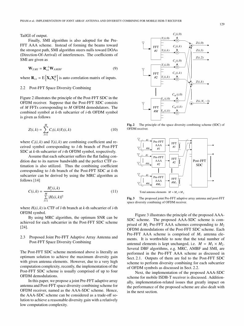
2.2 Post-FFT Space Diversity Combining
Figure 2 illustrates the principle of the Post-FFT SDC in theOFDM receiver. Suppose that the Post-FFT SDC consistsof M FFTs corresponding to M OFDM demodulators. Thecombined symbol at k-th subcarrier of i-th OFDM symbolis given as follows
Z(i, k) =M∑
l=1
Cl(i, k)Yl(i, k) (10)
where Cl(i, k) and Yl(i, k) are combining coefficient and re-ceived symbol corresponding to l-th branch of Post-FFTSDC at k-th subcarrier of i-th OFDM symbol, respectively.
Assume that each subcarrier suffers the flat fading con-dition due to its narrow bandwidth and the perfect CTF es-timation is also utilized. Thus the combining coefficientcorresponding to l-th branch of the Post-FFT SDC at k-thsubcarrier can be derived by using the MRC algorithm asfollows [14]
C(i, k) =H∗l (i, k)
M∑l=1|Hl(i, k)|2
(11)
where Hl(i, k) is CTF of l-th branch at k-th subcarrier of i-thOFDM symbol.
By using MRC algorithm, the optimum SNR can beachieved for each subcarrier in the Post-FFT SDC scheme[24].
2.3 Proposed Joint Pre-FFT Adaptive Array Antenna andPost-FFT Space Diversity Combining
The Post-FFT SDC scheme mentioned above is literally anoptimum solution to achieve the maximum diversity gainwith given antenna elements. However, due to a very highcomputation complexity, recently, the implementation of thePost-FFT SDC scheme is usually comprised of up to fourOFDM demodulations.
In this paper, we propose a joint Pre-FFT adaptive arrayantenna and Post-FFT space diversity combining scheme forOFDM receiver, named as the AAA-SDC scheme. Hence,the AAA-SDC scheme can be considered as a trade-off so-lution to achieve a reasonable diversity gain with a relativelylow computation complexity.
Fig. 2 The principle of the space diversity combining scheme (SDC) ofOFDM receiver.
Fig. 3 The proposed joint Pre-FFT adaptive array antenna and post-FFTspace diversity combining of OFDM receiver.
Figure 3 illustrates the principle of the proposed AAA-SDC scheme. The proposed AAA-SDC scheme is com-prised of M2 Pre-FFT AAA schemes corresponding to M2
OFDM demodulations of the Post-FFT SDC scheme. EachPre-FFT AAA scheme is comprised of M1 antenna ele-ments. It is worthwhile to note that the total number ofantennal elements is kept unchanged, i.e. M = M1 × M2.Several DBF algorithms, e.g. MRC, AMBF and SMI, areperformed in the Pre-FFT AAA scheme as discussed inSect. 2.1. Outputs of them are fed to the Post-FFT SDCscheme to perform diversity combining for each subcarrierof OFDM symbols as discussed in Sect. 2.2.
Next, the implementation of the proposed AAA-SDCscheme for mobile ISDB-T receiver is discussed. Addition-ally, implementation-related issues that greatly impact onthe performance of the proposed scheme are also dealt within the next section.

130IEICE TRANS. COMMUN., VOL.E91–B, NO.1 JANUARY 2008
3. Implementation of the Proposed AAA-SDC Schemefor Mobile ISDB-T Receiver
In this section, the implementation of the proposed AAA-SDC scheme is discussed from the viewpoint of hardwaredesign. The target of our design is to improve the perfor-mance of the mobile ISDB-T receiver up to a certain levelof reception quality. It is also required to provide a flexibleand unified platform that is capable of reconfigurations andfurther improvements.
3.1 Implementation-Related Issues
As realizing the AAA-SDC scheme, several implementationrelated issues are brought to our concern and listed as fol-lows
• Doppler shift and frequency error due to imperfect os-cillator.• Sampling rate error due to the mismatch sampling fre-
quency between the transmitter and the receiver.• OFDM symbol synchronization and CTF estimation.
Next, these issues are discussed thoroughly and their treat-ments are summarized.
A. Doppler Shift and Frequency Error.
In mobile ISDB-T receiver, incoming signal with car-rier frequency of fc comes to antenna with angle-of-arrival(AOA) of θ. As a result, each subcarrier of the OFDM signalsuffers a Doppler shift as
fd =v
cfc cos(θ) (12)
=v
λcos(θ)
where λ is wavelength of incoming signal; v and c are thespeed of the automobile and the light, respectively. Themaximum Doppler shift is determined as fdmax = (v/c) fc.
In mobile channel, assume that many waves arrive eachwith its own random AOA (thus with its own Doppler shift),which is uniformly distributed within [0, 2π], independentlyof other waves. A probability density function of the fre-quency of received signal can be obtained, referred to asDoppler spectrum [24]. Figure 4(a) illustrates Doppler spec-trum of received signal associated with an omnidirectionalantenna, i.e. all frequency components of received signalare subjects of Doppler shift randomly distributed within[− fdmax,+ fdmax].
In our application, totally four antenna elements areutilized and are set in the body of automobile, two antennaelements are set in the front and the others are set in the rear.However, as the body of automobile is made from metal,two front antenna elements seemingly experience a similarDoppler shift as discussed below, so do the others in the rear.Hence, in order to simply demonstrate different Doppler
(a) Doppler spectrum associated with omni-directional antennaelement in mobile channel.
(b) Illustration of Doppler shift in the case of two antenna elementsare set in the body of automobile.
(c) Doppler spectrums associated with directional antenna elements.
Fig. 4 Illustration of Doppler effect in case antenna elements are set inthe body of automobile.
shift phenomenon between the front and rear antenna ele-ments, let us assume in this subsection that there are onlytwo antenna elements, one set in the front and the other setin the rear of the body of automobile — see Fig. 4(b). As thebody of automobile is made from metal, it is experimentallyconfirmed that directional characteristic of the front antennais obviously distorted and concentrates on the front direc-tion, while that of the rear antenna focuses to the back di-rection of automobile [17]. Therefore, these antenna ele-ments can be considered as direction filters of which AOAof incoming signal is the subject. Consequentially, as illus-trated in Fig. 4(c), received signal of front antenna elementmostly experiences a positive Doppler shift randomly dis-tributed within [0,+ fdmax]; whereas that of rear antenna ele-ment mostly experiences a negative Doppler shift randomlydistributed within [− fdmax, 0]. In other words, performanceof mobile ISDB-T receiver is seemingly enhanced in mo-bile channel condition as bandwidth of Doppler spectrum isreduced by exploiting directional antenna elements.
In addition, imperfect analog components, such as car-rier frequency oscillator, also introduce a frequency errorto the received signal. A frequency error caused by imper-fect analog components can be considered to be invariant induration of many OFDM symbols. As a result, ICI (Inter-carrier Interference) caused by both Doppler shift and im-perfect analog components will increase the error floor of re-
PHAM et al.: IMPLEMENTATION OF JOINT ARRAY ANTENNA AND DIVERSITY COMBINING FOR MOBILE ISDB-T RECEIVER131
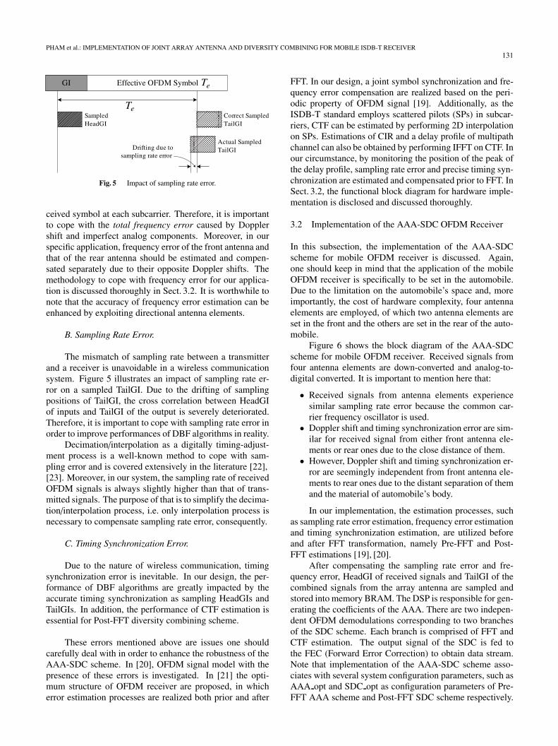
Fig. 5 Impact of sampling rate error.
ceived symbol at each subcarrier. Therefore, it is importantto cope with the total frequency error caused by Dopplershift and imperfect analog components. Moreover, in ourspecific application, frequency error of the front antenna andthat of the rear antenna should be estimated and compen-sated separately due to their opposite Doppler shifts. Themethodology to cope with frequency error for our applica-tion is discussed thoroughly in Sect. 3.2. It is worthwhile tonote that the accuracy of frequency error estimation can beenhanced by exploiting directional antenna elements.
B. Sampling Rate Error.
The mismatch of sampling rate between a transmitterand a receiver is unavoidable in a wireless communicationsystem. Figure 5 illustrates an impact of sampling rate er-ror on a sampled TailGI. Due to the drifting of samplingpositions of TailGI, the cross correlation between HeadGIof inputs and TailGI of the output is severely deteriorated.Therefore, it is important to cope with sampling rate error inorder to improve performances of DBF algorithms in reality.
Decimation/interpolation as a digitally timing-adjust-ment process is a well-known method to cope with sam-pling error and is covered extensively in the literature [22],[23]. Moreover, in our system, the sampling rate of receivedOFDM signals is always slightly higher than that of trans-mitted signals. The purpose of that is to simplify the decima-tion/interpolation process, i.e. only interpolation process isnecessary to compensate sampling rate error, consequently.
C. Timing Synchronization Error.
Due to the nature of wireless communication, timingsynchronization error is inevitable. In our design, the per-formance of DBF algorithms are greatly impacted by theaccurate timing synchronization as sampling HeadGIs andTailGIs. In addition, the performance of CTF estimation isessential for Post-FFT diversity combining scheme.
These errors mentioned above are issues one shouldcarefully deal with in order to enhance the robustness of theAAA-SDC scheme. In [20], OFDM signal model with thepresence of these errors is investigated. In [21] the opti-mum structure of OFDM receiver are proposed, in whicherror estimation processes are realized both prior and after
FFT. In our design, a joint symbol synchronization and fre-quency error compensation are realized based on the peri-odic property of OFDM signal [19]. Additionally, as theISDB-T standard employs scattered pilots (SPs) in subcar-riers, CTF can be estimated by performing 2D interpolationon SPs. Estimations of CIR and a delay profile of multipathchannel can also be obtained by performing IFFT on CTF. Inour circumstance, by monitoring the position of the peak ofthe delay profile, sampling rate error and precise timing syn-chronization are estimated and compensated prior to FFT. InSect. 3.2, the functional block diagram for hardware imple-mentation is disclosed and discussed thoroughly.
3.2 Implementation of the AAA-SDC OFDM Receiver
In this subsection, the implementation of the AAA-SDCscheme for mobile OFDM receiver is discussed. Again,one should keep in mind that the application of the mobileOFDM receiver is specifically to be set in the automobile.Due to the limitation on the automobile’s space and, moreimportantly, the cost of hardware complexity, four antennaelements are employed, of which two antenna elements areset in the front and the others are set in the rear of the auto-mobile.
Figure 6 shows the block diagram of the AAA-SDCscheme for mobile OFDM receiver. Received signals fromfour antenna elements are down-converted and analog-to-digital converted. It is important to mention here that:
• Received signals from antenna elements experiencesimilar sampling rate error because the common car-rier frequency oscillator is used.• Doppler shift and timing synchronization error are sim-
ilar for received signal from either front antenna ele-ments or rear ones due to the close distance of them.• However, Doppler shift and timing synchronization er-
ror are seemingly independent from front antenna ele-ments to rear ones due to the distant separation of themand the material of automobile’s body.
In our implementation, the estimation processes, suchas sampling rate error estimation, frequency error estimationand timing synchronization estimation, are utilized beforeand after FFT transformation, namely Pre-FFT and Post-FFT estimations [19], [20].
After compensating the sampling rate error and fre-quency error, HeadGI of received signals and TailGI of thecombined signals from the array antenna are sampled andstored into memory BRAM. The DSP is responsible for gen-erating the coefficients of the AAA. There are two indepen-dent OFDM demodulations corresponding to two branchesof the SDC scheme. Each branch is comprised of FFT andCTF estimation. The output signal of the SDC is fed tothe FEC (Forward Error Correction) to obtain data stream.Note that implementation of the AAA-SDC scheme asso-ciates with several system configuration parameters, such asAAA opt and SDC opt as configuration parameters of Pre-FFT AAA scheme and Post-FFT SDC scheme respectively.

132IEICE TRANS. COMMUN., VOL.E91–B, NO.1 JANUARY 2008
Fig. 6 Block diagram of the proposed AAA-SDC scheme.
Fig. 7 Interface between FPGA and DSP.
Their features are explained in next subsections.
A. Joint Hardware and Software Implementation.
We use joint hardware and software approach for im-plementing the proposed AAA-SDC scheme — see Fig. 6.FPGA is utilized as hardware side due to its million-logic-gate density and gigabit-per-second interface. Thereforeprefixed processes which also demand high computationload, such as FFTs, CTF estimation, Pre-FFT and Post-FFTestimations, are synthesized in FPGA. In contrast, DBF al-gorithms that require less computation load are realized inDSP. In our design, TI C6713 development board is usedto perform DBF algorithms. It features the TMS320C6713DSP of 225 MHz with floating-point support, which meetsthe demand of high precision computation for DBF algo-rithms. This joint hardware and software approach surely
Fig. 8 Timing diagram the AAA-SDC scheme.
provide a robust platform for investigation and further im-provement. Figure 7 shows the interface of FPGA and DSP.FPGA and DSP are coupled via a shared memory block lo-cated in FPGA, namely BRAM. BRAM is a dual-port mem-ory block which provides a common memory accessible toboth FPGA and DSP that can be used to share and trans-mit data and system status between them. DSP retrievesdata in BRAM via EMIF (External Memory Interface) us-ing EDMA (Enhanced Direct-Memory-Access). Handshakesignal from FPGA is used as external interrupt to trigger thedata transfer process and the operation of CPU.
In detail, a dual memory bank is utilized in both BRAMand internal memory of DSP to realize real-time opera-tion. Timing diagram is illustrated in Fig. 8. As mentionedabove, BRAM provides common memory accessible to both

PHAM et al.: IMPLEMENTATION OF JOINT ARRAY ANTENNA AND DIVERSITY COMBINING FOR MOBILE ISDB-T RECEIVER133
Table 1 Specification of the prototype.
Channel 4ADC Resolusion 10 bit
Adaptive Sampling rate 32 MHzArray FPGA Xilinx Virtex-II Pro VP70,Antenna VP20
DSP TI DSP C6713TMS320C6713 225 MHz
Space Xilinx Virtex-II 4000x2, V3000Diversity FPGA (OFDM Demod. and SDC)Combining
Fig. 9 Prototype of the AAA-SDC scheme.
FPGA and DSP. In FPGA, samples of HeadGI and TailGIare stored continuously to bank #0 and bank #1 in BRAM.Meanwhile, DSP retrieves data samples available in onememory bank in BRAM to generate the coefficients. Af-ter that, the coefficients are stored back to the correspondingmemory bank in BRAM. The duration for retrieving datasamples, generating the coefficients and storing the coeffi-cients is shorter than one OFDM symbol duration.
We successfully implement the prototype of the AAA-SDC scheme. Table 1 and Fig. 9 show the specificationand photograph of a prototype of the proposed AAA-SDCscheme.
B. Multiple System Configurations featured by theAAA-SDC Scheme.
The prototype is capable of altering the combination ofantenna elements, i.e. four antenna elements can be used asone array antenna or as two array antenna, of which one isset in the front and the other is set in the rear of automobile.In addition, the operation of the Post-FFT SDC scheme canalso be switched to a conventional equalizer by using onlyone OFDM demodulation. As a result, the prototype can beutilized as the proposed AAA-SDC scheme or as the Pre-FFT AAA scheme. Nevertheless, since DBF algorithms areembedded in DSP, beam-forming capability of the array an-tenna can also be reconfigurable on the fly. The capabilitiesof reconfiguring the system configuration and changing dif-
(a) System configuration A as the proposed joint AAA-SDC scheme.
(b) System configuration B as the conventional Pre-FFT AAA scheme.
Fig. 10 Multiple system configurations supported by the AAA-SDCscheme.
ferent DBF algorithms are to flexibly adapt the design forvarious applications. We believe these features are usefulfor investigation and further improvement.
Two system configurations are featured for evaluationand experiment. Figure 10(a) shows the proposed AAA-SDC scheme as a fully supported system configuration,in which both Pre-FFT AAA scheme and Post-FFT SDCscheme are exploited, and is hereto referred to as SystemConfiguration A. The other, shown in Fig. 10(b), is the con-ventional Pre-FFT AAA scheme referred to as System Con-figuration B [12]. Their implementations are significantlydifferent, such as:
• System Configuration A aims to exploit capabilitiesof beam forming and diversity combining algorithmwith regard to directional characteristics of antenna el-ements set in automobile. Meanwhile, System Config-uration B only supports beam forming capability.• In System Configuration A, two independent frequency
error compensations are used for received signals fromtwo front antennas and two rear antennas. However, inSystem Configuration B, only common frequency errorcompensation is used.
The performances of the prototype with both systemconfigurations are evaluated by simulations and field exper-iments comparatively and the results are given in Sect. 4 andSect. 5.

134IEICE TRANS. COMMUN., VOL.E91–B, NO.1 JANUARY 2008
4. Simulation Results
In this section, the operation of the AAA-SDC scheme isverified and studied by simulation. Coware Signal Process-ing Worksystem (SPW) is used as a developing EDA tool.SPW provides a flexible visualization environment withblock-oriented design. Nevertheless, because of its capa-bility of co-simulating multiple languages, such as VHDL,Verilog HDL as well as C/C++, ones can possibly performthe system-level design in a single design workbench inorder to verify the operation in co-simulating environmentstraightforwardly.
To evaluate performance of the AAA-SDC scheme inour application, based on [16], directional characteristics ofantenna elements are modeled as
E(θ) =
⎧⎪⎪⎪⎨⎪⎪⎪⎩E0 cos [k (θ − θ0)] , k |θ − θ0| ≤ 90o
or k (|θ − θ0| − 360o) ≥ −90o
0 otherwise
(13)
where E(θ) is an electric field strength in direction of θ, E0 isthe maximum electric field strength of the antenna element.θ0 is center direction of each antenna element and k is abeam width parameter.
In this paper, the value of k is determined by givenbeam width in which the electric field strength remainslarger than a half of E0, referred to as half-power beamwidth (HPBW). Thus, HPBW and the center direction ofeach antenna element could be used to model antenna direc-tional characteristic in these evaluations hereafter.
Table 2 shows the specifications of the AAA-SDCscheme. Furthermore, Fig. 11 illustrates electrical fieldstrength of antenna elements. As such, front antenna #1 and#2 with HPBW of 120 deg and center directions of 30 degand 330 deg, respectively, essentially concentrate their di-rectional characteristics on the front direction of the auto-mobile. In contrast, rear antenna #1 and #2 with HPBW of120 deg and center directions of 150 deg and 210 deg mainlyconcentrate on the back direction of automobile. Mode3 ofISDB-T standard using 64 QAM modulation scheme and GI
Table 2 Specification of the AAA-SDC scheme.
Two 2-antenna element linear arraysCenter direction Distant
Front 1 30 deg Half-wavelengthFront 2 330 deg = 0.2662 mRear 1 150 deg Half-wavelengthRear 2 210 deg = 0.2662 m
HPBW=120 deg
ISDB-T using DTV28CH Mode3Carrier Frequency 563.143 MHz
FFT size 8192Number of Subcarrier 5617
Effective Sym. Duration Te 1008 µsGI duration Tg = Te/8 126 µs
Modulation 64 QAM
duration Te = Tg/8 is selected as the simulation condition.In order to simplify the verification of the proposed AAA-SDC scheme, a perfect frequency error estimation is used.Also keep in mind that BER measurements are undertakenwithout Viterbi decoder.
As mentioned in Sect. 3, several system configurationscan be supported by using configuration parameters. Inthe previous project [11], [12], the Pre-FFT array antennahas been implemented due to its lowest cost in computa-tion complexity. Therefore, in order to demonstrate thecontinuous progress of our project and to convey the view-point of hardware design, the performance of the proposedAAA-SDC scheme (System Configuration A) and the con-ventional Pre-FFT AAA scheme (System Configuration B)are subjects for comparisons. More particularly, severalDBF algorithms for each configuration are included, such asMRC, AMBF and SMI. Varieties of multipath channel con-ditions are conducted to verify the operation of the AAA-SDC scheme and are discussed in next subsections.
4.1 Multipath Channel Condition 1
In this simulation, multipath channel condition is realizedto verify the AAA-SDC scheme. Table 3 shows the specifi-cation of this simulation condition. It is worthwhile notingthat in this condition delay spreads are shorter than GI du-ration. Therefore, it can be considered as a free ISI channelcondition.
Figure 12 shows the BER performances of the AAA-SDC scheme versus SNR with Doppler shift of 0 Hz. Theperformances of different DBF algorithms on the same sys-tem configuration are rather identical. Moreover, the BER
Fig. 11 Allocation of antenna elements in automobile and their direc-tional characteristics.
Table 3 Multipath channel condition 1.
Paths θ (deg) DUR (dB) Delay
#1 0 3 0.5 ∗ (Tg/8)#2 30 0 0#3 90 3 3.2 ∗ (Tg/8)#4 150 3 2.5 ∗ (Tg/8)#5 210 0 0.3 ∗ (Tg/8)#6 300 3 4.0 ∗ (Tg/8)

PHAM et al.: IMPLEMENTATION OF JOINT ARRAY ANTENNA AND DIVERSITY COMBINING FOR MOBILE ISDB-T RECEIVER135
Fig. 12 BER vs. SNR with Doppler shift of 0 Hz.
Fig. 13 BER vs. Doppler shift with SNR=30 dB.
performances of System Configuration A outperform thoseof System Configuration B due to the superiority of the Post-FFT SDC scheme.
In addition, the BER performances of the AAA-SDCscheme versus the maximum Doppler shift with SNR of30 dB are shown in Fig. 13. Again, the BER performancesof different DBF algorithms are similar for each particularsystem configuration. Interestingly, the DBF algorithms onSystem Configuration A is seemingly stable in a region ofvery high Doppler shift because of the perfect frequency er-ror compensation. However, the performances of DBF al-gorithms on System Configuration B are greatly degradedas Doppler shift increases. As antenna elements in the frontand in the rear gather incoming signals with different AOAs,their received signals suffer greatly different Doppler shift,from the front ones to the rear ones, due to their different di-rectional characteristics. As a result, Doppler shift is rarelycompensated by the common frequency error compensationand therefore greatly degrades the performances on SystemConfiguration B in a region of high Doppler shift.
4.2 Multipath Channel Condition 2
The channel condition for this simulation is given in Table 4.In this condition, there are two paths with delay spread ex-ceeding GI duration, considered as ISIs, coming from boththe front direction and the back direction. Once again, theperformances of DBF algorithms on System Configuration
Table 4 Multipath channel condition 2.
Paths θ (deg) DUR (dB) Delay
#1 0 3 10.0 ∗ (Tg/8)#2 30 0 0#3 90 3 3.2 ∗ (Tg/8)#4 150 3 11.2 ∗ (Tg/8)#5 210 0 0.3 ∗ (Tg/8)#6 300 3 4.0 ∗ (Tg/8)
Fig. 14 BER vs. SNR with Doppler shift of 0 Hz.
Fig. 15 BER vs. Doppler shift with SNR=30 dB.
A and B are evaluated. Figure 14 shows the BER perfor-mances versus SNR in case Doppler shift of 0 Hz. Withthe presence of interferences, System Configuration A stilloutperforms System Configuration B. In detail, SMI algo-rithm on both configurations achieves the best performancedue to its ability of suppressing interferences. Let it keepin mind that AMBF algorithm is the improvement of MRCalgorithm as discussed in Sect. 2.1. Therefore it is also in-teresting to note that the performances of AMBF algorithmoutperform those of MRC algorithm on both configurations.
BER performances versus Doppler shift in the caseof SNR of 30 dB are given in Fig. 15. Similarly, the per-formances of DBF algorithms on System Configuration Aare more stable in a region of high Doppler shift, mean-while their performances on System Configuration B areseverely degraded by Doppler shift. Over all, SMI algorithmachieves the highest performance on both configurations.

136IEICE TRANS. COMMUN., VOL.E91–B, NO.1 JANUARY 2008
Table 5 Experimental conditions.
City Center Loop ExpresswayTest (NLOS enviroment)Course Course length 10 km
Distance to ISDB-T tower approx. 20 km
4 on-glass antenna elementsEvaluation Evaluation signal 12-segment HDTVConditions Moving speed 80 km/h
Evaluation period approx. 8 minutes
Fig. 16 Illustration of experiment setup.
5. Experimental Results
The prototype of the AAA-SDC scheme is successfully im-plemented and is the subject of several experiments. Theexperimental conditions are summarized in Table 5 and theexperiment setup is illustrated in Fig. 16. In [17], the direc-tional characteristics of on-glass antennas mounted in dif-ferent positions in the body of automobile are illustrated. Inour experiment setup, four on-glass antenna elements are setin body of automobile, two antenna elements are mountedin corners of the front windshield, whereas the others aremounted in the rear windshield of the experimental auto-mobile. Output signal of the prototype is error-correctedby Viterbi decoder and Reed-Solomon decoder to obtainMPEG-2 stream. The broadcasted signal is then displayedin a monitor to evaluate the reception quality — see Fig. 16.
To validate the reception quality of the prototype, wedefine the reception rate as the ratio of error-free recep-tion duration to the total experiment duration. In the ex-periment, the reception rate of the prototype is measuredwhile the experimental vehicle is moving with speed ofabout 80 km/h in the highway. In the test course, the proto-type experiences no co-channel interference, however non-line-of-sight (NLOS) multipath condition with relativelylong delay paths is mostly observed during the experiments.The performances of both system configurations, in whichMRC, AMBF and SMI are selected, are measured sepa-rately. Figure 17 shows the average reception rate of Sys-tem Configuration A and System Configuration B. In the testcourse, System Configuration A that utilizes MRC, AMBFand SMI, can achieve the average reception rate of 100%;
Fig. 17 Performances of system configuration A and B.
Fig. 18 Performances of DBF algorithms in system configuration B.
whereas the average reception rate of System ConfigurationB utilizing MRC, AMBF and SMI can only reaches up to65%. Obviously, the performance of mobile ISDB-T re-ceiver set in the high-speed automobile are drastically im-proved by using the proposed AAA-SDC scheme.
Figure 18 illustrates the performances of MRC, AMBFand SMI in System Configuration B in detail. By exploit-ing the periodic property of OFDM signal as explained inSect. 2, the reception rate of AMBF is improved comparedwith that of MRC. More interestingly, as the receiver experi-ences mostly NLOS multipath condition with relatively longdelay paths in the test course, due to the null steering capa-bility, the performance of SMI outperforms that of MRC andAMBF.
The experimental results are also disclosed in [12] and[18].
6. Conclusions
In circumstances that multiple antenna elements are setin the body of automobile, it is inappropriate to considertheir directional characteristics as omnidirectional charac-teristics. Indeed, the directional characteristics of the frontones focus to the front direction while those of the rear onesfocus to the back direction of the automobile.
In this paper, the AAA-SDC scheme is proposed andimplemented to improve the performance of mobile ISDB-T receiver in such application. By exploiting the jointsoftware-hardware approach, several DBF algorithms canbe supported. Moreover, this approach also provides the

PHAM et al.: IMPLEMENTATION OF JOINT ARRAY ANTENNA AND DIVERSITY COMBINING FOR MOBILE ISDB-T RECEIVER137
platform in which several system configurations can be re-configurable on the fly. Simulations and experiments areconducted to verify the performance of the proposed AAA-SDC scheme. The results show that a performance of mo-bile ISDB-T receiver is drastically improved as the specificdirectional characteristics of antenna elements are taken intoaccount. The experiment results show that the proposedAAA-SDC scheme achieves the outstanding reception rateup to 100%, meanwhile the reception rate of the Pre-FFTAAA scheme only reaches up to 65%.
Acknowledgments
The authors would like to thank Dr. Shuji Murakami,Kazuhiro Kamiyama and Hiroyuki Mizutani of Magna De-sign Net Inc. for invaluable contribution to implement theprototype. The authors would like to thank Prof. NobuyukiKikuma of Nagoya Institute of Technology for useful dis-cussion and cooperation to enhance the performance of theprototype. Finally, the authors would like to express ourgratitude to Associate Prof. Mitoshi Fujimoto of Universityof Fukui for antenna-related technical discussions.
References
[1] J.A.C. Bingham, “Multicarrier modulation for data transmission: Anidea whose time has come,” IEEE Commun. Mag., vol.28, no.5,pp.5–14, May 1990.
[2] R. Van Nee and R. Prasad, OFDM for Wireless Multimedia Com-munication, pp.39–42, Artech House, 2000.
[3] N. Kikuma and M. Fujimoto, “Adaptive antennas,” IEICE Trans.Commun., vol.E86-B, no.3, pp.968–979, March 2003.
[4] L.C. Godara, “Application of antenna arrays to mobile communica-tion, Part II: Beam-forming and direction-of-arrival considerations,”Proc. IEEE, vol.85, no.8, pp.1195–1245, Aug. 1997.
[5] S. Hara, A. Nishikawa, and Y. Hara, “A novel OFDM adaptive an-tenna array for delayed signal and Doppler-shifted signal suppres-sion,” Proc. IEEE ICC2001, vol.7, pp.2302–2306, 2001.
[6] J. Imai, M. Fujimoto, T. Shibata, N. Itoh, N. Suzuki, and K.Mizutani, “Experimental results of diversity reception for terrestrialdigital broadcasting,” IEICE Trans. Commun., vol.E85-B, no.11,pp.2527–2530, Nov. 2002.
[7] S. Sakaguchi, M. Hori, T. Wada, and N. Itoh, “An adaptive arraydirection control LSI for mobile digital HDTV receivers,” Session7.4: Acquisition System, IEEE ICCE2005, USA, Jan. 2005.
[8] S. Hori, N. Kikuma, and N. Inagaki, “MMSE adaptive array utilizingguard interval in the OFDM systems,” Electron. Commun. Jpn.1,Commun., vol.86, no.10, pp.1–9, 2003.
[9] S. Hori, N. Kikuma, T. Wada, and M. Fujimoto, “Experimentalstudy on array beam forming utilizing the guard interval in OFDM,”WD3-3, International Symposium on Antennas and PropagationISAP2005, pp.257–260, Korea, Aug. 2005.
[10] S. Hori, Research on Adaptive Array Antenna for OFDM Transmis-sion, Doctor Dissertation, Nagoya Institute of Technology, Japan,April 2006.
[11] H. Asato, T. Tabata, D.H. Pham, H. Mizutani, K. Kamiyama, S.Hori, and T. Wada, “A software-configurable adaptive array an-tennna systems for ISDB-T reception,” Session: 11.2 Signal Pro-cessing for Multiple Ant., DVB-T and DAPSK/DMT, IEEE Int.Conf. on Consumer Electronics ICCE2006, USA, Jan. 2006.
[12] D.H. Pham, T. Tabata, H. Asato, S. Hori, and T. Wada, “Jointhardware-software implementation of adaptive array antenna forISDB-T reception,” IEICE Trans. Commun., vol.E89-B, no.12,
pp.3215–3224, Dec. 2006.[13] M. Fujimoto, K. Nishikawa, T. Shibata, N. Kikuma, and N. Inagaki,
“A novel adaptive array utilizing frequency characteristics of multi-carrier signals,” IEICE Trans. Commun., vol.E83-B, no.2, pp.371–379, Feb. 2000.
[14] S. Nakahara, H. Hamazumi, K. Shibuya, and M. Sasaki, “An appli-cation of diversity combination techniques to broadcasting wave re-lay station for ISDB-T,” ITE Technical Report, vol.25, no.31, pp.7–12, March 2001.
[15] K. Higuchi and H. Sasaoka, “Adaptive array suppressing inter-symbol interference based on frequency spectrum in OFDM sys-tem,” IEICE Trans. Commun. (Japanese Edition), vol.J87-B, no.9,pp.1222–1229, Sept. 2004.
[16] M. Fujimoto and T. Hori, “Effect of antenna element characteris-tics on antenna pattern control of array antenna,” IEICE TechinicalReport, RCS2004-177, Oct. 2004.
[17] S. Matsuzawa, K. Sata, and K. Nishikawa, “Study of on-glass mobileantennas for digital terrestrial television,” IEICE Trans. Commun.,vol.E88-B, no.7, pp.3094–3096, July 2005.
[18] T. Tabata, H. Asato, D.H. Pham, M. Fujimoto, H. Kikuma, S.Hori, and T. Wada, “Experiment study on adaptive array antennasystem for ISDB-T high speed mobile reception,” Session 150.5:Smart Ant. Sys., IEEE Ant. and Propagation Society Int. Sympo-sium (APS2007), pp.1697–1700, Hawaii, USA, June 2007.
[19] M. Speth, F. Classen, and H. Meyr, “Frame synchronization ofOFDM systems in frequency selective fading channels,” Proc. Ve-hicular Tech. Conf. (VTC’97 USA), pp.1807–1811, 1997.
[20] M. Speth, S.A. Fechtel, G. Fock, and H. Meyr, “Optimum receiverdesign for wireless broad-band systems using OFDM — Part I,”IEEE Trans. Commun., vol.47, no.11, pp.1668–1677, Nov. 1999.
[21] M. Speth, S.A. Fechtel, G. Fock, and H. Meyr, “Optimum receiverdesign for wireless broad-band systems using OFDM — Part II: Acase study,” IEEE Trans. Commun., vol.49, no.4, pp.571–578, April2001.
[22] F.M. Gardner, “Interpolation in digital modems — Part I: Fundamet-als,” IEEE Trans. Commun., vol.41, no.3, pp.501–507, March 1993.
[23] F.M. Gardner, “Interpolation in digital modems — Part I: Imple-mentation and performance,” IEEE Trans. Commun., vol.41, no.6,pp.998–1008, June 1993.
[24] J.G. Proakis, Digital Communications, fourth ed., McGraw-Hill,2001.
Dang Hai Pham was born in Hanoi, Viet-nam, on June 7, 1977. He received B.S. degreein Hanoi Univ. of Technology, Vietnam in 2000and M.S. in Univ. of the Ryukyus, Okinawa,Japan in 2003. Now he is a Ph.D. student inDepartment of Information Engineering, Univ.of the Ryukyus. His research interests are chan-nel estimation, adaptive array antenna with itsapplication to OFDM.

138IEICE TRANS. COMMUN., VOL.E91–B, NO.1 JANUARY 2008
Jing Gao received his B.E. degree and M.E.degree in Electrical and Electronic Engineer-ing from Ryukyu University, Okinawa, Japan,in 2003 and 2005, respectively. He is currentlyworking toward the Ph.D. degree in InformationEngineering at Ryukyu University. His researchinterests are adaptive array antenna and its ap-plication to mobile communications.
Takanobu Tabata was born in Mie, Japanon September 3, 1976. He received B.E. degreein Electrical Engineering from Nagoya Instituteof the Technology, Nagoya, Japan, in 2000. Hejoined Kojima Press Industry Co., Ltd. Aichi,Japan, in 2000. Currently, he is engaged in de-velopment of a system for mobile reception ofISDB-T.
Hirokazu Asato was born in Okinawa,Japan on June 20, 1976. He received B.S. degreein Electrical Engineering, Univ. of the Ryukyus,Okinawa, Japan, in 1999. He joined Nihon Syn-osys Co., Ltd. Tokyo, Japan, in 1999. From1992 to 2002, he was engaged in technical sup-port of ASIC design. In 2002, he joint MagnaDesign Net Inc., Okinawa, Japan. Currently,he was engaged in developing and programmingrelated to wireless communication LSI.
Satoshi Hori was born in Aichi, Japan,on November 4, 1964. He received B.E. de-gree in Electronics and Information Science andPh.D. from Toyota Technological Institute, Na-goya, Japan, in 1989 and Nagoya Institute ofthe Technology, Nagoya, Japan, in 2006, respec-tively. Since he joined Kojima Press IndustryCo., Ltd. in 1982, he has been engaged in re-search and development on antenna systems forautomobile use such as adaptive array antennaand vehicle communication. He is a member of
the IEEE.
Tomohisha Wada was born in Hiroshima,Japan, on December 2, 1959. He received B.S.degree in electronic engineering from OsakaUniv., Osaka, Japan, in 1983, M.S.E.E. degreefrom Stanford Univ., Stanford CA, in 1992,and Ph.D. in electronic engineering from OsakaUniv. in 1994. He joined the ULSI Laboratory,Mitsubishi Electric Corp., Itami, Japan, in 1983.From 1983 to 1999, he has been engaged in thedevelopment of CMOS/BiCMOS static RAMs,3-D graphics controller ASIC, flash memory,
low-voltage static RAM, and synchronous burst static RAMs. In 1998, hejoined Mitsubishi Electric Corp., Semiconductor Group, Memory IC Divi-sion, Itami, where he has been working on the development of applicationspecific synchronous burst static RAMs. In 1999, he became an Asso-ciate Professor with the Department of Information Engineering, Univ. ofthe Ryukyus, Okinawa, Japan. Since 2001, he has been a Professor at theDepartment of Information Engineering, Univ. of the Ryukyus, Okinawa,Japan. In 2001, He was the founding member of Magna Design Net, Inc.,which is a fab-less LSI design Company for communication related digitalsignal processing such as OFDM. Currently, he is also the chief scientistof Magna Design Net, Inc. From 1999 up to now, he has been engaged inthe research and development of high bandwidth communication systemssuch as terrestrial video broadcasting receivers and wireless LAN. Cur-rently his research interests include system-level large-scale VLSI design,digital signal processing for high-bandwidth communication, error correc-tion algorithm and circuit, networking software and protocols.
![Patch Antenna[1]](https://static.fdokumen.com/doc/165x107/63158e4cc32ab5e46f0d5c89/patch-antenna1.jpg)