ImTV: Towards an Immersive TV experience - Moody College ...
Upload
independentCategory
view
1download
0
IEEE SIGNAL PROCESSING MAGAZINE [58] JANUARY 2011
© A
RT
VIL
LE &
BR
AN
D X
PIC
TU
RE
S
Digital Object Identifier 10.1109/MSP.2010.939075
The National Academy of Engineering recently identified 14 grand challenges for engineering in the 21st century (www.engineeringchallenges.org). We believe that the continuing advances in ubiquitous sensing, processing, and computing
provide the potential to tackle two of these 14 grand challeng-es: specifically, enhancing virtual reality and advancing personalized learning.
INTRODUCTIONRecently, the ubiquity of digital cameras has made a great impact on visual communication as can be seen from the explo-sive growth of visual contents on the Internet and the default inclusion of a digital camera on cell phones and laptops. Two recent developments in sensing and computing have the poten-tial to revolutionize visual communication further by enabling immersive and interactive capabilities. The first development is the emergence of lower-priced, fast, and robust cameras for measuring depth [1]. Depth measurements provide a perfect complementary information to the traditional color imaging in capturing the three-dimensional (3-D) scene. The second devel-opment is the general-purpose parallel computing platforms such as graphics processing units (GPUs) that can significantly speedup many visual computing tasks [2] and bring them to the real-time realm. These developments and high demand for immersive communication present a tremendous opportunity for the signal processing field.
[ Minh N. Do, Quang H. Nguyen, Ha T. Nguyen, Daniel Kubacki, and Sanjay J. Patel]
[ An introduction of the
propagation algorithm and analysis
for image-based rendering with
depth cameras]
Date of publication: 17 December 2010
1053-5888/11/$26.00©2011IEEE
In particular, we envision systems, called remote reality, which can record real scenes and render 3-D free-viewpoint videos and augment it with virtual reality. Such a system can provide immersive and interactive 3-D viewing experi-ences for personalized distance learning and immersive com-munication. With recorded 3-D visual information, users can freely choose their viewpoints as if each of them had a virtual mobile camera. When users want to get a closer look at some part of a remote scene, they simply have to move the virtual camera to a suitable location. With depth keying, the video background can be removed and replaced by other interac-tive backgrounds. Moreover, 3-D free-viewpoint videos can be merged with objects of virtual 3-D worlds. Then users become integral parts of a virtual world, which frees them from some of the constraints imposed by current telecom-munication systems.

IEEE SIGNAL PROCESSING MAGAZINE [59] JANUARY 2011
The first key problem in remote reality is to find an effi-cient representation for gen -erating free-viewpoint 3-D videos, because this has major impact on subsequent process-ing, transmitting, and rendering steps. Image-based rendering (IBR) is the process of synthesizing novel views from preren-dered or preacquired reference images of a scene [3]. Obviating the need to create a full geometric 3-D model, IBR is relatively inexpensive compared to traditional rendering while still pro-viding high photorealism.
Depth IBR (DIBR) combines color images with per-pixel depth information of the scene to synthesize novel views. Depth information can be obtained by stereo matching algo-rithms [4]. However, these algorithms are usually complicat-ed, inaccurate, and inapplicable for real-time applications. Thanks to the recent developments of new range sensors [1] that measure time delay between transmission of a light pulse and detection of the reflected signal on an entire frame at once, depth information can be obtained in real time from depth cameras. This makes the DIBR problem less computa-tionally intense and more robust than other techniques. Furthermore, it helps to significantly reduce the required number of cameras and transmitting data.
A problem with DIBR techniques is that the resolution of depth images from depth cameras is often low, whereas the technology for color cameras is more mature. Hence, the need for integrating and exploiting the synergy between color cameras and depth cameras becomes significant. Moreover, because the geometric information in DIBR is usually captured in real time from the physical world instead of from modeling a synthetic world (which also makes DIBR more photorealistic), the obtained data always suffer from noise and insufficient sampling effects. Therefore, the need for coupling image processing techniques with rendering techniques is a must.
The fusion of depth and color information in DIBR raises a fundamental problem of analyzing the effects of different input factors on the rendering quality. The answer to this problem is crucial for both theoretical and practical purposes; we cannot effectively control the rendering quality and the cost of DIBR systems without accurate quantitative analysis of the rendering quality.
Finally, the need for processing and integrating acquired depth and color videos significantly increases the computa-tions and is infeasible for real-time applications without parallelism, which makes algorithm and architecture code-sign critical. Besides, since rendering with full geometric information (color and depth) has been optimized for GPUs, GPUs are considered to be the ideal computing platform for the DIBR problem. For these reasons, we should conscious-ly develop processing algorithms that are suitable for the GPU platform.
REVIEW OF EXISTING FREE-VIEWPOINT RENDERING SOLUTIONSMany IBR algorithms have been proposed to synthesize new views from actual acquired (referred to as reference) imag-es of a scene [3]. One earlier
approach is to use a large number (from tens to more than a hundred) of regular color cameras to compensate for the lack of geometry [6]–[8]. In such a system, new-view images are obtained by simply interpolating in the ray domain. However, the use of large number cameras put a heavy bur-den on the calibration, storage, and transmission tasks. Furthermore, the bulky setup required for large number of cam-eras limits the deployment of such systems.
An alternative approach for IBR is to use explicit depth information in addition with color images to synthesize novel views. If the per-pixel depth information is available, the warping equation [9] can be used to transfer information from actual color pixels to the virtual image plane. Zitnick et al. [4] demonstrated that high-quality and real-time new-view rendering can be achieved with depth plus color images using a modest number of cameras. However, their system requires intensive and off-line stereo matching computation to estimate depth information. A generalized framework of DIBR for 3-D TV applications was summarized in [10], which also includes the issues of compression and transmis-sion of IBR data.
Assuming that per-pixel color plus depth information is available at reference views, several algorithms have been recently developed for view synthesis under the DIBR frame-work [11]–[14]. Generally, these algorithms are based on the following steps:
1) Forward warp reference views to the new view.2) Process warped images to eliminate artifacts due to warp-ing and noise.3) Blend several warped images in the new view image plane.4) Inpaint or fill holes due to disocclusion.The first and third steps are quite straightforward and
standard. However, with slightly noisy DIBR data, they cre-ate visible artifacts. Most of these artifacts appear around object boundaries. Hence, the second and forth steps are crucial in reducing these artifacts. We refer to [14] for a detail discussion and comparison of various proposed artifact reduction algorithms.
With the recent progress of depth cameras technologies [1], the depth information the depth information can be directly measured by depth cameras instead of stereo matching. In practice, depth cameras often provide the depth images with lower resolution and poorer quality than those of the color images. Therefore, the combination of several high quality color cameras with a few depth cameras becomes an interesting setup for IBR.
WE ENVISION SYSTEMS, CALLED REMOTE REALITY, WHICH CAN RECORD REAL SCENES AND RENDER 3-D FREE-
VIEWPOINT VIDEOS AND AUGMENT IT WITH VIRTUAL REALITY.
IEEE SIGNAL PROCESSING MAGAZINE [60] JANUARY 2011
One way to increase the resolution and enhance the quality of depth images is to exploit the abundant informa-tion in high-quality color images. Several methods have been proposed to tackle this issue, including the Markov model approach [15] and the iterative bilateral filtering coupling with subpixel estimation [16]. However, these meth-ods are computationally complex, hence, they are not yet suitable for real-time applications.
While many IBR methods have been proposed, little research has addressed the fundamental questions on the impact of vari-ous configuration parameters on the rendering quality of IBR algorithms, such as the number of actual cameras and their geo-metrical positions as well as their resolution and image quality. A mathematical framework to study this problem is the concept of the plenoptic function [17] that describes the light intensity pass-ing through every viewpoint, in every direction for all time, and for every wavelength. McMillan and Bishop [18] recognized that the IBR problem is to reconstruct the plenoptic function (which leads to virtual images) using a set of discrete samples (i.e., actual images). Using a simplified domain of the plenoptic function, the light field, Chai et al. [19] analyzed the minimum number of images necessary to guarantee a given rendering quality.
In the analysis of IBR data, most existing literature addresses the Fourier domain because the IBR data exhibit fan-type structure in the frequency domain. However, Do et al. [20] showed that, in general, the plenoptic is not bandlim-ited unless the surface of the scene is flat. Another limit of the frequency-based approach is that it can not provide local analysis of the rendering quality. To address these drawbacks, Nguyen and Do [5] analyzed the rendering quality of novel views in the spatial domain using the framework of nonuni-form sampling and interpolation. The mean absolute error (MAE) of the rendered images can be bounded based on the configuration parameters such as depth and color errors (e.g., due to lossy coding), scene geometry and texture, num-ber of actual cameras and their positions, and resolution.
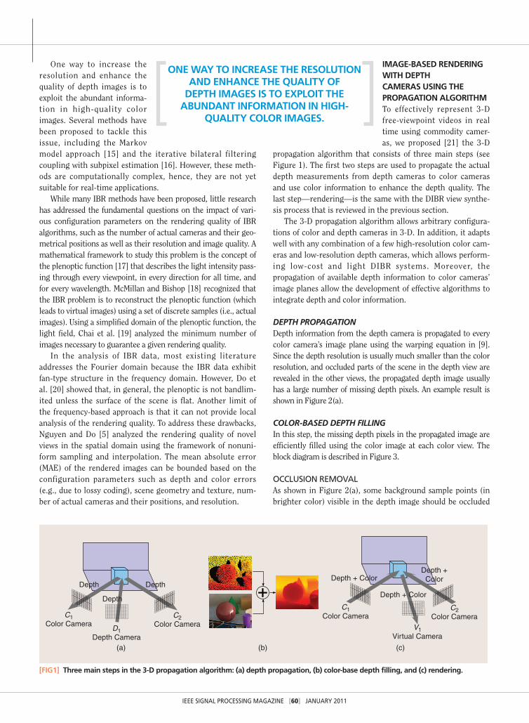
IMAGE-BASED RENDERING WITH DEPTH CAMERAS USING THE PROPAGATION ALGORITHMTo effectively represent 3-D free-viewpoint videos in real time using commodity camer-as, we proposed [21] the 3-D
propagation algorithm that consists of three main steps (see Figure 1). The first two steps are used to propagate the actual depth measurements from depth cameras to color cameras and use color information to enhance the depth quality. The last step—rendering—is the same with the DIBR view synthe-sis process that is reviewed in the previous section.
The 3-D propagation algorithm allows arbitrary configura-tions of color and depth cameras in 3-D. In addition, it adapts well with any combination of a few high-resolution color cam-eras and low-resolution depth cameras, which allows perform-ing low-cost and light DIBR systems. Moreover, the propagation of available depth information to color cameras’ image planes allow the development of effective algorithms to integrate depth and color information.
DEPTH PROPAGATIONDepth information from the depth camera is propagated to every color camera’s image plane using the warping equation in [9]. Since the depth resolution is usually much smaller than the color resolution, and occluded parts of the scene in the depth view are revealed in the other views, the propagated depth image usually has a large number of missing depth pixels. An example result is shown in Figure 2(a).
COLOR-BASED DEPTH FILLINGIn this step, the missing depth pixels in the propagated image are efficiently filled using the color image at each color view. The block diagram is described in Figure 3.
OCCLUSION REMOVALAs shown in Figure 2(a), some background sample points (in brighter color) visible in the depth image should be occluded
Depth DepthDepth + Color
Depth + ColorDepth +
Color
Depth
C1Color Camera
C1Color Camera
V1Virtual Camera
C2Color Camera
C2Color Camera
D1Depth Camera
(a) (b) (c)
[FIG1] Three main steps in the 3-D propagation algorithm: (a) depth propagation, (b) color-base depth filling, and (c) rendering.
ONE WAY TO INCREASE THE RESOLUTION AND ENHANCE THE QUALITY OF
DEPTH IMAGES IS TO EXPLOIT THE ABUNDANT INFORMATION IN HIGH-
QUALITY COLOR IMAGES.

IEEE SIGNAL PROCESSING MAGAZINE [61] JANUARY 2011
by the foreground (pixels with darker color) in the propagated depth image but are still visible. This significantly degrades the interpolation quality. We can remove these occluded pixels based on the smoothness of surfaces. If a point A in the propa-gated depth image is locally surrounded by neighboring points whose depth values are s smaller than the depth of A, then A is recognized to be occluded by the surface composed of those neighbors. In that case, the depth value of A is set to unknown. An example result is shown in Figure 2(b).
COLOR-BASED BILATERAL DEPTH FILTERINGThe color-based bilateral depth filtering (CBDF) is defined as follows:
dA51
WAa
B[SA
Gss1|xA2 xB|2 # Gsr
1|IA2 IB|2 # dB (1)
WA5 aB[SA
Gss1|xA2 xB|2 # Gsr
1|IA2 IB|2 , (2)
where dA, IA, and xA are the depth value, the color value, and the 2-D coordinate of point A. SA is set of neighboring pixels of A, Gs 1 |x| 2 5 exp 12|x|2/2s2 2 is the Gaussian kernel with vari-ance s2, and WA is the normalizing term.
The idea of using color differences as a range filter to interpo-late depth value is based on the observation that whenever a depth edge appears, there is almost always a corresponding color edge due to color differences between objects or between foreground and background. The CBDF also works well with textured surfaces since it counts only pixels on that surface which have similar color to the interpolated pixel. If surfaces have the same color, the color does not give any new information and the CBDF works as a simple interpolation scheme such as bilinear or bicubic. Therefore, by integrating known depth and color information, the proposed CBDF effectively interpolates unknown depth pixels while keeping sharp depth edges. An example result after this step is shown in Figure 2(c).
DIRECTIONAL DISOCCLUSION FILLINGTo fill the disocclusion areas, a filling direction needs to be specified. Otherwise, if the filling is performed from all directions, depth edges are spread out. Based on the observa-tion, as illustrated in Figure 4, which shows that the disocclu-sion areas are caused by the change of camera position, we choose the filling direction as the vector pointing from the epipole point (the projection of the depth camera position onto the image plane of the color camera) to the center of the propagated depth image.
DEPTH EDGE ENHANCEMENTThe sharpness of depth edges is extremely important. In the rendering step, a slightly blurred edge may blow up to a sig-nificant and visually annoying smearing artifact. The pur-pose of this stage is to correct and sharpen edges in the
(a) (b) (c) (d)
[FIG2] Steps for the color-based depth filling algorithm. Refer to the section “Color-Based Depth Filling” for a detailed description of these steps: (a) propagated depth, (b) occlusion removal, (c) CBDF, and (d) disocclusion and edge enhancement.
Propagated Depthat One Color View Occlusion
Removal
Depth-ColorBilateralFiltering
DirectionalDiocclusion
Filling
Depth EdgeEnhancement
Enhanced Depth
[FIG3] Block diagram of the color-based depth filling step.
C1 C2
D
[FIG4] Directional disocclusion filling. D, C1, and C2 are the camera centers of the depth and two color cameras. Stars indicate the epipole points. Black regions indicate the disocclusion areas. The arrows indicate the chosen directional disocclusion filling.
IEEE SIGNAL PROCESSING MAGAZINE [62] JANUARY 2011
propagated depth images at color views. The proposed depth edge enhancement stage includes two parts. First, depth edge gradients are detected with the Sobel operator. Then, pixels with significant edge gradients are marked as undetermined depth pixels and their depth val-ues need to be recalculated. Next, for each undetermined depth pixel, a block-based search is used to find the best pixel with known depth that matches in the color domain. Once the best candidate is chosen, its depth value is assigned to the unknown pixel. An example result after this step is shown in Figure 2(d).
RENDERINGFinally, depth and color information at each color view are propagated into the virtual view using the same technique as in the depth propagation step in Figure 1. The occlusion removal stage is performed for each propagated view. The final rendered images are blended and smoothed with a Gaussian filter. Note that most of the unknown color pixels in this step are caused by nonuniform resampling since the
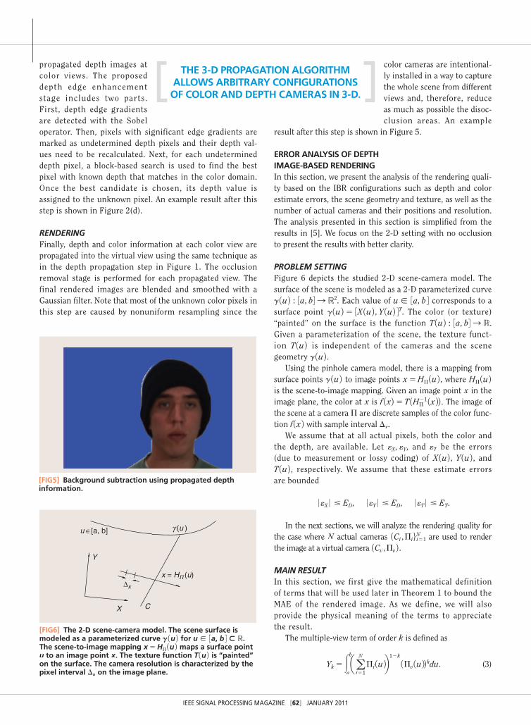
color cameras are intentional-ly installed in a way to capture the whole scene from different views and, therefore, reduce as much as possible the disoc-clusion areas. An example
result after this step is shown in Figure 5.
ERROR ANALYSIS OF DEPTH IMAGE-BASED RENDERINGIn this section, we present the analysis of the rendering quali-ty based on the IBR configurations such as depth and color estimate errors, the scene geometry and texture, as well as the number of actual cameras and their positions and resolution. The analysis presented in this section is simplified from the results in [5]. We focus on the 2-D setting with no occlusion to present the results with better clarity.
PROBLEM SETTINGFigure 6 depicts the studied 2-D scene-camera model. The surface of the scene is modeled as a 2-D parameterized curve g 1u 2 : 3a, b4 S R2. Each value of u [ 3a, b 4 corresponds to a surface point g 1u 2 5 3X 1u 2 , Y 1u 2 4T. The color (or texture) “painted” on the surface is the function T 1u 2 : 3a, b4 S R. Given a parameterization of the scene, the texture funct -ion T 1u 2 is independent of the cameras and the scene geometry g 1u 2 .
Using the pinhole camera model, there is a mapping from surface points g 1u 2 to image points x5HP 1u 2 , where HP 1u 2 is the scene-to-image mapping. Given an image point x in the image plane, the color at x is f 1x2 5 T 1HP
21 1x 22 . The image of the scene at a camera P are discrete samples of the color func-tion f 1x 2 with sample interval Dx.
We assume that at all actual pixels, both the color and the depth, are available. Let eX, eY, and eT be the errors (due to measurement or lossy coding) of X 1u 2 , Y 1u 2 , and T 1u 2 , respectively. We assume that these estimate errors are bounded
0 eX 0 # ED, 0 eY 0 # ED, 0 eT 0 # ET.
In the next sections, we will analyze the rendering quality for the case where N actual cameras 1Ci , Pi6i51
N are used to render the image at a virtual camera 1Cv , Pv 2 .MAIN RESULTIn this section, we first give the mathematical definition of terms that will be used later in Theorem 1 to bound the MAE of the rendered image. As we define, we will also provide the physical meaning of the terms to appreciate the result.
The multiple-view term of order k is defined as
Yk5 3b
aaa
N
i51Pi 1u 2b
12k 1Pv 1u 22 kdu. (3)
[FIG5] Background subtraction using propagated depth information.
X
Y
Δx
C
x = HΠ (u)
γ (u )u ∈[a, b]
[FIG6] The 2-D scene-camera model. The scene surface is modeled as a parameterized curve g 1u 2 for u [ 3a, b 4 ; R. The scene-to-image mapping x5HP 1u 2 maps a surface point u to an image point x. The texture function T 1u 2 is “painted” on the surface. The camera resolution is characterized by the pixel interval Dx on the image plane.
THE 3-D PROPAGATION ALGORITHM ALLOWS ARBITRARY CONFIGURATIONS OF COLOR AND DEPTH CAMERAS IN 3-D.

IEEE SIGNAL PROCESSING MAGAZINE [63] JANUARY 2011
This term measures the impact of the actual cameras on the virtual camera based on their relative geometrical positions.
The depth jittering term
Bv5 supu[ 3a,b4, i51,c, N
e k k Cv2 Ci k k 2
d 1u 2 2 f , (4)
where d 1u 2 is the depth at surface point g 1u 2 to the virtual image plane. This quantity measures how geometrically deviated the virtual camera is from the actual cameras.
Based on the above definitions, the following theorem presents a bound on the rendering quality of the propagation algorithm.
Theorem 1 [5]: The MAE of the virtual image using the propagation algorithm is bounded by
MAE #3Y3
4Y1Dx
2 7 fvrr 7` 1 ET1 ED Bv 7 fvr 7`. (5)
We note that the first term in (5) is related to the interpola-tion error in the texture regions. The second term is related to the quality of the actual color cameras. The third term mea-sures the impact of the depth and its estimate.
INTERPRETATIONSIn this section, we provide interpretations of the result in the section “Results.” The idea is to look at each component of the error bound in (5) and find its physical meaning and implica-tions on IBR applications. These interpretations should only be considered as “rules of thumb” when designing IBR systems. For rigorous analysis, we refer to the original paper [5].
■ Rule 1: In texture regions, the density of actual pixels counts. It can be shown that Y35O 1N22 2 . Hence, the first term in (5) behaves as O 1Dx
2/N 2 2 . In other words, increasing the resolution of actual cameras has a similar effect to hav-ing more actual cameras in texture regions.
■ Rule 2: The impact of the actual camera quality on the MAE is linear. It is intuitive to see that the quality of actual cameras effect directly to the rendering quality. However, the result in (5) also reveals that the rendering quality is linearly proportional to the actual camera quality (for both color and depth).
■ Rule 3: Use neighboring actual cameras when depth is inaccurate. To reduce the impact of depth errors, i.e., the third term, two options are available. The first option is obvious, to equip with better depth cameras, which is to reduce ED. The second option is to reduce Bv, or equivalent-ly to use information from actual cameras that are close to the virtual camera.
FAST PROCESSING USING GENERAL-PURPOSE PARALLEL COMPUTINGA major advantage of the algorithm outlined in the section “Image-Based Rendering with Depth Cameras Using
Propagation Algorithm” is that it can be easily mapped onto data parallel architectures such as modern GPUs. In this section, we briefly describe the parallelism of each processing step of our algorithm, and the
high-level mapping onto the Nvidia CUDA architecture for GPU-based computing.
The occlusion removal and CBDF stages are purely par-allel as each pixel in the desired view can be computed inde-pendently. In the depth propagation stage, copying the depth values in the reference view to appropriate pixels in the desired view is more complex from a parallelism per-spective since, at some pixels, this is not a one-to-one map-ping. This operation requires some form of synchronization to prevent concurrent writes to the same pixel and can be accomplished with the use of atomic memory operations, or alternatively, with the use of Z-buffering hardware available on modern GPUs.
The disocclusion filling stage also has a sequential compo-nent since calculating unknown depth information is depen-dent on previously interpolated values. However, this dependence exists only on one-dimensional (1-D) lines ema-nating from the epipole point, and thus the problem can be expressed as a parallel set of 1-D filters. First, find the epipole point position and categorize into one of eight following sub-sets: top, bottom, left, right, top left, top right, bottom left, or bottom right, corresponding to eight sets of par allel lines for every 45° angle. The parallel lines in each set need to pass through all pixels in the depth image. For each set of parallel lines, all pixel coordinates of each line can be precomputed and stored in a lookup table.
The 1-D CBDF is performed with each line proceeding in parallel, which can be easily mapped onto the GPU archi-tecture. The depth edge enhancement stage is simply a series of independent window-based operators and, hence, is naturally parallel. The final rendering step is quite simi-lar to the first and second part of the algorithm except for the inclusion of a median filter. However, the median filter is another window-based operator and, hence, is suitable for parallelism.
Regarding the parallel scalability of our algorithm: our experiments show that there is ample data parallelism to take advantage of the heavily threaded 128-core modern GPU architecture. Our technique scales further with image size, and higher resolution images will create additional parallel work for future data parallel architectures that support still higher degrees of parallelism. Furthermore, with the use of additional cameras, the data parallel com-putational load increases still further, creating additional work that can be gainfully accelerated on future data par-allel architectures.
To check the efficiency of the parallelism, we compare the CPU-based implementation and the preliminary GPU-based
A MAJOR ADVANTAGE OF OUR PROPOSED ALGORITHM IS THAT IT CAN
BE EASILY MAPPED ONTO DATA PARALLEL ARCHITECTURES SUCH AS MODERN GPUs.

IEEE SIGNAL PROCESSING MAGAZINE [64] JANUARY 2011
implementation of the depth propagation stage and the CBDF stage. The experiment was run on the platform of Intel Core2 Duo E8400 3.0 GHz and a Nvidia GeForce 9800GT 600 MHz with 112 processing cores.
Table 1 shows the comparison results of two representa-tive processing steps in the 3-D propagation algorithm. The depth propagation step, as mentioned above, requires
memory synchronization to prevent concurrent writes and thus limits the effec-tiveness of multithread. As a result, we observe the least speedup in the GPU imple-mentation compared to the
CPU implementation. The CBDF step, in contrast, is highly parallel and benefits a very large speedup with GPU. Since the CBDF step consumes the most computing time in the CPU implementation, the mapping from CPU to GPU sig-nificantly speeds up the overall computing time of the 3-D propagation algorithm and has potential to achieve real-time performance.
NUMERICAL EXPERIMENTSIn this section, we provide results from the implementation of the above algorithm using actual depth and color cameras. For our experiment, we used one PMD CamCube depth cam-era with a resolution of 204 3 204 and three Point Grey Flea2 color research cameras, each with a resolution of 640 3 480. The cameras were arranged similar to a typical teleconference setup. Two color cameras were placed approx-imately 20 in apart with a depth camera in the middle. A third camera was used to provide a ground truth for the vir-tual camera. Figure 7 shows the setup. Note that these cam-era are not necessarily on a consistent baseline, which demonstrates the greater generality for camera setups. The captured scene is of a person approximately 4 ft away from the camera setup. Figure 8 shows the input images for the algorithm; Figure 8(c) is an example of an image captured by the depth camera. This experiment is chosen to demonstrate that DIBR can be utilized to correct the eye-gaze problem of teleconference systems.
CALIBRATIONTo fuse depth and color information, the cameras are calibrat-ed using the classical checkerboard calibration technique, which is implemented using OpenCV’s camera calibration and
(a) (b) (c)
[FIG8] Images used as input for the DIBR algorithm. The color images have a resolution of 640 3 480 and the depth image has a resolution of 204 3 204. (a) Input left color view, (b) input right color view, and (c) input depth image.
[TABLE 1] TIMING COMPARISON (IN MILLISECONDS) OF SEQUENTIAL CPU-BASED AND GPU-BASED IMPLEMENTA-TIONS FOR THE DEPTH PROPAGATION STAGE AND THE CBDF STAGE. THE IMAGE RESOLUTION IS 800 3 600 AND THE FILTER KERNEL SIZE IS 11 3 11.
HARDWARE DEPTH PROP. CBDF
CPU INTEL CORE 2 DUO E8400, 3.0 GHZ
38 1041
GPU NVIDIA GEFORCE 9800 GT, 600 MHZ
24 14
SPEEDUP 1.6X 74.4X
(a)(b)
(c) (d)
[FIG7] The real camera setup used in our experiments. The (b) depth camera is positioned in the center with a color camera approximately 10 in to the left (a) and right (d). The third color camera (c) is used as a ground truth for the virtual camera.
AN EFFICIENT REPRESENTATION OF DIBR DATA IS IMPORTANT TO FACILITATING
THE PROCESSING, TRANSMITTING, AND RENDERING OF DIBR DATA.

IEEE SIGNAL PROCESSING MAGAZINE [65] JANUARY 2011
stereo reconstruction toolbox. For depth camera, the intensity image is used for calibration.
To utilize the propagation equation, it was necessary to cor-rect for the distortion of each camera. This was also imple-mented in OpenCV using the distortion coefficients determined in the camera calibration. The distortion propagates due to the depth enhancements made using the distorted color images.
RESULTSA comparison between the rendered virtual view and the ground truth virtual view can be seen in Figure 9. Visually, the rendered image and the ground truth are very similar. Figure 10 shows a closeup comparison of input color views, rendered virtual view, and ground truth. We can clearly see the value of the DIBR system for providing an eye-gaze corrected view for video conferencing. Note that the location of the ren-dered view can be changed freely and dynamically, for example, by following a gaze-tracking system.
Figure 2 displays a close up of the color-based depth filling process detailed in the section “Color-Based Depth Filling.” Note how the sparse propagated depth map is enhanced to a full depth map using the color information. Figure 5 makes evident the edge accuracy of the color-based depth filling. It also demonstrates another application of depth information for background subtraction. We can correct for eye gaze and
remove/replace background for video conferencing using the same setup and our algorithms.
DISCUSSIONS AND CONCLUSIONSIn this article, we present a brief introduction of our algo-rithm and analysis for IBR with depth cameras. Our algorithm includes various techniques to render virtual images from a set of actual color and depth cameras, as well as parallel pro-cessing for real-time applications. We also give rigorous analy-sis of the rendering quality based on the camera configurations, such as depth, color quality, and geometrical positions of the virtual cameras. Our algorithms and analysis are general for any camera configuration. The proposed algo-rithm produces excellent rendering quality, such as correct eye gazing, as demonstrated in the experimental results.
For future work, important open problems are necessary to make DIBR applications practical. An efficient representation of DIBR data is important to facilitating the processing, transmit-ting, and rendering of DIBR data. The problem of compressions will be in demand for DIBR applications to serve a large num-ber of users. The key to this problem will be how to use the redundancy between color and depth images. This redundancy can also be used in the processing and rendering steps. Finally, more precise analysis is necessary for DIBR applications to effectively control the quality and cost of DIBR applications.
(a) (b)
(c) (d)
[FIG10] Closeup of the eyes to show eye-gaze correction using DBIR. (a) Left view, (b) right view, (c) rendered view, and (d) ground truth.
[FIG9] A visual comparison between the (a) rendered virtual view and (b) the ground truth virtual view.
(a)
(b)

IEEE SIGNAL PROCESSING MAGAZINE [66] JANUARY 2011
ACKNOWLEDGMENTSThis work was supported in part by the U.S. National Science Foundation under grant CCF-0312432 and by the Universal Parallel Computing Research Center (UPCRC) at the University of Illinois, Urbana-Champaign. The UPCRC is sponsored by Intel Corporation and Microsoft Corporation.
AUTHORSMinh N. Do ([email protected]) is an associate professor in the Department of Electrical and Computer Engineering at the University of Illinois, Urbana-Champaign (UIUC). He received a Ph.D. degree in communication systems from the Swiss Federal Institute of Technology Lausanne (EPFL). His research interests include image and multidimensional signal processing, computational imaging, wavelets and multiscale geometric analysis, and visual information rep-resentation. He received a Best Doctoral Thesis Award from EPFL, a CAREER Award from the National Science Foundation, a Xerox Award for Faculty Research from UIUC, and an IEEE Signal Processing Society Young Author Best Paper A ward.
Quang H. Nguyen ([email protected]) received the M.Sc. degree in electrical an d computer engineering from the University of Illinois, Urbana-Champaign in 2009. His research interest includes DIBR and image processing using depth sensors. Currently, he is an R& D software engineer at Nuvixa Inc.
Ha T. Nguyen (nguyenthaiha67 [email protected]) received his engineering diploma from the Ecole Polytechnique, France, and a Ph.D. degree in electrical and computer engi-neering from the University of Illinois, Urbana-Champai gn. Since 2007, he has been with the Media Processing Technologies Lab at Sony Electronics, San Jose, California. His research interests include multip le-view geometry, wavelets, directional representations, image and multidi-mensional signal proc essing, and video coding. He received the 1996 Internatio nal Mathematical Olympiad Gold Medal, and he was a Best Student Paper Contest winner at the 2005 IEEE International Conference on Audio, Speech, and Si gnal Processing.
Daniel Kubacki ([email protected]) received his B.S. degree in electrical engineering from Penn State Erie, The Behrend Col lege in 2007. He is currently pursuing a Ph.D. degree in electrical and computer engineering at the University of Illinois, Urbana-Champaign. His research inter-ests include image processing, multidimensional signal pro-cessing, and computer vision. Specifically, he is interested in applications utilizing depth cameras and methods to integrate and represent information ga thered from calibrated depth and color videos.
Sanjay J. Patel ([email protected]) is an associate professor of electrical and computer engineering and Willett Faculty Scholar at the University of Illinois, Urbana-Champaign. From 2004 to 2008, he served as the chief architect and chief technology officer at AGEIA Techno logies, prior to its
acquisition by Nvidia Corp. He earned his bachelors degree (1990), M.Sc. degree (1992), and Ph.D. degree (1999) in computer science and engineering from the University of Michigan, Ann Arbor.
REFERENCES[1] A. Kolb, E. Barth, R. Koch, and R. Larsen, “Time-of-flight sensors in com-puter graphics,” in Eurographics (State-of-the-Art Report), Mar. 2009, pp. 119–134.
[2] D. Lin, X. Huang, Q. Nguyen, J. Blackburn, C. Rodrigues, T. Huang, M. Do, S. Patel, and W.-M. Hwu, “Parallelization of video processing: From program-ming models to applications,” IEEE Signal Processing Mag., vol. 26, no. 4, pp. 103–112, 2009.
[3] H.-Y. Shum, S.-C. Chan, and S. B. Kang, Image-Based Rendering. New York: Springer-Verlag, 2007.
[4] C. L. Zitnick, S. B. Kang, M. Uyttendaele, and R. Szeliski, “High-quality video view interpolation using a layered representation,” in Proc. SIGGRAPH, 2004, pp. 600–608.
[5] H. T. Nguyen and M. N. Do, “Error analysis for image-based rendering with depth information,” IEEE Trans. Image Processing., vol. 18, pp. 703–716, Apr. 2009.
[6] S. Gortler, R. Grzeszczuk, R. Szeliski, and M. Cohen, “The lumigraph,” in Proc. SIGGRAPH, 1996, pp. 43–54.
[7] M. Levoy and P. Hanrahan, “Light field rendering,” in Proc. SIGGRAPH, 1996, pp. 31–40.
[8] M. Tanimoto, “Overview of free viewpoint television,” Signal Processing: Image Commun., vol. 21, no. 6, pp. 454–461, 2006.
[9] L. McMillan, “An image-based approach to three-dimensional computer graphics,” Ph.D. dissertation, Dept. Comp. Sci., Univ. North Carolina, Chapel Hill, 1997.
[10] C. Fehn and R. Pastoor, “Interactive 3DTV—Concepts and key technologies,” Proc. IEEE, vol. 94, pp. 524–538, Mar. 2006.
[11] P. Kauff, N. Atzpadin, C. Fehn, M. Müller, O. Schreer, A. Smolic, and R. Tanger, “Depth map creation and image-based rendering for advanced 3DTV ser-vices providing interoperability and scalability,” Image Commun., vol. 22, no. 2, pp. 217–234, 2007.
[12] Y . Mori, N. Fukushima, T. Yendo, T. Fujii, and M. Tanimoto, “View generation with 3D warping using depth information for FTV,” Image Commun., vol. 24, no. 1–2, pp. 65–72, 2009.
[13] S . Zinger, L. Do, and P. H. N. de With, “Free-viewpoint depth image-based rendering,” J. Vis. Commun. Image Represent., vol. 21, no. 5–6, pp. 533–541, 2010.
[14] L . Yang, T. Yendo, M. P. Tehrani, T. Fujii, and M. Tanimoto, “Artifact reduction using reliability reasoning for image generation of ftv,” J. Vis. Commun. Image Represent., vol. 21, no. 5–6, pp. 542–560, 2010.
[15] J . Diebel and S. Thrun, “An application of Markov random fields to range sensing,” in Proc. Conf. Neural Information Processing Systems, 2005, pp. 291–298.
[16] Q . Yang, R. Yang, J. Davis, and D. Nistér, “Spatial-depth super resolution for range images,” in Proc. IEEE Conf. Computer Vision and Pattern Recognition, June 2007, pp. 1–8.
[17] E. H. Adelson and J. R. Bergen, “The plenoptic function and the elements of early vision,” in Computational Models of Visual Processing, M. Landy and J. A. Movshon, Eds. Cambridge, MA: MIT Press, 1991, pp. 3–20.
[18] L. McMillan and G. Bishop, “Plenoptic modeling: An image-based rendering system,” in Proc. SIGGRAPH, 1995, pp. 39–46.
[19] J. -X. Chai, X. Tong, S.-C. Chan, and H.-Y. Shum, “Plenoptic sampling,” in Proc. SIGGRAPH, 2000, pp. 307–318.
[20] M. N. Do, D. Marchand-Maillet, and M. Vetterli, “On the bandlimitedness of the plenoptic function,” in Proc. IEEE Int. Conf. Image Processing, Genova, Italy, Sept. 2005, pp. III–17–20.
[21] Q. H. Nguyen, M. N. Do, and S. J. Patel, “Depth image-based rendering from multiple cameras with 3D propagation algorithm,” in Proc. Int. Conf. Immersive Telecommunications, Berkeley, CA, May 2009, pp. 1–6. [SP]
Copyright © 2022 FDOKUMEN