IITKGP/IW/RAC/NAD/2018‐19P age - IIT Kharagpur
69
NIT No: IITKGP/IW/RAC/NAD/2018‐19Page | 1 INDIAN INSTITUTE OF TECHNOLOGY KHARAGPUR KHARAGPUR, WEST BENGAL 721302 TENDER DOCUMENT for SUPPLY, INSTALLATION, TESTING AND COMMISSIONING OF AIR CONDITIONING WORK AT NALANDA ADMIN BLOCK, IIT KHARAGPUR NIT No: IITKGP/IW/RAC/NAD/2018‐19 DATED 17.01.2019 Tender Serial No. ______________________________Issued to: …………………………………………………..…………………..…………………..………… ………………………………………………………..……………..…………………..………… …………………………………………………………..…………..…………………..…………
-
Upload
khangminh22 -
Category
Documents
-
view
1 -
download
0
Transcript of IITKGP/IW/RAC/NAD/2018‐19P age - IIT Kharagpur

NIT No: IITKGP/IW/RAC/NAD/2018‐19P a g e | 1
INDIAN INSTITUTE OF TECHNOLOGY KHARAGPUR
KHARAGPUR, WEST BENGAL 721302
TENDER DOCUMENT
for
SUPPLY, INSTALLATION, TESTING AND COMMISSIONING OF AIR CONDITIONING WORK AT NALANDA ADMIN BLOCK, IIT
KHARAGPUR
NIT No: IITKGP/IW/RAC/NAD/2018‐19 DATED 17.01.2019
Tender Serial No. ______________________________Issued to:
…………………………………………………..…………………..…………………..…………
………………………………………………………..……………..…………………..…………
…………………………………………………………..…………..…………………..…………

NIT No: IITKGP/IW/RAC/NAD/2018‐19P a g e | 2
Table of Contents
1.1. INTRODUCTION ..................................................................................................................................................... 3
1.2. PARTICULARS ........................................................................................................................................................ 3
1.3. ELIGIBILITY CRITERIA ............................................................................................................................................. 4
1. INFORMATION TO BIDDERS 6
1.1. SCOPE OF WORK ................................................................................................................................................... 6
1.2. GENERAL INSTRUCTIONS ................................................................................................................................... 6‐7
1.3. SUBMISSION OF TENDER ...................................................................................................................................... 7
1.4. EVALUATION OF BIDS AND AWARD OF WORK .................................................................................................... 8
2.5 TERMS OF PAYMENT: ........................................................................................................................................... 8
2. UNDERTAKING BY THE BIDDER 9
2. DESIGN PARAMETERS ...................................................................................................................... 19
AIR HANDLING SYSTEMS 22
1.0 Scope .................................................................................................................................................................. 22
2.0 Air Handling Units (Double – Skinned) ............................................................................................................ 23
3.0 Fan Coils Units ……………………………………………………………………………………………………………………………..26
4.0 Piping …………………………………………………………………………………………………………………………………………..28
Tech. Specification for Duct Air Leak Testing ………………………………………………………………………………………………… 48‐58
BOQ ………………………………………………………………………………………………………………………………………………………………59‐67

NIT No: IITKGP/IW/RAC/NAD/2018‐19P a g e | 3
1. NOTICE INVITING TENDER
1.1. INTRODUCTION
Indian Institute of Technology (IIT) Kharagpur, hereinafter called IITKGP, invites sealed tenders from the eligible contractors for SUPPLY, INSTALLATION, TESTING AND COMMISSIONING OF AIR CONDITIONING WORK AT NALANDA ADMIN BLOCK, IIT KHARAGPUR.Particulars of the project are as following.
1.2. PARTICULARS
1.NIT Number NIT No. IITKGP/IW/RAC/NAD/2018‐19
2.Name of Work
SUPPLY, INSTALLATION, TESTING AND COMMISSIONING OF AIR CONDITIONING WORK AT NALANDA ADMIN BLOCK, IIT KHARAGPUR
3.Location of Work Nalanda Admin Block,Nalanda campus, IIT Kharagpur, West Bengal 721302.
4.Estimated Cost(including GST) ₹ 1,33,64,337.00/‐ (Rupees One Crores Thirty Three Lakhs Sixty Four Thousand Three Hundred and Thirty Seven Only)
5.Earnest Money Deposit ₹ 2,67,286/‐ (Rupees Two Lakhs Sixty Seven Thousand Two Hundred and Eighty Six Only)
6.Time Limit 140 days.
7.Tender Fee ₹ 1000/‐ (Non‐refundable)
8.Tender Basis and Mode Two stage(Technical Bid & Financial Bid)
9.Mode of Payment to IITKGP(EMD/Tenderfee)
Demand Draft / Pay order in favour of IIT Kharagpur payable at Kharagpur.
10.Date, Time & Venue of Pre‐bid Meeting
25th January 2019, 1100hrs, E&M Meeting Room, 1st Fl, Old Bldg, IIT Kharagpur. Site visit shall be done on same day after the pre‐bid meeting if required.
11.Closing Date & Time for Receipt of bids 1st February 2019 up to 1500hrs
12.Date & Time for Opening of Technical Bid
1st February 2019 at 1600hrs
13.Date& Time for Opening of Price Bid To be intimated to the eligible bidders subsequently.
14. Engineer‐in‐charge and contact details.
Mr .Soumitra Banerjee, Engineer RAC Tel: 03222‐282724, Email: [email protected]
15. Address for tender issue, submission and opening
Office of SE(E&M), 1st Floor, Old Building, IIT Kharagpur, Kharagpur WB 721302
16.Website for full and updated information
https://eprocure.gov.in/cppp/tendersearch; http://www1.iitkgp.ac.in/topfiles/tenders.php
NIT No: IITKGP/IW/RAC/NAD/2018‐19P a g e | 4
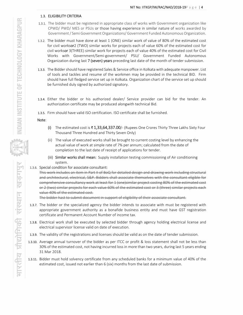
1.3. ELIGIBILITY CRITERIA
1.3.1. The bidder must be registered in appropriate class of works with Government organization like CPWD/ PWD/ MES or PSUs or those having experience in similar nature of works awarded by Government / Semi Government Organizations/ Government Funded Autonomous Organization.
1.3.2. The bidder must have done at least 1 (ONE) similar work of value of 80% of the estimated cost for civil worksor2 (TWO) similar works for projects each of value 60% of the estimated cost for civil worksor 3(THREE) similar work for projects each of value 40% of the estimated cost for Civil Works with Government/Semi‐government/ PSU/ Government Funded Autonomous Organization during last 7 (seven) years preceding last date of the month of tender submission.
1.3.3. The Bidder should have registered Sales & Service office in Kolkata with adequate manpower. List of tools and tackles and resume of the workmen may be provided in the technical BID. Firm should have full fledged service set up in Kolkata. Organization chart of the service set up should be furnished duly signed by authorized signatory.
1.3.4. Either the bidder or his authorized dealer/ Service provider can bid for the tender. An authorization certificate may be produced alongwith technical Bid.
1.3.5. Firm should have valid ISO certification. ISO certificate shall be furnished.
Note:
(i) The estimated cost is ₹ 1,33,64,337.00/‐ (Rupees One Crores Thirty Three Lakhs Sixty Four Thousand Three Hundred and Thirty Seven Only)
(ii) The value of executed works shall be brought to current costing level by enhancing the actual value of work at simple rate of 7% per annum; calculated from the date of completion to the last date of receipt of applications for tender.
(iii) Similar works shall mean: Supply installation testing commissioning of Air conditioning system.
1.3.6. Special condition for associate consultant: This work includes an item in Part II of BoQ for detailed design and drawing work including structural and architectural, electrical, S&P. Bidders shall associate themselves with the consultant eligible for comprehensive consultancy work at least for 1 (one)similar project costing 80% of the estimated cost or 2 (two) similar projects for each value 60% of the estimated cost or 3 (three) similar projects each value 40% of the estimated cost. The bidder hast to submit document in support of eligibility of their associate consultant.
1.3.7. The bidder or the specialized agency the bidder intends to associate with must be registered with appropriate government authority as a bonafide business entity and must have GST registration certificate and Permanent Account Number of income tax.
1.3.8. Electrical work shall be executed by selected bidder through agency holding electrical license and electrical supervisor license valid on date of execution.
1.3.9. The validity of the registrations and licenses should be valid as on the date of tender submission.
1.3.10. Average annual turnover of the bidder as per ITCC or profit & loss statement shall not be less than 30% of the estimated cost, not having incurred loss in more than two years, during last 5 years ending 31 Mar 2018.
1.3.11. Bidder must hold solvency certificate from any scheduled banks for a minimum value of 40% of the estimated cost, issued not earlier than 6 (six) months from the last date of submission.

NIT No: IITKGP/IW/RAC/NAD/2018‐19P a g e | 5
1.3.12. Special condition for HVAC related Electrical and Civil Work:
The scope of HAVC shall include following civil and electrical work‐
Civil Scope‐
False ceiling dismantling and re‐fixing work as per the BOQ.
Opening /Closing / Making hole in existing Masonry wall/ Concrete / Glass structure to facilitate entry and exit of duct / pipe work and finishing it good.
Removal/re fixing of grid false portion INSIDE the rooms along the HVAC duct.
Electrical Scope‐
Incomer cable (4Cx16sqmm Cu cable) of 10meter approx. with 63A MCCB from the existing LT panel located in the electrical room to the each starter panels of AHU.
1. Quality of above works shall be assessed by the bidder before quote as per his scheme of execution.
2. All above work shall be executed and finished good to the satisfactory of Engineer‐ in‐charge.
Sd/‐
Chief Engineer
On behalf of the Director, Indian Institute of Technology Kharagpur
Copy to: 1) Registrar 2) SE(C/ E&M) 3) Executive Engineer (Civil/ E&M) 4) Engineer (RAC) 5) Assistant / Junior Engineer (Civil/ E&M) 6) Notice Board 7) Office file

NIT No: IITKGP/IW/RAC/NAD/2018‐19P a g e | 6
1. INFORMATION TO BIDDERS
A. SCOPE OF WORK
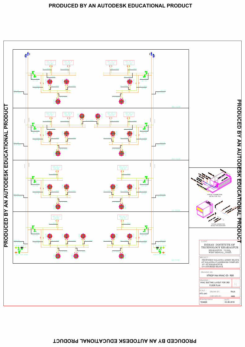
i. The IIT Kharagpur intends to air condition Admin Block of Nalanda Campus at Kharagpur. The Admin Block basically would be used for office space and would require a Cooling system of around 153 TR. The Chilled water pipe from existing plant available in the vicinity of the building. Ceiling mounted Air Handling units are planned to be located on the corridors outside the office space at Ground floor to 3rdfloor. The diagonal rooms located each floor would be air conditioned by Chilled water cassette of adequate capacity.Constraint: The job needs to executed adjacent to busytraffic area (vehicular/ pedestrian) without causing any disturbances to the normal traffic circulation. Adequate/ safe barricading has to be ensured to segregate construction zone from public circulating area.
ii. The scope of work under this tender comprises the supply, installation, testing and commissioning of Low side Work for HVAC System conforming to the specifications and in accordance with the details of the Bill of Quantity (BOQ) and the drawings issued. The work shall include all minor and incidental items necessary for the proper functioning of the complete system, even though not specifically detailed or mentioned herein.
iii. The vendor shall work out execution sequence and methodology so as to complete the project within the envisaged time and the estimated cost, duly handling the constraint mentioned above.Details of other scope of work are listed at Annex II & III.
iv. Detailed scope of work is further listed as under:
v. Supply and Installation of Chilled Water Piping valves and controls
vi. Supply and Installation of CS AHU’s, Cassette Units.
vii. Supply and Installation of Sheet Metal Ducting
viii. Supply and Installation of Air Distribution Devices.
ix. Supply and Installation of Ventilation system
x. Supply and Installation of Insulation for Ducting and Piping
xi. Submission of all Shop Drawings, Material Data Sheets and Performance details
xii. Submission of all final documentation including all Test‐Reports, Catalogues Instruction Manuals, O & M Manuals, ‘As Built’ drawings and all other applicable documents as part of Handing‐Over process.
xiii. Necessary interface with the IBMS system of the Purchaser including all the hardware required for the same as per I/O summary to be finalised.
xiv. On‐site training and familiarization of the Client’s operating staff for a period not less than one week in the overall operation of the installed systems
xv. The proposed drawings are enclosed from Annexure VII to XXIII.
B. GENERAL INSTRUCTIONS
i. Bidding documents areto be obtained electronically through websites: https://eprocure.gov.in/cppp/tendersearch; http://www1.iitkgp.ac.in/topfiles/tenders.php. The tender fee in the prescribed mode must accompany the tender documents issued electronically at the time of submission.
ii. This bid document shall be read in conjunction with GCC (General Conditions of Contract) available on http://www1.iitkgp.ac.in/topfiles/tenders.php.
iii. The bidder shall visit and inspect the site and obtain all information on his own responsibility and at own cost, which may be necessary for the purpose of quoting and submitting the tender. No excuse or ignorance as to site conditions and local information shall be accepted after awarding of the contract. Access to the site will be granted by the Engineer‐in‐charge on all working days within working hours.
iv. IITKGP shall not provide any space at site for labour hutments.
v. All clarifications about the tender shall be sought by bidder on or before pre‐bid meeting. The bidders may make suggestions which shall be considered during the Pre Bid Meeting. Intending bidder(s) may also send their queries or suggestion, if any, through e‐mail to the Engineer‐in‐charge on [email protected] on or before 25 Jan2019 11.00AM. No queries shall be entertained after notification of replies to noteworthy queries received till the date of pre‐bid meeting.
NIT No: IITKGP/IW/RAC/NAD/2018‐19P a g e | 7
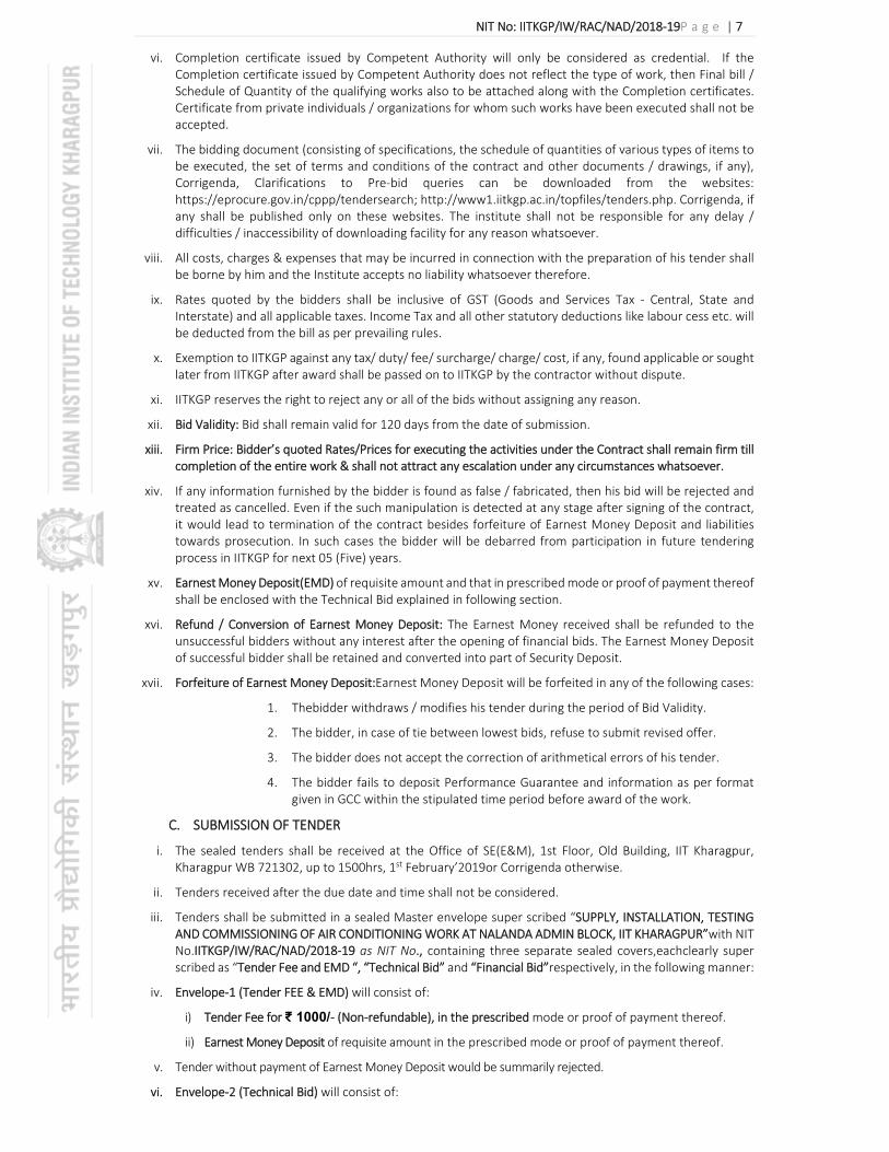
vi. Completion certificate issued by Competent Authority will only be considered as credential. If the Completion certificate issued by Competent Authority does not reflect the type of work, then Final bill / Schedule of Quantity of the qualifying works also to be attached along with the Completion certificates. Certificate from private individuals / organizations for whom such works have been executed shall not be accepted.
vii. The bidding document (consisting of specifications, the schedule of quantities of various types of items to be executed, the set of terms and conditions of the contract and other documents / drawings, if any), Corrigenda, Clarifications to Pre‐bid queries can be downloaded from the websites: https://eprocure.gov.in/cppp/tendersearch; http://www1.iitkgp.ac.in/topfiles/tenders.php. Corrigenda, if any shall be published only on these websites. The institute shall not be responsible for any delay / difficulties / inaccessibility of downloading facility for any reason whatsoever.
viii. All costs, charges & expenses that may be incurred in connection with the preparation of his tender shall be borne by him and the Institute accepts no liability whatsoever therefore.
ix. Rates quoted by the bidders shall be inclusive of GST (Goods and Services Tax ‐ Central, State and Interstate) and all applicable taxes. Income Tax and all other statutory deductions like labour cess etc. will be deducted from the bill as per prevailing rules.
x. Exemption to IITKGP against any tax/ duty/ fee/ surcharge/ charge/ cost, if any, found applicable or sought later from IITKGP after award shall be passed on to IITKGP by the contractor without dispute.
xi. IITKGP reserves the right to reject any or all of the bids without assigning any reason.
xii. Bid Validity: Bid shall remain valid for 120 days from the date of submission.
xiii. Firm Price: Bidder’s quoted Rates/Prices for executing the activities under the Contract shall remain firm till completion of the entire work & shall not attract any escalation under any circumstances whatsoever.
xiv. If any information furnished by the bidder is found as false / fabricated, then his bid will be rejected and treated as cancelled. Even if the such manipulation is detected at any stage after signing of the contract, it would lead to termination of the contract besides forfeiture of Earnest Money Deposit and liabilities towards prosecution. In such cases the bidder will be debarred from participation in future tendering process in IITKGP for next 05 (Five) years.
xv. Earnest Money Deposit(EMD) of requisite amount and that in prescribed mode or proof of payment thereof shall be enclosed with the Technical Bid explained in following section.
xvi. Refund / Conversion of Earnest Money Deposit: The Earnest Money received shall be refunded to the unsuccessful bidders without any interest after the opening of financial bids. The Earnest Money Deposit of successful bidder shall be retained and converted into part of Security Deposit.
xvii. Forfeiture of Earnest Money Deposit:Earnest Money Deposit will be forfeited in any of the following cases:
1. Thebidder withdraws / modifies his tender during the period of Bid Validity.
2. The bidder, in case of tie between lowest bids, refuse to submit revised offer.
3. The bidder does not accept the correction of arithmetical errors of his tender.
4. The bidder fails to deposit Performance Guarantee and information as per format given in GCC within the stipulated time period before award of the work.
C. SUBMISSION OF TENDER
i. The sealed tenders shall be received at the Office of SE(E&M), 1st Floor, Old Building, IIT Kharagpur, Kharagpur WB 721302, up to 1500hrs, 1st February’2019or Corrigenda otherwise.
ii. Tenders received after the due date and time shall not be considered.
iii. Tenders shall be submitted in a sealed Master envelope super scribed “SUPPLY, INSTALLATION, TESTING AND COMMISSIONING OF AIR CONDITIONING WORK AT NALANDA ADMIN BLOCK, IIT KHARAGPUR”with NIT No.IITKGP/IW/RAC/NAD/2018‐19 as NIT No., containing three separate sealed covers,eachclearly super scribed as “Tender Fee and EMD “, “Technical Bid” and “Financial Bid”respectively, in the following manner:
iv. Envelope‐1 (Tender FEE & EMD) will consist of:
i) Tender Fee for ₹ 1000/‐ (Non‐refundable), in the prescribed mode or proof of payment thereof.
ii) Earnest Money Deposit of requisite amount in the prescribed mode or proof of payment thereof.
v. Tender without payment of Earnest Money Deposit would be summarily rejected.
vi. Envelope‐2 (Technical Bid) will consist of:

NIT No: IITKGP/IW/RAC/NAD/2018‐19P a g e | 8
1. Covering letter of the offer signed by firm’s authorized signatory.
2. Documents establishing the identity and authenticity of the bidder/ bidding firm
3. Self‐certified copies of all the documents in support of eligibility of bidder.
4. Self‐certified copies of all the documents in support of eligibility of proposed/associated agencies for specialized services.
vii. Envelope‐3 (Financial Bid) will consist of the complete tender document, each page duly signed and stamped by the bidder as acceptance of the conditions, Declaration by Bidder and Financial Bid all duly filled‐in, signed by the bidder or his/her authorized signatory and stamped.
D. EVALUATION OF BIDS AND AWARD OF WORK
i. The Bid of bidder will be opened on the specified date and time of opening at the Office of SE(E&M), 1st
Floor, Old Building, IIT Kharagpur, Kharagpur WB 7213 in the presence of willing bidders or their authorized representatives.
ii. Date, time and place of opening of Financial Bid will be informed after evaluation of Technical Bid to the Technically Qualified Bidders.
iii. Bids shall, first, be checked for payment of Tender Fee and Earnest Money Deposit. Only those bids found to have duly paid/ submitted Tender Fee and Earnest Money Deposit shall be considered for evaluation.
iv. Evaluation of Technical Bid: The bids received will then be assessed on the eligibility criteria mentioned at para 0of Notice Inviting Tender. Bids found not meeting the eligibility criteria shall be considered non‐responsive and shall be rejected summarily.
v. IITKGP retains the right to revert back to individual bidders with further clarifications / queries on the Technical Bid. The bidder has to respond to the queries within the specified time mentioned in the covering letter.
vi. On the date & time specified for opening of Financial Bid or the Revised Financial Bids as the case may be will be opened on specified date and time.
vii. EVALUATION OF Financial Bids: The Financial Bid should contain the complete bid document with duly filled in Schedule of Financial Quote. Financial Bids opened as above will be checked for arithmetical errors.
viii. The successful bidder shall be issued Letter of Acceptance (LOA) of the bid, and be required to furnish a Performance Guarantee as per General Conditions of Contract, Program Schedule with specific Milestones to be achieved as to complete the work within the stipulated time limit and details of his Technical Staff to be deployed as per ANNEXURE‐I
ix. Letter of Award (Work Order)shall be issued to the successful bidder only after receipt of the Performance Guarantee, along with Program Schedule and the details of Technical Staff to be deployed for the work.
x. Agreement (Contract) consisting of complete tender document including conditions, bill of quantities, technical proposal and specialized services, drawings, if any, and acceptance thereof together with any correspondence leading thereto, shall be drawn and signed with the awardee within10 days of the Letter of Award.
xi. Date of start of work shall be reckoned from the 7th day of the issue of the Work Order.
xii. Defect Liability Period(DLP): In partial modification to clause no.16 of General Conditions of Contract(GCC), the Defect Liability Period shall be 12 months after the certificate final or otherwise of its completion of work or till the final bill has been prepared.
2.5 TERMS OF PAYMENT:
a. 70% towards supply of materials at site. b. 20% towards installation. c. 5% towards successful commissioning and handing over with all test reports and as‐built
drawings approved by IIT‐ Kharagpur. d. 5% towards retention amount till the completion of Defects Liability Period.
Period of payment will be minimum 60 days from the date of submission of bills.
NIT No: IITKGP/IW/RAC/NAD/2018‐19P a g e | 9
2. UNDERTAKING BY THE BIDDER
U N D E R T A K I N G
I / We have read and examined the Tender document including terms & conditions, specifications, bill of quantities, drawings and designs, general rules & directions, General Conditions of Contract, Special Conditions of Contract and all relevant other documents, publications and rules referred to in the Conditions of Contract and all other contents in the tender documents for the work.
I / We, hereby tender for execution of the work specified for the Indian Institute of Technology Kharagpur within the time specified and in accordance in all respects with the specifications, designs, drawings and instructions in writing.
We agree to keep the tender open for 120 days from the last date of its submission and not to make any modifications in its terms and conditions. A sum of Rs. ‐‐‐‐‐‐‐‐‐‐‐‐‐‐ has been deposited in cash / demand draft of a scheduled bank / Pay order as earnest money. If I / we, fail to furnish the prescribed performance guarantee within prescribed period, I / we agree that the said Director, Indian Institute of Technology Kharagpuror his authorized officer shall without prejudice to any other right or remedy, be at liberty to forfeit the said earnest money absolutely. Further, if I / we fail to commence work as specified, I / we agree that the Director, Indian Institute of Technology Kharagpurshall without prejudice to any other right or remedy available in law, be at liberty to forfeit the said earnest money and the performance guarantee absolutely, otherwise the said earnest money shall be retained by him towards security deposit to execute all the works referred to in the tender documents upon the terms and conditions contained or referred to therein.
Further, I / We agree that in case of forfeiture of earnest money or both Earnest Money & Performance Guarantee as aforesaid, I / We shall be debarred for participation in the re‐tendering process of the work.
I / We hereby declare that I / We shall treat the tender documents, drawings and other records connected with the work as secret / confidential documents and shall not communicate information derived there‐from to any person other than a person to whom I / We am / are authorized to communicate the same or use the information in any manner prejudicial to the safety of the State.
Seal & Signature of Contractor
Postal Address
Dated
Witness
Address
Occupation

NIT No: IITKGP/IW/RAC/NAD/2018‐19P a g e | 10
ANNEXURE‐I
TECHNICAL STAFF OF CONTRACTOR
DISCIPLINE NAME QUALIFICATION EXPERIENCE CONTACT NUMBER
Overall Project In‐charge
Engineer ‐ Structure and Civil Works
Engineer – Electrical & Mechanical Works
In‐charge ‐ Safety, Health & Environment
Seal & Signature of Contractor

NIT No: IITKGP/IW/RAC/NAD/2018‐19P a g e | 11
ANNEXURE‐IV
LIST OF APPROVED MAKES / MANUFACTURERS OF BUILDING MATERIALS
Sr# Description of materials List of Manufacturers
Civil Items
1 Ordinary Portland Cement of Grade 43 ACC, Birla Rajshree, Ultratech, Narmada, Ambuja
2 White Cement J.K. Cement &Birla White
3 Wall Putty JK / Birla / Sika
4 Lime Janatacem, Asian Paint
5 Neeru More (Peacock), Kamal
6 HYSD Bars (TMT Bars) TISCO, SAIL, RINL
7 Structural Plates and Steel Sections TISCO, SAIL, RINL
8 Lighter Structural sections not manufactured by TATA/SAIL/RINL
Shyam Steel / SRMB / Jindal (Hissar)
9 Pressed steel doors & fire resistant steel doors
Godrej, Windoors, Strategic Building Systems &Kutty Flush Doors
10 Mild Steel Rolling Shutters, GI Rolling SWASTIC, Windoors. Dodia,
11 Shutters, Stainless steel & aluminum rolling shutters
Trupti, Bharath& Larsen Engineering
12 Aluminium Extruded Sections Jindal, Indal, Hindalco &Bhoruka
13 Aluminium Grills M/s Alurniprofiles, DecogriIIs
14 Hardware Fittings & fixtures M/s Jayant Metal, Shalimar hardware, Everite, Garnish, Diamond, Navbharat, SAIF Enterprises, Hardwin Traders, Godrej, DE Lock Industries, Explore Engineers, Garg Hinges
15 Aluminium Powder Coated Curtain rods Bilmate, Elite
16 Anodized Aluminium fittings Allen / Metco / N.L.C.O.
17 SS Railing Sections Ozone / D‐Line / Jindal
18 Stainless steel D‐handles Godrej, Hettich, D‐line, Dorma, Dorset, Ozone
19 Door Locks Godrej, Dorma
20 Door Closer/Floor spring Godrej, Ozone, Hettich, Dorma, Hardwyn
21 False Ceiling Gyprock / Armstrong

NIT No: IITKGP/IW/RAC/NAD/2018‐19P a g e | 12
22 Aluminium Cladding sheets Alstrong, Alpolic, Alucobond, Alstone International, Aludecor Lamination
23 Asbestos Roofing Sheets Everest, Charminar & Asbestos Cement Ltd.
24 Colour Coated Steel / Zinc‐alu alloy roofing sheets
Kirby, Steelfah&Colour Roof India Ltd.
25 Anti‐Termite treatment M/s PARAGON, PEECOPP , Express Pesticides Corporation, Elite Corporation, Pest Control (I) Ltd. & NOCIL Chemicals,
26 Terrazzo Tiles M/s NITCO, BHARAT, G.K. BANSAL, Acme Tiles & Super Tiles
27 Ceramic Tiles H.R. Johnson (I) Ltd., Sornany, Kajaria
28 Glazed Tiles M/s H.R. Johnson (I) Ltd., Somany, Kajaria
29 Vitrified Floor Tiles M/s H.R. Johnson, RAK Ceramics, Bell Granito
30 Interlocking Paver Tiles Hindustan Tiles / Wonder / Ultra Tiles
31 Cement Based Paint
M/s Snowcem India Ltd. (Super snowcem, Sandex Matt), NITCO (Nitcocom) Paints, Hindustan Colour Chemical, Jayant colour, Surfa coat, Terraco, Berger‐Rabiacem, ApporvaBuildcare&Decocem
32 Distemper & Paints Asian Paints, Kansai Nerolac Paints Ltd., ICI Paints, Noble Paints, Berger Paints India Ltd., Jenson Nicholson, Garware Paints & Shalimar Paint
33 Anti‐corrosive water proofing paint with Aluminium finish
SIKA / Shalimar
34 Waterproofing Compound, Sealants Sunanda Chemicals, Mc‐Bauchemie, FOSROC, Pidilite, Roffe, BASF, Sika
35 Adhesive for wood Fevicol, Vamicol, Dunlop, Araldite
36 Water stops M/s Omai Plastics, BaseconPask, Asian Engineering Products, Caprihans India Ltd., R.C. Enterprises, Kanta Polymers (Kanta flex) &Fixopan
37 APP Membrane SIKA / PIDILITE / FOSROC / TIKIDAN
38 Expansion Joint Boards &Tarfelts M/s Shalitex, S.T.P. Ltd., Lloyd Insulation, Tiki Tar Industries
39 Expansion Joint Filters M/s Shalitex, S.T.P. Ltd., Lloyd Insulation & BASF Chemicals
40 Concrete Admixtures Sunanda Chemicals, Mc‐Bauchemie, FOSROC, Pidilite, Roffe, BASF
41 Bitumen (grade VG30) IOCL
42 P V C flooring M/s Premier Vinyl Flooring Ltd., Royal Cushion Vinyl Product Ltd., Armstrong, Responsive Industries Ltd.
43 P.V.C. Shutters Sintex / Raunaq / Duroplast
44 P.V.C. Pipes Oriplast / Supreme / Finolex
45 P.V.C. Cistern Parryware / Hindware / Cera
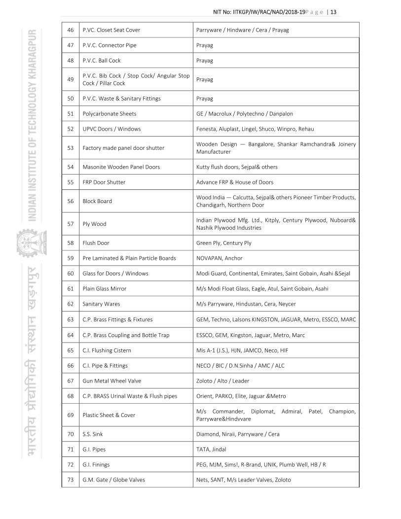
NIT No: IITKGP/IW/RAC/NAD/2018‐19P a g e | 13
46 P.VC. Closet Seat Cover Parryware / Hindware / Cera / Prayag
47 P.V.C. Connector Pipe Prayag
48 P.V.C. Ball Cock Prayag
49 P.V.C. Bib Cock / Stop Cock/ Angular Stop Cock / Pillar Cock
Prayag
50 P.V.C. Waste & Sanitary Fittings Prayag
51 Polycarbonate Sheets GE / Macrolux / Polytechno / Danpalon
52 UPVC Doors / Windows Fenesta, Aluplast, Lingel, Shuco, Winpro, Rehau
53 Factory made panel door shutter Wooden Design — Bangalore, Shankar Ramchandra& Joinery Manufacturer
54 Masonite Wooden Panel Doors Kutty flush doors, Sejpal& others
55 FRP Door Shutter Advance FRP & House of Doors
56 Block Board Wood India — Calcutta, Sejpal& others Pioneer Timber Products, Chandigarh, Northern Door
57 Ply Wood Indian Plywood Mfg. Ltd., Kitply, Century Plywood, Nuboard& Nashik Plywood Industries
58 Flush Door Green Ply, Century Ply
59 Pre Laminated & Plain Particle Boards NOVAPAN, Anchor
60 Glass for Doors / Windows Modi Guard, Continental, Emirates, Saint Gobain, Asahi &Sejal
61 Plain Glass Mirror M/s Modi Float Glass, Eagle, Atul, Saint Gobain, Asahi
62 Sanitary Wares M/s Parryware, Hindustan, Cera, Neycer
63 C.P. Brass Fittings & Fixtures GEM, Techno, Lalsons KINGSTON, JAGUAR, Metro, ESSCO, MARC
64 C.P. Brass Coupling and Bottle Trap ESSCO, GEM, Kingston, Jaguar, Metro, Marc
65 C.I. Flushing Cistern Mis A‐1 (J.S.), HJN, JAMCO, Neco, HIF
66 C.I. Pipe & Fittings NECO / BIC / D.N.Sinha / AMC / ALC
67 Gun Metal Wheel Valve Zoloto / Alto / Leader
68 C.P. BRASS Urinal Waste & Flush pipes Orient, PARKO, Elite, Jaguar &Metro
69 Plastic Sheet & Cover M/s Commander, Diplomat, Admiral, Patel, Champion, Parryware&Hindvvare
70 S.S. Sink Diamond, Niraii, Parryware / Cera
71 G.I. Pipes TATA, Jindal
72 G.I. Finings PEG, MJM, Sims!, R‐Brand, UNIK, Plumb Well, HB / R
73 G.M. Gate / Globe Valves Nets, SANT, M/s Leader Valves, Zoloto

NIT No: IITKGP/IW/RAC/NAD/2018‐19P a g e | 14
74 Copper ball Valve Techno, M/s GEM, ESSCO, Leader, A‐1 JS
75 Air Valve Leader, Sant, HAWN M/s Kirloskar
76 Water Meter Capstan, Keycee, Paramount
77 Sluice Valves Kirloskar, Minoti, ESSCO & Burn, Hawa
78 CI water quality pipes Deem) steel castings, Jindal, Lanco
79 Cast Iron Valves KirIoskar, Leader, HAWA
80 C.1. Soil Quality pipes NECO, BC, RIFCO3 ASP, A‐1, PARAS, HIF, Kajeriwal
81 S.W. Pipes & Gully Trap Perfect, Kashrnira, BURN, RK, ANAND, ISI marked
82 RCC Hume Pipes Mis Indian Hume Pipes, Pranali, Cement pipe, Ghambir, Kore Cement confirm to ISI
83 HDPE Pipes & HDPE fittings Prince, Gautam M/s Hastil, Sangir pipes, Supreme
84 RCC frame, covers & SFRC M/s Pratibha, Bharath, Vikrant
85 PIG LEAD M/s Hindustan Zinc Ltd.
86 CL frame & covers RIFCO, NECO, PARAS, A‐1, M/s. Ashok Iron, Foundry, HIF
87 CPVC, UPVC, SWR Pipes Finolex, Prince & Supreme
88 Poly Propylene — R Pipes Supreme &Sakthi Polymers
89 PVC Plastic High / Low level cistern Commander, Elite Dual, Champion, Parryware‐similine, Hindware
90 PVC Inlet connection & Waste Pipes Kohinoor, ECCSO, GEM & Elite
91 CP Brass towel rods and accessories Elite, GEM, Jacquar, ESSCO
Electrical Items
1 FRLS wire 1.1 KV Finolex, Havells, RR cable
2 PVC pipe (MMS) Presto Plast/ Precision/ Polycab
3 Switch/ Socket/ Regulator/ Blanking plate/ Modular box
Legrand (Myrius range)/ Crabtree Thames platinum range/ Wipro (Nowa)
4 3‐pole ceiling rose/ holder/ Call bell Anchor/ SSK
5 GI pipe TATA (medium)/ Bansal (Medium)/ Jindal
6 Brass Compression Gland ARUN Make/ Jonson/ 3M
7 All Lug Dowell’s / Jonson/ 3M
Telephone work Items
1 Perforated powder coated MS cable trays ISI Approved
2 Metal box with Phenolic Laminated sheet ISI Approved

NIT No: IITKGP/IW/RAC/NAD/2018‐19P a g e | 15
3 Multicore Telephone Cable Finolex/ Havells/ Delton
4 PVC Conduit pipe and PVC pipe Precision
5 Modular MS Box with front plate outlet No.1 RJ‐11
Crapree/ Legrand
Air‐conditioning Items
1 Air Handling Units Systemair/Flaktwood/ Citizen
2 AHU fans (AMCA certified) Nicotra / Comefri / Kruger/ Systemair
3 FCUs Sinko/ JCI/ Trane
4 GSS sheet(120 GSM) Jindal / Tata
5 Control Cables Finolex/ Polycab/ RR Kabel/ Havells /KEI.
6 Power Cables Finolex/ Polycab/ RR Kabel/ Havells /KEI.
7 Grilles/ Fire dampers/Diffusers/ VCD Caryaire/ Dynacraft / Systemair/ Air master
8 Expanded Polystyrene Thermolloyd/ Beardsell/ Astha polymer
9 Water line Valves Advance / Audco/ L & T
10 3/2Way mixing valves Johnson / Belimo / Honeywell/Siemens
11 MS Pipe Tata/ JindalHissar
12 Duct Thermal insulation Armaflex/ K‐flex/ Armacell
13 Duct acoustic insulation Armaflex/ K‐flex/ Armacell
14
Automatic air vent valves/Binder’s Test points
Anergy / Itap/ Equivalent
15 Strainer Sant/ DS Engineering/ Sant Industries
16 Pressure gauges/ Thermometer H Guru/ Waree/ Equivalent
17 Cassette Bhutoria/ Caryaire/JCI
18 Nitrile Rubber (pipe insulation) Aramflex/ Armacrell/ K flex
19 PUF Lloyd/India Insulation / Shree Venus
20 Thermostat JCI/ Siemens/ Honeywell
21 U PVC Ashirwad/Supreme/Eqv
22 Inline Fan Systemair/ Ostberg/ Ravistar
23
LT Panel EAP/ System Syndicate/ Power and Control / RNG /
Rayco/System Dynamic/ TTS Systematics
24 Cable Tray OBO/Profab/Legrand
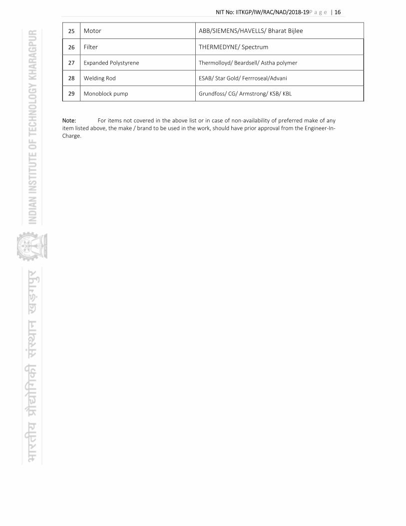
NIT No: IITKGP/IW/RAC/NAD/2018‐19P a g e | 16
25 Motor ABB/SIEMENS/HAVELLS/ Bharat Bijlee
26 Filter THERMEDYNE/ Spectrum
27 Expanded Polystyrene Thermolloyd/ Beardsell/ Astha polymer
28 Welding Rod ESAB/ Star Gold/ Ferrroseal/Advani
29 Monoblock pump Grundfoss/ CG/ Armstrong/ KSB/ KBL
Note: For items not covered in the above list or in case of non‐availability of preferred make of any item listed above, the make / brand to be used in the work, should have prior approval from the Engineer‐In‐Charge.

NIT No: IITKGP/IW/RAC/NAD/2018‐19P a g e | 17
ANNEXURE‐II
TECHNICAL SPECIFICATIONS 1. BASIS OF DESIGN
Site Location : KHARAGPUR
Geographic location : 22.34 Lat Deg. N
Altitude : 61 m above mean sea level.
1.1 OUTDOOR DESIGN CONDITIONS :
Outdoor Design Conditions for Kharagpur are based on Weather data compiled and published by ISHRAE (WeDCo) for Kolkata and past experience corresponding to 2 % annual cumulative frequency of occurrence and the outdoor design conditions have beenconsidered as follows:
1.2
INDOOR DESIGN CONDITIONS
Based on past experience, indoor design conditions for centrally air‐conditioned spaces shall be as follows:
SPACE Temperature Deg C
Relative Humidity % Remarks
Office 26±1.1 Not > 60 % at full load condition
Atrium& Corridor
‐ ‐ Natural Ventilation
Note: Winter Heating is not envisaged and RH is not directly controlled.
1.3 MECHANICAL VENTILATION
Design Conditions DRY BULB Mean Coincident WET BULB
RH
Deg F Deg C Deg F Deg C %
SUMMER 110 43.3 83 28 33
MONSOON 94.4 34.66 82 28 60
WINTER 56 13 48 9 55
Area Air Changes Per Hour(ACH) as per NBC
Remarks
Toilets 15

NIT No: IITKGP/IW/RAC/NAD/2018‐19P a g e | 18
1.4 PRESSURIZATION
Zone Differential Pressure in Pascals as per NBC
Remarks
Stairwell 50
Lift well 50
1.5 BUILDING CONSTRUCTION DATA
The Building construction data for calculating the building air‐conditioning load is as below.
i. External Wall : U = 1.81 Watt / SqmOC
(0.32 Btu / HrSqftOF)
(230mm thick brick wall)
ii. Roof (Exposed to sun) : U = 1.316 Watt / SqmOC
(0.23 Btu / HrSqftOF)
iii. External Glass Specifications : Glass with following details:
U = 5.8 Watt / SqmOC
(1.02 Btu / HrSqftOF)
Solar heat gain Coefficient: 0.8
iv. Outdoor Air Addition Rate : As per ASHRAE Standard‐62.1‐2007.
1.6 OCCUPANCY AND INTERNAL HEAT GAIN
SPACE Occupant Density
Equipment Load
Lighting Load
Fresh Air
Offices 75sft /person
125W/ Person
Average 1 W/sft
Asper ASHRAE 62.1 2004 or ACPH @1.5 , whichever higher
1.7 Duration of operation: 10 Hours per day, (Except few cabins of SRIC office)

NIT No: IITKGP/IW/RAC/NAD/2018‐19P a g e | 19
2. DESIGN PARAMETERS
2.1 DESIGN PARAMETER FOR SELECTION OF AIR HANDLING UNIT AND ITS COMPONENTS SHALL BE:
Maximum face velocity across prefilters and filters : 1.78 m/sec (350 fpm)
Maximum face velocity across cooling coils : 2.54 m/sec (500 fpm)
Maximum fan outlet velocity : 9.14 m/sec (1800 fpm)
Maximum fan speed :
a. Fan above 450 mm dia : 1000 RPM
b. Fan up to and including 450 mm dia : 1450 RPM
Maximum fan motor speed : 1450 RPM
2.3 PIPING SHALL BE SIZED FOR THE FOLLOWING DESIGN PARAMETERS:
Maximum velocity : 1.2 m/Sec (4 fps) for piping 50 mm & under
: 2.5 m/Sec (8.2 fps) for piping over 50 MM dia
Maximum friction : 15 k Pa per 30 M Run
(5 ft per 100 ft Run)
2.4 DESIGN PARAMETER FOR DUCT DESIGN SHALL BE:
Maximum flow velocity in ducts for air conditioning : 7.5 m / sec (1500 fpm)
Maximum flow velocity in ducts for ventilation in pump room, boiler room, generator room, toilet exhaust & Kitchen exhaust.
: 7.5 m / sec – 12.5 m / Sec
(1500 – 2500 FPM)
Maximum friction : 0.65 Pa / M run
(0.08 inch WG/100 ft run)
2.5 VENTILATION FAN
Maximum fan outlet velocity for fan upto 450 mm dia : 9.14 m/sec (1800 fpm)
Maximum fan outlet velocity for fan above 450 mm dia : 12 m/sec (2400 fpm)
Maximum fan speed for fans upto 450 mm dia : 1450 RPM
Maximum fan speed for fans above 450 mm dia : 1000 RPM
Filtration:
Recirculated air (mixed fresh & return air) at air handling units, fan coil units and ventilation units.
: Washable synthetic type air filters having 90% efficiency down to 10 microns (MERV 8)

NIT No: IITKGP/IW/RAC/NAD/2018‐19P a g e | 20
2.6 AIR CONDITIONING LOAD
SL.No
ROOM REF NAME
Area
LOAD SUMMARY EXTRACTED FROM CARRIER HAP 4.5
EQUIPMENT SELECTION TOTAL COOLING
LOAD TOTAL SENSIBLE COOLING LOAD
TOTAL DEH. AIR QTY.
Fresh Air Qty.
(SqMtr)
(Watts) (TR) (Watts) (TR) ( l / s ) (CFM) ( l / s ) (CFM)
GROND FLOOR
1 Airtifical Intelligence NA 101
216 50,600 14.4 43,900 12 2845 6,031 182 386 1no. 6100 CFM(14.4 TR) Ceiling Suspended Air Handling Unit (Chilled water type)
2 Hapiness Centre NA 102
216 47,500 13.5 40,100 11 2548 5,402 182 386 1no. 6100 CFM(14.4 TR) Ceiling Suspended Air Handling Unit (Chilled water type)
3 AI LAB NA103 54 21,200 6.0 19,300 5 1266 2,684 46 98 3 Nos. 2 TR Cassette Unit (Chilled water type)
4 NA104 54 21,500 6.1 19,800 6 1315 2,788 46 98 3 Nos. 2 TR Cassette Unit (Chilled water type)
FIRST FLOOR
5 Conference Room NA 201
216 50,600 14.4 43,900 12 2845 6,031 182 386 1no. 6100 CFM(14.4 TR) Ceiling Suspended Air Handling Unit (Chilled water type)
6 CDC NA 202 216 47,500 13.5 40,100 11 2548 5,402 182 386 1no. 6100 CFM(14.4 TR) Ceiling Suspended Air Handling Unit (Chilled water type)
7 CDC NA 203 54 21,200 6.0 19,300 5 1266 2,684 46 98 3 Nos. 2 TR Cassette Unit (Chilled water type)
8 IEEE NA 204 54 21,500 6.1 19,800 6 1315 2,788 46 98 3 Nos. 2 TR Cassette Unit (Chilled water type)

NIT No: IITKGP/IW/RAC/NAD/2018‐19P a g e | 21
SL.No ROOM REF NAME
Area
LOAD SUMMARY EXTRACTED FROM CARRIER HAP 4.5
EQUIPMENT SELECTION TOTAL COOLING
LOAD TOTAL SENSIBLE COOLING LOAD
TOTAL DEH. AIR QTY. Fresh Air Qty.
(SqMtr) (Watts) (TR) (Watts) (TR) ( l / s ) (CFM) ( l/s ) (CFM)
SECOND FLOOR
9 SRIC NA 301 360 70,000 19.9 58,200 17 3748 7,946 303 642 2 no.s 4000 CFM(9.95 TR) Ceiling Suspended Air Handling Unit (Chilled water type)
10 SRIC NA 302 360 69,600 19.8 57,900 16 3680 7,802 303 642 2 no.s 4000 CFM(9.9 TR) Ceiling Suspended Air Handling Unit (Chilled water type)
11 NA 303 BMS CONTROL RM 54 21,200 6.0 19,300 5 1266 2,684 46 98 3 Nos. 2 TR Cassette Unit (Chilled water type)
12 SRIC NA 304 54 21,500 6.1 19,800 6 1315 2,788 46 98 3 Nos. 2 TR Cassette Unit (Chilled water type)
13 SRIC ADD NA 305 54 12,900 3.7 10,200 3 627 1,329 66 140 2 Nos. 2 TR Cassette Unit (Chilled water type)
THIRD FLOOR
14 Academic NA 401 360 95,400 27.1 83,100 24 5300 11,236 303 642 2 no.s 5500 CFM(13.55 TR) Ceiling Suspended Air Handling Unit (Chilled water type)
15 Academic NA 402 360 95,100 27.0 82,700 24 5318 11,274 303 642 2 no.s 5500 CFM(13.5 TR) Ceiling Suspended Air Handling Unit (Chilled water type)
16 PIC NALANDA NA403 54 20700 5.8 20,000 5.6 1371 2892 21 42.2 2 Nos. 2 TR Cassette Unit (Chilled water type)
17 RESEREVED NA404 54 25,200 7.2 23,300 7 1555 3,297 46 98 2 Nos. 3 TR and 1 No. 2 TR Cassette Unit (Chilled water type)
GRAND TOTAL TR 204 TR 177.4 CFM 85419 CFM 5032
Diversity @75 % TOTAL COOLING LOAD IN TR 153
NIT No: IITKGP/IW/RAC/NAD/2018‐19 P a g e | 22
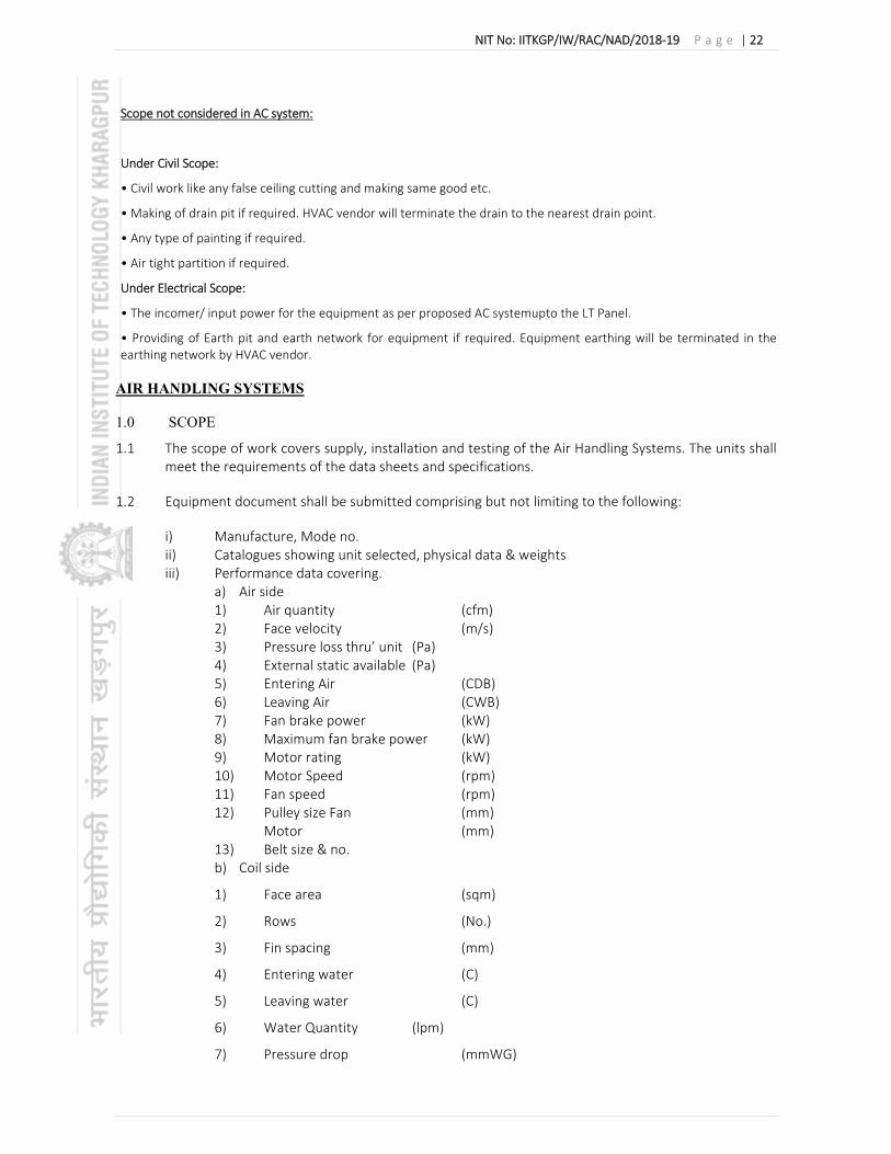
Scope not considered in AC system:
Under Civil Scope:
• Civil work like any false ceiling cutting and making same good etc.
• Making of drain pit if required. HVAC vendor will terminate the drain to the nearest drain point.
• Any type of painting if required.
• Air tight partition if required.
Under Electrical Scope:
• The incomer/ input power for the equipment as per proposed AC systemupto the LT Panel.
• Providing of Earth pit and earth network for equipment if required. Equipment earthing will be terminated in the earthing network by HVAC vendor.
AIR HANDLING SYSTEMS
1.0 SCOPE
1.1 The scope of work covers supply, installation and testing of the Air Handling Systems. The units shall meet the requirements of the data sheets and specifications.
1.2 Equipment document shall be submitted comprising but not limiting to the following:
i) Manufacture, Mode no. ii) Catalogues showing unit selected, physical data & weights iii) Performance data covering.
a) Air side 1) Air quantity (cfm) 2) Face velocity (m/s) 3) Pressure loss thru’ unit (Pa) 4) External static available (Pa) 5) Entering Air (CDB) 6) Leaving Air (CWB) 7) Fan brake power (kW) 8) Maximum fan brake power (kW) 9) Motor rating (kW) 10) Motor Speed (rpm) 11) Fan speed (rpm) 12) Pulley size Fan (mm)
Motor (mm) 13) Belt size & no. b) Coil side
1) Face area (sqm)
2) Rows (No.)
3) Fin spacing (mm)
4) Entering water (C)
5) Leaving water (C)
6) Water Quantity (lpm)
7) Pressure drop (mmWG)

NIT No: IITKGP/IW/RAC/NAD/2018‐19 P a g e | 23
c) Filters 1) Make & type 2) Area & thickness (Sqm/mm) 3) Velocity (m/s) 4) Pressure drop
i) New (Pa) ii) Dirty (Pa)
5) Media
2.0 AIR HANDLING UNITS (DOUBLE – SKINNED)
2.1.1 SCOPE: The scope of this section, comprises the supply, erection, testing and commissioning of double skin construction “EUROVENT CERTIFIED” air handling units, conforming to these Specifications and in accordance with requirements of drawings and of the Schedule of Quantities.
2.1.2 TYPE: The air handling units shall be double skin construction, draw‐thru/ blow thru type comprising of various sections, filter section, coil section and fan section, mixing box, (wherever the return air and fresh air are ducted) as shown on drawings and included in schedule of quantities.
2.1.3 CASING:
Double skinned panels shall be 25mm ± 2mm / 50mm ± 4mm thick made of galvanized steel, pressure injected with PU foam insulation (density 40 kg/m3) with K factor not exceeding 0.02 Watt/Mc shall be fixed to minimum1.5 mm thick aluminium alloy twin box section structural framework with stainless steel screws. Outer sheet of panels shall be made of galvanized prepainted with PVC guard film sheet of 0.63 mm thick, and inner sheet of 24 Gauge plain G.I. Sheet.
The entire framework shall be mounted on an aluminium alloy or galvanized steel (depending on size) channel base as per manufacturer’s recommendation. The panels shall be sealed to the framework by heavy duty neoprene gaskets held captive in the framed extrusion. All panels shall be detachable or hinged. Hinges shall be made of die cast aluminum / hard nylon with stainless steel pivots, handles shall be made of hard nylon and be operational from both inside and outside of the unit. Units supplied with various sections shall be suitable for onsite assembly with continuous neoprene gasket. All fixing and gaskets shall be concealed.Units shall have hinged, quick opening access door in the fan section and also in filter section where filters are not accessible from outside. Access doors shall be of double skin construction similar to unit.Condensatedrain pan shall be fabricated from 18 gage stainless steel sheet with all corners welded. It shall be isolated from bottom floor panel with 19 mm elastomeric nitrile rubber for ceiling suspended. For floor mounted unit drain pan shall be externally insulated with 19 mm self‐adhesive elastomeric nitrile rubber/ XLPE. Internal panels shall be fabricated so that there are no gaps between the panel and frame work. Fabrication clearances shall be closed with blank‐off pieces or with sealant. Partitions shall be of sufficient thickness to prevent deflection and vibration during AHU operation. Manufacturer shall provide suitable stiffening by means of box type members across the same. AHU shall be with clean inside surfaces with beveled corners to the best possible extent without crevices as may allow growth of algae / fungus. In case on internal fittings such as dampers, the same shall be with beveled edges and without sharp corners to prevent operator injury. There shall be no screws projecting into AHU or air stream. If the same is unavoidable, the tips shall be fitted with rubber caps to prevent operator injury.
AHU panels shall be factory fitted with pressure ports for DPT installation. The number and size of these shall be confirmed in the AHU technical approval stage. In case opening is to be made in AHU panel, the same shall be with C‐channel all around to prevent entry of PUF into air stream. The channels shall be cut at 45 degrees at the corners to avoid overlap. Material for the channel shall be same as that of internal skin of AHU.Rubber grommets shall be provided at all entry points into AHU such as coil connection, cable entry etc. The same shall be double lip tight fitting to prevent air leakage.

NIT No: IITKGP/IW/RAC/NAD/2018‐19 P a g e | 24
All access doors shall be outward opening. For doors provided downstream of the fan, especially in high static AHUs, additional clamps shall be provided along periphery of door to maintain constant pressure and ensure proper sealing.
Water resistance marine light with power cabling shall be included Micro switch with wiring for Door shall be provided such that fan motor shall stop upon opening the door.
2.1.4 DAMPER:
Dampers shall be opposed blade type. Blades shall be made of double skinned airfoil aluminium sections with integral gasket and assembled within a rigid extruded aluminium alloy frame. All linkages and supporting spindles shall be made of aluminium or nylon, turning in teflon bushes. Manual dampers shall be provided with a bakelite knob for locking the damper blades in position. Linkages shall be extended wherever specified for motorised operation. Damper frames shall be sectionalised to minimise blade warping. Air leakage through dampers when in the closed position shall not exceed 1.5% of the maximum design air volume flow rate at the maximum design air total pressure.
2.1.5 MOTOR AND DRIVE
Fan motors shall be energy efficient (IE‐2) and shall be 415±10% volts, 50 cycles, three phase, totally enclosed fan‐cooled class F, with IP‐55 protection. Motors shall be especially designed for quiet operation and motor speed shall not exceed 1440 rpm for forward curved fan and 2900 rpm for backward curved fan. Drive to fan shall be provided through belt‐drive arrangement. Belts shall be of the oil‐resistant type. For three stage filtration AHUs, belt drive shall not be used and direct driven plug fans shall be used.
2.1.6 FAN
Fans shall be “AMCA certified” centrifugal, forward curved / backward curved / backward curved airfoil so as to give maximum efficiency for given duty condition. Fans driven by variable frequency drive shall be backward inclined irrespective of static pressure value. Fans shall be selected for minimum efficiency of 65% for forward curved and 75% for backward curved/ airfoil. Fan casing shall be made of galvanised steel sheet. Fan wheels shall be made of galvanised steel. Fan shaft shall be grounded C40‐ 45 carbon steel and supported in self‐aligning plummer block operating less than 75% of first critical speed, grease lubricated bearings. Fan wheels and pulleys shall be individually tested and precision balanced dynamically. Fan motor assembly shall be statically and dynamically balanced to G6.3 grade as per relevant ISO/AMCA standard. Computerized fan selection print outs shall
be submitted along with the offer. Motors shall be mounted inside the AHU casing on slide rails for easy belt tensioning. Motors shall drive heavy duty V‐belt, constant pitch, drive selected at minimum 110% of motor horsepower.Both fan and motors assemblies shall be mounted on a deep section aluminium alloy or galvanised steel (depending on size) base frame. Combination spring and rubber anti vibration mounts shall be provided for isolating the unit casing. Flame retardant, waterproof silicone rubber impregnated flexible connectionshall be provided at the fan discharge.
2.1.7 COOLING COILS:
Chilled water coils shall have 12.5 to 15 mm dia (O.D )tubes minimum 0.4 mm thick with sine wave aluminium fins firmly bonded to copper tubes assembled in stainless steel frame. Face and surface areas shall be such as to ensure rated capacity from each unit and such that the air velocity across the coil shall not exceed 150 meters per minute.(500fpm) The coil shall be pitched in the unit casing for proper drainage. The coil shall have copper header with chilled water supply & return connections protruding out of AHU casing by minimum 150 mm and fitted with dielectric coupling or adapter for connection with MS pipes. Each coil shall be factory‐tested at 21 kg per sq. cm air pressure under water. Tube shall be hydraulically / mechanically expanded for minimum thermal contact resistance

NIT No: IITKGP/IW/RAC/NAD/2018‐19 P a g e | 25
with fins. Fin spacing shall be 4 ‐ 5 fins per cm. Water pressure drop in coil shall not exceed 10 PSIG(0.70 kg/cm.sq.) Coils shall be provided with mechanical means to purge air from the coil during
commissioning by means of a purge valve or nipple. To prevent splashing, discharge from the same shall be routed to the condensate drain pan by means of flexible PVC tubing of suitable diameter. Purge valve / nipple shall be accessible externally or by removal of blanking panel. All AHU’s shall be provided with minimum 6 Row Cooling Coil. All TFA AHU’s shall be provided with minimum 8 row cooling coil. TFA units which receives pre‐cooled fresh air can be provided with 6 row deep coil upon verification of coil selection output. Reheat coil may be provided if indicated in Schedule of Quantities. Reheat coil shall be 2 row deep and shall be of same construction as defined above. In case AHU has multiple coil stacked one above another, intermediate train of SS 304 (18 gauge) shall be provided so that upper level of coil drains into this train. Copper / SS 304 piping shall be provided from this train upto main bottom tray. Computerized cooling coil selection output shall be submitted. Coil rating shall be as per AHRI‐410 / EUROVENT Certified.
2.1.8 FILTERS
Each unit shall be provided with a factory assembled filter section containing washable synthetic type air filters having anodized aluminium frame. The filter shall have minimum 90% efficiency down to 10 microns . The media shall be supported with HDP mesh on one side and aluminium mesh on other side. Filter banks shall be easily accessible and designed for easy withdrawal and renewal of filter cells. Filter framework shall be fully sealed and constructed from aluminium alloy. For green buildings, AHUs shall also be provided with MERV‐13 filters, if the project is opting for credit EQ‐5.
2.1.9 ACCESSORIES
Each air handling unit shall be provided with manual air vent at high point in the cooling coil and drain plug in the bottom of the coil. In addition, the following accessories may be required at air handling units, their detailed specifications are given in individual sections, & quantities separately identified in schedule of Quantities.
a. Insulated butterfly valves, balancing valves, `Y’ strainer, union & condensate drain piping with ‘U’ trap upto sump or floor drain in air handling unit room, as described in section “Piping”.
b. Thermometers in the thermometer wells & pressure gauge (with cocks) within gauge ports in chilled / hot water supply and return lines as per the section “Instruments”.
c. Minimum 2 Nos nameplates (1 in etched metal and other plastic) mounted onto AHU panel with suitable water‐resistant adhesive along with relevant warning stickers on various panels. The nameplate shall give all relevant details including fan model selected, motor KW, Air quantity and total static pressure.
FRESH AIR INTAKES
Extruded aluminium construction duly anodized (20 microns and above) fresh air louvers with birdscreen and dampers shall be provided in the clear openings in masonry walls of the air handling unit rooms having atleast one external wall. Louvers, damper, pre‐filters, ducts and fresh air fan with speed regulator shall be provided as shown on Drawings and in Schedule of Quantities. Fresh air dampers shall be of the interlocking, opposed‐blade louver type. Blades shall be made of extruded aluminium construction and shall be rattle‐free. Dampers shall be similar to those specified in “Air Distribution”. Fresh air fans and fresh air intakes shall be as per the requirements of Schedule of Quantities.

NIT No: IITKGP/IW/RAC/NAD/2018‐19 P a g e | 26
Performance Data
Air handling unit shall be selected for the lowest operating noise level of the equipment. Fan performance rating and power consumption data, with operating points clearly indicated shall be submitted and verified at the time of testing and commissioning of the installation.
TESTING
Cooling capacity of various air handling unit models be computed from the measurements of air flow and dry and wet bulb temperatures of air entering and leaving the coil. Flow measurements shall be by an anemometer and temperature measurements by accurately calibrated mercury‐in‐glass thermometers. Computed results shall conform to the specified capacities and quoted ratings. Power consumption shall be computed from measurements of incoming voltage and input current.
The air handling and fan coil units shall be tested for establishing:
i) Air Side : Fresh air quantity (cfm) Dehumidified air quantity (cfm) Total static pressure (WG) Leaving & entering conditions DB & WB Coil Capacity
‐ Sensible heat (Kcal/hr) ‐ Total heat (Kcal/hr) ‐ Fan speed (rpm) Power consumption of fan (watts)
ii) Water side : Water flow (lpm) Temp. IN & OUT (deg C) Pressure IN & OUT (M of H2O) Noise level :NC level @1m from the unit and at the four corners of the room.
3. FAN COIL UNITS
3.1 SCOPE
The scope of this section comprises the supply, erection, testing and commissioning of fan coil units conforming to these Specifications and in accordance with the requirements of the Drawings and Schedule of Quantities.
3.2 TYPE
The fan coil units shall be vertical type for floor mounting, horizontal type for ceiling suspension.
Floor‐mounted vertical units shall have vertical top discharge; and horizontal units mounted within ceiling space shall have horizontal discharge and shall be deductible. All units shall be complete with chilled water coil, one or more centrifugal fans and motor, cleanable fabric filters, insulated condensate drain pan.
3.3 CAPACITY
The air moving and coil capacities shall be as shown on Drawings and indicated in Schedule of Quantities.
3.4 CABINETS

NIT No: IITKGP/IW/RAC/NAD/2018‐19 P a g e | 27
Cabinets for floor mounted exposed FCU shall be constructed of 18 gauge die‐formed cold‐rolled galvanized sheet steel, bonderized and painted with approved shade of powder coating finish. The cabinets shall be of sufficient size to enclose all piping and control valves, and shall have access doors to piping and controls. Access panels shall have positive locking fasteners for easy removal.
Horizontal furred‐in type units mounted within ceiling space shall be provided with a GI casing of 18 gauge, the coil and fan section with provision to mount filters within the fan section.
INTERIOR CHASSIS
The interior chassis shall be constructed of not less than 16 gauge cold rolledgalvanized sheet steel bonderized and painted with approved shade of powder coatingfinish. All ceiling suspended vertical fan coil units shall be securely mounted from thebuilding structure with top panel set dead level in both directions. In case of ceilingsuspended horizontal units fan deck and cooling coil shall be easily removable fromFCU without lowering down of the FCU or disturbing the other installation.
DRAIN PAN
Primary drain pan shall be pre‐pressed 22 gauge SS‐304 and an additional innerbottom panel of 22 gauge SS‐304 shall be provided to prevent damage to, andfloatation of the bottom panel insulation. The pan shall be insulated with not less than6 mm thick nitrile rubber (class O as per BS 476) insulation shall be effective to . The pan shall be of sufficient size to catch all drip page of condensationfrom any part of the unit. In all cases pan shall be large enough to cover cooling coilssupply and return water headers and bends, control valves and ball valves with copperpipes. A secondary (auxiliary) condensate pan similar to primary drain pan may beprovided by the manufacturer of these units which are so identified in Schedule ofQuantities. All drain pans shall be with powder coating finish as per interior chassis defined above.
COOLING COIL
All cooling coils shall be standard three‐row staggered seamless copper tube with aluminum sine wave fins. The coil shall be fitted with dielectric coupling or adaptor for connection with MS pipes by HVAC contractor. Tubes shall be minimum 10 mm OD and wall thickness shall be minimum 0.40 mm. Fin spacing shall be 4 ‐ 5 fins per cm. All bends and joints shall be enclosed within insulated end sections of the base unit for protection against sweating. Tubes shall be mechanically expanded for minimum thermal contact resistance with fins. Air vent shall be provided in headers at a level higher than coils. The cooling coil shall be easily removable from back side of FCU along with fan section without disturbing the Installations. All coils shall be factory tested at 21 KG per sq. cm (300 psig) air pressure while submerged in water.
FANS
Fans shall be centrifugal forward curve DIDW, direct driven by a fractional horse power shaded‐pole motor.
3.9 MOTOR
Motor shall be 220 ± 6% volts, 50 cycles single phase, energy efficient, six pole, shaded pole type, speed not exceeding 1000 rpm at maximum airflow. Motors shall have three speed windings and shall be factory wired to a terminal block mounted within the fan section. Motors shall have extended shaft on both sides.
3.10 THERMOSTAT
Thermostat shall be modulating and shall be able to maintain tighter temperature conditions (+10C) in occupied areas. Thermostat shall be with digital display. Sample of thermostat shall be got approved from Architect for look and feel. Thermostat shall be automatic resettable during power failure. Manual reset shall not be required when power resumes. All setting shall remain intact during power outage.

NIT No: IITKGP/IW/RAC/NAD/2018‐19 P a g e | 28
3.11 INSTALLATION
Ceiling suspended horizontal units and units mounted within the ceiling space shall be hung through rubber‐in‐shear vibration isolator suspenders.
3.12 ACCESSORIES
All fan coil units shall be equipped with copper piping connections, dielectric union and manual air vent at the cooling coil outlet header. In addition, the following accessories may be required at fan coil units; their detailed Specifications are given in individual sections and quantities separately identified in Schedule of Quantities.
a. Imported fan coil units as specified in Schedule of Quantities shall be factory fitted with Ball valves at inlet and outlet. Ball valve with `Y’ strainer shall be installed in the tapping of the chilled water pipe installed in riser/shaft or as shown on Drawings and in Schedule of Quantities.
b. ALTERNATELY Ball valve with ‘Y’ strainer, and ball valve as shown on Drawings and in Schedule of Quantities.
c. Adjustable discharge air grille as shown on Drawings and in Schedule of Quantities.
3.13 PAINTING
Shop coats of paints that have become marred during shipment or erection shall be cleaned off with mineral spirits, wire brushed and spot primed over the affected areas,then coated with enamel paint to match the finish over the adjoining shop paintedsurfaces.
3.14 PERFORMANCE DATA
Fan coil units shall be selected for the lowest operating noise level having standard sound level rating of NC 30 at low speed and NC 35 at medium/high speed. Fan performance rating and power consumption data, with operating points clearly indicated, shall be submitted by the Contractor and verified at the time of testing and commissioning of the installation.
3.15 TESTING
Cooling capacity of various fan coil unit models shall be computed from the measurements of air flow and dry and wet bulb temperatures of air entering and leaving the coil. Flow measurements shall be by anemometer and temperature measurements by accurately calibrated mercury‐in‐glass thermometers. Computed ratings shall conform to the specified capacities and quoted ratings. Power consumption shall be computed from measurements of incoming voltage and input current.
4.0 PIPING
4.1 SCOPE
The scope of this section comprises the supply and laying of pipes, pipe fittings and valves, testing and balancing of all water and refrigerant piping required for the complete installation as shown on the Drawings. All piping inclusive of fittings and valves shall follow the applicable Indian Standards. All welders used for piping erection shall be well qualified (certificate should be submitted to Project Manager for approval) and shall have minimum 8 to 10 years’ experience.
PIPE SIZES
Pipe sizes shall be as required for the individual fluid flows. Various pipe sizeshave been indicated on the Drawings, these are for Contractor’s guidance only andshall not relieve contractor ofresponsibility for providing smooth noiseless balancedcirculation of fluids.
NIT No: IITKGP/IW/RAC/NAD/2018‐19 P a g e | 29
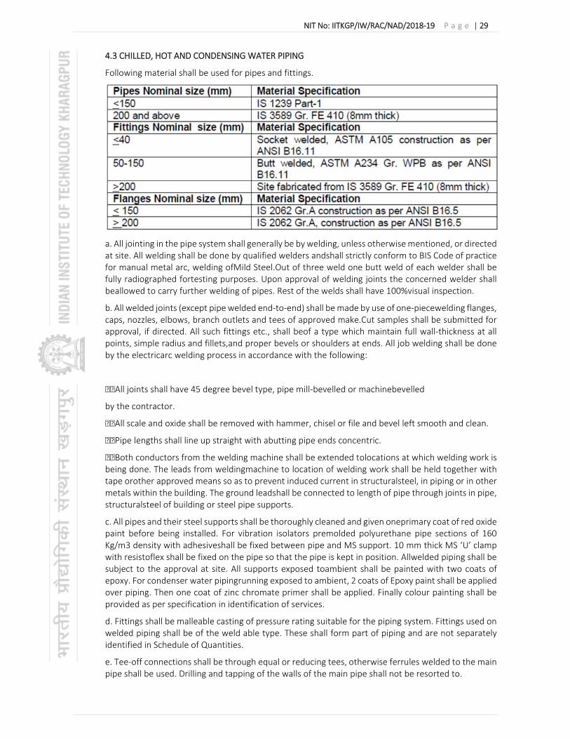
4.3 CHILLED, HOT AND CONDENSING WATER PIPING
Following material shall be used for pipes and fittings.
a. All jointing in the pipe system shall generally be by welding, unless otherwise mentioned, or directed at site. All welding shall be done by qualified welders andshall strictly conform to BIS Code of practice for manual metal arc, welding ofMild Steel.Out of three weld one butt weld of each welder shall be fully radiographed fortesting purposes. Upon approval of welding joints the concerned welder shall beallowed to carry further welding of pipes. Rest of the welds shall have 100%visual inspection.
b. All welded joints (except pipe welded end‐to‐end) shall be made by use of one‐piecewelding flanges, caps, nozzles, elbows, branch outlets and tees of approved make.Cut samples shall be submitted for approval, if directed. All such fittings etc., shall beof a type which maintain full wall‐thickness at all points, simple radius and fillets,and proper bevels or shoulders at ends. All job welding shall be done by the electricarc welding process in accordance with the following:
All joints shall have 45 degree bevel type, pipe mill‐bevelled or machinebevelled
by the contractor.
All scale and oxide shall be removed with hammer, chisel or file and bevel left smooth and clean.
Pipe lengths shall line up straight with abutting pipe ends concentric.
Both conductors from the welding machine shall be extended tolocations at which welding work is being done. The leads from weldingmachine to location of welding work shall be held together with tape orother approved means so as to prevent induced current in structuralsteel, in piping or in other metals within the building. The ground leadshall be connected to length of pipe through joints in pipe, structuralsteel of building or steel pipe supports.
c. All pipes and their steel supports shall be thoroughly cleaned and given oneprimary coat of red oxide paint before being installed. For vibration isolators premolded polyurethane pipe sections of 160 Kg/m3 density with adhesiveshall be fixed between pipe and MS support. 10 mm thick MS ‘U’ clamp with resistoflex shall be fixed on the pipe so that the pipe is kept in position. Allwelded piping shall be subject to the approval at site. All supports exposed toambient shall be painted with two coats of epoxy. For condenser water pipingrunning exposed to ambient, 2 coats of Epoxy paint shall be applied over piping. Then one coat of zinc chromate primer shall be applied. Finally colour painting shall be provided as per specification in identification of services.
d. Fittings shall be malleable casting of pressure rating suitable for the piping system. Fittings used on welded piping shall be of the weld able type. These shall form part of piping and are not separately identified in Schedule of Quantities.
e. Tee‐off connections shall be through equal or reducing tees, otherwise ferrules welded to the main pipe shall be used. Drilling and tapping of the walls of the main pipe shall not be resorted to.

NIT No: IITKGP/IW/RAC/NAD/2018‐19 P a g e | 30
f. Ball and butterfly valves conforming to the following specifications shall be provided as shown on Drawings :
‐‐‐‐‐‐‐‐‐‐‐‐‐‐‐‐‐‐‐‐‐‐‐‐‐‐‐‐‐‐‐‐‐‐‐‐‐‐‐‐‐‐‐‐‐‐‐‐‐‐‐‐‐‐‐‐‐‐‐‐‐‐‐‐‐‐‐‐‐‐‐‐‐‐‐‐‐‐‐‐‐‐‐‐‐‐‐‐‐‐‐‐‐‐‐‐‐‐‐‐‐‐‐ Size Construction Ends Type ‐‐‐‐‐‐‐‐‐‐‐‐‐‐‐‐‐‐‐‐‐‐‐‐‐‐‐‐‐‐‐‐‐‐‐‐‐‐‐‐‐‐‐‐‐‐‐‐‐‐‐‐‐‐‐‐‐‐‐‐‐‐‐‐‐‐‐‐‐‐‐‐‐‐‐‐‐‐‐‐‐‐‐‐‐‐‐‐‐‐‐‐‐‐‐‐‐‐‐‐‐‐‐ 15 to 40 mm Forged Brass Screwed Ball 50 mm and over Body Cast iron, Wafer Butterfly
Type and requirements shall be as indicated in Schedule of Quantities.Valves shall have non‐rising spindles unless specified otherwise and shall be suitable for PN 16 (unless specified otherwise in SOQ) rating. Butterfly valves should be of wafer type long neck construction single stem design with Centre lugs to ensure proper alignment of pipe flanges. Mount valve onto flanges onl yafter flanges have been welded to pipes using a tool piece and cooled down to room temperature to prevent damage to resilient seat. The rubber liner should be fully supported by the valve flanges. Appropriate dimensions and thickness of Flanges and Bolts, as per the Flange Tables ANSI B16.5 should be used. The flanges should be properly aligned with each other so that bolts are exactly perpendicular to the flanges. Evenly tighten the flange bolts to secure the valves.Counter flanges with nut‐bolts and gaskets shall be provided by valve manufacturer.
g. Butterfly valves shall perform the function of isolating valves and shall be suitable for PN 16 (unless specified otherwise in SOQ) rating. Butterfly valves shall have Epoxy Coated cast iron body with Integrally moulded EPDM liner of replaceable type. The liner shall be integrally moulded on hard backup ring and shall be suitable for PN 16 (unless specified otherwise in SOQ) rating. All butterfly valves shall be provided with locking devices. Valves 250 mm and above dia shall be gear driven.
i. Balancing cum control valves shall be sized based on flow rates and pressure drops across cooling coil.
j. Manual double regulating balancing valves shall be provided at chiller, condenser, various tapp‐offs and each AHU outlet line as indicated in Schedule of Quantities. These valves shall have built‐in pressure‐drop measuring facility to compute flow rate across the valve. The test cocks shall be long enough to protrude out of pipe insulation. To enable accurate and practical operation, measurement of flow and differential pressure shall be made with a computerized balancing instrument which shall enable the operator to read the flow directly without the use of diagrams or tables. In addition to measuring flow rate, differential pressure and temperature, computerized balancing instrument shall have a computer programme to provide the following functions:
i. To balance the HVAC installation and calculate the necessary valve settings, based on system measurements. ii. To store the results of balancing. iii. To log measured values from a valve (differential pressure, flowrate or temperature). iv. To printout saved data in computerised measurement protocol (CMP) consisting of : ‐ Name and size of Balancing Valve (BV) ‐ Presetting position of BV ‐ P at BV ‐ Flow at BV ‐ Design Flow
k. The supply of flanges shall form part of piping (not separately identified in Schedule of Quantities) and shall also include supply of bolts, washers, nuts and suitable asbestos fibre / rubber insertion gaskets (minimum 3 mm thick). Flanges shall be as per ANSI B16.5. l. All ball valves and ball valves with Y strainer shall be brass forged body construction with chrome plated brass ball and handle of stainless steel constructions. These are separately identified in Schedule of Quantities.

NIT No: IITKGP/IW/RAC/NAD/2018‐19 P a g e | 31
m. Non return valves shall be dual plate check valve provided as shown on the Drawings, and identified in Schedule of Quantities conforming to relevant Codes and in accordance with the following Specifications :
Size Construction Ends
‐‐‐‐‐‐‐‐‐‐‐‐‐‐‐‐‐‐‐‐‐‐‐‐‐‐‐‐‐‐‐‐‐‐‐‐‐‐‐‐‐‐‐‐‐‐‐‐‐‐‐‐‐‐‐‐‐‐‐‐‐‐‐‐‐‐‐‐‐‐‐‐‐‐‐‐‐‐‐‐‐‐‐‐‐‐‐‐‐‐‐‐‐‐‐‐‐‐‐‐‐‐ 40 to 300 mm Body: Grey Cast iron Flanged (Epoxy Coated), CI IS 210 Gr. FG 260 Plates: CF‐8 (SS‐304), Hinge/Stop Pin: SS‐410 Spring(s): SS‐316. Seal: EPDM
The bearing shall be PTFE material. Valves shall be PN 16 (unless specified otherwise in SOQ) rating.
n. Strainers shall be ‘Y’ type or Pot Strainer suitable for PN 16 (unless specified otherwise in SOQ) rating as shown on drawings and included in SOQ. ‘Y’ Strainer shall be fabricated out of MS ‘C’ class pipe two sizes higher than that of Strainer pipe size. Flanges as per ANSI B16.5 shall be provided at inlet and outlet connectors. The body shall be hot dip galvanized. Permanent magnet shall be provided in the body of the Strainer to arrest MS particles. Filter element shall be of nonmagnetic 20 gage SS sheet with 3 mm perforation. Cartridge having five different type of filters made out of SS 304 with different mesh sizes shall be provided. These will be replaced so as to get good quality of water in system during commissioning. Strainers shall be provided at inlet of each Air Handling Unit and Pump as shown in drawings and included in SOQ.
Pipe Installation
5.1 Pipe installation shall be carried out in a workman like manner in accordance with approved drawings. Pipe shall be aligned parallel to walls and ceiling and not along the room. Change of direction shall be through hydraulically formed or wrought iron welding fittings as specified. Alignment shall follow the approved drawings and wherever necessary pipe shall be rerouted under the instructions of the Engineer‐in‐charge in order to meet the site conditions and or interference from services.
Pipes passing through walls & floors shall be provided with sleeves with sealing as follows:
Space Sleeve
dia (mm)
Sleeve Projection (mm)
Sleeve Material
Sleeve Packing a Closure
Floor D + 50 50 AFF 1.25mm GSS or Light duty galvanized type / PVC Pipe
32 Kg/cum Resin bonded fibre glass with 8mm thick polysulphide
Well
i) Internal
D + 50 Flush
with finish
‐ do ‐ 32 kg/cum Resin bonded fibre glass closed on both sides with 1.0 mm GSS split flange.

NIT No: IITKGP/IW/RAC/NAD/2018‐19 P a g e | 32
ii) External
D + 50 ‐ do ‐ ‐ do ‐ Caulked with lead wool and oakum & closed on both sides with 1.25mm GSS split flanges with brass screws.
D = Outside diameter of pipe with insulation
GSS = Galvanised sheet steel AFF = Above finished floor
Pipe supports shall be standard factory made galvanised systems or fabricated from steel structural galvanised after fabrication. Supports shall be spaced as follows:
Size Horizontal Vertical
Upto 15mm 1.25m 1.8m
20 to 25mm 2 m 2.5m
32 to 125mm 2.4 m 3.0m
150 & over 3 m 3.0m
Additional supports shall be provided at the bends, at heavy fittings like valves, near equipment and as directed by the Engineer‐in‐charge. Pipe hangers shall be from galvanised structural steel, steel inserts in concrete, wall brackets or floor supports as decided by the Engineer‐in‐charge depending upon the location of the support. Hangers shall not be secured to light weight roof, wall, false ceiling or any other member which is not structurally meant for such loading. Hangers from structural steel shall be from suitably designed clamps or attachments and in no case should drilling or punching of such steel members be allowed. All pipe supports shall be capable of being adjusted in height to the tune of 50mm. All supports suspenders and hangers shall be galvanised after fabrication. Cut edges shall be painted with an approved zinc based paint.
Pipe clamps shall be specially fabricated fittings for pipes. All clamps shall be of galvanised mild steel. Clamps shall take into account pipe movement owing to temperature variations & anchors, and in no case shall the clamping arrangement induce stresses beyond the safe load limits of the pipe under fully filled conditions. Where pipes are insulated, the clamping shall interpose a hard insulation material or shall be designed so that the insulation is not compressed for more than 60% of its compression strength.
Vertical pipe risers shall be supported appropriately.
All pipe joints shall be welded except where flange joints are specified. Pipes upto 40mm NB shall use socket weld fittings with fillet welding and larger sizes use butt‐welding type single V 35 deg weld preparation. Flange joints shall be provided at the following positions:
Pair of flanges for isolation of equipment Mating flanges for equipment flange connections Mating flanges for valves, strainers as the case may be Pair of flanges at every 15m continuous run of piping
Where valves, strainers, NR valves adjoin, there is no need for additional mating flanges and valve flanges may be used to mate the other valves, strainers etc.
Entire piping shall be self‐draining, using only eccentric reducers at all change of sections, 25mm NB drain points with a dirt leg and a shut off valve shall be provided at all low points of the piping and the

NIT No: IITKGP/IW/RAC/NAD/2018‐19 P a g e | 33
piping system shall be pitched 1% towards such low points. All air handling units drains shall be pitched 2% with a 75mm water a 75m water seal trap. Fan coil unit drains also shall be pitched likewise but the water seal could be 40mm.
Burried Piping
For buried chilled water pipes, excavation of Earth on the path of piping is to be carried out. This has to be done prior to laying pipes into the earth. The earth has to be dug by 1500mm from the ground level and before laying the pipes the dug earth has to be compacted & levelled. On the levelled surface, a compacted sand bed has to be created for the height of 150mm..
Insulated buried pipes shall be cleaned, de‐rusted, then coated with rust‐resistant primer and placed on concrete blocks with PUF saddles dipped in bitumen at every 2 meters. Insulation shall be applied as per the section “Insulation”, wrapped with GI wire and covered with polyethylene sheet. Two coats (each 6 mm thick) of cement plaster shall be applied over chicken wire mesh lath. Where indicated in Schedule of Quantities, buried insulated pipes shall be water‐proofed using coat of Shall bond, or approved adhesive, over the plastered surface; wrapping one layer of fiber glass RP tissue and one layer of roofing tar felt with sufficient overlaps, set and sealed with the adhesive, held in position by 16 gage G.I wire tied at 15 cm intervals. The pipe has to be laid on the PCC pedestal. After the installing of pipes & insulation are to be covered by sand fill for 150mm from the top of the pipe insulation. Above the sand there will be a warning tape and after that back filling with multi gravel has to be done. Wherever the pipe crosses the road, it will be transferred by Hume pipe under the road to avoid the vehicle weight on the chilled water pipe
Testing
All hydraulic testing of piping shall be carried out before equipment connections are made. No insulation shall be carried out unless and until the piping, in section, is tested and tests approved. Piping may be tested in sections, with the approval of the Engineer and in such case all open ends shall be blanked off with necessary flanges.
All piping shall be tested for pressure equivalent to whichever is higher of the following:
2.5 times the no delivery head of the pump

NIT No: IITKGP/IW/RAC/NAD/2018‐19 P a g e | 34
1.5 times the maximum working pressures
In such a pressure test, the system shall hold for a minimum period of 3 hours. All pipe testing shall be witnessed and certified by the Engineer‐in‐charge and leaks or defects found in the joints shall be rectified.
The contractor shall make all arrangements for testing & removal after testing of all water connections, if any, without causing any damage to the property of the employer or any other contractor.
After the entire piping has been tested and equipment connected, the system of water piping shall be filled and drained till all the dirt, mill scale, welding debris and any other foreign matter is flushed out to the satisfaction of the Engineer‐in‐Charge. All strainers shall be cleaned of all accumulated dirt before the system is charged.
Entire piping system after equipment connection shall be flushed and chemically cleaned thoroughly to remove pipe scales, rust, oil and other loosely held particles on pipe surface. Immediately after cleaning and flushing the system shall be filled with clean water and chemically dosed to arrest further rusting and corrosion. Entire cleaning and refilling shall be carried out to the satisfaction of the engineer‐in‐charge.
Mode of measurement
All pipes shall be in unit length rounded off to the nearest centimeter and measured along the centre line of the pipe and all fittings, flanges etc. excluding the flange‐to‐flange distance of valves, strainers or any other equipment. The rate shall include all clamps, bolts etc. cutting holes in ceiling, floor or wall and making good the same including scaffolding staging supports, flexible etc. and painting of piping as per the painting specifications.
All valves, strainers etc. shall be measured per unit in each size and paid for.
All pressure gauges complete with socket, gauge cock and pressure gauge and CP brass capillary shall be measured per unit.
Thermometers together with thermo well, conducting fluid etc. shall be measured as one unit.
Air vents and drains shall each be measured per unit and paid for.
6.0 Air Distribution:
1. SHEET METAL DUCTING
TECHNICAL SPECIFICATIONS FOR SHEET METAL DUCTING WORKS(FABRICATION AS PER SMACNA STANDARDS 2005‐THIRD EDITION)
General
This section comprises supply fabrication, installation and testing of all sheet metal ducts. All are to be in accordance with these specifications and the general arrangement shown on the Drawings.
Scope: The scope of the sheet metal works for the HVAC contractor not limited to but inclusive of supply, installation, testing, balancing of sheet metal works and also inclusive of all fire retardant double layer leak proof flexible connections, necessary internal turning vanes, internal straightening vanes, internal duct splitter damper, flanges, gaskets, bolts & nuts, duct supports, hangers, vibration isolation pads or suspenders, flexible connection, inspection door, sealant, labour for installation, testing, balancing & commissioning and any other accessories required for fully completion of sheet metal ducting works as per approved shop drawing and as per actual site condition. All the above mentioned accessories are the part of the ducting work only. No additional measurement considered for the same.
Testing of Duct :All the Factory Duct mate corner piece, Longitudinal seam joint, Transverse joints and where ever required should sealed with quality fire retardant, low VOC Sealant to restrict the leakage not exceeding 3% or as per acceptable leakage as per SMACNA standards whichever is the stringent.

NIT No: IITKGP/IW/RAC/NAD/2018‐19 P a g e | 35
After duct installation, a part of duct section (approximately 5% of total ductwork) may be selected at random and tested for leakage. The procedure for leak testing should be followed as per SMACNA – „HVAC Air Duct Leakage Test manual; (First Edition). The test shall be conducted at the cost of the contractor. No extra shall be paid for the test.
Duct Raw Material: All the sheet metal ducting material shall be of Lock Forming Quality prime material along with mill test certificates. In addition, if deemed necessary, samples of raw material, selected at random by Client’s site representative shall be subject to approval and tested for thickness and coating at contractor’s expense. The raw material in Coil form (Sheet metal in Roll Form/ cut sheet) in order to facilitate location of longitudinal seams at corners/folded edges only, for required duct rigidity and leakage free characteristics. No longitudinal seams permitted along any face side of the duct. GSS Ducting:‐ Galvanized steel sheet shall be of Class VIII – light coating of zinc, nominal 120 gm / sqmt as per IS‐277.
Fabrication Standards & Equipment
1. All duct construction, installation, and commissioning shall be in accordance with SMACNA standards 2005 (Third edition). 2. Longitudinal seams at Corners / Folded edges only to obtain the duct rigidity and low leakage characteristics. No longitudinal seams permitted along any side of the duct. 3. All ducts, transformation pieces and fittings to be made on CNC profile cutter for requisite accuracy of dimensions, location and dimensions of notches at the folding lines. 4. Electric lock seamer to join the corners, mallet for fixing the flanges, Electric Drilling machine, C. Jaw clamp to hold flanges, Crimper to crimp the cleats, ratchet spanner for tightening bolts to be used for proper manufacturing and installation of ducts. 5. All edges to be machine treated using lock formers, flanges and rollers for turning up edges. 6. All the transverse duct connectors (Flanges\Cleats) and accessories related hardware such as support system shall be zinc coated (galvanized).
f) Duct Construction All ducts shall be fabricated and installed in workmanlike manner, conforming to relevant SMACNA codes.
1. The fabricated duct dimensions should be as per approved shop drawings prepared by the Contractor and care should be taken to ensure that all connecting sections are dimensionally matched to avoid any gaps. Duct dimensions shown on drawings, are overall sheet metal dimensions inclusive of the acoustic lining where required and indicated in Schedule of quantities.
2. Ducts shall be straight and smooth on the inside with longitudinal seams shall be airtight and at corners only which shall be either Pittsburgh or snap button as per SMACNA practice, to ensure air tightness.
3. All ducts for air conditioning system irrespective of width shall have DUCTMAT joints. The internal ends of joints shall be in the direction of airflow. Ducts and accessories including insulation within ceiling spaces, visible from air‐conditioned areas shall be provided with two coats of mat black finish paint.
4. Ducts shall be fabricated as per details shown on Drawings. All ducts shall be rigid and shall be adequately supported and braced where required with standing seams, tees or angels, of ample size to keep the ducts true to shape and to prevent buckling, vibration or breathing.
5. Self‐adhesive Neoprene rubber / UV resistant PVC foam lining 5 mm nominal thickness instead of felt shall be used between duct flanges and between duct supports in all ducting installation.
6. Changes in dimensions and shape of ducts shall be gradual (between 1:4 and 1:7).
7. All the changes in direction shall be made with elbows. The centre line radius of elbows shall not be less than 1.5 times the width of the duct. For shorter radius elbows necessary turning vanes shall be installed as per SMACNA standards.

NIT No: IITKGP/IW/RAC/NAD/2018‐19 P a g e | 36
8. Necessary Air turning vanes or Air splitters shall be installed in all bends and duct collars designed to permit the air to make the turn without appreciable turbulence.
9. All sheet metal factory fabricated Plenums: ‐ required to confine the flow of air to and through the filters and fans, shall be constructed of 18 gauge GSS /SS or 14 Gauge aluminum, thoroughly stiffened with not less than 25 mm x 25 mm x 3mm galvanized steel / SS angle braces for low pressure system up to 750Pascal. And for the High pressure system above 750pascal shall be of 16 gauge GSS / SS or 12 Gauge aluminum and fitted with all necessary inspection doors as required, to give access to all parts of the apparatus. Access doors shall be not less than 450mm x 450mm in size. All the plenum should be stiffened for not less than 150% of the rated plenum pressure or 130% of the connected fan total pressure whichever is greater.
10. Access Door: ‐ Access door shall be provided in the duct before and after the equipment installed and all the fire damper locations and any other place of requirements. All access doors shall be fabricated of same material as the sheet metal duct work and shall have minimum two hinges. Hinges shall be Zinc / SS plated and pins shall be of brass / SS. Access door shall be of minimum 450mm x 450mm size. At least two heavy solid brass fasteners and brass handle are required for each door. A continuous self‐adhesive neoprene rubbergasket shall be adhered to the opening frame / flange.
11. Flexible connection (connecting duct to the equipment like Supply or Exhaust fan etc.,):‐ All the flexible connection shall be of fire retardant double layer heavy duty canvas or equivalent material. The length of the canvass connection shall not be less than 100mm and the width & height shall be as suitable to connecting sheet metal duct and the equipment. The material shall be attached to Galvanized angle flanges at the end of the flexible connections. The material shall be secured between the galvanized flat strip and angle frame by riveting at regular intervals of not more than 75mm. The angle flanges & other fixing material shall be of galvanized MS
g) GI Sheet Gauge, Brazing by Size of Ducts All ducts shall be fabricated from galvanized steel of the following thickness, and brazing as indicated below. Duct gauges based on G‐60 coated galvanized steel of lock forming grade to ASTM standards A653 and A924. Minimum Reinforcement class & GI Sheet gauge required for Positive or Negative pressure class as per SMACNA 2005 ‐ Third edition

NIT No: IITKGP/IW/RAC/NAD/2018‐19 P a g e | 37
NOTES:
SMACNA NOTES: *1 – SMACNA – Sheet Metal and Air conditioning Contractors National Association Inc – “HVAC Duct Construction Standards – Metal and Flexible” – 1995, U.S.A.
*2 – Under SMACNA, alternative configurations of the duct gauge and flange system to be used to obtain an equivalent structural rigidity and class of construction of the duct system as shown here as per the supplier recommendation with previous approval.
*3 – For non critical comfort cooling applications (250pa. wg pressure class), optional Slip‐and‐Drive (C and S) cleats joints can be used.
*4 ‐ A higher‐class flange can always be substituted for a lower class (e.g. class “J” for class “H”, class “H” for Class “F”)
*5 – The additional GI metal clip for the different class of duct mate flanges should be spaced so that the cleat end is within 150mm of each companion flange end and the maximum pitch between cleats is 300mm. and the minimum length of the cleat should be 150mm.
*6 – The duct manufacturer should confirm for the ability of fabrication for the respective pressure class of sheet metal ducting with respective gauge of the sheet and the respective reinforcement distance & details as mentioned in the above chart and as per SMACNA standard 2005 (Third edition). h) Installation Practice All ducts shall be installed generally as per tender drawings, and in strict accordance with approved shop drawings to be prepared by the Contractor.

NIT No: IITKGP/IW/RAC/NAD/2018‐19 P a g e | 38
1. The Contractor shall provide and neatly erect all sheet metal work as may be required to carry out the intent of these Specifications and Drawings. The work shall meet with the approval of Client’s site representative in all its parts and details.
2. The Contractor shall make all necessary allowances and provisions for beams, pipes, or other obstructions in the building, whether or not the same are shown on the drawings. Where necessary to avoid beams or other structural work, plumbing or other pipes, and conduits, the ducts shall be transformed or divided or curved to one side (the required equivalent air flow area being maintained) all as per the site requirements with the approval of Client’s site representative.
3. If a duct cannot be run as shown on the drawings, the contractor shall install the duct between the required points by any path available in accordance with other services and as per approval of Client’s site representative.
4. All ductwork shall be independently supported from building construction. All Horizontal ducts shall be rigidly and securely supported, in an approved manner, with trapeze hangers formed of galvanized steel rods and galvanized steel angle / channel or a pair of brackets, connected by galvanized steel rod under ducts. The spacing between supports should be not greater than 2.4 meter. Structural members on each floor slab shall support all vertical ductwork. Duct supports may be through galvanized steel cleat with a hole for passing the hanger rods shall be welded to the plates. Trapeze hanger formed of galvanized steel rods shall be hung through these cleats. Wherever use of metal insert plates is not feasible, duct support shall be through dash / anchor fastener driven into the concrete slab by electrically operated gun. Hanger rods shall then hang through the cleats or fully threaded galvanized rods can be screwed into the anchor fasteners. Self‐adhesive Neoprene rubber / UV resistant PVC foam lining 5mm nominal thickness shall be used between duct and duct supports in all ducting installation.
5. Ducting over furred ceiling shall be supported from the slab above or from beams after obtaining approval of Client’s site representative. In no case shall any duct be supported from false ceiling hangers or be permitted to rest on false ceiling. All sheet metal work in dead or furred down spaces shall be erected in time to occasion no delay to other contractor’s work in the building.
6. Where ducts pass through brick or masonry openings, it shall be provided with 25 mm thick Phenotherm insulation around the duct and totally covered with fire barrier mortar for complete sealing. The cost of the Phenotherm shall be part of ducting & shall not be covered separately in BOM. It can also be executed with a layer of neoprene around the ducting.
7. All ducts shall be totally free from vibration under all conditions of operation. Whenever ductwork is connected to fans, air handling units or blower coil units that may cause vibration in the ducts, ducts shall be provided with a flexible connection; located at the unit discharge. Flexible connections shall be constructed of fire retarding flexible heavy canvas sleeve at least 100mm long securely bonded and bolted on both sides. Sleeve shall be made smooth and the connecting ductwork rigidly held by independent supports on both sides of the flexible connections. The flexible connection shall be suitable for pressure at the point of installation.
8. All the Anchor fasteners, Grouting bolts, supporting rods used / selected shall be capable of handling minimum twice the actual Duct weight and pressure irrespective of size mentioned in the tender speciation and drawing.
i) Factory Duct mate System components shall be as follows: Slip on Flanges Roll‐formed GI section with embedded sealant. Sections to provide a range of rigidity and strength characteristics.
Corners: To be inserted into the hollow web of the slip‐on flange. 4 corner pieces. Are required for each rectangular frame, 8 corner pieces, per joint.
Sealant :Sealant to be applied as a thin bead at the interface of duct and Factory Duct mate corner piece, Longitudinal seam joint, Transverse joints and where ever required to maintain the leakage not exceeding 3%.

NIT No: IITKGP/IW/RAC/NAD/2018‐19 P a g e | 39
Cleats
GI Metal Cleat 150 mm in length can be snap‐fitted or slid over the mating flanges.
Gasket –Neoprene / EPDM
UV resistant, Nontoxic, self‐adhesive, Polyethylene / Neoprene / EPDM 10 mm wide and 4.5 mm thick for Duct mate flange of class E,F& I 15 mm wide and 6.0 mm thick for Duct mate flange of class „J‟ and for all the flanges with 750pasacal wg pressure static and above.
Bolts, Nuts and Washer
Electro‐galvanized, square‐necked carriage bolts, nuts and washers. Each joint to have 4 sets.
Flange Selection
(Recommended Configurations as per SMACNA – 1995)
Factory Duct mate Flanges shall be available in different sizes and identified by its Rigidity / Reinforcement ‟Class‟ as per SMACNA. The proper selection of the right flange depends on the independent parameters:
a) duct static pressure b) duct size c) spacing between joint and or reinforcement.
ALTERNATIVE REINFORCEMENT CLASSES USING ANGLE IRON FLANGES FOR TRANSVERSE JOINTS INSTEAD OF DUCTMATE FOUR (4) BOLT SYSTEM. (PRIOR APPROVAL SHALL BE OBTAINED BEFORE USING THE ANGLE FLANGES)
Under SMACNA – 2005, the approximate Transverse joint reinforcement classes for duct assemblies with companion Angle Iron Flanges are:
The angle, rivets, bolts shall be of galvanized material. The Angle shall be riveted to the duct sheet as the starting rivet point shall be 40mm away from the corner of the duct, and the in‐between spacing of rivets shall not be more than 100mm. Two ducts can be joined with angle iron flange with necessary bolts and nuts of minimum 6mm diameter with c/c of the bolt not exceeding 200mm. Support for Horizontal Duct – Rectangular: A completely galvanized system consisting of fully threaded rods and bottom brackets, nuts, washers and anchor bolts conformed to SMACNA standards or as mentioned below whichever are greater.
Support for horizontal duct‐ Rectangular
A completely galvanized system consisting of fully threaded rods and bottom brackets, nuts, washers and anchor bolts conformed to SMACNA standards are as mentioned below whichever are greater.

NIT No: IITKGP/IW/RAC/NAD/2018‐19 P a g e | 40
a) General:‐
All ducts shall be installed generally as per tender drawings, and in strict accordance and approved shop drawings to be prepared by the contractor.
The adhesive &Sealant selected should be non‐combustible. Fire retardant, not stinking, eco‐friendly fungus proof, non‐injurious to health, chemically inert, non‐corrosive to steel and aluminium, and should have good bonding capacity etc.
The adhesives and sealant shall be of Low Volatile Organic Compound (VOC). The adhesive VOC contents shall not be more than 850gm/Litre. The duct sealant VOC contents shall not be more
than 420gm/litre. The supplier has to submit the certificate confirming the same and necessary technical data sheets of the adhesive &sealant to be provided for approval before the supply.
All the factory fabricated ducts opening shall need to be covered during transportation to the site. Any duct opening and joints need to be covered during installation till commissioning. The covering of opening shall be done with 500g/m2 polythene sheet or any other suitable method to ensure dust shall enter the duct.
LARGE DUCT SUPPORT
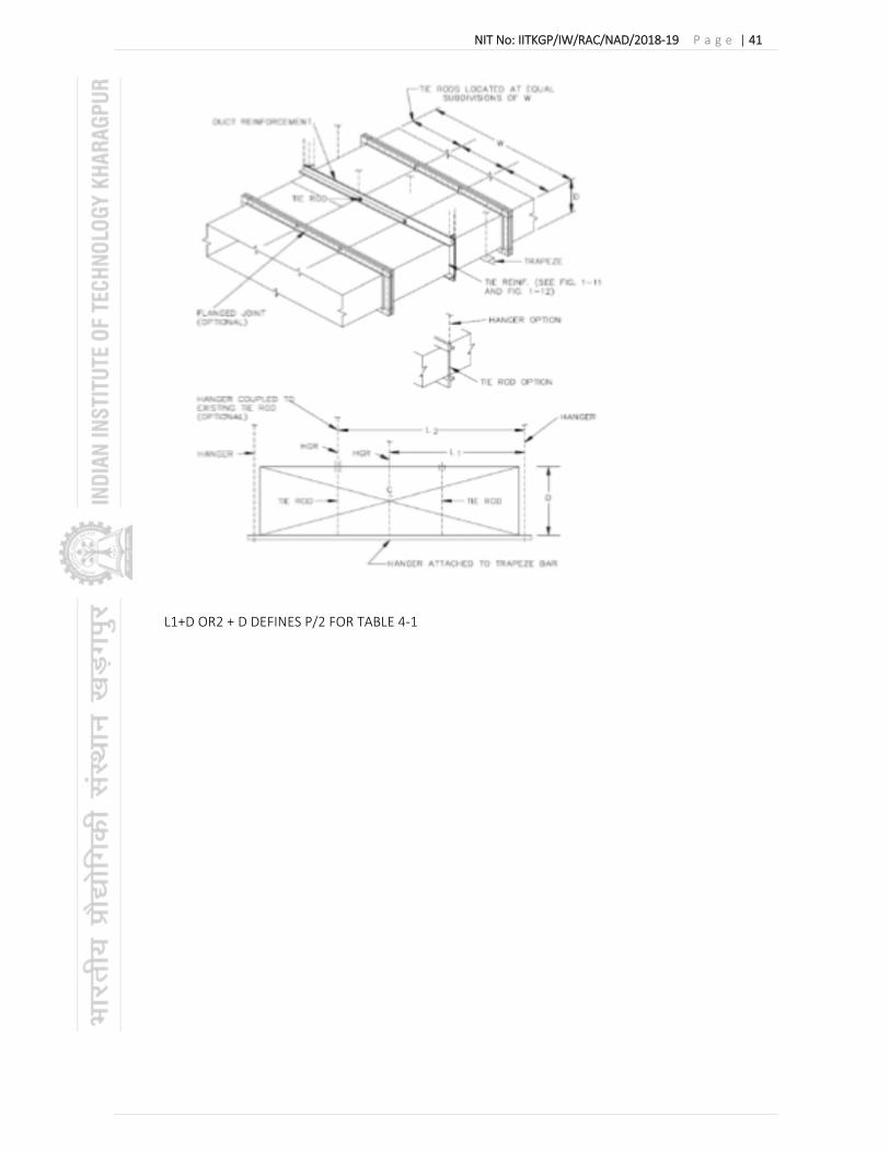
NIT No: IITKGP/IW/RAC/NAD/2018‐19 P a g e | 41
L1+D OR2 + D DEFINES P/2 FOR TABLE 4‐1

NIT No: IITKGP/IW/RAC/NAD/2018‐19 P a g e | 42

NIT No: IITKGP/IW/RAC/NAD/2018‐19 P a g e | 43

NIT No: IITKGP/IW/RAC/NAD/2018‐19 P a g e | 44

NIT No: IITKGP/IW/RAC/NAD/2018‐19 P a g e | 45

NIT No: IITKGP/IW/RAC/NAD/2018‐19 P a g e | 46

NIT No: IITKGP/IW/RAC/NAD/2018‐19 P a g e | 47
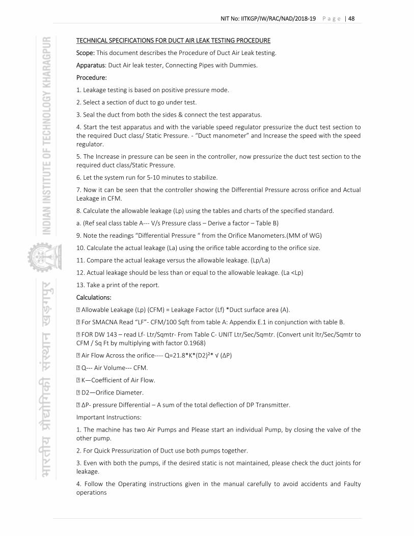
NIT No: IITKGP/IW/RAC/NAD/2018‐19 P a g e | 48
TECHNICAL SPECIFICATIONS FOR DUCT AIR LEAK TESTING PROCEDURE
Scope: This document describes the Procedure of Duct Air Leak testing.
Apparatus: Duct Air leak tester, Connecting Pipes with Dummies.
Procedure:
1. Leakage testing is based on positive pressure mode.
2. Select a section of duct to go under test.
3. Seal the duct from both the sides & connect the test apparatus.
4. Start the test apparatus and with the variable speed regulator pressurize the duct test section to the required Duct class/ Static Pressure. ‐ “Duct manometer” and Increase the speed with the speed regulator.
5. The Increase in pressure can be seen in the controller, now pressurize the duct test section to the required duct class/Static Pressure.
6. Let the system run for 5‐10 minutes to stabilize.
7. Now it can be seen that the controller showing the Differential Pressure across orifice and Actual Leakage in CFM.
8. Calculate the allowable leakage (Lp) using the tables and charts of the specified standard.
a. (Ref seal class table A‐‐‐ V/s Pressure class – Derive a factor – Table B)
9. Note the readings “Differential Pressure “ from the Orifice Manometers.(MM of WG)
10. Calculate the actual leakage (La) using the orifice table according to the orifice size.
11. Compare the actual leakage versus the allowable leakage. (Lp/La)
12. Actual leakage should be less than or equal to the allowable leakage. (La <Lp)
13. Take a print of the report.
Calculations:
Allowable Leakage (Lp) (CFM) = Leakage Factor (Lf) *Duct surface area (A).
For SMACNA Read “LF”‐ CFM/100 Sqft from table A: Appendix E.1 in conjunction with table B.
FOR DW 143 – read Lf‐ Ltr/Sqmtr‐ From Table C‐ UNIT Ltr/Sec/Sqmtr. (Convert unit ltr/Sec/Sqmtr to CFM / Sq Ft by multiplying with factor 0.1968)
Air Flow Across the orifice‐‐‐‐ Q=21.8*K*(D2)²* √ (ΔP)
Q‐‐‐ Air Volume‐‐‐ CFM.
K—Coefficient of Air Flow.
D2—Orifice Diameter.
ΔP‐ pressure Differential – A sum of the total deflection of DP Transmitter.
Important Instructions:
1. The machine has two Air Pumps and Please start an individual Pump, by closing the valve of the other pump.
2. For Quick Pressurization of Duct use both pumps together.
3. Even with both the pumps, if the desired static is not maintained, please check the duct joints for leakage.
4. Follow the Operating instructions given in the manual carefully to avoid accidents and Faulty operations

NIT No: IITKGP/IW/RAC/NAD/2018‐19 P a g e | 49
2.0 Volume Control Damper (VCD) & Duct damper
The Volume Control dampers & Duct Dampers shall be lever operated and complete with locking devices, which will permit the dampers to be adjusted and locked in any position, and clearly indicating the damper position.
The dampers shall be of splitter, butterfly or louver type. The damper blade thickness shall not be less than 1.25 mm (18 gauge).
Manual volume opposed blade dampers shall be complete with frames and bronze bearings as per drawings. Dampers and frames shall be constructed of 1.6 mm thick galvanised steel sheets and blades shall not be more than 225 mm wide.
For air balancing an opposed blade damper with quadrant and thumbscrew lock should be provided.
At the junction of each branch duct with main duct VCD’s must be provided. At the delivery of all IDU’s VCD’s must be provided.
The dampers shall be of Extruded aluminium.
Installation of VCD’s shall be as per drawings.
3.0 Fire Damper
Dampers should be fusible link type as indicated in BOQ. Fire dampers shall be provided at the delivery of all IDU’s.The dampers shall be of multiple blade type. The blades shall be constructed with minimum 1.8 mm thick aluminium sheets. The frame shall be of 1.6 mm thick. Other materials shall include return spring, locking device and temperature sensor.
Installation of fire damper shall be as per drawings.
4.0 Standard Grilles and diffusers
The supply and return air grille/diffuser shall be fabricated from extruded aluminium sections of thickness not less than 1.5 mm. The supply air grille/diffuser shall have single / double louvers. The front horizontal louvers shall be of adjustable type. The rear vertical louvers shall be of aluminium extruded sections and adjustable type. The return air grille shall have single horizontal extruded section fixed louvers.The damper blades shall also be of extruded aluminium. The grille flange shall be fabricated out of aluminium‐extruded section. Grilles longer than 450 mm shall have intermediate supports for the horizontal louvers.
The ceiling type square/circular diffusers shall be of aluminium‐extruded section with flush or step down face.All supply diffusers shall be provided with extruded aluminium dampers, with arrangement for adjustment from the bottom. (The centre portion should be spring loaded for easy removal and fitting). All grilles and diffuser shall be epoxy powder coated of 15 Micron in approved colour. Diffuser and grille shall be installed as per drawings. The linear grilles shall be provided with End Pieces at ends.
Fresh Air arrangements
Extruded aluminium construction duly anodized (20 microns and above) fresh air louvers with bird screen and extruded construction dampers shall be provided in the clear openings in the masonry walls near the IDU’s or as per drawing.
Louvers, dampers, cowl, ducts and fresh air fan, if required with speed regulator shall be provided as shown in the drawings and as per Bill of Quantities.
Fresh air dampers shall be of interlocking, opposed blade louver type. Blades shall be similar to those specified in “Air Distribution”.
Fresh air fan and fresh air intake as per BOQ.

NIT No: IITKGP/IW/RAC/NAD/2018‐19 P a g e | 50
Testing and Balancing
After completion of the installation of the complete air distribution system all ducts shall be tested for air leaks. All dampers of supply air diffuser and supply air grille shall be balanced as per user’s requirements. The entire air distribution system shall be balanced using approved anemometer.
5.0 Mode of Measurement.
All sheet metal ducting complete with duct supports, turning vanes, canvas connections erected in position shall be measured externally and paid per unit. All dampers shall be excluded in the duct area.
All manual control/splitter including Fire & Volume control damper sections with operations linkages, locking quadrant, sheet steel enclosure, frame, erection, supporting etc. shall be measured on the basis of quantity as mentioned in BOQ and will be paid as per unit rate.
Fresh air louvers with bird screen, damper, frame, ducting, erection & sealing shall be measured on the basis of quantity as mentioned in BOQ and will be paid as per unit rate.
Grilles/diffuser including volume control damper, installation etc. will be measured on the basis area and paid per unit area.
ACOUSTIC & THERMAL INSULATION
TECHNICAL SPECIFICATIONS FOR THERMAL INSULATION FOR DUCTS
SCOPE
The scope of this section comprises the supply and application of insulation conforming to these specifications.
This specification covers the technical requirements and essential particulars for the supply, application and finishing of the composite thermal insulation for cold equipment, piping systems, air‐conditioning ducts, etc. The scope of supply of the contractor shall include, but not be limited to, the following items:
(a) Insulation material as specified (b) Finishing and cladding/covering, laminated plastic elbows, T sections & finishing paint material as specified (c) Auxiliary materials such as binding and lacing wires, wire netting, vinyl bands, adhesive tapes, glue, screws, pop‐rivets, etc. as required (d) Angles, clamps, Insulated pipe support inserts, lugs, etc. for supporting insulation (e) Weather hoods (f) Any material as may be required for making the installation of insulation material complete and safe from mechanical damages.
MATERIAL
Insulation material shall be Closed Cell Microcellular Elastomeric Nitrile Rubber.
The Density of Material shall be between 40 to 60 Kg/m3.
Thermal conductivity of elastomeric nitrile rubber shall not exceed 0.036 W/m K at an average temperature of 0 C.
The insulation shall have fire performance such that it passes minimum fire rating Class 1 as per BS 476 Part 7 for surface spread of flame and also pass Fire Propagation requirement as per BS476 Part 6 to meet the Class ‘O’ Fire classification as per 1991 Building Regulations (England & Wales) and the Building Standards (Scotland) Regulations 1990.
Water vapour permeability shall not exceed 0.024 Perm inch (2.48 x 10‐14 Kg/m.s.Pa) i.e. Moisture Diffusion Resistance Factor or ‘μ’ value should be minimum 10,000.
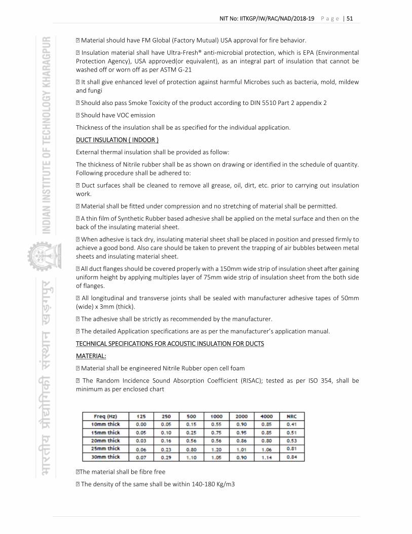
NIT No: IITKGP/IW/RAC/NAD/2018‐19 P a g e | 51
Material should have FM Global (Factory Mutual) USA approval for fire behavior.
Insulation material shall have Ultra‐Fresh® anti‐microbial protection, which is EPA (Environmental Protection Agency), USA approved(or equivalent), as an integral part of insulation that cannot be washed off or worn off as per ASTM G‐21
It shall give enhanced level of protection against harmful Microbes such as bacteria, mold, mildew and fungi
Should also pass Smoke Toxicity of the product according to DIN 5510 Part 2 appendix 2
Should have VOC emission
Thickness of the insulation shall be as specified for the individual application.
DUCT INSULATION ( INDOOR )
External thermal insulation shall be provided as follow:
The thickness of Nitrile rubber shall be as shown on drawing or identified in the schedule of quantity. Following procedure shall be adhered to:
Duct surfaces shall be cleaned to remove all grease, oil, dirt, etc. prior to carrying out insulation work.
Material shall be fitted under compression and no stretching of material shall be permitted.
A thin film of Synthetic Rubber based adhesive shall be applied on the metal surface and then on the back of the insulating material sheet.
When adhesive is tack dry, insulating material sheet shall be placed in position and pressed firmly to achieve a good bond. Also care should be taken to prevent the trapping of air bubbles between metal sheets and insulating material sheet.
All duct flanges should be covered properly with a 150mm wide strip of insulation sheet after gaining uniform height by applying multiples layer of 75mm wide strip of insulation sheet from the both side of flanges.
All longitudinal and transverse joints shall be sealed with manufacturer adhesive tapes of 50mm (wide) x 3mm (thick).
The adhesive shall be strictly as recommended by the manufacturer.
The detailed Application specifications are as per the manufacturer’s application manual.
TECHNICAL SPECIFICATIONS FOR ACOUSTIC INSULATION FOR DUCTS
MATERIAL:
Material shall be engineered Nitrile Rubber open cell foam
The Random Incidence Sound Absorption Coefficient (RISAC); tested as per ISO 354, shall be minimum as per enclosed chart
The material shall be fibre free
The density of the same shall be within 140‐180 Kg/m3

NIT No: IITKGP/IW/RAC/NAD/2018‐19 P a g e | 52
The material shall have a thermal conductivity not exceeding 0.047 W/m.K @ 20 Deg. C
The material shall withstand maximum surface temperature of +850C and minimum surface temperature of ‐200C
The material shall conform to Class 1 rating for surface spread of Flame in accordance to BS 476 Part 7 & UL 94 (HBF, HF 1 & HF 2) in accordance to UL 94, 1996.
The insulation shall pass Air Erosion Resistance Test in accordance to ASTM Standard C 1071‐05 (section 12.7), from an independent testing agency.
The insulation should have built‐in Ultra‐Fresh® Anti‐Microbial Protection, and should pass Fungi Resistance as per ASTM G21 & Bacterial resistance as per ASTM 2180.
Thickness of the material shall be as specified for the individual application. The insulation shall be installed as per manufacturer’s recommendation.
DUCT ACOUSTIC LINING
Ducts so identified and marked on Drawings and included in Schedule of Quantities shall be provided with acoustic lining of Open Cell Acoustic Insulation material for a distance of minimum 8 meters (or 30% of the duct length whichever is more).
Installation Procedure
The inside surface for the ducts shall be covered with adhesive recommended by the manufacturer. Cut Foamed sheets into required sizes apply adhesive on inside wall of duct as well as on the foam and stick it to the duct surface. At the starting point for the ducting from AHU put a flange and bend it towards the foam.
Installation Procedure:
The wall surface shall be cleaned and required surface preparation shall be done for applying adhesive.
Rubber based contact adhesive recommended by the manufacturer shall be used.
K‐FOINK foam sheets shall be cut to required size and a thin layer of adhesive shall be applied to both the surfaces; Insulation and inside duct.
When it is tack dry, it is applied / stuck with enough pressure to the walls/ceiling. Minimum 5 fasteners with washer (of G.I Sheet 2.5 inch x 2.5 inch) / square meter, 4 at corners & 1 at centre shall be put immediately after sticking with the help of adhesive. The length of the fastener shall be minimum 75 mm.
The acoustic lining of walls shall be terminated approximately 15cm above the finished floor to prevent damage to insulation due to accidental water logging in plant / AHU Rooms
TECHNICAL SPECIFICATIONS FOR ALUMINIUM FOIL COVERING
Insulation should be factory faced Aluminium foil flexible Covering :
Specification Clause: Factory faced FSK (Foil Scrim Kraft) type or PE film with class O fire rating.
Technical Details:
This Foil should be UV resistant and should provide protection against mechanical damage to the insulation. The foil should factory laminated on the insulation for sheets. It should have a Dull surface finish. Use of foil in areas exposed to weather not also recommended. Also please consult our technical department as thickness of insulation may go up with the use of foil due to change in the emissivity coefficient of the glossy surface.

NIT No: IITKGP/IW/RAC/NAD/2018‐19 P a g e | 53
Application Notes:
The insulation with Alu foil sheets, should be installed in similar manner to installation of regular insulation material. All the joints shall be sealed using an Alu Foil Tapes.
Storage: Material should be stored under covered roof at room temperature upto 30 Deg C. It should not stored in exposed areas open to atmosphere.
TECHNICAL SPECIFICATIONS FOR ACOUSTIC INSULATION FOR MECHANICAL ROOMS
ACOUSTIC LINING OF MECHANICAL ROOMS
Acoustic lining material shall be Nitrile Rubber open cell foam. Thermal conductivity of the insulation material shall not exceed 0.047 W/moK at an average temperature of 20oC. Density of the nitrile rubber shall be 100 – 160 Kg/m3. The material should withstand maximum surface temperature of +85oC and minimum surface temperature of ‐20oC. The material should conform to Class 1 rating for surface spread of Flame in accordance to BS 476 Part 7 & UL 94 (HBF, HF 1 & HF 2) in accordance to UL 94, 1996.
Two walls and ceiling of air conditioning plant room and air handling unit rooms may be provided with acoustic lining. Material shall be processed from Nitrile rubber foam.
Thickness, if not specified, shall be considered as 25mm.
Surface shall be cleaned and adhesive recommended by the manufacturer should be applied on the walls. The foam sheets should be cut to required size and a layer of adhesive should also be applied to it. When it is tack dry it is stuck to the walls / ceiling.
Acoustic lining of walls shall be terminated approximately 15 cm above the finished floor to prevent damage to insulation due to accidental water‐logging in plant/AHU rooms.
TECHNICAL SPECIFICATIONS FOR ADHESIVES
Adhesives – Ducting Adhesive Special adhesive for installing all flexible insulation materials. Adhesive shall be used for bonding the seams securely together. All butt & longitudinal joints, fittings and coverings must be closed with adhesive. The adhesive shall be specially formulated for the Duct insulation application and supplied by insulation manufacturer. The adhesive shall be free from benzene. The adhesive shall have excellent bonding to porous and non porous surfaces.
Technical Details

NIT No: IITKGP/IW/RAC/NAD/2018‐19 P a g e | 54
8.0 PIPE INSULATION
Thermal Insulation of chilled water piping accessories with Closed Cell Elastomeric Foam
Thermal insulation of chilled water piping shall be done with 6/9/13/16/19/22/25/32/38/44mm thick Closed Cell Elastomeric Foam structure of density 55 to 90 kg/m³ of Class „O‟ insulation material. Apply one coat of adhesive on the outer surface of the pipe and one coat of adhesive on one surface of the insulation material allow it to dry for 1minute and stick the insulation on the pipe by pressing neatly such a way that any formation rupture or buckle should be prevented. The joints shall be sealed with 50x 6 mm self adhesive nitrile rubber tapes. And according to the requirement the same can be finished with any one of the finishing method given in item‐„B‟ 16, as per BOM. General recommended thickness of Closed Cell Elastomeric Foam shall be as follows:‐ CHILLED WATER PIPE DIMENSIONS: Nominal chilled water pipe (7ºC) dia in mm. Thickness of Nitrile Rubber in mm Up to 40mm dia 32mm 50 mm to 125 mm dia 38mm 150 mm to 600mmdia 44mm 10mm to 100mm dia (Condensate drain pipe) 13mm
THERMAL INSULATION OF CHILLED WATER PIPE FITTINGS, VALVES & OTHER SPECIAL FITTINGS:‐
All pipe fittings, valves and special fittings shall be covered with the same type and thickness of insulation as specified for the adjoining pipe. On pipe fittings, insulation outside diameter shall be same as the outside diameter of adjacent pipe insulation. Unless specified otherwise in relevant section, Where ever possible the flanged joints, valves and special fittings of sizes 100 mm NB and larger shall be provided with removable box type insulation. Box shall be fabricated from sheet material specified for adjoining pipes. Pipe insulation on adjoining flanges shall be stopped at one bolt length plus 25 mm before flange to permit removal of bolts and nuts. The insulation shall be applied on the fittings after the insulation of on the adjacent piping.
Thermal Insulation of chilled water piping accessories with Closed Cell Elastomeric FoamThermal insulation of chilled water piping shall be done with 6/9/13/16/19/22/25/32/38/44mm thick Closed Cell Elastomeric Foam structure of density 55 to 90 kg/m³ of Class „O‟ insulation material. Apply one coat of adhesive on the outer surface of the pipe and one coat of adhesive on one surface of the insulation material allow it to dry for 1minute and stick the insulation on the pipe by pressing neatly such a way that any formation rupture or buckle should be prevented. The joints shall be sealed with 50x 6 mm self‐adhesive nitrile rubber tapes. And according to the requirement the same can be finished with any one of the finishing method given in item‐„B‟ 16, as per BOM. General recommended thickness of Closed Cell Elastomeric Foam shall be as follows:‐
Poly Urethane Foam:
PUF pipe insulation shall be carried out with preformed pipe sections. The surface of the pipe shall be painted with anticorrosive paint and rendered dry and clean. All joints shall be staggered and sealed with approved sealant. FRP tape shall be applied and finished with Polybond compound in accordance with the mfrs recommendation. Elastomeric insulation shall be in tube form and applied to refrigerant pipes as follows: Clean the pipe surface thoroughly. Apply synthetic bonding sealant recommended by the manufacturers. Seal the joints with approved sealant. Finished with Aluminium cladding with 0.5mm Aluminium sheet.
Buried u/g chilled water pipes shall be pre insulated MS pipes which shall be factory/ site insulated and brought to site. Only joint insulation shall be done on site after hydraulic testing.
ADHESIVES FOR INSULATIONThe adhesive selected should be noncombustible, fire retardant, not stinking, ecofriendly, fungus proof, non‐injurious to health, chemically inert, non‐corrosive to steel and aluminum, and should have good bonding capacity etc. The adhesives required for the insulation work shall be of Low Volatile Organic Compound (VOC). The adhesive selected should also have prior

NIT No: IITKGP/IW/RAC/NAD/2018‐19 P a g e | 55
approval from the insulation material supplier. The adhesive shall be uniformly spread at minimum of 0.5litre/m² or as prescribed by the insulation material supplier.
GENERAL APPLICATION GUIDELINES: The application of insulation shall be made in a professional manner. The insulation shall be applied to all surfaces when these are ambient temperature. Ample provisions shall be made for maximum possible thermal movement and the insulation shall be applied in a manner, which shall avoid breaking or telescoping due to alternate periods of contraction and expansion. A single layer of insulation shall not be more than 25mm for closed cell electrometric rubber / foam insulation. Where multilayer insulation is provided, insulation adhesive shall be usedbetween two layers. Insulation shall be applied after all leak tests on ducting, equipment and piping is over and PURCHASER has specifically released the section of the plant for such work. If the insulation has to be applied before the leak test, the same to be shall be done with pre‐ permission from the client or client‟s representatives. All welded and flanged joints shall be left exposed and insulated after satisfactory completion of the leak test only.
All surfaces to be insulated shall be clean and dry before the insulation is applied. The surfaces shall be cleaned of all foreign material such as scale, dirt, rust and paint, by the use of steel wire brushes and steel scrapers, where necessary. Where a surface is not free of paint the CONTRACTOR shall notify the PURCHASER of the condition for remedial action. The insulation shall be applied after the CONTRACTOR has taken remedial action, suggested by the PURCHASER. One coat of primer paint shall be applied and allowed to dry before application of insulation. All actions shall be taken to complete the application of finishing on exposed surfaces covered with insulation before closing the day‟s work. If this is not practicable, adequate precautions shall be taken to protect the insulation from weather, for example by wrapping it with polythene sheet, roofing felt or other approved material. All vertical pipes, ducts etc., shall be provided with suitable insulation supports to prevent the insulation from collapsing due to its own weight. Any welding required, shall be carried out by the CONTRACTOR with the prior permission of the PURCHASER and only under his direct supervision. Where welding is not permitted, suitable clamped supports shall be used. The insulation shall be applied starting from bottom up. Mattress type insulation materials shall be clamped from top. Depending on the type of insulation material used and the opening temperature, contraction joints shall be provided for equipment or pipes to prevent rupturing or buckling when the cold surface contracts.
9.0 ELECTRICAL
9.1 Scope.
The scope of this section covers supply, installation & Testing of cables, Control Panel with Voltmeter & Ammeter connecting Indoor Unit & Outdoor Unit as per specification.
9.2 Electrical.
The supply should be complete with appropriate earthing as per IE Rules. Each Unit should have a separate control panel. The control panel shall consist of Voltmeter & Ammeter with selector switches. Depending on the number and capacity of units to be installed, each unit should have separate control through a main incoming switch with adequate capacity of approved makes. Each ODU should have separate SFU adjacent to the unit / within the unit and visible from the unit. Electrical cabling should be done with armoured copper cable of approved makes only. Fuse switches should be HRC cartridge type with visible indication. The cabling shall be done as per drawings or instruction from Engineer . The cabling supporting shall be done as per drawing.
LT SWITCHGEAR PANEL
Approvals and Submissions LT Switchgear panel shall be deemed to be approved when a sample has been inspected and when the sample workshop drawings have been approved, by the Owner / Consultant.

NIT No: IITKGP/IW/RAC/NAD/2018‐19 P a g e | 56
Breaker Co‐ordination. The contractor shall submit breaker co‐ordination details along with selection of breakers during bidding. Selection of all switchgear components ‐ it is intended to achieve total discrimination and coordination, as such vendor shall justify selection of switchgear from upstream to final circuit components. The Vendor/Fabricator shall understand this from switchgear manufacturer before concluding selection.
LT Switchboards
General The switchboard shall be metal clad, totally enclosed, rigid, compartmentalized design, floor mounting, air insulated, extensible cubicle type for use on 415V, 3 phase, 4 wire, 50 Hz system. The equipment shall be designed for operation in high ambient temperature and high humidity tropical atmospheric conditions. Means shall be provided to facilitate ease of inspection, cleaning and repairs for use in installations where continuity of operation is of prime importance.
Standards The equipment listed below shall conform to tie requirements shown:
oMoulded Case Circuit Breaker (MCCB) – IS 13937 ‐ 1.2 / IEC 60947 – 1 & 2. Certificate for Test Sequence 1 is mandatory. o Contactors‐ IS 13947‐1,4 o Miniature Circuit Breaker (MCB) ‐ IS 8828 ‐ 1996/ IEC 898 – 1995 energy limiting class 3. o Residual Current Circuit Breaker (RCCB) ‐ IS 12640 ‐ 1988 / IEC 1008 o HRC fuse link ‐ IS 9224 and BS 8:8 o Current Transformer ‐ IS 2705 and IEC 185 o Potential Transformer‐ IS 3156 o Relay ‐ IS 3231 and IS 8686 (For Static Relays) o Indicating Instrument‐ IS 1248
2.3 Types and Construction The switchboard shall be of HVAC TECHNICAL SPECIFICATIONS
a. Sheet steel enclosed, indoor floor mounted free standing cubicle type.
b. Made up of the requisite vertical sections modular type which when coupled together shall form continuous dead front switchboards.
c. Dust, vermin and damp proof and enclosure protection of not less than IP 54. d. Each feeder/instrument compartment shall be provided with a hinged door interlocked with MCCB inside the compartment such that door can only be opened when MCCB in off position.
e. Readily extendable as required by the addition of vertical sections after removal of the end covers.
f. The MCCBs shall be lockable. Each vertical section shall comprise: a. A front framed structure of rolled/folded CRCA sheet steel angle section of minimum 3 mm thickness rigidly bolted together. This structure shall house the components contributing to the major weight of the equipment such as circuit breaker cassettes, main horizontal bus bars, vertical risers and other front mounted accessories. b. The structure shall be mounted on a rigid base frame of folded CRCA sheet steel of minimum 6 mm thickness and 75 mm height. The design shall ensure that the weight of the components is adequately supported without deformation or loss of alignment during transit or during operation. c. A cable chamber housing the cable end connections and power or control cable terminations. The design shall ensure generous availability of space for ease of installation and maintenance of cabling and adequate safety for working in one vertical or horizontal section without coming into accidental contact with live parts of the adjacent section. d. A cover plate at the top of the vertical section, provided with a ventilating hood where necessary. Any aperture for ventilation shall be covered with a perforated sheet having less than 1mm diameter perforations to prevent entry of vermin. e. Front and rear doors fitted with dust excluding neoprene gaskets with fasteners designed to ensure proper compression of the gaskets. When covers are provided in place of doors generous overlap shall be ensured between sheet steel surfaces with closely spaced fasteners to preclude the entry of dust. The height of the panel shall not be more than 2200 mm unless otherwise specified and maximum height of switch operating handle shall not be more than 1800mm from FFL. The total depth of the panel shall be
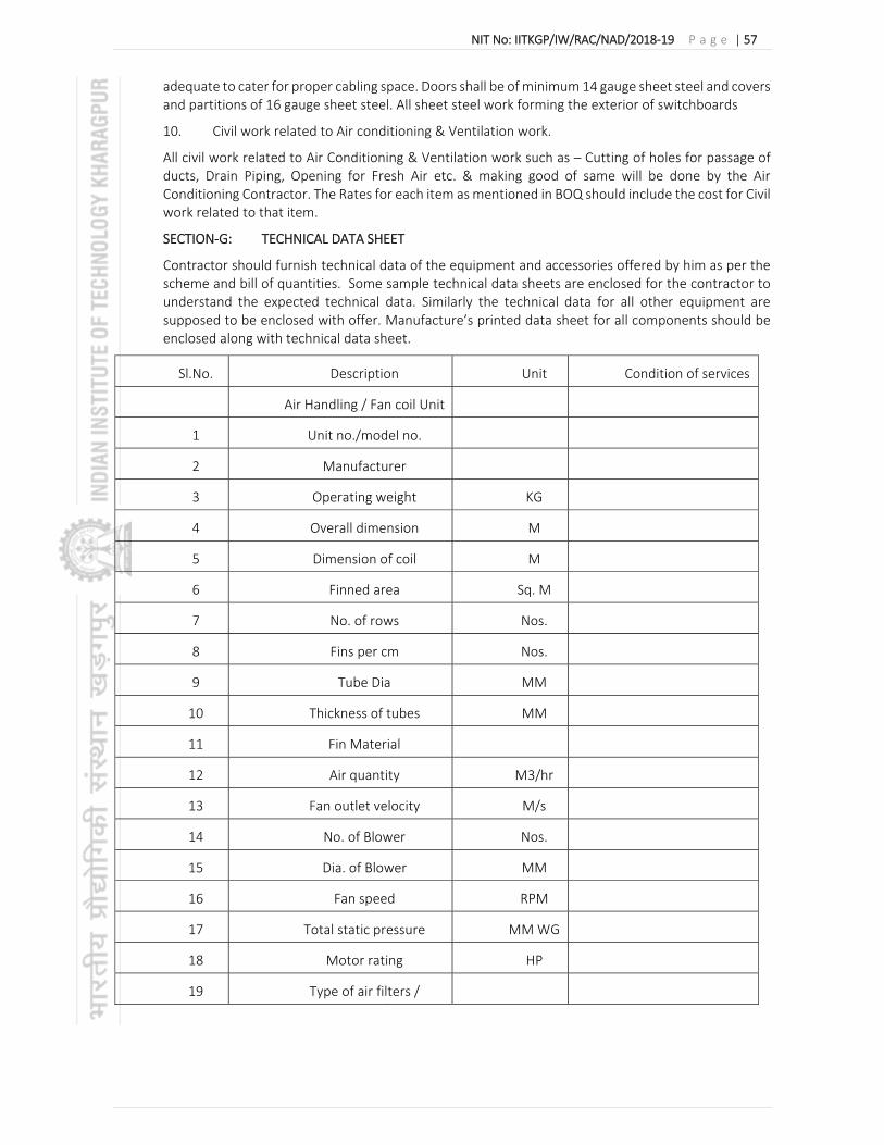
NIT No: IITKGP/IW/RAC/NAD/2018‐19 P a g e | 57
adequate to cater for proper cabling space. Doors shall be of minimum 14 gauge sheet steel and covers and partitions of 16 gauge sheet steel. All sheet steel work forming the exterior of switchboards
10. Civil work related to Air conditioning & Ventilation work.
All civil work related to Air Conditioning & Ventilation work such as – Cutting of holes for passage of ducts, Drain Piping, Opening for Fresh Air etc. & making good of same will be done by the Air Conditioning Contractor. The Rates for each item as mentioned in BOQ should include the cost for Civil work related to that item.
SECTION‐G: TECHNICAL DATA SHEET
Contractor should furnish technical data of the equipment and accessories offered by him as per the scheme and bill of quantities. Some sample technical data sheets are enclosed for the contractor to understand the expected technical data. Similarly the technical data for all other equipment are supposed to be enclosed with offer. Manufacture’s printed data sheet for all components should be enclosed along with technical data sheet.
Sl.No. Description Unit Condition of services
Air Handling / Fan coil Unit
1 Unit no./model no.
2 Manufacturer
3 Operating weight KG
4 Overall dimension M
5 Dimension of coil M
6 Finned area Sq. M
7 No. of rows Nos.
8 Fins per cm Nos.
9 Tube Dia MM
10 Thickness of tubes MM
11 Fin Material
12 Air quantity M3/hr
13 Fan outlet velocity M/s
14 No. of Blower Nos.
15 Dia. of Blower MM
16 Fan speed RPM
17 Total static pressure MM WG
18 Motor rating HP
19 Type of air filters / /

NIT No: IITKGP/IW/RAC/NAD/2018‐19 P a g e | 58
Sl.No. Description Unit Condition of services
Type & Make of
1 Electric starters
2 Electric switches
Sl.No. Description Unit Condition of services
Duct Insulation Make
Sl.No. Description Unit Condition of services
Supply air Diffusers/Grilles
1 Material
2 Face Velocity M/Min
3 Pressure drop across Supply air
diffusers/Grilles
4 Adjustable/fixed vol. Control dampers
5 Finish
Sl.No. Description Unit Condition of services
Return air Diffusers/Grilles
1 Material
2 Face Velocity M/Min
3 Finish
Sl.No. Description Unit Condition of services
Cables
1 Manufacturer
2 Type
3 Conductors
4 Insulation
5 Armour
SECTION‐H: LIST OF DRAWINGS
1. Schematic arrangement for CHW Piping layout IIT‐KGP/NA/HVAC‐03 –R00

NIT No: IITKGP/IW/RAC/NAD/2018‐19 P a g e | 59
ENVELOPE 3
BOQ WITH SCHEDULE OF RATES
Schedule of work (BOQ) for AC work at Nalanda Admin Building
Sl. Description Unit Qty Unit Rate
Amount
(Rs.) (Rs.)
1 Ceiling Suspended Double Skinned AHU:
Supplying, installing, testing and commissioning of double skin construction draw thru type CEILING SUSPENDED AIR HANDLING UNITS of Double Skinned AHUs each consisting of the following and having extruded Aluminum section frame construction, the coil shall be be placed on castor roll, Outer Skin with 0.6mm thick Pre-coated GI, Inner Skin with 0.6mm thick Pre coated /pre plasticized GI, Insulation with minimum 25mm thick PUF of density 40kg/ Cu. Mtr as per specification, each complete with following.
Supply air centrifugal forward/backward curved fan with efficiency >75%
Pre filter(MERV-8-90% down to 10 microns) in supply air stream.
Coil of copper tube and aluminum construction sized at maximum face velocity of 500 fpm and Filters shall be sized at maximum face velocity accross the filter shall be 350fpm.
Squirrel cage induction motor shall be shall be suitable for 415±10% volts, 50 cycles, 3 phase AC supply and shall be energy efficient having efficiency (IE 3) at full load ranging between 82.5% to 92% in accordance with motor rating as per specification.
Fan motor assembly (as whole) shall be statically and dynamically balanced to grade G 6.3 as per ISO-1940/AMCA 204-3.
Pre commissioning filters to be provided.
Fan belt drive package.
Vibration isolators.
Fan outlet velocity not exceeding 10 mps.
Minimum 20 mm (WC) external static pressure after sound attenuators(if required). Total static pressure of AHU shall be checked by Vendor.
All units shall be complete with opposed blade volume control dampers at oulet, return and fresh air connections. Duct flexible connector (fire proof) shall be provided at outlets and return connection of AHU.
The AHU to be selected that the noise level not to exceed 65dBA at 1.5meter distance from the AHU cabinet in all directions. To maintain the dB level attenuator shall be provided with AHU.
1.01 6,100CFM AHU (15.0 TR), 6Row Coil. Nos. 4

NIT No: IITKGP/IW/RAC/NAD/2018‐19 P a g e | 60
1.02 5,500CFM AHU (14.0 TR), 6Row Coil. Nos. 4
1.03 4,000CFM AHU (10.0 TR), 6Row Coil. Nos. 4
Note
CAS- Cassette Unit, CS-Ceiling Suspended Unit, FCU -Fan Coil Units
All air handling units to be provide with SS-304 end plates for coil.
All air handling units to be provided with 6 row cooling coil.
CSU AHU and CSU TFA shall be suitable for Ceiling Suspended .
The chilled water coil shall be suitable for CHW temperature are as follows:
CHW in : 44 Deg. F
CHW out : 54 Deg. F
All CS AHU's to be provided with additional tray covering the AHU and the valves. The tray will have 2 layers of 20 G GI sheet with 10mm thick nitrile rubber insulation sandwiched inbetween.The tray shall be of black colour powder-coated finish having one side drain .
The ceiling suspended AHU's shall be suspended with spring and neoprane in shear type hangers.
The AHU coil shall be selected considering ambient summer and mixing condition.
2 Cassette Units:
Supply, installation, testing and commissioning of CHILLED WATER CASSETTE TYPE units complete with three speed evaporator fan motor, fan, 3 row deep cooling coil, cleanable fabric filter and insulated drain pan enclosed in plastic casing complete with cord less remote control. Cassette unit shall be factory fitted with valve package comprising of pressure independent Balancing cum Control Valve with integrated 2 way motorized actuator in a single body for modulating operation suitable for static pressure of 1600 kPa and actuator shall be capable of withstanding 400 kPa shut off pressure, 24 V AC incoming power supply, ball valve with Y-strainer at inlet & Ball valve at outlet and necessary copper coil piping connections. The actuator of modulating valve shall be provided with interface cards to receive 0-10V or 4-20 mA signal from Digital Thermostat. All units shall be suitable for 220±6% volts, 50 cycles, single phase power supply.Cassette units shall be of following refrigeration capacities as listed.
2.01 2.0TR capacity - 800 CFM at low speed Nos. 25
2.02 1.0TR capacity - 400 CFM at low speed Nos. 6

NIT No: IITKGP/IW/RAC/NAD/2018‐19 P a g e | 61
Note :
Quoted price shall include the following:
a. Cost of the transformer (if any) and wiring to provide 24 Volt power 2 way Modulating Valve .
b. Cassette power wiring from power point with plug top will be in contractor’s scope.
.Control wiring for Transformer,Thermostat and Actuator with termination will be in Contractors scope.
d. The units are to be selected for both air flow and cooling capacity considering ambient summer condition taking derating into account.
4 Thermostat for Cassette unit:
Supply, installation, testing and commissioning of COOLING THERMOSTAT for various Cassette and fan coil units as described in specifications. The thermostat shall be proportionatory type for modulating 2 way valve with digital temperature indicator.
No. 31
Proportional cooling thermostat Cassette.
Note: The actuator shall be controlled by Building Automation System & should accept a signal of 4–20mA/ 2–10 VDC
5 UPVC Condensate Drain Piping:
Providing and fixing in position the following U-PVC pipes with 13 mm thick nitrile rubber insulation cut to required lengths and installed with all screwed joints, and providing and fixing in position the necessary elbows, tees and reducers as per specifications for AHU / Cassette drain.
5.01 32mm dia RMT 150
5.02 25mm dia RMT 300
6 Chilled Water Piping:
Supply, installation, testing and commissioning of following MS ERW heavy class pipes thickness as per IS3589/1239 cut to required lengths and installed with all welded joints. Providing and fixing in position the necessary fittings like elbows, tees, reducers, hanging arrangements including vibration isolation arrangements,painting etc. as required. Price to include for water balancing and commissioning. All Nut bolts to be of GI / Hot dipped galvanised only.
6.01 100mm dia Heavy Class MS Pipe. RMT 290
6.02 80mm dia Heavy Class MS Pipe. RMT 90
6.03 65mm dia Heavy Class MS Pipe. RMT 158
6.04 50mm dia Heavy Class MS Pipe. RMT 90

NIT No: IITKGP/IW/RAC/NAD/2018‐19 P a g e | 62
6.05 40mm dia Heavy Class MS Pipe. RMT 42
6.06 32mm dia Heavy Class MS Pipe. RMT 168
6.07 25mm dia Heavy Class MS Pipe. RMT 370
6A Chilled water underground HDPE Pipe
Supply, installation, testing and commissioning of following Burried 100 mm dia HDPE pipe (Schdule8 ). HDPE pipe shall be with jointing kit with Excavation, backfilling . The depth shall be 1.5 mtr. Providing and fixing in position the necessary fittings like elbows, tees, reducers, hanging arrangements including vibration isolation arrangements,painting etc. as required. This item shall include the cost of excavation , sand bedding , back filling and pedestal required for pipe. The insulation for the pipe has to be quoted in line item no. 8A
RMT 72
Note:
a)The above pipe under item no. 6A shall include the cost of Excavation of trench (Trench: 1.5 m x 1.5m)
b)150 mm depth Sand Bedding for pipe laying
c)PCC pedestal (1:3:6) for pipe (1200 x 150 x 200mm- 250 nos)
d)Backfilling of trench
7 Motorised 2way on/off type Pressure indepndent control Valves for AHU:
Supply, Installation, testing and commissioning of Pressure independent type 2 way Balancing and modulating Control valves in a single Unit of Valve with PN16 Rating. DN 15 to DN 32 Brass Body. DN 40 & above shall be Grey Iron or cast iron Body with flanged Ends Connection Duly mounted with Modulating actuator IP40 or above suitable for 24V AC. The actuator shall be equipped to transmit a transduced flow feedback signal in 4-20 mA format to the BMS. Valve shall be selected for maximum water flow rate of AHU. Wiring shall be included.
7.01 50mm dia No. RO
7.02 40mm dia No. 8
7.03 32mm dia No. 4
8 Insulation on Chilled Water Piping & Drain Piping:
Supply, installation and testing of 25/32 mm thick nitrile rubber class "O" self adhesive type insulation with protective coating on chilled water pipes and fittings like valves, flanges and unions, etc. as per approved shop drawings and specifications.For Shaft/ Risers - 24 G Al CladdingOther Horizontal run - Al foil facing
8.01 32 mm thick insulation on 100mm dia MS Pipe. RMT 290
8.02 25 - mm thick insulation on 80mm dia MS Pipe. RMT 90

NIT No: IITKGP/IW/RAC/NAD/2018‐19 P a g e | 63
8.03 25mm thick insulation on 65mm dia MS Pipe. RMT 158
8.04 25mm thick insulation on 50 mm dia MS Pipe. RMT 90
8.05 25mm thick insulation on 40mm dia MS Pipe. RMT 42
8.06 25mm thick insulation on 32mm dia MS Pipe. RMT 168
8.07 25mm thick insulation on 25mm dia MS Pipe. RMT 370
8A Insulation on Chilled Water burried Piping:
CHILLED WATER PIPING: Supply & erection PUF insulation on chilled water pipe of 100mm thick having K value of 0.018 W/mK at mean temperature of 10 degree C, and of density not less than 40 kg/Cum for chilled water piping with 500G polythene sheet covered with 24g x 19mm GI mesh tying with 16G GI lancing wire with 2layers of 6mm thick sand cement plastering and tarfelt. All Nut bolts to be of GI / Hot dipped galvanised only.
Insulated buried pipes shall be cleaned, de-rusted, then coated with rust-resistant primer and placed on concrete blocks with PUF saddles dipped in bitumen at every 2 meters. Insulation shall be applied as per the section “Insulation”, wrapped with GI wire and covered with polyethylene sheet. Two coats (each 6 mm thick) of cement plaster shall be applied over chicken wire mesh lath. Where indicated in Schedule of Quantities, buried insulated pipes shall be water-proofed using coat of Shalibond, or approved adhesive, over the plastered surface; wrapping one layer of fiber glass RP tissue and one layer of roofing tar felt with sufficient overlaps, set and sealed with the adhesive, held in position by 16 gage G.I wire tied at 15 cm intervals. Price to include for earth work escavation, back filling & PCC pedestal etc for laying the MS pipes as per spec.
100 mm thick insulation on 100mm dia HDPE Pipe (burried). RMT 72
9 Valves & Strainers:
Supply, installation, testing and commissioning of following Valves & Strainers along with necessary fittings for the Condenser & Chilled Water Piping:
Supply, installation, testing & commissioning of approved make Slim seal Butterfly valves wafer type with cast iron body, SG iron disc – NYLON Impregnated, Black Nitrile rubber liner, suitable for mounting between pipeline flanges, lever with insulation as specified above like valves, with companion flanges & unions and hardware of PN 16 rating etc. of chilled water system as per the approved shop drawings & specifications
9.01 200mm dia Butterfly Valves. No. RO
9.02 100mm dia Butterfly Valves. Nos. 4
9.03 80mm dia Butterfly Valves. Nos. 4
9.04 65mm dia Butterfly Valves. Nos. 12
9.05 50mm dia Butterfly Valves. Nos. 16
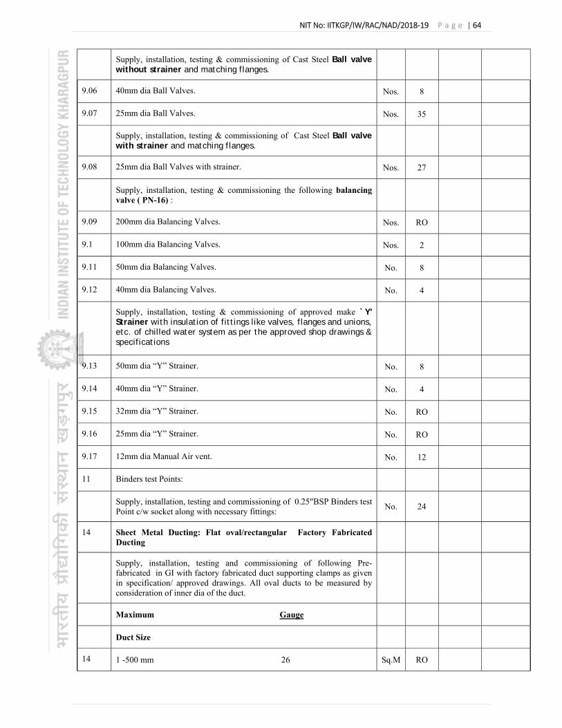
NIT No: IITKGP/IW/RAC/NAD/2018‐19 P a g e | 64
Supply, installation, testing & commissioning of Cast Steel Ball valve without strainer and matching flanges.
9.06 40mm dia Ball Valves. Nos. 8
9.07 25mm dia Ball Valves. Nos. 35
Supply, installation, testing & commissioning of Cast Steel Ball valve with strainer and matching flanges.
9.08 25mm dia Ball Valves with strainer. Nos. 27
Supply, installation, testing & commissioning the following balancing valve ( PN-16) :
9.09 200mm dia Balancing Valves. Nos. RO
9.1 100mm dia Balancing Valves. Nos. 2
9.11 50mm dia Balancing Valves. No. 8
9.12 40mm dia Balancing Valves. No. 4
Supply, installation, testing & commissioning of approved make `Y' Strainer with insulation of fittings like valves, flanges and unions, etc. of chilled water system as per the approved shop drawings & specifications
9.13 50mm dia “Y” Strainer. No. 8
9.14 40mm dia “Y” Strainer. No. 4
9.15 32mm dia “Y” Strainer. No. RO
9.16 25mm dia “Y” Strainer. No. RO
9.17 12mm dia Manual Air vent. No. 12
11 Binders test Points:
Supply, installation, testing and commissioning of 0.25"BSP Binders test Point c/w socket along with necessary fittings:
No. 24
14 Sheet Metal Ducting: Flat oval/rectangular Factory Fabricated Ducting
Supply, installation, testing and commissioning of following Pre-fabricated in GI with factory fabricated duct supporting clamps as given in specification/ approved drawings. All oval ducts to be measured by consideration of inner dia of the duct.
Maximum Gauge
Duct Size
14 1 -500 mm 26 Sq.M RO

NIT No: IITKGP/IW/RAC/NAD/2018‐19 P a g e | 65
14 501 -1200 mm 24 Sq.M 1255
14 751 - 900 mm 24 Sq.M RO
14 901 - 1200 mm 24 Sq.M RO
14.1 1201 - 1500 mm 22 Sq.M 1299
14.1 1501 - 1800 mm 22 Sq.M RO
14.1 1801 - 2100 mm 20 Sq.M 50
14.1 2101 - above 18 Sq.M 355
15 Grilles, Diffusers & Dampers:(Measurement in Neck to Neck size only )
Supply, installation, testing and commissioning of following Grilles, Diffusers & Dampers.
15 Powder Coated Extruded Aluminum Diffusers without VCD. Sq.M 14
15 Powder Coated Extruded Aluminum Double Louvered Grilles without VCD.
Sq.M
15 Powder Coated Extruded Aluminum Grilles without VCD. Sq.M 15
15 GI Volume Control Damper for Grilles/ Diffusers. Sq.M 15
15.1 Fusible link type GI Fire Damper. Sq.M 11
15.1 Fusible link for Fire Damper. Nos 18
15.1 GI Volume Control Duct Damper. Sq.M 11
15.1 Fresh Air Intake Louver Sq.M 13
16 Duct Insulation:
Supply, installation, testing and commissioning of following insulation for the Sheet Metal Ducting.
16 Thermal insulation on the Sheet Metal Duct with Al. Foil Faced Class "O" 19 mm thick Closed Cell Nitrile Rubber. Sq.M 300
16 Thermal insulation on the Sheet Metal Duct with Al. Foil Faced Class "O" 13 mm thick Closed Cell Nitrile Rubber.
Sq.M 25
16 Acoustic insulation with 10mm thick Open Cell Nitrile Rubber. Sq.M 195
17 Underdeck Insulation:

NIT No: IITKGP/IW/RAC/NAD/2018‐19 P a g e | 66
UNDER DECK INSULATION with 50 mm thk TF quality expanded polystyrene (20 kg/m3) stuck with cprx, GI screws and washers and GI wire.
Sq.M RO
18 Electrical Panel Board:
Supply, installation, testing and commissioning of following Wall Mounted AHU Starter Panel Board.
AHU Starter Panel Board consisting of following AHU starter cum control panel wall/floor mounted IP-55 protected factory fabricated with mim 2mm thick sheet steel, with copper bus bars, complete with incoming& outgoing MCB, switchgear/ mountings cable terminations, interconnections, on/off starters, incation lamps (on/off/trip) as required for 415Volts, 3phase, 4wire 50Hz AC supply suitable for 35MVA rupturing capacity ratings of switch gears etc. of incoming& outgoing feeders for AHUs. The provision for power supply for 2way motorised valve shall be considered in the panel.
18.1 Panel at Gr floor (For 15TR AHU-2nos & 1spare) No. 1
18.2 Panel at 1st floor (For 15TR AHU-2nos & 1spare) No. 1
18.3 Panel at 2nd floor (For 10TR AHU - 4nos & 1spare) No. 1
18.4 Panel at 3rd floor (14TR-4nos & 1spare) No. 1
18.5 Local push button for each AHU Nos. 12
18.6 16 A power socket with Plug top and isolation switch Nos. 31
19 Power & Control Cabling:
Supply, Laying, connecting and commissioning the following 1.1KV Grade ARMOURED AYFY/YFY/YWY cables with necessary clamps screws etc. and the cables shall be laid in trench/clamped along wall/column/laid in cable tray etc(the rates inclusive of suitable clamps, screws etc but exclusive of cable tray complete.
19.1 4 Core 6 Sq.mm Cu. Power Cable for AHUs+2 Core 6 Sq.mm Cu. Earth Wire for AHU
RMT 280
19.2 3 Core 2.5 Sq.mm Cu. Power Cable for Cassette Unit RMT 270
19.3 3 Core 1.5 Sq.mm Cu Control Cable. RMT 250
19.4 1 Core 1.5 Sq.mm Cu Cable for Cassette Unit RMT 1900
19.5 8G GI Wire for Earthing. RMT 500
20 Cable Tray for Power & Control Cabling:
Supply and installation of the following Hot dip Galvanized Cable Tray from the new Electrical Panel Board to various equipment’s.
20 300mm width X 25mm depth X 1.6mm thick RMT 90

NIT No: IITKGP/IW/RAC/NAD/2018‐19 P a g e | 67
20 200mm width X 25mm depth X 1.6mm thick RMT RO
20 150mm width X 25mm depth X 1.6mm thick RMT 120
21 Supply, installing, testing and commissioning of ceiling mounted AIR COOLED SPLIT TYPE Hi Wall AIR CONDITIONING UNITS air-conditioning units indoor unit comprising pre-filter, fan section and DX coil section housed in a powder coated galvanized steel enclosure, and low gas detection system and outdoor unit complete with scroll/rotary/reciprocating type compressor, Condenser fan and motor and coil enclosed in powder coated sheet metal cabinet.Prices quoted under installation shall be inclusive of stabilizer,pressure testing and commissioning of the air-conditioning system with topping up of CFC free gas,copper piping( consider distance of 15 meter between indoor and outdoor unit), power wiring from control panel to outdoor/indoor unit and control wiring between indoor and outdoor units and necessary MS frame work or civil pedestals for outdoor units made out of M25 grade cement concrete with necessary re-enforcement. Capacities shall be as follows: The unit capacities shall be after taking deration into account due to copper piping lengths. The unit shall be 5 star rated as per BEE level 2018 (for small units only).
1 TR Nominal Nos. 5
1.5 TR Nominal Nos. 5
2 TR Nominal Nos. 5
HVAC related to Civil work
22 Dismantling old plaster or skirting raking out joints and cleaning the surface for plaster including disposal of rubbish to the dumping ground within 50 metres lead.
sqm 9.00
23 Demolishing brick work manually/ by mechanical means includingstacking of serviceable material and disposal of unserviceable material within 50 metres lead as per direction of Engineer-in-charge.In cement mortar
cum 2.50
24 (ii)15 mm cement plaster on rough side of single or half brick wall of mix:1:6 (1 cement: 6 sand)
sqm 17.00
25 Dismantling aluminium/ Gypsum partitions, doors, windows, fixed glazing and false ceiling including disposal of unserviceable surplus material and stacking of serviceable material with in 50 meters lead as directed by Engineer-in-charge.
sqm 300.00
26 Supplying fitting & fixing concealed False ceiling Framework with G.I. Section (perimeter channels having one flange of 20 mm. and another flange of 30 mm. with thickness of 0.55 mm. and web of length 27 mm., along the perimeter of the ceiling, screws fixed to the wall with help of nylon sleeves or PVC dash fastners@ 610 mm c/c. then suspend G.I. intermediate 'C' section with web 90 mm. and flanges of 15 mm. each from soffit @ 1200 mm c/c with ceiling angle of size 25 mm. X 10 mm. X 0.55 mm. fixed to soffit G.I. Cleat and Steel expansion fasteners. Ceiling section of 0.55 mm. thickness having web of 51.5 mm. and two flanges of26 mm. each with lips of 10.55 mm., are then fixed on to the intermediate channel with the help of connecting clips in the direction perpendicular to the intermediate channel @ 610 mm c/c) with fully threaded fiber cement
Sqm 300.00

NIT No: IITKGP/IW/RAC/NAD/2018‐19 P a g e | 68
screws @ 300 mm c/c.all complete as per the drawing and direction of Engineer-in-Charge. Section specification :- Perimeter Channel :- 30 mm X 20 mm X 27 mm, thickness 0.55 mm (min), Intermidiate Channel :- 15 mm X 90 mm, thickness 0.90 mm (min), Ceiling Section :- 51.5 mm X 26 mm X 10.55 mm, thickness 0.55 mm (min), Ceiling Angle :- 25 mm X 10 mm, thickness 0.55 mm (min).
27 Supplying ,fitting & fixing Eco-friendly, Water Resistance and Incombustible Calcium Silicate board/tiles (Density >900 Kg per Cu.m.) of approved design and brand finished with calcium silicate jointing compound to form a joint less false ceiling all complete as per drawing & direction of Engineer - in- Charge. False ceiling with 8mm thick square edged Calcium Silicate Board
Sqm 300.00
28 Wall painting with acrylic emulsion paint, having VOC (Volatile Organic Compound ) content less than 50 grams/ litre, of approved brand and manufacture, including applying additional coats wherever required, to achieve even shade and colour.Two coats
Sqm 70.00
29 Providing and applying white cement based putty of average thickness 1 mm, of approved brand and manufacturer, over the plastered wall surface to prepare the surface even and smooth complete.
Sqm 70.00
Quoted Price shall be Inclusive of GST@18%
Total