IEPC-95-150 (I) -eiconal T - Electric Rocket Propulsion Society
7
IEPC-95-150 l . ' p.- ,h d ,i ; : ; . :sii plurn t- :ind p :i',,( lm ids of 'IectriL thrustlcr.s. - -[ - abdullin V i (larki-.usl ;: -\ t; KorsuI 1-. M i\crdokhlchboi ' The radio effects of exhausts plumes of stationary and pulsing plasma thrusters is analyzed. Plasma artificial formations (PAF) is a typical result of electric thrusters operation. Even radio tranparent PAF may present a senous obstacle to the communication, navigation and observation for certain orientation. Numerical calculation methods are developed, which makes it possible to prognosticate the shape of a radio shadows produced by PAF .Calculation results are presented for two type of radio wave: plan and sphencal. Nomenclature (I) -eiconal e - dielectric permeability ? - waves length n - electron concentration z,r - Cartenzian coordinates p - magnetic permeability ) - angle between radiation direction and PAF axis B - induction of magnetic field U - flow velosity a,l - cross and longitudinal size of PAF m,e - electron mass and charge s - variable parameter T - average plasma temperature k - wave number Introduction Plasma jets and plasmoids generation close to spacecraft vicinity is a typical enviromients produced by the electric propulsion (EP) during its operation Plasma plume impacts on the transmission / receiption of commun cations signa. in- space were recognized to be one of the cnticnlCa spaCecraft integrl tion i<u , flor satellit in!ustrv and are of prima:u Importance to user comini :,it l'i ::me ,:gnaturc t ;na!'ses performed uindc the nulmber (! recent l P pi;.gra,n. - >,in\Vi th! 11 p lume effect on c.mir'.in cations link. woui . be pic .. L !\ ; i i ti There are. howc' -r. some additional issues resulted fr,-;: consideration of a plasmC c\'aust ni;'on in space. which as authors beleive. should be analyzed *TSNIIASH . KMilinr!j Moscow region. Russia. i
-
Upload
khangminh22 -
Category
Documents
-
view
1 -
download
0
Transcript of IEPC-95-150 (I) -eiconal T - Electric Rocket Propulsion Society

IEPC-95-150
l . ' p.- ,h d ,i ; : ; .:sii plurn t- :ind p :i',,( lm ids
of 'IectriL thrustlcr.s.
--[ - abdullin V i (larki-.usl ;: -\ t; KorsuI 1-. M i\crdokhlchboi '
The radio effects of exhausts plumes of stationary and pulsing plasma thrustersis analyzed. Plasma artificial formations (PAF) is a typical result of electricthrusters operation. Even radio tranparent PAF may present a senous obstacleto the communication, navigation and observation for certain orientation.Numerical calculation methods are developed, which makes it possible toprognosticate the shape of a radio shadows produced by PAF .Calculationresults are presented for two type of radio wave: plan and sphencal.
Nomenclature
(I) -eiconale - dielectric permeability
? - waves lengthn - electron concentrationz,r - Cartenzian coordinates
p - magnetic permeability) - angle between radiation direction and PAF axis
B - induction of magnetic fieldU - flow velositya,l - cross and longitudinal size of PAFm,e - electron mass and charges - variable parameterT - average plasma temperaturek - wave number
Introduction
Plasma jets and plasmoids generation close to spacecraft vicinity is atypical enviromients produced by the electric propulsion (EP) during itsoperation Plasma plume impacts on the transmission / receiption ofcommun cations signa. in- space were recognized to be one of the cnticnlCaspaCecraft integrl tion i<u , flor satellit in!ustrv and are of prima:u Importanceto user comini :,it l'i ::me ,:gnaturc t ;na!'ses performed uindc the nulmber (!recent l P pi;.gra,n. - >,in\Vi th! 11 p lume effect on c.mir'.in cations link.woui . be pic .. L !\ ; i i ti
There are. howc' -r. some additional issues resulted fr,-;: consideration ofa plasmC c\'aust ni;'on in space. which as authors beleive. should be analyzed
*TSNIIASH . KMilinr!j Moscow region. Russia.
i

Ie 'IIi~on. and esini.;!io; o: a PAi ia thinc, ti- spli&2p;ri, Uni
equi: pincii 121N ,eirh\ satellict area parameters are beine ch: an sjigniican , \\ hile
electric propulsion s\witchin-on The local level of electron density is increasedon some orders in comparison \ith ionosphere background, and the distributionof one is described by three dimension nonlinear law. It was shown in work [1]that the configuration of plasma plumes is very specific. For example the plasmalet of stationary plasma thrusters can have either axial symmetric form orpetal"-type one close to spacecraft. During operation of pulsed plasma thusters
close to spacecraft there is a series of a plasmoids. each of which has "kneetingneedle" form oriented along the Earth magnetic field lines. It should be noted,when we speak about the form of PAF we mean configuration limited byconcentration level condition n=const. For correct prediction how PAF of anyform will affect on the radio wave propogation it is necessary to knowmathematical model of plasma plume expansion into vacuum Beforeproceeding with eventual description of present paper it is the desirable toconsider the above phenomena in the next section.
Accepted model of a plasma plume expansion
In work [4] it is shown that at initial expansion stage (first stage), whennternal kinetvc flow pressure nyT exeeds external pressure of magnetic field
/i /s- , the expansion of plasma jets and plasmoids into vacuum is defined byan internal self-agreed E-field. The ions are accelerated by this fieldpredominary in directions appropriate maximum significances of gradients(across narrow jet, along a direction of a thermal flow , etc.). As a result thedensity of a substance in peripheral part.of a flow appears to be greater than inI ideal gases. The isoconcentral surfaces have axial symmetry. Its form isdetermined by input flow parameters in particular by divergency angle. If thisangle is small the PAF has extended form and its longitudinal size more thancross one > a.
The next expansion stage (second stage) is characterized by reduction ofk.netyc pressure of a plasma. It concerns to far rarefied flo\w zone where, n" l10' cm- '. Here heomagnetic field B essentialy changes the currentcharacter: one-dimensional inertial expansion proceeds along a manetic lineand slo\\ diffusion of pl.m;a in a m:agnetic field occurs ;in a cross direcion. Ihei.oconcentrales form for this stage is defined by a pitcl-a.i:le ianale b-\teen a\.'to10 of flo\w elocity I and vector of a induction ,,! ; r:nmanetic field I' I At..- , pitch-angles a jets and plasmoids have the o,,, n of strongly c\ icndedalon, B needles the lon'itudinal size of which is much more than cross one/ -- :.If pitch-angle equals - 2 et accepts the "petal" form (Fig.2a.b) flattenedIv pondermotor fc:es. The plane of such petal is parallel to vectors t and B.
I
Piasmou- Ithi: a n initial stage acquire the e\icnded lorm with miain a\isdirected acrks) magnetic field B are also translormd to pctal, flattened acrossBI (I L - J
Problem tormulati on
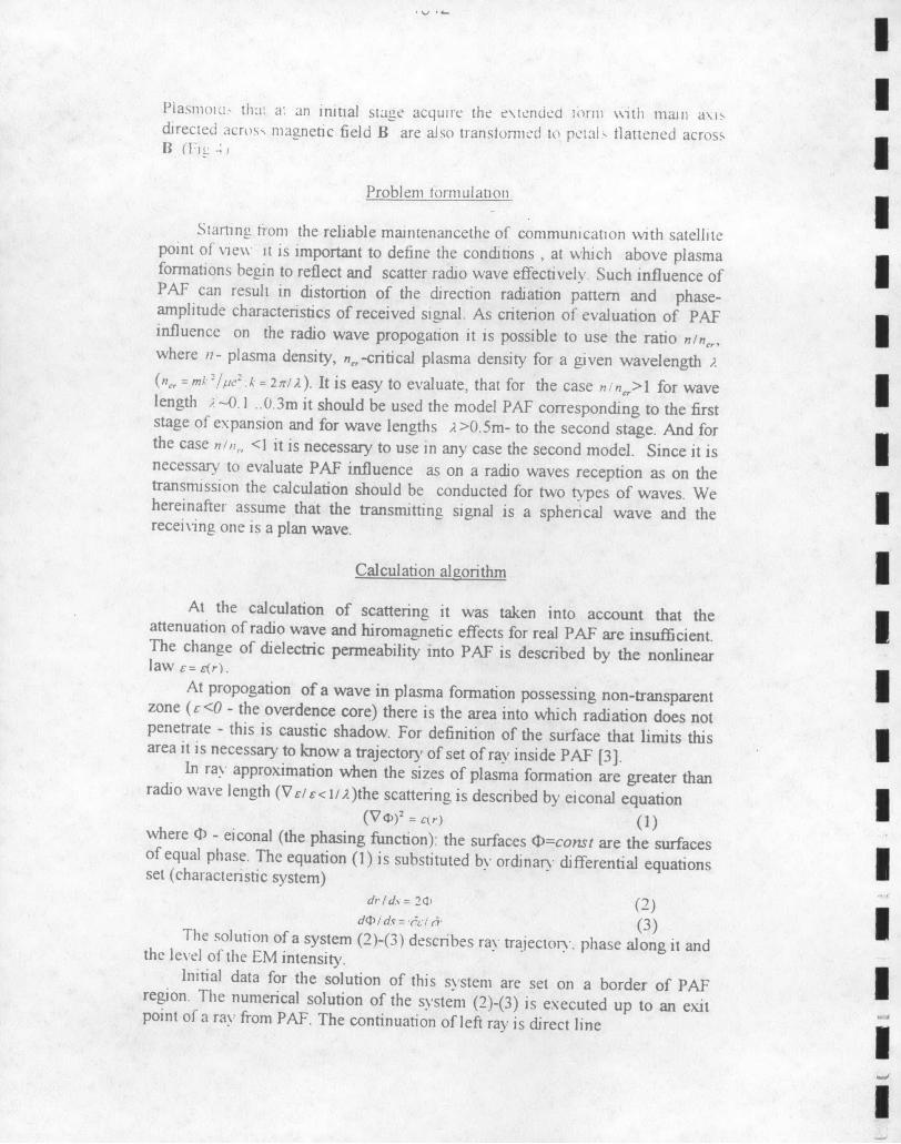
Starting from the reliable maintenancethe of communication with satellitepoint of 'xe\\ it is important to define the conditions , at which above plasmaformations begin to reflect and scatter radio wave effectively. Such influence ofPAF can result in distortion of the direction radiation pattern and phase-amplitude characteristics of received signal. As criterion of evaluation of PAFinfluence on the radio wave propogation it is possible to use the ratio n/in,,where n- plasma density, n,,-critical plasma density for a given wavelength ;(n,,, = mi/ :.- .k = 2 n/). It is easy to evaluate, that for the case n/ n,>1 for wavelength --. I ..0.3m it should be used the model PAF corresponding to the firststage of expansion and for wave lengths A>0.5m- to the second stage. And forthe case ,/,, <1 it is necessary to use in any case the second model. Since it isnecessary to evaluate PAF influence as on a radio waves reception as on thetransmission the calculation should be conducted for two types of waves. Wehereinafter assume that the transmitting signal is a spherical wave and therecei\ing one is a plan wave.
Calculation algorithm IAt the calculation of scattering it was taken into account that the
attenuation of radio wave and hiromagnetic effects for real PAF are insufficient.The change of dielectric permeability into PAF is described by the nonlinearlaw c= cr).
At propogation of a wave in plasma formation possessing non-transparentzone (c <0 - the overdence core) there is the area into which radiation does notpenetrate - this is caustic shadow. For definition of the surface that limits thisarea it is necessary to know a trajectory of set of ray inside PAF [3].
In ray approximation when the sizes of plasma formation are greater thanradio wave length (Vi/< i/;)the scattering is described by eiconal equation
(V) 2 :r) (I)where 0 - eiconal (the phasing function): the surfaces ?Q=const are the surfacesof equal phase. The equation (1) is substituted by ordinary differential equationsset (characteristic system)
dr/d. = 20, (2)d ,Dl-v l/ei. (3) j
The solution of a system (2)-(3) describes ray trajectorv. phase along it andthe level of the EM intensity.
Initial data for the solution of this s\stem are set on a border of PAFregion. The numerical solution of the system (2)-(3) is executed up to an exitpoint of a ray from PAF. The continuation of left ray is direct line
II

11 no\\ pass a section through whole set of left ray, w\e shall receivc a Lcontou 0ocaustic shado\\ On fig I the cross sections of caustic surface arc sihon\ asexample
3 In many real cases the radio wave scattering goes on the rarefiedperiphery of PAF when electron density less than critical one. It is allies, atfirst, to the sizes of these PAF witch , as a rule, make hundreds and thousandsof wave lengths . Therefore even a small deviation results on such distances tothe marked difference between initial and final trajectory of a ra\ And,secondly, such strongly extended or flattened three-dimensional PAF. when
i/c.<a,/i-(z I B, rB ), have sharp angular anisotropy of the scatteringcharacteristics. So, even radio transparent plasma formation creates the "half-shadows" area ( area where intensity of propagated signal is less on someorders than its initial value) for radio waves, which propagate by a small anglee, to a magnetic field. The form of scattering surface in this case is determinedapproximately by the ratio:
n = n,,-sinr e, < n, (5)
Calculation results.
On figs. 1 - 4 examples of radio shadows calculation are shown . Theseshadows are formed as a result of plan radio wave scattering on the PAF. Suchwave is formed if the direction of wave propagation to be fixed and coordinatesthe point of entrance to be varied.
On fig. I it is indicated a example of calculation the caustic surface. Thissurface is arised as a result of plane wave scattering on axis symmetry plasmajet (first stage expansion). The calculation is executed for three directions ofpropagation : 0",30 and 600. Some cross sections of caustic surface are shownon the bottom of figure. Linear sizes are given in the units k-'. From the figureit is visible that even small plasma jet with axis symmetrical overdence corecreates the caustic shadow of an asymmetric configuration and the size that isin several times greater than sizes of core.
On fig. 2 it is cited an example of calculation of the plane wave scatteringon "petal"-type PAF. On fig. 2 a-c three sections of a petal are shown. On thesurface such petal the ratio n=n,, ,cos' ,. is true . The radio waves are incidenton plasma jet at angle e, to "petal" at the XOY plane. Fig 2c shows the raypath pattern for plane wave incident at a small angle relative to the plane ofpetal. The final intensity distribution is shown in fig.2d. Behind transparentplasma petal with thickness about tens X there is shadow region with dimensionabout hundreds X. In fiont of petal there is radio wave interference themaximums of which corresponds to value of scattering signal intensity more inseveral times than initial intensity.
I

l'i 3 and 4 represents typical ray path patern of plan w\ave scattering on
plasmoids. The wave is incident on plasmoid at a angle e, to the axis OY. The
plasnmlid dimensions are given for testy calculations, where , - totalpanicles number, t - time from beginning of plasma expansion. Plasmolds onfig S3.b have round section. On fig. 3 a plasma is radio transparent: the
calculation is conducted for a wave length /k= 0.2 m.. In this case behind PAFthere is the "half-shadow" area. And on fig. 3b the calculation is conducted for
X=0.7 m.. For this wave length PAF has the overdense core that creates acaustic shadow. Flattened transverse to B plasmoids are represented on fig. 4.Their cross section has the ellipse form. The ray path patterns are given for twovariants: in the plane XOY ( fig. 4 a), and in the plane YOZ ( fig. 4 b). In bothcases PAF is radio transparent but at inclined incident it creates extensiveregions with low EM intensity.
On Fig. 5 and 6 there are submitted the examples of calculation the radioshadow arising when spherical wave is scattered on plasma formations. In thiscase the incident of set of rays to be formed by variation the angle of raydirection at the fixed coordinates of a radiation source The electronconcentration is less than critical one in both figures. Fig. 5 shows a ray pathpattern into plasma jet (second stage expansion) and angular distribution ofrelative intensity of onboard dot source radiation.
Fig.6 illustrates the calculation result of scattering a spherical wave on threeplasmoids. The testies accounts are conducted for a plasmoids with n/n,,=0.25.Plasmoids, each of which is characterized l/a=10, distant on 10m from a radiationsource. Behind them a section of a circle is choosed on a sphere with radius r=10km.The radiation intensity distribution is shown on Fig.6 for this line. The distancealong this line laid off as abscissa. The attenuation of radiation intensity 1/10 laid offas ordinate. The zero value of /llI corresponds to a principal mode; the gaps in theradiation pattern - a radio shadows; the sharp "wings" - a focusing of the scatteringrays. It is visible from the Figure that the radio perturbation zone takes about 25km. Itis hence possible to generalize that even the small series of three plasmoids essentialydeforms the principal radiation mode.
Conclusion.
Thus, it is visible, that even rather rarefied plasma formations, arisingnearby satellite as a result of electric propulsion operation , can significallyinfluence on direction radiation pattern of onboard VHF or SHF radio bandtransintter-receiver.
Reference1 B S.Borisov, V.I.Garkusha, N.V.Kozyrev, A.G.Korsun, L.Yu. Sokolov, V.A.Strashinski. The
Influence of Electric Thruster Plasma Plume on Downlink Communication in Space Experiments.AIAA paper 91-2349.
2 James S.Sovey, Lynnette M.Carney, Steven C.Knowles Electromagnetic Emission ExperiencesUsing Electric Propulsion Systems. Journal of Propulsion,vol.5, No 5, pp 534-547.
3 F.F Gabdullin, V.I. Garkusha, A.G. Korsun, E.M.Tverdokhlebova Radio Wave Refraction inExhaust Plasma Plumes. 23 rd IEPC - 93 -144
4 A G Korsun. Transverse expansion of electric thrnsters plasma plumes and plasmoids. 24rdIEPC-05-SO
'I

/ I 0i,2 -
I.0
"'~~ 'i I i i ..2 0:
Et 00 /Ab 20 J70Y MUit 5UO - y b) d)
-, -; - 'I,
I00 6000 Shadow
O - r/r .= r0e,
/ / 1 Ci~lOil
.1l plan cr . Jtcni
SCD
IL
a e scattcn ngIC
It
IIN -.
011 ;MS Sy ncrCpam iab
IIOil" l\ y"hlflctlcr piasmoid
)/.=0211 b,)=07m I -l
I~ 0)

3 4 ,..0 2, 1 I~r~I'2 I
- I
10 00
e.ou ;d iItn.t
X th Ie
4 fmid