Identification Data Salient Features - Bajaj Boxer BM 150
84
Dealer Development Center 2 Dealer Development Center 1 The Engine and Frame serial numbers are used to register the vehicles. They are the only means of identifying your particular vehicle from the other of the same model and type. These serial numbers may be needed by your dealer when ordering the parts. In the event of theft, the investigating authorities will require both these numbers in addition to the model, type and any special features of your vehicle that can help identifications. Location of Parts 1 2 3 4 5 6 7 8 Pulsar DTS-i UG-III-180cc Training Notes Pulsar DTS-i UG-III-180cc Training Notes 1. Control Switch RH 2. LCD Speedo Console 3. Control Switch LH 4. Body Control Unit (Placed inside Head Light fairing) 5. Hall Sensor for Indicator 6. Vehicle Speed Sensor 7. ExhausTEC 8. Tail Light LED display Refined engine power delivery by optimization of Exhaus TEC location and revised ignition timing with intelligent CDI New clutch & revamped gear shifting mechanism that gives smooth, positive, virtually friction-free gear shift feel New Bigger twin foam filter with an optimized intake system to provide better torque Optimized valve timing and Roller rocker with NR bearing for friction reduction that improves drivability. LED tail lamp that consumes negligible power & require zero maintenance Stainless steel silencer that overcomes rusting problem All sensor type electrical switches that enables switches to function for the life of the bike. Absolutely no maintenance in absence of mechanical contacts. Performance : Style : Stylish fairing and head lamp assembly with owleye A new black mask that separates headlamp from parking lights adds to aesthetics. Clear lens indicator with amber bulbs. New age, sharp and attractive 2 Row Tail lamp with LED lights New seat cowl to match stylish LED tail lamp. Louver type LH & RH covers with wire mesh gives sturdy look. Ergonomically designed self-letting switches Convenience and Comfort LCD Speedo Console with digital fuel gauge (12 level indicator) Digital speed display, odometer and two trip meter with resetting provision. Self-canceling indicators After completion of turn, the indicator will be switched off automatically. Engine oil level window for easy to monitor level. Maintenance free battery once a year electrolyte top up. In addition to Fuel gauge, Reserve indicator bulb is provided that glows continuously till the petrol filled to main level. Self check provision for Tachometer for its functioning Identification Data Salient Features
-
Upload
khangminh22 -
Category
Documents
-
view
3 -
download
0
Transcript of Identification Data Salient Features - Bajaj Boxer BM 150

Dealer Development Center2
Dealer Development Center1
The Engine and Frame serial numbers are used
to register the vehicles. They are the only
means of identifying your particular vehicle
from the other of the same model and type.
These serial numbers may be needed by your
dealer when ordering the parts. In the event of
theft, the investigating authorities will require
both these numbers in addition to the model,
type and any special features of your vehicle
that can help identifications.
Location of Parts
1
2
3
4
5
6
7
8
Pulsar DTS-i UG-III-180cc Training NotesPulsar DTS-i UG-III-180cc Training Notes
1. Control Switch RH
2. LCD Speedo Console
3. Control Switch LH
4. Body Control Unit(Placed inside Head Light fairing)
5. Hall Sensor for Indicator
6. Vehicle Speed Sensor
7. ExhausTEC
8. Tail Light LED display
� Refined engine power delivery by optimization of Exhaus TEC location and revised ignition timing with intelligent CDI
� New clutch & revamped gear shifting mechanism that gives smooth, positive, virtually friction-free gear shift feel
� New Bigger twin foam filter with an optimized intake system to provide better torque
� Optimized valve timing and Roller rocker with NR bearing for friction reduction that improves drivability.
� LED tail lamp that consumes negligible power & require zero maintenance
� Stainless steel silencer that overcomes rusting problem
� All sensor type electrical switches that enables switches to function for the life of the bike. Absolutely no maintenance in
absence of mechanical contacts.
Performance :
Style :
� Stylish fairing and head lamp assembly with owleye
� A new black mask that separates headlamp from parking lights adds to aesthetics.
� Clear lens indicator with amber bulbs.
� New age, sharp and attractive 2 Row Tail lamp with LED lights
� New seat cowl to match stylish LED tail lamp.
� Louver type LH & RH covers with wire mesh gives sturdy look.
� Ergonomically designed self-letting switches
Convenience and Comfort
� LCD Speedo Console with digital fuel gauge (12 level indicator)
� Digital speed display, odometer and two trip meter with resetting provision.
� Self-canceling indicators After completion of turn, the indicator will be switched off automatically.
� Engine oil level window for easy to monitor level.
� Maintenance free battery once a year electrolyte top up.
� In addition to Fuel gauge, Reserve indicator bulb is provided that glows continuously till the petrol filled to main level.
� Self check provision for Tachometer for its functioning
Identification Data Salient Features

Dealer Development Center4
Salient Features
Dealer Development Center3
Pulsar DTS-i UG-III-180cc Training NotesPulsar DTS-i UG-III-180cc Training Notes
� Day night mode of Speedo console
� The turn Indicator, neutral, high beam, and side stand Indicator bulb glow brightly in the day for clarity, and Intensity reduces during night to reduce irritance to the rider's eye
� High RPM warning lamp when engine reaches to 9000 RPM automatically Red LED bulb starts blinking. This enables the rider to control the speed to avoid damages if any that may take place to engine components.
� Engine cut-off at 10000 RPM Spark gets cut-off at 10000 RPM
to bring down the engines RPM for safety.
� LED illumination for tell-tale icons on electrical switches that glows in the night for positive access of individual functions.
Safety :
Engine and Transmission
Type : Four stroke DTS-i, Natural air cooled.
No. of cylinders : One
Bore : 63.50 mm.
Stroke : 56.40 mm.
Engine displacement : 178.60 cc.
Compression ratio : 9.5 + 0.5:1
Idling Speed : 1400 + 100 rpm.
Max. net power : 12.15 kW (16.51 Ps) at 8000 rpm.
Max. net torque : 15.22 Nm at 6000 rpm.
Ignition System : Microprocessor controlled digital C.D.I.0Ignition Timing : 10 BTDC at 1500 rpm.0: 28 BTDC at 3500 rpm.
Fuel : Unleaded petrol
Carburettor : UCAl-MIKUNI BS29, Side Drought, CV Type.
Spark Plug : 2 Nos. Champion RG4HC, Bosch UR3DC (Resistive)
Spark Plug Gap : 0.7 to 0.8 mm.
Lubrication : Wet sump, Forced.
Starting : Kick start / Electric start.
Clutch : Wet, Multidisc type.
Transmission : 5 speed constant mesh.
Primary Reduction : 3.47 : 1 (66/19)
Gear Ratios: 1st gear : 26.93 : 1 (36/13)
2nd gear : 18.31 : 1 (32/17)
3rd gear : 13.43 : 1 (29/21)
4th gear : 10.54 : 1 (26/24)
5th gear : 8.98 : 1 (24/26)
Final drive ratio : 2.80 : 1 (43/15)
CHASSIS & BODY
Frame Type : Double cradle.
Suspension Front : Telescopic front fork with DU bush (Stroke 135mm)
Rear : Trailing arm with coaxial hydraulic cum gas filled adjustable shock absorbers, and triple rate coil springs.
Brakes Front : Mechanically expanding shoe and drum type.Hydraulically operated disc type.
Rear : Mechanically expanding shoe and drum type.
Tyres Front : 2.75 x 17, 41 P
Rear : 100/90 x 17, 55 P
2Tyre Pressure Front : 1.75 kg/cm (24.5 Psi)2Rear Solo : 2.00 kg/cm (28.0 Psi)2Rear Pillion : 2.25 kg/cm (32.0 Psi)
Rims (Alloy Wheels) Front : 1.60 x 17
Rear : 2.15 x 17
Technical Specifications

Frequently Asked Questions (FAQ’s)
Dealer Development Center6
Technical Specifications
Dealer Development Center5
Fuel Tank Capacity : 15 liters Full
: 3.2 liters Reserve
: 2.0 liters Usable reserve
CONTROLS
Steering : Handle Bar
Accelerator : Twist grip type on RH side of handle bar
Gears : Left foot pedal operated
Clutch : Lever operated on LH side of handle bar
Brakes Front : Lever operated on RH side of handle bar
Rear : Pedal operated by right foot
ELECTRICALS
System : 12 V (AC+DC)
Battery : 12V 9Ah
Head Lamp : 35/35 W-HS1
Pilot Lamp : 5W - 2 Nos.
Tail/Stop lamp : LED
Turn signal lamp : 10 W (2 Nos.)
Turn signal pilot lamp : LED
Side stand indicator lamp : LED
Hi beam indicator lamp : LED
Neutral indicator lamp : LED
Speedometer lamp : LED display
Rear number plate lamp : 5 W
Horn : 12V DC
DIMENSIONS
Length : 1990 mm.
Width : 750 mm.
Height : 1090 mm.
Wheel base : 1320 mm.
Turning circle radius : 2180 mm. (Minimum)
Ground clearance : 165 mm. (Minimum)
WEIGHTS
Vehicle kerb weight : 143 kg.
Gross vehicle weight : 273 Kg.
PERFORMANCE
Maximum speed : 125 km/h with single rider (68kg)0Climbing ability : 28% (16 Maximum)
Notes:
• Values given babove are nominal and for guidance only, 15% variations is allowed to cater for
production and measurement variation.
• All dimensions are under UNLADEN condition.
• Definitions of terminologies wherever applicable are as per relevant IS/ISO standards.
• Specifications are subject to change without notice.
Pulsar DTS-i UG-III-180cc Training NotesPulsar DTS-i UG-III-180cc Training Notes
Ï What are the special features of 'PULSAR DTS-i 180 UG III '? OR
Ï What is so special in this 'PULSAR DTS-i 180 UG III '?
B Pulsar UGIII is next version of Pulsar breed. It is loaded with lots of unique & contemporary features and that distinguishes the Pulsar not only in the category of Power, Performance & Style but also for Comfort, Convenience & Safety from the competition.
B Apart from refining the power delivery, it is loaded with the features that are meant for cars. So, here is the Comfort, Convenience & Safety of the 4 wheels (cars) available on 2 wheels.
B The major changes / features are
� Enhanced Performance
• Refined engine power delivery by optimization of ExhausTEC location, bigger & twin Air Filter element, optimized valve timing, reduced engine friction etc.
• Stainless steel silencer that lasts long & overcomes rusting.
• All sensor type electrical switches that function for the life of the bike. Absolutely no maintenance in absence of mechanical contacts.
� Enhanced Style
• Stylish fairing & Headlamp assembly with owl eye, new black mask to separate headlamp from parking lights
• New age, sharp & attractive 2 Row Tail lamp with LED lights
• Louver type LH & RH covers with wire mesh gives sturdy look.
• Ergonomically designed self-letting switches
• Absolutely no maintenance in absence of mechanical contacts.
� Enhanced Comfort & Convenience
• Loaded with Digital Technology like LCD Speed/Odo display, digital fuel meter, Digital trip meter that enables to count two trips.
• Car like self canceling indicator switches that keeps rider free from switching off the indicators after turn.
• Apart from digital fuel meter, warning light for low fuel level is provided.
• Self check provision for tachometer to ensure proper functioning.
• Oil level inspection window that indicates oils level at a glance.
� Enhanced Safety
• Engine cut-off at 10000 RPM Spark gets cut-off at 10000 RPM
• High RPM warning lamp when engine reaches to 9000 RPM automatically Red LED bulb starts blinking.
• Day night mode of Speedo console, LED illumination for tell-tale icons on electrical switches that glows in the night for positive access.
Ï How does the digital Speedo work?
B Front wheel of the bike has a sensor & magnet unit. The sensor counts no. of pulses w.r.t. wheel rotation & logically calculates number of wheel rotation & gives input to the display unit in the speedo console and the LCD display indicates accurate speed, odo reading & trip meter readings.

Dealer Development Center8
Frequently Asked Questions (FAQ’s)Frequently Asked Questions (FAQ’s)
Dealer Development Center7
Pulsar DTS-i UG-III-180cc Training NotesPulsar DTS-i UG-III-180cc Training Notes
Ï What are the advantages / Benefits of the digital speedometer apart from giving accurate reading?
B This system is totally contact less & no mechanical transmission of drive from wheel to speedometer is available. Thus this system is totally maintenance free & lasts for the life of the bike.
Ï How the digital fuel indicator meter works? OR How one can understand the available fuel level in the fuel tank? OR How to read the graphical bar of the fuel meter?
B Graphic bar with 12-segment display is provided in the speedo console for indicating fuel level in the tank. If the all the 12 segments of a bar graph are 'ON', that indicates that the fuel tank is full.
B As the float gauge in the tank starts lowering down due fuel level coming down, the segments of the bar graph starts diminishing with corresponding drop in fuel level.
B When the petrol level comes down to below four liters, all the segments of the bar will vanish.
B Apart from LCD graph bar, a red warning light also has been provided in the console that glows continuously when the petrol level falls down to reserve. And it will be 'ON' till petrol is filled above reserve level.
Ï When the digital fuel meter is available, why the red warning light is provided?
B While the LCD graphical bar segments indicates the petrol level in the fuel tank, the red warning light continuously reminds the rider to fill the petrol.
Ï Why two trip meter reading option is given? How is it useful?
B It is just to enable the rider to count reading for two different trips unlike only single trip in case of conventional type.
B It is like this - on selecting 'Trip1' its will indicate the distance covered in first trip that is set for. In continuation, on selecting 'Trip2', it will indicate the distance covered in the second trip. Then if one wants to know the cumulative distance covered in first & second trip, it can be found in 'Trip1' mode. For this one has to just press/select 'Trip1' mode.
B This is an added advantage taken from digital technology!
Ï What do Self-canceling Indicators switches means?
B In conventional type of switches, the rider has to manually depress or turn knob of indicator switch for putting 'OFF' the indicator bulbs. In case of this Self-canceling' switches the indicator goes off automatically after the rider takes a turn & brings the handle bar straight. This feature is similar to cars. That means, rider do not have to press or turn the switch to cancel the indicators.
Ï What if one switches ON the indicator and do not physically take a turn? Will it work in such situation?
B Yes. Of course. When the rider selects a right or left turn indicator, but changes his mind and physically do not take a turn, the indicators turn 'OFF' automatically after pre-set time. For this a timer function is incorporated in the system. And the timing for this timer is set around 80 seconds.
Ï What does non-contact Handlebar switches mean?
B The control switches on both sides of the handlebar are conventional to look at, in terms of switch operations & knob position etc. But the key & distinguishing difference is the principle of functioning that means these switches do not function on the basis of physical contact for ON & OFF. These are on non-contact sensor based.
B This feature will have any wear and tear & hence its life would be more than the life of the bike. These are absolutely maintenance free as far as wear & tear is concerned.
B The other feature, in these switches is the Illumination of the tell-tale icons that is lit up with LEDs inside the switch body. This gives the icons a pleasant bluish white glow that can be seen in the night clearly & coolly.
Ï The tail lamp assembly seems to be too special. What is so in that?
B Yes. The tail lamp is unique on this vehicle and no other competitor's vehicle has this feature. It consists of 16 (8) nos. of LED bulbs with bi-filaments.
B The specialties of LED bulbs are
- Consume very low current
- Glow brightly
- Last far long
- Totally maintenance free
B So, the LED tail lamp apart from delivering fantastic performance, it adds to aesthetics.
Ï What is this bi-filament bulb?
B Bi-filament bulb means these LED bulbs have two filaments in each bulb. One filament of lower wattage for parking lights & another for brake lighting, which is of little higher wattage.
Ï If so much so electrical /electronic appliances are loaded, it may affect on Battery?
B Absolutely not. In fact, all the bulbs & backlit bulbs in the Speedo console (except Head Lamp bulb & pilot bulbs) are of LED type. Few of them works on AC & few are on DC i.e. battery. So there is hardly any drain on the battery as compared to conventional type of bulbs.
B Moreover, the Battery of this new Pulsar 180 is special & maintenance free.
Ï What is this maintenance free Battery?
B The battery is new development in DC system on two wheelers (in fact, such batteries are introduced in cars earlier than bikes) it is different than the conventional one in the material composition it is made up of. The main features of this new battery are
- Electrolyte level checking is required at every one year instead of every fortnight
- The unique vent mechanism that do not allow loss of electrolyte
- No drainpipe unlike in conventional type battery. So no chances of spillage of electrolyte.
B So, in all it is almost maintenance free battery. Moreover, the LED bulbs, & disable function of cranking after 3 successive self starts attempts, will further only enhance the life of the battery.

Pre Delivery Inspection Checklist
Dealer Development Center10
Dealer Development Center9
Pulsar DTS-i UG-III-180cc Training NotesPulsar DTS-i UG-III-180cc Training Notes
Ï What is that disabling of cranking after 3 successive attempts?
B A protective device has been incorporated in the system that allows rider to attempt self-start option (pressing of self-start button) for starting only three times at times. After third attempt the battery power supply gets cut-off to the self-starter motor, thus avoid rider from further cranking of engine by self-start.
B This is mainly to protect the battery from over draining by excess attempts of pressing of self-start button to start the engine.
B However, one can again use the self-start option after 15 seconds after third attempt.
Ï How come so many features are managed accurately & what is the guarantee of no malfunctioning of these features?
B It is needless to say that the digital technology that works with sensors & chips works accurately. To control all the functions of these electronics features, an intelligent device has been installed in the electrical system. This is called BCU (Body Control Unit)
Ï What exactly is BCU (Body Control Unit)? How it controls all these functioning?
B BCU (Body Control Unit) is a device that integrates & controls major of all electrical / electronic functions on the vehicle. It is an intelligent device that works on microchip base.
B In the eventuality of electrical overloads or short circuits, the built in intelligent protection circuit takes the control of the situation & prevent future damages on other electronic parts. For example:- During night, suppose one of the Head light filament blows OFF then there is a possibility of an accident due to sudden darkness.. To rescue, here the BSU plays an important role. It switches over the Headlight to the other beam automatically without manual shifting of any switches.
B It also checks & inspects the fused circuit religiously for any corrections and thus riders' safety is ensured.
Ï Are these type of product features available in Pulsar150cc also?
B Presently not. But as in all sphere of life, technology also proliferates. When that happens you may find similar features in Pulsar 150cc also.
Ï Can one alter the current Pulsar model & incorporate these features?
B` No. It is not possible. Physically lot of changes are there that are not easily accommodated in the existing Pulsar.
1
2
3
4
5
6
7
8
9
10
11
Sl. CheckPDI done by BAL/
Service Engg.PDI Done by
DealerCheck Points for PDI
LOCK OPERATION
STEERING LOCK NOT WORKING/JAM
SIDE COVER LOCK NOT WORKING
PAINT FINISH - OVER FLOW (Samples / photographs)
FUEL TANK DEFECTS
LEAKAGE
BLISTERS
RUSTY
OTHERS (Specify)
FUEL COCK OPERATION - HARD / LEAKAGE
FRONT / REAR WHEEL OFFSET
WHEEL
FR. WHEEL TYRE -Free rotation.
FRONT WHEEL RUNOUT (SPECIFY)
REAR WHEEL RUN OUT (SPECIFY)
SILENCER - BAFFLE NOISE
SWITCHES
RH switch operations
LH Switch operations
IGNITION SWITCH SHORT
LIGHTS:-
Side indicator blinking.
HEAD LIGHT
HORN :- DISTORTED/WEAK SOUND(DO NOT SET)
Tripmeter - 1/2 working -Resetting
Odometer working
Auto - Calibration of RPM meter
Fuel level indication
Reserve indication (by red lamp)
Red lamp blinking after crossing Engine RPM 9000
Auto-switch off of Ind lamps(H bar straight for > 2 sec)
Head light / tail light illumination after 3 seconds
SPEEDO Needle flickering.
LED functioning - Speedounit - Both side indication, Side stand, Neutral, Hi beam, RES ind lamp
TAIL/BRAKE LED
Speedo :
SPEEDO NOT SENSING.
Frequently Asked Questions (FAQ’s)
PDI SOP
Dealer Development Center12
Pre Delivery Inspection Checklist
Dealer Development Center11
Sl. CheckPDI done by BAL/
Service Engg.PDI Done by
DealerCheck Points for PDI
12 FLAT SPOT (GIVE CO %)
13 DRIVE CHAIN slack (mention amont of play)
14 BRAKE OPERATION - FRONT/REAR
FRONT BRAKE
REAR BRAKE EFFECTIVENESS
BRAKE LIGHT REMAINING ON CONTINUOUSLY.
15 GAP AT THE REED SWITCH AND MAGNETO.
CHECK POINTS FOR PDI
16
17
18
19
20
21
22
23
24
LOOSE PARTS
KICK BOSS BOLT
ENGINE MOUNTING BOLT
ENGINE NOISE
CHAIN TENSIONER / TIMING CHAIN
ENGINE OIL LEAKAGE
DRAIN BOLT
MAGNETO COVER
CRANKCASE JOINT
OIL FILLING PLUG
OHC COVER
TAPPET COVER
BENJO BOLT
CHAIN TENSIONER 'O' RING
OIL LEVEL INDICATOR WINDOW
OIL FILTER COVER
CLUTCH OPERATION
HARD
CLUTCH JUDDERING
PLATING DEFECTS
HANDLE BAR
ENGINE OPENING DURING PDI (If any)
(Give engine no & reason for engine opening)
FRAME OPENING DURING PDI (If any)
(Give chassis no & reason for chassis opening)
OTHER DEFECTS :
MINOR ADJUSTMENTS
TRANSIT DAMAGES (Send photographs)
TAPPET NOISE
Marked if the ok observed
Pulsar DTS-i UG-III-180cc Training NotesPulsar DTS-i UG-III-180cc Training Notes
Description Position SMM GP ToolsSpecialTools
PNR & itsAttachment
ConsumablesSr.No.
1Identify & Park Vehicle onWork Bay
0.80
2Remove the Thermocol andadditional packing if any. StudyPDI card and Work content.
0.50
3Open Petrol tank cap& pour petrol
0.50Petrol, Waste
ClothMeasuring Jar,
Funnel
12-13 RingSpanner
Check for smooth operation offuel cock lever
Check and correct tyre inflationpressure - Front Wheel
Check front brakes for efficientworking & Adjust if required.
Check clutch cable operation &Adjust if required.
Check & top up engine oil level,if required.
0.10
0.20
0.10
0.30
0.10
4
8
7
5
6
RH
RH12-13 OESpanner
Front/ RH
Pencil TypePressure Gauge
Front
9
Check Battery voltage, fill /top-up electrolyte, applypetroleum jelly, connectterminals properly.
LH 0.60
Screw Driver,Distilled water Filler, 10mm‘T’ Spanner
Cloth, FinePolish Paper,
PetroleumJelly,
Distilled Water
10Inspect Rear Shock Absorbersetting & correct if necessary.
RH/LH 0.10
11Check Rear brakes for efficientworking & adjust if required.
Rear 0.1014-15 No.
O.E. Spanner
12Check and Correct tyre inflationpressure - Rear Wheel.
Rear 0.20Pencil Type
Pressure Gauge
13Lubricate chain and Check /Adjust chain slackness if required.
LH 0.40
20-22, 24-27Ring Spanner,10-11 No. OE
Spanner,Torque Wrench,
Socket Set,Oil Can
Cloth,SAE 90 Oil
14 Check Choke lever operation LH 0.0510-11 No.
OE Spanner
15 Check Accelerator cable free play LH 0.058 & 10 No.OE Spanner
10-11 No.OE Spanner
16 Check & Adjust TPS LH 0.10
17 Check gear shifter lever operation LH 0.058 No.
‘T’ Spanner
18Check & Adjust steering andHandle bar for free movement.
RH /Front
0.2012-13, 16-17Ring Spanner
M & T / ServiceShop Equipments
Lifter Bay
Air Gun
Analogous/Digitaltype Pressure
gauge, Air fillingValve
Hydrometer,Battery Charger, Battery Tester
Cloth,Graphite Grease,Fine Polish Paper
Analogous/DigitalType Pressure
Gauge, Air FillingValve
Air gun
Fork Spanner
19Check front mudguard alignmentwrt Front Wheel
Front 0.05

Periodic Maintenance & Lubrication Chart
Dealer Development Center14
PDI SOP
Dealer Development Center13
Description Position SMM GP ToolsSpecialTools
PNR & itsAttachment
ConsumablesM & T / Service
Shop EquipmentsSr.No.
20
Check all important nut bolts for torque and tightness,
• Handle bar mounting bolt
• Stem lower & upper bracket bolts
• Stem of bolts
• Front axle nut
• Cylinder head nuts
• Engine foundation bolts
• Trailing arm bolts
• Silencer cover shield bolts
• Both LH/RH engine mtg. bolts
LH/RH 4.00
12-13, 14-15,16-17, 20-22
Ring Spanner,22 mm Box
Spanner withHandle Ratchet
Pistol GripPNR
21
Check the following andlubricate if necessary
• Rear brake lever
• Rear brake pedal / cam
• Pillion foot rest
• Center stand
• Side stand
• Kick lever boss
• Clutch lever
RH/LH
FRONT
REAR
1.00 Oil CanSAE
20W40 Oil
22OE accessories fitment -Mirrors RH & LH
LH/RH 1.1517mm
OE Spanner
23OE accessories fitment -Leg guard
LH/RH 3.25
10-12 No.OE Spannerand 12 No.
Box Spanner
Pistol GripPNR
24
Start vehicle, Check operation of electrical like- Head light, Tail light, Brake light, Side stand indicator, Horn, Speedometer, Odometer,Side indicators, Parking andPass light working.
LH/RH 0.35
25 Check Idling and CO%. LH/RH 0.60Small
Screw driver
CO-HC Analyzer;Tachometer,
Proper ExhaustSealing
Arrangement of Silencer
26 Trip meter working LH/RH 0.10
27 Check all locks for proper operation LH/RH 0.50
28
Test drive the vehicle, check digital speedometer working. Study thejob card and verify work done. Take vehicle out and park.
1.30
29 Clean/Wash the veh. before delivery 1.00
17.75Total SMM
30Repair for any other defects seenor observed during test drive.
Expected Output in 480 Minutes / Man / 27 Vehicles
Pulsar DTS-i UG-III-180cc Training NotesPulsar DTS-i UG-III-180cc Training Notes
1. Servicing l l l l l
2. Idle speed / CO% C,A l l l l l
3. Valve tappet clearance A l Every 5000 kms
4. Engine oil (SAE 20W50 of API SG+JASO MA) R l l Every 5000 kms
5. Oil strainer / Centrifugal filter CL Every 10000 kms
6. Air cleaner element V CL l l l l l
7. Air cleaner element R Every 10000 kms
8. Carburettor CL,A l l l l l
9. Fuel system leakages C,R l l l l l
10. Fuel pipes R Every Year
11. Spark plug / gap CL,A l l l l l
12. Spark plugs (2 Nos.) R Every 10000 kms
13. Battery electrolyte level C,A l l l l Every Year
14. Brake light switch C,A l l l l l
15. Clutch play C,A l l l l l
16. Throttle play C,A l l l l l
17. Rear brake pedal play C,A l l l l l
18. Brake lining or pad wear C,R l l l l l
19. Brake fluid level / top up C 1 Month l l l l l
20. Brake fluid change R Every 10,000 kms.
21. Steering play C,A l l l l l
22. All fasteners tightness C,T l l l l l
23. Engine mounting silent blocks R Every 20,000 kms.
24. Tyre tread wear C,R l l l l
25. General lubrication L l l l l l
26. Steering stem bearing L,R 1 year Every 10000kms
27. Wheel bearing C,L 1 year Every 10000kms
28. Master cylinder cup and Dust seal R Every 2 years
29. Caliper piston seal and Dust seal R Every 2 years
30. Swing arm pivot pin L l Every 5000kms.
31. Front fork C,L l l l
32. Front fork oil R Every 10000kms
33. Front brake hose C,R 2 years
234. Rr. Shock Absorber- Check gas pressure 7.0+0.5 Kg/cm Every 10000kms
35. Drive chain L Every 500 kms.
36. Drive chain slack A l Every 2500 kms.
37. Drive chain wear / Remove & Lubricate C,R l Every 5000kms.
38. Engine compression pressure C Every 10000kms
39. Cylinder head de-carbonising & valve lapping CL Every 30000kms
40. Valve oil seals R Every 30000kms
Sr.No.
Operation
Whichevercomes first
750 2,500
RECOMMENDED FREQUENCY
Initial Subsequent
5,000 7,500 Every 2,500kmKms.
DaysOR
30~45 105~120 195~210 285~300 Every 90 days
l : Indicates operation to be performed. « : More frequent cleaning may be required when driving in dusty condition.
Note: Parts / Lubricants to be replaced as per Periodic Maintenance and Lubrication Chart are mandatory and the same are chargeable to customer.
A - Adjust
CL - Clean
C - Check
L - Lubricate
T - Tighten
R - Replace

Dealer Development Center16
Dealer Development Center15
Pulsar DTS-i UG-III-180cc Training NotesPulsar DTS-i UG-III-180cc Training Notes
Description LH/RHSide
SMM GP ToolsSpecialTools
ConsumablesM & T / Service
Shop EquipmentsSr.No.
1 Wash vehicle thoroughly. BothTo be done bywashing boy
PNR
2 Identify the Vehicle 0.30
3 Bring vehicle & position on bay 0.50
4 Raise the lift 0.30
5
Start veh. & Warm up. RemoveRH/LH side covers, Seat,Petrol Tank & keep properly.
LH/RH 0.7012-13 No.
Ring Spanner,12mm Socket
Pistol GripPNR
6 Drain Engine Oil LH 1.30
16mm Socket,Extension,
Tommy & Plastic Tray
ClothOil DrainingEquipment
7Clean Air filter.(Replace - if necessary) RH 3.00
8mm‘T’ Spanner
Cloth,20W40 Oil,Diesel, Air
Filter Element
Filter Cleaning Stand, Air Gun
8Drain Carburetor.(Overhaul - if required) LH 1.30
Phillips ScrewDriver, ScrewDriver, 10mmNylon Brush, Plastic Tray,
10-11 & 14-15mm OE Spanner
FloatGauge
Cloth, Diesel Air gun
9 Check Accelerator and adjust LH 0.408-9, 10-11
OE spanner
10Clean, Check & Adjust (Replace - if necessary) LH 2.40
Spark PlugSpanner, Plug
Cleaner,Wire Brush
Filler Gauge
0.01~1mm
Cloth, FinePolish Paper,Spark Plug
Spark Plug Cleaner and
Tester, Air Gun
11
Check & Adjust tappetclearance. (if required) During4th Servicing or after 5000 Km whichever is later.
LH
8-9 No. RingSpanner, 24-27
OE Spanner,14 mm Box
Spanner withHandle Ratchet,
Spark PlugSpanner
Filler Gauge
0.01~1mmTappetHolder
Cloth
12
Check • Side bolts of Front fork • Engine foundation bolts • Side stand• RSA top and bottom nuts
14-15, 16-17,20-22 Ring
Spanner, 12 mmBox Spanner withHandle Ratchet,
12-13 No.OE Spanner
Pistol GripPNR
0.60LH/RH
13
Adjust chain slackness &Lubricate. Remove and Clean,If required.
LH /Rear
3.90
10mm ‘T’Spanner, 20-22,
24-27 RingSpanner, 10-11
OE Spanner
Cloth,SAE 90 Oil
Air gun
14 Check/ Adjust Rear 0.5020-22, 24-27 Ring
Spanner, 10-11,14-15 OE Spanner
Cloth, GraphiteGrease, Fine Polish Paper
Air Gun
Periodic Service SOP Periodic Service SOP
DescriptionLH/RHSide
SMM GP ToolsSpecialTools
ConsumablesM & T / Service
Shop EquipmentsSr.No.
PNR
15Check & AdjustRear tyre air pressure.
Rear 0.40Pencil Type
Pressure Gauge
Analogous /Digital Type
Pressure Gauge,Air Filling Valve
16
Check Battery, Top-up distilledwater. Clean terminals & applypetroleum jelly. Route cablesproperly and fit terminal capsproperly. Recharge battery ifrequired.
LH 1.80
Screw Driver,Distilled WaterFiller, 10mm‘T’ Spanner
Cloth, FinePolish Paper,
Petroleum JellyDistilled Water
Hydrometer, Battery Charger, Battery Tester
17
Clean oil strainer.(Replace - if required) After1 Year or 10000 Kmwhichever is later.
RH
8 No. BoxSpanner, 12-13
OE Spanner,12-13 Ring
Spanner, 8mm ‘T’Spanner. Plastic
Tray, PhillipsScrew Driver
Pistol GripPNR
Diesel, cloth, Clutch Cover
Gasket,Oil Strainer
18 Check clutch and Adjust. RH 0.3012-13 OE
Spanner, SmallScrew Driver
19 Fill engine oil. RH 1.356” Combination
Pliers, MeasuringJar 1Liter, Funnel
Cloth, Oil 20W50of API SG +
JASO MA grade
Oil Dispenser
20Clean, Check & Adjust RH spark plug. RH 2.40
Spark PlugSpanner,
Plug Cleaner,Wire Brush
FillerGauge
0.01~1mm
Cloth, FinePolish Paper,Spark Plug
Spark Plug Cleaner and
Tester, Air Gun
21Check and Top-upbrake fluid level.
Front 1.00Phillips
Screw DriverCloth,
Oil Dot-4
Check/ Adjust Front 0.50
12-13Ring Spanner,
5 & 10 mm Allen Key
Cloth, FinePolish Paper Air Gun22
23Check & Adjust front tyreair pressure.
Front 0.40Pencil Type
Pressure Gauge
Analogous /Digital Type
Pressure Gauge,Air filling Valve
24 Check and Adjust steering. Front 0.8016-17 No.
Ring Spanner
ForkSpanner
25
Check
• Engine foundation bolts • Front axle nut• Side bolts of Front fork • Handle bar bolts • RSA top and bottom nuts • Swing arm axle nut• Silencer protective cover screws / bolts• Rear view mirror
RH
10-11, 12-13,14-15, 16-17,
20-22 No.Ring Spanner,22 mm Box
Spanner withHandle Ratchet
Pistol GripPNR
1.30

Service Wise Part Kit
Dealer Development Center18
Dealer Development Center17
Pulsar DTS-i UG-III-180cc Training NotesPulsar DTS-i UG-III-180cc Training Notes
Description LH/RHSide
SMM GP ToolsSpecialTools
ConsumablesM & T / Service
Shop EquipmentsSr.No.
PNR
26
Lubricate
• Clutch lever• Rear Brake pedal• Rear Brake Cam• Pillion Foot Rest• Center Stand• Side Stand• Kick lever boss pin
Grease Gun LH/RH Oil Can0.8020W40 Oil,
Graphite Grease, Cloth
27Refit RH, LH side covers,Seat, Petrol tank
LH/RH 0.5012-13 No.
Ring Spanner,12mm Socket
Pistol GripPNR
28
Check and Clean fuel line &Clean petrol tank.(Replace fuel pipe - if required)
LH 0.50 Air Gun
29Check all Meters for properfunctioning & Correct, if reqd.
Front 0.50
30Start vehicle, Check & Adjustthe following. RH
Head light.
Tail light.
Brake light.
Horn
Speedo, Pass, Parking light
Side Indicators - Front & Rear
Front Screw Driver
Rear
PhillipsScrew Driver
RH/Rear
Front
Front
Both
0.95
30 Tune Engine & Carburetor. LH 2.00Small
Screw Driver
CO-HCAnalyzer,
Tachometer, Proper Exhaust
Sealing Arrangementof Silencer
31 Study Job Card. Verify work. 1.00
32 Lower the Lift 0.30
33 Take vehicle out and park 0.50
32.50Sub Total
34
Carry out any additional workas indicated by the Customeror as required.
10.00
42.50Total SMM
Expected Production / 480 minutes / Man / 11
35Test Ride of the Vehicleif required and park.
1.5To be Carriedout by Expert
36Clean the vehicle at thetime of delivery.
1Will be done
by Delivery boy
PNR = Pneumatic Nut Runner
Type of Service Part Name Quantity
Periodic Part Replacement Kit for Free Services
Days Kms. Limit
1st Free 500~750Engine oil 1000 ml.
30~45Clutch cover gasket 1
2nd Free 2000~2500 NIL NIL105~120
3rd Free 4500~5000 Engine oil 1000 ml.195~210
1st Paid
2nd Paid
NIL
Engine oil
NIL
1000 ml.
285~300
375~390
Clutch cover gasket 1
Air filter foam element 1
Spark plug 2
2
Fork oil 330 ml.
Drive chain lock & link set 1
Brake shoes (if worn out) 1
1
7000~7500
9500~10000
Starter clutch bush
Fork oil seal
Cylinder head gasket (If required) 1
Front disc pad inspect / replace (If worn out) 1
3rd Paid 12000~12500 NIL NIL465~480
4th Free 14500~15000
Engine oil 1000 ml.
555~570
4th Paid
Drive chain lock & link set
Steering cone kit
1
1
615~630 NIL NIL
Engine oil 1000 ml.
Clutch cover gasket 1
330 ml.
Air filter foam element 1
Spark plug 2
Brake shoes (if worn out) 1
1
17000~17500
Front disc pad inspect / replace (If worn out)
Fork oil
5th Paid 705~720 19500~20000
Clutch plate 1
Rear brake damper 1
Drive chain lock & link set 1
6th Paid 22000~22500 NIL NIL795~810
7th Paid
8th Paid
Carburettor insulator
Chain sprocket kit
1
1885~900
975~990 NIL NIL
24500~25000
27000~27500
Periodic Service SOP

Schedule Maintenance
Dealer Development Center20
Dealer Development Center19
Pulsar DTS-i UG-III-180cc Training NotesPulsar DTS-i UG-III-180cc Training Notes
Cleaning
The vehicle must be cleaned periodically using pressurized water. Before cleaning the vehicle cover the important parts like Ignition switch, Silencer Tail end, CDI unit, H.T. coil with plastic bags. Don’t apply the jet of water directly on electrical parts such as Switches, Ignition unit, Coils etc. otherwise they may get damaged.
Brushing with kerosene and wiping dry with clean rag is advisable for external cleaning of the engine. All painted surfaces should be washed with water. Do not use kerosene or hard detergent soap on painted surfaces as it damages the paint and turns it dull.
After washing, dry the vehicle with compressed air and carry out the lubrication as recommended
Caution : Water may enter on the brake liners during washing & brake slippage may occur. Ensure that brake liners are dry before driving the vehicle.
Periodic Maintenance
Periodic maintenance (in accordance with the periodic maintenance chart) of a vehicle is most important to prolong vehicle life, trouble free running and ensure your safety while driving.
Engine Oil Level Checking
• Park the vehicle on level surface on center stand to check the oil level.
• Inspect the oil level through oil inspection window
• It should be in between upper and lower mark
• Top up if required
Recommended Oil Grade and Qty
Grade SAE 20W50 of API ‘SG’ + JASO ‘MA’
Quantity Drain & Refill 1000 ml.Engine Overhaul 1100 ml.
Oil Strainer Cleaning
Remove :
• Drain engine oil.
• Clutch cover
• Oil pump mounting bolts (A) (3 Nos.)
• Pump with strainer.
• Cl ip (B) and take out ‘Oi l Strainer’ from oil pump.
Note : It is most vital to adhere to recommended frequency of oil change for the purpose of long life of critical engine components for details refer Periodic Maintenance Chart.
Upper Level Mark
Lower Level Mark
B
A
Service Wise Part Kit
Type of Service Part Name Quantity
Periodic Part Replacement Kit for Free Services
Days Kms. Limit
9th Paid 1065~1080
Engine oil 1000 ml.
Clutch cover gasket 1
4
Air filter foam element 1
Spark plug 2
Valve oil kit 1
129500~30000
Cylinder head gasket
Cylinder head stud copper washer
Use always Genuine Bajaj Auto parts & recommended lubricants.(Engine oil: SAE 20W50 API ‘SG’ + JASO ‘MA’ grade)
Brake shoes (If worn out) 1
Front disc pad inspect / replace (If worn out) 1
Steering cone kit 1
Fork oil 330 ml.
Drive chain lock & link set 1
Notes :

Dealer Development Center22
Schedule MaintenanceSchedule Maintenance
Dealer Development Center21
Air Filter
Air Cleaner Element Removal
Remove :
• RH side panel by unlocking it with key
Centrifugal Oil Filter Cleaning:
Remove :
• Centrifugal oil filter cover mounting screws (C) 3 Nos.
• The cover with gasket
• Replace gasket if damaged
• Clean centrifugal oil filter using Nylon brush/kerosene or Diesel
Remove :
• Clean oil strainer with Kerosene / Diesel blow compressed air and then refit it.
• Replace oil strainer if found damaged.
Remove :
• 2 bolts (A).
• Air filter cover (B).
Remove :
• Air filter element assembly along with catrej
• Seperate foam filter from the catrej
Note :
• No need of removing flame arrestor
• White colour filter portion towards carburettor side
• Ensure beading placed properly when fitting cover
Pulsar DTS-i UG-III-180cc Training NotesPulsar DTS-i UG-III-180cc Training Notes
1st Stage:
Clean with Kerosene
Squeeze
Clean withKerosene Again
Blow Low PressureCompressed Air
3rd Stage:
Dip intoEngine Oil (20W40)
Squeeze and RemoveExcess Oil
Dry with Cotton Cloth
Air Filter Cleaning
Air Filter Element Cleaning and Inspection
Warning : Clean the element in a well-ventilated area, and make sure that there are no sparks or flames anywhere near the working area.
Because of the danger of highly flammable liquid, do not use gasoline/petrol or a low-flash point solvent to clean the element.
Note : In dusty areas, the element should be cleaned more frequently than the recommended interval.
After riding through rain or on muddy roads, the element should be cleaned immediately.
Since repeated cleaning opens the pores of the foam element replace it with a new one in accordance with the Periodic Maintenance Chart. Also if there is a brakage in the element material or any other damage to the element replace the element with a new one.
Clean Air filter element adhering to standard SOP
2nd Stage:

Dealer Development Center24
Dealer Development Center23
Note : It is advisable that brake fluid should be replenished once in a year.
Spark Plug
Recommended Spark Plug Champion RG4HC / Bosch UR3DC
Electrode Gap 0.7 ~ 0.8 mm
Replace Spark Plug After every 10000 Kms.
Battery - 12V - 9 Ah
• Battery is located inside LH cover
• Check the electrolyte level in each cell and ensure that the level is between the upper and lower level lines.
• Remove the battery filler caps and fill with distilled water until the electrolyte level in each cell reaches the upper level line if required.
• Apply petroleum jelly on to the terminals
Front Brake Fluid Level
• Front brake fluid master cylinder reservior is located near RH switch on handle bar.
• To check oil level, park the vehicle on Main / Center stand with handle bar in straight position.
• Always ensure that brake fluid level is above ‘MIN’ mark given on inspection window.
• Use only DOT-3 or DOT-4 brake fluid (from sealed container) to top up if required.
Note : Add only distilled water to the battery. Tap water is not a substitute for distilled water and will shorten the life of the battery.
Rear Shock Absorber
The rear shock absorbers can be adjusted to one of five positions to suit riding conditions. Using special tool adjust the required position you desire. They can be left soft for average road riding condition but should be adjusted harder for rough road condition.
Shock Absorbers adjusted either too soft or too hard adversely affect riding comfort and stability.
To adjust the Rear Shock Absorbers
Turn the adjusting sleeve on each shock absorber to the desired position. The higher the adjuster sleeve is positioned, the stronger the spring tension, and the harder the ride.
Check to see that both sleeves are turned to the same relative position.
Pulsar DTS-i UG-III-180cc Training NotesPulsar DTS-i UG-III-180cc Training Notes
Nitrox Air Filling
Procedure for gas checking and Refilling
• Remove the Phillips-headed small screw and ‘O’ ring.
• Clamp the cylindrical guide clamp on to the canister keeping the rubber plug in the center to support the syringe needle insertion and keeping in position.
• Hold the pump as shown and pierce the syringe needle into the center of rubber plug.
• The molded needle adaptor will rest into the clamped cylindrical guide
• Read the gas pressure on the dial gauge. If the gas pressure is below 6.5 Kg/cm2 refill the air by pumping, keeping the needle in as it is condition without removal. As the natural air consists of 71% of nitrogen it will serve the purpose.
• To fill the air into the canister, apply full stroke of pump as shown; otherwise air will not get inflated into the pump.
• Keep on pumping the air unless you get 7.5 kg/cm2 on the gauge
• Pull out the air pump along with needle carefully and take out the guide clamp
• Finally fix the phillips headed screw with ‘O’ ring.
Drive Chain Slack / Lubrication
• Set the motorcycle upon its center stand.
• Rotate the rear wheel to find the position where the chain is tightest & measure the vertical movement midway between the sprockets.
• If the drive chain is too tight or too loose, adjust it so that the chain slack will be within the standard value.
• Check drive chain slackness at every 1000 kms.
Drive Chain Slackness : 25 ~ 30 mm
Service Limit 35 ~ 45 mm
If the Shock Absorber sleeves on both sides are not adjusted to the same position, an unsafe riding condition may result.
Position
Spring Action
1 2 3 4 5
Stronger
Note : Std setting is done in notch2nd
Schedule MaintenanceSchedule Maintenance

Dealer Development Center26
Dealer Development Center25
3rd Stage:
Dip into SAE 90 Oil
1st Stage:
Clean with Kerosene
Blow Compressed Air
Soak into SAE 90 Oil
Final Stage:
Hook Chain fordripping of excess oil
2nd Stage:
Clean with CleanerKerosene again
Drive Chain Cleaning / Lubrication
Pulsar DTS-i UG-III-180cc Training NotesPulsar DTS-i UG-III-180cc Training Notes
Tyre Air Pressure
• Keep appropriate tyre pressure as mentioned below to increase life of this tyre and for better fuel consumption.
Front
Rear - with Solo
Rear - with Pillion
21.75 Kg/cm (25 PSI)22.00 Kg/cm (28 PSI)22.25 Kg/cm (32 PSI)
Important Adjustments and Checking Procedures
Idling Speed Adjustment
Whenever the idling adjustment is disturbed follow the procedure given below for setting proper engine idling.
• Start engine & drive it for at least 5 kms. or warm the engine till
0the oil temp reaches 60 C.
Tappet Clearance Setting
• Ensure that the engine is cold.
• Ensure the ‘T’ mark on the ‘Rotor’ match with the mark on the ‘Crankcase LH’. At this stage the ‘Piston’ is at TDC and both the ‘Tappets’ are free.
• Holding tappet screw firmly with special tool loosen the tappet
• Remove the Bolt/Plug near Exhaus TEC
• Connect the probe of CO analyser. Set the CO between 1.75 ~ 2.25% by adjusting volume control screw.
• Then set the engine idling r.p.m. by rotating the idle adjustment screw clockwise or anticlockwise by hand.
• For the precise adjustment of idling speed, use of tachometer is recommended.
• Rotate the throttle a few times to make sure that the idling speed does not change. Readjust if necessary.
• Do not attempt to compensate for faults in other systems by adjusting the idle speed.
Idling Sped : 1400 + 100 rpm
screw nut.
• Put the feeler gauge, measure and adjust the clearance.
• Lock the nut holding screw with special tool after getting desired clearance.
• Again check the tappet clearance with gauge. The gauge should slide with slight resistance between tappet and valve stem head feeler and tighten the check nut with a spanner.• Inlet Valve : 0.05 mm • Exhaust Valve : 0.1 mmSpecial Tools : Feeler Gauge - 69 7502 51
: Valve Adjusting Screw Holder - 37 1031 53
Schedule MaintenanceSchedule Maintenance

Dealer Development Center28
Dealer Development Center27
Ignition Timing Inspection
� Connect cable of stroboscope to one of the H. T. Coil carrying current to spark plug.
� Start the engine.
� Aim the stroboscope light at Magneto cover glass window.
¡ At idling speed the ‘F’ marked line on the rotor coincide with 0 the line mark on magneto side c’case. (10 BTDC @ 1500 rpm).
¡ As the engine rpm is increased the ‘A’ marked on the rotor 0 coincide with the line mark on magneto side c’case. (28 BTDC
@ 3500 rpm).
¡ This indicates the advance timing is functioning correctly.
¡ Remember the ‘T’ marked line is a reference line for TDC position of the piston and is not for Ignition timing.
Clutch Lever Free Play Adjustment
• Slide the dust cover at lever yoke end.
• Check that the clutch cable outer end is fully seated in the adjuster.
• Turn the adjuster (A) until the proper amount of free play can be obtained.
• Tighten the lock nut (B) against the adjuster. If the clutch free play cannot be adjusted with the adjuster at the handle bar end, use the adjuster at the lower ends of the clutch cable situated on clutch cover.
• Loosen the 2 lock nuts (C) on clutch cable bracket and adjust threading in the adjuster provided on the clutch cover. Tighten both the lock nuts on clutch cable bracket by holding one nut and tightening the other, after the required free play.
Clutch Lever Free Play : 2 ~ 3 mm
Accelerator Free Play Adjustment
• Turn the adjuster (A) until the proper amount of free play can be obtained.
• Tighten the lock nut (B) against the adjuster.
• If the accelerator free play can not be adjusted with the adjuster at the handle bar end, use the adjuster at the lower ends of the Accelerator cable situated on carburettor.
• Loosen the 2 lock nuts (C) on accelerator cable bracket end adjust by adjuster (D) provided on the cable.
• Tighten both the lock nuts on bracket by holding one nut and tightening the other, after ensuring the required free play.
Accelerator Grip Free Play : 2 ~ 3 mm
B
A
C
D
C
Pulsar DTS-i UG-III-180cc Training NotesPulsar DTS-i UG-III-180cc Training Notes
Reed Switch Setting and Checking
Check throttle lever movement by rotating it with hand. It should not be sticky in operation and should return back it self on releasing. bracket Multimeter should show continuity.
• Magnet should not touch with reed switch.
• Gap between Magnet & Reed Switch should not be more than 2.5mm.
• Movement of throttle lever with magnet assembly and Reed Switch fitted should be free.
Reed Switch : Setting
• Accelerator cable play: 2-3 mm by adjusting the Adjuster
• Protude stopper of the throttle lever bracket must on idling screw tip.
Reed Switch : Checking
• Keep throttle at zero position.
• On connecting multimeter to Reed Switch coupler it should show continuity.
• When throttle is open and Reed Switch magnet crosses to straight edge of fix bracket of Reed Switch multimeter should show discontinuity.
• On De-acceleration, when of Reed Switch magnet re-coinsides with straight edge of fix bracket of Reed Switch Multimeter should show continuity.
Gap2.5mm max.
.0 00
1
0.00
Schedule MaintenanceSchedule Maintenance

Standard Checking Procedure
Dealer Development Center30
Dealer Development Center29
Rear Brake Light Switch AdjustmentWhen either the front or rear brake is applied, the brake light glows on. The front brake light switch requires no adjustment but the rear brake light switch should be adjusted in accordance with the periodic maintenance chart.Inspection :• Turn on the ignition switch. The brake light should go on wheel the front
brake is applied.• If it does not, then inspect the front brake light switch.• Check the operation of the rear brake light switch by depressing the
brake pedal. The brake light should glow after about 15 mm of pedal travel.
• If it does not, adjust the rear brake light switch.Adjustment :• Adjust the rear brake light switch (A) by rotating the switch nut to create
adequate tension in spring to operate the switch.
Rear Brake Pedal Position Adjustment
To suit rider foot comfort / operating style the angle of the rear brake pedal can be adjusted by loosening the lock nut (A) and adjusting the bolt (B).
Ensure free play by turning the adjuster clockwise or anticlockwise to achieve specified free play. Fix the rubber sleeve on the bolt.
Note : After pedal position adjustment, it is necessary to set the free play.
Front Brake Free Play Adjustment
There is no need for free play adjustment, since the pistons in caliper assembly will move towards the pads and take new positions in order to automatically compensate for pad wear. The free play will be approximately 2 ~ 3 mm.
Front Brake Lever Play : 2 ~ 3 mm.
Rear Brake Pedal Adjustment
Check the rear brake pedal play as stated below. If it is more or less than the standard, adjust the rear brake.
• Depress the rear brake pedal lightly by hand. This is free play.
• If the rear brake pedal free play is incorrect, adjusting the rear brake shoe adjuster nut (A).
• Operate the pedal (B) for few times to see that it returns to its rest position immediately upon release.
• Rotate rear wheels to check for brake drag.
• Check braking effectiveness.
• If there is any doubt as to the conditions of the brake, check the brake parts for wear or damage.
• Turn the adjuster until the rear brake pedal have the correct amount of play.
Rear Brake Pedal Play : 25 ~ 30 mm.
B
A
B
A
Pulsar DTS-i UG-III-180cc Training NotesPulsar DTS-i UG-III-180cc Training Notes
Compression Pressure Testing
� For testing the compression pressure first warm up the engine.
� Remove the spark plug. LH side.
Caution : Disconnect H. T. lead cable from second spark plug i.e. RH side.
� Fit the compression gauge with adapter in the Spark plug hole.
� Open the throttle fully – then kick 5 times instantaneously.
� Note the reading in the compression gauge.
� Release the pressure by pressing the release valve on hose pipe.
� Take average of 3 such readings for noting actual compression pressure.
2� Confirm the compression pressure is between 6 to 10 Kg/cm
Wet Compression Test :
� If the compression pressure is found below lower limit than specified, put few drops of engine oil through the spark plug hole and again check compression pressure.
� If you find considerable increase this time, then cause for the low compression pressure lies in Cylinder / Piston assembly.
� If compression pressure remains the same, then the cause for low compression pressure lies in Cylinder / Head assembly.
Caution : If wet compression is done, remove second spark plug and clean thoroughly to avoid oil fouling before fitment.
Chain Slack Adjustment :
• Set the motorcycle upon its centre stand.
• Rotate the rear wheel to find the position where the chain is tightest and measure the vertical movement midway between the sprockets.
• If the drive chain is too tight or too loose, adjust it so that the chain slack will be within the standard value i.e. 25-30 mm.
• Loosen the rear torque link nut (A) & rear brake adjusting nut (F).
• Loosen the left and right chain adjuster lock nuts (B).
• Loosen the axle nut (C).
• Loosen the bearing carrier nut (D).
• If the chain is too tight, back out the left & right chain adjusting nuts evenly & kick the wheel forward until the chain is too loose.
• Turn both chain adjusting nuts evenly until the drive chain has the correct amount of slack. To keep the chain and wheel properly aligned, the notch (E) on the left chain adjuster should align with the same swing arm mark that the right chain adjuster notch (E) aligns with.
Warning : Misalignment of the wheel will result in abnormal wear, and may result in unsafe riding condition.
AF
E
Schedule Maintenance

Power Up the Jig
The Jig should carry out a self test, where first all Red LED; glow sequentially and then all Green LED; flash twice.
Manual Testing
• Connect wiring harness to C1 connector.
• Through this harness the following testing can be carried out :
- Vehicle sensor speed.
- Hall sensor.
- Starter relay.
Dealer Development Center32
Dealer Development Center31
Piston Ring Fitment :
• Piston rings must always be fitted with respect to exhaust mark on the piston.
0 • First place the bottom oil rail ring with end gap 28 towards left of the exhaustmark in the last groove.
• Place oil expander ring with butting end downward and end gap facing opposite to the exhaust mark.
0 • Now fit top oil rail ring on the expander ring with end gap 30 towards right of the exhaust mark.
• Fit the second piston ring with ‘Top 2’ mark facing upward and end gap facing opposite to the exhaust mark.
• Finally fit the first ring with ‘Top 1’ mark upward and end gap facing towards the exhaust mark.
• Remember fitment of 2nd ring upside down may lead to passing of oil above the piston and ultimately leading to smoky exhaust.
• Tighten both chain adjuster lock nuts.
• Tighten the sleeve nuts securely.
• Center the brake panel assembly in the brake drum. This is done by tightening the axle nut lightly, spinning the wheel, and depressing the brake pedal forcefully. The partially tightened axle nut allows the brake panel assembly to center itself within the brake drum.
• Tighten the Axle Nut• Tighten the torque link nut • Fix the snap ring• Adjust the correct brake play
Note : This procedure can prevent a soft or spongy feeling brake.
CD
Warning : Tighten the bearing carrier nut before tightening the axle nut. If the nut tightening order is reversed, the rear axle will not be securely mounted on the swing arm. This may cause misalingment of the wheels and result in loss of control.
Pulsar DTS-i UG-III-180cc Training NotesPulsar DTS-i UG-III-180cc Training Notes
Nitrox Air Filling
• Remove the Phillips head screw & small ‘O’ ring fitted on air valve of Nitrox RSA.
• Fix the guide to canister of Nitrox shocker in such a way that guide hole is concentric with air filling valve.
• Insert the Nitrox air filling pumps needle end into the guide & carefully pierce the rubber pin fitted inside the air valve of Nitrox RSA.
• Note the pressure indicated by pressure gauge of Nitrox air pump. Refill the pressure.
2• Once the pressure reaches upto 7.5 Kg/cm , take out the needle slowly from canister.
• Fit the Phillips head screw & small ‘O’ ring fitted on air valve of Nitrox RSA.
Air Bleeding of Disc Brake System :
� For air bleeding from front Hydraulic brake system first top up the master cylinder with hydraulic oil.
� Operate the brake lever slowly in order to get filled the oil in the circuit.
� Connect transparent tube to the bleeder screw at caliper
� Operate the brake lever and keeping in pressed position loosens the bleeder screw so that some oil escapes with the air bubbles.
� Keep on operating the brake lever till the air bubble escape out completely through bleeder screw, and top up the master cylinder if required.
� Once the air escapes out from the hose pipe the brake lever meets resistance, which indicates completion of air bleeding
� After completing the bleeding, top up the master cylinder up to the maximum level mark.
Standard Checking ProcedureStandard Checking Procedure
Special Tools
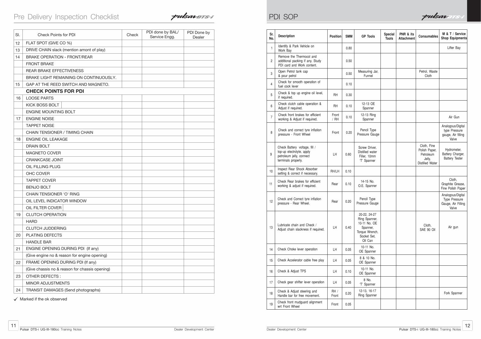
LCD Speedo Console Test
• Connect wiring harness number 2 to C2 connector.
• After connecting speedo console wait unitl console LCD goes blank.
• Now press speedo console test switch to start the test.
• Observe for working of speedo console till test ends.
Body Control Unit (BCU) Test
• Connect wiring harness number 3 to C3, C4 and C5 connectors respectively.
• Press the BCU test switch.
• At the end of complete test, Green colour glowing of ‘Result’ LED indicates BCU test passed.
• At the end of complete test, Red glowing of ‘Result’ LED indicates BCU test failed at respective Red indications.
Dealer Development Center34
Dealer Development Center33
Pulsar DTS-i UG-III-180cc Training NotesPulsar DTS-i UG-III-180cc Training Notes
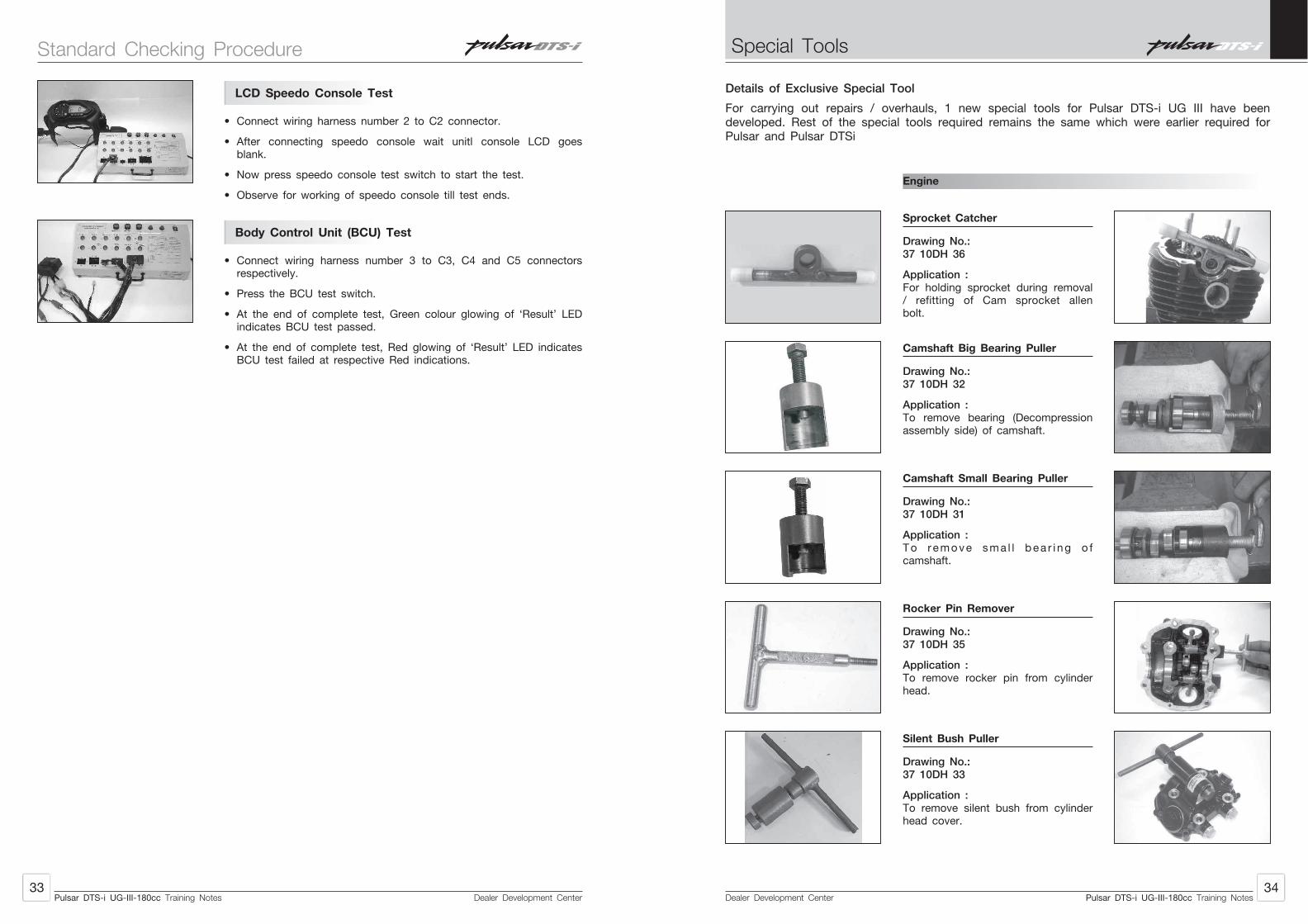
Camshaft Big Bearing Puller
Drawing No.:37 10DH 32
Application :To remove bearing (Decompression assembly side) of camshaft.
Camshaft Small Bearing Puller
Drawing No.:37 10DH 31
Application :To r emove sma l l bea r i ng o f camshaft.
Rocker Pin Remover
Drawing No.:37 10DH 35
Application :To remove rocker pin from cylinder head.
Silent Bush Puller
Drawing No.:37 10DH 33
Application :To remove silent bush from cylinder head cover.
Details of Exclusive Special Tool
For carrying out repairs / overhauls, 1 new special tools for Pulsar DTS-i UG III have been developed. Rest of the special tools required remains the same which were earlier required for Pulsar and Pulsar DTSi
Engine
Sprocket Catcher
Drawing No.:37 10DH 36
Application :For holding sprocket during removal / refitting of Cam sprocket allen bolt.
Standard Checking Procedure
Dealer Development Center36
Dealer Development Center35
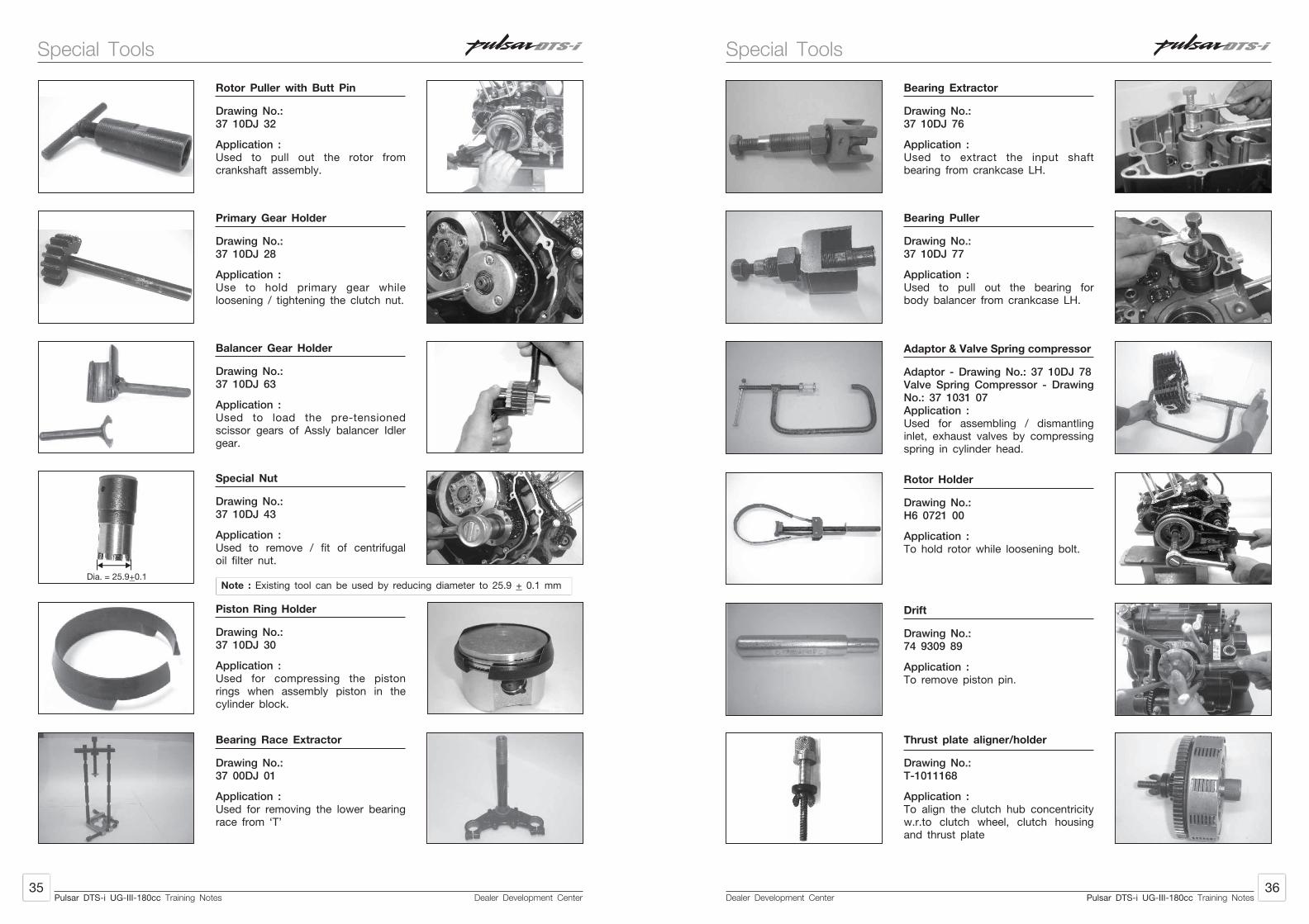
Rotor Puller with Butt Pin
Drawing No.:37 10DJ 32
Application :Used to pull out the rotor from crankshaft assembly.
Primary Gear Holder
Drawing No.:37 10DJ 28
Application :Use to hold primary gear while loosening / tightening the clutch nut.
Balancer Gear Holder
Drawing No.:37 10DJ 63
Application :Used to load the pre-tensioned scissor gears of Assly balancer Idler gear.
Special Nut
Drawing No.:37 10DJ 43
Application :Used to remove / fit of centrifugal oil filter nut.
Piston Ring Holder
Drawing No.:37 10DJ 30
Application :Used for compressing the piston rings when assembly piston in the cylinder block.
Bearing Race Extractor
Drawing No.:37 00DJ 01
Application :Used for removing the lower bearing race from ‘T’
Note : Existing tool can be used by reducing diameter to 25.9 + 0.1 mmDia. = 25.9+0.1
Pulsar DTS-i UG-III-180cc Training NotesPulsar DTS-i UG-III-180cc Training Notes
Bearing Extractor
Drawing No.:37 10DJ 76
Application :Used to extract the input shaft bearing from crankcase LH.
Bearing Puller
Drawing No.:37 10DJ 77
Application :Used to pull out the bearing for body balancer from crankcase LH.
Adaptor & Valve Spring compressor
Adaptor - Drawing No.: 37 10DJ 78Valve Spring Compressor - Drawing No.: 37 1031 07Application :Used for assembling / dismantling inlet, exhaust valves by compressing spring in cylinder head.
Rotor Holder
Drawing No.:H6 0721 00
Application :To hold rotor while loosening bolt.
Drift
Drawing No.:74 9309 89
Application :To remove piston pin.
Thrust plate aligner/holder
Drawing No.:T-1011168
Application :To align the clutch hub concentricity w.r.to clutch wheel, clutch housing and thrust plate
Special ToolsSpecial Tools

Dealer Development Center38
Dealer Development Center37
Crankshaft Bearing Extractor
Drawing No.:37 1001 14
Application :To remove bearing from crankshaft
Output Sprocket Holder
Drawing No.:37 1030 53
Application :To hold the output sprocket while removing sprocket bolt
Bearing Driver Set
Drawing No.:
Application :Common bearing driver set for fitting and r emov ing bea r i ngs f r om crankcase.
37 1030 61
Pulsar DTS-i UG-III-180cc Training NotesPulsar DTS-i UG-III-180cc Training Notes
Chassis
Fork oil seal fitment punch
Drawing No.:37 0040 03
Application :To fit fork oil seal on outer pipe
Rear Shock absorber adjuster
Drawing No.:37 00DH 14
Application :For adjusting the notch position of RSA to achieve hard or soft rear suspension
Fork Inner & Outer Tube Extractor
Drawing No.:74 9310 15
Application :Used for removing front fork inner tube from outer tube.
Special ToolsSpecial Tools

Carburettor and Fuel System
Dealer Development Center40
Dealer Development Center39
Carburettor
Specifications :
Item Pulsar 180cc
Make and Type Ucal-Mikuni BS29
Identification No. DJ - U3
Idling Speed 1400 +100
VC Screw setting 2.5 +2 turns out
Main Jet 117.5
Jet needle mark 4DHL42
Needle jet mark 922MP-1
Jet needle clip 2nd from top position
Pilot Jet 17.5
Starter jet Fixed type
Throttle valve Fixed type
Chock Lever 2 stage with push pull type mechanism
Notes :
Pulsar DTS-i UG-III-180cc Training NotesPulsar DTS-i UG-III-180cc Training Notes
Fuel Tank
• Turn the fuel tap to the off position.
• Disconnect the fuel pipe connections from the petrol cock.
• Disconnect the fuel indicator wiring harness connection.
Note : To remove the side covers LH and RH, unlock with the key then hold the front end of the cover and pull the front end out then pull the cover in forward direction to remove it from the lug.
Remove :
• Side cover LH and RH by unlocking it with key.
Remove :
• Pull the cable from the cover LH to unlock the seat lock• Seat assembly
Note : To remove the seat assembly hold the seat assembly and lift it from the rear end and pull it back.
Remove :
• 1 bolt (A).
• Fuel gauge wiring connection.
• Drain pipe connection.
• Fuel pipe connection.
• Fuel tank assembly
Note : To remove the fuel tank assembly from the chassis lift the fuel tank assembly by holding it at the rear end and pull it back.
Fuel Tank Inspection
Remove the hoses from the fuel tank, and open the tank cap. Check to see if the breather pipe and water drain pipe in the tank for clogging. If they are clogged, remove the tank and drain it, and then blow pipes free with compressed air.
Fuel Tank Cleaning
Warning : Clean the tank in well ventilated area, and take care that there are no smokes or flame anywhere near the working area. Because of the danger of highly flammable liquids, do not use gasoline or low-flash point solvents to clean the tank.
Carburettor and Fuel System
Dealer Development Center42
Dealer Development Center41
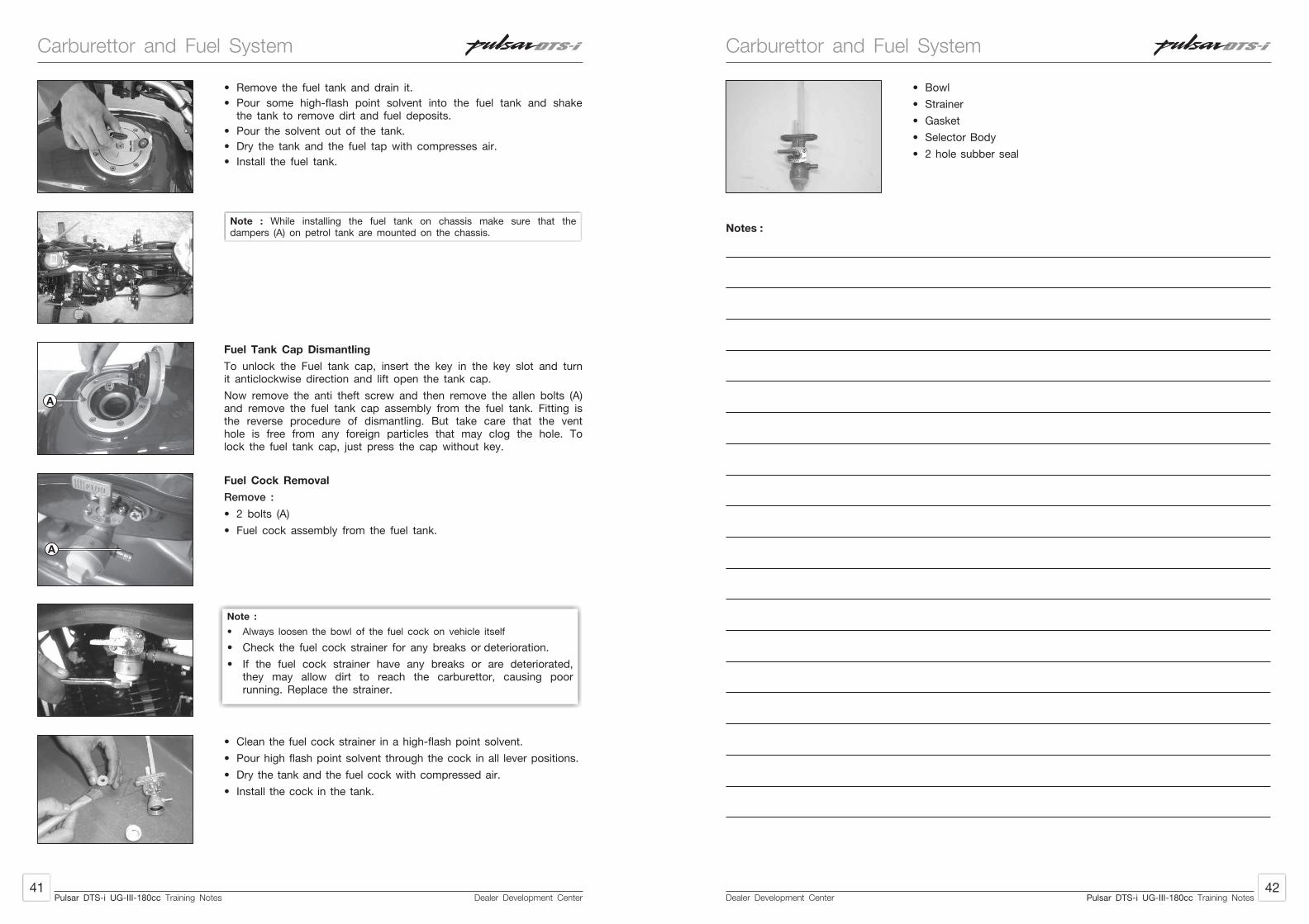
• Remove the fuel tank and drain it.
• Pour some high-flash point solvent into the fuel tank and shake the tank to remove dirt and fuel deposits.
• Pour the solvent out of the tank.
• Dry the tank and the fuel tap with compresses air.
• Install the fuel tank.
Note : While installing the fuel tank on chassis make sure that the dampers (A) on petrol tank are mounted on the chassis.
Fuel Tank Cap Dismantling
To unlock the Fuel tank cap, insert the key in the key slot and turn it anticlockwise direction and lift open the tank cap.
Now remove the anti theft screw and then remove the allen bolts (A) and remove the fuel tank cap assembly from the fuel tank. Fitting is the reverse procedure of dismantling. But take care that the vent hole is free from any foreign particles that may clog the hole. To lock the fuel tank cap, just press the cap without key.
Fuel Cock Removal
Remove :
• 2 bolts (A)
• Fuel cock assembly from the fuel tank.
• Clean the fuel cock strainer in a high-flash point solvent.
• Pour high flash point solvent through the cock in all lever positions.
• Dry the tank and the fuel cock with compressed air.
• Install the cock in the tank.
A
Note :
• Always loosen the bowl of the fuel cock on vehicle itself
• Check the fuel cock strainer for any breaks or deterioration.
• If the fuel cock strainer have any breaks or are deteriorated, they may allow dirt to reach the carburettor, causing poor running. Replace the strainer.
Pulsar DTS-i UG-III-180cc Training NotesPulsar DTS-i UG-III-180cc Training Notes
A
• Bowl
• Strainer
• Gasket
• Selector Body
• 2 hole subber seal
Notes :
Carburettor and Fuel SystemCarburettor and Fuel System

Dealer Development Center44
Dealer Development Center43
Starter Circuit : Constant Velocity Carburettor
1. Plunger Cap
2. Diaphragm Cap
3. Diaphragm Piston Valve
4. Piston Valve with Jet Needle
5. Float Chamber
Air inletfor choke
TowardsEngine
FunctionThe function of starter circuit is to provide rich air fuel mixture on starting / cold starting. At cold engine
condition the air is dense also the engine parts are cold enough this does not allow the petrol to
vaporize properly this leads to starting trouble.
ConstructionThe Starter Circuit consists of a starter jet and a plunger. The starter jet is used to meter the fuel and a
plunger that opens an air passage from the inlet of the carburettor (underneath the diaphragm) which
passes the mixture to the mainfold.
WorkingOn pulling the choke lever the plunger is lifted by a cable. This uncovers the fuel passage that leads to
the starter jet, air inlet passage and the outlet passage towards the manifold. This creates enough
suction to draw fuel up from the bowl into the mixing chamber (below the plunger). Here the fuel is
mixed with the air and the mixture is drawn into the engine through the outlet passage.
Cut Section Viewof Mixing Chamber
TowardsEngine
1. Plunger
2. Mixing Chamber
3. Starter Jet
Pulsar DTS-i UG-III-180cc Training NotesPulsar DTS-i UG-III-180cc Training Notes
1. Pilot Jet
2. Pilot Outlet Hole
3. Butterfly Valve
4. Volume Control Screw
5. Idling Adjustment Screw
6. Fuel Inlet
FunctionThe pilot circuit provides the air fuel mixture at idling when not enough air is being drawn through the
carburettor to cause the main circuit to operate.
ConstructionThe pilot circuit consists of pilot jet, pilot air jet and volume control screw. The pilot jet meters the fuel
and the pilot air jet meters the air quantity. The volume control (VC) screw controls the amount of air fuel
mixture flowing through the pilot outlet.
WorkingAs the air enters the pilot air inlet the fuel is metered by pilot jet and air quantity is metered by pilot air
jet. The atomized / vaporized mixture is discharged through the pilot outlet. The pilot outlet is located on
the manifold side of the carburettor. Since the throttle valve is almost at fully closed position, air fuel
mixture is supplied mainly by pilot outlet only. Air fuel mixture volume is adjusted by volume control (VC)
screw and mixture becomes lean when volume control (VC) screw turned clockwise and rich when it is
turned Anticlockwise direction.
Pilot Circuit : Constant Velocity Carburettor
TowardsEngine
Air Inletfor pilot jet
Working of CarburettorWorking of Carburettor
Dealer Development Center46
Dealer Development Center45
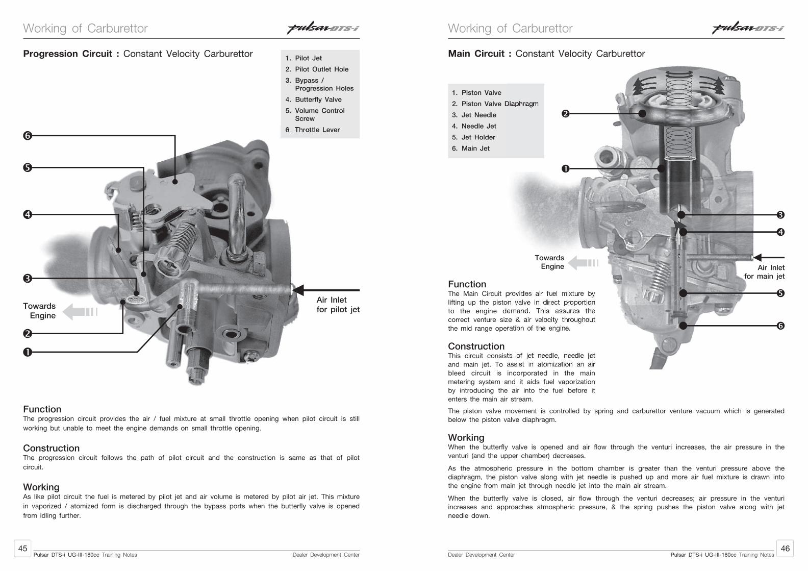
1. Pilot Jet
2. Pilot Outlet Hole
3. Bypass / Progression Holes
4. Butterfly Valve
5. Volume Control Screw
6. Throttle Lever
FunctionThe progression circuit provides the air / fuel mixture at small throttle opening when pilot circuit is still
working but unable to meet the engine demands on small throttle opening.
ConstructionThe progression circuit follows the path of pilot circuit and the construction is same as that of pilot
circuit.
WorkingAs like pilot circuit the fuel is metered by pilot jet and air volume is metered by pilot air jet. This mixture
in vaporized / atomized form is discharged through the bypass ports when the butterfly valve is opened
from idling further.
TowardsEngine
Air Inletfor pilot jet
Progression Circuit : Constant Velocity Carburettor
Pulsar DTS-i UG-III-180cc Training NotesPulsar DTS-i UG-III-180cc Training Notes
Main Circuit : Constant Velocity Carburettor
1. Piston Valve
2. Piston Valve Diaphragm
3. Jet Needle
4. Needle Jet
5. Jet Holder
6. Main Jet
FunctionThe Main Circuit provides air fuel mixture by
lifting up the piston valve in direct proportion
to the engine demand. This assures the
correct venture size & air velocity throughout
the mid range operation of the engine.
ConstructionThis circuit consists of jet needle, needle jet
and main jet. To assist in atomization an air
bleed circuit is incorporated in the main
metering system and it aids fuel vaporization
by introducing the air into the fuel before it
enters the main air stream.
TowardsEngine Air Inlet
for main jet
The piston valve movement is controlled by spring and carburettor venture vacuum which is generated
below the piston valve diaphragm.
WorkingWhen the butterfly valve is opened and air flow through the venturi increases, the air pressure in the
venturi (and the upper chamber) decreases.
As the atmospheric pressure in the bottom chamber is greater than the venturi pressure above the
diaphragm, the piston valve along with jet needle is pushed up and more air fuel mixture is drawn into
the engine from main jet through needle jet into the main air stream.
When the butterfly valve is closed, air flow through the venturi decreases; air pressure in the venturi
increases and approaches atmospheric pressure, & the spring pushes the piston valve along with jet
needle down.
Working of CarburettorWorking of Carburettor

Dealer Development Center48
Dealer Development Center47
Pulsar DTS-i UG-III-180cc Training NotesPulsar DTS-i UG-III-180cc Training Notes
Do’sDo’s Don’tsDon’ts
• Use appropr iate screw drivers.
Handling
Cleaning
• For cleaning always use carburettor cleaner like- Acetone- Carbon Tetra chloride- Aerosol- CVC spray
Maintenance
Ensure• Jets
- Holes are clean.- Holes are not worn out.- Size as per specification.
• Float is in good condition.
• Float Pin- Tip having no wear mark.- Spring loaded pin is free
in movement.
• Needle Jet- No wear at taper portion.- Circ l ip pos i t ion is in
specified groove.
• Piston valve
- No wear mark.
- Diaphragm condition.
• Never use oversize screw drivers.
• Do not over tighten the jets and screws.
• These will damage the jets and their seats.
• Never clean the carburettor with water.
• Jets & air passages will get clogged due to sediments if cleaned by water.
Replace• Jets
- Worn out jet.- Incorrect size jet.
- Punctured, Squeezed and distorted float.
- Worn out tip.
- If spring loaded pin is sticky.
- Needle worn out at taper portion.
- Piston valve worn out.Scoring marks.
- Diaphragm punctured.
Overhaul carburettor at every 10,000 kms. and insepct the parts.
Pulsar DTSi is the first bike in the world (In small cc engine) to have twin spark ignition system.
1. The most obvious feature is the Twin Spark Plug configuration o f the Engine. The cylinder head has 2 spark plugs one on either side. The spark plugs are of the smae Heat range (Champion RG4HC/Bosh UR3DC (Resistive) and have similar electrode gaps. These also spark simultaneuosly, This has been done to improve the combustion process by reducing the time of combustion. The end results are low emissions, good fuel economy and good driveability
2. To enable the sparking of the 2 spark plugs, a intelligent CDI capable of handling this was developed. Further more, the ignition timing has been optimised to give the best output from
0 0engine (10 BTDC @ 1500 rpm, 28 BTDC @ 3500 rpm). To enable optimum igntion timing for part throttle loads and full throttle loads, there are separate igntion maps stored in the memory of the CDI. These are activated depending on the throttle opening and engine speed. The Digital CDI has a bit Microprocessor which handles all these inputs and gives out the required and correct spark advance. The intelligent CDI can be easily indentified by 2 green dots marked on CDI case.
3. To enable switching the required igntion maps, a magnetically operated need switch is incorporated on the carburettor throttle shaft and carburettor body. This is known as TRICS. Throttle Responsive Igntion Control System.
4. These engines are capable of of reviving very high, quite easily. To keep them mechanically safe, a engine rpm limiter has been incorporated in the Digital CDI. This curtails the sparks to the spark plugs thereby limiting the engine rpm Max upto 9000 and thus keeps the engine mechanically safe. There are 2 spark plugs. LH spark plug fires at 350 rpm and then continues to give spark till at 9000 rpm of engine. The spark is cut off from LH plug 9000 rpm to protect engine from excessively high speed.RH spark plug gives spark at 750 rpm and then continues to give till 6000 rpm of engine. If engine rpm exceeds 6000 rpm then RH plug is cut off. This is done to reduce combustion noise created in engine.
5. This engine has been extensively tuned for more Power and Torque.
6. The DTSi technology has enabled the Pulsar to meet 2006 norms without any Secondary air injection devices.
Troubleshooting :
• Malfunctioning of the Reed switch assly will not harm the engine, neither it will give any physical indicators like starting trouble or misfiring.However checking of proper functioning of Reed Switch Assly at PDI and at every service is essential.
• Following symptoms may indicate as malfunctioning of Reed Switch Assly as one of the cause.
CauseSymptom Remedy
Sudden drop in mileage & power lack in mid range rpm
Replacement of Reed Switch AsslyThe igntion systems is working only in 2nd map due to reed switch is stuck in open circuit
Working of Carburettor Digital Twin Spark Plug Ignition (DTS-i)

Dealer Development Center50
Dealer Development Center49
Customer Eductaion Tips :• While starting the engine in any case throttle should not be rotated more. Even if this happens,
engine will start, but the engine rpm will shoot uo too much (due to too high throttle opening)• Whenever there is a sudden subtantial drop in mileage, customer should report to Bajaj Auto’s
Authorised Service Centres.
CO % Checking and Tune Up (To ensure betten mileage) :
Check following before CO % checking / Tune up -• Air filter connections, intake manifold, insulator fitment, connecting tube fitment.• Spark Plug gap (0.7 to 0.8 mm)• All pipes and connections of fuel system for any cracks, leakage, plucking, pinching and loose
connections.• Ensure Tappet Clearance :
Inlet : 0.05 mmExhaust : 0.1 mm
2• Ensure compression pressure inside the cylinder (6 to 10 Kg/cm )0 0• Check the ignition timing (10 BTDC at 1500 rpm and 28 BTDC at 3500 rpm)
CO % checking and carburettor VC screw setting • Start and warm up the engine
0• The oil temperature should be above 60 C. This can be achieved by running vehicle in top gear at the speed of minimum 40 Kmph for 5 ~ 6 Kms.
• Adjust the engine speed to 1400 + 100 rpm with idling adjustment screw of carburettor.• Adjust the CO with the VC screw. It should be in between 1.75 to 2.25 %• Confirm the engine speed whether it is within 1400 + 100 rpm or not. When setting Idle CO %,
idle rpm and VCS have to be adjusted together to achieve 2 % CO and 1400 + 100 engine rpm.
Item Pulsar 180cc
Make Ucal-Mikuni BS 26
Identification No DJ - U3
Type CV Type
Idling Speed 1400+100
VC Screw Setting 2.5+2 turns out
Main Jet 117.5
Jet needle mark 4DHL42
Needle jet mark 922MP-1
Jet needle clip position 2 from top
Pilot Jet 17.5
Starter Jet Fixed type
Throttle valve Fixed type
Chock lever 2 stage with push pull type mechanism
Pulsar DTS-i UG-III-180cc Training NotesPulsar DTS-i UG-III-180cc Training Notes
• Remove the ‘Allen Head Grub Screw’ before removing the ‘Sleeve Spark Plug’.
• Before fitting the ‘Sleeve Spark Plug’ apply thin layer of molybdenum disulphite grease on the entry chamfers for the ‘O’ rings for smooth sliding inside.
• ‘Inlet Rocker Arm Shaft’ is longer in length.
• Rocker arm has 20 Rollers inside the outer cage.
• Doesn't have inner cage.
• Take utmost care while dismantling. Rollers should not fall inside engine.
• Apply grease for fixing needle rollers inside rocker arm.
• While removing / refitting of piston pin circlip, cover the crankcase chamber with clean cotton cloth to avoid falling of circlip inside the engine.
• Blow pressurised air to oil passages in reverse direction to that of oil flow.
• Do not apply liquid gasket at location (A) which may block the lubrication passage.
A
• Secure the ‘Cam Chain Sprocket’ in the special tool firmly and then tighten the sprocket allen bolt (A).
• Ensure that the ‘O’ mark on washer always faces outwards when tightening the allen bolt.
A
Valve timing
• Ensure the sprocket marks (A) are aligned horizontally with cylinder head top machined face and the piston is at TDC.
AA
Digital Twin Spark Plug Ignition (DTS-i) Important Points to Remember

Dealer Development Center52
Dealer Development Center51
Pulsar DTS-i UG-III-180cc Training NotesPulsar DTS-i UG-III-180cc Training Notes
• Ensure damper rubber fitment on magneto side guide plate.
• When splitting crankcase always remove 1 long bolt fitted from clutch side first.
• Remove long bolt immediately after removal of long bolt clutch side.
• Ensure proper fitment of bolt with copper washer to avoid oil leakage.
• Shifter fork is having a roller. These roller are one side tappered inner dia.
• Taper portion of roller should face towards fork gear shift.
• Input shaft has special nut.
• Thick spacer washer tapered I.D. it should be placed on tapped portion of Input Shaft.
• Input Shaft has left hand threads.
• After placing Belleville, fit clutch plate with 48 friction material cubs (A) with more I.D.
• 4 Nos. of clutch plates with 36 friction material cubs (B) alternatively along with steel plates.
• Fit top clutch plate with 40 friction material cubs (C).
Ensure
• While assembling hub clutch place plain washer first and then place belleville washer. Concave face should be upwards i.e. toward technician.
BellevilleWasher
PlainWasher
ClutchHub
• Fit primary gear drive (A).• The mark teeth of the primary gear should match with the line mark on the c’case.
This indicated that the piston is at TDC position. This procedure should be carried before fitting the ‘Clutch Housing’ & this position should not be disturbed while fitting the ‘Clutch Housing’.
2
14
17
1
16
9
8
12
10
5
7
6
7
6
7
6
4
6
15
11
133
• Load the assly balancer idler gear with 2 teeths from either side using the special tool.
• Take the ‘Assembly Balancer Idler Gear’ along with Thrust Washer which is pre-loaded and is held in special tool, Slide down the special tool with ‘Gear’ to engage the bottom half of the ‘Assembly Balalncer Idler Gear’ with the ‘Body Balancer Gear Assembly’
• Fit ‘Thrust washer’ on the other side.• On assembly of ‘Assembly Balancer Idler Gear’ the itched/Dot mark of ;Body
Balancer Gear Assembly’ should match with the line mark on the ‘Crankcase’.
Holding the ‘Assembly Balancer Gear’ in special tool now slide inside the ‘Clutch Housing’ so that the ‘Clutch Housing’ smoothly engages with the top half of ‘Assembly Balancer Idler Gear’.
• Remove the special tool gently.
• Fit 2 dowels and Assly Balancer Idler Gear Cover
• Ensure perfect marking of gear marks with respect to crankcase mark.
Important Points to RememberImportant Points to Remember

Removal of Engine from Frame
Dealer Development Center54
Dealer Development Center53
Pulsar DTS-i UG-III-180cc Training NotesPulsar DTS-i UG-III-180cc Training Notes
Removal of Engine from Frame :
Remove :
• Put OFF the fuel cock
• Side panel LH
• Side panel RH
Remove :
• Seat assembly by pulling the cable for seat lock release located on RH side.
• Disconnect the negative terminal of the battery.
• Disconnect the wiring harness socket for fuel level Indicator.
• Fuel pipe connections and moisture drain pipe from fuel tank.
• Disconnect stator plate harness
• Disconnect neutral switch coupler
Remove :• Drain bolt (A) and drain out the oil from engine.• Refit the drain bolt with gasket & tighten it.
Remove :
• Bolt (A)
• Petrol tank assembly.
Remove :
• Bolts (A)
• Gear shift pedal bolt (B)
• Drive sprocket cover LH.
Using Special Tool : Sprocket Holder - 37 1030 53
Remove :
• Bolts (A)
• Plate drive sprocket
• Drive sprocket along with the chain.
• Neutral switch coupler (B).
A
A
B A
Recommended Oil Grade and Qty
Grade SAE 20W50 of API ‘SG’ + JASO ‘MA’
Quantity Drain & Refill 1000 ml.Engine Overhaul 1100 ml.
A
B
Remove :
• 2 nuts (B) for silencer flange
Remove :
• Bolt (A) of silencer bracket mounted on pillion RH side footstep.
• Silencer assembly.
Remove :
• Starter motor connection (A)
Remove :
• PCV pipe from breather
Remove :
• Disconnect the reed switch coupler.
• Spark plug cap LH
Remove :
• Air filter mounting bolts to facilitate the removal of carburettor with reed switch.
• Clamps of carburettor and disconnect carburettor along with insulator and dismantle cables from it.
• Bracket bolts securing clutch cable on clutch cover.• Spark plug cap RH
Note : Always remove the flange mounting first and then rear mounting to avoid misalignment of studs.
B
B
A
Removal of Engine from Frame

Dealer Development Center56
Dealer Development Center55
Remove :
• While removing engine foundation bolts, first remove the topmost bolt and then go down progressively.
Note : Bolts (A) holding the engine to the chassis. (4 bolts of 12 mm and 1 bolt needs deep socket for removing it).
• Lift up the engine off the chassis and place it on engine stand.
Note : After disconnecting all the sub assemblies and control cables from the engine lift up the engine and remove it from RHS of the vehicle.
Pulsar DTS-i UG-III-180cc Training NotesPulsar DTS-i UG-III-180cc Training Notes
Engine Top End Dismantling :
Remove :
• Pull out the cover on the spark plug cap RH and the spark plug cap itself
• Using a plug spanner, loosen and remove the spark plug RH
• Loosen and unscrew the allen head grub screw of the sleeve spark plug
Remove :
• Loosen bolt (A) and unscrew chain tensioner plunger
• Cam chain tensioner assembly 2 bolts (B)
• Cam chain tensioner assembly
Remove :
• Both tappet caps
• Magneto cover cap seal and rotate crankshaft to get piston at TDC.
• Ensure both tappets are at free state (i.e. at the end of compression stroke)
Remove :
• 2 dummy plug
• 2 gaskets
Note : Wrap a piece of cloth around the protruding edge of the sleeve spark plug and using a plier, pull out the sleeve.
Note : Remove these only if the ‘O’ ring protrusim in the bore is non-existant (which means that the ‘O’ ring has set and it has lost its compression or sealing ability.)
Remove :
• There are 2 ‘O’ rings fitted in the cylinder head, one on the cam chain wall and the other near the spark plug threading
• Using a thin, sharp pointed tool pierce the ‘O’ rings and remove them. (If required)
A
B
Removal of Engine from Frame Dismantling Engine

Dealer Development Center57
Dealer Development Center58
Remove :
• Cylinder head securing head cover 2 bolts (A)
• Cylinder head securing head cover 4 bolts (B)
• Cylinder head securing head cover 4 domed cap nuts (C)
• 4 copper plated steel washers
Remove :
• Cylinder head cover complete
• Cam shaft cap
Note : Improper tightening sequence may cause warpage in cylinder head cover and it can be damaged permanently.
A
B C
Sprcoket Catcher
Using Sp. Tool : Sprocket Catcher - 3710 DH 36
Remove :
• Allen bolt
• Spacer
• Cam sprocket
• Collar
• Cam shaft assly
Using Special Tool : Sprocket Catcher - 3710 DH 36
Note : Hold the cam chain up right using soft copper wire or thread. Do not use cotton waste for holding the cam chain.
Remove :
• Cylinder head assembly
• 2 dowels
• Gasket cylinder head
Remove :
• Non tensioner side chain guide
• Cylinder block assembly
Pulsar DTS-i UG-III-180cc Training NotesPulsar DTS-i UG-III-180cc Training Notes
Engine LH (Magneto Side) :
Remove :
• 5 bolts (A)
Remove :
• Piston pin lock LH & RH side
Note : Tie the cam chain firmly using soft copper wire/thread firmly to avoid slipping down into crankcase.
Note : Place a piece of clean cloth above hallow portion of crankcase to arrest piston pin circlip if it falls during fitment.
Using Special Tool :
Drift 74 9309 89
Remove :
• Remove piston pin
• Piston assembly
Caution : When tapping the drift for removal of piston pin, confirm that the connecting rod is held firmly against the direction of tapping to avoid damage to big end bearing connecting rod of crankshaft.
Remove :
• Block gasket
• 2 dowels (A)
Remove :
• Cover magneto.
A
A
Dismantling EngineDismantling Engine

Dealer Development Center60
Dealer Development Center59
Pulsar DTS-i UG-III-180cc Training NotesPulsar DTS-i UG-III-180cc Training Notes
Using Special Tool : Rotor Holder - H6 0721 00
• Hold the rotor assembly
Remove :
• Rotor bolt (A)
• Washer
Using Special Tool - Rotor Puller with butt pin : 37 10DJ 32
Remove :
• Rotor assembly
• Woodruff key.
A
Note : Holding the gear complete starter clutch rotate the rotor and pull it out in Anticlockwise direction to prevent rollers and springs coming out. Rotor puller has left hand threads.
Warning : • These components remain hot for a long time especially if removed
from a hot engine. Wear suitable hand protection to prevent burns.• Rotor puller has left hand threads
Remove :
• Gasket
• Bolt (A)
• Plate starter clutch gear return (B)
• Gear starter clutch
Remove :
• Collar (A)
• Shaft
• Gear comp. starter counter assly
A
A
B
Remove :
• 1 screw - (A)
• Starter motor cover
Remove :
• 3 Screw (A)
• Guide starter assembly along with oil seal.
Engine RH : (Clutch Side)
Remove :
• Kick starter bolt
• Kick starter
Warning : The oil pump may be hot, hence use suitable hand protection. Also, since the oil pump houses the oil strainer / mesh also, it may retain some quantity of oil. This oil may be hot. Hence proper care should be taken to drain it.
Note : The oil which is in the oil pump housing should also be drained out into the oil drain tray for measuring drained oil.
Note : The rod clutch lifter, plunger oil, plate plunger oil and spring joint may fall out of their respective places into the oil collection tray. If so, ensure that these are collected & accounted for before proceeding.
Remove
• 12 Clutch cover bolts (B)
• Bracket clutch cable (C)
• Clutch cover
Caution : Ensure that the woodruff key of rotor is removed prior to the removal of guide starter assembly. The lips of magneto oil seal housed in guide starter assembly will get damaged if not done so.
A
B
A
Remove :
• 3 bolts (A)
• Oil pump assembly
• 2 Dowels
• Clutch cover gasket
• Starter Motor (B)A
B
C
Dismantling EngineDismantling Engine

Dealer Development Center62
Dealer Development Center61
Dia. = 25.9+0.1
Using Special Tool :
Special Nut Puller 37 10DJ43
Primary Gear Holder 3710 DJ28
Remove :
• Centrifugal oil filter special nut
• Belleville washer
• Body centrifugal oil filter assly
Remove :
• Bearing with plunger
Using Special Tool : Special Nut Puller 37 10DJ 43
Primary Gear Holder 3710DJ28
Remove :
• Input shaft special nut
• Belleville washer
• Clutch assly comp
• Spacer
Note : The existing Special Nut Puller 37 10DJ 43 can be used by grinding the tool OD to 25.9 + 0.1 mm
Using Special Tool : Primary Gear Holder 37 10DJ 28
Remove :
• 3 phillips head screws (A)
• Centrifugal oil filter cover
• Gasket
Warning : These parts may be hot, if removed from a hot engine. Use gloves for protection.
Note : Some amount of oil is trapped in cover and body of centrifugal oil filter, this oil should be drained into the oil tray.
A
Pulsar DTS-i UG-III-180cc Training NotesPulsar DTS-i UG-III-180cc Training Notes
Remove :
• Assly Bal. idler gear
• 2 Washer
Note : Take case that square key does not fall inside the crankcase hollow portion while removing.
Remove :
• Bolt (A)
• Locking plate
• Body balancer gear assly
Remove :
• Primary gear
• Square key
Remove :
• Cam chain
• Cam chain sprocket
• Parallel Pin
A
Remove :
• 3 Assly balancer Idler gear cover bolts (A)
• Cover
• Washer
• 2 Dowel
Remove :
• Clutch housing
A
Note : For ease in removal of clutch house insert special tool (P. No.-37 10DJ 63) in Assly Balancer Idler Gear.
Dismantling EngineDismantling Engine

Dealer Development Center64
Dealer Development Center63
Using Kick starter lever
Remove :
• Washer
• Kick shaft assly comp
Remove :
• Bolt (A)
• Locking Plate
• Kick idler gear
Note : Check and inspect the drum change arm stopper for free movement always.
Note : Rotate the kick starter lever in Anticlockwise direction for removing the kick shaft assly.
Remove :
• Spring
• Allen bolt (A)
• Guide gear
• Spacer
• Parallel Pin
Engine Central Part :
Remove :
• Bolt (A) on RH side crankcase (Clutch side)
Remove :
• Gear change lever
A
A
Pulsar DTS-i UG-III-180cc Training NotesPulsar DTS-i UG-III-180cc Training Notes
Remove :
• Bolt (B) on LH side crankcase (Magneto side)
Remove :
• Kick spring
• 2 Shafts (A) & (B) of gear shifter fork.
• 3 fork shifts (1 small for input 2 big for output shaft.
• 3 Rollers
• Drum change
Remove :
• The entire gear box assembly together
Remove :
• Crankcase gasket
• 2 dowels
• Crankshaft assly
Remove :
• 8 bolts on LH side crankcase
• Split the Crankcase halves.
Note : Before separating crankcase halves confirm that all the crankcase joining bolts are removed and the sprocket cam drive with parallel pin on crankshaft assembly is removed.
B
A
Dismantling EngineDismantling Engine

Dealer Development Center66
Crankcase Clutch Side :
Using Special Tool : Bearing Driver set - 37 1030 61
Remove :
• Bearing (A) for input shaft assembly from crankcase RH
Using Special Tool : Bearing Extractor - 37 10DJ 77
Remove:
• Bearing (B) for output shaft assembly from crankcase RH
A
B
Crankcase Magneto Side :
Remove :
• Oil seal
Using Special Tool : Bearing Extractor - 37 10DJ 77
Remove :
• Bearing (A) for output shaft assembly from crankcase LH
Using Special Tool : Bearing Extractor - 37 10DJ 77
Remove :
• Bearing (A) for body balancer gear bearing from crankcase LH
Using Special Tool : Bearing Extractor - 37 10DJ 76
Remove :
• Bearing (A) for input shaft assembly from crankcase LH
A
A
A
Dismantling of Oil Seals and Bearings :
Pulsar DTS-i UG-III-180cc Training NotesDealer Development Center65
Pulsar DTS-i UG-III-180cc Training Notes
Remove :
• 2 Cotter valve (A)
• Valve spring retainer (B)
• Springs inner (D)
• Spring outer (C)
• Valve from below (E)
• Washer (F)
• Valve steam seal (G)
Similarly carry out the same procedure to dismantle the other valve from the cylinder head assembly.
Top End :
Cylinder Head
Using Sp. Tool Valve Spring Compressor 37 1031 07 & Adapter 37 10DJ 78
A
B
D
C
F
E
Cylinder Head Cover
Using Sp. Tool Rocker Pin remover 37 10DH 35
Remove :
• Rocker shaft (A)
• Rocker arm
• Set of washers (1 wave and 2 plane) (B)
• Rollers 20 nos. (C)
Note : Similarly remove the other Rocker shaft & Rocker Arm from head over
AB
C
Magneto CoverRemove :
• 2 Phillips head screws (A) of pulsar coil (E) mounting.
• Bolts (B) of stator assembly.
• 1 Phillips head screw (C) of stopper.
• Stator coil assembly (D) along with pulsar coil.
A
E
D
C
Remove :
• Bolt (A)
• Bearing stopper
Using Special Tool : Bearing Driver Set - 37 10BA 61
Remove:
• Bearing for gear drum from RH crankcase
Dismantling of Subassemblies :
A
B
Dismantling - Engine Sub Assemblies Dismantling - Engine Sub Assemblies

Dealer Development Center68
Dealer Development Center67
Pulsar DTS-i UG-III-180cc Training NotesPulsar DTS-i UG-III-180cc Training Notes
Chain Tensioner Assembly
Remove :
• Circlip (A) from the body (I)
• Cap (B) along with screw internal and screw external (C)
• Spring (D)
• Thrust washer (E)
• ‘O' ring (F)
• Bolt (G) and ‘O’ ring (H)
AB
E
D
C
HG
F
I
Kick Shaft Assembly
Remove :
• Thrust washer (A)
• Washer thrust (B)
• Circlip (C) & thrust washer (D)
• Spring kick starter ratchet (E)
• Ratchet kick starter (F)
• Circlip (G)
• Washer (H)
• Pinion complete kick starter (I)
Oil Pump
Remove :
• Clip (A)
• Oil strainer element (B) with ‘O’ ring (C)
Clutch Assembly
Remove :
• 4 bolts (A)
• Holder clutch (B)
• 4 springs (C)
• Clutch center (D)
• Plain washer
• Bellivellie washer
• Disc clutch friction (E) (Qty. 6 for 180cc / Qty. 5 for 150 cc)
• Plate clutch (F)
• Plate clutch pressure (G) (Wheel clutch)
• Clutch housing
• Thrust washer - conical from inner ID
B
C
A
C
E
F
G
H
I
BA
D
2
14
17
1
16
9
8
12
10
5
7
6
7
6
7
6
4
6
15
11
133
Bearing Removal from Assly Balancer Idler Gear Cover and Crankcase RH
Using Sp. Tool : Bearing Extractor - 37 10CD 30
Remove :
• Needle roller bearing from RH crankcase.
Assembly Balancer Idler Gear
Remove :
• Thrust washers (A)
• Circlip (B) from any one side of the gear
• Scissor gear (C)
• Torsion Spring (D)
Similarly carry out the same procedure on other side of the gear to dismantle the idler gear completely.
A C
B D E C B A
D
Gear Complete Starter Counter Assembly
• Place the gear comp. starter counter assly on the arbor press as shown in the figure.
• Using Bearing driver set (P. No. 37 1030 61)
Remove :
• Needle roller bearing
Input Shaft Assembly
• 1st gear is integral with the shaft (A)
• Remove thrust washer (B) and slide out gear 2nd drive (C)
• Remove gear 5th drive (D) and collect the splined washer (E) behind it.
• Remove circlip (F) and remove gear 3rd drive (G)
• Remove circlip (H) and collect the splined washer (I)
• Remove gear 4th (J) and collect the thrust washer (K) behind it.
Output Shaft Assembly
• There are no integral gears on output shaft.
• Remove thrust washer (A) and slide off the gear1st driven (B) and stcollect the steel bush (1 driven gear is mounted on steel bush (C)
with shoulder ring
• Slide off the gear 4th driven (D).rd • Remove circlip (E) and spline washer (F). Remove the gear 3
driven (G).rd• Collect the thrust washer (H) behind the 3 gear on output shaft (I)
• Remove circlip (J) and collect the washer (K)nd• Remove gear 2 driven (L) mounted on bush (N) with shoulder ring
• Slide out gear 5th driven (M)
B C
D
E F
G H J
I K
A
ABC
D
EF
G
H
IJ K
L M
N
Dismantling - Engine Sub Assemblies Dismantling - Engine Sub Assemblies

Dealer Development Center70
Dealer Development Center69
Crankcase Magneto Side
Remove :
• 3 Screws (A)
• Guide starter assembly (B) on which oil seal is mounted.
• Oil seal (C)
• Damper (D)
Gear Starter Clutch
Remove :
• Place the gear starter clutch on arbor press as shown in photo
• Using Bearing Driver Set (P. No.: 37 1030 61)
Remove :
• Needle roller bearing
Clutch Cover
Remove :
• Parallel Pin (A)
• Clutch shaft release completely (B) by slightly rotating it so,
• Rack (C)
• Plunger oil (D)
• Plate plunger oil (E)
• Spring joint ‘A’ (F)
• Oil filler plug (G)
• Oil seal kick shaft (H)
• Wire clip (I)
• Oil inspection window
• Flanged bolt (8 Nos.) (J)
• Set of damper (K)
• Set of plate (L)
• Grommet (M)
Camshaft Dismantling
Using Special Tool :
Bearing Pullers:
3710DJ 74 for Bearing 39227020
3710DJ75 for Bearing 39148520
Remove :
• Bigger Bearing using sp. tool from camshaft assembly(A)
• Collar de-comp (B)
• Decompression unit (C)
• Small Bearing (E)
• Lock washer (D)
• Parallel pin (F)
A
B
C
D
BG
FE
D
A
H
J
L
K
C
AB
C
D
E
F
Pulsar DTS-i UG-III-180cc Training NotesPulsar DTS-i UG-III-180cc Training Notes
Dismantling - Engine Sub Assemblies

Dealer Development Center72
Dealer Development Center71
Parts Inspection Parameters
Rings :
• No uneven wear around circumference / breakage.
• Discoloration at working face.
• Carbon built up on inner face if any.
• Piston ring end gap - As per Service data
• Piston ring width (thickness) - As per Service data
• Free rotation of Rings in Piston grooves - No stickyness.
• Piton ring identification markTop Ring : TOP 1, Second Ring : TOP 2
Spark Plug :
• Type / Heat value - RG 4 HC/Bosh UR3DC (Resistive)
• Gap between electrodes - 0.7 to 0.8 mm
• Electrode condition - No errosion
• Colour at the electrodes tip - Brownish
• Threads of reach portion - Ok / No damage
Cylinder Head :
• Mating surface : No warpage / No scratches (Service limit for warpage: 0.05mm)
• Identification mark - DJ mark embossed on casting
• No fins breakage
• Spark plug hole threads - Ok / No damage
• Carbon built up in combustion chamber cavity- Clean it
• Valve seat : No pitting / No carbon deposition
• Proper fitment of Dampers (4 Nos)
• Proper fitment of ‘O’rings
• Proper fitment of valve stem oil seals on valve guide
• Valve guide for crack if any
• Silencer mounting studs threads - Ok / No damage
Cylinder Block :
• No fins breakage
• No Scoring marks
• No Seizure marks
• Ok Seating – mating surfaces
• Smooth Honing pattern
• Correct / Same grouping mark w.r.t. piston (A & B group)
• Inner diameter of block as mentioned in service data.
• Ovality - Not more then 0.05 mm.
• 3 Nos. of damper rubbers Properly fitted on fins
• Proper fitment of ‘O’ ring on bottom side
Piston :
• Grouping mark with respect to cylinder block must be same.
• Diameter of the piston - As mentioned in service data
• No scoring marks on the skirt
• No blow by marks
• No seizure marks.
• Manufacturing / Identification code and date code
• Piston pin - scratches dent marks
Crankshaft :
• Big end axial/radial play : As per Service data.
• Runout : As per Service data.
• Threading condition : Ok / No damages.
• Key way condition : Ok / No damages.
• Big end bearing : Free rotation / Jam
• Con-rod : No bending / twisting
• Oil passage : No blockage.
• Square slot key way for primary gear
Crankcase :
• Mating surface : Smooth / No scratches.
• No Cracks, damages, breakage.
• Bearing seat, oil seal seat & proper pressing / positioning of oil seals, needle roller, ball bearings freely rotating
• No Blow holes in casting
• Breather pipe / hole : No clogging
• Oil passage : Clean / No clogging
• Threads of holes & studs : Ok / No damages
• Visible number punching on LH Crank Case
Bearings :
• Axial play : Ok / Not excessive
• Radial play : Ok / Not excessive
• Bearing Seat : No sign of high spot on seating area.
• Bearing class & code : As per specification numbers
• Bearing Rotation : Free Rotation
Clutch :
• Clutch plates / Steel plates - Thickness as per service data
• Warpage as per service data
• No Seizure / Damaged bonding of friction material
• Tangs (Lugs) / Teeth - No wearing
• Thrust plate cracked
• No Foreign material embedded
• Colour change / Signs of overheating if any
• No uneven wear pattern
• Steel plates planishing
• Conical face machining for spacer clutch
Clutch Housing :
• No Wear marks on slots.
• Clearance between clutch plate tangs and slot in the clutch housing should not be excessive
• Free movement of plates in clutch housing slots.
• Rivets of clutch housing should not be loose.
• Free rotation of housing on Input shaft
Pulsar DTS-i UG-III-180cc Training NotesPulsar DTS-i UG-III-180cc Training Notes
Parts Inspection Parameters

Dealer Development Center73
Dealer Development Center74
Clutch Hub / Clutch Wheel :
• Contact surface for friction plates-should not be worn out excessively
• Pressure Plate free movement in clutch hub splines
• Holes for lubrication
• Clutch hub height
• Smoothness in ID of clutch wheel
• Spacer free movement on clutch wheel
• Presence of plain and wave washer in 1st clutch plate
Transmission :
• No Teeth breakage or crack
• No Wear pattern on teeth
• No Wear of dog teeth & dog holes on gear
• No Seizure mark on gear seat. st nd rd• Free movement of gears on the shaft (1 Output, 2 Output, 3
th thOutput, 4 Input and 5 input gears are free on the respective shaft)
• Free movement of Fork shift on the fork shaft
• Gear shift drum groove profile - Ok / No damage - Wear
• Free movement of Fork shift guide roller in the drum groove
Drum :
• Presence of Neutral rivet on the Drum
• Free rotation of Drum in LH crankcase parent hole.
• Inner hollow portion must be free from casting dust / burr
• Groove profile width as per Service Data
• Hole available for parallel pin
• Drum profile free from Hi-Spot for free sliding of bush
Carburettor :
• Float
- No puncture
- Alignment w.r.t float pin - Ok
- Not touching to bowl walls
• Needle Valve
- No groove formation on the tip
- Smooth action of spring loaded pin,
- Smooth movement in its seat.
• Volume Control Screw
- Not bent / Threads OK. / Not jammed / Presence of Spring Washer and ‘O’ ring.
• Jets
- Correct size, No wear of jet hole, No clogging
• Piston Valve
- Smooth free sliding, clearance in its seat, no excess wear mark.
• Choke Operation - Smooth (Push and pull type)
Guide Kick :
• No presence of any burr & flashes
• Face to face fitment on Crankcase after tightening.
• Application of loctite 638 to securing allen bolts
Camshaft :
• Presence of locating washer
• Free rotation of bearing
• Lobe height - as per Service Data
• No cut / wear marks on cam
• De-comp mechanism stickyness
Pulsar DTS-i UG-III-180cc Training NotesPulsar DTS-i UG-III-180cc Training Notes
Notes :
Parts Inspection Parameters Parts Inspection Parameters

Service Data - Engine
Dealer Development Center75
Dealer Development Center76
Service Data - Engine
26.0 ~ 10.0 Kg/cmStd. Limit
Serv. Limit25.0 ~ 10.0 Kg/cm
Compression Pressure
31.0
Inlet
30.8
Std. Limit
Serv. Limit
30.4
Exhaust
30.2
Cam Height
4.48
Inlet
4.40
Std. Limit
Serv. Limit
4.46
Exhaust
4.41
Valve Stem Diameter
TIR 0.01Std. Limit
Serv. Limit TIR 0.03
Valve Stem Bend
0.5
Inlet
0.3
Std. Limit
Serv. Limit
0.8
Exhaust
0.6
Valve Head Thickness
127.00 ~ 127.20Std. Limit
Serv. Limit 128.0
Camshaft Chain Lth. 20 Links
20-link length
1st 2nd 21st
MEASURE THIS LENGTH
Serv. Limit 0.05
Cylinder Head Warp
Valve Clearance
0.05
Inlet
0.05
Std. Limit
Serv. Limit
0.10
Exhaust
0.15
Valve Spring Free Length
39.10
Inner
39.00
Std. Limit
Serv. Limit
43.6
Outer
42.6
Cam Sprocket Diameter
61.48 ~ 61.36Std. Limit
Serv. Limit 61.30
7.994 ~ 8.0Std. Limit
Serv. Limit 7.98
Rocker Arm Shaft Dia.
63.50 ~ 63.508Std. Limit
Serv. Limit 63.508 ~ 63.515
Cylinder Inside Diameter
10mm20mm
40mm
0.012 ~ 0.030Std. Limit
Serv. Limit —
Piston / Cylinder ClearancePiston Diameter
7mm
63.478 ~ 63.488Std. Limit
Serv. Limit 63.488 ~ 63.498
Piston Ring / Groove Clearn.
0.02~0.06
TOP
0.16
Std. Limit
Serv. Limit
0.01~0.05
SECOND
0.15
Piston Ring End Gap
0.15~0.30
TOP
0.55
Std. Limit
Serv. Limit
0.30~0.45
SECOND
0.70
Friction Plate Thickness
2.9 ~ 3.1Std. Limit
Serv. Limit 2.75
4.4Std. Limit
Serv. Limit 4.2
Shift Fork Guide Pin Dia. Shift Drum Groove Width
Std. Limit
Serv. Limit
7.15
7.0
Pressure Plate Warp
0.2Std. Limit
Serv. Limit 0.3
Clutch Spring Free Length
30.0Std. Limit
Serv. Limit 29.0
Std. Limit
Serv. Limit
0.02 Max.
0.05
Crankshaft Run Out
Pulsar DTS-i UG-III-180cc Training NotesPulsar DTS-i UG-III-180cc Training Notes

Dealer Development Center77
Dealer Development Center78
Front Brake Pad Thickness
7.4Std. Limit
Serv. Limit 3.8
Axle Run Out
TIR 0.1 or LessStd. Limit
Serv. Limit TIR 0.2
100 mm
Drive Chain Slack
25 ~ 35Std. Limit
Serv. Limit 40 ~ 50
Drive Chain Length
254.0 ~ 254.6Std. Limit
Serv. Limit 259.0
20-link length
1st 2nd 21st
MEASURE THIS LENGTH
Brake Panel Cam Hole Dia.
12.00 ~ 12.03Std. Limit
Serv. Limit 12.15
Brake Cam Diameter
11.95 ~ 11.98Std. Limit
Serv. Limit 11.88
Brake Drum Inside Diameter
130 .0 ~ 130.16Std. Limit
Serv. Limit 130.75
Brake Shoe Lining Thickness
3.85 ~ 4.15Std. Limit
Serv. Limit 2.0
Axial Wheel Run Out
TIR 1.0 or LessStd. Limit
Serv. Limit TIR 2.0
Radial Wheel Run Out
TIR 0.8 or LessStd. Limit
Serv. Limit TIR 2.0
Rear Sprocket Warp
0.4 or LessStd. Limit
Serv. Limit 0.5
Tyre Tread Depth
Front: 5.0 Rear: 6.8Std. Limit
Serv. Limit Front: 1.0 Rear: 1.5
Front Fork Spring Free Length
398.50Std. Limit
Serv. Limit 391.00
Free Length
Front Fork Oil
Grade : SAE 10W20
Quantity :165 ml / Fork Pipe(Drain & Refill)
Fo
rk O
il L
eve
l218 +
2.0
mm
.
Pulsar DTS-i UG-III-180cc Training NotesPulsar DTS-i UG-III-180cc Training Notes
Notes :
Service Data - Frame Service Data - Frame

Dealer Development Center79
Dealer Development Center80
Pulsar DTS-i UG-III-180cc Training NotesPulsar DTS-i UG-III-180cc Training Notes
Part Name
Description
Identification Mark
Part No.
Part Name
Description
Identification Mark
Part No.
Part Name
Description
Identification Mark
Part No.
Part Name
Description
Identification Mark
Shaft Input Transmission
DK 1011 25
Taper provided on shaft near clutch mounting end.
Guide Gear Shift
DK 1011 58
Guide Gear with 6 pins is meshed with gearchange lever & transmits reciprocating motion intorotary motion & thus rotates drum change.
Fork Gear Shift (Input & Output)
Input : DK 1011 33 Output : DK 1011 34
The roller in fork gear shift roll in the drum profile smoothlyas & when drum rotates & guides to transmit To & Fromotion to fork gear shift for matching respective gears.
• Pin diameter is 4.4 mm • ‘U’ mark on fork shift.
Gear Drum Change Assembly
DK 1011 32
Profile width is 7.15 mm. It has a square windowparallel to neutral stopper locater.
Part No.
Better clamping of clutch assly is ensured onInput Shaft for effective torque transmission withthis new clutch mechanism.
Guide Gear is having 6 pins.
It has a wide profile (groove) for smooth rolling offork gear shift roller in drum profile for smoothshifting of gear.7.15
mm
Ø 4.4
Parts Identification - Engine UG-III Parts Identification - Engine UG-II
Selector lever operates radially. Selector lever isshort in length.
Part No.
Part Name
Description
Identification Mark
Lever Comp Gear Shift
DH 1017 05
Lever comp. gear shift is meshed with guide gearshift constantly. Thus helps in transmittingreciprocating motion to guide gear.
Part Name
Description
Identification Mark
Part No.
Part Name
Description
Identification Mark
Part No.
Part Name
Description
Identification Mark
Part No.
Part Name
Description
Identification Mark
Shaft Input Transmission
DH 1015 19
No Taper provided on shaft near clutchmounting end.
Guide Gear Shift
DJ 1011 48
Guide Gear with 4 pins is meshed with gear changelever & transmits reciprocating motion into rotarymotion & thus rotates drum change.
Fork Gear Shift (Input & Output)
DH 1011 30 - Input DH 1011 32 - Output
The fork gear shift pin slides in the drum profile as& when drum rotates & guides to transmit To & Fromotion to fork gear shift for matching respective gear.
Pin dia. = 5 mm. I/P shaft fork mark = S 32.O/P shaft fork mark = S 95 & S 92 respectively.
Gear Drum Change Assembly
DJ 1011 46
Profile width is 5 mm. It has a odd shape windowparallel to neutral stopper locater.
Part No.
Effective clamping of clutch assembly is ensured onInput Shaft by using guide plate clutch in betweenshaft & clutch assembly.
Guide Gear is having 4 pins.
It has a wide profile (groove) for smooth sliding offork gear shift pin in drum profile forshifting of gears.
Selector lever operates To & Fro. Selector leveris more in length.
Part No.
Part Name
Description
Identification Mark
Lever Comp Gear Shift
DH 1011 34
Lever comp. gear shift is meshed with guide gearshift constantly. Thus helps in transmittingreciprocating motion to guide gear.
Ø 5 mm
5 mm
Parts Identification Parts Identification

Dealer Development Center81
Dealer Development Center82
Pulsar DTS-i UG-III-180cc Training NotesPulsar DTS-i UG-III-180cc Training Notes
Part Name
Description
Identification Mark
Part No.
Part Name
Description
Identification Mark
Part No.
Part Name
Description
Identification Mark
Part No.
Part Name
Description
Identification Mark
Clutch Cover
DJ 1012 41
Clutch cover has Engine oil inspection window.
Holder Clutch (Thrust Plate)
DK 1010 78
Holder clutch holds the clutch bearing & plunger.
Clutch Spring
DH 1017 43
Clutch spring helps smooth engaging & disengagingthe clutch mechanism.
Clutch spring height is 30.8 mm.
Clutch Center
DK 1010 01
Step for spacer is provided. Clutch centerheight is 26 mm.
Part No.
It houses the entrire clutch side assemblies.
Holder clutch has 4 holes for mounting.
Clutch center holds the set of clutch plate &pressure plate.
Parts Identification - Engine UG-III Parts Identification - Engine UG-II
Clutch wheel has 4 legs for mountingclutch springs.
Part No.
Part Name
Description
Identification Mark
Clutch Wheel
DK 1011 63
Clutch wheel holds the set of clutch plate &pressure plate.
26 mm
H
Part Name
Description
Identification Mark
Part No.
Part Name
Description
Identification Mark
Part No.
Part Name
Description
Identification Mark
Part No.
Part Name
Description
Identification Mark
Clutch Cover
DH 1011 49
Clutch cover does not have Engine oilinspection window.
Holder Clutch (Thrust Plate)
DH 1014 84
Holder clutch holds the clutch bearing & plunger.
Clutch Spring
DH 1014 83
Clutch spring helps smooth engaging & disengagingthe clutch mechanism.
Clutch spring height is 29.3 mm.
Clutch Center
DJ 1011 79
No step for guide plate provided. Clutch centerheight is 30 mm.
Part No.
It houses the entire clutch side assemblies.
Holder clutch has 6 holes for mounting.
Clutch center holds the set of clutch plate &pressure plate.
Clutch wheel has 6 legs for mountingclutch springs.
Part No.
Part Name
Description
Identification Mark
Clutch Wheel
DH 1013 44
Clutch wheel holds the set of clutch plate &pressure plate.
30 mm
H
Parts IdentificationParts Identification

Dealer Development Center83
Dealer Development Center84
Pulsar DTS-i UG-III-180cc Training NotesPulsar DTS-i UG-III-180cc Training Notes
Part Name
Description
Identification Mark
Part No.
Part Name
Description
Identification Mark
Part No.
Part Name
Description
Identification Mark
Part No.
Part Name
Description
Identification Mark
Clutch Plain Washer
Plain washer with no Identification Mark.
Clutch Belleville Washer
New part added for preventing clutch judder.
Disc Clutch Friction Plate
DK 1011 49
Clutch plate ID is smaller than regular clutch plate because toaccommodate the plain washer & wave washer of anti juddermechanism. This plate is fitted facing the clutch hub side.
• Internal diameter is 109.5 mm.• Friction material cubs are 48 nos.
Clutch Plate Pressure
DK 1011 63
Friction material cubs = 40 nos. Clutch plateappears to be in Brownish colour.
Part No.
New part added for preventing clutch judder.
Clutch Belleville Washer is concave in shape.
New part added. This plate is fitted facing theclutch wheel side.
Parts Identification - Engine UG-III Parts Identification - Engine UG-II
Friction material cubs 36 nos. Clutch plate appearsto be in Greenish colour.
Part No.
Part Name
Description
Identification Mark
Clutch Plate (4 Nos.)
DK 1011 51
New part added. 4 clutch plates of samespecifications are sandwiched in between LH & RHclutch plates for torque transmission.
Part Name
Description
Identification Mark
Part No.
Part Name
Description
Identification Mark
Part No.
Part Name
Description
Identification Mark
Part No.
Part Name
Description
Identification Mark
NA
NA
NA
NA
NA
Clutch Plate Pressure (6 Clutch Plates)
DH 1013 44
All clutch plates are Brown in colour.
Part No.
Total 6 clutch plates of same specifications arehoused in clutch assembly for torque transmission.
Part No.
Part Name
Description
Identification Mark
NA
NA
NA
NA
NA
NA
NA
NA
NA
NA
NA
39 2167 12
39 2161 11
Parts IdentificationParts Identification

Dealer Development Center85
Dealer Development Center86
Pulsar DTS-i UG-III-180cc Training NotesPulsar DTS-i UG-III-180cc Training Notes
Part Name
Description
Identification Mark
Part No.
Part Name
Description
Identification Mark
Part No.
Part Name
Description
Identification Mark
Part No.
Part Name
Description
Identification Mark
Plate Clutch (Pressure Plate)
Pressure plate is more wide. Pressure platewidth = 17 mm.
Spacer
New part added for adding is better face clampingof clutch assembly on Input Shaft.
Clutch Housing
DK 1010 74
Clutch housing holds the entire clutch assembly &the slots helps for effective lubrication.
Slots provided in clutch housing.
Head Cover
Cylinder head cover is a part of Cylinder Head Comp
‘U’ mark embossed in casting.
Part No.
Pressure plate are housed in between clutch plates.
Internal diameter (ID) is in conical shape.
Head cover houses the complete OHC system.
Parts Identification - Engine UG-III Parts Identification - Engine UG-II
‘DJ’ mark along with ‘U’ mark embossed in casting.Valve springs fitment groove is deep.
Part No.
Part Name
Description
Identification Mark
Cylinder Head Comp
DJ 1012 69
Cylinder head comp houses the complete OHCsystem with valve train.
ID
Part Name
Description
Identification Mark
Part No.
Part Name
Description
Identification Mark
Part No.
Part Name
Description
Identification Mark
Part No.
Part Name
Description
Identification Mark
Plate Clutch (Pressure Plate)
Guide plate clutch helps in better clamping ofclutch assly. on Input shaft.
Clutch Housing
Clutch housing holds the entire clutch assembly.
No slots in clutch housing.
Head Cover
Cylinder head cover is a part of Cylinder Head Comp
‘DJ’ mark embossed in casting.
Part No.
Pressure plate are housed in between clutch plates.
Guide Plate clutch has a stainless steel finish withinternal splines.
Head cover houses the complete OHC system.
‘DJ’ mark embossed in casting. Valve springsfitment groove is not deep.
Part No.
Part Name
Description
Identification Mark
Cylinder Head Comp
DH 1016 00
Cylinder head comp houses the completeOHC system with valve train.
Pressure plate is not wide as compared with regular.Width = 14 mm.
Guide Plate Clutch
DK 1011 63
DK 1011 26
DH 1015 57
DH 1013 74
DH 1015 58
Parts IdentificationParts Identification

Dealer Development Center87
Dealer Development Center88
Pulsar DTS-i UG-III-180cc Training NotesPulsar DTS-i UG-III-180cc Training Notes
Part Name
Description
Identification Mark
Part No.
Part Name
Description
Identification Mark
Part No.
Part Name
Description
Identification Mark
Part No.
Part Name
Description
Identification Mark
Camshaft Assembly
Cam (track) width is less. Track width = 9.6 mm.
Valve Spring Outer
Valve spring helps in smooth closing of valveswithout any noise as per enhanced valve timing.
Valve Spring Inner
DH 1017 31
Valve spring helps in smooth closing of valveswithout any noise as per enhanced valve timing.
It is more in length. Length = 39.1 mm. Spring ismarked with White oil paint.
Stator Plate
DJ 1110 21
Stator plate harness neutral coupler is havingsquare shape.
Part No.
Camshaft assly is housed in between cylinder headcover & cyl. head comp. It drives the entire valvetrain assly as per enhanced valve timing.
It is more in length. Length = 43.6 mm. Spring ismarked with White oil paint.
All Electrical coils like Pick-up, Exciter, Lighting,Battery charging coils with enhanced ignition timingvalues are fitted on this plate.
Parts Identification - Engine UG-III Parts Identification - Engine UG-II
UG-3 mark embossed on the body viewedfrom tail side.
Part No.
Part Name
Description
Identification Mark
Magneto Assembly (Rotor)
DJ 1110 20
Magneto assembly rotor is having analog ignitiontiming for initial starting for avoiding back kicking.
9.6 mm
DH 1017 03
DH 1017 30
Part Name
Description
Identification Mark
Part No.
Part Name
Description
Identification Mark
Part No.
Part Name
Description
Identification Mark
Part No.
Part Name
Description
Identification Mark
Camshaft Assembly
Cam (track) width is more. Track width = 12.6 mm.
Valve Spring Outer
Valve spring helps in smooth closing of valveswithout any noise.
Valve Spring Inner
DS 1011 10
Valve spring helps in smooth closing of valveswithout any noise.
It is short in length. Length = 38 mm. Spring ismarked with Blue oil paint.
Stator Plate
DJ 1110 04
Stator plate harness neutral coupler is having bullettype terminal.
Part No.
Camshaft assly is housed in between cylinder headcover & cyl. head comp. It drives the entirevalve train assly.
It is short in length. Length = 42 mm. Spring ismarked with Blue oil paint.
All Electrical coils like Pick-up, Exciter, Lighting,Battery charging coils are fitted on this plate.
‘E’ & ‘M’ mark embossed on the body viewed fromtail side.
Part No.
Part Name
Description
Identification Mark
Magneto Assembly (Rotor)
DJ 1110 57
Magneto assly rotor is having only Digital IgnitionTiming.
DH 1016 17
DS 1011 11
. m12 6 m
Parts IdentificationParts Identification

Dealer Development Center89
Dealer Development Center90
Pulsar DTS-i UG-III-180cc Training NotesPulsar DTS-i UG-III-180cc Training Notes
Part Name
Description
Identification Mark
Centrifugal Oil Filter
The centrifugal oil filter has a cut mark on tail end.
Part No.
The centrifugal oil filter body wall thickness hasbeen increased by reducing the internal diameterfor getting better strength.
Parts Identification - Engine UG-III Parts Identification - Engine UG-II
DH 1010 64
Part Name
Description
Identification Mark
Centrifugal Oil Filter
The centrifugal oil filter does not have cut markon tail end.
Part No.
The centrifugal oil filter body internal diameter ismore as compared to UG-III filter.
DH 1010 64
Parts IdentificationParts Identification

Part Name
Description
Identification Mark
Part No.
Part Name
Description
Identification Mark
Part No.
Part Name
Description
Identification Mark
Part No.
Part Name
Description
Identification Mark
Carburettor Assembly
On RH side of Carburettor body BS-29, DJ-U3mark is embossed.
Air Filter Assembly
The new large volume air filter with fine & corsefilter foam is incorporated to provide torque ondemand with optimised intake system.
Silencer Assembly
DJ 1012 43
The silencer has been further optimised to matchthe changes done incorporating the new camshaft& air filter assembly.
Flanged bolt on ExhausTEC is facing on LH side.
Head Light Assembly
DJ 2011 32
Parking lamps are projected out. Provision formask fitment.
Part No.
With enhanced valve timing & to achieve betterengine performance the carburettor assemblyis retuned.
Drain tube is provided on bottom side to dischargethe condensed engine oil.
The parking lamps are projected out with a new aggressivelook & together with the mask that gives a real ‘Phantom’look. H/L facing has been lowered to give balanced looks.
Parts Identification - Chassis UG-III Parts Identification - Chassis UG-II
Height of handle holder is more i.e. 31.5 mm.
Part No.
Part Name
Description
Identification Mark
Handle Holder Assembly
DH 1810 53
Handle holder assembly height has been increasedto accommodate new speedo console.
DJ 1012 32
DJ 1210 40
DrainTube
H
Part Name
Description
Identification Mark
Part No.
Part Name
Description
Identification Mark
Part No.
Part Name
Description
Identification Mark
Part No.
Part Name
Description
Identification Mark
Carburettor Assembly
On RH side of Carburettor body BS-29, DJ-U2mark is embossed.
Air Filter Assembly
A large volume air filter is introduced to providetorque on demand with optimised intake system.
Silencer Assembly
DJ 1011 61
The silencer has been optimised to meet theperformance of Pulsar UG-II with ExhausTECintroduction.
Flanged bolt on ExhausTEC for measuring CO% is facing perpendicular to steering.
Head Light Assembly
DJ 2011 04
Parking lamps are inline with head light body.No provision for mask fitment.
Part No.
To meet the requirement of UG-II enginespecifications the carburettor is tuned.
No drain tube is provided on bottom side todischarge the condensed eng. oil.
The parking lamps are in line with the head lightbody line.
Height of handle holder is less i.e. 18.5 mm.
Part No.
Part Name
Description
Identification Mark
Handle Holder Assembly
DJ 1810 38
Handle holder assembly height is been designedlow to accommodate twin pod speedo console.
DJ 1210 20
DJ 1211 05
H
Dealer Development Center91
Dealer Development Center92
Pulsar DTS-i UG-III-180cc Training NotesPulsar DTS-i UG-III-180cc Training Notes
Parts IdentificationParts Identification

Dealer Development Center93
Dealer Development Center94
Pulsar DTS-i UG-III-180cc Training NotesPulsar DTS-i UG-III-180cc Training Notes
Part Name
Description
Identification Mark
Part No.
Part Name
Description
Identification Mark
Part No.
Part Name
Description
Identification Mark
Part No.
Part Name
Description
Identification Mark
Holder Fork Upper
No bracket for holding speedo console.
Brace Fender
Brace fender gives reinforcement to mud guard &also guides the wire / hose going to wheel sensor& caliper assembly respectively.
Front Number Plate Bracket
DH 1612 92
The front number plate bracket holds the numberplate & for firm fitment 3 point mounting is given.
• 3 holes for mounting on lower ‘T’.• 1 hole is oblong.
Speedometer Assembly
DJ 2011 44
Digital speedometer with analogue type tachometer.
Part No.
Holder fork upper cover clamps the fork pipes &handle holder.
2 nos. of brackets provided fora) Speedometer wire. b) For disc brake hose.
Easy to read digital speedometer displaying speed inkmph, odometer displaying distance covered & trip meterdisplaying distance covered per trip with resetting facility.
Parts Identification - Chassis UG-III Parts Identification - Chassis UG-II
NIL
Part No.
Part Name
Description
Identification Mark
Wheel Sensor Unit
DK 1011 63
New part added. It is a sensor sensing the vehiclespeed and is a non contact type wheel sensor.
DH 1810 56
DH 1613 04
Part Name
Description
Identification Mark
Part No.
Part Name
Description
Identification Mark
Part No.
Part Name
Description
Identification Mark
Part No.
Part Name
Description
Identification Mark
Holder Fork Upper
To mount the twin pod speedo console there is abracket provided.
Brace Fender
Brace fender gives reinforcement to mud guard &also guides the brake hose going towardscaliper assembly.
Front Number Plate Bracket
DJ 1811 11
The front number plate bracket holds the numberplate & is mounted with 2 point mounting.
• 2 holes for mounting on lower ‘T’.
Speedometer Assembly
DJ 1910 48
Twin pod analogue type speedometer.
Part No.
Holder fork upper cover clamps the fork pipes,handle holder & twin pod speedometer assembly.
No bracket provided for disc brake hose /speedo cable.
Twin pod analogue type speedometer displayingvehicle speed, engine rpm, odometer & trip meter.With trip meter adjustment facility.
Provision for mounting pinion gear &speedometer gear.
Part No.
Part Name
Description
Identification Mark
Case Meter
DJ 1510 57
Case meter assly houses the speedometer wormgear & the pinion gear assly to drive speedometer.
DJ 1810 17
DH 1612 58
Parts IdentificationParts Identification
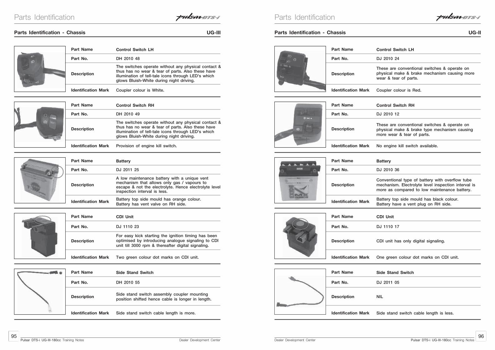
Dealer Development Center95
Dealer Development Center96
Pulsar DTS-i UG-III-180cc Training NotesPulsar DTS-i UG-III-180cc Training Notes
Parts Identification - Chassis UG-III Parts Identification - Chassis UG-II
Part Name
Description
Identification Mark
Part No.
Part Name
Description
Identification Mark
Part No.
Part Name
Description
Identification Mark
Part No.
Part Name
Description
Identification Mark
Control Switch LH
Coupler colour is White.
Control Switch RH
The switches operate without any physical contact &thus has no wear & tear of parts. Also these haveillumination of tell-tale icons through LED's whichglows Bluish-White during night driving.
Battery
DJ 2011 25
A low maintenance battery with a unique ventmechanism that allows only gas / vapours toescape & not the electrolyte. Hence electrolyte levelinspection interval is less.
Battery top side mould has orange colour.Battery has vent valve on RH side.
CDI Unit
DJ 1110 23
Two green colour dot marks on CDI unit.
Part No.
The switches operate without any physical contact &thus has no wear & tear of parts. Also these haveillumination of tell-tale icons through LED's whichglows Bluish-White during night driving.
Provision of engine kill switch.
For easy kick starting the ignition timing has beenoptimised by introducing analogue signaling to CDIunit till 3000 rpm & thereafter digital signaling.
Side stand switch cable length is more.
Part No.
Part Name
Description
Identification Mark
Side Stand Switch
DH 2010 55
Side stand switch assembly coupler mountingposition shifted hence cable is longer in length.
DH 2010 48
DH 2010 49
Part Name
Description
Identification Mark
Part No.
Part Name
Description
Identification Mark
Part No.
Part Name
Description
Identification Mark
Part No.
Part Name
Description
Identification Mark
Control Switch LH
Coupler colour is Red.
Control Switch RH
These are conventional switches & operate onphysical make & brake type mechanism causingmore wear & tear of parts.
Battery
DJ 2010 36
Conventional type of battery with overflow tubemechanism. Electrolyte level inspection interval ismore as compared to low maintenance battery.
Battery top side mould has black colour.Battery have a vent plug on RH side.
CDI Unit
DJ 1110 17
One green colour dot marks on CDI unit.
Part No.
These are conventional switches & operate onphysical make & brake mechanism causing morewear & tear of parts.
No engine kill switch available.
CDI unit has only digital signaling.
Side stand switch cable length is less.
Part No.
Part Name
Description
Identification Mark
Side Stand Switch
DJ 2011 05
NIL
DJ 2010 24
DJ 2010 12
Parts IdentificationParts Identification

Dealer Development Center97
Dealer Development Center98
Pulsar DTS-i UG-III-180cc Training NotesPulsar DTS-i UG-III-180cc Training Notes
Part Name
Description
Identification Mark
Part No.
Part Name
Description
Identification Mark
Part No.
Part Name
Description
Identification Mark
Part No.
Part Name
Description
Identification Mark
Side Stand Magnet
Side stand magnet body has green passivation.
Seat Assembly
For proper locking & proper fitment of tool kit theseat assembly is redesigned.
Seat Lock Assembly
DJ 2110 06
Since seat lock is shifted to tail end of the seat.
Seat lock cable length is more.
Gear Change Pedal
Gear pedal has more curved shape.
Part No.
NIL
No rib at tool kit mounting area. Seat locking studis located at extreme tail end.
The gear change pedal has more curved shape forproper placing of foot & to avoid foot foulingwith step holder.
Parts Identification - Chassis UG-III Parts Identification - Chassis UG-II
Additional projected step is provided for betteraesthetic look.
Part No.
Part Name
Description
Identification Mark
Holder RH Step & LH Step
DJ 1612 57 & DJ 1612 56
Holder step provided for resting pillion rider's foot.
DJ 2110 03
Part Name
Description
Identification Mark
Part No.
Part Name
Description
Identification Mark
Part No.
Part Name
Description
Identification Mark
Part No.
Part Name
Description
Identification Mark
Side Stand Magnet
Side stand magnet body is black in colour.
Seat Assembly
NIL
Seat Lock Assembly
DH 1610 46
The seat lock is located at center of the seat.
Seat lock cable length is short as compared toUG-III cable.
Gear Change Pedal
Gear pedal has less curved shape.
Part No.
NIL
Rib at tool kit mounting area. Seat locking stud islocated in central part of seat assly.
NIL
No additional projected step is provided.
Part No.
Part Name
Description
Identification Mark
Holder RH Step & LH Step
DJ 1611 12 & DJ 1611 11
Holder step provided for resting pillion rider's foot.
DJ 2110 01
DJ 1011 49 DH 1011 49
Parts IdentificationParts Identification

Dealer Development Center99
Dealer Development Center100
Pulsar DTS-i UG-III-180cc Training NotesPulsar DTS-i UG-III-180cc Training Notes
Part Name
Description
Identification Mark
Part No.
Part Name
Description
Identification Mark
Rear Fender
On rear fender a step is provided atrear end RH side.
Saree Guard
Saree guard is mounted on chassis as a safetyfeature for arresting the possibility of saree gettingentangled into rear wheel while riding the bike.
Part No.
The rear fender is located below the rider seat forarresting dust / dirt & water splashing on.
Saree guard has a less curve shape near ladiesfoot step as compared to UG-II. Saree guardmounting allen bolt is short in length.
Parts Identification - Chassis UG-III Parts Identification - Chassis UG-II
DJ 1612 54
DH 1612 94
Part Name
Description
Identification Mark
Part No.
Part Name
Description
Identification Mark
Rear Fender
On rear fender no step is provided.
Saree Guard
Saree guard is mounted on chassis as a safetyfeature for arresting the possibility of saree gettingentangled into rear wheel while riding the bike.
Part No.
The rear fender is located below the rider seat forarresting dust / dirt & washer splashing on.
Saree guard has more curve shape near ladies footstep as compared with Pulsar UG-III. Saree guardmounting allen bolt is more in length.
DJ 1610 51
DJ 1612 15
Parts IdentificationParts Identification
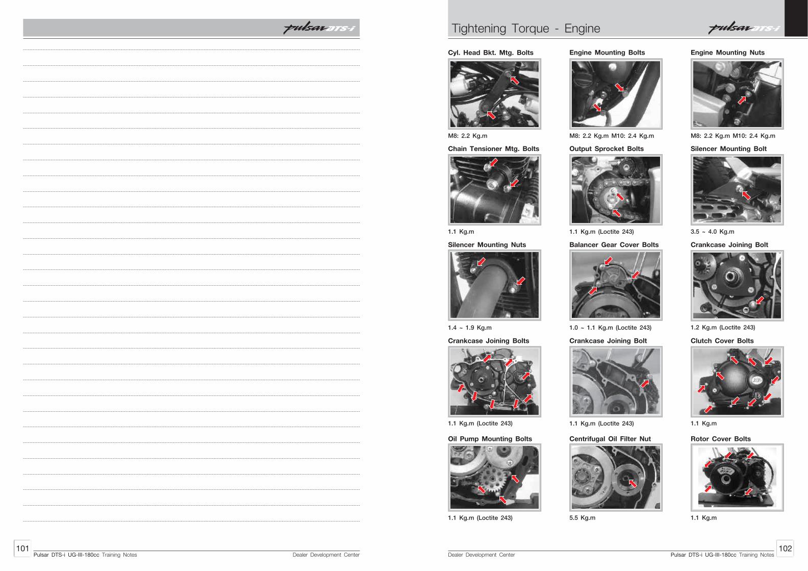
Dealer Development Center101
Dealer Development Center102
Cyl. Head Bkt. Mtg. Bolts
M8: 2.2 Kg.m
Engine Mounting Bolts
M8: 2.2 Kg.m M10: 2.4 Kg.m
Engine Mounting Nuts
M8: 2.2 Kg.m M10: 2.4 Kg.m
Chain Tensioner Mtg. Bolts
1.1 Kg.m
Output Sprocket Bolts
1.1 Kg.m (Loctite 243)
Silencer Mounting Bolt
3.5 ~ 4.0 Kg.m
Silencer Mounting Nuts
1.4 ~ 1.9 Kg.m
Balancer Gear Cover Bolts
1.0 ~ 1.1 Kg.m (Loctite 243) 1.2 Kg.m (Loctite 243)
Crankcase Joining Bolt
Crankcase Joining Bolts
1.1 Kg.m (Loctite 243)
Crankcase Joining Bolt
1.1 Kg.m (Loctite 243)
Clutch Cover Bolts
1.1 Kg.m
Oil Pump Mounting Bolts
1.1 Kg.m (Loctite 243)
Centrifugal Oil Filter Nut
5.5 Kg.m
Rotor Cover Bolts
1.1 Kg.m
Pulsar DTS-i UG-III-180cc Training NotesPulsar DTS-i UG-III-180cc Training Notes
Tightening Torque - Engine

Dealer Development Center103
Dealer Development Center104
Clutch Nut (LH Threads)
5.0 Kg.m
Camshaft Sprocket Allen Bolt
1.4 Kg.m (Loctite 243) 4.5 Kg.m
Rotor Mounting BoltStarter Motor Mounting Bolts
1.1 Kg.m
Kick Guide Allen Bolts
1.2 Kg.m
Drain Bolt
2.5 Kg.m
Cylinder Head Cover Bolts
3.5 Kg.m
Cylinder Head Cover Nuts
1.0 ~ 1.5 Kg.m
Spark Plugs (2 Nos.)
1.4 Kg.m
Front Axle Nut
4.0 ~ 5.0 Kg.m
Rear Axle Nut
8.0 ~ 10.0 Kg.m
Torque Rod Nut
3.0 ~ 4.0 Kg.m
Sleeve Nut
7.0 ~ 8.0 Kg.m
Rear Sprocket Mtg. Nut
1.8 ~ 2.5 Kg.m (Loctite 243)
Handle Bar Holder Bolts
2.0 ~ 2.2 Kg.m
Steering Top Cap Bolt
3.5 Kg.m 0.5 Kg.m
Stg. Stem Nut (slotted) Upper Clamp Allen Bolt
1.8 ~ 2.0 Kg.m
Lower Clamp Bolt
2.5 ~ 3.5 Kg.m
Swing Arm Pivot Nut
8.0 ~ 10.0 Kg.m
RSA Mounting Dome Nut
3.5 ~ 4.0 Kg.m
2.2 ~ 2.8 Kg.m
Caliper Install Bolts Brake Disc Allen Bolts
0.9 ~ 1.1 (Loctite 243)
Banjo Bolt Caliper
2.2 ~ 2.8 Kg.m
Pulsar DTS-i UG-III-180cc Training NotesPulsar DTS-i UG-III-180cc Training Notes
Tightening Torque - FrameTightening Torque - Engine

Dealer Development Center105
Dealer Development Center106
Fitting of Oil Seals and Bearings :
Crankcase RH (Clutch Side)
Use Bearing Driver set (P. No. 37 1030 61)
Fit :
• Bearing for ‘Input Shaft Assembly’
Use Bearing Driver set (P. No. 37 1030 61)
Fit :
• Bearing for ‘Output Shaft Assembly’
Crankcase LH (Magneto Side)
Use Bearing Driver set (P. No. 37 1030 61)
Fit :
• Bearing for ‘Output Shaft’
Use Bearing Driver set (P. No. 37 1030 61)
Fit :
• Bearing for ‘Input Shaft’
Note : Do not use inner guide while fitting the bearing for ‘Input Shaft’ in ‘Crankcase LH’ as this will damage the protruding lug of crankcase casting. Shield of brg. must be on crankcase side/protruding lug side.
Use Bearing Driver set (P. No. 37 1030 61)
Fit :
• Bearing for ‘Body Balancer gear Assembly’
Use Bearing Driver set (P. No. 37 1030 61)
Fit :
• Oil seal on ‘Guide Starter Assembly’
• ‘O’ ring on ‘Guide Starter Assembly’.
• Damper
Fit :
• Oil seal for ‘Output Shaft’
Fit :
• Oil seal for ‘Gear Changer Lever’
Clutch Cover
Fit :
• Oil seal for ‘Kick Shaft Assembly’
Fit :
• Oil seal for ‘Clutch Lever’ on ‘Clutch Cover’
Assembly of Sub assemblies :
Magneto Cover
Fit :
• ‘Harness’ in the ‘Cover’
• ‘Stopper’ and tighten the ‘Screw’ (Use Loctite 243)
• ‘Pulsar Coil’ and tighten 2 ‘Screws’ (Use Loctite 243)
• ‘Stator Assembly’ and tighten 2 ‘Bolts’ (Use Loctite 243)
• 2 ‘Dowel Pins’
Camshaft Assembly
Fit :
• Parallel Pin (A)
• De-compression Mechanism (B)
• ‘Washer’ (C)
• Washer (D)E
D
A
BC
F
Pulsar DTS-i UG-III-180cc Training NotesPulsar DTS-i UG-III-180cc Training Notes
Assembly - Engine Assembly - Engine

Dealer Development Center108
Dealer Development Center107
• Using Arbour Press
Fit :
• ‘Bigger Bearing’ (E)
• ‘Small Bearing’ (F)
Cylinder Head
Fit :
• Valve steam seals
• Slide the ‘Valve’ from below.
• Place the ‘Valve Springs’ (C&D) ( Inner and outer closed coiled ends placed at the bottom side)
• Valve Spring Retainer’ (B)
Using the sp. tool Valve Spring Compressor 37 1031 07 & Adaptor 37 10DJ 78
• Press the valve springs
• Fit the cotter valves (A) & release the special tool
Head Cover
Fit :
• Roller rocker arm
• Tappet Screw
• Tappet Nut
• 20 Rollers in cage outer
Note :
• There are 2 cages in roller rocker arm each cage holds 20 rollers
• Inner cage in Absent
• Multipurpose grease is to be applied in outer cage to hold the roller firmly while assembling
Note : Apply thin layer of oil on sliding surfaces of parts for smooth fitting.
Note : Repeat the same procedure for fitment of other roller rocker arm
Assembling Head Cover
Fit :
• Roller Rocker Arm
• Set of Plan and Wave Washer
• Rocker arm shaft
• Gaskets
• Dummy Plugs
A
B
D
C
F
E
AB
C
Similarly carry out the same procedure to assemble the other ‘Valve’ in the ‘Cylinder Head’.
Note : Ensure that there is no valve leakage. If required pour the petrol in intake and Exhaust manifold and observe leakage at valve head.
Note :
• Ensure concentrity of ‘Thrust Plate’ w.r.to ‘Clutch Wheel’, ‘Clutch Center’, ‘Clutch Housing’. Using Special Tool -
• The Special Tool can also helps in preventing the cracking / Bending of ‘Thrust Plate’ while removing and refilling the thrust plate.
Chain Tensioner Assembly
Fit :
• ‘O’ ring (F) in the body (I)
• ‘Thrust Washer’ (E)
• ‘Spring’ (D)
• ‘Cap’ (B) along with ‘Screw Internal’ and ‘Screw External’ (C) (Keep the ‘Spring’ and ‘Screw Terminal’ fully compressed inside)
• ‘Circlip’ (A)
Clutch Assembly
Assemble the clutch plates and friction plates in clutch center / clutch hub.
Fit :
• ‘Plain Washer’ in ‘Clutch Center’ / ‘Clutch Hub’
• ‘Bellivelli Washer’
• ‘Clutch Plate’(A) 1 Nos
• ‘Pressure Plate’ 5 Nos
• ‘Clutch Plate’ (B) 4 Nos
• ‘Clutch Plate’ (C) 1 Nos
• ‘Wheel Clutch’
• ‘Springs’ 4 Nos.
• ‘Thrust Plate’
• ‘Bolt’
Using Special Tool T1011168
Align the clutch assly into the clutch housing.
Fit :
• ‘Spacer’
• ‘Clutch Assly’
AB
E
D
C
HG
F
I
Pulsar DTS-i UG-III-180cc Training NotesPulsar DTS-i UG-III-180cc Training Notes
2
14
17
1
16
9
8
12
10
5
7
6
7
6
7
6
4
6
15
11
133
Assembly - EngineAssembly - Engine

Dealer Development Center110
Dealer Development Center109
B
A
C
Oil Pump
Fit :
• ‘O’ ring (A) on the ‘Oil Strainer’ (B)
• ‘Clip’ (C)
Kick Shaft Assembly
Fit :
• ‘Pinion Complete Kick Starter’ (I)
• ‘Washer’ (H)
• ‘Circlip’ (G)
• ‘Ratchet Kick Starter’ (F)
• ‘Spring Kick Starter Ratchet’ (E)
• ‘Washer Thrust’ (D)
• ‘Circlip’ (C)
• ‘Washer Thrust’ (B)
• ‘Thrust Washer’ (A)
Note : Match the dot mark of ‘Ratchet Kick Start’ with respect to ‘Spindle Kick Start Assembly’ and then slide ‘Ratchet Kick Starter’ (F) on ‘Spindle Kick Start’
Assembly Balancer Idler Gear Bearing
Using Bearing Driver set (P. No.: 37 1030 61)
Fit :
• Needle roller bearings in crankcase RH and Cover
Note : Apply oil on bearing OD before pressing bearings for smooth bearing
Note : Ensure that one spring end butts against spring dowel in ‘Balancer Idler Gear’ & the other end of spring should butt against the lug on ‘Scissor Gear’
Fit :
• ‘Springs’ (D)
• ‘Scissor Gears’ (C)
• ‘Circlip’ (B)
• Thrust washer
Similarly carry out the same procedure on other side of the gear to assemble the ‘Balancer Idler Gear’ completely.
C
E
F
G
H
I
BA
D
A C
B D E C B A
D
Note : Keep this Assembly balancer idler gear in loaded condition with special tool.
Gear Complete Starter Counter Assembly
Using Arbour Press
Fit :
• ‘Needle Roller Bearing’
Crankcase LH (Magneto Side)
Fit :
• ‘Guide Starter Assembly’
• 3 ‘Screws’ (A) (Use loctite 243)
Clutch Cover
Fit :
• Kick shaft oil seal (H)
• Oil inspection window
• Wire clip (I)
• Set dampers (K)
• Set of plates (L)
• Bolts (J)
• ‘Rack’ (C)
• ‘Shaft Clutch Release’ (B) in ‘Clutch Cover’ by rotating it slightly to match the teeth.
• ‘Parallel Pin’ (A) to lock the ‘Shaft Clutch Release’
• Washer
Loading the assembly Balancer Idler Gear
Using Special Tool - Balancer Gear Holder 37 10DJ 63
• Slide the ‘Assembly Balancer Idler Gear’ in special tool (A)
• Rotate the ‘Sc issor Gear ’ anticlockwise till the lug contactsthe torsion spring.
• Using a marker, mark the ‘Balancer Idler Gear’ and ‘Scissor Gear Tooth’
Using Special Tool
• Turn the ‘Scissor Gear’ anticlockwise such that 2 teeth pre-load is achieved. This can be confirmed by the markings done previously.
• Holding the ‘Scissor Gear’ pre-loaded in the above position slide the ‘Scissor Gear’ into the special tool completely.
Repeat the same procedure for loading the other ‘Scissor Gear’.
A
BG
FE
D
A
H
J
L
K
C
Pulsar DTS-i UG-III-180cc Training NotesPulsar DTS-i UG-III-180cc Training Notes
Assembly - EngineAssembly - Engine

Dealer Development Center112
Dealer Development Center111
• ‘Spring’ torsion clutch lever
• External lever
• ‘Bolt’
• Spring joint ‘A’ (F)
• ‘Plunger Plate’ (E)
• ‘Plunger oil (D)
• 2 ‘Dowel Pins’
• ‘Grommet (M)
• Oil feeler plug (G)
Apply loctite 243 to all damper fitment bolts.
Note : Ensure fitment of set of dampers and plate before fitting the above.
Input Shaft Assembly
Fit : From LH side of shaft (A)
• Thrust washer (K)
• Gear 4th (J)
• Splined washer (I)
• Circlip (H)
• Gear 3rd drive (G)
• Circlip (F)
• Splined washer (E)
• Gear 5th drive (D)
• Gear 2nd drive (C)
• Thrust washer (B)
Output Shaft Assembly
Fit : from LH side of shaft
• Gear 5th driven (M)
• Bush (N) with shoulder ringnd• Gear 2 driven (L)
• washer (K)
• Circlip (J)
Fit : from RH side of shaftrd• Thrust washer (H) behind the 3 gear on output shaft
rd • Gear 3 driven (G)
• Spline washer (F).
• Circlip (E)
• Gear 4th driven (D)
• Steel bush (C) with shoulder ring
• Gear1st driven (B)
• Thrust washer (A)
B C
D
E F
G H J
I K
A
ABC
D
EF
G
H
IJ K
L M
N
Clutch Side
Fit :
• ‘Parallel Pin’.
• ‘Sprocket Cam Drive’
• ‘Cam Chain’
Engine Assembling
Engine Central Part
Fit : (In Magneto side Crankcase)
• ‘Input and Output Shaft Assembly’ simultaneously.
• ‘Fork shifts’ along with rollers on ‘Input and Output Shaft Assembly’ (2 bigger fork shifts on output shaft and 1 smaller on input shaft).
Caution : Use a sharp blade or knife to cut off any protruding ‘Gasket’. This is very important for preventing any oil leakage from ‘Crankcase’ and ‘Cylinder Block Joint’. Don't apply grease / any adhesive to ‘Crankcase Gasket’ as these ‘Gasket’ when comes in contact with oil expands and seals hidden cavities.
Note : For ease of assembly of gears, remove gear 1st driven and insert both the input and output shaft assemblies with gears in mesh into their respective bearings. The gear box should be in neutral gear before ‘RH Crankcase’ is assembled on to ‘LH Crankcase’.
Fit :
• Crankcase RH
• Bolts (LH & RH Side)
Caution : Check oil supply to big end bearing by pumping oil in the clutch side end of crankshaft and lets oil dribble out of con-rod big end sides.
Fit :
• Crankshaft
Note : Hold the cam chain upright using a soft copper wire or a thread.
Fit :
• ‘Drum Change’
• ‘Shaft Gear Shift’
• ‘Kick Spring’ (A)
• 2 Dowels
• ‘Gasket’
A
Pulsar DTS-i UG-III-180cc Training NotesPulsar DTS-i UG-III-180cc Training Notes
Assembly - EngineAssembly - Engine
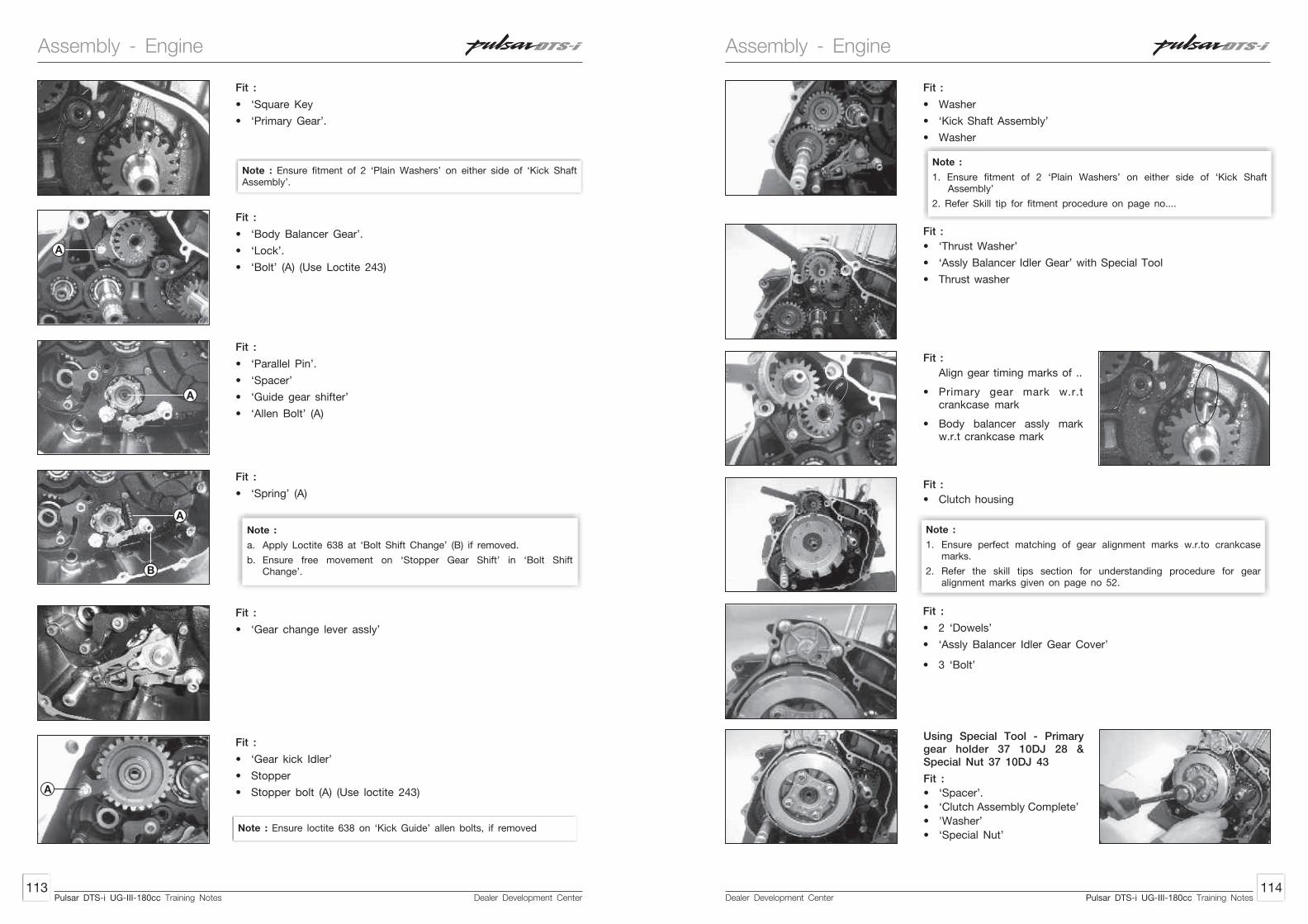
Dealer Development Center114
Dealer Development Center113
Fit :
• ‘Gear kick Idler’
• Stopper
• Stopper bolt (A) (Use loctite 243)
Note :
a. Apply Loctite 638 at ‘Bolt Shift Change’ (B) if removed.
b. Ensure free movement on ‘Stopper Gear Shift’ in ‘Bolt Shift Change’.
Note : Ensure fitment of 2 ‘Plain Washers’ on either side of ‘Kick Shaft Assembly’.
Fit :
• ‘Square Key
• ‘Primary Gear’.
Fit :
• ‘Body Balancer Gear’.
• ‘Lock’.
• ‘Bolt’ (A) (Use Loctite 243)
Fit :
• ‘Parallel Pin’.
• ‘Spacer’
• ‘Guide gear shifter’
• ‘Allen Bolt’ (A)
Fit :
• ‘Spring’ (A)
Fit :
• ‘Gear change lever assly’
A
A
A
B
A
Note : Ensure loctite 638 on ‘Kick Guide’ allen bolts, if removed
Note :
1. Ensure fitment of 2 ‘Plain Washers’ on either side of ‘Kick Shaft Assembly’
2. Refer Skill tip for fitment procedure on page no....
Fit :
• ‘Thrust Washer’
• ‘Assly Balancer Idler Gear’ with Special Tool
• Thrust washer
Fit :
• Washer
• ‘Kick Shaft Assembly’
• Washer
Fit :
• Clutch housing
Note :
1. Ensure perfect matching of gear alignment marks w.r.to crankcase marks.
2. Refer the skill tips section for understanding procedure for gear alignment marks given on page no 52.
Fit :
• 2 ‘Dowels’
• ‘Assly Balancer Idler Gear Cover’
• 3 ‘Bolt’
Using Special Tool - Primary gear holder 37 10DJ 28 & Special Nut 37 10DJ 43
Fit :
• ‘Spacer’.
• ‘Clutch Assembly Complete’
• 'Washer’
• ‘Special Nut’
Fit :
Align gear timing marks of ..
• Primary gear mark w.r.t crankcase mark
• Body balancer assly mark w.r.t crankcase mark
Pulsar DTS-i UG-III-180cc Training NotesPulsar DTS-i UG-III-180cc Training Notes
Assembly - EngineAssembly - Engine

Dealer Development Center116
Dealer Development Center115
Note : Special nut for input shaft has LH threads.
Fit :
• ‘Bearing with plunger’.
Using Special tool : Primary gear holder 37 10DJ 28
Fit :
• ‘Gasket’
• 3 screws
• Cover
Using Special Tool : Primary Gear Holder - 37 10DJ 28
Using Sp. Tool : Centrifugal Oil Filter Nut - 37 10DJ 43
Fit :
• ‘Centrifugal Oil Filter’.
• Washer
• ‘Special Nut’.
Fit :
• 2 Dowels
• ‘Oil Pump Assembly’
• 3 ‘Bolts’
Fit :
• ‘Starter Motor’
• Clutch cover gasket’
• ‘2 Dowels’
Note : Do not apply any grease to stick ‘Gaskets’ to the ‘Clutch Cover / Magneto Cover’ or ‘Crankcase’. As grease deteriorates the gasket material and reduces sealing effeciency.
Fit :
• ‘Clutch Cover’
• 10 ‘Bolts’
• ‘Bracket clutch cable’
• ‘Starter Motor Cap’
• ‘Screw’
• ‘Kick starter lever’
Magneto Side
Fit :
• ‘Shaft Starter Counter’.
• ‘Gear complete starter counter assly’.
• ‘Collar’
Fit :
• ‘Woodruff key’
• ‘Magnet along with gear starter clutch’.
Note : Always apply a thin layer of grease on to the roller bearing of starter counter gear.
Note : • Always apply a thin layer of grease to the roller bearing of gear
starter clutch.• Add few drops of oil on OD of gear starter clutch for lubrication.
Fit :
• ‘Plate starter clutch return (A)
• ‘Bolt’ (Use loctite 243) (B)
Note : When assembling the ‘Clutch Cover’ always remember that the entry of ‘Kick Shaft’ into the ‘Clutch Cover’ is the tightest as the tolerances are tightly controlled. One should concentrate on aligning the kick shaft bore and kick shaft first, rather than concentrating on the possibility of the plunger falling down. When working on vehicle It is advisable to loosen the ‘RH Rider Footrest’ which helps in the above and helps also in loosening and tightening of the 2 M6 bolts partially masked by the ‘Footrest’.
A
B
Pulsar DTS-i UG-III-180cc Training NotesPulsar DTS-i UG-III-180cc Training Notes
Assembly - EngineAssembly - Engine

Dealer Development Center118
Dealer Development Center117
Using Special Tool : Drift 74 9309 89
Fit :
• ‘Piston’
• ‘Piston Pin’
• ‘Circlip’
Using Special Tool : Rotor Holder H6 0721 00
Fit :
• ‘Washer’
• ‘Bolt’
Top End
Fit :
• 2 ‘Dowels’
• Block Base Gasket
Using Special Tool : Output sprocket holder 37 1030 53
Fit :
• ‘Bush’.
• ‘Sprocket’.
• ‘Plate drive Sprocket’.
• 2 ‘Bolts’ (Use loctite 243).
Fit :
• ‘2 Dowel’
• ‘Gasket’
Fit :
• ‘Magneto Cover’
• 5 ‘Bolts’
• Neutral switch coupler
Note : Place clean piece of cloth on the ‘Crankcase’ bottom end because their is chance of ring snap falling down while fitment.
Fit :
• Head gasket
• 2 ‘Dowels (A)
• ‘Chain Guide’ (Non tensioner side)
Note : Holding the chain firmly bring the piston assly to TDC position and Ensure ‘T’ mark on the rotor is matching with generator cover mark.
Note : Apply thin layer of oil in cylinder bore and piston assly when sliding inside for ease in fitment.
Using Special Tool : Piston Ring Holder 37 10DJ 30
Fit :
• Sl ide the ‘Cam Chain’ upright with soft copper wire / Thread into cylinder
• Slide the piston assly into cylinder
Fit :• ‘Cylinder Head Assly’.• 2 Dowels
Fit :• ‘Spark Plug Sleeve’.• ‘Grub Screw’. • ‘Spark Plug’
Note : Before fitting the sleeve spark plug apply thin layer of molybdenum disulphide grease on the entry chambers for the ‘O’ rings.
Pulsar DTS-i UG-III-180cc Training NotesPulsar DTS-i UG-III-180cc Training Notes
A
Assembly - EngineAssembly - Engine

Dealer Development Center120
Dealer Development Center119
AA
Fit :• ‘Cam Shaft’.• ‘Collar’.
Using Sp. Tool - 37 10DH 36Fit :• ‘Cam Sprocket’.• ‘Special Washer’. • ‘Allen Bolt’
Note :
• Ensure the sprocket marks are aligned horizontally with cylinder head top machined face and the piston is at TDC.
• Secure the ‘Cam Chain Sprocket’ in the special tool firmly and then tighten the sprocket allen bolt.
• Ensure that the ‘O’ mark on washer always faces outwards when tightening the allen bolt.
Fit :
• ‘Cam Shaft Cap’.
• Apply thin layer of liquid gasket to head cover
• ‘Head Cover’
Note :
• Do not apply liquid gasket on to the cam shaft cap and other inside mounting areas.
• Refer Skill Tip for more details
Fit :
• ‘Copper Plated Washer’
• Tighten bolts as per sequence
Ist : 4 Domed cap nut
IInd : 4 Long bolts of Head Cover
IIIrd : 2 Longest bolts of Head cover
Note : Improper tightening sequence of bolts may cause permanent warpage in cylinder head cover and it can get damaged permanently.
II
II
IIII
Fit :
• ‘Cam Chain Tensioner’
• 2 ‘Bolt’
• Release the tensioner plunger bolt
• ‘Dust cap’ and ‘O’ ring’
Adjust :• Check and adjust the tappet
clearance
Fit :• Tappet cap with ‘O’ ring• Cap magneto cover
Note : Always ensure that the piston is at the end of compression stroke and ‘T’ is seen from ‘Timing Inspection Window’ at generator cover. When adjusting tappet clearance.
Inlet Valve : 0.05 mm
Exhaust Valve : 0.1 mm
Pulsar DTS-i UG-III-180cc Training NotesPulsar DTS-i UG-III-180cc Training Notes
Assembly - EngineAssembly - Engine

Dealer Development Center122
Dealer Development Center121
Remove :
• Front axle self locking nut(A)
• Front axle (B)
• Distance piece (C)
• Wheel sensor (D)
• Pull out front wheel assly
Remove :
• 2 allen bolts (A) (on either side)
• Front mudguard assembly
Remove :
• Rubber grommet (A)
• 2 Allen bolts (B)
Remove :
• Speedometer sensor cable from wheel (A) and from fender clamp (B)
Skill Tip : Keep it aside safely
Remove :
• Caliper assembly front mounting bolt (A)
Skill Tip : Place wedge between pads. Remove front brake lever.
Skill Tip : Painted parts should be handled with utmost care to avoid scratches
B
A
A
A C D B
A
B
C
Remove :
• Loosen bolt (C)
• Pull down fork leg assembly by slowly rotating it
• Similarly carry out the same procedure to take out other side fork leg
Remove :
• Bellow clamp (A)
• Bellow (B)
• Bolt fork (C) from the top of front fork assembly along with the ‘O’ ring
Remove :
• Seat fork spring (8 Allen bolt)
• Spacer tube
• Washer
• Spring
• Fork oil in a container
• The dust seal and the snap ring over the oil seal
Recommended Oil Capacity per fork tube
Approx 145 + 2.5 ml. (Drain and refill)
Using Special Tool : Fork for Cylinder Holder Handle - 37 1830 06 & Adapter for Fork - 37 1830 11
Remove :
• Allen screw that is located at bottom with the help of allen key (A) by holding the fork piston with the help of a adapter (B) and holder
• Piston assembly
Using Special Tool : Front Fork Tube Extractor - 74 9310 15
Remove :
• The inner tube assembly will not come itself because of two DU bushes fitted. One bush is fitted on inner tube and other bush is fitted in outer tube.
• Fit the front fork tube on the vehicle by assembling the special tool (A) and lock it at number plate mounting screw.
• Rotate the special tool handle to seperate the inner tube from outer tube as shown in the fig.
Skill Tip : • Fit the fork tube without touching head light fairing• Rotate special tool without hitting number plate.
C
A
B
B
A
A
Remove :
• Inner tube (B) of front fork with DU bush
• Oil seal (C) for outer tube
• Guide bush washer (D)
• Spacer
• Bushing B
C D
Pulsar DTS-i UG-III-180cc Training NotesPulsar DTS-i UG-III-180cc Training Notes
A
Dismantling Front Fork Dismantling Front Fork

Dealer Development Center124
Dealer Development Center123
Using Sp. Tool : Fork for cylinder holder adapter - 37 1830 08/11
Fit :
• Place Fork cylinder set in the inner tube, cylinder base & place it in outer tube. Hold the piston with the help of special tool.
• Bolt it from lower side of outer tube with Allen key.
• Guide bush, washer
• Oil seal using special tool (A)
• Snap Ring
• Dust seal
• Spring and fill oil.
• Seat fork spring and Collar fork.
• Bolt
Similarly carry out the same procedure to assemble the other fork.
Fit :
• Front wheel assembly.
• Front axle (A)
• Tighten self lock nut
• C a l l i p e r a s s e m b l y a n d tighten 2 bolts
• Speedometer sensor cable connection.
Fit :
• Slide the front fork assly in the fork holder
• Allen bolts
• Bolt fork at the top end
Similarly carry out the same procedure for fitment of the other shock absorber.
Fit :
• Front fender
• 2 Allen bolts (A) (2 on either side)
Skill Tip : The Part Name & No written on oil seal should face up side i.e. towards technician while fitting.
Caution : Don’t apply excess grease or any other lubricant on the wheel sensor case.
A
A
A
Master Cylinder
Working:
When the brake lever is in idle condition, there is no pressure inside the cylinder. The feed & compensation aperture are open & connect the pressure chamber & compensation chamber to reservoir.
When the brake lever is operated, the push rod pushes the piston inside the cylinder. A small quantity of fluid returns from pressure chamber to reservoir before primary seal completely blocks the feed aperture. Once this condition is achieved, any force exerted on the lever is transformed into pressure in the brake circuit.
When the brake lever is released, the piston is pressed back quickly by the return spring to its idle position. Due to this, a vacuum is generated in the pressure chamber & the fluid in the compensation chamber flows to pressure chamber through the primary seal, the external edges of which flex approximately to allow fluid to pass to pressure chamber. After return of the master cyl. piston, the caliper retracts (after some relative time delay). This causes the fluid in the pressure chamber to return to the reservoir through feed aperture.
Master Cylinder Dismantling and Assembling
Dismantling :
• Remove front brake switch and its connection (A)
• Remove front brake lever by removing the nut and pivot bolt (B)
• The push rod boot (One end of the boot is held in a groove in the push rod and its other (larger) end is held in a groove in the cylinder body).
• Top cover by removing 2 screws (C)
• Nylon Cap (D)
• Rubber diaphragm (E)
A
B
C
D E
DiaphragmReservoir
Secondary seal
Spring
Compensation operature
Piston
CompensattionChamber
Master cylinder body
Primary seal
PressureChamber
Outlet Port
Feed aperatureCover
Air Vent
Brake Lever
Pulsar DTS-i UG-III-180cc Training NotesPulsar DTS-i UG-III-180cc Training Notes
Assembling Front Fork Front Disc Brake

Dealer Development Center126
Dealer Development Center125
• Brake fluid from the reservoir with the help of syringe/syphon pump
• Master cylinder along with hose assembly from handle bar by removing the 2 flanged 8 bolts (F) on the clamp.
• Brake hose from master cylinder outer by removing banjo bolt (G) • Wipe out clearly the outer surface of master cylinder.
• Hold the master cylinder in a soft jaw vice.
• Remove circlip with the help of a plier, by pressing the piston slightly inside the bore, with a nylon or wooden rod.
• Take out the piston assembly along with the Return spring by pulling it out.
If transparent window in the cylinder body for level indication needs replacement (due to damage, etc.) proceed as follows:-
• Remove Lock Ring on the window with screw driver
• Remove window and ‘O’ ring.
Skill Tip :
• Ensure that there should not be any spillage of brake fluid on
painted parts
Safety Tip :
• Take care of your eyes while working with brake fluid.
G
F
Master Cylinder Assembly :
• Never allow mineral oil to come in contact with seal or other rubber parts of disc brake, since it will cause damage to these parts.
• Free play at the end of the lever is provided to ensure that in the free condition, the piston does not remain in the pushed condition, This ensures that there is no pressure in the system when the brake is not applied.
CaliperBody
CarrierBracket
DiscPad
Dust SealDisc
Piston
Piston
Pin
DiscPad
Seal
Caliper Assembly
Working :
In the brake released condition, the brake fluid inside the caliper is at atmospheric pressure and the disc rotates freely as the pads do not press against it.
When the brake lever is operated, the pressure generated in the hydraulic circuit acts on the caliper pistons. The caliper in turn push the friction pad on the side of the caliper body against the rotating disc. The friction pad on the other side of the disc also presses against the disc due to reaction force on caliper body. Thus both the friction pads press against the disc, thereby generating braking torque.
When the lever is released, the pressure in the hydraulic circuit return to atmospheric level. The friction pads return to idle position due to return of the caliper pistons which is due to the spring action of the seals.
When the pads wear, the pistons move further towards the Disc during brake application, but after release of pressure they retract only to the extent allowed by the spring action of the seal. The pistons therefore take up new positions in idle condition, and thus provide automatic adjustment to compensate for pad wear. Due to this reason, there is no need for free play adjustment in the Brake Lever in Master Cylinder.
Dismantling of Caliper
Dismantling the Assembly
• Remove caliper mounting bolts (A)
• Remove banjo bolt (B)
• Remove caliper from fork
Removal of Pads :
• Remove the pad retaining body’s Allen bolt
• Remove the pads
• Remove the pad spring from the caliper body with a screw driver
Piston and Piston Seal Removal :
• Wipe out cleanly, the outer surface of the caliper.
• Remove LH pad retaining case by removing allen bolts
• Put a wooden wedge in between the piston and caliper.
• Blow compressed air into cylinder through benzo bolt hole where the brake hose was fitted, with the air pressure, the piston will be pushed out of cylinder.
BA
Bleeder Screw
Hose
BanjoBolt
Pulsar DTS-i UG-III-180cc Training NotesPulsar DTS-i UG-III-180cc Training Notes
Front Disc BrakeFront Disc Brake

Dealer Development Center128
Dealer Development Center127
Brake Fluid for Disc Brakes
Always use only recommended brake fluid from sealed container to ensure durability of the system. Never reuse brake fluid removed from a system.
Important points on 2 wheeler disc brake system :
1. Since front disc brake is more powerful than drum brake, apply front and rear brake together gradually. Avoid braking during turning.
2. Use only DOT 3 or DOT 4 brake fluid from a sealed container from recommended makes.
3. Do not apply mineral oil for cleaning any brake parts. Use only brake fluid for cleaning the seals.
4. Do not apply mineral based grease on bore, pistons and seals of master cylinder and caliper. Apply only recommended assembly fluid.
5. Do not use cotton cloth to wipe cylinder bore, fibres of cloth will remain in cylinder bore surface.
6. Ensure dust free condition during assembly.
7. Do not polish friction disc with sand paper, as hard particles deposited in the lining may damage steel disc.
8. While filling the reservoir after bleeding, ensure that drops or splashes do not remain on the painted surface or plastic surface, since brake fluid is corrosive.
Warning : Do not apply high pressure compressed air, which will cause the piston to jump out of the cylinder. The piston should be taken out gradually with moderately compressed air. Care to be taken not to damage the sealing surface of the inlet port while applying air pressure.
• Do not place your finger in front of the piston while applying compressed air to push it out.
• Remove piston seal using a thin part like a thickness gauge, etc.
Caution : Be careful not to damage inside (bore side) of the cylinder.
Skill Tip : While assembling use loctite paste 243 on allen bolt for mounting LH pad retainer case.
• Assemble the caliper assly in reverse order of dismantling
Air Bleeding of Disc Brake System :
� For air bleeding from front Hydraulic brake system first top up the master cylinder with hydraulic oil.
� Operate the brake lever slowly in order to get filled the oil in the circuit.
� Connect transparent tube to the bleeder screw at caliper or syphon pump
� Operate the brake lever and keeping in pressed position loosens the bleeder screw so that some oil escapes with the air bubbles.
� Keep on operating the brake lever till the air bubble escape out completely through bleeder screw, and top up the master cylinder if required.
� Once the air escapes out from the hose pipe the brake lever meets resistance, which indicates completion of air bleeding
� After completing the bleeding, top up the master cylinder up to the maximum level mark.
• Also syphon pump can be used for air bleeding
Brake Disc Inspect during every 5000 Km. and every 2500 Km thereafter.
Check for excessive scoring marks on friction surface of disc, and run out.
Master Cylinder & Caliper Inspect every 5000 Km for leakage.
Brake Hose Inspect for leakage & damage during every service / every 2500 Km.
Brake Pads lInspect during every 2500 Km thereafter for wear and condition of linings.
Inspection and Maintenance Frequency
Check Points Frequency
Brake Fluid Level / Leakage Inspect during every service / every 2500 Km refil up to upper limit (till step on the inner side of the reservoir) if level is low.
Replace brake fluid every two years. (In severe operating conditions, replace in a year.)
Brake Lever Operation Inspect during every service/every 2500 Km
Pulsar DTS-i UG-III-180cc Training NotesPulsar DTS-i UG-III-180cc Training Notes
Front Disc BrakeFront Disc Brake

Battery
Technical Specification :
• Type & Capacity 12V - 9 AH
0• Specific gravity of electrolyte 1.24 for use above 10 Cfor initial filling of new battery
0• Specific gravity of electrolyte 1.28 for use above 10 Cfor initial filling of new battery
• Initial charging duration 10 ~ 15 hrs
• Initial charging current 0.9 to 1 Amp
Dealer Development Center130
Dealer Development Center129
Initial Charging Procedure
1. Fill each cell with battery grade sulfuric acid of the correct Sp. gravity (1.24 at room temp.
0for use above 10 C and 1.28 at room temp. 0for use below10 C).
2. Allow the battery to stand for 30 min. after filling.
3. Keep vent plugs open. Connect battery to charger and charge at 0.9 Amp.
4. Charge continuously for 10~15 hours taking Sp. gravity readings every hour. Fully charged condition is indicated when all cells are gassing freely and evenly and show no rise in specific gravity over 3 successive readings.
5. After charging push vent plugs strip firmly into place and wash off acid spillage with water and dry the battery.
Checking the Specific Gravity
The charge condition of the individual cell can bechecked by measuring Sp. gravity of electrolyte in that cell. The specific gravity of electrolyte can be checked by using Hydrometer having small diameter spout.
For measuring the Sp. gravity bring the electrolyte in the Hydrometer to eye level, and read the graduations on the float scale bordering on the lower meniscus (i.e. curved down portion of electrolyte surface) as shown in the figure. After charging is over, fit the filling caps strip, wash acid spillage with water. Dry the battery. Ensure terminals are clean.
Battery Installation:
Install the battery on vehicle as described below
a. Ensure that in all six cells the level of electrolyte is near the maximum level mark.
b. To clean and dry the surface wipe the top of the battery with a clean cloth. Install the
happens, the chemical reactions within the battery are affected and results in loss of capacity. Mostly the causes of sulphation are as under :
a. Undercharging.
b. Standing in a partially or completely discharge condition for long time.
c. Low electrolyte level : If electrolyte level is permitted to fall below the top of the battery plates, then the exposed surfaces will harden and will become sulphated.
d. Adding acid : If acid is added to a cell in which sulphation exists the condition will be aggravated.
e. High specific gravity : If specific gravity is higher than the recommended value, then sulphation may occur.
f. High temp.: High temperature accelerates sulphation, particularly of an idle, partially discharged battery.
Voltage of the sulphated battery : -
Cells of the sulphated battery will show low specific gravity. Follow the procedure given below.
• Check voltage before charging.
• Charge for 2 hours
• Check voltage every 1 hour. If voltage increases then continue charging. But if voltage does not increase, discontinue charging. Otherwise battery charger will get permanently damaged. If battery is not badly sulphated (i.e. voltage more than 9 volts), then battery can be revived by special treatment. In such case it is advisable to give sulphated battery to authorised dealer of battery manufacturer for necessary special treatment.
Battery Maintenance
For the optimum performance and longer battery life the maintenance of battery is important.
a. Always keep the battery clean and dry.
b. Visually inspect the surface of the battery container. If there are any signs of cracking or electrolyte leakage from battery, replace the battery.
Never add acid or ordinary tap water for topping up since this will shorten Battery life.
Non Use Maintenance
When the vehicle is likely to remain off-road for longer, time (say more than a month) then Non Use Maintenance should be carried out as follows otherwise the battery may get sulphated and permanently damaged.
a. Remove the battery from vehicle.
b. Maintain electrolyte at ‘Upper Level’.
c. During off service period, battery should be charged once a month.
d. Keep the battery fully charged.
e. Store the battery in cool, dry place.
f. Keep the battery away from rain, dew, moisture and direct sunlight.
How to Determine Condition of Battery
Specific gravity check: - Whether battery is fully charged or partially charged, it will always show same “no load voltage” of 12 volts or more (unless battery cells are damaged due to sulphation etc). But specific gravity of the fully charged battery and partially charged battery will be different. Fully charged battery will show Sp. gravity of 1.240 while partially charged battery will show less specific gravity. Therefore, specific gravity check is very important to know condition of the battery.
battery inside the box provided on floor board. Fasten the battery firmly with bracket & allied fasteners.
c. Connect cables to the positive and negative terminals properly. Reverse connections will damage the charging system permanently.
d. Always connect the “negative (earthling) terminal” at Iast.
e. Clean the battery terminals and cable connections. Smear them with petroleum jelly to avoid corrosion
g. Check that the battery cable connections are firm and cables do not rub against any metal components.
Battery Charging Procedure :
This is a M.F (Maintenance Free) battery. This battery is not having any exhaust tube instead it has a unique vent mechanism.
The electrolyte level in this M.F. battery needs to be topped up with distilled water once in a year. In case battery in discharged and needs to be charged using battery changed procedure is as follows :
• Remove battery from vehicle
• Clean battery throughly
• Remove vent plug strip
• Top up level with distilled water in between Min and Max. level
• Connect battery to charge and ensure respective terminal are connected properly
• Set charging current at 0.9 A DC
• Charge battery for 3/4 hrs., then check voltage and special gravity.
• Voltage should be 12.5 volts and special gravity in all 6 cells should be 1.240. This is a confirmation check for a fully charged battery.
• Disconnect the battery from the changer.
• Fit vent plug strip firmly.
• Connect battery on to vehicle.
• Apply petroleum jelly on to the battery terminal.
Battery Sulphation
A sulphated battery is one which has been left s tand ing in a d i scha rged cond i t ion o r undercharged to the point where abnormal lead sulphate has formed on the plates (Sulphate cells looks like white crystal like sugar). Where this
Pulsar DTS-i UG-III-180cc Training NotesPulsar DTS-i UG-III-180cc Training Notes
Read Here
Hydrometer
Maintenance - Electricals Maintenance - Electricals

Relay (Inspection Using Multimeter) :
• Also this relay can be checked on electronic Test jig.
Dealer Development Center132
Dealer Development Center131
Switches :
a. Front Brake Light Switch Inspection :i. Turn ON the ignition switch.ii. The brake Light LED Blank should get on
when the front brake (Lever is pressed) is applied.
iii. If it does not, check the Front brake switch.
Lever Pressed
Lever Released
Brown Blue
b. Rear Brake Light Timing Inspection :i. Turn ON the ignition switch.ii. Check the operation of the rear brake
coils light switch by depressing the brake pedal
iii. If it does not operate as specified, adjust the brake light switch or check Rear brake switch
Pedal Pressed
Pedal Released
Brown Blue
c. Fuel Level Indicator :i. For knowing then quantity of fuel inside
the fuel tank at a glance, is provided on Speedo consle. The fuel gauge works on the principle of ‘variable resistance’. The fuel gauge works on D.C supply.
ii. For checking the resistance across the sender and across the gauge, make the connections verify the readings, make the connections verify the readings as tabulated below
Tank (Float)Connection Resistance
White / Yellow
Meter
10 W
Black / Yellow
Full
(Highest position)
Empty
(Lowest position)
4 - 10 W
95~105 W
d. Neutral Switch :i. The neutral switch will be in ON position
only when the engine is in neutral position.
ii. The neutral light will not glow when vehicle is in geared position
‘ON’ (Vehicle in neutral)
‘OFF’ (Vehicle in gear)
Brown Blue
e. Ignition Switch :
‘OFF’
‘ON’
Brown White Black / White Black / Yellow
g. Stator Plate Coils Inspection :i. Disconnect stator plate couplerii. Set multimeter on ohm range. (Ohm Meter)
• Pickup Coil Resistance :
Meter +ve Meter -ve
ReadingRange Connections
2 K WWhite/Red Black/Yellow
200+22ohm
• Excitor Coil :
Meter +ve Meter -ve ReadingRange
200 W Red Black/Yellow 14+1.4 W
• Battery Charging Coil :
Meter +ve Meter -ve ReadingRange
200 W Blue/White Blue/White 1.3+0.13 W
• Lighting Coil :
Meter +ve Meter -ve ReadingRange
200 W Yellow/Red Black/Yellow 0.7+0.07W
CDI Unit and H. T. Coil Inspection :
• CDI unit can be checked using OK H.T. coil on Electronic Test jig
• Similarly H.T. Coil can be checked using OK CDI unit on electronic Test jig
H.T. Coils : (Inspection Using Multimeter)
• Measure the primary winding resistance as follows
• Connect the hand tester between the coil terminals.
• Measure the secondary winding resistance as follows
• Remove the plug cap by turning it counter clockwise.
• Connect the tester between the spark plug leads.
• Measure primary winding resistance.
• Measure secondary winding resistance.
• If the valve does not match as per, replace the coil.
Primary Winding 0.40 to 0.49 Ohms
Secondary Winding 4.23 to 5.17 K Ohms
Coil Resistance Meter +ve Meter -ve Reading
X 200 Ohm 55+5.5 OhmGreen/WhiteBrown
• If the meter reads as specified, the ignition coil windings are probably good. However, if the ignition system still does not perform as it should after all other components have been checked test replace the coil with one known.
• Visually inspect the secondary winding lead.
• If it shows any damage, replace the coil.
Fuse Inspection (Capacity = 10 Amp)
• Inspect the fuse element
• If it is blown out, replace the fuse.
• If a fuse fails during operation, the electrical system to determine the cause, and then replace it with a new fuse of proper amperage.
Caution : When replacing a fuse be sure the new fuse matches the specified fuse rating for that circuit. Installing of a fuse with a higher rating may cause damage to wiring and components.
Pulsar DTS-i UG-III-180cc Training NotesPulsar DTS-i UG-III-180cc Training Notes
Maintenance - ElectricalsMaintenance - Electricals

Dealer Development Center134
Dealer Development Center133
Rectifier & Regulator Assembly :
AC Voltage Measurement :
To measure AC voltage, open the headlight housing. Start the engine and set it at 4000+25 RPM. Ensure that the headlight, tail light, Speedometer light are ‘ON’ and the dipper switch is at ‘Hi beam’ position.
Connect AC voltmeter in parallel across the AC circuit load by connecting the +ve meter lead to red/black lead from the dipper switch and the -ve meter lead to ground.
Measure AC lighting voltage at 4000+25 RPM. The voltage should be 13.5+0.5 V. Stop the engine. Disconnect the meter leads. Reassemble the headlight housing.
DC Charging Voltage Measurement : (Use ful ly charged battery while measuring)
To measure the DC voltage; set the meter at 20VDC range. Connect the meter +ve lead to white from RR unit and meter -ve lead to ground. Start the engine and set it at 4000+25 RPM. Measure the voltage with and without headlight switch to the ON position. Stop the engine disconnect the meter leads.
Meter Range Specification at 4000+25 RPM
AC 2o Volt 13.7 + 0.3 V
AC Lighting Circuit :
Meter Range Specification at 4000+25 RPM
DC 20 Volt 14 ~ 15 V
Meter Range Connection Specification
DC10A Meter +ve White/Blackterminal of R/R
Meter +ve White/Blackterminal of R/R
Battery DC Charging current : (Use fully charged battery while measuring)
To measure the DC charging current, set the meter at 20ADC. Connect meter+ve lead to White/black lead from RR Unit and meter -ve lead to battery +ve lead.
Start the engine and set it at 4000+25 RPM. Measure the DC charging current. The DC charging current should be 2 A max stop the engine and disconnect meter leads. Connect the RR unit and battery
Meter -ve Battery (+) lead (White)
2 A max at 4000+25 RPM
L/W
L/W W
REGULATOR RECTIFIER UNIT
L/W
L/W W
MAGNETO
B
FUSE(10 Amps.)
R
W/B
STARTER RELAYWITH DAMPER
BATTERY12V-9Ah
L/W
L/W
Multimeter connected in Parrallel with Battery for checking DC charging voltage
14.2
MAGNETO
.90
L/W
L/W W
B
FUSE(10 Amps.)
R
W/B
STARTER RELAYWITH DAMPER
BATTERY12V-9Ah
L/W
L/W W
L/W
L/W
Multimeter connected in Series with Battery
for checking DC charging Current
Pulsar DTS-i UG-III-180cc Training NotesPulsar DTS-i UG-III-180cc Training Notes
INS
TRU
MEN
T C
LUS
TER
Y/RY
RY
W
Y/R
MAGNETO
B
FUSE10 Amps
R
W/B
STARTER RELAY70A RATING
BATTERY12V-9Ah
POSITION LAMP12V-5W- 2 NOS.
B/Y
R
R/B
R
R/B
OFF
ON
R/Y
W
Br
HEAD LAMPASSY/LAMP
12V-35/35W HS1
IGNITIONSWITCH
R
R/B
B/Y
R
W
PIN NO.3HIGH BEAM INDICATOR
PIN NO.2INSTRUMENT CLUSTER + INPUT
PIN NO.11COMMON GROUND
PIN NO.13POSITION LAMP ON- INPUT
PIN NO.20PERMANENT BATTERY + INPUT
BODY CONTROL UNIT
R/Y
R/B
AC INPUT& OUTPUT
W
Br
R
R/B
R/Y
20 P
IN C
OU
PLE
R W
ITH
DU
ST
CO
VER
CONTROLSWITCH RH
REGULATORRECTIFIER
UNITY
/RY
TAIL/STOPLED ASSLY
RR
B/YB/Y
BrBr
NO.PLATELAMP5 W
LIGHTINGCOIL
13.5
-+
REGULATOR RECTIFIER UNIT
Maintenance - ElectricalsMaintenance - Electricals

Dealer Development Center136
Dealer Development Center135
Speedometer/Tachometer Console
The speedometer has a wide Digital LCD screen with a orange backlit display mode for superb visibility of display during night riding condition.
This entire speedo console houses following :
• A large analogue tachometer with self testing mechanism.
• A red LED indicator showing low fuel level inside the fuel tank. And also indicates a flashing signal when engine RPM exceeds above 9000 RPM. Thus ensuring safety of rider and engine.
• Digital Displays for
- Odometer
- Trip meter (Unique facility of resting the trip meter 1 & 2 respectively)- Fuel level indicator
• A row of indication LED displaying functioning of
- Neutral Light
- High beam
- Turn signal
- Side stand ON
with a unique Day-Night mode functioning feature for riders convenience and safety.
Vehicle Speed Sensor
• Non Contact Wheel Sensor : In LCD speedo console there are
no physical moving parts as sensing of wheel speed is through
a Non Contact hall effect Sensor.The hall sensor is a electronic switch which operates due to
magnetic field. The sensor has 3 wires supply, earth and output
whenever during rotations of wheel magnet passes through
sensor. A signal is given to speedometer through a wire to
speedometer which displays speed of vehicle in km/hr.
• Tail Lamp : The illumination for Tail lamp and Brake lamp are
done through 2 rows of LED’s each. These are high intensity
LED’s the main advantage of these LED’s is they consume very
less power. i.e LED consumes 3W power against 21 W power of
a conventional brake lamp. When you operate light control
switch to glow but intensity will be very low. As soon as you
operate brake switch the brightness of LED increases to size
you bright light.
This changeover of intensity is maintained with the help of
electronic circuit placed inside Tail Lamp Console assly and is a
totally sealed unit.
Horn Switch
Pass SwitchHead Light High Beam
HornBCU
BCUNote : The speedometer console has a unique builtin memory logic function which stores all the data like distance covered etc. in its memory even if DC supply is disconnected.
• Back-lit, Non-contact Handlebar switches : The control switches on both sides of the handlebar are conventional to look as, in terms of switch positioning. The main features of these are ...
• Operation is based on non-contact
• Switching is done without physical contact• There is no wear and tear• Life would be equal to that of the bike
itself.• The operational force required for the
switches has been kept as low as possible to give a light feel and reduce fatigue for the rider.
Working of Switches : These are non-contact type switches, so instead of contact set it consists of hall sensor and magnet combination. Whenever any handlebar switches is pressed the hall sensor gets operated and its output signal is gives to a BCU (Body Control Unit) and BCU further calculates and gives precise signal to the respective unit for functioning. e.g.
• Self Indicator Switch : In the conventional type of switches the rider has to manually depress the Turn Indicator knob or return the Turn indicator knob to its non-signalling position. In UG III there is no separate press to off buttons for cancelling side indicator signal. This feature is achieved by providing a self cancelling hall sensor and magnet fitted on steering column assembly. This cancellation signal is processed through BCU and then side indicators are switched off. The self cancelling feature automatically turns of the indicator of the indicator under 3 conditions.• The first indication is when after the turn has
been completed and the handlebar comes to a straight ahead position, the indicators switch off by themselves.
• The second condition is when the rider has selected a right or left turn but not physically done the turn and is continuing to go straight ahead and may be unaware of the enabled turn signal too. A timer function gets enabled which switches off the indicators after a pre-set time.
• The third condition is when the rider has selected for eg. a left turn, but changes his
mind and wants to continue straight ahead. The rider has only to re-select the opposite side indicator again to cancel the previously selected indication. (There is no depress to cancel function)
The other feature which has been incorporated in the switches is the illumination of the tell-tale icons. The illumination is backlit by LED’s which again are long-life and have a pleasant bluish-white glow to them. All the icons like the turn indicators, low beam, high beam, horn, starter etc. glow when the Parking or Headlight switches are put ON.
Checking of switches on handle bar : As like in conventional switches, since switch is not having any electrical contact, We can’t check the switch functioning (Continuity) by multimeter. But it can be checked on electronic test jig.
• Clutch Switch : The clutch switch has 3 wires and it has contact configration of
This vehicle is not having interlock relay Instead its working is taken care of by clutch
Light Green Yellow/GreenBlack/Yellow
OFF Clutch Lever Released
ON Clutch Lever Released
• Body Control Unit (BCU) : This is a sealed Electric Control Unit located inside head light assly.
- In case of overload or short circuit, BCU has a short circuit/overload prevention facility.
- This vehicle does not have a flasher. The flasher operation is carried out by BCU only.
- In case of failure of one of the filaments of head lamp. The BCU will automatically changeover to IInd filament. This is provided for safety rider during night driving conditions.
- If customer operated starter switch contunuously 3 times in a go for 4 th cranking BCU will disable cranking operation and next cranking would be possible after 20 second only. This feature is added which gives better battery life.
Maintenance :• Ensure no direct high pressure water
water is applied on Speedo console and wheel sensor.
Pulsar DTS-i UG-III-180cc Training NotesPulsar DTS-i UG-III-180cc Training Notes
Maintenance - ElectricalsMaintenance - Electricals

Dealer Development Center138
Dealer Development Center137
• Speedo console should not be kept inverted
• Ensure there are no scratches/breakage on console cover
` • Don’t open rubber pins located on back side of speedo under any under any circumstances.
• Ensure speedo console and harness mating coupler is always covered by rubber cover.
• Handle wheel sensor carefully while working on front brake drum relating problems.
• Ensure sensor cable is intact.• Do not apply in grease or lubricant in
between the rotating parts.• Do not open control switches and don’t
apply any grease or lubricant.
B/Y
INSTRUMENT CLUSTER
Y/R
L/W
L/W
Y
B Y/W
B/Y
B/Y
B/Y
SID
E S
TAN
DS
WIT
CH
B/Y
R/W
HO
RN
(R
H)
R
Y
B/Y
Br/B
W
B/Y
Y/RW/R
L/W
R
L/W
COIL PULSING
MA
GN
ETO
B
B/W
B/Y
B
B
STA
RTE
RM
OTO
R
R
FUS
E10
Am
ps
RW/B
STA
RTE
R R
ELA
Y70
A R
ATI
NG
BA
TTER
Y12
V-9
Ah
LgLg
B/Y
W/Y
FUEL
LEV
ELG
AU
GE
PO
SIT
ION
LA
MP
12V
-5W
- 2
Nos
.
BBr
B/Y
W/Y LgGr G RR/B
RB/Y
B/Y
R/B
O F F
O N
Y/R
L/W
L/W
W R /
R
B/Y
B/Y
Br/B
B/Y
GG
B Y/
B/Y
B/Y
B/Y
/B
YB
/Y
/B
Y/
B Y
L /B
Y R/
R W/
B YL
Gr
Gr
Br
LL
Br
GG
Br
LL
Br
R/Y
B/WWBr
Gr
Gr
NEU
TRA
LS
WIT
CH
HO
RN
(LH
)
SIG
NA
LLA
MP
REA
R L
H
SIG
NA
LLA
MP
REA
R R
H
REA
R B
RA
KE
SW
ITC
HFR
ON
T B
RA
KE
SW
ITC
H
SIG
NA
L LA
MP
FRO
NT
LH
HEA
D L
AM
PA
SS
Y/L
AM
P12
V-3
5/35W
HS
1
IGN
ITIO
NS
WIT
CH
SIG
NA
L LA
MP
FRO
NT
RH
LAM
P 1
2V-1
0W
EAR
TH-F
RA
ME
CA
BLE
AS
SY.
RED
CA
BLE
AS
SEM
BLY
EAR
TH
CLU
TCH
SW
ITC
H
Y/G
B/Y
Br
Y/G
B/Y
O/Br
O/Br
Y/G
SPAR
KPL
UGH
.T.
CO
IL
B/R
SW
ITC
H A
SS
Y.
R
Lg
Lg
R/W Br
R/B
O/B
r
W/Y
L/W Gr G Lg B B
/Y R W
PIN
NO
.1V
EHIC
LE S
PEE
D S
ENS
OR
+ I
NP
UT
PIN
NO
.2IN
STR
UM
ENT
CLU
STE
R +
IN
PU
T
PIN
NO
.3H
IGH
BEA
M I
ND
ICA
TOR
PIN
NO
.4TA
LE-T
ELL
SID
E S
TAN
D I
ND
ICA
TOR
PIN
NO
.5FU
EL G
AU
GE
IND
ICA
TOR
PIN
NO
.6V
EHIC
LE S
PEE
D S
ENS
OR
OU
TPU
T
PIN
NO
.7TA
LE-T
ELL
BLI
NK
ER-
RH
IN
PU
T
PIN
NO
.8TA
LE-
TELL
BLIN
KER
- LH
IN
PU
T
PIN
NO
.9TA
LE-T
ELL
NEU
TRA
L IN
DIC
ATO
R
PIN
NO
.10
TAC
HO
METE
R
PIN
NO
.11
CO
MM
ON
GR
OU
ND
PIN
NO
.13
PO
SIT
ION
LA
MP
ON
- IN
PU
T
PIN
NO
.20
PER
MA
NEN
T B
ATT
ERY
+ I
NP
UT
O/B
r
R/W
R/W
L/W
L/W
B/Y
VEH
ICLE
SP
EED
SEN
SO
RS
WIT
CH
- B
OD
Y C
ON
TRO
L U
NIT
FRO
MLH
SW
ITC
HFR
OM
S.C
.B.
UN
IT
R/Y
R/B
Br/B
G
Gr
R/W
R/W
NO
T U
SED
B/Y
W/R
B
Br
KIL
SW
ITC
H
HA
LL S
ENS
OR
AS
SLY
(S.C
.B.
UN
IT)
MA
GN
ET A
SS
LY(S
.C.B
. U
NIT
)
AC
IN
PU
T&
OU
TPU
TD
C I
NP
UT
& O
UTP
UT
W/R
RB/R
PO
SIT
IVE
SU
PP
LY
LH S
IDE
IN
D.
OU
TPU
T
RH
SID
E I
ND
. O
UTP
UT
GR
OU
ND
AS
SY.
LIG
HT
NO
.P
LATE
RB Y/
TAIL
LAM
PA
SS
Y
TAIL
/S
TOP
LED
B/Y
B/WWBr
R R/B
B/Y
R/Y
B/Y
20 PIN COUPLER WITH DUST COVER
FRO
MR
H S
WIT
CH
CO
NTR
OL
SW
ITC
HR
H
CO
NTR
OL
SW
ITC
H L
H
REG
ULA
TOR
C.D
.I.
AS
SY.
SPAR
KPL
UGH
.T.
CO
IL
Y/R
L/W
L/W
Y
B Y/W
Pulsar DTS-i UG-III-180cc Training NotesPulsar DTS-i UG-III-180cc Training Notes
Notes :
Maintenance - Electricals Main Electrical Wiring Diagram

Dealer Development Center140
Dealer Development Center139
Ignition Circuit : Brake Light Circuit :
Horn Circuit :
ILCO
PULS
ING
MAGNETO
OFF
ON
B/W
B/Y
IGNITIONSWITCH
B B/Y
W/R
B/R
REED SWITCHASSY. (TPS)
SPARKPLUG
H.T. COILNo. 2(For
SecondarySpark Plug)
B/R
H.T. COILNo. 1(For
PrimarySpark Plug)
B/W
B/Y
B/W
W/R
B/Y
W/R
B/Y
W/R
B/W
C.D.I. ASSY.
G
Y
SPARKPLUG
R
R
RR
EXCITER COIL
Kill Switch
MAGNETO
L/W
L/W
L/W
L/WW
W
FUSE10 Amps
R
W/B
STARTER RELAY70A RATING
BATTERY12V-9Ah
R
REGULATORRECTIFIER UNIT
B/Y
B/Y
BATTERYCHARGING COIL
B
FRONT BRAKESWITCH
OFF
ON
W
BrIGNITIONSWITCH
L
B/Y
STOPLAMPLEDBANK
B/Y
EARTH-FRAME
W
FUSE10 Amps
W/B
STARTER RELAY70A RATING
Br L
LBr
REAR BRAKESWITCH
Br L
LBr
BATTERY12V-9Ah
R B
CONTROLSWITCH LH
BODY CONTROL UNIT
B/Y
EARTH-FRAME
B/Y
Br/
B
B/Y
W
FUSE10 Amps
W/B
STARTER RELAY70A RATING
IGNITIONSWITCH
ON
Br Br
OFF
W
Br
Br/
BB
r/B
W
B/Y
Br/
B
HORN (RH)HORN (LH)
B/Y
BATTERY12V-9Ah
R B
Battery Charging Circuit :
Pulsar DTS-i UG-III-180cc Training NotesPulsar DTS-i UG-III-180cc Training Notes
Individual Circuit Diagrams Individual Circuit Diagrams

TUR
N S
IGN
AL
SEL
F C
AN
CEL
LATI
ON
DEV
ICE
POSITIVE SUPPLY
LH SIDE IND. OUTPUT
RH SIDE IND. OUTPUT
GROUND
PIN NO.7TALE-TELL BLINKER- RH INPUT
PIN NO.2INSTRUMENT CLUSTER- INPUT
PIN NO.8TALE-TELL BLINKER- LH INPUT
PIN NO.11COMMON GROUND
PIN NO.20PERMANENT BATTERY + INPUT
OFF
ON
BrIGNITIONSWITCH W
Br
B/Y
EARTH-FRAME
W
FUSE10 Amps
W/B
STARTERRELAY
70A RATING
B/Y
GrGr SIGNALLAMPREARRH
W
B/YB/Y
W
GrGr
B/Y
B/Y
GrGrSIGNAL LAMPFRONT RH
B/Y B/Y
B/YW
Gr
B/YBr
B/Y
B/Y
Gr
BODY CONTROL UNIT
GG
SIGNAL LAMPFRONT LH
GG
SIGNALLAMPREARLH
BATTERY12V-9Ah
R
GGG
Br
BrBr
CONTROLSWITCH LH
B
OFF
ON
IGNITIONSWITCH W
PIN NO.20PERMANENT BATTERY + INPUT
PIN NO.5FUEL GAUGE INDICATOR
B/Y
W/Y
FUEL LEVEL GAUGE
B/Y
EARTH-FRAME
W/YW/Y
W
INS
TRU
MEN
T C
LUS
TER
W
W
FUSE10 Amps
W/B
STARTERRELAY
70A RATING
BATTERY12V-9Ah
R
W/Y
PIN NO.11COMMON GROUND
B/YB/Y
SP
EED
OM
ETER
CO
UP
LER
PIN NO.2INSTRUMENT CLUSTER + INPUT
Br Br
Br Br
B
INS
TRU
MEN
T C
LUS
TER
Y/RY
RY
W
Y/R
MAGNETO
B
FUSE10 Amps
R
W/B
STARTER RELAY70A RATING
BATTERY12V-9Ah
POSITION LAMP12V-5W- 2 NOS.
B/Y
R
R/B
R
R/B
OFF
ON
R/Y
W
Br
HEAD LAMPASSY/LAMP
12V-35/35W HS1
IGNITIONSWITCH
R
R/B
B/Y
R
W
PIN NO.3HIGH BEAM INDICATOR
PIN NO.2INSTRUMENT CLUSTER + INPUT
PIN NO.11COMMON GROUND
PIN NO.13POSITION LAMP ON- INPUT
PIN NO.20PERMANENT BATTERY + INPUT
BODY CONTROL UNIT
R/Y
R/B
AC INPUT& OUTPUT
W
Br
R
R/B
R/Y
20 P
IN C
OU
PLE
R W
ITH
DU
ST
CO
VER
CONTROLSWITCH RH
REGULATORRECTIFIER
UNIT
Y/RY
TAIL/STOPLEDAssly
RR
B/YB/Y
BrBr
NO.PLATELAMP5 W
LIGHTINGCOIL
INS
TRU
MEN
T C
LUS
TER
WB
FUSE10 Amps
R
W/B
STARTER RELAY70A RATING
BATTERY12V-9Ah
B
Br
B/Y
OFF
ON
W
BrIGNITIONSWITCH
Br
L/W
B
B/Y
W
PIN NO.1VEHICLE SPEED SENSOR + INPUT
PIN NO.2INSTRUMENT CLUSTER + INPUT
PIN NO.6VEHICLE SPEED SENSOR OUTPUT
PIN NO.10TACHOMETER
PIN NO.11COMMON GROUND
PIN NO.20PERMANENT BATTERY + INPUT
L/W
VEHICLESPEED
SENSOR
W
Br
B/Y
20 P
IN C
OU
PLE
R W
ITH
DU
ST
CO
VER
C.D.I. ASSY.
R/W R/W
B
B
B/Y B/Y
Dealer Development Center142
Dealer Development Center141
AC Lighting Circuit : Side Indicator Circuit :
Fuel Indicator Circuit :Speedometer and Tachometer Circuit :
Pulsar DTS-i UG-III-180cc Training NotesPulsar DTS-i UG-III-180cc Training Notes
Individual Circuit DiagramsIndividual Circuit Diagrams

Dealer Development Center144
Dealer Development Center143
PIN NO.20PERMANENT BATTERY + INPUT
PIN NO.9TALE-TELL NEUTRAL INDICATOR
INS
TRU
MEN
T C
LUS
TER
LgLg
Lg
NEUTRAL SWITCH
OFF
ON
IGNITIONSWITCH W W
W
FUSE10 Amps
W/B
STARTERRELAY
70A RATING
Lg
W
W
PIN NO.11COMMON GROUND
B/YB/Y
BATTERY12V-9Ah
R
PIN NO.2INSTRUMENT CLUSTER + INPUT
BrBr
B
Br Br
Br
OFF
ON
IGNITIONSWITCH
W
W
FUSE10 Amps
W/B
STARTER RELAY70A RATING
B/Y
EARTH-FRAME
B/Y
B/Y
SIDE STAND SWITCH
O/B
r
O/B
r
INS
TRU
MEN
T C
LU
STE
R
PIN NO.4TALE-TELL SIDE STAND INDICATOR
PIN NO.11COMMON GROUND
PIN NO.20PERMANANT BATTERY + INPUT
O/Br
B/YB/Y
W
W
W
SP
EED
OM
ETE
R C
OU
PLER
BATTERY12V-9Ah
B
R
PIN NO.2INSTRUMENT CLUSTER + INPUT
BrBr
Br Br
Stator Motor Circuit :
Neutral Light Circuit :
Side Stand Indication Circuit :
OFF
ON
IGNITIONSWITCH
W
FUSE10 Amps
W/B
STARTERRELAY
70A RATING
Lg
NEUTRALSWITCH
Y/G
B/Y
Y/G
B/Y
Lg Lg
B/Y
EARTH-FRAME
INS
TR
UM
EN
T C
LU
ST
ER
PIN NO.9TALE-TELL NEUTRAL INDICATOR
PIN NO.20PERMANENT BATTERY + INPUT
Lg Lg
W
Y/G
W
STARTERMOTOR
BATTERY12V-9Ah
R
R
BODY CONTROL UNIT
DC INPUT& OUTPUT
CONTROLSWITCH RH
Br Br Br
W
B/Y
PIN NO.2INSTRUMENT CLUSTER + INPUT
PIN NO.11COMMON GROUND
Br Br
Please note thatStarter Switch is enable onlyif Kill Switch is in‘OFF’ condition.
BR
/WR/W
Pulsar DTS-i UG-III-180cc Training NotesPulsar DTS-i UG-III-180cc Training Notes
Individual Circuit DiagramsIndividual Circuit Diagrams

Dealer Development Center146
Dealer Development Center145
High Fuel Consumption
Check idling RPMas per specification
Adjust idling to specified idling rpmby idling adjusting screw
1st Step : Idling RPM Related
Not
OK
Continued.....
OK
Check air filter foamelement for
no clogging /correct oil soaking
Clean air filter foam element (fine & corse) as per SOP if clogged / excess oil soaked
2nd Step : Air Induction Related
Not
OK
OK
If OK
Clean air intake ductif blocked / clogged
Check free movement of choke knob
3rd Step : Choke Related
Not
OK
OK
Lubricate / Replace choke plungerif sticky / jam
If OK
Clean choke plunger if sticky / jam
Idling RPM 1400 + 100
Continued.....
OK
Check acceleratorcable free play for
TPS function
Adjust accelerator cable free play
4th Step : TPS Related
Not
OK
OK
If OK
If OK
Replace accelerator cableif sticky / jam
Check front wheelfor free rotation
Adjust front brake lever free playif less than specified
Check disc for run out
5th Step : Front Wheel Rotation Related
Not
OK
OK
2~3 mm
Front Brake Lever Free Play
2~3 mm
Accelerator Cable Free Play
If OK
If OK
Check proper fitment of wheel bearing Disc side
Using following sequence Tighten the fasteners asAxle Nut, Mudgaurd Mounting Bolts,
Lower ‘T’, Upper ‘T’, Cap nut
Pulsar DTS-i UG-III-180cc Training NotesPulsar DTS-i UG-III-180cc Training Notes
DTSi Trouble Shooting DTSi Trouble Shooting

Dealer Development Center148
Dealer Development Center147
Continued.....
Check rear wheelfor free rotation
Adjust rear brake free play ifless than specified
6th Step : Rear Wheel Rotation Related
Not
OK
If OK
Lubricate rear brake pedalshaft if dry / sticky
If OK
Lubricate rear brake cam if sticky / jam
OK
OK
Check clutch cablefor free play &
smooth operation
Adjust clutch lever free play ifless / more than specified
7th Step : Clutch Cable Related
Not
OK
If OK
Correct clutch cable routing
If OK
Replace clutch cable completeif sticky / jam
25 ~ 30 mm
Rear Brake Pedal Free Play
2~3 mm
Clutch CableFree Play
OK
Continued.....
OK
Check spark plugfor no fouling /
correct heat range& gap. Check both
spark plug forDTS-i engine
Clean & adjust spark plug gapas per specification
8th Step : Spark Plug Related
Not
OK
If OK
Replace spark plug by recommendedone if incorrect heat range
If OK
Replace spark plug if fouledOK
Check carburettorfor correct air fuel
mixture withthe help of ‘CO’
gas analyser
Adjust VC screw asper specification & CO limit
9th Step : Carburettor Related
Not
OK
If OK
Correct ‘e’ clip positionas per specification
If OK
Clean carburettor body air passagesif clogged
If OK
Replace carburettor jets if worn out
If OK
Replace needle valve & its seatif worn out
Standard CO % = 1.75 to 2.25%
Std. VC Screw Settings = 2.5+2 Turns
Pulsar DTS-i UG-III-180cc Training NotesPulsar DTS-i UG-III-180cc Training Notes
DTSi Trouble ShootingDTSi Trouble Shooting

Dealer Development Center150
Dealer Development Center149
Continued.....
OK
OK
OK
Checkignition timing
Replace CDI if timing is incorrect
11th Step : Ignition Timing Related
Not
OK
If OK
Replace rotor if cam position wrongleading to incorrect ignition timing
If OK
Replace H.T. coil for malfunctioning
Check TPS forcorrect gap / free
movement / magnetpresence / continuity
Adjust gap between magnet & reedswitch as per specification if found more
10th Step : TPS Related
Not
OK
If OK
Clean TPS switchif stuck up / sticky operation
If OK
Replace magnet if missing
If OK
Replace TPS switch if reed switchshort / open circuited
2.5 mm
Standard GapBetween Magnet &
Reed Switch
Checkcompression
pressure.Perform dry
& wetcompression
test
If compression pressurein wet test is NOT OK
Check & Rectifycylinder head
related reasons
If compression pressurein wet test is OK
Check & Rectifycylinder block
related reasons
Correct valve timingif mark on cam
sprocket not aligningwith cyl. head when
rotor ‘T’ mark isaligned with
crankcase L.H. mark
Clean compressionring & piston groove
if sticky / jam
OK
12th Step: Engine Compression Pressure Related
* Reset valve tappetclearance as per
specs. if found less
Replace piston ring setif compression ring
worn out
Clean valve guide &valve stem if gummysubstance deposited
Replace cylinder blockpiston assembly
if worn out /excessive clearance
Rectify valve seat and valve face by lapping if pitted /worn out / excess carbon
deposition Inspect De-comp mechanism for stickness
Replace cylinderpiston assemblyif partially seized
Replace inlet & exhaustvalve if bent
Inlet
0.05 mm 0.10 mm
*Standard Tappet
Clearance
Exhaust
Pulsar DTS-i UG-III-180cc Training NotesPulsar DTS-i UG-III-180cc Training Notes
DTSi Trouble ShootingDTSi Trouble Shooting

Dealer Development Center152
Dealer Development Center151
Poor Pick-up & Poor Acceleration
Not
OK
Check fuelfor no adulteration /
contamination
Replace fuel from petrol tank, cock& carburettor bowl
1st Step : Fuel Related
OK
Check air inductionsystem for
no choke-up / noclogging i.e. correctquantity & smooth
supply of air
Clean air intake duct if blocked
2nd Step : Air Induction Related
OK
Clean air filter foam element as perSOP if clogged / excess oil soaked
If OK
Not
OK
Check carburettorfor correct
air fuel mixturewith the help ofCO gas analyser
Re-adjust V.C. screw as per specifications
3rd Step : Carburettor Related
Not
OK
If OK
Correct ‘e’ clip positionas per specification
If OK
Clean main jet, pilot jet if clogged
If OK
Clean carburettor air &mixture passages if clogged
If OK
Correct diaphragm position if wrong
If OK
Replace carburettor piston valve asslyif diaphragm punctured
Continued.....
Standard Settings = 2.5+2.0 turns
OK
‘e’ Clip position = 2nd from top
Continued.....
Checkcompression
pressure.Perform dry
& wetcompression
test
If compression pressurein wet test is NOT OK
Check & Rectifycylinder head
related reasons
If compression pressurein wet test is OK
Check & Rectifycylinder block
related reasons
Correct valve timingif not OK
Clean compressionring & piston ring
if sticky / jam
OK
Reset valve tappetclearance if not
as per specifications
Replace piston ring setif compressionring worn out
Skill Tip :•Do not scribe.•Clean by Acetone/CCL4.
Replace cylinder blockpiston assly if worn out/ excessive clearance
Skill Tip :Ensure cylinder & piston are of the same group while replacing.
Replace cylinderpiston assemblyif partially seized
Tighten cylinder headbolts if loose
Replace cyl. hd. gasketif torn / cut / pressed
Replace cylinder headif spark plug mtg. hole
threads washed out
Carry out surface facing/ Replace cylinder headif warpage is equal toor more than 0.05 mm
4th Step: Engine Compression Pressure Related
Pulsar DTS-i UG-III-180cc Training NotesPulsar DTS-i UG-III-180cc Training Notes
DTSi Trouble ShootingDTSi Trouble Shooting

Dealer Development Center154
Dealer Development Center153
Checkcompression
pressure.Perform dry
& wetcompression
test Continued fromback page
Continued fromback page
Clean valve guide &valve stem if
deposited withgummy substance
OK
Rectify valve seat& valve face by
lapping if pitted /worn out / excesscarbon depostion
Replace inlet / exhaustvalve if bent
If compression pressurein wet test is NOT OK
If compression pressurein wet test is OK
Continued.....
‘A’ Group
63.478~63.488
Piston Standard Diameter
‘B’ Group
63.488~63.498
‘A’ Group
63.50~63.508
Cylinder Standard Diameter
‘B’ Group
63.508~63.515
Inspect De-compressionmechanism for stickyness
Piston ring to groove clearance
Std Limit Service Limit
Top Ring : 0.06 mm 0.16 mm
Compression Ring End Gap
Std Limit Service Limit
0.15 ~ 0.30 mm 0.50 mm
Vehicle pulling to one side
Not
OK
Not
OK
Check steering forfree movement
by rotating handleon either side
1st Step : Steering Related
If stg. jam, loosen front fork side bolts,top bolts, steering ring nut & adjust
the steering for free movement.Retighten the bolts as per SOP sequence.
Check rear wheelalignment w.r.t.
drive chain adjusters
OK
OK
Set both sidedrive chain adjusters equally
Replace handle bar if bent
Check handle bar &upper holder bkt.
for alignmentIf OK
Not
OK
Replace fork upper holder bracketif misaligned
OK
Replace fork inner pipes if bent
Check fork inner pipe& under holder
bracket for alignmentIf OK
Not
OK
Replace fork under holder bracket ‘T’ if bent
OK
2nd Step : Chain Adjuster Related
3rd Step : Handle Bar Related
4th Step : Fork Inner Pipe Related
Continued.....
Pulsar DTS-i UG-III-180cc Training NotesPulsar DTS-i UG-III-180cc Training Notes
DTSi Trouble ShootingDTSi Trouble Shooting

Dealer Development Center156
Dealer Development Center155
Not
OK
Check swing armfor alignment Replace swing arm if bent
OK
Replace frame if misaligned atsteering tube area
Check frame foralignment
If OK
Not
OK
Replace frame if mounting hole ofswing arm is oblonged
5th Step : Swing Arm Related
6th Step : Frame Alignment Related
OKKick lever not returning
Replace kick lever if bent / kick bossresting area worn out / not flat
Check kick leverassembly for no
fouling with silencer,for intact condition
Replace kick boss if kick leverresting area worn out / not flat
Not
OK
If OK
If OK
Replace kick boss if splines /serrations worn out
1st Step : Kick Lever Assembly Related
OK
OK
OK
Dismantle clutchcover & check kickshaft assembly for
• Correct timing of ratchet gear w.r.t. kick shaft• Return spring tension O.K.
Engine O/H and Replace kick shaft return spring if weak
Not
OK
If OK
Match the dot mark on ratchet gearw.r.t. dot mark on
kick shaft end if timing incorrect
2nd Step : Kick Shaft Related
Check kick guidescrews for tightnessand intact condition
Tighten kick guide allen bolts by applyingloctite 638 if loose
Not
OK
If OK
Replace kick guide allen bolts if sheared off
3rd Step : Kick Guide Related
Check crankcase RHkick boss area
for intact condition
Replace crankcase RH if cracked at kick boss area
4th Step : Crankcase L.H. Related
Not
OK
Pulsar DTS-i UG-III-180cc Training NotesPulsar DTS-i UG-III-180cc Training Notes
DTSi Trouble ShootingDTSi Trouble Shooting

Dealer Development Center158
Dealer Development Center157
Clutch slippage
If OK
Not
OK
Not
OK
Check clutch leverfree play
1st Step : Clutch Lever Free Play Related
Set clutch lever free playas per specifications
OK
Check clutch leveroperation for
smooth working
Dismantle, rectify & refitclutch lever if sticky
Replace clutch cable if sticky / jam
If OK
Not
OK
OK
Check engineoil level
and viscosity
Top up engine oil levelif less than specified
Replace engine oil if viscosity not OK
If OK
Not
OK
OK
Check clutch releasemechanism for
smooth operation
Replace clutch release leverif bent / O.D. oversize
Replace clutch cover if release lever’s parent hole undersize / oval
2nd Step : Clutch Cable Related
3rd Step : Engine Oil Related
4th Step : Clutch Release Mech. Related
If OK
Replace rack & ‘Clutch Release Shaft’if teeth worn out / damaged
OK
Std. Free Playfor Clutch Lever
2~3 mm
Continued.....
If OK
Not
OK
OK
Dismantle clutch &check all
components forcorrect dimensions
& no abnormal wear
Replace clutch springs if free lengthis less than standard
Replace friction platesif worn out /
burnt / friction bonding given away
If OK
Replace steel platesif worn out / burnt / glazy
5th Step : Clutch Assembly Related
If OK
Replace clutch center (clutch hub)if worn out
If OK
Replace clutch wheel if worn out
Pulsar DTS-i UG-III-180cc Training NotesPulsar DTS-i UG-III-180cc Training Notes
DTSi Trouble ShootingDTSi Trouble Shooting
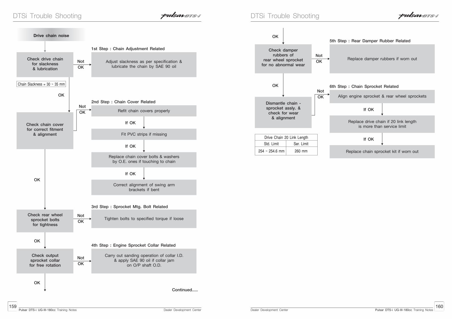
Dealer Development Center160
Dealer Development Center159
Drive chain noise
Not
OK
Not
OK
Not
OK
Check drive chainfor slackness& lubrication
1st Step : Chain Adjustment Related
Adjust slackness as per specification &lubricate the chain by SAE 90 oil
OK
Chain Slackness = 30 ~ 35 mm
Check chain coverfor correct fitment
& alignment
Refit chain covers properly
Fit PVC strips if missing
If OK
Not
OK
If OK
Replace chain cover bolts & washersby O.E. ones if touching to chain
If OK
Correct alignment of swing armbrackets if bent
Check rear wheelsprocket boltsfor tightness
OK
OK
Tighten bolts to specified torque if loose
Check outputsprocket collarfor free rotation
Carry out sanding operation of collar I.D.& apply SAE 90 oil if collar jam
on O/P shaft O.D.
OK
2nd Step : Chain Cover Related
3rd Step : Sprocket Mtg. Bolt Related
4th Step : Engine Sprocket Collar Related
Continued.....
Not
OK
OK
OK
Check damperrubbers of
rear wheel sprocketfor no abnormal wear
Replace damper rubbers if worn out
Dismantle chain -sprocket assly. &check for wear
& alignment
Align engine sprocket & rear wheel sprocketsNot
OK
If OK
Replace drive chain if 20 link lengthis more than service limit
If OK
Replace chain sprocket kit if worn out
Std. Limit
254 ~ 254.6 mm 260 mm
Drive Chain 20 Link Length
Ser. Limit
5th Step : Rear Damper Rubber Related
6th Step : Chain Sprocket Related
Pulsar DTS-i UG-III-180cc Training NotesPulsar DTS-i UG-III-180cc Training Notes
DTSi Trouble ShootingDTSi Trouble Shooting

Dealer Development Center162
Dealer Development Center161
Silencer noise
Not
OK
Check silencermouth securing nuts
for tightness
1st Step : Mounting Nuts Related
2nd Step : Gasket Related
3rd Step : Silencer Guard Related
4th Step : Footrest Fouling Related
Tighten silencer mouth nuts if loose
Not
OK
Check silencermouth gasket
for intact condition
Replace silencer mouth gasket (gasket exhaust) if pressed
OK
Not
OK
Check silencer guardsecuring screws /
allen boltsfor tightness
Tighten silencer guard screws / allen boltsif loose. Apply loctite 243.
OK
Not
OK
Check silencer forbend pipe not
fouling withrider’s foot rest
Correct silencer fitment if foulingwith rider’s foot rest
OK
Tightening Torque = 1.4~1.9 Kgm
OK
Continued.....
5th Step : Muffler Related
6th Step : Torque Expansion chamber Related
OK
Not
OK
Check silencer forintact baffle plates
Replace silencer if baffle plate /plates are loose
OK
Not
OK
Check silencerExhausTEC chamber
for no noise
Tighten ‘CO’ nozzle bolt if loose / replace silencer if nozzle given away
Replace silencer if noise in ExhausTEC chamber due to paint solidified from inside
If OK
Pulsar DTS-i UG-III-180cc Training NotesPulsar DTS-i UG-III-180cc Training Notes
DTSi Trouble ShootingDTSi Trouble Shooting

Dealer Development Center164
Dealer Development Center163
Torque
Steering sticky / Jam movement
Check steering ringnut & centernut / bolt for
correct tightness(No over tightening)
1st Step : Steering Ring Nut Related
Loosen steering center nut / bolt,fork side clamp bolts and
fork top bolts, steering ring nut& tighten them in sequence as per S.O.P.
to specified torque
Not
OK
Not
OK
OK
Check steering racesfor correct fitment
Refit steering races as per S.O.P.if fitted in tilted condition
2nd Step: Steering Races Fitment Related
Not
OK
OK
Check condition ofsteering races forno pitting marks
& steering balls forno rusting / breakage
Replace steering races & ballsif pitted / rusty respectively
3rd Step: Stg. Races Condition Related
Note : Lubricate steering races and balls by Servo Gem RR-3 grease at every 10,000 Kms.
Description
Tightening Torques in Kgm
Steering centerspecial nut /bolt
Fork side bolts
Fork top bolts
Steeringring nut
3.5 Kgm
2.5~3.5 Kgm
2.5~3.5 Kgm
0.5 Kgm
Poor braking - Disc brake system
Not
OKCheck brake fluidin master cylinderfor correct level
1st Step : Master Cylinder Related
Top-up master cylinder by using DOT-3/DOT-4 brake fluid if fluid
level is below minimum mark
If OK
2nd Step : Brake Disc Pad Related
3rd Step : Caliper Related
4th Step : Brake Disc Related
Identify source of leakage, rectify & top-up leakage if any,
if brake fluid level is low prematurely
OK
Not
OKCheck disc pads for
surface conditionClean disc pads by emery paper if found water soaked, oil / grease soaked, glazed
OK
Not
OKCheck disc pads
for thicknessReplace disc pads if worn out beyond service limit
Disc Pad Lining Thickness
Standard Limit Service Limit
7.4 mm 3.8 mm
7.4 mm 3.8 mmOK
Not
OK
Check oil seal ofCaliper piston for
intact lip condition
Replace Caliper seals if - seal lips worn out, deformed, became hard.
OK
Not
OKCheck brake disc forthickness & alignment
Replace brake disc if worn out, run out exceeds service limit.
Disc Disc Runout
Standard Limit Service Limit
Less than 0.2 mm 0.2 mm
Pulsar DTS-i UG-III-180cc Training NotesPulsar DTS-i UG-III-180cc Training Notes
DTSi Trouble ShootingDTSi Trouble Shooting

Dealer Development Center165
Spongy brakes - Disc brake system
Not
OK
Check brake fluidlevel in
master cylinder
1st Step : Master Cylinder Related
Top up master cylinder by DOT-3/DOT-4 brake fluid only if fluid level
is below minimum mark.
OK
Not
OK
Check brake hose,Caliper and
Master cylinderfor no leakages.
Identify source of leakage, rectify &top-up if brake fluid level is below
minimum mark
OK
Not
OK
Check Disc Brake system free
from air trapping.
Carry out air bleeding ofdisc brake system as per SOP
OK
Not
OK
Check master cylinder vent holes
for no clogging.
Clean master cylinder cover &vent holes if clogged
due to oxidation / dust.
OK
Not
OK
Check master cylinderdiaphragm for no
deformation teared off
Replace diaphragm by new oneif deformed / torn.
OK
Not
OK
Check master cylinder primary seal
for no wear.
Replace primary seal of master cylinder if worn out.
OK
Not
OK
Check for free floating movement
of Caliper.
Clean & Lubricate caliper pins bysilicon grease / brake fluid if jam.
2nd Step : Brake Fluid leakage Related
3rd Step : Air Trapping Related
4th Step : Master Cylinder Related
4th Step : Caliper Related
Pulsar DTS-i UG-III-180cc Training Notes
DTSi Trouble Shooting
Dealer Development Center Pulsar DTS-i UG-III-180cc Training Notes
Dealer Development CenterPulsar DTS-i UG-III-180cc Training Notes