ibaPDA-Interface-S7-TCP/UDP - IBA AG
80
ibaPDA-Interface-S7-TCP/UDP Data Interface TCP/UDP to SIMATIC S7 Manual Issue 2.3 Measurement Systems for Industry and Energy
-
Upload
khangminh22 -
Category
Documents
-
view
0 -
download
0
Transcript of ibaPDA-Interface-S7-TCP/UDP - IBA AG
ibaPDA-Interface-S7-TCP/UDPData Interface TCP/UDP to SIMATIC S7
ManualIssue 2.3
Measurement Systems for Industry and Energy
2
Manufacturer
iba AG
Koenigswarterstr. 44
90762 Fuerth
Germany
Contacts
Main office +49 911 97282-0
Fax +49 911 97282-33
Support +49 911 97282-14
Engineering +49 911 97282-13
E-mail [email protected]
Web www.iba-ag.com
Unless explicitly stated to the contrary, it is not permitted to pass on or copy this document, nor to make use of its contents or disclose its contents. Infringements are liable for compensation.
© iba AG 2019, All rights reserved.
The content of this publication has been checked for compliance with the described hardware and software. Nevertheless, discrepancies cannot be ruled out, and we do not provide guaran-tee for complete conformity. However, the information furnished in this publication is updated regularly. Required corrections are contained in the following regulations or can be downloaded on the Internet.
The current version is available for download on our web site www.iba-ag.com.
Version Date Revision - Chapter / Page Author Version SW
2.3 12-2019 Chapt. 2, 3.1 Footnote, 5.1.1 RM/IP 6.39
Windows® is a brand and registered trademark of Microsoft Corporation. Other product and company names mentioned in this manual can be labels or registered trademarks of the corre-sponding owners.
3 Issue 2.3 3
ibaPDA-Interface-S7-TCP/UDP Content
Content
1 About this Manual ............................................................................................................5
1.1 Target group and previous knowledge ..................................................................... 5
1.2 Notations .................................................................................................................. 5
1.3 Used symbols ............................................................................................................ 6
2 System requirements ........................................................................................................7
3 Data interface TCP/UDP to SIMATIC S7 ..............................................................................8
3.1 General information .................................................................................................8
3.2 SIMATIC S7 configuration & engineering .................................................................. 9
3.2.1 Data blocks ............................................................................................................. 10
3.2.1.1 Header ................................................................................................................. 11
3.2.1.2 Data areas ............................................................................................................ 12
3.2.2 S7-300 / S7-400-CPUs without local Ethernet interface .........................................13
3.2.3 S7-300 / S7-400-CPUs with local Ethernet interface .............................................. 15
3.2.4 S7-1200 CPU with local Ethernet interface ............................................................. 17
3.2.5 S7-1500-CPUs with local Ethernet interface ........................................................... 19
3.3 ibaPDA configuration & engineering ...................................................................... 22
3.3.1 General settings ......................................................................................................22
3.3.2 General interface settings ....................................................................................... 22
3.3.3 General module settings ......................................................................................... 25
3.3.4 General signal configuration ................................................................................... 26
3.3.5 Module type S7 TCP/UDP Integer ........................................................................... 27
3.3.6 Module type S7 TCP/UDP Real ............................................................................... 27
3.3.7 Module type S7 TCP/UDP General .......................................................................... 27
3.3.8 S7 UDP Request/S7 UDP Request Decoder module types ......................................28
3.3.9 Module diagnostics.................................................................................................28
4 Diagnosis ........................................................................................................................29
4.1 Checking the license ...............................................................................................29
4.2 Visibility of the interface ......................................................................................... 29
4.3 Log files ................................................................................................................... 30
4.4 Connection diagnostics with PING .......................................................................... 31
4.5 Checking the connection ........................................................................................ 32

4 Issue 2.3
Content ibaPDA-Interface-S7-TCP/UDP
4.6 Diagnostic modules ................................................................................................34
5 Appendix ........................................................................................................................37
5.1 Restrictions ............................................................................................................. 37
5.1.1 TCP/IP protocol variants ......................................................................................... 37
5.2 S7 engineering examples ........................................................................................ 38
5.2.1 S7CLASSIC_TCP_UDP ..............................................................................................39
5.2.1.1 CPU 317-2 with PN interface ............................................................................... 39
5.2.1.2 CPU 317 with CP 343-1 LEAN ............................................................................... 46
5.2.1.3 CPU 412-2 with PN interface ............................................................................... 54
5.2.1.4 CPU 412 with CP 443-1 ........................................................................................ 54
5.2.2 S7TIA_TCP_UDP_V13_SP1 ...................................................................................... 55
5.2.2.1 CPU 1212C (Firmware V2.0) ................................................................................ 55
5.2.2.2 CPU 1516 with PN interface ................................................................................ 64
5.2.2.3 CPU 1516 with PN interface and configuration dialog ......................................... 69
5.2.2.4 CPU 1516 with CP1543-1 ..................................................................................... 74
5.3 ibaPDA engineering example .................................................................................. 76
5.3.1 Configuration of data telegrams ............................................................................. 76
5.3.2 Configuration of Technostring ................................................................................ 77
5.3.3 Configuration Watchdog ......................................................................................... 78
5.3.4 Online view ............................................................................................................. 79
6 Support and contact ........................................................................................................80

5 Issue 2.3 5
ibaPDA-Interface-S7-TCP/UDP About this Manual
1 About this ManualThis document describes the function and application of the software interface
ibaPDA-Interface-S7-TCP/UDP
This documentation is a supplement to the ibaPDA manual. Information about all the other characteristics and functions of ibaPDA can be found in the ibaPDA manual or in the online help.
1.1 Target group and previous knowledgeThis documentation addresses qualified professionals, who are familiar with handling electrical and electronic modules as well as communication and measurement technology. A person is regarded as a professional if he/she is capable of assessing the work assigned to him/her and recognizing possible risks on the basis of his/her specialist training, knowledge and experience and knowledge of the standard regulations.
This documentation in particular addresses persons, who are concerned with the configuration, test, commissioning or maintenance of Programmable Logic Controllers of the supported prod-ucts. For the handling ibaPDA-Interface-S7-TCP/UDP the following basic knowledge is required and/or useful:
■ Windows operating system
■ Basic knowledge of ibaPDA
■ Knowledge of configuration and operation of the relevant control system
1.2 NotationsIn this manual, the following notations are used:
Action NotationMenu command Menu Logic diagramCalling the menu command Step 1 – Step 2 – Step 3 – Step x
Example: Select the menu Logic diagram - Add - New function block.
Keys <Key name>
Example: <Alt>; <F1>Press the keys simultaneously <Key name> + <Key name>
Example: <Alt> + <Ctrl>Buttons <Key name>
Example: <OK>; <Cancel>File names, paths "Filename", "Path"
Example: "Test.doc"
6 Issue 2.3
About this Manual ibaPDA-Interface-S7-TCP/UDP
1.3 Used symbolsIf safety instructions or other notes are used in this manual, they mean:
Danger!
Thenon-observanceofthissafetyinformationmayresultinanimminentriskof death or severe injury:
■ Observe the specified measures.
Warning!
Thenon-observanceofthissafetyinformationmayresultinapotentialriskofdeath or severe injury!
■ Observe the specified measures.
Caution!
Thenon-observanceofthissafetyinformationmayresultinapotentialriskofinjury or material damage!
■ Observe the specified measures
Note
A note specifies special requirements or actions to be observed.
Tip
Tip or example as a helpful note or insider tip to make the work a little bit easier.
Otherdocumentation
Reference to additional documentation or further reading.
7 Issue 2.3 7
ibaPDA-Interface-S7-TCP/UDP System requirements
2 System requirementsThe following system requirements are necessary to use the S7 TCP/UDP data interface:
■ ibaPDA v6.33.2 or higher
■ License for ibaPDA-Interface S7-TCP/UDP
■ Network connection 10/100 Mbits
■ Step7 from version V4.0 or TIA Portal from V11
■ S7 CPU with integrated PN port or communication processor
For more requirements on the PC hardware used and the supported operating systems, see the ibaPDA documentation.
Note
We recommend running the TCP/IP or UDP communication on a separate net-work segment to exclude any mutual influence by other network components.
Systemrestrictions
■ For different ways of handling the TCP/IP acknowledge see ì TCP/IP protocol variants, page 37 (all ibaPDA versions).
Licenses
Order No. Product name Description31.001040 ibaPDA-Interface-S7-TCP/UDP Extension license for an ibaPDA sys-
tem by one TCP/IP and UDP/IP inter-face
Number of connections: 6431.101040 one-step-up-Interface-S7-TCP/UDP Extension license for the extension of
an existing ibaPDA-Interface-S7-TCP/UDP interface by another 64 S7-TCP/UDP connections, max. 3 permitted

88 Issue 2.3
Data interface TCP/UDP to SIMATIC S7 ibaPDA-Interface-S7-TCP/UDP
3 Data interface TCP/UDP to SIMATIC S7
3.1 GeneralinformationThe S7-TCP/UDP interface can be used to acquire data from an S7 controller through the stan-dard network card of the ibaPDA PC using the TCP/IP or UDP protocol. This requires the connec-tion to be configured and data transmission to be programmed in the controller.
The signals to be measured are selected by arranging the values in data blocks (DB) whose data structures are defined by the module types of ibaPDA. Subsequently, the data blocks are sent to the ibaPDA PC as telegrams with S7 communication blocks.
Three module types are defined in ibaPDA-Interface-S7-TCP/UDP:
Integer: 32 analog values (integer) and 32 binary signalsReal: 8, 16 or 32 analog values (real) and 32 binary signalsGeneric: any data structure with a maximum length of 4096 bytes1)
Each module is assigned to a connection. You can create up to 256 connections on the side of ibaPDA. On the S7 side, the maximum number of connections depends on the CPU type.
This type of data acquisition has the main advantage of not requiring any special hardware if the controller already features an Ethernet connection.
1) Until ibaPDA V6.30 limited by properties of the S7 communication processors

Issue 2.3 9
ibaPDA-Interface-S7-TCP/UDP Data interface TCP/UDP to SIMATIC S7
TCP and UDPThe Transmission Control Protocol, short TCP, is a connection-oriented protocol. Its main func-tion is to prevent data loss, divide files and data streams and assign data packets to applications.
The User Datagram Protocol, short UDP, is a connectionless transport protocol. Its function is similar to that of the connection-oriented TCP. However, it works connectionless and is thus not secure, which means that the sender does not know whether the data packets it has sent have actually arrived. TCP sends confirmations upon receiving data, UDP does not. This method has the advantage that the packet header is much smaller and no acknowledgments have to be sent over the link. In principle, this enables a slightly higher data rate.
Both protocols use the IP Internet Protocol of layer 4 (transport layer) of the OSI model.
Note
The following examples use the term "connection" also for UDP. In this context, it refers only to the communication channel from sender to recipient and not to a network connection to be established and closed.
3.2 SIMATICS7configuration&engineeringThis section describes how to establish the TCP/IP or UDP connection, the necessary data blocks and how to parameterize the send blocks. Various options are possible depending on the CPU family.
■ CPUs without a local Ethernet interface The S7 side is configured using the STEP7 tools "HW Config" and "NetPro" included in SIMAT-IC Manager. In the STEP7 program, you insert send blocks (AG_SEND, AG_LSEND) that use the configured connections.
■ CPUs with a local Ethernet interface The connections do not need to be configured separately. Both connection establishment and sending are performed using standard blocks (TCON, TSEND, TUSEND) in STEP7.
■ The CPUs of the S7-1200 and S7-1500 series These CPUs generally feature local Ethernet interfaces and can only be configured using the TIA Portal. Here, there are blocks that perform both the task of connection establishment and sending data (TSEND_C).
Engineering examples for different configurations, see ì S7 engineering examples, page 38.

10 Issue 2.3
Data interface TCP/UDP to SIMATIC S7 ibaPDA-Interface-S7-TCP/UDP
Note
Please observe the following in all connection types described:
■ The S7-CPU is the active partner in all connections.
■ The partner port must match the setting in ibaPDA (interface S7-TCP-UDP) (default setting in ibaPDA: 4170).
■ This port has to be enabled in the ibaPDA PC in the Windows firewall.
■ This port must not be assigned elsewhere.
■ When creating additional connections, please observe:
� Always assign a new connection name.
� Always assign a new local port number.
� Always use the same partner IP address.
� Always use the same partner port number.
3.2.1 Data blocks
All methods described above require the data to be sent to be provided in data blocks.
According to the ibaPDA module structure, the data for each module are transmitted with a telegram. Each telegram is based on a data block and a connection. The data blocks have a uni-form header and a data structure that corresponds to the module type.
Note
Special for the S7-1200 / S7-1500 controller
The "Optimized block access" block attrbute must not be set for the telegram data blocks.
Issue 2.3 11
ibaPDA-Interface-S7-TCP/UDP Data interface TCP/UDP to SIMATIC S7
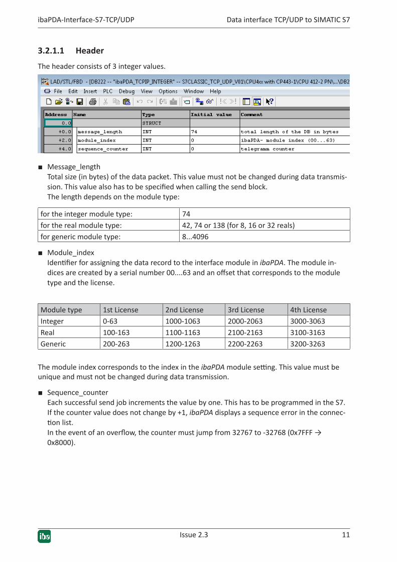
3.2.1.1 Header
The header consists of 3 integer values.
■ Message_length Total size (in bytes) of the data packet. This value must not be changed during data transmis-sion. This value also has to be specified when calling the send block. The length depends on the module type:
for the integer module type: 74for the real module type: 42, 74 or 138 (for 8, 16 or 32 reals)for generic module type: 8...4096
■ Module_index Identifier for assigning the data record to the interface module in ibaPDA. The module in-dices are created by a serial number 00....63 and an offset that corresponds to the module type and the license.
Module type 1st License 2nd License 3rd License 4th LicenseInteger 0-63 1000-1063 2000-2063 3000-3063Real 100-163 1100-1163 2100-2163 3100-3163Generic 200-263 1200-1263 2200-2263 3200-3263
The module index corresponds to the index in the ibaPDA module setting. This value must be unique and must not be changed during data transmission.
■ Sequence_counter Each successful send job increments the value by one. This has to be programmed in the S7. If the counter value does not change by +1, ibaPDA displays a sequence error in the connec-tion list. In the event of an overflow, the counter must jump from 32767 to -32768 (0x7FFF → 0x8000).

12 Issue 2.3
Data interface TCP/UDP to SIMATIC S7 ibaPDA-Interface-S7-TCP/UDP
3.2.1.2 Data areas
The structure of the data area depends on the module type.
Module type IntegerAfter the header, starting at offset 6, follow the 32 integer analog values and subsequently, starting at offset 70, the 4 bytes of binary values.
Note
Observe the different byte order between S7 and ibaPDA.
Example:
If you set bit DB222.DBX70.0, it will arrive as bit 24 in ibaPDA. But if you write 16#00000001 to DB222.DBD70, bit 0 is set in ibaPDA.
Module type RealAfter the header, starting at offset 6, follow the 4 bytes of binary values and subsequently, start-ing at offset 10, either 8, 16 or 32 analog values in the real format.
Module type GenericAny order of data with different data types can follow after the header starting at offset 6. ibaPDA supports the following data formats:
BYTE, WORD, DWORD, INT, DINT and FLOAT.
Issue 2.3 13
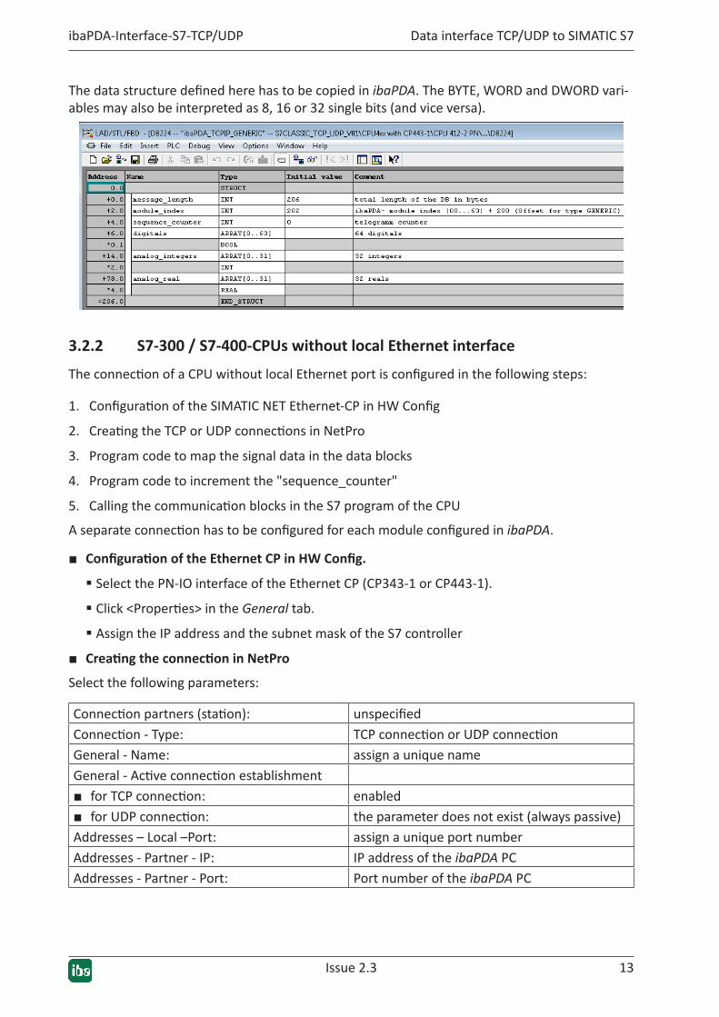
ibaPDA-Interface-S7-TCP/UDP Data interface TCP/UDP to SIMATIC S7
The data structure defined here has to be copied in ibaPDA. The BYTE, WORD and DWORD vari-ables may also be interpreted as 8, 16 or 32 single bits (and vice versa).
3.2.2 S7-300 / S7-400-CPUs without local Ethernet interface
The connection of a CPU without local Ethernet port is configured in the following steps:
1. Configuration of the SIMATIC NET Ethernet-CP in HW Config
2. Creating the TCP or UDP connections in NetPro
3. Program code to map the signal data in the data blocks
4. Program code to increment the "sequence_counter"
5. Calling the communication blocks in the S7 program of the CPU
A separate connection has to be configured for each module configured in ibaPDA.
■ ConfigurationoftheEthernetCPinHWConfig.
� Select the PN-IO interface of the Ethernet CP (CP343-1 or CP443-1).
� Click <Properties> in the General tab.
� Assign the IP address and the subnet mask of the S7 controller
■ CreatingtheconnectioninNetProSelect the following parameters:
Connection partners (station): unspecifiedConnection - Type: TCP connection or UDP connectionGeneral - Name: assign a unique nameGeneral - Active connection establishment■ for TCP connection: enabled■ for UDP connection: the parameter does not exist (always passive)Addresses – Local –Port: assign a unique port numberAddresses - Partner - IP: IP address of the ibaPDA PCAddresses - Partner - Port: Port number of the ibaPDA PC
14 Issue 2.3
Data interface TCP/UDP to SIMATIC S7 ibaPDA-Interface-S7-TCP/UDP
Note
For assigning the port numbers, observe the notes in ì SIMATIC S7 configura-tion & engineering, page 9
■ Mapping the signal data
Cyclically copy the desired signal data into the data blocks of the telegram modules at any posi-tion of your S7 program.
■ Incrementingthe"sequence_counter"
Increase the "sequence_counter" in the telegram data block with each rising edge of the DONE output.
Reset the "sequence_counter" to 0 if the CPU is restarted. In the event of an overflow, the counter must jump from 32767 to -32768 (0x7FFF → 0x8000).
■ Callingthecommunicationblocks
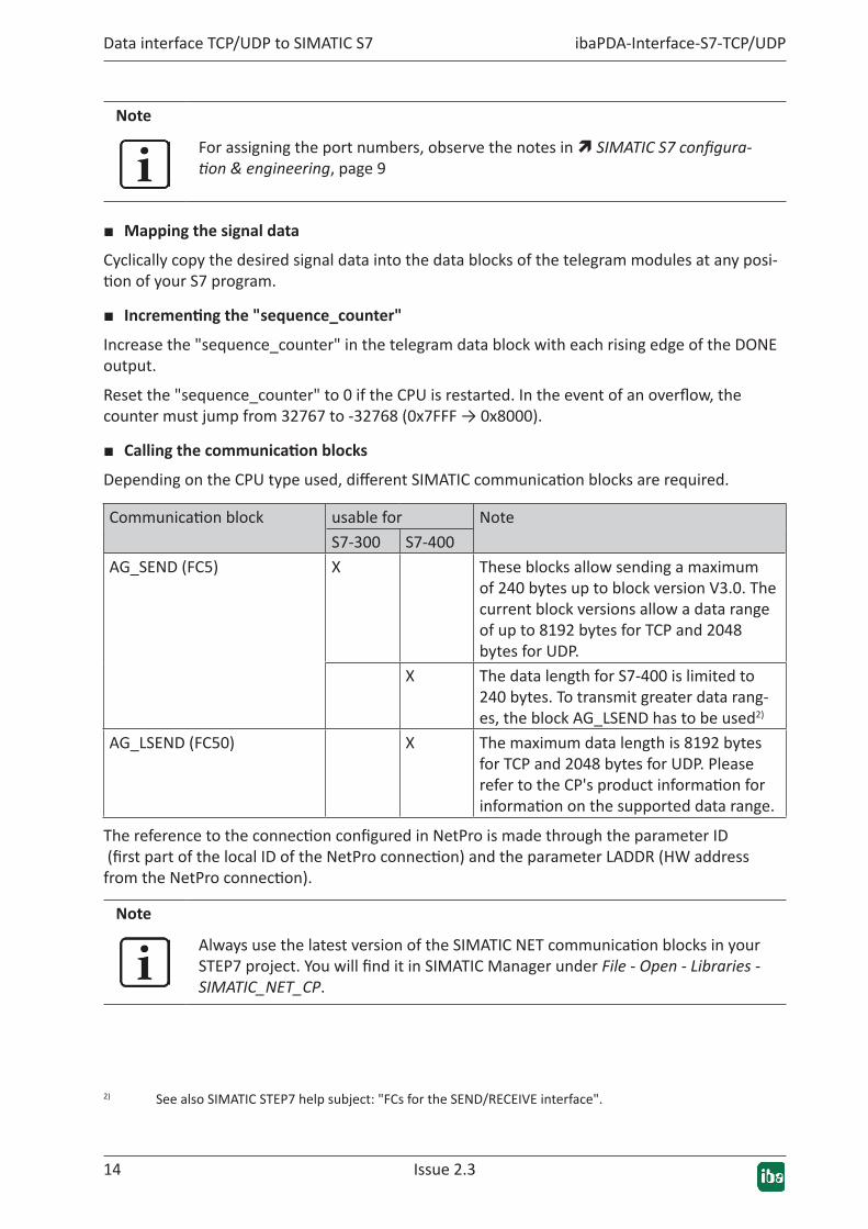
Depending on the CPU type used, different SIMATIC communication blocks are required.
Communication block usable for NoteS7-300 S7-400
AG_SEND (FC5) X These blocks allow sending a maximum of 240 bytes up to block version V3.0. The current block versions allow a data range of up to 8192 bytes for TCP and 2048 bytes for UDP.
X The data length for S7-400 is limited to 240 bytes. To transmit greater data rang-es, the block AG_LSEND has to be used2)
AG_LSEND (FC50) X The maximum data length is 8192 bytes for TCP and 2048 bytes for UDP. Please refer to the CP's product information for information on the supported data range.
The reference to the connection configured in NetPro is made through the parameter ID (first part of the local ID of the NetPro connection) and the parameter LADDR (HW address from the NetPro connection).
Note
Always use the latest version of the SIMATIC NET communication blocks in your STEP7 project. You will find it in SIMATIC Manager under File - Open - Libraries - SIMATIC_NET_CP.
2) See also SIMATIC STEP7 help subject: "FCs for the SEND/RECEIVE interface".

Issue 2.3 15
ibaPDA-Interface-S7-TCP/UDP Data interface TCP/UDP to SIMATIC S7
Tip
If AG_SEND/AG_LSEND is called cyclically, the send cycle is half the size of the call cycle at the most, because the block's output parameters are updated in the call in the cycle after the send job. You can prevent this by calling the block twice in each cycle. The first time to query the status (ACT=0), the second time to send the data (ACT=1).
Otherdocumentation
For more information on configuring the communication, see the STEP7 online help and the following FAQ from Siemens:
Configuring a TCP connection via Ethernet (TCP native) between a SIMATIC S7 and a PC with socket interface:
http://support.automation.siemens.com/ww/view/de/22790099
http://support.automation.siemens.com/ww/view/de/17853532
http://support.automation.siemens.com/ww/view/de/24693800
A detailed engineering example is provided in ì CPU 317 with CP 343-1 LEAN, page 46.
3.2.3 S7-300 / S7-400-CPUs with local Ethernet interface
The connection of a CPU with local Ethernet port is configured in the following steps:
1. Configuration of the CPU's Ethernet interface in HW Config
2. Program code to map the signal data in the data block
3. Program code to increment the "sequence_counter"
4. Creating and parameterizing the connection data (data structures TCON_PAR and if applica-ble TADDR_PAR)
5. Calling the communication blocks in the S7 program of the CPU
A separate connection has to be configured for each module configured in ibaPDA.
■ ConfigurationoftheCPU'sEthernetinterfaceinHWConfig
� Select the PN-IO interface of the CPU.
� Click <Properties> in the General tab.
� Assign the IP address and the subnet mask of the S7 controller
■ Mapping the signal data
Cyclically copy the desired signal data into the data blocks of the telegram modules at any posi-tion of your S7 program.

16 Issue 2.3
Data interface TCP/UDP to SIMATIC S7 ibaPDA-Interface-S7-TCP/UDP
■ Incrementingthe"sequence_counter"
Increase the "sequence_counter" in the telegram data block with each rising edge of the DONE output.
Reset the "sequence_counter" to 0 if the CPU is restarted. In the event of an overflow, the counter must jump from 32767 to -32768 (0x7FFF → 0x8000).
■ Parameterizingtheconnection
Create a static variable or a DB with the data structure TCON_PAR (UDT65) and enter the follow-ing parameters:
id: Connection ID, reference for the associated TCON and TSEND or TUSEND block
connection_type: for TCP: B#16#11 for UDP: B#16#13
active_est: for TCP: TRUE for UDP: FALSE
local_device_id: 2, 3 or 5 (depends on the CPU type)3)
local_tsap_id: Unique port number for each connection
rem_staddr: only for TCP: IP address of the ibaPDA PC
rem_tsap_id: only for TCP: Port number of the ibaPDA PC
With UDP, the remote IP address and port number is not taken from the connection data, but has to be stored in a separate data range with the structure TADDR_PAR (UDT66):
rem_ip_addr IP address of the ibaPDA PC
rem_port_nr Port number of the ibaPDA PC
Note
For assigning the port number, observe the notes in ì SIMATIC S7 configuration & engineering, page 9
■ CallingthecommunicationblocksintheS7programoftheCPU
The following communication block is used:
� TCON (FB65): to establish the connection
� TSEND (FB63): to send the data via TCP
� TUSEND (FB67): to send the data via UDP
The connection is parameterized by means of the data range with the specified structure, which is referenced through the unique connection ID.
3) See online help for system functions "Parameterizing the communication connections..."
Issue 2.3 17
ibaPDA-Interface-S7-TCP/UDP Data interface TCP/UDP to SIMATIC S7
Note
Always use the latest version of the SIMATIC NET communication blocks in your STEP7 project. You will find it in SIMATIC Manager under File - Open - Libraries - Standard Library - Communication Blocks.
Otherdocumentation
For more information on configuring the communication, see the STEP7 online help and the following FAQ from Siemens:
How do you program the communication blocks FB63 "TSEND", FB64 "TRCV", FB65 "TCON" and FB66 "TDISCON" in order to use the TCP protocol for data exchange by means of the integrated PROFINET interface of an S7-300/S7-400 CPU?
http://support.automation.siemens.com/ww/view/de/29737950
A detailed configuration example is provided inì CPU 317-2 with PN interface, page 39.
3.2.4 S7-1200 CPU with local Ethernet interface
Note
The following notes are applicable to firmware versions up to 3.x.
For S7-1200 from version 4.0, the settings are identical to the S7-1500 CPUs.
See also ì S7-1500-CPUs with local Ethernet interface, page 19 .
The connection of a CPU with local Ethernet port is configured in the following steps:
1. Configuration of the CPU's Ethernet interface in the device configuration
2. Program code to map the signal data in the data block
3. Program code to increment the "sequence_counter"
4. Creating and parameterizing the connection data (data structure TCON_Param)
5. Calling the communication blocks in the S7 program of the CPU
A separate connection has to be configured for each module configured in ibaPDA.
■ ConfigurationoftheEthernetinterfaceinthedeviceconfiguration
� Select the device configuration.
� On the graphic, click the Ethernet port connected to ibaPDA.
� Select the tab General – Ethernet address.
� Assign the IP address and the subnet mask of the S7 controller
18 Issue 2.3
Data interface TCP/UDP to SIMATIC S7 ibaPDA-Interface-S7-TCP/UDP
■ Mapping the signal data
Cyclically copy the desired signal data into the data blocks of the telegram modules at any posi-tion of your S7 program.
■ Incrementingthe"sequence_counter"
Increase the "sequence_counter" in the telegram data block with each rising edge of the DONE output.
Reset the "sequence_counter" to 0 if the CPU is restarted. In the event of an overflow, the counter must jump from 32767 to -32768 (0x7FFF → 0x8000).
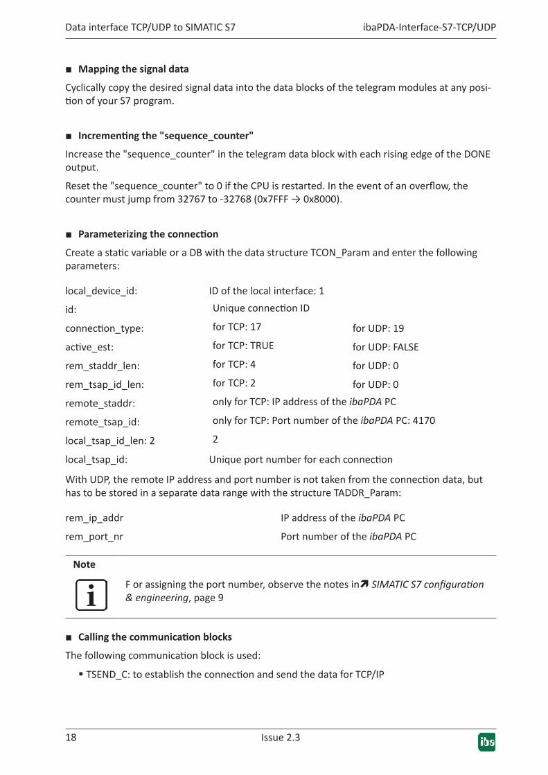
■ Parameterizingtheconnection
Create a static variable or a DB with the data structure TCON_Param and enter the following parameters:
local_device_id: ID of the local interface: 1
id: Unique connection ID
connection_type: for TCP: 17 for UDP: 19
active_est: for TCP: TRUE for UDP: FALSE
rem_staddr_len: for TCP: 4 for UDP: 0
rem_tsap_id_len: for TCP: 2 for UDP: 0
remote_staddr: only for TCP: IP address of the ibaPDA PC
remote_tsap_id: only for TCP: Port number of the ibaPDA PC: 4170
local_tsap_id_len: 2 2
local_tsap_id: Unique port number for each connection
With UDP, the remote IP address and port number is not taken from the connection data, but has to be stored in a separate data range with the structure TADDR_Param:
rem_ip_addr IP address of the ibaPDA PC
rem_port_nr Port number of the ibaPDA PC
Note
F or assigning the port number, observe the notes inì SIMATIC S7 configuration & engineering, page 9
■ Callingthecommunicationblocks
The following communication block is used:
� TSEND_C: to establish the connection and send the data for TCP/IP
Issue 2.3 19
ibaPDA-Interface-S7-TCP/UDP Data interface TCP/UDP to SIMATIC S7
� TCON : to establish the connection for UDP
� TUSEND: to send the data for UDP
The connection is parameterized by means of a data range with the specified structure, which is referenced through the unique connection ID.
Otherdocumentation
For more information on configuring the communication, see the TIA online help and the following FAQ from Siemens:
How do you program the TSEND_C and TRCV_C instructions for open user com-munication over the integrated PROFINET interface of the S7-1200 CPU?
http://support.automation.siemens.com/ww/view/de/67196808
A detailed engineering example is provided in ì CPU 1212C (Firmware V2.0), page 55.
3.2.5 S7-1500-CPUs with local Ethernet interface
Note
The following instructions also apply to S7-1200 from version 4.0.
The connection of a CPU with local Ethernet port is configured in the following steps:
1. Configuration of the CPU's Ethernet interface in the device configuration
2. Program code to map the signal data in the data block
3. Program code to increment the "sequence_counter"
4. Creating and parameterizing the connection data (data structure TCON_IP_v4)
5. Calling the communication blocks in the S7 program of the CPU
A separate connection has to be configured for each module configured in ibaPDA.
■ ConfigurationoftheEthernetinterfaceinthedeviceconfiguration
� Select the device configuration.
� On the graphic, click the Ethernet port connected to ibaPDA.
� Select the tab General – Ethernet address.
� Assign the IP address and the subnet mask of the S7 controller
■ Mapping the signal data
Cyclically copy the desired signal data into the data blocks of the telegram modules at any posi-tion of your S7 program.

20 Issue 2.3
Data interface TCP/UDP to SIMATIC S7 ibaPDA-Interface-S7-TCP/UDP
■ Incrementingthe"sequence_counter"
Increase the "sequence_counter" in the telegram data block with each rising edge of the DONE output.
Reset the "sequence_counter" to 0 if the CPU is restarted. In the event of an overflow, the counter must jump from 32767 to -32768 (0x7FFF → 0x8000).
■ Parameterizingtheconnection
Create a local variable or a DB with the data structure TCON_Param and enter the following pa-rameters:
interface_id: Hardware ID of the local interface: see device configuration
id: Connection ID
connection_type: for TCP: 11 for UDP: 19
active_est: for TCP: TRUE for UDP: FALSE
remote_address: only for TCP: IP address of the ibaPDA PC
remote_port: only for TCP: Port number of the ibaPDA PC: 4170
local_port: Unique port number for each connection
With UDP, the remote IP address and port number is not taken from the connection data, but has to be stored in a separate data range with the structure UDT 66 ("TADDR_Param"):
rem_ip_addr IP address of the ibaPDA PC
rem_port_nr Port number of the ibaPDA PC
Note
For assigning the port numbers, observe the notes in ì SIMATIC S7 configura-tion & engineering, page 9
■ Callingthecommunicationblocks
The following communication block is used:
� TSEND_C: to establish the connection and send the data
The connection is parameterized through a data range with the specified structure, which is ref-erenced through a unique connection ID.

Issue 2.3 21
ibaPDA-Interface-S7-TCP/UDP Data interface TCP/UDP to SIMATIC S7
Note
The block TSEND_C is available in two different variants.
■ For CPU S7-1200 <= V3.x (see S7-1200-CPU with local Ethernet interface)
■ For CPU S7-1500 and CPU S7-1200 >= V4.0
The differences refer to the different system data types for parameterizing the connection.
Otherdocumentation
For further information on configuring the communication, please refer to the following FAQ from Siemens:
How do you program the TSEND_C and TRCV_C instructions for open user com-munication over the integrated PROFINET interface of the S7-1200 CPU?
http://support.automation.siemens.com/ww/view/de/67196808
A detailed engineering example is provided in ì CPU 1516 with PN interface, page 64.
22 Issue 2.3
Data interface TCP/UDP to SIMATIC S7 ibaPDA-Interface-S7-TCP/UDP
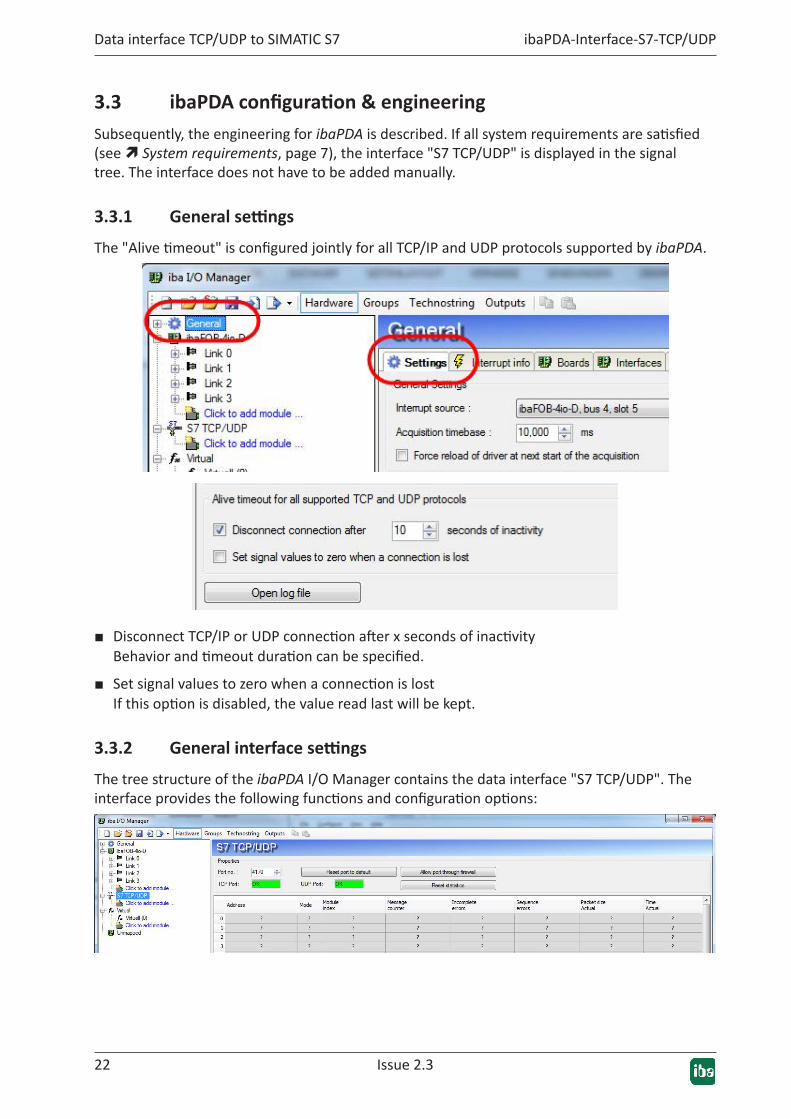
3.3 ibaPDAconfiguration&engineeringSubsequently, the engineering for ibaPDA is described. If all system requirements are satisfied (see ì System requirements, page 7), the interface "S7 TCP/UDP" is displayed in the signal tree. The interface does not have to be added manually.
3.3.1 Generalsettings
The "Alive timeout" is configured jointly for all TCP/IP and UDP protocols supported by ibaPDA.
■ Disconnect TCP/IP or UDP connection after x seconds of inactivity Behavior and timeout duration can be specified.
■ Set signal values to zero when a connection is lost If this option is disabled, the value read last will be kept.
3.3.2 Generalinterfacesettings
The tree structure of the ibaPDA I/O Manager contains the data interface "S7 TCP/UDP". The interface provides the following functions and configuration options:

Issue 2.3 23
ibaPDA-Interface-S7-TCP/UDP Data interface TCP/UDP to SIMATIC S7
■ Port no. Port used on PC side. The same port number has to be used in the S7 connection configuration (see ì S7 engi-neering examples, page 38).
■ Reset port to default The port number 4170 is set.
■ Allow port through firewall When installing ibaPDA, the default port numbers of the protocols used are automatically en-tered in the firewall. If the port number is changed here or if the interface was subsequently enabled, this port has to be enabled in the firewall here.
■ TCP Port / UDP Port OK is displayed here if the socket can be opened on this port. ERROR is displayed if conflicts occur, e.g. if the port is already occupied.
■ Connection table see ì Checking the connection, page 32
Adding a moduleTo add a module, click below the interface and select the desired module type.
Tip
If a TCP/IP or UDP connection to S7 exists already, right-click the interface and select Autodetect. Then the correct modules are automatically created for all available connections.

24 Issue 2.3
Data interface TCP/UDP to SIMATIC S7 ibaPDA-Interface-S7-TCP/UDP
Module type DescriptionS7 TCP/UDP General Module for any data structure with up to 4096 bytes lengthS7 TCP/UDP Integer Module for up to 32 analog signals (integer) and 32 digital sig-
nalsS7 TCP/UDP Real Module for up to 32 analog signals (Real) and 32 digital signalsS7 UDP Request Request module for a maximum of 1024 analog and 1024 dig-
ital signals.
See manual ibaPDA-Request-S7-UDPS7 UDP Request Decoder Request module for a maximum of 11728 digital signals trans-
mitted in the form of a maximum of 733 words (1466 byte).
See manual ibaPDA-Request-S7-UDPDiagnosis Type for creating diagnostic modules, see ì Diagnosis,
page 29Table 1: Module types for ibaPDA-Interface-S7-TCP-UDP interface
Issue 2.3 25
ibaPDA-Interface-S7-TCP/UDP Data interface TCP/UDP to SIMATIC S7
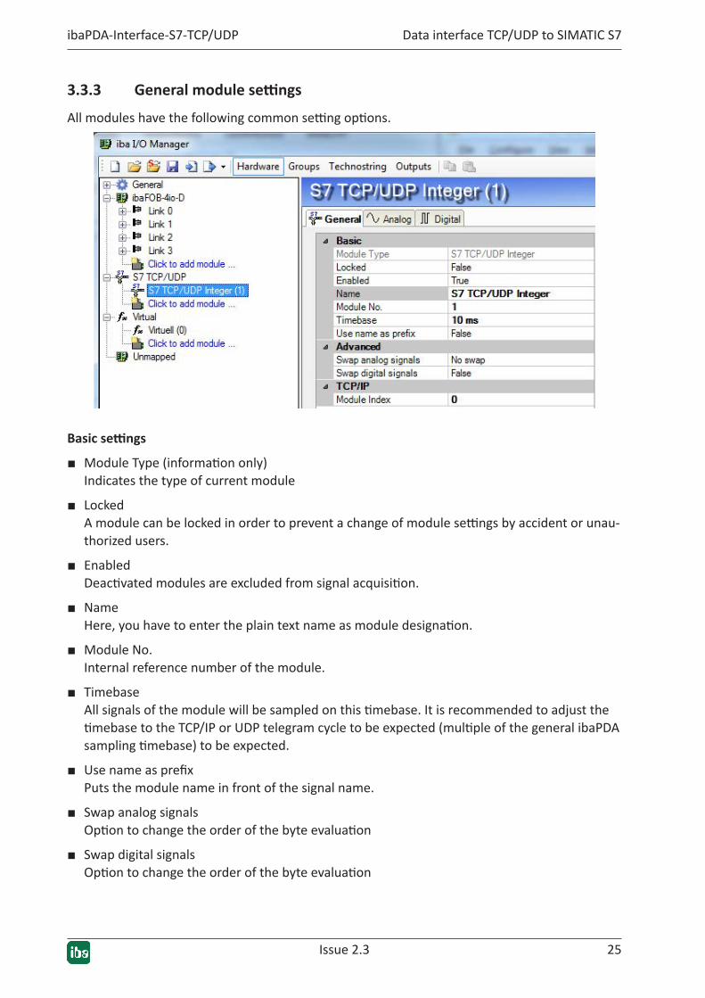
3.3.3 Generalmodulesettings
All modules have the following common setting options.
Basicsettings
■ Module Type (information only) Indicates the type of current module
■ Locked A module can be locked in order to prevent a change of module settings by accident or unau-thorized users.
■ Enabled Deactivated modules are excluded from signal acquisition.
■ Name Here, you have to enter the plain text name as module designation.
■ Module No. Internal reference number of the module.
■ Timebase All signals of the module will be sampled on this timebase. It is recommended to adjust the timebase to the TCP/IP or UDP telegram cycle to be expected (multiple of the general ibaPDA sampling timebase) to be expected.
■ Use name as prefix Puts the module name in front of the signal name.
■ Swap analog signals Option to change the order of the byte evaluation
■ Swap digital signals Option to change the order of the byte evaluation
26 Issue 2.3
Data interface TCP/UDP to SIMATIC S7 ibaPDA-Interface-S7-TCP/UDP
■ Module index The module indices are created by a serial number 00....63 and an offset that corresponds to the module type and the license. See also ì Header, page 11.
Otherdocumentation
For a detailed description of the parameters, see the ibaPDA manual.
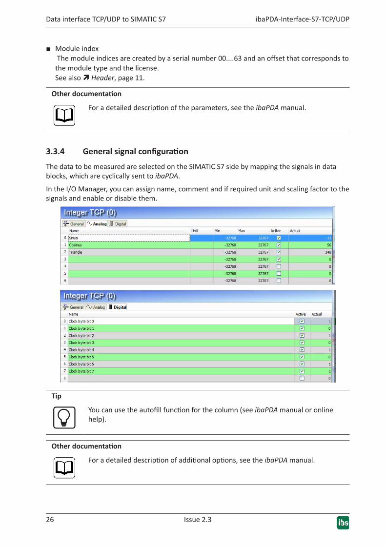
3.3.4 Generalsignalconfiguration
The data to be measured are selected on the SIMATIC S7 side by mapping the signals in data blocks, which are cyclically sent to ibaPDA.
In the I/O Manager, you can assign name, comment and if required unit and scaling factor to the signals and enable or disable them.
Tip
You can use the autofill function for the column (see ibaPDA manual or online help).
Otherdocumentation
For a detailed description of additional options, see the ibaPDA manual.
Issue 2.3 27
ibaPDA-Interface-S7-TCP/UDP Data interface TCP/UDP to SIMATIC S7
3.3.5 Module type S7 TCP/UDP Integer
The integer module allows up to 32 analog values (integer) and 32 binary signals to be acquired.
The module does not have any module-specific settings.
3.3.6 Module type S7 TCP/UDP Real
The real module allows up to 32 analog values (real) and 32 binary signals to be acquired.
The following module settings are module-specific:
■ Number of analog signals The number of analog signals to be acquired is configurable in the increments 8, 16 and 32 (the number of digital signals is fixed at 32).
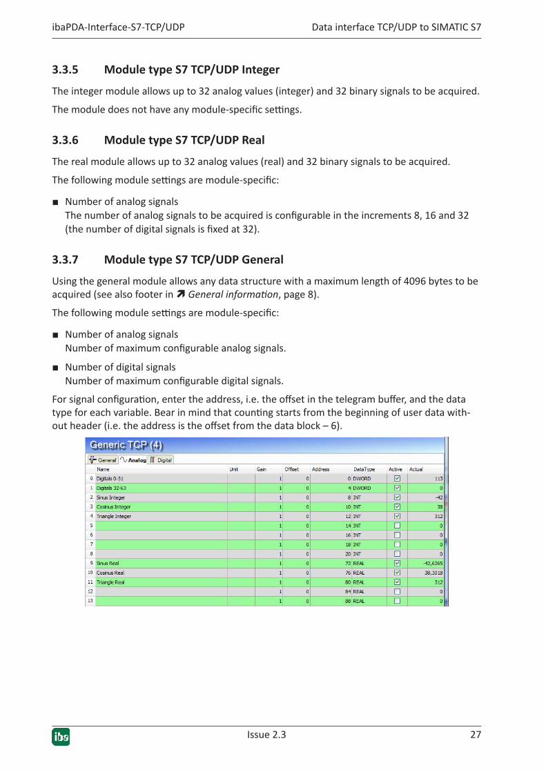
3.3.7 Module type S7 TCP/UDP General
Using the general module allows any data structure with a maximum length of 4096 bytes to be acquired (see also footer in ì General information, page 8).
The following module settings are module-specific:
■ Number of analog signals Number of maximum configurable analog signals.
■ Number of digital signals Number of maximum configurable digital signals.
For signal configuration, enter the address, i.e. the offset in the telegram buffer, and the data type for each variable. Bear in mind that counting starts from the beginning of user data with-out header (i.e. the address is the offset from the data block – 6).

28 Issue 2.3
Data interface TCP/UDP to SIMATIC S7 ibaPDA-Interface-S7-TCP/UDP
3.3.8 S7 UDP Request/S7 UDP Request Decoder module types
These two module types are only displayed, if license ibaPDA-Request-S7-UDP is available.
Otherdocumentation
The modules and their functions are described in detail in the manual ibaPDA-Request-S7-UDP.
3.3.9 Modulediagnostics
The tables Analog and Digital of the S7-TCP/UDP modules show the telegram contents.
The following errors may occur:
■ No data are displayed:
� The telegram DB on the S7 side is not filled correctly.
� The connectors of the send block are connected incorrectly.
■ Incorrect values are displayed:
� The telegram DB on the S7 side is not filled correctly (offset error).
� The byte order is set incorrectly, see ì General module settings, page 25
� There are multiple modules with the same module index.
■ The digital signals are sorted incorrectly.
� The byte order is set incorrectly, see ì General module settings, page 25
■ The telegrams do not arrive faster than approx. 200 ms with sequence error.
� Problem with "delayed acknowledge", see ì TCP/IP protocol variants, page 37

29 Issue 2.3 29
ibaPDA-Interface-S7-TCP/UDP Diagnosis
4 Diagnosis
4.1 Checking the licenseIf the "S7 TCP/UDP" interface is not displayed in the menu tree of the ibaPDA I/O Manager, you can check in the I/O Manager under General - Settings - License info whether your license is rec-ognized properly. The number of licensed connections is shown in brackets.
4.2 Visibility of the interfaceIf the interface is not visible despite a valid license, it may be hidden. Click the Interfaces and enable the "Interface S7 TCP/UDP".

30 Issue 2.3
Diagnosis ibaPDA-Interface-S7-TCP/UDP
4.3 LogfilesIf connections to target platforms or clients have been established, all connection-specific ac-tions are logged in a text file. You can open this (current) file and, e.g., scan it for indications of possible connection problems.
The log file can be opened via the button <Open log file>. The button is available in the I/O Manager:
■ for many interfaces in the respective interface overview
■ for integrated servers (e.g. OPC UA server) in the Diagnostics tab.
In the file system on the hard drive, you will find the log files in the program path of the ibaPDA server (...\Programs\iba\ibaPDA\Server\Log\). The file names of the log files include the name or abbreviation of the interface type.
Files named interface.txt are always the current log files. Files named Interface_yyyy_mm_dd_hh_mm_ss.txt are archived log files.
Examples:
■ ethernetipLog.txt (log of EtherNet/IP connections)
■ AbEthLog.txt (log of Allen-Bradley Ethernet connections)
■ OpcUAServerLog.txt (log of OPC UA server connections)
Issue 2.3 31
ibaPDA-Interface-S7-TCP/UDP Diagnosis
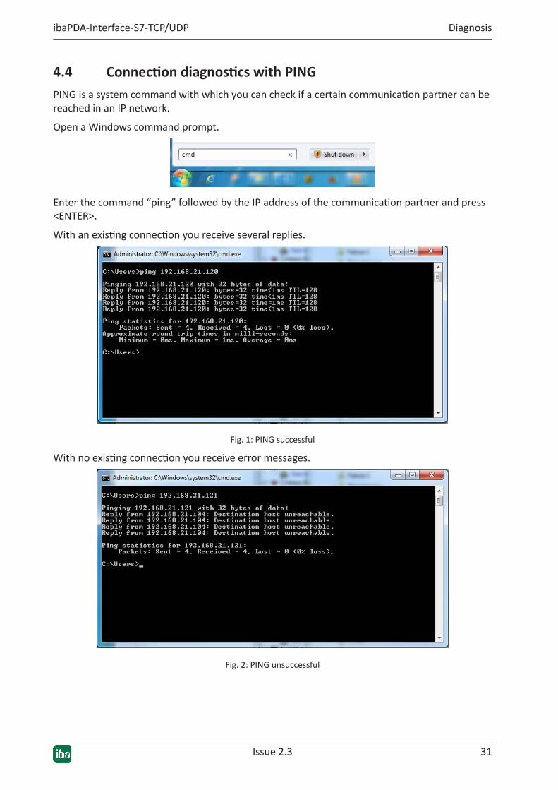
4.4 ConnectiondiagnosticswithPINGPING is a system command with which you can check if a certain communication partner can be reached in an IP network.
Open a Windows command prompt.
Enter the command “ping” followed by the IP address of the communication partner and press <ENTER>.
With an existing connection you receive several replies.
Fig. 1: PING successful
With no existing connection you receive error messages.
Fig. 2: PING unsuccessful
32 Issue 2.3
Diagnosis ibaPDA-Interface-S7-TCP/UDP
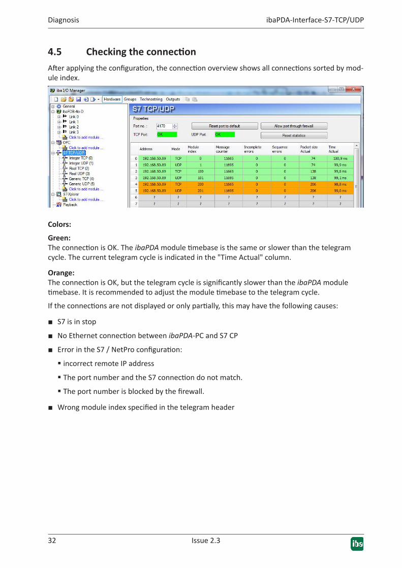
4.5 CheckingtheconnectionAfter applying the configuration, the connection overview shows all connections sorted by mod-ule index.
Colors:
Green:The connection is OK. The ibaPDA module timebase is the same or slower than the telegram cycle. The current telegram cycle is indicated in the "Time Actual" column.
Orange:The connection is OK, but the telegram cycle is significantly slower than the ibaPDA module timebase. It is recommended to adjust the module timebase to the telegram cycle.
If the connections are not displayed or only partially, this may have the following causes:
■ S7 is in stop
■ No Ethernet connection between ibaPDA-PC and S7 CP
■ Error in the S7 / NetPro configuration:
� incorrect remote IP address
� The port number and the S7 connection do not match.
� The port number is blocked by the firewall.
■ Wrong module index specified in the telegram header
Issue 2.3 33
ibaPDA-Interface-S7-TCP/UDP Diagnosis
Other errors:
■ If the telegram counters do not increment continuously, the send blocks AG_LSEND are not called cyclically on the S7 side.
■ If values in the columns "Incomplete errors" and/or "Sequence errors" are incremented, this points to one of the following errors:
� The "message_length" in the DB does not have the expected value.
� The "sequence_counter" in the DB is not incremented correctly.
� The "delayed acknowledge" problem occurs (see ì TCP/IP protocol variants, page 37)
34 Issue 2.3
Diagnosis ibaPDA-Interface-S7-TCP/UDP
4.6 DiagnosticmodulesDiagnostic modules are available for most Ethernet based interfaces and Xplorer interfaces. Us-ing a diagnostic module, information from the diagnostic displays (e. g. diagnostic tabs and con-nection tables of an interface) can be acquired as signals.
A diagnostic module is always assigned to a data acquisition module of the same interface and supplies its connection information. By using a diagnostic module you can record and analyze the diagnostic information continuously in the ibaPDA system.
Diagnostic modules do not consume any license connections, since they do not establish their own connection, but refer to another module.
Example for the use of diagnostic modules:
■ A notification can be generated, whenever the error counter of a communication connection exceeds a certain value or the connection gets lost.
■ In case of a disturbance, the current response times in the telegram traffic may be docu-mented in an incident report.
■ The connection status can be visualized in ibaQPanel .
■ You can forward diagnostic information via the SNMP server integrated in ibaPDA or via OPC DA/UA server to superordinate monitoring systems like network management tools.
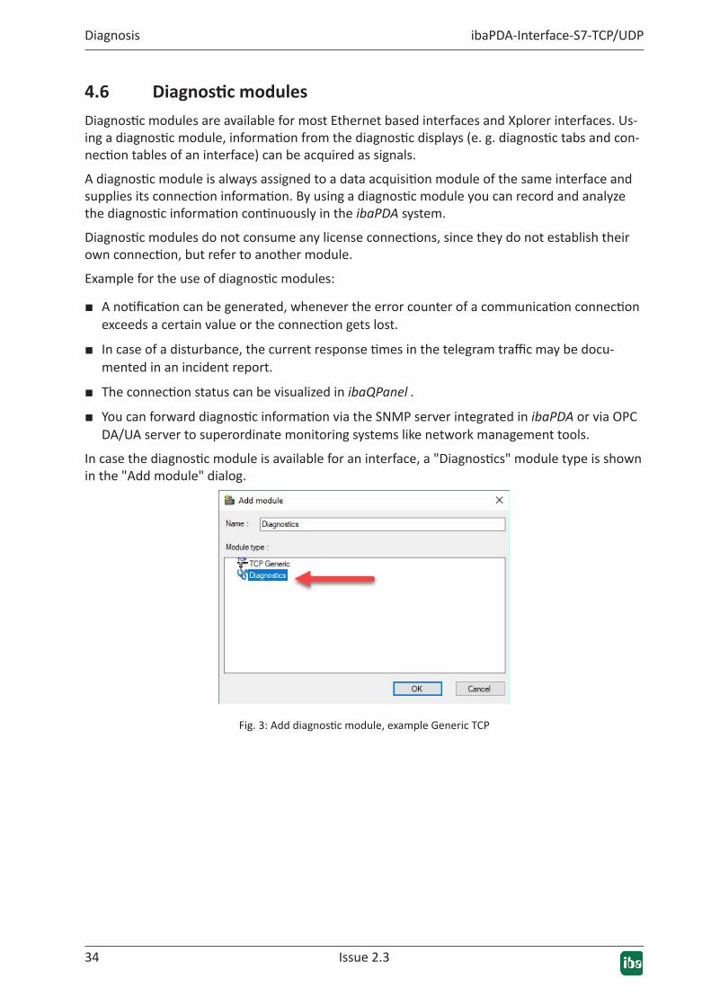
In case the diagnostic module is available for an interface, a "Diagnostics" module type is shown in the "Add module" dialog.
Fig. 3: Add diagnostic module, example Generic TCP

Issue 2.3 35
ibaPDA-Interface-S7-TCP/UDP Diagnosis
ModulesettingsdiagnosticmoduleFor a diagnostic module, you can make the following settings:
Fig. 4: Module settings diagnostic module, example TCP Generic
The basic settings of a diagnostic module equal those of other modules.
There is only one setting which is specific for the diagnostic module: the target module.
By selecting the target module, you assign the diagnostic module to the module on which you want to acquire information about the connection. You can select the supported modules of this interface in the drop down list of the setting. You can assign exactly one data acquisition module to each diagnostic module. When having selected a module, the available diagnostic signals are immediately added to the Analog and Digital tabs. It depends on the type of interface, which signals exactly are added.
Fig. 5: Example: Analog values of a diagnostic module for a TCP Generic module
For example, the IP (v4-) address of a TCP Generic module (see fig. above) will always be split into 4 parts derived from the dot-decimal notation, for better reading. Also other values are being determined, as there are port number, counters for telegrams and errors, data sizes and telegram cycle times.

36 Issue 2.3
Diagnosis ibaPDA-Interface-S7-TCP/UDP
Fig. 6: Example: Digital values of a diagnostic module for a TCP Generic module
37 Issue 2.3 37
ibaPDA-Interface-S7-TCP/UDP Appendix
5 Appendix
5.1 Restrictions
5.1.1 TCP/IP protocol variants
Restriction:ibaPDA measurements of automation devices using TCP/IP sometimes do not work with cycle times < 200 ms.
Errors shown in ibaPDA:Sequence errors and incomplete telegrams.
Cause:There are different variants of handling "acknowledge" in the TCP/IP protocol:
The standard WinSocket works in accordance with RFC1122 using the "delayed acknowledge" mechanism. It specifies that the "acknowledge" is delayed until other telegrams arrive in order to acknowledge them jointly. If no other telegrams arrive, the ACK telegram is sent after 200 ms at the latest (depending on the socket).
The data flow is controlled by a "sliding window" (parameter Win=nnnn). The recipient specifies how many bytes it can receive without sending an acknowledgment.
Some controllers do not accept this response, but instead, wait for an acknowledgment after each data telegram. If it does not arrive within a certain period of time (200 ms), it will repeat the telegram and include any new data to be sent, causing an error with the recipient, because the old one was received correctly.
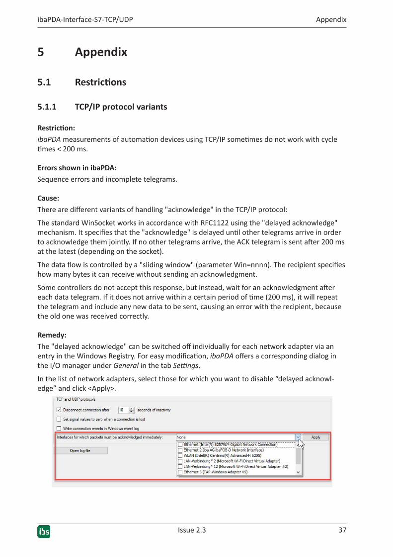
Remedy:The "delayed acknowledge" can be switched off individually for each network adapter via an entry in the Windows Registry. For easy modification, ibaPDA offers a corresponding dialog in the I/O manager under General in the tab Settings.
In the list of network adapters, select those for which you want to disable “delayed acknowl-edge” and click <Apply>.
38 Issue 2.3
Appendix ibaPDA-Interface-S7-TCP/UDP
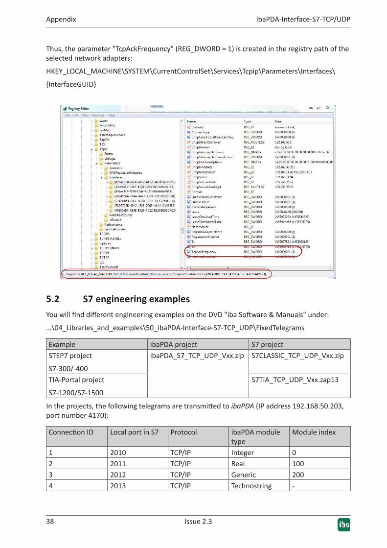
Thus, the parameter "TcpAckFrequency" (REG_DWORD = 1) is created in the registry path of the selected network adapters:
HKEY_LOCAL_MACHINE\SYSTEM\CurrentControlSet\Services\Tcpip\Parameters\Interfaces\
{InterfaceGUID}
5.2 S7 engineering examplesYou will find different engineering examples on the DVD "iba Software & Manuals" under:
…\04_Libraries_and_examples\50_ibaPDA-Interface-S7-TCP_UDP\FixedTelegrams
Example ibaPDA project S7 projectSTEP7 project
S7-300/-400
ibaPDA_S7_TCP_UDP_Vxx.zip S7CLASSIC_TCP_UDP_Vxx.zip
TIA-Portal project
S7-1200/S7-1500
S7TIA_TCP_UDP_Vxx.zap13
In the projects, the following telegrams are transmitted to ibaPDA (IP address 192.168.50.203, port number 4170):
Connection ID Local port in S7 Protocol ibaPDA module type
Module index
1 2010 TCP/IP Integer 02 2011 TCP/IP Real 1003 2012 TCP/IP Generic 2004 2013 TCP/IP Technostring -

Issue 2.3 39
ibaPDA-Interface-S7-TCP/UDP Appendix
Connection ID Local port in S7 Protocol ibaPDA module type
Module index
54) 2014 TCP/IP Technostring -6 2015 UDP Integer 17 2016 UDP Real 1018 2017 UDP Generic 20195) 2000 TCP/IP Watchdog -
5.2.1 S7CLASSIC_TCP_UDP
The S7 project was created using STEP7 V5.5 SP2 and it contains the demo engineering of sever-al configurations.
3 TCP/IP connections and 3 UDP connections are configured in each project
Additionally, 2 variants of the TCP/IP-Technostrings and the reception of an ibaPDA watchdog telegram are included.
The associated ibaPDA project can be used for all configurations, see ì ibaPDA engineering ex-ample, page 76
5.2.1.1 CPU 317-2 with PN interface
Demoproject:"CPU3xxwithPN-IF"The connection to ibaPDA is established through the integrated PN interface of the CPU.
■ Configuration of the CPU's Ethernet interface in HW Config
The IP address and the subnet mask are set in the HW Config:
4) The 2nd Technostring connection was only implemented in the S7-300/-400 projects. This connection is not implemented in the S7 TIA projects.5) This connection does not exist in the S7-3xx projects, because only 8 connections are possible in the S7-CPU 317 used.

40 Issue 2.3
Appendix ibaPDA-Interface-S7-TCP/UDP
■ Programming the send blocks
In the main program (OB1), first the test signals (sine, cosine, triangle) are generated (FC 99), then the send trigger is derived from the CPU clock memory M10.0.
Next the individual functions for sending the TCP/IP Technostring and UDP telegrams are called.
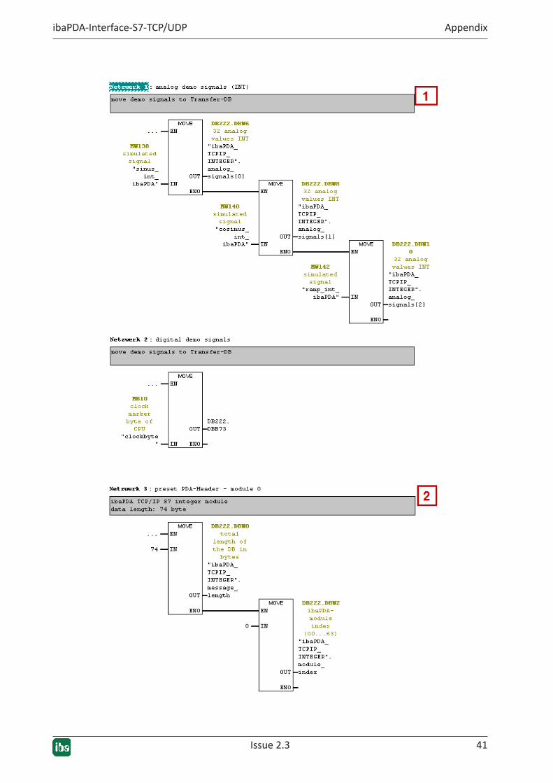
5.2.1.1.1 TCP/IP data telegrams
For each ibaPDA module type, a function FC100 (TCP-Integer), FC101 (TCP-Real) and FC102 (TCP-Generic) is called from OB1.
Each function has the same sequence:
1. Mapping the signal data in the TCP/IP data block
2. Default setting of the telegram headers
3. Calling the TCP/IP send blocks (FB151)
Issue 2.3 41
ibaPDA-Interface-S7-TCP/UDP Appendix
42 Issue 2.3
Appendix ibaPDA-Interface-S7-TCP/UDP
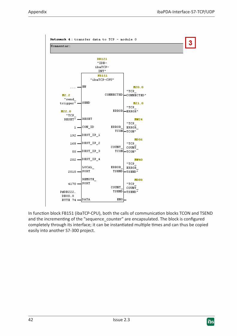
In function block FB151 (ibaTCP-CPU), both the calls of communication blocks TCON and TSEND and the incrementing of the "sequence_counter" are encapsulated. The block is configured completely through its interface; it can be instantiated multiple times and can thus be copied easily into another S7-300 project.
Issue 2.3 43
ibaPDA-Interface-S7-TCP/UDP Appendix
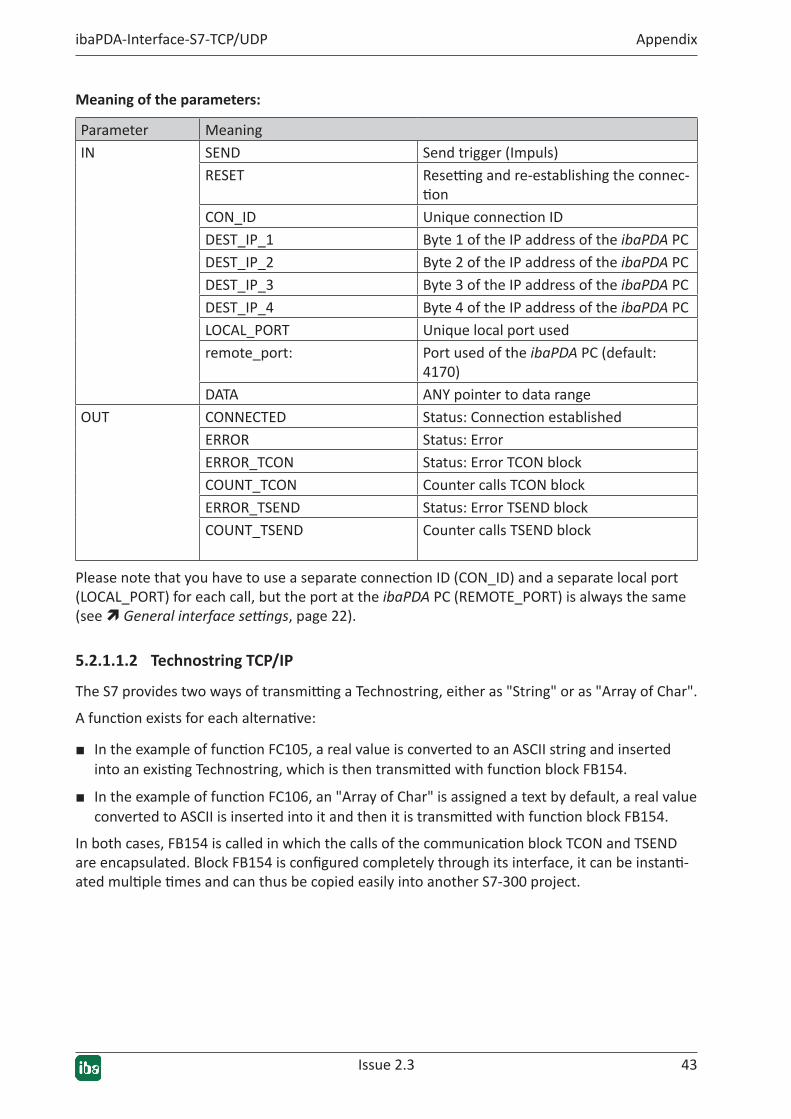
Meaning of the parameters:
Parameter MeaningIN SEND Send trigger (Impuls)
RESET Resetting and re-establishing the connec-tion
CON_ID Unique connection IDDEST_IP_1 Byte 1 of the IP address of the ibaPDA PCDEST_IP_2 Byte 2 of the IP address of the ibaPDA PCDEST_IP_3 Byte 3 of the IP address of the ibaPDA PCDEST_IP_4 Byte 4 of the IP address of the ibaPDA PCLOCAL_PORT Unique local port usedremote_port: Port used of the ibaPDA PC (default:
4170)DATA ANY pointer to data range
OUT CONNECTED Status: Connection establishedERROR Status: ErrorERROR_TCON Status: Error TCON blockCOUNT_TCON Counter calls TCON blockERROR_TSEND Status: Error TSEND blockCOUNT_TSEND Counter calls TSEND block
Please note that you have to use a separate connection ID (CON_ID) and a separate local port (LOCAL_PORT) for each call, but the port at the ibaPDA PC (REMOTE_PORT) is always the same (see ì General interface settings, page 22).
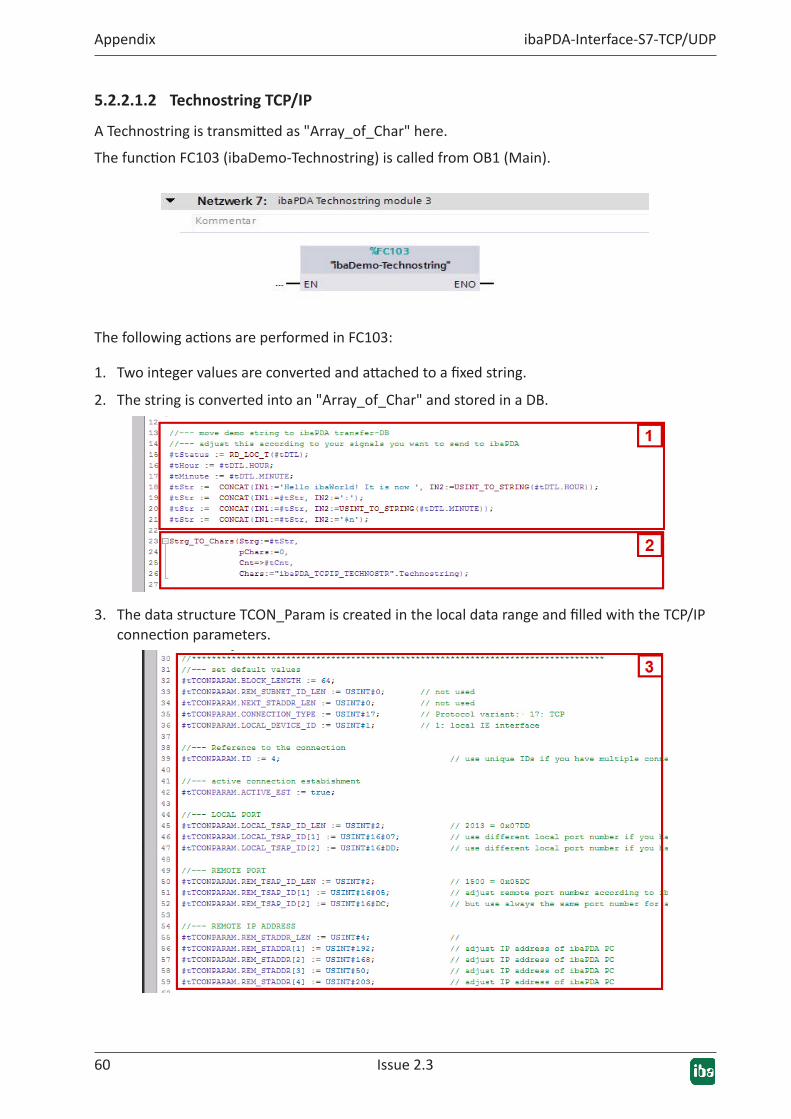
5.2.1.1.2 Technostring TCP/IP
The S7 provides two ways of transmitting a Technostring, either as "String" or as "Array of Char".
A function exists for each alternative:
■ In the example of function FC105, a real value is converted to an ASCII string and inserted into an existing Technostring, which is then transmitted with function block FB154.
■ In the example of function FC106, an "Array of Char" is assigned a text by default, a real value converted to ASCII is inserted into it and then it is transmitted with function block FB154.
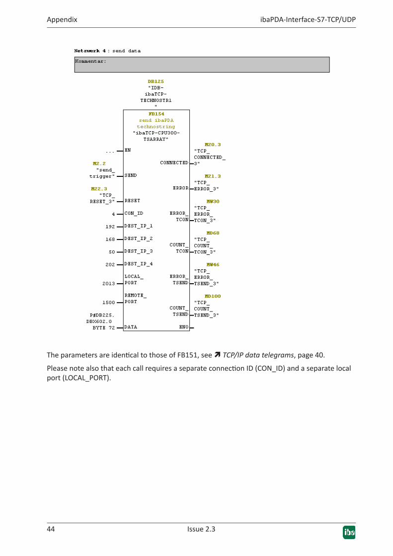
In both cases, FB154 is called in which the calls of the communication block TCON and TSEND are encapsulated. Block FB154 is configured completely through its interface, it can be instanti-ated multiple times and can thus be copied easily into another S7-300 project.
44 Issue 2.3
Appendix ibaPDA-Interface-S7-TCP/UDP
The parameters are identical to those of FB151, see ì TCP/IP data telegrams, page 40.
Please note also that each call requires a separate connection ID (CON_ID) and a separate local port (LOCAL_PORT).
Issue 2.3 45
ibaPDA-Interface-S7-TCP/UDP Appendix
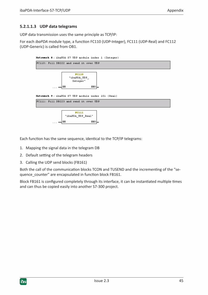
5.2.1.1.3 UDP data telegrams
UDP data transmission uses the same principle as TCP/IP:
For each ibaPDA module type, a function FC110 (UDP-Integer), FC111 (UDP-Real) and FC112 (UDP-Generic) is called from OB1.
Each function has the same sequence, identical to the TCP/IP telegrams:
1. Mapping the signal data in the telegram DB
2. Default setting of the telegram headers
3. Calling the UDP send blocks (FB161)
Both the call of the communication blocks TCON and TUSEND and the incrementing of the "se-quence_counter" are encapsulated in function block FB161.
Block FB161 is configured completely through its interface, it can be instantiated multiple times and can thus be copied easily into another S7-300 project.

46 Issue 2.3
Appendix ibaPDA-Interface-S7-TCP/UDP
The parameters are identical to those of FB151, see ì TCP/IP data telegrams, page 40.
Please note also that each call requires a separate connection ID (CON_ID) and a separate local port (LOCAL_PORT). The REMOTE_PORT must correspond to the setting in the ibaPDA PC (see ì General interface settings, page 22).
5.2.1.2 CPU 317 with CP 343-1 LEAN
Demoproject:"CPU3xxwithCP343-1"The connection to ibaPDA is established through the CP343-1 LEAN.
■ ConfigurationoftheSIMATICNETEthernet-CPinHWConfig
The IP address and the subnet mask are preset in the HW Config:

Issue 2.3 47
ibaPDA-Interface-S7-TCP/UDP Appendix
■ CreatingtheTCP/UDPconnectionsinNetProA separate connection has to be configured for each module.
48 Issue 2.3
Appendix ibaPDA-Interface-S7-TCP/UDP
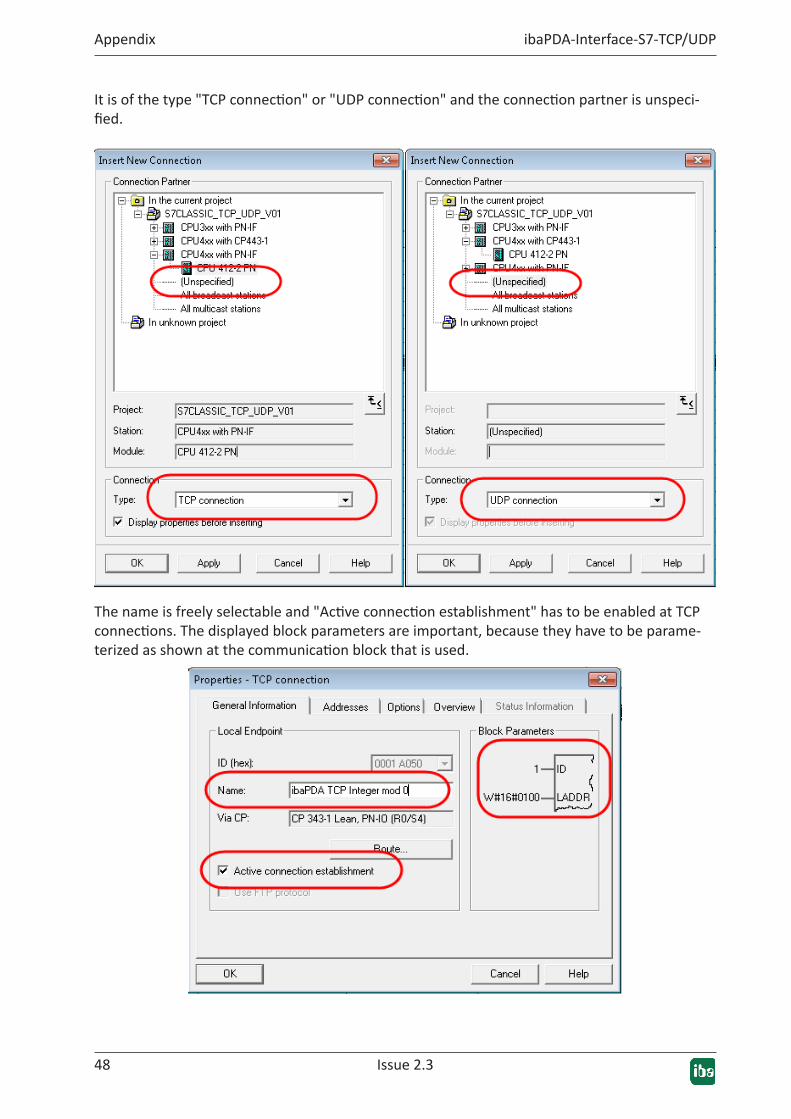
It is of the type "TCP connection" or "UDP connection" and the connection partner is unspeci-fied.
The name is freely selectable and "Active connection establishment" has to be enabled at TCP connections. The displayed block parameters are important, because they have to be parame-terized as shown at the communication block that is used.
Issue 2.3 49
ibaPDA-Interface-S7-TCP/UDP Appendix
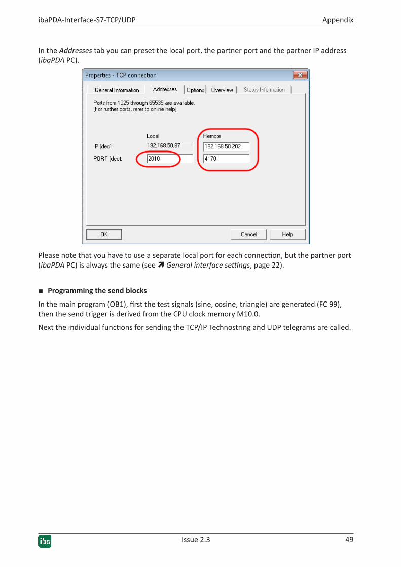
In the Addresses tab you can preset the local port, the partner port and the partner IP address (ibaPDA PC).
Please note that you have to use a separate local port for each connection, but the partner port (ibaPDA PC) is always the same (see ì General interface settings, page 22).
■ Programming the send blocks
In the main program (OB1), first the test signals (sine, cosine, triangle) are generated (FC 99), then the send trigger is derived from the CPU clock memory M10.0.
Next the individual functions for sending the TCP/IP Technostring and UDP telegrams are called.
50 Issue 2.3
Appendix ibaPDA-Interface-S7-TCP/UDP
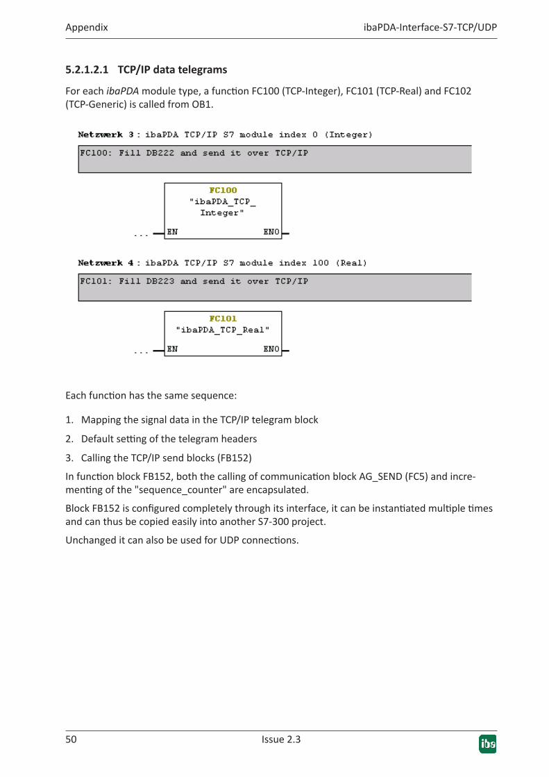
5.2.1.2.1 TCP/IP data telegrams
For each ibaPDA module type, a function FC100 (TCP-Integer), FC101 (TCP-Real) and FC102 (TCP-Generic) is called from OB1.
Each function has the same sequence:
1. Mapping the signal data in the TCP/IP telegram block
2. Default setting of the telegram headers
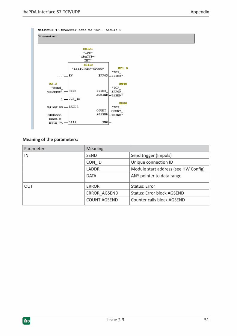
3. Calling the TCP/IP send blocks (FB152)
In function block FB152, both the calling of communication block AG_SEND (FC5) and incre-menting of the "sequence_counter" are encapsulated.
Block FB152 is configured completely through its interface, it can be instantiated multiple times and can thus be copied easily into another S7-300 project.
Unchanged it can also be used for UDP connections.
Issue 2.3 51
ibaPDA-Interface-S7-TCP/UDP Appendix
Meaning of the parameters:
Parameter MeaningIN SEND Send trigger (Impuls)
CON_ID Unique connection IDLADDR Module start address (see HW Config)DATA ANY pointer to data range
OUT ERROR Status: ErrorERROR_AGSEND Status: Error block AGSENDCOUNT-AGSEND Counter calls block AGSEND

52 Issue 2.3
Appendix ibaPDA-Interface-S7-TCP/UDP
5.2.1.2.2 Technostring TCP/IP
The S7 provides two ways of transmitting a Technostring, either as "String" or as "Array of Char". A function exists for each alternative:
■ In the example of function FC105, a real value is converted to an ASCII string and inserted into an existing Technostring, which is then transmitted with function block FB155.
■ In the example of function FC106, an "Array of Char" is assigned a text by default, a real value converted to ASCII is inserted into it and then it is transmitted with function block FB155.
In FB155, the call of communication block AG_SEND is encapsulated. Block FB155 is configured completely through its interface, it can be instantiated multiple times and can thus be copied easily into another S7-300 project.
The meaning of the parameters is identical to those of FB152, see ì TCP/IP data telegrams, page 50.
Please note here, too, that you need a separate connection ID (CON_ID) for each call.

Issue 2.3 53
ibaPDA-Interface-S7-TCP/UDP Appendix
5.2.1.2.3 UDP data telegrams
UDP data transmission works according to the same principle as TCP/IP:
For each ibaPDA module type, a function FC110 (UDP-Integer), FC111 (UDP-Real) and FC112 (UDP-Generic) is called from OB1.
Each function has the same sequence:
1. Mapping the signal data in the telegram DB
2. Default setting of the telegram headers
3. Calling the send blocks
Both calling of communication block AG_SEND (FC5) and incrementing of the „sequence_count-er" are encapsulated in function block FB152.
Block FB152 is configured completely through its interface, it can be instantiated multiple times and can thus be copied easily into another S7-300 project.
There is no difference to sending via a TCP/IP connection. TCP/IP and UDP are distinguished based on the connection type in the HW configuration, referenced by the connection ID.

54 Issue 2.3
Appendix ibaPDA-Interface-S7-TCP/UDP
5.2.1.3 CPU 412-2 with PN interface
Demoproject:"CPU4xxwithPN-IF"The connection to ibaPDA is established through the integrated PN interface of the CPU.
The example is identical to the example in ì CPU 317-2 with PN interface, page 39 with one exception:
The "local_device_id", which is entered into the connection parameters within the TCP-/UDP send blocks (FB151, FB154, FB157, FB161), depends on the CPU type:
■ for CPU3xx: local_device_id = 2,
■ for CPU4xx: local_device_id = 5.
See also the Step7 online help.
5.2.1.4 CPU 412 with CP 443-1
Demoproject:"CPU4xxwithCP443-1"The connection to ibaPDA is established through the CP443-1.
The example is identical to the example in ì CPU 317 with CP 343-1 LEAN, page 46, with the following exceptions:
■ FB153, in which the send block AG_LSEND (FC50) is encapsulated, is called within the func-tions FC100, FC101, FC102, FC110, FC111, FC112.
■ FB156, in which the send block AG_LSEND (FC50) is encapsulated, is called within the func-tions FC105, FC106.
■ Reception of the ibaPDA watchdog telegram is accomplished in function block FB159, in which the receive block AG_LRECV (FC60) is encapsulated.
Issue 2.3 55
ibaPDA-Interface-S7-TCP/UDP Appendix
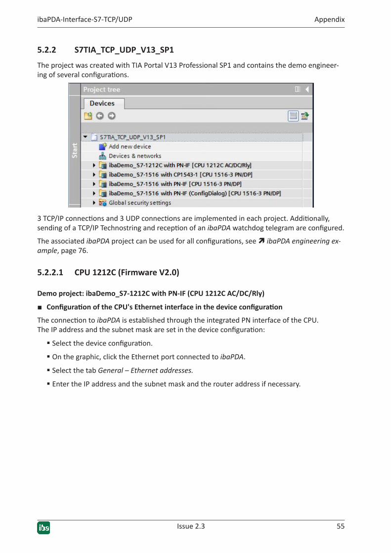
5.2.2 S7TIA_TCP_UDP_V13_SP1
The project was created with TIA Portal V13 Professional SP1 and contains the demo engineer-ing of several configurations.
3 TCP/IP connections and 3 UDP connections are implemented in each project. Additionally, sending of a TCP/IP Technostring and reception of an ibaPDA watchdog telegram are configured.
The associated ibaPDA project can be used for all configurations, see ì ibaPDA engineering ex-ample, page 76.
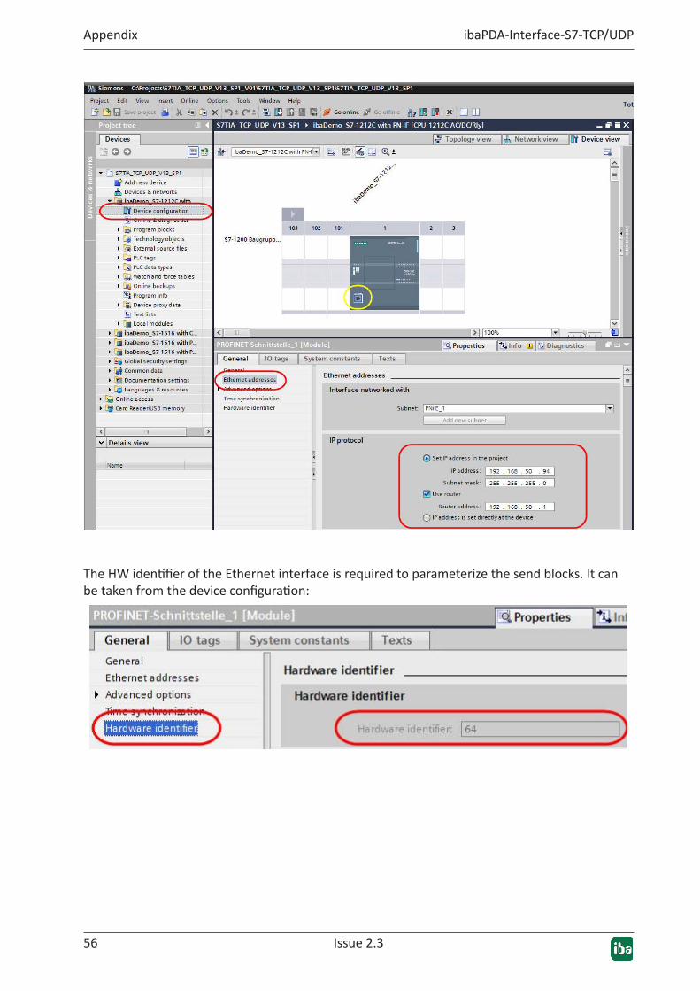
5.2.2.1 CPU1212C(FirmwareV2.0)
Demoproject:ibaDemo_S7-1212CwithPN-IF(CPU1212CAC/DC/Rly)
■ ConfigurationoftheCPU'sEthernetinterfaceinthedeviceconfigurationThe connection to ibaPDA is established through the integrated PN interface of the CPU. The IP address and the subnet mask are set in the device configuration:
� Select the device configuration.
� On the graphic, click the Ethernet port connected to ibaPDA.
� Select the tab General – Ethernet addresses.
� Enter the IP address and the subnet mask and the router address if necessary.
56 Issue 2.3
Appendix ibaPDA-Interface-S7-TCP/UDP
The HW identifier of the Ethernet interface is required to parameterize the send blocks. It can be taken from the device configuration:
Issue 2.3 57
ibaPDA-Interface-S7-TCP/UDP Appendix
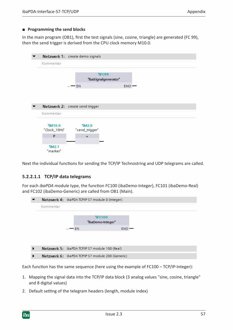
■ Programming the send blocks
In the main program (OB1), first the test signals (sine, cosine, triangle) are generated (FC 99), then the send trigger is derived from the CPU clock memory M10.0.
Next the individual functions for sending the TCP/IP Technostring and UDP telegrams are called.
5.2.2.1.1 TCP/IP data telegrams
For each ibaPDA module type, the function FC100 (ibaDemo-Integer), FC101 (ibaDemo-Real) and FC102 (ibaDemo-Generic) are called from OB1 (Main).
Each function has the same sequence (here using the example of FC100 – TCP/IP-Integer):
1. Mapping the signal data into the TCP/IP data block (3 analog values "sine, cosine, triangle" and 8 digital values)
2. Default setting of the telegram headers (length, module index)
58 Issue 2.3
Appendix ibaPDA-Interface-S7-TCP/UDP
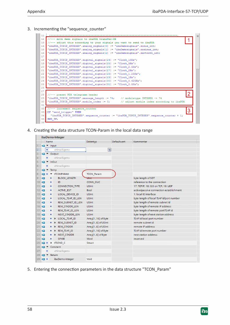
3. Incrementing the "sequence_counter"
4. Creating the data structure TCON-Param in the local data range
5. Entering the connection parameters in the data structure "TCON_Param"
Issue 2.3 59
ibaPDA-Interface-S7-TCP/UDP Appendix
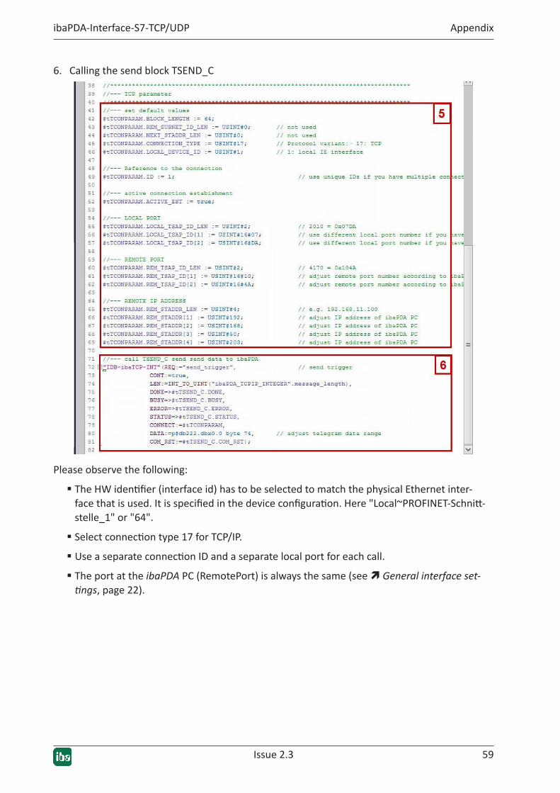
6. Calling the send block TSEND_C
Please observe the following:
� The HW identifier (interface id) has to be selected to match the physical Ethernet inter-face that is used. It is specified in the device configuration. Here "Local~PROFINET-Schnitt-stelle_1" or "64".
� Select connection type 17 for TCP/IP.
� Use a separate connection ID and a separate local port for each call.
� The port at the ibaPDA PC (RemotePort) is always the same (see ì General interface set-tings, page 22).
60 Issue 2.3
Appendix ibaPDA-Interface-S7-TCP/UDP
5.2.2.1.2 Technostring TCP/IP
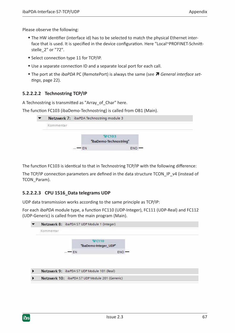
A Technostring is transmitted as "Array_of_Char" here.
The function FC103 (ibaDemo-Technostring) is called from OB1 (Main).
The following actions are performed in FC103:
1. Two integer values are converted and attached to a fixed string.
2. The string is converted into an "Array_of_Char" and stored in a DB.
3. The data structure TCON_Param is created in the local data range and filled with the TCP/IP connection parameters.

Issue 2.3 61
ibaPDA-Interface-S7-TCP/UDP Appendix
4. The send block TSEND_C is called.
Please note also that the call requires a separate connection ID and a separate local port. The remote port must match the setting in the ibaPDA Technostring.
5.2.2.1.3 Data telegrams UDP
CallingthecommunicationblocksintheS7programoftheCPUUDP data transmission works according to the same principle as TCP/IP:
For each ibaPDA module type, a function FC110 (ibaDemo-Integer-UDP), FC111 (ibaDemo-Re-al-UDP) and FC112 (ibaDemo-Generic-UDP) is called from OB1 (Main).
Each function has the same sequence, see TCP/IP data telegrams:
1. Mapping the signal data in the UDP data block (3 analog values "sine, cosine, triangle" and 8 digital values)
2. Default setting of the telegram headers (length, module index)
3. Incrementing the "sequence_counter"

62 Issue 2.3
Appendix ibaPDA-Interface-S7-TCP/UDP
4. Creating the data structures TCON-Param and TADDR_Param in the local data range
5. Entering the connection parameters in the data structure TCON_Param
Issue 2.3 63
ibaPDA-Interface-S7-TCP/UDP Appendix
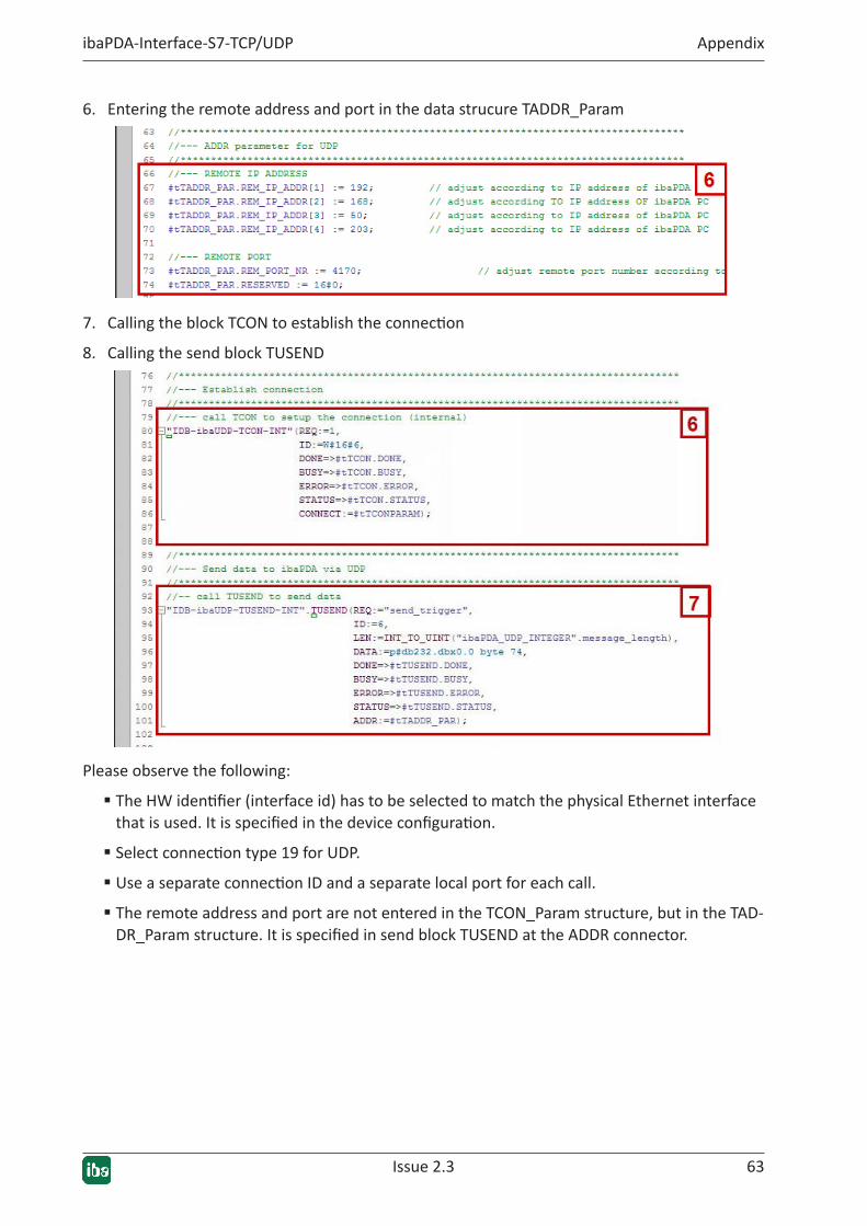
6. Entering the remote address and port in the data strucure TADDR_Param
7. Calling the block TCON to establish the connection
8. Calling the send block TUSEND
Please observe the following:
� The HW identifier (interface id) has to be selected to match the physical Ethernet interface that is used. It is specified in the device configuration.
� Select connection type 19 for UDP.
� Use a separate connection ID and a separate local port for each call.
� The remote address and port are not entered in the TCON_Param structure, but in the TAD-DR_Param structure. It is specified in send block TUSEND at the ADDR connector.
64 Issue 2.3
Appendix ibaPDA-Interface-S7-TCP/UDP
5.2.2.2 CPU 1516 with PN interface
Demoproject:"ibaDemo-S7-1516withPN-IF"The connection to ibaPDA is established through the integrated PN interface of the CPU.
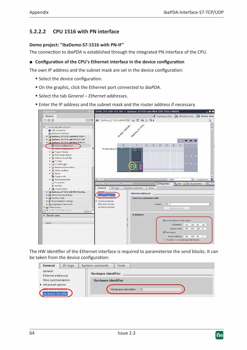
■ ConfigurationoftheCPU'sEthernetinterfaceinthedeviceconfigurationThe own IP address and the subnet mask are set in the device configuration:
� Select the device configuration.
� On the graphic, click the Ethernet port connected to ibaPDA.
� Select the tab General – Ethernet addresses.
� Enter the IP address and the subnet mask and the router address if necessary.
The HW identifier of the Ethernet interface is required to parameterize the send blocks. It can be taken from the device configuration:
Issue 2.3 65
ibaPDA-Interface-S7-TCP/UDP Appendix
■ Programming the send blocks
In the main program (OB1), first the test signals (sine, cosine, triangle) are generated (FC 99), then the send trigger is derived from the CPU clock memory M10.0.
Next the individual functions for sending the TCP/IP, Technostring and UDP telegrams are called.
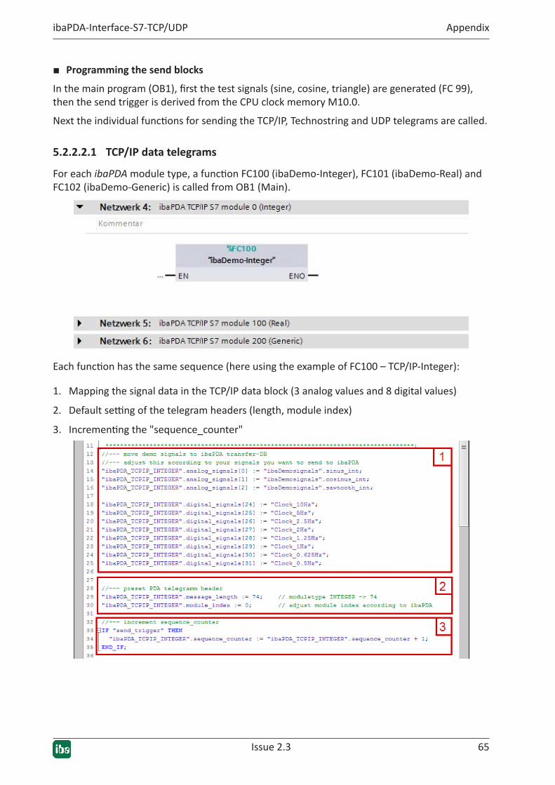
5.2.2.2.1 TCP/IP data telegrams
For each ibaPDA module type, a function FC100 (ibaDemo-Integer), FC101 (ibaDemo-Real) and FC102 (ibaDemo-Generic) is called from OB1 (Main).
Each function has the same sequence (here using the example of FC100 – TCP/IP-Integer):
1. Mapping the signal data in the TCP/IP data block (3 analog values and 8 digital values)
2. Default setting of the telegram headers (length, module index)
3. Incrementing the "sequence_counter"

66 Issue 2.3
Appendix ibaPDA-Interface-S7-TCP/UDP
4. Creating the data structure TCON_IP_v4 in the local data range
5. Entering the TCP/IP connection parameters
6. Calling the send block TSEND_C
Issue 2.3 67
ibaPDA-Interface-S7-TCP/UDP Appendix
Please observe the following:
� The HW identifier (interface id) has to be selected to match the physical Ethernet inter-face that is used. It is specified in the device configuration. Here "Local~PROFINET-Schnitt-stelle_2" or "72".
� Select connection type 11 for TCP/IP.
� Use a separate connection ID and a separate local port for each call.
� The port at the ibaPDA PC (RemotePort) is always the same (see ì General interface set-tings, page 22).
5.2.2.2.2 Technostring TCP/IP
A Technostring is transmitted as "Array_of_Char" here.
The function FC103 (ibaDemo-Technostring) is called from OB1 (Main).
The function FC103 is identical to that in Technostring TCP/IP with the following difference:
The TCP/IP connection parameters are defined in the data structure TCON_IP_v4 (instead of TCON_Param).
5.2.2.2.3 CPU1516_DatatelegramsUDP
UDP data transmission works according to the same principle as TCP/IP:
For each ibaPDA module type, a function FC110 (UDP-Integer), FC111 (UDP-Real) and FC112 (UDP-Generic) is called from the main program (Main).

68 Issue 2.3
Appendix ibaPDA-Interface-S7-TCP/UDP
Each function has the same sequence (here using the example of FC110):
1. Mapping the signal data in the UDP data block (3 analog values "sine, cosine, triangle" and 8 digital values), see ì TCP/IP data telegrams, page 65
2. Default setting of the telegram headers (length, module index), see ì TCP/IP data tele-grams, page 65
3. Incrementing the "sequence_counter", see ì TCP/IP data telegrams, page 65
4. Creating the data structure TCON_IP_v4 in the local data range, see ì TCP/IP data tele-grams, page 65
5. Entering the connection parameters in the data structure "TCON_IP"
6. Entering the remote address and port in the data structure "TADDR_PAR"
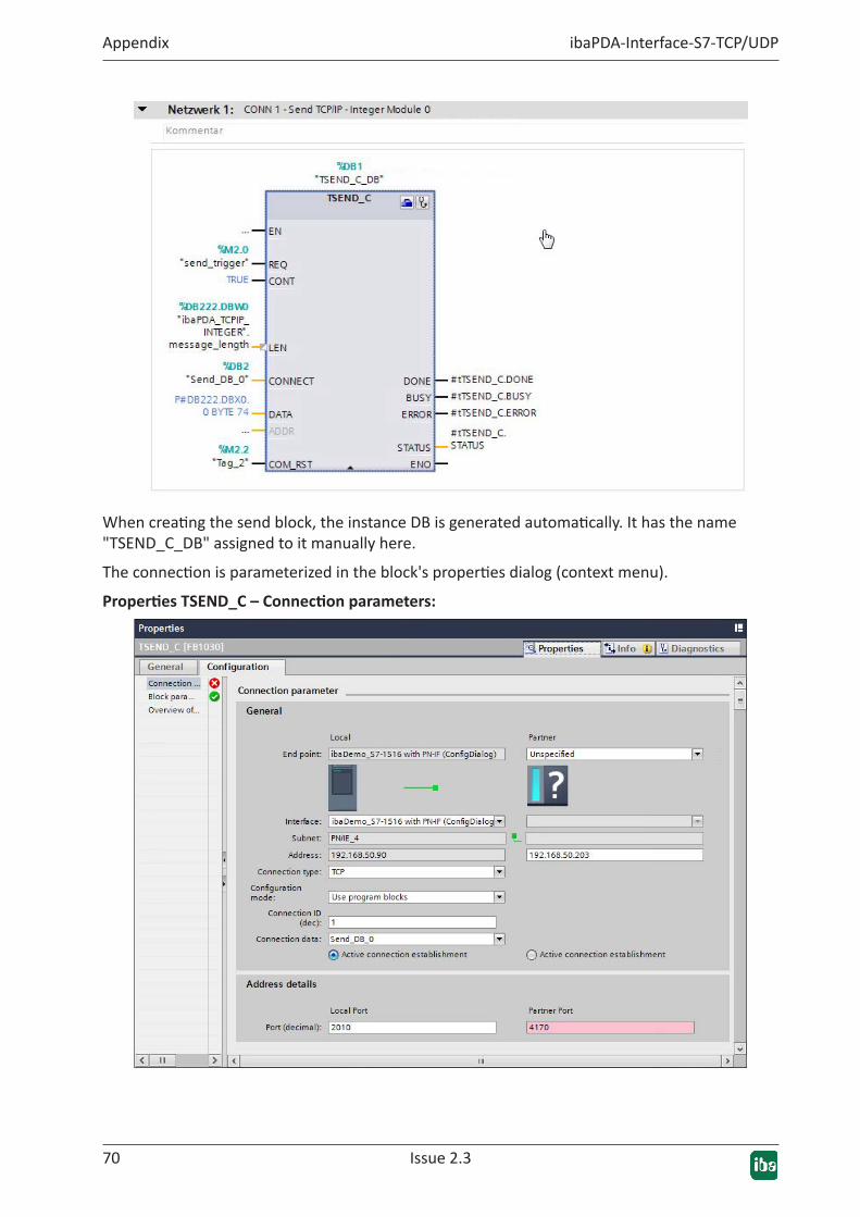
7. Calling the send block TSEND_C

Issue 2.3 69
ibaPDA-Interface-S7-TCP/UDP Appendix
Please observe the following:
� The HW identifier (interface id) has to be selected to match the physical Ethernet interface that is used. It is specified in the device configuration.
� Select connection type 19 for UDP.
� Use a separate connection ID and a separate local port for each call.
� The remote address and port are not entered in the TCON_Param structure, but in the TAD-DR_Param structure. It is specified in send block TSEND_C at the ADDR connector.
5.2.2.3 CPU1516withPNinterfaceandconfigurationdialog
Demoproject:"ibaDemo_S7-1516withPN-IF(ConfigDialog)"The connection to ibaPDA is established through the integrated PN interface of the CPU.
■ ConfigurationoftheCPU'sEthernetinterfaceinthedeviceconfigurationThe own IP address and the subnet mask are set in the device configuration:
The HW identifier can be taken from the device configuration.
See ì CPU 1516 with PN interface, page 64.
■ Programming the send blocks
In the main program (OB1), first the test signals (sine, cosine, triangle) are generated (FC 99), then the send trigger is derived from the CPU clock memory M10.0.
Then the function FC120 (Connections) is called in which all TCP/IP and UDP send blocks are configured in their properties dialog.
Callfrom"Main(OB1)"
In FC120, a send block TSEND_C is called for each connection.
70 Issue 2.3
Appendix ibaPDA-Interface-S7-TCP/UDP
When creating the send block, the instance DB is generated automatically. It has the name "TSEND_C_DB" assigned to it manually here.
The connection is parameterized in the block's properties dialog (context menu).
PropertiesTSEND_C–Connectionparameters:
Issue 2.3 71
ibaPDA-Interface-S7-TCP/UDP Appendix
Enter the following parameters here:
■ Select the local Ethernet interface, here "… PROFINET-Schnittstelle_2"
■ Configuration type: "Use program blocks"
■ Enter a DB name for the connection data; "Send_DB_x" is entered as the name here. The DB is created automatically; afterwards the remaining parameters can be entered in the dialog:
� Connection type: TCP
� Connection ID: unique number
� Active connection establishment
� Local unique port number
Partner data:
� Endpoint: unspecified
� Address: IP address of the ibaPDA PC
� Partner port: 4170
Note
Due to an error in the TIA Portal software, the partner port is marked as defec-tive here. This is probably because it is not allowed to configure multiple connec-tions with the same partner port.
Remedy: Open the connection data DB and enter the port number 4170 there.
72 Issue 2.3
Appendix ibaPDA-Interface-S7-TCP/UDP
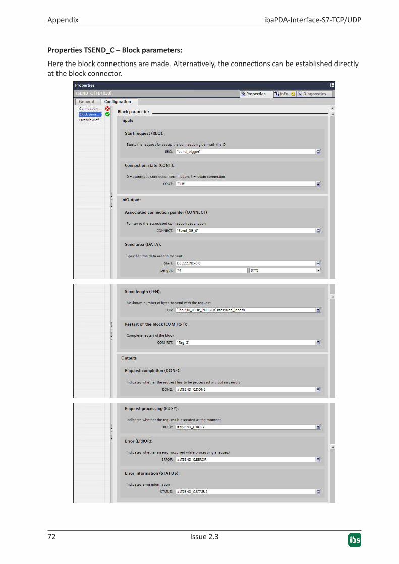
PropertiesTSEND_C–Blockparameters:
Here the block connections are made. Alternatively, the connections can be established directly at the block connector.
Issue 2.3 73
ibaPDA-Interface-S7-TCP/UDP Appendix
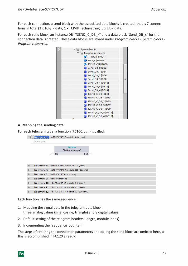
For each connection, a send block with the associated data blocks is created, that is 7 connec-tions in total (3 x TCP/IP data, 1 x TCP/IP Technostring, 3 x UDP data).
For each send block, an instance DB "TSEND_C_DB_x" and a data block "Send_DB_x" for the connection data is created. These data blocks are stored under Program blocks - System blocks - Program resources.
■ Mapping the sending data
For each telegram type, a function (FC100, . . . ) is called.
Each function has the same sequence:
1. Mapping the signal data in the telegram data block: three analog values (sine, cosine, triangle) and 8 digital values
2. Default setting of the telegram headers (length, module index)
3. Incrementing the "sequence_counter"
The steps of entering the connection parameters and calling the send block are omitted here, as this is accomplished in FC120 already.
74 Issue 2.3
Appendix ibaPDA-Interface-S7-TCP/UDP
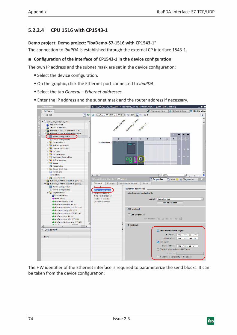
5.2.2.4 CPU 1516 with CP1543-1
Demoproject:Demoproject:"ibaDemo-S7-1516withCP1543-1"The connection to ibaPDA is established through the external CP interface 1543-1.
■ ConfigurationoftheinterfaceofCP1543-1inthedeviceconfigurationThe own IP address and the subnet mask are set in the device configuration:
� Select the device configuration.
� On the graphic, click the Ethernet port connected to ibaPDA.
� Select the tab General – Ethernet addresses.
� Enter the IP address and the subnet mask and the router address if necessary.
The HW identifier of the Ethernet interface is required to parameterize the send blocks. It can be taken from the device configuration:
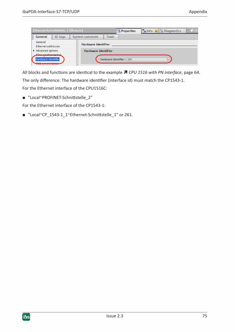
Issue 2.3 75
ibaPDA-Interface-S7-TCP/UDP Appendix
All blocks and functions are identical to the example ì CPU 1516 with PN interface, page 64.
The only difference: The hardware identifier (interface id) must match the CP1543-1.
For the Ethernet interface of the CPU1516C:
■ "Local~PROFINET-Schnittstelle_2"
For the Ethernet interface of the CP1543-1:
■ "Local~CP_1543-1_1~Ethernet-Schnittstelle_1" or 261.
76 Issue 2.3
Appendix ibaPDA-Interface-S7-TCP/UDP
5.3 ibaPDA engineering exampleThis ibaPDA configuration applies to all SIMATIC engineering examples mentioned above.
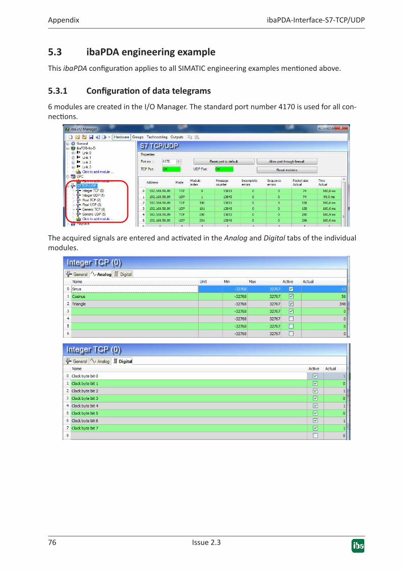
5.3.1 Configurationofdatatelegrams
6 modules are created in the I/O Manager. The standard port number 4170 is used for all con-nections.
The acquired signals are entered and activated in the Analog and Digital tabs of the individual modules.

Issue 2.3 77
ibaPDA-Interface-S7-TCP/UDP Appendix
5.3.2 ConfigurationofTechnostring
Under the Technostring menu item, Technostrings with the following parameters are defined under interface TCP/IP2:
� Technostring 1: Terminator: 13 (CR), port number 1500 and Mode: passive.
� Technostring 2: Terminator: 13 (CR), port number 1501 and Mode: passive.

78 Issue 2.3
Appendix ibaPDA-Interface-S7-TCP/UDP
5.3.3 ConfigurationWatchdog
Under Hardware - General you will find the Watchdog tab. The watchdog telegram with the fol-lowing parameters is defined there:
Port number: 40001, Protocol: TCP/IP, Mode: passive, Format: Binary big endian
Issue 2.3 79
ibaPDA-Interface-S7-TCP/UDP Appendix
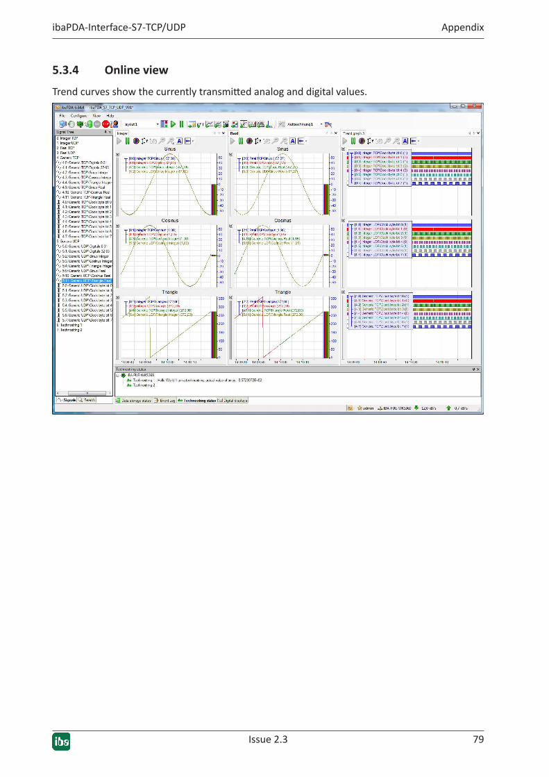
5.3.4 Online view
Trend curves show the currently transmitted analog and digital values.
8080 Issue 2.3
Support and contact ibaPDA-Interface-S7-TCP/UDP
6 Support and contactSupport
Phone: +49 911 97282-14
Fax: +49 911 97282-33
Email: [email protected]
Note
If you require support, indicate the serial number (iba-S/N) of the product and the license number.
Contact
Headoffice
iba AG Koenigswarterstrasse 44 90762 Fuerth Germany
Phone: +49 911 97282-0
Fax: +49 911 97282-33
Email: [email protected]
Contact: Harald Opel
Delivery address
iba AG Gebhardtstrasse 10 90762 Fuerth Germany
Regional and Worldwide
For contact data of your regional iba office or representative please refer to our web site
www.iba-ag.com.