I I I I - Wisconsin DNR
163
I_ I I I I I I Revised Groundwater Monitoring Plan W.I.D. 006-091-425 S.C. Johnson & Son, Inc. Waxdale Facility . L:.i;~ 0-- 1 !::r~·, '1.-- s-1..- ov by O'L - ~- S S1 19- S \ & U2--P :\ts CH2M HILL Qt -~ (7s? s-o\ May 19, 1995 "I, Lauri J. Gorton, hereby certify that I am a registered Professional Engineer in the State of Wisconsin in accordance with ch. A-E4, Wis. Adm. Code and that this report has been prepared in accordance with the Rules of Professional Conduct in ch. A-E8, Wis. Adm. Code." L~,P.E. Project Manager P .E. Number E-23252 "I, Kathryn A. Gehweiler, hereby certify that I am a hydrogeologist as defined in s. NR 600.03(98), Wis. Adm. Code, and that to the best of my knowledge all information contained in this document is correct." Kathryn A. Gehweiler Project Hydrogeologist MKE10015DC3 .DOC
-
Upload
khangminh22 -
Category
Documents
-
view
0 -
download
0
Transcript of I I I I - Wisconsin DNR

I_
I I I I
I
I
Revised Groundwater Monitoring Plan W.I.D. 006-091-425
S.C. Johnson & Son, Inc. Waxdale Facility . L:.i;~
0-- 1 !::r~·, '1.-- s-1..- ov by O'L -~- S S1 19- S \ & U2--P :\ts
CH2M HILL Qt- ~ (7s? ~ s-o\ May 19, 1995
"I, Lauri J. Gorton, hereby certify that I am a registered Professional Engineer in the State of Wisconsin in accordance with ch. A-E4, Wis. Adm. Code and that this report has been prepared in accordance with the Rules of Professional Conduct in ch. A-E8, Wis. Adm. Code."
L~,P.E. Project Manager P .E. Number E-23252
"I, Kathryn A. Gehweiler, hereby certify that I am a hydrogeologist as defined in s. NR 600.03(98), Wis. Adm. Code, and that to the best of my knowledge all information contained in this document is correct."
Kathryn A. Gehweiler Project Hydrogeologist
MKE10015DC3.DOC
I
I
I I
I
I i l l
I
I
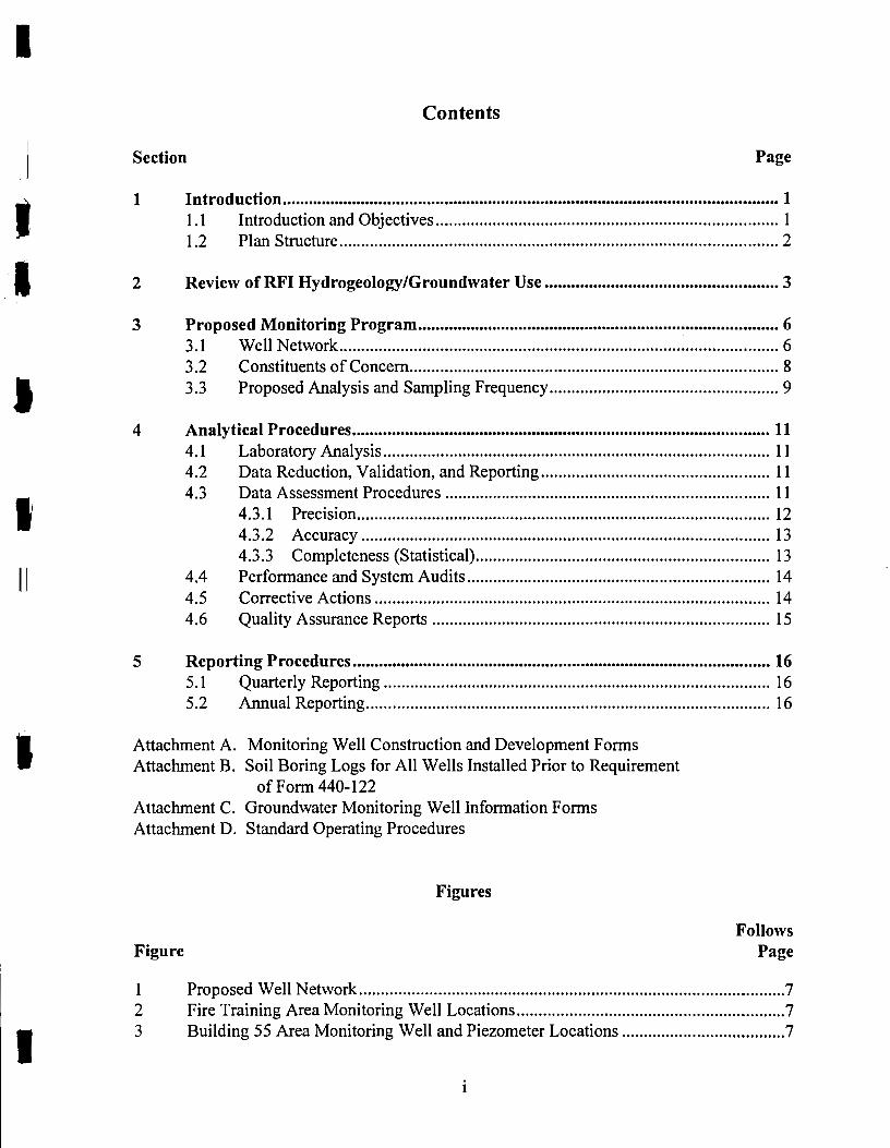
Contents
Section Page
1 Introduction ................................................................................................................. 1 1.1 Introduction and Objectives .............................................................................. 1 1.2 Plan Structure .................................................................................................... 2
2 Review of RFI Hydrogeology/Groundwater Use ..................................................... 3
3 Proposed Monitoring Program ............................................................ ~····················· 6 3.1 3.2 3.3
Well Network .................................................................................................... 6 Constituents of Concern .................................................................................... 8 Proposed Analysis and Sampling Frequency .................................................... 9
4 Analytical Procedures ............................................................................................... 11 4.1 4.2 4.3
4.4 4.5 4.6
Laboratory Analysis ........................................................................................ 11 Data Reduction, Validation, and Reporting .................................................... 11 Data Assessment Procedures .......................................................................... 11 4.3.1 Precision .............................................................................................. 12 4.3.2 Accuracy ............................................................................................. 13 4.3.3 Completeness (Statistical) ................................................................... 13 Performance and System Audits ..................................................................... 14 Corrective Actions .......................................................................................... 14 Quality Assurance Reports ............................................................................. 15
5 Reporting Procedures ............................................................................................... 16 5.1 Quarterly Reporting ........................................................................................ 16 5 .2 Annual Reporting............................................................................................ 16
Attachment A. Monitoring Well Construction and Development Forms Attachment B. Soil Boring Logs for All Wells Installed Prior to Requirement
of Form 440-122 Attachment C. Groundwater Monitoring Well Information Forms Attachment D. Standard Operating Procedures
Figure
1 2 3
Figures
Follows Page
Proposed Well Network ................................................................................................. 7 Fire Training Area Monitoring Well Locations ............................................................. ? Building 55 Area Monitoring Well and Piezometer Locations ..................................... 7

Figures (Continued)
Follows F~u~ Pa~
4 Building 51 Tank Farm Monitoring Well and Piezometer Locations ........................... 7 5 Parking Lot Landfill Monitoring Well and Piezometer Locations ................................ 7 6 Waxdale Landfill Monitoring Well Locations ............................................................... ? 7 Preliminary Interceptor Trench Alignment in Operating Area ...................................... 7
Tables
Follows Table Page
1 1995-1997 Groundwater Monitoring Plan-Existing and Supplemental Wells ........... 8 2 Estimated 1995 PCAMP Groundwater Monitoring Sample Matrix .............................. 9 3 Proposed Parameters and Analytical Methods ............................................................... 9 4 Estimated 1997 CAMP Groundwater Monitoring Sample Matrix .............................. 10
MKE10015DC3.DOC
11
I I I I I
I I I II
I
I I I I I
I I, I 11
t
I r I
I
Section 1
Introduction
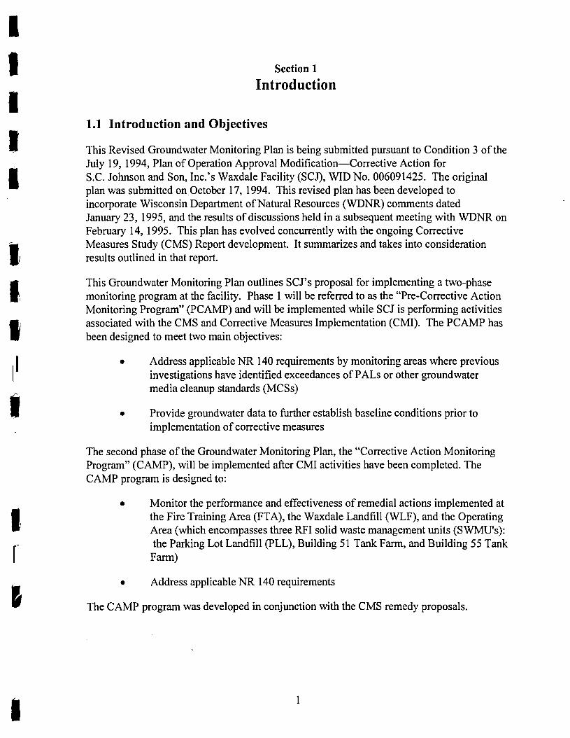
1.1 Introduction and Objectives
This Revised Groundwater Monitoring Plan is being submitted pursuant to Condition 3 of the July 19, 1994, Plan of Operation Approval Modification-Corrective Action for S.C. Johnson and Son, Inc.'s Waxdale Facility (SCJ), WID No. 006091425. The original plan was submitted on.October 17, 1994. This revised plan has been developed to incorporate Wisconsin Department of Natural Resources (WDNR) comments dated January 23, 1995, and the results of discussions held in a subsequent meeting with WDNR on February 14, 1995. This plan has evolved concurrently with the ongoing Corrective Measures Study (CMS) Report development. It summarizes and takes into consideration results outlined in that report.
This Groundwater Monitoring Plan outlines SCJ' s proposal for implementing a two-phase monitoring program at the facility. Phase 1 will be referred to as the "Pre-Corrective Action Monitoring Program" (PCAMP) and will be implemented while SCJ is performing activities associated with the CMS and Corrective Measures Implementation (CMI). The PCAMP has been designed to meet two main objectives:
•
•
Address applicable NR 140 requirements by monitoring areas where previous investigations have identified exceedances of P ALs or other groundwater media cleanup standards (MCSs)
Provide groundwater data to further establish baseline conditions prior to implementation of corrective measures
The second phase of the Groundwater Monitoring Plan, the "Corrective Action Monitoring Program" (CAMP), will be implemented after CMI activities have been completed. The CAMP program is designed to:
• Monitor the performance and effectiveness of remedial actions implemented at the Fire Training Area (FTA), the Waxdale Landfill (WLF), and the Operating Area (which encompasses three RFI solid waste management units (SWMU's): the Parking Lot Landfill (PLL), Building 51 Tank Farm, and Building 55 Tank Farm)
• Address applicable NR 140 requirements
The CAMP program was developed in conjunction with the CMS remedy proposals.
1

1.2 Plan Structure
Section 2 of this Plan provides summary information (a review of physical and chemical conditions delineated during the RFI and subsequent sampling events) that are pertinent to groundwater monitoring program components.
The proposed monitoring program is presented in Section 3 and provides the rationale for selecting sampling locations and analytes, a list of monitoring points, an analyte list, and proposed analytical methods. Section 3 describes the PCAMP scope and the CAMP proposal, which is based on and is consistent with the remedial actions proposed in the CMS, including implementation of the interceptor trench around the Operating Area. The CAMP is expected to be a dynamic program that would be reviewed and, if appropriate, modified over time to reflect observed conditions at the site and implementation of a remedy.
Section 4 of this Plan provides a brief description of data reduction and validation procedures and Section 5 is an outline of quarterly and annual reporting requirements and format. Monitoring Well Construction and Development Forms, soil boring logs, groundwater monitoring well information forms, and standard operating procedures are provided in Attachments A through D, respectively.
MKEI00l5DC3.DOC
2
I
I I
I
I I I I t
I
I I
I
I I I
I I
I
I
Section 2
Review of RFI Hydrogeology/Groundwater Use
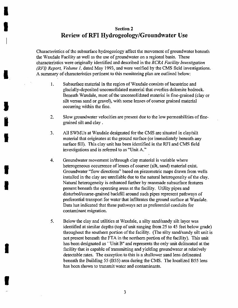
Characteristics of the subsurface hydrogeology affect the movement of groundwater beneath the Waxdale Facility as well as the use of groundwater on a regional basis. These characteristics were originally identified and described in the RCRA Facility Investigation (RFI) Report, Volume I, dated May 1993, and were verified by the CMS field investigations. A summary of characteristics pertinent to this monitoring plan are outlined below:
1.
2.
3.
4.
5.
Subsurface material in the region ofWaxdale consists of lacustrine and glacially-deposited unconsolidated material that overlies dolomite bedrock. Beneath Waxdale, most of the unconsolidated material is fine-grained (clay or silt versus sand or gravel), with some lenses of coarser grained material occurring within the fine.
Slow groundwater velocities are present due to the low permeabilities of finegrained silt and clay .
All SWMUs at Waxdale designated for the CMS are situated in clay/silt material that originates at the ground surface ( or immediately beneath any surface fill). This clay unit has been identified in the RFI and CMS field investigations and is referred to as "Unit A."
Groundwater movement in/through clay material is variable where heterogeneous occurrence of lenses of coarser (silt, sand) material exist. Groundwater "flow directions" based on piezometric maps drawn from wells installed in the clay are unreliable due to the natural heterogeneity of the clay. Natural heterogeneity is enhanced further by manmade subsurface features present beneath the operating areas at the facility. Utility pipes and disturbed/coarse-grained backfill around such pipes represent pathways of preferential transport for water that infiltrates the ground surface at Waxdale. Data has indicated that these pathways act as preferential conduits for contaminant migration.
Below the clay and utilities at Waxdale, a silty sand/sandy silt layer was identified at similar depths (top of unit ranging from 25 to 45 feet below grade) throughout the southern portion of the facility. (The silty sand/sandy silt unit is not present beneath the FTA in the northern portion of the facility). This unit has been designated as "Unit B" and represents the only unit delineated at the facility that is capable of transmitting and yielding groundwater at relatively detectable rates. The exception to this is a shallower sand lens delineated beneath the Building 55 (B55) area during the CMS. The localized B55 lens has been shown to transmit water and contaminants.
3

6. VOCs were the most often detected compounds and were detected at the highest concentrations in comparison to other compound classes in Unit A. Only trace contamination, on a sporadic basis, was detected in Unit B material.
7. Most SVOC concentrations detected in the RPI could be attributed to laboratory contamination (phthalates) or to being ubiquitous compounds. Therefore, SVOCs are not considered to be good indicator parameters of groundwater contamination nature and extent.
8.
9.
Metals are not considered as constituents of concern in groundwater at the site. Dissolved metals were used for comparison given the turbid nature of the
groundwater because the monitoring wells are screened in silty or clayey material. Very limited metals analysis is proposed for the Groundwater Monitoring Plan. Metals samples will be collected and analyzed only from locations where dissolved metals exceeded a media cleanup standard (as discussed in the CMS, PALs are the proposed MCSs for groundwater).
Pertinent conclusions relating to groundwater occurrence and movement in Units A and B for individual areas are as follows:
a.
b.
C.
Fire Training Area (FTA): 100 feet of a glacial till unit overlies dolomite bedrock. The till consists primarily of silty clay, with discontinuous lenses of silty to gravelly sand. No lens of sand was identified in the northern portion of Waxdale that correlates with the elevation of Unit B sand. "Flow directions" are to the southeast in the silty clay unit.
Waxdale Landfill (WLF): Approximately 25 feet of Unit A type silt and clay including locally varying amounts of organic soil (silt, clay, peat, and a clay/silt unit containing mollusk shells) overlie approximately 25 feet of Unit B type silty sand that overlies another Unit A type clay/silt unit. A shell layer, varying from 10 to 26 feet thick, was encountered beneath WLF and at the southern WLF margins. Groundwater "flow directions" ( determined based on use of groundwater elevations to draw elevation contours) in the clay (Unit A) are south toward Waxdale Creek. In the silty sand (Unit B) below the clay they are northward.
Operating Area: "Flow directions" in the operating area Unit A clay are strongly affected by the presence of pave_d areas and buildings, gravel parking areas, and subsurface utility pipes and backfill. The "flow directions" indicated on RPI groundwater elevation contour maps do not, in most cases, truly represent groundwater flow directions. Well elevations were not collected from wells installed within utility backfill, so influence of backfilled areas on groundwater flow direction may not be represented by the contours.
4
I I
I
I I I
I I I
I
I I

I
I I I I
I I I
I
I
10.
11.
•
•
•
Building 55 (B55): Groundwater "flow directions" in Unit A clay and silt are not readily discernible due to the fact that elevations from well to well can vary by less than 1/10th of a foot, so elevation contours between points cannot be drawn with accuracy. In general it could be considered to flow in a southern direction but this will need to be confirmed. Deep wells appear to be finished in sandy lenses of material within Unit A rather than in the thicker silty sand/sandy silt unit consistently identified deeper at this location (Unit B).
Parking Lot Landfill (PLL): Apparent "flow direction" in Unit A is toward the west and southwest. This direction follows the direction expected due to the location of subsurface utilities west and southwest of the PLL.
Building 51 (B51): "Flow direction" in the vicinity of the tank farm south ofB51 appears to be south toward Waxdale Creek, but is apparently variable in the immediate vicinity of the tank farm. Flow direction in Unit B in the vicinity of B51 is apparently toward the north.
Private groundwater uses in the vicinity of Waxdale are limited to withdrawal of groundwater from either the bedrock or coarse gravel immediately above bedrock. Both units are a minimum of 110 feet below ground surface, overlain by mostly clay with some silt/sand layers.
Residences that potentially have wells are all situated 1/4 mile or more away from the facility.
MKEIO0l5DC3.DOC
5

I
I
I I
I
I
Section 3
Proposed Monitoring Program
As mentioned in Section 1, the proposed groundwater monitoring program consists of two phases: the pre-corrective action monitoring program (PCAMP) and the corrective action monitoring program (CAMP). The objectives of the PCAMP program are to address applicable NR 140 requirements and augment baseline groundwater conditions prior to implementation of corrective measures. The PCAMP will be initiated as soon as final approval of this plan is received from WDNR, and will continue until corrective measures have been installed. CAMP will be implemented after the corrective measures are in place, and will monitor the performance and effectiveness of those measures. Results of the CAMP will be evaluated on an annual basis, and future modifications to the program will be proposed to reflect the conditions observed at the site.
3.1 Well Network
The proposed well network, as shown in Figure 1, will ultimately include 27 existing wells and 13 supplemental wells for a total of 40 wells. The network will also have a total of 22 piezometers (3 existing, 1 replacement, and 18 to be installed). Supplemental well locations were selected to meet the following objectives:
• Replace previously installed wells or piezometers that were abandoned when damaged by frost heave or plant operations.
• Monitor areas where exceedances of P ALs were detected as a result of the CMS fieldwork investigation completed during the fall of 1994 (see "Field Investigation Workplan-Corrective Measures Study," CH2M HILL, September 16, 1994).
• Be compatible with the CAMP program objectives and CMS remedies.
A brief description of the proposed well installations is provided below, for each of the areas that are undergoing corrective actions.
Fire Training Area-The proposed well network for the FT A is shown in Figure 2. MW28S and MW28D are proposed as replacement background wells should PCAMP analytical results indicate MW12S and MW12D (currently designated as background wells) are contaminated.
Because source removal is the corrective measure proposed for the FTA, monitoring wells MS14S and MW13D will not be replaced. Existing wells will be monitored for a period of 24 months. If constituent concentrations fall below their respective media cleanup standards (P ALs ), and the concentration is confirmed through two consecutive sampling events, the monitoring for these constituents will cease. If constituents of
6

concern are detected above PALs, MW13D and MW14S will be replaced and monitored.
Building 55-The proposed well network for the Building 55 area is shown in Figure 3. Monitoring wells MW24S and MW24D are proposed as a contaminant source well nest located within the sand lens west of Building 55. They will be installed during the PCAMP program and used to track and monitor the contamination in the area.
In an attempt to determine and monitor groundwater flow direction in Unit B, two Unit B wells will be installed during the PCAMP (MW23D and MW24D). Monitoring well MW23S, located west of the known extent of contamination, will be used to monitor contaminant migration in Unit A during PCAMP and the effectiveness of the interceptor trench as a barrier to contaminant migration during CAMP.
Building 51-The proposed well network for this area is shown in Figure 4. New wells (MW22D, located inside the proposed interceptor trench alignment, and MW27S and MW27D, located outside the proposed interceptor trench alignment) will be installed downgradient ofMW-DB03S. Figure 4 shows the proposed well locations. These wells will be used along with existing wells MWI 8S and MWI 8D to track and monitor the horizontal/vertical degree and extent ofVOC contamination in this area.
Monitoring wells DB02S and DB05S are proposed for abandonment. Historically, they have analytical results similar to other area wells and replicate other shallow source wells. DB03S will remain and be monitored as the shallow source well in BS 1.
I
I
I
Parking Lot Landfill-The proposed well network for the Parking Lot Landfill is
1 shown in Figure 5. One well nest (MW26S and MW26D) will be installed as part of the PC AMP. The new well nest will be located downgradient of known contamination and outside or downgradient of the proposed interceptor trench alignment. MWI OS I will be evaluated for replacement at the time of installation of the other wells.
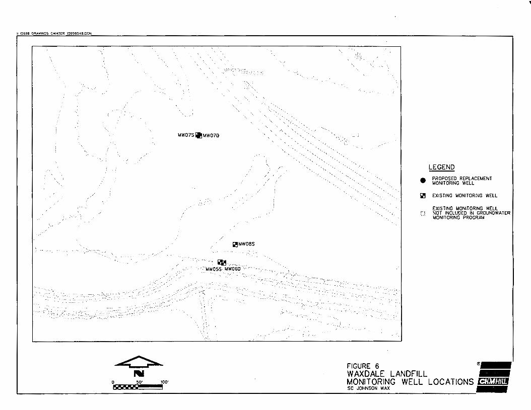
Waxdale Landfill-Source removal is the CMS remedy proposed for the WLF, therefore, no new or replacement wells are proposed at this time. Figure 6 presents existing well locations.
Facility-wide--MW29S and MW29D are proposed as an additional background well nest located in the upgradient portion of the Waxdale facility (see Figure 1). One replacement piezometer, PZ 2D(R), will be constructed downgradient, along the southeastern boundary of the site at WDNR's request.
The proposed well network will also include 18 new piezometers, strategically placed along the interceptor trench alignment. Piezometers that will be located in the middle of the trench do not appear in Figures 1 through 6. They will be used to observe the effect of corrective measures on the physical characteristics of site groundwater and to demonstrate that the trench acts as an effective hydraulic barrier. The proposed interceptor trench alignment is presented in Figure 7.
7
I

-
eMW28S e MW28D
- -••••••••-•••••:<:•••••••A'•••• .-.;.••-•A·,> s•-•-5•••••-~••"
sMW13-S
'>:·s~~-?-F · ..... ,.~>:-,.
LEGEND
•
EXISTING MONITORING WELL
EXISTING MONITORING WELL NOT INCLUDED IN GROUNDWATER MONITORING PROGRAM
PROPOSED REPLACEMENT OR NEW WELL NEST
-----:•.-- ..................... ~--······'--"--.--; ................. ;_,:;.:.·.•""•yy-~ ....... _,..,,...._.,_,~ ... ,-c:- -~-;••,,.
-,,,.,·v•;
NO. EXISTING WELLS • 27 NO. NEW WELLS • 13 TOT AL NO. WELLS • 40
t!'i5MW20-S MW20-D
•v"'~-••'~,,,;,
APZ2-DCR)
NO. REPLACEMENT PIEZOMETERS • 1 NO. EXISTING PIEZOMETERS • 3 NO. NEW PIEZOMETERS • 18 TOTAL NO. PIEZOMETERS • 22
PROPOSED PIEZOMETER
POTENTIAL TRENCH ALIGNMENT 0 150' 300' 450'
FIGURE 1 PROPOSED WELL NETWORK r-.•-······ I S.C. JOHNSON W/.:X

t, 15598 DRAWINGS GWATER 15698S46.DCN
C)MW28S
OMW28D
-
MW12S~MW120
0 75' 150'
l!iil"wi!i• -i!i--~--~--~~~j
1
LEGEND PROPOSED NEW OR
,Y MW13S~ • REPLACEMENT MONITORING
WELL
~MW14D
FIGURE 2
~ EXISTING MONITORING WELL
EXISTING MONITORING WELL NOT INCLUDED IN GROUNDWATER MONITORING PROGRAM
FIRE TRAINING AREA MONITORING WELL LOCATIONS
,_ - - . _, t-i:M,:11111
·@ SC JOHNSON WAX

I: 15698 DRAWINCS GWATER 15698S43.DCN
0 50' 100' ,.,,,._ . .,.... i ..
X
LEGEND
>,( • PROPOSED NEW OR REPLACEMENT MONITORING WELL
A PROPOSED PIEZOMETER
~ EXISTING MONITORING WELL
,-- EXISTING MONITORING WELL NOT INCLUDED IN GROUNDWATER MONITORING PROGRAM
----FP ----- FIRE PROTECTION WATER LINE
·----E------ ELECTRIC LINE
-----w ----- WATER LINE
----GAS----- GAS LINE
----SAN---- SANITARY SEWER
----STM ---- STORM SEWER
----STtJ---- PROCESS WASTE
✓
''
FIGURE 3 BUILDING 55 MONITORING PIEZOMETER
AREA WELL AND LOCATIONS
®
SC JOHNSON WAX

I
I
I
1, 15696 ORAWNCS CWAHR 15698S44.DCN
I I I ,"1 : : : ,,, 11 I 1 1
11 I 11
I I
~ 11 ,,,
52 ll., .,,, BUILDING 51
[! /,i 11 .. . . !/: ,,/''i 1: ~f- =: c:.c:::.::.::.:::.:._:.c.c.5ru-"-'-"""'-~'-~ · •r" ... 1·; "·~·/·r I ····L·;.N,.,~,~·-,~- -. .. ,.-,.- ............ ...., ... ""'"1-'t1fi·-~ ..
---------------'-FP-------- t 1 . ,'/ 1 ~, c;<1 1 111111111111111 u'~ : 1 L-r::,.;~----t-----------:----1 ~-1 1 / \::Hi .-'-+-----------,1--FJ --'-' , ' • •mmM-tt- ,<,., , , ......... , t __________ , ____ .,_ .... _'r-----FP---+-A-..,_L,1 i,;.
'. ..· l ,, M 1 ➔ -+--r...l..--·'"'"""'"- 1L------------ FP--------------'-t:;__~-r---------FP-------.J---.. ----2- . l · , '. " ' ''"'' ; ; ,, I / ,, ' 111111111111 II )Lt-7-----STAl------/--""-L ___ ;_ ___ ---------- -i_l' " : I ,r, I I 1,1,:1
// : ,' , ,f , .. -----~]:}---_-_-______ FDAU= ..S.'CM-:.-=. -=:---1~-------------------.-~--.-------rOAU=-----;-..---~-;,=-~----~-~,..--(------------------------_-_-_-.r- - - -,--{- - - -· PW--,,1'--,7.r_ ---i '!~ 1
1 I I , I lwnrnHl111 ti I I I I .,., -sru ·' +--------.--''Jr-- I '•j
,, 1' ' I 'w1111m111n II I I I ... ,...... - ; ---<- " I .. •u ,'/ {/ : ~111111111 II I : I I s~l' : · :1-:-;r11 -----1"--4 t/ tV I It~:::~~:::: : : : :.,..,.,.,. : :: ! :: I ::ii 11 I , I 'wtllllllhll II I I .,. : ..__.=-.:!I I 11 /1 _11'·. /V\ ~11111111111 }._ i,:;: . : [j" I 111
1~1
, /· ~ ~::::: :: 1
--... (.,. I ""t I _,,,· , ', I : ::: ti I, I :111111111111 H __ -_-..._-...,_.J_ : V, : i < ~ j ! : f_.. I 111
//. / . : ,::t;•=====j======================·_;}..~l I \_ ,..) ) ·. : I . : ::: : 1,' ·~,/ I :lllltlll§Jiiiii':~:::§~lif~~iinliiiii~i~ t,..; r't ' ~ 0802D : : :11 I/! 1\.T : i:: • I' \.?. i,, I /···.,, ,...v••,, ,----- I 1:~}
_./l/ ·" : ~"~ : (: : 1 ( ) ( ,i (,· ) ! : ~~ /{ / I ~111111 : 'l., L· { , '\ , ----:.·::::-===:{i=====r=========='=-13~ ,,,, / : ~n: 1• : : I/~ .. , .. ,-,v., /....... ,•·.·... _,v••., • ----:.-:.::-=-~~::::::----1-, ----- ~ -----::~----~~,
', 1 , 1 ~IIMI 1 1 t 1( \ : \ / .'<.. ,,, ',, I _.:::..,--:,-;.--::---- 1 1 8" t:1vc st' 1 I' ,~ I/ I ~IIIHI : 'I I 1; ) I : \ : I __ i-::.-::.::-~-- ! I 'I,;"' .... I
'fl t ; ~:: I ~ ~-~-... -~ __ \. _ _-,~-~---:·-:,-;~=--~~::"".:.:>, [ ~ V) e: /1 /: 1, lii1111 _.:-- ).,.,_:,: ---::::::::::::--- , I :. .1.. •~
I 1V/ I I ~:::: 1)"' : L-~-'- .. _:-:...L--::::::::--- II .,.__..___.....,._,_,...1-.-----'-' '"i; 1 •:
. ! I .,{-- .. 1 _ .. ,r- .. -::-~.. :: : ____ .. pj-- I I ~ I • !
BUILDING 50
I ! --:.i111111111111111111111UIL.~fzi11h~. ...... ~ DBO3S I! : ~~~~;. ____ ;c:::_L+pJ=:..L.···:::~ .... .] . I "' / ', ' ,,. l ·~~---- .. , I .. I I 41 ..,
-----'-s4N--,_ l,,;f .. ~ . ' ·. , ',~~/ ',t.-L~~·!-------~-·P•--------[.:1 · . l ·~:-STAl-rl-r--~-ST~j; \ .. ·~· ':r .. .. . .. ¥r
I~ - - - - s TM· -----:::.--..7\/-, _____ - ------t _ '.__ -~-' ---'------::::::--::-::::--~ ~~~/--.-----:::----t-_ }~-~~ ~-----. GAS- - - - - - - - - -l J.:----· ------. GAS - - -t------,, -----_ L _ ~---_.J!._ _____ .!:"_-5_-_~---;AS ~:I!_-..~--=--=--=--=--=--=--=--=-:r =======~GA s: I!:.:::..:-::::::: '1t......... .:1' ,~' : ,, .,,' :;,; · · ·· ', d : : / \ ·. : : :
,,...... ...... ~ ':t "".'.~::--- .... ).._ .......... __ ......... _ \/ : ~----[------------£~---,/ \ : lu ta:._ ........... - ........................... 1, I/, ...... _... --... /' ', I S°====;p I I \ a: :
• ...... ...... , ... 1
, ...... ..,_ , \ I : I I 1 . I I \ I
''-- ...... "!:.-::;, ...... '-,( ... ],'/,. ...... S-4. ... - ...... ...,~ ',, ~----,---C : : : : ~ f \ : , : ---:~,,---✓,~V,'~-f.,,__ ,}'!;Jf',,"-- . '11,,,..,.t.':_~~',,~',,,-~~220• : 1 fc:):'f : ~ \ / ~ --- __ -sr" __ _ _, /,' /~f :v: 58 -: -------- Jr ... ~ ... , : ------Pr--~:,-- :, : : \ 1 -~-------,.-__ !_-_-_-£------.-. -r---------E--
, / J./_ 1 : H -~::~~~ : J :,--,,::, I I ------~------~===:;:&---.... ✓-,-- , ... ../ ,' «...._ : ''. ---~----- I I,.._ ____ Ir I / --- sr.... J-;--~, ,-f ... , I-.,._ H ·, ~I rf If :, _______ I/ ,1
........ ,liff ... ~ ~ '-...... II ' ,._:",.:-:...-...... I I I I I I --- If \I
;:7 h , -...,,, ...... :.;.;-:------ Lt'====!..{ lit' J -- ST~ --- ~\ )l ,:~,, ,:' ,' .... J .J -- t_..._-::::_1 ,,,, ' uw21oe :· ............. - ......... _ --- ----1,,--
/1 !........ MW27S. ,,"";.ii . I .............. _ - ... ,.,_ ... ________ I
I ',('., (-~, LIO~~ -:-~,;::,, - / f ---'----- ',,-r ,,-- -----------, , -,, , ,,,y--s4N,,, , CITY WATER --------====------f,_-::•=:~::-----E-----------E------------£·-----o .,.,., '-... ~- .... _ '---::_:..,.><..,.... 1 / HETER Pl T _____ _
---- /' ' ,, "',"''<:£' ,{_ : , ---1- w--1,-----·: ------£
_______ £______ ---~-------- /' 'rJ-._ -,-,,__ , c,'\ 0 --..::,.-.::_~--';---/- ------c:- 'If: £ CABLE ------------ ---------------- --,~,---- ----------==•.::.-_-_:::.-:. ... ::~;~~-. 1, .u ~........... ,,,,,," _............. --r, -¢ 1 PHDN -------- ----------
, ,' -- -, / ,,, ' -------------~~------------------- ------,/ ( .:~~-~-:_--_-:.;\~~:~_;;:----------------------------f ---------------------- l
J * PVC CONDU Ir / ', ___________________ ~0'!.£ __ C_A_B_L_E _______ = ___ -.:r:_--__-_-_-_-::::.,._,....-__-_-_"!_~_8_S-sa ~ MW18O : '. \
40" OffP / __ :::=::~--:::::::_____ ------- ~ 1
FUTURE ELEC/i-- ;i: \
INSTALLED 4/92 : : \ I I
' I I I I I
: -----------SAN-------1 ---------\ --SAN-------()--------------
_____________ SAN------
FIGURE 4
LEGEND
• PROPOSED NEW MONITORING WELL
PROPOSED PIEZOMETER
EXISTING MONITORING WELL
----fP -----
·----[------
-----w -----
----GAS----
----SAN ----
----STM----
FIRE PROTECTION WATER LINE
ELECTRIC LINE
WATER LIN[
GAS LINE
SANIT AAY SEWER
STORM SEWER
BUILDING 51 TANK FARM WELL AND LOCATIONS
®
0 25' 50'
r-.•---,.·-- i
MONITORING PIEZOMETER SC JOHNSON WAX
C-::Mt:fll•

I
I
1, 15698 DRAWINGS GWATER 15698S45.DGN
BLDG 66A
I I I I I I I I
?:I:
:·•· 9 T I Ii I I I I
e: I I I I I I I I I
' I I I. I
r·1(: I I I I I I I I I I I I
::t:: 0.. li...:
' '
/
' ' ' ' ' ' ' -.., '<
I I I I I
BUILDING
I 7
538
,. I ,' •t-r------------- S TM-:~------------------{,2 _____ S TM------------~'< I l ,,- "-", I I \_.. I I I I I I I I I I I I I I I I
-~ .\ i-..: ·., l/J I
' ,.., ,\
0
I . I ·. / ,.
I I
I I
• I I
I I
I I
• I
-''/,
25' r-,,.,,. .....
I 11
I I I I I I I I I I
BUILDING 52
"' h,
z I I I I I I I I
\ \ I J I 1\ I•
------ l ·,
-1,---:~- E--------------1 ---1 ---
• LEGEND
PROPOSED NEW OR REPLACEMENT MONITORING WELL
PROPOSED PIEZOMETER
EXISTING MONITORING WELL
----- FP ------ FIRE PROTECTION WATER LINE
------ E ------- ELECTRIC LINE ~ ---------- ---------------------------1
----- L ._ ------------------ FP:..~:..~-,,--------------------------------· FP-r _________ j _________ FP--------\ • ·. ,.t... :
------ w ------- WATER LINE
50' j
I . H I I I I I I I
MW11D ~ c. · · ICI MW11S
------ .... _ --- --.:--.-- .... --- ----------:-:- .... _
----
----w::::::::::::::-----------
I /
I
I I ., ·,
I I I I I I I , , , ,
I I
-----GAS------ GAS LINE
----- SAN ----- SANITARY SEWER
----- STM ----- STORM SEWER
FIGURE 5 PARKING LOT MONITORING PIEZOMETER
LANDFILL WELL AND LOCATIONS
SC JOHNSON WAX
1: 1~698 DRAWINGS GWATER 1569854B.OGN
MW07S 'I! MW07D
~MWOBS
.. ... ~·,.,, .. ' "' . MW05S MW06D
0 :iO' 100' ,... ..... - I
/
FIGURE 6
LEGEND
• PROPOSED REPLACEMENT MONITORING WELL
EXISTING MONITORING WELL
EXISTING MONITORING WELL NOT INCLUDED IN GROUNDWATER MONITORING PROGRAM
WAXDALE LANDFILL MONITORING WELL LOCATIONS SC JOHNSON WAX
,

J: 15698 DRAWINGS CWAT[R 15698541.0CN
I ,, ) /
.... , .. , ... -/J . ·······-,
I 0 50' 100' F'L..,._._._ j
,.,·· , ·: ;.'.-/'' \
,..,~\·.<'·(
FIGURE 7 PRELIMINARY INTERCEPTOR TRENCH ALIGNMENT IN OPERATING AREA S.C. JOHNSON WAX
,,
®
t; ( \

Table 1 provides the rationale for each well's (both existing and supplemental) inclusion in the PCAMP and CAMP program, the unit each well is screened in, along with the location of each well (upgradient or downgradient, if known) in relation to each SWMU. Wells listed in Table 2 will be sampled as part of the PCAMP, and the first sampling event will be scheduled when final approval of this groundwater monitoring plan is received from WDNR. Wells listed in Table 4 will be sampled as part of the CAMP program, which will start once corrective measures are installed and operational.
3.2 Constituents of Concern
The primary constituents of concern for the Waxdale facility corrective measures are summarized below:
Profile of Constituents of Concern for Waxdale Facility
Volatile Organic Compounds
Benzene Chloroform 1, 1-Dichloroethene 1, 1-Dichloroethane 1,2-Dichloroethene 1,2-Dichloroethane Ethyl benzene
Toluene Xylene Dichlorofluoromethane Tetrahydrofuran Vinyl Chloride Gasoline Range Organic
Compounds
Semivolatile Compounds
Diesel Range Organic Compounds
Inorganic Chemicals
Dissolved Arsenic Dissolved Lead
Their designation as constituents of concern is based on their detection at two or more of the five individual SWMUs in soil or groundwater, exceedance of PALs, frequent detection, and relation to former waste management practices. The compounds listed in the table above represent a typical profile of constituents detected in groundwater and soil across the five different areas. PCAMP groundwater monitoring will be performed for these compounds as well as others unique to the individual areas (see Table 2).
Prior to the start of the monitoring portion of the CAMP program, relevant reductions in both the number of wells and the list of analytes being monitored on a quarterly basis will be sought from WDNR on the basis of the results of six quarters of PC AMP data. The number and location of the CAMP wells and piezometers will vary depending on the area being monitored and the remedy being implemented. Table 4 may be modified as a result of the reductions, with wells judged to be of limited usefulness for chemical data delegated as wells for water level information only.
8

Table 1 1995--1997 Groundwater Monitoring Plan-Existing and Supplemental Wells
(Page 1 of2)
Well ID Unit Screened Location/Rationale
Waxdale Landfill MW05S (A) Silty Clay Downgradient of landfill, upgradient of Waxdale Creek.
MW06D (B) Silty Sand Upgradient of landfill but beneath clay unit that is downgradient of landfill.
MW07S (A) Sand lens in Sandy Silt/Silty Clay Upgradient oflandfill.
MW07D (B) Silty Sand Downgradient of landfill.
MW0SS (A) Organic Silt and Clay Crossgradient to landfill.
Fire Training Area MW12S (A) Clay and Silt Upgradient of Ff A.
MW12D (A) Clay, 1-3" clayey sand lens Upgradient of Ff A.
MWIJA (A) No Unit B present. Clay and silt with sandy silt Downgradient of Ff A during some times of year. Check whether vinyl chloride still detected. lens
MWIJS (A) No Unit B present. Clay and silt and gravely fill Downgradient of Ff A during some times of year. Check whether vinyl chloride still detected. lens near ground surface.
MW14D (A) Clay Downgradient of Ff A; Sometimes crossgradienl
MW28Si i (A) To be determined ·. . Upgradient ofITA; Sometimes crossgradient. Proposed background well.< .. · .· .· / i./
MW28D • (A) To be determined . Upgradient of Ff A; Sometimes cross gradient. Proposed background well. .·.·• ··. ··•·• .. .
OPERA TING AREA
Building 55
MW16S (A) Sand lens in clay Point outside of contaminated soil. Flow direction variable.
MW16D (A) Silty clay with sand lenses--first incidence of sand GW Flow direction variable in A, therefore chose 2 deep locations beneath shallow depth in A but not in thick, deep sand (B)
MW17S (A) Clay with some sand-filled fractures Point outside of contaminated soil. Flow direction variable.
MW17D (A) Silty clay with sand lenses--first incidence of sand GW Flow direction variable in A, therefore chose 2 deep locations
beneath shallow depth in A but not in thick, deep sand
(B)
MW23S (A) To be determined . Point outside of contaminated soil. Flow direction variable, ·• . . MW23D •·· (B) To be determined •··· Point outside of contaminated soil. Flow direction variable. ... .
MW24S •·· .. (A) To be determined . Source well inside zone of contaminated soil.
MW24D·.•· •·•• < (B) To be determined· •· ·• .·. .. .
··•· Deep well below zone of .contaminated soil. .·· .. ··•·•··· ··• ·•· ·.·
MKEIO0ISAEE.XLS

Table I 1995--1997 Groundwater Monitoring Plan-Existing and Supplemental Wells
(Page 2 of2)
Well ID Unit Screened Location/Rationale
Building SI
DB02D (8) Silty Sand Only remaining deep well adjacent to Tank Farm on east (crossgradient):
DB0JS ' (A) Silty Clay Fill Immediately adjacent to tank farm on south (downgradient).
MWISS (A) Clay and Silt with 3" clayey sand lens. Downgradient of tank farm, immediately upgradient ofWaxdale Creek.
MW18D (B) Silty sand. Upgradient of tank farm but immediately beneath MW18S that is downgradient of tank farm in Unit A.
MW22D (B) To be detennined. .· Upgradient of tank farm; downgradient of proposed interceptor trench alignment.
MW27S (A) To be determined. Downgradient of tank farm and downgradient of proposed interceptor trench alignment.
MW27D (8) To be detennined. Up gradient of tank farm and upgradient of proposed interceptor trench alignment. .. ·.
Parking Lot Landfill
MWI0S (A) Clay with silty sand lens Downgradient/crossgradient to landfill.
MWIIS (A) Clay and Silt Upgradient of landfill.
MWIID (NB interface) Clay & silt/silty sand interface Beneath PLL to the east. Gradient/flow direction in B difficult to discern-so flat. Also only remaining deep well beneath SWMU.
MW26S (A) To be determined. Downgradient/crossgradient to landfill and proposed interceptor trench alignment. .. . MW26D (8) To be determined. Gradient/flow direction in B difficult to discern-so flat; outside proposed interceptor trench alignment.
.· .· ... ..
Facility Wide PZ0IS (A) Clay and Silt Along east boundary of facility.
PZ0ID (B) Silty Sand Along east boundary of facility, sometimes downgradient of facility
PZ02S (A) Clay with fine sand lens Along east boundary of facility.
IPZ02D (R) (8) Silty Sand Along east boundary of facility, sometimes downgradient of facility
IMW20S (A) Clay, Silt with well-graded sand lenses Upgradient portion ofWaxdale property.
IMW20D (A) Clay and Silt (No Unit B encountered) Upgradient portion ofWaxdale property.
IMW2IS (A) Clay with well-graded sand lens Down/crossgradient portion ofWaxdale property.
MW21D (A) Clay Down/crossgradient portion ofWaxdale property.
MW29S (A) To be determined. ·• Upgradient portion ofWaxdale property; proposed background well. .. . · ..
MW29D (A) To be determined Upgradient portion ofWaxdale property; proposed background well. .. ·.· ·.· ..
~otes:
R = indicates replacement wells
Shaded wells = indicates supplemental wells
MKEI00ISAEE.XLS

3.3 Proposed Analyte List and Sampling Frequency
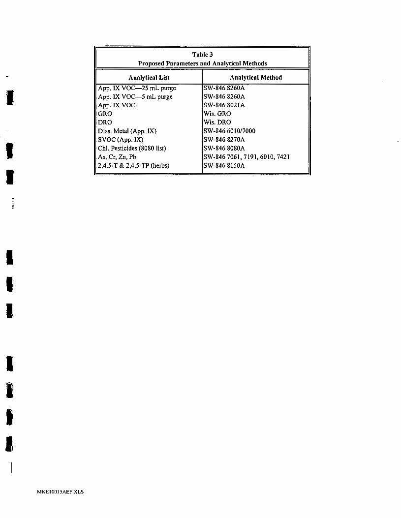
Analytical parameters and specific methods for groundwater analysis are listed in Tables 2, 3, and 4. Table 2 presents six quarters of proposed PCAMP groundwater monitoring (four quarterly sampling events and two annual sampling events); Table 4 presents four quarters of proposed CAMP groundwater monitoring (three quarterly sampling events and one annual sampling event). The wells to be sampled in 1995-1997 under PCAMP and CAMP are shown on Figures 1 through 6 and the specific wells to be sampled and analyses by well and area are listed in Tables 2 and 4.
Tables 2 and 4 were developed based on knowledge of previous land use at the site, chemicals and processes historically used at the facility, and pre-RF!, RFI, and one round of CMS soil and groundwater analytical results. Volatile organic compounds (VOCs) are the proposed primary indicator parameters since they were most frequently detected in Waxdale groundwater during four groundwater monitoring rounds from October 1990 through August 1991. VOCs will be analyzed for quarterly in all Unit A wells and on a semiannual basis in Unit B screened wells since there have been only very limited instances of detection of any constituents of concern in Unit B wells to date. Any VOC constituents detected in a given Unit B well during a semiannual sampling event will then be analyzed for on a quarterly basis thereafter.
SVOCs are proposed as analytes for monitoring because of previous SVOC detections at specific locations. GRO and DRO analyses (Wisconsin DNR Modified GRO/DRO and PUBLSW-140/141) are proposed quarterly for Building 51 samples and annually on a site-wide basis. These methods were not established prior to the RFI but will provide useful data in areas with naphtha contamination.
Analytical methods listed in Table 3 meet the majority of requirements established in NR 140 and include the Appendix IX groundwater monitoring list specified in 40 CFR 264. Appendix IX (and subsets) volatile organics, semivolatile organics, and dissolved metals will be analyzed per U.S. EPA SW-846 methodology and Contract Laboratory Program (CLP) QA/QC procedures. SW-846 sample extraction methodology will ensure comparability to other RCRA studies. CLP QA/QC procedures will ensure data of known and reproducible quality. The detection limits will meet the SW-846 and the majority ofNR 140 requirements. CLP equivalent quality control criteria will be applied to all QC data.
Appendix IX parameters that are not covered under CLP ( certain chlorinated pesticides and herbicides) will be analyzed by SW-846 methods, and an equivalent level of QA/QC effort will be implemented. Detection limits will meet SW-846 and the majority ofNR 140 specifications.
Field sampling quality control procedures will include the collection of trip blanks, field duplicates, equipment blanks, and matrix spike and matrix spike duplicates. One set of trip blanks is required for each day VOCs are sampled in the field. Trip blanks will originate at the contract laboratory and will be relabeled upon arrival at the site. Trip blanks will be analyzed for volatiles only. Field duplicates will be collected on approximately 10 percent of the total number of samples per analysis to be performed. Equipment blanks will be collected on approximately 5 percent of the total number of samples per analysis to be performed. Triplicate
9

Table 2 I
Estimated 1995 PCAMP Groundwater Monitoring Sample Matrix SC Johnson Waxdale Facility, Racine, WI
(Page 1 of 4)
July 1995 October 1995 (Annual Event) Well Unit Dissolved Chlor. Dissolved
Area ID Screened WL voe GRO DRO Metals WL voe GRO DRO svoc Pest. Metals Herbs.
MW5S A X X X X X X X X X X MW6D B X X X X X X X 0 X X ....
·5 WLF MW7S A X X X X X X X X "' X X
MW7D B X X X X X X X & X X MW8S A X X X X X X X X X X
MW12S A X X X X X X X >, X MW12D A X X X X X X X
'i:l X 0
FfA MW13A A X X X X X X X if X MW13S A X X X X X X X ..: X u MW14D A X X X X X X X .t X
MW16S A X X X X X X X MW16D B X X X X X X
I MW17S A X X X X X X
..,.
..I\.
Bldg 55 MW17D B X X X X X X MW23S A X X X X X X X MW23D B X X X X X X MW24S A X X X X X X X MW24D B X X X X X X
DB02D B X X X X X X X X DB03S A X X X X X X X X X X X >, X 'i:l MW18S A X X X X >, X X X X X X X 0 X
'i:l .D Bldg 51 MW18D B X 0 X X X X X X 11.. X
"' "C MW22D B X < X X X X X X § X MW27S A X X X X X X X X X X X -< X MW27D B X X X X X X X X
MWlOS A X X if X X X X X X X X X MWllS A X X "C X X X X X X X B X X
i::: >, -~ PLL MWllD A/B X «I - X X X X X X X X • i:::
MW26S A X X tG OX X X X X X X & X X
vi MW26D B X < X X X X X X X X
MKE10015B3A.XLS

Table 2 Estimated 1995 PCAMP Groundwater Monitoring Sample Matrix
SC Johnson Waxdale Facility, Racine, WI (Page2 of 4)
July 1995 October 1995 (Annual Event) Well Unit Dissolved Chlor. Dissolved
Area ID Screened WL voe GRO DRO Metals WL voe GRO DRO svoc Pest. Metals Herbs.
PZOlS A X X PZOlD B X X PZ02S A X X PZ02D(R) B X X
!Facility- MW20S A X X X X X X X X X wide MW20D A X X X X X X X ~ X X
MW21S A X X X X X X X ·s X X <i)
MW21D A X X X X X X X ~ X X MW29S A X X X X X X X X X MW29D A X X X X X X X X X
Total No. Wells 40 40
Total No. Samples 18 3 3 6 36 36 36 36 23 28 16
MKE10015B3A.XLS

Table 2 Estimated 1996 PCAMP Groundwater Monitoring Sample Matrix
SC Johnson Waxdale Facility, Racine, WI (Page 3 of 4)
January 1996 April 1996 July 1996 October 1996 (Annual Event) Well Unit Dissolved Dissolved Dissolved Chlor. Dissolved
Area ID Screened WL voe GRO DRO Metals WL voe GRO DRO Metals WL voe GRO DRO Metals WL voe GRO DRO svoc Pest. Metals Herbs.
MW5S A X X X X X X X X X X X X X X MW6D B X X X X X X X X X X B X X
WLF MW7S A X X X X X X X X X X X X -~
X X MW7D B X X X X X X X X X X & X X MW8S A X X X X X X X X X X X X X X
MW12S A X X X X X X X X X X X >, X i:: MW12D A X X X X X X X X X X X 0 X
FfA MW13A A X X X X X X X X X X X f X MW13S A X X X X X X X X X X X ..: X u MW14D A X X X X X X X X X X X ~ X
MW16S A X X X X X X X X X X X MW16D B X X X X X X X X X MW17S A X X X X X X X X X X X
=rctg 55 MW17D B X X X X X X X X X MW23S A X X X X X X X X X X X MW23D B X X X X X X X X X MW24S A X X X X X X X X X X X MW24D B X X X X X X X X X
DB02D B X X X X X X X X X X X X X X DB03S A X X X X X X X X X X X X X X X X X X X X X ~x
r:: MW18S A X X X X >, X X X X X ~x X X X X >, X X X X X X X o X
i:: § X i:: .0
,ldg 51 MW18D B X 0 X X X X X 0 X X X X X X 0.. X ell < < '0
MW22D B X <: X X X X X X X X X X X X § X MW27S A X X X X X X X X X X X X X X X X X X X X X ell X <: MW27D B X X X X X X X X X X X X X X
MKE10015DD4.XLS

Table 2
I futimated 1996 PCAMP Groundwater Monitoring Sample Matrix
SC Johnson Waxdale Facility, Racine, WI (Page 4 of 4)
I January 1996 April 1996 July 1996 October 1996 (Annual Event)
Well Unit Dissolved Dissolved Dissolved Chlor. Dissolved Area ID Screened WL voe GRO DRO Metals WL voe GRO DRO Metals WL voe GRO DRO Metals WL voe GRO DRO svoc Pest. Metals Herbs.
-I MWlOS A X X X X X X X X s:: X X X X X X X X X
MWllS A X X ~ X X X ~ X X X 't:l X X X X X X X B X X ~i • > §,?;- -~
PLL MWllD NB X X X ~ -ax X • i::: X X X X X X X X MW26S A X X rt ox X X "'°CX X X rG O
X X X X X X X & X X MW26D B X X X ~ X X .i X X X X X X X X
1· PZOlS A X X X X PZ0lD B X X X X PZ02S A X X X X PZ02D (R) B X X X X
•cility- MW20S A X X X X X X X X X X X wide MW20D A X X X X X X X X X B X X
I MW21S A X X X X X X X X X -~ X X MW21D A X X X X X X X X X & X X MW29S A X X X X X X X X X X X MW29D A X X X X X X X X X X X
::ital No. Wells 40 40 40 40
Total No. Samples 18 3 3 6 30 7 7 12 18 3 3 6 36 36 36 36 23 28 16
I WL = Water Level. Unit A wells: Quarterly VOCs (WDNR comments).
I Unit B wells: Semiannual VOCs (WDNR comments). Methods must meet NR 140 criteria and include App. 1X groundwater monitoring list 40 CFR 264.
Analytical List Analytical Method App. 1X VOC-25 mL purge SW-846 8260A App. 1X VOC-5 mL purge SW-846 8260A App. lXVOC SW-846 8021A GRO Wis. GRO DRO Wis. DRO Diss. Metal (App. IX) SW-846 6010/7000 SVOC (App. lX) SW-846 8270A Chi. Pesticides (8080 list) SW-846 8080A As, Cr, Zn, Pb SW-846 7061, 7191, 6010, 7421 2,4,5-T & 2,4,5-TP (herbs) SW-846 8150A
I
I MKE10015DD4.XLS
I
I I
.,
I I I
I ·I I I
MKEIOOISAEF.XLS
Table 3 Proposed Parameters and Analytical Methods
Analytical List Analytical Method
App. IX VOC-25 mL purge SW-846 8260A App. IX VOC-5 mL purge SW-846 8260A App. IXVOC SW-846 8021A
GRO Wis. GRO ORO Wis. ORO Diss. Metal (App. IX) SW-846 6010/7000 SVOC (App. lX) SW-846 8270A Chi. Pesticides (8080 list) SW-846 8080A As, Cr, Zn, Pb SW-846 7061, 7191, 6010, 7421 2,4,5-T & 2,4,5-TP (herbs) SW-846 8150A

volumes of sample will be collected at a frequency of 5 percent of the total number of samples per analysis to be performed. The additional volume of sample will be used by the analytical laboratory for matrix spike duplicates (MS/MSDs ). I
. \
The analytical data collected during the 1995-1996 PCAMP will be evaluated prior to the initiation of the CAMP program. PCAMP data will be compared to the RFI and one round of I CMS sample data collected for the same wells in 1990, 1991, and 1994. The comparison will 1
provide and indication of whether groundwater quality has changed in the wells over time. Based on the results of PCAMP, modifications in the number of wells being monitored, the analyte list, and the frequency of sampling will be proposed to WDNR for the program outlined· for the CAMP in Table 4. If constituent concentrations fall below their respective media
1 cleanup standards (PALs), and the concentration is confirmed through two consecutive sampling events, the monitoring for these constituents will cease.
MKEIO0l5DC3.DOC
I
I
10 I

,I I I
I
I
Well Area ID
MW5S MW6D
WLF MW7S MW7D MW8S
MW12S MW12D MW13A
FfA MW13S MW14D MW28S MW28D
MW16S MW16D MW17S
Bldg 55 MW17D MW23S MW23D MW24S MW24D
DB02D DB03S MW18S
Bldg 51 MW18D MW22D MW27S MW27D
MKE10015B3B.XLS
January 1997 Unit
Screened WL voe GRO DRO
A X X B X A X X B X A X X
A X X A X X A X X A X X A X X A X X A X X
A X X B X A X X B X A X X B X A X X B X
B X A X X X X A X X X X B X B X A X X X X B X
Table 4 Estimated 1997 CAMP Groundwater Monitoring Sample Matrix
SC Johnson Waxdale Facility, Racine, WI (Page 1 of 2)
April 1997 July 1997 Dissolved Dissolved
Metals WL voe GRO DRO Metals WL voe GRO
X X X X X X X X X X X X X X X X X X
X X X X X X X X X X X X X X X X X X X X X X X X X X X X
X X X X X X X X X X X X X X X X X X X X X X X X X X X X
X X X X X X X X X X X X X X X
>, X X X X X >, X X X X i3 i3 0 X X X X C X X
< X X X X < X X X X X X X X X X X
X X X X X X
October 1997 (Annual Event) Dissolved Chlor. Dissolved
DRO Metals WL voe GRO DRO svoc Pest. Metals Herbs.
X X X X X X X X X X X X X X ~ X X X X X X X X
·:3 "' X X .....
X X X X X X ~ X X X X X X X X X X
X X X X X X X X X X X >,
X i3 X X X X X 0 X X X X X X 5: X X X X X X
..: X u
X X X X X vi X X <: X X X X X X X
X X X X X X X X X X X X X X X X X X X X X X X X X X X X X X X X X X X X X X X X
X X X X X X X X X X X X X X X >, X i3 X >, X X X X X X X 0 X
i3 ..c 0 X X X X X X 11.. X "' -0 <: X X X X X X r::: X C'3
X X X X X X X X "' X <: X X X X X X X

I
I
I I I
I
January 1997 Well Unit Dissolved
Area ID Screened WL voe GRO DRO Metals WL
MWlOS A X X X X MWllS A X X ~ X X • >
PLL MWllO A/B X ~ i3 X MW26S .ox A X X < X MW260 B X X
PZOlS A X X PZOlO B X X PZ02S A X X PZ020 (R) B X X
Facility- MW20S A X X wide MW200 A X X
MW21S A X X MW210 A X X MW29S A X X MW290 A X X
rrotal No. Wells 42 42
rrotal No. Samples 20 3 3 6
WL = Water Level. Unit A wells: Quarterly VOCs (WDNR comments). Unit B wells: Semiannual VOCs (WDNR comments). Methods must meet NR 140 criteria and include App. IX groundwater monitoring list 40 CFR 264.
Analytical List Analytical Method App. IX VOC-25 mL purge SW-846 8260A App. IX VOC-5 mL purge SW-846 8260A App. IXVOC SW-846 8021A GRO Wis.ORO ORO Wis.ORO Diss. Metal (App. IX) SW-846 6010nooo SVOC (App. IX) SW-846 8270A Chi. Pesticides (8080 list) SW-846 8080A As, Cr, Zn, Pb SW-846 7061, 7191, 6010, 7421 2,4,5-T & 2,4,5-TP (herbs) SW-846 8150A
MKE10015B3B.XLS
Table 4 Estimated 1997 CAMP Groundwater Monitoring Sample Matrix
SC Johnson Waxdale Facility, Racine, WI (Pag,i 2 of 2)
April 1997 July 1997 October 1997 (Annual Event) Dissolved Dissolved Chlor. Dissolved
voe GRO DRO Metals WL voe GRO DRO Metals WL voe GRO DRO svoc Pest. Metals Herbs.
X X X X f X X X X X X X X X X f X X X ~ .?:x X X X X X X ~ X X • > ·3 X ~ i3 X X • i::: X X X X X X Cl) X X
.i ox ~ ox -X X X X X X X X X & X X X X X ~ X X X X X X X X
X X X X X X X X X X X X X X X X X X X X X X X X ~ X X X X X X X X X ·3 X X Cl)
X X X X X X X - X X & X X X X X X X X X X X X X X X X X X
42 42
32 7 7 12 20 3 3 6 38 38 38 38 23 30 18
I
I
I
I
I
I
I
I
Section 4
Analytical Procedures
4.1 Laboratory Analysis
A Wisconsin certified laboratory will be chosen for the groundwater monitoring program. WDNR will be notified of SC Johnson Wax's choice oflaboratory and the laboratory's certification number upon selection. The laboratory wi_ll provide bottles with appropriate preservatives already added. Preserved bottles will be prelabeled and identified as "preserved" in order to distinguish them from nonpreserved bottles.
4.2 Data Reduction, Validation, and Reporting
Data for all parameters will undergo two levels of review: at the laboratory and outside the laboratory.
Initial data reduction, validation, and reporting at the laboratory will be carried out as described in specific methods listed in Table 3. Quality control data will be obtained according to the procedures described in this plan and will be reported by the laboratory at the defined level of effort. In general, chemical data will be reviewed with regard to the following:
• •
Analytical methodology Parameter list
• Detection limits • Instrument calibration • Blanks
• Accuracy and precision
Data will also be reviewed outside the laboratory by staff chemists not assigned to the laboratory.
Field data validation will be based on field logbooks and field audits with regard to proper calibration and procedures.
4.3 Data Assessment Procedures
Data assessment will follow the review and validation described in Section 4.2. An assessment report summarizing the findings of the data review will be prepared. Data precision, accuracy, and completeness values will be presented in the assessment report.
Quantitative definitions of precision, accuracy, completeness, and method detection limit are presented below.
11

4.3.1 Precision
If calculated from duplicate measurements:
RPD =
where:
= = =
(C1-C2) X 100%
(C1 +C2) /2
Relative percent difference Larger of the two observed values Smaller of the two observed values
I
I
If calculated from three or more replicates, use relative standard deviation (RSD) rather than I RPD:
where:
RSD = (S/y) x 100%
RSD = s
y
= =
Relative standard deviation Standard deviation
Mean of replicate analyses
Standard deviation, s, is defined as follows:
where:
s = Standard deviation
Yi = Measured value of the ith replicate
y = Mean of replicate analyses
n = Number of replicates
4.3.2 Accuracy
For measurements where matrix spikes are used:
- [s u] %R=100%x --CsA
12
I
I
I
I

I I
I I
I
I
where:
%R = s = u = CsA =
Percent recovery Measured concentration in spiked aliquot Measured concentration in unspiked aliquot Actual concentration of spike added
For situations where a standard reference material (SRM) is used instead of or in addition to matrix spikes:
where:
%R=100%x[~] CsRM
CM %R CsRM
= = =
Measured concentration of SRM Percent recovery Actual concentration of SRM
4.3.3 Completeness (Statistical)
Defined as follows for all measurements:
where:
%C = 100% x [:]
%C V
n
= = =
Percent completeness Number of measurements judged valid Total number of measurements necessary to achieve a specified statistical level of confidence in decision making
4.4 Performance and System Audits
The quality Assurance Manager will monitor and audit the performance of QA procedures. Audits may be scheduled to evaluate the execution of sample identification, sample control, chain-of-custody procedures, field notebooks, sampling procedures, and field measurements.
The laboratories will be audited if necessary by a staff chemist not assigned to the laboratory who will also coordinate data review activities. The external onsite laboratory audits will cover analytical methodology quality control procedures and the level of efforts specific to this project. -
13
Computer models and software will be verified periodically by entry of known data sets or programs by a computer expert not assigned to the project. Electronic and paper-based data sets will be verified by double entry, cross checking, and range checking against the known programs and models to check for correctness, reasonableness, and user competence. Verification of model and software performance will be documented in the QA/QC sections of the specific reports.
4.5 Corrective Action
If Quality Control audits result in detection of unacceptable conditions or data, the project manager will be responsible for developing and initiating corrective action. The SC Johnson Wax project manager will be notified if nonconformance is of program significance or requires special expertise not normally available to the project team. Corrective action for sample collection and laboratory analysis may include:
• Reanalyzing samples if holding time criteria permit • Resampling and analyzing the samples • Evaluating and amending sampling and analytical procedures
Corrective action for field measurements may include:
• Repeating the measurement
• Checking instrument adjustments to see that they are appropriate for ambient conditions such as temperature
• Checking the batteries
• Checking the calibration
• Replacing the instrument or measurement devices
4.6 Quality Assurance Reports
A brief QA report summarizing the quality of the data will be prepared by the Quality Assurance Manager. The report will contain a summary of data assurance information collected during the sampling event. The QA report may include:
• • • •
Data review findings described under section 4.2 of this plan Assessment of measurement data, accuracy, precision, and completeness Results of performance or systems audits Significant QA problems and recommended solutions
MKEI0015DC3.DOC
14
I
I
I I
I I
I
I
I
I
I
I
Section 5
Reporting Procedures
5.1 Quarterly Reporting
Quarterly reports will be submitted to WDNR that will include water level data. Any analytical data collected that particular quarter will also be submitted. Reports with analytical data will be submitted 40 calendar days after receipt of laboratory data and will include the following components specifically indicated as requirements in the Plan Modification:
1. A site map showing all monitoring points, facility property lines, scale, north arrow, and key or legend. The topography and surveying was completed using State Plan Coordinates so there is not a local grid system to show on the site map.
2. Water level and chemical analytical data will be submitted on the State's T ADs, if provided, and on tape or diskette according to the State's instructions.
3. Exceedances of state or federal standards will be submitted in tabular format.
4. Groundwater quality detections will also be indicated on maps when detected. Judgment will be used to determine whether isoconcentration maps are appropriate based on analytical results and geology. For example, one detection of a VOC compound in one well cannot be contoured. Similarly, if cross sectional views including geologic features are pertinent to analytical results, cross sections will be presented.
5. Despite the RFI Report's conclusion that the "water table" maps are not a reliable means for portrayal of groundwater flow direction due to the nature of water flow through low permeability clay, groundwater elevations will be presented in both tabular and map forms in accordance with WDNR's request.
5.2 Annual Reporting
An annual report discussing the results of the quarterly groundwater monitoring program will be submitted to WDNR in accordance with the July 19, 1994, Plan Modification. The Report will be submitted by the last business day of April of the year following the year for which the Annual Report is written ( e.g., the 1995 Annual Report would be submitted by the end of April 1996).
The annual report will include the following components:
1. A site map showing the location of all existing monitoring points, drawn to scale and showing the facility property line, scale, north arrow, key or legend.
15

2.
3.
4.
State plane coordinates are used for the site so a local grid system will not be shown.
As stated in the section above entitled "Quarterly Reporting," the RFI Report concluded that the "water table" maps are not a reliable means for portrayal of groundwater flow direction due to the nature of water flow through low permeability clay. In spite of this, groundwater elevations will be presented in both tabular and map forms for the Annual Report. An evaluation of the rounds of groundwater surface elevations (MSL) determined at all facility monitoring wells on site, and supporting water table and potentiometric surface maps compiled from these groundwater surface elevations (MSL) will be performed. A table listing each monitoring well, the elevation of the top of the PVC riser (MSL), the ground surface elevation (MSL), the screen top elevation (MSL), the screen bottom elevation (MSL), and the rounds of depth to water level measurements and groundwater surface elevations (MSL), will be compiled. The groundwater surface elevations (MSL) will be reviewed to determine whether the water table properly intersects the screen of each water table observation well. The water table and potentiometric surface maps will be evaluated for their reliability in portraying the groundwater flow direction across the site.
An evaluation of horizontal and vertical hydraulic gradients calculated from the rounds of groundwater surface elevations determined at all facility monitoring wells on site will be made. A table of the monitoring wells used to determine the gradients, the groundwater surface elevations (MSL) used, the distances between wells that were used to calculate horizontal gradients, the surface water elevations (MSL) selected to determine the distance between nested wells and the actual measured distance between nested wells, all calculations and the resulting gradients will be compiled. A presentation of calculated values for horizontal gradients will be included where appropriate in a fashion similar to that presented in the RFI. Horizontal gradients in clay will be calculated and presented assuming no vertical component of flow exists (not a technically valid assumption for clay material). Because gradients derived in this technically deficient manner will be used to calculate velocity, velocity calculations will have similar limitations as outlined for the gradient calculations.
A presentation of horizontal and vertical average linear velocity calculations will be included in the report. Values used to calculate velocity will be noted, including effective porosity values used, if appropriate.
5. Results of evaluations of the condition of all existing facility monitoring wells and associated sampling equipment, procedures used for maintenance and repair of wells will be included. Discussion of in-place remediation
16
I
I
I
I
I
I

I
I I I
I
I
technologies and equipment will only be presented in CAMP (not PCAMP) reports.
6. A compilation of the standards comparison table included in each quarterly report will be completed and presented in the Annual Report. Re-submittal of all analytical data will not be included in the annual report.
7. Analytical information displayed on maps in the quarterly reports will be compiled onto one set of maps for the annual report. If cross sections with chemical analytical data were included in-quarterly reports, they will also be included in the annual report, again in summary form reflecting all sampling round results for the year.
8. Requests for modification of the existing monitoring program and justification supporting the request will be included, if applicable.
9. QA/QC procedures/results: Analytical data will be reviewed and validated each time data is received from the laboratory. The laboratory will follow QA/QC implicit in requested methods. Problems or concerns identified during analysis will be discussed in the Annual Report.
10. Documentation of sampling and analysis procedures are required for the Annual Report as described in the "Annual Monitoring Report Outline" and "Outline for Documentation of Sampling and Analysis Procedures" both attached to the July 19, 1994, Plan Modification. Requirements outlined in those documents will be addressed in the Annual Report or other documents as follows:
• Site Map: Included in the main portion of the Annual Report as a Figure (see item No. 1 above).
• Groundwater Monitoring Well Information Form 4400-89: Included as an attachment to the Annual Report.
•
•
Procedures for timing and submittal of quarterly analytical results and evaluation, and for submittal of the next Annual Monitoring Report will not be included in the Annual Report as implied on p. 1, item 4 and p. 2, item 12 in the "Outline for Documentation of Sampling and Analysis Procedures." The submittal dates for the Annual Report will be by the end of April of the following year, unless a variance form this date is requested and approved in a Plan Modification.
The following requirements for the Annual Report are included as an attachment to this report but will not be repeated in each annual report. SOPs are taken directly from the EPA and WDNR Approved RFI Work Plan with the exception of"Sample Preservation Procedures SOP
17

MKEl0015DC3.DOC
No. 2." Deviations from the SOPs will be noted and reported in the Annual Report.
Depth Measurement Procedures Well Purging Procedures Sample Withdrawal Procedures
· Well and Sampling Equipment Condition Evaluation Procedures Sample Preservation Procedures In-field Measurement Procedures In-field Filtration Procedures (not
necessary for VOCs, GRO/DRO) Chain-of-Custody Procedures
18
SOP No. 1 SOP No. 1 SOP No. 1
SOP No. 1 SOPNo.·2 SOP No. 3 SOP No. 1
SOP No. 5
I
I
I
I
I
I
MKE100!4F8B/l
ATTACHMENT A
MONITORING WELL CONSTRUCTION AND DEVELOPMENT FORMS (4400-113A AND B)

State of Wisconsin Dcpanmcnt of Natural Resources
acility/Project ame rid Location
MONITORING WELL CONSTRUCTION Form 4400-l 13A 8-89
S,C.. ~On'flSQ/1 . ..Jax d.&5",(o.;). && rL JS. N. □ s. ~ S:uCJ 8'~~.Su, ft. B- E. □ W.
;
ell Water Table Observation Well □ 11 Piczometer ~ 12
A. Protective pipe. top elevation __...-1. Cap and Ioele? J, -~;:=::::;T ~ - 2. Protective cover pipe:
B. Well casing. top elevation ~IL l :t . ~ ~ ft. MSL -----4+-....... a. Inside diameter. _(z.~in _1. QCt. C. Land surface elevation _ 4?._ !. 'i .:/ r MSL b. Length:
D. Surface seal, bottom_ /i, J 3 .~ · fL MSL or __ • _
12. uses classification of soil near saccn: □ GP □ GM □ GC □ fNI □ SW □ SP □ SM □ sc ~ML □ MH □ CL □ CI □ Bcmxk
13. Sieve analysis attached? □ Yes 511 N> Wot'X ~" ~(llJf.i. er,af' 1"11 ~'a. 19'0
14. Drilling method used: Rotmy □ 5 0 Hollow Stem Auger S 41
Other □ fi&Z::~
15. Drilling fluid med:Wattr □ 02 . Drilling Mud □ O 3
Ar □ 01 Nooe B 99
16. Drilling additives used? □ Yes ~N>
Dcscri~------------117. Soun:c of water (att.ach analysis):
E. Bentonite seal, top ____ ·- ft. MSL or __ l .Q
F. Fine sand. top ft. MSLor
G. Ftlterpack. top _____ ·-ft. MSLor __ <2: .Q
H. Well saeen. top ____ ·-ft. MSLor _ -~ /2.
I. Well screen. bonom ______ ft. MSL or_ f.. ~ __ O fL
J. Filter pack, bottom ____ ·- fL MSL or_ j ::?.2
K. Borehole. bottom ____ ·- ft.MSLor _14..2
L. Borehole, diameter _z . .o UL
M. 0.D. well casing
N. I.D. well casing -~.Q ~ in.
c. Material: Sroel □ 04 _ _____ A_l _u._'("(\ ......... \ t\ ___ 1.t-'-VY'I_____ o.hcr 2 Et
d. Additional patection? □ y cs 0. N>
Jfycs.describe: ----------
3. Surface seal: F:e.ironite □ 3 0 CmacteS 01
Other □ ~-=rt -------------- ~~ 4. Material between well C3Sing and protective pipe: Bammite &I 3 0
Amtuhorspscc seal □
-------------- Oda- a ma 5. ArmuliiY space seal: Grmmlar ~te r!!l · 3 3 __ Lbs/gal mud weight ••• ~ shmy □ 3 5 __ Lbs/gcl mud weight. • • • • Bentonite rhmy D 3 1 __ 9a Bcntonitc • • • • • Bentonit.e-<::ment grout □ 5 O
0 · 30 Ft3 volmµeaddcdfonnyof.the_abovc
How installed: Tremie D O 1
Trcmie pumped □ 0 2 Gravity ~ 08
6. Bentonite se~: Benton.itc granules □ 3 3
□ 1/4 in. 03/8 in. □ 1/2 in. Bentonitc pellets □ 3 2 Nonv Other Bl.·¥@
7. Fme sand material! Manufacturer, product name and mesh si7.c I Nor'J e..,.., . •
Volume added ______ ft3
8. Filter pack material: Manufacturer, JrOduct name and mesh size
Amt..<< c o.;t\ lfu..h,r~a.l t i · r l./S'- , S !: Volume added 3.&l, ft3
9. Well casing: Rush threaded PVC schedule 40 )I 2 3
Rush thrc!dcd PVC schedule 80 □ 2 4
------------- O!ha □ ;; 10. Screen material: _s.;;;;,._a._m_~------ lliff
Scrccn type: Factory cut S 1 1 Continuous slot D 0 1
______________ Olhcr □ ,:.:;:,:.:::;: Manuf acturcr r<l o "fl O £ \ e. :>'Slot size: Slotted length:
11. Bacldill material (below filter pack):
0. Q .lQ. in. J.Q. • .Q ft.
Nooe )ii
Other □

Slate of Wisconsin Department of Natural Resources
Facility/Project Name
S. c. ~ohnson Wo...x.. License. cnrut or Monitoring wnba
1. Can this well be purged dry?
2. Well development method
surged with bailer and bailed
surged with bailer and pumped surged with block and bailed
surged with block and pumped surged with block, bailed and pumped rompesscd air bailed only
pmipcdonly pumped slowly Olhcr
3. Time spcn1 developing well
4. Depth of well (from top of well casisng)
S. Inside diameter of well
6. Volume of water in filter pack md well casing
7. Volwne of water removed from well
8. Volume of water added (if any)
9. Source of water added
10. Analysis paformed on water added? (If yes. attach results)
Additional rommcnts on development:
ell developed by: Person's ame and Finn
Name:
Finn:
El Yes □ N>
□ 4 1
□ 6 1
□ 4 2
□ 6 2
□ 7 0
□ 2 0
l!i1 1 0
□ ·s 1
□ s 0
□ ltl<:@UI
_d 'l.J2.. min.
_L.:Z...2,ft.
-~-'lgal _.s:a._.o gal.
__ Q._gal.
□ Yes □ N>
MONITORING WELL DEVELOPN!ENT Fonn 4400-113B 8-89
WellName p .S ~ j_ -
Before Development After Development 11. Depth to Water
(from top of well casing)
Date
Tmic
2. Sediment in we)! • boaom
3. W atcr clarity
I !:S ft. ---·--
0 ~, _:J 31 _j O mm d d y y
0 =1.:.La?□ ~: .L Q_. Q inches
0car a 1 o ISi 1 S
r■:k~ri:b.a)
8rown
__ 3 . .QOrt.
.f:)5l.1 .Q .:J.., .:1 J2 mm d d y y
0 0 J:Ja.m. _£..:.ez3.5 □ p.m.
__ ._inches
Clear a 20 Tumid 18 25
)
,6rouzo.
Fill in if drilling fluids were used and well is at solid waste facility:
14.To<alsuspcndod ____ ._mg/1 ____ ._mg/1
solids
IS.COD ____ ._mg/1 ____ ._mg/1
hereby ~ that the above information is true and correct to the best of m , mewled c.
Signature: ??fa@& +· @mg 2
F= o t-J. c). rn kl-, LL
NOTE: Shaded areas arc for DNR use only. See instructions for more information.

State of Wisconsin Dq,artmcnt of Natural Resources
acility/Project arne rid Location
MONITORING WEU.. CONSTRUCTION Form 4400-113A 8-89
_:5 · C. ~oh n.S On w~ X cense. anut or Monitoring wnber
;;J.,u~. O q q. 0~ ft ;El N. □ S.
-<, s&o,. g, 3. 79 ft. ,a E. 0 w. ell Wata Table Observation Well □ 11
12
12. uses classification of soil near screen:
□ GP □ GM □ GC □ GN □ SW □ SP SSM □ sc □ML □ MH □ a. □ Cll □ Bedrock .
13. Sieve mulysis attached? □ Yes ~ NJ ulor~ <>\o.'I. cxp(lro'1t.d. (>,-;o" -f"l> F-d,. ,~40
14. Drilling method used: Rotary □ 5 0 Hollow _Stem Auger Jl;I 41
Other tJ f$':f~W
15. Drilling fluid used: Wattr .BJ 0 2 Drilling Mud □ 0 3
6. Drilling additives used? □ Yes
(l,.w;,,;.;.;,;,..,;.;-;
Afr □ 01 Nooe □ 99
Dcsai~------------7. Source of water (attach analysis):
C,
:. Bentonite seal, top
_ Fine smd. top
G. Filter pack. top ______ ft. MSLor -~~ .Q
_ Well saeen. top ______ ft. MSLor _3.5 .Q
ii Well screen. bonom ____ ·- ft. MSL or_ j Q .Q
Filter pack. bonom ____ ·- ft MSL or-~ Q .~
_ BOTChole. bonom ____ ·- ft. MSL or_~ Q. :j
L Borehole. diameta
1. 0.0. well casing
_<;{_O
~ 3 8 --.- -
in.
in.
d. Additional potcction?
.E Yes □ NJ
-'-.im. _J. .Qft.
Steel □ 04
0n:r :a IDB □ Yes 1if NJ
Hycs.dcsaibe: ________ _
Bentonitc □ 3 0 Conactc B O 1
____________ Other a iz& 4. Material ~een well casing and protective pipe:
3. Sunacc seal:
Bentonite l!!3 3 0
Annular space seal □
-------------- Other □ cu 5. Annular space seal: Granular Bentonite □ 3 3 __ Lbs/gal mud weight ••• Beruonite-sand slurry □ 3 5
~ Lbs/gal mud weight • • • • • Bentonite slurxy 12!1 3 1 __ 9a Bentonite • • • • • Bentonitc-ccment grout □ 5 O
IO · ;J. 0 Ft 3 volume added for any of the above
How installed: Tranie □ 0 I
Trcmic pumped DI 0 2 Gravity □ 08
6. Bentonitc seal: Bentonite granules D 3 3
□ 1/4 in. 03/8 in. □ 1/l in. Bentonite pellets □ 3 2 f"I - ' - ·+ r\. . ns f::I ,.,,.. __ _ t">C:rn;pn,L-n • r Other ,:;,;;r- ft}
7. Fme sand ma~al: Manufa.cturcr, product name and mesh size
tJ one-Volume added ______ ft3
8. Filia pack material: Mmufacrurer, product name and mesh size
C.o llog~ed :for 0"9:-+; of'\ · Volume added ______ ft3
9. Well casing: Rush lhrcaded PVC schedule 40 ~ 2 3 Rush lhrcaded PVC schedule 80 0 2 4
_____________ e>ma □ ML 10. Sae.en material: _.:::S:.:::0..;::..'171:.:..:.::<?/:;_______ rt:::
Screen type: Factory cut S 1 1 Continuous slot O 0 I
______________ Other □ Klli: Manufac111rcr m a n o I; \ (. X, Slot size: Slotted length:
0. QlQ in. _§: .~ft.
ft LO. well casing _ ~- .D ~ in. 11. Backfill material (below filta padc):
l~ereb certif that the information on this form is true and correct to the best of m
None 0
Olha □
IIlTl

State of Wisconsin Department of Natural Resources
Facility/Project Name
£ • C - ~Ohrt S011 uJo.. X License, Permit or Monitoring Nwnber
1. Can this well be ?Jrged dry?
2. Well development method
surged with bailer and bailed
surged with bailer and pumped surged with block and bailed
surged with block and ?Jffipcd surged with block, bailed and pumped
compressed air bailed only pumped only pumped slowly
Otha
3. Time spent developing well
4. Depth of well (from top of well casisng)
·:t~ 5. Inside diameter of well
6. Volume·of water in filter paclc and well casing
7. Volwne of wa.tcncmoved from well
0 Yes fill N>
□ 4 1
□ 6 1
□ 4 2
□ 6 2
□ 7 0
□ 2 0
□ 1 0
~ 5 1
□ 5 0
□ l£&2fal
_Las::mm. _Q<z_.8:_fL
__ &.~gal.
j_35" .QgaL
8. Volume of water added (if any)
9. Source of Water added Oo
_S'O. Ogal.
~ •3cf!../ (!_ ~43 ()~ R~c.,'O(?...,
10. Analysis perlonncd on water added? (If yes, attach icsults)
Additional comments on development:
ell developed by: Person's Name and Finn
Name:
Firm:
fi-Ycs □ N>
MONITORING WELL DEVELOPMENT Form 4400-113B 8-89
WellName pi!;: j_-J)
11. Depth to Water (from top of well casing)
Tune
12. Sediment in we~ .• bottom
13. Water clarity
Before Development After Development
__ 'i._.3 7 ft.
09.,;;.31'l_Q_ mm d d y y
3a.m. o~:3Q..ap.m
_E,..9.._inew
o '11 o!:1_, .:1 o mm d d y y
1:5a.m. .!'.l~: .2Q...a p.m.
__ ._inches
Fill in if drilling fluids were used and well is at M>lid waste facility:
14.Totalsuspended ____ ._mg/1 ____ ._mg/I
solids
15.COD . ____ ._mg/1 ____ ._mg/I
I hereby catify that the above infomation lS tIUe and correct to the best of mv knowlcd e.
Signature:
Furn: C fl ;;.m ;J.1LL
NOTE: Shaded areas are for DNR use only. See instructions for more information.

Late of Wisconsin D.::pa:tmcnt of Narural Resources
. ..acility/Project ame
MONITORING WELL CONSTRUCTION Form 4400-l 13A 8-89
I S-C-~oh-nson u.Ja'f... Paetlity 1cense. crnut or orutoring umber
d-u'-(, 03(.p. '-/.3 fL .E( N. 0 S.
d, 5&9, 'F~t./. 7/ ft. ;a:_E. □ W.
~o ell WaterTableObscrvationWell □ 11 non
~~--.,rr,-;~,.----n~~---,,:,--,--.=12--4 ~ 1/4 of $£ 1/4 of Section .:;, -< T ~ N, R ,;; ;i._ E □ W
1f- uses classification of soil near saccn:
II □ GP □ GM □ oc □ mv □ sw 21sP SSM □ sc EIML □ MH m ci □ OI □ Bcdroc:k: .
I. Sieve analysis attached? □ Yes ~ N:, .l,AJOr'\(.. p1o.l'\. OI.P{)n-l<.d rr:o.- -i,, ~b- 1196
• Drilling method mdl: Rotaxy □ 5 0
Hollow Stem Auger B 41
ls. Drilling nwa uscd:Watcr □ 02 Drilling Mud □ o 3
ii. Drilling additives used? □ Yes
Otha □ tt:T:X':1
Ar □ 01 Nooe N 99
Desai~------------• Source of water (attach analysis):
JJcntonite seal. top
'inc sand. top
G. Filter pack. top
;v ell screen. top
-~-- ·- ft.MSLor __ c£.Q
______ ft. MSL or __ '2,_Q
I r:11 screen, bottom - - - - . - ft. MSL or_ l ~. 9 j ~iltcr pack. bottom ______ ft. MSL or_ L~ _Q
d. Additional p-otec:tion?
_(!.~in. _j .QfL
Stcd □ 04 Otha 1a' fit} □ Yes 'f1 N:,
Hycs.dcscn'be: _________ _
3. Surface seal: Bcntonite □ 3 0 Conactc ct o t
_____________ Otha □
4. Material between well casing and protective pipe:
Bcntonite 'JiZl 3 0
Annular space seal □ ______________ Otha □
5. Annular space seal: Granular Bcntonitc Jil ~:;:::~::(' ~~z 33
__ Lbs/gal mud weight ••• Bcntonitc-sand sluny D __ Lbs/gal mud weight. • • • . Bcntonite slurry D 3 1 __ % Bcntonitc • • • • • Bcntonitc-ccmcnt grout □ SO
0 • 3 ~ Ft3 volume added for any of the above
35
How installed: Trcmie D O I
Trcmic pumped □ 0 2 Gravity .B:" 08
6. Bentonite seal: Bcntonite granules D 3 3
d 1/4 in. 03/8 in. D 1/1. in. Bcntonite pellets D 3 2 () ' . ' ('' . ' D,. .n4 ,.,.. .... , Qi" o::t:0 o , :tC.,n • r'"' Other ,:,a- ftfr
7. Fme sand material: Manufacturer, JrOduct name and mesh size
Noa"-Volume addcd ______ ft3
8. Ftl~ pack mllerial: Mmufacturcr, product name and mesh size
Aroe..'("'\c.o.n, r<\o-.ttf"",ili, ft.n~ sho+; ~r-~~ Volume added 3 · 1 '1 ft!"
9. Well casing: FlushthrcadcdPVCschcdule 40 )it 23
Aush threaded PVC schedule 80 □ 2 4 _____________ Otha □ bill
10. Sa-cen material: _'$....i.:a.:,_m---'-_e---______ _ 3orehole, bottom ____ ·- ft. MSL or_ L~ _ _g
L. Borehole, diameter _g_Q in.
O.D. well casing Ul.
Sa-ccntypc: Factory cut g 1 1 Continuous slot D O I
______________ Otha □
Manufacturer _ _i_;ffi~o~au.o£=..lw< ..... )(,c:,._ __ _
Slot size: 0. QLQ in. Slotted length: LO- 9ft. 'I.D. wclkuU,g _ ;,_. _D !,, m. 11. n-,i m,lmd (bclow 611a pack),
ereb certif that the information on this form is true and correct to the best of m knowled e .
None~
Otha □
. P.aa

Stale of Wisconsin Department of Natural Resources
Facility/Project Name 5 .c. ~ol,nso11 wa-,...
License. cnnit or Monitoring Number
1. Can this well be purged dry?
2. Well development method
surged with bailer and bailed
surged with bailer and pumped surged with blocl: and bailed
surged with blocl: and pumped surged with block, bailed and pumped compressed air bailed only pumped only pumped slowly
OdlCt'
3. Time spent developing well
4. Depth of well (from top of well casisng)
5. Inside diamctc:r of well
6. Volume of water in filter pack and well casing
7. Volume of water removed from well
8. Volume of watcr added (if any)
9. Source of watcr added
10 . .Amlysis performed on Wala added? (If yes, attach results)
Additional comments on development:
ell developed by: Person's Name and Firm
Name:
Firm:
l5l Yes □ NJ
a 4 1 a 6 1 a 4 2 a 6 2 □ 1 o □ 2 o !!if 10
□ 5 1 □ 5 0 a !diilM!
_ _J_[._Omin.
_ _j_.!_.2fL
~ c:,s· _____ Ill.
--~-E.gaI. .J?-0 0 . 0 gal
__ a ._ga1.
□ Yes □ NJ
MONITORING WELL DEVELOP.MENT Form 4400-113B 8-&9
Well Name
11. DcpthtoWater (from top of well casing)
Tune
12. Sediment in we~ . . bouom
13. Water clarity
Before Development After Development
.Q:l.l il:. 31 !12... mm d d y y
ig_Lm. o :l = .L~□ p.m
.LO .1 inclv;s
fl..rowQ,
O:f.1 ° 4 1 !i.2.. mm d d y y
E'ILmQ 9: 3o □ p.m.
__ ._inches
0car a 20 Tumid 3--25
)
/:>rouJn .
Fill in if drilling fluids were used and well is at solid waste facility:
14.Totalsuspc:nded ____ ._mg/1 ____ ._mg/1
solids
15. COD ____ ._mg/1 ____ ._mg/1
I hereby cenify that the above information is true and correct to the best of m • mowled c.
Signature: ~ )' Pdti;i;;-Fmn: C fl cJ..rr7 J/.1 L.L
NOfE: Shaded areas arc for DNR use only. Sec instIUctions for more information.

~late of Wisconsin ,:},=pa.'1mcnt of Natural Resources
acility/Project arne
MONITORING WELL CONSTRUCTION Form 4400-113A 8-89
.,_,,,,,,_ ........ s_._c_ . ..,..~_o....,h_f'\~S,_-o .... n_,..w-n_~-,.x-'-----1 ...c.....~ ......... .:...=i..=-...;;;;_..:._ ft. ~ N. □ s.
~t-=~~r;_,<..~l-L...- ft. )!I. E. O W.
l'ypeo ell
Piczometer
I. Protective pipe. top elevation
• Well casing. top elevation
. Land surface elevation
. Surface seal. bottom_ fL. 7. ~-~ fL MSL or __ • _
12. uses classification of soil near saccn:
□ GP □ GM DOC OGW IISW □ SP □ SM □ SC ,llML □ MH □ a. □ OI □ Bcmrl:: .
p. Sieve analysis attached? □ Yes ,JS:N> .4. Drilling method used: R.ota:ry □ 5 0
Hollow Stem Auger .Bl 4 1
Oba □~:
5. Drilling fluid used:Watcr □ 0 2 Drilling Mud □ o 3
Ar □ 01 Nm: E 99
6. Drilling additives used? □ Yes
Desai~------------7. Source of water (attach analysis):
Bentonite seal, top ____ ·- fL MSL or __ L .Q
~ Fme und. top ft. MSLor ---- ·- ---·-. Filter pack. top ft. MSLor 4o --- - ·- -----
Well saeen. top ft. MSL or lo 0 ----·- ---·-
I. Well screen. bottom ______ fL MSL or_ L (:!_ .9
Filter pack. bouom ____ ,- ft. MSL or_ 17 .9
(I Boreholc, bottom
[Borehole.diameter
____ ,_ ft.MSLor _fJ. .. Q
"'0 in. _Q,_
_ O.D. well casing _ ~-3 8 in.
N. LD. well casing _ ,2 _,2- '! in.
d. Additional protection?
Yes O Nl
-~-Qin. -L .Q fL
Steel 2 04
Otha □ EB □ Yes p;[_ NJ
Hycs.desaibe: ----------
3. Surface seal: Bcntonite □ 3 0 Concrete pl O 1
Otha □ rra -------------- ~:;;;;;;; 4. Material between well casing and protective pipe:
lkntonitc ):?1' 3 0
Annular space seal □ _____________ Otha □
tf2 5. Annular space seal: Granular lkntonitc I! 33 __ Lbs/gal mud weight ••• lkntonitc-sand sluny D 3 5 __ Lm/gal mud weight. • • • • Bcntonitc sluny D. 3 1 __ % Bcntonitc • • • • • Bcntonitc-ccmcnt grout □ 5 O
0, 9(q Ft3 volwne added for any of the above How installed: Trcmie D O 1
· Tremie pumped □ 0 2 Gravity jia 0 8
6. Bcntonitc seal: Bcntonitc granules O 3 3 0 l/4 in. 03/8 in. 0 lfl in. Bcntonite pellets O 3 2
tJorJe. 0mo- 9 TIIJ 7. Fme sand material: Manufacturer, product name and mesh size
,done.,, Volume added ______ rt3
8. Fil~ pack material: Manufacturer, product name and mesh size
~t'Y\Lf":co.i\. ffi-._+<...-;~ls ·, ·'IS·. S S Volwneaddcd '-I.(':/ J n3
9. Well casing: Flush threaded PVC schedule 40 0 2 3 Flush threaded PVC schedule 80 0 2 4
S°fo.;n/fr, !i"fte"l S:cb. S: O!ha fiL 10. Screen material: 5-fo.;,o\f~r S+t!t .. L
Screen type: Factory cut O 1 1 Continuous slot .El O 1
______________ Oma □
Manufacturer i-Jowacd S"<Y> i+~ Slot size: Slotted length:
11. Bacldill llllltcrial (below filter pack):
0. f)J f'in. 1(1.QfL
Nore .!Sf O!her □
that the information on this form is true and correct to the best of m

State of Wisconsin Department of Naniral Resources
Facility/Project Narr-e I .s, C - ..JDh Yl ~DI\ Wa.Y-..
License. Pemut or Monitoring umber
1. Can this well be purged dry?
2. Well development method
surged with bailer and bailed
surged with bailer and pumped surged with block and bailed
surged with block and pumped surged with block, bailed and pumped c:ompccsscd air
bailed only pumped only pumped slowly
Other
3. Time spent developing well
4. Depth of well (from top of well casisng)
5. Inside diarnctc:r of well
6. Volume of water in filter pack and well casing
7. Volume of water removed from well
8. Volume of water added (if any)
9. Source of water added
10. Analysis performed on wau:r added? (If yes, attach results)
Additional commenl.s on development:
ell developed by: Penon's ame and Furn
Name:
Finn:
D Yes ES l'b
a 4 1 a 6 1 a 4 2 a 6 2 □ 1 o □ 2 o □ 1 o 181 5 1 □ 5 0 □ IM.@&¥1
-- (i, Qmin.
_ _lE_ .,1 fL
-~_a.'-tin.
__ -3_. (.p gal.
_so .Ogat
__ ,Q._gal.
□ Yes □ l'b
MONITORING WELL DEVELOP.MENT Fonn 4400-113B 8-89
Well amc mW 7-S
Before Development After Development 11. Depth to Water
(from top of well casing)
Tune
2. Sediment in we(! • boaam
13. Wau:rclarity
--L/. ~ _!_tt.
6<i1:J.719D mm d d y y
..LQ..: J_ 7 ~~: - ~ .!2 inches
acar a 1 o mbid 0- 15
) £ro())fl ,
__ &, .'/7_fL
L01 oS-1.:fO m m d d y y
a .ea.m. D 2.-: 05 □ p.m.
__ ._inches
Fill in if drilling fluids were-med and well is at solid waste facility:
14.To(a}suspcndcd ____ ._mg/I ____ ._mg/1
solids
15. COD ____ ._mg/1 ____ ._mg/1
hereby certify that the above infomu.tion is true and correct to the best of m • mowlcd e.
SignaWIC: ~l.t41 J . ~,.___ Finn: [l ffc3. m tJ I L..L
NOTE: Shaded areas arc for DNR use only. Soc insttuctions for more information.

State of Wisconsin D.::pa.'Uncnt of Natural Resources
Facility/Project ame rid Location
MONITORING WEU. CONSTRUCTION Form 4400-l lJA 8-89
S'. c. - ~ohl'l.son.. l<la x.. ;)(p3, 9d}./. 17 ft. J!5 N. D S.
~ ,.5(g7, &83 .Oc./ ft • .a_ E. □ W.
.A. Proteetive pipe. top elevation
t_ Well casing. top elevation
· If· Land surface elevation _ f! 2~ .3 r MSL
a>. Surface seal. bottom_~-:} J. . .3 fL MSL or __ • _
12 uses classification of soil near screen:
□ GP □ GM OGC OCNI □ SW 1:!JSP □ SM Dsc ~ML □ MH □ a. DOI □ Bcdrodc: .
13. Sieve analysis attached? □ Yes ~ ~ vJort(.. p1Qn ~P(>fOv<ci. ir:or -+o H . , 9n
14. Drilling method used: Rolllr}' S Hollow Stem Auger BJ 4 1
Odxr □ ~:: 15. Drilling fluid used: Wat.er □ 0 2
. Drilling Mud □ o 3 Afr □ 01
Nmc .ts. 99
:6. Drilling additives used? □ Yes
Descri~------------,. Source of water (attach analysis):
_ Bentonite seal, top
fl Fine sand. top
U. Filter pack. top
Well saeen. top
ft. MSLor
____ ·-ft. MSLor -~~ .Q
I. Well screen. bottom ____ ·-ft. MSL or_ 1i .Q
Filter pack. bonom ____ ·- fL MSL or_~ ':J. .!?
II Borehole, bottom
[ Borehole, diamett:r
____ ·- ft.MSLor _1~ .Q
_g_Q m.
_ 0.D. well casing _ .2, . ~ ~ in.
- ,;l.~ i in.
d Additional p-otcc:tion7
El' Yes □ N>
(&,O. __ ._U1.
_-z .Q. fL Steel ":If 04
Oh:r □ lli@ □ Yes J9 N> Ifyes..dcsaibe:: _________ _
3. Smface seal: Bcntonit.c □ 3 0 Conacte 3 0 1
_____________ Oh:r □
4. Material between well cuing and protective pipe:
Bc:ntonite ~ 3 0 Annular space sca1 a
------------- Oba- □ S. Annular space seal: Grmular Bentonite D
tis 33
__ Lbs/gal mud weight ••• Bentonite-sand sluny D ...J.d... Lbs/gal mud weight • • • • • Bcntonilc shmy Iii 3 1 __ % Bentonitc • • • • • Bcruonitc<ement grout □ 5 o
g. :J. '1 Ft 3 volume added for any of the above
35
How installed: Trcmie □ 0 1 Tremie pumped l!l O 2
Gravity □ 08
6. Bentonitc seal: Bcntonitc granules □ 3 3 □ 1/4 in. 03/8 in. □ 1/2 in. Bmtonite pellets □ 3 2 &n:h,n,k ch:ps Other m IT@
7. Fme sand material: Manufacturer, product name and mesh siz.e /Joae.-
vo1ume added ft3 ------8. Filter pack maierial: Manufacturer, product name and mesh siz.c
fl@.,-.'(an f!Tu.,t~f":a.lS. • , c./S"-· S:-S Volumcaddcd ~- I</ 7ft3
9. Well casing: Flush lhrcadcd PVC schedule 40 □ 2 3 Flush threaded PVC schedule 80 □ 2 4
S~·,nl,s.s SI-al Sch.• S- Oma 'J:a LS 10.Sacenmaterial: :S½,•')l,,5,S s+-<'.eL :J2
Saeen type: Factory cut □ 1 l Continuous slot Ji! 0 l
______________ Oma □
Manufacturer f:h<-00..-.:! Sm , -1--h.. Slot size: Slotted length:
11. Baddill material (below filter pack):
0. Ql.9in. lQ .Q ft.
None)!;J Oilier □
that the information on this form is true and correct to the best of m knowled e. inn

State o[Wisconsin Department o[ Natural Resources
Facility/Project Name
~- C, ~o\.n::.o,,_ · W Gl'I<..
. License, Permit or Monitoring Number
1. Can this well be purged dry?
2. Well development method
surged with bailer and bailed surged with bailer and pumped surged with bloclc and bailed surged with bloclc mid pumped
· surged with block, bailed and pumped compccssed air bailed only pumped only pumped slowly ~
3. Time spent developing well
4. Depth of well (from top of well casisng)
5. Inside ·diameter of well
6. Volume of water in filter pack and well casing
7. Volume of water removed from well
8. Volume of water added (if any)
9. Sourccofwa.ta added
10. Analysis performed on water added? (If yes, att3Ch results)
Additional comm:cn1s on development:
ell developed by: Person's Name and Finn
Name:
Firm:
□ Yes f.iiJ' N>
□ 4 1 □ 6 1 □ 4 2 □ 6 2 □ 7 0 □ 2 0 □ 1 0 ti) 5 1 □ S 0 a !@Wilift!
- .1.. !. Q_ min.
_fl_~ .l_fL
_.:i_.~1.in.
__ 'j_.O gal
j_~Q.. 0 gal
__ o ._ga1.
□ Yes □ N>
MONITORING WELL DEVELOPMENT Form 4400-113B 8-89
Well Name
11. Depth to Water (from top of well casing)
Tune
12. Sediment in weJ! • bottom
13. Water clarity
Before Development After Development
~g/~71_:lD mm d d y y
·_m.a.m. j_Q_: ~Q..□ pm
..L Q... L inches
Clear □ 10 rrud,id ~ 1 s ~u.-~)
£ ro , .. ,.J\1 1
J_o·,os, :±.D mm d d y y
0 Z..:~zN;-:: __ ._inches
0c:ar ..E:1 20 Turbid □ 25 'IA"SlTlrr)
Fall in if drilling fluids were used and well is at solid waste facility:
14.Totalsuspcnded ____ ._mg/I ____ ._mg/1
solids
15.COD ____ ._mg/I ____ ._mg/1
I hereby catify that the above information is true and correct to the best of mv mowlco c.
Signature:
Fmn:
NOTE: Shaded areas arc for DNR use only. Sec instructions for more information.

L,ate of Wisconsin 6.:pa.'1mcnt of N arural Resources
rid Location
MONITORING WELL CONSTRUCTION Form 4400-l 13A 8-89
acility /Project arne
.S-C-~ohnsan wax_ JG, 3 {t 9 3 . o c.J ft Jsl' N. □ S. I
ol,S~7- 7{p;J.oS- ft • .,S..E. □ W.
-ypeo ell WaterTableObservationWellBll
Piezometer D 12
• orcement Sid. Apphcauon
□ Yes .E( l'-b D Downgra'.lient
l. Protective pipe. top elevation -~ :::Z 1 . ..2 Z ft. MSL
• Well casing. top elevation . _Jg]f.L. .~Q ft. MSL-----ff-..--,
1· Land surface elevation _ ftZ 2. rJ.. .!::/ f- MSL
•. Surface seal. bottom _ _fa.J .?.:l fL MSL or __ • _ fL
12. USCS classification of soil near saeen:
□ GP □ GM OGC □GN □ SW □ SP □ SM □ sc jaML □ MHJH a. □ rn □ Bcmxx
~
• Sieve analysis attached? 1 □ Yes B l'-b WOr~ ()\0..1\ o_{)OfUV<.C. O("i ot'~ f=£}- 199
• Drilling method~ ' · Rotary u 5 0 Hollow Stem Auger .E{ 4 1
~ □ fw.?<'=i\ v:,,.;.;,;,;.;.;,...;.;-;.;
lb. Drilling flui~:used:Wara- S-02 . Afr □ 01 Nale □ 99 Drilling Mud □ O 3
=5. Drilling additives used? □ Yes
Desai~------------•• Source of water (attach analysis):
0
Bentonite seaL top ____ ·- ft. MSL or __ l .Q
~ IF"mc und, top fL MSLor ----·- ---·-. Filter pack. top ft. MSLor ---·----- ·-
"VI ell saecn. top ---- ·- ft. MSLor __ 2_Q
I. Well screen. bottom ______ ft. MSL or_ {!S_ _Q f
Filter pack. bottom
Eorehole. bottom
L lore.hole, diameter
O.D. well casing
______ fLMSLor _J.0.<J
_ _ _ _ __ ft. MSL or_ L (! _g
_8.Q
_.J. .-3 ~
in.
in.
d. Additional potcction7
Yes □ NJ
_l'L.~ in. _2.qft
Steel B 04
O!hcr □ as: □ Yes J8' l'-b
Hycs.dcscribe: ----------
3. Surface seal: Bentonite □ 3 0 Concrete Jii1. 0 1
--------------~ □ Ll@ 4. Material between well casing and protective pipe:
Bentonite 0 3 0 Annular space sea1 a
--------------~ a S. Annular space seal: Granular Bentonite J:!l __ Lbs/gal mud weight • .. Bentonitc-sand shmy □ 3 5 __ Lbs/gal mud weight. • • • • Bentonite sluny □ 3 1 __ % Bentonite • • • • • Bentonite-ccment grout □ So
Q.'g'D Ft3 volumeaddodforanyoftheabove How installed: Trcmie □ 0 1
Tremie pumped □ O 2 Gravity 0 08
6. Bentonite seal: Bcntonite granules D 3 3
□ 1/4 in. 03/8 in. □ Ill. in. Bentonite pellets □ 3 2 IV Of) e.... Olha ..m fa:}
7. Fme sand material: Manufa.crurcr, product name and mesh siz.e ALooL
Volume added et3 ------8. Ftlt.er pack material: Manufactura', product name and mesh size
Ame,ri ca."- l11a;&e..,-ial}__s • , </5" - . 5 S" Volume added 3. 9'6 'ft3
9. Well casing: Flush threaded PVC schedule 40 Flush threaded PVC schedule 80
~~ri I ~~s sfu( sch . s Olha 10. Saeen material: __ s:..:.+a.;:,..:..;.·•l"\.:...:.l~e S.:..aSa<--~.:a:...:..e;;:.;c.::;.C.. __ _
a 23 a 24
0'.
Saecn type: Factory cut □ 1 l Continuous slot 1:3'. 0 1
______________ Oma □
Manufacturer _ .... H..:...:o::.:LUO-=-="'-r....;;cl;.__s~ffl-·_, +.;_h __ Slot size: Slotted length:
0. QL~ in. LO_.QfL r· LO. well casing _,2. -~ t.j_ in. 11. Baclcfill material ~low filt.erpadc):
I ereb certif that the information on this form is true and correct to the best of m knowled e.
None J?1. Other D
irm C!I ,::)_rf1. f/-tLL..

State of Wisconsin Department of Narural Resources
Facility/Project Name .
5. C . ~ oh n sor1 C{}c, x.. License, Pcnnit or Morutoring Number
1. Can this well be purged dry?
2. Well development method
surged with bailer and bailed
surged with bailer and pumped surged with block and bailed
surged with block and pumped
. surged with bloclc, bailed and pumped comp(CSSed air bailed only pumped only pumped slowly
Odicr
3. Time spent developing well
4. Dc:pth_of well (from top of well casisng)
5. Inside diameter of well
6. Volume of water in filter pack and well casing
7. Volume of water removed from well
8. Volume of watcr added (if any)
10. Analysis performed on Wata' added? (If yes, attach results)
Additional comments on development:
Well developed by: Person's ame and Finn
Name:
Firm:
J!1 Yes □ N>
□ 4 1 □ 6 1 □ 4 2 □ 6 2 □ 7 0 □ 2 0 Bl 1 o □ 5 1 □ 5 0 □ IC22N
_.1_80 min.
_ .l 2 . .!.. ft.
;l. ~4· _____ Ul.
__ .;i _{p gal.
.,__l_{. 0 gal
_J_tj_. 0 gal.
}a.Yes □ N>
MONITORING WELL DEVELOPMENT Form 4400-1138 8-89
Well Name (Y/u) g
11. Depth to Water (from top of well casing)
Tune
12. Sediment in weJ! • bottom
13. Wat.a clarity
Before Development After Development
___ • __ ft. --~ . .22. ft.
D:l.1iz:.&1'1Q_ .J..tJ,os,.:to m m d d y y m m ·d d y y
C3Lffi.
2:Z: ~o □ p.m
.:._ :2.. 8' inches
Clear □ 10 !I'UWMi £3 1 5 Dcsaibc)
/3rDwQ 1 .Si ,.,.,
oa.m. 0 ~= j_S" li:Jp.m.
__ ._inches
Clear □ 20 TurlidS 25 -~~)
f>r-ow<1 1
Fill in if drilling fluids wc:rc used and well is at solid waste facility:
14.Totalsuspcnded ____ ._mg/l ____ ._mg/1
solids
15.COD ____ ._mg/l ____ ._mg/1
I hacby catify lha.t the above infonnation is true and correct to the best of mv lcnowlcd c.
Signan= ~J-~ Furn: C tlc1: rn JJ t LL-
NOTE: Shaded areas arc for DNR use only. Sec instructions for more information.
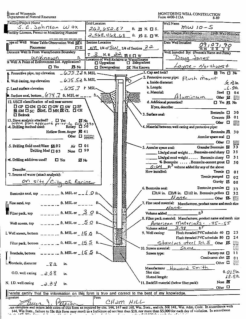
=ktate of Wisconsin D.:pa:tmcnt of Natural Resources
acility/Project ame S. t-. ~oh n~on
rid Location
..;z&3, (;5,;),I!, 7 , .;?,st.,g, 'fv,g .<,'l,
uon on
MONITORING WELL CONSTRUCTION Form 4400-ll3A 8-89
ft El N. □ s. ft. ,E1- E. □ W.
.,.,,. __ rTT"'~..,,...-T:T-~--..:---r---t JJJ..i;._ 1/4 of 5w 1/4 of Section ;z ,;i..
T ....::3_N, R .;l~ m E □ W
t. Protective pipe. top elevation _ (p J 2 .1 J ft. MSL --t:=:::::f ~l. Cap and Ioele?
-
1 _-, ~- -~-).._ fL MSL ____ ,_.,. 2. Protective cover pipe:
IS Yes □ N> FL~ sh rtlt1u.n+-
i. Well casing. top elevation J.F ..I. L Inside diameter. -~ -~in. _L .Pft f· Land surface elevation _ ~::JS .7 f" MSL
~- Surface seal. bottom_ f:!]'i .] ft MSLor --·- ft
12 uses classification of soil near saccn:
□ GP □ GM DOC □ ml □ SW □ SP jilSM □ sc l3ML □ MHB"<i DOI □ Beaocx .
13. Sieve analvsis attached? □ Yes JH N, wor""- pT~" "-(l'{)<:oJtd. p1,o,:+o !=(.h•J'½'Jo
-4. Drilling method used: Rotary □ :, 0
Hollow Stem Auger .Bl 4 1
...5. Drilling fluid uscd:Watcr S.02 .Drilling Mud □ 03
"6. Drilling additives uscd7 □ Yes
Oth:r □ !S:fft
Air □ 01 Ncnc □ 99
Dcsaibc _____________ _
7. Source of water (aruch analysis): •
0'("\ s, -1-c c_,·
Bcntonite seal. top
fi Fine sand. top
11 Filter pack. top fL MSLor
,"n
Well saeen. top ____ ·- fL MSL or _ -~ _Q
I. Well screen. bottom ______ fL MSL or_ L5 .0
Filter pack, bouom ____ ·- ft MSL or_ L~ 2_
[
Borehole. bottom
.~orehole. diameter
____ ·- fL MSL or _ L~ -~
O.D. well casing _ ~j ~ 1.11..
N. I.D. well casing _ ~. ~ <j_ in.
b.Lcngth: c. Matc:rial:
.4 I um in uvn.. d. Additional p-otection?
Sled □ 04
Oth:r Ji! . filfil □ Yes.El. N>
Hycs.describc: ----------
3. Surface seal: Bmtonit.c □ 3 0 Cona-ctc Ja- 0 l
_____________ Oth:r □ 4. Material bctwcc:n well casing and protective pipe:
Bcntonite B. 3 0 Annular space seal □
_______________ Odrr □ !lw 5. Annular space seal: Grmular Bcntonitc ~ 33
35 __ Lbs/gal mud weight ••• Bmtonit.c-smd shmy □ __ Lbs/gal mud weight • • • • • Bcntonite sluny □ 3 1 _.__ 9o Bcntonite • • • • • Bcntonitc-ccmcnt grout □ 5 0
0 • u,«.J Ft 3 volume added for any of the above
How in.stalled: Tremic □ O 1 Trcmic pumped □ 0 2
Gravity 0 08
6. Bentonite seal: Bcntonite granules D 3 3 □ 1/4 in. □3/8 in. D 1/2 in. Bcntonite pellets D 3 2
,V o O e- Other 0- ffi@ 7. Fine sand material: Manufacturer, product name and mesh si7.e
Alon<Z.- · Volume added ______ ft3
8. Filt.:r pack material: Mznufacrurer, product name and mesh size
A-rtU.ri l'a..n rYlo-.i-e r;ais , . </ S: - • ~ S" Volume added .3 , 9 8' rt3'
9. Well casing: Aush threaded PVC schedule 40 □ 23 Aush threaded PVC schedule 80
5f:a. cY'\ I e c s -s+~ d Sc" . .5 Other
□ 24 $5-
-:-:-:-:-.-.· :•;-:-:-:-:-• ~:~
10. Saccn material: _ __..S"-'a..;;;a.:.:m..L-=-----Saccn type: Factory cut D 1 1
Continuous slot 3 0 1 ______________ Other D EC
Manufacturer bJ.011 ,o c cl S-rn ; ~ Slot size: Slotted length:
11. Badfill material (below filter pack):
o. 01 Ein. 1.E-'2 ft.
~J!I ClUlcr D

State of Wisconsin Department of Natural Resources
Facility/Project Name h 5.C. ~o 11.So 1t. wqK_
License, Pennit or Monitoring Number
1. Can this well be purged dry?
2. Well development method
surged with bailer and bailed
surged with bailer and pumped surged with block and bailed
· surged with block and pumped surged with block, bailed and pumped compressed air bailed only pumped only pumped slowly
Otlxr
3. Time spent developing well
4. Depth of well (from top of well casisng)
5. Inside diameter of well
6, Volume of water in filter pack and well casing
7. Volume of water removed from well
8. Volume of water added (if any)
10. Analysis performed on will.er added? (If yes, attach results)
AddiLion.a.l comrnenlS on development:
Well developed by: Person's amc and Finn
Name:
Finn:
'JZ{ yes □ N:,
a 4 1 □ 6 1 □ 4 2 □ 6 2 a 1 o a 2 o a 10 a 5 1 a 5 o a l=Z:/ZJ!
__ l2.Q_min.
-L'-L- ~fL
-~-.;)</_in.
__ J_ .Q.. gal.
-~Ogal.
-~~-0 gal.
)3'._Yes □ N>
MONITORING WELL DEVELOPMENT Fonn 4400-113B 8-89
Well Name r(H,;.J J tJ - s
11. Depth io Water (from top of well casing)
Date
Tune
12. Sediment in we)! • boaom
13. Water clarity
Before Development After Development
___ • __ ft.
0£.1 id!l, :i.D mm d d y y
31..m. .l2.8.:3<2._a p.m
- .:2. (o inches
Clear □ 10 Tumid Ja. 15 n,..,,.,,i,,.)
/!;{-oUJO,
!_O,os-,_20 mm d d y y
(21:a.m. Q.~: OQ_□ p.m.
__ ._inches
Clear Jl 20 Tumid □ 25 n....-.."'h.)
Fall in if drilling fluids were used and well is at solid waste facility:
14.Totahuspcnded ____ ._mg/1 ____ ._mg/1
solids
15.COD ____ ._mg/1 ____ ._mg/1
hereby certify that the above infonna.tion is tIUe and correct lO the best of m • mowleo c.
Furn:
NOTE: Shaded areas arc for DNR use only. Sec instructions for more information.
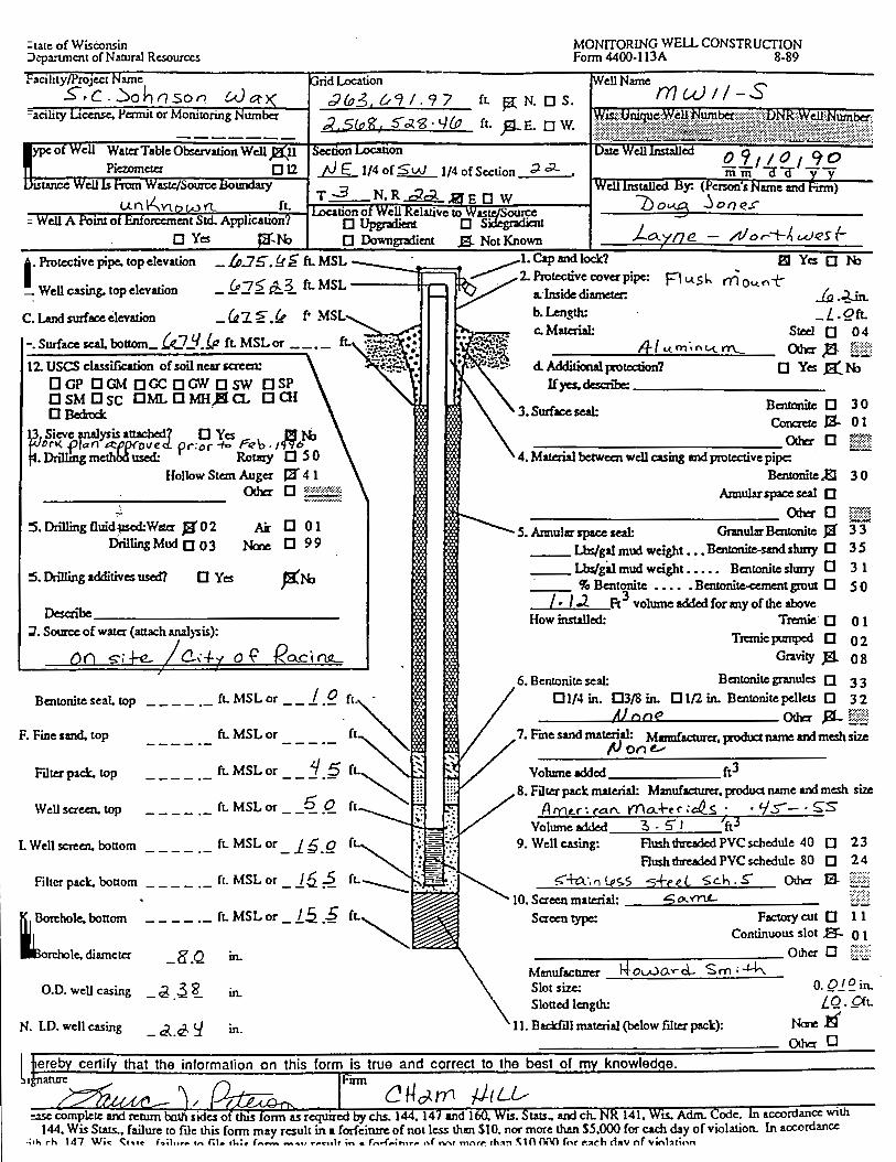
=tale of Wisconsin ::>qia.•tJm:nt of Narural Resow-ccs
• acility/Project ame
.5:. C . .:'.)a h t1 so ,., ""acility
ypc o ell WatcrTable Observation Well 11
Piez.omcta □ 12
=
()&3, &'9 1. 9 7 :l, Ste R, s-,;i:z · '-) (.p
1 · Protective pipe. top elevation
_ Well casing. top elevation _ £<, .:?i ~i ft. MSL -----ff-.,--,,
C. Land surface elevation _ Ci 2 ~ . /£ f MSL
-. Surface seal. bottom_ ~J _l/./J:z ft. MSL or __ • _
12. uses classification of soil near screen: □ GP □ GM OGC OGN □ SW □ SP □ SM □ SC □ML □ MH,S a. □ Cll □ lkdnx:k .
Dri,<. flofl ~()("ave.cl... pr:or -fu re:?\,. Jtf7TO ~ Sieve analysis attached? □ Yes ~ N,
Drilling mcthM used: R.otmy □ S 0 Hollow Stem Auger 13' 4 1
:S. Drilling fiuid~W11ter JiiJ 0 2 Drilling Mud □ o 3
:5. Drilling additives used7 □ Yes
O!ha □ ggg~
Aic □ 01 Ncnc □ 99
Desai~------------~. Source of water { attach analysis):
Bcntonite seaL top
F. Fine sand. top
Filter padc. top
Well screen. top
I. Well screen. bonom ______ ft. MSL or _ _L 5 .Q
Filter pack. bonom ______ ft. MSL or_ .16. :?_
fu _Borehole. bonom
Lrehole, diameter
______ ft. MSLor _ 15_ .-2
_8.Q m.
O.D. well casing _ '2$ } ~ in.
N. LD. well casing _ d.it:- Y, in.
MONITORING WELL CONSTRUCTION Form 4400-113A 8-89
ft ~ N. □ S.
ft. _,EL E. □ W.
ellName / S mw1 -
Bl Yes D Jib
Fl l.-C.$h n10(.(.(\-t:-_fti.~ _L .Qft.
d Additional pt>toction?
Steel □ 04 O!hcr )9- Effil □ Yes .B:_N>
Hycs.dcsaibc: __________ _
3. Surface sC!l: Bcntonit.e □ 3 0 Conaete !iJ- 0 1
______________ O!hcr □ ffi@ 4. Material between well casing and protective pipe:
Bcntonite .El 3 0
Annular space seal □ _____________ O!hcr □
lli~ S. Annular space seal: Granular Bentonitc "Ji{ 33 __ Lbs/gal mud weight ••• Bcntonite-sand sluny □ 3 S __ Lbs/gil mud weight • • • • • Bcntonite sllD'I)' D 3 1 _-__ % Bentonitc • • • • • Bcntonite<ement grout □ SO
I - I .2. Ft 3 vohnne added for any of the above How installed: Tranie · D O 1
Trcrnie pumped □ O 2 Gravity J& 0 8
6. Bentonite seal: Bcntonite granules □ 3 3
D l/4 in. □3/8 in. □ lll. in. Bcntonite pellets D 3 2
/J a a e Other J?L Ell 7. Fme sand material: Manufacturer, product name and mesh size
/J Or"le__,,
Volume addcd ______ ft3
8. Filia pack nu1erial: Manufacturer, product name and mesh size
i'.1 f'(lt_r; (Of\. rY\o..--h:r :~s . . '-Is-- . S'S Volume added ?:, • 5 I 'rt3
9. Well casing: Rush threaded PVC schedule 40 □ 2 3
Rush threaded PVC schedule 80 □ 2 4
~+o..-,,, Lgs.s :s+e~l sc.h . .s- Otha B- @TI 10. Screen material: ___ :$,"'-::.;:.;.-rnL-.:....:;;;;..._ ____ _
Screen type: Factory rut □ 1 1 Continuous slot H- 0 1
-----....--------- Other D TI@ 4owo.v--d... Sm; +h.. Manufacturer
Slot size: Slotted length:
11. Backfill material (below filter pack):
o. Qie in. LQ.QlL
~ Jg Olhc:r □

St.ate of Wisconsin Department of Natural Resources
Facility/Project Name S ·C. ~oh ns-011 W~K_
License, Penn.it or Monitoring Nwnbcr
1. Can this well be purged dry?
2. Well development method surged with bailer and bailed surged with bailer and pumped surged with bloclc and bailed surged with bloclc and pumped surged with block. bailed and pumped compressed air bailed only pumped only pumped slowly Other
3. Tune spent developing well
4. Depth of well (from top of well casisng)
5. Inside diameter of well _.,
6. Volume.of water in filter pack and well casing
7. Volwne of water removed from well
8. Volume of water added (if any)
C!i Yes □ N:,
□ 4 1 a 6 1 a 4 2
□ 62 □ 7 0 □ 2 0 a 1 o a s 1 □ 5 0
□ !9811 _J_~Q..min.
_j_~. {g ft.
- ..a. ;;,. j_ in.
- _3. . Gz. gal
. -~S:.6 gal
_ii5".0 gal.
MONITORING WELL DEVELOPMENT Form 4400-113B 8-89
Well Name .S rnw 11-
Before Development After Development 11. Depth to Water
(from top of well casing)
Date
Tune
12. Sediment in wel_! • boaom
· 13. Water clarity
___ • __ ft.
D9_1 ;i.~,<10 mm d d y y
□ Lm. O ..1: J_ 2µ:p.m
_Z,_. 0 inches
Clear □ 10 iI'mbid Jzl 1 5 -~~)
.B<owt1
__ ,a.3.S-fL
...f. 0 / OS-12..0 mm d d y y
OS:_~~~
__ ._inches
Clear □ 20 Turlid.Jzf-25 ---i-)
,/,row'I,
Fall in if drilling fluids were used and well is at solid waste facility:
14.Totalsuspc:ndcd ____ ._mg/1 ____ ._mg/1
solids
9.Sourccofwatc:radded 00 S~ttjc ,·+j a~ eo._c.;na... 15.COD ____ ._mg/1 ____ ._mg/1
_ 10. Analysis performed on water added? (If yes, attach results)
Additional comments on development:
ell developed by: Person's Name and Finn
Name;
Firm:
Ji(_Ya □ N:,
hacby certify that the above information is true and correct to the best of mv hlowlco e.
Signature: ~?1&-) -. B:zPlfHYl <
Fmn: (2 ft .;J 171 J-1- I {_.,(.,..
NOTE: Shadod areas are for DNR use only. See inslIUctions for more information.

Stale of Wisconsin Dq,a.'1.mcnt of Natural Resources
• acility/Project ame rid Location
MONITORING WELL CONSTRUCTION Form 4400-l 13A 8-89
£ .c. ~oht'SO/l wax acility cense, amit or Monitoring umber
,;J.w3, to a,tj. 4 8 fL :S' N. □ s. ::;.:,.,l,~~.-=.~..!..!.!!.::.L._ ft. _,Et E. 0 W.
Piezometc:r O 12 cJJ aste/Source undacy
'-<-11 ~now n.. fL orccment Sid. Appltcauon
□ Yes Jil)b □ Downgradient
A. Protective pipe, top elevation _ ~ Z. ~ • (e g_ ft. MSL
B. Well casing. top elevation _ fL::i S°.':l.~ ft. MSL
I C. Land surface elevation - (.f J5.{., r MSL
D.Swfacescal.bottom_~2~ _{,g fLMSLor --·- fL
12. USCS classification of soil near saccn:
□ GP □ GM □ GC □ CNI msw □ SP ~M □ sc j9ML □ MHS:<i □ Cll □ Bcmx:k: .
13. Sieve analysis attachod7 □ Yes IS'rrc Wor-.~ {)Ian <?t!)On>-.1"d. prior -1-o ~ 0:::,
090
14. Drilling method usM: Rot.my □ Hollow Stan Auger □ 4 1
~ ..... Ne.-; ... ·~.. ·,oo,_ - WO..> I Oba JZ1, f%:~,:✓.,~,:~~, ..:!d' ~ '-;:] "- ..;;;,;,;;;:-.;;-;
15. Drilling fluid·uscd:Wmr E'l 02 Ar □ 01 . 'Drilling Mud □ o 3 Nooe □ 9 9
16. Drilling additives used? □ Yes
Desai~------------17. Sow-cc of water (attach analysis):
n s;+a.
E Bentonitc seal. top
r- Fine sand. top
b. Filter pack. top
____ ·- fLMSLor --~_<2-rt.~
ft. MSL or t!).5 CJ Ct ----·- ---·-______ ft. MSLor -~f! .Q
-I. Well screen. top ______ ft. MSL or_ ~'Z.Q
I. Well scrcai. bottom ______ ft. MSLor _3Z .Q
_ Filter pack. bottom ______ ft. MSL or_ .J!?.Q fL--- ~-_.,......,..
~- Borehole. bottom
L Borehole, diameter
~--- ·- ft.MSLor _IJ.Q.2
~ 0 IIl.
~- 0.D. well casing _ .2_ 3 ~ 111.
N. LD. well casing _,2 -~ ':l in.
,S Yes □ N:l
/:'Iv.sh rtloCA.fl°l -~-~in. _L.QfL
fl:( um; nv.m,_ Steel □ 04
Oba 1zJ- WW □ Yes B N> d. Additional p-otec:tion7
Hycs.dcscribc: _________ _
3. Surface seal: Bentonite □ 3 0 Conacte 8 0 1
Oba □ t:YT -------------- ~:;;;;;;: 4. Material ~ccn well casing and protective pipe:
Bentonitc JB 3 0 Annular space seal □
------------- Oba □ &lZ 5. Annular space seal: Granular Bentonitc □ 33
__ Lbs/gal mud weight ••• Bcntonite-sand slurry □ _Jd_ Lbs/gal mud weight. • • • • Bentonitc sluny li 3 1 __ 9o Bcn~tc • • • • • Bcntonitc-ccment grout □ 5 O
;z? • I cl Ft volume added for any of the above
35
How installed: Trcmie □ O 1 Trcmie pumped ..Ef O 2
Gravity □ 08
6. Bentonitc seal: Bentonitc granules □ 3 3
□ 1/4 in. □3/8 in. □ 1/1. in. Bentonite pellets □ 3 2 e+o o¾n; tt cb ; p.s Odv:r 121- ~BD
7. Fme sand material: Manufacmrcr. po<hJct name and mesh size Brrw·:rao a'.10-+cr;..Ps: Fl;-o+- s-ho:l;· -~--35
Volume added O • ti rt3 1
8. Fil~ pack material: ManufactW'cr. product name and mesh size
Am,,.-ricoa aJ0--±<rjqQs · • :/s---S:S-Volurne added /, t/ 8 rt3
9. Well casing: AushthreadodPVCschedule 40 □ 23
5-/:o. , 1 I.es s Rush threaded PVC schedule 80 □ 2 4
~+eel .Sc I. . .5 Odv:r .3-- LG 10. Screen material: -~:;:_..a::,,.,u.CZ]..L;:-=;;;;;......----
Scrcen type: Factory cut □ 1 l Continuous slot )21'.' O l
______________ Omer □
Manufacturer :hb, ,)Of"~ Sen,· +i:i Slot size: 0. Q.!. Q. in.
lQ,QfL Slotted length:
11. Bacldill material ~low filter pack): ~ g Odv:r D
that the information on this form is true and correct to the best of m mn
CH ,;J.m JJ, LL

State of Wisconsin Department of Natural Resources
Facility/Project Name ~-C. ~oJ.nson wax
License. Pcnnit or Monitoring Number
l. Can this well be purged dry?
2. Well development method surged with bailer and bailed
surged with bailer and pumped surged with bloclc and bailed
surged with bloclc and pumped surged with block. bailed and pumped compressed air bailed only
pumped only pumped slowly
Olhc:r
3. Time spent develop!11g well
4. Depth of well (from top of well casisng)
.~
5. Inside diameter of well
6. Volume of water in filter pa.ck and well casing
7. Volume of waler removed from well
8. Volume of water added (if any)
10. Analysis performed on Water added? (If yes, attach results)
Additional comments on development:
ell developed by: Person's ame and Fmn
Name:
Firm:
□ Yes Ja N>
□ 4 1
□ 6 1
□ 4 2
□ 6 2
□ 7 0
□ 2 0
□ 1 0
J8 s 1
□ s 0
□ 1 ·.. . , I )uu1s~<
- .E-.l O min.
_3_ I. '3' fL
_ _?_ ;1.!:l_in.
-- 7.l_gaL
-~ 5:o. E.. gal
_.;loo. Q gal.
jt!Ycs □ N>
MONITORING WELL DEVELOPMENT Form 4400-113B 8-89
Well Name rnw1/--:b
11. Depth to Wat.er (from top of well casing)
Tune
2. Sediment in we}! • bottom
13. W ati::r clarity
Before Development After Development
___ • __ ft.
OJ_1.!_7 190 mm d d y y
oa.m. Qd:~,sp.m
..Lo .1 inches
Clear □ 10 mbid J3- 15
.. ----) .BrowQ,
S,'ffy
La, .11.s,.J o mm d d y y
m.a.m. 0 [. : q_o_□ p.m.
__ ._inches
Fill in if dril~g fluids were used and well is at solid waste facility:
14.Toulsuspcndcd ____ ._mg/I ____ ._mg/I
solids
____ ._mg/1 ____ ._mg/1
hc:rcby certify that the above infonnation is true and correct IO the best of mv l:nowleo c.
Signature:: 221fh✓.ffL ) .. r~'½k Furn: C fl ;i m ;..h LL-
NOfE: Shaded areas arc for DNR use only. Sec instructions for more infonn.ation.

-talc of Wisconsin D.::pa.-tmcnl of Narural Resourc.:s
MONITORING WELL CONSTRUCTION Form 4400-113A 8-89
acility/Project arnc 1
1,1-,...,_5.,...,,...c_ . ....,~~c--,-n _11 .... s.,..o-.-/l-.--UJ~a-,-.y.___~ ...::I::.!&:::...:~~-7-'-"'-'go,::;...:._. S?:::..;cP::::......_ fL ;g! N. 0 s. acility ccnsc. emit or Monitoring umber '
~, 5 IL 71 7 t../ (p . t./- g ft. .El E. D W.
-ype o ell Water Table Obscivation Well 11
012
;;
•· Protective pipe. top elevation
'I. Well using. top elevation _ !£ ~~ .i 1 ft. MSL
I;· Land surface elevation _ f.e:Z ~ .7 f+ MSL
fJ. Surface seal. bottom_ {g]]. .1 fL MSL or __ • _ fL
12 USCS classification of soil near saccn:.
□ GP □ GM gac □ rm □ SW □ SP □ SM □ sc )9ML □ MH)'J a. □ Cl{
□ Bechxk
~
• Sieve analysis attached? □ Yes ~NJ /µ(X't/... .pla.l'\.C).p{><'Ov~cl. D-rior- -h h .. ·19?0 • Drilling method used: r Rotary 5 0
Hollow Stem Auger ja 4 1
b. Drilling nwauscd:wara- □ o 2 Drilling Mud □ 03
6. Drilling additives used? □ Yes
Ocher □ r-~~~r-t:::3 .,;;.·v:,.:..;.·-:-:-·-:-·
Ar □ 01 Nooe B 99
Dcsaibc ____________ _
• Source of water (at13Ch analysis):
Bcntonite seal. top
-Pinc sand. top
!. Filter pack. top ______ ft. MSL or __ ':J .5
Well saccn. top ____ ·-ft. MSLor _ -~ _Q
ll Well screen. bottom ____ ·- ft. MSL or _ _ IJ.9 fL~ .
Filter pack. bottom ____ ·- fL MSL or_ j _.{P _ _? fL ____ .._-.-......,,_,,
Borehole. bottom
1- Borehole. diameter IIl.
I O.D. well casing -~.J2_ Ul.
d Additional JX"Otcction?
Yes O N>
_(!,.Qin. _z .QfL
Steel .B. 04
Och:r □ lli@ □ Yes Ci3'N> Hycs.dcsaibc: _________ _
3. Surface seal: Bcruonite □ 3 O Conactc.J3 01
Ocher □ tnn -------------- ~:~ 4. Matcrul betwocn well casing and prolcctive pipe:
Bcntonite fa:. 3 0 Annular space seal D
______________ Ocher D Pii
33 5. Annular space seal: Granular Bcntonite IS;1 35 __ Lbs/gal mud weight ••• Bcntonite-sand shmy □
__ Lbs/gal mud weight. • • • • Bc:ntonite slllD)' D 3 I __ 9'o ]3entonitc • • • • • Bcntonite-<:emcnt grout □ 5 O
0 • 8 0 Ft 3 volume added for any of the above
How installed: Tremie D O 1
Trcnie JXm1Pcd □ 0 2 Gravity 121 08
6. Bentonite seal: Bc:ntonite granules D 3 3 □ 1/4 in. -□3/8 in. □ lf]. in. Bc:ntonitc pellets □ 3 2
Alo o <-- Other Ja. ill$ 7. Fme sand material: Manufacturer, product name and mesh size
4mu-:ca,t1 O'.J"'--{er;a(Z.s ; Fl ,:n+ .Sho+ · • J..<;;;- .35 Volume added 0, ~ ' n3 ,
8. Filter pack mllerial: Manufacturer, product name and mesh size
A-a:v.<: (Q.I") rna..+t"r,o0.5; · t./S"- · s; S Volume added 3 •ufe n3
9. Well casing: Aush threaded PVC schedule 40 □ 2 3 Aush threaded PVC schedule 80 □ 2 4
5-f:9.~n i-9,;5 s+et"( .sci, .r Other _a.. bLl 10. Sacen material: :<::9 rru.. lli@
Saccn type: Factory cut D I 1 Continuous slot ,t;L 0 I
______________ Other □ @@
Manufacturer btouJo,rd Sm ,±b Slot size: Slotted length:
0 . .DJ Qin. 1Q. Q fL
N LD. well casing _ !?-. ~ ':J in. 11. Baddill material (below filtc:r pack):
I~ ~ereb certi that the information on this form is true and correct to the best of m
Nooe .Bl Other □
inn

State of Wisconsin Department of Natural Resources
Facility/Project Name :::, • C · .joh fl .Sot1. W 4 )(
License, Permit or Monitoring Number
1. Can this well be purged dry?
2. Well development method
surged with bailer and bailed
surged with bailer and pumped
surged with block and bailed
surged with block and pumped
surged with block. bailed and pumped comJJ(csscdair bailed only pumped only pumped slowly
Other
3. Time spent developing well
4. Depth of well (from top of well casisng)
5. lnside.<fiamctcr of well
6. Volume of water in filter pack and well casing
7. Volume of Waler removed from well
8. Volume of waler added (if any)
9. Source of water added
10. Analysis pcnormcd on Waler added? (If yes, attach results)
Additional comrricnl.s on development:
Well developed by: Person's ame and Finn
Name:
fal_ Yes □ N>
□ 4 1 □ 6 1 □ 4 2 □ 6 2 □ 7 0 □ 2 0 .,3 1 0
□ 5 1 □ 5 0
□ [@ggfil
_15'o min.
_j_ 7. o<fL
- ;;. . d- 'I in.
_ _3..l_gal.
_/00.Ogal
__ 0._gal.
□ Yes □ N>
Finn: La~oe c- /Uo,+liwes+
MONITORING WELL DEVELOPMENT Form 4400-113B 8-89
Well Na.me .S mw 1.;;.. -
Before Development After Development 11. Depth to Water
(from top of well casing)
Tune
12. Sediment in we{! • bottom
13. W aJ.a clarity
__ {2,j_j_ ft.
02.., ;J.31 9Q. mm d d y y
13'Lm. 0 7 :LS" a p.m
_-5:. ~ inches
QC,/ .J...01..J_E mm dd_yy
3a.m. LQ..:Ld□ p.m.
__ ._inches
0car □ 20 Tumid 0' 2 5
)
6rowo j
s,·t+f
Fill in if drilling fluids WC1C used and well is at solid waste facility:
14.Totlllsuspcnded ____ ._mg/1 ____ ._mg/1
solids
15.COD ____ ._mg/1 ____ ._mg/1
hereby catify that the above information is true and correct to the best of mv know lea c.
Signature: ~-14k-) , &tz,~ Furn: CH d 111 f/1 LA--
NOTE: Shaded areas arc for DNR use only. Sec instructions for more infonruition.
I

:State of Wisconsin --0.::pa."lmcnt of Na rural Resources
orcement Sid. Apphcauon
D Yes J!I--N, □ Downgradient
~- Protective pipe, top elevation _ &3. L .'i ~ ft. MSL
•. Well casing. top elevation _ .{p] L ~ "3: ft. MSL ---~--
C. Land swfacc elevation _ f2 :l ~ .J C- MSL
. Surface seal. bottom_ f.t.1 J .2 fL MSL or __ • _
12. uses classification of soil near screen: □ GP □GM QGC OCNI □ SW 0'SP □ SM~C J?1ML □ MHSa. □ Cll □ Bca-ock .
U. Sieve analysis auachcd7 D Yes fi:J' M,
uJoP',.f>\an ~~,o..,ec!.. ~<"; O<" +i, Feb.:.E9o • Drilling mcthoo used: Rotmy □. 5 0
Hollow Stem Auger J!J 4 1 Olha □ ~~: y,w;,.,;,.;-:,:-;-;-;,~
5. Drilling fluid used: Wacr Ja 0 2 Drilling Mud □ 0 3
Ar a 01 Nooe a 99
"6. Drilling additives used? □ Yes
Desai~------------7. Source of water (atuch analysis):
I Bentonite seal. top
ft Fine sand. top
II Filter pack. top
I Well sacen. top
I. Well screen. bottom
_____ .- ft.MSLor _2-~.fl
____ .-ft. MSLor _«:3~ .Q
____ .-ft. MSLor _J~ .!?
~iltcr pack. bottom ______ fL MSL or_~~ .Q
I, Borehole, bottom
~Borehole, diameta
I O.D. well casing
N. I.D. well casing
______ ft. MSLor -~f;! . .9
_ _g_Q in.
-~.:?~ in.
_:l,._~ 'i. in.
MONITORING WELL CONSTRUCTION Form 4400-113A 8-89
d. Addition.al potection?
Yes □ NJ
_f.JZ.Q. in. _2 .Q ft.
Steel )!- 04
Oba □ §@ □ Yes Ji1 NJ
Hyes.desaibe: ----------
3. Surface seal: Bentonite □ 3 O Ccnacte E3 0 1
_____________ Otha □
4. Ma.tcri.al between well casing and protective pipe:
Bentonite B 3 o Annular space seal □
______________ Otha □ fil§ 5. Annular space seal: GranularBentonite □ 33
__ Lbs/gal mud weight ••• Bcruonite-sand sluny □ .J.L Lbs/gal mud weight ••••• Bentonitesluny B 3 1 __ % Bcntonite • • • • • Bcntonite-a:ment grout D 5 0
L/-78' Ft3 volumeaddcdforanyoftheabove
35
How insttllcd: Tremie D 0 1
Trcmie pumped I!! o 2 Gravity □ 08
6. Bentonitc seal: Bentonitc granules □ 3 3
□ 1/4 in. □3/8 in. □ lf]. in. Bentonite pellets □ 3 2
£¼.nw;-k C'o ~ ~ Other · 1a Ett: 7. Fme sand material: Manufacturer, poduc:t name and mesh size
/lroµ-: (ar,. f(lahr:~; Fl>at shri; • , .,.~ - • 3S" Volume added O , lD '{ rt3 '
8. Ftlta pack material: Manufacrw-cr, product name and mesh size
(j(l1tr:catl ffio..hr:a\.t ·• , </~- -~S Volume added Y· 'll# , rt3
9. Well casing: Flush threaded PVC schedule 40
Flush threaded PVC schedule 80
5-+a..',n\e~ 5fl'<'l Sen• 5 Otha 10. Saecn material: _.;::S':..=a.:=..t'YlL-;....;... ______ _
□ 23 □ 24 le Ft .;.;.;-·.;..
Saeentype: Fact.my cut □ 1 1 Continuous slot "J!f O 1
______________ Other D @D Manufacturer µp ward. ~'"'; +b Slot size: Slotted length:
11. Backfill material (below filter pack):
0. Q.! .£ in. L'2.. Qft.
None Br Otho: □
that the information on this form is true and correct to the best of m mn

Stale of Wisconsin Department of Natural Resources
Facility/Project Name
.£ ,{;. ~ohnso,1 Wa "'-License. crntit or Morutoring Nwnber
1. Can this well be purged cfry7
2. Well development method surged with bailer and bailed
surged with bailer and pumped . surged with block and bailed
surged with block and pumped wged with block. bailed and pumped compn:ssed air bailed only pumped only pumped slowly
Oma
~ Yes □ N:>
a 4 1 a 6 1
a 4 2 a 6 2 a 7 0
a 2 0
a 1 0
Pl 5 1
a 5 0
a ~ 3. Time spent developing well _ 3 0 0 min.
4. Depth of well (from top of well casisng) _ 3 L k_ {L
5.Inside'diametero{well
6. Volume of water in filtcr pack and well casing
7. Volwne of water removed from well
8. Volume of water added (if any)
- - :J.. (p gal
~S-Q_. Ogal
.l O '2.. . Q_ gal.
9. Source of water added Q f"\ :Si..\-~ / C i4j 0£ Rae.;~ 7
10. Analysis pafonned on water added? ti Yes □ N:>
MONITORING WELL DEVELOPMENT Form 4400-113B 8-89
Well Name mWloJ. -b
Before Development After Development 11. Depth to Water
__ 5.j_dl ft. I (from top of __ u.QO fL well casing)
Date 68 ,~3,.23.. o911_0 1_:t6 I mm d d y y mm d d y y
2'.{.Lm. . ei-a.m.
I Tune 07 :.L~ap.m LL: 3CJap.m.
12. Sediment in wcJ! • _ 0. 5: inches __ ._inches bottom r 3. Water clarity Clear □ 10 Cear .,B.20
fl- 15 Tumd □ 25 ) )
Brown Sil+:jt
a Fill in if drilling fluids were used and well is at solid waste facility: I 14.Toulsuspendcd _ _:_ __ ._mg/I ____ ._mg/I '
solids I· 15.COD ____ ._mg/I ____ ._mg/I
I (If yes, attach ICSUlts)
--------------'• .. Additional comments on development \I
I
ell developed by: Person's ame and Furn
Name:
h~catify that the above · onnation is true and correct to the best o{m wlco e. I Signat=: ~----__). ~'1.-
Firm: Furn: (!_ff d- m 1-1- t V--
NOfE: Shaded areas are for DNR use only. Sec instructions for more information. i I

ls1a1e of Wisconsin Dq,a.-uncnt of Narural Resources
A •• acility/Projcct ame
MONITORING WELL CONSTRUCTION Form 4400-l 13A 8-89
S ~(.. '.:)o hnso11. ft. J:!r N. 0 s. _......c;...__;;~~-'---- ft. J5... E. 0 W.
ell Water Table Obsczvation Well _)all Piczomctcr □ l2
ell aste/Sourcc undary
l)Jl \( n ot,<J fl. ft. orccment Std. Applicauon
0 Yes Ja-N, O Downgradient
~- Protective pipe. top elevation _ 1, -:::l (g • :Z ,,;J. ft. MSL
3. Well casing. top elevation _ ~ 1fz.. . 5 ~ ft. MSL ----++-,,.....
• Land surface elevation _ & 21.L. .2 f+ MSL
. Surface seal. bottom_ Yl] ~.7 ft. MSL or __ • _
12 uses classification of soil nearsacc:n:
□ GP □ GM □ GC □ CNI □ SW □ SP □ SM □ SC ,£iMl. □ MH_Er"a.. □ ClI □ Bcdnrl:
~
. Sieve analysis attachcd7 0 Yes 0 N, 0_!~_:(>\o.f\ G\.POf'Ov(.O. P'fiOf' +o t="eb. 1qj_O
4. Drillmg methoUused: Rotmy □ 5 0 Hollow Stem Auger 18( 4 I
5. Drilling fluid used: Water J2f. 0 2 Drilling Mud O o 3
Olha- □ f12?'-:'\ .r,,;-;,.;,;,;,:-:,.;,.;..;-:-:
Afc □ 01 Nooe □ 99
, 6. Drilling additives used? □ Yes · J'i(N>
Dcsai~------------7. Source of water ( attach analysis):
0
'Bentonite seal, top ____ ·- ft. MSL or __ L .Q
l Fine sand. top
t Filter pack. top
ft. MSLor
ft. MSLor
I Well saeen. top ____ ·- ft. MSL or __ s_ .Q.
I. Well screen, bonom ____ ·-ft. MSL or_ L~ .0 7 =1 Filter pack. bonom ____ ·- fL MSL or_ .f .S .7
(I Borehole, bottom
[ Borehole, diameter
f O.D. well casing
_f:l. LD. well casing
____ ·- ft.MSLor _lf .1
_(Jz .Q. in.
~ 38 in. --.- -
_d,_~!:} in.
A-\1A..m·,nl(\'l'1.. .. d. Additional p-otcction?
_G-;,.~ in. _L .Q ft.
Stcd O 04 Olher;SJ gg □ Yes 1J N>
Hyes.dcsaibe: ----------
3. Surface seal: Bcntoniic □ 3 O Concrete t8' 0 1
_____________ Olher a 4. Ma.tcrial ~een well casing and protective pipe:
Bentonite JS= 3 0
Annular space seal a _____________ Olher- □ filill
5. Annular space seal: . Granular ~te .B 33
__ Lbs/gal mud weight ••• Bcntonitc-sand shmy □
__ Lbs/gal mud weight • • • • • Bentonite sluny O 3 l __ % Bcntonite • • • • • Bcntonite-cement grout □ 5 o
0, 5''g Ft3 volume added for any of the above
35
How installed: Trame □ 0 l
Tmnie pumped □ 0 2 Gravity .B 0 8
6. Bentonite seal: Bentonite granules D 3 3
□ 1/4 in: □3/8 in. □ 1/2 in. Bentonite pellets □ 3 2 ,. I fL-. n.L- c,f ~~':~x:: µoa ~~ P ~
7. Fme sand material: Manufacturer. product name and mesh size
Al 0 n L Volume addcd ______ rt3
8. Filter pack material: Mmufacturcr, product 112me and mesh siz.e
A~r:('o.r\ C:Oo..·h.r;o,!.s '. • t/ S- - • !;S-Volumeadde:d /, A'$" ' ft3
9. Well casing: Rush threaded PVC schedule 40 0 2 3
Rush threaded PVC schedule 80 0 2 4
5+o..·,"l£>S s±ul. Sc\, . .5 Olha .0 ffh 10. Saecn material: S O. n'\L d@
Saecn type: Factory cut □ I 1 Continuous slot 5 O 1
______________ Other □ @1:
Manufacturer hhulg r-cl $m .-.µ, Slot size: Slotted length:
11. Backfill material ~low filter pack):
0. Q.L Qin. LQ..Q.ft.
~,£ Olher a
ereb that the information on this form is true and correct to the best of m knowled e. irm

SL.ate of Wisconsin Department of Natural Resources
Facility/Proje£t Name / "S ·C -~01111 so 11. W a><
License, Pennit or Monitoring Number
1. Can this well be purged dry/
2. Well development method
surged with bailer and bailed
surged with bailer and pumped
surged with block and bailed
surged with block and pumped
surged with block, bailed and pumped comiressed air bailed only
pumped only pumped slowly
O!hcr
□ Yes pi_ N>
□ 4 1
□ 6 1
□ 4 2
□ 6 2
□ 7 0
□ 2 0
□ 1 0
;a 5 1
□ 5 0
□ IL.:L&.I 3. Time spent developing well _'} t I Q • _(2:l:r..._mm.
4. Depth of well (from top of well casisng) _ J_ ':}_ • 2._ ft. i,,
5. Inside diameter of well
6. Volume of water in filter pa.ck and well casing
7. Volume of water removed from well
__ d--2._gal.
_,SQ.. 0 gal
8. Volume of water added (tf any) _ _;! S. 0 gal.
9.So1.1m:ofwaterad&d Qr\ $~ +e_ /c:ry 0~ ((o.c.,'<UL
.-/ 10 • .Analysis paf ormed on Water added?
(If yes, attach results)
Additional comments on development:
Well developed by: Person's Name and Flllll
Name:
Finn:
MONITORING WELL DEVELOPMENT Form 4400-113B 8-89
Well Name
mW 1.3 -fl
Before Development After Development 11. Depth to Water
(from top of well casing)
Dale
Tune
12. Sediment in we!! • bottom
13. Water clarity
.fJ. !J 1 .l. (} I _2 () mm d d· y y
:s-a•-m. Q.g:L_op..m
Ccat- □ 10 Tumid E 1 s 11~ ;;_)
f,roLJJf\ 1 Si l-t--1
I
__ €" . .:l.3 ft.
LO·, os 1.J_.Q_ mm d d y y
~3 .El a.m. o 7: __ ap..m.
__ ._inches
Ca- J;it.20 Tumid □ 25
~ )
Fill in if drilling fluids were used and well is at solid waste facility:
14. Total suspended solids
15.COD
____ ._mg/1
____ ._mg/1
____ ._mg/1
____ ._mg/1
hereby certify that the above information as true and correct to the best of mv h,owleo c.
Signature: ~d4rr :) .. ~
F== (lf/,;im /-)./t,L.
NOTE: Shaded areas arc for DNR use only. See instructions for more information.
I I I I •
I
' I
' I I !!

lta.le of Wisconsin D¢pa.-uncnt of Narural Resources
MONITORING WEIL CONSTRUCTION Form 4400-113A 8-89
d-(o(.p 59 'Z • ~ '8' ft. _a N. □ S.
,;; 1 SlP~. c).3 t./ -3,;J. ft . .:El E. □ w.
I] j· Pro~ti~c pipe. top el~ation
. j_ Well casing. top elcva1.1on .
• Land surface elevation
. Surface seal. bottom_~] tJ.. .Q. fL MSL or __ • _
12 uses classification of soil near saccn: □ GP □ GM □ GC □ GN □ SW □ SP a SM □ SC IBML a MH l:!!I a. □ QI □ &mx .
13. Sieve analysis attached? □ Yes :SN, Wor\.l.. fl.in ~('fo..,ecl pr:or- ~ Fe\;_:_ ,~qo 4. Drilling method used: Rot.my U S 0
Hollow Stan Auger J8-41 Oher □ r~r::::~:-::;~
w:·»·n••···
5. Drilling fluid used:Wata j!t.02 Drilling Mud □ O 3
Ar □ 01 Nooe □ 99
,6. Drilling additives used? □ Yes
Desai~-------------,. Source of water ( attach analysis):
On ~,-+e C.., o~ fco.ci
I Bcntonite seal, top ______ fL MSL or __ I_ .Q
1-c
1
Fme sand. top
. Filter pack. top
ft. MSLor
____ ·- ft.MSLor --~ .Q
·1 weusaecn.top ____ ·- ft.MSLor --~-9
I. Well screen. bottom ______ ft. MSL or_ L~ .Q
I Filter pack. bottom ______ · fL MSL or_ f.~ -~
'
Borehole. bottom
' Borehole, diamet.er
I O.D. well casing
N. LD. well casing
- - - - -- ft. MSL ~ - LS:.. !2..
_8_Q in.
-~.3~ in.
_2_~1 Ja..
_&_.~in. _l .Q. fL
Sled O 04 ,4\ .. mf," f,(_m Oba a!S ill@
d. Additional pt>toc:rlon? · □ Yes _re Nl
Ifycs.dcsaibc: ----------
3. Surface seal: Bcntonitc □ 3 0 Cona-ctc ffl" 0 1
___________ Oba □
4. Material between well casing and protective pipe:
Bcntonitc J!5 3 0 Annular space sea.I □
______________ Ober □
5. Annular space seal: Granular Bcntonitc EJ ~:::"::::=:::: ~;;.;.;; 33
__ Lbs/gal mud weight ••• Bcntonitc-sand slurry D __ Lbs/gal mud weight. • • • • Bcntonitc sluny D 3 I __ 9o Bcntonite • • • • • Bcntonite<emcnt grout □ 5 O
Q ,/,et./ Ft3 volumeaddcdforanyoftheabove
35
How installed: Trcmic O O I Trcmic pmnpcd □ 0 2
Gravity B 08
6. Bentonite seal: Bcntonitc granules D 3 3
□ 1/4 in •. 03/8 in. □ 1/1. in. Bcntonitc pellets □ 3 2 ,{/ onL Oth:r Jii- EV@
7. Fme sand material: Manufacturer. product name and mesh size
1,/ool!.r-: Volume added ______ ft3
8. Filia pack material: Manufacturer, product name and mesh s~
A:01&ciCfl"- ,t7.,__t-u1,:ds:; • £/S"- .sr Volume added ~ • 8'.ce . ft 3
9. Well casing: Rush threaded PVC schedule 40 □ 2 3
Aush threaded PVC schedule 80 □ 2 4
5--1-a.-." l,.ss ~±al Sc~ · £ Oth:r 1B'- S'fil 10. Screen material: ___ 5=a.....,r'.'!---~=--------
Scrcen type: Factory cut □ I I Continuous slot 'S O l
--------------=,--,--,--- Other □ @b Manuf~turcr_JU=i..0~1&=..!0~~~d._5._m_,_·~-~Slot size: Slotted length:
11. Baddill material (below filter pack):
0.Ql~ in. LQ. .Q. ft.
Nooe ,0 Oth:r D
that the information on this form is true and correct to the best of m inn
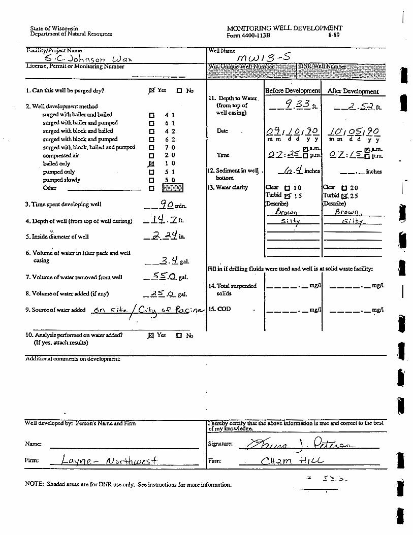
Slate of Wisconsin Department of Natural Resour~
Facility/Project Name
~ .c. . .Joh0son Wa..,._ License, Pcmut or Monitoring Nwnbcr
1. Can this well be purged dry?
2. Well development method
surged with bailer and bailed
surged with bailer and pumped surged with block and bailed
surged with block and pumped surged with block, bailed and pumped compressed air
. bailed only pumped only pumped slowly
Olhcr
3. Time spent developing well
4. Depth of well (from top of well casisng)
':.J
5. Inside diameter of well
6. Volume of water in filter pack and well casing
7. Volume of water tcmoved from well
8. Volume of water added (if any)
Ji1. Yes □ N>
□ 4 1 □ 6 1 □ 4 2 □ 6 2 □ 7 0 □ 2 0
J31 1 0
□ 5 1 □ 5 0 □ ILf:jkf
__ :1_ t) min.
_.l<J...2n.
_ _d:._~:l.in.
__ 3. ':L gal.
_ _E s-.o gal
- ..;{ $' .Q_ gal.
MONITORING WELL DEVELOPMENT Fonn 4400-113B 8-89
Well Name S mw13-
:z:D:~::2£1tt2:~=:?':~'.'.';!l:0?::-:~~~:~~E:r:::::~:'.cr2::sr::1 11 Before Development
11. Dc:pth to Water. 9 33 (from top of ______ ft.
well casing)
Dale C2_'11_L011_D mm d d y y
(1.a.m. Tune Q2:~S □ p.m
12. Sediment in we~ .• _(a_. tj_ inches bottom
13. War.a clarity Clear □ 10 Tumid 5 15 pcsawc)
hrol.,t)~ 5;1tt'
After Development
_ _ ;l . 5_ _;; fL
.10·, 05190 mm d d y y
5-a.m. o 7 : Ls- □ p.m.
__ ._inches
Clear a 20 Tudid 13'.-25 -~--)
f2.row(\ ,
~ii\!'.
I.
i
I :I
Fill in if drilling fluids were used and well is at solid waste facility: I' 14.Totalsuspcnded ____ ._mg/1 ____ ._mg/1
solids
9.Sourceofwatcraddoo 61'\ 5;·+L. IC-~ 6k" fu.c;,ie,.; 15.COD
I ____ ._mg/1 ____ ._mg/1
10. Analysis pcrf onncd on water added? (If yes, attach ICSU!ts)
Additional comments on development:
Well developed by: Person's ame and Firm
Name:
Firm:
,EJ Yes □ N>
I hereby ~ that the above information is true and correct to the best of mv mowlca c.
Signature: ~144. J· Q,.~
Furn:
NOTE: Shaded areas arc for DNR use only. Sec instructions for more information.
I 'i I

:State of Wisconsin Depa."'tmcnt of Natural Resources
MONITORING WELL CONSTRUCTION Form 4400-1 lJA 8-89
ell Name I
:::facilityfP1:$tiect arne ,_ ~ ·C. ~Orifl5011
;). (.e (tJ L/ 5°C, S-$" ft. li:f' N. □ s . •
rnw 1<.J-b ~, stof<, ;l. l/ t.,, , ,i}/.f1 ft. ,El_ E. □ W.
r· Protective pipe. top elevation
-.o. Well cuing. top elevation
if· Land surface elevation _ k 1 'i .Y f+ MSL
~- Surface seal. bottom_ y:JJ_ .f.fl fL MSL or __ • _
12. uses classification of soil near saccn: I □ GP □ GM □ GC □ CNI □ SW □ SP l~~~:::;;~r;.;: :;~o 14. Drillink method • Rotary □ 5 0 ' · Hollow Stem Auga Iii' 4 1
Js. Drilling nui~ used:Wattr a 02 Drilling Mud □ 03
6. Drilling additives used? □ Yes
<>ma- □ EZ@?
Ar □ 01 ~ □ 99
"- Dcsaibe ___________ _
7. Source of water (attach analysis):
6 <\ Si+e... (!.,
r . . .. 1 _ Bcntorute ~ top
l Fine sand. top
u. Filter pack. top
I Well saec:n. top
I. Well screen. bottom ft. MSL or .3 '1 8
I Filter ~c~ bono~ : : : : :: fL MSL or=~:~~
I Borehole. bottom
L. Borehole, diameter
. 0.D. well casing
LD. well casing
______ ft. MSL or_ J _!_ ~
_g_o in.
oZ 3 Z in.
in.
_(a .<2_in. _L .q ft.
Steel □ 04 A-( <-l m; n 1,u?3, Ober ~ fil@
d. Additional protection? □ Ye. ft-_N> Hycs.desaibc:: _________ _
3. Surface seal: Bcntonitc □ 3 0 Concrctc ,Jit. 0 1
______________ Ober □ 8& 4. Mlkrial between well casing and protective pipe:
Bentonitc a,. 3 0
Annular space seal □
-------------- <>ma- □ Will 5. Annular space seal: Granular Bentonitc □ 3 3 __ Lbs/gal mud weight ••• Bcntonitc-sand shmy □ 3 5
B_ Lbs/gal mud weight. • • • • Bcntonitc sluny S 3 1 __ % Ben~nitc • • • • • Bcntonitc-ccmcnt grout □ 5 O
8' · S 4 Ft volume added for any of the above How installed: Tronie □ O I
Tremie pumped Ji?I o 2 Gravity □ 08
6. Bentonite seal: Bcntonitc granules O 3 3
□ 1/4 in. 03/8 in. □ 1/2 in. Bcntonitc pellets □ 3 2 / - -t · 1- ,....h •-n~ 1':P ,z.,,__, e&I'"' or,,-'=- L IT Other ~ tt:~:
7. Fine sand material: Manufacturer, product name and mesh size A/oo e_
Volume lddcd ______ ft3 8. Filter pack malcrial: Mmufac:tura, product name and mesh size
1/-fllL_,- ,· eari rfla,4-,.r; -s ( 5. · • t../ S-- , ~ S Volume added 4, 3 7 > ft3
9. Well casing: Aush lhrc3dcdPVCschcdule 40 □ 23 Aush lhrc3dcd PVC schedule 80 □ 2 4
s+~ -. rd l' <; $ ~+er ( Sc h -S" Other s_ bill 10. Saccn material: 5arra- L:.:::a:
Screen type: Factory cut □ 1 1 Continuous slot f:J O 1
______________ Other □ [{:'. Manufacturer lJn 1,,Jo rd S rn ; +k Slot size: Stoned length:
11. Backfill material (below filter pack):
knowled e.
0. {)J2in. LQ .Qft.
~a Other □

State of Wisconsin Department of Natural Resources
Facility/Project Name
.s .c_ joh 11so·11 uJ ax License, Permit or Monitoring Number
1. Can this well be purged dry?
2. Well development method
surged with bailer and bailed
surged with bailer and pumped surged with block and bailed
surged with block and pumped
surged with block, bailed and pumped
co~air-bailedonly
pumpecfonly
pumped slowly
Omer
3. Time spent developing well
4. ~ of well (from top of well casisng)
· 5. Inside.diameter of well
6. Volume of water in filter pack and well casing
7. Volume of water removed from well
_µt--Ycs □ N>
□ 4 1 □ 6 1 □ 4 2 □ 6 2 □ 7 0 □ 2 0 □ 1 0 ~ 5 1 □ 5 0 □ IW1@MI
_ ,;i.~Q__min.
_ .3 9. &fL
- :J.._ .;i.. 1 in.
- - 'L ...l gal.
_ E .:2. a. gat
MONITORING WELL DEVELOPMENT Fonn 4400-113B 8-89
Well Name IYZWlt/-D
Before Development After Development 11. Depth 10 Wata
5 g,g ft. (from &opof --~-~3fL ---·--well casing)
Due 0 °!, .1_g_, '7 () .LO:.! 0 ~, 96 I mm d _d y y mm d d y y
'6 t3-Lm. J?ia.m. \l Tune 0 _ :;;i.S □ p.m o 1.:~L□ p.m.
_2.~inchcs 12. Sediment in we~ .• __ ._inches boaom
I 13. W atcr clarity acar □ 10 Clear ,13-20 ITmbid,a._ 15 Tumid □ 25 :.~ ~--) - - )
gfz,1,,c,n I IJ s,· try
Fill in if drilling fluids wee used and well is at solid waste facility: JI 14. Total $USpCndcd_
8. Volumeofwatcraddcd(ifany) _ a_s; .0 gal. solids
9.Somccofwatcraddcd 00 si+e.. /c,·::; (J~ ea.cine- 15.·coo
____ ._mg/I ____ ._mg/I ,.
I ____ ._mg/I ____ .;_mg/I
7 10. Analysis performed on water added? JES. Yes □ N>
(If yes, attach results) --
~-:-----,--e-------------- j [ Additional comments on developmenc
Well developed by: Person's ame and Finn
Name:
Finn: .laj n e- -IJ or+h wes +
11
I l h~ certify th.al the above information is true and correct 10 the best
._,:o:;.:f..:.:m:;.....:.::.;.;;..w;.;..;l~ed=c.'--------r)--, _-------1 Signature: <ZICl-uAfLJ . ~ Finn: C+f e1: m I.JI l-L-
NOfE: Shaded areas arc for DNR use only. See instIUctions for more information.

State of Wisconsin D.:paruncnt of Narural Resources
• acility/Project ame
MONITORING WElL CONSTRUCTION Form 4400-l 13A 8-89
5 -C. ~ohnso11_ w~x. d-b!/, 33 7, 5"9 ft. a_N. □ S •
.:l, s Ce 8 1 1.33 . ts fL ,a E. o W.
orcci:nmt Sid. Apphcauon Yes
.A. Protective pipe. top elevation
t. Well cuing. top elevation -~ '2. 2 .~2ft. MSL -----'h.--. . ,c. Land surface elevation _ft.Tl .fe C- MSL
_ D. Surface seal. bottom_ .f! 2. ~ .I:! fL MSL or __ • _ fL
12 uses classification of soil nCU' saem:
□ GP □ GM □ GC □ CNI tifsw &{SP □ SM □ sc □ML □ MH.S.a. □-OI □ &hrlc .
13. Sieve analysis attached? □ Yes )a' N, £,J~.l(...,.p\o.f\ ct.~Jt.cl.. fr-:or- +o F.eb• , 'i ,a
14. Drilling method • · Rotary □ 5 0 Hollow Stan Auger .l!iit 41
15. Drilling fluid uscd:Waur El O 2 Drilling Mud □ 0 3
16. Drilling additives used? □ Yes
Oda □ tf;;~~t{!
Ar □ 01 Nooe □ 99
Desai~------------! 7. Source of water ( att3Ch analysis :
(!) y\_ $; +e.-
I _ Bentonite seal, top
~ F"mo und. lop
. Filter pack. top ____ ·- ft. MSL or __ !::/ .Q
I Wellsaecn.top ______ ft. MSLor __ {e .Q
I. Well screen. bonom ______ ft. MSL or_ L ~ .Q
I Filter pack. bottom ______ fL MSL or_ L(p_ -~
'
Borehole. bottom
Borehole, diameter
I' . O.D. well casing
N. LD. well casing
____ ·-ft. MSLor _ L(g .':J.
_2.a. in.
_d_3~ in.
_.z-.~'i in.
d. Addition.al J;l'Otection7
JBf Yes □ NJ
-~-~in. _L .Q Ct.
Stcd □ 04 0cta a MiD □ Yes 122' NJ Hyes.descn'bc: __________ _
3. Surface seal: Bcntonite □ 3 0 Conaete fil O 1 _____________ Ob::r □
4. Material between well casing and protective pipe:
Bcntonitc Ja 3 0 Annular space seal □
______________ Ob::r □ am 5. Annular space seal: Granular Bcntonitc .El 3 3 __ Lbs/gal mud weight ••• Bentonitc-sand slurry O 3 5 __ Lbs/gal mud weight • • • • • Bcntonite sluny D 3 1 __ '1a Bentonitc • • • • • Bcntonite-cement grout □ 5 O
0 , 9 4' Ft 3
volmne added for any of the above How installed: Trcmie □ 0 1
Trcmie pumped □ 0 2 Gravity s: 08
6. Bentonite seal: Bentonite granules □ 3 3 □ 1/4 in. 03/8 in. □ 1/2 in. Bcntonite pellets □ 3 2
Alna~ Otha Ja-@t§ 7. Fine sand material: Manufa.cturcr, product name and mesh siz.c
/J Ot"J ~ Volume added ______ ft3
8. Filter pack material: Manufacturer, product name and mesh size
ArN..r;uv'l mo.:hr :Js · , t/S-- , 5.S-Volwne added 3, 9 g ' ft3
9. Well casing: Rush threaded PVC schedule 40 □ 23 Rush threadcd PVC schedule 80 □ 2 4
5k,nvss sf,d Sch -5 Other g mu 10. Screen material: __ 5J..:g:::...:...r,\/l__.:...===------
:·-·.··.;. ::_-::::;:::•: ~-;;:;;;;
Scrcen type: Factory cut □ l 1 Continuous slot .8 0 1
______________ Oilier □
Manufacturer Hui t,)Q r d. Sm i ¼ Slot size: Sloned length:
11. Backfill material (below filter pack):
o. OJ Qin. LQ. Qft.
Nooe Jil Other □
that the information on this form is true and correct to the best of m

Stale of Wisconsin Department of Narural Resources
Facility/Project Name
.S-C. ~o nsot? Wax. License, Permit or Monitoring Nwnber
1. Can this well be purged dry?
2. Well development method
surged with bailer and bailed
surged with bailer and pumped surged with block and bailed
surged with block and pumped . surged with block, bailed and pumped compccssed air
bailed only pumped only pumped slowly
Odicr
3. Time spent developing well
4. Depth of well (from top of well casisng)
5. Inside'diamcter of well
6. Volume of water in filter pack and well casing
7. Volume of water removed from well
j'i1. Yes ON>
□ 4 1 □ 6 1 □ 4 2 □ 6 2 □ 7 0 □ 2 0 j3- 1 0
□ 5 1 □ 5 0
□ ~
-.?.-..::1 .a min.
_ _/_$.&{L
_ _z_ <}..i.in.
- -~. ':L gal.
_60. Oga1.
8. Volume of water added (if any) _ l.. ':L. 0 gal.
MONITORING WELL DEVELOPt.iENT Fonn 4400-113B 8-89
Before Development After Development 11. Depth to Warr;r
· (fromtopof ___ • __ ft. __ 1_. 'f?'3{L well casing)
09..,a.7,:i.O LD",_g~J..D mmddyy mmddyy
□ a.m. ,a..a.m. Tune l_;)_ :O~J:;Jp.m 0_7:.1_1_:op.m.
2.Sedimentin w~.. _:8:. 0 ~ _ _;_._inches bottom
13. W au:r clarity acar a 20 Tudid _Ja-25
... --·-> Srown
s:,·tj
Fill in if drilling fluids were used and well is at solid waste facility:
14. Total suspended M>lids
____ ._mg/1 ____ ._mg/1
I II I I \I I
9.Sourccofwateraddcd On s=+(._/c.,,k 0~ go.dne... 15.COD I -::,
____ ._mg/1 . ____ ._mg/1
I~
10. Analysis performed on water added? (If yes, attach results)
Additional comments on developmenc
ell developed by: Person's ame and Firm
Name:
Firm:
Ji1. Yes □ N>
-Ill
I
haeby ~ that the above infonn.arion is true and correct to the best ~~~~cd~ I Signa~ ~~ • ~
1
Furn: c /1.;i_m t-1-1 l L- I NOTE: Shaded areas arc for DNR use only. See instructions for more information.

•tale of Wisconsin <!partmcnt of N an1ral Resources
MONITORING WELL CONSTRUCTION Form 4400-113A 8-89
Wax ;;l./.; '-/ 3 3't · </~ fL ;f;l N. 0 S.
~ I s & '8 I 938. s 'if ft. .,a: E. □ w. ell 't't ca Table Observation Well ~11
Piezometc:r □ 12
ft.
- orcement Std. Apphcaoon
Yes □ NJ
t· Protective pipe. top elevation
-. Well casing. top elevation
12. uses classifacation of soil near saecn:
□ GP □GM □ GC □ <NI SSW ~SP □ SM □ SC mlML □ MH l:a a. □ OI □ Bcaodc .
13. Sieve analysis attached? □ Yes )t N:, ~~~ .pla" ~0-1<d pr-, o, +o Fd,. l!tq 8 r. Drillint method'used: Rotary □ 5
Hollow Stem Auger □ 4 1
1) r; "e. c~ ~ 0 "-' was" O!ha B [=5'.l 5. Drilling fiuidmcd:Watcr ~o 2 Ar □ O 1
Drilling Mud □ 0 3 Nooe □ 9 9
. Drilling additives used? □ Yes
Desai~------------• Source of water (attach analysis):
Or\ Si+~
lnenronitc seal, top ______ ft. MSL or __ l .Q
F. Fine sand. top
IFiltcr pack. top
ft. MSL or
ft. MSL or ;J..;J. 0 - - - - ·- - - - ·-, rellsaecn.top ______ ft.MSLor_,2.j_Q
I. Well screen. bottom ______ ft. MSL or --2 ~ .Q
.,Filter pack. bottom ______ fL MSL or _31_ _{2_
]i8orehole. bottom
Lrchole, diameta
______ ft. MSL or_ .]':f. .9 ft.~
- ~ _Q_ in. -----""'
I O.D. well casing _ tl. 3 ~
N. LD. well casing _ 2-. ~ ~ in.
Al u.rn ·." l.(_ rY\..
d. Additional p-otection?
Yes □ NJ
_G.2in.
_L. Qft. Steel □ 04
O!ha ~ W'S □ Yes Jiil NJ
Ifycs.dcscribe: ---------
3. Smfacc seal: Bentonite □ 3 0 Concrctc B. 0 1
______________ O!ha □
4. Material between well casing and protective pipe:
tt~1} ~-=~
Bentonitc .J3- 3 0 Annular space seal D
______________ Other □ illli
5. Annular space seal: Granular Bcruonitc D 33 __ Lbs/gal mud weight ••• Bentonite-sand shmy □
.J.L Lbs/gal mud weight • • • • • Benronitc sluny S 3 1 -- 9o BentT~ • • • • • Benronitc-ccment grout □ 5 O
¢ • i:J.. .;l.. Ft volume addod for any of the above
35-
How installed: Tronie □ O 1
Trcmie pumped J3 0 2 Gravity □ 08
6. Bentonitc seal: Benronitc granules □ 3 3 D 1/4 in. 03/8 in. D 1/l in. Bentonite pellets D 3 2
(b!:"+o0 ;-k d-): pS Otha ~ lli-0 7. Fme sand material: Manufacturer, product name and mesh siz.e
/Ione-Volume added ______ ft3
8. Ftlt.:r pack material: Mmufacturcr, product name and mesh size
Am.u; rM\ (Ylo..+u ;a2.-..; , 45:- • S.S-Volumcadded / • .Z 7 rt3
9. Well casing: Aush threaded PVC schedule 40 □ 2 3
Aush threaded PVC schedule 80 □ 2 4
5-:t? i ,,._ L.t c;;: s- s+ ... .- (_ s; c. 1, · s- Odxr :a. ULI 10. Screen material: __ $""'O;>...;.rYl.L_~=-----
Scrccn type: Factory cut □ 1 1 Continuous slot ~ O I
______________ Other □ fa@ Manufacturer hh,,t,.Jo r d S m ; ::I±, Slot siz.e: Slotted length:
11. Baafill material (below filter pack):
o. QLQ in. UI. .Qft.
Nooe N Odxr □
that the information on this form is true and correct to the best of m

State of Wisconsin Department of Natural Resources
Facility/Project Name I
~ •C. ~o nnsot1 u.Ja x License. cnnit or Monitoring Number
1. Can this well be ?Jrgcd dry7
2. Well development method
surged with bailer and bailed
surged with bailer and pumped
surged with block and bailed
surged with block and ?Jmpcd smged with block, bailed and pumped compressed air bailed only
pumped only
?Jffipcd slowly
Odv:r
3. Time spent developing well
4. Depth of well (from top of well casisng)
5. Inside diameter of well
6. Volurde of water in filter pack and well casing
7. Volume of wa1cr removed from well
8. Volume of water added (if any)
10. Analysis perf ormcd on water added? (If yes. attach results)
Additional commenl.s on development:
Well developed by: Person's Name and Finn
Name:
Firm:
,;i1 Yes □ N:>
□ 4 1 □ 6 1 □ 4 2 □ 6 2 □ 7 0 □ 2 0 □ 1 0
□ 5 1
~R - d 1. ~ min.
_3 3 .2_fL
_.d:,._ ;;z_j_ in.
__ 5,.3 gal.
_Cj_s .Qga1.
_ ?S".Oga1.
l( Yes □ N:>
MONITORL'IG WELL DEVELOPMENT Form 4400-113B 8-89
Well Name rnv.Jlh-J:>
Before Development After Development 11. Depth to Water
(from top of ___ • __ ft. _LO . ~.S-fL well casing)
Dare 09,:2.7,9~ Lo·, 2 S-1.J. cJ mm d d y y mm d d y y
Tune ~Lm.
LL:30apm □ a.m. O'i...: .;i..o ~p.m.
2. Sediment in we~. . _.2.3.~ __ ._inches bottom
13. Wau:rclarity Clear □ 10 Clear ,r:a::20 mbid Ja 15 Tumd □ 25
) i!,1"0W<1
)
<nry
Fill in if drilling fluids were used and well is at solid waste facility: I
14. Total suspended solids
____ ._mg/I ____ ._mg/I
____ ._mg/I ____ ._mg/I
NITTE: Shaded areas arc for DNR use only. Sec instIUctions for more information.
I
r
r1
I -I

State of Wisconsin Dq,anrncnt of Natural Resources
• acility/Projcct ame
~ •C. ~6h"Son Wa.><- "'-''-'-_,__ ___ _ MONITORING WELL CONSTRUCTION Form 4400-113A 8-89
ft. 18'.. N. D S. acility
-,..c-___.,y...::.=<-=-c;;...:_~- ft. ~ E. □ W.
ell WatcrTableObscrvation Well 11
Piezomctcr D 12
.A. Protective pipe, top elevation
~- Well casing. top elevation .
undary
· If· Land surface elevation _ ft I]_ .1 · f' MSL
9). Surface~ bottom_ Mf! -~ fL MSL or __ • _
12. uses classification of soil near saccn:
□ GP □ GM □ GC □ mi □ SW □ SP □ SM □ SC JillML □ MH_J8 CL □ Of □ Bahd:
13. Sieve mal_,.,Y,Sis attached? □ Yes · uJor~ J(loJl OJ>Ofllv<.cL t)r;ar- -1-o 4. Drilling method usM: • Kolar}'
Hollow Stem Auger 18- 4 1
Othcr □ S:L'11J ,,,..,
_5_ Drilling fluid uscd:Wattr Ji!f 02 Drilling Mud □ 03
I i 6. Drilling additives used? □ Y cs
.;;...;,.:,;;.;;y;-;-;
Afr □ 01 Ncne □ 99
Dcsai~------------7. Source of water (attach analysis):
on s;..\-e
_ Bcntonite seal. !Op ____ ·- fL. MSL or __ l .Q
,_ Fine smd. top
u. Filter pack. top
Well saccn. top
fL MSLor
______ ft. MSL or
I. Well screen. bonom ______ ft. MSLor _ l ~-~
I Filter pad:. bonom ______ fL MSL or_ Lf.L ,5
II Borehole. bottom
[ Borehole, diameter
_ O.D. well casing
____ ·- ft. MSL or _ l C, . .S
_'K.Q in.
in.
If-I L<.m i nun"-d. Addition.al p-otection?
_G;,.~in. _L.QfL
Steel □ 04 Olha J5- g;g □ Yes J3i N> lfycs.dcsailx:: _________ _
3. Smface seal: Bmtonitc □ 3 0 Concrcte,.3" 0 1
______________ Olha □ fils 4. Material ~ccn well casing and protective pipe:
lkntonite Ji!. 3 0
Annular space seal D
-------------- Other □ llif2 5. Annular space seal: Granular lkntonitc Jil- 3 3 __ Lbs/gal mud weight ••• lkntonite-sand shmy D 3 5
__ Lbs/gal mud weight • • • • • Bentonite sluny D 3 1 __ % Bcntonitc • • • • • Bentonitc~cnt grout □ 5 0
0 · 9 IP Ft3
volwne added for any of the above How installed: Trcmie □ 0 I
Tr:cmic pumped □ 0 2 Gravity .K O 8
6. Bcntonite seal: Bcntonite granules D 3 3
□ 1/4 in. 03/8 in. □ 1/2 in. Bentonite pellets □ 3 2 AJo a~ awr ~tfffil
7. Fme sand material: Manufacturer, product_namc and mesh size J.Jon L
Volume addcd ______ ft3
8. Fil ta pack material: Manufacturer, product name and mesh size
A-m~ri(ar'"\ /'f1P...ftr:~~ · • t/S-- ,SS-Volume added 3 . 9 &
7 ft3
9. Well casing: Rush threaded PVC schedule 40 □ 2 3
Rush threaded PVC schedule 80 □ 2 4
5fo..·,11(6s s+-e~l sc\, · ~ Otha JEl. @El 10. Sa-cen material: __ 5.,__o..;;..."<YtL.:.==------
Sa-ccn type: Factory rut □ 1 1 Continuous slot ('3::: O 1
-----,...-----,-~---Omer □ 4-owar d Sm,+~ Manufacturer
Slot size: Slotted length:
0 . .91 Qin. [Q. Oft.
IN. LD. well casing _ J. ~ ~ in. 11. Backfill material (below filter pack):
. ereb certi that the information on this form is true and correct to the best of m
None}BOlher □
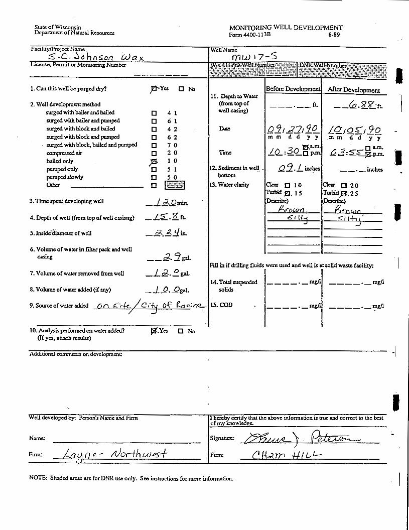
Stale of Wisconsin Department of Natural Resources
Facility/Pt-ojcct Name
S -C. ~oh 11 son Wa x License, Pennit or Monitoring Nwnbcr
1. Can this well be purged drf/
2. Well development method
surged with bailer and bailed
surged with bailer and pumped surged with bloclc and bailed
surged with block and pumped · surged with block, bailed and pumped
compressed a.ir bailed only
pumped only
pumped s1owly
Ocher
3. Time spent developing well
4. Depth of well (from top of well casisng)
5. Inside'diameter of well
6. Volume of water in filter pack and well casing
7. Volwne of water removed from well
□ 4 1 □ 6 1 □ 4 2 □ 6 2 □ 7 0 □ 2 0
)3- 10
□ 5 1 □ S 0
□ LlJiJ@]
_J_ ;;_ Omin.
_j_S°. 'g {L
- a... ~.!:/_in.
__ f2:..:}_ga1.
_Lid.!:.. ga1.
MONITORING WELL DEVELOPMENT Form 4400-113B 8-89
Well Name mw 17-5
11. Depth to Wata (from top of well casing)
Date
Tune
12. Sediment in we{! • bottom
13. Waterclarity
Before Development After Development
___ • __ ft. __ {Q •'if~ -CL
o 9, ~7, 912_ LCr ,os:-1 <Jo mm d d y y .m m d d y y
JJ)_:3Q..g~:
Q:l.Linches
Clear □ 10 !Tumid fl- 1 5 !Tl.-s:rnn,o)
/1,CQWYI I
~; lfj
·-'.
? □ a.m. 12. .,;.2 : 5 S" ja..P.m.
__ ._inches
Ce.a- 020 Turlid,B-25
- )
/2.,-Cor,,,o ~; 1±-:1
j
Fill in if drilling fluids were used and well is at solid waste facility:
14.Totalsuspcnded ____ ._mg/1 ____ ._mg/I
8. Volumeofwatcradded(ifany) _J_.Q . .QgaI. solids
9.Sourccofwateradded 60 c·,+;,/c,·::J 0~ Ra_c;ne_. 15.COD ____ ._mg/1 ____ ._mg/1
10. Analysis perlonned on water added? (If yes, attach results_)
Additional comments on development:
ell developed by: Person's Name and Fmn
Name:
Firm:
~Yes □ N>
hereby catify that the above information is true and correct to the best of m , KnOwled e.
Signa~ ~). p~ Finn:
NOfE: Shaded areas are for DNR use only. Sec instructions for more information.
I
II
-I
,,

I State ~f Wisconsin D¢pa."'1Jllcnt of Natural Resources
rid Location
MONITORING WElL CONSTRUCTION Fonn 4400-1 lJA 8-89
'J Facility/Project ame
S -C . .::)o°hnson l<JaY-.. .:2&'/ ys3-&o J
ft. ;tg___N. □ s . ~+-"--'-"'-=;..;;c...;::;...;...i.ta..:;_ ft. 1z1 E. □ W.
y: ( erson s ame and
V; rice_ 01e io&e(
otKnown L..o...yne - No ,.+i,w{S+ A. Protc:etive pipe. top elevation _ ~ :12 ,Z;L ft. MSL
B. Well a.sing. top elevation _ (2 ::1. 2 -~ ~ ft. MSL
_..-----:-1. Cap and lock? JrJ Yes □ NJ -~:==::::;T 2 Protective cover pipe: F l u5 h mdv. n-t-
I. c. Land surface elevation _ & Tl .$ C- MSL
D. Surface seal, bottom_ y.,.]{q .2 Ct. MSL or __ • _ ft.
12 uses classification of soil near saccn:
□ GP □ GM □ GC □ CNI □ SW □ SP a SM □ sc Ji!IML □ MH ~a. a rn □ Bcdnx:lc .
13. Sieve analysis attached? □ Yes 2f N> ().)or~ p\of\ ~-P Oro,1ec/.. lri o-< ~ f=~.h.- J~?
14. Drilling method o.sbf: r Romy □ 5 0 Hollow Stem Auger □ 4 1
"Dci -se.. $e1.-:,2:> * wa.s~ Ohcr J'i!l fdf;fj
· 15. Drilling fluid usod:Wm- m-0 2 · Drilling Mud □ 0 3
16. Drilling additives used? □ Yes
Ar □ 01 Ncnc □ 99
Dcsaibe ____________ _
17. Source of water ( attach analysis):
DY\ s;
3. Bentonite seal, top ____ ,_ ft. MSL or __ L .0
,I· Fmc sand, top
~- Filter pack. top
I. Well saccn. top
I. Well screen. bottom ft. MSL or 3 I 0
,. Fil~ pac~ bottom : : : : :: fL MSL or=~~
~- Borehole, bottom
t. Boreoolc, diameter
______ ft. MSL or_ J i'-.P CL~ ....... """" ...
_5.Q in.
L Inside diameter.
b.Length: c. Material:
A- l I..( m ·, n l,(_ m.. d. Addition.al Jrt)tection7
_(,-<zS-in. _L .Qft.
Stttl a 04
01bcr ,a: Wfil! □ Yes 3. NJ
Hycs,dcsaibe: -----------
3. Surface seal: Bentonite □ 3 0 Concrete JiJ- 0 1
Othcr a rnrn -------------- !,;;;;;::;;;;;;
4. Material between well casing and protective pipe:
Bcntonite S... 3 0
AnnulM space seal □
Olhcr □ PE -------------- ~::..: 5. Annular space seal: Granular Bcntonite □ 3 3 __ Lbs/gal mud weight ••• Bcntonite-sand slurry D 3 5 ..l.d.._ Lbs/gal mud weight • • • • • Bentonite sluny ta-- 3 1 __ % Bentonite • • • • • Bentonite-ccmcnt grout □ 5 O
I • 't O Ft 3
volume added for :my of the above How installed: Trcinie D 0 1
Trcmie pumped .:0 O 2 Gravity □ 08
6. Bentonite seal: Bentonite granules D 3 3
□ 1/4 in. 03/8 in. □ 1(1. in. Bentonite pellets □ 3 2 n +n . • - r' . ll.S 1:1' w,w.-. ce ~n, ::rs n, r Other ~ fut}
7. Fme sand material: Manufacturer, product name and mesh si.7.c #QQ'1-
Volume added ______ ft3
8. Filtcr pack material: M:mufacrurcr, product name and mesh size
Aro,,r.-ran. 010.-f:rr,·atJc:.: . t../S-- · s-~ Volume added / · '-18 h3
9. Well casing: Rush thn:adod PVC schedule 40 □ 23
Aush thn:adod PVC schedule 80 □ 2 4
<¾?,-.,._t.gc;.<,, s±:-e~l. Sch• S-- Odia 12i- ME 10. Saccn material: Sa... CY\.t.- u@
Saccn type: Factoty cut □ 1 1 Continuous slot .B o l
______________ Other □ ff@ Manufacturer · l-:b, ua cd S:m ;4-h-t . O.D. well casing _ ~ .:? ~ in. Slot size: 0 . .f)J .Qin. Slotted length: L Q. • Q fL
r- LD. well casing _ _J _ !Z' =1 in. 11. Bacldill material (below filter pack): =- ~

Sute of Wisconsin Department of Narural Resources
Facility/Project Name
c.;.--. C.. ~o n<;on· Wax.... License, Pemtit or Monitoring Number
1. Can this well be purged dry?
2. Well development method surged with bailer and bailed
surged with bailc:r and pumped
surged with bloclc and bailed
surged with block and pumped
surged with bloclc, bailed and pumped · comptessed air
bailed only
pumped only
pumped slowly
~
3. Time spent developing well
4. Depth of well (from top of well casisng)
5. Inside.diameter of well
6. Volume of water in filter pack md well casing
7. Volume of water removed from well
·□ Yes Q N>
□ 4 1 □ 6 1 □ 4 2 □ 62 □ 7 0 □ 2 0 □ 1 0 □ 5 1 }ii1- 5 0
□~
_e{~Omin.
_3_0 . .:ZfL
_ 2,._ .B !:l in.
__ s- .'l_gaL
.J_OQ_.O gal
8. Volume of water added (if any) _!_ O O • 0 gal.
9.Sourccofwateraddcd 60 s·,·+e /c_.-+y of; R.ac;rx.. l . .
10. Analysis performed on water added? (If yes, attach results)
Additional commal1.s on development:
Well developed by: Person's Name and Finn
Name:
Finn:
JaYes □ Nl ·
MONITORING WELL DEVELOPMENT Form 4400-113B 8-89
WellName -;--... rf/W I 7- .J.j
Before Development After Development 11~. Dc:pth lO Water_
(f.rom'topof ___ • __ ft; . """7 c:?'8 f --..L..•-- L ~ell. casing)
Tune
12. Sediment in well • : : bottom -·
i3. Water clarity
..09-1 cJ.7 /IO / 01 051 _J j) mm dd.yy -mm ·dd yy
_Ca_.2._in~ .. -~--inches 'I!',, ...
Clear □ 10. · Tmbid J;f-1 5 .
lUl:::iQlUC)
.6(o{,,1Jn 1
'i.'t ; Clear Jif-2 0
Tuibid □ 25 .................. ).
Fill in if drilling fluids wc:rc used and well is at solid waste facility:
14'.Totalsuspcndcd ____ ._rng/l ____ ._mg/l
solids
is::coo .:.:,_ ___ ._mg/I ____ ._mg/l
I hereby certify that the above information is true and correct to the best of mv blowlcd c. ,
NITTE: Shaded areas are for DNR use only. See instructions for more information.
r
,I
I I I I
I
I
I

I. Stale ~f Wisconsin D.:panmcnt of Natural Resources
rid Location Wa>'- ;)& 3 4 7S". s-,g
~ ,Sa,'i)' 99/, '-10 I
A. Protective pipe. top elevation
13. Well cuing. top elevation
C. L!.'ld surl'!ee e!:-1:.ticn _ {p:J 2. .9 r MSL
D. Surface seal. bottom_ Jo ..?k .E fL MSL or __ • _
12 USCS classification of soil near screen:
□ GP □ GM OGC OGH □ SW □ SP □ SM Dsc J3ML □ MH.iJCL □ OI a lkdrodc ·
13.$i~emuixsisalUICbed? □ Yes ~ wo_c--, ... 010.n~<o.i(<:Lpnor- +o t • I
4. Drilling n\eihod . Rotmy .5 0 Hollow Stem Auger 0' 41
01u □ ES!~i ~
S. Drilling fimd uscd:Wattr □ 02 fu1:~w Mud □ , .... '6 03
& a 01 Nmc ~ 99
6. Drilling additives used? □ Yes
Desai~------------7. Source of water (attach analysis):
I Bentonite seal, top
F. F.tne sand. top
I Filter pact. top
Wellsaecn.top
l. lcu screen. bottom
____ ·- ft.MSLor --~_Q
ft. MSLor
____ ·- ft.MSLor _lfJ.. .Q
____ ·-ft. MSLor _ l-6 .Q
______ ft.MSLor -~~-Q
I Filter pack. bottom~ ______ fL MSL or_~~?
K. Borehole. bottom ____ ·-ft. MSL or -~~.Q
18orehole, diameter _g_ .ll in.
I O.D. well casing
LD. well casing
.;;_ 3 <a' --.- - in.
IJl.
fl""' Ct,"
MONITORING WEU. CONSTRUCTION Form 4400-113A 8-89
fL ,El N. □ s. fL .,S.E. □ w.
Yes □ N>
_C,.Q in.
_7,gfL Steel ,6. 04
_ ___________ · Oho- a !:illf! d. Addition.al potcction? □ Yes S N:,
Ifycs.desaibc: _________ _
3. Surface seal: Bcruonite □ 3 0 Concrete ~ 0 1
_____________ 01u a 4. Material between well casing and protective pipe:
Bentonite la' 3 0 Annular space seal D
______________ 01u a gz s. Annular space seat: Granular Bcntonite E 3 3
--Lbs/gal mud 'weight ••• Bcntonit.e-sand sluny □ 3 5 __ ._ Lbs/gal mud weight • • • • • Bentonite slurry □ 3 1 __ 'lo Bcntonite • • • • • Bc:ntonite-c:cmcnt grout □ 5 o · ·;).._-. ~S" Ft3 volumeaddedforinyoftheabove How insulled: Tranie □ O 1
Tremiepunped □ 02 Gravity ra:,. 08
6. Bentonite seal: Bentonite granules □ 3 3
□ 1/4 in. 03/8 in. □ 1/1. in. Bentonitc pellets □ 3 2 A/one- Olhcr a: if;ffi
7. Fme sand material: Manufacturer, r.rocJuct name and mesh size
Nooe · Volume added ______ rt3
8. Filter pack material: Mmufacturcr, product name and mesh size
/1-rfl4.r: ca t'I. ('/la.:f-er ,·a.I<; • , c/S" - -SY Volume added 3 • <i?dl-3
9. Well casing: Flush lhrcadod PVC schedule 40
Flush threaded PVC schedule 80 □ 23 □ 24
:s±a. ~o \~s..S 5-+ee( sci,· S-- Other ~Zs 10. Screen material: ___ $....::9::u....m.A,,,.'-""'-------
Scrcen type: Factory cut □ 1 1 Continuous slot 13- O 1
______________ Other D LT Manufacwrer Hau )Qr d.- !;rn ,·+½, Slot size: Slolled length:
11. Backfill material (below filter pack):
0. P-' Qin . _/Q.Qft.
None JS'. Olher □
that the information on this form is true and correct to the best of m um

State of Wisconsin Department of Natural Resources
Facility/Project Name
$ • C. ~ohoso11 Wa. )(... License, Pcmtit or Monitoring Number
1. Can this well be purged dry?
2. Well development method
surged with bailer and bailed
surged with bailer and pumped surged with block and bailed surged with block and pumped surged with block, bailed and pumped compccsscd air
bailed only pumped only
pumped slowly
Olh:r
pi.Yes □ N>
□ 4 1
□ 6 1
□ 4 2
□ 6 2
□ 7 0
□ 2 0
pr 1 0
□ s 1 ,.□ 5 0
□ l;tb±t~:I
3. Time spent developing well __ &_ 0 min.
4. Depth of well (from top of well casisng) _ .2 5:' ~ Ott.
S. Insi<k".di~~ ~r"well _ ~ c). :J. in.
~ • • :""'f :. , .. , •
6. Volume.of water in filter pack and well . casing . _ _3_ :ir_ gal
7. Volume of wai.cr removed from well __ :Z . .Q gal. . : ', .....
8. Volume of water added (if any) __ 0 . _ gal.
9. Source of water added
·10. Analysis pafonned on water added? (If yes, attach results)
Additional comments on development:
ell developed by: Person's ame and Finn
Name:
Firm: Lo..
□ Yes □ N>
MONITORING WELL DEVELOPMENT Form 4400-113B 8-89
Before Development After Development 11. Depth to Water
(from top of · __ 2_. 3 2. ft. _J_'l_.!_7_tt. _well casing)
TllllC
12. Sc:diinent in wcJ! . ·boUom
13. Wau:r clarity
o~, t1!:1_,30 _i01.QS190 mmddyy mmddyy
5a.m. Q.2.:3-Qa p.m
_ll_ . .;l.~
Clear. □ 10 mbid E1 15
I.I.A.""'"""'") P,ro wr1,
.£:l-&.mf_~: LQ..□ p.m.
--• _: inches
Clear □ 20 Tumid J3 2S
....................... ) f>rowo
I Sjl'j
- Fill in if drilling fluids wac used and well is at solid waste facility:
14:Toulsuspcndcd ____ ._mg/I ____ ._mg/I_ , solids
15.COD ____ ._mg/I ____ ._mg/I
hereby certify that the above information is true and corrcct to the best of mv mowlcd e.
Signature:
Furn:
NOfE: Shaded areas arc for DNR use only. See instIUctions for more information..
I I I
I
I .I I
1.
I I
I

'.
tate of Wisconsin q,anrnc:nt of N arural Resources
d./i 3 4 75",&0
iR. 5"~8 CJ'9°!. 9/o ;
. ·-· . {:
• Land sun~ ~1cvliti<>O:; ·
. Surface seal. bottom_ {B] e-.3 ft. MSL or __ • _ fL
12. uses classificaiion" of soil near sacai: : .. □ GP □ GM .. □ OC-□ GW □ SW ~SP . JJsM □ sc :□ML □ MH □ ci a·rn--' _ ':1 'Bcatxx •. '- • -:~;~::,'.;.'. . . .' !_:,,:'~':.::,.\
13.Sievemulysisattachcd? · □ Yes · ·;Ja!N:i'. 4-~~~ix!~"~~-pn·or-.J:~o:s'tJ6
- · ·: ··-•--·-·Iio11ow stem Aiigcr··Jst·4·1: - ·" -7---- ·---·------·· = · ..... _ ~-~-Oh:r-·□··~5
s. Drillmg-nwJ~~~ ri ~~ ~=-~&--□-o i · -------&iliiig·MoolJ 0·3--~--:,El:·99
;
.. ····-·-- ft· ~be-· -------------7. Source of water (attach analysis):
I Bcntonite seal. top
IF. Fine s~ top
• Filter pack. top ____ ·- ft.MSLor -~~.Q.
. ~ Well saccn. top ____ ·- ft. MSL or -~i .Q
I. Well screen. bottom ____ ·- ft. MSL or_ q_ i .Q
I Filter paclc. bottom ____ ·- fL MSL or _ j ~ .Q
[. Borehole. bottom
ll Borch>lc, diameta
I· O.D. well casing
N. LO. well casing
____ ·- ft. MSL or _ _1 ~ .Q
-~.Q in.
_.cil,_.3~ in.
_J__~'i in.
MONITORING WEU. CONSTRUCTION Fonn 4400-llJA 8-89
fL ~N. 0 S.
ft. J3 E. OW.
. '• .. La L-t<Jor--f-~4)e';
l(_ Yes □ N,
/_ 0. _',R. - lJ1.
d. Additional potcc:tion?
_'7..QfL Sled Ji! 04 O!hcr □ fiifr □ Yes 121 N, : ' .. Ifycs.desaibe: _________ _
3jmface seal: . Bcnton.ite □ 3 0 Conacte a o 1
------------· Oh:r □ . 4. Material between well casing and protective pipe:
, .,__. . . Bcntonitc _B 3 0
Annular space seal □ ; ". !i--. -~ .. - -~
______________ CJdia- □ mw 33 .5. Annular space seal: ... · ·· · · Granular Bcntonitc · D
'. · _,._ .. _ Lbs/gd ~~;eight.·,~ . lknrorutc-sand shmy D 3 .5
· · ~ Lbs/gal mud weight. • • • • Bcntonitc sluny .B 3 1 ·. __ •--- 9a Bcntonitc ••••• Bcmonitc-ccmcntgrout D 50
-: -· ·. -·-5.-,,3 Ft3<~oln~fotanyoftheabove
How installed: . Tmruc □ o 1 Trcnic pumped _a
_Gravity □ 02 os·
6. Bcntonitc seal: Bcntonitc granules D 3 3
□ 1/4 in. □3/8 in.· □ 1/1. in. Bcntonitc pellets □ 3 2 ' :. . ~ ··:- .:;. ---· <b¢ (\'TO~::+L (' hi .p s: . . Olhct E ffi&. · 7. Fme sand material: Mann!~. -~name and mesh size
IJ011~ Volumeaddcd ______ ft3
8. Ftlta pack malerial: Mmufacrurcr. product name and mesh size .4rru..<";C~"'. lY\:,._-\-4!f';a.,Q_S.•, ,(/~-•S'S-
Volume added ...:l • tS Ct3
9. Well casing: · Flush lhrcadcd PVC schedule 40 □ 2 3
Flush lhrcadcd PVC schedule 80 0 2 4
S°1ZA,f'lu,$S s-1-,~c Sci,. s- Oma R Elli 10. Sacca material: >9! mg_ @@
Saecn type: Factory cut □ 1 1 Continuous slot;B'.- O 1
------------:----Otha- □ fil@ Manufacturer . bbu><2cd Sm iR Slot size: Slotted length:
11. Bacldill material (below filta pack):
0. J}J. Qin. lQ. QfL
Ncn: J!!. Oilier □
that the information on this form is true and correct to the best of m knowled e.
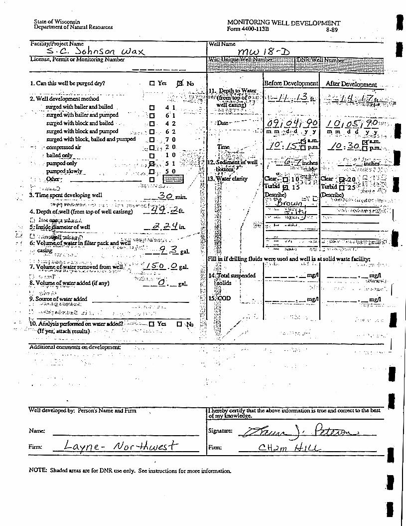
Slate of Wisconsin Dcpanment of Natural Resources
MONITORING WELL DEVELOPMENT Form 4400-113B 8-89 I
Facility/Project Name
S-C. ~6hnso11 wa.x... License. Permit or Monitoring Number
_8. Volume o[ ~atcr-addcd (if any) .•• ,•. -··. 'I,~ .... 'T ' .. ,-~.-. '
9. Source of Wala' added
.' '• .·.:. '·.;. •· ,,
tio. ~fsispcrfonricdon wat.cradded7' :.:.,.'.:._. □ Yes · -:·· · (lfycs;•attachrcsults)- - - - · · '· - ,., ·. -.
··._·-..
: - • t, •-·
I ;-..,-.,
Additional comm.ents on development: ·••·•·I
- .... ~ .
,·.
I ~~~--~--.-.--,---.,--....,..--,-,,--.....--.---,---,-:-- I
ell developed by: Person's ame and Furn 1 hereby~ that the above information is true and correct to the best of mv knowlca c. · -
Signature: ~4--:J I . Pm&h-> _Finn:_· __ L_o....;...y_n_e._-_!U_o_r_-M_w_es._+-__ __,__Fmn:_· ____ c._H_d_m_H_r_U: ______ I NainC:
NOTE: Shaded areas arc for DNR use only. See insn-uctions for more information.
.I I

I State of Wisconsin D.:pa.-tmcnt of Narur:ll Resourc.-:s
MONITORING WElL CONSTRUCTION Form 4400-113A 8-89
ell Wat.er Table Observation Well II uon uon
•_,..----,.,.,..,.,........---.-...--_.,,--..--_.;;;□;;;..12--' NW 1/4 of NE 1/4 of Section ;;z_;;:z undaI)' T .::2..__N, R ,,;?.;J... fJ.E □ W
----..---..~;:;.,;;;.....;..:....;.;..;:.;;-,;;..;.,.;.....,.--,-;f.,,.t.-f tion o ell Relative to Waste/Sou~ □ Upgr:wjicm □ Sidegnidicnl
D Yes N> 0 Downgraclient ot Not Known
12. uses classification of soil near screen:
0 GP □ GM l25GC OGN SSW □ SP DSM □ sc l!lML D MH El ci □ OI □ Bcaod: .
13. Sieve '1talysis attached? □ Yes §N> worv... Plan Cl.l)~roJtd. rr-, 0-< -to Feh, 1 a 4. Drill.mg methdd used: Rotziy .5 0
Hollow Stem Auger Ja. 4 1
Odxr □ ;;.g;.;;
15. Drilling fluid used:Watcr □ 0 2 Drilling Mud □ o 3
Afr D 01 Nooe 0' 99
:::J. 6. Drilling additives used? □ Yes
Desaibe _____________ _
17. Source of water (attach analysis):
, I Bcntonite seal, top ______ ft. MSL or __ l _ Q
F. Fine sand, top ft. MSLor
-. Ftlter pack. top ____ ·- ft. MSL or __ L .5
1- Well saecn. top ______ ft. MSL or_-~ .Q
I. Well screen. bo11om ______ ft. MSL or_ J. 2..9.
I Filter pack, bottom ______ ft. MSL or_ l ~Q_
It Borehole. bottom
I Borehole. diameter
,. 0.D. well casing
N. LD. well casing
_ _ _ _ __ ft. MSL or _ l ~-Q
_<J__Q in.
~3i --.- - in.
_?~LJ. in.
d. Additional protection?
_(c;..Q in. _':J.QfL
Steel J3 04
Otha o E@ □ Yes ,m_ N> Uycs.dcsaibe: ________ _
3. Surface seal: Bcntonite O 3 O Conacte ~ 0 1
Otha D tt:=,r -------------- ~:~ 4. Material between well casing and protective pipe:
lkntonite J3:. 3 0 Annular space seal D
------------- Otha- D Ii@ 5. Annular space seal: Granular Bcntonite 13 33 __ Lbs/gal mud weight ••• lknton.ite-sand shmy D
__ Lbs/gal mud weight. • • • • Bentonitc sluny D 3 I __ 9o Bentonitc • • • • • Bcntonite<ement grout D 5 O
0 • I & Ft 3 volume added for any of the above
35
How installed: Tranie O o 1 Trcmie pumped D o 2
Gravity J.il o 8
6. Bentonite seal: Bentonitc granules D 3 3
□ 1/4 in. 03/8 in. 01/1. in. Bentonitc pellets D 3 2 Alo oe- 01bcr pr rn&
7. Fme sand material: Manufa.crurer, product name and mesh size
Alooe.-vo1ume added ______ ft3
8. Filtcrpack material: Mmufac:turcr. product name and mesh s~
Amu ; , a " Oh+~ r .-a.1. s - • t./s:- -ss-vo1ume addcd 3-35" it3
9. Well casing: Flush threaded PVC schedule 40 O 2 3
Flush threaded PVC schedule 80 O 2 4
~-+a.~("\ tas<;, s+--r ~ l ::Sch . s: O!lxr s MS 10. Saccn material: _...,$==-;a..=.:.m&.:..=-· _____ _
Saccntype: Factory cut □ 1 1 Continuous slot .0 O 1
_____________ Other D MB Manufacturer /±a 1 µ <>- '<" c\. ? ro i +b Slot size: Slotted length:
11. Baclcfill material (below filter pack):
0.QLQin. lQ.. QfL
Nooe ra Other D
that the information on this form is true and correct to the best of m e. inn
~ K.i.m I+/ LL -case complete and return th sides o this orm as required by chs. 144, 14 and 1 is. tats~ and ch. 141. is. Adm. ode. accordance with - 144, Wis Sta1.s., failure to file this form may result in a forfeiture of not less than Sl0, nor more than S5,000 for each day of violation. In accordance
••• :,,._ ,..1, 1 A7 W:r <:',....... r ... :1 ... ,.._ ,_ r.1 ... •"-:- , ___ -•• ---••1• :_ ... '--'-=-•-... _, _.,.,. __ _,.., •"-- «-1 n l\."'V'\ r __ ---L ...1 ..... _,. •• :_,_..,: __

Stale of Wisconsin Department of Narural Resources
Facility/Project Name
~ · C · :::::iohr1so11 w~ X. License, Permit or Monitoring Nwnbcr
1. Can this well be purged dry?
2. Well development method
surged with bailer and bailed
surged with bailer and pumped
surged with bloclc and bailed
surged with block and pumped
surged with block, bailed and pumped·
com)RSSCd air bailed only pumped only pumped slowly
Other
3. Time spent developing well
4. Depth of well (from top of well casisng)
5. Inside diameter of well
6. Volume of water in filter pack md well casing
7. Volwneofwaterrcmoved from well
8. Volume of wata added (if any)
9. Source of water added
10. Analysis performed on w au:r added? (If yes, attach results)
Additional comments on development:
ell developed by: Person's ame and Furn
Name:
Finn:
□ Yes Ja N>
□ 4 1 □ 6 1 □ 4 2 □ 6 2 □ 7 0 □ 2 0 _a 1 0
□ 5 1 □ 5 0 □ ,.=:ttt/1
_.1_~0 min.
_.!_S: . l_ fL
--~-Lgat
_5-o.0 8at
__ O._gat.
□ Yes □ N>
MONITORING WELL DEVELOPMENT Form 4400-113B 8-89
Well Name
mwao -s
Before Development After Development 11. Depth IO Water
(from top of well casing)
Date
Tune
12. Sediment in we!! . . bottom
13. Waur clarity
__ .!i.oZrt.
~g /;;). 3 I 2_ {) mm d d y y
O 1:: 0 .3 g ~.:_LL . .;? inches:
Ca' □ 10 uibid )21- 15
)
.£rDvJ'I, Si 11:j
S- I 7 ___ • __ [L
_f_Q_/ os:, '70 mm d d y y
I I · I O ra::a.m. --•--□ p.m.
__ ._inches
Clar ,S. 20 Tumid □ 25
1,.UC=ilDC),
Fill in if drilling fluids were used and well is at solid waste facility:
14. Total suspended ____ • _ mg/1 ____ • _ mg/1
solids
15.COD ____ ._mg/1 ____ ._mg/1
I hereby catify that the above informwon is true and correct to the best of m , blowled e.
Signature: ~~✓d4=-;) · ~ Furn: Clidlrn NtLL
NOTE: Shaded areas arc for DNR use only. See instructions for more information.
I I I
I I
I
.-1
I I
I I I
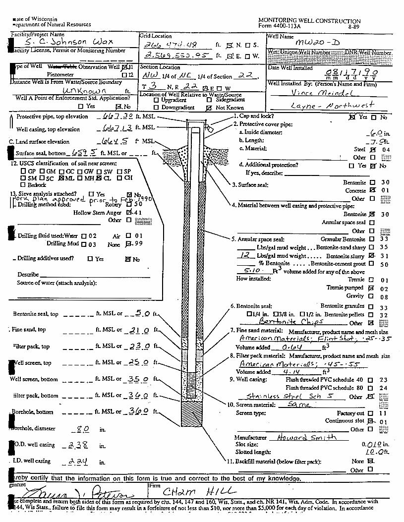
aatc of Wisconsin •~pa.'1mcnt of Natural Rcsour<:.!s
facility/Project Name rid Location
MONITORING WELL CONSTRUCTION Form 44()().) 13A 8-89
!well Name , ~. C.. ~oh ,,son Cua;<-
cense. Permit or Monitoring umber olb(p '-!rd. l/9. ft. _S: N. O s. oZ. SlP S: ,_;;.;; .::i • 9 S- ft. ,Et E. O W.
tYIWolO -b
Surface seal. bottom_ U ~1 .~ ft MSL or __ • _
12 USCS classification of soil near saeen:
0 GP □ GM DOC OGN □ SW □ SP □ SM □ sc .NML □ MHSa. om □ 1kdrod:: .
ln. Sieve analysis attached? □ Yes ~ N,
I or~ {) l&\1'\ ~Oro-Jed. .or; or -Kl . / ~90 Drilling method Med: r Roll!I)' S 0
Hollow Stem Auger 13-41
Other □ t.r:::1:2
,. Drilling fluid used:Watcr □ 0 2
Drilling Mud □ 0 3
_ Drilling additives used? □ Yes
-.;;·.········,;..:
Air □ 01 Nooe JiJ- 99
BNJ
Dcsai~------------Source of water (attach analysis):
3cntonite seal. top
·• Fme sand. top
=iltcr pack, top
rell saccn. top
Well screen. bottom
ilorchole. bottom
lorcholc, diameter
,.D. well casing
. LD. well casing
______ ft. MSLor _,3~ .Q
____ ·-ft. MSLor _-:2-:? .9 f
______ ft. MSLor _J{p_9
_;K,Q. in.
_J-_.3i in.
-~-~<{ in.
d. Additional rrotection?
Yes □ N>
IO. _'J!:'. - m. _ ""J. 9ft
Steel .0 04
Other □ &Wi □ Yes _a' N,
Ifycs.dcscribc: -----------Bentonite □ 3 0 Conaete 3' 0 l
____________ Other □ IB@ 4. Material between well casing and protective pipe:
3. Surface seal:
Bcntonite Ji§' 3 0
Annular Sp:ICC seal 0 ______________ Other □ nrr
Granular lkntonite □ ff 5. Annular space SC3l: __ Lbs/gal mud weight ••• lkntonitc-smd shmy D 3 5
../L Lbs/gal mud weight • • • • • Bcntonite sluny 13- 3 l __ % Bentonitc • • • • • Bcntonite-ccmenl grout D 5 0
5°• IO · R 3 vohune added for any of the above How installed: Tremie O O I
Tranie pwnpcd ~ 0 2
Gravity □ 08
6. Bcntonite seal: · Bcntonite gr.mules D 3 3
□ 1/4 in. 03/8 in. □ 1/l in. Bentonite pellets □ 3 2 &n-h,n,·-k C\, ifs Other 18 WE
7. Fme sand material: Manufacturer. JXOOl)Ct name and mesh size A-mu- i ca"' ma. +tr i a..( s: • F /; rr+- S~cri' ·• · cir- · 3 S
Volume added O, (p Y ' tt3 '
8. Ftlter pa.ck ma.tcria.l: Manufacturer. product name and mesh siz.c
Arrur; (""" r'l'.]o+a .-Q{l~ ; , C/ S- · S"S Volume added 4 • II/ ' ft3
9. Well ca.sing: Rush threaded PVC schedule 40 □ 2 3
Rush threaded PVC schedule 80 □ 2 4
:5-l-..._ ~ n Lt s s s+e el Sch s Otha ,Er M® 10. Sa-ccn material: :?3 QJL · ill@
Sa-ccn type: Factory cut □ 1 1 Continuous slot ,.S- 0 1
_____ __,.. ________ Other D filf@ Manufacturer No ,»ard. ~ra; +h. Slot size: Slotted length:
11. Backfill ma tcrial (below filter pl!Ck}:
0.01 Qin. LQ.QCt.
None B. Other □
that the information on this form is true and correct to the best of m

State of Wisconsin Department of Natural Resources
Facility/Project Name
S. C · ~ohnSol\... License, Pennit or Monitoring Nwnbcr
1. Can this well be purged dry?
2. Well development method
surged with bailer and bailed
surged with bailer and pumped surged with block and bailed surged with block and pumped surged with block, bailed and pumped compressed air bailed only
pumped only pumped slowly
Otha
3. Tune spent developing well
4. Depth of well (from top of well casisng)
5. Inside diameter of well
6. Volume of water in filter pack and well casing
7. Volwne of water removed from well
8. Volume of water added (if any)
9. Source of water added
10. Analysis performed on water added? (If yes, attach results)
Additional comments on developmcll:
ell developed by: Person's Name and Furn
Name::
Finn:
~Yes □ Nl
0 4 1 a 6 1 a 4 2 a 6 2
□ 7 0 □ 2 0 a 1 o Ji1 5 1 □ 5 0 a 1:;:=c;;:1
-~Qrnin.
_3_7 .& fL
- .a-. ~ !l. in.
__ f{.."2_gal.
_!:l.a. -0 gal.
__ Q._gal.
□ Yes □ Nl
MONITORING WELL DEVELOPMENT Form 4400-113B 8-89
Well Name mw~o-D
11. Depth to Water (from top of well casing)
Tune
12. Sediment in we~ .. bottom
13. Water clarity
Before Development After Development
I g I Ct. ---·--
O'l I c). 31 .:}_ mm dd yy
sa.m. O:l_: oz_0 p.m
_ Ji.. '7 inches
Clear □ 10 mbid _13 15
ibe)
!Jrow(J,
--d-ilfL
..LlYt C>S-1.:zO m m d d y y
/0.3o 13 a.m. __ . __ Qp.m.
__ ._inches
Clear 3. 20 Tumid □ 25
r,.,v,...-. ...... ) ..
Fill in i[ drilling fluids were used and well is at solid waste facility:
lA.To<alsuspendcd ____ ._mg/1 ____ ._mg/1
solids
15. COD ____ ._mg/1 _____ ._mg/1
I hereby catifv that the above infornwion is nue and correct to the best of mv mowleii c.
Signanue: ~L{;L, . ~ Fum: CH,;im 1-1-tLL-
NOTE: Shaded areas arc for DNR use only. Sec instructions for more infonna.tion.
I
I
I I
I
I
I I I

State of Wisconsin D.::pa.-uncnt of Naniral Resourc:.:s
Facility/Project ame
=:, ·C. 2)uh nS011 l<.)a ,<. rid Location
~(p5", 3'/2,.!:;! acility cense.. Permit or Monitoring umber
D. Surface seal. bottom_ {t,J .;>.$" fL MSL or __ • _
12. uses classification of soil neu sacen:
0 GP □ GM OGC OCNI O SW OSP □ SM □ SC IZrML □ MH IS a. □ al □ Bcrlnxx .
13. s,eve analysis attached? D Yes ~ Won"- flof\ c>-f P.fO../e.J. D<,or: -lo f-~ .J99
14. Drilling method usea: ~ Rotmy 5 o Hollow Stem Auger .81 4 l
Othcr □ f$.'.Q::J
15. Drilling fluid used:Water □ 0 2 Drilling Mud □ o 3
Air □ 01 Nooe;;! 99
16. Drilling additives used? □ Yes .181 NJ
Dcsai~------------17. Source of water (anach analysis):
3. Bentonite seal, top
F. Fine sand. top
s. Falter pack. top
,- Well saeen. top
I. Well screen, bottom
ft. MSLor
______ ft.MSLor __ 3.g
______ ft. MSLor _ JJ_Q
Filter paclc. bottom ______ fL MSL or_ J ~ .Q
K. Borehole, bottom ______ ft. MSL or _ j ~ . Q
- Borehole, diameter - '[ _Q_ in. r· O.D. well casing _,2-}.~ in.
N. LO. well casing _c3_~t{_ in.
MONITORING WELL CONSTRUCTION Fonn 4400- l 13A 8-89
fL ,13 N. o s. ft. Ja_E. □ W.
d. Additional potoction?
-~- ~in. _7.Q fL
Sled J8. 04 0t1xr □ B@ □ Yes J3- NJ
Ifycs. dc:saibc: -----------
3. Surface seal: Benr.onite □ 3 O Concrete 3 0 t
--------------Other □ llffi 4. Material ~tween well casing and protective pipe:
Bcntonitc J:& 3 0 Annular space seal □
------------- Other □ fi!E 5. Annular space seal: Granular Bcntonite 1iJ 33 __ Lbs/gal mud weight ••• lkntonitc-sand shmy D 3 5
__ Lbs/gal mud weight • • • • • Bentonitc sluny D 3 1 __ 9o Bent~nitc • • • • • Bcntonite-ccment grout D 5 O
a. (J:, y Ft volume added for any of the above How installed: Tremie D 0 I
02. Tmnie pumped □ Gravity .B 08
6. Bcntonitc seal: Bentonitc granules D 3 3 □ 1/4 in. 03/8 in. □ l{l in. Bentonite pellets □ 3 2
Al one_ Other B @2 7. Fme sand material: Manufacturer, poduct name and mesh size
Non~ Volume addcd ______ ft3
8. Fil tu pack mllerial: Manufacturer, product name and mesh size A-mu-, a:tY\ N'b_+, r; al s: •, , t/S- · S" s
Volume added 3 • !>" I rft3 9. Well cuing: Aush threaded PVC schedule 40 □ 2 3
Aush threaded PVC schedule 80 □ 2 4
~+oo.~ l'lles.s s+ul ScJ, S- Other ~ ill§ 10. Screen material: .:Sa.mt_ L@
Screen type: Factory cut □ 1 1 Continuous slot .EJ.. O 1
______________ Other □ ff@ H-owar-<l sea•-+\ Manufacturer
Slot size: Slotted length:
11. Baclcfill llllltcrial (below filter pack):
0.O.!9in. JQ.Q. ft.
None,.elOlhcr □
that the information on this form is true and correct to the best of m
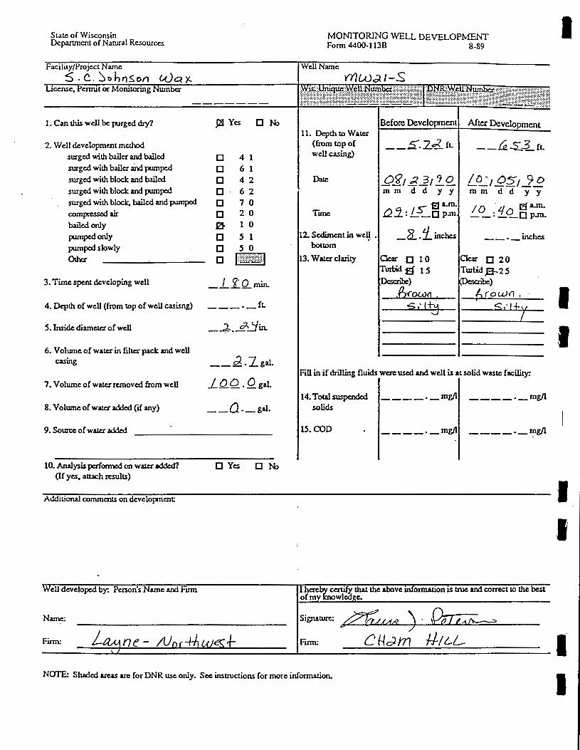
Stale of Wisconsin Department of Natural Resour=
Facili1y/Projec1 Name
S . C.. ~-o hnso11 l-Ua )(. License, Pennit or Monitoring umber
1. Can !his well be purged dry?
2. Well development method surged with bailer and bailed
surged with bailer and pumped surged with block and bailed
· surged with bloclc and pumped surged with block. bailed and pumped compressed air
bailed only pumped only pumped slowly
Other
3. Time spent developing well
4. Depth of well (from top of well casisng)
5. Inside diarneta of well
6. Volume of water in filter pack and well casing
7. Volume of water removed from well
8. Volume of Wat.er added (if any)
9. Sourceofwata added
10. Analysis performed on Wat.er added? (If ya, attach results)
Additional comments on development:
Well developed by: Person's Name and Furn
Name:
p!1 Yes □ l'b
□ 4 1 □ 6 1 □ 4 2 □ 6 2 □ 7 0 □ 2 0 0 10
□ 5 1 □ 5 0 a j:tt:lS!
- .L :l.. Q_ min.
___ ._fL
__ d-.2gal.
j_{) 0. 0 gal.
__ Q._gal.
□ Yes □ l'b
MONITORING WELL DEVELOP.MB'iT Form 4400-113B 8-89
Well Name
11. Depth to Water (from top of well casing)
Tune
12. Sediment in we~ .• bottom
13. Wat.er clarity
Before Development After Development
__ s.2~ ft.
_t;>~, ::?21 J_ 0 mm dd yy
EJa.m. .Q_i: 1.s.=_ □ pm
_3._.{inches
Clear □ 10 urbid S 15
)
.8-cowri p
I D...:_1 D51 _2 o mm d d y y
I (2_ i 4 Q_ g ;,-:-. __ ._inches
Clear □ 20 Turbid .B--2 5
,_..,.._.,...,..,,.,) p (OW{) I
Fill in if drilling fluids wen: used and well is at solid waste facility:
14. Total suspended ____ • _ mg/1 ____ ._mg/I
solids
15. COD ____ ._mg/1 ____ ._mg/I
hereby catify lhat the above · onnation is true and correct to the best of m • mowled e.
Signature: /2b,t.{AA ) . On f.-1.fr=::2
I
I I
I I
Firm: L Furn: C'Hd)tn -/+/LL- ,-_ _.....,_ ___ --L-_____ _ ne - /lJ
NOfE: Shaded areas are for DNR use only. Soc instIUctions for more information. I

Stale of Wisconsin D.::panmcnt of Natural Resources
Facility/Project ame
-=---L-=....::._.:_;_ __ _ ft. s· N. □ S.
MONITORING WELL CONSTRUCTION Form 4400-l l3A 8-89
I 5 -C. ~ohn.Son Way.._ Facility cense. amit or Moniroring umber
~....::....;...J.+-::.=~L,.J...- ft. tCk E. O W.
ypc o ell \I I •• IPable Observation Well :1a 11 Piezornetcr O 12
A. Protective pipe. top elevation
B. Well casing. top elevation - ~.:ZC! .l'l. fL MSL--.......u~
C. Land surfac.c elevation .fp_LL ~ r MSL ,•; ,,,._ -
D. Surface seal. bottom _ _;i-"'_J_-:_;:i fl MSL or __ • _
12 USCS classification of soil near saecn:
□ GP □ GM ESGC OGW MSW 0SP □ SM □ SC SML □ MH □ a. □ ClI □ Bcaod:: .
13. Sleve anal~is atbched7 D Yes J3-N> Won, plo.t\ otP!)ro~,.ci pcioc -h ~.h•J<¼7
14. Drilling method used: Rotl!r)' □ :, o Hollow Stern Auger Jiil 4 1
Other □~-:
I 15. Drilling fluid uscd:Watcr {zt.02
Drilling Mud □ 03 Air □ 01
Nooe □ 99
16. Drilling additives used? □ Yes
Dcsaibc _____________ _
17. Source of water (attach analysis):
6 s:+e c.-+ oi:_! Roc:f'e__
E. Bcnronite seal, !Op
F. Fine sand, top
G. Ftltcr pack. top
,,H. Well saecn, top ____ ·-ft. MSLor _ ~.S.Q
I. Well screen., bottom ____ ·- ft. MSL or_~ 5.'!J
J. Filrcrpaclc. bottom ____ ·-ft. MSL or_ ':J. y _!}
K. Borehole. bottom
IL Borehole. diameter
IM. O.D. well casing
N. I.D. well casing
____ ·- ft.MSLor -~!P . .Q ft.~
_HQ n ~=~
-~~~ in.
_ d.~i in.
d. Addition.al irotoction?
-~-°- in. _7.Q. fL ·
Sitt! E 04 Other □ IT@ □ Yes lS N>
Ifycs. desailx:: -----------
3. Surface sc.aJ: Bcntonitc □ 3 0 Conactc ..3 0 1
______________ Other O mm 4. Ma.tcrial between well casing and protective pipe:
Bcntonitc .B 3 0 Annular space seal D
-------------- Other □ ;su 5. Annular space seal: Granular Bentonitc D 3 3
__ Lbs/gal mud weight ••• lkntonite-sand slurry □ 3 5 __ Lbs/gal mud weight. • • • • Bcntonitc sluny H 3 1
-1d,._ % Bentonitc . • • • • Bcntonite<emcnt grout □ 5 O S? · '} .;J.. Ft
3 volume added for any of the above
How installed: Trcrnic □ O I Trcmie pumped. ,S- 0 2
Gravity □ 08
6. Bcnronite seal: Bcntonite granules □ 3 3
□ 1/4 in. 03/8 in. □ 1/2 in. Bcnronite pellets □ 3 2
& ""'±oo ; -6: C \, : .p s: Other .a. ills 7. Fine sand material: Manufa.cturcr, product name and mesh size
IJ D 11 e.. Volume added ______ ft3
8. Fil ta pack m11erial: Manufacturer, product name and mesh size
A (}'\J.' i cat\ rflo..f ,u :al 5. ', • t/.S-- • S'S Volume added 4, '\/ ' ft3
9. Well casing: Flush threaded PVC schedule 40 □ 23
Flush threaded PVC schedule 80 □ 2 4
5+o.·,nLt.ss Sf.Nl Sci,· 5"" Other ..B' m@ IO. Screen material: --~""Q._CT½:L.:..::;;;;.... _____ _ Elli
Saccntypc: Factory cut □ I I Continuous slot ,B o t
______________ Other □ ff@ Manufacturer bl-a11lor-d S.rn ,-+~ Slot size: Slotted length:
11. Backfill material (below filter pad:):
0. '7.! ~ in. LQJ]fL
Nooe _a.
Other □ that the information on this form is true and correct to the best of m
irm
CHo<m lease complete and re both sides o this orm as required by chs. 144. 14 and l 1s. tats~ and ch. 141, as. Adm. ode. accordance wilh h. 144, Wis Suts., failure to ftle this form may result in a forfeiture of not less than Sl0. nor more than S5,000 for each day of violation. In aocordancc
... ;,.._ ,..1, 1 A7 w;. c;:i........ ,_:1 .. - •- r.1 .... L:- , __ --••-... ~ .. I•:_ - r-J.,.:-•-- _, _,.., _,..._..,. ,.._..,_ <"1 n (\lV\ r,..., .,. ... ,..L ..a ..... _, •• : .... , .... : .... _

State of Wisconsin Department of Natural Resources
Facility/Project Name
S • C . .Jnhnsot1 w C-? x LiCC1Se, Permit or Monitoring wnber
1. Can this well be purged dry?
2. Well development method
surged with bailer and bailed
surged with bailer and pumped surged with block and bailed
surged with block and pumped surged with block, bailed and pumped
· compressed air
bailed only
pumped only
pumped slowly
Otha
3. Time spent developing well
4. Depth of well (from top of well casisng)
5. Inside diameter of well
6. Volume of water in fillet" pack and well casing
7. Volume of water removed from well
)& Yes □ Nl
□ 4 1 □ 6 1 □ 4 2 □ 6 2 □ 7 0 □ 2 0 □ 1 0 J! 5 1 □ 5 0
□ i=iilidffa!
I d- CJ • ____ nun.
___ ._fL
- J_ Q_ . .3 gal.
_L ~ Q. . D.. gal
MONITORING WELL DEVELOPMENT Form 4400-113B 8-89
Well Name Y()Wdl-L\
Before Development After Development 11. Depth to Water
3Ca7ft. (from top of __ ::3_.7ci_fL ---·--well casing)
Date O'i1c) 31:zO J_c:..:.,os 1.J6 mm d d y y mm .d d y y
Tune )e!•·m.
.LQ..: OQ..crp.m 00 ga.m . J.J_. __ p.m.
2. Sediment in we~. . _ 2. 1- inches __ ._inches bottom
13. W aur clarity Ocar □ 10 Clear ~o Uibidµt.15 Tumid □ 25
) )
brow a, ~1·/~
Fill in if drilling fluids wc:rc used and well is at solid waste facility:
14. Totalsuspcndod ____ • _mg/1 ____ ._mg/1
8. Volume of water added (if any) L Q_ 0 . .Q. gal. solids
9.Sourccofwateraddcd OQ $ ~ k le~½ 0~ ew:ne... 15.COD ____ ._mg/1 ____ ._mg/1 7
10. Analysispafonncdon Wala" added? (If yes, attach results)
~Yes □ N>
I
I
I
~-~---------1' Additional commcnts on development:
I
ell developed by: Person's arne and Firm
Name:
I hereby catify that the above information is true and correct to the best of mv bowled c.
1 signarurc: c:2fuua :J · fkrRAl2r\Firm: e. - .AJor+h Furn: Cl-(;im -/JILL
NOTE: Shaded areas arc for DNR use only. Sec instructions for more informa.tion.
·1

State of Wisconsin D.:panmcnt of Natural Resour~s
Facility/Project Name
MONITORING WELL CONSTRUCTION Form 4400-113A 8-89
5 . C. ~oh. r,f:.cil', IA)a x. Facility 1cense, Permit or Monitoring umber
;;J[.q 3 to88, 9 (e [L ,Et N. D s. -=-'-=-..::::_4-1~~_,_,__,'-- ft . .)!t--E. D W.
ell WJ& "FRle Observation Well .E"ll Piezometcr O 12
m aste/Sourcc Boundary
l,lYl;(nowY\. ft. orcement Std. Application
A. Protective pipe. top elevation
E. Well casing, top elevation
C. Land surface elevation _ U2 2 .L r MSL I D. Surface seal. bottom_ YJ ~.L fL MSL or __ • _
12. USCS classifJCation of soil ncu saccn:
I O GP □ GM OGC □ ml □ SW fr!fSP □ SM □ SC □ML □ MH □ a. □ 0I D Bcdrodc .
13. Sieve analysis attached? D Yes bl-b Wor-1._ p/od\ ~rovQcl pr;or +o Fr2 • 1'190
14. Drilling method used: Rotzry 5 0
Hollow Stan Auger El 4 1
I 15. Drilling fluid used:Wata' El 0 2
.Drilling Mud □ 0 3
16. Drilling additives used?
Or'\ s ;.\-
IE. Bentonite seal, top
F. Fine smd. top
:.. Fut.er pack. top
□ Yes
Olha □ hss§~
Ne □ 01 Nooe □ 99
-t Well saeen. top ______ ft. MSL or _J.~ .Q
I. Well screen, bottom ______ ft. MSLor _-,2~ .Q
- Filter pack. bottom :... · ___ ·- fL MSL or-~ 1 .Q.
~- Borehole, bottom
l Boreoole. diameter in.
f · 0.0. well casing _ ~. i ~ in.
N. LD. well casing _ ~. ?:- 1 in.
d. Additional p-otection?
12J Yes □ N>
_(:zD_in.
_7- .Q fL Steel 19, 04
Otha- □ sS □ Yes,tB:"?-b
Hycs,dcscribc: __________ _
3. Surface seal: Bentonitc □ 3 0 Conacte PJ- 0 1
___________ Otha- □ fil@ 4. Material between well casing and protective pipe:
Bcntonitc ):( 3 0 Annular space seal D
------------- Olha □ iss 5. Annular space seal: Granular Bcntonitc □ 33 __ Lbs/gal mud weight ••• Bcntonitc-sand shmy D
__J._a_ Lbs/gal mud weight • • • • • Bentonitc sh.1ny Ji!- 3 1 __ % Bcnt~nite • • • • • Bentonitc-ccmcnt grout D 5 O
,;J • ti g Ft volume added for any of the above
35
How installed: Tranie D 0 1
Trame pumped_ ,El o 2
Gravity □ 08
6. Bcntonitc seal: Bentonitc granules D 3 3
□ 1/4 in. 03/8 in. □ 1/1. in. Bentonite pellets □ 3 2 &zn\:oo,k C'n;~s Otha fir HH
7. Fine sand material: Manufacturer. product name and mesh size Am(r; mo rc\:,.-\-(!r-: oJc ·, E:J:a~ sho+·. ,.J~- ,35""
Volume added O • 17 ' rt3 r .
8. Filter pack material: Mmufacturcr. product name and mesh size
ar'Yl.lr;eo'(l ffiq-\-i,r:aO ~ · .. t./s - · SS" Volume added ;i • IS"' ' Ct3
9. Wcllcasing: AushthrcadcdPVCschedule 40 □ 23
Aush threaded PVC schedule 80 □ 2 4
s-w.·,n~~s S±P d S"ch. s- Otha ~ Mill 10. Screen material: Sa ~ ill@
Screen type: Factory cut □ 1 1 Continuous slot a O 1
______________ Other D fa@ Manufacturer .th,11) g c sl ~CO; -1-h Slot size: Slotted length:
11. Backfill material (below filter pack):
0. -" .L Q in. _/Q.Qft.
Nooe ,BOlha D
that the information on this form is true and correct to the best of m

State of Wisconsin Department of Naniral Resources
Facility/Project Name
S • C. . .J-o h n so fl W a x License, Pennit or Monitoring Number
1. Can this well be purged dry?
2. Well development method
surged with bailer and bailed
surged with bailer and pumped
surged with block and bailed
surged with block and pumped
surged with block, bailed and pumped
comJRSSed air bailed only
pumped only
pumped slowly
Olher
3. Time spent developing well
4. Depth of well (from 10p of well casisng)
5. Inside diameter of well
6. Volume of water in filter pack and well casing
7. Volurneofwaterrcmovcd from well
8. Volume of water added (if any)
□ Yes _a: N>
□ 4 1 □ 6 1 □ 4 2 □ 6 2 □ 7 0 □ 2 0 □ 1 0 tzJ. 5 1 □ 5 0
□ !LJ:ZJ
_3'.. OQ_min.
_3_'-1_.5 fL
__ ,&..~gal
.:2..Q {l. 0 gal
_E:Q_ . .Qgal.
9.Sourccofwateradded Q a 5; i! )C!..-1:j 0~ ~a.C.~()€_ 7
10. Analysis performed on Water added? (If yes, au:ich results)
Additional comments on development:
ell developed by: Person's Name and Furn
Name:
Firm: L
jll-Ses □ N>
MONITORING WELL DEVELOPtvfENT Form 4400-113B 8-89
11. Depth to Water (from top of well casing)
Date
Tune
12. Sediment in we~ . bottom
13. Water clarit)'.
Before Development After Development
___ • __ ft.
0 .:11 ,;?. 31 _2_1) mm d d y y
~a.m. .t22...: o.5" □ p.m
-~ ...3.. inches
Clear □ 10 TUibid~ 15 Describe)
!, rown,
j_ 0- I 05°1 JO m m d d y y
I □ a.m • 0 .1....=3.Ls p.m.
__ ._inches
Clear Jil" 2 0
Turbid □ 25 ~...,,_ ............. )
Fill in if drilling fluids were used and wdl is at solid waste facility:
14. Total suspended solids
15.COD
____ ._mg/1 ____ ._mg/I
____ ._mg/1 . ____ ._mg/I
l hacbv certify that the above information is true and correct to the best of mv mowlro e.
Signarure:
Fmn:
NOTE: Shaded areas are for DNR use only. See instructions for more information.
I
I
I
I I I

I I
I
MKE10014F8B.WP5/2
ATTACHMENT B CH2M HILL SOIL BORING LOGS FOR
ALL WELLS INSTALLED PRIOR TO REQllREMENT OF FORM 4400-122

I
I
PROJECT NUMBER
GL015698Jl.4A I BORING NUMBER
RFI-26 SHEET
SOIL BORING LOG
OF
PROJECT S.C. Johnson LOCATION RFI-26 (in Front ofBldg. 63)
4
ELEVATION __ -6.::..7"""9 _______________ DRILLING CONTRACTOR_=La=yn"'-'-'-e-.;;..N....co.c...rth....cw-----'es-'-t __________ _
DRILLING METHOD AND EQUIPMENT Mobile B-57 Rig; 4 1/4" HSA; 140-lb. Automatic Hammer WATER LEVEL AND DATE START 8-8-90 FINISH 8-9-90 LOGGER L Peterson · _ ___;;_...;.c,c.=.;:;..:__
SAMPLE STANDARD SOIL DESCRIPTION COMMENTS
~ E" PENETRATION
fi: TEST
Ww _, w RESULTS SOIL NAME, USCSGROUP SYMBOL, COLOR, DEPTHOFCASING,DRILLINGRATE, mu ~ ffi ~ ~ MOISTURECONTENT,RELATIVEDENSITY DRILLING FLUID LOSS, :I: rt a: 0 6"-6"-o' OR CONSISTENCY, SOIL STRUCTURE, TESTS AND INSTRUMENTATION I- a: ~ ::;; 0 @1z fh:::, :::>z (N) MINERALOGY 0 fJ) 2:; Z< a: -
HNu Bkgd = 0 ppm
- A 0.8 5-5-4-3 fill! (ML). Some sand. Bl.a.de. Slightly moisL Some - HNu=0ppm t= 1550 -roots in upper inch. Some pinkish-brown clay in tip.
2 - -- B - No recovery. - -
4 - -
5- C 1.7 3-4-5-6 Sandy Silt (ML). Dark grey to bl.a.de. Slightly moisL - HNu=0ppm t= 1601 SofL Some gravel. -
6 Cayey fill! (ML). Lt. grey. MoisL Stiff. Some - -gravel. Some orange mottling.
- D 2 4-6-10-17 As above. Some sand - Till -HNu=0.lppm t=l618
8 - -- E 1.5 6-7-7-8 As above. No visible sand. Very stiff. - HNu = 0.1 ppm t = 1626 -
1n ~o - -- F 1.7 - Shelby Tube ukm at 10'-12'. -
12 - -- G 1.7 3-5-7-10 As above (ML). - HNu =0ppm t= 1650 -
14 - -
15-- H l 2-4-4-7 As above. Some bl.a.ck silt mixed in. Rode fractures - HNu = 0 ppm t = 1654 - End drilling in tip of spoon. -
n6 - -
- I 1.7 9-12-11-9 As above. 2" sand seam 0.5 fL from tip of spoon - - 8-8-90. 0739 - Resume drilling. -wet. loose, fine to medium. (Y./ater flowed out of spoon.) 18 - HNu =0ppm t = 0750 -
- J 1.3 6-9-8-7 Sandy Silt (ML). Grey. WcL Med. stiff-stiff. Trace - HNu =0ppm t = 0802 -clay. Some gravel.
2v 20 Poorly-graded fine Sand (SP-SM). Some silL Loose. WeL -
K 1.5 7-12-23-30 - -Oayey Silt (ML). Grey. WeL Firm. Dk. orange rock HNu =0ppm t=0814
22 fragments in last 6". Largest is l '/4" and rounded. - -
- L 2 5-16-22-24 As above. No rode fragments. - -
124 Poorly-graded, fine Sand (SP-SM). Some silt. Brown- - HNu =0ppm t = 0827 -grey. Dense. WeL
25- M 2 8-19-45-43 As above. Very dense. A 3" clayey silt seam about 10" _ HNu = 0.1 ppm t = 0839 from top of spoon. -
126 - -
- N 2 47-67-77-57 As above (SP-SM). About 8"' from top of spoon grades _ HNu=0ppm t=0919 -into a sandy silt (ML-SM). Very stiff-hard. Grey. Trace
128 gravel. Trace clay. Wet. - -
- 0 1.7 19-16-10-11 As above (SM). Siltier. Medium-dense. Last 2'" has - HN u = 0 ppm t = 1002 -trace of clay.
30 30

PROJECT NUMBER
GL015698.Jl.4A I BORING NUMBER
RFI-26 SHEET 2 OF
SOIL BORING LOG
PROJECT S.C. Johnson LOCATION RFl-26 (in Front ofBldg. 63)
4
ELEVATION __ -6_7 __ 9 _______________ DRILLING CONTRACTOR._"'""La_yn"""'-e-"-N.;.;o=rth=-w_es'-t __________ _
DRILLING METHOD AND EQUIPMENT Mobile B-57 Rig; 4 1/4'' HSA; 140-lb. Automatic Hammer WATER LEVEL AND DATE START 8-8-90 FINISH 8-9-90 LOGGER L Peterson
SAMPLE STANDARD SOIL DESCRIPTION COMMENTS
~~ PENETRATIOO
~ TEST
-' - SOIL NAME, USCSGROUP SYMBOL, COLOR, DEPTHOFCASING,DRILLING RATE, Ww ~
w RESULTS mo ~~ g! MOISTURECONTENT,RELATIVEDENSTTY DRILLING FLUID LOSS, ~; ffi ~o §~ 6"-o'-o' OR CONSISTENCY, SOIL STRUCTURE, TESTS AND INSTRUMENTATION w ::, (N) MINERALOGY 0 (/) ~ z ::z a:-
HNu Bkgd = 0 ppm
- p 2 9-11-8-9 ~ (SM). Medium. - HNu=0ppm t= 1013 -32 - -
- Q 1.6 4-11-10-16 ~- - HNu=0ppm t= 1047 -34 - -
35- R 2 7-8-9-9 ~- - HNu=0ppm t= 1105 -36 - -
- s 1.7 10-11-14-19 ~- - HNu=0ppm t= 1118 -38 - -
- T 1.9 11-13-18-1S As above. - HNu=0ppm t=ll30 -4~ Im - -
u 1.8 S-S-1S-25 As above. HNu =0ppm t= 1142 -- - -~2 - -
- V 1.7 10-14-24-29 As above. Medium-dense. - HNu=0ppm t= 1157 -44 - -
45- w 2 10-19-20-14 As above. - HNu=0ppm t= 1301 -46 - -
- X 2 9-11-20-28 As above. Bollom foot siltier than upper foot with - HNu=0ppm t= 1321 -trace of clay. 48 - -
- y 2 6-10-10-10 As above. Loose-medium - HNu=0ppm t= 1335 -
5~ )0 - -
- - -- - -
)3 As above (SM). - -- z 2 7-12-17-21 Sandy Silt (ML). MoisL Stiff-very stiff. Some clay. - HNu =0 ppm t = 1350 -Brick-red mottling.
5~ )5 - -
- - -
)7 - -
- AA 2 9-15-22-23 Oayey Silt (ML). Very stiff. Some fine sand. A lot of - Till -gravel. l" sand lense about 2" from tip of spoon. Brick- HNu=0ppm t= 1408
59 red mottling. Very stiff. - -
60
I
I

PROJECT NUMBER
GW15698Jl.4A I BORING NUMBER
RFI-26 SHEET 3 OF
SOIL BORING LOG
PROJECT __ S~.C=·~J_ohns=_on _________________ LOCATION RFI-26 (in Front ofBldg. 63)
4
ELEVATION -679 DRIUING CONTRACTOR~-La~yn_e-_N_o_rth_w_es_t __________ _
DRILLING METHOD AND EOUIPMENT_..:..:M..:..:o:..::b.::il.::..e=cB-=-5:....:.7-=R.::i""g;'-4'-1-'--'/4_"..:..:Hc:.S..:..:A:.c.; .::...14.:..:0:..:-1:.=.b:....:. Ac.::.u::..:to..:..:m=a11..:..:·c-=H"'-amm __ er _______________ _
WATER LEVEL AND DATE START 8-8-90 FINISH 8-9-90 LOGGER L Peterson
SAMPLE STANDARD SOIL DESCRIPTION COMMENTS ~[E
PENETRATIOO
>- TEST -'- SOILNAME,USCSGROUPSYMBOL,COLOR, DEPTHOFCASING.DRILLING RATE, Ww ~
w a: RESULTS mu ~~ ~ MOISTURECONTEITT,RELATIVEDENSITY DRILLING FLUID LOSS, i:!:i'f: a: 0 6"-6"-6" ORCONSISTENCY,SOILSTRUCTURE, TESTS AND INSTRUMENTATION a.. a: ~ :::;; 0 @~ W::> ~ ~~ (N) MINERALOGY 0 (f) a: -
- - -52 - -
- AB 2 10-25-32-31 As above (ML). - Till -HNu=0ppm t= 1443 54 - -
6S- - -
- - -fi7 - -
- AC 2 13-25-41-49 As above. No red mottling. Very stiff. Hard. - HNu =0 ppm t= 1504 -69 - -
70- - -
- - -72 - -
- AD 2 27-45-67-59 As above (ML). - HNu =0ppm t = 1536 -74 - -
75-- - -- 1--------------- .= -
n - -AE 1.3 29-48-77-10 -~Cla~Id_Gm-.Soft. Ve!Y...moist. Tra~~eL~ - Clayey Silt (ML). Grey. Moist. Stiff-very stiff. Some !!Nu= 0 ppm I= 1601 -
~9 gravel. - -
80- - -
- - -
82 - -- AF I - Shelby Tube taken@ 82"-84'. -
84 - -
85--- - -- - -
87 - -
- AG 37-52-39+ No recovery. - Material too hard to finish hammering -the last 10"'.
,9 - -
90
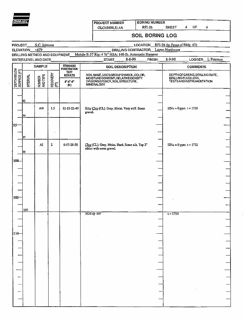
PROJECT NUMBER
GL015698Jl.4A I BORING NUMBER RFI-26 SHEET 4 OF
SOIL BORING LOG
PROJECT S.C. Johnson LOCATION RFI-26 (in Front ofBldg. 63)
4
ELEVATION, __ -6.;;..7;.:.9 ______________ DRILLING CONTRACTOR._.=La;::.yn=e-.:.;N:.::o:..:rth:.:.w;.;.;es=..:....t _________ _
DRILLING METHOD AND EQUIPMENT Mobile B-57 Rig; 4 1/4'' HSA; 140-lb. Automatic Hammer WATER LEVEL AND DATE START 8-8-90 FINISH 8-9-90 LOGGER L Peterson
SAMPLE STANDARD SOIL DESCRIPTION COMMENTS
~~ PENETRATION
?x: TEST _,_
SOIL NAME, USCSGROUP SYMBOL.COLOR, OEPTHOFCASING,DRILLING RATE, Ww ~
w RESULTS al (.) . ffi ~ ~ MOISTURECONTENT;RELATIVEDENSITY DRILLING FLUID LOSS, :I:~ a: 8 . 6"-6" -6" OR CONSISTENCY, SOIL STRUCTURE, TESTS AND INSTRUMENTATION lb ::, ~- 50
z~ w~ (N) MINERALOOY o en 0:-
- - -92 - -
AH 1.5 12-15-22-40 Silty Qll'. (CL). Grey. Moist. Very stiff. Some HNu=Oppm t=l728 - - -~4
gravel.
- -9.S-- - -
- - -tn - -
AI 2 6-17-28-38 Clay (CL). Grey. MoisL Hard. Sane silL Top 2" HNu=Oppm t= 1732 - siltier with some gravel. - -
~ - -100- - -
- - -
- - -
- - -- - -
165- - -- - -
107 EOB@ 107' t= 1758
- - -
- - -
11-0- - -
- - -- - -
- - -
- - -
- - -
- - -
- - -
- - -
- - -

PROJECT NUMBER
GL015698Jl .4A I BORING NUMBER
RFI-16 SHEET OF
SOIL BORING LOG
PROJECT S.C. Jolmson LOCATION RFI-16 (in front ofBldg. 61)
3
ELEVATION. __ -6_7_4 _______________ DRILLING CONTRACTOR--=La=-<yn-==-e-.=..N:..::orth=-=-=-w"-es=-'-t __________ _
DRILLING METHOD AND EQUIPMENT Mobile B-57 Rig; 4 '/4'' HSA; 140-lb. Hammer WATER LEVEL AND DATE START 8-7-90 FINISH 8-8-90 LOGGER L Peterson
SAMPLE STANDARD SOIL DESCRIPTION COMMENTS
~ E" PENETRATION
?i: TEST ...,_
RESULTS SOILNAME,USCSGROUPSYMBOL,COLOR, DEPTHOFCASING,DRILLING RATE, Ww ~
w mo ~~ ~ MOISlURE CONTENT, RELATIVE DENSITY DRILLING F'LUIDLOSS,
ii:i a: 0 6"-6"-6" OR CONSISTENCY, SOILSTRUClURE, TESTS AND INSTRUMENTATION ~ ::;; 0 frlE" W::> ~ ~ ~ (N) MINERALOGY
0 Cf) a: -HNu Bkgd = 0 ppm
A 0.8 7-10-10-8 Sandy Silt (ML). Dk. brown to black. Soft. Slightly - Topsoil - -moisL Some orange mottling. Some grass. HNu = bkgd t = 0928
'.0 - -B 1 8-7-8-9 - Poorly-graded fine Sand (SP). Lt. brown. Loose. MoisL
-Qayey Silt in tip. Scxne gravel. -
.0 HNu = Bkgd t = 0940 Clayey fill! (ML). Scxne gravel Stiff. Slightly moist Fracture zone at 5'3". -
5- C 1.4 5-8-12-15 - -Po----------------).0 Very stiff Qu (CL). Pinkish-brown. Some orange - HNu = Bkgd t = 1423
and light grey mottling. Slightly moisL -D 2 8-10-21-22 -- _ As above. Scxne ~el. ________ Tall -
to Silt (ML). Greenish-brown. Very stiff. Some clay. - HNu = Bkgd t = 1432 Some gravel MoisL -
E 1.9 6-8-12-14 - - -Clayey fil11 (ML-CL). Grey. Some orange mottling. HNu = Bkgd t = 1440
1n 10 Some gravel Very stiff. Upper foot somewhat softer - -and moister. Till F 1.8 3-7-11-14 As above, but med. stiff. MoisL Some re.d mottling. HNu = Bkgd t = 1450 - - -Some I" cobbles.
12 - -
G 2 4-10-17-19 Clayey fill! (ML-CL). Brownish-grey. Very moisL Soft._ HNu = Bkgd t = 1457 - -Some gravel Bottom foot stiff and wet with sand in 14 tip of spoon. - -
15- H 2 4-11-18-21 As above. Grey. MoisL Stiff. - HNu = Bkgd t = 1507 -16 - -
I 1.8 Shelby Tube taken for Sample I. - - -
18 - -
J 1.9 3-6-7-13 As above. Med. stiff-stiff. WeL - HNu = Bkgd t = 1535 - -
2" 20 - -
K 0.8 7-23-31-29 As above. Some fine sand. Soft. WeL HNu = Bkgd t = 1551 - - -
22 --------------- -
L 2 8-13-19-25 Silty Qu (CL-ML). Medium grey. Stiff. WeL - HNu = Bkgd t = 1607 - -Some sand.
24 - -
25- M 2 6-12-15-37 As above. Very weL Wet, fine sand with some silt in - HNu = Bkgd t = 1629 bottom 2". -
26 -
N 1.8 6-6-9-21 Poorly-graded, fine Sand (SP-SM). Some silL Brown- - HNu = Bkgd t = 1641 - -grey. Loose. Wet
28 - -
0 2 8-18-43-50 As above. Medium. About a 6" interval of sandy silt HNu = Bkgd t = 1653 - - -4"' from tip.
30

PROJECT NUMBER
GL015698Jl.4A I BORING NUMBER
RFI-16 SHEET
SOIL BORING LOG
2 OF
PROJECT S.C.Johnson LOCATION RFI-16(infrontofBldg. 61)
3
ELEVATION_-6_7"""4 _______________ DRILLING CONTRACTOR._La__,_yn~e-.;:..N""o""rth""w_es_t __________ _
DRILLING METHOD AND EQUIPMENT Mobile B-57 Rig; 4 1/4'' HSA; 140-lb. Hammer
WATER LEVELAND DATE START 8-7-90 FINISH 8-8-90 LOGGER L. Peterson
SAMPLE STANDARD SOIL DESCRIPTION COMMENTS
~ E' PENETRATION >- TEST _,_
SOILNAME,USCSGROUPSYMBOL,COLOR, DEPTHOFCASING,DRILUNG RATE, Ww ~
w a: RESULTS mu ~t g:! MOISTURECONTENT,RELATIVEDENSITY _ DRILLING FLUID LOSS, :I: ;t a: 0 6"~~ OR CONSISTENCY, SOIL STRUCTURE, TESTS AND INSTRUMENTATION Ii: a: ~ ::; 0 @~ w ::, ~~ (N) MINERALOGY o en o:;_
HNu Bkd = 0 ppm p 2 13-21-40-47 As above (SP-SM). Medium to dense. 3" sandy silt layer_ HNu = Bkgd t = l 7ITT -
about 3" from top of spoon -32 - -
Q 1.4 Shelby Tube taken for Sample Q. - -End day's drilling. t = 1805 -
34 8/8/90 ITT25 - -35- R 1.9 S-20-32-38 Poorly-graded, fine, silty Sand (SM). Brownish-grey. HNu = Bkgd t = ITT42
Dense. Wet. - -36 - -
- ~-Medium-dense. - -s 1.3 12-21-1S-12 HNu = Bkgd t = ITT52 38 Oavev Silt <ML-CU. Brown-l?rev. Wet. -
T 1.4 4-17-23-20 Poody-grdaed, fine, silty Sand (SM). Brownish-grey. HNu =0ppm t = 0809 -Medium. Wet.
- -4n 40 - -
u 1.9 8-9-S-3 As above. Trace 1?raveL - -42 Oavev Silt lMT .rr .,. Soft. Brown-ercv. Wet. HNu=0 ppm t=0824 -
V 15 6-14-19-23 Poorly-graded, fine, silty Sand (SM). Brown-grey. HNu=0ppm t=0838 -Wet. Medium. 3" layer of sandy silt, some clay, at - -
44 top of spoon. - -4~ w 1.7 7-7-28-16 Well-graded Sand (SW). Some silt. Wet. Mediwn. Somewhat coarser sand than above.
Grades into sandy silt w/some clay bottom 6". Med. stifL HNU=0ppm t=0852 -46 - -
- X 2 7-12-20-29 Poorly-graded, fine, silty Sand (SM). Dense. Brown- HNu=0.l ppm t=0904 grey. Wet.
- -48 - -
- y 2 7-7-9-15 As above (SM). Soft, grey, clayey silt in tip of spoon. HNu =0.1 ppm t = 0920 - -5n 50 - -
- z 2 13-13-22-26 As above (SM). Bouom 3" more of a grey, sandy silt Sand in upper spoon may be blow-in w/some clay.
-from auger. -
52 IINu = 0.1 ppm t = 0937 -- AA 0.5 11-16-24-28 Sandy Silt (ML). Grey. Dense. Wet. Some clay. - -
54 - -5~ - -
- - -
- - -
- - -- - (Continued) -
60

PROJECT NUMBER
GW15698Jl.4A I BORING NUMBER
RFl-16 SHEET 3 OF
SOIL BORING LOG
PROJECT S.C. Johnson LOCATION RFl-16 (in front ofBldg. 61)
3
ELEVATION_-6-'-7_4 _______________ DRILLING CONTRACTOR._=La::..yn=e-..,_N.:..::orth::.=w.:..:...:::es:..:.t __________ _
DRILLING METHOD AND EQUIPMENT Mobile B-57 Rig; 4 '/4'' HSA; 140-lb. Hammer
WATERLEVELANDDATE START 8-7-90 FINISH 8-8-90 LOGGER L Peterson
SAMPLE STANDARD SOIL DESCRIPTION COMMENTS
~E PENETRATION
~ TEST -'- SOILNAME,USCSGROUPSYMBOL,COLOR, DEPTH OF CASING, DRILLING RA TE, Ww
~ w RESULTS
<D (.) ffi ~ ~ MOISTURE CONTENT, RELATIVE DENSITY DRILLING FLUID LOSS, b:& a:
@E 6"-6"-o' ORCONSISTENCY,SOILSTRUCTURE, TESTS AND INSTRUMENTATION W:::> ~ 50
(N) MINERALOGY o en ~ z~ C:-
HNu Bkgd = 0 ppm
- AB 16-8-1-4 As above (ML). - HNu =0.1 ppm t = 1056 -t52 - -
- - -
- -------------- -
65- - -65- AC 1.0 17-12-14-10 Very silty !Ju (CL-ML). Brownish-grey. Sane fine HNu=0ppm 66 sand. Moist. Hard. 1-1433 is-n.i~m
EOB
- - -
- - -
- - -
- - -
- - -
- - -
- - -
- - -- - -
- - -
- - -- - -
- - -
- - -
- - -
- - -
- - -
- - -
- - -
- - -
- - -
- - -
- - -

PROJECT NUMBER GL015698.Jl.4A I
BORING NUMBER RFl-01 SHEET
SOIL BORING LOG
( mw7 s / 7b')
OF 4
PROJECT S.C. Johnson LOCATION RFl-01 (Waxdalc Landfill) ELEVATION -676 DRILLING CONTRACTOR Layne-Northwest -------------------- ____ ._ ________________ _ DRILLING METHOD ANO EQUIPMENT Mobile B-57; 4 1/4" HSA, 140-Ib. auto hammer
WATER LEVELAN0 DATE START 8-10-90 FINISH 8-13-90 LOGGER L. Peterson
SAMPLE STANDARD SOIL DESCRIPTION COMMENTS
~E' PENETRATION
>- TEST _,_ SOILNAME,USCSGROUPSYMBOL,COLOR, DEPTHOFCASING,DRILLING RATE, Ww __J w a: RESULTS
CJ (.) :'.;: ~~ ~ MOISTURE CONTENT, RELATIVE DENSITY DRILLING FLUID LOSS, :I: t1: a: 0 6"-6"-6" ORCONSISTENCY,SOILSTRUCTURE, TESTS AND INSTRUMENTATION Ii: a: ~ ::;;o @~ w ::> ;;;;;; §E ~ (N) MINERALOGY 0 1/) a: -
HNu Bkgd = 0.2 ppm I - Augercd down 1 ft. to checlc for fill. None. -Will begin sampling at 1 fL
- A 0.6 4-44-4 Sandy SILT {ML-SM). Brown. Slightly moisL SofL - HNu=Bkgd t= 1621 -Trace clay. I-inch angular rock fragmenL
3 - -- B - 22-7-o-7 No recovery. - HNu =Bkgd t= 1620 -
5 5 - -- C 1.1 3-3-4-7 As above. Black. Vuy moist. Somewhat more clay - Wet, silty sand & gravel in tip. -
than above. Angular. 1" gravel in upp 2 inches. Probably fill. 7 - HNu=Bkgd t = 1645 -
- D 1.5 3-4-5.f, As above. Black. WeL More clayey. About 6" from - -top grades into a grey, wet, sandy silt which contains HNu = Bkgd t = 1655
9 some clay and a lot of gravel - -}Q__ E 1 3-12-11-7 As above. Black. Vuy moist. - -
n I HNu = Bkgd t = 1701 -8-13-90 = Begin drilling@ 0747
- F 0.5 2-5-10-9 Well-graded, silty, med.-coarse Sand (SW-SM). - HNu Bkgd = 0.2 ppm -Black, wet, sofL Some clay. Lots of gravel Appears HNu = Bkgd t = 0753
13 to be fill. - No dioxin sample collected for F. -- G 1.3 15-13-40-11 ~-More pinkish-brown, silty clay present - HNu=Bkgd t=0815 -
than above.
15--15 - -- H 1.1 2-3-4-7 As above. Grades into a IL brown, silty, poorly- - HNu = Bkgd t = 0825 -
graded sand w/some clay and gravel (SM-SG). 17 Poorly-graded, silty, fine Sand (SM). Black, moist, sofL _ -
Some clay and gravel
- I 1.5 5-8-11-16 As above. Some mottling with brown peat which - HNu = Bkgd t = 0837 -cootains fine roots.
19 -
20-- J 2 4-6-12-16 Sandy Silt (ML). Black, wet, soft. Trace grey clay. - HNu = Bkgd t = 0846 -Some gravel Some brown, peat monling w/fine roots.
tn - -
K - 2 9-13-17-22 As above. Moist. More abundant peat which contains - Matrix spike collected for sample K. -tiny, white, spiral shells. HNu =llkgd t= 0900
23 - -- L 1.4 5-17- As above. Peat is dk. brown. Shells prcsenL Granitic - Must have hit rock. Only drove split spoon -
rock fragments in last 3 inches. about I ft.
2" 25 - HNu =Bkgd 1=0914 -
- M I 13•25-24-18 As above. Not as much peat. More soft, It. grey, silty - HNu =Bkgd t = 0928 -clay present in last 6"". Rounded, I" stone in upper 6"'.
77 - -As above. Wet.
- N 1.8 3-12-11-12 Poorly-graded, fine silty Sand (SM). Brown-grey, wet. - HNu = Bkgd t = 1019 _ Loose-medium. Soft, black, silty clay in upper 4". Matrix spike for dioxin collected at sample N.
?9 - -30

PROJECT NUMBER
GL015698.Jl.4A I BORING NUMBER
RFl-01 SHEET
SOIL BORING LOG
2 OF
PROJECT S.C. Johnson LOCATION RFl-01 (Waxdale Landfill)
4
ELEVATION._-6_7_6 _______________ DRILLING CONTRACTOR._La~yn_e_-_N_orth_w_es_t __________ _
DRILLING METHOD AND EQUIPMENT Mobile B-57; 4 1/4" HSA, 140-lb. auto hammer
WATER LEVEL AND DATE START 8-10-90 FINISH 8-13-90 LOGGER L. Peterson
SAMPLE STANDARD SOIL DESCRIPTION COMMENTS ~E'
PENETRATION
>- TEST _J - SOILNAME,USCSGROUPSYMBOL,COLOR, DEPTHOFCASING,DRILLING RATE, Ww _J w g! RESULTS CD (.) ~ ffi ~ MOISTURE CONTENT, RELATIVE DENSITY DRILLING FLUID LOSS, ~~ a:
@e- 6"-6"'-o' OR CONSISTENCY, SOIL STRUCTURE, TESTS AND INSTRUMENTATION a. a: ~ ::;; 0 w::, ~n~ {N) MINERALOGY 0 (f) ~ a: -
HNu Bkgd = 0 ppm 131 0 1.9 7-12-13-9 As above. Soft, IL grey clayey silt in upper 4 in. - HNu = Bkgd t =1035 -
- - -p 1.3 3-6-11-13 As above. Upper 6" more clayey with a lot of gravel. HNu = Bkgd t= 1104 tn - -
- - -Q 1.7 7-12-12-16 As above (SM). HNu = Bkgd t = 1121
3; 135 - -- - -
R 1.8' 4-4-11-9 As above (SM). HNu = Bkgd t = 1133 17 - -
- - -s 2 2-4-4-6 As aoove (SM). HNu = Bkgd t = 1149 39 - -
40-- - -T 2 3-4-4-6 As above (SM).
41 - -As above (SM).
- - -u 2 3-5-11-16 43 Silt (ML). Grey, moist, med. stiff. Some very fine sand.
1 I somecbv. -
- V 2 5-28-35-25 Poorly-graded, fine silty Sand (SM). Brown-grey, wet, _ -dense. Upper 2" grey clayey Silt with coarse sand and
4; 45 lots of gravel. Rock fragments (ML-CL). - -- - -w 1.8 14-12-15-9 As above (SM).
47 Well-graded Sand (SW). Grey, wet, medium, some - -silL Trace clay. Some gravel.
- X 2 7-12-18-31 Poorly-graded, fine silty Sand (SM). Brown-grey, weL - -~9
Last 2" a well-graded coarse sand with some gravel.
-Silty Q!Y (CL). LL brown, moist, stiff. Trace sand.
50-- Some gravel. Some orange mottling. - -
- -
ti2 - -
- y 1.6 6-16-27-41 Poorly-graded, fine silty Sand (SM). Brown-grey, wet, - -medium-<lense. Well-l!raded sand lens in last 2".
54 Silty Q!Y (CL-ML). Pinkish-brown. moist. very stiff. - -Trace sand. Some gravel.
55- - -
- - -
~7 - -
- z 1.6 5-10-18-24 As above (CL-ML). Brown-grey. - -
~9 - -
60
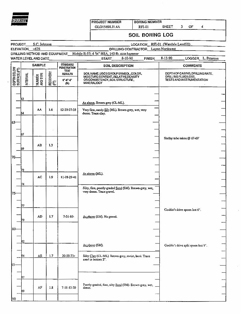
PROJECT NUMBER
GL015698Jl.4A I BORING NUMBER
RFI-01 SHEET 3 OF
SOIL BORING LOG
PROJECT S.C. Johnson LOCATION RFI-01 (Waxdale Landfill)
4
ELEVATION. __ -6;:;.;7;..;:6'--______________ DRILLING CONTRACTOR.---'La=yn.:.,.;;..e•.::..N;.;:;ortha.=w-'-es="'-t __________ _ DRILLING METHOD AND EQUIPMENT Mobile B-57· 4 1/4'' HSA 140-lb. auto hammer
WATER LEVEL AND DATE START 8-10-90 FINISH 8-13-90 LOGGER L Peterson
SAMPLE STANDARD SOIL DESCRIPTION COMMENTS
~{;: PENETRATION
I TEST
Ww ~ lli ! RESULTS SOIL NAME, USCSGROUP SYMBOL.COLOR, DEPTHOFCASING,DRILLING RATE,
al (.) MOISTURECONTENT;RELATIVEDENSITY DRILLING FLUID LOSS, t: ; a: 8E" 6" -6"' -6"' OR CONSISTENCY, SOIL STRUCTURE, TESTS AND INSTRUMENTATION
w => ~ ~o (N) MINERALOGY o en ii?,;. z~ ~-
- - -52 -
As above. Brown-grey (CL-ML). -- -
AA 1.6 12-30-37-35 Very fine, sandy Silt (ML). Brown-grey, wet, very -~ dense. Trace clay. - -
65- - ·-- - -
67 -Shelby tube taken@ 67-69' -
-AB 1.3
- -59 - -
70- - -- - -
n -~(ML). -
AC 1.9 11-28-29-41 - - -~4 -
Silty, fine, poorly-graded Sand (SM). Brown-grey, wet, -75-- very dense. Trace gravel. - -
- - -177 - -
Couldn't drive spoon last 6".
-AD 1.7 7-31-80- As above (SM). No gravel.
- -79 - -
80- - -
- - -132 -As above (SM). Couldn't drive split spoon last 9". -
- - -84 AE 1.7 20-55-73+ Silty Oay (CL-ML). Brown-grey, moist, hard. Trace -
sand in bouom 2". -
~5- - --- -
87 - -
- AF 1.8 7-II-15-20 Poorly-graded, fine, silty Sand (SM). Brown-grey, wet, _ dense. -
89 - -
90
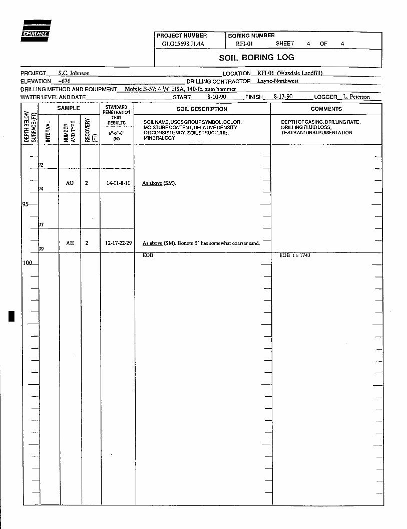
I
PROJECT NUMBER
GW15698.Jl.4A I BORING NUMBER
RFI-01 SHEET
SOIL BORING LOG
4 OF
PROJECT S.C. Johnson LOCATION RFI-01 (WaJCdale Landfill)
4
ELEVATION -676 DRILLING CONTRACTOR Layne-Northwest ------------------ ------------------DRILLING METHOD AND EQUIPMENT Mobile B-57i 4 1/4'' HSA, 140-lb. auto hammer WATER LEVEL AND DATE START 8-10-90 FINISH 8-13-90 LOGGER L Peterson
SAMPLE STANDARD SOIL DESCRIPTION COMMENTS
f5 E" PENETRATION >- TEST -'- SOILNAME,USCSGROUPSYMBOL,COLOR, DEPTH OF CASING, DRILLING RA TE, Ww
~ w a: RESULTS mu lli ~ ~ MOISTURECONTENT,RELATIVEDENSITY DRILLING A..UID LOSS, :::C<
I- LL. a: § E" 6'"-6"-6" OR CONSISTENCY, SOIL STRUCTURE, TESTS AND INSTRUMENTATION a. a: ~ ::!: 0 w =>
~ ~n~ (N) MINERALOGY Cl en a: -
- - -In - -
- AG 2 14-11-8-11 ~(SM). - -
~4 - -
95- - -
- - -n - -
- AH 2 12-17-22-29 As above (SM). Bottom 5" has somewhat coarser sand. - -99
EOB EOB t= 1743
100- - -- - -
- - -- - -- - -
- - -- - -- - -
- - -- - -
- - -
- - -
- - -
- - -
- - -
- - -
- - -
- - -
- - -
- - -

PROJECT NUMBER
GL015698Jl.4A I BORING NUMBER
MW8 SHEET OF
SOIL BORING LOG
PROJECT_---=S=.C=•;..:J..;;.o=hnso=n"'-_________________ LOCATION._.._(W""-'-'ruc .... da_le..;;.Lan"'----'d_fi_il_l) _________ _
ELEVATION -674 DRILLING CONTRACTOR._=La-'--yn~e-"--N-'o=rth=-w_es_t __________ _
DRILLING METHOD AND EQUIPMENT Mobile B-61 Rig w/4 1/4" HSA w/300-lb. Hammer
WATERLEVELANDDATE START 9/11/90 FINISH 9/11/90 LOGGER L. Peterson
SAMPLE STANDARD SOIL DESCRIPTION COMMENTS
~E" PENETRATION
1'i: TEST
-' - RESULTS SOILNAME,USCSGROUPSYMBOL,COLOR, DEPTHOFCASING,DRILLING RATE, Ww ~
w mu ~~ !:!;! MOISTURE CONTENT, RELATIVE DENSITY DRILLING FLUID LOSS, ~; a: 0 6" -6" -6" OR CONSISTENCY, SOIL STRUCTURE, TESTS AND INSTRUMENTATION
~ ::E 0 frlE" fu:::, :::,z (N) MINERALOGY 0 u, ~ Z< a:-HNu Bkgd = 0.1 ppm
A 0.8 4-3-4-S Sand and gravel (GM). Brown. Dry. Loose. Trace - (Fill} - clay and silL Some fine roots and bark. HNu = Bkgd t = 1331 -2 -
B 1 2-S-4-S Sandy Clay (CL). Pinkish-brown. Dry. Hard. Much - (Fill) - gravel. Trace silt. Some gold mottling. HNu = Bkgd t = 1342 -4 - -
5- C 1.3 1-2-2-2 Silry Qu (CL). Brown. Slightly moist. Stiff. Much - HNu = Bkgd t = 1348 gravel. Some sand and sandy fracwres. Rust monling. -
6 - -
- D 1.1 1-1-1-3 Qu (CL). Pinkish-brown. Slightly moisL Very stiff. HNu = 1.3 ppm (clay) t = 13S6 _ Trace sand an~vel. Som~old mo~ _ _ = HNu = 108 ppm (silt) Fill? -
8 San?L_~!±., Black. ~~ Some ~e .!!!._oul-2!!&- -E 1.9 1-1-1-1 Silt (OL). LL grey. MoisL SofL Some fine sand. Many (Organic) - - -tiny shells. A 2" brown silt lense -s• from tip. HNu=0.4ppm t=1401
1~ 0 - -
F 1.9 1-1 As above. Buff and greenish grey. A 1" shcll lense -8" - (Organic) - -from tip. Another l" shcll lense - 4" from top. Small HNu = 0.4 ppm (silt) 2 shells througholl1 whole sample. HNu =0.8 ppm (shell lense) t = 1407 - -
G 2 1-1-2-4 As above. Dk. grey. Trace clay and sand. A 2" fine, (Organic) - poorly graded sand lense 8" from tip. Some shells -HNu=Bkgd t= 1418 -
4 ~plant material in silt. _______ -
15- H 1.3 1-2-2-4 Silty Clay (CL). Brown-grey. MoisL Very niff. Some _ HNu = Bkgd t= 1422 rust mottling. A 2" clayey sand lense at top w/dlc. brown -
6 mottling.
EOB - - -- - -- - -
- - -- - -- - -- - -- - --- - -
- - -
- - -
- - -- - -

PROJECT NUMBER
GL015698.Jl .4A I BORING NUMBER
MWlO-S SHEET
SOIL BORING LOG
PROJECT S.C. Johnson LOCATION (Parking Lot Landfill)
OF
ELEVATION. __ -6-'-7"'""6'----------------- DRILLING CONTRACTOR._=La=-yn=e..:.-N.:..::o::.;rth::..:..:.:.w-=es::.:.t __________ _ DRILLING METHOD AND EQUIPMENT Mobile B-61 Rig w/4 '/4'' HSA w/300-lb. Hammer WATERLEVELANDDATE START 9n/90 FINISH 9n/90 LOGGER L.Peterson
SAMPLE STANDARD SOIL DESCRIPTION COMMENTS
~~ PENETRATION
>- TEST Ww
~ w a: RESULTS SOIL NAME, USCSGROUP SYMBOL, COLOR, DEPTHOFCASING,DRILLING RATE,
mu ffi ~ ~ MOISTURE CONTENT, RELATIVE DENSITY DRILLING FLUID LOSS, ~; a: hl~ 6"-6" -6" ORCONSISTENCY,SOILSTRUCTURE, TESTS AND INSTRUMENTATION
~ ::;; 0 W:::> => z (ti) MINERALOGY □ en ~ Z< a: ~
HNu=0.l ppm
- A 0.4 2-2-4-4 Sand and gravel (GM). Dty. Loose. Bottom inch - (Fill) -a sandy S.i!1 (ML). Black. Dty. Hard. Some gravel. HNu = Bkgd t = 1016
2 Some rust monlino. -
- B 1.6 2-5-3-4 Silty Oay (CL). Brown-grey. Slightly moisL Stiff. - HNu = Bkgd t = 1021 -Some sand and gravel Some rust mottling. Trace of
4 blaclc charred material Some plant material. Slight - -greenish discoloration.
5- C 0.6 2-1-2-9 As above. Grey. MoisL Soft-finn. More sand than - HNu = Bkgd t = 1028 above. Rust mottling. Some plant material. Some
-6 greenish discoloration. - -
- D 1.9 1-2-3-5 As above. Brown-grey. MoisL Firm. Trace sand. Some _ HNu = Bkgd t - 1046 -plant material A sandy fracture -to" from tip.
8 -------------- -
- E 0.9 3-5-3-6 Oayey fill! (ML). Brown-grey. Wd.. Firm. Some sand. _ HNu = Bkgd t = 1115 -Trace gravel
10 1:; - -
F 1.9 5-5-6-9 As above. - -- Poorly-graded, fine, silty Sand (SP). Brown-grey. Moist. HNu=Bkgd t=ll20 12 Dense. Trace "ravel. 1
Silt (ML). Brown-grey. Moist. Very stiff. Al" fine san§ -
- G 15 4-8-6-8 lenscat ·. _r------ _ Uty~ lcr..)':lrrown. Dty. Hard. A 3" fine, silty sand HNu=Bkgd t= 1126
-14 lensc -1 fL from tip. - -
H 1 4-4 As above. A 2" fine, silty sand lense -6" from tip. HNu=Bkgd t= 1131 1:;
EOB - - -
- - -
- - -
- - -
- - -- - -- - -- ·- -
- - -
- - -
- - -
- - -
- - -
- - -

PROJECT NUMBER
GL015698.Jl.4A I BORING NUMBER
MWll-S SHEET 1 OF
SOIL BORING LOG
PROJECT S.C. Johnson LOCATION MWI 1-S (Parking Lot Landfill) ELEVATION __ -_67_6 _______________ DRILLING CONTRACTOR __ La_yn..._e-_N_o_rth_w_cs_t __________ _
DRILLING METHOD AND EQUIPMENT Mobile B-61 Rig w/6 1/4'' HSA w/140-lb. Hammer WATER LEVEL AND DATE __________ START 9/10/90 FINISH. __ 9"""/_10-'--/9_0 ___ LOGGER L. Peterson
SAMPLE STANDARD SOIL DESCRIPTION COMMENTS
~E" PENETRATION
>- TEST Ww
~ w a: RESULTS SOILNAME,USCSGROUPSYMBOL,COLOR, DEPTHOFCASING,DRILLING RATE, mo ~~ ~ MOISTURE CONTENT, RELATIVE DENSITY DRILLING FLUID LOSS, ~; a:
§~ 6"-6" ,$' OR CONSISTENCY, SOIL STRUCTURE, TESTS AND INSTRUMENTATION w::, ~ s~ (N) MINERALOGY ccn ;;;;; Z< C:-
HNu Bkgd = 0.1 ppm
- A 1 8-9-7-6 Sand and gravel (GW). Dty. Loose. - (Fill) -HNu = Bkgd t = 1139
2 Sandy Oay (CL). Grey w/much green discoloration. - -
B 5-6-17-9 Diy. Soft. Some gravel {Green sand in tip.) Some - Rust mottling. - -4 No rccoveiy. - -
5- C 5-3-4-5 No rccoveiy. - Cunings are a brown, finn, moist, silty Oay w/sand and gravel -
6 - -
- D 1.7 4-6-7-8 Silty Oay {CL). Brown-grey. Moist. Stiff. Some - HNu = Bkgd t = 1321 -sand and gravel. Some green mouling.
8 - -- E 1.7 4-6-7-5 ~ {CL). Brown. Moist. V eiy stiff. Trace silt and - HNu = Bkgd t = 1333 -
gravel. Some brick-red mottling.
1: ~o - -- F 1.8 1-2-4-6 As above. Bottom inch has some fine sand and is wet. - HNu = Bkgd t = 1341 -
2 - -
- G 1.9 3-3-5-6 Silty Oay {CL). Brown-grey. Moist. Stiff. Trace - HNu = Bkgd t = 1350 -sand and gravel 4 - -
H 0.7 6-4 As above {CL). Veiy stiff. HNu = Bkgd t = 1401 l.S-- u:
EOB - - -- - -- - -
- - -
- - -- - -
- - -- - -
- - -
- - -
-- - -
- - -
- - -- - -
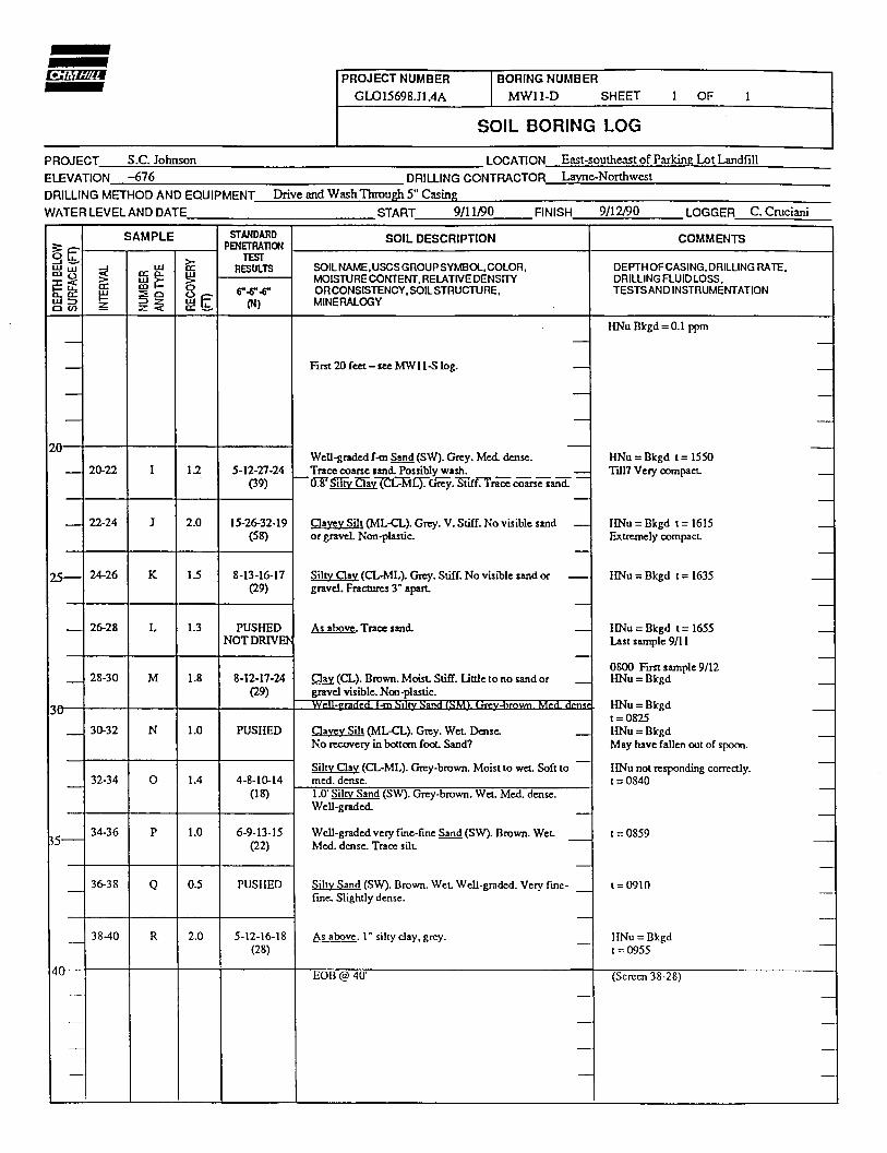
PROJECT NUMBER
GL015698.Jl .4A I BORING NUMB ER
MWll-D SHEET 1 OF
SOIL BORING LOG
PROJECT S.C. Johnson LOCATION East-southeast of Parking Lot Landfill ELEVATION __ -6..;;..7'""'6;...._ ______________ DRILLING CONTRACTOR. __ La_yn.__e_-N_o-'-rth_w_es_t __________ _
DRILLING METHOD AND EOUIPMENT __ Dri_·v_e_an_d_W_as_h_Thro __ u~gh.__5_" _C_as_in_.g..__ _____________________ _
WATERLEVELANDDATE START 9/llf)0 FINISH 9/lW0 LOGGER C. Cruciani
SAMPLE STANDARD SOIL DESCRIPTION COMMENTS
~ E" PENETRATION
~ TEST
Ww ~
w RESULTS SOILNAME,USCSGROUPSYMBOl..,COLOR, DEPTHOFCASING,DRILLING RATE, mo ffi i:: !:!;! MOISTURE CONTENT, RELATIVE DENSITY DRILLING FLUID LOSS, ~~ a:
@E" 6"-6"-6" OR CONSISTENCY, SOIL STRUCTURE, TESTS AND INSTRUMENTATION ~ 50 W::> ~ z~ (N) MINERALOGY 0 (/) a: ~
HNu Bkgd = 0.1 ppm
- - -- First 20 feet - sec MW 11-S log. - -
- - -
- - -
2~ - -Well-graded f-m Sand (SW). Grey. Med. dense. HNu = Bkgd t = 1550
- 20-22 I 1.2 5-12-27-24 Trace coarse sand. Possibly wash. - Till7 Very compact -('.39) .-o.s"Suiy Oay~ML).Grey.Sti.ff.'Tracc coai-sesand. -
- -- 22-24 J 2.0 15-26-32-19 Oayey Silt (ML-CL). Grey. V. Stiff. No visible sand - HNu = Bkgd t = 1615 -
(58) or gravel Non-plastic. Extremely compact - -
25- 24-26 K 1.5 8-13-16-17 Silty Oay (CL-ML). Grey. Stiff. No visible sand or - HNu = Bkgd t = 1635 -(29) gravel. Fractures 3" apart
- -
- 26-28 L 1.3 PUSHED As above. Trace sand. - HNu = Bkgd t = 1655 -NOT DRIVB Last sample 9/11
- -28-30 M 1.8 8-12-17-24
0800 FITTl sample 9/12
- Oay (CL). Bro'IVII. Moist. Stiff. Little to no sand or - HNu=Bkgd -(29) gravel visible. Non-plastic.
3v """' .n-n,,.n ._..,,. .'\I ITV ,!!!Inn . HNu=Bkgd -
t=0825
- 30-32 N 1.0 PUSHED Oayey Silt (ML-CL). Grey. Wet Dense. - HNu=Bkgd -No recovery in bottom foot. Sand7 May have fallen out of spoon.
-Silty Oay (CL-ML). Grey-bro'IVII. Moist to wet Soft to HNu not responding correctly. -
32-34 0 1.4 4-8-10-14 med. dense. t = 0840 -(18) 1.0' Silty Sand (SW). Grey-bro'IVII. Wet Med. dense. -
Well-graded. - -
~5-34-36 p 1.0 6-9-13-15 Well-graded very fme-fine Sand (SW). Bro'IVII. WeL t = 0859
(22) Med. dense. Trace sill - -- -
36-38 Q 0.5 PUSHED Silty Sand (SW). Bro'IVII. Wet Well-graded. Very fme- t = 0910 -fmc. Slightly dense. - -
- -38-40 R 2.0 - 5-12-16-18 As above. 1" silty clay, grey. - HNu =Bkgd
(28) t = 0955 -
4u EOB@40' (Screen 38-28)
- - -
- - -
- - -
- - -

PROJECT NUMBER
Gl..015698.Jl .4A I BORING NUMBER
RFI-15 SHEET OF 4
SOIL BORING LOG
PROJECT S.C. Johnson LOCATION RFI-15 (Northwest of Fire Training Site) ELEVATION_-6_7_9 ______________ DRILLING CONTRACTOR.--=La=yn:.::e::...;-N:...:.o:::rthc=::.:.w:..:es;::.:t'--_________ _
DRILLING METHOD AND EOUIPMENT_..:.4...!.1/;::,.4'...:' H:.::S::.:Ac.:...:.:w~/3:..."..=s.i::;pli::.:'t-=spoo=::.:n-=s=am::..:.p~l;::er'-------------------------WATER LEVELAND DATE START 8-7-90 FINISH 8-9-90 LOGGER C Cruciani
SAMPLE STANDARD SOIL DESCRIPTION COMMENTS
~~ PENETRATION
>- TEST __, - SOILNAME,USCSGROUPSYMBOL,COLOR, DEPTHOFCASING,DRILLING RATE, Ww ~
w a: RESULTS al <.)
. ~~ g! MOISTURECONTENT;RELATIVEDENSITY DRILLING FLUID LOSS. ~; ~ ~o §~ 6"-6"'-Q' OR CONSISTENCY, SOIL STRUCTURE, TESTS AND INSTRUMENTATION w ::> (N) MINERALOOY o en ~- :z~ a:-
0-2 A 1.5 4-6-8-6 Sandy Silt (ML) with clay. Brown. Diy to rnoisL (Topsoil) Sample BKGD - - -(14) Hard. 1124 - -
2-4 B 1.4 6-6-8-9 Silty~ (CL-ML). Mottled grey and buff to tan. - 1153 - (14) Diy to rnoisL Hard. Horizontal cracks. Trace gravel (Till} BKGD -
- -
5- 4-6 C 2 6-6-10-13 As above. Brown. Med. Trace gravel. - 1320 BKGD (16) (Till) -
- -6-8 D 1.9 4-8-10-13 ~ (CL-ML). Wtt. SofL - Spoon wet. (Softer till?) BKGD - -
(18) 1340
- -- 8-10 E 1.9 2-9-10-14 ~ (CL). Brown. Hard again. Sane brown, - HNu=Bkgd -(19) vatical fraaurc staining along cracks. 1350
1n 1-1" horiz.ootal section of brown sandy silt, poor! y - -graded, wet, med. dense.
- 10-12 F 1.9 3-9-10-11 As above. Grey. FraClllrcs 6" aparL Brown along - -(19) fraaures. Trace gravel. (Till)
- -1422 12-14 G 1.9 5-5-11-15 Silty Qay (CL). Grey. Plastic. Trace gravel. Softer - HNu=Bkgd - -(16) toward bottom. {Till)
- -15- 14-16 H 1.!1 1-7-13-25 As above. - 1429
(20) (Till} -~--------------V. fin.!:.,!~ filU {M_L):Eo...&.,ra~ ______ 1450 -
- - -16-17.5 I 1.4 Shelby Tube Silty~ (CL). Grey. Hard. Trace gravel. Shelby Drive 1.5' -------------~ -(Till)
Sandv Silt ISM\ Grev. 1532 - -18-20 ] l.5 1-1-3-3 ..,_ V. fm~rain~rly_Eadcd ~ Sand (S11... ~-- _ (Lacustrine)
2" (4) 0.5' Gravellv clavev Sand 7SP-GP). Grev. 0.5' Qayey Silt (ML-CL). Grev, soft. No ~ravel. 1545 -
- 20-22 K 2.0 2-2-4-6 l.S' Silty, clayey Sand (SP). Poorly graded. Grey. Fine _ (Lacustrine) -(6)
- -Fine grained Sand (SP). Med. dense. Trace silt. Loose. 1600
22-24 L 2.0 7-6-6-12 - -(12) 0.8' Silty~ (CL). Grey. Trace gravel and sand. Hard. (Till}
-1610
25- 24-26 M 2.0 3-7-7-8 Siltv verv fine Sand fSP\. Poorlv <>radcd wet. loose. (14) Silty~ (CL). Grey. Hard. Trace c. sand. (Till)
-
- - -
- 26-28 N 1.4 4-4-6-6 As above. Trace gravel, plastic, soft. - 1621 -(10) (Till)
- -As above. (Till)
28-30 0 1.5 1630 - -n ~- l -•P _,_,, __ , wPll --~-~ <:.n,l r<:r\
30 As previous (CL). (Till)
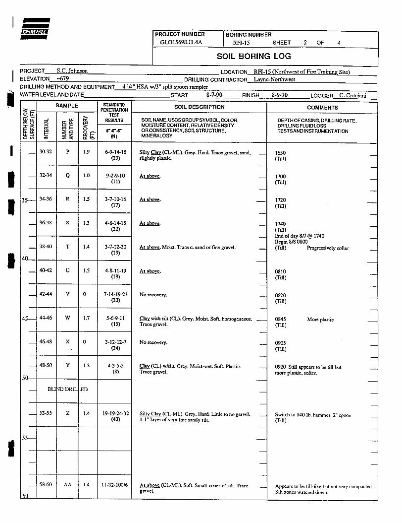
I
I
I
I I
I
I
PROJECT NUMBER
GL015698Jl.4A l BORING NUMBER
I RFI-15 SHEET
SOIL BORING LOG
2 OF 4
PROJECT S.C. Johnson LOCATION RFI-15 (Northwest of Fire Training Site) ELEVATION. __ -6.=..7;.,::9'---------------- DRILLING CONTRACTOR._=La=-yn=e-..:.N.:..:o:.:.:rth=-=~wes:..:.t __________ _ DRILLING METHOD AND EQUIPMENT 4 1/4" HSA w/3" split spoon sampler WATERLEVELANDDATE START 8-7-90 FINISH 8-9-90 LOGGER C Cruciani
SAMPLE STANDARD SOIL DESCRIPTION COMMENTS ~E" PENETRATION
~ TEST -' ~
RESULTS SOILNAME,USCSGROUPSYMBOL,COLOR, DEPTHOFCASING,DRILLING RATE, Ww ~
w Cl <..> ~~ ~ MOISTURE CONTENT, RELATIVE DENSITY DRILLING FLUID LOSS, b: ~ !§ 0 6" -6" -6" OR CONSISTENCY, SOIL STRUCTURE, TESTS AND INSTRUMENTATION ::;;o hl E" w => ;; ~ni (N) MINERALOGY o en a:~
- 30-32 p 1.9 6-9-14-16 Silty Clay (CL-ML). Grey. Hard. Trace gravel, sand, - 1650 -(23) slightly plastic. (Till)
- -- 32-34 Q 1.0 9-2-9-10 As above. - 1700
(11) (Till) -
- -35-- 34-36 R 1.5 3-7-10-16 As above. - 1720 -(17) (Till)
- -- 36-38 s 1.3 4-8-14-15 As above. - 1740
(22) (Till) -
- End of day 8ll@ 1740 -Begin 8/8 0800
- 38-40 T 1.4 3-7-12-20 As above. Moist. Trace c. sand or fine gravel - (Till) Progressively softer -(19) 4n - -
- 40-42 u 1.5 4-8-11-19 As above. - 0810 -(19) (Till)
- -- 42-44 V 0 7-14-19-23 No recovery. - 0820
(33) (Till) -
- -
4~ 44-46 w 1.7 5-6-9-11 Clay with silt (CL). Grey. Moist Soft, homogeneous. _ 0845 More plastic -(15) Trace gravel (Till)
- -
- 46-48 X 0 3-12-12-7 No recovery. - 0905 (24) (Till)
-
- -- 48-50 y 1.3 4-3-5-5 Clay (CL) w/silL Grey. Moist-wet Soft Plastic. - 0920 Still appears to be till but -(8) Trace gravel. more plastic, softer.
5n - -
- BU NDDRIL LED - -
- -
- 53-55 z 1.4 19-19-24-32 Silty Clay (CL-ML). Grey. Hard. Little to no gravel. - Switch to 140-Ib. hammer, 2" spoon -(43) 1-1" layer of very fine sandy silt. (fill) - -
5~ - -
- -
- - -
- -
- 58-60 AA 1.4 11-32-100/6"' As aoove (CL-ML). Soft. Small zones of silt. Trace - Appears to be till-like but not very compacted.__ gravel. Silt zones watered down.
60

PROJECT NUMBER
GL015698Jl.4A I BORING NUMBER
RFI-15 SHEET
SOIL BORING LOG
3 OF 4
PROJECT S.C. Johnson LOCATION RFI-15 (Northwest of Fire Training Site) ELEVATION_-6-"-'7....;;.9 _______________ DRILLING CONTRACTOR_La_yn_e_-_N_orth"---'-w_es_t __________ _
DRILLING METHOD AND EQUIPMENT_...;.4...,1/-'-4'....;' H:.:.S::.:A:..:...;..wc:..;{3:;..."...;.s..._p_lit....;spoo-'-'-;;.;;.n;;_;:s;.;;:am=pl:.:.er;..._ _____________ ~ _______ _ WATERLEVELANDDATE START 8-7-90 FINISH 8-9-90 LOGGER C Cruciani
SAMPLE STANDARD SOIL DESCRIPTION COMMENTS
fS~ PENETRATION
>- TEST _, ~ SOILNAME,USCSGROUPSYMBOl.,COLOR, DEPTHOFCASING,DRILLING RATE, Ww
~ w a: RESULTS mo ffi ~ ~ MOISTURE CONTENT, RELATIVE DENSITY DRILLING FLUID LOSS,
t: ~ a:
~~ 6" -6" -6" OR CONSISTENCY, SOIL STRUCTURE, - TESTS AND INSTRUMENTATION w :, ~ ~o
(N) MINERALOGY 0 <n z =E
- - -- -
1050
- 62-64 AB 1.4 7-23-29-32 As above (CL-ML). Harder. Plastic. - -(52)
- -
65- - -- - -
- -- 6U,9 AC 1.0 7-13-30-43 As above (CL-ML). Plastic. Lower sample as above - 1125 -
(43) but hard and non-plastic. Lower material definitely appears to be
- lodgancnt till. -7o__ - -
- - -- -
- 72.74 AD 1.9 5-17-30-43 As above. Softer, sticky. - 1150 (softer) -(47)
- -7f)- - -
- - -- -
- 77.79 AE 1.8 7-14-19-23 Silty Oay (CL-ML). Grey. MoisL Hard. Trace gravel. - (fill) -(33)
- -80- - Told drillers to go 10 ft. blind -
- - -- - -
- - -- - -
Sf)- - --- -------------- -
- -
- 87-88.3 AF 1.3 42-84-50/3" As above. Small "balls" of it (-2") within very fine - Sample rods bouncing through interval -Sand with Silt. Grey. Wet. Med. dense. HNu sample= Bkgd
- - -
90
I
i
I
I I
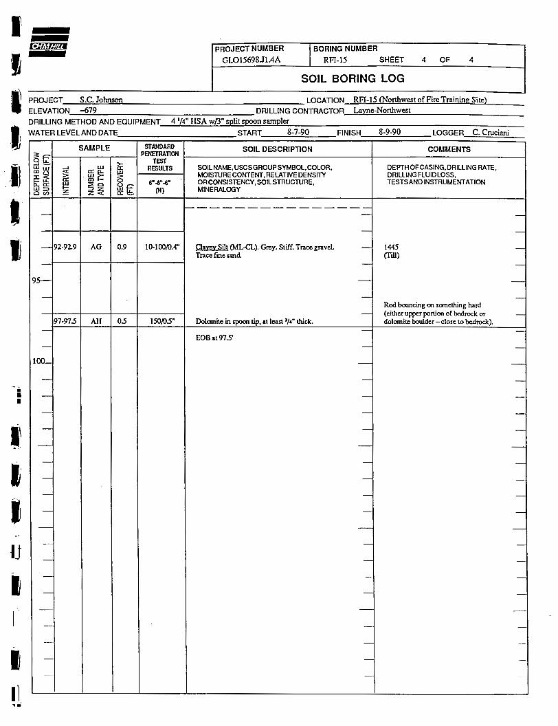
·. ,IJ
I I
-. • I
I I I u I I
I ll
PROJECT NUMBER
GL015698Jl.4A I BORING NUMBER
RFI-15 SHEET
SOIL BORING LOG
4 OF 4
PROJECT S.C. Johnson LOCATION RFI-15 (Northwest of Fire Training Site) ELEVATION. __ -6,;;..7;,.;;.9 _______________ DRILLING CONTRACTOR'---'La=yn=-e-""'"N_o"'"rth_w_.;.;;escc.t __________ _ DRILLING METHOD AND EOUIPMENT_..:.4....!11..:.4'....:' H:.:.S::.:A:.:...:.wc,.:!3::..."-=s""pli::.:.t:.::SJ>OO.c.::.::.:;n:.:.s.;;;;am=pl:.:.er,.._ _____________________ _
WATERLEVELANDDATE START 8-7-90 FINISH __ 8-_9-"'"9_0 ___ LOGGER C. Cruciani
SAMPLE STANDARD SOIL DESCRIPTION COMMENTS
~ E" PrnETRATION
>- TEST _J ~ SOIL NAME, USCSGROUP SYMBOL, COLOR, DEPTH OF CASING, DRILLING RA TE, WUJ
~ w a: RESULTS
CJ u ~H~ g;! MOISTURE CONTENT, RELATIVE DENSITY DRILLING FLUID LOSS, ~~ a:
§ E" 6"-6"-6" OR CONSISTENCY, SOIL STRUCTURE, TESTS AND INSTRUMENT ATIQN W::> ~ ~o
(N) MINERALOGY 0 CJ) ~ z :z a:~
---------------- - -- -
- 92-929 AG 0.9 10-100/0.4" Clayey Silt (ML-CL). Grey. Stiff. Trace gravel. - 1445 -Trace fine sand. (Till)
- -95-- - -
- - -Rod bouncing on something hard
- (either upper portion of bedrock or -97-97.5 AH 0.5 150/0.5" Dolomite in spoon tip, at least '/4" thick. dolomite boulder-close to bedrock).
- - -EOB at97.5'
- - -
1oo_ - -- - -- - -- - -- - -
- - -- - -- - -
- - -- - -
- - -
- - -
- - -
- - -
- - -
- - -- - -
- - -
- - -
- - -

PROJECT NUMBER
GLO 1569811 .4A I BORING NUMBER
MW13-A SHEET 1 OF
SOIL BORING LOG
PROJECT S.C. Johnson LOCATION_~(F-'-ir_e_T_r_ai_run_· ~g~S_it_e-) _________ _ ELEVATION, __ -6-"-7'""'7 _______________ DRILLING CONTRACTOR._=La=yn~e-..c.N_o-'-rth--'--w_es_t __________ _
DRILLING METHOD AND EQUIPMENT Mobile B-61 w/4 1/4" HSA and 300-lb. Hammer
WATER LEVEL AND DATE START 9/6/90 FINISH 9/6/90 LOGGER L. Peterson
SAMPLE STANDARD SOIL DESCRIPTION COMMENTS ~E'
PENETRATION
ii: TEST _, - SOIL NAME, USCSGROUP SYMBOL,COLOR, DEPTHOFCASING,DRILLING RATE, Ww _, w RESULTS
al <.) ~ ~~ ~ MOISTURE CONTENT, RELATIVE DENSITY DRILLING FLUID LOSS, ~~ 1§ ::;;o @E" 6"-6"-6" OR CONSISTENCY, SOIL STRUCTURE, TESTS AND INSTRUMENTATION w::, ~ :i (N) MINERALOGY o en ~ a: -
HNu Bkgd = 0.7 ppm A 1.7 3-5-5-7 fill! (ML). Dk. brown-black. Dry. Hard. Trace clay. (fopsoil) - Some sand. Some rust mauling. Some fine roots.
-HNu = Bkgd t = 0856 -
2 - -B 1 3-5-7-8 As above. Black. HNu = Bkgd t = 0005 - - -
4 -
5- C 1.1 2-1-1-3 Silty Oay (CL). Lt. grey. MoisL Firm. Some fine - HNu = Bkgd t = 0012 sand. Some black streaks. Some rust mottling. -
6 - -D 1.8 1-1-2-1 As above. Wd.. More sand than above. Some gravel HNu = Bkgd t = 0023 - Much rust monling
- -8 - -
E 2 1-2-2-3 As above. Brown-grey. Very moisL Stiff. Trace sand HNu=Bkgd t=0031 -and gravel. Some rust mottling. Some fine plant
- -
1:: ~o material. - -F 1.8 2-2-4-6 ~-Stiff.Very stiff. Some brick-red mottling. - HNu = Bkgd t = 0037 -
No plant material. -~2 -As above. Very stiff. Siltier than above. -
G 1.7 3-5-10-13 - - HNu = Bkgd t = 0044 -~4 =nay ~ lML) wun ~ l:St' ). lirown-grey. MOlSL o'>lll..!:,__
Sand is very fine. Trace gravel. -
1.:; ~5 H 1 5-7 As above. Somewhat less sand. HNu = Bki:d t = 0053
EOB - - -- - -- - -- - -
- - -- - -- - -- - -- - -
- - --- - -
- - -
- - -
- - -
I I I I
r 'I ~ ..
1. I u ·,
I
I I

I i
I
j,
I l
I
I I I
PROJECT NUMBER
GW15698.Jl.4A I BORING NUMBER
MW13-D SHEET
SOIL BORING LOG
PROJECT S.C. Johnson LOCATION East of Fire Training Site
OF 2
ELEVATION __ -6_7"'"'5'----------------- DRILLING CONTRACTOR._=-La=yn~e-.;;..N...co.;;..;rth=w......;;.;es'-'-t __________ _
DRILLING METHOD AND EQUIPMENT Boring 4 '/4'' HSA and 2" Split Spoon/MW Install WATER LEVEL AND DATE START 9/6/90 FINISH9 - ./7.f)_O LOGGER C. Cruciani
SAMPLE STANDARD SOIL DESCRIPTION COMMENTS
~~ PENETRATION
~ TEST _, ~
SOILNAME,USCSGROUPSYMBOL,COLOR, DEPTHOFCASING,DRILLING RATE, Ww _, w RESULTS ID (.) ;!: ~~ ~ MOISTURE CONTENT, RELATIVE DENSITY DRILLING FLUID LOSS, ::C< I- u. a: 0 6"-6"-6" OR CONSISTENCY ,SOIL STRUCTURE, TESTS AND INSTRUMENTATION a. a: ~ :::;;o ~~ w::, ~~ (N) MINERALOGY o en ;;::;; a:~
- 0-2 A 0.7 2-2-4-5 Silty Qay (CL-ML) with sand. Buff. MoisL Soft. - HNu=Bkgd -(6) Plastic. t = 1404
-
- 2-4 B 0.3 2-2-7-6 Gravelly fill. Dry. Loose - HNu=Bkgd -(9) t = 1410
(Fill from above7) -
5- 4-6 C 2.0 5-8-8-10 Silty Qay (CL-ML). Tan/grey mottling. Dry to moisL - HNu=Bkgd -(16) Finn. Trace gravel. t = 1418
- (till) -
- 6-8 D 2.0 8-11-12-16 As above. Brown. Large, moist gravel in clay. - HNu=Bkgd -(23) t = 1429
- -
- 8-10 E 1.4 1-4-5-11 As above (CL-ML). Otey. MoisL 2" scam of silt at 9'. - HNu=Bkgd -(9) t = 1435
1:: - -- 10-12 F 0.9 2-8-8-12 As above. Stiff. - HNu=Bkgd -
(16) t = 1450 - (Till) -
- 12-14 G 1.4 2-5-10-8 As above. Plastic. - HNu=Bkgd -(15) t = 1501
- (Till) -
IS- 14-16 H 0.8 5-4-11-13 As above (CL-ML). Grades to silt with clay (ML). - HNu=Bkgd -(15) Trace sand, grey, dry to moisL Loose. (Silt)
- t = 1510 -
- 16-18 I 1.9 5-7-8-11 Qaycy Silt (CL-ML). Otey. Moist to weL Soft to firm. - HNu=Bkgd -(15) Trace gravel. One 2" sand scam at 17 fceL Poorly- t = 1520
graded, med. grained. - (Till) -
- 18-20 J 1.8 3-4-5-9 As above (CL-ML). More gravel Trace sand. - HNu=Bkgd -(9) t = 1528
2~ - (Till) -- 20-22 K 1.9 2-4-8-10 As above. - HNu =Bkgd -
(12) t = 1535 - -
- 22-24 L 1.9 3-6-11-14 As above. More Q!)'. (CL). - HNu = Bkgd -(17) I= 1545
- -
25-- 24-26 M 1.7 5-11-17-19 As above (CL). - HNu =Bkgd -(26) 0.2' Poorly-graded sand. Grey, WeL Dense at 1 fl l = 1557
- -
- 26-28 N 1.9 6-9-14-19 As above Q!)'. (CL). - HNu = Bkgd -(23) l= 1600
- Spoon wet. -
- 28-30 0 1.5 4-16-10-9 As above. - HNu = Bkgd -(26) 6"" Silt (ML). Grey. Wet. Dense at 29'. l = 1620
30

PROJECT NUMBER
GL015698.Jl.4A I BORING NUMBER
MW13-D SHEET 2 OF
SOIL BORING LOG
PROJECT S.C. Johnson LOCATION East of Fire Training Site
2
ELEVATION_-6-'-'7-"5 _______________ DRILLING CONTRACTOR._La~yn-'-'---e--'-N""o""'rth"""w_cs~t __________ _
DRILLING METHOD AND EQUIPMENT Boring 4 1/4'' HSA and 2" Split Spoon/MW Install
WATERLEVELANDDATE START 9/6/90 FINISH 9(7{)0 LOGGER C. Cruciani
SAMPLE STANDARD SOIL DESCRIPTION COMMENTS
f5 E" PENETRATION >- TEST _,_
SOILNAME,USCSGROUPSYMBOL,COLOR, DEPTHOFCASING,DRILLING RATE, Ww ...J w a: RESULTS m <.> ~ ~~ ~ MOISTURE CONTENT, RELATIVE DENSITY DRILLING FLUID LOSS, :c u': a: 0 6" -6" -6" OR CONSISTENCY ,SOIL STRUCTURE, TESTS AND INSTRUMENTATION fu~ ~ ~o (.) . wE" (N) MINERALOGY
Cl en b· :z ~ 0:-
- 30-32 p 1.4 2-5-8-12 ~(CL). - HNu=Bkgd -(13) Last sample 9/6
- First sample 9n -
- 32-34 Q 0.9 3-6-10-12 Clay wjth Silt (CL). Grey. Wet. Sticky. Trace gravel. - (Still till.) -(16)
- -
35- 34-36 R 1.4 3-4-6-6 As above. Wet. - t=0745 -(10)
- -- 36-38 s 1.5 6-8-9-10 As above. Ahnost all clay. - t=0755 -
(17) - -
- 38-40 T 1.3 7-9-9-11 As above. - t=0810 -(18)
~~
EOB@40' - - -- - -- - -- - -
- - -- - -- - -- - -- - -
- - -- - -
- - -- - -- - -
- - --
- - -- - -- - -- - -
I
' I j -I-
f
I -1
•

I I I j_
I,
L _j
_j
I r -
l
I I
PROJECT NUMBER
GL015698.Jl.4A I BORING NUMBER
MW14-D SHEET
SOIL BORING LOG
OF 2
PROJECT S.C. Johnson LOCATION._-=-F=ire"'-=-T,::,,;ramc=·"'in=g"-"'S~ite'---_________ _
ELEVATION. __ --6-'--7"""5 ______________ DRILLING CONTRACTOR._=La::.iyn=-=-e--=-N:,,::;orth::=;.w"--es=.:...t _________ _
DRILLING METHOD AND EQUIPMENT Mobile B-61 Rig w/4 1/4'' HSA; 300-lb. Hammer
WATER LEVEL AND DATE START 9/5f)O FINISH 9/5f)0 LOGGER L. Peterson
SAMPLE STANDARD SOIL DESCRIPTION COMMENTS
~~ PENETRATION
>- TEST -l~ SOILNAME,USCSGROUPSYMBOL,COLOR, DEPTHOFCASING,DRILLING RATE, Ww _J w a: RESULTS
Cl (,) < ~i:: ~ MOISTURE CONTENT, RELATIVE DENSITY DRILLING FLUID LOSS, ~~
> a: @E" 6"-o'-6" OR CONSISTENCY ,SOIL STRUCTURE, TESTS AND INSTRUMENTATION
~ :::;; 0 W::> => z (N) MINERALOGY o en ;;:; Z< a:~
HNu Bkgd = 0.5 ppm A 0.5 8-6-6-5 Sand and gravel (GW). Dry. Loose. Clay in tip of - (Fill) -
HNu = Bkgd t = 0816 -spoon. 2 - -
B 0.8 4-2-3-2 Silty Qn: (CL). Greyish-brown. Slightly moist. Stiff. HNu = Bkgd t = 0831 - Rocle fragment 6" from tip. Much rust mottling. - -
4 - -
5- C 2 3-3-5-5 As above. Lt. grey. Very stiff. Much rust mottling. HNu = Bkgd t = 0840 (More rust color than grey.)
- -6 - -
D 1.8 3-2-2-3 As above. 2" from tip becomes a die. grey, moist, HNu = Bkgd t = 0847 -silty clay.
- -8 -
E 1.7 3-1-2-1 Poorly-graded, fme ~ (SP). Dk. brown. Wet HNu = Bkgd t = 0903 -Medium. Some silt
- -
1:: no -
As above. Dk. grey. -F 1.2 2-2-2-3 --
HNu = Bkgd t = 0909 -2
Silt (ML). Dk. grey. Moist. Stiff. Trace clay. - -
G 1.1 1-4-5-5 -~-Some rust mottling. ______ - -14 Cay (CL). Lt. brown. Very moist. Very stiff. Some - HNu = Bkgd t = 0915
silt Lt. orange mottling. Some sand and gravel -
15-H 1.6 1-1-2-3 As above. Greyish-brown. HNu = Bkgd t = 0921 - -
~6 - -I 1.9 2-4-6-9 As above. Stiff. Fractures -2" from tip w/sand in it HNu = Bkgd t = 0929 -
No orange mottling. - -
n8 - -
J 2 2-2-5-6 As above. Very stiff. Trace sand. Some gravel. Fracture _ HNu = Bkgd t = 0937 --5" from top with sand in it -
2" 20 - -K 1.8 2-3-5-5 As above. Not as moist HNu = Bkgd 1 = 0944 - - -
22 - -
L 2 2-3-4-5 As above. HNu = Bkgd t = 1009 - - -
~4 As above. A 1/2" well-graded sand lense - 8" from top. - -
25-- M 1.9 4-5-8-8 ~--------------Silt (ML). Brown. Moist Stiff. Upper 5" more of a
- -l!Nu = Bkgd t = 1018 ~ greyish-brown w/trace clay and some sand and gravel. - -
N 1.9 4-5-5-6 As above. Some sand. Trace gravel. Trace clay. l!Nu = Bkgd t = 1027 - - -Trace of brick-rc<l mottling.
tl8 - -
0 - 2-5-5-9 No recovery. - - -(Silty clay in tip,)
30 30

PROJECT NUMBER
GL015698Jl.4A I BORING NUMBER
MW14-D SHEET
SOIL BORING LOG
2 OF 2
PROJECT S.C. Johnson LOCATION_:...Frr=-· e;c..T-=-r=-=am=· .::in:.:.g,._S=i=te'------------ELEVATION __ -6_7_5 _______________ DRILLING CONTRACTOR._=La-=-yn=e...:.-N..:..:o:.:..rth='-'w.;:;;es=t __________ _
DRILLING METHOD AND EQUIPMENT Mobile B-61 Rig w/4 1/4'' HSA; 300-lb. Hammer
WATER LEVEL AND DATE START 9/5/90 FINISH 9/5/90 LOGGER L Peterson
SAMPLE STANDARD SOIL DESCRIPTION COMMENTS
~~ PENETRATIOO
>- TEST -'- SOILNAME,USCSGROUPSYMBOL,COLOR, DEPTHOFCASING,DRILLING RATE, Ww -' w a: RESULTS mo ~ ~~ !t;! MOISTURECONTENT,RELATIVEDENSITY _ DRILLING FLUID LOSS, ti:~ a:
§~ 6" -6"-6" OR CONSISTENCY ,SOIL STRUCTURE, TESTS AND INSTRUMENTATION w::, ~ 5~ (N) MINERALOGY C en Z< a:-
HNu Bkgd = 0.5 ppm
- p 1.9 3-3-6-7 Oay (CL). Grey-brown. Moist. Very stiff. Trace sand - HNu = Bkgd t = 1047 -and gravel. Some silt. B2 - -
- Q 2 3-4-6-6 As above. - HNu = Bkgd t = llOO -B4 - -
3S- R 1.7 4-5-6-8 As above in upper foot. Lower foot much sillier -with some sand. A sand fracture -7" from Lip. HNu = Bkgd t = ll09 -
B6 Another-I ft. from_!!P~ _______ -
- s 2 2-4-5-6 Clayey fill! (ML). Brown-grey. MoisL Very sliff. - HNu=Bkgd t= lll9 -Some gravel. BS - -As above.
T 1.8 3-5-7-7 -._@"{CLT-13rown":gi'cµfotsL Very s~ome rut. - = -
HNu = Bkgd t = ll31 40 4:; <:nmP n~uPI
EOB
- - -- - -- - -- - -
- - -- - -- - -- - -- - -
- - -
- - -- - -
- - -- - -
- - --- - -
- - -
- - -
- - -
I j
I , ... /
,, ,,
4
I , l_
I ~ 1
I..
I I

I 11
I
'
PROJECT NUMBER
GL015698Jl.4A I BORING NUMBER
MW16-S SHEET
SOIL BORING LOG
OF
PROJECT S.C. Johnson LOCATION MW16-S (Parking Lot Landfill) ELEVATION __ -_67_8 _______________ DRILLING CONTAACTOR._-'-La_yn'--'-'-e-'--N-'oc.c.rth-'--'-w_es_t __________ _
DRILLING METHOD AND EQUIPMENT MobileB-57 Rig w/41/4'' HSA; 140-lb. Hammer
WATER LEVEL AND DATE START 9/13/90 FINISH 9/13/90 LOGGER L. Peterson
SAMPLE STANDARD SOIL DESCRIPTION COMMENTS
~E PENETRAT100
>- TEST _, ~ SOILNAME,USCSGROUPSYMBOl..,COLOR, DEPTH OF CASING.DRILLING RATE, Ww _, w a: RESULTS
Cl 0 ~ a: a.. ~ MOISTURE CONTEITT, RELATIVE DENSITY DRILLING FLUID LOSS, :i: <C ~~ I- u. a: hlE 6"-6" -6" OR CONSISTENCY ,SOIL STRUCTURE, TESTS AND INSTRUMEITT ATION a.. a: ~ ::;; Cl
W:::> ~ ~n~ (N) MINERALOGY
Cl en a:~ HNu Bkgd = 0.2 ppm
- A 1.1 8-4-7-7 Sand and gravel Fill (GW). LL grey. Dry. Loose - (Fill) -2 Chyey Silt (ML). BLaclc. Dry. Hard. Trace sand. - HNu = Bkgd t = 1136 -
Much gravel Rust and green mottling. (Soil in spoon
- tip same only It. brown.) - -B 13-5-5-8 No recovery.
4 - -
5- C 4-4-3-4 No rccoverv. Cuttings arc a silty Q!Y (CL). Brown. Moist. Erm. Some sand and gravel.
-6 - Some orange mottling. HNu = Bkgd -
- D 0.9 9--6-5-7 Poorly graded, fine, silty Sand (SM). Black and grey. - HNu = Bkgd t = 1155 -Slightly moist. Loose. Trace gravel
8 - -- E 1.1 10-8-11-9 Well-graded, gravelly Sand (SW). Dk. grey. Moist. - (Fill) -
Medium. Trace clay. Some greenish discoloration. Bottom HNu = Bkgd t = 1201
1:: 10 2" same only onmgish-brown. -As above. Black and grey w/orange discoloration. Wd..
-
- F 0.8 2-5-5-4 Loose. - HNu = 0.3 ppm t = 1205 -~2 Silty Qay (CL). Brown-grey. Wet. Stiff. Trace fine - -
gravel.
- G 1.1 2-2-2-'.3 As above. Brown. Soft-firm. Trace gravel Some fine - HNu = Bkgd t = 1210 -sand.
~4 - -
15-H 1.1 2-2-5-7 As above. Brown-grey. Wd.. Very stiff. Trace gravel. _ HNu = Bkgd t = 1215 -
Top '.3" is clayey with much well-graded sand and gravel. ~6
EOB
- - -
- - -- - -
- - -
- - -
- - -
- - -- - -
- - -
- - -
- - -
- - -
- - -

PROJECT NUMBER
Gl..015698Jl.4A I BORING NUMBER
MW16-D SHEET 1 OF
SOIL BORING LOG
PROJECT S.C. Johnson LOCATION_S::..o;:.;u=th~of""'B"-'1,_.gd_.~5~5 __________ _ ELEVATION __ -6_7_8 _______________ DRILLING CONTRACTORc........,;La=yn~e--=-N;.;:.orth;;.;;;..;;..w_es="-t _________ _
DRILLING METHOD AND EQUIPMENT_.;.5_" ;;;..Dri;;.;;·v_c;...;an=d..;;;Ccccas;;.;;;in"'g,_W.:..:..c;;as;.;.;;h~-----------------------WATER LEVEL AND DATE START 9/20/90 FINISH 9/20/90 LOGGER B. Aument
SAMPLE STANDARD SOIL DESCRIPTION COMMENTS
~E PENETRATION
fi: TEST _, - w RESULTS SOILNAME,USCSGROUPSYMBOL,COLOR, DEPTH OF CASING, DRILLING RA TE, Ww
~ mu a: n. g;! MOISTURE CONTENT, RELATIVE DENSITY DRILLING FLUID LOSS, ::c rt a: ~u= 0 6"-o'-o' OR CONSISTENCY, SOIL STRUCTURE, TESTS AND INSTRUMENTATION li: a: ~ ~o @ E w ::> (NJ MINERALOGY o en ~ :z ~ a: -
HNu Bkgd = 0.3 ppm
- Sec log for MW16-S for 0-20'. - -
- - -- - -
- - -
2v -
- 20-22 K 0.7 2-3-4-6 Oay (CL). Grey. Moist. Furn. Trace coarse sand. - HNu = Bkgd t = 1450 -(1)
------------- -
- 22-24 L 1.6 11-15-13-22 Oayey Sil! (ML-CL). Grey. WeL Loose-well-graded - HNu=Bkgd t= 1510 -(28) Sand (SW) seam@ 23.4'; Trace gravel@ 24'. Dark/light layering in silt above and seam.
Varies? Not distincL - -125- 24-26 M 1.6 7-8-14-17 As above. Moist. Dense. Upper ponion Coarse Sand to HNu = Bkgd t = 1535 -(22) Gravel (GW). 3 seams of well-graded Sand (SW). Cay content - 25.9'.
- -
- 26-28 N 0.7 5-7-17-14 As above. Lower ponion silty Sand (SP-ML). Grey. WeL_ HNu = Bkgd t = 1630 -(24) Loose. Trace clay.
-Fine Sand (SW). Grey. WcL Loose. HNu = Bkgd t = 1650
28-30 0 1.5 8-12-11-13 -(23) Siltv Oav (CL-MU Grev. MoisL Finn Sequences fine upward, gradational changes. -
3v Med. Sand (SW). Grev. WeL Loose. -
- 30-32 p 1.7 4-6-12-26 Oay (CL). Grey. Moist. Furn. Upper l' medium Sand - HNu = Bkgd t = 1715 -(18) (SW). Grey. WeL Loose.
- -
- 32-34 Q 1.2 5-8-11-18 ~-Trace fine to medium Sand (SP). - HNu = Bkgd t = 1740 -(19) Horizontal fracture.
EOB@34'
35- - -- - -
- - -
- - -- - -
- - -
- - -
- - -
- - -
- - -
I
I r !
I I I 11
I
.I

I
I I
., I
-I
1,
I
I I
PROJECT NUMBER
GL015698Jl.4A I BORING NUMBER
MW17-S SHEET
SOIL BORING LOG
1 OF
PROJECT S.C. Johnson LOCATION_=E_as~t ~ofc..cB=l=gd=·~5"""5 __________ _ ELEVATION __ -6_7_8 _______________ DRILLING CONTRACTOR._=La-""'yn=e-..::.N.;..:o;.:.;rth:c.:w...;..;;.:es:.:;.t __________ _
DRILLING METHOD AND EQUIPMENT 41/4'' HSA wfl" Split Spoon and 140-lb. Hammer
WATERLEVELANDDATE START 9/12/)0 FINISH 9/121)0 LOGGER C. Cruciani
SAMPLE STANDARD SOIL DESCRIPTION COMMENTS
~~ PENETRATION
>- TEST -'-RESULTS SOILNAME,USCSGROUPSYMBOL,COLOR. DEPTHOFCASING,DRILLING RATE, Ww ..J w a:
co u ~ a: 0. ~ MOISTURE CONTENT, REL.A TIVE DENSITY DRILLING FLUID LOSS, :x: rt a: ~~ 0 6" -6" -6" OR CONSISTENCY, SOIL STRUCTURE, TESTS AND INSTRUMENTATION Ii: a: ~ ::;; 0 u-w ::, ::, z w G: (N) MINERALOGY o en ;;:;; Z< a: -
HNu Bkgd = <0.1 ppm
- 0-2 A 0.8 Silty Oay (CL-ML). Black-die. brown. Dry. Stiff. - (Topsoil) -_Tracesand. ___________ HNu = Bkgd t = 1535 Clayey Silt (ML). Tan-buff. Dry. Stiff. Trace sand and _ -gravel.
- 2-4 B 1 20-12-23-13 As above. Dry-moisL - (Fill) -(35) HNu = Bkgd t = 1542
- -
5- 4-6 C 0.9 11-7-4-16 Silty Qay (CL-ML). Brown. MoisL Fum. Trace - (Till} -(11) coarse sand. HNu = Bkgd t = 1549
- -
- 6-8 D 1 7-8-3-9 As above. Grey. Ha.rd. - (Till) -(11) HNu = Bkgd t = 1553
- -
- 8-10 E 1.4 6-5-5-7 As above. Bottom 0.6' is soft and moist-weL - HNu = Bkgd t = 1605 -(10)
1~ - -As above.
- 10-12 F 1.5 4-5-6-10 1 fL from bottom is a 0.1' poorly-graded, fine-med. sand _ HNu = Bkgd t = 1610 -(11) that is grey, wet, dense. Bottom l' is silty Qay (CL-ML).
Grey. Moist. Finn-ha.rd. Trace coarse sand or fine graveL_ -
- 12-14 G 1.3 3-5-6-11 As above. Trace fme sand.@ 13.5' is a horirorizontal - HNu = Bkgd t = 1615 -(11) fracture w/silty, very fme, poorly-graded, grey Sand (SP).
- -
lS-14-16 H 2 5-7-10-17 As above (CL-ML). Hard. l large piece gravel in bottom_ HNu = Bkgd t = 1623 -
(17) of spoon.
-
- 16-18 I 1 3-3-4-6 Very fme, poorly-graded, silty Sand (SM). Grey. WeL - HNu = Bkgd t = 1631 -(7) Loose. Spoon WCL
-
- 18-20 J 1.5 10-10-12-22 Oayey Silt (ML). MoisL Stiff. Some fme sand. - (Till) -(22) IINu = Bkgd t = 1637
20 EOB
- - -
- - -
- - -
- - -
-- -
- - -
- - -
- - -
- - -

PROJECT NUMBER
GL015698Jl.4A I BORING NUMBER
MW17-D SHEET OF
SOIL BORING LOG
PROJECT S.C. Johnson LOCATION East ofBlgd. 55 -=---~------------ELEV AT10 N __ -6_7_8 _______________ DR IL UNG CONTRACTOR,_;:;;;La=yn~c...;;.-N_,;o"'-rth-'-w..;.;es"'-t __________ _ DRILLING METHOD AND EOUIPMENT __ 5_"_Dri_._v_c_an_d_C'-as---'-in..,g_W.;_as=h ________________________ _
WATERLEVELANDDATE START 9/19/90 FINISH 9/19/90 LOGGER Cruciani/Aumcnt
SAMPLE STANDARD SOIL DESCRIPTION COMMENTS
~E" PENETRATIOO
ii: TEST
_J - RESULTS SOILNAME,USCSGROUPSYMBOL,COLOR, DEPTHOFCASING,DRILLING RATE, Ww _J w CJo < ~ ~ !:1;! MOISTURE CONTENT, RELATIVE DENSITY DRILLING FLUID LOSS, :I:< > l:i:: ~ a: 0 6"' -6" -6" OR CONSISTENCY, SOIL STRUCTURE, TESTS AND INSTRUMENTATION
~ :;; 0 hl E" w::, ;;g;;_ ~~ (N) MINERALOGY C Cl) a:-
HNu Bkgd = l ppm
- - -- See log of MW17-S for 0-20'. - -
- - -
- - -
2~ --- 20-21.9 K 1.9 4-8-22-34 fill! (ML). Grey. W CL Med. dense. Trace fine sand. - HNu = Bkgd t = 1510 -(30) 0.3 ft. of poorly-graded, fine sand at 21 fL
- -As above (ML). HNu = Bkgd t = 1535 22-23.5 L 1.5 21-38-76-46 -
>-Siftylli)'.~CM(f."~:Wei:sillr.veiy suil.- - == -
Lam.ina.e.(L2..mm)_ - - - - - - - - - -
25-24-25 M 1.0 28-49 Clayey fill! (ML-CL). Grey. WeL Med. dense. Trace fine HNu = Bkgd t = 1550
refused sand~0~rlf/itdcd fine sand.~ Wd.. I....oose --<;Ev . l=l'.:.Wci. urr--- ---- --------- -
26-272. N 1.2 10-35-28- Silty Oay (CL-ML). Grey. MoisL Stiff. HNu = Bkgd t = 1630 - refused -(fill - compressed) -
- -28-28.7 0 0.7 12-18-53/6 As above. Grades to lighter grey. HNu = Bkgd t = 1650 - -
(Till -compressed) -3v As above. Firm. - -
- 30-31.6 p 1.6 19-18-28-22 Sandy Silt (ML). Grey. WeL Loose. Sand is very fine. -HNu = Bkgd t = 1715 -
(46)
EOB Screen 2 l'-3 I' - - -- - -
- - -- - -
- - -- - -
- - -
- - -
- - -- - -
- - -- - -
I
,j
I -
I r ,_
I I
I

I··
I
~
I
t
•
PROJECT NUMBER
GL015698.Jl.4A I BORING NUMBER
RFI-27 SHEET
SOIL BORING LOG
1 OF 2
PROJECT S.C. Johnson LOCATION_.;:;..So=u=th:..:...=.;of:...:B::..:lc::.dg=·-=5-=-1-----------ELEVATION __ -6_7-'8 _______________ DRILLING CONTRACTOR __ La_yn~e_-N_o_rth_w_es_t __________ _
DRILLING METHOD AND EQUIPMENT 4 1/4'' HSA; 140-lb. Hammer; 2" Split Spoon
WATERLEVELANDDATE START 8-14-90 FINISH 8-14-90 LOGGER C. Cruciani
SAMPLE STANDARD SOIL DESCRIPTION COMMENTS f§~ PENETRATION
>- TEST -' ~ SOILNAME,USCSGROUPSYMBOL,COLOR, DEPTHOFCASING,DRILLING RATE, ww ~
w a: RESULTS co (.) a: a. g! MOISTURE CONTENT, RELATIVE DENSITY DRILLING FLUID LOSS, :X:rt_ a: ~n= 0 6"-6"'-o' OR CONSISTENCY, SOIL STRUCTURE, TESTS AND INSTRUMENTATION I:;: a: ~ ::;; 0 (.) -w:::, ~ ~~ wt;: (N) MINERALOGY 0 C/) a: ~
HNu Bkgd = 0.3 ppm
- A Coarse railroad bed fill. - Blind drilled through fill. -
-
- 2-4 B l 2-3-3-5 Silty Q!)'. (CL-ML). Brown and black. Dry. Finn. - (Fill) HNu = Bkgd -(6) Trace gravel and coarse sand. 0802
- -
5- 4-6 C 1.1 10-7-8-9 Sandy Q!)'. (CL). Brown/black/grey. Dry-moist. - (Fill) HNu = Bkgd (15) Trace gravel 0815 -
- -
- 6-8 D 0.3 2-3-3-5 As above. - (Fill) HNu = Bkgd -(6) 0825
- --
- 8-10 E l 2-2-4-4 Q!)'. (CL). Blade and brown. Dry-moisL Plastic. - HNu=Bkgd -(6) Trace sand and gravel 0835
1~ - -- 10-12 F 1.5 7-9-14-16 Silty Clay (CL-ML). Brown. Dry to moisL SofL - (HNu hiu 5 ppm in borehole.) -(23) Plastic. Trace gravel 0845 "Till-like" HNu=Bkgd
- -- 12-14 G 1.8 5-6-9-10 As above. Mottled grey-brown. MoisL - (Till) HNu = Bkgd -(15) 0852
- -
15-14-16 H 1.6 3-8-11-10 As above. - (Till) HNu=Bkgd -
(19) weu-.,raaea. Clavcv ~_ana (~l..J. 0905 HNu=Bkgd Silty Q!)'. (CL-ML). Monled grey-brown. MoisL - -Plastic. Trace gravel and sand.
- 16-18 I 1.5 3-8-11-12 As above. Grey. Furn. - (Till) HNu=Bkgd -(19) 0916
- -- 18-20 J 1.5 5-9-14-16 Q!)'. (CL). Grey. MoisL Stiff to hard. Some siIL - (Till) HNu=Bkgd -
(23) Trace gravel. 0930 28 - -
- 20-22 K 1.7 5-18-30-24 As above. - (Till) HNu=Bkgd -(48) - Sruldy°Si!TTM[f. Grey~msL Hara.Very dense-:- - - 0939
Trace clay and gravel. - (Till) HNu = Bkgd -
- 22-24 L 1.7 7-11-65-30 Clayey Silt (ML-CL). Grey. MoisL Stiff-hard. - 0959 -(76) Trace sand and gravel. One 3" cobble.
- -
25- 24-26 M 1.6 10-17-19-20 As above. 4" cracks. - 1011 IINu = Bkgd -(36)
- -
- 26-28 N 1.7 13-25-24-13 As above. Lower portion wet silt w/no clay (ML). - 1030 IINu = Bkgd -(49)
- -As above (ML-CL). Brown. Hard. IINu = Bkgd
- 28-30 0 1.5 5-18-)9-60 --------------- -
30 (37) Silt (ML). Grey. WeL Med. dense.
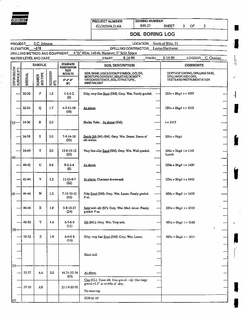
PROJECT NUMBER
Gl..015698.Jl .4A I BORING NUMBER
RFI-27 SHEET
SOIL BORING LOG
2 OF 2
PROJECT S.C. Johnson LOCATION._=-So=-=u==thc:...o:.:f..:B:.:.ld=<g:a.:... =-51:..._ _________ _ ELEVATION. __ -6,;;.7;.;:8'--_____________ DRILLING CONTRACTOR. __ La__.yn~e-..;..N=orthc.=w_es;;.;;,.c...t _________ _
DRILLING METHOD AND EQUIPMENT 4 '/4'' HSA; 140-lb. Hammer, 2" Split Spoon
WATER LEVEL AND DATE START 8-14-90 FINISH 8-14-90 LOGGER C Cruciani
SAMPLE STANDARD SOIL DESCRIPTION COMMENTS
~E' PENETRATION
ii: TEST _, - SOIL NAME,USCSGROUP SYMBOL.COLOR, DEPTHOFCASING,DRILLING RATE, Ww ~ w RESULTS
CXl 0 ~~ ~ MOISTURE CONTENT, RELATIVE DENSITY_ DRILLING FLUID LOSS, ::I:< > I- u.. a:
§ E' 6"-6"'-o' OR CONSISTENCY, SOIL STRUCTURE, TESTS AND INSTRUMENTATION C. a: ~ ::e 0 w::, ~ni! (N) MINERALOGY 0 (/) ~ a: -
- 30-32 p 1.5 1-1-1-2 Sihy, very fine Sand (SM). Grey. WeL Poorly graded. - HNu = Bkgd t,; 1055 -(2)
- -- 32-34 Q 1.7 4-7-11-19 As above. - HNu=Bkgd t= 1110 -
(18) - -
35- 34-36 R 2.0 Shelby Tube • ~ (SM). - l= 1115 -- -
- 36-38 s 2.0 7-8-14-18 Sandy Silt (ML-SM). Grey. WeL Dense. Zones of - HNu=Bkgd -(22) silt within.
- -
- 38-40 T 2.0 11-9-13-13 Very fine silty Sand (SM). Grey. WeL Well-graded. - HNu = Bkgd t = 1145 -(22) Lunch
4" - -- 40-42 u 0.8 9.3.3-4 As above. - HNu = Bkgd t = 1430 -
(6) - -
- 42-44 V 1.2 11-13-9-7 As above. Coarsens downward. - HNu = Bkgd t = 1445 -(22)
- -45- 44-46 w 1.3 7-15-10-12 Silty Sand (SM). Grey. WeL Loose. Poorly graded. - HNu = Bkgd t = 1450 -
(25) F-m. - -
- 46-48 X 1.9 5-9-15-27 Sand with silt (SP). Grey. WeL Med. dense. Poorly - HNu = Bkgd t = 1510 -(24) graded. F-m.
-
- 48-50 y 1.4 6-5.{i-9 Silt (ML). Grey. WeL Very sofL - HNu = Bkgd t = 1610 -(11)
5v - -
- 50-52 z 1.0 6-6-8-8 Silty, very fine Sand (SM). Grey. WeL Loose. - HNu=Bkgd t= 1611 -(14)
- -
- - -Blind drill
- - -
5~ - -
- 55-57 AA 2.0 16-31-32-34 As above. - -(63)
Qu (CL). Trace silt. Fine gravel - till. One large - -gravel = I .5" in middle of clay.
- 57-59 AB 21-14-20-50 - -No recovery.
60 EOB@59'
I
r
i
I
,_
I I

I I I ,,
11.
I
I
I
I
PROJECT NUMBER
GL015698.Jl .4A I BORING NUMBER
RFl-25 SHEET
SOIL BORING LOG
PROJECT S.C. Johnson LOCATION Northeast Portion of Site
OF 2
ELEVATION __ -6_64 ________________ DRILLING CONTRACTOR_La~yn_e-_N_o_rth_w_es_t __________ _
DRILLING METHOD AND EOUIPMENT __ 4--'1/_4'_' H_S_A _________ -:---------=-=--------=----
WATER LEVELAND DATE START 8-13-90 FINISH 8-13-90 LOGGER C. Cruciani
SAMPLE STANDARD SOIL DESCRIPTION COMMENTS
~~ PENETRATIOO
ii: TEST
Ww _, w RESULTS SOILNAME,USCSGROUPSYMBOL,COLOR, DEPTHOFCASING,DRILLING RATE, al (.) ~ ~~
w MOISTURE CONTENT, RELATIVE DENSITY DRILLING FLUID LOSS, ::c i'.t > a: 0 6"-6" -6" OR CONSISTENCY, SOIL STRUCTURE, TESTS AND INSTRUMENTATION l:i: a: ~ :;; 0 &3E" w~ ~ ~ ~ (N) MINERALOGY 0 U) a: -
- 0-2 A 0.3 1-1-1-2 Sandy Silt {ML). Black. trace fine sand, roots. - Topsoil/fill -(2) I =0935
- -- 2-4 B 0.2 2-1-1-1 As above {ML) with small shells. - I= 0940 -
(2)
- -0.5' As above (ML), I= 0950
5- 4-6 C 1.3 3-4-2-2 n15' "".J"ded Si!n.'. Sand~\Yl:_G.,!!:Y,jYeL Loose-:-,- -(6) m SIZC.
0.2'1:aJ!!e Gravel in Q_!Y,(GC). Gre:t.,_WeL Soft.__ -0.6' Well-graded Sand and small Gnvel (SW). Grey. WeL I= 1003
- 6-8 D 1.2 3-3-4-8 Loose -(7) 0.6' Sil!Y Oay (CL-ML). Grey-brown. Firm. Trace gravel.
-
- 8-10 E 0.7 1-1-1-2 Well-graded Sand (SW). Grey. WeL Loose. - I= 1015 -(2)
1n - -0.6' As above (SW). I= 1020
10-12 F - 1.2 1-3-5-6 -(8) 0.6' Sil!Y Oay (CL-ML). Grey-brown. WeL SofL
- -0.7' As above (CL-ML). I= 1025
12-14 G - 1.5 3-4-7-9 -(11) 0.5' Silty, well-graded clayey Sand (SM). Grey. WeL
0.3' As above (SM). - I= 1041 -0.3' :O.ll!Y uay t -= 1• 1.irey. WeL :SOit.
15- 14-16 H 1.1 4-5-8-4 0.4' Silty, well-graded Sand (SW). - -(13) U.4' :Stl!Y Uay _ -~ . \Jr'Cy. WeL .:)()lt. Trace graveL I= 1048
- -
- 16-18 1 1.3 2-3-2-5 As above (CL) - -(5)
-Well-graded Silty Sand (SW). Grey. WeL Loose I= 1057 - 18-20 J 1.5 2-3-4-8 -~ ~ \.-1.,J. orown-grey . ..,.,,~ 1 race grave,.
2n (7) weu-graucu ,;i_an_<! t::> w ). -
- 20-22 K 0.3 3-5-14-14 lliY (CL). Grey. Soft. Trace gravel. - t = I 105 VOA's only sample taken -(19) Till (lodgement)-likc
- -
- 22-24 L 2.0 6-6-15-14 As above (CL) - t=lll3 -(21)
- -
25- 24-26 M 1.8 6-7-7-11 As above (CL). - I= 1128 --(14)
- -
- 26-28 N 1.8 4-9-13-17 As above (CL). - I= 1138 Harder toward bonom. -(22) Lunch
- -
- 28-30 0 1.9 5-9-14-15 Silly Qay (CL-ML). Grey. Moist. Firm. Trace gravel. - I= 1300 -
30 (19) Sulfur smell in hole.

r
PROJECT NUMBER GL015698.Jl.4A I
BORING NUMBER RA-25 SHEET
SOIL BORING LOG
2 OF 2
PROJECT S.C. Johnson LOCATION Northeast Portion of Site ELEVATION. __ -6.:...64;;..;... ______________ DRILLING CONTRACTOR._=cLa:c.<yn:.:.:..::..e-.:...N:..:co:..:rth:c:..w:..:..;es::::..:....t _________ _ DRILLING METHOD AND EOUIPMENT_....:4....:'l:....:.4_" H=SA:,.:..._ ___________________________ _
WATER LEVEL AND DATE. START8 __ .13-90 FINISH.8 _-1 .. 3.-9.0 .. LOGGER C. Cruciani
SAMPLE STANDARD SOIL DESCRIPTION COMMENTS
~E" PENETRATION
_. - i TEST
Ww ;t w RESULTS SOILNAME,USCSGROUPSYMBOl..,COLOR, DEPTHOFCASING,DRILLING RATE, co (.)
~~ MOISTURE CONTENT, RELATIVE DENSITY DRILLING FLUID LOSS, :x: rt a: §E" li-o'-o' OR CONSISTENCY, SOIL STRUCTURE, TESTS AND INSTRUMENTATION l:i: a: t!:! ~o w ::::,
~ z~ (N) MINERALOGY 0 V, 0:-
30-32 - p 2.0 6-10-13-16 As above (CL-ML). - t= 1308 -(23) Angular piece of large gravel
- -0.7' As above (CL-ML).
- 32-34 Q 1.7 7-17-17-9 -------------- -(34) 1.0' fill! (ML). Grey. WeL SofL A few fractures filled t= 1320
'?d[me S3D!!...™-L) _________ -
3S-- 34-36 R 1.5 5-8-23-14 Silty Qay (CL-ML). Grey. MoisL Furn Trace c. - t = 1335 (31) sand.
-- -
- 36-38 s 1.8 4-7-12-18 ~ (CL-ML). Trace gravel - t = 1345 All appean till-like but sofL -(19)
- -0.5' ~ (CL-ML).
- 38-40 T 1.9 2-6-7-8 1.4' ~ (CL-ML) with silt. Red-brown. Trace sand - t = 1350 -(13) and soft, grey IOward bottom.
4n - -- 40-42 u 1.9 11-7-8-9 A! above (CL-ML). BO!h grey and brown. - t = 1416 -
(15) 2" sand seam.
- -As above (CL-ML). t = 1421
- 42-44 V 1.9 7-11-13-14 - -(24) Oayey, well-graded Sand (SC).
-
45- 44-46 w 1.8 3-4-10-12 Silty Oay (CL-ML). Grey. WeL SofL Trace sand, - t = 1440 (14) gravel.
-
------------- -
- 46-48 X 1.5 .._ 0.5' fill! (ML). Grc:J:._ WeL Finn. ______
10-17-36-29 1.0' Oaycy Silt (ML-CL). Grey. MoisL Firm. _ t = 1450 -(53) Firm, lodgement till-like
- -
48-50 - y 1.6 18-30-31-47 As above (ML-CL). - I= 1530 -(61) Angular piece of gravel in tip of spoon.
Su EOB@50'
- - -
- - -
- - -
- - -
- - -
- - -
- - -
- - -
- - -·
I I ,, I :1
I
I lll
j
I I I
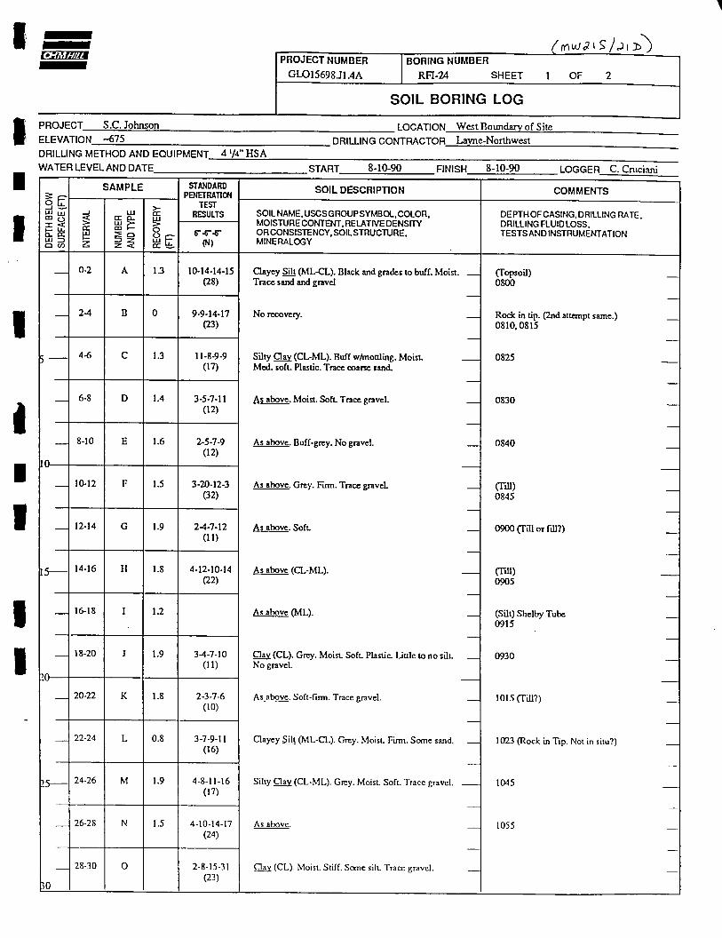
I
I I
I
I
I
I
I I
PROJECT NUMBER
GL015698Jl.4A 1 BORING NUMBER
I RFI-24 SHEET
SOIL BORING LOG
OF 2
PROJECT S.C. Johnson LOCATION,_W!.!.!:es~t..!:B:.:;:o.::::un~dary~L.:o:!.!:f..::S:..:.:ite::::..._ ________ _ ELEVATION,_-6_.::..;.7..:c5 _______________ DRILLING CONTRACTOR.--=La==yn.::.e=---=-Nc::.o:.::::.:..rthw:..:..es=.:...t __________ _ DRILLING METHOD AND EQUIPMENT_4:.:.....!.:1/4::...."..!.H~S:.:..A:..__ ___________________________ _
WATER LEVEL AND DATE START 8-10-90 FINISH 8-10-90 LOGGER C Cruciani
SAMPLE STANDARD SOIL DESCRIPTION COMMENTS ~ E"" PENETRATIOO
>- TEST ...J-SOILNAME,USCSGROUPSYMBOL,COLOR, DEPTHOFCASING,DRILLING RATE, Ww ...J w a: RESULTS m o ;!: a: a. ~ MOISTURE CONTENT, RELATIVE DENSITY DRILLING FLUID LOSS, ::i::: <C w >-
I- LL a: m I- 0 6"-6"-6" OR CONSISTENCY, SOIL STRUCTURE, TESTS AND INSTRUMENTATION a. a: ~ ;:e Cl ~E"" w => ~ni: {N) MINERALOGY Cl U) ~ a: -
- 0-2 A 1.3 10-14-14-15 Oayey Silt (ML-CL). Black and grades to buff. Moist. _ (fopsoil) -(28) Trace sand and gravel 0800
- -
- 2-4 B 0 9-9-14-17 No recovery. - Rock in tip. (2nd attempt same.) -(23) 0810,0815 - -
Ii- 4-6 C 1.3 11-8-9-9 Silty Oay (CL-ML). Buff w/monling. Moist. - 0825 -(17) Med. soft. Plastic. Trace roarse sand.
- -- 6-8 D 1.4 3-5-7-11 As above. Moist. Soft. Trace gravel. - 0830 -(12)
- -
- 8-10 E 1.6 2-5-7-9 As above. Buff-grey. No gravel. - 0840 -(12)
110 - -- 10-12 F 1.5 3-20-12-3 As above. Grey. Furn. Trace gravel. - (Till) -(32) 0845
- -
- 12-14 G 1.9 2-4-7-12 As above. Soft. - 0900 (fill or fill?) -(11)
- -
h5- 14-16 H 1.8 4-12-10-14 As above (CL-ML). - (Till) -(22) 0905 - -
- 16-18 I 1.2 As above (ML). - (Silt) Shelby Tube -0915
- -
- 18-20 1 1.9 3-4-7-10 ~ (CL). Grey. Moist. Soft. Plastic. Liule to no silt. - 0930 -(11) No gravel. hn - -
- 20-22 K 1.8 2-3-7-6 As above. Sof1-fum. Trace gravel. - 1015 (fill?) -(10)
- -
- 22-24 L 0.8 3-7-9-11 Oayey Silt (ML-CL). Grey. Moist. Firm. Some sand. - 1023 (Rock in Tip. Not in situ?) -(16)
- -
25-- 24-26 M 1.9 4-8-11-16 Silty~ (CL-ML). Grey. Moist. Soft. Trace gravel. - HMS -(17)
- -
- 26-28 N 1.5 4-10-14-17 As above. - 1055 -(24)
- -
- 28-30 0 2-8-15-31 ~ (CL). Moist. Stiff. Some silt. Trace gravel. - -m
(23)

PROJECT NUMBER
GL015698Jl.4A I BORING NUMBER
RFI-24 SHEET
SOIL BORING LOG
2 OF 2
PROJECT S.C. Johnson LOCA TJON_W"""'-'es:.:.;t:...:B::;..;o:...:un=dary=----=o;.:;.f"""S=it"'""e ________ _ ELEVATION. __ -6_7_5 _______________ DRILLING CONTRACTOR._-=La"""'yn=-e-..:.N.;..::o:.:.;rth=.cw..:ccs:..:.t __________ _ DRILLING METHOD AND EOUIPMENT_....;.4...:.1/-'-4"....;;H=S=A.c-__________________________ _
WATER LEVEL AND DATE START 8-10-90 FINISH 8-10-90 LOGGER C. Cruciani
SAMPLE STANDARD SOIL DESCRIPTION COMMENTS
~E" PENETRATION
>- TEST Ww
~ w a: RESULTS SOILNAME,USCSGROUPSYMBOL,COLOR, DEPTHOFCASING,DRILLING RATE,
me., ~~ ~ MOISTURE CONTENT, RELATIVE DENSITY DRILLING FLUID LOSS, b:; a: 0 6"-6"-6" OR CONSISTENCY, SOIL STRUCTURE, TESTS AND INSTRUMENTATION
~ ::Eo al E" w::, ~~ (N) MINERALOGY o en ~- a: -As above (CL).
- 30-32 p 2 3-17-9-15 1150 -(26) Well-graded, fine-med.~ (SW). Grey. Med. dense.
Trace coarse sand. Little-trace silL - -
- 32-34 Q 1.1 2-20-30-14 _As above. __________ Hard rock in spoon. -(50) Clayey, well-graded Gravel (GC).
- -
35- 34-36 R 0.1 8-18-21-25 Rock. Sandy, clayey Gravel (GC) or cobbles >3", - Hard rock in tip. -(39) breaking w/spoon. Clay is reddish brown.
-------------- -
- 36-38 s 1.5 3-6-10-18 Well-graded Sand (SW). Brown. WeL Some silL Sand - 1435 -(16) is very fine-fine. Lacustrine
- -
- 38-40 T 1.7 5-11-17-21 As above. - 1450 -(28)
4n - -~-- 40-42 u 1.7 6-11-15-15 -
(26) fill! (ML). Grey. WCL Soft/loose. 1510
-- 42-44 V 1.8 5-10-14-16 Very fine, silty, poorly-graded Sand (SP). Grey. WeL - 1520 -
(24)
- -~ (SP-SM). Grades into a 1530
45- 44-46 w 1.9 6-7-8-10 1--------------- -(15) Oayey Silt (ML). Grey. WeL SofL
- -
- 46-48 X Upper portion as above. Lower is well-graded sand. - 1545 Shelby Tube -
------------- -Silty~ (CL-ML). Grey. Hard. Trace coarse sand. (Till)
- 48-50 y 1.8 5-14-56-36 -(70) Very fine, poorly-graded, silty Sand (SP). Grey. WeL 1620
5~ Dense. (Till) --~ Oa~L-Ml:L{hn-, MoisL VE:J stiff. Tra~eL
- 50-52 z 1.7 15-52-60 Very fine, sandy Silt (ML). Grey. WeL Very dense. - 1650 -
------------------.= -Silty~ (CL-ML). Grey. Moist. Very stiff. Trace
- 52-54 AA 1.8 23-26-27-32 gravel. - -(53)
As above. EOB@54'
55- - -
-- - -
- - -
- - -
- - -·
I
I
I
i
I
I I

I
I I
I
I I I I
I
I
PROJECT NUMBER
GL015698.Jl .4A I BORING NUMBER
DB02-D SHEET
SOIL BORING LOG
OF 2
PROJECT S.C. Johnson LOCATION_(B=ld=g,.,_. ::.c51:..T.c..:ank=..:..F-=arm=) ________ _ ELEVATION __ -_67_7 _______________ DRILLING CONTRACTOR __ La~yn'--e-..:..N..:o..:..rth=-w-'-'es'"'"t __________ _
DRILLING METHOD AND EQUIPMENT 4 1/4" HSA; 2" Split Spoon Sampler; 140-lb. Hammer
WATERLEVELANDDATE START FINISH LOGGER D. Plomb
SAMPLE STANDARD SOIL DESCRIPTION COMMENTS
~~ PENETRATION
>- TEST _, - w SOILNAME,USCSGROUPSYMBOL,COLOR, DEPTH OF CASING, DRILLING RA TE, Ww _, a: RESULTS a:, (.) <C ffi ~ w MOISTURE CONTENT, RELATIVE DENSITY DRILLING FLUID LOSS, b: ~ > > a: 0 6"-6"-6" OR CONSISTENCY, SOIL STRUCTURE, TESTS AND INSTRUMENTATION
~ ::;; 0 (.) -W:::> ;;:;; ~~ w t: (N) MINERALOGY 0 II) a: -
HNu (PPM)
- - Sample Borehole Breathing -0-2 SS-1 I 5-4-7-7 Crushed limestone. 4.0 20 0.2
- (Fill) -Silty Oay (CL). Brown. Mixed w/black clayey topsoil 1059
2-4 SS-2 1.3 5-7-7-7 - MoisL - 1.0 2.5 0.0 -1----------------- 1113
- -Oayey topsoil. Black. MoisL Some silt, sand. 0.0 2.5 0.2
5- 4-6 SS-3 2 3-4-11-11 - -1-----------------
Silty Oay (CL). Brownish-grey. MoisL Stiff. Trace - 1119 -sand and gravel 6-8 SS-4 - 2 4-11-21-20 As above. - 0.0 0.8 0.0 -
- 1127 -8-10 - SS-5 2 5-10-10-11 As above. - 0.0 0.0 0.0 -
1: - 1138 -
- 10-12 SS-6 2 9-5-3-6 As above, with a 6" grey, sandy silt, trace clay lense - 0.0 0.0 0.0 -from 11.1 to 11.6'.
1144 - -- 12-14 SS-7 2 7-11-14-20 As above (CL). - 0.0 0.0 0.0 -
- 1149 -
15- 14-16 SS-8 2 5-11-23-34 As above. Grey. Stiff-hard. - 0.0 0.0 0.0 -
- 1325 -- 16-18 SS-9 1.5 14-28-30-30 As above., grades to a hard, grey, very silty Q.u'. (CL- - 0.0 0.0 0.0 -
ML). Some sand and small gravel@ 17 .25'
- 1339 -- 18-20 SS-10 2 12-18-24-31 As above (CL-ML). - 0.0 0.0 0.0 -
2 - 1350 -
20-22 SS-11 - 2 26-30-29-25 As above (CL-MU. 0.0 0.2 0.0 -_ F. san~ Sin (ML). G~Moist. Dense. Little cl~ __ 1401
- -Silty, fine to med. Sand (SP). Grey. Saturated. Dense.
- 22-24 SS-12 1.2 14-19-26-24 Poorly graded. Trace clay. - -As above. 0.0 0.2 0.0
- 1434 -
25-- 24-26 SS-13 1.7 5-7-17-33 As above. - 0.0 0.0 0.0 -
- 1452 -
- 26-28 SS-14 1.3 14-41-50/5 As above. - 0.0 0.0 0.0 -
- 1506 -
- 28-30 SS-15 1.2 24-49-50/3 As above (SP-SM). - 00 00 0.0 -
30 1523

PROJECT NUMBER
GL015698Jl.4A I BORING NUMBER
D802-D SHEET l- OF
SOIL BORING LOG
PROJECT S.C. Johnson LOCATION (Bldg. 51 Tank Farm)
2
ELEVATION __ -6..;:;.;_77'----------------- DRILLING CONTRACTOR,_=La:::.yn~cc...:-N...;.o::..:r-=th.:..:w.:...:c:::cs:...t __________ _ DRILLING METHOD AND EQUIPMENT 4 1/4'' HSA; 2" Split Spoon Sampler; 140-lb. Hammer
WATERLEVELANDDATE START FINISH LOGGER D Plomb
SAMPLE STANDARD SOIL DESCRIPTION COMMENTS
f5 E" PENETRATION
ii: TEST _, - SOILNAME,USCSGROUPSYMBOL,COLOR, DEPTHOFCASING,DRILLINGRATE, Ww
~ w RESULTS
a::, u ffi ~ !:!;! MOISTURE CONTENT, RELATIVE DENSITY DRILLING FLUID LOSS, ::i:: rt a: 0 6" -6" -6" OR CONSISTENCY, SOIL STRUCTURE, TESTS AND INSTRUMENTATION ~ a: ~ :;; 0 ta E" w ::> ;;;; ~~ (N) MINERALOGY 0 rJ) a: -
HNu(PPM)
- - Sample • Borehole Breathing -30-32 SS-16 1.8 8-13-31-34 As above (SP-SM). 0.0 0.0 0.0
- -As above (SP-SM). 1544
- 32-34 SS-17 - 0.0 0.0 0.0 -1555
EOB@34'
3S-- - -- - -
- - -- - -- - --- - -- - -- - -- - -- - -
-- - -- - -- - -
- - -- - -
- - -- - -
- - -
- - -
- - -
- - --- - -
- - -
- - -
- - -
I
I I I
I
I
I I I
MKEJ0014F8B/3
ATTACHMENT C GROUNDWATER MONITORING
WELL INFORMATION FORM (WIF)

, .. -Stale of Wi.sconsin Department of Na rural Resources
aci.Jicv Name [Facility ID Number ..5C... johnson uJo..x
CNR Well ID Date
WeU Name Nu.rnbc: Well Location N S EW Establish cd
;l.6$, I 03 X f .ZOI S
;J,51P11 SJ.~ f{-.;J.;)..9C
X
;)0'5 0 99 x P~o1b ;;J. 1Su>'i, ~I Y g'-J.l-'7D
)(
r z:-0.) s .)(p~ o 3G )(
'3'-:;i;J._ 'Jo ..J, 5~ :>, ~<./.<;" ;<
.
Jiol.{ 01./ I X: Pz-o~]) <g -,);;J.-90
,;1 .~(.?", 'f/L/L/ ;<
NA mwo1 ;vft /1,/ /9glt
/1)~ /V /9~& )1 ().,IO ;2_
/VA ~<d &5'1 ..J
,.J J9g&. rn w o :~ J.,Slt7 G'iO x ~(a 3, & <:;'({ ><
rn u-' 0 ~ /U ;9&& '),Sf..J.7 £43G )('.
.:2.~3 (,,5 3 >< mwo.s- .v /'7&&
;).,5~7,733 ><'.
;ll.a,3 li 5.}.. ,<,
(Y1 w D G ,v Je,gl, :J.,Slo.7 "7 3~ )(
;)&.~, 9atJ X ~ -o<3 .. 90 (Y)u...10'7 S
'/.. ;),S&i7, &9.0
:}u39,;_, x Yll.,l) o 7 b i,~3-90
),,':;~7 &&3 x ~ation Coordinau:s Are: !Remarks:
0 Lo:al Grid Syst.e.m ~ St.ate Pl!l.l:e C\x:miinz.te (Jn.fan:d) 0 Nonhcm
r, r,nrn1
- - .. GROUNDWATER lvONrTORING WELL INFORf)ATK)~~ FORM Chapter 144, Wis. Stats. Form 4400-89 R cv ! • %
!)ale
10/1;,./91( <;omplete<l !iY (Na.me and F.i!Jn) / .
l. o...u..r0- PR. f< r .SO n. C.. 1-L:Z rYl. J-.IILL Well Casing Elevations Reference Type of Well ( ✓ l Gr;ici,cnt
Tot:of Ground MSL 41te Screen Well
~ ~ ~ Aban· IEnf. Stds U.S. D
Diam T),pc Well asing Surface ( ✓ ) ~ Length Depth ~~ 01hcr a:n:rl Apply orN
&J7'-l-t./ I I
.2" fvc. <..ot./.o& ✓ JO )3 X
;/' .5 I L.jo I
Ne.. &71../-tS &7i/·c../ v X
~,, rv~ ~78· 3~ /..a7f5-/.ri V Jo' Id. I X
)._ I( PJc /,t.78 -3& /.47'6. & ,./ 5' '-/O I >< - v'
d I( fVc u.7& ·l/'t &_ 7(/. 7 v '5' '9 / X
;;2 fl f.JC,, l.#.7t,,.3, {.,71/,lt v 5' 3'?
I X
;i" f'-1c lt.7&• </Gz (i,C/.J V 5' 17,3& X V
,:Z II f'1C l.47t,.(pl/ ~71../,3 ,./ ~I 3~.39 X ✓
J'' {>vc /.t 7& ·8 C &'71./·.3 ✓ 5" /7,5 X
.)'' ?JC &7& .io ~71{, a'"{ ✓ 5' .3J,t..,5 X
.::i" fvc.. G,7g .&,o ~7&-3 v } 0 I n/ X
.;? ,, fvc. &7&-3 v Jo I l-J3 I <.t7~-38 X
PSS Use:
File MainL Completed:
. - . . . . . - .. ..... r.1--

St.ate of Wisconsin Department of Na rural Resources
acilitv Name !Facility ID Number ~ C.. .) oh nso,'1. \JJO~..Y,
DNR WeUID Da1.c.
WeU Name Numbcr WeU Location N S EW Established
;).{t::, ~93 X <Y\u.JOS 9-1/-')0
;;i_r;;(t7-:J&.;2._ f.
).le 3 'iS..<S c>(
01wog S ),St.,8 :35'1 >< 'is -;i.o~'Jo
.)tp?:, '833 ~ mwofb
:?, .S (/if 3 UJO ;,<. <g-.)J-90
J~ ?:>. 75 / ,< CJ-10-<Jo mw,oA
~ S (o~ 3& 'if >< ~lt3, &S3 >(
mw10 ~ ~,S1,pg,L/b'J 9-7- '70 ;<
c).1,p3 [pSI I-mwioD
J,S-1..P<g,y7s X Cf - /3-90
J..&3, lt '3~ x mu.Ji IS
~.SIPS S ,1,51 ,< t/-lQ-90
.2£t3 (p']q ,,( (Yiw /11)
.;l. Stpg S.,;l..}.. >< 9 -/d, -90
~('.pl, 7g I x (Yl l,V i ~ s
:J..,E:/.n 74~ ,< ~-17-90
J.&& 7<;?~ 'A (Yl W Id- l)
~,S(Q7, ,y C, >< g'-\7-90
,).&(; Y73 x mu)i3A 9- &-90
.;! , s; Loi, 0 I 0 'I,.
(Ylw,35' ;).&,/./, 59~ ~
9- 7- 9-0 IJ 51.,S? J. 3Y x
...ocation Coordinau:s /uc: IRcma.rks:
nl al G ~~ ~Ute ilfl/:irlliiil {Jrcl t J g -~ C;Tl .
Dau. /0 / ld- /94
GROUNDWATER l'v'ONfTORING WELL INFORNIATlON FORM Chapter 144, Wis. Stats. Fenn 4400-89 Rev. I .90
<;:omplcted ~ (Ne.me~d r.UJil). / l- O...v..s-o..... :Q.. +e_ cso r'1. c.. 1-\ .'.l. rr1 Hll-L
Well Casing Elevations Refc:rence Type or Well ( ✓ l Gr.id,c~!
Tot of Ground MSL Rite Sc:recr1 WcU
~ V) Aban- Enf. Stcls u. s. l)
Diam Type Well asing Surface (✓) ~ 1...aigth Depth ~~ >- 01her ocra:! Apply or N c.. ..l
;;/' P-..rc.. &7·&. 5 o i,~.y ✓ ID I 15 I X
,;;re Ol)c, /o7~• 1'7 {t7S.,$ v ro' /5; ><- v'
.::2'' A)(:.. &71/-17 (pi 'S, 3 i./ IO I 55' x v
~I\ '?vc. fo7S,(.p0 f;.7s;-.9 v 10 1 /l, I X ,/
.;2. II (¼c., &7~.'5~ i,~. 7 ✓ Jb' '5 / X
;;)'' {)JC. &7S,l.{7 &7S.7 ✓ /01 3~' v<'- V
;). ,, ~75.~
I b I I
Pvc &7'5', .;i.~ l/ 1$ X
.)'' f\Jc.. &7S'-'/O /17S.~ v /61 3~' X
, ~·· Pvc. (i,go,gg {.q7f5,7 ✓ I() I 15 X
;2'' Pvc.. {pg/.3~ &,<"l,7 v JO I 351
X
d). ,, 'JVC. &7&-~;). 1£7~.7 v JO I )5 I X
:i ,, ~ &71./ ·& 1 U.7S'.O V I D1 JS I X
PSS Use:
File MainL Completed: - ,,,,_ - .

-Stale of Wi..scoruin Dcparonent of Natural Re sour=
acilitv Name !Facility W Number SC. ':Johfl>O''\. WD..)'...
DNR Well ID Dale
Well Name Number Well Location N S EW Es tab Us ned
.;.0& 5S8 ;;<.
mu,1131> ::) ,SIP~ ;)3L/ ~ Cf-7-~0
d.U& L/&'S x mw1~S ?-&-90
~,SlP8 ).1../S ,<.
:J.<4v 4'4o ){.,
CJ-5-90 mwit.Jb d,, r S'~ 8 ;;J. 1./ /.; >< -
rY1W l~ S IJ.wl/ /t,70 ><
<if· I 7-90 .:?, s&g 37/ ~
:J.&1./ 1-4.-,, >< mw;s]) <;J,;Jo--'70
.;i ,S'lo~ 3qg x ,
;;;1,;i4 l/oS >< 9--l/-9o m L,t} 11.,, A
~,5//~ 37r..; X
;l.(Jl/, 338 -,,(
r(l u.) ; v S 9-13-90 ),5/Q~, y33 ><
n1W l l9]) ,)~lf. 339 -J.
CJ--d,.0·-'10 ::i..s,,s '-13~ j(.
mw17S ,Ji.PL/ 444 ><
9-t 3-90 ~ ~~8' sst.r x d-i.P~,4~L/ :,(
mw1,b 9-.:?0 -'JD u S:&,9 ss-& ~
J(a 3 I..J76? X. 11w1gS 9-&-90
::? ~{J)g 99 I >< .).lP.3, L./7& ~
9-'S-90 ('(\ l)..) I <_? j) ~ ,Si.D9 000 ~
...ocation Coordinal.CS Are: Remarks:
D Lo:al Grid System }!t St.ate Pl!ll:e Coorciin=-tc (Jref crn:d) D Northern - ,,... ___ ,
LJale
)0-\;;.-9t./
- -GROUNDWATER IYK>NTTORING WELL INFOR~MTK)N FORM Chapter 144, Wi,. Stats. Form 4400-89 Rev 1-90
Completed~ (Namef='.t Firm) ./ . La..u..ro.... e..+~.'r-~011.. C1t.').rt1 f-1-1 L,L
Well Casing Elevations Refcn:nce Type of Well ( -.J) Gr.id,cnt
Tot;of Ground MSL Site Sc:rccn Well
~ ~ ~~ Ab.in- Enf. Stc!s U.S. D
Diam Type Well asing Surface (✓) 19~ Length Depth Otra ch-cd Apply or N
;} I( P.JC. &71/,'59 u7t/, i v /01 'lo, ;<. v
;;J'' Ne... 671-/, 1/7 ~'71/,& V to' ,s' X V
4?71./,39 I I ~I( P..ic. {.p71./. & v lo 31,. e X
,;/ It Ric. &7~-;;J,3 ,&7&•7 i../ /0 1 13 1
X. ✓
:;,) tr PIA.- &7~•1./d. {47uz·"7 v 101 so' lX v
;,/ I( p~ &7&,3S &7S-,& ✓ /6 I 17 ,
K v
,) ,, Pvc. {i77,YS {t_77,& v I e> I I& I X
..2. ,, Pvc (_p77, S"O u77,~ V JO I 3 z../ I X
~•1 fvc. &77. ~S" G 77 .'if (./' )CJ I /&, I )(
I I ,;J. •r ('vc.. &_77, S".;1. ~77,8 ✓ JO 31 X
(.i7'g. 0 ✓ I I
~I( pve, ~8'/,06 I 0 ~,;i_ X
.:i t &..77, 9 v 16 I L/<;J I Pvc t,,; 79 .ofQ X
PSS Use:
File MainL Completed:
r-._L.-

St.ale of Wisronsin Dcpartrnrnt of Natural Resourus
acilirv Name !Facility ID Number
5 C.- .:::>ohn 50r'1 l<..la .,.._ DNR
Well ID Da!.e· Well Name Number Well Location N S EW Es Lab Us h ed
Ju~ udd,. X. rY"\W1'tS 'J-1 ,;}.-Jo
J.,S~CJ 077 )(.
,}1.d _ /,, olo<. X: mw1~b
~ Sto, ()Q_:1 be 9--oll{-'rb
;}.lDo. , Lh 3 :>< mLt.l.:~OS b<
~ ~II..P-9o ~ ~u:; 5'.35 -
J.lt&, 471./ >< nwoiob 8-J7-9D
.;2,Sw1,SS-I >< ;;J.~~ 3L/l/ x
mu..1~1s ~S&7 ;;ll7 X
cg-;i.o.-9o
;J..tu'5 337 ")(
rY\Wd-1 D b< ~ -,;i.o --9o ~,Sl..?7.?-;l,\
,;2.£a3 7n7 x ,w I 98"1 D601S
.:J S<q8 ',- ~~ "' J. u.3. 70? x...
9 ~lg -9o D~l7' J S(J)~ 93~ X
;2~3 (l'tS r-;..,1 19 ~G, DSo.;1.S ~. 5 <;°J,00.:,,-. X
;1.{p3 &9.9 ~ 9-S--90 DE:,o~D ~,S(p'T 001 x
Jeo3 u3<f; x tv I 9 81.it "D{:,a 3S :i. ,5~8'.'71./t{ lX
:?~3 {,,2-0 )< 'D O'.) 3])
~.Sii,x 94'-I l,L 9-17--'70 ...ocation Coordinall:S AJe: Remarks:
•I ~Lem 111ftag~;r1111
~
/Q-/;;J.-9'-/
GROUNDWATER r-x:lNrTORING WELL INFORf-..AATION FORM Chapter 144, Wi.,. Sta.ts. Form4400-89 Rev. 1-90
Completed~ (Name md hrm) _/( . · Let.Lt"l'l:l.. Pe+~v·~-o/'"\. C f-1.~tn J-1 !LL
Well Casing Elev3lions Refcrmcc Type of Well ( ✓) Gr.i,::Jicnt
Tot of Ground ~Ile
Scrccn Well
~ ~ V) ~ban- ,En!. Stc!s U.S. D
Diam Type Well asing Surf= MSL ~ L,:nglh Depth ~ >- Otha ck:rcd Apply or N
r ✓ , ...l
[:711 NC- ~7tr'60 u77.o J Jo' }5/ >< ✓
v I tJ I I
✓ ~,, Rrc. l..t7t;-'i!.2 {,,77,/- L/J,t/ )( .,
,;.11 Ne lJ~7•'-IO &~C/,3 ✓ Jc/ l:l. I X
&&'/,S c/ J01 35" ;i'' f'v'c t,,1.47, 13 X
I
;). I/ fvc {.p71..t, .g 9 ~71/-~ ✓ JO I J3 I X
.:/~ fvc. &71t:,.<:t,3 U7/,S ✓ /QI L/:; I
K
;;2 /( .ss u7s-<Jo {i7 &·7~ V 10 1 J 5.B'J x ti
;} II s5
(., i8'. ~" &77,.;J v } b I 34' X ✓
'J,'' S5 ~7<t, c.ao &77, .J. ✓ /01
.;io.38 X
d II S> l,78 .S7 {.p ,7, I v J() I 331
X.
;)_ I/ .ss r.09. </;J. &77,0 v IO' I i•I/J.- X
,;;J'r ,?5 (i7'i!• ~9 /.,?7•CJ ✓ /01 3Z' X ✓
- PSS Use:
File MainL Completed:
~- -

State of Wisconsin Depa.run mt of Na rural Resources
acuirv Name _i,,),, ~aciliry ID Number
SC ncnri lua..'A. DNR
Well ID Da1e Well Name Numbcr Well Location N s EW Established
,1~3 591 )( ;v /9Ut2 DBoL/s L2 s~t ,9(pf.f >(
;).(p, 3 (p_77 l(
])BCJ $:., ~ 5lo8, <o ~o ;,(. ,,..; I 98CI)
-
..ocation Coordi.nat.cS Are: iRcmarks:
D Lxf.J Grid System Ja SLlte Pl:ll:e Coordinr.tc (frc! cmd) D Northern ,..... r-- ___ ,
LJale
/0··1~~9'-/
GROUNDWATER ~fTORING WELL \NFORI-MTKJN FORM Chapter I 44, Wu. Stars. Form 4400-89 Rev 1-9{)
<;omplet.e<l f1y (Name <:t-i:ir;n) /< Lau. n:::i_ e+e -. ~on. c2 fl.;; m IJ;U-
Well Casing Elevations Reference .,
Type of Well ( ✓) Gr;;d,cnt
Tot of Ground Site Scru:n Well
~ ~ ~~ :Aba:n- Enf. Std.s U.S. D
Diam Type Well asing Surface MSL ~~ Length Depth Ou-a cbu:l Apply or N
(✓)
J'' 5'S /t}78 · 77 & 7/4 · 7 V to' J9-o8 X ✓
d, I ( ss ~77•0 V I &79., 9/ lO J,).9/ X
I
PSS Use:
File MainL Completed:
n.1.._
I
I
SOP NO.
Attachment D STANDARD OPERATING PROCEDURES
SC JOHNSON WAX GROUNDWATER MONITORING PLAN
1 WATER LEVEL MEASUREMENT AND GROUNDWATER SAMPLING
2 SAMPLE CONTAINERS, PRESERVATION, HANDLING
3 IN-FIELD MEASUREMENTS
4 DECONTAMINATION AND WASTE DISPOSAL
5 CHAIN-OF-CUSTODY AND SHIPPING PROCEDURES
MKE10014F79 .WP5

I
I
SOP NO. 1: WATER LEVEL MEASUREMENT AND GROUNDWATER SAMPLING
:MEASURING WATER LEVEL
Periodic water level measurements will be collected to monitor changes in gradients over time. Also, water level measurements will be taken prior to groundwater sampling. The following procedures will be used to measure static water levels. Water level measurements will be made with an electric tape:
1. The probe or electrode will be lowered into the well by unreeling cable from the hand held reel.
2. Lowering will continue until the bulb lights up, the beeper beeps or the meter needle deflects, indicating that the water table has been reached.
3. Measurements will be read directly to the nearest 0.01 foot. The length of cable in the well from the top of casing or other reference point to the probe (depth to the water table) will be subtracted from the measuring point elevation to determine the water level elevation.
4. The water level indicator equipment will be decontaminated using established decontamination procedures detailed in SOP 4.), "Decontamination and Waste Disposal. ''
GROUNDWATER SA1\1PLING
For groundwater field operations and procedures, portions of the WDNR Groundwater Sampling Procedures Field Manual have been reprinted with the author's permission. The Field Manual is a guide for groundwater sampling procedures. Specifically, the Field Manual is organized into a series of checklists. This checklist will be used by the Sample Team Leader at the beginning of a sampling round.
PRESAMPLING CHECKLIST
Equipment (Not all of the following may be necessary each time you sample.):
1.
2. 3.
A map of the Waxdale Facility and each specific site (preferably a 8-1/2" x 11" topographic map) that shows the access roads and the locations of the wells you will be sampling.
- A field notebook for recording all observations. Well Information Forms (WIFs), well construction reports or well logs for all wells being sampled.
1

4. 5.
6. 7. 8.
9.
10. 11.
12. 13. 14.
15. 16. 17. 18. 19. 20. 21. 22. 23. 24.
25. 26. 27. 28. 29.
30. 31. 32. 33. 34. 35.
Waterproof marking pens or pencils. Calculator and necessary conversions (or tables) to calculate the volume of water you will need to purge from the well(s). Keys for all locked well caps. Camera and film. Water level measuring device and a backup device. Make sure both devices will extend deep enough to reach water in the well. If using an electrical tape, bring extra batteries. Sampling and purging device. Make sure the diameter is compatible with the well diameters being sampled. Plastic bags or plastic sheets to place on the ground around the well. Calibrated bucket to measure the volume of water removed when purging the well. Extra monofilament (if a bailer is being used). Five feet of tubing for peristaltic pump. Sample containers-bring enough for samples and field quality control (blanks, duplicates) and to allow for breakage. Labels for sample containers and preservatives. Bring extra. Thermometer. Conductivity meter, standards, and extra batteries. pH meter, buffers, extra batteries, beakers for buffers and standards. Filtering apparatus, disposable 0.45-micron handheld or in-line filters. Preservatives. Bring extras. pH paper. Lab sheets (if required). Ice to cool the samples. Cooler large enough to hold all the sample containers (including duplicates and blanks) and ice. Lab packs for the samples that need to be mailed to the lab. Tape and stamps for mailing. At least two 250 mL plastic squeeze bottles with squirter (for rinsing). Scrub brush for cleaning sampling equipment. Two 5-gallon glass jugs of reagent grade water (distilled) from lab or lab supply house. Note: Do not purchase this water from a supermarket. Tools: wrenches, screwdrivers, hammers, scissors/utility knife. Miscellaneous hardware: nails, screws, washers, etc. Latex or nitrile gloves, face shields, respiratory equipment, if needed. First aid kit eye wash. Treble fish hook with sinker to retrieve bailer. Chain-of-custody paperwork.
The following steps must be followed before groundwater sampling may begin.
1. - Contact the laboratory coordinator with sampling information (date, number of samples, analyses desired).
2
I
I
I
I
I

I
- I
2.
3.
4.
5. 6.
7. 8. 9.
10.
Check equipment log book for previous problems with sampling equipment. If there were any problems, check to make sure equipment has been repaired. Check equipment for good working order.
test batteries __ test with a tap sample
calibrate instruments Follow the formalized procedures set up by your company to check out equipment for use. Measure volume of water your bailer holds (a one time measurement). Fill in as much of the data collection sheets as possible (i.e., lab sheets and well inventory forms). Obtains keys to the wells. Familiarize yourself with chain-of-custody procedures. Review general site hydrogeology and past water quality information. List wells from least to most contaminated. Review well information:
Well location Well depth Well diameter Well casing elevation (top of casing) Well screen elevation (and depth to top of well screen) Well history (ex: recovery times) Water level depth
11. Check diameter of sampling equipment for compatibility with wells to be sampled.
12. Assign a sample ID for all wells without a sample ID. 13. Locate the nearest post office, United Parcel Service, or overnight delivery
service office if you will need to mail samples to the lab.
3

WELL AND SAMPLING EQUIPMENT CONDITION EVALUATION CHECKLIST I
The condition of well and sampling equipment should be checked, and any maintenance should be performed before the start of groundwater sampling. For the equipment listed below, the following items should be examined:
Equipment Bailers
1.
2.
Date -------Field Team No. ---
Check that ball valve seats properly by lowering bailer into bucket of clean water and retrieving it.
If ball valve leaks, check for pitting or other signs of wear. Replace ball valve, if necessary.
Submersible Pumps
1. Check that battery is fully charged. Recharge as needed. (Replace battery if it will not hold a charge for a 12-hour period.)
2. Lower pump into bucket of clean water and tum pump on. Observe flow rate.
3. If flow rate is low, remove pump and check 0-rings for signs of wear. Replace 0-rings if worn.
4. Refer to manufacturer's operations manual for maintenance checklists and troubleshooting guides.
MKE10014F7A.WP5
4

I
I
PURGING
Wells Screened in Low Permeability Formations (e.g., wells that can be purged dry):
1. Pump ( or bail) the well dry.
2. While purging temperature, specific conductance, and pH measurements will be obtained. These measurements will provide an indication of stable groundwater conditions.
3. Wait 15 minutes, allowing the well to recover after purging. If well recovers less than 80 percent, then the sample team may begin sampling.
4. Collect the sample as soon as there is a sufficient volume of water for the intended analyses (not necessarily when the well is fully recovered).
Wells Screened in High Permeability Formations:
1. Remove three well volumes (Calculate this volume as shown in Equation (1) or refer to Table 1).
2. Purge wells by pumping or bailing from as near the water surface as possible to ensure that no stagnant water remains in the well above the well screen after purging.
3. Introduce as little air and turbulence into the formation as possible to prevent alteration of the samples.
EQUATION (1)
V = 1t • (~r . H x 3 well volumes x 7.48
Where:
V D H
= = =
Total volume of water needed to purge (gallons) Inside diameter of well (ft) Height of water column in well (ft) (depth to bottom of well minus depth to water)
5

Table i Volume of Water Contained in each 1-foot Section
of Well Casing
Gallons to be Inside Diameter Volume of Water Purged (3 X 1 Well
(inches) (gallons)/ft Volume of Water)
1 0.041 0.123
1-1/4 0.064 0.192
1-1/2 0.092 0.276
2 0.163 0.489
3 0.367 1.101
4 0.653 1.959
SAMPLE COLLECTION
Before Sampling:
1. Choose a sampling device which minimizes the potential for altering the water quality of the sample. In the case of Waxdale sampling, stainless steel hailers will be used.
2. Withdraw samples shortly after purging (as soon as a volume of water sufficient for the intended analyses reenters the well).
3. · Sample the least contaminated wells first, the more contaminated wells last (i.e., sample in increasing order of contamination). If the degree of contamination is unknown, sample the upgradient wells first, the downgradient wells last.
4. Withdraw samples from within or just above the screened section of the well.
Sampling with a Bailer
1. Rinse the bailer and mono filament line with reagent grade water.
2. Place a large clean plastic bag or cloth on the ground around the well to prevent the bailer line from touching the ground.
6
I
I
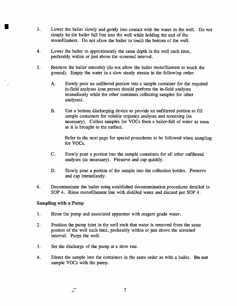
I 3. Lower the bailer slowly and gently into contact with the water in the well. Do not simply let the bailer fall free into the well while holding the end of the monofilament. Do not allow the bailer to touch the bottom of the well.
4. Lower the bailer to approximately the same depth in the well each time, preferably within or just above the screened interval.
5. Retrieve the bailer smoothly (do not allow the bailer monofilament to touch the ground). Empty the water in a slow steady stream in the following order:
A. Slowly pour an unfiltered portion into a sample container for the required in-field analyses (one person should perform the in-field analyses immediately while the other continues collecting samples for other analyses).
B. Use a bottom discharging device to provide an unfiltered portion to fill sample containers for volatile organics analyses and screening (as necessary). Collect samples for VOCs from a bailer-full of water as soon as it is brought to the surface.
Refer to the next page for special procedures to be followed when sampling for voes.
C. Slowly pour a portion into the sample containers for all other unfiltered analyses (as necessary). Preserve and cap quickly.
D. Slowly pour a portion of the sample into the collection bottles. Preserve and cap immediately.
6. Decontaminate the bailer using established decontamination procedures detailed in SOP 4. Rinse monofilament line with distilled water and discard per SOP 4.
Sampling with a Pump
1. Rinse the pump and associated apparatus with reagent grade water.
2. Position the pump inlet in the well such that water is removed from the same portion of the well each time, preferably within or just above the screened interval. Purge the well.
3. Set the discharge of the pump at a slow rate.
4. Direct the sample into the containers in the same order as with a bailer. Do not sample VOCs with the pump.
7

Note: The tubing which comes in contact with the water should be Teflon. New tubing will be used at each well (unless dedicated) and discarded after sample collection is completed.
SPECIAL PROCEDURES WHEN SAMPLING FOR voes
1. Evaluate the area around the sampling point prior to sample collection for possible sources of air contamination by VOCs. Products that may give off VOCs and possibly contaminate a sample include perfumes and cosmetics, skin applied pharmaceuticals, suntan lotion, and automotive products (gasoline, starting fluid, windshield deicers, carburetor cleaners, etc.) Keep the caps off the sample vials for as short a time as possible.
2. Wear clean gloves (latex or surgical) when sampling for VOCs.
3. Use a bottom-emptying device when using a bailer to sample for VOCs.
4. Do not use a suction pump when sampling for VOCs. Do not filter samples collected for VOC analysis.
5. Keep the VOC sample butt!P.s and the containers used for mailing the bottles tightly sealed to prevent possible contamination.
6. CH2M HILL requires two 40-mL vials with Teflon septum tops to be filled by staff.
7. Remove the cap ring from the first sample vial. Make sure that the Teflon liner does not fall out. If the liner falls out, replace it with a new clean cap.
8. Fill the sample vial immediately, allowing the water stream to strike the inner wall of the vial to minimize formation of air bubbles. · Do not rinse the sample vial before filling. Fill the sample vial, with a minimum of turbulence, until the water forms a positive meniscus at the brim. Allow the vial to overflow slightly.
9. Replace the cap quickly by gently setting it on the water meniscus. Tighten firmly, but do not over tighten. Invert the vial and tap it lightly. If you see air bubbles in the sample, do not add more sample. Use another vial to collect another sample. If bubbles form in the sample collected repeat the procedure until you obtain a proper sample.
10. Repeat this procedure for the second VOC sample.
8
I

I FIELD FILTERING
Inorganic Compounds:
A 0.45-micron disposable filter will be used while collecting inorganics samples with a bailer. The used filter will be discarded after sample collection at each well is completed per SOP 4.
MKE10014F7 A. WPS
9
I
I
SOP NO. 2: SAMPLE CONTAINERS, PRESERVATION, AND HANDLING
Samples will be collected at each monitoring well location as indicated in the current Groundwater Monitoring Plan for SC Johnson Wax. The sample matrix table in the plan will specify the well location, analyses, sample containers, and preservation methods. Sample bottles are to be placed on iced coolers immediately after collecti_on.
Some sample types require preservation to retard biological action, retard hydrolysis, and reduce sorption effects. Preservation methods consist of pH control through chemical addition, refrigeration, and protection from light. Refrigeration of samples will be achieved by storing samples in iced coolers until samples are ready for packaging and shipment in coolers with double-bagged ice. The laboratory will provide bottles with appropriate preservatives already added or provide appropriate preservatives in vials so samples can be preserved in the field. Preserved bottles will be prelabeled and identified as "preserved" in order to distinguish them from nonpreserved bottles. Safety glasses and nitrite or latex gloves should be worn whenever handling sample bottles containing preservatives.
VOC/GRO Samples
The laboratory will pretreat bottles used for volatile organics and GRO samples with HCl before delivery to the site.
The sample bottles should be filled slowly to minimize volatilization due to agitation. Sample containers should be filled so that no headspace (air bubbles) remain in the container. Avoid overfilling the VOC and GRO bottles (overfilling will dilute the HCl preservative). Each sample container must be checked for the presence of air bubbles using the procedure described in the section ''Special Procedures When Sampling for VOCs" under the SOP entitled, "Water Level Measurement and Groundwater Sampling.''
ORO Samples
A 1-liter amber bottle will be used for DRO samples. The sample bottle should be filled to the shoulder. Following sample collection, add 5 mL of 50-percent HCl to the sample bottle to preserve the sample. Cap the bottle and invert to mix.
MKE10014F7 A. WP5
10
I SOP NO. 3: IN-FIELD MEASUREMENTS
The following are general procedures. See the individual tests in the section entitled '' Field Measurement Equipment'' for more detailed calibration instructions.
TEMPERATURE
1. Rinse the thermometer with reagent grade water.
2. Immerse the thermometer in a freshly collected sample.
3. Wait for the temperature to equilibrate (no more than 2 to 3 minutes).
4. Read and record the temperature to the nearest l.0°C while the thermometer is immersed in the sample (do not pull the thermometer out of the sample.)
5. Rinse the thermometer with reagent grade water, and place it somewhere safe for future use.
SPECIFIC CONDUCTANCE
1. Set up and calibrate the conductivity meter according to manufacturer's instructions.
2. Set the dial to the desired range for measurement (e.g., x 100 µmhos/cm range).
3. Measure the temperature of the sample with a thermometer per above procedure and set the temperature dial on the conductivity meter to the measured temperature (if required by your particular meter).
4. Rinse the probe (and thermometer if one is used) with reagent grade water.
5. Place the probe in the sample and move it up and down several times. Rotate the cell or probe slowly in the sample until the reading stabilizes. (Some cells may require different procedures.)
6. Read and record conductivity measurement and the temperature. Multiply the reading by the range to which the dial is set.
7. Rinse the probe with reagent grade water.
11

8. Correct the measurement to 25°C using the equation supplied by the manufacturer (if not already corrected by the meter). The ''corrected'' specific conductance should be recorded onsite.
pH
1. Set up and calibrate the pH meter according to the manufacturer's instructions to cover the range of expected values. The temperatures of the buffers and the sample should be within 5°C ofeach other.
2. Rinse the electrodes thoroughly with reagent grade water.
3. Immerse the electrode in the sample.
4. Wait for the reading to stabilize (usually no more than 2 or 3 minutes).
5. Read and record the pH to the nearest O .1 unit.
6. Remove the electrode from the sample.
7. Rinse the electrode with reagent grade water.
8. Store the electrode in the buffer solution (or solution recommended by the manufacturer) between sample measurements.
9. Recalibrate according to the manufacturer's instructions, at beginning and end of day.
COLOR AND TURBIDITY
Color: Note color after filtration against a white background.
Turbidity: Note if any turbidity is present, e.g., cloudy, turbid, clear.
12
I
I - I
FIELD MEASUREMENT EQUIPMENT
FIELD MEASUREMENT OF SPECIFIC CONDUCTIVITY AND TEMPERATURE
METHOD: Specific Conductivity
REFERENCE: Methods for Chemical Analysis of Water and Wastes, U.S. EPA Method 120.1, 1983
DETECTION LIMIT: 1 µmho/cm@ 25°C
RANGE: 0.1 to 100,000 µmholcm
SAMPLE HOLDING TIME: Determine onsite or within 24 hours
REAGENTS: Distilled water in squirt bottle and standard potassium chloride solution
APPARATUS: Conductivity meter and electrode
REAGENT PREPARATION
1. Stock Potassium Chloride (KCI) Solution (1.00 N): Dissolve 74.555 g KCl in distilled water and dilute to 1,000 mL in a volumetric flask.
2. Standard Potassium Chloride Solution (0.01 N): Dilute 10.0 mL of stock 1.00 N KCl solution to 1,000 mL with distilled water using a volumetric pipet and flask.
PROCEDURE
1. With mode switch at OFF position, check meter zero. If not zeroed, use meter screw to adjust to zero.
2. Plug probe into jack on side of meter.
3. Turn mode switch to red line and turn red line knob until needle aligns with red line on dial. If they cannot be aligned, change the batteries.
13

4. Immerse probe in 0.01 N standard potassium chloride solution. Do not allow the probe to touch the sample container.
5. Set the mode control to TEMPERATURE. Record the temperature on the bottom scale of the meter in degrees Celsius.
6. Tum MODE switch to appropriate conductivity scale, (i.e., XlOO, XlO, or Xl). Use a scale that will give a mid-range output on the meter.
7. Wait for needle to stabilize (about 15 seconds}, multiply reading by scale setting, and record the conductivity. The conductivity reading must then be corrected for temperature.
Where:
Calculate conductivity using the formula:
GT Gzs ;;::; -----~
[1 + 0.02 (T-25)]
Gzs
T
GT
=
-
-
conductivity at 25°C, µmho/cm
temperature of sample, °C
conductivity of sample at temperature T, µmho/cm
Table 1 lists the values of conductivity this solution would have if the distilled water were nonconductive. However, since even high purity distilled water is slightly conductive, the measured conductivity will be higher by an amount equal to the water's conductivity.
8. Report results for the standard solution with each data set.
9. Record the type of meter and probe used on field sheet.
10. Rinse probe with deionized water.
11. Wipe meter clean as necessary.
12. Repeat steps 5 through 11 for water samples.
13. After returning to laboratory, compare results with previous data. Report problems to laboratory personnel.
14
I

Table 1 Conductivity Meter Calibration Table
Temperature Conductivity Temperature Conductivity (OC) (µmho/cm) (OC) (µmho/cm)
15 1,141.5 23 1,353.6
16 1,167.5 24 1,380.8
17 1,193.6 25 1,408.1
18 1,219.9 26 1,436.5
19 1,246.4 27 1,463.2
20 1,273.0 28 1,490.9
21 1,299.7 29 1,518.7
22 1,326.6 30 1,546.7
ACCURACY AND PRECISION
Accuracy and precision are dependent on the instrument used. Refer to the manufacturer's manual.
For the YSI Model 33 conductivity meter (per operating manual):
Conductivity
Expected accuracy ±2.5 percent at 500, 5,000, and 50,000 plus ±2 percent for probe.
Expected accuracy ±3 percent at 250, 2,500, and 25,000 plus ±2 percent for probe.
Temperature
Expected accuracy ±0.1 °C at 2 °C plus probe ±0.6°C at 45°C plus probe
Probe ±0.1 °C at 0°C ±0.3 °C at 40°C
15

PREVENTATIVE MAINTENANCE
Refer to manufacturer's manual.
FIELD MEASUREMENT OF pH
METHOD: Electro metric
REFERENCE: Methods for Chemical Analysis of Water and Wastes, U.S. EPA, Method 150.1, 1983
SENSITMTY: 0.1 pH unit
RANGE: 1 to 12 pH units
SAMPLE HOLDING TIME: Less than 6 hours
REAGENTS
• pH buffer solutions for pH 4, 7, and 10
• Deionized water in squirt bottle
APPARATUS
• pH meter
• Combination electrodes
• Beakers
• Glassware that has been washed with soap and water, rinsed twice with hot water, and rinsed twice with deionized water
CALIBRATION
Per manufacturer's instructions at the beginning and end of each day.
16
I

I
I
PROCEDURE
1. Before going into the field:
a) Check batteries.
b) Do a quick calibration at pH 7 and 4 to check electrode.
c) Obtain fresh solutions.
2. Calibrate meter using calibration procedure.
3. Pour the sample into a clean beaker.
4. Rinse electrode with deionized water between samples.
5. Immerse electrode in solution. Make sure the white KCl junction on side of electrode is in the solution. The level of electrode solution should be 1 inch above sample to be measured.
When calibrating the meter, use pH buffers 4 and 7 for samples with pH < 8, and buffers 7 and 10 for samples with pH > 8. If meter will not read pH 4 or 10, something may be wrong with the electrode. Return it to the laboratory and explain the malfunction.
Measurement of pH is temperature dependent. Therefore, temperatures of buffers and samples should be within about 2°C. For refrigerated or cool samples, use refrigerated buffers to calibrate the pH meter.
Weak organic and inorganic salts and oil and grease interfere with pH measurements. If oil and grease are visible, note on data sheet. Clean electrode with soap and water and rinse with a 10-percent solution of HCl. Then recalibrate meter.
Following field measurements:
a) Report any problems. b) Compare with previous data. c) Clean all dirt off meter and inside case. d) Store electrode in pH 4 buffer.
ACCURACY AND PRECISION
Accuracy and precision are dependent on the instrument used; refer to manufacturer's manual. Expected accuracy and precision are ±0.1 pH unit.
17
PREVENTATIVE MAINTENANCE
Refer to manufacturer's manual.
HNu MONITORING SOP
OPERATION
For complete operating instructions, refer to the manufacturer's instruction manual.
CALIBRATION
By analyzing a gas of known concentration, the HNu is easily calibrated. Isobutylene, typically a 100 ppm benzene equivalent, is used as the calibration gas. When calibrating the HNu, always remember to:
• Calibrate in the range to be tested.
• Deliver the calibration gas at ambient temperature and pressure. Handle gas cylinders with care.
• Calibrate every day.
The calibration gas must be stable during the period of use and must be at a concentration that reflects field sample concentrations. All gas cylinders must have proper regulators.
CALIBRATION PROCEDURE
To calibrate an HNu:
1. Identify the probe by lamp label.
2. Connect the probe.
3. Affirm the ionization potential of the calibration gas.
4. Perform a battery check.
5. Zero the HNu.
6. Sample calibration gas and adjust to proper reading.
7. Repeat steps 5 and 6.
18
I
I I

I
8. If calibration cannot be achieved, the lamp must be cleaned.
9. Replace lamp if the lamp output is too low or if the lamp has failed.
To obtain more than a two-point calibration, dilute the calibration gas to known concentrations and take additional readings.
PREVENTATIVE MAINTENANCE
Refer to manufacturer's instruction manual.
OVA MONITORING SOP
OPERATION
For complete operating instructions, refer to the manufacturer's instruction manual.
CALIBRATION
By analyzing a gas of known concentration, the OVA is easily calibrated. Methane in air at a concentration of 100 ppm is typically used as the calibration mixture, although the OVA can be calibrated to many other compounds.
Primary calibration of an OVA is performed at the factory.
CALIBRATION PROCEDURE
To calibrate an OVA in the field:
1. Zero the instrument.
2. Sample the calibration mixture and adjust to proper reading. Handle gas cylinders with care.
3. Next, set the calibration switch to a different range.
4. Sample another calibration mixture of different concentration and adjust to proper reading.
5. Zero the instrument.
PREVENTATIVE MAINTENANCE
Refer to manufacturer's instruction manual.
MKE10014F7A.WP5
19

I
SOP NO. 4: DECONTAMINATION AND WASTE DISPOSAL
This section documents the decontamination and waste disposal procedures to be used during the execution of the field program. The decontamination procedures cover the decontamination of personnel, sampling equipment, monitoring equipment, heavy equipment.
PERSONNEL DECONTAMINATION
The following personnel decontamination procedures will be used:
• Wash boots in trisodium phosphate (TSP) and water (approximately 2.5 percent TSP by weight), then rinse with water.
• If disposable latex booties are worn over boots while in the work area, remove and discard into DOT-approved 55-gallon drums.
• Wash outer gloves in TSP solution, rinse, remove, and discard into DOT-approved 55-gallon drums.
• Remove disposable coveralls and discard.
• Remove respirator if worn.
• Remove inner gloves and discard.
• At end of the work day, shower entire body including hair either at the work place or home. Put all clothing worn onsite in plastic bag for separate laundering.
• Sanitize respirator, if worn.
SAMPLING EQUIPMENT DECONTAMINATION
The following sampling equipment decontamination procedures will be used:
• Prior to entering the potentially contaminated zone, wrap soil contact points in clean plastic.
• Wash all equipment surfaces that will contact the soil/water with 2.5 weight percent TSP and water solution, rinse with a 50-volume percent
20

mixture of methanol and distilled water. Follow with triple rinse with distilled water.
• Collect all rinsate for proper disposal in SC Johnson Wax process sewers.
• Place clean samplers (hailers) on a clean plastic sheet to air dry before reuse.
MONITORING EQUIPMENT DECO NT AMINA TI ON
The following monitoring equipment decontamination procedures will be used:
• Wrap soil contact points in plastic to reduce need for subsequent washing.
• Wipe any monitoring equipment that had possible contaminated soil/water contact with a damp cloth. Wipe first with a cloth damp with TSP wash solution, next with a cloth damp with methanol/distilled water rinse, and then three times with a cloth damp with distilled water.
HEAVY EQUIPMENT DECONT AMINA TI ON
The following procedures will be used to decontaminate heavy equipment:
• Steam clean the rigs and excavating equipment, prior to admitting the equipment into the work area, using SC Johnson Wax steam cleaning facilities located near Building 51 or a portable steam cleaner. (This consists of a high pressure hot water [50 to 60°C] rinse.)
• At completion of drilling, steam clean the augers and other equipment coming into contact with potentially contaminated soil/water.
• At completion of fieldwork (just before demobilization), steam clean equipment again. The rinse waters will be collected in drains that lead to process sewers.
WASTE DISPOSAL
When generated, drummed excess soil boring cuttings will be stored at the facility within a secure area. To minimize drum storage, whenever possible, excavation spoils generated during excavation will be used as backfill and returned to their respective places of orig1n, i.e., test pit or boring.
21
I
Decontamination liquids from heavy equipment steam cleaning will be collected at the Building 51 truck unloading dock process sewer leading to the Waxdale wastewater treatment plant. At this plant, they will be treated to meet industrial pretreatment requirements for the City of Racine wastewater treatment plant.
During drum storage, analytical sample results will be obtained from soil borings. These results will be used to evaluate the nature of contamination of each drum. To enable correlation of this data with drum contents, all drums will be clearly and permanently labeled so that materials contained within can be associated with a specific boring analytical results.
Depending on the results of this evaluation, the need for additional waste sampling and characterization will be identified as appropriate for the selected waste disposal method.
MKEI0014F7A.WP5
22

SOP NO. 5: CH2M HILL CHAIN-OF-CUSTODY PROCEDURES
SAMPLE CUSTODY
A sample is under custody if:
1. It is in your possession, or 2. It is in your view, after being in your possession,-or 3. It was in your possession and you locked it up, or 4. It is in a designated secure area.
FIELD CUSTODY PROCEDURES
1. Collect only the number of samples needed to represent the media being sampled. To the extent possible, determine the quantity and types of samples and sample locations prior to the actual fieldwork. As few people as possible should handle samples.
2. The field sampler is personally responsible for the care and custody of all samples collected until they are properly transferred or dispatched.
3. Sample tags shall be completed for each sample, using waterproof ink unless prohibited by weather conditions. Each sample tag or label will contain the month, day, year, and time of sampling, the sample identification number, the media (soil, water, sediment), the nature of collection (grab or composite), the location of the sample, the sampler's name, the analyses requested, and any preservatives used.
4. The CH2M HILL Project Manager will determine whether proper custody procedures were followed during the fieldwork and will decide if additional samples are required.
TRANSFER OF CUSTODY AND SIDPMENT
1. Samples are accompanied by a chain-of-custody record. When transferring the possession of samples, both the individual relinquishing and receiving will sign, date, and note the time of custody transfer on the record. This record documents sample custody transfer from the sampler, through another, to the analyst in the laboratory.
23

2. Samples will be packaged properly for shipment and dispatched to the laboratory for analysis, with a separate custody record accompanying each shipment. Shipping containers will be sealed for shipment to the laboratory. The method of shipment, courier name(s), and other pertinent information is entered in the "Remarks" section on the custody record.
3. All shipments will be accompanied by the chain-of-custody record identifying its contents. The original record will accompany the shipment, and the copy will be retained by the field team leaders.
4. Freight bills, Post Office receipts, and Bills of Lading will be retained as part of the permanent documentation.
CHAIN-OF-CUSTODY FORM
Those samples being shipped to laboratories for analysis will use the appropriate laboratory-specific chain-of-custody.
The CH2M HILL chain-of-custody form (Figure C-1) will be used for shipment of all other samples and is filled out .as follows:
1. SAMPLED BY AND TITLE-The person who took the samples signs this box and gives his title, and the date and time he finished taking samples.
2. RELINQUISHED BY -The sampler signs this box when he gives the samples to someone else, and he fills in the date and time they left his possession.
3. RECEIVED BY -The person who receives the samples signs here and fills in the date and time he receives them. This date and time should be the same as the ''relinquished by,'' unless the samples were shipped.
4. RELINQUISHED BY-The person who has custody of the samples signs here and fills in the date and time when he relinquishes them.
5. See instructions for 3.
6. See instructions for 4.
7. For laboratory use only, do not mark in this box.
8. PROJECT NUMBER-Applies only to samples submitted by CH2M HILL.
9. PROJECT NAME-Applies only to samples submitted by CH2M HILL.
10. CLIENT NAME-Name of the company requesting the analysis.
24

- - k'tGuim---t!-1 - I!!!!
ClfM HI LL CHAJN OF CUSTODY RECORD PROJECT NUMBER PROJECT NAME
ANALYSES REQUESTED FOR LAB USE ONL'{ 21 8 9
CLIENT NAME LAB A'
1 0 .,, PROJ H QC
REPORT TO: COPr'TO: w z
1 1 1 2 ~ z ACK VERIFIED
REQUESIED COMPLETION DATE LABORATORY 0 DATE lt-NOICED u 1 3 1 4 u.
0 NO. OF SAMPLES pg __ ol __ QC
0.. u.J aJ
~ ~ ~ DISPOSITION: D R STA 0 ::> DAIi NO DAIE llME u l.!) SAMPLE DESCRIPTION z
REMARKS
·--· --- ---- ----- -- ·-- -· ---· ---- ·--- ··-- -----· ---•• ·----·- -- --- -- -- .
J 5 __ 1 6 --· _J.1- J.8 _is ?n .2J -- 22... --· ------ -- - - ----··- -- ---- -2.4 ·- -·· . -- ...
--··--- ------ ----f--· -·- ·-···· ·--- .. -·---------··-------·
. ------ ----- -·- ------ -------- - -
---, __
-·-- ----------------------- ·- ...
-·. -- . ---·· ----- ----------------.
.. .. ----------- -- - ,___ __ --- .. - ------· ----·- - .
···---- -----·-- - ---- ----------- --··- -- ------ --- ..
. -- ----- ------- - - -- - -· ---- ------- ------ . - --·- ------·•--··· -·-- - . -
-- --- -------. --- - - --- - --- ------ ------------- ----- . -.... - -.
----- ----· --- -·· -- .. --··- --- - -- .. - --··-·· -- -·- -- ·-- --------. .. ----
-- . -- ---·· ---· ---- --·- -- -·- •· --- ---- ---· __ ,. ___ ---------·--····- .. -- . -·· -- --
·····---- --•·· --- ··- - -·----·---- ·----------·----· ·-·- --- -- --· -- ---- --- ·-- . --- ·- ·• --- ---- ----- --·· - .. - - .. --
- ..... --- --· ---· -· ·- ---· --· ·--- -- -- --· ---- -··- ··--· -- ·------· -·-. - ···--· --
SAMPLED BY AND TITLE (SIGNATURE) DATE/TIME RELINQUISHf ,IIE) DATE/TIME RECENED BY: (SIGNAIURE) DAIE/IIME
1 2 3 -I
RELINQUISHED BY: (SIGNAIURE) DATE/TIME RECENED BY: (SIGNATURE) ,,ME RELINQUISHED BY: (SIGNATURE) DAIE/TIME RECENED BY LAB: (SIGNAJURE) DAIE/IIME
4 5 I 6 7 ··-
SAMPLING PROGRAM SAMPLE SHIPPED VIA 27 AJR BUS BILL NUMBER REMARKS ?C.
SOWA NPOES RCRA 26 0 UPS 0 BUS 0 FED-EX OJHER 28 D D D (SPEClfY) □ HAND OTHER
('\,c,o,A, ,1>nN w1m. - no1r..1NAI ArrnMPANlf~ ~HIPMFNT PINK - COP\' JO COORDINATOR FIELD FILES YELLOW - CLIENT REY 6/87 fORM 340

11. REPORT TO-Name of the person who receives the laboratory report.
12. COPY TO-Name of anyone else who should receive a copy of the report.
13. REQUESTED COMPLETION DATE-When the results are required. Additional charges may apply whenever requests are made for dates of less than 4 weeks turnaround time.
14. LABORATORY-The location of the laboratory to which the samples will be submitted.
15. STATION NO.-If the sample points are numbered, record the number here.
16. DATE-The date on which the sample was taken.
17. TIME-The time at which the sample was taken.
18. COMP-Check here if this is a composite sample.
19. GRAB-Check here if this is a grab sample.
20. SAMPLE DESCRIPTION-Sample identification number is entered here.
21. NUMBER OF CONTAINERS-The number of individual sample bottles containing portions of the same samples.
22. ANALYSES REQUESTED-Make one column for each parameter or group of parameters.
23. FOR LAB USE ONLY-Do not mark in this area.
24. REMARKS-Record any comments about each sample on the same line as the sample description, e.g. , '' Wastewater contains V OCs. ''
25. REMARKS-Record any comments regarding the samples as a whole.
26. SAMPLING PROGRAM-The reason the samples were taken. For example, mark the NPDES box for samples taken for an NPDES DMAR.
27. SAMPLE SHIPPED VIA-How the samples are being shipped to the laboratory, e.g., "UPS."
28. AIR BUS BILL NUMBER-The number on the shipping papers by which the package can be traced.
25
I

I
LABORATORY CUSTODY
Laboratory custody procedures for the selected laboratory will be as described in the Laboratory's QAPP.
These procedures will include:
• Designation of a sample custodian
• Correct completion by the custodian of the chain- of-custody record, sample tag, and laboratory request sheet (including documentation of sample condition upon receipt)
• Laboratory sample tracking and documentation procedures
• Secure sample storage (in the appropriate environment-refrigerated, dry, etc.)
• Proper data logging and documentation procedures including custody of all original laboratory records
FIELD LOGBOOK
All information pertinent to a field survey or sampling effort will be recorded in a field log book or equivalent standardized form. Each page/form will be consecutively numbered and will be at least 4-1/2 inches by 7 inches in size. All entries will be made in indelible ink and all corrections will consist of line-out deletions that are initialed and dated. As a minimum, log book will include the following:
• Purpose of sampling
• Location, description, and log of photographs of the sampling point
• Details of the specific site sampled (for example, the elevation of the casing, casing diameter and depth, integrity of the casing, etc.)
• Name and address of field contact
• Documentation of procedures for preparation of reagents or supplies which become an integral part of the sample (e.g., filters and absorbing reagents)
• Identification of sampling crew members
• Type of sample (for example, groundwater, soil, sludge, or wastewater)
26

• Suspected waste composition
• Number and volume of sample taken
• Sampling methodology, including distinction between grab and composite samples
• Information on the calibration of any field equipment used
• Sample preservation
• Date and time of collection
• Collector's sample identification number(s)
• Sample distribution and how transported (for example, name of the laboratory and cartage agent-Federal Express, United Parcel Service)
• References such as maps of the facility or site sampled
• Any field measurements made (for example, pH, specific conductance, temperature, and water depth)
• Signature and date by the personnel responsible for observations
• Decontamination procedures
Sampling situations vary widely. No general rules can specify the extent of information that must be entered in a log book or standardized form. However, such records must contain sufficient information so that someone can reconstruct the sampling activity without relying on the collector's memory. The log book and standardized forms will be kept under strict chain-of-custody procedures.
CORRECTIONS TO DOCUMENTATION
Unless prohibited by weather conditions, all original data recorded on sample identification tags and chain-of-custody records will be written with waterproof ink. No accountable serialized documents are to be destroyed or thrown away, even if they are illegible or contain inaccuracies that require a replacement document. These documents will be archived as part of the project file.
, If an error is made on an accountable document assigned to one individual, that individual shall make corrections by making a line through the error and entering the correct information. The erroneous information should not be obliterated. Any
27
I
I
I

I
subsequent error discovered on an accountable document should be corrected by the person who made the entry. All subsequent corrections must be initialed and dated.
PACKING AND SIDPPING PROCEDURES
Sample packaging and shipping procedures are based on U.S. Environmental Protection Agency (EPA) Specifications, as well as U.S. Department of Transportation (DOT) regulations and the IATA Regulations. The procedures will vary according to sample concentration and matrix and are designed to provide optimum protection of samples and the public. As a guideline, we will be using CH2M HILL's document "Shipping Dangerous Goods by Air" as appropriate.
The samples will be shipped within 24 hours of collection. Shipping containers must be insulated and durable. If vermiculite is used in packing, bagged samples are to be cushioned within the shipping container with vermiculite packing material (Zonolite) or bubble wrap. To prevent vermiculite contamination of samples, all containers regardless of size/type must be placed inside a sealed plastic bag before packing in vermiculite/ zonolite.
MKE10014F7 A. WPS
28

1- ,_ ----
c_
" (T'
• I J
~ '') I 'I
I I. u '-' u I (J
r., re v -~ :L: (/) rt)
l.., 111 11:
I I. I II.
--
506
,_ I- - 1-, I- - - - - - - - -
UJ 0.. >-I-a: 0 I-z a: a.. w en <( UJ _J 0..
FIGURE C-2
l'l[.I\Sf 1,;0MrlE I~ 1111 1111 0111.11\I IOll 111 IIIE ~ CII.OCKS OVII IMEll ltl 0111\H!lf. ~f.f 111\CK OF rOIIM 6El HIii COl.ll'I EIE l'IIErAllllTION INStnUCIIClNS.
----·---YOllll ir11r11111 rxrm~s IIC:C:C>IIIII IIIIWll'll OAlE
~~~~$:• All1B1ll NUMeen
W llt!ii□-7-4 i'.3•-mo\
II II I Ill llll Ill I Ill I I Ill Ill I I Ill I Ill l\l I I\I I Ill I \II\ ----·····-. ·----------:-----------------1 FROU (You, Na,ne) to 1nec1p11nr1 H1m<1) II lloll fol Piek Up DI S11unhy o,1v,r,.
lleclpl1n1'1 l'!lon1 Nc,nbtr
CQUPANY
STREET ADDnESS
CITY
OEPARTUENT/FLOOR HO.
STATE
COUPAHY
STllEEt ADDRESS (P.O. BOX NVUBEnS
OEPARTMENT/FlOOn NO
>-0..
i-------------------=--=---~o CIIY STIITE (.)
(.!) --··---l,..1---------_,..._........., ___ "'I ·-·--·--·-•··• 7.
IN l!HO!nlHG 1111S s111rM(HI, s111rPtn AGnus IIIAI ZIP ~':..:'.:.!!:,f:t~~;""" I-___ LL_L I I c s11All NOi e1 UABll Ion SP!Wl. 1Nc101H• L
IAl on COHS!OUINIIAL 011~G1s AA1S1No rnoM J l Z CAnAIAGE IIEnfOI. 1.1.C. 01S -- .• -··· --- ::)
voun HO 11 S,f\ff!nEHCl Nu,..01ns 1rns 1 12 CIIAAACIERSGI." ~(SO APl'EAA OH INVOICE! CLAIMS All wAAIIAHIIIS. rxi•nf SS on IMruEO. wrru HOERAlE ,rn1ss use O ~,3~ ~l~~mTs~f.msTg•~~~6~:o,g"J, 1€u~rn~irm:t~[,\ fO(ICHT CllAnC!S 0
. p:, .. ;N·; I] e,~ 5-,pp., 0 BIi Rtelplonl'I f. ~Aecl 8JI lid My f I.C Accl O 811 C,odll C.,d ~~cmrtNJ' f::rr:: ... ~·.t~~1ri1 rrm:,Yr~p~m"b'Jt. ~
, ........:_ · fORAIIUH IS llMITIU 10 $100 00 IIUIOAI IXPn!SS 00£S ._O!Cl_A_nE-O V-Al-'-UE-CIIA_RC_( •• , - __ q ~!.• II\ Ad,,nc, Accounl Humbo</C.tdll ~ mbtf=======..===;:===;:=:a=?.~:=r==J...:~;;O~t ,;CAAO;;.;;.;,;,'.;;CA;,;n;;G;.;O;.;l;;;IA;;;e;;;,l;,;ll~Y.;;•H;.;;S..,u!IA;,;,;;H..,CE;.;.. ____ ~ z
SERVICES l)(llVERY AHO SPIOAL HANa.iHo- rACAACIS ~ °\,Cjf~O 0IS Clll:CK ~y CHE eox 01(0( SERVIC(S lll~RED ,--------+-----'----(.!)
AG!il'OO rnionm 1
L·)1MAIIG,1f,-(1....:111 11.Jt" 10 llS I
! I hllO \1111 itn
l[j
~Ii) --.□
:$ 0 ORM·S ANO RAOIOACTIVE
0 gwi1c:~J.'°:>a.:~':~ MAURIAL ONLY I 0 cu, te 1011S I
. IIVllllllC.111. IS NEXT DUSINESS OAY I 0
IIOLD ,un r1CK•UP Al f()ll OWIIIG 1----.t.--..::if-,-----1f--l
IA1mi,H1r~rJE~"ifr"1!r'gJ,fl 1~y;
1' 1---H-l.~~'-'t---il--l
PII0NE NUMll!ll 1S IIEUUllllll
DtlMl
IAluMAr M.fl'flCl AIOll"IO .._....,wl1._.,.,,...,,._,.,.....,.,yl A«IIM:IIU MUCUS Mlll't1Cl l'·I W ........... ,"""'91 ............ ,
w,s..-..... s.o.. .. ..,,.., ,......._ ............. , .,,.., _____ ,n
011Clll Ult.lAl, llhttl ____ _ fed•nl (xp,111 CD1pG11lon lmployH Ho .
IMONOAY THn0UG~ fnlOAYI: two DAYS ROM J,LJ.Sl(}J)!AWAII SATURDAY [){UV• I O __________ 1------------1
ERY AVAILABLE IH COHIIHEH!Al U.S. DATE/TIME for fed11&1 lai,,111 Uu _SE_E_··_SP~~!_IA:_:H::;O:.:l::;.IN;.:0::;..'_' -----·•..:t..;0:=.. _________ _
ADVANCE 01\ICIH a: 0
AC!il'RO AOVAHC( O[SIIHAll()H
OTIIER
.. · •. ,
·,.~ IOTAl CIIARCES
rART 120◄ 1730164
R(VISIOH DAIi 2/0) S PnlHl(O US A
-· ~-.11.,.~
{1
' - ,,. -1...
·...,
.;;J
•

...
-
I L ' I
~-} I• I
I r
·• -- ,,.--~- -,~-- . -- ,_ -~aa:5~,,-.,~=-... ··:· ... ,-' . . . '. •. ~ · ....
FIGURE C-3
~ I HEREBY CERTIFY THAT THE CONTENTS OF THIS CONSIGNMENT ARE FULLY AND ACCURATELY DESCRIBED ABOVE BY PROPER ~,
S SHIPPING NAME AND ARE CLASSIFIED, PACKED, MARKED, AHO LABELED, AND IN PROPER CONDITION FOR CARRIAGE BY AIR s~' ACCORDING TO APPLICABLE NATIONAL GOVERNMENTAL REGULATIONS.
NAME AND t'1lEOF >ER ON SIG~IIID CERTIFICATION ' •". •; . ~~,, ' >; '"'"~'Ne~ 1ELEPkONE Nd.·, . · ; · ' s,aNA TuaE OF SHIPPER · .• • s S~,,,,, ,,,,,,,,, _.J .I
..-.:--• .. ,,'