I-5 Existing Geometric Deficiency Analysis - WSDOT
21
G:\DEA\WDOT00000330\0600INFO\0650DESIGNDOCUMENTS\0651GENERAL\GEOMETRIC DEFICIENCIES LIST\GEOMETRIC DEFICIENCIES ANALYSIS REPORT FORM DRAFT1.DOC Report I-5 Existing Geometric Deficiency Analysis Prepared for Oregon Department of Transportation Washington State Department of Transportation April 2011 Prepared by
-
Upload
khangminh22 -
Category
Documents
-
view
0 -
download
0
Transcript of I-5 Existing Geometric Deficiency Analysis - WSDOT

G:\DEA\WDOT00000330\0600INFO\0650DESIGNDOCUMENTS\0651GENERAL\GEOMETRIC DEFICIENCIES LIST\GEOMETRIC DEFICIENCIES ANALYSIS REPORT FORM DRAFT1.DOC
Re p or t
I-5 Existing Geometric Deficiency Analysis
Prepared for
Oregon Department of Transportation
Washington State Department of Transportation
April 2011
Prepared by

COLUMBIA RIVER CROSSING PROJECT

Contents
COLUMBIA RIVER CROSSING PROJECT I
Sections Page
Executive Summary ......................................................................................................................ES-1
Objective ........................................................................................................................................... 1-1 Introduction and Background ........................................................................................................ 2-1 Analysis ............................................................................................................................................ 3-1
1. Adequacy of Horizontal and Vertical Sight Distance for the Given Design Speed ............. 3-1 2. Insufficient Superelevation on the Ramps, Connectors, and Mainline Highway ................ 3-2 3. Available Shoulder and Lane Widths for Emergency Access and/or Incident Response... 3-2 4. Weaving Lengths of Collector-Distributor and Auxiliary Lanes ........................................... 3-3 5. Speed Change (Acceleration/Deceleration) Lane Lengths ................................................. 3-5
Oregon .......................................................................................................................... 3-5 Washington ................................................................................................................... 3-5
6. Adequacy of Guardrail, Barriers, and Crash Cushions ....................................................... 3-8 7. Susceptibility to Wrong-way Moves .................................................................................... 3-8 8. Deficient Vertical Clearances (Under 17 Feet) ................................................................... 3-8 9. Pavement Rutting, Abrupt Edges, and Flat Spots in Superelevation Transitions ............... 3-8 10. Sufficient Maintenance Vehicle Parking Locations ........................................................... 3-9 11. Bicycle and Pedestrian Pathways ..................................................................................... 3-9
List of Tables
Table 2-1. Geometric Features Studied ............................................................................................. 2-2 Table 3-1. Horizontal and Vertical Sight Distance Evaluation for Oregon and Washington .............. 3-1 Table 3-2. Superelevation Deficiencies .............................................................................................. 3-2 Table 3-3. Shoulder Width Deficiencies in Oregon ............................................................................ 3-3 Table 3-4. Shoulder Width Deficiencies in Washington ..................................................................... 3-3 Table 3-5. Weaving Length Deficiencies of Auxiliary (AUX) Lanes in Oregon................................... 3-4 Table 3-6. Weaving Length Deficiencies of AUX Lanes in Washington............................................. 3-4 Table 3.7. Speed Change Lane Deficiencies in Oregon .................................................................... 3-6 Table 3-8. Speed Change Lane Lengths in Washington ................................................................... 3-7 Table 3-9. Locations Susceptible to Wrongt Way Movements ........................................................... 3-8
List of Appendices
Appendix A. Bicycle and Pedestrian Pathway Photos .......................................................................A-1

COLUMBIA RIVER CROSSING PROJECT ES-1
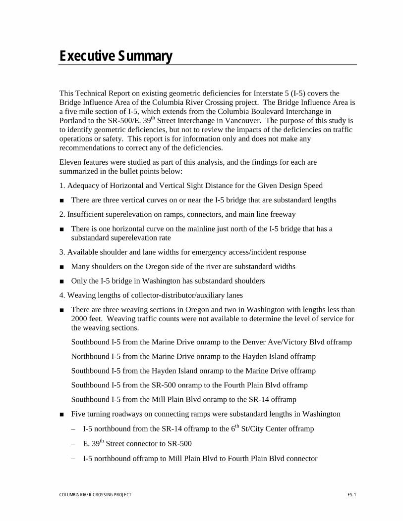
Executive Summary
This Technical Report on existing geometric deficiencies for Interstate 5 (I-5) covers the Bridge Influence Area of the Columbia River Crossing project. The Bridge Influence Area is a five mile section of I-5, which extends from the Columbia Boulevard Interchange in Portland to the SR-500/E. 39th Street Interchange in Vancouver. The purpose of this study is to identify geometric deficiencies, but not to review the impacts of the deficiencies on traffic operations or safety. This report is for information only and does not make any recommendations to correct any of the deficiencies.
Eleven features were studied as part of this analysis, and the findings for each are summarized in the bullet points below:
1. Adequacy of Horizontal and Vertical Sight Distance for the Given Design Speed
■ There are three vertical curves on or near the I-5 bridge that are substandard lengths
2. Insufficient superelevation on ramps, connectors, and main line freeway
■ There is one horizontal curve on the mainline just north of the I-5 bridge that has a substandard superelevation rate
3. Available shoulder and lane widths for emergency access/incident response
■ Many shoulders on the Oregon side of the river are substandard widths
■ Only the I-5 bridge in Washington has substandard shoulders
4. Weaving lengths of collector-distributor/auxiliary lanes
■ There are three weaving sections in Oregon and two in Washington with lengths less than 2000 feet. Weaving traffic counts were not available to determine the level of service for the weaving sections.
Southbound I-5 from the Marine Drive onramp to the Denver Ave/Victory Blvd offramp
Northbound I-5 from the Marine Drive onramp to the Hayden Island offramp
Southbound I-5 from the Hayden Island onramp to the Marine Drive offramp
Southbound I-5 from the SR-500 onramp to the Fourth Plain Blvd offramp
Southbound I-5 from the Mill Plain Blvd onramp to the SR-14 offramp
■ Five turning roadways on connecting ramps were substandard lengths in Washington
− I-5 northbound from the SR-14 offramp to the 6th
− E. 39
St/City Center offramp th
− I-5 northbound offramp to Mill Plain Blvd to Fourth Plain Blvd connector
Street connector to SR-500

I-5 EXISTING GEOMETRIC DEFICIENCY ANALYSIS
ES-2 COLUMBIA RIVER CROSSING PROJECT
− SR-14 loop ramp to I-5 southbound where it merges with the 5th
− I-5 northbound offramp to SR-500 to the E. 39
Street onramp th
5. Acceleration/deceleration lane lengths
Street connector ramp
■ Seven speed change lanes in Oregon and five in Washington are substandard length
I-5 southbound Victory Blvd onramp
I-5 southbound Marine Drive offramp
I-5 northbound Marine Drive onramp
I-5 northbound Hayden Island offramp
I-5 northbound Hayden Island onramp
I-5 southbound Hayden Island onramp
I-5 southbound Hayden Island offramp
I-5 northbound to SR-14 offramp
I-5 northbound to 6th
SR-14 westbound to I-5 southbound loop ramp
Street/City Center offramp
I-5 southbound to Mill Plain Blvd offramp (ramp grade greater than maximum allowable)
I-5 southbound Fourth Plain Blvd onramp
6. Adequacy of guardrail, barriers, and crash cushions
■ No needs identified in this study
7. Susceptibility to wrong-way moves
■ The on and offramp connections to I-5 southbound from Fourth Plain Blvd present movements confusing to drivers that may lead to wrong-way movements
8. Deficient vertical clearances (under 17 feet)
■ There were no vertical clearance issues found in this study
9. Pavement condition for rutting or abrupt edges
■ Minor rutting exists on the Portland Cement Concrete sections of I-5 on the Oregon side of the river
10. Sufficient maintenance vehicle pull-out locations
■ Discussions with WSDOT and ODOT maintenance personnel did not reveal the need for any additional pull-out locations for maintenance vehicles
11. Bicycle and pedestrian pathways for current ADA standards, bridge railing heights, exposure to traffic, tripping hazards, fixed objects in path, etc.

I-5 EXISTING GEOMETRIC DEFICIENCY ANALYSIS
COLUMBIA RIVER CROSSING PROJECT ES-3
■ A field trip along the bicycle and pedestrian pathways from Victory Blvd to 6th
Connectivity headed northbound from Victory Blvd through Delta Park is blocked by a raised median near the 76 gasoline station
Street in Vancouver revealed many deficiencies detailed by photos in Appendix A. Some deficiencies found were as follows:
Pathway widths on the I-5 bridge are 3 to 5 feet
Hand railings on the I-5 bridge are lower than OSHA standards
Connectivity at Hayden Island is poor since the pathway crosses three streets and cyclists are forced to dismount and walk in the crosswalk
Concrete barriers at bridge heads need fencing to protect pedestrians and cyclists from falling into I-5 traffic
Large gaps in chain link fencing leave opportunity for pedestrians to cross the on and off ramps from I-5 northbound at Hayden Island
Directional sign mounted in the path of bikes and pedestrians near the Hayden Island offramp from I-5 northbound


COLUMBIA RIVER CROSSING PROJECT 1-1
SECTION 1
Objective
The purpose of this study was to identify existing geometric deficiencies along the Interstate 5 mainline and interchange ramps from the N. Lombard Street Interchange in Portland to the State Route-500/E. 39th Street (Burnt Bridge Creek) Interchange in Vancouver. The deficiencies represent significant safety hazards for this section of I-5, which carries around 125,000 vehicles per day to and from Portland and Vancouver. This list was compiled as part of the environmental review process for the Columbia River Crossing Project and serves to inform the project owners of the existing freeway conditions. This review does not include an economic analysis of what it would cost to upgrade the freeway and its interchange components to today’s engineering standards, nor does it recommend that any of these deficiencies be fixed. This report is purely for information only and does not represent a comprehensive engineering analysis of the impacts that the deficiencies make on day to day traffic operations or safety.


COLUMBIA RIVER CROSSING PROJECT 2-1
SECTION 2
Introduction and Background
As part of the existing geometric deficiencies inventory for the Columbia River Crossing Project, data was collected for the I-5 mainline and all connecting ramps using the following sources of information:
Washington State Department of Transportation (WSDOT) • Video log of I-5 between the Washington/Oregon State Line (MP 0.00) and the Main
Street/Hwy 99 Interchange (MP 2.91) • TRIPS System State Highway Log for I-5 from MP 0.00 to MP 2.91 • Interchange Viewer sheets from WSDOT website (link accessed 11/10/05):
http://www.wsdot.wa.gov/mapsdata/tdo/interchange/ • As-constructed plans of the SR 14 Interchange project (Contract No. 2156) dated July 31,
1981 • As-constructed plans of the Mill Plain Interchange project (Contract No. 1193) dated
May 12, 1978 • As-constructed plans of the Fourth Plain Interchange project (Contract No. 1978) dated
October 3, 1980 • As-constructed plans of the Fourth Plain to Burnt Bridge Creek Interchange project
(Contract No. 0694) March 4, 1977 • WSDOT Design Manual (English version with 2005 updates and supplements), Chapters
6, 9, and 10 (link accessed 11/10/05): http://www.wsdot.wa.gov/fasc/EngineeringPublications/Manuals/DesignManual.pdf
Oregon Department of Transportation (ODOT) • Video log of I-5 between the Lombard Street Interchange (MP 305.22) and the
Oregon/Washington State Line (MP 308.38) • Straightline Chart (Highway Log) and Interchange Diagrams from ODOT website (link
accessed 11/10/05): ftp://ftp.odot.state.or.us/tdb/trandata/maps/slchart/ • As-constructed plans of the Swift Interchange – Delta Park Interchange Section project
(“V” No. 22V-89) dated October, 1992 • As-constructed plans of the North Unit Minnesota Freeway Section project (“V” No. 8V-
56) dated February 3, 1966 • As-constructed plans of the Jantzen Beach Interchange project (“V” No. 10V-83) dated
November 1, 1974 • As-constructed plans of the Minnesota Freeway Section project (“V” No. 7V-247) dated
April 29, 1966 • ODOT Standard Drawings RD205 and RD210 (links accessed 11/10/05):
http://www.oregon.gov/ODOT/HWY/ENGSERVICES/docs/dwgs/eng/erd205.pdf http://www.oregon.gov/ODOT/HWY/ENGSERVICES/docs/dwgs/eng/erd210.pdf

I-5 EXISTING GEOMETRIC DEIFICIENCIES ANALYSIS
2-2 COLUMBIA RIVER CROSSING PROJECT
• ODOT Highway Design Manual (2003 English version), Chapters 5, 6, 9, and 11 (link accessed 11/10/05): http://egov.oregon.gov/ODOT/HWY/ENGSERVICES/hwy_manuals.shtml
The features listed in Table 2-1 were compared to the current standards as published by the Oregon and Washington Departments of Transportation and are presented in the analysis portion of this memo.
TABLE 2-1. GEOMETRIC FEATURES STUDIED Geometric features evaluated in this study from Milepost (MP) 305.98 in Oregon to MP 2.42 in Washington
NUMBER FEATURE
1 Adequacy of horizontal and vertical sight distance for the given design speed
2 Insufficient superelevation on ramps, connectors, and main line freeway
3 Available shoulder and lane widths for emergency access/incident response
4 Weaving lengths of collector-distributor/auxiliary lanes
5 Acceleration/deceleration lane lengths
6 Adequacy of guardrail, barriers, and crash cushions
7 Susceptibility to wrong-way moves
8 Deficient vertical clearances (under 17 feet)
9 Pavement condition for rutting or abrupt edges
10 Sufficient maintenance vehicle pull-out locations
11 Bicycle and pedestrian pathways for current ADA standards, bridge railing heights, exposure to traffic, tripping hazards, fixed objects in path, etc.
The features listed above represent the major components of an urban freeway that affect safety and traffic operations. Most of these features are governed by the design speed of the given highway. Oregon and Washington determine design speed in very different manners. In brief, Oregon takes the desired running speed on the highway during off-peak hours, but Washington designs urban freeways dependent on 10 mph greater than the posted speed limit. Due to the slight differences in standard-selecting policies, the two states have similar, but different criteria for what is considered “standard” in their respective jurisdictions. Also, Oregon and Washington horizontal alignments differ since Oregon chooses to use spiral transitions to connect the circular horizontal curves and Washington does not. The analysis section breaks each of the listed categories down and describes what resources and methods were used to obtain the results presented in each sub-section.

COLUMBIA RIVER CROSSING PROJECT A-1
SECTION 3
Analysis
1. Ad e q u a c y o f Ho rizo n ta l a n d Ve rtic a l S ig h t Dis ta n c e fo r th e Give n De s ig n S p e e d Horizontal and vertical stopping sight distance, or the distance one would take at a given design speed to avoid an object in the road, is one component of the project that governs the design of horizontal and vertical alignment. Crashes occur frequently in areas where long queues back up close to a short vertical or horizontal sight distance. The following tables outline the questionable horizontal and vertical curves in the corridor with those below standard in yellow.
TABLE 3-1. HORIZONTAL AND VERTICAL SIGHT DISTANCE EVALUATION FOR OREGON AND WASHINGTON
LOCATION (MILEPOST)
FEATURE DESCRIPTION
AS-BUILT EXISTING
CURVE LENGTH
(FT)
MIN. STAND-
ARD LENGTH
(FT)
MAIN-LINE
DESIGN SPEED (MPH)
RAMP DESIGN SPEED (MPH)
SUPER-ELEVA-
TION RATE
(FT/FT)
CURVE RADIUS
(FT)
SIGHT DIST. TYPE (VERT., HORIZ., OR STOPPING)
308.10 - 0.20
I-5 bridge crest vertical curve
531.4 3795.9 70 N/A N/A N/A Vertical
0.34 Sag vertical curve
400 963.0 70 N/A 0.05 1890 Vertical
0.45 Sag vertical curve
400 532.8 70 N/A 0.05 3400 Vertical

I-5 EXISTING GEOMETRIC DEIFICIENCIES ANALYSIS
3-2 COLUMBIA RIVER CROSSING PROJECT
2. In s u ffic ie n t S u p e re le va tio n o n th e Ra m p s , Co n n e c to rs , a n d Ma in lin e Hig h wa y Superelevation governs the speed drivers can navigate horizontal curves at a given level of comfort. The following tables indicate where the superelevation is deficient for the given design speed.
TABLE 3-2. SUPERELEVATION DEFICIENCIES
LOCA-TION
(STATION RANGE)
DIREC-TION
FEATURE DESCRIP-
TION
LINE DESIG-NATION
MAIN-LINE
DESIGN SPEED (MPH)
CURVE RADIUS
(FT)
CURVE SUPER-ELEVA-
TION (FT/FT)
NOTES
102+80 to 105+37
North-bound
Mainline Horizontal Alignment
LR 60 1200 0.05 For a design speed of 60 mph and a radius of 1200 ft, a
superelevation of 8% is required
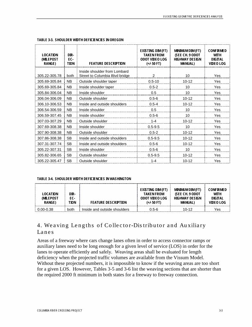
3. Ava ila b le S h o u ld e r a n d La n e Wid th s fo r Em e rg e n c y Ac c e s s a n d /o r In c id e n t Re s p o n s e Freeway shoulders provide space for vehicles to recover if they veer off the traveled way, a space for broken down vehicles to wait outside of the stream of traffic, and a pathway for emergency vehicle access/egress from a crash scene. The Highway Capacity Manual states that a lack of shoulder space actually inhibits the flow of traffic since drivers feel more comfortable driving at higher speeds if they have empty pavement beside them rather than guardrails, concrete barriers, or other fixed objects. Both ODOT and WSDOT require 10 to 12 foot outside shoulders and 10 foot inside shoulders for freeways with six lanes or more. The following tables outline where the shoulders are deficient along the corridor. It is clear that Oregon has many more locations with substandard shoulder widths. This hampers operations and safety of the highway and should be remedied if the highway were to be reconstructed.
I-5 EXISTING GEOMETRIC DEIFICIENCIES ANALYSIS
COLUMBIA RIVER CROSSING PROJECT 3-3
TABLE 3-3. SHOULDER WIDTH DEFICIENCIES IN OREGON
LOCATION (MILEPOST
RANGE)
DIR-EC-
TION FEATURE DESCRIPTION
EXISTING DIM (FT) TAKEN FROM
ODOT VIDEO LOG (+/- 50 FT)
MINIMUM DIM (FT) (SEE CH. 9 ODOT
HIGHWAY DESIGN MANUAL)
CONFIRMED WITH
DIGITAL VIDEO LOG
305.22-305.78 both Inside shoulder from Lombard Street to Columbia Blvd bridge 2 10 Yes
305.69-305.84 NB Outside shoulder taper 0.5-10 10-12 Yes 305.69-305.84 NB Inside shoulder taper 0.5-2 10 Yes 305.84-306.04 NB Inside shoulder 0.5 10 Yes 306.04-306.09 NB Outside shoulder 0.5-6 10-12 Yes 306.10-306.53 NB Inside and outside shoulders 0.5-4 10-12 Yes 306.54-306.59 NB Inside shoulder 0.5 10 Yes 306.59-307.45 NB Inside shoulder 0.5-6 10 Yes 307.03-307.29 NB Outside shoulder 1-4 10-12 Yes 307.69-308.38 NB Inside shoulder 0.5-9.5 10 Yes 307.90-308.38 NB Outside shoulder 0.5-2 10-12 Yes 307.86-308.38 SB Inside and outside shoulders 0.5-9.5 10-12 Yes 307.31-307.74 SB Inside and outside shoulders 0.5-6 10-12 Yes 305.22-307.31 SB Inside shoulder 0.5-6 10 Yes 305.82-306.65 SB Outside shoulder 0.5-9.5 10-12 Yes 305.22-305.47 SB Outside shoulder 1-4 10-12 Yes
TABLE 3-4. SHOULDER WIDTH DEFICIENCIES IN WASHINGTON
LOCATION (MILEPOST
RANGE)
DIR-EC-
TION FEATURE DESCRIPTION
EXISTING DIM (FT) TAKEN FROM
ODOT VIDEO LOG (+/- 50 FT)
MINIMUM DIM (FT) (SEE CH. 9 ODOT
HIGHWAY DESIGN MANUAL)
CONFIRMED WITH
DIGITAL VIDEO LOG
0.00-0.38 both Inside and outside shoulders 0.5-6 10-12 Yes
4. We a vin g Le n g th s o f Co lle c to r-Dis tr ib u to r a n d Au xilia ry La n e s Areas of a freeway where cars change lanes often in order to access connector ramps or auxiliary lanes need to be long enough for a given level of service (LOS) in order for the lanes to operate efficiently and safely. Weaving areas shall be evaluated for length deficiency when the projected traffic volumes are available from the Vissum Model. Without these projected numbers, it is impossible to know if the weaving areas are too short for a given LOS. However, Tables 3-5 and 3-6 list the weaving sections that are shorter than the required 2000 ft minimum in both states for a freeway to freeway connection.

I-5 EXISTING GEOMETRIC DEIFICIENCIES ANALYSIS
3-4 COLUMBIA RIVER CROSSING PROJECT
TABLE 3-5. WEAVING LENGTH DEFICIENCIES OF AUXILIARY (AUX) LANES IN OREGON (see Fig. 9-28 of the ODOT Highway Design Manual)
LOCATION (MILEPOST
RANGE)
DIR-EC-
TION FEATURE DESCRIPTION
EXISTING DIM (FT) TAKEN FROM ODOT
VIDEO LOG (+/- 50 FT)
EXISTING DIM (FT) TAKEN FROM 7/2005
MICROSTATION BASE-MAPS & AS-
BUILTS
MINIMUM DIM (FT) (SEE CH. 9 ODOT
HIGHWAY DESIGN MANUAL)
RAMP DESIGN SPEED (MPH)
307.06-306.90 SB
Marine Drive onramp terminal point to Victory Blvd/Denver Ave offramp terminal point 1214.4 1245 2000 55
307.45-307.77 NB
Marine Drive onramp terminal point to Hayden Island offramp terminal point 2059.2 1820.3 2000 50
307.68-307.36 SB
Hayden Island onramp terminal point to Marine Dr offramp terminal point 2059.2 1855.3 2000 50
TABLE 3-6. WEAVING LENGTH DEFICIENCIES OF AUX LANES IN WASHINGTON (see Fig. 940-5 and 940-15 of the WSDOT Design Manual)
LOCATION (MILEPOST
RANGE)
DIR-EC-
TION FEATURE DESCRIPTION
SPEED CHANGE LANE
TYPE AS-BUILT EXISTING
DEMENSION (FT)
MINIMUM DIM (FT) (SEE CH. 940
WSDOT DESIGN MANUAL)
0.36-0.48 NB
005 P1 00028 offramp to 005 P5 00039 loop offramp
Off to off Free-way 633.6 1000
2.08-1.72 SB 005 S1 00198 onramp to 005 R1 00182 offramp
On to off (weaving) 1900.8 2000
0.94-0.70 SB 005 S1 00087 onramp to 005 R1 00079 offramp
On to off (weaving) 1267.2 2000
0.18-0.28 N/A 005 S1 00198 onramp to SR500 connector
System I/C turning rdwy 528 800
0.16-0.17 N/A 005 P1 00078 to 005 P2 00078 C/D road
System I/C turning rdwy 52.8 600
0.00-0.10 N/A
005 S5 00029 connector to 005 S6 00029 connector
System I/C turning rdwy 528 800
0.19-0.26 N/A 005 P1 00199 offramp to SR500 connector
System I/C turning rdwy 369.6 800

I-5 EXISTING GEOMETRIC DEIFICIENCIES ANALYSIS
COLUMBIA RIVER CROSSING PROJECT 3-5
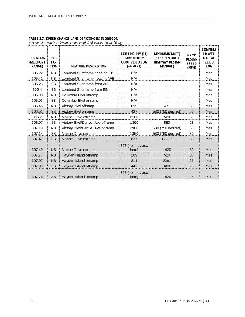
5. S p e e d Ch a n g e (Ac c e le ra tio n /De c e le ra tio n ) La n e Le n g th s One of the most critical aspects of a freeway interchange ramp is the length of the speed change lane. This could be the distance for cars and trucks to accelerate onto the freeway or decelerate onto an offramp. Considerable time was spent on this one aspect of the deficiency list since so many factors are involved when determining the standard length. If this lane is too short for heavy traffic volumes typical in an urban area, traffic operations are likely to deteriorate and crashes could result from a lack of merge length. This is particularly true when high truck volumes are present. This corridor has a large percentage of trucks (8%), thus making the case for keeping to “desirable” level standards instead of “minimum” levels.
Oregon The lengths of each existing speed change lane in Oregon were determined using the ODOT Standard Drawings RD205 and RD210. The entrance ramp adjusted acceleration lane lengths are determined using the existing degree of curve to find the turning highway design speed. A uniform value of 70 mph was used as the design speed for the mainline freeway to be conservative in the speed change lane lengths. An adjustment for grades was made where the ramp grade exceeded three percent. The exit ramp deceleration lane lengths were also adjusted for grade and for trucks where there are typically more than twenty per hour. The Lombard Street and Columbia Boulevard interchange ramp dimensions were taken from the as-constructed plans. The minimum dimensions for acceleration lanes listed in Table 3-7 below do not include the required 300 ft taper as shown on RD205. MicroStation was used to verify the as-constructed plan dimensions for all ramps. The maximum grade was checked against the maximum allowable grade for each state (5% for Oregon and 7% for Washington) and reported as well. The video logs were used to confirm lane drop and taper locations for the mainline freeway. The ramps are not available via video log, so a field trip confirmed questions regarding the ramps.
Washington When determining the length of each existing speed change lane in Washington, ramp design speed was determined by the superelevation and horizontal curve radius. The mainline design speed was taken to be ten miles per hour greater than the posted speed, per the WSDOT Design Manual. Also, the standard lengths are corrected for grades greater than three percent. The posted speed from the Columbia River to approximately MP 0.75 is currently 50 mph. Outside of this area, the posted speed is 60 mph. Therefore, design speeds of 60 and 70 mph were used for the respective mainline freeway sections. Table 3-8 shows the results of the analysis. Four ramp locations were found to be deficient in the length of the speed change lane. Two of these are deceleration lanes at SR-14 and I-5 Northbound. One is the acceleration lane from SR-14 to I-5 Southbound. The last is an acceleration lane from Fourth Plain Blvd to I-5 Southbound. All other lanes appear to have sufficient length.
I-5 EXISTING GEOMETRIC DEIFICIENCIES ANALYSIS
3-6 COLUMBIA RIVER CROSSING PROJECT
TABLE 3.7. SPEED CHANGE LANE DEFICIENCIES IN OREGON (Acceleration and Deceleration Lane Length Deficiencies Shaded Gray)
LOCATION (MILEPOST
RANGE)
DIR-EC-
TION FEATURE DESCRIPTION
EXISTING DIM (FT) TAKEN FROM
ODOT VIDEO LOG (+/- 50 FT)
MINIMUM DIM (FT) (SEE CH. 9 ODOT
HIGHWAY DESIGN MANUAL)
RAMP DESIGN SPEED (MPH)
CONFIRM-ED WITH DIGITAL VIDEO LOG
305.22 NB Lombard St offramp heading EB N/A Yes 305.41 NB Lombard St offramp heading WB N/A Yes 305.23 SB Lombard St onramp from WB N/A Yes 305.4 SB Lombard St onramp from EB N/A Yes 305.98 NB Columbia Blvd offramp N/A Yes 305.93 SB Columbia Blvd onramp N/A Yes 306.45 NB Victory Blvd offramp 695 471 60 Yes 306.51 SB Victory Blvd onramp 437 580 (750 desired) 60 Yes 306.7 NB Marine Drive offramp 2100 520 60 Yes 306.97 SB Victory Blvd/Denver Ave offramp 1390 550 25 Yes 307.19 NB Victory Blvd/Denver Ave onramp 2900 580 (750 desired) 60 Yes 307.14 SB Marine Drive onramp 1350 580 (750 desired) 30 Yes 307.47 SB Marine Drive offramp 637 1228.5 30 Yes
307.49 NB Marine Drive onramp 367 (not incl. aux
lane) 1420 30 Yes 307.77 NB Hayden Island offramp 289 520 30 Yes 307.97 NB Hayden Island onramp 211 2201 25 Yes 307.99 SB Hayden Island offramp 447 660 25 Yes
307.76 SB Hayden Island onramp 367 (not incl. aux
lane) 1420 25 Yes

I-5 EXISTING GEOMETRIC DEIFICIENCIES ANALYSIS
COLUMBIA RIVER CROSSING PROJECT 3-7
TABLE 3-8. SPEED CHANGE LANE LENGTHS IN WASHINGTON (Acceleration and Deceleration Lane Length Deficiencies Shaded Gray)
DIR-EC-
TION FEATURE
DESCRIPTION
AS-BUILT EXISTING
DIM-ENSION
(FT)
MICRO-STATION EXISTING DIMEN-
SION (FT)
MIN. STD.
DIM. (FT)
MAIN-LINE
DESIGN SPEED (MPH)
RAMP DESIGN SPEED (MPH)
AVG GRADE OF SPD
CHANGE LANE
RAMP MAX
GRADE (%)
RAMP RADIUS
(FT)
RAMP SUPER-ELEVA-
TION (FT/FT)
NB I-5 to SR-14 EB N/A 170 430 60 30 -2.54 +4.3 340 0.08
NB I-5 to 7th St/Downtown N/A 385 460 60 25 +1.77 +5.93 210 0.06
NB SR-14 WB to I-5 1203.48 900 420 60 45 -1.29 +6.34 625 0.08
SB SR-14 WB to I-5 600 450 1020 60 25 -1.52 -2.02 200 0.06
SB I-5 to SR-14 WB 1601.16 1680 420 60 40 -3.23 -4.54 600 0.08
NB I-5 to Mill Plain Blvd 1530 1500 390 70 45 +2.76 +3.05 700 0.06
NB Mill Plain to I-5 4811.88 4300 2600 70 40 +5.23 +6.47 600 0.06
SB I-5 to Mill Plain Blvd 1029.64 1500 830.25 70 0 -5.59 -8.39 2000 0.04
SB Mill Plain to I-5 1887.12 1700 1620 70 0 +0.38 +2.84 1500 0.05
NB I-5 to Fourth Plain Blvd 3207.84 3700 351 70 45 +3.96 +5.19 600 0.04
NB I-5 to Fourth Plain Blvd 489.63 525 346.5 45 0 -1.45 +3.96 0 0.04
NB Fourth Plain Blvd to I-5 2884.33 2400 1620 70 0 +1.71 +5.00 3000 0.04
SB I-5 to Fourth Plain Blvd 1661.71 1400 490 70 35 -2.60 -2.60 350 0.09
SB Fourth Plain Blvd to I-5 1830.68 1250 1420 70 25 -2.18 -2.29 200 0.06
NB
I-5 to SR-500 EB/E 39th St 117.06 875 290 70 55 -0.36 -0.80 1000 0.08
NB
I-5 to SR-500 EB/E 39th St 657.96 800 576 55 0 -4.60 -4.60 3500 0.02
NB E 39th St to I-5 764.88 1600 348 70 50 -4.36 -5.96 800 0.08
SB I-5 to E 39th St N/A 2400 513 70 20 +4.10 +5.94 150 0.06
SB
E 39th St/SR500 to I-5 2037.73 2050 1000 70 40 +2.92 -3.82 550 0.07

I-5 EXISTING GEOMETRIC DEIFICIENCIES ANALYSIS
3-8 COLUMBIA RIVER CROSSING PROJECT
6. Ad e q u a c y o f Gu a rd ra il, Ba rrie rs , a n d Cra s h Cu s h io n s Guardrail, concrete barriers, and impact attenuators such as a sand barrel type crash cushions all serve to keep traffic from hitting fixed objects, steep slopes, or head-on traffic. This analysis did not reveal any drastic need for different treatments to the roadside or median, however, in a reconstruction project, an engineering analysis of each feature named above should be completed to reveal any necessary improvements.
7. S u s c e p tib ility to Wro n g -wa y Mo ve s Interchange ramps that take unconventional shapes or paths may confuse drivers enough where they may travel the wrong way on such a facility. This extremely hazardous scenario can be avoided through standard design of interchange ramps and proper signing and delineation. The analysis in this study identified the ramps in the following table as susceptible to wrong way movements due to the listed reasons.
TABLE 3-9. LOCATIONS SUSCEPTIBLE TO WRONGT WAY MOVEMENTS
LOCATION (MILEPOST RANGE) DIRECTION FEATURE DESCRIPTION NOTES
Ramps “005R100182” & “005S500154”
SB Fourth Plain Blvd on and off-ramps
Unconventional configuration of channelization could confuse drivers
8. De fic ie n t Ve rtic a l Cle a ra n c e s (Un d e r 17 Fe e t) The Federal Highway Administration (FHWA) currently requires 17 feet vertical clearance for all bridge structures crossing over a freeway. The profile sheets of the as-constructed plans were used to find the vertical clearances on the existing structures in the corridor. There were no vertical clearance deficiencies in the corridor of study.
9. P a ve m e n t Ru tt in g , Ab ru p t Ed g e s , a n d Fla t S p o ts in S u p e re le va tio n Tra n s it io n s Pavement rutting can cause serious safety issues when heavy rains fall and standing water collects in the wheel paths of cars and trucks. To avoid hydroplaning, freeway pavements need to drain quickly and efficiently. Edge drops at the inside edge of a horizontal curve (especially on connector ramps) are hazardous if drivers overcorrect the steering wheel when the front wheels drop off the pavement. This can cause the vehicle to swerve into adjacent lanes and possibly lose control. Flat spots that occur between superelevation transitions if poorly constructed can collect concentrated flows of water and pose a hazard to the traffic traveling through the water. The Portland Cement Concrete pavement surfaces on the Oregon side of the river have minor rutting problems, but no edges, flat spots, or rutting was observed elsewhere.
I-5 EXISTING GEOMETRIC DEIFICIENCIES ANALYSIS
COLUMBIA RIVER CROSSING PROJECT 3-9
10. S u ffic ie n t Ma in te n a n c e Ve h ic le P a rkin g Lo c a tio n s The safety of State Employees is of great concern to the sponsoring agencies of this study. Safe areas for maintenance vehicles to park preferably off of the existing shoulder provide refuge for these vehicles, plus protection to their operators. When speaking with maintenance superintendents in Oregon and Washington about the need for additional pull-out locations, they said that there is not a need at this time for additional pull-outs. Therefore, this analysis will not recommend the addition of any more pull-out spaces.
11. Bic yc le a n d P e d e s tr ia n P a th wa ys A field trip via bicycle on the Oregon and Washington bicycle and pedestrian pathways was made to survey the existing conditions in early September, 2005. The photos in Appendix A show the deficiencies noted on the field trip. Standards in the ODOT Highway Design Manual (Chapter 11) and the WSDOT Design Manual (Section 1020) were not noted in this study. Most of the bicycle and pedestrian pathways were in Oregon since Washington does not currently have any multi-use paths on the I-5 right of way within the corridor of study. Photos of the field trip appear at the end of this memo in Appendix A. Some of the deficiencies noted in the photos are as follows:
Connectivity headed northbound from Victory Blvd through Delta Park is blocked by a raised median near the 76 gasoline station
Pathway widths on the I-5 bridge are 3 to 5 feet
Hand railings on the I-5 bridge are lower than OSHA standards
Connectivity at Hayden Island is poor since the pathway crosses three streets and cyclists are forced to dismount and walk in the crosswalk
Concrete barriers at bridge heads need fencing to protect pedestrians and cyclists from falling into I-5 traffic
Large gaps in chain link fencing leave opportunity for pedestrians to cross the on and off ramps from I-5 northbound at Hayden Island
Directional sign mounted in the path of bikes and pedestrians near the Hayden Island offramp from I-5 northbound