Hygienic Design, Installation, and Maintenance Standards for Draft Beer Dispense: German Progress...
9
MBAA TQ vol. 40, no. 4 • 2003 • pp. 271–279 271 Hygienic Design, Installation, and Maintenance Standards for Draft Beer Dispense: German Progress and North America’s Challenge Jaime Jurado The Gambrinus Company, San Antonio, TX 78232 ABSTRACT DIN 6650 (for beverage-dispensing systems) and the Gesellschaft für Öffentlichkeitsarbeit der deutschen Brauwirtschaft e.V. frame- work of practical systemwide standards indicate that component manufacturer standards, and industry-developed standards for design and installation in the field, can be established by expert panels in one case and by competing brewing companies working in cooperation in a taskforce in the other. The objectives of the recently established Draught Beer Guild in North America also demonstrate acknowledg- ment that draft dispense presents an opportunity for improvement. Field examples of component installation and hygienic maintenance issues will be shared, and the role of the brewer to support clearer standards will be discussed. Keywords: DIN 6650, draft beer, draft beer dispense, draft beer hygiene, draft beer installation, Draught Beer Guild SÍNTESIS Los estándares prácticos englobando sistemas amplios, señalados por la DIN 6650 (sistemas de dispensar bebidas) y la Sociedad de Divulgación de la Industria Cervecera Alemana, indican que están- dares de los fabricantes de componentes y estándares desarrollados para el diseño e instalación en el campo de trabajo pueden ser esta- blecidos por grupos expertos, para el primer caso, y por distintas cervecerías trabajando en conjunto con un grupo de trabajo, para el segundo caso. Los objetivos de la Draught Beer Guild (Gremio para Cerveza de Sifón) recientemente establecida en Norte América reco- noce que el equipo de sifón podría mejorarse. Se expondrán ejemplos del campo de trabajo para la instalación de componentes y se com- partirán temas de mantenimiento higiénico; también se discutirá porqué el cervecero debe respaldar la creación de estándares más claras. Palabras claves: DIN 6650, cerveza de sifón, la dispensa de cerveza de sifón, higiene de cerveza de sifón, equipo de cerveza de sifón, Draught Beer Guild Introduction Modern breweries are staffed with professionals who are qualified to evaluate and improve hygienic conditions in their operations. There is increasing demand for the expertise inside the brewery walls to be deployed in bars, taverns, pubs, and other outlets to ensure that draft beer is in the best presented form possible—to bring brewery standards to the dispense point. Progress from Germany will be shared, and a concept will be developed that is applicable to North America. An example this brewer has found that points toward the need for a better design of draft dispense is illustrated in Figure 1, which shows an actual installation where the beer from one keg is split to be dispensed from two separate taps. In this venue, the beer python bundle runs above the ceiling, and the beer drops down to dispense fonts. One could visit the restau- rant at noon, request the same beer from either tap, and then taste two markedly different beers. We avoid deadlegs in the brewery, and this is a philosophy that is prudent for the field as well. Correcting the system de- scribed above is physically challenging, and one solution is found in Figure 2; although anytime a keg is “shared” between two faucets, there is a much greater need to accommodate the split line with more complex cleaning protocols, which increases the likelihood of error. What may be a superior solution, if there is space in the cold keg storage area in the restaurant, is for an individual keg to feed to each line; but this solution is a compromise and beer quality suffers, since there was a deadleg put in place by the designer/installer to economize on installa- tion cost. Common sense and experience from the brewery can go a long way toward delivering draft dispense excellence. So how does it occur that situations such as deadlegs; incon- sistent cleaning routes and protocols; unbalanced gas applied to kegs; “hot spots” in the dispense route; worn and leaking hardware; blind spots not touched by detergents; brittle beer tubes; dark, slippery, cold rooms; etc. are found in the field? One answer is that there is not sufficient ‘looking’ being done; but the deeper answer is that brewers have not issued clear Corresponding author Jaime Jurado is director of brewing opera- tions at The Gambrinus Company, brewers and importers of beer in the United States. He researches practical and engineering ele- ments of draft dispense issues, and is an active participant in the Draught Beer Guild. E-mail: [email protected] Presented at the 116th Convention of the Master Brewers Associa- tion of the Americas, Milwaukee, WI, October 2003. Publication no. T-2003-1020-01 © 2003 Master Brewers Association of the Americas
-
Upload
independent -
Category
Documents
-
view
1 -
download
0
Transcript of Hygienic Design, Installation, and Maintenance Standards for Draft Beer Dispense: German Progress...

MBAA TQ vol. 40, no. 4 • 2003 • pp. 271–279
271
Hygienic Design, Installation, and Maintenance Standards for Draft Beer Dispense: German Progress and North America’s Challenge Jaime Jurado The Gambrinus Company, San Antonio, TX 78232
ABSTRACT
DIN 6650 (for beverage-dispensing systems) and the Gesellschaft für Öffentlichkeitsarbeit der deutschen Brauwirtschaft e.V. frame-work of practical systemwide standards indicate that component manufacturer standards, and industry-developed standards for design and installation in the field, can be established by expert panels in one case and by competing brewing companies working in cooperation in a taskforce in the other. The objectives of the recently established Draught Beer Guild in North America also demonstrate acknowledg-ment that draft dispense presents an opportunity for improvement. Field examples of component installation and hygienic maintenance issues will be shared, and the role of the brewer to support clearer standards will be discussed.
Keywords: DIN 6650, draft beer, draft beer dispense, draft beer hygiene, draft beer installation, Draught Beer Guild
SÍNTESIS
Los estándares prácticos englobando sistemas amplios, señalados por la DIN 6650 (sistemas de dispensar bebidas) y la Sociedad de Divulgación de la Industria Cervecera Alemana, indican que están-dares de los fabricantes de componentes y estándares desarrollados para el diseño e instalación en el campo de trabajo pueden ser esta-blecidos por grupos expertos, para el primer caso, y por distintas cervecerías trabajando en conjunto con un grupo de trabajo, para el segundo caso. Los objetivos de la Draught Beer Guild (Gremio para Cerveza de Sifón) recientemente establecida en Norte América reco-noce que el equipo de sifón podría mejorarse. Se expondrán ejemplos del campo de trabajo para la instalación de componentes y se com-partirán temas de mantenimiento higiénico; también se discutirá porqué el cervecero debe respaldar la creación de estándares más claras.
Palabras claves: DIN 6650, cerveza de sifón, la dispensa de cerveza de sifón, higiene de cerveza de sifón, equipo de cerveza de sifón, Draught Beer Guild
Introduction Modern breweries are staffed with professionals who are
qualified to evaluate and improve hygienic conditions in their operations. There is increasing demand for the expertise inside the brewery walls to be deployed in bars, taverns, pubs, and other outlets to ensure that draft beer is in the best presented form possible—to bring brewery standards to the dispense point. Progress from Germany will be shared, and a concept will be developed that is applicable to North America.
An example this brewer has found that points toward the need for a better design of draft dispense is illustrated in Figure 1, which shows an actual installation where the beer from one
keg is split to be dispensed from two separate taps. In this venue, the beer python bundle runs above the ceiling, and the beer drops down to dispense fonts. One could visit the restau-rant at noon, request the same beer from either tap, and then taste two markedly different beers.
We avoid deadlegs in the brewery, and this is a philosophy that is prudent for the field as well. Correcting the system de-scribed above is physically challenging, and one solution is found in Figure 2; although anytime a keg is “shared” between two faucets, there is a much greater need to accommodate the split line with more complex cleaning protocols, which increases the likelihood of error. What may be a superior solution, if there is space in the cold keg storage area in the restaurant, is for an individual keg to feed to each line; but this solution is a compromise and beer quality suffers, since there was a deadleg put in place by the designer/installer to economize on installa-tion cost.
Common sense and experience from the brewery can go a long way toward delivering draft dispense excellence.
So how does it occur that situations such as deadlegs; incon-sistent cleaning routes and protocols; unbalanced gas applied to kegs; “hot spots” in the dispense route; worn and leaking hardware; blind spots not touched by detergents; brittle beer tubes; dark, slippery, cold rooms; etc. are found in the field? One answer is that there is not sufficient ‘looking’ being done; but the deeper answer is that brewers have not issued clear
Corresponding author Jaime Jurado is director of brewing opera-tions at The Gambrinus Company, brewers and importers of beer in the United States. He researches practical and engineering ele-ments of draft dispense issues, and is an active participant in the Draught Beer Guild.
E-mail: [email protected]
Presented at the 116th Convention of the Master Brewers Associa-tion of the Americas, Milwaukee, WI, October 2003.
Publication no. T-2003-1020-01 © 2003 Master Brewers Association of the Americas

272 MBAA TQ vol. 40, no. 4 • 2003 Draft Beer Dispense Standards
guidelines and standards for installations to the personnel who plan and execute field installations. We also are not spending enough time to ensure that our distributors are serving as im-portant partners to our efforts.
In North America, it is easy to specify National Sanitary Foundation (NSF) approval or SK certification for hardware; but then we generally stop after mandating recommended clean-ing protocols and cleaning frequency as individual brewery
Figure 2. Deadleg removed from the installation in Figure 1.
Figure 1. Deadleg between active bar and overflow bar causes quality-dispense problems and a cleaning challenge.
Draft Beer Dispense Standards MBAA TQ vol. 40, no. 4 • 2003 273
standards. Here is where there is a need to establish and issue specifications.
Design Standards Germany is a good place to search for uniform standards, be-
cause there are two complementary sets of standards one can readily use as important guidelines: one set of standards exists for design/installation, and another set of standards exists for equipment manufacturers.
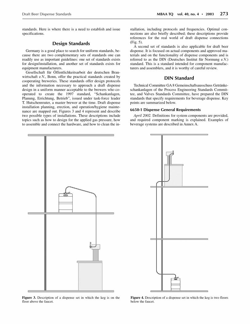
Gesellschaft für Öffentlichkeitsarbeit der deutschen Brau-wirtschaft e.V., Bonn, offer the practical standards created by cooperating breweries. These standards offer design protocols and the information necessary to approach a draft dispense design in a uniform manner acceptable to the brewers who co-operated to create the 1997 standard, “Schankanlagen, Planung, Errichtung, Betrieb”, issued under task-force leader T. Hutschenreuter, a master brewer at the time. Draft dispense installation planning, erection, and operation/hygiene mainte-nance are mapped out. Figures 3 and 4 represent and describe two possible types of installations. These descriptions include topics such as how to design for the applied gas pressure, how to assemble and connect the hardware, and how to clean the in-
stallation, including protocols and frequencies. Optimal con-nections are also briefly described; these descriptions provide references for the real world of draft dispense connections (Fig. 5).
A second set of standards is also applicable for draft beer dispense. It is focused on actual components and approved ma-terials and on the functionality of dispense components and is referred to as the DIN (Deutsches Institut für Normung e.V.) standard. This is a standard intended for component manufac-turers and assemblers, and it is worthy of careful review.
DIN Standard Technical Committee GA 8 Gemeinschaftsausschuss Getränke-
schankanlagen of the Process Engineering Standards Commit-tee, and Valves Standards Committee, have prepared the DIN standards that specify requirements for beverage dispense. Key points are summarized below.
6650-1 Dispense General Requirements April 2002. Definitions for system components are provided,
and required component marking is explained. Examples of beverage systems are described in Annex A.
Figure 3. Description of a dispense set in which the keg is on the floor above the faucet.
Figure 4. Description of a dispense set in which the keg is two floors below the faucet.

274 MBAA TQ vol. 40, no. 4 • 2003 Draft Beer Dispense Standards
6650-2 Requirements for Materials April 2002. Materials in beverage-dispensing systems shall
be suitable for the intended use. Materials shall safely with-stand mechanical and thermal stresses encountered when bev-erage-dispensing systems are installed and operated. Annex A lists examples of suitable materials in contact with beverages.
6650-3 Safety Requirements on Facility Component Parts
June 2002. Clause 5 addresses safety requirements so that all system components remain operative and tight and safely with-stand all mechanical and chemical stresses. Pressure regula-tors, pressure-relief valves, shut-off devices and manifolds for pressure pipes (i.e., required to be rated for at least 300 bar), pressure gauges (including required accuracy and error limit of ±0.1 bar), nonreturn valves, fittings and connectors, inlet gas lines, Y-fittings and connectors, liquid pumps, and flow meters are discussed.
6650-4 Hygienic Requirements on Components and Parts
April 2002. Dirt and contamination are defined. General hy-giene requirements are detailed in clause 4: all system compo-nents are designed so as to preclude contamination due to dirt, particularly due to microbial growth. Allowable dead space depth is described as “their depth shall be smaller than the smallest dimension of their cross section to facilitate cleaning.” Annex A illustrates examples of hygienic connections, includ-ing an acceptable hose-clip connection compared with an unac-ceptable one.
6650-5 Testing Requirements June 2002. Certification is a procedure by which a third
party gives written assurance that a product, process, or service conforms to specified requirements. An accredited testing labo-ratory can issue documentation, which is subject to third-party inspection, and an accredited certification body issues a certifi-cate. The body issues a test mark (SK mark) valid for 5 years, together with the certificate. A manufacturer shall maintain qualified staff, testing equipment, and instrumentation to vali-date compliance with technical specifications. A manufacturer can request that the period of validity may be extended without renewed testing if no modifications to the original have been incorporated. Appropriate tests are described and summarized
Figure 6. Performance testing and evaluation of hardware compo-nents is important. The single-beer font (or standard) shown, incorpo-rates the beer line, coolant inlet, coolant return, and insulation inside the font up to the shank. The beer at the face of the faucet is cooled by conduction from the shank, so the shank itself must be cooled to realize the goal. Once installed, it was determined that the system worked exactly as described by the manufacturer. The manufacturer characterized the unit in order for the customer to plan for correct in-stallation and utilization.
Figure 5. Connection to the beer-trunk python bundle.
Figure 7. Components such as python bundles are critical to success-ful installations, and parameters include thickness of the insulation layer, beer tube construction (barrier-lined), moisture barrier, and outer protective covering.
Draft Beer Dispense Standards MBAA TQ vol. 40, no. 4 • 2003 275
in Annex A, with additional tests described and summarized in Annex B. An example of a certificate and a test mark (SK mark) is found in Annex C.
6650-6 Requirements for Cleaning and Disinfection April 2002. Disinfection is defined as “a procedure to kill
microorganisms in a manner which is neither detrimental to health nor impairs the quality of foodstuffs”. Cleaning and dis-infection shall be deemed to have reached their objective if testing, briefly described in clause 7, does not result in any negative findings. Methods of testing include
i. Visual inspection. ii. Mechanical cleaning check.
iii. Chemical methods (with or without indicator) and the spent cleaning agent is visually checked.
iv. Sensory analyses (i.e., smell, taste). v. Microbiological methods. The tapped beverage is sampled
into sterile containers, without prior disinfection. A positive result would be 1,000 colony-forming units (CFU)/mL, and a value exceeding 100,000 CFU/mL is “unacceptable”.
vi. Other methods. Using the same sample technique as in (v), bioluminometry shall correlate with the above values.
Beer dispensers shall be cleaned and disinfected at 7-day inter-vals. Cleaning and disinfection methods are described in gen-eral terms.
6647-1 Means of Packaging— Cylindrical Beverage Containers—Part 1
October 1999. Applies to containers with a capacity of up to 100 L and rated for an allowable operating pressure of up to 3 bar.
32677 Connectors for Tapping Units of Beverage-Dispensing Systems
May 1998. Keg coupler/connector dimensions are described.
3542 Connectors and Sockets for Beverage Containers— Mating Dimensions
August 1998. Sockets for beverage containers are described.
Meeting a standard and being certified is a necessary attrib-ute of every component in an installation. The DIN standard ensures that a component conforms to clear performance, safety, and hygiene specifications.
But DIN standards lead to commercial options that can be utilized by any designer following the practical guidelines cre-ated by the German brewer’s task-force standards.
Not every aspect is covered. Actual performance of compo-nents over time is something draft dispense professionals come to learn by experience and field observation. Some components are easier to evaluate as acceptable, as in Figure 6. Yet there are important components that take effort for the installer to evaluate, as in Figure 7, and some components that are ex-tremely difficult to evaluate. Breweries or a third-party organi-
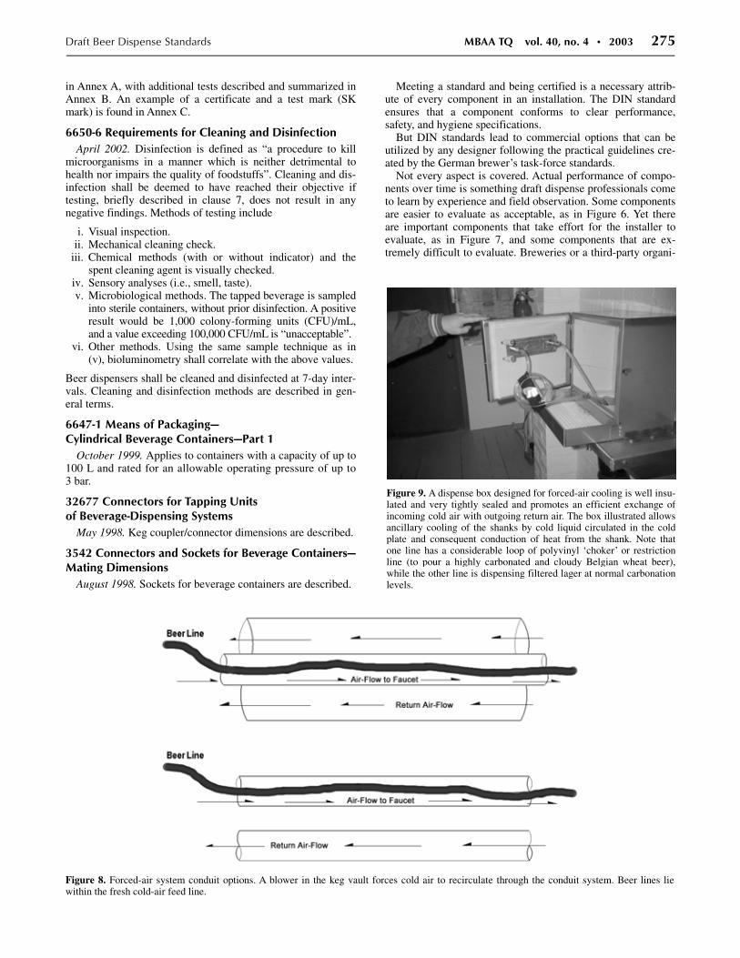
Figure 8. Forced-air system conduit options. A blower in the keg vault forces cold air to recirculate through the conduit system. Beer lines lie within the fresh cold-air feed line.
Figure 9. A dispense box designed for forced-air cooling is well insu-lated and very tightly sealed and promotes an efficient exchange of incoming cold air with outgoing return air. The box illustrated allows ancillary cooling of the shanks by cold liquid circulated in the cold plate and consequent conduction of heat from the shank. Note that one line has a considerable loop of polyvinyl ‘choker’ or restriction line (to pour a highly carbonated and cloudy Belgian wheat beer), while the other line is dispensing filtered lager at normal carbonation levels.

276 MBAA TQ vol. 40, no. 4 • 2003 Draft Beer Dispense Standards
zation could provide advise to professional installers relative to the evaluation of these difficult components.
Design Options We often find an opportunity for options in the installation.
For example, one recognizes several solutions for maintaining beer at the proper dispense temperatures in the beer trunk to the faucet. A distance up to 30 feet can be managed at a cool temperature, if the keg storage cooler has an adequate cool-ing capacity, by use of forced-air cooling; this allows recircula-tion of cold air from within the cold box to the font and returns the air to the box in a closed loop in one of two types of con-duit construction (Fig. 8). Forced-air cooling can only be con-sidered if the cooler has the sufficient refrigeration capacity specified.
There is one challenge with such a dispense that must be carefully addressed and that is cooling at the shank (the shank is the component where the faucet is attached). One can find dispense fonts that are designed for air cooling that also incor-porate connections so the shanks can also be water- or glycol-cooled, if required (Fig. 9).
Glycol-chilled pythons provide reliable and high-quality management of temperatures of dispensing beer. The capital cost is significantly greater than that for a forced-air installa-tion because of the Powerpack component, but there are fewer installation constraints and it is the only good method for long-draw installations. The Powerpack needs scheduled preventa-tive maintenance to keep it in good order. Careful attention to selection of the appropriate python bundle (Fig. 10), including consideration of planning for future growth at the installation, can make this technology very robust and include flexibility for the future. With the correct selection, water recirculation systems are an alternative to glycol recirculation systems; wa-ter systems include a mild biocide in the water (Fig. 11) for ad-ditional functionality.
Cleaning and Cleanability Standards Proven methodologies for cleaning dispense systems are
readily accepted by various breweries. The two types of “clean” one encounters are the ‘soak’ clean and the ‘recirculat-ing’ clean. The soak clean involves flushing a beer line, pack-ing it with detergent, soaking it for a manufacturer-specified time, and then flushing out the detergent with water prior to re-turning the route to dispense service. Depending on the length of line to be cleaned, there are different canisters available to provide adequate detergent volume (Figs. 12 and 13).
Figure 11. An under-the-cover look at a chilled water cooler, in use for python bundle and font cooling, in which two internal stainless steel loops could additionally be used for cooling a product flowing through the lines, such as pasteurized keg beer that is not kept cold. In this in-stallation (Shiner, TX), filtered drinking water and a noncarbonated lem-onade are chilled through the water reservoir before being dispensed.
Figure 10. What is under the protective cover of a beer python? A five-beer python is shown. In lieu of the thermal foil wrapping, a manufacturer might utilize thick polyethylene cling film.
Figure 12. Portable canisters for small “box” dispense sets and short draws.

Draft Beer Dispense Standards MBAA TQ vol. 40, no. 4 • 2003 277
The alternative is to approach dispense-system cleaning in the familiar way we utilize in the brewery, which is the recircu-lating line clean (Fig. 14). In Figure 14, eight distinct beer dis-pense routes are looped to make up the circuit. The concept is identical to cleaning beer mains in the brewery. If possible, in-cluding sponges in the protocol can add an extra degree of ef-fectiveness by physically scouring the walls of the beer line. Unfortunately, in the modern installation, one often encounters components that preclude use of sponges because they repre-sent sponge traps.
Hardware selection is complex, because the system designer sometimes has competing options for the same component. Standards such as NSF are important for proper component material selection criteria by the vendor, but an unanswered need is for meeting cleanability standards, such as 3-A in North America or the European Hygienic Engineering and Design Group (1). A common component of many long-draw lines is the flow-of-beer stop (FOB) (Fig. 15). There are a number of competing products available, and each has a differ-ent ease-of-cleaning characteristic. The FOB requires some free volume internally, and it is comparable to trying to clean a beer main that has a large cylindrical canister in the route, which can trap air (if not vented) and which has a larger sur-face area than the beer main.
There are many choices for beer faucets, keg couplers, flow meters, connection hardware, and flow restriction devices. Agreement between breweries on cleaning evaluation for com-ponents is an area that requires effort and time. A simple con-cept such as that utilized by the European Hygienic Engineer-ing and Design Group is useful when the evaluation is based
on determining how well a component is cleaned compared with a piece of food-grade tubing subjected to the same soil loading and cleaning regimen.
Different brewing companies have different specifications for cleaning draft dispense systems. Careful long-term study, such as that which we are undertaking at a commercial-grade eval-uation center representative of a ‘real account’ at The Spoetzl Brewery (Shiner, TX) will help in better understanding clean-ing frequency questions. Development work at Brewing Re-search International in the United Kingdom, in equipment manufacturer facilities, and by other breweries and university labs will progress the state of draft dispense. Dialogue between breweries through forums such as the Draught Beer Guild may help frame more-uniform requirements for draft beer customers from competing breweries.
Dispense Gas Versus Pneumatic Pump Beer dispense incorporates gases. Breweries might recom-
mend that electronic air-quality monitors be installed in keg cold rooms in the field. We accept the importance of such technology in our brewery cellars, but this has not been a concern in the field. The applied gas is assumed not to leak into the environ-ment but to remain trapped in the keg where it has displaced
Figure 13. Canister for mid-distance draw sets that remains in the cold room.
Figure 15. The flow-of-beer stop (FOB) allows a beer line to remain packed with beer when the keg empties and prevents loss of beer.
Figure 14. Efficient recirculating line-clean loops in multiple draft dispense routes.

278 MBAA TQ vol. 40, no. 4 • 2003 Draft Beer Dispense Standards
beer; but leaks are possible. The only way this recommendation will work is if all breweries agree to it, so the account receives the same message from all the brands being served on draft.
The options for controlled dispense at the faucet are defined by the physics of the installation at hand. The easiest way to prop-erly determine the gas blend required is to ‘do the simple math’. The required dispense pressure that must be applied to the keg is calculated and then the correct gas blend is determined, which maintains carbon dioxide equilibrium. Uniform presentation of the calculation technique would be helpful, but of course there are several reliable approaches, using identical math but with a different presentation, yielding the same result. Graphic tools, such as illustrated in Figure 16, can support calculations. Premixed blends of mixed gas are available in many markets (Fig. 17).
Often an account finds it more economically attractive to custom-blend the mixed gas required at the site of application. The nitrogen stream can be supplied in bulk form or generated on site.
For carbon dioxide, we can rely on the standards established by the International Society of Beverage Technologists (ISBT) for purity and trace ‘other’ components and these are our “specifications” (2); but do we actually test purity in the field? Table 1 illustrates the relationship between gas purity % and impurity loading. One major North American brewery is cur-rently promoting at-source installation of a final filter to ensure that the carbon dioxide reaching the keg is in the most pristine condition. Things are a bit more challenging for nitrogen, how-ever, and this is because of the commercial appeal of nitrogen generators. The systems are available from several vendors and include air compressors to feed pressurized air to the genera-tors. Air compressors trap water in the high-pressure reservoir.
Appropriate filtration is not supplied (but available as an addi-tional purchase item), so these need to be specified by the brewery. At least a water-removal filter should precede a sterile filter to ensure that the air reaching the generator is as ‘clean’ as possible. The best filtration addresses the tramp vapors of oils, hydrocarbons, and off-odors.
Figure 17. Mixed gas can be purchased in many markets at blends varying from 60% to 80% nitrogen, with the balance being carbon di-oxide. The cylinders shown are in a manifold.
Figure 16. A selection chart identifies the appropriate carbon dioxide/nitrogen blend mix for a given beer temperature (in this case, for beer stored at 38°F), applied dispense pressure, and beer carbonation (courtesy McDantim, Inc., Helena, MT).
Draft Beer Dispense Standards MBAA TQ vol. 40, no. 4 • 2003 279
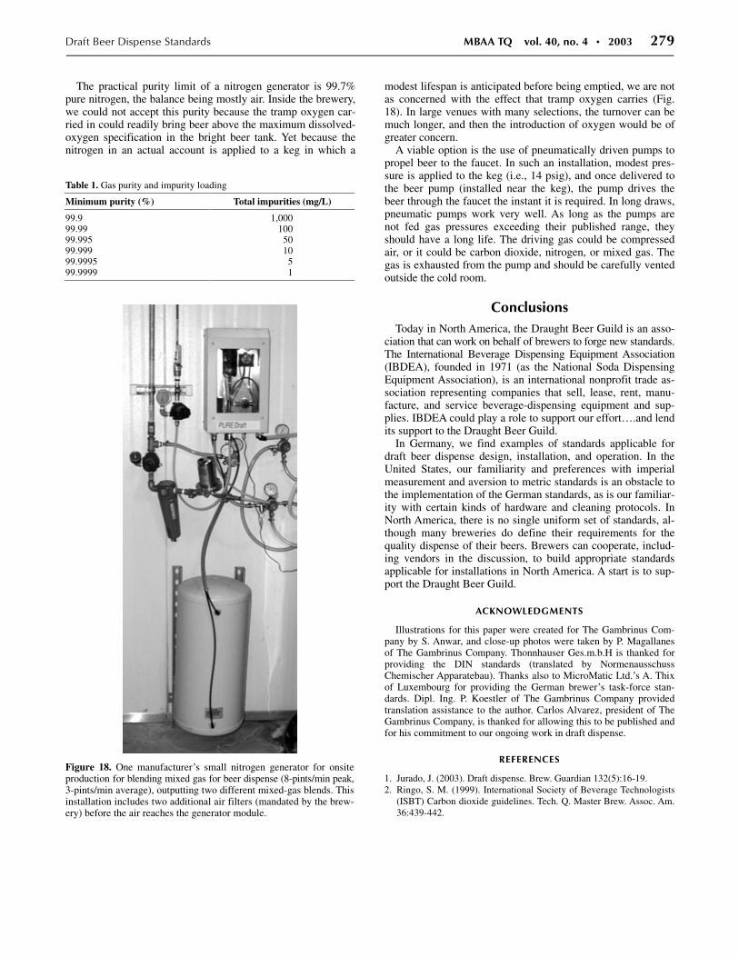
The practical purity limit of a nitrogen generator is 99.7% pure nitrogen, the balance being mostly air. Inside the brewery, we could not accept this purity because the tramp oxygen car-ried in could readily bring beer above the maximum dissolved-oxygen specification in the bright beer tank. Yet because the nitrogen in an actual account is applied to a keg in which a
modest lifespan is anticipated before being emptied, we are not as concerned with the effect that tramp oxygen carries (Fig. 18). In large venues with many selections, the turnover can be much longer, and then the introduction of oxygen would be of greater concern.
A viable option is the use of pneumatically driven pumps to propel beer to the faucet. In such an installation, modest pres-sure is applied to the keg (i.e., 14 psig), and once delivered to the beer pump (installed near the keg), the pump drives the beer through the faucet the instant it is required. In long draws, pneumatic pumps work very well. As long as the pumps are not fed gas pressures exceeding their published range, they should have a long life. The driving gas could be compressed air, or it could be carbon dioxide, nitrogen, or mixed gas. The gas is exhausted from the pump and should be carefully vented outside the cold room.
Conclusions Today in North America, the Draught Beer Guild is an asso-
ciation that can work on behalf of brewers to forge new standards. The International Beverage Dispensing Equipment Association (IBDEA), founded in 1971 (as the National Soda Dispensing Equipment Association), is an international nonprofit trade as-sociation representing companies that sell, lease, rent, manu-facture, and service beverage-dispensing equipment and sup-plies. IBDEA could play a role to support our effort….and lend its support to the Draught Beer Guild.
In Germany, we find examples of standards applicable for draft beer dispense design, installation, and operation. In the United States, our familiarity and preferences with imperial measurement and aversion to metric standards is an obstacle to the implementation of the German standards, as is our familiar-ity with certain kinds of hardware and cleaning protocols. In North America, there is no single uniform set of standards, al-though many breweries do define their requirements for the quality dispense of their beers. Brewers can cooperate, includ-ing vendors in the discussion, to build appropriate standards applicable for installations in North America. A start is to sup-port the Draught Beer Guild.
ACKNOWLEDGMENTS
Illustrations for this paper were created for The Gambrinus Com-pany by S. Anwar, and close-up photos were taken by P. Magallanes of The Gambrinus Company. Thonnhauser Ges.m.b.H is thanked for providing the DIN standards (translated by Normenausschuss Chemischer Apparatebau). Thanks also to MicroMatic Ltd.’s A. Thix of Luxembourg for providing the German brewer’s task-force stan-dards. Dipl. Ing. P. Koestler of The Gambrinus Company provided translation assistance to the author. Carlos Alvarez, president of The Gambrinus Company, is thanked for allowing this to be published and for his commitment to our ongoing work in draft dispense.
REFERENCES
1. Jurado, J. (2003). Draft dispense. Brew. Guardian 132(5):16-19. 2. Ringo, S. M. (1999). International Society of Beverage Technologists
(ISBT) Carbon dioxide guidelines. Tech. Q. Master Brew. Assoc. Am. 36:439-442.
�
Figure 18. One manufacturer’s small nitrogen generator for onsite production for blending mixed gas for beer dispense (8-pints/min peak, 3-pints/min average), outputting two different mixed-gas blends. Thisinstallation includes two additional air filters (mandated by the brew-ery) before the air reaches the generator module.
Table 1. Gas purity and impurity loading
Minimum purity (%) Total impurities (mg/L)
99.9 1,000 99.99 100 99.995 50 99.999 10 99.9995 5 99.9999 1